VOLVO GEAR ACTUATOR - WABCO Customer Centre
78
VOLVO GEAR ACTUATOR DESIGN • FUNCTION • REPAIR
-
Upload
khangminh22 -
Category
Documents
-
view
0 -
download
0
Transcript of VOLVO GEAR ACTUATOR - WABCO Customer Centre
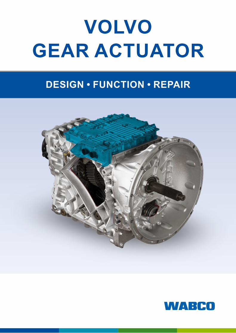
VOLVO GEAR ACTUATOR
DESIGN • FUNCTION • REPAIR

Table of contents
Original document: The German version is the original document.
Translation of the original document: All non-German language editions of this document are translations of the original document.
Edition 2 (08.2020) Version 2Document Number: 815 010 227 3 (en)
You will find the current edition at: http://www.wabco.info/i/1476
3
Table of contents
Table of contents1 List of abbreviations ........................................................................................................................................ 5
2 Symbols used in this document ..................................................................................................................... 6
3 Safety information ............................................................................................................................................ 7
4 Information about this document ................................................................................................................... 84.1 Target group for this document . . . . . . . . . . . . . . . . . . . . . . . . . . . . . . . . . . . . . . . . . . . . . . . . . . . . . . . . 84.2 Scope of application: Volvo brake actuators up to generation PS and Renault Optidriver . . . . . . . . . . . 8
5 Introduction ...................................................................................................................................................... 9
6 General information on the gear actuators ................................................................................................. 106.1 Gear actuator generations . . . . . . . . . . . . . . . . . . . . . . . . . . . . . . . . . . . . . . . . . . . . . . . . . . . . . . . . . . . 106.2 Gear models: Direct drive and overdrive . . . . . . . . . . . . . . . . . . . . . . . . . . . . . . . . . . . . . . . . . . . . . . . . 10
7 Mechanics of the transmission ..................................................................................................................... 117.1 Basic structure of the transmission . . . . . . . . . . . . . . . . . . . . . . . . . . . . . . . . . . . . . . . . . . . . . . . . . . . . 117.2 Shafts and wheel set . . . . . . . . . . . . . . . . . . . . . . . . . . . . . . . . . . . . . . . . . . . . . . . . . . . . . . . . . . . . . . 127.3 Planetary gear: Operating principle . . . . . . . . . . . . . . . . . . . . . . . . . . . . . . . . . . . . . . . . . . . . . . . . . . . . 13
7.3.1 Shift position: Range High ....................................................................................................... 137.3.2 Shift position: Range Low ....................................................................................................... 13
7.4 Splitter group, main group and range group . . . . . . . . . . . . . . . . . . . . . . . . . . . . . . . . . . . . . . . . . . . . . 147.5 Direct drive transmission and overdrive in comparison . . . . . . . . . . . . . . . . . . . . . . . . . . . . . . . . . . . . . 147.6 Sliding sleeves and shift forks . . . . . . . . . . . . . . . . . . . . . . . . . . . . . . . . . . . . . . . . . . . . . . . . . . . . . . . 157.7 The flow of force in 1st gear (using the direct drive transmission as an example) . . . . . . . . . . . . . . . . 157.8 The flow of force in gears 1 to 12 (direct drive transmission) . . . . . . . . . . . . . . . . . . . . . . . . . . . . . . . . 167.9 The flow of force in neutral position (direct drive transmission) . . . . . . . . . . . . . . . . . . . . . . . . . . . . . . . 177.10 The flow of force in the reverse gears (direct drive transmission) . . . . . . . . . . . . . . . . . . . . . . . . . . . . 187.11 Position of the shift forks in forward and reverse gears . . . . . . . . . . . . . . . . . . . . . . . . . . . . . . . . . . . . 187.12 Clutch . . . . . . . . . . . . . . . . . . . . . . . . . . . . . . . . . . . . . . . . . . . . . . . . . . . . . . . . . . . . . . . . . . . . . . . . . . . 197.13 Countershaft brake . . . . . . . . . . . . . . . . . . . . . . . . . . . . . . . . . . . . . . . . . . . . . . . . . . . . . . . . . . . . . . . . 20
8 Design of the gear changing system ........................................................................................................... 218.1 Compressed air supplies and compressed air connections . . . . . . . . . . . . . . . . . . . . . . . . . . . . . . . . . 218.2 Electrical connections . . . . . . . . . . . . . . . . . . . . . . . . . . . . . . . . . . . . . . . . . . . . . . . . . . . . . . . . . . . . . . 228.3 Components in the cover of the gear changing system. . . . . . . . . . . . . . . . . . . . . . . . . . . . . . . . . . . . . 23
8.3.1 Solenoid valves ....................................................................................................................... 238.3.2 Transmission control unit (TECU) and pressure sensor .......................................................... 23
8.4 Components in the bottom section of the gear changing system . . . . . . . . . . . . . . . . . . . . . . . . . . . . . 248.4.1 Cylinders and shift forks .......................................................................................................... 248.4.2 Locking mechanisms ............................................................................................................... 248.4.3 Position sensor ........................................................................................................................ 258.4.4 Rotary encoder ........................................................................................................................ 25
9 Network integration of the transmission control unit ................................................................................ 269.1 Bus connections . . . . . . . . . . . . . . . . . . . . . . . . . . . . . . . . . . . . . . . . . . . . . . . . . . . . . . . . . . . . . . . . . . 269.2 Examples of CAN messages . . . . . . . . . . . . . . . . . . . . . . . . . . . . . . . . . . . . . . . . . . . . . . . . . . . . . . . . . 27
10 Disassembly of the gear changing system ................................................................................................. 2910.1 Preparatory activities . . . . . . . . . . . . . . . . . . . . . . . . . . . . . . . . . . . . . . . . . . . . . . . . . . . . . . . . . . . . . . . 2910.2 Prior to disassembly . . . . . . . . . . . . . . . . . . . . . . . . . . . . . . . . . . . . . . . . . . . . . . . . . . . . . . . . . . . . . . . 3010.3 Move the shift forks into the required position . . . . . . . . . . . . . . . . . . . . . . . . . . . . . . . . . . . . . . . . . . . . 3210.4 Remove bottom section . . . . . . . . . . . . . . . . . . . . . . . . . . . . . . . . . . . . . . . . . . . . . . . . . . . . . . . . . . . . . 3410.5 Important note regarding the following descriptions . . . . . . . . . . . . . . . . . . . . . . . . . . . . . . . . . . . . . . . 35

4
Table of contents List of abbreviations
11 General overhaul of the gear changing system .......................................................................................... 3611.1 Replacing the pressure sensor . . . . . . . . . . . . . . . . . . . . . . . . . . . . . . . . . . . . . . . . . . . . . . . . . . . . . . . 3611.2 Removing the rotary encoder and cable harness . . . . . . . . . . . . . . . . . . . . . . . . . . . . . . . . . . . . . . . . . 3711.3 Removing the locking mechanisms, cylinder covers and piston rods . . . . . . . . . . . . . . . . . . . . . . . . . . 3811.4 Renewing the components . . . . . . . . . . . . . . . . . . . . . . . . . . . . . . . . . . . . . . . . . . . . . . . . . . . . . . . . . . 44
11.4.1 Range cylinder ........................................................................................................................ 4411.4.2 Cylinder 2/3 ............................................................................................................................. 4411.4.3 Cylinder 1/R ............................................................................................................................. 4511.4.4 Split cylinder ............................................................................................................................ 4511.4.5 Other renewable components ................................................................................................. 4611.4.6 Learning the transmission control unit .................................................................................... 46
12 Available repair kits ....................................................................................................................................... 4712.1 Seal set: static seals (421 365 920 2) . . . . . . . . . . . . . . . . . . . . . . . . . . . . . . . . . . . . . . . . . . . . . . . . . . 5412.2 Cable set with cable bridge and rotary encoders (421 365 921 2) . . . . . . . . . . . . . . . . . . . . . . . . . . . . 5412.3 Kit with detent pins (421 365 922 2) . . . . . . . . . . . . . . . . . . . . . . . . . . . . . . . . . . . . . . . . . . . . . . . . . . . 5512.4 Nut ring and piston kit (421 365 923 2) . . . . . . . . . . . . . . . . . . . . . . . . . . . . . . . . . . . . . . . . . . . . . . . . . 5512.5 Cylinder cover (split cylinder) (421 365 924 2) . . . . . . . . . . . . . . . . . . . . . . . . . . . . . . . . . . . . . . . . . . . 5612.6 Cylinder cover (1/R cylinder) (421 365 925 2) . . . . . . . . . . . . . . . . . . . . . . . . . . . . . . . . . . . . . . . . . . . . 5612.7 Cylinder cover (2/3 cylinder) (421 365 926 2) . . . . . . . . . . . . . . . . . . . . . . . . . . . . . . . . . . . . . . . . . . . . 5712.8 Clutch cylinder cover with seal (421 365 927 2) . . . . . . . . . . . . . . . . . . . . . . . . . . . . . . . . . . . . . . . . . . 5712.9 Anchor, conical spring for shift fork 2/3 (421 365 928 2) . . . . . . . . . . . . . . . . . . . . . . . . . . . . . . . . . . . . 5812.10 Distance sensor kit (421 365 929 2) . . . . . . . . . . . . . . . . . . . . . . . . . . . . . . . . . . . . . . . . . . . . . . . . . . . 5812.11 Piston rod for divided cylinder (421 365 932 2) . . . . . . . . . . . . . . . . . . . . . . . . . . . . . . . . . . . . . . . . . . . 5912.12 Piston rod for cylinder 1/R (421 365 933 2) . . . . . . . . . . . . . . . . . . . . . . . . . . . . . . . . . . . . . . . . . . . . . . 5912.13 Piston rod for cylinder 2/3 (421 365 934 2) . . . . . . . . . . . . . . . . . . . . . . . . . . . . . . . . . . . . . . . . . . . . . . 6012.14 Clutch piston (421 365 935 2) . . . . . . . . . . . . . . . . . . . . . . . . . . . . . . . . . . . . . . . . . . . . . . . . . . . . . . . . 6012.15 Bridging cable (421 365 938 2) . . . . . . . . . . . . . . . . . . . . . . . . . . . . . . . . . . . . . . . . . . . . . . . . . . . . . . . 6112.16 Stop plate for the splitter group (421 365 939 2) . . . . . . . . . . . . . . . . . . . . . . . . . . . . . . . . . . . . . . . . . . 6112.17 Bridging cable (421 365 946 2) . . . . . . . . . . . . . . . . . . . . . . . . . . . . . . . . . . . . . . . . . . . . . . . . . . . . . . . 6212.18 Pressure sensor kit (421 365 947 2) . . . . . . . . . . . . . . . . . . . . . . . . . . . . . . . . . . . . . . . . . . . . . . . . . . . 6212.19 Pressure sensor module (421 367 900 2) . . . . . . . . . . . . . . . . . . . . . . . . . . . . . . . . . . . . . . . . . . . . . . . 6312.20 Static seal (421 367 921 2) . . . . . . . . . . . . . . . . . . . . . . . . . . . . . . . . . . . . . . . . . . . . . . . . . . . . . . . . . . 6312.21 Bridging cable (421 367 922 2) . . . . . . . . . . . . . . . . . . . . . . . . . . . . . . . . . . . . . . . . . . . . . . . . . . . . . . . 6412.22 Valve unit with seal (421 367 924 2) . . . . . . . . . . . . . . . . . . . . . . . . . . . . . . . . . . . . . . . . . . . . . . . . . . . 6412.23 Cylinder cover for cylinder 1/R (421 367 927 2) . . . . . . . . . . . . . . . . . . . . . . . . . . . . . . . . . . . . . . . . . . 6512.24 Cylinder cover for split cylinder (421 367 928 2) . . . . . . . . . . . . . . . . . . . . . . . . . . . . . . . . . . . . . . . . . . 6512.25 Cylinder cover cylinder 2/3 (421 367 929 2) . . . . . . . . . . . . . . . . . . . . . . . . . . . . . . . . . . . . . . . . . . . . . 6612.26 Plate for split cylinder (421 367 930 2) . . . . . . . . . . . . . . . . . . . . . . . . . . . . . . . . . . . . . . . . . . . . . . . . . 6612.27 Connection holder with seal (421 367 931 2) . . . . . . . . . . . . . . . . . . . . . . . . . . . . . . . . . . . . . . . . . . . . 6712.28 Bridging cable (421 369 921 2) . . . . . . . . . . . . . . . . . . . . . . . . . . . . . . . . . . . . . . . . . . . . . . . . . . . . . . . 6712.29 Dynamic sealing kit (421 369 923 2) . . . . . . . . . . . . . . . . . . . . . . . . . . . . . . . . . . . . . . . . . . . . . . . . . . . 6812.30 Cover and piston for cylinder 1/R (421 369 924 2) . . . . . . . . . . . . . . . . . . . . . . . . . . . . . . . . . . . . . . . . 6812.31 Connection holder with seal (421 369 925 2) . . . . . . . . . . . . . . . . . . . . . . . . . . . . . . . . . . . . . . . . . . . . 6912.32 Cylinder cover for cylinder 2/3, nut rings and O-rings for cylinder (421 369 926 2). . . . . . . . . . . . . . . . 6912.33 Rod kit for cylinder 3, nut rings and O-rings for cylinder (421 369 927 2) . . . . . . . . . . . . . . . . . . . . . . . 7012.34 Rod kit for cylinder 2, nut rings and O-rings for cylinder (421 369 928 2) . . . . . . . . . . . . . . . . . . . . . . . 70
13 Glossary .......................................................................................................................................................... 71
14 Spare parts ..................................................................................................................................................... 72
15 Disposal .......................................................................................................................................... 73
16 WABCOregionaloffices ................................................................................................................................ 74
5
List of abbreviations
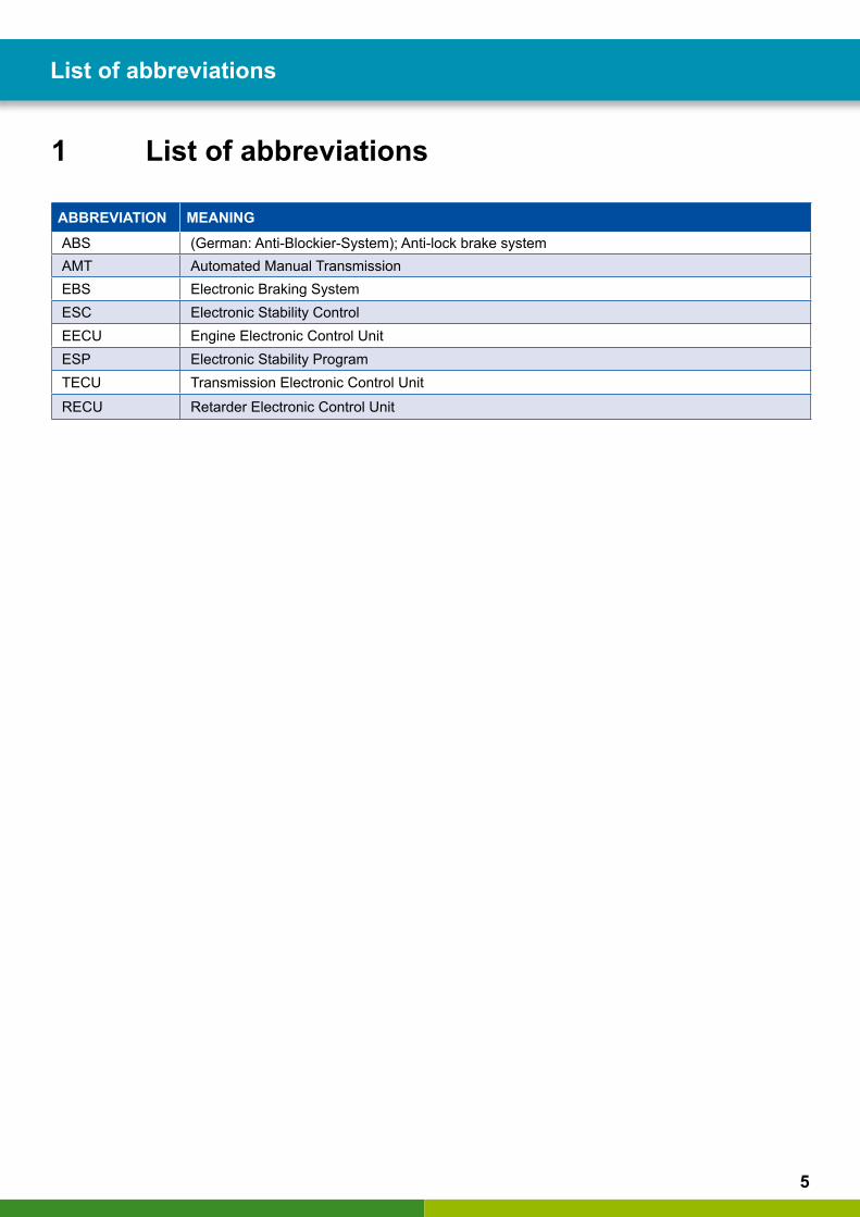
1 List of abbreviations
ABBREVIATION MEANINGABS (German: Anti-Blockier-System); Anti-lock brake systemAMT Automated Manual TransmissionEBS Electronic Braking SystemESC Electronic Stability ControlEECU Engine Electronic Control Unit ESP Electronic Stability ProgramTECU Transmission Electronic Control UnitRECU Retarder Electronic Control Unit
6
Symbols used in this document Safety information
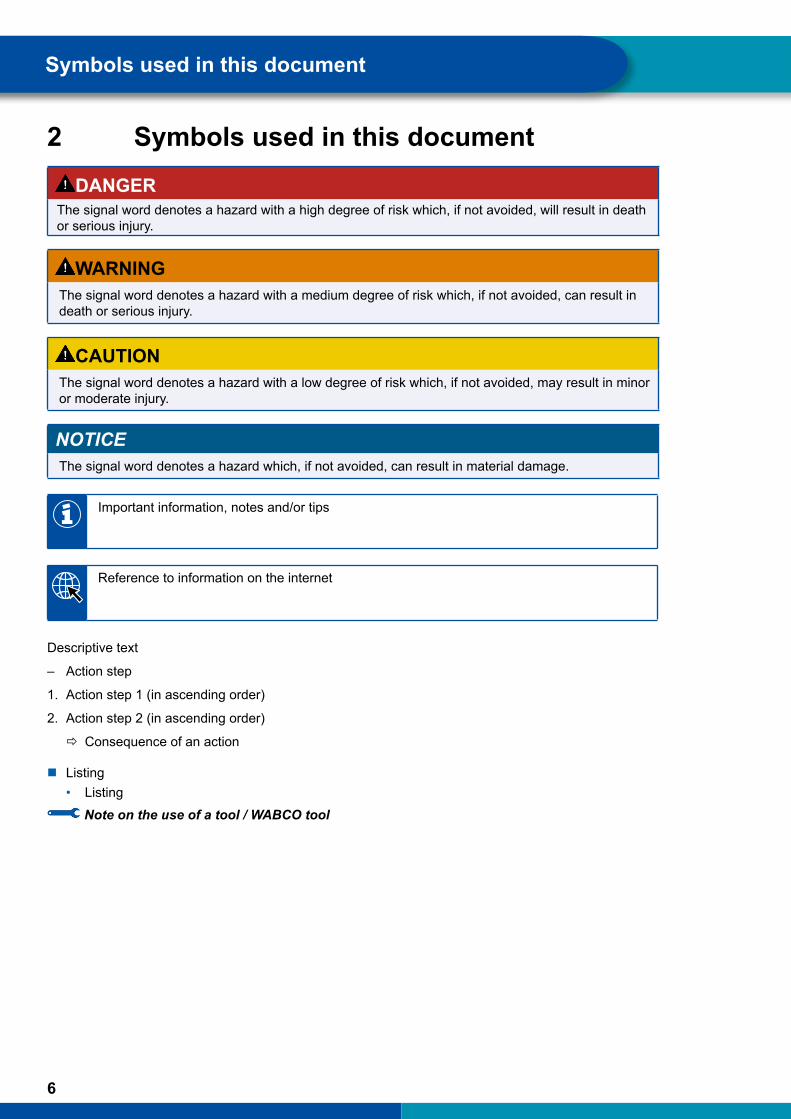
2 Symbols used in this documentDANGER
The signal word denotes a hazard with a high degree of risk which, if not avoided, will result in death or serious injury.
WARNINGThe signal word denotes a hazard with a medium degree of risk which, if not avoided, can result in death or serious injury.
CAUTIONThe signal word denotes a hazard with a low degree of risk which, if not avoided, may result in minor or moderate injury.
NOTICEThe signal word denotes a hazard which, if not avoided, can result in material damage.
Important information, notes and/or tips
Reference to information on the internet
Descriptive text
– Action step
1. Action step 1 (in ascending order)
2. Action step 2 (in ascending order)
Ö Consequence of an action
� Listing • Listing
Note on the use of a tool / WABCO toolO
7
Safety information
3 Safety informationRequirements and protective measures
– Follow the vehicle manufacturer's specifications and instructions.
– Follow the company's accident prevention regulations as well as regional and national regulations.
– Follow all warning notes, notices and instructions in this document to avoid personal injury and material damage.
– Follow regional and national road traffic regulations.
– Use protective equipment if required (safety footwear, protective eyewear, respiratory protection, ear defenders, etc.).
– Only trained and qualified technicians may carry out work on the vehicle.
– Make sure the workplace is dry as well as adequately lit and ventilated.
Proper working practice
– Only use original WABCO replacement parts.
– Perform the repair work using only the recommended tools and tightening torques.
– Always undertake a test drive after completing the repair work.
Improper working practice
– Do not use any compressed air or other high-pressure devices when cleaning the Volvo gear actuator or the vehicle. Hazardous dusts arising may lead to injuries. Parts of the system could also be damaged.
– Do not use motor-powered screwdriver or torque tools.
– Do not use fuels as cleaning agents.
8
Information about this document Introduction
4 Information about this document
4.1 Target group for this documentThis publication is intended for trained and qualified workshop employees.trained and qualified workshop employees.
4.2 Scope of application: Volvo brake actuators up to generation PS and Renault Optidriver
The contents of this document refer to generations A, B, C, D, E and F, as well as PS. Furthermore, the statements made therein also refer as far as possible to the corresponding transmissions from Renault. These are also known under the name "Optidriver".
9
Introduction
5 IntroductionThe Volvo gear actuator is an automated manual transmission for AMT commercial vehicles. The shifting processes are essentially automated by a gear changing system that is installed in the transmission.
This gear changing system – particularly its mechanical components – is subject to normal wear. Advanced wear may become apparent when a gear can no longer be engaged or when an internally installed sensor no longer returns measured values.
Benefitsforyou:costreduction
WABCO has a comprehensive range of repair-solutions for guaranteed flawless repair of many automated manual transmission components. Normally, these repairs make the complete replacement of the system unnecessary.
It is a cost-effective process and it considerably reduces downtimes.
Structure of the WABCO product number
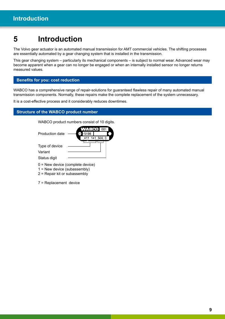
WABCO product numbers consist of 10 digits.
Production date
Type of deviceVariant Status digit
0 = New device (complete device) 1 = New device (subassembly) 2 = Repair kit or subassembly
7 = Replacement device
10
General information on the gear actuators Mechanics of the transmission
6 General information on the gear actuatorsThe automated manual transmission is very similar to a normal manual transmission with respect to the shafts and the gear sets. However, the shift linkage and the gear lever are replaced by an electronically controlled and electro-pneumatically operated gear changing system.
The transmission has 12 forward gears and 4 reverse gears.
6.1 Gear actuator generations � Generations A and B still have an external clutch cylinder installed on the outside. Delivery of series production has
been since 2001. � From generation C, an internal clutch cylinder is installed. This is arranged concentrically around the drive shaft.
Generation C has been delivered for series production since 2008. � In comparison to the C generation, the D generation is equipped with an altered rotational speed sensor. � Generations E & F have been adapted to the requirements of Euro 6. They have been delivered for series
production since 2013. � Generation PS is equipped with a dual clutch and has been delivered for series production since 2014.
6.2 Gear models: Direct drive and overdriveGear actuators are available in direct drive transmission and overdrive models. The glossary (see chapter "13 Glossary" on page 71) explains what these terms mean specifically in relation to gear actuators. The difference in design of these two gear models is explained here: see chapter "7.5 Direct drive transmission and overdrive in comparison" on page 14.
Labelling of the transmission
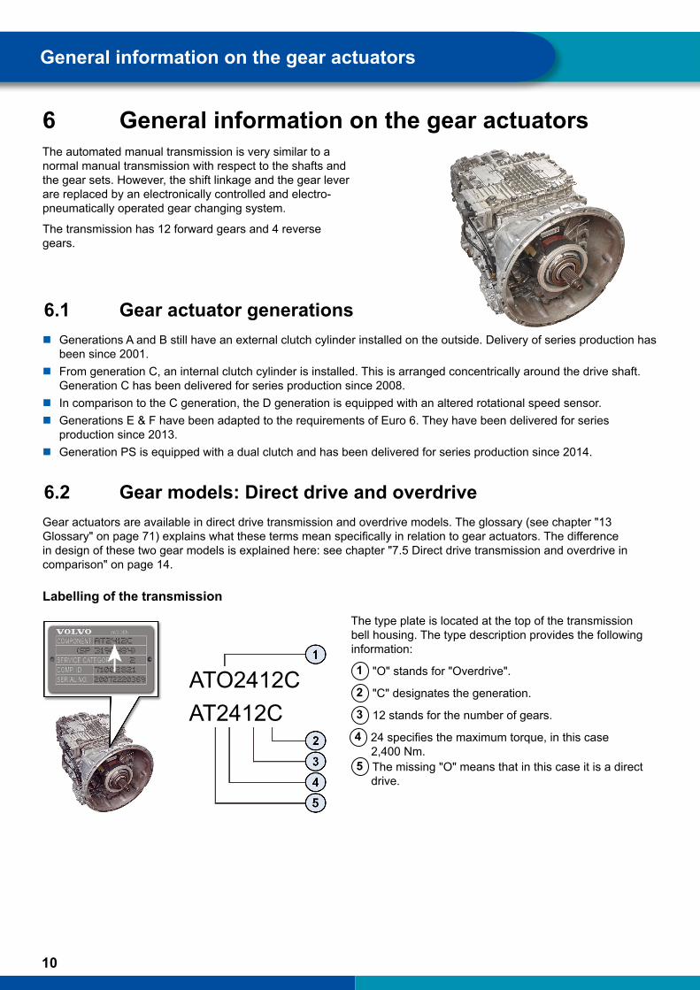
The type plate is located at the top of the transmission bell housing. The type description provides the following information:
1 "O" stands for "Overdrive".
2 "C" designates the generation.
3 12 stands for the number of gears.
4 24 specifies the maximum torque, in this case 2,400 Nm.
5 The missing "O" means that in this case it is a direct drive.
COMPONENTSWEDEN
SERVICE CATEGORYCOMP. IDSERIAL NO. ATO2412C
AT2412C

11
Mechanics of the transmission
7 Mechanics of the transmission
7.1 Basic structure of the transmission Gear actuators have the following basic design:
1 Clutch housing with transmission bell housing
2 Basic housing in which the splitter group and the main group are installed
3 Range housing in which the range group (also referred to as the rear-mounted group) is installed
4 Gear changing system on the top side of the basic housing
12
Mechanics of the transmission Mechanics of the transmission
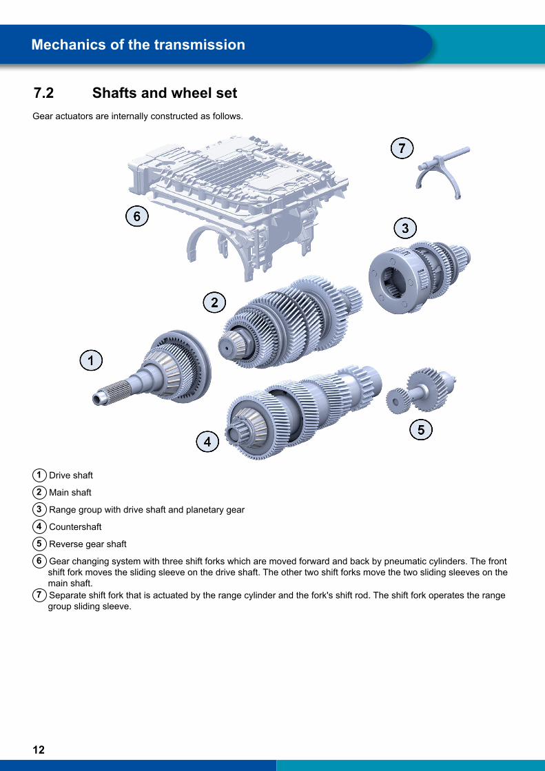
7.2 Shafts and wheel set Gear actuators are internally constructed as follows.
1 Drive shaft
2 Main shaft
3 Range group with drive shaft and planetary gear
4 Countershaft
5 Reverse gear shaft
6 Gear changing system with three shift forks which are moved forward and back by pneumatic cylinders. The front shift fork moves the sliding sleeve on the drive shaft. The other two shift forks move the two sliding sleeves on the main shaft.7 Separate shift fork that is actuated by the range cylinder and the fork's shift rod. The shift fork operates the range
group sliding sleeve.
13
Mechanics of the transmission
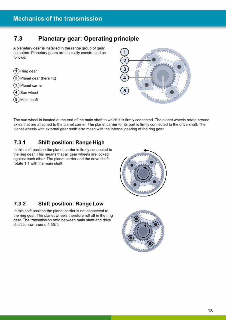
7.3 Planetary gear: Operating principleA planetary gear is installed in the range group of gear actuators. Planetary gears are basically constructed as follows:
1 Ring gear
2 Planet gear (here 4x)
3 Planet carrier
4 Sun wheel
5 Main shaft
The sun wheel is located at the end of the main shaft to which it is firmly connected. The planet wheels rotate around axles that are attached to the planet carrier. The planet carrier for its part is firmly connected to the drive shaft. The planet wheels with external gear teeth also mesh with the internal gearing of the ring gear.
7.3.1 Shift position: Range HighIn this shift position the planet carrier is firmly connected to the ring gear. This means that all gear wheels are locked against each other. The planet carrier and the drive shaft rotate 1:1 with the main shaft.
7.3.2 Shift position: Range Low In this shift position the planet carrier is not connected to the ring gear. The planet wheels therefore roll off in the ring gear. The transmission ratio between main shaft and drive shaft is now around 4.35:1.
14
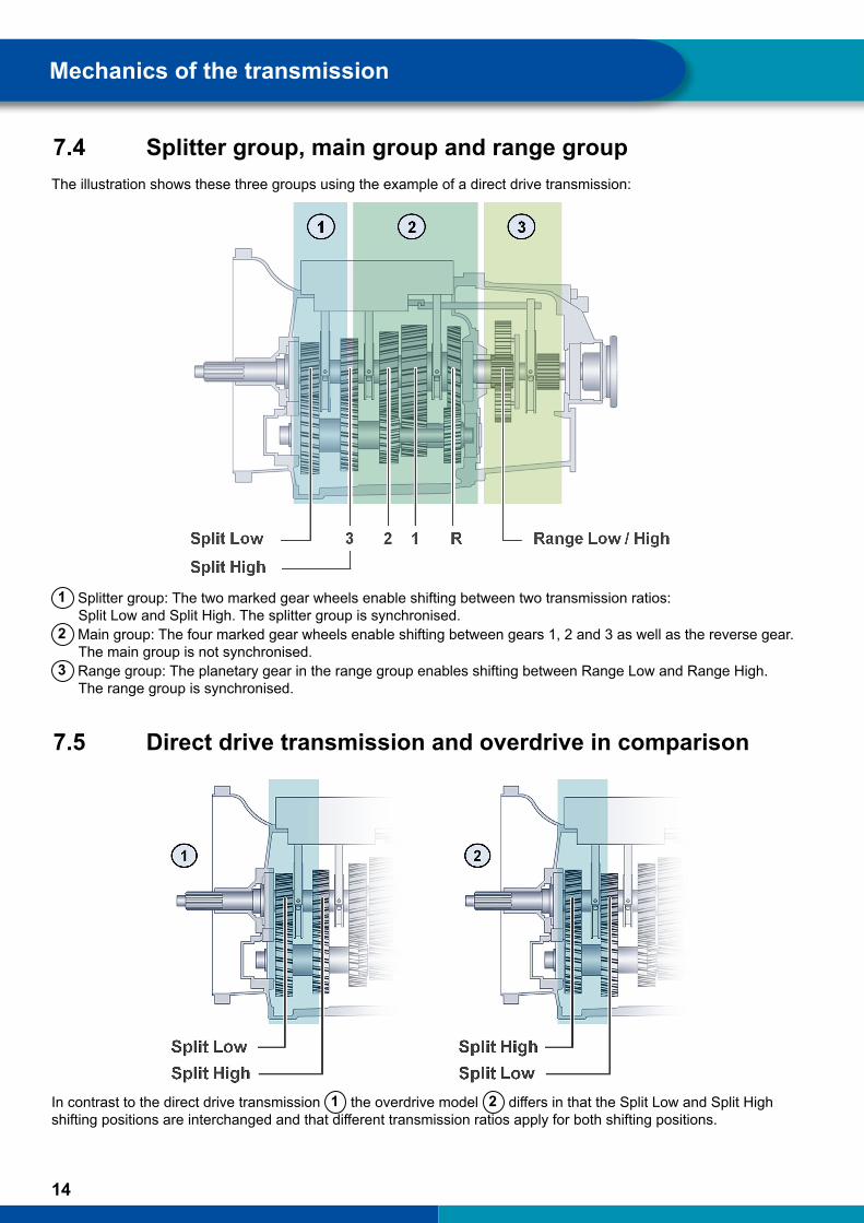
7.4 Splitter group, main group and range groupThe illustration shows these three groups using the example of a direct drive transmission:
1 Splitter group: The two marked gear wheels enable shifting between two transmission ratios:Split Low and Split High. The splitter group is synchronised.
2 Main group: The four marked gear wheels enable shifting between gears 1, 2 and 3 as well as the reverse gear.The main group is not synchronised.
3 Range group: The planetary gear in the range group enables shifting between Range Low and Range High.The range group is synchronised.
7.5 Direct drive transmission and overdrive in comparison
In contrast to the direct drive transmission 1 the overdrive model 2 differs in that the Split Low and Split High shifting positions are interchanged and that different transmission ratios apply for both shifting positions.
Mechanics of the transmission
15
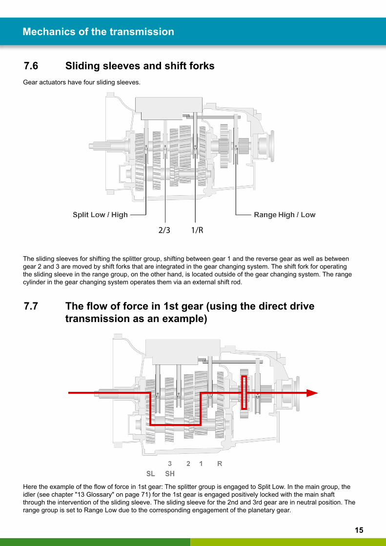
7.6 Sliding sleeves and shift forks Gear actuators have four sliding sleeves.
2/3 1/R
The sliding sleeves for shifting the splitter group, shifting between gear 1 and the reverse gear as well as between gear 2 and 3 are moved by shift forks that are integrated in the gear changing system. The shift fork for operating the sliding sleeve in the range group, on the other hand, is located outside of the gear changing system. The range cylinder in the gear changing system operates them via an external shift rod.
7.7 Theflowofforcein1stgear(usingthedirectdrivetransmission as an example)
Here the example of the flow of force in 1st gear: The splitter group is engaged to Split Low. In the main group, the idler (see chapter "13 Glossary" on page 71) for the 1st gear is engaged positively locked with the main shaft through the intervention of the sliding sleeve. The sliding sleeve for the 2nd and 3rd gear are in neutral position. The range group is set to Range Low due to the corresponding engagement of the planetary gear.
Mechanics of the transmission
16
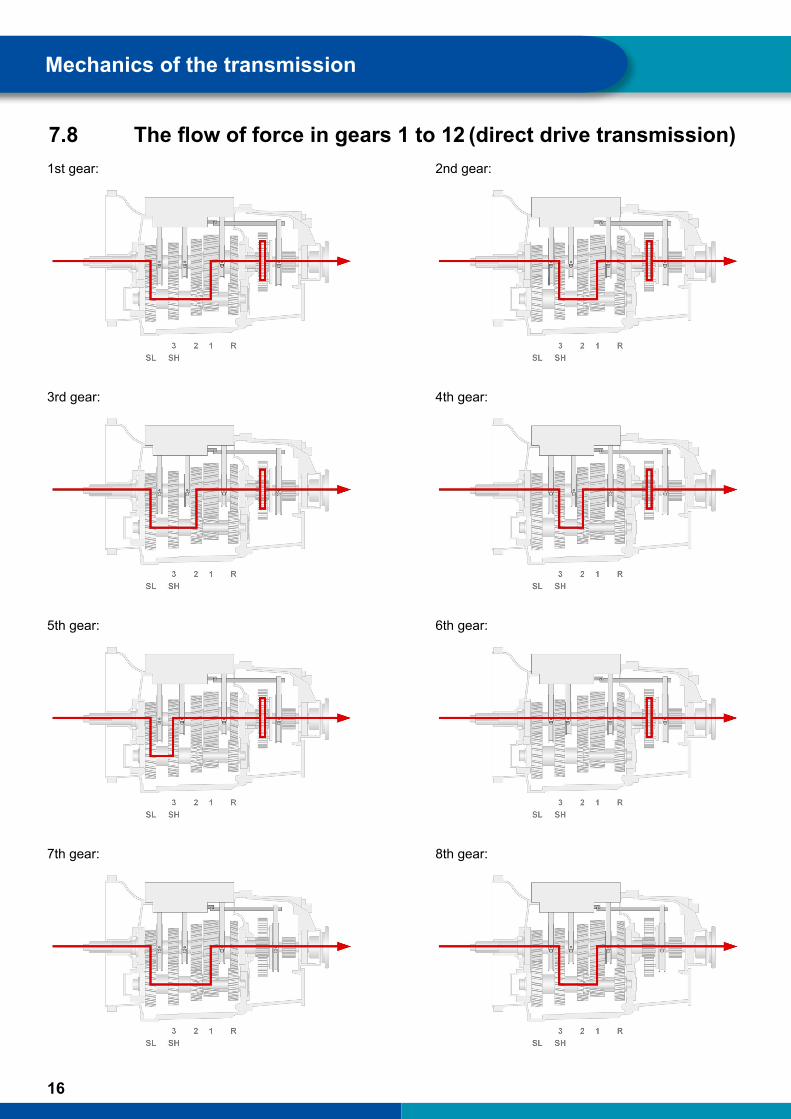
7.8 Theflowofforceingears1to12 (direct drive transmission)1st gear: 2nd gear:
3rd gear: 4th gear:
5th gear: 6th gear:
7th gear: 8th gear:
Mechanics of the transmission

17
9th gear: 10th gear:
11th gear: 12th gear:
7.9 Theflowofforceinneutralposition(directdrivetransmission)
Neutral N1: Neutral N2:
Mechanics of the transmission
18
Mechanics of the transmission Mechanics of the transmission
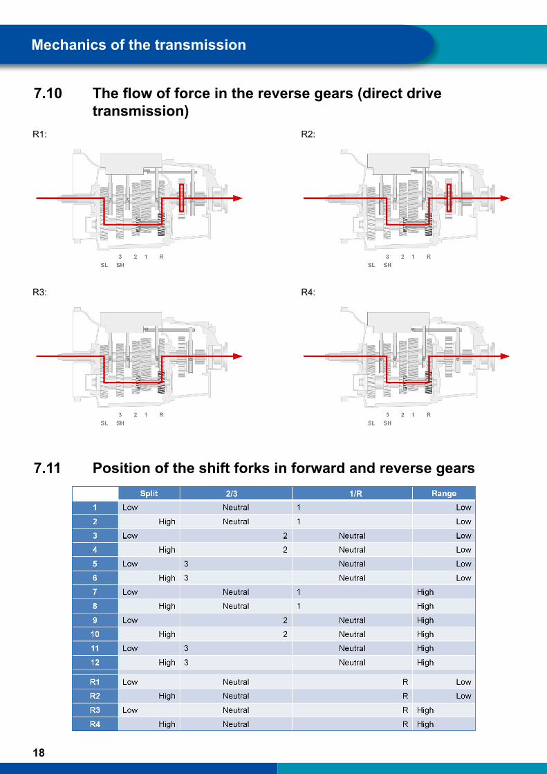
7.10 Theflowofforceinthereversegears(directdrivetransmission)
R1: R2:
R3: R4:
7.11 Position of the shift forks in forward and reverse gears 2/3 1/R

19
Mechanics of the transmission
The table on the previous page shows the positions of the sliding sleeves and shift forks in the different gears using the example of a direct drive transmission. The perspective on the transmission is here also shown from the side, so that the drive side is on the left.
Let us examine the 8th gear. Here the following can be noted:
� The shift fork for split is in the position to the right. � The shift fork for 2/3 is in the central position. � The shift fork for 1/R is on the left. � The shift fork for range is on the right.
With overdrive transmissions the position of the shift fork split is exactly the opposite in all gears. The other shift forks, on the other hand, are in exactly the same position as with the direct drive transmission.
7.12 Clutch
The PS gear actuator generation has a dual clutch. As of gear actuator generation C, the pneumatic cylinder for operating the clutch 1 is installed – concentrically around the drive shaft – in the transmission bell housing. A position sensor 2 measures the clutch wear. The valve package for clutch operation 3 is arranged on the outside of the clutch housing.
20
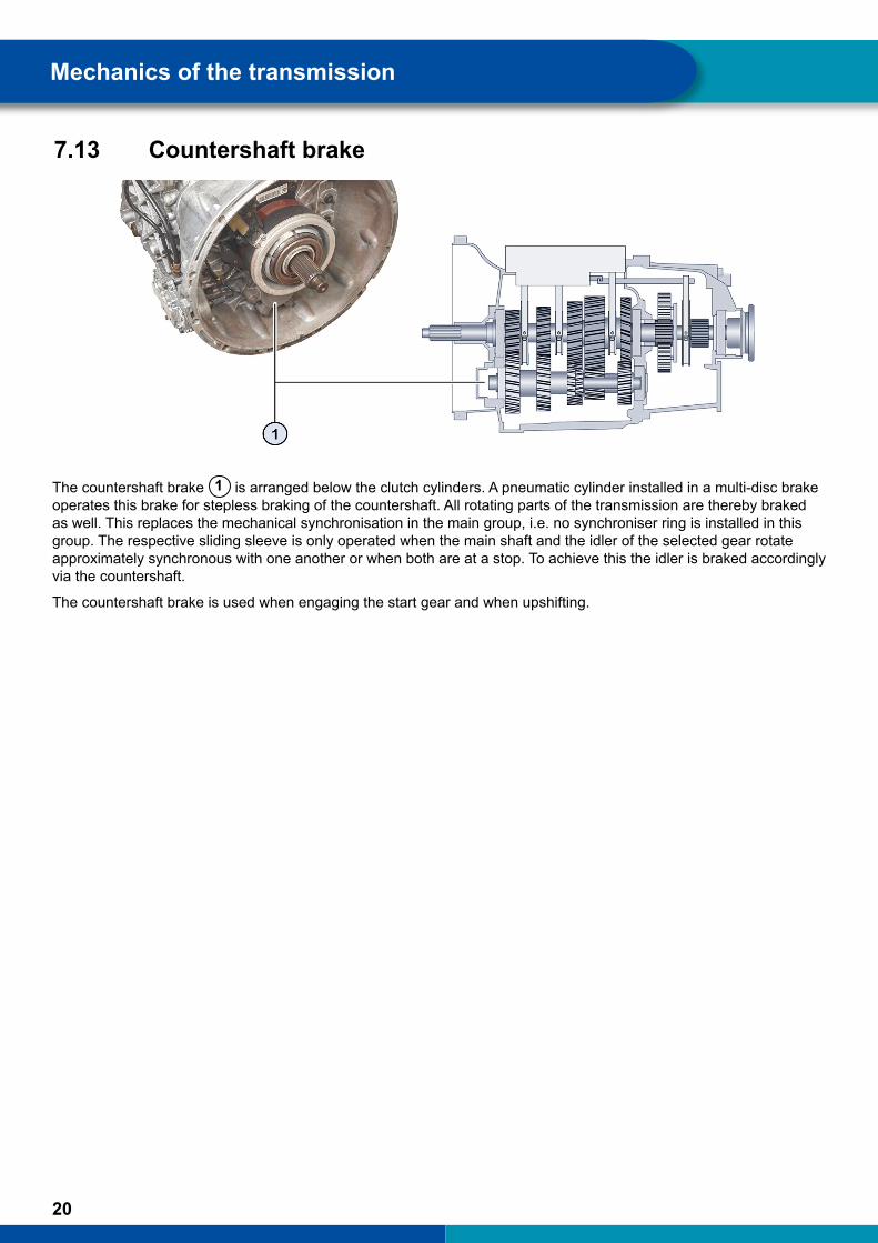
7.13 Countershaft brake
The countershaft brake 1 is arranged below the clutch cylinders. A pneumatic cylinder installed in a multi-disc brake operates this brake for stepless braking of the countershaft. All rotating parts of the transmission are thereby braked as well. This replaces the mechanical synchronisation in the main group, i.e. no synchroniser ring is installed in this group. The respective sliding sleeve is only operated when the main shaft and the idler of the selected gear rotate approximately synchronous with one another or when both are at a stop. To achieve this the idler is braked accordingly via the countershaft.
The countershaft brake is used when engaging the start gear and when upshifting.
Mechanics of the transmission
21
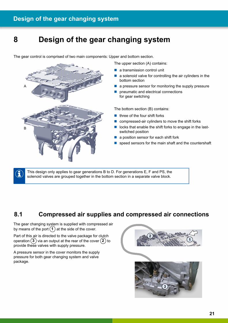
8 Design of the gear changing system
The gear control is comprised of two main components: Upper and bottom section.
The upper section (A) contains:
� a transmission control unit � a solenoid valve for controlling the air cylinders in the
bottom section � a pressure sensor for monitoring the supply pressure � pneumatic and electrical connections
for gear switching
The bottom section (B) contains:
� three of the four shift forks � compressed-air cylinders to move the shift forks � locks that enable the shift forks to engage in the last-
switched position � a position sensor for each shift fork � speed sensors for the main shaft and the countershaft
This design only applies to gear generations B to D. For generations E, F and PS, the solenoid valves are grouped together in the bottom section in a separate valve block.
8.1 Compressed air supplies and compressed air connectionsThe gear changing system is supplied with compressed air by means of the port 1 at the side of the cover.
Part of this air is directed to the valve package for clutch operation 3 via an output at the rear of the cover 2 to provide these valves with supply pressure.
A pressure sensor in the cover monitors the supply pressure for both gear changing system and valve package.
A
B
Design of the gear changing system
22
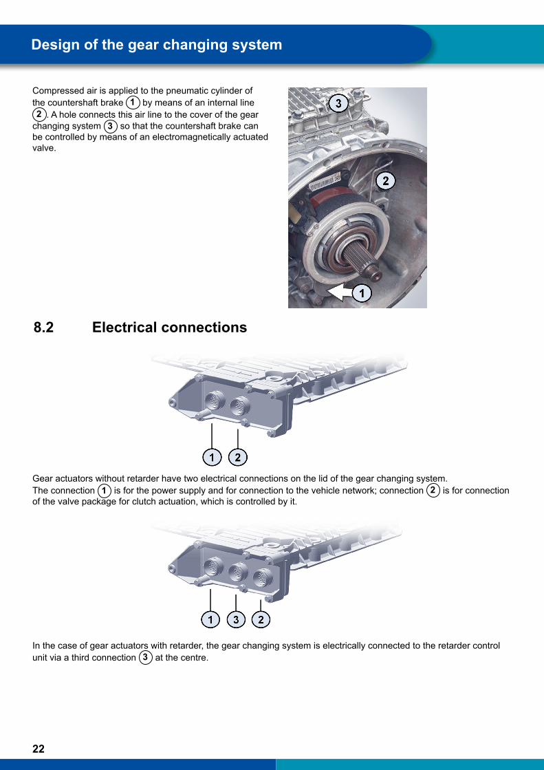
Compressed air is applied to the pneumatic cylinder of the countershaft brake 1 by means of an internal line 2 . A hole connects this air line to the cover of the gear
changing system 3 so that the countershaft brake can be controlled by means of an electromagnetically actuated valve.
8.2 Electrical connections
Gear actuators without retarder have two electrical connections on the lid of the gear changing system. The connection 1 is for the power supply and for connection to the vehicle network; connection 2 is for connection of the valve package for clutch actuation, which is controlled by it.
In the case of gear actuators with retarder, the gear changing system is electrically connected to the retarder control unit via a third connection 3 at the centre.
Design of the gear changing system
23
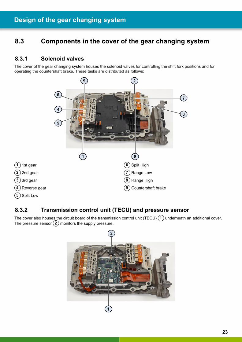
8.3 Components in the cover of the gear changing system
8.3.1 Solenoid valvesThe cover of the gear changing system houses the solenoid valves for controlling the shift fork positions and for operating the countershaft brake. These tasks are distributed as follows:
1 1st gear
2 2nd gear
3 3rd gear
4 Reverse gear
5 Split Low
6 Split High
7 Range Low
8 Range High
9 Countershaft brake
8.3.2 Transmission control unit (TECU) and pressure sensorThe cover also houses the circuit board of the transmission control unit (TECU) 1 underneath an additional cover. The pressure sensor 2 monitors the supply pressure.
Design of the gear changing system

24
8.4 Components in the bottom section of the gear changing
system
8.4.1 Cylinders and shift forksThe sequence of shift forks (from the drive side ("Front") to the driven side) arises from the construction of the transmission: Split, 2/3 and 1/R.
Range 2/3 1/R Split
1/R
2/3
Split
Range
The corresponding cylinders are accompanied on the left side by the range cylinder. The thickening at the end of its piston rod is mounted into the external shift rod of the range group.
8.4.2 Locking mechanismsLocking mechanisms are used to retain the shift forks exactly in their shift positions. To this end, the locking pins extend into the depressions 1 in the piston rods. Three locking mechanisms are installed in the gear changing system. The range locking mechanism (not accessible), on the other hand, is located in the range housing.
2/31/R
Design of the gear changing system

25
8.4.3 Position sensorThe current positions of the four piston rods and thus the shift forks is captured by four positions sensors. These are located at one end of the respective piston rod. This enables detection of whether a new shift position has actually been reached.
1/R 2/3
8.4.4 Rotary encoder
The current rotational speed of the main shaft is captured by a horizontally arranged rotational speed sensor 1 by means of a pulse disc 4 that is connected torque-proof to the main shaft.
A second, vertically arranged rotational speed sensor 2 captures the countershaft's rotational speed via the rotational speed of the idler 3 for the 2nd gear.
Design of the gear changing system
26
9 Network integration of the transmission control unit
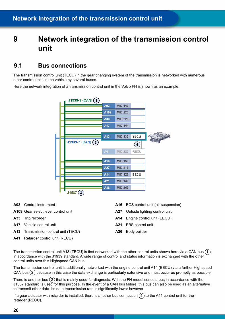
9.1 Bus connectionsThe transmission control unit (TECU) in the gear changing system of the transmission is networked with numerous other control units in the vehicle by several buses.
Here the network integration of a transmission control unit in the Volvo FH is shown as an example.
A03 Central instrument
A109 Gear select lever control unit
A33 Trip recorder
A17 Vehicle control unit
A13 Transmission control unit (TECU)
A41 Retarder control unit (RECU)
A16 ECS control unit (air suspension)
A27 Outside lighting control unit
A14 Engine control unit (EECU)
A21 EBS control unit
A36 Body builder
The transmission control unit A13 (TECU) is first networked with the other control units shown here via a CAN bus 1 in accordance with the J1939 standard. A wide range of control and status information is exchanged with the other control units over this Highspeed CAN bus.
The transmission control unit is additionally networked with the engine control unit A14 (EECU) via a further Highspeed CAN bus 2 because in this case the data exchange is particularly extensive and must occur as promptly as possible.
There is another bus 3 that is mainly used for diagnosis. With the FH model series a bus in accordance with the J1587 standard is used for this purpose. In the event of a CAN bus failure, this bus can also be used as an alternative to transmit other data. Its data transmission rate is significantly lower however.
If a gear actuator with retarder is installed, there is another bus connection 4 to the A41 control unit for the retarder (RECU).
Network integration of the transmission control unit

27
9.2 Examples of CAN messagesThe transmission control unit exchanges numerous messages with the other control units via the two CAN buses. Here are a few examples:
Gear select lever control unit:
� Current select lever position
Engine control unit (EECU):
� Engine speed � Engine torque � Engine configuration
Vehicle control unit:
� Accelerator pedal position, including kickdown � Brake pedal position � Parking brake position � Control of the retarder
EBS control unit:
� Wheel speeds � Wheel slip � ABS intervention � ESC intervention
� Launch Control: prior to shifting between a forward and a reverse gear: automatic activation of the service brake
Network integration of the transmission control unit
28
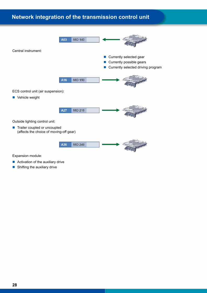
Central instrument:
� Currently selected gear � Currently possible gears � Currently selected driving program
ECS control unit (air suspension):
� Vehicle weight
Outside lighting control unit:
� Trailer coupled or uncoupled (affects the choice of moving-off gear)
Expansion module:
� Activation of the auxiliary drive � Shifting the auxiliary drive
Network integration of the transmission control unit
29
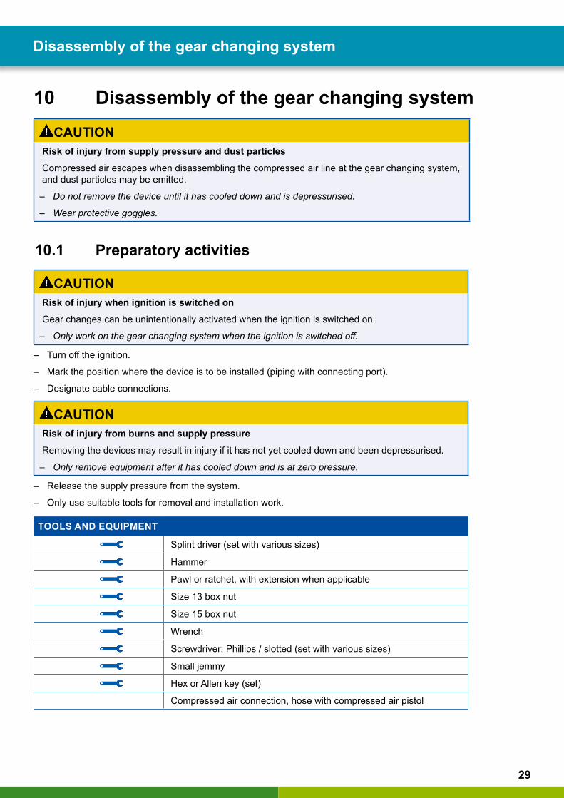
10 Disassembly of the gear changing systemCAUTION
Risk of injury from supply pressure and dust particles Compressed air escapes when disassembling the compressed air line at the gear changing system, and dust particles may be emitted.
– Do not remove the device until it has cooled down and is depressurised.
– Wear protective goggles.
10.1 Preparatory activities
CAUTIONRisk of injury when ignition is switched onGear changes can be unintentionally activated when the ignition is switched on.
– Only work on the gear changing system when the ignition is switched off.
– Turn off the ignition.
– Mark the position where the device is to be installed (piping with connecting port).
– Designate cable connections.
CAUTIONRisk of injury from burns and supply pressure Removing the devices may result in injury if it has not yet cooled down and been depressurised.
– Only remove equipment after it has cooled down and is at zero pressure.
– Release the supply pressure from the system.
– Only use suitable tools for removal and installation work.
TOOLS AND EQUIPMENT
Splint driver (set with various sizes)
Hammer
Pawl or ratchet, with extension when applicable
Size 13 box nut
Size 15 box nut
Wrench
Screwdriver; Phillips / slotted (set with various sizes)
Small jemmy
Hex or Allen key (set)
Compressed air connection, hose with compressed air pistol
Disassembly of the gear changing system
30
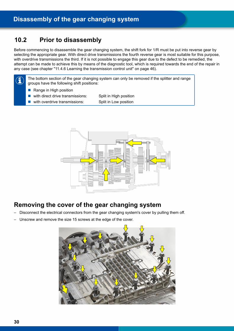
10.2 Prior to disassemblyBefore commencing to disassemble the gear changing system, the shift fork for 1/R must be put into reverse gear by selecting the appropriate gear. With direct drive transmissions the fourth reverse gear is most suitable for this purpose, with overdrive transmissions the third. If it is not possible to engage this gear due to the defect to be remedied, the attempt can be made to achieve this by means of the diagnostic tool, which is required towards the end of the repair in any case (see chapter "11.4.6 Learning the transmission control unit" on page 46).
The bottom section of the gear changing system can only be removed if the splitter and range groups have the following shift positions:
� Range in High position � with direct drive transmissions: Split in High position � with overdrive transmissions: Split in Low position
Removing the cover of the gear changing system – Disconnect the electrical connectors from the gear changing system's cover by pulling them off.
– Unscrew and remove the size 15 screws at the edge of the cover.
Disassembly of the gear changing system
31
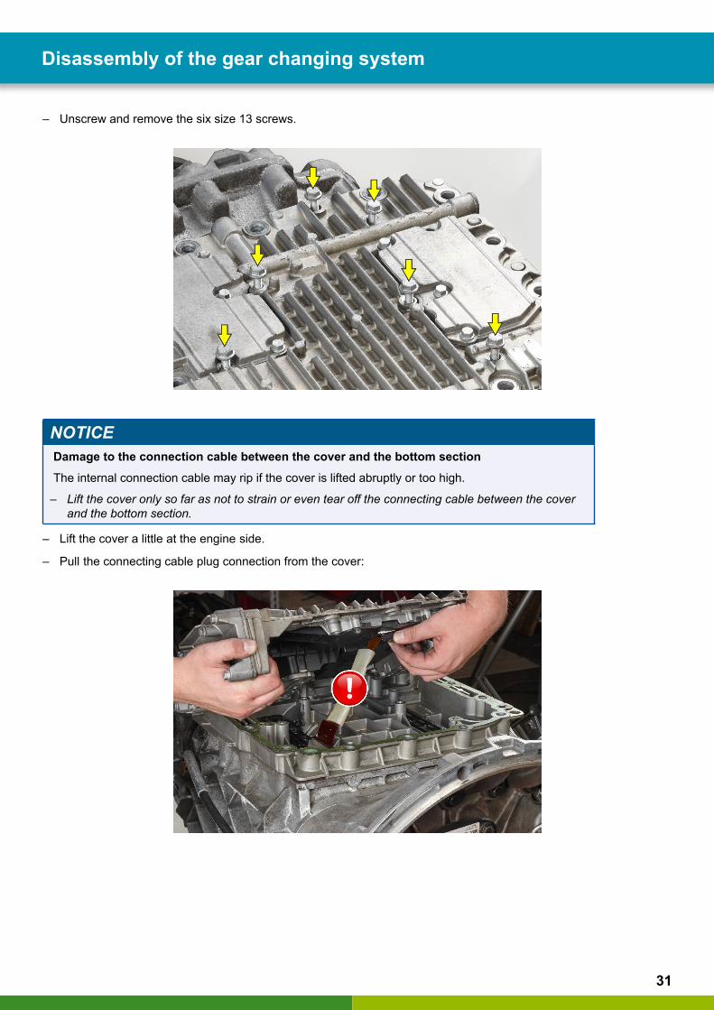
– Unscrew and remove the six size 13 screws.
NOTICEDamage to the connection cable between the cover and the bottom section The internal connection cable may rip if the cover is lifted abruptly or too high.
– Lift the cover only so far as not to strain or even tear off the connecting cable between the cover and the bottom section.
– Lift the cover a little at the engine side.
– Pull the connecting cable plug connection from the cover:
Disassembly of the gear changing system
32
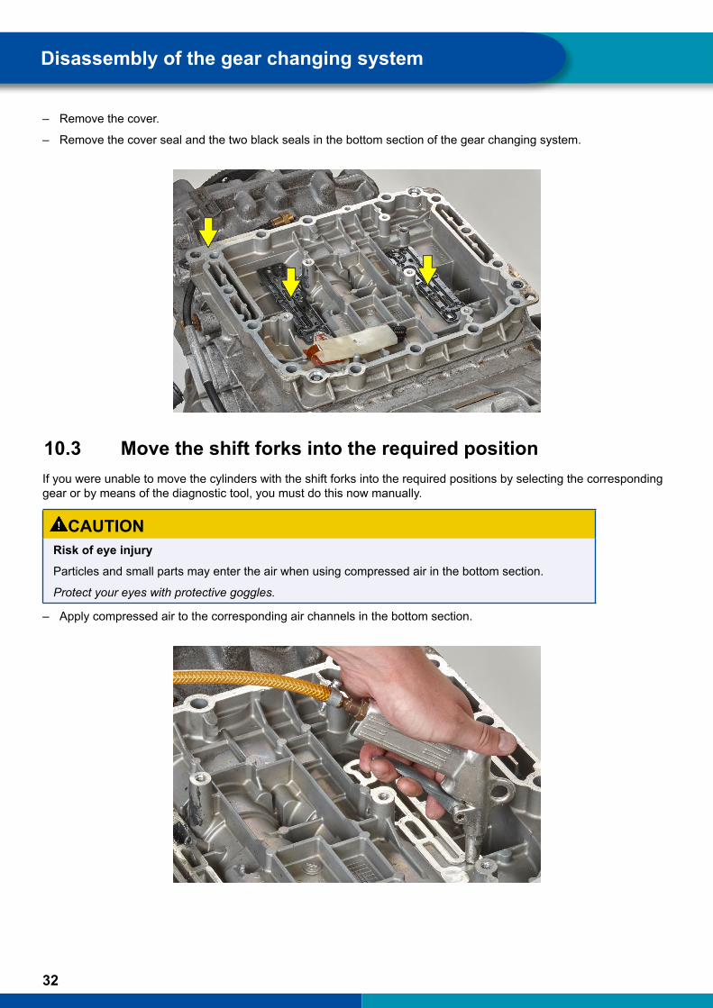
– Remove the cover.
– Remove the cover seal and the two black seals in the bottom section of the gear changing system.
10.3 Move the shift forks into the required positionIf you were unable to move the cylinders with the shift forks into the required positions by selecting the corresponding gear or by means of the diagnostic tool, you must do this now manually.
CAUTIONRisk of eye injuryParticles and small parts may enter the air when using compressed air in the bottom section.
Protect your eyes with protective goggles.
– Apply compressed air to the corresponding air channels in the bottom section.
Disassembly of the gear changing system
33
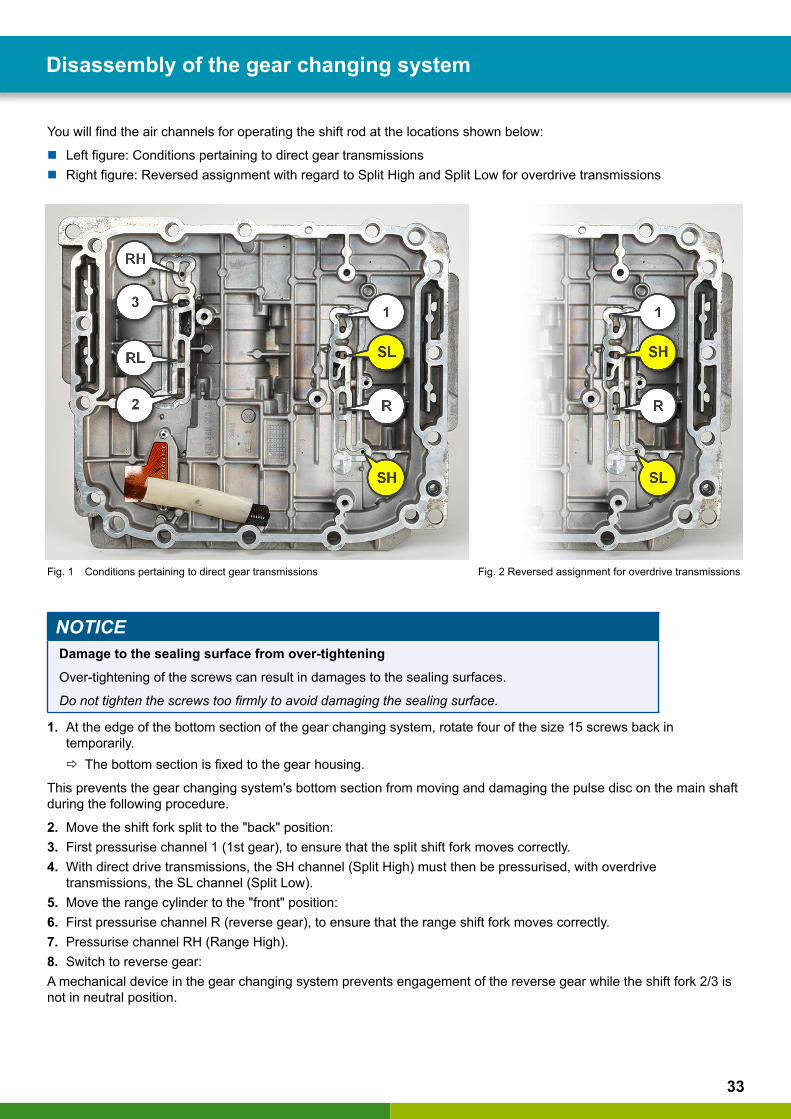
You will find the air channels for operating the shift rod at the locations shown below:
� Left figure: Conditions pertaining to direct gear transmissions � Right figure: Reversed assignment with regard to Split High and Split Low for overdrive transmissions
Fig. 1 Conditions pertaining to direct gear transmissions Fig. 2 Reversed assignment for overdrive transmissions
NOTICEDamage to the sealing surface from over-tightening Over-tightening of the screws can result in damages to the sealing surfaces.
Do not tighten the screws too firmly to avoid damaging the sealing surface.
1. At the edge of the bottom section of the gear changing system, rotate four of the size 15 screws back in temporarily.
Ö The bottom section is fixed to the gear housing.
This prevents the gear changing system's bottom section from moving and damaging the pulse disc on the main shaft during the following procedure.
2. Move the shift fork split to the "back" position:3. First pressurise channel 1 (1st gear), to ensure that the split shift fork moves correctly.4. With direct drive transmissions, the SH channel (Split High) must then be pressurised, with overdrive
transmissions, the SL channel (Split Low).5. Move the range cylinder to the "front" position:6. First pressurise channel R (reverse gear), to ensure that the range shift fork moves correctly.7. Pressurise channel RH (Range High).8. Switch to reverse gear:A mechanical device in the gear changing system prevents engagement of the reverse gear while the shift fork 2/3 is not in neutral position.
Disassembly of the gear changing system
34
9. Check whether the main transmission is in neutral position. For this purpose, rotate the drive shaft by hand. Ö If this is possible, the transmission is in neutral position.
Ö If this is not possible, the neutral position needs to be established first.
– To do this, carefully pressurise channel 2 (2nd gear) or channel 3 (3rd gear), alternately if necessary.
– Have a second person continuously rotate the drive shaft when doing this.
Ö As soon as this becomes possible, the shift fork 2/3 has reached the neutral position.
– Then pressurise channel R (reverse gear).
– Remove the four size 15 screws used to fix the bottom section of the gear changing system in position.
10.4 Remove bottom section
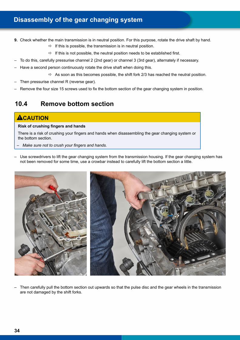
CAUTIONRiskofcrushingfingersandhandsThere is a risk of crushing your fingers and hands when disassembling the gear changing system or the bottom section.
– Make sure not to crush your fingers and hands.
– Use screwdrivers to lift the gear changing system from the transmission housing. If the gear changing system has not been removed for some time, use a crowbar instead to carefully lift the bottom section a little.
– Then carefully pull the bottom section out upwards so that the pulse disc and the gear wheels in the transmission are not damaged by the shift forks.
Disassembly of the gear changing system

35
10.5 Important note regarding the following descriptions
The following descriptions of how to recondition the gear changing system can only be provided as anoverviewhere.Whenreplacingparts,alwaysfollowallthespecificationsandrepairnotesinthedocuments included in the respective repair kit.
You can find spare parts and technical documentation for each repair kit using the WABCO part number at the following page:
http://www.wabco.info/i/1365
Disassembly of the gear changing system
36
11 General overhaul of the gear changing system
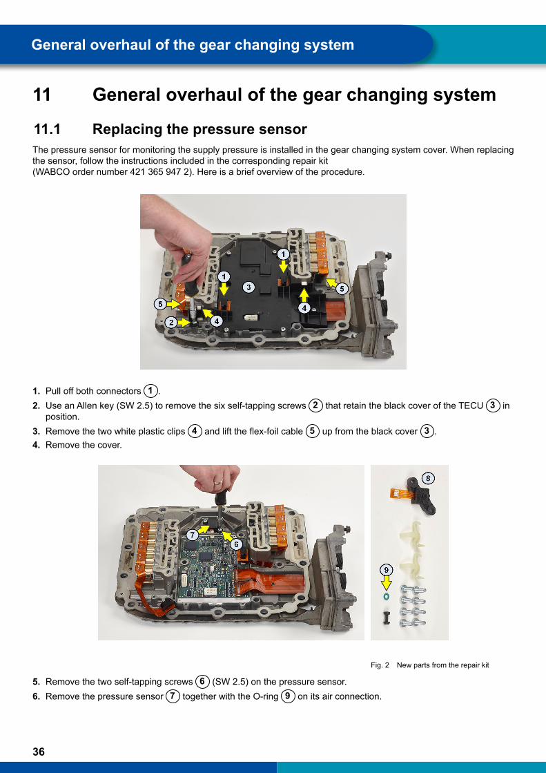
11.1 Replacing the pressure sensorThe pressure sensor for monitoring the supply pressure is installed in the gear changing system cover. When replacing the sensor, follow the instructions included in the corresponding repair kit (WABCO order number 421 365 947 2). Here is a brief overview of the procedure.
1. Pull off both connectors 1 .2. Use an Allen key (SW 2.5) to remove the six self-tapping screws 2 that retain the black cover of the TECU 3 in
position.3. Remove the two white plastic clips 4 and lift the flex-foil cable 5 up from the black cover 3 .4. Remove the cover.
Fig. 2 New parts from the repair kit
5. Remove the two self-tapping screws 6 (SW 2.5) on the pressure sensor.6. Remove the pressure sensor 7 together with the O-ring 9 on its air connection.
General overhaul of the gear changing system
37
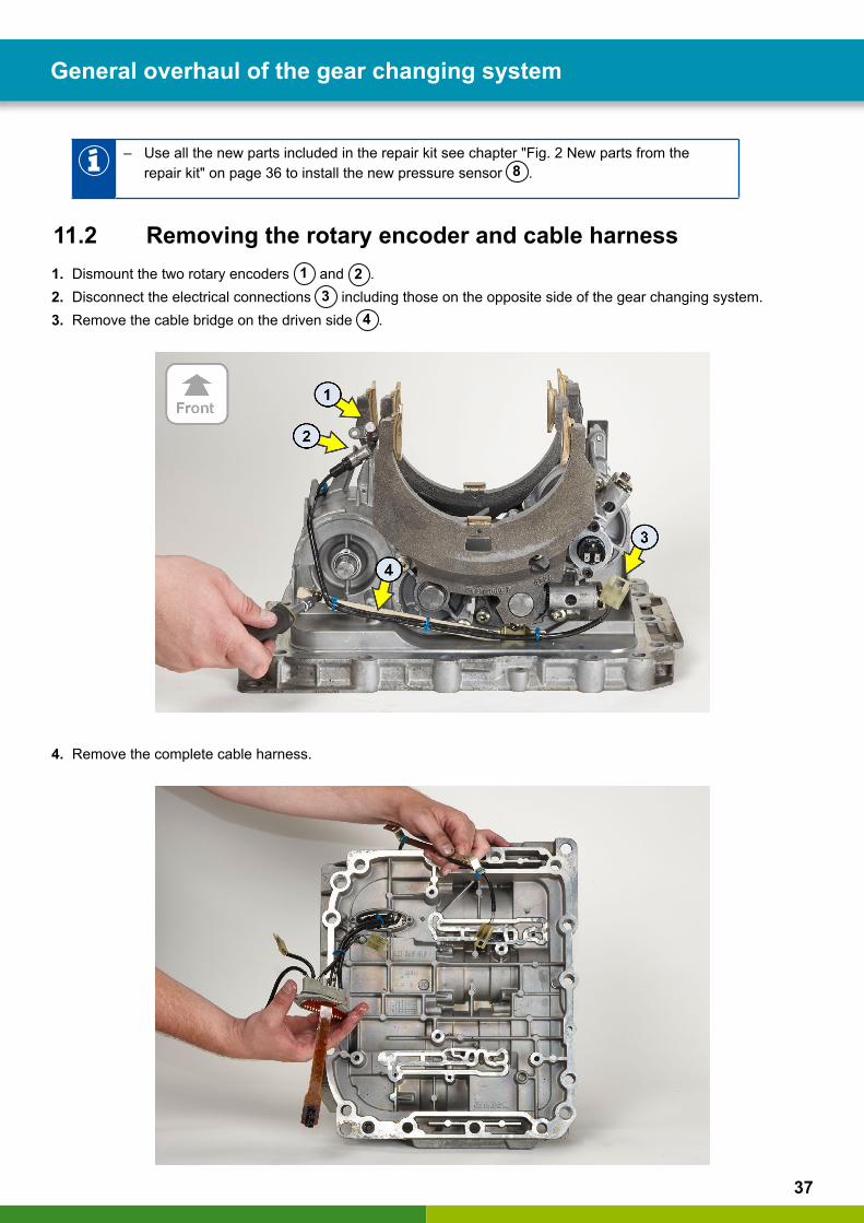
– Use all the new parts included in the repair kit see chapter "Fig. 2 New parts from the repair kit" on page 36 to install the new pressure sensor 8 .
11.2 Removing the rotary encoder and cable harness1. Dismount the two rotary encoders 1 and 2 .2. Disconnect the electrical connections 3 including those on the opposite side of the gear changing system.3. Remove the cable bridge on the driven side 4 .
4. Remove the complete cable harness.
General overhaul of the gear changing system

38
11.3 Removing the locking mechanisms, cylinder covers and piston rods
CAUTIONRiskofinjurytofingersandhandsThere is a risk of injury to fingers and hands from sharp-edged parts when removing and locking.
– Wear protective gloves to protect your hands.
CAUTIONRiskofcrushingfingersandhandsWhen removing heavy components there is a risk of crushing your fingers and hands.
– Make sure that your fingers and hands are not crushed.
1. On the drive side, remove the locking mechanisms for split 1 and 1/R 2 .
General overhaul of the gear changing system
39
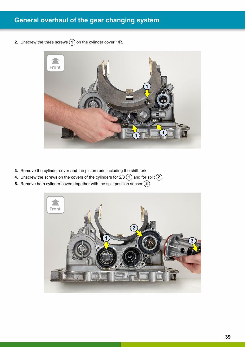
2. Unscrew the three screws 1 on the cylinder cover 1/R.
3. Remove the cylinder cover and the piston rods including the shift fork.4. Unscrew the screws on the covers of the cylinders for 2/3 1 and for split 2 .5. Remove both cylinder covers together with the split position sensor 3 .
General overhaul of the gear changing system
40
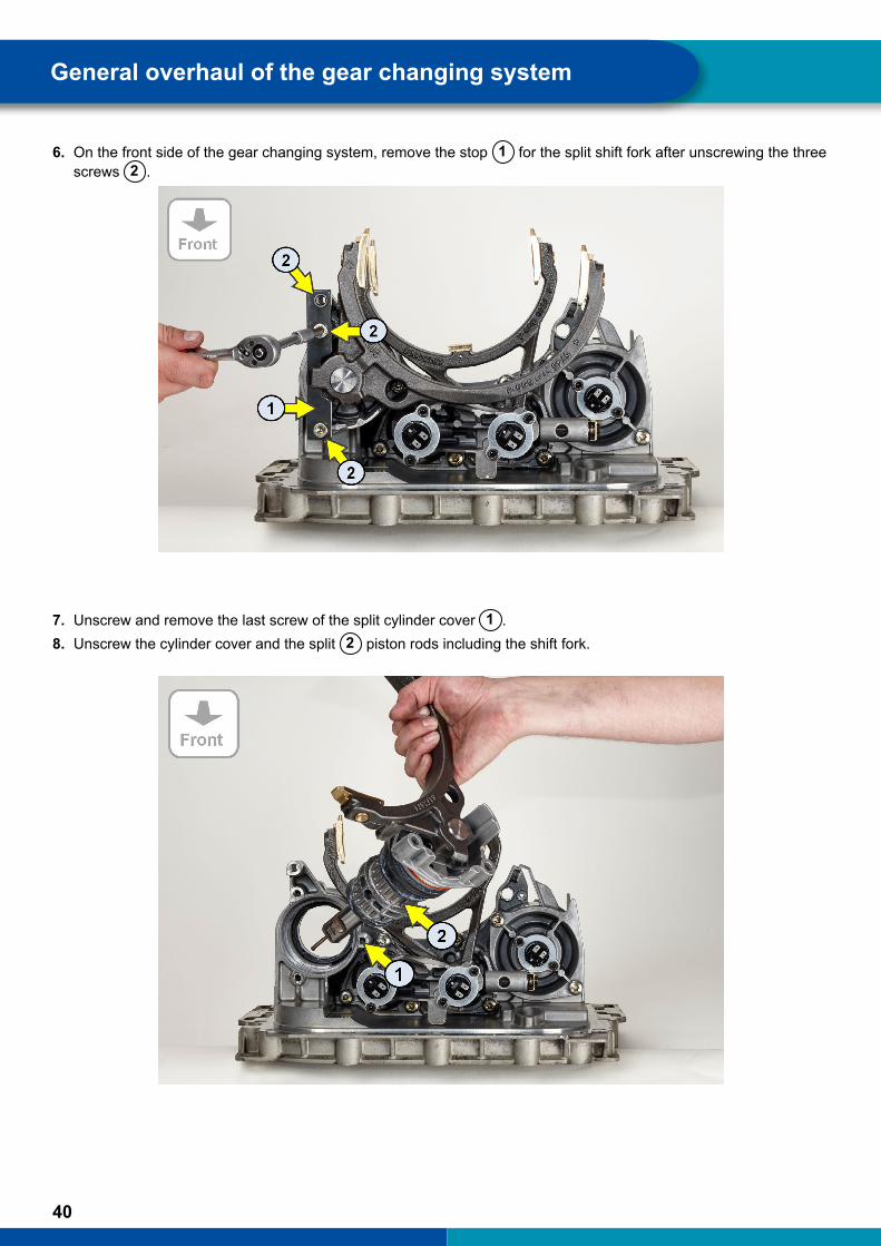
6. On the front side of the gear changing system, remove the stop 1 for the split shift fork after unscrewing the three screws 2 .
7. Unscrew and remove the last screw of the split cylinder cover 1 .8. Unscrew the cylinder cover and the split 2 piston rods including the shift fork.
General overhaul of the gear changing system

41
9. Unscrew the three screws on the cylinder cover 1/R 1 .10. Remove the cylinder cover 1/R 2 including the position sensors for 1/R 3 and 2/3 4 .
11. Remove the locking mechanism for the shift rod of cylinder 2/3.
General overhaul of the gear changing system
42
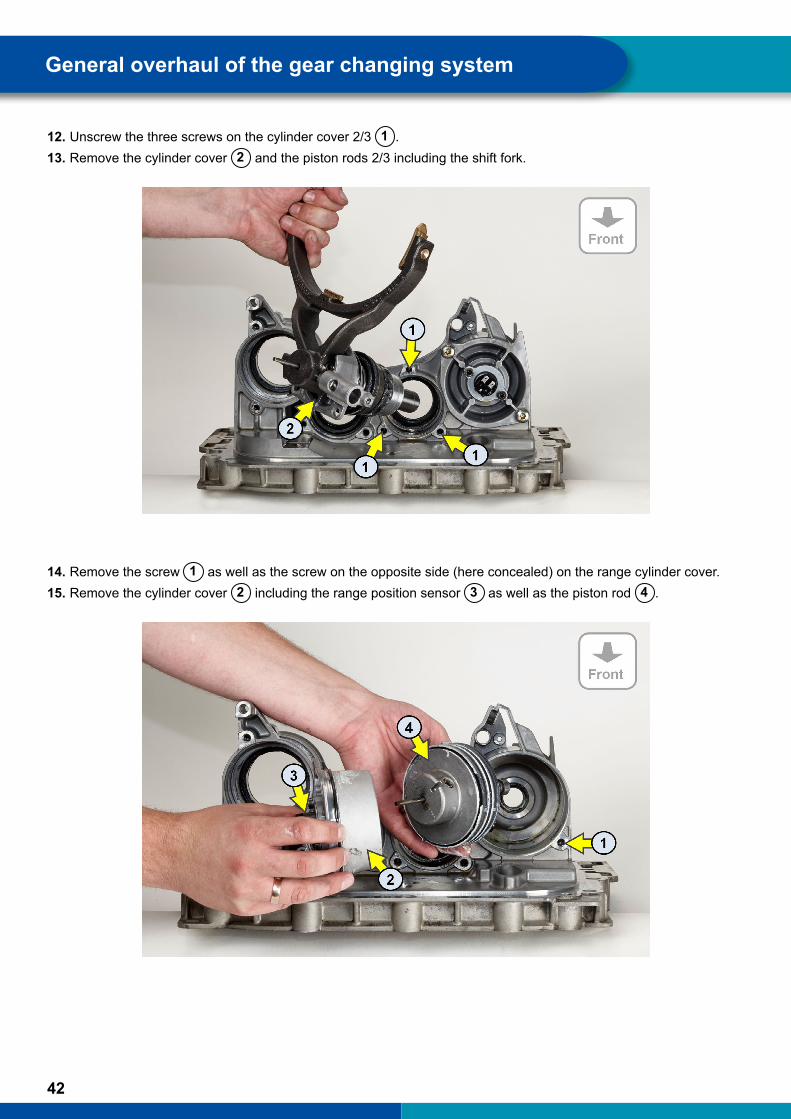
12. Unscrew the three screws on the cylinder cover 2/3 1 .13. Remove the cylinder cover 2 and the piston rods 2/3 including the shift fork.
14. Remove the screw 1 as well as the screw on the opposite side (here concealed) on the range cylinder cover.15. Remove the cylinder cover 2 including the range position sensor 3 as well as the piston rod 4 .
General overhaul of the gear changing system

43
The following figure shows the bottom section of the gear changing system after all cylinder covers, piston rods and shift forks have been removed.
General overhaul of the gear changing system
44
11.4 Renewing the components
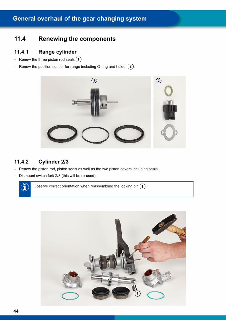
11.4.1 Range cylinder – Renew the three piston rod seals 1 .
– Renew the position sensor for range including O-ring and holder 2 .
11.4.2 Cylinder 2/3 – Renew the piston rod, piston seals as well as the two piston covers including seals.
– Dismount switch fork 2/3 (this will be re-used).
Observe correct orientation when reassembling the locking pin 1 !
General overhaul of the gear changing system
1
45
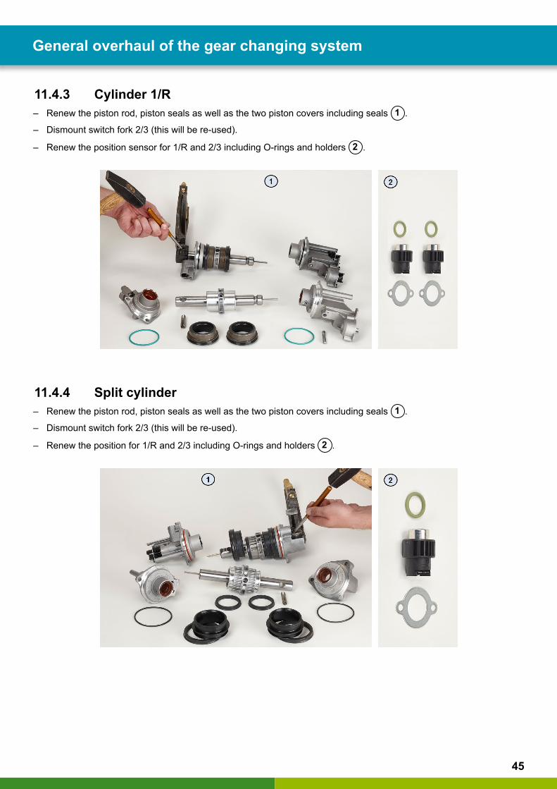
11.4.3 Cylinder 1/R – Renew the piston rod, piston seals as well as the two piston covers including seals 1 .
– Dismount switch fork 2/3 (this will be re-used).
– Renew the position sensor for 1/R and 2/3 including O-rings and holders 2 .
11.4.4 Split cylinder – Renew the piston rod, piston seals as well as the two piston covers including seals 1 .
– Dismount switch fork 2/3 (this will be re-used).
– Renew the position for 1/R and 2/3 including O-rings and holders 2 .
General overhaul of the gear changing system
46
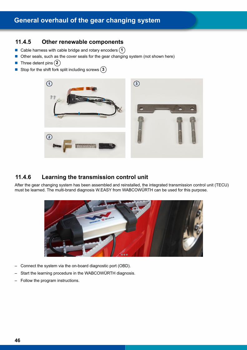
11.4.5 Other renewable components � Cable harness with cable bridge and rotary encoders 1 � Other seals, such as the cover seals for the gear changing system (not shown here) � Three detent pins 2 � Stop for the shift fork split including screws 3
11.4.6 Learning the transmission control unit After the gear changing system has been assembled and reinstalled, the integrated transmission control unit (TECU) must be learned. The multi-brand diagnosis W.EASY from WABCOWÜRTH can be used for this purpose.
– Connect the system via the on-board diagnostic port (OBD).
– Start the learning procedure in the WABCOWÜRTH diagnosis.
– Follow the program instructions.
General overhaul of the gear changing system

47
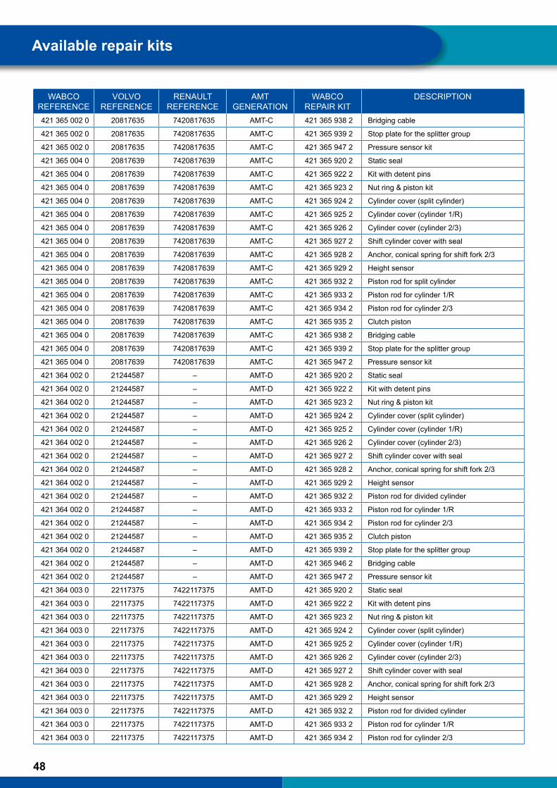
12 Available repair kitsWABCO
REFERENCEVOLVO
REFERENCERENAULT
REFERENCEAMT
GENERATIONWABCO
REPAIR KITDESCRIPTION
421 365 000 0 21327979 7421327979 AMT-B 421 365 920 2 Static seal
421 365 000 0 21327979 7421327979 AMT-B 421 365 921 2 Bridging plug
421 365 000 0 21327979 7421327979 AMT-B 421 365 922 2 Kit with detent pins
421 365 000 0 21327979 7421327979 AMT-B 421 365 923 2 Nut ring & piston kit
421 365 000 0 21327979 7421327979 AMT-B 421 365 924 2 Cylinder cover (split cylinder)
421 365 000 0 21327979 7421327979 AMT-B 421 365 925 2 Cylinder cover (cylinder 1/R)
421 365 000 0 21327979 7421327979 AMT-B 421 365 926 2 Cylinder cover (cylinder 2/3)
421 365 000 0 21327979 7421327979 AMT-B 421 365 928 2 Anchor, conical spring for shift fork 2/3
421 365 000 0 21327979 7421327979 AMT-B 421 365 929 2 Height sensor
421 365 000 0 21327979 7421327979 AMT-B 421 365 932 2 Piston rod for divided cylinder
421 365 000 0 21327979 7421327979 AMT-B 421 365 933 2 Piston rod for cylinder 1/R
421 365 000 0 21327979 7421327979 AMT-B 421 365 934 2 Piston rod for cylinder 2/3
421 365 000 0 21327979 7421327979 AMT-B 421 365 935 2 Clutch piston
421 365 000 0 21327979 7421327979 AMT-B 421 365 939 2 Stop plate for the splitter group
421 365 000 0 21327979 7421327979 AMT-B 421 365 947 2 Pressure sensor kit
421 365 000 0 21327979 7421327979 AMT-B 421 367 900 2 Pressure sensor module
421 364 001 0 20829006 – AMT-C 421 365 920 2 Static seal
421 364 001 0 20829006 – AMT-C 421 365 922 2 Kit with detent pins
421 364 001 0 20829006 – AMT-C 421 365 923 2 Nut ring & piston kit
421 364 001 0 20829006 – AMT-C 421 365 924 2 Cylinder cover (split cylinder)
421 364 001 0 20829006 – AMT-C 421 365 925 2 Cylinder cover (cylinder 1/R)
421 364 001 0 20829006 – AMT-C 421 365 926 2 Cylinder cover (cylinder 2/3)
421 364 001 0 20829006 – AMT-C 421 365 927 2 Shift cylinder cover with seal
421 364 001 0 20829006 – AMT-C 421 365 928 2 Anchor, conical spring for shift fork 2/3
421 364 001 0 20829006 – AMT-C 421 365 929 2 Height sensor
421 364 001 0 20829006 – AMT-C 421 365 932 2 Piston rod for split cylinder
421 364 001 0 20829006 – AMT-C 421 365 933 2 Piston rod for cylinder 1/R
421 364 001 0 20829006 – AMT-C 421 365 934 2 Piston rod for cylinder 2/3
421 364 001 0 20829006 – AMT-C 421 365 935 2 Clutch piston
421 364 001 0 20829006 – AMT-C 421 365 938 2 Bridging cable
421 364 001 0 20829006 – AMT-C 421 365 939 2 Stop plate for the splitter group
421 364 001 0 20829006 – AMT-C 421 365 947 2 Pressure sensor kit
421 365 002 0 20817635 7420817635 AMT-C 421 365 920 2 Static seal
421 365 002 0 20817635 7420817635 AMT-C 421 365 922 2 Kit with detent pins
421 365 002 0 20817635 7420817635 AMT-C 421 365 923 2 Nut ring & piston kit
421 365 002 0 20817635 7420817635 AMT-C 421 365 924 2 Cylinder cover (split cylinder)
421 365 002 0 20817635 7420817635 AMT-C 421 365 925 2 Cylinder cover (cylinder 1/R)
421 365 002 0 20817635 7420817635 AMT-C 421 365 926 2 Cylinder cover (cylinder 2/3)
421 365 002 0 20817635 7420817635 AMT-C 421 365 927 2 Shift cylinder cover with seal
421 365 002 0 20817635 7420817635 AMT-C 421 365 928 2 Anchor, conical spring for shift fork 2/3
421 365 002 0 20817635 7420817635 AMT-C 421 365 929 2 Height sensor
421 365 002 0 20817635 7420817635 AMT-C 421 365 932 2 Piston rod for split cylinder
421 365 002 0 20817635 7420817635 AMT-C 421 365 933 2 Piston rod for cylinder 1/R
421 365 002 0 20817635 7420817635 AMT-C 421 365 934 2 Piston rod for cylinder 2/3
421 365 002 0 20817635 7420817635 AMT-C 421 365 935 2 Clutch piston
Available repair kits
48
WABCO REFERENCE
VOLVO REFERENCE
RENAULT REFERENCE
AMT GENERATION
WABCO REPAIR KIT
DESCRIPTION
421 365 002 0 20817635 7420817635 AMT-C 421 365 938 2 Bridging cable
421 365 002 0 20817635 7420817635 AMT-C 421 365 939 2 Stop plate for the splitter group
421 365 002 0 20817635 7420817635 AMT-C 421 365 947 2 Pressure sensor kit
421 365 004 0 20817639 7420817639 AMT-C 421 365 920 2 Static seal
421 365 004 0 20817639 7420817639 AMT-C 421 365 922 2 Kit with detent pins
421 365 004 0 20817639 7420817639 AMT-C 421 365 923 2 Nut ring & piston kit
421 365 004 0 20817639 7420817639 AMT-C 421 365 924 2 Cylinder cover (split cylinder)
421 365 004 0 20817639 7420817639 AMT-C 421 365 925 2 Cylinder cover (cylinder 1/R)
421 365 004 0 20817639 7420817639 AMT-C 421 365 926 2 Cylinder cover (cylinder 2/3)
421 365 004 0 20817639 7420817639 AMT-C 421 365 927 2 Shift cylinder cover with seal
421 365 004 0 20817639 7420817639 AMT-C 421 365 928 2 Anchor, conical spring for shift fork 2/3
421 365 004 0 20817639 7420817639 AMT-C 421 365 929 2 Height sensor
421 365 004 0 20817639 7420817639 AMT-C 421 365 932 2 Piston rod for split cylinder
421 365 004 0 20817639 7420817639 AMT-C 421 365 933 2 Piston rod for cylinder 1/R
421 365 004 0 20817639 7420817639 AMT-C 421 365 934 2 Piston rod for cylinder 2/3
421 365 004 0 20817639 7420817639 AMT-C 421 365 935 2 Clutch piston
421 365 004 0 20817639 7420817639 AMT-C 421 365 938 2 Bridging cable
421 365 004 0 20817639 7420817639 AMT-C 421 365 939 2 Stop plate for the splitter group
421 365 004 0 20817639 7420817639 AMT-C 421 365 947 2 Pressure sensor kit
421 364 002 0 21244587 – AMT-D 421 365 920 2 Static seal
421 364 002 0 21244587 – AMT-D 421 365 922 2 Kit with detent pins
421 364 002 0 21244587 – AMT-D 421 365 923 2 Nut ring & piston kit
421 364 002 0 21244587 – AMT-D 421 365 924 2 Cylinder cover (split cylinder)
421 364 002 0 21244587 – AMT-D 421 365 925 2 Cylinder cover (cylinder 1/R)
421 364 002 0 21244587 – AMT-D 421 365 926 2 Cylinder cover (cylinder 2/3)
421 364 002 0 21244587 – AMT-D 421 365 927 2 Shift cylinder cover with seal
421 364 002 0 21244587 – AMT-D 421 365 928 2 Anchor, conical spring for shift fork 2/3
421 364 002 0 21244587 – AMT-D 421 365 929 2 Height sensor
421 364 002 0 21244587 – AMT-D 421 365 932 2 Piston rod for divided cylinder
421 364 002 0 21244587 – AMT-D 421 365 933 2 Piston rod for cylinder 1/R
421 364 002 0 21244587 – AMT-D 421 365 934 2 Piston rod for cylinder 2/3
421 364 002 0 21244587 – AMT-D 421 365 935 2 Clutch piston
421 364 002 0 21244587 – AMT-D 421 365 939 2 Stop plate for the splitter group
421 364 002 0 21244587 – AMT-D 421 365 946 2 Bridging cable
421 364 002 0 21244587 – AMT-D 421 365 947 2 Pressure sensor kit
421 364 003 0 22117375 7422117375 AMT-D 421 365 920 2 Static seal
421 364 003 0 22117375 7422117375 AMT-D 421 365 922 2 Kit with detent pins
421 364 003 0 22117375 7422117375 AMT-D 421 365 923 2 Nut ring & piston kit
421 364 003 0 22117375 7422117375 AMT-D 421 365 924 2 Cylinder cover (split cylinder)
421 364 003 0 22117375 7422117375 AMT-D 421 365 925 2 Cylinder cover (cylinder 1/R)
421 364 003 0 22117375 7422117375 AMT-D 421 365 926 2 Cylinder cover (cylinder 2/3)
421 364 003 0 22117375 7422117375 AMT-D 421 365 927 2 Shift cylinder cover with seal
421 364 003 0 22117375 7422117375 AMT-D 421 365 928 2 Anchor, conical spring for shift fork 2/3
421 364 003 0 22117375 7422117375 AMT-D 421 365 929 2 Height sensor
421 364 003 0 22117375 7422117375 AMT-D 421 365 932 2 Piston rod for divided cylinder
421 364 003 0 22117375 7422117375 AMT-D 421 365 933 2 Piston rod for cylinder 1/R
421 364 003 0 22117375 7422117375 AMT-D 421 365 934 2 Piston rod for cylinder 2/3
Available repair kits

49
WABCO REFERENCE
VOLVO REFERENCE
RENAULT REFERENCE
AMT GENERATION
WABCO REPAIR KIT
DESCRIPTION
421 364 003 0 22117375 7422117375 AMT-D 421 365 935 2 Clutch piston
421 364 003 0 22117375 7422117375 AMT-D 421 365 939 2 Stop plate for the splitter group
421 364 003 0 22117375 7422117375 AMT-D 421 365 946 2 Bridging cable
421 364 003 0 22117375 7422117375 AMT-D 421 365 947 2 Pressure sensor kit
421 365 005 0 21314138 7421314138 AMT-D 421 365 920 2 Static seal
421 365 005 0 21314138 7421314138 AMT-D 421 365 922 2 Kit with detent pins
421 365 005 0 21314138 7421314138 AMT-D 421 365 923 2 Nut ring & piston kit
421 365 005 0 21314138 7421314138 AMT-D 421 365 924 2 Cylinder cover (split cylinder)
421 365 005 0 21314138 7421314138 AMT-D 421 365 925 2 Cylinder cover (cylinder 1/R)
421 365 005 0 21314138 7421314138 AMT-D 421 365 926 2 Cylinder cover (cylinder 2/3)
421 365 005 0 21314138 7421314138 AMT-D 421 365 927 2 Shift cylinder cover with seal
421 365 005 0 21314138 7421314138 AMT-D 421 365 928 2 Anchor, conical spring for shift fork 2/3
421 365 005 0 21314138 7421314138 AMT-D 421 365 929 2 Height sensor
421 365 005 0 21314138 7421314138 AMT-D 421 365 932 2 Piston rod for divided cylinder
421 365 005 0 21314138 7421314138 AMT-D 421 365 933 2 Piston rod for cylinder 1/R
421 365 005 0 21314138 7421314138 AMT-D 421 365 934 2 Piston rod for cylinder 2/3
421 365 005 0 21314138 7421314138 AMT-D 421 365 935 2 Clutch piston
421 365 005 0 21314138 7421314138 AMT-D 421 365 939 2 Stop plate for the splitter group
421 365 005 0 21314138 7421314138 AMT-D 421 365 946 2 Bridging cable
421 365 005 0 21314138 7421314138 AMT-D 421 365 947 2 Pressure sensor kit
421 365 006 0 21314140 7421314140 AMT-D 421 365 920 2 Static seal
421 365 006 0 21314140 7421314140 AMT-D 421 365 922 2 Kit with detent pins
421 365 006 0 21314140 7421314140 AMT-D 421 365 923 2 Nut ring & piston kit
421 365 006 0 21314140 7421314140 AMT-D 421 365 924 2 Cylinder cover (split cylinder)
421 365 006 0 21314140 7421314140 AMT-D 421 365 925 2 Cylinder cover (cylinder 1/R)
421 365 006 0 21314140 7421314140 AMT-D 421 365 926 2 Cylinder cover (cylinder 2/3)
421 365 006 0 21314140 7421314140 AMT-D 421 365 927 2 Shift cylinder cover with seal
421 365 006 0 21314140 7421314140 AMT-D 421 365 928 2 Anchor, conical spring for shift fork 2/3
421 365 006 0 21314140 7421314140 AMT-D 421 365 929 2 Height sensor
421 365 006 0 21314140 7421314140 AMT-D 421 365 932 2 Piston rod for divided cylinder
421 365 006 0 21314140 7421314140 AMT-D 421 365 933 2 Piston rod for cylinder 1/R
421 365 006 0 21314140 7421314140 AMT-D 421 365 934 2 Piston rod for cylinder 2/3
421 365 006 0 21314140 7421314140 AMT-D 421 365 935 2 Clutch piston
421 365 006 0 21314140 7421314140 AMT-D 421 365 939 2 Stop plate for the splitter group
421 365 006 0 21314140 7421314140 AMT-D 421 365 946 2 Bridging cable
421 365 006 0 21314140 7421314140 AMT-D 421 365 947 2 Pressure sensor kit
421 365 007 0 – – AMT-D 421 365 920 2 Static seal
421 365 007 0 – – AMT-D 421 365 922 2 Kit with detent pins
421 365 007 0 – – AMT-D 421 365 923 2 Nut ring & piston kit
421 365 007 0 – – AMT-D 421 365 924 2 Cylinder cover (split cylinder)
421 365 007 0 – – AMT-D 421 365 925 2 Cylinder cover (cylinder 1/R)
421 365 007 0 – – AMT-D 421 365 926 2 Cylinder cover (cylinder 2/3)
421 365 007 0 – – AMT-D 421 365 927 2 Shift cylinder cover with seal
421 365 007 0 – – AMT-D 421 365 928 2 Anchor, conical spring for shift fork 2/3
421 365 007 0 – – AMT-D 421 365 929 2 Height sensor
421 365 007 0 – – AMT-D 421 365 932 2 Piston rod for divided cylinder
421 365 007 0 – – AMT-D 421 365 933 2 Piston rod for cylinder 1/R
421 365 007 0 – – AMT-D 421 365 934 2 Piston rod for cylinder 2/3
Available repair kits

50
WABCO REFERENCE
VOLVO REFERENCE
RENAULT REFERENCE
AMT GENERATION
WABCO REPAIR KIT
DESCRIPTION
421 365 007 0 – – AMT-D 421 365 935 2 Clutch piston
421 365 007 0 – – AMT-D 421 365 939 2 Stop plate for the splitter group
421 365 007 0 – – AMT-D 421 365 946 2 Bridging cable
421 365 007 0 – – AMT-D 421 365 947 2 Pressure sensor kit
421 365 008 0 21571886 7421571886 AMT-D 421 365 920 2 Static seal
421 365 008 0 21571886 7421571886 AMT-D 421 365 922 2 Kit with detent pins
421 365 008 0 21571886 7421571886 AMT-D 421 365 923 2 Nut ring & piston kit
421 365 008 0 21571886 7421571886 AMT-D 421 365 924 2 Cylinder cover (split cylinder)
421 365 008 0 21571886 7421571886 AMT-D 421 365 925 2 Cylinder cover (cylinder 1/R)
421 365 008 0 21571886 7421571886 AMT-D 421 365 926 2 Cylinder cover (cylinder 2/3)
421 365 008 0 21571886 7421571886 AMT-D 421 365 927 2 Shift cylinder cover with seal
421 365 008 0 21571886 7421571886 AMT-D 421 365 928 2 Anchor, conical spring for shift fork 2/3
421 365 008 0 21571886 7421571886 AMT-D 421 365 929 2 Height sensor
421 365 008 0 21571886 7421571886 AMT-D 421 365 932 2 Piston rod for divided cylinder
421 365 008 0 21571886 7421571886 AMT-D 421 365 933 2 Piston rod for cylinder 1/R
421 365 008 0 21571886 7421571886 AMT-D 421 365 934 2 Piston rod for cylinder 2/3
421 365 008 0 21571886 7421571886 AMT-D 421 365 935 2 Clutch piston
421 365 008 0 21571886 7421571886 AMT-D 421 365 939 2 Stop plate for the splitter group
421 365 008 0 21571886 7421571886 AMT-D 421 365 946 2 Bridging cable
421 365 008 0 21571886 7421571886 AMT-D 421 365 947 2 Pressure sensor kit
421 365 009 0 21571887 7421571887 AMT-D 421 365 920 2 Static seal
421 365 009 0 21571887 7421571887 AMT-D 421 365 922 2 Kit with detent pins
421 365 009 0 21571887 7421571887 AMT-D 421 365 923 2 Nut ring & piston kit
421 365 009 0 21571887 7421571887 AMT-D 421 365 924 2 Cylinder cover (split cylinder)
421 365 009 0 21571887 7421571887 AMT-D 421 365 925 2 Cylinder cover (cylinder 1/R)
421 365 009 0 21571887 7421571887 AMT-D 421 365 926 2 Cylinder cover (cylinder 2/3)
421 365 009 0 21571887 7421571887 AMT-D 421 365 927 2 Shift cylinder cover with seal
421 365 009 0 21571887 7421571887 AMT-D 421 365 928 2 Anchor, conical spring for shift fork 2/3
421 365 009 0 21571887 7421571887 AMT-D 421 365 929 2 Height sensor
421 365 009 0 21571887 7421571887 AMT-D 421 365 932 2 Piston rod for divided cylinder
421 365 009 0 21571887 7421571887 AMT-D 421 365 933 2 Piston rod for cylinder 1/R
421 365 009 0 21571887 7421571887 AMT-D 421 365 934 2 Piston rod for cylinder 2/3
421 365 009 0 21571887 7421571887 AMT-D 421 365 935 2 Clutch piston
421 365 009 0 21571887 7421571887 AMT-D 421 365 939 2 Stop plate for the splitter group
421 365 009 0 21571887 7421571887 AMT-D 421 365 946 2 Bridging cable
421 365 009 0 21571887 7421571887 AMT-D 421 365 947 2 Pressure sensor kit
421 365 010 0 21571889 7421571889 AMT-D 421 365 920 2 Static seal
421 365 010 0 21571889 7421571889 AMT-D 421 365 922 2 Kit with detent pins
421 365 010 0 21571889 7421571889 AMT-D 421 365 923 2 Nut ring & piston kit
421 365 010 0 21571889 7421571889 AMT-D 421 365 924 2 Cylinder cover (split cylinder)
421 365 010 0 21571889 7421571889 AMT-D 421 365 925 2 Cylinder cover (cylinder 1/R)
421 365 010 0 21571889 7421571889 AMT-D 421 365 926 2 Cylinder cover (cylinder 2/3)
421 365 010 0 21571889 7421571889 AMT-D 421 365 927 2 Shift cylinder cover with seal
421 365 010 0 21571889 7421571889 AMT-D 421 365 928 2 Anchor, conical spring for shift fork 2/3
421 365 010 0 21571889 7421571889 AMT-D 421 365 929 2 Height sensor
421 365 010 0 21571889 7421571889 AMT-D 421 365 932 2 Piston rod for divided cylinder
421 365 010 0 21571889 7421571889 AMT-D 421 365 933 2 Piston rod for cylinder 1/R
421 365 010 0 21571889 7421571889 AMT-D 421 365 934 2 Piston rod for cylinder 2/3
Available repair kits

51
WABCO REFERENCE
VOLVO REFERENCE
RENAULT REFERENCE
AMT GENERATION
WABCO REPAIR KIT
DESCRIPTION
421 365 010 0 21571889 7421571889 AMT-D 421 365 935 2 Clutch piston
421 365 010 0 21571889 7421571889 AMT-D 421 365 939 2 Stop plate for the splitter group
421 365 010 0 21571889 7421571889 AMT-D 421 365 946 2 Bridging cable
421 365 010 0 21571889 7421571889 AMT-D 421 365 947 2 Pressure sensor kit
421 365 011 0 22106301 7422780682 AMT-D 421 365 920 2 Static seal
421 365 011 0 22106301 7422780682 AMT-D 421 365 922 2 Kit with detent pins
421 365 011 0 22106301 7422780682 AMT-D 421 365 923 2 Nut ring & piston kit
421 365 011 0 22106301 7422780682 AMT-D 421 365 924 2 Cylinder cover (split cylinder)
421 365 011 0 22106301 7422780682 AMT-D 421 365 925 2 Cylinder cover (cylinder 1/R)
421 365 011 0 22106301 7422780682 AMT-D 421 365 926 2 Cylinder cover (cylinder 2/3)
421 365 011 0 22106301 7422780682 AMT-D 421 365 927 2 Shift cylinder cover with seal
421 365 011 0 22106301 7422780682 AMT-D 421 365 928 2 Anchor, conical spring for shift fork 2/3
421 365 011 0 22106301 7422780682 AMT-D 421 365 929 2 Height sensor
421 365 011 0 22106301 7422780682 AMT-D 421 365 932 2 Piston rod for divided cylinder
421 365 011 0 22106301 7422780682 AMT-D 421 365 933 2 Piston rod for cylinder 1/R
421 365 011 0 22106301 7422780682 AMT-D 421 365 934 2 Piston rod for cylinder 2/3
421 365 011 0 22106301 7422780682 AMT-D 421 365 935 2 Clutch piston
421 365 011 0 22106301 7422780682 AMT-D 421 365 939 2 Stop plate for the splitter group
421 365 011 0 22106301 7422780682 AMT-D 421 365 946 2 Bridging cable
421 365 011 0 22106301 7422780682 AMT-D 421 365 947 2 Pressure sensor kit
421 365 012 0 22117097 7422780683 AMT-D 421 365 920 2 Static seal
421 365 012 0 22117097 7422780683 AMT-D 421 365 922 2 Kit with detent pins
421 365 012 0 22117097 7422780683 AMT-D 421 365 923 2 Nut ring & piston kit
421 365 012 0 22117097 7422780683 AMT-D 421 365 924 2 Cylinder cover (split cylinder)
421 365 012 0 22117097 7422780683 AMT-D 421 365 925 2 Cylinder cover (cylinder 1/R)
421 365 012 0 22117097 7422780683 AMT-D 421 365 926 2 Cylinder cover (cylinder 2/3)
421 365 012 0 22117097 7422780683 AMT-D 421 365 927 2 Shift cylinder cover with seal
421 365 012 0 22117097 7422780683 AMT-D 421 365 928 2 Anchor, conical spring for shift fork 2/3
421 365 012 0 22117097 7422780683 AMT-D 421 365 929 2 Height sensor
421 365 012 0 22117097 7422780683 AMT-D 421 365 932 2 Piston rod for divided cylinder
421 365 012 0 22117097 7422780683 AMT-D 421 365 933 2 Piston rod for cylinder 1/R
421 365 012 0 22117097 7422780683 AMT-D 421 365 934 2 Piston rod for cylinder 2/3
421 365 012 0 22117097 7422780683 AMT-D 421 365 935 2 Clutch piston
421 365 012 0 22117097 7422780683 AMT-D 421 365 939 2 Stop plate for the splitter group
421 365 012 0 22117097 7422780683 AMT-D 421 365 946 2 Bridging cable
421 365 012 0 22117097 7422780683 AMT-D 421 365 947 2 Pressure sensor kit
421 365 013 0 22117091 – AMT-D 421 365 920 2 Static seal
421 365 013 0 22117091 – AMT-D 421 365 922 2 Kit with detent pins
421 365 013 0 22117091 – AMT-D 421 365 923 2 Nut ring & piston kit
421 365 013 0 22117091 – AMT-D 421 365 924 2 Cylinder cover (split cylinder)
421 365 013 0 22117091 – AMT-D 421 365 925 2 Cylinder cover (cylinder 1/R)
421 365 013 0 22117091 – AMT-D 421 365 926 2 Cylinder cover (cylinder 2/3)
421 365 013 0 22117091 – AMT-D 421 365 927 2 Shift cylinder cover with seal
421 365 013 0 22117091 – AMT-D 421 365 928 2 Anchor, conical spring for shift fork 2/3
421 365 013 0 22117091 – AMT-D 421 365 929 2 Height sensor
421 365 013 0 22117091 – AMT-D 421 365 932 2 Piston rod for divided cylinder
421 365 013 0 22117091 – AMT-D 421 365 933 2 Piston rod for cylinder 1/R
421 365 013 0 22117091 – AMT-D 421 365 934 2 Piston rod for cylinder 2/3
Available repair kits

52
WABCO REFERENCE
VOLVO REFERENCE
RENAULT REFERENCE
AMT GENERATION
WABCO REPAIR KIT
DESCRIPTION
421 365 013 0 22117091 – AMT-D 421 365 935 2 Clutch piston
421 365 013 0 22117091 – AMT-D 421 365 939 2 Stop plate for the splitter group
421 365 013 0 22117091 – AMT-D 421 365 946 2 Bridging cable
421 365 013 0 22117091 – AMT-D 421 365 947 2 Pressure sensor kit
421 367 001 0 21949395 7422780685 AMT-E 421 365 922 2 Kit with detent pins
421 367 001 0 21949395 7422780685 AMT-E 421 365 923 2 Nut ring & piston kit
421 367 001 0 21949395 7422780685 AMT-E 421 365 927 2 Shift cylinder cover with seal
421 367 001 0 21949395 7422780685 AMT-E 421 365 928 2 Anchor, conical spring for shift fork 2/3
421 367 001 0 21949395 7422780685 AMT-E 421 365 929 2 Height sensor
421 367 001 0 21949395 7422780685 AMT-E 421 365 932 2 Piston rod for divided cylinder
421 367 001 0 21949395 7422780685 AMT-E 421 365 933 2 Piston rod for cylinder 1/R
421 367 001 0 21949395 7422780685 AMT-E 421 365 934 2 Piston rod for cylinder 2/3
421 367 001 0 21949395 7422780685 AMT-E 421 365 935 2 Clutch piston
421 367 001 0 21949395 7422780685 AMT-E 421 367 900 2 Pressure sensor module
421 367 001 0 21949395 7422780685 AMT-E 421 367 921 2 Static seal
421 367 001 0 21949395 7422780685 AMT-E 421 367 922 2 Bridging cable
421 367 001 0 21949395 7422780685 AMT-E 421 367 924 2 Valve unit with seal
421 367 001 0 21949395 7422780685 AMT-E 421 367 927 2 Cylinder cover for cylinder 1/R
421 367 001 0 21949395 7422780685 AMT-E 421 367 928 2 Cylinder cover for split cylinder
421 367 001 0 21949395 7422780685 AMT-E 421 367 929 2 Cylinder cover cylinder 2/3
421 367 001 0 21949395 7422780685 AMT-E 421 367 930 2 Plate for split cylinder
421 367 001 0 21949395 7422780685 AMT-E 421 367 931 2 Connection holder with seal
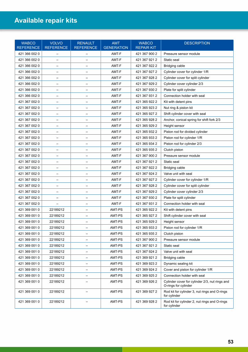
421 366 001 0 – – AMT-F 421 365 922 2 Kit with detent pins
421 366 001 0 – – AMT-F 421 365 923 2 Nut ring & piston kit
421 366 001 0 – – AMT-F 421 365 927 2 Shift cylinder cover with seal
421 366 001 0 – – AMT-F 421 365 928 2 Anchor, conical spring for shift fork 2/3
421 366 001 0 – – AMT-F 421 365 929 2 Height sensor
421 366 001 0 – – AMT-F 421 365 932 2 Piston rod for divided cylinder
421 366 001 0 – – AMT-F 421 365 933 2 Piston rod for cylinder 1/R
421 366 001 0 – – AMT-F 421 365 934 2 Piston rod for cylinder 2/3
421 366 001 0 – – AMT-F 421 365 935 2 Clutch piston
421 366 001 0 – – AMT-F 421 367 900 2 Pressure sensor module
421 366 001 0 – – AMT-F 421 367 921 2 Static seal
421 366 001 0 – – AMT-F 421 367 922 2 Bridging cable
421 366 001 0 – – AMT-F 421 367 927 2 Cylinder cover for cylinder 1/R
421 366 001 0 – – AMT-F 421 367 928 2 Cylinder cover for split cylinder
421 366 001 0 – – AMT-F 421 367 929 2 Cylinder cover cylinder 2/3
421 366 001 0 – – AMT-F 421 367 930 2 Plate for split cylinder
421 366 001 0 – – AMT-F 421 367 931 2 Connection holder with seal
421 366 002 0 – – AMT-F 421 365 922 2 Kit with detent pins
421 366 002 0 – – AMT-F 421 365 923 2 Nut ring & piston kit
421 366 002 0 – – AMT-F 421 365 927 2 Shift cylinder cover with seal
421 366 002 0 – – AMT-F 421 365 928 2 Anchor, conical spring for shift fork 2/3
421 366 002 0 – – AMT-F 421 365 929 2 Height sensor
421 366 002 0 – – AMT-F 421 365 932 2 Piston rod for divided cylinder
421 366 002 0 – – AMT-F 421 365 933 2 Piston rod for cylinder 1/R
421 366 002 0 – – AMT-F 421 365 934 2 Piston rod for cylinder 2/3
421 366 002 0 – – AMT-F 421 365 935 2 Clutch piston
Available repair kits
53
WABCO REFERENCE
VOLVO REFERENCE
RENAULT REFERENCE
AMT GENERATION
WABCO REPAIR KIT
DESCRIPTION
421 366 002 0 – – AMT-F 421 367 900 2 Pressure sensor module
421 366 002 0 – – AMT-F 421 367 921 2 Static seal
421 366 002 0 – – AMT-F 421 367 922 2 Bridging cable
421 366 002 0 – – AMT-F 421 367 927 2 Cylinder cover for cylinder 1/R
421 366 002 0 – – AMT-F 421 367 928 2 Cylinder cover for split cylinder
421 366 002 0 – – AMT-F 421 367 929 2 Cylinder cover cylinder 2/3
421 366 002 0 – – AMT-F 421 367 930 2 Plate for split cylinder
421 366 002 0 – – AMT-F 421 367 931 2 Connection holder with seal
421 367 002 0 – – AMT-F 421 365 922 2 Kit with detent pins
421 367 002 0 – – AMT-F 421 365 923 2 Nut ring & piston kit
421 367 002 0 – – AMT-F 421 365 927 2 Shift cylinder cover with seal
421 367 002 0 – – AMT-F 421 365 928 2 Anchor, conical spring for shift fork 2/3
421 367 002 0 – – AMT-F 421 365 929 2 Height sensor
421 367 002 0 – – AMT-F 421 365 932 2 Piston rod for divided cylinder
421 367 002 0 – – AMT-F 421 365 933 2 Piston rod for cylinder 1/R
421 367 002 0 – – AMT-F 421 365 934 2 Piston rod for cylinder 2/3
421 367 002 0 – – AMT-F 421 365 935 2 Clutch piston
421 367 002 0 – – AMT-F 421 367 900 2 Pressure sensor module
421 367 002 0 – – AMT-F 421 367 921 2 Static seal
421 367 002 0 – – AMT-F 421 367 922 2 Bridging cable
421 367 002 0 – – AMT-F 421 367 924 2 Valve unit with seal
421 367 002 0 – – AMT-F 421 367 927 2 Cylinder cover for cylinder 1/R
421 367 002 0 – – AMT-F 421 367 928 2 Cylinder cover for split cylinder
421 367 002 0 – – AMT-F 421 367 929 2 Cylinder cover cylinder 2/3
421 367 002 0 – – AMT-F 421 367 930 2 Plate for split cylinder
421 367 002 0 – – AMT-F 421 367 931 2 Connection holder with seal
421 369 001 0 22189212 – AMT-PS 421 365 922 2 Kit with detent pins
421 369 001 0 22189212 – AMT-PS 421 365 927 2 Shift cylinder cover with seal
421 369 001 0 22189212 – AMT-PS 421 365 929 2 Height sensor
421 369 001 0 22189212 – AMT-PS 421 365 933 2 Piston rod for cylinder 1/R
421 369 001 0 22189212 – AMT-PS 421 365 935 2 Clutch piston
421 369 001 0 22189212 – AMT-PS 421 367 900 2 Pressure sensor module
421 369 001 0 22189212 – AMT-PS 421 367 921 2 Static seal
421 369 001 0 22189212 – AMT-PS 421 367 924 2 Valve unit with seal
421 369 001 0 22189212 – AMT-PS 421 369 921 2 Bridging cable
421 369 001 0 22189212 – AMT-PS 421 369 923 2 Dynamic sealing kit
421 369 001 0 22189212 – AMT-PS 421 369 924 2 Cover and piston for cylinder 1/R
421 369 001 0 22189212 – AMT-PS 421 369 925 2 Connection holder with seal
421 369 001 0 22189212 – AMT-PS 421 369 926 2 Cylinder cover for cylinder 2/3, nut rings and O-rings for cylinder
421 369 001 0 22189212 – AMT-PS 421 369 927 2 Rod kit for cylinder 3, nut rings and O-rings for cylinder
421 369 001 0 22189212 – AMT-PS 421 369 928 2 Rod kit for cylinder 2, nut rings and O-rings for cylinder
Available repair kits

54
12.1 Seal set: static seals (421 365 920 2)
12.2 Cable set with cable bridge and rotary encoders (421 365 921 2)
Available repair kits
55
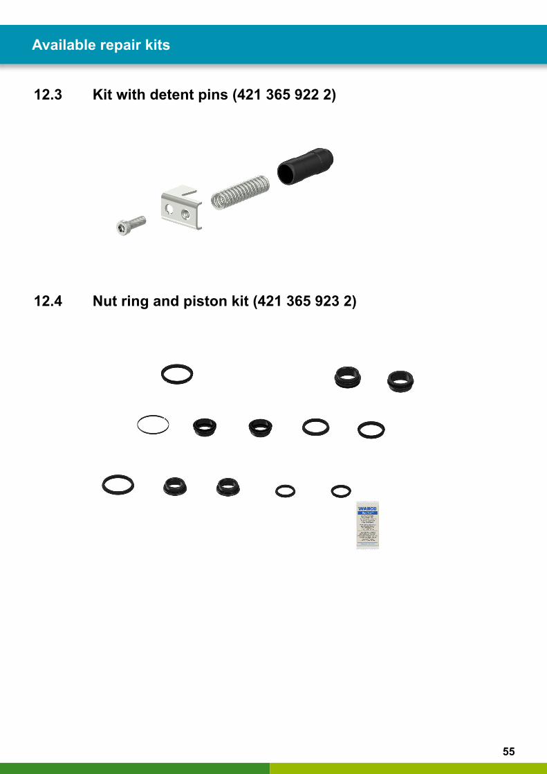
12.3 Kit with detent pins (421 365 922 2)
12.4 Nut ring and piston kit (421 365 923 2)
Available repair kits
56
Available repair kits Available repair kits
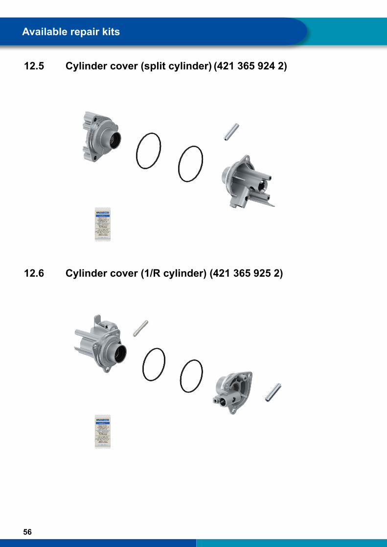
12.5 Cylinder cover (split cylinder) (421 365 924 2)
12.6 Cylinder cover (1/R cylinder) (421 365 925 2)
57
Available repair kits
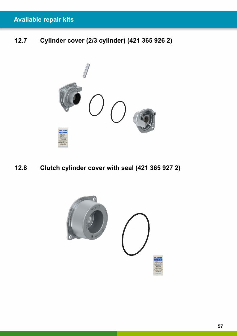
12.7 Cylinder cover (2/3 cylinder) (421 365 926 2)
12.8 Clutch cylinder cover with seal (421 365 927 2)
58
Available repair kits Available repair kits
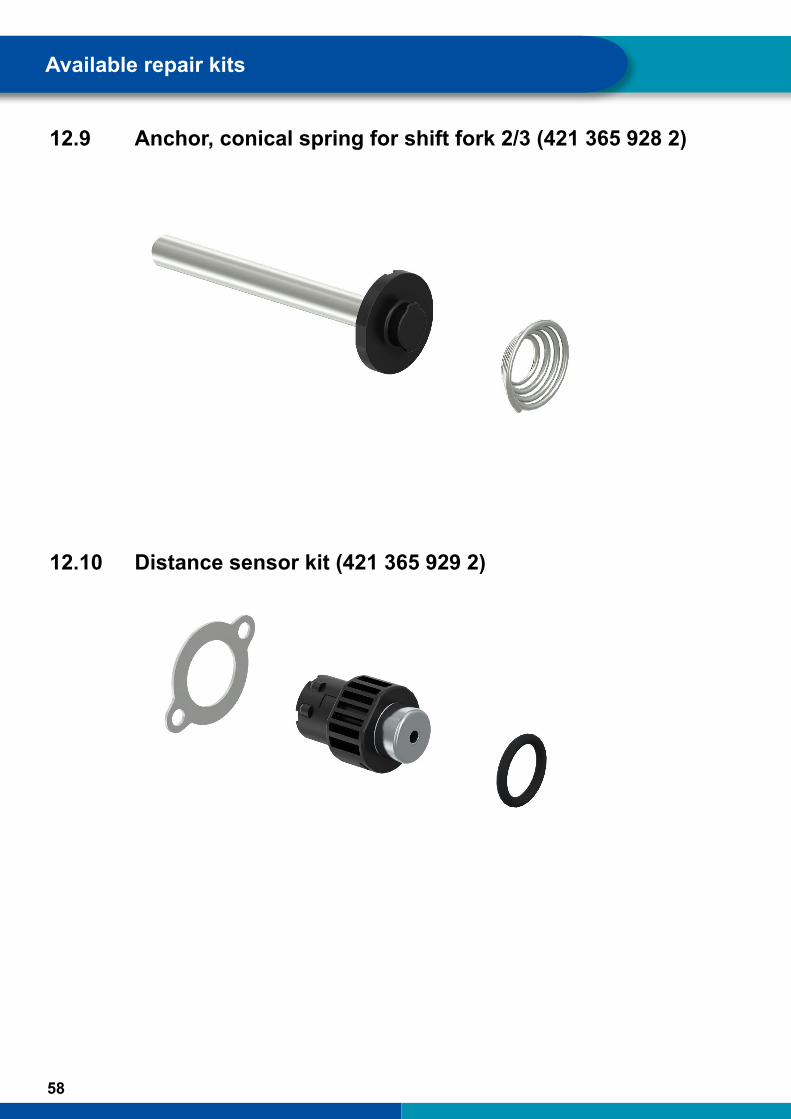
12.9 Anchor, conical spring for shift fork 2/3 (421 365 928 2)
12.10 Distance sensor kit (421 365 929 2)
59
Available repair kits
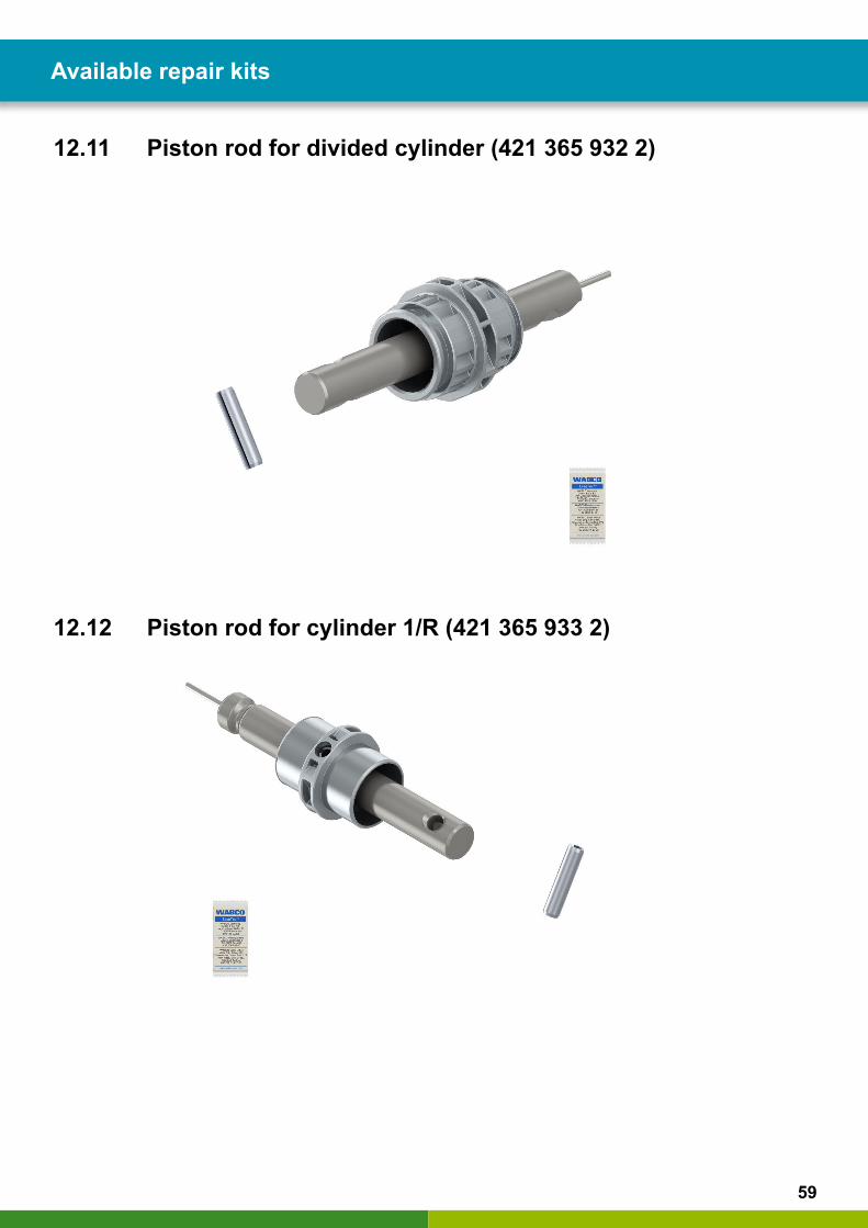
12.11 Piston rod for divided cylinder (421 365 932 2)
12.12 Piston rod for cylinder 1/R (421 365 933 2)
60
Available repair kits Available repair kits
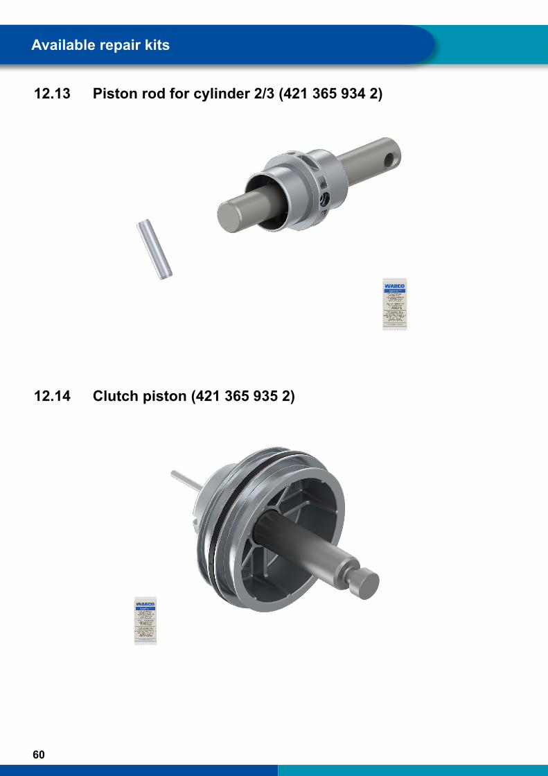
12.13 Piston rod for cylinder 2/3 (421 365 934 2)
12.14 Clutch piston (421 365 935 2)
61
Available repair kits
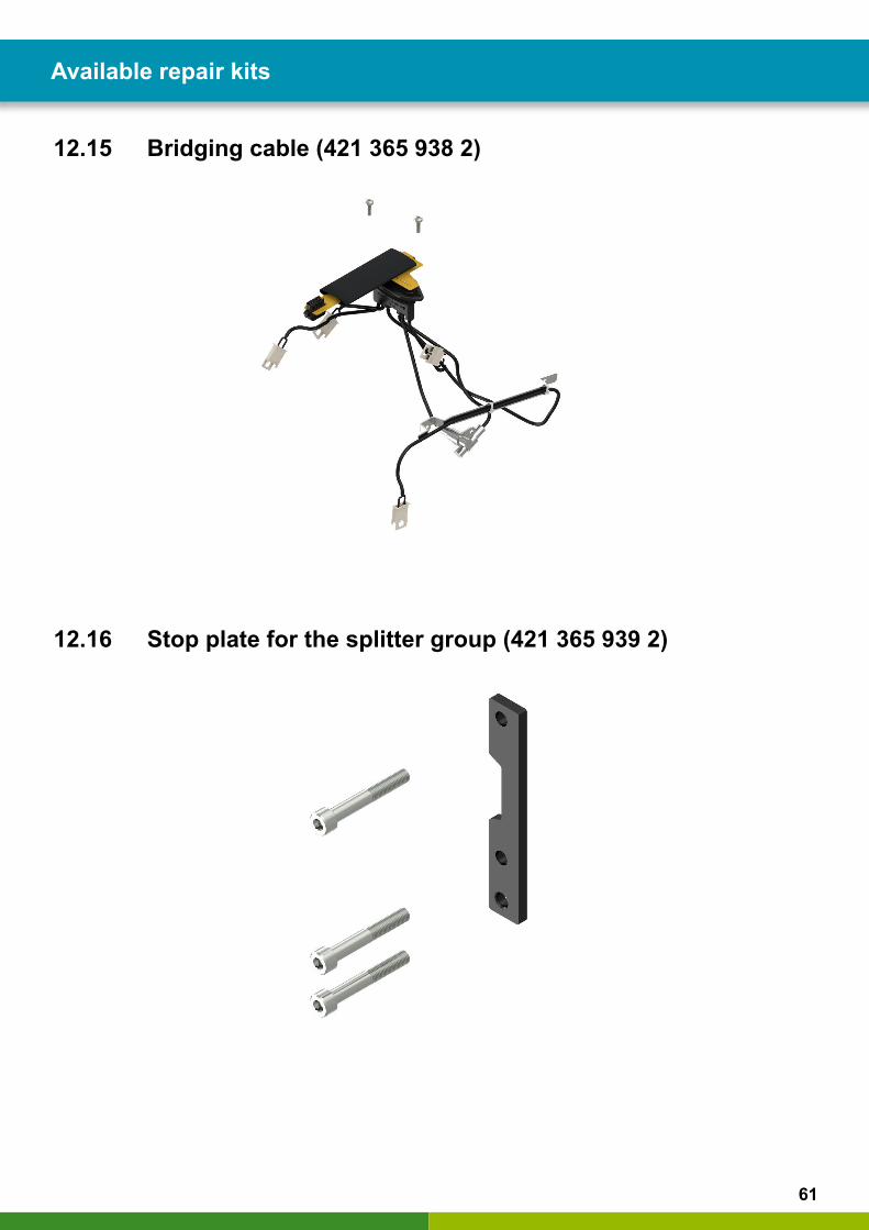
12.15 Bridging cable (421 365 938 2)
12.16 Stop plate for the splitter group (421 365 939 2)
62
Available repair kits Available repair kits
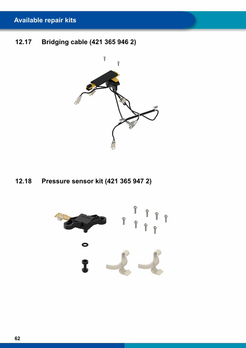
12.17 Bridging cable (421 365 946 2)
12.18 Pressure sensor kit (421 365 947 2)

63
Available repair kits
12.19 Pressure sensor module (421 367 900 2)
12.20 Static seal (421 367 921 2)

64
Available repair kits Available repair kits
12.21 Bridging cable (421 367 922 2)
12.22 Valve unit with seal (421 367 924 2)
65
Available repair kits
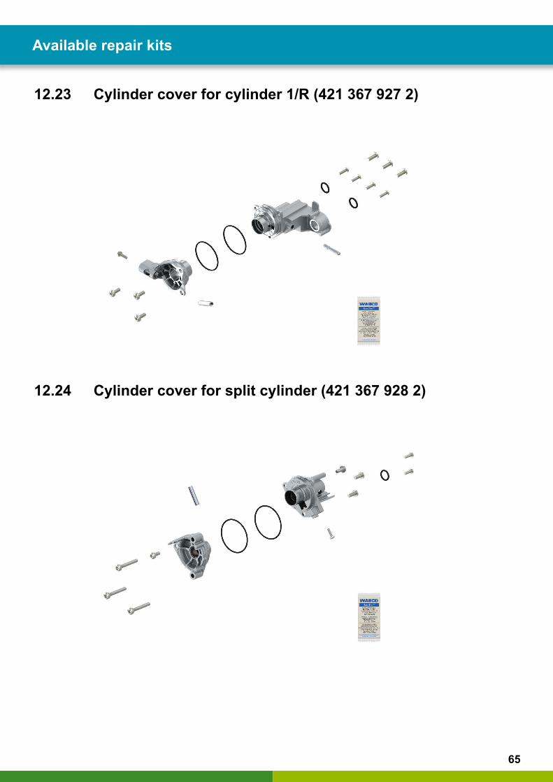
12.23 Cylinder cover for cylinder 1/R (421 367 927 2)
12.24 Cylinder cover for split cylinder (421 367 928 2)
66
Available repair kits Available repair kits
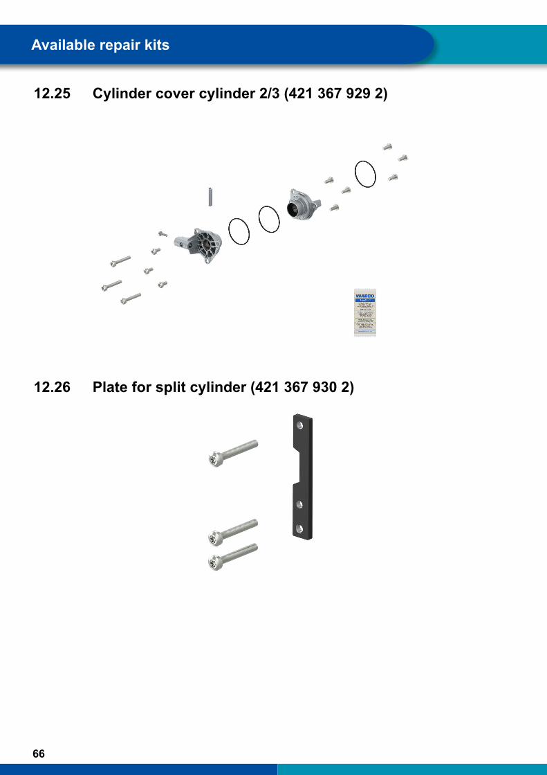
12.25 Cylinder cover cylinder 2/3 (421 367 929 2)
12.26 Plate for split cylinder (421 367 930 2)
67
Available repair kits
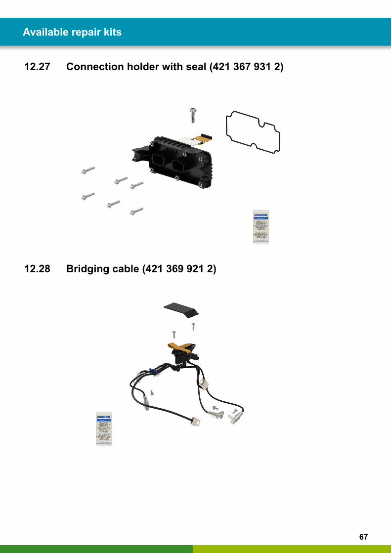
12.27 Connection holder with seal (421 367 931 2)
12.28 Bridging cable (421 369 921 2)
68
Available repair kits Available repair kits
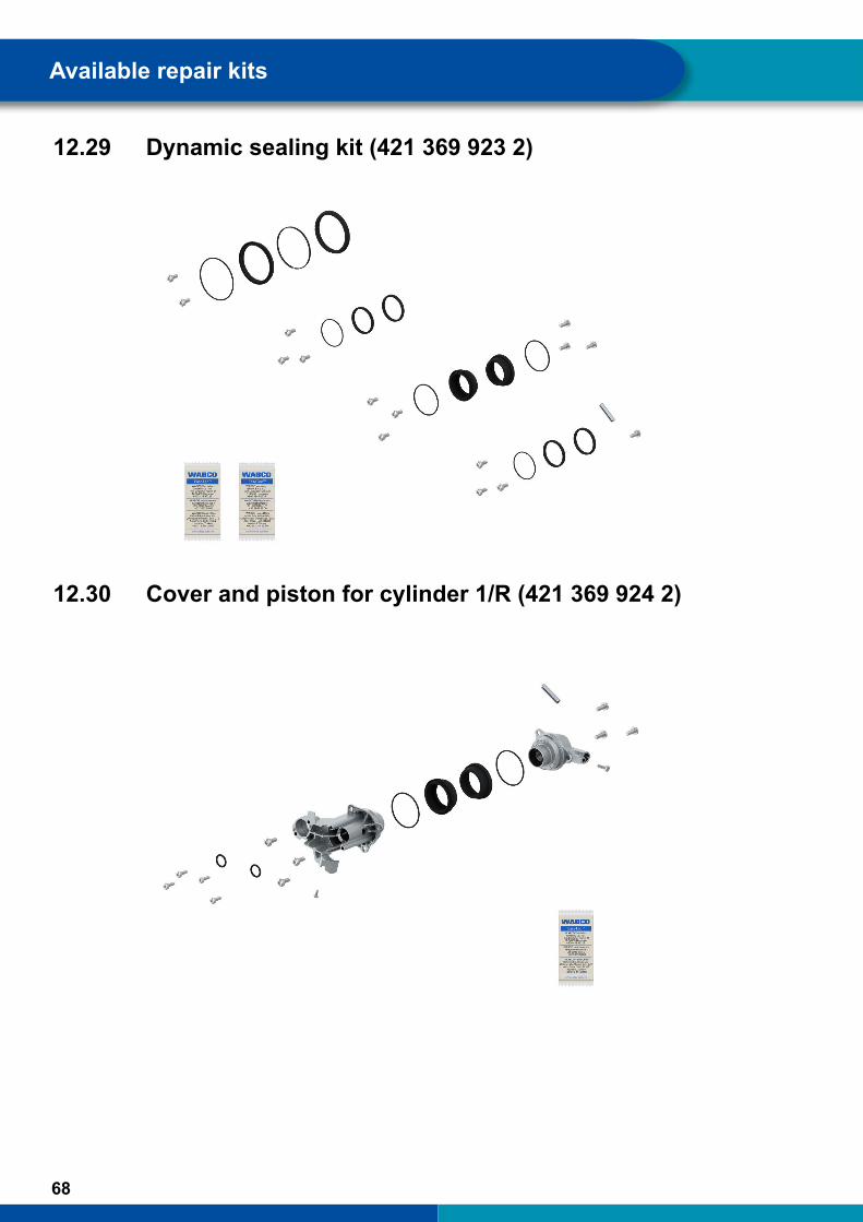
12.29 Dynamic sealing kit (421 369 923 2)
12.30 Cover and piston for cylinder 1/R (421 369 924 2)

69
Available repair kits
12.31 Connection holder with seal (421 369 925 2)
12.32 Cylinder cover for cylinder 2/3, nut rings and O-rings for cylinder (421 369 926 2)

70
Available repair kits Glossary
12.33 Rod kit for cylinder 3, nut rings and O-rings for cylinder (421 369 927 2)
12.34 Rod kit for cylinder 2, nut rings and O-rings for cylinder (421 369 928 2)
71
Glossary
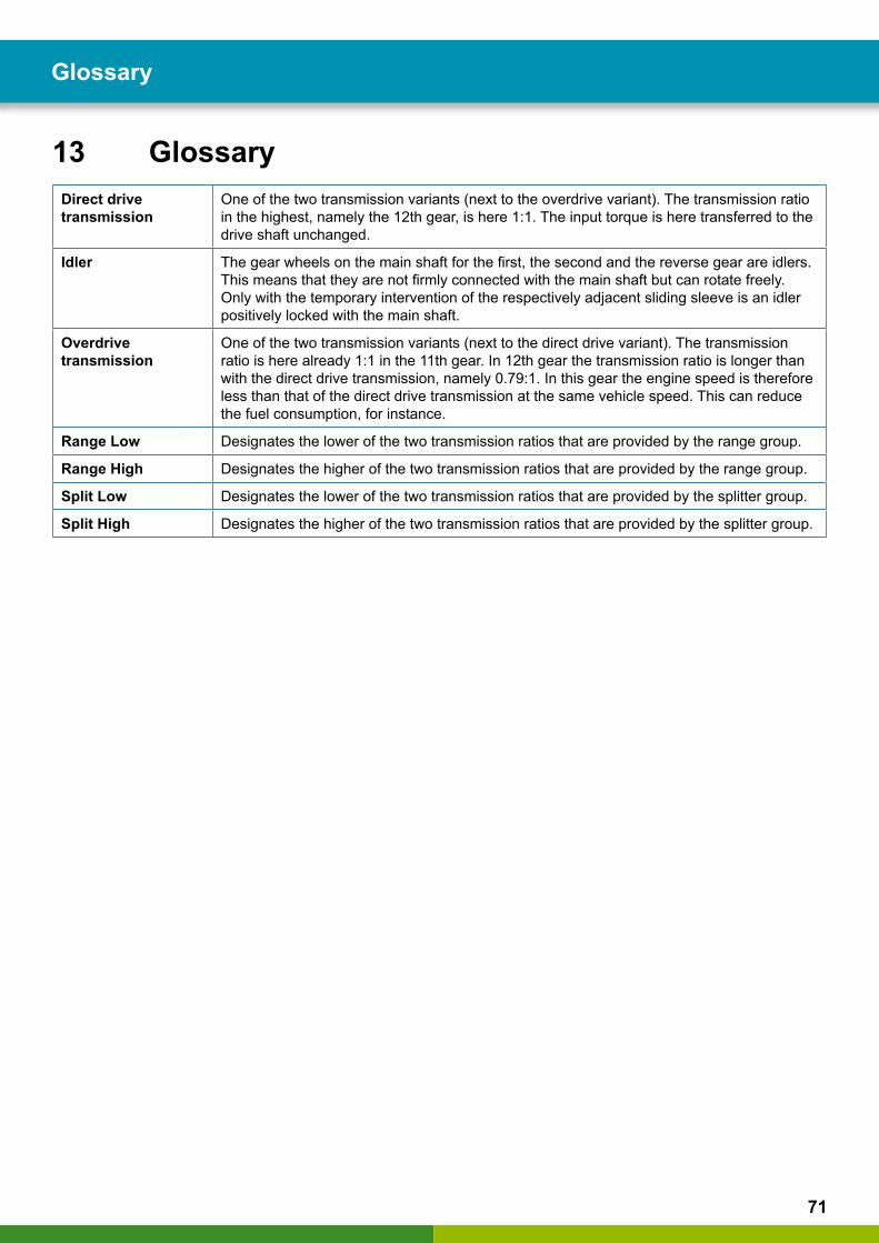
13 GlossaryDirect drive transmission
One of the two transmission variants (next to the overdrive variant). The transmission ratio in the highest, namely the 12th gear, is here 1:1. The input torque is here transferred to the drive shaft unchanged.
Idler The gear wheels on the main shaft for the first, the second and the reverse gear are idlers. This means that they are not firmly connected with the main shaft but can rotate freely. Only with the temporary intervention of the respectively adjacent sliding sleeve is an idler positively locked with the main shaft.
Overdrive transmission
One of the two transmission variants (next to the direct drive variant). The transmission ratio is here already 1:1 in the 11th gear. In 12th gear the transmission ratio is longer than with the direct drive transmission, namely 0.79:1. In this gear the engine speed is therefore less than that of the direct drive transmission at the same vehicle speed. This can reduce the fuel consumption, for instance.
Range Low Designates the lower of the two transmission ratios that are provided by the range group.
Range High Designates the higher of the two transmission ratios that are provided by the range group.
Split Low Designates the lower of the two transmission ratios that are provided by the splitter group.
Split High Designates the higher of the two transmission ratios that are provided by the splitter group.
72
Spare parts Disposal
14 Spare partsSpare parts can be found using the WABCO part number on the following page:
http://www.wabco.info/i/1365
73
Disposal
15 Disposal
� The final and professional decommissioning and disposal of the product must be carried out in accordance with the applicable legal regulations of the user country. In particular, the regulations for the disposal of batteries, equipment and the electrical system must be observed.
� Electrical appliances must be collected separately from household or commercial waste and recycled or disposed of in accordance with regulations.
� If applicable, take the old device to the company's internal disposal department, which will then forward it to specialist companies (specialist disposal companies).
� In principle, it is also possible to return the old device to the manufacturer. For this purpose, contact the manufacturer's customer service. Any special agreements must be observed.
� Electrical and electronic equipment must be collected separately from unsorted municipal waste and recycled or disposed of properly, because harmful substances can cause lasting damage to health and the environment if disposed of improperly.
� Detailed information can be obtained from specialist waste management companies or the responsible authorities.
� The packaging must be disposed of separately. Paper, cardboard and plastics must be recycled.

74
WABCOregionaloffices WABCOregionaloffices
16 WABCOregionaloffices
WABCO Headquarters, Giacomettistrasse 1, 3006 Bern 31, Switzerland, Tel.: +32-2663 98 00
WABCO Europe BVChaussée de la Hulpe 1661170 Brüssel BelgiumTel.: +32 2 663 9800Fax: +32 2 663 9896
WABCO Belgium BV/SPRL't Hofveld 6 B1-31702 Groot-BijgaardenBelgiumTel.: +32 2 481 09 00
WABCO Austria GesmbHRappachgasse 421110 WienAustriaTel.: +43 1 680 700
WABCO GmbHAm Lindener Hafen 2130453 HannoverGermanyTel.: +49 511 9220
WABCO GmbHGartenstraße 131028 GronauGermanyTel.: +49 511 922 3000
WABCO Radbremsen GmbHBärlochweg 2568229 MannheimGermanyTel.: +49 621 48310
WABCO brzdy k vozidlům spol. s r.o.Sourcing & Purchasing OfficeU Trezorky 921/2Prague 5 Jinonice158 00 PragCzech RepublicTel.: +420 226 207 010
WABCO brzdy k vozidlům spol. s r.o.Pražákova 1008/69, Štýřice,639 00 BrnoCzech RepublicTel.: +420 543 428 800
WABCO Automotive BVRhijnspoor 263Capelle aan den IJssel (Rotterdam) 2901 LBNetherlandsTel.: +31 10 288 86 00
WABCO (Schweiz) GmbHMorgenstrasse 136Bern 3018SwitzerlandTel.: +41 31 997 41 41
WABCO International Sourcing & Purchasing OfficeHarmandere Mh. Dedepasa Cd. 24 Atlas Park B/5 Pendik, 34912 IstanbulTurkeyTel.: +90 216 688 81 72Fax: +90 216 688 38 26
WABCO Sales OfficeHalide Edip Adivar Mh. Ciftecevizler Deresi Sok. 2/2 Akin Plaza, Sisli, 34382 IstanbulTurkeyTel.: +90 212 314 20 00Fax: +90 212 314 20 01
WABCOCarre Haussmann1 cours de la Gondoire 77600 JossignyFrankreichTel.: +33 1 60 26 62 06
WABCO Automotive Italia S.r.L.Studio Tributario e Societario, Galleria San Federico 54 Torino, 10121ItalyTel.: +39 011 4010 411
WABCO Polska Sp. z o.o.ul. Ostrowskiego 3453-238 WroclawPolandTel.: +48 71 78 21 888
WABCO España S. L. U.Av de Castilla 33San Fernando de Henares Madrid 28830 SpainTel.: +34 91 675 11 00
WABCO Automotive ABDrakegatan 10, Box 188 SE 401 23 Gothenburg SwedenTel.: +46 31 57 88 00
WABCO Automotive U.K. LtdUnit A1 Grange Valley Grange Valley Road, Batley, W Yorkshire, England, WF17 6GHTel.: +44 (0)1924 595 400

75
WABCOregionaloffices
WABCO Australia Pty LtdUnit 3, 8 Anzed CourtMulgrave, Victoria 3170AustraliaTel.: +61 3 8541 7000Hotline: 1300-4-WABCO
WABCO do Brasil Indústria e Comércio De Freios LtdaRodovia Anhanguera, km 106CEP 13180-901Sumaré-SPBrazilTel.: +55 19 2117 4600Tel.: +55 19 2117 5800
WABCO Hong Kong Limited14/F Lee Fund Centre31 Wong Chuk Hang RoadHong Kong ChinaTel.: +852 2594 9746
Asia Pacific Headquarters, WABCO (Shanghai) Mgmt Co. Ltd29F & 30F, Building B, New Caohejing Intl Bus. Center391 Guiping Rd, Xuhui Dist.Shanghai 200233, ChinaTel.: +86 21 3338 2000
WABCO (China) Co. Ltd. JinanShandong WABCO Automotive Products Co. Ltd.1001 Shiji Av, Jinan Indust. Zone, Shandong 250104ChinaTel.: +86 531 6232 8800
WABCO (China) Co. LtdNo. 917 Weihe Road, Economic & Tech. Dev. ZoneQingdao 266510ChinaTel.: +86 532 8686 1000
WABCO (China) Co. LtdGuangdong WABCO FUHUA Automobile Brake System Co. Ltd.Building E, No. 1 North, Santai Av, Taishan CityGuangdong 529200ChinaTel.: +86 750 5966 123
Shanghai G7 WABCO IOT Technology Co. LtdRoom 503,Liguo Building, No. 255 Wubao Road, Minhang Dist.Shanghai 201100ChinaTel.: 021-64058562/826
China-US RH Sheppard Hubei Steering Systems Co. LtdNo. 18, Jingui Road, Xianning CityHubei 437000China
WABCO India LimitedPlot No. 3 (SP), III Main RoadAmbattur Industrial EstateChennai 600 058IndiaTel.: +91 44 42242000
WABCO Japan IncGate City Ohsaki W. Tower 2F,1-11-1, Osaki,Shinagawa-ku, Tokyo 141-0032JapanTel.: +81 3 5435 5711
WABCO Korea Ltd23, Cheongbuksandan-ro, Cheongbuk-eup Pyongtaek-siGyeonggi-do, 17792KoreaTel.: +82 31 680 3707
WABCO Asia Private Ltd25 International Business Park#03-68/69 German Centre609916SingaporeTel.: +65 6562 9119
WABCO Automotive SA 10 Sunrock CloseSunnyrock Ext 2, Germison 1401PO Box 4590, Edenvale 1610South AfricaTel.: +27 11 450 2052
WABCO Middle East and Africa FZCO Vehicle Control SystemDWC Business Park, Building A3, Room NO: 115,PO Box 61231,DubaiUnited Arab EmiratesE-mail: [email protected]


ZF Friedrichshafen AG
ZF is a global technology company and supplies systems for passenger cars, commercial vehicles and industrial technology, enabling the next generation of mobility. ZF allows vehicles to see, think and act. In the four technology domains Vehicle Motion Control, Integrated Safety, Automated Driving, and Electric Mobility, ZF offers comprehensive solutions for established vehicle manufacturers and newly emerging transport and mobility service providers. ZF electrifies different kinds of vehicles. With its products, the company contributes to reducing emissions and protecting the climate.
ZF, which acquired WABCO Holdings Inc. on May 29, 2020, now has 162,000 employees worldwide with approximately 260 locations in 41 countries. In 2019, the two then-independent companies achieved sales of €36.5 billion (ZF) and $3.4 billion (WABCO).
With the integration of WABCO, the leading global supplier of braking control systems and other advanced technologies that improve the safety, efficiency and connectivity of commercial vehicles ZF will create a new level of capability to pioneer the next generation of solutions and services for original equipment manufacturers and fleets globally. WABCO, with almost 12,000 people in 40 locations worldwide, will now operate under the ZF brand as its new Commercial Vehicle Control Systems division.
YoucanfindinformationonWABCOproductshere:http://www.wabco.info/i/1365Please contact your WABCO partner for further information.
© 2
020
WAB
CO
– A
ll rig
hts
rese
rved
– 8
15 0
10 2
27 3
/ 08
.202
0