Parameter Optimization and Electrode Improvement of Rotary Stepper Micromotor
12
Journal of Advanced Mechanical Design, Systems, and Manufacturing Vol.4, No.6, 2010 Parameter Optimization and Electrode Improvement of Rotary Stepper Micromotor ∗ Junji SONE ∗∗ , Toshinari MIZUMA ∗∗ , Shunsuke MOCHIZUKI ∗∗∗ , Edin SARAJLIC † , Christophe YAMAHATA † and Hiroyuki FUJITA † ∗∗ Tokyo Polytechnic University 1583 Iiyama Atsugi, Kanagawa 243-0297 ∗∗∗ Mathematical Systems, Inc. 2-4-3 Shinjuku Sinjuku-ku Tokyo 160-0022 † The University of Tokyo 4-6-1 Komaba, Meguro-ku, Tokyo, 153-8505 Abstract We developed a three-phase electrostatic stepper micromotor and performed a numer- ical simulation to improve its performance for practical use and to optimize its de- sign. We conducted its circuit simulation by simplifying its structure, and the effect of springback force generated by supported mechanism using flexures was considered. And we considered new improvement method for electrodes. This improvement and other parameter optimizations achieved the low voltage drive of micromotor. Key words : MEMS, Circuit Simulation, Micromotor, FEM Analysis, Parameter De- sign. 1. Introduction MEMS (1) actuators for highly accurate angular control are required for industrial uses (e.g., hard disk drives). At the University of Tokyo, a 3-phase electrostatic stepper micromotor Fig. 1 Working principle of 3-phase electorstatic stepper motor. ∗ Received 10 May, 2010 (No. 10-0196) [DOI: 10.1299/jamdsm.4.1133] Copyright c 2010 by JSME 1133
-
Upload
independent -
Category
Documents
-
view
5 -
download
0
Transcript of Parameter Optimization and Electrode Improvement of Rotary Stepper Micromotor

Journal of Advanced Mechanical Design,Systems, andManufacturing
Vol.4, No.6, 2010
Parameter Optimization and ElectrodeImprovement of Rotary Stepper Micromotor∗
Junji SONE∗∗, Toshinari MIZUMA∗∗, Shunsuke MOCHIZUKI∗∗∗,Edin SARAJLIC†, Christophe YAMAHATA† and Hiroyuki FUJITA†
∗∗ Tokyo Polytechnic University
1583 Iiyama Atsugi, Kanagawa 243-0297∗∗∗Mathematical Systems, Inc.
2-4-3 Shinjuku Sinjuku-ku Tokyo 160-0022† The University of Tokyo
4-6-1 Komaba, Meguro-ku, Tokyo, 153-8505
AbstractWe developed a three-phase electrostatic stepper micromotor and performed a numer-ical simulation to improve its performance for practical use and to optimize its de-sign. We conducted its circuit simulation by simplifying its structure, and the effectof springback force generated by supported mechanism using flexures was considered.And we considered new improvement method for electrodes. This improvement andother parameter optimizations achieved the low voltage drive of micromotor.
Key words : MEMS, Circuit Simulation, Micromotor, FEM Analysis, Parameter De-sign.
1. Introduction
MEMS(1) actuators for highly accurate angular control are required for industrial uses(e.g., hard disk drives). At the University of Tokyo, a 3-phase electrostatic stepper micromotor
Fig. 1 Working principle of 3-phase electorstatic stepper motor.
∗Received 10 May, 2010 (No. 10-0196)[DOI: 10.1299/jamdsm.4.1133]
Copyright c© 2010 by JSME
1133

Journal of Advanced Mechanical Design,Systems, andManufacturing
Vol.4, No.6, 2010
(2) was developed. Figure 1 shows the working principle of motor and the structure of stator(layout of vertical trench isolation). It consists of a rotor with grounded poles and a stator withactive poles that are controlled by integrated 3-phase electrical connections. The actuationdepends on the electrostatic force generated by applying a voltage between the grounded rotorpoles and the stator poles of a given phase. Although the radial component of the electrostaticforce acting on the rotor is cancelled because of the symmetry, the tangential componentgenerates a global torque realigning the rotor with the stator poles of the active phase. Inthis design, the rotor is suspended by flexures, called a butterfly pivot(3) instead of the usualfriction bearings. In this research, we investigated methods for analyzing the micromotorbased on MEMS Design Tools, MemsONETM(4), and we investigated an optimal design forlow voltage operation of this motor.
It is difficult to analyze the entire structure of this motor because it generates rotation.Therefore, we simplified the motor’s structure by reducing the four-layer flexures to two layersand deploying rotational movement for parallel displacement. In this analysis, the resonancefrequency characteristic and static deformation are important; therefore, we adjusted the pa-rameters of the analysis model considering these features. The stiffness of the flexure springsis converted from the butterfly pivot to a parallel suspension (PS). We deduced a theoreti-cal equation for the relationship between force (torque) and deformation (rotation angle). Toadjust the resonance frequency, we obtained the transfer function of the four-layer flexuresand simplified it; its resonance frequency is calculated by eigenvalue analysis. The resonancefrequency of the simplified model is also obtained. By comparing these two relations, weobtained an equation for converting the stiffness. Theoretical descriptions are mentioned atlast paper(5). In addition, we implemented the calculating function of accurate electrostaticforce caused by the lateral offset between opposing poles in MemsONETM. We simulated oursimplified model using circuit simulation in MemsONETM.
A previous paper showed that drive voltage of a micromotor increased for the load case.Then, the problem with too high voltage occurred in the actual drive. Therefore, to achievean efficient drive, we need to improve and optimize the structure of a micromotor, which weattempted to do in this study by improving electrode structure and by performing completeparameter optimization.
2. Analysis model
Figure 2 shows the SEM micrograph of a completed micromotor. The device has adiameter of 1.4 mm and height of 37 μm. Electrodes on the stator and rotor are 10 μm longand 4 μm wide, and are separated by a gap of 1.25 μm. The pitch of the electrodes on the
Fig. 2 Rotary stepper motor (SEM photograph).
1134

Journal of Advanced Mechanical Design,Systems, andManufacturing
Vol.4, No.6, 2010
Fig. 3 Double layer parallel spring model (FEM Analysis model).
rotor and stator is 1◦ (10 μm) and 4/3◦, respectively. During operation of the motor, only64 stator poles in each phase face the opposite poles on the rotor. The motor is suspendedwith a ’butterfly’ flexure pivot (BFP) consisting of eight beam flexures that are 400 μm long,3 μm wide and 37 μm high. One layer is constructed of two beams, then it has four layers.These layers connect from the upper fixed part to the rotor. The stator poles are symmetricallylocated around the rotor to cancel the radial component of the electrostatic force acting on therotor. Figure 3 shows the two-layer PS. The structure is designed referring from the paper(6).A rotor of weight m2 is supported by a high-stiffness beam (m1) and flexure beams.
The displacement can be halved to convert the structure from four layers to two layers ofBFPs. In addition, the displacement can be halved to convert the structure from two layers toone layer of PS. Therefore, the spring constant of one layer of PS matches that of two layersof BFP. This relation will give equivalent displacement between two layer of PS analysis andfour layers of BFP.
2.1. Matching the characteristics between resonance frequency and displacement
A four-layer BFP is equivalent to a four-layer torsion vibration model. We simplified thismodel; the relationship between resonance frequency and stiffness is obtained from eigenvalueanalysis. We also obtained the relationship between the resonance frequency and stiffness ofa two-layer PS from eigenvalue analysis. The stiffness of a two-layer PS is obtained from theequivalence of the above-mentioned two relationships.
The relationship between resonance frequency and stiffness is complicated. First, weobtained the stiffness from the equation relating resonance frequency and stiffness, matchinga four-layer BFP and a two-layer PS. The displacement is linear, and it is changed by a stiffnessratio (R) obtained from the difference between the relationships of equivalence of resonancefrequency and equivalence of displacement. The required force is proportional to dependon the displacement. The drive voltage is proportional to the square root of the drive force.Thus, the drive voltage can be computed by multiplying the 1√
Rby the drive voltage of circuit
simulation results.The stiffness of the analysis model can be obtained from the equivalence relationship
between the displacement of a one-layer PS and that of a two-layer BFP. The angular stiffnessof a two-layer BFP(7) is obtained from the following equation:
kθ,2 =4EIlp
(1 +3Plp+
3P2
lp2
) = 2.828 × 10⁻⁷Nm/rad (1)
Here,Flexure length: lp = 400×10−6m, distance to the virtual center: P = 115×10−6m, young
modulus:E = 1.6 × 10¹¹N/m2
kθ,1 is one layer, kθ,2 is two layers, kθ,4 is four layers angular stiffness of BFP. Thesestiffnesses have the following relationship: kθ,4 =
kθ,22 =
kθ,14
The conversion Young’s modulus of a one-layer PS (CEPSW, whole model) is calculatedusing the equivalence relationship between the displacement of a two-layer BFP and that of a
1135

Journal of Advanced Mechanical Design,Systems, andManufacturing
Vol.4, No.6, 2010
one-layer PS, as follows:
CEPSW =kθ,2l3
192IlB2= 3.38 × 10⁴MPa (2)
Here, kθ,2 is the angular stiffness of a two-layer BFP(7), l is twice the length of the beam, andlB is the flexure length plus the distance to the virtual center. l = 8×10⁻⁴m, lB = 5.15×10⁻⁴m,Area moment of inertia: I = bh3
12 , beam thickness: b=3.7×10⁻⁵m, beam width: h=3.0×10⁻⁶m.The spring constant of the one-layer PS (kPS) is computed by the spring constant equation ofthe one-layer parallel spring and equation (2), as follows:
kPS =kθ,2lB
2(3)
The resonance frequency of a two-layer PS is obtained from the following equation(8):
ω =
√√√√2m2k + m1k
2m1m2− 1
2
⎛⎜⎜⎜⎜⎜⎜⎜⎝√(
2m2k + m1km1m2
)2
− 4k2
m1m2
⎞⎟⎟⎟⎟⎟⎟⎟⎠ (4)
It is the first eigen frequency. Here, m1,m2 is first and second layer of mass, k is stiffness ofspring. We solved the stiffness using the resonance frequency and stiffness equation from therelationship between a four-layer torsion vibration and two-layer PS model. The stiffness ofa two-layer PS (kPSD) is obtained(5) from the equivalent relation between a four-layer torsionvibration and the two-layer PS model, as follows:
kPSD =4√
m1√m2
kθ,2lB
2(5)
The difference between this equation and equation (3) is coefficient of 4√
m1√m2= 0.495.
Thus, the square root of the coefficient : 1.42 must be multiply the circuit simulation voltage.The resonance frequency of the actual motor is 279 Hz. The resonance frequency value of atwo-layer PS is 369Hz using k = kPSD. Further improvement in the accuracy is a subject offuture investigation. The stiffness parameter of the circuit simulation is the Young’s modulusof spring that is described in the next section.
2.2. Analysis methodTo improve the accuracy of simulation, we approximate the capacitance per thickness
(C(x)[F/m],F : farad) between opposite poles by a Gauss-Lorentz mixture function.
C(x) = h(1 − m) exp
(−2
(x − μ)2
w2
)+ hm
w2
4(x − μ)2 + w2+C0 (6)
Here, x is deviation of two poles, h is peak value, m is weight, μ is average value, w is widthof half deviation, C0 is offset value. The parameters of this equation are computed using theresults of FEM(9) simulations for electric field. The relation between electrostatic force (Fx),electrostatic capacitance and drive voltage (V) is described as follows:
Fx =12
V2 dC (x)dx
(7)
we implemented a function to calculate the force caused by lateral offset between oppositepoles in the MemsONETM circuit simulator.
Figure 4 shows the poles of the analysis model in detail. The gap between the rotorand the stator pole is 1.25 μm, the width of the pole is 5 μm, the pitch of the stator poles is13.333 μm and that of the rotor poles is 10 μm. In this motor, three poles form a set. Threesteps are needed to progress to the next set, and each pole pulls the opposite pole at each stepsequentially. The circuit simulation is executed using three sets of poles that match each other
1136

Journal of Advanced Mechanical Design,Systems, andManufacturing
Vol.4, No.6, 2010
in a sequential order. The total displacement is 6.7 μm and is almost the same as one degreeof rotor rotation.
This model has two sets of poles at each side, for a total of four sets. This is a 1/16 scalemodel of the actual motor. Table1 shows the parameters of the analysis. A conversion Young’smodulus of CEPS = 1051 MPa (calculated as CEPSA × 0.495 × 1/16) is used for the spring.SBF was given by external force resource for circuit simulation. In the following simulation,required voltage is obtained by multiplying simulation result by 1.42.
The drive voltage is determined by estimating the approximate voltage by achieving thefinal position when increasing the drive voltage from a low to high value and by calculatingthe precise voltage when the overshoot is less than 0.5 μm.
Fig. 4 Detail structure of rotor and electrode.
3. Spring back force and effect to response
The actual movement of a motor is influenced by the viscosity of air and other materials(10). In our configuration, the rotor of the electrostatic stepper micromotor is suspended usinga butterfly pivot. The springback force (SBF) is then increased by increasing the rotation angleof the rotor. In this manner, we consider the effect of air viscosity and SBF.
3.1. Spring back force and air viscosityThe response characteristic is influenced by mechanical damping and air viscosity. We
first consider air viscosity; Figure 5 shows its two main effects. One main effect is caused bythe slide-film damping force between opposite poles(11). This viscosity force is 2.3×10⁻⁹Nfor 1.85×10⁻¹⁰ m2 pole’s area and 64 set of poles, obtained from equation (8).
τ = μUhg
(8)
Here, μ=2×10⁻⁵Pa·s,U=0.012m/s,hg=1.25×10−6m.The other effect is caused by the air resistance of flexures, which have a large area and
a resistance face perpendicular to the direction of movement. This viscosity force (D) is6.96×10−10N for 8 flexures, calculated from following equation.
D =∫ l
0
12
CDρU(x)2hdx (9)
U(x) =lx
Umax (10)
D =16
CDρhU2maxl (11)
Here, Umax=0.012m/s,l=4×10−4m,h=3.7×10−5m,CD=200.0(circular plate, Re=0.1). In thiscase we used circular plate’s CD instead of rectangular column’s CD, because we have noinformation of rectangular column’s CD for low Reynolds number (Re) and both type’s CD
are almost same value at Re=1000(12). And although Re of this case is 0.02, a minimumexperiment value of Re is 0.1(12). Then we use CD of Re=0.1 case.
1137

Journal of Advanced Mechanical Design,Systems, andManufacturing
Vol.4, No.6, 2010
Table 1 Parameters of each parts.
Part Weight Volume ratio Density (1/16)(kg) Motor and model (kg/μm3)
Rotor(m2) 4.87 × 10⁻⁸ 904 1.317 × 10⁻¹³
m1 7.47 × 10⁻¹⁰ 2.2 3.21 × 10⁻¹⁵
Spring 1.04 × 10⁻¹⁰ 1.0 1.46 × 10⁻¹⁶
Fig. 5 Main effect of viscosity.
To estimate SBF, we set the maximum angle (θ) of rotor to 15 degree for practical us-age. First, springback torque (SBT) is derived by multiplying stiffness with rotation angle asfollows:
SBT = kθ,3θ (12)
SBF is then obtained by dividing torque with total length of a flexure(13).
SBF =SBT
4l(13)
Thus, a flexure with the dimensions of length = 400 μm, width = 37 μm and thickness = 3 μmproduces an SBF of 2.3×10⁻⁵N. SBF is much higher as compared to air viscosity.
Regarding the SBF value in this simulation, we execute the circuit simulation for themost severe condition at a 15-degree rotation angle, and we assume that the SBF value isconstant because the transformation angle is only one degree.
3.2. Effect of spring back forceFigure 6 shows the drive voltage waveforms of the simulations. Three step voltages are
applied for each phase for three set poles with a stepwise voltage input pattern. Figure 7compares rotor displacement with SBF to that without SBF for a drive speed of 1800 Hz(We defined the frequency of the matching ratio of the rotor poles against the stator poles.In this case, the rotor poles match against 1800 stator poles in one second.) and stepwisedrive voltage. It is more difficult to perform positioning control in the case with SBF. DS1
Fig. 6 Stepwise drive voltage pattern.
1138

Journal of Advanced Mechanical Design,Systems, andManufacturing
Vol.4, No.6, 2010
Fig. 7 Displacement for stepwise drive voltage with or without of SBF (1800Hz).
indicates a drive voltage of 72 V, no SBF and viscosity of 2×10⁻⁵Pa·s; DS3 indicates a drivevoltage of 121 V, SBF acting in the direction opposite to that of the rotor and viscosity of2×10−5Pa·s; DS4 indicates a drive voltage of 118 V, SBF acting in the same direction as thatof the rotor and viscosity of 2×10⁻⁵Pa·s. From this result, the residual vibration of DS3 andDS4 is smaller than that of DS1. Then, the residual vibration was reduced using SBF for theappropriate drive voltage. The drive voltage for the case with SBF needs to be increased byalmost 70% over the case without SBF which is the same as the condition around zero degreerotation. The final position of DS3 and DS4 differs from that of DS1 by about 1 μm, due tothe effect of SBF.
Fig. 8 Displacement for stepwise drive voltage with or without of SBF (18000Hz).
Figure 8 compares rotor displacement with SBF to that without SBF for a drive speedof 18000Hz and stepwise drive voltage. This drive speed is the maximum speed for practicalusage. DFS1 indicates a drive voltage of 110 V, no SBF and viscosity of 2×10⁻⁵Pa·s; DFS3indicates a drive voltage of 131 V, SBF acting in the direction opposite to that of the rotorand viscosity of 2×10⁻⁵Pa·s; DFS4 indicates a drive voltage of 124 V, SBF acting in thesame direction as that of the rotor and viscosity of 2×10⁻⁵Pa·s. From this result, the residualvibration of DFS3 and DFS4 is smaller than that of DFS1. Then, the residual vibration wasreduced using SBF for the appropriate drive voltage. The drive voltage for the case with SBFneeds to be increased by almost 20% over the case without SBF.
A low drive voltage is required for the actual motor drive. To attain this, we added agradient to the drive voltage waveform to improve the dynamic characteristics of the rotor.Figure 9 shows the drive voltage with gradients added on both sides (ramp voltage pattern(Ramp)).
Figure 10 compares rotor displacement with SBF to that without SBF for a drive speedof 18000 Hz and ramp drive voltage. DFR1 indicates a drive voltage of 97 V, no SBF andviscosity of 2×10⁻⁵Pa·s; DFR3 indicates a drive voltage of 109 V, SBF acting in the directionopposite to that of the rotor and viscosity of 2×10⁻⁵Pa s; DFR4 indicates a drive voltage of104 V, SBF acting in the same direction as that of the rotor and viscosity of 2×10⁻⁵Pa·s. Thedrive voltages in this case were decreased as compared to the voltages of the stepwise drive.
1139

Journal of Advanced Mechanical Design,Systems, andManufacturing
Vol.4, No.6, 2010
Fig. 9 Ramp drive voltage pattern.
Fig. 10 Displacement for stepwise drive voltage with or without of SBF (1800Hz).
From this result, we realise that the residual vibration of DFR3 and DFR4 is smaller than thatof DFR1. Then, the residual vibration was reduced by SBF for the appropriate drive voltage.The drive voltage for the case with SBF needs to be increased by almost 12% over the casewithout SBF.
Figure 11 shows the force between opposite poles: (a) is the force of DFR1 and (b) is theforce of DFR3. In this figure, F1, F2 and F3 are the drive direction forces for the first, secondand third pairs of poles, respectively. The F3 vibration of DFR3 is lower than that of DFR1.Then, the displacement vibration of DFR3 can be lowered compared with DFR1, which isaffected by lower force vibration.
Fig. 11 Force between opposite poles, with no SBF and with SBF case.
4. Optimization for low voltage drive
There are several parameters that may be optimized. In the following section, we describethe improvement method and the optimization method, as well as their results.
4.1. Optimization parameterThe simulation parameters important for the various optimization conditions are as fol-
lows. The number of poles can be increased by increasing the flexure length. The analysis
1140
Journal of Advanced Mechanical Design,Systems, andManufacturing
Vol.4, No.6, 2010
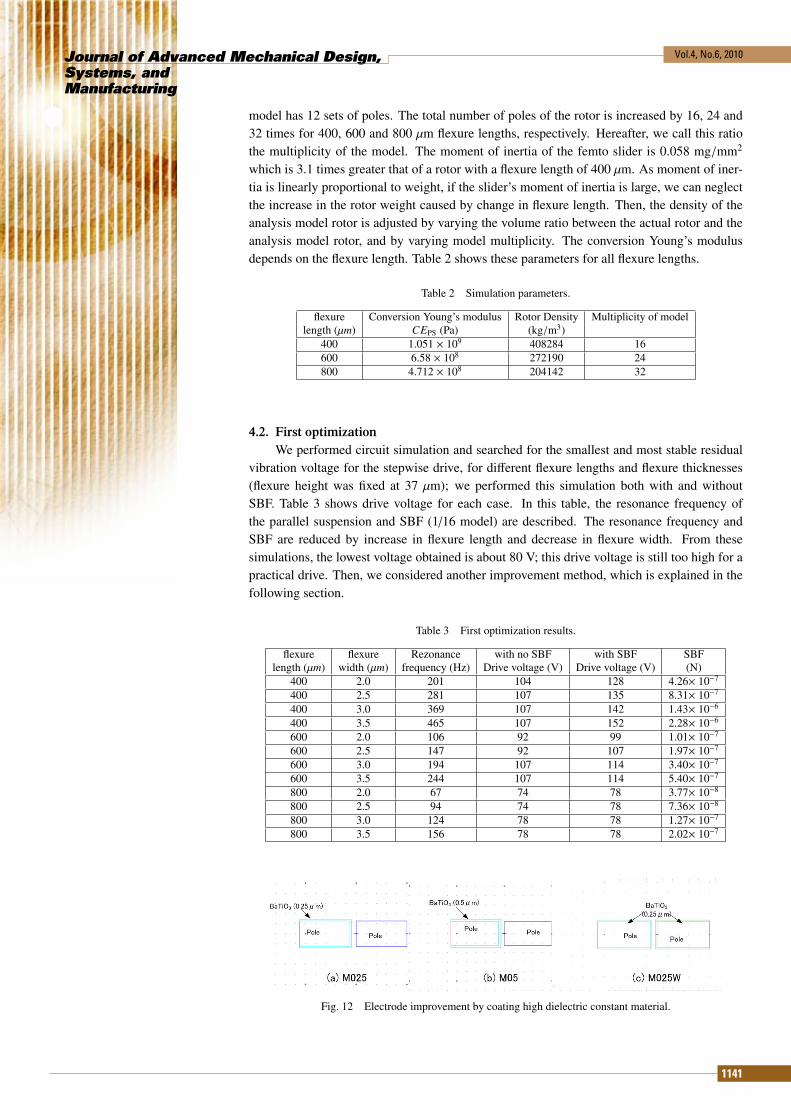
model has 12 sets of poles. The total number of poles of the rotor is increased by 16, 24 and32 times for 400, 600 and 800 μm flexure lengths, respectively. Hereafter, we call this ratiothe multiplicity of the model. The moment of inertia of the femto slider is 0.058 mg/mm2
which is 3.1 times greater that of a rotor with a flexure length of 400 μm. As moment of iner-tia is linearly proportional to weight, if the slider’s moment of inertia is large, we can neglectthe increase in the rotor weight caused by change in flexure length. Then, the density of theanalysis model rotor is adjusted by varying the volume ratio between the actual rotor and theanalysis model rotor, and by varying model multiplicity. The conversion Young’s modulusdepends on the flexure length. Table 2 shows these parameters for all flexure lengths.
Table 2 Simulation parameters.
flexure Conversion Young’s modulus Rotor Density Multiplicity of modellength (μm) CEPS (Pa) (kg/m3)
400 1.051 × 10⁹ 408284 16600 6.58 × 10⁸ 272190 24800 4.712 × 10⁸ 204142 32
4.2. First optimizationWe performed circuit simulation and searched for the smallest and most stable residual
vibration voltage for the stepwise drive, for different flexure lengths and flexure thicknesses(flexure height was fixed at 37 μm); we performed this simulation both with and withoutSBF. Table 3 shows drive voltage for each case. In this table, the resonance frequency ofthe parallel suspension and SBF (1/16 model) are described. The resonance frequency andSBF are reduced by increase in flexure length and decrease in flexure width. From thesesimulations, the lowest voltage obtained is about 80 V; this drive voltage is still too high for apractical drive. Then, we considered another improvement method, which is explained in thefollowing section.
Table 3 First optimization results.
flexure flexure Rezonance with no SBF with SBF SBFlength (μm) width (μm) frequency (Hz) Drive voltage (V) Drive voltage (V) (N)
400 2.0 201 104 128 4.26× 10⁻⁷
400 2.5 281 107 135 8.31× 10⁻⁷
400 3.0 369 107 142 1.43× 10⁻⁶
400 3.5 465 107 152 2.28× 10⁻⁶
600 2.0 106 92 99 1.01× 10⁻⁷
600 2.5 147 92 107 1.97× 10⁻⁷
600 3.0 194 107 114 3.40× 10⁻⁷
600 3.5 244 107 114 5.40× 10⁻⁷
800 2.0 67 74 78 3.77× 10⁻⁸
800 2.5 94 74 78 7.36× 10⁻⁸
800 3.0 124 78 78 1.27× 10⁻⁷
800 3.5 156 78 78 2.02× 10⁻⁷
Fig. 12 Electrode improvement by coating high dielectric constant material.
1141

Journal of Advanced Mechanical Design,Systems, andManufacturing
Vol.4, No.6, 2010
Fig. 13 Force for drive direction and the offset of opposite poles.
4.3. Improvement of electrode designTo increase the electrostatic force, we need to improve the air gap characteristic while
ensuring that sufficient electrical insulation exists, because the dielectric constant of an air gapis very low. We considered the electrodes to be covered with high dielectric constant material.Recent technological developments(14) have produced various functional materials with highdielectric constants material coating. In addition, high dielectric constant materials have goodinsulation property. Therefore, even if the length of an air gap is reduced, the risk of a shortcircuit does not increase. This method suffers from build-up of charges at the insulating layer,and therefore, a technique to control discharge of the insulating layer is required to maintainthe performance. We selected BaTiO3 as the coating material. Figure 12 shows three types ofcoating methods. Figure 13 shows the relationship between the force applied in the directionof the drive and the offset of opposite poles for normal conditions: no coat, M025: one poleis coated 0.25 μm, M05: one pole is coated 0.5 μm, M025W: both poles are coated, 0.25μm. These curves are computed by electric-field finite element analysis (gap is 1.25 μm). Thecharacteristics are almost the same between M05 and M025W. The force is almost two timeshigher than normal for M025W and M05. Therefore, we can reduce the drive voltage usingthese improvements. These curves are approximated by the Gauss-Lorentz mixture functionand used in MemsONETM circuit simulation.
4.4. Second optimizationWe performed a circuit simulation for M025W coating and searched for the smallest
and most stable residual vibration voltage for a stepwise and ramp drive, for different flexurelengths and flexure thicknesses (flexure height is fixed at 37 μm); we executed this simulationwith and without SBF. Table 4 shows the drive voltage for each case. In this simulation, thedrive voltages of the case with SBF (800 μm) were lower than the case without SBF. Weconsidered that lower drive voltages were realized by suppression of vibration by SBF. Fromthese simulations, the lowest voltage achieved was below 50 V for a ramp drive. A flexure(length = 600 μm and width = 2 μm) is also useful for a low voltage drive. In addition, thedifference between the final positions for the cases without SBF and with SBF was reduced towithin 0.5 μm for an 800-μm-long flexure.
5. Conclusion
We simplified an electrostatic stepper micromotor to a parallel suspension model whilekeeping the former resonance and displacement characteristics. We also considered springback force which was caused by supported mechanism using flexures. Circuit simulationswere executed by MemsONETM which was improved for the relation between force and op-posite poles offset. From these simulation, spring back force was reduced the residual vibra-tion for same and opposite direction of moving, and this effect act as similar to large viscosity
1142

Journal of Advanced Mechanical Design,Systems, andManufacturing
Vol.4, No.6, 2010
Table 4 Second optimization results.
flexure flexure with no SBF with no SBF with SBF with SBFlength (μm) width (μm) ST voltage (V) Ramp voltage (V) ST voltage (V) Ramp voltage (V)
400 2.0 74 71 75 71400 2.5 74 71 92 82400 3.0 75 71 99 92400 3.5 75 71 109 107600 2.0 71 57 78 57600 2.5 71 64 78 64600 3.0 78 71 82 78600 3.5 85 78 89 85800 2.0 54 50 64 47800 2.5 54 50 68 47800 3.0 54 50 71 47800 3.5 54 50 71 50
damping effect.We optimized the flexure length and width for the stepwise drive voltage; however, our
results were not sufficient for implementing a low drive voltage. Then, we considered elec-trodes to be coated with high dielectric constant material. In this improvement, the maximumforce value was almost two times higher for the offset of opposite poles, compared with thecase where no coating was used. A second optimization using coated electrodes and rampinput drive voltage (pattern is changed to trapeziform) achieved a drive voltage of under 50 V.
This coated effect is considered as follows. The drive signals of the neighbour set ofpoles overlap each other, and then some drive forces cancel each other. A maximum force,which is twice the SBF, was applied at 0.1 ms, as shown in Fig. 11 (b), and a displacementof 0.5 μm was obtained at 0.1 ms, as shown in Fig. 10. Each gradient of the drive force forcoated and non-coated types differ from the other at 0.5 μm offset, as shown in Fig. 13. Inaddition, for a low-voltage (high-efficiency) drive, the initial force gradient against offset ispreferred to be large.
The dimension constraint is severe to be applied to a hard disk drive. The spring lengthand the drive voltage are trade-off relation. Our simulation and optimization results in thispaper search for basic characteristics. Furthermore, our results can be used for improvingthe drive power and compact design in practical applications. For achieving compactness, amulti-stack actuator design can be employed.
Acknowledgement
This research is supported by SRC(Storage Research Consortium). We want to thankNorio Yoshikawa, Shinji Koganezawa (Toshiba corp.), Cheki Mizuta (Mathmatical SystemsInc.), Masaki Muto (Mathmatical Systems Inc.) and Prof. Shuji Tanaka (Tohoku Univ.) forsupport and discussion of research.
References
( 1 ) H. Fujita, EE Text, Sensor and Micro Machine Engineering, Ohmsha, (2005).( 2 ) E. Sarajlic, C. Yamahata, M. Cordero and H. Fujita, ELECTROSTATIC ROTARY
STEPPER MICROMOTOR FOR SKEW ANGLE COMPENSATION IN HARDDISK DRIVE,IEEE 22nd International Conference on Micro Electro MechanicalSystems,(2009),pp.1079-1082.
( 3 ) S. Henein, P. Spanoudakis, S Droz, L. I. Mykelbust, E. Onillon, Flexurepivot for aerospace mechanisms, 10th European Space Mechanisms and TribologySymposium,(2003),pp.285-288.
( 4 ) http://www.mmc.or.jp/mems-one/( 5 ) J. Sone,T. Mizuma, M. Masunaga, S. Mochizuki, E. Sarajlic, C. Yamahata, H. Fu-
jita, Analysis of the Characteristics of a Rotary Stepper Micromotor, IEEJ Trans. SM,Vol.130,No.7,(2010),pp.310-316.
1143

Journal of Advanced Mechanical Design,Systems, andManufacturing
Vol.4, No.6, 2010
( 6 ) T. Hirano, T. Furuhata, K.J. Gabriel, H. Fujita:”Effect of Air Damping and SuspensionCompliance on Electrostatic Comb-drive Actuators with Sub-Micron Gaps ” Proc. of2nd International Symposium on Measurement and Control in Robotics,(1992), pp.507-512.
( 7 ) S. Henein, Conception des guidages flexibles,Presses Polytechniques et UniversitairesRomandes, (2001).
( 8 ) P.D. Pilkey, Yohji Okada, Matrix Methods in Mechanical Vibration, Corona, (1989).( 9 ) W. G. Strang, G. J. Fix, An Analysis of the Finite Element Method, Wellesley-
Cambridge, (1973).(10) M.H. Bao, Analysis and Design Principles of MEMS Devices, Elsevier, Amsterdam,
(2005).(11) K. Nakabayashi, M. Ito, O. Kito, Fundamentals of Hydrodynamics (1), Corona, (1993).(12) The Japan Society of Mechanical Engineers, Mechanical Engineer’s Handbook,
Maruzen,(1987).(13) E. Sarajlic, C. Yamahata, M. Cordero, H. Fujita, Three-Phase Electrostatic Rotary Step-
per Micromotor With a Flexural Pivot Bearing, Journal of microelectromechanical sys-tems, Vol. 19, No.2, (2010),pp.338-349.
(14) M. Okuyama, Recent Progress in Study of Dielectric Thin Films, OYOBUTURI,Vol.78,No.10,(2009),pp.937-946.
1144