Optimization of Three-Phase Hybrid Stepper Motors for Noise ...
16
Citation: Peng, Z.; Bi, C.; Fang, L.; Xiao, L. Optimization of Three-Phase Hybrid Stepper Motors for Noise Reduction. Sensors 2022, 22, 356. https://doi.org/10.3390/s22010356 Academic Editor: Yolanda Vidal Received: 30 November 2021 Accepted: 3 January 2022 Published: 4 January 2022 Publisher’s Note: MDPI stays neutral with regard to jurisdictional claims in published maps and institutional affil- iations. Copyright: © 2022 by the authors. Licensee MDPI, Basel, Switzerland. This article is an open access article distributed under the terms and conditions of the Creative Commons Attribution (CC BY) license (https:// creativecommons.org/licenses/by/ 4.0/). sensors Article Optimization of Three-Phase Hybrid Stepper Motors for Noise Reduction Zhen Peng 1 , Chao Bi 2, *, Lingli Fang 2 and Longfei Xiao 2 1 Department of Control Science and Engineering, University of Shanghai for Science and Technology, Shanghai 200093, China; [email protected] 2 Department of Electrical Engineering, University of Shanghai for Science and Technology, Shanghai 200093, China; [email protected] (L.F.); [email protected] (L.X.) * Correspondence: [email protected] Abstract: For the optimization of three-phase hybrid stepper motors with complex electromagnetic structures, an optimization method is presented in this paper. The method is a combination of 3D- FEM and the Taguchi optimization method intended to reduce the dependence on FEM results during the optimization calculation. In this paper, the optimization method is used in the optimization of the tooth shape of the three-phase hybrid stepper motor, and the objective is to reduce the noise caused by harmonics in the “torque-angle characteristic” of the motor. It is clear that traditional optimization methods make it very difficult to carry out such an optimization calculation as a large number of finite element calculations have to be used in the optimization process, and the required computation time is extremely long. Using the optimization method presented in the paper, the optimization becomes feasible because the number of finite element calculations is greatly reduced and the computation time is thus greatly reduced. In order to check the effectiveness of the optimization, the waterfall diagram for noise analysis and its application to check torque ripple are also presented in the paper. Both simulation and test results show that the optimized structure can significantly reduce the motor noise caused by torque ripple. Therefore, the optimization method proposed in this paper can be an effective tool for the optimal design of high-performance motors, including stepper motors. Keywords: optimization; torque ripple; acoustic noise; total harmonic distortion (THD); finite element; Taguchi method 1. Introduction Hybrid stepper motors (HSMs) are widely used in control systems because of their high positioning accuracy, compact size, and lower operation noise [1]. Among various HSMs, the 3P-HSM has more advantages, e.g., higher torque and fewer MOSFETs in the control system, and thus, will dominate the HSMs market with the increase in market requirements in terms of motor performance and cost [1,2]. The optimization of HSMs is very difficult because of the complexity of the motor structure, the small air gap of the motor, and the presence of both axial and radial magnetic fields [3–6]. The three-dimensional finite element method (FE method, FEM) is an effective tool for the analysis of such motors [4], but they are extremely computationally intensive and require very long computation times, making them ineffective for the optimization of HSMs. The 3P-HSM has a multi magnetic-pole structure and the most common structures include six-poles and 12-poles. Based on the unique electromagnetic (EM) structure of 3P-HSM, the reduction in motor torque ripple and noise has always been a research hotspot [5]. The reduction is clearly related with the optimization of the motor design [5,6]. It is clear that traditional optimization methods make it very difficult to carry out such an optimization calculation as a large number of FE calculations have to be used in the optimization process, and the required computation time is so long that optimization using Sensors 2022, 22, 356. https://doi.org/10.3390/s22010356 https://www.mdpi.com/journal/sensors
-
Upload
khangminh22 -
Category
Documents
-
view
1 -
download
0
Transcript of Optimization of Three-Phase Hybrid Stepper Motors for Noise ...
�����������������
Citation: Peng, Z.; Bi, C.; Fang, L.;
Xiao, L. Optimization of Three-Phase
Hybrid Stepper Motors for Noise
Reduction. Sensors 2022, 22, 356.
https://doi.org/10.3390/s22010356
Academic Editor: Yolanda Vidal
Received: 30 November 2021
Accepted: 3 January 2022
Published: 4 January 2022
Publisher’s Note: MDPI stays neutral
with regard to jurisdictional claims in
published maps and institutional affil-
iations.
Copyright: © 2022 by the authors.
Licensee MDPI, Basel, Switzerland.
This article is an open access article
distributed under the terms and
conditions of the Creative Commons
Attribution (CC BY) license (https://
creativecommons.org/licenses/by/
4.0/).
sensors
Article
Optimization of Three-Phase Hybrid Stepper Motors forNoise ReductionZhen Peng 1 , Chao Bi 2,*, Lingli Fang 2 and Longfei Xiao 2
1 Department of Control Science and Engineering, University of Shanghai for Science and Technology,Shanghai 200093, China; [email protected]
2 Department of Electrical Engineering, University of Shanghai for Science and Technology,Shanghai 200093, China; [email protected] (L.F.); [email protected] (L.X.)
* Correspondence: [email protected]
Abstract: For the optimization of three-phase hybrid stepper motors with complex electromagneticstructures, an optimization method is presented in this paper. The method is a combination of 3D-FEM and the Taguchi optimization method intended to reduce the dependence on FEM results duringthe optimization calculation. In this paper, the optimization method is used in the optimization of thetooth shape of the three-phase hybrid stepper motor, and the objective is to reduce the noise causedby harmonics in the “torque-angle characteristic” of the motor. It is clear that traditional optimizationmethods make it very difficult to carry out such an optimization calculation as a large number of finiteelement calculations have to be used in the optimization process, and the required computation timeis extremely long. Using the optimization method presented in the paper, the optimization becomesfeasible because the number of finite element calculations is greatly reduced and the computationtime is thus greatly reduced. In order to check the effectiveness of the optimization, the waterfalldiagram for noise analysis and its application to check torque ripple are also presented in the paper.Both simulation and test results show that the optimized structure can significantly reduce the motornoise caused by torque ripple. Therefore, the optimization method proposed in this paper can be aneffective tool for the optimal design of high-performance motors, including stepper motors.
Keywords: optimization; torque ripple; acoustic noise; total harmonic distortion (THD); finiteelement; Taguchi method
1. Introduction
Hybrid stepper motors (HSMs) are widely used in control systems because of theirhigh positioning accuracy, compact size, and lower operation noise [1]. Among variousHSMs, the 3P-HSM has more advantages, e.g., higher torque and fewer MOSFETs in thecontrol system, and thus, will dominate the HSMs market with the increase in marketrequirements in terms of motor performance and cost [1,2].
The optimization of HSMs is very difficult because of the complexity of the motorstructure, the small air gap of the motor, and the presence of both axial and radial magneticfields [3–6]. The three-dimensional finite element method (FE method, FEM) is an effectivetool for the analysis of such motors [4], but they are extremely computationally intensiveand require very long computation times, making them ineffective for the optimizationof HSMs.
The 3P-HSM has a multi magnetic-pole structure and the most common structuresinclude six-poles and 12-poles. Based on the unique electromagnetic (EM) structure of3P-HSM, the reduction in motor torque ripple and noise has always been a researchhotspot [5]. The reduction is clearly related with the optimization of the motor design [5,6].It is clear that traditional optimization methods make it very difficult to carry out suchan optimization calculation as a large number of FE calculations have to be used in theoptimization process, and the required computation time is so long that optimization using
Sensors 2022, 22, 356. https://doi.org/10.3390/s22010356 https://www.mdpi.com/journal/sensors

Sensors 2022, 22, 356 2 of 16
FE calculations becomes infeasible [7]. This paper presents the Taguchi method for theoptimization of the EM structure of HSMs. The aim of the optimization is to reduce thetorque ripple and operation noise of the motor [8]. The Taguchi algorithm was proposedby Gen’chi Taguchi in the 1950s. Through local optimization, the Taguchi algorithm canestablish the lowest FE model using the smallest number of tests, and use discrete data tofind the best combination, which greatly reduces the time cost [9–12].
The sources of acoustic noise in the motor operation can be classified into threecategories: mechanical, aerodynamic, and EM noise [5]. In the 3P-HSM, the EM acousticnoise is mainly related to the drive circuit. The drive circuit noise is induced by the drivecurrent with high-order harmonics. The drive current generates EM torque ripples, andthen induces the vibration and acoustic noise in the motor’s operation [7]. This noise typeis not discussed here. This paper focuses on the EM noise caused by cogging torque ripples.Optimizing the motor tooth shape to reduce the THD is an effective method in terms ofreducing motor cogging torque and improving motor noise.
In order to minimize the THD, it is necessary to analyze and optimize the EM structureof 3P-HSM. Using a 3D FEM model, it is very difficult and time-consuming to carry outan EM analysis even for the 3P-HSM, let alone to optimize the motor [13–15]. Takingthe computation in the authors’ research on 3P-HSM as an example, it is known that one3D FE mode needs about 1 million elements and 10 million nodes. For every “Torque-angle characteristic” curve, the torque for 30 rotor positions was calculated, and every FEcomputation needed about 2 h. Considering that four parameters needed to be optimizedwhen using the FEM directly for the optimization, it is clear that it is not practical to useFEM directly for optimization calculations.
In this paper, a method that combines the Taguchi method with FEM is introduced tooptimize the tooth structure. This method can significantly reduce the results obtained viathe FEM. A practical product for 3P-HSM is selected as the prototype for optimal design,which is shown in Figure 1. The optimization is aimed at reducing the THD of the holdingtorque. Furthermore, the testing results of the optimal THD-min 3P-HSM confirm theeffectiveness of the optimization method.
Figure 1. The practical product for the initial 3P-HSM model: (a) 3P-HSM with 12 slots; (b) rotor structure.
2. Torque-Angle Characteristics
The torque-angle characteristics reflect the ability of the stepper motor to produce EMtorque. Many researchers and engineers use the magnetic circuit method for calculationsrelating to motor design [16]. Unlike the structure of other synchronous motors, the HSMhas a more complex magnetic circuit, which contains both radial and axial magnetic paths.Figure 2 shows the equivalent magnetic circuit of the motor.
Sensors 2022, 22, 356 3 of 16
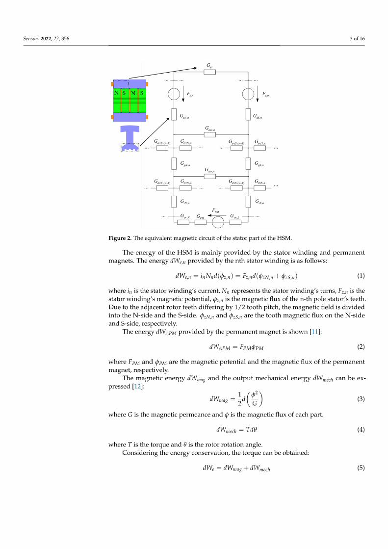
Figure 2. The equivalent magnetic circuit of the stator part of the HSM.
The energy of the HSM is mainly provided by the stator winding and permanentmagnets. The energy dWe,n provided by the nth stator winding is as follows:
dWe,n = inNnd(φz,n) = Fz,nd(φzN,n + φzS,n) (1)
where in is the stator winding’s current, Nn represents the stator winding’s turns, Fz,n is thestator winding’s magnetic potential, φz,n is the magnetic flux of the n-th pole stator’s teeth.Due to the adjacent rotor teeth differing by 1/2 tooth pitch, the magnetic field is dividedinto the N-side and the S-side. φzN,n and φzS,n are the tooth magnetic flux on the N-sideand S-side, respectively.
The energy dWe,PM provided by the permanent magnet is shown [11]:
dWe,PM = FPMφPM (2)
where FPM and φPM are the magnetic potential and the magnetic flux of the permanentmagnet, respectively.
The magnetic energy dWmag and the output mechanical energy dWmech can be ex-pressed [12]:
dWmag =12
d(
φ2
G
)(3)
where G is the magnetic permeance and φ is the magnetic flux of each part.
dWmech = Tdθ (4)
where T is the torque and θ is the rotor rotation angle.Considering the energy conservation, the torque can be obtained:
dWe = dWmag + dWmech (5)

Sensors 2022, 22, 356 4 of 16
T = ddθ (We,n + We,PM)− d
dθ
(Wmag
)= d
dθ
{12∑
n=1[Fz,n(φzN,n + φzS,n)] + FPMφPM
}− 1
2ddθ
[12∑
n=1(
φ2yz,n
Gyz,n+
φ2zN,n
GzN,n+
φ2zS,n
GzS,n+
φ2axz,n
Gaxz,n+
φ2σzN,n
GσzN,n+
φ2σzS,n
GσzS,n+
φ2gN,n
GgN,n+
φ2gS,n
GgS,n
+φ2
axr,nGaxr,n
+φ2
σrN,nGσrN,n
+φ2
σrS,nGσrS,n
+φ2
rN,nGrN,n
+φ2
rS,nGrS,n
+φ2
yr,NGyr,N
+φ2
yr,SGyr,S
)
]− 1
2ddθ
(φ2
PMGPM
)(6)
where φvz is the stator’s axial yoke’s magnetic flux, and φaxz and φaxr represent the statorand rotor’s axial tooth’s leakage magnetic flux, respectively. φδzN,n and φδzS,n are the N-side and S-side’s stator radial inter-tooth’s leakage flux, φgN,n and φgN,n are the N-sideand S-side’s air gap’s magnetic flux, φδrN,n and φδrS,n are the N-side and S-side’s rotor’sradial inter-tooth’s leakage flux, φrN,n and φrS,n are the N-side and S-side’s rotor’s radialinter-tooth’s magnetic flux, and φvr,N and φvr,S are the N-side and S-side’s rotor’s axialyoke’s magnetic flux.
In the actual optimization process, a slight change in the tooth structure has a greatimpact on the air gap’s magnetic field density. At the same time, the local magneticsaturation of HSMs must be considered. Therefore, the magnetic circuit method and FEMare often combined in the design of motors to improve the accuracy of the calculationresults with regard to the torque-angle characteristics.
3. FEM Model of 3P-HSM
Due to its very complex EM structure and the large number of non-linear materialsused in the motor, combined with the very small step angle, conventional methods, suchas the equivalent magnetic circuit method, are unable to obtain highly accurate results forthe analysis and calculation of HSMs. In recent years, designers have attempted to utilize3D models to calculate the characteristic of motors [17,18]. Compared with other methods,FEM is better suited to the analysis and design of HSMs.
Figures 3 and 4 illustrate 3D models of the initial 3P-HSM and FEM mesh around therotor teeth of the motor. The number of turns of the stator winding was 62. The magneticdensity of the motor when 1.9A DC was applied to one-phase winding is shown in Figure 5.For HSMs, the tooth layer structure, which directly affects the tooth shape, is one of themain factors that determine the performance of the motor. In the calculations, high densitymeshes were used in the areas close to the iron small teeth; this, of course, significantlyincreased the computation time in the 3D-FEM calculation, in line with the findings givenin [19]. In order to effectively utilize the results obtained from the 3D-FEM, the optimizationof HSMs relies on the Taguchi optimization method, and this was also used in the authors’research. The process will be presented in detail in the next section.
Figure 3. The 3D model of initial 3P-HSM: (a) 3D model of the 3P-HSM with 12 slots; (b) axialsectional view of the motor.

Sensors 2022, 22, 356 5 of 16
Figure 4. The FEM mesh around the rotor teeth of the motor.
Figure 5. The magnetic flux density of single-phase winding energized with direct current.
The main calculated parameters of the 3P-HSMs are listed in Tables 1 and 2. For HSMs,the tooth geometry is closely related with motor performance, and thus, was naturallyselected for optimization.
In the past decades, researchers put forward different opinions about the tooth shape,such as it being rectangular, triangular, circular, and so on [20–22]. Among them, the rect-angular tooth shape shown in Figure 6 has been widely used in many products. However,according to practical experience, the trapezoidal tooth shape, as shown in Figure 7, is muchbetter than the rectangular one, because this tooth profile contains more shape parametersand allows more degrees of freedom for optimization, making it easier to achieve therequired motor performance.
Table 1. Main parameters of HSMs.
Parameters Values
Stator poles 12Small teeth stator pole 4
Rotor layers 4Small teeth per rotor layer 50
Permanent magnets 3
Table 2. Geography of teeth for 3P-HSMs.
Model Tooth Geometry
Initial 3P-HSM RectangularTHD-min 3P-HSM Trapezoidal

Sensors 2022, 22, 356 6 of 16
Figure 6. The rectangular teeth.
Figure 7. The trapezoidal teeth.
4. Optimization of 3P-HSM
In order to efficiently optimize HSMs with complex EM structures, an optimizationapproach combining FEM and the Taguchi optimization method was developed.
4.1. Taguchi Optimization Method
The Taguchi optimization algorithm, which is adept in the use of discrete results toidentify the optimal point, has been widely used in many areas, e.g., national defense,chemical, and motor applications [23]. The orthogonal array (OA) and the signal-to-noise(S/N) ratio are the main tools used in this method [24–26]. The former was applied todesign representative experiments and shorten the number of required hours. The latterwas used to analyze the factors’ effect and determine the next optimization. Figure 8 showsthe flowchart of the Taguchi optimization method.
The THD-min objective functions for the 3P-HSM can be expressed by
THDmin = min
(√∞
∑n=2
V2n
/V1
)(7)

Sensors 2022, 22, 356 7 of 16
where V1 is the fundamental component of output voltage and Vn represents other har-monic components.
Using the Taguchi method, three formulas can be applied to calculate the S/N ratio:
SNN = 10 log(
y2/s2)
(8)
SNL = −10 log
[(n
∑i=1
1/y2i
)/n
](9)
SNS = −10 log
[(n
∑i=1
y2i
/n
)](10)
where y is the average value of objective functions, s is the standard deviation, n representsthe repeat numbers in each test and yi is the output of the test in the ith repetition.
Equation (10) was adopted in the optimization target (THD-min), but the value of theS/N ratio needed to be maximal.
Figure 8. The flowchart of the Taguchi optimization method.
4.2. The Optimization Target: THD-min
In HSMs, the torque-angle characteristic is generally not sinusoidal and it is evidentlyaffected by harmonics, especially the second ones, which will reduce motor performanceand increase motor noise [27,28]. In this study, it was desired to optimize the tooth geometryin order to reduce the harmonic.
In this paper, the HSM with the original structure is defined as “Initial 3P-HSM”, andthe motor with the optimized structure is denoted as “THD-min”. The optimization processof THD-min 3P-HSM was divided into two stages. The optimization parameters of eachstage are shown in Table 3, and the formulations of S/N adopted in this section are shownas Equations (7) and (10).

Sensors 2022, 22, 356 8 of 16
Table 3. Optimization parameters of THD-min.
Optimization ParametersOptimization Stage
First Stage Second Stage
A rt1/rλ rt/rλB st1/sλ st/sλC rθ rh/rλD sθ sh/sλ
The combinations of signal-to-noise ratios, at different levels, for the four factors(A = rt1/rλ, B = st1/sλ, C = rθ, D = sθ) during the optimization process are shown in Table 4.The effect of each shape factor is reflected in Figure 9. It is clear that except that factor Dhad the least impact, the effect of each tooth shape factor was not significantly different.According to the average value of the S/N ratio, the best factor level combination can bejudged as A1B3C4D3, where A1 = 0.15, B3 = 0.1, C4 = 15, and D3 = 60. After the first stageoptimization, the THD of the THD-min 3P-HSM was reduced from 7.55% to 6.2% of theprototype’s initial 3P-HSM.
Table 4. The simulation results of THD-min 3P-HSM in the first stage.
No.Factor
THD (%) S/NA B C D
1 1 1 1 1 7.36 −17.342 1 2 2 2 7.10 −17.033 1 3 3 3 7.50 −17.504 1 4 4 4 7.91 −17.965 2 1 2 3 7.20 −17.156 2 2 1 4 7.30 −17.277 2 3 4 1 7.68 −17.718 2 4 3 2 8.10 −18.179 3 1 3 4 8.60 −18.69
10 3 2 4 3 8.51 −18.6011 3 3 1 2 8.80 −18.8912 3 4 2 1 9.81 −19.8313 4 1 4 2 5.96 −15.5014 4 2 3 1 6.80 −16.6515 4 3 2 4 6.19 −15.8316 4 4 1 3 7.00 −16.90
Figure 9. The main effect diagram of S/N for THD-min in the first stage.

Sensors 2022, 22, 356 9 of 16
In the second stage of optimization, the impact of the parameters from the first stagewas analyzed and the parameters for the new optimization were adjusted, as shownin Table 3. From Table 5 and Figure 10, the simulation results and the influence of theindividual shape factors for the second stage, respectively, can be found. It is clear that Aplayed a decisive role in the THD values, which were generally smaller when A was atlevel 4. The best combination of factor levels for the second stage was A4B1C4D2, whereA4 = 0.45, B1 = 0.55, C4 = 0.2, and D2 = 0.6. Furthermore, the THD for the best combinationof factor levels decreased from 6.2% to 5.96% in the first stage. Clearly, the second stagewas relatively weak and, thus, the optimization was over at this stage.
Table 5. The simulation results of THD-min 3P-HSM in the second stage.
No.Factor
THD (%) S/NA B C D
1 1 1 1 1 6.54 −16.312 1 2 2 2 6.56 −16.343 1 3 3 3 6.20 −15.854 1 4 4 4 6.84 −16.705 2 1 2 3 6.80 −16.656 2 2 1 4 6.66 −16.477 2 3 4 1 6.20 −15.858 2 4 3 2 7.20 −17.159 3 1 3 4 7.00 −16.90
10 3 2 4 3 6.25 −15.9211 3 3 1 2 7.43 −17.4212 3 4 2 1 6.44 −16.1813 4 1 4 2 6.56 −16.3414 4 2 3 1 7.66 −17.6815 4 3 2 4 6.48 −16.2316 4 4 1 3 7.56 −17.57
Figure 10. The main effect diagram of S/N for THD-min in the second stage.
4.3. Tooth Geometry after Optimization and FE Results
As the EM structure of HSM is very complicated, the traditional equivalent magneticcircuit method and other analytical methods could not accurately calculate its torque,and thus, a 3D FE model had to be used to calculate the torque-angle characteristics ofthe HSMs.
In the optimization process, discrete data on the magnetic potential of the motors wereobtained with FEM, which was then used to calculate the EM torque of the motor. In thecalculation, the torque was obtained using the energy method. This was due to the factthat the energy method was able to use the global results of the FE to calculate the torque
Sensors 2022, 22, 356 10 of 16
with a high degree of accuracy. The formula for calculating the EM torque using the energymethod is as follows:
T =dW(θ, i)
dθ(11)
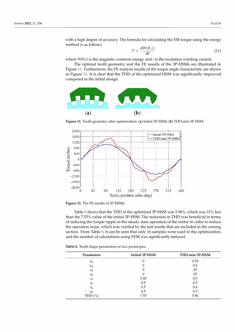
where W(θ,i) is the magnetic common energy and i is the excitation winding current.The optimal tooth geometry and the FE results of the 3P-HSMs are illustrated in
Figure 11. Furthermore, the FE analysis results of the torque angle characteristic are shownin Figure 12. It is clear that the THD of the optimized HSM was significantly improvedcompared to the initial design.
Figure 11. Tooth geometry after optimization: (a) initial 3P-HSM; (b) THD-min 3P-HSM.
Figure 12. The FE results of 3P-HSMs.
Table 6 shows that the THD of the optimized 3P-HSM was 5.96%, which was 21% lessthan the 7.55% value of the initial 3P-HSM. The reduction in THD was beneficial in termsof reducing the torque ripple in the steady state operation of the motor in order to reducethe operation noise, which was verified by the test results that are included in the comingsection. From Table 5, it can be seen that only 16 samples were used in the optimization,and the number of calculations using FEM was significantly reduced.
Table 6. Tooth shape parameters of two prototypes.
Parameters Initial 3P-HSM THD-min 3P-HSM
rt1 0 0.35st1 0 0.4rθ 0 25sθ 0 35rt 0.45 0.5st 0.5 0.5rh 0.5 0.4sh 0.5 0.5
THD (%) 7.55 5.96
Sensors 2022, 22, 356 11 of 16
5. Motor Noise Test
For a 3P-HSM, due to its unique multi antipole structure, the high-order harmonictorque ripples are difficult to measure directly. However, the motor noise caused by torqueripple can be obtained by means of a noise test, which can be used to analyze the torqueripple of the motor [29,30].
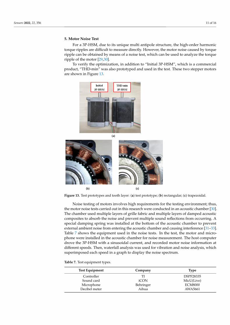
To verify the optimization, in addition to “Initial 3P-HSM”, which is a commercialproduct, “THD-min” was also prototyped and used in the test. These two stepper motorsare shown in Figure 13.
Figure 13. Test prototypes and tooth layer: (a) test prototype; (b) rectangular; (c) trapezoidal.
Noise testing of motors involves high requirements for the testing environment; thus,the motor noise tests carried out in this research were conducted in an acoustic chamber [30].The chamber used multiple layers of grille fabric and multiple layers of damped acousticcomposites to absorb the noise and prevent multiple sound reflections from occurring. Aspecial damping spring was installed at the bottom of the acoustic chamber to preventexternal ambient noise from entering the acoustic chamber and causing interference [31–33].Table 7 shows the equipment used in the noise tests. In the test, the motor and micro-phone were installed in the acoustic chamber for noise measurement. The host computerdrove the 3P-HSM with a sinusoidal current, and recorded motor noise information atdifferent speeds. Then, waterfall analysis was used for vibration and noise analysis, whichsuperimposed each speed in a graph to display the noise spectrum.
Table 7. Test equipment types.
Test Equipment Company Type
Controller TI DSPF28335Sound card iCON MicU(Live)Microphone Behringer ECM8000
Decibel meter Aihua AWA5661

Sensors 2022, 22, 356 12 of 16
The experimental system is shown in Figure 14.
Figure 14. The experimental noise system: (a) outside of the testing system; (b) inside of theacoustic chamber.
During the test, the noise information of the motor was collected by the host computerand the Fast Fourier Transform (FFT) analysis was used to obtain the noise spectrum of themotor. Figure 15 shows the complete noise spectrum under the sinusoidal drive current of3P-HSM, including the low-frequency harmonic part (ellipse-1) and the chopping frequencypart (ellipse-2).
Figure 15. Complete noise waterfall: (a) initial 3P-HSM; (b) THD-min 3P-HSM.
Sensors 2022, 22, 356 13 of 16
From Figure 15, it can be found that the noise amplitude of THD-min 3P-HSM wassignificantly reduced, which shows that the reduction in THD caused a significant improve-ment in motor noise. Furthermore, the noises near the ordinate axis were chaotic, whichwas related to the working environment and the internal friction of 3P-HSM and will notbe discussed here.
The noise frequency linked with the motor drive current is:
fi = i × p × n60
(12)
where fi is the ith order harmonic frequency component of the drive current, n is themotor’s synchronous speed, and p is the number of pole pairs of 3P-HSM. Therefore, thefundamental frequency of the drive current generating EM noise can be calculated
f1 = 1 × 50 × 40060
= 333Hz (13)
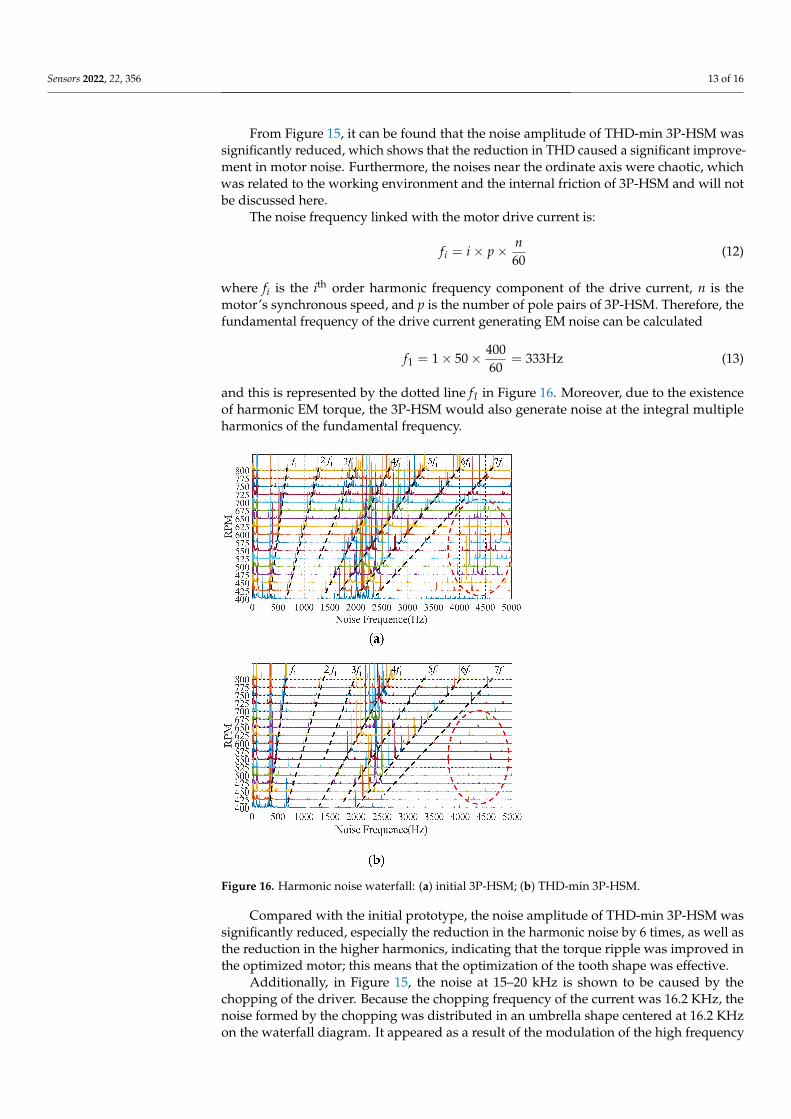
and this is represented by the dotted line f1 in Figure 16. Moreover, due to the existenceof harmonic EM torque, the 3P-HSM would also generate noise at the integral multipleharmonics of the fundamental frequency.
Figure 16. Harmonic noise waterfall: (a) initial 3P-HSM; (b) THD-min 3P-HSM.
Compared with the initial prototype, the noise amplitude of THD-min 3P-HSM wassignificantly reduced, especially the reduction in the harmonic noise by 6 times, as well asthe reduction in the higher harmonics, indicating that the torque ripple was improved inthe optimized motor; this means that the optimization of the tooth shape was effective.
Additionally, in Figure 15, the noise at 15–20 kHz is shown to be caused by thechopping of the driver. Because the chopping frequency of the current was 16.2 KHz, thenoise formed by the chopping was distributed in an umbrella shape centered at 16.2 KHzon the waterfall diagram. It appeared as a result of the modulation of the high frequency
Sensors 2022, 22, 356 14 of 16
carrier signal and the low frequency modulating wave signal and was not related to thetooth shape of the motor; thus, it is not discussed in detail here.
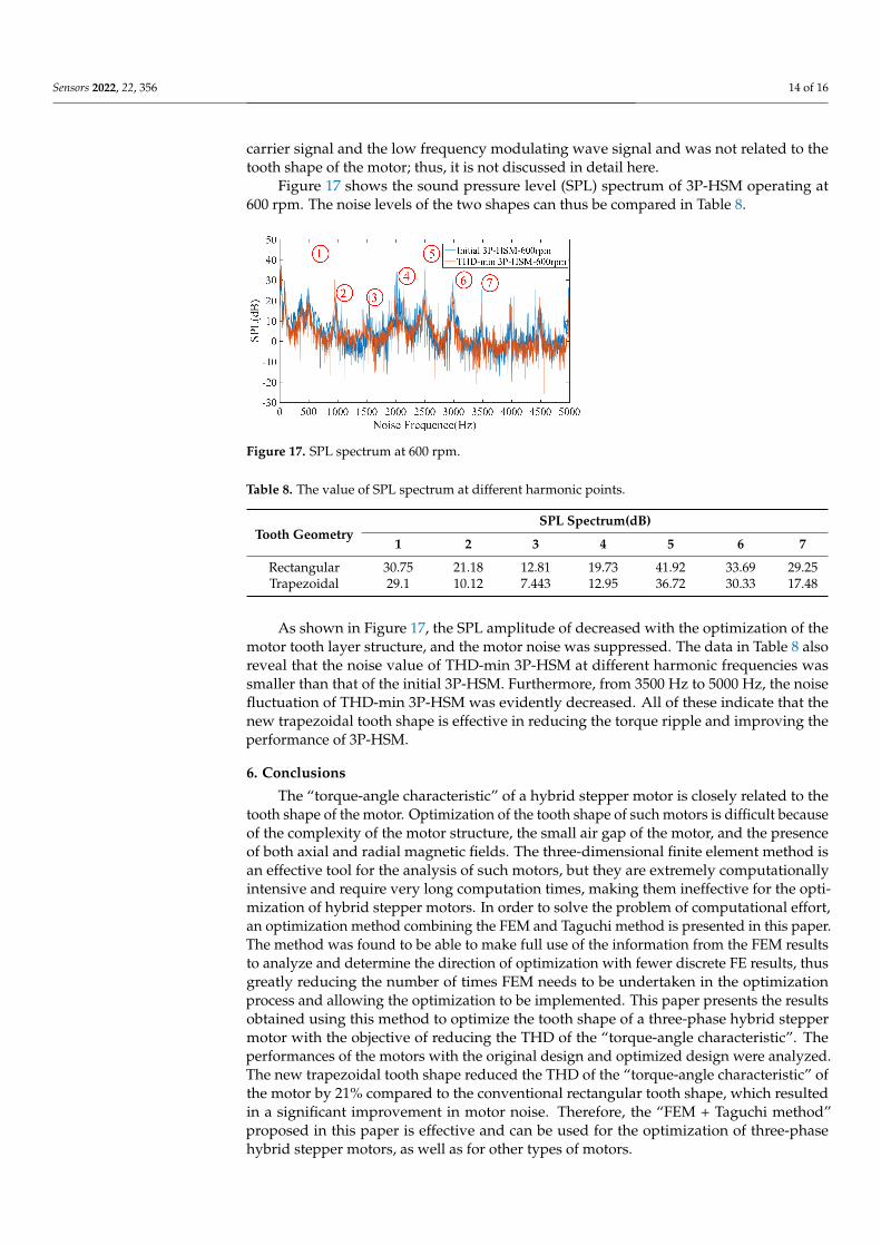
Figure 17 shows the sound pressure level (SPL) spectrum of 3P-HSM operating at600 rpm. The noise levels of the two shapes can thus be compared in Table 8.
Figure 17. SPL spectrum at 600 rpm.
Table 8. The value of SPL spectrum at different harmonic points.
Tooth GeometrySPL Spectrum(dB)
1 2 3 4 5 6 7
Rectangular 30.75 21.18 12.81 19.73 41.92 33.69 29.25Trapezoidal 29.1 10.12 7.443 12.95 36.72 30.33 17.48
As shown in Figure 17, the SPL amplitude of decreased with the optimization of themotor tooth layer structure, and the motor noise was suppressed. The data in Table 8 alsoreveal that the noise value of THD-min 3P-HSM at different harmonic frequencies wassmaller than that of the initial 3P-HSM. Furthermore, from 3500 Hz to 5000 Hz, the noisefluctuation of THD-min 3P-HSM was evidently decreased. All of these indicate that thenew trapezoidal tooth shape is effective in reducing the torque ripple and improving theperformance of 3P-HSM.
6. Conclusions
The “torque-angle characteristic” of a hybrid stepper motor is closely related to thetooth shape of the motor. Optimization of the tooth shape of such motors is difficult becauseof the complexity of the motor structure, the small air gap of the motor, and the presenceof both axial and radial magnetic fields. The three-dimensional finite element method isan effective tool for the analysis of such motors, but they are extremely computationallyintensive and require very long computation times, making them ineffective for the opti-mization of hybrid stepper motors. In order to solve the problem of computational effort,an optimization method combining the FEM and Taguchi method is presented in this paper.The method was found to be able to make full use of the information from the FEM resultsto analyze and determine the direction of optimization with fewer discrete FE results, thusgreatly reducing the number of times FEM needs to be undertaken in the optimizationprocess and allowing the optimization to be implemented. This paper presents the resultsobtained using this method to optimize the tooth shape of a three-phase hybrid steppermotor with the objective of reducing the THD of the “torque-angle characteristic”. Theperformances of the motors with the original design and optimized design were analyzed.The new trapezoidal tooth shape reduced the THD of the “torque-angle characteristic” ofthe motor by 21% compared to the conventional rectangular tooth shape, which resultedin a significant improvement in motor noise. Therefore, the “FEM + Taguchi method”proposed in this paper is effective and can be used for the optimization of three-phasehybrid stepper motors, as well as for other types of motors.
Sensors 2022, 22, 356 15 of 16
Author Contributions: All authors have made significant contributions to this manuscript. Concep-tualization, Z.P.; Data curation, L.F.; Formal analysis, L.X.; Investigation, Z.P.; Methodology, L.X.;Resources, C.B.; Validation, Z.P.; Writing—original draft, Z.P.; Writing—review and editing, C.B.All authors have read and agreed to the published version of the manuscript.
Funding: This research received no external funding.
Institutional Review Board Statement: Not applicable.
Informed Consent Statement: Not applicable.
Data Availability Statement: Not applicable.
Acknowledgments: We acknowledge the support and the use of the facilities and equipment pro-vided by the China Fortior Technology (Shenzhen)Co., Ltd.
Conflicts of Interest: The authors declare no conflict of interest.
References1. Peng, Z.; Bi, C. Analysis of Drive Mode on Torque and Noise of Stepper Motor. Micromotors 2019, 52, 27–31. (In Chinese)2. Lin, S.; Bi, C.; Jiang, Q. Analysis of acoustic noise sources of FDB and ADB spindle motors operating at BLDC mode. In Proceedings
of the 2008 4th IET Conference on Power Electronics, Machines and Drives, York, UK, 2–4 April 2008; pp. 315–319. [CrossRef]3. Simon-Sempere, V.; Simon-Gomez, A.; Burgos-Payan, M.; Cerquides-Bueno, J.-R. Optimisation of Magnet Shape for Cogging
Torque Reduction in Axial-Flux Permanent-Magnet Motors. IEEE Trans. Energy Convers. 2021, 36, 2825–2838. [CrossRef]4. Wang, N.; Peng, X.; Kong, L. Optimum Design of a Composite Optical Receiver by Taguchi and Fuzzy Logic Methods. Microma-
chines 2021, 12, 1434. [CrossRef] [PubMed]5. Peng, Z.; Bi, C.; Yao, K.; Fang, L. Reducing acoustic noise of 3-phase hybrid stepper motor with drive mode. Electr. Eng. 2021, 1–9.
[CrossRef]6. Cvetkovski, G.; Petkovska, L. Cogging Torque Minimisation of PM Synchronous Motor Using Nature Based Algorithms. In
Proceedings of the 2021 IEEE 19th International Power Electronics and Motion Control Conference (PEMC), Gliwice, Poland,25–29 April 2021; pp. 419–425.
7. Lin, S.; Jiang, Q.; Mamun, A.; Bi, C. Effect of drive modes on the acoustic noise of fluid dynamic bearing spindle motors. IEEETrans. Magn. 2003, 39, 3277–3279. [CrossRef]
8. Li, T.; Kou, Z.; Wu, J.; Yahya, W.; Villecco, F. Multipoint Optimal Minimum Entropy Deconvolution Adjusted for Automatic FaultDiagnosis of Hoist Bearing. Shock. Vib. 2021, 2021, 6614633. [CrossRef]
9. de Assis, L.F.; Filho, C.-C.L.; de Paula, G.T.; de Alvarenga, B.P. Comparative Analysis of Different Methods Associated to the FrozenPermeability Method for On-Load Cogging Torque Evaluation in Permanent Magnet Synchronous Machines. In Proceedings ofthe IEEE Latin America Transactions, February 2021; Volume 19, pp. 199–207. Available online: https://ieeexplore.ieee.org/document/9443061 (accessed on 2 January 2022). [CrossRef]
10. Oswald, A.; Herzog, H.G. Investigation of the usability of 2D- and 3D-FEM for a hybrid stepper motor. In Proceedings of the2009 IEEE International Electric Machines and Drives Conference, Miami, FL, USA, 3–6 May 2009; pp. 535–542.
11. Kang, S.G.; Lieu, D.K. Torque analysis of combined 2D FEM and lumped parameter method for a hybrid stepping motor.In Proceedings of the IEEE International Conference on Electric Machines and Drives, San Antonio, TX, USA, 15 May 2005;pp. 1199–1203.
12. Stuebig, C.; Ponick, B. Determination of air gap permeances of hybrid stepping motors for calculation of motor behaviour.In Proceedings of the 2008 18th International Conference on Electrical Machines, Vilamoura, Portugal, 6–9 September 2008;pp. 1–5.
13. Kuert, C.; Jufer, M.; Perriard, Y. New method for dynamic modeling of hybrid stepping motors. In Proceedings of the ConferenceRecord of the 2002 IEEE Industry Applications Conference. 37th IAS Annual Meeting (Cat. No.02CH37344), Pittsburgh, PA, USA,13–18 October 2002; Volume 1, pp. 6–12.
14. Praveen, R.P.; Ravichandran, M.; Achari, V.T.S.; Raj, V.P.J.; Madhu, G.; Bindu, G. Design and finite element analysis of hybridstepper motor for spacecraft applications. In Proceedings of the 2009 IEEE International Electric Machines and Drives Conference,Miami, FL, USA, 3–6 May 2009; pp. 1051–1057.
15. Salvati, L.; D’Amore, M.; Fiorentino, A.; Pellegrino, A.; Sena, P.; Villecco, F. On-Road Detection of Driver Fatigue and Drowsinessduring Medium-Distance Journeys. Entropy 2021, 23, 135. [CrossRef] [PubMed]
16. Sakamoto, M.; Tozune, A. High torque 2 phase hybrid type stepping motor. In Proceedings of the 2005 International Conferenceon Electrical Machines and Systems, Nanjing, China, 27–29 September 2005; Volume 1, pp. 630–634. Available online: https://ieeexplore.ieee.org/abstract/document/1574839 (accessed on 2 January 2022). [CrossRef]
17. Ionica, I.; Modreanu, M.; Morega, A.; Boboc, C. Design and modeling of a hybrid stepper motor. In Proceedings of the 201710th International Symposium on Advanced Topics in Electrical Engineering (ATEE), Bucharest, Romania, 23–25 March 2017;pp. 192–195.
Sensors 2022, 22, 356 16 of 16
18. Rajagopal, K.; Singh, B. Optimal tooth-geometry for specific performance requirements of a hybrid stepper motor. IEEE Trans.Magn. 2003, 39, 3010–3012. [CrossRef]
19. Xiao, L.; Bi, C. Optimization of Absolute Variable Reluctance Resolver with Taguchi and FEM. In Proceedings of the 2019 22ndInternational Conference on Electrical Machines and Systems (ICEMS), Harbin, China, 11–14 August 2019; pp. 1–6.
20. Tanabe, I. Development of a Tool for the Easy Determination of Control Factor Interaction in the Design of Experiments and theTaguchi Methods. In Proceedings of the 2017 International Conference on Control, Artificial Intelligence, Robotics & Optimization(ICCAIRO), Prague, Czech Republic, 20–22 May 2017; pp. 301–306.
21. Mahardika, M.; Setyawan, M.A.; Sriani, T.; Miki, N.; Prihandana, G.S. Electropolishing Parametric Optimization of SurfaceQuality for the Fabrication of a Titanium Microchannel Using the Taguchi Method. Machines 2021, 9, 325. [CrossRef]
22. Ragab, T.I.M.; Alminderej, F.M.; El-Sayed, W.A.; Saleh, S.M.; Shalaby, A.S.G. Enhanced Optimization of Bioethanol Productionfrom Palm Waste Using the Taguchi Method. Sustainability 2021, 13, 13660. [CrossRef]
23. Fujikawa, S. Optimum parameter design using the Taguchi method for Finite-element analysis of 3D forging deformation. J. Jpn.Soc. Technol. Plast. 1999, 40, 1061–1065. (In Japanese)
24. Pindoriya, R.M.; Rajpurohit, B.S.; Kumar, R. A Novel Application of Harmonics Spread Spectrum Technique for Acoustic Noiseand Vibration Reduction of PMSM Drive. IEEE Access 2020, 8, 103273–103284. [CrossRef]
25. Tang, M.; Odhano, S.; Formentini, A.; Zanchetta, P. Reuse of a Damaged Permanent Magnet Synchronous Motor for TorqueRipple and Acoustic Noise Elimination Using a Novel Repetitive Observer. IEEE Trans. Ind. Appl. 2020, 56, 3790–3798. [CrossRef]
26. Tang, X.; Zhang, D.; Liu, T.; Khajepour, A.; Yu, H.; Wang, H. Research on the energy control of a dual-motor hybrid vehicle duringengine start-stop process. Energy 2019, 166, 1181–1193. [CrossRef]
27. Qin, Y.; Tang, X.; Jia, T.; Duan, Z.; Zhang, J.; Li, Y.; Zheng, L. Noise and vibration suppression in hybrid electric vehicles: State ofthe art and challenges. Renew. Sustain. Energy Rev. 2020, 124, 109782. [CrossRef]
28. Bi, C.; Phyu, H.N.; Jiang, Q. Unbalanced magnetic pull induced by leading wires of permanent magnet synchronous motor.In Proceedings of the 2009 International Conference on Electrical Machines and Systems, Tokyo, Japan, 15–18 November 2009.
29. Huang, S.; Aydin, M.; Lipo, T. Electromagnetic vibration and noise assessment for surface mounted PM machines. In Proceedingsof the 2001 Power Engineering Society Summer Meeting, Vancouver, BC, Canada, 15–19 July 2001; Volume 3, pp. 1417–1426.
30. Vijayraghavan, P.; Krishnan, R. Noise in electric machines: A review. In Proceedings of the IEEE Transactions on IndustryApplications, September–October 1999; Volume 35, pp. 1007–1013. Available online: https://ieeexplore.ieee.org/abstract/document/793360 (accessed on 2 January 2022). [CrossRef]
31. Kangning, C.U.I.; Shenbo, Y.U.; Rutong, D.O.U.; Pengpeng, X.I.A. Reduction Method of Torque Ripple and Vibration and Noiseof Permanent Magnet Synchronous Motor. Micromotors 2020, 53, 11–16.
32. Pindoriya, R.M.; Gautam, G.; Rajpurohit, B.S. A Novel Application of Pseudorandom-Based Technique for Acoustic Noise andVibration Reduction of PMSM Drive. IEEE Trans. Ind. Appl. 2020, 56, 5511–5522. [CrossRef]
33. Chen, L.; Yan, Z.; Liu, X. Control Motor; Xidian Univ. Press: Xi’an, China, 2013. (In Chinese)