Fuzzy and neural controllers for a pneumatic actuator
13
International Journal of Computers, Communications & Control Vol. II (2007), No. 4, pp. 375-387 Fuzzy and Neural Controllers for a Pneumatic Actuator Tiberiu Vesselenyi, Simona Dzi¸ tac, Ioan Dzi¸ tac, Mi¸ su-Jan Manolescu Abstract: There is a great diversity of ways to use fuzzy inference in robot con- trol systems, either in the place where it is applied in the control scheme or in the form or type of inference algorithms used. On the other hand, artificial neural net- works ability to simulate nonlinear systems is used in different researches in order to develop automated control systems of industrial processes. In these applications of neural networks, there are two important steps: system identification (development of neural process model) and development of control (definition of neural control structure). In this paper we present some modelling applications, which uses fuzzy and neural controllers, developed on a pneumatic actuator containing a force and a position sensor, which can be used for robotic grinding operations. Following the simulation one of the algorithms was tested on an experimental setup. The paper also presents the development of a NARMA-L2 neural controller for a pneumatic actua- tor using position feedback. The structure had been trained and validated, obtaining good results. Keywords: fuzzy control, neural control, force-position feedback, pneumatic actua- tor. 1 Introduction There is a great diversity in which fuzzy inference and neural networks can be used in robotics operation control either in the place it has in the control scheme or in the type of fuzzy or neural controller. From the studied references the conclusion can be drawn that fuzzy inference is used (among others) in trajectory generation [3], robot model design [2], instead of P.I.D. controllers [4] or in combination with these [6]. A detailed presentation of general purpose fuzzy controllers is given in [5]. In the same work, it is shown that there can be made fuzzy controllers similar to classical ones (quasi - P.I.D.). In other researches the importance of parameter adjustment is emphasized and also that fuzzy controllers can be adjusted more easily [6]. Due to the fact that a large part of fuzzy inference systems had been implemented on heuristic basis (usually the membership functions are chosen upon the educated guess of specialists) there is no guarantee of a reliable operation or stability of the system in unforeseen conditions. Due to this, experimental tests must be considered. A great number of researches in this field have as goal the development of methodologies of synthesis and analysis of fuzzy inference systems, in the field of robotics [2], [4] or in the larger field of control systems [5] (i.e. study of stability of fuzzy controllers). Also there are works regarding the elaboration of fuzzy models of robots (used in direct and inverse kinematics [3] or in inverse dynamics [1], which can replace analytical models, and shorten the comput- ing times. Many researches try a systematic approach of fuzzy systems design (development of a design methodology), which can eliminate the subjectivity in choosing the membership functions and rule sets, as in [2], in which a clear method is presented for a rigorous selection of fuzzy inference parameters. In order to develop a model and test fuzzy and neural control in the design phase an adequate pro- gramming environment must be selected. For this purpose we had chosen the MATLAB programming environment, because it offers predefined functions to develop fuzzy and neural control systems. These functions are linked to extern modules like the "inference system" and the "fuzzy engine", and the SIMULINK module can also use these functions. User applications can be linked to these modules using the predefined functions. The typical base structure of fuzzy systems develop a model which make the correspondence: Copyright © 2006-2007 by CCC Publications
Transcript of Fuzzy and neural controllers for a pneumatic actuator
International Journal of Computers, Communications & ControlVol. II (2007), No. 4, pp. 375-387
Fuzzy and Neural Controllers for a Pneumatic Actuator
Tiberiu Vesselenyi, Simona Dzitac, Ioan Dzitac, Misu-Jan Manolescu
Abstract: There is a great diversity of ways to use fuzzy inference in robot con-trol systems, either in the place where it is applied in the control scheme or in theform or type of inference algorithms used. On the other hand, artificial neural net-works ability to simulate nonlinear systems is used in different researches in order todevelop automated control systems of industrial processes. In these applications ofneural networks, there are two important steps: system identification (developmentof neural process model) and development of control (definition of neural controlstructure). In this paper we present some modelling applications, which uses fuzzyand neural controllers, developed on a pneumatic actuator containing a force and aposition sensor, which can be used for robotic grinding operations. Following thesimulation one of the algorithms was tested on an experimental setup. The paper alsopresents the development of a NARMA-L2 neural controller for a pneumatic actua-tor using position feedback. The structure had been trained and validated, obtaininggood results.Keywords: fuzzy control, neural control, force-position feedback, pneumatic actua-tor.
1 Introduction
There is a great diversity in which fuzzy inference and neural networks can be used in roboticsoperation control either in the place it has in the control scheme or in the type of fuzzy or neural controller.From the studied references the conclusion can be drawn that fuzzy inference is used (among others) intrajectory generation [3], robot model design [2], instead of P.I.D. controllers [4] or in combination withthese [6]. A detailed presentation of general purpose fuzzy controllers is given in [5]. In the samework, it is shown that there can be made fuzzy controllers similar to classical ones (quasi - P.I.D.). Inother researches the importance of parameter adjustment is emphasized and also that fuzzy controllerscan be adjusted more easily [6]. Due to the fact that a large part of fuzzy inference systems had beenimplemented on heuristic basis (usually the membership functions are chosen upon the educated guess ofspecialists) there is no guarantee of a reliable operation or stability of the system in unforeseen conditions.Due to this, experimental tests must be considered. A great number of researches in this field have asgoal the development of methodologies of synthesis and analysis of fuzzy inference systems, in the fieldof robotics [2], [4] or in the larger field of control systems [5] (i.e. study of stability of fuzzy controllers).
Also there are works regarding the elaboration of fuzzy models of robots (used in direct and inversekinematics [3] or in inverse dynamics [1], which can replace analytical models, and shorten the comput-ing times. Many researches try a systematic approach of fuzzy systems design (development of a designmethodology), which can eliminate the subjectivity in choosing the membership functions and rule sets,as in [2], in which a clear method is presented for a rigorous selection of fuzzy inference parameters.
In order to develop a model and test fuzzy and neural control in the design phase an adequate pro-gramming environment must be selected. For this purpose we had chosen the MATLAB programmingenvironment, because it offers predefined functions to develop fuzzy and neural control systems. Thesefunctions are linked to extern modules like the "inference system" and the "fuzzy engine", and theSIMULINK module can also use these functions. User applications can be linked to these modulesusing the predefined functions.
The typical base structure of fuzzy systems develop a model which make the correspondence:
Copyright © 2006-2007 by CCC Publications
376 Tiberiu Vesselenyi, Simona Dzitac, Ioan Dzitac, Misu-Jan Manolescu
• crisp value - input membership functions - inference rules -
• output characteristics - output membership functions - crisp output value.
Also, a typical fuzzy inference system, supposes a user defined set of parameters which try to en-crypt the model’s variables characteristics. If instead the development of a process model is wantedfor which certain experimental input-output data sets exists, the fuzzy system parameters can be auto-matically generated that is the system identification can be done. In this case the identification strategycan be a neural-fuzzy approach, which has at its base acquiring knowledge from the presented data setin order to generate membership function parameters. In the MATLAB environment the adjustment ofthese parameters can be done with a module which works similar to a neural network named ANFIS(Adaptive Neural Fuzzy Inference System). As teaching algorithm error back propagation is used andthe optimization is made by a gradient method, followed by error minimization (by the quadratic summethod).
In [10], a methodology is presented for designing an adaptive fuzzy logic controller. "The neuro-fuzzy controller is first trained using data from an approximate analytical model of a cellular network thenthe controller is fine tuned and adapted to the unique cell dwell time and call holding time distributionsof a particular cell in the network".
The ability of neural networks to simulate non-linear systems, is used in some researches [13], inorder to develop industrial processes control systems. When using neural networks in controlling pro-cesses there have to be two steps: system identification (development of process neural model) andcontrol design (development of neural control system).
In the system identification step, the neural model of the controlled process is developed and inthe second step this model is used to obtain the neural net that will control the process. The trainingof process neural model is made "offline" (or "batch processing"), but the training and optimization ofneural control must be made "online" using training data sets.
A chaos search immune algorithm is proposed in [12] by integrating the chaos optimization algo-rithm and the clonal selection algorithm: "first, optimization variables are expressed by chaotic variablesthrough solution space transformation. Then, taking advantages of the ergodic and stochastic propertiesof chaotic variables, a chaos search is performed in the neighborhoods of high affinity antibodies to ex-ploit local solution space, and the motion of the chaotic variables in their ergodic space is used to explorethe whole solution space. Furthermore, a generalized radial basis function neuro-fuzzy controller [...] isconstructed and designed automatically".
2 Simulation of pneumatic system with fuzzy controller
2.1 General considerations
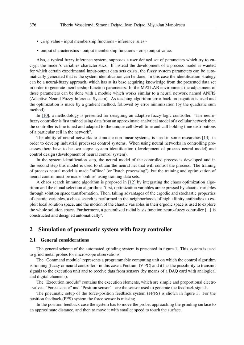
The general scheme of the automated grinding system is presented in figure 1. This system is usedto grind metal probes for microscope observations.
The "Command module" represents a programmable computing unit on which the control algorithmis running (fuzzy or neural controller - in this case a Pentium IV PC) and it has the possibility to transmitsignals to the execution unit and to receive data from sensors (by means of a DAQ card with analogicaland digital channels).
The "Execution module" contains the execution elements, which are simple and proportional electro- valves, "Force sensor" and "Position sensor" - are the sensor used to generate the feedback signals.
The pneumatic setup of the force-position feedback system (FPFS) is shown in figure 3. For theposition feedback (PFS) system the force sensor is missing.
In the position feedback case the system has to move the probe, approaching the grinding surface toan approximate distance, and then to move it with smaller speed to touch the surface.
Fuzzy and Neural Controllers for a Pneumatic Actuator 377
Figure 1: Scheme of automated metal probe grinding system
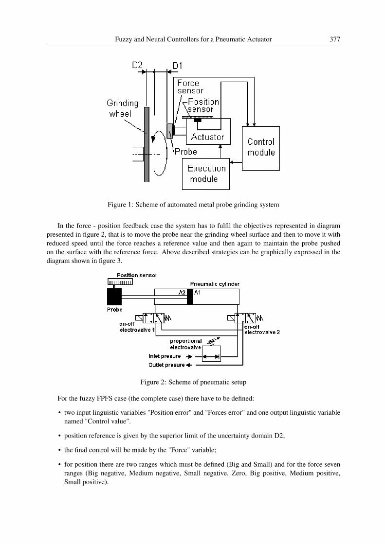
In the force - position feedback case the system has to fulfil the objectives represented in diagrampresented in figure 2, that is to move the probe near the grinding wheel surface and then to move it withreduced speed until the force reaches a reference value and then again to maintain the probe pushedon the surface with the reference force. Above described strategies can be graphically expressed in thediagram shown in figure 3.
Figure 2: Scheme of pneumatic setup
For the fuzzy FPFS case (the complete case) there have to be defined:
• two input linguistic variables "Position error" and "Forces error" and one output linguistic variablenamed "Control value".
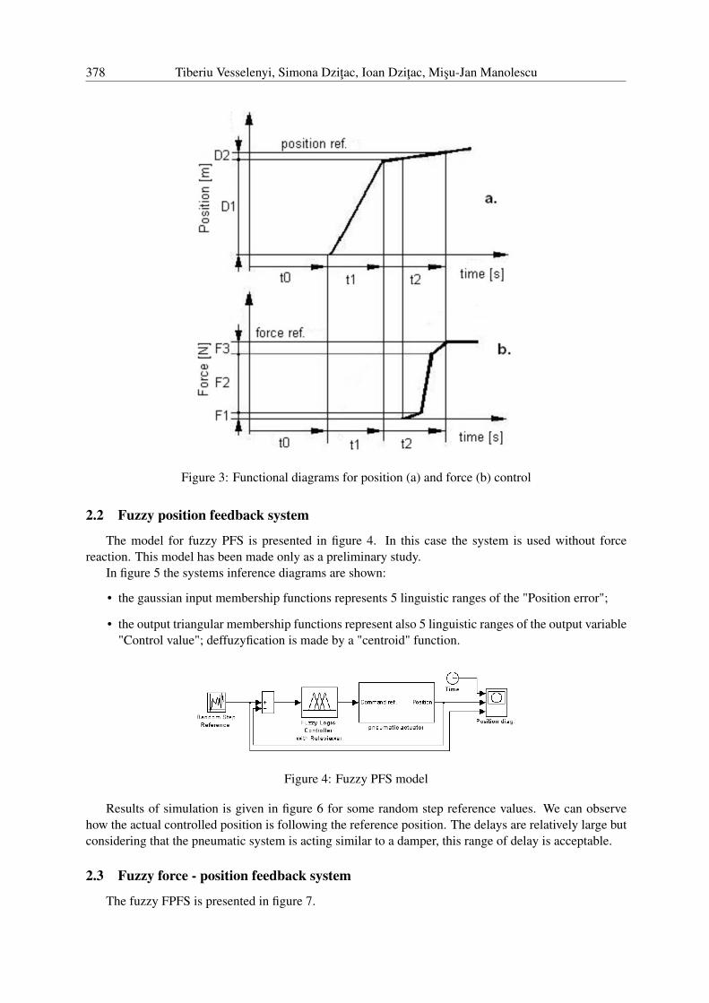
• position reference is given by the superior limit of the uncertainty domain D2;
• the final control will be made by the "Force" variable;
• for position there are two ranges which must be defined (Big and Small) and for the force sevenranges (Big negative, Medium negative, Small negative, Zero, Big positive, Medium positive,Small positive).
378 Tiberiu Vesselenyi, Simona Dzitac, Ioan Dzitac, Misu-Jan Manolescu
Figure 3: Functional diagrams for position (a) and force (b) control
2.2 Fuzzy position feedback system
The model for fuzzy PFS is presented in figure 4. In this case the system is used without forcereaction. This model has been made only as a preliminary study.
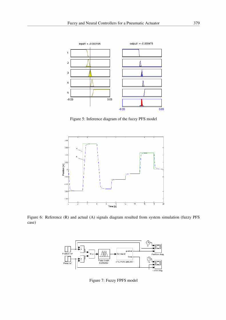
In figure 5 the systems inference diagrams are shown:
• the gaussian input membership functions represents 5 linguistic ranges of the "Position error";
• the output triangular membership functions represent also 5 linguistic ranges of the output variable"Control value"; deffuzyfication is made by a "centroid" function.
Figure 4: Fuzzy PFS model
Results of simulation is given in figure 6 for some random step reference values. We can observehow the actual controlled position is following the reference position. The delays are relatively large butconsidering that the pneumatic system is acting similar to a damper, this range of delay is acceptable.
2.3 Fuzzy force - position feedback system
The fuzzy FPFS is presented in figure 7.
Fuzzy and Neural Controllers for a Pneumatic Actuator 379
Figure 5: Inference diagram of the fuzzy PFS model
Figure 6: Reference (R) and actual (A) signals diagram resulted from system simulation (fuzzy PFScase)
Figure 7: Fuzzy FPFS model
380 Tiberiu Vesselenyi, Simona Dzitac, Ioan Dzitac, Misu-Jan Manolescu
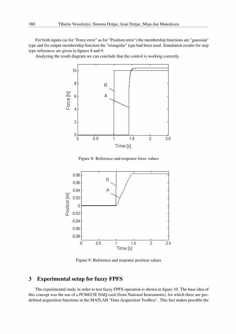
For both inputs (as for "Force error" as for "Position error") the membership functions are "gaussian"type and for output membership function the "triangular" type had been used. Simulation results for steptype references are given in figures 8 and 9.
Analyzing the result diagram we can conclude that the control is working correctly.
Figure 8: Reference and response force values
Figure 9: Reference and response position values
3 Experimental setup for fuzzy FPFS
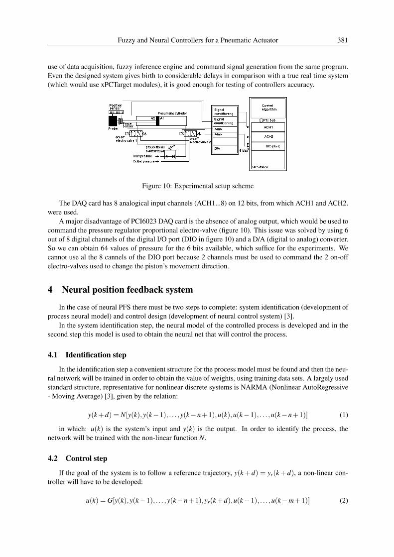
The experimental study in order to test fuzzy FPFS operation is shown in figure 10. The base idea ofthis concept was the use of a PCI6023E DAQ card (from National Instruments), for which there are pre-defined acquisition functions in the MATLAB "Data Acquisition Toolbox". This fact makes possible the
Fuzzy and Neural Controllers for a Pneumatic Actuator 381
use of data acquisition, fuzzy inference engine and command signal generation from the same program.Even the designed system gives birth to considerable delays in comparison with a true real time system(which would use xPCTarget modules), it is good enough for testing of controllers accuracy.
Figure 10: Experimental setup scheme
The DAQ card has 8 analogical input channels (ACH1...8) on 12 bits, from which ACH1 and ACH2.were used.
A major disadvantage of PCI6023 DAQ card is the absence of analog output, which would be used tocommand the pressure regulator proportional electro-valve (figure 10). This issue was solved by using 6out of 8 digital channels of the digital I/O port (DIO in figure 10) and a D/A (digital to analog) converter.So we can obtain 64 values of pressure for the 6 bits available, which suffice for the experiments. Wecannot use al the 8 cannels of the DIO port because 2 channels must be used to command the 2 on-offelectro-valves used to change the piston’s movement direction.
4 Neural position feedback system
In the case of neural PFS there must be two steps to complete: system identification (development ofprocess neural model) and control design (development of neural control system) [3].
In the system identification step, the neural model of the controlled process is developed and in thesecond step this model is used to obtain the neural net that will control the process.
4.1 Identification step
In the identification step a convenient structure for the process model must be found and then the neu-ral network will be trained in order to obtain the value of weights, using training data sets. A largely usedstandard structure, representative for nonlinear discrete systems is NARMA (Nonlinear AutoRegressive- Moving Average) [3], given by the relation:
y(k +d) = N[y(k),y(k−1), . . . ,y(k−n+1),u(k),u(k−1), . . . ,u(k−n+1)] (1)
in which: u(k) is the system’s input and y(k) is the output. In order to identify the process, thenetwork will be trained with the non-linear function N.
4.2 Control step
If the goal of the system is to follow a reference trajectory, y(k + d) = yr(k + d), a non-linear con-troller will have to be developed:
u(k) = G[y(k),y(k−1), . . . ,y(k−n+1),yr(k +d),u(k−1), . . . ,u(k−m+1)] (2)
382 Tiberiu Vesselenyi, Simona Dzitac, Ioan Dzitac, Misu-Jan Manolescu
In order to generate the function G, which minimizes the quadratic mean error, a dynamic back-propagation learning algorithm should be used which is hard to implement and very slow. That is thereason why some approximate models are usually used.
Such an approximate model is given by relation:
y(k +d) = f [y(k),y(k−1), . . . ,y(k−n+1),u(k−1), . . . ,u(k−m+1)] (3)
+g[y(k),y(k−1), . . . ,y(k−n+1),u(k−1), . . . ,u(k−m+1)] ·u(k)
This model is in a form in which the input u(k) is not contained in the non-linear term and ify(k +d) = yr(k +d), it can then be written that:
u(k) =yr(k +d)− f [y(k),y(k−1), . . . ,y(k−n+1),u(k−1), . . . ,u(k−n+1)]
g[y(k),y(k−1), . . . ,y(k−n+1),u(k−1), . . . ,u(k−n+1)](4)
In this form it is necessary to find the input values u(k), based on the output in the same step y(k),which is inconvenient and is better to use the form:
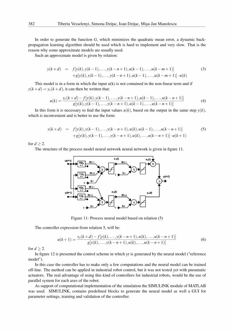
y(k +d) = f [y(k),y(k−1), . . . ,y(k−n+1),u(k),u(k−1), . . . ,u(k−n+1)] (5)
+g[y(k),y(k−1), . . . ,y(k−n+1),u(k), . . . ,u(k−n+1)] ·u(k +1)
for d ≥ 2.The structure of the process model neural network neural network is given in figure 11.
Figure 11: Process neural model based on relation (5)
The controller expression from relation 5, will be:
u(k +1) =yr(k +d)− f [y(k), . . . ,y(k−n+1),u(k), . . . ,u(k−n+1)]
g[y(k), . . . ,y(k−n+1),u(k), . . . ,u(k−n+1)](6)
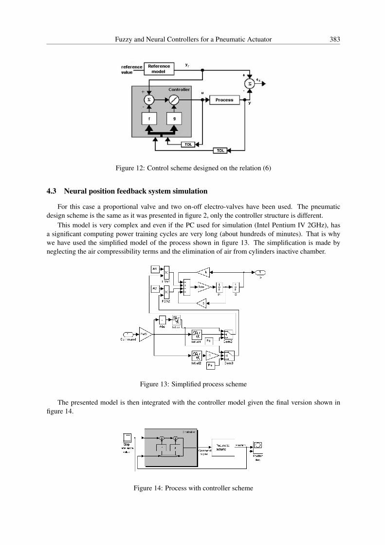
for d ≥ 2.In figure 12 is presented the control scheme in which yr is generated by the neural model ("reference
model").In this case the controller has to make only a few computations and the neural model can be trained
off-line. The method can be applied in industrial robot control, but it was not tested yet with pneumaticactuators. The real advantage of using this kind of controllers for industrial robots, would be the use ofparallel system for each axes of the robot.
As support of computational implementation of the simulation the SIMULINK module of MATLABwas used. SIMULINK, contains predefined blocks to generate the neural model as well a GUI forparameter settings, training and validation of the controller.
Fuzzy and Neural Controllers for a Pneumatic Actuator 383
Figure 12: Control scheme designed on the relation (6)
4.3 Neural position feedback system simulation
For this case a proportional valve and two on-off electro-valves have been used. The pneumaticdesign scheme is the same as it was presented in figure 2, only the controller structure is different.
This model is very complex and even if the PC used for simulation (Intel Pentium IV 2GHz), hasa significant computing power training cycles are very long (about hundreds of minutes). That is whywe have used the simplified model of the process shown in figure 13. The simplification is made byneglecting the air compressibility terms and the elimination of air from cylinders inactive chamber.
Figure 13: Simplified process scheme
The presented model is then integrated with the controller model given the final version shown infigure 14.
Figure 14: Process with controller scheme
384 Tiberiu Vesselenyi, Simona Dzitac, Ioan Dzitac, Misu-Jan Manolescu
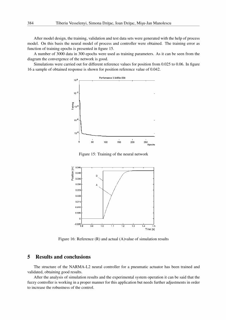
After model design, the training, validation and test data sets were generated with the help of processmodel. On this basis the neural model of process and controller were obtained. The training error asfunction of training epochs is presented in figure 15.
A number of 3000 data in 300 epochs were used as training parameters. As it can be seen from thediagram the convergence of the network is good.
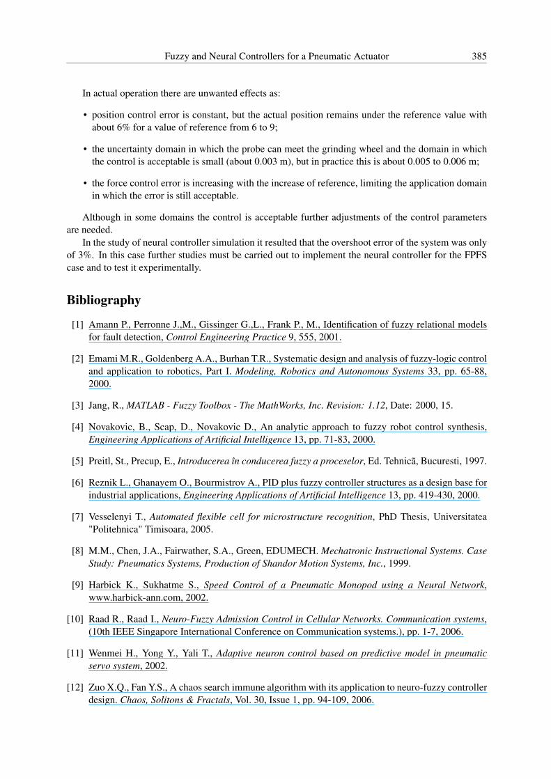
Simulations were carried out for different reference values for position from 0.025 to 0.06. In figure16 a sample of obtained response is shown for position reference value of 0.042.
Figure 15: Training of the neural network
Figure 16: Reference (R) and actual (A)value of simulation results
5 Results and conclusions
The structure of the NARMA-L2 neural controller for a pneumatic actuator has been trained andvalidated, obtaining good results.
After the analysis of simulation results and the experimental system operation it can be said that thefuzzy controller is working in a proper manner for this application but needs further adjustments in orderto increase the robustness of the control.
Fuzzy and Neural Controllers for a Pneumatic Actuator 385
In actual operation there are unwanted effects as:
• position control error is constant, but the actual position remains under the reference value withabout 6% for a value of reference from 6 to 9;
• the uncertainty domain in which the probe can meet the grinding wheel and the domain in whichthe control is acceptable is small (about 0.003 m), but in practice this is about 0.005 to 0.006 m;
• the force control error is increasing with the increase of reference, limiting the application domainin which the error is still acceptable.
Although in some domains the control is acceptable further adjustments of the control parametersare needed.
In the study of neural controller simulation it resulted that the overshoot error of the system was onlyof 3%. In this case further studies must be carried out to implement the neural controller for the FPFScase and to test it experimentally.
Bibliography
[1] Amann P., Perronne J.,M., Gissinger G.,L., Frank P., M., Identification of fuzzy relational modelsfor fault detection, Control Engineering Practice 9, 555, 2001.
[2] Emami M.R., Goldenberg A.A., Burhan T.R., Systematic design and analysis of fuzzy-logic controland application to robotics, Part I. Modeling, Robotics and Autonomous Systems 33, pp. 65-88,2000.
[3] Jang, R., MATLAB - Fuzzy Toolbox - The MathWorks, Inc. Revision: 1.12, Date: 2000, 15.
[4] Novakovic, B., Scap, D., Novakovic D., An analytic approach to fuzzy robot control synthesis,Engineering Applications of Artificial Intelligence 13, pp. 71-83, 2000.
[5] Preitl, St., Precup, E., Introducerea în conducerea fuzzy a proceselor, Ed. Tehnicã, Bucuresti, 1997.
[6] Reznik L., Ghanayem O., Bourmistrov A., PID plus fuzzy controller structures as a design base forindustrial applications, Engineering Applications of Artificial Intelligence 13, pp. 419-430, 2000.
[7] Vesselenyi T., Automated flexible cell for microstructure recognition, PhD Thesis, Universitatea"Politehnica" Timisoara, 2005.
[8] M.M., Chen, J.A., Fairwather, S.A., Green, EDUMECH. Mechatronic Instructional Systems. CaseStudy: Pneumatics Systems, Production of Shandor Motion Systems, Inc., 1999.
[9] Harbick K., Sukhatme S., Speed Control of a Pneumatic Monopod using a Neural Network,www.harbick-ann.com, 2002.
[10] Raad R., Raad I., Neuro-Fuzzy Admission Control in Cellular Networks. Communication systems,(10th IEEE Singapore International Conference on Communication systems.), pp. 1-7, 2006.
[11] Wenmei H., Yong Y., Yali T., Adaptive neuron control based on predictive model in pneumaticservo system, 2002.
[12] Zuo X.Q., Fan Y.S., A chaos search immune algorithm with its application to neuro-fuzzy controllerdesign. Chaos, Solitons & Fractals, Vol. 30, Issue 1, pp. 94-109, 2006.

386 Tiberiu Vesselenyi, Simona Dzitac, Ioan Dzitac, Misu-Jan Manolescu
[13] Zhang J., Knoll A., Schmidt R., A neuro-fuzzy control model for fine-positioning of manipulators,Robotics and Autonomous Systems, 32, pp. 101-113, 2000.
Tiberiu VesselenyiUniversity of Oradea
Universitatii St. 1, 410087, Oradea, [email protected]
Simona DzitacUniversity of Oradea
Universitatii St. 1, 410087, Oradea, [email protected]
Ioan DzitacDepartment of Economic Informatics
Agora University of OradeaPiata Tineretului 8, Oradea 410526, Romania
Misu-Jan ManolescuAgora University
Piata Tineretului 8, 410526 Oradea, [email protected]
Received: February, 14, 2007
Fuzzy and Neural Controllers for a Pneumatic Actuator 387
Tiberiu Vesselenyi was born in Oradea, Romania in 1957, he fin-ished the University "Politehnica" from Timisoara in 1983. From1983 to 1991 he worked at a machine building company in Oradeaas designer and CNC programmer. From 1991 till 1994 he was aresearch engineer at the "Geothermal Energy Research Center" inOradea and from 1994 till today is assoc. prof. at the UniversityOf Oradea, where he teaches robot and CNC programming. Hehad earned a PhD in robotics at the University "Politehnica" atTimisoara. He had published over 150 papers in national and in-ternational conferences and journals, and is author or coo - authorof 4 books.
Simona Dzitac received B.Sc. (2000) and M. Sc. (2001) inMathematics-Physics, B.Sc. (2005) and M. Sc. (2007) in EnergyEngineering from University of Oradea and B.Sc. in EconomicInformatics (2007) from University of Craiova, Romania. At thismoment, she is PhD student in Energy Engineering field and re-searcher at University of Oradea. Her current research interestsinclude Reliability, Applied Mathematics and Computer Sciencein Engineering fields. She published 4 books and 38 scientificpapers in journals and conferences proceedings.
Ioan Dzitac received M. Sc. in Mathematics (1977) and Ph.D in Information Sc. (2002) from "Babes-Bolyai" Universityof Cluj-Napoca. At this moment, he is associate professor andhead of Economic Informatics Department at AGORA Univer-sity, Oradea, Romania. His current research interests includedifferent aspects of Parallel and Distributed Computing, AppliedMathematics and Economic Informatics. He has edited 4 con-ference proceedings, published 12 books and 47 scientific papersin journals and conferences proceedings. He was member of theProgram Committee of 18 international conferences.
Misu-Jan Manolescu received M. Sc in Electro-mechanics(1984) from the University of Craiova, Ph. D in Microwave(1994) from the University of Oradea, and Ph. D in HumanResources Management (2000) from the University of Craiova.Now, he is professor and president of AGORA University,Oradea, Romania. His current research interests include differentaspects of Knowledge Management, and Knowledge Engineer-ing. He has edited 4 conference proceedings, published 9 booksand 63 scientific papers in journals and conferences proceedings.He has been member of Program Committee of the 5 internationalconferences.