PSM Series Motorized Slide Potentiometer - Mouser Electronics
6
3 T 1' 1 2 2' 3' N 1.2 ± 0.05 (.047 ± .002) 3.75 ± 0.1 (.148 ± .004) 11.25 ± 0.1 (.443 ± .004) 1.5 +0/-0.1 (.059 +0/-.004) 2.0 (.079) 1.2 (.047) DIA. HOLES 6.3 (.248) 6.3 (.248) 2.0 (.079) DIA. 2 PLCS. 1.0 (.039) 1.5 (.059) 2.0 (.079) 4.0 (.157) 23.8 (.937) 35.0 (1.378) 13.2 (.520) 12.4 (.488) B (-) A (+) 38.7 (1.524) 71.0 (2.795) 81.0 (3.189) 82.35 (3.242) 120.0 ± 0.5 (4.724 ± .020) 100.0 ± 1.0 (3.937 ± .039) TRAVEL 0.50 (.020) M3 x 2 PLCS. 8.2 ± 0.5 (.323 ± .020) 82.5 ± 0.1 (3.248 ± .039) 38.8 ± 0.1 (1.528 ± .039) 127.5 ± 0.1 (5.020 ± .039) 15.8 ± 0.5 (.622 ± .020) 43.7 (1.720) 8.0 (.315) 14.5 (.571) 18.5 (.728) 13.0 (.512) 9.0 (.354) 6.0 (.236) 2.0 +0.2/-0 (.079 +.008/-0) DIA. HOLES 2 PLCS. DIRECTION OF LEVER DIA. HOLES 7 PLCS. 1.5 +0.2/-0 (.059 +.008/-0) N TERMINAL DETAIL 1.00 (.039) 2.1 (.083) 3.75 (.148) 2.2 (.087) 3.5 (.138) Features n Long life carbon element n Assortment of resistance tapers n 60 and 100 mm travel lengths n Touch sense lever n PC terminals or snap-in connector option PSM Series Motorized Slide Potentiometer *RoHS Directive 2015/863, Mar 31, 2015 and Annex. Specifications are subject to change without notice. Users should verify actual device performance in their specific applications. The products described herein and this document are subject to specific legal disclaimers as set forth on the last page of this document, and at www.bourns.com/docs/legal/disclaimer.pdf. Electrical Characteristics Standard Resistance Range ....................... 1K ohms to 1 megohm Standard Resistance Tolerance... ±20 % End Resistance ............... 20 ohms max. Insulation Resistance @ 250 VDC ............................. 100 megohms min. Dielectric Withstanding Voltage .............................................. 250 VAC Standard Taper .................. Linear, Audio Power Rating - Linear................ 0.5 watt Power Rating - Audio .............. 0.25 watt Slider Noise ......................... 47 mV max. Touch Sense Track Conductive Resistance Snap-in Connector......... 2 ohms max. (Mating Connector CH325) PC Terminal TR > 30k ohms...0.1 % of TR max. TR ≤ 30k ohms ........ 30 ohms max. Environmental Characteristics Operational Life .............. 100,000 cycles TR Shift .................................... ±15 % Operating Temperature Range ................................. -10 °C to +55 °C Resistance to Solder Heat............. ±5 % Mechanical Characteristics Mechanical Travel .................... See Product Dimensions Operating Force 100 mm Travel..................... 30-130 gf 60 mm Travel..................... 10-110 gf Stop Strength ......................... 5 kgf min. Shaft Wobble 100 mm Travel......... 1.3 mm p-p max. 60 mm Travel......... 1.6 mm p-p max. Soldering Condition Manual ...........350 °C ±5 °C for 3 sec. Wave ..............260 °C ±5 °C for 5 sec. Wash ..................... Not recommended Motor Drive Characteristics Rated Voltage .............................10 VDC Operating Voltage Supply .. 6 to 11 VDC Starting Current .................800 mA max. Lever Speed @ 10 VDC ................................... 20 mm/0.1 sec. Product Dimensions PC Terminals - 100 mm Travel Mounting Hole Detail DIMENSIONS: MM (INCHES) WARNING Cancer and Reproductive Harm www.P65Warnings.ca.gov
-
Upload
khangminh22 -
Category
Documents
-
view
3 -
download
0
Transcript of PSM Series Motorized Slide Potentiometer - Mouser Electronics
B=+13
Motor
3
3'
3
1
1'
2'
2
1
A=+
T
B - +
A + -
OR
3T
1'12
2'1'12
2'3'
3T
3'
N
1.2 ± 0.05(.047 ± .002)
3.75 ± 0.1(.148 ± .004)11.25 ± 0.1
(.443 ± .004)
1.5 +0/-0.1(.059 +0/-.004)
2.0(.079)
1.2(.047) DIA. HOLES
3.75 ± 0.1(.148 ± .004)11.25 ± 0.1
(.443 ± .004)
6.3(.248)
6.3(.248)
2.0(.079)
DIA. 2 PLCS.
1.0(.039)
1.5(.059)
2.0(.079)
4.0(.157)
23.8(.937)
35.0(1.378)
13.2(.520)
12.4(.488)
B(-)
A(+)
38.7(1.524)
71.0(2.795)
81.0(3.189)
82.35(3.242)
120.0 ± 0.5(4.724 ± .020)
100.0 ± 1.0(3.937 ± .039)
TRAVEL
0.50(.020)
M3 x
2 PLCS.
8.2 ± 0.5(.323 ± .020)
82.5 ± 0.1(3.248 ± .039)
38.8 ± 0.1(1.528 ± .039)
127.5 ± 0.1(5.020 ± .039)
15.8 ± 0.5(.622 ± .020)
51.7 ± 0.1(2.035 ± .039)
87.5 ± 0.1(3.445 ± .039)
43.7(1.720)
8.0(.315)
14.5(.571)
18.5(.728)
13.0(.512)
9.0(.354)
6.0(.236)
2.0 +0.2/-0(.079 +.008/-0)DIA. HOLES 2 PLCS.
2.0 +0.2/-0(.079 +.008/-0)DIA. HOLES 2 PLCS.
DIRECTIONOF LEVERDIRECTION
OF LEVER
DIA. HOLES 7 PLCS.1.5 +0.2/-0
(.059 +.008/-0)DIA. HOLES 7 PLCS.1.5 +0.2/-0
(.059 +.008/-0)
N
TERMINAL DETAIL
1.00(.039)
2.1(.083)
3.75(.148)
2.2(.087)
3.5(.138)
51.0(2.008)
25.6(1.008)
51.2(2.016)
61.0(2.402)
9.0(.354) 80.0 ± 0.5
(3.150 ± .020)13.0
(.512)
6.0(.236)
0.5(.020)
M3 x
2 PLCS.
12.4(.488)
B(-)
A(+)
2.0(.079)
4.0(.157)
60.0 ± 1.0(2.362 ± .039)
TRAVEL
8.0(.315)
14.5(.571)
18.5(.728)
35.0(1.378)
23.8(.937)
8.2 ± 0.5(.323 ± .020)
Featuresn Longlifecarbonelementn Assortmentofresistancetapersn 60and100mmtravellengthsn Touchsenselevern PCterminalsorsnap-inconnectoroption
PSM Series Motorized Slide Potentiometer
*RoHSDirective2015/863,Mar31,2015andAnnex.Specificationsaresubjecttochangewithoutnotice.Usersshouldverifyactualdeviceperformanceintheirspecificapplications.Theproductsdescribedhereinandthisdocumentaresubjecttospecificlegaldisclaimersassetforthonthelastpageofthisdocument,andatwww.bourns.com/docs/legal/disclaimer.pdf.
Electrical CharacteristicsStandard Resistance Range ....................... 1K ohms to 1 megohmStandard Resistance Tolerance ... ±20 %End Resistance ............... 20 ohms max.Insulation Resistance @ 250 VDC ............................. 100 megohms min.Dielectric Withstanding Voltage ..............................................250 VACStandard Taper .................. Linear, AudioPower Rating - Linear ................0.5 wattPower Rating - Audio ..............0.25 wattSlider Noise .........................47 mV max.Touch Sense Track Conductive Resistance Snap-in Connector ......... 2 ohms max. (Mating Connector CH325) PC Terminal TR > 30k ohms ...0.1 % of TR max. TR ≤ 30k ohms ........ 30 ohms max.
Environmental CharacteristicsOperational Life ..............100,000 cycles TR Shift .................................... ±15 %Operating Temperature Range ................................. -10 °C to +55 °CResistance to Solder Heat ............. ±5 %
Mechanical CharacteristicsMechanical Travel .................... See Product DimensionsOperating Force 100 mm Travel ..................... 30-130 gf 60 mm Travel ..................... 10-110 gfStop Strength ......................... 5 kgf min.Shaft Wobble 100 mm Travel ......... 1.3 mm p-p max. 60 mm Travel ......... 1.6 mm p-p max.Soldering Condition Manual ...........350 °C ±5 °C for 3 sec. Wave ..............260 °C ±5 °C for 5 sec. Wash .....................Not recommended
Motor Drive CharacteristicsRated Voltage .............................10 VDCOperating Voltage Supply .. 6 to 11 VDCStarting Current .................800 mA max.Lever Speed @ 10 VDC ...................................20 mm/0.1 sec.
Product Dimensions
PC Terminals - 100 mm Travel
Mounting Hole Detail
DIMENSIONS: MM (INCHES)
WARNING Cancer and Reproductive Harm www.P65Warnings.ca.gov
B=+13
Motor
3
3'
3
1
1'
2'
2
1
A=+
T
B - +
A + -
OR
3T
1'12
2'1'12
2'3'
3T
3'
N
1.2 ± 0.05(.047 ± .002)
3.75 ± 0.1(.148 ± .004)11.25 ± 0.1
(.443 ± .004)
1.5 +0/-0.1(.059 +0/-.004)
2.0(.079)
1.2(.047) DIA. HOLES
3.75 ± 0.1(.148 ± .004)11.25 ± 0.1
(.443 ± .004)
6.3(.248)
6.3(.248)
2.0(.079)
DIA. 2 PLCS.
1.0(.039)
1.5(.059)
2.0(.079)
4.0(.157)
23.8(.937)
35.0(1.378)
13.2(.520)
12.4(.488)
B(-)
A(+)
38.7(1.524)
71.0(2.795)
81.0(3.189)
82.35(3.242)
120.0 ± 0.5(4.724 ± .020)
100.0 ± 1.0(3.937 ± .039)
TRAVEL
0.50(.020)
M3 x
2 PLCS.
8.2 ± 0.5(.323 ± .020)
82.5 ± 0.1(3.248 ± .039)
38.8 ± 0.1(1.528 ± .039)
127.5 ± 0.1(5.020 ± .039)
15.8 ± 0.5(.622 ± .020)
51.7 ± 0.1(2.035 ± .039)
87.5 ± 0.1(3.445 ± .039)
43.7(1.720)
8.0(.315)
14.5(.571)
18.5(.728)
13.0(.512)
9.0(.354)
6.0(.236)
2.0 +0.2/-0(.079 +.008/-0)DIA. HOLES 2 PLCS.
2.0 +0.2/-0(.079 +.008/-0)DIA. HOLES 2 PLCS.
DIRECTIONOF LEVERDIRECTION
OF LEVER
DIA. HOLES 7 PLCS.1.5 +0.2/-0
(.059 +.008/-0)DIA. HOLES 7 PLCS.1.5 +0.2/-0
(.059 +.008/-0)
N
TERMINAL DETAIL
1.00(.039)
2.1(.083)
3.75(.148)
2.2(.087)
3.5(.138)
51.0(2.008)
25.6(1.008)
51.2(2.016)
61.0(2.402)
9.0(.354) 80.0 ± 0.5
(3.150 ± .020)13.0
(.512)
6.0(.236)
0.5(.020)
M3 x
2 PLCS.
12.4(.488)
B(-)
A(+)
2.0(.079)
4.0(.157)
60.0 ± 1.0(2.362 ± .039)
TRAVEL
8.0(.315)
14.5(.571)
18.5(.728)
35.0(1.378)
23.8(.937)
8.2 ± 0.5(.323 ± .020)
Specificationsaresubjecttochangewithoutnotice.Usersshouldverifyactualdeviceperformanceintheirspecificapplications.Theproductsdescribedhereinandthisdocumentaresubjecttospecificlegaldisclaimersassetforthonthelastpageofthisdocument,andatwww.bourns.com/docs/legal/disclaimer.pdf.
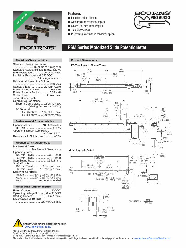
PSM Series Motorized Slide Potentiometer
Product Dimensions
Snap-in Connector - 100 mm Travel
Applicationsn Audiomixingconsolesn Broadcastmixingconsoles
B=+13
Motor
3
3'
3
1
1'
2'
2
1
A=+
T
B - +
A + -
OR
3T
1'12
2'1'12
2'3'
3T
3'
N
1.2 ± 0.05(.047 ± .002)
3.75 ± 0.1(.148 ± .004)11.25 ± 0.1
(.443 ± .004)
1.5 +0/-0.1(.059 +0/-.004)
2.0(.079)
1.2(.047) DIA. HOLES
3.75 ± 0.1(.148 ± .004)11.25 ± 0.1
(.443 ± .004)
6.3(.248)
6.3(.248)
2.0(.079)
DIA. 2 PLCS.
1.0(.039)
1.5(.059)
2.0(.079)
4.0(.157)
23.8(.937)
35.0(1.378)
13.2(.520)
12.4(.488)
B(-)
A(+)
38.7(1.524)
71.0(2.795)
81.0(3.189)
82.35(3.242)
120.0 ± 0.5(4.724 ± .020)
100.0 ± 1.0(3.937 ± .039)
TRAVEL
0.50(.020)
M3 x
2 PLCS.
8.2 ± 0.5(.323 ± .020)
82.5 ± 0.1(3.248 ± .039)
38.8 ± 0.1(1.528 ± .039)
127.5 ± 0.1(5.020 ± .039)
15.8 ± 0.5(.622 ± .020)
51.7 ± 0.1(2.035 ± .039)
87.5 ± 0.1(3.445 ± .039)
43.7(1.720)
8.0(.315)
14.5(.571)
18.5(.728)
13.0(.512)
9.0(.354)
6.0(.236)
2.0 +0.2/-0(.079 +.008/-0)DIA. HOLES 2 PLCS.
2.0 +0.2/-0(.079 +.008/-0)DIA. HOLES 2 PLCS.
DIRECTIONOF LEVERDIRECTION
OF LEVER
DIA. HOLES 7 PLCS.1.5 +0.2/-0
(.059 +.008/-0)DIA. HOLES 7 PLCS.1.5 +0.2/-0
(.059 +.008/-0)
N
TERMINAL DETAIL
1.00(.039)
2.1(.083)
3.75(.148)
2.2(.087)
3.5(.138)
51.0(2.008)
25.6(1.008)
51.2(2.016)
61.0(2.402)
9.0(.354) 80.0 ± 0.5
(3.150 ± .020)13.0
(.512)
6.0(.236)
0.5(.020)
M3 x
2 PLCS.
12.4(.488)
B(-)
A(+)
2.0(.079)
4.0(.157)
60.0 ± 1.0(2.362 ± .039)
TRAVEL
8.0(.315)
14.5(.571)
18.5(.728)
35.0(1.378)
23.8(.937)
8.2 ± 0.5(.323 ± .020)
PC Terminals - 60 mm Travel
DIMENSIONS: MM (INCHES)
B=+ 13
Motor
3
3'
3
1
1'
2'
2
1
A=+
T
Motor
Line Track
Servo Track
Touch Sense Track
B - +
A + -
OR
35.0(1.378)
8.2 ± 0.5(.323 ± .020)
6.3(.248)
13.2(.520)
N
15.8 ± 0.5(.622 ± .020)
B(-)
2'3' T1' 31 2(+)A
71.0(2.795)
81.0(3.189)
9.0(.354)
120.0 ± 0.5(4.724 ± .020)
13.0(.512)
6.0(.236)
2.0(.079)
4.0(.157)
LEAD FREESOLDER M705 2.5 x 7
(.098 x .276)
SHRINK-TUBEF32 (BLACK)
2 PLCS.
CABLEUL 1007 AWG 26
100.0 ± 1.0(3.937 ± .039)
TRAVEL
8.0(.315)
14.5(.571)
18.5(.728)
5.8(.228)
CONNECTOR
Mating Connector CH325
2.5(.098)
2.5(.098)15.0
(.591)
19.95(.785)
7.45(.293)
1.2 ± 0.05(.047 ± .002)
1.5 +0/-0.1(.059 +0/-.004)
6.3(.248)
2.0(.079)DIA.
2 PLCS.
N
51.0(2.008)
61.0(2.402)
0.5(.020)
M3 x 2 PLCS.
9.0(.354) 80.0 ± 0.5
(3.150 ± .020)13.0
(.512)
6.0(.236)
2.0(.079)
4.0(.157)
60.0 ± 1.0(2.362 ± .039)
TRAVEL
8.0(.315)
14.5(.571)
18.5(.728)
35.0(1.378)
8.2 ± 0.5(.323 ± .020)
0.50(.020)
M3 x 2 PLCS.
B=+13
Motor
3
3'
3
1
1'
2'
2
1
A=+
T
B - +
A + -
OR
3T
1'12
2'1'12
2'3'
3T
3'
N
1.2 ± 0.05(.047 ± .002)
3.75 ± 0.1(.148 ± .004)11.25 ± 0.1
(.443 ± .004)
1.5 +0/-0.1(.059 +0/-.004)
2.0(.079)
1.2(.047) DIA. HOLES
3.75 ± 0.1(.148 ± .004)11.25 ± 0.1
(.443 ± .004)
6.3(.248)
6.3(.248)
2.0(.079)
DIA. 2 PLCS.
1.0(.039)
1.5(.059)
2.0(.079)
4.0(.157)
23.8(.937)
35.0(1.378)
13.2(.520)
12.4(.488)
B(-)
A(+)
38.7(1.524)
71.0(2.795)
81.0(3.189)
82.35(3.242)
120.0 ± 0.5(4.724 ± .020)
100.0 ± 1.0(3.937 ± .039)
TRAVEL
0.50(.020)
M3 x
2 PLCS.
8.2 ± 0.5(.323 ± .020)
82.5 ± 0.1(3.248 ± .039)
38.8 ± 0.1(1.528 ± .039)
127.5 ± 0.1(5.020 ± .039)
15.8 ± 0.5(.622 ± .020)
51.7 ± 0.1(2.035 ± .039)
87.5 ± 0.1(3.445 ± .039)
43.7(1.720)
8.0(.315)
14.5(.571)
18.5(.728)
13.0(.512)
9.0(.354)
6.0(.236)
2.0 +0.2/-0(.079 +.008/-0)DIA. HOLES 2 PLCS.
2.0 +0.2/-0(.079 +.008/-0)DIA. HOLES 2 PLCS.
DIRECTIONOF LEVERDIRECTION
OF LEVER
DIA. HOLES 7 PLCS.1.5 +0.2/-0
(.059 +.008/-0)DIA. HOLES 7 PLCS.1.5 +0.2/-0
(.059 +.008/-0)
N
TERMINAL DETAIL
1.00(.039)
2.1(.083)
3.75(.148)
2.2(.087)
3.5(.138)
51.0(2.008)
25.6(1.008)
51.2(2.016)
61.0(2.402)
9.0(.354) 80.0 ± 0.5
(3.150 ± .020)13.0
(.512)
6.0(.236)
0.5(.020)
M3 x
2 PLCS.
12.4(.488)
B(-)
A(+)
2.0(.079)
4.0(.157)
60.0 ± 1.0(2.362 ± .039)
TRAVEL
8.0(.315)
14.5(.571)
18.5(.728)
35.0(1.378)
23.8(.937)
8.2 ± 0.5(.323 ± .020)
Mounting Hole Detail
Motor
3'
3
1'
2'
2
1
T
B - +
A + -
OR
3T
1'12
2'3'
N
1.2 ± 0.05(.047 ± .002)
1.5 +0/-0.1(.059 +0/-.004)
2.0(.079)
1.2(.047) DIA. HOLES
6.3(.248)
6.3(.248)
2.0(.079)
DIA. 2 PLCS.
1.0(.039)
1.5(.059)
2.0(.079)
4.0(.157)
23.8(.937)
35.0(1.378)
13.2(.520)
12.4(.488)
B(-)
A(+)
38.7(1.524)
71.0(2.795)
81.0(3.189)
82.35(3.242)
120.0 ± 0.5(4.724 ± .020)
100.0 ± 1.0(3.937 ± .039)
TRAVEL
8.2 ± 0.5(.323 ± .020)
82.5 ± 0.1(3.248 ± .039)
38.8 ± 0.1(1.528 ± .039)
127.5 ± 0.1(5.020 ± .039)
15.8 ± 0.5(.622 ± .020)
43.7(1.720)
8.0(.315)
14.5(.571)
18.5(.728)
13.0(.512)
9.0(.354)
6.0(.236)
2.0 +0.2/-0(.079 +.008/-0)DIA. HOLES 2 PLCS.
DIA. HOLES 7 PLCS.1.5 +0.2/-0
(.059 +.008/-0)
DIRECTIONOF LEVER
N
A=+ 13
3 1B=+
Specificationsaresubjecttochangewithoutnotice.Usersshouldverifyactualdeviceperformanceintheirspecificapplications.Theproductsdescribedhereinandthisdocumentaresubjecttospecificlegaldisclaimersassetforthonthelastpageofthisdocument,andatwww.bourns.com/docs/legal/disclaimer.pdf.
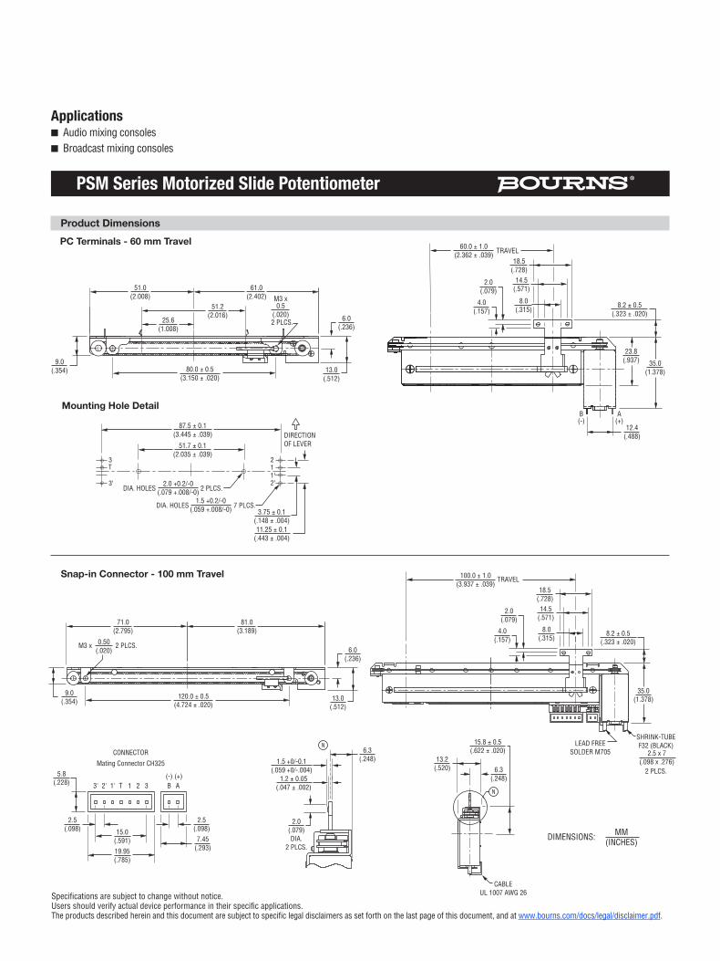
PSM Series Motorized Slide Potentiometer
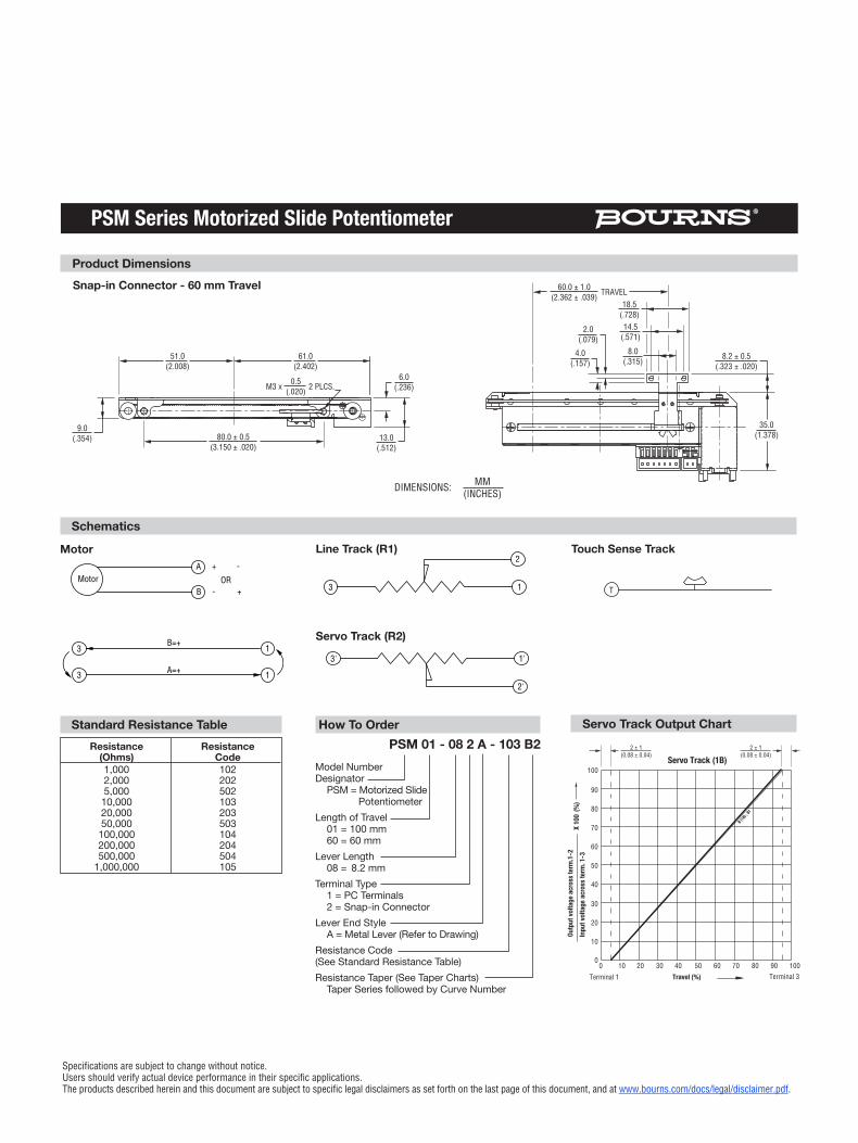
Standard Resistance Table Resistance Resistance (Ohms) Code 1,000 102 2,000 202 5,000 502 10,000 103 20,000 203 50,000 503 100,000 104 200,000 204 500,000 504 1,000,000 105
How To OrderPSM 01 - 08 2 A - 103 B2
Model Number Designator PSM = Motorized Slide PotentiometerLength of Travel 01 = 100 mm 60 = 60 mmLever Length 08 = 8.2 mmTerminal Type 1 = PC Terminals 2 = Snap-in ConnectorLever End Style A = Metal Lever (Refer to Drawing)Resistance Code (See Standard Resistance Table)Resistance Taper (See Taper Charts) Taper Series followed by Curve Number
Motor
3'
3
1'
2'
2
1
T
B - +
A + -
OR
3T
1'12
2'3'
N
1.2 ± 0.05(.047 ± .002)
1.5 +0/-0.1(.059 +0/-.004)
2.0(.079)
1.2(.047) DIA. HOLES
6.3(.248)
6.3(.248)
2.0(.079)
DIA. 2 PLCS.
1.0(.039)
1.5(.059)
2.0(.079)
4.0(.157)
23.8(.937)
35.0(1.378)
13.2(.520)
12.4(.488)
B(-)
A(+)
38.7(1.524)
71.0(2.795)
81.0(3.189)
82.35(3.242)
120.0 ± 0.5(4.724 ± .020)
100.0 ± 1.0(3.937 ± .039)
TRAVEL
8.2 ± 0.5(.323 ± .020)
82.5 ± 0.1(3.248 ± .039)
38.8 ± 0.1(1.528 ± .039)
127.5 ± 0.1(5.020 ± .039)
15.8 ± 0.5(.622 ± .020)
43.7(1.720)
8.0(.315)
14.5(.571)
18.5(.728)
13.0(.512)
9.0(.354)
6.0(.236)
2.0 +0.2/-0(.079 +.008/-0)DIA. HOLES 2 PLCS.
DIA. HOLES 7 PLCS.1.5 +0.2/-0
(.059 +.008/-0)
DIRECTIONOF LEVER
N
A=+ 13
3 1B=+
Schematics
Motor Line Track (R1) Touch Sense Track
Servo Track (R2)
B=+13
Motor
3
3'
3
1
1'
2'
2
1
A=+
T
B - +
A + -
OR
3T
1'12
2'1'12
2'3'
3T
3'
N
1.2 ± 0.05(.047 ± .002)
3.75 ± 0.1(.148 ± .004)11.25 ± 0.1
(.443 ± .004)
1.5 +0/-0.1(.059 +0/-.004)
2.0(.079)
1.2(.047) DIA. HOLES
3.75 ± 0.1(.148 ± .004)11.25 ± 0.1
(.443 ± .004)
6.3(.248)
6.3(.248)
2.0(.079)
DIA. 2 PLCS.
1.0(.039)
1.5(.059)
2.0(.079)
4.0(.157)
23.8(.937)
35.0(1.378)
13.2(.520)
12.4(.488)
B(-)
A(+)
38.7(1.524)
71.0(2.795)
81.0(3.189)
82.35(3.242)
120.0 ± 0.5(4.724 ± .020)
100.0 ± 1.0(3.937 ± .039)
TRAVEL
0.50(.020)
M3 x
2 PLCS.
8.2 ± 0.5(.323 ± .020)
82.5 ± 0.1(3.248 ± .039)
38.8 ± 0.1(1.528 ± .039)
127.5 ± 0.1(5.020 ± .039)
15.8 ± 0.5(.622 ± .020)
51.7 ± 0.1(2.035 ± .039)
87.5 ± 0.1(3.445 ± .039)
43.7(1.720)
8.0(.315)
14.5(.571)
18.5(.728)
13.0(.512)
9.0(.354)
6.0(.236)
2.0 +0.2/-0(.079 +.008/-0)DIA. HOLES 2 PLCS.
2.0 +0.2/-0(.079 +.008/-0)DIA. HOLES 2 PLCS.
DIRECTIONOF LEVERDIRECTION
OF LEVER
DIA. HOLES 7 PLCS.1.5 +0.2/-0
(.059 +.008/-0)DIA. HOLES 7 PLCS.1.5 +0.2/-0
(.059 +.008/-0)
N
TERMINAL DETAIL
1.00(.039)
2.1(.083)
3.75(.148)
2.2(.087)
3.5(.138)
51.0(2.008)
25.6(1.008)
51.2(2.016)
61.0(2.402)
9.0(.354) 80.0 ± 0.5
(3.150 ± .020)13.0
(.512)
6.0(.236)
0.5(.020)
M3 x
2 PLCS.
12.4(.488)
B(-)
A(+)
2.0(.079)
4.0(.157)
60.0 ± 1.0(2.362 ± .039)
TRAVEL
8.0(.315)
14.5(.571)
18.5(.728)
35.0(1.378)
23.8(.937)
8.2 ± 0.5(.323 ± .020)
Motor
3'
3
1'
2'
2
1
T
B - +
A + -
OR
3T
1'12
2'3'
N
1.2 ± 0.05(.047 ± .002)
1.5 +0/-0.1(.059 +0/-.004)
2.0(.079)
1.2(.047) DIA. HOLES
6.3(.248)
6.3(.248)
2.0(.079)
DIA. 2 PLCS.
1.0(.039)
1.5(.059)
2.0(.079)
4.0(.157)
23.8(.937)
35.0(1.378)
13.2(.520)
12.4(.488)
B(-)
A(+)
38.7(1.524)
71.0(2.795)
81.0(3.189)
82.35(3.242)
120.0 ± 0.5(4.724 ± .020)
100.0 ± 1.0(3.937 ± .039)
TRAVEL
8.2 ± 0.5(.323 ± .020)
82.5 ± 0.1(3.248 ± .039)
38.8 ± 0.1(1.528 ± .039)
127.5 ± 0.1(5.020 ± .039)
15.8 ± 0.5(.622 ± .020)
43.7(1.720)
8.0(.315)
14.5(.571)
18.5(.728)
13.0(.512)
9.0(.354)
6.0(.236)
2.0 +0.2/-0(.079 +.008/-0)DIA. HOLES 2 PLCS.
DIA. HOLES 7 PLCS.1.5 +0.2/-0
(.059 +.008/-0)
DIRECTIONOF LEVER
N
A=+ 13
3 1B=+
X 10
0 (%
)In
put v
olta
ge a
cros
s ter
m. 1
-3Ou
tput
volta
ge a
cros
s ter
m.1
-2
Terminal 3
B(1B) ;
B1
Terminal 1 Travel
Servo Track (1B)
(%)0
0
10
20
30
40
50
60
70
80
90
100
10 20 30 40 50 60 70 80 90 100
2 ± 1(0.08 ± 0.04)
2 ± 1(0.08 ± 0.04)
Servo Track Output Chart
DIMENSIONS: MM (INCHES)
Snap-in Connector - 60 mm TravelB=+ 13
Motor
3
3'
3
1
1'
2'
2
1
A=+
T
Motor
Line Track
Servo Track
Touch Sense Track
B - +
A + -
OR
35.0(1.378)
8.2 ± 0.5(.323 ± .020)
6.3(.248)
13.2(.520)
N
15.8 ± 0.5(.622 ± .020)
B(-)
2'3' T1' 31 2(+)A
71.0(2.795)
81.0(3.189)
9.0(.354)
120.0 ± 0.5(4.724 ± .020)
13.0(.512)
6.0(.236)
2.0(.079)
4.0(.157)
LEAD FREESOLDER M705 2.5 x 7
(.098 x .276)
SHRINK-TUBEF32 (BLACK)
2 PLCS.
CABLEUL 1007 AWG 26
100.0 ± 1.0(3.937 ± .039)
TRAVEL
8.0(.315)
14.5(.571)
18.5(.728)
5.8(.228)
CONNECTOR
Mating Connector CH325
2.5(.098)
2.5(.098)15.0
(.591)
19.95(.785)
7.45(.293)
1.2 ± 0.05(.047 ± .002)
1.5 +0/-0.1(.059 +0/-.004)
6.3(.248)
2.0(.079)DIA.
2 PLCS.
N
51.0(2.008)
61.0(2.402)
0.5(.020)
M3 x 2 PLCS.
9.0(.354) 80.0 ± 0.5
(3.150 ± .020)13.0
(.512)
6.0(.236)
2.0(.079)
4.0(.157)
60.0 ± 1.0(2.362 ± .039)
TRAVEL
8.0(.315)
14.5(.571)
18.5(.728)
35.0(1.378)
8.2 ± 0.5(.323 ± .020)
0.50(.020)
M3 x 2 PLCS.
B=+ 13
Motor
3
3'
3
1
1'
2'
2
1
A=+
T
Motor
Line Track
Servo Track
Touch Sense Track
B - +
A + -
OR
35.0(1.378)
8.2 ± 0.5(.323 ± .020)
6.3(.248)
13.2(.520)
N
15.8 ± 0.5(.622 ± .020)
B(-)
2'3' T1' 31 2(+)A
71.0(2.795)
81.0(3.189)
9.0(.354)
120.0 ± 0.5(4.724 ± .020)
13.0(.512)
6.0(.236)
2.0(.079)
4.0(.157)
LEAD FREESOLDER M705 2.5 x 7
(.098 x .276)
SHRINK-TUBEF32 (BLACK)
2 PLCS.
CABLEUL 1007 AWG 26
100.0 ± 1.0(3.937 ± .039)
TRAVEL
8.0(.315)
14.5(.571)
18.5(.728)
5.8(.228)
CONNECTOR
Mating Connector CH325
2.5(.098)
2.5(.098)15.0
(.591)
19.95(.785)
7.45(.293)
1.2 ± 0.05(.047 ± .002)
1.5 +0/-0.1(.059 +0/-.004)
6.3(.248)
2.0(.079)DIA.
2 PLCS.
N
51.0(2.008)
61.0(2.402)
0.5(.020)
M3 x 2 PLCS.
9.0(.354) 80.0 ± 0.5
(3.150 ± .020)13.0
(.512)
6.0(.236)
2.0(.079)
4.0(.157)
60.0 ± 1.0(2.362 ± .039)
TRAVEL
8.0(.315)
14.5(.571)
18.5(.728)
35.0(1.378)
8.2 ± 0.5(.323 ± .020)
0.50(.020)
M3 x 2 PLCS.
Product Dimensions
DIMENSIONS: MM (INCHES)
Specificationsaresubjecttochangewithoutnotice.Usersshouldverifyactualdeviceperformanceintheirspecificapplications.Theproductsdescribedhereinandthisdocumentaresubjecttospecificlegaldisclaimersassetforthonthelastpageofthisdocument,andatwww.bourns.com/docs/legal/disclaimer.pdf.
PSM Series Motorized Slide Potentiometer
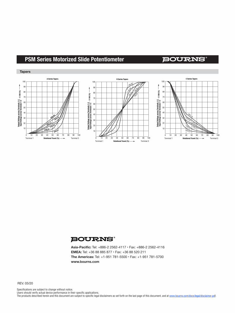
Tapers
0 10
10
20
20
30
30
40
40
50
50
60
60
70
70
80
80
90
90
100
100A Series Tapers
Terminal1
Outp
ut Vo
ltage
acr
oss T
erm
inal
s 1-2
Inpu
t Vol
tage
acr
oss T
erm
inal
s 1-3
X 10
0 (%
)
Terminal3Rotational Travel (%)
(05A);A1(10A);A2(15A);A3(20A);A4
(25A);A5(30A);A6
0 10
10
20
20
30
30
40
40
50
50
60
60
70
70
80
80
90
90
100
100B Series Tapers
Terminal1
Outp
ut Vo
ltage
acr
oss T
erm
inal
s 1-2
Inpu
t Vol
tage
acr
oss T
erm
inal
s 1-3
X 10
0 (%
)
Terminal3Rotational Travel (%)
(4B)
;B4
(3B)
;B3
(2B)
;B2
(1B)
;B1
(5B);B5
0 10
10
20
20
30
30
40
40
50
50
60
60
70
70
80
80
90
90
100
100C Series Tapers
Terminal1
Outp
ut Vo
ltage
acr
oss T
erm
inal
s 1-2
Inpu
t Vol
tage
acr
oss T
erm
inal
s 1-3
X 10
0 (%
)
Terminal3Rotational Travel (%)
(05C);C1
(10C);C2(15C);C3
(20C);C4
(25C);C5
(30C);C6
Asia-Pacific: Tel: +886-2 2562-4117 • Fax: +886-2 2562-4116EMEA: Tel: +36 88 885 877 • Fax: +36 88 520 211The Americas: Tel: +1-951 781-5500 • Fax: +1-951 781-5700www.bourns.com
REV. 03/20
Legal Disclaimer NoticeThis legal disclaimer applies to purchasers and users of Bourns® products manufactured by or on behalf of Bourns, Inc. and its affiliates (collectively, “Bourns”).
Unless otherwise expressly indicated in writing, Bourns® products and data sheets relating thereto are subject to change without notice. Users should check for and obtain the latest relevant information and verify that such information is current and complete before placing orders for Bourns® products.
The characteristics and parameters of a Bourns® product set forth in its data sheet are based on laboratory conditions, and statements regarding the suitability of products for certain types of applications are based on Bourns’ knowledge of typical requirements in generic applications. The characteristics and parameters of a Bourns® product in a user application may vary from the data sheet characteristics and parameters due to (i) the combination of the Bourns® product with other components in the user’s application, or (ii) the environment of the user application itself. The characteristics and parameters of a Bourns® product also can and do vary in different applications and actual performance may vary over time. Users should always verify the actual performance of the Bourns® product in their specific devices and applications, and make their own independent judgments regarding the amount of additional test margin to design into their device or application to compensate for differences between laboratory and real world conditions.
Unless Bourns has explicitly designated an individual Bourns® product as meeting the requirements of a particular industry standard (e.g., ISO/TS 16949) or a particular qualification (e.g., UL listed or recognized), Bourns is not responsible for any failure of an individual Bourns® product to meet the requirements of such industry standard or particular qualification. Users of Bourns® products are responsible for ensuring compliance with safety-related requirements and standards applicable to their devices or applications.
Bourns® products are not recommended, authorized or intended for use in nuclear, lifesaving, life-critical or life-sustaining ap-plications, nor in any other applications where failure or malfunction may result in personal injury, death, or severe property or environmental damage. Unless expressly and specifically approved in writing by two authorized Bourns representatives on a case-by-case basis, use of any Bourns® products in such unauthorized applications might not be safe and thus is at the user’s sole risk. Life-critical applications include devices identified by the U.S. Food and Drug Administration as Class III devices and generally equivalent classifications outside of the United States.
Bourns expressly identifies those Bourns® standard products that are suitable for use in automotive applications on such products’ data sheets in the section entitled “Applications.” Unless expressly and specifically approved in writing by two authorized Bourns representatives on a case-by-case basis, use of any other Bourns® standard products in an automotive application might not be safe and thus is not recommended, authorized or intended and is at the user’s sole risk. If Bourns expressly identifies a sub-category of automotive application in the data sheet for its standard products (such as infotainment or lighting), such identification means that Bourns has reviewed its standard product and has determined that if such Bourns® standard product is considered for potential use in automotive applications, it should only be used in such sub-category of automotive applications. Any reference to Bourns® standard product in the data sheet as compliant with the AEC-Q standard or “automotive grade” does not by itself mean that Bourns has approved such product for use in an automotive application.
Bourns® standard products are not tested to comply with United States Federal Aviation Administration standards generally or any other generally equivalent governmental organization standard applicable to products designed or manufactured for use in aircraft or space applications. Bourns expressly identifies Bourns® standard products that are suitable for use in aircraft or space applications on such products’ data sheets in the section entitled “Applications.” Unless expressly and specifically approved in writing by two authorized Bourns representatives on a case-by-case basis, use of any other Bourns® standard product in an aircraft or space application might not be safe and thus is not recommended, authorized or intended and is at the user’s sole risk.
The use and level of testing applicable to Bourns® custom products shall be negotiated on a case-by-case basis by Bourns and the user for which such Bourns® custom products are specially designed. Absent a written agreement between Bourns and the user regarding the use and level of such testing, the above provisions applicable to Bourns® standard products shall also apply to such Bourns® custom products.
Users shall not sell, transfer, export or re-export any Bourns® products or technology for use in activities which involve the design, development, production, use or stockpiling of nuclear, chemical or biological weapons or missiles, nor shall they use Bourns® products or technology in any facility which engages in activities relating to such devices. The foregoing restrictions apply to all uses and applications that violate national or international prohibitions, including embargos or international regulations. Further, Bourns® products and Bourns technology and technical data may not under any circumstance be exported or re-exported to countries subject to international sanctions or embargoes. Bourns® products may not, without prior authorization from Bourns and/or the U.S. Government, be resold, transferred, or re-exported to any party not eligible to receive U.S. commodities, software, and technical data.
To the maximum extent permitted by applicable law, Bourns disclaims (i) any and all liability for special, punitive, consequential, incidental or indirect damages or lost revenues or lost profits, and (ii) any and all implied warranties, including implied warranties of fitness for particular purpose, non-infringement and merchantability.
For your convenience, copies of this Legal Disclaimer Notice with German, Spanish, Japanese, Traditional Chinese and Simplified Chinese bilingual versions are available at: Web Page: http://www.bourns.com/legal/disclaimers-terms-and-policies PDF: http://www.bourns.com/docs/Legal/disclaimer.pdf
C1753 05/17/18R
Mouser Electronics
Authorized Distributor
Click to View Pricing, Inventory, Delivery & Lifecycle Information: Bourns:
PSM01-081A-103B2 PSM01-082A-103B2 PSM01-081A-204A4 PSM01-081A-104B2 PSM01-081A-203B2 PSM01-
081A-105A4 PSM60-081A-103B2 PSM60-082A-103B2 PSM60-082A-103B1 PSM60-081A-103B1 PSM01-081A-
103A3 PSM01-082A-103B1 PSM01-081A-103B1