Results of surgical treatment in metacarpal shaft fractures ...
Upload
khangminh22Category
view
1download
0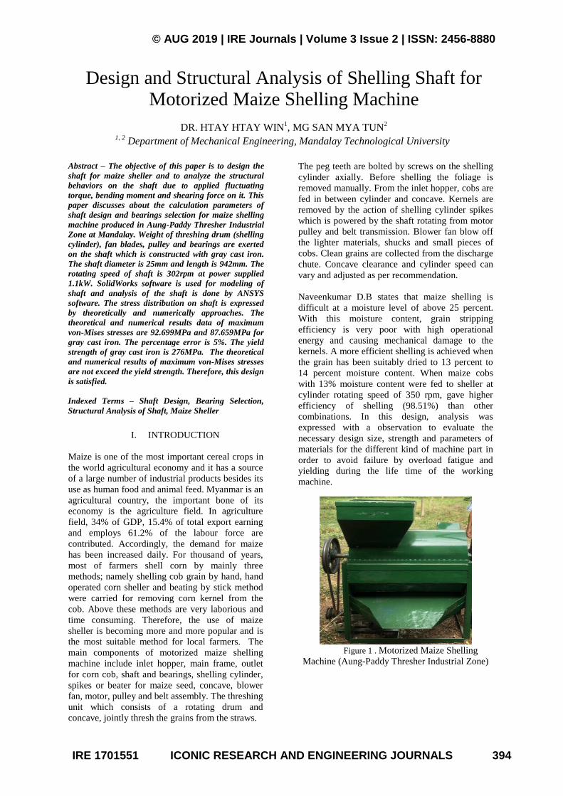
© AUG 2019 | IRE Journals | Volume 3 Issue 2 | ISSN: 2456-8880
IRE 1701551 ICONIC RESEARCH AND ENGINEERING JOURNALS 394
Design and Structural Analysis of Shelling Shaft for Motorized Maize Shelling Machine
DR. HTAY HTAY WIN1, MG SAN MYA TUN
2
1, 2 Department of Mechanical Engineering, Mandalay Technological University
Abstract – The objective of this paper is to design the
shaft for maize sheller and to analyze the structural
behaviors on the shaft due to applied fluctuating
torque, bending moment and shearing force on it. This
paper discusses about the calculation parameters of
shaft design and bearings selection for maize shelling
machine produced in Aung-Paddy Thresher Industrial
Zone at Mandalay. Weight of threshing drum (shelling
cylinder), fan blades, pulley and bearings are exerted
on the shaft which is constructed with gray cast iron.
The shaft diameter is 25mm and length is 942mm. The
rotating speed of shaft is 302rpm at power supplied
1.1kW. SolidWorks software is used for modeling of
shaft and analysis of the shaft is done by ANSYS
software. The stress distribution on shaft is expressed
by theoretically and numerically approaches. The
theoretical and numerical results data of maximum
von-Mises stresses are 92.699MPa and 87.659MPa for
gray cast iron. The percentage error is 5%. The yield
strength of gray cast iron is 276MPa. The theoretical
and numerical results of maximum von-Mises stresses
are not exceed the yield strength. Therefore, this design
is satisfied.
Indexed Terms – Shaft Design, Bearing Selection,
Structural Analysis of Shaft, Maize Sheller
I. INTRODUCTION
Maize is one of the most important cereal crops in
the world agricultural economy and it has a source
of a large number of industrial products besides its
use as human food and animal feed. Myanmar is an
agricultural country, the important bone of its
economy is the agriculture field. In agriculture
field, 34% of GDP, 15.4% of total export earning
and employs 61.2% of the labour force are
contributed. Accordingly, the demand for maize
has been increased daily. For thousand of years,
most of farmers shell corn by mainly three
methods; namely shelling cob grain by hand, hand
operated corn sheller and beating by stick method
were carried for removing corn kernel from the
cob. Above these methods are very laborious and
time consuming. Therefore, the use of maize
sheller is becoming more and more popular and is
the most suitable method for local farmers. The
main components of motorized maize shelling
machine include inlet hopper, main frame, outlet
for corn cob, shaft and bearings, shelling cylinder,
spikes or beater for maize seed, concave, blower
fan, motor, pulley and belt assembly. The threshing
unit which consists of a rotating drum and
concave, jointly thresh the grains from the straws.
The peg teeth are bolted by screws on the shelling
cylinder axially. Before shelling the foliage is
removed manually. From the inlet hopper, cobs are
fed in between cylinder and concave. Kernels are
removed by the action of shelling cylinder spikes
which is powered by the shaft rotating from motor
pulley and belt transmission. Blower fan blow off
the lighter materials, shucks and small pieces of
cobs. Clean grains are collected from the discharge
chute. Concave clearance and cylinder speed can
vary and adjusted as per recommendation.
Naveenkumar D.B states that maize shelling is
difficult at a moisture level of above 25 percent.
With this moisture content, grain stripping
efficiency is very poor with high operational
energy and causing mechanical damage to the
kernels. A more efficient shelling is achieved when
the grain has been suitably dried to 13 percent to
14 percent moisture content. When maize cobs
with 13% moisture content were fed to sheller at
cylinder rotating speed of 350 rpm, gave higher
efficiency of shelling (98.51%) than other
combinations. In this design, analysis was
expressed with a observation to evaluate the
necessary design size, strength and parameters of
materials for the different kind of machine part in
order to avoid failure by overload fatigue and
yielding during the life time of the working
machine.
Figure 1 . Motorized Maize Shelling
Machine (Aung-Paddy Thresher Industrial Zone)
© AUG 2019 | IRE Journals | Volume 3 Issue 2 | ISSN: 2456-8880
IRE 1701551 ICONIC RESEARCH AND ENGINEERING JOURNALS 395
II. METHODOLOGY
In this research, the design parameter is collected
from maize sheller with motor power of 1.1kW,
measuring the data of the shelling cylinder at
Aung-Paddy Thresher Industrial Zone,
(Mandalay), Myanmar, and then, calculated the
weight of shelling cylinder, angular velocity,
shelling power, and shelling torque for the shelling
cylinder design. The theoretical and numerical
analysis of shelling cylinder are expressed in this
paper.
In this paper, it includes of three main parts, which
are;
A: Design Consideration of Shelling Shaft
B: Theoretical Analysis of Shelling Shaft
C: Numerical Analysis of Shelling Shaft
A. Design Consideration of Shaft for Maize
Shelling Machine
(1). Weight of shelling cylinder, pulley and fan
blade:
Weight of shelling cylinder;
(1)
(2)
(3)
where,
Vc - volume of shelling cylinder (m3)
ρ - density of cast iron (kg/m3)
g - acceleration due to gravity (m/s2)
Ac - area of shelling cylinder (m2)
Weight of pulley,
(4)
Weight of fan blade,
(5)
(6)
where,
VF - volume of fan blade (m3)
- number of blades
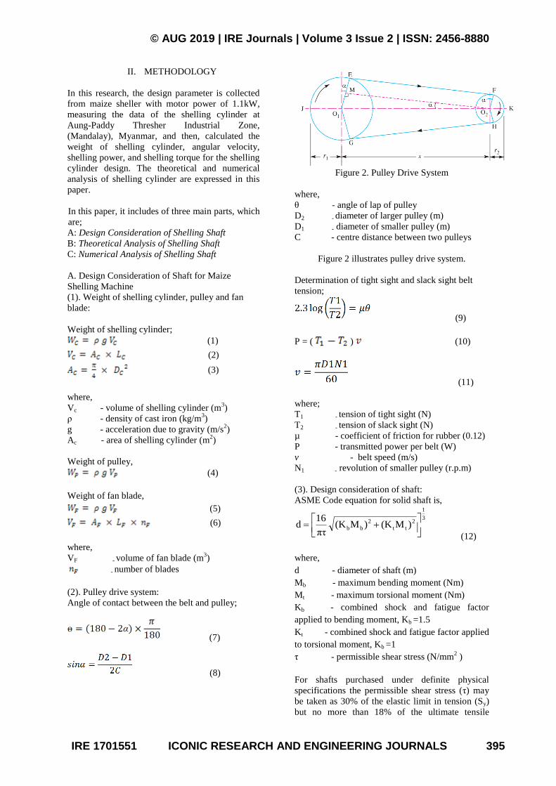
(2). Pulley drive system:
Angle of contact between the belt and pulley;
(7)
(8)
Figure 2. Pulley Drive System
where,
θ - angle of lap of pulley
D2 - diameter of larger pulley (m)
D1 - diameter of smaller pulley (m)
C - centre distance between two pulleys
Figure 2 illustrates pulley drive system.
Determination of tight sight and slack sight belt
tension;
(9)
P = ( ) (10)
(11)
where;
T1 - tension of tight sight (N)
T2 - tension of slack sight (N)
µ - coefficient of friction for rubber (0.12)
P - transmitted power per belt (W)
v - belt speed (m/s)
N1 - revolution of smaller pulley (r.p.m)
(3). Design consideration of shaft:
ASME Code equation for solid shaft is,
3
1
2
tt
2
bb )M(K)M(Kπτ
16d
(12)
where,
d - diameter of shaft (m)
Mb - maximum bending moment (Nm)
Mt - maximum torsional moment (Nm)
Kb - combined shock and fatigue factor
applied to bending moment, Kb =1.5
Kt - combined shock and fatigue factor applied
to torsional moment, Kb =1
τ - permissible shear stress (N/mm2 )
For shafts purchased under definite physical
specifications the permissible shear stress (τ) may
be taken as 30% of the elastic limit in tension (Sy)
but no more than 18% of the ultimate tensile
© AUG 2019 | IRE Journals | Volume 3 Issue 2 | ISSN: 2456-8880
IRE 1701551 ICONIC RESEARCH AND ENGINEERING JOURNALS 396
strength (Sut). In other words, the permissible shear
stress,
τ = 0.3 Sy or 0.18 Sut (13)
(choose smaller value)
The maximum torsional moment acting on the
shaft,
(14)
(4). Bearing selection:
The equivalent bearing load P;
P = X V Fr +Y Fa (15)
For pure radial load,
Fa = 0, X = 1, V = 1;
P = Fr
where,
P - equivalent bearing load
Fr - actual radial bearing load
Fa - actual axial bearing load
X - radial factor
Y - thrust factor
V - rotating factor
Nominal life in revolution;
h
6
60NLL=
10 (16)
where,
Lh - nominal life in working hour
L - speed in rev/min
Relationship between load and life;
prCL=( )
P (17)
where,
L - nominal life in revolution
Cr - basic dynamic capacity
P - equivalent bearing load
P - 3 for ball bearings / (10/3) for roller
bearings
Calculation of bearing selection.
P = Fr = 1465.36
Lh = 8000 hr
N = 302 rpm
L = 144. 96
Cr = 7697.69 N = 7.697 kN
Therefore, bearing number 16005 Single-row Deep
Groove Ball bearing is selected.
Inside diameter of bearing =25 mm
Outside diameter of bearing = 47 mm
Face width of bearing = 8 mm
Table 1: Result Data of Shelling Shaft
Parameters Symbol Value Unit
Weight of shelling
cylinder
Wc 864 N
Weight of pulley Wp 652 N
Weight of fan blade WF 69.22 N
Speed of cylinder
pulley
N2 302 rpm
Angle of lap of
smaller pulley
θ 2.15 rad
Tension in tight
sight
T1 182.335 N
Tension in slack
sight
T2 85.72 N
Maximum bending
moment
Mb 140.771 N-m
Maximum torsional
moment
Mt 23.187 N-m
Permissible shear
stress
τ 82.8 MPa
Diameter of shaft d 25 mm
Table I shows the calculated weight, diameter and
bearing selection of the shelling shaft design used
in maize sheller.
B. Theoretical Analysis of Shaft
Structural behaviour (von-Mises stress, effective
strain) of threshing shaft are calculated by
theoretical approach. The threshing shaft is made of
gray cast iron ASTM40.
τxy
Ϭx
Ϭx
τxy
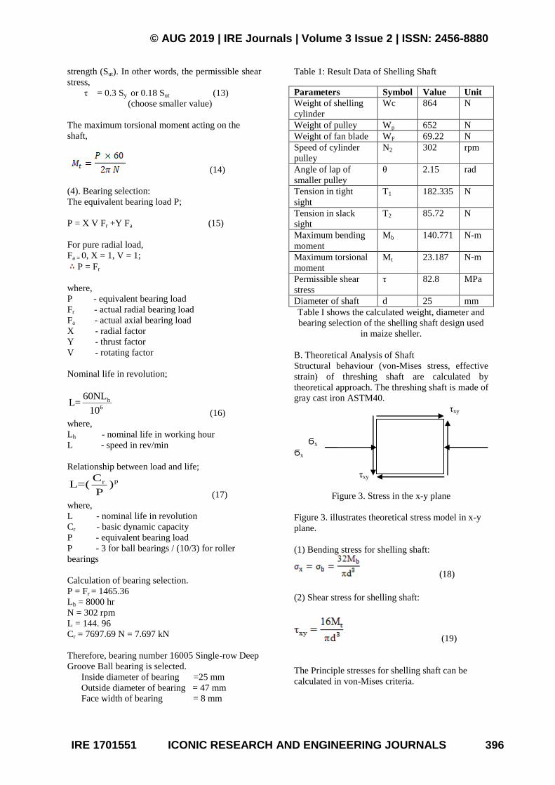
Figure 3. Stress in the x-y plane
Figure 3. illustrates theoretical stress model in x-y
plane.
(1) Bending stress for shelling shaft:
(18)
(2) Shear stress for shelling shaft:
(19)
The Principle stresses for shelling shaft can be
calculated in von-Mises criteria.
© AUG 2019 | IRE Journals | Volume 3 Issue 2 | ISSN: 2456-8880
IRE 1701551 ICONIC RESEARCH AND ENGINEERING JOURNALS 397
2
1
24
2
2
1
2
1
21
xyτyσxσyσxσ,σ (20)
The von-Mises stress,
2
1
213
232
221
2
1
)σ(σ)σ(σ)σ(σσ (21)
The constitutive equations are called the relation
between stress and strain. Hooke's law would be
show that;
Principle strains:
)συ(σσE
ε 321
1
1 (22)
)συ(σσE
ε 312
1
2 (23)
213
1
3 σσυσE
ε (24)
The effective strain for threshing drum:
21
23
22
21
3
2
εεεε (25)
Table 2: Material Properties of ASTM 40 Gray
Cast Iron [1]
Material Properties Values Units
Young Modulus, E 124 GPa
Poisson Ratio, 0.27 -
Yield Strength, Sy 276 MPa
Density, ρ 7200 kg/m3
Table 2 shows the materials properties of ASTM40
gray cast iron for design calculation of the shelling
shaft.
Table 3: Theoretical Result of Shelling Shaft Von-
Mises
Stresses,
(MPa)
Effective
Strain,
(×10-4
)
Shear
Stress, τ
(MPa)
Bending
Stress, b
(MPa)
92.699 6.529 7.56 91.769
Table 3 shows the theoretical results of the
threshing shaft design. The von-Mises stress, the
effective strain, shear stress and bending stress are
calculated by theoretically in the shelling shaft
design.
C. Numerical Analysis of Shaft
To estimate the following stresses and strains
distribution of the shelling shaft, ANSYS software
has been used. The design of the shelling shaft was
analysed with gray cast iron ASTM40.
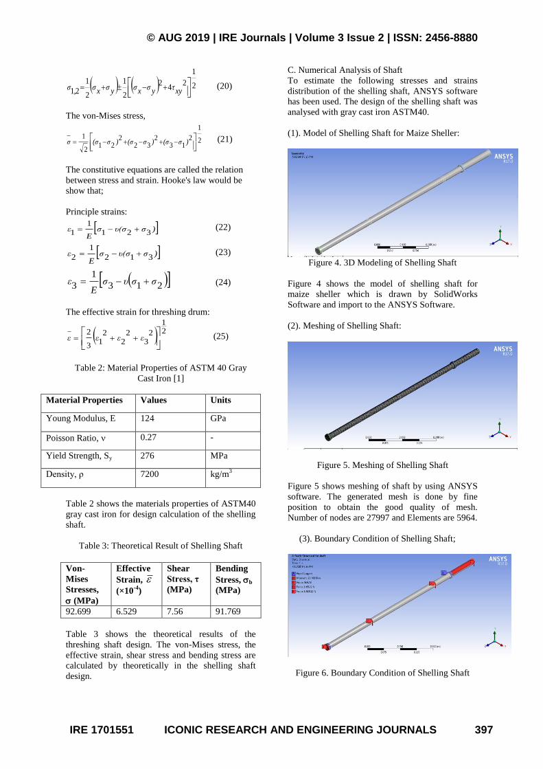
(1). Model of Shelling Shaft for Maize Sheller:
Figure 4. 3D Modeling of Shelling Shaft
Figure 4 shows the model of shelling shaft for
maize sheller which is drawn by SolidWorks
Software and import to the ANSYS Software.
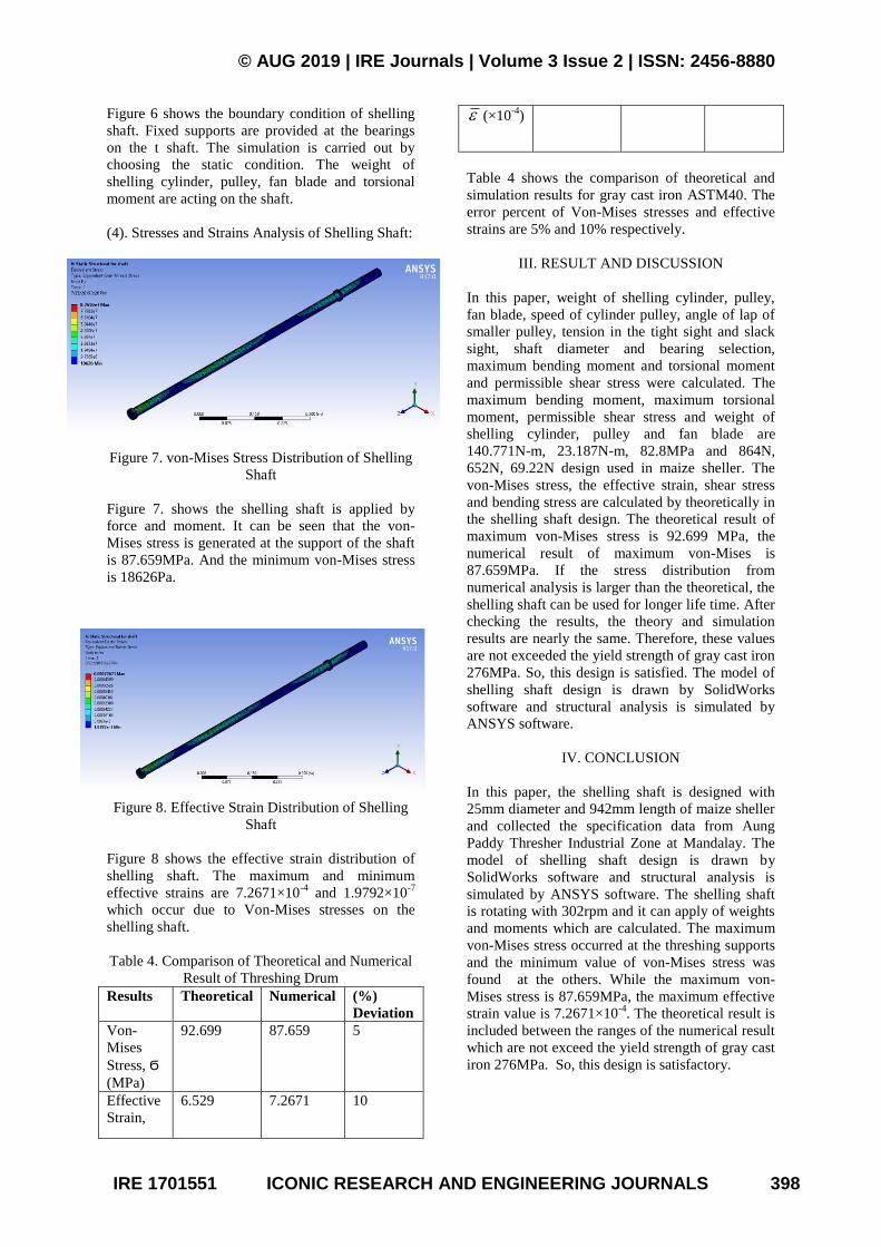
(2). Meshing of Shelling Shaft:
Figure 5. Meshing of Shelling Shaft
Figure 5 shows meshing of shaft by using ANSYS
software. The generated mesh is done by fine
position to obtain the good quality of mesh.
Number of nodes are 27997 and Elements are 5964.
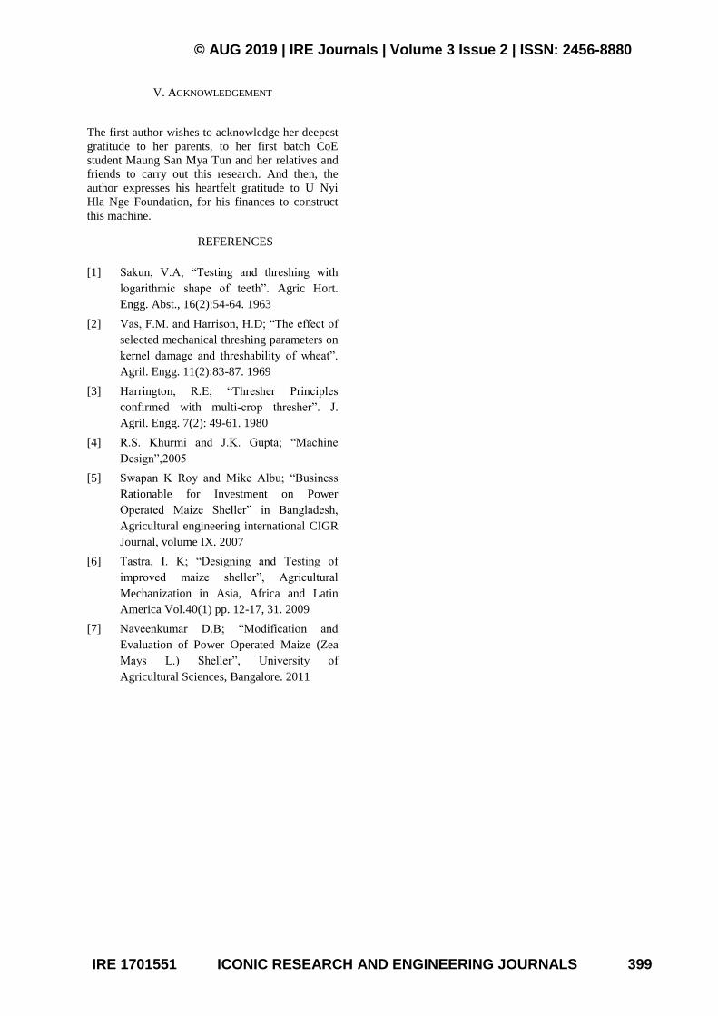
(3). Boundary Condition of Shelling Shaft;
Figure 6. Boundary Condition of Shelling Shaft
© AUG 2019 | IRE Journals | Volume 3 Issue 2 | ISSN: 2456-8880
IRE 1701551 ICONIC RESEARCH AND ENGINEERING JOURNALS 398
Figure 6 shows the boundary condition of shelling
shaft. Fixed supports are provided at the bearings
on the t shaft. The simulation is carried out by
choosing the static condition. The weight of
shelling cylinder, pulley, fan blade and torsional
moment are acting on the shaft.
(4). Stresses and Strains Analysis of Shelling Shaft:
Figure 7. von-Mises Stress Distribution of Shelling
Shaft
Figure 7. shows the shelling shaft is applied by
force and moment. It can be seen that the von-
Mises stress is generated at the support of the shaft
is 87.659MPa. And the minimum von-Mises stress
is 18626Pa.
Figure 8. Effective Strain Distribution of Shelling
Shaft
Figure 8 shows the effective strain distribution of
shelling shaft. The maximum and minimum
effective strains are 7.2671×10⁻⁴
and 1.9792×10⁻⁷
which occur due to Von-Mises stresses on the
shelling shaft.
Table 4. Comparison of Theoretical and Numerical
Result of Threshing Drum
Results Theoretical Numerical (%)
Deviation
Von-
Mises
Stress, Ϭ
(MPa)
92.699 87.659 5
Effective
Strain,
6.529 7.2671 10
(×10-4
)
Table 4 shows the comparison of theoretical and
simulation results for gray cast iron ASTM40. The
error percent of Von-Mises stresses and effective
strains are 5% and 10% respectively.
III. RESULT AND DISCUSSION
In this paper, weight of shelling cylinder, pulley,
fan blade, speed of cylinder pulley, angle of lap of
smaller pulley, tension in the tight sight and slack
sight, shaft diameter and bearing selection,
maximum bending moment and torsional moment
and permissible shear stress were calculated. The
maximum bending moment, maximum torsional
moment, permissible shear stress and weight of
shelling cylinder, pulley and fan blade are
140.771N-m, 23.187N-m, 82.8MPa and 864N,
652N, 69.22N design used in maize sheller. The
von-Mises stress, the effective strain, shear stress
and bending stress are calculated by theoretically in
the shelling shaft design. The theoretical result of
maximum von-Mises stress is 92.699 MPa, the
numerical result of maximum von-Mises is
87.659MPa. If the stress distribution from
numerical analysis is larger than the theoretical, the
shelling shaft can be used for longer life time. After
checking the results, the theory and simulation
results are nearly the same. Therefore, these values
are not exceeded the yield strength of gray cast iron
276MPa. So, this design is satisfied. The model of
shelling shaft design is drawn by SolidWorks
software and structural analysis is simulated by
ANSYS software.
IV. CONCLUSION
In this paper, the shelling shaft is designed with
25mm diameter and 942mm length of maize sheller
and collected the specification data from Aung
Paddy Thresher Industrial Zone at Mandalay. The
model of shelling shaft design is drawn by
SolidWorks software and structural analysis is
simulated by ANSYS software. The shelling shaft
is rotating with 302rpm and it can apply of weights
and moments which are calculated. The maximum
von-Mises stress occurred at the threshing supports
and the minimum value of von-Mises stress was
found at the others. While the maximum von-
Mises stress is 87.659MPa, the maximum effective
strain value is 7.2671×10⁻⁴
. The theoretical result is
included between the ranges of the numerical result
which are not exceed the yield strength of gray cast
iron 276MPa. So, this design is satisfactory.
© AUG 2019 | IRE Journals | Volume 3 Issue 2 | ISSN: 2456-8880
IRE 1701551 ICONIC RESEARCH AND ENGINEERING JOURNALS 399
V. ACKNOWLEDGEMENT
The first author wishes to acknowledge her deepest
gratitude to her parents, to her first batch CoE
student Maung San Mya Tun and her relatives and
friends to carry out this research. And then, the
author expresses his heartfelt gratitude to U Nyi
Hla Nge Foundation, for his finances to construct
this machine.
REFERENCES
[1] Sakun, V.A; “Testing and threshing with
logarithmic shape of teeth”. Agric Hort.
Engg. Abst., 16(2):54-64. 1963
[2] Vas, F.M. and Harrison, H.D; “The effect of
selected mechanical threshing parameters on
kernel damage and threshability of wheat”.
Agril. Engg. 11(2):83-87. 1969
[3] Harrington, R.E; “Thresher Principles
confirmed with multi-crop thresher”. J.
Agril. Engg. 7(2): 49-61. 1980
[4] R.S. Khurmi and J.K. Gupta; “Machine
Design”,2005
[5] Swapan K Roy and Mike Albu; “Business
Rationable for Investment on Power
Operated Maize Sheller” in Bangladesh,
Agricultural engineering international CIGR
Journal, volume IX. 2007
[6] Tastra, I. K; “Designing and Testing of
improved maize sheller”, Agricultural
Mechanization in Asia, Africa and Latin
America Vol.40(1) pp. 12-17, 31. 2009
[7] Naveenkumar D.B; “Modification and
Evaluation of Power Operated Maize (Zea
Mays L.) Sheller”, University of
Agricultural Sciences, Bangalore. 2011
Copyright © 2022 FDOKUMEN