
Engine foundation re-design due to modification of the shaft ...
128
1 Engine foundation re-design due to modification of the shaft line arrangement Marcos Enrique Di Iorio Master Thesis presented in partial fulfillment of the requirements for the double degree: “Advanced Master in Naval Architecture” conferred by University of Liege "Master of Sciences in Applied Mechanics, specialization in Hydrodynamics, Energetics and Propulsion” conferred by Ecole Centrale de Nantes developed at University of Genoa in the framework of the “EMSHIP” Erasmus Mundus Master Course in “Integrated Advanced Ship Design” Ref. 159652-1-2009-1-BE-ERA MUNDUS-EMMC Supervisor: Prof. Dario Boote, University of Genoa Reviewer: Prof. Philippe Rigo, University of Liege Genoa, February 2016
-
Upload
khangminh22 -
Category
Documents
-
view
3 -
download
0
Transcript of Engine foundation re-design due to modification of the shaft ...

1
Engine foundation re-design due to modification of
the shaft line arrangement
Marcos Enrique Di Iorio
Master Thesis
presented in partial fulfillment of the requirements for the double degree:
“Advanced Master in Naval Architecture” conferred by University of Liege "Master of Sciences in Applied Mechanics, specialization in Hydrodynamics,
Energetics and Propulsion” conferred by Ecole Centrale de Nantes
developed at University of Genoa in the framework of the
“EMSHIP” Erasmus Mundus Master Course
in “Integrated Advanced Ship Design”
Ref. 159652-1-2009-1-BE-ERA MUNDUS-EMMC
Supervisor: Prof. Dario Boote, University of Genoa
Reviewer: Prof. Philippe Rigo, University of Liege
Genoa, February 2016
P 2 Marcos Enrique Di Iorio
Master Thesis developed at University of Genoa, La Spezia.
The following document reports the main project developed during the internship performed at
Baglietto Shipyards in collaboration with the Department of Naval Architecture of the
University of Genova. This production will be presented as Master Thesis for the conclusion of
the Erasmus Mundus Master in Advanced Ship Design (EMShip).
ABSTRACT
The project is assigned after the initiative from Baglietto's shipyard to consider the
implementation of a thrust bearing block in the shaft line, starting with the study of one of their
displacement super- yachts. The main characteristics of this type of ships are represented by the
study case used for this project, which corresponds to an existent 46m long yacht. Construction
plans, technical information and assistance is provided by the shipyard's technical office
The main objective of this work is not to prove the advantages of the incorporation of a thrust
block in the propulsion system, but to study the adaptation of the original configuration to the
variations proposed in the shaft line arrangement. The modifications are applied on the engine’s
foundation structure in combination with the redesign of engine block's mounting and coupling
systems proposed by competing providers.
Different possible modifications of the structure are tested on a partial model of the ship, in
order to study the response of the engine block's supporting structure when subjected to selected
loads. Part of the work is dedicated to determine the loads that should be taken into account and
how to reproduce the way these are transmitted to the structure by the mounting system.
The behavior of each proposed modified structure is analyzed and compared based on their
stress and deformation distribution and maximum values. These tests are carried out through
computational analysis, using the FEM software Patran-Nastran from MSC, under the
supervision of the Nautical Engineering Department of La Spezia.
The resulting modified configurations of the engine’s foundation presents sufficiently low stress
and deformation values. The advantages and disadvantages of each type of proposed solution is
described so that it can be consulted as a reference when considering the incorporation of a
thrust block during the pre-design stage of yachts with similar characteristics.

Engine foundation re-design due to modification of the shaft line arrangement 3
“EMSHIP” Erasmus Mundus Master Course, period of study September 2014 – February 2016
1. AKNOWLEDGEMENTS
Special thanks are dedicated to the people that made this work possible:
Prof. Dario Boote, Ing. Gian Marco Vergassola, Ing. Tatiana Pais from the University of Genoa
and Scuola Politecnica from La Spezia;
Ing. Guido Penco, Ing. Ana Doniao from Bablietto Shipyards in La Spezia;
Ing. Gianpiero Repetti, Ilaria Siccardi, Ing. Francesco Gambarotta and Ing. Alessandro
Angeleri from Vulkan Italy, Nuovi Ligure branch; and
Ing. Christian Boomas from Rubber Design, Netherlands.
I also would like to thank my family and friends for their support.

P 4 Marcos Enrique Di Iorio
Master Thesis developed at University of Genoa, La Spezia.
2. DECLARATION OF AUTHORSHIP
I declare that this thesis and the work presented in it are my own and have been generated by
me as the result of my own original research.
Where I have consulted the published work of others, this is always clearly attributed.
Where I have quoted from the work of others, the source is always given. With the exception of
such quotations, this thesis is entirely my own work.
I have acknowledged all main sources of help.
Where the thesis is based on work done by myself jointly with others, I have made clear exactly
what was done by others and what I have contributed myself.
This thesis contains no material that has been submitted previously, in whole or in part, for the
award of any other academic degree or diploma.
I cede copyright of the thesis in favour of the University of …..
Date: Signature

Engine foundation re-design due to modification of the shaft line arrangement 5
“EMSHIP” Erasmus Mundus Master Course, period of study September 2014 – February 2016
CONTENTS
1. AKNOWLEDGEMENTS ...................................................................................................... 3
2. DECLARATION OF AUTHORSHIP ................................................................................... 4
3. INTRODUCTION .................................................................................................................. 8
4. Engine foundations ................................................................................................................. 9
4.1. Mounting systems types ................................................................................................... 9
5. Thrust bearing ....................................................................................................................... 10
5.1. Types and applications ................................................................................................... 11
5.2. Implementation of the thrust bearing in the shaft line ................................................... 12
6. Characteristics of the study case: Ship 216. ......................................................................... 13
6.1. Block Description .......................................................................................................... 14
6.2. Engine room ................................................................................................................... 14
6.2.1. Available space ....................................................................................................... 14
6.2.2. Main elements ......................................................................................................... 15
6.3. Conclusion ..................................................................................................................... 19
7. Loads ..................................................................................................................................... 20
7.1. Classification of Loads on a ship ................................................................................... 20
7.2. Dynamic loads from the propeller and the main engine ................................................ 21
Why adding a thrust bearing in the shaft line? ..................................................................... 22
7.3. Loads applied on the engine foundation ........................................................................ 23
Constant loads ....................................................................................................................... 23
Variable loads ....................................................................................................................... 26
7.4. Conclusion ..................................................................................................................... 28
8. Engine block supports ........................................................................................................... 29
8.1. Static load calculation .................................................................................................... 29
Loads applied on the engine supports ................................................................................... 29
Loads applied on the gear box supports ............................................................................... 32
8.2. Resilient mount selection ............................................................................................... 34
Transmissibility of the resilient mounts ............................................................................... 35
8.3. Mounting system configuration ..................................................................................... 37
Case 1: Original mounting system configuration ................................................................. 38
P 6 Marcos Enrique Di Iorio
Master Thesis developed at University of Genoa, La Spezia.
Case 2: Rubber Design proposed mounting system configuration ....................................... 40
Case 3: Vulkan proposed mounting system configuration ................................................... 43
8.4. Conclusion ..................................................................................................................... 45
9. Thrust block .......................................................................................................................... 45
9.1. Rubber Design's proposal .............................................................................................. 46
Thrust bearing ....................................................................................................................... 46
Thrust block coupling ........................................................................................................... 47
Thrust block configuration ................................................................................................... 48
9.2. Vulkan Italy's proposed solution .................................................................................... 49
Thrust block coupling ........................................................................................................... 49
Thrust bearing ....................................................................................................................... 50
Thrust block configuration ................................................................................................... 51
9.3. Thrust block comparison ................................................................................................ 52
9.4. Conclusion ..................................................................................................................... 53
10. Proposed structural modifications ..................................................................................... 53
Modification conditions ........................................................................................................ 53
10.1. Modified Solution A ................................................................................................... 54
Featured modifications: ........................................................................................................ 54
10.1. Modified Solution B ................................................................................................... 58
Modification restriction ........................................................................................................ 58
10.2. Modified Solution V ................................................................................................... 59
10.3. Conclusion .................................................................................................................. 62
11. Finite element analysis ...................................................................................................... 62
11.1. Model types ................................................................................................................ 62
Partial Model global analysis................................................................................................ 62
11.2. Finite elements ........................................................................................................... 63
Stiffeners: .............................................................................................................................. 65
Plates: .................................................................................................................................... 67
11.3. Reproducing the applied loads ................................................................................... 68
MPC elements ....................................................................................................................... 68
11.3.1. Mesh .................................................................................................................... 71
Meshing methodology .......................................................................................................... 71
Mesh validation .................................................................................................................... 72
11.4. Materials ..................................................................................................................... 72
Engine foundation re-design due to modification of the shaft line arrangement 7
“EMSHIP” Erasmus Mundus Master Course, period of study September 2014 – February 2016
Unit system ........................................................................................................................... 72
11.5. Final models ............................................................................................................... 73
11.6. Conclusion .................................................................................................................. 74
12. Structural strength representation ...................................................................................... 75
12.1. von Mises combined stress ......................................................................................... 75
12.2. Combined load approach ............................................................................................ 76
Representative stiffener: ....................................................................................................... 77
Applied loads ........................................................................................................................ 77
Collapse modes ..................................................................................................................... 78
12.3. Critical buckling load ................................................................................................. 79
12.4. Boundary condition analysis ...................................................................................... 80
12.4.1. Symmetry boundary conditions: ......................................................................... 81
12.4.2. Model constrains: ................................................................................................ 82
Node motion restriction and constrain configuration ........................................................... 82
Boundary conditions according to the combined load approach .......................................... 85
12.1. Conclusion .................................................................................................................. 86
13. Static strength analysis ...................................................................................................... 87
13.1. Resistance comparison ............................................................................................... 87
13.2. Strength comparison with the proposed modifications .............................................. 92
13.3. Performance prediction .............................................................................................. 99
Original structure ................................................................................................................ 100
Solution A ........................................................................................................................... 102
Solution B ........................................................................................................................... 105
Solution V ........................................................................................................................... 107
13.4. Conclusion ................................................................................................................ 110
14. FUTURE DEVELOPMENTS ......................................................................................... 110
Final technical design plans ................................................................................................ 110
Dynamic analysis ................................................................................................................ 112
15. CONCLUSION................................................................................................................ 114
1. Appendix A: Resilient mounting elements selection .......................................................... 115
1.1. Dynamic analysis ......................................................................................................... 116
1.2. Transmissibility of the resilient mounts ....................................................................... 119
1.2.1. Vibration analysis ................................................................................................. 123
2. REFERENCES ................................................................................................................... 127
P 8 Marcos Enrique Di Iorio
Master Thesis developed at University of Genoa, La Spezia.
3. INTRODUCTION
The work here presented was assigned with the objective of providing a technical approach to
solve a situation or asses a decision that could be presented during the design and construction
of a ship. Such is the incorporation of thrust blocks into their propulsion system. A 46m long
displacement type yacht, "the 216" was chosen to be used as a study case from which
generalizations could be made for other ships with similar characteristics.
The addition of the thrust bearing cannot bring by itself significant benefits to the performance
of the ship. It needs to be complemented not only by an appropriate thrust block, including the
coupling connection to the gear box flange and support configuration, but also, by an
appropriate engine block support system. This is so because the most important advantage of
adding a thrust block is that the engine support system is not responsible of resisting the axial
load transmitted by the shaft. Therefore it can be designed with the only objective of reducing
the noise and vibration generated by the engine.
However, apart from understanding how to take advantage from the addition of the thrust
bearing, it is necessary to determine if such implementation is feasible and if it would jeopardize
the structural strength of the engine foundation and of the entire ship. Then, original structure
was modified into three different solutions, each one adapted to one of the different thrust blocks
provided by companies from the industry.
After studying the advantages and disadvantages related to their construction, structural strength
of the original version and the three proposed modified solutions were compared using finite
element methods.

Engine foundation re-design due to modification of the shaft line arrangement 9
“EMSHIP” Erasmus Mundus Master Course, period of study September 2014 – February 2016
4. Engine foundations
The main objective of this work is to assess the structural modifications to be performed on the
engine foundation of the studied ship, corresponding to a 46m length displacement yacht. It is
intended that the solutions found can be consulted as a reference when considering the
incorporation of a thrust block during the pre-design stage of yachts with similar characteristics.
Diesel engines:
A foundation for a diesel engine must be sufficiently stiff to absorb forces and moments
generated by the engine, while precluding the transfer of bending moments from the hull to the
engine.
The foundation consists of longitudinal and transverse members, fully integrated into the bottom
structure, which support a horizontal seating flange where the engine flange is mounted. The
mounting flange of the engine is bolted to the seating flange through chocking, which provides
solid contact between the flanges.
Chocking:
Traditional chocking consists of a series of individual cast iron or steel chocks, each spanning
two hold-down bolts, which are individually machined to precisely fit each location after the
unit is aligned on temporary supports. Alternatively, continuous chocking may be formed by an
epoxy resin, which is poured in place after the unit is aligned on temporary supports, and which
then hardens, after which the hold-down bolts are tightened.
4.1. Mounting systems types
Two basic types of mounting systems can be found depending on the characteristics of the ship:
Rigid mounting: For most machinery, fitted bolts, dowels, or keys are used to positively secure
one end only, while other bolts have clearances to accommodate thermal expansion.
Resilient mounting: Resilient mounting is used when necessary, to reduce the structure-borne
vibration or noise which the mounted machinery would transmit to the hull. Common candidates
include medium- and high-speed diesel engines and gas turbines, and complete generator sets. In
principle, resilient mounting uses a flexible material or device instead of solid chocking.
P 10 Marcos Enrique Di Iorio
Master Thesis developed at University of Genoa, La Spezia.
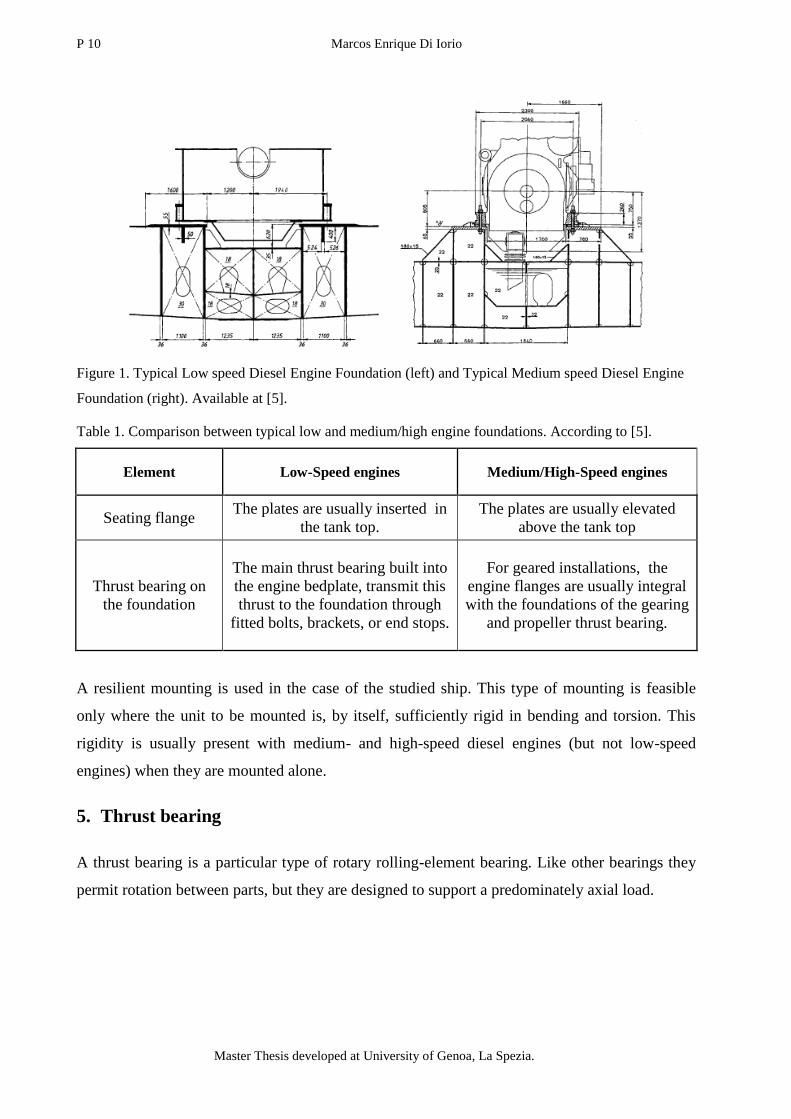
Figure 1. Typical Low speed Diesel Engine Foundation (left) and Typical Medium speed Diesel Engine
Foundation (right). Available at [5].
Table 1. Comparison between typical low and medium/high engine foundations. According to [5].
Element Low-Speed engines Medium/High-Speed engines
Seating flange The plates are usually inserted in
the tank top.
The plates are usually elevated
above the tank top
Thrust bearing on
the foundation
The main thrust bearing built into
the engine bedplate, transmit this
thrust to the foundation through
fitted bolts, brackets, or end stops.
For geared installations, the
engine flanges are usually integral
with the foundations of the gearing
and propeller thrust bearing.
A resilient mounting is used in the case of the studied ship. This type of mounting is feasible
only where the unit to be mounted is, by itself, sufficiently rigid in bending and torsion. This
rigidity is usually present with medium- and high-speed diesel engines (but not low-speed
engines) when they are mounted alone.
5. Thrust bearing
A thrust bearing is a particular type of rotary rolling-element bearing. Like other bearings they
permit rotation between parts, but they are designed to support a predominately axial load.
Engine foundation re-design due to modification of the shaft line arrangement 11
“EMSHIP” Erasmus Mundus Master Course, period of study September 2014 – February 2016
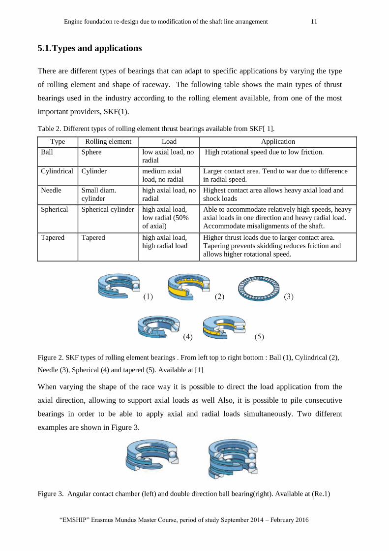
5.1. Types and applications
There are different types of bearings that can adapt to specific applications by varying the type
of rolling element and shape of raceway. The following table shows the main types of thrust
bearings used in the industry according to the rolling element available, from one of the most
important providers, SKF(1).
Table 2. Different types of rolling element thrust bearings available from SKF[ 1].
Type Rolling element Load Application
Ball Sphere low axial load, no
radial
High rotational speed due to low friction.
Cylindrical Cylinder medium axial
load, no radial
Larger contact area. Tend to war due to difference
in radial speed.
Needle Small diam.
cylinder
high axial load, no
radial
Highest contact area allows heavy axial load and
shock loads
Spherical Spherical cylinder high axial load,
low radial (50%
of axial)
Able to accommodate relatively high speeds, heavy
axial loads in one direction and heavy radial load.
Accommodate misalignments of the shaft.
Tapered Tapered high axial load,
high radial load
Higher thrust loads due to larger contact area.
Tapering prevents skidding reduces friction and
allows higher rotational speed.
Figure 2. SKF types of rolling element bearings . From left top to right bottom : Ball (1), Cylindrical (2),
Needle (3), Spherical (4) and tapered (5). Available at [1]
When varying the shape of the race way it is possible to direct the load application from the
axial direction, allowing to support axial loads as well Also, it is possible to pile consecutive
bearings in order to be able to apply axial and radial loads simultaneously. Two different
examples are shown in Figure 3.
Figure 3. Angular contact chamber (left) and double direction ball bearing(right). Available at (Re.1)
P 12 Marcos Enrique Di Iorio
Master Thesis developed at University of Genoa, La Spezia.
There are other non conventional bearings that can be found in different applications in the
industry such as:
Fluid bearings, where the axial thrust is supported on a thin layer of pressurized
liquid—these give low drag.
Magnetic bearings, where the axial thrust is supported on a magnetic field. This is used
where very high speeds or very low drag is needed, for example the Zippe-type
centrifuge.
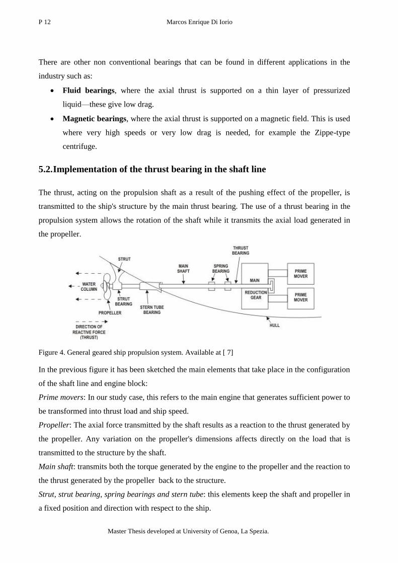
5.2. Implementation of the thrust bearing in the shaft line
The thrust, acting on the propulsion shaft as a result of the pushing effect of the propeller, is
transmitted to the ship's structure by the main thrust bearing. The use of a thrust bearing in the
propulsion system allows the rotation of the shaft while it transmits the axial load generated in
the propeller.
Figure 4. General geared ship propulsion system. Available at [ 7]
In the previous figure it has been sketched the main elements that take place in the configuration
of the shaft line and engine block:
Prime movers: In our study case, this refers to the main engine that generates sufficient power to
be transformed into thrust load and ship speed.
Propeller: The axial force transmitted by the shaft results as a reaction to the thrust generated by
the propeller. Any variation on the propeller's dimensions affects directly on the load that is
transmitted to the structure by the shaft.
Main shaft: transmits both the torque generated by the engine to the propeller and the reaction to
the thrust generated by the propeller back to the structure.
Strut, strut bearing, spring bearings and stern tube: this elements keep the shaft and propeller in
a fixed position and direction with respect to the ship.
Engine foundation re-design due to modification of the shaft line arrangement 13
“EMSHIP” Erasmus Mundus Master Course, period of study September 2014 – February 2016
Thrust bearing: This element should be positioned somewhere between the stern tube and the
gear box (main reduction gear) resisting to the axial thrust load transmitted by the shaft.
6. Characteristics of the study case: Ship 216.
The following sketch shows the location and relative sizes of the main element of the propulsion
system, shaft line and engine block obtained from the construction plans of the ship 216,
provided by Baglietto's technical office.
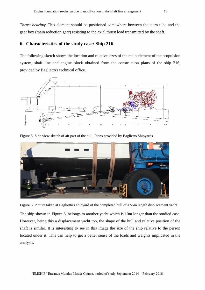
Figure 5. Side view sketch of aft part of the hull. Plans provided by Baglietto Shipyards.
Figure 6. Picture taken at Baglietto's shipyard of the completed hull of a 55m length displacement yacht.
The ship shown in Figure 6, belongs to another yacht which is 10m longer than the studied case.
However, being this a displacement yacht too, the shape of the hull and relative position of the
shaft is similar. It is interesting to see in this image the size of the ship relative to the person
located under it. This can help to get a better sense of the loads and weights implicated in the
analysis.

P 14 Marcos Enrique Di Iorio
Master Thesis developed at University of Genoa, La Spezia.
6.1. Block Description
In order to include the thrust bearing in the shaft line, the structural modifications are performed
to the aft compartment shown in Figure 5, which correspond to the engine room (section 6 to
11). Additional modifications outside of the engine room, for example in the garage (section 3 to
6), are also possible. However, there are pre-established limits that must remain:
the position of the bulkheads that limit the engine room (section 6 and section 11).
the angle of inclination of the shaft (7,7°).
Position of intersection between the shaft and hull (hull tube).
This restrictions were set by Baglietto's technical office instructions. Any variation would
implicate larger adaptations outside the engine room of the structure and propulsion system in
order to maintain the integrity and performance of the whole ship.
In Figure 5 it has been highlighted in blue the engine and gear box mounting systems, as well as
the coupling between them. This elements play a significant role in the structural modifications
due to the addition of the thrust block.
6.2. Engine room
6.2.1. Available space
As mentioned before, the main structural modifications should be developed inside the engine
room. The addition of an element in the shaft line is only possible if there is sufficient available
space. If it is not enough, structural modifications can be performed taking into account the
previously mentioned restrictions. The following figure shows in a side view the available space
between the different elements inside the engine room..
Engine foundation re-design due to modification of the shaft line arrangement 15
“EMSHIP” Erasmus Mundus Master Course, period of study September 2014 – February 2016
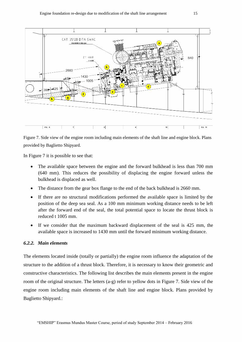
Figure 7. Side view of the engine room including main elements of the shaft line and engine block. Plans
provided by Baglietto Shipyard.
In Figure 7 it is possible to see that:
The available space between the engine and the forward bulkhead is less than 700 mm
(640 mm). This reduces the possibility of displacing the engine forward unless the
bulkhead is displaced as well.
The distance from the gear box flange to the end of the back bulkhead is 2660 mm.
If there are no structural modifications performed the available space is limited by the
position of the deep sea seal. As a 100 mm minimum working distance needs to be left
after the forward end of the seal, the total potential space to locate the thrust block is
reduced t 1005 mm.
If we consider that the maximum backward displacement of the seal is 425 mm, the
available space is increased to 1430 mm until the forward minimum working distance.
6.2.2. Main elements
The elements located inside (totally or partially) the engine room influence the adaptation of the
structure to the addition of a thrust block. Therefore, it is necessary to know their geometric and
constructive characteristics. The following list describes the main elements present in the engine
room of the original structure. The letters (a-g) refer to yellow dots in Figure 7. Side view of the
engine room including main elements of the shaft line and engine block. Plans provided by
Baglietto Shipyard.:

P 16 Marcos Enrique Di Iorio
Master Thesis developed at University of Genoa, La Spezia.
Engine block (engine (a)+ gear box (b)):
The engine used in the original design of the study case corresponds to a 3512B DITA SWAC
from Caterpillar. The dimensions of this engine where considered in the structural modification.
At the nominal the pre-established nominal speed of 16 knots, the engine should provide
1454BKW at a rotational speed 1830 RPM. At this nominal speed, the torque provided by the
engine is 7,57 kN.
The gear box corresponds to a ZF-4661, with a engine-gear box relation of 4,062. This reduces
the rational speed to 452 RPM and increases the torque to 30,74 kN, in the shaft at nominal
working speed.
The main characteristics of the elements in the engine block are exposed in the following table:
Table 3. Main characteristics of the engine and gear box used in the original configuration.
Figure 8. Pictures from the engine (left) , Vulkardan-E Series Coupling, from Vulkan (middle) (Available
at [9]) and gear box (right) (Available at [ 4]).
Engine Gear Box
Model CAT 3512B DITA SWAC ZF 4661
Dry weight (kg) 6537 1700
Maximum Length (mm) 2819 873
Maximum Height (mm) 2091 1238
Maximum Width (mm) 1785 904
Speed Range (RPM) 1200-1925 2500
Power Range (HP/kW) 1100-2250 / 820-1678 2382-2822 / 1778-2106
Engine-Gear box relation 4.062
Engine foundation re-design due to modification of the shaft line arrangement 17
“EMSHIP” Erasmus Mundus Master Course, period of study September 2014 – February 2016
Engine-Gear box coupling (c):
This element is responsible of transmitting the power generated at the engine into the gear box.
There are different possible couple configurations depending not only on the transmitted torque
and rotational speed, but also on the external loads and vibration transmission requirements.
The couple used in the original structure corresponds to a VULKARDAN E-57-1188/4110,
produced by Vulkan. In this case the elements are connected rigidly by the coupling's cover (see
Figure 8).
This cover is used to transmit the remaining axial thrust load applied on the gear box to the
engine without damaging the engine's shaft. However, this also makes the engine and gear box
to move together as a block and present a major influence on the support system design, which
is discussed with further detail in section 8.3.
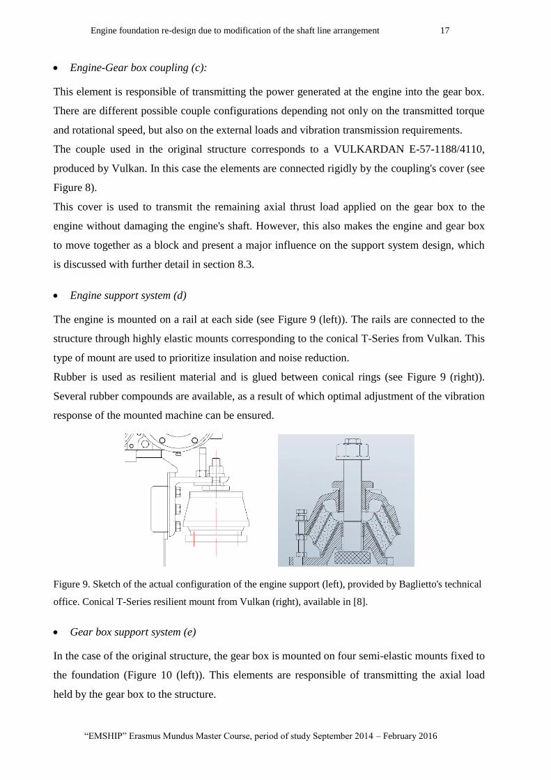
Engine support system (d)
The engine is mounted on a rail at each side (see Figure 9 (left)). The rails are connected to the
structure through highly elastic mounts corresponding to the conical T-Series from Vulkan. This
type of mount are used to prioritize insulation and noise reduction.
Rubber is used as resilient material and is glued between conical rings (see Figure 9 (right)).
Several rubber compounds are available, as a result of which optimal adjustment of the vibration
response of the mounted machine can be ensured.
Figure 9. Sketch of the actual configuration of the engine support (left), provided by Baglietto's technical
office. Conical T-Series resilient mount from Vulkan (right), available in [8].
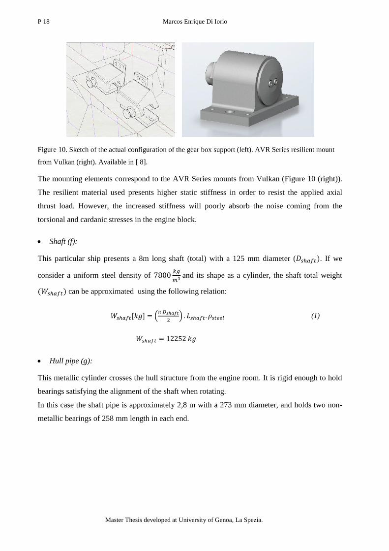
Gear box support system (e)
In the case of the original structure, the gear box is mounted on four semi-elastic mounts fixed to
the foundation (Figure 10 (left)). This elements are responsible of transmitting the axial load
held by the gear box to the structure.
P 18 Marcos Enrique Di Iorio
Master Thesis developed at University of Genoa, La Spezia.
Figure 10. Sketch of the actual configuration of the gear box support (left). AVR Series resilient mount
from Vulkan (right). Available in [ 8].
The mounting elements correspond to the AVR Series mounts from Vulkan (Figure 10 (right)).
The resilient material used presents higher static stiffness in order to resist the applied axial
thrust load. However, the increased stiffness will poorly absorb the noise coming from the
torsional and cardanic stresses in the engine block.
Shaft (f):
This particular ship presents a 8m long shaft (total) with a 125 mm diameter ( . If we
consider a uniform steel density of
and its shape as a cylinder, the shaft total weight
can be approximated using the following relation:
(1)
Hull pipe (g):
This metallic cylinder crosses the hull structure from the engine room. It is rigid enough to hold
bearings satisfying the alignment of the shaft when rotating.
In this case the shaft pipe is approximately 2,8 m with a 273 mm diameter, and holds two non-
metallic bearings of 258 mm length in each end.
Engine foundation re-design due to modification of the shaft line arrangement 19
“EMSHIP” Erasmus Mundus Master Course, period of study September 2014 – February 2016
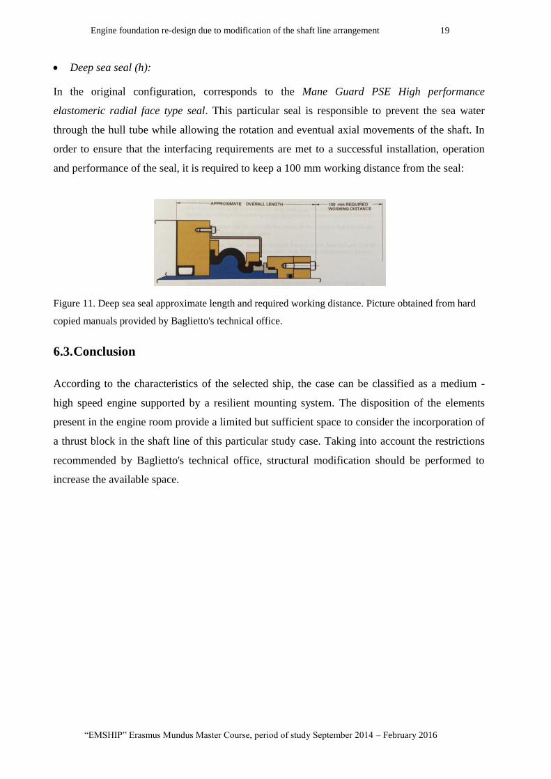
Deep sea seal (h):
In the original configuration, corresponds to the Mane Guard PSE High performance
elastomeric radial face type seal. This particular seal is responsible to prevent the sea water
through the hull tube while allowing the rotation and eventual axial movements of the shaft. In
order to ensure that the interfacing requirements are met to a successful installation, operation
and performance of the seal, it is required to keep a 100 mm working distance from the seal:
Figure 11. Deep sea seal approximate length and required working distance. Picture obtained from hard
copied manuals provided by Baglietto's technical office.
6.3. Conclusion
According to the characteristics of the selected ship, the case can be classified as a medium -
high speed engine supported by a resilient mounting system. The disposition of the elements
present in the engine room provide a limited but sufficient space to consider the incorporation of
a thrust block in the shaft line of this particular study case. Taking into account the restrictions
recommended by Baglietto's technical office, structural modification should be performed to
increase the available space.

P 20 Marcos Enrique Di Iorio
Master Thesis developed at University of Genoa, La Spezia.
7. Loads
7.1. Classification of Loads on a ship
The following load differentiation is considered for the classification proposed by Philippe Rigo
and Enrico Rizzuto at (6). The forces acting on the ship are divided according to their time
duration and the adopted structural scheme.
Time Duration:
Static loads: These are the loads experienced by the ship in still water. They act with
time duration well above the range of sea wave periods.
Quasi-static loads: A second class of loads includes those with a period corresponding to
wave actions (∼3 to 15 seconds). Quasi-static refers to the fact that this forces are
studied as if it was a static analysis.
Dynamic loads: When studying responses with frequency components close to the first
structural resonance modes, the dynamic properties of the structure have to be
considered.
High frequency loads: Loads at frequencies higher than the first resonance modes (> 10-
20 Hz) also are present on ships: this kind of excitation, however, involves more the
study of noise propagation on board than structural design.
Other loads: All other loads that do not fall in the above mentioned categories and need
specific models can be generally grouped in this class. Among them are thermal and
accidental loads.
Adopted structural scheme:
Global loads: This type of loads are act on the ship as a whole and so does the response.
Local loads: Defined in order to be applied on limited structural models of the ship.
This loads can be evaluated separately and later summed up to provide the total stress in the
selected position of the structure However, in the analysis of subsystems, the surrounding
structure must not be ignored, because it defines the connecting stiffness, i.e. the supporting
conditions.

Engine foundation re-design due to modification of the shaft line arrangement 21
“EMSHIP” Erasmus Mundus Master Course, period of study September 2014 – February 2016
7.2. Dynamic loads from the propeller and the main engine
Although there are several exciting sources which induce ship hull vibration and local structure
vibration, serious vibration problems are caused mainly by propeller and by the main engine.
Propeller excitations:
One part of the propeller exciting force occurs as a fluctuating pressure acting on the outer shell
plating of the after-body above the propeller and is called the surface force. Another part is
transmitted to the engine room double bottom structure through propeller shafting, and resulting
in bearing forces and thrust forces. Those exciting forces induced by the propeller cause hull
girder vibration, superstructure vibration, and local structure vibration as well.
Main engine excitations:
The exciting forces of the main engine, which take the form of unbalanced moments, guide
forces, guide moments and thrust fluctuation of the line shafting are transferred from the main
engine bed or from the thrust block to the engine room double bottom and may finally induce
hull girder vibration or superstructure vibration.
Figure 12. Dynamic loads generated at the engine and propulsion block. Available at [4].
Depending on general arrangement and on number of cylinders, diesel engines generate
internally unbalanced forces and moments, mainly at the engine revolution frequency, at the
cylinders firing frequency and inherent harmonics.
P 22 Marcos Enrique Di Iorio
Master Thesis developed at University of Genoa, La Spezia.
The excitation due to the first harmonics of low speed diesel engines can be at frequencies close
to the first natural hull girder frequencies, thus representing a possible cause of a global
resonance. In addition to frequency coincidence, also direction and location of the excitation are
important factors: for example, a vertical excitation in a nodal point of a vertical flexural mode
has much less effect in exciting that mode than the same excitation placed on a point of
maximum modal deflection.
Why adding a thrust bearing in the shaft line?
The principal difference resulting from the incorporation of a thrust bearing in the shaft line is
that the engine and gear box are isolated from the forces applied in the shaft. Therefore, the only
theoretical force transmitted between the engine block and the shaft, is the torque. This
difference gives several benefits, such as lighter and smaller elements in the engine block, being
able to use only torsion couplings between the engine and gear boxes, etc.
However, the main advantage of the incorporation of a thrust bearing relays on the configuration
of the mounting system that connects the elements in the engine block to the structure.
Without the addition of the thrust block, the mounting system of the engine (or gear box) need to
be stiff enough to resist the axial load coming from the shaft. This increased stiffness reduces
the capacity of the mounting system to absorb loads generated by the engine and allows its
transmition into the structure.
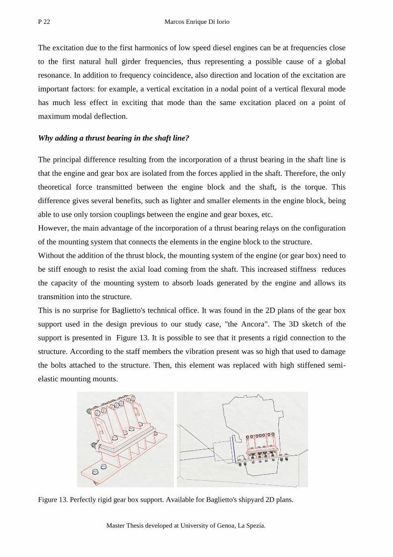
This is no surprise for Baglietto's technical office. It was found in the 2D plans of the gear box
support used in the design previous to our study case, "the Ancora". The 3D sketch of the
support is presented in Figure 13. It is possible to see that it presents a rigid connection to the
structure. According to the staff members the vibration present was so high that used to damage
the bolts attached to the structure. Then, this element was replaced with high stiffened semi-
elastic mounting mounts.
Figure 13. Perfectly rigid gear box support. Available for Baglietto's shipyard 2D plans.

Engine foundation re-design due to modification of the shaft line arrangement 23
“EMSHIP” Erasmus Mundus Master Course, period of study September 2014 – February 2016
When a thrust block is resisting the axial load transmitted by the shaft, the engine block's
mounting system should be designed in order to minimize the vibration transmitted by the
engine into the structure.
7.3. Loads applied on the engine foundation
The main loads that are taken into account in this study are the ones that act on the foundation of
the engine block and thrust block. Therefore, according to the classification mentioned section
7.1, they are considered "local loads". From the selected forces we can divide them into two
main groups:
forces that are always acting on the structure "constant loads";
forces that exists only when the engine is working "variable loads".
Constant loads
This corresponds to the weight of the elements and the pressure of the fluids applied on the
structure. The loads present no variation in time (static loads) or really small variation in time
(quasi static loads). For example, a change in the ship's weight due toa a load condition will
change the pressure values around the hull. Then a dynamic analysis is not needed to be
performed apart from the typical static analysis.
Weight:
It includes all the weight that should be supported by the mounting system. This means, the dry
weight of the engine, gear box and couplings in addition to operational fluids, such as lubricant
oil, fuel, refrigerants, etc.
The weight of this different elements transmit to the structure through the resilient mounts of
the supports system. The weight is distributed on the supporting elements depending on their
position respect to the centre of gravity of the element they support.
Coordinate system: In practice, the coordinate system originates from crossing 03 line with
centre of crankshaft on shaft line arrangement drawing.
X - Longitudinal direction, positive towards engine free end;
Y - Lateral direction, positive towards the right, looking at engine free end;
Z - Vertical direction, positive above centre of crankshaft.
The following image shows the position of the centre of gravity of the engine of the study case,
which correspond to a CAT 3512B DITA SWAC with the original support configuration.

P 24 Marcos Enrique Di Iorio
Master Thesis developed at University of Genoa, La Spezia.
Table 4. details the position of the engine, coupling (engine - gear box) and the four resilient
mounts of the support system respect to the engine block's coordinate system.
Figure 14. Location of the centre of gravity of the engine respect to the origin (lines: 01,02,03) coordinate
system used.
Table 4. Location of centre of gravity, coupling and mounts respect to the engine block's coordinate
system.
Position from origin
Element x y z
Engine (CoG) 900 -35 244
Coupling -300 - -
Mount 1 192 553 -412
Mount 2 192 -553 -412
Mount 3 1525 -553 -412
Mount 4 1525 553 -412
The vertical position of the mounting elements in the actual foundation depends on the
inclination of the supporting flanges. The weight is then distributed un-evenly between all the
supports. The weight distribution also depends on the configuration of the support system. This
is explained with further detail in section 8.3.
Engine foundation re-design due to modification of the shaft line arrangement 25
“EMSHIP” Erasmus Mundus Master Course, period of study September 2014 – February 2016
Hydrostatic Loads
Sea water pressure: The surrounding water is considered at rest, and is represented as pressure
applied on the model's hull. The pressure value at a point below a pre-established water line
increases according to the known hydrostatic pressure relation. :
(2)
where:
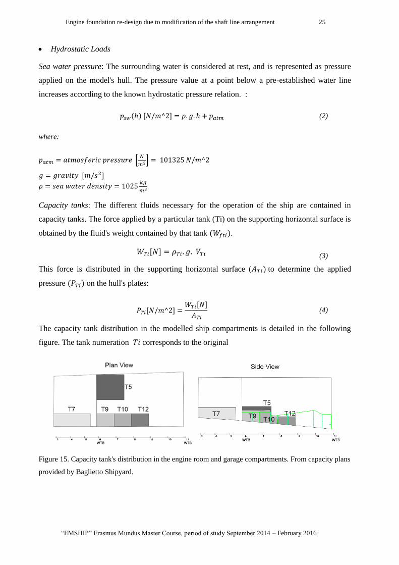
Capacity tanks: The different fluids necessary for the operation of the ship are contained in
capacity tanks. The force applied by a particular tank (Ti) on the supporting horizontal surface is
obtained by the fluid's weight contained by that tank .
(3)
This force is distributed in the supporting horizontal surface ( to determine the applied
pressure on the hull's plates:
(4)
The capacity tank distribution in the modelled ship compartments is detailed in the following
figure. The tank numeration corresponds to the original
Figure 15. Capacity tank's distribution in the engine room and garage compartments. From capacity plans
provided by Baglietto Shipyard.
P 26 Marcos Enrique Di Iorio
Master Thesis developed at University of Genoa, La Spezia.
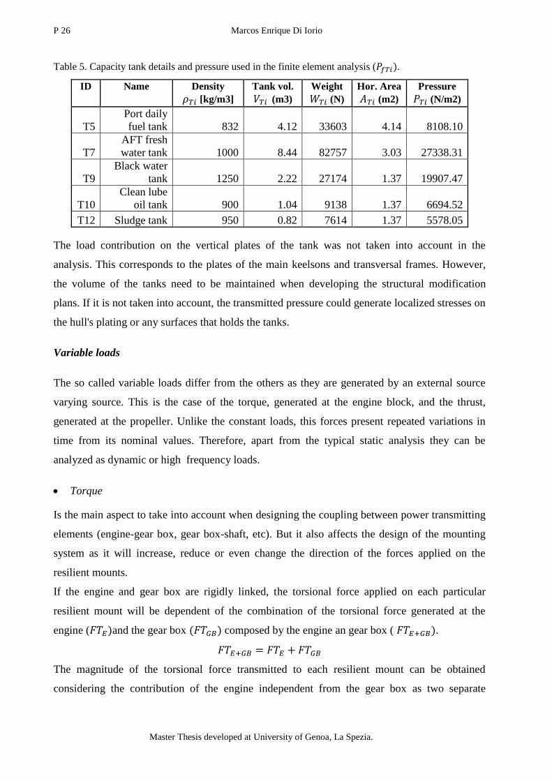
Table 5. Capacity tank details and pressure used in the finite element analysis ( .
ID Name Density
[kg/m3]
Tank vol.
(m3)
Weight
(N)
Hor. Area
(m2)
Pressure
(N/m2)
T5
Port daily
fuel tank 832 4.12 33603 4.14 8108.10
T7
AFT fresh
water tank 1000 8.44 82757 3.03 27338.31
T9
Black water
tank 1250 2.22 27174 1.37 19907.47
T10
Clean lube
oil tank 900 1.04 9138 1.37 6694.52
T12 Sludge tank 950 0.82 7614 1.37 5578.05
The load contribution on the vertical plates of the tank was not taken into account in the
analysis. This corresponds to the plates of the main keelsons and transversal frames. However,
the volume of the tanks need to be maintained when developing the structural modification
plans. If it is not taken into account, the transmitted pressure could generate localized stresses on
the hull's plating or any surfaces that holds the tanks.
Variable loads
The so called variable loads differ from the others as they are generated by an external source
varying source. This is the case of the torque, generated at the engine block, and the thrust,
generated at the propeller. Unlike the constant loads, this forces present repeated variations in
time from its nominal values. Therefore, apart from the typical static analysis they can be
analyzed as dynamic or high frequency loads.
Torque
Is the main aspect to take into account when designing the coupling between power transmitting
elements (engine-gear box, gear box-shaft, etc). But it also affects the design of the mounting
system as it will increase, reduce or even change the direction of the forces applied on the
resilient mounts.
If the engine and gear box are rigidly linked, the torsional force applied on each particular
resilient mount will be dependent of the combination of the torsional force generated at the
engine ( and the gear box composed by the engine an gear box ( .
The magnitude of the torsional force transmitted to each resilient mount can be obtained
considering the contribution of the engine independent from the gear box as two separate
Engine foundation re-design due to modification of the shaft line arrangement 27
“EMSHIP” Erasmus Mundus Master Course, period of study September 2014 – February 2016
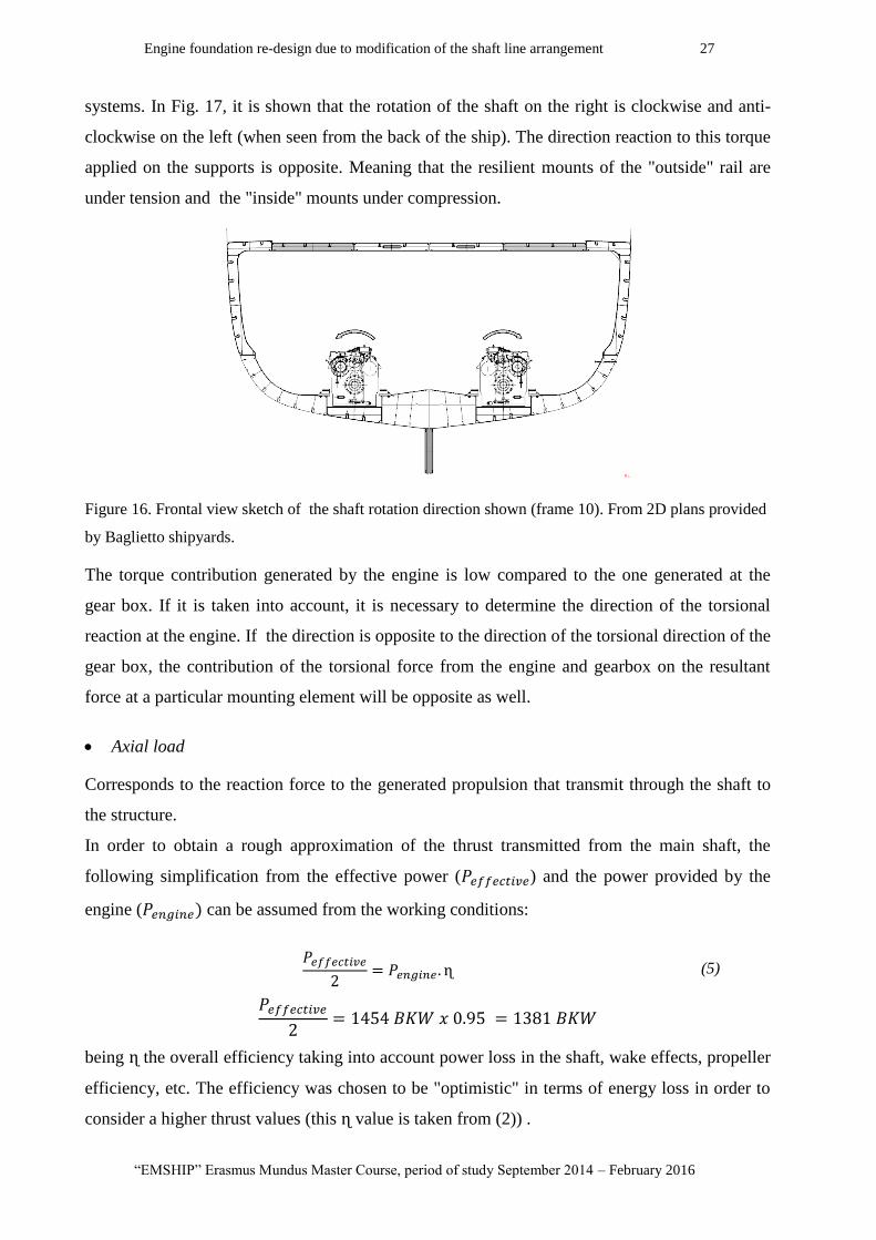
systems. In Fig. 17, it is shown that the rotation of the shaft on the right is clockwise and anti-
clockwise on the left (when seen from the back of the ship). The direction reaction to this torque
applied on the supports is opposite. Meaning that the resilient mounts of the "outside" rail are
under tension and the "inside" mounts under compression.
Figure 16. Frontal view sketch of the shaft rotation direction shown (frame 10). From 2D plans provided
by Baglietto shipyards.
The torque contribution generated by the engine is low compared to the one generated at the
gear box. If it is taken into account, it is necessary to determine the direction of the torsional
reaction at the engine. If the direction is opposite to the direction of the torsional direction of the
gear box, the contribution of the torsional force from the engine and gearbox on the resultant
force at a particular mounting element will be opposite as well.
Axial load
Corresponds to the reaction force to the generated propulsion that transmit through the shaft to
the structure.
In order to obtain a rough approximation of the thrust transmitted from the main shaft, the
following simplification from the effective power ( ) and the power provided by the
engine ( can be assumed from the working conditions:
(5)
being the overall efficiency taking into account power loss in the shaft, wake effects, propeller
efficiency, etc. The efficiency was chosen to be "optimistic" in terms of energy loss in order to
consider a higher thrust values (this value is taken from (2)) .

P 28 Marcos Enrique Di Iorio
Master Thesis developed at University of Genoa, La Spezia.
The thrust ( ) in generated in each propeller and transmitted to the shaft line can then be
calculated as:
(6)
being the ship velocity (v), set in 16 knots (8.23m/s), then:
According to the propulsion system responsable from Baglietto's technical office, for this
particular ship at a ship velocity of 16 knots, the thrust at each shaft is expected to be 100 kN
being the efficiency ( less than the expected theoretical value.
Loads to be used in the FEM analysis
The analysis performed during this work are intended to provide a comparison between the
performance of the foundation of the original structure and the proposed modifications. In this
particular case the effect of the "constant" hydrostatic pressure on the structure do not vary
significantly from one design to the other. Therefore, its influence has been considered
secondary and was not taken into account in the calculation
The structural response of the actual and modified foundations is studied from the reaction to the
forces generated by the:
elements weight: Generated by the main elements supported by the foundation (engine,
gear box, couplings, etc.)
torque: generated at the engine and gearbox.
thrust: transmitted through the shaft to the respective resisting element (gear box or
thrust bearings)
As the generated forces and moments are applied through the different supporting elements, it is
necessary to understand the implications related to the supporting systems.
7.4. Conclusion
From different types of loads that act on a ship only these that affect directly the structural
strength of the engine foundation are taken into account. This are the loads generated and
transmitted by the engine block and added thrust block. This loads are applied on the structure
during the analysis as static forces in order to obtain its linear stress and deformation response.
The dynamic effect is discussed but not calculated.

Engine foundation re-design due to modification of the shaft line arrangement 29
“EMSHIP” Erasmus Mundus Master Course, period of study September 2014 – February 2016
8. Engine block supports
As explained before the main objective in the incorporation of the thrust bearing is not to modify
how the axial load is applied, but to improve how the dynamic loads of the engine are
transmitted to the structure. Therefore, it is crucial to understand how the engine vibration is
dealt with so that the beneficial aspect resulting from the addition of the thrust block are
exploited as much as possible.
With this objective, a three day visit to the Vulkan company Branch in Novi Ligure, Italy, was
arranged. Apart from selecting and positioning their own thrust blocks the company's technical
office is in charge of designing mounting systems for different required engine blocks.
This section includes the main aspects that need to be considered when choosing the appropriate
support system for a particular engine. Despite the main calculations used to choose the support
system configuration and resilient elements are performed by the providing company with
internal computer programs, the selection procedure is described in the following
8.1. Static load calculation
The analysis can be performed in order to determine the maximum loads that are going to be
applied on the resilient elements to be used in the support system, according to the
recommendations and assistance provided by Vulkan Italy's technical staff.
The analysis is performed on the engine and gear box, considering the support system
configuration of the original design (see section 6.2.2). For each case, the engine and gear box
are analyzed as separate and independent systems and the forces are analyzed only applied in the
direction of the mounting element (no transversal forces or moments are considered):
Loads applied on the engine supports
Weight:
o Engine's total weight ( ): this takes into account the "dry" weight of the engine with
an additional 35% related to the operating fluids and fuel. This value was recommended
by Vulkan Italy.
(7)
P 30 Marcos Enrique Di Iorio
Master Thesis developed at University of Genoa, La Spezia.
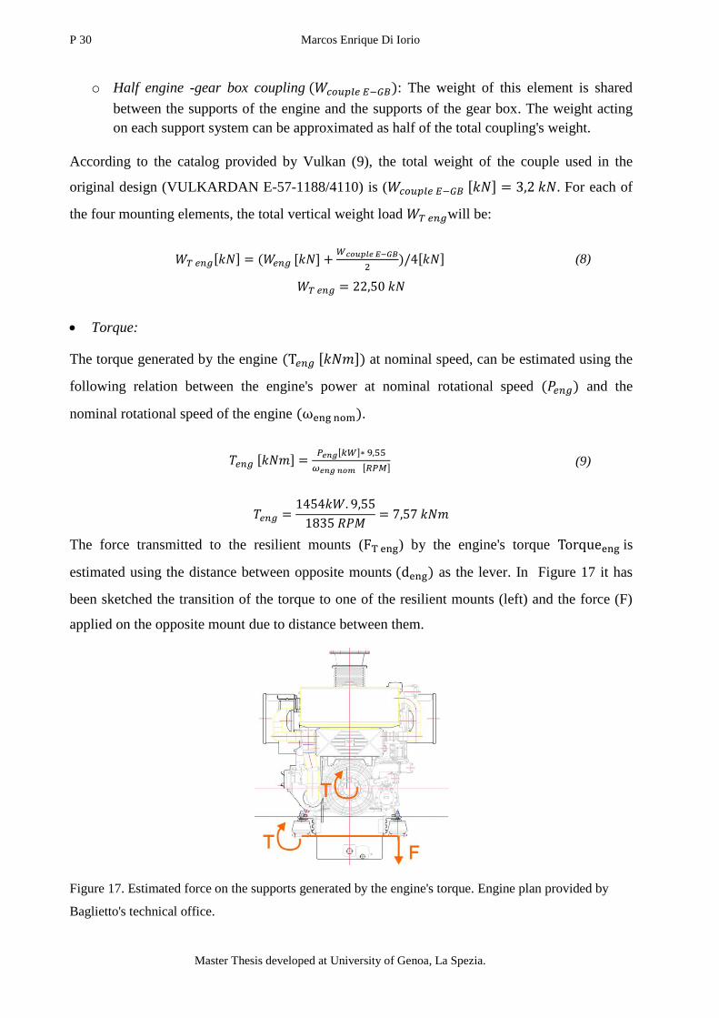
o Half engine -gear box coupling : The weight of this element is shared
between the supports of the engine and the supports of the gear box. The weight acting
on each support system can be approximated as half of the total coupling's weight.
According to the catalog provided by Vulkan (9), the total weight of the couple used in the
original design (VULKARDAN E-57-1188/4110) is ( For each of
the four mounting elements, the total vertical weight load will be:
(8)
Torque:
The torque generated by the engine at nominal speed, can be estimated using the
following relation between the engine's power at nominal rotational speed and the
nominal rotational speed of the engine .
(9)
The force transmitted to the resilient mounts ( ) by the engine's torque is
estimated using the distance between opposite mounts as the lever. In Figure 17 it has
been sketched the transition of the torque to one of the resilient mounts (left) and the force (F)
applied on the opposite mount due to distance between them.
Figure 17. Estimated force on the supports generated by the engine's torque. Engine plan provided by
Baglietto's technical office.
Engine foundation re-design due to modification of the shaft line arrangement 31
“EMSHIP” Erasmus Mundus Master Course, period of study September 2014 – February 2016
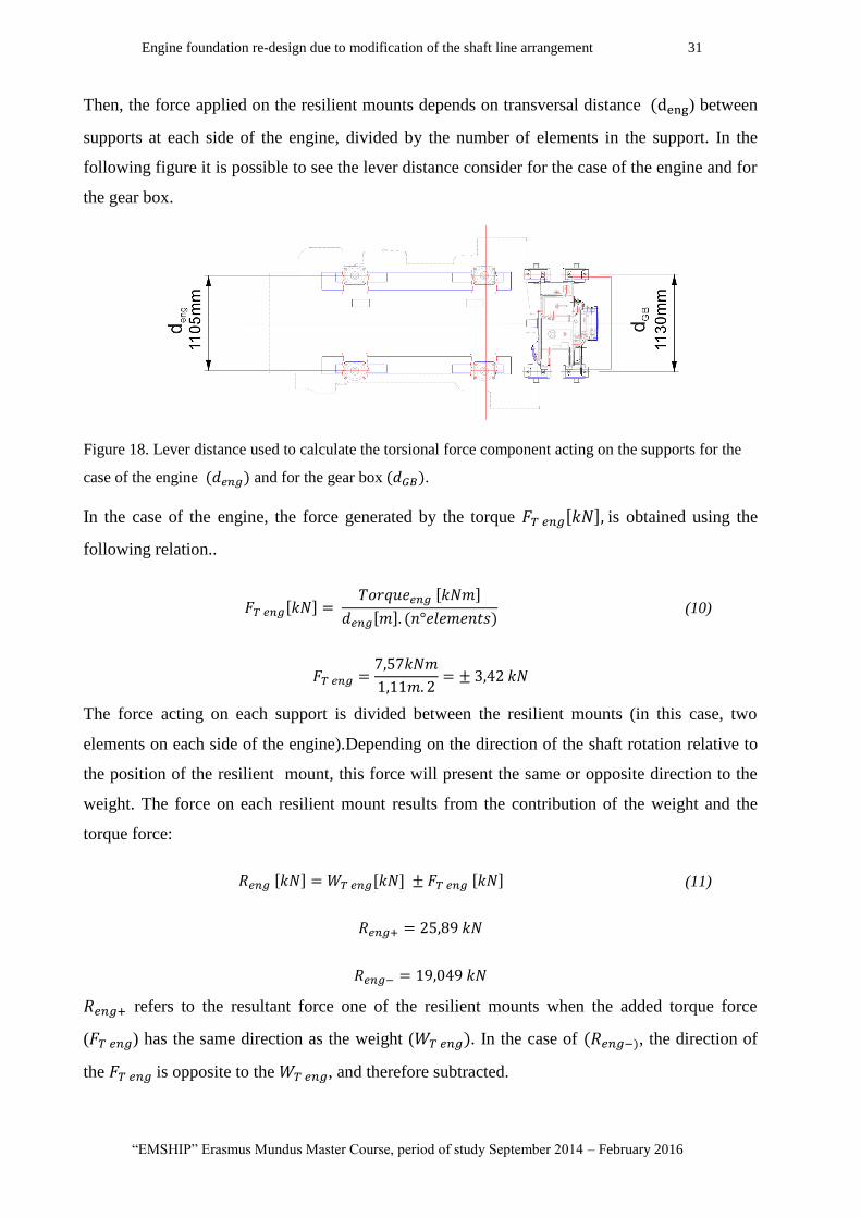
Then, the force applied on the resilient mounts depends on transversal distance ) between
supports at each side of the engine, divided by the number of elements in the support. In the
following figure it is possible to see the lever distance consider for the case of the engine and for
the gear box.
Figure 18. Lever distance used to calculate the torsional force component acting on the supports for the
case of the engine and for the gear box .
In the case of the engine, the force generated by the torque is obtained using the
following relation..
(10)
The force acting on each support is divided between the resilient mounts (in this case, two
elements on each side of the engine).Depending on the direction of the shaft rotation relative to
the position of the resilient mount, this force will present the same or opposite direction to the
weight. The force on each resilient mount results from the contribution of the weight and the
torque force:
(11)
refers to the resultant force one of the resilient mounts when the added torque force
( ) has the same direction as the weight ( . In the case of , the direction of
the is opposite to the , and therefore subtracted.

P 32 Marcos Enrique Di Iorio
Master Thesis developed at University of Genoa, La Spezia.
Loads applied on the gear box supports
The forces acting on the gear box's support are calculated taking into account the same
considerations as the engine.
Weight:
o Gear box's total weight ( ): It is obtained from the gear box dry weight (1700 kg)
from equation (7),
To the gearbox total weight it is necessary to add:
o Half engine-gearbox coupling:
,
In this case half of the coupling's weight is added to consider half of the weight of the shaft
between the hull tube and the gear box flange (2660 mm length), see Figure 7 .
From Equation (1), the shaft total weight is 12,252 kN.
o Half partial shaft weight (2660 mm length):
(12)
The total weight applied at on the gear box's support system is:
Then, the weight applied on each side of the supports is
o Half thrust bearing-gear box coupling ( :
In the case of the modified structures, half of the thrust block's coupling should be added as
well. For example, in the case of the thrust bearing proposed by Vulkan Italy, the Prop-flex
couple that was recommended with a total weight of 300kg.. Then:
The weight distribution of this couple between the gear box supports and the thrust bearing
supports can be estimated as half of the couple's weight, but this can lead into errors depending
on the relative positions between the support and the coupling. Then, it is not considered in the
analysis.

Engine foundation re-design due to modification of the shaft line arrangement 33
“EMSHIP” Erasmus Mundus Master Course, period of study September 2014 – February 2016
Torque:
The force generated by the torque on each support is obtained in Eq.(13). It is possible to see
that the torque is "r" times the torque in the engine:
(13)
The same relation (Eq.(10)) can be used to obtain the forces transmitted by the gear box torque
( to each support ):
Using (11), it is possible to estimate the resultant force applied on each side of the gear
box:
Unlike the engine supporting elements, it is possible to see that the supports on one side of the of
the gear box will be loaded under compression ( ) and the other under tension (
This is due to the fact that:
o the gear box is almost 4 times lighter than the engine (
o the torque transmitted by the gear box is more than 4 times the torque transmitted by the
engine (r=4062).
As a result, the torque generated force ( applied on the supports is higher than the
contribution of the gear box weight ( ) and the direction of the resulting force changes. In
such case, it is necessary to use resilient mounts that are able to resist both types of loads.
P 34 Marcos Enrique Di Iorio
Master Thesis developed at University of Genoa, La Spezia.
Thrust:
In the working condition of 16 knots, the total thrust at each shaft is ( =100 kN). The applied
thrust on each support of the gear box is then /2=50 kN ,
Taking into account that the shaft inclination angle is 7,7°, it is possible to decompose the force
into:
A component parallel to the resilient mount axis (
(14)
A component perpendicular to the resilient mount axis (
(15)
The thrust force is usually neglected when performing a pre-selection of the resilient mounts of
the support system, because the predominant component of the force is generally perpendicular
to the direction of the element. However, it is possible to see that the vertical component of the
thrust load ( is in this case almost half of the contribution of the gear box's weight on each
support (
).
8.2. Resilient mount selection
The resultant force applied on the resilient mount will generate its deflection. Once the loads
acting on the supports are known, it is possible to pre-select the resilient mounts to be used
based on its desired maximum deflection.
Considering only the static load, the distance ( that the mount is displaced will depend on its
static stiffness (k).
(16)
It is important to distinguish the static stiffness from the rubber hardness (*). The first
correspond to a property of the resilient mount element as a whole and the second corresponds
to a property of the elastic material used in the element.
Engine foundation re-design due to modification of the shaft line arrangement 35
“EMSHIP” Erasmus Mundus Master Course, period of study September 2014 – February 2016
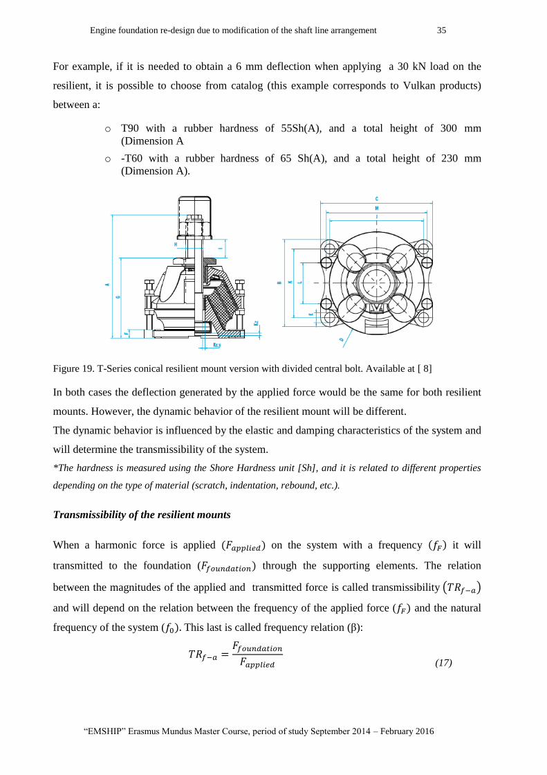
For example, if it is needed to obtain a 6 mm deflection when applying a 30 kN load on the
resilient, it is possible to choose from catalog (this example corresponds to Vulkan products)
between a:
o T90 with a rubber hardness of 55Sh(A), and a total height of 300 mm
(Dimension A
o -T60 with a rubber hardness of 65 Sh(A), and a total height of 230 mm
(Dimension A).
Figure 19. T-Series conical resilient mount version with divided central bolt. Available at [ 8]
In both cases the deflection generated by the applied force would be the same for both resilient
mounts. However, the dynamic behavior of the resilient mount will be different.
The dynamic behavior is influenced by the elastic and damping characteristics of the system and
will determine the transmissibility of the system.
*The hardness is measured using the Shore Hardness unit [Sh], and it is related to different properties
depending on the type of material (scratch, indentation, rebound, etc.).
Transmissibility of the resilient mounts
When a harmonic force is applied on the system with a frequency it will
transmitted to the foundation ( through the supporting elements. The relation
between the magnitudes of the applied and transmitted force is called transmissibility
and will depend on the relation between the frequency of the applied force ( and the natural
frequency of the system ( This last is called frequency relation (β):
(17)
P 36 Marcos Enrique Di Iorio
Master Thesis developed at University of Genoa, La Spezia.
(18)
If the foundation is considered perfectly rigid, the force applied can be analyzed in terms of the
deflection of the mounting element. In other word, the force transmitted to the foundation will
be considered equal to the force applied on the supports which depends of the deflection. The
varying force will generate a variation of the displacement from its static position, and the
transmissibility can be defined as:
(19)
The main objective in the design of the support system is to minimize the force transmitted to
the foundation from the applied force by reducing as much as possible the dynamic motion of
the supported masses.
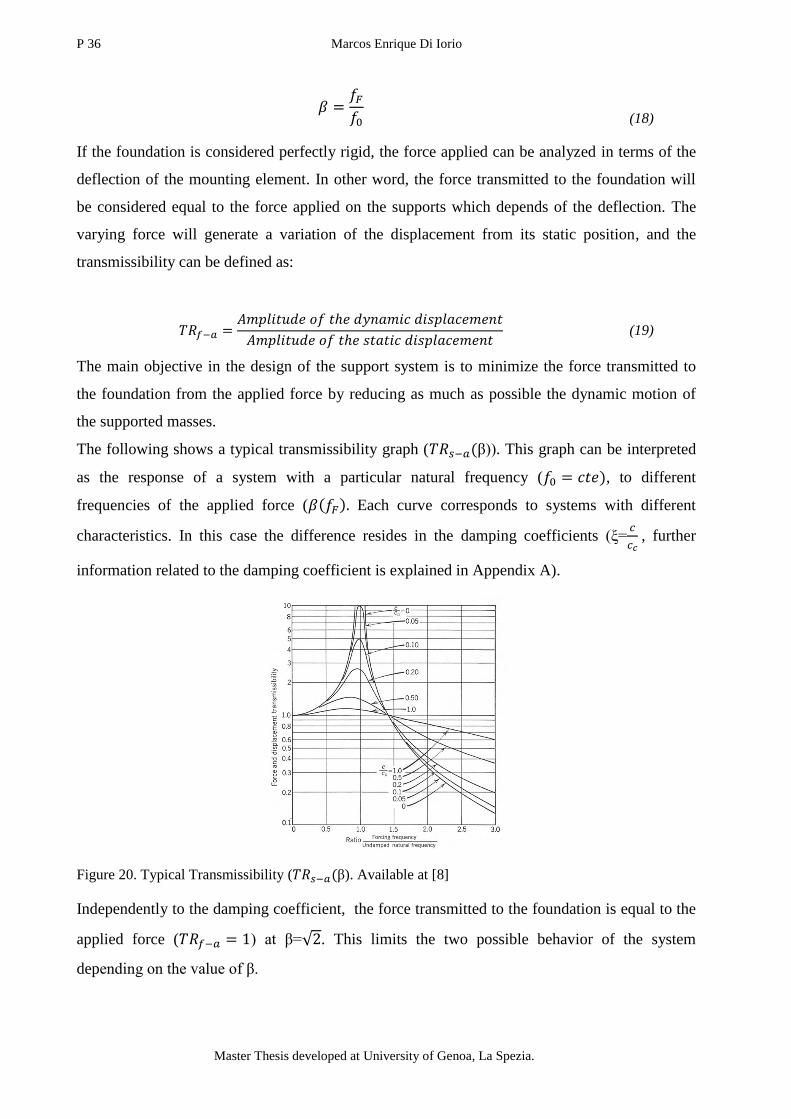
The following shows a typical transmissibility graph ( β)). This graph can be interpreted
as the response of a system with a particular natural frequency ( , to different
frequencies of the applied force ( Each curve corresponds to systems with different
characteristics. In this case the difference resides in the damping coefficients (ξ=
, further
information related to the damping coefficient is explained in Appendix A).
Figure 20. Typical Transmissibility ( β). Available at [8]
Independently to the damping coefficient, the force transmitted to the foundation is equal to the
applied force ( ) at β= . This limits the two possible behavior of the system
depending on the value of β.
Engine foundation re-design due to modification of the shaft line arrangement 37
“EMSHIP” Erasmus Mundus Master Course, period of study September 2014 – February 2016
o If β < , there is an amplification of the applied force. The force transmitted on to the
foundation is maximum when the frequency of the excitation force is equal to the
system's natural frequency (β=1), where the system achieves resonance. When using
higher damping coefficients (ξ) it is possible to reduce the maximum transmissibility
values at the resonance frequency.
o If β > there is an attenuation of the transmitted force, respect to the applied force.
In this case, when increasing the damping coefficient reduces the attenuation capacity
and the force transmitted is increased.
In order validate the selection of a particular resilient mount, it is necessary to analyze the
transmissibility of the system composed by an element (engine, gear box, etc.) elastically
supported on a perfectly rigid foundation.
This analysis is usually performed by the supporting system providers using special
computational tools and specific knowledge and information is required and is beyond the reach
of this work. Moreover, it is difficult to anticipate the influence of the system's dynamic
response on the structure before performing the modifications.
The resilient mounts and supporting structure configurations where designed and proposed by
the same companies that provided the thrust bearing proposals. However, in Appendix A it has
been explained the procedure used to perform a dynamic analysis of a support system of the
engine block that corresponds to our studied case.
8.3. Mounting system configuration
Despite the characteristics of the different resilient mounts used (static and dynamic stiffness,
damping ratio, etc.) is not addressed in the analysis performed, it is necessary to understand how
the modifications proposed for the supporting systems affect the way that forces and moments
are applied and transmitted to the structure.
In this section it has been described the supporting system configurations of the original design
and compared to the proposed modifications:
P 38 Marcos Enrique Di Iorio
Master Thesis developed at University of Genoa, La Spezia.
Case 1: Original mounting system configuration
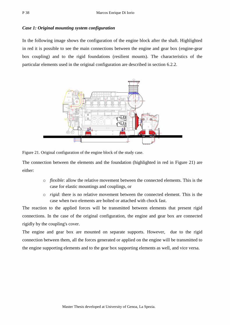
In the following image shows the configuration of the engine block after the shaft. Highlighted
in red it is possible to see the main connections between the engine and gear box (engine-gear
box coupling) and to the rigid foundations (resilient mounts). The characteristics of the
particular elements used in the original configuration are described in section 6.2.2.
Figure 21. Original configuration of the engine block of the study case.
The connection between the elements and the foundation (highlighted in red in Figure 21) are
either:
o flexible: allow the relative movement between the connected elements. This is the
case for elastic mountings and couplings, or
o rigid: there is no relative movement between the connected element. This is the
case when two elements are bolted or attached with chock fast.
The reaction to the applied forces will be transmitted between elements that present rigid
connections. In the case of the original configuration, the engine and gear box are connected
rigidly by the coupling's cover.
The engine and gear box are mounted on separate supports. However, due to the rigid
connection between them, all the forces generated or applied on the engine will be transmitted to
the engine supporting elements and to the gear box supporting elements as well, and vice versa.
Engine foundation re-design due to modification of the shaft line arrangement 39
“EMSHIP” Erasmus Mundus Master Course, period of study September 2014 – February 2016
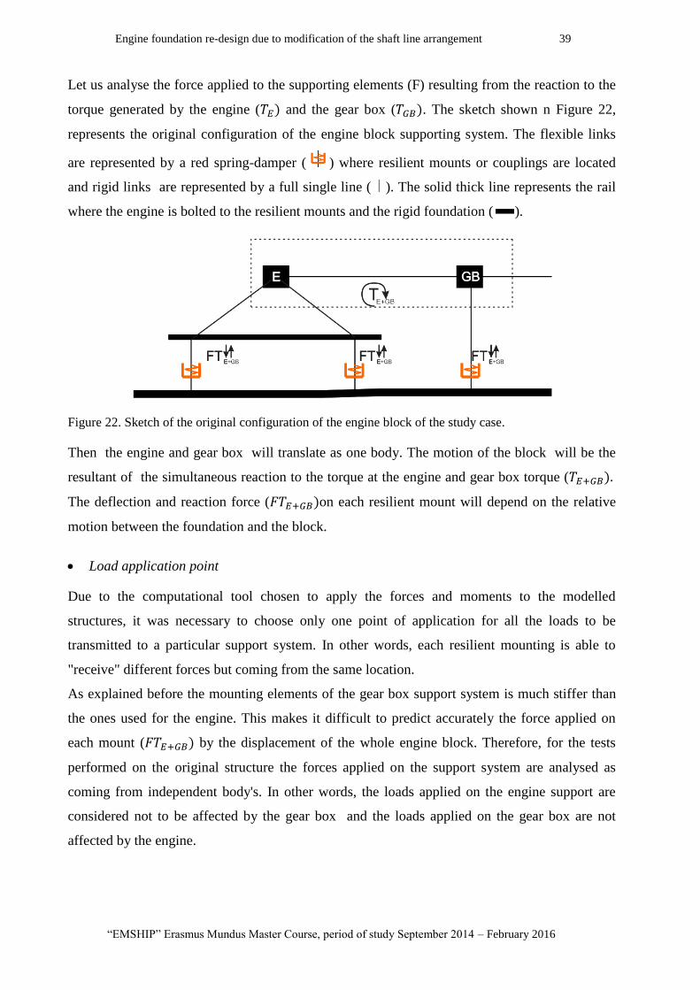
Let us analyse the force applied to the supporting elements (F) resulting from the reaction to the
torque generated by the engine ( and the gear box ( . The sketch shown n Figure 22,
represents the original configuration of the engine block supporting system. The flexible links
are represented by a red spring-damper ( ) where resilient mounts or couplings are located
and rigid links are represented by a full single line ( ). The solid thick line represents the rail
where the engine is bolted to the resilient mounts and the rigid foundation ( ).
Figure 22. Sketch of the original configuration of the engine block of the study case.
Then the engine and gear box will translate as one body. The motion of the block will be the
resultant of the simultaneous reaction to the torque at the engine and gear box torque (
The deflection and reaction force ( on each resilient mount will depend on the relative
motion between the foundation and the block.
Load application point
Due to the computational tool chosen to apply the forces and moments to the modelled
structures, it was necessary to choose only one point of application for all the loads to be
transmitted to a particular support system. In other words, each resilient mounting is able to
"receive" different forces but coming from the same location.
As explained before the mounting elements of the gear box support system is much stiffer than
the ones used for the engine. This makes it difficult to predict accurately the force applied on
each mount ( by the displacement of the whole engine block. Therefore, for the tests
performed on the original structure the forces applied on the support system are analysed as
coming from independent body's. In other words, the loads applied on the engine support are
considered not to be affected by the gear box and the loads applied on the gear box are not
affected by the engine.
P 40 Marcos Enrique Di Iorio
Master Thesis developed at University of Genoa, La Spezia.
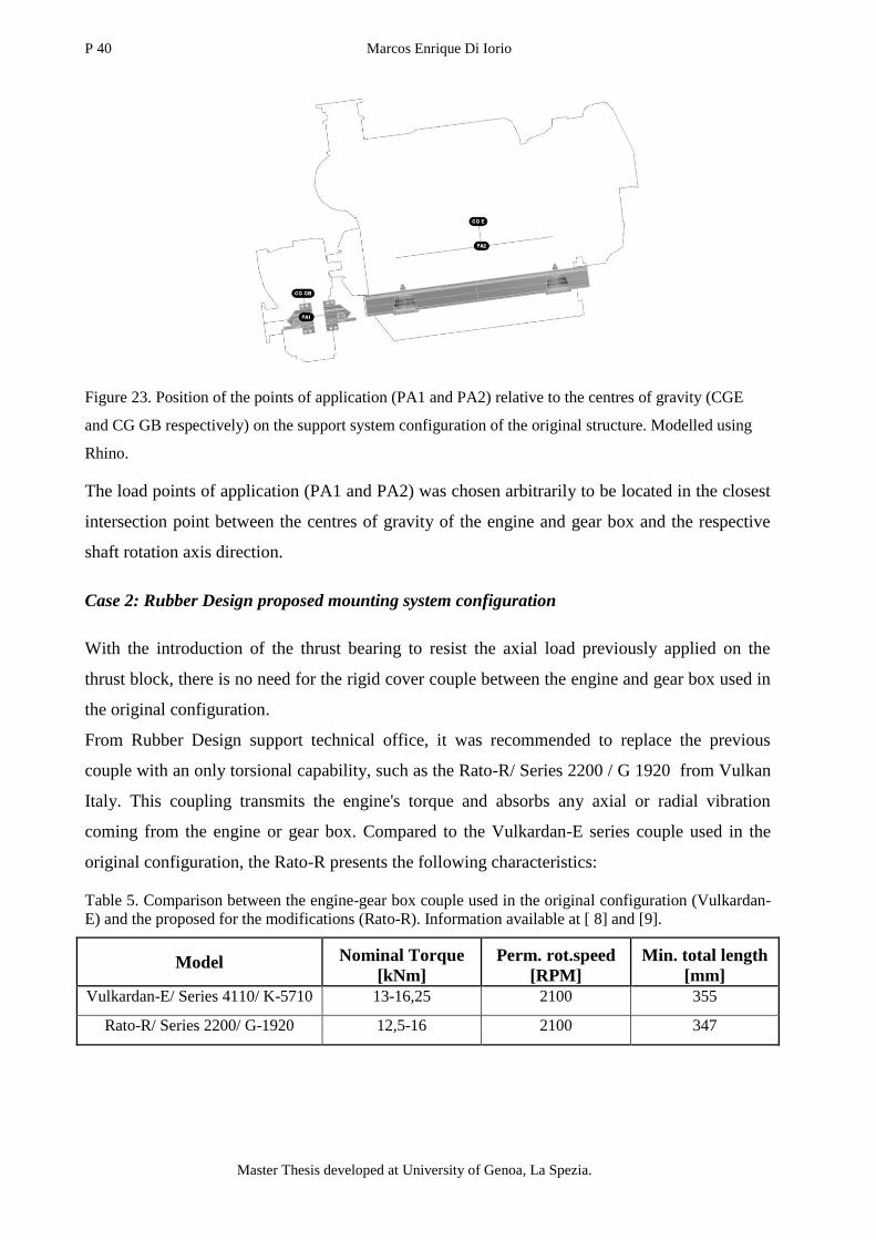
Figure 23. Position of the points of application (PA1 and PA2) relative to the centres of gravity (CGE
and CG GB respectively) on the support system configuration of the original structure. Modelled using
Rhino.
The load points of application (PA1 and PA2) was chosen arbitrarily to be located in the closest
intersection point between the centres of gravity of the engine and gear box and the respective
shaft rotation axis direction.
Case 2: Rubber Design proposed mounting system configuration
With the introduction of the thrust bearing to resist the axial load previously applied on the
thrust block, there is no need for the rigid cover couple between the engine and gear box used in
the original configuration.
From Rubber Design support technical office, it was recommended to replace the previous
couple with an only torsional capability, such as the Rato-R/ Series 2200 / G 1920 from Vulkan
Italy. This coupling transmits the engine's torque and absorbs any axial or radial vibration
coming from the engine or gear box. Compared to the Vulkardan-E series couple used in the
original configuration, the Rato-R presents the following characteristics:
Table 5. Comparison between the engine-gear box couple used in the original configuration (Vulkardan-
E) and the proposed for the modifications (Rato-R). Information available at [ 8] and [9].
Model Nominal Torque
[kNm]
Perm. rot.speed
[RPM]
Min. total length
[mm]
Vulkardan-E/ Series 4110/ K-5710 13-16,25 2100 355
Rato-R/ Series 2200/ G-1920 12,5-16 2100 347

Engine foundation re-design due to modification of the shaft line arrangement 41
“EMSHIP” Erasmus Mundus Master Course, period of study September 2014 – February 2016
Despite the flexible connection in the coupling, it is proposed to mount rigidly both engine and
gear box on the same rail creating a rigid connection between the two elements. The resultant
torque on the rail ( will be a combination of the torque generated at the engine ( and
the one generated at the gear box ( .
Figure 24. Rubber Design's proposed solution. Preliminary design (S01-0214-1075) presented by RB
technical office.
Unlike the original configuration, the stiffness of all the resilient mounting elements is the same.
Then, the resultant torque and weight force on each supporting element can be considered to
depend only on their relative position respect to a particular point.
Figure 25. Sketch of Rubber Design modification of the original engine block.
Advantages and disadvantages:
This type of supporting system configuration distributes totally the force and torque between all
element. The force generated from the gear box increased torque may generate a traction
resultant force on some or all of the mounting elements. The potential tensional loads need to be
taken into account when choosing the type of resilient mount.
At the same time the resultant weight of the whole engine block increases the compression
found in the resilient mounts below the gear box.

P 42 Marcos Enrique Di Iorio
Master Thesis developed at University of Genoa, La Spezia.
If the stiffness of each resilient mount element is not appropriately calculated, the force may not
be equally distributed between the elements. This could generate overloading that can eventually
destroy the support and damage the structure.
Load application point
As explained before, each resilient mounting is able to "receive" different forces but coming
from the same location.
This is not an easy task due to the fact that the considered forces to be transmitted (weight,
torque and thrust) are different both in origin, nature and application point. For example, the
engine's weight applied on its centre of mass and the gear box's torque is applied somewhere in
the direction of the main shaft. Moreover, the rigid connection between the engine and gear box
presents eccentricity with respect to any force application point.
Figure 26. Position of the point of application (PA) relative to the centres of gravity (CGE and CG GB
respectively) on the support system configuration proposed by Rubber Design. Modelled using Rhino.
The load point of application was chosen arbitrarily to be located in the middle point between
the centres of gravity of the engine and gear box.
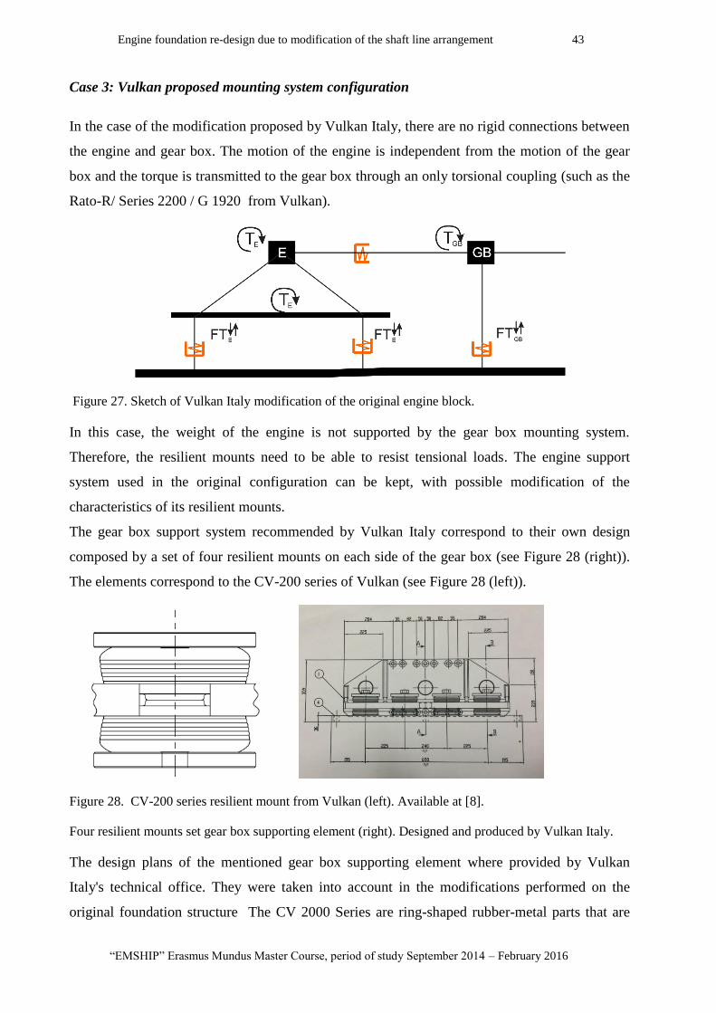
Engine foundation re-design due to modification of the shaft line arrangement 43
“EMSHIP” Erasmus Mundus Master Course, period of study September 2014 – February 2016
Case 3: Vulkan proposed mounting system configuration
In the case of the modification proposed by Vulkan Italy, there are no rigid connections between
the engine and gear box. The motion of the engine is independent from the motion of the gear
box and the torque is transmitted to the gear box through an only torsional coupling (such as the
Rato-R/ Series 2200 / G 1920 from Vulkan).
Figure 27. Sketch of Vulkan Italy modification of the original engine block.
In this case, the weight of the engine is not supported by the gear box mounting system.
Therefore, the resilient mounts need to be able to resist tensional loads. The engine support
system used in the original configuration can be kept, with possible modification of the
characteristics of its resilient mounts.
The gear box support system recommended by Vulkan Italy correspond to their own design
composed by a set of four resilient mounts on each side of the gear box (see Figure 28 (right)).
The elements correspond to the CV-200 series of Vulkan (see Figure 28 (left)).
Figure 28. CV-200 series resilient mount from Vulkan (left). Available at [8].
Four resilient mounts set gear box supporting element (right). Designed and produced by Vulkan Italy.
The design plans of the mentioned gear box supporting element where provided by Vulkan
Italy's technical office. They were taken into account in the modifications performed on the
original foundation structure The CV 2000 Series are ring-shaped rubber-metal parts that are
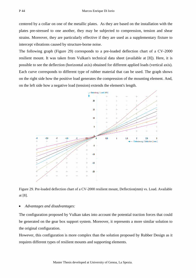
P 44 Marcos Enrique Di Iorio
Master Thesis developed at University of Genoa, La Spezia.
centered by a collar on one of the metallic plates. As they are based on the installation with the
plates pre-stressed to one another, they may be subjected to compression, tension and shear
strains. Moreover, they are particularly effective if they are used as a supplementary fixture to
intercept vibrations caused by structure-borne noise.
The following graph (Figure 29) corresponds to a pre-loaded deflection chart of a CV-2000
resilient mount. It was taken from Vulkan's technical data sheet (available at [8]). Here, it is
possible to see the deflection (horizontal axis) obtained for different applied loads (vertical axis).
Each curve corresponds to different type of rubber material that can be used. The graph shows
on the right side how the positive load generates the compression of the mounting element. And,
on the left side how a negative load (tension) extends the element's length.
Figure 29. Pre-loaded deflection chart of a CV-2000 resilient mount, Deflection(mm) vs. Load. Available
at [8].
Advantages and disadvantages:
The configuration proposed by Vulkan takes into account the potential traction forces that could
be generated on the gear box support system. Moreover, it represents a more similar solution to
the original configuration.
However, this configuration is more complex than the solution proposed by Rubber Design as it
requires different types of resilient mounts and supporting elements.
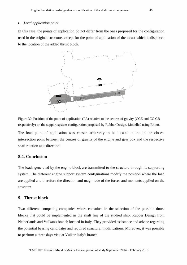
Engine foundation re-design due to modification of the shaft line arrangement 45
“EMSHIP” Erasmus Mundus Master Course, period of study September 2014 – February 2016
Load application point
In this case, the points of application do not differ from the ones proposed for the configuration
used in the original structure, except for the point of application of the thrust which is displaced
to the location of the added thrust block.
Figure 30. Position of the point of application (PA) relative to the centres of gravity (CGE and CG GB
respectively) on the support system configuration proposed by Rubber Design. Modelled using Rhino.
The load point of application was chosen arbitrarily to be located in the in the closest
intersection point between the centres of gravity of the engine and gear box and the respective
shaft rotation axis direction.
8.4. Conclusion
The loads generated by the engine block are transmitted to the structure through its supporting
system. The different engine support system configurations modify the position where the load
are applied and therefore the direction and magnitude of the forces and moments applied on the
structure.
9. Thrust block
Two different competing companies where consulted in the selection of the possible thrust
blocks that could be implemented in the shaft line of the studied ship, Rubber Design from
Netherlands and Vulkan's branch located in Italy. They provided assistance and advice regarding
the potential bearing candidates and required structural modifications. Moreover, it was possible
to perform a three days visit at Vulkan Italy's branch.
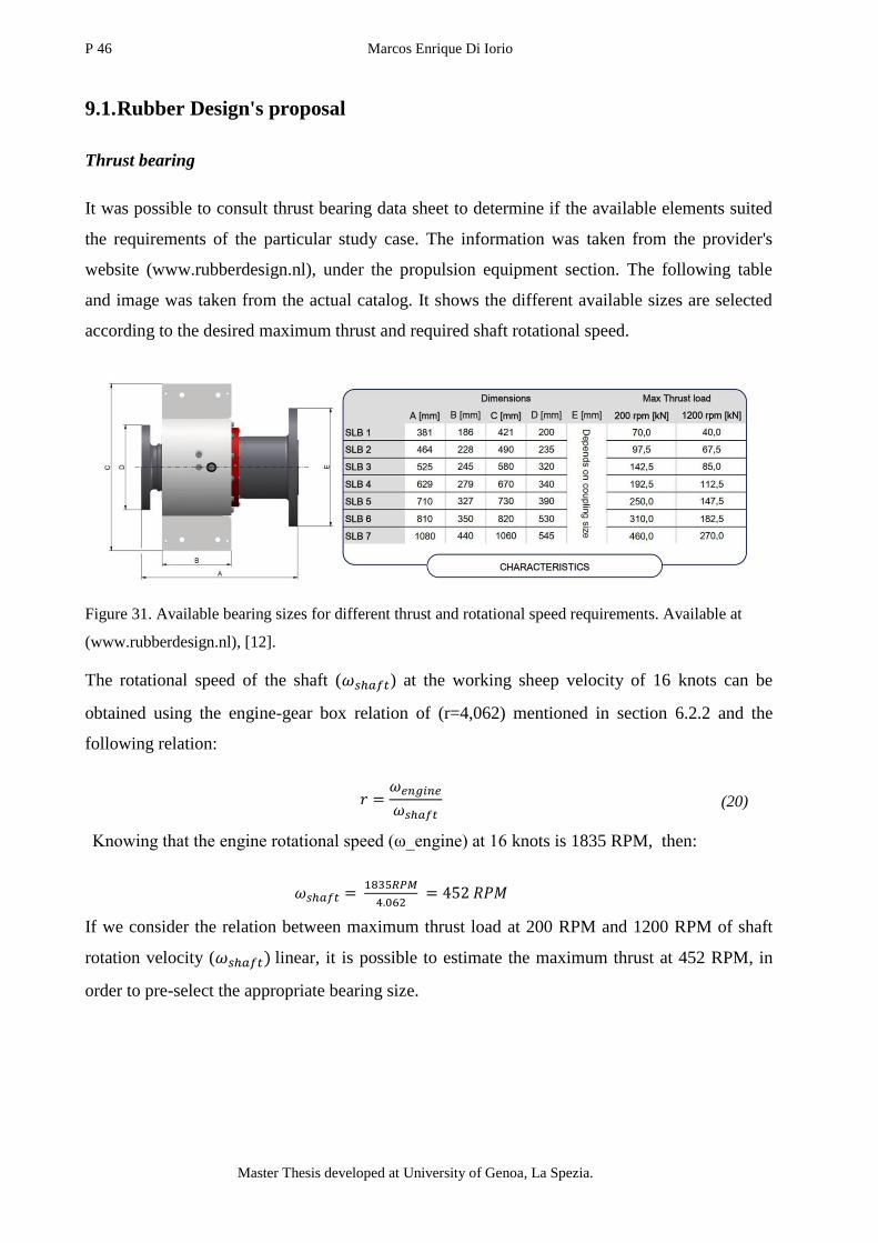
P 46 Marcos Enrique Di Iorio
Master Thesis developed at University of Genoa, La Spezia.
9.1. Rubber Design's proposal
Thrust bearing
It was possible to consult thrust bearing data sheet to determine if the available elements suited
the requirements of the particular study case. The information was taken from the provider's
website (www.rubberdesign.nl), under the propulsion equipment section. The following table
and image was taken from the actual catalog. It shows the different available sizes are selected
according to the desired maximum thrust and required shaft rotational speed.
Figure 31. Available bearing sizes for different thrust and rotational speed requirements. Available at
(www.rubberdesign.nl), [12].
The rotational speed of the shaft ( ) at the working sheep velocity of 16 knots can be
obtained using the engine-gear box relation of (r=4,062) mentioned in section 6.2.2 and the
following relation:
(20)
Knowing that the engine rotational speed (ω_engine) at 16 knots is 1835 RPM, then:
If we consider the relation between maximum thrust load at 200 RPM and 1200 RPM of shaft
rotation velocity ( linear, it is possible to estimate the maximum thrust at 452 RPM, in
order to pre-select the appropriate bearing size.

Engine foundation re-design due to modification of the shaft line arrangement 47
“EMSHIP” Erasmus Mundus Master Course, period of study September 2014 – February 2016
Table 6. Maximum thrust of each available bearing size at the working shaft rotational velocity (
of 452 RPM.
Reference
size
Total
Length(A)
[mm]
Total
Width(C)
[mm]
Max Thrust Load
at 452 RPM
[kN]
SLB 1 381 421 62.44
SLB 2 464 490 89.94
SLB 3 525 580 128.01
SLB 4 629 670 172.34
SLB 5 710 730 224.17
SLB 6 810 820 277.87
SLB 7 1080 1060 412.12
Knowing thet thrust applied on each shaft at a ship velocity of 16 knots is expected to be 100 kN
(In section 6.2.2 it is mentioned that this thrust value was recomended by Baglietto's staff
members).
According to Rubber Design's representants this bearing size satisfied the required prestation.
However, it was recomended to use a SLB4 reference size bearing. This added 100 mm to the
SLB3 bearing length (Length "A" in Figure 31).
Thrust block coupling
In addition to the thrust bearing, the bearing block is composed by one or several coupling
elements before reachig the gear box flange. The blocks accommodate movement in all
directions, making couplings exceptionally tolerant of relative propeller shaft displacements in
combination with flexible mounted propulsion engine and providing controlled damping of
torsional vibration excitation.
Figure 32. Example used by Rubber Design's technical office to show the proposed solution. (Image sent
by Rubber Design staff members).
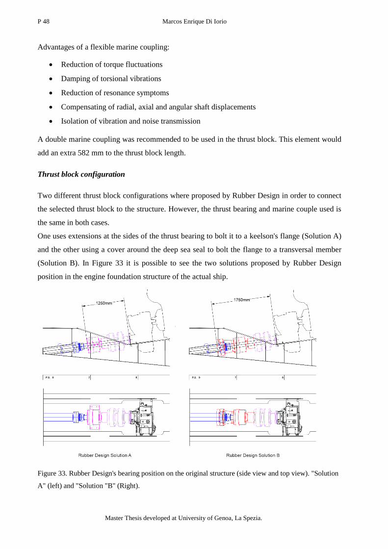
P 48 Marcos Enrique Di Iorio
Master Thesis developed at University of Genoa, La Spezia.
Advantages of a flexible marine coupling:
Reduction of torque fluctuations
Damping of torsional vibrations
Reduction of resonance symptoms
Compensating of radial, axial and angular shaft displacements
Isolation of vibration and noise transmission
A double marine coupling was recommended to be used in the thrust block. This element would
add an extra 582 mm to the thrust block length.
Thrust block configuration
Two different thrust block configurations where proposed by Rubber Design in order to connect
the selected thrust block to the structure. However, the thrust bearing and marine couple used is
the same in both cases.
One uses extensions at the sides of the thrust bearing to bolt it to a keelson's flange (Solution A)
and the other using a cover around the deep sea seal to bolt the flange to a transversal member
(Solution B). In Figure 33 it is possible to see the two solutions proposed by Rubber Design
position in the engine foundation structure of the actual ship.
Figure 33. Rubber Design's bearing position on the original structure (side view and top view). "Solution
A" (left) and "Solution "B" (Right).
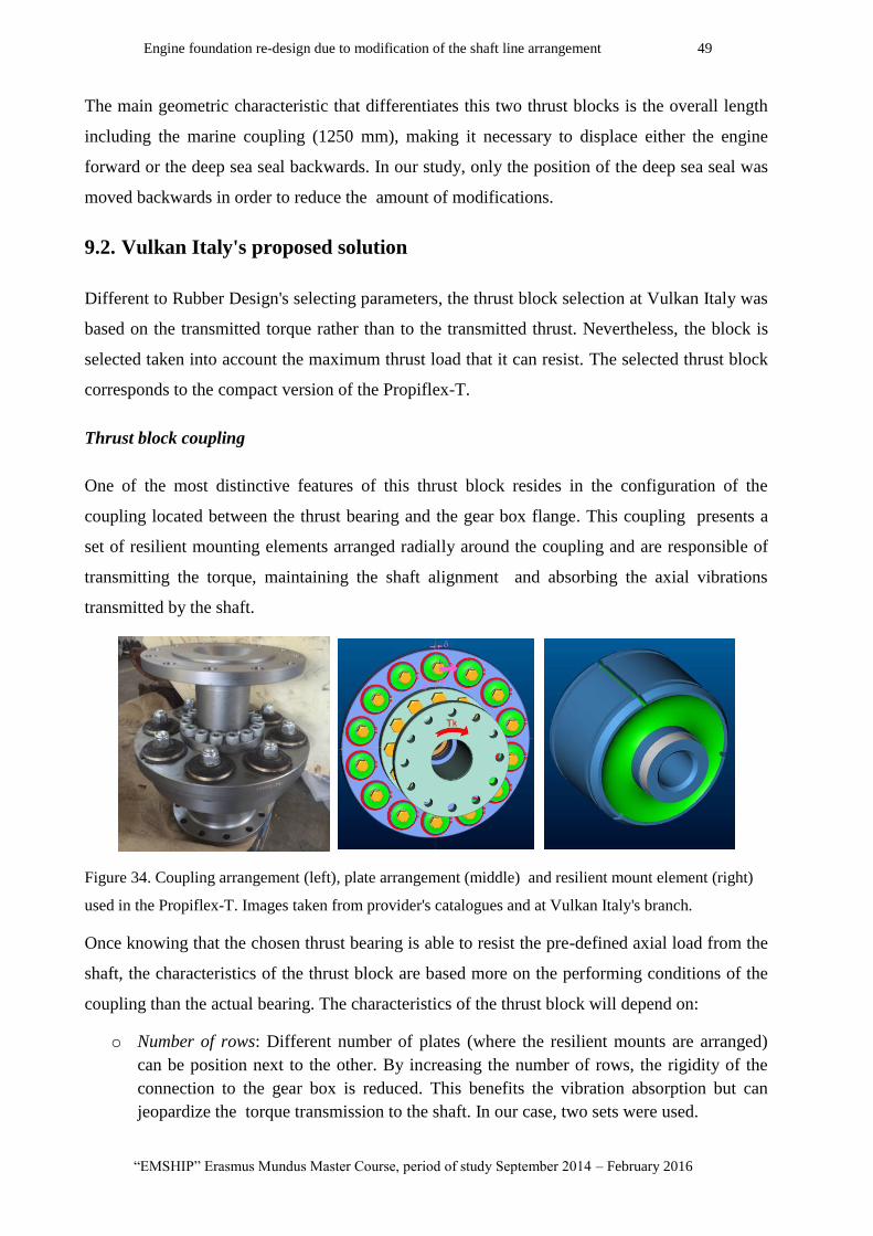
Engine foundation re-design due to modification of the shaft line arrangement 49
“EMSHIP” Erasmus Mundus Master Course, period of study September 2014 – February 2016
The main geometric characteristic that differentiates this two thrust blocks is the overall length
including the marine coupling (1250 mm), making it necessary to displace either the engine
forward or the deep sea seal backwards. In our study, only the position of the deep sea seal was
moved backwards in order to reduce the amount of modifications.
9.2. Vulkan Italy's proposed solution
Different to Rubber Design's selecting parameters, the thrust block selection at Vulkan Italy was
based on the transmitted torque rather than to the transmitted thrust. Nevertheless, the block is
selected taken into account the maximum thrust load that it can resist. The selected thrust block
corresponds to the compact version of the Propiflex-T.
Thrust block coupling
One of the most distinctive features of this thrust block resides in the configuration of the
coupling located between the thrust bearing and the gear box flange. This coupling presents a
set of resilient mounting elements arranged radially around the coupling and are responsible of
transmitting the torque, maintaining the shaft alignment and absorbing the axial vibrations
transmitted by the shaft.
Figure 34. Coupling arrangement (left), plate arrangement (middle) and resilient mount element (right)
used in the Propiflex-T. Images taken from provider's catalogues and at Vulkan Italy's branch.
Once knowing that the chosen thrust bearing is able to resist the pre-defined axial load from the
shaft, the characteristics of the thrust block are based more on the performing conditions of the
coupling than the actual bearing. The characteristics of the thrust block will depend on:
o Number of rows: Different number of plates (where the resilient mounts are arranged)
can be position next to the other. By increasing the number of rows, the rigidity of the
connection to the gear box is reduced. This benefits the vibration absorption but can
jeopardize the torque transmission to the shaft. In our case, two sets were used.
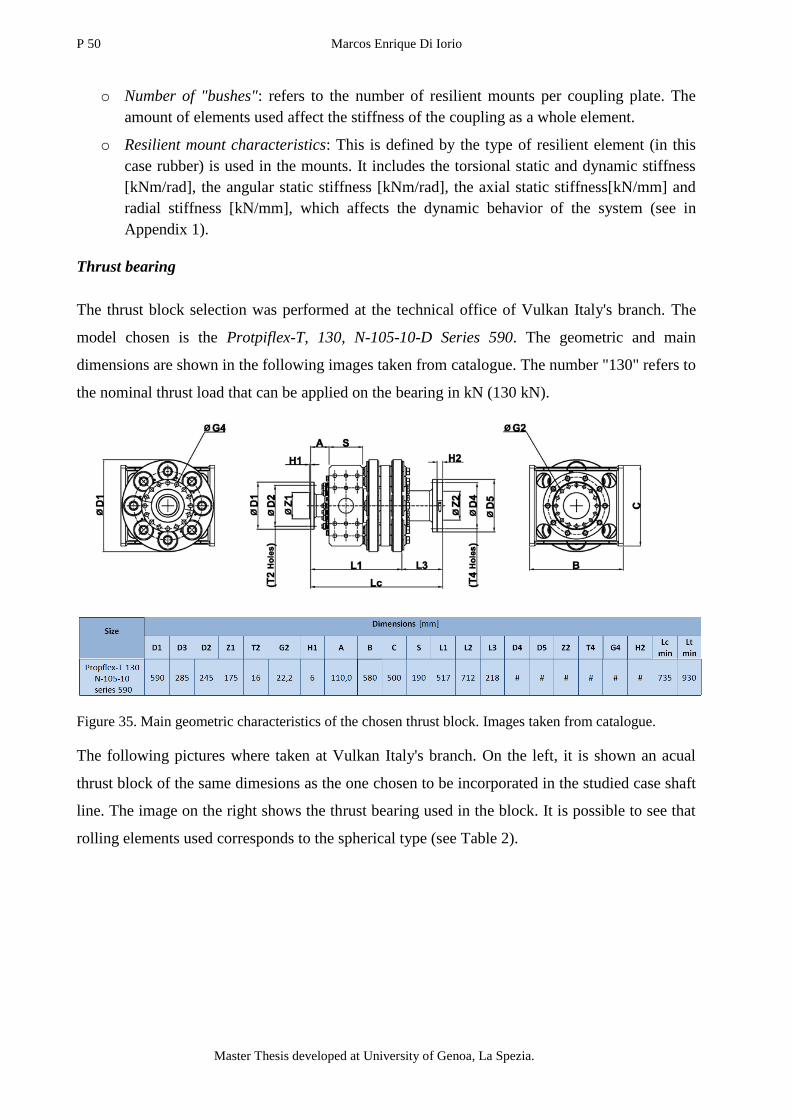
P 50 Marcos Enrique Di Iorio
Master Thesis developed at University of Genoa, La Spezia.
o Number of "bushes": refers to the number of resilient mounts per coupling plate. The
amount of elements used affect the stiffness of the coupling as a whole element.
o Resilient mount characteristics: This is defined by the type of resilient element (in this
case rubber) is used in the mounts. It includes the torsional static and dynamic stiffness
[kNm/rad], the angular static stiffness [kNm/rad], the axial static stiffness[kN/mm] and
radial stiffness [kN/mm], which affects the dynamic behavior of the system (see in
Appendix 1).
Thrust bearing
The thrust block selection was performed at the technical office of Vulkan Italy's branch. The
model chosen is the Protpiflex-T, 130, N-105-10-D Series 590. The geometric and main
dimensions are shown in the following images taken from catalogue. The number "130" refers to
the nominal thrust load that can be applied on the bearing in kN (130 kN).
Figure 35. Main geometric characteristics of the chosen thrust block. Images taken from catalogue.
The following pictures where taken at Vulkan Italy's branch. On the left, it is shown an acual
thrust block of the same dimesions as the one chosen to be incorporated in the studied case shaft
line. The image on the right shows the thrust bearing used in the block. It is possible to see that
rolling elements used corresponds to the spherical type (see Table 2).

Engine foundation re-design due to modification of the shaft line arrangement 51
“EMSHIP” Erasmus Mundus Master Course, period of study September 2014 – February 2016
Figure 36. Vulkan Italy's thrust block (left) and thrust bearing (right). Images taken at Vulkan Italy's
branch.
Thrust block configuration
This particular thrust block is that the supporting elements are independent from the main
bearing. This allows to vary the configuration and shape of the thrust block in order to adapt the
connection to the supporting base. Vulkan even offers the possibility to bolt the thrust block to
the main keelson's web instead of the flange.
In the following figure shows an exploded 3D view of the main elements that compose the thrust
block highlighting in red the supporting elements. Highlighted in red it is possible to see the
supporting elements of the block that can be replaced according to existing structural
configuration.
Figure 37. Vulkan's thrust block exploded 3D view. Thrust bearing (middle grey), gear box couplings
(forward grey) and supporting elements (sides red). Step file provided by Vulkan Italy.

P 52 Marcos Enrique Di Iorio
Master Thesis developed at University of Genoa, La Spezia.
9.3. Thrust block comparison
The three chosen thrust bearings (two from Rubber Design and one from Vulkan) differ mainly
in the longitudinal position where the force is transmitted to the structure. This gives a wide
range of structural modifications when considering the addition of the bearing on other projected
ships. In the following image it has been sketched the mid position of the transmition of the
thrust load to the structure from the shaft line of the:
Original configuration ("O");
Rubber Design's first proposed solution ("A");
Rubber Design's second proposed solution ("B");
Vulkan's proposed solution ("V").
Figure 38. Position where the thrust load is transferred to the structure (middle point between the
supports). Modeled using Rhinoceros 3D.
It is possible to see how the different solutions displace the thrust load of application closer to
the aft bulkhead (2210 mm of maximum difference in Rubber Design's solution B) . This
changes the length of the section that is under compression modifying the response to the
combination of the axial load and perpendicular forces. Other aspect that can be appreciated is
the available vertical space between the shaft and the hull that is reduced by the displacement of
the point of application of the load.

Engine foundation re-design due to modification of the shaft line arrangement 53
“EMSHIP” Erasmus Mundus Master Course, period of study September 2014 – February 2016
9.4. Conclusion
Thrust blocks are provided in different dimensions and configurations for the same thrust and
torque requirements. The considered proposals present differences in their support system and
total length. This influences directly the modifications that should be performed during the
structure adaptation.
10. Proposed structural modifications
Modification conditions
The assistance of Baglietto's technical office was requested to perform the adaptation of the
structure to the different thrust bearings. Each step in the evolution of the proposed
modifications was analysed according to Baglietto's criteria and standards based on three main
conditions:
1- Is the modification possible?
Basically, this refers to the available space imposed by the modification restrictions (see section
6.2.1) and if it is needed to shift the position of any other existing element of the engine block or
located in the shaft line.
2- Is the modification the less invasive option?
There are always different variations to be performed on the structure to adapt to the added
element. The proposed solutions studied were the ones that minimized the differences with the
original version.
3-Is the modification feasible?
This refers to the difficulty of passing from the design to the actual construction of the ship.
Taking into account welding (sufficient plate thickness, available space for the welder,), plate
bending limits, etc. The expertise and advice from Bagglieto's staff members was crucial to be
able to anticipate any constructive problem.

P 54 Marcos Enrique Di Iorio
Master Thesis developed at University of Genoa, La Spezia.
10.1. Modified Solution A
The main obstacle to overcome when considering the use of this type of bearing block is related
to the vertical position of the flanges. If it is intended to be bolted on the main keelson of the
foundation before the engine block, the distance ( in Figure 39 ) between the flanges and the
hull is reduced. This is not beneficial for the longitudinal stiffness as the web's height needs to
be reduced to adapt to the position of the flange. Moreover, as four of the five main stiffeners
are reduced, the inertia of the overall section is affected. This jeopardize the hull girder
longitudinal resistance to global loads.
The minimum web height recommended by Baglietto's technical office for this particular case is
500 mm. The most critical situation corresponds to the outer main keelson (2150 mm from
middle of the ship. In the original structure the minimum, the minimum web height is 405 mm
before the position of the gear box mounts ( in Figure 39). Which is already below the
recommended minimum web height, as it is said in the in the industry "it does not have enough
meat".
Figure 39. Shortest distance (d) between Rubber Design's thrust block flange and the hull. Modeled using
Rhinoceros 3D.
For this particular case, the is less than 250 mm before the TB's flange, less than half of the
recommended minimum height. Making it necessary to apply other type of solution, the addition
of internal longitudinal supports.
Featured modifications:
Addition of internal longitudinal supports
In our case, it has been proposed the use of internal secondary keelsons between the main
stiffeners of the foundation, where only the thrust block would be supported. This simple
solution present other construction obstacles. The transversal distance between the original and
the added keelsons was not enough to allow the welder to reach the junction of the web and the
hull.
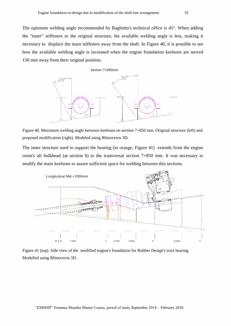
Engine foundation re-design due to modification of the shaft line arrangement 55
“EMSHIP” Erasmus Mundus Master Course, period of study September 2014 – February 2016
The optimum welding angle recommended by Baglietto's technical office is 45°. When adding
the "inner" stiffeners to the original structure, the available welding angle is less, making it
necessary to displace the main stiffeners away from the shaft. In Figure 40, it is possible to see
how the available welding angle is increased when the engine foundation keelsons are moved
150 mm away from their original position.
Figure 40. Maximum welding angle between keelsons on section 7+850 mm. Original structure (left) and
proposed modification (right). Modeled using Rhinoceros 3D.
The inner structure used to support the bearing (in orange, Figure 41) extends from the engine
room's aft bulkhead (at section 6) to the transversal section 7+850 mm. It was necessary to
modify the main keelsons to assure sufficient space for welding between this sections.
Figure 41 (top). Side view of the modified engine's foundation for Rubber Design's trust bearing.
Modelled using Rhinoceros 3D.
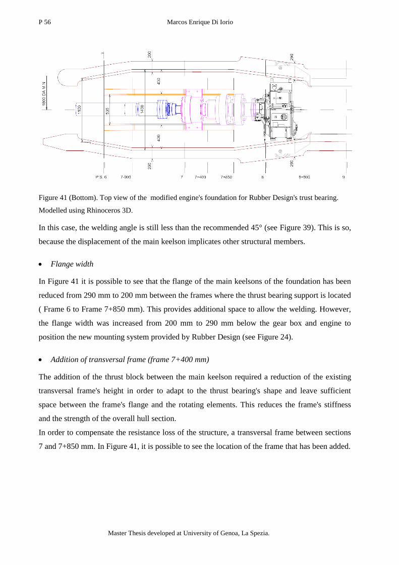
P 56 Marcos Enrique Di Iorio
Master Thesis developed at University of Genoa, La Spezia.
Figure 41 (Bottom). Top view of the modified engine's foundation for Rubber Design's trust bearing.
Modelled using Rhinoceros 3D.
In this case, the welding angle is still less than the recommended 45° (see Figure 39). This is so,
because the displacement of the main keelson implicates other structural members.
Flange width
In Figure 41 it is possible to see that the flange of the main keelsons of the foundation has been
reduced from 290 mm to 200 mm between the frames where the thrust bearing support is located
( Frame 6 to Frame 7+850 mm). This provides additional space to allow the welding. However,
the flange width was increased from 200 mm to 290 mm below the gear box and engine to
position the new mounting system provided by Rubber Design (see Figure 24).
Addition of transversal frame (frame 7+400 mm)
The addition of the thrust block between the main keelson required a reduction of the existing
transversal frame's height in order to adapt to the thrust bearing's shape and leave sufficient
space between the frame's flange and the rotating elements. This reduces the frame's stiffness
and the strength of the overall hull section.
In order to compensate the resistance loss of the structure, a transversal frame between sections
7 and 7+850 mm. In Figure 41, it is possible to see the location of the frame that has been added.
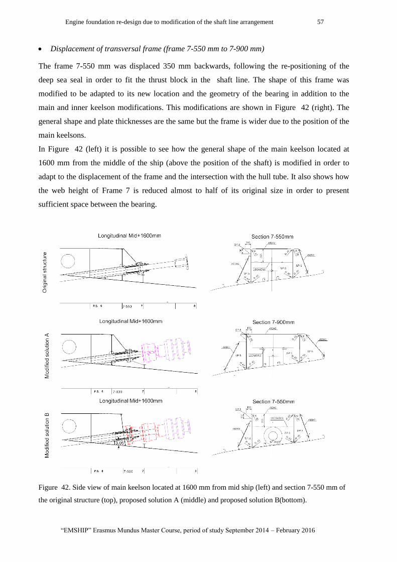
Engine foundation re-design due to modification of the shaft line arrangement 57
“EMSHIP” Erasmus Mundus Master Course, period of study September 2014 – February 2016
Displacement of transversal frame (frame 7-550 mm to 7-900 mm)
The frame 7-550 mm was displaced 350 mm backwards, following the re-positioning of the
deep sea seal in order to fit the thrust block in the shaft line. The shape of this frame was
modified to be adapted to its new location and the geometry of the bearing in addition to the
main and inner keelson modifications. This modifications are shown in Figure 42 (right). The
general shape and plate thicknesses are the same but the frame is wider due to the position of the
main keelsons.
In Figure 42 (left) it is possible to see how the general shape of the main keelson located at
1600 mm from the middle of the ship (above the position of the shaft) is modified in order to
adapt to the displacement of the frame and the intersection with the hull tube. It also shows how
the web height of Frame 7 is reduced almost to half of its original size in order to present
sufficient space between the bearing.
Figure 42. Side view of main keelson located at 1600 mm from mid ship (left) and section 7-550 mm of
the original structure (top), proposed solution A (middle) and proposed solution B(bottom).
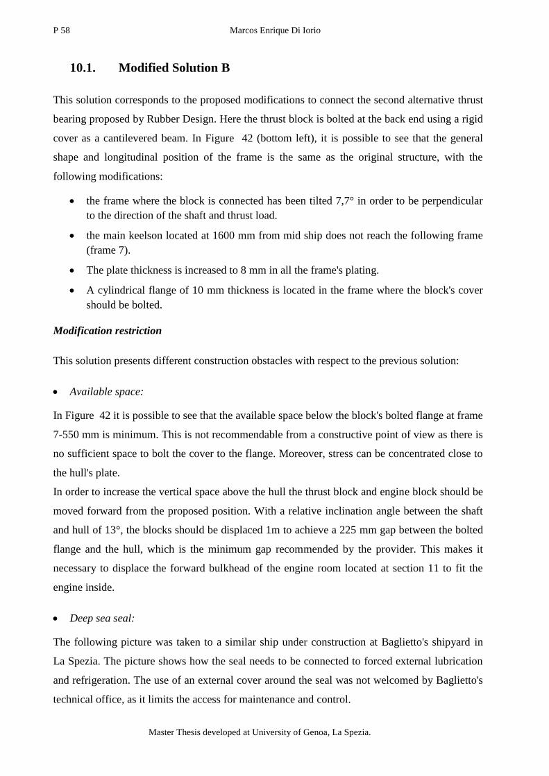
P 58 Marcos Enrique Di Iorio
Master Thesis developed at University of Genoa, La Spezia.
10.1. Modified Solution B
This solution corresponds to the proposed modifications to connect the second alternative thrust
bearing proposed by Rubber Design. Here the thrust block is bolted at the back end using a rigid
cover as a cantilevered beam. In Figure 42 (bottom left), it is possible to see that the general
shape and longitudinal position of the frame is the same as the original structure, with the
following modifications:
the frame where the block is connected has been tilted 7,7° in order to be perpendicular
to the direction of the shaft and thrust load.
the main keelson located at 1600 mm from mid ship does not reach the following frame
(frame 7).
The plate thickness is increased to 8 mm in all the frame's plating.
A cylindrical flange of 10 mm thickness is located in the frame where the block's cover
should be bolted.
Modification restriction
This solution presents different construction obstacles with respect to the previous solution:
Available space:
In Figure 42 it is possible to see that the available space below the block's bolted flange at frame
7-550 mm is minimum. This is not recommendable from a constructive point of view as there is
no sufficient space to bolt the cover to the flange. Moreover, stress can be concentrated close to
the hull's plate.
In order to increase the vertical space above the hull the thrust block and engine block should be
moved forward from the proposed position. With a relative inclination angle between the shaft
and hull of 13°, the blocks should be displaced 1m to achieve a 225 mm gap between the bolted
flange and the hull, which is the minimum gap recommended by the provider. This makes it
necessary to displace the forward bulkhead of the engine room located at section 11 to fit the
engine inside.
Deep sea seal:
The following picture was taken to a similar ship under construction at Baglietto's shipyard in
La Spezia. The picture shows how the seal needs to be connected to forced external lubrication
and refrigeration. The use of an external cover around the seal was not welcomed by Baglietto's
technical office, as it limits the access for maintenance and control.

Engine foundation re-design due to modification of the shaft line arrangement 59
“EMSHIP” Erasmus Mundus Master Course, period of study September 2014 – February 2016
Figure 43. Deep sea seal on actual ship in construction "Pachamama". Picture taken at Baglietto's
Shipyard, La Spezia, Italia.
The motioned obstacles makes this solution unfeasible for this particular ship. Despite this, it
was tested through numerical analysis presenting interesting advantages related to the stress
distribution on the main keelsons of the structure, that should be considered in future projects.
10.2. Modified Solution V
Apart from the possibility of adapting the thrust block to the existing structural configuration of
the engine foundation, there is another main difference between the thrust block built at Vulkan
respect the block proposed at Rubber Design that reduces the amount of structural modifications
that are necessary to perform the adaptation of foundation. This is the thrust bearing block total
length.
The thrust block's combined length (thrust bearing and coupling) of 800 mm is 2/3 of the
shortest version presented by Rubber Design (Solution A:1250 mm and Solution B:1820 mm).
In Figure 38 it is possible to see how this allows to displace the thrust block supports towards
the gear box connection flange.
As the thrust bearing is positioned 1/2 m forward with respect to Rubber Design's Solution A,
allows to consider mounting the thrust block on the same foundation as the gear box and engine.
This is so, because the web height reduction is not as significant as in proposed Solution A. In
the following sketch it is possible to see the relative distance between the middle point of the
thrust load application and the hull is 100 mm larger. Nevertheless, the web height for this
solution would be also below the 500 mm.

P 60 Marcos Enrique Di Iorio
Master Thesis developed at University of Genoa, La Spezia.
Figure 44. Distance between the middle point of the thrust load application and the hull, for the cases of
solution A (Rubber Design) and solution V (Vulkan). Modeled using Rhinoceros 3D.
Featured modifications
This two aspects allows to perform a less invasive and more flexible structural modification
when considering the incorporation of the thrust block in an existing design. A structural
configuration proposed to be compares with the original structure and other solutions that are
presented in the next Figure 45:
Figure 45. Side view (top) and top view (bottom) of the modified engine's foundation
for Vulkan Italy's trust bearing. Modeled using Rhinoceros 3D.
In the previous ( Figure 45) it is possible to see the location in the structure and general shape of
the:
1
2
1 2

Engine foundation re-design due to modification of the shaft line arrangement 61
“EMSHIP” Erasmus Mundus Master Course, period of study September 2014 – February 2016
1- thrust block: main cylinder corresponds to the coupling. The diameter needed to be
taken into account as it is located in the same longitudinal position as frame 7+850 mm
and should not interfere. Also the support's (highlighted in red) dimension determine the
position where the thrust load is transmitted to the structure.
2- engine mounting system: The engine and gear box support configuration was sketched
accordingly to the provided specifications and technical drawings. This way, identify
lack of space and interference between the elements.
The modifications performed are simple, as only the height of the main keelsons of the
foundation are redesigned so that the engine, gear box and thrust block are supported on the
same "ski". In Figure 45 (top) side view of the original flange shape is represented in light gray.
Compared to this last,
the flange is lifted 85 mm so that is adapts to the thrust block and gear box supporting
element position. A 30 mm gap is left between the supports and the flange for the
addition of chock fast and plates.
the flange is extended more than 700 mm backwards until the end of the thrust block's
support.
This modifications are simple but present disadvantages with respect to the original
configuration:
The two flange's curvature angle between frames 7-550 mm and 8 are increased in more
than 10°.
There is no sufficient space before the position of the thrust block support and the
transition curvature is not smooth enough.
This jeopardizing conditions were chosen to test the structure under a "worst case scenario" but
keeping the main keelson's web with a reasonable height. However, for the case of the main
keelson located at 2150 mm from the middle of the ship, the minimum web height is reduced to
a dangerous 350 mm, when in the original structure this distance is 405 mm.
Figure 46. Superposed side view of the foundation's main keelsons between frames 7-550 mm and 8.
Detail on the minimum web heights and curvature angles. Modeled using Rhinoceros 3D.
P 62 Marcos Enrique Di Iorio
Master Thesis developed at University of Genoa, La Spezia.
10.3. Conclusion
Different solutions are considered to adapt the existing structure to the incorporation of the
proposed thrust bearing in the shaft line. From the selected candidates, the thrust block
recommended by Vulkan Italy results more beneficial for this particular studied case as it
requires a less invasive structural modification.
A practical solution was not to include one of the two bearing connections proposed by Rubber
Design. However, modification plans are developed for the remaining options, which required
the addition of secondary structural members.
11. Finite element analysis
11.1. Model types
3D models
Three-dimensional models represent a part of the ship cargo such as hold structure of one or
more cargo holds.
2D Models
Two-dimensional beam models, grillage or frame models, represent selected part of the ship
such as transverse frame structure which is calculated by a framework structure subjected to in
plane loading, transverse bulkhead structure, which is modelled as a framework model subjected
to in plane loading, double bottom structure, which is modelled as a grillage model, subjected to
lateral loading. In the 2D model analysis the boundary conditions may be used from the results
of other 2D model in way of cut–off structure.
Partial Model global analysis
According to the DNVGL finite element analysis Class Guide (14), the model used in the study
can be classified into a partial ship structural type analysis. Different to global strength analysis,
only a section of a global ship model is represented, in our study case only two internal sections,
the engine room and garage, are modelled. However, there are main differences in the
consideration of loads and boundary conditions that are more similar to a global than a typical
partial strength analysis. The model was created from the 2D plans of the last two blocks, where
the engine room and garage are included, provided by Baglietto Shipyard technical office.
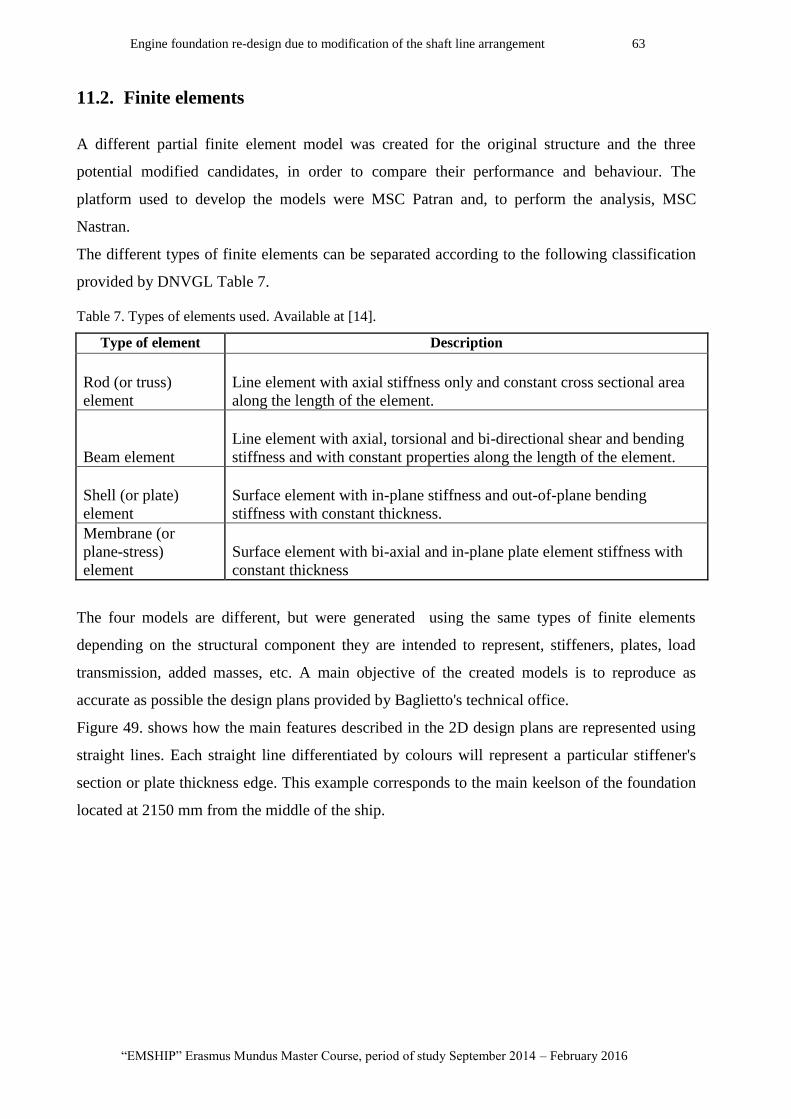
Engine foundation re-design due to modification of the shaft line arrangement 63
“EMSHIP” Erasmus Mundus Master Course, period of study September 2014 – February 2016
11.2. Finite elements
A different partial finite element model was created for the original structure and the three
potential modified candidates, in order to compare their performance and behaviour. The
platform used to develop the models were MSC Patran and, to perform the analysis, MSC
Nastran.
The different types of finite elements can be separated according to the following classification
provided by DNVGL Table 7.
Table 7. Types of elements used. Available at [14].
Type of element Description
Rod (or truss)
element
Line element with axial stiffness only and constant cross sectional area
along the length of the element.
Beam element
Line element with axial, torsional and bi-directional shear and bending
stiffness and with constant properties along the length of the element.
Shell (or plate)
element
Surface element with in-plane stiffness and out-of-plane bending
stiffness with constant thickness.
Membrane (or
plane-stress)
element
Surface element with bi-axial and in-plane plate element stiffness with
constant thickness
The four models are different, but were generated using the same types of finite elements
depending on the structural component they are intended to represent, stiffeners, plates, load
transmission, added masses, etc. A main objective of the created models is to reproduce as
accurate as possible the design plans provided by Baglietto's technical office.
Figure 49. shows how the main features described in the 2D design plans are represented using
straight lines. Each straight line differentiated by colours will represent a particular stiffener's
section or plate thickness edge. This example corresponds to the main keelson of the foundation
located at 2150 mm from the middle of the ship.
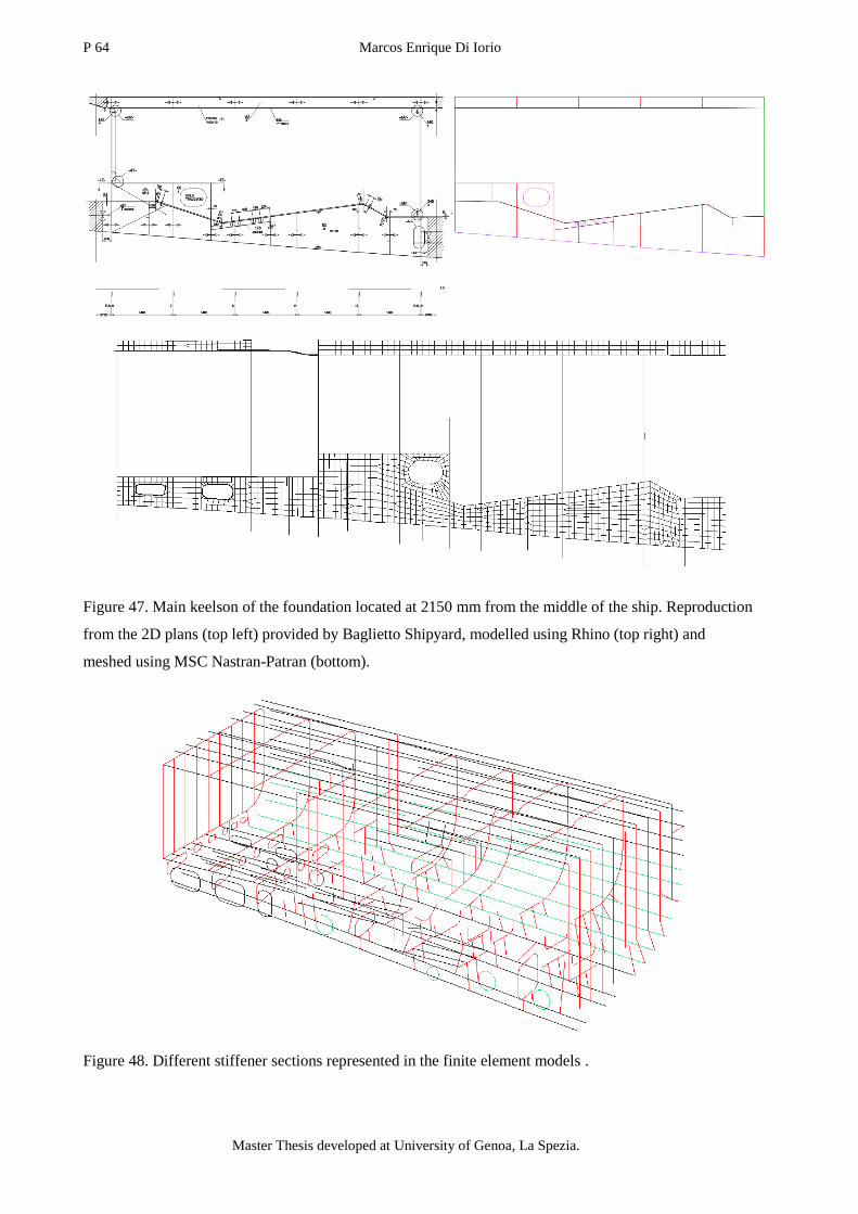
P 64 Marcos Enrique Di Iorio
Master Thesis developed at University of Genoa, La Spezia.
Figure 47. Main keelson of the foundation located at 2150 mm from the middle of the ship. Reproduction
from the 2D plans (top left) provided by Baglietto Shipyard, modelled using Rhino (top right) and
meshed using MSC Nastran-Patran (bottom).
Figure 48. Different stiffener sections represented in the finite element models .
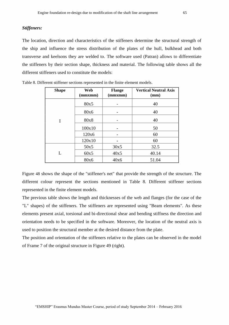
Engine foundation re-design due to modification of the shaft line arrangement 65
“EMSHIP” Erasmus Mundus Master Course, period of study September 2014 – February 2016
Stiffeners:
The location, direction and characteristics of the stiffeners determine the structural strength of
the ship and influence the stress distribution of the plates of the hull, bulkhead and both
transverse and keelsons they are welded to. The software used (Patran) allows to differentiate
the stiffeners by their section shape, thickness and material. The following table shows all the
different stiffeners used to constitute the models:
Table 8. Different stiffener sections represented in the finite element models.
Shape Web
(mmxmm)
Flange
(mmxmm)
Vertical Neutral Axis
(mm)
I
80x5 - 40
80x6 - 40
80x8 - 40
100x10 - 50
120x6 - 60
120x10 - 60
L
50x5 30x5 32.5
60x5 40x5 40.14
80x6 40x6 51.04
Figure 48 shows the shape of the "stiffener's net" that provide the strength of the structure. The
different colour represent the sections mentioned in Table 8. Different stiffener sections
represented in the finite element models.
The previous table shows the length and thicknesses of the web and flanges (for the case of the
"L" shapes) of the stiffeners. The stiffeners are represented using "Beam elements". As these
elements present axial, torsional and bi-directional shear and bending stiffness the direction and
orientation needs to be specified in the software. Moreover, the location of the neutral axis is
used to position the structural member at the desired distance from the plate.
The position and orientation of the stiffeners relative to the plates can be observed in the model
of Frame 7 of the original structure in Figure 49 (right).

P 66 Marcos Enrique Di Iorio
Master Thesis developed at University of Genoa, La Spezia.
Figure 49. Transversal Frame 7 reproduction from the 2D plans (left) provided by Baglietto Shipyard to
the finite element model (right).
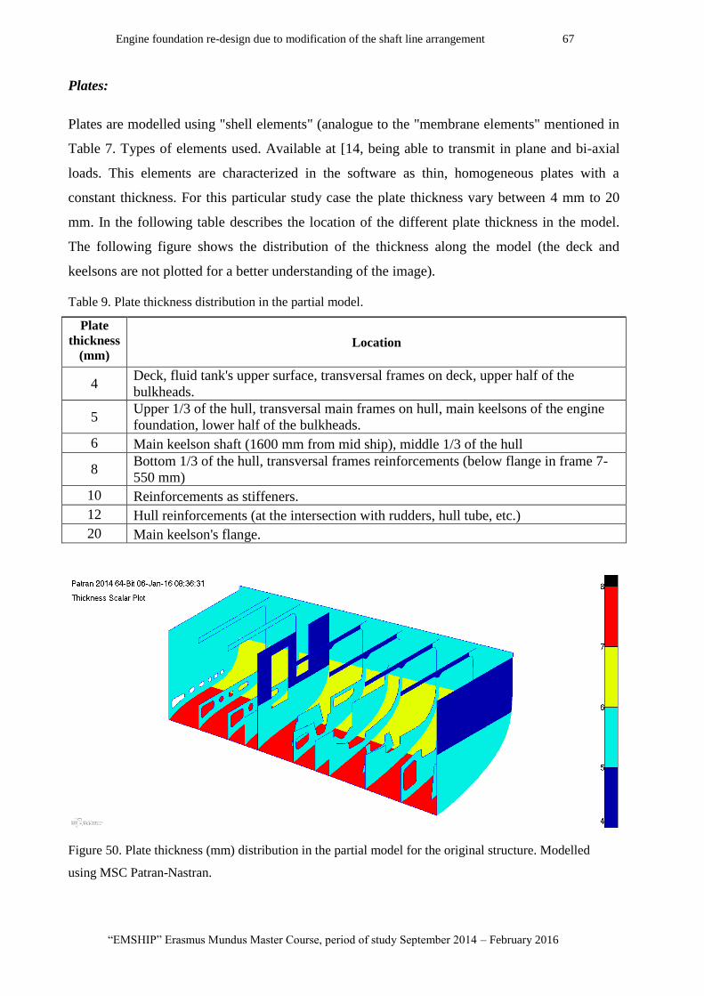
Engine foundation re-design due to modification of the shaft line arrangement 67
“EMSHIP” Erasmus Mundus Master Course, period of study September 2014 – February 2016
Plates:
Plates are modelled using "shell elements" (analogue to the "membrane elements" mentioned in
Table 7. Types of elements used. Available at [14, being able to transmit in plane and bi-axial
loads. This elements are characterized in the software as thin, homogeneous plates with a
constant thickness. For this particular study case the plate thickness vary between 4 mm to 20
mm. In the following table describes the location of the different plate thickness in the model.
The following figure shows the distribution of the thickness along the model (the deck and
keelsons are not plotted for a better understanding of the image).
Table 9. Plate thickness distribution in the partial model.
Plate
thickness
(mm) Location
4 Deck, fluid tank's upper surface, transversal frames on deck, upper half of the
bulkheads.
5 Upper 1/3 of the hull, transversal main frames on hull, main keelsons of the engine
foundation, lower half of the bulkheads.
6 Main keelson shaft (1600 mm from mid ship), middle 1/3 of the hull
8 Bottom 1/3 of the hull, transversal frames reinforcements (below flange in frame 7-
550 mm)
10 Reinforcements as stiffeners.
12 Hull reinforcements (at the intersection with rudders, hull tube, etc.)
20 Main keelson's flange.
Figure 50. Plate thickness (mm) distribution in the partial model for the original structure. Modelled
using MSC Patran-Nastran.

P 68 Marcos Enrique Di Iorio
Master Thesis developed at University of Genoa, La Spezia.
11.3. Reproducing the applied loads
The loads considered in our study case are generated by external forces acting on the engine
block and thrust block and transmitted trough supporting or connective elements. Therefore, the
forces and moments should be applied on the structure in the location of each supporting
element. Depending on the force or moment, it is not easy to predefine its contribution on each
connection point in the structure. This can lead to errors in the magnitude and direction of the
applied load. The application of external load to the structure was carried out using a solution
recommended by the researchers of UNIGE, which corresponded to the use of "rigid links".
MPC elements
The rigid link is a tool provided by the MSC Patran software, which allows to connect two
element nodes through a infinitely rigid rod type element (see Table 7) with the particularity that
the rotation and translation of one of the nodes depends on the other.
The tool is called in the in the program as "MPC" and uses RBE2 rod elements to connect the
only "independent" node where the load is applied to all the "dependent" nodes that transmit the
load to the structure. However, when using this tool, the "dependent nodes" can only depend on
one only "independent node".
This limitation makes it necessary to define the position where all the loads that are acting on a
particular support system (engine block, thrust block, etc.). In section 8.3, is described the
location of the points of application for the loads that act on the different support systems. The
following figure shows a top view of the rigid links used to connect the nodes where the load is
applied to the nodes where the loads are transmitted to the structure. This last correspond to
nodes that share the same position as the mounting elements of the engine and gear box support
system.
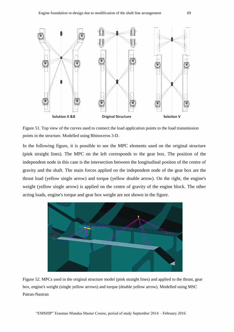
Engine foundation re-design due to modification of the shaft line arrangement 69
“EMSHIP” Erasmus Mundus Master Course, period of study September 2014 – February 2016
Figure 51. Top view of the curves used to connect the load application points to the load transmission
points in the structure. Modelled using Rhinoceros 3-D.
In the following figure, it is possible to see the MPC elements used on the original structure
(pink straight lines). The MPC on the left corresponds to the gear box. The position of the
independent node in this case is the intersection between the longitudinal positon of the centre of
gravity and the shaft. The main forces applied on the independent node of the gear box are the
thrust load (yellow single arrow) and torque (yellow double arrow). On the right, the engine's
weight (yellow single arrow) is applied on the centre of gravity of the engine block. The other
acting loads, engine's torque and gear box weight are not shown in the figure.
Figure 52. MPCs used in the original structure model (pink straight lines) and applied to the thrust, gear
box, engine's weight (single yellow arrows) and torque (double yellow arrow). Modelled using MSC
Patran-Nastran
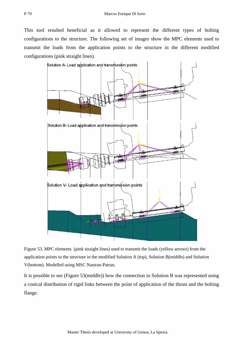
P 70 Marcos Enrique Di Iorio
Master Thesis developed at University of Genoa, La Spezia.
This tool resulted beneficial as it allowed to represent the different types of bolting
configurations to the structure. The following set of images show the MPC elements used to
transmit the loads from the application points to the structure in the different modified
configurations (pink straight lines).
Figure 53. MPC elements (pink straight lines) used to transmit the loads (yellow arrows) from the
application points to the structure in the modified Solution A (top), Solution B(middle) and Solution
V(bottom). Modelled using MSC Nastran-Patran.
It is possible to see (Figure 53(middle)) how the connection in Solution B was represented using
a conical distribution of rigid links between the point of application of the thrust and the bolting
flange.
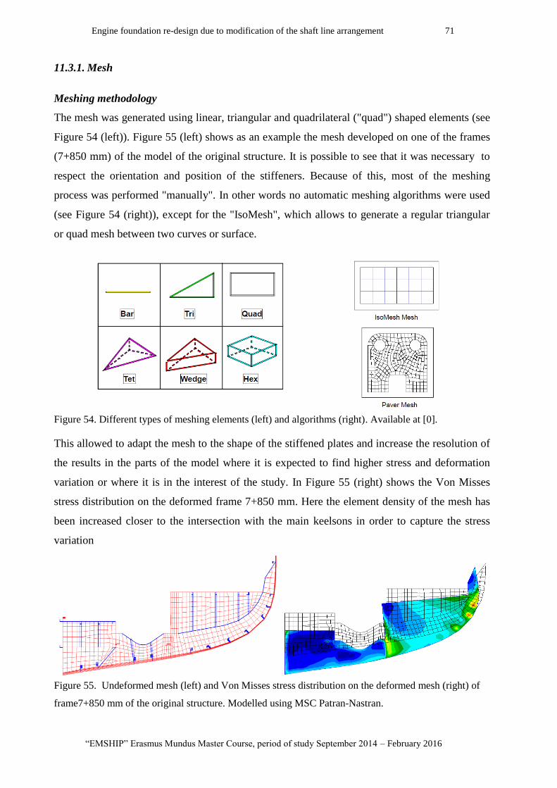
Engine foundation re-design due to modification of the shaft line arrangement 71
“EMSHIP” Erasmus Mundus Master Course, period of study September 2014 – February 2016
11.3.1. Mesh
Meshing methodology
The mesh was generated using linear, triangular and quadrilateral ("quad") shaped elements (see
Figure 54 (left)). Figure 55 (left) shows as an example the mesh developed on one of the frames
(7+850 mm) of the model of the original structure. It is possible to see that it was necessary to
respect the orientation and position of the stiffeners. Because of this, most of the meshing
process was performed "manually". In other words no automatic meshing algorithms were used
(see Figure 54 (right)), except for the "IsoMesh", which allows to generate a regular triangular
or quad mesh between two curves or surface.
Figure 54. Different types of meshing elements (left) and algorithms (right). Available at [0].
This allowed to adapt the mesh to the shape of the stiffened plates and increase the resolution of
the results in the parts of the model where it is expected to find higher stress and deformation
variation or where it is in the interest of the study. In Figure 55 (right) shows the Von Misses
stress distribution on the deformed frame 7+850 mm. Here the element density of the mesh has
been increased closer to the intersection with the main keelsons in order to capture the stress
variation
Figure 55. Undeformed mesh (left) and Von Misses stress distribution on the deformed mesh (right) of
frame7+850 mm of the original structure. Modelled using MSC Patran-Nastran.
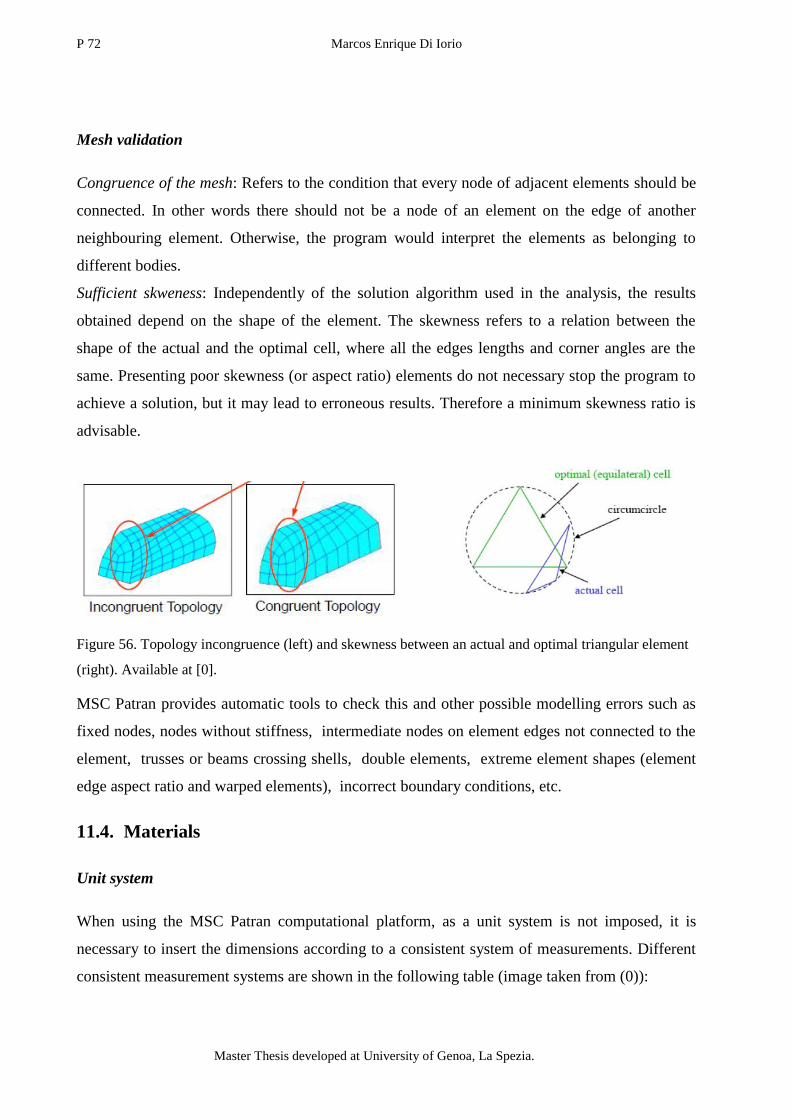
P 72 Marcos Enrique Di Iorio
Master Thesis developed at University of Genoa, La Spezia.
Mesh validation
Congruence of the mesh: Refers to the condition that every node of adjacent elements should be
connected. In other words there should not be a node of an element on the edge of another
neighbouring element. Otherwise, the program would interpret the elements as belonging to
different bodies.
Sufficient skweness: Independently of the solution algorithm used in the analysis, the results
obtained depend on the shape of the element. The skewness refers to a relation between the
shape of the actual and the optimal cell, where all the edges lengths and corner angles are the
same. Presenting poor skewness (or aspect ratio) elements do not necessary stop the program to
achieve a solution, but it may lead to erroneous results. Therefore a minimum skewness ratio is
advisable.
Figure 56. Topology incongruence (left) and skewness between an actual and optimal triangular element
(right). Available at [0].
MSC Patran provides automatic tools to check this and other possible modelling errors such as
fixed nodes, nodes without stiffness, intermediate nodes on element edges not connected to the
element, trusses or beams crossing shells, double elements, extreme element shapes (element
edge aspect ratio and warped elements), incorrect boundary conditions, etc.
11.4. Materials
Unit system
When using the MSC Patran computational platform, as a unit system is not imposed, it is
necessary to insert the dimensions according to a consistent system of measurements. Different
consistent measurement systems are shown in the following table (image taken from (0)):
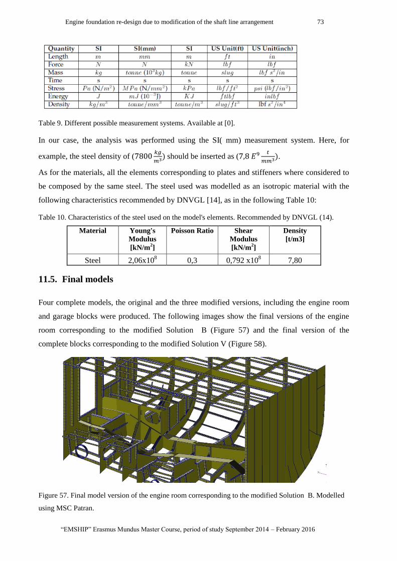
Engine foundation re-design due to modification of the shaft line arrangement 73
“EMSHIP” Erasmus Mundus Master Course, period of study September 2014 – February 2016
Table 9. Different possible measurement systems. Available at [0].
In our case, the analysis was performed using the SI( mm) measurement system. Here, for
example, the steel density of (
should be inserted as (
.
As for the materials, all the elements corresponding to plates and stiffeners where considered to
be composed by the same steel. The steel used was modelled as an isotropic material with the
following characteristics recommended by DNVGL [14], as in the following Table 10:
Table 10. Characteristics of the steel used on the model's elements. Recommended by DNVGL (14).
Material Young's
Modulus
[kN/m2]
Poisson Ratio Shear
Modulus
[kN/m2]
Density
[t/m3]
Steel 2,06x10⁸ 0,3 0,792 x10
8 7,80
11.5. Final models
Four complete models, the original and the three modified versions, including the engine room
and garage blocks were produced. The following images show the final versions of the engine
room corresponding to the modified Solution B (Figure 57) and the final version of the
complete blocks corresponding to the modified Solution V (Figure 58).
Figure 57. Final model version of the engine room corresponding to the modified Solution B. Modelled
using MSC Patran.

P 74 Marcos Enrique Di Iorio
Master Thesis developed at University of Genoa, La Spezia.
Figure 58. Final model version of the engine room block and garage block, corresponding to the modified
Solution V. Modelled using MSC Patran.
The variation present in Solution A respect to Solution B cannot be appreciated at this scale. The
same the differences between the original configuration and solution V.
11.6. Conclusion
Due to the fact that the model corresponds to a section of the whole ship but the loads applied
are considered to act only on the engine foundation, the finite element study corresponds to a
"global" analysis applied on a partial model. Four complete models, corresponding to the
original structure and three modified versions of the engine room and garage blocks are
presented.
The transformation of the 2D design plans provided by Baglietto into 3D models was performed
respecting the design details in order to obtain a sufficiently accurate stress distribution. The
application of forces and moments on the structure was reproduced using external rigid elements
called "MPC".
The mesh was developed using MSC Patran-Nastran without the use of automatic algorithmic
techniques in order be adapted to the represented structural details.
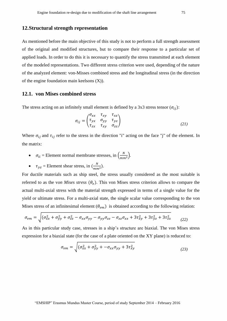
Engine foundation re-design due to modification of the shaft line arrangement 75
“EMSHIP” Erasmus Mundus Master Course, period of study September 2014 – February 2016
12. Structural strength representation
As mentioned before the main objective of this study is not to perform a full strength assessment
of the original and modified structures, but to compare their response to a particular set of
applied loads. In order to do this it is necessary to quantify the stress transmitted at each element
of the modeled representations. Two different stress criterion were used, depending of the nature
of the analyzed element: von-Misses combined stress and the longitudinal stress (in the direction
of the engine foundation main keelsons (X)).
12.1. von Mises combined stress
The stress acting on an infinitely small element is defined by a 3x3 stress tensor ( :
(21)
Where and refer to the stress in the direction "i" acting on the face "j" of the element. In
the matrix:
= Element normal membrane stresses, in
= Element shear stress, in
.
For ductile materials such as ship steel, the stress usually considered as the most suitable is
referred to as the von Mises stress . This von Mises stress criterion allows to compare the
actual multi-axial stress with the material strength expressed in terms of a single value for the
yield or ultimate stress. For a multi-axial state, the single scalar value corresponding to the von
Mises stress of an infinitesimal element ( is obtained according to the following relation:
(22)
As in this particular study case, stresses in a ship’s structure are biaxial. The von Mises stress
expression for a biaxial state (for the case of a plate oriented on the XY plane) is reduced to:
(23)
P 76 Marcos Enrique Di Iorio
Master Thesis developed at University of Genoa, La Spezia.
DNV [14] proposes von Mises hypothesis to evaluate an equivalent stress to check against the
materials yield limit , which is a property of the material. The material will yield if
. The von Mises stress, is to be calculated based on the membrane normal and shear stresses
of the shell element. The stresses are to be evaluated at the element centroid of the mid-plane
(layer).
The yield strength found in steel will vary depending on the different types for a regular
structural steel (ASTM A36) the 250 MPa. Different safety factor and maximum allowed
stresses are dependent on the type of load and the type of analysed element. For example,
longitudinal hull girder stresses within 0.4 L amidships caused by global bending moments are
not allowed to be greater than 175
. However, as it is going to be seen in the analysis, this
value is much larger than the maximum stress values obtained.
12.2. Combined load approach
Different types of analysis have been considered to expose the reaction of the proposed
structural modifications to the selected set of applied loads. Due to the shape of modelled
structure and the nature of the forces acting on it, the approach of the analysis has been
"inspired" based on the Ultimate strength of stiffened panels (16), proposed by O. F.Hughes.
The interpretation of his study was used to define the type of boundary conditions used and the
stress distribution used to describe and compare the behaviour of the different modelled engine
foundations.
In his work, Hughes analyses the possible mechanisms of collapse of longitudinally stiffened
panels applying compressive axial load in combination with the perpendicular load. Under this
type of compressive load the panel is essentially a group of symmetric columns , each consisting
of a stiffener and a plate flange of effective width (b).

Engine foundation re-design due to modification of the shaft line arrangement 77
“EMSHIP” Erasmus Mundus Master Course, period of study September 2014 – February 2016
This simplification can be compared to our case, taking into account differences in:
Representative stiffener:
In the simplified approach the representative structural element is composed by :
o web : actual thickness and height of the stiffener's web,
o flange: actual thickness and width of the stiffener's flange,
o plate: plate thickness and width determined by the span between adjacent stiffeners.
The plate thickness and width is much more important than the case of the flange, displacing the
neutral axis of the stiffener towards the plate.
Differences with our study case:
The representative stiffeners correspond to the main keelsons of the structure. This structures are
more complex than the simplified representative stiffeners used in Hughes study:
web: variation of thickness and height along the stiffener's length,
flange: variation of with and direction along the stiffener's length,
plate: the plate between the keelson is by itself a stiffened plate.
At the forward boundary, the section is composed by a 100 mmx8 mm plate and a 290 mmx20
mm flange. In this case the neutral axis is closer to the centre of the representative stiffener.
Applied loads
Hughes, considers three types of loads:
1- Lateral load causing negative bending of the panel.
2- Lateral load causing positive bending of the panel.
3- In-plane compression.
The first two correspond to distributed load applied perpendicularly to the representative
stiffener's length. "Negative" refers to the load applied on the flange (plate in tension) and
"positive" refers to the load applied on the plate (compression of the plate).
The third corresponds to the uniform compression on each section of the representative stiffener
which causes shortening of the panel. This load is transmitted at the ends of the column by the
flexural moment of global (or larger) structures. For example, the hull girder bending
"negatively" will generate compression of the plates located on the deck.
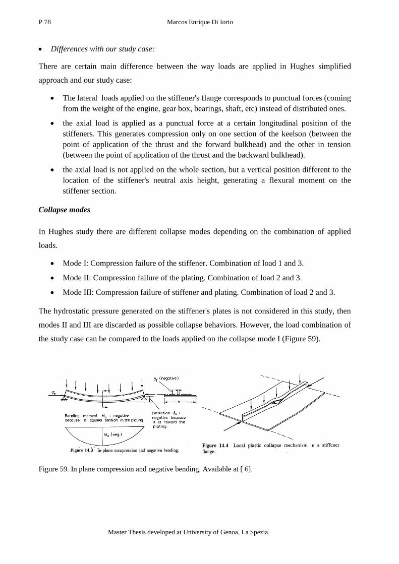
P 78 Marcos Enrique Di Iorio
Master Thesis developed at University of Genoa, La Spezia.
Differences with our study case:
There are certain main difference between the way loads are applied in Hughes simplified
approach and our study case:
The lateral loads applied on the stiffener's flange corresponds to punctual forces (coming
from the weight of the engine, gear box, bearings, shaft, etc) instead of distributed ones.
the axial load is applied as a punctual force at a certain longitudinal position of the
stiffeners. This generates compression only on one section of the keelson (between the
point of application of the thrust and the forward bulkhead) and the other in tension
(between the point of application of the thrust and the backward bulkhead).
the axial load is not applied on the whole section, but a vertical position different to the
location of the stiffener's neutral axis height, generating a flexural moment on the
stiffener section.
Collapse modes
In Hughes study there are different collapse modes depending on the combination of applied
loads.
Mode I: Compression failure of the stiffener. Combination of load 1 and 3.
Mode II: Compression failure of the plating. Combination of load 2 and 3.
Mode III: Compression failure of stiffener and plating. Combination of load 2 and 3.
The hydrostatic pressure generated on the stiffener's plates is not considered in this study, then
modes II and III are discarded as possible collapse behaviors. However, the load combination of
the study case can be compared to the loads applied on the collapse mode I (Figure 59).
Figure 59. In plane compression and negative bending. Available at [ 6].

Engine foundation re-design due to modification of the shaft line arrangement 79
“EMSHIP” Erasmus Mundus Master Course, period of study September 2014 – February 2016
12.3. Critical buckling load
From the performed analysis, the longitudinal stress distribution on the main keelsons of the
engine foundations is compared between the different structures.
The same way as the material yield stress is compared to the von Mises combined stress, an
acceptance criteria for buckling needs to be defined. This way it is possible to determine if the
buckling capability of plates and stiffened panels are within acceptable limits.
This limit was chosen to be determined by the critical buckling load of a stiffener's section. This
value determines the maximum axial load (P) that can be applied on the stiffener's end without
achieving an unstable state, in other words, the buckling of the stiffener column.
Figure 60. Equilibrium states of axially loaded beam column. Available at [15].
The following relation (Equation (24)) can be used to determine the critical load ( that
generates the first buckling mode on an axially loaded stiffener. This relation is obtained from
Euler's Beam theory. The steps to reach to the presented equation is not explained.
(24)
where:
Stiffeners length;
Young modulus. Depends on the stiffeners material (will assume the material to
be isotropic). In the case of the steel used, this value corresponds to
;
Moment of inertia of the section (respect to the neutral axis;
safety factor depending on the type of boundary condition used. In or case k=2,
corresponding to a simply supported boundary condition, which is the most pessimistic
approach.

P 80 Marcos Enrique Di Iorio
Master Thesis developed at University of Genoa, La Spezia.
Representative stiffener
The critical load value used ( corresponds to the most vulnerable section found on the main
keelsons of the engine foundation of the original structure. This section is located on the "outer"
keelson (2150 mm from mid ship), at between the frame 7+850 mm and frame 8, where the web
of this stiffener presents a minimum height of 405 mm (see Figure 39). Knowing the web's
thickness, as well as the flanges width and thickness, it is possible to define the section's
moment of inertia :
Figure 61. Representative stiffener section used to determine the . Modelled using Corel Draw X5.
GIven that the moment of inertia of a rectangular section of height (h) and width (b) is:
the length of the representative stiffener corresponds to the distance between two main
frames ( . Then, from equation (24),
Dividing the by the section's total area ( , we obtain the critical stress
value:
(25)
As it is going to be seen in the analysis, this values is not reached at any point of the
foundation's keelsons (maximum reported stress values lower than 50 MPa).
12.4. Boundary condition analysis
Two different types of boundary conditions were used: symmetry boundary conditions and
model constrains.
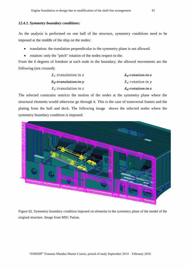
Engine foundation re-design due to modification of the shaft line arrangement 81
“EMSHIP” Erasmus Mundus Master Course, period of study September 2014 – February 2016
12.4.1. Symmetry boundary conditions:
As the analysis is performed on one half of the structure, symmetry conditions need to be
imposed at the middle of the ship on the nodes:
translation: the translation perpendicular to the symmetry plane is not allowed.
rotation: only the "pitch" rotation of the nodes respect to the.
From the 6 degrees of freedom at each node in the boundary, the allowed movements are the
following (not crossed):
The selected constrains restricts the motion of the nodes at the symmetry plane where the
structural elements would otherwise go through it. This is the case of transversal frames and the
plating from the hull and deck. The following image shows the selected nodes where the
symmetry boundary condition is imposed:
Figure 62. Symmetry boundary condition imposed on elements in the symmetry plane of the model of the
original structure. Image from MSC Patran.
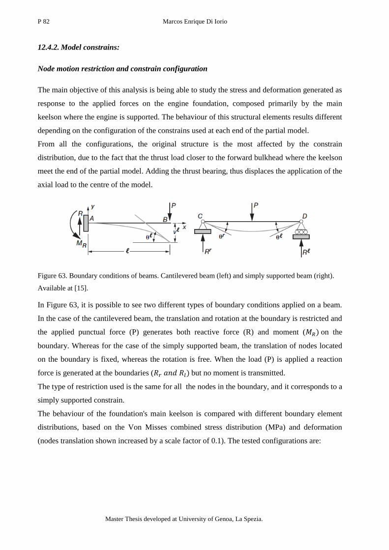
P 82 Marcos Enrique Di Iorio
Master Thesis developed at University of Genoa, La Spezia.
12.4.2. Model constrains:
Node motion restriction and constrain configuration
The main objective of this analysis is being able to study the stress and deformation generated as
response to the applied forces on the engine foundation, composed primarily by the main
keelson where the engine is supported. The behaviour of this structural elements results different
depending on the configuration of the constrains used at each end of the partial model.
From all the configurations, the original structure is the most affected by the constrain
distribution, due to the fact that the thrust load closer to the forward bulkhead where the keelson
meet the end of the partial model. Adding the thrust bearing, thus displaces the application of the
axial load to the centre of the model.
Figure 63. Boundary conditions of beams. Cantilevered beam (left) and simply supported beam (right).
Available at [15].
In Figure 63, it is possible to see two different types of boundary conditions applied on a beam.
In the case of the cantilevered beam, the translation and rotation at the boundary is restricted and
the applied punctual force (P) generates both reactive force (R) and moment ( on the
boundary. Whereas for the case of the simply supported beam, the translation of nodes located
on the boundary is fixed, whereas the rotation is free. When the load (P) is applied a reaction
force is generated at the boundaries ( but no moment is transmitted.
The type of restriction used is the same for all the nodes in the boundary, and it corresponds to a
simply supported constrain.
The behaviour of the foundation's main keelson is compared with different boundary element
distributions, based on the Von Misses combined stress distribution (MPa) and deformation
(nodes translation shown increased by a scale factor of 0.1). The tested configurations are:
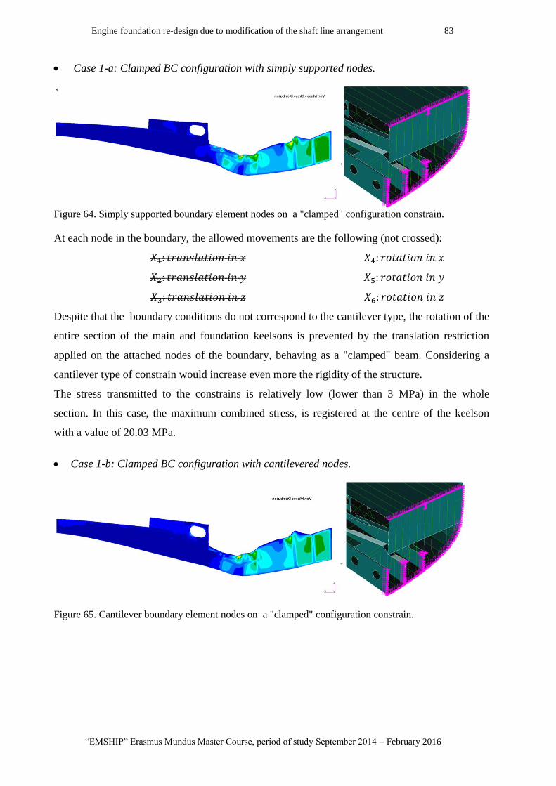
Engine foundation re-design due to modification of the shaft line arrangement 83
“EMSHIP” Erasmus Mundus Master Course, period of study September 2014 – February 2016
Case 1-a: Clamped BC configuration with simply supported nodes.
Figure 64. Simply supported boundary element nodes on a "clamped" configuration constrain.
At each node in the boundary, the allowed movements are the following (not crossed):
Despite that the boundary conditions do not correspond to the cantilever type, the rotation of the
entire section of the main and foundation keelsons is prevented by the translation restriction
applied on the attached nodes of the boundary, behaving as a "clamped" beam. Considering a
cantilever type of constrain would increase even more the rigidity of the structure.
The stress transmitted to the constrains is relatively low (lower than 3 MPa) in the whole
section. In this case, the maximum combined stress, is registered at the centre of the keelson
with a value of 20.03 MPa.
Case 1-b: Clamped BC configuration with cantilevered nodes.
Figure 65. Cantilever boundary element nodes on a "clamped" configuration constrain.

P 84 Marcos Enrique Di Iorio
Master Thesis developed at University of Genoa, La Spezia.
At each node in the boundary, the allowed movements are the following (not crossed):
It is possible to see that the maximum stresses achieved (24.22 MPa) at the centre of the
structure are higher than in the previous case (20.03 MPa). However, this difference is small
compared to simplified case of a punctual force applied in the middle of a beam supported by its
ends.
Case 2-a: Simply supported BC configuration with simply supported nodes on the plate.
Figure 66. Simply supported boundary element nodes on a "simply supported" configuration constrain.
At each node in the boundary, the allowed movements are the following (not crossed):
In this case the translation is restricted at the junction between the keelson and the hull's plates.
If we consider the keelson as a simplified beam, this would correspond to the simply supported
case, where the rotation of the section is free. Here the deformation parameter seems to be more
"natural" as it allows the translation of the points located on the bulkheads.
In Figure 66, it is possible to see that stress distribution is similar to the previous case. The
maximum stress is also achieved at the middle of the simplified beam, with a maximum value of
21.81 MPa. However, it is possible to observe stress concentration at one of the anchor point
where the simplified beam would be supported.

Engine foundation re-design due to modification of the shaft line arrangement 85
“EMSHIP” Erasmus Mundus Master Course, period of study September 2014 – February 2016
Case 2-b: Simply supported BC configuration with simply supported nodes on the flange.
Figure 67. Cantilever supported boundary element nodes on a "simply supported" configuration
constrain.
At each node in the boundary, the allowed movements are the following (not crossed):
In Case 2-b, the centre of rotation is now located on the flange of the simplified beam. It is
possible to see that the translation of the nodes located at the extremes is even less restricted.
This is due to the fact that the bulkhead that surrounds the keelsons are also free to translate and
rotate with respect to the flanges. Despite that the combined stress at the centre of the beam
present a similar magnitude to the previous cases (21.98 MPa), the stress achieved at the flanges
is superior to 36 MPa.
Boundary conditions according to the combined load approach
As it is possible to see, using a simplified beam under a perpendicular load is not sufficient to
predict the stress distribution on the main keelsons of the foundation. Otherwise, the maximum
stresses using clamped BC (Cases 1-a and 1-b) should have been 1,5 times the ones achieved
using simply supported BC (Cases 2-a and 2-b). This is due to the contribution of the almost
horizontal (7,7°) axial load applied on the structure generating in plane compression and tension
of the stiffener's plates.
A more adequate approach to the definition boundary conditions can be based on that used by
Hughes (16). In his tests, Hughes uses simply supported of boundary conditions at the ends of
the stiffened plate because it provides the lowest resistance to axial compression load, despite
the maximum flexural stress achieved is lower.

P 86 Marcos Enrique Di Iorio
Master Thesis developed at University of Genoa, La Spezia.
BC chosen: Clamped BC configuration with simply supported nodes.
The type of boundary condition used for the analysis of this study case corresponds to the Case
1-b, "clamped" ends with simply supported nodes.
The "clamped" section allows to observe the stress distribution with more pessimistic values. At
the same time take into account the plate deformation that can be related to linear buckling
prediction.
Moreover, as explained before, the "clamped" boundary element distribution was chosen to be
implemented on the analysis performed because it presents similar stress distributions to the
other considered cases far from the ends, without generating stress concentration at the
boundaries.
12.1. Conclusion
Apart from the von Mises combined stress distribution, the longitudinal stress (X) distribution is
proposed to describe and compare the structural strength of the main keelsons of the engine
foundation. This approach is based on Hughes study on stiffened plates columns predicting the
most vulnerable point in a stiffener's section according to the applied loads.
A correlation between this theoretical stiffener and the ones that form the studied structure
allowed to establish a maximum longitudinal stress limit: a critical buckling stress ) define
the type.
Moreover, the boundary conditions were selected according to this combined approach. This has
been done not only to define which degrees of freedom of the nodes at the boundaries should be
restricted, but to determine which nodes should be used as boundary elements.
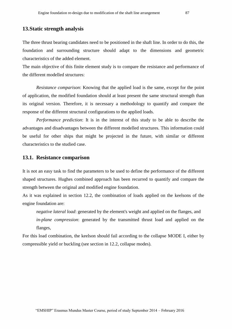
Engine foundation re-design due to modification of the shaft line arrangement 87
“EMSHIP” Erasmus Mundus Master Course, period of study September 2014 – February 2016
13. Static strength analysis
The three thrust bearing candidates need to be positioned in the shaft line. In order to do this, the
foundation and surrounding structure should adapt to the dimensions and geometric
characteristics of the added element.
The main objective of this finite element study is to compare the resistance and performance of
the different modelled structures:
Resistance comparison: Knowing that the applied load is the same, except for the point
of application, the modified foundation should at least present the same structural strength than
its original version. Therefore, it is necessary a methodology to quantify and compare the
response of the different structural configurations to the applied loads.
Performance prediction: It is in the interest of this study to be able to describe the
advantages and disadvantages between the different modelled structures. This information could
be useful for other ships that might be projected in the future, with similar or different
characteristics to the studied case.
13.1. Resistance comparison
It is not an easy task to find the parameters to be used to define the performance of the different
shaped structures. Hughes combined approach has been recurred to quantify and compare the
strength between the original and modified engine foundation.
As it was explained in section 12.2, the combination of loads applied on the keelsons of the
engine foundation are:
negative lateral load: generated by the element's weight and applied on the flanges, and
in-plane compression: generated by the transmitted thrust load and applied on the
flanges,
For this load combination, the keelson should fail according to the collapse MODE I, either by
compressible yield or buckling (see section in 12.2, collapse modes).
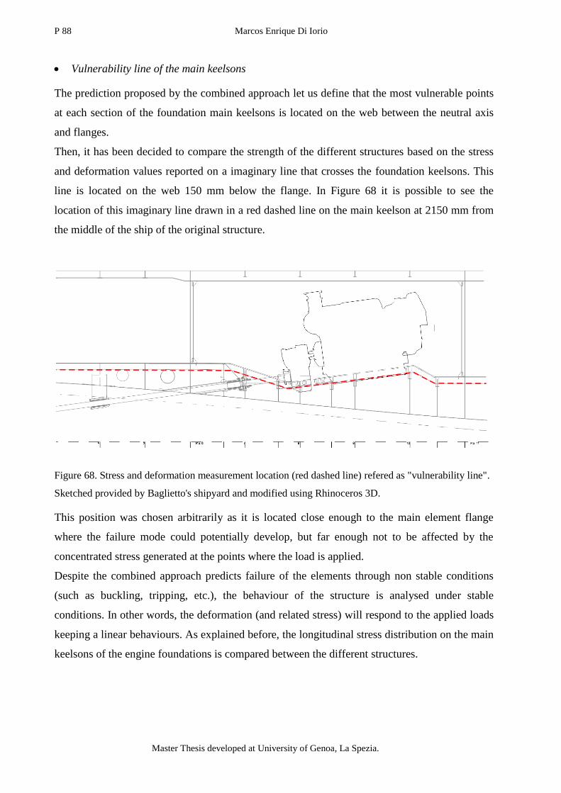
P 88 Marcos Enrique Di Iorio
Master Thesis developed at University of Genoa, La Spezia.
Vulnerability line of the main keelsons
The prediction proposed by the combined approach let us define that the most vulnerable points
at each section of the foundation main keelsons is located on the web between the neutral axis
and flanges.
Then, it has been decided to compare the strength of the different structures based on the stress
and deformation values reported on a imaginary line that crosses the foundation keelsons. This
line is located on the web 150 mm below the flange. In Figure 68 it is possible to see the
location of this imaginary line drawn in a red dashed line on the main keelson at 2150 mm from
the middle of the ship of the original structure.
Figure 68. Stress and deformation measurement location (red dashed line) refered as "vulnerability line".
Sketched provided by Baglietto's shipyard and modified using Rhinoceros 3D.
This position was chosen arbitrarily as it is located close enough to the main element flange
where the failure mode could potentially develop, but far enough not to be affected by the
concentrated stress generated at the points where the load is applied.
Despite the combined approach predicts failure of the elements through non stable conditions
(such as buckling, tripping, etc.), the behaviour of the structure is analysed under stable
conditions. In other words, the deformation (and related stress) will respond to the applied loads
keeping a linear behaviours. As explained before, the longitudinal stress distribution on the main
keelsons of the engine foundations is compared between the different structures.

Engine foundation re-design due to modification of the shaft line arrangement 89
“EMSHIP” Erasmus Mundus Master Course, period of study September 2014 – February 2016
Influence of the load combination
The following figure compares the stress (X-component) distribution along the same keelson
(located at 2150 mm from the mid ship) of the original structure, but under different loading
conditions. In one of them (top) only the axial thrust load is applied and on the other (bottom)
the engine's block's weight and torque is added to the thrust load.
Figure 69. Longitudinal stress (MPa) distribution on Keelson at 2150 mm from mid ship. Under thrust
load (top) and under thrust, weight and torque loads (bottom).
The displacement reported at each node was amplified by (0.05) in order to be able observe the
deformation pattern generated by the different sets of loads. The blue "wire" represents the
original position of the undeformed elements. This figures shows that without the addition of the
forces transmitted from the engine block, according to the distinction made by the combined
approach (see in section 12.2 (Collapse modes)), the deformation of the keelson is not negative
(towards the hull plates). In fact the upwards vertical component of the thrust load tends to
"bend" the keelson of the foundation "positively", allowing the failure to be generated by Modes
I and II.

P 90 Marcos Enrique Di Iorio
Master Thesis developed at University of Genoa, La Spezia.
In following graph, it has been plotted the stress (X component) reported at the "vulnerability
line" (described previously Figure 68) on the main keelson located at 2150 mm from mid ship,
for the two load cases:
Graph 1. Longitudinal stress distribution along vulnerability line of the main keelson located at 1050 mm
F.M.S (top) and2150 mm F.M.S(bottom).
Here it is possible to see that the position of the maximum values differs from the two loading
conditions depending on the longitudinal position where the forces are applied. However, the
maximum reported values present the same order of magnitude in both cases:
Only thrust load: Between (-6 MPa(Compression) and +6 MPa(Traction).
This gives a Δ=12 MPa.
Thrust, weight and torque loads: Between (-10 MPa(Compression) and +2
MPa(Traction). This gives a Δ=12 MPa.

Engine foundation re-design due to modification of the shaft line arrangement 91
“EMSHIP” Erasmus Mundus Master Course, period of study September 2014 – February 2016
In Graph 1, it has been included the approximate position of the frames from the original
structure. It is possible to see that the longitudinal position of the reported peaks are coincident
with the position of the frames. This is due to the fact that the frames provides a barrier where
stress (compression and tension) concentrate.
Longitudinal stress (X-direction) profiles
As it was shown in Graph 1, stress concentration and peaks can be found at the intersection
between the main keelsons of the foundation and the transversal frames and bulkhead. Using
MSC Patran graphical interface it is possible to obtain a stress distribution (in this case
longitudinal stress X) along the intersection between the main keelsons and the intersection, by
selecting manually the nodes or elements that it is required to report (the same procedure was
used to report the stress values along the "vulnerability line").
The following graphs show this X-stress profiles for each of the main transversal structural
member's crossings with the main keelsons of the foundation:
Graph 2. Longitudinal stress distribution profiles along the intersection between the main frames and the
main keelson at 2150 mm F.M.S (right) and 2150 mm F.M.S (right).
In Graph 2 it is possible that the stress values along the profiles is mainly kept between ±4 MPa,
with the exceptions of one "peak" value reported at the top node the intersection of frame 8+800
mm from the main keelson located at 1050 mm (left of Graph 2). This is due to the fact that this
node belongs to one of the elements where the forces generated by the gearbox (mainly torque)
is applied. Then, this value shouldn't be considered as representative of the load applied on the
structure.
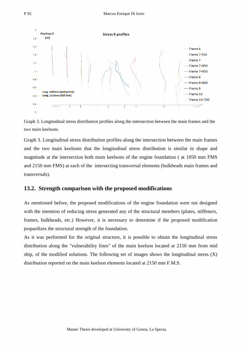
P 92 Marcos Enrique Di Iorio
Master Thesis developed at University of Genoa, La Spezia.
Graph 3. Longitudinal stress distribution profiles along the intersection between the main frames and the
two main keelsons.
Graph 3. Longitudinal stress distribution profiles along the intersection between the main frames
and the two main keelsons that the longitudinal stress distribution is similar in shape and
magnitude at the intersection both main keelsons of the engine foundation ( at 1050 mm FMS
and 2150 mm FMS) at each of the intersecting transversal elements (bulkheads main frames and
transversals).
13.2. Strength comparison with the proposed modifications
As mentioned before, the proposed modifications of the engine foundation were not designed
with the intention of reducing stress generated any of the structural members (plates, stiffeners,
frames, bulkheads, etc.) However, it is necessary to determine if the proposed modification
jeopardizes the structural strength of the foundation.
As it was performed for the original structure, it is possible to obtain the longitudinal stress
distribution along the "vulnerability lines" of the main keelson located at 2150 mm from mid
ship, of the modified solutions. The following set of images shows the longitudinal stress (X)
distribution reported on the main keelson elements located at 2150 mm F.M.S.

Engine foundation re-design due to modification of the shaft line arrangement 93
“EMSHIP” Erasmus Mundus Master Course, period of study September 2014 – February 2016
Figure 70. Side view of the stress (MPa) distribution on keelson at 2150 mm FMS of the modified
proposed solutions: Solution A (top), Solution B middle and Solution V (Bottom). Modelled using MSC
Patran-Nastran.

P 94 Marcos Enrique Di Iorio
Master Thesis developed at University of Genoa, La Spezia.
From these last images it is possible to find similitude's in the stress distribution between the
different shaped keelsons.
a. The maximum and minimum stresses present the same order of magnitude. The lowest
stress (compression) reported is -17 MPa (Solution A) and the highest stress (traction)
reported is (14 MPa).
b. There is a stress concentration point between the frame 7+850 mm and frame 8. The
stress peak is located where the web of this stiffener not only presents a minimum height
of 405 mm but there is also a web height variation. This peak is close to the stiffeners
flange, as predicted by Hughes approach.
Vulnerability line of the main keelsons
The stress distributions shown in Figure 70 confirms that the maximum and minimum
longitudinal stress values are found closer to the main keelson flange. Using the same
methodology than in Graph 1, the longitudinal stress is reported for the different modified
foundations at the "vulnerability line" on the main keelsons located at 1050 mm F.M.S. (Graph
4) and 2150 mm F.M.S. (Graph 5).
Graph 4. Longitudinal stress distribution along the vulnerability line of the main keelson located at 1050
mm (F.M.S) of the original and modified structures (Solutions A, B and V) .
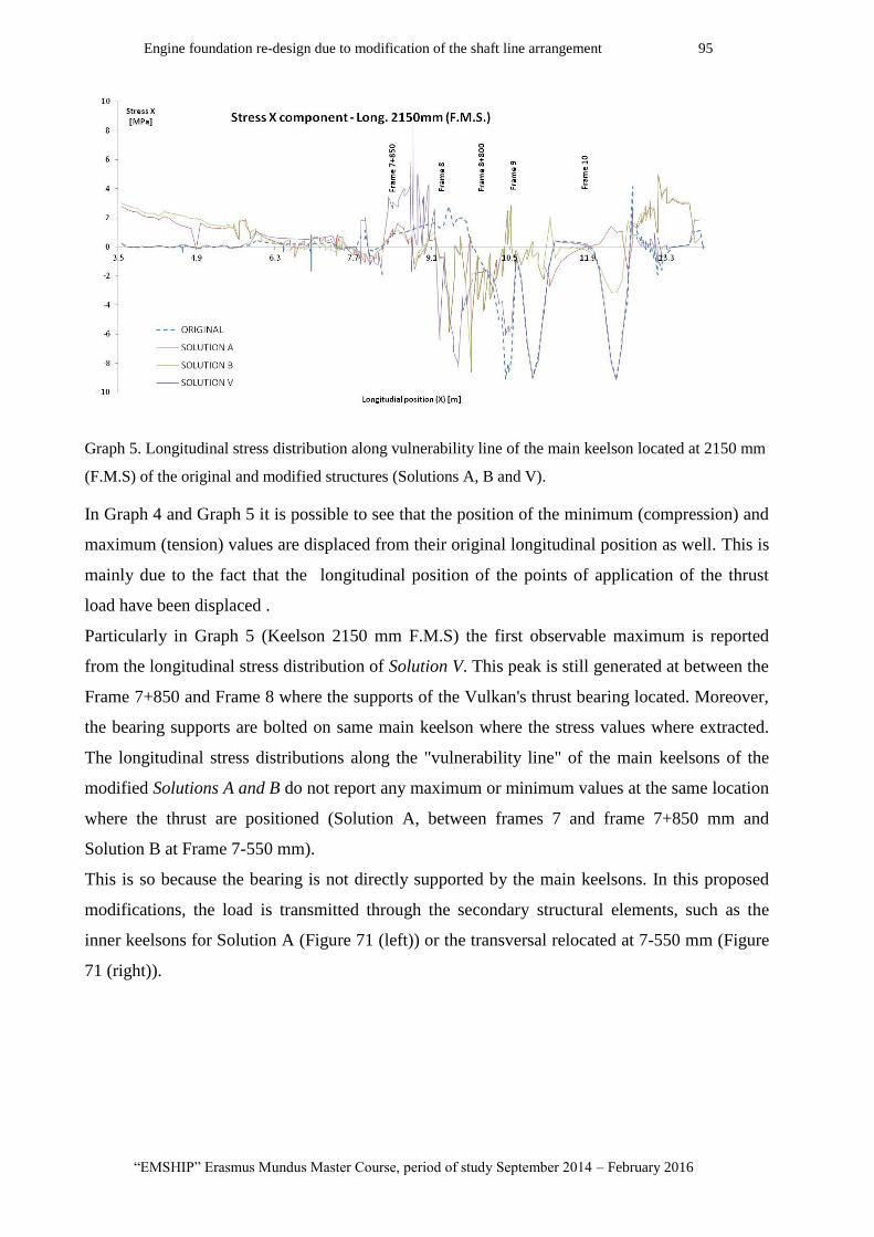
Engine foundation re-design due to modification of the shaft line arrangement 95
“EMSHIP” Erasmus Mundus Master Course, period of study September 2014 – February 2016
Graph 5. Longitudinal stress distribution along vulnerability line of the main keelson located at 2150 mm
(F.M.S) of the original and modified structures (Solutions A, B and V).
In Graph 4 and Graph 5 it is possible to see that the position of the minimum (compression) and
maximum (tension) values are displaced from their original longitudinal position as well. This is
mainly due to the fact that the longitudinal position of the points of application of the thrust
load have been displaced .
Particularly in Graph 5 (Keelson 2150 mm F.M.S) the first observable maximum is reported
from the longitudinal stress distribution of Solution V. This peak is still generated at between the
Frame 7+850 and Frame 8 where the supports of the Vulkan's thrust bearing located. Moreover,
the bearing supports are bolted on same main keelson where the stress values where extracted.
The longitudinal stress distributions along the "vulnerability line" of the main keelsons of the
modified Solutions A and B do not report any maximum or minimum values at the same location
where the thrust are positioned (Solution A, between frames 7 and frame 7+850 mm and
Solution B at Frame 7-550 mm).
This is so because the bearing is not directly supported by the main keelsons. In this proposed
modifications, the load is transmitted through the secondary structural elements, such as the
inner keelsons for Solution A (Figure 71 (left)) or the transversal relocated at 7-550 mm (Figure
71 (right)).
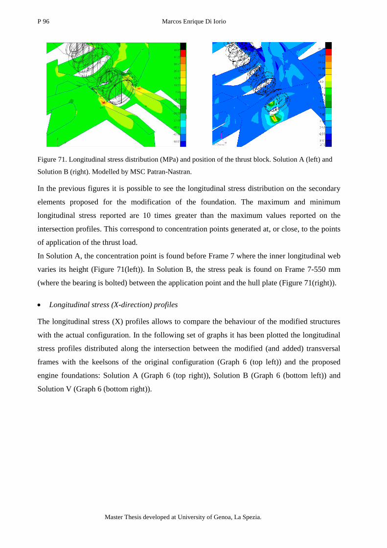
P 96 Marcos Enrique Di Iorio
Master Thesis developed at University of Genoa, La Spezia.
Figure 71. Longitudinal stress distribution (MPa) and position of the thrust block. Solution A (left) and
Solution B (right). Modelled by MSC Patran-Nastran.
In the previous figures it is possible to see the longitudinal stress distribution on the secondary
elements proposed for the modification of the foundation. The maximum and minimum
longitudinal stress reported are 10 times greater than the maximum values reported on the
intersection profiles. This correspond to concentration points generated at, or close, to the points
of application of the thrust load.
In Solution A, the concentration point is found before Frame 7 where the inner longitudinal web
varies its height (Figure 71(left)). In Solution B, the stress peak is found on Frame 7-550 mm
(where the bearing is bolted) between the application point and the hull plate (Figure 71(right)).
Longitudinal stress (X-direction) profiles
The longitudinal stress (X) profiles allows to compare the behaviour of the modified structures
with the actual configuration. In the following set of graphs it has been plotted the longitudinal
stress profiles distributed along the intersection between the modified (and added) transversal
frames with the keelsons of the original configuration (Graph 6 (top left)) and the proposed
engine foundations: Solution A (Graph 6 (top right)), Solution B (Graph 6 (bottom left)) and
Solution V (Graph 6 (bottom right)).

Engine foundation re-design due to modification of the shaft line arrangement 97
“EMSHIP” Erasmus Mundus Master Course, period of study September 2014 – February 2016
Graph 6. Longitudinal stress distribution profiles along the intersection between the main frames and the
main keelson at 1050 mm F.M.S of the original structure (top left), Solution A (top right), Solution B
(bottom left) and Solution V (bottom right).
The longitudinal stress profiles found in the intersection of the different configuration seem to
present maximum and minimum values comparable in magnitude with the stress distribution
found along the original structure. For the three modified structural configurations, the absolute
longitudinal stress is kept below 4 MPa; Which can be considered insignificant with respect to
the critical buckling stress ( (see Equation (25)).
This last lets us predict that loads applied on none of the proposed modifications transmit
stresses to the main keelsons that could lead to their failure.

P 98 Marcos Enrique Di Iorio
Master Thesis developed at University of Genoa, La Spezia.
In the following graphs the stress profiles of the modified versions have been plotted over the
profiles of the original version. Apart from the magnitude analysed in the previous graphs
(Graph 6), the variation of the stress distribution along the intersection may let us predict if there
is any change in stress direction (compression to tension).
The profiles are located at the intersection between the main element (in this case located at
1050 mm FMS) and the transversal frames. In the case of the displaced frames, they where
compared with the original version at the original position. And in the case of the added frames,
they were compared with the stress distribution at that particular longitudinal position on the
original version without the frame.
Graph 7. Longitudinal stress distribution profiles along the intersection between the main frames and the
main keelson at 1050 mm F.M.S. of the modified structure (full line) with the original structure (dashed
line). Solution A (top) and Solution B (bottom).
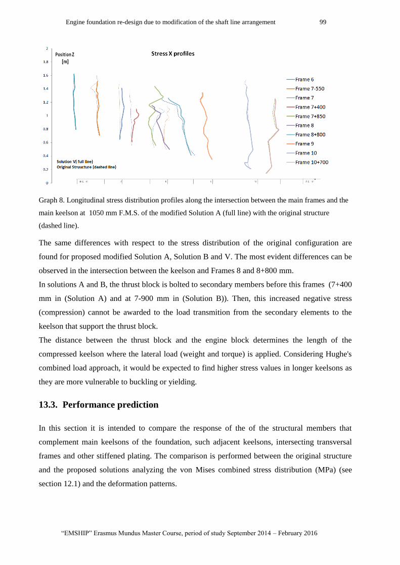
Engine foundation re-design due to modification of the shaft line arrangement 99
“EMSHIP” Erasmus Mundus Master Course, period of study September 2014 – February 2016
Graph 8. Longitudinal stress distribution profiles along the intersection between the main frames and the
main keelson at 1050 mm F.M.S. of the modified Solution A (full line) with the original structure
(dashed line).
The same differences with respect to the stress distribution of the original configuration are
found for proposed modified Solution A, Solution B and V. The most evident differences can be
observed in the intersection between the keelson and Frames 8 and 8+800 mm.
In solutions A and B, the thrust block is bolted to secondary members before this frames (7+400
mm in (Solution A) and at 7-900 mm in (Solution B)). Then, this increased negative stress
(compression) cannot be awarded to the load transmition from the secondary elements to the
keelson that support the thrust block.
The distance between the thrust block and the engine block determines the length of the
compressed keelson where the lateral load (weight and torque) is applied. Considering Hughe's
combined load approach, it would be expected to find higher stress values in longer keelsons as
they are more vulnerable to buckling or yielding.
13.3. Performance prediction
In this section it is intended to compare the response of the of the structural members that
complement main keelsons of the foundation, such adjacent keelsons, intersecting transversal
frames and other stiffened plating. The comparison is performed between the original structure
and the proposed solutions analyzing the von Mises combined stress distribution (MPa) (see
section 12.1) and the deformation patterns.

P 100 Marcos Enrique Di Iorio
Master Thesis developed at University of Genoa, La Spezia.
Figure 72. von Mises stress distribution (MPa) of the foundation's keelson flanges of the original
structure (top left), Solution A (top right), Solution B(bottom left) and Solution V (bottom right).
The last figure confirms the analysis performed using the longitudinal stress (X-direction) on the
webs of the main keelsons. Only for the engine foundation flanges from original structure and
proposed Solution V, the longitudinal position of the maximum combined stresses are located on
the flanges where the forces are applied.
In the case of Solution A and Solution B, the maximum stresses are not found on the main
keelsons flanges, but on the secondary structures used to support and resist the axial load
coming from the thrust bearing.
Original structure
The following image (Figure 73) show a general top view of the whole model of the original
structure. From this picture it is interesting to observe the exaggerated deformation patterns (by
0.1) of the keelson and main frames. The hull and deck plates are not plotted in order to
facilitate the observation. Moreover, the curves corresponding to the engine support system has
been added for orientation in the model.

Engine foundation re-design due to modification of the shaft line arrangement 101
“EMSHIP” Erasmus Mundus Master Course, period of study September 2014 – February 2016
Figure 73. von Mises stress distribution and deformation patterns of the original structure model (top
view). Modelled using MSC Patran-Nastran
Figure 73 shows how not only the main keelson of the foundation bend between frames, but also
the main keelson at mid ship and the keelsons. The main frames seem to be dragged by the main
keelsons modifying their shape.
The following images (Figure 74) show the combined stress distribution of the frames and
transversal members that were modified during the development of the modified structures. This
are going to be used to compare the maximum stresses and their position relative to the frame
Figure 74(a). von Mises stress distribution (MPa) and deformation patterns of the frames (from 6 to 7-
550 mm) corresponding to the Original Structure. Modelled using MSC Patran-Nastran
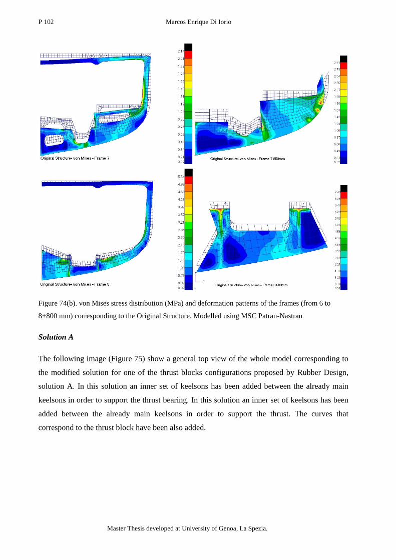
P 102 Marcos Enrique Di Iorio
Master Thesis developed at University of Genoa, La Spezia.
Figure 74(b). von Mises stress distribution (MPa) and deformation patterns of the frames (from 6 to
8+800 mm) corresponding to the Original Structure. Modelled using MSC Patran-Nastran
Solution A
The following image (Figure 75) show a general top view of the whole model corresponding to
the modified solution for one of the thrust blocks configurations proposed by Rubber Design,
solution A. In this solution an inner set of keelsons has been added between the already main
keelsons in order to support the thrust bearing. In this solution an inner set of keelsons has been
added between the already main keelsons in order to support the thrust. The curves that
correspond to the thrust block have been also added.
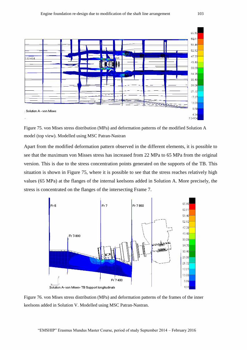
Engine foundation re-design due to modification of the shaft line arrangement 103
“EMSHIP” Erasmus Mundus Master Course, period of study September 2014 – February 2016
Figure 75. von Mises stress distribution (MPa) and deformation patterns of the modified Solution A
model (top view). Modelled using MSC Patran-Nastran
Apart from the modified deformation pattern observed in the different elements, it is possible to
see that the maximum von Misses stress has increased from 22 MPa to 65 MPa from the original
version. This is due to the stress concentration points generated on the supports of the TB. This
situation is shown in Figure 75, where it is possible to see that the stress reaches relatively high
values (65 MPa) at the flanges of the internal keelsons added in Solution A. More precisely, the
stress is concentrated on the flanges of the intersecting Frame 7.
Figure 76. von Mises stress distribution (MPa) and deformation patterns of the frames of the inner
keelsons added in Solution V. Modelled using MSC Patran-Nastran.
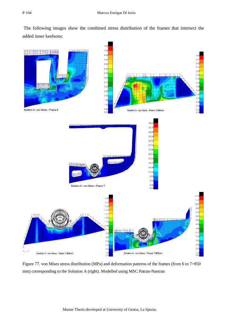
P 104 Marcos Enrique Di Iorio
Master Thesis developed at University of Genoa, La Spezia.
The following images show the combined stress distribution of the frames that intersect the
added inner keelsons:
Figure 77. von Mises stress distribution (MPa) and deformation patterns of the frames (from 6 to 7+850
mm) corresponding to the Solution A (right). Modelled using MSC Patran-Nastran
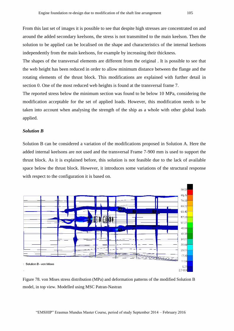
Engine foundation re-design due to modification of the shaft line arrangement 105
“EMSHIP” Erasmus Mundus Master Course, period of study September 2014 – February 2016
From this last set of images it is possible to see that despite high stresses are concentrated on and
around the added secondary keelsons, the stress is not transmitted to the main keelson. Then the
solution to be applied can be localised on the shape and characteristics of the internal keelsons
independently from the main keelsons, for example by increasing their thickness.
The shapes of the transversal elements are different from the original . It is possible to see that
the web height has been reduced in order to allow minimum distance between the flange and the
rotating elements of the thrust block. This modifications are explained with further detail in
section 0. One of the most reduced web heights is found at the transversal frame 7.
The reported stress below the minimum section was found to be below 10 MPa, considering the
modification acceptable for the set of applied loads. However, this modification needs to be
taken into account when analysing the strength of the ship as a whole with other global loads
applied.
Solution B
Solution B can be considered a variation of the modifications proposed in Solution A. Here the
added internal keelsons are not used and the transversal Frame 7-900 mm is used to support the
thrust block. As it is explained before, this solution is not feasible due to the lack of available
space below the thrust block. However, it introduces some variations of the structural response
with respect to the configuration it is based on.
Figure 78. von Mises stress distribution (MPa) and deformation patterns of the modified Solution B
model, in top view. Modelled using MSC Patran-Nastran

P 106 Marcos Enrique Di Iorio
Master Thesis developed at University of Genoa, La Spezia.
In Figure 78 it is possible to see than main keelson located at 1600 mm F.M.S (located at the
same transversal position than the shaft line ) is significantly more deformed than in Solution A.
This main keelson extends from the back end of the ship until the intersection with the thrust
block support at the end of the hull tube, in this case in Frame 7-550 mm (see Figure 42).
This particular configuration, composed by the frame where thrust block is bolted, the forward
end of the main keelson (at 1600 mm F.M.S) and the hull tube was represented in the FEM
model. Figure 79 (left) shows the meshed surfaces used to perform the static analysis.
Figure 79. Modelled Frame 7-550 mm and hull tube from Solution B (left) and its corresponding von
Mises distribution (MPa) (right). Modelled using MSC Patran-Nastran.
The linear response to the applied loads confirmed that there are high concentrated stresses
located in the intersection between the main keelson above the hull tube and the supporting
transversal elements located at the points where the load is applied (see Figure 79 (left)).
The longitudinal stress analysis performed on the main keelsons of the foundation (see Graph 7)
showed that there is no stress transferred from the transversal intersecting elements. Then it is
possible to consider this situation as a localized matter. In the following set of images it has been
compared the combined stress distribution at the forward end of the same main keelson (at 1600
mm F.M.S.) from the original structure ( top left), Solution A ( top right) and Solution B
(bottom). It is interesting to see that the reported maximum stress in Solution is 30 times higher
(Original Str.: 3,06 MPa, Solution A: 3,86 and Solution B (complete):86,52 MPa).
However, if the elements with the stress concentration are not reported, it is possible to see that
the stress distribution in the keelson reaches a maximum value of 17 MPa (Solution B
(Incomplete)). This means that the stress in the rest of the keelson presets tolerable stress values.
This is interesting to know because this solution would isolate almost completely the main
keelsons of the engine foundation from the thrust load.
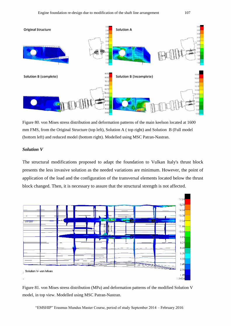
Engine foundation re-design due to modification of the shaft line arrangement 107
“EMSHIP” Erasmus Mundus Master Course, period of study September 2014 – February 2016
Figure 80. von Mises stress distribution and deformation patterns of the main keelson located at 1600
mm FMS, from the Original Structure (top left), Solution A ( top right) and Solution B (Full model
(bottom left) and reduced model (bottom right). Modelled using MSC Patran-Nastran.
Solution V
The structural modifications proposed to adapt the foundation to Vulkan Italy's thrust block
presents the less invasive solution as the needed variations are minimum. However, the point of
application of the load and the configuration of the transversal elements located below the thrust
block changed. Then, it is necessary to assure that the structural strength is not affected.
Figure 81. von Mises stress distribution (MPa) and deformation patterns of the modified Solution V
model, in top view. Modelled using MSC Patran-Nastran.
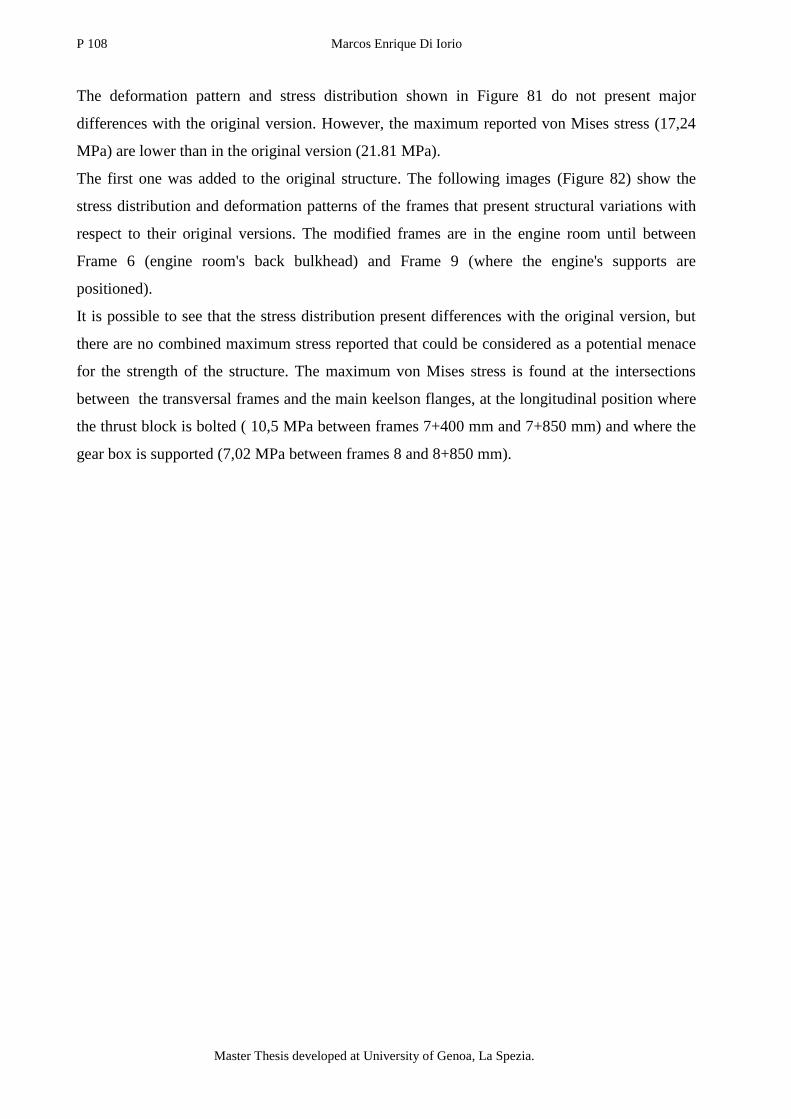
P 108 Marcos Enrique Di Iorio
Master Thesis developed at University of Genoa, La Spezia.
The deformation pattern and stress distribution shown in Figure 81 do not present major
differences with the original version. However, the maximum reported von Mises stress (17,24
MPa) are lower than in the original version (21.81 MPa).
The first one was added to the original structure. The following images (Figure 82) show the
stress distribution and deformation patterns of the frames that present structural variations with
respect to their original versions. The modified frames are in the engine room until between
Frame 6 (engine room's back bulkhead) and Frame 9 (where the engine's supports are
positioned).
It is possible to see that the stress distribution present differences with the original version, but
there are no combined maximum stress reported that could be considered as a potential menace
for the strength of the structure. The maximum von Mises stress is found at the intersections
between the transversal frames and the main keelson flanges, at the longitudinal position where
the thrust block is bolted ( 10,5 MPa between frames 7+400 mm and 7+850 mm) and where the
gear box is supported (7,02 MPa between frames 8 and 8+850 mm).

Engine foundation re-design due to modification of the shaft line arrangement 109
“EMSHIP” Erasmus Mundus Master Course, period of study September 2014 – February 2016
Figure 82. von Mises stress distribution (MPa) and deformation patterns of the frames (from 6 to 9)
corresponding to the Solution V (right). Modelled using MSC Patran-Nastran

P 110 Marcos Enrique Di Iorio
Master Thesis developed at University of Genoa, La Spezia.
13.4. Conclusion
The methodology used to quantify the strength of the engine foundations corresponding to the
modified structures showed a reduction with respect to the strength of the original configuration.
The less invasive modified solution, proposed to adapt the structure to the thrust block offered
by Vulkan, presented the highest stresses on the foundation. This is due to the fact that it is the
only block directly bolted to the main keelson flanges, whereas the other use secondary
elements. Nevertheless, the longitudinal stress values are small compared to the predefined
critical stress limit (
Performing a combined stress distribution and deformation pattern analysis on the modified
solutions corresponding to the thrust blocks proposed by Rubber Design, it was possible to find
stress concentration points in the secondary structures added or modified in order to support the
thrust blocks.
This high stress values should be considered when designing the final shape of the secondary
element. However, this stress concentration is not transmitted to the main elements of the
structure and the problem can be addressed as a localized issue keeping the general modified
configuration.
14. FUTURE DEVELOPMENTS
Final technical design plans
From the proposed analysis it is possible to distinguish the advantages and disadvantages in the
incorporation of the different thrust block candidates. Once the modified solution has been
chosen for the projected ship it is necessary to provide the technical design plans of the
structure.
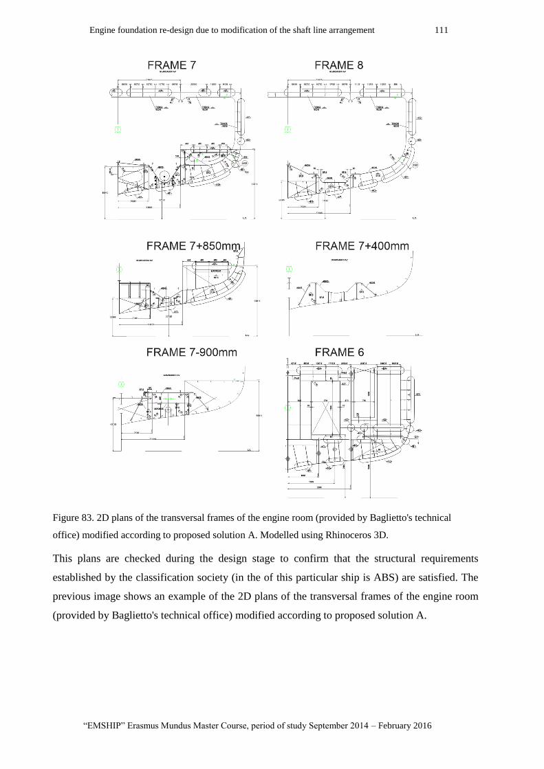
Engine foundation re-design due to modification of the shaft line arrangement 111
“EMSHIP” Erasmus Mundus Master Course, period of study September 2014 – February 2016
Figure 83. 2D plans of the transversal frames of the engine room (provided by Baglietto's technical
office) modified according to proposed solution A. Modelled using Rhinoceros 3D.
This plans are checked during the design stage to confirm that the structural requirements
established by the classification society (in the of this particular ship is ABS) are satisfied. The
previous image shows an example of the 2D plans of the transversal frames of the engine room
(provided by Baglietto's technical office) modified according to proposed solution A.

P 112 Marcos Enrique Di Iorio
Master Thesis developed at University of Genoa, La Spezia.
Dynamic analysis
As it is explained in the Appendix A, a dynamic analysis is performed on the system composed
by the engine block supported by a resilient mount system on a rigid foundation. From this
analysis it is possible to determine the natural frequencies of the system and predict the engine's
rotational speed where resonance can be found. The following table shows the natural
frequencies found for an engine similar to the one used in this particular study case.
Table 11. Natural frequencies: Coupled natural frequencies and mode shapes. Values provided by
Vulkan's technical office.
F-Mode Freq [Hz] Mode Shape
X y z α β γ
1 22,35 0,00 0,08 0,00 1,00 0,00 -0,02
2 17,67 -0,14 0,00 0,02 0,00 1,00 -0,03
3 15,58 0,00 -0,01 0,00 0,09 0,03 1,00
4 8,27 0,13 0,02 1,00 0,00 0,01 0,00
5 4,80 0,00 -0,74 0,01 1,00 0,00 -0,06
6 6,54 1,00 0,00 -0,13 0,00 0,79 -0,01
The following figure (Figure 84), shows the Campbell diagram obtained for this particular
engine. The diagonal curves represent the excitation frequencies coming from the engine at the
different operating revolutions. The intersection with the horizontal curves, corresponding the
natural frequencies of the engine, determine that at that particular speed the system achieves
resonance.
It would be interesting to perform the same analysis but considering the system composed by the
engine elastically supported on the modeled engine foundation structure, instead of a theoretical
perfect rigid foundation. This way, it would be possible to determine the natural frequencies of
the whole system and be able to design the support system and select the characteristics of the
resilient mountings so that the excitation frequencies do not cause resonance problems on the
structure.
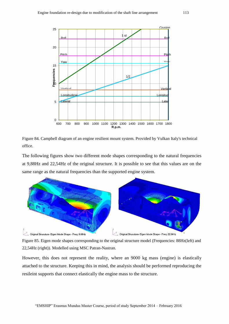
Engine foundation re-design due to modification of the shaft line arrangement 113
“EMSHIP” Erasmus Mundus Master Course, period of study September 2014 – February 2016
Figure 84. Campbell diagram of an engine resilient mount system. Provided by Vulkan Italy's technical
office.
The following figures show two different mode shapes corresponding to the natural frequencies
at 9,88Hz and 22,54Hz of the original structure. It is possible to see that this values are on the
same range as the natural frequencies than the supported engine system.
Figure 85. Eigen mode shapes corresponding to the original structure model (Frequencies: 88Hz(left) and
22,54Hz (right)). Modelled using MSC Patran-Nastran.
However, this does not represent the reality, where an 9000 kg mass (engine) is elastically
attached to the structure. Keeping this in mind, the analysis should be performed reproducing the
resileint supports that connect elastically the engine mass to the structure.
0
5
10
15
20
25
600 700 800 900 1000 1100 1200 1300 1400 1500 1600 1700 1800
Fre
qu
en
cie
s
R.p.m.
Longitud
Pitch
Lateral Later
Longitudinal
Vertical Vertical
Roll Roll
Yaw Yaw
Pitch
1/2
Crusing
1 st
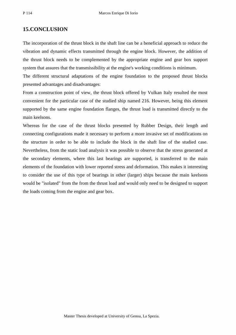
P 114 Marcos Enrique Di Iorio
Master Thesis developed at University of Genoa, La Spezia.
15. CONCLUSION
The incorporation of the thrust block in the shaft line can be a beneficial approach to reduce the
vibration and dynamic effects transmitted through the engine block. However, the addition of
the thrust block needs to be complemented by the appropriate engine and gear box support
system that assures that the transmissibility at the engine's working conditions is minimum.
The different structural adaptations of the engine foundation to the proposed thrust blocks
presented advantages and disadvantages:
From a construction point of view, the thrust block offered by Vulkan Italy resulted the most
convenient for the particular case of the studied ship named 216. However, being this element
supported by the same engine foundation flanges, the thrust load is transmitted directly to the
main keelsons.
Whereas for the case of the thrust blocks presented by Rubber Design, their length and
connecting configurations made it necessary to perform a more invasive set of modifications on
the structure in order to be able to include the block in the shaft line of the studied case.
Nevertheless, from the static load analysis it was possible to observe that the stress generated at
the secondary elements, where this last bearings are supported, is transferred to the main
elements of the foundation with lower reported stress and deformation. This makes it interesting
to consider the use of this type of bearings in other (larger) ships because the main keelsons
would be "isolated" from the from the thrust load and would only need to be designed to support
the loads coming from the engine and gear box.

Engine foundation re-design due to modification of the shaft line arrangement 115
“EMSHIP” Erasmus Mundus Master Course, period of study September 2014 – February 2016
APPENDIX
1. Appendix A: Resilient mounting elements selection
The resultant force will generate a deflection of the resilient mount. Considering only the static
load, the distance ( that the mount is displaced will depend on its static stiffness (k).
(A-1)
It is important to distinguish the static stiffness from the rubber hardness (*). The first
correspond to a property of the resilient mount element as a whole. The second corresponds to a
property of the elastic material used in the element. For example, if it is needed to obtain a 6 mm
deflection when applying a 30 kN load, it is possible to choose in a catalog between a:
- T90 with a rubber hardness of 55 Sh(A), and a total height of 300 mm (Dimension A );
But we will achieve the same deflection with a:
- T60 with a rubber hardness of 65 Sh(A), and a total height of 230 mm (Dimension A ).
Figure 1. T-Series conical resilient mount version with divided central bolt. Available at [8]
This static stiffness is also direction dependent. In our case, the mounts used are conical so they
present a vertical stiffness ( ) and a radial stiffness ( ).
* The hardness is measured using the Shore Hardness unit [Sh], and it is related to different properties
depending on the type of material (scratch, indentation, rebound, etc.).
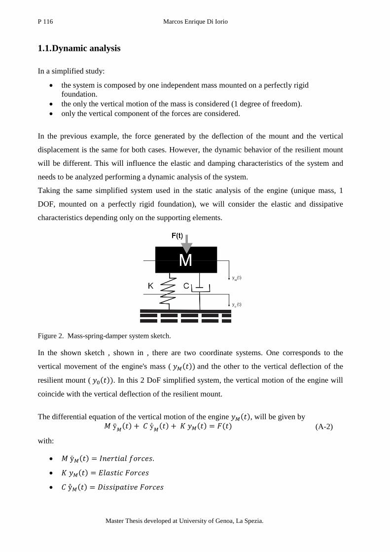
P 116 Marcos Enrique Di Iorio
Master Thesis developed at University of Genoa, La Spezia.
1.1. Dynamic analysis
In a simplified study:
the system is composed by one independent mass mounted on a perfectly rigid
foundation.
the only the vertical motion of the mass is considered (1 degree of freedom).
only the vertical component of the forces are considered.
In the previous example, the force generated by the deflection of the mount and the vertical
displacement is the same for both cases. However, the dynamic behavior of the resilient mount
will be different. This will influence the elastic and damping characteristics of the system and
needs to be analyzed performing a dynamic analysis of the system.
Taking the same simplified system used in the static analysis of the engine (unique mass, 1
DOF, mounted on a perfectly rigid foundation), we will consider the elastic and dissipative
characteristics depending only on the supporting elements.
Figure 2. Mass-spring-damper system sketch.
In the shown sketch , shown in , there are two coordinate systems. One corresponds to the
vertical movement of the engine's mass ( and the other to the vertical deflection of the
resilient mount ( . In this 2 DoF simplified system, the vertical motion of the engine will
coincide with the vertical deflection of the resilient mount.
The differential equation of the vertical motion of the engine , will be given by
(A-2)
with:
Engine foundation re-design due to modification of the shaft line arrangement 117
“EMSHIP” Erasmus Mundus Master Course, period of study September 2014 – February 2016
Inertial Forces: Depend on the acceleration ( of the considered mass (M), in this case, the
engine.
Elastic forces: K corresponds to the linear stiffness of the spring. The generated force depend on
the vertical displacement of the mass, which is as well the deflection of the spring.
If there were no dissipative forces applied ( or applied forces (F(t)=0), it is possible to
obtain the natural frequency of the system from the differential equation of motion . The natural
frequency ( can be defined as:
(A-3)
If we consider the elastic stiffness (K) as linear, it is possible to relate the resilient mount's static
deflection to the force that is generating the deflection. The static deflection is obtained.
with the system at rest ( . In this simplified case, this will only correspond to the
weight supported by the system:
(A-4)
Then,
From this relation, It is possible to define the natural frequency ( ) of the system with the
deflection obtained in the resilient mount ( ):
(A-5)
As it is going to be explained later, in practice the elastic stiffness used in the selection of the
resilient mounts, will correspond to the element's vertical dynamic stiffness
Dissipative forces: This component depends on the vertical velocity of the considered mass
and defines the capacity of the system of reducing, restricting or preventing its
oscillations. Considering the applied forces as equal to 0 (F(t)=0), it necessary to define for the:
Critical damping ( ):
(A-6)
Damping ratio :
(A-7)

P 118 Marcos Enrique Di Iorio
Master Thesis developed at University of Genoa, La Spezia.
Depending on the damping coefficient, the system will be:
Under-damped ( : The system oscillates (at reduced frequency compared to the un-
damped case) with the amplitude gradually decreasing to zero (. In this case, the damping
coefficient will determine the reduction in the amplitude of the displacement in each osculation,
according to the following equation:
(A-8)
Over-damped ( ): The system returns to equilibrium without oscillating.
Figure 3. Under-damped to over-dumped oscillatory response for different values of ( ).
Applied forces: A harmonic force is applied on the system with a frequency and magnitude
F. The relation between the force that is applied on the engine that is transmitted to
the foundation is called transmissibility :
(A-9)
The force applied can be amplified ( or attenuated ( depending on the
elastic and dissipative characteristics of the system. Apart from the damping ratio , defined in
(, it is necessary to define the frequency ratio (β). Which is the relation between the frequency of
the applied force ( the natural frequency of the system:
(A-10)
The following shows a typical transmissibility graph ( β)). This graph can be interpreted
as the response of a system with a particular natural frequency ( , to different
frequencies of the applied force ( Each curve corresponds to different damping
coefficients ( ) of the system.

Engine foundation re-design due to modification of the shaft line arrangement 119
“EMSHIP” Erasmus Mundus Master Course, period of study September 2014 – February 2016
Figure 4. Typical Transmissibility ( β).
Independently to the damping coefficient, the force transmitted to the foundation is equal to the
applied force ( ) at β= . This limits the two possible behavior of the system
depending on the value of β.
If β < , there is an amplification of the applied force. The force transmitted on to the
foundation is maximum when the frequency of the excitation force is equal to the
system's natural frequency (β=1), where the system achieves resonance. When using
higher damping coefficients (ξ) it is possible to reduce the maximum transmissibility
values at the resonance frequency.
If β < there is an attenuation of the transmitted force, respect to the applied force. In
this case, when increasing the damping coefficient reduces the attenuation capacity and
the force transmitted is increased.
1.2. Transmissibility of the resilient mounts
If the foundation mounting element. In other word, the force transmitted to the foundation will
be considered equal to the force applied on the supports which depends of the deflection. The
varying force will generate a variation of the displacement from its static position, and the
transmissibility can be defined as:
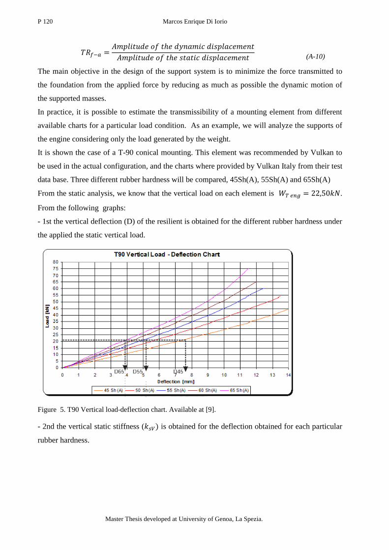
P 120 Marcos Enrique Di Iorio
Master Thesis developed at University of Genoa, La Spezia.
(A-10)
The main objective in the design of the support system is to minimize the force transmitted to
the foundation from the applied force by reducing as much as possible the dynamic motion of
the supported masses.
In practice, it is possible to estimate the transmissibility of a mounting element from different
available charts for a particular load condition. As an example, we will analyze the supports of
the engine considering only the load generated by the weight.
It is shown the case of a T-90 conical mounting. This element was recommended by Vulkan to
be used in the actual configuration, and the charts where provided by Vulkan Italy from their test
data base. Three different rubber hardness will be compared, 45Sh(A), 55Sh(A) and 65Sh(A)
From the static analysis, we know that the vertical load on each element is .
From the following graphs:
- 1st the vertical deflection (D) of the resilient is obtained for the different rubber hardness under
the applied the static vertical load.
Figure 5. T90 Vertical load-deflection chart. Available at [9].
- 2nd the vertical static stiffness ( is obtained for the deflection obtained for each particular
rubber hardness.

Engine foundation re-design due to modification of the shaft line arrangement 121
“EMSHIP” Erasmus Mundus Master Course, period of study September 2014 – February 2016
Figure 6. T90 Vertical load-deflection chart. Available at [ 9].
The natural frequency of the system can be estimated using the equation (A-3), using the
dynamic vertical stiffness in the elastic constant (K) place:
(A-11)
The dynamic vertical stiffness , is obtained using a known dynamic/static ratio ( . This
coefficients correspond to empirical values. In this case load, the for the three
compared rubber hardness.
(26)
The critical damping ratio ( ) is also known, as it is a property that depends on the rubber
hardness value. The following table resumes the values obtained for each rubber hardness:
Table 12. Main characteristics of the T90 resilient mount for rubber hardness of 45, 55 and 66
SH(A).
Rubber
Hardness
[Sh(A)]
Vertical
deflection
[mm]
Vertical static
stiffness
[kN/mm]
Vertical
dynamic
stiffness
[kN/mm]
Vertical Natural
Frequency
Damping to
Critical
Damping
Ratio [Hz] [RPM]
45 7.6 3.1 4.65 8,86 531 0.05
55 5.2 4.2 6.3 10,31 618 0.0625
65 3.8 5.2 7.8 11,48 688 0.07

P 122 Marcos Enrique Di Iorio
Master Thesis developed at University of Genoa, La Spezia.
As it is possible to see, the natural frequency is expressed in RPM. This is due to the fact that in
practice, the transmissibility is analyzed for the different order engine excitations at different
rotational velocities.
Figure 7. Vertical transmissibility or a single DOF.
Two particular engine rotation velocities are highlighted, corresponding to the nominal
rotational speed . This will limit the range of consideration for the analysis:
It is possible to appreciate the influence of the rubber hardness in the behavior of the system. At
nominal speed (1800RPM), the three considered rubber hardness offer sufficient attenuation
( . However, the difference in the response is more important at lower engine
speeds. The hardness selection will depend on the desired engine's performance. For example, if
it is intended to work at a 1000RPM, a more stiff mount (65 Sh(A)) will not be able to absorb
the vibration and the force transmitted will be equal to the applied one. Then a softer support (45
Sh(A)) is recommendable. Whereas, if it is intended to perform at the lowest rotational speed of
the range (600RPM), choosing a 55Sh(A) would mean to be working close to the natural
frequency of the system (618RPM).

Engine foundation re-design due to modification of the shaft line arrangement 123
“EMSHIP” Erasmus Mundus Master Course, period of study September 2014 – February 2016
In this case, the 1st order excitation curve intersect the first three natural frequencies between
900-1400 RPM. Then, the system will temporarily meet resonance when the ship accelerates to
achieve the nominal speed.
Different from the 1st order excitation load, the 1/2 order excitation frequency intersects the yaw
natural frequency (mode shape 3) at nominal speed.
1.2.1. Vibration analysis
This simplified analysis is useful when performing a pre-design of the support system. However,
this values are far from describing the actual behavior of the system. Different methods and
computational tools can be used to take into account more complex configurations and loads.
Foundation:
The system can be composed by elastically connected bodies. Such is the case o a two stage
isolation which will modify the natural frequency of the system and the transmissibility. The
following graph compares a simplified transmissibility chart between a one stage and two stage
isolations systems:
Figure 8. Transmissibility charts for a one stage and two stage isolations systems (left). Sea way motion
(right).
Degrees of Freedom (DoF):
In addition to the vertical motion considered in the simplified analysis, all the possible
translations and rotations are studied. Therefore, the center of gravity and mass moments need to
be defined.

P 124 Marcos Enrique Di Iorio
Master Thesis developed at University of Genoa, La Spezia.
Boundary elements:
All the connective elements that restrict the translation and rotation of the body is considered a
mounting element, including the coupling with the gearbox.
The mounting element are fixed to a perfectly rigid foundation, so that the body motion is
directly related to the element's deflection. Then, the position of the base of the mounting
elements (respect to the origin of the coordinate system) needs to be detailed, as well as the
characteristics of each element.
Loads
Harmonic Loads: The excitation forces that are applied on the engine that are considered in the
study are:
Torsional forces: The static torsional load is applied on each mounting element. The magnitude
of deflection and reaction forces on each element depends on their position relative to the shaft
line. The excitation frequency will depend on the rotational speed. Different excitation orders
are studied, to take into account potential vibration sources.
Gravity load: This load is applied on the center of mass of the body. The position of the center
of gravity of the body is not modified by addition couplings weight to the total mass of the body
(for example the case of the engine-gear box coupling). The deflection and reaction force is
generated by the distribution of the weight on each element.
Seaway movements: Corresponds to the motion of the ship relative to the engine. Despite that
the three relative translations (x1 surge, x2 sway and x3 heave) and rotations (x4 roll,x5 pitch,
x6 yaw) present a load contribution on the engine, only roll and pitch are considered in the
study. This is because their hydrodynamic restoring forces give higher frequencies compared to
the other possible motions. As well as the gravity, this load is applied on the center of gravity of
the body.
The hydrodynamic forces generated by an incident wave field are studied as a low frequency
dynamic load in seakeeping analysis. This loads will generate an harmonic motion of the ship's
structure relative to the engine's position at rest. In practice, the two motions that are taken into
account are roll (X4) and pitch (X5).

Engine foundation re-design due to modification of the shaft line arrangement 125
“EMSHIP” Erasmus Mundus Master Course, period of study September 2014 – February 2016
The following table shows the frequency and angle typically used as input in a 6DoF analysis:
Table 13.
Motion Angle [°] Time
period [s]
Roll (x4) 7 5
Pitch(x5) 22.5 10
Campbell diagram
This diagram is used to see if the excitation loads wich meet any of the natural frequencies of
the system in the engine's working range The following diagram corresponds to the case of a
CATERPILLAR C32 ACERT main propulsion engine, rated 746 bkW @ 1800 rpm performed
by Vulkan Italy using the computational tools is 6DOF version 1.0 for Windows, rev.0.2.
Despite that this engine is lighter and the power at nominal speed is lower than the study case,
the analysis is similar.
Table 14. Natural frequencies: Coupled natural frequencies and mode shapes
F-Mode Freq [Hz] Mode Shape
X y z α β γ
1 22,35 0,00 0,08 0,00 1,00 0,00 -0,02
2 17,67 -0,14 0,00 0,02 0,00 1,00 -0,03
3 15,58 0,00 -0,01 0,00 0,09 0,03 1,00
4 8,27 0,13 0,02 1,00 0,00 0,01 0,00
5 4,80 0,00 -0,74 0,01 1,00 0,00 -0,06
6 6,54 1,00 0,00 -0,13 0,00 0,79 -0,01

P 126 Marcos Enrique Di Iorio
Master Thesis developed at University of Genoa, La Spezia.
Figure 9. Campbell diagram of an engine resilient mount system. Provided by Vulkan Italy's technical
office.
In this diagram it is possible to see how the 1st order and 1/2 order excitation frequency loads
generated by the engine at the different rotational velocities. This excitation loads intersect the
different coupled natural frequencies.
In this case, the 1st order excitation curve intersect the first three natural frequencies between
900-1400 RPM. Then, the system will temporarily meet resonance when the ship accelerates to
achieve the nominal speed.
Different from the 1st order excitation load, the 1/2 order excitation frequency intersects the yaw
natural frequency (mode shape 3) at nominal speed.
0
5
10
15
20
25
600 700 800 900 1000 1100 1200 1300 1400 1500 1600 1700 1800
Fre
qu
en
cie
s
R.p.m.
Longitudina
Pitch
Lateral Lateral
Longitudinal
Vertical Vertical
Roll Roll
Yaw Yaw
Pitch
1/2 order
Crusing
1 st order
Engine foundation re-design due to modification of the shaft line arrangement 127
“EMSHIP” Erasmus Mundus Master Course, period of study September 2014 – February 2016
2. REFERENCES
1. SKF Group -2007. Available from: http://www.skf.com/group/products/bearings-units-
housings/ball-bearings/principles/bearing-basics/bearing-types-and-designs/thrust-
bearings/index.html
2. Propellerpages.com.2006.Available from:
http://www.propellerpages.com/?c=articles&f=2006-02-17_Ship_Propulsion.
3. Basic Principles of Ship Propulsion. Man Diesel and Turbo, Teglholmsgade Copenhagen
SV, Denmark. Dec 2011. Available from: www.mandieselturbo.com
4. ZF-4661 Catalog from Marine propulsion systems. ZF Drive and Chasis Technology.
November 2007. Available from http://www.zf.com/.
5. Alan L. Rowen. 2003. Machinery considerations. In Ship Design and Construction,
SNAME. Volumes 1 and 2. United States of America. Sheridan Books. Chapter 24,
Pages (24-21 to 24-23).
6. Philippe Rigo and Enrico Rizzuto. 2003. Analysis and Design of Ship Structure. In Ship
Design and Construction, SNAME. Volumes 1 and 2. United States of America.
Sheridan Books. Chapter 18, Pages (18-5 to 18-6).
7. Prof. Yasuhisa Okumoto. Design of ship hull structures. A practical guide for engineers.
Kinki University. Schoo of Engineering,Higashi-Oirishima 739-2166 Japan. Springer
Verlag Berlin Heidelberg 2009.
8. Vulkan Coupling, Resilient mounts data sheet. Published 09-2014, Herne, Germany.
Available from www.vulkan.com
9. Vulkan Coupling, VULKARDAN E data sheet. Published 09-2014, Herne, Germany.
Available from www.vulkan.com
10. Vulkan Coupling, Rato E data sheet. Published 09-2014, Herne, Germany. Available
from www.vulkan.com
11. Technical data sheet, T-series conical mounting T90. Revision: 1.1. Dated: 20.03.2006.
Issued by: Santoro Fabio. Approved by: P. Groenenboom.
12. The Netherlands. August 2012. Propulsion equipment, Thrust bearing documentation
sheet Rubber Design B.V. Industrieweg, Heerjansdam, Available from:
www.rubberdesign.nl.
13. Iwer Asmussen,Wolfgang Menzel, Holger Mumm Germanischer Lloyd. GL Technology
Ship Vibration. Published 01-2001. Hamburg, Germany.
P 128 Marcos Enrique Di Iorio
Master Thesis developed at University of Genoa, La Spezia.
14. Class guideline. DNVGL-CG-0127 Finite element analysis. Edition October 2015.
Available from: http://www.dnvgl.com.
15. Surya N.Patnaik and Dale A.Hopkins. Strenght of materials: A unified theory for the
21st Century. Published by Elsevier January 2004 USA.
16. Owen F. Hughes. Chapter 14. Ultimate strength of stiffened panels Ship structural
design. A rationally-based, Computer-aided optimization approach. Department of
aerospace and ocean engineering. Virginia Polytechnic Institute and State University
Blacksburg, Virginia.. Published by The Society of Naval Architects 601 Pavonia
Avenue, Jersey City, New Jersey 07306
MSC Patran-Nastran base level course by Lorenzo Zamparo. Section 4. December 2005.