CONTENTS - TORQUE-ARM Shaft Mount Speed Reducers
186
CONTENTS G2-1 TIGEAR-2 Gearing Reference Guide TORQUE-ARM II TORQUE-ARM MAXUM TORQUE-ARM Shaft Mount Speed Reducers Features / Benefits . . . . . . . . . . . . . . . . . . . . . . . . . . . . . . . . . . . . . . . . . . . . . . . . . . . . G2-2 Specifications ........................................................ G2-9 Nomenclature ....................................................... G2-10 Easy Selection TORQUE-ARM - TXT ............................................. G2-18 Screw Conveyor - SCXT. . . . . . . . . . . . . . . . . . . . . . . . . . . . . . . . . . . . . . . . . . . G2-84 HYDROIL - HXT ................................................ G2-130 Selection TORQUE-ARM Selection - TXT for Electric Motors ...................... G2-12 SCXT - Screw Conveyor Selection. . . . . . . . . . . . . . . . . . . . . . . . . . . . . . . . . . . G2-81 TORQUE-ARM Selection - HXT for Hydraulic Motors ................... G2-129 Selection / Dimensions TORQUE-ARM Shaft Mount Reducers - TXT. . . . . . . . . . . . . . . . . . . . . . . . . . . G2-30 Screw Conveyor Reducers - SCXT .................................. G2-90 HYDROIL Shaft Mount Reducers - HXT ............................. G2-144 Modification / Accessories TXT ....................................................... G2-71 SCXT ...................................................... G2-120 Related Products HXT Reducers For Char-Lynn Motors ............................... G2-154 Harsh Duty Accessories . . . . . . . . . . . . . . . . . . . . . . . . . . . . . . . . . . . . . . . . . . G2-156 TXT-ABHS Reducers ............................................ G2-160 BIO-DISC Reducers ............................................. G2-162 V-Drives for TORQUE-ARM Reducers . . . . . . . . . . . . . . . . . . . . . . . . . . . . . . . G2-164 Renewal Parts . . . . . . . . . . . . . . . . . . . . . . . . . . . . . . . . . . . . . . . . . . . . . . . . . . . . . . G2-168 Engineering/Technical . . . . . . . . . . . . . . . . . . . . . . . . . . . . . . . . . . . . . . . . . . . . . . . . G2-171 Part Number Index ................................................. INDEX-1
-
Upload
khangminh22 -
Category
Documents
-
view
0 -
download
0
Transcript of CONTENTS - TORQUE-ARM Shaft Mount Speed Reducers

CONTENTS
G2-1
TIG
EA
R-2
Gea
rin
g R
efe
ren
ce
Gu
ide
TO
RQ
UE
-AR
M II
TO
RQ
UE
-AR
MM
AX
UM
TORQUE-ARM Shaft Mount Speed Reducers
Features / Benefits . . . . . . . . . . . . . . . . . . . . . . . . . . . . . . . . . . . . . . . . . . . . . . . . . . . . G2-2
Specifications . . . . . . . . . . . . . . . . . . . . . . . . . . . . . . . . . . . . . . . . . . . . . . . . . . . . . . . . G2-9
Nomenclature . . . . . . . . . . . . . . . . . . . . . . . . . . . . . . . . . . . . . . . . . . . . . . . . . . . . . . . G2-10
Easy Selection
TORQUE-ARM - TXT . . . . . . . . . . . . . . . . . . . . . . . . . . . . . . . . . . . . . . . . . . . . . G2-18
Screw Conveyor - SCXT. . . . . . . . . . . . . . . . . . . . . . . . . . . . . . . . . . . . . . . . . . . G2-84
HYDROIL - HXT . . . . . . . . . . . . . . . . . . . . . . . . . . . . . . . . . . . . . . . . . . . . . . . . G2-130
Selection
TORQUE-ARM Selection - TXT for Electric Motors . . . . . . . . . . . . . . . . . . . . . . G2-12
SCXT - Screw Conveyor Selection. . . . . . . . . . . . . . . . . . . . . . . . . . . . . . . . . . . G2-81
TORQUE-ARM Selection - HXT for Hydraulic Motors . . . . . . . . . . . . . . . . . . . G2-129
Selection / Dimensions
TORQUE-ARM Shaft Mount Reducers - TXT. . . . . . . . . . . . . . . . . . . . . . . . . . . G2-30
Screw Conveyor Reducers - SCXT . . . . . . . . . . . . . . . . . . . . . . . . . . . . . . . . . . G2-90
HYDROIL Shaft Mount Reducers - HXT . . . . . . . . . . . . . . . . . . . . . . . . . . . . . G2-144
Modification / Accessories
TXT . . . . . . . . . . . . . . . . . . . . . . . . . . . . . . . . . . . . . . . . . . . . . . . . . . . . . . . G2-71
SCXT . . . . . . . . . . . . . . . . . . . . . . . . . . . . . . . . . . . . . . . . . . . . . . . . . . . . . . G2-120
Related Products
HXT Reducers For Char-Lynn Motors . . . . . . . . . . . . . . . . . . . . . . . . . . . . . . . G2-154
Harsh Duty Accessories . . . . . . . . . . . . . . . . . . . . . . . . . . . . . . . . . . . . . . . . . . G2-156
TXT-ABHS Reducers . . . . . . . . . . . . . . . . . . . . . . . . . . . . . . . . . . . . . . . . . . . . G2-160
BIO-DISC Reducers . . . . . . . . . . . . . . . . . . . . . . . . . . . . . . . . . . . . . . . . . . . . . G2-162
V-Drives for TORQUE-ARM Reducers . . . . . . . . . . . . . . . . . . . . . . . . . . . . . . . G2-164
Renewal Parts . . . . . . . . . . . . . . . . . . . . . . . . . . . . . . . . . . . . . . . . . . . . . . . . . . . . . . G2-168
Engineering/Technical . . . . . . . . . . . . . . . . . . . . . . . . . . . . . . . . . . . . . . . . . . . . . . . . G2-171
Part Number Index . . . . . . . . . . . . . . . . . . . . . . . . . . . . . . . . . . . . . . . . . . . . . . . . . INDEX-1

G2-2
En
gin
ee
ring
FEATURES/BENEFITS
Gea
ring
Re
fere
nc
e Gu
ide
TO
RQ
UE
-AR
M II
TO
RQ
UE
-AR
MM
AX
UM
TIG
EA
R-2
TORQUE-ARM Shaft Mount Speed Reducers
DODGE TORQUE-ARM TWIN TAPERED BUSHINGS
MAKE DODGE TORQUE-ARM THE LEADER
DODGE Twin Tapered Bushings have provided customers almost forty years of reliable and proven service. This exclusive feature revolutionized the shaft mount reducer concept and insured that TORQUE-ARM Speed Reducers would not seize to the customer’s driven shaft. Another first from DODGE, the supplier of industry preferred quality speed reducers.
TORQUE-ARM Speed Reducers provide positive, easy-on, easy-off mounting for all reducer sizes from fractional to 700
HP. A tapered bore in both sides of the reducer’s output hub snugs up against a matching taper on the outer surface of the bushing . . . “Twin Tapered”.
Bushing mounting screws pass through the bushing flange into a mounting collar on the hub. As the screws are tightened, the bushing moves inward, gripping the driven machine’s input shaft tightly and evenly around every point on its circumference.
You can now realize significant cost savings with the TXT TORQUE-ARM Speed Reducer.
And here is how:
- TXT reducers now have increased horsepower ratings which may allow you to use a smaller TORQUE-ARM reducer, while receiving the same torque at the output shaft.
- The reducer mounts directly on the driven shaft, eliminating the need for a coupling or chain drive, sliding motor base, and support structure. There’s no alignment problem.
• TXT reducers incorporate standard DODGE features
- Ratios up to 210:1.
- Capacities fractional to 700 HP
- Output speeds through 400 rpm.
- Trouble-free maintenance.
- Up-front installation savings.
- Quality proven design.
- Easier, more accurate drive alignment.
• Rugged, cast-iron housing. Cast, corrosion-resistant gray and ductile iron housings are precision machined for posi tive gear alignment. Rugged housing construction provides strong, rigid support for bear ings and gearing. Additionally, internal rib design helps chan nel oil to all bearings for supe rior lubrication.
• Efficient helical gear tooth design produces an efficiency rating of 98.5% per gear set. Gear teeth feature a softer core to resist shock loads, com bined with a case carburized surface for maximum wear resistance. Precision crown shaving produces an elliptoid tooth shape, so that teeth mesh at the stronger center area eliminating end loading. The result: uniform load distri bution with no tooth-end wear.
• Lip seals. Metal cased lip seals keep lubricat ing oil in, lock dirt and contami nants out. The cavity between the inner and outer lips is filled with grease at assembly to pre lubricate the seal. A garter spring exerts a constant, gentle pressure at every point around the circumference of the shaft to insure a positive seal. All seals ride on precision ground surfaces for maximum life.
• Dependable performance. All DODGE TORQUE-ARM speed reducers are 100% fac tory noise and leak tested to assure long life and trouble-free service.
• DODGE has a TORQUE-ARM reducer for every applica tion.
And all this adds up to more sav ings for you! The TXT reducer-the best package available to meet tough industrial requirements.
It’s easy to see why DODGE TORQUE-ARM is America’s #1 Shaft Mounted Speed Reducer.

FEATURES/BENEFITS
G2-3
En
gin
ee
rin
gT
IGE
AR
-2G
eari
ng
Re
fere
nc
e G
uid
eT
OR
QU
E-A
RM
IIT
OR
QU
E-A
RM
MA
XU
M
TORQUE-ARM Shaft Mount Speed Reducers
DODGE TORQUE-ARM THE COMPLETE SHAFT MOUNT SPEED REDUCER SYSTEM
DODGE TORQUE-ARM IS AMERICA’S LEADING SHAFT-MOUNT REDUCER BECAUSE:• Experience-over 2,000,000 sold.• Delivery-nearly 5,000 reducers and 20,000
acces sories in stock.• Quality-warranties of less than 1/2% of sales.• Customer Preferred-over 60 years of proven experience.• Twin Tapered Bushings-reliable installation and removal.• Performance Capability-applications through 700 HP.• Product Configurations-TORQUE-ARM, Screw Conveyor and
HYDROIL.• Accessory Package-motor mount, backstop, bushings and
auxiliary seals.
1.
PRECISION HIGH QUALITY GEARING• Computer Designed Helical Gears• 98.5% Efficiency Per Gear Stage• Case Carburized for Long Life• Strong Alloy Materials for High Load Capacity• Crown Shaved Gear Tooth Profile for Even Load Distribution• Smooth Quiet Operation with Several Teeth in Mesh• Designed in Conformance with AGMA
2.
MAXIMUM CAPACITY HOUSING DESIGN• Rugged Cast Iron and Ductile Iron• Rigid Bearing Support and Positive Gear Alignment• High Corrosion Resistance• Excellent Vibration Dampening & Shock Resistance Features
3.
RELIABLE ANTI-FRICTION BEARINGS• Anti-friction Bearing Manufacturers Association Bearing Ratings• Combination Ball & Tapered Roller Designs• Straddle Mounted Gears for Optimum Support• High Thrust Capacity Screw Conveyor Drive Bearings
4.
STRONG SHAFTS FOR SUPPORT• Precision-Machined & Hardened for Maximum Load• High Alloy Steel for Maximum Torsional Loads• Generous Size Shaft Keys for Shock Loading• Press or Heat-Shrunk Design for Total Reliability
5.
PROVEN SEALS KEEP OIL IN AND CONTAMINANTS OUT• Lip Spring-Loaded Construction• Metal Reinforcement for Strength• Broad Operating Range of -20°F to 225°F• 100% Factory-Tested Before Shipment• Smooth Ground Shaft Surfaces for Maximum Life• Seal Kits Available for All Reducer Sizes
6.
EFFICIENT SPLASH LUBRICATION SYSTEM• Generous Oil Sump for Lubricating All Gears & Bearings• Standard Gear Petroleum Lubricants Are Suitable• Multiple Oil Plugs for Total Mounting Flexibility• New Breather With Baffle And Filter• Magnetic Drain Plug for Protection
DODGE has been the leader as a shaft mounted reducer manufacturer for over 60 years. Since our start in 1949, we have developed thousands of satisfied customers. The TORQUE-ARM success is due to initial design and rating conservatism and a rigid quality control program. We have recently tabulated the quantity of reducers sold. This has resulted in the kind of quality and dependability that’s proven by one of the lowest percentage replacement rates in the industry-and that’s with more than 2.0 million units sold.Design features built into every shaft mounted TORQUE-ARM reducer are presented in this bulletin. Remember, a speed reducer is a complete system of balanced, high quality components.
Our success as a manufacturer begins with our design features and extends to our rigid quality program which provides the highest quality and dependability that customers have grown to expect from DODGE. The TORQUE-ARM shaft mounted reducer line, consisting of many sizes and types and with capacities from fractional through 700 HP, is available from our factory warehouse stock, branch warehouse stocks, and authorized distributors located throughout the United States. No other manufacturer in the world can claim this type of coverage and back-up assistance for their products and customer.

G2-4
En
gin
ee
ring
FEATURES/BENEFITS
Gea
ring
Re
fere
nc
e Gu
ide
TO
RQ
UE
-AR
M II
TO
RQ
UE
-AR
MM
AX
UM
TIG
EA
R-2
TAPERED BUSHING ASSEMBLIES Securely mounts Taper Bushed Reducer to driven shaftFeatures Benefits
• Twin Bushings • Reliably supports both sides of reducer.• Full Length Shaft Key • Maximum torque & shock load capability.• Flanged Bushing Mount • Fast & simple installation.• Removal Screws • Reliable demount of reducer.• Fully Split Bushings • Eliminates fretting & seizing problems.• Ductile Iron • Strong, shock resistant bushings.• No Setscrews • Eliminates driven shaft damage.• Clamp Fit • Reduces wobble & fits undersized shafts.
STRAIGHT BORE BUSHING ASSEMBLIES
Accommodate less than maximum bore straight bore reducer applicationsFeatures Benefits
• Steel or Ductile Iron • High load capacity.• Two Bushings • Locking setscrews on both sides of
reducer.• Mount in Reducer Bore • Original Design • Suitable for shorter driven shafts.
• Equivalent to most competitive reducers.
MOTOR MOUNTS Provide a compact and economical method of mounting electric motors on TORQUE-ARM Reducers
Features Benefits• All-Steel Construction • Rigid motor support.• Compactness • Eliminates separate motor bases.• Adjustable Top Plate • Fast & easy belt tensioning.• Pre-Drilled • Accommodates standard NEMA Motors.• Economical • Low cost & eliminates alignment problems.• Flexible Mounting • Pre-drilled for belt guard attachment.• Interchangeability • Also fits screw conveyor drives.
AUXILIARY SEAL KITS Provide extra sealing on Taper Bushed ReducersFeatures Benefits
• Labyrinth Seals • Protection from dust, dirt, & moisture.• Economical • Low cost reducer protection.• Simple Installation • Can be grease purged for protection.• Lubrication Fittings • Filtered air breather included.• Air Breather
BACKSTOPS Prevents reverse of shaft directionFeatures Benefits
• Quick Installation • Fits input shaft of all TORQUE-ARM Reducers• Internally Mounted
• Oil Lubricated • Sealed inside reducer for protection.• Long Life • No external relubrication required.• Keyed to Reducer • Case hardened, shock resistant sprags.• Reversible • High load capacity.
• Suitable for either direction of rotation.
TORQUE-ARM Enclose and Protect Belt DriveBELT GUARDS Features Benefits
• Slotted Metal Panel Construction • Light weight, ventilated• Yellow Paint • Meets safety requirements• Mounting Hardware • Quick easy assembly• Assembles to Reducer and Motor Mount Holes • No machining needed• Flexibility • One size fits most common sheave
diameters
TORQUE-ARM Shaft Mount Speed ReducersDODGE TORQUE-ARM ACCESSORIES

FEATURES/BENEFITS
G2-5
En
gin
ee
rin
gT
IGE
AR
-2G
eari
ng
Re
fere
nc
e G
uid
eT
OR
QU
E-A
RM
IIT
OR
QU
E-A
RM
MA
XU
M
TORQUE-ARM Shaft Mount Speed ReducersAPPLICATION FLEXIBILITY Typical DODGE TORQUE-ARM Reducer Installations
VERTICAL SHAFT APPLICATION HORIZONTAL SHAFT APPLICATIONDODGE TORQUE-ARM TWIN TAPERED BUSHED
VERTICAL SPEED REDUCERSTANDARD DODGE TORQUE-ARM TWIN
TAPERED BUSHED SPEED REDUCER
TDT1530TApplication: 200 HP, Class Ill Service on vertical shaft mixer application. This TDT 1530 Vertical Tapered Bushed Speed Reducer with shock absorbing DYNA-V Belt Drive package replaced an expensive, hard-to-replace, open gear drive system. TORQUE-ARM reducers can mount in many posi tions, such as vertical shaft applications simply by reposi tioning the breather and drain plug for lubrication purposes. Another standard feature of compact and highly efficient TORQUE-ARM reducers.
Application: 40 HP drive, Class II service, on main con veyor drive. Standard Tapered Bushed TXT 725 x 3-15/ 16” Speed Reducer package offers long life and depend ability. Other user benefits on this horizontal shaft applica tion include compactness, off-the-shelf components, flexible motor mount arrangement, and reliable easy-on, easy-off Tapered Bushings. The lowest cost installed sys tem for moving bulk materials.
FLANGE MOUNTED APPLICATION HYDRAULIC REDUCER APPLICATIONDODGE TORQUE-ARM FLANGE MOUNTED VERTICAL
TWIN TAPER BUSHED SPEED REDUCER
DODGE HYDROIL TORQUE-ARM TWIN TAPER BUSHED SPEED REDUCER
Application: 15 HP, Class II Service, on Vertical Agitator Shaft in cement mixing system. This rugged reducer is rig idly mounted via the flange mounting pads which are stan dard on all TORQUE-ARM reducers. This no-charge, flange drilling option allows the reducer to support the agitator shaft and any thrust loads imposed. Flange mounted reducers do not require TORQUE-ARM rod assemblies.
Application: Variable speed DODGE HYDROIL speed reducer with hydraulic power is another example of TORQUE-ARM reducer flexibility. This version powers a rugged, mobile brand of road construction equipment. Simply regulating the pressure and volume of fluid to the motor provides variable speed, variable torque, and even direction of rotation change.
TXT725T X 3-15/16”
TXT625T HXT525T WITH B30 MOTOR

G2-6
En
gin
ee
ring
FEATURES/BENEFITS
Gea
ring
Re
fere
nc
e Gu
ide
TO
RQ
UE
-AR
M II
TO
RQ
UE
-AR
MM
AX
UM
TIG
EA
R-2
TORQUE-ARM Shaft Mount Speed Reducers
DODGE SCREW CONVEYOR DRIVES INDUSTRY WIDE APPLICATION
DODGE quality designed with the Screw Con veyor Industry in mind
The dependable DODGE Screw Conveyor Drives provide a rug ged, competitively priced, application-engineered drive for stan dard CEMA screw conveyors. And the screw conveyor drive incorporates the proven reliability you have come to expect from the DODGE TORQUE-ARM reducer line.
Tapered roller bearings within the drive eliminate the need for an external thrust bearing. The bearings take thrust from the screw conveyor and make external thrust bearings unnecessary.
DODGE Screw Conveyor Drives are available in 5:1, 9:1, 15:1 and 25:1 ratios and the durable drives include:
• A compact design reducer with increased torque ratings.
• The CEMA standard drive shaft.
• A standard trough end mounting adapter with CEMA four-bolt mounting.
• Standard adapter for use with choice of lip, braided or waste pack seals.
• Optional adjustable packing adapter kit.
The DODGE complete, rugged, highly developed, screw con-veyor drive mounts on the trough end of your screw conveyor. Tapered roller bearings in the reducer take the thrust from the screw conveyor. This eliminates the external thrust bearing
com monly required. The drives may be mounted in any position on horizontal, inclined, or vertical shafts by relocating breather and drain plugs. For complete drive between trough and motor, spec ify the screw conveyor drive and the following accessories: trough end plate and motor mount.
Where V-belt drives or electric motors cannot be used, DODGE offers a screw conveyor drive powered by a hydraulic motor.
Note: Guards have been removed for pho tographic purposes
Typical Industry Applications
Food AgricultureGrain SoapsAggregates LumberChemicals StoneMinerals ClayCoal Glass
. . . and many more

FEATURES/BENEFITS
G2-7
En
gin
ee
rin
gT
IGE
AR
-2G
eari
ng
Re
fere
nc
e G
uid
eT
OR
QU
E-A
RM
IIT
OR
QU
E-A
RM
MA
XU
M
TORQUE-ARM Shaft Mount Speed Reducers
DODGE SCREW CONVEYOR DRIVES Two alternative seals in CEMA Standard Adapter
CEMA drive shafts offer easy installation and maintenance.This means increased production, less down-time and substantial cost savings. You can save even more because of convenience and interchangeability. Different diameter drive shafts are inter changeable within each drive, and there’s a wide range of diame ters from 1-1/2 to 3-7/16 inches to choose from. Stainless steel and three-hole CEMA drive shafts are available on request.
Lip Seals.They’re pre-lubricated for pro tection from dust and dirt dur ing installation and are excellent for conveying semi-solids. Metallic parts are par tially coated with synthetic rub ber for added protection from corrosion.
Waste Packing.(Not supplied by DODGE)This can be inserted in a special cavity in the adapter for added protec tion while operating under abrasive conditions.
Belt GuardA slotted metal panel style belt guard with mounting straps for SCXT Reducers will fit standard M series motor mounts. The belt guards are designed to fit most common sheave diameters. They mount eas ily with no machining required.
Auxiliary Seal Kit
GREASE CAVITY
BREATHERFILTER
OUTPUT INPUT
Auxiliary Seal Kits for DODGE Screw Conveyor Drives are avail-able for SCXT Sizes 1-7 Speed Reducers. Each kit contains an input shaft auxiliary seal with cover, output shaft end cap and a fil ter air breather.
Motor mounts need no drilling.Rugged, all-steel DODGE motor mounts bolt directly to the screw conveyor drive reducer. They’re available in fourteen sizes, which easily fit NEMA motor frames. Since the four adjusting bolts allow easy belt tensioning, it’s less time-consuming and you save on installation costs immediately.
Adjustable Packing KitThe adjustable packing kit is used with the standard CEMA adapter to allow repacking the adapter without removing it from the trough end. The adjustable packing kit is a proven sealing option for hostile environments, such as cement dust. Packing can be retightened.
Standard CEMA Adapter
Standard CEMA Adapterwith Adjustable Packing Kit

G2-8
En
gin
ee
ring
FEATURES/BENEFITS
Gea
ring
Re
fere
nc
e Gu
ide
TO
RQ
UE
-AR
M II
TO
RQ
UE
-AR
MM
AX
UM
TIG
EA
R-2
TORQUE-ARM Shaft Mount Speed ReducersDODGE HYDROIL™ DRIVES
Hydraulically Powered TORQUE-ARM Speed Reducers with Infinitely Adjustable Speed and Torque
This is a modified version of the famous TORQUE-ARM speed reducer with the same quality features and ease of installation.
A Hydraulic motor powers the HYDROIL reducer, greatly expanding its scope of application and versatility. It has proven to be popular for locations remote from the prime mover where shafts or belt and chain drives are impractical or where electric motors are not available. Exceptional flexibility is provided in the control of the driven machine by simply regulating the pressure and volume of fluid fed to the HYDROIL motor.
Users can provide flexible control of the HYDROIL drive by selecting proper auxiliary equipment. Output speeds of the reducer are infinitely adjustable through the use of regulating valves in the hydraulic circuit. Both speed and torque can be adjusted to meet the requirements of the driven machine which can be inched or jogged. The direction of rotation is reversible.
Where V-belt drives or electric motors cannot be used, DODGE offers a screw conveyor drive powered by a hydraulic motor.
Hydroil Vane Motors are a superior single stage vane type fluid motor. A series of internal ports admit oil to and carry it from the power element. Complete hydraulic balance of the assembly contributes to the mechanical efficiency and long life of these motors as well as to their unusually quiet operation. Other exclusive features assure a minimum of friction and efficient valving action regardless of operating speeds.
HYDROIL Vane Motors A10 and A20
HYDROIL Vane Motors B30
HYDROIL Vane Motors B40
HYDROIL Vane Motors B50

SPECIFICATIONS
G2-9
TIG
EA
R-2
Gea
rin
g R
efe
ren
ce
Gu
ide
TO
RQ
UE
-AR
M II
TO
RQ
UE
-AR
MM
AX
UM
TORQUE-ARM Shaft Mount Speed Reducers
The speed reducer shall be a belt driven enclosed shaft mount type unit with a single or double reduction ratio. The reducer shall mount directly on the driven shaft and utilize an adjustable torque arm that attaches from the gear case to the support structure or foundation. Optional all steel motor mount adjusts to various belt center distances and supports the motor.
The reducer housing shall be constructed of two-piece corrosion resistant, class 30 gray iron. All housings shall be doweled and precision machined to assure accurate alignment for all gear sets.
All gearing shall be of helical design, case carburized and precision finished to insure a high surface durability with a resilient tooth core for impact resistance and optimum service
life. Gears shall be supported between bearings to maintain proper alignment of gear meshes, to maximize load carrying capabilities, and to eliminate overhung loads imposed on bearings. Design meets or exceeds AGMA standards.
Reducer bearings shall be of the ball or tapered roller type, and provide a 25,000 hour minimum average life, 5,000 L-10 AGMA Class I standard.
All seals shall be of the lip, spring loaded type, made of nitrile rubber or HNBR.
Reducer installation shall be accomplished by using ductile iron, fully split, two bushing system. Reducer removal shall be accomplished by providing jack screw holes in the bushing flanges to mechanically remove the tapered assembly.
TORQUE-ARM Speed Reducers:
Screw Conveyor Drives:
HYDROIL Drives:
The drive shall be a belt driven enclosed, adapter mounted unit with a single or double reduction ratio. The drive shall consist of a standard speed reducer; a cast iron, bolt on, four bolt mounting adapter with double lip seals on both ends, an optional bolt on adjustable packing kit, and a drive shaft machined from a high quality alloy steel. The drive shall conform to Conveyor Equipment Manufacturers Association (CEMA) standards. Optional all steel motor mount adjusts to various belt center distances and supports the motor.
The reducer housing shall be constructed of two-piece corrosion resistant, class 30 gray iron. All housings shall be doweled and precision machined to assure accurate alignment of all gear sets.
All gearing shall be of helical design, case carburized and precision finished to insure a high surface durability with a resilient tooth core for impact resistance and optimum service life. Gears shall be supported between bearings to maintain roper alignment of gear meshes, to maximize load carrying capabilities, and to eliminate overhung loads imposed on bearings. Design meets or exceeds AGMA standards.
Reducer output bearings shall be of the tapered roller type, to absorb thrust loads from the screw conveyor. All bearings shall provide 25,000 hour minimum average life, 5,000 L-10 AGMA Class I standard.
All seals shall be of the lip, spring loaded type, made of nitrile rubber or HNBR.
The speed reducer shall be a hydraulically powered enclosed shaft mount type unit with a single or double reduction ratio. The reducer shall mount directly on the driven shaft and utilize an adjustable torque arm that attaches from the gear case to the support structure or foundation.
The reducer shall be powered using a Hydroil single stage vane type fluid motor. The reducer shall be provided with a cast iron SAE mounting flange adaptor and splined input shaft to allow an integral fit with the splined hydraulic motor shaft.
The reducer housing shall be constructed of two-piece corrosion resistant, class 30 gray iron. All housings shall be doweled and precision machined to assure accurate alignment for all gear sets.
All gearing shall be of helical design, case carburized and recision finished to insure a high surface durability with a
resilient tooth core for impact resistance and optimum service life. Gears shall be supported between bearings to maintain proper alignment of gear meshes, to maximize load carrying capabilities, and to eliminate overhung loads imposed on bearings. Design meets or exceeds AGMA standards.
Reducer bearings shall be of the ball or tapered roller type and provide a 25,000 hour minimum average life, 5,000 L-10 AGMA Class I standard.
All seals shall be of the lip, spring loaded type, made of nitrile rubber or HNBR.
Reducer installation shall be accomplished by using ductile iron, fully split, two bushing system. Reducer removal shall be accomplished by providing jack screw holes in the bushing flanges to mechanically remove the tapered assembly.
General Specifications

G2-10
NOMENCLATURE
FEATURES/BENEFITS PAGE G2-2
SPECIFICATION PAGE G2-9
MODIFICATION/ACCESSORIES PAGE G2-71
RELATED PRODUCTS PAGE G2-152
Gea
ring
Re
fere
nc
e Gu
ide
TO
RQ
UE
-AR
M II
TO
RQ
UE
-AR
MM
AX
UM
TIG
EA
R-2
TORQUE-ARM Shaft Mount Speed ReducersNOMENCLATURE: TORQUE-ARM REDUCERS
XXXX - X XX - x - X - XXXXX
Configuration Bushing Bore SizeTXT Standard TORQUE-ARM Reducer, 1 - 12 1” - 10” TDT Twin Tapered Bushing AssemblyTDT Large TORQUE-ARM Reducer, 13 - 15 1” - 5-7/16” TAXD Straight Bore Bushing AssemblyHXT HYDROIL TORQUE-ARM Reducer, 1 - 7
Type of Reducer/BushingGear Case Size T Twin Taper Bushed Reducer
1 thru 12 TXT S Straight Bore Reducer13 thru 15 TDT1 thru 7 HXT
Ratio *5:1 Single Reduction9, 15, 25:1 Double Reduction
NOMENCLATURE EXAMPLE: TORQUE-ARM REDUCERSTXT - 6 - 25 - T - x - 3-7/16”
Standard TORQUE-ARM Shaft Mount ReducerCase Size 625:1 Ratio, Double ReductionTwin Taper Bushed ReducerTwin Tapered Bushing Assembly with bore to fit 3-7/16” diameter driven shaft
TXT - 2 - 05 - S - x - 1-15/16”Standard TORQUE-ARM Shaft Mount ReducerCase Size 25:1 Ratio, Single ReductionStraight Bore Reducer1-15/16” is maximum bore for TXT2 Straight Bore Reducer; no bushing required
HXT - 1 - 25 - T - x - 1-7/16”HYDROIL Shaft Mount Reducer Case Size 125:1 Ratio, Double ReductionTwin Taper Bushed ReducerTwin Tapered Bushing Assembly with bore to kit 1-7/16” diameter driven shaft
* Note: “A” , “B” or “C” in nomenclature after ratio denotes latest reducer design

NOMENCLATURE
G2-11
FEATURES/BENEFITS PAGE G2-2
SPECIFICATION PAGE G2-9
MODIFICATION/ACCESSORIES PAGE G2-71
RELATED PRODUCTS PAGE G2-152
TIG
EA
R-2
Gea
rin
g R
efe
ren
ce
Gu
ide
TO
RQ
UE
-AR
M II
TO
RQ
UE
-AR
MM
AX
UM
TORQUE-ARM Shaft Mount Speed ReducersNOMENCLATURE: SCREW CONVEYOR DRIVE REDUCERS
XXXXX - X XX - x - XXXXX - XX - XXXXX
Configuration Motor Mount
SCXT Screw Conveyor Drive Reducer MStandard Motor Mount for 6” - 20” screw
HSCXTHYDROIL Screw Conveyor Drive Reducer
ML Long Motor Mount for 24” screw
Gear Case Size Adapter Style1 thru 7 SCXT C Standard CEMA 4-bolt Adapter1 thru 7 HSCXT AC Adjustable Packing Kit
Ratio* CEMA Standard Drive Shaft Diameter5:1 Single Reduction Sizes 1-1/2”, 2”, 2-7/16”, 3”, 3-7/16”9, 15, 25:1
Double Reduction Dependent on screw diameter
NOMENCLATURE EXAMPLE: SCREW CONVEYOR DRIVE REDUCERSSCXT - 7 25 - x - 3-7/16” - C - M724L
Screw Conveyor Drive Reducer Long Motor Mount for 24” screwStandard CEMA 4-bolt Adapter
Case Size 7 3-7/16” diameter Drive Shaft
25:1 Ration, Double Reduction
SCXT - 5 25 - x 2-7/16” - C - M518
Screw Conveyor Drive Reducer Standard Motor Mount for 12” screwStandard CEMA 4-bolt Adapter
Case Size 5 2-7/16” diameter Drive Shaft
25:1 Ratio, Double Reduction
HSCXT - 2 05 - x - 1-1/2” - AC
HYDROIL Screw Conveyor Drive Reducer C Adapter with Adjustable Packing Kit1-1/2” diameter Drive Shaft
Case Size 2
5:1 Ratio, single Reduction
* Note: “A”, “B” or “C” in nomenclature after ratio denotes latest reducer design

G2-12
SELECTIONS
Gea
ring
Re
fere
nc
e Gu
ide
TO
RQ
UE
-AR
M II
TO
RQ
UE
-AR
MM
AX
UM
TIG
EA
R-2
FEATURES/BENEFITS PAGE G2-2
SPECIFICATION PAGE G2-9
MODIFICATION/ACCESSORIES PAGE G2-71
RELATED PRODUCTS PAGE G2-152
TORQUE-ARM Shaft Mount Speed Reducers
When to Use Easy SelectionThe Easy Selection tables for TXT Shaft Mount reducers are for electric motor selections up to 700 horsepower with output speeds up to 400 RPM, using AGMA recommended application class numbers. For extreme shock or high energy loads which must be absorbed, as when stalling; for power source other than an electric motor; or for extreme ambient temperatures, or oversized equipment, consult DODGE Application Engineering, (864) 284-5700.
How to Select
Step 1: Determine Class of Service-See Table 1, page G2-15, to determine Load Classification for applications under nor mal conditions. Find the type application and duty cycle that most closely matches your specific application.
Class I Steady load not exceeding Motor HP rating and light shock loads during 10 hours a day. Moderate shock loads are allowable if operation is intermittent.
For Class I applications, the maximum value of starting and momentary peak loads should not exceed 2 x Motor HP rating. If it exceeds this amount it should be divided by 2 and the result used in the selection table instead of the Motor HP rating.
Class II Steady load not exceeding Motor HP rating for over 10 hours a day. Moderate shock loads are allowable during 10 hours a day.
For Class II applications, the maximum value of starting and momentary peak loads should not exceed 2.8 x Motor HP rating. If it exceeds this amount it should be divided by 2.8 and the result used in the selection table instead of the Motor HP rating.
Class III Moderate shock loads for over 10 hours a day. Heavy shock loads are allowable during 10 hours a day.
For Class III applications, the maximum value of starting and momentary peak loads should not exceed 4 x Motor HP rating. If it exceeds this amount it should be divided by 4 and the result used in the selection table instead of the Motor HP rating.
Step 2: Determine Reducer Size-See the Easy Selection Tables, pages G2-18 thru G2-29. From Selection Table I, II or III read the reducer size for the application horsepower and output speed. Note: For applications where fan cool ing is unacceptable use the Easy Selection tables with an increased Class number. Where more than one reducer selection is listed, the most economical ratio is generally listed first. See Table 31, page G2-179 for maximum input and output speeds.
Step 3: Compare Hollow Shaft Bore with the size of the driven shaft. All DODGE Torque-Arm Taper Bushed reduc ers require bushings. Refer to reducer pages for available bushings. If the driven shaft is larger than the bore of the selected reducer, the shaft must be machined to the proper size, or select a larger reducer. Check driven shaft and key for strength.
Step 4: Check Dimensions-See Selection/Dimensions section, pages G2-30 thru G2-71 for reducer dimensions, weights and part numbers. See Engineering/Technical section, page G2-173 for reducer mounting positions. For optional Torque-Arm rod mounting positions, see page G2-176.

SELECTIONS
G2-13
TIG
EA
R-2
Gea
rin
g R
efe
ren
ce
Gu
ide
TO
RQ
UE
-AR
M II
TO
RQ
UE
-AR
MM
AX
UM
FEATURES/BENEFITS PAGE G2-2
SPECIFICATION PAGE G2-9
MODIFICATION/ACCESSORIES PAGE G2-71
RELATED PRODUCTS PAGE G2-152
TORQUE-ARM Shaft Mount Speed Reducers
Step 5: Select a Belt Drive Arrangement-From the Sheave Ratio table, page G2-164 through G2-167, select the required sheave ratio for the belt drive. Be careful to select the belt drive so that the sheave mounted on the reducer shaft is not smaller than the minimum sheave diameter shown in Table 19, page G2-163. Note: Mount the sheave as close as possible to the reducer to minimize the effect of over hung load on the reducer.
Step 6: Select Accessories-See Modifications/Accesso ries section, pages G2-73 thru G2-81, for description, dimensions, weights, and part numbers for accessories available for the Torque-Arm reducer selected:
Motor Mounts Backstop Assemblies Belt Guards Cooling Fans Auxiliary Seal Kits Filter Breathers Auxiliary End Covers
NOTE: A Torque-Arm rod assembly is furnished with all TXT and HXT reducers, except for those factory-prepared for flange mounting. Torque- Arm reduc ers are shipped without oil.
Ratings and selections are the same for both taper bushed and straight bore reducers - standard, inclined or vertically mounted.
EXAMPLES: Easy Selection Method - TXT TORQUE-ARM Reducers
A 10 HP 1750 RPM motor is used to drive a uniformly loaded belt conveyor moving sand at 70 RPM, operating 16 hours per day. Head pulley shaft diameter is 2-7/16”. Spec calls for a means of holding the conveyor from mov ing backwards. User needs immediately so does not have time to build his own motor mount or belt guard.
Step 1: Determine Class of Service-From Table 1, locate “belt conveyors, uniformly loaded or fed” for over 10 hours per day. This load is classified as a Class II application.
Step 2: Determine Reducer Size-From Table 3-Class II Application, page G2-23, find the column for 10 HP and read down to 70 RPM. A TXT425 reducer is the correct selection.
Step 3: Compare Hollow Shaft Bore of TXT425 with the application driven shaft diameter. Per page G2-43, 2-7/16” is the maximum bore available for this size reducer, so it will work in this application. Be sure to check driven shaft and key for strength.
Step 4: Check Dimensions and Weights-See Selection/ Dimensions section, page G2-30 thru G2-71, for reducer dimensions, weights, part numbers and other pertinent drive dimen sions. See Engineering/Technical section, page G2-173 for information on mounting positions.
Step 5: Select a Belt Drive Arrangement-From the Sheave Ratio table, page G2-164, select a V-drive ratio for the conveyor speed of 70 RPM. With this information, select a belt drive that meets your customer’s needs - i.e. belt style preference, service factor requirements, Taper Lock or QD mounting, etc. Sheave diameter must not be less than minimum diame ters shown in Table 19, page G2-163.
Step 6: Select Accessories-See Modifications/Accesso ries section of catalog to pick out accessories for this appli cation:
TXT4 Backstop Assembly - to hold conveyor from moving backwards when shutdown
TXT4 Auxiliary Seal Kit - extra help to keep sand out of the TXT425 reducer
TA4M Motor Mount - to mount motor to top of TXT425 reducer
TXT4D Belt Guard - to cover and protect the rotating belt drive

G2-14
SELECTIONS
Gea
ring
Re
fere
nc
e Gu
ide
TO
RQ
UE
-AR
M II
TO
RQ
UE
-AR
MM
AX
UM
TIG
EA
R-2
FEATURES/BENEFITS PAGE G2-2
SPECIFICATION PAGE G2-9
MODIFICATION/ACCESSORIES PAGE G2-71
RELATED PRODUCTS PAGE G2-152
TORQUE-ARM Shaft Mount Speed ReducersSELECTION GUIDE: TXT TORQUE-ARM SHAFT MOUNT REDUCERS
This Is A Reference Sheet For Quick Selection And Specification Of DODGE TXT TORQUE-ARM Shaft Mount Reducers. Use It To Identify Information Needed To Make An Accurate Selection With A Step-By-Step Selection Format For Choosing Reducers, Accessories And Belt Drive.
Name Company Name
Phone No. Fax. No.
Application Data:
Type of Driven Equipment
Hours of service per day Class of Service
Type of Load: Uniform Moderate Shock
Motor Type: HP RPM Frame Size Shaft Size
RPM of Driven Equipment Driven Shaft Size
Type of Reducer Mounting: Horizontal Vertical: Input Up
Input Down Incline (Degree of) Flange
Unusual Ambient Temperature
Other Pertinent Application Characteristics (i.e.-dusty Environment, Reversing Duty, Start/Stop Cycles. Etc.)
Reducer Driver Selection
Step 1 - Determine Class of Service
Step 2 - From Appropriate Service Class Table, Select Reducer Size And Ration That Meets Application HP And Driven RPM Requirements:
Twin Taper Bushed Straight Bore
Step 3 - Select Reducer Accessories Required For Application: Backstop
Motor Mount: Standard Long Bottom
Belt Guard: Standard Long Cooling Fan
Auxiliary Seal Kit
Other
Belt Drive Specification:
Service Factor Belt Drive Ratio Needed
Belt Center Distance Type of Belt Desired
Driver: Shaft Diameter Driven: Shaft Diameter
Sheave Sheave
Bushing Bushing
Belts: Size Quantity

SELECTIONS
G2-15
TIG
EA
R-2
Gea
rin
g R
efe
ren
ce
Gu
ide
TO
RQ
UE
-AR
M II
TO
RQ
UE
-AR
MM
AX
UM
FEATURES/BENEFITS PAGE G2-2
SPECIFICATION PAGE G2-9
MODIFICATION/ACCESSORIES PAGE G2-71
RELATED PRODUCTS PAGE G2-152
TORQUE-ARM Shaft Mount Speed Reducers Table 1 - Application Classification And Class
Application
Class Numbers3 to 10
HrsOver 10
Hrsper Day per Day
AGITATORS (Mixers)Pure Liquids I IILiquids and Solids II IILiquids-Variable Density II II
BLOWERSCentrifugal I IILobe II IIVane II II
BREWING AND DISTILLINGBottling Machinery I IIBrew Kettles-Continuous Duty II IICookers-Continuous Duty II IIMash Tubs-Continuous Duty II IIScale Hopper-Frequent Starts II II
CAN FILLING MACHINES I IICAR DUMPERS III IIICAR PULLERS II IICLARIFIERS I IICLASSIFIERS II IICLAY WORKING MACHINERY
Brick Press III IIIBriquette Machine III IIIPug Mill II II
COMPACTORS ★ ★
COMPRESSORSCentrifugal I IILobe II IIReciprocating, Multi-Cylinder II IIIReciprocating, Single-Cylinder III III
CONVEYORS-GENERAL PURPOSEIncludes Apron, Assembly, belt, BucketChain, Flight, Oven and Screw
Uniformly Loaded or Fed I IIHeavy Duty-Not Uniformly Fed II IISevere Duty-Reciprocating or Shaker III III
CRANES ★ ★
CRUSHERStone or Ore III III
DREDGESCable Reels II IIConveyors II IICutter Head Drives III IIIPumps III IIIScreen Drives III IIIStackers II IIWinches II II
ELEVATORSBucket II II
Application
Class Numbers3 to 10
HrsOver 10
Hrsper Day per Day
ELEVATOR (continued)Centrifugal Discharge I IIEscalators I IIFreight II IIGravity Discharge I II
EXTRUDERSGeneral II IIPlastics
Variable Speed Drive III IIIFixed Speed Drive III III
RubberContinuous Screw Operation III IIIIntermittent Screw Operation III III
FANSCentrifugal I IIForced Draft II IIInduced Draft II IIIndustrial & Mine II IIClass Numbers
FEEDERSApron II IIBelt II IIDisc I IIReciprocating III IIIScrew II II
FOOD INDUSTRYCereal Cooker I IIDough Mixer II IIMeat Grinders II IISlicers II II
GENERATORS AND EXCITERS II IIHAMMER MILLS III IIIHOISTS ★ ★
LAUNDRY TUMBLERS II IILAUNDRY WASHERS II IIILUMBER INDUSTRY
BakersSpindle Feed II IIMain Drive III III
ConveyorsBurner II IIMain or Heavy Duty II IIMain Log III III“Re-saw, Merry-Go-Round” II IISlab III IIITransfer II II
ChainsFloor II II
★ Consult DODGE for more information on class number

G2-16
SELECTIONS
Gea
ring
Re
fere
nc
e Gu
ide
TO
RQ
UE
-AR
M II
TO
RQ
UE
-AR
MM
AX
UM
TIG
EA
R-2
FEATURES/BENEFITS PAGE G2-2
SPECIFICATION PAGE G2-9
MODIFICATION/ACCESSORIES PAGE G2-71
RELATED PRODUCTS PAGE G2-152
Application
Class Numbers3 to 10
HrsOver 10
Hrsper Day per Day
LUMBER INDUSTRY (continued)Green II III
Cut-Off SawsChain II IIIDrag II III
Debarking Drums III IIIFeeds
Edger II IIGang III IIITrimmer II II
Log Deck III IIILog Hauls-Incline-Well Type III IIILog Tuning Devices III IIIPlaner Feed II IIPlaner Tilting Hoists II IIRolls-Live-off brg.- Roll Cases III IIISorting Table II IITriple Hoist II IITransfers
Chain II IIICraneway II III
Tray Drives II IIVeneer Lathe Drives II II
METAL MILLSDraw bench Carriage and Main Drive II IIRunout Table
Non-ReversingGroup Drives II IIIndividual Drives III III
Reversing III IIISlab Pushers II IIShears III IIIWire Drawing II IIWire Winding Machine II II
METAL STRIP PROCESSING MACHINERYBridles II IICoilers & Uncoilers I IIEdge Trimmers II IIFlatteners II IILoopers (Accumulators) I IPinch Rolls II IIScrap Choppers II IIShears III IIISlitters II II
MILLS, ROTARY TYPEBall & Rod
Spur Ring Gear III III
Application
Class Numbers3 to 10
HrsOver 10
Hrsper Day per Day
MILLS, ROTARY TYPE (continued)Helical Ring Gear II IIDirect Connected III III
Cement Kilns II IIDryers & Coolers II II
MIXERS, CEMENT II IIPAPER MILLS
Agitator (Mixer) II IIAgitator for Pure Liquors II IIBarking Drums III IIIBarkers-Mechanical III IIIBeater II IIBreaker Stack II IIChipper III IIIChip Feeder II IICoating Rolls II IIConveyors
Chip, Bark, Chemical II IILog (including Slab) III III
Couch Rolls II IICutter III IIICylinder Molds II IIEmbosser II IIExtruder II IIFourdrinier Rolls (includes Lump
breaker, dandy roll, wireturning, and return rolls II II
Jordan II IIKiln Drive II IIMt. Hope Roll II IIPaper Rolls II IIPlatter II IIPresses-Felt & Suction II IIPulper III IIIPumps-Vacuum II IIReel (Surface Type) II IIScreens
Chip II IIRotary II IIVibrating III III
Size Press II IIThickener (AC Motor) II II
(DC Motor) II IIWasher (AC Motor) II II
(DC Motor) II IIWind and Unwind Stand I IWinders (Surface Type) II II
TORQUE-ARM Shaft Mount Speed Reducers Table 1 - Application Classification And Class

SELECTIONS
G2-17
TIG
EA
R-2
Gea
rin
g R
efe
ren
ce
Gu
ide
TO
RQ
UE
-AR
M II
TO
RQ
UE
-AR
MM
AX
UM
FEATURES/BENEFITS PAGE G2-2
SPECIFICATION PAGE G2-9
MODIFICATION/ACCESSORIES PAGE G2-71
RELATED PRODUCTS PAGE G2-152
Application
Class Numbers3 to 10
HrsOver 10
Hrsper Day per Day
PLASTICS INDUSTRY-SECONDARYPROCESSING
Blow Molders II IICoating II IIFilm II IIPipe II IIPre-Plasticizers II IIRods II IISheet II IITubing II II
PULLERS-BARGE HAUL II IIPUMPS
Centrifugal I IIProportioning II IIReciprocating
Single Acting, 3 or more cylinders II IIDouble Acting, 2 or more cylinders II II
RotaryGear Type I II
Lobe I IIVane I II
RUBBER AND PLASTICS INDUSTRYIntensive Internal Mixers
Batch Mixers III IIIContinuous Mixers II II
Mixing Mill2 smooth rolls II IIor 2 corrugated rolls III III
Batch Drop Mill - 2 smooth rolls II IICracker Warmer - 2 roll, 1 corrugated roll III IIICracker-2 corrugated rolls III IIIHolding, Feed & Blend Mill-2 rolls II IIIRefiner-2 rolls II IICalenders II II
SAND MULLER II IISEWAGE DISPOSAL EQUIPMENT
Bar Screens II IIChemical Feeders II IIDewatering Screens II IIScum Breakers II IISlow or Rapid Mixers II IISludge Collectors II IIThickener II IIVacuum Filters II II
SCREENSAir Washing I IIRotary-Stone or Gravel II IITraveling Water Intake I I
TORQUE-ARM Shaft Mount Speed Reducers Table 1 - Application Classification And Class
Application
Class Numbers3 to 10
HrsOver 10
Hrsper Day per Day
SCREW CONVEYORSUniformly Loaded or Fed I IIHeavy Duty II II
SUGAR INDUSTRYBeet Slicer III IIICane knives II IICrushers II IIMills (low speed end) III III
TEXTILE INDUSTRYBatchers II IICalenders II IICards II IIDry Cans II IIDyeing Machinery II IILooms II IIMangles II IINappers II IIPads I IIStashers II IISoapers II IISpinners II IITenter Frames II IIWashers II IIWinders II II
Reference: AGMA Standard 6021-G89 (11/89). The table of application class numbers has been developed from the experience of manufac turers and users of gear drives for use in common applications and has been found to be generally satisfactory for the listed industries when gears are rated using AGMA standards. It is recommended that class numbers for special applications be agreed upon by the user and the gear manufacturer when variations of the table may be required. Special conditions can be any special type of prime mover, starting or stop ping conditions, system conditions, ambient conditions, lubrication, overloads, overspeeds, brake equipped applications, high inertia and reversing loads.

G2-18
EASY SELECTIONS
Gea
ring
Re
fere
nc
e Gu
ide
TO
RQ
UE
-AR
M II
TO
RQ
UE
-AR
MM
AX
UM
TIG
EA
R-2
FEATURES/BENEFITS PAGE G2-2
SPECIFICATION PAGE G2-9
MODIFICATION/ACCESSORIES PAGE G2-71
RELATED PRODUCTS PAGE G2-152
TORQUE-ARM Shaft Mount Speed ReducersTable 2 - Class I Selection Table TXT Reducers ★
★ See page G2-173 for lubrication for 15 RPM and slower
HPOutputRPM
Reducer Selection
Single Double
1/4
4-70 TXT125A TXT115A
71-85 TXT115A TXT125A
86-115 TXT115A TXT109A
116-140 TXT105 TXT109A TXT115A
141-200 TXT105 TXT109A
201-400 TXT105
1/3
5-70 TXT125A TXT115A
71-85 TXT115A TXT125A
86-115 TXT115A TXT109A
116-140 TXT105 TXT109A TXT115A
141-200 TXT105 TXT109A
201-400 TXT105
1/2
4-6 TXT225A
7-70 TXT125A TXT115A
71-85 TXT115A TXT125A
86-115 TXT115A TXT109A
116-140 TXT105 TXT109A TXT115A
141-200 TXT105 TXT109A
201-400 TXT105
3/4
4-5 TXT325B
6-10 TXT225A
11-70 TXT125A TXT115A
71-85 TXT115A TXT125A
86-115 TXT115A TXT109A
116-140 TXT105 TXT109A TXT115A
141-200 TXT105 TXT109A
201-400 TXT105
1
4-5 TXT425B
6-7 TXT325B
8-15 TXT225A
16-70 TXT125A TXT115A
71-85 TXT115A TXT125A
86-115 TXT115A TXT109A
116-140 TXT105 TXT109A TXT115A
141-200 TXT105 TXT109A
201-400 TXT105
1-1/2
4 TXT525C
5-7 TXT425B
8-12 TXT325B
HPOutputRPM
Reducer Selection
Single Double
1-1/2(Continued)
13-23 TXT225A
24-70 TXT125A TXT115A
71-85 TXT115A TXT125A
86-115 TXT115A TXT109A
116-140 TXT105 TXT109A TXT115A
141-200 TXT105 TXT109A
201-400 TXT105
2
4-6 TXT525C
7-10 TXT425B
11-17 TXT325B
18-32 TXT225A TXT215A
33-70 TXT125A TXT115A
71-85 TXT115A TXT125A
86-115 TXT115A TXT109A
116-140 TXT105 TXT109A TXT115A
141-200 TXT105 TXT109A
201-400 TXT105
3
4-5 TXT625A
6-10 TXT525C
11-15 TXT425B
16-26 TXT325B
27-51 TXT225A TXT215A
52-70 TXT125A TXT115A
71-85 TXT115A TXT125A
86-115 TXT115A TXT109A
116-140 TXT105 TXT109A TXT115A
141-200 TXT105 TXT109A
201-400 TXT105
5
5-6 TXT725A
7-9 TXT625A
10-17 TXT525C
18-26 TXT425B TXT415B
27-46 TXT325B TXT315B
47-70 TXT225A TXT215A
71-85 TXT215A TXT225A
86-92 TXT109A TXT215A
93-115 TXT115A TXT109A
116-119 TXT109A TXT115A
120-140 TXT105 TXT109A TXT115A

EASY SELECTIONS
G2-19
TIG
EA
R-2
Gea
rin
g R
efe
ren
ce
Gu
ide
TO
RQ
UE
-AR
M II
TO
RQ
UE
-AR
MM
AX
UM
FEATURES/BENEFITS PAGE G2-2
SPECIFICATION PAGE G2-9
MODIFICATION/ACCESSORIES PAGE G2-71
RELATED PRODUCTS PAGE G2-152
TORQUE-ARM Shaft Mount Speed ReducersTable 2 - Class I Selection Table TXT Reducers ★
★ See page G2-173 for lubrication for 15 RPM and slower + Fan cooling required - see page G2-81.
HPOutputRPM
Reducer Selection
Single Double
5(Continued)
141-200 TXT105 TXT109A
201-400 TXT105
7-1/2
4-6 TXT825A
7-9 TXT725A
10-15 TXT625A
16-26 TXT525C
27-40 TXT425B TXT415B
41-70 TXT325B TXT315B
71-74 TXT315B TXT325B
75-85 TXT215A TXT225A
86-95 TXT215A TXT209A
96-140 TXT205 TXT209A TXT215A
141-200 TXT205 TXT209A
201-231 TXT205
232-400 TXT105
10
5 TXT926A
6-8 TXT825A
9-12 TXT725A
13-20 TXT625A
21-36 TXT525C TXT515C
37-56 TXT425B TXT415B
57-70 TXT325B TXT315B
71-85 TXT315B TXT325B
86-103 TXT315B TXT309B
104-115 TXT215A TXT209A
116-140 TXT305A TXT215A
141-158 TXT305A TXT309B
159-200 TXT305A TXT309B
201-400 TXT205
15
5-6 TXT1024A
7-8 TXT926A
9-13 TXT825A
14-19 TXT725A
20-32 TXT625A TXT615A
33-56 TXT525C TXT515C
57-70 TXT425B TXT415B
71-85 TXT415B TXT425B
86-93 TXT415B TXT409B
94-115 TXT309B+ TXT315B
HPOutputRPM
Reducer Selection
Single Double
15(Continued)
116-140 TXT405A TXT315B TXT309B+
141-145 TXT405A TXT309B+
146-200 TXT305A TXT309B+
201-400 TXT305A
20
4-6 TXT1225
7-8 TXT1024A
9-12 TXT926A
13-18 TXT825A
19-26 TXT725A TXT715A
27-45 TXT625A TXT615A
46-70 TXT525C TXT515C
71-78 TXT515C TXT525C
79-85 TXT415B TXT425B
86-115 TXT415B TXT409B+
116-140 TXT405A TXT409B+ TXT415B+
141-200 TXT405A TXT309B+
201-241 TXT405A
242-400 TXT305A+
25
5-7 TXT1225
8-10 TXT1024A
11-15 TXT926A
16-23 TXT825A
24-33 TXT725A TXT715A
34-59 TXT625A TXT615A
60-70 TXT525C+ TXT515C+
71-80 TXT515C+ TXT525C+
81-101 TXT515C+ TXT509C+
102-132 TXT505A TXT415B+ TXT409B+
133-140 TXT505A TXT409B+ TXT415B+
141-163 TXT505A TXT409B+
164-200 TXT405A+ TXT409B+
201-400 TXT405A+
30
4-5 TDT1425
6-9 TXT1225
10-13 TXT1024A
14-19 TXT926A
20-28 TXT825A TXT815A
29-41 TXT725A TXT715A
42-70 TXT625A TXT615A

G2-20
EASY SELECTIONS
Gea
ring
Re
fere
nc
e Gu
ide
TO
RQ
UE
-AR
M II
TO
RQ
UE
-AR
MM
AX
UM
TIG
EA
R-2
FEATURES/BENEFITS PAGE G2-2
SPECIFICATION PAGE G2-9
MODIFICATION/ACCESSORIES PAGE G2-71
RELATED PRODUCTS PAGE G2-152
TORQUE-ARM Shaft Mount Speed ReducersTable 2 - Class I Selection Table TXT Reducers ★
HPOutputRPM
Reducer Selection
Single Double
30(Continued)
71-75 TXT615A TXT625A
76-115 TXT515C+ TXT509C+
116-125 TXT605 TXT509C+ TXT515C+
126-131 TXT605 TXT409B+
132-200 TXT505A TXT409B+
201-215 TXT505A+
216-400 TXT405A+
40
5-6 TDT1425
7 TDT1325
8-12 TXT1225
13-18 TXT1024A
19-25 TXT926A TXT915A
26-38 TXT825A TXT815A
39-57 TXT725A TXT715A
58-70 TXT625A TXT615A
71-81 TXT615A+ TXT625A+
82-114 TXT605 TXT615A+ TXT609A+
115-125 TXT605 TXT515C+ TXT509C+
126-200 TXT605 TXT509C+
201-241 TXT605
242-400 TXT505A+
50
3-5 TDT1530
6-8 TDT1425
9 TDT1325
10-15 TXT1225
16-22 TXT1024A
23-32 TXT926A TXT915A
33-49 TXT825A TXT815A
50-70 TXT725A TXT715A
71-74 TXT715A TXT725A
75-125 TXT615A+ TXT709A+
126-163 TXT605+ TXT709A+
164-200 TXT605+ TXT609A+
201-400 TXT605+
60
4-6 TDT1530
7-11 TDT1425
12 TDT1325
13-18 TXT1225
19-27 TXT1024A TXT1015A
HPOutputRPM
Reducer Selection
Single Double
60(Continued)
28-39 TXT926A TXT915A
40-60 TXT825A TXT815A
61-70 TXT725A+ TXT715A+
71-120 TXT715A+ TXT709A+
121-131 TXT705 TXT709A+
132-200 TXT605+ TXT709A+
201-400 TXT605+
75
5-8 TDT1530
9-13 TDT1425
14-15 TDT1325
16-23 TXT1225
24-34 TXT1024A TXT1015A
35-50 TXT926A TXT915A
51-70 TXT825A TXT815A
71-78 TXT815A+
79-120 TXT715A+ TXT709A+
121-200 TXT705 TXT709A+
201-210 TXT705
211-400 TXT605+
100
6-11 TDT1530
12-17 TDT1425
18-22 TDT1325
23-31 TXT1225 TXT1215
32-46 TXT1024A TXT1015A
47-69 TXT926A+ TXT915A+
70-120 TXT815A+
121-123 TXT805+ TXT709A+
124-200 TXT705+ TXT709A+
201-400 TXT705+
125
8-14 TDT1530
15-22 TDT1425
23-29 TDT1325
30-40 TXT1225 TXT1215
41-59 TXT1024A TXT1015A
60-70 TXT915A+ TXT926A+
71-90 TXT915A+
91-123 TXT815A+
124-172 TXT805+
173-400 TXT705+
★ See page G2-173 for lubrication for 15 RPM and slower + Fan cooling required - see page G2-81.

EASY SELECTIONS
G2-21
TIG
EA
R-2
Gea
rin
g R
efe
ren
ce
Gu
ide
TO
RQ
UE
-AR
M II
TO
RQ
UE
-AR
MM
AX
UM
FEATURES/BENEFITS PAGE G2-2
SPECIFICATION PAGE G2-9
MODIFICATION/ACCESSORIES PAGE G2-71
RELATED PRODUCTS PAGE G2-152
TORQUE-ARM Shaft Mount Speed ReducersTable 2 - Class I Selection Table TXT Reducers ★
HPOutputRPM
Reducer Selection
Single Double
150
9-17 TDT1530
18-27 TDT1425
28-36 TDT1325
37-49 TXT1225 TXT1215
50-70 TXT1024A TXT1015A
71-75 TXT1015A+ TXT1024A+
76-80 TXT1015A+
81-120 TXT915A+
121-165 TXT905
166-400 TXT805+
200
12-23 TDT1530
24-36 TDT1425
37-51 TDT1325+
52-68 TXT1225✽ TXT1215✽
69-120 TXT1015A+
212-400 TXT905+
250
16-30 TDT1530
31-46 TDT1425+
47-67 TDT1325+
68-75 TXT1225✽ TXT1215✽
76-120 TXT1215✽
HPOutputRPM
Reducer Selection
Single Double
300
19-36 TDT1530
37-58 TDT1425✽
59-70 TDT1325+
71-75 TDT1325✽
83-120 TXT1215✽
350
23-43 TDT1530+
44-69 TDT1425✽
70-75 TDT1325✽
40027-50 TDT1530+
51-75 TDT1425✽
450
30-31 TDT1530✽
32-57 TDT1530+
59-75 TDT1425✽
50034-57 TDT1530✽
66-75 TDT1425✽
600 41-57 TDT1530✽
700 50-57 TDT1530✽
★ See page G2-173 for lubrication for 15 RPM and slower
+ Fan cooling required - see page G2-81.
✽ Heat exchanger required - see page G2-81.

G2-22
EASY SELECTIONS
Gea
ring
Re
fere
nc
e Gu
ide
TO
RQ
UE
-AR
M II
TO
RQ
UE
-AR
MM
AX
UM
TIG
EA
R-2
FEATURES/BENEFITS PAGE G2-2
SPECIFICATION PAGE G2-9
MODIFICATION/ACCESSORIES PAGE G2-71
RELATED PRODUCTS PAGE G2-152
TORQUE-ARM Shaft Mount Speed ReducersTable 3 - Class II Selection Table TXT Reducers ★
★ See page G2-173 for lubrication for 15 RPM and slower + Fan cooling required - see page G2-81
HPOutputRPM
Reducer Selection
Single Double
1/4
5-70 TXT125A TXT115A
71-85 TXT115A TXT125A
86-115 TXT115A TXT109A
116-140 TXT105 TXT109A TXT115A
141-200 TXT105 TXT109A
201-400 TXT105
1/3
4-6 TXT225A
7-70 TXT125A TXT115A
71-85 TXT115A TXT125A
86-115 TXT115A TXT109A
116-140 TXT105 TXT109A TXT115A
141-200 TXT105 TXT109A
201-400 TXT105
1/2
4-5 TXT325B
6-9 TXT225A
10-70 TXT125A TXT115A
71-85 TXT115A TXT125A
86-115 TXT115A TXT109A
116-140 TXT105 TXT109A TXT115A
141-200 TXT105 TXT109A
201-400 TXT105
3/4
4-5 TXT425B
6-8 TXT325B
9-16 TXT225A
17-70 TXT125A TXT115A
71-85 TXT115A TXT125A
86-115 TXT115A TXT109A
116-140 TXT105 TXT109A TXT115A
141-200 TXT105 TXT109A
201-400 TXT105
1
5-7 TXT425B
8-11 TXT325B
12-22 TXT225A
23-70 TXT125A TXT115A
71-85 TXT115A TXT125A
86-115 TXT115A TXT109A
116-140 TXT105 TXT109A TXT115A
141-200 TXT105 TXT109A
201-400 TXT105
HPOutputRPM
Reducer Selection
Single Double
1-1/2
5-6 TXT525C
7-11 TXT425B
12-18 TXT325B
19-34 TXT225A TXT215A
35-70 TXT125A TXT115A
71-85 TXT115A TXT125A
86-115 TXT115A TXT109A
116-140 TXT105 TXT109A TXT115A
141-200 TXT105 TXT109A
201-400 TXT105
2
4-5 TXT625A
6-9 TXT525C
10-14 TXT425B
15-24 TXT325B TXT315B
25-47 TXT225A TXT215A
48-70 TXT125A TXT115A
71-85 TXT115A TXT125A
86-115 TXT115A TXT109A
116-140 TXT105 TXT109A TXT115A
141-200 TXT105 TXT109A
201-400 TXT105
3
4-5 TXT725A
6-8 TXT625A
9-14 TXT525C
15-22 TXT425B TXT415B
23-38 TXT325B TXT315B
39-70 TXT225A TXT215A
71-75 TXT215A TXT225A
76-85 TXT115A TXT125A
86-115 TXT115A TXT109A
116-140 TXT105 TXT109A TXT115A
141-200 TXT105 TXT109A
201-400 TXT105
5
4-6 TXT825A
7-8 TXT725A
9-14 TXT625A
15-24 TXT525C
25-37 TXT425B TXT415B
38-69 TXT325B TXT315B

EASY SELECTIONS
G2-23
TIG
EA
R-2
Gea
rin
g R
efe
ren
ce
Gu
ide
TO
RQ
UE
-AR
M II
TO
RQ
UE
-AR
MM
AX
UM
FEATURES/BENEFITS PAGE G2-2
SPECIFICATION PAGE G2-9
MODIFICATION/ACCESSORIES PAGE G2-71
RELATED PRODUCTS PAGE G2-152
TORQUE-ARM Shaft Mount Speed ReducersTable 3 - Class II Selection Table TXT Reducers ★
HPOutputRPM
Reducer Selection
Single Double
5(Continued)
70-85 TXT215A TXT225A
86-89 TXT215A TXT209A
90-136 TXT205 TXT209A TXT215A
137-140 TXT205 TXT115A TXT209A
141-191 TXT205 TXT109A
192-200 TXT105 TXT109A
201-400 TXT105
7-1/2
5 TXT926A
6-9 TXT825A
10-13 TXT725A
14-21 TXT625A
22-38 TXT525C TXT515C
39-59 TXT425B TXT415B
60-70 TXT325B TXT315B
71-85 TXT315B TXT325B
86-110 TXT315B TXT309B
111-122 TXT215A
123-140 TXT305A TXT209A TXT215A
141-183 TXT305A TXT209A
184-200 TXT205 TXT209A
201-400 TXT205
10
4 TXT1225
5 TXT1024A
6-7 TXT926A
8-12 TXT825A
13-18 TXT725A
19-29 TXT625A TXT615A
30-52 TXT525C TXT515C
53-70 TXT425B TXT415B
71-84 TXT415B TXT425B
85-130 TXT315B TXT309B
131-140 TXT305A TXT315B TXT309B
141-200 TXT305A TXT309B
201-353 TXT305A
354-400 TXT205
15
4-6 TXT1225
7-9 TXT1024A
10-12 TXT926A
13-19 TXT825A
HPOutputRPM
Reducer Selection
Single Double
15(Continued)
20-27 TXT725A
28-47 TXT625A TXT615A
48-70 TXT525C TXT515C
71-82 TXT515C TXT525C
83-117 TXT415B TXT409B
118-140 TXT405A TXT409B TXT415B
141-150 TXT405A TXT409B
151-200 TXT405A TXT309B+
201-269 TXT405A
270-400 TXT305A
20
5 TDT1325
6-8 TXT1225
9-12 TXT1024A
13-17 TXT926A
18-26 TXT825A
27-38 TXT725A TXT715A
39-68 TXT625A TXT615A
69-80 TXT515C TXT525C
81-89 TXT515C
90-117 TXT515C+ TXT509C+
118-125 TXT505A TXT409B+ TXT415B+
126-200 TXT505A TXT409B+
201-400 TXT405A+
25
4-6 TDT1425
7-10 TXT1225
11-15 TXT1024A
16-22 TXT926A
23-33 TXT825A TXT815A
34-49 TXT725A TXT715A
50-80 TXT615A TXT625A
81-94 TXT615A TXT609A
95-125 TXT605 TXT509C+ TXT515C+
126-174 TXT605 TXT509C+
175-200 TXT505A TXT409B+
201-270 TXT505A
271-400 TXT405A+
30
5-7 TDT1425
8 TDT1325
9-12 TXT1225
★ See page G2-173 for lubrication for 15 RPM and slower + Fan cooling required - see page G2-81

G2-24
EASY SELECTIONS
Gea
ring
Re
fere
nc
e Gu
ide
TO
RQ
UE
-AR
M II
TO
RQ
UE
-AR
MM
AX
UM
TIG
EA
R-2
FEATURES/BENEFITS PAGE G2-2
SPECIFICATION PAGE G2-9
MODIFICATION/ACCESSORIES PAGE G2-71
RELATED PRODUCTS PAGE G2-152
TORQUE-ARM Shaft Mount Speed ReducersTable 3 - Class II Selection Table TXT Reducers ★
★ See page G2-173 for lubrication for 15 RPM and slower
+ Fan cooling required - see page G2-81✽ Heat exchange required - see page G2-81
HPOutputRPM
Reducer Selection
Single Double
30(Continued)
13-19 TXT1024A
20-27 TXT926A TXT915A
28-41 TXT825A TXT815A
42-60 TXT725A TXT715A
61-76 TXT625A TXT615A
77-89 TXT615A TXT609A
90-125 TXT605 TXT615A+ TXT609A+
126-200 TXT605 TXT509C+
201-233 TXT605
234-349 TXT505A+
350-400 TXT405A+
40
4-6 TDT1530
7-9 TDT1425
10-11 TDT1325
12-17 TXT1225
18-25 TXT1024A
26-36 TXT926A TXT915A
37-56 TXT825A TXT815A
57-75 TXT725A TXT715A
76-88 TXT715A
89-114 TXT615A+ TXT609A+
115-120 TXT615A+ TXT609A+
121-200 TXT605 TXT609A+
201-347 TXT605+
348-400 TXT505A+
50
5-8 TDT1530
9-12 TDT1425
13-14 TDT1325
15-21 TXT1225
22-32 TXT1024A TXT1015A
33-46 TXT926A TXT915A
47-70 TXT825A TXT815A
71-72 TXT815A TXT825A
73-95 TXT715A+
96-110 TXT705 TXT709A TXT715A+
111-120 TXT705 TXT709A+ TXT715A+
121-179 TXT705 TXT709A+
180-200 TXT605+ TXT609A+
201-400 TXT605+
HPOutputRPM
Reducer Selection
Single Double
60
5-9 TDT1530
10-14 TDT1425
15-18 TDT1325
19-26 TXT1225
27-39 TXT1024A TXT1015A
40-56 TXT926A TXT915A
57-70 TXT825A TXT815A
71-75 TXT815A TXT825A
76-89 TXT815A
90-120 TXT705 TXT715A+ TXT709A+
121-200 TXT705 TXT709A+
201-285 TXT705
286-400 TXT605+
75
7-12 TDT1530
13-18 TDT1425
19-24 TDT1325
25-33 TXT1225 TXT1215
34-49 TXT1024A TXT1015A
50-73 TXT926A TXT915A
74-75 TXT815A TXT825A
76-120 TXT805 TXT815A+
121-133 TXT805 TXT709A+
134-200 TXT705 TXT709A+
201-400 TXT705
100
8-16 TDT1530
17-25 TDT1425
26-33 TDT1325
34-45 TXT1225 TXT1215
46-67 TXT1024A TXT1015A
68-75 TXT915A+ TXT926A+
76-103 TXT915A+
104-120 TXT905 TXT815A+
121-149 TXT905
150-180 TXT805
181-200 TXT805 TXT709A
201-204 TXT805
205-246 TXT705
247-400 TXT705+

EASY SELECTIONS
G2-25
TIG
EA
R-2
Gea
rin
g R
efe
ren
ce
Gu
ide
TO
RQ
UE
-AR
M II
TO
RQ
UE
-AR
MM
AX
UM
FEATURES/BENEFITS PAGE G2-2
SPECIFICATION PAGE G2-9
MODIFICATION/ACCESSORIES PAGE G2-71
RELATED PRODUCTS PAGE G2-152
TORQUE-ARM Shaft Mount Speed ReducersTable 3 - Class II Selection Table TXT Reducers ★
HPOutputRPM
Reducer Selection
Single Double
125
11-20 TDT1530
21-31 TDT1425
32-43 TDT1325
44-58 TXT1225 TXT1215
59-75 TXT1024A TXT1015A
76-85 TXT1015A
86-120 TXT915A+
145-209 TXT905
210-303 TXT805+
304-400 TXT705+
150
13-25 TDT1530
26-38 TDT1425
39-54 TDT1325
55-72 TXT1225+ TXT1215+
73-75 TXT1015A+ TXT1024A+
76-120 TXT1015A+
184-279 TXT905+
280-400 TXT805+
HPOutputRPM
Reducer Selection
Single Double
200
18-33 TDT1530
34-53 TDT1425+
54-75 TDT1325+
77-120 TXT1215✽
250
23-42 TDT1530
43-46 TDT1425+
47-69 TDT1425✽
70-75 TDT1325+
30028-53 TDT1530
54-75 TDT1425✽
35033-57 TDT1530
66-75 TDT1425✽
400 38-57 TDT1530+
450 43-57 TDT1530+
500 50-57 TDT1530+
★ See page G2-173 for lubrication for 15 RPM and slower
+ Fan cooling required - see page G2-81.
✽ Heat exchanger required - see page G2-81.

G2-26
EASY SELECTIONS
Gea
ring
Re
fere
nc
e Gu
ide
TO
RQ
UE
-AR
M II
TO
RQ
UE
-AR
MM
AX
UM
TIG
EA
R-2
FEATURES/BENEFITS PAGE G2-2
SPECIFICATION PAGE G2-9
MODIFICATION/ACCESSORIES PAGE G2-71
RELATED PRODUCTS PAGE G2-152
TORQUE-ARM Shaft Mount Speed ReducersTable 4 - Class IIi Selection Table TXT Reducers ★
★ See page G2-173 for lubrication for 15 RPM and slower
HPOutputRPM
Reducer Selection
Single Double
1/4
4-6 TXT225A
7-70 TXT125A TXT115A
71-85 TXT115A TXT125A
86-89 TXT115A TXT109A
90-115 TXT115A TXT109A
116-140 TXT105 TXT109A TXT115A
141-200 TXT105 TXT109A
201-400 TXT105
1/3
5-9 TXT225A
10-70 TXT125A TXT115A
71-85 TXT115A TXT125A
86-115 TXT115A TXT109A
116-140 TXT105 TXT109A TXT115A
141-200 TXT105 TXT109A
201-400 TXT105
1/2
4-5 TXT425B
6-7 TXT325B
8-15 TXT225A
16-70 TXT125A TXT115A
71-85 TXT115A TXT125A
86-115 TXT115A TXT109A
116-140 TXT105 TXT109A TXT115A
141-200 TXT105 TXT109A
201-400 TXT105
3/4
4 TXT525C
5-7 TXT425B
8-12 TXT325B
13-23 TXT225A
24-70 TXT125A TXT115A
71-85 TXT115A TXT125A
86-115 TXT115A TXT109A
116-140 TXT105 TXT109A TXT115A
141-200 TXT105 TXT109A
201-400 TXT105
1
4-6 TXT525C
7-10 TXT425B
11-17 TXT325B
18-32 TXT225A
33-70 TXT125A TXT115A
HPOutputRPM
Reducer Selection
Single Double
1(Continued)
71-85 TXT115A TXT125A
86-115 TXT115A TXT109A
116-140 TXT105 TXT109A TXT115A
141-200 TXT105 TXT109A
201-400 TXT105
1-1/2
4-5 TXT625A
6-10 TXT525C
11-15 TXT425B
16-26 TXT325B
27-51 TXT225A TXT215A
52-70 TXT125A TXT115A
71-85 TXT115A TXT125A
86-115 TXT115A TXT109A
116-140 TXT105 TXT109A TXT115A
141-200 TXT105 TXT109A
201-400 TXT105
2
5-7 TXT625A
8-13 TXT525C
14-21 TXT425B
22-36 TXT325B TXT315B
37-71 TXT225A TXT215A
72-85 TXT115A TXT125A
86-115 TXT115A TXT109A
116-140 TXT105 TXT109A TXT115A
141-200 TXT105 TXT109A
201-400 TXT105
3
4-5 TXT825A
6-7 TXT725A
8-12 TXT625A
13-20 TXT525C
21-32 TXT425B TXT415B
33-57 TXT325B TXT315B
58-70 TXT225A TXT215A
71-85 TXT215A TXT225A
86-89 TXT215A TXT209A
90-113 TXT205 TXT215A TXT209A
114-140 TXT205 TXT109A TXT115A
141-155 TXT205 TXT109A
156-200 TXT105 TXT109A
201-400 TXT105

EASY SELECTIONS
G2-27
TIG
EA
R-2
Gea
rin
g R
efe
ren
ce
Gu
ide
TO
RQ
UE
-AR
M II
TO
RQ
UE
-AR
MM
AX
UM
FEATURES/BENEFITS PAGE G2-2
SPECIFICATION PAGE G2-9
MODIFICATION/ACCESSORIES PAGE G2-71
RELATED PRODUCTS PAGE G2-152
HPOutputRPM
Reducer Selection
Single Double
5
5 TXT926A
6-8 TXT825A
9-12 TXT725A
13-20 TXT625A
21-36 TXT525C TXT515C
37-56 TXT425B TXT415B
57-70 TXT325B TXT315B
71-85 TXT315B TXT325B
86-103 TXT315B TXT309B
104-114 TXT305A TXT215A TXT309B
115-140 TXT305A TXT209A TXT215A
141-167 TXT305A TXT209A
168-200 TXT205 TXT209A
201-400 TXT205
7-1/2
5-6 TXT1024A
7-8 TXT926A
9-13 TXT825A
14-19 TXT725A
20-32 TXT625A TXT615A
33-56 TXT525C TXT515C
57-70 TXT425B TXT415B
71-85 TXT415B TXT425B
86-93 TXT415B TXT409B
94-140 TXT405A TXT309B TXT315B
141-144 TXT405A TXT309B
145-200 TXT305A TXT309B
201-400 TXT305A
10
4-6 TXT1225
7-8 TXT1024A
9-12 TXT926A
13-18 TXT825A
19-26 TXT725A TXT715A
27-45 TXT625A TXT615A
46-70 TXT525C TXT515C
71-78 TXT515C TXT525C
79-92 TXT415B
93-105 TXT415B TXT409B
106-141 TXT405A TXT409B TXT415B
142-200 TXT405A TXT309B
HPOutputRPM
Reducer Selection
Single Double
10(Continued)
201-241 TXT405A
242-400 TXT305A
15
4-5 TDT1425
6-9 TXT1225
10-13 TXT1024A
14-19 TXT926A
20-28 TXT825A TXT815A
29-41 TXT725A TXT715A
42-70 TXT625A TXT615A
71-75 TXT615A TXT625A
76-93 TXT515C
94-115 TXT515C TXT509C
116-125 TXT605 TXT509C TXT515C
126-131 TXT605 TXT509C
132-200 TXT505A TXT409B
201-215 TXT505A
216-400 TXT405A
20
5-6 TDT1425
7 TDT1325
8-12 TXT1225
13-18 TXT1024A
19-25 TXT926A TXT915A
26-38 TXT825A TXT815A
39-57 TXT725A TXT715A
58-70 TXT625A TXT615A
71-114 TXT615A TXT609A
115-125 TXT605 TXT509C+ TXT515C+
126-200 TXT605 TXT509C+
201-218 TXT605
219-324 TXT505A
325-400 TXT405A+
25
4-5 TDT1530
6-8 TDT1425
9 TDT1325
10-15 TXT1225
16-22 TXT1024A
23-32 TXT926A TXT915A
33-49 TXT825A TXT815A
50-70 TXT725A TXT715A
TORQUE-ARM Shaft Mount Speed ReducersTable 4 - Class IIi Selection Table TXT Reducers ★
★ See page G2-173 for lubrication for 15 RPM and slower + Fan cooling required - see page G2-81

G2-28
EASY SELECTIONS
Gea
ring
Re
fere
nc
e Gu
ide
TO
RQ
UE
-AR
M II
TO
RQ
UE
-AR
MM
AX
UM
TIG
EA
R-2
FEATURES/BENEFITS PAGE G2-2
SPECIFICATION PAGE G2-9
MODIFICATION/ACCESSORIES PAGE G2-71
RELATED PRODUCTS PAGE G2-152
HPOutputRPM
Reducer Selection
Single Double
25(Continued)
71-74 TXT715A TXT725A
75-104 TXT615A TXT609A
105-113 TXT615A+ TXT609A
114-125 TXT605 TXT615A+ TXT609A+
126-200 TXT605 TXT609A+
201-294 TXT605
295-400 TXT505A+
30
4-6 TDT1530
7-10 TDT1425
11-12 TDT1325
13-18 TXT1225
19-27 TXT1024A TXT1015A
28-39 TXT926A TXT915A
40-60 TXT825A TXT815A
61-70 TXT725A TXT715A
71-98 TXT715A
99-125 TXT615A+ TXT609A+
126-131 TXT705 TXT609A+
132-200 TXT605 TXT609A+
201-381 TXT605
382-400 TXT505A+
40
5-9 TDT1530
10-14 TDT1425
15-17 TDT1325
18-25 TXT1225
26-37 TXT1024A TXT1015A
38-53 TXT926A TXT915A
54-70 TXT825A TXT815A
71-84 TXT815A
85-89 TXT715A TXT709A
90-120 TXT705 TXT715A+ TXT709A
121-200 TXT705 TXT709A+
201-249 TXT705
250-400 TXT605+
50
6-11 TDT1530
12-17 TDT1425
18-22 TDT1325
23-31 TXT1225 TXT1215
32-46 TXT1024A TXT1015A
HPOutputRPM
Reducer Selection
Single Double
50(Continued)
47-69 TXT926A TXT915A
70-75 TXT815A TXT825A
76-110 TXT815A
111-120 TXT715A+ TXT709A+
121-123 TXT805 TXT709A+
124-200 TXT705 TXT709A+
201-400 TXT705
60
7-14 TDT1530
15-21 TDT1425
22-28 TDT1325
29-38 TXT1225 TXT1215
39-56 TXT1024A TXT1015A
57-75 TXT926A TXT915A
76-85 TXT915A
86-115 TXT815A
116-141 TXT805
142-161 TXT805 TXT709A+
162-200 TXT705 TXT709A+
201-400 TXT705
75
9-17 TDT1530
18-26 TDT1425
27-36 TDT1325
37-49 TXT1225 TXT1215
50-72 TXT1024A TXT1015A
73-75 TXT915A+ TXT926A+
76-120 TXT915A+
121-165 TXT905
166-234 TXT805
235-400 TXT705
100
12-23 TDT1530
24-36 TDT1425
37-51 TDT1325
52-68 TXT1225+ TXT1215+
69-120 TXT1015A
175-259 TXT905
260-387 TXT805+
388-400 TXT705+
12516-30 TDT1530
31-43 TDT1425
TORQUE-ARM Shaft Mount Speed ReducersTable 4 - Class IIi Selection Table TXT Reducers ★
★ See page G2-173 for lubrication for 15 RPM and slower + Fan cooling required - see page G2-81

EASY SELECTIONS
G2-29
TIG
EA
R-2
Gea
rin
g R
efe
ren
ce
Gu
ide
TO
RQ
UE
-AR
M II
TO
RQ
UE
-AR
MM
AX
UM
FEATURES/BENEFITS PAGE G2-2
SPECIFICATION PAGE G2-9
MODIFICATION/ACCESSORIES PAGE G2-71
RELATED PRODUCTS PAGE G2-152
HPOutputRPM
Reducer Selection
Single Double
125(Continued)
44-46 TDT1425+
47-67 TDT1325
68-70 TXT1225+ TXT1215+
71-75 TXT1215+ TXT1225+
76-90 TXT1215+
91-120 TXT1015A+
150
19-36 TDT1530
37-41 TDT1425
42-58 TDT1425+
59-75 TDT1325+
83-110 TXT1215✽
HPOutputRPM
Reducer Selection
Single Double
20027-50 TDT1530
51-75 TDT1425✽
25034-57 TDT1530
66-75 TDT1425✽
300 41-57 TDT1530
350 50-57 TDT1530
+ Fan cooling required - see page G2-81.
★ See page G2-173 for lubrication for 15 RPM and slower
✽ Heat exchanger required - see page G2-81.
TORQUE-ARM Shaft Mount Speed ReducersTable 4 - Class III Selection Table TXT Reducers ★

G2-30
SELECTION/DIMENSIONS
Gea
ring
Re
fere
nc
e Gu
ide
TO
RQ
UE
-AR
M II
TO
RQ
UE
-AR
MM
AX
UM
TIG
EA
R-2
FEATURES/BENEFITS PAGE G2-2
SPECIFICATION PAGE G2-9
MODIFICATION/ACCESSORIES PAGE G2-71
RELATED PRODUCTS PAGE G2-152
TORQUE-ARM Shaft Mount Speed ReducersTXT1A - Double Reduction Taper Bushed
TXT1A - Double Reduction Straight Bore
90°
23.81 MIN.29.63 MAX.
3/8 BOLTS
END OF BRG.ON DRIVENSHAFT
7.13
3.75
3.18 9.94
1.91
7.06
1.304.50
2.031.25 MIN. DIST.FOR BUSHING
SCREW REMOVAL
1-7/16 MAX.
3.25
3/4 SHAFT3/16 X 3/32 X 2-11/16 KS
3.71
3.55
1.06
2.67
0.94
3.292.50
7.23
3.44
7.23
3.44
5.62
0.582.75
3.19
2.83
1-7/16 MAX.

SELECTION/DIMENSIONS
G2-31
TIG
EA
R-2
Gea
rin
g R
efe
ren
ce
Gu
ide
TO
RQ
UE
-AR
M II
TO
RQ
UE
-AR
MM
AX
UM
FEATURES/BENEFITS PAGE G2-2
SPECIFICATION PAGE G2-9
MODIFICATION/ACCESSORIES PAGE G2-71
RELATED PRODUCTS PAGE G2-152
TORQUE-ARM Shaft Mount Speed Reducers
TXT1A Taper Bushed Reducers ■ Accessories for TXT1A ReducersReducer
Size Part Number AGMA Code Actual Ratio Weight Description Part Number Weight
TXT109AT 241092 107D09 9.44 45 TA1M Standard Motor Mount (56T-215T) 241391 37.3
TXT115AT 241065 107D15 15.35 45 TAB1 Bottom Motor Mount (56T-215T) ♣ ♠ 241421 34
TXT125AT 241066 107D25 25.64 45 TXT1 Backstop Assembly 242101 .8
TXT1A Straight Bore Reducers ■ Optional Filter Breather (3/8-18 NPT) 430048 .2
TXT1D TA Reducer Belt Guard (56T-215T) 241395 30
Reducer Size Part Number AGMA Code Actual
Ratio WeightTXT1 Taconite Auxiliary Seal Kit ♥ 272515 4.40
TXT1 Lube Kit LUBEKITTXT1 4.6
TXT109AS 241327 ♣ 107D09 9.44 45
TXT115AS 241073 107D15 15.35 45
TXT125AS 241074 107D25 25.64 45
TXT1 Bushing Assemblies ●
Stock Bore Size
Part Number Shaft Keyseat Required † Weight
TaperedBushing
Straight Bore
Bushing
TaperedBushing
Straight Bore Bushing
TaperedBushing
Straight Bore Bushing
1-7/16 (Max.) 241292 ◆ 3/8 x 3/16 x 6-7/16 3/8 x 3/16 x 2 2.0
1-3/8 241294 - 5/16 x 5/32 x 6-7/16 - 1.8 -
1-5/16 ▲ 241290 241347 5/16 x 5/32 x 6-7/16 5/16 x 5/32 x 2 1.8 0.4
1-1/4 ▲ 241288 241346 1/4 x 1/8 x 6-7/16 1/4 x 1/8 x 2 2.0 0.6
1-3/16 ▲ 241286 241345 1/4 x 1/8 x 6-7/16 1/4 x 1/8 x 2 2.2 0.6
1-1/8 ▲ 241282 241344 1/4 x 1/8 x 6-7/16 1/4 x 1/8 x 1-3/4 2.2 0.6
1 ▲ 241278 241342 1/4 x 1/8 x 6-7/16 1/4 x 1/8 x 1-3/4 2.5 1.0
♣ Made to order ■ See pages G2-174 and G2-175 for reducer part numbers and drill and tap dimensions for Flange Mount TXT Reducers. Now available only as special factory order.
† Shaft key furnished.
▲ Check the driven shaft and key for strength.
◆ Preferred bore. No bushing required for this bore size. ● Taper Bushed Reducers require bushing for all bore sizes.
Stock TXT1 Reducers are drilled for vertical mounting. ♥ Use with Taper Bushed Reducer only. See page G2-177 for drill and tap information required to mount to reducer.♠ DODGE standard belt guards will not fit this motor mount.

G2-32
SELECTION/DIMENSIONS
Gea
ring
Re
fere
nc
e Gu
ide
TO
RQ
UE
-AR
M II
TO
RQ
UE
-AR
MM
AX
UM
TIG
EA
R-2
FEATURES/BENEFITS PAGE G2-2
SPECIFICATION PAGE G2-9
MODIFICATION/ACCESSORIES PAGE G2-71
RELATED PRODUCTS PAGE G2-152
TORQUE-ARM Shaft Mount Speed ReducersTXT105 - Single Reduction Taper Bushed
TXT105 - Single Reduction Straight Bore
7.23
3.44
7.23
3.44
5.62
0.582.73
3.19
2.83
1-7/16 MAX.
90°
23.81 MIN.29.63 MAX.
3/8 BOLTS
END OF BRG.ON DRIVENSHAFT
7.13
3.75
3.27 9.94
7.06
1.304.50
2.001.25 MIN. DIST.FOR BUSHING
SCREW REMOVAL
1-7/16 MAX.
3.25
1 1/8 SHAFT1/4 X 1/8 X 2 KS
3.55
1.06
2.67
0.94
3.272.50

SELECTION/DIMENSIONS
G2-33
TIG
EA
R-2
Gea
rin
g R
efe
ren
ce
Gu
ide
TO
RQ
UE
-AR
M II
TO
RQ
UE
-AR
MM
AX
UM
FEATURES/BENEFITS PAGE G2-2
SPECIFICATION PAGE G2-9
MODIFICATION/ACCESSORIES PAGE G2-71
RELATED PRODUCTS PAGE G2-152
TORQUE-ARM Shaft Mount Speed Reducers
TXT1 Bushing Assemblies
Stock Bore Size
Part Number Shaft Keyseat Required † Weight
Tapered Bushing
Straight Bore
Bushing
TaperedBushing
Straight BoreBushing
TaperedBushing
Straight BoreBushing
1-7/16 (Max.) 241292 ◆ 3/8 x 3/16 x 6-7/16 3/8 x 3/16 x 2 2.0 -
1-3/8 241294 - 5/16 x 5/32 x 6-7/16 - 1.8 -
1-5/16 ▲ 241290 241347 5/16 x 5/32 x 6-7/16 5/16 x 5/32 x 2 1.8 0.4
1-1/4 ▲ 241288 241346 1/4 x 1/8 x 6-7/16 1/4 x 1/8 x 2 2.0 0.6
1-3/16 ▲ 241286 241345 1/4 x 1/8 x 6-7/16 1/4 x 1/8 x 2 2.2 0.6
1-1/8 ▲ 241282 241344 1/4 x 1/8 x 6-7/16 1/4 x 1/8 x 1-3/4 2.2 0.6
1 ▲ 241278 241342 1/4 x 1/8 x 6-7/16 1/4 x 1/8 x 1-3/4 2.5 1.0
TXT105 Taper Bushed Reducers ■ Accessories for TXT105 ReducersReducer
SizePart
Number AGMA Code Actual Ratio Weight Description Part Number Weight
TXT105T 241083 107S05 5.62 40 TA1M Standard Motor Mount (56T-215T) 241391 37.3
TXT105 Straight Bore Reducers ■ TAB1 Bottom Motor Mount (56T-215T) ♠ ♣ 241421 34
TXT105 Backstop Assembly 242101 .8
Reducer Size
Part Number AGMA Code Actual
Ratio WeightOptional Filter Breather (3/8-18 NPT) 430048 .2
TXT1S TA Reducer Belt Guard (56T-215T) 241397 30
TXT105S 241087 107S05 5.62 40 TXT105 Taconite Auxiliary Seal Kit ♥ 272521 5
TXT105 Lube Kit LUBEKITTXT105 4.5
♣ Made to order ■ See pages G2-174 and G2-175 for reducer part numbers and drill and tap dimensions for Flange Mount TXT Reducers. Now available only as special factory order.
† Shaft key furnished.
▲ Check the driven shaft and key for strength.
◆ Preferred bore. No bushing required for this bore size. ● Taper Bushed Reducers require bushing for all bore sizes.
Stock TXT1 Reducers are drilled for vertical mounting. ♥ Use with Taper Bushed Reducer only. See page G2-177 for drill and tap information required to mount to reducer.♠ DODGE standard belt guards will not fit this motor mount.

G2-34
SELECTION/DIMENSIONS
Gea
ring
Re
fere
nc
e Gu
ide
TO
RQ
UE
-AR
M II
TO
RQ
UE
-AR
MM
AX
UM
TIG
EA
R-2
FEATURES/BENEFITS PAGE G2-2
SPECIFICATION PAGE G2-9
MODIFICATION/ACCESSORIES PAGE G2-71
RELATED PRODUCTS PAGE G2-152
TORQUE-ARM Shaft Mount Speed ReducersTXT2A - Double Reduction Taper Bushed
TXT2A - Double Reduction Straight Bore
7.52
4.48
7.52
4.48
5.81
0.642.98
3.56
2.92
0.84
8.95
0.84
1-15/16 MAX.
8.95
90°
26.94 MIN.32.94 MAX.
7/16 BOLTS
END OF BRG.ON DRIVENSHAFT
8.38
4.09
3.75 11.41
2.14
7.33
1.394.56
2.22 1.25 MIN. DIST.FOR BUSHING
SCREW REMOVAL
1-15/16 MAX.4.06
1-1/8 SHAFT1/4 X 1/8 X 2-1/2 KS
4.32
3.67
1.25
2.89
1.06
3.593.00

SELECTION/DIMENSIONS
G2-35
TIG
EA
R-2
Gea
rin
g R
efe
ren
ce
Gu
ide
TO
RQ
UE
-AR
M II
TO
RQ
UE
-AR
MM
AX
UM
FEATURES/BENEFITS PAGE G2-2
SPECIFICATION PAGE G2-9
MODIFICATION/ACCESSORIES PAGE G2-71
RELATED PRODUCTS PAGE G2-152
TORQUE-ARM Shaft Mount Speed Reducers
TXT2 Bushing Assemblies ●
Stock Bore Size
Part Number Shaft Keyseat Required † Weight
TaperedBushing
Straight Bore
Bushing
TaperedBushing
Straight BoreBushing
TaperedBushing
Straight BoreBushing
1-15/16 (Max.) 242168 ◆ 1/2 x 1/4 x 6-11/16 1/2 x 1/4 x 2-1/2 2.9 -
1-3/4 242166 242351 3/8 x 3/16 x 6-11/16 3/8 x 3/16 x 2-7/8 3.3 0.8
1-11/16 242164 242350 3/8 x 3/16 x 6-11/16 3/8 x 3/16 x 2-7/8 3.4 1.1
1-5/8 ▲ 242162 242349 3/8 x 3/16 x 6-11/16 3/8 x 3/16 x 2-7/8 3.2 1.2
1-1/2 ▲ 242158 242348 3/8 x 3/16 x 6-11/16 3/8 x 3/16 x 2-1/2 3.8 1.5
1-7/16 ▲ 242156 242347 3/8 x 3/16 x 6-11/16 3/8 x 3/16 x 2-1/2 4.0 1.7
1-3/8 ▲ 242154 242346 5/16 x 5/32 x 6-11/16 5/16 x 5/32 x 2 3.6 1.8
1-5/16 ▲ 242152 242345 5/16 x 5/32 x 6-11/16 5/16 x 5/32 x 2 3.6 1.8
1-1/4 ▲ 242150 242344 1/4 x 1/8 x 6-11/16 1/4 x 1/8 x 2 3.6 2.1
1-3/16 ▲ 242148 242343 1/4 x 1/8 x 6-11/16 1/4 x 1/8 x 2 3.6 2.2
1-1/8 ▲ 242146 - 1/4 x 1/8 x 6-11/16 - 3.8 -
TXT2A Taper Bushed Reducers ■ Accessories for TXT2A ReducersReducer
SizePart
NumberAGMA Code
ActualRatio Weight Description Part Number Weight
TXT209AT 242079 115D09 9.25 58 TA1M Standard Motor Mount (56T-215T) 241391 37.3
TXT215AT 242082 115D15 14.10 58 TAB2 Bottom Motor Mount (56T-215T) ♠ ♣ 242421 34
TXT225AT 242083 115D25 23.46 58 TXT2 Backstop Assembly 252101 1
TXT2A Straight Bore Reducers ■ Optional Filter Breather (3/8-18 NPT) 430048 .2
TXT2D TA Reducer Belt Guard (56T-215T) 242395 36
Reducer Size
Part Number
AGMA Code
ActualRatio Weight
TXT2 Taconite Auxiliary Seal Kit ♥ 272446 5.5
TXT2 Lube Kit LUBEKITTXT2 4.6
TXT209AS 242327 ♣ 115D09 9.25 58
TXT215AS 242090 115D15 14.10 58
TXT225AS 242091 115D25 23.46 58
♠ DODGE standard belt guard will not fit this motor mount ■ See pages G2-174 and G2-175 for reducer part numbers and drill and tap dimensions for Flange Mount TXT Reducers. Now available only as special factory order.
† Shaft key furnished.
▲ Check the driven shaft and key for strength.
◆ Preferred bore. No bushing required for this bore size. ● Taper Bushed Reducers require bushing for all bore sizes.
❍ Stock TXT2 Reducers are drilled for vertical mounting. ♥ Use with Taper Bushed Reducer only. See page G2-177 for drill and tap information required to mount to reducer.♣ Made to order

G2-36
SELECTION/DIMENSIONS
Gea
ring
Re
fere
nc
e Gu
ide
TO
RQ
UE
-AR
M II
TO
RQ
UE
-AR
MM
AX
UM
TIG
EA
R-2
FEATURES/BENEFITS PAGE G2-2
SPECIFICATION PAGE G2-9
MODIFICATION/ACCESSORIES PAGE G2-71
RELATED PRODUCTS PAGE G2-152
TORQUE-ARM Shaft Mount Speed ReducersTXT205 - Single Reduction Taper Bushed
TXT205 - Single Reduction Straight Bore
90°
26.94 MIN.32.94 MAX.
7/16 BOLTS
END OF BRG.ON DRIVENSHAFT
8.38
4.09
3.86 11.41
7.33
1.394.56
2.27 1.25 MIN. DIST.FOR BUSHING
SCREW REMOVAL
1-15/16 MAX.4.06
1 7/16 SHAFT3/8 X 3/16 X 2-3/8 KS
3.67
1.25
2.83
1.06
3.643.00
7.52
4.48
7.52
4.48
5.81
0.643.03
3.56
2.92
0.84
8.95
0.84
1-15/16 MAX.
8.95

SELECTION/DIMENSIONS
G2-37
TIG
EA
R-2
Gea
rin
g R
efe
ren
ce
Gu
ide
TO
RQ
UE
-AR
M II
TO
RQ
UE
-AR
MM
AX
UM
FEATURES/BENEFITS PAGE G2-2
SPECIFICATION PAGE G2-9
MODIFICATION/ACCESSORIES PAGE G2-71
RELATED PRODUCTS PAGE G2-152
TORQUE-ARM Shaft Mount Speed Reducers
TXT2 Bushing Assemblies ●
Stock Bore Size
Part Number Shaft Keyseat Required † Weight
TaperedBushing
Straight Bore
Bushing
TaperedBushing
Straight BoreBushing
TaperedBushing
Straight BoreBushing
1-15/16 (Max.) 242168 ◆ 1/2 x 1/4 x 6-11/16 1/2 x 1/4 x 2-1/2 2.9 -
1-3/4 242166 242351 3/8 x 3/16 x 6-11/16 3/8 x 3/16 x 2-7/8 3.3 0.8
1-11/16 242164 242350 3/8 x 3/16 x 6-11/16 3/8 x 3/16 x 2-7/8 3.4 1.1
1-5/8 ▲ 242162 242349 3/8 x 3/16 x 6-11/16 3/8 x 3/16 x 2-7/8 3.2 1.2
1-1/2 ▲ 242158 242348 3/8 x 3/16 x 6-11/16 3/8 x 3/16 x 2-1/2 3.8 1.5
1-7/16 ▲ 242156 242347 3/8 x 3/16 x 6-11/16 3/8 x 3/16 x 2-1/2 4.0 1.7
1-3/8 ▲ 242154 242346 5/16 x 5/32 x 6-11/16 5/16 x 5/32 x 2 3.6 1.8
1-5/16 ▲ 242152 242345 5/16 x 5/32 x 6-11/16 5/16 x 5/32 x 2 3.6 1.8
1-1/4 ▲ 242150 242344 1/4 x 1/8 x 6-11/16 1/4 x 1/8 x 2 3.6 2.1
1-3/16 ▲ 242148 242343 1/4 x 1/8 x 6-11/16 1/4 x 1/8 x 2 3.6 2.2
1-1/8 ▲ 242146 - 1/4 x 1/8 x 6-11/16 - 3.8 -
TXT205 Taper Bushed Reducers ■ Accessories for TXT205 ReducersReducer
SizePart
NumberAGMA Code
ActualRatio Weight Description Part Number Weight
TXT205T 242249 115S05 5.29 52 TA1M Standard Motor Mount (56T-215T) 241391 37.3
TXT205 Straight Bore Reducers ■ TAB2 Bottom Motor Mount (56T-215T) ♠ ♣ 242421 34
TXT205 Backstop Assembly 252101 1
Reducer Size
Part Number
AGMA Code
ActualRatio Weight
Optional Filter Breather (3/8-18 NPT) 430048 0.2
TXT2S TA Reducer Belt Guard (56T-215T) 242397 36
TXT205S 242253 115S05 5.29 52 TXT205 Taconite Auxiliary Seal Kit ♥ 272459 5.8
TXT205 Lube Kit LUBEKITTXT205 6.9
♠ DODGE standard belt guard will not fit this motor mount ■ See pages G2-174 and G2-175 for reducer part numbers and drill and tap dimensions for Flange Mount TXT Reducers. Now available only as special factory order.
† Shaft key furnished.
▲ Check the driven shaft and key for strength.
◆ Preferred bore. No bushing required for this bore size. ● Taper Bushed Reducers require bushing for all bore sizes.
❍ Stock TXT2 Reducers are drilled for vertical mounting. ♥ Use with Taper Bushed Reducer only. See page G2-177 for drill and tap information required to mount to reducer.♣ Made to order

G2-38
SELECTION/DIMENSIONS
Gea
ring
Re
fere
nc
e Gu
ide
TO
RQ
UE
-AR
M II
TO
RQ
UE
-AR
MM
AX
UM
TIG
EA
R-2
FEATURES/BENEFITS PAGE G2-2
SPECIFICATION PAGE G2-9
MODIFICATION/ACCESSORIES PAGE G2-71
RELATED PRODUCTS PAGE G2-152
TORQUE-ARM Shaft Mount Speed ReducersTXT3B - Double Reduction Taper Bushed
TXT3B - Double Reduction Straight Bore
90°
26.94 MIN.32.94 MAX.
7/16 BOLTS
END OF BRG.ON DRIVENSHAFT
9.25
4.84
4.17 12.88
2.33
9.21
1.465.75
2.341.50 MIN. DIST.FOR BUSHING
SCREW REMOVAL
2-3/16 MAX.4.38
1-1/4 SHAFT1/4 X 1/8 X 2-7/8 KS
4.78
4.52
1.25
3.30
1.06
4.30
3.00
8.93
4.88
8.93
4.88 7.66
0.66
3.09
4.00
3.720.98
10.30
0.98
10.30
2-3/16 MAX.

SELECTION/DIMENSIONS
G2-39
TIG
EA
R-2
Gea
rin
g R
efe
ren
ce
Gu
ide
TO
RQ
UE
-AR
M II
TO
RQ
UE
-AR
MM
AX
UM
FEATURES/BENEFITS PAGE G2-2
SPECIFICATION PAGE G2-9
MODIFICATION/ACCESSORIES PAGE G2-71
RELATED PRODUCTS PAGE G2-152
TORQUE-ARM Shaft Mount Speed Reducers
TXT3B Taper Bushed Reducers ■ Accessories for TXT3B ReducersReducer
SizePart
NumberAGMA Code
ActualRatio Weight Description Part Number Weight
TXT309BT 243500 203D09 8.91 98 TA3M Standard Motor Mount (56T-215T) 243391 38
TXT315BT 243501 203D15 14.88 98 TA3M Special Motor Mount (254T-256T) ♠ ♣ 243393 45
TXT325BT 243502 203D25 24.71 98 TA3ML Long Motor Mount (143T-215T) ♣ 243392 42
TXT3B Straight Bore Reducers ■ TAB3 Bottom Motor Mount (143T-286T) ♠ ♣ 243404 54
TXT3A Backstop Assembly 243106 .6
Reducer Size
Part Number
AGMA Code
ActualRatio Weight
Optional Filter Breather (3/8-18 NPT) 430048 .2
TXT3D TA Reducer Belt Guard (56T-215T) 243387 43
TXT309BS 243512 ♣ 203D09 8.91 98 TXT3D TA Reducer Belt Guard for LongMotor Mount (56T-215T) ♣
243153 52TXT315BS 243513 203D15 14.88 98
TXT325BS 243514 203D25 24.71 98 TXT3A Cooling Fan Assembly 243581 3
TXT3A Taconite Auxiliary Seal Kit ♥ 243577 7.3
TXT3 Lube Kit LUBEKITTXT3 6.9
TXT3 Bushing Assemblies ●
Stock Bore SizePart Number Shaft Keyseat Required † Weight
TaperedBushing
Straight BoreBushing
TaperedBushing
Straight BoreBushing
TaperedBushing
Straight BoreBushing
2-3/16 (Max.) 243276 ◆ 1/2 x 1/4 x 8-1/16 1/2 x 1/4 x 3-5/8 3.7 -
2 243274 243429 1/2 x 1/4 x 8-1/16 1/2 x 1/4 x 3-5/8 4.1 1.0
1-15/16 243272 243428 1/2 x 1/4 x 8-1/16 1/2 x 1/4 x 3-5/8 4.4 1.2
1-7/8 ▲ 243270 243427 ♣ 1/2 x 1/4 x 8-1/16 1/2 x 1/4 x 3-5/8 4.3 1.9
1-3/4 ▲ 243266 243426 3/8 x 3/16 x 8-1/16 3/8 x 3/16 x 3-1/4 4.8 1.9
1-11/16 ▲ 243268 243425 3/8 x 3/16 x 8-1/16 3/8 x 3/16 x 3-1/4 4.8 2.2
1-5/8 ▲ 243264 ♣ 243424 3/8 x 3/16 x 8-1/16 3/8 x 3/16 x 2-1/4 4.8 2.3
1-1/2 ▲ 243262 243423 3/8 x 3/16 x 8-1/16 3/8 x 3/16 x 2-1/4 5.4 2.5
1-7/16 ▲ 243260 243422 3/8 x 3/16 x 8-1/16 3/8 x 3/16 x 2-1/4 5.6 2.7
1-3/8 ▲ 243284 243421 5/16 x 5/32 x 8-1/16 5/16 x 5/32 x 2-1/4 5.8 3.2
1-5/16 ▲ 243282 243420 5/16 x 5/32 x 8-1/16 5/16 x 5/32 x 2-1/4 5.8 3.8
♠ DODGE standard belt guard will not fit this motor mount ■ See pages G2-174 and G2-175 for reducer part numbers and drill and tap dimensions for Flange Mount TXT Reducers. Now available only as special factory order.
† Shaft key furnished.
▲ Check the driven shaft and key for strength.
◆ Preferred bore. No bushing required for this bore size. ● Taper Bushed Reducers require bushing for all bore sizes.
❍ Stock TXT3 Reducers are drilled for vertical mounting. ♥ Use with Taper Bushed Reducer only. See page G2-177 for drill and tap information required to mount to reducer.♣ Made to order

G2-40
SELECTION/DIMENSIONS
Gea
ring
Re
fere
nc
e Gu
ide
TO
RQ
UE
-AR
M II
TO
RQ
UE
-AR
MM
AX
UM
TIG
EA
R-2
FEATURES/BENEFITS PAGE G2-2
SPECIFICATION PAGE G2-9
MODIFICATION/ACCESSORIES PAGE G2-71
RELATED PRODUCTS PAGE G2-152
TORQUE-ARM Shaft Mount Speed ReducersTXT305A - Single Reduction Taper Bushed
TXT305A - Single Reduction Straight Bore
90°
26.94 MIN.32.94 MAX.
7/16 BOLTS
END OF BRG.ON DRIVENSHAFT
9.25
4.84
4.29 12.88
9.26
1.545.79
2.401.50 MIN. DIST.FOR BUSHING
SCREW REMOVAL
2-3/16 MAX.4.38
1-5/8 SHAFT3/8 X 3/16 X 2-3/4 KS
4.35
1.25
3.30
1.06
4.33
3.00

SELECTION/DIMENSIONS
G2-41
TIG
EA
R-2
Gea
rin
g R
efe
ren
ce
Gu
ide
TO
RQ
UE
-AR
M II
TO
RQ
UE
-AR
MM
AX
UM
FEATURES/BENEFITS PAGE G2-2
SPECIFICATION PAGE G2-9
MODIFICATION/ACCESSORIES PAGE G2-71
RELATED PRODUCTS PAGE G2-152
TORQUE-ARM Shaft Mount Speed Reducers
TXT305A Taper Bushed Reducers ■ Accessories for TXT305A ReducersReducer
SizePart
NumberAGMA Code
ActualRatio Weight Description Part Number Weight
TXT305AT 253151 203S05 5.60 86 TA3M Standard Motor Mount (56T-215T) 243391 38
TXT305A Straight Bore Reducers ■ TA3M Special Motor Mount (254T-256T) ♠ ♣ 243393 45
TA3ML Long Motor Mount (143T-215T) ♣ 243392 42
Reducer Size
Part Number
AGMA Code
ActualRatio Weight
TAB3 Bottom Motor Mount (143T-286T) ♠ ♣ 243404 54
TXT305A Backstop Assembly 252101 1
TXT305AS 253155 203S05 5.60 86 Optional Filter Breather (3/8-18 NPT) 430048 .2
TXT3S TA Reducer Belt Guard (56T-215T) 243389 43
TXT3S TA Reducer Belt Guard for Long Motor Mount (56T-215T) ♣
243164 55
TXT305A Cooling Fan Assembly 253188 3
TXT305A Taconite Auxiliary Seal Kit ♥ 253186 7.6
TXT305 Lube Kit LUBEKITTXT305 8.1
TXT3 Bushing Assemblies ●
Stock Bore SizePart Number Shaft Keyseat Required † Weight
TaperedBushing
Straight BoreBushing
TaperedBushing
Straight BoreBushing
TaperedBushing
Straight BoreBushing
2-3/16 (Max.) 243276 ◆ 1/2 x 1/4 x 8-1/16 1/2 x 1/4 x 3-5/8 3.7 -
2 243274 243429 1/2 x 1/4 x 8-1/16 1/2 x 1/4 x 3-5/8 4.1 1.0
1-15/16 243272 243428 1/2 x 1/4 x 8-1/16 1/2 x 1/4 x 3-5/8 4.4 1.2
1-7/8 ▲ 243270 243427 ♣ 1/2 x 1/4 x 8-1/16 1/2 x 1/4 x 3-5/8 4.3 1.9
1-3/4 ▲ 243266 243426 3/8 x 3/16 x 8-1/16 3/8 x 3/16 x 3-1/4 4.8 1.9
1-11/16 ▲ 243268 243425 3/8 x 3/16 x 8-1/16 3/8 x 3/16 x 3-1/4 4.8 2.2
1-5/8 ▲ 243264 ♣ 243424 3/8 x 3/16 x 8-1/16 3/8 x 3/16 x 2-1/4 4.8 2.3
1-1/2 ▲ 243262 243423 3/8 x 3/16 x 8-1/16 3/8 x 3/16 x 2-1/4 5.4 2.5
1-7/16 ▲ 243260 243422 3/8 x 3/16 x 8-1/16 3/8 x 3/16 x 2-1/4 5.6 2.7
1-3/8 ▲ 243284 243421 5/16 x 5/32 x 8-1/16 5/16 x 5/32 x 2-1/4 5.8 3.2
1-5/16 ▲ 243282 243420 5/16 x 5/32 x 8-1/16 5/16 x 5/32 x 2-1/4 5.8 3.8
♠ DODGE standard belt guard will not fit this motor mount ■ See pages G2-174 and G2-175 for reducer part numbers and drill and tap dimensions for Flange Mount TXT Reducers. Now available only as special factory order.
† Shaft key furnished.
▲ Check the driven shaft and key for strength.
◆ Preferred bore. No bushing required for this bore size. ● Taper Bushed Reducers require bushing for all bore sizes.
❍ Stock TXT3 Reducers are drilled for vertical mounting. ♥ Use with Taper Bushed Reducer only. See page G2-177 for drill and tap information required to mount to reducer.♣ Made to order

G2-42
SELECTION/DIMENSIONS
Gea
ring
Re
fere
nc
e Gu
ide
TO
RQ
UE
-AR
M II
TO
RQ
UE
-AR
MM
AX
UM
TIG
EA
R-2
FEATURES/BENEFITS PAGE G2-2
SPECIFICATION PAGE G2-9
MODIFICATION/ACCESSORIES PAGE G2-71
RELATED PRODUCTS PAGE G2-152
TORQUE-ARM Shaft Mount Speed ReducersTXT4B - Double Reduction Taper Bushed
TXT4B - Double Reduction Straight Bore
90°
29.19 MIN.35.19 MAX.
1/2 BOLTS
END OF BRG.ON DRIVENSHAFT
10.38
5.50
4.79 15.13
2.76
9.98
1.606.25
3.441.75 MIN. DIST.FOR BUSHING
SCREW REMOVAL
2-7/16 MAX.4.81
1-7/16 SHAFT3/8 X 3/16 X 4-1/16 KS
5.53
4.97
1.44
3.59
1.75
5.57
4.00
10.05
5.48
10.05
5.48 8.22
0.72
4.32
4.38
3.911.07
11.74
1.07
11.74
2-7/16 MAX.

SELECTION/DIMENSIONS
G2-43
TIG
EA
R-2
Gea
rin
g R
efe
ren
ce
Gu
ide
TO
RQ
UE
-AR
M II
TO
RQ
UE
-AR
MM
AX
UM
FEATURES/BENEFITS PAGE G2-2
SPECIFICATION PAGE G2-9
MODIFICATION/ACCESSORIES PAGE G2-71
RELATED PRODUCTS PAGE G2-152
TORQUE-ARM Shaft Mount Speed Reducers
TXT4B Taper Bushed Reducers ■ ❍ Accessories for TXT4B ReducersReducer
SizePart
NumberAGMA Code
ActualRatio Weight Description Part
Number Weight
TXT409BT 244525 207D09 9.67 139 TA4M Standard Motor Mount (143T-286T) 244391 75
TXT415BT 244526 207D15 15.13 139 TA4ML Long Motor Mount (143T-286T) 244392 75
TXT425BT 244527 207D25 24.38 139 TAB4 Bottom Motor Mount (143T-326T) ♠ ♣ 244404 55
TXT4B Straight Bore Reducers ■ ❍TXT4A Backstop Assembly 244106 1.2
Optional Filter Breather (3/8-18 NPT) 430048 .2
Reducer Size
Part Number
AGMA Code
ActualRatio Weight
TXT4D TA Reducer Belt Guard (143T-286T) 244395 54
TXT4D TA Reducer Belt Guard for Long Motor Mount (143T-286T) ♠ ♣
244151 65TXT409BS 244537 ♣ 207D09 9.67 139
TXT415BS 244538 207D15 15.13 139 TXT4A Cooling Fan Assembly 272594 3
TXT425BS 244539 207D25 24.38 139 TXT4A Taconite Auxiliary Seal Kit ♥ 244676 7.7
TXT4 Lube Kit LUBEKITTXT4 10.4
TXT4 Bushing Assemblies ●
Stock Bore Size
Part Number Shaft Keyseat Required † Weight
TaperedBushing
Straight Bore
Bushing
TaperedBushing
Straight BoreBushing
TaperedBushing
Straight BoreBushing
2-7/16 (Max.) 244115 ◆ 5/8 x 5/16 x 9-1/32 5/8 x 5/16 x 3-3/8 5.8 -
2-1/4 ▲ 244113 244430 1/2 x 1/4 x 9-1/32 1/2 x 1/4 x 3-3/8 6.3 1.2
2-3/16 ▲ 244111 244429 1/2 x 1/4 x 9-1/32 1/2 x 1/4 x 3-3/8 6.7 1.5
2-1/8 ▲ 244109 244428 1/2 x 1/4 x 9-1/32 1/2 x 1/4 x 3-3/8 7.0 2.6
2 ▲ 244095 244427 1/2 x 1/4 x 9-1/32 1/2 x 1/4 x 4 7.1 2.6
1-15/16 ▲ 244093 244426 1/2 x 1/4 x 9-1/32 1/2 x 1/4 x 4 7.4 3.5
1-3/4 ▲ 244087 244424 3/8 x 3/16 x 9-1/32 3/8 x 3/16 x 2-7/16 8.0 3.6
1-11/16 ▲ 244085 244423 ♣ 3/8 x 3/16 x 9-1/32 3/8 x 3/16 x 2-7/16 8.3 3.6
1-1/2 ▲ 244081 244421 3/8 x 3/16 x 9-1/32 3/8 x 3/16 x 2-7/16 8.3 4.1
1-7/16 ▲ 244079 244420 3/8 x 3/16 x 9-1/32 3/8 x 3/16 x 2-7/16 8.8 4.1
♠ DODGE standard belt guard will not fit this motor mount ■ See pages G2-174 and G2-175 for reducer part numbers and drill and tap dimensions for Flange Mount TXT Reducers. Now available only as special factory order.† Shaft key furnished.
▲ Check the driven shaft and key for strength. ● Taper Bushed Reducers require bushing for all bore sizes.
◆ Preferred bore. No bushing required for this bore size. ♥ Use with Taper Bushed Reducer only. See page G2-177 for drill and tap information required to mount to reducer.❍ Stock TXT4 Reducers are drilled for vertical mounting.
♣ Made to order

G2-44
SELECTION/DIMENSIONS
Gea
ring
Re
fere
nc
e Gu
ide
TO
RQ
UE
-AR
M II
TO
RQ
UE
-AR
MM
AX
UM
TIG
EA
R-2
FEATURES/BENEFITS PAGE G2-2
SPECIFICATION PAGE G2-9
MODIFICATION/ACCESSORIES PAGE G2-71
RELATED PRODUCTS PAGE G2-152
TORQUE-ARM Shaft Mount Speed ReducersTXT405A - Single Reduction Taper Bushed
TXT405A - Single Reduction Straight Bore
90°
29.19 MIN.35.19 MAX.
1/2 BOLTS
END OF BRG.ON DRIVENSHAFT
10.38
5.50
4.88 15.13
9.98
1.726.13
3.431.75 MIN. DIST.FOR BUSHING
SCREW REMOVAL
2-7/16 MAX.4.81
1-15/16 SHAFT1/2 X 1/4 X 3-13/16 KS
4.91
1.44
3.70
1.75
5.56
4.00
10.05
5.48
10.05
5.48 8.22
0.84
4.32
4.38
3.911.07
11.74
1.07
11.74
2-7/16 MAX.

SELECTION/DIMENSIONS
G2-45
TIG
EA
R-2
Gea
rin
g R
efe
ren
ce
Gu
ide
TO
RQ
UE
-AR
M II
TO
RQ
UE
-AR
MM
AX
UM
FEATURES/BENEFITS PAGE G2-2
SPECIFICATION PAGE G2-9
MODIFICATION/ACCESSORIES PAGE G2-71
RELATED PRODUCTS PAGE G2-152
TORQUE-ARM Shaft Mount Speed Reducers
TXT405A Taper Bushed Reducers ■ ❍ Accessories for TXT405A ReducersReducer
SizePart
NumberAGMA Code
ActualRatio Weight Description Part
Number Weight
TXT405AT 254200 207S05 5.65 122 TA4M Standard Motor Mount (143T-286T) 244391 75
TXT405A Straight Bore Reducers ■ ❍TA4ML Long Motor Mount (143T-286T) 244392 75
TAB4 Bottom Motor Mount (143T-326T) ♠ ♣ 244404 55
Reducer Size
Part Number
AGMA Code
ActualRatio Weight
TXT405A Backstop Assembly 244148 .9
Optional Filter Breather (3/8-18 NPT) 430048 .2
TXT405AS 254204 207S05 5.65 122 TXT4S TA Reducer Belt Guard (143T-286T) 244397 54
TXT4S TA Reducer Belt Guard for Long Motor Mount (143T-286T) ♠ ♣
244164 65
TXT405A Cooling Fan Assembly 254268 3
TXT405A Taconite Auxiliary Seal Kit ♥ 254267 7.9
TXT405 Lube Kit LUBEKITTXT405 12.7
TXT4 Bushing Assemblies ●
Stock Bore Size
Part Number Shaft Keyseat Required † Weight
TaperedBushing
Straight Bore
Bushing
TaperedBushing
Straight BoreBushing
TaperedBushing
Straight BoreBushing
2-7/16 (Max.) 244115 ◆ 5/8 x 5/16 x 9-1/32 5/8 x 5/16 x 3-3/8 5.8 -
2-1/4 ▲ 244113 244430 1/2 x 1/4 x 9-1/32 1/2 x 1/4 x 3-3/8 6.3 1.2
2-3/16 ▲ 244111 244429 1/2 x 1/4 x 9-1/32 1/2 x 1/4 x 3-3/8 6.7 1.5
2-1/8 ▲ 244109 244428 1/2 x 1/4 x 9-1/32 1/2 x 1/4 x 3-3/8 7.0 2.6
2 ▲ 244095 244427 1/2 x 1/4 x 9-1/32 1/2 x 1/4 x 4 7.1 2.6
1-15/16 ▲ 244093 244426 1/2 x 1/4 x 9-1/32 1/2 x 1/4 x 4 7.4 3.5
1-3/4 ▲ 244087 244424 3/8 x 3/16 x 9-1/32 3/8 x 3/16 x 2-7/16 8.0 3.6
1-11/16 ▲ 244085 244423 ♣ 3/8 x 3/16 x 9-1/32 3/8 x 3/16 x 2-7/16 8.3 3.6
1-1/2 ▲ 244081 244421 3/8 x 3/16 x 9-1/32 3/8 x 3/16 x 2-7/16 8.3 4.1
1-7/16 ▲ 244079 244420 3/8 x 3/16 x 9-1/32 3/8 x 3/16 x 2-7/16 8.8 4.1
♠ DODGE standard belt guard will not fit this motor mount ■ See pages G2-174 and G2-175 for reducer part numbers and drill and tap dimensions for Flange Mount TXT Reducers. Now available only as special factory order.
† Shaft key furnished.
▲ Check the driven shaft and key for strength.
◆ Preferred bore. No bushing required for this bore size. ● Taper Bushed Reducers require bushing for all bore sizes.
❍ Stock TXT4 Reducers are drilled for vertical mounting. ♥ Use with Taper Bushed Reducer only. See page G2-177 for drill and tap information required to mount to reducer.♣ Made to order
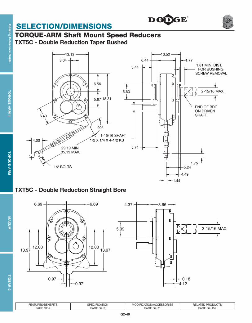
G2-46
SELECTION/DIMENSIONS
Gea
ring
Re
fere
nc
e Gu
ide
TO
RQ
UE
-AR
M II
TO
RQ
UE
-AR
MM
AX
UM
TIG
EA
R-2
FEATURES/BENEFITS PAGE G2-2
SPECIFICATION PAGE G2-9
MODIFICATION/ACCESSORIES PAGE G2-71
RELATED PRODUCTS PAGE G2-152
TORQUE-ARM Shaft Mount Speed ReducersTXT5C - Double Reduction Taper Bushed
TXT5C - Double Reduction Straight Bore
90°
29.19 MIN.35.19 MAX.
1/2 BOLTS
END OF BRG.ON DRIVENSHAFT
13.13
6.56
5.67 18.31
3.04
10.52
1.776.44
3.44 1.81 MIN. DIST.FOR BUSHING
SCREW REMOVAL
2-15/16 MAX.5.63
1-15/16 SHAFT1/2 X 1/4 X 4-1/2 KS
6.43
5.24
1.44
4.49
1.75
5.74
4.00
12.00
6.69
12.00
6.69 8.66
0.18
4.37
5.09
4.120.97
13.97
0.97
13.97
2-15/16 MAX.

SELECTION/DIMENSIONS
G2-47
TIG
EA
R-2
Gea
rin
g R
efe
ren
ce
Gu
ide
TO
RQ
UE
-AR
M II
TO
RQ
UE
-AR
MM
AX
UM
FEATURES/BENEFITS PAGE G2-2
SPECIFICATION PAGE G2-9
MODIFICATION/ACCESSORIES PAGE G2-71
RELATED PRODUCTS PAGE G2-152
TORQUE-ARM Shaft Mount Speed Reducers
TXT5C Taper Bushed Reducers ■ ❍ Accessories for TXT5C ReducersReducer
SizePart
NumberAGMA Code
ActualRatio Weight Description Part
Number Weight
TXT509CT 245550 215D09 8.95 207 TA5M Standard Motor Mount (143T-286T) 245391 76
TXT515CT 245551 215D15 15.40 207 TA5M Special Motor Mount (324T-326T) ♠ ♣ 245393 79
TXT525CT 245552 215D25 25.56 207 TA5ML Long Motor Mount (143T-286T) 245392 89
TAB5 Bottom Motor Mount (143T-326T) ♠ 245405 55
TXT5C Straight Bore Reducers ■ ❍TXT5B Backstop Assembly 245154 2.2
Optional Filter Breather (1/2-14 NPT) 430049 .2
Reducer Size
Part Number
AGMA Code
ActualRatio Weight
TXT5D TA Reducer Belt Guard (143T-286T) 245387 75
TXT5D TA Reducer Belt Guard for Long 245102 90
TXT509CS 245562 ♣ 215D09 8.95 207 Motor Mount (143T-286T) ♣
TXT515CS 245563 215D15 15.40 207 TXT5B Cooling Fan Assembly 272369 3
TXT525CS 245564 215D25 25.56 207 TXT5B Taconite Auxiliary Seal Kit ♥ 245635 11.9
TXT5 Lube Kit LUBEKITTXT5 18.5
TXT5 Bushing Assemblies ●
Stock Bore Size
Part Number Shaft Keyseat Required † Weight
TaperedBushing
Straight Bore
Bushing
TaperedBushing
Straight BoreBushing
TaperedBushing
Straight BoreBushing
2-15/16 (Max.) 245112 ◆ 3/4 x 3/8 x 9-3/8 3/4 x 3/8 x 4-3/8 7.8 -
2-11/16 245110 245428 5/8 x 5/16 x 9-3/8 5/8 x 5/16 x 4-3/8 7.9 3.0
2-1/2 ▲ 245099 245427 5/8 x 5/16 x 9-3/8 5/8 x 5/16 x 4-3/8 8.5 3.4
2-7/16 ▲ 245094 245426 5/8 x 5/16 x 9-3/8 5/8 x 5/16 x 4-3/8 8.5 4.3
2-1/4 ▲ 245092 245425 1/2 x 1/4 x 9-3/8 1/2 x 1/4 x 3 9.2 4.7
2-3/16 ▲ 245090 245424 1/2 x 1/4 x 9-3/8 1/2 x 1/4 x 3 10.0 5.6
2 ▲ 245088 245423 1/2 x 1/4 x 9-3/8 1/2 x 1/4 x 3 10.2 5.9
1-15/16 ▲ 245086 245422 1/2 x 1/4 x 9-3/8 1/2 x 1/4 x 3 10.3 6.1
♠ DODGE standard belt guard will not fit this motor mount ■ See pages G2-174 and G2-175 for reducer part numbers and drill and tap dimensions for Flange Mount TXT Reducers. Now available only as special factory order.
† Shaft key furnished.
▲ Check the driven shaft and key for strength.
◆ Preferred bore. No bushing required for this bore size. ● Taper Bushed Reducers require bushing for all bore sizes.
❍ Stock TXT5 Reducers are drilled for vertical mounting. ♥ Use with Taper Bushed Reducer only. See page G2-177 for drill and tap information required to mount to reducer.♣ Made to order

G2-48
SELECTION/DIMENSIONS
Gea
ring
Re
fere
nc
e Gu
ide
TO
RQ
UE
-AR
M II
TO
RQ
UE
-AR
MM
AX
UM
TIG
EA
R-2
FEATURES/BENEFITS PAGE G2-2
SPECIFICATION PAGE G2-9
MODIFICATION/ACCESSORIES PAGE G2-71
RELATED PRODUCTS PAGE G2-152
TORQUE-ARM Shaft Mount Speed ReducersTXT505A - Single Reduction Taper Bushed
TXT505A - Single Reduction Straight Bore
90°
29.19 MIN.35.19 MAX.
1/2 BOLTS
END OF BRG.ON DRIVENSHAFT
13.13
6.56
5.86 18.31
10.52
1.776.44
3.91 1.81 MIN. DIST.FOR BUSHING
SCREW REMOVAL
2-15/16 MAX.5.63
2-3/16 SHAFT1/2 X 1/4 X 4-1/2 KS
5.18
1.44
4.14
1.75
6.21
4.00
12.00
6.69
12.00
6.69 8.66
0.10
4.84
5.09
4.120.97
13.97
0.97
13.97
2-15/16 MAX.

SELECTION/DIMENSIONS
G2-49
TIG
EA
R-2
Gea
rin
g R
efe
ren
ce
Gu
ide
TO
RQ
UE
-AR
M II
TO
RQ
UE
-AR
MM
AX
UM
FEATURES/BENEFITS PAGE G2-2
SPECIFICATION PAGE G2-9
MODIFICATION/ACCESSORIES PAGE G2-71
RELATED PRODUCTS PAGE G2-152
TORQUE-ARM Shaft Mount Speed Reducers
TXT505A Taper Bushed Reducers ■ ❍ Accessories for TXT505A ReducersReducer
SizePart
NumberAGMA Code
ActualRatio Weight Description Part
Number Weight
TXT505AT 255200 215S05 5.67 182 TA5M Standard Motor Mount (143T-286T) 245391 76
TXT505A Straight Bore Reducers ■ ❍TA5M Special Motor Mount (324T-326T) ♠ ♣ 245393 79
TA5ML Long Motor Mount (143T-286T) 245392 89
Reducer Size
Part Number
AGMA Code
ActualRatio Weight
TAB5 Bottom Motor Mount (143T-326T) ♠ 245405 55
TXT505A Backstop Assembly 246101 1.8
TXT505AS 255204 215S05 5.67 182 Optional Filter Breather (1/2-14 NPT) 430049 .2
TXT5S TA Reducer Belt Guard (143T-286T) 245389 59
TXT5S TA Reducer Belt Guard for Long Motor Mount (143T-286T) ♣
245162 90
TXT505A Cooling Fan Assembly 255231 3
TXT505A Taconite Auxiliary Seal Kit ♥ 255230 12.3
TXT505 Lube Kit LUBEKITTXT505 18.5
TXT5 Bushing Assemblies ●
Stock Bore Size
Part Number Shaft Keyseat Required † Weight
TaperedBushing
Straight Bore
Bushing
TaperedBushing
Straight BoreBushing
TaperedBushing
Straight BoreBushing
2-15/16 (Max.) 245112 ◆ 3/4 x 3/8 x 9-3/8 3/4 x 3/8 x 4-3/8 7.8 -
2-11/16 245110 245428 5/8 x 5/16 x 9-3/8 5/8 x 5/16 x 4-3/8 7.9 3.0
2-1/2 ▲ 245099 245427 5/8 x 5/16 x 9-3/8 5/8 x 5/16 x 4-3/8 8.5 3.4
2-7/16 ▲ 245094 245426 5/8 x 5/16 x 9-3/8 5/8 x 5/16 x 4-3/8 8.5 4.3
2-1/4 ▲ 245092 245425 1/2 x 1/4 x 9-3/8 1/2 x 1/4 x 3 9.2 4.7
2-3/16 ▲ 245090 245424 1/2 x 1/4 x 9-3/8 1/2 x 1/4 x 3 10.0 5.62 ▲ 245088 245423 1/2 x 1/4 x 9-3/8 1/2 x 1/4 x 3 10.2 5.9
1-15/16 ▲ 245086 245422 1/2 x 1/4 x 9-3/8 1/2 x 1/4 x 3 10.3 6.1
♠ DODGE standard belt guard will not fit this motor mount ■ See pages G2-174 and G2-175 for reducer part numbers and drill and tap dimensions for Flange Mount TXT Reducers. Now available only as special factory order.
† Shaft key furnished.
▲ Check the driven shaft and key for strength.
◆ Preferred bore. No bushing required for this bore size. ● Taper Bushed Reducers require bushing for all bore sizes.
❍ Stock TXT5 Reducers are drilled for vertical mounting. ♥ Use with Taper Bushed Reducer only. See page G2-177 for drill and tap information required to mount to reducer.♣ Made to order

G2-50
SELECTION/DIMENSIONS
Gea
ring
Re
fere
nc
e Gu
ide
TO
RQ
UE
-AR
M II
TO
RQ
UE
-AR
MM
AX
UM
TIG
EA
R-2
FEATURES/BENEFITS PAGE G2-2
SPECIFICATION PAGE G2-9
MODIFICATION/ACCESSORIES PAGE G2-71
RELATED PRODUCTS PAGE G2-152
TORQUE-ARM Shaft Mount Speed ReducersTXT6A - Double Reduction Taper Bushed
TXT6A - Double Reduction Straight Bore
90°
29.19 MIN.35.19 MAX.
5/8 BOLTS
END OF BRG.ON DRIVENSHAFT
15.13
6.73 21.31
4.09
11.53
2.177.00
3.731.81 MIN. DIST.FOR BUSHING
SCREW REMOVAL
3-7/16 MAX.6.13
2 3/16 SHAFT1/2 X 1/4 X 4-1/2 KS
7.88
5.73
2.75
4.41
2.006.08
4.00
7.56
9.63
1.344.67
5.63
4.77
7.75
13.6315.85
0.92
0.92
7.75
13.6315.85
3-7/16 MAX.

SELECTION/DIMENSIONS
G2-51
TIG
EA
R-2
Gea
rin
g R
efe
ren
ce
Gu
ide
TO
RQ
UE
-AR
M II
TO
RQ
UE
-AR
MM
AX
UM
FEATURES/BENEFITS PAGE G2-2
SPECIFICATION PAGE G2-9
MODIFICATION/ACCESSORIES PAGE G2-71
RELATED PRODUCTS PAGE G2-152
TORQUE-ARM Shaft Mount Speed Reducers
TXT6A Taper Bushed Reducers ■ ❍ Accessories for TXT6A ReducersReducer
SizePart
NumberAGMA Code
ActualRatio Weight Description Part
Number Weight
TXT609AT 246149 ♣ 307D09 9.20 285 TA6M Standard Motor Mount (143T-326T) 246391 99
TXT615AT 246150 307D15 15.33 285 TA6M Special Motor Mount (364T) ♣ ♠ 246388 110
TXT625AT 246151 307D25 25.13 285 TA6ML Long Motor Mount (143T-326T) 246390 100
TXT6A Straight Bore Reducers ■ ❍TAB6 Bottom Motor Mount (182T-326T) ♠ 246392 84
TXT6 Backstop Assembly 246092 2.5
Reducer Size
Part Number
AGMA Code
ActualRatio Weight
Optional Filter Breather (1/2-14 NPT) 430049 0.2
TXT6D TA Reducer Belt Guard (143T-326T) 246366 83
TXT609AS 246327 ♣ 307D09 9.20 285 TXT6D TA Reducer Belt Guard for Long 246147 100
TXT615AS 246158 ♣ 307D15 15.33 285 Motor Mount (143T-326T)
TXT625AS 246159 307D25 25.13 285 TXT6 Cooling Fan Assembly 272325 3
TXT6 Taconite Auxiliary Seal Kit ♥ 272450 17.7
TXT6 Lube Kit LUBEKITTXT6 20.8
TXT6 Bushing Assemblies ●
Stock Bore Size
Part Number Shaft Keyseat Required † Weight
TaperedBushing
Straight Bore
Bushing
TaperedBushing
Straight BoreBushing
TaperedBushing
Straight BoreBushing
3-7/16 (Max.) 246268 ◆ 7/8 x 7/16 x 10-11/16 7/8 x 7/16 x 5-7/8 9.0 -
3 ▲ 246283 246427 3/4 x 3/8 x 10-11/16 3/4 x 3/8 x 5-7/8 11.3 4.6
2-15/16 ▲ 246267 246426 3/4 x 3/8 x 10-11/16 3/4 x 3/8 x 5-7/8 11.6 6.7
2-7/8 ▲ 246266 246425 3/4 x 3/8 x 10-11/16 3/4 x 3/8 x 5-7/8 12.2 6.7
2-11/16 ▲ 246265 246424 5/8 x 5/16 x 10-11/16 5/8 x 5/16 x 5-7/8 12.9 6.7
2-1/2 ▲ 246264 246423 5/8 x 5/16 x 10-11/16 5/8 x 5/16 x 3-1/2 14.0 8.2
2-7/16 ▲ 246263 246422 5/8 x 5/16 x 10-11/16 5/8 x 5/16 x 3-1/2 14.4 8.5
2-1/4 ▲ 246262 246421 1/2 x 1/4 x 10-11/16 1/2 x 1/4 x 3-1/2 14.9 9.8
2-3/16 ▲ 246261 246420 ♣ 1/2 x 1/4 x 10-11/16 1/2 x 1/4 x 3-1/2 15.3 11.0
♠ DODGE standard belt guard will not fit this motor mount ■ See pages G2-174 and G2-175 for reducer part numbers and drill and tap dimensions for Flange Mount TXT Reducers. Now available only as special factory order.† Shaft key furnished.
▲ Check the driven shaft and key for strength. ● Taper Bushed Reducers require bushing for all bore sizes.
◆ Preferred bore. No bushing required for this bore size. ♥ Use with Taper Bushed Reducer only. See page G2-176 for drill and tap information required to mount to reducer.❍ Stock TXT6 Reducers are drilled for vertical mounting.
♣ Made to order

G2-52
SELECTION/DIMENSIONS
Gea
ring
Re
fere
nc
e Gu
ide
TO
RQ
UE
-AR
M II
TO
RQ
UE
-AR
MM
AX
UM
TIG
EA
R-2
FEATURES/BENEFITS PAGE G2-2
SPECIFICATION PAGE G2-9
MODIFICATION/ACCESSORIES PAGE G2-71
RELATED PRODUCTS PAGE G2-152
TORQUE-ARM Shaft Mount Speed ReducersTXT605 - Single Reduction Taper Bushed
TXT605 - Single Reduction Straight Bore
90°
29.19 MIN.35.19 MAX.
5/8 BOLTS
END OF BRG.ON DRIVENSHAFT
15.13
6.89 21.31
11.53
2.306.88
3.751.81 MIN. DIST.FOR BUSHING
SCREW REMOVAL
3-7/16 MAX.6.13
2-3/16 SHAFT
1/2 X 1/4 X 4-1/2 KS
2.86
2.75
1.53
2.006.11
4.00
7.56
9.63
1.344.69
5.63
4.77
8.23
14.2116.61
0.87
0.87
8.23
14.2116.61
3-7/16 MAX.

SELECTION/DIMENSIONS
G2-53
TIG
EA
R-2
Gea
rin
g R
efe
ren
ce
Gu
ide
TO
RQ
UE
-AR
M II
TO
RQ
UE
-AR
MM
AX
UM
FEATURES/BENEFITS PAGE G2-2
SPECIFICATION PAGE G2-9
MODIFICATION/ACCESSORIES PAGE G2-71
RELATED PRODUCTS PAGE G2-152
TORQUE-ARM Shaft Mount Speed Reducers
TXT605 Taper Bushed Reducers ■ ❍ Accessories for TXT605 ReducersReducer
SizePart
NumberAGMA Code
ActualRatio Weight Description Part
Number Weight
TXT605T 246380 307S05 5.67 251 TA6M Standard Motor Mount (143T-326T) 246391 99
TXT605 Straight Bore Reducers ■ ❍TA6ML Long Motor Mount (143T-326T) 246390 100
TAB6 Bottom Motor Mount (182T-326T) ♠ 246392 84
Reducer Size
Part Number
AGMA Code
ActualRatio Weight
TXT605 Backstop Assembly 246092 2.5
Optional Filter Breather (1/2-14 NPT) 430049 0.2
TXT605S 246382 307S05 5.67 251 TXT6S TA Reducer Belt Guard (143T-326T) 246368 95
TXT6S TA Reducer Belt Guard for Long Motor Mount (143T-326T) ♣
246132 100
TXT605 Cooling Fan Assembly ♣ 272681 3
TXT605 Taconite Auxiliary Seal Kit ♥ 272450 17.7
TXT605 Lube Kit LUBEKITTXT605 24.3
TXT6 Bushing Assemblies ●
Stock Bore Size
Part Number Shaft Keyseat Required † Weight
TaperedBushing
Straight Bore
Bushing
TaperedBushing
Straight BoreBushing
TaperedBushing
Straight BoreBushing
3-7/16 (Max.) 246268 ◆ 7/8 x 7/16 x 10-11/16 7/8 x 7/16 x 5-7/8 9.0 -
3 ▲ 246283 246427 3/4 x 3/8 x 10-11/16 3/4 x 3/8 x 5-7/8 11.30 4.6
2-15/16 ▲ 246267 246426 3/4 x 3/8 x 10-11/16 3/4 x 3/8 x 5-7/8 11.60 6.7
2-7/8 ▲ 246266 246425 3/4 x 3/8 x 10-11/16 3/4 x 3/8 x 5-7/8 12.20 6.7
2-11/16 ▲ 246265 246424 5/8 x 5/16 x 10-11/16 5/8 x 5/16 x 5-7/8 12.90 6.7
2-1/2 ▲ 246264 246423 5/8 x 5/16 x 10-11/16 5/8 x 5/16 x 3-1/2 14.0 8.2
2-7/16 ▲ 246263 246422 5/8 x 5/16 x 10-11/16 5/8 x 5/16 x 3-1/2 14.40 8.5
2-1/4 ▲ 246262 246421 1/2 x 1/4 x 10-11/16 1/2 x 1/4 x 3-1/2 14.90 9.8
2-3/16 ▲ 246261 246420 ♣ 1/2 x 1/4 x 10-11/16 1/2 x 1/4 x 3-1/2 15.30 11.0
♠ DODGE standard belt guard will not fit this motor mount ■ See pages G2-174 and G2-175 for reducer part numbers and drill and tap dimensions for Flange Mount TXT Reducers. Now available only as special factory order.† Shaft key furnished.
▲ Check the driven shaft and key for strength. ● Taper Bushed Reducers require bushing for all bore sizes.
◆ Preferred bore. No bushing required for this bore size. ♥ Use with Taper Bushed Reducer only. See page G2-176 for drill and tap information required to mount to reducer.❍ Stock TXT7 Reducers are drilled for vertical mounting.
♣ Made to order

G2-54
SELECTION/DIMENSIONS
Gea
ring
Re
fere
nc
e Gu
ide
TO
RQ
UE
-AR
M II
TO
RQ
UE
-AR
MM
AX
UM
TIG
EA
R-2
FEATURES/BENEFITS PAGE G2-2
SPECIFICATION PAGE G2-9
MODIFICATION/ACCESSORIES PAGE G2-71
RELATED PRODUCTS PAGE G2-152
TORQUE-ARM Shaft Mount Speed ReducersTXT7A - Double Reduction Taper Bushed
TXT7A - Double Reduction Straight Bore
90°
29.44 MIN.35.44 MAX.
5/8 BOLTS
END OF BRG.ON DRIVENSHAFT
18.75
8.3025.94
5.11
12.85
2.387.88
3.75 2.06 MIN. DIST.FOR BUSHING
SCREW REMOVAL
3-15/16 MAX.7.25
2-7/16 SHAFT5/8 X 5/16 X 4-3/4 KS
9.74
6.38
2.75
4.68
2.006.35
4.75
9.38
10.78
1.344.79
6.69
4.68
8.96
15.7618.76
1.271.27
8.96
15.7618.76
3-15/16 MAX.

SELECTION/DIMENSIONS
G2-55
TIG
EA
R-2
Gea
rin
g R
efe
ren
ce
Gu
ide
TO
RQ
UE
-AR
M II
TO
RQ
UE
-AR
MM
AX
UM
FEATURES/BENEFITS PAGE G2-2
SPECIFICATION PAGE G2-9
MODIFICATION/ACCESSORIES PAGE G2-71
RELATED PRODUCTS PAGE G2-152
TORQUE-ARM Shaft Mount Speed Reducers
TXT7A Taper Bushed Reducers ■ ❍ Accessories for TXT7A Reducers
Reducer Size
Part Number
AGMA Code
ActualRatio Weight
Description Part Number Weight
TA7M Standard Motor Mount (143T-365T) 247395 110
TXT709AT 247159 315D09 9.61 462 TA7ML Long Motor Mount (143T-326T) ♣ 247396 100
TXT715AT 247160 315D15 15.23 462 TAB7 Bottom Motor Mount (182T-326T) ♠ ♣ 247404 105
TXT725AT 247161 315D25 24.59 462 TXT7 Backstop Assembly 247260 2.8
TXT7A Straight Bore Reducers ■ ❍Optional Filter Breather (1/2-14 NPT) 430049 .2
TXT7D TA Reducer Belt Guard (143T-365T) 247390 90
Reducer Size
Part Number
AGMA Code
ActualRatio Weight TXT7D TA Reducer Belt Guard for Long
Motor Mount (143T-365T) ♣247152 108
TXT709AS 247327 ♣ 315D09 9.61 462 TXT7 Cooling Fan Assembly 272326 6
TXT715AS 247168 ♣ 315D15 15.23 462 TXT7 Taconite Auxiliary Seal Kit ♥ 272451 25
TXT725AS 247169 315D25 24.59 462 TXT7 Lube Kit LUBEKITTXT7 34.7
TXT7 Bushing Assemblies ●
Stock Bore Size
Part Number Shaft Keyseat Required † Weight
TaperedBushing
Straight Bore
Bushing
TaperedBushing
Straight BoreBushing
TaperedBushing
Straight BoreBushing
3-15/16 (Max.) 272136 ◆ 1 x 1/2 x 11-27/32 1 x 1/2 x 4-7/8 13.8 -
3-7/16 272135 247428 7/8 x 7/16 x 11-27/32 7/8 x 7/16 x 6-3/8 16.9 7.8
3-3/16 ▲ 272134 247427 3/4 x 3/8 x 11-27/32 3/4 x 3/8 x 6-3/8 19.2 9.0
3 ▲ 272133 247426 3/4 x 3/8 x 11-27/32 3/4 x 3/8 x 6-3/8 20.1 10.1
2-15/16 ▲ 272132 247425 3/4 x 3/8 x 11-27/32 3/4 x 3/8 x 4-7/8 21.3 10.1
2-11/16 ▲ 272147 247422 5/8 x 5/16 x 11-27/32 5/8 x 5/16 x 3-1/2 23.0 14.0
2-7/16 ▲ 272125 247420 5/8 x 5/16 x 11-27/32 5/8 x 5/16 x 3-1/2 24.2 14.2
♠ DODGE standard belt guard will not fit this motor mount ■ See pages G2-174 and G2-175 for reducer part numbers and drill and tap dimensions for Flange Mount TXT Reducers. Now available only as special factory order.† Shaft key furnished.
▲ Check the driven shaft and key for strength. ● Taper Bushed Reducers require bushing for all bore sizes.
◆ Preferred bore. No bushing required for this bore size. ♥ Use with Taper Bushed Reducer only. See page G2-176 for drill and tap information required to mount to reducer.❍ Stock TXT7 Reducers are drilled for vertical mounting.
♣ Made to order

G2-56
SELECTION/DIMENSIONS
Gea
ring
Re
fere
nc
e Gu
ide
TO
RQ
UE
-AR
M II
TO
RQ
UE
-AR
MM
AX
UM
TIG
EA
R-2
FEATURES/BENEFITS PAGE G2-2
SPECIFICATION PAGE G2-9
MODIFICATION/ACCESSORIES PAGE G2-71
RELATED PRODUCTS PAGE G2-152
TORQUE-ARM Shaft Mount Speed ReducersTXT705 - Single Reduction Taper Bushed
TXT705 - Single Reduction Straight Bore
90°
29.44 MIN.35.44 MAX.
5/8 BOLTS
END OF BRG.ON DRIVENSHAFT
18.75
8.31 25.94
12.85
2.507.75
3.75 2.06 MIN. DIST.FOR BUSHING
SCREW REMOVAL
3-15/16 MAX.7.25
2 7/16 SHAFT
5/8 X 5/16 X 4-3/4 KS
6.38
2.75
4.68
2.006.34
4.75
9.38
10.78
1.464.79
6.69
4.68
8.96
15.7618.76
1.271.27
8.96
15.7618.76
3-15/16 MAX.

SELECTION/DIMENSIONS
G2-57
TIG
EA
R-2
Gea
rin
g R
efe
ren
ce
Gu
ide
TO
RQ
UE
-AR
M II
TO
RQ
UE
-AR
MM
AX
UM
FEATURES/BENEFITS PAGE G2-2
SPECIFICATION PAGE G2-9
MODIFICATION/ACCESSORIES PAGE G2-71
RELATED PRODUCTS PAGE G2-152
TXT7 Bushing Assemblies ●
Stock Bore Size
Part Number Shaft Keyseat Required † WeightTaperedBushing
Straight BoreBushing
TaperedBushing
Straight BoreBushing
TaperedBushing
Straight BoreBushing
3-15/16 (Max.) 272136 ◆ 1 x 1/2 x 11-27/32 1 x 1/2 x 4-7/8 13.8 -
3-7/16 272135 247428 7/8 x 7/16 x 11-27/32 7/8 x 7/16 x 6-3/8 16.9 7.8
3-3/16 ▲ 272134 247427 3/4 x 3/8 x 11-27/32 3/4 x 3/8 x 6-3/8 19.2 9.0
3 ▲ 272133 247426 3/4 x 3/8 x 11-27/32 3/4 x 3/8 x 6-3/8 20.1 10.1
2-15/16 ▲ 272132 247425 3/4 x 3/8 x 11-27/32 3/4 x 3/8 x 4-7/8 21.3 10.1
2-11/16 ▲ 272147 247422 5/8 x 5/16 x 11-27/32 5/8 x 5/16 x 3-1/2 23.0 14.0
2-7/16 ▲ 272125 247420 5/8 x 5/16 x 11-27/32 5/8 x 5/16 x 3-1/2 24.2 14.2
♠ DODGE standard belt guard will not fit this motor mount ■ See pages G2-174 and G2-175 for reducer part numbers and drill and tap dimensions for Flange Mount TXT Reducers. Now available only as special factory order.† Shaft key furnished.
▲ Check the driven shaft and key for strength. ● Taper Bushed Reducers require bushing for all bore sizes.
◆ Preferred bore. No bushing required for this bore size. ♥ Use with Taper Bushed Reducer only. See page G2-176 for drill and tap information required to mount to reducer.❍ Stock TXT7 Reducers are drilled for vertical mounting.
♣ Made to order
TORQUE-ARM Shaft Mount Speed Reducers
TXT705 Taper Bushed Reducers ■ ❍ Accessories for TXT705 ReducersReducer
SizePart
NumberAGMA Code
ActualRatio Weight Description Part
Number Weight
TXT705T 247285 ♣ 315S05 5.36 410 TA7M Standard Motor Mount (143T-365T) 247395 110
TXT705 Straight Bore Reducers ■ ❍TA7ML Long Motor Mount (143T-326T) ♣ 247396 100
TAB7 Bottom Motor Mount (182T-326T) ♠ ♣ 247404 105
Reducer Size
Part Number
AGMA Code
ActualRatio Weight
TXT705 Backstop Assembly 247260 2.80
Optional Filter Breather (1/2-14 NPT) 430049 0.20
TXT705S 247287 ♣ 315S05 5.36 410 TXT7S TA Reducer Belt Guard (143T-365T) 247392 112
TXT7S TA Reducer Belt Guard for Long Motor Mount (143T-365T) ♣
247146 135
TXT705 Cooling Fan Assembly ♣ 272685 6
TXT705 Taconite Auxiliary Seal Kit ♥ 272451 25
TXT705 Lube Kit LUBEKITTXT705 39.3

G2-58
SELECTION/DIMENSIONS
Gea
ring
Re
fere
nc
e Gu
ide
TO
RQ
UE
-AR
M II
TO
RQ
UE
-AR
MM
AX
UM
TIG
EA
R-2
FEATURES/BENEFITS PAGE G2-2
SPECIFICATION PAGE G2-9
MODIFICATION/ACCESSORIES PAGE G2-71
RELATED PRODUCTS PAGE G2-152
TORQUE-ARM Shaft Mount Speed ReducersTXT8A - Double Reduction Taper Bushed
TXT8A - Double Reduction Straight Bore
90°
30.00 MIN.36.00 MAX.
3/4 BOLTS
END OF BRG.ON DRIVENSHAFT
20.25
9.50 28.25
6.03
14.03
2.708.49
4.28 2.06 MIN. DIST.FOR BUSHING
SCREW REMOVAL
4-7/16 MAX.7.75
2-7/16 SHAFT5/8 X 5/16 X 5-3/8 KS
11.25
7.01
4.00
5.61
3.13
7.117.00
10.13
11.38
1.355.57
7.50
5.667.57
19.52 21.31
7.57
19.52
4-7/16 MAX.

SELECTION/DIMENSIONS
G2-59
TIG
EA
R-2
Gea
rin
g R
efe
ren
ce
Gu
ide
TO
RQ
UE
-AR
M II
TO
RQ
UE
-AR
MM
AX
UM
FEATURES/BENEFITS PAGE G2-2
SPECIFICATION PAGE G2-9
MODIFICATION/ACCESSORIES PAGE G2-71
RELATED PRODUCTS PAGE G2-152
TORQUE-ARM Shaft Mount Speed Reducers
TXT8A Taper Bushed Reducers ■ ❍ Accessories for TXT8A ReducersReducer
SizePart
NumberAGMA Code
ActualRatio Weight Description Part
Number Weight
TXT815AT 248279 407D15 15.08 633 TA8 Standard Motor Mount (213T-365T) 248401 119
TXT825AT 248280 407D25 24.62 633 TAB8 Bottom Motor Mount (213T-365T) ♠ ♣ 248406 120
TXT8A Straight Bore Reducers ■ ❍TXT8 Backstop Assembly 249260 3.8
Optional Filter Breather (1/2-14 NPT) 430049 .2
Reducer Size
Part Number
AGMA Code
ActualRatio Weight
TXT8D TA Reducer Belt Guard (213T-365T) 248395 107
TXT8 Cooling Fan Assembly 272327 9
TXT815AS 248283 ♣ 407D15 15.08 633 TXT8 Taconite Auxiliary Seal Kit ♥ 272452 26.3
TXT825AS 248284 407D25 24.62 633 TXT8 Lube Kit LUBEKITTXT8 40.5
TXT8 Bushing Assemblies ●
Stock Bore Size
Part Number Shaft Keyseat Required † Weight
TaperedBushing
Straight Bore
Bushing
TaperedBushing
Straight BoreBushing
TaperedBushing
Straight BoreBushing
4-7/16 (Max.) 272035 ◆ 1 x 1/2 x 13-1/16 1 x 1/2 x 6-7/8 15 -
4-3/16 272034 248424 1 x 1/2 x 13-1/16 1 x 1/2 x 6-7/8 17 6.8
3-15/16 272033 248423 1 x 1/2 x 13-1/16 1 x 1/2 x 6-7/8 20 8.0
3-7/16 ▲ 272032 248422 7/8 x 7/16 x 13-1/16 7/8 x 7/16 x 6-7/8 25 12
2-15/16 ▲ 272048 248420 3/4 x 3/8 x 13-1/16 3/4 x 3/8 x 4-3/8 29 19
♠ DODGE standard belt guard will not fit this motor mount ■ See pages G2-174 and G2-175 for reducer part numbers and drill and tap dimensions for Flange Mount TXT Reducers. Now available only as special factory order.† Shaft key furnished.
▲ Check the driven shaft and key for strength. ● Taper Bushed Reducers require bushing for all bore sizes.
◆ Preferred bore. No bushing required for this bore size. ♥ Use with Taper Bushed Reducer only. See page G2-176 for drill and tap information required to mount to reducer.❍ Stock TXT8 Reducers are drilled for vertical mounting.
♣ Made to order

G2-60
SELECTION/DIMENSIONS
Gea
ring
Re
fere
nc
e Gu
ide
TO
RQ
UE
-AR
M II
TO
RQ
UE
-AR
MM
AX
UM
TIG
EA
R-2
FEATURES/BENEFITS PAGE G2-2
SPECIFICATION PAGE G2-9
MODIFICATION/ACCESSORIES PAGE G2-71
RELATED PRODUCTS PAGE G2-152
TORQUE-ARM Shaft Mount Speed ReducersTXT805 - Single Reduction Taper Bushed
TXT805 - Single Reduction Straight Bore
90°
30.00 MIN.36.00 MAX.
3/4 BOLTS
END OF BRG.ON DRIVENSHAFT
20.25
9.64 28.25
14.03
2.838.37
4.34 2.06 MIN. DIST.FOR BUSHING
SCREW REMOVAL
4-7/16 MAX.7.75
2-7/16 SHAFT5/8 X 5/16 X 5-3/8 KS
7.01
4.00
5.61
3.13
7.177.00
10.13
11.38
1.475.64
7.50
5.667.57
19.52 21.31
7.57
19.52
4-7/16 MAX.

SELECTION/DIMENSIONS
G2-61
TIG
EA
R-2
Gea
rin
g R
efe
ren
ce
Gu
ide
TO
RQ
UE
-AR
M II
TO
RQ
UE
-AR
MM
AX
UM
FEATURES/BENEFITS PAGE G2-2
SPECIFICATION PAGE G2-9
MODIFICATION/ACCESSORIES PAGE G2-71
RELATED PRODUCTS PAGE G2-152
TORQUE-ARM Shaft Mount Speed Reducers
TXT805 Taper Bushed Reducers ■ ❍ Accessories for TXT805 ReducersReducer
SizePart
NumberAGMA Code
ActualRatio Weight Description Part
Number Weight
TXT805T 248275 ♣ 407S05 5.50 557 TA8 Standard Motor Mount (254T-365T) 248401 119
TAB8 Bottom Motor Mount (213T-365T) ♠ ♣ 248406 120
TXT805 Straight Bore Reducers ■ ❍ TXT805 Backstop Assembly 250260 5.6
Reducer Size
Part Number
AGMA Code
ActualRatio Weight
Optional Filter Breather (1/2-14 NPT) 430049 .2
TXT8S TA Reducer Belt Guard (213T-365T) 248397 125
TXT805S 248277 ♣ 407S05 5.50 557 TXT8 Cooling Fan Assembly 272327 9
TXT8 Taconite Auxiliary Seal Kit ♥ 272452 26.3
TXT8 Lube Kit LUBEKITTXT805 45.1
TXT8 Bushing Assemblies ●
Stock Bore Size
Part Number Shaft Keyseat Required † Weight
TaperedBushing
Straight Bore
Bushing
TaperedBushing
Straight BoreBushing
TaperedBushing
Straight BoreBushing
4-7/16 (Max.) 272035 ◆ 1 x 1/2 x 13-1/16 1 x 1/2 x 6-7/8 15 -
4-3/16 272034 248424 1 x 1/2 x 13-1/16 1 x 1/2 x 6-7/8 17 6.8
3-15/16 272033 248423 1 x 1/2 x 13-1/16 1 x 1/2 x 6-7/8 20 8.0
3-7/16 ▲ 272032 248422 7/8 x 7/16 x 13-1/16 7/8 x 7/16 x 6-7/8 25 12
2-15/16 ▲ 272048 248420 3/4 x 3/8 x 13-1/16 3/4 x 3/8 x 4-3/8 29 19
♠ DODGE standard belt guard will not fit this motor mount ■ See pages G2-174 and G2-175 for reducer part numbers and drill and tap dimensions for Flange Mount TXT Reducers. Now available only as special factory order.† Shaft key furnished.
▲ Check the driven shaft and key for strength. ● Taper Bushed Reducers require bushing for all bore sizes.
◆ Preferred bore. No bushing required for this bore size. ♥ Use with Taper Bushed Reducer only. See page G2-176 for drill and tap information required to mount to reducer.❍ Stock TXT8 Reducers are drilled for vertical mounting.
♣ Made to order

G2-62
SELECTION/DIMENSIONS
Gea
ring
Re
fere
nc
e Gu
ide
TO
RQ
UE
-AR
M II
TO
RQ
UE
-AR
MM
AX
UM
TIG
EA
R-2
FEATURES/BENEFITS PAGE G2-2
SPECIFICATION PAGE G2-9
MODIFICATION/ACCESSORIES PAGE G2-71
RELATED PRODUCTS PAGE G2-152
TORQUE-ARM Shaft Mount Speed ReducersTXT9A - Double Reduction Taper Bushed
TXT9A - Double Reduction Straight Bore
90°
30.00 MIN.36.00 MAX.
3/4 BOLTS
END OF BRG.ON DRIVENSHAFT
22.63
10.81 31.69
6.59
14.12
2.818.27
6.622.44 MIN. DIST.FOR BUSHING
SCREW REMOVAL
4-15/16 MAX.8.75
2 7/16 SHAFT5/8 X 5/16 X 7 3/4 KS
12.66
7.02
4.00
5.50
3.13
9.657.00
11.31
11.38
1.468.00
8.38
5.669.62
20.6423.62
9.62
20.64
4-15/16 MAX.

SELECTION/DIMENSIONS
G2-63
TIG
EA
R-2
Gea
rin
g R
efe
ren
ce
Gu
ide
TO
RQ
UE
-AR
M II
TO
RQ
UE
-AR
MM
AX
UM
FEATURES/BENEFITS PAGE G2-2
SPECIFICATION PAGE G2-9
MODIFICATION/ACCESSORIES PAGE G2-71
RELATED PRODUCTS PAGE G2-152
TORQUE-ARM Shaft Mount Speed Reducers
TXT9A Taper Bushed Reducers ■ ❍ Accessories for TXT9A ReducersReducer
SizePart
NumberAGMA Code
Actual Ratio Weight Description Part
Number Weight
TXT915AT 249269 415D15 15.12 760 TA9 Standard Motor Mount (213T-365T) 249401 120
TXT926AT 249270 415D26 25.66 760 TA9 Special Motor Mount (404T-405T) ♣ ♠ 249399 125
TXT9A Straight Bore Reducers ■ ❍TAB9 Bottom Motor Mount (213T-365T) ♠ ♣ 249404 125
TXT9 Backstop Assembly 249260 3.8
Reducer Size
Part Number
AGMA Code
Actual Ratio Weight
Optional Filter Breather (1/2-14 NPT) 430049 .2
TXT9D TA Reducer Belt Guard (213T-365T) 249395 125
TXT915AS 249273 ♣ 415D15 15.12 760 TXT9 Cooling Fan Assembly 272328 15
TXT926AS 249274 415D26 25.66 760 TXT9 Taconite Auxiliary Seal Kit ♥ 272453 32.6
TXT9 Lube Kit LUBEKITTXT9 53.2
TXT9 Bushing Assemblies ●
Stock Bore Size
Part Number Shaft Keyseat Required † Weight
TaperedBushing
Straight Bore
Bushing
TaperedBushing
Straight BoreBushing
TaperedBushing
Straight BoreBushing
4-15/16 (Max.) 272080 ◆ 1-1/4 x 5/8 x 12-15/16 1-1/4 x 5/8 x 11-3/8 22 -
4-7/16 272079 249422 1 x 1/2 x 12-15/16 1 x 1/2 x 11-3/8 27 12.5
3-15/16 ▲ 272077 249421 1 x 1/2 x 12-15/16 1 x 1/2 x 11-3/8 32.4 26
3-7/16 ▲ 272056 249420 7/8 x 7/16 x 12-15/16 7/8 x 7/16 x 5 36 28
♠ DODGE standard belt guard will not fit this motor mount ■ See pages G2-174 and G2-175 for reducer part numbers and drill and tap dimensions for Flange Mount TXT Reducers. Now available only as special factory order.† Shaft key furnished.
▲ Check the driven shaft and key for strength. ● Taper Bushed Reducers require bushing for all bore sizes.
◆ Preferred bore. No bushing required for this bore size. ♥ Use with Taper Bushed Reducer only. See page G2-176 for drill and tap information required to mount to reducer.❍ Stock TXT9 Reducers are drilled for vertical mounting.
♣ Made to order

G2-64
SELECTION/DIMENSIONS
Gea
ring
Re
fere
nc
e Gu
ide
TO
RQ
UE
-AR
M II
TO
RQ
UE
-AR
MM
AX
UM
TIG
EA
R-2
FEATURES/BENEFITS PAGE G2-2
SPECIFICATION PAGE G2-9
MODIFICATION/ACCESSORIES PAGE G2-71
RELATED PRODUCTS PAGE G2-152
TORQUE-ARM Shaft Mount Speed ReducersTXT905 - Single Reduction Taper Bushed
TXT905 - Single Reduction Straight Bore
90°
30.00 MIN.36.00 MAX.
3/4 BOLTS
END OF BRG.ON DRIVENSHAFT
22.63
10.97 31.69
14.12
2.968.13
6.572.44 MIN. DIST.FOR BUSHING
SCREW REMOVAL
4-15/16 MAX.8.75
2-7/16 SHAFT5/8 X 5/16 X 7-3/4 KS
7.30
4.00
7.02
3.13
9.617.00
11.31
11.38
1.607.96
8.38
5.669.62
20.6423.62
9.62
20.64
4-15/16 MAX.

SELECTION/DIMENSIONS
G2-65
TIG
EA
R-2
Gea
rin
g R
efe
ren
ce
Gu
ide
TO
RQ
UE
-AR
M II
TO
RQ
UE
-AR
MM
AX
UM
FEATURES/BENEFITS PAGE G2-2
SPECIFICATION PAGE G2-9
MODIFICATION/ACCESSORIES PAGE G2-71
RELATED PRODUCTS PAGE G2-152
TORQUE-ARM Shaft Mount Speed Reducers
TXT905 Taper Bushed Reducers ■ ❍ Accessories for TXT905 ReducersReducer
SizePart
NumberAGMA Code
ActualRatio Weight Description Part
Number Weight
TXT905T 249265 ♣ 415S05 5.38 668 TA9 Standard Motor Mount (284T-365T) 249401 120
TXT905 Straight Bore Reducers ■ ❍TA9 Special Motor Mount (404T-445T) ♣ ♠ 249399 125
TAB9 Bottom Motor Mount (213T-365T) ♣ ♠ 249404 125
Reducer Size
Part Number
AGMA Code
ActualRatio Weight
TXT905 Backstop Assembly 272259 6.7
Optional Filter Breather (1/2-14 NPT) 430049 .2
TXT905S 249267 ♣ 415S05 5.38 668 TXT9-S TA Reducer Belt Guard (213T-365T) 249397 156
TXT905 Cooling Fan Assembly ♣ 272324 15
TXT9 Taconite Auxiliary Seal Kit ♥ 272453 32.6
TXT9 Lube Kit LUBEKITTXT905 64.8
♠ DODGE standard belt guard will not fit this motor mount ■ See pages G2-174 and G2-175 for reducer part numbers and drill and tap dimensions for Flange Mount TXT Reducers. Now available only as special factory order.† Shaft key furnished.
▲ Check the driven shaft and key for strength. ● Taper Bushed Reducers require bushing for all bore sizes.
◆ Preferred bore. No bushing required for this bore size. ♥ Use with Taper Bushed Reducer only. See page G2-176 for drill and tap information required to mount to reducer.❍ Stock TXT9 Reducers are drilled for vertical mounting.
♣ Made to order
TXT9 Bushing Assemblies ●
Stock Bore Size
Part Number Shaft Keyseat Required † Weight
TaperedBushing
Straight Bore
Bushing
TaperedBushing
Straight BoreBushing
TaperedBushing
Straight BoreBushing
4-15/16 (Max.) 272080 ◆ 1-1/4 x 5/8 x 12-15/16 1-1/4 x 5/8 x 11-3/8 22 -
4-7/16 272079 249422 1 x 1/2 x 12-15/16 1 x 1/2 x 11-3/8 27 12.5
3-15/16 ▲ 272077 249421 1 x 1/2 x 12-15/16 1 x 1/2 x 11-3/8 32.4 26
3-7/16 ▲ 272056 249420 7/8 x 7/16 x 12-15/16 7/8 x 7/16 x 5 36 28

G2-66
SELECTION/DIMENSIONS
Gea
ring
Re
fere
nc
e Gu
ide
TO
RQ
UE
-AR
M II
TO
RQ
UE
-AR
MM
AX
UM
TIG
EA
R-2
FEATURES/BENEFITS PAGE G2-2
SPECIFICATION PAGE G2-9
MODIFICATION/ACCESSORIES PAGE G2-71
RELATED PRODUCTS PAGE G2-152
TORQUE-ARM Shaft Mount Speed ReducersTXT10A - Double Reduction Taper Bushed
TXT10A - Double Reduction Straight Bore
90°
30.00 MIN.36.00 MAX.
3/4 BOLTS
END OF BRG.ON DRIVENSHAFT
25.50
12.5035.00
6.59
15.30
2.789.55
6.532.44 MIN. DIST.FOR BUSHING
SCREW REMOVAL
5-7/16 MAX.10.13
2 11/16 SHAFT5/8 X 5/16 X 7-7/8 KS
14.13
7.66
4.00
6.80
3.13
9.507.00
12.75
12.37
1.338.01
8.94
6.218.88
23.46 25.56
8.88
23.46
5-7/16 MAX.

SELECTION/DIMENSIONS
G2-67
TIG
EA
R-2
Gea
rin
g R
efe
ren
ce
Gu
ide
TO
RQ
UE
-AR
M II
TO
RQ
UE
-AR
MM
AX
UM
FEATURES/BENEFITS PAGE G2-2
SPECIFICATION PAGE G2-9
MODIFICATION/ACCESSORIES PAGE G2-71
RELATED PRODUCTS PAGE G2-152
TORQUE-ARM Shaft Mount Speed Reducers
TXT10A Taper Bushed Reducers ■ ❍ Accessories for TXT10A ReducersReducer
SizePart
NumberAGMA Code
ActualRatio Weight Description Part
Number Weight
TXT1015AT 272600 507D15 15.16 1020 TA10 Standard Motor Mount (254T-365T) 250401 130
TXT1024AT 272601 507D24 24.30 1020 TA10 Special Motor Mount (404T-445T) 250404 150
TXT10A Straight Bore Reducers ■ ❍TAB10 Bottom Motor Mount (254T-365T) ♠ ♣ 250411 150
TXT10 Backstop Assembly 250260 5.60
Reducer Size
Part Number
AGMA Code
ActualRatio Weight
Optional Filter Breather (1/2-14 NPT) 430049 0.20
TXT10D TA Reducer Belt Guard (254T-445T) 250395 140
TXT1015AS 272604 ♣ 507D15 15.16 1020 TXT10 Cooling Fan Assembly 272329 15
TXT1024AS 272605 ♣ 507D24 24.30 1020 TXT10 Taconite Auxiliary Seal Kit ♥ 272454 35.80
TXT10 Lube Kit LUBEKITTXT10 89.1
TXT10 Bushing Assemblies ●
Stock Bore Size
Part Number Shaft Keyseat Required † Weight
TaperedBushing
Straight Bore
Bushing
TaperedBushing
Straight BoreBushing
TaperedBushing
Straight BoreBushing
5-7/16 (Max.) 272240 ◆ 1-1/4 x 5/8 x 14-1/16 1-1/4 x 5/8 x 12-3/8 26.50 -
4-15/16 272239 250422 1-1/4 x 5/8 x 14-1/16 1-1/4 x 5/8 x 12-3/8 33.50 12.90
4-7/16 ▲ 272238 250421 1 x 1/2 x 14-1/16 1 x 1/2 x 12-3/8 38.40 31.40
3-15/16 ▲ 272214 250420 1 x 1/2 x 14-1/16 1 x 1/2 x 6-5/8 44 33
♠ DODGE standard belt guard will not fit this motor mount ■ See pages G2-174 and G2-175 for reducer part numbers and drill and tap dimensions for Flange Mount TXT Reducers. Now available only as special factory order.† Shaft key furnished.
▲ Check the driven shaft and key for strength. ● Taper Bushed Reducers require bushing for all bore sizes.
◆ Preferred bore. No bushing required for this bore size. ♥ Use with Taper Bushed Reducer only. See page G2-176 for drill and tap information required to mount to reducer.❍ Stock TXT10 Reducers are drilled for vertical mounting.
♣ Made to order

G2-68
SELECTION/DIMENSIONS
Gea
ring
Re
fere
nc
e Gu
ide
TO
RQ
UE
-AR
M II
TO
RQ
UE
-AR
MM
AX
UM
TIG
EA
R-2
FEATURES/BENEFITS PAGE G2-2
SPECIFICATION PAGE G2-9
MODIFICATION/ACCESSORIES PAGE G2-71
RELATED PRODUCTS PAGE G2-152
TORQUE-ARM Shaft Mount Speed ReducersTXT12 - Double Reduction Taper Bushed
TXT12 Taper Bushed Reducers ❒Reducer
SizePart
NumberAGMA Code
ActualRatio Weight
TXT1215TV 272615 ♣ 608D15 14.89 2042
TXT1225TV 272617 608D25 24.65 2042
TXT12 AccessoriesDescription Part Number Weight
TA12 Standard Motor Mount (286T-445T) 272310 255
TXT12 Backstop Assembly 250260 5.6
Optional Filter Breather (1/2-14 NPT) 430049 .2
TXT12 Cooling Fan Assembly 272330 15
Heat Exchanger Cooling Package 014148 55
TXT12 Taconite Auxiliary Seal Kit 272455 67.8
TXT12D TA Reducer Belt Guard (320T-445T) ♣ 272688 170
TXT12 Lube Kit LUBEKITTXT12 202.5
TXT12 Tapered Bushing Assemblies ●Stock Bore Size Part Number Shaft Keyseat Required † Weight
6-1/2 (Max.) 272219 1-1/2 x 3/4 x 17-5/16 37.4
6-7/16 272218 1-1/2 x 3/4 x 17-5/16 38.4
6 272217 1-1/2 x 3/4 x 17-5/16 46.2
5-15/16 272216 1-1/2 x 3/4 x 17-5/16 47.3
5-7/16 ▲ 272215 1-1/4 x 5/8 x 17-5/16 53.1
† Shaft key furnished. ❒ Reducers are supplied already drilled and tapped for vertical mounting and flange mounting. See page G2-173 for Flange Mounting dimensions▲ Check the driven shaft and key for strength.
♣ Made to order ● Taper Bushed Reducers require bushing for all bore sizes.
90°30.50 MIN.36.50 MAX.
END OF BRG.ON DRIVENSHAFT
31.50
22.91
43.50
18.49
3.2112.00
6.122.44 MIN. DIST.FOR BUSHING
SCREW REMOVAL
6-1/2 MAX.10.75
2 11/16 SHAFT5/8 X 5/16 X 7-3/8 KS
9.21
4.91
8.23
3.38
9.39
8.44
15.38
1" BOLTS
34.13

SELECTION/DIMENSIONS
G2-69
TIG
EA
R-2
Gea
rin
g R
efe
ren
ce
Gu
ide
TO
RQ
UE
-AR
M II
TO
RQ
UE
-AR
MM
AX
UM
FEATURES/BENEFITS PAGE G2-2
SPECIFICATION PAGE G2-9
MODIFICATION/ACCESSORIES PAGE G2-71
RELATED PRODUCTS PAGE G2-152
TORQUE-ARM Shaft Mount Speed ReducersTDT13 - Double Reduction Taper Bushed
TDT13 Taper Bushed Reducer ❒Reducer
SizePart
NumberAGMA Code
ActualRatio Weight
TDT1325T 272250 700D25 24.73 2476
TDT13 AccessoriesDescription Part Number Weight
TA13 Standard Motor Mount (324T-447T) 272313 290
TDT13 Backstop Assembly 272259 6.70
Optional Filter Breather (1/2-14 NPT) 430049 0.20
TDT13 Cooling Fan Assembly 272331 20
Heat Exchanger Cooling Package 014148 55
TDT13 Taconite Auxiliary Seal Kit ♣ 272456 87
TDT13 Lube Kit LUBEKITTXT13 223.8
TDT13 Tapered Bushing Assemblies �Stock Bore Size Part Number Shaft Keyseat Required † Weight7 (Max.) 272257 1-3/4 x 3/4 x 19-9/16 74
6-1/2 ▲ 272292 ♣ 1-1/2 x 3/4 x 19-9/16 92
6 ▲ 272291 ♣ 1-1/2 x 3/4 x 19-9/16 111
5-15/16 ▲ 272290 1-1/2 x 3/4 x 19-9/16 113
† Shaft key furnished. ❒ Reducers are supplied already drilled and tapped for vertical mounting and flange mounting. See page G2-175 for Flange Mounting dimensions▲ Check the driven shaft and key for strength.
♣ Made to order ● Taper Bushed Reducers require bushing for all bore sizes.

G2-70
SELECTION/DIMENSIONS
Gea
ring
Re
fere
nc
e Gu
ide
TO
RQ
UE
-AR
M II
TO
RQ
UE
-AR
MM
AX
UM
TIG
EA
R-2
FEATURES/BENEFITS PAGE G2-2
SPECIFICATION PAGE G2-9
MODIFICATION/ACCESSORIES PAGE G2-71
RELATED PRODUCTS PAGE G2-152
TORQUE-ARM Shaft Mount Speed ReducersTDT14 - Double Reduction Taper Bushed
TDT14 Taper Bushed Reducer ❒Reducer
SizePart
NumberAGMA Code
ActualRatio Weight
TDT1425T 272150 ♣ 800D25 24.80 3436
TDT14 AccessoriesDescription Part Number Weight
TA14 Standard Motor Mount (324T-447T) 272318 295
TDT14 Backstop Assembly 272293 13.4
Optional Filter Breather (1/2-14 NPT) 430049 .2
TDT14 Cooling Fan Assembly 272332 20
Heat Exchanger Cooling Package 014148 55
TDT14 Taconite Auxiliary Seal Kit ♣ 272457 131
TDT14 Lube Kit LUBEKITTXT14 307.8
TDT14 Tapered Bushing Assemblies ●Stock Bore Size Part Number Shaft Keyseat Required † Weight8 (Max.) 272194 ♣ 2 x 3/4 x 22-1/4 135
7 ▲ 272193 ♣ 1-3/4 x 3/4 x 22-1/4 144
6-1/2 ▲ 272192 ♣ 1-1/2 x 3/4 x 22-1/4 162.1
6 ▲ 272191 ♣ 1-1/2 x 3/4 x 22-1/4 188
† Shaft key furnished. ❒ Reducers are supplied already drilled and tapped for vertical mounting and flange mounting. See page G2-173 for Flange Mounting dimensions▲ Check the driven shaft and key for strength.
♣ Made to order ● Taper Bushed Reducers require bushing for all bore sizes.

SELECTION/DIMENSIONS
G2-71
TIG
EA
R-2
Gea
rin
g R
efe
ren
ce
Gu
ide
TO
RQ
UE
-AR
M II
TO
RQ
UE
-AR
MM
AX
UM
FEATURES/BENEFITS PAGE G2-2
SPECIFICATION PAGE G2-9
MODIFICATION/ACCESSORIES PAGE G2-71
RELATED PRODUCTS PAGE G2-152
✻
TORQUE-ARM Shaft Mount Speed ReducersTDT15 - Double Reduction Taper Bushed
TDT15 Taper Bushed ReducerReducer
SizePart
NumberAGMA Code
ActualRatio Weight
TDT1530T 272370 ♣ 1000D30 30.64 5622
TDT15 AccessoriesDescription Part Number Weight
TA15 Standard Motor Mount (405T-449T) ♣ 272392 300
TDT15 Backstop Assembly 272293 13.40
Optional Filter Breather (1/2-14 NPT) 430049 0.20
TDT15 Cooling Fan Assembly 272333 23
Heat Exchanger Cooling Package 014148 55
TDT15 Taconite Auxiliary Seal Kit ♣ 272458 180
TDT15 Lube Kit LUBEKITTXT15 575.1
TDT15 Tapered Bushing Assemblies ●Stock Bore Size Part Number Shaft Keyseat Required † Weight
10 (Max.) 272395 2-1/2 x 7/8 x 27-5/16 202
9 ▲ 272396 2 x 3/4 x 27-5/16 267
8-1/2 ▲ 272397 2 x 3/4 x 27-5/16 300
8 ▲ 272398 ♣ 2 x 3/4 x 27-5/16 307
† Shaft key furnished. ❒ Reducers are supplied already drilled and tapped for vertical mounting and flange mounting. See page G2-175 for Flange Mounting dimensions▲ Check the driven shaft and key for strength.
♣ Made to order ● Taper Bushed Reducers require bushing for all bore sizes.

G2-72
MODIFICATIONS/ ACCESSORIES
Gea
ring
Re
fere
nc
e Gu
ide
TO
RQ
UE
-AR
M II
TO
RQ
UE
-AR
MM
AX
UM
TIG
EA
R-2
FEATURES/BENEFITS PAGE G2-2
SPECIFICATION PAGE G2-9
RELATED PRODUCTS PAGE G2-152
RENEWAL PARTS PAGE G2-166
TORQUE-ARM Shaft Mount Speed ReducersTable 5- Dodge Torque-Arm Reducers And Accessories Compatibility
TXTReducer
MaximumBore
AGMACode
Input HP @75 RPM
Output15, 25:1
Input HP @100 RPM
Output 5:1
TaperBushed
Straight Bore
HYDROIL Style
Vertical Style
Motor Mount Backstop
TaconiteAuxiliary
Seals
Belt Guards
TXT1 1-7/16” 107 4.15 4.49 Yes Yes Yes Yes Yes Yes Yes Yes
TXT2 1-15/16” 115 7.52 7.70 Yes Yes Yes Yes Yes Yes Yes Yes
TXT3 2-3/16” 203 12.7 11.7 Yes Yes Yes Yes Yes Yes Yes Yes
TXT4 2-7/16” 207 19.3 19.6 Yes Yes Yes Yes Yes Yes Yes Yes
TXT5 2-15/16” 215 29.9 25.0 Yes Yes Yes Yes Yes Yes Yes Yes
TXT6 3-7/16” 307 50.3 51.6 Yes Yes Yes Yes Yes Yes Yes Yes
TXT7 3-15/16” 315 72.3 87.4 Yes Yes Yes Yes Yes Yes Yes Yes
TXT8 4-7/16” 407 106.9 111.0 Yes Yes - Yes Yes Yes Yes Yes
TXT9 4-15/16” 415 154.7 140.0 Yes Yes - Yes Yes Yes Yes Yes
TXT10 5-7/16” 507 216.0 - Yes Yes - Yes Yes Yes Yes Yes
TXT12 6-1/2” 608 275.0 - Yes - - Yes Yes Yes Yes Yes
TDT13 7” 700 374.0 - Yes - - Yes Yes Yes Yes Yes
TDT14 8” 800 561.0 - Yes - - Yes Yes Yes Yes Yes
TDT15 10” 1000 - - Yes - - Yes Yes Yes Yes Yes
Table 6 - Dodge Screw Conveyor Drive Reducers And Accessories Compatibility
SCXTReducer
AGMACode
Input HP@ 75 RPM
Output 15,25:1
Input HP@100 RPM
Output5:1
HYDROIL Style
DriveShafts Adapter Motor
Mount
TaconiteAuxiliary
Seals
BeltGuards
SCXT1 107 4.15 4.49 Yes Yes Yes Yes Yes Yes
SCXT2 115 7.52 7.70 Yes Yes Yes Yes Yes Yes
SCXT3 203 12.70 11.70 Yes Yes Yes Yes Yes Yes
SCXT4 207 19.30 19.60 Yes Yes Yes Yes Yes Yes
SCXT5 215 29.90 25.00 Yes Yes Yes Yes Yes Yes
SCXT6 307 50.30 51.60 Yes Yes Yes Yes Yes Yes
SCXT7 315 72.30 87.40 Yes Yes Yes Yes Yes Yes
SCXT8 407 106.90 111.00 - Yes Yes Yes Yes Yes
Table 7 - NEMA Motor Information Table 8 - Minimum Sheave Diameters For Dodge (1750 RPM) TORQUE-ARM Reducers
HorsepowerNEMA Motor Frame
ShaftDiameter
Minimum Sheave
Diameters
TXT,SCXT
Reducer
Single Reduction Double ReductionShaft
Diameter 5:1 ShaftDiameter 9:1 15:1 25:1
1 143T 7/8 2.2 1 1-1/8 4.0 3/4 4.0 3.0 3.01-1/2 145T 7/8 2.4 2 1-7/16 3.0 1-1/8 5.0 3.0 3.0
2 145T 7/8 2.4 3 1-5/8 7.0 1-1/4 5.0 4.0 4.03 182T 1-1/8 2.4 4 1-15/16 7.5 1-7/16 6.5 4.6 4.65 184T 1-1/8 3.0 5 2-3/16 9.5 1-15/16 7.0 5.4 5.4
7-1/2 213T 1-3/8 3.0 6 2-3/16 6.5 2-3/16 7.0 6.2 6.210 215T 1-3/8 3.8 7 2-7/16 7.5 2-7/16 7.0 6.2 6.215 254T 1-5/8 4.420 256T 1-5/8 4.4 8 2-7/16 9.2 2-7/16 6.2 6.225 284T 1-7/8 4.4 9 2-7/16 9.5 2-7/16 8.0 8.0
10 2-11/16 8.5 8.530 286T 1-7/8 5.2 12 2-11/16 9.5 9.540 324T 2-1/8 6.0 13 2-15/16 12.050 326T 2-1/8 6.8 14 2-15/16 15.060 364T 2-3/8 7.4 15 3-7/16 20.075 365T 2-3/8 8.6
100 +405T 2-7/8 8.6125 +444T 3-3/8 10.5150 +445T 3-3/8 10.5200 +447T 3-3/8 13.2
+ Energy Efficient (TEFC-XE) Frame

G2-73
TOR
QU
E-TA
MER
Bus
hing
sV-
Driv
esFH
PD
rives
Com
pone
nt A
cces
sorie
s
MODIFICATIONS/ ACCESSORIES
TIG
EA
R-2
Gea
rin
g R
efe
ren
ce
Gu
ide
TO
RQ
UE
-AR
M II
TO
RQ
UE
-AR
MM
AX
UM
FEATURES/BENEFITS PAGE G2-2
SPECIFICATION PAGE G2-9
RELATED PRODUCTS PAGE G2-152
RENEWAL PARTS PAGE G2-166
TORQUE-ARM Shaft Mount Speed Reducers
TA MOTOR MOUNTSThe TA Motor Mount is a rugged all steel unit which requires no drilling and no foundation. It bolts directly to the top of the TORQUE-ARM reducer and can be located in any position around the shaft. It permits easy belt tensioning.
Each motor mount accommodates a wide variety of NEMA motor frames - see table below.
All motor mount fasteners are supplied with zinc-plated finish as standard. Bolt hole configuration will also allow this mount to fasten to the top of a Screw Conveyor Drive reducer of equivalent size.
V-Belt Drive Center Distances For TA1M Thru TA7M TORQUE-ARM Motor MountsMotor Mount
No.
Reducer Size
Center Distances For Various NEMA Motor Frames56 140 180 210 250 280 320 360
Min Max Min Max Min Max Min Max Min Max Min Max Min Max Min Max
TA1MTXT1A 17.6 21.0 17.6 21.0 18.5 22.0 19.3 22.7
TXT2A 18.7 22.1 18.7 22.1 19.7 23.1 20.5 23.9
TA3M TXT3B 20.2 23.6 20.2 23.6 21.2 24.6 22.0 25.3 23.0 26.3
TA4M TXT4B 21.2 25.2 22.2 26.2 23.0 26.9 23.9 27.9 24.7 28.7
TA5M TXT5C 22.7 26.6 23.7 27.6 24.4 28.4 25.4 29.4 26.2 30.1 27.2 31.1
TA6M TXT6A 25.9 29.7 26.9 30.7 27.6 31.4 28.6 32.4 29.4 33.2 30.4 34.2
TA7M TXT7A 30.6 34.4 31.6 35.4 32.4 36.2 33.4 37.2 34.1 37.9 35.1 38.9 36.1 40.0
■ Can be used with any ratio TORQUE-ARM Reducer (5, 9, 15, 25) ♣ Made to order
● Necessary mounting bolts are included
▲ Made to order belt guards required for these motor mounts. Consult DODGE.
◆ Provides for V-belt adjustment
TORQUE-ARM Motor Mounts - TA1M Thru TA7MMotor Mount No. ■
Part Number
●Wt. Reducer
SizeNEMA
Motor Frame A B C DE ◆
G H J KMin Max
TA1M 241391 37TXT1A
56T - 215T 14.63 11.00 13.50 9.2510.03 14.18
12.00 3.38 5/8 x 73.88
TXT2A 10.59 14.75 4.18
TA3M243391 40
TXT3B56T - 215T 14.63 11.00 13.50 9.25 11.59 15.78 12.00
4.255/8 x 7
4.88243393 ▲ 70 254T - 256T 18.63 17.00 17.50 14.25 11.59 15.78 15.50 3/4 x 8
TA4M 244391 75 TXT4B 143T - 286T 18.63 17.00 17.50 14.25 11.96 16.73 15.50 4.63 3/4 x 8 6.13
TA5M245391
76 TXT5C143T - 286T 18.63 17.00 17.50 14.25 12.53 17.28 15.50
4.133/4 x 8
6.65245393 ▲ ♣ 324T - 326T 20.50 18.50 19.25 16.50 12.53 17.28 17.50 3/4 x 8
TA6M 246391 99 TXT6A 143T - 326T 20.50 18.50 19.25 16.50 14.56 19.31 17.50 4.50 3/4 x 8 7.31
TA7M 247395 110 TXT7A 143T - 365T 22.50 19.00 21.25 16.50 17.62 22.13 19.25 4.75 1 x 9 7.81

G2-74
MODIFICATIONS/ ACCESSORIES
Gea
ring
Re
fere
nc
e Gu
ide
TO
RQ
UE
-AR
M II
TO
RQ
UE
-AR
MM
AX
UM
TIG
EA
R-2
FEATURES/BENEFITS PAGE G2-2
SPECIFICATION PAGE G2-9
RELATED PRODUCTS PAGE G2-152
RENEWAL PARTS PAGE G2-166
TORQUE-ARM Shaft Mount Speed Reducers
TORQUE-ARM Motor Mounts - TA8 Thru TA15Motor Mount
No.
Part Wt. Reducer
SizeNominal
RatioNEMA
Motor Frame A B C DE ◆
F GNumber Min Max
●
TA8 248401 ■ 119 TXT8A15, 25 213T - 365T
18.63 19 5.25 4.36 19.4 23.9 4.25 115 254T - 365T
TA9249401 ■ 120
TXT9A
15, 26 213T - 365T18.63 19
5.25 4.6321.46 25.9 4.25
115 284T - 365T
249399 ♣ ▲ 125 15, 26 404T - 445T 25.06 24 20.21 24.71 3.81
TA10250401 130
TXT10A 15, 24254T - 365T 18.63 19 6 3.88 22.6 27.09 4.25 11
250404 200 404T - 445T 25.06 24 6 3.88 21.86 27.38 3.81 18.5
TA12 272310 255 TXT12 15, 25 286T - 445T 25.06 24 7.63 5.25 25.65 31.13 3.81 18.5
TA13 272313 290 TDT13 25 324T - 445T 25.06 24 8.75 8.63 25.65 31.13 3.81 18.5
TA14 272318 295 TDT14 25 324T - 447T 25.06 24 10 7.38 25.81 31.31 3.81 18.5
TA15 272392 ♣ 320 TDT15 30 405T - 449T 25.06 24 12.63 5.75 33.5 39 3.81 18.5
V-BELT Drive Center Distances For TA8 Thru TA15 TORQUE-ARM Motor MountsMotor Mount
No.
Reducer Size
Nominal Ratio
Center Distances For Various NEMA Motor Frames210 250 280 320 360 400 440
Min Max Min Max Min Max Min Max Min Max Min Max Min Max
TA8 TXT8A15, 25 35.5 40.5 36.4 41.2 37.2 42.2 38.2 43.2 39.2 44.2
5 37.2 41.5 37.9 42.3 38.9 43.3 39.9 44.3
TA9 TXT9A15, 26 38.0 43.0 39.0 44.0 39.8 44.7 40.7 45.7 41.7 46.7 42.8 47.7
5 40.5 44.8 41.5 45.8 42.5 46.8 43.5 47.8
TA10 TXT10A 15, 24 42.6 47.5 43.3 48.2 44.3 49.2 45.3 50.2 45.8 50.7 47.3 51.7
TA12 TXT12 15, 25 57.0 61.0 57.7 62.1 58.7 63.1 59.7 64.1 60.7 65.1
TA13 TDT13 25 59.7 65.1 60.7 66.1 61.7 67.1 62.0 66.7
TA14 TDT14 25 61.7 67.1 62.7 68.1 63.7 69.1 64.7 70.1
TA15 TDT15 30 75.0 80.5 76.0 81.5
■ Can be used with any ratio TORQUE-ARM reducer (5, 15, 25) ♣ Made to order.
● Necessary mounting bolts are included ◆ Provides for V-belt adjustment
▲ Made to order belt guards required for these motor mounts. Consult DODGE.

G2-75
TOR
QU
E-TA
MER
Bus
hing
sV-
Driv
esFH
PD
rives
Com
pone
nt A
cces
sorie
s
MODIFICATIONS/ ACCESSORIES
TIG
EA
R-2
Gea
rin
g R
efe
ren
ce
Gu
ide
TO
RQ
UE
-AR
M II
TO
RQ
UE
-AR
MM
AX
UM
FEATURES/BENEFITS PAGE G2-2
SPECIFICATION PAGE G2-9
RELATED PRODUCTS PAGE G2-152
RENEWAL PARTS PAGE G2-166
TAML Long Motor MountsThe TAML Motor Mount has longer support brackets, which allows for more clearance between the conveyor pulley and the bottom plate of the motor mount. (Reference table below for clearance dimensions). The motor mount is a rugged all steel unit which requires no drilling and no foundation. It bolts directly to the top of the TORQUE-ARM reducer and can be located in any position around the shaft. It permits easy belt tensioning and accommodates a wide variety of NEMA motor frames.
All motor mount fasteners are supplied with zinc-plated finish as standard.
Bolt hole configuration will also allow this mount to fasten to the top of a Screw Conveyor Drive Reducer of equivalent size.
TORQUE-ARM Long Motor Mounts - TA3ML Thru TA7ML ▲†Motor Mount No. ¢
Part Number ● Wt. Reducer
SizeNEMA Motor
Frame A B C DE ◆
F G H J KMin Max
TA3ML 243392 ♣ 42 TXT3B 56T - 215T 14.63 11.00 13.50 9.25 14.59 18.72 1.59 12.00 4.25 5/8 x 7 4.88
TA4ML 244392 78 TXT4B 143T - 286T 18.63 17.00 17.50 14.25 16.46 21.20 1.78 15.50 4.63 3/4 x 8 6.13
TA5ML 245392 80 TXT5C 143T - 286T 18.63 17.00 17.50 14.25 19.28 24.03 1.84 15.50 4.13 3/4 x 8 6.65
TA6ML 246390 102 TXT6A 143T - 326T 20.50 18.50 19.25 16.50 28.56 33.30 1.84 17.50 4.50 3/4 x 8 7.31
TA7ML 247396 ♣ 115 TXT7A 143T - 326T 22.50 19.00 21.25 16.50 32.46 37.20 1.84 19.25 4.75 3/4 x 8 7.81
V-BELT Drive Center Distances For TA3ML Thru TA7ML TORQUE-ARM Long Motor MountsMotor Mount
No.
Reducer Size
Center Distances For Various NEMA Motor Frames56 140 180 210 250 280 320
Min Max Min Max Min Max Min Max Min Max Min Max Min MaxTA3ML TXT3B 23.1 26.5 23.1 26.5 24.1 27.5 24.9 28.3
TA4ML TXT4B 25.6 30.6 26.7 30.6 27.4 31.4 28.3 32.4 29.2 33.1
TA5ML TXT5C 29.4 33.4 30.4 34.3 31.1 35.1 32.1 36.1 32.9 36.8
TA6ML TXT6A 40.8 44.6 41.6 45.4 42.6 46.4 43.3 47.1 44.3 48.1
TA7ML TXT7A 47.0 50.8 47.7 51.5 48.7 52.5 49.5 53.3 50.5 54.3
Clearance Dimensions ■ Clearance Dimensions ■
Reducer Motor Mount Clearance Dimensions (1) Reducer Motor Mount Clearance
Dimensions (1)TXT1A TA1M 7.63 TXT3B TA3ML 12.25
TXT2A TA1M 8.25 TXT4B TA4ML 13.94
TXT3B TA3M 9.25 TXT5C TA5ML 16.75
TXT4B TA4M 9.44 TXT6A TA6ML 25.96
TXT5C TA5M 10.00 TXT7A TA7ML 29.88
TXT6A TA6M 11.97 (1) Distance from centerline of head shaft (reducer bore) and lowest component of motor mount hardware extending over top of conveyor
TXT7A TA7M 14.38
■ Can be used with any ratio TORQUE-ARM Reducer (5, 9, 15, 25)
● Necessary mounting bolts are included ♣ Made to order
▲ Made to order belt guards required for these motor mounts. Consult DODGE.
◆ Provides for V-belt adjustment
† Consult DODGE for Long Motor Mounts for reducers TXT8A and larger.
TORQUE-ARM Shaft Mount Speed Reducers

G2-76
MODIFICATIONS/ ACCESSORIES
Gea
ring
Re
fere
nc
e Gu
ide
TO
RQ
UE
-AR
M II
TO
RQ
UE
-AR
MM
AX
UM
TIG
EA
R-2
FEATURES/BENEFITS PAGE G2-2
SPECIFICATION PAGE G2-9
RELATED PRODUCTS PAGE G2-152
RENEWAL PARTS PAGE G2-166
TORQUE-ARM Shaft Mount Speed ReducersTAB BOTTOM MOTOR MOUNTSFor those applications where space constraints do not allow a DODGE TORQUE-ARM motor mount to be mounted from the top end of the reducer with our standard TORQUE-ARM motor mounts, TAB Bottom Motor Mounts are available. The TAB Motor Mount is a rugged all-steel unit which requires no drilling or foundation. It bolts directly to the bottom of a TORQUE-ARM reducer housing and also serves as a support member for the TORQUE-ARM rod assembly. Each mount accommodates a wide variety of NEMA AC motor frames. For initial belt installation, the adjusting screws can be set at a minimum position which offers adequate future V-belt adjustment.
TORQUE-ARM Bottom Motor Mounts - TAB 1 Thru TAB 10 ▲Motor Part
Number ●
Wt. Reducer Size Nominal Ratio NEMA
Motor Frame A B C DE ◆
G H J KMountMin Max
No.TAB1 241421 ♣ 40 TXT1A 5, 9, 15, 25 56T - 215T 12-1/8 11-1/2 3-3/8 2-43/64 14-17/64 17-61/64 8 5-25/32 1/4 2-3/8TAB2 242421 ♣ 45 TXT2A 5, 9, 15, 25 56T - 215T 12-1/8 11-1/2 3-3/8 2-43/64 14-29/32 18-19/32 8 5-25/32 1/4 2-3/8TAB3 243404 ♣ 60 TXT3B 5, 9, 15, 25 143T - 286T 15-1/8 16-1/2 4-1/4 3-15/32 19-1/4 23-7/8 11 5-13/32 1/4 2-3/8
TAB4 244404 ♣ 65 TXT4B 5, 9, 15, 25143T - 145T
15-1/8 16-1/2 4-5/85-13/32
20-13/32 25-1/32 11 5-1/32 1/4 2-3/8182T - 326T 3-21/32
TAB5 245405 70 TXT5C 5, 9, 15, 25143T - 145T
15-1/8 16-1/2 4-1/85-21/64
21-15/32 26-3/32 11 5-17/32 1/4 2-3/8182T - 326T 3-37/64
TAB6 246392 75 TXT6A 5, 9, 15, 25182T - 215T
15-1/8 16-1/2 4-1/25-5/32
24-1/4 28-13/16 11 5-17/16 1/4 2-3/8254T - 326T 3-13/32
TAB7 247404 ♣ 85 TXT7A 5, 9, 15, 25182T - 215T
15-1/8 16-1/2 4-3/45-1/2
27-3/4 32-1/4 11 5-1/8 1/4 2-3/8254T - 326T 3-3/4
TAB8 248406 ♣ 90 TXT8A 5, 15, 25213T - 256T
15-1/8 19 5-1/43-5/8
33-13/32 37-25/32 11 4-5/8 3/8 4-1/4284T - 365T 3-7/8
TAB9 249404 ♣ 95 TXT9A 5, 15, 26213T - 256T
18-5/8 19 5-1/45-5/8
34-29/32 39-9/32 11 4-5/8 3/8 4-1/4284T - 365T 3-7/8
TAB10 250411♣ 105 TXT10A 15, 24 254T - 365T 25-1/16 24 6 4-23/32 36-3/32 41-17/32 18-1/2 4-1/8 3/8 3-13/16● Necessary mounting bolts are included. ▲ Made to order belt guards required for these motor mounts. Consult DODGE◆ Provides for V-belt adjustment. ♣ Made to order
V-BELT Drive Center Distances For TORQUE-ARM Bottom Motor MountsMotor Mount
No.
Reducer Size
Nominal Ratio
Center Distances For Various NEMA Motor Frames56 140 180 210 250 280 320 360
Min Max Min Max Min Max Min Max Min Max Min Max Min Max Min Max
TAB1 TXT1A9, 15, 25 14.70 18.40 14.70 18.40 15.70 19.40
5 14.50 18.20 14.50 18.20 16.30 19.20 17.20 19.90
TAB2 TXT2A9, 15, 25 14.80 18.50 14.80 18.50 15.80 19.50 16.50 20.20
5 14.60 18.20 15.60 19.20 16.30 20.00
TAB3TXT3B 9, 15, 25 18.70 23.30 18.70 23.30 19.70 24.30 20.50 25.10
TXT305A 5 19.50 24.10 20.20 24.80 21.20 25.80
TAB4TXT4B 9, 15, 25 19.30 23.90 19.30 23.90 20.30 24.90 21.10 25.70 22.10 26.60
TX405A 5 20.00 24.70 20.80 25.40 21.80 26.40 22.50 27.20
TAB5TXT5C 9, 15, 25 19.50 24.10 20.50 25.10 21.30 25.90 22.30 26.90 23.00 27.60
TXT505A 5 20.90 25.50 21.90 26.50 22.60 27.20 23.60 28.20
TAB6 TXT6A9, 15, 25 21.40 25.90 22.40 26.90 23.10 27.60 24.10 28.60 24.90 29.40 25.80 30.40
5 23.60 28.20 24.40 28.90 25.40 29.90
TAB7 TXT7A9, 15, 25 24.50 28.90 25.20 29.70 26.20 30.60 26.90 31.40 27.90 32.40
5 25.70 30.20 26.40 30.90 27.40 31.90
TAB8TXT8A 15, 25 29.50 33.80 30.50 34.80 31.20 35.60 32.20 36.50 33.20 37.50TXT8 5 30.50 34.90 31.50 35.90 32.50 36.90
TAB9TXT9A 15, 26 29.90 34.10 30.80 35.10 31.60 35.90 32.50 36.80 33.50 37.80TXT9 5 31.70 36.10 32.70 37.10
TAB10 TXT10A 15, 24 32.00 37.00 32.80 38.00 33.70 39.00 34.70 40.00

G2-77
TOR
QU
E-TA
MER
Bus
hing
sV-
Driv
esFH
PD
rives
Com
pone
nt A
cces
sorie
s
MODIFICATIONS/ ACCESSORIES
TIG
EA
R-2
Gea
rin
g R
efe
ren
ce
Gu
ide
TO
RQ
UE
-AR
M II
TO
RQ
UE
-AR
MM
AX
UM
FEATURES/BENEFITS PAGE G2-2
SPECIFICATION PAGE G2-9
RELATED PRODUCTS PAGE G2-152
RENEWAL PARTS PAGE G2-166
TORQUE-ARM Shaft Mount Speed ReducersSLOTTED METAL PANEL BELT GUARD
Belt guards with mounting straps for TXT Reducers will fit standard TA motor mounts. The belt guards are designed to fit most common sheave diame ters. They mount easily with no machining required.
Belt Guards For Double Reduction TXT Reducers (9, 15, 25:1) With Standard Motor Mounts ■
Reducer Size
Belt Guard Size
Part Number
Motor Mount
No.Wt.
NEMA Motor Frame
Center Distance A B C D E F G
Min MaxTXT1A TXT1D 241395 TA1M 30 56T-215T 17.6 22.7 5.0 12.0 32.0 13.0 3.50 3.63 -
TXT2A TXT2D 242395 TA1M 36 56T-215T 18.7 23.9 6.0 12.0 34.0 15.0 4.00 3.50 -
TXT3B TXT3D 243387 ▲ TA3M 43 56T-215T 20.2 25.3 7.0 14.0 37.0 17.0 4.00 3.94 -
TXT4B TXT4D 244395 TA4M 54 143T-286T 21.2 28.7 7.0 15.0 43.0 18.0 4.50 5.19 -
TXT5C TXT5D 245387 ▲ TA5M 75 143T-286T 22.7 30.2 7.0 15.0 45.0 18.0 4.25 5.13 0.625
TXT6A TXT6D 246366 TA6M 83 143T-326T 25.9 34.2 8.0 18.0 50.0 20.0 6.00 6.06 1.63
TXT7A TXT7D 247390 TA7M 90 143T-365T 30.6 40 10.0 20.0 56.0 23.0 6.00 6.88 0.500
TXT8A TXT8D 248395 TA8 107 213T-365T 35.4 44.2 12.0 25.0 63.0 27.0 6.50 7.46 0.156
TXT9A TXT9D 249395 ▲ TA9 125 213T-365T 38 46.7 12.0 25.0 66.0 30.0 9.00 7.63 2.91
TXT10A TXT10D 250395 TA10 140 254T-445T 42.5 50.8 12.0 25.0 72.5 30.0 9.00 8.25 4.31
TXT12 TXT12D 272688 ♣ TA12 170 320T-445T 58.1 66.6 15.0 30.0 91.0 34.0 9.50 8.13 -
Belt Guards For Single Reduction TXT Reducers (5:1) With Standard Motor Mounts ■
Reducer Size
Belt Guard Size
Part Number
Motor Mount
No.Wt.
NEMA Motor Frame
Center Distance A B C D E F
Min MaxTXT105 TXT1S 241397 TA1M 30 56T-215T 17.6 22.7 5.0 12.0 32.0 13.0 3.50 3.63
TXT205 TXT2S 242397 TA1M 36 56T-215T 18.7 23.9 6.0 13.0 34.0 15.0 4.00 3.50
TXT305A TXT3S 243389 ▲ TA3M 43 56T-215T 20.2 25.3 7.0 15.0 37.0 17.0 4.00 3.94
TXT405A TXT4S 244397 TA4M 54 143T-286T 21.2 28.7 8.0 16.0 43.0 18.0 4.50 5.19
TXT505A TXT5S 245389 ▲ TA5M 59 143T-286T 22.7 30.2 8.0 16.0 45.0 18.0 5.25 5.13
TXT605 TXT6S 246368 TA6M 95 143T-326T 25.9 34.2 10.0 18.0 50.0 20.0 6.00 6.06
TXT705 TXT7S 247392 TA7M 112 143T-365T 30.6 40.0 10.0 25.0 58.0 27.0 6.00 6.88
TXT805 TXT8S 248397 TA8 125 213T-365T 35.1 43.9 13.0 30.0 66.0 32.0 6.50 7.46
TXT905 TXT9S 249397 ▲ TA9 156 213T-365T 37.6 46.4 13.0 30.0 69.0 32.0 9.00 7.63
▲ These belt guards do not fit the larger frame, higher H.P. TORQUE-ARM motor mounts on pages G2-73 and G2-74.
■ These belt guards do not fit TAB Bottom Motor Mounts. Consult DODGE for made-to-order belt guards for use with Bottom Motor Mounts
♣ Made to order.

G2-78
MODIFICATIONS/ ACCESSORIES
Gea
ring
Re
fere
nc
e Gu
ide
TO
RQ
UE
-AR
M II
TO
RQ
UE
-AR
MM
AX
UM
TIG
EA
R-2
FEATURES/BENEFITS PAGE G2-2
SPECIFICATION PAGE G2-9
RELATED PRODUCTS PAGE G2-152
RENEWAL PARTS PAGE G2-166
TORQUE-ARM Shaft Mount Speed Reducers
Belt Guards For Double Reduction TXT Reducers (9, 15, 25:1) With Long Motor Mounts
Reducer Size
Belt Guard Size
Part Number
Motor Mount
No.
NEMA Motor Frame
Center DistanceWt. A B C D E F G
Min MaxTXT3B TXT3DLMM 243153 ▲ ♣ TA3ML 52 56T-215T 23.1 28.3 7 14 40 17 4 3.94 -
TXT4B TXT4DLMM 244151 ♣ TA4ML 65 143T-286T 25.6 33.1 7 15 47.5 18 4.5 5.19 -
TXT5C TXT5DLMM 245102 ▲ ♣ TA5ML 90 143T-286T 29.4 36.8 7 15 51.7 18 4.25 5.13 0.625
TXT6A TXT6DLMM 246147 TA6ML 100 143T-326T 39.8 48.1 8 18 64 20 6 6.06 1.63
TXT7A TXT7DLMM 247152 ♣ TA7ML 108 143T-365T 46 55.3 10 20 71.5 23 6 6.88 0.5
Belt Guards For Single Reduction TXT Reducers (5:1) With Long Motor Mounts
Reducer Size
Belt Guard Size
Part Number
Motor Mount No.
NEMA Motor Frame
Center DistanceWt. A B C D E F
Min MaxTXT305A TXT3SLMM 243164 ▲ ♣ TA3ML 55 56T-215T 23.1 28.3 7.0 15.0 40.0 17.0 4.00 3.94TXT405A TXT4SLMM 244164 ♣ TA4ML 65 143T-286T 25.6 33.1 8.0 16.0 47.5 18.0 4.50 5.19TXT505A TXT5SLMM 245162 ▲ ♣ TA5ML 90 143T-286T 29.4 36.8 8.0 16.0 51.7 18.0 4.25 5.13TXT605 TXT6SLMM 246132 ♣ TA6ML 100 143T-326T 39.8 48.1 10.0 18.0 64.0 20.0 6.00 6.06TXT705 TXT7SLMM 247146 ♣ TA7ML 135 143T-365T 46.0 55.3 10.0 20.0 71.5 23.0 6.00 6.88
▲ These belt guards do not fit the larger frame, higher H.P. TORQUE-ARM motor mounts on pages G2-73♣ Made to order

G2-79
TOR
QU
E-TA
MER
Bus
hing
sV-
Driv
esFH
PD
rives
Com
pone
nt A
cces
sorie
s
MODIFICATIONS/ ACCESSORIES
TIG
EA
R-2
Gea
rin
g R
efe
ren
ce
Gu
ide
TO
RQ
UE
-AR
M II
TO
RQ
UE
-AR
MM
AX
UM
FEATURES/BENEFITS PAGE G2-2
SPECIFICATION PAGE G2-9
RELATED PRODUCTS PAGE G2-152
RENEWAL PARTS PAGE G2-166
TORQUE-ARM Shaft Mount Speed Reducers
Backstop Assemblies For TORQUE-ARM Reducers
Backstop Assemblies ■Reducer Size Nominal Ratio Part Number WeightTXT1A 5, 9, 15, 25 242101 0.6TXT2A 5, 9, 15, 25 252101 1.0TXT3B 9, 15, 25 243106 0.6TXT3A 5 252101 1.0TXT4B 9, 15, 25 244106 1.2TXT4A 5 244148 0.9TXT5C 9, 15, 25 245154 2.2TXT5A 5 246101 1.8TXT6 A 5, 9, 15, 25 246092 2.5TXT7A 5, 9, 15, 25 247260 2.8TXT8A 15, 25 249260 3.8TXT8 5 250260 5.6TXT9A 15, 26 249260 3.8TXT9 5 272259 6.7TXT10A 15, 24 250260 5.6TXT12 15, 25 250260 5.6TDT13 25 272259 6.7TDT14 25 272293 13.4TDT15 30 272293 13.4
■ See pages G2-184 and G2-185 for complete listing of Backstop assemblies for all generations of DODGE TXT TORQUE-ARM reducers.
FILTER BREATHERS FOR TORQUE-ARM REDUCERS
Backstops are offered for service conditions that require the prevention of reverse direction. They can be quickly installed by removing cover plate and slipping the back stop over the input shaft. After cover is replaced, back stop becomes completely sealed inside the reducer case. Since the reducer lubricates the backstop, no addi tional lubrication is required.
When ordering backstops, specify by reducer size and ratio. Keys are included in each backstop assembly.
Warning: Backstops are not recommended for appli-cations involving energy absorption and shock or torque loads in excess of reducer ratings or on appli cations such as chair lifts, amusement rides, etc., where the safety of persons or property is dependent on their function. On such applications, other safety devices should be provided.
FILTER BREATHERS ★ Filter air breathers are designed for use in dusty atmospheres where the standard Torque-Arm breather may become clogged and inoperative. The 40 micron mesh opening allows the reducer to breathe, yet keep dust out, under the most extreme conditions. Clean oil is necessary for proper service and long gear and bearing life. Breathers may be used in all reducers and screw conveyor drives. When ordering, specify reducer size.
Reducer Part PlugSize Number Dimensions
TXT1 to TXT4 430048 3/8-18 NPSF
TXT5 to TXT10 430049 1/2-14 NPSF
★ Breathers fit all reducer ratios.

G2-80
MODIFICATIONS/ ACCESSORIES
Gea
ring
Re
fere
nc
e Gu
ide
TO
RQ
UE
-AR
M II
TO
RQ
UE
-AR
MM
AX
UM
TIG
EA
R-2
FEATURES/BENEFITS PAGE G2-2
SPECIFICATION PAGE G2-9
RELATED PRODUCTS PAGE G2-152
RENEWAL PARTS PAGE G2-166
TORQUE-ARM Shaft Mount Speed Reducers
Auxiliary Seal Kits For TORQUE-ARM Reducers
Auxiliary Seal Kits ★■●Reducer Nominal Part Reducer Nominal Part
Size Ratio Number Size Ratio NumberTXT1A 9, 15, 25 272515 TXT6A 5, 9, 15, 25 272450TXT1 5 272521 TXT7A 5, 9, 15, 25 272451
TXT2A 9, 15, 25 272446 TXT8A 5, 15, 25 272452TXT2 5 272459 TXT9A 5, 15, 26 272453
TXT3B 9, 15, 25 243577 TXT10A 15, 24 272454TXT3A 5 253186 TXT12 15, 25 272455TXT4B 9, 15, 25 244676 TDT13 25 272456TXT4A 5 254267 TDT14 25 272457 ♣TXT5C 9, 15, 25 245635 TDT15 30 272458 ♣TXT5A 5 255230
★ For Taper Bushed reducers only.
■ See page G2-175 and G2-176 for dimensions to drill and tap reducer housing for mounting of auxiliary seal kit. Dodge will install upon request.
♣ Made to order
● Input auxiliary seal can not be used on same input shaft with a cooling fan
An Auxiliary Seal Kit consists of two output seals and one input seal with necessary mounting hardware. Seal rings are equipped with a standard grease fitting and a large cavity which permits grease purging of the seal in severe applications, such as taconite mining, rock processing, fertilizer processing, etc. Reducer housings on sizes 1 and 2 must be drilled and tapped to accommodate auxiliary seals. On sizes 3-10, the input and front side output auxiliary seals bolt to the existing seal carriers, but the housing must be drilled and tapped for the back side output auxiliary seal. A filter breather is included with each auxiliary seal kit.

G2-81
TOR
QU
E-TA
MER
Bus
hing
sV-
Driv
esFH
PD
rives
Com
pone
nt A
cces
sorie
s
MODIFICATIONS/ ACCESSORIES
TIG
EA
R-2
Gea
rin
g R
efe
ren
ce
Gu
ide
TO
RQ
UE
-AR
M II
TO
RQ
UE
-AR
MM
AX
UM
FEATURES/BENEFITS PAGE G2-2
SPECIFICATION PAGE G2-9
RELATED PRODUCTS PAGE G2-152
RENEWAL PARTS PAGE G2-166
TORQUE-ARM Shaft Mount Speed ReducersCooling Fan Assemblies For Torque-Arm ReducersWhen the thermal capacity of a Torque-Arm reducer is exceeded, cooling fans provide an optional, inexpensive way of lowering the oil temperature, thus increasing the thermal horsepower capacity of the reducer. Selection tables indicate when a cooling fan is required.
Installation is accomplished simply by attaching formed steel mounting straps to the reducer input shaft seal car rier. The fan assembly, which fastens to the input shaft, is compact enough to allow installation of the origi nally designed for the reducer. The fan housing is attached to the
outer edges of the straps, which are spaced to allow free circulation of air at the back of the housing as well as through the front of the unit. The fan blade offers a radial streamline air flow which means smaller fans yet a more efficient movement of air.
For thermal capacities beyond the range of cooling fans, heat exchangers may be used-see below.
NOTE: See page G2-179 for maximum input shaft speeds
TORQUE-ARM Reducer Cooling Fan AssembliesReducer
SizeCoolingFan No.
PartNumber
NominalRatios Wt. A B C D
TXT3B, SCXT3B TXT3A 243581 9, 15, 25 3.0 4.88 2.13 0.15 9.38
TXT305A, SCXT305A TXT305A 253188 5 3.0 3.94 1.88 - -
TXT4B, SCXT4B TDT4 272594 9, 15, 25 3.0 5.88 2.94 0.50 10.88
TXT405A, SCXT405A TXT405A 254268 5 3.0 4.68 2.94 - -
TXT5C, SCXT5C TDT5 272369 9, 15, 25 3.0 7.08 3.44 - -
TXT505A, SCXT505A TXT505A 255231 5 3.0 5.75 3.44 - -
TXT6A, SCXT6A TDT6 272325 9, 15, 25 6.0 10.25 3.44 1.31 16.44
TXT605, SCXT605 TXT605 272681 ♣ 5 6.0 7.08 3.42 - -
TXT7A, SCXT7A TDT7 272326 9, 15, 25 6.0 12.75 3.68 2.18 20.94
TXT705, SCXT705 TXT705 272685 ♣ 5 6.0 9.25 3.88 - -
TXT8A TDT8 272327 15, 25 9.0 12.75 4.18 2.38 22.63
TXT805 TDT8 272327 5 9.0 12.75 4.25 - -
TXT9A TDT9 272328 15, 26 15.0 16.75 6.31 3.75 26.38
TXT905 T19 272324 ♣ 5 15.0 12.75 7.44 - -
TXT10A TDT10 272329 15, 24 15.0 16.75 6.13 2.25 27.75
TXT12 TDT12 272330 15, 25 15.0 16.75 5.88 3.25 46.75
TDT13 TDT13 272331 25 20.0 18.50 5.68 3.94 49.75
TDT14 TDT14 272332 25 20.0 18.50 8.63 2.81 52.88
TDT15 TDT15 272333 30 23.0 18.50 9.50 2.00 60.63
♣ MADE TO ORDER
Reducer Heat Exchanger Cooling PackageFor thermal capacities beyond the range of cooling fanes, an optional heat exchanger cooling package is available to prevent overheating the reducer and allow the use of full mechanical HP rating by lowering the oil temperature to an acceptable level.
Specifications for the heat exchange motor are as follows: 1/2 HP, 60 Hz, 3PH, 230/460 Volt, TEFC, 56 frame Minimum coolant (water) flow is 3 G.P.M. based upon a maximum water temperature of 80°f. Minimum oil temperature for operation is 60°F
Part Number014148 ♣
♣ Made to order

G2-82
SELECTION
Gea
ring
Re
fere
nc
e Gu
ide
TO
RQ
UE
-AR
M II
TO
RQ
UE
-AR
MM
AX
UM
TIG
EA
R-2
FEATURES/BENEFITS PAGE G2-2
SPECIFICATION PAGE G2-9
MODIFICATION/ACCESSORIES PAGE G2-71
RELATED PRODUCTS PAGE G2-152
Screw Conveyor Shaft Mount Speed Reducers Easy Selection Method (For Electric Motors)
When to Use Easy Selection
The Easy Selection tables for Shaft Mount reducers are for electric motor selections up to 75 horsepower with output speeds up to 400 RPM, using AGMA recommended application class numbers. For extreme shock or high energy loads which must be absorbed, as when stalling; for power source other than an electric motor; or for extreme ambient temperatures, or oversized equipment, consult DODGE Application Engineering, (864) 284-5700
How to SelectStep 1: Determine Class of Service-See Table 1, page G2-15 to determine Load Classification for applications under normal conditions. Find the type application and duty cycle that most closely matches your specific application.
Class I Steady load not exceeding Motor HP rating and light shock loads during 10 hours a day. Moderate shock loads are allowable if operation is intermittent.
For Class I applications, the maximum value of starting and momentary peak loads should not exceed 2 x Motor HP rating. If it exceeds this amount it should be divided by 2 and the result used in the selection table instead of the Motor HP rating.
Class II Steady load not exceeding Motor HP rating for over 10 hours a day. Moderate shock loads are allowable during 10 hours a day.
For Class II applications, the maximum value of starting and momentary peak loads should not exceed 2.8 x Motor HP rating. If it exceeds this amount it should be divided by 2.8 and the result used in the selection table instead of the Motor HP rating.
Class III Moderate shock loads for over 10 hours a day. Heavy shock loads are allowable during 10 hours a day.
For Class III applications, the maximum value of starting and momentary peak loads should not exceed 4 x Motor HP rating. If it exceeds this amount it should be divided by 4 and the result used in the selection table instead of the Motor HP rating.
Step 2: Determine Reducer Size-See the Easy Selection Tables, pages G2-85 thru G2-91. From Selection Table I, II or III read the reducer size for the application horsepower and output speed. Note: For applications where fan cooling is unacceptable use the Easy Selection tables with an increased Class number. Where more than one reducer selection is listed, the most economical ratio is generally listed first. See page G2-177 for maximum input and output speeds, overhung load ratings and WR2 ratings.
Step 3: Check Dimensions-See Selection/Dimensions sections, pages G2-92 thru G2-121 for reducer dimensions, weights and part numbers. See Engineering/ Technical section, page G2-172 and G2-176 for reducer and torque-arm rod mounting positions.
Step 4: Select Screw Conveyor Drive Shaft and Adapter to fit screw diameter-See Selection/Dimensions section, pages G2-92 thru G2-121 for compatibility of screw diameter and drive shaft diameter.

G2-83
SELECTION
TIG
EA
R-2
Gea
rin
g R
efe
ren
ce
Gu
ide
TO
RQ
UE
-AR
M II
TO
RQ
UE
-AR
MM
AX
UM
FEATURES/BENEFITS PAGE G2-2
SPECIFICATION PAGE G2-9
MODIFICATION/ACCESSORIES PAGE G2-71
RELATED PRODUCTS PAGE G2-152
Step 5: Select a Belt Drive Arrangement-From the Sheave Ratio table, page G2-164 thru G2-167, select the required sheave ratio for the belt drive. Select the belt drive so that the sheave mounted on the reducer shaft is not smaller than the minimum sheave diameter shown in Table 19, page G2-163. Note: Mount the sheave as close as possible to the reducer to minimize the effect of overhung load on the reducer.
Step 6: Select Accessories-See Modifications/ Accessories section, pages G2-122 thru G2-128, for description, dimensions, weights, and part numbers for accessories available for the Screw Conveyor Drive reducer selected:
Motor Mounts
Belt Guards
Cooling Fans
Auxiliary Seal Kits
Alternative drive shaft styles
Filter Breathers
Note: Screw Conveyor Drive reducers are shipped without oil. Screw Conveyor Drive reducers are suitable from stock for vertical or incline mounting, no modification required.
A 5 HP 1750 RPM motor is used to drive a heavy duty screw conveyor that runs 10 hours per day in a local feed mill, conveying grain. User needs a replacement reducer drive for a CEMA standard screw conveyor with a 12” diameter screw and 2-7/16, diameter drive shaft. Conveyor speed is 72 RPM.
Step 1: Determine Class of Service-From Table 1, page G2-15, locate “conveyors, general purpose; screw conveyor-heavy duty, not uniformly loaded” for 3 to 10 hours per day. This load is classified as a Class II application.
Step 2: Determine Reducer Size-From Table 10, Class II Selection, page G2-88, find the column for 5 HP and read down to 72 RPM. An SCXT225 reducer is the correct selection. Check maximum input and output speed, overhung load, and WR2 requirements with reducer ratings on page G2-177.
Step 3: Check Dimensions-See Selection/Dimensions section, page G2-94, for reducer dimensions, weights, part numbers and other pertinent drive dimensions. See Engineering/Technical section page G2-173 for information on mounting positions.
Step 4: Select Screw Conveyor Drive Shaft and Adapter to fit screw diameter-See Selection/Dimensions section, page G2-96. Here we verify that a 2-7/16” diameter drive shaft is compatible with 12” diameter screw. From this same page, select a C2A adapter which fits the 2-7/16” CEMA standard screw conveyor drive shaft.
Step 5: Select a Belt Drive Arrangement-From the Sheave Ratio table, page G2-164, select a V-drive ratio for the conveyor speed of 72 RPM. With this information, select a belt drive that meets your customer’s needs -i.e. belt style preference, service factor requirements, Taper Lock or QD mounting, etc. Sheave diameter must not be less than minimum diameters shown in Table 19, page G2-163.
Step 6: Select Accessories-See Selection/Dimensions page G2-97 and Modifications/Accessories page G2-126 to pick out accessories for this application:
M214 Motor Mount-to mount motor to side of SCXT225 reducer.
SCXT2D Expanded Metal Belt Guard-to cover and protect the rotating belt drive.
EXAMPLE: Easy Selection Method - SCXT Screw Conveyor Drive Reducers
Screw Conveyor Shaft Mount Speed Reducers

G2-84
SELECTION
Gea
ring
Re
fere
nc
e Gu
ide
TO
RQ
UE
-AR
M II
TO
RQ
UE
-AR
MM
AX
UM
TIG
EA
R-2
FEATURES/BENEFITS PAGE G2-2
SPECIFICATION PAGE G2-9
MODIFICATION/ACCESSORIES PAGE G2-71
RELATED PRODUCTS PAGE G2-152
Screw Conveyor Shaft Mount Speed ReducersSELECTION GUIDE: SCXT SCREW CONVEYOR DRIVE REDUCERS
This Is A Handy Reference Sheet For Quick Selection And Specification Of DODGE Screw Conveyor Drive Reducers. Use It To Identify Information Needed To Make An Accurate Selection With A Step-By-Step Selection Format For Choosing Reducer, Accessories And V-Drive.
Use This Page To Make Your Own Selections Or Send This Form, With Application Data To DODGE For Assistance.
Name Company Name
Phone No. Fax. No.
Application Data:
Type of Driven Equipment
Hours of Service Per Day Class of Service
Type of Load: Uniform Moderate Shock
Motor Type: HP RPM Frame Size Shaft Size
Screw Conveyor RPM
Drive Shaft Diameter And Type
Adapter Type
Unusual Ambient Temperature
Other Pertinent Application Characteristics (i.e. - Dusty Environment, Reversing Duty, Start/Stop Cycles, Etc.)
Reducer Drive Selection:
Step 1 Determine Class of Service
Step 2 From Appropriate Service Class Table, Select Reducer Size And Rotation That Meets Application HP and Driven RPM Requirements
Step 3 Select Drive Shaft With Diameter To Fit Screw Size
Determine Type Of Drive Shaft Needed: Standard Stainless Steel
3-Hole Standard 3-Hole Stainless
Step 4 Select Adapter: C Standard
AC Adjustable Packing Kit Step 5 Select accessories required for application:
Motor Mount: Standard Long
Belt Guard: Standard Long
Cooling Fan Auxiliary Seal Kit Filter Breather
Other
V-Belt Drive Specification:
Service Factor V-Belt Drive Ratio Needed
Belt Center Distance Type of Belt Desired
Driver: Shaft Diameter Driven: Shaft Diameter
Sheave Sheave
Bushing Bushing
Belts: Size Quantity

G2-85
TOR
QU
E-TA
MER
Bus
hing
sV-
Driv
esFH
PD
rives
Com
pone
nt A
cces
sorie
s
EASY SELECTION
FEATURES/BENEFITS PAGE G2-2
SPECIFICATION PAGE G2-9
MODIFICATION/ACCESSORIES PAGE G2-71
RELATED PRODUCTS PAGE G2-152
TIG
EA
R-2
Gea
rin
g R
efe
ren
ce
Gu
ide
TO
RQ
UE
-AR
M II
TO
RQ
UE
-AR
MM
AX
UM
Screw Conveyor Shaft Mount Speed Reducers Table 9 - Class I Selection Table SCXT Reducers ★
★ See Page G2-173 for lubrication for 15 RPM and slower
HP OutputRPM
Reducer Selection
Single Double
1/4
4-70 SCXT125A SCXT115A
71-85 SCXT115A SCXT125A
86-115 SCXT115A SCXT109A
116-140 SCXT105 SCXT109A SCXT115A
141-200 SCXT105 SCXT109A
201-400 SCXT105
1/3
5-70 SCXT125A SCXT115A
71-85 SCXT115A SCXT125A
86-115 SCXT115A SCXT109A
116-140 SCXT105 SCXT109A SCXT115A
141-200 SCXT105 SCXT109A
201-400 SCXT105
1/2
4-6 SCXT225A
7-70 SCXT125A SCXT115A
71-85 SCXT115A SCXT125A
86-115 SCXT115A SCXT109A
116-140 SCXT105 SCXT109A SCXT115A
141-200 SCXT105 SCXT109A
201-400 SCXT105
3/4
4-5 SCXT325B
6-10 SCXT225A
11-70 SCXT125A SCXT115A
71-85 SCXT115A SCXT125A
86-115 SCXT115A SCXT109A
116-140 SCXT105 SCXT109A SCXT115A
141-200 SCXT105 SCXT109A
201-400 SCXT105
1
4-5 SCXT425B
6-7 SCXT325B
8-15 SCXT225A
16-70 SCXT125A SCXT115A
71-85 SCXT115A SCXT125A
86-115 SCXT115A SCXT109A
116-140 SCXT105 SCXT109A SCXT115A
141-200 SCXT105 SCXT109A
201-400 SCXT105
1-1/2
4 SCXT525C
5-7 SCXT425B
8-12 SCXT325B
13-23 SCXT225A
24-70 SCXT125A SCXT115A
HP OutputRPM
Reducer Selection
Single Double
1-1/2(Continued)
71-85 SCXT115A SCXT125A
86-115 SCXT115A SCXT109A
116-140 SCXT105 SCXT109A SCXT115A
141-200 SCXT105 SCXT109A
201-400 SCXT105
2
4-6 SCXT525C
7-10 SCXT425B
11-17 SCXT325B
18-32 SCXT225A SCXT215A
33-70 SCXT125A SCXT115A
71-85 SCXT115A SCXT125A
86-115 SCXT115A SCXT109A
116-140 SCXT105 SCXT109A SCXT115A
141-200 SCXT105 SCXT109A
201-400 SCXT105
3
4-5 SCXT625A
6-10 SCXT525C
11-15 SCXT425B
16-26 SCXT325B
27-51 SCXT225A SCXT215A
52-70 SCXT125A SCXT115A
71-85 SCXT115A SCXT125A
86-115 SCXT115A SCXT109A
116-140 SCXT105 SCXT109A SCXT115A
141-200 SCXT105 SCXT109A
201-400 SCXT105
5
5-6 SCXT725A
7-9 SCXT625A
10-17 SCXT525C
18-26 SCXT425B SCXT415B
27-46 SCXT325B SCXT315B
47-70 SCXT225A SCXT215A
71-85 SCXT215A SCXT225A
86-92 SCXT109A SCXT215A
93-115 SCXT115A SCXT109A
116-119 SCXT109A SCXT115A
120-140 SCXT105 SCXT109A SCXT115A
141-200 SCXT105 SCXT109A
201-400 SCXT105
7-1/24-6 SCXT825A
7-9 SCXT725A

G2-86
EASY SELECTION
FEATURES/BENEFITS PAGE G2-2
SPECIFICATION PAGE G2-9
MODIFICATION/ACCESSORIES PAGE G2-71
RELATED PRODUCTS PAGE G2-152
Gea
ring
Re
fere
nc
e Gu
ide
TO
RQ
UE
-AR
M II
TO
RQ
UE
-AR
MM
AX
UM
TIG
EA
R-2
HP OutputRPM
Reducer Selection
Single Double
7-1/2(Continued)
10-15 SCXT625A
16-26 SCXT525C
27-40 SCXT425B SCXT415B
41-70 SCXT325B SCXT315B
71-74 SCXT315B SCXT325B
75-85 SCXT215A SCXT225A
86-95 SCXT215A SCXT209A
96-140 SCXT205 SCXT209A SCXT215A
141-200 SCXT205 SCXT209A
201-231 SCXT205
10
6-8 SCXT825A
9-12 SCXT725A
13-20 SCXT625A
21-36 SCXT525C SCXT515C
37-56 SCXT425B SCXT415B
57-70 SCXT325B SCXT315B
71-85 SCXT315B SCXT325B
86-103 SCXT315B SCXT309B
104-115 SCXT215A SCXT209A
116-140 SCXT305A SCXT215A
141-158 SCXT305A SCXT309B
159-200 SCXT305A SCXT309B
201-400 SCXT205
15
9-13 SCXT825A
14-19 SCXT725A
20-32 SCXT625A SCXT615A
33-56 SCXT525C SCXT515C
57-70 SCXT425B SCXT415B
71-85 SCXT415B SCXT425B
86-93 SCXT415B SCXT409B
94-115 SCXT309B+ SCXT315B
116-140 SCXT405A SCXT315B SCXT309B+
141-145 SCXT405A SCXT309B+
146-200 SCXT305A SCXT309B+
201-400 SCXT305A
20
13-18 SCXT825A
19-26 SCXT725A SCXT715A
27-45 SCXT625A SCXT615A
46-70 SCXT525C SCXT515C
71-78 SCXT515C SCXT525C
HP OutputRPM
Reducer Selection
Single Double
20(Continued)
79-85 SCXT415B SCXT42B
86-115 SCXT415B SCXT409B+
116-140 SCXT405A SCXT409B+ SCXT415B+
141-200 SCXT405A SCXT309B+
201-241 SCXT405A
242-400 SCXT305A+
25
16-23 SCXT825A
24-33 SCXT725A SCXT715A
34-59 SCXT625A SCXT615A
60-70 SCXT525C+ SCXT515C+
71-80 SCXT515C+ SCXT525C+
81-101 SCXT515C+ SCXT509C+
102-132 SCXT505A SCXT415B+ SCXT409B+
133-140 SCXT505A SCXT409B+ SCXT415B+
141-163 SCXT505A SCXT409B+
164-200 SCXT405A+ SCXT409B+
201-400 SCXT405A+
30
20-28 SCXT825A SCXT815A
29-41 SCXT725A SCXT715A
42-70 SCXT625A SCXT615A
71-75 SCXT615A SCXT625A
76-115 SCXT515C+ SCXT509C+
116-125 SCXT605 SCXT509C+ SCXT515C+
126-131 SCXT605 SCXT409B+
132-200 SCXT505A SCXT409B+
201-215 SCXT505A+
216-400 SCXT405A+
40
26-38 SCXT825A SCXT815A
39-57 SCXT725A SCXT715A
58-70 SCXT625A SCXT615A
71-81 SCXT615A+ SCXT625A+
82-114 SCXT605 SCXT615A+ SCXT609A+
115-125 SCXT605 SCXT515C+ SCXT509C+
126-200 SCXT605 SCXT509C+
201-241 SCXT605
242-400 SCXT505A+
50
33-49 SCXT825A SCXT815A
50-70 SCXT725A SCXT715A
71-74 SCXT715A SCXT725A
75-125 SCXT615A+ SCXT709A+
Screw Conveyor Shaft Mount Speed Reducers (Continued) Table 9 - Class I Selection Table SCXT Reducers ★
★ See Page G2-173 for lubrication for 15 RPM and slower + Fan cooling required - see page G2-81

G2-87
TOR
QU
E-TA
MER
Bus
hing
sV-
Driv
esFH
PD
rives
Com
pone
nt A
cces
sorie
s
EASY SELECTION
FEATURES/BENEFITS PAGE G2-2
SPECIFICATION PAGE G2-9
MODIFICATION/ACCESSORIES PAGE G2-71
RELATED PRODUCTS PAGE G2-152
TIG
EA
R-2
Gea
rin
g R
efe
ren
ce
Gu
ide
TO
RQ
UE
-AR
M II
TO
RQ
UE
-AR
MM
AX
UM
HP OutputRPM
Reducer Selection
Single Double
50(Continued)
126-163 SCXT605+ SCXT709A+
164-200 SCXT605+ SCXT609A+
201-400 SCXT605+
60
40-60 SCXT825A SCXT815A
61-70 SCXT725A+ SCXT715A+
71-120 SCXT715A+ SCXT709A+
121-131 SCXT705 SCXT709A+
132-200 SCXT605+ SCXT709A+
201-400 SCXT605+
75
51-70 SCXT825A SCXT815A
71-78 SCXT815A+
79-120 SCXT715A+ SCXT709A+
121-200 SCXT705 SCXT709A+
201-210 SCXT705
211-400 SCXT605+
Screw Conveyor Shaft Mount Speed Reducers (Continued) Table 9 - Class I Selection Table SCXT Reducers ★
★ See Page G2-173 for lubrication for 15 RPM and slower + Fan cooling required - see page G2-81

G2-88
EASY SELECTION
FEATURES/BENEFITS PAGE G2-2
SPECIFICATION PAGE G2-9
MODIFICATION/ACCESSORIES PAGE G2-71
RELATED PRODUCTS PAGE G2-152
Gea
ring
Re
fere
nc
e Gu
ide
TO
RQ
UE
-AR
M II
TO
RQ
UE
-AR
MM
AX
UM
TIG
EA
R-2
Screw Conveyor Shaft Mount Speed Reducers Table 10 - Class II Selection Table SCXT Reducers ★
★ See page G2-173 for lubrication for 15 RPM and slower
HP Output RPM
Reducer SelectionSingle Double
1/4
5-70 SCXT125A SCXT115A
71-85 SCXT115A SCXT125A
86-115 SCXT115A SCXT109A
116-140 SCXT105 SCXT109A SCXT115A
141-200 SCXT105 SCXT109A
201-400 SCXT105
1/3
4-6 SCXT225A
7-70 SCXT125A SCXT115A
71-85 SCXT115A SCXT125A
86-115 SCXT115A SCXT109A
116-140 SCXT105 SCXT109A SCXT115A
141-200 SCXT105 SCXT109A
201-400 SCXT105
1/2
4-5 SCXT325B
6-9 SCXT225A
10-70 SCXT125A SCXT115A
71-85 SCXT115A SCXT125A
86-115 SCXT115A SCXT109A
116-140 SCXT105 SCXT109A SCXT115A
141-200 SCXT105 SCXT109A
201-400 SCXT105
3/4
4-5 SCXT425B
6-8 SCXT325B
9-16 SCXT225A
17-70 SCXT125A SCXT115A
71-85 SCXT115A SCXT125A
86-115 SCXT115A SCXT109A
116-140 SCXT105 SCXT109A SCXT115A
141-200 SCXT105 SCXT109A
201-400 SCXT105
1
5-7 SCXT425B
8-11 SCXT325B
12-22 SCXT225A
23-70 SCXT125A SCXT115A
71-85 SCXT115A SCXT125A
86-115 SCXT115A SCXT109A
116-140 SCXT105 SCXT109A SCXT115A
141-200 SCXT105 SCXT109A
201-400 SCXT105
1-1/2
5-6 SCXT525C
7-11 SCXT425B
12-18 SCXT325A
19-34 SCXT225A SCXT215A
35-70 SCXT125A SCXT115A
71-85 SCXT115A SCXT125A
86-115 SCXT115A SCXT109A
116-140 SCXT105 SCXT109A SCXT115A
141-200 SCXT105 SCXT109A
201-400 SCXT105
HP Output RPM
Reducer SelectionSingle Double
2
4-5 SCXT625A
6-9 SCXT525C
10-14 SCXT425B
15-24 SCXT325B SCXT315B
25-47 SCXT225A SCXT215A
48-70 SCXT125A SCXT115A
71-85 SCXT115A SCXT125A
86-115 SCXT115A SCXT109A
116-140 SCXT105 SCXT109A SCXT115A
141-200 SCXT105 SCXT109A
201-400 SCXT105
3
4-5 SCXT725A
6-8 SCXT625A
9-14 SCXT525C
15-22 SCXT425B SCXT415B
23-38 SCXT325B SCXT315B
39-70 SCXT225A SCXT215A
71-75 SCXT215A SCXT225A
76-85 SCXT115A SCXT125A
86-115 SCXT115A SCXT109A
116-140 SCXT105 SCXT109A SCXT115A
141-200 SCXT105 SCXT109A
201-400 SCXT105
5
4-6 SCXT825A
7-8 SCXT725A
9-14 SCXT625A
15-24 SCXT525C
25-37 SCXT425B SCXT415B
38-69 SCXT325B SCXT315B
70-85 SCXT215A SCXT225A
86-89 SCXT215A SCXT209A
90-136 SCXT205 SCXT209A SCXT215A
137-140 SCXT205 SCXT115A SCXT209A
141-191 SCXT205 SCXT109A
192-200 SCXT105 SCXT109A
201-400 SCXT105
7-1/2
6-9 SCXT825A
10-13 SCXT725A
14-21 SCXT625A
22-38 SCXT525C SCXT515C
39-59 SCXT425B SCXT415B
60-70 SCXT325B SCXT315B
71-85 SCXT315B SCXT325B
86-110 SCXT315B SCXT309B
111-122 SCXT215A
123-140 SCXT305A SCXT209A SCXT215A
141-183 SCXT305A SCXT209A
184-200 SCXT205 SCXT209A
201-400 SCXT205

G2-89
TOR
QU
E-TA
MER
Bus
hing
sV-
Driv
esFH
PD
rives
Com
pone
nt A
cces
sorie
s
EASY SELECTION
FEATURES/BENEFITS PAGE G2-2
SPECIFICATION PAGE G2-9
MODIFICATION/ACCESSORIES PAGE G2-71
RELATED PRODUCTS PAGE G2-152
TIG
EA
R-2
Gea
rin
g R
efe
ren
ce
Gu
ide
TO
RQ
UE
-AR
M II
TO
RQ
UE
-AR
MM
AX
UM
★ See page G2-173 for lubrication for 15 RPM and slower
HP Output RPM
Reducer SelectionSingle Double
10
8-12 SCXT825A
13-18 SCXT725A
19-29 SCXT625A SCXT615A
30-52 SCXT525C SCXT515C
53-70 SCXT425B SCXT415B
71-84 SCXT415B SCXT425B
85-130 SCXT315B SCXT309B
131-140 SCXT305A SCXT315B SCXT309B
141-200 SCXT305A SCXT309B
201-353 SCXT305A
354-400 SCXT205
15
13-19 SCXT825A
20-27 SCXT725A
28-47 SCXT625A SCXT615A
48-70 SCXT525C SCXT515C
71-82 SCXT515C SCXT525C
83-117 SCXT415B SCXT409B
118-140 SCXT405A SCXT409B SCXT415B
141-150 SCXT405A SCXT409B
151-200 SCXT405A SCXT309B+
201-269 SCXT405A
270-400 SCXT305A
20
18-26 SCXT825A
27-38 SCXT725A SCXT715A
39-68 SCXT625A SCXT615A
69-80 SCXT515C SCXT525C
81-89 SCXT515C
90-117 SCXT515C+ SCXT509C+
118-125 SCXT505A SCXT409B+ SCXT415B+
126-200 SCXT505A SCXT409B+
201-400 SCXT405A+
25
23-33 SCXT825A SCXT815A
34-49 SCXT725A SCXT715A
50-80 SCXT615A SCXT625A
81-94 SCXT615A SCXT609A
95-125 SCXT605 SCXT509C+ SCXT515C+
126-174 SCXT605 SCXT509C+
175-200 SCXT505A SCXT409B+
201-270 SCXT505A
271-400 SCXT405A+
30
28-41 SCXT825A SCXT815A
42-60 SCXT725A SCXT715A
61-76 SCXT625A SCXT615A
77-89 SCXT615A SCXT609A
90-125 SCXT605 SCXT615A+ SCXT609A+
126-200 SCXT605 SCXT509C+
201-233 SCXT605
234-349 SCXT505A+
350-400 SCXT405A+
HP Output RPM
Reducer SelectionSingle Double
40
37-56 SCXT825A SCXT815A
57-75 SCXT725A SCXT715A
76-88 SCXT715A
89-114 SCXT615A+ SCXT609A+
115-120 SCXT615A+ SCXT609A+
121-200 SCXT605 SCXT609A+
201-347 SCXT605+
348-400 SCXT505A+
50
47-70 SCXT825A SCXT815A
71-72 SCXT815A SCXT825A
73-95 SCXT715A+
96-110 SCXT705 SCXT709A SCXT715A+
111-120 SCXT705 SCXT709A+ SCXT715A+
121-179 SCXT705 SCXT709A+
180-200 SCXT605 SCXT609A+
201-400 SCXT605+
60
57-70 SCXT825A SCXT815A
71-75 SCXT815A SCXT825A
76-89 SCXT815A
90-120 SCXT705 SCXT715A+ SCXT709A+
121-200 SCXT705 SCXT709A+
201-285 SCXT705
286-400 SCXT605+
75
74-75 SCXT815A SCXT825A
76-120 SCXT815A+
121-133 SCXT709A+
134-200 SCXT705 SCXT709A+
201-400 SCXT705
Screw Conveyor Shaft Mount Speed Reducers (Continued) Table 10 - Class II Selection Table SCXT Reducers ★
+ Fan cooling required - see page G2-81

G2-90
EASY SELECTION
FEATURES/BENEFITS PAGE G2-2
SPECIFICATION PAGE G2-9
MODIFICATION/ACCESSORIES PAGE G2-71
RELATED PRODUCTS PAGE G2-152
Gea
ring
Re
fere
nc
e Gu
ide
TO
RQ
UE
-AR
M II
TO
RQ
UE
-AR
MM
AX
UM
TIG
EA
R-2
HP Output RPM
Reducer SelectionSingle Double
1/4
4-6 SCXT225A
7-70 SCXT125A SCXT115A
71-85 SCXT115A SCXT125A
86-89 SCXT115A SCXT109A
90-115 SCXT115A SCXT109A
116-140 SCXT105 SCXT109A SCXT115A
141-200 SCXT105 SCXT109A
201-400 SCXT105
1/3
5-9 SCXT225A
10-70 SCXT125A SCXT115A
71-85 SCXT115A SCXT125A
86-115 SCXT115A SCXT109A
116-140 SCXT105 SCXT109A SCXT115A
141-200 SCXT105 SCXT109A
201-400 SCXT105
1/2
4-5 SCXT425B
6-7 SCXT325B
8-15 SCXT225A
16-70 SCXT125A SCXT115A
71-85 SCXT115A SCXT125A
86-115 SCXT115A SCXT109A
116-140 SCXT105 SCXT109A SCXT115A
141-200 SCXT105 SCXT109A
201-400 SCXT105
3/4
4 SCXT525C
5-7 SCXT425B
8-12 SCXT325B
13-23 SCXT225A
24-70 SCXT125A SCXT115A
71-85 SCXT115A SCXT125A
86-115 SCXT115A SCXT109A
116-140 SCXT105 SCXT109A SCXT115A
141-200 SCXT105 SCXT109A
201-400 SCXT105
1
4-6 SCXT525C
7-10 SCXT425B
11-17 SCXT325B
18-32 SCXT225A
33-70 SCXT125A SCXT115A
71-85 SCXT115A SCXT125A
86-115 SCXT115A SCXT109A
116-140 SCXT105 SCXT109A SCXT115A
141-200 SCXT105 SCXT109A
201-400 SCXT105
1-1/2
4-5 SCXT625A
6-10 SCXT525C
11-15 SCXT425B
16-26 SCXT325B
27-51 SCXT225A SCXT215A
Screw Conveyor Shaft Mount Speed Reducers Table 10 - Class III Selection Table SCXT Reducers ★
HP Output RPM
Reducer SelectionSingle Double
1-1/2(Continued)
52-70 SCXT125A SCXT115A
71-85 SCXT115A SCXT125A
86-115 SCXT115A SCXT109A
116-140 SCXT105 SCXT109A SCXT115A
141-200 SCXT105 SCXT109A
201-400 SCXT105
2
5-7 SCXT625A
8-13 SCXT525C
14-21 SCXT425B
22-36 SCXT325B SCXT315B
37-71 SCXT225A SCXT215A
72-85 SCXT115A SCXT125A
86-115 SCXT115A SCXT109A
116-140 SCXT105 SCXT109A SCXT115A
141-200 SCXT105 SCXT109A
201-400 SCXT105
3
4-5 SCXT825A
6-7 SCXT725A
8-12 SCXT625A
13-20 SCXT525C
21-32 SCXT425B SCXT415B
33-57 SCXT325B SCXT315B
58-70 SCXT225A SCXT215A
71-85 SCXT215A SCXT225A
86-89 SCXT215A SCXT209A
90-113 SCXT205 SCXT215A SCXT209A
114-140 SCXT205 SCXT109A SCXT115A
141-155 SCXT205 SCXT109A
156-200 SCXT105 SCXT109A
201-400 SCXT105
5
6-8 SCXT825A
9-12 SCXT725A
13-20 SCXT625A
21-36 SCXT525C SCXT515C
37-56 SCXT425B SCXT415B
57-70 SCXT325B SCXT315B
71-85 SCXT315B SCXT325B
86-103 SCXT315B SCXT309B
104-114 SCXT305A SCXT215A SCXT309B
115-140 SCXT305A SCXT209A SCXT215A
141-167 SCXT305A SCXT209A
168-200 SCXT205 SCXT209A
201-400 SCXT205
7-1/2
9-13 SCXT825A
14-19 SCXT725A
20-32 SCXT625A SCXT615A
33-56 SCXT525C SCXT515C
57-70 SCXT425B SCXT415B
71-85 SCXT415B SCXT425B
★ See page G2-173 for lubrication for 15 RPM and slower

G2-91
TOR
QU
E-TA
MER
Bus
hing
sV-
Driv
esFH
PD
rives
Com
pone
nt A
cces
sorie
s
EASY SELECTION
FEATURES/BENEFITS PAGE G2-2
SPECIFICATION PAGE G2-9
MODIFICATION/ACCESSORIES PAGE G2-71
RELATED PRODUCTS PAGE G2-152
TIG
EA
R-2
Gea
rin
g R
efe
ren
ce
Gu
ide
TO
RQ
UE
-AR
M II
TO
RQ
UE
-AR
MM
AX
UM
HP Output RPM
Reducer SelectionSingle Double
7-1/2(Continued)
86-93 SCXT415B SCXT409B
94-140 SCXT405A SCXT309B SCXT315B
141-144 SCXT405A SCXT309B
145-200 SCXT305A SCXT309B
201-400 SCXT305A
10
13-18 SCXT825A
19-26 SCXT725A SCXT715A
27-45 SCXT625A SCXT615A
46-70 SCXT525C SCXT515C
71-78 SCXT515C SCXT525C
79-92 SCXT415B
93-105 SCXT415B SCXT409B
106-141 SCXT405A SCXT409B SCXT415B
142-200 SCXT405A SCXT309B
201-241 SCXT405A
242-400 SCXT305A
15
20-28 SCXT825A SCXT815A
29-41 SCXT725A SCXT715A
42-70 SCXT625A SCXT615A
71-75 SCXT615A SCXT625A
76-93 SCXT515C
94-115 SCXT515C SCXT509C
116-125 SCXT605 SCXT509C SCXT515C
126-131 SCXT605 SCXT509C
132-200 SCXT505A SCXT409B
201-215 SCXT505A
216-400 SCXT405A
20
26-38 SCXT825A SCXT815A
39-57 SCXT725A SCXT715A
58-70 SCXT625A SCXT615A
71-114 SCXT615A SCXT609A
115-125 SCXT605 SCXT509C+ SCXT515C+
126-200 SCXT605 SCXT509C+
201-218 SCXT605
219-324 SCXT505A
325-400 SCXT405A+
25
33-49 SCXT825A SCXT815A
50-70 SCXT725A SCXT715A
71-74 SCXT715A SCXT725A
75-104 SCXT615A SCXT609A
105-113 SCXT615A+ SCXT609A
114-125 SCXT605 SCXT615A+ SCXT609A+
126-200 SCXT605 SCXT609A+
201-294 SCXT605
295-400 SCXT505A+
30
40-60 SCXT825A SCXT815A
61-70 SCXT725A SCXT715A
71-98 SCXT715A
99-125 SCXT615A SCXT609A+
HP Output RPM
Reducer SelectionSingle Double
30(Continued)
126-131 SCXT705 SCXT609A+
132-200 SCXT605 SCXT609A+
201-381 SCXT605
382-400 SCXT505A+
40
54-70 SCXT825A SCXT815A
71-84 SCXT815A
85-89 SCXT715A SCXT709A
90-120 SCXT705 SCXT715A+ SCXT709A
121-200 SCXT705 SCXT709A+
201-249 SCXT705
250-400 SCXT605+
50
70-75 SCXT815A SCXT825A
76-110 SCXT815A
111-120 SCXT715A+ SCXT709A+
121-123 SCXT709A+
124-200 SCXT705 SCXT709A+
201-400 SCXT705
60
86-120 SCXT815A
142-161 SCXT709A+
162-200 SCXT705 SCXT709A+
201-400 SCXT705
★ See page G2-173 for lubrication for 15 RPM and slower
Screw Conveyor Shaft Mount Speed Reducers (Continued) Table 10 - Class III Selection Table SCXT Reducers ★
+ Fan cooling required - see page G2- 81

G2-92
SELECTION/DIMENSIONS
Gea
ring
Re
fere
nc
e Gu
ide
TO
RQ
UE
-AR
M II
TO
RQ
UE
-AR
MM
AX
UM
TIG
EA
R-2
FEATURES/BENEFITS PAGE G2-2
SPECIFICATION PAGE G2-9
MODIFICATION/ACCESSORIES PAGE G2-71
RELATED PRODUCTS PAGE G2-152
Screw Conveyor Shaft Mount Speed Reducers SCXT1A - DOUBLE REDUCTION SCREW CONVEYOR DRIVES
ReducersSize Part No. AGMA Code Ratio Weight
SCXT109A 241480 107D09 9.44 45
SCXT115A 351163 107D15 15.35 45
SCXT125A 351164 107D25 25.64 45
CEMA Drive Shafts ★ Adapter Assembly ▲Drive Shaft Screw Dia. Part
No. A B C D F Dia. Weight Size Part
No. Weight
C1 x 1-1/2 6” - 9” 351094 1.50 6.00 2.13 3.00 .52 7.2
C1A 351086 13C1 x 2 9” - 12" 351095 2.00 6.00 2.13 3.00 .64 9.1
C1 x 2-7/16 12” - 14” 351096 2.44 6.69 2.75 3.00 .64 12.5
C1 x 3 12” - 20” 351097 3.00 6.88 2.88 3.00 .77 17.4
SCXT1A Screw Conveyor Drives†
11.00
9.25
5/8 x 7STUD
3/4” DIA. SHAFT
3/16x3/32x1-15/16” K.S
3.38
F DIA.
A
7.75
C
D
B
1.45
11.26
3.363.22
1-7/16 DIABORE
TROUGH END PLATE
3.75
3.18
9.94
1.917.13
E
14.6313.50
12.00
1.59

G2-93
TOR
QU
E-TA
MER
Bus
hing
sV-
Driv
esFH
PD
rives
Com
pone
nt A
cces
sorie
s
SELECTION/DIMENSIONS
TOR
QU
E-TA
MER
Bus
hing
sV-
Driv
esFH
PD
rives
Com
pone
nt A
cces
sorie
sT
IGE
AR
-2G
eari
ng
Re
fere
nc
e G
uid
eT
OR
QU
E-A
RM
IIT
OR
QU
E-A
RM
MA
XU
M
FEATURES/BENEFITS PAGE G2-2
SPECIFICATION PAGE G2-9
MODIFICATION/ACCESSORIES PAGE G2-71
RELATED PRODUCTS PAGE G2-152
Screw Conveyor Shaft Mount Speed Reducers SCXT1A - Double Reduction Screw Conveyor Drives
Accessories for SCXT1A ReducersDescription NEMA Motor Frame Screw Dia. Part No. Weight
AC1 Adjustable Packing Kit ♠ 356301 0.8
M112 Standard Motor Mount 56T thru 210T 6”-12” 351069 42
M120L Long Motor Mount 56T thru 210T 14”-20” 272625 51
SCXT1D SCD Reducer Belt Guard 56T thru 210T - 241489 27
SCXT1D SCD Reducer Belt Guard for Long Motor Mount 56T thru 210T - 241149 32
SCXT1 Auxiliary Seal Kit ♥ - - 272721 2
SCXT1 Lube Kit - - LUBEKITTXT1 4.6
SCXT1 Motor Mount Assembly Dimensions
Motor MountE ◆
V-Belt Drive Center Distances for Various NEMA Motor Frames56, 140 180 210
Min. Max. Min. Max. Min. Max. Min. Max.M112 11.10 15.30 13.50 17.00 14.50 18.00 15.30 19.00
M120L 17.10 21.30 19.50 22.90 20.50 23.90 21.20 24.70
† For a complete SCXT drive, order a reducer, drive shaft and adapter assembly by their respective part numbers. Drive is shipped unassembled.
▲ Includes adapter, necessary mounting bolts, seal retainer and lip type seal. See page G2-122 for adapter bolt pattern details.
♠ AC Adjustable Packing Kit , with braided seals, is furnished if specified. It bolts to the C adapter.
★ CEMA drive shaft and key is furnished unless otherwise specified. See pages G2-123 thru G2-125 for optional drive shafts available from DODGE.
◆ Provides for V-Belt adjustment.
♥ See page G2-177 for drill and tap information required to mount to reducer.

G2-94
SELECTION/DIMENSIONS
Gea
ring
Re
fere
nc
e Gu
ide
TO
RQ
UE
-AR
M II
TO
RQ
UE
-AR
MM
AX
UM
TIG
EA
R-2
FEATURES/BENEFITS PAGE G2-2
SPECIFICATION PAGE G2-9
MODIFICATION/ACCESSORIES PAGE G2-71
RELATED PRODUCTS PAGE G2-152
Screw Conveyor Shaft Mount Speed Reducers SCXT105 - Single Reduction Screw Conveyor Drives
SCXT105 Screw Conveyor Drives†
ReducersSize Part No. AGMA Code Ratio Weight
SCXT105 351165 107S05 5.62 40
CEMA Drive Shafts ★ Adapter Assembly ▲Drive
Screw Dia.Part
A B C DF
Weight SizePart
WeightShaft No. Dia. No.
C1 x 1-1/2 6” - 9” 351094 1.50 6.00 2.13 3.00 .52 7.20
C1A 351086 13C1 x 2 9” - 12" 351095 2.00 6.00 2.13 3.00 .64 9.10
C1 x 2-7/16 12” - 14” 351096 2.44 6.69 2.75 3.00 .64 12.50
C1 x 3 12” - 20” 351097 3.00 6.88 2.88 3.00 .77 17.40
11.00
9.25
3.38
1.44
3.31
11.22
3.22
B
C
D
A
14.63
13.50
1.59
E
5/8 x 7 STUD
7.13
12.00
3.75
3.27
9.94TROUGH END
PLATE
1-7/16 DIA. BORE
F DIA.1-1/8" DIA. SHAFT1/4 x 1/8 x 2" K.S.
7.75

G2-95
TOR
QU
E-TA
MER
Bus
hing
sV-
Driv
esFH
PD
rives
Com
pone
nt A
cces
sorie
s
SELECTION/DIMENSIONS
TOR
QU
E-TA
MER
Bus
hing
sV-
Driv
esFH
PD
rives
Com
pone
nt A
cces
sorie
sT
IGE
AR
-2G
eari
ng
Re
fere
nc
e G
uid
eT
OR
QU
E-A
RM
IIT
OR
QU
E-A
RM
MA
XU
M
FEATURES/BENEFITS PAGE G2-2
SPECIFICATION PAGE G2-9
MODIFICATION/ACCESSORIES PAGE G2-71
RELATED PRODUCTS PAGE G2-152
Screw Conveyor Shaft Mount Speed Reducers SCXT105 - Single Reduction Screw Conveyor Drives
Accessories for SCXT105 ReducersDescription NEMA Motor Frame Screw Dia. Part No. Weight
AC1 Adjustable Packing Kit ♠ 356301 0.8
M112 Standard Motor Mount 56T thru 210T 6” - 12” 351069 42
M120L Long Motor Mount 56T thru 210T 14” - 20” 272625 51
SCXT1S SCD Reducer Belt Guard 56T thru 210T - 241491 30
SCXT1S SCD Reducer Belt Guard for Long Motor Mount ♣ 56T thru 210T - 241142 36
SCXT105 Auxiliary Seal Kit ♥ ♣ - - 251146 2
SCXT105 Lube Kit - - LUBEKITTXT105 4.5
SCXT105 Motor Mount Assembly Dimensions
Motor MountE ◆
V-Belt Drive Center Distances for Various NEMA Motor Frames56, 140 180 210
Min. Max. Min. Max. Min. Max. Min. Max.M112 11.10 15.30 15.40 19.00 16.40 20.00 17.20 20.60
M120L 17.10 21.30 21.40 24.80 22.40 25.80 23.10 26.60
† For a complete SCXT drive, order a reducer, drive shaft and adapter assembly by their respective part numbers. Drive is shipped unassembled.
▲ Includes adapter, necessary mounting bolts, seal retainer and lip type seal. See page G2-122 for adapter bolt pattern details.
♠ AC Adjustable Packing Kit, with braided seals, is furnished if specified. It bolts to the C adapter.
★ CEMA drive shaft and key is furnished unless otherwise specified. See pages G2-123 thru G2-125 for optional drive shafts available from DODGE.
◆ Provides for V-Belt adjustment.
♥ See page G2-177 for drill and tap information required to mount to reducer. ♣ Made to order

G2-96
SELECTION/DIMENSIONS
Gea
ring
Re
fere
nc
e Gu
ide
TO
RQ
UE
-AR
M II
TO
RQ
UE
-AR
MM
AX
UM
TIG
EA
R-2
FEATURES/BENEFITS PAGE G2-2
SPECIFICATION PAGE G2-9
MODIFICATION/ACCESSORIES PAGE G2-71
RELATED PRODUCTS PAGE G2-152
Screw Conveyor Shaft Mount Speed Reducers SCXT2A - Double Reduction Screw Conveyor Drives
SCXT2A Screw Conveyor Drives†
ReducersSize Part No. AGMA Code Ratio Weight
SCXT209A 242480 ♣ 115D09 9.25 58
SCXT215A 352065 115D15 14.10 58
SCXT225A 352066 115D25 23.46 58
CEMA Drive Shafts ★ Adapter Assembly ▲Drive
Screw Dia.Part
A B C DF
Weight SizePart
WeightShaft No. Dia. No.
C2 x 1-1/2 6” - 9” 352090 1.50 6.00 2.13 3.00 .52 11.40
C2A 352052 15C2 x 2 9” - 12" 352091 2.00 6.00 2.13 3.00 .64 13.80
C2 x 2-7/16 12” - 14” 352092 2.44 6.69 2.75 3.00 .64 17.30
C2 x 3 12” - 20” 352093 3.00 6.88 2.88 3.00 .77 19
11.00
9.25
3.38
1-1/8” DIA. SHAFT1/4x1/8x2-1/2”K.S3.38
F DIA.
A
7.75
1.42C
D
B
3.56 3.53
12.03
1-15/16 DIA.BORE
TROUGH ENDPLATE
4.09
3.77
11.41
E
1.59
2.148.38
5/8 x 7STUD
14.63
13.50
12.00

G2-97
TOR
QU
E-TA
MER
Bus
hing
sV-
Driv
esFH
PD
rives
Com
pone
nt A
cces
sorie
s
SELECTION/DIMENSIONS
TOR
QU
E-TA
MER
Bus
hing
sV-
Driv
esFH
PD
rives
Com
pone
nt A
cces
sorie
sT
IGE
AR
-2G
eari
ng
Re
fere
nc
e G
uid
eT
OR
QU
E-A
RM
IIT
OR
QU
E-A
RM
MA
XU
M
FEATURES/BENEFITS PAGE G2-2
SPECIFICATION PAGE G2-9
MODIFICATION/ACCESSORIES PAGE G2-71
RELATED PRODUCTS PAGE G2-152
Screw Conveyor Shaft Mount Speed Reducers SCXT2A - Double Reduction Screw Conveyor Drives
Accessories for SCXT2A ReducersDescription NEMA Motor Frame Screw Dia. Part No. Weight
AC2 Adjustable Packing Kit ♠ 356302 1.2
M214 Standard Motor Mount 56T thru 210T 6” - 14” 352069 43
M220L Long Motor Mount 56T thru 210T 16” - 20” 272626 51
SCXT2D SCD Reducer Belt Guard 56T thru 210T - 242489 32
SCXT2D SCD Reducer Belt Guard for Long Motor Mount 56T thru 210T - 242223 38
SCXT2 Auxiliary Seal Kit ♥ - - 272722 3
SCXT2 Lube Kit - - LUBEKITTXT2 4.6
SCXT2 Motor Mount Assembly Dimensions
Motor MountE ◆
V-Belt Drive Center Distances for Various NEMA Motor Frames56, 140 180 210
Min. Max. Min. Max. Min. Max. Min. Max.M214 12.6 16.8 14.9 18.3 15.9 19.3 16.6 20.0
M220L 18.6 22.8 20.9 24.2 21.9 25.3 22.6 26.0
† For a complete SCXT drive, order a reducer, drive shaft and adapter assembly by their respective part numbers. Drive is shipped unassembled.
▲ Includes adapter, necessary mounting bolts, seal retainer and lip type seal. See page G2-122 for adapter bolt pattern details.
♠ AC Adjustable Packing Kit, with braided seals, is furnished if specified. It bolts to the C adapter.
★ CEMA drive shaft and key is furnished unless otherwise specified. See pages G2-123 thru G2-125 for optional drive shafts available from DODGE.
◆ Provides for V-Belt adjustment.
♥ See page G2-177 for drill and tap information required to mount to reducer.

G2-98
SELECTION/DIMENSIONS
Gea
ring
Re
fere
nc
e Gu
ide
TO
RQ
UE
-AR
M II
TO
RQ
UE
-AR
MM
AX
UM
TIG
EA
R-2
FEATURES/BENEFITS PAGE G2-2
SPECIFICATION PAGE G2-9
MODIFICATION/ACCESSORIES PAGE G2-71
RELATED PRODUCTS PAGE G2-152
Screw Conveyor Shaft Mount Speed Reducers SCXT205 - Single Reduction Screw Conveyor Drives
SCXT205 Screw Conveyor Drives†
ReducersSize Part No. AGMA Code Ratio Weight
SCXT205 352218 115S05 5.29 52
CEMA Drive Shafts ★ Adapter Assembly ▲Drive
Screw Dia.Part
A B C DF
Weight SizePart
WeightShaft No. Dia. No.
C2 x 1-1/2 6” - 9” 352090 1.50 6.00 2.13 3.00 .52 11.40
C2A 352052 15C2 x 2 9” - 12" 352091 2.00 6.00 2.13 3.00 .64 13.80
C2 x 2-7/16 12” - 14” 352092 2.44 6.69 2.75 3.00 .64 17.30
C2 x 3 12” - 20” 352093 3.00 6.88 2.88 3.00 .77 19
11.00
9.25
3.56
B
C
D
A
14.63
13.50
1.59
E
5/8 x 7 STUD
4.09
11.37TROUGH END PLATE
1-15/16 DIA. BORE
F DIA.
12.00
8.38
1.42
1-7/16" DIA. SHAFT3/8 x 3/16 x 2-3/8" K.S.
3.72
12.22
3.86
7.75

G2-99
TOR
QU
E-TA
MER
Bus
hing
sV-
Driv
esFH
PD
rives
Com
pone
nt A
cces
sorie
s
SELECTION/DIMENSIONS
TOR
QU
E-TA
MER
Bus
hing
sV-
Driv
esFH
PD
rives
Com
pone
nt A
cces
sorie
sT
IGE
AR
-2G
eari
ng
Re
fere
nc
e G
uid
eT
OR
QU
E-A
RM
IIT
OR
QU
E-A
RM
MA
XU
M
FEATURES/BENEFITS PAGE G2-2
SPECIFICATION PAGE G2-9
MODIFICATION/ACCESSORIES PAGE G2-71
RELATED PRODUCTS PAGE G2-152
Screw Conveyor Shaft Mount Speed Reducers SCXT205 - Single Reduction Screw Conveyor Drives
Accessories for SCXT205 ReducersDescription NEMA Motor Frame Screw Dia. Part No. Weight
AC2 Adjustable Packing Kit ♠ 356302 1.2
M214 Standard Motor Mount 56T thru 210T 6” - 14” 352069 43
M220L Long Motor Mount 56T thru 210T 16” - 20” 272626 51
SCXT2S SCD Reducer Belt Guard 56T thru 210T - 242491 34
SCXT2S SCD Reducer Belt Guard for Long Motor Mount 56T thru 210T - 242114 41
SCXT205 Auxiliary Seal Kit ♥ ♣ - - 252146 3
SCXT205 Lube Kit - - LUBEKITTXT205 6.9
SCXT205 Motor Mount Assembly Dimensions
Motor MountE ◆
V-Belt Drive Center Distances for Various NEMA Motor Frames56, 140 180 210
Min. Max. Min. Max. Min. Max. Min. Max.M214 12.6 16.8 17.0 20.5 18.0 21.4 18.7 22.2
M220L 18.6 22.8 23.0 26.4 24.0 27.5 24.7 28.2
† For a complete SCXT drive, order a reducer, drive shaft and adapter assembly by their respective part numbers. Drive is shipped unassembled.
▲ Includes adapter, necessary mounting bolts, seal retainer and lip type seal. See page G2-122 for adapter bolt pattern details.
♠ AC Adjustable Packing Kit, with braided seals, is furnished if specified. It bolts to the C adapter.
★ CEMA drive shaft and key is furnished unless otherwise specified. See pages G2-123 thru G2-125 for optional drive shafts available from DODGE.
◆ Provides for V-Belt adjustment. ♣ Made to order
♥ See page G2-177 for drill and tap information required to mount to reducer.

G2-100
SELECTION/DIMENSIONS
Gea
ring
Re
fere
nc
e Gu
ide
TO
RQ
UE
-AR
M II
TO
RQ
UE
-AR
MM
AX
UM
TIG
EA
R-2
FEATURES/BENEFITS PAGE G2-2
SPECIFICATION PAGE G2-9
MODIFICATION/ACCESSORIES PAGE G2-71
RELATED PRODUCTS PAGE G2-152
Screw Conveyor Shaft Mount Speed Reducers SCXT3B - Double Reduction Screw Conveyor Drives
SCXT3B Screw Conveyor Drives†
ReducersSize Part No. AGMA Code Ratio Weight
SCXT309B 243524 203D09 8.91 98
SCXT315B 243525 203D15 14.88 98
SCXT325B 243526 203D25 24.71 98
CEMA Drive Shafts ★ Adapter Assembly ▲Drive
Screw Dia.Part
A B C DF
Weight SizePart
WeightShaft No. Dia. No.
C3A x 1-1/2 9” 243562 1.50 6.00 2.13 3.00 .52 15
C3 353047 29C3A x 2 9” - 12” 243563 2.00 6.00 2.13 3.00 .64 16
C3A x 2-7/16 12” - 14” 243564 2.44 6.69 2.75 3.00 .64 19.50
C3A x 3 12” - 20” 243565 3.00 6.88 2.88 3.00 .77 26
** M316/250T MM
11.0017.00**
9.2514.25**
F DIA.
A
4.25
1-1/4” DIA. SHAFT1/4x1/8x2-7/8”K.S.
DC
B
3.69
13.65
4.342.30
2-3/16 DIA. BORE
TROUGHEND PLATE
8.50
4.844.17
12.88
E
2.33
9.25
14.6318.63**
1.591.78**
13.5017.50**
12.0015.50**
5/8x7 STUD3/4x8 STUD**

G2-101
TOR
QU
E-TA
MER
Bus
hing
sV-
Driv
esFH
PD
rives
Com
pone
nt A
cces
sorie
s
SELECTION/DIMENSIONS
TOR
QU
E-TA
MER
Bus
hing
sV-
Driv
esFH
PD
rives
Com
pone
nt A
cces
sorie
sT
IGE
AR
-2G
eari
ng
Re
fere
nc
e G
uid
eT
OR
QU
E-A
RM
IIT
OR
QU
E-A
RM
MA
XU
M
FEATURES/BENEFITS PAGE G2-2
SPECIFICATION PAGE G2-9
MODIFICATION/ACCESSORIES PAGE G2-71
RELATED PRODUCTS PAGE G2-152
Screw Conveyor Shaft Mount Speed Reducers SCXT3B - Double Reduction Screw Conveyor Drives
Accessories for SCXT3B ReducersDescription NEMA Motor Frame Screw Dia. Part No. Weight
AC3 Adjustable Packing Kit ♠ 356303 1.4
M316 Standard Motor Mount 56T thru 210T 6” - 16” 353069 44
M316/250T Special Motor Mount ■ ● 250T 6” - 16” 353070 44
M320L Long Motor Mount 56T thru 210T 18” - 20” 272627 56
SCXT3-D SCD Reducer Belt Guard 56T thru 210T - 243416 40
SCXT3-D SCD Reducer Belt Guard for Long Motor Mount 56T thru 210T - 243154 48
SCXT3A Cooling Fan Assembly - - 243581 3
SCXT3A Auxiliary Seal Kit - - 243582 5
SCXT3 Lube Kit - - LUBEKITTXT3 6.9
SCXT3B Motor Mount Assembly Dimensions
Motor Mount
E ◆V-Belt Drive Center Distances for Various NEMA Motor Frames
“56,140” 180 210 250Min. Max. Min. Max. Min. Max. Min. Max. Min. Max.
M316 13.8 18.0 15.8 19.3 16.8 20.3 17.6 21.0 18.6 22.0
M320L 19.8 24.0 21.8 25.3 22.8 26.3 23.6 27.0 - -
† For a complete SCXT drive, order a reducer, drive shaft and adapter assembly by their respective part numbers. Drive is shipped unassembled.
▲ Includes adapter, necessary mounting bolts, seal retainer and lip type seal. See page G2-122 for adapter bolt pattern details.
♠ AC Adjustable Packing Kit, with braided seals, is furnished if specified. It bolts to the C adapter.
★ CEMA drive shaft and key is furnished unless otherwise specified. See pages G2-123 thru G2-125 for optional drive shafts available from DODGE.
◆ Provides for V-Belt adjustment. ■ DODGE standard belt guards will not fit with this motor mount. ● Drawing dimensions are noted as **.

G2-102
SELECTION/DIMENSIONS
Gea
ring
Re
fere
nc
e Gu
ide
TO
RQ
UE
-AR
M II
TO
RQ
UE
-AR
MM
AX
UM
TIG
EA
R-2
FEATURES/BENEFITS PAGE G2-2
SPECIFICATION PAGE G2-9
MODIFICATION/ACCESSORIES PAGE G2-71
RELATED PRODUCTS PAGE G2-152
Screw Conveyor Shaft Mount Speed Reducers SCXT305A - Single Reduction Screw Conveyor Drives
SCXT305A Screw Conveyor Drives†
ReducersSize Part No. AGMA Code Ratio Weight
SCXT305A 253159 203S05 5.60 86
CEMA Drive Shafts ★ Adapter Assembly ▲Drive
Screw Dia.Part
A B C DF
Weight SizePart
WeightShaft No. Dia. No.
C3A x 1-1/2 9” 243562 1.50 6.00 2.13 3 .52 15
C3 353047 29C3A x 2 9” - 12” 243563 2.00 6.00 2.13 3 .64 16
C3A x 2-7/16 12” - 14” 243564 2.44 6.69 2.75 3 .64 19.5
C3A x 3 12” - 20” 243565 3.00 6.88 2.88 3 .77 26
4.25
17.00** 11.00
14.25**9.25
F DIA.
13.80B
C
D 3.69 4.33
2.14
** M316/250T MM
1-5/8" DIA. SHAFT
3/8 x 3/16 x 2-3/4 K.S.
13.50
12.00
14.63
17.50**
18.63**
15.50**
1.591.78**
5/8 X 7 STUD
3/4 X 8 STUD**
E
TROUGH
4.84
9.25
12.88END PLATE
A
2-3/16 DIA. BORE
4.29
8.50

G2-103
TOR
QU
E-TA
MER
Bus
hing
sV-
Driv
esFH
PD
rives
Com
pone
nt A
cces
sorie
s
SELECTION/DIMENSIONS
TOR
QU
E-TA
MER
Bus
hing
sV-
Driv
esFH
PD
rives
Com
pone
nt A
cces
sorie
sT
IGE
AR
-2G
eari
ng
Re
fere
nc
e G
uid
eT
OR
QU
E-A
RM
IIT
OR
QU
E-A
RM
MA
XU
M
FEATURES/BENEFITS PAGE G2-2
SPECIFICATION PAGE G2-9
MODIFICATION/ACCESSORIES PAGE G2-71
RELATED PRODUCTS PAGE G2-152
Screw Conveyor Shaft Mount Speed Reducers SCXT305A - Single Reduction Screw Conveyor Drives
Accessories for SCXT305A ReducersDescription NEMA Motor Frame Screw Dia. Part No. Weight
AC3 Adjustable Packing Kit ♠ 356303 1.4
M316 Standard Motor Mount 56T thru 210T 6’-16” 353069 44
M316/250T Special Motor Mount ■ ● ♣ 250T 6”-16” 353070 44
M320L Long Motor Mount 56T thru 210T 18”-20” 272627 56
SCXT3S SCD Reducer Belt Guard 56T thru 210T - 243418 40
SCXT3S SCD Reducer Belt Guard for Long Motor Mount ♣ 56T thru 210T - 243167 48
SCXT305A Cooling Fan Assembly - - 253188 3
SCXT305A Auxiliary Seal Kit ♣ - - 253146 5
SCXT305 Lube Kit - - LUBEKITTXT305 8.1
SCXT305A Motor Mount Assembly Dimensions
Motor Mount
E ◆V-Belt Drive Center Distances for Various NEMA Motor Frames
56, 140 180 210 250Min. Max. Min. Max. Min. Max. Min. Max. Min. Max.
M316 13.8 18.0 18.2 21.6 19.2 22.6 19.5 23.4 20.9 24.4
M320L 19.8 24.0 24.2 27.6 25.2 28.6 25.9 29.4 - -
† For a complete SCXT drive, order a reducer, drive shaft and adapter assembly by their respective part numbers. Drive is shipped unassembled.
▲ Includes adapter, necessary mounting bolts, seal retainer and lip type seal. See page G2-122 for adapter bolt pattern details.
♠ AC Adjustable Packing Kit, with braided seals, is furnished if specified. It bolts to the C adapter.
★ CEMA drive shaft and key is furnished unless otherwise specified. See pages G2-123 thru G2-125 for optional drive shafts available from DODGE.
◆ Provides for V-Belt adjustment. ■ DODGE standard belt guards will not fit with this motor mount.
● Drawing dimensions are noted as **. ♣ Made to order

G2-104
SELECTION/DIMENSIONS
Gea
ring
Re
fere
nc
e Gu
ide
TO
RQ
UE
-AR
M II
TO
RQ
UE
-AR
MM
AX
UM
TIG
EA
R-2
FEATURES/BENEFITS PAGE G2-2
SPECIFICATION PAGE G2-9
MODIFICATION/ACCESSORIES PAGE G2-71
RELATED PRODUCTS PAGE G2-152
Screw Conveyor Shaft Mount Speed Reducers SCXT4B - Double Reduction Screw Conveyor Drives
SCXT4B Screw Conveyor Drives†Reducers
Size Part No. AGMA Code Ratio WeightSCXT409B 244549 207D09 9.67 139
SCXT415B 244550 207D15 15.13 139
SCXT425B 244551 207D25 24.38 139
CEMA Drive Shafts ★ Adapter Assembly ▲Drive
Screw Dia.Part
A B C DF
Weight SizePart
WeightShaft No. Dia. No.
C4A x 1-1/2 9” 244594 1.50 6.00 2.13 3 .52 19
C4 354121 33
C4A x 2 9” - 12” 244595 2.00 6.00 2.13 3 .64 20.8
C4A x 2-7/16 12” - 14” 244596 2.44 6.69 2.75 3 .64 24.3
C4A x 3 12” - 20” 244597 3.00 6.88 2.88 3 .77 29.2
C4A x 3-7/16 18” - 24” 244598 3.44 9.13 3.88 4 .89 39.3
15.50
TROUGH ENDPLATE
10.38
E
18.63
17.50
2.76
1-7/16" DIA. SHAFT3/8 X 3/16 X 4-1/16 KEYSEAT
5.56
2-7/16 DIA. BORE
15.13
4.79
5.50
1.78
17.00
14.25
3/4 x 8” STUD
4.63
F DIA.
A
D C
B
4.00
15.69
2.30
9.26
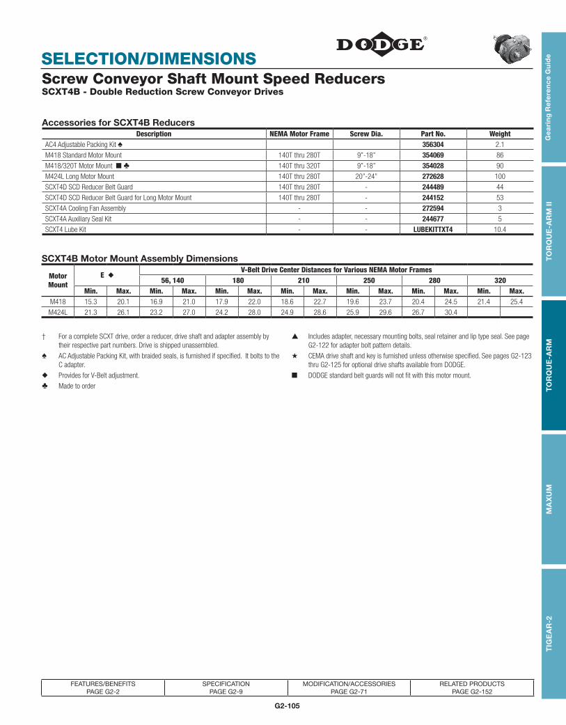
G2-105
TOR
QU
E-TA
MER
Bus
hing
sV-
Driv
esFH
PD
rives
Com
pone
nt A
cces
sorie
s
SELECTION/DIMENSIONS
TOR
QU
E-TA
MER
Bus
hing
sV-
Driv
esFH
PD
rives
Com
pone
nt A
cces
sorie
sT
IGE
AR
-2G
eari
ng
Re
fere
nc
e G
uid
eT
OR
QU
E-A
RM
IIT
OR
QU
E-A
RM
MA
XU
M
FEATURES/BENEFITS PAGE G2-2
SPECIFICATION PAGE G2-9
MODIFICATION/ACCESSORIES PAGE G2-71
RELATED PRODUCTS PAGE G2-152
Screw Conveyor Shaft Mount Speed Reducers SCXT4B - Double Reduction Screw Conveyor Drives
Accessories for SCXT4B ReducersDescription NEMA Motor Frame Screw Dia. Part No. Weight
AC4 Adjustable Packing Kit ♠ 356304 2.1
M418 Standard Motor Mount 140T thru 280T 9”-18” 354069 86
M418/320T Motor Mount ■ ♣ 140T thru 320T 9”-18” 354028 90
M424L Long Motor Mount 140T thru 280T 20”-24” 272628 100
SCXT4D SCD Reducer Belt Guard 140T thru 280T - 244489 44
SCXT4D SCD Reducer Belt Guard for Long Motor Mount 140T thru 280T - 244152 53
SCXT4A Cooling Fan Assembly - - 272594 3
SCXT4A Auxiliary Seal Kit - - 244677 5
SCXT4 Lube Kit - - LUBEKITTXT4 10.4
SCXT4B Motor Mount Assembly Dimensions
Motor Mount
E ◆V-Belt Drive Center Distances for Various NEMA Motor Frames
56, 140 180 210 250 280 320Min. Max. Min. Max. Min. Max. Min. Max. Min. Max. Min. Max. Min. Max.
M418 15.3 20.1 16.9 21.0 17.9 22.0 18.6 22.7 19.6 23.7 20.4 24.5 21.4 25.4
M424L 21.3 26.1 23.2 27.0 24.2 28.0 24.9 28.6 25.9 29.6 26.7 30.4
† For a complete SCXT drive, order a reducer, drive shaft and adapter assembly by their respective part numbers. Drive is shipped unassembled.
▲ Includes adapter, necessary mounting bolts, seal retainer and lip type seal. See page G2-122 for adapter bolt pattern details.
♠ AC Adjustable Packing Kit, with braided seals, is furnished if specified. It bolts to the C adapter.
★ CEMA drive shaft and key is furnished unless otherwise specified. See pages G2-123 thru G2-125 for optional drive shafts available from DODGE.
◆ Provides for V-Belt adjustment. ■ DODGE standard belt guards will not fit with this motor mount.
♣ Made to order

G2-106
SELECTION/DIMENSIONS
Gea
ring
Re
fere
nc
e Gu
ide
TO
RQ
UE
-AR
M II
TO
RQ
UE
-AR
MM
AX
UM
TIG
EA
R-2
FEATURES/BENEFITS PAGE G2-2
SPECIFICATION PAGE G2-9
MODIFICATION/ACCESSORIES PAGE G2-71
RELATED PRODUCTS PAGE G2-152
Screw Conveyor Shaft Mount Speed Reducers SCXT405A - Single Reduction Screw Conveyor Drives
SCXT405A Screw Conveyor Drives†
ReducersSize Part No. AGMA Code Ratio Weight
SCXT405A 254208 207S05 5.65 122
CEMA Drive Shafts ★ Adapter Assembly ▲Drive
Screw Dia.Part
A B C DF
Weight SizePart
WeightShaft No. Dia. No.
C4 x 1-1/2 9” 244594 1.50 6.00 2.13 3.00 .52 19
C4 354121 33
C4 x 2 9” - 12” 244595 2.00 6.00 2.13 3.00 .64 20.80
C4 x 2-7/16 12” - 14” 244596 2.44 6.69 2.75 3.00 .64 24.30
C4 x 3 12” - 20” 244597 3.00 6.88 2.88 3.00 .77 29.20
C4 x 3-7/16 18” - 24” 244598 3.44 9.13 3.88 4.00 .89 39.30
3/4 X 8" STUD
1-15/16" DIA. SHAFT
1/2 X 1/4 X 3-13/16 K.S.
4.63
14.25
17.00
15.69
5.56
2.30
4.00B
CD
2-7/16 DIA. BORE
F DIA.
A
18.63
17.50
1.7815.50
TROUGH ENDPLATE
10.38
E
9.26
15.31
4.88
5.50

G2-107
TOR
QU
E-TA
MER
Bus
hing
sV-
Driv
esFH
PD
rives
Com
pone
nt A
cces
sorie
s
SELECTION/DIMENSIONS
TOR
QU
E-TA
MER
Bus
hing
sV-
Driv
esFH
PD
rives
Com
pone
nt A
cces
sorie
sT
IGE
AR
-2G
eari
ng
Re
fere
nc
e G
uid
eT
OR
QU
E-A
RM
IIT
OR
QU
E-A
RM
MA
XU
M
FEATURES/BENEFITS PAGE G2-2
SPECIFICATION PAGE G2-9
MODIFICATION/ACCESSORIES PAGE G2-71
RELATED PRODUCTS PAGE G2-152
Screw Conveyor Shaft Mount Speed Reducers SCXT405A - Single Reduction Screw Conveyor Drives
Accessories for SCXT405A ReducersDescription NEMA Motor Frame Screw Dia. Part No. Weight
AC4 Adjustable Packing Kit ♠ 356304 2.1
M418 Standard Motor Mount 140T thru 280T 9”-18” 354069 86
M418/320T Motor Mount ■ ♣ 140T thru 320T 9”-18” 354028 90
M424L Long Motor Mount 140T thru 280T 20”-24” 272628 100
SCXT4S SCD Reducer Belt Guard 140T thru 280T - 244491 50
SCXT4S SCD Reducer Belt Guard for Long Motor Mount ♣ 140T thru 280T - 244167 60
SCXT405A Cooling Fan Assembly - - 254268 3
SCXT405A Auxiliary Seal Kit ♣ - - 254146 5
SCXT405 Lube Kit - - LUBEKITTXT405 12.7
SCXT405A Motor Mount Assembly Dimensions
Motor Mount
E ◆V-Belt Drive Center Distances for Various NEMA Motor Frames
56, 140 180 210 250 280 320Min. Max. Min. Max. Min. Max. Min. Max. Min. Max. Min. Max. Min. Max
M418 15.3 20.1 19.6 23.7 20.6 24.7 21.4 25.5 22.4 26.5 23 27.2 21.4 25.4M424L 21.3 26.1 25.9 29.7 26.9 30.7 27.7 31.4 28. 7 32.3 29.4 33.2
† For a complete SCXT drive, order a reducer, drive shaft and adapter assembly by their respective part numbers. Drive is shipped unassembled.
▲ Includes adapter, necessary mounting bolts, seal retainer and lip type seal. See page G2-122 for adapter bolt pattern details.
♠ AC Adjustable Packing Kit, with braided seals, is furnished if specified. It bolts to the C adapter.
★ CEMA drive shaft and key is furnished unless otherwise specified. See pages G2-123 thru G2-125 for optional drive shafts available from DODGE.
◆ Provides for V-Belt adjustment. ■ DODGE standard belt guards will not fit with this motor mount.
♣ Made to order.

G2-108
SELECTION/DIMENSIONS
Gea
ring
Re
fere
nc
e Gu
ide
TO
RQ
UE
-AR
M II
TO
RQ
UE
-AR
MM
AX
UM
TIG
EA
R-2
FEATURES/BENEFITS PAGE G2-2
SPECIFICATION PAGE G2-9
MODIFICATION/ACCESSORIES PAGE G2-71
RELATED PRODUCTS PAGE G2-152
Screw Conveyor Shaft Mount Speed Reducers SCXT5C - Double Reduction Screw Conveyor Drives
SCXT5C Screw Conveyor Drives†
ReducersSize Part No. AGMA Code Ratio Weight
SCXT509C 245574 ♣ 215D09 8.95 207
SCXT515C 245575 215D15 15.40 207
SCXT525C 245576 215D25 25.56 207
CEMA Drive Shafts ★ Adapter Assembly ▲Drive
Screw Dia.Part
A B C DF
Weight SizePart
WeightShaft No. Dia. No.
C5B x 2 9” 355175 2.00 6.00 2.13 3.00 .64 29.4
C5 355072 43C5B x 2-7/16 9” - 12” 355176 2.44 6.69 2.75 3.00 .64 33
C5B x 3 12” - 14” 355177 3.00 6.88 2.88 3.00 .77 37.9
C5B x 3-7/16 12” - 20” 355178 3.44 9.13 3.88 4.00 .89 48.3
14.25 16.50**
17.00 18.50**
15.50 17.50**
17.50 19.25**
18.63 20.50**
16.305.74
2.42
4.25B
CD
A
F DIA.
3/4 X 8" STUD
**M518/320T MM
1-15/16" DIA. SHAFT1/2 X 1/4 X 4-1/2" K.S.
2-15/16 DIA. BORE
TROUGH ENDPLATE
E
1.84
13.133.04
9.26
4.13
5.676.5618.31

G2-109
TOR
QU
E-TA
MER
Bus
hing
sV-
Driv
esFH
PD
rives
Com
pone
nt A
cces
sorie
s
SELECTION/DIMENSIONS
TOR
QU
E-TA
MER
Bus
hing
sV-
Driv
esFH
PD
rives
Com
pone
nt A
cces
sorie
sT
IGE
AR
-2G
eari
ng
Re
fere
nc
e G
uid
eT
OR
QU
E-A
RM
IIT
OR
QU
E-A
RM
MA
XU
M
FEATURES/BENEFITS PAGE G2-2
SPECIFICATION PAGE G2-9
MODIFICATION/ACCESSORIES PAGE G2-71
RELATED PRODUCTS PAGE G2-152
Screw Conveyor Shaft Mount Speed Reducers SCXT5C - Double Reduction Screw Conveyor Drives
Accessories for SCXT5C ReducersDescription NEMA Motor Frame Screw Dia. Part No. Weight
AC5 Adjustable Packing Kit ♠ 356305 2.1
M518 Standard Motor Mount 140T thru 280T 9”-18” 355169 82
M518/320T Special Motor Mount ● ■ ♣ 320T 9”-18” 355168 82
M524L Long Motor Mount 140T thru 280T 20”-24” 272629 110
SCXT5D SCD Reducer Belt Guard 140T thru 280T - 245495 45
SCXT5D SCD Reducer Belt Guard for Long Motor Mount 140T thru 280T - 245103 54
SCXT5B Cooling Fan Assembly - - 272369 3
SCXT5B Auxiliary Seal Kit - - 245637 6
SCXT5 Lube Kit - - LUBEKITTXT5 18.5
SCXT5C Motor Mount Assembly Dimensions
Motor Mount
E ◆V-Belt Drive Center Distances for Various NEMA Motor Frames
56, 140 180 210 250 280 320
Min. Max. Min. Max. Min. Max. Min. Max. Min. Max. Min. Max. Min. Max.M518 15.3 20.1 16.6 20.7 17.6 21.7 18.4 22.4 19.4 23.4 20 24.2 21.1 25.2
M524L 21.3 26.1 22.9 26.6 23.9 27.6 24.7 28.4 25.7 29.4 26.4 30.1 - -
† For a complete SCXT drive, order a reducer, drive shaft and adapter assembly by their respective part numbers. Drive is shipped unassembled.
▲ Includes adapter, necessary mounting bolts, seal retainer and lip type seal. See page G2-122 for adapter bolt pattern details.
♠ AC Adjustable Packing Kit, with braided seals, is furnished if specified. It bolts to the C adapter.
★ CEMA drive shaft and key is furnished unless otherwise specified. See pages G2-123 thru G2-125 for optional drive shafts available from DODGE.
◆ Provides for V-Belt adjustment. ■ DODGE standard belt guards will not fit with this motor mount.
♣ Made to order. ● Drawing dimensions are noted as **

G2-110
SELECTION/DIMENSIONS
Gea
ring
Re
fere
nc
e Gu
ide
TO
RQ
UE
-AR
M II
TO
RQ
UE
-AR
MM
AX
UM
TIG
EA
R-2
FEATURES/BENEFITS PAGE G2-2
SPECIFICATION PAGE G2-9
MODIFICATION/ACCESSORIES PAGE G2-71
RELATED PRODUCTS PAGE G2-152
Screw Conveyor Shaft Mount Speed Reducers SCXT505A - Single Reduction Screw Conveyor Drives
SCXT505A Screw Conveyor Drives†
ReducersSize Part No. AGMA Code Ratio Weight
SCXT505A 255208 215S05 5.67 182
CEMA Drive Shafts ★ Adapter Assembly ▲Drive
Screw Dia.Part
A B C DF
Weight SizePart
WeightShaft No. Dia. No.
C5B x 2 9” - 12” 355175 2.00 6.00 2.13 3.00 .64 29.40
C5 355072 43C5B x 2-7/16 12” - 14” 355176 2.44 6.69 2.75 3.00 .64 33
C5B x 3 12” - 20” 355177 3.00 6.88 2.88 3.00 .77 37.90
C5B x 3-7/16 18” - 24” 355178 3.44 9.13 3.88 4.00 .89 48.30
17.00**18.50
14.25**16.50
4.13
4.25
2.40
6.21
16.77
18.63 20.50**
17.50 19.25**
15.50 17.50**
13.13
18.31
6.56
**M518/320T MM
E
1.84
3/4 X 8" STUD
TROUGH ENDPLATE
2-15/16 DIA. BORE
2-3/16" DIA. SHAFT1/2 X 1/4 X 4-1/2" K.S.
F DIA.
5.86
9.26
A
CD
B

G2-111
TOR
QU
E-TA
MER
Bus
hing
sV-
Driv
esFH
PD
rives
Com
pone
nt A
cces
sorie
s
SELECTION/DIMENSIONS
TOR
QU
E-TA
MER
Bus
hing
sV-
Driv
esFH
PD
rives
Com
pone
nt A
cces
sorie
sT
IGE
AR
-2G
eari
ng
Re
fere
nc
e G
uid
eT
OR
QU
E-A
RM
IIT
OR
QU
E-A
RM
MA
XU
M
FEATURES/BENEFITS PAGE G2-2
SPECIFICATION PAGE G2-9
MODIFICATION/ACCESSORIES PAGE G2-71
RELATED PRODUCTS PAGE G2-152
Screw Conveyor Shaft Mount Speed Reducers SCXT505A - Single Reduction Screw Conveyor Drives
Accessories for SCXT505A ReducersDescription NEMA Motor Frame Screw Dia. Part No. Weight
AC5 Adjustable Packing Kit ♠ 356305 2.1
M518 Standard Motor Mount 140T thru 280T 9”-18” 355169 82
M518/320T Special Motor Mount � ■ ♣ 320T 9”-18” 355168 82
M524L Long Motor Mount 140T thru 280T 20”-24” 272629 110
SCXT5S SCD Reducer Belt Guard 140T thru 280T - 245497 70
SCXT5S SCD Reducer Belt Guard for Long Motor Mount ♣ 140T thru 280T - 245015 84
SCXT505A Cooling Fan Assembly - - 255231 3
SCXT505A Auxiliary Seal Kit ♣ - - 255148 6
SCXT505 Lube Kit - - LUBEKITTXT505 18.5
SCXT505A Motor Mount Assembly Dimensions SCD
Motor Mount
E ◆V-Belt Drive Center Distances for Various NEMA Motor Frames
56, 140 180 210 250 280 320Min. Max. Min. Max. Min. Max. Min. Max. Min. Max. Min. Max. Min. Max.
M518 15.3 20.1 19.7 23.8 20.7 24.7 21.4 25.5 22.4 26.5 23.0 27.2 24.2 28.2
M524L 21.3 26.1 25.9 29.7 26.9 30.7 27.7 31.4 28.7 32.4 29.5 33.2 - -
† For a complete SCXT drive, order a reducer, drive shaft and adapter assembly by their respective part numbers. Drive is shipped unassembled.
▲ Includes adapter, necessary mounting bolts, seal retainer and lip type seals. See page G2-122 for adapter bolt pattern details.
♠ AC Adjustable Packing Kit, with braided seals, is furnished if specified. It bolts to the C adapter.
★ CEMA drive shaft and key is furnished unless otherwise specified. See pages G2-123 thru G2-125 for optional drive shafts available from DODGE.
◆ Provides for V-Belt adjustment. ■ DODGE standard belt guards will not fit with this motor mount. Consult DODGE for special belt guard.♣ Made to order.
� Drawing dimensions are noted as **

G2-112
SELECTION/DIMENSIONS
Gea
ring
Re
fere
nc
e Gu
ide
TO
RQ
UE
-AR
M II
TO
RQ
UE
-AR
MM
AX
UM
TIG
EA
R-2
FEATURES/BENEFITS PAGE G2-2
SPECIFICATION PAGE G2-9
MODIFICATION/ACCESSORIES PAGE G2-71
RELATED PRODUCTS PAGE G2-152
Screw Conveyor Shaft Mount Speed Reducers SCXT6A - Double Reduction Screw Conveyor Drives
SCXT6A Screw Conveyor Drives†
ReducersSize Part No. AGMA Code Ratio Weight
SCXT609A 246480 ♣ 307D09 9.20 285
SCXT615A 356057 307D15 15.33 285
SCXT625A 356058 307D25 25.13 285
CEMA Drive Shafts ★ Adapter Assembly ▲Drive
Screw Dia.Part
A B C DF
Weight SizePart
WeightShaft No. Dia. No.
C6 x 2-7/16 12” - 14” 356042 2.44 6.69 2.75 3.00 .64 47.70
C6 356055 56C6 x 3 12” - 20” 356043 3.00 6.88 2.88 3.00 .77 52.70
C6 x 3-7/16 18” - 24” 356044 3.44 9.13 3.88 4.00 .89 63
18.50
4.50
20.5019.25
17.50
15.134.09
21.31
3/4 X 8 STUD
18.46
6.08
2.79
5.50
B
A
F DIA.
3-7/16DIA BORE
2-3/16" DIA. SHAFT1/2 X 1/4 X 4-1/2" K.S.
6.737.56
E
1.84
9.26
16.50
TROUGH ENDPLATE
CD

G2-113
TOR
QU
E-TA
MER
Bus
hing
sV-
Driv
esFH
PD
rives
Com
pone
nt A
cces
sorie
s
SELECTION/DIMENSIONS
TOR
QU
E-TA
MER
Bus
hing
sV-
Driv
esFH
PD
rives
Com
pone
nt A
cces
sorie
sT
IGE
AR
-2G
eari
ng
Re
fere
nc
e G
uid
eT
OR
QU
E-A
RM
IIT
OR
QU
E-A
RM
MA
XU
M
FEATURES/BENEFITS PAGE G2-2
SPECIFICATION PAGE G2-9
MODIFICATION/ACCESSORIES PAGE G2-71
RELATED PRODUCTS PAGE G2-152
Screw Conveyor Shaft Mount Speed Reducers SCXT6A - Double Reduction Screw Conveyor Drives
Accessories for SCXT6A ReducersDescription NEMA Motor Frame Screw Dia. Part No. Weight
AC6 / AC7 Adjustable Packing Kit ♠ 356306 2.4
M620 Standard Motor Mount 140T thru 320T 12”-20” 356069 105
M624L Long Motor Mount ♣ 140T thru 320T 24” 272630 122
SCXT6D SCD Reducer Belt Guard 140T thru 320T - 246476 60
SCXT6D SCD Reducer Belt Guard for Long Motor Mount 140T thru 320T - 246148 72
SCXT6 Cooling Fan Assembly - - 272325 3
SCXT6 Auxiliary Seal Kit - - 272726 7
SCXT6 Lube Kit - - LUBEKITTXT6 20.8
SCXT6A Motor Mount Assembly Dimensions
Motor Mount
E ◆V-Belt Drive Center Distances for Various NEMA Motor Frames
56, 140 180 210 250 280 320Min. Max. Min. Max. Min. Max. Min. Max. Min. Max. Min. Max. Min. Max.
M620 16.7 21.4 17.0 21.0 18.0 22.0 18.8 22.8 19.7 23.8 20.5 24.5 21.5 25.5
M624L 22.7 27.4 23.2 27.0 24.2 27.9 24.9 28.7 25.9 29.7 26.7 30.5 27.6 31.4
† For a complete SCXT drive, order a reducer, drive shaft and adapter assembly by their respective part numbers. Drive is shipped unassembled.
▲ Includes adapter, necessary mounting bolts, seal retainer and lip type seals. See page G2-122 for adapter bolt pattern details.
♠ AC Adjustable Packing Kit, with braided seals, is furnished if specified. It bolts to the C adapter.
★ CEMA drive shaft and key is furnished unless otherwise specified. See pages G2-123 thru G2-125 for optional drive shafts available from DODGE.
◆ Provides for V-Belt adjustment.
♣ Made to order

G2-114
SELECTION/DIMENSIONS
Gea
ring
Re
fere
nc
e Gu
ide
TO
RQ
UE
-AR
M II
TO
RQ
UE
-AR
MM
AX
UM
TIG
EA
R-2
FEATURES/BENEFITS PAGE G2-2
SPECIFICATION PAGE G2-9
MODIFICATION/ACCESSORIES PAGE G2-71
RELATED PRODUCTS PAGE G2-152
Screw Conveyor Shaft Mount Speed Reducers SCXT605 - Single Reduction Screw Conveyor Drives
SCXT605 Screw Conveyor Drives†
ReducersSize Part No. AGMA Code Ratio Weight
SCXT605 356285 307S05 5.67 251
CEMA Drive Shafts ★ Adapter Assembly ▲Drive
Screw Dia.Part
A B C DF
Weight SizePart
WeightShaft No. Dia. No.
C6 x 2-7/16 12” - 14” 356042 2.44 6.69 2.75 3.00 .64 47.70
C6 356055 56C6 x 3 12” - 20” 356043 3.00 6.88 2.88 3.00 .77 52.70
C6 x 3-7/16 18” - 24” 356044 3.44 9.13 3.88 4.00 .89 63
18.50
4.50
20.5019.25
17.50
15.13
21.31
3/4 X 8 STUD
18.48
6.11
2.79
5.50
B
CD
A
F DIA.
3-7/16DIA BORE
2-3/16" DIA. SHAFT1/2 X 1/4 X 4-1/2" K.S.
7.56 6.89
E
1.84
16.50
TROUGH ENDPLATE
9.26

G2-115
TOR
QU
E-TA
MER
Bus
hing
sV-
Driv
esFH
PD
rives
Com
pone
nt A
cces
sorie
s
SELECTION/DIMENSIONS
TOR
QU
E-TA
MER
Bus
hing
sV-
Driv
esFH
PD
rives
Com
pone
nt A
cces
sorie
sT
IGE
AR
-2G
eari
ng
Re
fere
nc
e G
uid
eT
OR
QU
E-A
RM
IIT
OR
QU
E-A
RM
MA
XU
M
FEATURES/BENEFITS PAGE G2-2
SPECIFICATION PAGE G2-9
MODIFICATION/ACCESSORIES PAGE G2-71
RELATED PRODUCTS PAGE G2-152
Screw Conveyor Shaft Mount Speed Reducers SCXT605 - Single Reduction Screw Conveyor Drives
Accessories for SCXT605 ReducersDescription NEMA Motor Frame Screw Dia. Part No. Weight
AC6 / AC7 Adjustable Packing Kit ♠ 356306 2.4
M620 Standard Motor Mount 140T thru 320T 12”-20” 356069 105
M624L Long Motor Mount ♣ 140T thru 320T 24” 272630 122
SCXT6S SCD Reducer Belt Guard 140T thru 320T - 246478 77
SCXT6S SCD Reducer Belt Guard for Long Motor Mount ♣ 140T thru 320T - 246142 92
SCXT605 Cooling Fan Assembly ♣ - - 272681 3
SCXT6 Auxiliary Seal Kit - - 272726 7
SCXT605 Lube Kit - - LUBEKITTXT605 24.3
SCXT605 Motor Mount Assembly Dimensions
Motor Mount
E ◆V-Belt Drive Center Distances for Various NEMA Motor Frames
56, 140 180 210 250 280 320Min. Max. Min. Max. Min. Max. Min. Max. Min. Max. Min. Max. Min. Max.
M620 16.7 21.4 21.1 25.1 22.1 26.1 22.8 26.8 23.8 27.9 24.6 28.6 25.6 29.6
M624L 22.7 27.4 27.2 31.1 28.2 32.1 29 32.8 30 33.8 30.7 34.6 31.7 35.5
† For a complete SCXT drive, order a reducer, drive shaft and adapter assembly by their respective part numbers. Drive is shipped unassembled.
▲ Includes adapter, necessary mounting bolts, seal retainer. and lip type seals. See page G2-122 for adapter bolt pattern details.
♠ AC Adjustable Packing Kit, with braided seals, is furnished if specified. It bolts to the C adapter.
★ CEMA drive shaft and key is furnished unless otherwise specified. See pages G2-123 thru G2-125 for optional drive shafts available from DODGE.
◆ Provides for V-Belt adjustment.
♣ Made to order

G2-116
SELECTION/DIMENSIONS
Gea
ring
Re
fere
nc
e Gu
ide
TO
RQ
UE
-AR
M II
TO
RQ
UE
-AR
MM
AX
UM
TIG
EA
R-2
FEATURES/BENEFITS PAGE G2-2
SPECIFICATION PAGE G2-9
MODIFICATION/ACCESSORIES PAGE G2-71
RELATED PRODUCTS PAGE G2-152
Screw Conveyor Shaft Mount Speed Reducers SCXT7A - Double Reduction Screw Conveyor Drives
SCXT7A Screw Conveyor Drives†
ReducersSize Part No. AGMA Code Ratio Weight
SCXT709A 247480 ♣ 315D09 9.61 462
SCXT715A 356256 ♣ 315D15 15.23 462
SCXT725A 356257 315D25 24.59 462
CEMA Drive Shafts ★ Adapter Assembly ▲Drive
Screw Dia.Part
A B C DF
Weight SizePart
WeightShaft No. Dia. No.
C7 x 2-7/16 12” - 14” 356182 ♣ 2.44 6.69 2.75 3.00 .64 58
C7 356187 72C7 x 3 12” - 20” 356183 3.00 6.88 2.88 3.00 .77 70
C7 x 3-7/16 18” - 24” 356184 3.44 9.13 3.88 4.00 .89 80.30
19.00 22.50
21.25
19.25
1 X 9 STUD
B
A
E
1.84
20.55**
19.25**
17.50**
3/4" X 8 STUD**16.50
18.50**
CD 6.31
20.57
6.35
2.94
3-15/16DIA. BORE
TROUGH ENDPLATE
2-7/16" DIA. SHAFT5/8 x 5/16 x 4-3/4 K.S.
9.38 8.3025.94
5.11
18.75
4.75
**M724L MM
F DIA.
9.26

G2-117
TOR
QU
E-TA
MER
Bus
hing
sV-
Driv
esFH
PD
rives
Com
pone
nt A
cces
sorie
s
SELECTION/DIMENSIONS
TOR
QU
E-TA
MER
Bus
hing
sV-
Driv
esFH
PD
rives
Com
pone
nt A
cces
sorie
sT
IGE
AR
-2G
eari
ng
Re
fere
nc
e G
uid
eT
OR
QU
E-A
RM
IIT
OR
QU
E-A
RM
MA
XU
M
FEATURES/BENEFITS PAGE G2-2
SPECIFICATION PAGE G2-9
MODIFICATION/ACCESSORIES PAGE G2-71
RELATED PRODUCTS PAGE G2-152
Screw Conveyor Shaft Mount Speed Reducers SCXT7A - Double Reduction Screw Conveyor Drives
Accessories for SCXT7A ReducersDescription NEMA Motor Frame Screw Dia. Part No. Weight
AC6 / AC7 Adjustable Packing Kit ♠ 356306 2.4
M720 Standard Motor Mount 140T thru 360T 12”-20” 356269 106
M724L Long Motor Mount ♣ ● 140T thru 320T 24” 272631 130
SCXT7D SCD Reducer Belt Guard 140T thru 360T - 247474 75
SCXT7D SCD Reducer Belt Guard for Long Motor Mount 140T thru 320T - 247153 90
SCXT7 Cooling Fan Assembly - - 272326 6
SCXT7 Auxiliary Seal Kit - - 272727 8
SCXT7 Lube Kit - - LUBEKITTXT7 34.7
SCXT7A Motor Mount Assembly Dimensions
Motor Mount
E ◆V-Belt Drive Center Distances for Various NEMA Motor Frames
56,140 180 210 250 280 320 360Min. Max. Min. Max. Min. Max. Min. Max. Min. Max. Min. Max. Min. Max. Min. Max.
M720 17.5 21.7 17.1 20.5 18.1 21.5 18.8 22.2 19.8 23.2 20.5 24.0 21.5 25.0 22.5 26.0
M724L 23.5 27.7 22.4 26.1 23.3 27.1 24.1 27.8 25.0 28.8 25.8 29.5 26.8 30.5 --- ---
† For a complete SCXT drive, order a reducer, drive shaft and adapter assembly by their respective part numbers. Drive is shipped unassembled.
▲ Includes adapter, necessary mounting bolts, seal retainer and lip type seals. See page G2-122 for adapter bolt pattern details.
♠ AC Adjustable Packing Kit, with braided seals, is furnished if specified. It bolts to the C adapter.
★ CEMA drive shaft and key is furnished unless otherwise specified. See pages G2-123 thru G2-125 for optional drive shafts available from DODGE.
◆ Provides for V-Belt adjustment. ● Drawing dimensions are noted as **♣ Made to order

G2-118
SELECTION/DIMENSIONS
Gea
ring
Re
fere
nc
e Gu
ide
TO
RQ
UE
-AR
M II
TO
RQ
UE
-AR
MM
AX
UM
TIG
EA
R-2
FEATURES/BENEFITS PAGE G2-2
SPECIFICATION PAGE G2-9
MODIFICATION/ACCESSORIES PAGE G2-71
RELATED PRODUCTS PAGE G2-152
Screw Conveyor Shaft Mount Speed Reducers SCXT705 - Single Reduction Screw Conveyor Drives
SCXT705 Screw Conveyor Drives†
ReducersSize Part No. AGMA Code Ratio Weight
SCXT705 356295 ♣ 315S05 5.36 410
CEMA Drive Shafts ★ Adapter Assembly ▲Drive
Screw Dia.Part
A B C DF
Weight SizePart
WeightShaft No. Dia. No.
C7 x 2-7/16 12” - 14” 356182 ♣ 2.44 6.69 2.75 3 0.64 58 C7 356187 72C7 x 3 12” - 20” 356183 3 6.88 2.88 3 0.77 70
C7 x 3-7/16 18” - 24” 356184 3.44 9.13 3.88 4 0.89 80.3
19.00 22.50
21.25
19.25
1 X 9 STUD
B
A
E
1.84
20.50**
19.25**
17.50**
3/4" X 8 STUD**16.50
18.50**
C
D 6.31
20.56
6.34
2.94
3-15/16DIA. BORE
TROUGH ENDPLATE
2-7/16" DIA. SHAFT5/8 x 5/16 x 4-3/4 K.S.
9.38
25.94
18.75
4.75
8.31
**M724L MM
9.26

G2-119
TOR
QU
E-TA
MER
Bus
hing
sV-
Driv
esFH
PD
rives
Com
pone
nt A
cces
sorie
s
SELECTION/DIMENSIONS
TOR
QU
E-TA
MER
Bus
hing
sV-
Driv
esFH
PD
rives
Com
pone
nt A
cces
sorie
sT
IGE
AR
-2G
eari
ng
Re
fere
nc
e G
uid
eT
OR
QU
E-A
RM
IIT
OR
QU
E-A
RM
MA
XU
M
FEATURES/BENEFITS PAGE G2-2
SPECIFICATION PAGE G2-9
MODIFICATION/ACCESSORIES PAGE G2-71
RELATED PRODUCTS PAGE G2-152
Screw Conveyor Shaft Mount Speed Reducers SCXT705 - Single Reduction Screw Conveyor Drives
Accessories for SCXT705 ReducersDescription NEMA Motor Frame Screw Dia. Part No. Weight
AC6 / AC7 Adjustable Packing Kit ♠ 356306 2.4
M720 Standard Motor Mount 140T thru 360T 12”-20” 356269 106
M724L Long Motor Mount ♣ ● 140T thru 320T 24” 272631 130
SCXT7S SCD Reducer Belt Guard 140T thru 360T - 247476 84
SCXT7S SCD Reducer Belt Guard for Long Motor Mount 140T thru 320T - 247149 100
SCXT705 Cooling Fan Assembly ♣ - - 272685 6
SCXT705 Auxiliary Seal Kit - - 272727 8
SCXT705 Lube Kit - - LUBEKITTXT705 39.3
SCXT705 Motor Mount Assembly Dimensions
Motor Mount
E ◆V-Belt Drive Center Distances for Various NEMA Motor Frames
56,140 180 210 250 280 320 360Min. Max. Min. Max. Min. Max. Min. Max. Min. Max. Min. Max. Min. Max. Min. Max.
M720 17.5 21.7 22.1 25.6 23.1 26.5 23.8 27.3 24.8 28.3 25.6 29.0 26.6 30.0 27.5 31.0
M724L 23.5 27.7 27.3 31.1 28.3 32.1 29.1 32.9 30.1 33.9 30.8 34.7 31.8 35.6 - -
† For a complete SCXT drive, order a reducer, drive shaft and adapter assembly by their respective part numbers. Drive is shipped unassembled.
▲ Includes adapter, necessary mounting bolts, seal retainer and lip type seals. See page G2-122 for adapter bolt pattern details.
♠ AC Adjustable Packing Kit, with braided seals, is furnished if specified. It bolts to the C adapter.
★ CEMA drive shaft and key is furnished unless otherwise specified. See pagesG2-123 thru G2-125 for optional drive shafts available from DODGE.
◆ Provides for V-Belt adjustment. ♣ Made to order.
● Drawing dimensions are noted as **

G2-120
SELECTION/DIMENSIONS
Gea
ring
Re
fere
nc
e Gu
ide
TO
RQ
UE
-AR
M II
TO
RQ
UE
-AR
MM
AX
UM
TIG
EA
R-2
FEATURES/BENEFITS PAGE G2-2
SPECIFICATION PAGE G2-9
MODIFICATION/ACCESSORIES PAGE G2-71
RELATED PRODUCTS PAGE G2-152
Screw Conveyor Shaft Mount Speed Reducers SCXT8A - Double Reduction Screw Conveyor Drives
SCXT8A Screw Conveyor Drives†
ReducersSize Part No. AGMA Code Ratio Weight
SCXT815A 248464 ♣ 407D15 15.08 633
SCXT825A 248465 ♣ 407D25 24.62 633
CEMA Drive Shafts ★ Adapter Assembly ▲Drive
Screw Dia.Part
A B C DF
Weight SizePart
WeightShaft No. Dia. No.
C8 X 3 12” - 20” 248473 ♣ 3.00 9.88 2.88 3.00 .77 88C8 ♠ 248470 ♣ 90
C8 X 3-7/16 18” - 24” 248474 ♣ 3.44 13.13 3.88 4.00 .89 100
19.00 22.50
21.25
19.25
1 X 9 STUD
B
A
E
1.84
16.50
7.00
22.48
7.10
2.91
4-7/16DIA. BORE
TROUGH ENDPLATE
2-7/16" DIA. SHAFT5/8 x 5/16 x 5-3/8 K.S.
10.13 9.50D C
D
5.25
28.25
6.03
20.25
F DIA.
12.81
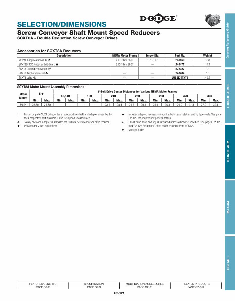
G2-121
TOR
QU
E-TA
MER
Bus
hing
sV-
Driv
esFH
PD
rives
Com
pone
nt A
cces
sorie
s
SELECTION/DIMENSIONS
TOR
QU
E-TA
MER
Bus
hing
sV-
Driv
esFH
PD
rives
Com
pone
nt A
cces
sorie
sT
IGE
AR
-2G
eari
ng
Re
fere
nc
e G
uid
eT
OR
QU
E-A
RM
IIT
OR
QU
E-A
RM
MA
XU
M
FEATURES/BENEFITS PAGE G2-2
SPECIFICATION PAGE G2-9
MODIFICATION/ACCESSORIES PAGE G2-71
RELATED PRODUCTS PAGE G2-152
Screw Conveyor Shaft Mount Speed Reducers SCXT8A - Double Reduction Screw Conveyor Drives
Accessories for SCXT8A ReducersDescription NEMA Motor Frame Screw Dia. Part No. Weight
M824L Long Motor Mount ♣ 210T thru 360T 12” - 24” 248469 163
SCXT8D SCD Reducer Belt Guard ♣ 210T thru 360T --- 248477 113
SCXT8 Cooling Fan Assembly --- --- 272327 9
SCXT8 Auxiliary Seal Kit ♣ --- --- 248484 10
SCXT8 Lube Kit --- --- LUBEKITTXT8 40.5
SCXT8A Motor Mount Assembly Dimensions
Motor Mount
E ◆V-Belt Drive Center Distances for Various NEMA Motor Frames
56,140 180 210 250 280 320 360Min. Max. Min. Max. Min. Max. Min. Max. Min. Max. Min. Max. Min. Max. Min. Max.
M824 22.70 28.60 --- --- --- --- 23.3 28.4 24.3 29.4 25.1 30.1 26.0 31.1 27.0 32.1
† For a complete SCXT drive, order a reducer, drive shaft and adapter assembly by their respective part numbers. Drive is shipped unassembled.
▲ Includes adapter, necessary mounting bolts, seal retainer and lip type seals. See page G2-122 for adapter bolt pattern details.
♠ Totally enclosed adapter is standard for SCXT8A screw conveyor drive reducer. ★ CEMA drive shaft and key is furnished unless otherwise specified. See pages G2-123 thru G2-125 for optional drive shafts available from DODGE.◆ Provides for V-Belt adjustment.
♣ Made to order

G2-122
MODIFICATIONS/ ACCESSORIESG
earin
g R
efe
ren
ce G
uid
eT
OR
QU
E-A
RM
IIT
OR
QU
E-A
RM
MA
XU
MT
IGE
AR
-2
FEATURES/BENEFITS PAGE G2-2
SPECIFICATION PAGE G2-9
RELATED PRODUCTS PAGE G2-152
RENEWAL PARTS PAGE G2-166
Screw Conveyor Shaft Mount Reducers SCXT Screw Conveyor Adapters
SCXT Sizes 1-6
A
A
RADIUS
(4) TAPPED HOLES AND SLOTSFOR “K” DIAMETER TROUGHEND FASTENERS
J
SCXT Size 7
A RADIUS
(4) SLOTS FOR “K”DIAMETER TROUGHEND FASTENERS
J
(4) DRILLED HOLES FOR “K” DIAMETER TROUGHEND FASTENERS
SCXT Size 8
A
J
Reducer Size Drive Shaft Diameter J K A Radius
SCXT 1
1-1/2 4 1/2 7.75 0.875
2 5-1/8 5/8 7.75 0.875
2-7/16 5-5/8 5/8 7.75 0.875
3 6 3/4 7.75 0.875
SCXT 2
1-1/2 4 1/2 7.75 0.875
2 5-1/8 5/8 7.75 0.875
2-7/16 5-5/8 5/8 7.75 0.875
3 6 3/4 7.75 0.875
SCXT 3
1-1/2 4 1/2 8.50 1.25
2 5-1/8 5/8 8.50 1.25
2-7/16 5-5/8 5/8 8.50 1.25
3 6 3/4 8.50 1.25
SCXT 4
1-1/2 4 1/2 9.26 1.25
2 5-1/8 5/8 9.26 1.25
2-7/16 5-5/8 5/8 9.26 1.25
3 6 3/4 9.26 1.25
3-7/16 6-3/4 3/4 9.26 1.25
SCXT 5
2 5-1/8 5/8 9.26 1.25
2-7/16 5-5/8 5/8 9.26 1.25
3 6 3/4 9.26 1.25
3-7/16 6-3/4 3/4 9.26 1.25
SCXT 6
2-7/16 5-5/8 5/8 9.26 1.25
3 6 3/4 9.26 1.25
3-7/16 6-3/4 3/4 9.26 1.25
SCXT 7
2-7/16 5-5/8 5/8 11.00 1.25
3 6 3/4 11.00 1.25
3-7/16 6-3/4 3/4 11.00 1.25
SCXT 8 3 6 3/4 12.81 n/a
3-7/16 6-3/4 3/4 12.81 n/a

G2-123
TOR
QU
E-TA
MER
Bus
hing
sV-
Driv
esFH
PD
rives
Com
pone
nt A
cces
sorie
s
MODIFICATIONS/ ACCESSORIES
TOR
QU
E-TA
MER
Bus
hing
sV-
Driv
esFH
PD
rives
Com
pone
nt A
cces
sorie
s
TIG
EA
R-2
Gea
rin
g R
efe
ren
ce
Gu
ide
TO
RQ
UE
-AR
M II
TO
RQ
UE
-AR
MM
AX
UM
FEATURES/BENEFITS PAGE G2-2
SPECIFICATION PAGE G2-9
RELATED PRODUCTS PAGE G2-152
RENEWAL PARTS PAGE G2-166
Screw Conveyor Shaft Mount Speed Reducers SCXT Screw Conveyor Drive Optional Drive Shafts
Optional Drive Shafts for SCXT1A Reducers ♣Description Drive Shaft Screw Dia. Part No. Figure A B C D F Weight
StainlessSteel *
Drive Shafts
C1 x 1-1/2 6” - 9” 351147 2 1.50 6.00 2.13 3.00 0.52 7.20
C1 x 2 9” - 12” 351148 2 2.00 6.00 2.13 3.00 0.64 9.10
C1 x 2-7/16 12” - 14” 351149 2 2.44 6.69 2.75 3.00 0.64 12.50
C1 x 3 12” - 20” 351150 2 3.00 6.88 2.88 3.00 0.77 17.40
3-HoleDriveShafts
C1 x 1-1/2 6” - 9” 351300 1 1.50 9.00 2.13 3.00 0.52 8.70
C1 x 2 9” - 12” 351301 1 2.00 9.00 2.13 3.00 0.64 11.80
C1 x 2-7/16 12” - 14” 351302 1 2.44 9.69 2.75 3.00 0.64 16.40
C1 x 3 12” - 20” 351303 1 3.00 9.88 2.88 3.00 0.77 23.40
Stainless Steel *3-Hole
Drive Shafts
C1 x 1-1/2 6” - 9” 351025 1 1.50 9.00 2.13 3.00 0.52 8.70
C1 x 2 9” - 12” 351026 1 2.00 9.00 2.13 3.00 0.64 11.80
C1 x 2-7/16 12” - 14” 351027 1 2.44 9.69 2.75 3.00 0.64 16.40
C1 x 3 12” - 20” 351028 1 3.00 9.88 2.88 3.00 0.77 23.40
Optional Drive Shafts for SCXT2A Reducers ♣Description Drive Shaft Screw Dia. Part No. Figure A B C D F Weight
StainlessSteel *
Drive Shafts
C2 x 1-1/2 6” - 9” 352160 2 1.50 6.00 2.13 3.00 0.52 11.40
C2 x 2 9” - 12” 352161 2 2.00 6.00 2.13 3.00 0.64 13.80
C2 x 2-7/16 12” - 14” 352162 2 2.44 6.69 2.75 3.00 0.64 17.30
C2 x 3 12” - 20” 352163 2 3.00 6.88 2.88 3.00 0.77 19
3-HoleDriveShafts
C2 x 1-1/2 6” - 9” 351305 1 1.50 9.00 2.13 3.00 0.52 12.90
C2 x 2 9” - 12” 351306 1 2.00 9.00 2.13 3.00 0.64 16.50
C2 x 2-7/16 12” - 14” 351307 1 2.44 9.69 2.75 3.00 0.64 21.20
C2 x 3 12” - 20” 351308 1 3.00 9.88 2.88 3.00 0.77 25
Stainless Steel *3-Hole
Drive Shafts
C2 x 1-1/2 6” - 9” 352186 1 1.50 9.00 2.13 3.00 0.52 12.90
C2 x 2 9” - 12” 352187 1 2.00 9.00 2.13 3.00 0.64 16.50
C2 x 2-7/16 12” - 14” 352188 1 2.44 9.69 2.75 3.00 0.64 21.20
C2 x 3 12” - 20” 352189 1 3.00 9.88 2.88 3.00 0.77 25
* Supplied as #316 stainless steel. ♣ Made to order. Consult DODGE for lead time.

G2-124
MODIFICATIONS/ ACCESSORIESG
earin
g R
efe
ren
ce G
uid
eT
OR
QU
E-A
RM
IIT
OR
QU
E-A
RM
MA
XU
MT
IGE
AR
-2
FEATURES/BENEFITS PAGE G2-2
SPECIFICATION PAGE G2-9
RELATED PRODUCTS PAGE G2-152
RENEWAL PARTS PAGE G2-166
Screw Conveyor Shaft Mount Speed Reducers
Optional Drive Shafts for SCXT3B and SCXT305A Reducers ♣Description Drive Shaft Screw Dia. Part No. Figure A B C D F Weight
StainlessSteel *
C3A x 1-1/2 9” 243446 2 1.50 6.00 2.13 3.00 0.52 15
C3A x 2 9” - 12” 243447 2 2.00 6.00 2.13 3.00 0.64 16
C3A x 2-7/16 12” - 14” 243448 2 2.44 6.69 2.75 3.00 0.64 19.50
C3A x 3 12” - 20” 243449 2 3.00 6.88 2.88 3.00 0.77 26
Drive Shafts3-HoleDriveShafts
C3A x 1-1/2 9” 243016 1 1.50 9.00 2.13 3.00 0.52 16.50
C3A x 2 9” - 12” 243017 1 2.00 9.00 2.13 3.00 0.64 18.70
C3A x 2-7/16 12” - 14” 243018 1 2.44 9.69 2.75 3.00 0.64 23.40
C3A x 3 12” - 20” 243019 1 3.00 9.88 2.88 3.00 0.77 32
Stainless Steel *3-Hole
Drive Shafts
C3A x 1-1/2 9” 353180 1 1.50 9.00 2.13 3.00 0.52 16.50
C3A x 2 9” - 12” 353181 1 2.00 9.00 2.13 3.00 0.64 18.70
C3A x 2-7/16 12” - 14” 353182 1 2.44 9.69 2.75 3.00 0.64 23.40
C3A x 3 12” - 20” 353183 1 3.00 9.88 2.88 3.00 0.77 32
Optional Drive Shafts for SCXT4B and SCXT405A Reducers ♣Description Drive Shaft Screw Dia. Part No. Figure A B C D F Weight
StainlessSteel *Drive Shafts
C4A x 1-1/2 9” 244680 2 1.50 6.00 2.13 3.00 0.52 19
C4A x 2 9” - 12” 244681 2 2.00 6.00 2.13 3.00 0.64 20.80
C4A x 2-7/16 12” - 14” 244682 2 2.44 6.69 2.75 3.00 0.64 24.30
C4A x 3 12” - 20” 244683 2 3.00 6.88 2.88 3.00 0.77 29.20
C4A x 3-7/16 18” - 24” 244684 2 3.44 9.13 3.88 4.00 0.89 39.30
3-HoleDriveShafts
C4A x 1-1/2 9” 244494 1 1.50 9.00 2.13 3.00 0.52 20.50
C4A x 2 9” - 12” 244496 1 2.00 9.00 2.13 3.00 0.64 23.50
C4A x 2-7/16 12” - 14” 244497 1 2.44 9.69 2.75 3.00 0.64 28.20
C4A x 3 12” - 20” 244498 1 3.00 9.88 2.88 3.00 0.77 35.20
C4A x 3-7/16 18” - 24” 244499 1 3.44 14.13 3.88 4.00 0.89 49.80
Stainless Steel *3-Hole Drive Shafts
C4A x 1-1/2 9” 354351 1 1.50 9.00 2.13 3.00 0.52 20.50
C4A x 2 9” - 12” 354352 1 2.00 9.00 2.13 3.00 0.64 23.50
C4A x 2-7/16 12” - 14” 354353 1 2.44 9.69 2.75 3.00 0.64 28.20
C4A x 3 12” - 20” 354354 1 3.00 9.88 2.88 3.00 0.77 35.20
C4A x 3-7/16 18” - 24” 354355 1 3.44 14.13 3.88 4.00 0.89 49.80
Optional Drive Shafts for SCXT5C and SCXT505A Reducers ♣Description Drive Shaft Screw Dia. Part No. Figure A B C D F Weight
StainlessSteel *
Drive Shafts
C5B x 2 9” - 12” 245651 2 2.00 6.00 2.13 3.00 0.64 29.40
C5B x 2-7/16 12” - 14” 245652 2 2.44 6.69 2.75 3.00 0.64 33
C5B x 3 12” - 20” 245653 2 3.00 6.88 2.88 3.00 0.77 37.90
C5B x 3-7/16 18” - 24” 245654 2 3.44 9.13 3.88 4.00 0.89 48.30
3-HoleDriveShafts
C5B x 2 9” - 12” 245474 1 2.00 9.00 2.13 3.00 0.64 32.10
C5B x 2-7/16 12” - 14” 245476 1 2.44 9.69 2.75 3.00 0.64 36.90
C5B x 3 12” - 20” 245477 1 3.00 9.88 2.88 3.00 0.77 43.90
C5B x 3-7/16 18” - 24” 245478 1 3.44 14.13 3.88 4.00 0.89 58.80
Stainless Steel *3-Hole
Drive Shafts
C5B x 2 9” - 12” 355225 1 2.00 9.00 2.13 3.00 0.64 32.10
C5B x 2-7/16 12” - 14” 355226 1 2.44 9.69 2.75 3.00 0.64 36.90
C5B x 3 12” - 20” 355227 1 3.00 9.88 2.88 3.00 0.77 43.90
C5B x 3-7/16 18” - 24” 355228 1 3.44 14.13 3.88 4.00 0.89 58.80
* Supplied as # 316 stainless steel. ♣ Made to order. Consult DODGE for lead time.

G2-125
TOR
QU
E-TA
MER
Bus
hing
sV-
Driv
esFH
PD
rives
Com
pone
nt A
cces
sorie
s
MODIFICATIONS/ ACCESSORIES
TOR
QU
E-TA
MER
Bus
hing
sV-
Driv
esFH
PD
rives
Com
pone
nt A
cces
sorie
s
TIG
EA
R-2
Gea
rin
g R
efe
ren
ce
Gu
ide
TO
RQ
UE
-AR
M II
TO
RQ
UE
-AR
MM
AX
UM
FEATURES/BENEFITS PAGE G2-2
SPECIFICATION PAGE G2-9
RELATED PRODUCTS PAGE G2-152
RENEWAL PARTS PAGE G2-166
Screw Conveyor Shaft Mount Speed Reducers SCXT Screw Conveyor Drive Optional Drive Shafts (Continued)
Optional Drive Shafts for SCXT6A Reducers ♣Description Drive Shaft Screw Dia. Part No. Figure A B C D F Weight
Stainless Steel *Drive Shafts
C6 x 2-7/16 12” - 14” 356014 2 2.44 6.69 2.75 3.00 0.64 47.7
C6 x 3 12” - 20” 356015 2 3.00 6.88 2.88 3.00 0.77 52.7
C6 x 3-7/16 18” - 24” 356016 2 3.44 9.13 3.88 4.00 0.89 63.0
3-HoleDrive Shafts
C6 x 2-7/16 12” - 14” 351327 1 2.44 9.69 2.75 3.00 0.64 51.6
C6 x 3 12” - 20” 351328 1 3.00 9.88 2.88 3.00 0.77 58.7
C6 x 3-7/16 18” - 24” 351329 1 3.44 14.13 3.88 4.00 0.89 73.5
Stainless Steel *3-Hole Drive Shafts
C6 x 2-7/16 12” - 14” 356275 1 2.44 9.69 2.75 3.00 0.64 51.6
C6 x 3 12” - 20” 356276 1 3.00 9.88 2.88 3.00 0.77 58.7
C6 x 3-7/16 18” - 24” 356277 1 3.44 14.13 3.88 4.00 0.89 73.5
Optional Drive Shafts for SCXT7A Reducers ♣Description Drive Shaft Screw Dia. Part No. Figure A B C D F Weight
Stainless Steel *Drive Shafts
C7 x 2-7/16 12” - 14” 356240 2 2.44 6.69 2.75 3.00 0.64 58.0
C7 x 3 12” - 20” 356241 2 3.00 6.88 2.88 3.00 0.77 70.0
C7 x 3-7/16 18” - 24” 356242 2 3.44 9.13 3.88 4.00 0.89 80.3
3-HoleDrive Shafts
C7 x 2-7/16 12” - 14” 351332 1 2.44 9.69 2.75 3.00 0.64 61.9
C7 x 3 12” - 20” 351333 1 3.00 9.88 2.88 3.00 0.77 76.0
C7 x 3-7/16 18” - 24” 351334 1 3.44 14.13 3.88 4.00 0.89 90.8
Stainless Steel*3-Hole Drive Shafts
C7 x 2-7/16 12” - 14” 356281 1 2.44 9.69 2.75 3.00 0.64 61.9
C7 x 3 12” - 20” 356282 1 3.00 9.88 2.88 3.00 0.77 76.0
C7 x 3-7/16 18” - 24” 356283 1 3.44 14.13 3.88 4.00 0.89 90.8
* Supplied as # 316 stainless steel. ♣ Made to order. Consult DODGE for lead time.NOTE: See page G2-120 for dimensions and part numbers for drive shafts available for SCXT8A Screw Conveyor Drives.

G2-126
MODIFICATIONS/ ACCESSORIESG
earin
g R
efe
ren
ce G
uid
eT
OR
QU
E-A
RM
IIT
OR
QU
E-A
RM
MA
XU
MT
IGE
AR
-2
FEATURES/BENEFITS PAGE G2-2
SPECIFICATION PAGE G2-9
RELATED PRODUCTS PAGE G2-152
RENEWAL PARTS PAGE G2-166
Screw Conveyor Shaft Mount Speed Reducers Slotted Metal Panel Belt Guards
Belt Guards For Double Reduction SCXT Reducers (9, 15, 25:1) With Standard Motor Mounts
Reducer Size
Belt Guard Size
Part Number
Motor Mount
No.
NEMA Motor Frame
Center Wt. Distance A B C D E F G
Min. Max.SCXT1A SCXT1D 241489 M 112L 21 56T-215T 13.5 19.0 5.0 12.0 27.5 13.0 3.5 12.5 1.00
SCXT2A SCXT2D 242489 M 214L 32 56T-215T 14.9 20.0 5.0 12.0 30.0 14.0 3.8 13.5 0.875
SCXT3B SCXT3D 243416 ▲ M 316L 40 56T-215T 15.8 22.0 6.0 14.0 32.5 16.0 4.0 14.6 1.06
SCXT4B SCXT4D 244489 M 418L 44 143T-286T 16.9 24.5 7.0 15.0 37.0 17.0 5.0 16.8 1.78
SCXT5C SCXT5D 245495▲ M 518L 45 143T-286T 16.6 25.2 7.0 15.0 37.0 18.0 4.3 18.9 3.25
SCXT6A SCXT6D 246476 M 620L 60 143T-326T 17.0 25.5 8.0 18.0 41.0 20.0 6.0 21.4 4.38
SCXT7A SCXT7D 247474 M 720L 75 143T-365T 17.1 26.0 10.0 20.0 43.0 23.0 6.0 23.5 6.25
Belt Guards For Double Reduction SCXT Reducers (5:1) With Standard Motor Mounts
Reducer Size
Belt Guard Size
Part Number
Motor Mount
No.
NEMA Motor Frame
Center Wt. Distance A B C D E F G
Min. Max.SCXT105 SCXT1S 241491 M 112 30 56T-215T 15.4 20.6 5.0 ■ 12.0 31.0 13.50 3.50 12.50 0.38
SCXT205 SCXT2S 242491 M 214 34 56T-215T 17.0 22.2 6.0 ■ 12.0 33.0 13.50 3.75 13.50 1.25
SCXT305A SCXT3S 243418 ▲ M 316 40 56T-215T 18.2 24.4 7.0 12.0 35.0 13.50 4.00 14.63 2.38
SCXT405A SCXT4S 244491 M 418 50 143T-286T 19.6 27.2 8.0 12.0 40.0 14.50 5.00 16.75 3.63
SCXT505A SCXT5S 245497 ▲ M 518 70 143T-286T 19.7 28.2 8.0 12.0 40.0 14.50 5.50 18.91 5.68
SCXT605 SCXT6S 246478 M 620 77 143T-326T 21.1 29.6 10.0 16.0 45.0 18.00 6.00 21.44 5.97
SCXT705 SCXT7S 247476 M 720 84 143T-365T 22.1 31.0 10.0 16.0 45.5 19.00 6.00 23.53 9.25
■ Guard will interfere with floor when used with 6” screw unless trough is raised above floor.
▲ These belt guards do not fit the larger frame, higher H.P. motor mounts in SCXT Selection/Dimension pages. Consult DODGE for special belt guard.

G2-127
TOR
QU
E-TA
MER
Bus
hing
sV-
Driv
esFH
PD
rives
Com
pone
nt A
cces
sorie
s
MODIFICATIONS/ ACCESSORIES
TOR
QU
E-TA
MER
Bus
hing
sV-
Driv
esFH
PD
rives
Com
pone
nt A
cces
sorie
s
TIG
EA
R-2
Gea
rin
g R
efe
ren
ce
Gu
ide
TO
RQ
UE
-AR
M II
TO
RQ
UE
-AR
MM
AX
UM
FEATURES/BENEFITS PAGE G2-2
SPECIFICATION PAGE G2-9
RELATED PRODUCTS PAGE G2-152
RENEWAL PARTS PAGE G2-166
Screw Conveyor Shaft Mount Speed Reducers Slotted Metal Panel Belt Guards
C
GD
A-MAX
B-MAXTROUGH END
EF
Belt Guards For Double Reduction SCXT Reducers (9, 15, 25:1) With Long Motor Mounts
Reducer Size
Belt Guard Size
Part Number
Motor Mount
No.
NEMA Motor Frame
Center Wt. Distance A B C D E F G
Min. Max.SCXT1A SCXT1DLMM 241149 M120L 26 56T-215T 19.5 25.0 5.0 12.0 33.5 13.0 3.50 12.50 1.00
SCXT2A SCXT2DLMM 242223 M220L 37 56T-215T 20.9 26.0 5.0 12.0 36.0 14.0 3.75 13.50 0.875
SCXT3B SCXT3DLMM 243154 ▲ M320L 45 56T-215T 21.8 27.0 6.0 14.0 38.0 16.0 4.00 14.63 1.06
SCXT4B SCXT4DLMM 244152 ▲ M424L 50 143T-286T 23.2 30.4 7.0 15.0 43.0 17.0 5.00 16.75 1.78
SCXT5C SCXT5DLMM 245103 ▲ M524L 52 143T-286T 22.9 30.9 7.0 15.0 43.0 18.0 4.25 18.91 3.25
SCXT6A SCXT6DLMM 246148 M624L 65 143T-326T 23.3 31.4 8.0 18.0 47.0 20.0 6.00 21.44 4.38
SCXT7A SCXT7DLMM 247153 ▲ M724L 80 143T-326T 23.2 30.5 10.0 20.0 49.0 23.0 6.00 23.53 6.25
SCXT8A SCXT8DLMM 248477 ♣ M824L 113 210T-360T 23.3 32.1 12.0 25.0 53.0 28.0 6.50 24.81 5.62
EF
C
GD
A-MAX
B-MAX TROUGH END
Belt Guards For Single Reduction SCXT Reducers (5:1) With Long Motor Mounts
Reducer Size
Belt Guard Size
Part Number
Motor Mount
No.
NEMA Motor Frame
Center Wt. Distance A B C D E F G
Min. Max.SCXT105 SCXT1SLMM 241142 M120L 35 56T-215T 21.4 26.6 5.0 ■ 12.0 37.0 13.5 3.50 12.50 0.38
SCXT205 SCXT2SLMM 242114 M220L 40 56T-215T 23.3 28.2 6.0 ■ 12.0 39.0 13.5 3.75 13.50 1.25
SCXT305A SCXT3SLMM 243167 ▲ M320L 45 56T-215T 24.2 29.4 7.0 12.0 41.0 13.5 4.00 14.63 2.38
SCXT405A SCXT4SLMM 244167 ▲ M424L 55 143T-286T 25.9 33.2 8.0 12.0 46.0 14.5 5.00 16.75 3.63
SCXT505A SCXT5SLMM 245015 ▲ M524L 70 143T-286T 26.0 33.2 8.0 12.0 46.0 14.5 5.50 18.91 5.68
SCXT605 SCXT6SLMM 246142 M624L 82 143T-326T 27.4 35.5 10.0 16.0 51.0 18.0 6.00 21.44 5.97
SCXT705 SCXT7SLMM 247149 M724L 90 143T-326T 28.2 35.6 10.0 16.0 51.5 19.0 6.00 23.53 9.25
■ Guard will interfere with floor when used with 6, screw unless trough is raised above floor.
▲ These belt guards do not fit the larger frame, higher H.P. motor mounts in SCXT Selection/Dimension pages. Consult DODGE for special belt guard.
♣ Made to order.

G2-128
MODIFICATIONS/ ACCESSORIESG
earin
g R
efe
ren
ce G
uid
eT
OR
QU
E-A
RM
IIT
OR
QU
E-A
RM
MA
XU
MT
IGE
AR
-2
FEATURES/BENEFITS PAGE G2-2
SPECIFICATION PAGE G2-9
RELATED PRODUCTS PAGE G2-152
RENEWAL PARTS PAGE G2-166
Screw Conveyor Shaft Mount Speed Reducers Auxiliary Seal Kit For Screw Conveyor Drive Reducers
Screw conveyor drives often operate in harsh environ ments in which the input shaft side of the reducer ends up turning in such materials as sand, cement, saw dust and grain. These materials are very abrasive and often damage seals, bearings and gears. These damages can lead to costly repair bills and downtime. To help prevent these maintenance problems DODGE offers an Auxiliary Seal Kit to protect the input side of the reducer. The
kit contains a drive shaft end cover, spe cial filter breather and a grease purged input seal with necessary mounting hardware. The auxiliary seals pre vent contaminates from getting to the seal area and thus prevents them from entering the reducer. Use the auxiliary seal kit to get the longest possible life out of your DODGE Screw Conveyor Drive Reducer. Reducer housings on sizes SCXT1 and SCXT2 must be drilled and tapped to accommodate the input auxiliary seal.
Auxiliary Seal Kits for SCXT Reducers ● ♦Reducer
SizeNominal
RatioPart
NumberNominal
RatioPart
Number ♣SCXT1A 9, 15, 25 272721 5 251146SCXT2A 9, 15, 25 272722 5 252146SCXT3B 9, 15, 25 243582 5 253146SCXT4B 9, 15, 25 244677 5 254146SCXT5C 9, 15, 25 245637 5 255148SCXT6A 5, 9, 15, 25 272726 - -SCXT7A 5, 9, 15, 25 272727 - -SCXT8A 15, 25 248484 ♣ - -
Input Auxiliary Seal for SCXT Reducers ● ■Reducer
SizeNominal
RatioPart
NumberNominal
RatioPart
Number SCXT1A 9, 15, 25 241102 5 241109SCXT2A 9, 15, 25 242102 ♣ 5 242109 ♣SCXT3B 9, 15, 25 243108 5 243109SCXT4B 9, 15, 25 244117 5 244159 ♣SCXT5C 9, 15, 25 245104 5 245106 ♣SCXT6A 5, 9, 15, 25 246102 - -SCXT7A 5, 9, 15, 25 247102 ♣ - -SCXT8A 15, 25 248102 - -
♦ Auxiliary seal kit consists of drive shaft end cover, filter breather, grease purged input seal and all mounting hardware.
■ Input auxiliary seal is the grease purged input seal and hardware only. See page G2-177 for dimensions to drill and tap reducer housing for mounting of auxiliary input seal.
�Input auxiliary seals cannot be used on the same input shaft with a cooling fan
♣ Made to order.

G2-129
SELECTION
TOR
QU
E-TA
MER
Bus
hing
sV-
Driv
esFH
PD
rives
Com
pone
nt A
cces
sorie
sT
IGE
AR
-2G
eari
ng
Re
fere
nc
e G
uid
eT
OR
QU
E-A
RM
IIT
OR
QU
E-A
RM
MA
XU
M
FEATURES/BENEFITS PAGE G2-2
SPECIFICATION PAGE G2-9
RELATED PRODUCTS PAGE G2-152
RENEWAL PARTS PAGE G2-166
TORQUE-ARM Shaft Mount Speed Reducers Easy Selection Method (For Hydraulic Motors)
When to Use Easy SelectionThe Easy Selection tables for HXT Shaft Mount reducers are for hydraulic motor selections up to approximately horsepower with output speeds up to 400 RPM, using AGMA recommended application class numbers. For extreme repetitive shock loads, consult DODGE Application Engineering, (864) 284-5700
How to SelectStep 1: Determine Class of Service-See Table 1, G2-15 to determine Load Classification for applications under normal conditions. Find the type application and duty cycle that most closely matches your specific application.
Class I Steady load not exceeding Motor HP rating and light shock loads during 10 hours a day. Moderate shock loads are allowable if operation is intermittent.
For Class I applications, the maximum value of starting and momentary peak loads should not exceed 2 x Motor HP rating. If it exceeds this amount it should be divided by 2 and the result used in the selection table instead of the Motor HP rating.
Class II Steady load not exceeding Motor HP rating for over 10 hours a day. Moderate shock loads are allowable during 10 hours a day.
For Class II applications, the maximum value of starting and momentary peak loads should not exceed 2.8 x Motor HP rating. If it exceeds this amount it should be divided by 2.8 and the result used in the selection table instead of the Motor HP rating.
Class III Moderate shock loads for over 10 hours a day. Heavy shock loads are allowable during 10 hours a day.
For Class III applications, the maximum value of starting and momentary peak loads should not exceed 4 x Motor HP rating. If it exceeds this amount it should be divided by 4 and the result used in the selection table instead of the Motor HP rating.
Step 2: Determine Reducer Size-See the Easy Selection Tables, pages G2-130 thru G2-144. From Selection Table I, II or III read the reducer size for the application horsepower and output speed. Also compare the reducer/ motor running and starting torque, running pressure and flow rate with that required for the application. See Table 18, page G2-145 for maximum hydraulic motor starting pressure for HYDROIL Vane Motors.
Step 3: Compare Hollow Shaft Bore with the size of the driven shaft. All DODGE TORQUE-ARM Taper Bushed reducers require bushings. Refer to TXT reducer pages for available bushings. If the driven shaft is larger than the bore of the selected reducer, the shaft must be machined to the proper size, or select a larger reducer. Check driven shaft and key for strength.
Step 4: Check Dimensions-See Selection/Dimensions sections, pages G2-146 thru G2-149 for reducer dimensions, weights and part numbers. See Engineering/ Technical section, pages G2-173 and G2-176 for reducer and torque-arm rod mounting positions.
Step 5: Select a Hydroil Vane Motor-See Selection/ Dimensions pages for listing of HYDROIl Vane Motors required to drive each size and ratio of HXT reducer. See page G2-153 for dimensions and part numbers. Note: 100 RPM is minimum speed for Hydroil Vane Motors.
EXAMPLE: Easy Selecton Method - HXT TORQUE-ARM Reducer
A 3HP motor is used to drive the head shaft on a heavily loaded bucket elevator at 30 RPM, 16 hours per day. Head shaft diameter is 2-3/16”. User wants to use a hydraulic motor as prime mover since drive is not in an easily acces sible location.
Step 1: Determine Class of Service-From Table 1, page G2-15 locate “bucket elevators, heavily loaded” for over 10 hours per day. This load will be classified as a Class II application.
Step 2: Determine Reducer Size-From Table 13 -Class II Application, page G2-134, find the 30 RPM output column at the top of the table. Read down to the HP rating of 3HP or greater. At 3.6HP, trace to the far left column to find that the basic reducer size for the application is an HXT3. Either an HXT315 or an HXT325 may be used, depending on the starting torque requirements.
Step 3: Compare Hollow Shaft Bore of an HXT315/325 with the application driven shaft diameter. Per page G2-146, 2-3/16” is the maximum bore available for this size reducer, so it will work in this application. Select reducer bushing from part numbers listed with TXT reducers on page G2-39. Be sure to check driven shaft and key for strength.
Step 4: Check Dimensions and Weights-See Selection/ Dimensions section, page G2-146, for reducer dimensions, weights, part numbers and other pertinent drive dimen sions. See Engineering/Technical section, pages G2-173 and G2-176 for information on reducer and torque-arm rod mounting positions.
Step 5: Select a Hydroil Vane Motor-See Selection/ Dimension page G2-146. Trace from Reducer size HXT315 right to column labeled Hydroil Motor. It must be driven by a size B30 Hyroil Vane Motor. Likewise a reducer size HXT325 is designed to be driven by an A20 Hydroil Vane Motor. See page G2-153 for the motor part numbers and dimensions.

G2-130
EASY SELECTION
Gea
ring
Re
fere
nc
e Gu
ide
TO
RQ
UE
-AR
M II
TO
RQ
UE
-AR
MM
AX
UM
TIG
EA
R-2
FEATURES/BENEFITS PAGE G2-2
SPECIFICATION PAGE G2-9
RELATED PRODUCTS PAGE G2-152
RENEWAL PARTS PAGE G2-166
HYDROIL TORQUE-ARM Shaft Mount Speed Reducers
Table 12 - Class I Selection Table HXT Reducers - Double Reduction HXT-115A - HXT425B
Reducer Size Requirements ★
Output Speed10 15 20 25 30 35 40 45 50 55 60
OUTPUT HP (RUN) 0.6 0.9 1.2 1.4 1.7 1.9 2.2 2.4 2.7 2.9 3.1
Running Torque (lb.-in.) 4025 3776 3651 3577 3527 3491 3465 3396 3342 3298 3260
HXT-115A Starting Torque (lb.-in.) 4025 4025 4025 4025 4025 4025 4025 4025 4025 4025 4025
Running Pressure (psi) 1685 1581 1529 1498 1477 1462 1451 1422 1399 1381 1365
Flow Rate (gpm) 2.0 2.3 2.7 3.0 3.4 3.8 4.1 4.5 4.9 5.2 5.6
OUTPUT HP (RUN) 0.5 0.8 1.1 1.3 1.6 1.9 2.2 2.4 2.7 2.9 3.1
Running Torque (lb.-in.) 3403 3403 3403 3403 3403 3403 3403 3396 3342 3298 3260
HXT-125A Starting Torque (lb.-in.) 2868 2868 2868 2868 2868 2868 2868 2868 2868 2868 2868
Running Pressure (psi) 2000 2000 2000 2000 2000 2000 2000 1996 1964 1938 1916
Flow Rate (gpm) 1.5 1.8 2.1 2.3 2.6 2.9 3.2 3.4 3.7 3.9 4.2
OUTPUT HP (RUN) 0.7 1.0 1.4 1.7 2.1 2.4 2.8 3.1 3.5 3.8 4.2
Running Torque (lb.-in.) 4387 4387 4387 4387 4387 4387 4387 4387 4387 4387 4387
HXT-215A Starting Torque (lb.-in.) 3697 3697 3697 3697 3697 3697 3697 3697 3697 3697 3697
Running Pressure (psi) 2000 2000 2000 2000 2000 2000 2000 2000 2000 2000 2000
Flow Rate (gpm) 2.2 2.6 2.9 3.3 3.6 4.0 4.3 4.7 5.0 5.4 5.7
OUTPUT HP (RUN) 1.1 1.6 2.1 2.6 3.0 3.5 4.0 4.4 4.8 5.2 5.6
Running Torque (lb.-in.) 7245 6824 6613 6486 6402 6342 6297 6171 6070 5988 5919
HXT-225A Starting Torque (lb.-in.) 6152 6152 6152 6152 6152 6152 6152 6152 6152 6152 6152
Running Pressure (psi) 1985 1870 1812 1777 1754 1737 1725 1691 1663 1640 1622
Flow Rate (gpm) 2.7 3.2 3.7 4.3 4.8 5.4 6.0 6.5 7.1 7.6 8.2
OUTPUT HP (RUN) 1.8 2.6 3.4 4.3 5.1 5.9 6.8 7.4 8.1 8.7 9.4
Running Torque (lb.-in.) 11098 10894 10791 10730 10689 10660 10638 10379 10171 10001 9860
HXT-315B Starting Torque (lb.-in.) 17190 17190 17190 17190 17190 17190 17190 17190 17190 17190 17190
Running Pressure (psi) 1523 1495 1481 1473 1467 1463 1460 1425 1396 1373 1353
Flow Rate (gpm) 4.6 5.7 6.9 8.0 9.2 10.3 11.5 12.6 13.7 14.8 15.9
OUTPUT HP (RUN) 1.2 1.8 2.4 3.0 3.7 4.3 4.9 5.5 6.1 6.7 7.3
Running Torque (lb.-in.) 7689 7689 7689 7689 7689 7689 7689 7689 7689 7689 7689
HXT-325B Starting Torque (lb.-in.) 6479 6479 6479 6479 6479 6479 6479 6479 6479 6479 6479
Running Pressure (psi) 2000 2000 2000 2000 2000 2000 2000 2000 2000 2000 2000
Flow Rate (gpm) 2.7 3.4 4.0 4.6 5.2 5.8 6.4 7.0 7.6 8.3 8.9
OUTPUT HP (RUN) 2.6 3.9 5.1 6.3 7.5 8.7 9.9 11.0 12.1 13.1 14.2
Running Torque (lb.-in.) 16676 16229 16005 15871 15781 15717 15669 15424 15227 15066 14932
HXT-415B Starting Torque (lb.-in.) 17479 17479 17479 17479 17479 17479 17479 17479 17479 17479 17479
Running Pressure (psi) 2251 2191 2161 2142 2130 2122 2115 2082 2056 2034 2016
Flow Rate (gpm) 5.7 6.8 8.0 9.1 10.3 11.4 12.6 13.7 14.9 16.0 17.2
OUTPUT HP (RUN) 2.6 3.9 5.1 6.3 7.5 8.7 9.9 11.0 12.1 13.1 14.2
Running Torque (lb.-in.) 16676 16229 16005 15871 15781 15717 15669 15424 15227 15066 14932
HXT-425B Starting Torque (lb.-in.) 28164 28164 28164 28164 28164 28164 28164 28164 28164 28164 28164
Running Pressure (psi) 1397 1360 1341 1330 1322 1317 1313 1292 1276 1262 1251
Flow Rate (gpm) 5.9 7.7 9.6 11.5 13.4 15.3 17.2 19.0 20.9 22.8 24.7
★ See pages G2-145 for definition of requirements.

G2-131
EASY SELECTION
TOR
QU
E-TA
MER
Bus
hing
sV-
Driv
esFH
PD
rives
Com
pone
nt A
cces
sorie
sT
IGE
AR
-2G
eari
ng
Re
fere
nc
e G
uid
eT
OR
QU
E-A
RM
IIT
OR
QU
E-A
RM
MA
XU
M
FEATURES/BENEFITS PAGE G2-2
SPECIFICATION PAGE G2-9
RELATED PRODUCTS PAGE G2-152
RENEWAL PARTS PAGE G2-166
HYDROIL TORQUE-ARM Shaft Mount Speed Reducers
Table 12 - Class I Selection Table HXT Reducers - Double Reduction HXT-115A - HXT425B
Reducer Size
Output Speed65 70 75 80 85 90 95 100 105 110 115 120 125 130 135 1403.3 3.6 3.8 4.0 4.2 4.5 4.7 4.9 5.1 5.3 5.5 5.7 5.9 6.1 6.3 6.50
3229 3202 3179 3158 3140 3124 3099 3076 3056 3037 3020 3005 2983 2964 2945 2929
HXT-115A 4025 4025 4025 4025 4025 4025 4025 4025 4025 4025 4025 4025 4025 4025 4025 4025
1352 1341 1331 1322 1315 1308 1298 1288 1280 1272 1265 1258 1249 1241 1233 1226
6.0 6.3 6.7 7.1 7.5 7.8 8.2 8.6 9.0 9.3 9.7 10.1 10.5 10.8 11.2 11.6
3.3 3.6 3.8 4.0 4.2
3229 3202 3179 3158 3140
HXT-125A 2868 2868 2868 2868 2868
1898 1882 1868 1856 1845
4.5 4.7 5.0 5.2 5.5
4.5 4.9 5.2 5.6 5.9 6.3 6.6 7.0 7.3 7.7 8.0 8.4 8.7 9.0 9.4 9.7
4387 4387 4387 4387 4387 4387 4387 4387 4387 4387 4387 4387 4387 4387 4387 4387
HXT-215A 3697 3697 3697 3697 3697 3697 3697 3697 3697 3697 3697 3697 3697 3697 3697 3697
2000 2000 2000 2000 2000 2000 2000 2000 2000 2000 2000 2000 2000 2000 2000 2000
6.1 6.4 6.8 7.1 7.5 7.8 8.2 8.5 8.9 9.2 9.6 9.9 10.3 10.6 11.0 11.3
6.0 6.5 6.9 7.3 7.7
5861 5811 5768 5730 5697
HXT-225A 6152 6152 6152 6152 6152
1606 1592 1580 1570 1561
8.8 9.3 9.9 10.5 11.1
10.0 10.7 11.4 12.0 12.7 13.3 13.8 14.3 14.8 15.3 15.8 15.9 15.7 15.5 15.2 15.0
9740 9637 9549 9471 9402 9341 9172 9020 8883 8758 8644 8351 7916 7515 7096 6753
HXT-315B 17190 17190 17190 17190 17190 17190 17190 17190 17190 17190 17190 17078 16862 16663 16478 16306
1337 1323 1311 1300 1291 1282 1259 1238 1219 1202 1186 1146 1087 1031 974 927
17.1 18.2 19.4 20.5 21.7 22.8 23.9 25.1 26.2 27.3 28.5 29.6 30.6 31.7 32.8 33.9
7.9 8.5 9.1 9.8 10.4
7689 7689 7689 7689 7689
HXT-325B 6479 6479 6479 6479 6479
2000 2000 2000 2000 2000
9.5 10.1 10.7 11.3 11.9
15.3 16.3 17.4 18.5 19.6 20.6 21.5 22.0 21.5 21.0 20.5 20.0 19.5 19.0 18.5 18.0
14818 14721 14636 14563 14497 14440 14295 13866 12905 12032 11235 10504 9832 9211 8637 8103
HXT-415B 17479 17479 17479 17479 17479 17479 17479 17479 17479 17479 17479 17479 17479 17479 17479 17479
2000 1987 1976 1966 1957 1949 1930 1872 1742 1624 1517 1418 1327 1244 1166 1094
18.30 19.5 20.7 21.8 23.0 24.1 25.3 26.4 27.4 28.4 29.4 30.4 31.5 32.5 33.6 34.7
15.30 16.3 17.4 18.5 19.6
14818 14721 14636 14563 14497
HXT-425B 28164 28164 28164 28164 28164
1241 1233 1226 1220 1215
26.6 28.5 30.3 32.2 34.1

G2-132
EASY SELECTION
Gea
ring
Re
fere
nc
e Gu
ide
TO
RQ
UE
-AR
M II
TO
RQ
UE
-AR
MM
AX
UM
TIG
EA
R-2
FEATURES/BENEFITS PAGE G2-2
SPECIFICATION PAGE G2-9
RELATED PRODUCTS PAGE G2-152
RENEWAL PARTS PAGE G2-166
HYDROIL TORQUE-ARM Shaft Mount Speed Reducers
Table 12 - Class I Selection Table HXT Reducers - Double Reduction HXT-515C - HXT725A
Reducer Size Requirements ★
Output Speed10 15 20 25 30 35 40 45 50 55 60
OUTPUT HP (RUN) 4.6 6.5 8.5 10.5 12.5 14.4 16.4 17.9 19.3 20.8 22.3
Running Torque (lb.-in.) 28751 27474 26835 26451 26196 26013 25876 25046 24381 23838 23384
HXT-515C Starting Torque (lb.-in.) 31924 31924 31924 31924 31924 31924 31924 31924 31924 31924 31924
Running Pressure (psi) 2125 2031 1983 1955 1936 1923 1913 1851 1802 1762 1728
Flow Rate (gpm) 10.0 11.9 13.9 16.0 18.1 20.2 22.3 24.3 26.3 28.4 30.5
OUTPUT HP (RUN) 4.6 6.5 8.5 10.5 12.5 14.4 16.4 17.9 19.3 20.8 22.3
Running Torque (lb.-in.) 28751 27474 26835 26451 26196 26013 25876 25046 24381 23838 23384
HXT-525C Starting Torque (lb.-in.) 29528 29528 29528 29528 29528 29528 29528 29528 29528 29528 29528
Running Pressure (psi) 2298 2195 2144 2114 2093 2079 2068 2001 1948 1905 1869
Flow Rate (gpm) 7.4 9.3 11.2 13.1 15.1 17.1 19.0 20.9 22.8 24.8 26.7
OUTPUT HP (RUN) 5.3 8.0 10.7 13.4 16.0 18.7 21.4 24.0 26.7 29.4 32.1
Running Torque (lb.-in.) 33671 33671 33671 33671 33671 33671 33671 33671 33671 33671 33671
HXT-615A Starting Torque (lb.-in.) 31779 31779 31779 31779 31779 31779 31779 31779 31779 31779 31779
Running Pressure (psi) 2500 2500 2500 2500 2500 2500 2500 2500 2500 2500 2500
Flow Rate (gpm) 11.0 13.1 15.3 17.4 19.5 21.7 23.8 26.0 28.1 30.3 32.4
OUTPUT HP (RUN) 7.2 10.4 13.7 16.9 20.1 23.3 26.6 29.1 31.6 34.1 36.6
Running Torque (lb.-in.) 45427 43830 43031 42552 42233 42004 41833 40699 39792 39050 38431
HXT-625A Starting Torque (lb.-in.) 52094 52094 52094 52094 52094 52094 52094 52094 52094 52094 52094
Running Pressure (psi) 2058 1985 1949 1927 1913 1903 1895 1843 1802 1769 1741
Flow Rate (gpm) 12.5 15.8 19.3 22.7 26.2 29.7 33.2 36.6 40.0 43.4 46.8
OUTPUT HP (RUN) 9.6 14.4 19.2 23.8 28.3 32.9 37.4 41.4 45.3 49.3 53.2
Running Torque (lb.-in.) 60533 60533 60533 59918 59483 59173 58940 57937 57135 56478 55931
HXT-715A Starting Torque (lb.-in.) 57132 57132 57132 57132 57132 57132 57132 57132 57132 57132 57132
Running Pressure (psi) 2500 2500 2500 2475 2457 2444 2434 2393 2360 2333 2310
Flow Rate (gpm) 12.7 16.6 20.4 24.2 28.0 31.9 35.7 39.5 43.3 47.1 50.9
OUTPUT HP (RUN) 8.6 12.9 17.1 21.4 25.7 30.0 34.3 38.6 42.8 47.1 51.4
Running Torque (lb.-in.) 54009 54009 54009 54009 54009 54009 54009 54009 54009 54009 54009
HXT-725A Starting Torque (lb.-in.) 50975 50975 50975 50975 50975 50975 50975 50975 50975 50975 50975
Running Pressure (psi) 2500 2500 2500 2500 2500 2500 2500 2500 2500 2500 2500
Flow Rate (gpm) 13.6 17.0 20.4 23.9 27.3 30.7 34.2 37.6 41.1 44.5 47.9
★ See pages G2-145 for definition of requirements.

G2-133
EASY SELECTION
TOR
QU
E-TA
MER
Bus
hing
sV-
Driv
esFH
PD
rives
Com
pone
nt A
cces
sorie
sT
IGE
AR
-2G
eari
ng
Re
fere
nc
e G
uid
eT
OR
QU
E-A
RM
IIT
OR
QU
E-A
RM
MA
XU
M
FEATURES/BENEFITS PAGE G2-2
SPECIFICATION PAGE G2-9
RELATED PRODUCTS PAGE G2-152
RENEWAL PARTS PAGE G2-166
HYDROIL TORQUE-ARM Shaft Mount Speed Reducers
Table 12 - Class I Selection Table HXT Reducers - Double Reduction HXT-515C - HXT725A
Reducer Size
Output Speed65 70 75 80 85 90 95 100 105 110 115 120 125 130 135 14023.7 24.8 24.2 23.5 22.9 22.3 21.7 21.1 20.5 19.8 19.2 18.6 18.0
23001 22329 20336 18514 16980 15616 14396 13298 12305 11345 10522 9769 9076
HXT-515C 31924 31924 31924 31924 31924 31924 31924 31924 31924 31924 31924 31924 31924
1700 1650 1503 1368 1255 1154 1064 983 909 838 778 722 671
32.5 34.6 36.3 38.1 40.0 41.8 43.8 45.7 47.7 49.6 51.6 53.6 55.6
23.7 24.8 24.2 23.5
23001 22329 20336 18514
HXT-525C 29528 29528 29528 29528
1838 1784 1625 1479
28.7 30.6 32.3 34.1
34.7 37.4 39.6 37.6 35.7 33.7 31.8 29.8 27.8 25.9 23.9 22.0 20.0
33671 33671 33277 29622 26471 23599 21097 18781 16687 14840 13098 11555 10084
HXT-615A 31779 31779 31779 31779 31779 31779 31779 31779 31779 31779 31779 31779 31779
2500 2500 2471 2199 1965 1752 1566 1395 1239 1102 973 858 749
34.5 36.7 38.8 40.2 41.7 43.3 44.9 46.6 48.3 50.1 51.9 53.7 55.6
39.1 41.5 39.6 37.6
37908 37365 33277 29622
HXT-625A 52094 52094 52094 52094
1717 1692 1507 1342
50.3 53.7 56.7 59.8
57.2 55.6 53.5 51.4 49.3 47.2 45.0 43.0 41.0 39.0 37.0 35.0
55468 50060 44958 40494 36555 33053 29854 27101 24610 22345 20278 18382
HXT-715A 57132 57132 57132 57132 57132 57132 57132 57132 57132 57132 57132 57132
2291 2067 1857 1672 1510 1365 1233 1119 1016 923 837 759
54.7 58.1 61.5 65.0 68.5 72.1 75.7 79.3 83.0 86.6 90.3 94.0
55.7 55.6 53.5
54009 50060 44958
HXT-725A 50975 50975 50975
2500 2317 2081
51.4 54.3 57.1

G2-134
EASY SELECTION
Gea
ring
Re
fere
nc
e Gu
ide
TO
RQ
UE
-AR
M II
TO
RQ
UE
-AR
MM
AX
UM
TIG
EA
R-2
FEATURES/BENEFITS PAGE G2-2
SPECIFICATION PAGE G2-9
RELATED PRODUCTS PAGE G2-152
RENEWAL PARTS PAGE G2-166
HYDROIL TORQUE-ARM Shaft Mount Speed Reducers
Table 13 - Class II Selection Table HXT Reducers - Double Reduction HXT-115A - HXT425B
Reducer Size Requirements ★
Output Speed10 15 20 25 30 35 40 45 50 55 60
OUTPUT HP (RUN) 0.5 0.6 0.8 1.0 1.2 1.4 1.6 1.7 1.9 2.1 2.2
Running Torque (lb.-in.) 2875 2697 2608 2555 2519 2494 2475 2426 2387 2355 2329
HXT-115A Starting Torque (lb.-in.) 4025 4025 4025 4025 4025 4025 4025 4025 4025 4025 4025
Running Pressure (psi) 1204 1129 1092 1070 1055 1044 1036 1016 1000 986 975
Flow Rate (gpm) 1.7 2.0 2.4 2.7 3.1 3.5 3.8 4.2 4.6 4.9 5.3
OUTPUT HP (RUN) 0.5 0.6 0.8 1.0 1.2 1.4 1.6 1.7 1.9 2.1 2.2
Running Torque (lb.-in.) 2875 2697 2608 2555 2519 2494 2475 2426 2387 2355 2329
HXT-125A Starting Torque (lb.-in.) 2868 2868 2868 2868 2868 2868 2868 2868 2868 2868 2868
Running Pressure (psi) 1690 1585 1533 1501 1480 1465 1454 1426 1403 1384 1369
Flow Rate (gpm) 1.4 1.6 1.8 2.1 2.4 2.6 2.9 3.1 3.4 3.7 3.9
OUTPUT HP (RUN) 0.7 1.0 1.4 1.7 2.1 2.4 2.8 3.1 3.4 3.7 4.0
Running Torque (lb.-in.) 4387 4387 4387 4387 4387 4387 4387 4387 4336 4277 4228
HXT-215A Starting Torque (lb.-in.) 3697 3697 3697 3697 3697 3697 3697 3697 3697 3697 3697
Running Pressure (psi) 2000 2000 2000 2000 2000 2000 2000 2000 1976 1950 1927
Flow Rate (gpm) 2.2 2.6 2.9 3.3 3.6 4.0 4.3 4.7 5 5.3 5.7
OUTPUT HP (RUN) 0.8 1.2 1.5 1.8 2.2 2.5 2.9 3.1 3.4 3.7 4.0
Running Torque (lb.-in.) 5175 4874 4723 4633 4573 4530 4498 4408 4336 4277 4228
HXT-225A Starting Torque (lb.-in.) 6152 6152 6152 6152 6152 6152 6152 6152 6152 6152 6152
Running Pressure (psi) 1418 1335 1294 1269 1253 1241 1232 1208 1188 1172 1158
Flow Rate (gpm) 2.2 2.8 3.3 3.9 4.4 5.0 5.6 6.2 6.7 7.3 7.9
OUTPUT HP (RUN) 1.3 1.9 2.4 3.0 3.6 4.2 4.8 5.3 5.8 6.2 6.7
Running Torque (lb.-in.) 7927 7781 7708 7664 7635 7614 7599 7413 7265 7144 7043
HXT-315B Starting Torque (lb.-in.) 17190 17190 17190 17190 17190 17190 17190 17190 17190 17190 17190
Running Pressure (psi) 1088 1068 1058 1052 1048 1045 1043 1018 997 981 967
Flow Rate (gpm) 4.0 5.1 6.2 7.4 8.5 9.7 10.8 12.0 13.1 14.2 15.4
OUTPUT HP (RUN) 1.2 1.8 2.4 3.0 3.6 4.2 4.8 5.3 5.8 6.2 6.7
Running Torque (lb.-in.) 7689 7689 7689 7664 7635 7614 7599 7413 7265 7144 7043
HXT-325B Starting Torque (lb.-in.) 6479 6479 6479 6479 6479 6479 6479 6479 6479 6479 6479
Running Pressure (psi) 2000 2000 2000 1994 1986 1981 1977 1928 1890 1858 1832
Flow Rate (gpm) 2.7 3.4 4.0 4.6 5.2 5.8 6.4 7.0 7.6 8.1 8.7
OUTPUT HP (RUN) 1.9 2.8 3.6 4.5 5.4 6.2 7.1 7.9 8.6 9.4 10.2
Running Torque (lb.-in.) 11911 11592 11432 11336 11272 11227 11192 11017 10876 10761 10665
HXT-415B Starting Torque (lb.-in.) 17479 17479 17479 17479 17479 17479 17479 17479 17479 17479 17479
Running Pressure (psi) 1608 1565 1543 1530 1522 1516 1511 1487 1468 1453 1440
Flow Rate (gpm) 4.8 5.9 7.0 8.2 9.4 10.5 11.7 12.8 14 15.2 16.3
OUTPUT HP (RUN) 1.9 2.8 3.6 4.5 5.4 6.2 7.1 7.9 8.6 9.4 10.2
Running Torque (lb.-in.) 11911 11592 11432 11336 11272 11227 11192 11017 10876 10761 10665
HXT-425B Starting Torque (lb.-in.) 28164 28164 28164 28164 28164 28164 28164 28164 28164 28164 28164
Running Pressure (psi) 998 971 958 950 944 941 938 923 911 902 894
Flow Rate (gpm) 5.3 7.2 9.0 10.9 12.8 14.7 16.6 18.5 20.4 22.3 24.1
★ See pages G2-145 for definition of requirements.

G2-135
EASY SELECTION
TOR
QU
E-TA
MER
Bus
hing
sV-
Driv
esFH
PD
rives
Com
pone
nt A
cces
sorie
sT
IGE
AR
-2G
eari
ng
Re
fere
nc
e G
uid
eT
OR
QU
E-A
RM
IIT
OR
QU
E-A
RM
MA
XU
M
FEATURES/BENEFITS PAGE G2-2
SPECIFICATION PAGE G2-9
RELATED PRODUCTS PAGE G2-152
RENEWAL PARTS PAGE G2-166
HYDROIL TORQUE-ARM Shaft Mount Speed Reducers
Table 13 - Class II Selection Table HXT Reducers - Double Reduction HXT-115A - HXT425B
Reducer Size
Output Speed65 70 75 80 85 90 95 100 105 110 115 120 125 130 135 1402.40 2.50 2.70 2.90 3.00 3.20 3.30 3.50 3.60 3.80 3.90 4.10 4.20 4.40 4.50 4.60
2306 2287 2271 2256 2243 2232 2214 2197 2183 2169 2157 2146 2131 2117 2104 2092
HXT-115A 4025 4025 4025 4025 4025 4025 4025 4025 4025 4025 4025 4025 4025 4025 4025 4025
966 958 951 945 939 934 927 920 914 908 903 899 892 886 881 876
5.7 6.1 6.4 6.8 7.2 7.6 7.9 8.3 8.7 9.1 9.4 9.8 10.2 10.6 10.9 11.3
2.4 2.5 2.7 2.9 3.0
2306 2287 2271 2256 2243
HXT-125A 2868 2868 2868 2868 2868
1355 1344 1334 1326 1318
4.2 4.5 4.7 5.0 5.3
4.3 4.6 4.9 5.2 5.5 5.8 6.0 6.3 6.6 6.8 7.1 7.4 7.6 7.9 8.2 8.4
4186 4151 4120 4093 4069 4048 4010 3976 3945 3917 3891 3868 3847 3828 3810 3793
HXT-215A 3697 3697 3697 3697 3697 3697 3697 3697 3697 3697 3697 3697 3697 3697 3697 3697
1908 1892 1878 1866 1855 1845 1828 1812 1798 1786 1774 1763 1754 1745 1737 1729
6.0 6.3 6.7 7.0 7.4 7.7 8.0 8.4 8.7 9.0 9.4 9.7 10.1 10.4 10.8 11.1
4.3 4.6 4.9 5.2 5.5
4186 4151 4120 4093 4069
HXT-225A 6152 6152 6152 6152 6152
1147 1137 1129 1121 1115
8.4 9.0 9.6 10.2 10.7
7.2 7.6 8.1 8.6 9.1 9.5 9.9 10.2 10.6 10.9 11.3 11.6 11.9 12.3 12.6 12.9
6957 6884 6820 6765 6716 6672 6552 6443 6345 6256 6174 6099 6022 5951 5885 5824
HXT-315B 17190 17190 17190 17190 17190 17190 17190 17190 17190 17190 17190 17078 16862 16663 16478 16306
955 945 936 929 922 916 899 884 871 859 847 837 827 817 808 799
16.5 17.7 18.8 20 21.1 22.2 23.4 24.5 25.7 26.8 27.9 29.1 30.2 31.4 32.5 33.7
7.2 7.6 8.1 8.6 9.1
6957 6884 6820 6765 6716
HXT-325B 6479 6479 6479 6479 6479
1810 1791 1774 1760 1747
9.3 9.9 10.5 11.1 11.7
10.9 11.7 12.4 13.2 14.0 14.7 15.4 16.1 16.7 17.4 18.0 18.7 19.2 19.0 18.5 18.0
10584 10515 10455 10402 10355 10314 10211 10118 10034 9957 9887 9823 9693 9211 8637 8103
HXT-415B 17479 17479 17479 17479 17479 17479 17479 17479 17479 17479 17479 17479 17479 17479 17479 17479
1429 1419 1411 1404 1398 1392 1378 1366 1355 1344 1335 1326 1309 1244 1166 1094
17.5 18.6 19.8 21.0 22.1 23.3 24.5 25.6 26.8 28.0 29.1 30.3 31.4 32.5 33.6 34.7
10.9 11.7 12.4 13.2 14.0
10584 10515 10455 10402 10355
HXT-425B 28164 28164 28164 28164 28164
887 881 876 871 868
26 27.9 29.8 31.7 33.6
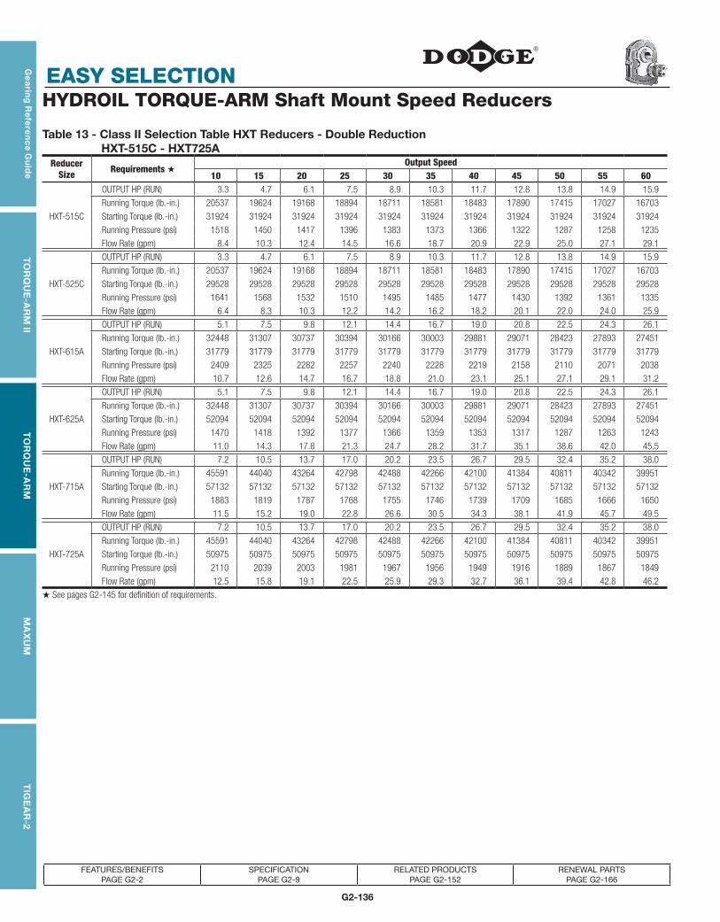
G2-136
EASY SELECTION
Gea
ring
Re
fere
nc
e Gu
ide
TO
RQ
UE
-AR
M II
TO
RQ
UE
-AR
MM
AX
UM
TIG
EA
R-2
FEATURES/BENEFITS PAGE G2-2
SPECIFICATION PAGE G2-9
RELATED PRODUCTS PAGE G2-152
RENEWAL PARTS PAGE G2-166
HYDROIL TORQUE-ARM Shaft Mount Speed Reducers
Table 13 - Class II Selection Table HXT Reducers - Double Reduction HXT-515C - HXT725A
Reducer Size Requirements ★
Output Speed10 15 20 25 30 35 40 45 50 55 60
OUTPUT HP (RUN) 3.3 4.7 6.1 7.5 8.9 10.3 11.7 12.8 13.8 14.9 15.9
Running Torque (lb.-in.) 20537 19624 19168 18894 18711 18581 18483 17890 17415 17027 16703
HXT-515C Starting Torque (lb.-in.) 31924 31924 31924 31924 31924 31924 31924 31924 31924 31924 31924
Running Pressure (psi) 1518 1450 1417 1396 1383 1373 1366 1322 1287 1258 1235
Flow Rate (gpm) 8.4 10.3 12.4 14.5 16.6 18.7 20.9 22.9 25.0 27.1 29.1
OUTPUT HP (RUN) 3.3 4.7 6.1 7.5 8.9 10.3 11.7 12.8 13.8 14.9 15.9
Running Torque (lb.-in.) 20537 19624 19168 18894 18711 18581 18483 17890 17415 17027 16703
HXT-525C Starting Torque (lb.-in.) 29528 29528 29528 29528 29528 29528 29528 29528 29528 29528 29528
Running Pressure (psi) 1641 1568 1532 1510 1495 1485 1477 1430 1392 1361 1335
Flow Rate (gpm) 6.4 8.3 10.3 12.2 14.2 16.2 18.2 20.1 22.0 24.0 25.9
OUTPUT HP (RUN) 5.1 7.5 9.8 12.1 14.4 16.7 19.0 20.8 22.5 24.3 26.1
Running Torque (lb.-in.) 32448 31307 30737 30394 30166 30003 29881 29071 28423 27893 27451
HXT-615A Starting Torque (lb.-in.) 31779 31779 31779 31779 31779 31779 31779 31779 31779 31779 31779
Running Pressure (psi) 2409 2325 2282 2257 2240 2228 2219 2158 2110 2071 2038
Flow Rate (gpm) 10.7 12.6 14.7 16.7 18.8 21.0 23.1 25.1 27.1 29.1 31.2
OUTPUT HP (RUN) 5.1 7.5 9.8 12.1 14.4 16.7 19.0 20.8 22.5 24.3 26.1
Running Torque (lb.-in.) 32448 31307 30737 30394 30166 30003 29881 29071 28423 27893 27451
HXT-625A Starting Torque (lb.-in.) 52094 52094 52094 52094 52094 52094 52094 52094 52094 52094 52094
Running Pressure (psi) 1470 1418 1392 1377 1366 1359 1353 1317 1287 1263 1243
Flow Rate (gpm) 11.0 14.3 17.8 21.3 24.7 28.2 31.7 35.1 38.6 42.0 45.5
OUTPUT HP (RUN) 7.2 10.5 13.7 17.0 20.2 23.5 26.7 29.5 32.4 35.2 38.0
Running Torque (lb.-in.) 45591 44040 43264 42798 42488 42266 42100 41384 40811 40342 39951
HXT-715A Starting Torque (lb.-in.) 57132 57132 57132 57132 57132 57132 57132 57132 57132 57132 57132
Running Pressure (psi) 1883 1819 1787 1768 1755 1746 1739 1709 1685 1666 1650
Flow Rate (gpm) 11.5 15.2 19.0 22.8 26.6 30.5 34.3 38.1 41.9 45.7 49.5
OUTPUT HP (RUN) 7.2 10.5 13.7 17.0 20.2 23.5 26.7 29.5 32.4 35.2 38.0
Running Torque (lb.-in.) 45591 44040 43264 42798 42488 42266 42100 41384 40811 40342 39951
HXT-725A Starting Torque (lb.-in.) 50975 50975 50975 50975 50975 50975 50975 50975 50975 50975 50975
Running Pressure (psi) 2110 2039 2003 1981 1967 1956 1949 1916 1889 1867 1849
Flow Rate (gpm) 12.5 15.8 19.1 22.5 25.9 29.3 32.7 36.1 39.4 42.8 46.2
★ See pages G2-145 for definition of requirements.

G2-137
EASY SELECTION
TOR
QU
E-TA
MER
Bus
hing
sV-
Driv
esFH
PD
rives
Com
pone
nt A
cces
sorie
sT
IGE
AR
-2G
eari
ng
Re
fere
nc
e G
uid
eT
OR
QU
E-A
RM
IIT
OR
QU
E-A
RM
MA
XU
M
FEATURES/BENEFITS PAGE G2-2
SPECIFICATION PAGE G2-9
RELATED PRODUCTS PAGE G2-152
RENEWAL PARTS PAGE G2-166
HYDROIL TORQUE-ARM Shaft Mount Speed Reducers
Table 13 - Class II Selection Table HXT Reducers - Double Reduction HXT-515C - HXT725A
Reducer Size
Output Speed65 70 75 80 85 90 95 100 105 110 115 120 125 130 135 14016.9 18.0 19.0 20.1 21.1 22.2 21.7 21.1 20.5 19.8 19.2 18.6 18.0
16429 16195 15991 15813 15656 15517 14396 13298 12305 11344 10522 9769 9076
HXT-515C 31924 31924 31924 31924 31924 31924 31924 31924 31924 31924 31924 31924 31924
1214 1197 1182 1169 1157 1147 1064 983 909 838 778 722 671
31.2 33.3 35.5 37.6 39.7 41.8 43.8 45.7 47.7 49.6 51.6 53.6 55.6
16.9 18.0 19.0 20.1
16429 16195 15991 15813
HXT-525C 29528 29528 29528 29528
1313 1294 1278 1264
27.9 29.8 31.8 33.8
27.9 29.7 31.5 33.3 35.1 33.7 31.8 29.8 27.8 25.9 23.9 22.0 20.0
27077 26756 26479 26236 26021 23599 21097 18781 16687 14840 13098 11555 10084
HXT-615A 31779 31779 31779 31779 31779 31779 31779 31779 31779 31779 31779 31779 31779
2010 1987 1966 1948 1932 1752 1566 1395 1239 1102 973 858 749
33.2 35.3 37.4 39.5 41.6 43.3 44.9 46.6 48.3 50.1 51.9 53.7 55.6
27.9 29.7 31.5 33.3
27077 26756 26479 26236
HXT-625A 52094 52094 52094 52094
1226 1212 1199 1188
49.0 52.4 55.9 59.4
40.9 43.7 46.5 49.3 49.3 47.2 45.0 43.0 41.0 39.0 37.0 35.0
39620 39337 39091 38876 36555 33053 29854 27101 24610 22345 20278 18382
HXT-715A 57132 57132 57132 57132 57132 57132 57132 57132 57132 57132 57132 57132
1636 1625 1614 1606 1510 1365 1233 1119 1016 923 837 759
53.4 57.2 61.0 64.9 68.5 72.1 75.7 79.3 83.0 86.6 90.3 94.0
40.9 43.7 46.5
39620 39337 39091
HXT-725A 50975 50975 50975
1834 1821 1809
49.6 53.0 56.4

G2-138
EASY SELECTION
Gea
ring
Re
fere
nc
e Gu
ide
TO
RQ
UE
-AR
M II
TO
RQ
UE
-AR
MM
AX
UM
TIG
EA
R-2
FEATURES/BENEFITS PAGE G2-2
SPECIFICATION PAGE G2-9
RELATED PRODUCTS PAGE G2-152
RENEWAL PARTS PAGE G2-166
HYDROIL TORQUE-ARM Shaft Mount Speed Reducers
Table 14 - Class III Selection Table HXT Reducers - Double Reduction HXT-115A - HXT1425B
Reducer Size Requirements ★
Output Speed10 15 20 25 30 35 40 45 50 55 60
OUTPUT HP (RUN) 0.3 0.4 0.6 0.7 0.8 1.0 1.1 1.2 1.3 1.4 1.6
Running Torque (lb.-in.) 2013 1888 1826 1788 1763 1746 1732 1698 1671 1649 1630
HXT-115A Starting Torque (lb.-in.) 4025 4025 4025 4025 4025 4025 4025 4025 4025 4025 4025
Running Pressure (psi) 843 791 764 749 738 731 725 711 700 690 683
Flow Rate (gpm) 1.4 1.7 2.1 2.5 2.8 3.2 3.6 4.0 4.3 4.7 5.1
OUTPUT HP (RUN) 0.3 0.4 0.6 0.7 0.8 1.0 1.1 1.2 1.3 1.4 1.6
Running Torque (lb.-in.) 2013 1888 1826 1788 1763 1746 1732 1698 1671 1649 1630
HXT-125A Starting Torque (lb.-in.) 2868 2868 2868 2868 2868 2868 2868 2868 2868 2868 2868
Running Pressure (psi) 1183 1110 1073 1051 1036 1026 1018 998 982 969 958
Flow Rate (gpm) 1.1 1.4 1.6 1.9 2.1 2.4 2.7 2.9 3.2 3.5 3.7
OUTPUT HP (RUN) 0.6 0.8 1.0 1.3 1.5 1.8 2.0 2.2 2.4 2.6 2.8
Running Torque (lb.-in.) 3623 3412 3306 3243 3201 3171 3148 3085 3035 2994 2959
HXT-215A Starting Torque (lb.-in.) 3697 3697 3697 3697 3697 3697 3697 3697 3697 3697 3697
Running Pressure (psi) 1651 1555 1507 1478 1459 1445 1435 1406 1383 1365 1349
Flow Rate (gpm) 2.0 2.2 2.5 2.9 3.2 3.5 3.9 4.2 4.5 4.9 5.2
OUTPUT HP (RUN) 0.6 0.8 1.0 1.3 1.5 1.8 2.0 2.2 2.4 2.6 2.8
Running Torque (lb.-in.) 3623 3412 3306 3243 3201 3171 3148 3085 3035 2994 2959
HXT-225A Starting Torque (lb.-in.) 6152 6152 6152 6152 6152 6152 6152 6152 6152 6152 6152
Running Pressure (psi) 993 935 906 889 877 869 863 845 832 820 811
Flow Rate (gpm) 1.9 2.5 3.0 3.6 4.2 4.7 5.3 5.9 6.4 7.0 7.6
OUTPUT HP (RUN) 0.9 1.3 1.7 2.1 2.5 3.0 3.4 3.7 4.0 4.4 4.7
Running Torque (lb.-in.) 5549 5447 5396 5365 5345 5330 5319 5189 5086 5001 4930
HXT-315B Starting Torque (lb.-in.) 17190 17190 17190 17190 17190 17190 17190 17190 17190 17190 17190
Running Pressure (psi) 762 748 741 736 734 732 730 712 698 686 677
Flow Rate (gpm) 3.5 4.6 5.8 6.9 8.1 9.2 10.4 11.5 12.6 13.8 14.9
OUTPUT HP (RUN) 0.9 1.3 1.7 2.1 2.5 3.0 3.4 3.7 4.0 4.4 4.7
Running Torque (lb.-in.) 5549 5447 5396 5365 5345 5330 5319 5189 5086 5001 4930
HXT-325B Starting Torque (lb.-in.) 6479 6479 6479 6479 6479 6479 6479 6479 6479 6479 6479
Running Pressure (psi) 1443 1417 1403 1396 1390 1386 1384 1350 1323 1301 1282
Flow Rate (gpm) 2.3 2.9 3.5 4.1 4.7 5.3 6.0 6.5 7.1 7.7 8.3
OUTPUT HP (RUN) 1.3 1.9 2.5 3.1 3.8 4.4 5.0 5.5 6.0 6.6 7.1
Running Torque (lb.-in.) 8338 8114 8002 7935 7891 7859 7835 7712 7613 7533 7466
HXT-415B Starting Torque (lb.-in.) 17479 17479 17479 17479 17479 17479 17479 17479 17479 17479 17479
Running Pressure (psi) 1126 1095 1080 1071 1065 1061 1058 1041 1028 1017 1008
Flow Rate (gpm) 4.1 5.2 6.3 7.5 8.7 9.8 11.0 12.2 13.3 14.5 15.7
OUTPUT HP (RUN) 1.3 1.9 2.5 3.1 3.8 4.4 5.0 5.5 6.0 6.6 7.1
Running Torque (lb.-in.) 8338 8114 8002 7935 7891 7859 7835 7712 7613 7533 7466
HXT-425B Starting Torque (lb.-in.) 28164 28164 28164 28164 28164 28164 28164 28164 28164 28164 28164
Running Pressure (psi) 699 680 670 665 661 658 656 646 638 631 625
Flow Rate (gpm) 4.9 6.7 8.6 10.5 12.4 14.3 16.2 18.1 20.0 21.8 23.7
★ See pages G2-145 for definition of requirements.

G2-139
EASY SELECTION
TOR
QU
E-TA
MER
Bus
hing
sV-
Driv
esFH
PD
rives
Com
pone
nt A
cces
sorie
sT
IGE
AR
-2G
eari
ng
Re
fere
nc
e G
uid
eT
OR
QU
E-A
RM
IIT
OR
QU
E-A
RM
MA
XU
M
FEATURES/BENEFITS PAGE G2-2
SPECIFICATION PAGE G2-9
RELATED PRODUCTS PAGE G2-152
RENEWAL PARTS PAGE G2-166
HYDROIL TORQUE-ARM Shaft Mount Speed Reducers
Table 14 - Class III Selection Table HXT Reducers - Double Reduction HXT-115A - HXT1425B
Reducer Size
Output Speed65 70 75 80 85 90 95 100 105 110 115 120 125 130 135 1401.7 1.8 1.9 2.0 2.1 2.2 2.3 2.4 2.5 2.7 2.8 2.9 3.0 3.1 3.2 3.3
1615 1601 1589 1579 1570 1562 1550 1538 1528 1519 1510 1502 1492 1482 1473 1464
HXT-115A 4025 4025 4025 4025 4025 4025 4025 4025 4025 4025 4025 4025 4025 4025 4025 4025
676 670 666 661 657 654 649 644 640 636 632 629 625 620 617 613
5.5 5.8 6.2 6.6 7.0 7.3 7.7 8.1 8.5 8.9 9.2 9.6 10.0 10.4 10.7 11.1
1.7 1.8 1.9 2.0 2.1
1615 1601 1589 1579 1570
HXT-125A 2868 2868 2868 2868 2868
949 941 934 928 923
4.0 4.3 4.5 4.8 5.1
3.0 3.2 3.4 3.6 3.8 4.0 4.2 4.4 4.6 4.8 5.0 5.2 5.3 5.5 5.7 5.9
2930 2906 2884 2865 2848 2834 2807 2783 2762 2742 2724 2707 2693 2679 2667 2655
HXT-215A 3697 3697 3697 3697 3697 3697 3697 3697 3697 3697 3697 3697 3697 3697 3697 3697
1336 1324 1315 1306 1298 1292 1280 1269 1259 1250 1242 1234 1228 1221 1216 1210
5.6 5.9 6.2 6.6 6.9 7.3 7.6 8.0 8.3 8.6 9.0 9.3 9.7 10.0 10.4 10.7
3.0 3.2 3.4 3.6 3.8
2930 2906 2884 2865 2848
HXT-225A 6152 6152 6152 6152 6152
803 796 790 785 780
8.2 8.7 9.3 9.9 10.5
5.0 5.4 5.7 6.0 6.3 6.7 6.9 7.2 7.4 7.6 7.9 8.1 8.4 8.6 8.8 9.1
4870 4819 4774 4735 4701 4671 4586 4510 4441 4379 4322 4270 4216 4166 4119 4077
HXT-315B 17190 17190 17190 17190 17190 17190 17190 17190 17190 17190 17190 17078 16862 16663 16478 16306
668 661 655 650 645 641 630 619 610 601 593 586 579 572 565 560
16.1 17.2 18.4 19.5 20.7 21.8 23.0 24.1 25.3 26.4 27.6 28.7 29.9 31.0 32.2 33.3
5.0 5.4 5.7 6.0 6.3
4870 4819 4774 4735 4701
HXT-325B 6479 6479 6479 6479 6479
1267 1253 1242 1232 1223
8.9 9.5 10.1 10.7 11.3
7.6 8.2 8.7 9.2 9.8 10.3 10.8 11.2 11.7 12.2 12.6 13.1 13.5 13.8 14.2 14.6
7409 7360 7318 7281 7249 7220 7147 7082 7024 6970 6921 6876 6785 6701 6623 6551
HXT-415B 17479 17479 17479 17479 17479 17479 17479 17479 17479 17479 17479 17479 17479 17479 17479 17479
1000 994 988 983 979 975 965 956 948 941 934 928 916 905 894 884
16.8 18.0 19.2 20.3 21.5 22.7 23.9 25.0 26.2 27.4 28.5 29.7 30.9 32.0 33.2 34.3
7.6 8.2 8.7 9.2 9.8
7409 7360 7318 7281 7249
HXT-425B 28164 28164 28164 28164 28164
621 617 613 610 607
25.6 27.5 29.4 31.3 33.2

G2-140
EASY SELECTION
Gea
ring
Re
fere
nc
e Gu
ide
TO
RQ
UE
-AR
M II
TO
RQ
UE
-AR
MM
AX
UM
TIG
EA
R-2
FEATURES/BENEFITS PAGE G2-2
SPECIFICATION PAGE G2-9
RELATED PRODUCTS PAGE G2-152
RENEWAL PARTS PAGE G2-166
HYDROIL TORQUE-ARM Shaft Mount Speed Reducers
Table 14 - Class III Selection Table HXT Reducers - Double Reduction HXT-515C - HXT725A
Reducer Size Requirements ★
Output Speed10 15 20 25 30 35 40 45 50 55 60
OUTPUT HP (RUN) 2.3 3.3 4.3 5.2 6.2 7.2 8.2 8.9 9.7 10.4 11.1
Running Torque (lb.-in.) 14376 13737 13417 13226 13098 13007 12938 12523 12191 11919 11692
HXT-515C Starting Torque (lb.-in.) 31924 31924 31924 31924 31924 31924 31924 31924 31924 31924 31924
Running Pressure (psi) 1063 1015 992 978 968 961 956 926 901 881 864
Flow Rate (gpm) 7.1 9.2 11.3 13.4 15.5 17.6 19.8 21.9 23.9 26.0 28.2
OUTPUT HP (RUN) 2.3 3.3 4.3 5.2 6.2 7.2 8.2 8.9 9.7 10.4 11.1
Running Torque (lb.-in.) 14376 13737 13417 13226 13098 13007 12938 12523 12191 11919 11692
HXT-525C Starting Torque (lb.-in.) 29528 29528 29528 29528 29528 29528 29528 29528 29528 29528 29528
Running Pressure (psi) 1149 1098 1072 1057 1047 1039 1034 1001 974 952 934
Flow Rate (gpm) 5.7 7.6 9.6 11.5 13.5 15.5 17.5 19.4 21.4 23.3 25.3
OUTPUT HP (RUN) 3.6 5.2 6.8 8.4 10.1 11.7 13.3 14.5 15.8 17 18.3
Running Torque (lb.-in.) 22714 21915 21516 21276 21116 21002 20917 20350 19896 19525 19216
HXT-615A Starting Torque (lb.-in.) 31779 31779 31779 31779 31779 31779 31779 31779 31779 31779 31779
Running Pressure (psi) 1686 1627 1598 1580 1568 1559 1553 1511 1477 1450 1427
Flow Rate (gpm) 8.8 10.8 12.8 14.9 17.1 19.2 21.3 23.3 25.4 27.5 29.5
OUTPUT HP (RUN) 3.6 5.2 6.8 8.4 10.1 11.7 13.3 14.5 15.8 17 18.3
Running Torque (lb.-in.) 22714 21915 21516 21276 21116 21002 20917 20350 19896 19525 19216
HXT-625A Starting Torque (lb.-in.) 52094 52094 52094 52094 52094 52094 52094 52094 52094 52094 52094
Running Pressure (psi) 1029 993 975 964 956 951 947 922 901 884 870
Flow Rate (gpm) 9.8 13.2 16.7 20.1 23.6 27.1 30.6 34.1 37.5 41.0 44.5
OUTPUT HP (RUN) 5.1 7.3 9.6 11.9 14.2 16.4 18.7 20.7 22.7 24.6 26.6
Running Torque (lb.-in.) 31914 30828 30285 29959 29742 29587 29470 28969 28567 28239 27966
HXT-715A Starting Torque (lb.-in.) 57132 57132 57132 57132 57132 57132 57132 57132 57132 57132 57132
Running Pressure (psi) 1318 1273 1251 1237 1228 1222 1217 1196 1180 1166 1155
Flow Rate (gpm) 10.3 14.1 17.9 21.7 25.6 29.4 33.3 37.1 40.9 44.7 48.6
OUTPUT HP (RUN) 5.1 7.3 9.6 11.9 14.2 16.4 18.7 20.7 22.7 24.6 26.6
Running Torque (lb.-in.) 31914 30828 30285 29959 29742 29587 29470 28969 28567 28239 27966
HXT-725A Starting Torque (lb.-in.) 50975 50975 50975 50975 50975 50975 50975 50975 50975 50975 50975
Running Pressure (psi) 1477 1427 1402 1387 1377 1370 1364 1341 1322 1307 1294
Flow Rate (gpm) 10.8 14.1 17.5 20.9 24.3 27.7 31.2 34.5 37.9 41.3 44.7
★ See pages G2-145 for definition of requirements.

G2-141
EASY SELECTION
TOR
QU
E-TA
MER
Bus
hing
sV-
Driv
esFH
PD
rives
Com
pone
nt A
cces
sorie
sT
IGE
AR
-2G
eari
ng
Re
fere
nc
e G
uid
eT
OR
QU
E-A
RM
IIT
OR
QU
E-A
RM
MA
XU
M
FEATURES/BENEFITS PAGE G2-2
SPECIFICATION PAGE G2-9
RELATED PRODUCTS PAGE G2-152
RENEWAL PARTS PAGE G2-166
HYDROIL TORQUE-ARM Shaft Mount Speed Reducers
Table 14 - Class III Selection Table HXT Reducers - Double Reduction HXT-515C - HXT725A
Reducer Size
Output Speed65 70 75 80 85 90 95 100 105 110 115 120 125 130 135 14011.9 12.6 13.3 14.1 14.8 15.5 16.1 16.6 17.2 17.7 18.2 18.6 18
11501 11336 11194 11069 10959 10862 10653 10466 10296 10141 10000 9769 9076
HXT-515C 31924 31924 31924 31924 31924 31924 31924 31924 31924 31924 31924 31924 31924
850 838 827 818 810 803 787 774 761 750 739 722 671
30.3 32.4 34.5 36.6 38.8 40.9 43.0 45.1 47.3 49.4 51.5 53.6 55.6
11.9 12.6 13.3 14.1
11501 11336 11194 11069
HXT-525C 29528 29528 29528 29528
919 906 895 885
27.3 29.2 31.2 33.2
19.5 20.8 22.1 23.3 24.6 25.8 26.6 27.5 27.8 25.9 23.9 22.0 20.0
18954 18729 18535 18365 18215 18081 17680 17318 16687 14840 13098 11555 10084
HXT-615A 31779 31779 31779 31779 31779 31779 31779 31779 31779 31779 31779 31779 31779
1407 1391 1376 1364 1352 1343 1313 1286 1239 1102 973 858 749
31.6 33.7 35.8 37.9 40.1 42.2 44.2 46.3 48.3 50.1 51.9 53.7 55.6
19.5 20.8 22.1 23.3
18954 18729 18535 18365
HXT-625A 52094 52094 52094 52094
858 848 840 832
48.0 51.5 55.0 58.4
28.6 30.6 32.6 34.5 36.5 38.5 40.2 41.9 41.0 39.0 37.0 35.0
27734 27536 27364 27213 27080 26962 26663 26394 24610 22345 20278 18382
HXT-715A 57132 57132 57132 57132 57132 57132 57132 57132 57132 57132 57132 57132
1145 1137 1130 1124 1118 1114 1101 1090 1016 923 837 759
52.4 56.2 60.1 63.9 67.8 71.6 75.4 79.3 83 86.6 90.3 94
28.6 30.6 32.6
27734 27536 27364
HXT-725A 50975 50975 50975
1284 1275 1267
48.1 51.5 55.0

G2-142
EASY SELECTION
Gea
ring
Re
fere
nc
e Gu
ide
TO
RQ
UE
-AR
M II
TO
RQ
UE
-AR
MM
AX
UM
TIG
EA
R-2
FEATURES/BENEFITS PAGE G2-2
SPECIFICATION PAGE G2-9
RELATED PRODUCTS PAGE G2-152
RENEWAL PARTS PAGE G2-166
HYDROIL TORQUE-ARM Shaft Mount Speed Reducers
Table 15 - Class I Selection Table HXT Reducers - Single Reduction HXT-105 - HXT-505A
Reducer Size Requirements ★
Output Speed90 100 110 120 130 140 150 160 180 200 220 250 300 350 400
OUTPUT HP (RUNNING) 3.9 4.2 4.4 4.7 5.0 5.2 5.5 5.7 6.2 6.7 6.9 7.1 7.6 7.9 8.3
Running Torque (lb.-in.) 2758 2641 2546 2467 2400 2342 2293 2249 2176 2118 1973 1799 1586 1424 1303
HXT-105 Starting Torque (lb.-in.) 5515 5283 5093 4934 4800 4685 4585 4498 4353 4237 3946 3598 3172 2848 2605
Running Pressure (psi) 982 940 907 878 854 834 816 801 775 754 702 640 565 507 464
Flow Rate (gpm) 9.4 10.2 11.0 11.8 12.7 13.5 14.4 15.2 16.9 18.7 20.3 22.9 27.1 31.4 35.7
OUTPUT HP (RUNNING) 6.8 7.1 7.4 7.7 8.0 8.3 8.6 8.9 9.5 10.1 10.5 11.1 12.0 12.9 13.8
Running Torque (lb.-in.) 4759 4475 4243 4049 3886 3745 3624 3517 3340 3198 3014 2793 2523 2322 2171
HXT-205 Starting Torque (lb.-in.) 6238 6238 6238 6238 6238 6238 6238 6238 6238 6238 6028 5586 5046 4644 4342
Running Pressure (psi) 1800 1693 1605 1532 1470 1417 1371 1330 1263 1210 1140 1056 954 878 821
Flow Rate (gpm) 10.1 10.8 11.5 12.2 12.9 13.7 14.4 15.2 16.7 18.3 19.9 22.2 26.2 30.2 34.2
OUTPUT HP (RUNNING) 10.1 10.7 11.3 12.0 12.6 13.2 13.8 14.4 15.7 16.9 17.6 17.7 16.8 15.9 15.0
Running Torque (lb.-in.) 7074 6758 6499 6284 6102 5946 5810 5692 5495 5337 5056 4462 3529 2863 2363
HXT-305A Starting Torque (lb.-in.) 11851 11851 11851 11851 11851 11851 11621 11384 10989 10673 10112 9438 8614 7705 7024
Running Pressure (psi) 1408 1346 1294 1251 1215 1184 1157 1133 1094 1063 1007 888 703 570 471
Flow Rate (gpm) 17.9 19.3 20.7 22.1 23.6 25.1 26.6 28.1 31.1 34.2 37.1 41.5 48.9 56.3 63.9
OUTPUT HP (RUNNING) 17.7 18.5 19.3 20.1 20.9 21.7 22.5 23.3 24.5 23.8 23.1 22.1 20.4 18.7 17.0
Running Torque (lb.-in.) 12387 11655 11056 10557 10135 9773 9459 9185 8578 7500 6618 5571 4286 3367 2679
HXT-405A Starting Torque (lb.-in.) 11956 11956 11956 11956 11956 11956 11956 11956 11956 11956 11956 11956 11956 11956 11956
Running Pressure (psi) 2445 2300 2182 2083 2000 1929 1867 1813 1693 1480 1306 1099 846 665 529
Flow Rate (gpm) 20.8 21.9 23.2 24.5 25.9 27.3 28.7 30.1 33.0 35.6 38.3 42.4 49.7 57.1 64.6
OUTPUT HP (RUNNING) 21.9 23.1 24.3 25.5 26.7 27.9 29.1 30.4 31.3 30.1 28.9 27.1 24.1 21.0 18.0
Running Torque (lb.-in.) 15321 14552 13923 13398 12954 12574 12244 11955 10959 9485 8279 6832 5063 3782 2836
HXT-505A Starting Torque (lb.-in.) 21713 21713 21713 21713 21713 21713 21713 21713 21713 21713 21529 20748 19794 18659 17808
Running Pressure (psi) 1665 1581 1513 1456 1408 1366 1331 1299 1191 1031 900 742 550 411 308
Flow Rate (gpm) 29.2 31.9 34.6 37.3 40.1 42.9 45.7 48.5 54.0 59.5 64.9 73.2 87.20 101.3 115.4
★ See pages G2-145 for definition of requirements.

G2-143
EASY SELECTION
TOR
QU
E-TA
MER
Bus
hing
sV-
Driv
esFH
PD
rives
Com
pone
nt A
cces
sorie
sT
IGE
AR
-2G
eari
ng
Re
fere
nc
e G
uid
eT
OR
QU
E-A
RM
IIT
OR
QU
E-A
RM
MA
XU
M
FEATURES/BENEFITS PAGE G2-2
SPECIFICATION PAGE G2-9
RELATED PRODUCTS PAGE G2-152
RENEWAL PARTS PAGE G2-166
Table 16 - Class II Selection Table HXT Reducers - Single Reduction HXT-105 - HXT-505A
Reducer Size Requirements ★
Output Speed90 100 110 120 130 140 150 160 180 200 220 250 300 350 400
OUTPUT HP (RUNNING) 2.8 3.0 3.2 3.4 3.5 3.7 3.9 4.1 4.4 4.8 4.9 5.1 5.4 5.6 5.9
Running Torque 1970 1887 1819 1762 1714 1673 1638 1606 1555 1513 1409 1285 1133 1017 930
HXT-105 Starting Torque 5515 5283 5093 4934 4800 4685 4585 4498 4353 4237 3946 3598 3172 2848 2605
Running Pressure 701 672 648 627 610 596 583 572 553 539 502 457 403 362 331
Flow Rate, GPM 8.9 9.8 10.6 11.5 12.3 13.2 14.0 14.9 16.6 18.3 20.0 22.6 26.9 31.2 35.5
OUTPUT HP (RUNNING) 4.9 5.1 5.3 5.5 5.7 5.9 6.2 6.4 6.8 7.2 7.5 7.9 8.6 9.2 9.8
Running Torque 3399 3197 3031 2892 2775 2675 2588 2512 2386 2284 2153 1995 1802 1659 1551
HXT-205 Starting Torque 6238 6238 6238 6238 6238 6238 6238 6238 6238 6238 6028 5586 5046 4644 4342
Running Pressure 1286 1209 1146 1094 1050 1012 979 950 902 864 814 755 682 627 587
Flow Rate, GPM 9.4 10.1 10.8 11.5 12.3 13.1 13.8 14.6 16.2 17.8 19.4 21.7 25.8 29.8 33.9
OUTPUT HP (RUNNING) 7.2 7.7 8.1 8.5 9.0 9.4 9.9 10.3 11.2 12.1 12.6 13.4 14.6 15.3 15.0
Running Torque 5053 4827 4642 4489 4358 4247 4150 4066 3925 3812 3611 3371 3076 2752 2363
HXT-305A Starting Torque 11851 11851 11851 11851 11851 11851 11621 11384 10989 10673 10112 9438 8614 7705 7024
Running Pressure 1006 961 924 894 868 846 826 810 781 759 719 671 613 548 471
Flow Rate, GPM 16.8 18.2 19.7 21.2 22.7 24.2 25.7 27.2 30.3 33.4 36.4 40.9 48.6 56.3 63.9
OUTPUT HP (RUNNING) 12.6 13.2 13.8 14.4 14.9 15.5 16.1 16.7 17.8 19.0 20.2 22.0 20.4 18.7 17.0
Running Torque 8848 8325 7897 7541 7239 6981 6757 6561 6234 5973 5776 5541 4286 3367 2679
HXT-405A Starting Torque 11956 11956 11956 11956 11956 11956 11956 11956 11956 11956 11956 11956 11956 11956 11956
Running Pressure 1746 1643 1559 1488 1429 1378 1333 1295 1230 1179 1140 1093 846 665 529
Flow Rate, GPM 18.9 20.2 21.5 22.9 24.4 25.8 27.3 28.7 31.7 34.8 37.8 42.4 49.7 57.1 64.6
HXT-505A
OUTPUT HP (RUNNING) 15.6 16.5 17.4 18.2 19.1 20.0 20.8 21.7 23.4 25.1 26.8 27.1 24.1 21.0 18.0
Running Torque 10944 10394 9945 9570 9253 8981 8746 8540 8196 7921 7689 6832 5063 3782 2836
Starting Torque 21713 21713 21713 21713 21713 21713 21713 21713 21713 21713 21529 20748 19794 18659 17808
Running Pressure 1189 1130 1081 1040 1006 976 950 928 891 861 836 742 550 411 308
Flow Rate, GPM 28.2 31.0 33.7 36.5 39.3 42.1 44.9 47.8 53.4 59.1 64.8 73.2 87.2 101.3 115.4
★ See pages G2-145 for definition of requirements.
HYDROIL TORQUE-ARM Shaft Mount Speed Reducers

G2-144
EASY SELECTION
Gea
ring
Re
fere
nc
e Gu
ide
TO
RQ
UE
-AR
M II
TO
RQ
UE
-AR
MM
AX
UM
TIG
EA
R-2
FEATURES/BENEFITS PAGE G2-2
SPECIFICATION PAGE G2-9
RELATED PRODUCTS PAGE G2-152
RENEWAL PARTS PAGE G2-166
HYDROIL TORQUE-ARM Shaft Mount Speed Reducers
Table 17 - Class III Selection Table HXT Reducers - Single Reduction HXT-105 - HXT-505A
Reducer Size Requirements ★
Output Speed90 100 110 120 130 140 150 160 180 200 220 250 300 350 400
OUTPUT HP (RUNNING) 2.0 2.1 2.2 2.3 2.5 2.6 2.7 2.9 3.1 3.4 3.4 3.6 3.8 4.0 4.1
Running Torque (lb.-in.) 1379 1321 1273 1234 1200 1171 1146 1125 1088 1059 987 899 793 712 651
HXT-105 Starting Torque (lb.-in.) 5515 5283 5093 4934 4800 4685 4585 4498 4353 4237 3946 3598 3172 2848 2605
Running Pressure (psi) 491 470 453 439 427 417 408 400 387 377 351 320 282 254 232
Flow Rate (gpm) 8.6 9.5 10.3 11.2 12.0 12.9 13.8 14.6 16.4 18.1 19.8 22.4 26.7 31.0 35.4
OUTPUT HP (RUNNING) 3.4 3.6 3.7 3.9 4.0 4.2 4.3 4.5 4.8 5.1 5.3 5.5 6.0 6.4 6.9
Running Torque (lb.-in.) 2380 2238 2121 2025 1943 1873 1812 1759 1670 1599 1507 1397 1262 1161 1086
HXT-205 Starting Torque (lb.-in.) 6238 6238 6238 6238 6238 6238 6238 6238 6238 6238 6028 5586 5046 4644 4342
Running Pressure (psi) 900 846 802 766 735 708 685 665 632 605 570 528 477 439 411
Flow Rate (gpm) 8.8 9.5 10.3 11.0 11.8 12.6 13.4 14.2 15.8 17.4 19.0 21.4 25.5 29.5 33.6
OUTPUT HP (RUNNING) 5.1 5.4 5.7 6.0 6.3 6.6 6.9 7.2 7.8 8.5 8.8 9.4 10.3 10.7 11.1
Running Torque (lb.-in.) 3537 3379 3250 3142 3051 2973 2905 2846 2747 2668 2528 2359 2153 1926 1756
HXT-305A Starting Torque (lb.-in.) 11851 11851 11851 11851 11851 11851 11621 11384 10989 10673 10112 9438 8614 7705 7024
Running Pressure (psi) 704 673 647 626 607 592 578 567 547 531 503 470 429 384 350
Flow Rate (gpm) 16.0 17.5 19.0 20.5 22.0 23.5 25.0 26.6 29.7 32.7 35.8 40.4 48.1 55.8 63.6
OUTPUT HP (RUNNING) 8.8 9.2 9.6 10.1 10.5 10.9 11.3 11.7 12.5 13.3 14.1 15.4 17.5 18.7 17.0
Running Torque (lb.-in.) 6194 5828 5528 5279 5068 4887 4730 4592 4364 4181 4043 3879 3677 3367 2679
HXT-405A Starting Torque (lb.-in.) 11956 11956 11956 11956 11956 11956 11956 11956 11956 11956 11956 11956 11956 11956 11956
Running Pressure (psi) 1222 1150 1091 1042 1000 964 933 906 861 825 798 765 726 665 529
Flow Rate (gpm) 17.5 18.9 20.3 21.7 23.2 24.7 26.2 27.7 30.7 33.8 36.9 41.5 49.3 57.1 64.6
OUTPUT HP (RUNNING) 10.9 11.5 12.1 12.8 13.4 14.0 14.6 15.2 16.4 17.6 18.8 20.6 23.6 21.0 18.0
Running Torque (lb.-in.) 7661 7276 6961 6699 6477 6287 6122 5978 5737 5545 5382 5187 4948 3782 2836
HXT-505A Starting Torque (lb.-in.) 21713 21713 21713 21713 21713 21713 21713 21713 21713 21713 21529 20748 19794 18659 17808
Running Pressure (psi) 832 791 756 728 704 683 665 650 623 603 585 564 538 411 308
Flow Rate (gpm) 27.5 30.3 33.1 35.9 38.7 41.5 44.4 47.2 52.9 58.6 64.3 72.9 87.2 101.3 115.4
★ See pages G2-145 for definition of requirements.

G2-145
EASY SELECTION
TOR
QU
E-TA
MER
Bus
hing
sV-
Driv
esFH
PD
rives
Com
pone
nt A
cces
sorie
sT
IGE
AR
-2G
eari
ng
Re
fere
nc
e G
uid
eT
OR
QU
E-A
RM
IIT
OR
QU
E-A
RM
MA
XU
M
FEATURES/BENEFITS PAGE G2-2
SPECIFICATION PAGE G2-9
RELATED PRODUCTS PAGE G2-152
RENEWAL PARTS PAGE G2-166
HYDROIL TORQUE-ARM Shaft Mount Speed Reducers
★ Requirements:
Output HP - Horsepower rating of the reducer/motor under continuous operation after load has been started.
Running Torque - Continuous output torque rating of reducer/motor (lb.-in.)
Starting Torque - Momentary output torque available for starting (lb.-in.)
Running Pressure - Motor pressure required to generate running torque. This will start loads not to exceed 75% of the run ning load. For greater starting requirements, motor pressure may be increased-see table 18. (psi)
Flow Rate - Flow required for given output RPM (gpm). With oil viscosity of 300SUS @ 100ºF. for A10 and A20 motors, and 200SUS @ 100ºF. for B30, B40 and B50 motors.
Table 18 - Maximum Hydraulic Motor Pressures Available For StartingDouble Single Maximum Hydraulic
Reduction Reduction Pressure--- HXT105
--- HXT205
HXT315B HXT305A
HXT415B, 425B HXT405A 2500 psi
HXT515C, 525C HXT505A
HXT615A, 625A ---
HXT715A, 725A ---
HXT115A, 125A ---
HXT215A, 225A --- 2000 psi
HXT325B ---

G2-146
SELECTION/DIMENSIONS
Gea
ring
Re
fere
nc
e Gu
ide
TO
RQ
UE
-AR
M II
TO
RQ
UE
-AR
MM
AX
UM
TIG
EA
R-2
FEATURES/BENEFITS PAGE G2-2
SPECIFICATION PAGE G2-9
RELATED PRODUCTS PAGE G2-152
RENEWAL PARTS PAGE G2-166
HYDROIL TORQUE-ARM Shaft Mount Speed ReducersHXT1 Thru HXT7 Taper Bushed Reducers
●
◆
◆ Recommended minimum distance to loosen bushing using bushing screws as jack screws.
Reducer will operate satisfactorily at 90° or 180° from normal position shown in front view by relocating breather and drain plugs.
● The ideal position for the TORQUE-ARM is at right angles to a line between the point of attachment of the TORQUE-ARM to the reducer and the output shaft. This may vary up to ± 20° in tension and ± 20° in compression.
CAUTION: Exceeding the position variance of the TORQUE- ARM could result in excessive reaction load and result in damage to the equipment.
HXT1A Thru HXT7A HYDROIL Double Reduction Taper Bushed TORQUE-ARM Speed Reducers
Reducer Size AGMA Code Gear Ratio Part NumberWt.
HYDROIL Motor A
BMax. Bore
♥
C D E F G J K15:1 25:1 15:1 25:1 15:1 25:1 15:1 25:1 Size Wt.
. . . . . HXT125A . . . . . 107H25 . . . . . 25.64 . . . . . 241070 ♣49
A1011 7.06 1.44 13.22 1.25 3.25 4.47 2.41 1.28 3.53
HXT115A . . . . . 107H15 . . . . . 15.35 . . . . . 241069 ♣ . . . . . A20
HXT215A HXT225A 115H15 115H25 14.10 23.46 242086 ♣ 242087 ♣ 65 A20 11 7.31 1.94 13.38 1.25 4.06 4.69 2.41 1.38 3.66
. . . . . HXT325B . . . . . 205H25 . . . . . 24.71 . . . . . 243508112
A20 119.22 2.19
14.641.50 4.38
4.88 2.411.58 4.44
HXT315B . . . . . 203H15 . . . . . 14.88 . . . . . 243507 . . . . . B30 30 15.45 5.75 2.38
HXT415B HXT425B 207H15 207H25 15.13 24.38 244532 244533 ♣ 143 B30 30 10 2.44 16.13 1.75 4.81 6.19 2.38 1.81 4.75
. . . . . HXT525C . . . . . 215H25 . . . . . 25.56 245557 245558212
B30 3010.5 2.94
16.881.81 5.63
6.50 2.381.94 5.50
HXT515C . . . . . 215H15 . . . . . 15.40 . . . . . . . . . . B40 55 17.63 7.25 3.06
HXT615A HXT625A 307H15 307H25 15.33 25.13 246154 ♣ 246155 ♣ 293 B40 55 11.5 3.44 18.58 1.81 6.13 8.28 3.06 1.94 5.70
. . . . . HXT725A . . . . . 315H25 . . . . . 24.59 . . . . . 247165 ♣470
B40 5512.81 3.94
19.162.06 7.25
9.30 3.062.16 6.34
HXT715A . . . . . 315H15 . . . . . 15.23 . . . . . 247164 ♣ . . . . . B50 106 22.75 9.30 3.69
Reducer Size L R
Bolt ST
U V W X Z CC GG HHMin. Max.
HXT1A 1.06 0.38 2.50 23.81 29.63 7.13 3.75 3.19 9.94 1.91 4.50 2.66 0.94
HXT2A 1.25 0.44 3.00 26.94 32.94 8.38 4.13 3.75 11.41 2.13 4.56 2.94 1.06
HXT3B 1.25 0.44 3.00 26.94 32.94 9.25 4.81 4.19 12.88 2.31 6.38 3.25 1.06
HXT4B 1.44 0.50 4.00 29.19 35.19 10.38 5.50 4.78 15.13 2.75 6.88 3.38 1.75
HXT5C 1.44 0.50 4.00 29.19 35.19 13.13 6.56 5.69 18.31 3.06 7.06 4.50 1.75
HXT6A 2.75 0.63 4.75 29.19 35.19 15.13 7.56 6.75 21.31 4.09 7.63 4.56 2.00
HXT7A 2.75 0.63 4.75 29.44 35.44 18.75 9.38 8.31 25.94 5.13 8.13 4.69 2.00
Note: All reducers on this page require bushings. Stock HXT reducers are drilled for vertical mounting. Reducer includes motor adapter.
♥See pages G2-30 thru G2-57 for bore and keyseat information and bushing part numbers.
♣ Made to order.

G2-147
SELECTION/DIMENSIONS
TOR
QU
E-TA
MER
Bus
hing
sV-
Driv
esFH
PD
rives
Com
pone
nt A
cces
sorie
sT
IGE
AR
-2G
eari
ng
Re
fere
nc
e G
uid
eT
OR
QU
E-A
RM
IIT
OR
QU
E-A
RM
MA
XU
M
FEATURES/BENEFITS PAGE G2-2
SPECIFICATION PAGE G2-9
RELATED PRODUCTS PAGE G2-152
RENEWAL PARTS PAGE G2-166
HYDROIL TORQUE-ARM Shaft Mount Speed ReducersHXT105 Thru HXT505 Taper Bushed Reducers
●
◆
Reducer will operate satisfactorily at 90° or 180° from nor mal position shown in front view by relocating breather and drain plugs.◆ Recommended minimum distance to loosen
bushing using bushing screws as jack screws.
● The ideal position for the TORQUE-ARM is at right angles to a line between the point of attachment of the TORQUE-ARM to the reducer and the output shaft. This may vary up to ± 20° in tension and ± 20° in compression.
CAUTION: Exceeding the position variance of the TORQUE-ARM could result in excessive reaction load and result in damage to the equipment.
HXT105 Thru HXT505A HYDROL Single Reduction Taper Bushed TORQUE-ARM Speed Reducers
ReducerSize
AGMACode
GearRatio
PartNumber
ReducerWt.
HYDROIL Motor
A
BMax. Bore
♥
C D E G J K LSize Wt.
HXT105 107H05 5.62 241085 44 B30 30 5.63 1.44 14.97 1.25 3.25 2.38 1.28 3.53 1.06HXT205 115H05 5.29 242251 56 B30 30 5.81 1.94 15.25 1.25 4.06 2.38 1.38 3.66 1.25
HXT305A 203H05 5.60 253153 ♣ 90 B40 55 6.88 2.19 17.66 1.5 4.38 3.06 1.58 4.44 1.25HXT405A 207H05 5.65 254202 ♣ 126 B40 55 7.81 2.44 18.69 1.75 4.81 3.06 1.81 4.75 1.44HXT505A 215H05 5.67 255202 ♣ 186 B50 106 8.38 2.94 22 1.81 5.63 3.69 1.92 4.13 1.44
HXT105 Thru HXT505A HYDROL Single Reduction Taper Bushed TORQUE-ARM Speed ReducersReducer
SizeR
Bolt ST
U V W X CC GG HHMin. Max.
HXT105 0.38 2.50 23.81 29.63 7.13 3.75 3.25 9.94 4.50 2.64 0.94
HXT205 0.44 3.00 26.94 32.94 8.50 4.13 3.88 11.41 4.56 2.83 1.06
HXT305A 0.44 3.00 26.94 32.94 9.25 4.81 4.28 12.88 6.38 3.25 1.06
HXT405A 0.50 4.00 29.19 35.19 10.38 5.50 4.88 15.13 6.88 3.38 1.75
HXT505A 0.50 4.00 29.19 35.19 13.13 6.56 5.88 18.31 7.06 4.50 1.75
Note: All reducers on this page require bushings. Stock HXT reducers are drilled for vertical mounting. Reducer includes motor adapter.
♥ See pages G2-30 thru G2-57 for bore and keyseat information and bushing part numbers.
♣ Made to order.

G2-148
SELECTION/DIMENSIONS
Gea
ring
Re
fere
nc
e Gu
ide
TO
RQ
UE
-AR
M II
TO
RQ
UE
-AR
MM
AX
UM
TIG
EA
R-2
FEATURES/BENEFITS PAGE G2-2
SPECIFICATION PAGE G2-9
RELATED PRODUCTS PAGE G2-152
RENEWAL PARTS PAGE G2-166
HYDROIL TORQUE-ARM Shaft Mount Speed ReducersHXT1 Thru HXT7 Straight Bore Reducers
●
◆
Reducer will operate satisfactorily at 90° or 180° from nor mal position shown in front view by relocating breather and drain plugs.
● The ideal position for the TORQUE-ARM is at right angles to a line between the point of attachment of the TORQUE-ARM to the reducer and the output shaft. This may vary up to ± 20° in tension and ± 20° in compression. CAUTION: Exceeding the position variance of the TORQUE-ARM could result in excessive reaction load and result in damage to the equipment.
HXT1A Thru HXT7A HYDROIL Double Reduction Straight Bore TORQUE-ARM Speed Reducers ♣
Reducer Size AGMA Code Gear Ratio Part NumberWt.
HYDROIL Motor A
BMax. Bore
♥
C E F G J K L15:1 25:1 15:1 25:1 15:1 25:1 15:1 25:1 Size Wt.
. . . . . HXT125A . . . . . 107H25 . . . . . 25.64 . . . . 24107849
A1011 5.63 1.44 12.50 3.19 4.47 2.41 0.56 2.81 1.06
HXT115A . . . . . 107H15 . . . . . 15.35 . . . . . 241077 . . . . A20
HXT215A HXT225A 115H15 115H25 14.10 23.46 242094 242095 65 A20 11 5.81 1.94 12.63 3.56 4.69 2.41 0.63 2.91 1.25
. . . . . HXT325B . . . . . 203H25 . . . . . 24.71 . . . . 243520112
A20 117.81 2.19
13.694.00
4.88 2.410.63 2.47 1.25
HXT315B . . . . . 203H15 . . . . . 14.88 . . . . . 243519 . . . . B30 30 14.50 5.75 2.38
HXT415B HXT425B 207H15 207H25 15.13 24.38 244544 244545 143 B30 30 8.22 2.44 15.16 4.38 6.19 2.38 0.84 3.88 1.44
. . . . . HXT525C . . . . . 215H25 . . . . . 25.56 . . . . 245570212
B30 308.66 2.94
15.94 5.13
6.50 2.381.00 4.13 1.44
HXT515C . . . . . 215H15 . . . . . 15.40 . . . . . 245569 . . . . B40 55 16.69 7.25 3.06
HXT615A HXT625A 307H15 307H25 15.33 25.13 246162 246163 293 B40 55 9.63 3.44 17.69 5.63 8.28 3.06 1.00 4.81 2.75
. . . . . HXT725A . . . . . 315H25 . . . . . 24.59 . . . . 247173470
B40 5510.78 3.94
18.196.69
9.31 3.061.14 5.39 2.75
HXT715A . . . . . 315H15 . . . . . 15.23 . . . . . 247172 . . . . B50 106 21.50 8.38 3.69
Reducer Size
RBolt S
TU V W X Z CC GG HH
Min. Max.HXT1A 0.38 2.50 23.81 29.63 7.13 3.75 3.19 9.94 1.91 4.50 2.66 0.94
HXT2A 0.44 3.00 26.94 32.94 8.38 4.13 3.75 11.41 2.13 4.56 2.94 1.06
HXT3B 0.44 3.00 26.94 32.94 9.25 4.81 4.19 12.88 2.31 6.38 3.25 1.06
HXT4B 0.50 4.00 29.19 35.19 10.38 5.50 4.78 15.13 2.75 6.88 3.38 1.75
HXT5C 0.50 4.00 29.19 35.19 13.13 6.56 5.69 18.31 3.06 7.06 4.50 1.75
HXT6A 0.63 4.75 29.19 35.19 15.13 7.50 6.75 21.31 4.09 7.63 4.56 2.00
HXT7A 0.63 4.75 29.44 35.44 18.75 9.38 8.31 25.94 5.13 8.50 4.69 2.00
Note: Except for maximum bore, all reducers on this page require bushings. Stock HXT Reducers are drilled for vertical mounting. Reducer includes motor adapter.
♥ See pages G2-30 thru G2-57 for bore and keyseat information and bushing part numbers.
♣ Made to order.

G2-149
SELECTION/DIMENSIONS
TOR
QU
E-TA
MER
Bus
hing
sV-
Driv
esFH
PD
rives
Com
pone
nt A
cces
sorie
sT
IGE
AR
-2G
eari
ng
Re
fere
nc
e G
uid
eT
OR
QU
E-A
RM
IIT
OR
QU
E-A
RM
MA
XU
M
FEATURES/BENEFITS PAGE G2-2
SPECIFICATION PAGE G2-9
RELATED PRODUCTS PAGE G2-152
RENEWAL PARTS PAGE G2-166
HYDROIL TORQUE-ARM Shaft Mount Speed ReducersHXT105 Thru HXT505A Straight Bore Reducers
●
◆
HXT105 Thru HXT505A HYDROIL Single Reduction Straight Bore TORQUE-ARM Speed Reducers
ReducerSize
AGMACode
GearRatio
Part Number
Reducer Wt.
HYDROIL Motor
A
BMax. Bore
♥
C D E G J KSize Wt.
HXT105 107H05 5.62 241089 ♣ 44 B30 30 5.63 1.44 14.25 3.19 2.38 0.56 2.81 1.06
HXT205 115H05 5.29 242255 56 B30 30 5.81 1.94 14.5 3.56 2.38 0.63 2.91 1.25
HXT305A 203H05 5.60 253157 90 B40 55 7.41 2.19 16.69 4 3.06 0.63 4.44 1.25
HXT405A 207H05 5.65 254206 ♣ 126 B40 55 8.22 2.44 17.72 4.38 3.06 0.84 4.75 1.44
HXT505A 215H05 5.67 255206 ♣ 186 B50 106 8.66 2.94 21.06 5.13 3.69 1 4.13 1.44
ReducerSize
RBolt S
TU V W X CC GG HH
Min. Max.HXT105 0.38 2.5 23.81 29.63 7.13 3.75 3.25 9.94 4.5 2.64 0.94
HXT205 0.44 3 26.94 32.94 8.5 4.13 3.88 11.41 4.56 2.83 1.06
HXT305A 0.44 3 26.94 32.94 9.25 4.81 4.29 12.88 6.38 3.25 1.06
HXT405A 0.5 4 29.19 35.19 10.38 5.5 4.88 15.13 6.88 3.38 1.75
HXT505A 0.5 4 29.19 35.19 13.13 6.56 5.88 18.31 7.06 4.15 1.75
Note: Except for maximum bore, all reducers on this page require bushings. Stock HXT Reducers are drilled for vertical mounting. Reducer includes motor adapter.
♥See pages G2-30 thru G2-57 for bore and keyseat information and bushing part numbers.
♣ Made to order.
Reducer will operate satisfactorily at 90° or 180° from nor mal position shown in front view by relocating breather and drain plugs.
● The ideal position for the TORQUE-ARM is at right angles to a line between the point of attachment of the TORQUE-ARM to the reducer and the output shaft. This may vary up to ± 20° in tension and ± 20° in compression. CAUTION: Exceeding the position variance of the TORQUE-ARM could result in excessive reaction load and result in damage to the equipment.

G2-150
SELECTION/DIMENSIONS
Gea
ring
Re
fere
nc
e Gu
ide
TO
RQ
UE
-AR
M II
TO
RQ
UE
-AR
MM
AX
UM
TIG
EA
R-2
FEATURES/BENEFITS PAGE G2-2
SPECIFICATION PAGE G2-9
RELATED PRODUCTS PAGE G2-152
RENEWAL PARTS PAGE G2-166
HYDROIL TORQUE-ARM Shaft Mount Speed Reducers
HSCT1A Thru HSCXT7A Double Reduction HYDROIL Screw Conveyor Drives †
ReducerSize
DriveShaftDia.
To FitScrew
Dia.
HYDROILMotor
Parts When Ordering SeparatelyReducer ■ CEMA Drive Shaft ★ Adapter
Size Wt.Part Number
Wt. Size Part No. Wt. C D EAssy. ▲
15:1 25:1 Size Part No. Wt.
HSCXT115A1-1/2 6, 9
A20
11 351191 351192
46 C1 x 1-1/2 351094 7.2 6.00 0.52 2.13
C1A 351086 172 9, 12
46
C1 x 2 351095 9.1 6.00 0.64 2.13
HSCXT125A2-7/16 12, 14
A10C1 x 2-7/16 351096 12.5 6.69 0.64 2.75
3 12 thru 20 C1 x 3 351097 17.4 6.88 0.77 2.88
HSCXT215A1-1/2 6, 9
A20 11 352191 352192
58 C2 x 1-1/2 352090 11.4 6.00 0.52 2.13
C2A 352052 202 9, 12
58
C2 x 2 352091 13.8 6.00 0.64 2.13
HSCXT225A2-7/16 12, 14 C2 x 2-7/16 352092 17.3 6.69 0.64 2.75
3 12 thru 20 C2 x 3 352093 22.1 6.88 0.77 2.88
HSCXT315B1-1/2 9
B30 11
243528 243529 90
C3A x 1-1/2 243562 13.5 6.00 0.52 2.13
C3 353047 272 9, 12 C3A x 2 243563 16 6.00 0.64 2.13
HSCXT325B2-7/16 12, 14
A20 30C3A x 2-7/16 243564 19.5 6.69 0.64 2.75
3 12 thru 20 C3A x 3 243565 26 6.88 0.77 2.88
HSCXT415B
1-1/2 9
B30 30 244553 244554 113
C4A x 1-1/2 244594 19 6.00 0.52 2.13
C4 354121 31
2 9, 12 C4A x 2 244595 20.8 6.00 0.64 2.13
2-7/16 12, 14 C4A x 2-7/16 244596 24.3 6.69 0.64 2.75
HSCXT425B3 12 thru 20 C4A x 3 244597 29.2 6.88 0.77 2.88
3-7/16 18 thru 24 C4A x 3-7/16 244598 29.3 9.13 0.89 3.88
HSCXT515C2 9, 12
B40 30
245578 245579 165
C5B x 2 355175 29.4 6.00 0.64 2.13
C5 355072 432-7/16 12, 14 C5B x 2-7/16 355176 33 6.69 0.64 2.75
HSCXT525C3 12 thru 20
B30 55C5B x 3 355177 37.9 6.88 0.77 2.88
3-7/16 18 thru 24 C5B x 3-7/16 355178 48.3 9.13 0.89 3.88
HSCXT615A2-7/16 12, 14
B40 55 356291 356292 225
C6 x 2-7/16 356042 47.7 6.69 0.64 2.75
C6 356055 563 12 thru 20 C6 x 3 356043 52.7 6.88 0.77 2.88
HSCXT625A 3-7/16 18 thru 24 C6 x 3-7/16 356044 63 9.13 0.89 3.88
HSCXT715A2-7/16 12, 14
B50 55356296 356297 390
C7 x 2-7/16 356182 65 6.69 0.64 2.75
C7 356187 723 12 thru 20 C7 x 3 356183 70 6.88 0.77 2.88
HSCXT725A 3-7/16 18 thru 24 B40 106 C7 x 3-7/16 356184 80.3 9.13 0.89 3.88

G2-151
SELECTION/DIMENSIONS
TOR
QU
E-TA
MER
Bus
hing
sV-
Driv
esFH
PD
rives
Com
pone
nt A
cces
sorie
sT
IGE
AR
-2G
eari
ng
Re
fere
nc
e G
uid
eT
OR
QU
E-A
RM
IIT
OR
QU
E-A
RM
MA
XU
M
FEATURES/BENEFITS PAGE G2-2
SPECIFICATION PAGE G2-9
RELATED PRODUCTS PAGE G2-152
RENEWAL PARTS PAGE G2-166
HYDROIL TORQUE-ARM Shaft Mount Speed ReducersHSCXT1A Thru HSCXT7A Double Reduction HYDROIL Screw Conveyor Drives †
Reducer Size
Actual Ratio Max. RPM of ShaftA G H K L U V W X Y Z
15:1 25:1Input Driven
15:1 25:1 15:1 25:1
HSCXT1A15.35 . . . . 2149 . . . . 140 . . .
15.34 4.47 3.22 7.44 7.00 7.13 3.75 3.38 9.94 9.34 1.91. . . . 25.64 . . . . 2179 . . . 85
HSCXT2A 14.97 24.92 2096 2118 140 85 15.94 4.69 3.56 7.44 7.00 8.38 4.09 3.77 11.41 10.27 2.14
HSCXT3B15.26 . . . . 2136 . . . . 140 . . . 17.81 5.75
3.69 7.44 11.38 9.25 4.84 4.17 13.7211.39
2.33. . . . 25.34 . . . . 2155 . . . 85 17.00 4.88 11.42
HSCXT4B 15.30 24.64 2142 2094 140 85 18.44 6.19 4.00 7.38 11.38 10.38 5.50 4.78 15.31 12.66 2.75
HSCXT5C15.38 . . . . 1919 . . . . 125 . . . 20.56 7.25
4.259.19
11.38 13.13 6.56 5.67 18.3114.30
3.05. . . . 25.54 . . . . 2043 . . . 80 19.81 6.50 7.75 14.61
HSCXT6A 15.33 25.13 1895 1985 125 80 21.81 8.28 5.50 9.31 11.38 15.13 7.56 6.73 21.31 17.36 4.09
HSCXT7A15.23 . . . . 1767 . . . . 116 . . . 26.28 8.38
6.3110.56
11.38 18.75 9.38 8.30 25.9422.11
5.11. . . . 24.59 . . . . 1844 . . . 75 23.00 9.31 8.81 20.36
† For a complete HSCXT drive, order a reducer, drive shaft and adapter assembly by their respective part numbers. Drive is shipped unassembled.
■ Reducer includes hydroil motor adapter.
★ CEMA drive shaft and key furnished unless otherwise specified. See pages G2-123 thru G2-125 for optional drive shafts available from DODGE.
▲ Includes adapter, necessary mounting bolts, seal retainer and lip type seals. See page G2-122 for adapter bolt pattern details.

G2-152
SELECTION/DIMENSIONS
Gea
ring
Re
fere
nc
e Gu
ide
TO
RQ
UE
-AR
M II
TO
RQ
UE
-AR
MM
AX
UM
TIG
EA
R-2
FEATURES/BENEFITS PAGE G2-2
SPECIFICATION PAGE G2-9
RELATED PRODUCTS PAGE G2-152
RENEWAL PARTS PAGE G2-166
HYDROIL TORQUE-ARM Shaft Mount Speed Reducers
ReducerSize
Actual Ratio
Max. RPM of ShaftA H K L U V W X Y
Input DrivenHSCXT105 5.62 2246 400 16.28 3.22 8.38 7.00 7.13 3.75 3.27 9.94 9.39
HSCXT205 5.62 2246 400 16.50 3.56 8.50 7.00 8.38 4.09 3.86 11.41 10.33
HSCXT305A 5.31 2124 400 20.00 3.69 10.31 11.38 9.25 4.84 4.28 13.72 12.19
HSCXT405A 5.27 2108 400 21.00 4.00 10.63 11.38 10.38 5.50 4.88 15.94 16.50
HSCXT505A 5.69 2275 400 22.00 4.25 11.72 11.38 13.00 6.56 5.86 18.31 16.86
† For a complete HSCXT drive, order a reducer, drive shaft and adapter assembly by their respective part numbers. Drive is shipped unassembled.
■ Reducer includes hydroil motor adapter.
♣ Made to order.
▲ Includes adapter, necessary mounting bolts, seal retainer and lip type seals. ★ CEMA drive shaft and key furnished unless otherwise specified. See pages G2-123 thru G2-125 for optional drive shafts available from DODGE.
HSCXT105 Thru HSCXT505A Single Reduction HYDROIL Screw Conveyor Drives †
Reducer Size
DriveShaftDia.
To FitScrew
Dia
HYDROILMotor
Parts When Ordering Separately
Reducer ■ ♣ CEMA Drive Shaft ★AdapterAssy. ▲
Size Wt. Part No. Wt. Size Part No. Wt. C D E Size Part No. Wt.
HSCXT105
1-1/2 6, 9
B30 30 351190
41 C1 x 1-1/2 351094 7.2 6.00 0.52 2.13
C1A 351086 172 9, 12
41
C1 x 2 351095 9.1 6.00 0.64 2.13
2-7/16 12, 14 C1 x 2-7/16 351096 12.5 6.69 0.64 2.75
3 12 thru 20 C1 x 3 351097 14.4 6.88 0.77 2.88
HSCXT205
1-1/2 6, 9
B30 30 352190
53 C2 x 1-1/2 352090 11.4 6.00 0.52 2.13
C2A 352052 202 9, 12
53
C2 x 2 352091 13.8 6.00 0.64 2.13
2-7/16 12, 14 C2 x 2-7/16 352092 17.3 6.69 0.64 2.75
3 12 thru 20 C2 x 3 352093 22.1 6.88 0.77 2.88
HSCXT305A
1-1/2 9
B40 55 253160 79
C3A x 1-1/2 243562 13.5 6.00 0.52 2.13
C3 353047 272 9, 12 C3A x 2 243563 16.0 6.00 0.64 2.13
2-7/16 12, 14 C3A x 2-7/16 243564 19.5 6.69 0.64 2.75
3 12 thru 20 C3A x 3 243565 26.0 6.88 0.77 2.88
HSCXT405A
1-1/2 9
B40 55 254209 101
C4A x 1-1/2 244594 19.0 6.00 0.52 2.13
C4 354121 31
2 9, 12 C4A x 2 244595 20.8 6.00 0.64 2.13
2-7/16 12, 14 C4A x 2-7/16 244596 24.3 6.69 0.64 2.75
3 12 thru 20 C4A x 3 244597 29.2 6.88 0.77 2.88
3-7/16 18 thru 24 C4A x 3-7/16 244598 39.3 9.13 0.89 3.88
HSCXT505A
2 9, 12
B50 106 255209 160
C5B x 2 355175 29.4 6.00 0.64 2.13
C5 355072 432-7/16 12, 14 C5B x 2-7/16 355176 33.0 6.69 0.64 2.75
3 12 thru 20 C5B x 3 355177 37.9 6.88 0.77 2.88
3-7/16 18 thru 24 C5B x 3-7/16 355178 48.3 9.13 0.89 3.88

G2-153
SELECTION/DIMENSIONS
TOR
QU
E-TA
MER
Bus
hing
sV-
Driv
esFH
PD
rives
Com
pone
nt A
cces
sorie
sT
IGE
AR
-2G
eari
ng
Re
fere
nc
e G
uid
eT
OR
QU
E-A
RM
IIT
OR
QU
E-A
RM
MA
XU
M
FEATURES/BENEFITS PAGE G2-2
SPECIFICATION PAGE G2-9
RELATED PRODUCTS PAGE G2-152
RENEWAL PARTS PAGE G2-166
HYDROIL TORQUE-ARM Shaft Mount Speed Reducers HYDROIL Van Motors
HYDROIL Vane Motors-are superior single stage vane type fluid motor. A series of internal ports admit oil to and carry it from the power element. Complete hydraulic balance of the assembly contributes to the mechanical efficiency and long life of these motors as well as to their unusually quiet oper-ation. Other exclusive features assure a minimum of friction and efficient valving action regardless of operating speeds.
HYDROIL Vane Motors can be run in either direction of rotation. Flow into port A (see drawing) will result in clock wise rotation as viewed from shaft end of motor. Flow into port B will result in counterclockwise rotation.
Inlet and outlet ports on sizes A10 and A20 will accommo date standard tapered pipe fittings. Larger sizes will accommodate SAE split flanges.
Drains should be connected to tank with connections and hoses capable of withstanding 50 psi. No drain is required on sizes A10 and A20 if the housing port is the low pressure port and is never subjected to more than 20 psi, in which case the motor drains internally.
B40 (Port A and Port B, 1’ 1/4” dia.)
HYDROIL Vane Motors for HXT ReducersMotor Size Part Number Wt. (lbs)
A10 444049 11
A20 444050 11
B30 444054 30
B40 444055 55
B50 444056 106
NOTE: HXT1A thru HXT7A reducers are available in selected ratios to accommodate H, S and T-Series 6B spline, SAE “A” 2-bolt motors. See Related Products section for information on the HXT6B spline reducers.
B50 (Port A & Port B, 2” dia.)
A10 & A20 B30 (Port A & Port B, 1” dia.)

G2-154
RELATED PRODUCTS
Gea
ring
Re
fere
nc
e Gu
ide
TO
RQ
UE
-AR
M II
TO
RQ
UE
-AR
MM
AX
UM
TIG
EA
R-2
FEATURES/BENEFITS PAGE G2-2
SPECIFICATION PAGE G2-9
MODIFICATION/ACCESSORIES PAGE G2-120
RENEWAL PARTS PAGE G2-166
HYDROIL TORQUE-ARM Shaft Mount Speed Reducers CHAR-LYNN* Compatible 6B Spline Reducer
Maximum Input and Driven Speeds for HXT-6B Reducers
ReducerSize
Double Reduction Single ReductionInput RPM Driven RPM
Reducer Size InputRPM Driven
15 25 9 15 25HXT3 6B - 2100 200 140 85 HXT105 6B 2246 400
HXT4 6B 2118 2072 200 140 85 HXT205 6B 2116 400
HXT5 6B - 2044 200 125 80 HXT305 6B 2240 400
HXT6 6B - 2010 200 125 80 HXT405 6B 2280 400
HXT7 6B - 1844 200 125 75 HXT505 6B 2287 400
TORQUE-ARM Hydraulic Taper Bushed Speed Reducers
Reducer Size Part Number Exact Ratios Max. BoreHXT105T C/L 6B 251140 5.62 1.44
HXT205T C/L 6B 252140 5.29 1.94
HXT305AT C/L 6B 253140 5.60 2.19
HXT405AT C/L 6B 254140 5.65 2.44
HXT505AT C/L 6B 255160 5.67 2.94
HXT325BT CL 6B 243571 24.71 2.19
HXT415BT C/L 6B 244556 15.13 2.44
HXT425BT C/L 6B 244557 24.38 2.44
HXT525CT C/L 6B 245640 25.56 2.94
HXT625AT C/L 6B 246520 25.13 3.44
HXT725AT C/L 6B 247520 24.59 3.94
New hydraulically powered DODGE TORQUE-ARM Twin Taper bushed speed reducers with 6B spline, SAE “A” 2-bolt motor flange. Suitable for Char-Lynn H, S, T and 2000 series motors or equal. This is a modified version of the HXT TORQUE-ARM speed reducer Twin Tapered Mounting
Material Cost Savings
Installed Cost Savings
Simple Installation
No Periodic Maintenance Cost Associated with Chain Drives
Eliminate V-Drives
Compact Drive Design
Infinitely Adjustable Speeds/Torque
- Driven machinery can be inched/jogged
- Direction of rotation can be reversed
- Low speed, high torque capability
Shock Resistant Helical Gearing
Reduced Motor Costs
Optimized Pressure, Ratio and Flow
No Motor Drain
SpecificationsReducer will be modified on the input section to facilitate the mounting of a basic Char-Lynn hydraulic motor or equivalent. This modification allows the mounting of H, S and T series motors which must be equipped with a two-bolt SAE “A” flange (3.25 pilot diameter) and a 6B splined shaft (other comparably equipped motor brands will also work).Reducer installation shall be accomplished by using ductile iron, fully split Twin Tapered bushings. Reducer removal shall be accomplished by providing jack screw holes in the bushing flanges to mechanically remove the tapered assembly.
*Char-Lynn is a registered trademark of EATON
Motor Mounting Dimensions

G2-155
RELATED PRODUCTS
TOR
QU
E-TA
MER
Bus
hing
sV-
Driv
esFH
PD
rives
Com
pone
nt A
cces
sorie
sT
IGE
AR
-2G
eari
ng
Re
fere
nc
e G
uid
eT
OR
QU
E-A
RM
IIT
OR
QU
E-A
RM
MA
XU
M
FEATURES/BENEFITS PAGE G2-2
SPECIFICATION PAGE G2-9
MODIFICATION/ACCESSORIES PAGE G2-120
RENEWAL PARTS PAGE G2-166
HYDROIL TORQUE-ARM Shaft Mount Speed ReducersClass I - Refer to pages G2-16 thru G2-18 - to determine appropriate drive service factor for your specific application and duty cycle. Refer to tables below for reducer Class I ratings.
Class II - Refer to pages G2-16 thru G2-18 to determine appropriate drive service factor for your specific application and duty cycle. To obtain Class II reducer ratings, divide Class I ratings from the tables below by 1.4.
Class III - Refer to pages G2-16 thru G2-18 to determine appropriate drive service factor for your specific application and duty cycle. To obtain Class III reducer ratings, divide Class I ratings from the tables below by 2.0.
Continuous Input Horsepower - Class I*Output RPM
Reducer SizeHXT105 C/L HXT205 C/L HXT305A C/L HXT405A C/L HXT505A C/L HXT325B C/L HXT415B C/L HXT425B C/L HXT525C C/L HXT625A C/L HXT725A C/L
1 0.06 0.11 0.16 0.22 0.33 0.17 0.26 0.26 0.44 0.69 1.005 0.26 0.52 0.72 1.01 1.55 0.84 1.29 1.29 2.18 3.46 4.9810 0.50 0.99 1.41 1.96 3.04 1.68 2.52 2.52 4.35 6.89 9.6620 0.98 1.95 2.45 3.88 6.05 3.30 4.98 4.98 8.38 13.37 18.6830 1.47 2090 4.14 5.78 8.74 4.90 7.33 7.33 12.2440 1.95 3.85 5.51 7.64 11.13 9.5250 2.43 4.81 6.88 9.55 13.51 11.5760 2.70 5.34 7.92 11.0770 2.95 5.86 8.97 12.4680 3.22 6.38 10.01 13.8590 3.48 6.92 11.06 15.29100 3.75 7.44 12.10 16.83110 3.77 7.48 12.53120 3.98 7.92 13.46130 4.21 8.37 14.41140 4.42 8.81150 4.66 9.27160 4.87 9.71
* INPUT HP-HP rating of reducer at input shaft under continuous operation after load has been started
Continuous Output Torque - Class I**Output RPM
Reducer SizeHXT105 C/L HXT205 C/L HXT305A C/L HXT405A C/L HXT505A C/L HXT325B C/L HXT415B C/L HXT425B C/L HXT525C C/L HXT625A C/L HXT725A C/L
1 3470 6980 9580 13500 20100 10400 16000 16000 27000 42700 616005 3200 6380 8950 12500 19200 10400 16000 16000 27000 42700 6160010 3100 6140 8700 12100 18800 10400 15600 15600 26900 42600 5970020 3040 6020 8580 12000 18700 10200 15400 15400 25900 41300 5770030 3020 5980 8530 11900 18000 10100 15100 15100 2520040 3010 5950 8510 11800 17200 1470050 3000 5940 8500 11800 16700 1430060 2780 5500 8160 1140070 2600 5170 7920 1100080 2490 4930 7730 1070090 2390 4750 7590 10500100 2320 4600 7480 10400110 2120 4200 7040120 2050 4080 6930130 2000 3980 6850140 1950 2890150 1920 3820160 1880 3750
** OUTPUT TORQUE - Continuous output torque rating of reducer (in-lbs)PEAK HP - Momentarily, peak horsepower may be very high. For example, in applications with high inertia loads, oversize or high torque motors, etc. Where this momentary peak exceeds 200% of normal (100% overload) the equivalent HP may be obtained by dividing the peak HP by two. If the results exceed the horsepower obtained from a consideration of service and duty, it should be used to select the reducer size. NOTE: Below 15 RPM output speed, oil level must be adjusted to reach highest oil level plug (P).

G2-156
RELATED PRODUCTS
Gea
ring
Re
fere
nc
e Gu
ide
TO
RQ
UE
-AR
M II
TO
RQ
UE
-AR
MM
AX
UM
TIG
EA
R-2
FEATURES/BENEFITS PAGE G2-2
SPECIFICATION PAGE G2-9
MODIFICATION/ACCESSORIES PAGE G2-120
RENEWAL PARTS PAGE G2-166
TORQUE-ARM Shaft Mount Speed Reducers
HARSH DUTY ACCESSORIESXT CORROSION RESISTANCE
Zinc Plated FastenersIncludes all housing and TORQUE-ARM rod fasteners. Factory assembled.
TDNC Coated Tapered Busings (Thin Dense Nickel Chrome)TDNC coating on bushing, backup plate and snap rings provide maximum corrosion resistance. Zinc plated fasteners included. Consult Dodge for price and delivery.
CEMA Stainless Steel Drive Shafts for Screw Conveyor Drives#316 stainless steel, three hole construction now available on short cycle delivery. Consult DODGE for delivery.
XT Hostile Environments
Filter BreatherOptional 40 micron filter with cap. Combats dust, dirt and wet environments. Replaces standard breather assembly. Stock item.
Enclosed Breather ChamberElastic diaphragm enclosed in steel chamber provides closed system. Protects reducer components and lubricant in wet, dusty or hot environments. Install in new reducer installations only. Mounts in uppermost position and replaces standard breather. Stock item.
Oil Sump Heater110 volt, single phase, AC cartridge heater, threads into standard tapped drain hole. Provides approximately 70 ° F tem perature rise in one hour for cold climates. Simple time phased on/off construction. Standard oil sump heater does not come with thermostat. Factory cycle item.
CEMA AC Packing Adaptor KitFor tough, abrasive environments. Protects reducer from contamination. Multiple braided felt seal rings. Repack without removal. Stock item.
Long Term StoragePreparation for long storage or delayed job start-up. Reducer is protected internally with a vapor phase corrosion inhibit ing oil. Breather removed and reducer sealed with pipe plug. See page G2-181 for details.
FilterBreather
EnclosedChamberBreather
OilSump Heater

G2-157
RELATED PRODUCTS
TOR
QU
E-TA
MER
Bus
hing
sV-
Driv
esFH
PD
rives
Com
pone
nt A
cces
sorie
sT
IGE
AR
-2G
eari
ng
Re
fere
nc
e G
uid
eT
OR
QU
E-A
RM
IIT
OR
QU
E-A
RM
MA
XU
M
FEATURES/BENEFITS PAGE G2-2
SPECIFICATION PAGE G2-9
MODIFICATION/ACCESSORIES PAGE G2-120
RENEWAL PARTS PAGE G2-166
TORQUE-ARM Shaft Mount Speed Reducers Harsh Duty Accessories
ABRASION*
2% (wear) 12% (wear)
98%88%
XT NITRILE
* Run in accordance with ASTM D-3389
TORQUE-ARM Shaft Mount Speed ReducersHARSH DUTY ACCESSORIES
XT SAFETY & SEALING
Metal End Covers, Open, Closed and Split
Protection for oil seal areas and from rotating components. Enhances seal life.
Closed or open for input shaft side. Two piece split for backstop side.
Simply position on reducer, drill holes and insert self tapping screws. Stock item.
Extended life high temperature and abrasion resistant XT harsh duty oil seals (TXT 5B-10A double reduction.) Stocked individually or installed to order.Optional feature.
The addition of lithium sterate aluminate to the XT harsh duty seal compound acts as a friction-reducing, antiwear additive resulting in extended service life. XT harsh duty seals provide 4 to 6 times the abrasion resistance of standard nitrile seals, resulting in lower seal life and less unscheduled downtime. As oil tempera ture increases, seal life may be reduced. With standard nitrile seals, the increase in temperature from 200 ° F to 225 ° F can reduce seal life up to 50% as the seal lip gets brittle and cracks. XT harsh duty seals will handle up to 350 ° F (176 ° C), a 40% increase in temperature capability over standard nitrile seals. Note: Contact DODGE if oil sump temperature exceeds 200 degrees F maximum with petroleum lubricants.
Belt Guards, BackstopsRugged slotted metal construction with welded straps. No drilling required to install. Includes mounting hardware and bolts to reducer and motor mount. Backstops prevent reversing and allow for either direction of operation. Stock items.
Input Auxiliary SealMetal cover with internal V-Seal/Labyrinth construction. Complete with lubrica tion filling or no-lub plug. Combats dust, dirt and moisture. Protects high speed oil seal. Stock item.
TEMPERATURE
350-F
250-F
XT NITRILE

G2-158
RELATED PRODUCTS
Gea
ring
Re
fere
nc
e Gu
ide
TO
RQ
UE
-AR
M II
TO
RQ
UE
-AR
MM
AX
UM
TIG
EA
R-2
FEATURES/BENEFITS PAGE G2-2
SPECIFICATION PAGE G2-9
MODIFICATION/ACCESSORIES PAGE G2-120
RENEWAL PARTS PAGE G2-166
TORQUE-ARM Shaft Mount Speed Reducers Harsh Duty Accessories XT Lubrication
● Oil level sight gauge. Stock item● New DODGE/AGMA/ISO viscosity standards● New higher viscosity lubricant selections● Brand options
Maximizing productivity and uptime is paramount in today’s industry. By following some simple recommendations on lubri cation, OEMs and users can improve product performance and reduce downtime. Remember, the purpose of speed reducer lubrication is to minimize frictional forces, eliminate wear and dissipate heat.
The American Gear Manufacturing Association (AGMA) and ISO have changed their lubrication standards.
This change was necessitated by the increased horsepower that helical gearing is asked to transmit. As a result, higher ISO viscosity grades have been selected. The proper oil viscosity is based upon ambient temperature and gearing pitch line velocity. DODGE has converted pitch line velocity into reducer output speed (RPM).
Recommended Lubricants For TORQUE-ARM Reducers +
For further lubrication information, refer to DODGE TORQUE-ARM Lubrication Manual # 499336 or individual product manuals.
Brand With Or Without Backstop EP Oils Without BackstopsEXXON150 Teresstic 150 Spartan EP 150
220 220 220
320 320 320
CHEVRON150 Machine 150 Gear Compound 150
220 220 EP 220
320 320 320
UNICAL
150 Turbine Oil 150 Extra Duty HL 141
220 220 Gear Lube 207
320 320 300
MOBIL SYNTHETIC150 SHC 629 SHC 629
220 SHC 630 SHC 630
320 SHC 632 SHC 632
MOBIL150 Mobil DTE BB Mobil Gear 629
220 Extra Heavy AA 630
320 632
TEXACO150 Regal Oil R&O 150 Meropa 150
220 220 220
320 320 320
SHELL150 Morlina 52B 150 Omala S2G 150
220 220 220
320 320 320
+ Partial list. Consult DODGE or a lubricant manufacturer for further options

G2-159
RELATED PRODUCTS
TOR
QU
E-TA
MER
Bus
hing
sV-
Driv
esFH
PD
rives
Com
pone
nt A
cces
sorie
sT
IGE
AR
-2G
eari
ng
Re
fere
nc
e G
uid
eT
OR
QU
E-A
RM
IIT
OR
QU
E-A
RM
MA
XU
M
FEATURES/BENEFITS PAGE G2-2
SPECIFICATION PAGE G2-9
MODIFICATION/ACCESSORIES PAGE G2-120
RENEWAL PARTS PAGE G2-166
TORQUE-ARM Shaft Mount Speed Reducers Harsh Duty & Sensorized Accessories
Product Part # Product Part #TXT Encl Breather Sys. Sm (1-10) 240050 TXT405A Taconite Aux Seal Kit 254267TXT Encl Breather Sys. Lg. (12-15) 240051 TXT4A,4B Taconite Aux Seal Kit 244676TXT 5D Harsh Duty Input Seal 245543 TXT505A Taconite Aux Seal Kit 255230TXT 6D, 7D, 705 XT Duty Input Seal 246543 TXT5B,5C Taconite Aux Seal Kit 245635TXT8-10D, 805, 905, XT Duty I/P Seal 248443 TXT6 Taconite Aux Seal 272450TXT 5D Harsh Duty Output Seal 245444 TXT7 Taconite Aux Seal Kit 272451TXT 6D Harsh Duty Output Seal 246444 TXT8 Taconite Aux Seal Kit 272452TXT 7D Harsh Duty Output Seal 247444 TXT9 Taconite Aux Seal Kit 272453TXT 8D Harsh Duty Output Seal 248444 TXT10 Taconite Aux Seal Kit 272454TXT 9D Harsh Duty Output Seal 249444 TXT12 Taconite Aux Seal Kit 272455TXT 10D Harsh Duty Output Seal 250444 TDT13 Taconite Aux Seal Kit 2724563/8 Filter Breather Plug 430048 TDT14 Taconite Aux Seal Kit 2724571/2 Filter Breather Plug 430049 TDT15 Taconite Aux Seal Kit 272458Pressure Breather Vent Plug * 6-030657 3/8 Sight Oil Level Gauge (TXT1-4) * 430120TXT 1-4 Immersion Heater 241103 1/2 Sight Oil Level Gauge (TXT5-6) * 430121TXT 5-6 Immersion Heater 241104 3/4 Sight Oil Level Gauge (TXT7-TDT15) * 430159TXT 7-10 Immersion Heater 241105 C1x1-1/2 3H SS Drive Shaft 351025TXT1 SS Cls Aux Cvr Asy 246601 C1x2 3H SS Drive Shaft 351026TXT1 SS Opn Aux Cvr Asy 246602 C2x1-1/2 3H SS Drive Shaft 352186TXT1 BS Split Aux Cvr Asy 246603 C2x2 3H SS Drive Shaft 352187TXT2 SS Cls Aux Cvr Asy 246604 C3Ax2 3H SS Drive Shaft 353181TXT2 SS Opn Aux Cvr Asy 246605 C3Ax2-7/16 3H SS Drive Shaft 353182TXT2 BS Split Aux Cvr Asy 246606 C4Ax2 3H SS Drive Shaft 354352TXT3 SS Cls Aux Cvr Asy 246607 C4Ax2-7/16 3H SS Drive Shaft 354353TXT3 SS Opn Aux Cvr Asy 246608 C4Ax3 3H SS Drive Shaft 354354TXT3 BS Split Aux Cvr Asy 246609 C5Bx2-7/16 3H SS Drive Shaft 355226TXT4 SS Cls Aux Cvr Asy 246610 C5Bx3 3H SS Drive Shaft 355227TXT4 SS Opn Aux Asy 246611 C6x3 3H SS Drive Shaft 356276TXT4 BS Split Aux Cvr Asy 246612 C7x3-7/16 3H SS Drive Shaft 356283TXT5 SS Cls Aux Cvr Asy 246616 AC1 Adjustable Packing Kit 356301TXT5 SS Opn Aux Cvr Asy 246617 AC2 Adjustable Packing Kit 356302TXT5 SS BS Split Aux Cvr Asy 246618 AC3 Adjustable Packing Kit 356303TXT6 SS Cls Aux Cvr Asy 246619 AC4 Adjustable Packing Kit 356304TXT6 SS Opn Aux Cvr Asy 246620 AC5 Adjustable Packing Kit 356305TXT6 BS Split Aux Cvr Asy 246621 AC6/AC7 Adjustable Packing Kit 356306TXT7 SS Cls Aux Cvr Asy 246622 SCXT1 Taconite Aux Seal Kit 272721TXT7 SS Opn Aux Cvr Asy 246623 SCXT2 Taconite Aux Seal Kit 272722TXT7 BS Split Aux Cvr Asy 246624 SCXT3A,3BTaconite Aux Seal Kit 243582TXT8 SS Cls Aux Cvr Asy 246625 SCXT4A,4B Taconite Aux Seal Kit 244677TXT8 SS Opn Aux Cvr Asy 246625 SCXT5B,5C Taconite Aux Seal Kit 245637TXT8 BS Split Aux Cvr Asy 246627 SCXT505A Taconite Aux Seal Kit 255148TXT9 SS Cls Aux Cvr Asy 246628 SCXT6 Taconite Aux Seal Kit 272726TXT9 SS Opn Aux Cvr Asy 246629 SCXT7 Taconite Aux Seal Kit 272727TXT9 SS Split Aux Cvr Asy 246630 TXT/SCXT1 Input Taconite Seal 241102TXT10 SS Cls Aux Cvr Asy 246631 TXT/SCXT2 Input Taconite Seal 242102TXT10 SS Opn Aux Cvr Asy 246632 TXT/SCXT3A,3B Input Tac. Seal 243108TXT10 SS Split Aux Cvr Asy 246633 TXT/SCXT4A,4B Input Tac. Seal 244117TXT12 SS Cls Aux Cvr Asy 246634 TXT/SCXT5B,5C Input Tac. Seal 245104TXT12 SS Opn Aux Cvr Asy 246635 TXT/SCXT6, 605 Input Tac. Seal 246102TXT12 SS Split Aux Cvr Asy 246635 TXT/SCXT7, 705 Input Tac. Seal 247102TXT105 BS SPL Aux Cvr Asy 246613 TXT8, 805 Input Taconite Seal 248102TXT205 BS SPL Aux Cvr Asy 246614 TXT9, 905 Input Taconite Seal 249102TXT305 BS SPL Aux Cvr Asy 246615 TXT10 Input Taconite Seal 250102TXT1 Taconite Aux Seal Kit 272515 TXT12 Input Taconite Seal 242102TXT105 Taconite Aux Seal Kit 272521 TXT/SCXT105 Input Taconite Seal 241109TXT2 Taconite Aux Seal Kit 272446 TXT/SCXT205 Input Taconite Seal 242109TXT205 Taconite Aux Seal kit 272459 TXT/SCXT305A Input Tac. Seal 243109TXT305A Taconite Aux Seal Kit 253186 TXT/SCXT405A Input Tac. Seal 244159TXT3A,3B Taconite Aux Seal Kit 243577 TXT/SCXT505A Input Tac. Seal 245106
* Available as Renewal Parts

G2-160
RELATED PRODUCTS
Gea
ring
Re
fere
nc
e Gu
ide
TO
RQ
UE
-AR
M II
TO
RQ
UE
-AR
MM
AX
UM
TIG
EA
R-2
FEATURES/BENEFITS PAGE G2-2
SPECIFICATION PAGE G2-9
MODIFICATION/ACCESSORIES PAGE G2-120
RENEWAL PARTS PAGE G2-166
TORQUE-ARM Shaft Mount Speed Reducers TXT-ABHS Airport Baggage Handling System Reducer For ConveyorsWith 60 years of proven dependability and more than 2.0 million units in service throughout the world, DODGE TORQUE-ARM speed reducers are the standard of the industry.
SHAFT MOUNT CONCEPT
Twin-Tapered Mounting to the Driven Shaft
Material Cost Savings● Eliminates support structures
● Eliminates chain, sprocket or coupling
Installed Cost Savings● No installation and alignment of chains or coupling
● Simple installation and motor alignment
Compact Flexible Drive Design● Space Savings
● Reducer mounts 360° around the shaft
Flexibility to Change Output Speed● Ease of changing V-belt drives
● Economical to change speeds
● Ability to fine tune speeds at a later date
Efficiency
● 98.5% per gear stage
Hollow Bore● Exclusive Twin-Tapered bushings
● Wide range of bore sizes
Performance● Oversized input bearings and shaft for extended duty hours and
service
● New premium material oil seals for continuous duty operation
● 100% factory tested and shipped with mobil DTE-BB premium lubrication
● Zinc plated torque arm rods for corrosion resistance
● Thousands of units in operation
● Maintenance Free
● Ease of repair, fewer spares, high parts availability
● Designed with years of industry analysis and research
Interchanges with Standard DODGE TXT Dimensions and Ratios 36/12 Warranty Meets or Exceeds AGMA Standards

G2-161
RELATED PRODUCTS
TOR
QU
E-TA
MER
Bus
hing
sV-
Driv
esFH
PD
rives
Com
pone
nt A
cces
sorie
sT
IGE
AR
-2G
eari
ng
Re
fere
nc
e G
uid
eT
OR
QU
E-A
RM
IIT
OR
QU
E-A
RM
MA
XU
M
FEATURES/BENEFITS PAGE G2-2
SPECIFICATION PAGE G2-9
MODIFICATION/ACCESSORIES PAGE G2-120
RENEWAL PARTS PAGE G2-166
TORQUE-ARM Shaft Mount Speed Reducers TXT-ABHS Reducers For Airport Baggage Handling System Conveyors
TXT-ABHS Reducers
Size Part Number
TXT 125T ABHS Reducer ▲ 241153+TXT 115T ABHS Reducer ▲ 241155+TXT 109T ABHS Reducer ▲ 241154+TXT 105T ABHS Reducer ▲ 251120TXT 225T ABHS Reducer ▲ 242258TXT 215T ABHS Reducer ▲ 242257TXT 209T ABHS Reducer ▲ 242259TXT 205T ABHS Reducer ▲ 252120TXT 325T ABHS Reducer 243251TXT 315T ABHS Reducer 243252TXT 309T ABHS Reducer 243253TXT 305T ABHS Reducer 253199TXT 425T ABHS Reducer 244251TXT 415T ABHS Reducer 244252TXT 409T ABHS Reducer 244253TXT 405T ABHS Reducer 254199TXT 525T ABHS Reducer 245251TXT 515T ABHS Reducer 245252TXT 509T ABHS Reducer 245253TXT 505T ABHS Reducer 255199TXT 1 ABHS TA Assembly ★ 241213TXT 2 ABHS TA Assembly ★ 242280TXT 3 ABHS TA Assembly ★ 243254TXT 4 ABHS TA Assembly ★ 244254TXT 5 ABHS TA Assembly ★ 245254
+15/16” diameter input shaft.
▲ Backstops not available.
★ TORQUE-ARM assembly does not come with the TXT ABHS Reducer. It must be ordered separately by the above part number
DODGE TORQUE-ARM Speed Reducer. The speed reducer shall be either a belt driven or direct coupled enclosed shaft mount type unit with a single or double reduction ratio. The reducer shall mount directly on the driven shaft and utilize an adjustable TORQUE-ARM that attaches from the gear case to the support structure or foundation.
The reducer housing shall be constructed of two-piece corrosion resistant, gray or ductile iron. All housings shall be doweled and precision machined.
All gearing shall be helical design and crown shaved. All gears shall be case carburized to ensure a high surface durability with a resilient tooth core for greater impact resistance and longer service life. Gears shall be supported between bearings to maintain proper alignment of gear meshes.
Reducer bearings shall be ball or tapered roller type. All seals are premium material for continuous duty operation. Dual seals and V-ring seal on input.
Reducer gears and bearings shall be splash lubricated using a premium lubricant.
Reducer installation shall be accomplished by using ductile iron, fully split Twin Tapered bushings.
Reducer removal shall be accomplished by providing jack screw holes in the busing flanges to mechanically remove the tapered assembly
Taper Bushing Assemblies
Stock Bore Reducer Size Part Number
1-7/16(Max.)
TXT1ABHS
TDT1
2412921-3/8 2412941-5/16 ▲ 2412901-1/4 ▲ 2412881-3/16 ▲ 2412861-1/8 ▲ 2412821-1/16 ▲ 2412801 ▲ 2412781-15/16(Max.)
TXT2ABHS
TDT2
2421681-3/4 2421661-11/16 2421641-5/8 ▲ 2421621-1/2 ▲ 2421581-7/16 ▲ 2421561-3/8 ▲ 2421541-5/16 2421521-1/4 ▲ 2421501-3/16 ▲ 2421481-1/8 ▲ 2421462-3/16(Max.)
TXT3ABHS
TDT3
2432762 2432741-15/16 2432721-7/8 ▲ 2432701-3/4 ▲ 2432661-11/16 ▲ 2432681-5/6 ▲ 2432641-1/2 ▲ 2432621-7/16 ▲ 2432601-3/6 ▲ 2432841-5/16 ▲ 2432822-7/16(Max.)
TXT4ABHS
TDT4
2441152-1/4 ▲ 2441132-3/16 ▲ 2441112-1/8 ▲ 2441092 ▲ 2440951-15/16 ▲ 2440931-3/4 ▲ 2440871-11/16 ▲ 2440851-1/2 ▲ 2440811-7/16 ▲ 2440792-15/16(Max.)
TXT5ABHS
TDT5
2451122-11/16 2451102-7/16 ▲ 2450942-1/4 ▲ 2450922-3/16 ▲ 2450902 ▲ 2450881-15/16 ▲ 245086
▲ Check driven shaft and key for strength.

G2-162
RELATED PRODUCTS
Gea
ring
Re
fere
nc
e Gu
ide
TO
RQ
UE
-AR
M II
TO
RQ
UE
-AR
MM
AX
UM
TIG
EA
R-2
FEATURES/BENEFITS PAGE G2-2
SPECIFICATION PAGE G2-9
MODIFICATION/ACCESSORIES PAGE G2-120
RENEWAL PARTS PAGE G2-166
TORQUE-ARM Shaft Mount Speed Reducers Dodge Biological Contact Drive (BIO-DISC) Industrial Drive For Wastewater Treatment Industry
Product Specification
The speed reducer shall be either a belt driven or direct coupled enclosed shaft mount type unit with a triple reduc tion ratio of 170.44:1. The reducer shall mount directly on the driven shaft and utilize an adjustable TORQUE-ARM that attaches to the support structure or foundation.
The reducer housing shall be constructed of two-piece cor-rosion resistant, gray iron and be ribbed for added strength. All housings shall be doweled and precision machined to assure accurate alignment for all gear sets. The reducer housing shall be painted with primer plus two (2) coats of epoxy ester enamel to minimize corrosion.
All gearing shall be of helical or spur design, and crown shaved to provide an elliptoid tooth to eliminate tooth end bearing and assure meshing at the strongest tooth area. All gears shall be case carburized to ensure a high surface durability with a resilient tooth core for greater impact resistance and long service life. Gears shall be supported between bearings to maintain proper alignment on gear meshes, to maximize load carrying capabilities, and elimi nate overhung loads imposed on bearings. The gears shall be rated for 7-1/2 horsepower at 1.5 RPM - Class I service and 5 horsepower at 1.5 RPM - Class II Service. Reducer bearings shall be of the straight or tapered roller type and provide a 5,000 hour minimum L-10 life at the 7-1/2 HP Class I rating.
All seals shall be of the lip, spring loaded type, made of nitrile rubber.
Reducer gears and bearings shall be splash lubricated using a quality petroleum base oil, containing anti-foamants and rust inhibitors.
Reducer installation shall be accomplished by using ductile iron, fully split twin-tapered bushings. The maximum and preferred bore shall be 4-15/16 inch. Reducer removal shall be accomplished by providing jack screw holes in the bushing flanges to mechanically remove the tapered assembly.
DODGE 188D BIO-DISC DRIVE PRODUCTSPRODUCT PART WEIGHT
DESCRIPTION NO. LBS.188D BIO DISC REDUCER LH ASSEMBLY 259166 * 1392.0
188D BIO DISC REDUCER RH ASSEMBLY 259164 * 1392.0
188D BIO DISC REDUCER REPLACEMENT 021832 20.8
BUSHING ASSY
BIO DISC REDUCER V-DRIVE KIT BIO DR KIT ** 50.0
188D LH BELT GUARD ASSEMBLY 259023 125.0
188D RH BELT GUARD ASSEMBLY 259024 125.0
188D UNIVERSAL BELT GUARD 963763 125.0
* Consists of Reducer, Tapered Bushing Assembly and Motor Mount.
** Consists of 3/3V4.12/3V19.0/3VX850 V-drive with Taper Lock Bushings

G2-163
RELATED PRODUCTS
TOR
QU
E-TA
MER
Bus
hing
sV-
Driv
esFH
PD
rives
Com
pone
nt A
cces
sorie
sT
IGE
AR
-2G
eari
ng
Re
fere
nc
e G
uid
eT
OR
QU
E-A
RM
IIT
OR
QU
E-A
RM
MA
XU
M
FEATURES/BENEFITS PAGE G2-2
SPECIFICATION PAGE G2-9
MODIFICATION/ACCESSORIES PAGE G2-120
RENEWAL PARTS PAGE G2-166
TORQUE-ARM Shaft Mount Speed Reducers Dodge V-Belt Drives For TORQUE-ARM Reducers And Screw Conveyor Drive Reducers
These are typical drives for average service conditions. For other conditions, output speeds or motor speeds, see reducer specifications for minimum driven sheave diame ter and use V-belt drive selection tables.For adequate horsepower, 3v, 5v, and 8v sheaves require 3VX, 5VX and 8VX belts; and A, B, C and D sheaves require AX, BX, CX and DX belts.
Keep driven sheave as close to reducer housing as possi ble.The belt drive may be located in any convenient position. If the torque-arm is to be used to tighten the belts, the drive should be at about 90° to a line between the input and out put shafts.
Table 19 - NEMA Motor Information (1750 RPM)Table 20 - Minimum Sheave Diameters For Dodge TORQUE-ARM Reducers
HorsepowerNEMAMotorFrame
ShaftDiameter
Minimum Sheave
Diameters
TXT,SCXT
Reducer
Single Reduction Double Reduction
ShaftDiameter 5:1 Shaft
Diameter 9:1 15:1 25:1
1 143T 7/8 2.20 1 1-1/8 4.00 3/4 4.0 3.0 3.0
1-1/2 145T 7/8 2.40 2 1-7/16 3.00 1-1/8 5.0 3.0 3.0
2 145T 7/8 2.40 3 1-5/8 7.00 1-1/4 5.0 4.0 4.0
3 182T 1-1/8 2.40 4 1-15/16 7.50 1-7/16 6.5 4.6 4.6
5 184T 1-1/8 3.00 5 2-3/16 9.50 1-15/16 7.0 5.4 5.4
7-1/2 213T 1-3/8 3.00 6 2-3/16 6.50 2-3/16 7.0 6.2 6.2
10 215T 1-3/8 3.80 7 2-7/16 7.50 2-7/16 7.0 6.2 6.2
15 254T 1-5/8 4.40
20 256T 1-5/8 4.40 8 2-7/16 9.20 2-7/16 6.2 6.2
25 284T 1-7/8 4.40 9 2-7/16 9.50 2-7/16 8.0 8.0
10 2-11/16 8.5 8.5
30 286T 1-7/8 5.20 12 2-11/16 9.5 9.5
40 324T 2-1/8 6.00 13 2-15/16 12.0
50 326T 2-1/8 6.80 14 2-15/16 15.0
60 364T 2-3/8 7.40 15 3-7/16 20.0
75 365T 2-3/8 8.60
100 +405T 2-7/8 8.60
125 +444T 3-3/8 10.50
150 +445T 3-3/8 10.50
200 +447T 3-3/8 13.20
+ Energy Efficient (TEFC-XE) Frame

G2-164
RELATED PRODUCTS
Gea
ring
Re
fere
nc
e Gu
ide
TO
RQ
UE
-AR
M II
TO
RQ
UE
-AR
MM
AX
UM
TIG
EA
R-2
FEATURES/BENEFITS PAGE G2-2
SPECIFICATION PAGE G2-9
MODIFICATION/ACCESSORIES PAGE G2-120
RENEWAL PARTS PAGE G2-166
TORQUE-ARM Shaft Mount Speed Reducers
Table 21 - Nominal Sheave Ratios Required For Dodge TORQUE-ARM Reducers
ReducerOutputRPM
5:1 Nominal ReducerReducer OutputRPM
9:1 Nominal ReducerReducer Output
RPM
15:1 Nominal ReducerReducer OutputRPM
25:1 Nominal ReducerRatio Ratio Ratio Ratio
Motor Speed Motor Speed Motor Speed Motor Speed1750 1450 1170 1750 1450 1170 1750 1450 1170 1750 1450 1170
400.00 1.14 1.38 1.71 200.00 1.03 1.24 1.54 120.00 1.03 1.24 1.54 76.00 1.09 1.31 1.62395.00 1.13 1.36 1.69 198.00 1.02 1.23 1.52 118.00 1.01 1.22 1.51 74.00 1.06 1.28 1.58390.00 1.11 1.34 1.67 196.00 1.01 1.22 1.51 116.00 1.01 1.20 1.49 72.00 1.03 1.24 1.54385.00 1.10 1.33 1.65 194.00 1.00 1.20 1.49 114.00 1.02 1.18 1.46 70.00 1.00 1.21 1.50380.00 1.09 1.31 1.62 192.00 1.01 1.19 1.48 112.00 1.04 1.16 1.44 68.00 1.03 1.17 1.45375.00 1.07 1.29 1.60 190.00 1.02 1.18 1.46 110.00 1.06 1.14 1.41 66.00 1.06 1.14 1.41370.00 1.06 1.28 1.58 188.00 1.03 1.17 1.45 108.00 1.08 1.12 1.38 64.00 1.09 1.10 1.37365.00 1.04 1.26 1.56 186.00 1.05 1.15 1.43 106.00 1.10 1.10 1.36 62.00 1.13 1.07 1.32360.00 1.03 1.24 1.54 184.00 1.06 1.14 1.42 104.00 1.12 1.08 1.33 60.00 1.17 1.03 1.28355.00 1.01 1.22 1.52 182.00 1.07 1.13 1.40 102.00 1.14 1.06 1.31 58.00 1.21 1.00 1.24
350.00 1.00 1.21 1.50 180.00 1.08 1.12 1.38 100.00 1.17 1.03 1.28 56.00 1.25 1.04 1.20
345.00 1.01 1.19 1.47 178.00 1.09 1.10 1.37 98.00 1.19 1.01 1.26 54.00 1.30 1.07 1.15
340.00 1.03 1.17 1.45 176.00 1.10 1.09 1.35 96.00 1.22 1.01 1.23 52.00 1.35 1.12 1.11
335.00 1.04 1.16 1.43 174.00 1.12 1.08 1.34 94.00 1.24 1.03 1.21 50.00 1.40 1.16 1.07
330.00 1.06 1.14 1.41 172.00 1.13 1.07 1.32 92.00 1.27 1.05 1.18 48.00 1.46 1.21 1.03
325.00 1.08 1.12 1.39 170.00 1.14 1.06 1.31 90.00 1.30 1.07 1.15 46.00 1.52 1.26 1.02
320.00 1.09 1.10 1.37 168.00 1.16 1.04 1.29 88.00 1.33 1.10 1.13 44.00 1.59 1.32 1.06
315.00 1.11 1.09 1.35 166.00 1.17 1.03 1.28 86.00 1.36 1.12 1.10 42.00 1.67 1.38 1.11
310.00 1.13 1.07 1.32 164.00 1.19 1.02 1.26 84.00 1.39 1.15 1.08 40.00 1.75 1.45 1.17
305.00 1.15 1.05 1.30 162.00 1.20 1.01 1.25 82.00 1.42 1.18 1.05 38.00 1.84 1.53 1.23
300.00 1.17 1.03 1.28 160.00 1.22 1.01 1.23 80.00 1.46 1.21 1.03 36.00 1.94 1.61 1.30
295.00 1.19 1.02 1.26 158.00 1.23 1.02 1.22 78.00 1.50 1.24 1.00 34.00 2.06 1.71 1.38
290.00 1.21 1.00 1.24 156.00 1.25 1.03 1.20 76.00 1.54 1.27 1.03 32.00 2.19 1.81 1.46
285.00 1.23 1.02 1.22 154.00 1.26 1.05 1.18 74.00 1.58 1.31 1.05 30.00 2.33 1.93 1.56
280.00 1.25 1.04 1.20 152.00 1.28 1.06 1.17 72.00 1.62 1.34 1.08 28.00 2.50 2.07 1.67
275.00 1.27 1.05 1.18 150.00 1.30 1.07 1.15 70.00 1.67 1.38 1.11 26.00 2.69 2.23 1.80
270.00 1.30 1.07 1.15 148.00 1.31 1.09 1.14 68.00 1.72 1.42 1.15 24.00 2.92 2.42 1.95
265.00 1.32 1.09 1.13 146.00 1.33 1.10 1.12 66.00 1.77 1.46 1.18 22.00 3.18 2.64 2.13
260.00 1.35 1.12 1.11 144.00 1.35 1.12 1.11 64.00 1.82 1.51 1.22 20.00 3.50 2.90 2.34
255.00 1.37 1.14 1.09 142.00 1.37 1.13 1.09 62.00 1.88 1.56 1.26 18.00 3.89 3.22 2.60
250.00 1.40 1.16 1.07 140.00 1.39 1.15 1.08 60.00 1.94 1.61 1.30 16.00 4.38 3.63 2.93
245.00 1.43 1.18 1.05 138.00 1.41 1.17 1.06 58.00 2.01 1.67 1.34 14.00 5.00 4.14 3.34
240.00 1.46 1.21 1.03 136.00 1.43 1.18 1.05 56.00 2.08 1.73 1.39 12.00 5.83 4.83 3.90
235.00 1.49 1.23 1.00 134.00 1.45 1.20 1.03 54.00 2.16 1.79 1.44 10.00 7.00 5.80 4.68
230.00 1.52 1.26 1.02 132.00 1.47 1.22 1.02 52.00 2.24 1.86 1.50 8.00 8.75 7.25 5.85
225.00 1.56 1.29 1.04 130.00 1.50 1.24 1.00 50.00 2.33 1.93 1.56 6.00 11.67 9.67 7.80
220.00 1.59 1.32 1.06 128.00 1.52 1.26 1.02 48.00 2.43 2.01 1.63
215.00 1.63 1.35 1.09 126.00 1.54 1.28 1.03 46.00 2.54 2.10 1.70
210.00 1.67 1.38 1.11 124.00 1.57 1.30 1.05 44.00 2.65 2.20 1.77
205.00 1.71 1.41 1.14 122.00 1.59 1.32 1.07 42.00 2.78 2.30 1.86
200.00 1.75 1.45 1.17 120.00 1.62 1.34 1.08 40.00 2.92 2.42 1.95
Speed Increase Ratios are shown in bold type

G2-165
RELATED PRODUCTS
TOR
QU
E-TA
MER
Bus
hing
sV-
Driv
esFH
PD
rives
Com
pone
nt A
cces
sorie
sT
IGE
AR
-2G
eari
ng
Re
fere
nc
e G
uid
eT
OR
QU
E-A
RM
IIT
OR
QU
E-A
RM
MA
XU
M
FEATURES/BENEFITS PAGE G2-2
SPECIFICATION PAGE G2-9
MODIFICATION/ACCESSORIES PAGE G2-120
RENEWAL PARTS PAGE G2-166
TORQUE-ARM Shaft Mount Speed Reducers
Table 21 - Nominal Sheave Ratios Required For Dodge TORQUE-ARM Reducers (Continued)
ReducerOutputRPM
5:1 Nominal ReducerReducer OutputRPM
9:1 Nominal ReducerReducer Output
RPM
15:1 Nominal ReducerReducer OutputRPM
25:1 Nominal ReducerRatio Ratio Ratio Ratio
Motor Speed Motor Speed Motor Speed Motor Speed1750 1450 1170 1750 1450 1170 1750 1450 1170 1750 1450 1170
195.00 1.79 1.49 1.20 118.00 1.65 1.37 1.10 38.00 3.07 2.54 2.05
190.00 1.84 1.53 1.23 116.00 1.68 1.39 1.12 36.00 3.24 2.69 2.17
185.00 1.89 1.57 1.26 114.00 1.71 1.41 1.14 34.00 3.43 2.84 2.29
180.00 1.94 1.61 1.30 112.00 1.74 1.44 1.16 32.00 3.65 3.02 2.44
175.00 2.00 1.66 1.34 110.00 1.77 1.46 1.18 30.00 3.89 3.22 2.60
170.00 2.06 1.71 1.38 108.00 1.80 1.49 1.20 28.00 4.17 3.45 2.79
165.00 2.12 1.76 1.42 106.00 1.83 1.52 1.23 26.00 4.49 3.72 3.00
160.00 2.19 1.81 1.46 104.00 1.87 1.55 1.25 24.00 4.86 4.03 3.25
155.00 2.26 1.87 1.51 102.00 1.91 1.58 1.27 22.00 5.30 4.39 3.55
150.00 2.33 1.93 1.56 100.00 1.94 1.61 1.30 20.00 5.83 4.83 3.90
145.00 2.41 2.00 1.61 18.00 6.48 5.37 4.33
140.00 2.50 2.07 1.67 16.00 7.29 6.04 4.88
135.00 2.59 2.15 1.73 14.00 8.33 6.90 5.57
130.00 2.69 2.23 1.80 12.00 9.72 8.06 6.50
125.00 2.80 2.32 1.87 10.00 11.67 9.67 7.80
120.00 2.92 2.42 1.95
115.00 3.04 2.52 2.03
110.00 3.18 2.64 2.13
105.00 3.33 2.76 2.23
100.00 3.50 2.90 2.34
Speed Increase Ratios are shown in bold type

G2-166
RELATED PRODUCTS
Gea
ring
Re
fere
nc
e Gu
ide
TO
RQ
UE
-AR
M II
TO
RQ
UE
-AR
MM
AX
UM
TIG
EA
R-2
FEATURES/BENEFITS PAGE G2-2
SPECIFICATION PAGE G2-9
MODIFICATION/ACCESSORIES PAGE G2-120
RENEWAL PARTS PAGE G2-166
TORQUE-ARM Shaft Mount Speed Reducers
Table 22 - Nominal Sheave Speed (RPM) At Input For Dodge Reducers 1750 RPM MotorReducer OutputRPM
5:1 Nominal Reducer
Ratio
Reducer OutputRPM
9:1 Nominal Reducer Ratio
Reducer OutputRPM
15:1 Nominal Reducer
Ratio
Reducer OutputRPM
25:1 Nominal Reducer Ratio
400.00 2000 200.00 1800 120.00 1800 76.00 1900
395.00 1975 198.00 1782 118.00 1770 74.00 1850
390.00 1950 196.00 1764 116.00 1740 72.00 1800
385.00 1925 194.00 1746 114.00 1710 70.00 1750
380.00 1900 192.00 1728 112.00 1680 68.00 1700
375.00 1875 190.00 1710 110.00 1650 66.00 1650
370.00 1850 188.00 1692 108.00 1620 64.00 1600
365.00 1825 186.00 1674 106.00 1590 62.00 1550
360.00 1800 184.00 1656 104.00 1560 60.00 1500
355.00 1775 182.00 1638 102.00 1530 58.00 1450
350.00 1750 180.00 1620 100.00 1500 56.00 1400
345.00 1725 178.00 1602 98.00 1470 54.00 1350
340.00 1700 176.00 1584 96.00 1440 52.00 1300
335.00 1675 174.00 1566 94.00 1410 50.00 1250
330.00 1650 172.00 1548 92.00 1380 48.00 1200
325.00 1625 170.00 1530 90.00 1350 46.00 1150
320.00 1600 168.00 1512 88.00 1320 44.00 1100
315.00 1575 166.00 1494 86.00 1290 42.00 1050
310.00 1550 164.00 1476 84.00 1260 40.00 1000
305.00 1525 162.00 1458 82.00 1230 38.00 950
300.00 1500 160.00 1440 80.00 1200 36.00 900
295.00 1475 158.00 1422 78.00 1170 34.00 850
290.00 1450 156.00 1404 76.00 1140 32.00 800
285.00 1425 154.00 1386 74.00 1110 30.00 750
280.00 1400 152.00 1368 72.00 1080 28.00 700
275.00 1375 150.00 1350 70.00 1050 26.00 650
270.00 1350 148.00 1332 68.00 1020 24.00 600
265.00 1325 146.00 1314 66.00 990 22.00 550
260.00 1300 144.00 1296 64.00 960 20.00 500
255.00 1275 142.00 1278 62.00 930 18.00 450
250.00 1250 140.00 1260 60.00 900 16.00 400
245.00 1225 138.00 1242 58.00 870 14.00 350
240.00 1200 136.00 1224 56.00 840 12.00 300
235.00 1175 134.00 1206 54.00 810 10.00 250
230.00 1150 132.00 1188 52.00 780 8.00 200
225.00 1125 130.00 1170 50.00 750 6.00 150
220.00 1100 128.00 1152 48.00 720
215.00 1075 126.00 1134 46.00 690
210.00 1050 124.00 1116 44.00 660
205.00 1025 122.00 1098 42.00 630
200.00 1000 120.00 1080 40.00 600

G2-167
RELATED PRODUCTS
TOR
QU
E-TA
MER
Bus
hing
sV-
Driv
esFH
PD
rives
Com
pone
nt A
cces
sorie
sT
IGE
AR
-2G
eari
ng
Re
fere
nc
e G
uid
eT
OR
QU
E-A
RM
IIT
OR
QU
E-A
RM
MA
XU
M
FEATURES/BENEFITS PAGE G2-2
SPECIFICATION PAGE G2-9
MODIFICATION/ACCESSORIES PAGE G2-120
RENEWAL PARTS PAGE G2-166
TORQUE-ARM Shaft Mount Speed Reducers
Table 22 - Nominal Sheave Speed (RPM) At Input For Dodge Reducers 1750 RPM Motor Reducer 5:1 Nominal
Reducer Reducer 9:1 Nominal
ReducerReducer 15:1 Nominal
Reducer Reducer 25:1 Nominal
ReducerOutput Output Output OutputRPM Ratio RPM Ratio RPM Ratio RPM Ratio
195.00 975 118.00 1062 38.00 570
190.00 950 116.00 1044 36.00 540
185.00 925 114.00 1026 34.00 510
180.00 900 112.00 1008 32.00 480
175.00 875 110.00 990 30.00 450
170.00 850 108.00 972 28.00 420
165.00 825 106.00 954 26.00 390
160.00 800 104.00 936 24.00 360
155.00 775 102.00 918 22.00 330
150.00 750 100.00 900 20.00 300
145.00 725 18.00 270
140.00 700 16.00 240
135.00 675 14.00 210
130.00 650 12.00 180
125.00 625 10.00 150
120.00 600
115.00 575
110.00 550
105.00 525
100.00 500

G2-168
RELATED PRODUCTS
Gea
ring
Re
fere
nc
e Gu
ide
TO
RQ
UE
-AR
M II
TO
RQ
UE
-AR
MM
AX
UM
TIG
EA
R-2
FEATURES/BENEFITS PAGE G2-2
SPECIFICATION PAGE G2-9
MODIFICATION/ACCESSORIES PAGE G2-120
RENEWAL PARTS PAGE G2-166
TORQUE-ARM Shaft Mount Speed Reducers Dodge TORQUE-ARM Protection Plan
Pre-Packaged Rebuild Kits for TXT, SCXT & TORQUE-ARM II Reducers
DODGE TORQUE-ARM reducers are designed to achieve optimum service life from all components. Wear does occur over the service life of a reducer, particularly to bearings and seals. To rebuild DODGE TORQUE-ARM reducers to factory tolerances and specifications, use only genuine DODGE replacement parts.
Preventive actions such as scheduled maintenance and on-site inventory of TORQUE-ARM Level 1 or Level 2 Rebuild Kits are recommended to minimize the cost of down time. Having replacement parts available before they are needed contributes to a quick return of the machine to productivity.
Unexpected machine downtime usually means loss of productivity. Consider:
•Timetodiagnoseandorderreplacementparts
•Timewaitingforpartstoarrive
Each Rebuild Kit is assigned a unique part number based on reducer size and ratio making selection easy. Kits components are packaged individually and marked for easy identification. Individual components are then over packed and shipped in one clearly marked container that can be dedicated to a specific reducer.
DODGE Rebuild Kits offer protection and economy. Pricing is structured to offer savings over the purchase of individual components.
Level 1 Kit Includes:
•Input&outputSeals
•Completesetofbearings
•Shimkit
•Gearcasesealant
•Instructionmanual
Level 2 Kit Includes:
•1ststageinputshaftwithpinion
•1ststagematinggear
•Input&outputseals
•Completesetofbearings
•Shimkit
•Gearcasesealant
•Instructionmanual
Log on to ptplace.com to locate your nearest authorized Key Parts Distributor
Rebuild Kit Accessories Available for Order (not included in kit)
Lubricant:
It is important that a rebuilt reducer be refilled with fresh lubricant of the proper viscosity group.
To make this an easy selection we have prepackaged the required volume of factory standard lubricant which may be ordered along with the rebuild kit. See Accessory table for kit part numbers.
Paint – Touch Up
To restore damaged paint following the rebuild you may order Dodge part number 810001 on PTPlace. This is a 12 oz aerosol spray can of factory original Reliance blue-green paint.

G2-169
RELATED PRODUCTS
TOR
QU
E-TA
MER
Bus
hing
sV-
Driv
esFH
PD
rives
Com
pone
nt A
cces
sorie
sT
IGE
AR
-2G
eari
ng
Re
fere
nc
e G
uid
eT
OR
QU
E-A
RM
IIT
OR
QU
E-A
RM
MA
XU
M
FEATURES/BENEFITS PAGE G2-2
SPECIFICATION PAGE G2-9
MODIFICATION/ACCESSORIES PAGE G2-120
RENEWAL PARTS PAGE G2-166
TORQUE-ARM Shaft Mount Speed Reducers Dodge TDT-TX-SCX TORQUE-ARM Rebuild Kits
Level 1 Kit includes input and output seals, set of bearings, shim kit, sealant and instruction manual. Kit provides protection against down time due to fatigue of high wear components.
Level 2 Kit includes all items in Level 1 along with input pinion and 1st stage gear. Level 2 kit provides maximum protection against down time.
Rebuild kits available for all current sizes as listed below. For older, obsolete sizes not listed it is recommended that seal kit, bearing kit and shim kit be ordered for Level 1 coverage. Add input pinion and gear for Level 2 protection.
TXT-TDT Rebuild KitsSize Size/Ratio Level 1 Level 2
TXT1
TXT109
392270392271
TXT115 392272TXT125 392273
TXT1A
TXT109A
392270392271
TXT115A 392272TXT125A 392273
TXT2
TXT209
392274392275
TXT215 392276TXT225 392277
TXT2A
TXT209A
392274392275
TXT215A 392276TXT225A 392277
TXT3A
TXT309A
392278392279
TXT315A 392280TXT325A 392281
TXT3B
TXT309B
392278392279
TXT315B 392280TXT325B 392281
TXT4A
TXT409A
392282392283
TXT415A 392284TXT425A 392285
TXT4B
TXT409B
392282392283
TXT415B 392284TXT425B 392285
TXT5B
TXT509B392287
392288TXT515B 392289TXT525B 392290
TXT5C
TXT509C
392287392288
TXT515C 392289TXT525C 392290
TXT-TDT Rebuild Kits (Continued)Size Size/Ratio Level 1 Level 2
TXT-TDT6
TXT609
392291392292
TXT615 392293TXT625 392294
TXT6A
TXT609A
392291392292
TXT615A 392293TXT625A 392294
TXT-TDT7
TXT709
392295392296
TXT715 392297TXT725 392298
TXT7A
TXT709A
392295392296
TXT715A 392297TXT725A 392298
TXT-TDT8TXT815
392299392300
TXT825 392301
TXT8ATXT815A
392299392300
TXT825A 392301
TXT-TDT9TXT915
392302392303
TXT926 392304
TXT9ATXT915A
392302392303
TXT926A 392304
TXT-TDT10TXT1015
392305392306
TXT1024 392307
TXT10ATXT1015A
392305392306
TXT1024A 392307
TXT-TDT12TXT1215
392308392309
TXT1225 392310TDT13 TDT1325 392311 392312TDT14 TDT1425 392313 392314TDT15 TDT1530 392315 392316

G2-170
RELATED PRODUCTS
Gea
ring
Re
fere
nc
e Gu
ide
TO
RQ
UE
-AR
M II
TO
RQ
UE
-AR
MM
AX
UM
TIG
EA
R-2
FEATURES/BENEFITS PAGE G2-2
SPECIFICATION PAGE G2-9
MODIFICATION/ACCESSORIES PAGE G2-120
RENEWAL PARTS PAGE G2-166
SCXT Rebuild KitsSize Size/Ratio Level 1 Level 2
SCXT1
SCXT109
392395392398
SCXT115 392399SCXT125 392400
SCXT1A
SCXT109A
392395392398
SCXT115A 392399SCXT125A 392400
SCXT2
SCXT209
392396392401
SCXT215 392402SCXT225 392403
SCXT2A
SCXT209A
392396392401
SCXT215A 392402SCXT225A 392403
SCXT3A
SCXT309A
392278392279
SCXT315A 392280SCXT325A 392281
SCXT3B
SCXT309B
392278392279
SCXT315B 392280SCXT325B 392281
SCXT4A
SCXT409A
392282392283
SCXT415A 392284SCXT425A 392285
SCXT4B
SCXT409B
392282392283
SCXT415B 392284SCXT425B 392285
SCXT5B
SCXT509B
392287392288
SCXT515B 392289SCXT525B 392290
SCXT5C
SCXT509C
392287392288
SCXT515C 392289SCST525C 392290
SCXT6
SCXT609
392291392292
SCXT615 392293SCXT625 392294
SCXT6A
SCXT609A
392291392292
SCXT615A 392293SCXT625A 392294
TORQUE-ARM Shaft Mount Speed Reducers (Continued) Dodge TDT-TX-SCX TORQUE-ARM Rebuild Kits
SCXT Rebuild KitsSize Size/Ratio Level 1 Level 2
SCXT7
SCXT709
392295392296
SCXT715 392297SCXT725 392298
SCXT7A
SCXT709A
392295392296
SCXT715A 392297SCXT725A 392298
SCXT8SCXT815
392397392404
SCXT825 392405
SCXT8ASCXT815A
392397392404
SCXT825A 392405
TXT - SCXT 5:1
TXT Rebuild Kits 5:1 Ratio
Size Level 1TXT105 392379TXT205 392380
TXT305A 392381TXT405A 392382TXT505A 392383TXT605 392384TXT705 392385TXT805 392386TXT905 392387
SCXT Rebuild Kits5:1 Ratio
Size Level 1SCXT105 392388SCXT205 392389
SCXT305A 392390SCXT405A 392391SCXT505A 392392SCXT605 392393SCXT705 392394
G2-171
TOR
QU
E-TA
MER
Bus
hing
sV-
Driv
esFH
PD
rives
Com
pone
nt A
cces
sorie
s
ENGINEERING/TECHNICAL
TOR
QU
E-TA
MER
Bus
hing
sV-
Driv
esFH
PD
rives
Com
pone
nt A
cces
sorie
sT
IGE
AR
-2G
eari
ng
Re
fere
nc
e G
uid
eT
OR
QU
E-A
RM
IIT
OR
QU
E-A
RM
MA
XU
M
FEATURES/BENEFITS PAGE G2-2
SPECIFICATION PAGE G2-9
MODIFICATION/ACCESSORIES PAGE G2-120
RENEWAL PARTS PAGE G2-166
TORQUE-ARM Shaft Mount Speed Reducers Lubrication Of TORQUE-ARM Reducers
CAUTION: Unit is shipped without oil. Add proper amount of rust and oxidation inhibited (R & O) gear oil before operating. Failure to observe these precautions could result in damage to, or destruction of, the equipment.
Lubrication is extremely important for satisfactory operation. The proper oil level as shown in Table 25, page G2-173, must be maintained at all times. Frequent inspections with the unit not running and allowing sufficient time for the oil to cool and the entrapped air to settle out of the oil should be made by removing the level plug to see that the level is being maintained. If low, add the proper type and viscosity of lubricant through one of the upper openings until it comes out of the oil level hole. Replace the oil level plug securely. Refer to Tables 23 and 24 for viscosity recommendations.
After an initial operation of about two weeks, the oil should be changed. If desired, this oil may be filtered and reused. Very often, small metal particles will show up in the oil due to the wearing process. After the initial break in period, the lubricant should be drained, magnetic drain plug cleaned, gear case flushed and refilled every 2500 hours of operation under average industrial conditions.
CAUTION: Too much oil will cause overheating and too little will result in gear failure. Check oil level regularly.
More frequent oil changes are recommended when operating continuously or at high temperatures or under conditions of extreme dirt or dust. Use only recommended lubricants listed
on next page, or equivalent. Special attention should be given to checking of lubricants when any of the following conditions exist:
1. High operating temperatures resulting from heavy intermittent loads causes the temperature of the gear case to rise rapidly and then cool.
2. Unusual ambient conditions, which may tend to cause condensation on the inside of the gearcase thereby contaminating the oil.
3. Operating temperatures that would cause oil to approach 200°F continually.
4. Subjection of reducer to unusual vapors or moist atmosphere.
5. Subjection of reducer to extremely dusty or dirty environment.
Under these extreme operating conditions, the oil should be changed every 1 to 3 months depending on severity of conditions.
Operating Temperatures
Heating is a natural characteristic of enclosed gearing, and a maximum gear case temperature approaching 200°F is not uncommon for some units operating in normal ambient temperatures (80°F). When operating at rated capacity, no damage will result from this temperature as this was taken into consideration in the design of the gear case and in the selection of the lubricants.

G2-172
ENGINEERING/TECHNICAL
FEATURES/BENEFITS PAGE G2-2
SPECIFICATION PAGE G2-9
MODIFICATION/ACCESSORIES PAGE G2-120
RENEWAL PARTS PAGE G2-166
Gea
ring
Re
fere
nc
e Gu
ide
TO
RQ
UE
-AR
M II
TO
RQ
UE
-AR
MM
AX
UM
TIG
EA
R-2
TORQUE-ARM Shaft Mount Speed Reducers Lubrication Of TORQUE-ARM Reducers (Continued)
Table 23: Lubrication Recommendations - ISO GradesFor Ambient Temperatures Of 50°F Thru 125°F ✧
Output TXT, SCXT, HXT ReducersRPM 1 2 3 4 5 6 7 8 9 10 12 13 14 15
301-400 320 320 220 220 220 220 220 220 220 220 220 220 220 220
201-300 320 320 220 220 220 220 220 220 220 220 220 220 220 220
151-200 320 320 220 220 220 220 220 220 220 220 220 220 220 220
126-150 320 320 320 220 220 220 220 220 220 220 220 220 220 220
101-125 320 320 320 320 220 220 220 220 220 220 220 220 220 220
81-100 320 320 320 320 320 220 220 220 220 220 220 220 220 220
41-80 320 320 320 320 320 220 220 220 220 220 220 220 220 220
11-40 320 320 320 320 320 320 320 320 320 320 220 220 220 220
1-10 320 320 320 320 320 320 320 320 320 320 320 320 320 320
Table 24: Lubrication Recommendations - ISO GradesFor Ambient Temperatures Of 15°F Thru 60°F ✧
Output TXT, SCXT, HXT ReducersRPM 1 2 3 4 5 6 7 8 9 10 12 13 14 15
301-400 220 220 150 150 150 150 150 150 150 150 150 150 150 150
201-300 220 220 150 150 150 150 150 150 150 150 150 150 150 150
151-200 220 220 150 150 150 150 150 150 150 150 150 150 150 150
126-150 220 220 220 150 150 150 150 150 150 150 150 150 150 150
101-125 220 220 220 220 150 150 150 150 150 150 150 150 150 150
81-100 220 220 220 220 220 150 150 150 150 150 150 150 150 150
41-80 220 220 220 220 220 150 150 150 150 150 150 150 150 150
11-40 220 220 220 220 220 220 220 220 220 220 150 150 150 150
1-10 220 220 220 220 220 220 220 220 220 220 220 220 220 220
Lubricant Grade Equivalents ✧ NOTES:ISO AGMA 1. Assumes auxiliary cooling where recommended in the catalog.
150 4 2. Pour point of lubricant selected should be at least 10°F. lower than expected minimum ambient starting temperature.220 5
320 6 3. Extreme pressure (EP) lubricants are not necessary for average operating conditions. TORQUE-ARM internal backstops are not suitable for use with EP lubricants.NOTE: Mobil SHC 600 Series oil is recommended for
high ambient temperatures 4. Special lubricants may be required for food and drug industry applications where contact with the product being manufactured may occur. Consult a lubrication manufacturer’s representative for his recommendations.
5. Do not use oils containing additives such as graphite or molybdenum disuphide in the reducer when a backstop is used. These additives will destroy sprag action.
6. For reducers operating in ambient temperatures between -22°F (-30°C) and 20°F (-6.6°C) use a synthetic hydrocarbon lubricant, 100 ISO grade or AGMA 35 grade (for example - Mobil SHC627). Above 125°F (51°C), consult DODGE Gear Application Engineering (864) 284-5700 for lubrication recommendation.

G2-173
TOR
QU
E-TA
MER
Bus
hing
sV-
Driv
esFH
PD
rives
Com
pone
nt A
cces
sorie
s
ENGINEERING/TECHNICAL
TOR
QU
E-TA
MER
Bus
hing
sV-
Driv
esFH
PD
rives
Com
pone
nt A
cces
sorie
sT
IGE
AR
-2G
eari
ng
Re
fere
nc
e G
uid
eT
OR
QU
E-A
RM
IIT
OR
QU
E-A
RM
MA
XU
M
FEATURES/BENEFITS PAGE G2-2
SPECIFICATION PAGE G2-9
MODIFICATION/ACCESSORIES PAGE G2-120
RENEWAL PARTS PAGE G2-166
TORQUE-ARM Shaft Mount Speed Reducers Lubrication Of TORQUE-ARM Reducers (Continued)
Horizontal Installations - Install the magnetic drain plug in the hole closest to the bottom of the reducer. Throw away the tape that covers the filler/ventilation plug in shipment and install plug in topmost hole. Of the remaining plugs on the sides of the reducer, the lowest one is the minimum oil level plug. Vertical installations-Install the filler/ventilation plug in the hole provided in the top face of the reducer housing. Use the hole in the bottom face for the magnetic drain plug. Of the remaining holes on the sides of the reducer, use a plug in the upper housing half for the minimum oil level plug.
The running position of the reducer in a horizontal application is not limited to the four positions shown below. However, if running position is over 20° either way from sketches, the oil level plug cannot be safely used to check the oil level, unless during the checking the torque arm is disconnected and the reducer is swung to within 20° in position B or D, or 5° in position A and C shown below. Because of the many possible positions of the reducer, it may be necessary or desirable to make special adaptations using the lubrication fitting holes furnished along with other standard pipe fittings, stand pipes and oil level gauges as required.
Mounting Positions
Vertical Installations - Install the filter/ventilation plug in the hole provided in the top face of the reducer housing. Use the hole in the bottom face for the magnetic drain plug. Of the remaining holes on the sides of the reducer, use a plug in the upper housing half for the minimum oil level plug.
Table 25 - Approx. Oil Capacity in Quarts ■ ◆Reducer Size Reducer Positions
TXT Horizontal VerticalSCXT
A B C D E FHXT
109,115,125 1/2 1/2 5/8 3/4 1 1-1/4
105 5/8 3/4 5/8 3/4 1-1/8 1-3/8
209,215,225 7/8 1 5/8 1 1-5/8 1-3/4
205 3/4 7/8 7/8 7/8 1-3/4 2-1/4
309,315,325 1-1/2 1-1/2 3/4 2-1/4 2-5/8 3
305 7/8 1-1/2 1-3/8 1-3/8 2-1/2 3-1/8
409,415,425 1-7/8 2-1/4 1-1/4 1-3/4 3-3/8 4-1/4
405 1-1/2 2-1/4 2-1/8 1-7/8 4 4-7/8
509,515,525 3-1/4 4 3-1/4 4 7 8-5/8
505 3-3/8 4-1/4 3-7/8 3-3/4 7-3/4 9
609, 615, 625 4-1/4 5 4-1/4 5 8-5/8 9-1/8
605 4-1/2 5-3/4 4-1/2 5 12 11
709,715,725 6-1/2 8 7-1/4 9-1/4 15-3/8 16-3/8
705 7-1/2 9 7-1/2 9-1/4 19 17-1/4
815,825 8-1/2 11 10-1/2 8-1/2 19-1/8 19-1/8
805 6 15 10 8-1/2 22 18-3/4
915,926 13 13 12-1/2 14-1/4 25-3/8 25-3/8
905 14-3/4 15 16-1/4 13-3/4 31-7/8 31-7/8
1015, 1024 23 14 15-3/4 18-3/4 41 41
1215, 1225 59 38 59 36-1/2 100 100
TDT1325 86 62 86 59 110 110
TDT1425 120 88 120 61 150 150
TDT1530 197 138 197 170 281 281
■ U.S. Measure: 1 qt. = 32 fluid oz. = .94616 liters
◆ Consult DODGE for proper oil level for reducers with backstops and which are mounted in C-position or D-position.
▲ Note: Below 15 RPM output speed, oil level must be adjusted to reach the highest oil level plug (P)

G2-174
ENGINEERING/TECHNICAL
FEATURES/BENEFITS PAGE G2-2
SPECIFICATION PAGE G2-9
MODIFICATION/ACCESSORIES PAGE G2-120
RENEWAL PARTS PAGE G2-166
Gea
ring
Re
fere
nc
e Gu
ide
TO
RQ
UE
-AR
M II
TO
RQ
UE
-AR
MM
AX
UM
TIG
EA
R-2
TORQUE-ARM Shaft Mount Speed Reducers TORQUE-ARM Speed Reducer Flange Mounting And Clearance Dimensions
TXT Taper Bushed and Straight Bore Reducers can be supplied with mounting pads on the back of the housing which are drilled and tapped to permit bolting the reducer to the supporting framework. Reducers are now provided from the factory with this feature. They can no longer be field modified. There is
no additional charge for the modification. Order flange mount TXT reducers per the part number below. Consult DODGE for delivery. See page G2-179, Tables 32 and 33 or consult DODGE for allowable output shaft overhung loads.
TXT Flange Mount Taper Bushed Reducers (1) (2) (3) TXT Flange Mount Straight Bore Reducers (1) (2) (3)
Part No Reducer Size Weight Part No Reducer Size Weight241415 TXT105T Flange Mount Reducer 40 241416 TXT105S Flange Mount Reducer 40
241417 TXT115AT Flange Mount Reducer 45 241418 TXT115AS Flange Mount Reducer 45
241419 TXT125AT Flange Mount Reducer 45 241420 TXT125AS Flange Mount Reducer 45
242415 TXT205T Flange Mount Reducer 52 242416 TXT205S Flange Mount Reducer 52
242417 TXT215AT Flange Mount Reducer 58 242418 TXT215AS Flange Mount Reducer 58
242419 TXT225AT Flange Mount Reducer 58 242420 TXT225AS Flange Mount Reducer 58
243620 TXT305AT Flange Mount Reducer 86 243621 TXT305AS Flange Mount Reducer 86
243622 TXT315BT Flange Mount Reducer 98 243623 TXT315BS Flange Mount Reducer 98
243624 TXT325BT Flange Mount Reducer 98 243625 TXT325BS Flange Mount Reducer 98
244381 TXT405AT Flange Mount Reducer 122 244382 TXT405AS Flange Mount Reducer 122
244383 TXT415BT Flange Mount Reducer 139 244384 TXT415BS Flange Mount Reducer 139
244385 TXT425BT Flange Mount Reducer 139 244386 TXT425BS Flange Mount Reducer 139
245341 TXT505AT Flange Mount Reducer 182 245342 TXT505AS Flange Mount Reducer 182
245343 TXT515CT Flange Mount Reducer 207 245344 TXT515CS Flange Mount Reducer 207
245345 TXT525CT Flange Mount Reducer 207 245346 TXT525CS Flange Mount Reducer 207
246428 TXT605T Flange Mount Reducer 251 246429 TXT605S Flange Mount Reducer 251
246430 TXT615AT Flange Mount Reducer 285 246431 TXT615AS Flange Mount Reducer 285
246432 TXT625AT Flange Mount Reducer 285 246433 TXT625AS Flange Mount Reducer 285
247431 TXT705T Flange Mount Reducer 410 247432 TXT705S Flange Mount Reducer 410
247433 TXT715AT Flange Mount Reducer 462 247434 TXT715AS Flange Mount Reducer 462
247435 TXT725AT Flange Mount Reducer 462 247436 TXT725AS Flange Mount Reducer 462
248414 TXT805T Flange Mount Reducer 557 248415 TXT805S Flange Mount Reducer 557
248416 TXT815AT Flange Mount Reducer 633 248417 TXT815AS Flange Mount Reducer 633
248418 TXT825AT Flange Mount Reducer 633 248419 TXT825AS Flange Mount Reducer 633
249414 TXT905T Flange Mount Reducer 668 249415 TXT905S Flange Mount Reducer 668
249416 TXT915AT Flange Mount Reducer 760 249417 TXT915AS Flange Mount Reducer 760
249418 TXT926AT Flange Mount Reducer 760 249419 TXT926AS Flange Mount Reducer 760
250416 TXT1015AT Flange Mount Reducer 1020 250417 TXT1015AS Flange Mount Reducer 1020
250418 TXT1024AT Flange Mount Reducer 1020 250419 TXT1024AS Flange Mount Reducer 1020
(1) Flange mount reducers are Made-to-order with two week cycle time. (3) TDT13-TDT15 reducers are supplied from stock already drilled and tapped for flange mounting. See page G2-69 Thru G2-71.(2) TORQUE-ARM Assembly not included with flange mount reducers.

G2-175
TOR
QU
E-TA
MER
Bus
hing
sV-
Driv
esFH
PD
rives
Com
pone
nt A
cces
sorie
s
ENGINEERING/TECHNICAL
TOR
QU
E-TA
MER
Bus
hing
sV-
Driv
esFH
PD
rives
Com
pone
nt A
cces
sorie
sT
IGE
AR
-2G
eari
ng
Re
fere
nc
e G
uid
eT
OR
QU
E-A
RM
IIT
OR
QU
E-A
RM
MA
XU
M
FEATURES/BENEFITS PAGE G2-2
SPECIFICATION PAGE G2-9
MODIFICATION/ACCESSORIES PAGE G2-120
RENEWAL PARTS PAGE G2-166
TORQUE-ARM Shaft Mount Speed Reducers TORQUE-ARM Speed Reducer Flange Mounting Pads And Clearance Dimensions
Table 28 - Flange Mounting Drilling Dimensions For TXT ReducersReducer
SizeNominal
Reference A B C D E F G HTap Tap Drill Tap
Ratio Size Depth DepthTXT1 5, 9, 15, 25 Fig. 1 2-13/16 3 . . . . . . . 5-1/2 7/8 . . . . . . . . . . . . . . . . . . . . . 7/16 -14 29/32 17/32
TXT2 9, 15, 25 Fig. 1 3-3/8 3-5/16 . . . . . . . 5-7/8 13/16 . . . . . . . . . . . . . . . . . . . . . 7/16 -14 7/8 1/2
TXT2 5 Fig. 2 3-3/8 3-5/16 . . . . . . . 4-7/8 7/8 . . . . . . . . . . . . . . 2-17/32 7/16 -14 7/8 1/2
TXT3 9, 15, 25 Fig. 3 3-5/8 3-5/16 7/8 6-3/16 1-1/4 . . . . . . . . . . . . . . . . . . . . . 1/2-13 1 5/8
TXT3 5 Fig. 2 3-7/8 3-5/16 1 5-19/32 3/4 . . . . . . . . . . . . . . 2-11/16 1/2-13 29/32 17/32
TXT4 5, 9, 15, 25 Fig. 3 3-5/8 3-7/8 2 7-5/8 1 . . . . . . . . . . . . . . . . . . . . . 1/2-13 1 5/8
TXT5 9, 15, 25 Fig. 3 4-5/8 4-9/16 2-9/32 9-1/2 1-1/4 . . . . . . . . . . . . . . . . . . . . . 5/8-11 7/8 7/16
TXT5 5 Fig. 3 4-5/8 4-9/16 2-9/32 9-1/4 1-1/4 . . . . . . . . . . . . . . . . . . . . . 5/8-11 7/8 7/16
TXT6 5, 9, 15, 25 Fig. 3 6-3/16 5-1/8 2-3/16 11 1-7/8 . . . . . . . . . . . . . . . . . . . . . 5/8-11 1-1/8 11/16
TXT7 5, 9, 15, 25 Fig. 3 5-5/8 6-1/4 2-15/16 13-1/4 2 . . . . . . . . . . . . . . . . . . . . . 3/4-10 1-3/8 7/8
TXT8 5, 15, 25 Fig. 3 6-5/16 7 3 15-1/16 2 . . . . . . . . . . . . . . . . . . . . . 3/4-10 1-11/32 27/32
TXT9 15, 26 Fig. 4 5-7/16 5-15/16 . . . . . . . 16-7/8 2 . . . . . . . . . . . . . . 3-3/8 3/4-10 1-1/32 17/32
TXT9 5 Fig. 5 8-1/16 8-1/16 5/8 13-7/8 2 . . . . . . . . . . . . . . 7-15/16 3/4-10 1-1/32 15/16
TXT10 15, 24 Fig. 6 5-13/16 7-15/16 3-1/2 19 2 . . . . . . . 9-13/16 3-1/8 3/4-10 1-7/32 23/32
TXT12 15, 25 Fig. 6 6-1/8 10-3/4 7-1/4 22-11/16 2-1/2 . . . . . . . 12-9/16 9-1/16 3/4-10 1-25/32 1-9/32
TDT13 25 Fig. 6 7-5/16 12-3/4 6-1/2 25-3/4 2-1/2 . . . . . . . 15-3/4 7-5/16 1-8 2-3/8 1-3/4
TDT14 25 Fig. 7 8-1/4 12-3/4 1-1/4 28-1/4 2-1/2 16-3/4 18-1/16 8-1/4 1-8 2-5/8 2
TDT15 30 Fig. 7 11 15-1/8 1-1/4 32-3/8 3-1/2 19-5/8 22 11 1-8 2-5/8 2
TABLE 29 - FLANGE MOUNTING CLEARANCE DIMENSIONSReducer
SizeNominal
Ratio J K L M N P Q R Reducer Size
Nominal Ratio J K L M N P Q R
TXT1 9, 15, 25 3-1/4 2-9/16 . . . . . 3-3/16 3-3/16 1-29/32 2-17/32 . . . TXT7 9, 15, 25 9-1/8 5-1/16 4-11/16 8-5/16 8-5/32 5-1/8 6-3/4 . . . . .
TXT1 5 3-1/4 2-13/16 . . . . . 3-1/4 . . . . . . . . . . . . . . . . . . TXT7 5 9-1/8 5-1/16 . . . . . 8-5/16 . . . . . . . . . . . . . . . . . . . .
TXT2 9, 15, 25 4-1/16 3-1/2 . . . . . 3-3/4 3-3/4 2-1/8 3 . . . TXT8 15, 25 9-1/2 7-5/8 6 9-1/2 9-1/2 6-1/32 7-23/32 . . . . .
TXT2 5 4-1/16 3-1/2 . . . . . 3-7/8 . . . . . . . . . . . . . . . . . . TXT8 5 9-1/2 7-1/2 . . . . . 9-41/64 . . . . . . . . . . . . . . . . . . . .
TXT3 9, 15, 25 4-3/8 3-1/2 2-11/16 4-3/16 4-3/16 2-5/16 3-5/16 . . . TXT9 15, 26 10-15/16 8 8 10-13/16 10-13/16 6-19/32 8-5/8 . . . . .
TXT3 5 4-3/8 3-1/2 . . . . . 4-1/4 . . . . . . . . . . . . . . . . . . TXT9 5 10-15/16 8 . . . . . 10-31/32 . . . . . . . . . . . . . . . . . . . .
TXT4 9, 15, 25 4-13/16 3-7/8 3-1/4 4-25/32 4-25/32 2-3/4 3-11/16 . . . TXT10 15, 24 12-1/4 8 7-5/8 12-1/2 12-1/2 6-9/16 8-23/32 . . . . .
TXT4 5 4-13/16 4-1/16 . . . . . 4-7/8 . . . . . . . . . . . . . . . . . . TXT12 15, 25 14-1/4 8-5/8 9 22-29/32 13-25/32 5-9/16 . . . . . 11-1/8
TXT5 9, 15, 25 5-5/8 4-1/4 3-1/4 5-11/16 5-21/32 3-1/16 4-9/16 . . . TDT13 25 15-5/8 8-5/8 10-1/4 24-27/64 14-15/32 6-5/16 . . . . . 12-5/8
TXT5 5 5-5/8 4-3/4 . . . . . 5-7/8 . . . . . . . . . . . . . . . . . . TDT14 25 17-5/8 10-3/4 11-3/4 26-9/32 15-5/16 7-1/8 . . . . . 14-1/4
TXT6 9, 15, 25 8-1/8 5-1/16 4 6-3/4 6-23/32 4-3/32 5-5/8 . . . TDT15 30 22-1/2 10-3/4 13-1/2 30-9/16 18-1/8 8 . . . . . 16
TXT6 5 8-1/8 5-1/16 . . . . . 6-7/8 . . . . . . . . . . . . . . . . . .

G2-176
ENGINEERING/TECHNICAL
FEATURES/BENEFITS PAGE G2-2
SPECIFICATION PAGE G2-9
MODIFICATION/ACCESSORIES PAGE G2-120
RENEWAL PARTS PAGE G2-166
Gea
ring
Re
fere
nc
e Gu
ide
TO
RQ
UE
-AR
M II
TO
RQ
UE
-AR
MM
AX
UM
TIG
EA
R-2
TORQUE-ARM Shaft Mount Speed Reducers Optional TORQUE-ARM Rod Mounting Positions For TORQUE-ARM Reducers
Table 26 - TORQUE-ARM Rod Optional Mounting Positions For TXT1 Thru TXT10 Double Reduction Reducers ★
Reducer Size A - Radius B - Radius C D E, E1 F, F1T
Min. Max.TXT1A 8.00 - - 7.25 - 3.41 23.81 29.63
TXT2A 8.75 9.00 8.94 7.50 0.81 4.50 26.94 32.94
TXT3B 10.16 10.38 10.31 8.88 0.97 4.94 26.94 32.94
TXT4B 11.47 11.84 11.78 10.06 1.09 5.50 29.19 35.19
TXT5C 13.75 14.03 13.97 12.06 1.00 6.63 29.19 35.19
TXT6A 15.69 15.88 15.84 13.63 0.94 7.75 29.19 35.19
TXT7A 18.19 18.84 18.81 15.88 1.25 8.94 29.44 35.44
TXT8A 21.00 21.38 21.38 19.56 - 7.63 30.00 36.00
TXT9A 22.72 23.63 23.63 20.63 - 9.50 30.00 36.00
TXT10A 25.20 25.56 25.56 23.56 - 8.94 30.00 36.00
Table 27 - TORQUE-ARM Rod Optional Mounting Positions For TXT105 Thru TXT905 Single Reduction Reducers ★
Reducer Size A - Radius B - Radius C D E, E1 F, F1
TMin. Max.
TXT105 8.00 - - 7.25 - 3.41 23.81 29.63
TXT205 8.75 9.00 8.94 7.50 0.81 4.50 26.94 32.94
TXT305A 10.16 10.38 10.31 8.88 0.97 4.94 26.94 32.94
TXT405A 11.47 11.84 11.78 10.06 1.09 5.50 29.19 35.19
TXT505A 14.53 14.81 14.78 12.59 0.91 7.25 29.19 35.19
TXT605 16.44 16.66 16.63 14.22 0.88 8.22 29.19 35.19
TXT705 18.19 18.84 18.81 15.88 1.25 8.94 29.44 35.44
TXT805 21.00 21.38 21.38 19.56 - 7.63 30.00 36.00
TXT905 22.70 23.63 23.63 20.63 - 9.50 30.00 36.00
★ It is preferred to mount the TORQUE-ARM rod in tension. However, the design allows mounting in compression as well. If mounted in compression, observe the tolerance ± 20° to the 90° referenced above, to minimize bending. The housing direction will be opposite to the direction of output or driven shaft rotation.
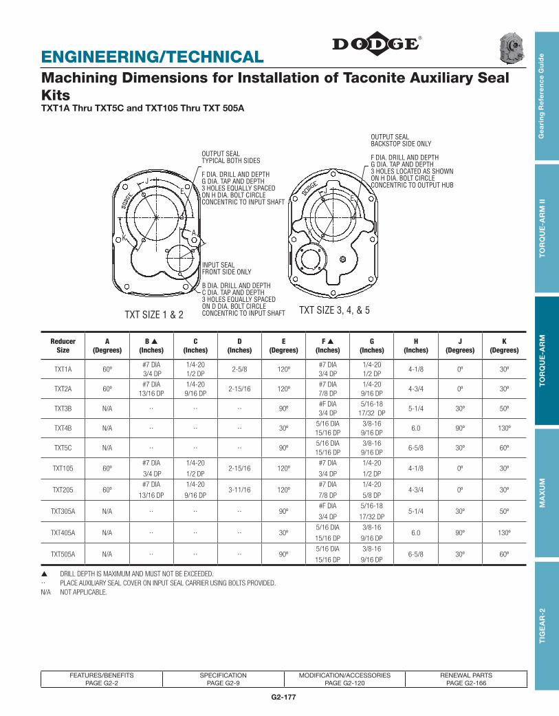
G2-177
TOR
QU
E-TA
MER
Bus
hing
sV-
Driv
esFH
PD
rives
Com
pone
nt A
cces
sorie
s
ENGINEERING/TECHNICAL
TOR
QU
E-TA
MER
Bus
hing
sV-
Driv
esFH
PD
rives
Com
pone
nt A
cces
sorie
sT
IGE
AR
-2G
eari
ng
Re
fere
nc
e G
uid
eT
OR
QU
E-A
RM
IIT
OR
QU
E-A
RM
MA
XU
M
FEATURES/BENEFITS PAGE G2-2
SPECIFICATION PAGE G2-9
MODIFICATION/ACCESSORIES PAGE G2-120
RENEWAL PARTS PAGE G2-166
Machining Dimensions for Installation of Taconite Auxiliary Seal KitsTXT1A Thru TXT5C and TXT105 Thru TXT 505A
Reducer Size
A(Degrees)
B ▲ (Inches)
C (Inches)
D (Inches)
E (Degrees)
F ▲ (Inches)
G(Inches)
H(Inches)
J (Degrees)
K (Degrees)
TXT1A 60º#7 DIA 3/4 DP
1/4-20 1/2 DP
2-5/8 120º#7 DIA 3/4 DP
1/4-20 1/2 DP
4-1/8 0º 30º
TXT2A 60º#7 DIA
13/16 DP1/4-20 9/16 DP
2-15/16 120º#7 DIA 7/8 DP
1/4-20 9/16 DP
4-3/4 0º 30º
TXT3B N/A 90º#F DIA 3/4 DP
5/16-18 17/32 DP
5-1/4 30º 50º
TXT4B N/A 30º5/16 DIA 15/16 DP
3/8-16 9/16 DP
6.0 90º 130º
TXT5C N/A 90º5/16 DIA 15/16 DP
3/8-16 9/16 DP
6-5/8 30º 60º
TXT105 60º#7 DIA
3/4 DP
1/4-20
1/2 DP2-15/16 120º
#7 DIA
3/4 DP
1/4-20
1/2 DP4-1/8 0º 30º
TXT205 60º#7 DIA
13/16 DP
1/4-20
9/16 DP3-11/16 120º
#7 DIA
7/8 DP
1/4-20
5/8 DP4-3/4 0º 30º
TXT305A N/A 90º#F DIA
3/4 DP
5/16-18
17/32 DP5-1/4 30º 50º
TXT405A N/A 30º5/16 DIA
15/16 DP
3/8-16
9/16 DP6.0 90º 130º
TXT505A N/A 90º5/16 DIA
15/16 DP
3/8-16
9/16 DP6-5/8 30º 60º
▲ DRILL DEPTH IS MAXIMUM AND MUST NOT BE EXCEEDED. PLACE AUXILIARY SEAL COVER ON INPUT SEAL CARRIER USING BOLTS PROVIDED.N/A NOT APPLICABLE.

G2-178
ENGINEERING/TECHNICAL
FEATURES/BENEFITS PAGE G2-2
SPECIFICATION PAGE G2-9
MODIFICATION/ACCESSORIES PAGE G2-120
RENEWAL PARTS PAGE G2-166
Gea
ring
Re
fere
nc
e Gu
ide
TO
RQ
UE
-AR
M II
TO
RQ
UE
-AR
MM
AX
UM
TIG
EA
R-2
Machining Dimensions for Installation of Taconite Auxiliary Seal KitsTXT6A Thru TXT10A
ReducerSize
A(Degrees)
B ▲ (Inches)
C(Inches)
D(Inches)
E(Inches)
TXT6A 0º
5/16 ∅1-3/8 DP
3/8-16
1-1/16 DP
7/16 ∅3/8 DP 7-1/4 ∅
TXT7A 0º
23/64 ∅1-11/16 DP
7/16-14
1-5/16 DP
1/2 ∅3/8 DP 8-1/8 ∅
TXT8A 0º
5/16 ∅1-11/16 DP
3/8-16
1-3/8 DP
7/16 ∅3/8 DP 8-5/8 ∅
TXT9A 0º
5/16 ∅1-5/8 DP
3/8-16
1-5/16 DP
7/16 ∅3/8 DP 9-15/16 ∅
TXT10A 0º
5/16 ∅1-5/8 DP
3/8-16
1-5/16 DP
7/16 ∅3/8 DP 11.0 ∅
▲ DRILL DEPTH IS MAXIMUM AND MUST NOT BE EXCEEDED.

G2-179
TOR
QU
E-TA
MER
Bus
hing
sV-
Driv
esFH
PD
rives
Com
pone
nt A
cces
sorie
s
ENGINEERING/TECHNICAL
TOR
QU
E-TA
MER
Bus
hing
sV-
Driv
esFH
PD
rives
Com
pone
nt A
cces
sorie
sT
IGE
AR
-2G
eari
ng
Re
fere
nc
e G
uid
eT
OR
QU
E-A
RM
IIT
OR
QU
E-A
RM
MA
XU
M
FEATURES/BENEFITS PAGE G2-2
SPECIFICATION PAGE G2-9
MODIFICATION/ACCESSORIES PAGE G2-120
RENEWAL PARTS PAGE G2-166
TORQUE-ARM Shaft Mount Speed ReducersTable 31 - Maximum Input and Driven Speeds for TXT and SCXT Reducers
Single Reduction Double ReductionReducer
Size Input DrivenReducer
Size
Input RPM Driven RPMReducer
Size
Input RPM Driven RPM
TXT/SCXT1 2248 400 Nominal Ratio Nominal Ratio Nominal Ratio Nominal RatioTXT/SCXT2 2116 400 9 15 25 9 15 25 15 25 30 15 25 30TXT/SCXT3 2240 400 TXT/SCXT1 1888 2149 2179 200 140 85 TXT/SCXT8 1809 1847 . . . . 120 75 . .TXT/SCXT4 2260 400 TXT/SCXT2 1850 1974 1994 200 140 85 TXT9 1814 1925 . . . . 120 75 . .TXT/SCXT5 2268 400 TXT/SCXT3 1782 2083 2100 200 140 85 TXT10 1819 1823 . . . . 120 75 . .TXT/SCXT6 2268 400 TXT/SCXT4 1934 2118 2072 200 140 85 TXT12 1786 1849 . . . . 120 75 . .TXT/SCXT7 2144 400 TXT/SCXT5 1790 1925 2044 200 125 85 TDT13 . . . . 1855 . . . . . . . . 75 . .
TXT8 2200 400 TXT/SCXT6 1840 1916 2010 200 125 85 TDT14 . . . . 1860 . . . . . . . . 75 . .TXT9 2154 400 TXT/SCXT7 1922 1827 1844 200 120 75 TDT15 . . . . . . . . 1746 . . . . 57 . .
Table 33 - Output Shaft Overhung Load Ratings for Single Reduction TXT ReducersReducer Nominal Shaft Overhung Load (Lbs.) @ Various RPM’s *
Size Ratio Size 100 150 200 250 300 350 400
TXT1 51-1/4 775 610 600 500 500 500 490
1-7/16 660 520 520 430 430 420 420
TXT2 51-7/16 760 620 530 530 530 530 520
1-15/16 665 545 470 470 470 460 460
TXT3 51-15/16 2370 2100 1950 1840 1760 1700 16602-3/16 2300 2040 1890 1780 1710 1650 1610
TXT4 52-3/16 3030 2720 2490 2310 2170 2060 19702-7/16 2930 2640 2400 2240 2100 1990 1900
TXT5 52-7/16 3080 2750 2560 2400 2260 2160 2080
2-15/16 2920 2610 2430 2270 2140 2050 1980
TXT6 52-15/16 4350 3850 3500 3250 3200 3100 30503-7/16 3950 3500 3200 2950 2900 2800 2750
TXT7 5 3-7/16 3800 3650 3300 3450 3500 3400 3300* Values shown are for loads applied at one output shaft diameter from reducer bushing. Interpolate for values between RPM’s listed.
Table 1 - WR2 (Lb.-FT2 ) At High Speed Shaft for TXT Reducers *Reducer Nominal Ratio Reducer Nominal Ratio
Size 5:1 9:1 15:1 25:1 Size 5:1 9:1 15:1 25:1TXT1 0.002 0.013 0.008 0.007 TXT9 1.66 . . . 1.39 0.794TXT2 0.013 0.027 0.011 0.007 TXT10 . . . . . . 1.63 0.927TXT3 0.034 0.059 0.026 0.013 TXT12 . . . . . . . 7.71 3.68TXT4 0.075 0.092 0.043 0.023 TDT13 . . . . . . . . . 6.56TXT5 0.15 0.233 0.099 0.067 TDT14 . . . . . . . . . 9.0TXT6 0.201 0.461 0.197 0.109 TDT15 . . . . . . . . . 11.42TXT7 0.48 1.004 0.417 0.285TXT8 0.96 . . . 0.942 0.571
* For WR2 at low speed shaft, multiply WR2 value listed by (actual ratio) 2.
Table 32 - Output Shaft Overhung Load Ratings for Double Reduction TXT ReducersReducer
SizeNominal
Ratio Shaft SizeOverhung Load (Lbs.) @ Various RPM’s *
10 20 30 50 80 100 120 140 160 180 200
TXT1 9, 15, 251-1/4 1990 1520 1300 1100 930 780 760 740 720 700 680
1-7/16 1700 1300 1110 945 790 665 650 640 630 620 610
TXT2 9, 15, 251-7/16 2000 1510 1270 1010 840 820 720 720 710 710 700
1-15/16 1750 1320 1110 890 730 710 630 630 620 620 610
TXT3 9, 15, 251-15/16 5400 4250 3680 3050 2620 2440 2310 2210 2110 2040 19802-3/16 5240 4120 3570 2960 2540 2370 2240 2140 2050 1980 1920
TXT4 9, 15, 252-3/16 6520 5180 4510 3800 3230 3000 2830 2710 2600 2510 24302-7/16 6360 5060 4410 3710 3160 2930 2770 2640 2530 2450 2370
TXT5 9, 15, 252-7/16 7460 5860 5080 4280 3690 3450 3270 3110 2980 2880 2790
2-15/16 7060 5540 4800 4040 3490 3260 3090 2940 2820 2720 2640
TXT6 9, 15, 252-15/16 9100 7100 6100 5000 4100 4050 3700 3550 3400 3300 32003-7/16 8200 6400 5500 4500 3700 3650 3400 3300 3250 3200 3150
TXT7 9, 15, 25 3-7/16 11,400 9500 7300 5950 4750 5050 4500 4300 4250 4200 4150Values shown are for loads applied at one output shaft diameter from reducer bushing. Interpolate for values between RPM’s listed.

G2-180
ENGINEERING/TECHNICAL
FEATURES/BENEFITS PAGE G2-2
SPECIFICATION PAGE G2-9
MODIFICATION/ACCESSORIES PAGE G2-120
RENEWAL PARTS PAGE G2-166
Gea
ring
Re
fere
nc
e Gu
ide
TO
RQ
UE
-AR
M II
TO
RQ
UE
-AR
MM
AX
UM
TIG
EA
R-2
TORQUE-ARM Shaft Mount Speed Reducers Thrust Capacity Of Screw Conveyor Drive Reducers
Table 1 - Thrust Capacity Of Screw Conveyor Drive Reducers (Pounds) ●
Reducer SizeScrew Conveyor RPM
80 100 120 140 160 180 200SCXT109A 3986 3765 3588 3434 3303 3192 3092
SCXT209A 5389 5025 4742 4505 4304 4138 3990
SCXT309B 5290 4920 4660 4450 4240 4100 3970
SCXT409B 6000 6000 5800 5500 5200 5000 5000
SCXT509C 6000 6000 6000 6000 5800 5700 5500
SCXT609A 6000 6000 6000 6000 6000 6000 6000
SCXT709A 4863 4527 4244 3959 3713 3520 3335
Reducer SizeScrew Conveyor RPM
25 50 75 100 125 140SCXT115A 6000 4840 4220 3820 3540 3414
SCXT215A 6000 6000 5440 4920 4560 4380
SCXT315B 6000 6000 5400 4920 4600 4450
SCXT415B 6000 6000 6000 6000 5800 5600
SCXT515C 6000 6000 6000 6000 6000 . . . .
SCXT615A 6000 6000 6000 6000 6000 . . . .
SCXT715A † 6000 6000 5220 4530 . . . . . . . .
Reducer SizeScrew Conveyor RPM
25 50 75 80 85SCXT125A 6000 4840 4220 4130 4040
SCXT225A 6000 6000 5440 5320 5000
SCXT325B 6000 6000 5400 5290 5200
SCXT425B 6000 6000 6000 6000 6000
SCXT525C 6000 6000 6000 6000 . . . .
SCXT625A 6000 6000 6000 6000 . . . .
SCXT725A 6000 6000 5220 . . . . . . . .
Reducer SizeScrew Conveyor RPM
100 150 200 250 300 350 400SCXT105 6000 5500 5060 4730 4520 4340 4200
SCXT205 5310 4760 4390 4160 3970 3810 3680
SCXT305A 6000 5300 4900 4600 4400 4300 4200
SCXT405A 6000 5900 5500 5000 4600 4500 4500
SCXT505B 6000 6000 6000 6000 5700 5400 5000
SCXT805 6000 6000 6000 6000 6000 6000 6000
SCXT705 5860 5500 4810 4710 4830 4980 4900
† Actual maximum output speed for SCXT715 reducer is 120 rpm
● Consult DODGE for SCXT8 Thrust capacity
The screw conveyor drive reducer uses tapered roller bearings which take Thrust in either direction from the screw conveyor.
This eliminates the need for external Thrust bearings commonly used.

G2-181
TOR
QU
E-TA
MER
Bus
hing
sV-
Driv
esFH
PD
rives
Com
pone
nt A
cces
sorie
s
ENGINEERING/TECHNICAL
TOR
QU
E-TA
MER
Bus
hing
sV-
Driv
esFH
PD
rives
Com
pone
nt A
cces
sorie
sT
IGE
AR
-2G
eari
ng
Re
fere
nc
e G
uid
eT
OR
QU
E-A
RM
IIT
OR
QU
E-A
RM
MA
XU
M
FEATURES/BENEFITS PAGE G2-2
SPECIFICATION PAGE G2-9
MODIFICATION/ACCESSORIES PAGE G2-120
RENEWAL PARTS PAGE G2-166
TORQUE-ARM Shaft Mount Speed Reducers Guidelines For Long-Term Storage Of TORQUE-ARM Reducers
During periods of long storage (3 months or more), or when awaiting delivery or installation of other equipment, special care should be taken to protect a gear reducer to have it in the best condition when placed into service.
By taking special precautions, problems such as seal leak-age and reducer failure due to the lack of lubrication, improper lubrication quantity, or contamination can be avoided. The following precautions will protect gear reduc ers during periods of extended storage.
Table 1 - Vci #105 Oil For TORQUE-ARM ReducersCase Size Quarts Or Liters
TXT1 0.1TXT2 0.1TXT3 0.1TXT4 0.2TXT5 0.3TXT6 0.4TXT7 0.5TXT8 0.6TXT9 0.9TXT10 1.3TXT11 1.9TXT12 2.5
VCI #105 & #10 are interchangeable, but VCI #105 is more readily available.
PREPARATION
1. Drain the oil from the unit. Add a vapor phase corrosion inhibiting oil such as VCI-105 oil by Daubert Chemical Co.
2. Seal the unit air tight. Replace the vent plug with a standard pipe plug and wire the vent to the unit.
3. Cover the shaft extension with a waxy rust preventive compound that will keep oxygen away from the bare metal such as Non-Rust X-110 by Daubert Chemical Co.
4. The instruction manuals and lubrication tags are paper and must be kept dry. Either remove these documents and store them inside or cover the unit with a durable waterproof cover which can keep moisture away.
5. Protect the reducer from dust, moisture, and other contaminants by storing the unit in a dry area.
6. In damp environments, the reducer should be packed inside a moisture-proof container or an envelope of plastic containing a desiccant material. If the reducer is to be stored outdoors, cover the entire exterior with a rust preventive.
7. Once a month rotate the input shaft at least 30 revolutions to redistribute the weight of gears and shafts and to prevent brinnelling of the bearings and drying of the seal track.
WHEN PLACING THE REDUCER INTO SERVICE
1. Assemble the vent plug into the proper hole.
2. Clean the shaft extensions with petroleum solvents.
3. Fill the unit to the proper oil level using a recommended lubricant. The VCI oil will not affect the new lubricant.
4. Follow the installation instructions provided with the unit

G2-182
ENGINEERING/TECHNICAL
FEATURES/BENEFITS PAGE G2-2
SPECIFICATION PAGE G2-9
MODIFICATION/ACCESSORIES PAGE G2-120
RENEWAL PARTS PAGE G2-166
Gea
ring
Re
fere
nc
e Gu
ide
TO
RQ
UE
-AR
M II
TO
RQ
UE
-AR
MM
AX
UM
TIG
EA
R-2
TORQUE-ARM Shaft Mount Speed Reducers Trouble-Shooting Guide For TORQUE-ARM Reducers
Symptom Probable Cause RemedyExcessive Noise and Vibration Improper arm attachment. Check instructions and correct. Tighten all fasteners
properly.Low oil level. Check level. Fill to proper oil capacity per instruction
manual.Excessive premature gear wear due to improper size reducer.
Reselect reducer in catalog with proper service factor. Replace worn unit.
Driven shaft undersized. Replace shaft or remachine to properly fit next smaller bushing size. (Check shaft strength.)
Driven shaft bent. Check runout. Replace or straighten shaft.Worn gears and bearings. Replace gears and bearings as necessary.Driven shaft not projecting through output bore or bushings. Reposition reducer on shaft or replace shaft.Tapered reducer bushings improperly tightened. Check instruction manual and tighten per recommended
torque values.Improper connection to driver and driven equipment. Check belt tension and V-belt sheave alignment. Check
coupling alignment. Check all fasteners and setscrews; tighten properly. Inspect driven shaft key positioning.
Worn or cracked V-belts. Replace with new belts.Driven equipment noise. Check for source, reducer may amplify existing noise.
Overheating Reducers Improper oil level Check oil and fill to proper oil capacity per instruction manual. Too much oil causes heat due to churning and friction; too little starves components.
Exceeds 195 Deg F. Housing Temperature Improper reducer size. Reselect reducer in catalog. Decrease load or replace reducer with proper unit.
Excessive V-belt tension. Tension belts properly. Position sheaves as close to reducer as possible.
Excessive reducer operating speed. Check catalog recommendations. If necessary refer all application details to manufacturer.
Located near high ambient heat source. Shield reducer from heat source. Relocate reducer. Refer application details to manufacturer.
No cooling fan installed. Check catalog recommendation. Instal fan if required.Oil Leakage Undetermined source of leak. Clean reducer and dry all surfaces. Run for one hour and
inspect for leak from seals, gaskets, covers and plugs.Plugged breather air passage. Clean air passage. Remove air passage tape on new
reducers.Loose drain, breather or pipe plugs. Tighten securely. Check oil level.Excessive oil level. Check level. Fill to proper oil capacity per instruction
manual.Breather plug below oil. Relocate breather to highest location. Check oil level.Premature seal wear due to hostile environment. Replace seals. Install auxiliary seal kit.
Excessive Backlash Worn gears. Replace worn gears in sets.Loose bearings. Check bearing wear, adjustment and replace.Worn shaft keys Replace worn keys. Check shaft keyway for wearDriven equipment backlash Check equipment for backlash
Excessive Lateral Movement Worn and loose bearings Replace bearings.Improper bearing adjustment. Readjust bearing per instruction manual.Loose bearing carrier caps. Check and tighten fasteners.Improper reducer mounting. Check and tighten straight bore reducer set screws to
recommended torque values. Check and tighten tapered reducer bearing fasteners to recommended torque values. See instruction manual.
Reversing duty applications. Refer application details to manufacturer.Excessive Reducer Wobble Driven shaft undersized. Replace shaft or remachine to properly fit next smaller
bushing size. (Check shaft strength.)Driven shaft bent. Check runout. Replace or straighten shaft.Improper torque arm attachment. Check instructions and correct. Tighten all fasteners
promptly.Driven shaft not projecting through output bore or bushings. Reposition reducer on shaft or replace shaft.Worn or loose driven shaft key. Check for proper size and replace. Check shaft keyway size.
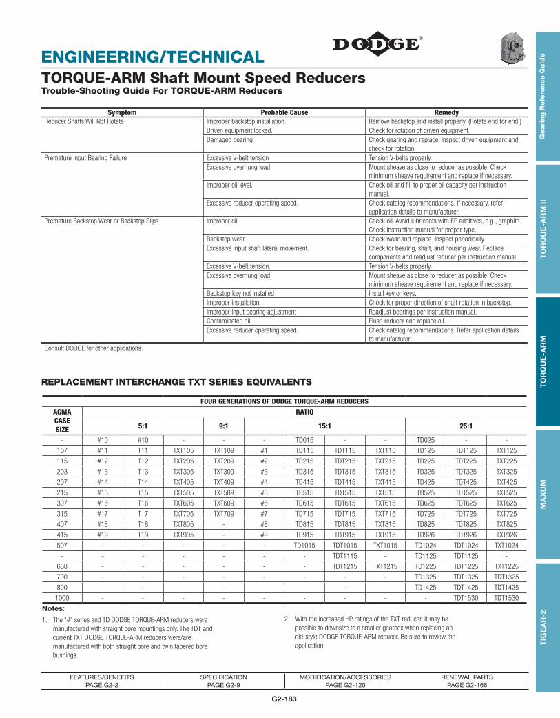
G2-183
TOR
QU
E-TA
MER
Bus
hing
sV-
Driv
esFH
PD
rives
Com
pone
nt A
cces
sorie
s
ENGINEERING/TECHNICAL
TOR
QU
E-TA
MER
Bus
hing
sV-
Driv
esFH
PD
rives
Com
pone
nt A
cces
sorie
sT
IGE
AR
-2G
eari
ng
Re
fere
nc
e G
uid
eT
OR
QU
E-A
RM
IIT
OR
QU
E-A
RM
MA
XU
M
FEATURES/BENEFITS PAGE G2-2
SPECIFICATION PAGE G2-9
MODIFICATION/ACCESSORIES PAGE G2-120
RENEWAL PARTS PAGE G2-166
Symptom Probable Cause RemedyReducer Shafts Will Not Rotate Improper backstop installation. Remove backstop and install properly. (Rotate end for end.)
Driven equipment locked. Check for rotation of driven equipment.Damaged gearing Check gearing and replace. Inspect driven equipment and
check for rotation.Premature Input Bearing Failure Excessive V-belt tension Tension V-belts properly.
Excessive overhung load. Mount sheave as close to reducer as possible. Check minimum sheave requirement and replace if necessary.
Improper oil level. Check oil and fill to proper oil capacity per instruction manual.
Excessive reducer operating speed. Check catalog recommendations. If necessary, refer application details to manufacturer.
Premature Backstop Wear or Backstop Slips Improper oil Check oil. Avoid lubricants with EP additives, e.g., graphite. Check instruction manual for proper type.
Backstop wear. Check wear and replace. Inspect periodically.Excessive input shaft lateral movement. Check for bearing, shaft, and housing wear. Replace
components and readjust reducer per instruction manual.Excessive V-belt tension. Tension V-belts properly.Excessive overhung load. Mount sheave as close to reducer as possible. Check
minimum sheave requirement and replace if necessary.Backstop key not installed Install key or keys.Improper installation. Check for proper direction of shaft rotation in backstop.Improper input bearing adjustment Readjust bearings per instruction manual.Contaminated oil. Flush reducer and replace oil.Excessive reducer operating speed. Check catalog recommendations. Refer application details
to manufacturer.Consult DODGE for other applications.
TORQUE-ARM Shaft Mount Speed Reducers Trouble-Shooting Guide For TORQUE-ARM Reducers
REPLACEMENT INTERCHANGE TXT SERIES EQUIVALENTS
FOUR GENERATIONS OF DODGE TORQUE-ARM REDUCERSAGMACASESIZE
RATIO
5:1 9:1 15:1 25:1
- #10 #10 - - - TD015 - - TD025 - -
107 #11 T11 TXT105 TXT109 #1 TD115 TDT115 TXT115 TD125 TDT125 TXT125
115 #12 T12 TXT205 TXT209 #2 TD215 TDT215 TXT215 TD225 TDT225 TXT225
203 #13 T13 TXT305 TXT309 #3 TD315 TDT315 TXT315 TD325 TDT325 TXT325
207 #14 T14 TXT405 TXT409 #4 TD415 TDT415 TXT415 TD425 TDT425 TXT425
215 #15 T15 TXT505 TXT509 #5 TD515 TDT515 TXT515 TD525 TDT525 TXT525
307 #16 T16 TXT605 TXT609 #6 TD615 TDT615 TXT615 TD625 TDT625 TXT625
315 #17 T17 TXT705 TXT709 #7 TD715 TDT715 TXT715 TD725 TDT725 TXT725
407 #18 T18 TXT805 - #8 TD815 TDT815 TXT815 TD825 TDT825 TXT825
415 #19 T19 TXT905 - #9 TD915 TDT915 TXT915 TD926 TDT926 TXT926
507 - - - - - TD1015 TDT1015 TXT1015 TD1024 TDT1024 TXT1024
- - - - - - - TDT1115 - TD1125 TDT1125 -
608 - - - - - - TDT1215 TXT1215 TD1225 TDT1225 TXT1225
700 - - - - - - - - TD1325 TDT1325 TDT1325
800 - - - - - - - - TD1425 TDT1425 TDT1425
1000 - - - - - - - - - TDT1530 TDT1530
Notes:
1. The “#” series and TD DODGE TORQUE-ARM reducers were manufactured with straight bore mountings only. The TDT and current TXT DODGE TORQUE-ARM reducers were/are manufactured with both straight bore and twin tapered bore bushings.
2. With the increased HP ratings of the TXT reducer, it may be possible to downsize to a smaller gearbox when replacing an old-style DODGE TORQUE-ARM reducer. Be sure to review the application.

G2-184
ENGINEERING/TECHNICAL
FEATURES/BENEFITS PAGE G2-2
SPECIFICATION PAGE G2-9
MODIFICATION/ACCESSORIES PAGE G2-120
RENEWAL PARTS PAGE G2-166
Gea
ring
Re
fere
nc
e Gu
ide
TO
RQ
UE
-AR
M II
TO
RQ
UE
-AR
MM
AX
UM
TIG
EA
R-2
TORQUE-ARM Shaft Mount Speed Reducers Backstop Interchange For Dodge TXT-TDT-TD-T-No. TORQUE-ARM Reducers
Part Number
Current TXT Series
Housing Redesign 2005
TXT Series Brg Redesign
1991
TXT Series Intro 1985
TDT Series TD Series Number Series
241101TDT115 TD115
No. 1TDT125 TD125
242101TXT109ATXT115ATXT125A
TXT105T11
TDT215TDT225
TD215TD225
No. 2No. 3No. 11
TXT109
TXT115
TXT125
243101TDT315 TD315
TDT325 TD325
243102 Use Part Number 244106
243106TXT309B TXT309A
TXT315B TXT315A
TXT325B TXT325A
244092TDT415 TD415
TDT425 TD425
244101No. 4
No. 5
244106TXT409B TXT409A TXT309
TXT415B TXT415A TXT315
TXT425B TXT425A TXT435
244148 TXT405A
TXT405
TXT409
TXT415
TXT425
245101TDT515 TD515
TDT525 TD525
245154TXT509C TXT509B TXT509A, TXT509
TXT515C TXT515B TXT515A, TXT515
TXT525C TXT525B TXT525A, TXT525
246092TXT609ATXT615ATXT625A
TXT605TXT609TXT615TXT625
T16TDT615TDT625
TD615A, TD615TD625A, TD625
No. 16A

G2-185
TOR
QU
E-TA
MER
Bus
hing
sV-
Driv
esFH
PD
rives
Com
pone
nt A
cces
sorie
s
ENGINEERING/TECHNICAL
TOR
QU
E-TA
MER
Bus
hing
sV-
Driv
esFH
PD
rives
Com
pone
nt A
cces
sorie
sT
IGE
AR
-2G
eari
ng
Re
fere
nc
e G
uid
eT
OR
QU
E-A
RM
IIT
OR
QU
E-A
RM
MA
XU
M
FEATURES/BENEFITS PAGE G2-2
SPECIFICATION PAGE G2-9
MODIFICATION/ACCESSORIES PAGE G2-120
RENEWAL PARTS PAGE G2-166
TORQUE-ARM Shaft Mount Speed Reducers Backstop Interchange For All Dodge TORQUE-ARM Reducers
Part Number
Current TXT Series
Housing Redesign 2005
TXT Series Brg Redesign
1991
TXT Series Intro 1985
TDT Series TD Series Number Series
246101 TXT505A TXT505 T15 No. 6
247092 Use Part Number 247260247101 No. 7A
247260
TXT709A TXT705 T17 TD715A, TD715
No. 17ATXT715A TXT709 TDT715 TD725A, TD725
TXT725A TXT715 TDT725
TXT725
248101 Use Part Number 249260
249260
TXT 815A TXT815 TDT815 TD815A, TD815 No. 8
TXT 825A TXT825 TDT825 TD825A, TD825 No. 9
TXT 915A TXT915 TDT915 TD915 No. 18
TXT 926A TXT926 TDT926 TD926
TDT1115 TD1115
TDT1125 TD1125
250101 Use Part Number 250260
250260
TXT1015A TXT805 T18 TD1015
TXT1024A TXT1015 TDT1015 TD1024
TXT1024 TDT1024 TD1215
TXT1215 TDT1215 TD1225
TXT1225 TDT1225
252101
TXT209A TXT305A TXT205 T12 No. 13
TXT215A TXT209 T13
TXT225A TXT215
TXT225
TXT305
254101 T14 No. 14
255101 No. 15
256101 No. 16
257101 No. 17
272259TXT905 T19,
TDT1325
272293TDT1425
TDT1530

G2-186
ENGINEERING/TECHNICAL
FEATURES/BENEFITS PAGE G2-2
SPECIFICATION PAGE G2-9
MODIFICATION/ACCESSORIES PAGE G2-120
RENEWAL PARTS PAGE G2-166
Gea
ring
Re
fere
nc
e Gu
ide
TO
RQ
UE
-AR
M II
TO
RQ
UE
-AR
MM
AX
UM
TIG
EA
R-2
TORQUE-ARM Shaft Mount Speed Reducers Screw Conveyor Drive Mounting Positions Based On Screw Diameter
ReducerSize Motor Mount No. ★
For Use on Troughs with Screw Diameters of:Top, Right and Left Bottom
Side Portions PositionSCXT1A M112 6, 9, 12” 6, 9”
SCXT2A M214 6, 9, 12, 14” 6, 9, 12”
SCXT3B M316 6, 9, 12, 14, 16” 6, 9, 12, 14”
SCXT4B, SCXT5C M418, M518 9, 12, 14, 16, 18” 9, 12, 14, 16”
SCXT6A, SCXT7A M620, M720 12, 14, 16, 18, 20” 12, 14, 16, 18”
★ Long Series Motor Mount to fit troughs with screws up Thru 24” diameter are available from stock.
See pages G2-92 Thru G2-119.