Overview - Torque Converter Rebuilders Association
34
-
Upload
khangminh22 -
Category
Documents
-
view
6 -
download
0
Transcript of Overview - Torque Converter Rebuilders Association


OverviewOverview• Raybestos Friction Materials.
– TAN– HIGH ENERGY (KEVLAR®)– SW CARBON™– POWERTORQUE™
• Applications Chart• Adhesive Coating• Surface Prep• Bond Validation• Clutch Packs in Converters
OverviewOverview
• Closing– Contact Information
– Questions or Comments
Raybestos Torque Converter Raybestos Torque Converter Friction MaterialsFriction Materials
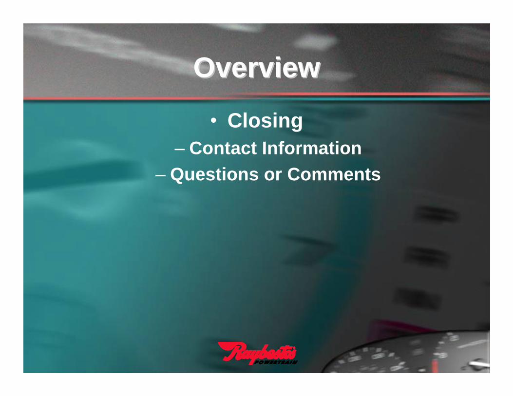
• OE Tan– Used by OE Manufacturers– Commonly used for ON/OFF Lock up strategies– Proprietary blend of cellulose fibers and resin– High friction
• High-Energy Kevlar®
– Tolerates elevated temperatures and added stresses associated with electronicacontrolled transmissions without glazing or burning.
– Great for modulated lock up systems
• SW Carbon™– Developed specifically for Continuously Slipping EC³ applications– No slip codes– Extreme temperature resistance– Low compression-set after installation– High porosity for optimum oil flow– Low Wear

Raybestos Torque Converter Raybestos Torque Converter Friction MaterialsFriction Materials
• PowerTorque™– Developed Specifically for Heavy Duty/Diesel and
High Performance Applications.– 25% higher torque capacity and greater durability
than Kevlar or Carbon based friction materials.– Higher density and higher temperature capacity
than conventional tan torque converter linings.– Eliminates premature wear.– Higher friction levels for greater holding capacity
and slip resistance behind high torque diesels and high powered performance vehicles.

EC³ PWM ON/OFF Heavy Duty High Performance
Temperature Resistance 1=Highest 5=Lowest
Torque Capacity 1=Highest 5=Lowest
(T) Tan Organic Paper ● 5 2(K) High Energy Kevlar® ● 3 3
(HC) Carbon Paper ● 2 4(SW Carbon™) Carbon Fiber ● 1 5
(PT) Pow erTorque™ ● ● 4 1
Application Cheat SheetApplication Cheat Sheet

Adhesive CoatingAdhesive Coating
• Plasti-Lock® 700
– Black in Color– Heat Curing– Nitrile/Phenolic Base– Applied via Curtain Coat Process– Does not require a “pre-tack” activator– Possesses a high shear strength due to
the lattice structure formed with the friction material.
– OEM proven– Shear Strength @ 75°F = 2000 psi– Shear Strength @ 400°F = 500 psi

Adhesive CoatingAdhesive Coating
• Shelf Life– 6 months at temperatures
below 95°F and controlled humidity.
– Can qualify with MEK Test
• Recommended bond cycle “window” as specified by SIA

Bond PressureBond Pressure
PFrPressure at friction (psi)FR/AFr
FRForce of Ram (lbs.)AR(PI)
AFrArea of Friction Material (Inches squared)AOD-AID
AIDArea of friction ring ID (Inches squared):3.1416x(FrID/2)²
FrIDFriction Ring ID (Inches):
AODArea of friction ring OD (Inches squared):3.1416x(FrOD/2)²
FrODFriction Ring OD (Inches):
PiLine Pressure in (psi):
ARArea of Ram (inches squared):3.1416x(DR/2)²
DRHydraulic/Pneumatic Ram DIA (Inches):• Optimum pressure on Friction Material during bond cycle = 200 psi Face pressure.
• Acceptable range = 100-200 psi net facing pressure ON THE SURFACE OF THE FRICTION MATERIAL.
Surface PrepSurface Prep
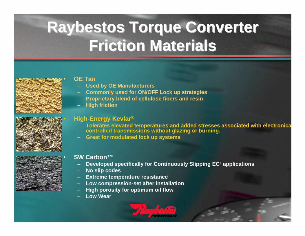
• Material Removal• Lathe (Machining)• Caustic Solution (Piston face is not disturbed)
• Surface Preparation and Finish• Recommended surface finish range of 80-150 Ra• Media blast bond surface ONLY w/80grit Aluminum Oxide
for optimum bond• Remove ALL oils from the bond surface with solvents such
as MEK or Acetone.
• Reaction Surface• Recommended surface finish range of 25 Ra MAX

Surface PrepSurface Prep
• Although the analogy of a “record finish” is loosely used in the industry, the typical surface of a record is very course.
Bond ValidationBond ValidationStandard Bend Test
– The purpose of this evaluation is to measure the mechanical integrity of the bond between the friction material and the mating surface under the most extreme moisture and temperature conditions.
– The degree of cure, percent of bond area, and quality of adhesion are determined.
– The equipment must be capable of uniformly bending the bonded section over the specified radius, after being subjected to specific controlled temperature and moisture conditions

Bond ValidationBond Validation• The bonded samples are soaked in ATF
• Parts are then placed in boiling water for 10 minutes.
• Parts are removed from water and allowed to sit for 10 minutes with the friction side facing up.
• A 12mm rod is anchored in place
• Within 15 minutes of removing the test piece from the water, pressure is exerted on the plate until the bend reaches a 90° angle.
• The test piece is placed on the rod over the diameter of the sample piece.
• The delaminated material is carefully removed from the bend area.
• The bond is considered satisfactory if a minimum of 50% of the friction material remains in the bend radius
Excellent Bond Marginal Bond
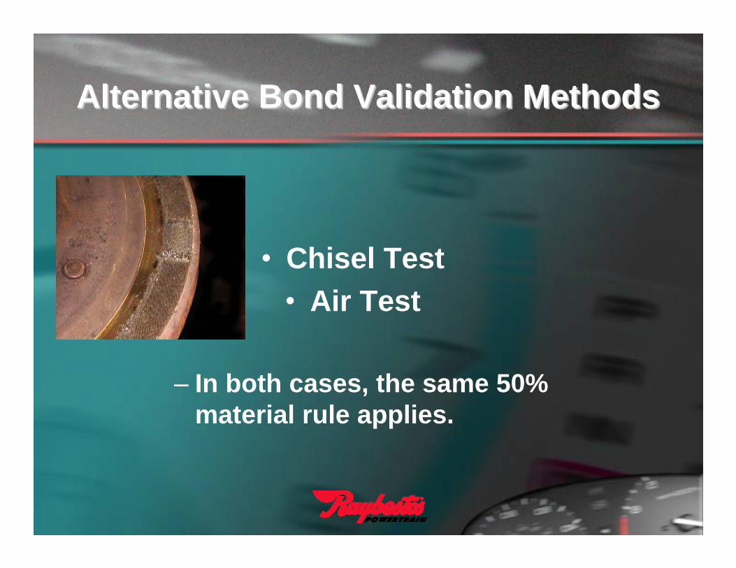
Alternative Bond Validation MethodsAlternative Bond Validation Methods
• Chisel Test• Air Test
– In both cases, the same 50% material rule applies.
Clutch Packs in Torque Clutch Packs in Torque Converters Converters
• Evolution• Applications
• Benefits• Components
• The Clutch Pack• Friction Plate FYI
• Reaction Plate Requirements• Clearance
Clutch Packs in Torque Clutch Packs in Torque Converters Converters –– EvolutionEvolution
• Single Piston/Dampener to Cover Engagement.
• Multi-Plate Piston/Dampener to Cover Engagement.
• Multi-Plate “Clutch Pack” Engagement.

• Examples of Applications where you will find a clutch pack instead of a single piston lockup dampener:
– Nissan RE5R05A– Mercedes 722.6, 722.7, 722.9
Clutch Packs in Torque Clutch Packs in Torque Converters Converters –– ApplicationsApplications
• The “clutch pack” system grounds the inner hub to the front cover during an engagement.
• Packaging/Converter size is reduced:– Reduces rotating inertia– Overall Mass– Increases response to the engine
performance.
Clutch Packs in Torque Clutch Packs in Torque Converters Converters –– BenefitsBenefits

• One of the greatest benefits of the “clutch pack” design is that it is a lubricated system.
• Oil is continuously carrying heat away from the pack, allowing for slippage, without catastrophic failure.
Clutch Packs in Torque Clutch Packs in Torque Converters Converters –– BenefitsBenefits

Clutch Packs in Torque Clutch Packs in Torque Converters Converters -- ComponentsComponents• The clutch pack system in a converter is made
up of the same general components, you would find in a transmission drum or housing.
– Housing/Outer Hub– Apply Piston– Inner and outer piston seals
– Inner hub (Part of Dampener Assembly)
– Clutch Pack

Clutch Packs in Torque Clutch Packs in Torque ConvertersConverters
• The clutch pack consists of:– Steel Reaction Plates– Friction Plates– Backing/Pressure Plate– Backing/Pressure Plate Snap Ring
• Stackup begins with a steel reaction plate splined to the outer hub, then stacked in an alternating pattern.
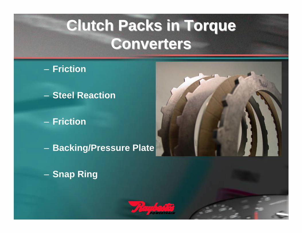
– Friction
– Steel Reaction
– Friction
– Backing/Pressure Plate
– Snap Ring
Clutch Packs in Torque Clutch Packs in Torque ConvertersConverters
• Friction plates are made with a thin steel core with friction material typically bonded to both sides.
• Cores are blanked, heat flattened, and etched to remove oils or surface contaminants, then coated with adhesive.
• Friction wafers are bonded to both sides under a specific time/temp/pressure cycle that will achieve a satisfactory bond & meet the target spec for material compression.
Clutch Packs in Torque Clutch Packs in Torque Converters Converters –– Friction PlatesFriction Plates

• Critical points to keep in mind if you are going to take the time to re-line a friction plate:– Plates need to be caustically stripped and
thoroughly cleaned.– Since some cores are as little as 0.032” thick, any
removal of material (steel) will weaken the steel and upset the flatness.
– When assembling, too much compression can fracture the material matrix.
– Too little compression can result in material delamination.
Clutch Packs in Torque Clutch Packs in Torque Converters Converters –– Friction PlatesFriction Plates
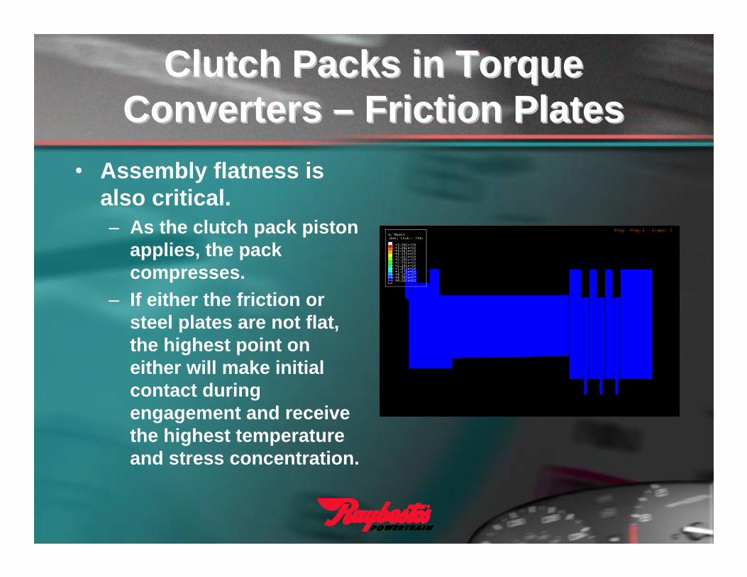
• Assembly flatness is also critical.– As the clutch pack piston
applies, the pack compresses.
– If either the friction or steel plates are not flat, the highest point on either will make initial contact during engagement and receive the highest temperature and stress concentration.
Clutch Packs in Torque Clutch Packs in Torque Converters Converters –– Friction PlatesFriction Plates
Clutch Packs in Torque Clutch Packs in Torque Converters Converters –– Friction PlatesFriction Plates
• Friction material grooving is more vital on a small diameter friction plate than a typical piston/dampener assembly.
• The grooves serve several purposes:
– Channel oil away from the friction material as it is being compressed.
– Depending on groove geometry, grooving can be used to calibrate engagement time and control shudder.
– Cool the interface.

Clutch Packs in Torque Clutch Packs in Torque Converters Converters –– Reaction PlatesReaction Plates
• Steel Reaction Plates aren’t just stamped and packaged.
– Steel thickness is a critical consideration in pack design.
– Like friction cores, steel plates require a flattening process.
– Finally, the surface finish is polished to spec.

Clutch Packs in Torque Clutch Packs in Torque Converters Converters –– Reaction PlatesReaction Plates
• Surface finish is critical. Think of a steel plate like the front cover of a converter.
• Average Surface roughness should not exceed 25 microinches.
• Warped or “Potato-Chipped” steels should not be re-used.

Clutch Packs in Torque Clutch Packs in Torque Converters Converters –– Reaction PlatesReaction Plates
• Steel plates with Hot Spots or Smeared material should not be reused or reworked.
• Scotch Briting hot spots will only make the appearance disappear. The steel structure is permanently damaged.

Clutch Packs in Torque Clutch Packs in Torque Converters Converters –– ClearanceClearance
• Aside from pre-soaking the friction plates, the most critical part of the clutch pack stackup is clearance.
• Clearance allows the pack to separate and relax when unapplied, preventing unwanted parasitic drag.
• Clearance can also be used to assist lockup modulation by controlling the amount of slip between the inner and outer hubs.

Clutch Packs in Torque Clutch Packs in Torque Converters Converters –– ClearanceClearance
• Setting Clearance
– Refer to manufacturer’s recommended spec. for clearance range.
– Assemble the clutch pack “dry”
– The optimum method is to dial indicate off the piston, then apply the piston with air via the feed orifice in the housing, and measure piston travel.
– Although not as accurate, feeler gauges can be placed in between the backing plate and snap ring or backing plate and first friction plate to confirm clearance.

Clutch Packs in Torque Clutch Packs in Torque Converters Converters –– RecapRecap
• If friction material is contaminated, burnt, or flaking, replace it rather than spending production time trying to reline it.
• If you choose to re-use the friction plates, do so at your own risk.
• Inspect steel reaction plates for flatness and surface imperfections.
• If the reaction plate is hot spotted, scratched, or out-of-flat –discard it.
• It is okay to re-use steels that have been polished. DO NOT REWORK! Wash and re-use.
Questions/Comments?Questions/Comments?
ContactsContacts• Sales
– Dave Perry– Business Development Manager– Office: 765-359-1943– FAX: 765-359-1944– E-mail: [email protected]
• Technical/Engineering– Chris Horbach– Chief Product Application Engineer/
Technical Support Supervisor– Office: 765-364-4577– FAX: 765-364-4573– E-mail: [email protected]