CSG-GH High Torque Series - Electromate
52
76 Gearheads High-Performance Gearhead for Servomotors CSG-GH Series Size 14, 20, 32, 45, 65 Sizes 5 Zero backlash High Accuracy Repeatability ±4 to ±10 arc-sec Quick Connect ® motor adaptation system includes a clamshell style servo coupling and piloted adapter flange. A Cross Roller bearing is integrated with the output flange to provide high moment stiffness, high load capacity and precise positioning accuracy. CSG-GH High Torque Series Gearhead Construction Figure 076-1 (The figure indicates output shaft type.) Mounting pilot Grease filling port (2 locations) Output Shaft (flange optional) Output rotational direction Oil seal Cross roller bearing Mounting bolt hole Motor mounting flange Input rotational direction Shielded bearing Rubber cap Quick Connect® coupling CONTENTS Rating Table, Ratcheting Torque, Buckling Torque …............ 79 Performance Table …............ …............ …............ …....... 80 Torsional Stiffness …............ …...................................... 81 Outline Dimensions ….......................... …............ ….. 82-86 Rating Table Definitions, Life, Torque Limits ................ 98-99 Torsional Stiffness, Vibration, Efficiency ..................... 100-101 Product Sizing & Selection ............ …........................ 102-103 CSG Reduction Ratio Size Model Name CSG High Torque Output Configuration Input Configuration 14 20 32 45 65 50, 80, 100 50, 80, 100, 120, 160 80, 100, 120, 160 Model GH :Gearhead 20 100 GH F0 - - - - - This code represents the motor mounting configuration. Please contact us for a unique part number based on the motor you are using. Motor Code Peak torque 23Nm to 3419Nm Reduction ratio 50:1 to 160:1 High Load Capacity Output Bearing Easy mounting to a wide variety of servomotors F0: Flange output J2: Shaft output without key J6: Shaft output with key and center tapped hole
-
Upload
khangminh22 -
Category
Documents
-
view
1 -
download
0
Transcript of CSG-GH High Torque Series - Electromate

76 Gearheads
CSG-GH Gearhead Series
High
-Per
form
ance
Gea
rhea
d fo
r Ser
vom
otor
s
High
-Per
form
ance
Gea
rhea
d fo
r Ser
vom
otor
s
CSG-
GH S
eries
CSG-
GH S
eries
High
-Per
form
ance
Gea
rhea
d fo
r Ser
vom
otor
s
High
-Per
form
ance
Gea
rhea
d fo
r Ser
vom
otor
s
CSF-
GH S
eries
CSF-
GH S
eries
4-Ø18
2-M10X20
6-M16X24
C0.5
C0.5
C1 R0.4M16x35
□230+1
65 65 7
1257 25
G
H
B
110130
16522 h9
Ø260
-3
Ø120 Ø220
h8
Ø214
Ø168
Ø60
H7
ØF H
7ØA
H7
ØC
14 h
1171
-0.20
Ø168
Ø80
h7
High
-per
form
ance
Gea
r Hea
ds fo
r Ser
vo M
otor
s ser
iesHP
GP se
ries
High
-per
form
ance
Gea
r Hea
ds fo
r Ser
vo M
otor
s ser
iesHP
G se
ries
High
-per
form
ance
Gea
r Hea
ds fo
r Ser
vo M
otor
s ser
iesCS
G-GH
serie
sHi
gh-p
erfo
rman
ce G
ear H
eads
for S
ervo
Mot
ors s
eries
CSF-
GH se
ries
High
-per
form
ance
Gea
r Hea
ds fo
r Ser
vo M
otor
s ser
iesHP
G se
ries (
Orth
ogon
al S
haft
Type
)
High
-per
form
ance
Gea
r Hea
ds fo
r Ser
vo M
otor
s ser
iesHP
GP se
ries
High
-per
form
ance
Gea
r Hea
ds fo
r Ser
vo M
otor
s ser
iesHP
G se
ries
High
-per
form
ance
Gea
r Hea
ds fo
r Ser
vo M
otor
s ser
iesCS
G-GH
serie
sHi
gh-p
erfo
rman
ce G
ear H
eads
for S
ervo
Mot
ors s
eries
CSF-
GH se
ries
High
-per
form
ance
Gea
r Hea
ds fo
r Ser
vo M
otor
s ser
iesHP
G se
ries (
Orth
ogon
al S
haft
Type
)
Size14, 20, 32, 45, 65 Sizes
5
Zero backlash
High AccuracyRepeatability ±4 to ±10 arc-sec
Quick Connect® motor adaptation system includes a clamshell style servo coupling and piloted adapter flange.
A Cross Roller bearing is integrated with the output flange to provide high moment stiffness, high load capacity and precise positioning accuracy.
HPG Gearhead Series
Figure 039-1
HPG-65 Outline DimensionsOnly primary dimensions are shown in the drawings below. Refer to the confirmation drawing for detailed dimensions.
CSG-GH High Torque Series
Tap for eyebolt Hexagon sockethead boltRubber cap
Dimension Table
Moment of Inertia
(Unit: mm) Table 039-1
Gearhead ConstructionFigure 076-1
(The figure indicates output shaft type.)
Mounting pilotGrease filling port
(2 locations)Output Shaft (flange optional)
Output rotational direction
Oil sealCross roller bearing
Mounting bolt hole Motor mounting flange
Input rotational direction
Shielded bearing
Rubber cap
Quick Connect® coupling
C O N T E N T SRating Table, Ratcheting Torque, Buckling Torque …............ 79Performance Table …............…............…............…....... 80Torsional Stiffness …............…...................................... 81Outline Dimensions …..........................…............….. 82-86Rating Table Definitions, Life, Torque Limits ................ 98-99Torsional Stiffness, Vibration, Efficiency .....................100-101Product Sizing & Selection ............…........................102-103
(Note) The dimension tolerances that are not specified vary depending on the manufacturing method. Please check the confirmation drawing or contact us for dimension tolerances not shown on the drawing above. The flange output is standard, the shaft output is optional.
CSG
Reduction RatioSizeModel Name
CSG High Torque
Output Configuration Input Configuration
1420324565
50, 80, 100
50, 80, 100, 120, 160
80, 100, 120, 160
Model
GH: Gearhead
20 100 GH F0- - - - -
This code represents the motor mounting configuration. Please contact us for a unique part number based on the motor you are using.
Motor Code
Peak torque23Nm to 3419Nm
Reduction ratio50:1 to 160:1
High Load Capacity Output Bearing
Easy mounting to a wide variety of servomotors
Shaft
2 130
65
130
65
245
175
245
175
15
15
15
15
140
75
140
75
290
225
290
225
35.0
24.0
35.0
24.0
43.9
36.5
43.9
36.5
65.0
52.0
65.0
52.0
126.5
85.0
126.5
85.0
48.0
52.0
52.0
52.0
38.0
42.0
42.0
42.0
FlangeMin. Max. Max. Min. Max. Min. Max. Min. Max.
246.5
288
314.5
288
TypicalFlange
2
1
2
1
1
2
3
SingleStage
Two Stage
Coupling
Refer to the confirmation drawing for detailed dimensions. Dimensions of typical products are shown. Please contact us for other mounting options if the configurations shown above are not suitable for your particular motor. *1 May vary depending on motor interface dimensions. *2 The mass will vary slightly depending on the ratio and on the inside diameter of the input shaft coupling.*3 Tapped hole for motor mounting screw.
E*1
4-D*3
Table 039-2
4
-
89
5
-
74
12
25
67
15
24
65
20
15
53
25
14
53
40
9
-
50
9
-
1
2
CouplingRatio
HPG 65
(Unit: mm)
(10-4 kgm2)
F0: Flange outputJ2: Shaft output without key J6: Shaft output with key
and center tapped hole
Mass (kg) *2B *1A (H7) *1 C *1 G *1F (H7) *1 H *1

77Gearheads
CSG-GH Gearhead Series
High
-Per
form
ance
Gea
rhea
d fo
r Ser
vom
otor
s
High
-Per
form
ance
Gea
rhea
d fo
r Ser
vom
otor
s
CSG-
GH S
eries
CSG-
GH S
eries
High
-Per
form
ance
Gea
rhea
d fo
r Ser
vom
otor
s
High
-Per
form
ance
Gea
rhea
d fo
r Ser
vom
otor
s
CSF-
GH S
eries
CSF-
GH S
eries
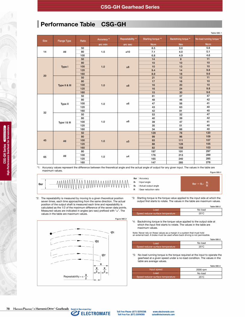
*1: Accuracy values represent the difference between the theoretical angle and the actual angle of output for any given input. The values in the table are maximum values.
arc min
1.5
1.0
1.0
1.0
1.0
1.0
1.0
arc sec
±10
±8
±8
±6
±6
±5
±4
All
Type I
Type II & III
Type II
Type I & III
All
All
Ncm8.57.16.81410109.48.921171616156148474342534039353412999938882197176165147
Nm3.04.04.98101314181216202430374656638132394751667896111128158191213240285
Ncm5.65.14.61110109.89.61110109.89.647424140404742414040120109107105103297289285278
14
20
32
45
65
50801005080100120160508010012016050801001201605080100120160508010012016080100120160
θer = θ2− Rθ1θer
Figure 080-1
X2
X2
XX
2
1
2
7
Table 080-2
Table 080-3
Table 080-4
Size 14 20 32 45 65
All Ratios 260 800 3500 8900 26600
Rating Table CSG-GH Performance Table CSG-GH
Ratcheting Torque CSG-GH
Buckling Torque CSG-GH
Table 079-2
RatioSize
14 20 32 45 65
5080
100120160
110140100——
280450330310280
12001800130012001200
35005000400036003300
—14000120001000010000
(Unit: Nm)
Table 079-3(Unit: Nm)
*3: Starting torque is the torque value applied to the input side at which the output first starts to rotate. The values in the table are maximum values.
*4: Backdriving torque is the torque value applied to the output side at which the input first starts to rotate. The values in the table are maximum values.
*5: No-load running torque is the torque required at the input to operate the gearhead at a given speed under a no-load condition. The values in the table are average values.
Input speedLoad
Speed reducer surface temperature
2000 rpmNo load
25°C
LoadSpeed reducer surface temperature
No load25°C
No load25°C
LoadSpeed reducer surface temperature
CSG-GH Gearhead Series CSG-GH Gearhead Series
042 043
Hig
h-pe
rform
ance
Gea
r Hea
ds fo
r Ser
vo M
otor
s se
ries
HPG
P se
ries
Hig
h-pe
rform
ance
Gea
r Hea
ds fo
r Ser
vo M
otor
s se
ries
HPG
ser
ies
Hig
h-pe
rform
ance
Gea
r Hea
ds fo
r Ser
vo M
otor
s se
ries
CSG
-GH
ser
ies
Hig
h-pe
rform
ance
Gea
r Hea
ds fo
r Ser
vo M
otor
s se
ries
CSF
-GH
ser
ies
Hig
h-pe
rform
ance
Gea
r Hea
ds fo
r Ser
vo M
otor
s se
ries
HPG
ser
ies
(Orth
ogon
al S
haft
Type
)
Hig
h-pe
rform
ance
Gea
r Hea
ds fo
r Ser
vo M
otor
s se
ries
HPG
P se
ries
Hig
h-pe
rform
ance
Gea
r Hea
ds fo
r Ser
vo M
otor
s se
ries
HPG
ser
ies
Hig
h-pe
rform
ance
Gea
r Hea
ds fo
r Ser
vo M
otor
s se
ries
CSG
-GH
ser
ies
Hig
h-pe
rform
ance
Gea
r Hea
ds fo
r Ser
vo M
otor
s se
ries
CSF
-GH
ser
ies
Hig
h-pe
rform
ance
Gea
r Hea
ds fo
r Ser
vo M
otor
s se
ries
HPG
ser
ies
(Orth
ogon
al S
haft
Type
)
*1: Rated torque is based on L10 life of 10,000 hours when input speed is 2000 rpm *2: Rated torque is based on L10 life of 10,000 hours when input speed is 3000 rpm, input rotational speed for size 65 is 2800 rpm. *3: Average load torque calculated based on the application motion profile must not exceed values shown in the table. See p. 102.*4: The limit for torque during start and stop cycles. *5: The limit for torque during emergency stops or from external shock loads. Always operate below this value.*6: Max value of average input rotational speed during operation. *7: Maximum instantaneous input speed.*8: The mass is for the gearhead only (without input shaft coupling & motor flange). Please contact us for the mass of your specific configuration.
Size RatioFlange Type Accuracy *1 Repeatability *2 Starting torque *3 Backdriving torque *4 No-load running torque *5
θer :θ1 :θ2 :R :
Accuracy Input angleActual output angleGear reduction ratio
Repeatability = ±
*2: The repeatability is measured by moving to a given theoretical position seven times, each time approaching from the same direction. The actual position of the output shaft is measured each time and repeatability is calculated as the 1/2 of the maximum difference of the seven data points. Measured values are indicated in angles (arc-sec) prefixed with "±". The values in the table are maximum values.
Table 079-1 Table 080-1
14
20
32
45
65
3500
3500
3500
3000
1900
8500
6500
4800
3800
2800
0.62
1.8
4.6
13
32
0.50
1.4
3.2
10
24
508010050801001201605080100120160508010012016080100120160
7.01010334452525299153178178178229407459523523969123612361236
2330367396107113120281395433459484650918982107011472743299032633419
466170127165191191191497738812812812123516512033203320334836517451745174
9.0141444616464641402172812812813455076508068191352197620412041
6.18.78.7293845454586134155155155200356401457457846108010801080
Nm Nm Nm Nm Nm rpm rpm kg kgSize
Rated Torque at 2000 rpm *1
Rated Torque at 3000 rpm *2
Limit for Average Torque *3
Limit for Repeated
Peak Torque *4
Max. Average Input Speed *6
Max. Input Speed *7
Limit for Momentary
Torque *5
Mass *8
Shaft Flange Ratio
Figure 080-2
Note: Never rely on these values as a margin in a system that must hold an external load. A brake must be used where back driving is not permissible.
78 Gearheads
CSG-GH Gearhead Series
High
-Per
form
ance
Gea
rhea
d fo
r Ser
vom
otor
s
High
-Per
form
ance
Gea
rhea
d fo
r Ser
vom
otor
s
CSG-
GH S
eries
CSG-
GH S
eries
High
-Per
form
ance
Gea
rhea
d fo
r Ser
vom
otor
s
High
-Per
form
ance
Gea
rhea
d fo
r Ser
vom
otor
s
CSF-
GH S
eries
CSF-
GH S
eries
*1: Accuracy values represent the difference between the theoretical angle and the actual angle of output for any given input. The values in the table are maximum values.
arc min
1.5
1.0
1.0
1.0
1.0
1.0
1.0
arc sec
±10
±8
±8
±6
±6
±5
±4
All
Type I
Type II & III
Type II
Type I & III
All
All
Ncm8.57.16.81410109.48.9211716161561484743425340393534
12999938882
197176165147
Nm3.04.04.98
101314181216202430374656638132394751667896
111128158191213240285
Ncm5.65.14.61110109.89.61110109.89.647424140404742414040120109107105103297289285278
14
20
32
45
65
50801005080100120160508010012016050801001201605080100120160508010012016080100120160
θer = θ2− Rθ1θer
Figure 080-1
X2
X2
XX
2
1
2
7
Table 080-2
Table 080-3
Table 080-4
Size 14 20 32 45 65
All Ratios 260 800 3500 8900 26600
Rating Table CSG-GH Performance Table CSG-GH
Ratcheting Torque CSG-GH
Buckling Torque CSG-GH
Table 079-2
RatioSize
14 20 32 45 65
5080
100120160
110140100——
280450330310280
12001800130012001200
35005000400036003300
—14000120001000010000
(Unit: Nm)
Table 079-3(Unit: Nm)
*3: Starting torque is the torque value applied to the input side at which the output first starts to rotate. The values in the table are maximum values.
*4: Backdriving torque is the torque value applied to the output side at which the input first starts to rotate. The values in the table are maximum values.
*5: No-load running torque is the torque required at the input to operate the gearhead at a given speed under a no-load condition. The values in the table are average values.
Input speedLoad
Speed reducer surface temperature
2000 rpmNo load
25°C
LoadSpeed reducer surface temperature
No load25°C
No load25°C
LoadSpeed reducer surface temperature
CSG-GH Gearhead Series CSG-GH Gearhead Series
042 043
Hig
h-pe
rform
ance
Gea
r Hea
ds fo
r Ser
vo M
otor
s se
ries
HPG
P se
ries
Hig
h-pe
rform
ance
Gea
r Hea
ds fo
r Ser
vo M
otor
s se
ries
HPG
ser
ies
Hig
h-pe
rform
ance
Gea
r Hea
ds fo
r Ser
vo M
otor
s se
ries
CSG
-GH
ser
ies
Hig
h-pe
rform
ance
Gea
r Hea
ds fo
r Ser
vo M
otor
s se
ries
CSF
-GH
ser
ies
Hig
h-pe
rform
ance
Gea
r Hea
ds fo
r Ser
vo M
otor
s se
ries
HPG
ser
ies
(Orth
ogon
al S
haft
Type
)
Hig
h-pe
rform
ance
Gea
r Hea
ds fo
r Ser
vo M
otor
s se
ries
HPG
P se
ries
Hig
h-pe
rform
ance
Gea
r Hea
ds fo
r Ser
vo M
otor
s se
ries
HPG
ser
ies
Hig
h-pe
rform
ance
Gea
r Hea
ds fo
r Ser
vo M
otor
s se
ries
CSG
-GH
ser
ies
Hig
h-pe
rform
ance
Gea
r Hea
ds fo
r Ser
vo M
otor
s se
ries
CSF
-GH
ser
ies
Hig
h-pe
rform
ance
Gea
r Hea
ds fo
r Ser
vo M
otor
s se
ries
HPG
ser
ies
(Orth
ogon
al S
haft
Type
)
*1: Rated torque is based on L10 life of 10,000 hours when input speed is 2000 rpm *2: Rated torque is based on L10 life of 10,000 hours when input speed is 3000 rpm, input rotational speed for size 65 is 2800 rpm. *3: Average load torque calculated based on the application motion profile must not exceed values shown in the table. See p. 102.*4: The limit for torque during start and stop cycles. *5: The limit for torque during emergency stops or from external shock loads. Always operate below this value. *6: Max value of average input rotational speed during operation. *7: Maximum instantaneous input speed. *8: The mass is for the gearhead only (without input shaft coupling & motor flange). Please contact us for the mass of your specific configuration.
Size RatioFlange Type Accuracy *1 Repeatability *2 Starting torque *3 Backdriving torque *4 No-load running torque *5
θer :θ1 :θ2 : R :
Accuracy Input angleActual output angleGear reduction ratio
Repeatability = ±
*2: The repeatability is measured by moving to a given theoretical position seven times, each time approaching from the same direction. The actual position of the output shaft is measured each time and repeatability is calculated as the 1/2 of the maximum difference of the seven data points. Measured values are indicated in angles (arc-sec) prefixed with "±". The values in the table are maximum values.
Table 079-1 Table 080-1
14
20
32
45
65
3500
3500
3500
3000
1900
8500
6500
4800
3800
2800
0.62
1.8
4.6
13
32
0.50
1.4
3.2
10
24
508010050801001201605080100120160508010012016080100120160
7.01010334452525299153178178178229407459523523969123612361236
2330367396107113120281395433459484650918982107011472743299032633419
466170127165191191191497738812812812123516512033203320334836517451745174
9.0141444616464641402172812812813455076508068191352197620412041
6.18.78.7293845454586134155155155200356401457457846108010801080
Nm Nm Nm Nm Nm rpm rpm kg kgSize
Rated Torque at 2000 rpm *1
Rated Torque at 3000 rpm *2
Limit for Average Torque *3
Limit for Repeated
Peak Torque *4
Max. Average Input Speed *6
Max. Input Speed *7
Limit for Momentary
Torque *5
Mass *8
Shaft Flange Ratio
Figure 080-2
Note: Never rely on these values as a margin in a system that must hold an external load. A brake must be used where back driving is not permissible.
79Gearheads
CSG-GH Gearhead Series
High
-Per
form
ance
Gea
rhea
d fo
r Ser
vom
otor
s
High
-Per
form
ance
Gea
rhea
d fo
r Ser
vom
otor
s
CSG-
GH S
eries
CSG-
GH S
eries
High
-Per
form
ance
Gea
rhea
d fo
r Ser
vom
otor
s
High
-Per
form
ance
Gea
rhea
d fo
r Ser
vom
otor
s
CSF-
GH S
eries
CSF-
GH S
eries
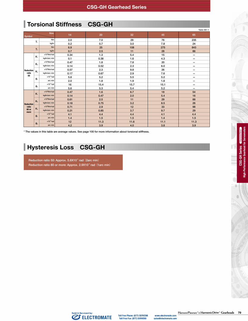
Reduction ratio 50: Approx. 5.8X10⁻⁴ rad (2arc min)Reduction ratio 80 or more: Approx. 2.9X10⁻⁴ rad (1arc min)
Only primary dimensions are shown in the drawings below. Refer to the confirmation drawing for detailed dimensions.Symbol
Size 14 20 32 45 65
Reductionratio 50
Reductionratio 80 or more
T1
T2
K1
K2
K3
θ1
θ2
K1
K2
K3
θ1
θ2
2.00.26.90.7
0.340.1
0.470.140.570.175.82.0165.6
0.470.140.610.180.710.214.11.4124.2
7.00.7252.51.3
0.381.8
0.522.3
0.675.21.8
15.45.31.6
0.472.5
0.752.9
0.854.41.5
11.33.9
293.0108115.41.67.82.39.82.95.51.9
15.75.46.72.0113.2123.74.41.5
11.64.0
767.827528154.3206.0267.65.21.8
15.15.2185.4298.5339.74.11.4
11.13.8
23524
84386——————————5416882698294.41.5
11.33.9
Nm
kgfm
Nm
kgfm
×104Nm/rad
kgfm/arc min
×104Nm/rad
kgfm/arc min
×104Nm/rad
kgfm/arc min
×10-4rad
arc min
×10-4rad
arc min
×104Nm/rad
kgfm/arc min
×104Nm/rad
kgfm/arc min
×104Nm/rad
kgfm/arc min
×10-4rad
arc min
×10-4rad
arc min
Torsional Stiffness CSG-GH CSG-GH-14 Outline Dimensions
Dimension Table
Table 081-1
* The values in this table are average values. See page 100 for more information about torsional stiffness.
Hysteresis Loss CSG-GH
Table 082-1(Unit: mm)
Flange Type Ⅰ
Flange Type Ⅱ
Output shaft shape: J2 (Shaft output without key) J6 (Shaft output with key and center tapped hole)
Figure 082-1
(Unit: mm)
H
4-Ø5.5
□60±0.5
1-Ø3H7×5
8-M4×7
Ø70
Ø30
22.5°
Ø56
h7 C0.5
Ø14
h7
Ø55.
8Ø4
0
478211 20
3
C0.5
B
Ø80
Ø19
ØA
(9.5)G
R0.45 45°
□60±1
C
F
F
H
□ 60±0.5
22.5°
Ø70
Ø30
1-Ø3H7×5
8-M4×74-Ø5.5
C0.5
Ø56
h7
Ø14
h7
Ø55.
8Ø4
0
3
8 47
M6 P=1Rubber cap
2021
1
B
Ø19
ØA Ø60
C.05
(9.5)G
R0.45
45°
C
M4×8
5
513 Ø5
6 h7
C0.5
Ø16
h7
Ø55.
8Ø4
0
R0.4
R0.4
25
Ø20
5828 9 21
38
M3 Hexagon socket head bolt
Grease filling port2 locations (symmetrical locations)
M6 P=1 Rubber capM3 Hexagon socket head bolt
Grease filling port2 locations (symmetrical locations)
4-D*3
4-D*3
Refer to the confirmation drawing for detailed dimensions. Dimensions of typical products are shown. Please contact us for other mounting options if the configurations shown above are not suitable for your particular motor. *1 May vary depending on motor interface dimensions. *2 The mass will vary slightly depending on the ratio and on the inside diameter of the input shaft coupling.*3 Tapped hole for motor mounting screw.
High
-per
form
ance
Gea
r Hea
ds fo
r Ser
vo M
otor
s ser
iesCS
F-GH
serie
s
CSG-GH Gearhead Series CSG-GH Gearhead Series
044 045
High
-per
form
ance
Gea
r Hea
ds fo
r Ser
vo M
otor
s ser
iesHP
GP se
ries
High
-per
form
ance
Gea
r Hea
ds fo
r Ser
vo M
otor
s ser
iesHP
G se
ries
High
-per
form
ance
Gea
r Hea
ds fo
r Ser
vo M
otor
s ser
iesCS
G-GH
serie
sHi
gh-p
erfo
rman
ce G
ear H
eads
for S
ervo
Mot
ors s
eries
CSF-
GH se
ries
High
-per
form
ance
Gea
r Hea
ds fo
r Ser
vo M
otor
s ser
iesHP
G se
ries (
Orth
ogon
al S
haft
Type
)
High
-per
form
ance
Gea
r Hea
ds fo
r Ser
vo M
otor
s ser
iesHP
GP se
ries
High
-per
form
ance
Gea
r Hea
ds fo
r Ser
vo M
otor
s ser
iesHP
G se
ries
High
-per
form
ance
Gea
r Hea
ds fo
r Ser
vo M
otor
s ser
iesCS
G-GH
serie
sHi
gh-p
erfo
rman
ce G
ear H
eads
for S
ervo
Mot
ors s
eries
CSF-
GH se
ries
High
-per
form
ance
Gea
r Hea
ds fo
r Ser
vo M
otor
s ser
iesHP
G se
ries (
Orth
ogon
al S
haft
Type
)
(Note) The dimension tolerances that are not specified vary depending on the manufacturing method. Please check the confirmation drawing or contact us for dimension tolerances not shown on the drawing above.
Shaft
B *1
1 30 50 6.5 35 55 6.0 8 20.5 32.5 0.88 0.76
A (H7) *1 C *1 G *1F (H7) *1
FlangeMin. Max. Max. Min. Max. Min. Max. Min. Max.
76
Flange
Type I
1 50 55 7 55 75 6.0 8 20.5 32.5 0.90 0.7876Type II
CouplingMass (kg) *2H *1
Typical
0.07
0.07
Moment of Inertia
(10-4kgm2)

80 Gearheads
CSG-GH Gearhead Series
High
-Per
form
ance
Gea
rhea
d fo
r Ser
vom
otor
s
High
-Per
form
ance
Gea
rhea
d fo
r Ser
vom
otor
s
CSG-
GH S
eries
CSG-
GH S
eries
High
-Per
form
ance
Gea
rhea
d fo
r Ser
vom
otor
s
High
-Per
form
ance
Gea
rhea
d fo
r Ser
vom
otor
s
CSF-
GH S
eries
CSF-
GH S
eries
Reduction ratio 50: Approx. 5.8X10⁻⁴ rad (2arc min)Reduction ratio 80 or more: Approx. 2.9X10⁻⁴ rad (1arc min)
Only primary dimensions are shown in the drawings below. Refer to the confirmation drawing for detailed dimensions.Symbol
Size 14 20 32 45 65
Reductionratio 50
Reductionratio 80 or more
T1
T2
K1
K2
K3
θ1
θ2
K1
K2
K3
θ1
θ2
2.00.26.90.7
0.340.1
0.470.140.570.175.82.0165.6
0.470.140.610.180.710.214.11.4124.2
7.00.7252.51.3
0.381.8
0.522.3
0.675.21.8
15.45.31.6
0.472.5
0.752.9
0.854.41.5
11.33.9
293.0108115.41.67.82.39.82.95.51.9
15.75.46.72.0113.2123.74.41.5
11.64.0
767.827528154.3206.0267.65.21.8
15.15.2185.4298.5339.74.11.4
11.13.8
23524
84386——————————5416882698294.41.5
11.33.9
Nm
kgfm
Nm
kgfm
×104Nm/rad
kgfm/arc min
×104Nm/rad
kgfm/arc min
×104Nm/rad
kgfm/arc min
×10-4rad
arc min
×10-4rad
arc min
×104Nm/rad
kgfm/arc min
×104Nm/rad
kgfm/arc min
×104Nm/rad
kgfm/arc min
×10-4rad
arc min
×10-4rad
arc min
Torsional Stiffness CSG-GH CSG-GH-14 Outline Dimensions
Dimension Table
Table 081-1
* The values in this table are average values. See page 100 for more information about torsional stiffness.
Hysteresis Loss CSG-GH
Table 082-1(Unit: mm)
Flange Type Ⅰ
Flange Type Ⅱ
Output shaft shape: J2 (Shaft output without key) J6 (Shaft output with key and center tapped hole)
Figure 082-1
(Unit: mm)
H
4-Ø5.5
□60±0.5
1-Ø3H7×5
8-M4×7
Ø70
Ø30
22.5°
Ø56
h7 C0.5
Ø14
h7
Ø55.
8Ø4
047821
1 203
C0.5
B
Ø80
Ø19
ØA
(9.5)G
R0.45 45°
□60±1
C
F
F
H
□ 60±0.5
22.5°
Ø70
Ø30
1-Ø3H7×5
8-M4×74-Ø5.5
C0.5
Ø56
h7
Ø14
h7
Ø55.
8Ø4
0
3
8 47
M6 P=1Rubber cap
2021
1
B
Ø19
ØA Ø60
C.05
(9.5)G
R0.45
45°
C
M4×8
5
513 Ø5
6 h7
C0.5
Ø16
h7
Ø55.
8Ø4
0
R0.4
R0.4
25
Ø20
5828 9 21
38
M3 Hexagon socket head bolt
Grease filling port2 locations (symmetrical locations)
M6 P=1 Rubber capM3 Hexagon socket head bolt
Grease filling port2 locations (symmetrical locations)
4-D*3
4-D*3
Refer to the confirmation drawing for detailed dimensions. Dimensions of typical products are shown. Please contact us for other mounting options if the configurations shown above are not suitable for your particular motor. *1 May vary depending on motor interface dimensions. *2 The mass will vary slightly depending on the ratio and on the inside diameter of the input shaft coupling.*3 Tapped hole for motor mounting screw.
High
-per
form
ance
Gea
r Hea
ds fo
r Ser
vo M
otor
s ser
iesCS
F-GH
serie
s
CSG-GH Gearhead Series CSG-GH Gearhead Series
044 045
High
-per
form
ance
Gea
r Hea
ds fo
r Ser
vo M
otor
s ser
iesHP
GP se
ries
High
-per
form
ance
Gea
r Hea
ds fo
r Ser
vo M
otor
s ser
iesHP
G se
ries
High
-per
form
ance
Gea
r Hea
ds fo
r Ser
vo M
otor
s ser
iesCS
G-GH
serie
sHi
gh-p
erfo
rman
ce G
ear H
eads
for S
ervo
Mot
ors s
eries
CSF-
GH se
ries
High
-per
form
ance
Gea
r Hea
ds fo
r Ser
vo M
otor
s ser
iesHP
G se
ries (
Orth
ogon
al S
haft
Type
)
High
-per
form
ance
Gea
r Hea
ds fo
r Ser
vo M
otor
s ser
iesHP
GP se
ries
High
-per
form
ance
Gea
r Hea
ds fo
r Ser
vo M
otor
s ser
iesHP
G se
ries
High
-per
form
ance
Gea
r Hea
ds fo
r Ser
vo M
otor
s ser
iesCS
G-GH
serie
sHi
gh-p
erfo
rman
ce G
ear H
eads
for S
ervo
Mot
ors s
eries
CSF-
GH se
ries
High
-per
form
ance
Gea
r Hea
ds fo
r Ser
vo M
otor
s ser
iesHP
G se
ries (
Orth
ogon
al S
haft
Type
)
(Note) The dimension tolerances that are not specified vary depending on the manufacturing method. Please check the confirmation drawing or contact us for dimension tolerances not shown on the drawing above.
Shaft
B *1
1 30 50 6.5 35 55 6.0 8 20.5 32.5 0.88 0.76
A (H7) *1 C *1 G *1F (H7) *1
FlangeMin. Max. Max. Min. Max. Min. Max. Min. Max.
76
Flange
Type I
1 50 55 7 55 75 6.0 8 20.5 32.5 0.90 0.7876Type II
CouplingMass (kg) *2H *1
Typical
0.07
0.07
Moment of Inertia
(10-4kgm2)

81Gearheads
CSG-GH Gearhead Series
High
-Per
form
ance
Gea
rhea
d fo
r Ser
vom
otor
s
High
-Per
form
ance
Gea
rhea
d fo
r Ser
vom
otor
s
CSG-
GH S
eries
CSG-
GH S
eries
High
-Per
form
ance
Gea
rhea
d fo
r Ser
vom
otor
s
High
-Per
form
ance
Gea
rhea
d fo
r Ser
vom
otor
s
CSF-
GH S
eries
CSF-
GH S
eries
CSG-GH-20 Outline Dimensions CSG-GH-32 Outline Dimensions
Dimension TableDimension TableTable 083-1(Unit: mm)
Only primary dimensions are shown in the drawings below. Refer to the confirmation drawing for detailed dimensions.Figure 083-1
(Unit: mm)
* Output part dimension is the same as the flange type III.* Output part dimension is the same as the flange type III.
Ø32
8
721
M6×12
Ø85
H7
Ø25
H7
Ø84
Ø59
C1
36
8042 11 1027
8
R0.4
R0.4
B
10 62
Ø89
C0.5
ØAØ29F
(11)G
ØC
45°
H
Ø105
1-Ø5H7×8
22.5
°
□90±0.56
4-Ø9
Ø458-M6×10
5
C0.5
Ø85
h7
Ø24
H7
Ø84
Ø59
6210271
826
Ø110ØAØ2
9F
C0.5
B
R0.4
G(11)
ØC
45°
10 5526.5 28.5
C0.5
(11)G
Ø19
ØAØ5
5Ø8
9FB
ØC
45°
Flange Type Ⅲ
(Unit: mm)
Only primary dimensions are shown in the drawings below. Refer to the confirmation drawing for detailed dimensions.
* Output part dimension is the same as the flange type III. * Output part dimension is the same as the flange type III.
12
358
1335 131682
133
M10×20
C1
Ø115
h7
Ø40
h7
Ø114
Ø84
70
Ø44
R0.4
R0.4
1-Ø5H7×8□120±0.62
4-Ø1110-M8×12
Ø135
18° Ø60
R0.4(26)(37)
5C0.5
Ø115
h7
Ø32
H7
Ø114
Ø84
B
ØF Ø42
ØA
45°
E*436
92.555.5
25
3713
35 13105.5
H
C0.5
ØC
7520
13
C0.5
(14)(25)
G
G
G
B
Ø116ØAØ3
5ØF
ØC
45°
13 8346
2812
ØF
BC0.5
(22)(33)
Ø35
ØA Ø140
ØC
45°
Output shaft shape: J2 (Shaft output without key) J6 (Shaft output with key and center tapped hole)
Rubber capM6 P=1
Grease filling port2 locations (symmetrical locations)
M3 Hexagon socket head bolt
Rubber capM6 P=1
Grease filling port2 locations (symmetrical locations)
M4 Hexagon socket head bolt
Rubber capRubber cap
Rubber cap
M6 P=1
Grease filling port2 locations (symmetrical locations)
M6 P=1
Grease filling port2 locations (symmetrical locations)
M6 P=1
Grease filling port2 locations (symmetrical locations)
M4 Hexagon socket head boltM4 Hexagon socket head bolt
M4 Hexagon socket head bolt
Rubber capM6 P=1
Grease filling port2 locations (symmetrical locations) M4 Hexagon
socket head bolt
(Unit: mm) Table 084-1
Figure 084-1
Refer to the confirmation drawing for detailed dimensions. Dimensions of typical products are shown. Please contact us for other mounting options if the configurations shown above are not suitable for your particular motor. *1 May vary depending on motor interface dimensions. *2 The mass will vary slightly depending on the ratio and on the inside diameter of the input shaft coupling.*3 Tapped hole for motor mounting screw.
Refer to the confirmation drawing for detailed dimensions. Dimensions of typical products are shown. Please contact us for other mounting options if the configurations shown above are not suitable for your particular motor. *1 May vary depending on motor interface dimensions. *2 The mass will vary slightly depending on the ratio and on the inside diameter of the input shaft coupling.*3 Tapped hole for motor mounting screw.
4-D*3
4-D*3
4-D*3
4-D*3
4-D*3
HH H H
High
-per
form
ance
Gea
r Hea
ds fo
r Ser
vo M
otor
s ser
iesCS
F-GH
serie
s
CSG-GH Gearhead Series CSG-GH Gearhead Series
046 047
High
-per
form
ance
Gea
r Hea
ds fo
r Ser
vo M
otor
s ser
iesHP
GP se
ries
High
-per
form
ance
Gea
r Hea
ds fo
r Ser
vo M
otor
s ser
iesHP
G se
ries
High
-per
form
ance
Gea
r Hea
ds fo
r Ser
vo M
otor
s ser
iesCS
G-GH
serie
sHi
gh-p
erfo
rman
ce G
ear H
eads
for S
ervo
Mot
ors s
eries
CSF-
GH se
ries
High
-per
form
ance
Gea
r Hea
ds fo
r Ser
vo M
otor
s ser
iesHP
G se
ries (
Orth
ogon
al S
haft
Type
)
High
-per
form
ance
Gea
r Hea
ds fo
r Ser
vo M
otor
s ser
iesHP
GP se
ries
High
-per
form
ance
Gea
r Hea
ds fo
r Ser
vo M
otor
s ser
iesHP
G se
ries
High
-per
form
ance
Gea
r Hea
ds fo
r Ser
vo M
otor
s ser
iesCS
G-GH
serie
sHi
gh-p
erfo
rman
ce G
ear H
eads
for S
ervo
Mot
ors s
eries
CSF-
GH se
ries
High
-per
form
ance
Gea
r Hea
ds fo
r Ser
vo M
otor
s ser
iesHP
G se
ries (
Orth
ogon
al S
haft
Type
)
Flange Type Ⅰ
Flange Type IIⅠ
Flange Type Ⅱ Flange Type Ⅰ Flange Type Ⅱ
Output shaft shape: J2 (Shaft output without key) J6 (Shaft output with key and center tapped hole)
(Note) The dimension tolerances that are not specified vary depending on the manufacturing method. Please check the confirmation drawing or contact us for dimension tolerances not shown on the drawing above.
(Note) The dimension tolerances that are not specified vary depending on the manufacturing method. Please check the confirmation drawing or contact us for dimension tolerances not shown on the drawing above.
4-D*1
Shaft
1 30 45 5 35 50 7.0 7.8 22.0 33.0 2.3 1.9
FlangeMin. Max. Max. Min. Max. Min. Max. Min. Max.
92.0
Flange
Type I
2 50 79 10 55 84 8.0 14.6 24.0 32.0 2.6 2.299.0
2 50 100 10 55 105 8.0 14.6 24.0 32.0 2.8 2.499.0
Type II
Type III
CouplingTypical
0.28
0.42
0.42
Moment of Inertia
(10-4kgm2)
Shaft
3
3
50 105 10 55 11010.8 19.6 27.0 6.4 5.0
6.4 5.0
FlangeMin. Max. Max. Min. Max. Min. Max. Min. Max.
123
Flange
Type I
2 60 175 *1 5 70 225 *1 16.0 25.8 39.0 7.9 6.5140.5
1
1
35 130 *1 7 40 135 *1
8.8 19.6 35.0
578.8 19.6 27.0 57
72
6510.8 19.6 35.0 65
6.6 5.26.6 5.2
131
Type II
Type III
Coupling Max.
2.7
2.7
2.0
Moment of Inertia
(10-4kgm2)
B *1A (H7) *1 C *1 G *1F (H7) *1 Mass (kg) *2H *1
B *1A (H7) *1 C *1 G *1F (H7) *1 Mass (kg) *2H *1

82 Gearheads
CSG-GH Gearhead Series
High
-Per
form
ance
Gea
rhea
d fo
r Ser
vom
otor
s
High
-Per
form
ance
Gea
rhea
d fo
r Ser
vom
otor
s
CSG-
GH S
eries
CSG-
GH S
eries
High
-Per
form
ance
Gea
rhea
d fo
r Ser
vom
otor
s
High
-Per
form
ance
Gea
rhea
d fo
r Ser
vom
otor
s
CSF-
GH S
eries
CSF-
GH S
eries
CSG-GH-20 Outline Dimensions CSG-GH-32 Outline Dimensions
Dimension TableDimension TableTable 083-1(Unit: mm)
Only primary dimensions are shown in the drawings below. Refer to the confirmation drawing for detailed dimensions.Figure 083-1
(Unit: mm)
* Output part dimension is the same as the flange type III.* Output part dimension is the same as the flange type III.
Ø32
8
721
M6×12
Ø85
H7
Ø25
H7
Ø84
Ø59
C1
36
8042 11 1027
8
R0.4
R0.4
B
10 62
Ø89
C0.5
ØAØ29F
(11)G
ØC
45°
H
Ø105
1-Ø5H7×8
22.5
°
□90±0.56
4-Ø9
Ø458-M6×10
5
C0.5
Ø85
h7
Ø24
H7
Ø84
Ø59
6210271
826
Ø110ØAØ2
9F
C0.5
B
R0.4
G(11)
ØC
45°
10 5526.5 28.5
C0.5
(11)G
Ø19
ØAØ5
5Ø8
9FB
ØC
45°
Flange Type Ⅲ
(Unit: mm)
Only primary dimensions are shown in the drawings below. Refer to the confirmation drawing for detailed dimensions.
* Output part dimension is the same as the flange type III. * Output part dimension is the same as the flange type III.
12
358
1335 131682
133
M10×20
C1
Ø115
h7
Ø40
h7
Ø114
Ø84
70
Ø44
R0.4
R0.4
1-Ø5H7×8□120±0.62
4-Ø1110-M8×12
Ø135
18° Ø60
R0.4(26)(37)
5C0.5
Ø115
h7
Ø32
H7
Ø114
Ø84
B
ØF Ø42
ØA
45°
E*436
92.555.5
25
3713
35 13105.5
H
C0.5
ØC
7520
13
C0.5
(14)(25)
G
G
G
B
Ø116ØAØ3
5ØF
ØC
45°
13 8346
2812
ØF
BC0.5
(22)(33)
Ø35
ØA Ø140
ØC
45°
Output shaft shape: J2 (Shaft output without key) J6 (Shaft output with key and center tapped hole)
Rubber capM6 P=1
Grease filling port2 locations (symmetrical locations)
M3 Hexagon socket head bolt
Rubber capM6 P=1
Grease filling port2 locations (symmetrical locations)
M4 Hexagon socket head bolt
Rubber capRubber cap
Rubber cap
M6 P=1
Grease filling port2 locations (symmetrical locations)
M6 P=1
Grease filling port2 locations (symmetrical locations)
M6 P=1
Grease filling port2 locations (symmetrical locations)
M4 Hexagon socket head boltM4 Hexagon socket head bolt
M4 Hexagon socket head bolt
Rubber capM6 P=1
Grease filling port2 locations (symmetrical locations) M4 Hexagon
socket head bolt
(Unit: mm) Table 084-1
Figure 084-1
Refer to the confirmation drawing for detailed dimensions. Dimensions of typical products are shown. Please contact us for other mounting options if the configurations shown above are not suitable for your particular motor. *1 May vary depending on motor interface dimensions. *2 The mass will vary slightly depending on the ratio and on the inside diameter of the input shaft coupling.*3 Tapped hole for motor mounting screw.
Refer to the confirmation drawing for detailed dimensions. Dimensions of typical products are shown. Please contact us for other mounting options if the configurations shown above are not suitable for your particular motor. *1 May vary depending on motor interface dimensions. *2 The mass will vary slightly depending on the ratio and on the inside diameter of the input shaft coupling.*3 Tapped hole for motor mounting screw.
4-D*3
4-D*3
4-D*3
4-D*3
4-D*3
HH H H
High
-per
form
ance
Gea
r Hea
ds fo
r Ser
vo M
otor
s ser
iesCS
F-GH
serie
s
CSG-GH Gearhead Series CSG-GH Gearhead Series
046 047
High
-per
form
ance
Gea
r Hea
ds fo
r Ser
vo M
otor
s ser
iesHP
GP se
ries
High
-per
form
ance
Gea
r Hea
ds fo
r Ser
vo M
otor
s ser
iesHP
G se
ries
High
-per
form
ance
Gea
r Hea
ds fo
r Ser
vo M
otor
s ser
iesCS
G-GH
serie
sHi
gh-p
erfo
rman
ce G
ear H
eads
for S
ervo
Mot
ors s
eries
CSF-
GH se
ries
High
-per
form
ance
Gea
r Hea
ds fo
r Ser
vo M
otor
s ser
iesHP
G se
ries (
Orth
ogon
al S
haft
Type
)
High
-per
form
ance
Gea
r Hea
ds fo
r Ser
vo M
otor
s ser
iesHP
GP se
ries
High
-per
form
ance
Gea
r Hea
ds fo
r Ser
vo M
otor
s ser
iesHP
G se
ries
High
-per
form
ance
Gea
r Hea
ds fo
r Ser
vo M
otor
s ser
iesCS
G-GH
serie
sHi
gh-p
erfo
rman
ce G
ear H
eads
for S
ervo
Mot
ors s
eries
CSF-
GH se
ries
High
-per
form
ance
Gea
r Hea
ds fo
r Ser
vo M
otor
s ser
iesHP
G se
ries (
Orth
ogon
al S
haft
Type
)
Flange Type Ⅰ
Flange Type IIⅠ
Flange Type Ⅱ Flange Type Ⅰ Flange Type Ⅱ
Output shaft shape: J2 (Shaft output without key) J6 (Shaft output with key and center tapped hole)
(Note) The dimension tolerances that are not specified vary depending on the manufacturing method. Please check the confirmation drawing or contact us for dimension tolerances not shown on the drawing above.
(Note) The dimension tolerances that are not specified vary depending on the manufacturing method. Please check the confirmation drawing or contact us for dimension tolerances not shown on the drawing above.
4-D*1
Shaft
1 30 45 5 35 50 7.0 7.8 22.0 33.0 2.3 1.9
FlangeMin. Max. Max. Min. Max. Min. Max. Min. Max.
92.0
Flange
Type I
2 50 79 10 55 84 8.0 14.6 24.0 32.0 2.6 2.299.0
2 50 100 10 55 105 8.0 14.6 24.0 32.0 2.8 2.499.0
Type II
Type III
CouplingTypical
0.28
0.42
0.42
Moment of Inertia
(10-4kgm2)
Shaft
3
3
50 105 10 55 11010.8 19.6 27.0 6.4 5.0
6.4 5.0
FlangeMin. Max. Max. Min. Max. Min. Max. Min. Max.
123
Flange
Type I
2 60 175 *1 5 70 225 *1 16.0 25.8 39.0 7.9 6.5140.5
1
1
35 130 *1 7 40 135 *1
8.8 19.6 35.0
578.8 19.6 27.0 57
72
6510.8 19.6 35.0 65
6.6 5.26.6 5.2
131
Type II
Type III
Coupling Max.
2.7
2.7
2.0
Moment of Inertia
(10-4kgm2)
B *1A (H7) *1 C *1 G *1F (H7) *1 Mass (kg) *2H *1
B *1A (H7) *1 C *1 G *1F (H7) *1 Mass (kg) *2H *1

83Gearheads
CSG-GH Gearhead Series
High
-Per
form
ance
Gea
rhea
d fo
r Ser
vom
otor
s
High
-Per
form
ance
Gea
rhea
d fo
r Ser
vom
otor
s
CSG-
GH S
eries
CSG-
GH S
eries
High
-Per
form
ance
Gea
rhea
d fo
r Ser
vom
otor
s
High
-Per
form
ance
Gea
rhea
d fo
r Ser
vom
otor
s
CSF-
GH S
eries
CSF-
GH S
eries
Figure 086-1
(Unit: mm)
(Note) If using size 45 or 65 gearheads with a shaft output and required torques are as high as the "Limit for Momentary Torque," you must use a J2 shaft configuration (shaft output without key ) with a friction / compression coupling to the output load. This is due to the limited strength of the connection using a keyed shaft.
62.5
M16×35
20
12
R0.4
R0.4
C1
Ø220
h8
Ø70
h7
Ø80
Ø214
Ø168
192100
85
2512.5
13
5735
Ø8H7×12
2-M10×20□230±265 65
4-Ø18
Ø120 Ø260
10-M16×24R0.4
C0.5
10
Ø220
h8
Ø214
Ø60
H7
Ø168
H1322557
2 55 65.512.5
Ø58
C0.5
(28.5)
ØA
Ø225
ØC
45°
ØF
13B
□230±2
4-Ø18 10-M16×24
2-M10×20
Ø8H7×12
Ø260Ø 120
65 65
C0.5
10
R0.4
2 5513 12.5
H57
5465.525 119.5
C0.5 ØC
45°(16)
ØFØ5
8
Ø225
Ø137
ØA
(23)
(58)
Ø220
h8
Ø60
H7
Ø168
Ø214
(Note) If using size 45 or 65 gearheads with a shaft output and require torques as high as the "Limit for Momentary Torque" you must use a J2 shaft configuration (shaft output without key) with a friction / compression coupling to the output load. This is due to the limited strength of the connection using a keyed shaft.
□170±24-Ø14
10-M12×181-Ø6H7×9
Ø190Ø92
C0.510
Ø165
h8
Ø47
H7
Ø163
Ø122
R0.4
25351
13
16 87 25H
45 42
B
C0.5
(28.5)G
G
ØFØ5
8ØA
Ø165
ØC
45°
14
944
.5
M10×20
Ø165
h8
Ø50
h7
Ø163
Ø122
C1 R0.4
R0.4
70
15682 21 53 16
13
Ø56
□170±2
4-Ø14
Ø92 Ø190
1-Ø6H7×910-M12×18
C0.5
R0.4
10
Ø165
h8
Ø47
H7
Ø167ØAØ5
0ØF
Ø163
Ø122
53512
16H
13
9858
BC0.5
(14.5)
(17)
ØC
(62)
45°
CSG-GH-45 Outline Dimensions
Dimension Table
CSG-GH-65 Outline Dimensions
Dimension TableTable 085-1
Table 086-1(Unit: mm)
(Unit: mm)
Only primary dimensions are shown in the drawings below. Refer to the confirmation drawing for detailed dimensions. Only primary dimensions are shown in the drawings below. Refer to the confirmation drawing for detailed dimensions.
Flange Type Ⅰ Flange Type Ⅰ
Flange Type Ⅱ Flange Type Ⅱ
Output shaft shape: J2 (Shaft output without key) J6 (Shaft output with key and center tapped hole)
Output shaft shape: J2 (Shaft output without key) J6 (Shaft output with key and center tapped hole)
Figure 085-1
(Unit: mm)
E*1 E*1
B
G
G4-D*3
4-D*3
4-D*3
4-D*3
Refer to the confirmation drawing for detailed dimensions. Dimensions of typical products are shown. Please contact us for other mounting options if the configurations shown above are not suitable for your particular motor. *1 May vary depending on motor interface dimensions. *2 The mass will vary slightly depending on the ratio and on the inside diameter of the input shaft coupling.*3 Tapped hole for motor mounting screw.
Refer to the confirmation drawing for detailed dimensions. Dimensions of typical products are shown. Please contact us for other mounting options if the configurations shown above are not suitable for your particular motor. *1 May vary depending on motor interface dimensions. *2 The mass will vary slightly depending on the ratio and on the inside diameter of the input shaft coupling.*3 Tapped hole for motor mounting screw.
High
-per
form
ance
Gea
r Hea
ds fo
r Ser
vo M
otor
s ser
iesCS
F-GH
serie
s
CSG-GH Gearhead Series CSG-GH Gearhead Series
048 049
High
-per
form
ance
Gea
r Hea
ds fo
r Ser
vo M
otor
s ser
iesHP
GP se
ries
High
-per
form
ance
Gea
r Hea
ds fo
r Ser
vo M
otor
s ser
iesHP
G se
ries
High
-per
form
ance
Gea
r Hea
ds fo
r Ser
vo M
otor
s ser
iesCS
G-GH
serie
sHi
gh-p
erfo
rman
ce G
ear H
eads
for S
ervo
Mot
ors s
eries
CSF-
GH se
ries
High
-per
form
ance
Gea
r Hea
ds fo
r Ser
vo M
otor
s ser
iesHP
G se
ries (
Orth
ogon
al S
haft
Type
)
High
-per
form
ance
Gea
r Hea
ds fo
r Ser
vo M
otor
s ser
iesHP
GP se
ries
High
-per
form
ance
Gea
r Hea
ds fo
r Ser
vo M
otor
s ser
iesHP
G se
ries
High
-per
form
ance
Gea
r Hea
ds fo
r Ser
vo M
otor
s ser
iesCS
G-GH
serie
sHi
gh-p
erfo
rman
ce G
ear H
eads
for S
ervo
Mot
ors s
eries
CSF-
GH se
ries
High
-per
form
ance
Gea
r Hea
ds fo
r Ser
vo M
otor
s ser
iesHP
G se
ries (
Orth
ogon
al S
haft
Type
)
Rubber cap
Rubber cap
M6 P=1
Grease filling port2 locations (symmetrical locations)
M6 P=1
Grease filling port2 locations (symmetrical locations)
M6 Hexagon socket head bolt
M6 Hexagon socket head bolt
Rubber cap
Rubber cap
M6 P=1
Grease filling port2 locations (symmetrical locations)
M6 P=1
Grease filling port2 locations (symmetrical locations)
M6 Hexagon socket head bolt
M6 Hexagon socket head bolt
(Note) The dimension tolerances that are not specified vary depending on the manufacturing method. Please check the confirmation drawing or contact us for dimension tolerances not shown on the drawing above. (Note) The dimension tolerances that are not specified vary depending on the manufacturing
method. Please check the confirmation drawing or contact us for dimension tolerances not shown on the drawing above.
Shaft
1 95 110 10 105 125 19.0 39.3 32.0 72 36.2 27.6
FlangeMin. Max. Max. Min. Max. Min. Max. Min. Max.
201.5 51
51
Flange
Type I
1 70 215 *1 6.5 80 260 *1 19.0 39.3 44.5 84.5 38.3 29.7214Type II
CouplingMoment of Inertia
Max. (10-4kgm2)
Shaft
1 70 119 7 80 157 14.0 29.4 30.5 72 17.3 14.3
FlangeMin. Max. Max. Min. Max. Min. Max. Min. Max.
167
Flange
Type I
2 70 119 7 80 157 19.0 41 30.5 68 17.3 14.3167
1 70 175 *1 6.5 80 225 *1 14.0 29.4 44.5 86 17.7 14.7181
2 70 175 *1 6.5 80 225 *1 19.0 41 44.5 82 17.7 14.7181
Type II
Coupling Typical
11
11
11
11
Moment of Inertia
(10-4kgm2) B *1A (H7) *1 C *1 G *1F (H7) *1 Mass (kg) *2H *1
B *1A (H7) *1 C *1 G *1F (H7) *1 Mass (kg) *2H *1

84 Gearheads
CSG-GH Gearhead Series
High
-Per
form
ance
Gea
rhea
d fo
r Ser
vom
otor
s
High
-Per
form
ance
Gea
rhea
d fo
r Ser
vom
otor
s
CSG-
GH S
eries
CSG-
GH S
eries
High
-Per
form
ance
Gea
rhea
d fo
r Ser
vom
otor
s
High
-Per
form
ance
Gea
rhea
d fo
r Ser
vom
otor
s
CSF-
GH S
eries
CSF-
GH S
eries
Figure 086-1
(Unit: mm)
(Note) If using size 45 or 65 gearheads with a shaft output and required torques are as high as the "Limit for Momentary Torque," you must use a J2 shaft configuration (shaft output without key ) with a friction / compression coupling to the output load. This is due to the limited strength of the connection using a keyed shaft.
62.5
M16×35
20
12
R0.4
R0.4
C1
Ø220
h8
Ø70
h7
Ø80
Ø214
Ø168
192100
85
2512.5
13
5735
Ø8H7×12
2-M10×20□230±265 65
4-Ø18
Ø120 Ø260
10-M16×24R0.4
C0.5
10
Ø220
h8
Ø214
Ø60
H7
Ø168
H1322557
2 55 65.512.5
Ø58
C0.5
(28.5)
ØA
Ø225
ØC
45°
ØF
13B
□230±2
4-Ø18 10-M16×24
2-M10×20
Ø8H7×12
Ø260Ø 120
65 65
C0.5
10
R0.4
2 5513 12.5
H57
5465.525 119.5
C0.5 ØC
45°(16)
ØFØ5
8
Ø225
Ø137
ØA
(23)
(58)
Ø220
h8
Ø60
H7
Ø168
Ø214
(Note) If using size 45 or 65 gearheads with a shaft output and require torques as high as the "Limit for Momentary Torque" you must use a J2 shaft configuration (shaft output without key) with a friction / compression coupling to the output load. This is due to the limited strength of the connection using a keyed shaft.
□170±24-Ø14
10-M12×181-Ø6H7×9
Ø190Ø92
C0.510
Ø165
h8
Ø47
H7
Ø163
Ø122
R0.4
25351
13
16 87 25H
45 42
B
C0.5
(28.5)G
G
ØFØ5
8ØA
Ø165
ØC
45°
14
944
.5
M10×20
Ø165
h8
Ø50
h7
Ø163
Ø122
C1 R0.4
R0.4
70
15682 21 53 16
13
Ø56
□170±2
4-Ø14
Ø92 Ø190
1-Ø6H7×910-M12×18
C0.5
R0.4
10
Ø165
h8
Ø47
H7
Ø167ØAØ5
0ØF
Ø163
Ø122
53512
16H
13
9858
BC0.5
(14.5)
(17)
ØC
(62)
45°
CSG-GH-45 Outline Dimensions
Dimension Table
CSG-GH-65 Outline Dimensions
Dimension TableTable 085-1
Table 086-1(Unit: mm)
(Unit: mm)
Only primary dimensions are shown in the drawings below. Refer to the confirmation drawing for detailed dimensions. Only primary dimensions are shown in the drawings below. Refer to the confirmation drawing for detailed dimensions.
Flange Type Ⅰ Flange Type Ⅰ
Flange Type Ⅱ Flange Type Ⅱ
Output shaft shape: J2 (Shaft output without key) J6 (Shaft output with key and center tapped hole)
Output shaft shape: J2 (Shaft output without key) J6 (Shaft output with key and center tapped hole)
Figure 085-1
(Unit: mm)
E*1 E*1
B
G
G4-D*3
4-D*3
4-D*3
4-D*3
Refer to the confirmation drawing for detailed dimensions. Dimensions of typical products are shown. Please contact us for other mounting options if the configurations shown above are not suitable for your particular motor. *1 May vary depending on motor interface dimensions. *2 The mass will vary slightly depending on the ratio and on the inside diameter of the input shaft coupling.*3 Tapped hole for motor mounting screw.
Refer to the confirmation drawing for detailed dimensions. Dimensions of typical products are shown. Please contact us for other mounting options if the configurations shown above are not suitable for your particular motor. *1 May vary depending on motor interface dimensions. *2 The mass will vary slightly depending on the ratio and on the inside diameter of the input shaft coupling.*3 Tapped hole for motor mounting screw.
High
-per
form
ance
Gea
r Hea
ds fo
r Ser
vo M
otor
s ser
iesCS
F-GH
serie
s
CSG-GH Gearhead Series CSG-GH Gearhead Series
048 049
High
-per
form
ance
Gea
r Hea
ds fo
r Ser
vo M
otor
s ser
iesHP
GP se
ries
High
-per
form
ance
Gea
r Hea
ds fo
r Ser
vo M
otor
s ser
iesHP
G se
ries
High
-per
form
ance
Gea
r Hea
ds fo
r Ser
vo M
otor
s ser
iesCS
G-GH
serie
sHi
gh-p
erfo
rman
ce G
ear H
eads
for S
ervo
Mot
ors s
eries
CSF-
GH se
ries
High
-per
form
ance
Gea
r Hea
ds fo
r Ser
vo M
otor
s ser
iesHP
G se
ries (
Orth
ogon
al S
haft
Type
)
High
-per
form
ance
Gea
r Hea
ds fo
r Ser
vo M
otor
s ser
iesHP
GP se
ries
High
-per
form
ance
Gea
r Hea
ds fo
r Ser
vo M
otor
s ser
iesHP
G se
ries
High
-per
form
ance
Gea
r Hea
ds fo
r Ser
vo M
otor
s ser
iesCS
G-GH
serie
sHi
gh-p
erfo
rman
ce G
ear H
eads
for S
ervo
Mot
ors s
eries
CSF-
GH se
ries
High
-per
form
ance
Gea
r Hea
ds fo
r Ser
vo M
otor
s ser
iesHP
G se
ries (
Orth
ogon
al S
haft
Type
)
Rubber cap
Rubber cap
M6 P=1
Grease filling port2 locations (symmetrical locations)
M6 P=1
Grease filling port2 locations (symmetrical locations)
M6 Hexagon socket head bolt
M6 Hexagon socket head bolt
Rubber cap
Rubber cap
M6 P=1
Grease filling port2 locations (symmetrical locations)
M6 P=1
Grease filling port2 locations (symmetrical locations)
M6 Hexagon socket head bolt
M6 Hexagon socket head bolt
(Note) The dimension tolerances that are not specified vary depending on the manufacturing method. Please check the confirmation drawing or contact us for dimension tolerances not shown on the drawing above. (Note) The dimension tolerances that are not specified vary depending on the manufacturing
method. Please check the confirmation drawing or contact us for dimension tolerances not shown on the drawing above.
Shaft
1 95 110 10 105 125 19.0 39.3 32.0 72 36.2 27.6
FlangeMin. Max. Max. Min. Max. Min. Max. Min. Max.
201.5 51
51
Flange
Type I
1 70 215 *1 6.5 80 260 *1 19.0 39.3 44.5 84.5 38.3 29.7214Type II
CouplingMoment of Inertia
Max. (10-4kgm2)
Shaft
1 70 119 7 80 157 14.0 29.4 30.5 72 17.3 14.3
FlangeMin. Max. Max. Min. Max. Min. Max. Min. Max.
167
Flange
Type I
2 70 119 7 80 157 19.0 41 30.5 68 17.3 14.3167
1 70 175 *1 6.5 80 225 *1 14.0 29.4 44.5 86 17.7 14.7181
2 70 175 *1 6.5 80 225 *1 19.0 41 44.5 82 17.7 14.7181
Type II
Coupling Typical
11
11
11
11
Moment of Inertia
(10-4kgm2) B *1A (H7) *1 C *1 G *1F (H7) *1 Mass (kg) *2H *1
B *1A (H7) *1 C *1 G *1F (H7) *1 Mass (kg) *2H *1

85Gearheads
CSG-GH Gearhead Series
High
-Per
form
ance
Gea
rhea
d fo
r Ser
vom
otor
s
High
-Per
form
ance
Gea
rhea
d fo
r Ser
vom
otor
s
CSG-
GH S
eries
CSG-
GH S
eries
High
-Per
form
ance
Gea
rhea
d fo
r Ser
vom
otor
s
High
-Per
form
ance
Gea
rhea
d fo
r Ser
vom
otor
s
CSF-
GH S
eries
CSF-
GH S
eries
32
■NOTES
NOTES
Harmonic Drive®
CSG/CSF Gearhead SeriesServomotor Matching TableMotor flanges and input couplings have been prepared for all motors listed in the servomotor matching table. Please contact Harmonic Drive Systems' sales office if using a motor which is not listed in the matching table.The motor must be torque limited if using a motor capable of producing more output torque than the repeated peak torque listed in the rating table.The gearheads listed in the servomotor matching table are selected based upon the peak torque of the motor.Please contact Harmonic Drive Systems' sales office if you use a motor under the conditions when a load greater than the motor maximum torque is applied to the output shaft.The gearheads listed in the servo matching table should be used for “preliminary” selection. Be sure to check the machine operating conditions before making the "final” selection of the gear size and ratio.Please double check the dimensions shown on the gearhead confirmation drawing with the motor drawing before ordering.

86 Gearheads
CSG-GH/CSF-GH Gearhead Series
HPG
Stan
dard
Ser
iesHi
gh-P
erfo
rman
ce G
earh
ead
for S
ervo
mot
ors
HPG
Stan
dard
Ser
iesHi
gh-P
erfo
rman
ce G
earh
ead
for S
ervo
mot
ors
High
-Per
form
ance
Gea
rhea
d fo
r Ser
vom
otor
s
High
-Per
form
ance
Gea
rhea
d fo
r Ser
vom
otor
s HP
GP S
eries
HPGP
Ser
ies
High
-Per
form
ance
Gea
rhea
d fo
r Ser
vom
otor
s
High
-Per
form
ance
Gea
rhea
d fo
r Ser
vom
otor
s
CSG-
GH S
eries
CSG-
GH S
eries
High
-Per
form
ance
Gea
rhea
d fo
r Ser
vom
otor
s
High
-Per
form
ance
Gea
rhea
d fo
r Ser
vom
otor
s
High
-Per
form
ance
Gea
rhea
d fo
r Ser
vom
otor
s
High
-Per
form
ance
Gea
rhea
d fo
r Ser
vom
otor
s
CSF-
GH S
eries
CSF-
GH S
eries
High
-Per
form
ance
Gea
rhea
d fo
r Ser
vom
otor
s
High
-Per
form
ance
Gea
rhea
d fo
r Ser
vom
otor
s
CSF-
GH S
eries
CSF-
GH S
eries
HPG
Righ
t Ang
le
HPG
Righ
t Ang
le
Torque Limits
Life
+
ー+
ー
Graph 098-1
Life
Calculation formula for Rated Lifetime
Lh=Ln ・ ・ TavTr 3
NavNr
Formula 098-1
Table 098-1
Table 098-2
LnTrNr
TavNav
105 106 107 108 109 1010 0
1
2
3
4
5
6
7
8
9
10
16
17
Graph 098-2
Formula 099-1
Figure 099-1
N= 1.0×10⁴
2× ×tn60
Caution
N occurrencest secn rpm
Permissible occurrencesTime that impact torque is appliedRotational speed of the wave generator
The flexspline bends two times per one revolution of the wave generator.
If the number of occurrences is exceeded, the Flexspline may experience a fatigue failure.
Calculation formula
Warning
When the flexspline buckles, early failure of the HarmonicDrive® gear may occur.
When a highly excessive torque (16 to 17 times rated torque) is applied to the output with the input stationary, the flexspline may experience elastic deformation. This is defined as buckling torque.
■ Buckling torque
* See the corresponding pages of each series for buckling torque values.
CSG-GH/CSF-GH Gearhead Series CSG-GH/CSF-GH Gearhead Series
036 037
High
-per
form
ance
Gea
r Hea
ds fo
r Ser
vo M
otor
s ser
iesHP
GP se
ries
High
-per
form
ance
Gea
r Hea
ds fo
r Ser
vo M
otor
s ser
iesHP
G se
ries
High
-per
form
ance
Gea
r Hea
ds fo
r Ser
vo M
otor
s ser
iesCS
G-GH
serie
sHi
gh-p
erfo
rman
ce G
ear H
eads
for S
ervo
Mot
ors s
eries
CSF-
GH se
ries
High
-per
form
ance
Gea
r Hea
ds fo
r Ser
vo M
otor
s ser
iesHP
G se
ries (
Orth
ogon
al S
haft
Type
)
High
-per
form
ance
Gea
r Hea
ds fo
r Ser
vo M
otor
s ser
iesHP
GP se
ries
High
-per
form
ance
Gea
r Hea
ds fo
r Ser
vo M
otor
s ser
iesHP
G se
ries
High
-per
form
ance
Gea
r Hea
ds fo
r Ser
vo M
otor
s ser
iesCS
G-GH
serie
sHi
gh-p
erfo
rman
ce G
ear H
eads
for S
ervo
Mot
ors s
eries
CSF-
GH se
ries
High
-per
form
ance
Gea
r Hea
ds fo
r Ser
vo M
otor
s ser
iesHP
G se
ries (
Orth
ogon
al S
haft
Type
)
Rating Table Definitions
See the corresponding pages of each series for values from the ratings.
Example of load torque pattern
Start
(Speed cycle)
Load
torq
ue
Start
Stop
Steady
Time
Time
Wav
e G
ener
ator
rota
tiona
l spe
ed Max
. mom
enta
ry to
rque
Torq
ue a
t ste
ady
stat
e
Peak
torq
ue a
t sta
rt/st
op
Abnormal impact torque
■ Rated torqueRated torque indicates allowable continuous load torque at input speed.
■ Inertia The rating indicates the moment of inertia reflected to the gear input.
■ Maximum Average Input Speed Maximum Input Speed Do not exceed the allowable rating. (calculation formula of the average input speed: Page 103).
■ Limit for Repeated Peak Torque (see Graph 098-1)
During acceleration and deceleration the Harmonic Drive® gear experiences a peak torque as a result of the moment of inertia of the output load. The table indicates the limit for repeated peak torque.
■ Limit for Momentary Torque (see Graph 098-1)
The gear may be subjected to momentary torques in the event of a collision or emergency stop. The magnitude and frequency of occurrence of such peak torques must be kept to a minimum and they should, under no circumstance, occur during normal operating cycle. The allowable number of occurrences of the momentary torque may be calculated by using the formula on page 103.
■ Limit for Average TorqueIn cases where load torque and input speed vary, it is necessary to calculate an average value of load torque. The table indicates the limit for average torque. The average torque calculated must not exceed this limit. (calculation formula: Page 103)
■ Life of the wave generatorThe life of a gear is determined by the life of the wavegenerator bearing. The life may be calculated by using theinput speed and the output load torque.
CSF-GH
7,000 hours35,000 hours
CSG-GH
10,000 hours50,000 hours
Series name
L10 L50 (average life)
Life of L10 or L50 Rated torqueRated input speedAverage load torque on the output side (calculation formula: Page 103)Average input speed (calculation formula: Page 103)
* Life is based on the input speed and output load torque from the ratings.
Buckling torque
Racheting torque
Fatigue strength of the flexspline
Repeated peak torque
Rated torque
Life of wave generator (L10)
Momentary peak torque
Load
torq
ue (w
hen
the
rate
d to
rque
is 1
)
Relative torque rating
Total number of input rotations
* Lubricant life not taken into consideration in the graph described above.* Use the graph above as reference values.
The Flexspline is subjected to repeated deflections, and its strength determines the torque capacity of the Harmonic Drive® gear. The values given for Rated Torque at Rated Speed and for the allowable Repeated Peak Torque are based on an infinite fatiguelife for the Flexspline. The torque that occurs during a collision must be below the momentary torque (impact torque). The maximum number of occurrences is given by the equation below.
■ Strength of flexspline
Allowable limit of the bending cycles of the flexspline during rotation of the wave generator while the impact torque is applied: 1.0 x 10⁴ (cycles)
The torque that occurs during a collision must be below the momentary torque (impact torque). The maximum numberof occurrences is given by the equation below.
When excessive torque (8 to 9 times rated torque) is applied while the gear is in motion, the teeth between the Circular Spline and Flexspline may not engage properly.This phenomenon is called ratcheting and the torque at whichthis occurs is called ratcheting torque. Ratcheting may cause theFlexspline to become non-concentric with the Circular Spline. Operating in this condition may result in shortened life and a Flexspline fatigue failure. * See the corresponding pages of each series for ratcheting torque values.* Ratcheting torque is affected by the stiffness of the housing to be used when
installing the circular spline. Contact us for details of the ratcheting torque.
■ Ratcheting torque
Caution
Caution
When ratcheting occurs, the teeth may not be correctly engaged and become out of alignment as shown in Figure 099-1. Operating the drive in this condition will cause vibration and damage the flexspline.
Once ratcheting occurs, the teeth wear excessively and the ratcheting torque may be lowered.
Circular Spline
"Dedoidal" condition.
Flexspline
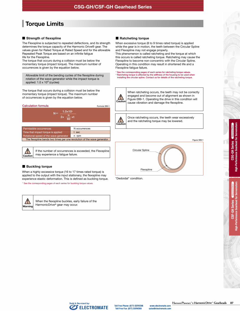
87Gearheads
CSG-GH/CSF-GH Gearhead Series
HPG
Stan
dard
Ser
iesHi
gh-P
erfo
rman
ce G
earh
ead
for S
ervo
mot
ors
HPG
Stan
dard
Ser
iesHi
gh-P
erfo
rman
ce G
earh
ead
for S
ervo
mot
ors
High
-Per
form
ance
Gea
rhea
d fo
r Ser
vom
otor
s
High
-Per
form
ance
Gea
rhea
d fo
r Ser
vom
otor
s HP
GP S
eries
HPGP
Ser
ies
High
-Per
form
ance
Gea
rhea
d fo
r Ser
vom
otor
s
High
-Per
form
ance
Gea
rhea
d fo
r Ser
vom
otor
s
CSG-
GH S
eries
CSG-
GH S
eries
High
-Per
form
ance
Gea
rhea
d fo
r Ser
vom
otor
s
High
-Per
form
ance
Gea
rhea
d fo
r Ser
vom
otor
s
High
-Per
form
ance
Gea
rhea
d fo
r Ser
vom
otor
s
High
-Per
form
ance
Gea
rhea
d fo
r Ser
vom
otor
s
CSF-
GH S
eries
CSF-
GH S
eries
High
-Per
form
ance
Gea
rhea
d fo
r Ser
vom
otor
s
High
-Per
form
ance
Gea
rhea
d fo
r Ser
vom
otor
s
CSF-
GH S
eries
CSF-
GH S
eries
HPG
Righ
t Ang
le
HPG
Righ
t Ang
le
Torque Limits
Life
+
ー
+
ー
Graph 098-1
Life
Calculation formula for Rated Lifetime
Lh=Ln ・ ・ TavTr 3
NavNr
Formula 098-1
Table 098-1
Table 098-2
LnTrNr
TavNav
105 106 107 108 109 1010 0
1
2
3
4
5
6
7
8
9
10
16
17
Graph 098-2
Formula 099-1
Figure 099-1
N= 1.0×10⁴
2× ×tn60
Caution
N occurrencest secn rpm
Permissible occurrencesTime that impact torque is appliedRotational speed of the wave generator
The flexspline bends two times per one revolution of the wave generator.
If the number of occurrences is exceeded, the Flexspline may experience a fatigue failure.
Calculation formula
Warning
When the flexspline buckles, early failure of the HarmonicDrive® gear may occur.
When a highly excessive torque (16 to 17 times rated torque) is applied to the output with the input stationary, the flexspline may experience elastic deformation. This is defined as buckling torque.
■ Buckling torque
* See the corresponding pages of each series for buckling torque values.
CSG-GH/CSF-GH Gearhead Series CSG-GH/CSF-GH Gearhead Series
036 037
High
-per
form
ance
Gea
r Hea
ds fo
r Ser
vo M
otor
s ser
iesHP
GP se
ries
High
-per
form
ance
Gea
r Hea
ds fo
r Ser
vo M
otor
s ser
iesHP
G se
ries
High
-per
form
ance
Gea
r Hea
ds fo
r Ser
vo M
otor
s ser
iesCS
G-GH
serie
sHi
gh-p
erfo
rman
ce G
ear H
eads
for S
ervo
Mot
ors s
eries
CSF-
GH se
ries
High
-per
form
ance
Gea
r Hea
ds fo
r Ser
vo M
otor
s ser
iesHP
G se
ries (
Orth
ogon
al S
haft
Type
)
High
-per
form
ance
Gea
r Hea
ds fo
r Ser
vo M
otor
s ser
iesHP
GP se
ries
High
-per
form
ance
Gea
r Hea
ds fo
r Ser
vo M
otor
s ser
iesHP
G se
ries
High
-per
form
ance
Gea
r Hea
ds fo
r Ser
vo M
otor
s ser
iesCS
G-GH
serie
sHi
gh-p
erfo
rman
ce G
ear H
eads
for S
ervo
Mot
ors s
eries
CSF-
GH se
ries
High
-per
form
ance
Gea
r Hea
ds fo
r Ser
vo M
otor
s ser
iesHP
G se
ries (
Orth
ogon
al S
haft
Type
)
Rating Table Definitions
See the corresponding pages of each series for values from the ratings.
Example of load torque pattern
Start
(Speed cycle)
Load
torq
ue
Start
Stop
Steady
Time
Time
Wav
e G
ener
ator
rota
tiona
l spe
ed Max
. mom
enta
ry to
rque
Torq
ue a
t ste
ady
stat
e
Peak
torq
ue a
t sta
rt/st
op
Abnormal impact torque
■ Rated torqueRated torque indicates allowable continuous load torque at input speed.
■ Inertia The rating indicates the moment of inertia reflected to the gear input.
■ Maximum Average Input Speed Maximum Input Speed Do not exceed the allowable rating. (calculation formula of the average input speed: Page 103).
■ Limit for Repeated Peak Torque (see Graph 098-1)
During acceleration and deceleration the Harmonic Drive® gear experiences a peak torque as a result of the moment of inertia of the output load. The table indicates the limit for repeated peak torque.
■ Limit for Momentary Torque (see Graph 098-1)
The gear may be subjected to momentary torques in the event of a collision or emergency stop. The magnitude and frequency of occurrence of such peak torques must be kept to a minimum and they should, under no circumstance, occur during normal operating cycle. The allowable number of occurrences of the momentary torque may be calculated by using the formula on page 103.
■ Limit for Average TorqueIn cases where load torque and input speed vary, it is necessary to calculate an average value of load torque. The table indicates the limit for average torque. The average torque calculated must not exceed this limit. (calculation formula: Page 103)
■ Life of the wave generatorThe life of a gear is determined by the life of the wavegenerator bearing. The life may be calculated by using theinput speed and the output load torque.
CSF-GH
7,000 hours35,000 hours
CSG-GH
10,000 hours50,000 hours
Series name
L10 L50 (average life)
Life of L10 or L50 Rated torqueRated input speedAverage load torque on the output side (calculation formula: Page 103)Average input speed (calculation formula: Page 103)
* Life is based on the input speed and output load torque from the ratings.
Buckling torque
Racheting torque
Fatigue strength of the flexspline
Repeated peak torque
Rated torque
Life of wave generator (L10)
Momentary peak torque
Load
torq
ue (w
hen
the
rate
d to
rque
is 1
)
Relative torque rating
Total number of input rotations
* Lubricant life not taken into consideration in the graph described above.* Use the graph above as reference values.
The Flexspline is subjected to repeated deflections, and its strength determines the torque capacity of the Harmonic Drive® gear. The values given for Rated Torque at Rated Speed and for the allowable Repeated Peak Torque are based on an infinite fatiguelife for the Flexspline. The torque that occurs during a collision must be below the momentary torque (impact torque). The maximum number of occurrences is given by the equation below.
■ Strength of flexspline
Allowable limit of the bending cycles of the flexspline during rotation of the wave generator while the impact torque is applied: 1.0 x 10⁴ (cycles)
The torque that occurs during a collision must be below the momentary torque (impact torque). The maximum numberof occurrences is given by the equation below.
When excessive torque (8 to 9 times rated torque) is applied while the gear is in motion, the teeth between the Circular Spline and Flexspline may not engage properly.This phenomenon is called ratcheting and the torque at whichthis occurs is called ratcheting torque. Ratcheting may cause theFlexspline to become non-concentric with the Circular Spline. Operating in this condition may result in shortened life and a Flexspline fatigue failure. * See the corresponding pages of each series for ratcheting torque values.* Ratcheting torque is affected by the stiffness of the housing to be used when
installing the circular spline. Contact us for details of the ratcheting torque.
■ Ratcheting torque
Caution
Caution
When ratcheting occurs, the teeth may not be correctly engaged and become out of alignment as shown in Figure 099-1. Operating the drive in this condition will cause vibration and damage the flexspline.
Once ratcheting occurs, the teeth wear excessively and the ratcheting torque may be lowered.
Circular Spline
"Dedoidal" condition.
Flexspline

88 Gearheads
CSG-GH/CSF-GH Gearhead Series
HPG
Stan
dard
Ser
iesHi
gh-P
erfo
rman
ce G
earh
ead
for S
ervo
mot
ors
HPG
Stan
dard
Ser
iesHi
gh-P
erfo
rman
ce G
earh
ead
for S
ervo
mot
ors
High
-Per
form
ance
Gea
rhea
d fo
r Ser
vom
otor
s
High
-Per
form
ance
Gea
rhea
d fo
r Ser
vom
otor
s HP
GP S
eries
HPGP
Ser
ies
High
-Per
form
ance
Gea
rhea
d fo
r Ser
vom
otor
s
High
-Per
form
ance
Gea
rhea
d fo
r Ser
vom
otor
s
CSG-
GH S
eries
CSG-
GH S
eries
High
-Per
form
ance
Gea
rhea
d fo
r Ser
vom
otor
s
High
-Per
form
ance
Gea
rhea
d fo
r Ser
vom
otor
s
High
-Per
form
ance
Gea
rhea
d fo
r Ser
vom
otor
s
High
-Per
form
ance
Gea
rhea
d fo
r Ser
vom
otor
s
CSF-
GH S
eries
CSF-
GH S
eries
High
-Per
form
ance
Gea
rhea
d fo
r Ser
vom
otor
s
High
-Per
form
ance
Gea
rhea
d fo
r Ser
vom
otor
s
CSF-
GH S
eries
CSF-
GH S
eries
HPG
Righ
t Ang
le
HPG
Righ
t Ang
le
Torsional Stiffness Vibration
Efficiency
θ 1 K 1
T 1 T 2
θ 2
K 2
K 3
0
−T 0 +T 00
A
A'
B
B'
Figure 100-1
Figure 100-2
Stiffness and backlash of the drive system greatly affects the performance of the servo system. Please perform a detailed review of these items before designing your equipment and selecting a model number.
Fixing the input side (wave generator) and applying torque to the output side (flexspline) generates torsion almost proportional to the torque on the output side. Figure 098-1 shows the torsional angle at the output side when the torque applied on the output side starts from zero, increases up to +T0 and decreases down to –T0. This is called the “Torque – torsion angle diagram,” which normally draws a loop of 0 – A – B – Aʼ – Bʼ – A. The slope described in the “Torque – torsion angle diagram” is represented as the spring constant for the stiffness of the HarmonicDrive® gear (unit: Nm/rad).As shown in Figure 100-2, this “Torque – torsional angle diagram” is divided into 3 regions, and the spring constants in the area are represented by K1, K2 and K3.
■ Stiffness
■ See the corresponding pages of each series for values of the spring constants (K1, K2, K3) and the torque-torsional angles (T1, T2, - θ1, θ2).
K1 ···· The spring constant when the torque changes from [zero] to [T1]K2 ···· The spring constant when the torque changes from [T1] to [T2]K3 ···· The spring constant when the torque changes from [T2] to [T3]
■ Hysteresis loss
■ See the appropriate page for each model series for the hysteresis loss value.
As shown in Figure 098-1, when the applied torque is increased to the rated torque and is brought back to [zero], the torsional angle does not return exactly back to the zero point This small difference (B – B') is called hysteresis loss.
Table 101-1
Formula 101-2
Formula 101-1
N = −−− ・ 60 = 450 rpm2
15
12π
KJ
f =
f Hz
KJ
Nm/radkgm2
■ BacklashHysteresis loss is primarily caused by internal friction. It is a very small value and will vary roughly in proportion to the applied load. Because HarmonicDrive® gearheads have zero backlash, the only true backlash is due to the clearance in the Oldham coupling, a self-aligning mechanism used on the wave generator. Since the Oldham coupling is used on the input, the backlash measured at the output is extremely small (arc-seconds) since it is divided by the gear reduction ratio.
The efficiency will vary depending on the following factors:■ Reduction ratio■ Input speed■ Load torque■ Temperature■ Lubrication condition (Type of lubricant and the quantity)
CSG-GH/CSF-GH Gearhead Series CSG-GH/CSF-GH Gearhead Series
038 039
High
-per
form
ance
Gea
r Hea
ds fo
r Ser
vo M
otor
s ser
iesHP
GP se
ries
High
-per
form
ance
Gea
r Hea
ds fo
r Ser
vo M
otor
s ser
iesHP
G se
ries
High
-per
form
ance
Gea
r Hea
ds fo
r Ser
vo M
otor
s ser
iesCS
G-GH
serie
sHi
gh-p
erfo
rman
ce G
ear H
eads
for S
ervo
Mot
ors s
eries
CSF-
GH se
ries
High
-per
form
ance
Gea
r Hea
ds fo
r Ser
vo M
otor
s ser
iesHP
G se
ries (
Orth
ogon
al S
haft
Type
)
High
-per
form
ance
Gea
r Hea
ds fo
r Ser
vo M
otor
s ser
iesHP
GP se
ries
High
-per
form
ance
Gea
r Hea
ds fo
r Ser
vo M
otor
s ser
iesHP
G se
ries
High
-per
form
ance
Gea
r Hea
ds fo
r Ser
vo M
otor
s ser
iesCS
G-GH
serie
sHi
gh-p
erfo
rman
ce G
ear H
eads
for S
ervo
Mot
ors s
eries
CSF-
GH se
ries
High
-per
form
ance
Gea
r Hea
ds fo
r Ser
vo M
otor
s ser
iesHP
G se
ries (
Orth
ogon
al S
haft
Type
)
■ Example for calculating the torsion angleThe torsion angle (θ) is calculated here using CSG-32-100-GH as an example. T1 = 29 Nm T2 = 108 Nm K1 = 11 x 104 Nm/rad K2 = 12 x 104 Nm/rad K3 = 6.7 x 10⁴ Nm/rad θ1=4.4 x 10⁻⁴ rad θ2=11.6 x 10⁻⁴ rad When the applied torque is T1 or less, the torsion angle θL1 is calculated as follows: When the load torque TL1=6.0 Nm θL1 =TL1/K1 =6.0/6.7×104 =9.0×10⁻⁵ rad(0.31 arc min) When the applied torque is between T1 and T2, the torsion angle θL2 is calculated as follows: When the load torque is TL2=50 Nm θL2 =θ1+(TL2−T1)/K2 =4.4×10⁻⁴ +(50−29)/11.0×104 =4.4×10⁻⁴ +1.9×10-4 =6.3×10⁻⁴ rad(2.17 arc min) When the applied torque is greater than T2, the torsion angle θL3 is calculated as follows: When the load torque is TL3=178 Nm θL3 =θ1+θ2+(TL3−T2)/K3 =4.4×10⁻⁴ +11.6×10⁻⁴+(178−108)/12.0×104 =4.4×10⁻⁴ +11.6×10⁻⁴+5.8×10-4 =2.18×10⁻³ rad(7.5 arc min) When a bidirectional load is applied, the total torsion angle will be 2 x θLX plus hysteresis loss.
* The torsion angle calculation is for the gear component set only and does not include any torsional windup of the output shaft.
Torque - torsion angle diagramTorsion angle
Hysteresis loss
Torque
Spring constant diagramTorsion angle
Torque
The primary frequency of the transmission error of the HarmonicDrive® gear may rarely cause a vibration of the load inertia. This can occur when the driving frequency of the servo system including the HarmonicDrive® gear is at, or close to the resonant frequency of the system. Refer to the design guide of each series.
The primary component of the transmission error occurs twice per input revolution of the input. Therefore, the frequency generated by the transmission error is 2x the input frequency (rev / sec).
If the resonant frequency of the entire system, including the HarmonicDrive® gear, is F=15 Hz, then the input speed (N) which would generate that frequency could be calculated with the formula below.
The resonant frequency is generated at an input speed of 450 rpm.
How to the calculate resonant frequency of the system
Formula variablesThe resonant frequency of the system
Spring constantLoad inertia
See pages of each series.

89Gearheads
CSG-GH/CSF-GH Gearhead Series
HPG
Stan
dard
Ser
iesHi
gh-P
erfo
rman
ce G
earh
ead
for S
ervo
mot
ors
HPG
Stan
dard
Ser
iesHi
gh-P
erfo
rman
ce G
earh
ead
for S
ervo
mot
ors
High
-Per
form
ance
Gea
rhea
d fo
r Ser
vom
otor
s
High
-Per
form
ance
Gea
rhea
d fo
r Ser
vom
otor
s HP
GP S
eries
HPGP
Ser
ies
High
-Per
form
ance
Gea
rhea
d fo
r Ser
vom
otor
s
High
-Per
form
ance
Gea
rhea
d fo
r Ser
vom
otor
s
CSG-
GH S
eries
CSG-
GH S
eries
High
-Per
form
ance
Gea
rhea
d fo
r Ser
vom
otor
s
High
-Per
form
ance
Gea
rhea
d fo
r Ser
vom
otor
s
High
-Per
form
ance
Gea
rhea
d fo
r Ser
vom
otor
s
High
-Per
form
ance
Gea
rhea
d fo
r Ser
vom
otor
s
CSF-
GH S
eries
CSF-
GH S
eries
High
-Per
form
ance
Gea
rhea
d fo
r Ser
vom
otor
s
High
-Per
form
ance
Gea
rhea
d fo
r Ser
vom
otor
s
CSF-
GH S
eries
CSF-
GH S
eries
HPG
Righ
t Ang
le
HPG
Righ
t Ang
le
Torsional Stiffness Vibration
Efficiency
θ 1 K 1
T 1 T 2
θ 2
K 2
K 3
0
−T 0 +T 00
A
A'
B
B'
Figure 100-1
Figure 100-2
Stiffness and backlash of the drive system greatly affects the performance of the servo system. Please perform a detailed review of these items before designing your equipment and selecting a model number.
Fixing the input side (wave generator) and applying torque to the output side (flexspline) generates torsion almost proportional to the torque on the output side. Figure 098-1 shows the torsional angle at the output side when the torque applied on the output side starts from zero, increases up to +T0 and decreases down to –T0. This is called the “Torque – torsion angle diagram,” which normally draws a loop of 0 – A – B – Aʼ – Bʼ – A. The slope described in the “Torque – torsion angle diagram” is represented as the spring constant for the stiffness of the HarmonicDrive® gear (unit: Nm/rad).As shown in Figure 100-2, this “Torque – torsional angle diagram” is divided into 3 regions, and the spring constants in the area are represented by K1, K2 and K3.
■ Stiffness
■ See the corresponding pages of each series for values of the spring constants (K1, K2, K3) and the torque-torsional angles (T1, T2, - θ1, θ2).
K1 ···· The spring constant when the torque changes from [zero] to [T1]K2 ···· The spring constant when the torque changes from [T1] to [T2]K3 ···· The spring constant when the torque changes from [T2] to [T3]
■ Hysteresis loss
■ See the appropriate page for each model series for the hysteresis loss value.
As shown in Figure 098-1, when the applied torque is increased to the rated torque and is brought back to [zero], the torsional angle does not return exactly back to the zero point This small difference (B – B') is called hysteresis loss.
Table 101-1
Formula 101-2
Formula 101-1
N = −−− ・ 60 = 450 rpm2
15
12π
KJ
f =
f Hz
KJ
Nm/radkgm2
■ BacklashHysteresis loss is primarily caused by internal friction. It is a very small value and will vary roughly in proportion to the applied load. Because HarmonicDrive® gearheads have zero backlash, the only true backlash is due to the clearance in the Oldham coupling, a self-aligning mechanism used on the wave generator. Since the Oldham coupling is used on the input, the backlash measured at the output is extremely small (arc-seconds) since it is divided by the gear reduction ratio.
The efficiency will vary depending on the following factors:■ Reduction ratio■ Input speed■ Load torque■ Temperature■ Lubrication condition (Type of lubricant and the quantity)
CSG-GH/CSF-GH Gearhead Series CSG-GH/CSF-GH Gearhead Series
038 039
High
-per
form
ance
Gea
r Hea
ds fo
r Ser
vo M
otor
s ser
iesHP
GP se
ries
High
-per
form
ance
Gea
r Hea
ds fo
r Ser
vo M
otor
s ser
iesHP
G se
ries
High
-per
form
ance
Gea
r Hea
ds fo
r Ser
vo M
otor
s ser
iesCS
G-GH
serie
sHi
gh-p
erfo
rman
ce G
ear H
eads
for S
ervo
Mot
ors s
eries
CSF-
GH se
ries
High
-per
form
ance
Gea
r Hea
ds fo
r Ser
vo M
otor
s ser
iesHP
G se
ries (
Orth
ogon
al S
haft
Type
)
High
-per
form
ance
Gea
r Hea
ds fo
r Ser
vo M
otor
s ser
iesHP
GP se
ries
High
-per
form
ance
Gea
r Hea
ds fo
r Ser
vo M
otor
s ser
iesHP
G se
ries
High
-per
form
ance
Gea
r Hea
ds fo
r Ser
vo M
otor
s ser
iesCS
G-GH
serie
sHi
gh-p
erfo
rman
ce G
ear H
eads
for S
ervo
Mot
ors s
eries
CSF-
GH se
ries
High
-per
form
ance
Gea
r Hea
ds fo
r Ser
vo M
otor
s ser
iesHP
G se
ries (
Orth
ogon
al S
haft
Type
)
■ Example for calculating the torsion angleThe torsion angle (θ) is calculated here using CSG-32-100-GH as an example. T1 = 29 Nm T2 = 108 Nm K1 = 11 x 104 Nm/rad K2 = 12 x 104 Nm/rad K3 = 6.7 x 10⁴ Nm/rad θ1=4.4 x 10⁻⁴ rad θ2=11.6 x 10⁻⁴ rad When the applied torque is T1 or less, the torsion angle θL1 is calculated as follows: When the load torque TL1=6.0 Nm θL1 =TL1/K1 =6.0/6.7×104 =9.0×10⁻⁵ rad(0.31 arc min) When the applied torque is between T1 and T2, the torsion angle θL2 is calculated as follows: When the load torque is TL2=50 Nm θL2 =θ1+(TL2−T1)/K2 =4.4×10⁻⁴ +(50−29)/11.0×104 =4.4×10⁻⁴ +1.9×10-4 =6.3×10⁻⁴ rad(2.17 arc min) When the applied torque is greater than T2, the torsion angle θL3 is calculated as follows: When the load torque is TL3=178 Nm θL3 =θ1+θ2+(TL3−T2)/K3 =4.4×10⁻⁴ +11.6×10⁻⁴+(178−108)/12.0×104 =4.4×10⁻⁴ +11.6×10⁻⁴+5.8×10-4 =2.18×10⁻³ rad(7.5 arc min) When a bidirectional load is applied, the total torsion angle will be 2 x θLX plus hysteresis loss.
* The torsion angle calculation is for the gear component set only and does not include any torsional windup of the output shaft.
Torque - torsion angle diagramTorsion angle
Hysteresis loss
Torque
Spring constant diagramTorsion angle
Torque
The primary frequency of the transmission error of the HarmonicDrive® gear may rarely cause a vibration of the load inertia. This can occur when the driving frequency of the servo system including the HarmonicDrive® gear is at, or close to the resonant frequency of the system. Refer to the design guide of each series.
The primary component of the transmission error occurs twice per input revolution of the input. Therefore, the frequency generated by the transmission error is 2x the input frequency (rev / sec).
If the resonant frequency of the entire system, including the HarmonicDrive® gear, is F=15 Hz, then the input speed (N) which would generate that frequency could be calculated with the formula below.
The resonant frequency is generated at an input speed of 450 rpm.
How to the calculate resonant frequency of the system
Formula variablesThe resonant frequency of the system
Spring constantLoad inertia
See pages of each series.

90 Gearheads
CSG-GH/CSF-GH Gearhead Series
HPG
Stan
dard
Ser
iesHi
gh-P
erfo
rman
ce G
earh
ead
for S
ervo
mot
ors
HPG
Stan
dard
Ser
iesHi
gh-P
erfo
rman
ce G
earh
ead
for S
ervo
mot
ors
High
-Per
form
ance
Gea
rhea
d fo
r Ser
vom
otor
s
High
-Per
form
ance
Gea
rhea
d fo
r Ser
vom
otor
s HP
GP S
eries
HPGP
Ser
ies
High
-Per
form
ance
Gea
rhea
d fo
r Ser
vom
otor
s
High
-Per
form
ance
Gea
rhea
d fo
r Ser
vom
otor
s
CSG-
GH S
eries
CSG-
GH S
eries
High
-Per
form
ance
Gea
rhea
d fo
r Ser
vom
otor
s
High
-Per
form
ance
Gea
rhea
d fo
r Ser
vom
otor
s
High
-Per
form
ance
Gea
rhea
d fo
r Ser
vom
otor
s
High
-Per
form
ance
Gea
rhea
d fo
r Ser
vom
otor
s
CSF-
GH S
eries
CSF-
GH S
eries
High
-Per
form
ance
Gea
rhea
d fo
r Ser
vom
otor
s
High
-Per
form
ance
Gea
rhea
d fo
r Ser
vom
otor
s
CSF-
GH S
eries
CSF-
GH S
eries
HPG
Righ
t Ang
le
HPG
Righ
t Ang
le
Product Sizing & Selection
NG
NG
NG
NG
NG
OK
OK
OK
OK
OK
In general, a servo system rarely operates at a continuous load and speed. The input rotational speed, load torque change and comparatively large torque are applied at start and stop. Unexpected impact torque may be applied.These fluctuating load torques should be converted to the average load torque when selecting a model number.As an accurate cross roller bearing is built in the direct external load support (output flange), the maximum moment load, life of the cross roller bearing and the static safety coefficient should also be checked.
(Note) If HarmonicDrive® CSG-GH or CSG-GH series is installed vertically with the output shaft facing downward (motor mounted above it) and continuously operated in one direction under the constant load state, lubrication failure may occur. In this case, please contact us for details.
+
ー
T 1
T 2
T 3
T 4
T n
t 1 t 2 t 3 t 4 t n
n 1
n 2
n 3
n 4
n n
Graph 100-1
OK
OK
OK
OK
OK
NG
NG
NG
NG
NG
■ Example of model number selection
Review the application motion profile. Check the specifications shown in the figure below.
■ Application Motion Profile
Time
Time* n1, n2 and nn indicate the average values.
Load
torq
ueO
utpu
t rot
atio
nal
spee
d
Obtain the value of each application motion profile.Load torque Tn (Nm)Time tn (sec)Output rotational speed nn (rpm)
Maximum rotational speedMax. output speed no maxMax. input rotational speed ni max(Restricted by motors)
Emergency stop torqueWhen impact torque is applied Ts, ts, ns
Required life L10 = L (hours)
Normal operation patternStarting (acceleration) T1, t1, n1
Steady operation (constant velocity) T2, t2, n2
Stopping (deceleration) T3, t3, n3
Idle T4, t4, n4
Calculate the average load torque applied on the output side from the load torque pattern: Tav (Nm).
Make a preliminary model selection with the following conditions. Tav ≦ Limit for average torque torque
(See the ratings of each series).
n 1 ・t 1 +n 2 ・t 2 +・・・n n ・t nt 1 + t 2 +・・・ t n
no av = ————————————————
ni maxno max——————≧ R
ni av = no av・R
ni max = no max・R
Calculate the average output speed: no av (rpm)
Obtain the reduction ratio (R). A limit is placed on “ni max” by motors.
Calculate the average input rotational speed from the average output rotational speed (no av) and the reduction ratio (R): ni av (rpm)
Calculate the maximum input rotational speed from the max. output rotational speed (no max) and the reduction ratio (R): ni max (rpm)
Tav =3 n 1 ・t 1 ・|T 1 |3+n 2 ・t 2 ・|T 2 |3+・・・n n ・t n ・|T n |3
n 1 ・t 1 +n 2 ・t 2 +・・・n n ・t n
Check whether the preliminary model number satisfies the following condition from the ratings.
Ni av ≦ Limit for average speed (rpm)
Ni max ≦ Limit for maximum speed (rpm)
104
n S ・RN S =————— ・・・・・・N S ≦ 1.0×10⁴ 2・————・t 60
L10 = 7,000・( ———) ・ ( ——— ) (hours)Tav ni avTr nr3
Check whether T1 and T3 are equal to or less than the repeated peak torque specification.
Check whether Ts is equal to or less than the the momentary torque specification.
Check whether the calculated lifetime is equal to or more than the life of the wave generator (see Page 98).
Calculate (Ns) the allowable number of rotations during impact torque.
Calculate the lifetime.
The model number is confirmed.
Maximum rotational speedMax. output rotational speed no max = 14 rpmMax. input rotational speed ni max = 1800 rpm(Restricted by motors)
Emergency stop torqueWhen impact torque is applied Ts = 500 Nm, ts = 0.15 sec,
ns = 14 rpm Required life L10 = 7000 (hours)
Load torqueTimeOutput rotational speed
Normal operation patternStarting (acceleration) T1 = 400 Nm, t1 = 0.3 sec, n1 = 7 rpmSteady operation(constant velocity) T2 = 320 Nm, t2 = 3 sec, n2 = 14 rpmStopping (deceleration) T3 = 200 Nm, t3 = 0.4 sec, n3 = 7 rpm Dwell Idle T4 = 0 Nm, t4 = 0.2 sec, n4 = 0 rpm
Tn(Nm)tn(sec)nn(rpm)
Revi
ew t
he o
pera
tion
cond
ition
s an
d m
odel
num
ber
CSG-GH/CSF-GH Gearhead Series CSG-GH/CSF-GH Gearhead Series
040 041
High
-per
form
ance
Gea
r Hea
ds fo
r Ser
vo M
otor
s ser
iesHP
GP se
ries
High
-per
form
ance
Gea
r Hea
ds fo
r Ser
vo M
otor
s ser
iesHP
G se
ries
High
-per
form
ance
Gea
r Hea
ds fo
r Ser
vo M
otor
s ser
iesCS
G-GH
serie
sHi
gh-p
erfo
rman
ce G
ear H
eads
for S
ervo
Mot
ors s
eries
CSF-
GH se
ries
High
-per
form
ance
Gea
r Hea
ds fo
r Ser
vo M
otor
s ser
iesHP
G se
ries (
Orth
ogon
al S
haft
Type
)
High
-per
form
ance
Gea
r Hea
ds fo
r Ser
vo M
otor
s ser
iesHP
GP se
ries
High
-per
form
ance
Gea
r Hea
ds fo
r Ser
vo M
otor
s ser
iesHP
G se
ries
High
-per
form
ance
Gea
r Hea
ds fo
r Ser
vo M
otor
s ser
iesCS
G-GH
serie
sHi
gh-p
erfo
rman
ce G
ear H
eads
for S
ervo
Mot
ors s
eries
CSF-
GH se
ries
High
-per
form
ance
Gea
r Hea
ds fo
r Ser
vo M
otor
s ser
iesHP
G se
ries (
Orth
ogon
al S
haft
Type
)
Please use the flowchart shown below for selecting a size.Operating conditions must not exceed the performanceratings.
■ Flowchart for selecting a size
Revi
ew th
e op
erat
ion
cond
ition
s an
d m
odel
num
ber
Calculate the average load torque applied on the output side of the Harmonic Drive® gear from the load torque pattern: Tav (Nm).
7 rpm・0.3 sec・|400Nm|3+14 rpm・3 sec・|320Nm|3+7 rpm・0.4 sec・|200Nm|3 3 Tav = 7 rpm・0.3 sec+14 rpm・3 sec+7 rpm・0.4 sec
7 rpm・0.3 sec+14 rpm・3 sec+7 rpm・0.4 sec0.3 sec + 3 sec + 0.4 sec + 0.2 secno av = ———————————————————————————— = 12 rpm
1800 rpm14 rpm——————— = 128.6 ≧ 120
ni av = 12 rpm・120 = 1440 rpm
ni max = 14 rpm・120 = 1680 rpm
Calculate the average output rotational speed: no av (rpm)
Calculate the average input rotational speed from the average output rotational speed (no av) and the reduction ratio (R): ni av (rpm)Calculate the maximum input rotational speed from the maximum output rotational speed (no max) and the reduction ratio (R): ni max (rpm)
Obtain the reduction ratio (R).
Check whether the preliminary selected model number satisfies the following condition from the ratings.
Ni av = 1440 rpm ≦ 3000 rpm (Max average input speed of size 45)Ni max = 1680 rpm ≦ 3800 rpm (Max input speed of size 45)
Make a preliminary model selection with the following conditions. Tav = 319 Nm ≦ 620 Nm (Limit for average torque for model number CSF-45-120-GH: See the ratings on Page 89.)Thus, CSF-45-120-GH is tentatively selected.
104
14 rpm・120N S =————————= 1190 ≦ 1.0×10⁴
2・————————・0.15 sec 60
L10 = 7000・( —————— ) ・ ( ————————— ) (hours)319 Nm 1440 rpm402 Nm 2000 rpm3
Check whether T1 and T3 are equal to or less than the repeated peak torque specification. T1 = 400 Nm ≦ 823 Nm (Limit of repeated peak torque of size 45)
T3 = 200 Nm ≦ 823 Nm (Limit of repeated peak torque of size 45)
Check whether Ts is equal to or less than the momentary torque specification. Ts = 500 Nm ≦ 1760 Nm (Limit for momentary torque of size 45)
Calculate the allowable number (Ns) rotation during impact torque and confirm ≦ 1.0×10⁴
Check whether the calculated life is equal to or more than the life of the wave generator (see Page 98).L10 =19,457 hours ≧ 7000 (life of the wave generator: L10)
The selection of model number CSF-45-120-GH is confirmed from the above calculations.
Calculate the lifetime.

91Gearheads
CSG-GH/CSF-GH Gearhead Series
HPG
Stan
dard
Ser
iesHi
gh-P
erfo
rman
ce G
earh
ead
for S
ervo
mot
ors
HPG
Stan
dard
Ser
iesHi
gh-P
erfo
rman
ce G
earh
ead
for S
ervo
mot
ors
High
-Per
form
ance
Gea
rhea
d fo
r Ser
vom
otor
s
High
-Per
form
ance
Gea
rhea
d fo
r Ser
vom
otor
s HP
GP S
eries
HPGP
Ser
ies
High
-Per
form
ance
Gea
rhea
d fo
r Ser
vom
otor
s
High
-Per
form
ance
Gea
rhea
d fo
r Ser
vom
otor
s
CSG-
GH S
eries
CSG-
GH S
eries
High
-Per
form
ance
Gea
rhea
d fo
r Ser
vom
otor
s
High
-Per
form
ance
Gea
rhea
d fo
r Ser
vom
otor
s
High
-Per
form
ance
Gea
rhea
d fo
r Ser
vom
otor
s
High
-Per
form
ance
Gea
rhea
d fo
r Ser
vom
otor
s
CSF-
GH S
eries
CSF-
GH S
eries
High
-Per
form
ance
Gea
rhea
d fo
r Ser
vom
otor
s
High
-Per
form
ance
Gea
rhea
d fo
r Ser
vom
otor
s
CSF-
GH S
eries
CSF-
GH S
eries
HPG
Righ
t Ang
le
HPG
Righ
t Ang
le
Product Sizing & Selection
NG
NG
NG
NG
NG
OK
OK
OK
OK
OK
In general, a servo system rarely operates at a continuous load and speed. The input rotational speed, load torque change and comparatively large torque are applied at start and stop. Unexpected impact torque may be applied.These fluctuating load torques should be converted to the average load torque when selecting a model number.As an accurate cross roller bearing is built in the direct external load support (output flange), the maximum moment load, life of the cross roller bearing and the static safety coefficient should also be checked.
(Note) If HarmonicDrive® CSG-GH or CSG-GH series is installed vertically with the output shaft facing downward (motor mounted above it) and continuously operated in one direction under the constant load state, lubrication failure may occur. In this case, please contact us for details.
+
ー
T 1
T 2
T 3
T 4
T n
t 1 t 2 t 3 t 4 t n
n 1
n 2
n 3
n 4
n n
Graph 100-1
OK
OK
OK
OK
OK
NG
NG
NG
NG
NG
■ Example of model number selection
Review the application motion profile. Check the specifications shown in the figure below.
■ Application Motion Profile
Time
Time* n1, n2 and nn indicate the average values.
Load
torq
ueO
utpu
t rot
atio
nal
spee
d
Obtain the value of each application motion profile.Load torque Tn (Nm)Time tn (sec)Output rotational speed nn (rpm)
Maximum rotational speedMax. output speed no maxMax. input rotational speed ni max(Restricted by motors)
Emergency stop torqueWhen impact torque is applied Ts, ts, ns
Required life L10 = L (hours)
Normal operation patternStarting (acceleration) T1, t1, n1
Steady operation (constant velocity) T2, t2, n2
Stopping (deceleration) T3, t3, n3
Idle T4, t4, n4
Calculate the average load torque applied on the output side from the load torque pattern: Tav (Nm).
Make a preliminary model selection with the following conditions. Tav ≦ Limit for average torque torque
(See the ratings of each series).
n 1 ・t 1 +n 2 ・t 2 +・・・n n ・t nt 1 + t 2 +・・・ t n
no av = ————————————————
ni maxno max——————≧ R
ni av = no av・R
ni max = no max・R
Calculate the average output speed: no av (rpm)
Obtain the reduction ratio (R). A limit is placed on “ni max” by motors.
Calculate the average input rotational speed from the average output rotational speed (no av) and the reduction ratio (R): ni av (rpm)
Calculate the maximum input rotational speed from the max. output rotational speed (no max) and the reduction ratio (R): ni max (rpm)
Tav =3 n 1 ・t 1 ・|T 1 |3+n 2 ・t 2 ・|T 2 |3+・・・n n ・t n ・|T n |3
n 1 ・t 1 +n 2 ・t 2 +・・・n n ・t n
Check whether the preliminary model number satisfies the following condition from the ratings.
Ni av ≦ Limit for average speed (rpm)
Ni max ≦ Limit for maximum speed (rpm)
104
n S ・RN S =————— ・・・・・・N S ≦ 1.0×10⁴ 2・————・t 60
L10 = 7,000・( ———) ・ ( ——— ) (hours)Tav ni avTr nr3
Check whether T1 and T3 are equal to or less than the repeated peak torque specification.
Check whether Ts is equal to or less than the the momentary torque specification.
Check whether the calculated lifetime is equal to or more than the life of the wave generator (see Page 98).
Calculate (Ns) the allowable number of rotations during impact torque.
Calculate the lifetime.
The model number is confirmed.
Maximum rotational speedMax. output rotational speed no max = 14 rpmMax. input rotational speed ni max = 1800 rpm(Restricted by motors)
Emergency stop torqueWhen impact torque is applied Ts = 500 Nm, ts = 0.15 sec,
ns = 14 rpm Required life L10 = 7000 (hours)
Load torqueTimeOutput rotational speed
Normal operation patternStarting (acceleration) T1 = 400 Nm, t1 = 0.3 sec, n1 = 7 rpmSteady operation(constant velocity) T2 = 320 Nm, t2 = 3 sec, n2 = 14 rpmStopping (deceleration) T3 = 200 Nm, t3 = 0.4 sec, n3 = 7 rpm Dwell Idle T4 = 0 Nm, t4 = 0.2 sec, n4 = 0 rpm
Tn(Nm)tn(sec)nn(rpm)
Revi
ew t
he o
pera
tion
cond
ition
s an
d m
odel
num
ber
CSG-GH/CSF-GH Gearhead Series CSG-GH/CSF-GH Gearhead Series
040 041
High
-per
form
ance
Gea
r Hea
ds fo
r Ser
vo M
otor
s ser
iesHP
GP se
ries
High
-per
form
ance
Gea
r Hea
ds fo
r Ser
vo M
otor
s ser
iesHP
G se
ries
High
-per
form
ance
Gea
r Hea
ds fo
r Ser
vo M
otor
s ser
iesCS
G-GH
serie
sHi
gh-p
erfo
rman
ce G
ear H
eads
for S
ervo
Mot
ors s
eries
CSF-
GH se
ries
High
-per
form
ance
Gea
r Hea
ds fo
r Ser
vo M
otor
s ser
iesHP
G se
ries (
Orth
ogon
al S
haft
Type
)
High
-per
form
ance
Gea
r Hea
ds fo
r Ser
vo M
otor
s ser
iesHP
GP se
ries
High
-per
form
ance
Gea
r Hea
ds fo
r Ser
vo M
otor
s ser
iesHP
G se
ries
High
-per
form
ance
Gea
r Hea
ds fo
r Ser
vo M
otor
s ser
iesCS
G-GH
serie
sHi
gh-p
erfo
rman
ce G
ear H
eads
for S
ervo
Mot
ors s
eries
CSF-
GH se
ries
High
-per
form
ance
Gea
r Hea
ds fo
r Ser
vo M
otor
s ser
iesHP
G se
ries (
Orth
ogon
al S
haft
Type
)
Please use the flowchart shown below for selecting a size.Operating conditions must not exceed the performanceratings.
■ Flowchart for selecting a size
Revi
ew th
e op
erat
ion
cond
ition
s an
d m
odel
num
ber
Calculate the average load torque applied on the output side of the Harmonic Drive® gear from the load torque pattern: Tav (Nm).
7 rpm・0.3 sec・|400Nm|3+14 rpm・3 sec・|320Nm|3+7 rpm・0.4 sec・|200Nm|3 3 Tav = 7 rpm・0.3 sec+14 rpm・3 sec+7 rpm・0.4 sec
7 rpm・0.3 sec+14 rpm・3 sec+7 rpm・0.4 sec0.3 sec + 3 sec + 0.4 sec + 0.2 secno av = ———————————————————————————— = 12 rpm
1800 rpm14 rpm——————— = 128.6 ≧ 120
ni av = 12 rpm・120 = 1440 rpm
ni max = 14 rpm・120 = 1680 rpm
Calculate the average output rotational speed: no av (rpm)
Calculate the average input rotational speed from the average output rotational speed (no av) and the reduction ratio (R): ni av (rpm)Calculate the maximum input rotational speed from the maximum output rotational speed (no max) and the reduction ratio (R): ni max (rpm)
Obtain the reduction ratio (R).
Check whether the preliminary selected model number satisfies the following condition from the ratings.
Ni av = 1440 rpm ≦ 3000 rpm (Max average input speed of size 45)Ni max = 1680 rpm ≦ 3800 rpm (Max input speed of size 45)
Make a preliminary model selection with the following conditions. Tav = 319 Nm ≦ 620 Nm (Limit for average torque for model number CSF-45-120-GH: See the ratings on Page 89.)Thus, CSF-45-120-GH is tentatively selected.
104
14 rpm・120N S =————————= 1190 ≦ 1.0×10⁴
2・————————・0.15 sec 60
L10 = 7000・( —————— ) ・ ( ————————— ) (hours)319 Nm 1440 rpm402 Nm 2000 rpm3
Check whether T1 and T3 are equal to or less than the repeated peak torque specification. T1 = 400 Nm ≦ 823 Nm (Limit of repeated peak torque of size 45)
T3 = 200 Nm ≦ 823 Nm (Limit of repeated peak torque of size 45)
Check whether Ts is equal to or less than the momentary torque specification. Ts = 500 Nm ≦ 1760 Nm (Limit for momentary torque of size 45)
Calculate the allowable number (Ns) rotation during impact torque and confirm ≦ 1.0×10⁴
Check whether the calculated life is equal to or more than the life of the wave generator (see Page 98).L10 =19,457 hours ≧ 7000 (life of the wave generator: L10)
The selection of model number CSF-45-120-GH is confirmed from the above calculations.
Calculate the lifetime.

92 Gearheads23
The greatest benefit of HarmonicDrive® gearing is the weight and space savings compared to other gearheads because it consists of only three basic parts. Since many teeth are engaged simultaneously, it can transmit higher torque and provides high accuracy. A unique S tooth profile significantly improves torque capacity, life and torsional stiffness of the gear.
◆ Zero-backlash◆ High Reduction ratios, 50:1 to 160:1 in a single stage◆ High precision positioning (repeatability ±4 to ±10 arc-sec)◆ High capacity cross roller output bearing◆ High torque capacity
Motor mounting flange
Shielded bearing
Circular Spline
Wave Generator
Robust cross roller bearing is integrated with the output flange to provide high moment stiffness, high load capacity and precise positioning accuracy.
Flexspline
CSG/CSF-GH Series
HarmonicDrive® gearing has a unique operating principle which utilizes the elastic mechanics of metals. This precision gear reducer consists of only 3 basic parts and provides high accuracy and repeatability.
Quick Connect® servo couplingmachined and balanced to matchthe motor shaft diameter (singlebolt clamping design)
The Wave Generator is athin raced ball bearing fitted onto an elliptical shaped hub. The inner race of the bearing is fixed to the cam and the outer race is elastically deformed into an ellipse via the balls. The Wave Generator is usually mounted onto the input shaft.
Wave GeneratorT h e F l e x s p l i n e i s a non-rigid, thin cylindrical cup with external teeth. The Flexspline fits over the Wave Generator and takes on its elliptical shape. The Flexspline is generally used as the output of the gear.
FlexsplineThe Circular Spline is a rigid ring with internal teeth, engaging the teeth of the Flexspline across the major axis of the Wave Generator. The Circular Spline has two more teeth than the Flexspline and is generally mounted to the housing.
Circular Spline

93Gearheads23
The greatest benefit of HarmonicDrive® gearing is the weight and space savings compared to other gearheads because it consists of only three basic parts. Since many teeth are engaged simultaneously, it can transmit higher torque and provides high accuracy. A unique S tooth profile significantly improves torque capacity, life and torsional stiffness of the gear.
◆ Zero-backlash◆ High Reduction ratios, 50:1 to 160:1 in a single stage◆ High precision positioning (repeatability ±4 to ±10 arc-sec)◆ High capacity cross roller output bearing◆ High torque capacity
Motor mounting flange
Shielded bearing
Circular Spline
Wave Generator
Robust cross roller bearing is integrated with the output flange to provide high moment stiffness, high load capacity and precise positioning accuracy.
Flexspline
CSG/CSF-GH Series
HarmonicDrive® gearing has a unique operating principle which utilizes the elastic mechanics of metals. This precision gear reducer consists of only 3 basic parts and provides high accuracy and repeatability.
Quick Connect® servo couplingmachined and balanced to matchthe motor shaft diameter (singlebolt clamping design)
The Wave Generator is athin raced ball bearing fitted onto an elliptical shaped hub. The inner race of the bearing is fixed to the cam and the outer race is elastically deformed into an ellipse via the balls. The Wave Generator is usually mounted onto the input shaft.
Wave GeneratorT h e F l e x s p l i n e i s a non-rigid, thin cylindrical cup with external teeth. The Flexspline fits over the Wave Generator and takes on its elliptical shape. The Flexspline is generally used as the output of the gear.
FlexsplineThe Circular Spline is a rigid ring with internal teeth, engaging the teeth of the Flexspline across the major axis of the Wave Generator. The Circular Spline has two more teeth than the Flexspline and is generally mounted to the housing.
Circular Spline

1 Gearheads
Technical Data Technical Data
230 231
Tech
nica
l Inf
orm
atio
n / H
andl
ing
Expl
anat
ion
Tech
nica
l Inf
orm
atio
n / H
andl
ing
Expl
anat
ion
HPG HPF
Calculate:Maximum moment load (Mi max)Maximum axial load (Fai max)Maximum radial load (Fri max)
Calculate:Average moment load (Mi av)Average axial load (Fai av) Average input speed (Ni av)
Maximum moment load (Mi max) ≦ Allowable moment load (Mc)Maximum axial load (Fai max) ≦ Allowable axial load (Fac)Maximum radial load (Fri max) ≦ Allowable radial load (Frc)
Calculate the life and check it.
(2) Checking the life
(1) Checking maximum load
Time: t
Time: t
n1
n2
n3
M1
M2
M3
M4
n4
t1 t2 t3 t4
L10
NiCrPci
LifeAverage input speedBasic dynamic load ratingDynamic equivalent load
HourrpmN (kgf)N
av
111420325065
0.137 × Mi av + 1.232 × Fai av0.444 × Mi av + 1.426 × Fai av
0.041 × Mi av + 1.232 × Fai av
0.109 × Mi av + 1.232 × Fai av0.071 × Mi av + 1.232 × Fai av0.053 × Mi av + 1.232 × Fai av
maxmax
Fai
Lri
Fri
Lai
111420325065
111420325065
2532
2532
*1 The allowable axial load is the value of an axial load applied along the axis of rotation.*2 The allowable radial load of HPG series is the value of a radial load applied at the mid-point of the input shaft.*3 The allowable radial load of HPG series is the value of a radial load applied to the point of 20 mm from the shaft edge (input flange edge).
2532 106 × Mi av + 2.7 × Fai av
121 × Mi av + 2.7 × Fai av
Fai
Fri
Lai
Lri
Check the maximum load and life of the bearing on the input side if the reducer is an HPG input shaft unit or an HPF hollow shaft unit.
FriFaiLri,Lai
If moment load and axial load fluctuate, they should be converted into the average load to check the life of the bearing.
Calculate the bearing life according to Calculation Formula 132-5 and check the life.
Specification of input bearing
Specification of input shaft bearing
Table 149-1
Table 150-1
Table 150-2
Figure 150-1
Formula 150-2
Formula 150-3
Formula 150-4
Graph 150-1
Formula 150-5
Table 149-2
Size
Table 149-3
Table 149-4
〔Note: Table 149-2 and 149-4〕
External load influence diagram
Dynamic equivalent load
Size
Dynamic equivalent load
HPG HPF
HPG
HPF
HPG HPF
HPG
HPF
Pci
N270058009700
225003550051000
kgf275590990
230036005200
N127031505600148002510039500
kgf129320570151025604050
Nm0.166.313.544.496.9210
kgfm0.0160.641.384.539.8821.4
N2456571206328555408600
kgf2567123335565878
N20.6500902197032265267
kgf2.15192
201329537
N1450029700
kgf14803030
N1010020100
kgf10302050
Nm1019
kgfm1.021.93
N15383263
kgf157333
N522966
kgf53.298.5
Pci
HPG HPF
Formula 150-1
Checking procedure
Specification of input bearing
SizeBasic load rating
Basic dynamic load rating Cr Basic static load rating Cor
SizeAllowable moment load Mc Allowable axial load Fac *1 Allowable radial load Frc *2
SizeBasic load rating
Basic dynamic load rating Cr Basic static load rating Cor
SizeAllowable moment load Mc Allowable axial load Fac *1 Allowable radial load Frc *3
Calculating maximum moment load ON input shaft
How to calculate average load(Average moment load, average axial load, average input speed)
Mi max ≦ Mc (Allowable moment load)Fai max ≦ Fac (Allowable axial load)
Max. radial loadMax. axial load————
N (kgf)N (kgf)m
See Fig. 150-1.See Fig. 150-1.See Fig. 150-1.
The maximum moment load (Mi max ) is calculated as follows.Check that the following formulas are established in all circumstances:
Inpu
t spe
edM
omen
t loa
d
How to calculate the average moment load (Miav )
How to calculate the average axial load (Faiav)
How to calculate the average input speed (Niav)
Calculating life of input bearing
Miav Average moment load Nm (kgfm) See Formula 150-2Faiav Average axial load N (kgf) See Formula 150-3
See Formula 150-4See Table 149-1 and -3See Table 150-1 and -2
Input Bearing Specifications and Checking Procedure
220 221
Tech
nica
l Inf
orm
atio
n / H
andl
ing
Expl
anat
ion
Tech
nica
l Inf
orm
atio
n / H
andl
ing
Expl
anat
ion
N O T E S
Graph 143-1
Graph 143-3 Graph 143-4
Graph 143-2
Reduction ratio = 100
200 600 800 1000 1200 1400 1800 20001600400
90100
80706050403020100
Effic
ienc
y %
0
Input torque Ncm
Reduction ratio = 160
200 600 800 1000 1200 1400400
90100
80706050403020100
Effic
ienc
y %
0
Input torque Ncm
Reduction ratio = 120
200 600 800 1000 1200 1400 18001600400
90100
80706050403020100
Effic
ienc
y %
0
Input torque Ncm
Reduction ratio = 80
90100
80706050403020100
Effic
ienc
y %
0 200 600 800 1000 1200 1400 1800 20001600
Input torque Ncm400
Technical Data
Size 65 : Gearhead CSG-GH CSF-GH
500 rpm 1000 rpm 2000 rpm 3500 rpmInput rotational speed
Technical Information126
145
149
Product Handling151
154
155
157
158
Efficiency
Output Bearing Specifications and Checking Procedure
Input Bearing Specifications and Checking Procedure
Assembly
Mechanical Tolerances
Lubrication
Warranty, Disposal
Safety
N O T E S
The rated value and performance vary depending on the product series.Be sure to check the usage conditions and refer to the items conforming to the related product.

2Gearheads
Technical Information126
145
149
Product Handling151
154
155
157
158
Efficiency
Output Bearing Specifications and Checking Procedure
Input Bearing Specifications and Checking Procedure
Assembly
Mechanical Tolerances
Lubrication
Warranty, Disposal
Safety
N O T E S
The rated value and performance vary depending on the product series.Be sure to check the usage conditions and refer to the items conforming to the related product.

122 Gearheads
Technical DataTechnical Data Technical Data
230 231
Tech
nica
l Inf
orm
atio
n / H
andl
ing
Expl
anat
ion
Tech
nica
l Inf
orm
atio
n / H
andl
ing
Expl
anat
ion
HPG HPF
Calculate:Maximum moment load (Mi max)Maximum axial load (Fai max)Maximum radial load (Fri max)
Calculate:Average moment load (Mi av)Average axial load (Fai av) Average input speed (Ni av)
Maximum moment load (Mi max) ≦ Allowable moment load (Mc)Maximum axial load (Fai max) ≦ Allowable axial load (Fac)Maximum radial load (Fri max) ≦ Allowable radial load (Frc)
Calculate the life and check it.
(2) Checking the life
(1) Checking maximum load
Time: t
Time: t
n1
n2
n3
M1
M2
M3
M4
n4
t1 t2 t3 t4
L10
NiCrPci
LifeAverage input speedBasic dynamic load ratingDynamic equivalent load
HourrpmN (kgf)N
av
111420325065
0.137 × Mi av + 1.232 × Fai av0.444 × Mi av + 1.426 × Fai av
0.041 × Mi av + 1.232 × Fai av
0.109 × Mi av + 1.232 × Fai av0.071 × Mi av + 1.232 × Fai av0.053 × Mi av + 1.232 × Fai av
maxmax
Fai
Lri
Fri
Lai
111420325065
111420325065
2532
2532
*1 The allowable axial load is the value of an axial load applied along the axis of rotation.*2 The allowable radial load of HPG series is the value of a radial load applied at the mid-point of the input shaft.*3 The allowable radial load of HPG series is the value of a radial load applied to the point of 20 mm from the shaft edge (input flange edge).
2532 106 × Mi av + 2.7 × Fai av
121 × Mi av + 2.7 × Fai av
Fai
Fri
Lai
Lri
Check the maximum load and life of the bearing on the input side if the reducer is an HPG input shaft unit or an HPF hollow shaft unit.
FriFaiLri,Lai
If moment load and axial load fluctuate, they should be converted into the average load to check the life of the bearing.
Calculate the bearing life according to Calculation Formula 132-5 and check the life.
Specification of input bearing
Specification of input shaft bearing
Table 149-1
Table 150-1
Table 150-2
Figure 150-1
Formula 150-2
Formula 150-3
Formula 150-4
Graph 150-1
Formula 150-5
Table 149-2
Size
Table 149-3
Table 149-4
〔Note: Table 149-2 and 149-4〕
External load influence diagram
Dynamic equivalent load
Size
Dynamic equivalent load
HPG HPF
HPG
HPF
HPG HPF
HPG
HPF
Pci
N270058009700
225003550051000
kgf275590990
230036005200
N127031505600148002510039500
kgf129320570151025604050
Nm0.166.313.544.496.9210
kgfm0.0160.641.384.539.8821.4
N2456571206328555408600
kgf2567123335565878
N20.6500902197032265267
kgf2.15192
201329537
N1450029700
kgf14803030
N1010020100
kgf10302050
Nm1019
kgfm1.021.93
N15383263
kgf157333
N522966
kgf53.298.5
Pci
HPG HPF
Formula 150-1
Checking procedure
Specification of input bearing
SizeBasic load rating
Basic dynamic load rating Cr Basic static load rating Cor
SizeAllowable moment load Mc Allowable axial load Fac *1 Allowable radial load Frc *2
SizeBasic load rating
Basic dynamic load rating Cr Basic static load rating Cor
SizeAllowable moment load Mc Allowable axial load Fac *1 Allowable radial load Frc *3
Calculating maximum moment load ON input shaft
How to calculate average load(Average moment load, average axial load, average input speed)
Mi max ≦ Mc (Allowable moment load)Fai max ≦ Fac (Allowable axial load)
Max. radial loadMax. axial load————
N (kgf)N (kgf)m
See Fig. 150-1.See Fig. 150-1.See Fig. 150-1.
The maximum moment load (Mi max ) is calculated as follows.Check that the following formulas are established in all circumstances:
Inpu
t spe
edM
omen
t loa
d
How to calculate the average moment load (Miav )
How to calculate the average axial load (Faiav)
How to calculate the average input speed (Niav)
Calculating life of input bearing
Miav Average moment load Nm (kgfm) See Formula 150-2Faiav Average axial load N (kgf) See Formula 150-3
See Formula 150-4See Table 149-1 and -3See Table 150-1 and -2
Input Bearing Specifications and Checking Procedure
Technical Data Technical Data
208 209
Tech
nica
l Inf
orm
atio
n / H
andl
ing
Expl
anat
ion
Tech
nica
l Inf
orm
atio
n / H
andl
ing
Expl
anat
ion
25℃Use standard lubricant for each model. (See pages 155- 156 for details.)
HPGP / HPG / HPF / HPN:3000rpmCSG-GH / CSF-GH:Indicated on each efficiency graph.
Effic
ienc
y co
rrect
ion
coef
ficie
nt
1.0
0.8
0.6
0.4
0.2
0.0 0 10 20 30Ambient temperature(℃)
TRi×100%
TRi×50%
TRi×25%
TRi×10%
TRi×100%
TRi×50%
TRi×25%
TRi×10%
In general, the efficiency of a speed reducer depends on the reduction ratio, input rotational speed, load torque, temperature and lubrication condition. The efficiency of each series under the following measurement conditions is plotted in the graphs on the next page. The values in the graph are average values.
Measurement condition
Efficiency compensated for low temperatureCalculate the efficiency at an ambient temperature of 25°C or less by multiplying the efficiency at 25°C by the low-temperature efficiency correction value. Obtain values corresponding to an ambient temperature and to an input torque (TRi*) from the following graphs when calculating the low-temperature efficiency correction value.
Input rotational speed
Ambient temperatureLubricant
Efficiency Reduction Ratio = 21
100
90
80
70
60
50
40
30
20
10
0
TRi
0 0.1 0.2 0.3 0.50.4
Reduction Ratio = 5
Input torque Nm Input torque Nm
Graph 127-1 Graph 127-2
Table 126-1
Graph 127-3
100
90
80
70
60
50
40
30
20
10
0
TRi
Effic
ienc
y %
Effic
ienc
y %
Input torque Nm
Effic
ienc
y %
0 0.5 1 1.5 2
Reduction Ratio = 37, 45100
90
80
70
60
50
40
30
20
10
0
TRiTRi
0 0.1 0.2 0.3
Reduction ratio = 45
Reduction ratio = 37
Reduction ratio = 21
Size 11 : Gearhead
Graph 127-4
Graph 127-6
Graph 127-5
Graph 127-7
Reduction Ratio = 5
Input torque Nm
1009080706050403020100
0 1 2 3 4 5
Effic
ienc
y %
Input torque Nm
Effic
ienc
y %
Input torque Nm
Effic
ienc
y %
Input torque Nm
Effic
ienc
y %
TRiReduction Ratio = 11
1009080706050403020100
0 0.5 1 1.5 2 2.5
TRi
Reduction Ratio = 15, 211009080706050403020100
0 0.5 1 1.5 2
TRiTRi
Reduction ratio = 15
Reduction ratio = 21
Reduction Ratio = 33, 451009080706050403020100
0 0.2 0.4 0.6 0.8 1
TRiTRi
Reduction ratio = 33
Reduction ratio = 45
Size 14 : Gearhead
HPGP
HPG HPF HPNHPGP
HPGP
1.4
1.2
1.0
0.8
0.6
0.4
0.2
0.00 10 20 30
Effic
ienc
y co
rrect
ion
coef
ficie
nt
Ambient Temperature(℃)
5 15 25 4035
* TRi is an input torque corresponding to output torque at 25°C.
CSG-GH CSF-GH* TRi is an input torque corresponding to output torque at 25°C. Graph 126-2
Graph 126-1
Gearhead (standard item) Input torque corresponding to output torqueTRiGearhead with D bearing (double sealed)
Gearhead (standard item) Input torque corresponding to output torqueTRiGearhead with D bearing (double sealed)
Reduction ratio = 5
Reduction ratio = 5 Reduction ratio = 11

123Gearheads
Technical DataTechnical Data Technical Data
230 231
Tech
nica
l Inf
orm
atio
n / H
andl
ing
Expl
anat
ion
Tech
nica
l Inf
orm
atio
n / H
andl
ing
Expl
anat
ion
HPG HPF
Calculate:Maximum moment load (Mi max)Maximum axial load (Fai max)Maximum radial load (Fri max)
Calculate:Average moment load (Mi av)Average axial load (Fai av) Average input speed (Ni av)
Maximum moment load (Mi max) ≦ Allowable moment load (Mc)Maximum axial load (Fai max) ≦ Allowable axial load (Fac)Maximum radial load (Fri max) ≦ Allowable radial load (Frc)
Calculate the life and check it.
(2) Checking the life
(1) Checking maximum load
Time: t
Time: t
n1
n2
n3
M1
M2
M3
M4
n4
t1 t2 t3 t4
L10
NiCrPci
LifeAverage input speedBasic dynamic load ratingDynamic equivalent load
HourrpmN (kgf)N
av
111420325065
0.137 × Mi av + 1.232 × Fai av0.444 × Mi av + 1.426 × Fai av
0.041 × Mi av + 1.232 × Fai av
0.109 × Mi av + 1.232 × Fai av0.071 × Mi av + 1.232 × Fai av0.053 × Mi av + 1.232 × Fai av
maxmax
Fai
Lri
Fri
Lai
111420325065
111420325065
2532
2532
*1 The allowable axial load is the value of an axial load applied along the axis of rotation.*2 The allowable radial load of HPG series is the value of a radial load applied at the mid-point of the input shaft.*3 The allowable radial load of HPG series is the value of a radial load applied to the point of 20 mm from the shaft edge (input flange edge).
2532 106 × Mi av + 2.7 × Fai av
121 × Mi av + 2.7 × Fai av
Fai
Fri
Lai
Lri
Check the maximum load and life of the bearing on the input side if the reducer is an HPG input shaft unit or an HPF hollow shaft unit.
FriFaiLri,Lai
If moment load and axial load fluctuate, they should be converted into the average load to check the life of the bearing.
Calculate the bearing life according to Calculation Formula 132-5 and check the life.
Specification of input bearing
Specification of input shaft bearing
Table 149-1
Table 150-1
Table 150-2
Figure 150-1
Formula 150-2
Formula 150-3
Formula 150-4
Graph 150-1
Formula 150-5
Table 149-2
Size
Table 149-3
Table 149-4
〔Note: Table 149-2 and 149-4〕
External load influence diagram
Dynamic equivalent load
Size
Dynamic equivalent load
HPG HPF
HPG
HPF
HPG HPF
HPG
HPF
Pci
N270058009700
225003550051000
kgf275590990
230036005200
N127031505600148002510039500
kgf129320570151025604050
Nm0.166.313.544.496.9210
kgfm0.0160.641.384.539.8821.4
N2456571206328555408600
kgf2567123335565878
N20.6500902197032265267
kgf2.15192
201329537
N1450029700
kgf14803030
N1010020100
kgf10302050
Nm1019
kgfm1.021.93
N15383263
kgf157333
N522966
kgf53.298.5
Pci
HPG HPF
Formula 150-1
Checking procedure
Specification of input bearing
SizeBasic load rating
Basic dynamic load rating Cr Basic static load rating Cor
SizeAllowable moment load Mc Allowable axial load Fac *1 Allowable radial load Frc *2
SizeBasic load rating
Basic dynamic load rating Cr Basic static load rating Cor
SizeAllowable moment load Mc Allowable axial load Fac *1 Allowable radial load Frc *3
Calculating maximum moment load ON input shaft
How to calculate average load(Average moment load, average axial load, average input speed)
Mi max ≦ Mc (Allowable moment load)Fai max ≦ Fac (Allowable axial load)
Max. radial loadMax. axial load————
N (kgf)N (kgf)m
See Fig. 150-1.See Fig. 150-1.See Fig. 150-1.
The maximum moment load (Mi max ) is calculated as follows.Check that the following formulas are established in all circumstances:
Inpu
t spe
edM
omen
t loa
d
How to calculate the average moment load (Miav )
How to calculate the average axial load (Faiav)
How to calculate the average input speed (Niav)
Calculating life of input bearing
Miav Average moment load Nm (kgfm) See Formula 150-2Faiav Average axial load N (kgf) See Formula 150-3
See Formula 150-4See Table 149-1 and -3See Table 150-1 and -2
Input Bearing Specifications and Checking Procedure
Technical Data Technical Data
208 209
Tech
nica
l Inf
orm
atio
n / H
andl
ing
Expl
anat
ion
Tech
nica
l Inf
orm
atio
n / H
andl
ing
Expl
anat
ion
25℃Use standard lubricant for each model. (See pages 155- 156 for details.)
HPGP / HPG / HPF / HPN:3000rpmCSG-GH / CSF-GH:Indicated on each efficiency graph.
Effic
ienc
y co
rrect
ion
coef
ficie
nt
1.0
0.8
0.6
0.4
0.2
0.0 0 10 20 30Ambient temperature(℃)
TRi×100%
TRi×50%
TRi×25%
TRi×10%
TRi×100%
TRi×50%
TRi×25%
TRi×10%
In general, the efficiency of a speed reducer depends on the reduction ratio, input rotational speed, load torque, temperature and lubrication condition. The efficiency of each series under the following measurement conditions is plotted in the graphs on the next page. The values in the graph are average values.
Measurement condition
Efficiency compensated for low temperatureCalculate the efficiency at an ambient temperature of 25°C or less by multiplying the efficiency at 25°C by the low-temperature efficiency correction value. Obtain values corresponding to an ambient temperature and to an input torque (TRi*) from the following graphs when calculating the low-temperature efficiency correction value.
Input rotational speed
Ambient temperatureLubricant
Efficiency Reduction Ratio = 21
100
90
80
70
60
50
40
30
20
10
0
TRi
0 0.1 0.2 0.3 0.50.4
Reduction Ratio = 5
Input torque Nm Input torque Nm
Graph 127-1 Graph 127-2
Table 126-1
Graph 127-3
100
90
80
70
60
50
40
30
20
10
0
TRi
Effic
ienc
y %
Effic
ienc
y %
Input torque Nm
Effic
ienc
y %
0 0.5 1 1.5 2
Reduction Ratio = 37, 45100
90
80
70
60
50
40
30
20
10
0
TRiTRi
0 0.1 0.2 0.3
Reduction ratio = 45
Reduction ratio = 37
Reduction ratio = 21
Size 11 : Gearhead
Graph 127-4
Graph 127-6
Graph 127-5
Graph 127-7
Reduction Ratio = 5
Input torque Nm
1009080706050403020100
0 1 2 3 4 5
Effic
ienc
y %
Input torque Nm
Effic
ienc
y %
Input torque Nm
Effic
ienc
y %
Input torque Nm
Effic
ienc
y %
TRiReduction Ratio = 11
1009080706050403020100
0 0.5 1 1.5 2 2.5
TRi
Reduction Ratio = 15, 211009080706050403020100
0 0.5 1 1.5 2
TRiTRi
Reduction ratio = 15
Reduction ratio = 21
Reduction Ratio = 33, 451009080706050403020100
0 0.2 0.4 0.6 0.8 1
TRiTRi
Reduction ratio = 33
Reduction ratio = 45
Size 14 : Gearhead
HPGP
HPG HPF HPNHPGP
HPGP
1.4
1.2
1.0
0.8
0.6
0.4
0.2
0.00 10 20 30
Effic
ienc
y co
rrect
ion
coef
ficie
nt
Ambient Temperature(℃)
5 15 25 4035
* TRi is an input torque corresponding to output torque at 25°C.
CSG-GH CSF-GH* TRi is an input torque corresponding to output torque at 25°C. Graph 126-2
Graph 126-1
Gearhead (standard item) Input torque corresponding to output torqueTRiGearhead with D bearing (double sealed)
Gearhead (standard item) Input torque corresponding to output torqueTRiGearhead with D bearing (double sealed)
Reduction ratio = 5
Reduction ratio = 5 Reduction ratio = 11

124 Gearheads
Technical DataTechnical Data Technical Data
230 231
Tech
nica
l Inf
orm
atio
n / H
andl
ing
Expl
anat
ion
Tech
nica
l Inf
orm
atio
n / H
andl
ing
Expl
anat
ion
HPG HPF
Calculate:Maximum moment load (Mi max)Maximum axial load (Fai max)Maximum radial load (Fri max)
Calculate:Average moment load (Mi av)Average axial load (Fai av) Average input speed (Ni av)
Maximum moment load (Mi max) ≦ Allowable moment load (Mc)Maximum axial load (Fai max) ≦ Allowable axial load (Fac)Maximum radial load (Fri max) ≦ Allowable radial load (Frc)
Calculate the life and check it.
(2) Checking the life
(1) Checking maximum load
Time: t
Time: t
n1
n2
n3
M1
M2
M3
M4
n4
t1 t2 t3 t4
L10
NiCrPci
LifeAverage input speedBasic dynamic load ratingDynamic equivalent load
HourrpmN (kgf)N
av
111420325065
0.137 × Mi av + 1.232 × Fai av0.444 × Mi av + 1.426 × Fai av
0.041 × Mi av + 1.232 × Fai av
0.109 × Mi av + 1.232 × Fai av0.071 × Mi av + 1.232 × Fai av0.053 × Mi av + 1.232 × Fai av
maxmax
Fai
Lri
Fri
Lai
111420325065
111420325065
2532
2532
*1 The allowable axial load is the value of an axial load applied along the axis of rotation.*2 The allowable radial load of HPG series is the value of a radial load applied at the mid-point of the input shaft.*3 The allowable radial load of HPG series is the value of a radial load applied to the point of 20 mm from the shaft edge (input flange edge).
2532 106 × Mi av + 2.7 × Fai av
121 × Mi av + 2.7 × Fai av
Fai
Fri
Lai
Lri
Check the maximum load and life of the bearing on the input side if the reducer is an HPG input shaft unit or an HPF hollow shaft unit.
FriFaiLri,Lai
If moment load and axial load fluctuate, they should be converted into the average load to check the life of the bearing.
Calculate the bearing life according to Calculation Formula 132-5 and check the life.
Specification of input bearing
Specification of input shaft bearing
Table 149-1
Table 150-1
Table 150-2
Figure 150-1
Formula 150-2
Formula 150-3
Formula 150-4
Graph 150-1
Formula 150-5
Table 149-2
Size
Table 149-3
Table 149-4
〔Note: Table 149-2 and 149-4〕
External load influence diagram
Dynamic equivalent load
Size
Dynamic equivalent load
HPG HPF
HPG
HPF
HPG HPF
HPG
HPF
Pci
N270058009700
225003550051000
kgf275590990
230036005200
N127031505600148002510039500
kgf129320570151025604050
Nm0.166.313.544.496.9210
kgfm0.0160.641.384.539.8821.4
N2456571206328555408600
kgf2567123335565878
N20.6500902197032265267
kgf2.15192
201329537
N1450029700
kgf14803030
N1010020100
kgf10302050
Nm1019
kgfm1.021.93
N15383263
kgf157333
N522966
kgf53.298.5
Pci
HPG HPF
Formula 150-1
Checking procedure
Specification of input bearing
SizeBasic load rating
Basic dynamic load rating Cr Basic static load rating Cor
SizeAllowable moment load Mc Allowable axial load Fac *1 Allowable radial load Frc *2
SizeBasic load rating
Basic dynamic load rating Cr Basic static load rating Cor
SizeAllowable moment load Mc Allowable axial load Fac *1 Allowable radial load Frc *3
Calculating maximum moment load ON input shaft
How to calculate average load(Average moment load, average axial load, average input speed)
Mi max ≦ Mc (Allowable moment load)Fai max ≦ Fac (Allowable axial load)
Max. radial loadMax. axial load————
N (kgf)N (kgf)m
See Fig. 150-1.See Fig. 150-1.See Fig. 150-1.
The maximum moment load (Mi max ) is calculated as follows.Check that the following formulas are established in all circumstances:
Inpu
t spe
edM
omen
t loa
d
How to calculate the average moment load (Miav )
How to calculate the average axial load (Faiav)
How to calculate the average input speed (Niav)
Calculating life of input bearing
Miav Average moment load Nm (kgfm) See Formula 150-2Faiav Average axial load N (kgf) See Formula 150-3
See Formula 150-4See Table 149-1 and -3See Table 150-1 and -2
Input Bearing Specifications and Checking Procedure
Technical Data Technical Data
210 211
Tech
nica
l Inf
orm
atio
n / H
andl
ing
Expl
anat
ion
Tech
nica
l Inf
orm
atio
n / H
andl
ing
Expl
anat
ion
*3 Only one line is shown because the difference between the gearhead and a bearing assembled on the input side is small.
Size 50 : Gearhead
Size 65 : Gearhead
HPGPHPGP
HPGPSize 32 : Gearhead HPGP
Input torque Nm
100
90
70
50
30
10
80
60
40
20
00
Effic
ienc
y %
2 4 6 8 10
Reduction ratio = 5TRi
Input torque Nm
100
90
80
70
60
50
40
30
20
10
00 1 2 3 4 5
Effic
ienc
y %
Reduction ratio = 11TRi
Input torque Nm
100
90
80
70
60
50
40
30
20
10
00 1 2 3 4 5
Effic
ienc
y %
Reduction ratio = 15, 21TRiTRi
Reduction ratio = 15
Reduction ratio = 21
Input torque Nm
100
90
80
70
60
50
40
30
20
10
00 1 2 3
Effic
ienc
y %
Reduction ratio = 33, 45TRiTRi
Reduction ratio = 33
Reduction ratio = 45
Reduction ratio = 5 *1
Input torque Nm
100
90
80
70
60
50
40
30
20
10
00 10 20 30 40 50
Effic
ienc
y %
TRiReduction ratio = 11
Input torque Nm
100
90
80
70
60
50
40
30
20
10
00 10 20 255 15
Effic
ienc
y %
TRi
Reduction ratio = 15, 21
Input torque Nm
100
90
80
70
60
50
40
30
20
10
00 10 155 20 25
Effic
ienc
y %
TRiTRi
Reduction ratio = 15
Reduction ratio = 21
Reduction ratio = 33, 45
Input torque Nm
100
90
80
70
60
50
40
30
20
10
00 4 6 82 10
Effic
ienc
y %
TRiTRi
Reduction ratio = 33
Reduction ratio = 45
*1 Only one line is shown because the difference between the gearhead and a bearing assembled on the input side is small.
Size 20 : Gearhead
Graph 128-1
Graph 128-3
Graph 128-2
Graph 128-4
Graph 128-5
Graph 128-7
Graph 128-6
Graph 128-8
*2 Only one line is shown because the difference between the gearhead and a bearing assembled on the input side is small.
Reduction ratio = 11 *2
Input torque Nm
100
90
80
70
60
50
40
30
20
10
00 10 20 30 40 50
Effic
ienc
y %
TRi
Reduction ratio = 5 *2
Input torque Nm
100
90
80
70
60
50
40
30
20
10
00 20 40 60 80 100
Effic
ienc
y %
TRi
Reduction ratio = 15, 21 *2
Input torque Nm
100
90
80
70
60
50
40
30
20
10
00 10 20 30 40 50
Effic
ienc
y %
TRiTRi
Reduction ratio = 15
Reduction ratio = 21
Reduction ratio = 33, 45
Input torque Nm
100
90
80
70
60
50
40
30
20
10
00 5 10 15 20
Effic
ienc
y %
TRiTRi
Reduction ratio = 33
Reduction ratio = 45
Input torque Nm
100
90
80
70
60
50
40
30
20
10
0
TRi
Effic
ienc
y %
0 50 100 150 250200
TRi
Input torque Nm
100
90
80
70
60
50
40
30
20
10
0
Effic
ienc
y %
0 50 150100
TRi
Input torque Nm
100
90
80
70
60
50
40
30
20
10
0
Effic
ienc
y %
0 50 150100
TRiTRi
Input torque Nm
100
90
80
70
60
50
40
30
20
10
0
Effic
ienc
y %
0 20 10040 60 80
TRi
Graph 129-1
Graph 129-3
Graph 129-2
Graph 129-4
Graph 129-5
Graph 129-7
Graph 129-6
Graph 129-8
Reduction ratio = 12 *3Reduction ratio = 4, 5 *3
Reduction ratio = 25 *3Reduction ratio = 15, 20 *3
Reduction ratio = 5
Reduction ratio = 4
Reduction ratio = 20
Reduction ratio = 15
Reduction ratio = 5
Reduction ratio = 5 Reduction ratio = 11
Reduction ratio = 25
Reduction ratio = 12
Gearhead (standard item) Input torque corresponding to output torqueTRiGearhead with D bearing (double sealed)
Gearhead (standard item) Input torque corresponding to output torqueTRiGearhead with D bearing (double sealed)
Gearhead (standard item) Input torque corresponding to output torqueTRiGearhead with D bearing (double sealed)
Gearhead (standard item) Input torque corresponding to output torqueTRiGearhead with D bearing (double sealed)
Speed reducer only Gearhead (standard item) Input ShaftDDU bearing (bearing with double side rubber contact seal)assembled on input side of the gearhead (custom item)
Input torque corresponding to output torque
TRi
Reduction ratio = 5 Reduction ratio = 11
Reduction ratio = 11

125Gearheads
Technical DataTechnical Data Technical Data
230 231
Tech
nica
l Inf
orm
atio
n / H
andl
ing
Expl
anat
ion
Tech
nica
l Inf
orm
atio
n / H
andl
ing
Expl
anat
ion
HPG HPF
Calculate:Maximum moment load (Mi max)Maximum axial load (Fai max)Maximum radial load (Fri max)
Calculate:Average moment load (Mi av)Average axial load (Fai av) Average input speed (Ni av)
Maximum moment load (Mi max) ≦ Allowable moment load (Mc)Maximum axial load (Fai max) ≦ Allowable axial load (Fac)Maximum radial load (Fri max) ≦ Allowable radial load (Frc)
Calculate the life and check it.
(2) Checking the life
(1) Checking maximum load
Time: t
Time: t
n1
n2
n3
M1
M2
M3
M4
n4
t1 t2 t3 t4
L10
NiCrPci
LifeAverage input speedBasic dynamic load ratingDynamic equivalent load
HourrpmN (kgf)N
av
111420325065
0.137 × Mi av + 1.232 × Fai av0.444 × Mi av + 1.426 × Fai av
0.041 × Mi av + 1.232 × Fai av
0.109 × Mi av + 1.232 × Fai av0.071 × Mi av + 1.232 × Fai av0.053 × Mi av + 1.232 × Fai av
maxmax
Fai
Lri
Fri
Lai
111420325065
111420325065
2532
2532
*1 The allowable axial load is the value of an axial load applied along the axis of rotation.*2 The allowable radial load of HPG series is the value of a radial load applied at the mid-point of the input shaft.*3 The allowable radial load of HPG series is the value of a radial load applied to the point of 20 mm from the shaft edge (input flange edge).
2532 106 × Mi av + 2.7 × Fai av
121 × Mi av + 2.7 × Fai av
Fai
Fri
Lai
Lri
Check the maximum load and life of the bearing on the input side if the reducer is an HPG input shaft unit or an HPF hollow shaft unit.
FriFaiLri,Lai
If moment load and axial load fluctuate, they should be converted into the average load to check the life of the bearing.
Calculate the bearing life according to Calculation Formula 132-5 and check the life.
Specification of input bearing
Specification of input shaft bearing
Table 149-1
Table 150-1
Table 150-2
Figure 150-1
Formula 150-2
Formula 150-3
Formula 150-4
Graph 150-1
Formula 150-5
Table 149-2
Size
Table 149-3
Table 149-4
〔Note: Table 149-2 and 149-4〕
External load influence diagram
Dynamic equivalent load
Size
Dynamic equivalent load
HPG HPF
HPG
HPF
HPG HPF
HPG
HPF
Pci
N270058009700
225003550051000
kgf275590990
230036005200
N127031505600148002510039500
kgf129320570151025604050
Nm0.166.313.544.496.9210
kgfm0.0160.641.384.539.8821.4
N2456571206328555408600
kgf2567123335565878
N20.6500902197032265267
kgf2.15192
201329537
N1450029700
kgf14803030
N1010020100
kgf10302050
Nm1019
kgfm1.021.93
N15383263
kgf157333
N522966
kgf53.298.5
Pci
HPG HPF
Formula 150-1
Checking procedure
Specification of input bearing
SizeBasic load rating
Basic dynamic load rating Cr Basic static load rating Cor
SizeAllowable moment load Mc Allowable axial load Fac *1 Allowable radial load Frc *2
SizeBasic load rating
Basic dynamic load rating Cr Basic static load rating Cor
SizeAllowable moment load Mc Allowable axial load Fac *1 Allowable radial load Frc *3
Calculating maximum moment load ON input shaft
How to calculate average load(Average moment load, average axial load, average input speed)
Mi max ≦ Mc (Allowable moment load)Fai max ≦ Fac (Allowable axial load)
Max. radial loadMax. axial load————
N (kgf)N (kgf)m
See Fig. 150-1.See Fig. 150-1.See Fig. 150-1.
The maximum moment load (Mi max ) is calculated as follows.Check that the following formulas are established in all circumstances:
Inpu
t spe
edM
omen
t loa
d
How to calculate the average moment load (Miav )
How to calculate the average axial load (Faiav)
How to calculate the average input speed (Niav)
Calculating life of input bearing
Miav Average moment load Nm (kgfm) See Formula 150-2Faiav Average axial load N (kgf) See Formula 150-3
See Formula 150-4See Table 149-1 and -3See Table 150-1 and -2
Input Bearing Specifications and Checking Procedure
Technical Data Technical Data
210 211
Tech
nica
l Inf
orm
atio
n / H
andl
ing
Expl
anat
ion
Tech
nica
l Inf
orm
atio
n / H
andl
ing
Expl
anat
ion
*3 Only one line is shown because the difference between the gearhead and a bearing assembled on the input side is small.
Size 50 : Gearhead
Size 65 : Gearhead
HPGPHPGP
HPGPSize 32 : Gearhead HPGP
Input torque Nm
100
90
70
50
30
10
80
60
40
20
00
Effic
ienc
y %
2 4 6 8 10
Reduction ratio = 5TRi
Input torque Nm
100
90
80
70
60
50
40
30
20
10
00 1 2 3 4 5
Effic
ienc
y %
Reduction ratio = 11TRi
Input torque Nm
100
90
80
70
60
50
40
30
20
10
00 1 2 3 4 5
Effic
ienc
y %
Reduction ratio = 15, 21TRiTRi
Reduction ratio = 15
Reduction ratio = 21
Input torque Nm
100
90
80
70
60
50
40
30
20
10
00 1 2 3
Effic
ienc
y %
Reduction ratio = 33, 45TRiTRi
Reduction ratio = 33
Reduction ratio = 45
Reduction ratio = 5 *1
Input torque Nm
100
90
80
70
60
50
40
30
20
10
00 10 20 30 40 50
Effic
ienc
y %
TRiReduction ratio = 11
Input torque Nm
100
90
80
70
60
50
40
30
20
10
00 10 20 255 15
Effic
ienc
y %
TRi
Reduction ratio = 15, 21
Input torque Nm
100
90
80
70
60
50
40
30
20
10
00 10 155 20 25
Effic
ienc
y %
TRiTRi
Reduction ratio = 15
Reduction ratio = 21
Reduction ratio = 33, 45
Input torque Nm
100
90
80
70
60
50
40
30
20
10
00 4 6 82 10
Effic
ienc
y %
TRiTRi
Reduction ratio = 33
Reduction ratio = 45
*1 Only one line is shown because the difference between the gearhead and a bearing assembled on the input side is small.
Size 20 : Gearhead
Graph 128-1
Graph 128-3
Graph 128-2
Graph 128-4
Graph 128-5
Graph 128-7
Graph 128-6
Graph 128-8
*2 Only one line is shown because the difference between the gearhead and a bearing assembled on the input side is small.
Reduction ratio = 11 *2
Input torque Nm
100
90
80
70
60
50
40
30
20
10
00 10 20 30 40 50
Effic
ienc
y %
TRi
Reduction ratio = 5 *2
Input torque Nm
100
90
80
70
60
50
40
30
20
10
00 20 40 60 80 100
Effic
ienc
y %
TRi
Reduction ratio = 15, 21 *2
Input torque Nm
100
90
80
70
60
50
40
30
20
10
00 10 20 30 40 50
Effic
ienc
y %
TRiTRi
Reduction ratio = 15
Reduction ratio = 21
Reduction ratio = 33, 45
Input torque Nm
100
90
80
70
60
50
40
30
20
10
00 5 10 15 20
Effic
ienc
y %
TRiTRi
Reduction ratio = 33
Reduction ratio = 45
Input torque Nm
100
90
80
70
60
50
40
30
20
10
0
TRi
Effic
ienc
y %
0 50 100 150 250200
TRi
Input torque Nm
100
90
80
70
60
50
40
30
20
10
0
Effic
ienc
y %
0 50 150100
TRi
Input torque Nm
100
90
80
70
60
50
40
30
20
10
0
Effic
ienc
y %
0 50 150100
TRiTRi
Input torque Nm
100
90
80
70
60
50
40
30
20
10
0
Effic
ienc
y %
0 20 10040 60 80
TRi
Graph 129-1
Graph 129-3
Graph 129-2
Graph 129-4
Graph 129-5
Graph 129-7
Graph 129-6
Graph 129-8
Reduction ratio = 12 *3Reduction ratio = 4, 5 *3
Reduction ratio = 25 *3Reduction ratio = 15, 20 *3
Reduction ratio = 5
Reduction ratio = 4
Reduction ratio = 20
Reduction ratio = 15
Reduction ratio = 5
Reduction ratio = 5 Reduction ratio = 11
Reduction ratio = 25
Reduction ratio = 12
Gearhead (standard item) Input torque corresponding to output torqueTRiGearhead with D bearing (double sealed)
Gearhead (standard item) Input torque corresponding to output torqueTRiGearhead with D bearing (double sealed)
Gearhead (standard item) Input torque corresponding to output torqueTRiGearhead with D bearing (double sealed)
Gearhead (standard item) Input torque corresponding to output torqueTRiGearhead with D bearing (double sealed)
Speed reducer only Gearhead (standard item) Input ShaftDDU bearing (bearing with double side rubber contact seal)assembled on input side of the gearhead (custom item)
Input torque corresponding to output torque
TRi
Reduction ratio = 5 Reduction ratio = 11
Reduction ratio = 11

126 Gearheads
Technical DataTechnical Data Technical Data
230 231
Tech
nica
l Inf
orm
atio
n / H
andl
ing
Expl
anat
ion
Tech
nica
l Inf
orm
atio
n / H
andl
ing
Expl
anat
ion
HPG HPF
Calculate:Maximum moment load (Mi max)Maximum axial load (Fai max)Maximum radial load (Fri max)
Calculate:Average moment load (Mi av)Average axial load (Fai av) Average input speed (Ni av)
Maximum moment load (Mi max) ≦ Allowable moment load (Mc)Maximum axial load (Fai max) ≦ Allowable axial load (Fac)Maximum radial load (Fri max) ≦ Allowable radial load (Frc)
Calculate the life and check it.
(2) Checking the life
(1) Checking maximum load
Time: t
Time: t
n1
n2
n3
M1
M2
M3
M4
n4
t1 t2 t3 t4
L10
NiCrPci
LifeAverage input speedBasic dynamic load ratingDynamic equivalent load
HourrpmN (kgf)N
av
111420325065
0.137 × Mi av + 1.232 × Fai av0.444 × Mi av + 1.426 × Fai av
0.041 × Mi av + 1.232 × Fai av
0.109 × Mi av + 1.232 × Fai av0.071 × Mi av + 1.232 × Fai av0.053 × Mi av + 1.232 × Fai av
maxmax
Fai
Lri
Fri
Lai
111420325065
111420325065
2532
2532
*1 The allowable axial load is the value of an axial load applied along the axis of rotation.*2 The allowable radial load of HPG series is the value of a radial load applied at the mid-point of the input shaft.*3 The allowable radial load of HPG series is the value of a radial load applied to the point of 20 mm from the shaft edge (input flange edge).
2532 106 × Mi av + 2.7 × Fai av
121 × Mi av + 2.7 × Fai av
Fai
Fri
Lai
Lri
Check the maximum load and life of the bearing on the input side if the reducer is an HPG input shaft unit or an HPF hollow shaft unit.
FriFaiLri,Lai
If moment load and axial load fluctuate, they should be converted into the average load to check the life of the bearing.
Calculate the bearing life according to Calculation Formula 132-5 and check the life.
Specification of input bearing
Specification of input shaft bearing
Table 149-1
Table 150-1
Table 150-2
Figure 150-1
Formula 150-2
Formula 150-3
Formula 150-4
Graph 150-1
Formula 150-5
Table 149-2
Size
Table 149-3
Table 149-4
〔Note: Table 149-2 and 149-4〕
External load influence diagram
Dynamic equivalent load
Size
Dynamic equivalent load
HPG HPF
HPG
HPF
HPG HPF
HPG
HPF
Pci
N270058009700
225003550051000
kgf275590990
230036005200
N127031505600148002510039500
kgf129320570151025604050
Nm0.166.313.544.496.9210
kgfm0.0160.641.384.539.8821.4
N2456571206328555408600
kgf2567123335565878
N20.6500902197032265267
kgf2.15192
201329537
N1450029700
kgf14803030
N1010020100
kgf10302050
Nm1019
kgfm1.021.93
N15383263
kgf157333
N522966
kgf53.298.5
Pci
HPG HPF
Formula 150-1
Checking procedure
Specification of input bearing
SizeBasic load rating
Basic dynamic load rating Cr Basic static load rating Cor
SizeAllowable moment load Mc Allowable axial load Fac *1 Allowable radial load Frc *2
SizeBasic load rating
Basic dynamic load rating Cr Basic static load rating Cor
SizeAllowable moment load Mc Allowable axial load Fac *1 Allowable radial load Frc *3
Calculating maximum moment load ON input shaft
How to calculate average load(Average moment load, average axial load, average input speed)
Mi max ≦ Mc (Allowable moment load)Fai max ≦ Fac (Allowable axial load)
Max. radial loadMax. axial load————
N (kgf)N (kgf)m
See Fig. 150-1.See Fig. 150-1.See Fig. 150-1.
The maximum moment load (Mi max ) is calculated as follows.Check that the following formulas are established in all circumstances:
Inpu
t spe
edM
omen
t loa
d
How to calculate the average moment load (Miav )
How to calculate the average axial load (Faiav)
How to calculate the average input speed (Niav)
Calculating life of input bearing
Miav Average moment load Nm (kgfm) See Formula 150-2Faiav Average axial load N (kgf) See Formula 150-3
See Formula 150-4See Table 149-1 and -3See Table 150-1 and -2
Input Bearing Specifications and Checking Procedure
Technical Data Technical Data
212 213
Tech
nica
l Inf
orm
atio
n / H
andl
ing
Expl
anat
ion
Tech
nica
l Inf
orm
atio
n / H
andl
ing
Expl
anat
ion
Graph 130-1
Graph 130-3
Graph 130-2
Graph 130-4
Size 11 :Gearhead & Input Shaft Unit
Graph 130-5
Graph 130-7
Graph 130-6
Graph 130-8
Size 14 :Gearhead & Input Shaft Unit
HPG
HPG
HPG
Size 32 :Gearhead & Input Shaft Unit HPG
Size 20 :Gearhead & Input Shaft Unit
Graph 131-1
Graph 131-3
Graph 131-2
Graph 131-4
Graph 131-5
Graph 131-7
Graph 131-6
Graph 131-8
Reduction ratio = 21TRi
Reduction ratio = 5TRi
Reduction ratio = 9TRi
Reduction ratio = 37, 45TRi TRi TRiTRi
Reduction ratio = 3, 5TRiTRi
Reduction ratio = 5
Input Shaft
Gearhead
Reduction ratio = 3
Reduction ratio = 11TRi
Reduction ratio = 15, 21TRiTRi
Reduction ratio = 15
Reduction ratio = 21
Reduction ratio = 33, 45TRiTRi
Reduction ratio = 33
Reduction ratio = 45
Reduction ratio = 3, 5 Reduction ratio = 11
Reduction ratio = 15, 21 Reduction ratio = 33, 45
Reduction ratio = 3, 5*1 Reduction ratio = 11
Reduction ratio = 15, 21 Reduction ratio = 33, 45
Input torque Nm
100
90
80
70
60
50
40
30
20
10
0
Effic
ienc
y %
0 0.1 0.2 0.3 0.50.4
Input torque Nm
100
90
80
70
60
50
40
30
20
10
0
Effic
ienc
y %
0 0.5 1 1.5 2
Input torque Nm
100
90
80
70
60
50
40
30
20
10
0
Effic
ienc
y %
0 0.40.2 0.6 0.8 1
Input torque Nm
100
90
80
70
60
50
40
30
20
10
0Ef
ficie
ncy
%0 0.1 0.2 0.3
Input shaftReduction ratio = 45
Input shaftReduction ratio = 37
GearheadReduction ratio = 45
GearheadReduction ratio = 37
Input torque Nm
1009080706050403020100
0 1 2 3 4 5
Effic
ienc
y %
Input torque Nm
1009080706050403020100
0 0.5 1 1.5 2 2.5
Effic
ienc
y %
Input torque Nm
1009080706050403020100
0 0.5 1 1.5 2
Effic
ienc
y %
Input torque Nm
1009080706050403020100
0 0.2 0.4 0.6 0.8 1
Effic
ienc
y %
Input torque Nm
100
90
70
50
30
10
80
60
40
20
00
Effic
ienc
y %
2 4 6 8 10
TRiTRi
Reduction ratio = 5
Reduction ratio = 3
Input torque Nm
100
90
80
70
60
50
40
30
20
10
00 1 2 3 4 5
Effic
ienc
y %
TRi
Input torque Nm
100
90
80
70
60
50
40
30
20
10
00 1 2 3 4 5
Effic
ienc
y %
TRiTRi
Reduction ratio = 15
Reduction ratio = 21
Input torque Nm
100
90
80
70
60
50
40
30
20
10
00 1 2 3
Effic
ienc
y %
TRiTRi
Reduction ratio = 33
Reduction ratio = 45
TRi
Input torque Nm
100
90
80
70
60
50
40
30
20
10
00 10 20 30 40 50
Effic
ienc
y %
TRi
Reduction ratio = 5
Reduction ratio = 3
Input torque Nm
100
90
80
70
60
50
40
30
20
10
00 10 20 255 15
Effic
ienc
y %
TRi
Input torque Nm
100
90
80
70
60
50
40
30
20
10
00 10 155 20
Effic
ienc
y %
TRiTRi
Reduction ratio = 15
Reduction ratio = 21
Input torque Nm
100
90
80
70
60
50
40
30
20
10
00 4 6 82 10
Effic
ienc
y %
TRiTRi
Reduction ratio = 33
Reduction ratio = 45
*1 Only one line is shown because the di�erence between the gearhead and a bearing assembled on the input side is small.
Gearhead (standard item) Input torque corresponding to output torqueTRiGearhead with D bearing (double sealed) Gearhead (standard item) Input torque corresponding to output torqueTRiGearhead with D bearing (double sealed) Input Shaft
Reduction ratio = 11Reduction ratio = 5
Reduction ratio = 9
Reduction ratio = 11 Reduction ratio = 11
Gearhead (standard item) Input torque corresponding to output torqueTRiGearhead with D bearing (double sealed) Gearhead (standard item) Input torque corresponding to output torqueTRiGearhead with D bearing (double sealed) Input Shaft

127Gearheads
Technical DataTechnical Data Technical Data
230 231
Tech
nica
l Inf
orm
atio
n / H
andl
ing
Expl
anat
ion
Tech
nica
l Inf
orm
atio
n / H
andl
ing
Expl
anat
ion
HPG HPF
Calculate:Maximum moment load (Mi max)Maximum axial load (Fai max)Maximum radial load (Fri max)
Calculate:Average moment load (Mi av)Average axial load (Fai av) Average input speed (Ni av)
Maximum moment load (Mi max) ≦ Allowable moment load (Mc)Maximum axial load (Fai max) ≦ Allowable axial load (Fac)Maximum radial load (Fri max) ≦ Allowable radial load (Frc)
Calculate the life and check it.
(2) Checking the life
(1) Checking maximum load
Time: t
Time: t
n1
n2
n3
M1
M2
M3
M4
n4
t1 t2 t3 t4
L10
NiCrPci
LifeAverage input speedBasic dynamic load ratingDynamic equivalent load
HourrpmN (kgf)N
av
111420325065
0.137 × Mi av + 1.232 × Fai av0.444 × Mi av + 1.426 × Fai av
0.041 × Mi av + 1.232 × Fai av
0.109 × Mi av + 1.232 × Fai av0.071 × Mi av + 1.232 × Fai av0.053 × Mi av + 1.232 × Fai av
maxmax
Fai
Lri
Fri
Lai
111420325065
111420325065
2532
2532
*1 The allowable axial load is the value of an axial load applied along the axis of rotation.*2 The allowable radial load of HPG series is the value of a radial load applied at the mid-point of the input shaft.*3 The allowable radial load of HPG series is the value of a radial load applied to the point of 20 mm from the shaft edge (input flange edge).
2532 106 × Mi av + 2.7 × Fai av
121 × Mi av + 2.7 × Fai av
Fai
Fri
Lai
Lri
Check the maximum load and life of the bearing on the input side if the reducer is an HPG input shaft unit or an HPF hollow shaft unit.
FriFaiLri,Lai
If moment load and axial load fluctuate, they should be converted into the average load to check the life of the bearing.
Calculate the bearing life according to Calculation Formula 132-5 and check the life.
Specification of input bearing
Specification of input shaft bearing
Table 149-1
Table 150-1
Table 150-2
Figure 150-1
Formula 150-2
Formula 150-3
Formula 150-4
Graph 150-1
Formula 150-5
Table 149-2
Size
Table 149-3
Table 149-4
〔Note: Table 149-2 and 149-4〕
External load influence diagram
Dynamic equivalent load
Size
Dynamic equivalent load
HPG HPF
HPG
HPF
HPG HPF
HPG
HPF
Pci
N270058009700
225003550051000
kgf275590990
230036005200
N127031505600148002510039500
kgf129320570151025604050
Nm0.166.313.544.496.9210
kgfm0.0160.641.384.539.8821.4
N2456571206328555408600
kgf2567123335565878
N20.6500902197032265267
kgf2.15192
201329537
N1450029700
kgf14803030
N1010020100
kgf10302050
Nm1019
kgfm1.021.93
N15383263
kgf157333
N522966
kgf53.298.5
Pci
HPG HPF
Formula 150-1
Checking procedure
Specification of input bearing
SizeBasic load rating
Basic dynamic load rating Cr Basic static load rating Cor
SizeAllowable moment load Mc Allowable axial load Fac *1 Allowable radial load Frc *2
SizeBasic load rating
Basic dynamic load rating Cr Basic static load rating Cor
SizeAllowable moment load Mc Allowable axial load Fac *1 Allowable radial load Frc *3
Calculating maximum moment load ON input shaft
How to calculate average load(Average moment load, average axial load, average input speed)
Mi max ≦ Mc (Allowable moment load)Fai max ≦ Fac (Allowable axial load)
Max. radial loadMax. axial load————
N (kgf)N (kgf)m
See Fig. 150-1.See Fig. 150-1.See Fig. 150-1.
The maximum moment load (Mi max ) is calculated as follows.Check that the following formulas are established in all circumstances:
Inpu
t spe
edM
omen
t loa
d
How to calculate the average moment load (Miav )
How to calculate the average axial load (Faiav)
How to calculate the average input speed (Niav)
Calculating life of input bearing
Miav Average moment load Nm (kgfm) See Formula 150-2Faiav Average axial load N (kgf) See Formula 150-3
See Formula 150-4See Table 149-1 and -3See Table 150-1 and -2
Input Bearing Specifications and Checking Procedure
Technical Data Technical Data
212 213
Tech
nica
l Inf
orm
atio
n / H
andl
ing
Expl
anat
ion
Tech
nica
l Inf
orm
atio
n / H
andl
ing
Expl
anat
ion
Graph 130-1
Graph 130-3
Graph 130-2
Graph 130-4
Size 11 :Gearhead & Input Shaft Unit
Graph 130-5
Graph 130-7
Graph 130-6
Graph 130-8
Size 14 :Gearhead & Input Shaft Unit
HPG
HPG
HPG
Size 32 :Gearhead & Input Shaft Unit HPG
Size 20 :Gearhead & Input Shaft Unit
Graph 131-1
Graph 131-3
Graph 131-2
Graph 131-4
Graph 131-5
Graph 131-7
Graph 131-6
Graph 131-8
Reduction ratio = 21TRi
Reduction ratio = 5TRi
Reduction ratio = 9TRi
Reduction ratio = 37, 45TRi TRi TRiTRi
Reduction ratio = 3, 5TRiTRi
Reduction ratio = 5
Input Shaft
Gearhead
Reduction ratio = 3
Reduction ratio = 11TRi
Reduction ratio = 15, 21TRiTRi
Reduction ratio = 15
Reduction ratio = 21
Reduction ratio = 33, 45TRiTRi
Reduction ratio = 33
Reduction ratio = 45
Reduction ratio = 3, 5 Reduction ratio = 11
Reduction ratio = 15, 21 Reduction ratio = 33, 45
Reduction ratio = 3, 5*1 Reduction ratio = 11
Reduction ratio = 15, 21 Reduction ratio = 33, 45
Input torque Nm
100
90
80
70
60
50
40
30
20
10
0
Effic
ienc
y %
0 0.1 0.2 0.3 0.50.4
Input torque Nm
100
90
80
70
60
50
40
30
20
10
0
Effic
ienc
y %
0 0.5 1 1.5 2
Input torque Nm
100
90
80
70
60
50
40
30
20
10
0
Effic
ienc
y %
0 0.40.2 0.6 0.8 1
Input torque Nm
100
90
80
70
60
50
40
30
20
10
0
Effic
ienc
y %
0 0.1 0.2 0.3
Input shaftReduction ratio = 45
Input shaftReduction ratio = 37
GearheadReduction ratio = 45
GearheadReduction ratio = 37
Input torque Nm
1009080706050403020100
0 1 2 3 4 5
Effic
ienc
y %
Input torque Nm
1009080706050403020100
0 0.5 1 1.5 2 2.5
Effic
ienc
y %
Input torque Nm
1009080706050403020100
0 0.5 1 1.5 2
Effic
ienc
y %
Input torque Nm
1009080706050403020100
0 0.2 0.4 0.6 0.8 1
Effic
ienc
y %
Input torque Nm
100
90
70
50
30
10
80
60
40
20
00
Effic
ienc
y %
2 4 6 8 10
TRiTRi
Reduction ratio = 5
Reduction ratio = 3
Input torque Nm
100
90
80
70
60
50
40
30
20
10
00 1 2 3 4 5
Effic
ienc
y %
TRi
Input torque Nm
100
90
80
70
60
50
40
30
20
10
00 1 2 3 4 5
Effic
ienc
y %
TRiTRi
Reduction ratio = 15
Reduction ratio = 21
Input torque Nm
100
90
80
70
60
50
40
30
20
10
00 1 2 3
Effic
ienc
y %
TRiTRi
Reduction ratio = 33
Reduction ratio = 45
TRi
Input torque Nm
100
90
80
70
60
50
40
30
20
10
00 10 20 30 40 50
Effic
ienc
y %
TRi
Reduction ratio = 5
Reduction ratio = 3
Input torque Nm
100
90
80
70
60
50
40
30
20
10
00 10 20 255 15
Effic
ienc
y %
TRi
Input torque Nm
100
90
80
70
60
50
40
30
20
10
00 10 155 20
Effic
ienc
y %
TRiTRi
Reduction ratio = 15
Reduction ratio = 21
Input torque Nm
100
90
80
70
60
50
40
30
20
10
00 4 6 82 10
Effic
ienc
y %
TRiTRi
Reduction ratio = 33
Reduction ratio = 45
*1 Only one line is shown because the di�erence between the gearhead and a bearing assembled on the input side is small.
Gearhead (standard item) Input torque corresponding to output torqueTRiGearhead with D bearing (double sealed) Gearhead (standard item) Input torque corresponding to output torqueTRiGearhead with D bearing (double sealed) Input Shaft
Reduction ratio = 11Reduction ratio = 5
Reduction ratio = 9
Reduction ratio = 11 Reduction ratio = 11
Gearhead (standard item) Input torque corresponding to output torqueTRiGearhead with D bearing (double sealed) Gearhead (standard item) Input torque corresponding to output torqueTRiGearhead with D bearing (double sealed) Input Shaft

128 Gearheads
Technical DataTechnical Data Technical Data
230 231
Tech
nica
l Inf
orm
atio
n / H
andl
ing
Expl
anat
ion
Tech
nica
l Inf
orm
atio
n / H
andl
ing
Expl
anat
ion
HPG HPF
Calculate:Maximum moment load (Mi max)Maximum axial load (Fai max)Maximum radial load (Fri max)
Calculate:Average moment load (Mi av)Average axial load (Fai av) Average input speed (Ni av)
Maximum moment load (Mi max) ≦ Allowable moment load (Mc)Maximum axial load (Fai max) ≦ Allowable axial load (Fac)Maximum radial load (Fri max) ≦ Allowable radial load (Frc)
Calculate the life and check it.
(2) Checking the life
(1) Checking maximum load
Time: t
Time: t
n1
n2
n3
M1
M2
M3
M4
n4
t1 t2 t3 t4
L10
NiCrPci
LifeAverage input speedBasic dynamic load ratingDynamic equivalent load
HourrpmN (kgf)N
av
111420325065
0.137 × Mi av + 1.232 × Fai av0.444 × Mi av + 1.426 × Fai av
0.041 × Mi av + 1.232 × Fai av
0.109 × Mi av + 1.232 × Fai av0.071 × Mi av + 1.232 × Fai av0.053 × Mi av + 1.232 × Fai av
maxmax
Fai
Lri
Fri
Lai
111420325065
111420325065
2532
2532
*1 The allowable axial load is the value of an axial load applied along the axis of rotation.*2 The allowable radial load of HPG series is the value of a radial load applied at the mid-point of the input shaft.*3 The allowable radial load of HPG series is the value of a radial load applied to the point of 20 mm from the shaft edge (input flange edge).
2532 106 × Mi av + 2.7 × Fai av
121 × Mi av + 2.7 × Fai av
Fai
Fri
Lai
Lri
Check the maximum load and life of the bearing on the input side if the reducer is an HPG input shaft unit or an HPF hollow shaft unit.
FriFaiLri,Lai
If moment load and axial load fluctuate, they should be converted into the average load to check the life of the bearing.
Calculate the bearing life according to Calculation Formula 132-5 and check the life.
Specification of input bearing
Specification of input shaft bearing
Table 149-1
Table 150-1
Table 150-2
Figure 150-1
Formula 150-2
Formula 150-3
Formula 150-4
Graph 150-1
Formula 150-5
Table 149-2
Size
Table 149-3
Table 149-4
〔Note: Table 149-2 and 149-4〕
External load influence diagram
Dynamic equivalent load
Size
Dynamic equivalent load
HPG HPF
HPG
HPF
HPG HPF
HPG
HPF
Pci
N270058009700
225003550051000
kgf275590990
230036005200
N127031505600148002510039500
kgf129320570151025604050
Nm0.166.313.544.496.9210
kgfm0.0160.641.384.539.8821.4
N2456571206328555408600
kgf2567123335565878
N20.6500902197032265267
kgf2.15192
201329537
N1450029700
kgf14803030
N1010020100
kgf10302050
Nm1019
kgfm1.021.93
N15383263
kgf157333
N522966
kgf53.298.5
Pci
HPG HPF
Formula 150-1
Checking procedure
Specification of input bearing
SizeBasic load rating
Basic dynamic load rating Cr Basic static load rating Cor
SizeAllowable moment load Mc Allowable axial load Fac *1 Allowable radial load Frc *2
SizeBasic load rating
Basic dynamic load rating Cr Basic static load rating Cor
SizeAllowable moment load Mc Allowable axial load Fac *1 Allowable radial load Frc *3
Calculating maximum moment load ON input shaft
How to calculate average load(Average moment load, average axial load, average input speed)
Mi max ≦ Mc (Allowable moment load)Fai max ≦ Fac (Allowable axial load)
Max. radial loadMax. axial load————
N (kgf)N (kgf)m
See Fig. 150-1.See Fig. 150-1.See Fig. 150-1.
The maximum moment load (Mi max ) is calculated as follows.Check that the following formulas are established in all circumstances:
Inpu
t spe
edM
omen
t loa
d
How to calculate the average moment load (Miav )
How to calculate the average axial load (Faiav)
How to calculate the average input speed (Niav)
Calculating life of input bearing
Miav Average moment load Nm (kgfm) See Formula 150-2Faiav Average axial load N (kgf) See Formula 150-3
See Formula 150-4See Table 149-1 and -3See Table 150-1 and -2
Input Bearing Specifications and Checking Procedure
Tech
nica
l Inf
orm
atio
n / H
andl
ing
Expl
anat
ion
Tech
nica
l Inf
orm
atio
n / H
andl
ing
Expl
anat
ion
Technical Data
214 215
Technical Data
Reduction ratio = 11
Reduction ratio = 5
Reduction ratio = 5
Reduction ratio = 5 Reduction ratio = 11
*3 Only one line is shown because the difference between the gearhead and a bearing assembled on the input side is small.
Reduction ratio = 11*2Reduction ratio = 3, 5*2
Reduction ratio = 15, 21*2 Reduction ratio = 33, 45
Reduction ratio = 40 *3
Reduction ratio = 4, 5 *3 Reduction ratio = 12 Reduction ratio = 15, 20
Reduction ratio = 25 Reduction ratio = 50
Reduction ratio = 11Reduction ratio = 5
Reduction ratio = 15, 21 Reduction ratio = 33, 45
TRi TRi
TRiTRi TRiTRi
Reduction ratio = 15
Reduction ratio = 45
Reduction ratio = 33
Reduction ratio = 21
Reduction ratio = 11Reduction ratio = 5
Reduction ratio = 15, 21 Reduction ratio = 33, 45
TRi TRi
TRiTRiTRiTRi
Reduction ratio = 15
Reduction ratio = 21 Reduction ratio = 33
Reduction ratio = 45
*2 Only one line is shown because the difference between the gearhead and a bearing assembled on the input side is small.
Input torque Nm
100
90
80
70
60
50
40
30
20
10
00 10 20 30 40 50
Effic
ienc
y %
TRi
Input torque Nm
100
90
80
70
60
50
40
30
20
10
00 20 40 60 80 100
Effic
ienc
y %
TRiTRi
Reduction ratio = 5
Reduction ratio = 3
Input torque Nm
100
90
80
70
60
50
40
30
20
10
00 10 20 30 40 50
Effic
ienc
y %
TRiTRi
Reduction ratio = 15
Reduction ratio = 21
Input torque Nm
100
90
80
70
60
50
40
30
20
10
00 5 10 15 20
Effic
ienc
y %
TRiTRi
Reduction ratio = 33
Reduction ratio = 45
Input torque Nm
100
90
80
70
60
50
40
30
20
10
0
TRi
Effic
ienc
y %
0 50 100 150 300250200
TRi
Input torque Nm
100
90
80
70
60
50
40
30
20
10
0
Effic
ienc
y %
0 50 150100
TRi
Input torque Nm
100
90
80
70
60
50
40
30
20
10
0
Effic
ienc
y %
0 50 150100
TRi TRi
Input torque Nm
100
90
80
70
60
50
40
30
20
10
0
Effic
ienc
y %
0 20 10040 60 80
TRi
TRi
Input torque Nm
100
90
80
70
60
50
40
30
20
10
0
Effic
ienc
y %
0 20 10040 60 80
TRi
Input torque Nm
100
90
80
70
60
50
40
30
20
10
0
Effic
ienc
y %
0 20 10040 60 80
TRi
Reduction ratio = 4 Reduction ratio = 15
Reduction ratio = 20
100
90
80
70
60
50
40
30
20
10
0
Effic
ienc
y %
Input torque Nm0 5 10 15 20 25 30
100
90
80
70
60
50
40
30
20
10
0
Effic
ienc
y %
Input torque Nm0 5 10 15 20 25 30
100
90
80
70
60
50
40
30
20
10
0
Effic
ienc
y %
Input torque Nm0 5 10 15 20 25
100
90
80
70
60
50
40
30
20
10
0
Effic
ienc
y %
Input torque Nm0 5 10 15 20
100
90
80
70
60
50
40
30
20
10
0
Effic
ienc
y %
Input torque Nm0 5 10 15 20 25 30 35 40
100
90
80
70
60
50
40
30
20
10
0
Effic
ienc
y %
Input torque Nm0 5 10 15 20 25 30 35 40
100
90
80
70
60
50
40
30
20
10
0
Effic
ienc
y %
Input torque Nm0 5 10 15 20 25 30 35 40
100
90
80
70
60
50
40
30
20
10
0
Effic
ienc
y %
Input torque Nm0 5 10 15 20 25 30 35 40
Size 50 :Gearhead & Input Shaft Unit
Size 65 :Gearhead & Input Shaft Unit
Graph 132-1
Graph 132-3
Graph 132-2
Graph 132-4
Graph 132-5 Graph 132-6 Graph 132-7
Graph 132-8 Graph 132-9 Graph 132-10
Size 32 RA3 :Right Angle Gearhead
Size 50 RA3 :Right Angle Gearhead
Graph 135-1
Graph 135-3
Graph 135-2
Graph 135-4
Graph 135-5
Graph 135-7
Graph 135-6
Graph 135-8
HPG
HPG
HPG
HPG
Input torque corresponding to output torqueTRi
Input torque corresponding to output torqueTRi
Reduction ratio = 11
Reduction ratio = 12
Reduction ratio = 25 Reduction ratio = 40
Gearhead (standard item) Input torque corresponding to output torqueTRiGearhead with D bearing (double sealed) Input Shaft
Gearhead (standard item) Input torque corresponding to output torqueTRiGearhead with D bearing (double sealed) Input Shaft
Reduction ratio = 50

129Gearheads
Technical DataTechnical Data Technical Data
230 231
Tech
nica
l Inf
orm
atio
n / H
andl
ing
Expl
anat
ion
Tech
nica
l Inf
orm
atio
n / H
andl
ing
Expl
anat
ion
HPG HPF
Calculate:Maximum moment load (Mi max)Maximum axial load (Fai max)Maximum radial load (Fri max)
Calculate:Average moment load (Mi av)Average axial load (Fai av) Average input speed (Ni av)
Maximum moment load (Mi max) ≦ Allowable moment load (Mc)Maximum axial load (Fai max) ≦ Allowable axial load (Fac)Maximum radial load (Fri max) ≦ Allowable radial load (Frc)
Calculate the life and check it.
(2) Checking the life
(1) Checking maximum load
Time: t
Time: t
n1
n2
n3
M1
M2
M3
M4
n4
t1 t2 t3 t4
L10
NiCrPci
LifeAverage input speedBasic dynamic load ratingDynamic equivalent load
HourrpmN (kgf)N
av
111420325065
0.137 × Mi av + 1.232 × Fai av0.444 × Mi av + 1.426 × Fai av
0.041 × Mi av + 1.232 × Fai av
0.109 × Mi av + 1.232 × Fai av0.071 × Mi av + 1.232 × Fai av0.053 × Mi av + 1.232 × Fai av
maxmax
Fai
Lri
Fri
Lai
111420325065
111420325065
2532
2532
*1 The allowable axial load is the value of an axial load applied along the axis of rotation.*2 The allowable radial load of HPG series is the value of a radial load applied at the mid-point of the input shaft.*3 The allowable radial load of HPG series is the value of a radial load applied to the point of 20 mm from the shaft edge (input flange edge).
2532 106 × Mi av + 2.7 × Fai av
121 × Mi av + 2.7 × Fai av
Fai
Fri
Lai
Lri
Check the maximum load and life of the bearing on the input side if the reducer is an HPG input shaft unit or an HPF hollow shaft unit.
FriFaiLri,Lai
If moment load and axial load fluctuate, they should be converted into the average load to check the life of the bearing.
Calculate the bearing life according to Calculation Formula 132-5 and check the life.
Specification of input bearing
Specification of input shaft bearing
Table 149-1
Table 150-1
Table 150-2
Figure 150-1
Formula 150-2
Formula 150-3
Formula 150-4
Graph 150-1
Formula 150-5
Table 149-2
Size
Table 149-3
Table 149-4
〔Note: Table 149-2 and 149-4〕
External load influence diagram
Dynamic equivalent load
Size
Dynamic equivalent load
HPG HPF
HPG
HPF
HPG HPF
HPG
HPF
Pci
N270058009700
225003550051000
kgf275590990
230036005200
N127031505600148002510039500
kgf129320570151025604050
Nm0.166.313.544.496.9210
kgfm0.0160.641.384.539.8821.4
N2456571206328555408600
kgf2567123335565878
N20.6500902197032265267
kgf2.15192
201329537
N1450029700
kgf14803030
N1010020100
kgf10302050
Nm1019
kgfm1.021.93
N15383263
kgf157333
N522966
kgf53.298.5
Pci
HPG HPF
Formula 150-1
Checking procedure
Specification of input bearing
SizeBasic load rating
Basic dynamic load rating Cr Basic static load rating Cor
SizeAllowable moment load Mc Allowable axial load Fac *1 Allowable radial load Frc *2
SizeBasic load rating
Basic dynamic load rating Cr Basic static load rating Cor
SizeAllowable moment load Mc Allowable axial load Fac *1 Allowable radial load Frc *3
Calculating maximum moment load ON input shaft
How to calculate average load(Average moment load, average axial load, average input speed)
Mi max ≦ Mc (Allowable moment load)Fai max ≦ Fac (Allowable axial load)
Max. radial loadMax. axial load————
N (kgf)N (kgf)m
See Fig. 150-1.See Fig. 150-1.See Fig. 150-1.
The maximum moment load (Mi max ) is calculated as follows.Check that the following formulas are established in all circumstances:
Inpu
t spe
edM
omen
t loa
d
How to calculate the average moment load (Miav )
How to calculate the average axial load (Faiav)
How to calculate the average input speed (Niav)
Calculating life of input bearing
Miav Average moment load Nm (kgfm) See Formula 150-2Faiav Average axial load N (kgf) See Formula 150-3
See Formula 150-4See Table 149-1 and -3See Table 150-1 and -2
Input Bearing Specifications and Checking Procedure
Tech
nica
l Inf
orm
atio
n / H
andl
ing
Expl
anat
ion
Tech
nica
l Inf
orm
atio
n / H
andl
ing
Expl
anat
ion
Technical Data
214 215
Technical Data
Reduction ratio = 11
Reduction ratio = 5
Reduction ratio = 5
Reduction ratio = 5 Reduction ratio = 11
*3 Only one line is shown because the difference between the gearhead and a bearing assembled on the input side is small.
Reduction ratio = 11*2Reduction ratio = 3, 5*2
Reduction ratio = 15, 21*2 Reduction ratio = 33, 45
Reduction ratio = 40 *3
Reduction ratio = 4, 5 *3 Reduction ratio = 12 Reduction ratio = 15, 20
Reduction ratio = 25 Reduction ratio = 50
Reduction ratio = 11Reduction ratio = 5
Reduction ratio = 15, 21 Reduction ratio = 33, 45
TRi TRi
TRiTRi TRiTRi
Reduction ratio = 15
Reduction ratio = 45
Reduction ratio = 33
Reduction ratio = 21
Reduction ratio = 11Reduction ratio = 5
Reduction ratio = 15, 21 Reduction ratio = 33, 45
TRi TRi
TRiTRiTRiTRi
Reduction ratio = 15
Reduction ratio = 21 Reduction ratio = 33
Reduction ratio = 45
*2 Only one line is shown because the difference between the gearhead and a bearing assembled on the input side is small.
Input torque Nm
100
90
80
70
60
50
40
30
20
10
00 10 20 30 40 50
Effic
ienc
y %
TRi
Input torque Nm
100
90
80
70
60
50
40
30
20
10
00 20 40 60 80 100
Effic
ienc
y %
TRiTRi
Reduction ratio = 5
Reduction ratio = 3
Input torque Nm
100
90
80
70
60
50
40
30
20
10
00 10 20 30 40 50
Effic
ienc
y %
TRiTRi
Reduction ratio = 15
Reduction ratio = 21
Input torque Nm
100
90
80
70
60
50
40
30
20
10
00 5 10 15 20
Effic
ienc
y %
TRiTRi
Reduction ratio = 33
Reduction ratio = 45
Input torque Nm
100
90
80
70
60
50
40
30
20
10
0
TRi
Effic
ienc
y %
0 50 100 150 300250200
TRi
Input torque Nm
100
90
80
70
60
50
40
30
20
10
0
Effic
ienc
y %
0 50 150100
TRi
Input torque Nm
100
90
80
70
60
50
40
30
20
10
0
Effic
ienc
y %
0 50 150100
TRi TRi
Input torque Nm
100
90
80
70
60
50
40
30
20
10
0
Effic
ienc
y %
0 20 10040 60 80
TRi
TRi
Input torque Nm
100
90
80
70
60
50
40
30
20
10
0
Effic
ienc
y %
0 20 10040 60 80
TRi
Input torque Nm
100
90
80
70
60
50
40
30
20
10
0
Effic
ienc
y %
0 20 10040 60 80
TRi
Reduction ratio = 4 Reduction ratio = 15
Reduction ratio = 20
100
90
80
70
60
50
40
30
20
10
0
Effic
ienc
y %
Input torque Nm0 5 10 15 20 25 30
100
90
80
70
60
50
40
30
20
10
0
Effic
ienc
y %
Input torque Nm0 5 10 15 20 25 30
100
90
80
70
60
50
40
30
20
10
0
Effic
ienc
y %
Input torque Nm0 5 10 15 20 25
100
90
80
70
60
50
40
30
20
10
0
Effic
ienc
y %
Input torque Nm0 5 10 15 20
100
90
80
70
60
50
40
30
20
10
0
Effic
ienc
y %
Input torque Nm0 5 10 15 20 25 30 35 40
100
90
80
70
60
50
40
30
20
10
0
Effic
ienc
y %
Input torque Nm0 5 10 15 20 25 30 35 40
100
90
80
70
60
50
40
30
20
10
0
Effic
ienc
y %
Input torque Nm0 5 10 15 20 25 30 35 40
100
90
80
70
60
50
40
30
20
10
0
Effic
ienc
y %
Input torque Nm0 5 10 15 20 25 30 35 40
Size 50 :Gearhead & Input Shaft Unit
Size 65 :Gearhead & Input Shaft Unit
Graph 132-1
Graph 132-3
Graph 132-2
Graph 132-4
Graph 132-5 Graph 132-6 Graph 132-7
Graph 132-8 Graph 132-9 Graph 132-10
Size 32 RA3 :Right Angle Gearhead
Size 50 RA3 :Right Angle Gearhead
Graph 135-1
Graph 135-3
Graph 135-2
Graph 135-4
Graph 135-5
Graph 135-7
Graph 135-6
Graph 135-8
HPG
HPG
HPG
HPG
Input torque corresponding to output torqueTRi
Input torque corresponding to output torqueTRi
Reduction ratio = 11
Reduction ratio = 12
Reduction ratio = 25 Reduction ratio = 40
Gearhead (standard item) Input torque corresponding to output torqueTRiGearhead with D bearing (double sealed) Input Shaft
Gearhead (standard item) Input torque corresponding to output torqueTRiGearhead with D bearing (double sealed) Input Shaft
Reduction ratio = 50
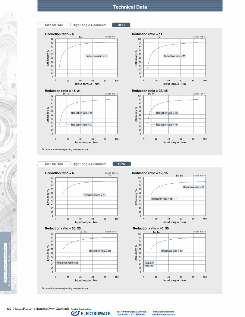
130 Gearheads
Technical DataTechnical Data Technical Data
230 231
Tech
nica
l Inf
orm
atio
n / H
andl
ing
Expl
anat
ion
Tech
nica
l Inf
orm
atio
n / H
andl
ing
Expl
anat
ion
HPG HPF
Calculate:Maximum moment load (Mi max)Maximum axial load (Fai max)Maximum radial load (Fri max)
Calculate:Average moment load (Mi av)Average axial load (Fai av) Average input speed (Ni av)
Maximum moment load (Mi max) ≦ Allowable moment load (Mc)Maximum axial load (Fai max) ≦ Allowable axial load (Fac)Maximum radial load (Fri max) ≦ Allowable radial load (Frc)
Calculate the life and check it.
(2) Checking the life
(1) Checking maximum load
Time: t
Time: t
n1
n2
n3
M1
M2
M3
M4
n4
t1 t2 t3 t4
L10
NiCrPci
LifeAverage input speedBasic dynamic load ratingDynamic equivalent load
HourrpmN (kgf)N
av
111420325065
0.137 × Mi av + 1.232 × Fai av0.444 × Mi av + 1.426 × Fai av
0.041 × Mi av + 1.232 × Fai av
0.109 × Mi av + 1.232 × Fai av0.071 × Mi av + 1.232 × Fai av0.053 × Mi av + 1.232 × Fai av
maxmax
Fai
Lri
Fri
Lai
111420325065
111420325065
2532
2532
*1 The allowable axial load is the value of an axial load applied along the axis of rotation.*2 The allowable radial load of HPG series is the value of a radial load applied at the mid-point of the input shaft.*3 The allowable radial load of HPG series is the value of a radial load applied to the point of 20 mm from the shaft edge (input flange edge).
2532 106 × Mi av + 2.7 × Fai av
121 × Mi av + 2.7 × Fai av
Fai
Fri
Lai
Lri
Check the maximum load and life of the bearing on the input side if the reducer is an HPG input shaft unit or an HPF hollow shaft unit.
FriFaiLri,Lai
If moment load and axial load fluctuate, they should be converted into the average load to check the life of the bearing.
Calculate the bearing life according to Calculation Formula 132-5 and check the life.
Specification of input bearing
Specification of input shaft bearing
Table 149-1
Table 150-1
Table 150-2
Figure 150-1
Formula 150-2
Formula 150-3
Formula 150-4
Graph 150-1
Formula 150-5
Table 149-2
Size
Table 149-3
Table 149-4
〔Note: Table 149-2 and 149-4〕
External load influence diagram
Dynamic equivalent load
Size
Dynamic equivalent load
HPG HPF
HPG
HPF
HPG HPF
HPG
HPF
Pci
N270058009700
225003550051000
kgf275590990
230036005200
N127031505600148002510039500
kgf129320570151025604050
Nm0.166.313.544.496.9210
kgfm0.0160.641.384.539.8821.4
N2456571206328555408600
kgf2567123335565878
N20.6500902197032265267
kgf2.15192
201329537
N1450029700
kgf14803030
N1010020100
kgf10302050
Nm1019
kgfm1.021.93
N15383263
kgf157333
N522966
kgf53.298.5
Pci
HPG HPF
Formula 150-1
Checking procedure
Specification of input bearing
SizeBasic load rating
Basic dynamic load rating Cr Basic static load rating Cor
SizeAllowable moment load Mc Allowable axial load Fac *1 Allowable radial load Frc *2
SizeBasic load rating
Basic dynamic load rating Cr Basic static load rating Cor
SizeAllowable moment load Mc Allowable axial load Fac *1 Allowable radial load Frc *3
Calculating maximum moment load ON input shaft
How to calculate average load(Average moment load, average axial load, average input speed)
Mi max ≦ Mc (Allowable moment load)Fai max ≦ Fac (Allowable axial load)
Max. radial loadMax. axial load————
N (kgf)N (kgf)m
See Fig. 150-1.See Fig. 150-1.See Fig. 150-1.
The maximum moment load (Mi max ) is calculated as follows.Check that the following formulas are established in all circumstances:
Inpu
t spe
edM
omen
t loa
d
How to calculate the average moment load (Miav )
How to calculate the average axial load (Faiav)
How to calculate the average input speed (Niav)
Calculating life of input bearing
Miav Average moment load Nm (kgfm) See Formula 150-2Faiav Average axial load N (kgf) See Formula 150-3
See Formula 150-4See Table 149-1 and -3See Table 150-1 and -2
Input Bearing Specifications and Checking Procedure
Technical Data Technical Data
216 217
Tech
nica
l Inf
orm
atio
n / H
andl
ing
Expl
anat
ion
Tech
nica
l Inf
orm
atio
n / H
andl
ing
Expl
anat
ion
Reduction ratio = 11Reduction ratio = 5
Reduction ratio = 15, 21 Reduction ratio = 33, 45
100
90
80
70
60
50
40
30
20
10
0
Effic
ienc
y %
Input torque Nm0 20 40 60 80 100
100
90
80
70
60
50
40
30
20
10
0
Effic
ienc
y %
Input torque Nm0 20 40 60 80 100
100
90
80
70
60
50
40
30
20
10
0
Effic
ienc
y %
Input torque Nm0 20 40 60 80 100
100
90
80
70
60
50
40
30
20
10
0Ef
ficie
ncy
%
Input torque Nm0 20 40 60 80 100
Reduction ratio = 12, 15Reduction ratio = 5
Reduction ratio = 20, 25 Reduction ratio = 40, 50
100
90
80
70
60
50
40
30
20
10
0
Effic
ienc
y %
Input torque Nm0 20 40 60 80 100
100
90
80
70
60
50
40
30
20
10
0
Effic
ienc
y %
Input torque Nm0 20 40 60 80 100
100
90
80
70
60
50
40
30
20
10
0
Effic
ienc
y %
Input torque Nm0 20 40 60 80 100
100
90
80
70
60
50
40
30
20
10
0
Effic
ienc
y %
Input torque Nm0 20 40 60 80 100
Reduction ratio = 11
Input torque Nm
100
90
70
50
30
10
80
60
40
20
00
Effic
ienc
y %
1 2 3 4 5 6
Reduction ratio = 11
Input torque Nm
100
90
70
50
30
10
80
60
40
20
00
Effic
ienc
y %
1 2 3 4 5 6
HPGSize 50 RA5 :Right Angle Gearhead
HPGSize 65 RA5 :Right Angle Gearhead
HPF
HPF
Size 25 : Hollow Shaft Unit
Size 32 : Hollow Shaft Unit
TRi TRi
TRiTRi TRiTRi
TRi TRiTRi
TRiTRi TRiTRi
Reduction ratio = 15
Reduction ratio = 21
Reduction ratio = 33
Reduction ratio = 45
Reduction ratio = 20 Reduction ratio = 40
Reduction ratio = 12
Reduction ratio = 50
Reduction ratio = 25
Reduction ratio = 15
TRi
TRi
Graph 136-5
Graph 136-7
Graph 136-6
Graph 136-8
Graph 136-1
Graph 136-3
Graph 136-2
Graph 136-4
Graph 140-1
Graph 140-2
Input torque corresponding to output torqueTRi
Input torque corresponding to output torqueTRi
Reduction ratio = 11
Reduction ratio = 11
Reduction ratio = 11Reduction ratio = 5
Reduction ratio = 5

131Gearheads
Technical DataTechnical Data Technical Data
230 231
Tech
nica
l Inf
orm
atio
n / H
andl
ing
Expl
anat
ion
Tech
nica
l Inf
orm
atio
n / H
andl
ing
Expl
anat
ion
HPG HPF
Calculate:Maximum moment load (Mi max)Maximum axial load (Fai max)Maximum radial load (Fri max)
Calculate:Average moment load (Mi av)Average axial load (Fai av) Average input speed (Ni av)
Maximum moment load (Mi max) ≦ Allowable moment load (Mc)Maximum axial load (Fai max) ≦ Allowable axial load (Fac)Maximum radial load (Fri max) ≦ Allowable radial load (Frc)
Calculate the life and check it.
(2) Checking the life
(1) Checking maximum load
Time: t
Time: t
n1
n2
n3
M1
M2
M3
M4
n4
t1 t2 t3 t4
L10
NiCrPci
LifeAverage input speedBasic dynamic load ratingDynamic equivalent load
HourrpmN (kgf)N
av
111420325065
0.137 × Mi av + 1.232 × Fai av0.444 × Mi av + 1.426 × Fai av
0.041 × Mi av + 1.232 × Fai av
0.109 × Mi av + 1.232 × Fai av0.071 × Mi av + 1.232 × Fai av0.053 × Mi av + 1.232 × Fai av
maxmax
Fai
Lri
Fri
Lai
111420325065
111420325065
2532
2532
*1 The allowable axial load is the value of an axial load applied along the axis of rotation.*2 The allowable radial load of HPG series is the value of a radial load applied at the mid-point of the input shaft.*3 The allowable radial load of HPG series is the value of a radial load applied to the point of 20 mm from the shaft edge (input flange edge).
2532 106 × Mi av + 2.7 × Fai av
121 × Mi av + 2.7 × Fai av
Fai
Fri
Lai
Lri
Check the maximum load and life of the bearing on the input side if the reducer is an HPG input shaft unit or an HPF hollow shaft unit.
FriFaiLri,Lai
If moment load and axial load fluctuate, they should be converted into the average load to check the life of the bearing.
Calculate the bearing life according to Calculation Formula 132-5 and check the life.
Specification of input bearing
Specification of input shaft bearing
Table 149-1
Table 150-1
Table 150-2
Figure 150-1
Formula 150-2
Formula 150-3
Formula 150-4
Graph 150-1
Formula 150-5
Table 149-2
Size
Table 149-3
Table 149-4
〔Note: Table 149-2 and 149-4〕
External load influence diagram
Dynamic equivalent load
Size
Dynamic equivalent load
HPG HPF
HPG
HPF
HPG HPF
HPG
HPF
Pci
N270058009700
225003550051000
kgf275590990
230036005200
N127031505600148002510039500
kgf129320570151025604050
Nm0.166.313.544.496.9210
kgfm0.0160.641.384.539.8821.4
N2456571206328555408600
kgf2567123335565878
N20.6500902197032265267
kgf2.15192
201329537
N1450029700
kgf14803030
N1010020100
kgf10302050
Nm1019
kgfm1.021.93
N15383263
kgf157333
N522966
kgf53.298.5
Pci
HPG HPF
Formula 150-1
Checking procedure
Specification of input bearing
SizeBasic load rating
Basic dynamic load rating Cr Basic static load rating Cor
SizeAllowable moment load Mc Allowable axial load Fac *1 Allowable radial load Frc *2
SizeBasic load rating
Basic dynamic load rating Cr Basic static load rating Cor
SizeAllowable moment load Mc Allowable axial load Fac *1 Allowable radial load Frc *3
Calculating maximum moment load ON input shaft
How to calculate average load(Average moment load, average axial load, average input speed)
Mi max ≦ Mc (Allowable moment load)Fai max ≦ Fac (Allowable axial load)
Max. radial loadMax. axial load————
N (kgf)N (kgf)m
See Fig. 150-1.See Fig. 150-1.See Fig. 150-1.
The maximum moment load (Mi max ) is calculated as follows.Check that the following formulas are established in all circumstances:
Inpu
t spe
edM
omen
t loa
d
How to calculate the average moment load (Miav )
How to calculate the average axial load (Faiav)
How to calculate the average input speed (Niav)
Calculating life of input bearing
Miav Average moment load Nm (kgfm) See Formula 150-2Faiav Average axial load N (kgf) See Formula 150-3
See Formula 150-4See Table 149-1 and -3See Table 150-1 and -2
Input Bearing Specifications and Checking Procedure
222 223
0 10 20 300 10 20 30 0 10 2520155
0 1510 205 0 2 4 8 1060 2 4 8 106
0 21 3 4 5 6 0 1 2 3 4 5
0 5 10 15 20
0 40 60 80 100200 40 60 1008020 0 20 40 60 80
0 20 40 60 0 10 20 300 10 20 30
0 105 15
90100
80706050403020100
Graph 134-2 Graph 134-3
Graph 134-6
Graph 134-7 Graph 134-8
Graph 134-4
90100
80706050403020100
Graph 134-1
90100
80706050403020100
90100
80706050403020100
90100
80706050403020100
90100
80706050403020100
Graph 134-5
90100
80706050403020100
90100
80706050403020100
90100
80706050403020100
Graph 134-10 Graph 134-11
Graph 134-14
Graph 134-15 Graph 134-16
Graph 134-12
90100
80706050403020100
Graph 134 -9
90100
80706050403020100
90100
80706050403020100
90100
80706050403020100
90100
80706050403020100
Graph 134-13
90100
80706050403020100
90100
80706050403020100
Graph 133-2 Graph 133-3
Graph 133-6
Graph 133-7
Graph 133-4
90100
80706050403020100
0 1 3 42
Graph 133-1
90100
80706050403020100
0 1 3 4 52
90100
807060504030201000 1 2 3
90100
807060504030201000 0.5 1 1.5
90100
807060504030201000 0.5 1 1.5
Graph 133-5
90100
807060504030201000 0.5 1 1.5
90100
807060504030201000 0.2 0.4 0.6 0.8 1 1.2
90100
80706050403020100
0 1.50.5 1 2
Graph 133-10 Graph 133-11
Graph 133-14
Graph 133-15 Graph 133-16
Graph 0133-12
90100
80706050403020100
0 2 6 8 104
Graph 133-9
90100
80706050403020100
0 2 4 6 8 10
90100
807060504030201000 2 4 6 8 10
90100
807060504030201000 2 4 6
90100
807060504030201000 1 2 3
Graph 133-13
90100
807060504030201000 1 2 3
90100
807060504030201000 1 2 3
Tech
nica
l Inf
orm
atio
n / H
andl
ing
Expl
anat
ion
Technical Data
Size 11A :Gearhead HPN
Tech
nica
l Inf
orm
atio
n / H
andl
ing
Expl
anat
ion
Technical Data
Size 20A :Gearhead HPN
Size 14A :Gearhead HPN
Reduction ratio = 4
Input torque Nm
Effic
ienc
y %
Reduction ratio = 5
Input torque Nm
Effic
ienc
y %
Reduction ratio = 7
Input torque Nm
Effic
ienc
y %
Reduction ratio = 3
Input torque Nm
Effic
ienc
y %
Size 32A :Gearhead HPN
Reduction ratio = 3
Input torque Nm
Effic
ienc
y %
Reduction ratio = 4
Input torque Nm
Effic
ienc
y %
Reduction ratio = 5
Input torque Nm
Effic
ienc
y %
Reduction ratio = 7
Input torque NmEf
ficie
ncy
%
Reduction ratio = 10
Input torque Nm
Effic
ienc
y %
Reduction ratio = 13
Input torque Nm
Effic
ienc
y %
Reduction ratio = 21
Input torque Nm
Effic
ienc
y %
Reduction ratio = 31
Input torque Nm
Effic
ienc
y %
Reduction ratio = 7
Input torque Nm
Effic
ienc
y %
Reduction ratio = 21
Input torque Nm
Effic
ienc
y %
Reduction ratio = 4
Input torque Nm
Effic
ienc
y %
Reduction ratio = 10
Input torque Nm
Effic
ienc
y %
Reduction ratio = 31
Input torque Nm
Effic
ienc
y %
Reduction ratio = 5
Input torque Nm
Effic
ienc
y %
Reduction ratio = 13
Input torque Nm
Effic
ienc
y %
Reduction ratio = 20
Input torque Nm
Effic
ienc
y %
Reduction ratio = 16
Input torque Nm
Effic
ienc
y %
Reduction ratio = 10
Input torque Nm
Effic
ienc
y %
Reduction ratio = 30
Input torque Nm
Effic
ienc
y %
Reduction ratio = 3
Input torque Nm
Effic
ienc
y %
Reduction ratio = 4
Input torque Nm
Effic
ienc
y %
Reduction ratio = 5
Input torque Nm
Effic
ienc
y %
Reduction ratio = 13
Input torque Nm
Effic
ienc
y %
Reduction ratio = 10
Input torque Nm
Effic
ienc
y %
Reduction ratio = 7
Input torque Nm
Effic
ienc
y %
Reduction ratio = 21
Input torque Nm
Effic
ienc
y %
Reduction ratio = 31
Input torque Nm
Effic
ienc
y %
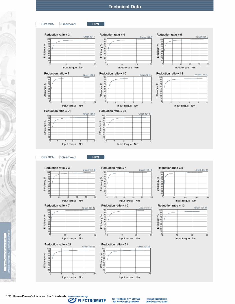
132 Gearheads
Technical DataTechnical Data Technical Data
230 231
Tech
nica
l Inf
orm
atio
n / H
andl
ing
Expl
anat
ion
Tech
nica
l Inf
orm
atio
n / H
andl
ing
Expl
anat
ion
HPG HPF
Calculate:Maximum moment load (Mi max)Maximum axial load (Fai max)Maximum radial load (Fri max)
Calculate:Average moment load (Mi av)Average axial load (Fai av) Average input speed (Ni av)
Maximum moment load (Mi max) ≦ Allowable moment load (Mc)Maximum axial load (Fai max) ≦ Allowable axial load (Fac)Maximum radial load (Fri max) ≦ Allowable radial load (Frc)
Calculate the life and check it.
(2) Checking the life
(1) Checking maximum load
Time: t
Time: t
n1
n2
n3
M1
M2
M3
M4
n4
t1 t2 t3 t4
L10
NiCrPci
LifeAverage input speedBasic dynamic load ratingDynamic equivalent load
HourrpmN (kgf)N
av
111420325065
0.137 × Mi av + 1.232 × Fai av0.444 × Mi av + 1.426 × Fai av
0.041 × Mi av + 1.232 × Fai av
0.109 × Mi av + 1.232 × Fai av0.071 × Mi av + 1.232 × Fai av0.053 × Mi av + 1.232 × Fai av
maxmax
Fai
Lri
Fri
Lai
111420325065
111420325065
2532
2532
*1 The allowable axial load is the value of an axial load applied along the axis of rotation.*2 The allowable radial load of HPG series is the value of a radial load applied at the mid-point of the input shaft.*3 The allowable radial load of HPG series is the value of a radial load applied to the point of 20 mm from the shaft edge (input flange edge).
2532 106 × Mi av + 2.7 × Fai av
121 × Mi av + 2.7 × Fai av
Fai
Fri
Lai
Lri
Check the maximum load and life of the bearing on the input side if the reducer is an HPG input shaft unit or an HPF hollow shaft unit.
FriFaiLri,Lai
If moment load and axial load fluctuate, they should be converted into the average load to check the life of the bearing.
Calculate the bearing life according to Calculation Formula 132-5 and check the life.
Specification of input bearing
Specification of input shaft bearing
Table 149-1
Table 150-1
Table 150-2
Figure 150-1
Formula 150-2
Formula 150-3
Formula 150-4
Graph 150-1
Formula 150-5
Table 149-2
Size
Table 149-3
Table 149-4
〔Note: Table 149-2 and 149-4〕
External load influence diagram
Dynamic equivalent load
Size
Dynamic equivalent load
HPG HPF
HPG
HPF
HPG HPF
HPG
HPF
Pci
N270058009700
225003550051000
kgf275590990
230036005200
N127031505600148002510039500
kgf129320570151025604050
Nm0.166.313.544.496.9210
kgfm0.0160.641.384.539.8821.4
N2456571206328555408600
kgf2567123335565878
N20.6500902197032265267
kgf2.15192
201329537
N1450029700
kgf14803030
N1010020100
kgf10302050
Nm1019
kgfm1.021.93
N15383263
kgf157333
N522966
kgf53.298.5
Pci
HPG HPF
Formula 150-1
Checking procedure
Specification of input bearing
SizeBasic load rating
Basic dynamic load rating Cr Basic static load rating Cor
SizeAllowable moment load Mc Allowable axial load Fac *1 Allowable radial load Frc *2
SizeBasic load rating
Basic dynamic load rating Cr Basic static load rating Cor
SizeAllowable moment load Mc Allowable axial load Fac *1 Allowable radial load Frc *3
Calculating maximum moment load ON input shaft
How to calculate average load(Average moment load, average axial load, average input speed)
Mi max ≦ Mc (Allowable moment load)Fai max ≦ Fac (Allowable axial load)
Max. radial loadMax. axial load————
N (kgf)N (kgf)m
See Fig. 150-1.See Fig. 150-1.See Fig. 150-1.
The maximum moment load (Mi max ) is calculated as follows.Check that the following formulas are established in all circumstances:
Inpu
t spe
edM
omen
t loa
d
How to calculate the average moment load (Miav )
How to calculate the average axial load (Faiav)
How to calculate the average input speed (Niav)
Calculating life of input bearing
Miav Average moment load Nm (kgfm) See Formula 150-2Faiav Average axial load N (kgf) See Formula 150-3
See Formula 150-4See Table 149-1 and -3See Table 150-1 and -2
Input Bearing Specifications and Checking Procedure
222 223
0 10 20 300 10 20 30 0 10 2520155
0 1510 205 0 2 4 8 1060 2 4 8 106
0 21 3 4 5 6 0 1 2 3 4 5
0 5 10 15 20
0 40 60 80 100200 40 60 1008020 0 20 40 60 80
0 20 40 60 0 10 20 300 10 20 30
0 105 15
90100
80706050403020100
Graph 134-2 Graph 134-3
Graph 134-6
Graph 134-7 Graph 134-8
Graph 134-4
90100
80706050403020100
Graph 134-1
90100
80706050403020100
90100
80706050403020100
90100
80706050403020100
90100
80706050403020100
Graph 134-5
90100
80706050403020100
90100
80706050403020100
90100
80706050403020100
Graph 134-10 Graph 134-11
Graph 134-14
Graph 134-15 Graph 134-16
Graph 134-12
90100
80706050403020100
Graph 134 -9
90100
80706050403020100
90100
80706050403020100
90100
80706050403020100
90100
80706050403020100
Graph 134-13
90100
80706050403020100
90100
80706050403020100
Graph 133-2 Graph 133-3
Graph 133-6
Graph 133-7
Graph 133-4
90100
80706050403020100
0 1 3 42
Graph 133-1
90100
80706050403020100
0 1 3 4 52
90100
807060504030201000 1 2 3
90100
807060504030201000 0.5 1 1.5
90100
807060504030201000 0.5 1 1.5
Graph 133-5
90100
807060504030201000 0.5 1 1.5
90100
807060504030201000 0.2 0.4 0.6 0.8 1 1.2
90100
80706050403020100
0 1.50.5 1 2
Graph 133-10 Graph 133-11
Graph 133-14
Graph 133-15 Graph 133-16
Graph 0133-12
90100
80706050403020100
0 2 6 8 104
Graph 133-9
90100
80706050403020100
0 2 4 6 8 10
90100
807060504030201000 2 4 6 8 10
90100
807060504030201000 2 4 6
90100
807060504030201000 1 2 3
Graph 133-13
90100
807060504030201000 1 2 3
90100
807060504030201000 1 2 3
Tech
nica
l Inf
orm
atio
n / H
andl
ing
Expl
anat
ion
Technical Data
Size 11A :Gearhead HPN
Tech
nica
l Inf
orm
atio
n / H
andl
ing
Expl
anat
ion
Technical Data
Size 20A :Gearhead HPN
Size 14A :Gearhead HPN
Reduction ratio = 4
Input torque Nm
Effic
ienc
y %
Reduction ratio = 5
Input torque Nm
Effic
ienc
y %
Reduction ratio = 7
Input torque Nm
Effic
ienc
y %
Reduction ratio = 3
Input torque Nm
Effic
ienc
y %
Size 32A :Gearhead HPN
Reduction ratio = 3
Input torque Nm
Effic
ienc
y %
Reduction ratio = 4
Input torque Nm
Effic
ienc
y %
Reduction ratio = 5
Input torque Nm
Effic
ienc
y %
Reduction ratio = 7
Input torque Nm
Effic
ienc
y %
Reduction ratio = 10
Input torque Nm
Effic
ienc
y %
Reduction ratio = 13
Input torque Nm
Effic
ienc
y %
Reduction ratio = 21
Input torque Nm
Effic
ienc
y %
Reduction ratio = 31
Input torque Nm
Effic
ienc
y %
Reduction ratio = 7
Input torque Nm
Effic
ienc
y %
Reduction ratio = 21
Input torque Nm
Effic
ienc
y %
Reduction ratio = 4
Input torque Nm
Effic
ienc
y %
Reduction ratio = 10
Input torque Nm
Effic
ienc
y %
Reduction ratio = 31
Input torque Nm
Effic
ienc
y %
Reduction ratio = 5
Input torque Nm
Effic
ienc
y %
Reduction ratio = 13
Input torque Nm
Effic
ienc
y %
Reduction ratio = 20
Input torque Nm
Effic
ienc
y %
Reduction ratio = 16
Input torque Nm
Effic
ienc
y %
Reduction ratio = 10
Input torque Nm
Effic
ienc
y %
Reduction ratio = 30
Input torque Nm
Effic
ienc
y %
Reduction ratio = 3
Input torque Nm
Effic
ienc
y %
Reduction ratio = 4
Input torque Nm
Effic
ienc
y %
Reduction ratio = 5
Input torque Nm
Effic
ienc
y %
Reduction ratio = 13
Input torque Nm
Effic
ienc
y %
Reduction ratio = 10
Input torque Nm
Effic
ienc
y %
Reduction ratio = 7
Input torque Nm
Effic
ienc
y %
Reduction ratio = 21
Input torque Nm
Effic
ienc
y %
Reduction ratio = 31
Input torque Nm
Effic
ienc
y %

133Gearheads
Technical DataTechnical Data Technical Data
230 231
Tech
nica
l Inf
orm
atio
n / H
andl
ing
Expl
anat
ion
Tech
nica
l Inf
orm
atio
n / H
andl
ing
Expl
anat
ion
HPG HPF
Calculate:Maximum moment load (Mi max)Maximum axial load (Fai max)Maximum radial load (Fri max)
Calculate:Average moment load (Mi av)Average axial load (Fai av) Average input speed (Ni av)
Maximum moment load (Mi max) ≦ Allowable moment load (Mc)Maximum axial load (Fai max) ≦ Allowable axial load (Fac)Maximum radial load (Fri max) ≦ Allowable radial load (Frc)
Calculate the life and check it.
(2) Checking the life
(1) Checking maximum load
Time: t
Time: t
n1
n2
n3
M1
M2
M3
M4
n4
t1 t2 t3 t4
L10
NiCrPci
LifeAverage input speedBasic dynamic load ratingDynamic equivalent load
HourrpmN (kgf)N
av
111420325065
0.137 × Mi av + 1.232 × Fai av0.444 × Mi av + 1.426 × Fai av
0.041 × Mi av + 1.232 × Fai av
0.109 × Mi av + 1.232 × Fai av0.071 × Mi av + 1.232 × Fai av0.053 × Mi av + 1.232 × Fai av
maxmax
Fai
Lri
Fri
Lai
111420325065
111420325065
2532
2532
*1 The allowable axial load is the value of an axial load applied along the axis of rotation.*2 The allowable radial load of HPG series is the value of a radial load applied at the mid-point of the input shaft.*3 The allowable radial load of HPG series is the value of a radial load applied to the point of 20 mm from the shaft edge (input flange edge).
2532 106 × Mi av + 2.7 × Fai av
121 × Mi av + 2.7 × Fai av
Fai
Fri
Lai
Lri
Check the maximum load and life of the bearing on the input side if the reducer is an HPG input shaft unit or an HPF hollow shaft unit.
FriFaiLri,Lai
If moment load and axial load fluctuate, they should be converted into the average load to check the life of the bearing.
Calculate the bearing life according to Calculation Formula 132-5 and check the life.
Specification of input bearing
Specification of input shaft bearing
Table 149-1
Table 150-1
Table 150-2
Figure 150-1
Formula 150-2
Formula 150-3
Formula 150-4
Graph 150-1
Formula 150-5
Table 149-2
Size
Table 149-3
Table 149-4
〔Note: Table 149-2 and 149-4〕
External load influence diagram
Dynamic equivalent load
Size
Dynamic equivalent load
HPG HPF
HPG
HPF
HPG HPF
HPG
HPF
Pci
N270058009700
225003550051000
kgf275590990
230036005200
N127031505600148002510039500
kgf129320570151025604050
Nm0.166.313.544.496.9210
kgfm0.0160.641.384.539.8821.4
N2456571206328555408600
kgf2567123335565878
N20.6500902197032265267
kgf2.15192
201329537
N1450029700
kgf14803030
N1010020100
kgf10302050
Nm1019
kgfm1.021.93
N15383263
kgf157333
N522966
kgf53.298.5
Pci
HPG HPF
Formula 150-1
Checking procedure
Specification of input bearing
SizeBasic load rating
Basic dynamic load rating Cr Basic static load rating Cor
SizeAllowable moment load Mc Allowable axial load Fac *1 Allowable radial load Frc *2
SizeBasic load rating
Basic dynamic load rating Cr Basic static load rating Cor
SizeAllowable moment load Mc Allowable axial load Fac *1 Allowable radial load Frc *3
Calculating maximum moment load ON input shaft
How to calculate average load(Average moment load, average axial load, average input speed)
Mi max ≦ Mc (Allowable moment load)Fai max ≦ Fac (Allowable axial load)
Max. radial loadMax. axial load————
N (kgf)N (kgf)m
See Fig. 150-1.See Fig. 150-1.See Fig. 150-1.
The maximum moment load (Mi max ) is calculated as follows.Check that the following formulas are established in all circumstances:
Inpu
t spe
edM
omen
t loa
d
How to calculate the average moment load (Miav )
How to calculate the average axial load (Faiav)
How to calculate the average input speed (Niav)
Calculating life of input bearing
Miav Average moment load Nm (kgfm) See Formula 150-2Faiav Average axial load N (kgf) See Formula 150-3
See Formula 150-4See Table 149-1 and -3See Table 150-1 and -2
Input Bearing Specifications and Checking Procedure
224 225
90100
80706050403020100
0 2010 4030
Graph 135-2 Graph 135-3
Graph 135-6
Graph 135-7 Graph 135-8
Graph 135-4
90100
80706050403020100
0 50 100 150 250200
Graph 135-1
90100
80706050403020100
0 50 150 200 250100
90100
807060504030201000 50 100 200150
90100
807060504030201000 30 60 90 120
90100
807060504030201000 20 40 60 80
Graph 135-5
90100
80706050403020100
90100
807060504030201000 10 20 30 40 50
0 20 40 8060
0
100
200
300
400
500
600
700
800
900
0 100 200 300 400 500 600 700 800 900 1000
HPN-14A
0 100 200 300 400 500 600 700
HPN-11A
0
200
400
600
800
1000
1200
1400
1600
1800
2000
0 500 1000 1500 2000 2500
HPN-20A
0
500
1000
1500
2000
2500
3000
3500
4000
4500
0 1000 2000 3000 4000
HPN-32A6000
5000
4000
3000
2000
1000
00 1000 2000 3000 4000 5000 6000
HPN-40A
fw=1
fw=1.2
fw=1.5
Graph 144-1 Graph 144-2
Graph 144-4 Graph 144-5
Graph 144-3600
500
400
300
200
100
0
Tech
nica
l Inf
orm
atio
n / H
andl
ing
Expl
anat
ion
Technical Data
Size 40A :Gearhead HPN
Tech
nica
l Inf
orm
atio
n / H
andl
ing
Expl
anat
ion
Technical Data
Reduction ratio = 3
Input torque Nm
Effic
ienc
y %
Reduction ratio = 4
Input torque Nm
Effic
ienc
y %
Effic
ienc
y %
Effic
ienc
y %
Reduction ratio = 5
Input torque Nm
Effic
ienc
y %
Axial load N
HPN Series Output Shaft Load Limits are plotted below.
HPN uses deep groove ball bearings to support the output shaft. Please use the curve on the graph for the appropriate load coefficient (fw) that represents the expected operating condition.
Radi
al lo
ad N
Axial load N
Radi
al lo
ad N
Axial load N
Radi
al lo
ad N
Axial load N
Output shaft speed - 100 rpm, bearing life is based on 20,000 hours. The load-point is based on shaft center of radial load and axial load.
Load coefficientfw=1~1.2 Smooth operation without impactfw=1.2~1.5 Standard operation
Radi
al lo
ad N
Axial load N
Radi
al lo
ad N
Reduction ratio = 7
Input torque Nm
Effic
ienc
y %
Reduction ratio = 10
Input torque Nm
Reduction ratio = 13
Input torque Nm
Effic
ienc
y %
Reduction ratio = 21
Input torque Nm
Effic
ienc
y %
Reduction ratio = 31
Input torque Nm
Output Shaft Bearing Load Limits

134 Gearheads
Technical DataTechnical Data Technical Data
230 231
Tech
nica
l Inf
orm
atio
n / H
andl
ing
Expl
anat
ion
Tech
nica
l Inf
orm
atio
n / H
andl
ing
Expl
anat
ion
HPG HPF
Calculate:Maximum moment load (Mi max)Maximum axial load (Fai max)Maximum radial load (Fri max)
Calculate:Average moment load (Mi av)Average axial load (Fai av) Average input speed (Ni av)
Maximum moment load (Mi max) ≦ Allowable moment load (Mc)Maximum axial load (Fai max) ≦ Allowable axial load (Fac)Maximum radial load (Fri max) ≦ Allowable radial load (Frc)
Calculate the life and check it.
(2) Checking the life
(1) Checking maximum load
Time: t
Time: t
n1
n2
n3
M1
M2
M3
M4
n4
t1 t2 t3 t4
L10
NiCrPci
LifeAverage input speedBasic dynamic load ratingDynamic equivalent load
HourrpmN (kgf)N
av
111420325065
0.137 × Mi av + 1.232 × Fai av0.444 × Mi av + 1.426 × Fai av
0.041 × Mi av + 1.232 × Fai av
0.109 × Mi av + 1.232 × Fai av0.071 × Mi av + 1.232 × Fai av0.053 × Mi av + 1.232 × Fai av
maxmax
Fai
Lri
Fri
Lai
111420325065
111420325065
2532
2532
*1 The allowable axial load is the value of an axial load applied along the axis of rotation.*2 The allowable radial load of HPG series is the value of a radial load applied at the mid-point of the input shaft.*3 The allowable radial load of HPG series is the value of a radial load applied to the point of 20 mm from the shaft edge (input flange edge).
2532 106 × Mi av + 2.7 × Fai av
121 × Mi av + 2.7 × Fai av
Fai
Fri
Lai
Lri
Check the maximum load and life of the bearing on the input side if the reducer is an HPG input shaft unit or an HPF hollow shaft unit.
FriFaiLri,Lai
If moment load and axial load fluctuate, they should be converted into the average load to check the life of the bearing.
Calculate the bearing life according to Calculation Formula 132-5 and check the life.
Specification of input bearing
Specification of input shaft bearing
Table 149-1
Table 150-1
Table 150-2
Figure 150-1
Formula 150-2
Formula 150-3
Formula 150-4
Graph 150-1
Formula 150-5
Table 149-2
Size
Table 149-3
Table 149-4
〔Note: Table 149-2 and 149-4〕
External load influence diagram
Dynamic equivalent load
Size
Dynamic equivalent load
HPG HPF
HPG
HPF
HPG HPF
HPG
HPF
Pci
N270058009700
225003550051000
kgf275590990
230036005200
N127031505600148002510039500
kgf129320570151025604050
Nm0.166.313.544.496.9210
kgfm0.0160.641.384.539.8821.4
N2456571206328555408600
kgf2567123335565878
N20.6500902197032265267
kgf2.15192
201329537
N1450029700
kgf14803030
N1010020100
kgf10302050
Nm1019
kgfm1.021.93
N15383263
kgf157333
N522966
kgf53.298.5
Pci
HPG HPF
Formula 150-1
Checking procedure
Specification of input bearing
SizeBasic load rating
Basic dynamic load rating Cr Basic static load rating Cor
SizeAllowable moment load Mc Allowable axial load Fac *1 Allowable radial load Frc *2
SizeBasic load rating
Basic dynamic load rating Cr Basic static load rating Cor
SizeAllowable moment load Mc Allowable axial load Fac *1 Allowable radial load Frc *3
Calculating maximum moment load ON input shaft
How to calculate average load(Average moment load, average axial load, average input speed)
Mi max ≦ Mc (Allowable moment load)Fai max ≦ Fac (Allowable axial load)
Max. radial loadMax. axial load————
N (kgf)N (kgf)m
See Fig. 150-1.See Fig. 150-1.See Fig. 150-1.
The maximum moment load (Mi max ) is calculated as follows.Check that the following formulas are established in all circumstances:
Inpu
t spe
edM
omen
t loa
d
How to calculate the average moment load (Miav )
How to calculate the average axial load (Faiav)
How to calculate the average input speed (Niav)
Calculating life of input bearing
Miav Average moment load Nm (kgfm) See Formula 150-2Faiav Average axial load N (kgf) See Formula 150-3
See Formula 150-4See Table 149-1 and -3See Table 150-1 and -2
Input Bearing Specifications and Checking Procedure
Technical Data Technical Data
216 217
Tech
nica
l Inf
orm
atio
n / H
andl
ing
Expl
anat
ion
Tech
nica
l Inf
orm
atio
n / H
andl
ing
Expl
anat
ion
Reduction ratio = 11Reduction ratio = 5
Reduction ratio = 15, 21 Reduction ratio = 33, 45
100
90
80
70
60
50
40
30
20
10
0
Effic
ienc
y %
Input torque Nm0 20 40 60 80 100
100
90
80
70
60
50
40
30
20
10
0
Effic
ienc
y %
Input torque Nm0 20 40 60 80 100
100
90
80
70
60
50
40
30
20
10
0
Effic
ienc
y %
Input torque Nm0 20 40 60 80 100
100
90
80
70
60
50
40
30
20
10
0
Effic
ienc
y %
Input torque Nm0 20 40 60 80 100
Reduction ratio = 12, 15Reduction ratio = 5
Reduction ratio = 20, 25 Reduction ratio = 40, 50
100
90
80
70
60
50
40
30
20
10
0
Effic
ienc
y %
Input torque Nm0 20 40 60 80 100
100
90
80
70
60
50
40
30
20
10
0
Effic
ienc
y %
Input torque Nm0 20 40 60 80 100
100
90
80
70
60
50
40
30
20
10
0
Effic
ienc
y %
Input torque Nm0 20 40 60 80 100
100
90
80
70
60
50
40
30
20
10
0
Effic
ienc
y %
Input torque Nm0 20 40 60 80 100
Reduction ratio = 11
Input torque Nm
100
90
70
50
30
10
80
60
40
20
00
Effic
ienc
y %
1 2 3 4 5 6
Reduction ratio = 11
Input torque Nm
100
90
70
50
30
10
80
60
40
20
00
Effic
ienc
y %
1 2 3 4 5 6
HPGSize 50 RA5 :Right Angle Gearhead
HPGSize 65 RA5 :Right Angle Gearhead
HPF
HPF
Size 25 : Hollow Shaft Unit
Size 32 : Hollow Shaft Unit
TRi TRi
TRiTRi TRiTRi
TRi TRiTRi
TRiTRi TRiTRi
Reduction ratio = 15
Reduction ratio = 21
Reduction ratio = 33
Reduction ratio = 45
Reduction ratio = 20 Reduction ratio = 40
Reduction ratio = 12
Reduction ratio = 50
Reduction ratio = 25
Reduction ratio = 15
TRi
TRi
Graph 136-5
Graph 136-7
Graph 136-6
Graph 136-8
Graph 136-1
Graph 136-3
Graph 136-2
Graph 136-4
Graph 140-1
Graph 140-2
Input torque corresponding to output torqueTRi
Input torque corresponding to output torqueTRi
Reduction ratio = 11
Reduction ratio = 11
Reduction ratio = 11Reduction ratio = 5
Reduction ratio = 5

135Gearheads
Technical DataTechnical Data Technical Data
230 231
Tech
nica
l Inf
orm
atio
n / H
andl
ing
Expl
anat
ion
Tech
nica
l Inf
orm
atio
n / H
andl
ing
Expl
anat
ion
HPG HPF
Calculate:Maximum moment load (Mi max)Maximum axial load (Fai max)Maximum radial load (Fri max)
Calculate:Average moment load (Mi av)Average axial load (Fai av) Average input speed (Ni av)
Maximum moment load (Mi max) ≦ Allowable moment load (Mc)Maximum axial load (Fai max) ≦ Allowable axial load (Fac)Maximum radial load (Fri max) ≦ Allowable radial load (Frc)
Calculate the life and check it.
(2) Checking the life
(1) Checking maximum load
Time: t
Time: t
n1
n2
n3
M1
M2
M3
M4
n4
t1 t2 t3 t4
L10
NiCrPci
LifeAverage input speedBasic dynamic load ratingDynamic equivalent load
HourrpmN (kgf)N
av
111420325065
0.137 × Mi av + 1.232 × Fai av0.444 × Mi av + 1.426 × Fai av
0.041 × Mi av + 1.232 × Fai av
0.109 × Mi av + 1.232 × Fai av0.071 × Mi av + 1.232 × Fai av0.053 × Mi av + 1.232 × Fai av
maxmax
Fai
Lri
Fri
Lai
111420325065
111420325065
2532
2532
*1 The allowable axial load is the value of an axial load applied along the axis of rotation.*2 The allowable radial load of HPG series is the value of a radial load applied at the mid-point of the input shaft.*3 The allowable radial load of HPG series is the value of a radial load applied to the point of 20 mm from the shaft edge (input flange edge).
2532 106 × Mi av + 2.7 × Fai av
121 × Mi av + 2.7 × Fai av
Fai
Fri
Lai
Lri
Check the maximum load and life of the bearing on the input side if the reducer is an HPG input shaft unit or an HPF hollow shaft unit.
FriFaiLri,Lai
If moment load and axial load fluctuate, they should be converted into the average load to check the life of the bearing.
Calculate the bearing life according to Calculation Formula 132-5 and check the life.
Specification of input bearing
Specification of input shaft bearing
Table 149-1
Table 150-1
Table 150-2
Figure 150-1
Formula 150-2
Formula 150-3
Formula 150-4
Graph 150-1
Formula 150-5
Table 149-2
Size
Table 149-3
Table 149-4
〔Note: Table 149-2 and 149-4〕
External load influence diagram
Dynamic equivalent load
Size
Dynamic equivalent load
HPG HPF
HPG
HPF
HPG HPF
HPG
HPF
Pci
N270058009700
225003550051000
kgf275590990
230036005200
N127031505600148002510039500
kgf129320570151025604050
Nm0.166.313.544.496.9210
kgfm0.0160.641.384.539.8821.4
N2456571206328555408600
kgf2567123335565878
N20.6500902197032265267
kgf2.15192
201329537
N1450029700
kgf14803030
N1010020100
kgf10302050
Nm1019
kgfm1.021.93
N15383263
kgf157333
N522966
kgf53.298.5
Pci
HPG HPF
Formula 150-1
Checking procedure
Specification of input bearing
SizeBasic load rating
Basic dynamic load rating Cr Basic static load rating Cor
SizeAllowable moment load Mc Allowable axial load Fac *1 Allowable radial load Frc *2
SizeBasic load rating
Basic dynamic load rating Cr Basic static load rating Cor
SizeAllowable moment load Mc Allowable axial load Fac *1 Allowable radial load Frc *3
Calculating maximum moment load ON input shaft
How to calculate average load(Average moment load, average axial load, average input speed)
Mi max ≦ Mc (Allowable moment load)Fai max ≦ Fac (Allowable axial load)
Max. radial loadMax. axial load————
N (kgf)N (kgf)m
See Fig. 150-1.See Fig. 150-1.See Fig. 150-1.
The maximum moment load (Mi max ) is calculated as follows.Check that the following formulas are established in all circumstances:
Inpu
t spe
edM
omen
t loa
d
How to calculate the average moment load (Miav )
How to calculate the average axial load (Faiav)
How to calculate the average input speed (Niav)
Calculating life of input bearing
Miav Average moment load Nm (kgfm) See Formula 150-2Faiav Average axial load N (kgf) See Formula 150-3
See Formula 150-4See Table 149-1 and -3See Table 150-1 and -2
Input Bearing Specifications and Checking Procedure
Tech
nica
l Inf
orm
atio
n / H
andl
ing
Expl
anat
ion
Tech
nica
l Inf
orm
atio
n / H
andl
ing
Expl
anat
ion
218 219
Size 14 : Gearhead
Size 20 : Gearhead
500 rpm 1000 rpm 2000 rpm 3500 rpmInput rotational speed
500 rpm 1000 rpm 2000 rpm 3500 rpmInput rotational speed
CSG-GH CSF-GH
CSG-GH CSF-GH
Size 32 : Gearhead CSG-GH CSF-GH
Size 45 : Gearhead CSG-GH CSF-GH
500 rpm 1000 rpm 2000 rpm 3500 rpmInput rotational speed
500 rpm 1000 rpm 2000 rpm 3500 rpmInput rotational speed
Reduction ratio = 100
90100
80706050403020100
Effic
ienc
y %
0 2 4 6 10 12 14 16 188Input torque Ncm
Reduction ratio = 80
90100
80706050403020100
Effic
ienc
y %
0 2 64 8 2010 12 14Input torque Ncm
16 18
Reduction ratio = 50
90100
80706050403020100
Effic
ienc
y %
0 5 10 15 20 25Input torque Ncm
90100
80706050403020100
Effic
ienc
y %
0 10 20 30 60 70 8040 50
Input torque Ncm
Reduction ratio = 100
90100
80706050403020100
Effic
ienc
y %
0 10 20 30 40 50 60 70
Input torque Ncm
Reduction ratio = 120
90100
8070605040302010
0
Effic
ienc
y %
0 5 10 15 20 25 30 35 40 45 50 55
Input torque Ncm
Reduction ratio = 160
Reduction ratio = 50
90100
80706050403020100
Effic
ienc
y %
0 10 20 30 60 70 80 90 10040 50
Input torque Ncm
90100
80706050403020100
Effic
ienc
y %
0 10 20 30 40 50 60 70 80 90
Input torque Ncm
Reduction ratio = 80
Reduction ratio = 50
90100
8070605040
30%20100
Effic
ienc
y %
0 200 300100 400 500 600 700 800
Input torque Ncm
Reduction ratio = 80
90100
80706050403020100
Effic
ienc
y %
0 100 300 800700400 500 600200
Input torque Ncm
Reduction ratio = 100
90100
80706050403020100
Effic
ienc
y %
0 100 300 500 700200 400 600 800
Input torque Ncm
Reduction ratio = 120
90100
80706050403020100
Effic
ienc
y %
0 100 200 300 600 700400 500
Input torque Ncm
Reduction ratio = 160
90100
80706050403020100
Effic
ienc
y %
0 100 200 300 400 500 600
Input torque Ncm
Reduction ratio = 50
90100
80706050403020100
Effic
ienc
y %
0 50 100 200 250 300 350150
Input torque Ncm
Reduction ratio = 80
90100
8070605040302010
0
Effic
ienc
y %
0 50 100 150 200 250 300
Input torque Ncm
Reduction ratio = 100
90100
8070605040302010
0
Effic
ienc
y %
0 50 100 150 200 250 300
Input torque Ncm
Reduction ratio = 120
90100
8070605040302010
0
Effic
ienc
y %
0 50 100 150 200 250
Input torque Ncm
Reduction ratio = 160
90100
8070605040302010
0
Effic
ienc
y %
0 20 40 60 80 100 120 140 160 180 200
Input torque Ncm
Graph 141-1
Graph 141-4 Graph 141-5
Graph 141-7 Graph 141-8
Graph 141-6
Graph 141-2 Graph 141-3
Graph 142-6 Graph 142-7
Graph 142-9 Graph 142-10
Graph 142-8
Graph 142-1 Graph 142-2
Graph 142-4 Graph 142-5
Graph 142-3
Technical Data Technical Data
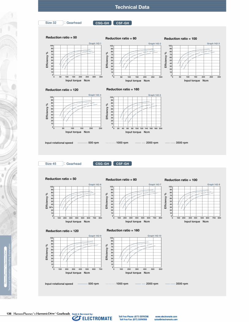
136 Gearheads
Technical DataTechnical Data Technical Data
230 231
Tech
nica
l Inf
orm
atio
n / H
andl
ing
Expl
anat
ion
Tech
nica
l Inf
orm
atio
n / H
andl
ing
Expl
anat
ion
HPG HPF
Calculate:Maximum moment load (Mi max)Maximum axial load (Fai max)Maximum radial load (Fri max)
Calculate:Average moment load (Mi av)Average axial load (Fai av) Average input speed (Ni av)
Maximum moment load (Mi max) ≦ Allowable moment load (Mc)Maximum axial load (Fai max) ≦ Allowable axial load (Fac)Maximum radial load (Fri max) ≦ Allowable radial load (Frc)
Calculate the life and check it.
(2) Checking the life
(1) Checking maximum load
Time: t
Time: t
n1
n2
n3
M1
M2
M3
M4
n4
t1 t2 t3 t4
L10
NiCrPci
LifeAverage input speedBasic dynamic load ratingDynamic equivalent load
HourrpmN (kgf)N
av
111420325065
0.137 × Mi av + 1.232 × Fai av0.444 × Mi av + 1.426 × Fai av
0.041 × Mi av + 1.232 × Fai av
0.109 × Mi av + 1.232 × Fai av0.071 × Mi av + 1.232 × Fai av0.053 × Mi av + 1.232 × Fai av
maxmax
Fai
Lri
Fri
Lai
111420325065
111420325065
2532
2532
*1 The allowable axial load is the value of an axial load applied along the axis of rotation.*2 The allowable radial load of HPG series is the value of a radial load applied at the mid-point of the input shaft.*3 The allowable radial load of HPG series is the value of a radial load applied to the point of 20 mm from the shaft edge (input flange edge).
2532 106 × Mi av + 2.7 × Fai av
121 × Mi av + 2.7 × Fai av
Fai
Fri
Lai
Lri
Check the maximum load and life of the bearing on the input side if the reducer is an HPG input shaft unit or an HPF hollow shaft unit.
FriFaiLri,Lai
If moment load and axial load fluctuate, they should be converted into the average load to check the life of the bearing.
Calculate the bearing life according to Calculation Formula 132-5 and check the life.
Specification of input bearing
Specification of input shaft bearing
Table 149-1
Table 150-1
Table 150-2
Figure 150-1
Formula 150-2
Formula 150-3
Formula 150-4
Graph 150-1
Formula 150-5
Table 149-2
Size
Table 149-3
Table 149-4
〔Note: Table 149-2 and 149-4〕
External load influence diagram
Dynamic equivalent load
Size
Dynamic equivalent load
HPG HPF
HPG
HPF
HPG HPF
HPG
HPF
Pci
N270058009700
225003550051000
kgf275590990
230036005200
N127031505600148002510039500
kgf129320570151025604050
Nm0.166.313.544.496.9210
kgfm0.0160.641.384.539.8821.4
N2456571206328555408600
kgf2567123335565878
N20.6500902197032265267
kgf2.15192
201329537
N1450029700
kgf14803030
N1010020100
kgf10302050
Nm1019
kgfm1.021.93
N15383263
kgf157333
N522966
kgf53.298.5
Pci
HPG HPF
Formula 150-1
Checking procedure
Specification of input bearing
SizeBasic load rating
Basic dynamic load rating Cr Basic static load rating Cor
SizeAllowable moment load Mc Allowable axial load Fac *1 Allowable radial load Frc *2
SizeBasic load rating
Basic dynamic load rating Cr Basic static load rating Cor
SizeAllowable moment load Mc Allowable axial load Fac *1 Allowable radial load Frc *3
Calculating maximum moment load ON input shaft
How to calculate average load(Average moment load, average axial load, average input speed)
Mi max ≦ Mc (Allowable moment load)Fai max ≦ Fac (Allowable axial load)
Max. radial loadMax. axial load————
N (kgf)N (kgf)m
See Fig. 150-1.See Fig. 150-1.See Fig. 150-1.
The maximum moment load (Mi max ) is calculated as follows.Check that the following formulas are established in all circumstances:
Inpu
t spe
edM
omen
t loa
d
How to calculate the average moment load (Miav )
How to calculate the average axial load (Faiav)
How to calculate the average input speed (Niav)
Calculating life of input bearing
Miav Average moment load Nm (kgfm) See Formula 150-2Faiav Average axial load N (kgf) See Formula 150-3
See Formula 150-4See Table 149-1 and -3See Table 150-1 and -2
Input Bearing Specifications and Checking Procedure
Tech
nica
l Inf
orm
atio
n / H
andl
ing
Expl
anat
ion
Tech
nica
l Inf
orm
atio
n / H
andl
ing
Expl
anat
ion
218 219
Size 14 : Gearhead
Size 20 : Gearhead
500 rpm 1000 rpm 2000 rpm 3500 rpmInput rotational speed
500 rpm 1000 rpm 2000 rpm 3500 rpmInput rotational speed
CSG-GH CSF-GH
CSG-GH CSF-GH
Size 32 : Gearhead CSG-GH CSF-GH
Size 45 : Gearhead CSG-GH CSF-GH
500 rpm 1000 rpm 2000 rpm 3500 rpmInput rotational speed
500 rpm 1000 rpm 2000 rpm 3500 rpmInput rotational speed
Reduction ratio = 100
90100
80706050403020100
Effic
ienc
y %
0 2 4 6 10 12 14 16 188Input torque Ncm
Reduction ratio = 80
90100
80706050403020100
Effic
ienc
y %
0 2 64 8 2010 12 14Input torque Ncm
16 18
Reduction ratio = 50
90100
80706050403020100
Effic
ienc
y %
0 5 10 15 20 25Input torque Ncm
90100
80706050403020100
Effic
ienc
y %
0 10 20 30 60 70 8040 50
Input torque Ncm
Reduction ratio = 100
90100
80706050403020100
Effic
ienc
y %
0 10 20 30 40 50 60 70
Input torque Ncm
Reduction ratio = 120
90100
8070605040302010
0
Effic
ienc
y %
0 5 10 15 20 25 30 35 40 45 50 55
Input torque Ncm
Reduction ratio = 160
Reduction ratio = 50
90100
80706050403020100
Effic
ienc
y %
0 10 20 30 60 70 80 90 10040 50
Input torque Ncm
90100
80706050403020100
Effic
ienc
y %
0 10 20 30 40 50 60 70 80 90
Input torque Ncm
Reduction ratio = 80
Reduction ratio = 50
90100
8070605040
30%20100
Effic
ienc
y %
0 200 300100 400 500 600 700 800
Input torque Ncm
Reduction ratio = 80
90100
80706050403020100
Effic
ienc
y %
0 100 300 800700400 500 600200
Input torque Ncm
Reduction ratio = 100
90100
80706050403020100
Effic
ienc
y %
0 100 300 500 700200 400 600 800
Input torque Ncm
Reduction ratio = 120
90100
80706050403020100
Effic
ienc
y %
0 100 200 300 600 700400 500
Input torque Ncm
Reduction ratio = 160
90100
80706050403020100
Effic
ienc
y %
0 100 200 300 400 500 600
Input torque Ncm
Reduction ratio = 50
90100
80706050403020100
Effic
ienc
y %
0 50 100 200 250 300 350150
Input torque Ncm
Reduction ratio = 80
90100
8070605040302010
0
Effic
ienc
y %
0 50 100 150 200 250 300
Input torque Ncm
Reduction ratio = 100
90100
8070605040302010
0
Effic
ienc
y %
0 50 100 150 200 250 300
Input torque Ncm
Reduction ratio = 120
90100
8070605040302010
0
Effic
ienc
y %
0 50 100 150 200 250
Input torque Ncm
Reduction ratio = 160
90100
8070605040302010
0
Effic
ienc
y %
0 20 40 60 80 100 120 140 160 180 200
Input torque Ncm
Graph 141-1
Graph 141-4 Graph 141-5
Graph 141-7 Graph 141-8
Graph 141-6
Graph 141-2 Graph 141-3
Graph 142-6 Graph 142-7
Graph 142-9 Graph 142-10
Graph 142-8
Graph 142-1 Graph 142-2
Graph 142-4 Graph 142-5
Graph 142-3
Technical Data Technical Data

137Gearheads
Technical DataTechnical Data Technical Data
230 231
Tech
nica
l Inf
orm
atio
n / H
andl
ing
Expl
anat
ion
Tech
nica
l Inf
orm
atio
n / H
andl
ing
Expl
anat
ion
HPG HPF
Calculate:Maximum moment load (Mi max)Maximum axial load (Fai max)Maximum radial load (Fri max)
Calculate:Average moment load (Mi av)Average axial load (Fai av) Average input speed (Ni av)
Maximum moment load (Mi max) ≦ Allowable moment load (Mc)Maximum axial load (Fai max) ≦ Allowable axial load (Fac)Maximum radial load (Fri max) ≦ Allowable radial load (Frc)
Calculate the life and check it.
(2) Checking the life
(1) Checking maximum load
Time: t
Time: t
n1
n2
n3
M1
M2
M3
M4
n4
t1 t2 t3 t4
L10
NiCrPci
LifeAverage input speedBasic dynamic load ratingDynamic equivalent load
HourrpmN (kgf)N
av
111420325065
0.137 × Mi av + 1.232 × Fai av0.444 × Mi av + 1.426 × Fai av
0.041 × Mi av + 1.232 × Fai av
0.109 × Mi av + 1.232 × Fai av0.071 × Mi av + 1.232 × Fai av0.053 × Mi av + 1.232 × Fai av
maxmax
Fai
Lri
Fri
Lai
111420325065
111420325065
2532
2532
*1 The allowable axial load is the value of an axial load applied along the axis of rotation.*2 The allowable radial load of HPG series is the value of a radial load applied at the mid-point of the input shaft.*3 The allowable radial load of HPG series is the value of a radial load applied to the point of 20 mm from the shaft edge (input flange edge).
2532 106 × Mi av + 2.7 × Fai av
121 × Mi av + 2.7 × Fai av
Fai
Fri
Lai
Lri
Check the maximum load and life of the bearing on the input side if the reducer is an HPG input shaft unit or an HPF hollow shaft unit.
FriFaiLri,Lai
If moment load and axial load fluctuate, they should be converted into the average load to check the life of the bearing.
Calculate the bearing life according to Calculation Formula 132-5 and check the life.
Specification of input bearing
Specification of input shaft bearing
Table 149-1
Table 150-1
Table 150-2
Figure 150-1
Formula 150-2
Formula 150-3
Formula 150-4
Graph 150-1
Formula 150-5
Table 149-2
Size
Table 149-3
Table 149-4
〔Note: Table 149-2 and 149-4〕
External load influence diagram
Dynamic equivalent load
Size
Dynamic equivalent load
HPG HPF
HPG
HPF
HPG HPF
HPG
HPF
Pci
N270058009700
225003550051000
kgf275590990
230036005200
N127031505600148002510039500
kgf129320570151025604050
Nm0.166.313.544.496.9210
kgfm0.0160.641.384.539.8821.4
N2456571206328555408600
kgf2567123335565878
N20.6500902197032265267
kgf2.15192
201329537
N1450029700
kgf14803030
N1010020100
kgf10302050
Nm1019
kgfm1.021.93
N15383263
kgf157333
N522966
kgf53.298.5
Pci
HPG HPF
Formula 150-1
Checking procedure
Specification of input bearing
SizeBasic load rating
Basic dynamic load rating Cr Basic static load rating Cor
SizeAllowable moment load Mc Allowable axial load Fac *1 Allowable radial load Frc *2
SizeBasic load rating
Basic dynamic load rating Cr Basic static load rating Cor
SizeAllowable moment load Mc Allowable axial load Fac *1 Allowable radial load Frc *3
Calculating maximum moment load ON input shaft
How to calculate average load(Average moment load, average axial load, average input speed)
Mi max ≦ Mc (Allowable moment load)Fai max ≦ Fac (Allowable axial load)
Max. radial loadMax. axial load————
N (kgf)N (kgf)m
See Fig. 150-1.See Fig. 150-1.See Fig. 150-1.
The maximum moment load (Mi max ) is calculated as follows.Check that the following formulas are established in all circumstances:
Inpu
t spe
edM
omen
t loa
d
How to calculate the average moment load (Miav )
How to calculate the average axial load (Faiav)
How to calculate the average input speed (Niav)
Calculating life of input bearing
Miav Average moment load Nm (kgfm) See Formula 150-2Faiav Average axial load N (kgf) See Formula 150-3
See Formula 150-4See Table 149-1 and -3See Table 150-1 and -2
Input Bearing Specifications and Checking Procedure
220 221
Tech
nica
l Inf
orm
atio
n / H
andl
ing
Expl
anat
ion
Tech
nica
l Inf
orm
atio
n / H
andl
ing
Expl
anat
ion
N O T E S
Graph 143-1
Graph 143-3 Graph 143-4
Graph 143-2
Reduction ratio = 100
200 600 800 1000 1200 1400 1800 20001600400
90100
80706050403020100
Effic
ienc
y %
0
Input torque Ncm
Reduction ratio = 160
200 600 800 1000 1200 1400400
90100
80706050403020100
Effic
ienc
y %
0
Input torque Ncm
Reduction ratio = 120
200 600 800 1000 1200 1400 18001600400
90100
80706050403020100
Effic
ienc
y %
0
Input torque Ncm
Reduction ratio = 80
90100
80706050403020100
Effic
ienc
y %
0 200 600 800 1000 1200 1400 1800 20001600
Input torque Ncm400
Technical Data
Size 65 : Gearhead CSG-GH CSF-GH
500 rpm 1000 rpm 2000 rpm 3500 rpmInput rotational speed

138 Gearheads
Technical DataTechnical Data Technical Data
230 231
Tech
nica
l Inf
orm
atio
n / H
andl
ing
Expl
anat
ion
Tech
nica
l Inf
orm
atio
n / H
andl
ing
Expl
anat
ion
HPG HPF
Calculate:Maximum moment load (Mi max)Maximum axial load (Fai max)Maximum radial load (Fri max)
Calculate:Average moment load (Mi av)Average axial load (Fai av) Average input speed (Ni av)
Maximum moment load (Mi max) ≦ Allowable moment load (Mc)Maximum axial load (Fai max) ≦ Allowable axial load (Fac)Maximum radial load (Fri max) ≦ Allowable radial load (Frc)
Calculate the life and check it.
(2) Checking the life
(1) Checking maximum load
Time: t
Time: t
n1
n2
n3
M1
M2
M3
M4
n4
t1 t2 t3 t4
L10
NiCrPci
LifeAverage input speedBasic dynamic load ratingDynamic equivalent load
HourrpmN (kgf)N
av
111420325065
0.137 × Mi av + 1.232 × Fai av0.444 × Mi av + 1.426 × Fai av
0.041 × Mi av + 1.232 × Fai av
0.109 × Mi av + 1.232 × Fai av0.071 × Mi av + 1.232 × Fai av0.053 × Mi av + 1.232 × Fai av
maxmax
Fai
Lri
Fri
Lai
111420325065
111420325065
2532
2532
*1 The allowable axial load is the value of an axial load applied along the axis of rotation.*2 The allowable radial load of HPG series is the value of a radial load applied at the mid-point of the input shaft.*3 The allowable radial load of HPG series is the value of a radial load applied to the point of 20 mm from the shaft edge (input flange edge).
2532 106 × Mi av + 2.7 × Fai av
121 × Mi av + 2.7 × Fai av
Fai
Fri
Lai
Lri
Check the maximum load and life of the bearing on the input side if the reducer is an HPG input shaft unit or an HPF hollow shaft unit.
FriFaiLri,Lai
If moment load and axial load fluctuate, they should be converted into the average load to check the life of the bearing.
Calculate the bearing life according to Calculation Formula 132-5 and check the life.
Specification of input bearing
Specification of input shaft bearing
Table 149-1
Table 150-1
Table 150-2
Figure 150-1
Formula 150-2
Formula 150-3
Formula 150-4
Graph 150-1
Formula 150-5
Table 149-2
Size
Table 149-3
Table 149-4
〔Note: Table 149-2 and 149-4〕
External load influence diagram
Dynamic equivalent load
Size
Dynamic equivalent load
HPG HPF
HPG
HPF
HPG HPF
HPG
HPF
Pci
N270058009700
225003550051000
kgf275590990
230036005200
N127031505600148002510039500
kgf129320570151025604050
Nm0.166.313.544.496.9210
kgfm0.0160.641.384.539.8821.4
N2456571206328555408600
kgf2567123335565878
N20.6500902197032265267
kgf2.15192
201329537
N1450029700
kgf14803030
N1010020100
kgf10302050
Nm1019
kgfm1.021.93
N15383263
kgf157333
N522966
kgf53.298.5
Pci
HPG HPF
Formula 150-1
Checking procedure
Specification of input bearing
SizeBasic load rating
Basic dynamic load rating Cr Basic static load rating Cor
SizeAllowable moment load Mc Allowable axial load Fac *1 Allowable radial load Frc *2
SizeBasic load rating
Basic dynamic load rating Cr Basic static load rating Cor
SizeAllowable moment load Mc Allowable axial load Fac *1 Allowable radial load Frc *3
Calculating maximum moment load ON input shaft
How to calculate average load(Average moment load, average axial load, average input speed)
Mi max ≦ Mc (Allowable moment load)Fai max ≦ Fac (Allowable axial load)
Max. radial loadMax. axial load————
N (kgf)N (kgf)m
See Fig. 150-1.See Fig. 150-1.See Fig. 150-1.
The maximum moment load (Mi max ) is calculated as follows.Check that the following formulas are established in all circumstances:
Inpu
t spe
edM
omen
t loa
d
How to calculate the average moment load (Miav )
How to calculate the average axial load (Faiav)
How to calculate the average input speed (Niav)
Calculating life of input bearing
Miav Average moment load Nm (kgfm) See Formula 150-2Faiav Average axial load N (kgf) See Formula 150-3
See Formula 150-4See Table 149-1 and -3See Table 150-1 and -2
Input Bearing Specifications and Checking Procedure
224 225
90100
80706050403020100
0 2010 4030
Graph 135-2 Graph 135-3
Graph 135-6
Graph 135-7 Graph 135-8
Graph 135-4
90100
80706050403020100
0 50 100 150 250200
Graph 135-1
90100
80706050403020100
0 50 150 200 250100
90100
807060504030201000 50 100 200150
90100
807060504030201000 30 60 90 120
90100
807060504030201000 20 40 60 80
Graph 135-5
90100
80706050403020100
90100
807060504030201000 10 20 30 40 50
0 20 40 8060
0
100
200
300
400
500
600
700
800
900
0 100 200 300 400 500 600 700 800 900 1000
HPN-14A
0 100 200 300 400 500 600 700
HPN-11A
0
200
400
600
800
1000
1200
1400
1600
1800
2000
0 500 1000 1500 2000 2500
HPN-20A
0
500
1000
1500
2000
2500
3000
3500
4000
4500
0 1000 2000 3000 4000
HPN-32A6000
5000
4000
3000
2000
1000
00 1000 2000 3000 4000 5000 6000
HPN-40A
fw=1
fw=1.2
fw=1.5
Graph 144-1 Graph 144-2
Graph 144-4 Graph 144-5
Graph 144-3600
500
400
300
200
100
0
Tech
nica
l Inf
orm
atio
n / H
andl
ing
Expl
anat
ion
Technical Data
Size 40A :Gearhead HPN
Tech
nica
l Inf
orm
atio
n / H
andl
ing
Expl
anat
ion
Technical Data
Reduction ratio = 3
Input torque Nm
Effic
ienc
y %
Reduction ratio = 4
Input torque Nm
Effic
ienc
y %
Effic
ienc
y %
Effic
ienc
y %
Reduction ratio = 5
Input torque Nm
Effic
ienc
y %
Axial load N
HPN Series Output Shaft Load Limits are plotted below.
HPN uses deep groove ball bearings to support the output shaft. Please use the curve on the graph for the appropriate load coefficient (fw) that represents the expected operating condition.
Radi
al lo
ad N
Axial load N
Radi
al lo
ad N
Axial load N
Radi
al lo
ad N
Axial load N
Output shaft speed - 100 rpm, bearing life is based on 20,000 hours. The load-point is based on shaft center of radial load and axial load.
Load coefficientfw=1~1.2 Smooth operation without impactfw=1.2~1.5 Standard operation
Radi
al lo
ad N
Axial load N
Radi
al lo
ad N
Reduction ratio = 7
Input torque Nm
Effic
ienc
y %
Reduction ratio = 10
Input torque Nm
Reduction ratio = 13
Input torque Nm
Effic
ienc
y %
Reduction ratio = 21
Input torque Nm
Effic
ienc
y %
Reduction ratio = 31
Input torque Nm
Output Shaft Bearing Load Limits

139Gearheads
Technical DataTechnical Data Technical Data
230 231
Tech
nica
l Inf
orm
atio
n / H
andl
ing
Expl
anat
ion
Tech
nica
l Inf
orm
atio
n / H
andl
ing
Expl
anat
ion
HPG HPF
Calculate:Maximum moment load (Mi max)Maximum axial load (Fai max)Maximum radial load (Fri max)
Calculate:Average moment load (Mi av)Average axial load (Fai av) Average input speed (Ni av)
Maximum moment load (Mi max) ≦ Allowable moment load (Mc)Maximum axial load (Fai max) ≦ Allowable axial load (Fac)Maximum radial load (Fri max) ≦ Allowable radial load (Frc)
Calculate the life and check it.
(2) Checking the life
(1) Checking maximum load
Time: t
Time: t
n1
n2
n3
M1
M2
M3
M4
n4
t1 t2 t3 t4
L10
NiCrPci
LifeAverage input speedBasic dynamic load ratingDynamic equivalent load
HourrpmN (kgf)N
av
111420325065
0.137 × Mi av + 1.232 × Fai av0.444 × Mi av + 1.426 × Fai av
0.041 × Mi av + 1.232 × Fai av
0.109 × Mi av + 1.232 × Fai av0.071 × Mi av + 1.232 × Fai av0.053 × Mi av + 1.232 × Fai av
maxmax
Fai
Lri
Fri
Lai
111420325065
111420325065
2532
2532
*1 The allowable axial load is the value of an axial load applied along the axis of rotation.*2 The allowable radial load of HPG series is the value of a radial load applied at the mid-point of the input shaft.*3 The allowable radial load of HPG series is the value of a radial load applied to the point of 20 mm from the shaft edge (input flange edge).
2532 106 × Mi av + 2.7 × Fai av
121 × Mi av + 2.7 × Fai av
Fai
Fri
Lai
Lri
Check the maximum load and life of the bearing on the input side if the reducer is an HPG input shaft unit or an HPF hollow shaft unit.
FriFaiLri,Lai
If moment load and axial load fluctuate, they should be converted into the average load to check the life of the bearing.
Calculate the bearing life according to Calculation Formula 132-5 and check the life.
Specification of input bearing
Specification of input shaft bearing
Table 149-1
Table 150-1
Table 150-2
Figure 150-1
Formula 150-2
Formula 150-3
Formula 150-4
Graph 150-1
Formula 150-5
Table 149-2
Size
Table 149-3
Table 149-4
〔Note: Table 149-2 and 149-4〕
External load influence diagram
Dynamic equivalent load
Size
Dynamic equivalent load
HPG HPF
HPG
HPF
HPG HPF
HPG
HPF
Pci
N270058009700
225003550051000
kgf275590990
230036005200
N127031505600148002510039500
kgf129320570151025604050
Nm0.166.313.544.496.9210
kgfm0.0160.641.384.539.8821.4
N2456571206328555408600
kgf2567123335565878
N20.6500902197032265267
kgf2.15192
201329537
N1450029700
kgf14803030
N1010020100
kgf10302050
Nm1019
kgfm1.021.93
N15383263
kgf157333
N522966
kgf53.298.5
Pci
HPG HPF
Formula 150-1
Checking procedure
Specification of input bearing
SizeBasic load rating
Basic dynamic load rating Cr Basic static load rating Cor
SizeAllowable moment load Mc Allowable axial load Fac *1 Allowable radial load Frc *2
SizeBasic load rating
Basic dynamic load rating Cr Basic static load rating Cor
SizeAllowable moment load Mc Allowable axial load Fac *1 Allowable radial load Frc *3
Calculating maximum moment load ON input shaft
How to calculate average load(Average moment load, average axial load, average input speed)
Mi max ≦ Mc (Allowable moment load)Fai max ≦ Fac (Allowable axial load)
Max. radial loadMax. axial load————
N (kgf)N (kgf)m
See Fig. 150-1.See Fig. 150-1.See Fig. 150-1.
The maximum moment load (Mi max ) is calculated as follows.Check that the following formulas are established in all circumstances:
Inpu
t spe
edM
omen
t loa
d
How to calculate the average moment load (Miav )
How to calculate the average axial load (Faiav)
How to calculate the average input speed (Niav)
Calculating life of input bearing
Miav Average moment load Nm (kgfm) See Formula 150-2Faiav Average axial load N (kgf) See Formula 150-3
See Formula 150-4See Table 149-1 and -3See Table 150-1 and -2
Input Bearing Specifications and Checking Procedure
226 227
Tech
nica
l Inf
orm
atio
n / H
andl
ing
Expl
anat
ion
Tech
nica
l Inf
orm
atio
n / H
andl
ing
Expl
anat
ion
* The ratio specified in parentheses is for the HPG Series.
* The ratio specified in parentheses is for the HPG Series.
4305106607808306007008909801080124013601250146018502030225025802830
28034044052055040047060065072083091084098012401360151017291890
5(9)
213745(3)
51115213345(3)
51115213345
11
14
20
24302830359039404360499054805570649082209030998011400125001320014100183001960021400229002630028200
1630190024102640292033403670370043505500605066907660840088609470
123001310014300153001760018900
(3)51115213345(3)
511152133454512152025
(40)(50)
32
50
65
0.260.90
5.012.529.7108
0.883.0
16.842.1100364
0.973.3018.746.1110398
9.5032.3183452
10763900
417720
176533477755
15102
40877060
173003280076000
148000
318521
1082209242459245
31165110
10600205004160090600
0.0060.0110.01150.0140.0190.023
0.02750.04050.0640.0850.1230.170
111420325065
109322674385889917454
73215192938596211693
0.895.0123096
3.01742100323
2.7614.826.381.3220
271452587972156
72017653347775515204
7060173003280076000149000
5211082209242458327
511010600205004160081600
0.0110.01150.0140.019
0.0225
0.04050.0640.0850.1230.170
1420324565
19903940
13302640
11.325.7
37.986.1
41.895
410932
20714071
2030039900
11632296
1140022500
0.01530.015
0.0850.1115
2532
HPGP, HPG, HPG Helical, CSF-GH, CSG-GH, HPF, and HPG-U1 are equipped with cross roller bearings. A precision cross roller bearing supports the external load (output flange).Check the maximum load, moment load, life of the bearing and static safety coefficient to maximize performance.
Output Bearing Specifications and Checking Procedure
Tables 145-1, -2 and -3 indicate the cross roller bearing specifications for in-line, right angle and input shaft gears.
Table 146-1 indicates the specifications for cross roller bearing.
Table 146-2 indicates the specifications for cross roller bearing.
Checking procedure
Specification of output bearing
Table 145-1
Table 145-3Table 145-2
HPGP/HPG Series
Table 146-1
CSG-GH/CSF-GH Series
〔Note:Table 145-1, -2 and -3 Table 146-1 and -2〕
Table 146-2
HPF Series
Technical Data Technical Data
SizePitch circle Basic rated load Allowable moment load Mc*3 Moment stiffness Km*4
Basic dynamic load rating C*1 Basic static load rating Co*2
Offset amount
Size
Basic load rating Allowable moment load Mc*3
Allowable radial load*5
Allowable axial load*5
Moment stiffness Km*4
Basic dynamic load rating C*1
Basic static load rating Co*2
Offset amount
Size
Pitch circle
Pitch circle
Basic load rating Allowable moment load Mc*3
Allowable radial load*5
Allowable axial load*5
Moment stiffness Km*4
Basic dynamic load rating C*1
Basic static load rating Co*2
Offset amount
N N N N
dpm
Rm
Nm Kgfm ×104
Nm/radKgfm/
arc minN kgf N kgf
m
dp
m
R
Nm kgfmkgf N N×104
Nm/radNkgfNkgfm/
arc min
m
dp
m
R
Nm kgfmkgf N N×104
Nm/radNkgfNkgfm/
arc min
(1) Checking the maximum moment load (M )max
(2) Checking the life
(3) Checking the static safety coefficient
Calculate the maximum moment load (M ).
Calculate the static equivalent radial load coefficient (Po). Check the static safety coefficient. (fs)
Calculate the life and check it.Calculate the radial load coefficient (X) and the axial load coefficient (Y).
Maximum moment load (M ) ≦ Permissible moment (Mc)max max
Calculate the average radial load (Fr ) and the average axial load (Fa ).av
av
Reduction ratio
Allowable axial load *5 Allowable radial load *5
Size Reduction ratio
Allowable axial load *5 Allowable radial load *5
Size
*1 The basic dynamic load rating means a certain static radial load so that the basic dynamic rated life of the roller bearing is a million rotations.*2 The basic static load rating means a static load that gives a certain level of contact stress (4kN/mm2) in the center of the contact area
between rolling element receiving the maximum load and orbit.*3 The allowable moment load is a maximum moment load applied to the bearing. Within the allowable range, basic performance is maintained
and the bearing is operable. Check the bearing life based on the calculations shown on the next page.*4 The value of the moment stiffness is the average value. *5 The allowable radial load and allowable axial load are the values that satisfy the life of a speed reducer when a pure radial load or an axial
load applies to the main bearing. (Lr + R = 0 mm for radial load and La = 0 mm for axial load) If a compound load applies, refer to the calculations shown on the next page.
〔Note:Table 145-1, -2 and -3 Table 146-1 and -2〕*1 The basic dynamic load rating means a certain static radial load so that the basic dynamic rated life of the roller bearing is a million rotations.*2 The basic static load rating means a static load that gives a certain level of contact stress (4kN/mm2) in the center of the contact area
between rolling element receiving the maximum load and orbit.*3 The allowable moment load is a maximum moment load applied to the bearing. Within the allowable range, basic performance is maintained
and the bearing is operable. Check the bearing life based on the calculations shown on the next page.*4 The value of the moment stiffness is the average value. *5 The allowable radial load and allowable axial load are the values that satisfy the life of a speed reducer when a pure radial load or an axial
load applies to the main bearing. (Lr + R = 0 mm for radial load and La = 0 mm for axial load) If a compound load applies, refer to the calculations shown on the next page.

140 Gearheads
Technical DataTechnical Data Technical Data
230 231
Tech
nica
l Inf
orm
atio
n / H
andl
ing
Expl
anat
ion
Tech
nica
l Inf
orm
atio
n / H
andl
ing
Expl
anat
ion
HPG HPF
Calculate:Maximum moment load (Mi max)Maximum axial load (Fai max)Maximum radial load (Fri max)
Calculate:Average moment load (Mi av)Average axial load (Fai av) Average input speed (Ni av)
Maximum moment load (Mi max) ≦ Allowable moment load (Mc)Maximum axial load (Fai max) ≦ Allowable axial load (Fac)Maximum radial load (Fri max) ≦ Allowable radial load (Frc)
Calculate the life and check it.
(2) Checking the life
(1) Checking maximum load
Time: t
Time: t
n1
n2
n3
M1
M2
M3
M4
n4
t1 t2 t3 t4
L10
NiCrPci
LifeAverage input speedBasic dynamic load ratingDynamic equivalent load
HourrpmN (kgf)N
av
111420325065
0.137 × Mi av + 1.232 × Fai av0.444 × Mi av + 1.426 × Fai av
0.041 × Mi av + 1.232 × Fai av
0.109 × Mi av + 1.232 × Fai av0.071 × Mi av + 1.232 × Fai av0.053 × Mi av + 1.232 × Fai av
maxmax
Fai
Lri
Fri
Lai
111420325065
111420325065
2532
2532
*1 The allowable axial load is the value of an axial load applied along the axis of rotation.*2 The allowable radial load of HPG series is the value of a radial load applied at the mid-point of the input shaft.*3 The allowable radial load of HPG series is the value of a radial load applied to the point of 20 mm from the shaft edge (input flange edge).
2532 106 × Mi av + 2.7 × Fai av
121 × Mi av + 2.7 × Fai av
Fai
Fri
Lai
Lri
Check the maximum load and life of the bearing on the input side if the reducer is an HPG input shaft unit or an HPF hollow shaft unit.
FriFaiLri,Lai
If moment load and axial load fluctuate, they should be converted into the average load to check the life of the bearing.
Calculate the bearing life according to Calculation Formula 132-5 and check the life.
Specification of input bearing
Specification of input shaft bearing
Table 149-1
Table 150-1
Table 150-2
Figure 150-1
Formula 150-2
Formula 150-3
Formula 150-4
Graph 150-1
Formula 150-5
Table 149-2
Size
Table 149-3
Table 149-4
〔Note: Table 149-2 and 149-4〕
External load influence diagram
Dynamic equivalent load
Size
Dynamic equivalent load
HPG HPF
HPG
HPF
HPG HPF
HPG
HPF
Pci
N270058009700
225003550051000
kgf275590990
230036005200
N127031505600148002510039500
kgf129320570151025604050
Nm0.166.313.544.496.9210
kgfm0.0160.641.384.539.8821.4
N2456571206328555408600
kgf2567123335565878
N20.6500902197032265267
kgf2.15192
201329537
N1450029700
kgf14803030
N1010020100
kgf10302050
Nm1019
kgfm1.021.93
N15383263
kgf157333
N522966
kgf53.298.5
Pci
HPG HPF
Formula 150-1
Checking procedure
Specification of input bearing
SizeBasic load rating
Basic dynamic load rating Cr Basic static load rating Cor
SizeAllowable moment load Mc Allowable axial load Fac *1 Allowable radial load Frc *2
SizeBasic load rating
Basic dynamic load rating Cr Basic static load rating Cor
SizeAllowable moment load Mc Allowable axial load Fac *1 Allowable radial load Frc *3
Calculating maximum moment load ON input shaft
How to calculate average load(Average moment load, average axial load, average input speed)
Mi max ≦ Mc (Allowable moment load)Fai max ≦ Fac (Allowable axial load)
Max. radial loadMax. axial load————
N (kgf)N (kgf)m
See Fig. 150-1.See Fig. 150-1.See Fig. 150-1.
The maximum moment load (Mi max ) is calculated as follows.Check that the following formulas are established in all circumstances:
Inpu
t spe
edM
omen
t loa
d
How to calculate the average moment load (Miav )
How to calculate the average axial load (Faiav)
How to calculate the average input speed (Niav)
Calculating life of input bearing
Miav Average moment load Nm (kgfm) See Formula 150-2Faiav Average axial load N (kgf) See Formula 150-3
See Formula 150-4See Table 149-1 and -3See Table 150-1 and -2
Input Bearing Specifications and Checking Procedure
226 227
Tech
nica
l Inf
orm
atio
n / H
andl
ing
Expl
anat
ion
Tech
nica
l Inf
orm
atio
n / H
andl
ing
Expl
anat
ion
* The ratio specified in parentheses is for the HPG Series.
* The ratio specified in parentheses is for the HPG Series.
4305106607808306007008909801080124013601250146018502030225025802830
28034044052055040047060065072083091084098012401360151017291890
5(9)
213745(3)
51115213345(3)
51115213345
11
14
20
24302830359039404360499054805570649082209030998011400125001320014100183001960021400229002630028200
1630190024102640292033403670370043505500605066907660840088609470
123001310014300153001760018900
(3)51115213345(3)
511152133454512152025
(40)(50)
32
50
65
0.260.90
5.012.529.7108
0.883.0
16.842.1100364
0.973.3018.746.1110398
9.5032.3183452
10763900
417720
176533477755
15102
40877060
173003280076000
148000
318521
1082209242459245
31165110
10600205004160090600
0.0060.0110.01150.0140.0190.023
0.02750.04050.0640.0850.1230.170
111420325065
109322674385889917454
73215192938596211693
0.895.0123096
3.01742100323
2.7614.826.381.3220
271452587972156
72017653347775515204
7060173003280076000149000
5211082209242458327
511010600205004160081600
0.0110.01150.0140.019
0.0225
0.04050.0640.0850.1230.170
1420324565
19903940
13302640
11.325.7
37.986.1
41.895
410932
20714071
2030039900
11632296
1140022500
0.01530.015
0.0850.1115
2532
HPGP, HPG, HPG Helical, CSF-GH, CSG-GH, HPF, and HPG-U1 are equipped with cross roller bearings. A precision cross roller bearing supports the external load (output flange).Check the maximum load, moment load, life of the bearing and static safety coefficient to maximize performance.
Output Bearing Specifications and Checking Procedure
Tables 145-1, -2 and -3 indicate the cross roller bearing specifications for in-line, right angle and input shaft gears.
Table 146-1 indicates the specifications for cross roller bearing.
Table 146-2 indicates the specifications for cross roller bearing.
Checking procedure
Specification of output bearing
Table 145-1
Table 145-3Table 145-2
HPGP/HPG Series
Table 146-1
CSG-GH/CSF-GH Series
〔Note:Table 145-1, -2 and -3 Table 146-1 and -2〕
Table 146-2
HPF Series
Technical Data Technical Data
SizePitch circle Basic rated load Allowable moment load Mc*3 Moment stiffness Km*4
Basic dynamic load rating C*1 Basic static load rating Co*2
Offset amount
Size
Basic load rating Allowable moment load Mc*3
Allowable radial load*5
Allowable axial load*5
Moment stiffness Km*4
Basic dynamic load rating C*1
Basic static load rating Co*2
Offset amount
Size
Pitch circle
Pitch circle
Basic load rating Allowable moment load Mc*3
Allowable radial load*5
Allowable axial load*5
Moment stiffness Km*4
Basic dynamic load rating C*1
Basic static load rating Co*2
Offset amount
N N N N
dpm
Rm
Nm Kgfm ×104
Nm/radKgfm/
arc minN kgf N kgf
m
dp
m
R
Nm kgfmkgf N N×104
Nm/radNkgfNkgfm/
arc min
m
dp
m
R
Nm kgfmkgf N N×104
Nm/radNkgfNkgfm/
arc min
(1) Checking the maximum moment load (M )max
(2) Checking the life
(3) Checking the static safety coefficient
Calculate the maximum moment load (M ).
Calculate the static equivalent radial load coefficient (Po). Check the static safety coefficient. (fs)
Calculate the life and check it.Calculate the radial load coefficient (X) and the axial load coefficient (Y).
Maximum moment load (M ) ≦ Permissible moment (Mc)max max
Calculate the average radial load (Fr ) and the average axial load (Fa ).av
av
Reduction ratio
Allowable axial load *5 Allowable radial load *5
Size Reduction ratio
Allowable axial load *5 Allowable radial load *5
Size
*1 The basic dynamic load rating means a certain static radial load so that the basic dynamic rated life of the roller bearing is a million rotations.*2 The basic static load rating means a static load that gives a certain level of contact stress (4kN/mm2) in the center of the contact area
between rolling element receiving the maximum load and orbit.*3 The allowable moment load is a maximum moment load applied to the bearing. Within the allowable range, basic performance is maintained
and the bearing is operable. Check the bearing life based on the calculations shown on the next page.*4 The value of the moment stiffness is the average value. *5 The allowable radial load and allowable axial load are the values that satisfy the life of a speed reducer when a pure radial load or an axial
load applies to the main bearing. (Lr + R = 0 mm for radial load and La = 0 mm for axial load) If a compound load applies, refer to the calculations shown on the next page.
〔Note:Table 145-1, -2 and -3 Table 146-1 and -2〕*1 The basic dynamic load rating means a certain static radial load so that the basic dynamic rated life of the roller bearing is a million rotations.*2 The basic static load rating means a static load that gives a certain level of contact stress (4kN/mm2) in the center of the contact area
between rolling element receiving the maximum load and orbit.*3 The allowable moment load is a maximum moment load applied to the bearing. Within the allowable range, basic performance is maintained
and the bearing is operable. Check the bearing life based on the calculations shown on the next page.*4 The value of the moment stiffness is the average value. *5 The allowable radial load and allowable axial load are the values that satisfy the life of a speed reducer when a pure radial load or an axial
load applies to the main bearing. (Lr + R = 0 mm for radial load and La = 0 mm for axial load) If a compound load applies, refer to the calculations shown on the next page.
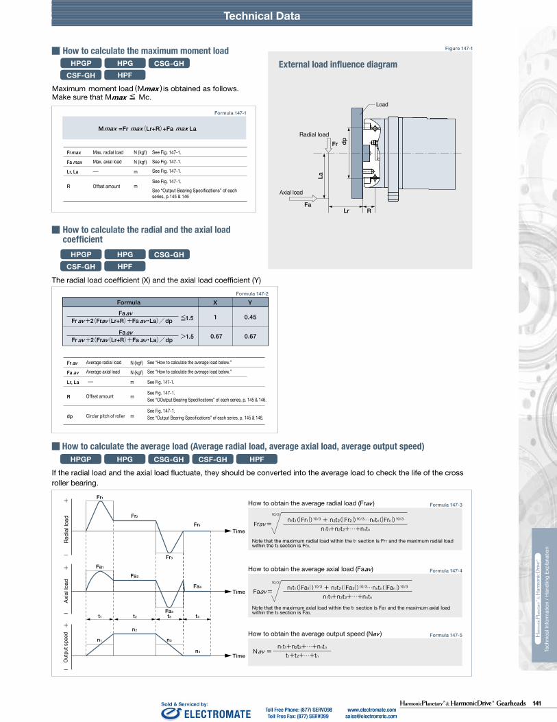
141Gearheads
Technical DataTechnical Data Technical Data
230 231
Tech
nica
l Inf
orm
atio
n / H
andl
ing
Expl
anat
ion
Tech
nica
l Inf
orm
atio
n / H
andl
ing
Expl
anat
ion
HPG HPF
Calculate:Maximum moment load (Mi max)Maximum axial load (Fai max)Maximum radial load (Fri max)
Calculate:Average moment load (Mi av)Average axial load (Fai av) Average input speed (Ni av)
Maximum moment load (Mi max) ≦ Allowable moment load (Mc)Maximum axial load (Fai max) ≦ Allowable axial load (Fac)Maximum radial load (Fri max) ≦ Allowable radial load (Frc)
Calculate the life and check it.
(2) Checking the life
(1) Checking maximum load
Time: t
Time: t
n1
n2
n3
M1
M2
M3
M4
n4
t1 t2 t3 t4
L10
NiCrPci
LifeAverage input speedBasic dynamic load ratingDynamic equivalent load
HourrpmN (kgf)N
av
111420325065
0.137 × Mi av + 1.232 × Fai av0.444 × Mi av + 1.426 × Fai av
0.041 × Mi av + 1.232 × Fai av
0.109 × Mi av + 1.232 × Fai av0.071 × Mi av + 1.232 × Fai av0.053 × Mi av + 1.232 × Fai av
maxmax
Fai
Lri
Fri
Lai
111420325065
111420325065
2532
2532
*1 The allowable axial load is the value of an axial load applied along the axis of rotation.*2 The allowable radial load of HPG series is the value of a radial load applied at the mid-point of the input shaft.*3 The allowable radial load of HPG series is the value of a radial load applied to the point of 20 mm from the shaft edge (input flange edge).
2532 106 × Mi av + 2.7 × Fai av
121 × Mi av + 2.7 × Fai av
Fai
Fri
Lai
Lri
Check the maximum load and life of the bearing on the input side if the reducer is an HPG input shaft unit or an HPF hollow shaft unit.
FriFaiLri,Lai
If moment load and axial load fluctuate, they should be converted into the average load to check the life of the bearing.
Calculate the bearing life according to Calculation Formula 132-5 and check the life.
Specification of input bearing
Specification of input shaft bearing
Table 149-1
Table 150-1
Table 150-2
Figure 150-1
Formula 150-2
Formula 150-3
Formula 150-4
Graph 150-1
Formula 150-5
Table 149-2
Size
Table 149-3
Table 149-4
〔Note: Table 149-2 and 149-4〕
External load influence diagram
Dynamic equivalent load
Size
Dynamic equivalent load
HPG HPF
HPG
HPF
HPG HPF
HPG
HPF
Pci
N270058009700
225003550051000
kgf275590990
230036005200
N127031505600148002510039500
kgf129320570151025604050
Nm0.166.313.544.496.9210
kgfm0.0160.641.384.539.8821.4
N2456571206328555408600
kgf2567123335565878
N20.6500902197032265267
kgf2.15192
201329537
N1450029700
kgf14803030
N1010020100
kgf10302050
Nm1019
kgfm1.021.93
N15383263
kgf157333
N522966
kgf53.298.5
Pci
HPG HPF
Formula 150-1
Checking procedure
Specification of input bearing
SizeBasic load rating
Basic dynamic load rating Cr Basic static load rating Cor
SizeAllowable moment load Mc Allowable axial load Fac *1 Allowable radial load Frc *2
SizeBasic load rating
Basic dynamic load rating Cr Basic static load rating Cor
SizeAllowable moment load Mc Allowable axial load Fac *1 Allowable radial load Frc *3
Calculating maximum moment load ON input shaft
How to calculate average load(Average moment load, average axial load, average input speed)
Mi max ≦ Mc (Allowable moment load)Fai max ≦ Fac (Allowable axial load)
Max. radial loadMax. axial load————
N (kgf)N (kgf)m
See Fig. 150-1.See Fig. 150-1.See Fig. 150-1.
The maximum moment load (Mi max ) is calculated as follows.Check that the following formulas are established in all circumstances:
Inpu
t spe
edM
omen
t loa
d
How to calculate the average moment load (Miav )
How to calculate the average axial load (Faiav)
How to calculate the average input speed (Niav)
Calculating life of input bearing
Miav Average moment load Nm (kgfm) See Formula 150-2Faiav Average axial load N (kgf) See Formula 150-3
See Formula 150-4See Table 149-1 and -3See Table 150-1 and -2
Input Bearing Specifications and Checking Procedure
228 229
Tech
nica
l Inf
orm
atio
n / H
andl
ing
Expl
anat
ion
Tech
nica
l Inf
orm
atio
n / H
andl
ing
Expl
anat
ion
Technical Data Technical Data
HPG HPFCSG-GH CSF-GHHPGPHow to calculate the maximum moment loadExternal load influence diagram
How to calculate the radial and the axial load coefficient
The radial load coefficient (X) and the axial load coefficient (Y)
( )
HPGHPF
CSG-GHCSF-GH
HPG HPFCSG-GH CSF-GH
HPG HPFCSG-GH CSF-GHHPGP
HPG HPFCSG-GH CSF-GHHPGP
HPGP
HPGHPF
CSG-GHCSF-GH
HPGP
HPGP
Formula 147-1
Formula 147-3
Formula 147-4
Formula 147-5
Formula 147-2
Figure 147-1
Load coefficient
Static safety coefficient
Formula 148-1
Table 148-1
Table 148-2
Formula 148-3
Figure 148-1
Formula 148-4 Formula 148-5
Formula 148-2
Note
Note that the maximum axial load within the t1 section is Fa1 and the maximum axial load within the t3 section is Fa3.
Note that the maximum radial load within the t1 section is Fr1 and the maximum radial load within the t3 section is Fr3.
Fr1
Fr2
Fr4
Fa1
Fa2
Fa4
Fa3t1 t2 t3 t4
n1
n2
n4
n3
Fr3
Time
Time
Time
N (kgf)
N (kgf)
m
m
M =Fr (Lr+R)+Fa ・ Lamax max max
N (kgf)
N (kgf)
m
m
m
Fr
Fa
Lr, La
R
dp
av
av
1
0.67 0.67
0.45≦1.5Fa
Fr +2(Fr (Lr+R)+Fa ・La)/dpavav avav
>1.5FaFr +2(Fr (Lr+R)+Fa ・La)/dpavav av
av
hourrpmN (kgf)N (kgf)
N (kgf)N (kgf)m––
m
FrFadpXY
Lr, La
avav
Locn1CPcfwθ
Rated life under oscillating motionNo. of reciprocating oscillation per min.Basic dynamic load ratingDynamic equivalent load Load coefficientOscillating angle /2
hourcpmN (kgf)N (kgf)—Deg.
−−See “Output Bearing Specs.” See Formula 148-2.See Table 148-1.See Figure 148-1.
Basic static loadStatic equivalent load
N (kgf)N (kgf)
See “Output Bearing Specs.” See Formula 148-5.
FrFaM
N (kgf)N (kgf)Nm (kgfm)
See “Output Bearing Specs” of each series. mdp
maxmaxmax
When it is used for a long time while the rotation speed of the output shaft is in the ultra-low operation range (0.02rpm or less), the lubrication of the bearing becomes insufficient, resulting in deterioration of the bearing or increased load in the output side. When using it in the ultra-low operation range, contact us.
See “Output Bearing Specifications” of each series, p.145 & 146
See “OOutput Bearing Specifications” of each series, p. 145 & 146.
During smooth operation without impact or vibrationDuring normal operationDuring operation with impact or vibration
When high precision is requiredWhen impact or vibration is expectedUnder normal operating condition
≧3≧2≧1.5
How to obtain the average radial load (Fr )av
How to obtain the average axial load (Fa )av
How to obtain the average output speed (N )av
Fr
Fa
Lr, La
R
max
max
X Y
Calculate the life of the cross roller bearing during oscillating motion by Formula 144-3.
If the radial load and the axial load fluctuate, they should be converted into the average load to check the life of the cross roller bearing.
Formula
L10
NavCPcfw
See “How to calculate the ave. load.”See “Output Bearing Specs.” See Formula 148-2.See Table 148-1.
LifeAve. output speedBasic dynamic load ratingDynamic equivalent loadLoad coefficient
Load status fw 1 to 1.21.2 to 1.51.5 to 3
fs
CoPo
dp
RLrFa
La
Fr
θ
Oscillating angle
Note:
maxmax
Max. radial load
Max. axial load
Offset amount
See Fig. 147-1.
See Fig. 147-1.
See Fig. 147-1.
See Fig. 147-1.
Average radial load
Average axial load
Offset amount
Circlar pitch of roller
See “How to calculate the average load below.”
See “How to calculate the average load below.”
See Fig. 147-1.
See Fig. 147-1.
See “Output Bearing Specifications” of each series, p. 145 & 146. See Fig. 147-1.
How to calculate the average load (Average radial load, average axial load, average output speed)
Radi
al lo
adAx
ial l
oad
Outp
ut sp
eed
Load
Radial load
Axial load
Calculate the life of the cross roller bearing using Formula 148-1. You can obtain the dynamic equivalent load (Pc) using Formula 148-2.
How to calculate the life
How to calculate the life during oscillating motion
How to calculate the static safety coefficient
Average radial loadAverage axial loadPitch Circle of roller Radial load coefficientAxial load coefficient
Offset amount mR
See "How to calculate the ave. load."
See “Output Bearing Specs.”
See “How to calculate the radial load coefficient and the axial load coefficient.”
See Figure 147-1. See “External load influence diagram.”
See Figure 147-1.See “External load influence diagram” and “Output Bearing Specs” of each series.
When the oscillating angle is small (5˚ or less), it is difficult to generate an oil film on the contact surface of the orbit ring and the rolling element and fretting corrosion may develop.
In general, the basic static load rating (Co) is considered to be the permissible limit of the static equivalent load. However, obtain the limit based on the operating and required conditions. Calculate the static safety coefficient (fs) of the cross roller bearing using Formula 148-4. General values under the operating condition are shown in Table 148-2. You can calculate the static equivalent load (Po) using Formula 148-5.
Load status
Max. radial loadMax. axial load See “How to calculate
the max. moment load.”Max. moment load
Pitch Circle

142 Gearheads
Technical DataTechnical Data Technical Data
230 231
Tech
nica
l Inf
orm
atio
n / H
andl
ing
Expl
anat
ion
Tech
nica
l Inf
orm
atio
n / H
andl
ing
Expl
anat
ion
HPG HPF
Calculate:Maximum moment load (Mi max)Maximum axial load (Fai max)Maximum radial load (Fri max)
Calculate:Average moment load (Mi av)Average axial load (Fai av) Average input speed (Ni av)
Maximum moment load (Mi max) ≦ Allowable moment load (Mc)Maximum axial load (Fai max) ≦ Allowable axial load (Fac)Maximum radial load (Fri max) ≦ Allowable radial load (Frc)
Calculate the life and check it.
(2) Checking the life
(1) Checking maximum load
Time: t
Time: t
n1
n2
n3
M1
M2
M3
M4
n4
t1 t2 t3 t4
L10
NiCrPci
LifeAverage input speedBasic dynamic load ratingDynamic equivalent load
HourrpmN (kgf)N
av
111420325065
0.137 × Mi av + 1.232 × Fai av0.444 × Mi av + 1.426 × Fai av
0.041 × Mi av + 1.232 × Fai av
0.109 × Mi av + 1.232 × Fai av0.071 × Mi av + 1.232 × Fai av0.053 × Mi av + 1.232 × Fai av
maxmax
Fai
Lri
Fri
Lai
111420325065
111420325065
2532
2532
*1 The allowable axial load is the value of an axial load applied along the axis of rotation.*2 The allowable radial load of HPG series is the value of a radial load applied at the mid-point of the input shaft.*3 The allowable radial load of HPG series is the value of a radial load applied to the point of 20 mm from the shaft edge (input flange edge).
2532 106 × Mi av + 2.7 × Fai av
121 × Mi av + 2.7 × Fai av
Fai
Fri
Lai
Lri
Check the maximum load and life of the bearing on the input side if the reducer is an HPG input shaft unit or an HPF hollow shaft unit.
FriFaiLri,Lai
If moment load and axial load fluctuate, they should be converted into the average load to check the life of the bearing.
Calculate the bearing life according to Calculation Formula 132-5 and check the life.
Specification of input bearing
Specification of input shaft bearing
Table 149-1
Table 150-1
Table 150-2
Figure 150-1
Formula 150-2
Formula 150-3
Formula 150-4
Graph 150-1
Formula 150-5
Table 149-2
Size
Table 149-3
Table 149-4
〔Note: Table 149-2 and 149-4〕
External load influence diagram
Dynamic equivalent load
Size
Dynamic equivalent load
HPG HPF
HPG
HPF
HPG HPF
HPG
HPF
Pci
N270058009700
225003550051000
kgf275590990
230036005200
N127031505600148002510039500
kgf129320570151025604050
Nm0.166.313.544.496.9210
kgfm0.0160.641.384.539.8821.4
N2456571206328555408600
kgf2567123335565878
N20.6500902197032265267
kgf2.15192
201329537
N1450029700
kgf14803030
N1010020100
kgf10302050
Nm1019
kgfm1.021.93
N15383263
kgf157333
N522966
kgf53.298.5
Pci
HPG HPF
Formula 150-1
Checking procedure
Specification of input bearing
SizeBasic load rating
Basic dynamic load rating Cr Basic static load rating Cor
SizeAllowable moment load Mc Allowable axial load Fac *1 Allowable radial load Frc *2
SizeBasic load rating
Basic dynamic load rating Cr Basic static load rating Cor
SizeAllowable moment load Mc Allowable axial load Fac *1 Allowable radial load Frc *3
Calculating maximum moment load ON input shaft
How to calculate average load(Average moment load, average axial load, average input speed)
Mi max ≦ Mc (Allowable moment load)Fai max ≦ Fac (Allowable axial load)
Max. radial loadMax. axial load————
N (kgf)N (kgf)m
See Fig. 150-1.See Fig. 150-1.See Fig. 150-1.
The maximum moment load (Mi max ) is calculated as follows.Check that the following formulas are established in all circumstances:
Inpu
t spe
edM
omen
t loa
d
How to calculate the average moment load (Miav )
How to calculate the average axial load (Faiav)
How to calculate the average input speed (Niav)
Calculating life of input bearing
Miav Average moment load Nm (kgfm) See Formula 150-2Faiav Average axial load N (kgf) See Formula 150-3
See Formula 150-4See Table 149-1 and -3See Table 150-1 and -2
Input Bearing Specifications and Checking Procedure
228 229
Tech
nica
l Inf
orm
atio
n / H
andl
ing
Expl
anat
ion
Tech
nica
l Inf
orm
atio
n / H
andl
ing
Expl
anat
ion
Technical Data Technical Data
HPG HPFCSG-GH CSF-GHHPGPHow to calculate the maximum moment loadExternal load influence diagram
How to calculate the radial and the axial load coefficient
The radial load coefficient (X) and the axial load coefficient (Y)
( )
HPGHPF
CSG-GHCSF-GH
HPG HPFCSG-GH CSF-GH
HPG HPFCSG-GH CSF-GHHPGP
HPG HPFCSG-GH CSF-GHHPGP
HPGP
HPGHPF
CSG-GHCSF-GH
HPGP
HPGP
Formula 147-1
Formula 147-3
Formula 147-4
Formula 147-5
Formula 147-2
Figure 147-1
Load coefficient
Static safety coefficient
Formula 148-1
Table 148-1
Table 148-2
Formula 148-3
Figure 148-1
Formula 148-4 Formula 148-5
Formula 148-2
Note
Note that the maximum axial load within the t1 section is Fa1 and the maximum axial load within the t3 section is Fa3.
Note that the maximum radial load within the t1 section is Fr1 and the maximum radial load within the t3 section is Fr3.
Fr1
Fr2
Fr4
Fa1
Fa2
Fa4
Fa3t1 t2 t3 t4
n1
n2
n4
n3
Fr3
Time
Time
Time
N (kgf)
N (kgf)
m
m
M =Fr (Lr+R)+Fa ・ Lamax max max
N (kgf)
N (kgf)
m
m
m
Fr
Fa
Lr, La
R
dp
av
av
1
0.67 0.67
0.45≦1.5Fa
Fr +2(Fr (Lr+R)+Fa ・La)/dpavav avav
>1.5FaFr +2(Fr (Lr+R)+Fa ・La)/dpavav av
av
hourrpmN (kgf)N (kgf)
N (kgf)N (kgf)m––
m
FrFadpXY
Lr, La
avav
Locn1CPcfwθ
Rated life under oscillating motionNo. of reciprocating oscillation per min.Basic dynamic load ratingDynamic equivalent load Load coefficientOscillating angle /2
hourcpmN (kgf)N (kgf)—Deg.
−−See “Output Bearing Specs.” See Formula 148-2.See Table 148-1.See Figure 148-1.
Basic static loadStatic equivalent load
N (kgf)N (kgf)
See “Output Bearing Specs.” See Formula 148-5.
FrFaM
N (kgf)N (kgf)Nm (kgfm)
See “Output Bearing Specs” of each series. mdp
maxmaxmax
When it is used for a long time while the rotation speed of the output shaft is in the ultra-low operation range (0.02rpm or less), the lubrication of the bearing becomes insufficient, resulting in deterioration of the bearing or increased load in the output side. When using it in the ultra-low operation range, contact us.
See “Output Bearing Specifications” of each series, p.145 & 146
See “OOutput Bearing Specifications” of each series, p. 145 & 146.
During smooth operation without impact or vibrationDuring normal operationDuring operation with impact or vibration
When high precision is requiredWhen impact or vibration is expectedUnder normal operating condition
≧3≧2≧1.5
How to obtain the average radial load (Fr )av
How to obtain the average axial load (Fa )av
How to obtain the average output speed (N )av
Fr
Fa
Lr, La
R
max
max
X Y
Calculate the life of the cross roller bearing during oscillating motion by Formula 144-3.
If the radial load and the axial load fluctuate, they should be converted into the average load to check the life of the cross roller bearing.
Formula
L10
NavCPcfw
See “How to calculate the ave. load.”See “Output Bearing Specs.” See Formula 148-2.See Table 148-1.
LifeAve. output speedBasic dynamic load ratingDynamic equivalent loadLoad coefficient
Load status fw 1 to 1.21.2 to 1.51.5 to 3
fs
CoPo
dp
RLrFa
La
Fr
θ
Oscillating angle
Note:
maxmax
Max. radial load
Max. axial load
Offset amount
See Fig. 147-1.
See Fig. 147-1.
See Fig. 147-1.
See Fig. 147-1.
Average radial load
Average axial load
Offset amount
Circlar pitch of roller
See “How to calculate the average load below.”
See “How to calculate the average load below.”
See Fig. 147-1.
See Fig. 147-1.
See “Output Bearing Specifications” of each series, p. 145 & 146. See Fig. 147-1.
How to calculate the average load (Average radial load, average axial load, average output speed)
Radi
al lo
adAx
ial l
oad
Outp
ut sp
eed
Load
Radial load
Axial load
Calculate the life of the cross roller bearing using Formula 148-1. You can obtain the dynamic equivalent load (Pc) using Formula 148-2.
How to calculate the life
How to calculate the life during oscillating motion
How to calculate the static safety coefficient
Average radial loadAverage axial loadPitch Circle of roller Radial load coefficientAxial load coefficient
Offset amount mR
See "How to calculate the ave. load."
See “Output Bearing Specs.”
See “How to calculate the radial load coefficient and the axial load coefficient.”
See Figure 147-1. See “External load influence diagram.”
See Figure 147-1.See “External load influence diagram” and “Output Bearing Specs” of each series.
When the oscillating angle is small (5˚ or less), it is difficult to generate an oil film on the contact surface of the orbit ring and the rolling element and fretting corrosion may develop.
In general, the basic static load rating (Co) is considered to be the permissible limit of the static equivalent load. However, obtain the limit based on the operating and required conditions. Calculate the static safety coefficient (fs) of the cross roller bearing using Formula 148-4. General values under the operating condition are shown in Table 148-2. You can calculate the static equivalent load (Po) using Formula 148-5.
Load status
Max. radial loadMax. axial load See “How to calculate
the max. moment load.”Max. moment load
Pitch Circle

143Gearheads
Technical DataTechnical Data Technical Data
230 231
Tech
nica
l Inf
orm
atio
n / H
andl
ing
Expl
anat
ion
Tech
nica
l Inf
orm
atio
n / H
andl
ing
Expl
anat
ion
HPG HPF
Calculate:Maximum moment load (Mi max)Maximum axial load (Fai max)Maximum radial load (Fri max)
Calculate:Average moment load (Mi av)Average axial load (Fai av) Average input speed (Ni av)
Maximum moment load (Mi max) ≦ Allowable moment load (Mc)Maximum axial load (Fai max) ≦ Allowable axial load (Fac)Maximum radial load (Fri max) ≦ Allowable radial load (Frc)
Calculate the life and check it.
(2) Checking the life
(1) Checking maximum load
Time: t
Time: t
n1
n2
n3
M1
M2
M3
M4
n4
t1 t2 t3 t4
L10
NiCrPci
LifeAverage input speedBasic dynamic load ratingDynamic equivalent load
HourrpmN (kgf)N
av
111420325065
0.137 × Mi av + 1.232 × Fai av0.444 × Mi av + 1.426 × Fai av
0.041 × Mi av + 1.232 × Fai av
0.109 × Mi av + 1.232 × Fai av0.071 × Mi av + 1.232 × Fai av0.053 × Mi av + 1.232 × Fai av
maxmax
Fai
Lri
Fri
Lai
111420325065
111420325065
2532
2532
*1 The allowable axial load is the value of an axial load applied along the axis of rotation.*2 The allowable radial load of HPG series is the value of a radial load applied at the mid-point of the input shaft.*3 The allowable radial load of HPG series is the value of a radial load applied to the point of 20 mm from the shaft edge (input flange edge).
2532 106 × Mi av + 2.7 × Fai av
121 × Mi av + 2.7 × Fai av
Fai
Fri
Lai
Lri
Check the maximum load and life of the bearing on the input side if the reducer is an HPG input shaft unit or an HPF hollow shaft unit.
FriFaiLri,Lai
If moment load and axial load fluctuate, they should be converted into the average load to check the life of the bearing.
Calculate the bearing life according to Calculation Formula 132-5 and check the life.
Specification of input bearing
Specification of input shaft bearing
Table 149-1
Table 150-1
Table 150-2
Figure 150-1
Formula 150-2
Formula 150-3
Formula 150-4
Graph 150-1
Formula 150-5
Table 149-2
Size
Table 149-3
Table 149-4
〔Note: Table 149-2 and 149-4〕
External load influence diagram
Dynamic equivalent load
Size
Dynamic equivalent load
HPG HPF
HPG
HPF
HPG HPF
HPG
HPF
Pci
N270058009700
225003550051000
kgf275590990
230036005200
N127031505600148002510039500
kgf129320570151025604050
Nm0.166.313.544.496.9210
kgfm0.0160.641.384.539.8821.4
N2456571206328555408600
kgf2567123335565878
N20.6500902197032265267
kgf2.15192
201329537
N1450029700
kgf14803030
N1010020100
kgf10302050
Nm1019
kgfm1.021.93
N15383263
kgf157333
N522966
kgf53.298.5
Pci
HPG HPF
Formula 150-1
Checking procedure
Specification of input bearing
SizeBasic load rating
Basic dynamic load rating Cr Basic static load rating Cor
SizeAllowable moment load Mc Allowable axial load Fac *1 Allowable radial load Frc *2
SizeBasic load rating
Basic dynamic load rating Cr Basic static load rating Cor
SizeAllowable moment load Mc Allowable axial load Fac *1 Allowable radial load Frc *3
Calculating maximum moment load ON input shaft
How to calculate average load(Average moment load, average axial load, average input speed)
Mi max ≦ Mc (Allowable moment load)Fai max ≦ Fac (Allowable axial load)
Max. radial loadMax. axial load————
N (kgf)N (kgf)m
See Fig. 150-1.See Fig. 150-1.See Fig. 150-1.
The maximum moment load (Mi max ) is calculated as follows.Check that the following formulas are established in all circumstances:
Inpu
t spe
edM
omen
t loa
d
How to calculate the average moment load (Miav )
How to calculate the average axial load (Faiav)
How to calculate the average input speed (Niav)
Calculating life of input bearing
Miav Average moment load Nm (kgfm) See Formula 150-2Faiav Average axial load N (kgf) See Formula 150-3
See Formula 150-4See Table 149-1 and -3See Table 150-1 and -2
Input Bearing Specifications and Checking Procedure
Technical Data Technical Data
230 231
Tech
nica
l Inf
orm
atio
n / H
andl
ing
Expl
anat
ion
Tech
nica
l Inf
orm
atio
n / H
andl
ing
Expl
anat
ion
HPG HPF
Calculate:Maximum moment load (Mi max)Maximum axial load (Fai max)Maximum radial load (Fri max)
Calculate:Average moment load (Mi av)Average axial load (Fai av) Average input speed (Ni av)
Maximum moment load (Mi max) ≦ Allowable moment load (Mc)Maximum axial load (Fai max) ≦ Allowable axial load (Fac)Maximum radial load (Fri max) ≦ Allowable radial load (Frc)
Calculate the life and check it.
(2) Checking the life
(1) Checking maximum load
Time: t
Time: t
n1
n2
n3
M1
M2
M3
M4
n4
t1 t2 t3 t4
L10
NiCrPci
LifeAverage input speedBasic dynamic load ratingDynamic equivalent load
HourrpmN (kgf)N
av
111420325065
0.137 × Mi av + 1.232 × Fai av0.444 × Mi av + 1.426 × Fai av
0.041 × Mi av + 1.232 × Fai av
0.109 × Mi av + 1.232 × Fai av0.071 × Mi av + 1.232 × Fai av0.053 × Mi av + 1.232 × Fai av
maxmax
Fai
Lri
Fri
Lai
111420325065
111420325065
2532
2532
*1 The allowable axial load is the value of an axial load applied along the axis of rotation.*2 The allowable radial load of HPG series is the value of a radial load applied at the mid-point of the input shaft.*3 The allowable radial load of HPG series is the value of a radial load applied to the point of 20 mm from the shaft edge (input flange edge).
2532 106 × Mi av + 2.7 × Fai av
121 × Mi av + 2.7 × Fai av
Fai
Fri
Lai
Lri
Check the maximum load and life of the bearing on the input side if the reducer is an HPG input shaft unit or an HPF hollow shaft unit.
FriFaiLri,Lai
If moment load and axial load fluctuate, they should be converted into the average load to check the life of the bearing.
Calculate the bearing life according to Calculation Formula 132-5 and check the life.
Specification of input bearing
Specification of input shaft bearing
Table 149-1
Table 150-1
Table 150-2
Figure 150-1
Formula 150-2
Formula 150-3
Formula 150-4
Graph 150-1
Formula 150-5
Table 149-2
Size
Table 149-3
Table 149-4
〔Note: Table 149-2 and 149-4〕
External load influence diagram
Dynamic equivalent load
Size
Dynamic equivalent load
HPG HPF
HPG
HPF
HPG HPF
HPG
HPF
Pci
N270058009700
225003550051000
kgf275590990
230036005200
N127031505600148002510039500
kgf129320570151025604050
Nm0.166.313.544.496.9210
kgfm0.0160.641.384.539.8821.4
N2456571206328555408600
kgf2567123335565878
N20.6500902197032265267
kgf2.15192
201329537
N1450029700
kgf14803030
N1010020100
kgf10302050
Nm1019
kgfm1.021.93
N15383263
kgf157333
N522966
kgf53.298.5
Pci
HPG HPF
Formula 150-1
Checking procedure
Specification of input bearing
SizeBasic load rating
Basic dynamic load rating Cr Basic static load rating Cor
SizeAllowable moment load Mc Allowable axial load Fac *1 Allowable radial load Frc *2
SizeBasic load rating
Basic dynamic load rating Cr Basic static load rating Cor
SizeAllowable moment load Mc Allowable axial load Fac *1 Allowable radial load Frc *3
Calculating maximum moment load ON input shaft
How to calculate average load(Average moment load, average axial load, average input speed)
Mi max ≦ Mc (Allowable moment load)Fai max ≦ Fac (Allowable axial load)
Max. radial loadMax. axial load————
N (kgf)N (kgf)m
See Fig. 150-1.See Fig. 150-1.See Fig. 150-1.
The maximum moment load (Mi max ) is calculated as follows.Check that the following formulas are established in all circumstances:
Inpu
t spe
edM
omen
t loa
d
How to calculate the average moment load (Miav )
How to calculate the average axial load (Faiav)
How to calculate the average input speed (Niav)
Calculating life of input bearing
Miav Average moment load Nm (kgfm) See Formula 150-2Faiav Average axial load N (kgf) See Formula 150-3
See Formula 150-4See Table 149-1 and -3See Table 150-1 and -2
Input Bearing Specifications and Checking Procedure

144 Gearheads
Technical DataTechnical Data Technical Data
230 231
Tech
nica
l Inf
orm
atio
n / H
andl
ing
Expl
anat
ion
Tech
nica
l Inf
orm
atio
n / H
andl
ing
Expl
anat
ion
HPG HPF
Calculate:Maximum moment load (Mi max)Maximum axial load (Fai max)Maximum radial load (Fri max)
Calculate:Average moment load (Mi av)Average axial load (Fai av) Average input speed (Ni av)
Maximum moment load (Mi max) ≦ Allowable moment load (Mc)Maximum axial load (Fai max) ≦ Allowable axial load (Fac)Maximum radial load (Fri max) ≦ Allowable radial load (Frc)
Calculate the life and check it.
(2) Checking the life
(1) Checking maximum load
Time: t
Time: t
n1
n2
n3
M1
M2
M3
M4
n4
t1 t2 t3 t4
L10
NiCrPci
LifeAverage input speedBasic dynamic load ratingDynamic equivalent load
HourrpmN (kgf)N
av
111420325065
0.137 × Mi av + 1.232 × Fai av0.444 × Mi av + 1.426 × Fai av
0.041 × Mi av + 1.232 × Fai av
0.109 × Mi av + 1.232 × Fai av0.071 × Mi av + 1.232 × Fai av0.053 × Mi av + 1.232 × Fai av
maxmax
Fai
Lri
Fri
Lai
111420325065
111420325065
2532
2532
*1 The allowable axial load is the value of an axial load applied along the axis of rotation.*2 The allowable radial load of HPG series is the value of a radial load applied at the mid-point of the input shaft.*3 The allowable radial load of HPG series is the value of a radial load applied to the point of 20 mm from the shaft edge (input flange edge).
2532 106 × Mi av + 2.7 × Fai av
121 × Mi av + 2.7 × Fai av
Fai
Fri
Lai
Lri
Check the maximum load and life of the bearing on the input side if the reducer is an HPG input shaft unit or an HPF hollow shaft unit.
FriFaiLri,Lai
If moment load and axial load fluctuate, they should be converted into the average load to check the life of the bearing.
Calculate the bearing life according to Calculation Formula 132-5 and check the life.
Specification of input bearing
Specification of input shaft bearing
Table 149-1
Table 150-1
Table 150-2
Figure 150-1
Formula 150-2
Formula 150-3
Formula 150-4
Graph 150-1
Formula 150-5
Table 149-2
Size
Table 149-3
Table 149-4
〔Note: Table 149-2 and 149-4〕
External load influence diagram
Dynamic equivalent load
Size
Dynamic equivalent load
HPG HPF
HPG
HPF
HPG HPF
HPG
HPF
Pci
N270058009700
225003550051000
kgf275590990
230036005200
N127031505600148002510039500
kgf129320570151025604050
Nm0.166.313.544.496.9210
kgfm0.0160.641.384.539.8821.4
N2456571206328555408600
kgf2567123335565878
N20.6500902197032265267
kgf2.15192
201329537
N1450029700
kgf14803030
N1010020100
kgf10302050
Nm1019
kgfm1.021.93
N15383263
kgf157333
N522966
kgf53.298.5
Pci
HPG HPF
Formula 150-1
Checking procedure
Specification of input bearing
SizeBasic load rating
Basic dynamic load rating Cr Basic static load rating Cor
SizeAllowable moment load Mc Allowable axial load Fac *1 Allowable radial load Frc *2
SizeBasic load rating
Basic dynamic load rating Cr Basic static load rating Cor
SizeAllowable moment load Mc Allowable axial load Fac *1 Allowable radial load Frc *3
Calculating maximum moment load ON input shaft
How to calculate average load(Average moment load, average axial load, average input speed)
Mi max ≦ Mc (Allowable moment load)Fai max ≦ Fac (Allowable axial load)
Max. radial loadMax. axial load————
N (kgf)N (kgf)m
See Fig. 150-1.See Fig. 150-1.See Fig. 150-1.
The maximum moment load (Mi max ) is calculated as follows.Check that the following formulas are established in all circumstances:
Inpu
t spe
edM
omen
t loa
d
How to calculate the average moment load (Miav )
How to calculate the average axial load (Faiav)
How to calculate the average input speed (Niav)
Calculating life of input bearing
Miav Average moment load Nm (kgfm) See Formula 150-2Faiav Average axial load N (kgf) See Formula 150-3
See Formula 150-4See Table 149-1 and -3See Table 150-1 and -2
Input Bearing Specifications and Checking Procedure
Technical Data Technical Data
230 231
Tech
nica
l Inf
orm
atio
n / H
andl
ing
Expl
anat
ion
Tech
nica
l Inf
orm
atio
n / H
andl
ing
Expl
anat
ion
HPG HPF
Calculate:Maximum moment load (Mi max)Maximum axial load (Fai max)Maximum radial load (Fri max)
Calculate:Average moment load (Mi av)Average axial load (Fai av) Average input speed (Ni av)
Maximum moment load (Mi max) ≦ Allowable moment load (Mc)Maximum axial load (Fai max) ≦ Allowable axial load (Fac)Maximum radial load (Fri max) ≦ Allowable radial load (Frc)
Calculate the life and check it.
(2) Checking the life
(1) Checking maximum load
Time: t
Time: t
n1
n2
n3
M1
M2
M3
M4
n4
t1 t2 t3 t4
L10
NiCrPci
LifeAverage input speedBasic dynamic load ratingDynamic equivalent load
HourrpmN (kgf)N
av
111420325065
0.137 × Mi av + 1.232 × Fai av0.444 × Mi av + 1.426 × Fai av
0.041 × Mi av + 1.232 × Fai av
0.109 × Mi av + 1.232 × Fai av0.071 × Mi av + 1.232 × Fai av0.053 × Mi av + 1.232 × Fai av
maxmax
Fai
Lri
Fri
Lai
111420325065
111420325065
2532
2532
*1 The allowable axial load is the value of an axial load applied along the axis of rotation.*2 The allowable radial load of HPG series is the value of a radial load applied at the mid-point of the input shaft.*3 The allowable radial load of HPG series is the value of a radial load applied to the point of 20 mm from the shaft edge (input flange edge).
2532 106 × Mi av + 2.7 × Fai av
121 × Mi av + 2.7 × Fai av
Fai
Fri
Lai
Lri
Check the maximum load and life of the bearing on the input side if the reducer is an HPG input shaft unit or an HPF hollow shaft unit.
FriFaiLri,Lai
If moment load and axial load fluctuate, they should be converted into the average load to check the life of the bearing.
Calculate the bearing life according to Calculation Formula 132-5 and check the life.
Specification of input bearing
Specification of input shaft bearing
Table 149-1
Table 150-1
Table 150-2
Figure 150-1
Formula 150-2
Formula 150-3
Formula 150-4
Graph 150-1
Formula 150-5
Table 149-2
Size
Table 149-3
Table 149-4
〔Note: Table 149-2 and 149-4〕
External load influence diagram
Dynamic equivalent load
Size
Dynamic equivalent load
HPG HPF
HPG
HPF
HPG HPF
HPG
HPF
Pci
N270058009700
225003550051000
kgf275590990
230036005200
N127031505600148002510039500
kgf129320570151025604050
Nm0.166.313.544.496.9210
kgfm0.0160.641.384.539.8821.4
N2456571206328555408600
kgf2567123335565878
N20.6500902197032265267
kgf2.15192
201329537
N1450029700
kgf14803030
N1010020100
kgf10302050
Nm1019
kgfm1.021.93
N15383263
kgf157333
N522966
kgf53.298.5
Pci
HPG HPF
Formula 150-1
Checking procedure
Specification of input bearing
SizeBasic load rating
Basic dynamic load rating Cr Basic static load rating Cor
SizeAllowable moment load Mc Allowable axial load Fac *1 Allowable radial load Frc *2
SizeBasic load rating
Basic dynamic load rating Cr Basic static load rating Cor
SizeAllowable moment load Mc Allowable axial load Fac *1 Allowable radial load Frc *3
Calculating maximum moment load ON input shaft
How to calculate average load(Average moment load, average axial load, average input speed)
Mi max ≦ Mc (Allowable moment load)Fai max ≦ Fac (Allowable axial load)
Max. radial loadMax. axial load————
N (kgf)N (kgf)m
See Fig. 150-1.See Fig. 150-1.See Fig. 150-1.
The maximum moment load (Mi max ) is calculated as follows.Check that the following formulas are established in all circumstances:
Inpu
t spe
edM
omen
t loa
d
How to calculate the average moment load (Miav )
How to calculate the average axial load (Faiav)
How to calculate the average input speed (Niav)
Calculating life of input bearing
Miav Average moment load Nm (kgfm) See Formula 150-2Faiav Average axial load N (kgf) See Formula 150-3
See Formula 150-4See Table 149-1 and -3See Table 150-1 and -2
Input Bearing Specifications and Checking Procedure

145Gearheads
Assembly InstructionsTechnical Data Technical Data
230 231
Tech
nica
l Inf
orm
atio
n / H
andl
ing
Expl
anat
ion
Tech
nica
l Inf
orm
atio
n / H
andl
ing
Expl
anat
ion
HPG HPF
Calculate:Maximum moment load (Mi max)Maximum axial load (Fai max)Maximum radial load (Fri max)
Calculate:Average moment load (Mi av)Average axial load (Fai av) Average input speed (Ni av)
Maximum moment load (Mi max) ≦ Allowable moment load (Mc)Maximum axial load (Fai max) ≦ Allowable axial load (Fac)Maximum radial load (Fri max) ≦ Allowable radial load (Frc)
Calculate the life and check it.
(2) Checking the life
(1) Checking maximum load
Time: t
Time: t
n1
n2
n3
M1
M2
M3
M4
n4
t1 t2 t3 t4
L10
NiCrPci
LifeAverage input speedBasic dynamic load ratingDynamic equivalent load
HourrpmN (kgf)N
av
111420325065
0.137 × Mi av + 1.232 × Fai av0.444 × Mi av + 1.426 × Fai av
0.041 × Mi av + 1.232 × Fai av
0.109 × Mi av + 1.232 × Fai av0.071 × Mi av + 1.232 × Fai av0.053 × Mi av + 1.232 × Fai av
maxmax
Fai
Lri
Fri
Lai
111420325065
111420325065
2532
2532
*1 The allowable axial load is the value of an axial load applied along the axis of rotation.*2 The allowable radial load of HPG series is the value of a radial load applied at the mid-point of the input shaft.*3 The allowable radial load of HPG series is the value of a radial load applied to the point of 20 mm from the shaft edge (input flange edge).
2532 106 × Mi av + 2.7 × Fai av
121 × Mi av + 2.7 × Fai av
Fai
Fri
Lai
Lri
Check the maximum load and life of the bearing on the input side if the reducer is an HPG input shaft unit or an HPF hollow shaft unit.
FriFaiLri,Lai
If moment load and axial load fluctuate, they should be converted into the average load to check the life of the bearing.
Calculate the bearing life according to Calculation Formula 132-5 and check the life.
Specification of input bearing
Specification of input shaft bearing
Table 149-1
Table 150-1
Table 150-2
Figure 150-1
Formula 150-2
Formula 150-3
Formula 150-4
Graph 150-1
Formula 150-5
Table 149-2
Size
Table 149-3
Table 149-4
〔Note: Table 149-2 and 149-4〕
External load influence diagram
Dynamic equivalent load
Size
Dynamic equivalent load
HPG HPF
HPG
HPF
HPG HPF
HPG
HPF
Pci
N270058009700
225003550051000
kgf275590990
230036005200
N127031505600148002510039500
kgf129320570151025604050
Nm0.166.313.544.496.9210
kgfm0.0160.641.384.539.8821.4
N2456571206328555408600
kgf2567123335565878
N20.6500902197032265267
kgf2.15192
201329537
N1450029700
kgf14803030
N1010020100
kgf10302050
Nm1019
kgfm1.021.93
N15383263
kgf157333
N522966
kgf53.298.5
Pci
HPG HPF
Formula 150-1
Checking procedure
Specification of input bearing
SizeBasic load rating
Basic dynamic load rating Cr Basic static load rating Cor
SizeAllowable moment load Mc Allowable axial load Fac *1 Allowable radial load Frc *2
SizeBasic load rating
Basic dynamic load rating Cr Basic static load rating Cor
SizeAllowable moment load Mc Allowable axial load Fac *1 Allowable radial load Frc *3
Calculating maximum moment load ON input shaft
How to calculate average load(Average moment load, average axial load, average input speed)
Mi max ≦ Mc (Allowable moment load)Fai max ≦ Fac (Allowable axial load)
Max. radial loadMax. axial load————
N (kgf)N (kgf)m
See Fig. 150-1.See Fig. 150-1.See Fig. 150-1.
The maximum moment load (Mi max ) is calculated as follows.Check that the following formulas are established in all circumstances:
Inpu
t spe
edM
omen
t loa
d
How to calculate the average moment load (Miav )
How to calculate the average axial load (Faiav)
How to calculate the average input speed (Niav)
Calculating life of input bearing
Miav Average moment load Nm (kgfm) See Formula 150-2Faiav Average axial load N (kgf) See Formula 150-3
See Formula 150-4See Table 149-1 and -3See Table 150-1 and -2
Input Bearing Specifications and Checking Procedure
232 233
Assembly Instructions Assembly Instructions
Tech
nica
l Inf
orm
atio
n / H
andl
ing
Expl
anat
ion
Tech
nica
l Inf
orm
atio
n / H
andl
ing
Expl
anat
ion
Assemble and mount your gearhead in accordance with these instructions to achieve the best performance.Be sure to use the recommended bolts and use a torque wrench to achieve the proper tightening torques as recommended in the tables below.
To properly mount the motor to the gearhead, follow the procedure outlined below, refer to figure 151-1
Assembly
Table 152-1
Table 152-2
Figure 152-1
Part B
Part A
Some right angle gearhead models weigh as much as 60 kg. No thread for an eyebolt is provided because the mountingorientation varies depending on the customer's needs. When mounting the reducer, hoist it using a sling paying extremeattention to safety.When assembling gearheads into your equipment, check the flatness of your mounting surface and look for any burrs on tapped holes. Then fasten the flange (Part A in the diagram below) using appropriate bolts.
* Recommended bolts: JIS B 1176 "Hexagon socket head bolts." Strength classification 12.9 or higher in JIS B 1051.
* Recommended bolts: JIS B 1176 "Hexagon socket head bolts." Strength classification 12.9 or higher in JIS B 1051.
Bolt* tightening torque for output flange (Part B in the Figure 152-1)
Output flange mounting specifications
(1) (2)
(3)
(5)
(4)
(1) Turn the input shaft coupling and align the bolt head with the rubber cap hole.
Bolt tightening torque
(3) Tighten the input shaft coupling bolt to the recommended torque specified in the table below. The bolt(s) or screw(s) is (are) already inserted into the input coupling when delivered. Check the bolt size on the confirmation drawing provided.
(5) Insert the rubber cap provided. This completes the assembly. (Size 11: Fasten screws with a gasket in two places)
(2) With the speed reducer in an upright position as illustrated in the figure below, slowly insert the motor shaft into the coupling of speed reducer. Slide the motor shaft without letting it drop down. If the speed reducer cannot be positioned upright, slowly insert the motor shaft into the coupling of speed reducer, then tighten the motor bolts evenly until the motor flange and gearhead flange are in full contact. Exercise care to avoid tilting the motor when inserting it into the gear head.
Caution: Always tighten the bolts to the tightening torque specified in the table above. If the bolt is not tightened to the torque value recommended slippage of the motor shaft in the shaft coupling may occur. The bolt size will vary depending on the size of the gear and the shaft diameter of the mounted motor. Check the bolt size on the confirmation drawing provided.
Two setscrews need to be tightened on size 11. See the outline dimensions on page 22 (HPGP) and page 34 (HPG standard) and page 46 (HPG helical). Tighten the screws to the tightening torque specified below.
HPG CSG-GH CSF-GHHPGP HPN
HPG HPFCSG-GH CSF-GHHPGP HPN
HPGP
Bolt* tightening torque for flange (Part A in the diagram below)
655032201411Size4
M4184.5
0.4625.32.58
8M4304.5
0.46848.6
8M645
15.31.5628629.2
8M860
37.23.869771.2
8M1290
128.413.12407245
8M1612031932.55972609
mmNm
kgfmNm
kgfm
Table 152-3
* Recommended bolts: JIS B 1176 "Hexagon socket head bolts." Strength classification 12.9 or higher in JIS B 1051.
Bolt* tightening torque for output flange (Part B in the Figure 152-1) HPG
655032201411Size3
M4184.5
0.4619.01.9
6M4304.5
0.46636.5
6M645
15.31.5621521.9
6M860
37.23.852453.4
14M810037.23.802036207.8
6M1612031932.54480457
mmNm
kgfmNm
kgfm
Motor assembly procedure
Speed reducer assembly
Mounting the load to the output flangeTable 151-1
Bolt size
Tightening torque
M3 M4 M5 M6 M8 M10 M122.0
0.204.5
0.469.0
0.9215.31.56
37.23.8
73.57.5
12813.1
Nmkgfm
Bolt* tightening torque
*Recommended bolt: JIS B 1176 Hexagon socket head bolt, Strength: JIS B 1051 12.9 or higherCaution: Be sure to tighten the bolts to the tightening torques specified in the table.
(4) Fasten the motor to the gearhead flange with bolts.Table 151-3
Bolt size
Tightening torque
M3 M4 M5 M6 M8 M10 M12M2.5Nm
kgfm1.40.14
3.20.32
6.30.64
10.71.09
26.12.66
51.55.25
89.99.17
0.590.06
Tightening torque
M30.690.07
Nmkgfm
Bolt size
Follow the specifications in the table below when mounting the load onto the output flange.
Number of boltsBolt sizeMounting PCD
Tightening torque
Transmission torque
Number of boltsBolt sizeMounting PCD
Tightening torque
Transmission torque
Figure 151-1
4M1626025526.05180528
12M41274.5
0.4653154.2
12M51579.0
0.921060108
4M1219010310.52030207
4M1013551.55.2586888.6
4M810526.12.6642843.6
4M5706.3
0.6411011.3
4M3461.40.1426.32.69
4M3501.40.1427.92.85
11 14 20114
M5706.3
0.6411011.3
4M610010.71.0922322.8
4M813026.12.6652853.9
14 20 324
M1016551.55.261063108.5
40 32HPGP / HPG / CSG-GH / CSF-GHHPN HPF
45/50 65 25 32Number of boltsBolt sizeMounting PCD
Size
mmNm
kgfmNm
kgfm
Tightening torque
Transmission torque
Table 151-2

146 Gearheads
Assembly InstructionsTechnical Data Technical Data
230 231
Tech
nica
l Inf
orm
atio
n / H
andl
ing
Expl
anat
ion
Tech
nica
l Inf
orm
atio
n / H
andl
ing
Expl
anat
ion
HPG HPF
Calculate:Maximum moment load (Mi max)Maximum axial load (Fai max)Maximum radial load (Fri max)
Calculate:Average moment load (Mi av)Average axial load (Fai av) Average input speed (Ni av)
Maximum moment load (Mi max) ≦ Allowable moment load (Mc)Maximum axial load (Fai max) ≦ Allowable axial load (Fac)Maximum radial load (Fri max) ≦ Allowable radial load (Frc)
Calculate the life and check it.
(2) Checking the life
(1) Checking maximum load
Time: t
Time: t
n1
n2
n3
M1
M2
M3
M4
n4
t1 t2 t3 t4
L10
NiCrPci
LifeAverage input speedBasic dynamic load ratingDynamic equivalent load
HourrpmN (kgf)N
av
111420325065
0.137 × Mi av + 1.232 × Fai av0.444 × Mi av + 1.426 × Fai av
0.041 × Mi av + 1.232 × Fai av
0.109 × Mi av + 1.232 × Fai av0.071 × Mi av + 1.232 × Fai av0.053 × Mi av + 1.232 × Fai av
maxmax
Fai
Lri
Fri
Lai
111420325065
111420325065
2532
2532
*1 The allowable axial load is the value of an axial load applied along the axis of rotation.*2 The allowable radial load of HPG series is the value of a radial load applied at the mid-point of the input shaft.*3 The allowable radial load of HPG series is the value of a radial load applied to the point of 20 mm from the shaft edge (input flange edge).
2532 106 × Mi av + 2.7 × Fai av
121 × Mi av + 2.7 × Fai av
Fai
Fri
Lai
Lri
Check the maximum load and life of the bearing on the input side if the reducer is an HPG input shaft unit or an HPF hollow shaft unit.
FriFaiLri,Lai
If moment load and axial load fluctuate, they should be converted into the average load to check the life of the bearing.
Calculate the bearing life according to Calculation Formula 132-5 and check the life.
Specification of input bearing
Specification of input shaft bearing
Table 149-1
Table 150-1
Table 150-2
Figure 150-1
Formula 150-2
Formula 150-3
Formula 150-4
Graph 150-1
Formula 150-5
Table 149-2
Size
Table 149-3
Table 149-4
〔Note: Table 149-2 and 149-4〕
External load influence diagram
Dynamic equivalent load
Size
Dynamic equivalent load
HPG HPF
HPG
HPF
HPG HPF
HPG
HPF
Pci
N270058009700
225003550051000
kgf275590990
230036005200
N127031505600148002510039500
kgf129320570151025604050
Nm0.166.313.544.496.9210
kgfm0.0160.641.384.539.8821.4
N2456571206328555408600
kgf2567123335565878
N20.6500902197032265267
kgf2.15192
201329537
N1450029700
kgf14803030
N1010020100
kgf10302050
Nm1019
kgfm1.021.93
N15383263
kgf157333
N522966
kgf53.298.5
Pci
HPG HPF
Formula 150-1
Checking procedure
Specification of input bearing
SizeBasic load rating
Basic dynamic load rating Cr Basic static load rating Cor
SizeAllowable moment load Mc Allowable axial load Fac *1 Allowable radial load Frc *2
SizeBasic load rating
Basic dynamic load rating Cr Basic static load rating Cor
SizeAllowable moment load Mc Allowable axial load Fac *1 Allowable radial load Frc *3
Calculating maximum moment load ON input shaft
How to calculate average load(Average moment load, average axial load, average input speed)
Mi max ≦ Mc (Allowable moment load)Fai max ≦ Fac (Allowable axial load)
Max. radial loadMax. axial load————
N (kgf)N (kgf)m
See Fig. 150-1.See Fig. 150-1.See Fig. 150-1.
The maximum moment load (Mi max ) is calculated as follows.Check that the following formulas are established in all circumstances:
Inpu
t spe
edM
omen
t loa
d
How to calculate the average moment load (Miav )
How to calculate the average axial load (Faiav)
How to calculate the average input speed (Niav)
Calculating life of input bearing
Miav Average moment load Nm (kgfm) See Formula 150-2Faiav Average axial load N (kgf) See Formula 150-3
See Formula 150-4See Table 149-1 and -3See Table 150-1 and -2
Input Bearing Specifications and Checking Procedure
232 233
Assembly Instructions Assembly Instructions
Tech
nica
l Inf
orm
atio
n / H
andl
ing
Expl
anat
ion
Tech
nica
l Inf
orm
atio
n / H
andl
ing
Expl
anat
ion
Assemble and mount your gearhead in accordance with these instructions to achieve the best performance.Be sure to use the recommended bolts and use a torque wrench to achieve the proper tightening torques as recommended in the tables below.
To properly mount the motor to the gearhead, follow the procedure outlined below, refer to figure 151-1
Assembly
Table 152-1
Table 152-2
Figure 152-1
Part B
Part A
Some right angle gearhead models weigh as much as 60 kg. No thread for an eyebolt is provided because the mountingorientation varies depending on the customer's needs. When mounting the reducer, hoist it using a sling paying extremeattention to safety.When assembling gearheads into your equipment, check the flatness of your mounting surface and look for any burrs on tapped holes. Then fasten the flange (Part A in the diagram below) using appropriate bolts.
* Recommended bolts: JIS B 1176 "Hexagon socket head bolts." Strength classification 12.9 or higher in JIS B 1051.
* Recommended bolts: JIS B 1176 "Hexagon socket head bolts." Strength classification 12.9 or higher in JIS B 1051.
Bolt* tightening torque for output flange (Part B in the Figure 152-1)
Output flange mounting specifications
(1) (2)
(3)
(5)
(4)
(1) Turn the input shaft coupling and align the bolt head with the rubber cap hole.
Bolt tightening torque
(3) Tighten the input shaft coupling bolt to the recommended torque specified in the table below. The bolt(s) or screw(s) is (are) already inserted into the input coupling when delivered. Check the bolt size on the confirmation drawing provided.
(5) Insert the rubber cap provided. This completes the assembly. (Size 11: Fasten screws with a gasket in two places)
(2) With the speed reducer in an upright position as illustrated in the figure below, slowly insert the motor shaft into the coupling of speed reducer. Slide the motor shaft without letting it drop down. If the speed reducer cannot be positioned upright, slowly insert the motor shaft into the coupling of speed reducer, then tighten the motor bolts evenly until the motor flange and gearhead flange are in full contact. Exercise care to avoid tilting the motor when inserting it into the gear head.
Caution: Always tighten the bolts to the tightening torque specified in the table above. If the bolt is not tightened to the torque value recommended slippage of the motor shaft in the shaft coupling may occur. The bolt size will vary depending on the size of the gear and the shaft diameter of the mounted motor. Check the bolt size on the confirmation drawing provided.
Two setscrews need to be tightened on size 11. See the outline dimensions on page 22 (HPGP) and page 34 (HPG standard) and page 46 (HPG helical). Tighten the screws to the tightening torque specified below.
HPG CSG-GH CSF-GHHPGP HPN
HPG HPFCSG-GH CSF-GHHPGP HPN
HPGP
Bolt* tightening torque for flange (Part A in the diagram below)
655032201411Size4
M4184.5
0.4625.32.58
8M4304.5
0.46848.6
8M645
15.31.5628629.2
8M860
37.23.869771.2
8M1290
128.413.12407245
8M1612031932.55972609
mmNm
kgfmNm
kgfm
Table 152-3
* Recommended bolts: JIS B 1176 "Hexagon socket head bolts." Strength classification 12.9 or higher in JIS B 1051.
Bolt* tightening torque for output flange (Part B in the Figure 152-1) HPG
655032201411Size3
M4184.5
0.4619.01.9
6M4304.5
0.46636.5
6M645
15.31.5621521.9
6M860
37.23.852453.4
14M810037.23.802036207.8
6M1612031932.54480457
mmNm
kgfmNm
kgfm
Motor assembly procedure
Speed reducer assembly
Mounting the load to the output flangeTable 151-1
Bolt size
Tightening torque
M3 M4 M5 M6 M8 M10 M122.0
0.204.5
0.469.0
0.9215.31.56
37.23.8
73.57.5
12813.1
Nmkgfm
Bolt* tightening torque
*Recommended bolt: JIS B 1176 Hexagon socket head bolt, Strength: JIS B 1051 12.9 or higherCaution: Be sure to tighten the bolts to the tightening torques specified in the table.
(4) Fasten the motor to the gearhead flange with bolts.Table 151-3
Bolt size
Tightening torque
M3 M4 M5 M6 M8 M10 M12M2.5Nm
kgfm1.40.14
3.20.32
6.30.64
10.71.09
26.12.66
51.55.25
89.99.17
0.590.06
Tightening torque
M30.690.07
Nmkgfm
Bolt size
Follow the specifications in the table below when mounting the load onto the output flange.
Number of boltsBolt sizeMounting PCD
Tightening torque
Transmission torque
Number of boltsBolt sizeMounting PCD
Tightening torque
Transmission torque
Figure 151-1
4M1626025526.05180528
12M41274.5
0.4653154.2
12M51579.0
0.921060108
4M1219010310.52030207
4M1013551.55.2586888.6
4M810526.12.6642843.6
4M5706.3
0.6411011.3
4M3461.40.1426.32.69
4M3501.40.1427.92.85
11 14 20114
M5706.3
0.6411011.3
4M610010.71.0922322.8
4M813026.12.6652853.9
14 20 324
M1016551.55.261063108.5
40 32HPGP / HPG / CSG-GH / CSF-GHHPN HPF
45/50 65 25 32Number of boltsBolt sizeMounting PCD
Size
mmNm
kgfmNm
kgfm
Tightening torque
Transmission torque
Table 151-2

147Gearheads
Assembly InstructionsTechnical Data Technical Data
230 231
Tech
nica
l Inf
orm
atio
n / H
andl
ing
Expl
anat
ion
Tech
nica
l Inf
orm
atio
n / H
andl
ing
Expl
anat
ion
HPG HPF
Calculate:Maximum moment load (Mi max)Maximum axial load (Fai max)Maximum radial load (Fri max)
Calculate:Average moment load (Mi av)Average axial load (Fai av) Average input speed (Ni av)
Maximum moment load (Mi max) ≦ Allowable moment load (Mc)Maximum axial load (Fai max) ≦ Allowable axial load (Fac)Maximum radial load (Fri max) ≦ Allowable radial load (Frc)
Calculate the life and check it.
(2) Checking the life
(1) Checking maximum load
Time: t
Time: t
n1
n2
n3
M1
M2
M3
M4
n4
t1 t2 t3 t4
L10
NiCrPci
LifeAverage input speedBasic dynamic load ratingDynamic equivalent load
HourrpmN (kgf)N
av
111420325065
0.137 × Mi av + 1.232 × Fai av0.444 × Mi av + 1.426 × Fai av
0.041 × Mi av + 1.232 × Fai av
0.109 × Mi av + 1.232 × Fai av0.071 × Mi av + 1.232 × Fai av0.053 × Mi av + 1.232 × Fai av
maxmax
Fai
Lri
Fri
Lai
111420325065
111420325065
2532
2532
*1 The allowable axial load is the value of an axial load applied along the axis of rotation.*2 The allowable radial load of HPG series is the value of a radial load applied at the mid-point of the input shaft.*3 The allowable radial load of HPG series is the value of a radial load applied to the point of 20 mm from the shaft edge (input flange edge).
2532 106 × Mi av + 2.7 × Fai av
121 × Mi av + 2.7 × Fai av
Fai
Fri
Lai
Lri
Check the maximum load and life of the bearing on the input side if the reducer is an HPG input shaft unit or an HPF hollow shaft unit.
FriFaiLri,Lai
If moment load and axial load fluctuate, they should be converted into the average load to check the life of the bearing.
Calculate the bearing life according to Calculation Formula 132-5 and check the life.
Specification of input bearing
Specification of input shaft bearing
Table 149-1
Table 150-1
Table 150-2
Figure 150-1
Formula 150-2
Formula 150-3
Formula 150-4
Graph 150-1
Formula 150-5
Table 149-2
Size
Table 149-3
Table 149-4
〔Note: Table 149-2 and 149-4〕
External load influence diagram
Dynamic equivalent load
Size
Dynamic equivalent load
HPG HPF
HPG
HPF
HPG HPF
HPG
HPF
Pci
N270058009700
225003550051000
kgf275590990
230036005200
N127031505600148002510039500
kgf129320570151025604050
Nm0.166.313.544.496.9210
kgfm0.0160.641.384.539.8821.4
N2456571206328555408600
kgf2567123335565878
N20.6500902197032265267
kgf2.15192
201329537
N1450029700
kgf14803030
N1010020100
kgf10302050
Nm1019
kgfm1.021.93
N15383263
kgf157333
N522966
kgf53.298.5
Pci
HPG HPF
Formula 150-1
Checking procedure
Specification of input bearing
SizeBasic load rating
Basic dynamic load rating Cr Basic static load rating Cor
SizeAllowable moment load Mc Allowable axial load Fac *1 Allowable radial load Frc *2
SizeBasic load rating
Basic dynamic load rating Cr Basic static load rating Cor
SizeAllowable moment load Mc Allowable axial load Fac *1 Allowable radial load Frc *3
Calculating maximum moment load ON input shaft
How to calculate average load(Average moment load, average axial load, average input speed)
Mi max ≦ Mc (Allowable moment load)Fai max ≦ Fac (Allowable axial load)
Max. radial loadMax. axial load————
N (kgf)N (kgf)m
See Fig. 150-1.See Fig. 150-1.See Fig. 150-1.
The maximum moment load (Mi max ) is calculated as follows.Check that the following formulas are established in all circumstances:
Inpu
t spe
edM
omen
t loa
d
How to calculate the average moment load (Miav )
How to calculate the average axial load (Faiav)
How to calculate the average input speed (Niav)
Calculating life of input bearing
Miav Average moment load Nm (kgfm) See Formula 150-2Faiav Average axial load N (kgf) See Formula 150-3
See Formula 150-4See Table 149-1 and -3See Table 150-1 and -2
Input Bearing Specifications and Checking Procedure
Assembly Instructions Assembly Instructions
234 235
Tech
nica
l Inf
orm
atio
n / H
andl
ing
Expl
anat
ion
Tech
nica
l Inf
orm
atio
n / H
andl
ing
Expl
anat
ion
Table 153-2
Figure 154-2
Table 154-1
Table 154-2
Table 154-3
Table 154-4
Table 153-3
Bolt* tightening torque for output flange (Part B in Figure 152-1)
65453220148
M4304.5
0.46848.6
8M645
15.31.5628729.3
10M860373.886788.5
10M12941283.1
3067313
10M1612031932.57477763
mmNm
kgfmNm
kgfm
Bolt* tightening torque for output flange (Part B in Figure 152-1)
322512M4774.5
0.4632232.9
12M51009.0
0.9267568.9
mmNm
kgfmNm
kgfm
Output Flange: F0 (flange) Output shaft: J2 [J20], J6 [J60] (shaft output)
0.0500.0600.0600.060
0.0400.0500.0500.050
0.0300.0400.0400.040
0.0200.0200.0200.020
11142032
0.0600.090
0.0500.080
0.0400.060
0.0200.040
5065
0.0600.060
0.0500.050
0.0400.040
0.0200.020
4565
0.0600.060
0.0500.050
0.0400.040
0.0200.020
2532
Size Axial runout of output flangea
Radial runout of output flange pilot or output shaft
b
Perpendicularity ofmounting flange
cConcentricity of mounting flange
d
(T.I.R.* Unit: mm)
CSF-GH
HPF
HPF
HPG
HPG CSG-GH CSF-GH
CSG-GH CSF-GH
Table 153-1Bolt* tightening torque for output flange (Part B in Figure 152-1)
65453220146
M4304.5
0.46636.5
6M645
15.31.5621521.9
6M860
37.23.8052453.4
16M810037.23.802326237
8M1612031932.55981610
mmNm
kgfmNm
kgfm
CSG-GH
HPGP
HPGP
HPN HPFHPG CSG-GH CSF-GHHPGP
Mounting the load to the output flange
Gearheads with an output shaft
Do not subject the output shaft to any impact when mounting a pulley, pinion or other parts. An impact to the the output bearing may affect the speed reducer precision and may cause reduced life or failure.
SizeNumber of boltsBolt sizeMounting PCD
Tightening torque
Transmission torque
SizeNumber of boltsBolt sizeMounting PCD
Tightening torque
Transmission torque
* Recommended bolts: JIS B 1176 "Hexagon socket head bolts." Strength classification 12.9 or higher in JIS B 1051.
SizeNumber of boltsBolt sizeMounting PCD
Tightening torque
Transmission torque
Superior mechanical precision is achieved by integrating the output flange with a high-precision cross roller bearing as a single component. The mechanical tolerances of the output shaft and mounting flange are specified below.
* T.I.R.: Total indicator reading
Mechanical Tolerances
Figure 154-1

148 Gearheads
Assembly InstructionsTechnical Data Technical Data
230 231
Tech
nica
l Inf
orm
atio
n / H
andl
ing
Expl
anat
ion
Tech
nica
l Inf
orm
atio
n / H
andl
ing
Expl
anat
ion
HPG HPF
Calculate:Maximum moment load (Mi max)Maximum axial load (Fai max)Maximum radial load (Fri max)
Calculate:Average moment load (Mi av)Average axial load (Fai av) Average input speed (Ni av)
Maximum moment load (Mi max) ≦ Allowable moment load (Mc)Maximum axial load (Fai max) ≦ Allowable axial load (Fac)Maximum radial load (Fri max) ≦ Allowable radial load (Frc)
Calculate the life and check it.
(2) Checking the life
(1) Checking maximum load
Time: t
Time: t
n1
n2
n3
M1
M2
M3
M4
n4
t1 t2 t3 t4
L10
NiCrPci
LifeAverage input speedBasic dynamic load ratingDynamic equivalent load
HourrpmN (kgf)N
av
111420325065
0.137 × Mi av + 1.232 × Fai av0.444 × Mi av + 1.426 × Fai av
0.041 × Mi av + 1.232 × Fai av
0.109 × Mi av + 1.232 × Fai av0.071 × Mi av + 1.232 × Fai av0.053 × Mi av + 1.232 × Fai av
maxmax
Fai
Lri
Fri
Lai
111420325065
111420325065
2532
2532
*1 The allowable axial load is the value of an axial load applied along the axis of rotation.*2 The allowable radial load of HPG series is the value of a radial load applied at the mid-point of the input shaft.*3 The allowable radial load of HPG series is the value of a radial load applied to the point of 20 mm from the shaft edge (input flange edge).
2532 106 × Mi av + 2.7 × Fai av
121 × Mi av + 2.7 × Fai av
Fai
Fri
Lai
Lri
Check the maximum load and life of the bearing on the input side if the reducer is an HPG input shaft unit or an HPF hollow shaft unit.
FriFaiLri,Lai
If moment load and axial load fluctuate, they should be converted into the average load to check the life of the bearing.
Calculate the bearing life according to Calculation Formula 132-5 and check the life.
Specification of input bearing
Specification of input shaft bearing
Table 149-1
Table 150-1
Table 150-2
Figure 150-1
Formula 150-2
Formula 150-3
Formula 150-4
Graph 150-1
Formula 150-5
Table 149-2
Size
Table 149-3
Table 149-4
〔Note: Table 149-2 and 149-4〕
External load influence diagram
Dynamic equivalent load
Size
Dynamic equivalent load
HPG HPF
HPG
HPF
HPG HPF
HPG
HPF
Pci
N270058009700
225003550051000
kgf275590990
230036005200
N127031505600148002510039500
kgf129320570151025604050
Nm0.166.313.544.496.9210
kgfm0.0160.641.384.539.8821.4
N2456571206328555408600
kgf2567123335565878
N20.6500902197032265267
kgf2.15192
201329537
N1450029700
kgf14803030
N1010020100
kgf10302050
Nm1019
kgfm1.021.93
N15383263
kgf157333
N522966
kgf53.298.5
Pci
HPG HPF
Formula 150-1
Checking procedure
Specification of input bearing
SizeBasic load rating
Basic dynamic load rating Cr Basic static load rating Cor
SizeAllowable moment load Mc Allowable axial load Fac *1 Allowable radial load Frc *2
SizeBasic load rating
Basic dynamic load rating Cr Basic static load rating Cor
SizeAllowable moment load Mc Allowable axial load Fac *1 Allowable radial load Frc *3
Calculating maximum moment load ON input shaft
How to calculate average load(Average moment load, average axial load, average input speed)
Mi max ≦ Mc (Allowable moment load)Fai max ≦ Fac (Allowable axial load)
Max. radial loadMax. axial load————
N (kgf)N (kgf)m
See Fig. 150-1.See Fig. 150-1.See Fig. 150-1.
The maximum moment load (Mi max ) is calculated as follows.Check that the following formulas are established in all circumstances:
Inpu
t spe
edM
omen
t loa
d
How to calculate the average moment load (Miav )
How to calculate the average axial load (Faiav)
How to calculate the average input speed (Niav)
Calculating life of input bearing
Miav Average moment load Nm (kgfm) See Formula 150-2Faiav Average axial load N (kgf) See Formula 150-3
See Formula 150-4See Table 149-1 and -3See Table 150-1 and -2
Input Bearing Specifications and Checking Procedure
Assembly Instructions Assembly Instructions
234 235
Tech
nica
l Inf
orm
atio
n / H
andl
ing
Expl
anat
ion
Tech
nica
l Inf
orm
atio
n / H
andl
ing
Expl
anat
ion
Table 153-2
Figure 154-2
Table 154-1
Table 154-2
Table 154-3
Table 154-4
Table 153-3
Bolt* tightening torque for output flange (Part B in Figure 152-1)
65453220148
M4304.5
0.46848.6
8M645
15.31.5628729.3
10M860373.886788.5
10M12941283.1
3067313
10M1612031932.57477763
mmNm
kgfmNm
kgfm
Bolt* tightening torque for output flange (Part B in Figure 152-1)
322512M4774.5
0.4632232.9
12M51009.0
0.9267568.9
mmNm
kgfmNm
kgfm
Output Flange: F0 (flange) Output shaft: J2 [J20], J6 [J60] (shaft output)
0.0500.0600.0600.060
0.0400.0500.0500.050
0.0300.0400.0400.040
0.0200.0200.0200.020
11142032
0.0600.090
0.0500.080
0.0400.060
0.0200.040
5065
0.0600.060
0.0500.050
0.0400.040
0.0200.020
4565
0.0600.060
0.0500.050
0.0400.040
0.0200.020
2532
Size Axial runout of output flangea
Radial runout of output flange pilot or output shaft
b
Perpendicularity ofmounting flange
cConcentricity of mounting flange
d
(T.I.R.* Unit: mm)
CSF-GH
HPF
HPF
HPG
HPG CSG-GH CSF-GH
CSG-GH CSF-GH
Table 153-1Bolt* tightening torque for output flange (Part B in Figure 152-1)
65453220146
M4304.5
0.46636.5
6M645
15.31.5621521.9
6M860
37.23.8052453.4
16M810037.23.802326237
8M1612031932.55981610
mmNm
kgfmNm
kgfm
CSG-GH
HPGP
HPGP
HPN HPFHPG CSG-GH CSF-GHHPGP
Mounting the load to the output flange
Gearheads with an output shaft
Do not subject the output shaft to any impact when mounting a pulley, pinion or other parts. An impact to the the output bearing may affect the speed reducer precision and may cause reduced life or failure.
SizeNumber of boltsBolt sizeMounting PCD
Tightening torque
Transmission torque
SizeNumber of boltsBolt sizeMounting PCD
Tightening torque
Transmission torque
* Recommended bolts: JIS B 1176 "Hexagon socket head bolts." Strength classification 12.9 or higher in JIS B 1051.
SizeNumber of boltsBolt sizeMounting PCD
Tightening torque
Transmission torque
Superior mechanical precision is achieved by integrating the output flange with a high-precision cross roller bearing as a single component. The mechanical tolerances of the output shaft and mounting flange are specified below.
* T.I.R.: Total indicator reading
Mechanical Tolerances
Figure 154-1

149Gearheads
Product HandlingTechnical Data Technical Data
230 231
Tech
nica
l Inf
orm
atio
n / H
andl
ing
Expl
anat
ion
Tech
nica
l Inf
orm
atio
n / H
andl
ing
Expl
anat
ion
HPG HPF
Calculate:Maximum moment load (Mi max)Maximum axial load (Fai max)Maximum radial load (Fri max)
Calculate:Average moment load (Mi av)Average axial load (Fai av) Average input speed (Ni av)
Maximum moment load (Mi max) ≦ Allowable moment load (Mc)Maximum axial load (Fai max) ≦ Allowable axial load (Fac)Maximum radial load (Fri max) ≦ Allowable radial load (Frc)
Calculate the life and check it.
(2) Checking the life
(1) Checking maximum load
Time: t
Time: t
n1
n2
n3
M1
M2
M3
M4
n4
t1 t2 t3 t4
L10
NiCrPci
LifeAverage input speedBasic dynamic load ratingDynamic equivalent load
HourrpmN (kgf)N
av
111420325065
0.137 × Mi av + 1.232 × Fai av0.444 × Mi av + 1.426 × Fai av
0.041 × Mi av + 1.232 × Fai av
0.109 × Mi av + 1.232 × Fai av0.071 × Mi av + 1.232 × Fai av0.053 × Mi av + 1.232 × Fai av
maxmax
Fai
Lri
Fri
Lai
111420325065
111420325065
2532
2532
*1 The allowable axial load is the value of an axial load applied along the axis of rotation.*2 The allowable radial load of HPG series is the value of a radial load applied at the mid-point of the input shaft.*3 The allowable radial load of HPG series is the value of a radial load applied to the point of 20 mm from the shaft edge (input flange edge).
2532 106 × Mi av + 2.7 × Fai av
121 × Mi av + 2.7 × Fai av
Fai
Fri
Lai
Lri
Check the maximum load and life of the bearing on the input side if the reducer is an HPG input shaft unit or an HPF hollow shaft unit.
FriFaiLri,Lai
If moment load and axial load fluctuate, they should be converted into the average load to check the life of the bearing.
Calculate the bearing life according to Calculation Formula 132-5 and check the life.
Specification of input bearing
Specification of input shaft bearing
Table 149-1
Table 150-1
Table 150-2
Figure 150-1
Formula 150-2
Formula 150-3
Formula 150-4
Graph 150-1
Formula 150-5
Table 149-2
Size
Table 149-3
Table 149-4
〔Note: Table 149-2 and 149-4〕
External load influence diagram
Dynamic equivalent load
Size
Dynamic equivalent load
HPG HPF
HPG
HPF
HPG HPF
HPG
HPF
Pci
N270058009700
225003550051000
kgf275590990
230036005200
N127031505600148002510039500
kgf129320570151025604050
Nm0.166.313.544.496.9210
kgfm0.0160.641.384.539.8821.4
N2456571206328555408600
kgf2567123335565878
N20.6500902197032265267
kgf2.15192
201329537
N1450029700
kgf14803030
N1010020100
kgf10302050
Nm1019
kgfm1.021.93
N15383263
kgf157333
N522966
kgf53.298.5
Pci
HPG HPF
Formula 150-1
Checking procedure
Specification of input bearing
SizeBasic load rating
Basic dynamic load rating Cr Basic static load rating Cor
SizeAllowable moment load Mc Allowable axial load Fac *1 Allowable radial load Frc *2
SizeBasic load rating
Basic dynamic load rating Cr Basic static load rating Cor
SizeAllowable moment load Mc Allowable axial load Fac *1 Allowable radial load Frc *3
Calculating maximum moment load ON input shaft
How to calculate average load(Average moment load, average axial load, average input speed)
Mi max ≦ Mc (Allowable moment load)Fai max ≦ Fac (Allowable axial load)
Max. radial loadMax. axial load————
N (kgf)N (kgf)m
See Fig. 150-1.See Fig. 150-1.See Fig. 150-1.
The maximum moment load (Mi max ) is calculated as follows.Check that the following formulas are established in all circumstances:
Inpu
t spe
edM
omen
t loa
d
How to calculate the average moment load (Miav )
How to calculate the average axial load (Faiav)
How to calculate the average input speed (Niav)
Calculating life of input bearing
Miav Average moment load Nm (kgfm) See Formula 150-2Faiav Average axial load N (kgf) See Formula 150-3
See Formula 150-4See Table 149-1 and -3See Table 150-1 and -2
Input Bearing Specifications and Checking Procedure
Product Handling Product Handling
236 237
Tech
nica
l Inf
orm
atio
n / H
andl
ing
Expl
anat
ion
Tech
nica
l Inf
orm
atio
n / H
andl
ing
Expl
anat
ion
• Provisions for proper sealing to prevent grease leakage from the input shaft are incorporated into the gearhead. • A double lip Teflon oil seal is used for the output shaft (HPGP/HPG uses a single lip seal), gaskets or o-rings are used on all mating
surfaces, and non contact shielded bearings are used for the motor shaft coupling (Double sealed bearings (D type) are available as an option*) . On the CSG/CSF-GH series, non contact shielded bearing and a Teflon oil seal with a spring is used.
• Material and surface: Gearbox: Aluminum, corrosion protected roller bearing steel, carbon steel (output shaft). Adapter flange: (if provided by Harmonic Drive) high-strength aluminum or carbon steel. Screws: black phosphate. The ambient environment should not subject any corrosive agents to the above mentioned material. The product provides protection class IP 54 under the provision that corrosion from the ambient atmosphere (condensation, liquids or gases) at the running surface of the output shaft seal is prevented. If necessary, the adapter flange can be sealed by means of a surface seal (e.g. Loctite 515).
The standard lubrication for the HPG/HPGP/HPF/HPN series gearheads is grease.All gearheads are lubricated at the factory prior to shipment and additional application of grease during assembly is not required. The gearheads are lubricated for the life of the gear and do not require re-lubrication. High efficiency is achieved through the unique planetary gear design and grease selection.
1010
109
108
107
20 40 60 80 100 120
SK-1ASK-2
Life of grease
LGTn (when the average load torque is equal to or less than the rated torque)
Reference values for grease refill amount Size
Amount: g 0.8 3.2 6.6 11.6 78.6
The life of the Harmonic Drive® gear is affected by the grease pe r fo rmance . The g rease pe r fo rmance va r i e s w i th temperature and deteriorates at elevated temperatures. Therefore, the grease will need to be changed sooner than usual when operating at higher temperatures. The graph on the right indicates when to change the grease based upon the temperature (when the average load torque is less than or equal to the rated output torque at 2000 rpm). Also, using the formula below, you can calculate when to change the grease when the average load torque exceeds the rated output torque (at 2000 rpm).
Strictly observe the following instructions when changing the grease to avoid problems such as grease leakage or increase in running torque.
●Note that the amount of grease listed in Table 156-2 is the amount used to lubricate the gear at assembly. This should be used as a reference. Do not exceed this amount when re-greasing the gearhead.●Remove grease from the gearhead and refill it with the same quantity. The adverse effects listed above normally do not occur until the
gear has been re-greased 2 times. When re-greasing 3 times or more, it is essential to remove grease (using air pressure or other means) before re-lubricating with the same amount of grease that was removed.
Figure 156-1
Table 156-1
Formula 156-1
Table 156-2
TrTav( )3
LGT = LGTn ×
HPG/HPGP/HPF/HPN Series
CSG-GH/CSF-GH Series
Lubricants
Ambient operating temperature range: –10℃ to +40℃
The lubricant may deteriorate if the ambient operating temperature is outside of recommended operating range. Please contact our sales office or distributor for operation outside of the ambient operating temperature range.The temperature rise of the gear depends upon the operating cycle, ambient temperature and heat conduction and radiation based on the customers installation of the gear. A housing surface temperature of 70ºC is the maximum allowable limit.
The standard lubrication for the CGS-GH / CSF-GH series gearheads is grease.All gearheads are lubricated at the factory prior to shipment and additional application of grease during assembly is not necessary.
This grease has been developed exclusively for HarmonicDrive® gears and is excellent in durability and efficiency compared to commercial general-purpose grease.
This grease has been developed exclusively for smaller sized HarmonicDrive® gears and allows smooth wave generator rotation.
Precautions when changing the grease
(Common to all models)
• Contact us when using HarmonicDrive® CSG/CSF-GH series with the output shaft facing downward (motor on top) at a constant load or rotating continuously in one direction.
(CSG/CSF-GH Series)
• Using the double sealed bearing (D type) for the HPGP/HPG series gearhead will result in a slightly lower efficiency compared to the standard product.
• An oil seal without a spring is used ON the input side of HPG series with an input shaft (HPG-1U) and HPF series hollow shaft reducer. An option for an oil seal with a spring is available for improved seal reliability, however, the efficiency will be slightly lower (available for HPF and HPG series for sizes 14 and larger).
• Do not remove the screw plug and seal cap of the HPG series right angle gearhead. Removing them may cause leakage of grease or affect the precision of the gear.
(HPG/HPGP/HPF/HPN Series)
• Only use the recommended greases.• Provisions for proper sealing to prevent grease leakage are incorporated into the gearheads. However, please note that some leakage
may occur depending on the application or operating condition. Discuss other sealing options with our applications engineers.• When mounting the gearhead horizontally, position the gearhead so that the rubber cap in the adapter flange is facing upwards.
(Common to all models)
* D type: Bearing with a rubber contact seal on both sides
Sealing
Prevention of grease and oil leakage
Standard Lubricants
Harmonic Grease SK-2 Manufacturer: Harmonic Drive Systems Inc.
(HPGP/HPG-14, 20, 32) (HPGP/HPG-11, 50, 65/HPF-25, 32)EPNOC Grease AP (N) 2 Manufacturer: Nippon Oil Co.
(HPG right angle gearhead/HPN)PYRONOC UNIVERSAL 00 Manufacturer: Nippon Oil Co.
Base oil: Refined mineral oilThickening agent: Lithium soapAdditive: Extreme pressure agent
and other Standard: NLGI No. 2
Consistency: 265 to 295 at 25°CDropping point: 198°CColor: Green
Base oil: Refined mineral oilThickening agent: UreaStandard: NLGI No. 00
Consistency: 420 at 25°CDropping point: 250°C or higherColor: Light yellow
(HPG-X-R)MULTEMP AC-P Manufacturer: KYODO YUSHI CO, LTD
Base oil: Composite hydrocarbon oil and diesterThickening agent: Lithium soapAdditive: Extreme pressure and others
Standard: NLGI No. 2 Consistency: 280 at 25°CDropping point: 200°CColor: Black viscose
Base oil: Refined mineral oilThickening agent: Lithium soapAdditive: Extreme pressure agent
and other Standard: NLGI No. 2
Consistency: 282 at 25°CDropping point: 200°CColor: Light brown
Lubricants
Harmonic Grease SK-1A Manufacturer: Harmonic Drive Systems Inc.
(Size 20, 32, 45, 65) (Size 14)Harmonic Grease SK-2 Manufacturer: Harmonic Drive Systems Inc.
Base oil: Refined mineral oilThickening Agent: Lithium soapAdditive: Extreme pressure agent
and other Standard: NLGI No. 2
Consistency: 265 to 295 at 25°CDropping point: 197°CColor: Yellow
Base oil: Refined mineral oilThickening Agent: Lithium soapAdditive: Extreme pressure agent
and other Standard: NLGI No. 2
Consistency: 265 to 295 at 25°CDropping point: 198°CColor: Green
Ambient operating temperature range: –10℃ to +40℃
When to change the grease
The lubricant may deteriorate if the ambient operating temperature is outside the recommended temperature range. Please contact our sales office or distributor for operation outside of the ambient operating temperature range.The temperature rise of the gear depends upon the operating cycle, ambient temperature and heat conduction and radiation based on the customers installation of the gear. A housing surface temperature of 70ºC is the maximum allowable limit.
Formula to calculate the grease change interval when the average loadtorque exceeds the rated torque
Formula symbols
LGT
LGTn
Tr
Tav
Grease change interval when Tav > Tr
Grease change interval when Tav <= Tr See Graph 156-1
See the "Rating table" on pages 79 & 89.
Calculation formula: See page 104.Average load torque
Output torque at 2000 rpm
Input rotations
Input rotations
Nm, kgfm
Nm, kgfm
When to change the grease: LGTn (when the average load torque is equal to or less than the ratedoutput torque at 2000 rpm)
Num
ber o
f inp
ut re
volu
tions
Life of wave generator
Grease temperature (oC)
* L10 Life of wave generator bearing
14 20 32 45 65
Lubrication
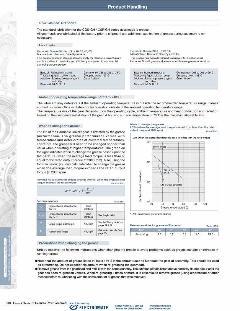
150 Gearheads
Product HandlingTechnical Data Technical Data
230 231
Tech
nica
l Inf
orm
atio
n / H
andl
ing
Expl
anat
ion
Tech
nica
l Inf
orm
atio
n / H
andl
ing
Expl
anat
ion
HPG HPF
Calculate:Maximum moment load (Mi max)Maximum axial load (Fai max)Maximum radial load (Fri max)
Calculate:Average moment load (Mi av)Average axial load (Fai av) Average input speed (Ni av)
Maximum moment load (Mi max) ≦ Allowable moment load (Mc)Maximum axial load (Fai max) ≦ Allowable axial load (Fac)Maximum radial load (Fri max) ≦ Allowable radial load (Frc)
Calculate the life and check it.
(2) Checking the life
(1) Checking maximum load
Time: t
Time: t
n1
n2
n3
M1
M2
M3
M4
n4
t1 t2 t3 t4
L10
NiCrPci
LifeAverage input speedBasic dynamic load ratingDynamic equivalent load
HourrpmN (kgf)N
av
111420325065
0.137 × Mi av + 1.232 × Fai av0.444 × Mi av + 1.426 × Fai av
0.041 × Mi av + 1.232 × Fai av
0.109 × Mi av + 1.232 × Fai av0.071 × Mi av + 1.232 × Fai av0.053 × Mi av + 1.232 × Fai av
maxmax
Fai
Lri
Fri
Lai
111420325065
111420325065
2532
2532
*1 The allowable axial load is the value of an axial load applied along the axis of rotation.*2 The allowable radial load of HPG series is the value of a radial load applied at the mid-point of the input shaft.*3 The allowable radial load of HPG series is the value of a radial load applied to the point of 20 mm from the shaft edge (input flange edge).
2532 106 × Mi av + 2.7 × Fai av
121 × Mi av + 2.7 × Fai av
Fai
Fri
Lai
Lri
Check the maximum load and life of the bearing on the input side if the reducer is an HPG input shaft unit or an HPF hollow shaft unit.
FriFaiLri,Lai
If moment load and axial load fluctuate, they should be converted into the average load to check the life of the bearing.
Calculate the bearing life according to Calculation Formula 132-5 and check the life.
Specification of input bearing
Specification of input shaft bearing
Table 149-1
Table 150-1
Table 150-2
Figure 150-1
Formula 150-2
Formula 150-3
Formula 150-4
Graph 150-1
Formula 150-5
Table 149-2
Size
Table 149-3
Table 149-4
〔Note: Table 149-2 and 149-4〕
External load influence diagram
Dynamic equivalent load
Size
Dynamic equivalent load
HPG HPF
HPG
HPF
HPG HPF
HPG
HPF
Pci
N270058009700
225003550051000
kgf275590990
230036005200
N127031505600148002510039500
kgf129320570151025604050
Nm0.166.313.544.496.9210
kgfm0.0160.641.384.539.8821.4
N2456571206328555408600
kgf2567123335565878
N20.6500902197032265267
kgf2.15192
201329537
N1450029700
kgf14803030
N1010020100
kgf10302050
Nm1019
kgfm1.021.93
N15383263
kgf157333
N522966
kgf53.298.5
Pci
HPG HPF
Formula 150-1
Checking procedure
Specification of input bearing
SizeBasic load rating
Basic dynamic load rating Cr Basic static load rating Cor
SizeAllowable moment load Mc Allowable axial load Fac *1 Allowable radial load Frc *2
SizeBasic load rating
Basic dynamic load rating Cr Basic static load rating Cor
SizeAllowable moment load Mc Allowable axial load Fac *1 Allowable radial load Frc *3
Calculating maximum moment load ON input shaft
How to calculate average load(Average moment load, average axial load, average input speed)
Mi max ≦ Mc (Allowable moment load)Fai max ≦ Fac (Allowable axial load)
Max. radial loadMax. axial load————
N (kgf)N (kgf)m
See Fig. 150-1.See Fig. 150-1.See Fig. 150-1.
The maximum moment load (Mi max ) is calculated as follows.Check that the following formulas are established in all circumstances:
Inpu
t spe
edM
omen
t loa
d
How to calculate the average moment load (Miav )
How to calculate the average axial load (Faiav)
How to calculate the average input speed (Niav)
Calculating life of input bearing
Miav Average moment load Nm (kgfm) See Formula 150-2Faiav Average axial load N (kgf) See Formula 150-3
See Formula 150-4See Table 149-1 and -3See Table 150-1 and -2
Input Bearing Specifications and Checking Procedure
Product Handling Product Handling
236 237
Tech
nica
l Inf
orm
atio
n / H
andl
ing
Expl
anat
ion
Tech
nica
l Inf
orm
atio
n / H
andl
ing
Expl
anat
ion
• Provisions for proper sealing to prevent grease leakage from the input shaft are incorporated into the gearhead. • A double lip Teflon oil seal is used for the output shaft (HPGP/HPG uses a single lip seal), gaskets or o-rings are used on all mating
surfaces, and non contact shielded bearings are used for the motor shaft coupling (Double sealed bearings (D type) are available as an option*) . On the CSG/CSF-GH series, non contact shielded bearing and a Teflon oil seal with a spring is used.
• Material and surface: Gearbox: Aluminum, corrosion protected roller bearing steel, carbon steel (output shaft). Adapter flange: (if provided by Harmonic Drive) high-strength aluminum or carbon steel. Screws: black phosphate. The ambient environment should not subject any corrosive agents to the above mentioned material. The product provides protection class IP 54 under the provision that corrosion from the ambient atmosphere (condensation, liquids or gases) at the running surface of the output shaft seal is prevented. If necessary, the adapter flange can be sealed by means of a surface seal (e.g. Loctite 515).
The standard lubrication for the HPG/HPGP/HPF/HPN series gearheads is grease.All gearheads are lubricated at the factory prior to shipment and additional application of grease during assembly is not required. The gearheads are lubricated for the life of the gear and do not require re-lubrication. High efficiency is achieved through the unique planetary gear design and grease selection.
1010
109
108
107
20 40 60 80 100 120
SK-1ASK-2
Life of grease
LGTn (when the average load torque is equal to or less than the rated torque)
Reference values for grease refill amount Size
Amount: g 0.8 3.2 6.6 11.6 78.6
The life of the Harmonic Drive® gear is affected by the grease pe r fo rmance . The g rease pe r fo rmance va r i e s w i th temperature and deteriorates at elevated temperatures. Therefore, the grease will need to be changed sooner than usual when operating at higher temperatures. The graph on the right indicates when to change the grease based upon the temperature (when the average load torque is less than or equal to the rated output torque at 2000 rpm). Also, using the formula below, you can calculate when to change the grease when the average load torque exceeds the rated output torque (at 2000 rpm).
Strictly observe the following instructions when changing the grease to avoid problems such as grease leakage or increase in running torque.
●Note that the amount of grease listed in Table 156-2 is the amount used to lubricate the gear at assembly. This should be used as a reference. Do not exceed this amount when re-greasing the gearhead.●Remove grease from the gearhead and refill it with the same quantity. The adverse effects listed above normally do not occur until the
gear has been re-greased 2 times. When re-greasing 3 times or more, it is essential to remove grease (using air pressure or other means) before re-lubricating with the same amount of grease that was removed.
Figure 156-1
Table 156-1
Formula 156-1
Table 156-2
TrTav( )3
LGT = LGTn ×
HPG/HPGP/HPF/HPN Series
CSG-GH/CSF-GH Series
Lubricants
Ambient operating temperature range: –10℃ to +40℃
The lubricant may deteriorate if the ambient operating temperature is outside of recommended operating range. Please contact our sales office or distributor for operation outside of the ambient operating temperature range.The temperature rise of the gear depends upon the operating cycle, ambient temperature and heat conduction and radiation based on the customers installation of the gear. A housing surface temperature of 70ºC is the maximum allowable limit.
The standard lubrication for the CGS-GH / CSF-GH series gearheads is grease.All gearheads are lubricated at the factory prior to shipment and additional application of grease during assembly is not necessary.
This grease has been developed exclusively for HarmonicDrive® gears and is excellent in durability and efficiency compared to commercial general-purpose grease.
This grease has been developed exclusively for smaller sized HarmonicDrive® gears and allows smooth wave generator rotation.
Precautions when changing the grease
(Common to all models)
• Contact us when using HarmonicDrive® CSG/CSF-GH series with the output shaft facing downward (motor on top) at a constant load or rotating continuously in one direction.
(CSG/CSF-GH Series)
• Using the double sealed bearing (D type) for the HPGP/HPG series gearhead will result in a slightly lower efficiency compared to the standard product.
• An oil seal without a spring is used ON the input side of HPG series with an input shaft (HPG-1U) and HPF series hollow shaft reducer. An option for an oil seal with a spring is available for improved seal reliability, however, the efficiency will be slightly lower (available for HPF and HPG series for sizes 14 and larger).
• Do not remove the screw plug and seal cap of the HPG series right angle gearhead. Removing them may cause leakage of grease or affect the precision of the gear.
(HPG/HPGP/HPF/HPN Series)
• Only use the recommended greases.• Provisions for proper sealing to prevent grease leakage are incorporated into the gearheads. However, please note that some leakage
may occur depending on the application or operating condition. Discuss other sealing options with our applications engineers.• When mounting the gearhead horizontally, position the gearhead so that the rubber cap in the adapter flange is facing upwards.
(Common to all models)
* D type: Bearing with a rubber contact seal on both sides
Sealing
Prevention of grease and oil leakage
Standard Lubricants
Harmonic Grease SK-2 Manufacturer: Harmonic Drive Systems Inc.
(HPGP/HPG-14, 20, 32) (HPGP/HPG-11, 50, 65/HPF-25, 32)EPNOC Grease AP (N) 2 Manufacturer: Nippon Oil Co.
(HPG right angle gearhead/HPN)PYRONOC UNIVERSAL 00 Manufacturer: Nippon Oil Co.
Base oil: Refined mineral oilThickening agent: Lithium soapAdditive: Extreme pressure agent
and other Standard: NLGI No. 2
Consistency: 265 to 295 at 25°CDropping point: 198°CColor: Green
Base oil: Refined mineral oilThickening agent: UreaStandard: NLGI No. 00
Consistency: 420 at 25°CDropping point: 250°C or higherColor: Light yellow
(HPG-X-R)MULTEMP AC-P Manufacturer: KYODO YUSHI CO, LTD
Base oil: Composite hydrocarbon oil and diesterThickening agent: Lithium soapAdditive: Extreme pressure and others
Standard: NLGI No. 2 Consistency: 280 at 25°CDropping point: 200°CColor: Black viscose
Base oil: Refined mineral oilThickening agent: Lithium soapAdditive: Extreme pressure agent
and other Standard: NLGI No. 2
Consistency: 282 at 25°CDropping point: 200°CColor: Light brown
Lubricants
Harmonic Grease SK-1A Manufacturer: Harmonic Drive Systems Inc.
(Size 20, 32, 45, 65) (Size 14)Harmonic Grease SK-2 Manufacturer: Harmonic Drive Systems Inc.
Base oil: Refined mineral oilThickening Agent: Lithium soapAdditive: Extreme pressure agent
and other Standard: NLGI No. 2
Consistency: 265 to 295 at 25°CDropping point: 197°CColor: Yellow
Base oil: Refined mineral oilThickening Agent: Lithium soapAdditive: Extreme pressure agent
and other Standard: NLGI No. 2
Consistency: 265 to 295 at 25°CDropping point: 198°CColor: Green
Ambient operating temperature range: –10℃ to +40℃
When to change the grease
The lubricant may deteriorate if the ambient operating temperature is outside the recommended temperature range. Please contact our sales office or distributor for operation outside of the ambient operating temperature range.The temperature rise of the gear depends upon the operating cycle, ambient temperature and heat conduction and radiation based on the customers installation of the gear. A housing surface temperature of 70ºC is the maximum allowable limit.
Formula to calculate the grease change interval when the average loadtorque exceeds the rated torque
Formula symbols
LGT
LGTn
Tr
Tav
Grease change interval when Tav > Tr
Grease change interval when Tav <= Tr See Graph 156-1
See the "Rating table" on pages 79 & 89.
Calculation formula: See page 104.Average load torque
Output torque at 2000 rpm
Input rotations
Input rotations
Nm, kgfm
Nm, kgfm
When to change the grease: LGTn (when the average load torque is equal to or less than the ratedoutput torque at 2000 rpm)
Num
ber o
f inp
ut re
volu
tions
Life of wave generator
Grease temperature (oC)
* L10 Life of wave generator bearing
14 20 32 45 65
Lubrication

151Gearheads
Product HandlingTechnical Data Technical Data
230 231
Tech
nica
l Inf
orm
atio
n / H
andl
ing
Expl
anat
ion
Tech
nica
l Inf
orm
atio
n / H
andl
ing
Expl
anat
ion
HPG HPF
Calculate:Maximum moment load (Mi max)Maximum axial load (Fai max)Maximum radial load (Fri max)
Calculate:Average moment load (Mi av)Average axial load (Fai av) Average input speed (Ni av)
Maximum moment load (Mi max) ≦ Allowable moment load (Mc)Maximum axial load (Fai max) ≦ Allowable axial load (Fac)Maximum radial load (Fri max) ≦ Allowable radial load (Frc)
Calculate the life and check it.
(2) Checking the life
(1) Checking maximum load
Time: t
Time: t
n1
n2
n3
M1
M2
M3
M4
n4
t1 t2 t3 t4
L10
NiCrPci
LifeAverage input speedBasic dynamic load ratingDynamic equivalent load
HourrpmN (kgf)N
av
111420325065
0.137 × Mi av + 1.232 × Fai av0.444 × Mi av + 1.426 × Fai av
0.041 × Mi av + 1.232 × Fai av
0.109 × Mi av + 1.232 × Fai av0.071 × Mi av + 1.232 × Fai av0.053 × Mi av + 1.232 × Fai av
maxmax
Fai
Lri
Fri
Lai
111420325065
111420325065
2532
2532
*1 The allowable axial load is the value of an axial load applied along the axis of rotation.*2 The allowable radial load of HPG series is the value of a radial load applied at the mid-point of the input shaft.*3 The allowable radial load of HPG series is the value of a radial load applied to the point of 20 mm from the shaft edge (input flange edge).
2532 106 × Mi av + 2.7 × Fai av
121 × Mi av + 2.7 × Fai av
Fai
Fri
Lai
Lri
Check the maximum load and life of the bearing on the input side if the reducer is an HPG input shaft unit or an HPF hollow shaft unit.
FriFaiLri,Lai
If moment load and axial load fluctuate, they should be converted into the average load to check the life of the bearing.
Calculate the bearing life according to Calculation Formula 132-5 and check the life.
Specification of input bearing
Specification of input shaft bearing
Table 149-1
Table 150-1
Table 150-2
Figure 150-1
Formula 150-2
Formula 150-3
Formula 150-4
Graph 150-1
Formula 150-5
Table 149-2
Size
Table 149-3
Table 149-4
〔Note: Table 149-2 and 149-4〕
External load influence diagram
Dynamic equivalent load
Size
Dynamic equivalent load
HPG HPF
HPG
HPF
HPG HPF
HPG
HPF
Pci
N270058009700
225003550051000
kgf275590990
230036005200
N127031505600148002510039500
kgf129320570151025604050
Nm0.166.313.544.496.9210
kgfm0.0160.641.384.539.8821.4
N2456571206328555408600
kgf2567123335565878
N20.6500902197032265267
kgf2.15192
201329537
N1450029700
kgf14803030
N1010020100
kgf10302050
Nm1019
kgfm1.021.93
N15383263
kgf157333
N522966
kgf53.298.5
Pci
HPG HPF
Formula 150-1
Checking procedure
Specification of input bearing
SizeBasic load rating
Basic dynamic load rating Cr Basic static load rating Cor
SizeAllowable moment load Mc Allowable axial load Fac *1 Allowable radial load Frc *2
SizeBasic load rating
Basic dynamic load rating Cr Basic static load rating Cor
SizeAllowable moment load Mc Allowable axial load Fac *1 Allowable radial load Frc *3
Calculating maximum moment load ON input shaft
How to calculate average load(Average moment load, average axial load, average input speed)
Mi max ≦ Mc (Allowable moment load)Fai max ≦ Fac (Allowable axial load)
Max. radial loadMax. axial load————
N (kgf)N (kgf)m
See Fig. 150-1.See Fig. 150-1.See Fig. 150-1.
The maximum moment load (Mi max ) is calculated as follows.Check that the following formulas are established in all circumstances:
Inpu
t spe
edM
omen
t loa
d
How to calculate the average moment load (Miav )
How to calculate the average axial load (Faiav)
How to calculate the average input speed (Niav)
Calculating life of input bearing
Miav Average moment load Nm (kgfm) See Formula 150-2Faiav Average axial load N (kgf) See Formula 150-3
See Formula 150-4See Table 149-1 and -3See Table 150-1 and -2
Input Bearing Specifications and Checking Procedure
238 239
Product HandlingTe
chni
cal I
nfor
mat
ion
/ Han
dlin
g Ex
plan
atio
n
Design Precaution: Be certain to read the catalog when designing the equipment.
Operational Precaution: Be certain to read the catalog before operating the equipment.
Handling Lubricant
Disposal
Use only in the proper environment.● Please ensure to comply with the following environmental conditions:
• Ambient temperature 0 to 40˚C • No splashing of water or oil• Do not expose to corrosive or explosive gas• No dust such as metal powder Caution
Caution
Caution
Caution
Caution Caution
Caution
Warning
Warning
Warning
Warning
Caution
Caution
Caution
Caution
Caution
Caution
When disposing of the product, disassemble it and sort the component parts by material type and dispose of the parts as industrial waste in accordance with the applicable laws and regulations. The component part materials can be classified into three categories.
(1) Rubber parts: Oil seals, seal packings, rubber caps, seals of shielded bearings on input side (D type only)(2) Aluminum parts: Housings, motor flanges(3) Steel parts: Other parts
HarmonicDrive® is a registered trademark of Harmonic Drive LLC.HarmonicPlanetary® is a registered trademark of Harmonic Drive LLC.
Please contact us or visit our website at www.harmonicdrive.net for warranty details for your specific product.
All efforts have been made to ensure that the information in this catalog is complete and accurate. However, Harmonic Drive LLC is not liable for any errors, omissions or inaccuracies in the reported data. Harmonic Drive LLC reserves the right to change the product specifications, for any reason, without prior notice. For complete details please refer to our current Terms and Conditions posted on our website.
Disposal
Trademark
Install the equipment properly.● Carry out the assembly and installation precisely as specified in the catalog.● Observe our recommended fastening methods (including bolts used and
tightening torques).● Operating the equipment without precise assembly can cause problems such
as vibration, reduction in life, deterioration of precision and product failure.
Operate within the allowable torque range.● Do not apply torque exceeding the momentary peak torque. Applying
excess torque can cause problems such as loosened bolts, generation of backlash and product failure.
● An arm attached directly to the output shaft that strikes a solid object can damage the arm or cause the output of the gearhead to fail.
Do not disassemble the products.● Do not disassemble and reassemble the products. Original performance
may not be achieved.
● Rust-proofing was applied before shipping. However, please note that rusting may occur depending on the customers' storage environment.
● Although black oxide finish is applied to some of our products, it does not guarantee that rust will not form.
Stop operating the system if any abnormality occurs.● Shut down the system promptly if any abnormal sound or vibration is detected, the
rotation has stopped, an abnormally high temperature is generated, an abnormal motor current value is observed or any other anomalies are detected. Continuing to operate the system may adversely affect the product or equipment.
● Please contact our sales office or distributor if any anomaly is detected.
Use caution when handling the product and parts.● Do not hit the gear or any part with a hammer. ● If you use the equipment in a damaged condition, the gearhead may not
perform to catalog specifications. It can also cause problems including product failure.
Do not alter or disassemble the product or parts. ● Harmonic Planetary® and Harmonic Drive® products are manufactured
as matched sets. Catalog ratings may not be achieved if the component parts are interchanged.
Do not use your finger to turn the gear.● Do not insert your finger into the gear under any circumstances. The
finger may get caught in the gear causing an injury.
Large sizes (45, 50 and 65) are heavy. Use caution when handling.● They are heavy and may cause a lower-back injury or an injury if
dropped on a hand or foot. Wear protective shoes and back support when handling the product.
Disposal of waste oil and containers● Follow all applicable laws regarding waste disposal. Contact your
distributor if you are unsure how to properly dispose of the material. ● Do not apply pressure to an empty container. The container may explode.● Do not weld, heat, drill or cut the container. This may cause residual oil
to ignite or cause an explosion.
Storage● Tightly seal the container after use. Store in a cool, dry, dark place.
Keep away from open flames and high temperatures.
Precautions on handling lubricants● Lubricant in the eye can cause inflammation. Wear protective glasses to
prevent it from getting in your eye. ● Lubricant coming in contact with the skin can cause inflammation. Wear
protective gloves when you handle the lubricant to prevent it from contacting your skin.
● Do not ingest (to avoid diarrhea and vomiting).● Use caution when opening the container. There may be sharp edges that
can cut your hand. Wear protective gloves.● Keep lubricant out of reach of children.
First-aid● Inhalation: Remove exposed person to fresh air if adverse effects are
observed. ● Ingestion: Seek immediate medical attention and do not induce vomiting
unless directed by medical personnel. ● Eyes: Flush immediately with water for at least 15 minutes. Get immediate
medical attention. ● Skin: Wash with soap and water. Get medical attention if irritation
develops.
Please dispose of as industrial waste.● Please dispose of the products as industrial waste when their useful
life is over.
SafetyWarningCaution
: Means that improper use or handling could result in a risk of death or serious injury.
: Means that improper use or handling could result in personal injury or damage to property.
* Space flight hardware * Aircraft equipment * Nuclear power equipment * Equipment and apparatus used in residential dwellings* Vacuum environments * Automotive equipment * Personal recreation equipment * Equipment that directly works on human bodies * Equipment for transport of humans * Equipment for use in a special environment * Medical equipmentPlease consult Harmonic Drive LLC beforehand if intending to use one of our product for the aforementionedapplications.Fail-safe devices that prevent an accident must be designed into the equipment when the products are used in any equipment that could result in personal injury or damage to property in the event of product failure.
Application RestrictionsThis product cannot be used for the following applications:
Use the specified lubricant.● Using other than our recommended lubricant can reduce the life of the
product. Replace the lubricant as recommended.● Gearheads are factory lubricated. Do not mix installed lubricant with other
kinds of grease.
Install the equipment with the required precision.● Design and assemble parts to keep all catalog recommended tolerances
for installation.● Failure to hold the recommended tolerances can cause problems such
as vibration, reduction in life, deterioration of precision and product failure.
Warranty

152 Gearheads238 239
Product Handling
Tech
nica
l Inf
orm
atio
n / H
andl
ing
Expl
anat
ion
Design Precaution: Be certain to read the catalog when designing the equipment.
Operational Precaution: Be certain to read the catalog before operating the equipment.
Handling Lubricant
Disposal
Use only in the proper environment.● Please ensure to comply with the following environmental conditions:
• Ambient temperature 0 to 40˚C • No splashing of water or oil• Do not expose to corrosive or explosive gas• No dust such as metal powder Caution
Caution
Caution
Caution
Caution Caution
Caution
Warning
Warning
Warning
Warning
Caution
Caution
Caution
Caution
Caution
Caution
When disposing of the product, disassemble it and sort the component parts by material type and dispose of the parts as industrial waste in accordance with the applicable laws and regulations. The component part materials can be classified into three categories.
(1) Rubber parts: Oil seals, seal packings, rubber caps, seals of shielded bearings on input side (D type only)(2) Aluminum parts: Housings, motor flanges(3) Steel parts: Other parts
HarmonicDrive® is a registered trademark of Harmonic Drive LLC.HarmonicPlanetary® is a registered trademark of Harmonic Drive LLC.
Please contact us or visit our website at www.harmonicdrive.net for warranty details for your specific product.
All efforts have been made to ensure that the information in this catalog is complete and accurate. However, Harmonic Drive LLC is not liable for any errors, omissions or inaccuracies in the reported data. Harmonic Drive LLC reserves the right to change the product specifications, for any reason, without prior notice. For complete details please refer to our current Terms and Conditions posted on our website.
Disposal
Trademark
Install the equipment properly.● Carry out the assembly and installation precisely as specified in the catalog.● Observe our recommended fastening methods (including bolts used and
tightening torques).● Operating the equipment without precise assembly can cause problems such
as vibration, reduction in life, deterioration of precision and product failure.
Operate within the allowable torque range.● Do not apply torque exceeding the momentary peak torque. Applying
excess torque can cause problems such as loosened bolts, generation of backlash and product failure.
● An arm attached directly to the output shaft that strikes a solid object can damage the arm or cause the output of the gearhead to fail.
Do not disassemble the products.● Do not disassemble and reassemble the products. Original performance
may not be achieved.
● Rust-proofing was applied before shipping. However, please note that rusting may occur depending on the customers' storage environment.
● Although black oxide finish is applied to some of our products, it does not guarantee that rust will not form.
Stop operating the system if any abnormality occurs.● Shut down the system promptly if any abnormal sound or vibration is detected, the
rotation has stopped, an abnormally high temperature is generated, an abnormal motor current value is observed or any other anomalies are detected. Continuing to operate the system may adversely affect the product or equipment.
● Please contact our sales office or distributor if any anomaly is detected.
Use caution when handling the product and parts.● Do not hit the gear or any part with a hammer. ● If you use the equipment in a damaged condition, the gearhead may not
perform to catalog specifications. It can also cause problems including product failure.
Do not alter or disassemble the product or parts. ● Harmonic Planetary® and Harmonic Drive® products are manufactured
as matched sets. Catalog ratings may not be achieved if the component parts are interchanged.
Do not use your finger to turn the gear.● Do not insert your finger into the gear under any circumstances. The
finger may get caught in the gear causing an injury.
Large sizes (45, 50 and 65) are heavy. Use caution when handling.● They are heavy and may cause a lower-back injury or an injury if
dropped on a hand or foot. Wear protective shoes and back support when handling the product.
Disposal of waste oil and containers● Follow all applicable laws regarding waste disposal. Contact your
distributor if you are unsure how to properly dispose of the material. ● Do not apply pressure to an empty container. The container may explode.● Do not weld, heat, drill or cut the container. This may cause residual oil
to ignite or cause an explosion.
Storage● Tightly seal the container after use. Store in a cool, dry, dark place.
Keep away from open flames and high temperatures.
Precautions on handling lubricants● Lubricant in the eye can cause inflammation. Wear protective glasses to
prevent it from getting in your eye. ● Lubricant coming in contact with the skin can cause inflammation. Wear
protective gloves when you handle the lubricant to prevent it from contacting your skin.
● Do not ingest (to avoid diarrhea and vomiting).● Use caution when opening the container. There may be sharp edges that
can cut your hand. Wear protective gloves.● Keep lubricant out of reach of children.
First-aid● Inhalation: Remove exposed person to fresh air if adverse effects are
observed. ● Ingestion: Seek immediate medical attention and do not induce vomiting
unless directed by medical personnel. ● Eyes: Flush immediately with water for at least 15 minutes. Get immediate
medical attention. ● Skin: Wash with soap and water. Get medical attention if irritation
develops.
Please dispose of as industrial waste.● Please dispose of the products as industrial waste when their useful
life is over.
SafetyWarningCaution
: Means that improper use or handling could result in a risk of death or serious injury.
: Means that improper use or handling could result in personal injury or damage to property.
* Space flight hardware * Aircraft equipment * Nuclear power equipment * Equipment and apparatus used in residential dwellings* Vacuum environments * Automotive equipment * Personal recreation equipment * Equipment that directly works on human bodies * Equipment for transport of humans * Equipment for use in a special environment * Medical equipmentPlease consult Harmonic Drive LLC beforehand if intending to use one of our product for the aforementionedapplications.Fail-safe devices that prevent an accident must be designed into the equipment when the products are used in any equipment that could result in personal injury or damage to property in the event of product failure.
Application RestrictionsThis product cannot be used for the following applications:
Use the specified lubricant.● Using other than our recommended lubricant can reduce the life of the
product. Replace the lubricant as recommended.● Gearheads are factory lubricated. Do not mix installed lubricant with other
kinds of grease.
Install the equipment with the required precision.● Design and assemble parts to keep all catalog recommended tolerances
for installation.● Failure to hold the recommended tolerances can cause problems such
as vibration, reduction in life, deterioration of precision and product failure.
Warranty

153 Gearheads Rev 12-16
Group Companies Harmonic Drive Systems, Inc. 6-25-3 Minami-Ohi, Shinagawa-ku Tokyo 141-0013, Japan
Harmonic Drive AG Hoenbergstrasse, 14, D-6555 Limburg/Lahn Germany
Harmonic Drive® and HarmonicPlanetary® are registered trademarks and Quick Connect is a trademark of Harmonic Drive LLC. All other trade-marks are property of their respective owners.
Harmonic Drive LLCBoston US Headquarters247 Lynnfield Street Peabody, MA 01960
New York Sales Office100 Motor ParkwaySuite 116Hauppauge, NY 11788
California Sales Office333 W. San Carlos Street Suite 1070San Jose, CA 95110
Chicago Sales Office137 N. Oak Park Ave., Suite 410Oak Park, IL 60301
T: 800.921.3332 T: 978.532.1800 F: 978.532.9406
www.HarmonicDrive.net