
DESIGN, FABRICATION AND EVALUATION OF A MOTORIZED FRUIT JUICE EXTRACTOR
92
1 DESIGN, FABRICATION AND EVALUATON OF A MOTORIZED FRUIT JUICE EXTRACTOR BY: BAMIDELE, Christopher S. (B.ENG) DEGREE IN AGRICULTURAL AND ENVIRONMENTAL ENGINEERING. (UE/8795/06) PROJECT REPORT SUBMITTED TO: DEPARTMENT OF AGRICULTURAL AND ENVIRONMENTAL ENGINEERING, UNIVERSITY OF AGRICULTURE, MAKURDI IN PARTIAL FULFILMENT OF THE REQUIREMENT FOR THE AWARD OF BACHELOR OF ENGINEERING JANUARY, 2011.
Transcript of DESIGN, FABRICATION AND EVALUATION OF A MOTORIZED FRUIT JUICE EXTRACTOR

1
DESIGN, FABRICATION AND EVALUATON OF A
MOTORIZED FRUIT JUICE EXTRACTOR
BY:
BAMIDELE, Christopher S.
(B.ENG) DEGREE IN AGRICULTURAL AND
ENVIRONMENTAL ENGINEERING.
(UE/8795/06)
PROJECT REPORT SUBMITTED TO:
DEPARTMENT OF AGRICULTURAL AND ENVIRONMENTAL
ENGINEERING,
UNIVERSITY OF AGRICULTURE, MAKURDI IN PARTIAL
FULFILMENT OF THE REQUIREMENT FOR THE AWARD OF
BACHELOR OF ENGINEERING
JANUARY, 2011.

2
DECLARATION
I declare that the work described in this report represent my original work and has not been
submitted to any University or similar institution for any degree.
NAME: BAMIDELE, CHRISTOPHER S. .......................................
REG NO: UE/8795/06 SIGNATURE/DATE
3
CERTIFICATION
We, the under signed, hereby certifies that this report presented by Bamidele, Christopher S.
(UE/8795/06) be accepted as fulfilling part of the requirement for the degree of B. Eng.
Agricultural and Environmental Engineering.
TITLE OF PROJECT: DESIGN, FABRICATION AND EVALUATION OF A MOTORIZED
FRUIT JUICE EXTRACTOR
…………………………………. ……………………………...
Engr. Dr. S.E. Obetta Date
(Project Supervisor)
………………………………… ………………………………
Engr. Dr. S.E. Obetta Date
(Head of Department)
.................................................. .............................................
Engr. Prof. L.A.S. Agbetoye Date
(External Examiner)

4
DEDICATION
This project work is dedicated to Almighty God for his infinite mercies and guidance during my
academic pursuit.

5
ACKNOWLEDGMENT
I acknowledge with gratitude and great regards the following for their patience, concern,
encouragement, advice and assistance in the course of my studies and this project write up. My
Dad and Mum, W. O and Mrs. Bamidele, who made me what I am today.
I also acknowledge my supervisor Engr. Dr. S.E. Obetta for using his professional
knowledge in guiding me throughout this work and more so whose valuable time was spent in
going through the work making sure it was well straightened. He was a mediator between all my
sources of consultations ensuring that there was a balance of idea at the end of the work, I say a
very big thanks to you sir.
My appreciation also goes to my project coordinator, Engr. Dr. S.B. Onoja and all
lecturers in the Department and: to all my fellow colleagues, I say thank you.

6
ABSTRACT
Several varieties of juicy fruits are available in abundant quantities in many parts of Nigeria,
most especially during the harvesting seasons. Incidentally, there is an increasing demand for
fruits juices among people of all age groups due to the vitamins, mineral and fiber contents.
These products are essential for human and animal growth, aid metabolic activities and improve
health standards. I designed, constructed and evaluated the performance of the extractor in the
laboratory using orange fruits. The fruits were washed and weights (1kg, 1.5kg and 2kg
respectively) of fruit slice (8 and 16 slices) were then processed using the extractor to extract the
juice. The juice yield, extraction loss and extraction efficiency were determined by standard
formulae and methods. Maximum juice yield of 64.6 % extraction efficiency of 68.2 % and
corresponding extraction loss of 7.05 % respectively were obtained from the 16 slice lengths
orange fruit.
A device of this nature can be manufactured in small machine shops in orange producing
developing countries for village level applications.

7
TABLE OF CONTENTS
Title 1
Declaration 2
Certification 3
Dedication 4
Acknowledgement 5
Abstract 6
Table of Contents 7
List of Tables 11
List of Figures 12
1.0 INTRODUCTION 13
1.1 Economic Importance of Fruit Juice 13
1.2 Statement of Problem 17
1.3 Objectives of the Project 17
1.4 Justification 17
2.0 LITERATURE REVIEW 18
2.1 Fruits Quality for Processing 18
2.2 Size Reduction 20
2.2.1 Grinding and Cutting 22
2.3 Energy used in Grinding 28
2.4 Fruits Juices 30
8
2.5 Types of Juice Extractors 31
2.5.1 F.M.C Citrus Extractor 31
2.5.2 Bicycle Powered Citrus Extractor 33
2.5.3 Rotary Juice Press 36
2.5.4 Victorio Strainer 38
2.5.5 Hydraulic Juice Press 40
2.5.6 Screw – Type Juice Extractor 42
2.5.7 Roto Rotary Orange Juicer 44
2.5.8 Multi – Fruit Juice Extractor 46
2.5.9 Domestic Rubber – Type Extractor 48
2.5.10 Use of Bare Hands (Traditional Method) 48
2.6 Extraction of Fruit Juice 48
3.0 MATERIALS AND METHODS 52
3.1 Material Selection and Description 52
3.1.1 Design Consideration 52
3.1.2 Economic Factors and Safety Considerations 52
3.2 Materials and Equipment for Performance Evaluation 53
3.3 Determination of Physical and Mechanical Properties 54
3.3.1 Sizes and Shapes 54
3.3.2 Angle of Repose 55
3.4 Pre – treatment of Fruits 55
3.5 Design Analysis 56
3.5.1 Belt and Pulley Selection 56

9
3.5.2 Size of Belt 57
3.5.3 Length of Belt 60
3.5.4 Hopper Design Specification 60
3.5.5 Shaft Design 63
3.5.6 Auger Conveyor Specification 66
3.6 Performance Evaluation of the Extractor 68
3.7 Philosophy of the Design 68
3.8 An Isometric Projection of the Juice Extractor 70
3.8.1 Components of the Extractor 71
3.9 Description of the Extractor’s Component Parts 71
3.9.1 Hopper 71
3.9.2 Cylindrical Drum 72
3.9.3 Cylindrical Mesh Sieve 72
3.9.4 Concave 72
3.9.5 Power Shaft 73
3.9.6 Frame and Supports 73
3.10 Bill of Quantities 74
4.0 RESULTS AND DISCUSSION 75
4.1 Discussion of Results 79
5.0 CONCLUSION AND RECOMMENDATION 83
5.1 Conclusion 83
5.2 Recommendation 84

10
REFERENCES 85
APPENDICES 87

11
LIST OF TABLES
Table 1 Type of Fruits and Example
Table 2 Information on Fruits and Vegetables
Table 3 Extraction Pressure Ranges of Commodities
Table 4 Densities and Solid Content of Some Fruit
Table 5 Auger Conveyor Specifications
Table 6 Bill of Quantities
Table 7 Summary of Appendix 1, 2 and 3
Table 8 Summary of Appendix 4a and 4b: Juice Yield, Extraction Loss, Extraction
Efficiency and Throughput Capacity for 8 Slice Lengths using the extractor
Table 9 Summary of Appendix 4a and 4b: Juice Yield, Extraction Loss, Extraction
Efficiency and Throughput Capacity for 16 Slice Lengths using the extractor
Table 10 Summary of Appendix 5a and 5b: Juice Yield, Extraction Efficiency using the
Hand pressing method

12
LIST OF FIGURES
Figure 1: Flow chart of processing of juice
Figure 2a: Shearing
Figure 2b: Cutting or Slicing
Figure 2c: Crushing
Figure 3: Crushers, (a) jaw, (b) gyratory
Figure 4 Grinders: (a) hammer mill, (b) plate mill
Figure 5: A rotary fruit press.
Figure 6: A Victorio Strainer
Figure 7: Screw – Type Juice Extractor
Figure 8: Roto Rotary Orange Juicer
Figure 9: An auger design and specification
Figure 10: Orthographic Projection of the Extractor
Figure 11: Isometric View of the Extractor
Figure 12: Effect weight of fruit slice on juice yield
Figure 13: Effect of weight of fruit slice on extraction efficiency
Figure 14: Effect of weight of fruit slice on extraction loss
Plate 1: A jaw crusher
Plate 2: Citrus Extractor Diagram
Plate 3: Bicycle powered citrus extraction
Plate 4: Juice strainer and pasteurization coil.
Plate 5: A Hydraulic Juice Press
Plate 6a: A multi-fruit juice extractor
plate 6b: internal parts of the juice extractor
13
1.0 INTRODUCTION
1.1 Economic Importance of Fruit Juice
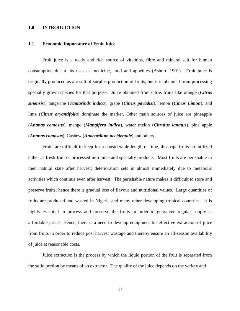
Fruit juice is a ready and rich source of vitamins, fibre and mineral salt for human
consumption due to its uses as medicine, food and appetites (Ashurt, 1991). Fruit juice is
originally produced as a result of surplus production of fruits, but it is obtained from processing
specially grown species for that purpose. Juice obtained from citrus fruits like orange (Citrus
sinensis), tangerine (Tamarinds indica), grape (Citrus pavadisi), lemon (Citrus Limon), and
lime (Citrus oryantifolia) dominate the market. Other main sources of juice are pineapple
(Ananas comosus), mango (Mangifera indica), water melon (Citrulus lanatus), pine apple
(Ananas comosus), Cashew (Anacardium occidentale) and others.
Fruits are difficult to keep for a considerable length of time, thus ripe fruits are utilized
either as fresh fruit or processed into juice and specialty products. Most fruits are perishable in
their natural state after harvest; deterioration sets in almost immediately due to metabolic
activities which continue even after harvest. The perishable nature makes it difficult to store and
preserve fruits; hence there is gradual loss of flavour and nutritional values. Large quantities of
fruits are produced and wasted in Nigeria and many other developing tropical countries. It is
highly essential to process and preserve the fruits in order to guarantee regular supply at
affordable prices. Hence, there is a need to develop equipment for effective extraction of juice
from fruits in order to reduce post harvest wastage and thereby ensure an all-season availability
of juice at reasonable costs.
Juice extraction is the process by which the liquid portion of the fruit is separated from
the solid portion by means of an extractor. The quality of the juice depends on the variety and

14
maturity of the fresh fruit. According to Otterloo (1997), extraction of juice can be done using
three methods. In the first method, the fruit is cleaned, crushed and cut into pieces, heated,
poured onto a wet muslin cloth and sieved without pressing. The second method requires a fruit
press or a fruit mill after which the juice is heated to about 60˚C and strained through a muslin or
cheese cloth. In the third method, the fruit is washed, cut into pieces and put into a juice
steamer. The steam and heat extract the juice from fruits; the juice drips through the cloth and is
collected in a small pan.
In Nigeria, fruit juices are highly demanded among people of different age groups and
this has led to the influx of varieties of imported and home-made fruit juices into the market.
Unfortunately, some of these imported fruit juices do not come in natural form but have been
stored with preservatives. There are abundant under-exploited juicy fruits in Nigeria with high
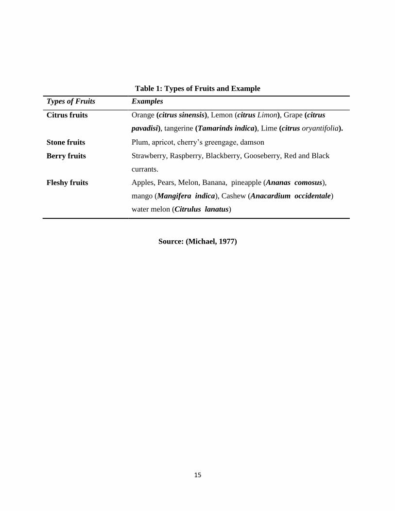
Agro-industrial potentials. Types of fruits and examples is illustrated in table 1 below and
information on fruits and vegetables is shown in table 2
15
Table 1: Types of Fruits and Example
Source: (Michael, 1977)
Types of Fruits Examples
Citrus fruits Orange (citrus sinensis), Lemon (citrus Limon), Grape (citrus
pavadisi), tangerine (Tamarinds indica), Lime (citrus oryantifolia).
Stone fruits Plum, apricot, cherry’s greengage, damson
Berry fruits Strawberry, Raspberry, Blackberry, Gooseberry, Red and Black
currants.
Fleshy fruits Apples, Pears, Melon, Banana, pineapple (Ananas comosus),
mango (Mangifera indica), Cashew (Anacardium occidentale)
water melon (Citrulus lanatus)

16
Table 2: Information on Fruits and Vegetables
Fruits/vegetables Nutrition Fact Energy in kj/kcal per
3.5oz/100g
Apples Rich in protein, fibres, vitamin C 218kJ/52kcal
Oranges Rich in vitamin C, folates,
vitamin A
207kJ/49kcal
Strawberries Rich in vitamin C, folates, lutein 136kJ/32kcal
Pears Rich in fibres, carotene, vitamin
A
242kJ/58kcal
Watermelon Rich in carotene, vitamin A,
lycopene
127kJ/30kcal
Grapes (seedless) Rich in calcium, vitamin C,
vitamin A
288kJ/69kcal
Peaches Rich in vitamin A, vitamin C,
folate
165kJ/39kcal
Nectarines Rich in vitamin A, vitamin C,
carotene
185kJ/44kcal
Tomatoes Rich in calcium, vitamin A,
folates
75kJ/18kcal
Fennel Rich in calcium, vitamin C,
vitamin A
130kJ/31kcal
Celery Rich in calcium, folates, carotene 67kJ/16kcal
Cucumber Rich in carotene, vitamin A,
lutein
65kJ/15kcal
Carrots Rich in fibres, calcium, vitamin A 173kJ/41kcal
Source: www.gehousewares.com

17
1.2 Statement of Problem
There are many problems that face the farmers in the course of extracting the fruit juice. In
the past, fruits were processed and stages involved include peeling with knife and squeezing the
juice out with bare hands. This method of processing is unhygienic and has low efficiency, and
contributes to human drudgery. Problems associated with this are:
(a) Deterioration sets in almost immediately due to metabolic activities which continue
even after harvest. The perishable nature makes it difficult to store and preserve fruits; hence
there is gradual loss of flavour and nutritional values.
(b) The local way of extracting fruit juice is prone to contamination, and as such reduces
the quality of juice produced.
1.3 Objectives of the Project
i. To design a small – scale fruit juice extractor
ii. To fabricate the machine
iii. To evaluate the performance of the extractor in terms of juice yield, extraction efficiency
and extraction loss of orange fruits.
1.4 Justification
The successful implementation of this project work will give a boost to Federal Government
initiative of importation ban on a variety of fruit juice into the country. This work would enable
the study of performance evaluation of the extractor and suggest ways for improvement and will
propel farmers to engage in the extraction of the fruit juice. To achieve this, they need such
machine that is simple to design and operate.

18
2.0 LITERATURE REVIEW
2.1 Fruits Quality for Processing
Fruits are grown primarily for fresh consumption but significant and increasing portion of
the crop is now being canned as either fruit segment or juices.
Processing is a process carried out on agricultural products to make them more hygienic for
consumption and also to preserve them for longer period of time without spoilage (Ihekoronye
and Ngoddy 1985).
Processing alone is the post-harvest treatment that is performed on agricultural products
right from where it was harvested to the point where it is to be processed as foods. It is also
aimed at quality preservation or improvement of crop quality after being worked upon by various
processing means (Adegoke, 1991).
All major fruit producing areas have regulation which outlines the physical qualities and
the chemical maturity level of fruits for processing. Fruits used should be whole, mature and
recently harvested. The fruit should contain no “drops” (daft, stale fruit that had fallen to the
ground and subsequently picked up during harvesting) or “splits” (fruits with peek breaks), and
be free from the internal insect infestation and mole damage. In order to ensure optimum
quality, standards have been established based on colour break, minimum juice content,
minimum acid content and minimum percentage of total soluble solids.

19
Figure 1: Flow chart of processing of juice
Source: (FAO, 1999)
Sorting and Grading
Bending Moment Diagram
Packaging
Storage
Clarification.
Pasteurization
Juice formulation
Juice extraction
Peeling or cutting
Size reduction

20
Fruits are processed into juice products all over the world. Juice processing flows through
several stages as shown in Figure 1 above. It is reasonable to assume that no two countries will
produce identical juice products. Differences whether they be minor or major, exist because of:
type of fruit processed, equipment, processing techniques, national and provincial standards
governing juice quality and industry’s commitment to quality control.
2.2 Size Reduction
Raw materials often occur in sizes that are too large to be used and therefore, they must
be reduced in size. Size reduction is brought about by mechanical means without change in
chemical properties of the grains or units of the end product.
Processes such as cutting fruits or vegetable for canning, shredding sweet potatoes for
drying, and grinding grains for livestock feed and milling flour are size reduction.
Size reduction can be divided into two major categories depending on whether the material is a
solid or liquid. If it is solid, operations are called cutting and grinding and if it is liquid, the
operation is regarded as emulsification or atomization (Droste, 2001). All depends on the
reaction to shearing forces within solids and liquids.
In any size reduction process, there are combinations of forces applied. It is rare for only
one of such forces to be utilized in the reduction process. These forces are:
i Compression
ii Tension
iii Shearing
iv Impact
v Cutting or slicing

21
Diagrammatically, the stress mechanisms that results in the size reduction are as shown in
figure 2 below
V1
Figure 2a: Shearing
V2
Pressure
V = velocity Figure 2b: Cutting or Slicing
Figure 2c: Crushing P, V
(Compression impact)

22
2.2.1 Grinding and Cutting
Grinding and cutting reduce the size of solid materials by mechanical action, dividing
them into smaller particles. Perhaps the most extensive application of grinding in the food
industry is in the milling of grains to make flour, but it is used in many other processes, such as
grinding of corn for manufacture of corn starch, the grinding of sugar and the milling of dried
foods, such as vegetables.
In the grinding process materials are reduced in size by fracturing them. The
mechanism is not fully understood, but in the process, the material is stressed by the action of
mechanical moving parts in the grinding machine and initially the stress is absorbed internally by
the material as strain energy (Droste, 2001). When the local strain energy exceeds a critical
level, which is a function of the material, fracture occurs along lines of weakness and the stored
energy is released. Some of the energy is taken up in the creation of new surface, but the greater
part of it is dissipated as heat. Time also plays a part in fracturing process and it appears that
materials will fracture at lower stress concentrations if these can be maintained for longer
periods. Grinding is therefore, achieved by mechanical stress followed by rupture and the
energy required depends upon the hardness of the materials and also the force applied maybe
compression, impact, or shear, and both magnitude of the force and the kind of application affect
the extent of grinding achieved. For efficient grinding, the energy applied to the material should
exceed, by a small margin as possible, the minimum energy needed to rupture the material.
Excess energy is lost as heat and this loss should be kept as low as practicable. The important
factors to be studied in the grinding process are the amount of energy used and the amount of
new surface formed by grinding.
23
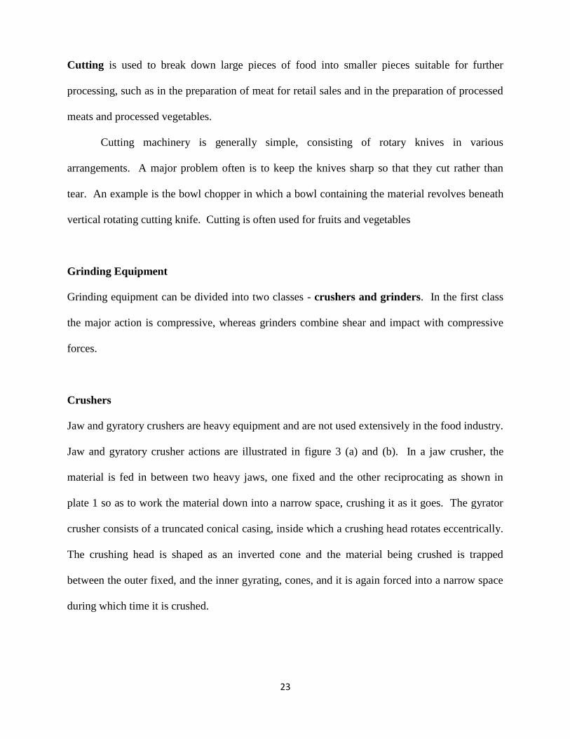
Cutting is used to break down large pieces of food into smaller pieces suitable for further
processing, such as in the preparation of meat for retail sales and in the preparation of processed
meats and processed vegetables.
Cutting machinery is generally simple, consisting of rotary knives in various
arrangements. A major problem often is to keep the knives sharp so that they cut rather than
tear. An example is the bowl chopper in which a bowl containing the material revolves beneath
vertical rotating cutting knife. Cutting is often used for fruits and vegetables
Grinding Equipment
Grinding equipment can be divided into two classes - crushers and grinders. In the first class
the major action is compressive, whereas grinders combine shear and impact with compressive
forces.
Crushers
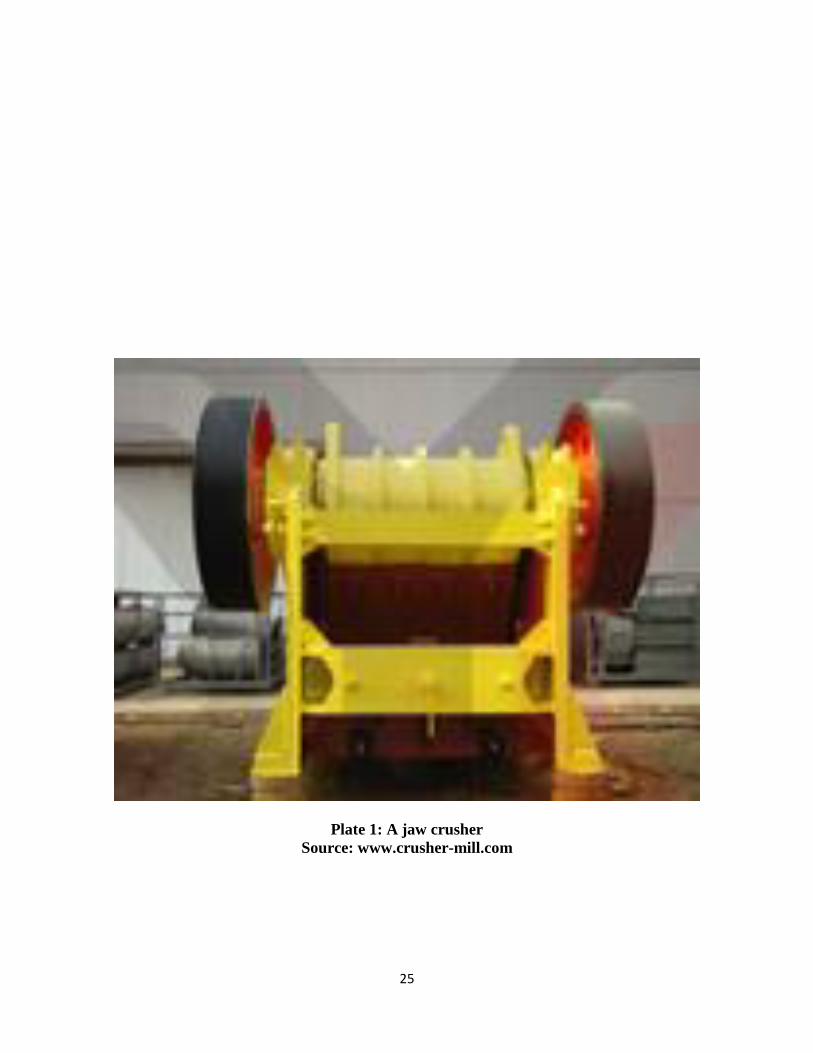
Jaw and gyratory crushers are heavy equipment and are not used extensively in the food industry.
Jaw and gyratory crusher actions are illustrated in figure 3 (a) and (b). In a jaw crusher, the
material is fed in between two heavy jaws, one fixed and the other reciprocating as shown in
plate 1 so as to work the material down into a narrow space, crushing it as it goes. The gyrator
crusher consists of a truncated conical casing, inside which a crushing head rotates eccentrically.
The crushing head is shaped as an inverted cone and the material being crushed is trapped
between the outer fixed, and the inner gyrating, cones, and it is again forced into a narrow space
during which time it is crushed.

24
Figure 3: Crushers, (a) jaw, (b) gyratory
Source: (Earle, 1983)
25
Plate 1: A jaw crusher
Source: www.crusher-mill.com

26
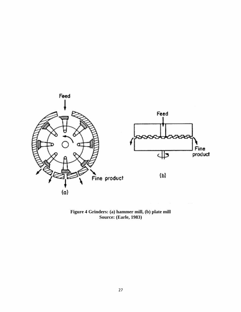
Hammer mills
In a hammer mill, swinging hammerheads are attached to a rotor that rotates at high speed inside
a hardened casing. The principle is illustrated in Fig. 4(a) below
27
Figure 4 Grinders: (a) hammer mill, (b) plate mill
Source: (Earle, 1983)

28
The material is crushed and pulverized between the hammers and the casing and remains in the
mill until it is fine enough to pass through a screen which forms the bottom of the casing. Both
brittle and fibrous materials can be handled in hammer mills, though with fibrous material,
projecting sections on the casing may be used to give a cutting action.
Plate mills
In plate mills the material is fed between two circular plates, one of them fixed and the other
rotating. The feed comes in near the axis of rotation and is sheared and crushed as it makes its
way to the edge of the plates; see Fig. 2.5(b). The plates can be mounted horizontally as in the
traditional Buhr stone used for grinding corn, which has a fluted surface on the plates. The plates
can be mounted vertically also. Developments of the plate mill have led to the colloid mill,
which uses very fine clearances and very high speeds to produce particles of colloidal
dimensions.
2.3 Energy used in Grinding
No specific energy predicting method could be used for size reduction due to the elastic
and inelastic properties of food materials, which vary considerably with moisture content and
distribution of water in the material (Ezekiel, 1985).
Grinding is a very inefficient process and it is important to use energy as efficiently as possible.
Unfortunately it is not easy to calculate the minimum energy required for a given reduction
process, but some theories have been advanced which are useful. These theories depend upon
the basic assumption that the energy required to produce a change dL in a particle of a typical
size dimension L is a simple power function of L:

29
dE/dL = KLn - - - - - - - - - (i)
Where dE is the differential energy required, dL is the change in a typical dimension; L is the
magnitude of a typical length dimension and K, n, are constants.
Kick assumed that the energy required to reduce a material in size was directly proportional to
the size reduction ratio dL/L. This implies that n in equation (i) is equal to -1. If
K = KKfc
Where KK is called Kick's constant and fc is called the crushing strength of the material,
we have:
dE/dL = KKfcL-1
Which, on integration gives:
E = KKfc log (L1/L2) - - - - - - - - (ii)
Equation (ii) is a statement of Kick's Law. It implies that the specific energy required to crush a
material, for example from 10 cm down to 5 cm, is the same as the energy required to crush the
same material from 5 mm to 2.5 mm.
Rittinger, on the other hand, assumed that the energy required for size reduction is directly
proportional, not to the change in length dimensions, but to the change in surface area. This
leads to a value of -2 for n in equation (i) as area is proportional to length squared. If we put:
K = KRfc
and so
dE/dL = KRfcL-2
Where KR is called Rittinger's constant, and integrate the resulting form of equation. (i), we
obtain:
E = KRfc (1/L2– 1/L1) - - - - - - - - (iii)
30
Equation (iii) is known as Rittinger's Law. As the specific surface of a particle, the surface area
per unit mass, is proportional to 1/L, eqn. (iii) postulates that the energy required to reduce L for
a mass of particles from 10 cm to 5 cm would be the same as that required to reduce, for
example, the same mass of 5 mm particles down to 4.7 mm. This is a very much smaller
reduction, in terms of energy per unit mass for the smaller particles, than that predicted by Kick's
Law.
It has been found, experimentally, that for the grinding of coarse particles in which the increase
in surface area per unit mass is relatively small, Kick's Law is a reasonable approximation. For
the size reduction of fine powders, on the other hand, in which large areas of new surface are
being created, Rittinger's Law fits the experimental data better.
2.4 Fruit Juices
Substantial quantities of fruit juice are manufactured and mostly they are marketed
canned. The most commonly manufactured product is citrus juices (orange juices). Orange
juices are the most common and popular, but quite large amounts of grape fruit juice and
significant amounts of lemon juice, pineapple, prune, and apple juice are in lesser amount
Fruit juices are manufactured for two main purposes; firstly for preparing pleasant tasting “soft”
drinks and secondly, as a contribution of vitamin C to the diet.

31
2.5 Types of Juice Extractors
2.5.1 Food Machinery and Chemical Corporation (F.M.C) Citrus Extractor
This is an extractor used widely in all citrus producing areas. Plate 2 gives an overview of the
FMC extraction process. A plug is cut in the centre of the fruit and a strainer pushed up inside
the orange. A mechanical hand presses the juice and pulp against this strainer keeping the juice
away from the exterior of the fruit and strongly flavoured peel oils. The juice exits out the
bottom of the FMC Extractor after being separated from the pulp and the peel is pushed up and
out from the front. At the precise moment the peel is being put under pressure and a fine mist of
water is sprayed on the peel making an emulsion of the peel oil that is being forced from the
peel. Thus in one stroke five oranges are separated into juice, pulp, peel, peel oil, seeds and rag.
The juice and any remaining pulp are sent to specially designed finishers to remove any small
seeds, bits of peel and excessive pulp from the juice prior to evaporation.

32
Plate 2: Citrus Extractor Diagram
Source: (FMC, 2000)

33
2.5.2 Bicycle Powered Citrus Extractor
The bicycle or small engine powered reamer uses two standard juice reamers. Alternative fruit
grinders for different types of fruit could be powered by a similar system. This extractor uses 5
or 6 people and will extract about 70 kg of citrus per hour. This will give a juice yield of about
30 L/ hour which is only 1/3 as fast as the flow rate of the tubular pasteurizer at 90 L/hour.
Three sets of bicycle reamers will keep one tubular pasteurizer operating on 100 percent juice or
the extraction can start and get 40 to 50 L of juice ready before pasteurizing starts. Alternatively
other juice and flavourings can be used to increase the volume of juice going to the pasteurizer.
The whole rear bicycle axle, tire, rim and chain drive sprockets are first removed. An 18-cm
threaded shaft with a toothed rear wheel-driving sprocket, two reamers and a bearing are used to
replace the rear bicycle axle. The bicycle chain is placed around the threaded shaft, fitted to the
driving sprocket and tightened in the rear wheel axle mounting brackets in the bicycle frame.
Metal or plastic troughs are constructed to protect the bearing from the acid fruit juice and to
direct the extracted juice into a collection bucket. A stand made from old bicycle handle bars is
used to elevate and stabilize the reamers. Plate 3 illustrates a bicycle-powered reamer in
operation and a close up of the reamer.
After the citrus has been thoroughly cleaned, one person cuts the fruit in half between the stem
and blossom ends. A second person rides the bicycle or operates a small engine powering a
drive chain providing power to vertical mounted reamers. A third and fourth person press the cut
cup halves against the reamer and collect the juice in a bucket. A fifth person presses the juice
through a metal colander, a perforated metal cone with a wooded dasher; to remove the excess
pulp and seeds that would plug the pasteurizer coils (plate 4). This juice is now ready to be
pasteurized or can be blended with other juices and flavourings to make a citrus beverage.

34
Plate 3: Bicycle powered citrus extraction
Source: (FMC, 2000)

35
Plate 4: Juice strainer and pasteurization coil.
Source: (FMC, 2000)

36
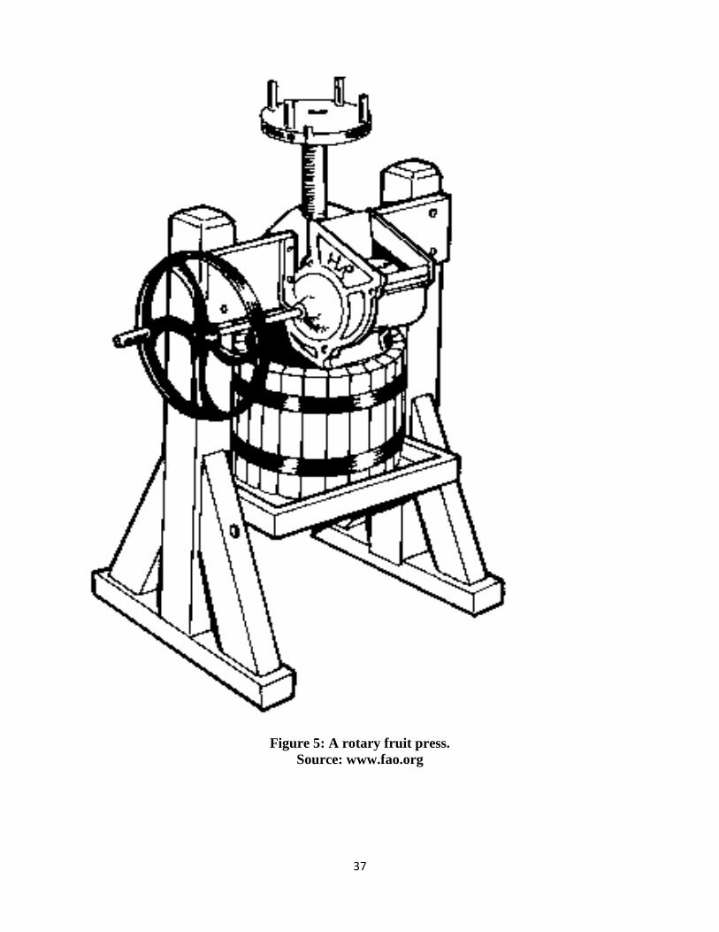
2.5.3 Rotary Juice Press
The fruit is placed into the machine via a hopper. A handle, attached to the machine, is turned
to press the fruit and extract the juice as shown in Figure 5. This self-contained machine will
grind and press all types of fruit. Eight rows of stainless steel teeth are embedded in a hardwood
tub. All pulped fruit drops directly into a basket. Basket capacity: 0.035m³.
37
Figure 5: A rotary fruit press.
Source: www.fao.org

38
2.5.4 Victorio Strainer
This purees soft fruits and vegetables. No peeling or coring is necessary for this machine, as the
juices and fruits are separated from the seeds. The fruit or vegetables are placed in the hopper as
shown in Figure 6 and the handle is turned. Seeds, skins and cores are continuously separated
from the puree. The machine works best with tomatoes and apples but accessories are available
for grapes, berries, pumpkins and squash.

39
Figure 6: A Victorio Strainer
Source: www.fao.org

40
2.5.5 Hydraulic Juice Press
These manually-operated presses extract juice from soft fruit, e.g. grapes. Hydraulic pressure is
used to extract the juice. This is illustrated in plate 5 below

41
Plate 5: A Hydraulic Juice Press
Source: www.suppliers.jimtrade.com

42
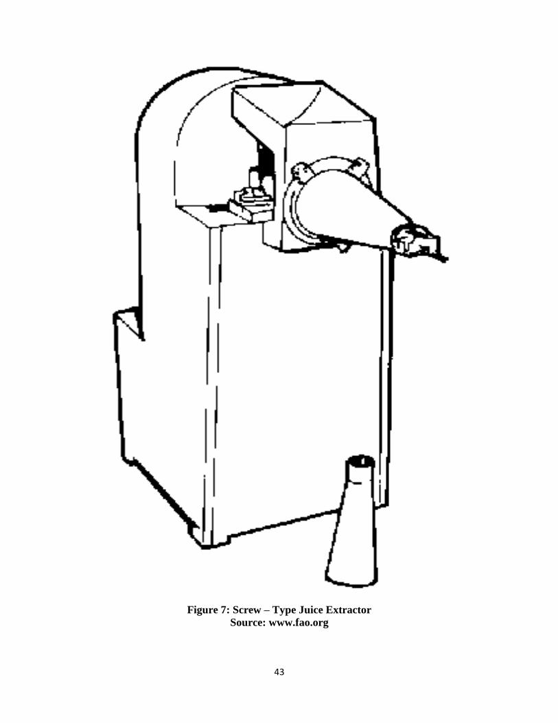
2.5.6 Screw-Type Juice Extractor
This is designed for medium-scale juice extraction, this machine in Figure 7 is driven by a
0.75kW (1hp), three-phase, 440V motor. All contact parts are fabricated from stainless steel and
there are two sets of sieves. A hand operated version is also available. Throughput: 1000
oranges or 800 lemons per hour.
43
Figure 7: Screw – Type Juice Extractor
Source: www.fao.org

44
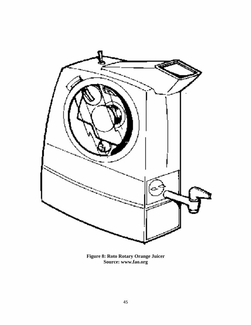
2.5.7 Roto Rotary Orange Juicer
This is a table-sized automatic orange juicer in a self-contained unit. Oranges are fed into the
juice hopper of Figure 8 below for automatic selection and slicing in half. The orange halves are
then mechanically reamed. The seeds are strained and the pulp is compressed to maximize the
yield of juice. All waste is deposited in a disposable unit. Throughput: 2640-3960 oranges per
hour. Dimensions: length 40.6 x width 22.9 x height 55.9cm.
45
Figure 8: Roto Rotary Orange Juicer
Source: www.fao.org

46
2.5.8 Multi – Fruit Juice Extractor
In the operation of the extractor as shown in plate 6a below, the fruit is introduced through the
hopper into the cylindrical drum inside which is the rotating shaft attached with cutter blades and
nylon brushes. Extraction takes place by mastication through cutting by the cutter blades and
maceration by the nylon brushes as the shaft is powered by the electric motor. The juice
extracted is sieved by the mesh as shown in plate 6b below and collected from the juice outlet
while the residual products (fibre and process wastes) are collected separately at the fibre outlet.

47
Plate 6a: A multi-fruit juice extractor plate 6b: internal parts of the juice extractor
Source: (Oyeleke et al, 2007)

48
2.5.9 Domestic Rubber-Type Extractor
This extractor is better than extracting juice with bare hands. It is a cone-shaped
instrument made either of rubber or plastic. This machine is used in the homes, not for
commercial production. For its operation, the already peeled fruit is cut into two halves, placed
on the apex of the instrument, pressed down a bit and turned in a clockwise direction continually
until all the juice is extracted through perforated holes on the instrument and is collected in small
tank below it. There is the problem of frequent blockages of these holes during operation which
hampers extraction at times. Moreover, a lot of energy is expended during the proper extraction.
The upper part of this machine is detachable after the small tank is full of the juice.
2.5.10 Manual (Traditional) Method
This is rather an age-long and also crude method of extracting juice from fruit. Here,
fruits are peeled first, then cut into two halves, held in between the palms and compressed.
Surely the juice is expressed or expelled but this is an inefficient way of extraction.
2.6 Extraction of Fruit Juice
Extraction, otherwise known as “expression” is the act of expelling a liquid from a solid
either by squeezing or by compaction. It is used for a variety of purpose such as recovering fruit
and vegetable juices and recovering oil from seeds. Extraction pressure ranges of commodities
as well as density and solid content of some fruits are shown in table 3 and 4 below.

49
Table 3: Extraction Pressure Ranges of Commodities
COMMODITY PRESSURE (kN/m2)
Oil seeds
11,248
Sugar cane extraction 422
Sugar beet extraction
352-703
Spent coffee grounds
703-1406
Fruit juice extraction
141-316
Hand cheese pressing
4-8
Source: (Michael, 1977)

50
Table 4: Densities and Solid Content of Some Fruit
FRUIT JUICES MEAN DENSITY
(g/ml-1
)
MEAN TOTAL
SOLID (g)
Orange
1.042
10.8
Grape fruit 1.040 10.4
Lemon
1.035
10.0
Lime 1.035 9.3
Apple
1.060
13.0
Black currant 1.055 13.5
Source: (Egan et al, 1981)
51
Extraction or expression of fruit juice can either be batch or continuous, and its efficiency is
monitored by the yield and solid content of the liquid obtained. Extraction can usually be
divided into an induction period, during which the air is expelled from the pressed cake pores
and the pores gradually filled with exude liquid, and an out flow period. Some juice extracted
depends on the size of fruit, degree of fruit ripeness, and the applied pressure. 3.0

52
MATERIALS AND METHODS
3.1 Material Selection and Description
For the design of this project, steel materials will be selected considering the following qualities:
mild steel has about 0.15 to 0.25% carbon content which makes it easy to be worked on and
welded. It also has density of 7.68 × 10 3 kg/m3, heat expansivity of 11.7× 10
-6 °k
-1, Young’s
modulus of elasticity 210GN/m 2
, tensile strength of 350 MN/m 2 and elongation of 30%.
The following factors are considered for a successful design and operation of the juice extractor.
3.1.1 Design Consideration
i. Strength, rigidity and simplicity of materials of construction
ii. The expression pressure must be high enough to ensure acceptable level of
extraction
iii. The transmission belt should be properly aligned such that it permits easy rotation
of the shaft auger during extraction.
iv. The power shaft should be rigid enough to withstand combined bending and tension
stresses to which it will be subjected to while transmitting power under various
operating and loading conditions.
v. Required force to expel out the juice.
vi. Portability of the machine.
vii. Easy inspection, serviceability, and maintenance of the machine.
viii. Durability of the machine.
53
3.1.2 Economic Factors and Safety Considerations
Construction materials will be selected based on economic factors and safety consideration.
These factors are:
i. Availability and the cost of construction and materials
ii. Durability and strength of materials
iii. Manufacturing /fabrication methods that will be employed in construction.
iv. Efficiency of extraction and minimizing juice contamination
v. Corrosion resistant properties
3.2 Materials and Equipment for Performance Evaluation
The materials/equipment used in conducting the experiments are;
Weighing Balance
Stop Watch
Fruit Samples such as Orange, Watermelon and Pineapple
The Juice Extractor (the fabricated machine)
Collector Pan
Metal Plate
Vernier caliper
Micrometer screw gauge
54
3.3 Determination of Physical and Mechanical Properties
3.3.1 Sizes and Shapes
5kg of Orange samples was collected and the axial dimensions were measured using a
vernier caliper and micrometer screw gauge. From the table of results, the geometric mean
diameter, Dg, arithmetic mean diameter, Da, sphericity ,Ø, volume, V and surface area, S was
calculated using equations i, ii, iii, iv and v respectively as given by Joshi et al; (1993)
Geometric mean diameter, Dg = (abc) 1/3
. . . . . . (i)
Where a = length (dimension along longest axis) = 7.5
b = width (dimension along longest axis perpendicular to a) = 6.5
c = thickness (dimension along the longest axis perpendicular to a and b) = 7.0
Dg = (7.5 x 6.5 x 7.0) 1/3
= 6.99 7.0cm
Arithmetic mean diameter, Da = . . . . . . (ii)
Da = = 7.0 cm
Sphericity, = . . . . . . . . . (iii)
= = 0.93
For an oblate spheroid like orange, the volume, V = a2 b) . . . (iv)
V = × 7.52
× 6.5) = 1532 cm3
Surface area, S = 2 a2 + b
2 / e) ln . . . . . (v)

55
Where eccentricity, e = [1- (a/b) 2
] 1/2
= [1- (6.5/7.5) 1/2
= 0.5
S = 2 7.52 + 6.5
2 / 0.5) ln = 645 cm
2
3.3.2 Angle of Repose
This was determined by placing sample of oranges on an adjustable. The adjustable was
inclined. This was done using 10 oranges and their corresponding coefficient of friction was
analyzed. The results are shown in appendix 1
3.4 Pre-treatment of Fruits
Clean, ripe and mature fruits (orange,) were purchased from fruits merchants at
Wurukum market in Makurdi. Each orange fruit was washed and weights (kg) of each fruit slice
of 8 and 16 respectively were used for the evaluation. Yellow oranges with almost no- acidic
content were selected and separated from the green ones and kept in refrigerator pending when
it was to be used and some of the green oranges were kept in cartons at an ambient temperature
to inhibit ripening of the oranges when the yellow color begin to appear.

56
3.5 Design Analysis
Intended Efficiency of 95% is anticipated for the machine at engine speed N1= 1400 rpm
95% Efficiency of 1hP will become
1hp = 0.95hP
But 1hP = 0.75kW
0.95hp → 0.95 x 0.75kW = 0.713kW
An engine pulley diameter of 76mm diameter will be chosen from standard table with belt
thickness of 0.12mm.
Engine pulley diameter, d1 = 7.6mm or 0.076m
Radius, r1 = 0.038m
Angular velocity of engine (motor), 1 =
Where N1 = Speed of the engine.
1 = = 146.6 147 rad / sec. . . . . . (i)
The linear velocity of the engine, V = r1 . . . . . . (ii)
Substitute the value of 1 in (i) into (ii) we have,
V = 146.6 x 0.038 = 5.6 m / s . . . . . . (iii)
3.5.1 Belt and Pulley Selection
A speed reduction ratio of 3 is chosen
=
Where N1 = Speed of driver pulley

57
N2 = Speed of driven pulley
= Reduction ratio = 3
N2 = = = 466.7 467 rpm . . . . . . (iv)
Diameter of driven pulley, d2
= {this equation is given by Khurmi and Gupta, 2005} . . (v)
Where N1 = Speed of driver pulley
N2 = Speed of driven pulley
d1 = diameter of driver pulley
d2 = diameter of driver pulley
Substitute the value of N2 in (iv) into (v) we have,
d2 = = = 0.22 0.2 m . . . . . (vi)
Radius of driven pulley, r2 = = 0.1 m
Angular velocity of the driven pulley, 2 = . . . . . (vii)
Substitute the value of N2 in (iv) into (vii) we have,
2 = = 48.87 rad / sec
3.5.2 Size of Belt
For an efficient torque in V- belts, a minimum angle of contact of the belt on the smaller pulley
should not be less than 1200
(Reshetor, 1978). Therefore an angle of 1650
is chosen for the
smaller pulley.

58
01
02
M
?
R1 X R2
Belt Arrangement
Sin = O2m / O1O2 = r2 – r1 / x = d2 – d1 / 2x ({this equation is given by Khurmi and Gupta,
2005} . . . . . . . . . . (viii)
r1 and r2 are radii of smaller and larger pulleys
x is the distance between the centers of the two pulley (i.e. O1O2)
The angle of contact, in this case is 1650
But = 180 - 2
= = = 15 / 2 = 7.50
Or 7.5 x rad = 0.13 rad
But sin = d2 – d1 / 2x 2x = d2 – d1 / sin
2x = 2x =
x = = 0.48 m
An A55 V – belt size will be selected
Angle of contact, is selected to be 1650
= 165 x = 2.88 rad
59
We know that
2.3 log ( ) =
Coefficient of friction, for rubber belt material on dry cast iron is 0.3
2.3 log ( ) = = 0.3 x 2.88 = 0.864
Log ( ) = = 0.376
= log -1
(0.376) = 2.37 . . . . . . . (ix)
Power transmitted by belt,
P = (T1 –T2) v
Where P = Power in watts
T1 – T2 = Overall belt tension
T1 = Tension in tight side of belt
T2 = Tension in slack side of belt
0.713 x 103
= (T1 –T2) 5.6
T1 –T2 = = 127 N . . . . . . (x)
From equation (ix), T1 = 2.37T2
Substituting the value of T1 into equation (x)
We have,
2.3T2 - T2 = 127 N
1.37T2 = 127 N

60
T2 = = 92.7 N . . . . . . . . (xi)
Substituting T2 in (xi) into (x) we have,
T1 – 92.7 = 127
T1 = 127 + 92.7 = 220 N
3.5.3 Length of Belt
L = (d2 + d1) + 2x + (d2 –d1)2 / 4x {this equation is given by R.S. Khurmi and J.K.
Gupta, 2005}
L = (0.2 + 0.076) + 2 (0.48) + (0.2 – 0.076)2
/ 4 (0.48)
= 0.4336 + 0.96 + = 1.40 m
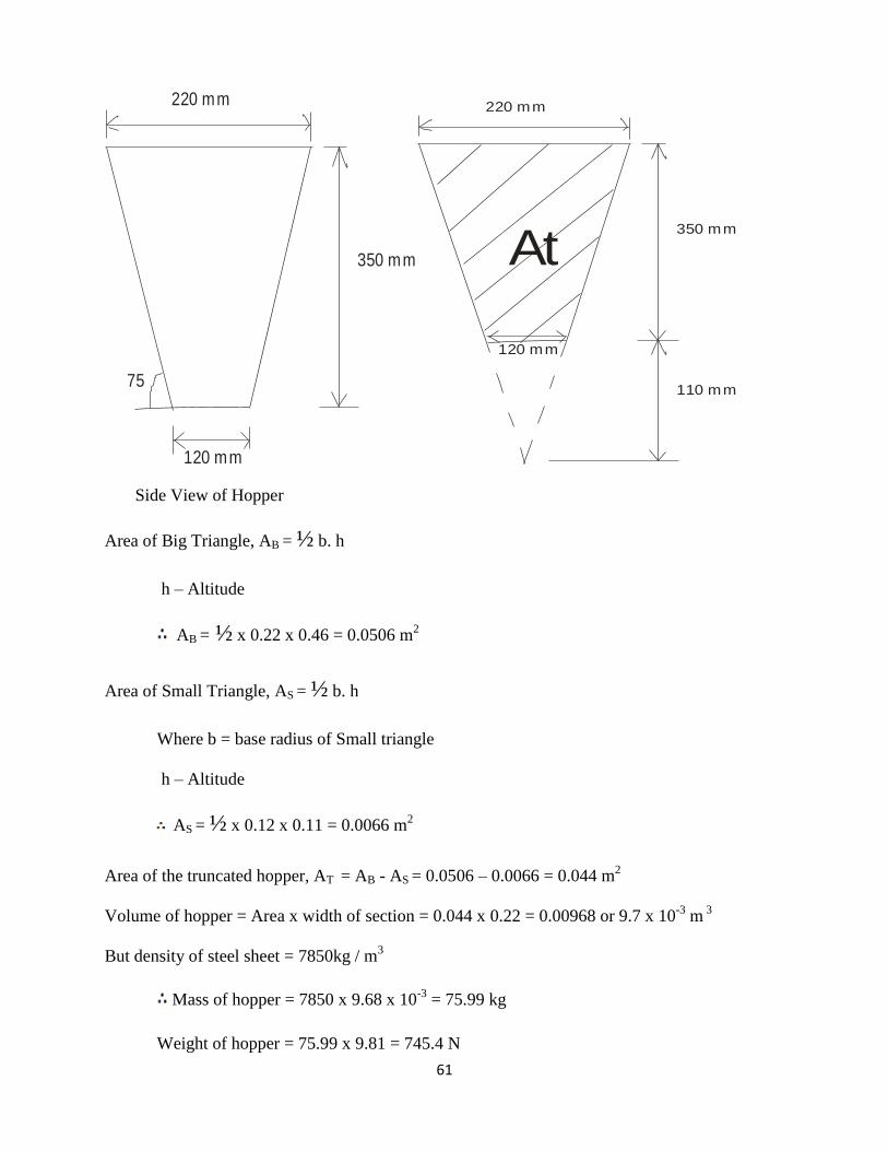
3.5.4 Hopper Design Specification
The following assumptions are made so as to choose the dimensions for the hopper
Volume of material
Shape of material
Angle of repose
The hopper is considered to be a frustum. The height is 350 mm and the top and base radii 220
mm and 120 mm respectively.
61
220 mm
350 mm
120 mm
75
220 mm
350 mm
120 mm
110 mm
At
Side View of Hopper
Area of Big Triangle, AB = ½ b. h
h – Altitude
AB = ½ x 0.22 x 0.46 = 0.0506 m2
Area of Small Triangle, AS = ½ b. h
Where b = base radius of Small triangle
h – Altitude
AS = ½ x 0.12 x 0.11 = 0.0066 m2
Area of the truncated hopper, AT = AB - AS = 0.0506 – 0.0066 = 0.044 m2
Volume of hopper = Area x width of section = 0.044 x 0.22 = 0.00968 or 9.7 x 10⁻³
m 3
But density of steel sheet = 7850kg / m3
Mass of hopper = 7850 x 9.68 x 10-3
= 75.99 kg
Weight of hopper = 75.99 x 9.81 = 745.4 N

62
Assumed mass of fruits = 5 kg
Bulk density = = 5 kg / 9.68 x 10³
Bulk density of fruits = 516.5 or 517 kg / m3
Weight of fruit = 5 kg x 9.81 = 49. 05 N

63
3.5.5 Shaft Design
The shaft was made up of ductile material to resist cyclic load. It was designed against bending
and torsion failures and the design is governed by the maximum shear stress
theory
A
B CPulley
100mm 810 mm
Torque transmitted by shaft, T is given by
T = = 0.713 x 103 x 60 / 2 x 466.7 = 14.60 x 10
3 N –mm
T = 14.60 x 10³
N – mm . . . . . . . (xii)
Tangential force acting on pulley, FTA is given by
FTA = T / RA where RA is the radius of the pulley . . . . (xiii)
Substitute the value of T in (xii) into (xiii) we have,
FTA = =146 N
Total load acting downwards on the shaft at A = FTA + WA + weight of spiral rods + blades on
shaft
Where WA is the weight of the pulley
Assumed mass of pulley = 1 kg
Therefore, weight of pulley = 1 x 9.81 = 9.81 N
Assumed weight of spiral rod + blades = 1 x 9.81 = 9.8 N
The total load acting on the shaft at A = 146 + 9.81 +9.81 = 165.62 N
64
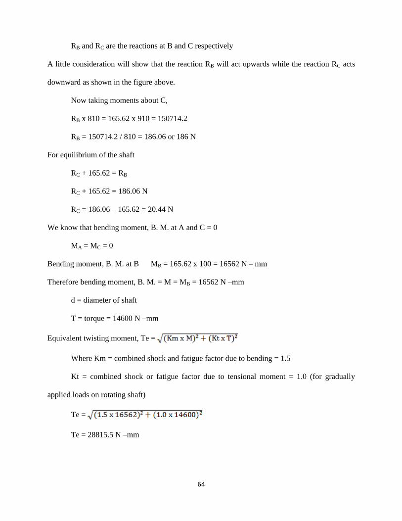
RB and RC are the reactions at B and C respectively
A little consideration will show that the reaction RB will act upwards while the reaction RC acts
downward as shown in the figure above.
Now taking moments about C,
RB x 810 = 165.62 x 910 = 150714.2
RB = 150714.2 / 810 = 186.06 or 186 N
For equilibrium of the shaft
RC + 165.62 = RB
RC + 165.62 = 186.06 N
RC = 186.06 – 165.62 = 20.44 N
We know that bending moment, B. M. at A and C = 0
MA = MC = 0
Bending moment, B. M. at B MB = 165.62 x 100 = 16562 N – mm
Therefore bending moment, B. M. = M = MB = 16562 N –mm
d = diameter of shaft
T = torque = 14600 N –mm
Equivalent twisting moment, Te =
Where Km = combined shock and fatigue factor due to bending = 1.5
Kt = combined shock or fatigue factor due to tensional moment = 1.0 (for gradually
applied loads on rotating shaft)
Te =
Te = 28815.5 N –mm

65
But equivalent twisting moment,
Te = x x d3
= 42 Mpa (allowable shear stress)
d = shaft diameter
28815.5 = x 42 x d3
d3
=
= 3494.2 mm3
d3
= 3494.2 mm3
d = = 15 mm say 25 mm
Also Equivalent bending moment, Me =
Me = [Km x M + Te] = [1.5 x 16562 + 28815.5] = 26829.25
Me = 26829.25
b = 56 Mpa (maximum tensile or permissible stress)
Me = x b x d3
26829.25 = x 56 x d3
d3
=
= 4880 mm3
d3 = 4880 mm
3
d = = 17 mm say 25 mm

66
A
B CPulley
100mm 810 mm
910 mm
34 . 04 x 1000 N - mm
359.6 N Rcv
RBV
AB C
A CB
A B C
35960 N - mm
(A) space diagram
(B) Torque diagram
(D) vertical bendingMoment diagram
(C) vertical
Load diagram
Bending Moment and Shear Force Diagram
3.5.6 Auger Conveyor Specification
The shaft was translated into an auger with crushing blades mounted at an angle of 900
on the
circumference of the spiral rods at equal distance in helical arrangement and made parallel to
each other. These blades strike the fruit which are displaced. These blades repeat impact and
rubbing actions on the crushed mass and perform series of cyclic operations. Figure 9 shows the
auger design and table shows the design specifications.
Blade length = 25 mm
Thickness = 1 mm Width =12 mm

67
Figure 9: An auger design and specification
A – Auger pitch
D – Outside diameter of auger
d – Outside diameter of auger shaft
E – Length of intake opening
L – Effective length of conveyance
B – Blade length, T – Blade thickness, W – Blade width
Table 5: Auger Conveyor Specifications
S/N Legend Auger Diameter (mm)
1
2
3
4
5
6
7
8
A
D
d
E
L
B
W
T
72
52
25
100
480
25
12
1

68
3.6 Performance Evaluation of the Extractor
The machine was tested in the Department of Mechanical Engineering Fabrication
Workshop. The test was carried out into two different stages. Stage 1, the free test run (without
load) and stage 2 involves testing with load (i.e. fruits) under different weights (1kg, 1.5kg and
2kg) of fruit slice (8 and 16 slices). The test was replicated six (6) times (i.e. 3 weights for each
individual slice lengths of 8 and 16 respectively). A stop watch and weighing balance were used
to ascertain the time of extraction and measuring the quantity of the extracted fruit and cake.
The performance of the extractor was evaluated in terms of;
Juice yield, Jy = W2 / W2+W3 x 100
Extraction loss, EL = W1 – (W2+W3) / W1 x 100
Extraction efficiency, EJ = W2 / W5 x 100
Throughput capacity = W1 / hr
Where W1 = Weight of fresh orange,
W2 = Weight of juice obtained,
W3 = Weight of wet cake,
W5 = Weight of juice obtainable,
3.7 Philosophy of the Design
In this design, the use of an electric motor (1hp) to obtain a large mechanical advantage on the
power shaft in masticating and macerating fruits will be adopted for juice extraction. The
pressure that will be made available on the shaft which is to be translated/converted to an auger
will be great so that it is able to crush by mastication with the cutter blades and make the juice
bearing cells release their contents as the shaft auger is rotated along its horizontal axis.

69
Figure 10: Orthographic Projection of the Extractor
70
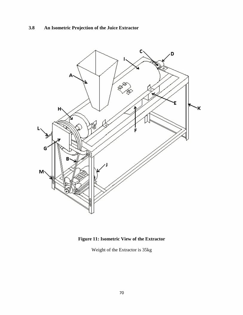
3.8 An Isometric Projection of the Juice Extractor
Figure 11: Isometric View of the Extractor
Weight of the Extractor is 35kg

71
3.8.1 Components of the Extractor
LEGEND NAME
A Hopper
B Transmission Belt
C Power Shaft Assembly
D Bearing
E Pulp Outlet
F Juice Outlet
G Shaft Protection
H Seal
I Cylindrical Drum
J Electric Motor
K Frame and Support
L Bolt
M Adjustable Port
3.9 Description of the Extractor Component Parts
3.9.1 Hopper
The hopper will be fitted directly above the cylindrical drum. It shall be made of steel material
and will be designed to accommodate the allowable volume required of the mass of fruits
(assume 5kg). The fruits are to run down the hopper into the cylinder by means of gravity. The
hopper will be inclined at an assumed angle assumed to be 75°. The hopper is in form of a
frustum.

72
3.9.2 Cylindrical Drum
Its main function is to collect the squeezed juice and pulp via its outlet. The cylinder will be
fabricated from 3 mm galvanized steel sheet with an appropriate diameter 16.5cm and length 68
cm. The cylindrical drum will be housing the cylindrical mesh sieve that will be responsible for
sieving the masticated and macerated fruits. The cylinder will be designed to have two outlets
(juice outlet and pulp/fibre outlet) attached to it to aid in juice and pulp collection.
3.9.3 Cylindrical Mesh Sieve
This is going to be responsible for sieving the crushed and pulverized fruits. it is designed to
cover the rotation shaft in such a way that both of them will be situated inside the cylindrical
drum. It shall be manufactured from galvanized steel sheet of an appropriate diameter 12.5 cm
inlet diameter, 6.7 cm outlet diameter and 1.2 mm thickness. The length of the sieve/strainer is
51cm. The pressing operation shall take place inside this cylindrical which will be perforated
with circular holes (openings 2mm x 2mm) to allow the passage of the expelled juice into the
juice outlet created in the cylindrical drum
3.9.4 Concave
It is a mesh of semi circle shape in between the drum and the sieve and the concave clearance is
25 mm and the minimum clearance between blades and sieve surfaces needed for mastication
and maceration was equal to the fruit size sliced / fed into the system, thus; reducing drum
clearance tends to reduce drum losses and increase seed damage.
73
3.9.5 Power Shaft
The rotating shaft will be translated to form a conveyor auger. Cutter blades and nylon brushes
will be welded to it to aid mastication (crushing) and maceration (softening). The shaft auger
ensures that the pulverized fruits are conveyed throughout the whole process until the pulp is
finally collected from the fibre outlet. The rotating shaft auger is going to be directly attached to
a bearing and a pulley and power will be transmitted from an electric motor through belt
transmission to the drive shaft auger. Shaft shall be sized on the basis of strength, stress,
deformation and rigidity.
3.9.6 Frame and Supports
The main frame shall be made of mild steel of considerable strength and size in which the whole
system will rest upon. In order to withstand the pressure exerted by the shaft during extraction,
the frame and supports must be appropriately considered so that the design doesn’t collapse or
rupture.
74
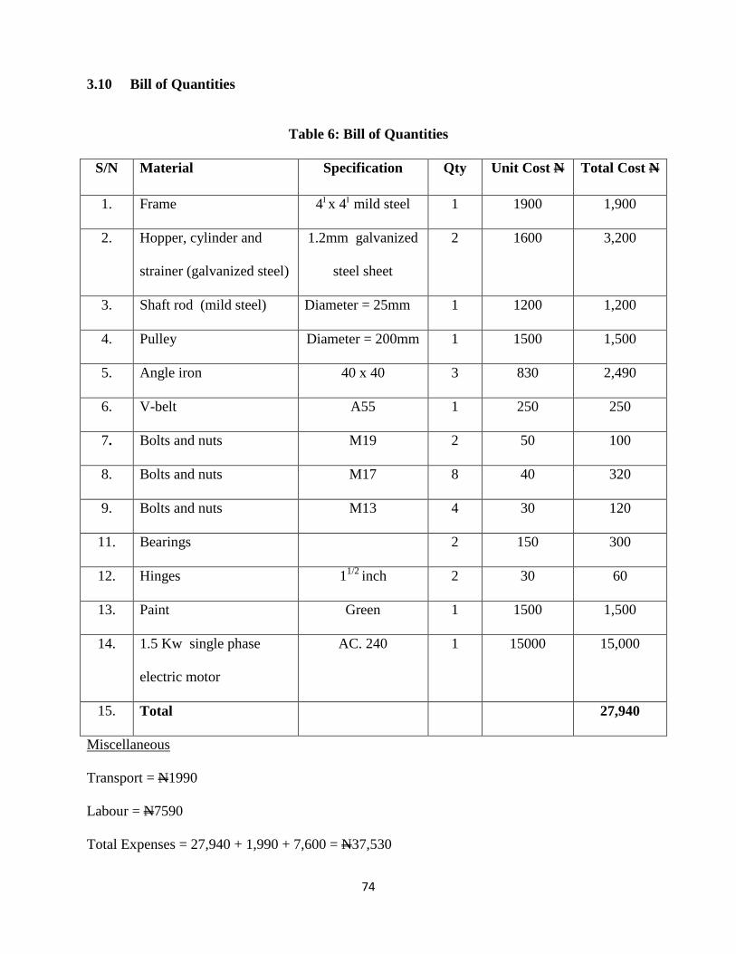
3.10 Bill of Quantities
Table 6: Bill of Quantities
S/N Material Specification Qty Unit Cost N Total Cost N
1. Frame 4I x 4I mild steel 1 1900 1,900
2. Hopper, cylinder and
strainer (galvanized steel)
1.2mm galvanized
steel sheet
2 1600 3,200
3. Shaft rod (mild steel) Diameter = 25mm 1 1200 1,200
4. Pulley Diameter = 200mm 1 1500 1,500
5. Angle iron 40 x 40 3 830 2,490
6. V-belt A55 1 250 250
7. Bolts and nuts M19 2 50 100
8. Bolts and nuts M17 8 40 320
9. Bolts and nuts M13 4 30 120
11. Bearings 2 150 300
12. Hinges 11/2
inch 2 30 60
13. Paint Green 1 1500 1,500
14. 1.5 Kw single phase
electric motor
AC. 240 1 15000 15,000
15. Total 27,940
Miscellaneous
Transport = N1990
Labour = N7590
Total Expenses = 27,940 + 1,990 + 7,600 = N37,530

75
4.0 RESULTS AND DISCUSSION
Table 7: Summary of Appendix 1, 2 and 3
Measurements Minimum Maximum Mean
Angle of repose,
75.00
76.00
75.53
Coefficient of friction,
=tan
3.73
4.01
3.88
Orange seed length
(cm)
1.50
1.65
1.58
Orange seed width
(cm)
0.48
0.65
0.56
Orange seed height
(cm)
0.86
1.12
1.01
Orange fruit length
(cm)
7.10
7.90
7.50
Orange fruit width
(cm)
6.25
6.73
6.52
Orange fruit height
(cm)
6.63
7.20
6.96
76
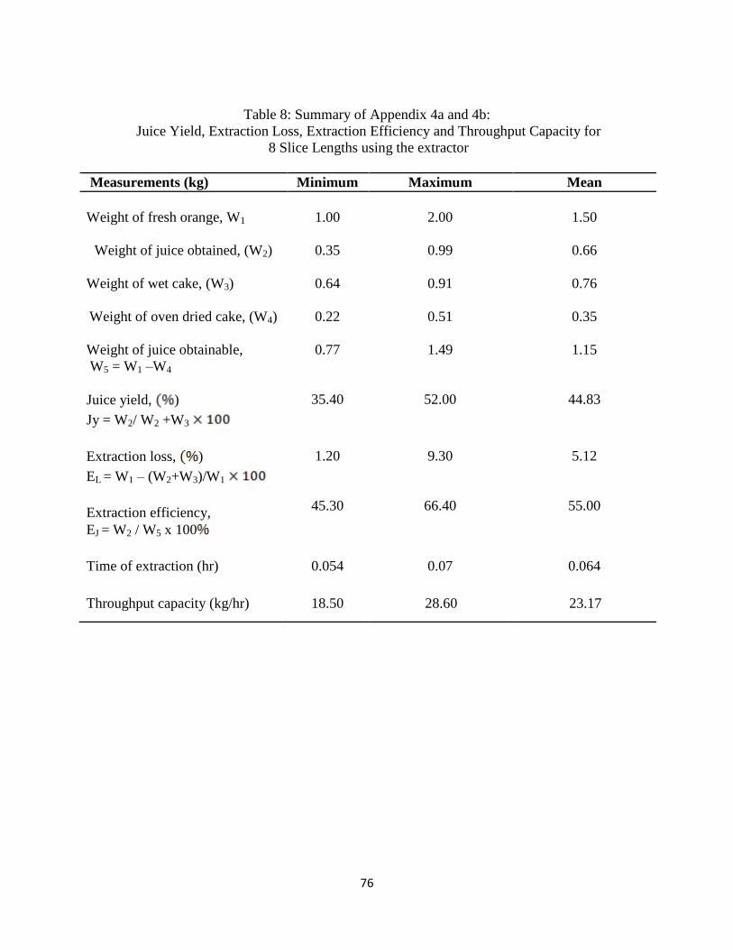
Table 8: Summary of Appendix 4a and 4b:
Juice Yield, Extraction Loss, Extraction Efficiency and Throughput Capacity for
8 Slice Lengths using the extractor
Measurements (kg) Minimum Maximum Mean
Weight of fresh orange, W1
1.00
2.00
1.50
Weight of juice obtained, (W2)
0.35
0.99
0.66
Weight of wet cake, (W3)
0.64
0.91
0.76
Weight of oven dried cake, (W4)
0.22
0.51
0.35
Weight of juice obtainable,
W5 = W1 –W4
0.77
1.49
1.15
Juice yield, )
Jy = W2/ W2 +W3
35.40
52.00
44.83
Extraction loss, )
EL = W1 – (W2+W3)/W1
Extraction efficiency,
EJ = W2 / W5 x 100
1.20
45.30
9.30
66.40
5.12
55.00
Time of extraction (hr) 0.054 0.07 0.064
Throughput capacity (kg/hr) 18.50 28.60 23.17

77
Table 9: Summary of Appendix 4a and 4b:
Juice Yield, Extraction Loss, Extraction Efficiency and Throughput Capacity for
16 Slice Lengths using the extractor
Measurements (kg) Minimum Maximum Mean
Weight of fresh orange, (W1)
1.00
2.00
1.50
Weight of juice obtained, (W2)
0.46
1.20
0.79
Weight of wet cake, (W3)
0.48
0.67
0.60
Weight of oven dried cake, (W4)
0.08
0.26
0.19
Weight of juice obtainable,
W5 = W1 –W4
0.92
1.76
1.32
Juice yield, )
Jy = W2/ W2 +W3
48.90
64.60
58.80
Extraction loss, )
EL = W1 – (W2+W3)/W1
Extraction efficiency,
EJ = W2 / W5 x 100
0.60
50.00
9.00
68.20
7.35
57.70
Time of extraction (hr) 0.05 0.066 0.057
Throughput capacity (kg/hr) 20.00 30.30 25.83

78
Table 10: Summary of Appendix 5a and 5b: Juice Yield, Extraction Efficiency using the
Hand pressing method
Measurements (kg) Minimum Maximum Mean
Weight of fresh orange, (W1)
1.00
2.00
1.50
Weight of juice obtained, (W2)
0.22
0.51
0.36
Weight of wet cake, (W3)
0.78
1.49
1.14
Weight of oven dried cake, (W4)
0.15
0.25
0.21
Weight of juice obtainable,
W5 = W1 –W4
0.85
1.75
1.30
Juice yield, )
Jy = W2/ W2 +W3
22
26
24
Extraction efficiency,
EJ = W2 / W5 x 100
28
29.1
28.5
Time of extraction (hr) 0.14 0.29 0.21
NOTE: An orange contains about 0.036kg of juice
1kg orange contains 0.22kg juice

79
4.1 DISCUSSION OF RESULTS
The effects of fruit slice lengths on juice yield, extraction efficiency and extraction loss
are shown in figures 9, 10 and 11 respectively. The figure revealed that 16 sliced lengths gave
the maximum juice yield of 64.60 % while the corresponding extraction efficiency was 68.20%.
Also, the minimum extraction loss of 0.6 % was obtained for 16 sliced lengths. This showed that
the 16 sliced lengths was the best for preparing fruits for juice extraction.
Results also showed that juice yield and extraction efficiency decreased while extraction loss
increased with increase in fruit size slice lengths. This is in agreement with the findings of
Wagami (1979) and Ishiwu and Oluka (2004) while evaluating the performances of millet
thresher and a juice extractor, respectively and also the findings of Oyeleke and Olaniyan (2007)
while evaluating the performance of a small scale multi – fruit juice extractor. Fruit slice lengths
is an indication of surface area of the fruit and juice cells exposed to maceration and pressing
action. This study showed that surface area of fruits is an important factor to consider when
preparing fruits for juice extraction.

80
Figure 9: Effect weight of fruit slice on juice yield

81
Figure 10: Effect of weight of fruit slice on extraction efficiency

82
Figure 11: Effect of weight of fruit slice on extraction loss

83
5.0 CONCLUSION AND RECOMMENDATION
5.1 Conclusion
A machine was designed and constructed to extract fruit juice from orange fruit to
forestall the usual wastage during peak harvest on most orchards in Nigeria. The machine was
tested and found workable. From the test result carried out using the juice extractor and the hand
squeezing method, it was found out that the rate of extraction increases as the weight of fruit
increased with a corresponding increase in the juice yield and extraction efficiency. The average
juice extraction efficiency and throughput were 57.70 % and 25.83 % respectively. The present
study showed that juice yield and extraction efficiency decreased while extraction loss increased
with increase in the size of fruit slices. Juice yield, extraction efficiency and extraction loss from
16 slice lengths oranges ranged between 48.90 – 64.60 %, 50.00 – 68.20 % and 0.6 – 7.35 %
respectively. The higher extraction efficiency (mean value) of 57.70 % of the juice extractor
showed that the extraction rate is more efficient than that f the hand squeezing method which has
extraction efficiency (mean value) of 28.5 %. This showed that the juice extractor can be used
for small and medium juice processing business in rural and urban communities.

84
5.2 Recommendations
In order to obtain an efficient juice extraction, the following recomrnendation should be
considered.
1. 16 slice lengths of orange fruit should be prepared when using the juice extractor
2. Nylon brushes should be incorporated into the machine in order to increase the fruit
maceration capacity and efficiency of conveyance and discharge of residual products.
3. To avoid contamination o the extracted juice, stainless steel materials should be used in
the overall fabrication of the machine.
4. The length of the cylindrical sieve can be extended to a few centimetres to ensure
thorough mastication and maceration of the fruit cells

85
REFERENCES
Adegoke, B. (1991). Testing and evaluation of locally constructed hammer mill and feed mixer.
Unpublished HND project report submitted to the Federal College of Agriculture, Moore
plantation Ibadan.
Ajibola O.O. Adetunji S.O. and Owolarafe O.K. (2000). Oil pressure of sesame seed. Ife
Journal of Technology. 9(1), 57-62.
Ajibola O.O. Okunade D.A. and Owolarafe O.K. (2002). Oil point pressure of soybean. Journal
of Food Process Engineering. 25: 407-416.
Ashurt, P.R. (1991). History of Fruit Drinks and Food Flavouring. Rumbold, New York.
PP 9-35.
Daniel, E.A. (1985). Processes of size reduction. Agricultural Engineering international: the
CIGR Ejournal. Vol iv. PP 66 -72
Droste, J. (2001). Vibrational Energy brakes fine powered problem and Nutritional content in
some vegetables. Trans. of ASAE (11): 171- 178.
Earle, R.L. (1983). Unit Operations in Food Processing. Published by NZIFST (Inc.) Chapter 11
Egan, H. R., Kochlar, S.L. (1981). Tropical Crops Macmillan Publisher Limited.
Ezekiel, A. O. (1985). Processing of Agricultural products. Unpublished B. Eng. Project report
submitted to Agricultural. Engineering Dept. University of Nigeria, Nsukka
FAO, (1991). Small – scale processing in African http://www.fao.org. pp. 1-8.
FMC, (2000). Principles and practices of small and medium-scale fruit juice processing
http://www.fao.org. Chapter 11.
Ihekoronye and Ngoddy (1985). Processing of Vegetable Products. The Plant Equipment and
System Journal for Processing Industries. Pp 56-58
Ishiwu, C. N. and Oluka, S.I. 2004. Development and performance evaluation of a juice
extractor. Proceedings of the 5th
International Conference and 26th
Annual General
Meeting of the Nigerian Institution of Agricultural Engineers 26, 391 – 395.
Joshi D.C., Das S.K. and Mokheijiec R.K. (1993). Physical Properties of Pumpkin. Journal of
Agricultural Engineering, 54(3), pp: 219-229.
Khurmi, R.S. and Gupta, J.K. (2005). A Text Book of Machine Design. Eurasia Publishing
House (prt) Ltd. New Delhi, India.
Michael, L.J. (1977). Physical Properties of Food and Food Processing Systems, Pp 23 – 26

86
Otterloo, S. (1997). Preservation of Fruits and Vegetables. Agrodoc Publications. The
Netherlands.75pp.
Oyeleke, F.I. and Olaniyan, A.M. (2007). Extraction of juice from some tropical fruits using a
small scale multi – fruit juice extractor. African Crop Science Conference Proceedings
Vol. 8. pp. 1803 – 1808
Sukuruman C.R. and Singh B.P.N. (1989). Compression of bed of rape seed; the oil point.
Journal of Agricultural Engineering Research. 42: 77-84.
Wagami, S.Y. 1979. Design and fabrication of a prototype thresher for millet. Unpublished
B.Sc Thesis, Department of Agricultural Engineering, Ahmadu Bello University, Zaria,
Nigeria. pp 3 -5
INTERNET REFERENCES
http://www.crusher-mill.com/Products/Crushers/Capital-Saving-Jaw-Crusher.html
http://www.fao.org/wairdocs/x5434e/x5434e0j.htm#53.0%20presses
http://www.fao.org/wairdocs/x5434e/x5434e0j.htm#55.0%20pulpers%20and%20juicers
http://suppliers.jimtrade.com/165/164131/186333.htm
87
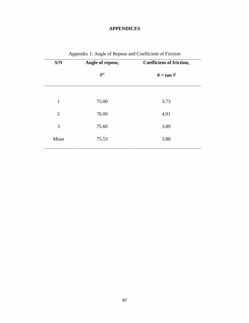
APPENDICES
Appendix 1: Angle of Repose and Coefficient of Friction
S/N Angle of repose,
Coefficient of friction,
= tan
1
2
3
Mean
75.00
76.00
75.60
75.53
3.73
4.01
3.89
3.88

88
Appendix 2: Orange Seed Axial Dimension (cm)
S/N Length Width Height
1
2
3
4
5
6
7
8
9
10
Mean
1.65 0.60
1.50 0.50
1.50 0.65
1.62 0.55
1.55 0.48
1.65 0.59
1.60 0.52
1.59 0.53
1.62 0.60
1.58 0.56
1.58 0.56
0.97
1.09
1.10
0.91
1.06
0.92
1.12
0.86
0.95
1.09
1.01

89
Appendix 3: Orange Fruit Axial Dimension (cm)
S/N Length Width Height
1
2
3
4
5
6
7
8
9
10
Mean
7.50 6.50
7.60 6.70
7.65 6.73
7.55 6.48
7.60 6.60
7.50 6.40
7.30 6.40
7.90 6.73
7.10 6.25
7.25 6.37
7.50 6.52
7.00
7.10
7.20
6.90
7.00
6.90
6.86
7.20
6.63
6.84
6.96

90
Appendix 4a: Results of Evaluation for the juice extractor
Slice
Length
(cm)
Weight of
fresh orange,
W1 (kg)
Weight of juice
obtained, W2
(kg)
Weight of
wet cake, W3
(kg)
Weight of
oven dried
cake, W4 (kg)
Weight of juice
obtainable,
W5 = W1 –W4
(kg)
8 Slice
length
1
1.5
2
0.35
0.64
0.99
0.64
0.72
0.91
0.22
0.30
0.51
0.77
1.20
1.49
Mean
1.5
0.66
0.76
0.35
1.15
16
Slice
length
1
1.5
2
0.46
0.70
1.20
0.48
0.67
0.66
0.08
0.26
0.24
0.92
1.28
1.76
Mean
1.5
0.79
0.60
0.19
1.32

91
Appendix 4b: Results of Evaluation
Slice
Length
(cm)
Weight of
fresh
orange, W1
(kg)
Juice
yield
(
Extraction
efficiency
( )
Extraction
loss ( )
Time of
extraction
(hr)
Throughput
capacity
(kg/hr)
8 Slice
length
1
1.5
2
35.40
47.10
52.00
45.30
53.30
66.40
1.20
9.30
4.85
0.054
0.067
0.07
18.50
22.40
28.60
Mean
1.5
44.83
55.00
5.12
0.064
23.17
16
Slice
length
1
1.5
2
48.90
51.00
64.60
50.00
55.00
68.20
0.60
9.00
7.05
0.05
0.055
0.066
20.00
27.20
30.30
Mean
1.5
54.80
57.70
7.35
0.057
25.83

92
Appendix 5a: Results of Evaluation using the hand pressing method
S/N Weight of
fresh orange,
W1 (kg)
Weight of juice
obtained, W2
(kg)
Weight of
wet cake, W3
(kg)
Weight of oven
dried cake, W4
(kg)
Weight of juice
obtainable,
W5 = W1 –W4
(kg)
1
2
3
1
1.5
2
0.22
0.36
0.51
0.78
1.14
1.49
0.15
0.23
0.25
0.85
1.29
1.75
Mean
1.5
0.36
1.14
0.21
1.30
Appendix 5b: Results of Evaluation using the hand pressing method
S/N Weight of fresh orange,
W1 (kg)
Juice yield
(
Extraction efficiency
( )
Time of extraction
(hr)
1
2
3
1
1.5
2
22
24
26
28
28.3
29.1
0.14
0.21
0.29
Mean
1.5
24
28.5
0.21