Emotron M10 Shaft Power Monitor
34
Emotron M10 Shaft Power Monitor Instruction manual English
-
Upload
khangminh22 -
Category
Documents
-
view
3 -
download
0
Transcript of Emotron M10 Shaft Power Monitor
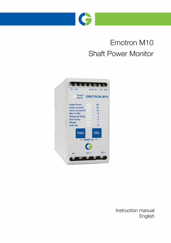
Emotron M10
Shaft Power Monitor
Instruction manualEnglish


Contents
1 Inside the box ............................................................................. 3
2 Safety .......................................................................................... 4
3 Description.................................................................................. 5
4 Getting Started ........................................................................... 6
4.1 Please take note of the safety section...................................................... 64.2 Connection and set-up before first start ................................................... 6
5 Wiring .......................................................................................... 8
5.1 Latched or un-latched alarm................................................................... 10
6 Selecting the current transformer .......................................... 11
6.1 For motors up to 50 A ............................................................................. 11
7 Operation .................................................................................. 13
7.1 LED ........................................................................................................... 137.2 Auto Set .................................................................................................... 14
8 Programming ............................................................................ 16
9 Parameter list ........................................................................... 20
9.1 Terminals.................................................................................................. 21
10 Technical data .......................................................................... 22
10.1 Dismantling and disposal........................................................................ 2510.2 US specifications ..................................................................................... 2510.3 Canada specifications ............................................................................. 25
11 Service....................................................................................... 27
12 Appendix ................................................................................... 28
CG Drives & Automation 01-5973-01r0 1

2 CG Drives & Automation 01-5973-01r0

1 Inside the box
Please check the delivery. Despite the fact that all products from CG Drives & Automation are carefully inspected and packed, transport damage may occur:
• Your shipment should contain the Emotron M10 shaft power monitor, a current transformer, 2x terminal covers (optional*) and this instruction manual.
• Check carefully that the equipment ordered complies with the motor's input voltage and that the current transformer rating is as stated on the delivery note.
• Check that the contents have not been damaged during transport.
• If something is missing, or has been damaged, contact the supplier as well as the forwarding agent within 48 hours of receipt.
NOTE: If in doubt contact your supplier before installing or commissioning the product.
*)
CG Drives & Automation 01-5973-01r0 Inside the box 3

2 Safety
• Read this manual thoroughly before installing and using the Emotron M10.
• The Emotron M10 must be installed by qualified personnel.
• Always disconnect supply circuits prior to installation.
• The installation must comply with standard and local regulations.
• Pay special attention to the information in this chapter and the parts marked WARNING and CAUTION in the chapter on operation.
• Check that the Emotron M10 and the equipment are correctly connected before use.
• Should questions or uncertainties arise, please contact your local sales outlet or see Chapter 11 page 27, Service.
• Faults that arise due to faulty installation or operation are not covered by the warranty.
NOTE: Removing or tampering with the seal on the housing will invalidate the warranty.
4 Safety CG Drives & Automation 01-5973-01r0

3 Description
This instruction manual describes the installation and commissioning of the Emotron M10 shaft power monitor. The Emotron M10 is a single function monitor intended for machine builders and OEMs. It is the ideal choice for price sensitive applications requiring only basic under- or overload protection. For more advanced load monitoring we recommend the Emotron M20 shaft power monitor.
The Emotron M10 is well suited for supervising induction motor driven equipment, such as centrifugal pumps, magnetic pumps, mixers, scrapers, crushers and conveyors in applications with drive motors of up to 50 A. It can also be used as an electronic shear pin (Motors max. 50A).
The Emotron M10 provides reliable monitoring and protection, optimizing production equipment and minimizing expensive breakdowns and interruptions. It immediately detects any abnormal condition and initiates a warning. If the normal machine load level is exceeded, the internal relay changes state and the alarm LED turns red (LED is green at normal load). The output relay contact can be used for alarm indication and/or for machine shut-down.
Shaft power is calculated by measuring motor input power and subtracting the motor power loss calculated using a unique principle. Calculating shaft power gives more reliable supervision than non-linear techniques, such as current and phase angle measurements. Current measurement is only sufficient at high motor loads and phase angle only at low loads. Input power, sometimes called true or real power, is linear but ignores motor power loss.
Using the motor as its own sensor means no external sensors or extra cabling are required. By taking into account the motor power losses, the monitor is able to accurately measure the shaft power supplied by the motor to the application. This advanced technique allows the Emotron M10 to monitor the "application load" rather than the total motor load, which includes the varying motor losses.
The monitor is easy to install and is mounted on a standard DIN rail. It is easy to select and set up the function you wish to use, for example under- or overload protection, relay function, response delay or alarm margin. The "Auto Set" function can be used to set the desired load level automatically.
For further information, visit www.emotron.com/www.cgglobal.com.
CG Drives & Automation 01-5973-01r0 Description 5

4 Getting Started
4.1 Please take note of the safety section1. Pay special attention to the safety section in this manual and the parts
marked CAUTION.2. Check that the motor/supply voltage corresponds to the values on the
Emotron M10 product label at the side of the monitor.
3. Make a note of the motor's rated power and rated current from its nameplate. Confirm that the current transformer supplied is of the correct size according to table 1, page 11 in this manual.
4.2 Connection and set-up before first start1. Connect the Emotron M10 according to Chapter 5 and Fig. 1.2. Make sure all safety measures have been implemented and switch on the
supply voltage - Power LED turns green.
3. Minimum parameters to be set are "Rated Power" and desired relay function "Max or Min", see Chapter 8, Table 2, 3 and Fig. 6.
4. Press PAR once - "LED" AUTO SET turns green.
5. Keep pressing PAR until the desired parameter is selected e.g. RATED POWER, see Chapter 8, Table 2 and 3.
6. Press VAL - Factory set value or earlier set value flashes e.g. "64".
7. Keep pressing VAL until desired value is displayed (0 - 64).
8. Confirm chosen value by pressing PAR.
9. Press PAR again and repeat steps 4 to 8 for all parameters except for AUTO SET. See Chapter 8, Table 2, 3 and Fig. 6 for possible value settings for each of the eight parameters.
10. Start and run the motor/system at normal load conditions, also wait until the START DELAY has expired.
6 Getting Started CG Drives & Automation 01-5973-01r0

HINT!Short-circuit the output relay during the set-up, this prevents the equipment stopping unintentionally, see Hint! in Chapter 5.
11. Press PAR once - "LED" AUTO SET turns green.
12. Press and hold VAL for 3 seconds, at normal machine load. The Auto Set load level is automatically set and the LED is switched off.
13. Set/reset e.g. start delay, response delay, margin, etc. if necessary (see Chapter 8, Table 2, 3 and Fig. 6).
If the machines "normal" load level is exceeded, the internal relay change state and the alarm LED turns red (LED is green at normal load).
CG Drives & Automation 01-5973-01r0 Getting Started 7

5 Wiring
The following wiring diagram provides an example of how the Emotron M10 can be connected to control the start/stop circuit of a three-phase motor, Fig. 1, page 8. Connections to a single-phase motor are described later in this manual (Fig. 2).
1. The current transformer CTMXXX must be placed in the same phase that isconnected to terminal 9, phase L1, see Fig. 1. Failure to follow thisrequirement will result in the monitor failing to function.
2. For single-phase connection see Fig. 2, page 9.
Normally the appropriate current transformer (CTM XXX) will have been ordered and shipped with the Emotron M10. Check that this is the case; see Chapter 6 page 11 Selection of current transformer, contact the supplier if in doubt.
When using DC voltage, terminal 6 should be connected to negative polarity (ground) and terminal 5 to positive polarity (max. 48 VDC), see Fig. 1, page 8. See also the alternative auxiliary circuit Fig. 11, page 30.
Fig. 1 Standard wiring 3-phase motors (alternatively see Fig. 11, page 30)
5
8
7
6
21
13
11
9
CTMxxx
L3L2L1
K1
K1
RESS1 S2
L2
L3
L1 C
NO
NCM10
U V W
M
K1
Max. 240 VAC (alt. 0 VDC-)
Stop
Start
N (alt. 48 VDC+)
Please see CTM information on table 1, page 11 .Note: Monitor voltage, see note on page 9.
8 Wiring CG Drives & Automation 01-5973-01r0

HintIf the START/STOP is connected as per Fig. 1, it is recommended that terminals 6 and 7 be bypassed during settings. After the settings are completed the bypass must be taken out.
Please use the enclosed plastic (rubber) insert (if ordered, optional) to cover the monitor terminals.
Alternative example for single-phase connectionThis wiring example shows the alternative connection to be made with regard to a single-phase connection. Refer to Fig. 1 for the remaining wiring.
Fig. 2 Single-phase wiring example (alternatively see Fig. 10, page 29)
NOTE: The current transformer (CTMxxx) must be placed in the same phase that is connected to terminal 9, phase L1, see Fig. 1. Make sure that the Emotron M10 voltage range e.g. 3x100-600 VAC matches the connected motor/line voltage, e.g. 3x400V.
K1
L N
M
M10NC
NO
CL1
L3
L2
S2S1RES
L1N
CTMxxx
9
11
13
1 2
6
7
8
5
CG Drives & Automation 01-5973-01r0 Wiring 9

5.1 Latched or un-latched alarm
Fig. 3 Wiring example for latched or un-latched alarm.
When using DC voltage, alternatively see Fig. 11, page 30.If terminal 5 is not connected, see Fig. 3, the alarm is not automatically reset when the machine load is normal again after an alarm situation. The alarm is then latched; function "Latched alarm". The alarm can then be manually reset by pressing both PAR and VAL buttons at the same time for 3 seconds. It is only possible to reset an alarm if the power level is on the "right side" of the set alarm level (depending on under- or overload monitoring).
If, however, terminal 5 is connected to an AC or DC signal the alarm will be reset automatically (un-latched alarm). This is only possible if the power level is on the "right side" of the set alarm level.
Un-Latched (Auto Reset)when voltage supplied toterminal 5 and 6.Latched Alarm whenterminal 5 and 6 opened(not connected).
RESET
5 6 7 8 5 6 7 8
MAX 240 VAC (alt. DC-)N (alt. DC+)
Unlatched(Auto Reset)
Latched
10 Wiring CG Drives & Automation 01-5973-01r0

6 Selecting the current transformer
6.1 For motors up to 50 A1. Check the rated motor current on the motor plate.2. Compare this value with the rated motor current in Table 1.
3. From Table 1, select the current transformer and the appropriate numbers of windings.
6.1.1 ExampleRated motor current = 12 A.
• Select 10.1 - 12.5 A from the first column in table 1 and choose CTM 025 with two (2) primary windings (the motor wire is drawn through the CTM hole twice).
In order to ensure an accurate calibration of the Emotron M10, it is essential that you use the correct CTM and apply the exact number of windings in accordance with the above table.
Table 1 Current transformer and number of primary windings.
RATED MOTOR CURRENT (A)Number of primary windings
CTM010 CTM025 CTM050
0.4 - 1.0 10
1.01 - 2.0 5
2.01 - 3.0 3
3.1 - 5.0 2
5.1 - 10.0 1
10.1 - 12.5 2
12.6 - 25 1
26 - 50A 1
NOTE: Max. length of CTM cable is 1 m (39 inches). For motors with rated current over 50 A Emotron M20 must be used, contact your supplier.
CG Drives & Automation 01-5973-01r0 Selecting the current transformer 11

Fig. 4 Example CTM 025 with 2 windings for a 12 A motor
Fig. 5 Example 1, 2 and 3 windings.
NOTE: Normally the appropriate Current Transformer (CTM XXX) will have been ordered and shipped with the Emotron M10. Check that this is the case; contact the supplier if in doubt.
CAUTION! Terminals 1 and 2 (S1, S2) carry live voltage.
NOTE: The current transformer connection and orientation are not polarity sensitive, but must be connected to the same phase that is being referenced for terminal 9 of the Emotron M10.
L1L2L3
1 2
S1 S2
M3
M10
2 windingsCTM025
P2
1 2
P2
5:1 5:2 5:3
12 Selecting the current transformer CG Drives & Automation 01-5973-01r0

7 Operation
Make sure that the enclosed plastic (rubber) insert (if ordered, optional) covers the monitor terminals before you start programming.
If the normal machine load level is exceeded, the internal relay changes state and the Power/Alarm LED turns red. The LED is green at "power on" and at normal load.
7.1 LED• A constant green LED indicates a parameter type.
• A flashing green LED indicates a value.
Under normal system operation, the eight LEDs are all off (see table 2, page 18). Any illuminated LEDs will be automatically switched off 30 seconds after the last key press.
CG Drives & Automation 01-5973-01r0 Operation 13

7.2 Auto SetThe alarm load level is automatically set by the Auto set function, see Chapter 8
The value for a parameter, e.g. seconds, kW, HP or margin, can only be set as 0, 1, 2, 4, 8, 16, 32 or 64. Select closest value.
The Emotron M10 with article number 01-3160-00 "Fast Response" (M10 FR) is identical with the standard Emotron M10 except for where the start-up delay and the response delay are shorter than below:
• Article number 01-2487-10 standard Emotron M10:RESPONSE DELAY: 0.05 - 64 sSTART-UP DELAY: 1 - 64 s
• Article number 01-3160-00 "Fast Response" (M10 FR):RESPONSE DELAY: 0.05 - 6.4 sSTART-UP DELAY: 0.1 - 6.4 s
PARParameter change (LED light constant green) - pressing PAR key when parameter is displayed proceeds to next parameter.
VALValue setting - Pressing VAL key when green LED is flashing increases value. A changed value is confirmed by pressing PAR.
Reset inputTerminal 5 and 6 are used for external reset and selection of latched/unlatched alarm.
Current inputTerminal 1 and 2. Current Transformer; CTM 010, 025 or 050 (Max. 50 A motor).
Relay outputTerminal 6, 7 and 8 output relay.
Motor terminalsTerminal 9 (L1), 11 (L2) and 13 (L3) for supply and motor voltage input.
Power/AlarmThe Power/Alarm LED turns green at "power on" and at normal load. Red at alarm.
ResetReset a latched alarm by pressing both PAR and VAL at the same time for 3 seconds.
14 Operation CG Drives & Automation 01-5973-01r0

The Emotron M10 is a single function monitor intended for machine builders and OEMs. It is the ideal choice for price sensitive applications requiring only basic under- or overload protection. If the operator needs to know the normal load level and set load level of the output shaft power either in percent or kW/HP the Emotron M20 must be used.
CG Drives & Automation 01-5973-01r0 Operation 15

8 Programming
Set-up and program the Emotron M10 according the "Example" on page 17, see also table 2, page 18, table 3, page 19 and Fig. 7, page 19. In Chapter 4 more information and hints are given about connection and set-up before the first start-up.
Fig. 6 Parameter change and value setting.
64
32
16
8
4
2
1
0
Rated Power
Relay Inverted
Block Current =0
Max or Min
Response Delay
Start Delay
Margin
Aut set
Parameter change(LED light constant green)
Value setting(Green LED is flashing)
16 Programming CG Drives & Automation 01-5973-01r0

When the Emotron M10 is installed, the machine is running, and the normal machine load level is exceeded, the internal relay changes state and the Power/Alarm LED turns red. The LED is green at normal load.
Example: Conveyor with overload protectionConveyor with overload protection, motor 11 kW (Fig. 7, page 19).
1. Check output power on motor plate and see table 3 (11 kW = Rated MotorPower 6.1- 12) - setting 8.
2. Switch on the supply voltage - Power LED green.
3. Press PAR once - “LED” AUTO SET turns green.
4. Keep pressing PAR until RATED POWER is selected, see Fig. 6, page 16.
5. Press VAL - Value “64” flashes (factory setting).
6. Set recommended value according to table 3. Keep pressing VAL until chosen value (8) flashes.
7. Confirm chosen value by pressing PAR.
8. Press PAR again and select MAX.
9. Press VAL. Choose the factory setting MAX - Overload Protection - “1”.
10. Confirm chosen value (1) by pressing PAR.
11. Press PAR again and select RELAY INVERTED.
12. Press VAL. Choose the factory setting “no” = “0”.
13. Confirm chosen value (0) by pressing PAR.
The above parameters are necessary to set for safe functioning. Note that “Rated power”for the motor must be set before Auto Set.
HintChange the load on the machine to find out if appropriate load limit margin is set correctly. You can also reduce the margin by one or more steps to find out at what level the machine will trip. See Fig. 7, page 19. Set/reset e.g start delay, response delay, trip margin etc. if necessary (see table 2, page 18).
CAUTION!Make sure that all safety measures have been taken before switching on the supply voltage and starting the motor/machine in order to avoid personal injury.
CG Drives & Automation 01-5973-01r0 Programming 17

More hints• If the alarm level is difficult to set - simply perform an Auto Set when the
motor is stopped. Then start the machine, run at normal load and perform an Auto Set again.
• If a wrong value is unintentionally set - simply set a new value. If the value is not confirmed by pressing PAR, the new value is not accepted (time out after 30 seconds).
Table 2 Parameters and values.
Parameter ValueFactory setting
Note
RATED POWER 0 1 2 4 8 16 32 64 64 See table 3
RELAY INVERTED 0 (no) 1 (yes) 0 0 = Relay activated at alarm
ALARMCURRENT = 0
0 (no) 1 (yes) 0 Alarm at no motor current
MAX OR MIN 0 (MIN) 1 (MAX) 10 = under load 1 = overload alarm
RESPONSE DELAY
0 1 2 4 8 16 32 64 2Response delay in seconds (0=50 ms)
START DELAY 0 1 2 4 8 16 32 64 2 Start delay in seconds
MARGIN (% of rated power)
0 1 2 4 8 16 32 64 8Load change for alarm sensitivity, Fig. 7
AUTO SET
Auto Set load level is automatically set if VAL key is pressed for 3 seconds.
VAL key must be pressed when LED parameter AUTO SET is light. LED bar is switched off when Auto Set level is set.
18 Programming CG Drives & Automation 01-5973-01r0

Fig. 7 Alarm level and margin.
Table 3 Setting of rated motor power.
Setting Rated motor power in kW or HP
0 0 - 0.5
1 0.51 - 1.5
2 1.51 - 2.5
4 2.51 - 6
8 6.1 - 12
16 12.1 - 24
32 24.1 - 48
64 48.1 - 75
Alarm level
Power at AUTO SET(Auto Set load Level)
Power
t(underload monitor)
Start-up
Underload
(MIN)
Margin
Underload protection
Power at AUTO SET(Auto Set load Level)
Alarm level
Power
t
(overload monitor)
Start-up Overload (MAX)
Margin
Overload protection
CG Drives & Automation 01-5973-01r0 Programming 19

9 Parameter list
Table 4 Parameter list
ParameterFactory setting
Actual setting Alt. setting
Rated power 64
Relay inverted 0
Alarm current = 0 0
Max or Min 1
Response delay 2
Start delay 2
Margin 8
20 Parameter list CG Drives & Automation 01-5973-01r0

9.1 Terminals
1) Note! Terminals 1 and 2 (S1, S2) carry line voltage.2) N must be connected to terminal 11 and 13 (single phase).
Table 5 Terminals and labels
Terminal Label Function
1 S1Current transformer input for CTM 010, CTM 025 or CTM 050, blue wire1
2 S2 Current transformer input, brown wire1)
3 (not used)
4 (not used)
5 RESReset input. Latched or unlatched alarm is selected via this input. Connect to + at DC.
6 CAlarm relay common and also reset common. Connect to “-” at DC.
7 NC Alarm relay normally closed
8 NO Alarm relay normally open
9 L1 Motor voltage phase L1
10 (not used)
11 L2 Motor voltage phase L2 (N for single phase motors)2)
12 (not used)
13 L3 Motor voltage phase L3 (N for single phase motors)2)
CG Drives & Automation 01-5973-01r0 Parameter list 21

10 Technical data
Dimensions (WxHxD)
45x90x115 mm (1.77" x 3.54" x 4.53")
Mounting 35 mm DIN-rail 46277
Weight 175 g (5.65 oz)
Supply voltage (VAC)*1x100-240 (± 10 %)3x100-600 (± 10 %)3x600-690 (± 10 %)
Frequency 50 or 60 Hz
Current inputCurrent transformers; CTM 010, 025 or 050 (Max 50 A motor)
Power consumption Max 3 W
Start-up delay 1-64 s (“Fast response, see page 14; 0.1 - 6.4s)
Response delay0.05-64 s (“Fast response, see page 14; 0.05 - 6.4s)
Relay output5 A/240 VAC Resistive, 1.5 A/240 VAC Pilot duty/AC12
Fuse Max 10 A
Terminal wire size
Use 75°C copper (CU) wire only.0.2-4.0 mm2 single core (AWG12).0.2-2.5 mm2 flexible core (AWG14),stripp length 8 mm (0.32")
Terminal tightening torque 0.56-0.79 Nm (5-7 lb-in)
Repeatability ± 2.5% FS, 24 H, @ +25 °C (+77°F)
Temperature tolerance <0.1%/°C
����� ��������� �����
� ��
������
����
������
����
�����
22 Technical data CG Drives & Automation 01-5973-01r0

*)Please note that these are separate voltage units; see table 6 with ordernumbers
10.0.1 Technical Data for Current Transformer (CT)
*) Weight including 1 m (39 inch) cable. Please note that max. length of the CT cable is 1 m and this cable can not be extended.
External RESET on term. 5Max 240 VAC or 48 VDC. High:24 VAC/DCLow:< 1 VAC/DC. Reset >50 ms
Operating temperature -20 (4°F) – +50 °C (+122°F)
Storage temperate -30 (22°F) – +80 °C (+176°F)
Protection class IP20
RoHS directive 2002/95/EC
Approved to CE (up to 690VAC), UL and cUL (up to 600 VAC)
Table 6 Order numbers and designation
Order number Designation
01-2487-15 Emotorn M10 1x100-240/3x100-690 VAC
01-3160-05 Emotorn M10 1x100-240/3x100-690 VAC “Fast response”
TypeDimensions
(WxØ) Weight* Mounting
CTM 010 27(35) X Ø48mm 0.20 kg 35mm DIN rail 46277
CTM 025 27(35) X Ø48mm 0.20 kg 35mm DIN rail 46277
CTM 050 27(35) X Ø48mm 0.20 kg 35mm DIN rail 46277
CG Drives & Automation 01-5973-01r0 Technical data 23

Fig. 8 Current Transformer CTxxx.
10.0.2 Accessories and documentation
Order number Designation
01-2471-10 Current Transformer (CT) CTM010, max. 10A
01-2471-20 Current Transformer (CT) CTM025, max. 25A
01-2471-30 Current Transformer (CT) CTM050, max. 50A
01-2368-00 Front Panel Kit 1 (2x terminal covers included)
01-4136-01 2x terminal covers
01-5973-00 Instruction manual (Swedish)
01-5973-01 Instruction manual (English)
48
27
17
35
4. 3
78
45
35
42
10. 3
24 Technical data CG Drives & Automation 01-5973-01r0

10.1 Dismantling and disposalThe product is designed to comply with the RoHS directive, and shall be handled and recycled in accordance with local legislations.
EU (European Union) specifications
EMC EN 61000-6-3, EN 61000-6-2EN 61000-4-5
Electrical safety EN 60947-5-1Rated insulated voltage 690 VRated impulse withstand voltage 4000 VPollution degree 2Terminals 3, 4, 5, 6, 7 and 8 are basic insulated from the line.Terminals 3 and 4 are basic insulated from terminals 5, 6, 7 and 8.
10.2 US specifications
FCC (Federal Communications Commission)This equipment has been tested and found to comply with the limits for a Class A digital device pursuant to Part 15 of the FCC Rules. These limits are designed to provide reasonable protection against harmful interference when the equipment is operated in a commercial environment. This equipment generates, uses and can radiate radio frequency energy and, if not installed and used in accor-dance with the instruction manual, may cause harmful interference, in which case, the user will be required to correct the interference at their own expense.
10.3 Canada specifications
DOC (Department of communications)This digital apparatus does not exceed the Class A limits for radio noise emissions from digital apparatus as set out in the Canadian Interference-Causing Equipment Regulations. Le présent appareil numérique n’émet pas de bruits radioélectriques dépassant les limites applicables aux appareils numériques de la classe A prescrites dans le Règlement sur le brouillage radioélectrique édicté par le ministère des Communications du Canada.
CG Drives & Automation 01-5973-01r0 Technical data 25

26 Technical data CG Drives & Automation 01-5973-01r0

11 Service
This manual is valid for the following model:
Emotron M10.
CG Drives & Automation Sweden AB reserves the right to alter product specifications without prior notification. No part of this document may be reproduced without permission from CG Drives & Automation AB.
For more information contact your local sales outlet or visit us at: www.emotron.com/www.cgglobal.com
Protected by utility patents EP 1027759 and US 6879260
Document number: 01-5973-01
Document version: r0
Date of release: 2012-04-02
CG Drives & Automation 01-5973-01r0 Service 27

12 Appendix
Fig. 9 M10 connection example
5876
2
1
13119
CTM
xxx
L3L2L1
K1
K1
RES
S1S2
L2 L3L1C NO
NC
M10
UVW
M
K1
Max. 240 VAC (alt. 0 VDC-)
Stop Start
N
Plea
se s
ee C
TM in
form
atio
n on
tabl
e 1
, pag
e 11
.N
ote:
Mon
itor
volta
ge,
see
note
on
page
9.
(alt. 48 VDC+)
28 Appendix CG Drives & Automation 01-5973-01r0

Fig. 10 M10 single-phase connection example
K1
LN M
M10
NC
NO
CL1 L3L2
S2S1
RES
L1 N CTM
xxx
9 11 13
1
2
6 7 8 5
CG Drives & Automation 01-5973-01r0 Appendix 29

Fig. 11 M10 example of auxiliary circuit when VDC is used.
24VD
C+
0VDC-
5876
2
1
13119
CTM
xxx
L3L2L1
RES
S1S2
L2 L3L1C NO
NC
M10
UVW
M
30 Appendix CG Drives & Automation 01-5973-01r0


CG D
rives
& A
utom
atio
n 0
1-5
973
-01
r0 2
01
2-0
4-0
2
CG Drives & Automation Sweden ABMörsaregatan 12
Box 222 25
SE-250 24 HelsingborgSweden
T +46 42 16 99 00
F +46 42 16 99 49www.cgglobal.com / www.emotron.com