LCD Monitor - pro.sony
30
LCD Monitor 4-281-140-14(1) © 2011 Sony Corporation Instructions for Use Before operating the unit, please read this manual thoroughly and retain it for future reference. LMD-2110MD
-
Upload
khangminh22 -
Category
Documents
-
view
0 -
download
0
Transcript of LCD Monitor - pro.sony
LCD Monitor
4-281-140-14(1)
© 2011 Sony Corporation
Instructions for UseBefore operating the unit, please read this manual thoroughly and retain it for future reference.
LMD-2110MD
2
Owner’s Record
The model and serial numbers are located at the rear. Record these numbers in the spaces provided below. Refer to these numbers whenever you call upon your Sony dealer regarding this product.
Model No. ____________________Serial No. ____________________
WARNING
To reduce the risk of fire or electric shock, do not expose this apparatus to rain or moisture.
To avoid electrical shock, do not open the cabinet. Refer servicing to qualified personnel only.
No modification of this apparatus is allowed.
WARNINGTHIS APPARATUS MUST BE EARTHED.
To disconnect the main power, unplug the AC plug.
CAUTIONThe apparatus shall not be exposed to dripping or splashing. No objects filled with liquids, such as vases, shall be placed on the apparatus.
WARNINGMake sure the surface is wide enough so that this apparatus’s width and depth don’t exceed the surface’s edges.If not, this apparatus may lean or fall over and cause an injury.
Consult with Sony qualified personnel for mounting arm, wall or ceiling mount installation.
Do not install the appliance in a confined space, such as book case or built-in cabinet.
For the customers in the U.S.A.This equipment has been tested and found to comply with the limits for a Class A digital device, pursuant to Part 15 of the FCC Rules. These limits are designed to provide reasonable protection against harmful interference when the equipment is operated in a commercial environment. This equipment generates, uses, and can radiate radio frequency energy and, if not installed and used in accordance with the instruction manual, may cause harmful interference to radio communications. Operation of this equipment in a residential area is likely to cause harmful interference in which case the user will be required to correct the interference at his own expense.
You are cautioned that any changes or modifications not expressly approved in this manual could void your authority to operate this equipment.
All interface cables used to connect peripherals must be shielded in order to comply with the limits for a digital device pursuant to Subpart B of Part 15 of FCC Rules.
This device complies with Part 15 of the FCC Rules. Operation is subject to the following two conditions: (1) this device may not cause harmful interference, and (2) this device must accept any interference received, including interference that may cause undesired operation.
WARNING:Using this unit at a voltage other than 120 V may require the use of a different line cord or attachment plug, or both. To reduce the risk of fire or electric shock, refer servicing to qualified service personnel.
For the customers in CanadaThis Class A digital apparatus complies with Canadian ICES-003.
For the customers in CanadaThis unit has been certified according to Standard CAN/CSA-C22.2 No. 60601-1.
For the customers in the U.S.A and CanadaWhen you use this product connected to 240 V single phase, be sure to connect this product to a center tapped circuit.
For the customers in EuropeThis product has been manufactured by or on behalf of Sony Corporation, 1-7-1 Konan Minato-ku Tokyo, 108-0075 Japan. Inquiries related to product compliance based on European Union legislation shall be addressed to the authorized representative, Sony Deutschland GmbH, Hedelfinger Strasse 61, 70327 Stuttgart, Germany. For any service or guarantee matters, please refer to the addresses provided in the separate service or guarantee documents.
Important safeguards/notices for use in the medical environments1. All the equipments connected to this unit shall be
certified according to Standard IEC60601-1, IEC60950-1, IEC60065 or other IEC/ISO Standards applicable to the equipments.
2. Furthermore all configurations shall comply with the system standard IEC60601-1-1. Everybody who connects additional equipment to the signal input part or signal output part configures a medical system, and is therefore, responsible that the system complies with the requirements of the system standard IEC60601-1-1.
If in doubt, consult the qualified service personnel.3. The leakage current could increase when connected
to other equipment.4. For this particular equipment, all accessory
equipment connected as noted above, must be connected to mains via an additional isolation transformer conforming with the construction requirements of IEC60601-1 and providing at least Basic Insulation.
5. This equipment generates, uses, and can radiate radio frequency energy. If it is not installed and used in accordance with the instruction manual, it may cause interference to other equipment. If this unit causes interference (which can be determined by unplugging the power cord from the unit), try these measures: Relocate the unit with respect to the susceptible equipment. Plug this unit and the susceptible equipment into different branch circuit.
Consult your dealer. (According to standard EN60601-1-2 and CISPR11, Class B, Group 1)
6. Model LMD-2110MD is a monitor intended for use in a medical environment to display pictures from cameras or other systems, other than diagnostic X-ray equipment.
WARNINGWhen installing the unit, incorporate a readily accessible disconnect device in the fixed wiring, or connect the power plug to an easily accessible socket-outlet near the unit. If a fault should occur during operation of the unit, operate the disconnect device to switch the power supply off, or disconnect the power plug.
CautionWhen you dispose of the unit or accessories, you must obey the laws in the relative area or country and the regulations in the relative hospital.
WARNING on power connectionUse a proper power cord for your local power supply.1. Use the approved Power Cord (3-core mains lead) /
Appliance Connector / Plug with earthing-contacts that conforms to the safety regulations of each country if applicable.
2. Use the Power Cord (3-core mains lead) / Appliance Connector / Plug conforming to the proper ratings (Voltage, Ampere).If you have questions on the use of the above Power Cord / Appliance Connector / Plug, please consult a qualified service personnel.
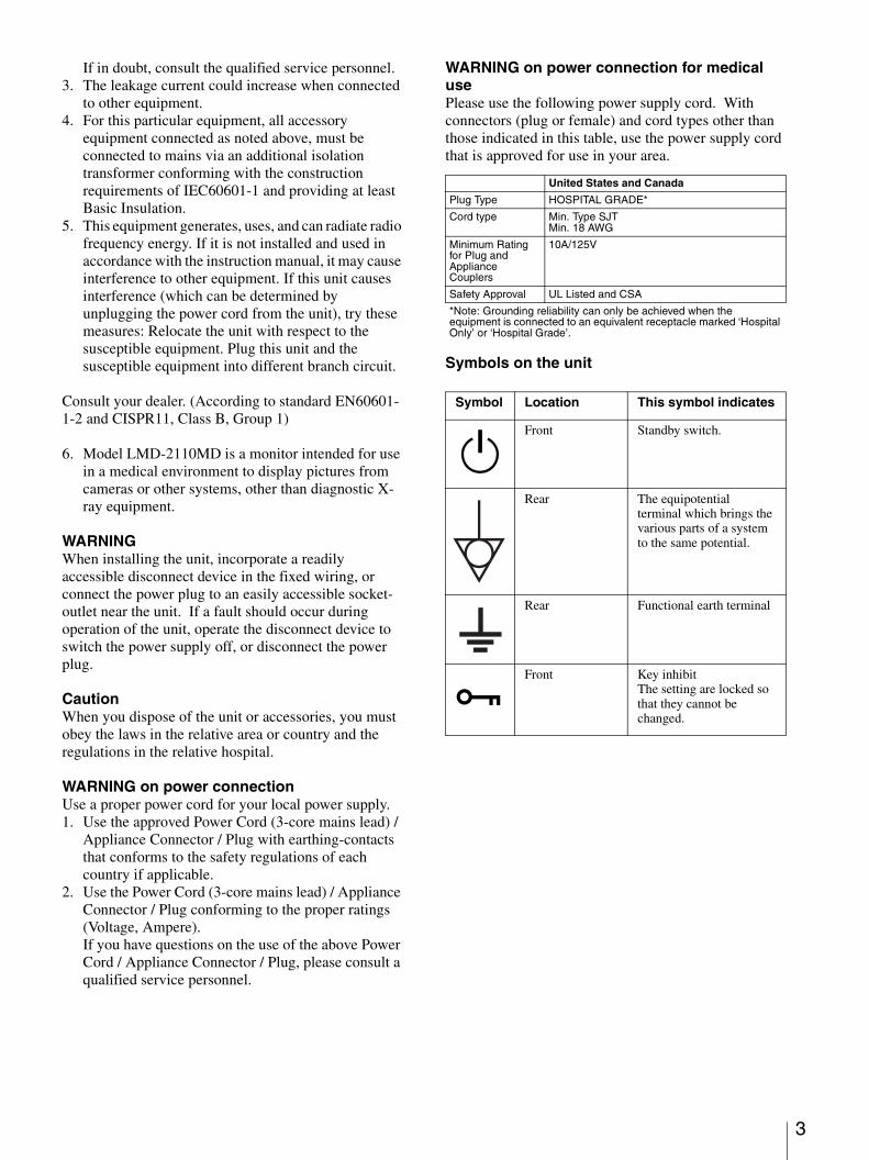
WARNING on power connection for medical usePlease use the following power supply cord. With connectors (plug or female) and cord types other than those indicated in this table, use the power supply cord that is approved for use in your area.
*Note: Grounding reliability can only be achieved when the equipment is connected to an equivalent receptacle marked ‘Hospital Only’ or ‘Hospital Grade’.
Symbols on the unit
United States and Canada
Plug Type HOSPITAL GRADE*
Cord type Min. Type SJTMin. 18 AWG
Minimum Rating for Plug and Appliance Couplers
10A/125V
Safety Approval UL Listed and CSA
Symbol Location This symbol indicates
1Front Standby switch.
Rear The equipotential terminal which brings the various parts of a system to the same potential.
Rear Functional earth terminal
-Front Key inhibit
The setting are locked so that they cannot be changed.
3
4
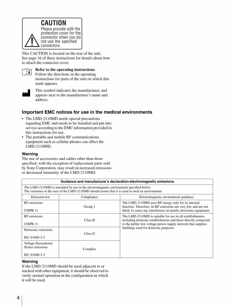
This CAUTION is located on the rear of the unit.See page 16 of these instructions for details about how to attach the connector cover.
Refer to the operating instructionsFollow the directions in the operating instructions for parts of the unit on which this mark appears.
This symbol indicates the manufacturer, and appears next to the manufacturer’s name and address.
Important EMC notices for use in the medical environments• The LMD-2110MD needs special precautions
regarding EMC and needs to be installed and put into service according to the EMC information provided in this instructions for use.
• The portable and mobile RF communications equipment such as cellular phones can affect the LMD-2110MD.
WarningThe use of accessories and cables other than those specified, with the exception of replacement parts sold by Sony Corporation, may result in increased emissions or decreased immunity of the LMD-2110MD.
WarningIf the LMD-2110MD should be used adjacent to or stacked with other equipment, it should be observed to verify normal operation in the configuration in which it will be used.
CAUTIONPlease provide with theprotection cover for theconnector when you donot use the specifiedconnectors.
Guidance and manufacturer’s declaration-electromagnetic emissions
The LMD-2110MD is intended for use in the electromagnetic environment specified below.The customer or the user of the LMD-2110MD should assure that it is used in such an environment.
Emission test Compliance Electromagnetic environment-guidance
RF emissions
CISPR 11Group 1
The LMD-2110MD uses RF energy only for its internal function. Therefore, its RF emissions are very low and are not likely to cause any interference in nearby electronic equipment.
RF emissions
CISPR 11Class B
The LMD-2110MD is suitable for use in all establishments, including domestic establishments and those directly connected to the public low-voltage power supply network that supplies buildings used for domestic purposes.
Harmonic emissions
IEC 61000-3-2Class D
Voltage fluctuations/flicker emissions
IEC 61000-3-3
Complies
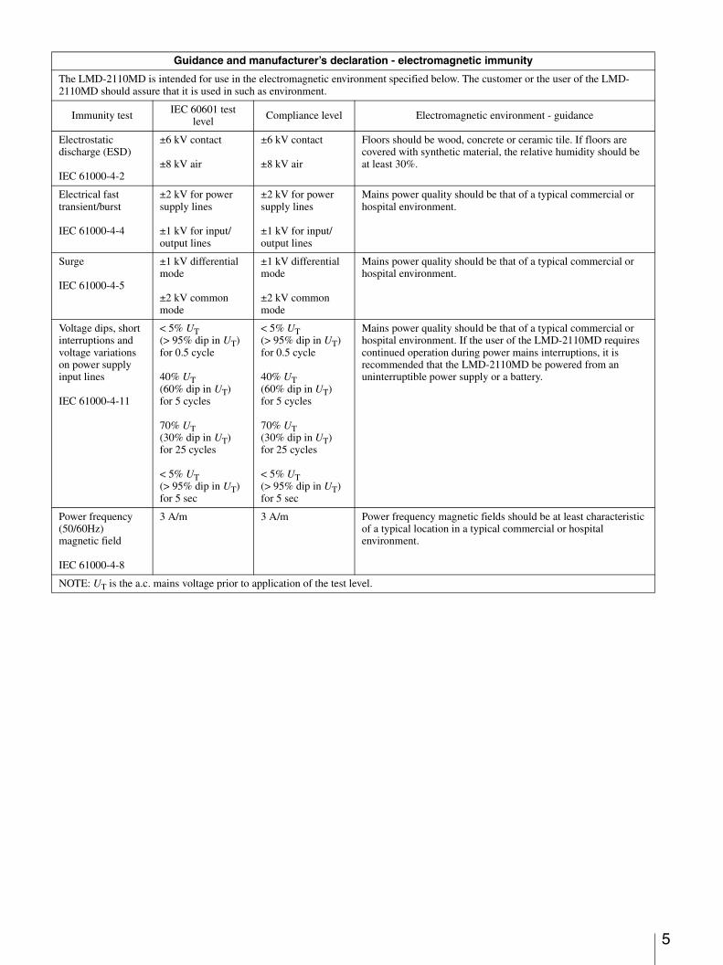
Guidance and manufacturer’s declaration - electromagnetic immunity
The LMD-2110MD is intended for use in the electromagnetic environment specified below. The customer or the user of the LMD-2110MD should assure that it is used in such as environment.
Immunity test IEC 60601 test level
Compliance level Electromagnetic environment - guidance
Electrostatic discharge (ESD)
IEC 61000-4-2
±6 kV contact
±8 kV air
±6 kV contact
±8 kV air
Floors should be wood, concrete or ceramic tile. If floors are covered with synthetic material, the relative humidity should be at least 30%.
Electrical fast transient/burst
IEC 61000-4-4
±2 kV for power supply lines
±1 kV for input/output lines
±2 kV for power supply lines
±1 kV for input/output lines
Mains power quality should be that of a typical commercial or hospital environment.
Surge
IEC 61000-4-5
±1 kV differential mode
±2 kV common mode
±1 kV differential mode
±2 kV common mode
Mains power quality should be that of a typical commercial or hospital environment.
Voltage dips, short interruptions and voltage variations on power supply input lines
IEC 61000-4-11
< 5% UT (> 95% dip in UT) for 0.5 cycle
40% UT (60% dip in UT) for 5 cycles
70% UT (30% dip in UT) for 25 cycles
< 5% UT (> 95% dip in UT) for 5 sec
< 5% UT (> 95% dip in UT) for 0.5 cycle
40% UT (60% dip in UT) for 5 cycles
70% UT (30% dip in UT) for 25 cycles
< 5% UT (> 95% dip in UT) for 5 sec
Mains power quality should be that of a typical commercial or hospital environment. If the user of the LMD-2110MD requires continued operation during power mains interruptions, it is recommended that the LMD-2110MD be powered from an uninterruptible power supply or a battery.
Power frequency (50/60Hz) magnetic field
IEC 61000-4-8
3 A/m 3 A/m Power frequency magnetic fields should be at least characteristic of a typical location in a typical commercial or hospital environment.
NOTE: UT is the a.c. mains voltage prior to application of the test level.
5
6
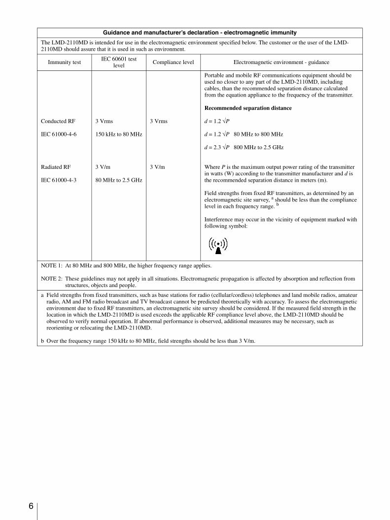
Guidance and manufacturer’s declaration - electromagnetic immunity
The LMD-2110MD is intended for use in the electromagnetic environment specified below. The customer or the user of the LMD-2110MD should assure that it is used in such as environment.
Immunity test IEC 60601 test level
Compliance level Electromagnetic environment - guidance
Conducted RF
IEC 61000-4-6
Radiated RF
IEC 61000-4-3
3 Vrms
150 kHz to 80 MHz
3 V/m
80 MHz to 2.5 GHz
3 Vrms
3 V/m
Portable and mobile RF communications equipment should be used no closer to any part of the LMD-2110MD, including cables, than the recommended separation distance calculated from the equation appliance to the frequency of the transmitter.
Recommended separation distance
d = 1.2 √P
d = 1.2 √P 80 MHz to 800 MHz
d = 2.3 √P 800 MHz to 2.5 GHz
Where P is the maximum output power rating of the transmitter in watts (W) according to the transmitter manufacturer and d is the recommended separation distance in meters (m).
Field strengths from fixed RF transmitters, as determined by an electromagnetic site survey, a should be less than the compliance level in each frequency range. b
Interference may occur in the vicinity of equipment marked with following symbol:
NOTE 1: At 80 MHz and 800 MHz, the higher frequency range applies.
NOTE 2: These guidelines may not apply in all situations. Electromagnetic propagation is affected by absorption and reflection from structures, objects and people.
a Field strengths from fixed transmitters, such as base stations for radio (cellular/cordless) telephones and land mobile radios, amateur radio, AM and FM radio broadcast and TV broadcast cannot be predicted theoretically with accuracy. To assess the electromagnetic environment due to fixed RF transmitters, an electromagnetic site survey should be considered. If the measured field strength in the location in which the LMD-2110MD is used exceeds the applicable RF compliance level above, the LMD-2110MD should be observed to verify normal operation. If abnormal performance is observed, additional measures may be necessary, such as reorienting or relocating the LMD-2110MD.
b Over the frequency range 150 kHz to 80 MHz, field strengths should be less than 3 V/m.
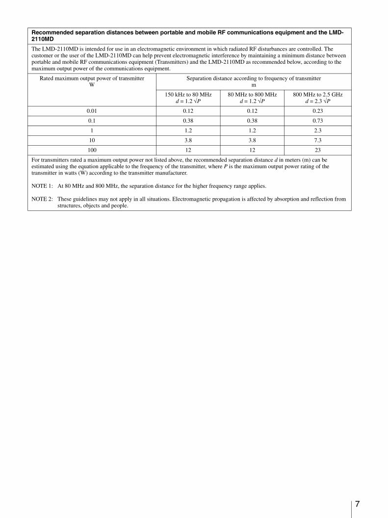
Recommended separation distances between portable and mobile RF communications equipment and the LMD-2110MD
The LMD-2110MD is intended for use in an electromagnetic environment in which radiated RF disturbances are controlled. The customer or the user of the LMD-2110MD can help prevent electromagnetic interference by maintaining a minimum distance between portable and mobile RF communications equipment (Transmitters) and the LMD-2110MD as recommended below, according to the maximum output power of the communications equipment.
Rated maximum output power of transmitter W
Separation distance according to frequency of transmitter m
150 kHz to 80 MHzd = 1.2 √P
80 MHz to 800 MHzd = 1.2 √P
800 MHz to 2.5 GHzd = 2.3 √P
0.01 0.12 0.12 0.23
0.1 0.38 0.38 0.73
1 1.2 1.2 2.3
10 3.8 3.8 7.3
100 12 12 23
For transmitters rated a maximum output power not listed above, the recommended separation distance d in meters (m) can be estimated using the equation applicable to the frequency of the transmitter, where P is the maximum output power rating of the transmitter in watts (W) according to the transmitter manufacturer.
NOTE 1: At 80 MHz and 800 MHz, the separation distance for the higher frequency range applies.
NOTE 2: These guidelines may not apply in all situations. Electromagnetic propagation is affected by absorption and reflection from structures, objects and people.
7
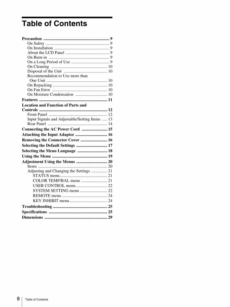
Table of Contents8
Table of Contents
Precaution .............................................................. 9On Safety ............................................................ 9On Installation .................................................... 9About the LCD Panel ......................................... 9On Burn-in ......................................................... 9On a Long Period of Use .................................... 9On Cleaning ..................................................... 10Disposal of the Unit ......................................... 10Recommendation to Use more than
One Unit ......................................................... 10On Repacking ................................................... 10On Fan Error .................................................... 10On Moisture Condensation .............................. 10
Features ................................................................ 11Location and Function of Parts and Controls ................................................................ 12
Front Panel ....................................................... 12Input Signals and Adjustable/Setting Items ..... 13Rear Panel ........................................................ 14
Connecting the AC Power Cord ........................ 15Attaching the Input Adaptor .............................. 16Removing the Connector Cover ......................... 16Selecting the Default Settings ............................. 17Selecting the Menu Language ............................ 18Using the Menu .................................................... 19Adjustment Using the Menus ............................. 20
Items ................................................................. 20Adjusting and Changing the Settings ............... 21
STATUS menu............................................. 21COLOR TEMP/BAL menu ......................... 21USER CONTROL menu.............................. 22SYSTEM SETTING menu .......................... 22REMOTE menu ........................................... 24KEY INHIBIT menu.................................... 24
Troubleshooting ................................................... 25Specifications ....................................................... 25Dimensions ........................................................... 29
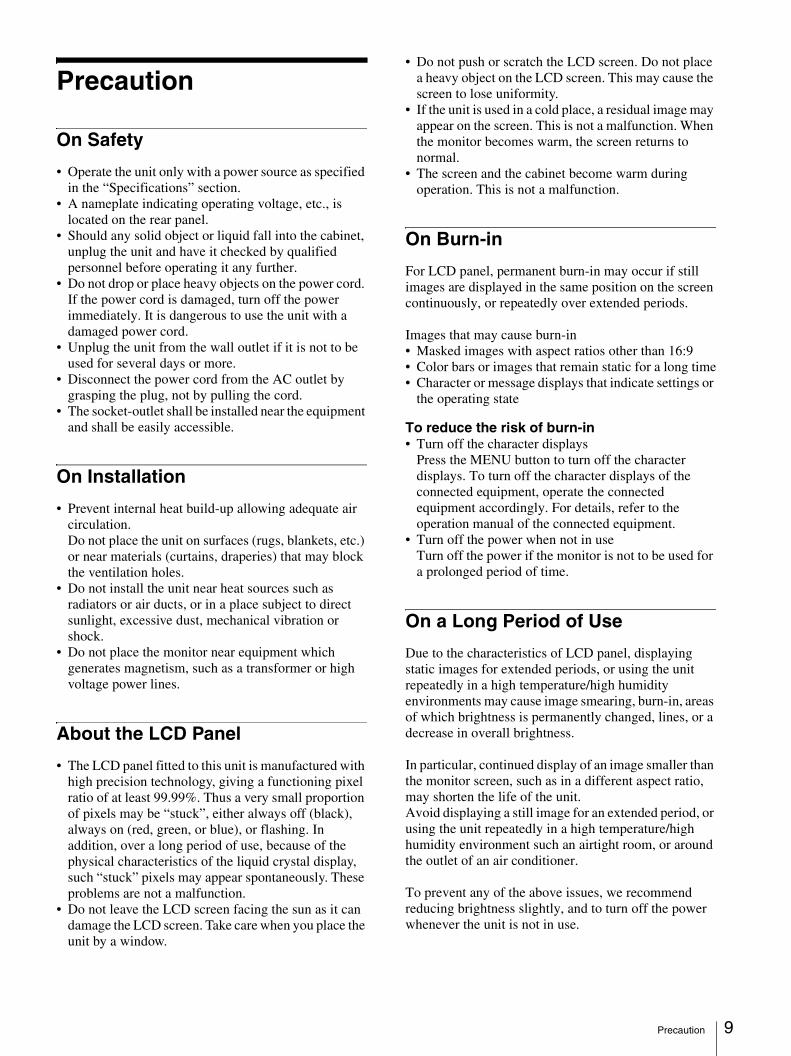
Precaution
On Safety
• Operate the unit only with a power source as specified in the “Specifications” section.
• A nameplate indicating operating voltage, etc., is located on the rear panel.
• Should any solid object or liquid fall into the cabinet, unplug the unit and have it checked by qualified personnel before operating it any further.
• Do not drop or place heavy objects on the power cord. If the power cord is damaged, turn off the power immediately. It is dangerous to use the unit with a damaged power cord.
• Unplug the unit from the wall outlet if it is not to be used for several days or more.
• Disconnect the power cord from the AC outlet by grasping the plug, not by pulling the cord.
• The socket-outlet shall be installed near the equipment and shall be easily accessible.
On Installation
• Prevent internal heat build-up allowing adequate air circulation.Do not place the unit on surfaces (rugs, blankets, etc.) or near materials (curtains, draperies) that may block the ventilation holes.
• Do not install the unit near heat sources such as radiators or air ducts, or in a place subject to direct sunlight, excessive dust, mechanical vibration or shock.
• Do not place the monitor near equipment which generates magnetism, such as a transformer or high voltage power lines.
About the LCD Panel
• The LCD panel fitted to this unit is manufactured with high precision technology, giving a functioning pixel ratio of at least 99.99%. Thus a very small proportion of pixels may be “stuck”, either always off (black), always on (red, green, or blue), or flashing. In addition, over a long period of use, because of the physical characteristics of the liquid crystal display, such “stuck” pixels may appear spontaneously. These problems are not a malfunction.
• Do not leave the LCD screen facing the sun as it can damage the LCD screen. Take care when you place the unit by a window.
• Do not push or scratch the LCD screen. Do not place a heavy object on the LCD screen. This may cause the screen to lose uniformity.
• If the unit is used in a cold place, a residual image may appear on the screen. This is not a malfunction. When the monitor becomes warm, the screen returns to normal.
• The screen and the cabinet become warm during operation. This is not a malfunction.
On Burn-in
For LCD panel, permanent burn-in may occur if still images are displayed in the same position on the screen continuously, or repeatedly over extended periods.
Images that may cause burn-in• Masked images with aspect ratios other than 16:9• Color bars or images that remain static for a long time• Character or message displays that indicate settings or
the operating state
To reduce the risk of burn-in• Turn off the character displays
Press the MENU button to turn off the character displays. To turn off the character displays of the connected equipment, operate the connected equipment accordingly. For details, refer to the operation manual of the connected equipment.
• Turn off the power when not in useTurn off the power if the monitor is not to be used for a prolonged period of time.
On a Long Period of Use
Due to the characteristics of LCD panel, displaying static images for extended periods, or using the unit repeatedly in a high temperature/high humidity environments may cause image smearing, burn-in, areas of which brightness is permanently changed, lines, or a decrease in overall brightness.
In particular, continued display of an image smaller than the monitor screen, such as in a different aspect ratio, may shorten the life of the unit. Avoid displaying a still image for an extended period, or using the unit repeatedly in a high temperature/high humidity environment such an airtight room, or around the outlet of an air conditioner.
To prevent any of the above issues, we recommend reducing brightness slightly, and to turn off the power whenever the unit is not in use.
Precaution 9
10
On Cleaning
Before cleaningBe sure to disconnect the AC power cord from the AC outlet.
On cleaning the monitorA material that withstands disinfection is used for the medical use LCD monitor. When solvents such as benzene or thinner, or acid, alkaline or abrasive detergent, or chemical cleaning cloth are used for the monitor surface, the performance of the monitor may be impaired or the finish of the surface may be damaged. Take care with respect to the following:• Clean the monitor surface with a 50 to 70 v/v%
concentration of isopropyl alcohol or a 76.9 to 81.4 v/v% concentration of ethanol using a swab method. Wipe the monitor surface gently (wipe using less than 1 N force).
• Stubborn stains may be removed with a soft cloth such as a cleaning cloth lightly dampened with mild detergent solution using a swab method and then clean using the above chemical solution.Never use solvents such as benzene or thinner, or acid, alkaline or abrasive detergent, or chemical cleaning cloth for cleaning or disinfection, as they will damage the monitor surface.
• Do not use unnecessary force to rub the monitor surface with a stained cloth. The monitor surface may be scratched.
• Do not keep the monitor surface in contact with a rubber or vinyl resin product for a long period of time. The finish of the surface may deteriorate or the coating may come off.
Disposal of the Unit
Do not dispose of the unit with general waste.Do not include the monitor with household waste.
Recommendation to Use more than One Unit
As problems can occasionally occur for the monitor, when the monitor is used for safety control of personnel, assets or stable picture, or for emergencies, we strongly recommend you use more than one unit or prepare a spare unit.
On Repacking
Do not throw away the carton and packing materials. They make an ideal container which to transport the unit.If you have any questions about this unit, contact your authorized Sony dealer.
On Fan Error
The fan for cooling the unit is built in. When the fan stops and the - indicator on the front panel blinks for fan error indication, turn off the power and contact an authorized Sony dealer.
On Moisture Condensation
If the unit is brought directly from a cold place to a warm place, or the unit is warm and the ambient temperature cools suddenly (by air-conditioning, for example), moisture may condense on the surface or inside of the unit. This is called moisture condensation, and is not a malfunction of the product itself, although it may cause damage to the unit.Leave the unit in a condensation free area.If moisture condensation has occurred, turn off the unit and do not use it until moisture condensation has evaporated.
Precaution
Features
The LMD-2110MD is a 21.5-type LCD monitor that conforms to medical safety standards. This unit is suitable for endoscopy or use as a sub-monitor.
Compliance with medical safety standards in U.S.A., Canada and EuropeIEC 60601-1 and product safety standards in the U.S.A., Canada and Europe have been obtained for this monitor.
High brightness LCD panelBecause of precise image and high speed response, real color image can be reproduced.
Monitor stand with tilt functionAs the stand with tilt function is equipped normally for the monitor, you can use it easily on the desk top.
Tally lampThe green LED lamp is used for the tally lamp. You can check the status of the monitor, controlling the lamp from the external remote.
Multi-formatThe monitor supports the video, Y/C, RGB, component and HDMI1) input signals.Both NTSC and PAL color systems are supported, and the appropriate color system is selected automatically.HD/SD-SDI signals can be available when input adaptor BKM-341HS (optional) is used.
For more information, see “Video signal formats” (page 27).
1) HDMI, the HDMI logo and High-Definition Multimedia Interface are trademarks or registered trademarks of HDMI Licensing LLC.
Blue only modeIn the blue only mode, an apparent monochrome display is obtained with all three of the R/G/B cathodes driven with a blue signal. This facilitates color saturation and phase adjustments and observation of signal noise.
Analog RGB/component input connectorsAnalog RGB or component signals from video equipment can be input through these connectors.
Y/C input connectors Y/C signals of the video signal can be input through this connector.
External sync inputWhen the EXT SYNC button is in the on position, the unit can be operated on the sync signal supplied from an external sync generator.
Automatic termination (connector with mark only)The input connector is terminated internally at 75 ohms when nothing has been connected to the output connector. If a cable is connected to the output connector, the internal terminal is automatically released and the signals input to the input connector are output to the output connector (loop-through).
Select color temperature and gamma modeYou can select the color temperature from among three (HIGH, LOW and LOW2) settings and gamma mode from among five settings. You can also adjust the color temperature to the appropriate setting.
Aspect settingYou can set the monitor to 4:3, 16:9 or 5:4 display mode according to the input video signal.
Scan settingYou can set the display size to normal scan, over scan or full screen.
Key inhibit functionYou can inhibit a key function to prevent misoperation.
Select language displayYou can select from seven display languages English, Chinese, Japanese, Italian, Spanish, German and French.
External remote control functionYou can directly select the input signal, aspect, etc., by operating the equipment connected to the PARALLEL REMOTE terminal.
I/P mode settingThis unit is equipped with an I/P mode setting function that is used to minimize picture delay due to the signal conversion process.
Two kinds of ground terminalsTwo kinds of ground terminals are built into the monitor to equal the electric potential.
Features 11
12
Location and Function of Parts and Controls
Front Panel
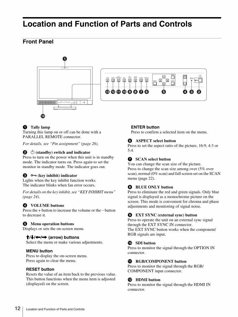
a Tally lampTurning this lamp on or off can be done with a PARALLEL REMOTE connector.
For details, see “Pin assignment” (page 26).
b 1 (standby) switch and indicatorPress to turn on the power when this unit is in standby mode. The indicator turns on. Press again to set the monitor in standby mode. The indicator goes out.
c - (key inhibit) indicatorLights when the key inhibit function works.The indicator blinks when fan error occurs.
For details on the key inhibit, see “KEY INHIBIT menu” (page 24).
d VOLUME buttonsPress the + button to increase the volume or the – button to decrease it.
e Menu operation buttonsDisplays or sets the on-screen menu.
M/m/</, (arrow) buttonsSelect the menu or make various adjustments.
MENU buttonPress to display the on-screen menu.Press again to clear the menu.
RESET buttonResets the value of an item back to the previous value.This button functions when the menu item is adjusted (displayed) on the screen.
ENTER buttonPress to confirm a selected item on the menu.
f ASPECT select buttonPress to set the aspect ratio of the picture, 16:9, 4:3 or 5:4.
g SCAN select buttonYou can change the scan size of the picture.Press to change the scan size among over (5% over scan), normal (0% scan) and full screen set on the SCAN menu (page 22).
h BLUE ONLY buttonPress to eliminate the red and green signals. Only blue signal is displayed as a monochrome picture on the screen. This mode is convenient for chroma and phase adjustments and monitoring of signal noise.
i EXT SYNC (external sync) buttonPress to operate the unit on an external sync signal through the EXT SYNC IN connector.The EXT SYNC button works when the component/RGB signals are input.
j SDI buttonPress to monitor the signal through the OPTION IN connector.
k RGB/COMPONENT buttonPress to monitor the signal through the RGB/COMPONENT input connector.
l HDMI buttonPress to monitor the signal through the HDMI IN connector.
LINE HDMI SDI SCAN ASPECT
RESET
MENU VOLUME
-ENTER
RGB/COMPONENT
EXTSYNC
BLUEONLY
1
qd
qf
1
qs qa09876 5 4 3 2
Location and Function of Parts and Controls
m LINE buttonPress to monitor the signal through the LINE input connector.
n SpeakerThe audio signal selected by the input select button (j SDI button, k RGB/COMPONENT button, l HDMI button or m LINE button) on the front panel is output.
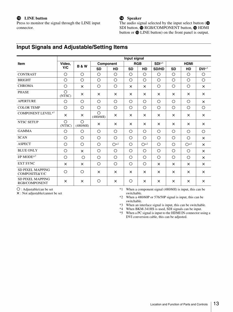
Input Signals and Adjustable/Setting Items
a : Adjustable/can be set× : Not adjustable/cannot be set
*1 When a component signal (480/60I) is input, this can be switchable.
*2 When a 480/60P or 576/50P signal is input, this can be switchable.
*3 When an interlace signal is input, this can be switchable.*4 When BKM-341HS is used, SDI signals can be input.*5 When a PC signal is input to the HDMI IN connector using a
DVI conversion cable, this can be adjusted.
Input signal
Item Video, Y/C B & W
Component RGB SDI*4 HDMI
SD HD SD HD SD/HD SD HD DVI*5
CONTRAST a a a a a a a a a a
BRIGHT a a a a a a a a a a
CHROMA a × a a × × a a a ×PHASE a
(NTSC) × × × × × × × × ×
APERTURE a a a a a a a a a ×COLOR TEMP a a a a a a a a a a
COMPONENT LEVEL*1× × a
(480/60I) × × × × × × ×
NTSC SETUP a (NTSC)
a(480/60I) × × × × × × × ×
GAMMA a a a a a a a a a a
SCAN a a a a a a a a a ×ASPECT a a a a*2 a a*2 a a a*2 ×BLUE ONLY a × a a a a a a a ×I/P MODE*3 a a a a a a a a a ×EXT SYNC × × a a a a × × × ×SD PIXEL MAPPING COMPOSITE&Y/C a a × × × × × × × ×
SD PIXEL MAPPING RGB/COMPONENT × × a × a × × × × ×
Location and Function of Parts and Controls 13
14
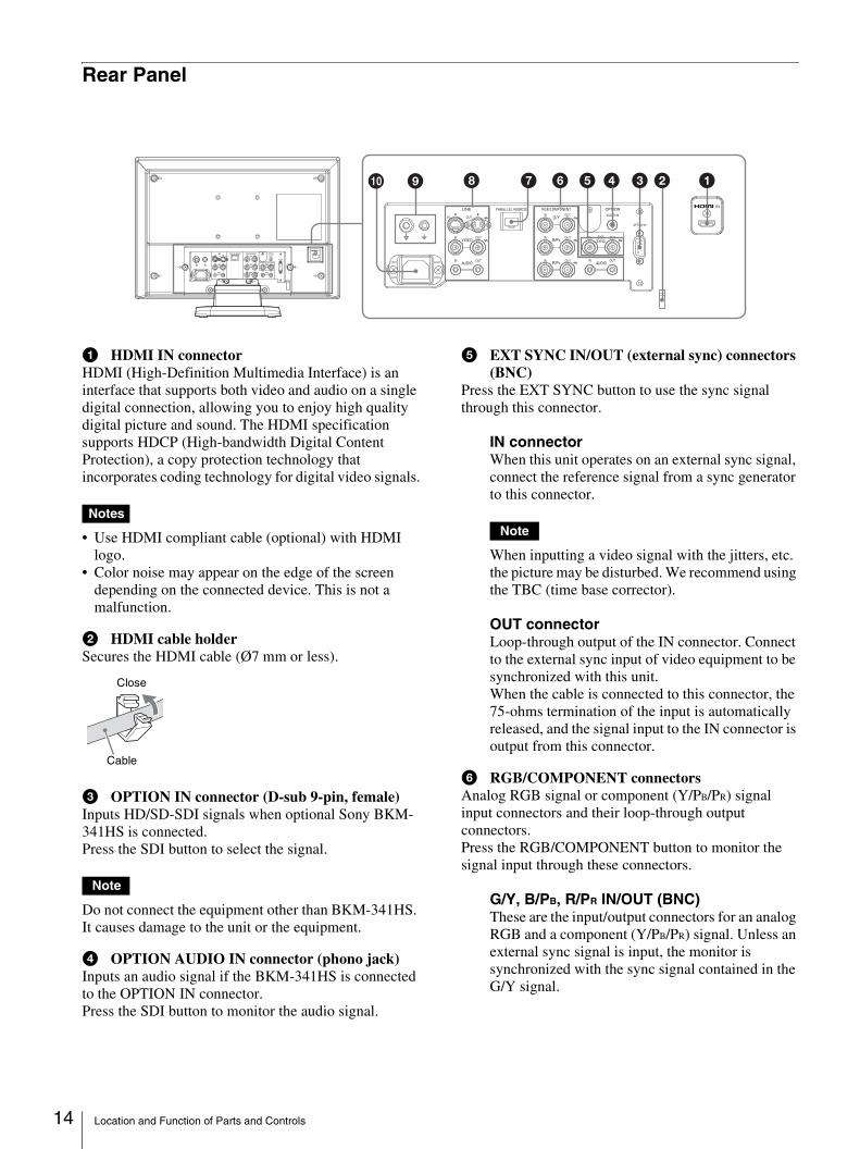
Rear Panel
a HDMI IN connectorHDMI (High-Definition Multimedia Interface) is an interface that supports both video and audio on a single digital connection, allowing you to enjoy high quality digital picture and sound. The HDMI specification supports HDCP (High-bandwidth Digital Content Protection), a copy protection technology that incorporates coding technology for digital video signals.
Notes
• Use HDMI compliant cable (optional) with HDMI logo.
• Color noise may appear on the edge of the screen depending on the connected device. This is not a malfunction.
b HDMI cable holderSecures the HDMI cable (Ø7 mm or less).
c OPTION IN connector (D-sub 9-pin, female)Inputs HD/SD-SDI signals when optional Sony BKM-341HS is connected.Press the SDI button to select the signal.
Note
Do not connect the equipment other than BKM-341HS. It causes damage to the unit or the equipment.
d OPTION AUDIO IN connector (phono jack)Inputs an audio signal if the BKM-341HS is connected to the OPTION IN connector.Press the SDI button to monitor the audio signal.
e EXT SYNC IN/OUT (external sync) connectors (BNC)
Press the EXT SYNC button to use the sync signal through this connector.
IN connectorWhen this unit operates on an external sync signal, connect the reference signal from a sync generator to this connector.
Note
When inputting a video signal with the jitters, etc. the picture may be disturbed. We recommend using the TBC (time base corrector).
OUT connectorLoop-through output of the IN connector. Connect to the external sync input of video equipment to be synchronized with this unit.When the cable is connected to this connector, the 75-ohms termination of the input is automatically released, and the signal input to the IN connector is output from this connector.
f RGB/COMPONENT connectorsAnalog RGB signal or component (Y/PB/PR) signal input connectors and their loop-through output connectors.Press the RGB/COMPONENT button to monitor the signal input through these connectors.
G/Y, B/PB, R/PR IN/OUT (BNC)These are the input/output connectors for an analog RGB and a component (Y/PB/PR) signal. Unless an external sync signal is input, the monitor is synchronized with the sync signal contained in the G/Y signal.
LINE PARALLEL REMOTE RGB/COMPONENT
VIDEOIN OUT
IN OUT
IN OUT G/YIN OUT
B/PBIN OUT EXT
SYNCIN OUT
R/PRIN OUT
AUDIO AUDIOIN
IN
OUT
OPTION
AUDIO IN
OPTION IN
4 3 2 156780 9
Close
Cable
Location and Function of Parts and Controls
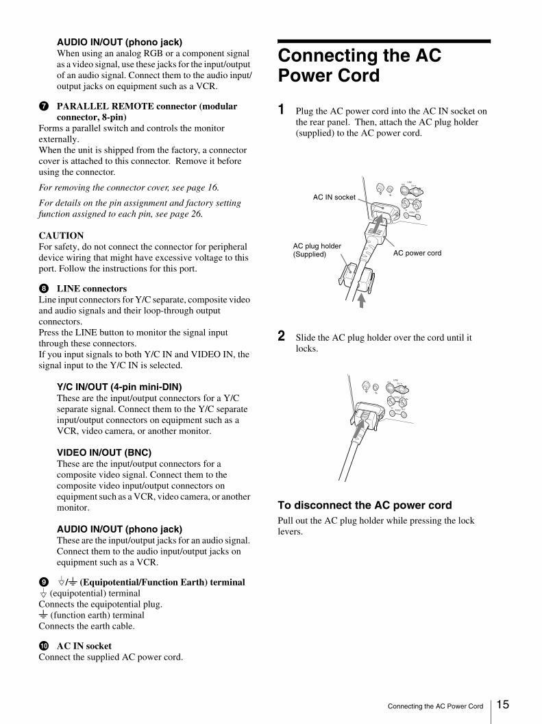
AUDIO IN/OUT (phono jack)When using an analog RGB or a component signal as a video signal, use these jacks for the input/output of an audio signal. Connect them to the audio input/output jacks on equipment such as a VCR.
g PARALLEL REMOTE connector (modular connector, 8-pin)
Forms a parallel switch and controls the monitor externally.When the unit is shipped from the factory, a connector cover is attached to this connector. Remove it before using the connector.
For removing the connector cover, see page 16.
For details on the pin assignment and factory setting function assigned to each pin, see page 26.
CAUTIONFor safety, do not connect the connector for peripheral device wiring that might have excessive voltage to this port. Follow the instructions for this port.
h LINE connectorsLine input connectors for Y/C separate, composite video and audio signals and their loop-through output connectors.Press the LINE button to monitor the signal input through these connectors.If you input signals to both Y/C IN and VIDEO IN, the signal input to the Y/C IN is selected.
Y/C IN/OUT (4-pin mini-DIN)These are the input/output connectors for a Y/C separate signal. Connect them to the Y/C separate input/output connectors on equipment such as a VCR, video camera, or another monitor.
VIDEO IN/OUT (BNC)These are the input/output connectors for a composite video signal. Connect them to the composite video input/output connectors on equipment such as a VCR, video camera, or another monitor.
AUDIO IN/OUT (phono jack)These are the input/output jacks for an audio signal. Connect them to the audio input/output jacks on equipment such as a VCR.
i /I (Equipotential/Function Earth) terminal (equipotential) terminal
Connects the equipotential plug.I (function earth) terminalConnects the earth cable.
j AC IN socketConnect the supplied AC power cord.
Connecting the AC Power Cord
1 Plug the AC power cord into the AC IN socket on the rear panel. Then, attach the AC plug holder (supplied) to the AC power cord.
2 Slide the AC plug holder over the cord until it locks.
To disconnect the AC power cordPull out the AC plug holder while pressing the lock levers.
LINE
VIDEOIN
OUT
AUDIOIN
OUT
INOUT
AC power cord
AC IN socket
AC plug holder (Supplied)
LINE
VIDEOIN
OUT
AUDIOIN
OUT
INOUT
Connecting the AC Power Cord 15
16
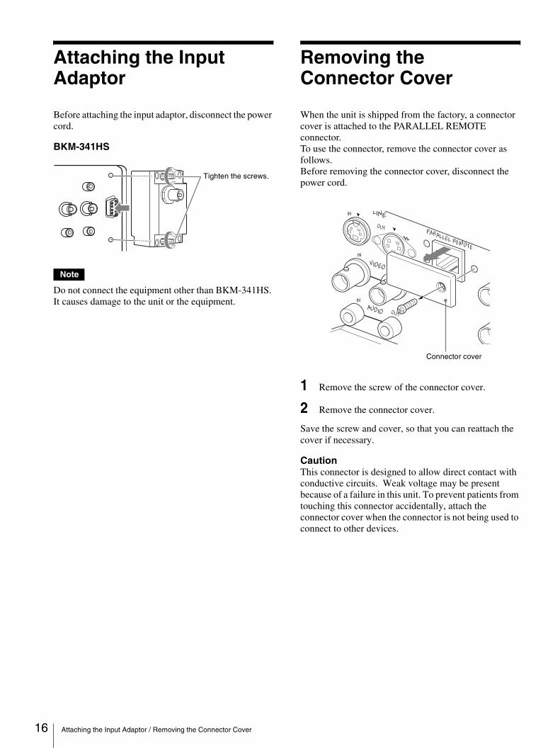
Attaching the Input Adaptor
Before attaching the input adaptor, disconnect the power cord.
BKM-341HS
Note
Do not connect the equipment other than BKM-341HS. It causes damage to the unit or the equipment.
Removing the Connector Cover
When the unit is shipped from the factory, a connector cover is attached to the PARALLEL REMOTE connector.To use the connector, remove the connector cover as follows.Before removing the connector cover, disconnect the power cord.
1 Remove the screw of the connector cover.
2 Remove the connector cover.
Save the screw and cover, so that you can reattach the cover if necessary.
CautionThis connector is designed to allow direct contact with conductive circuits. Weak voltage may be present because of a failure in this unit. To prevent patients from touching this connector accidentally, attach the connector cover when the connector is not being used to connect to other devices.
Tighten the screws.
LINE
PARALLEL REMOTE
VIDEO
IN
OUT
IN
OUT
IN
OUT
AUDIO
Connector cover
Attaching the Input Adaptor / Removing the Connector Cover
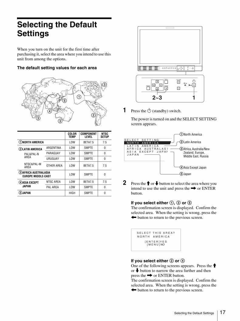
Selecting the Default Settings
When you turn on the unit for the first time after purchasing it, select the area where you intend to use this unit from among the options.
The default setting values for each area
1 Press the 1 (standby) switch.
The power is turned on and the SELECT SETTING screen appears.
2 Press the M or m button to select the area where you intend to use the unit and press the , or ENTER button.
If you select either 1, 3 or 5The confirmation screen is displayed. Confirm the selected area. When the setting is wrong, press the < button to return to the previous screen.
If you select either 2 or 4One of the following screens appears. Press the M or m button to narrow the area further and then press the , or ENTER button.The confirmation screen is displayed. Confirm the selected area. When the setting is wrong, press the < button to return to the previous screen.
3
3
4
5
3
1
2
COLOR TEMP
COMPONENT LEVEL
NTSC SETUP
1NORTH AMERICA LOW BETA7.5 7.5
2LATIN AMERICA
PAL&PAL-N AREA
ARGENTINA LOW SMPTE 0
PARAGUAY LOW SMPTE 0
URUGUAY LOW SMPTE 0
NTSC&PAL-M AREA OTHER AREA LOW BETA7.5 7.5
3AFRICA AUSTRALASIAEUROPE MIDDLE-EAST LOW SMPTE 0
4ASIA EXCEPT JAPAN
NTSC AREA LOW BETA7.5 7.5
PAL AREA LOW SMPTE 0
5JAPAN HIGH SMPTE 0
RESET
MENU VOLUME
ENTER
1-
2~3 1
S E L E C T S E T T I N G N O R T H _ A M E R I C A L A T I N A M E R I C A A F R I C A A U S T R A L A S I A E A S I A E X C E P T J A P A N J A P A N
1North America
2Latin America
3Africa, Australia/New Zealand, Europe, Middle East, Russia
4Asia Except Japan
5Japan
S E L E C T T H I S A R E A ?
[ E N T E R ] Y E S [ M E N U ] NO
N O R T H A M E R I C A
Selecting the Default Settings 17
18
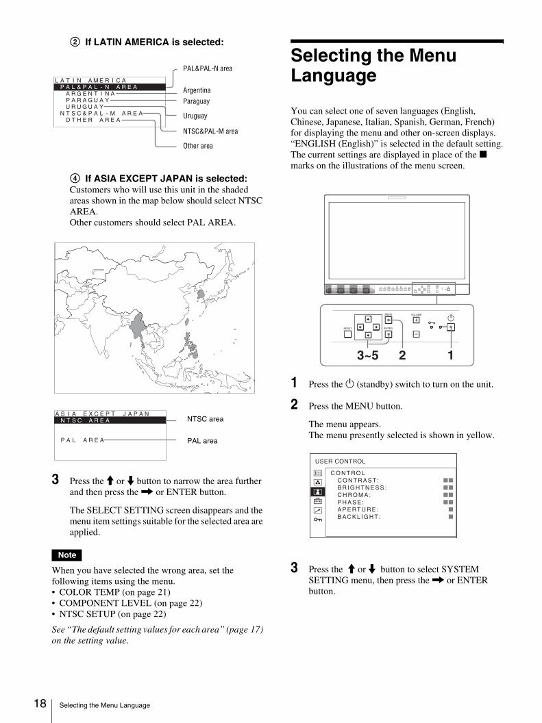
2 If LATIN AMERICA is selected:
4 If ASIA EXCEPT JAPAN is selected:Customers who will use this unit in the shaded areas shown in the map below should select NTSC AREA.Other customers should select PAL AREA.
3 Press the M or m button to narrow the area further and then press the , or ENTER button.
The SELECT SETTING screen disappears and the menu item settings suitable for the selected area are applied.
Note
When you have selected the wrong area, set the following items using the menu. • COLOR TEMP (on page 21)• COMPONENT LEVEL (on page 22)• NTSC SETUP (on page 22)
See “The default setting values for each area” (page 17) on the setting value.
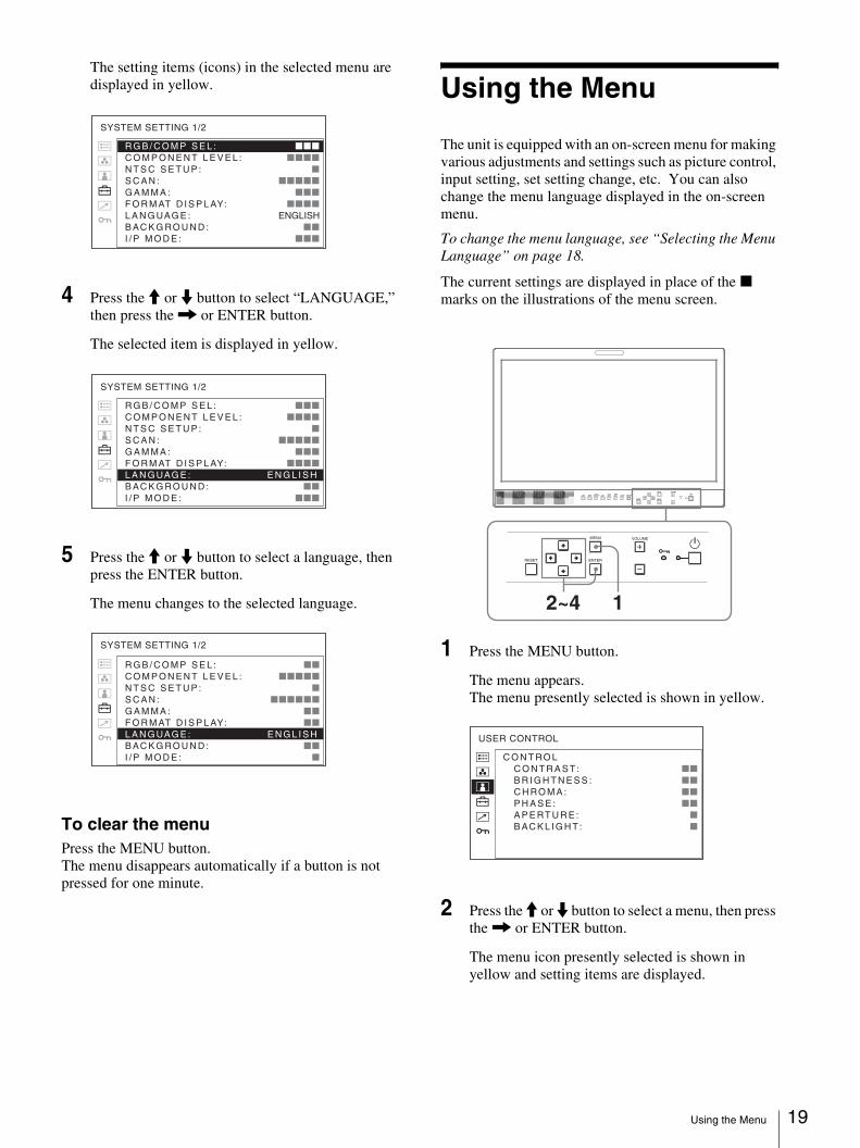
Selecting the Menu Language
You can select one of seven languages (English, Chinese, Japanese, Italian, Spanish, German, French) for displaying the menu and other on-screen displays.“ENGLISH (English)” is selected in the default setting.The current settings are displayed in place of the x marks on the illustrations of the menu screen.
1 Press the 1 (standby) switch to turn on the unit.
2 Press the MENU button.
The menu appears.The menu presently selected is shown in yellow.
3 Press the M or m button to select SYSTEM SETTING menu, then press the , or ENTER button.
L A T I N A M E R I C AP A L & P A L - N _ A R E A
A R G E N T I N A P A R A G U A Y U R U G U A Y
N T S C & P A L - M A R E A O T H E R A R E A
PAL&PAL-N area
ArgentinaParaguay
Uruguay
NTSC&PAL-M area
Other area
A S I A E X C E P T J A P A N N T S C _ A R E A P A L A R E A
NTSC area
PAL area
RESET
MENU VOLUME
ENTER
1-
3~5 2 1
C O N T RO L C O N T R A S T: xx B R I G H T N E S S : xx C H RO M A : xx P H A S E : xx A P E RT U R E : x B AC K L I G H T: x
USER CONTROL
Selecting the Menu Language
The setting items (icons) in the selected menu are displayed in yellow.
4 Press the M or m button to select “LANGUAGE,” then press the , or ENTER button.
The selected item is displayed in yellow.
5 Press the M or m button to select a language, then press the ENTER button.
The menu changes to the selected language.
To clear the menuPress the MENU button.The menu disappears automatically if a button is not pressed for one minute.
Using the Menu
The unit is equipped with an on-screen menu for making various adjustments and settings such as picture control, input setting, set setting change, etc. You can also change the menu language displayed in the on-screen menu.
To change the menu language, see “Selecting the Menu Language” on page 18.
The current settings are displayed in place of the x marks on the illustrations of the menu screen.
1 Press the MENU button.
The menu appears.The menu presently selected is shown in yellow.
2 Press the M or m button to select a menu, then press the , or ENTER button.
The menu icon presently selected is shown in yellow and setting items are displayed.
R G B / C O M P S E L : xxxxxxxC O M P O N E N T L E V E L : xxxxxxxN T S C S E T U P : xxxxxxxS C A N : xxxxxxx G A M M A : xxxxxxxF O R M AT D I S P L AY: xxxxxxxL A N G UAG E : xxENGLISHB AC K G RO U N D : xxxxxxxI / P M O D E : xxxxxxx
SYSTEM SETTING 1/2
R G B / C O M P S E L : xxxxxxx
C O M P O N E N T L E V E L : xxxxxxx
N T S C S E T U P : xxxxxxx
S C A N : xxxxxxx
G A M M A : xxxxxxx
F O R M AT D I S P L AY: xxxxxxx
L A N G UAG E : xE N G L I S HB AC K G RO U N D : xxxxxxx
I / P M O D E : xxxxxxx
SYSTEM SETTING 1/2
R G B / C O M P S E L : xxxC O M P O N E N T L E V E L : xxxxxN T S C S E T U P : xS C A N : xxxxxx G A M M A : xxF O R M AT D I S P L AY: xxL A N G UAG E : E N G L I S HB AC K G RO U N D : xxI / P M O D E : x
SYSTEM SETTING 1/2
RESET
MENU VOLUME
ENTER
1-
2~4 1
C O N T RO L C O N T R A S T: xx B R I G H T N E S S : xx C H RO M A : xx P H A S E : xx A P E RT U R E : x B AC K L I G H T: x
USER CONTROL
Using the Menu 19

20
3 Press the M or m button to select the item, then press the , or ENTER button.
The item to be changed is displayed in yellow.
Note
If the menu consists of multiple pages, press M or m button to go to the desired menu page.
4 Make the setting or adjustment on an item.
When changing the adjustment level:To increase the number, press the M button.To decrease the number, press the m button.Press the ENTER button to confirm the number, then restore the original screen.When changing the setting:Press the M or m button to change the setting.Press the ENTER button to confirm the setting.
Notes
• An item displayed in black cannot be accessed. You can access the item if it is displayed in white.
• If the key inhibit has been turned on, all items are displayed in black. To change any of the items, turn the key inhibit to OFF first.
For details on the key inhibit, see “KEY INHIBIT menu” (page 24).
To clear the menuPress the MENU button.The menu disappears automatically if a button is not pressed for one minute.
About the memory of the settingsThe settings are automatically stored in the monitor memory.
To reset items that have been adjustedPressing the RESET button while you are adjusting any of the menu items resets the menu item to the previous setting.
Adjustment Using the Menus
Items
The screen menu of this monitor consists of the following items.
STATUS (the items indicate the current settings.)
For the video inputFORMATCOLOR TEMPGAMMACOMPONENT LEVELNTSC SETUPRGB/COMP SELSCAN MODEASPECTModel name and serial numberOPTION
For the DVI inputFORMATfHfVCOLOR TEMPModel name and serial numberOPTION
COLOR TEMP/BALCOLOR TEMPMANUAL ADJUSTMENT
USER CONTROLCONTROL
SYSTEM SETTINGRGB/COMP SELCOMPONENT LEVELNTSC SETUPSCANGAMMAFORMAT DISPLAYLANGUAGEBACKGROUNDI/P MODESD PIXEL MAPPING
R G B / C O M P S E L : xxxC O M P O N E N T L E V E L : xxxxxN T S C S E T U P : xS C A N : xxxxxx G A M M A : xxF O R M AT D I S P L AY: xxL A N G UAG E : E N G L I S HB AC K G RO U N D : xxI / P M O D E : x
SYSTEM SETTING 1/2
Adjustment Using the Menus
REMOTEPARALLEL REMOTE
1PIN2PIN3PIN4PIN6PIN7PIN8PIN
KEY INHIBITKEY INHIBIT
Adjusting and Changing the Settings
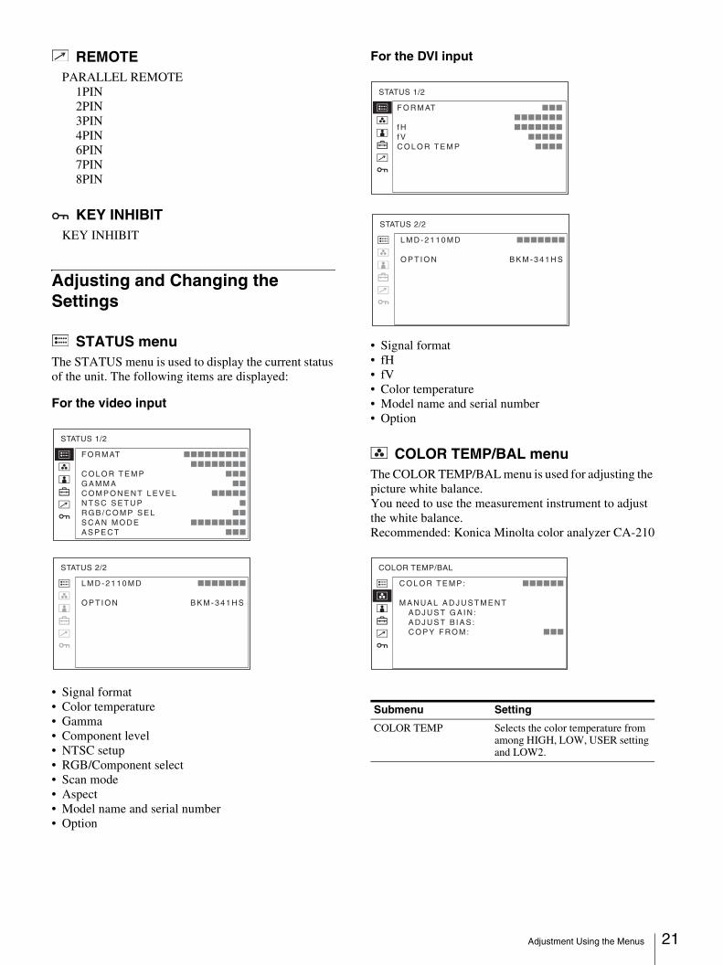
STATUS menuThe STATUS menu is used to display the current status of the unit. The following items are displayed:
For the video input
• Signal format• Color temperature• Gamma• Component level• NTSC setup• RGB/Component select• Scan mode• Aspect• Model name and serial number• Option
For the DVI input
• Signal format• fH• fV• Color temperature• Model name and serial number• Option
COLOR TEMP/BAL menuThe COLOR TEMP/BAL menu is used for adjusting the picture white balance. You need to use the measurement instrument to adjust the white balance.Recommended: Konica Minolta color analyzer CA-210
F O R M AT xxxxxxxxx xxxxxxxxC O L O R T E M P xxxG A M M A xxC O M P O N E N T L E V E L xxxxxN T S C S E T U P xR G B / C O M P S E L xxS C A N M O D E xxxxxxxxA S P E C T xxx
STATUS 1/2
L M D - 2 1 1 0 M D xxxxxxx
O P T I O N B K M - 3 4 1 H S
STATUS 2/2
Submenu Setting
COLOR TEMP Selects the color temperature from among HIGH, LOW, USER setting and LOW2.
F O R M AT xxx xxxxxxxf H xxxxxxxf V xxxxxC O L O R T E M P xxxx
STATUS 1/2
L M D - 2 1 1 0 M D xxxxxxx
O P T I O N B K M - 3 4 1 H S
STATUS 2/2
C O L O R T E M P : xxxxxx
M A N UA L A D J U S T M E N T
A D J U S T G A I N : A D J U S T B I A S : C O P Y F RO M : xxx
COLOR TEMP/BAL
Adjustment Using the Menus 21
22
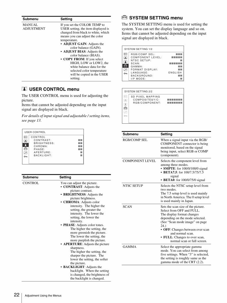
USER CONTROL menuThe USER CONTROL menu is used for adjusting the picture.Items that cannot be adjusted depending on the input signal are displayed in black.
For details of input signal and adjustable / setting items, see page 13.
SYSTEM SETTING menuThe SYSTEM SETTING menu is used for setting the system. You can set the display language and so on.Items that cannot be adjusted depending on the input signal are displayed in black.
MANUAL ADJUSTMENT
If you set the COLOR TEMP to USER setting, the item displayed is changed from black to white, which means you can adjust the color temperature.• ADJUST GAIN: Adjusts the
color balance (GAIN). • ADJUST BIAS: Adjusts the
color balance (BIAS). • COPY FROM: If you select
HIGH, LOW or LOW2, the white balance data for the selected color temperature will be copied in the USER setting.
Submenu Setting
CONTROL You can adjust the picture.• CONTRAST: Adjusts the
picture contrast. • BRIGHTNESS: Adjusts the
picture brightness.• CHROMA: Adjusts color
intensity. The higher the setting, the greater the intensity. The lower the setting, the lower the intensity.
• PHASE: Adjusts color tones. The higher the setting, the more greenish the picture. The lower the setting, the more purplish the picture.
• APERTURE: Adjusts the picture sharpness. The higher the setting, the sharper the picture. The lower the setting, the softer the picture.
• BACKLIGHT: Adjusts the backlight. When the setting is changed, the brightness of the backlight is changed.
Submenu Setting
C O N T RO L C O N T R A S T: xx B R I G H T N E S S : xx C H RO M A : xx P H A S E : xx A P E RT U R E : x B AC K L I G H T: x
USER CONTROLSubmenu Setting
RGB/COMP SEL When a signal input via the RGB/COMPONENT connector is being monitored, based on the signal being input, select RGB or COMP (component).
COMPONENT LEVEL Selects the component level from among three modes.• SMPTE: for 100/0/100/0 signal• BETA7.5: for 100/7.5/75/7.5
signal• BETA0: for 100/0/75/0 signal
NTSC SETUP Selects the NTSC setup level from two modes.The 7.5 setup level is used mainly in North America. The 0 setup level is used mainly in Japan.
SCAN Sets the scan size of the picture. Select from OFF and FULL.The display format changes depending on the mode selected. (See “Scan mode image” on page 24.)• OFF: Changes between over scan
and normal scan.• FULL: Changes to over scan,
normal scan or full screen.
GAMMA Select the appropriate gamma mode. You can select from among five settings. When “3” is selected, the setting is roughly same as the gamma mode of the CRT (2.2).
R G B / C O M P S E L : xxxC O M P O N E N T L E V E L : xxxxxN T S C S E T U P : xS C A N : xxxxxxG A M M A : xxF O R M AT D I S P L AY: xxL A N G UAG E : E N G L I S HB AC K G RO U N D : xxI / P M O D E : x
SYSTEM SETTING 1/2
S D P I X E L M A P P I N G C O M P O S I T E & Y / C : xxxxxxx R G B / C O M P O N E N T: xxxxxxx
SYSTEM SETTING 2/2
Adjustment Using the Menus
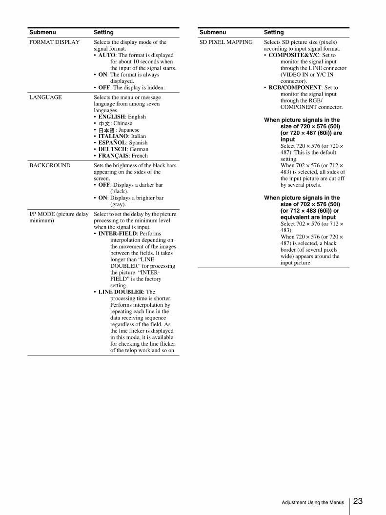
FORMAT DISPLAY Selects the display mode of the signal format.• AUTO: The format is displayed
for about 10 seconds when the input of the signal starts.
• ON: The format is always displayed.
• OFF: The display is hidden.
LANGUAGE Selects the menu or message language from among seven languages. • ENGLISH: English• : Chinese• : Japanese• ITALIANO: Italian• ESPAÑOL: Spanish• DEUTSCH: German• FRANÇAIS: French
BACKGROUND Sets the brightness of the black bars appearing on the sides of the screen.• OFF: Displays a darker bar
(black).• ON: Displays a brighter bar
(gray).
I/P MODE (picture delay minimum)
Select to set the delay by the picture processing to the minimum level when the signal is input.• INTER-FIELD: Performs
interpolation depending on the movement of the images between the fields. It takes longer than “LINE DOUBLER” for processing the picture. “INTER-FIELD” is the factory setting.
• LINE DOUBLER: The processing time is shorter. Performs interpolation by repeating each line in the data receiving sequence regardless of the field. As the line flicker is displayed in this mode, it is available for checking the line flicker of the telop work and so on.
Submenu Setting
SD PIXEL MAPPING Selects SD picture size (pixels) according to input signal format.• COMPOSITE&Y/C: Set to
monitor the signal input through the LINE connector (VIDEO IN or Y/C IN connector).
• RGB/COMPONENT: Set to monitor the signal input through the RGB/COMPONENT connector.
When picture signals in the size of 720 × 576 (50i) (or 720 × 487 (60i)) are inputSelect 720 × 576 (or 720 × 487). This is the default setting. When 702 × 576 (or 712 × 483) is selected, all sides of the input picture are cut off by several pixels.
When picture signals in the size of 702 × 576 (50i) (or 712 × 483 (60i)) or equivalent are inputSelect 702 × 576 (or 712 × 483). When 720 × 576 (or 720 × 487) is selected, a black border (of several pixels wide) appears around the input picture.
Submenu Setting
Adjustment Using the Menus 23
24
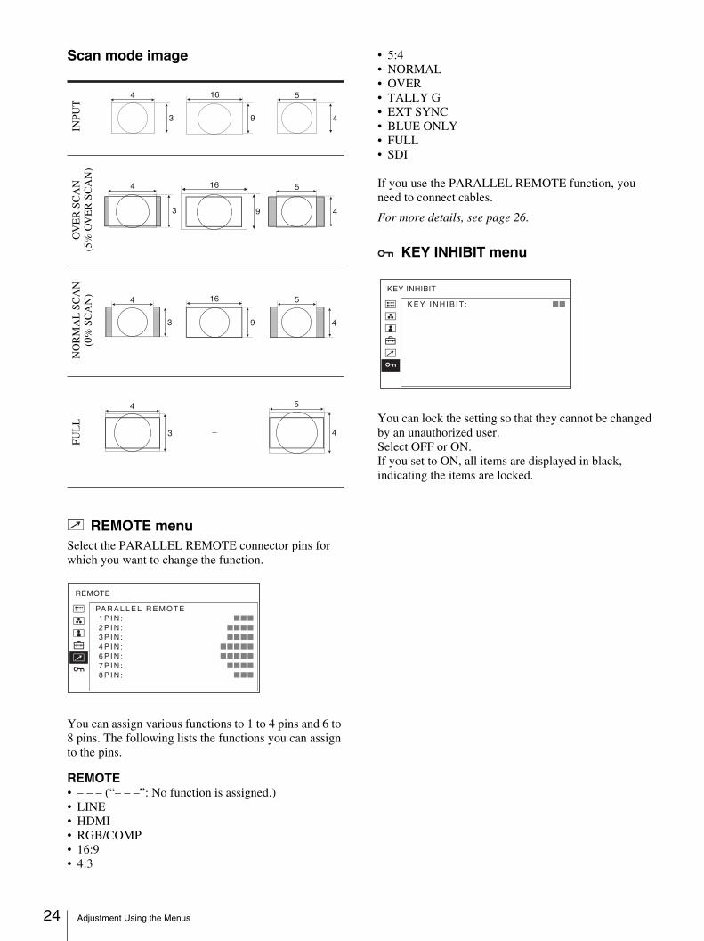
Scan mode image
REMOTE menuSelect the PARALLEL REMOTE connector pins for which you want to change the function.
You can assign various functions to 1 to 4 pins and 6 to 8 pins. The following lists the functions you can assign to the pins.
REMOTE• – – – (“– – –”: No function is assigned.)• LINE• HDMI• RGB/COMP• 16:9• 4:3
• 5:4• NORMAL• OVER• TALLY G• EXT SYNC• BLUE ONLY• FULL• SDI
If you use the PARALLEL REMOTE function, you need to connect cables.
For more details, see page 26.
KEY INHIBIT menu
You can lock the setting so that they cannot be changed by an unauthorized user.Select OFF or ON.If you set to ON, all items are displayed in black, indicating the items are locked.
4
3
16
9
5
4
4
3
5
4
4
3
16
9
4
3
5
4
5
4
16
9
INPU
TO
VE
R S
CA
N(5
% O
VE
R S
CA
N)
NO
RM
AL
SC
AN
(0%
SC
AN
)F
UL
L
PA R A L L E L R E M OT E 1 P I N : xxx 2 P I N : xxxx 3 P I N : xxxx 4 P I N : xxxxx 6 P I N : xxxxx 7 P I N : xxxx 8 P I N : xxx
REMOTE
K E Y I N H I B I T : xx
KEY INHIBIT
Adjustment Using the Menus
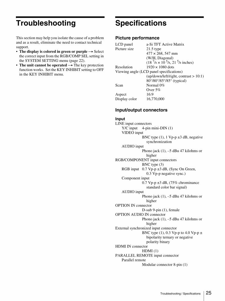
Troubleshooting
This section may help you isolate the cause of a problem and as a result, eliminate the need to contact technical support.• The display is colored in green or purple t Select
the correct input from the RGB/COMP SEL setting in the SYSTEM SETTING menu (page 22).
• The unit cannot be operated t The key protection function works. Set the KEY INHIBIT setting to OFF in the KEY INHIBIT menu.
Specifications
Picture performanceLCD panel a-Si TFT Active MatrixPicture size 21.5 type
477 × 268, 547 mm(W/H, Diagonal)(18 7/8 × 10 5/8, 21 5/8 inches)
Resolution 1920 × 1080 dotsViewing angle (LCD panel specifications)
(up/down/left/right, contrast > 10:1)80°/80°/85°/85° (typical)
Scan Normal 0%Over 5%
Aspect 16:9Display color 16,770,000
Input/output connectors
InputLINE input connectors
Y/C input 4-pin mini-DIN (1)VIDEO input
BNC type (1), 1 Vp-p ±3 dB, negative synchronization
AUDIO inputPhono jack (1), –5 dBu 47 kilohms or
higherRGB/COMPONENT input connectors
BNC type (3)RGB input 0.7 Vp-p ±3 dB, (Sync On Green,
0.3 Vp-p negative sync.)Component input
0.7 Vp-p ±3 dB, (75% chrominance standard color bar signal)
AUDIO inputPhono jack (1), –5 dBu 47 kilohms or
higherOPTION IN connector
D-sub 9-pin (1), femaleOPTION AUDIO IN connector
Phono jack (1), –5 dBu 47 kilohms or higher
External synchronized input connectorBNC type (1), 0.3 Vp-p to 4.0 Vp-p ±
bipolarity ternary or negative polarity binary
HDMI IN connectorHDMI (1)
PARALLEL REMOTE input connectorParallel remote
Modular connector 8-pin (1)
Troubleshooting / Specifications 25
26
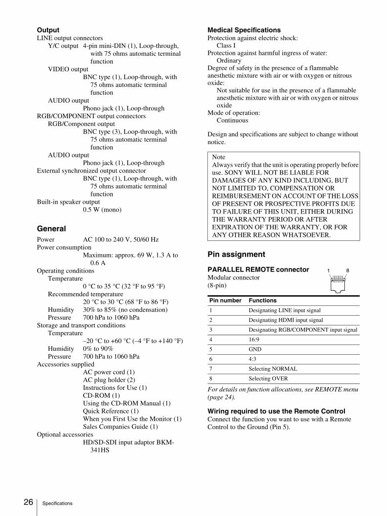
OutputLINE output connectors
Y/C output 4-pin mini-DIN (1), Loop-through, with 75 ohms automatic terminal function
VIDEO outputBNC type (1), Loop-through, with
75 ohms automatic terminal function
AUDIO outputPhono jack (1), Loop-through
RGB/COMPONENT output connectorsRGB/Component output
BNC type (3), Loop-through, with 75 ohms automatic terminal function
AUDIO outputPhono jack (1), Loop-through
External synchronized output connectorBNC type (1), Loop-through, with
75 ohms automatic terminal function
Built-in speaker output0.5 W (mono)
GeneralPower AC 100 to 240 V, 50/60 HzPower consumption
Maximum: approx. 69 W, 1.3 A to 0.6 A
Operating conditionsTemperature
0 °C to 35 °C (32 °F to 95 °F)Recommended temperature
20 °C to 30 °C (68 °F to 86 °F)Humidity 30% to 85% (no condensation)Pressure 700 hPa to 1060 hPa
Storage and transport conditionsTemperature
–20 °C to +60 °C (–4 °F to +140 °F)Humidity 0% to 90%Pressure 700 hPa to 1060 hPa
Accessories suppliedAC power cord (1)AC plug holder (2)Instructions for Use (1)CD-ROM (1)Using the CD-ROM Manual (1)Quick Reference (1)When you First Use the Monitor (1)Sales Companies Guide (1)
Optional accessoriesHD/SD-SDI input adaptor BKM-
341HS
Medical SpecificationsProtection against electric shock:
Class IProtection against harmful ingress of water:
OrdinaryDegree of safety in the presence of a flammable anesthetic mixture with air or with oxygen or nitrous oxide:
Not suitable for use in the presence of a flammable anesthetic mixture with air or with oxygen or nitrous oxide
Mode of operation: Continuous
Design and specifications are subject to change without notice.
Pin assignment
PARALLEL REMOTE connector Modular connector(8-pin)
For details on function allocations, see REMOTE menu (page 24).
Wiring required to use the Remote ControlConnect the function you want to use with a Remote Control to the Ground (Pin 5).
NoteAlways verify that the unit is operating properly before use. SONY WILL NOT BE LIABLE FOR DAMAGES OF ANY KIND INCLUDING, BUT NOT LIMITED TO, COMPENSATION OR REIMBURSEMENT ON ACCOUNT OF THE LOSS OF PRESENT OR PROSPECTIVE PROFITS DUE TO FAILURE OF THIS UNIT, EITHER DURING THE WARRANTY PERIOD OR AFTER EXPIRATION OF THE WARRANTY, OR FOR ANY OTHER REASON WHATSOEVER.
Pin number Functions
1 Designating LINE input signal
2 Designating HDMI input signal
3 Designating RGB/COMPONENT input signal
4 16:9
5 GND
6 4:3
7 Selecting NORMAL
8 Selecting OVER
1 8
Specifications
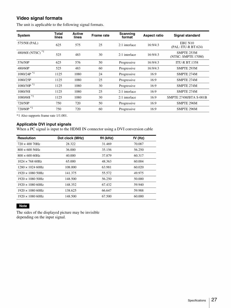
Video signal formatsThe unit is applicable to the following signal formats.
*1 Also supports frame rate 1/1.001.
Applicable DVI input signalsWhen a PC signal is input to the HDMI IN connector using a DVI conversion cable
Note
The sides of the displayed picture may be invisible depending on the input signal.
System Total lines
Active lines Frame rate Scanning
format Aspect ratio Signal standard
575/50I (PAL) 625 575 25 2:1 interlace 16:9/4:3 EBU N10(PAL: ITU-R BT.624)
480/60I (NTSC) *1525 483 30 2:1 interlace 16:9/4:3
SMPTE 253M(NTSC: SMPTE 170M)
576/50P 625 576 50 Progressive 16:9/4:3 ITU-R BT.1358
480/60P 525 483 60 Progressive 16:9/4:3 SMPTE 293M
1080/24P *1 1125 1080 24 Progressive 16:9 SMPTE 274M
1080/25P 1125 1080 25 Progressive 16:9 SMPTE 274M
1080/30P *1 1125 1080 30 Progressive 16:9 SMPTE 274M
1080/50I 1125 1080 25 2:1 interlace 16:9 SMPTE 274M
1080/60I *1 1125 1080 30 2:1 interlace 16:9 SMPTE 274M/BTA S-001B
720/50P 750 720 50 Progressive 16:9 SMPTE 296M
720/60P *1 750 720 60 Progressive 16:9 SMPTE 296M
Resolution Dot clock (MHz) fH (kHz) fV (Hz)
720 × 400 70Hz 28.322 31.469 70.087
800 × 600 56Hz 36.000 35.156 56.250
800 × 600 60Hz 40.000 37.879 60.317
1024 × 768 60Hz 65.000 48.363 60.004
1280 × 1024 60Hz 108.000 63.981 60.020
1920 × 1080 50Hz 141.375 55.572 49.975
1920 × 1080 50Hz 148.500 56.250 50.000
1920 × 1080 60Hz 148.352 67.432 59.940
1920 × 1080 60Hz 138.625 66.647 59.988
1920 × 1080 60Hz 148.500 67.500 60.000
Specifications 27
28
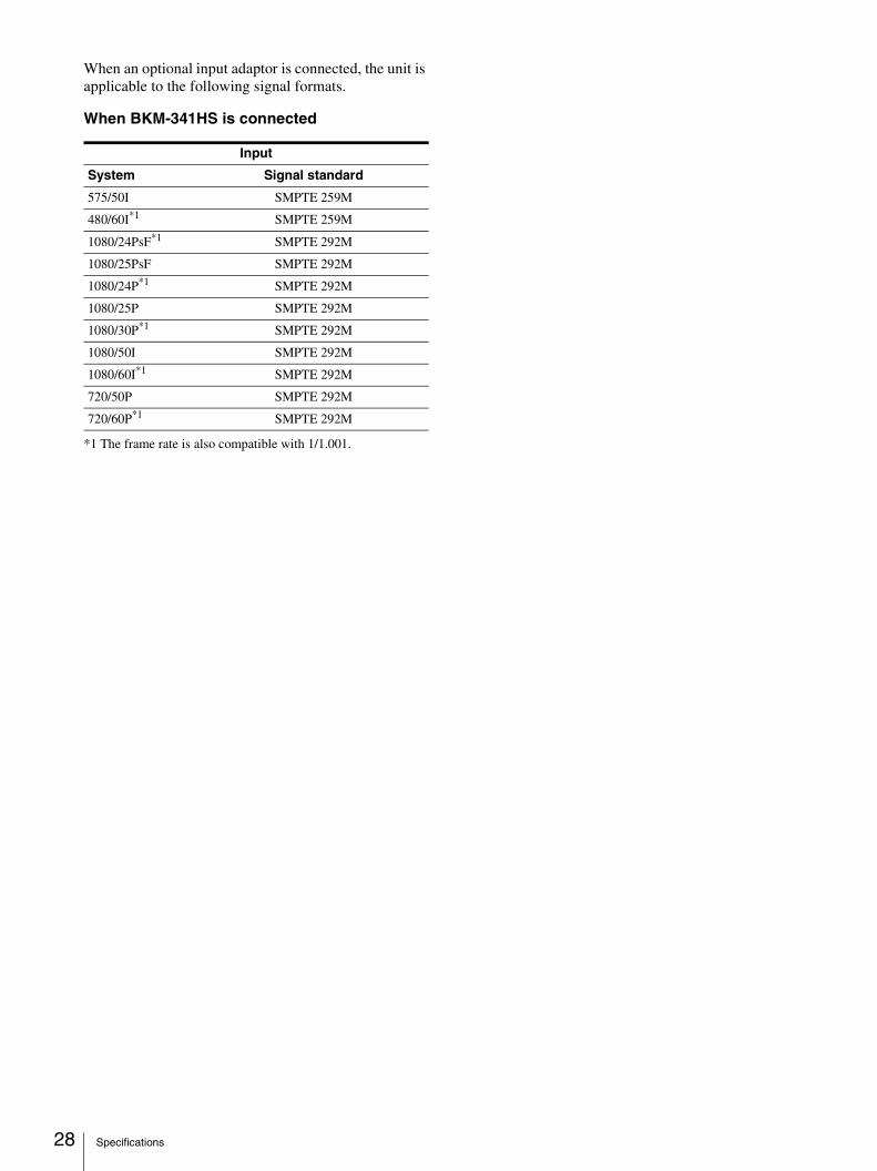
When an optional input adaptor is connected, the unit is applicable to the following signal formats.
When BKM-341HS is connected
*1 The frame rate is also compatible with 1/1.001.
Input
System Signal standard
575/50I SMPTE 259M
480/60I*1 SMPTE 259M
1080/24PsF*1 SMPTE 292M
1080/25PsF SMPTE 292M
1080/24P*1 SMPTE 292M
1080/25P SMPTE 292M
1080/30P*1 SMPTE 292M
1080/50I SMPTE 292M
1080/60I*1 SMPTE 292M
720/50P SMPTE 292M
720/60P*1 SMPTE 292M
Specifications
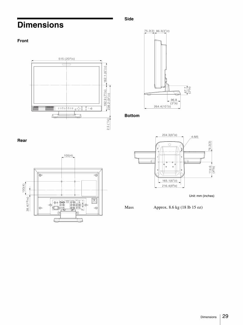
Dimensions
Front
Rear
Side
Bottom
515 (203/8)
16
2.1
(6
1/2
)1
92
.9 (
75/8
)2
38
.2 (
91/2
)2
.5 (
1/8
)
100(4)
38
.4(1
9 /16
)1
00
(4)
75.2(3)
96.8(37/8)
67
.7
264.4(101/2)
86.3(31/2)
(23 /
4)
204.3(81/8)
165.1(61/2)
216.4(85/8)
4-M5
76
.2(3
)1
14
.6(4
5 /8)
Mass Approx. 8.6 kg (18 lb 15 oz)
Unit: mm (inches)
Dimensions 29

Sony Corporation