Portable Memory Recorder - pro.sony
101
4-547-852-13 (1) © 2014 Sony Corporation Portable Memory Recorder Operating Instructions Before operating the unit, please read this manual thoroughly and retain it for future reference. PMW-RX50
-
Upload
khangminh22 -
Category
Documents
-
view
0 -
download
0
Transcript of Portable Memory Recorder - pro.sony

4-547-852-13 (1)
© 2014 Sony Corporation
Portable Memory Recorder
Operating InstructionsBefore operating the unit, please read this manual thoroughly and retain it for future reference.
PMW-RX50
2
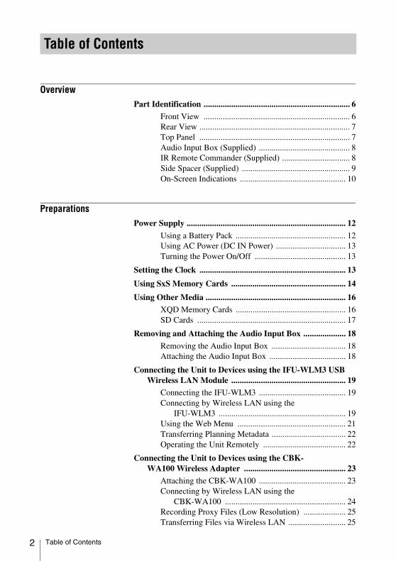
OverviewPart Identification ..................................................................... 6
Front View ..................................................................... 6Rear View ....................................................................... 7Top Panel ....................................................................... 7Audio Input Box (Supplied) ........................................... 8IR Remote Commander (Supplied) ................................ 8Side Spacer (Supplied) ................................................... 9On-Screen Indications .................................................. 10
PreparationsPower Supply ........................................................................... 12
Using a Battery Pack .................................................... 12Using AC Power (DC IN Power) ................................. 13Turning the Power On/Off ........................................... 13
Setting the Clock ..................................................................... 13
Using SxS Memory Cards ...................................................... 14
Using Other Media .................................................................. 16XQD Memory Cards .................................................... 16SD Cards ...................................................................... 17
Removing and Attaching the Audio Input Box .................... 18
Removing the Audio Input Box ................................... 18Attaching the Audio Input Box .................................... 18
Connecting the Unit to Devices using the IFU-WLM3 USB Wireless LAN Module ...................................................... 19
Connecting the IFU-WLM3 ......................................... 19Connecting by Wireless LAN using the
IFU-WLM3 ............................................................ 19Using the Web Menu ................................................... 21Transferring Planning Metadata ................................... 22Operating the Unit Remotely ....................................... 22
Connecting the Unit to Devices using the CBK-WA100 Wireless Adapter ................................................ 23
Attaching the CBK-WA100 ......................................... 23Connecting by Wireless LAN using the
CBK-WA100 ......................................................... 24Recording Proxy Files (Low Resolution) .................... 25Transferring Files via Wireless LAN ........................... 25
Table of Contents
Table of Contents

Monitoring via Wireless LAN ..................................... 25High-Quality Streaming using Sony QoS
Technology ............................................................ 25Using the “Content Browser Mobile” Application ...... 25Compatible devices ...................................................... 26
RecordingChanging Basic Settings ......................................................... 27
Selecting an Input Signal ............................................. 27Video Formats .............................................................. 27Time Data ..................................................................... 29Setting the Output Mode .............................................. 29
Recording ................................................................................. 30
Useful Functions ...................................................................... 31Color Bars/Reference Tone .......................................... 31Shot Marks .............................. 31OK/NG/KP Flags .................................. 31OK Mark ....................................................... 31Assignable Buttons ....................................................... 32Clip Continuous Recording ................... 32Loop Recording ..................................... 33Simultaneous Recording to Both Slots
............................................. 33Deleting Clips ............................................................... 34Storing/Retrieving the Setting Data ............................. 34Planning Metadata ........................................................ 35
PlaybackThumbnail Screens ................................................................. 38
Configuration of the Thumbnail Screen ....................... 38Changing the Type of Thumbnail Screen .................... 39
Playing Clips ............................................................................ 40
Playing the Selected and Subsequent Clips in Sequence ................................................................ 40
Playing between In-point and Out-point ...................... 40Playing Clips in Repeat Mode ...................................... 41Monitoring Audio ......................................................... 41Cueing Up .................................................................... 41
Clip Operations ....................................................................... 42Clip Operation Menus .................................................. 42Basic Operations of the Clip Operation Menus ........... 42Displaying the Detailed Information of a Clip ............. 44OK/NG/KP Flag .................................... 44
UDF exFAT FAT/HDUDF exFAT
FAT/HD
UDF exFATUDF exFAT
UDF/HD exFAT/HD
UDF exFAT
Table of Contents 3

4
OK Mark ....................................................... 45Copying Clips ............................................................... 45Deleting Clips ............................................................... 45EXPAND CLIP Screen ................................................ 45SHOT MARK Screen ............. 47Changing the Index Frame ..... 48Dividing a Clip ............................................. 48
Status DisplaysShowing the Status Screens .................................................... 49
Audio Status Screen ..................................................... 49Video Status Screen ..................................................... 49Button/Remote Status Screen ....................................... 50Battery/Media Status Screen ........................................ 50
Menu Configuration and Detailed SettingsOverview of the Setup Menus ................................................ 51
Setup Menu Layers ...................................................... 51
Basic Menu Operations .......................................................... 52
Setup Menu List ...................................................................... 53[AUDIO SET] Menu .................................................... 53[VIDEO SET] Menu .................................................... 55[LCD SET] Menu ......................................................... 58[TC/UB] SET Menu ..................................................... 59[OTHERS] Menu ......................................................... 60
Connecting External DevicesConnecting External Monitors and Camcorders ................. 71
Connecting Audio Equipment ............................................... 72
Connecting a Computer ......................................................... 73
Connecting via i.LINK ........................................................... 74Recording the Image on an External Device ...... 74Nonlinear Editing ................................................ 74Recording and SDI Output of External Input
Signals .................................................................... 75Recording and Playback of MXF DV Clips ...... 75
Connecting USB Media .......................................................... 76Supported USB Media ................................................. 76Copying Clips ............................................................... 77Displaying the USB Media Thumbnail Screen ............ 77
FAT/HD
UDF exFAT FAT/HDUDF exFAT FAT/HD
FAT/HD
FATFAT
UDF
Table of Contents

AppendicesImportant Notes on Operation .............................................. 78
Recording Video Formats ([Rec Format]) ............................ 80
Formats and Limitations of Outputs .................................... 82
Backup Battery Replacement ................................................ 89
Troubleshooting ...................................................................... 90
Licenses .................................................................................... 94
MPEG-4 AVC Patent Portfolio License ...................... 94Bitmap Fonts ................................................................ 94On accessing software to which the GPL applies ........ 94About OpenSSL ........................................................... 94
About JQuery,Sizzle.js ........................................................... 96
Software Downloads ............................................................... 97
Specifications ........................................................................... 97
Table of Contents 5

6
Overview
For functions and usage, see the pages in parentheses.
The above is an illustration with the audio input box removed. For details on the parts of the audio input box, see “Audio Input Box (Supplied)” (page 8).
1. LCD monitorThe LCD monitor LCD can be rotated 180° in the clockwise direction and 90° in the counterclockwise direction when it is open. It can also be stowed on the top surface of the recorder with the screen facing up.To rotate the LCD monitor, tilt it toward you (approximately 80°) and then turn it sideways.
2. Exhaust ventDo not block the exhaust vent.
3. TALLY lamp
4. Infrared light receiver sensor
5. SLOT SELECT button
6. VOLUME buttons
7. Headphone connector
8. Memory card slots (page 14)
9. Power button/lamp (page 13)
10. Built-in speaker
11. Shoulder strap mounting pointsThe supplied shoulder straps mount as shown in the following diagram.
12. Intake ventDo not block the intake vent.
Overview
Part Identification
Front View
Part Identification
Overview
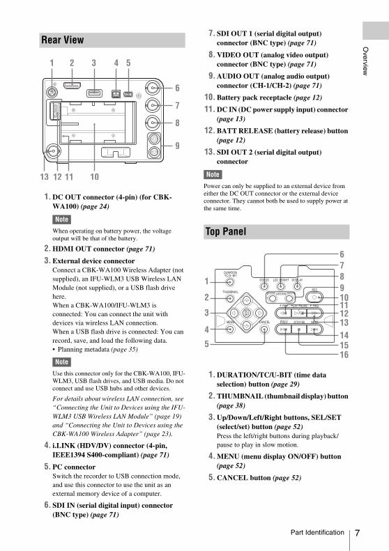
1. DC OUT connector (4-pin) (for CBK-WA100) (page 24)
Note
When operating on battery power, the voltage output will be that of the battery.
2. HDMI OUT connector (page 71)
3. External device connectorConnect a CBK-WA100 Wireless Adapter (not supplied), an IFU-WLM3 USB Wireless LAN Module (not supplied), or a USB flash drive here.When a CBK-WA100/IFU-WLM3 is connected: You can connect the unit with devices via wireless LAN connection.When a USB flash drive is connected: You can record, save, and load the following data.• Planning metadata (page 35)
Note
Use this connector only for the CBK-WA100, IFU-WLM3, USB flash drives, and USB media. Do not connect and use USB hubs and other devices.
For details about wireless LAN connection, see “Connecting the Unit to Devices using the IFU-WLM3 USB Wireless LAN Module” (page 19) and “Connecting the Unit to Devices using the CBK-WA100 Wireless Adapter” (page 23).
4. i.LINK (HDV/DV) connector (4-pin, IEEE1394 S400-compliant) (page 71)
5. PC connectorSwitch the recorder to USB connection mode, and use this connector to use the unit as an external memory device of a computer.
6. SDI IN (serial digital input) connector (BNC type) (page 71)
7. SDI OUT 1 (serial digital output) connector (BNC type) (page 71)
8. VIDEO OUT (analog video output) connector (BNC type) (page 71)
9. AUDIO OUT (analog audio output) connector (CH-1/CH-2) (page 71)
10. Battery pack receptacle (page 12)
11. DC IN (DC power supply input) connector (page 13)
12. BATT RELEASE (battery release) button (page 12)
13. SDI OUT 2 (serial digital output) connector
Note
Power can only be supplied to an external device from either the DC OUT connector or the external device connector. They cannot both be used to supply power at the same time.
1. DURATION/TC/U-BIT (time data selection) button (page 29)
2. THUMBNAIL (thumbnail display) button (page 38)
3. Up/Down/Left/Right buttons, SEL/SET (select/set) button (page 52)Press the left/right buttons during playback/pause to play in slow motion.
4. MENU (menu display ON/OFF) button (page 52)
5. CANCEL button (page 52)
Rear View
Top Panel
DURATION
THUMBNAIL
SELSET
MENU CANCEL PREV STOP/EE
F REV F FWDPLAY /PAUSE
NEXT
RECASSIGN
STATUS LCD BRIGHT DISPLAY
21
TC/U-BIT
Part Identification 7
8
Overview
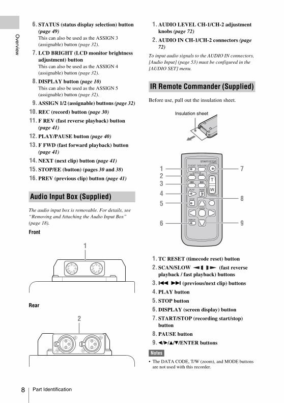
6. STATUS (status display selection) button (page 49)This can also be used as the ASSIGN 3 (assignable) button (page 32).
7. LCD BRIGHT (LCD monitor brightness adjustment) buttonThis can also be used as the ASSIGN 4 (assignable) button (page 32).
8. DISPLAY button (page 10)This can also be used as the ASSIGN 5 (assignable) button (page 32).
9. ASSIGN 1/2 (assignable) buttons (page 32)
10. REC (record) button (page 30)
11. F REV (fast reverse playback) button (page 41)
12. PLAY/PAUSE button (page 40)
13. F FWD (fast forward playback) button (page 41)
14. NEXT (next clip) button (page 41)
15. STOP/EE (button) (pages 30 and 38)
16. PREV (previous clip) button (page 41)
The audio input box is removable. For details, see “Removing and Attaching the Audio Input Box” (page 18).
Front
Rear
1. AUDIO LEVEL CH-1/CH-2 adjustment knobs (page 72)
2. AUDIO IN CH-1/CH-2 connectors (page 72)
To input audio signals to the AUDIO IN connectors, [Audio Input] (page 53) must be configured in the [AUDIO SET] menu.
Before use, pull out the insulation sheet.
1. TC RESET (timecode reset) button
2. SCAN/SLOW (fast reverse playback / fast playback) buttons
3. . > (previous/next clip) buttons
4. PLAY button
5. STOP button
6. DISPLAY (screen display) button
7. START/STOP (recording start/stop) button
8. PAUSE button
9. b/B/v/V/ENTER buttons
Notes
• The DATA CODE, T/W (zoom), and MODE buttons are not used with this recorder.
Audio Input Box (Supplied)
IR Remote Commander (Supplied)
Insulation sheet
Part Identification

Overview
• To avoid malfunctions, the remote control function is automatically deactivated when the recorder is turned off. Activate the function each time when required after you turn the recorder on.
Replacing the battery in the IR Remote CommanderUse a commercially available CR2025 lithium battery. Do not use any battery other than a CR2025.
1 Press the tab inward and grasp it with your fingernail to pull out the battery case.
2 Insert the new battery with its + side facing up.
3 Insert the battery case until it clicks into place.
• Battery may explode if mistreated.Do not recharge, disassemble, or dispose of in fire.
• Batteries shall not be exposed to excessive heat such as sunshine, fire or the like.
Danger of explosion if battery is incorrectly replaced. Replace only with the same or equivalent type recommended by the manufacturer.When you dispose of the battery, you must obey the law in the relative area or country.
When using more than one unit, you can attach the supplied side spacer on the left side of the unit and place two units side by side.
Attach the side spacer on the left side of the unit as illustrated.
WARNING
CAUTION
Side Spacer (Supplied)
Tab
Side spacer
Part Identification 9

10
Overview
While recording or in standby mode, pressing the DISPLAY button displays the status and settings of this unit on the LCD monitor.
Remarks[M]: The indication of the items named with this suffix can be independently turned on/off with [Display
On/Off] in the [LCD SET] menu (page 58).
1. Battery remaining/DC IN voltage indication [M] (page 12)
2. i.LINK status indication (page 74)Only when an external device is connected to the i.LINK connector, the status of the device is displayed.
3. Special recording/operation status indication
4. Media status indicationDisplays the active memory card slots.
5. Time data indication [M] (page 29)
6. Media remaining indication [M] (page 15)
7. Output mode indication (page 29)Displays “Out Thru” when the output mode is set to [THROUGH], or [Out Auto] when the output mode is set to [AUTO].
8. In-point to out-point partial playback indication (page 40)Displays “P-PLAY” when playing the interval from the in-point to the out-point.
9. Synchronous recording indication [M]
Displays “RM-SDI” when [SDI Rec Control] in the [VIDEO SET] menu is set to [On].Displays “Rec2” when the REC trigger signal is output when using the CBK-WA100.
10. Trim indication (page 41)
On-Screen Indications
zREC Recording in progress
STBY Standby for recordingCONT Standby for Clip
Continuous RecordingLit Indicates that a clip is
being continued while using the Clip Continuous Recording function
Flashing Indicates that there is not continuing clip while using the Clip Continuous Recording function
zSML REC Simultaneous recording to both slots in progress
SML STBY Standby for simultaneous recording to both slots
Part Identification

Overview
11. Loop recording indication (page 33)Displayed when loop recording.
12. Audio level meters [M]
13. USB media icon indication (page 76) or wireless adapter status indication (page 23)Displays an icon when valid USB media (HDD, flash drive, or other USB device) is connected. If the media is protected, a lock mark appears.If a CBL-WA100 Wireless Adapter is connected, the status is indicated as described in the “Wireless adapter status display” section below.
14. Input signal indicationDisplayed when a signal is input from the input source selected by [Input Source Select] in the [VIDEO SET] menu.
Note
If the indication is blinking, check whether [REC Format] matches the input signal and whether the input signal is distorted.
15. Video Format indication [M] (page 27)
16. Clip name indication [M] (page 30)
Wireless adapter status displayWhen the CBK-WA100 is connected to the unit, the network status and settings are displayed on the LCD monitor.
17. Network client mode status indication/Streaming status indication [M]Displays the network client mode connection status and streaming status.
18. Network connection status indication [M]Displays the network connection status.
19. SD card remaining capacity indication [M]Displays the remaining recording time of the SD card, when an SD card is inserted in the SD card slot of the CNK-WA100.
20. Clip transfer status indication [M]Displays the transfer status when transferring files over a network connection via the CBK-WA100. It displays the number of clips remaining to be transferred and the transfer rate (%).
Ext SDI in Input from the SDI IN connector
Ext i.LINK in HDV/DVCAM input from the i.LINK connector
SG Color bar output
Ext.
STRM
AP Wireless LAN connection (Access Point mode)
Wireless LAN connection (Station mode)
3G/4G Modem connection
LAN Wired LAN connection
Part Identification 11

12
Preparations
You can use a battery pack or AC power via an AC adaptor.For safety, use only the Sony battery packs and AC adaptor listed below:
Lithium-ion Battery PackBP-U30/BP-U60/BP-U90
Battery Charger/AC AdaptorBC-U1/BC-U2
Batteries shall not be exposed to excessive heat such as sunshine, fire or the like.
Note
The AC adaptor cannot be connected to the recorder while the battery pack is inserted.
Fully insert the battery pack into the battery pack receptacle (page 7), then slide it to the right to lock it.To remove the battery pack, press and hold the BATT RELEASE button (page 7), slide the battery pack to the left to unlock it, then pull it out.
Notes
• Before use, charge the battery pack with the supplied BC-U1 or BC-U2 Battery Charger.
• A warm battery pack immediately after use may not be able to be fully recharged.
• The high-capacity BP-U90 Battery Pack is large, and protrudes from the recorder when attached.
Checking battery charge remainingWhen recording or playback is in progress on the battery pack, an icon to show the current battery charge level and usage time remaining are displayed on the LCD monitor (page 10).
The recorder indicates the remaining usage time in minutes if operation is continued at the current rate of power consumption.
If the battery charge remaining becomes lowIf the battery charge remaining decreases to a certain level during operation (Low BATT status), a low-battery message, flashing of the tally lamps, and a beep sound will warn you.If the remaining further decreases to a level at which operation cannot be continued (BATT Empty status), a battery-empty message appears.Replace the battery pack with one that is fully charged.
To change the message levelsThe “Low BATT” level is set to 10% of full charge, and the “BATT Empty” level is set to 3% of full charge at the factory. These settings can be changed with [Battery Alarm] (page 63) in the [OTHERS] menu.
Preparations
Power Supply
WARNING
Using a Battery Pack
Icon Remaining
100% to 91%
90% to 71%
70% to 51%
50% to 31%
30% to 11%
10% to 0%
Power Supply

Preparations
Connection example: when connecting BC-U1
1 Connect the DC power output cable of the BC-U1 to the DC IN connector of the recorder.
2 Connect the power cord of the BC-U1 to an AC power source.
3 Set the mode switch of the BC-U1 to the DC OUT position.
To turn on the power supply, press the power button (page 6). The power supply lamp lights up. To turn off the power supply, press the power button again.
Notes
• This recorder uses a little standby power even when the power button is set to OFF. Remove the battery pack if the recorder will not be used for a prolonged period.
• When removing the battery pack or the DC IN power, be sure to first set the power button to the OFF position. Removing the battery pack or the DC IN power while the recorder is ON may cause damage to the recorder or the SxS memory card.
When you turn the recorder on for the first time after purchasing or replacing the backup battery (page 89), the Initial Setting display appears on the LCD monitor.
Time ZoneThe value shows the time difference from UTC (Coordinated Universal Time). Change the setting if needed.
Setting the time and dateMove the cursor, then press the SEL/SET button to set each menu item. When you press the SEL/SET button when the cursor is on [Finish], the Initial Setting display disappears, and the clock setting is completed.
After the Initial Setting display disappears, [Time Zone] (page 61) and [Clock Set] (page 61) in the [OTHERS] menu can be used to set [Time Zone] and [Date/Time].
Notes
• If the clock setting is cleared because of exhaustion of the backup battery while no operation power was being supplied (no battery pack and no DC IN connection), the Initial Setting display will be displayed when you turn the recorder on at the next opportunity.
• While the Initial Setting display is shown, no other operation except turning the power off is permitted until you finish the setting for this display.
Using AC Power (DC IN Power)
Turning the Power On/Off
DC OUTCHARGE
BATTERY CHARGER
BC-U1
0%
80100
Setting the Clock
Setting the Clock 13
14
Preparations
Insert SxS memory cards (not supplied) (herein referred to as memory cards) into the card slots to record video and audio.
For details on other types of media you can use with the recorder, see “Using Other Media” (page 16).
Supported SxS memory cardsUse the following Sony-made memory cards.For details on operations with media from other manufacturers, refer to the operating instructions for the media or consult the manufacturer’s information.
SxS PRO+ series
SxS PRO series
SxS-1 series
SxS PRO and SxS-1 series cards comply with the ExpressCard standard.
Note
If using SxS-1 series memory cards, recording may not be possible at XAVC-I 1080/59.94P or 50P, depending on the card used. The use of SxS PRO+ and SxS PRO series memory cards is recommended.
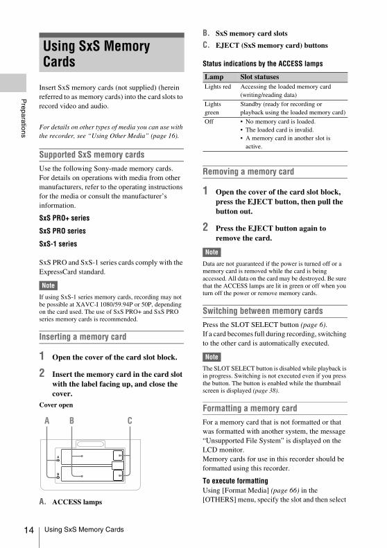
Inserting a memory card
1 Open the cover of the card slot block.
2 Insert the memory card in the card slot with the label facing up, and close the cover.
Cover open
A. ACCESS lamps
B. SxS memory card slots
C. EJECT (SxS memory card) buttons
Status indications by the ACCESS lamps
Removing a memory card
1 Open the cover of the card slot block, press the EJECT button, then pull the button out.
2 Press the EJECT button again to remove the card.
Note
Data are not guaranteed if the power is turned off or a memory card is removed while the card is being accessed. All data on the card may be destroyed. Be sure that the ACCESS lamps are lit in green or off when you turn off the power or remove memory cards.
Switching between memory cardsPress the SLOT SELECT button (page 6).If a card becomes full during recording, switching to the other card is automatically executed.
Note
The SLOT SELECT button is disabled while playback is in progress. Switching is not executed even if you press the button. The button is enabled while the thumbnail screen is displayed (page 38).
Formatting a memory cardFor a memory card that is not formatted or that was formatted with another system, the message “Unsupported File System” is displayed on the LCD monitor.Memory cards for use in this recorder should be formatted using this recorder.
To execute formattingUsing [Format Media] (page 66) in the [OTHERS] menu, specify the slot and then select
Using SxS Memory Cards
A
B
Lamp Slot statusesLights red Accessing the loaded memory card
(writing/reading data)
Lights green
Standby (ready for recording or playback using the loaded memory card)
Off • No memory card is loaded.• The loaded card is invalid.• A memory card in another slot is
active.
Using SxS Memory Cards

Preparations
[Execute]. On a confirmation message, select [Execute] again.When formatting is completed, the completion message is displayed for three seconds.
Recording/playback during formattingYou can perform recording or playback using the memory card in the other card slot while formatting is in progress.
If formatting failsA write-protected memory card or memory card that cannot be used with this recorder will not be formatted. Replace the card with an appropriate SxS memory card, as per the instructions in the message.
Notes
• All the data, including recorded pictures and setup files, are erased when a memory card is formatted.
• Use only SxS memory cards that were formatted using the recorder’s formatting function. Memory cards formatted on other devices will be recognized as a different format, and reformatting on the recorder will be required.
Recorder and computer connectionConnect the recorder to a computer using a USB cable, and insert a memory card recorded on an XDCAM/XDCAM EX series device in the recorder’s memory card slot.
Checking the remaining time available for recordingWhile recording or in standby mode, you can check the time remaining for the memory cards loaded in the card slots on the LCD monitor (page 10).The available time for recording with the current video format (recording bit rate) is displayed in time units of minutes.The remaining can also be checked in a meter format on the Battery/Media status screen (page 50).
Notes
• A icon appears if the memory card is write-protected.
• The remaining capacity indication for memory cards is an approximation. When recording to a memory card, in addition to the video data, some space is reserved for media management. Accordingly, the actual remaining capacity may be slightly smaller than indicated.
Replacing a memory card• If the available time on two cards in total
becomes less than 5 minutes, a message “Media Near Full,” flashing of the tally lamps, and a beep sound will warn you. Replace the cards with those with sufficient space.
• If you continue recording until the total remaining time reaches zero, the message changes to “Media Full,” and recording stops.
Note
Approximately 600 clips can be recorded on one memory card at maximum.If the number of recorded clips reaches the limit, the remaining time indication becomes “0,” and the message “Media Full” is displayed.
Restoring a memory cardIf an error occurs with data in a memory card for some reason, the card must be restored.If a memory card that needs to be restored is loaded, a message that prompts you to execute a restore operation is displayed on the LCD monitor.
To restore a cardSelect “Execute,” then push the SEL/SET button.When restoration is completed, the completion message is displayed for three seconds.
If restoration fails• A write-protected memory card or one on which
an error occurred cannot be restored. For such a card, a warning message is displayed. Release the write protection or replace the card, as per the instructions in the message.
• A memory card on which an error occurred may become usable again through repeated formatting.
• In some cases, only parts of clips cannot be restored. Playback of the restored clips becomes possible again.
• The following operation may restore a memory card for which the message “Could not Restore Some Clips” is repeatedly displayed each time you try the restoration process:
1 Copy necessary clips to another memory card, using the copy function (page 45) of the recorder or the dedicated application software (page 97).
2 Format the problem memory card, using the format function of this recorder.
Using SxS Memory Cards 15

16
Preparations
3 Copy the necessary clips back to the memory card.
Recording/playback during restorationYou can perform recording or playback using the memory card in the other card slot while restoration is in progress.
Note
For restoration of media recorded with this unit, be sure to use this unit. Media recorded with a device other than this unit or with another unit of different version (even of the same model) may not be restored using this unit.
Notes
• The high reliability and durability of professional SxS memory cards is not guaranteed.
• Operation with all memory cards is not guaranteed. For compatible memory cards, contact your Sony dealer.
• Format media for use with this unit using the format function of this unit.
By using an optional QDA-EX1 media adapter, you can insert an XQD memory card into the SxS memory card slot and use it for recording/playback instead of an SxS memory card.
For details about using a QDA-EX1 media adapter, refer to the instruction manual supplied with it.
Notes
• High-speed playback (page 8) may not be properly achieved with an XQD memory card.
• Recording in XAVC-I may not be supported, depending on the XQD memory cards used. The use of SxS PRO+ and SxS PRO series memory cards is recommended.
FormattingWhen you use an XQD memory card with this unit for the first time, formatting is required.An XQD memory card to be used with this unit must be formatted using the format function of this unit. It is also necessary to format an XQD memory card for use if a caution message is displayed when you mount the XQD memory card.For an XQD memory card that was formatted with another system unsupported by this unit, the message “Unsupported File System” is displayed on the LCD monitor.Format the memory card as instructed below.
Formatting (initializing)
Specify [Media(A)] (slot A) or [Media(B)] (slot B) using [OTHERS] >[Format Media] (page 66) in the setup menu, and select [Execute].
During execution, a message progress status (%) appears, and the ACCESS lamp lights in red. When formatting is completed, a completion message is displayed for three seconds.
Using Other Media
XQD Memory Cards
Using Other Media

Preparations
Note
When formatting, all data in an XQD memory card-including protected images-are erased and cannot be restored.
Connection between the unit and a computerTo use an XQD memory card in which data have been recorded with an XDCAM/XDCAM EX-series product, insert it into the slot of the unit and connect between the computer and this unit using a USB cable.
To use media formatted with this unit in the slots of other devicesMake a backup of the media, then format it using the other device.
By using an optional MEAD-SD02 media adapter, you can insert an SD card into the SxS memory card slot and use it for recording/playback instead of an SxS memory card.
For details about using an MEAD-SD02 media adapter, refer to the instruction manual supplied with it.
Note
High-speed playback (page 8) may not be properly achieved with an SD card.
SDHC cards (FAT only)SDHC cards (SD speed class: Class 10)
Note
Cannot be used in UDF and exFAT modes.
SDXC cards (exFAT only)SDXC cards (SD speed class: Class 10)
Note
• Cannot be used in other than exFAT mode.• Do not use SDXC cards with other memory cards at
the same time. If different types of media are used, the unit cannot switch between media during recording when one media becomes full.
• Recording in XAVC-I may not be supported, depending on the SDXC cards used. The use of SxS PRO+ and SxS PRO series memory cards is recommended.
• SDXC card compatibilitySDXC cards recorded using PMW-series or PXW-series camcorders are supported for playback on the
unit. However, recording and clip details display on the thumbnail screen may not be supported, depending on the device. For details, contact a Sony sales or service representative.
Formatting (initializing)When you use an SD card with this unit for the first time, formatting is required.An SD card to be used with this unit must be formatted using the format function of this unit. It is also necessary to format an SD card for use if a caution message is displayed when you mount the SD card.For an SD card that was formatted with another system unsupported by this unit, the message “Unsupported File System” is displayed on the LCD monitor.Format the SD card as instructed below.
Formatting (initializing)Specify [Media(A)] (slot A) or [Media(B)] (slot B) using [OTHERS]> [Format Media] (page 66) in the setup menu, and select [Execute].
During execution, a message progress status (%) appears, and the ACCESS lamp lights in red. When formatting is completed, a completion message is displayed for three seconds.
Note
In formatting, all data in an SD card, including protected images, are erased and cannot be restored.
Connection between the unit and a computerTo use an SD card in which data have been recorded with an XDCAM/XDCAM EX-series product, establish USB connection between the computer and this unit and insert it into the slot of the unit, or use the specified USB card reader SBAC-US20.
To use media formatted with this unit in the slots of other devicesMake a backup of the media, then format it using the other device.
SD Cards
Using Other Media 17

18
Preparations
The audio input box is removable. You can remove the audio input box when it is not in use.
Note
Turn the recorder off before attaching and removing the audio input box.
1 Loosen the four screws (M3) on the audio input box, and lift the box straight up.
2 Remove the covers stored on the bottom of the audio input box, and attach them to the holes on the recorder.
Tip
Pressing the area in the illustration will make removing the covers for the screw holes easier.
1 Remove the covers attached to the recorder, and attach them to the bottom of the audio input box.
Be sure to store the removed covers on the bottom of the audio input box to prevent losing them.
2 Place the audio input box on the recorder, and secure the four screws (M3).
Align the two guides on the bottom of the audio input box with the holes on the recorder, and place it directly on the recorder.There are also position alignment guide lines on the front of the recorder and front of the audio input box. Position the audio input box so that the two guide lines align.
Removing and Attaching the Audio Input Box
Removing the Audio Input Box
Screws (M3)
Attaching the Audio Input Box
Removing and Attaching the Audio Input Box

Preparations
You can connect a device (such as a computer, smartphone, or tablet, collectively referred to as “device”) to the unit over a wireless LAN connection by attaching an optional IFU-WLM3 USB wireless LAN module.The following operations are supported between the unit and devices connected by wireless LAN using the IFU-WLM3.• Using the web menu (page 21)• Transferring planning metadata between a
device and this unit (page 22)• Remote operation of the unit using a device
(page 22)
Connect the IFU-WLM3 to the connector of an
external device.
Notes
• Do not connect an unspecified device to the external device connector.
• The IFU-WLM3 may not be used in some countries/regions.
• Attach/remove the IFU-WLM3 after the unit is turned off.
• The CBK-WA100 Wireless Adapter cannot be used when using an IFU-WLM3.
• An i.LINK connection and USB wireless LAN module cannot be used at the same time.When using a wireless connection with an IFU-WLM3 inserted directly into the external device connector, do not connect a device to the i.LINK connector.
• If you use another wireless device near the unit, the unit may not work correctly. Turn any wireless devices off that are near the unit.
To connect by wireless LAN using the IFU-WLM3, two types of wireless LAN connections are available. In “ad-hoc mode”, you can make a
Guide
Guide
Guide
Guide
Guide line
Guide line
Screws (M3)
Connecting the Unit to Devices using the IFU-WLM3 USB Wireless LAN Module
Connecting the IFU-WLM3
Connecting by Wireless LAN using the IFU-WLM3
Connecting the Unit to Devices using the IFU-WLM3 USB Wireless LAN Module 19

20
Preparations
peer-to-peer Wi-Fi connection between a device and a unit. In “infrastructure mode”, you can make Wi-Fi connections between a device and multiple units via a wireless LAN access point (building a LAN).
To configure network settings
Change settings under [OTHERS] >[Network] in the setup menu as required.
a) The IP address determined by DHCP server is displayed here.
When you have changed a settingSet [Set] to [Execute].
To make a connection in ad hoc mode
1 Configure network connection settings on the device to be connected to the unit.
2 Start a connection on the device.
3 Set [OTHERS] >[Wi-Fi] >[Wi-Fi] to [Enable] in the setup menu.
4 Select [Execute] in [OTHERS] >[Wi-Fi] >[Scan Networks] in the setup menu, and press the SEL/SET button.
The unit starts scanning for a network connection.
When networks are detected, the NETWORK SCAN list appears.
5 Select a network for connection using the up/down buttons, and press the SEL/SET button.
The [OTHERS] menu appears again.
6 Confirm that the Wi-Fi settings match the network settings.
SSID (network name): Selected network name
Network Type (connection mode): “Adhoc”
CH (channel): “1”Authentication (network
authentication): Depending on the settings of the device, “Open,” “Shared,” or “WPA”
Encryption (data encryption): Depending on the settings on the device, “Disable,” “WEP,” “TKIP,” or “AES”
WEP Key Index (key index): “1” when “Encryption” is set to “WEP”
Input Select (key input format): Depending the network key (or security key), “ASCII5,” “ASCII13,” “HEX10,” or “HEX26” when “Encryption” is set to “WEP,” “ASCII8-63” or “HEX64” when “Encryption” is set to “TKIP” or “AES”
7 Enter the configured network key (or security key) in “Key” on the device, move the cursor to END, and press the SEL/SET button.
8 Set [Set] to [Execute], and press the SEL/SET button.
The message “Wi-Fi Setting Executing…” appears and the unit starts connection.If the connection to the device is successful, then the message changes to “Wi-Fi Setting OK”.Black squares (x) appear in the Wi-Fi Status column to show the connection status. (The number of x squares shows the level of connection status.) In the Wireless Mode column, the IEEE802.11 standard of the established connection appears (802.11b, 802.11g or 802.11n).
Item SettingDHCP Setting that specifies whether to
acquire the IP address automatically from a DHCP server.Enabled: Acquire automatically.Disabled: Do not acquire
automatically (factory default setting).
IP Address IP address a) (factory default setting: 192.168.1.10)
Subnet Mask Subnet mask (factory default setting: 255.255.255.0)
Default Gateway Default gateway (factory default setting: 0.0.0.0)
User Name User name for log-in (factory default setting: admin)
Password Password for log-in (factory default setting: model name “pmw-rx50”)
Connecting the Unit to Devices using the IFU-WLM3 USB Wireless LAN Module

Preparations
It is also possible to access the unit from a device by first starting a wireless LAN connection on the unit.
To terminate the connectionTerminate the connection on the device.
To revert to the default settings (reset)If you have trouble making a connection, or you want to start over, you can reset your wireless LAN connection settings to their defaults.
Select [Execute] in [OTHERS] >[Network] >[Net Config Reset] in the setup menu, and press the SEL/SET button.If the reset is executed, the message “Done” appears.The unit attempts to connect to the network using a MAC address as the SSID.
To make a connection in infrastructure mode
Setting up the wireless LAN access pointThe following settings are required.• Network ID (SSID)• Encryption method• Network key (Key)
For details about setting up the wireless LAN access point, refer to the Operation Manual of the wireless LAN access point.
To find and connect to a wireless LAN from the unitPerform the same procedure in “To make a connection in ad hoc mode” (page 20).Note the following variations.• Do not perform steps 1 and 2.• The settings made in step 6 change as follows.
SSID (network name): Selected network name
Network Type (connection mode): “Infra”
Ch (channel): “Auto”Authentication (network
authentication): Depending the settings on the computer, “Open,” “Shared,” “WPA,” or “WPA2”
Encryption (data encryption): Depending the settings on the computer, “Disable,” “WEP,” “TKIP,” or “AES”
WEP Key Index (key index): “1” when “Encryption” is set to “WEP”
Input Select (key input format): Depending the network key (or security key), “ASCII5,” “ASCII13,” “HEX10,” or “HEX26” when “Encryption” is set to “WEP,” “ASCII8-63” or “HEX64” when “Encryption” is set to “TKIP” or “AES”
You can operate the Web menu built in the unit from a device when it is connected to the unit via a wireless LAN connection.You can check the information and setting status of the unit, and upload a planning metadata file, using the Web menu.
Note
You cannot access the Web menu during recording/playback. (You cannot send/receive files via a wireless LAN connection.)
Example web menu
Product Information• Model name• Serial No.
Network• MAC Address• IP Address• Subnet Mask
Wi-Fi Status (Wireless LAN setting)• Wireless Mode• SSID• Type (connection mode)• Channel• Authentication (network authentication)• Data Encryption (encryption method)
Planning MetadataClicking “Upload” displays the Planning Metadata screen which allows upload of a planning metadata file (page 22).
Wi-Fi RemoteClicking “Control Panel” displays the Wi-Fi
Remote screen, allowing you to operate the unit
remotely (page 22).
Note
The configuration of items displayed in the Web menu varies depending on the browser you are using.
Tip
Using the Web Menu
Connecting the Unit to Devices using the IFU-WLM3 USB Wireless LAN Module 21
22
Preparations
To display the Web menu
1 Launch a web browser on the device, and navigate to “http://<unit’s IP address> (setting of [OTHERS] >[Network] >[IP Address] in the setup menu).
Example (when the IP address is “192.168.1.10”): Type “http://192.168.1.10/” in the address bar.If the connection is complete, a dialog appears asking you to enter the user name and password.
2 Enter the user name and password, and click “OK.”
User name: adminPassword: pmw-rx50 (model name in lower
case)
You can transfer planning metadata created beforehand to the unit to specify clip names, shot marks, and other items.
To upload a planning metadata file
1 Insert a media such as an SxS memory card.
2 Click “Upload” in the Web menu.
The Planning Metadata screen appears.
3 Click “Select” to show the “Choose File” dialog.
4 Select the planning metadata file you want to upload, and then click “Open.”
The path of the selected file appears.
5 Click “Execute.”
The planning metadata file is loaded into the unit’s memory and stored in the media.“OK” appears in the Status field when the transfer is complete.
To upload a planning metadata file automaticallyIn the planning metadata file you want to load automatically, add a “load” property to the PlanningMetadata tag and set the value of the property to “True.” When you display the Web menu and insert a media, the planning metadata file is immediately loaded into the unit’s memory.Example: <PlanningMetadata …sp spversion="1.00">
For details on the planning metadata, refer to the Operating Instructions supplied with the unit.
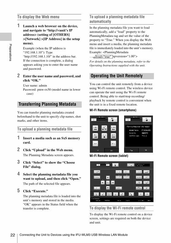
You can control the unit remotely from a device using Wi-Fi remote control. The wireless device can operate the unit using the Wi-Fi remote control. Being able to start/stop recording/playback by remote control is convenient when the unit is in a fixed remote location.
Wi-Fi Remote screen (smartphone)
Wi-Fi Remote screen (tablet)
To display the Wi-Fi remote controlTo display the Wi-Fi remote control on a device screen, settings are required on both the device and unit.
Transferring Planning Metadata
Operating the Unit Remotely
load="true"
Connecting the Unit to Devices using the IFU-WLM3 USB Wireless LAN Module

Preparations
Configuring the Unit
1 Set [OTHERS] >[Wi-Fi] >[Wi-Fi] to [Enable] in the setup menu.
2 Set [OTHERS] >[Wi-Fi] >[Wi-Fi Remote] to [On] in the setup menu.
Configuring the deviceSet the smartphone, tablet, PC, etc., to be used as the Wi-Fi remote control.
1 Connect the unit and device using a wireless LAN connection (page 19 or page 24).
2 Launch a browser on the device, and navigate to “http://<unit’s IP address>/rm.html” (where IP address is the setting of [OTHERS] >[Network] >[IP Address] in the setup menu).
Example: When the IP address is 192.168.1.10, enter “http://192.168.1.10/rm.html” in the address bar.The Wi-Fi Remote screen will appear on the device screen when the Wi-Fi connection is established.Thereafter, operate the unit as shown on the screen of the Wi-Fi connected device.The REC button becomes unavailable when the Lock switch is moved to the right.
Notes
• To display the page for a smartphone, change the page to “rms.html.” To display the page for a tablet device, change the page to “rmt.html.” Normally, when “rm.html” is entered, the page displayed switches automatically for the device. However, in some cases, a different page may be displayed, depending on the device.
• The unit status may not match the Wi-Fi Remote screen in the following cases. If this happens, reload the browser display.- When the unit is restarted while the Wi-Fi
connection is established.- When the unit is controlled directly while the Wi-Fi
connection is established.- When the device is reconnected.- When you operate forward/backward on the device’s
browser.• If the Wi-Fi signal is poor, the Wi-Fi remote control
may not work properly.• Your smartphone/tablet may not be compatible with
the ad hoc mode. For details, refer to the operating instructions supplied with the smartphone/tablet.
You can connect a device (such as a computer, smartphone, or tablet, collectively referred to as “device”) to the unit over a wireless LAN connection by attaching an optional CBK-WA100 Wireless Adapter.The following operations are supported between the unit and devices connected by wireless LAN using the CBK-WA100.• Using the web menu (page 21)• Transferring planning metadata between a
device and this unit (page 22)• Remote operation of the unit using a device
(page 22)• Recording proxy files (low resolution) (page
25)• Transferring files via wireless LAN (page 25)• Monitoring via wireless LAN (page 25)• High-quality streaming using Sony QoS
technology (page 25)• Using the “Content Browser Mobile”
application (page 25)In addition to the operations above, the following operations are also supported using the “Content Browser Mobile” application.- Partial transfer of proxy files and original
files.- Live logging function
Notes
• Attach/remove the CBK-WA100 after the unit is turned off.
• The IFU-WLM3 USB Wireless LAN Module cannot be used when using an CBK-WA100.
• If you use another wireless device near the unit, the unit may not work correctly. Turn any wireless devices off that are near the unit.
1 Remove the top part of the bracket, and secure the main part of the bracket to the CBK-WA100 using the three screws (M2×5) supplied with the CBK-WA100.
Connecting the Unit to Devices using the CBK-WA100 Wireless Adapter
Attaching the CBK-WA100
Connecting the Unit to Devices using the CBK-WA100 Wireless Adapter 23

24
Preparations
2 Secure the CBK-WA100 to the recorder using the two screws (M4×6) supplied with the CBK-WA100.
3 Use the USB cable supplied with the CBK-WA100 to connect the external device connector (page 7) on the
recorder to the Mini USB connector on the CBK-WA100.
4 Use the BNC cable supplied with the CBK-WA100 to connect the SDI OUT 2 or 1 connector (page 7) on the recorder to the SDI IN connector on the CBK-WA100.
Note
Connection to the SDI OUT 1 connector may not be possible depending on the [SDI OUT1 Mode Select] setting selected in the [VIDEO SET] menu.
5 When supplying power to the CBK-WA100 from the recorder, use the DC power supply cable supplied with the CBK-WA100 to connect the DC OUT connector (page 7) on the recorder to the (DC IN) connector on the CBK-WA100.
When using a separately supplied AC adapter, connect it to the (DC IN) connector on the CBK-WA100.
Note
Power can only be supplied to an external device from either the DC OUT connector or the external device connector. They cannot both be used to supply power at the same time.
1 Set the CBK-WA100 power switch to the “|” position.
2 Turn on the unit.
3 When supplying power to the CBK-WA100 from the unit, set [OTHERS] >[Power Enable] in the setup menu to [Sony Wireless Adapter].
The unit will restart after you change the setting, and the CBK-WA100 will power on.
4 Set the output signal from the SDI OUT 2 or 1 connector that is connected to the CBK-WA100 to [HD] in [VIDEO SET] >[SDI OUT2 OUTPUT Select] in the setup menu.
Connecting by Wireless LAN using the CBK-WA100
Connecting the Unit to Devices using the CBK-WA100 Wireless Adapter

Preparations
You can record proxy files (low resolution) using the following menu operations from both the unit and the Wi-Fi remote control menu of a connected device.• [Play & SDI Rec] assigned to an assignable
button on the unit (page 62) or [PLAY & SDI REC] from the Wi-Fi remote control
• Clip operation menu of the unit[P-PLAY&SDI REC] (page 41)
You can transfer proxy files (low resolution) and original files (high resolution recorded on the SD card of an optional CBK-WA100 to a server via a wireless LAN.
You can create a stream (H.264) of the input video or playback video of the unit for monitoring and live logging from a device via wireless LAN using the “Content Browser Mobile” application.
You can stream high-quality video using an optional Sony PWS-100RX1 Network RX Station as a Connection Control Manager (CCM) connected with a CBK-WA100 used in network client mode.
This application allows you to configure the unit and remotely control the unit while viewing a stream on the screen of the device.Check the version of the “Content Browser Mobile” application and use the latest version.
For details about the “Content Browser Mobile” application, contact a Sony service representative.
Also refer to the CBK-WA100 Operating Instructions manual.
Partial transfer of a proxy fileYou can transfer a cutout part of a file by specifying In and Out points in the proxy file. You can also transfer the cutout parts of multiple files using the Storyboard.
Notes
• The created clip has margins of up to 15 frames added to both ends of the trimmed clip.
• If a proxy file recorded using CBK-WA100 (sold separately) software (V1.3) or earlier is trimmed, it may not be able to be imported into a non-linear editor.
Partial transfer of an original file recorded on a camcorderYou can transfer a cutout part of a file by specifying In and Out points in the original file recorded by a camcorder. You can also transfer the cutout parts of multiple files using the Storyboard.The following media is required in order to use this function.• Media containing the original files recorded on
a camcorder (attached to the unit)• SD card (inserted in the CBK-WA100)
containing the proxy files (low resolution) recorded in sync with the original files and having the same name
The unit supports original files and proxy files (low resolution) recorded on PMW/PXW-series camcorders (excluding the PXW-X70)The following original file formats are supported.
• exFAT mode: XAVC-I/XAVC-L50, 35, 25/MPEG2 HD422/MPEG2 HD420HQ
• UDF mode: MPEG2 HD422/MPEG2 HD420HQ
Note
The following operations are not supported during partial transfer of original files.• Clip operations• Media formatting• USB connection with a computer
Live logging functionYou can add essence marks while recording on the unit.
Recording Proxy Files (Low Resolution)
Transferring Files via Wireless LAN
Monitoring via Wireless LAN
High-Quality Streaming using Sony QoS Technology
Using the “Content Browser Mobile” Application
Connecting the Unit to Devices using the CBK-WA100 Wireless Adapter 25

26
Preparations
About monitoring in Content Browser MobileVideo monitoring may stop, depending on the RF signal strength and mobile device.
The following devices, OS, and browsers (and later versions) are supported.
Compatible devices
Device OS BrowserPC Windows 7/
Windows 8/Windows 10
Chrome
Mac OS10.8/10.9/10.10
Safari
Smartphone Android 4.1/4.2/4.3/4.4/5.0/5.1/6.0
Chrome
iOS 8.0/8.1/8.2/8.3/8.4/9.0
Safari
Tablet Android 4.1/4.2/4.3/4.4/5.0/5.1/6.0
Chrome
iOS 8.0/8.1/8.2/8.3/8.4/9.0
Safari
Connecting the Unit to Devices using the CBK-WA100 Wireless Adapter

Recording
To record or output a signal, either SDI or i.LINK must be selected as the input signal source. The setting is made in [Input Source Select] in the [VIDEO SET] menu.If i.LINK is selected, output to i.LINK is not possible (except during DVCAM playback in UDF mode).In UDF/HD mode and exFAT mode, i.LINK cannot be selected.
Switching between UDF/exFAT/FATSwitch by setting [F.Sys.] under [System] (page 63) in the [OTHERS] menu.After switching this setting, the recorder will automatically restart.
Switching between HD Mode/SD ModeFor [HD/SD] switching, use [System] (page 63) in the [OTHERS] menu.When you change the menu setting, the recorder automatically restarts, executing the switching.
Note
[UDF/exFAT/FAT] and [HD/SD] switching is disabled during recording and playback.
Switching between XAVC/MPEG2Switch by setting [XAVC/MPEG2] under [System] (page 63) in the [OTHERS] menu.This can be selected when [F.Sys.] is set to [exFAT] and [HD/SD] is set to [HD].
Note
You cannot switch between XAVC/MPEG2 during recording or playback.
Changing the formatThe format of the input signal connected to the SDI IN connector must match the video format
set in [Rec Format] (page 64) in the [OTHERS] menu.The format of the signals output from the SDI OUT 1/2, VIDEO OUT, and HDMI OUT connectors changes according to the video format setting.Selectable formats vary depending on the UDF/exFAT/FAT, HD/SD, and usage region (NTSC/PAL) settings (page 63).The supported video format settings and corresponding supported input formats are shown below.
For details about the output signal format, see “Formats and Limitations of Outputs” (page 82).
For NTSC
UDF/HD mode
exFAT/HD mode
Recording
Changing Basic Settings
Selecting an Input Signal
Video Formats
[Rec Format] setting Input signal formatHD422 50/1080/59.94i 1080/59.94i, 1080/
29.97PsF
HQ 1920×1080/59.94i 1080/59.94i, 1080/29.97PsF
HQ 1440×1080/59.94i 1080/59.94i, 1080/29.97PsF
HD422 50/1080/29.97P 1080/59.94i, 1080/29.97PsF
HQ 1920×1080/29.97P 1080/59.94i, 1080/29.97PsF
HQ 1440×1080/29.97P 1080/59.94i, 1080/29.97PsF
HD422 50/1080/23.98P 1080/23.98PsF
HQ 1920×1080/23.98P 1080/23.98PsF
HQ 1440×1080/23.98P 1080/23.98PsF
HD422 50/720/59.94P 720/59.94P
HQ 1280×720/59.94P 720/59.94P
[Rec Format] setting Input signal formatXAVC-I 1080/59.94P 1080/59.94P
XAVC-L50 1080/59.94P 1080/59.94P
XAVC-L35 1080/59.94P 1080/59.94P
XAVC-I 1080/59.94i 1080/59.94i, 1080/29.97PsF
XAVC-L50 1080/59.94i 1080/59.94i, 1080/29.97PsF
XAVC-L35 1080/59.94i 1080/59.94i, 1080/29.97PsF
Changing Basic Settings 27

28
Recording
FAT/HD mode
UDF/SD mode
exFAT/SD mode
FAT/SD mode
For PAL
UDF/HD mode
exFAT/HD mode
FAT/HD mode
XAVC-L25 1080/59.94i 1080/59.94i, 1080/29.97PsF
XAVC-I 1080/29.97P 1080/59.94i, 1080/29.97PsF
XAVC-L50 1080/29.97P 1080/59.94i, 1080/29.97PsF
XAVC-L35 1080/29.97P 1080/59.94i, 1080/29.97PsF
XAVC-I 1080/23.98P 1080/23.98PsF
XAVC-L50 1080/23.98P 1080/23.98PsF
XAVC-L35 1080/23.98P 1080/23.98PsF
XAVC-I 720/59.94P 720/59.94P
XVAC-L50 720/59.94P 720/59.94P
HD422 50/1080/59.94i 1080/59.94i, 1080/29.97PsF
HQ 1920×1080/59.94i 1080/59.94i, 1080/29.97PsF
HQ 1440×1080/59.94i 1080/59.94i, 1080/29.97PsF
HD422 50/1080/29.97P 1080/59.94i, 1080/29.97PsF
HQ 1920×1080/29.97P 1080/59.94i, 1080/29.97PsF
HQ 1440×1080/29.97P 1080/59.94i, 1080/29.97PsF
HD422 50/1080/23.98P 1080/23.98PsF
HQ 1920×1080/23.98P 1080/23.98PsF
HQ 1440×1080/23.98P 1080/23.98PsF
HD422 50/720/59.94P 720/59.94P
HQ 1280×720/59.94P 720/59.94P
[Rec Format] setting Input signal formatHQ 1920×1080/59.94i 1080/59.94i, 1080/
29.97PsF
HQ 1440×1080/59.94i 1080/59.94i, 1080/29.97PsF
SP 1440×1080/59.94i 1080/59.94i, 1080/29.97PsF
HQ 1920×1080/29.97P 1080/59.94i, 1080/29.97PsF
HQ 1440×1080/29.97P 1080/59.94i, 1080/29.97PsF
HQ 1920×1080/23.98P 1080/23.98PsF
HQ 1440×1080/23.98P 1080/23.98PsF
HQ 1280×720/59.94P 720/59.94P
[Rec Format] setting Input signal formatDVCAM 59.94i 480/59.94i
IMX50 59.94i 486/59.94i
[Rec Format] setting Input signal format
[Rec Format] setting Input signal formatDVCAM 59.94i 480/59.94i
IMX50 59.94i 486/59.94i
[Rec Format] setting Input signal formatDVCAM 59.94i 480/59.94i
[Rec Format] setting Input signal formatHD422 50/1080/50i 1080/50i, 1080/25PsF
HQ 1920×1080/50i 1080/50i, 1080/25PsF
HQ 1440×1080/50i 1080/50i, 1080/25PsF
HD422 50/1080/25P 1080/50i, 1080/25PsF
HQ 1920×1080/25P 1080/50i, 1080/25PsF
HQ 1440×1080/25P 1080/50i, 1080/25PsF
HD422 50/720/50P 720/50P
HQ 1280×720/50P 720/50P
[Rec Format] setting Input signal formatXAVC-I 1080/50P 1080/50P
XAVC-L50 1080/50P 1080/50P
XAVC-L35 1080/50P 1080/50P
XAVC-I 1080/50i 1080/50i, 1080/25PsF
XAVC-L50 1080/50i 1080/50i, 1080/25PsF
XAVC-L35 1080/50i 1080/50i, 1080/25PsF
XAVC-L25 1080/50i 1080/50i, 1080/25PsF
XAVC-I 1080/25P 1080/50i, 1080/25PsF
XAVC-L50 1080/25P 1080/50i, 1080/25PsF
XAVC-L35 1080/25P 1080/50i, 1080/25PsF
XAVC-I 720/50P 720/50P
XAVC-L50 720/50P 720/50P
HD422 50/1080/50i 1080/50i, 1080/25PsF
HQ 1920×1080/50i 1080/50i, 1080/25PsF
HQ 1440×1080/50i 1080/50i, 1080/25PsF
HD422 50/1080/25P 1080/50i, 1080/25PsF
HQ 1920×1080/25P 1080/50i, 1080/25PsF
HQ 1440×1080/25P 1080/50i, 1080/25PsF
HD422 50/720/50P 720/50P
HQ 1280×720/50P 720/50P
[Rec Format] setting Input signal formatHQ 1920×1080/50i 1080/50i, 1080/25PsF
HQ 1440×1080/50i 1080/50i, 1080/25PsF
SP 1440×1080/50i 1080/50i, 1080/25PsF
HQ 1920×1080/25P 1080/50i, 1080/25PsF
HQ 1440×1080/25P 1080/50i, 1080/25PsF
HQ 1280×720/50P 720/50P
Changing Basic Settings

Recording
UDF/SD mode
exFAT/SD mode
FAT/SD mode
Setting the TimecodeSpecify the timecode to be recorded with [Timecode] and [TC Format] in the [TC/UB SET] menu (page 59). The following methods are available for recording the timecode.
Preset mode (Preset)Records an internally generated timecode with a preset initial value. You can select one of the following run modes.• Free Run: Timecode is always running.• Rec Run: Timecode runs only when recording.
Regeneration mode (Regen)Records an internally generated timecode that continues from the timecode of the last recorded clip.
External regeneration mode (ExtRegen)Records an internally generated timecode that is synchronized to the timecode superimposed on an external input signal. If a timecode is not superimposed on an input SDI signal, the value of the internal timecode generator is used as the initial value.
Setting the Users BitYou can add a hexadecimal number of 8 digits for pictures as the user bits.The user bits can also be set to the current date.Use [Users Bit] (page 59) in the [TC/UB SET] menu.
Displaying the Time DataPressing the DISPLAY button displays the time data on the screen (page 10). The indication is switched among the timecode, user bits, and recording duration by pressing the DURATION/TC/U-BIT button (page 7).
The output mode of the video signal output on the SDI OUT 1 connector can be selected when editing while simultaneously outputting video. The setting is made in [SDI OUT1 Mode Select] of the [VIDEO SET] menu. The image on the LCD monitor is output from the SDI OUT 2, HDMI, VIDEO OUT, and i.LINK connectors.[Normal] mode: The same video as that displayed on the LCD monitor is output.[Through] mode: The SDI IN input signal is always output, regardless of the operating state.[Auto] mode: The playback video is output during playback operations on the recorder (PLAY/PAUSE, F FWD, F REV). In all other cases, the SDI IN input signal is output.In Auto mode, [SDI/HDMI/Video Out Super] (page 57) in the [VIDEO SET] menu is set to [Off], and no character information is output.
[Rec Format] setting Input signal formatDVCAM 50i 576/50i
IMX50 50i 576/50i
[Rec Format] setting Input signal formatDVCAM 50i 576/50i
IMX50 50i 576/50i
[Rec Format] setting Input signal formatDVCAM 50i 576/50i
Time Data
Display ContentsTCG **:**:**:** Timecode
TCR **:**:**:** Timecode superimposed on the input signal
CLK **:**:**:** Timecode (Clock mode)
UBG ** ** ** ** User bits
UGR ** ** ** ** User bits superimposed on the input signal
DUR **:**:** Duration from the beginning of recording
Setting the Output Mode
Changing Basic Settings 29
30
Recording
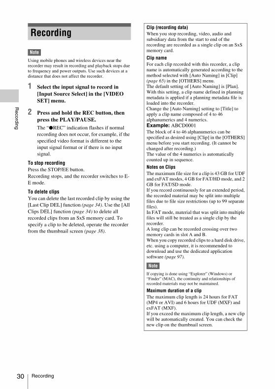
Note
Using mobile phones and wireless devices near the recorder may result in recording and playback stops due to frequency and power outputs. Use such devices at a distance that does not affect the recorder.
1 Select the input signal to record in [Input Source Select] in the [VIDEO SET] menu.
2 Press and hold the REC button, then press the PLAY/PAUSE.
The “zREC” indication flashes if normal recording does not occur, for example, if the specified video format is different to the input signal format or if there is no input signal.
To stop recordingPress the STOP/EE button.Recording stops, and the recorder switches to E-E mode.
To delete clipsYou can delete the last recorded clip by using the [Last Clip DEL] function (page 34). Use the [All Clips DEL] function (page 34) to delete all recorded clips from an SxS memory card. To specify a clip to be deleted, operate the recorder from the thumbnail screen (page 38).
RecordingClip (recording data)When you stop recording, video, audio and subsidiary data from the start to end of the recording are recorded as a single clip on an SxS memory card.
Clip nameFor each clip recorded with this recorder, a clip name is automatically generated according to the method selected with [Auto Naming] in [Clip] (page 65) in the [OTHERS] menu.The default setting of [Auto Naming] is [Plan]. With this setting, a clip name defined in planning metadata is applied if a planning metadata file is loaded into the recorder.Change the [Auto Naming] setting to [Title] to apply a clip name composed of 4 to 46 alphanumerics and 4 numerics.Example: ABCD0001The block of 4 to 46 alphanumerics can be specified as desired using [Clip] in the [OTHERS] menu before you start recording. (It cannot be changed after recording.) The value of the 4 numerics is automatically counted up in sequence.
Notes on ClipsThe maximum file size for a clip is 43 GB for UDF and exFAT modes, 4 GB for FAT/HD mode, and 2 GB for FAT/SD mode.If you record continuously for an extended period, the recorded material may be split into multiple files due to file size restrictions (up to 99 separate files).In FAT mode, material that was split into multiple files will still be treated as a single clip by the recorder.A long clip can be recorded crossing over two memory cards in slot A and B.When you copy recorded clips to a hard disk drive, etc. using a computer, it is recommended to download and use the dedicated application software (page 97).
Note
If copying is done using “Explorer” (Windows) or “Finder” (MAC), the continuity and relationships of recorded materials may not be maintained.
Maximum duration of a clipThe maximum clip length is 24 hours for FAT (MP4 or AVI) and 6 hours for UDF (MXF) and exFAT (MXF).If you exceed the maximum clip length, a new clip will be automatically created. You can check the new clip on the thumbnail screen.
Recording

Recording
By setting [Color Bars On/Off] (page 55) in the [VIDEO SET] menu to [On], you can output a color-bar signal in place of the camera picture. When this item is set to [Off], the output returns to the camera picture.A 1 kHz reference tone is output with the color bar signal if [1KHz Tone] in [Audio Output] (page 55) in the [AUDIO SET] menu is set to [On].The color-bar signal and reference-tone signal are also fed out from the SDI OUT 1/2, HDMI OUT, i.LINK, VIDEO OUT (color bars only), and AUDIO OUT connectors (reference audio signal only).You can select the type of color bars with [Color Bars Type] in the [VIDEO SET] menu.
Shot marks can be recorded at important audio/video scenes for clips recorded in UDF, exFAT or FAT/HD mode. Using shot marks enables the target scenes to be quickly and easily cued up on the Shot Mark screen (page 47).The recorder permits you to record two types of shot marks: shot mark 1 and shot mark 2.Shot marks can be inserted as needed during recording or can be added after recording while checking the playback pictures on the thumbnail screen.The recorder can use shot mark 1 and shot mark 2 as the in-point and out-point, respectively, for in-point to out-point partial playback (page 40).
Inserting a shot mark during recordingAssign [Shot Mark1] and [Shot Mark2] to the assignable buttons (page 32), and press the buttons at the scenes you want the shot marks inserted during recording.
Inserting a shot mark during playbackPress the assignable buttons to which [Shot Mark1] and [Shot Mark2] are assigned at the scenes you want the shot marks inserted during clip playback.
Note
Shot marks cannot be recorded onto write-protected SxS memory cards. Also, shot marks cannot be inserted at the start or end of a clip.
Shot marks can also be added and deleted using the Shot Mark screen (page 47).
For operation to apply a name to a shot mark, see “Defining Shot Mark names in Planning Metadata” on page 36.
You can add OK/NG/KP flags to clips recorded with UDF or exFAT. By adding flags, you can set the recorder to display only clips with certain flag settings on the thumbnail screen (OK/NG/KP/None-Clip thumbnail screen) (page 39).
Note
Use the [Lock Clip] setting (page 43) to protect clips.
Adding a flagDuring recording or playback, press the assignable button to which you assigned the [Clip Flag OK/Clip Flag NG/Clip Flag Keep] function.
Deleting a flagPress the assignable button, twice in succession, to which you assigned the [Clip Flag OK/Clip Flag NG/Clip Flag Keep] function.
OK/NG/KP flags can also be added and deleted from the thumbnail screen. For details, see “OK/NG/KP Flag” (page 44).
By adding the OK mark to a clip recorded in FAT HD Mode, you can prevent the clip from being deleted or divided inadvertently. You can also set the recorder to display only clips with the OK mark on the thumbnail screen (OK-Clip thumbnail screen) (page 39).
Adding the OK markWhen recording of a clip ends, press the assignable button to which you assigned the [OK Mark] function.While standing by to record, you can also add an OK mark to the last-recorded clip ([Last Clip]) on the selected memory card.
Useful Functions
Color Bars/Reference Tone
Shot Marks UDF exFAT FAT/HD
OK/NG/KP Flags
OK Mark
UDF exFAT
FAT/HD
Useful Functions 31

32
Recording
Deleting the OK markPress the assignable button to which you assigned the [OK Mark] function, and select [Execute].While standing by to record, you can also delete the OK mark from the clip with the last-added OK mark.
Adding or deleting the OK mark to or from clips before the last oneMake changes via the thumbnail screen (page 45).
The recorder has five assignable buttons (page 8) to which you can assign various functions for convenience.
To change functionsUse [Assign Button] (page 62) in the [OTHERS] menu.The assigned functions can be viewed on the Button/Remote status screen (page 50).
Clips are normally created individually for each time you start and stop recording, but you can also continue recording to a single clip regardless of the number of times you start and stop recording by using the Clip Continuous Recording function, which will add recordings to the same clip until the function is disabled or turned off.This is convenient for when you do not want to create a large number of short clips, or when you do not want to be restricted by a maximum number of clips.A recording start mark is added to each point at which you resume recording, making it easy to search for each point.
Preparatory settingsSet [Clip Cont. Rec Setting] (page 57) in the [VIDEO SET] menu to [On].When you set [Setting] to [On] the [Clip Continuous Recording] function is enabled, and “CONT” appears on the screen (page 10).You can also assign [Clip Continuous Rec] to an assignable button (page 32), and set to [On]/[Off] by pressing the button.
Notes
• Clip Continuous Recording cannot be used while recording.
• This function cannot be used with FAT.• This function cannot be used at the same time as the
function for simultaneous recording to both slots.
Performing clip continuous recording
Press and hold the REC button, then press the PLAY/PAUSE.
When recording starts, the “CONT” indication on the screen changes to “zREC” (with z in red).To pause recording, press the PLAY/PAUSE button. To resume, press and hold the REC button, then press the PLAY/PAUSE button.Pressing the STOP/EE button closes the clip. In clip continuous mode, the “CONT” indicator flashes if there is no continuous clip.When operating the IR Remote Commander, press the START/STOP button to start recording, and press the START/STOP button or PAUSE button to stop recording. To resume, press the START/STOP button again. Pressing the STOP button will close the clip.
Notes
• If you remove the SxS memory card or the battery while recording or standing by to record (the “CONT” indication appears), the SxS memory card must be restored. Only remove the SxS memory card after Clip Continuous Recording is complete. If “CONT” is flashing (1 time per second), you can remove the SxS memory card.
• Record for at least 2 seconds before you stop recording.
• If [Input Source Select] is set to [i.LINK], the [Clip Continuous Recording] function is disabled.
To disable Clip Continuous Recording modeWhile standing by to record, set [Clip Cont. Rec Setting] (page 57) in the [VIDEO SET] menu to [Off].
Restricted operationsIf you perform any of the following operations while recording or standing by to record, 1 continuous clip will not be created. The next time you start recording, a new clip will be created.• Performing clip operations (locking, deleting,
or changing the names of clips).• Switching the memory card slot.• Changing the recording format.• Setting the power button to OFF.• Displaying the thumbnail screen.• Playing clips.
Assignable Buttons
Clip Continuous Recording UDF exFAT
Useful Functions

Recording
You can continue recording video for a fixed interval by alternately recording and deleting video using two SxS memory cards.
Preparatory settingsSet [Segment Loop Rec] (page 57) in the [VIDEO SET] menu to [On]. Loop recording is enabled, and “SL-REC” appears on the screen (page 11).Set the recording retention time in [Segment Duration].In loop recording, the recording time that is retained of a clip varies depending on the recording status of the memory card when recording was stopped. When [15~35min] is selected in [Segment Duration], a minimum of 15 minutes and a maximum of 35 minutes is retained. When [15~35min] is selected, a minimum of 25 minutes free capacity is required on each SxS memory card. When [30~65min] is selected, a minimum of 40 minutes free capacity is required.
Notes
• Use SxS memory cards for loop recording. Recording to other memory cards using a media adapter is not supported.
• Loop recording is not supported in FAT mode.• This function cannot be used at the same time as the
function for simultaneous recording to both slots.
Starting loop recordingPress and hold the REC button, and press the PLAY/PAUSE button.Recording starts and “zREC” appears on the screen. Pressing the STOP/EE button stops recording and closes the clip. Simultaneously, the [Segment Loop Rec] setting is set to [Off].If the REC button and PLAY/PAUSE button are pressed simultaneously during loop recording, the recorder switches to normal recording and continues recording the clip seamlessly. After switching, the “SL-REC” indication on the screen disappears.
Notes
• In loop recording, video on the SxS memory cards is repeatedly recorded and deleted, shortening the rewrite life of the cards. Accordingly, check the remaining life of the memory cards periodically.
• If using loop recording continuously for longer than one week, restart the recorder once per week. Also, if the loop stops operating or other abnormality appears during operation, restart the recorder.
Restricted operationsIf you perform any of the following operations while loop recording, the recorder will switch to normal recording and the [Segment Loop Rec] setting will be set to [Off] automatically.• Switching the memory card slot• Ejecting media that is not recording
You can record simultaneously to both the memory cards in slots A and B.
Preparatory settingsBefore starting simultaneous recording to both slots, set [Simul Rec] to [Simul] (page 57) in the [VIDEO SET] menu.
Supported mediaSxS PRO+ seriesSxS PRO seriesSxS-1 seriesXQD memory card seriesSDXC cards (exFAT only)
Supported formatsWhen UDF/HD mode or exFAT mode is selected under [System] in the [OTHERS] menu:
For details, see “Recording Video Formats ([Rec Format])” (page 80).
Notes
• When simultaneously recording to both slots, use memory cards that are identical in type and size.
• The use of SxS memory cards is recommended.• The function for simultaneous recording to both slots
does not support SDHC cards.
Simultaneously recording to both slotsStart recording after configuring the necessary preparatory settings.
Press and hold the REC button, and press the PLAY/PAUSE button.
Recording starts, and the operation to stop recording is identical to that of normal recording.
Loop Recording UDF exFAT
Simultaneous Recording to Both
Slots UDF/HD exFAT/HD
Useful Functions 33

34
Recording
Notes
• The function for simultaneous recording to both slots cannot be used with the clip continuous recording function or loop recording function.
• The function for simultaneous recording to both slots cannot be configured during recording, playback, or thumbnail display.
• If one of the cards in the slots becomes full during recording, normal recording to the other card will continue for as long as possible. Even if the card is replaced while normal recording is in progress, simultaneous or relay recording will not be performed.
• If a card was inserted in only one of the slots or if one of the cards was full when simultaneous recording to both slots was started, normal recording to the available card will be performed.
• The IFU-WLM3 cannot be used when recording simultaneously to both slots.
While standing by to record, the [Last Clip DEL] function for deleting the last recorded clip and the [All Clips DEL] function for deleting all clips from an SxS memory card are available.
For clip deletion on the thumbnail screen, see “Deleting Clips” on page 45.
To delete using the assignable buttonAssign the [Last Clip DEL] function to one of the assignable buttons (page 32) in advance.Press the assignable button to which you have assigned [Last Clip DEL], and select [Execute] to delete the last recorded clip from the SxS memory card.
To delete using the Setup menuSelect [Last Clip DEL] in [Clip] (page 65) in the [OTHERS] menu, select [Execute], then select [Execute] again to delete the last recorded clip from the SxS memory card.
Note
When Clip Continuous Recording is set to [On], [Last Clip DEL] cannot be selected.
Deleting clips collectivelySelect [All Clips DEL] in [Clip] (page 65) in the [OTHERS] menu, select [Execute], then select [Execute] again to delete all the clips from the SxS memory card.
Notes
• If the SxS memory card contains clips of both of HD Mode and SD Mode, only the clips of the currently selected mode are deleted.
• Clips with the OK mark (page 31) cannot be deleted in FAT mode. In UDF or exFAT mode, clips set to [Lock Clip] (page 43) cannot be deleted.
You can store all the menu settings as a setup file on an SxS memory card or a USB flash drive.By retrieving the stored setup file, the proper setup condition can be immediately obtained.
Note
Values for [Clock Set] and [Hours Meter] in the [OTHERS] menu are not stored.
Storing the Setup file
To use an SxS memory cardOnly one setup file—designated with the file name “SETUP.SUF”—can be stored on one SxS memory card.
1 Insert a memory card on which you wish to store the setup file to a card slot.
Check that the inserted card is selected.
2 Select [Store(SxS)] in [Setup Data] (page 61) in the [OTHERS] menu, then select [Execute].
Note
If a setup file already exists on the memory card you specified in Step 1, a message to confirm whether to overwrite the file is displayed.
To use a USB flash drive Connect the formatted USB flash drive to the external device connector.Select [Store(USB)] >[Execute] in step 2.
Retrieving the Setup file
To use an SxS memory cardWhen you retrieve the stored setup file, the recorder settings are changed according to the file.
1 Insert the memory card on which you stored the setup file into a card slot.
Deleting Clips
Storing/Retrieving the Setting Data
UDF exFAT
Useful Functions

Recording
Check that the inserted card is selected.
2 Select [Recall(SxS)] in [Setup Data] (page 61) in the [OTHERS] menu, then select [Execute].
To use a USB flash drive Connect the formatted USB flash drive to the external device connector.Select [Recall(USB)] >[Execute] in step 2.
Resetting to the standard valuesThe current recorder settings you made through various menu and button operations can be collectively returned to the standard statuses (factory settings) by executing [All Reset] in the [OTHERS] menu.
Planning metadata is information about shooting and recording plans, recorded in an XML file. You can shoot using clip names and shot mark names defined in advance in a planning metadata file.This recorder can display clip names and shot mark names defined in the following languages:
English/Chinese/German/French/Italian/Spanish/Dutch/Portuguese/Swedish/Norwegian/Danish/Finnish
Notes
• If you define clip and shot mark names in languages other than those listed above, they may not be displayed on the LCD monitor.
• If you define clip and shot mark names in French, Dutch, or Finnish, some characters are displayed in a different but similar font.
Loading a Planning Metadata fileTo record planning metadata together with clips, it is necessary to load a planning metadata file into the recorder’s memory in advance.
To use an SxS memory cardInsert the SxS memory card with the planning metadata file (.xml) saved to the directory below into the recorder’s card slot, then select and load the file via [Load / Slot(A)] or [Load / Slot(B)] in [Plan.Metadata] (page 66) in the [OTHERS] menu.UDF: General/Sony/PlanningexFAT: XDROOT/General/Sony/PlanningFAT: BPAV/General/Sony/Planning
To use a USB flash drive Be sure to select [USB A] for [Power Enable] (page 67) in the [OTHERS] menu beforehand.
Notes
Proper operation may not be possible if the USB flash drive is connected without selecting [USB A].
1 Connect a USB flash drive formatted in the FAT32 file system to the external device connector.
A file list appears.
Note
The file list displays up to 64 files.Even if the total number of planning metadata files is 64 or less, all of the planning metadata files may not appear if the directory where they are located on the USB flash drive (General/Sony/Planning) contains 512 or more files.
2 Select the file which you want to load in the file list, then press the SEL/SET button.
Confirming the detailed information in planning metadata After loading a planning metadata file into memory of the recorder, you can check the details of the file, such as the filename, time and date of file creation, and the titles specified in the file. Select [Properties] in [Plan.Metadata] (page 66) in the [OTHERS] menu, then select [Execute].
When using the wireless LAN functionWhen a wireless LAN connection is made between the unit and a device, operate the Web menu built in the unit from the device to transfer a file.
1 Launch a browser on the device, and enter “http://<IP address of unit>” (page 67) in the address bar of the browser.
2 Input the user name and password, then click [OK].
User name: adminPassword: pmw-rx50
Clearing the loaded planning metadataTo clear the planning data loaded in the recorder’s memory, proceed as follows:Select [Clear] > [Execute] in [Plan.Metadata] (page 66) in the [OTHERS] menu.
Planning Metadata
UDF exFAT
UDF exFAT
Useful Functions 35

36
Recording
Defining a clip name in Planning MetadataThe following two types of clip name strings can be written in a planning metadata file.• ASCII-format name, which is displayed on the
LCD monitor • UTF-8-format name, which is actually
registered as the clip name
You can select the type for displaying the clip name with [Clip Name Disp] in [Plan.Metadata] (page 66) in the [OTHERS] menu.When you specify a clip name in planning metadata, the name is displayed under the operation status indication on the LCD monitor.
Example of clip name stringsUse a text editor to modify the description for the <Title> tag.The shaded fields in the example are clip name strings. “Typhoon” is described in ASCII format (up to 44 characters). “Typhoon_Strikes_Tokyo” is described in UTF-8 format (up to 44 bytes). Here, “sp” indicates a space, and 3 indicates a carriage return.
<?xmlspversion="1.0"spencoding="UTF-8"?>3
<PlanningMetadataspxmlns="http://xmlns.sony.net/pro/metadata/planningmetadata"spassignId="P0001"spcreationDate="2011-08-20T17:00:00+09:00"splastUpdate="2011-09-28T10:30:00+09:00"spversion="1.00">3
<PropertiessppropertyId="assignment"spupdate="2011-09-28T10:30:00+09:00"spmodifiedBy="Chris">3
<TitlespusAscii=" "spxml:lang="en"></Title>3
</Properties>3
</PlanningMetadata>3
Notes
• When you create a file, enter each statement as a single line by breaking a line with a CRLF only after the last character of the line, and do not enter spaces except where specified with “sp.”
• A string of up to 44 bytes (or 44 characters) is valid as a clip name. If a UTF-8-format string exceeds 44 bytes, the string up to the 44th byte is used as the clip name. If only a string in ASCII format is specified, the ASCII-format name up to the 44th characters is used as the clip name. When neither the ASCII-format name string nor UTF-8-format name string is valid, a clip name in the standard format is used.
Using a clip name defined in planning metadata Load a planning metadata file that contains the clip name into memory of the recorder, then select [Plan] in [Auto Naming] in [Clip] (page 65) in the [OTHERS] menu.Clip names are generated by adding an underscore (_) and a 5-digit serial number (00001 to 99999).Example: Typhoon_Strikes_Tokyo_00001,
Typhoon_Strikes_Tokyo_00002, ...
Notes
• If the serial number reaches 99999, it returns to 00001 upon the next recording.
• When you load another planning metadata file, the 5-digit serial number returns to 00001.
Defining Shot Mark names in Planning MetadataWhen you record shot mark 1 or shot mark 2, you can apply a name to the shot mark, using a string defined in planning metadata.
Example of shot mark name stringsUse a text editor to modify the description for the <Meta name> tag.The shaded fields in the example are shot mark name strings.Names can be either in ASCII format (up to 32 characters) or UTF-8 format (up to 16 characters).Here, “sp” indicates a space and 3 indicates a carriage return.
Note
If a name string contains even one non-ASCII character, the maximum length of that string is limited to 16 characters.
<?xmlspversion="1.0"spencoding="UTF-8"?>3
<PlanningMetadata xmlns="http://xmlns.sony.net/pro/metadata/ planningmetadata"spassignId=" H00123"spcreationDate=" 2011-04-15T08:00:00Z"splastUpdate="2011-04-15T15:00:00Z"spversion="1.00">3
TyphoonTyphoon_Strikes_Tokyo
Useful Functions

Recording
<PropertiessppropertyId="assignment"spclass="original"spupdate="2011-04-15T15:00:00Z"spmodifiedBy="Chris">3
<TitlespusAscii="Football Game"spxml:lang="en">Football Game 15/04/2011</Title>3
<Metaspname="_ShotMark1"spcontent=" "/>3
<Metaspname="_ShotMark2"spcontent=" "/>3
</Properties>3
</PlanningMetadata>3
Note
When you create a file, enter each statement as a single line by breaking a line with a CRLF only after the last character of the line, and do not enter spaces except where specified with “sp,” except within shot mark name strings.
Copying Planning Metadata files collectivelyYou can copy planning metadata files stored in the “General” folder on an SxS memory card collectively to another SxS memory card.Select [General Files] in [Copy All] (page 66) in the [OTHERS] menu.
USB flash drivesThe use of Sony flash drives is recommended.
Notes
• Use USB flash drives with capacity of 4 GB to 32 GB.• USB flash drives other than those listed above may not
be recognized if connected to the external device connector.
To format a USB flash driveUSB flash drives must be formatted with the FAT32 file system.
1 Connect the USB flash drive to the external device connector.
If the drive is unformatted or is formatted in an unsupported format, a message indicating that it cannot be used appears on the LCD monitor.
2 Set [USB Set] >[Format USB] to [FAT32] in the [OTHERS] menu.
When you select [FAT32], a message for confirming whether to execute formatting appears on the LCD monitor.
Note
Be sure to select [USB A] for [Power Enable] (page 67) in the [OTHERS] menu beforehand.
3 Select [Execute], then press the SEL/SET button.
When formatting is completed, the message “Format USB Memory Done” is displayed.The “\MSSONY\PRO\XDCAM\MEMDISC” folder and “\General\Sony\Planning” folder are automatically created in the drive.
To restore a USB flash driveWhen you load a USB flash drive that cannot be mounted normally because the file system is destroyed, a message appears on the LCD monitor to ask whether you want to restore it.Select [Execute], then press the SEL/SET button.When formatting is completed, the message “Restore USB Memory Done” is displayed.
Goal
Shoot
Useful Functions 37

38
Playback
When you press the THUMBNAIL button (page 7), clips recorded on the SxS memory card are displayed as thumbnails on the screen.You can start playback from the clip selected on the thumbnail screen. The playback picture can be seen on the LCD monitor and external monitors.Press the STOP/EE button (page 8) to exit the thumbnail screen and return to the recording standby screen.
Note
Even if the SxS memory card contains a mixture of HD and SD clips, the normal thumbnail screen shows only clips of the mode selected in [HD/SD] in [System] (page 63) in the [OTHERS] menu. To display all recorded clips regardless of the HD/SD Mode, switch the screen to the All-Clip thumbnail screen (page 39).
Data for the clip selected with the cursor are displayed at the bottom of the screen.
1. ThumbnailIn UDF, exFAT and FAT HD Mode: The thumbnail image for each clip is an index frame from the clip. When recording, the first frame of a clip is automatically set as the index frame. This frame can be adjusted (page 48). If the clip is locked or is set with an OK mark, the lock mark is displayed.In FAT SD mode: The thumbnail image for each clip is the first frame of the clip. If the file was split into multiple parts because its file size exceeded 2 GB, the take mark is displayed.
Split files can be viewed via the EXPAND CLIP screen (page 45).
2. Date and starting time of recording
3. Clip nameIn FAT SD Mode, if the file was split into multiple parts because its file size exceeded 2 GB, the segment number is displayed after the name, separated with a slash.
4. Lock mark UDF and exFAT: A lock mark appears if the selected clip is locked.
Playback
Thumbnail Screens
Configuration of the Thumbnail Screen
120min
05:42:49:13 05:42:53:06 05:42:56:18 22:31:04:14
22:31:16:12 22:31:18:17 22:31:20:23 22:31:22:28
22:31:24:33 22:31:26:38 22:31:28:43 22:31:30:48
0011 / 0300
01 / JAN / 2009 10 : 53 S&Q 29 / 24 JPAN0011(1) HQ 1920 / 23.9P MP4
TCR 00 :00 :00 : 00DUR 00 :03 :19 :23
2
1
3 4 5 6 7 8
9
10
11
Current clip No./ Total number of clips
Cursor(yellow)
The icon of the current SxS memory card is highlighted, shading the nonselected one. (If the card is write-protected, a lock icon is displayed to the left.)
UDF exFAT FAT/HD
Thumbnail Screens

Playback
FAT HD Mode: A lock mark appears if the selected clip has an OK mark.
5. AV independent file icon
Displayed only if the selected clip is an AV independent file. This indicates that not all operations and indications may be available, because the clip may have been added manually to the SxS file via a computer, etc., and there is no management file for it.
6. Recording video format
7. File formatThe file format (MXF, MP4, AVI) of the selected clip is displayed. (This item is not indicated when the recording mode is UDF/HD mode or exFAT mode.)
8. Duration of the clip
9. TimecodeThe timecode of the index frame is displayed.
10. OK/NG/KP mark UDF and exFAT: The mark is displayed if the selected clip has an OK/NG/KP flag.FAT HD Mode: The OK mark is displayed if the selected clip has an OK mark.
11. Special recording information
If the selected clip was recorded in a special recording mode (Slow & Quick Motion, Interval Recording, or Frame Recording), the mode is displayed.Clips recorded in Slow & Quick Motion display the “Recording frame rate/playback frame rate fps” to the right.
The type of thumbnail screen can be changed as follows by pressing the THUMBNAIL button (page 7).
UDF and exFATThe normal thumbnail screen, OK/NG/KP/None clip thumbnail screen, and All-Clip thumbnail screen are cyclically displayed.
FAT HD ModeThe normal thumbnail screen, OK clip thumbnail screen, and All-Clip thumbnail screen are cyclically displayed.
FAT SD ModeThe normal thumbnail screen and All-Clip thumbnail screen are alternately displayed.
OK/NG/KP/None-Clip thumbnail screenOnly the clips flagged OK/NG/KP—or clips with no flag (“None”)—among the clips on the current SxS memory card are displayed.You can select the type of flag to display with [Filter Clips] in [Clip] (page 65) in the [OTHERS] menu.
OK-Clip thumbnail screenOnly the clips marked OK among the clips on the current SxS memory card are displayed.
All-Clip thumbnail screenThe All-Clip thumbnail screen shows all clips on the current SxS memory card regardless of the HD or SD Mode, permitting you to check whether the card contains any clips of another mode than that currently selected.
Note
You cannot start playback from the All-Clip thumbnail screen.Press the THUMBNAIL button again to return to the normal thumbnail screen, and playback and clip operations are enabled.
Switching the SxS memory cardsWhen two memory cards are loaded, press the SLOT SELECT button (page 6) to switch memory cards.
Note
Card switching is enabled only when the thumbnail screen is displayed or when an external input picture is displayed by pressing the STOP/EE button.You cannot switch memory cards during playback.Continuous playback of cards in slots A and B is not possible.
Changing the Type of Thumbnail Screen
UDF exFAT FAT/HD
UDF exFAT FAT/HD
UDF exFAT FAT/HD
Thumbnail Screens 39

40
Playback
For playback operations, use the playback control buttons on the top panel (page 7). When the IR Remote Commander is enabled, you can use its playback control buttons instead (page 62).
1 Move the cursor to the thumbnail image of the clip with which you wish to start playback.
2 Press the PLAY/PAUSE button.
Playback starts from the beginning of the selected clip.
Notes
• The playback picture may be momentarily distorted or frozen between clips. The playback control buttons and THUMBNAIL button do not function during this condition.
• When you select a clip on the thumbnail screen and start playback, the playback picture at the beginning of the clip may be distorted. To start playback without distortion, once pause playback after starting it, press the PREV button to return to the top of the clip, then restart playback.
Information displayed on the playback screenThe following information is superimposed on the playback picture.
1. Battery remaining/DC IN voltage
2. Playback mode
3. SxS memory cardA mark appears to the left if the SxS memory card is write-protected.
4. Time dataEach time you press the DURATION/TC/U-BIT button, the indication is switched between timecode (TCR) and user-bit (UB) data.
5. Clip no./total number of clipsThis is displayed for FAT. It is also displayed for UDF and exFAT, if [Find Mode] in [Clip] (page 65) in the [OTHERS] menu is set to [Clip].
6. Clip no./total number of clips, essence mark no./total number of essence marksThis is displayed for UDF and exFAT, if [Find Mode] in [Clip] (page 65) in the [OTHERS] menu is set to [Rec Start].
7. Audio levelsThe audio levels for the recording are displayed.
The recorder can play a section between start and stop points specified in advance. The recorder plays continuously between the in-point and out-point for the clips after the selected clip.
Note
In FAT/SD mode, playback between in-point and out-point is not supported because shot marks cannot be inserted in clips.
Specifying the In-point and Out-pointSpecifying shot mark 1 and shot mark 2 for a clip allows the shot marks to be used as an in-point and out-point, respectively.When the recorder plays a clip with shot marks recorded on another device, the recorder can play the interval between shot marks 1 and 2 in the same way as for clips recorded on this recorder.When a clip with shot marks recorded on this recorder is played on another device, the shot marks are not treated as an in-point and out-point.
Selecting the Clip to PlayOnly clips with an attached OK flag or OK mark support partial playback between in-point and out-point.
Playing Clips
Playing the Selected and Subsequent Clips in Sequence
TCR 00:00:00:000011/03 00
120min B PLAY
CH1CH2
1 2 3 4 5
7
Playing between In-point and Out-point
Playing Clips

Playback
To select a clip for partial playback, attach an OK flag or OK mark to the clip on the thumbnail screen.
Playing between In-point and Out-pointSelect [PARTIAL PLAYBACK] from the clip operation menus.Playback starts from the first clip in the OK-Clip thumbnail screen.
When playback of the first clip ends, playback continues with the next clip that has an attached OK flag or OK mark.If shot mark 1 only is specified, the clip plays from shot mark 1 until the end of the clip. If shot mark 2 only is specified, the clip plays from the start of the clip up to shot mark 2.Selecting [P-PLAY & SDI REC] in the clip operation menus starts playing between In-point and Out-point and simultaneously outputs a REC trigger signal, allowing you to start proxy file recording using the CBK-WA100. To stop recording on the CBK-WA100, press the STOP/EE button to stop playback and REC trigger output.
Note
When playing between In-point and Out-point, the signal cannot be output on i.LINK (DVCAM/HDV).
Trim: Adjusting the In-point and Out-pointTrimming provides fine control of the playback start point and stop point.
1 Display the SHOT MARK screen (page 47).
2 Select the shot mark point you want to trim, then select [TRIM SHOT MARK1/2] in the clip operation menus.
A still image for the selected frame is displayed.
3 Use fast-forward/reverse, play/pause, or slow-motion play (left/right buttons) to move to the frame for which you want to set the shot mark.
4 Press the SEL/SET button.
The shot mark selected in step 3 is set at the current point, and the display returns to the OK-Clip thumbnail screen.
1 Select the thumbnail for the clip you want to play on the thumbnail screen.
2 Select [CLIP REPEAT] in the clip operation menus.
The selected clip starts playing, loops back to the start of the clip when it reaches the end, and continues playing.
To stop repeat playPress the STOP/EE button or the THUMBNAIL button.
In Normal playback mode, you can monitor the recorded audio signals through the built-in speaker (page 6) or connected headphones.With the headphones connected to the headphone connector (page 6), the built-in speaker is turned off.Press the VOLUME buttons (page 6) to adjust the sound volume.You can select audio channel(s) to be monitored with [Audio Output] (page 55) in the [AUDIO SET] menu.
To start playback from the top of the first clipPress the PREV button and F REV button simultaneously.
To start playback from the top of the last clipPress the F FWD button and NEXT button simultaneously.
Playing Clips in Repeat Mode
Monitoring Audio
Cueing Up
Playing Clips 41
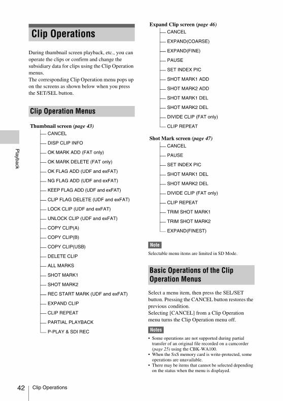
42
Playback
During thumbnail screen playback, etc., you can operate the clips or confirm and change the subsidiary data for clips using the Clip Operation menus.The corresponding Clip Operation menu pops up on the screens as shown below when you press the SET/SEL button.
Note
Selectable menu items are limited in SD Mode.
Select a menu item, then press the SEL/SET button. Pressing the CANCEL button restores the previous condition.Selecting [CANCEL] from a Clip Operation menu turns the Clip Operation menu off.
Notes
• Some operations are not supported during partial transfer of an original file recorded on a camcorder (page 25) using the CBK-WA100.
• When the SxS memory card is write-protected, some operations are unavailable.
• There may be items that cannot be selected depending on the status when the menu is displayed.
Clip Operations
Clip Operation Menus
Thumbnail screen (page 43)CANCEL
DISP CLIP INFO
OK MARK ADD (FAT only)
OK MARK DELETE (FAT only)
OK FLAG ADD (UDF and exFAT)
NG FLAG ADD (UDF and exFAT)
KEEP FLAG ADD (UDF and exFAT)
CLIP FLAG DELETE (UDF and exFAT)
LOCK CLIP (UDF and exFAT)
UNLOCK CLIP (UDF and exFAT)
COPY CLIP(A)
COPY CLIP(B)
COPY CLIP(USB)
DELETE CLIP
ALL MARKS
SHOT MARK1
SHOT MARK2
REC START MARK (UDF and exFAT)
EXPAND CLIP
CLIP REPEAT
PARTIAL PLAYBACK
P-PLAY & SDI REC
Expand Clip screen (page 46)CANCEL
EXPAND(COARSE)
EXPAND(FINE)
PAUSE
SET INDEX PIC
SHOT MARK1 ADD
SHOT MARK2 ADD
SHOT MARK1 DEL
SHOT MARK2 DEL
DIVIDE CLIP (FAT only)
CLIP REPEAT
Shot Mark screen (page 47)CANCEL
PAUSE
SET INDEX PIC
SHOT MARK1 DEL
SHOT MARK2 DEL
DIVIDE CLIP (FAT only)
CLIP REPEAT
TRIM SHOT MARK1
TRIM SHOT MARK2
EXPAND(FINEST)
Basic Operations of the Clip Operation Menus
Clip Operations

Playback
Clip Operation menu on the thumbnail screen
1) Effective with FAT HD Mode only.
2) Effective with UDF and exFAT Mode only.3) Effective with UDF, exFAT and FAT HD Mode.
Item FunctionDISP CLIP INFO Displays the clip’s information
screen (page 44).
OK MARK
ADD 1)
Adds an OK mark (page 45).
OK MARK
DELETE 1)
Deletes the OK mark (page 45).
OK FLAG
ADD 2)
Adds an OK flag (page 44).
NG FLAG
ADD 2)
Adds a NG flag (page 44).
KEEP FLAG
ADD 2)
Adds a KP flag (page 44).
CLIP FLAG
DELETE 2)
Deletes the flag (page 44).
LOCK CLIP 2) Locks and protects a clip (page 44).
UNLOCK CLIP 2) Unlocks a protected clip (page 44).
COPY CLIP(A) Copies the selected clips to the SxS memory card in slot A or slot B (page 45). COPY CLIP(B)
COPY CLIP(USB)
Copies the selected clips to USB media (page 45).
DELETE CLIP Deletes the clip (page 45).
ALL MARKS 3) Displays thumbnails of all frames with an essence mark recorded (page 47).
SHOT MARK1 3) Displays only thumbnails of frames with shot mark 1 recorded (page 47).
SHOT MARK2 3) Displays only thumbnails of frames with shot mark 2 recorded (page 47).
REC START MARK
Displays thumbnails of frames with a Recording Start mark and the first frames of clips without Recording Start marks (page 47).
EXPAND CLIP Displays the EXPAND CLIP screen (page 45).
CLIP REPEAT Plays the selected clip repeatedly (page 41).
PARTIAL PLAYBACK
Plays back the clip between the In-point and Out-point (page 41). (OK-clip thumbnail screen only)
P-PLAY & SDI REC
Plays back between the In-point and Out-point and simultaneously outputs a REC trigger signal (page 41). (OK-clip thumbnail screen only)
Clip Operations 43

44
Playback
Select [DISP CLIP INFO] from a Clip Operation menu.
1. Image of the current clip
2. Image of the previous clipPress the PREV button to switch to the clip info screen of the previous clip.In FAT SD Mode, the previous segment of a segmented clip is displayed.
3. Image of the next clipPress the NEXT button to switch to the clip info screen of the next clip.In FAT SD Mode, the next segment of a segmented clip is displayed.
4. Clip nameFor a clip name of 12 characters or longer, only the first 5 and last 5 characters of the name are displayed. To check the non-displayed block of the name, press the SEL/SET button to display the entire clip name (Long-Display mode). Press the SEL/SET button again to cancel Long-Display mode. Long-Display mode is also canceled by switching to the previous or next clip with the PREV or NEXT button.In FAT SD Mode, if the file was split into multiple parts because its file size exceeded 2 GB, the segment number is displayed after the name, separated with a slash.
5. Lock mark UDF and exFAT: A lock mark appears if the selected clip is locked.FAT HD Mode: A lock mark appears if the selected clip has an OK mark.
6. OK/NG/KP mark UDF and exFAT: The mark is displayed if the selected clip has an OK/NG/KP flag.FAT HD Mode: The OK mark is displayed if the selected clip has an OK mark.
7. Date and starting time of recording
8. File formatThe file format (MXF, MP4, AVI) of the selected clip is displayed.
9. Special recording information
If the selected clip was recorded in a special recording mode (Slow & Quick Motion, Interval Recording, or Frame Recording), the mode is displayed.Clips recorded in Slow & Quick Motion display the “Recording frame rate/playback frame rate fps” to the right.
10. Timecode of the displayed frame
11. Timecode at the recording starting point
12. Timecode at the recording ending point
13. Duration of the clip
14. Recorded audio channels
15. Recorded video format
When adding a flag, you can select from [OK FLAG ADD], [NG FLAG ADD], and [KEEP
Displaying the Detailed Information of a Clip
OKOK
120min CLIP I NFO 0011 / 0300
PREV CLIP NEXT CLIP
JPAN0011(1)01 / JAN / 2009 10 :53HQ 1920 / 23.9P MP4S&Q Mot i on 29 / 24fpsTCR 00 :05 :00 : 02TCR 00 :05 :00 : 00 STRTCR 00 :08 :19 : 23 ENDDUR 00 :03 :20 :00CH1/2 /3 /4 /5 /6 /7 /8
1
2
3
4
56789101112131415
UDF exFAT FAT/HD
OK/NG/KP Flag
UDF exFAT FAT/HD
UDF exFAT FAT/HD
UDF exFAT
Clip Operations
Playback
FLAG ADD] in the Clip Operation menu (page 43) on the thumbnail screen. When deleting a flag, select [CLIP FLAG DELETE].
Note
Flagged clips are not protected. To protect clips from deletion, select [LOCK CLIP] in the Clip Operation menu (page 43) on the thumbnail screen. To remove the protection, select [UNLOCK CLIP].
Select [OK MARK ADD] from the Clip Operation menu (page 43) to add the OK mark, or select [OK MARK DELETE] from the Clip Operation menu to delete it.
You can copy clips on an SxS memory card to another SxS memory card.Each clip is copied with the same name to the destination SxS memory card.
Notes
• If there is another clip having the same name on the destination SxS memory card, the clip is copied under a name adding a single-digit number in parentheses to the end of the original clip name.The parenthetical number is the minimum value that does not exist in the destination memory card.Examples: ABCD0002(1) if ABCD0002 exists ABCD0002(2) if ABCD0002(1) exists ABCD0005(4) if ABCD0005(3) exists
• When using FAT, you cannot copy a file 10 times or more if clips with the same clip name followed by parenthetical numbers (1) to (9) already exist on the card.
• When using UDF or exFAT, you cannot copy a file 1000 times or more if clips with the same clip name followed by parenthetical numbers (1) to (999) already exist on the card.
• A warning message is displayed if there is not sufficient space on the destination SxS memory card. Replace the SxS memory card with one with sufficient space.
• When copying an SxS memory card on which multiple clips have been recorded, copying all clips to the end may not be achieved, even if the destination card has the same capacity as the source card, depending on usage conditions, memory characteristics, etc.
Copying a specified clipSelect a clip on a thumbnail screen, then select [COPY CLIP(A)] or [COPY CLIP(B)] from the Clip Operation menu.
Copying clips collectivelySelect [Clips] in [Copy All] (page 66) in the [OTHERS] menu to copy clips on an SxS memory card collectively to another SxS memory card.If the memory card contains clips of both HD and SD Mode, only the clips of the currently selected mode are copied. This is convenient when you wish to extract clips of the same mode only.
Copying to USB mediaWhen USB media is connected, select a clip on a thumbnail screen and select [COPY CLIP (USB)] from the Clip Operation menu to copy the clip to the USB media. You can also copy all SxS memory card clips to USB media by selecting [USB SET] > [Copy To USB] in the [OTHERS] menu. This copies only clips for the selected mode in the same way as selecting [Copy All] in the [OTHERS] menu.
Select [DELETE CLIP] from the Clip Operation menu.
Note
Clips with an OK mark and flagged clips set to [LOCK CLIP] cannot be deleted.To delete them, release the OK mark or the [LOCK CLIP] setting before performing the delete operation.
Deleting clips collectivelySelect [All Clips DEL] in [Clip] (page 65) in the [OTHERS] menu.
Notes
• If the memory card contains clips of both HD and SD Mode, only the clips of the currently selected mode are deleted.
• Clips with an OK mark and flagged clips set to [LOCK CLIP] cannot be deleted.
In UDF, exFAT and FAT HD Mode, the [EXPAND CLIP] screen permits you to divide a clip into 12 blocks of equal duration and show a thumbnail image of the first frame of each block on the screen.In FAT SD Mode, the [EXPAND CLIP] screen shows the thumbnail images of the first frames of the segment files only for a clip segmented because its file size exceeded 2 GB.
OK Mark
Copying Clips
FAT/HD
Deleting Clips
EXPAND CLIP Screen
Clip Operations 45
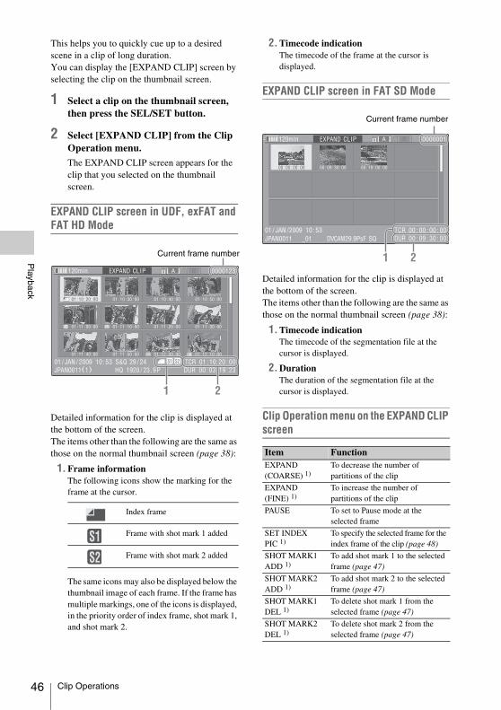
46
Playback
This helps you to quickly cue up to a desired scene in a clip of long duration.You can display the [EXPAND CLIP] screen by selecting the clip on the thumbnail screen.
1 Select a clip on the thumbnail screen, then press the SEL/SET button.
2 Select [EXPAND CLIP] from the Clip Operation menu.
The EXPAND CLIP screen appears for the clip that you selected on the thumbnail screen.
EXPAND CLIP screen in UDF, exFAT and FAT HD Mode
Detailed information for the clip is displayed at the bottom of the screen.The items other than the following are the same as those on the normal thumbnail screen (page 38):
1. Frame informationThe following icons show the marking for the frame at the cursor.
The same icons may also be displayed below the thumbnail image of each frame. If the frame has multiple markings, one of the icons is displayed, in the priority order of index frame, shot mark 1, and shot mark 2.
2. Timecode indicationThe timecode of the frame at the cursor is displayed.
EXPAND CLIP screen in FAT SD Mode
Detailed information for the clip is displayed at the bottom of the screen.The items other than the following are the same as those on the normal thumbnail screen (page 38):
1. Timecode indicationThe timecode of the segmentation file at the cursor is displayed.
2. DurationThe duration of the segmentation file at the cursor is displayed.
Clip Operation menu on the EXPAND CLIP screen
Index frame
Frame with shot mark 1 added
Frame with shot mark 2 added
S1 S2
S2 S1
120min EXPAND CLIP
01 : 10 : 20 : 00 01 : 10 : 30 : 00 01 : 10 : 40 : 00 01 : 10 : 50 : 00
01 : 11 : 00 : 00 01 : 11 : 10 : 00 01 : 11 : 20 : 00 01 : 11 : 30 : 00
01 : 11 : 40 : 00 01 : 11 : 50 : 00 01 : 12 : 00 : 00 01 : 12 : 10 : 00
0000123
01 / JAN / 2009 10 :53 S&Q 29 / 24JPAN0011(1) HQ 1920 / 23.9P
TCR 01 :10:20 : 00DUR 00 :03 :19 :23
21
Current frame number
S1S2
Item FunctionEXPAND(COARSE) 1)
To decrease the number of partitions of the clip
EXPAND(FINE) 1)
To increase the number of partitions of the clip
PAUSE To set to Pause mode at the selected frame
SET INDEX PIC 1)
To specify the selected frame for the index frame of the clip (page 48)
SHOT MARK1 ADD 1)
To add shot mark 1 to the selected frame (page 47)
SHOT MARK2 ADD 1)
To add shot mark 2 to the selected frame (page 47)
SHOT MARK1 DEL 1)
To delete shot mark 1 from the selected frame (page 47)
SHOT MARK2 DEL 1)
To delete shot mark 2 from the selected frame (page 47)
120min EXPAND CLIP
00 : 00 : 00 : 00 00 : 09 : 30 : 00 00 : 19 : 00 : 00
0000001
01 / JAN /2009 10 :53JPAN0011 _01 DVCAM29.9PsF SQ
TCR 00 : 00 : 00 : 00DUR 00 : 09 : 30 : 00
21
Current frame number
Clip Operations

Playback
1) Enabled in UDF, exFAT and FAT/HD mode.
You can display only those frames with shot marks or recording start marks as thumbnail images on the screen.
1 Select a clip on the thumbnail screen, then press the SEL/SET button.
2 Select [ALL MARKS], [SHOT MARK1], [SHOT MARK2], or [REC START MARK] from the Clip Operation menu.
SHOT MARK screen example (when [ALL MARKS] is selected)
The detailed information of the clip is displayed at the bottom of the screen.The items other than the following are the same as those on the EXPAND CLIP screen (page 46) in UDF, exFAT and FAT HD mode:
1. Timecode indicationThe timecode of the frame at the cursor on the SHOT MARK screen is displayed.
Move the cursor to the first/last frameFirst frame: When the cursor is at a user-designated position, press the F REV and PREV buttons simultaneously.
Last frame: Press the F FWD and NEXT buttons simultaneously.
Switch to the clip shot mark screen for a different clipPrevious clip: When the cursor is at the first frame for a clip, press the PREV or up button.Next clip: When the cursor is at the last frame for a clip, press the NEXT or down button.
Clip Operation menu on the SHOT MARK screen
Adding/Deleting Shot Marks
Adding a shot mark in Pause modeSelect [SHOT MARK1 ADD] or [SHOT MARK2 ADD] from the Clip Operation menu.
Adding a shot mark on the EXPAND CLIP screenSelect [SHOT MARK1 ADD] or [SHOT MARK2 ADD] from the Clip Operation menu.
Deleting a shot markSelect [SHOT MARK1 DEL] or [SHOT MARK2 DEL] from the Clip Operation menu on the [EXPAND CLIP] screen (page 45) or on the [SHOT MARK] screen (page 47).
DIVIDE CLIP 1) To divide the clip into two clips at the selected frame (page 48)
CLIP REPEAT 1) Plays the selected clip repeatedly (page 41).
SHOT MARK Screen
Item Function
UDF exFAT FAT/HD
S1 S2 S2 S1
S1 S1
120min SHOTSHOT MARK1
01 : 10 : 20 : 00 01 : 10 : 30 : 00 01 : 10 : 40 : 00 01 : 10 : 50 : 00
01 : 11 : 00 : 00 01 : 11 : 10 : 00
- - -
- - -
- - -
- - -
- - - - - -
0031 / 0031
01 / JAN / 2009 10 :53 S&Q 29 / 24JPAN0011(1) HQ 1920 / 23.9P
TCR 01 : 12:00 : 00DUR 00 : 03 : 19 : 23
1
Item FunctionPAUSE To set to Pause mode at the selected
frame
SET INDEX PIC To specify the selected frame for the index frame of the clip (page 48)
SHOT MARK1 DEL
To delete the shot mark 1 from the selected frame (page 47)
SHOT MARK2 DEL
To delete the shot mark 2 from the selected frame (page 47)
DIVIDE CLIP To divide the clip into two clips at the selected frame (page 48) (FAT HD mode Only)
CLIP REPEAT Plays the selected clip repeatedly (page 41).
TRIM SHOT MARK1
Trims the set position of the specified shot mark 1 (page 41).
TRIM SHOT MARK2
Trims the set position of the specified shot mark 2 (page 41).
EXPAND (FINEST)
Displays the CLIP EXPAND screen, showing the smallest segment of the clip, and displays the selected frame in the center of the screen.
Clip Operations 47
48
Playback
You can change the index frame to another frame you selected on the [EXPAND CLIP] screen (page 45) or the [SHOT MARK] screen (page 47).Select [SET INDEX PIC] from the Clip Operation menu.
Note
Even if you specify a frame other than the top frame for the index frame, playback always begins from the top frame when you start it from the thumbnail screen.
You can divide a clip into two different clips at the frame you select on the [EXPAND CLIP] screen (page 45) or the [SHOT MARK] screen (page 47).Select [DIVIDE CLIP] from the Clip Operation menu.The first 4 characters of the original clip name are carried on, continuing to the last number on the memory card by the second 4 numerics.Example: If you divide a clip named
“ABCD0002” into two clips under the condi-tion where a new clip will be named “EFGH0100,” clip “ABCD0100” and clip “ABCD0101” are created.
Note
If the remaining space on the memory card is insufficient for divided clips, a message informing you of it appears.
Changing the Index Frame
Dividing a Clip
UDF exFAT FAT/HD
FAT/HD
Clip Operations
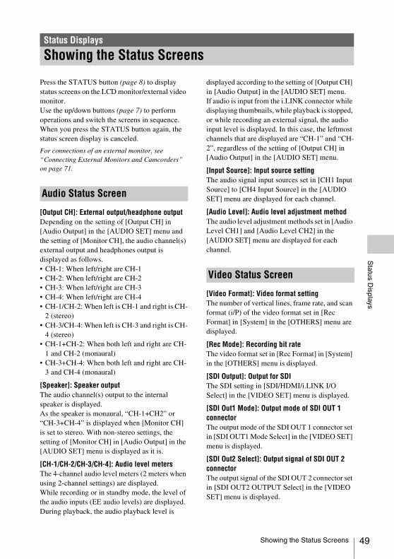
Status D
isplays
Press the STATUS button (page 8) to display status screens on the LCD monitor/external video monitor.Use the up/down buttons (page 7) to perform operations and switch the screens in sequence.When you press the STATUS button again, the status screen display is canceled.
For connections of an external monitor, see “Connecting External Monitors and Camcorders” on page 71.
[Output CH]: External output/headphone outputDepending on the setting of [Output CH] in [Audio Output] in the [AUDIO SET] menu and the setting of [Monitor CH], the audio channel(s) external output and headphones output is displayed as follows.• CH-1: When left/right are CH-1• CH-2: When left/right are CH-2• CH-3: When left/right are CH-3• CH-4: When left/right are CH-4• CH-1/CH-2: When left is CH-1 and right is CH-
2 (stereo)• CH-3/CH-4: When left is CH-3 and right is CH-
4 (stereo)• CH-1+CH-2: When both left and right are CH-
1 and CH-2 (monaural)• CH-3+CH-4: When both left and right are CH-
3 and CH-4 (monaural)
[Speaker]: Speaker outputThe audio channel(s) output to the internal speaker is displayed.As the speaker is monaural, “CH-1+CH2” or “CH-3+CH-4” is displayed when [Monitor CH] is set to stereo. With non-stereo settings, the setting of [Monitor CH] in [Audio Output] in the [AUDIO SET] menu is displayed as it is.
[CH-1/CH-2/CH-3/CH-4]: Audio level metersThe 4-channel audio level meters (2 meters when using 2-channel settings) are displayed.While recording or in standby mode, the level of the audio inputs (EE audio levels) are displayed. During playback, the audio playback level is
displayed according to the setting of [Output CH] in [Audio Output] in the [AUDIO SET] menu.If audio is input from the i.LINK connector while displaying thumbnails, while playback is stopped, or while recording an external signal, the audio input level is displayed. In this case, the leftmost channels that are displayed are “CH-1” and “CH-2”, regardless of the setting of [Output CH] in [Audio Output] in the [AUDIO SET] menu.
[Input Source]: Input source settingThe audio signal input sources set in [CH1 Input Source] to [CH4 Input Source] in the [AUDIO SET] menu are displayed for each channel.
[Audio Level]: Audio level adjustment methodThe audio level adjustment methods set in [Audio Level CH1] and [Audio Level CH2] in the [AUDIO SET] menu are displayed for each channel.
[Video Format]: Video format settingThe number of vertical lines, frame rate, and scan format (i/P) of the video format set in [Rec Format] in [System] in the [OTHERS] menu are displayed.
[Rec Mode]: Recording bit rateThe video format set in [Rec Format] in [System] in the [OTHERS] menu is displayed.
[SDI Output]: Output for SDIThe SDI setting in [SDI/HDMI/i.LINK I/O Select] in the [VIDEO SET] menu is displayed.
[SDI Out1 Mode]: Output mode of SDI OUT 1 connectorThe output mode of the SDI OUT 1 connector set in [SDI OUT1 Mode Select] in the [VIDEO SET] menu is displayed.
[SDI Out2 Select]: Output signal of SDI OUT 2 connectorThe output signal of the SDI OUT 2 connector set in [SDI OUT2 OUTPUT Select] in the [VIDEO SET] menu is displayed.
Status Displays
Showing the Status Screens
Audio Status Screen
Video Status Screen
Showing the Status Screens 49

50
Status D
isplays
[3G SDI Out Level]: Data mapping method for 3G SDI signalsThe data mapping method for 3G SDI signals set in [3G SDI OUT Level A/B] in the [VIDEO SET] menu is displayed.
[HDMI Output]: Output for HDMIThe HDMI setting in [SDI/HDMI/i.LINK I/O Select] in the [VIDEO SET] menu is displayed.
[i.LINK I/O]: Input and output for i.LINKThe i.LINK setting in [SDI/HDMI/i.LINK I/O Select] in the [VIDEO SET] menu is displayed.
[Input Setting]: Recording sourceThe input source or SG output setting in [Input Source Select] in the [VIDEO SET] menu is displayed.
[Down Converter]: SD output down-converter settingThe [Down Converter] setting ([Squeeze], [Letterbox], [Edge Crop]) in the [VIDEO SET] menu is displayed.
[23.98P Output]: 23.98P output modeThe [23.98P Output] setting (23.98PsF, 59.94i (2-3 Pull Down)) in the [VIDEO SET] menu is displayed.
[Assign Button]: Assignable button statusesThe functions assigned with the [Assign Button] in the [OTHERS] menu to the respective assignable buttons are displayed.
[IR Remote]: IR Remote Commander statusThe [IR Remote] setting in the [OTHERS] menu is displayed.
[Wi-Fi Remote]: Wi-Fi remote control enable/disableThe [Wi-Fi] >[Wi-Fi Remote] setting in the [OTHERS] menu is displayed.
[Battery]: Battery charge remainingThe remaining charge level of the mounted battery pack is displayed.
[Charge Count]: Repeated charge timesThe number of times that the mounted battery pack has been charged is displayed.
[Media A/Media B]: Remaining space, available recording time, and estimated service life (rewriting limit)The remaining space of the SxS memory cards in the respective card slots is indicated on the meters.At the right, the available time for recording if done at the current bit rate is displayed, in minutes.The time indication will be “- - min” if no SxS memory card or an invalid card is in the slot.If the card is write-protected, a icon is shown to the right of the time indication.The Life value is displayed only for an SxS memory card which supports the life value indication. It indicates the estimated remaining usable period of the card (virgin status as 100%). If an alarm is generated, make a backup of the card as soon as possible and replace it with a new card.
[USB Drv]: Remaining capacity of USB mediaWhen USB media is connected, the remaining recording capacity is displayed on the meter.
Button/Remote Status Screen
Battery/Media Status Screen
Showing the Status Screens

Menu C
onfiguration and Detailed S
ettings
Press the MENU button to display setup menus on the LCD monitor with settings necessary for recording and playback. (You can also display setup menus on an external monitor.) Set items by selecting them from the following menus.[AUDIO SET] menu: For setting audio-related items.[VIDEO SET] menu: For setting video output-related items.[LCD SET] menu: For setting items related to the LCD monitor.[TC/UB SET] menu: For setting items related to timecodes and user bits.[OTHERS] menu: For setting other items.
Menu Configuration and Detailed Settings
Overview of the Setup Menus
Setup Menu Layers
MENU
AUDIO SET Audio InputAudio Output
VIDEO SET Input Source SelectColor Bars On/OffColor Bars TypeSDI/HDMI/i.LINK I/O SelectSDI OUT1 Mode SelectSDI OUT2 OUTPUT Select3G SDI OUT Level A/BSDI/HDMI/Video Out SuperDown Converter23.98P OutputSDI Rec ControlSimul RecClip Cont. Rec SettingSegment Loop RecSegment Duration
LCD SET LCDDisplay On/Off
TC/UB SET TimecodeUsers BitTC Format
OTHERS All ResetSetup DataTime ZoneClock SetLanguageAssign ButtonTallyHours MeterIR RemoteBattery AlarmBattery INFOTrigger ModeSystemClipCopy AllFormat MediaPlan.MetadataPower EnableNetworkWi-FiUSB SETVersionVersion UpMenu Scroll
Overview of the Setup Menus 51

52
Menu C
onfiguration and Detailed S
ettings
Menu controls
MENU button (page 7)To turn Menu mode to use Setup menus on/off.
Up/Down/Left/Right buttons, SEL/SET button (page 7)Press the up/down/left/right buttons to move the cursor the corresponding direction to select menu items or setting values.Press the SEL/SET button to enter the highlighted item.
CANCEL button (page 7)To return to the previous layer of the menu. An uncompleted change is canceled.
Setting the Setup menusMove the cursor to the icon of the menu you wish to set, then push the SEL/SET button to select that menu.• The menu item selection area can show 7 lines
at maximum. When all the selectable items cannot be displayed at one time, you can scroll the display up or down by moving the cursor. A triangle appears at the upper or lower right corner of the menu item selection area to indicate that scrolling is enabled.
• For items having a wide range of available values (example: –99 to +99), the available value area is not displayed. The current setting is highlighted instead, indicating that the setting is ready for change.
• When you select [Execute] for an execution item, the corresponding function is executed.
• When you select an item that you must confirm before execution, the menu display temporarily disappears, and a confirmation message is displayed. Following the instructions of the message, and specify whether to execute or cancel.
Entering a character stringWhen you select an item for which a character string, such as a time value or filename, is to be specified, the input area for the character string is highlighted, and [SET] appears at the right end.
1 Select characters, then press the SEL/SET button to proceed.
The cursor moves to the next column.To return to the previous column, press the left button.
2 Perform setting in the same manner up to the last column/digit.
The cursor moves to [SET].
3 Press the SEL/SET button.
The setting is completed.
Basic Menu Operations
Basic Menu Operations

Menu C
onfiguration and Detailed S
ettings
The functions and available settings of menus are listed below.The default settings set at the factory are shown in bold face (example: Speed). The items marked with [M] in the Menu items column cannot be set while displaying the thumbnail screen or during playback operations.
Setup Menu List
[AUDIO SET] Menu
AUDIO SET
Menu items Subitems and setting values Contents
Audio InputSetting for audio inputs (only when audio input box is attached)
[M]
Note
This item cannot be configured when [i.Link] is selected for [Input Source Select] in the [VIDEO SET] menu.
CH1 Input SourceSDI IN / Ext
Select the audio signal input source to be recorded as channel 1 for formats that support audio recording.[SDI IN]: Record the CH-1 signal of the SDI IN connector.[Ext]: Record the signal selected in [EXT CH Select].
CH2 Input SourceSDI IN / Ext
Select the audio signal input source to be recorded as channel 2 for formats that support audio recording.[SDI IN]: Record the CH-2 signal of the SDI IN connector.[Ext]: Record the signal selected in [EXT CH Select].
CH3 Input SourceSDI IN / Ext
Select the audio signal input source to be recorded as channel 3 for formats that support 4-channel audio recording.[SDI IN]: Record the CH-3 signal of the SDI IN connector.[Ext]: Record the signal selected in [EXT CH Select].
CH4 Input SourceSDI IN / Ext
Select the audio signal input source to be recorded as channel 4 for formats that support 4-channel audio recording.[SDI IN]: Record the CH-4 signal of the SDI IN connector.[Ext]: Record the signal selected in [EXT CH Select].
EXT CH SelectCH1/CH2 / CH1
Set the signal settings that are selected when [Ext] is selected for [CH1 Input Source] to [CH4 Input Source].[CH1/CH2]: Input the audio signal from the CH-1 AUDIO IN
connector to the odd-numbered channel for which [Ext] is selected, and input the audio signal from the CH-2 AUDIO IN connector to the even-numbered channels.
[CH1]: Input the audio signal from the CH-1 AUDIO IN connector to all the channels for which [Ext] is selected.
Line Input Ref+4dB / 0dB / –3dB / EBUL
Set the reference input level that is used when the input source is set to [Ext] in [CH1 Input Source] to [CH4 Input Source]. The same setting is used for both CH-1 and CH-2 of the AUDIO connector.
Tip
This setting is only enabled when the input source is set to [Ext].
Reference Level-20dB / –18dB / –16dB / –12dB / EBUL
Set the output level of the 1 kHz test signal.
Tip
This setting is only enabled when the input source is set to [Ext].
Setup Menu List 53
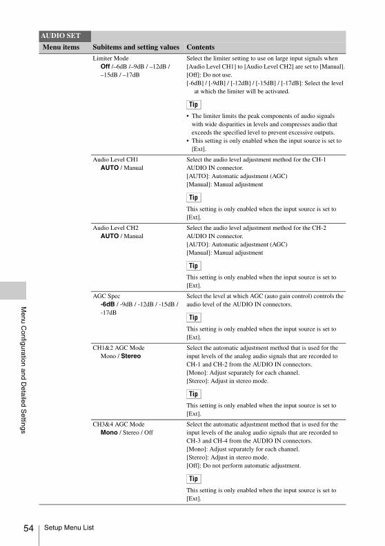
54
Menu C
onfiguration and Detailed S
ettings
Limiter ModeOff /–6dB /–9dB / –12dB / –15dB / –17dB
Select the limiter setting to use on large input signals when [Audio Level CH1] to [Audio Level CH2] are set to [Manual].[Off]: Do not use.[-6dB] / [-9dB] / [-12dB] / [-15dB] / [-17dB]: Select the level
at which the limiter will be activated.
Tip
• The limiter limits the peak components of audio signals with wide disparities in levels and compresses audio that exceeds the specified level to prevent excessive outputs.
• This setting is only enabled when the input source is set to [Ext].
Audio Level CH1AUTO / Manual
Select the audio level adjustment method for the CH-1 AUDIO IN connector.[AUTO]: Automatic adjustment (AGC)[Manual]: Manual adjustment
Tip
This setting is only enabled when the input source is set to [Ext].
Audio Level CH2AUTO / Manual
Select the audio level adjustment method for the CH-2 AUDIO IN connector.[AUTO]: Automatic adjustment (AGC)[Manual]: Manual adjustment
Tip
This setting is only enabled when the input source is set to [Ext].
AGC Spec-6dB / -9dB / -12dB / -15dB / -17dB
Select the level at which AGC (auto gain control) controls the audio level of the AUDIO IN connectors.
Tip
This setting is only enabled when the input source is set to [Ext].
CH1&2 AGC ModeMono / Stereo
Select the automatic adjustment method that is used for the input levels of the analog audio signals that are recorded to CH-1 and CH-2 from the AUDIO IN connectors.[Mono]: Adjust separately for each channel.[Stereo]: Adjust in stereo mode.
Tip
This setting is only enabled when the input source is set to [Ext].
CH3&4 AGC ModeMono / Stereo / Off
Select the automatic adjustment method that is used for the input levels of the analog audio signals that are recorded to CH-3 and CH-4 from the AUDIO IN connectors.[Mono]: Adjust separately for each channel.[Stereo]: Adjust in stereo mode.[Off]: Do not perform automatic adjustment.
Tip
This setting is only enabled when the input source is set to [Ext].
AUDIO SET
Menu items Subitems and setting values Contents
Setup Menu List

Menu C
onfiguration and Detailed S
ettings
Audio OutputSetting for audio outputs
1KHz ToneOn / Off
Turn the 1-kHz reference tone signal on/off.
Monitor CHCH-1/CH-2 (CH-3/CH-4)CH-1+CH-2 (CH-3+CH-4)CH-1 (CH-3)CH-2 (CH-4)
Select the audio channel(s) to be fed to the headphones and the built-in speaker.[CH-1/CH-2 (CH-3/CH-4)]: Stereo[CH-1+CH-2 (CH-3+CH-4)]: Mix[CH-1 (CH-3)]: CH-1 (CH-3) only[CH-2 (CH-4)]: CH-2 (CH-4) only( ): with [Output CH] set to [CH-3/CH-4]
Output CHCH-1/CH-2CH-3/CH-4
Select audio output channels from either channels 1 and 2 or channels 3 and 4.
Alarm Level0 to 7 (4)
Set the alarm sound volume.
AUDIO SET
Menu items Subitems and setting values Contents
[VIDEO SET] Menu
VIDEO SET
Menu items Setting values Contents
Input Source SelectSetting the input source
SDI / i.LINK Select video and audio signal for the input source.[SDI]: Input from SDI IN connector[i.LINK]: HDV/DVCAM input via the i.LINK connector
Note
i.LINK is unavailable in UDF/HD mode and exFAT mode.
Color Bars On/OffSetting the Color Bars
On / Off Turn color bars output on/off when [Input Source Select] is set to [SDI].
Color Bars TypeSelecting the type of color bars
Multi / 75% / 100% / SMPTE Select the type of color bars to be output when [Color Bars On/Off] is set to [On].[Multi]: Multiformat color bars are output.[75%]: To output 75% color bars[100%]: To output 100% color bars[SMPTE]: To output SMPTE color bars.
Setup Menu List 55

56
Menu C
onfiguration and Detailed S
ettings
SDI/HDMI/i.LINK I/O SelectSelecting input/output signals for the connectors
In UDF/HD modeHD SDSD POff
In exFAT/HD mode3G (SDI)HD SDSD POff
In FAT/HD mode (HQ)HD SD & DVCAMSD POff
In FAT/HD mode (SP)HD & HDV SD & HDVSD P & HDVSD & DVCAMOff
In UDF/SD modeSD Off
In exFAT/SD modeSD Off
In FAT/SD modeSD & DVCAM Off
[3G (SDI)]: Output a 3G SDI signal from the SDI OUT 1/2 connectors, and an HD HDMI signal from the HDMI OUT connector.
[HD]: Output an HD SDI signal from the SDI OUT 1/2 connectors, and an HD HDMI signal from the HDMI OUT connector.
[SD]: Output an SD SDI signal from the SDI OUT 1/2 connectors, and an SD HDMI interlaced signal from the HDMI OUT connector. In UDF/SD mode, DVCAM stream is input/output on the i.LINK connector.
[HD & HDV]: Output an HD SDI signal from the SDI OUT 1/2 connectors, and an HD HDMI signal from the HDMI OUT connector. Input/output an HDV stream on the i.LINK connector.
[SD & HDV]: Output an SD SDI signal from the SDI OUT 1/2 connectors, and an SD HDMI interlaced signal from the HDMI OUT connector. Input/output an HDV stream on the i.LINK connector.
[SD P & HDV]: Output an SD HDMI progressive signal from the HDMI OUT connector. Input/output an HDV stream on the i.LINK connector. No signal is output from the SDI OUT and VIDEO OUT connectors.
[SD & DVCAM]: Output an SD SDI signal from the SDI OUT 1/2 connectors, and an SD HDMI interlaced signal from the HDMI OUT connector. Input/output a DVCAM stream on the i.LINK connector.
[SD P]: Output an SD HDMI progressive signal on the HDMI OUT connector. No signal is output from the SDI OUT 1/2 and VIDEO OUT connectors.
[Off]: No output from each of the SDI/HDMI/i.LINK connectors. A composite signal is output when composite signal output from the VIDEO OUT connector is enabled.
SDI OUT1 Mode SelectSetting the output mode of the SDI OUT 1 connector
Normal / Through / Auto Set the video signal output mode for the SDI OUT 1 connector.[Normal]: Output the same video as the LCD monitor.[Through]: Always perform through output of the SDI IN
input signal.[Auto]: Output the playback video when playback is being
performed on the recorder, and output the SDI IN input signal at all other times.
SDI OUT2 OUTPUT SelectSetting the output signal of the SDI OUT 2 connector
3G / HD Set the output signal of the SDI OUT 2 connector.[3G]: Output a 3G SDI signal.[HD]: Output an HD SDI signal.
Tip
This setting is only enabled when the [SDI/HDMI/i.LINK I/O Select] is set to [3G (SDI)].
Note
When [3G (SDI)] is not selected, the signal set in [SDI/HDMI/i.LINK I/O Select] will be output. However, if [System] >[HD/SD] is set to [HD] and [SDI/HDMI/i.LINK I/O Select] is set to [SD], no signal will be output.
VIDEO SET
Menu items Setting values Contents
Setup Menu List
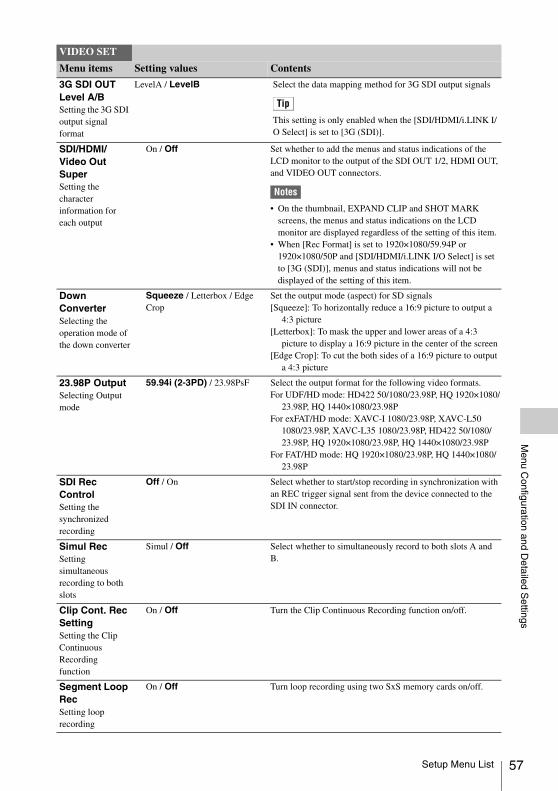
Menu C
onfiguration and Detailed S
ettings
3G SDI OUT Level A/BSetting the 3G SDI output signal format
LevelA / LevelB Select the data mapping method for 3G SDI output signals
Tip
This setting is only enabled when the [SDI/HDMI/i.LINK I/O Select] is set to [3G (SDI)].
SDI/HDMI/Video Out SuperSetting the character information for each output
On / Off Set whether to add the menus and status indications of the LCD monitor to the output of the SDI OUT 1/2, HDMI OUT, and VIDEO OUT connectors.
Notes
• On the thumbnail, EXPAND CLIP and SHOT MARK screens, the menus and status indications on the LCD monitor are displayed regardless of the setting of this item.
• When [Rec Format] is set to 1920×1080/59.94P or 1920×1080/50P and [SDI/HDMI/i.LINK I/O Select] is set to [3G (SDI)], menus and status indications will not be displayed of the setting of this item.
Down ConverterSelecting the operation mode of the down converter
Squeeze / Letterbox / Edge Crop
Set the output mode (aspect) for SD signals[Squeeze]: To horizontally reduce a 16:9 picture to output a
4:3 picture[Letterbox]: To mask the upper and lower areas of a 4:3
picture to display a 16:9 picture in the center of the screen[Edge Crop]: To cut the both sides of a 16:9 picture to output
a 4:3 picture
23.98P OutputSelecting Output mode
59.94i (2-3PD) / 23.98PsF Select the output format for the following video formats.For UDF/HD mode: HD422 50/1080/23.98P, HQ 1920×1080/
23.98P, HQ 1440×1080/23.98PFor exFAT/HD mode: XAVC-I 1080/23.98P, XAVC-L50
1080/23.98P, XAVC-L35 1080/23.98P, HD422 50/1080/23.98P, HQ 1920×1080/23.98P, HQ 1440×1080/23.98P
For FAT/HD mode: HQ 1920×1080/23.98P, HQ 1440×1080/23.98P
SDI Rec ControlSetting the synchronized recording
Off / On Select whether to start/stop recording in synchronization with an REC trigger signal sent from the device connected to the SDI IN connector.
Simul RecSetting simultaneous recording to both slots
Simul / Off Select whether to simultaneously record to both slots A and B.
Clip Cont. Rec SettingSetting the Clip Continuous Recording function
On / Off Turn the Clip Continuous Recording function on/off.
Segment Loop RecSetting loop recording
On / Off Turn loop recording using two SxS memory cards on/off.
VIDEO SET
Menu items Setting values Contents
Setup Menu List 57

58
Menu C
onfiguration and Detailed S
ettings
Segment DurationSetting loop recording retention time
15~35min / 30~65min Set the retention time of video during loop recording. Cannot be selected if the remaining recording time of the SxS memory cards is less than the capacity required for recording.
VIDEO SET
Menu items Setting values Contents
[LCD SET] Menu
LCD SET
Menu items Subitems and setting values Contents
LCDAdjusting the LCD monitor
Color–99 to +99 (±0)
Adjust the color of pictures on the LCD monitor.
Contrast–99 to +99 (±0)
Adjust the contrast of pictures on the LCD monitor.
Brightness–99 to +99 (±0)
Adjust the brightness of pictures on the LCD monitor.
Display On/OffSelecting the items to be displayed on the LCD monitor
[M]
Audio Level MeterOn / Off
Turn the audio level meter indication on/off.
TimecodeOn / Off
Turn the time data (timecode, user bits, duration) indication on/off.
Battery RemainOn / Off
Turn the battery remaining/DC input voltage indication on/off.
Media RemainOn / Off
Turn the media remaining indication on/off.
Video FormatOn / Off
Turn the video format indication on/off.
Clip NameOn / Off
Turn the clip name display on/off.
ClipNumber (PB)On / Off
Turn the clip number display on/off.
SDI Rec ControlOn / Off
Turn the synchronous recording display (the Rec2 display) on/off.
Input Signal I/FOn / Off
Turn the input signal display ON/OFF.
Wireless StatusOn / Off
Turn the wireless signal status indication on/off when using the CBK-WA100.
Streaming&NCM StatusOn / Off
Turn the streaming status indication and network client mode status indication on/off when using the CBK-WA100.
Ext Media RemainOn / Off
Turn the SD card remaining capacity indication on/off when using the CBK-WA100.
Sending Clip InfoOn / Off
Turn the clip transfer status indication on/off when using the CBK-WA100.
Setup Menu List
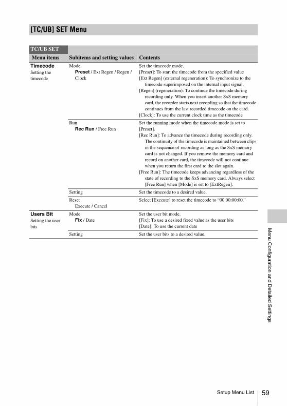
Menu C
onfiguration and Detailed S
ettings
[TC/UB] SET Menu
TC/UB SET
Menu items Subitems and setting values Contents
TimecodeSetting the timecode
ModePreset / Ext Regen / Regen / Clock
Set the timecode mode.[Preset]: To start the timecode from the specified value[Ext Regen] (external regeneration): To synchronize to the
timecode superimposed on the internal input signal.[Regen] (regeneration): To continue the timecode during
recording only. When you insert another SxS memory card, the recorder starts next recording so that the timecode continues from the last recorded timecode on the card.
[Clock]: To use the current clock time as the timecode
RunRec Run / Free Run
Set the running mode when the timecode mode is set to [Preset].[Rec Run]: To advance the timecode during recording only.
The continuity of the timecode is maintained between clips in the sequence of recording as long as the SxS memory card is not changed. If you remove the memory card and record on another card, the timecode will not continue when you return the first card to the slot again.
[Free Run]: The timecode keeps advancing regardless of the state of recording to the SxS memory card. Always select [Free Run] when [Mode] is set to [ExtRegen].
Setting Set the timecode to a desired value.
ResetExecute / Cancel
Select [Execute] to reset the timecode to “00:00:00:00.”
Users BitSetting the user bits
ModeFix / Date
Set the user bit mode.[Fix]: To use a desired fixed value as the user bits[Date]: To use the current date
Setting Set the user bits to a desired value.
Setup Menu List 59

60
Menu C
onfiguration and Detailed S
ettings
TC FormatSetting the time code format
DF / NDF Set the timecode format.[DF]: Drop frame[NDF]: Non drop frame
Note
The current video format/frame frequency determines whether the mode is fixed either to DF or NDF (see below), regardless of the [TC Format] setting.
1) The frame digits in [Setting] is limited to 00, 04, 08, 12, 16, and 20.The frame at the beginning of recording is limited to 00, 04, 08, 12, 16, or 20.As [23.98P Output] (page 57) in the [VIDEO SET] menu becomes 2-3 pull-down 59.94i when recording (or standing by to record) HQ 1920/23.98P other than when [23.98PsF] is selected, the overlapping timecodes of frames output from the SDI OUT 1/2 connectors are renumbered from 00 to 29.
2) Even in [Clock] mode, the timecode is gradually shifted, because it is counted by NDF.As output from the SDI OUT 1/2 connectors becomes 2-3 pulled-down video when recording (or standing by to record) HQ 1920/23.98P and other than [23.98PsF] is selected for [23.98P Output] (page 57) in the [VIDEO SET] menu, fields are created in which overlapping timecodes are displayed on the screen.
TC/UB SET
Menu items Subitems and setting values Contents
Video formats Frame setting
TC Format
59.94i59.94P29.97P
00 to 29 DF/NDF switchable (Fixed to DF in Clock mode)
23.98P 00 to 23 1) Fixed to NDF 2)
50i50P25P
00 to 24 Fixed to NDF
[OTHERS] Menu
OTHERS
Menu items Subitems and setting values Contents
All ResetRestoring default settings, with the exception of some settings
Execute / Cancel Select [Execute] to reset the recorder to the factory status.
Setup Menu List

Menu C
onfiguration and Detailed S
ettings
Setup DataStoring/recalling the menu settings on SxS memory cards or USB flash drive
Store(SxS)/(USB)Execute / Cancel
When you select [Execute] to store the setting values, the setup file is stored to one of the following directories.When using SxS memory cardsFor UDF: /General/Sony/PRO/CAMERA/XDCAM/
PMW_rx50/For exFAT: /XDROOT/General/Sony/PRO/CAMERA/
XDCAM/PMW_RX50For FAT: /SONY/PRO/CAMERA/XDCAM_EX/PMW_rx50/When using USB flash drivesFor USB flash drives formatted in FAT32: /MSSONY/SONY/
PRO/CAMERA/XDCAM/PMW_RX50
Tip
The setup file cannot be saved to a USB flash drive formatted in exFAT.
Recall(SxS)/(USB)Execute / Cancel
Select [Execute] to retrieve the setting values from an SxS memory card.
Time ZoneSetting the time difference
UTC –12:00 to +13:30 Set the time-zone difference from UTC in steps of 30 minutes.
Note
The default setting is different among the sales areas.United States and Canada: –5:00Europe area: 0:00Oceania: +10:00
Clock SetSetting the built-in clock
Date/Time Set the current time and date.
12H/24H12H / 24H
Select the display mode of time.[12H]: 12-hour mode[24H]: 24-hour mode
Date ModeYYMMDD / MMDDYY / DDMMYY
Select the display mode of the date.[YYMMDD]: In sequence of year, month, day[MMDDYY]: In sequence of month, day, year[DDMMYY]: In sequence of day, month, year
LanguageSelecting the language for menus and messages
English / Japanese / Chinese / Spanish / Portuguese / Russian / Indonesian
[English]: To display in English[Japanese]: To display in Japanese[Chinese]: To display in Chinese[Spanish]: To display in Spanish[Portuguese]: To display in Portuguese[Russian]: To display in Russian[Indonesian]: To display in Indonesian
Note
[Japanese] is valid only on messages for warning and caution. The menus and status indications do not change.
OTHERS
Menu items Subitems and setting values Contents
Setup Menu List 61

62
Menu C
onfiguration and Detailed S
ettings
Assign ButtonAssigning functions to the assignable buttons
<1>, <2>, <3>, <4>, <5>Off / Last Clip DEL / IR Remote / Shot Mark1 / Shot Mark2 / OK Mark / Clip Flag OK / Clip Flag NG / Clip Flag Keep / Clip Continuous Rec / Clip Update / Play & SDI Rec / LCD Adjust / Color Bars On/Off / Quick Backup / USB Thumbnail View / Partial Playback/ STATUS / LCD BRIGHT / DISPLAY<1> On<2> Off<3> STATUS<4> LCD BRIGHT<5> DISPLAY
Assign a function to the ASSIGN 1/2/3/4/5 buttons. (The selectable functions are shared.)[Off]: No function[Last Clip DEL]: Execute the last clip delete (retake) function[IR Remote]: Enable/disable the IR Remote Commander.[Shot Mark1]: Add shot mark 1 (HD Mode only).[Shot Mark2]: Add shot mark 2 (HD Mode only).[OK Mark]: For adding or removing an OK mark (HD Mode
only, not valid via the thumbnail screen).[Clip Flag OK]: Enable/disable OK flags for clips during
recording and playback (UDF and exFAT).[Clip Flag NG]: Enable/disable NG flags for clips during
recording and playback (UDF and exFAT).[Clip Flag Keep]: Enable/disable Keep flags for clips during
recording and playback (UDF and exFAT).[Clip Continuous Rec]: Switch the Clip Continuous
Recording function on/off.[Clip Update]: Update the management file on the selected
SxS memory card (not supported in continuous recording mode).
[Play & SDI Rec]: Start playback and REC trigger output, or pause playback and stop REC trigger output (when using the CBK-WA100).
[LCD Adjust]: Switch the LCD Adjust function level bar indication (brightness adjustment t contrast adjustment t off ).
[Color Bars On/Off]: Switch the color bars output on/off.[Quick Backup]: Backup all clips from the selected SxS
memory card to a new folder on USB media. [USB Thumbnail View]: Display the USB media thumbnail
screen. [Partial Playback]: Playback between In-point and Out-point[STATUS]: Display the status screens on LCD monitors and
external monitors.[LCD BRIGHT]: Adjust the backlight brightness for the LCD
monitor.[DISPLAY]: Enable/disable display of the recorder’s status
information and settings on the LCD monitor’s video.
TallySetting the tally lamps
FrontHigh / Low / Off
Set the brightness of the tally lamp.
Hours MeterDisplaying the hours meter
Hours (Sys) The non-resettable accumulated time of use is displayed.
Hours (Reset) The resettable accumulated time of use is displayed.
ResetExecute / Cancel
Select [Execute] to reset the [Hours (Reset)] value to 0.
IR RemoteActivating/deactivating the Remote Commander
On / Off Set to [On] to activate remote control operations from the supplied IR Remote Commander.
Note
The setting automatically returns to [Off] when the recorder is turned off.
OTHERS
Menu items Subitems and setting values Contents
Setup Menu List

Menu C
onfiguration and Detailed S
ettings
Battery AlarmSetting the low power alarm
Low BATT5% / 10% / 15% / ... / 45% / 50%
Set the battery level at which the Low BATT warning is generated (in steps of 5%).
BATT Empty3% to 7% (3%)
Set the battery level at which the BATT Empty warning is generated.
DC Low Volt111.5 V to 17.0 V (11.5 V)
Set the DC IN voltage at which the DC Low Volt1 warning is generated.
DC Low Volt211.0 V to 14.0 V (11.0 V)
Set the DC IN voltage at which the DC Low Volt2 warning is generated.
Battery INFOShowing information regarding the battery pack (display only)
Type The type (product name) is displayed.
MFG Date The date of manufacture is displayed.
Charge Count The accumulated number of times of charge/discharge is displayed.
Capacity The estimated total capacity of full charge is displayed.
Voltage The current output voltage is displayed.
Remaining The current remaining level is displayed.
Trigger ModeSetting for operating an external recording device connected via the i.LINK connector (FAT only)
[M]
Internal / Both / External [Internal]: To activate recording start/stop operations only for an SxS memory card in a built-in slot.
[Both]: To activate recording start/stop operations both for an SxS memory card in a built-in slot and the external recording device connected via the i.LINK connector.
[External]: To activate recording start/stop operations only for the external recording device connected via the i.LINK connector.
System CountryNTSC Area / NTSC(J) Area / PAL Area
Select the area of use and setup ON/OFF setting.[NTSC Area]: Setup ON[NTSC(J) Area]: Setup OFF[PAL Area]: Setup OFF
Note
The default setting is different among the sales areas.United States and Canada: NTSC AreaOther areas: PAL Area
F.Sys.UDF / exFAT / FAT
Switch the file system between UDF/exFAT/FAT.
HD/SDHD / SD
Switch between HD Mode and SD Mode for recording/playback.
XAVC/MPEG2XAVC / MPEG2
Switch between the XAVC and MPEG2 formats during exFAT and HD mode.
OTHERS
Menu items Subitems and setting values Contents
Setup Menu List 63

64
Menu C
onfiguration and Detailed S
ettings
Rec Format Select the video format for recording.The selectable video formats for recording will differ depending on the mode.HD Mode• Bit rate
UDF: HD422 50 or HD420 HQexFat: XAVC, HD422 50, or HD420 HQFAT: HQ or SP
• Horizontal resolution1920, 1440, or 1280
• Frame rate23.98, 25, 29.97, 50, or 59.94
• Scan systemi (interlace) or P (progressive)
SD Mode• Frame rate
50 or 59.94• Scan system
i (interlace)
For details on the selectable video formats for recording in each mode, see “Recording Video Formats ([Rec Format])” (page 80).
Wide ModeAuto / 16:9
Set wide video processing when the input signal is an SD SDI signal.[Auto]: To set squeeze mode when the input signal is wide
video or set to edge crop mode when the input signal is not wide video.
[16:9]: To set fixed squeeze mode to always treat the input signal as wide video.
Audio (IMX)16bit / 24bit
Set the number of audio quantization bits when the video format is IMX.
OTHERS
Menu items Subitems and setting values Contents
Setup Menu List

Menu C
onfiguration and Detailed S
ettings
ClipSetting for clip name or deletion
Auto NamingC**** / Title / Plan
Select the method to specify clip names.C****: UDF and exFAT[Title]: To specify as desired by [Title Prefix][Plan]: To use a name specified in planning metadata (if no
name is specified in planning metadata, the name specified by [Title Prefix] is used.)
Title Prefixnnn_ (nnn=least three digits of the serial number)(Max. 7 characters displayed)
Call the [Character Set] screen to set the title part (4 to 46 characters) of the clip names.Configuration of the [Character Set] screenCharacter selection area (3 lines):
To select a character to insert in the cursor position of the Title Prefix area.!#$%()+,-.=@[]^_~0123456789abcdefghijklmnopqrstuvwxyzABCDEFGHIJKLMNOPQRSTUVWXYZ
Cursor operation area (1 line):[Space]: To change the character in the cursor position to a
space[INS]: To insert a space in the cursor position[DEL]: To delete a character in the cursor position[T]: To move the cursor to the left[t]: To move the cursor to the right[ESC]: To cancel the change and exit the [Character Set]
screen[END]: To validate the change and exit the [Character Set]
screen[Title Prefix] area (1 line):
For entering the titleTo set the title1 Select (highlight) a character in the character selection area
to be entered in the cursor position of the [Title Prefix] area. Then press the SEL/SET button.
2 Repeat Step 1 for setting the title. (Use [Space], [INS], and [DEL] as required.)
3 When the title setting is completed, select [END] to exit the [Character Set] screen.
Number Set0001 to 9999
Set the second 4-numeric part of the clip name.
UpdateMedia(A) / Media(B)
To update the managerial file on the SxS memory card in the selected slot.1)
Last Clip DELExecute / Cancel
Select [Execute] to delete the last recorded clip.
All Clips DELExecute / Cancel
Select [Execute] to delete all clips on the active SxS memory card.
Note
Clips to which you applied OK mark and clips that are locked cannot be deleted.
Filter ClipsOK / NG / KP / None
Select from among [OK] (the OK flag), [NG] (the not good flag), [KP] (the keep flag), or [None] (for no flag) to filter displayed clips. (UDF and exFAT)
Lock All ClipsExecute / Cancel
Select [Execute] to protect all clips. (UDF and exFAT)
OTHERS
Menu items Subitems and setting values Contents
Setup Menu List 65

66
Menu C
onfiguration and Detailed S
ettings
Unlock All ClipsExecute / Cancel
Select [Execute] to remove protection from all clips. (UDF and exFAT)
Index Picture Pos0sec to 10sec (0sec)
Set the image for viewing thumbnails. This selects the time difference from the start of the clip.
Find ModeClip / Rec Start
Set the action for when you press the PREV button/NEXT button. (UDF and exFAT)[Clip]: Move to the start of the current clip/next clip.
(Pressing the PREV button from the start of a clip will move to the start of the previous clip.)
[Rec Start]: Move to the previous [Rec Start Essence Mark]/the next [Rec Start Essence Mark].
Copy All 2)
Setting for collective copy of clips and/or “General” files
Clips To copy all clips on an SxS memory card to the other.
General Files To copy all files in the “General” folder on an SxS memory card to the other.
Clips&General To copy all clips and files in the “General” folder on an SxS memory card to the other.
Format MediaFormatting SxS memory cards
Media(A)Execute / Cancel
Select [Execute] to format the SxS memory card in slot A with the selected file system (UDF/exFAT/FAT).
Media(B)Execute / Cancel
Select [Execute] to format the SxS memory card in slot B with the selected file system (UDF/exFAT/FAT).
Plan.MetadataSetting planning metadata
Load/Slot(A) or Load/Slot(B)Execute / Cancel
To load planning metadata from the SxS memory card in slot A or B.Selecting [Execute] displays the list of the planning metadata files stored on the SxS memory card in slot A or B. Specify a file, select [Load] then [Execute] for loading.
Notes
• The file list displays up to 64 files. Even if the total number of planning metadata files is 64 or less, all of the planning metadata files may not appear if the directory where they are located in the SxS memory card (General/Sony/Planning) contains 512 or more files.
• After you start loading, do not remove the SxS memory card until the completion message is displayed.
Load/USB(UDF and exFAT mode)Execute / Cancel
Loads planning metadata from the USB flash drive connected to the external device connector.Select [Execute] to show the list of the planning metadata files stored in the USB flash drive and select a file to be loaded.
OTHERS
Menu items Subitems and setting values Contents
Setup Menu List
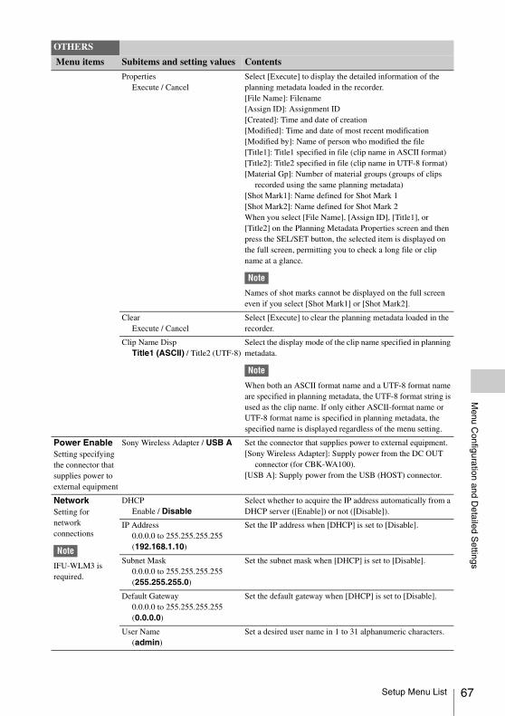
Menu C
onfiguration and Detailed S
ettings
PropertiesExecute / Cancel
Select [Execute] to display the detailed information of the planning metadata loaded in the recorder.[File Name]: Filename[Assign ID]: Assignment ID[Created]: Time and date of creation[Modified]: Time and date of most recent modification[Modified by]: Name of person who modified the file[Title1]: Title1 specified in file (clip name in ASCII format)[Title2]: Title2 specified in file (clip name in UTF-8 format)[Material Gp]: Number of material groups (groups of clips
recorded using the same planning metadata)[Shot Mark1]: Name defined for Shot Mark 1[Shot Mark2]: Name defined for Shot Mark 2When you select [File Name], [Assign ID], [Title1], or [Title2] on the Planning Metadata Properties screen and then press the SEL/SET button, the selected item is displayed on the full screen, permitting you to check a long file or clip name at a glance.
Note
Names of shot marks cannot be displayed on the full screen even if you select [Shot Mark1] or [Shot Mark2].
ClearExecute / Cancel
Select [Execute] to clear the planning metadata loaded in the recorder.
Clip Name DispTitle1 (ASCII) / Title2 (UTF-8)
Select the display mode of the clip name specified in planning metadata.
Note
When both an ASCII format name and a UTF-8 format name are specified in planning metadata, the UTF-8 format string is used as the clip name. If only either ASCII-format name or UTF-8 format name is specified in planning metadata, the specified name is displayed regardless of the menu setting.
Power EnableSetting specifying the connector that supplies power to external equipment
Sony Wireless Adapter / USB A Set the connector that supplies power to external equipment.[Sony Wireless Adapter]: Supply power from the DC OUT
connector (for CBK-WA100).[USB A]: Supply power from the USB (HOST) connector.
NetworkSetting for network connections
Note
IFU-WLM3 is required.
DHCPEnable / Disable
Select whether to acquire the IP address automatically from a DHCP server ([Enable]) or not ([Disable]).
IP Address0.0.0.0 to 255.255.255.255(192.168.1.10)
Set the IP address when [DHCP] is set to [Disable].
Subnet Mask0.0.0.0 to 255.255.255.255(255.255.255.0)
Set the subnet mask when [DHCP] is set to [Disable].
Default Gateway0.0.0.0 to 255.255.255.255(0.0.0.0)
Set the default gateway when [DHCP] is set to [Disable].
User Name(admin)
Set a desired user name in 1 to 31 alphanumeric characters.
OTHERS
Menu items Subitems and setting values Contents
Setup Menu List 67

68
Menu C
onfiguration and Detailed S
ettings
Password(pmw-rx50)
Sets a password in 0 to 31 alphanumeric characters.
Note
Each password character is displayed as “ * ” (asterisk).
SetExecute / Cancel
Confirms the [Network] settings. Select [Execute] to confirm.
MAC Address Display the MAC address.
Net Config ResetExecute / Cancel
Reset the [Network] settings to the preset values.Select [Execute] to reset.
Wi-FiSetting for wireless LAN connection
Note
• IFU/WLM is required.
• Menus other than “Wi-Fi” and “Wi-Fi Remote” are not used when using the CBK-WA101.
Scan NetworksExecute / Cancel
Scan the available network connections when [Wi-Fi] is set to [Enable].
Note
“Unknown” is displayed as the scan result when using the IFU-WLM3. In this case, set [Network Type] to [Infra] or [Adhoc].
SSID (Network connection name display)
Reset
Reset the network connection name to the default settings.
Network TypeInfra / Adhoc
Select the connection mode.[Infra]: Infrastructure mode[Adhoc]: Ad hoc mode
Ch1 to 11
Set the wireless channel when [Network Type] is [Adhoc].
Authentication
When [Network Type] is [Infra]Open / Shared / WPA / WPA2
When [Network Type] is [Adhoc] Open / Shared
Select the network authentication.[Open]: Open system authentication[Shared]: Shared key authentication[WPA]: WPA (Wi-Fi Protected Access) authentication[WPA2]: WPA2 (Wi-Fi Protected Access 2) authentication
Encryption
When [Authentication] is [Open] or [Shared]
Disable / WEPWhen [Authentication] is [WPA] or [WPA2]
Disable / TKIP / AES
Select the type of data encryption.[Disable]: Do not apply data encryption.[WEP]: WEP (Wired Equivalent Privacy) [TKIP]: TKIP (Temporal Key Integrity Protocol) [AES]: AES (Advanced Encryption Standard)
WEP Key Index1 / 2 / 3 / 4
Select the key index when [Encryption] is [WEP].
Input Select
When [Encryption] is [WEP]ASCII5 / ASCII13 / HEX10 / HEX26
When [Encryption] is [TKIP] or [AES]
ASCII8-63 / HEX64
Select the input format depending on the network key (or security key).[ASCII5]: Five characters ASCII format[ASCII13]: 13 characters ASCII format[HEX10]: 10 hexadecimal digits[HEX26]: 26 hexadecimal digits[ASCII8-63]: 8 to 63 characters ASCII 8-bit format[HEX64]: 64 hexadecimal digits (characters)
Key (network key) Set the network key (or security key).
SetExecute / Cancel
Confirm the [Wi-Fi] settings when [Wi-Fi] is set to [Enable].Select [Execute] to confirm.
OTHERS
Menu items Subitems and setting values Contents
Setup Menu List

Menu C
onfiguration and Detailed S
ettings
Wi-Fi Statusx x x Connecting (display only)
Display “Connecting” while connection is being attempted.Display black squares to show the connection status by the number of squares during communication.
Note
[Wi-Fi Status] is displayed when using the IFU-WLM3 in Adhoc mode.
Wireless Mode802.11b / 802.11g / 802.11n
Display an IEEE802.11 standard.
Wi-FiEnable / Disable
Select whether to enable or disable wireless LAN connection.
Wi-Fi RemoteOn / Off
Select whether to enable or disable Wi-Fi remote control.
USB SETSetting for USB media connection
Thumbnail ViewExecute / Cancel
Display the USB media thumbnail screen.
Select Folder Select a folder on USB media as the destination when copying clips and for display on the thumbnail screen. Select [New] to create a new folder.
Rename Folder Rename the current folder.
Error CheckOn / Off
Select whether to perform error checking when copying clips.
Format USBexFAT / FAT32
Format USB media. [exFAT]: Format USB media for copying clips. [FAT32]: Format USB flash drive for writing planning
metadata (UDF and exFAT mode).
Copy To USBA t USB / B t USB / A&B t USB
Copy SxS memory card clips to USB media.
Note
Available only when the thumbnail screen is displayed.
Copy From USBUSB t A / USB t B
Copy USB media clips to SxS memory card.
Note
Available only when the thumbnail screen is displayed.
With GeneralEnable / Disable
Enable/disable copying of files in the “General” folder when copying clips.
VersionShowing the version of this unit
Vx.xx The current software version of the recorder is displayed.
Version UpUpdating this unit
Execute / Cancel Select [Execute] to update the recorder.Use when updating is required.
Note
This item cannot be selected when no SxS memory card has been loaded.
Menu ScrollSetting the menu scroll operation
Normal / Loop Select the method for menu scrolling.[Normal]: The cursor moves and stops at the top or the
bottom.[Loop]: The cursor continues moving up (jumping from the
top to the bottom) or down (jumping from the bottom to the top).
OTHERS
Menu items Subitems and setting values Contents
Setup Menu List 69
70
Menu C
onfiguration and Detailed S
ettings
1) If recording/playback cannot be made with an SxS memory card because it has been operated with a device other than this recorder, or for some other reason, updating the managerial file on the card may improve the situation.
2) When you copy an SxS memory card including multiple clips and files to another card with the same capacity, all the clips and files may not be copied completely to the end, depending on the usage conditions or memory properties.
Setup Menu List

Connecting E
xternal Devices
To display recording/playback pictures on an external monitor, select the output signal and use an appropriate cable for the monitor to be connected.Regardless of the 3G, HD, or SD signal, the same status information and menus that appear on the LCD monitor can be displayed on the external monitor. Set [SDI/HDMI/Video Out Super] (page 57) in the [VIDEO SET] menu to [On].When outputting SD signals in HD Mode, select the output mode in advance using [Down Converter] (page 57) in the [VIDEO SET] menu.
Note
When down-converted SD signals are output, images of 50P/50i/25P are output as PAL signals, images of 59.94P/59.94i/29.97P are output as NTSC signals, and images of 23.98P are output as 2-3 pulled-down NTSC signals.
SDI OUT 1/2 connectors (BNC type)The following signals are output depending on the 3G/HD/SD setting on the recorder.• 3G SDI signals• HD SDI signals (default setting)• SDI signalsSet [SDI/HDMI/i.LINK I/O Select] (page 56) in the [VIDEO SET] menu to output down-converted SD SDI signals for monitoring, even in HD Mode. If an HDV or DVCAM stream is being input from the device connected to the i.LINK connector, you can output the input signal on the i.LINK connector from the SDI OUT 1/2 connectors.Use a commercially available 75-ohm coaxial cable for connection.
HDMI OUT connector (Type A connector)Signal output from this connector is enabled by setting [SDI/HDMI/i.LINK I/O Select] (page 56) in the [VIDEO SET] menu.In HD Mode, you can select HD HDMI, SD HDMI interlace, or SD HDMI Progressive output.In SD Mode, only an SD HDMI interlace signal can be output.
Use a commercially available HDMI cable for connection.
VIDEO OUT connector (BNC type)By changing the setting of [SDI/HDMI/i.LINK I/O Select] (page 56) in the [VIDEO SET] menu, you can output HD-Y signals in HD Mode or down-converted SD analog composite signals for monitoring in SD Mode.Use a commercially available BNC cable for connection.
i.LINK connector (IEEE1394, 4-pin)Input/output of an HDV or DVCAM stream can be enabled by changing [SDI/HDMI/i.LINK I/O Select] (page 56) in the [VIDEO SET] menu.To set the input, select [i.LINK] in [Input Source Select] (page 55) in the [VIDEO SET] menu.A monitor or VTR that supports i.LINK can be connected (page 74).
AUDIO OUT connector (pin jack)Outputs the recording audio signal during recording or standby mode, and outputs the playback signal during playback.By changing the setting of [AUDIO OUTPUT] > [Output CH] in the [AUDIO SET] menu, you can select channels 1 and 2 or channels 3 and 4 for audio output.Use a commercially available audio cable for connection.
SDI IN Connector (BNC type)The recorder supports the input of SDI signals (3G SDI/HD SDI/SD SDI), from a camcorder or other device for recording or output to another device.To set an SDI input signal, select [SDI] in [Input Source Select] in the [VIDEO SET] menu.Use a commercially available 75-ohm coaxial cable for connection.
To start recording using a trigger signal from an external deviceWhen recording HD SDI signal input, setting [SDI Rec Control] (page 57) to [On] in the
Connecting External Devices
Connecting External Monitors and Camcorders
Connecting External Monitors and Camcorders 71

72
Connecting E
xternal Devices
[VIDEO SET] menu enables the recorder to start recording when a REC trigger signal is received from the device connected to the SDI IN connector.
Notes
• Level A/Level B is automatically determined for 3G SDI signal inputs.
• No operation occurs if the connected external device does not support the REC trigger signal function.
You can input audio signals on channels separate from the video signal by using the AUDIO IN 1/2 connectors on the audio input box. Audio input levels can be adjusted using the audio input level knobs on the audio input box.
AUDIO IN 1/2 connectors (XLR type, 3-pin)Input audio signals from an audio mixer, or other audio equipment.
Connecting Audio Equipment
Connecting Audio Equipment

Connecting E
xternal Devices
When you connect the recorder to a computer using the supplied USB cable, the memory card inserted in the recorder’s slot is recognized as an external drive for the computer.When two memory cards are mounted in this recorder, they are acknowledged as two independent extended drives by the computer.
Notes
• The recorder does not work on the bus power from the computer. Supply the operating power independently.
• When using the ExpressCard slot on a computer, set the SxS card to write protect (i.e., read only), and back up data onto the computer before editing.
• When doing a partial transfer of an original file recorded on a camcorder (page 25) using the CBK-WA100, the unit cannot be connected to a computer.
To check the connection to the recorder
1 Connect the PC connector on the recorder to the computer using the supplied USB cable, and turn on the recorder.
A message prompting you to confirm that you wish to enable connection with the computer is displayed on the LCD monitor.
This message will not be displayed while another confirmation message or in-progress message (e.g., for formatting or restoration of an SxS memory card) is shown on the screen. It appears when formatting or restoration is completed. The message is also not displayed while the CLIP INFO screen is shown on the screen. It appears when an operation on the CLIP INFO screen is completed or you return to the thumbnail screen.
2 Select [Execute].
3 On Windows, check that the memory card is displayed as a removable disk in My Computer.On Macintosh, check that a “NO NAME” or “Untitled” folder was created on the desktop. (The Macintosh folder name can be changed.)
If the computer is equipped with an ExpressCard/34 or ExpressCard/54 slot, you can directly insert the SxS memory card to access the files.
Notes
• The following operations must be eliminated when the access lamp is lit in red.—Turning the power off or disconnecting the power
cord—Removing the SxS memory card—Disconnecting the USB cable
• When removing an SxS memory card from a Macintosh, do not select “Card Power Off” from the SxS memory card icon displayed on the menu bar.
• Operation is not guaranteed with all computers.• Use the supplied USB cable for connection.
Connecting a Computer
Note
Connecting a Computer 73

74
Connecting E
xternal Devices
Signals can be input/output on the i.LINK connector when an HDV-compatible video format (SP 1440/59.94i, SP 1440/50i) or when DVCAM in SD mode is selected.In FAT mode, set “SDI/HDMI/i.LINK I/O Select” to “HD & HDV,” “SD & HDV,” “SD P & HDV,” or “SD & DVCAM” in the VIDEO SET menu. In UDF/SD, set it to “SD.”You can record the same images as those recorded in this recorder on an external device connected to the i.LINK connector, or record playback pictures from the external device on the recorder.For playback, DVCAM streams of 16-bit 2-channel lock audio are acceptable.Nonlinear editing conforming to the HDV format is also enabled.
Notes
• Use the i.LINK connector only for one-to-one i.LINK connection.
• When you change a setting which affects output signals from the i.LINK connector, such as “System” in the OTHERS menu or “SDI/HDMI/i.LINK I/O Select” and “Down Converter” in the VIDEO SET menu, disconnect the i.LINK cable then change the setting. Changing such a setting with the i.LINK cable connected may cause improper operation of the connected i.LINK device.
• If [F.Sys] is set to [UDF] and [HD/SD] is set to [HD] in the [OTHERS] menu or if [F.Sys] is set to [exFAT], input/output from the i.LINK connector will stop.
• An i.LINK connection and USB wireless LAN module cannot be used at the same time. Do not connect an IFU-WLM3 directly to an external device connector during i.LINK connections.
While recording or in standby mode, the image being recorded with this recorder is output as an HDV or DVCAM stream via the i.LINK connector. It can be recorded on a connected HDV or DVCAM recorder in synchronization with the recording operation on this recorder.
1 Perform the preparatory settings of the recorder.
• “SDI/HDMI/i.LINK I/O Select” (page 56) in the VIDEO SET menu
• “Trigger Mode” (page 63) in the OTHERS menu
2 Set the external device to recording standby status.
3 Start recording with the recorder.
The external device starts recording in synchronization.
The status of the external device is displayed in the i.LINK status indication area (page 10) on the LCD monitor.
Notes
• Operation may be different depending on the type of external device.
• There is some time lag from when you start recording until the i.LINK status indication changes. Recording does not start on the connected i.LINK device before it enters synchronization even if [Trigger Mode] is set to [Both].
• While you can insert shot marks on the memory card during recording, they are not added to the pictures recorded on the external device.
When the recorder is in playback mode, you can transfer an HDV stream to a nonlinear editing system connected via the i.LINK connector.
Notes
• The i.LINK connector of this recorder is a 4-pin connector. Check the number of pins of the i.LINK connector on your computer and use an appropriate i.LINK cable.
• In searching pictures of this recorder on the computer, it may take some time until the display is reflected on the computer.
• If the playback clip is short or the playback starting point is near the end of the clip, the i.LINK signal may be interrupted between the clip and the next clip. When you try to capture such a signal using the nonlinear editing system, a malfunction may occur, depending on the nonlinear editing software in use.
• If you specify a search speed other than 4, 15, or 24 times normal with the nonlinear editing system, no i.LINK signal is fed out. In such a case, the picture on the LCD monitor may stay frozen.
Connecting via i.LINK
Recording the Image on an External Device FAT
Indication Status of the external device
STBY In HDV recording standby
zREC In HDV recording
STBY In DV recording standby
zREC In DV recording
Nonlinear Editing
HDV
HDV
DV
DV
FAT
Connecting via i.LINK

Connecting E
xternal Devices
• High-speed playback picture may not be displayed on the computer screen, depending on the nonlinear editing software in use.
Setting on this recorderSet [SDI/HDMI/i.LINK I/O Select] (page 56) in the [VIDEO SET] menu to [HD & HDV], [SD & HDV], [SD P & HDV], or [SD & DVCAM].
The recorder supports HDV or DVCAM stream input from a device connected to the i.LINK connector, and output to a device connected to the SDI OUT connector. Input signals can also be recorded on SxS memory cards in the recorder. The timecode superimposed on the i.LINK input is recorded.
1 Set the external signal to a format supported by the recorder.
1440 × 1080/59.94i, 1440 × 1080/50i, and DVCAM input formats are supported.
2 In FAT mode, set [SDI/HDMI/i.LINK I/O Select] (page 56) to [HD & HDV], [SD & HDV], [SD P & HDV], or [SD & DVCAM] in the [VIDEO SET] menu. In UDF/SD mode, set it to [SD].
3 Set [Input Source Select] (page 55) to [i.LINK] in the [VIDEO SET] menu.
The input signal is output from the SDI OUT 1/2 connectors.The video signal is output on the VIDEO OUT connector and the LCD monitor. The audio signal is output on the AUDIO OUT connector, headphone connector, and built-in speaker.
4 To record, press and hold the REC button, then press the PLAY/PAUSE button.
Notes
• An error is displayed if any of the following conditions occur during recording. When an error is displayed, press the STOP/EE button to stop recording.—The video format of the input signal is different to
the recorder format setting.—A copy-prohibited stream is input.
• If the input signal to the recorder during recording is lost, the tally lamp and the “zREC” i.LINK status
indication on the LCD monitor start flashing, indicating that nothing is being recorded on the SxS memory card.Recording resumes when the signal is restored, but the clip number on the recorder is incremented.
• During DVCAM streams, images and audio may skip or repeat after consecutive operations during DVCAM streams due to CLK frequency differences between the DVCAM signal source and recorder.
• During HDV streams, the recorder operates as if locked to the input HDV signals. Therefore, frequency shifts in the signal source may cause deviations from the SDI output signal standards (frequency, jitter, etc.)
You can record in MXF format during i.LINK DVCAM input, or output in i.LINK DVCAM format during MXF DV clip playback.
Supported formats
MXF DV recording
1 Set [System] >[HD/SD] (page 63) to [SD] in the [OTHERS] menu.
2 Set [System] >[Rec Format] (page 64) to [DVCAM] in the [OTHERS] menu.
3 Configure the following settings in the [VIDEO SET] menu.
• Set [Input Source Select] to [i.LINK] (page 55).
• Set [SDI/HDMI/i.LINK I/O Select] to [SD] (page 56).
4 Connect to the external device via i.LINK.
5 Start recording on the unit.
The DVCAM signal inputs to the i.LINK connector are recorded.
Note
Ch1/2 of the audio is recorded.
Recording and SDI Output of External Input Signals
Recording and Playback of MXF DV Clips
FormatDuring recording (during i.LINK input)
MXF DVCAM NTSC/PAL
During playback (during i.LINK output)
720×480/59.94i, 720×576/50i
UDF
Connecting via i.LINK 75
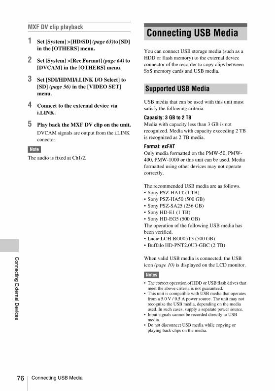
76
Connecting E
xternal Devices
MXF DV clip playback
1 Set [System] >[HD/SD] (page 63)to [SD] in the [OTHERS] menu.
2 Set [System] >[Rec Format] (page 64) to [DVCAM] in the [OTHERS] menu.
3 Set [SDI/HDMI/i.LINK I/O Select] to [SD] (page 56) in the [VIDEO SET] menu.
4 Connect to the external device via i.LINK.
5 Play back the MXF DV clip on the unit.
DVCAM signals are output from the i.LINK conector.
Note
The audio is fixed at Ch1/2.
You can connect USB storage media (such as a HDD or flash memory) to the external device connector of the recorder to copy clips between SxS memory cards and USB media.
USB media that can be used with this unit must satisfy the following criteria.
Capacity: 3 GB to 2 TBMedia with capacity less than 3 GB is not recognized. Media with capacity exceeding 2 TB is recognized as 2 TB media.
Format: exFATOnly media formatted on the PMW-50, PMW-400, PMW-1000 or this unit can be used. Media formatted using other devices may not operate correctly.
The recommended USB media are as follows.• Sony PSZ-HA1T (1 TB)• Sony PSZ-HA50 (500 GB)• Sony PSZ-SA25 (256 GB)• Sony HD-E1 (1 TB)• Sony HD-EG5 (500 GB)The operation of the following USB media has been verified.• Lacie LCH-RG005T3 (500 GB)• Buffalo HD-PNT2.0U3-GBC (2 TB)
When valid USB media is connected, the USB icon (page 10) is displayed on the LCD monitor.
Notes
• The correct operation of HDD or USB flash drives that meet the above criteria is not guaranteed.
• This unit is compatible with USB media that operates from a 5.0 V / 0.5 A power source. The unit may not recognize the USB media, depending on the media used. In such cases, supply a separate power source.
• Input signals cannot be recorded directly to USB media.
• Do not disconnect USB media while copying or playing back clips on the media.
Connecting USB Media
Supported USB Media
Connecting USB Media
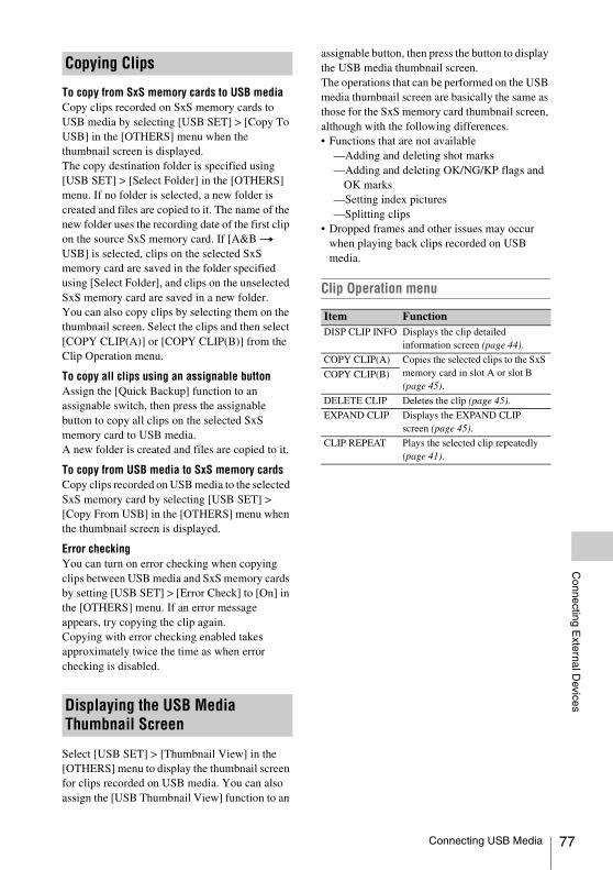
Connecting E
xternal Devices
To copy from SxS memory cards to USB mediaCopy clips recorded on SxS memory cards to USB media by selecting [USB SET] > [Copy To USB] in the [OTHERS] menu when the thumbnail screen is displayed.The copy destination folder is specified using [USB SET] > [Select Folder] in the [OTHERS] menu. If no folder is selected, a new folder is created and files are copied to it. The name of the new folder uses the recording date of the first clip on the source SxS memory card. If [A&B t USB] is selected, clips on the selected SxS memory card are saved in the folder specified using [Select Folder], and clips on the unselected SxS memory card are saved in a new folder. You can also copy clips by selecting them on the thumbnail screen. Select the clips and then select [COPY CLIP(A)] or [COPY CLIP(B)] from the Clip Operation menu.
To copy all clips using an assignable buttonAssign the [Quick Backup] function to an assignable switch, then press the assignable button to copy all clips on the selected SxS memory card to USB media. A new folder is created and files are copied to it.
To copy from USB media to SxS memory cardsCopy clips recorded on USB media to the selected SxS memory card by selecting [USB SET] > [Copy From USB] in the [OTHERS] menu when the thumbnail screen is displayed.
Error checkingYou can turn on error checking when copying clips between USB media and SxS memory cards by setting [USB SET] > [Error Check] to [On] in the [OTHERS] menu. If an error message appears, try copying the clip again. Copying with error checking enabled takes approximately twice the time as when error checking is disabled.
Select [USB SET] > [Thumbnail View] in the [OTHERS] menu to display the thumbnail screen for clips recorded on USB media. You can also assign the [USB Thumbnail View] function to an
assignable button, then press the button to display the USB media thumbnail screen. The operations that can be performed on the USB media thumbnail screen are basically the same as those for the SxS memory card thumbnail screen, although with the following differences. • Functions that are not available
—Adding and deleting shot marks—Adding and deleting OK/NG/KP flags and
OK marks—Setting index pictures—Splitting clips
• Dropped frames and other issues may occur when playing back clips recorded on USB media.
Clip Operation menu
Copying Clips
Displaying the USB Media Thumbnail Screen
Item FunctionDISP CLIP INFO Displays the clip detailed
information screen (page 44).
COPY CLIP(A) Copies the selected clips to the SxS memory card in slot A or slot B (page 45).
COPY CLIP(B)
DELETE CLIP Deletes the clip (page 45).
EXPAND CLIP Displays the EXPAND CLIP screen (page 45).
CLIP REPEAT Plays the selected clip repeatedly (page 41).
Connecting USB Media 77
78
Appendices
Use and storage
Do not subject the unit to severe shockThe internal mechanism may be damaged or the body warped.
Do not cover the unit while operatingPutting a cloth, for example, over the unit can cause excessive internal heat build-up.
After useAlways turn the power OFF.
Before storing the unit for a long periodRemove the battery pack.
When carryingIf you carry it by the LCD monitor block, the recorder may drop, causing damage.
Shipping• Remove the memory cards before transporting
the unit.• If sending the unit by truck, ship, air or other
transportation service, pack it in the shipping carton of the unit.
Care of the unitIf the body of the unit is dirty, clean it with a soft, dry cloth. In extreme cases, use a cloth steeped in a little neutral detergent, then wipe dry. Do not use organic solvents such as alcohol or thinner, as these may cause discoloration or other damage to the finish of the unit.
In the event of operating problemsIf you should experience problems with the unit, contact your Sony dealer.
Note about the battery terminalThe battery terminal of this unit (the connector for battery packs and AC adaptors) is a consumable part.Power may not be supplied to the unit properly if the pins of the battery terminal are bent or deformed by shock or vibrations, or if they become corroded due to prolonged outdoor use.
Periodic inspections are recommended to keep the unit working properly and to prolong its usable lifetime.Contact a Sony service or sales representative for more information about inspections.
Use and storage locationsStore in a level, ventilated place. Avoid using or storing the unit in the following places:• In excessive heat or cold (operating temperature
range: 0 ºC to 40 ºC or 32 ºF to 104 ºF)Remember that in summer in warm climates the temperature inside a car with the windows closed can easily exceed 50 ºC (122 ºF).
• In damp or dusty locations• Locations where the unit may be exposed to rain• Locations subject to violent vibration• Near strong magnetic fields• Close to radio or TV transmitters producing
strong electromagnetic fields.• In direct sunlight or close to heaters for
extended periods
To prevent electromagnetic interference from portable communications devicesThe use of portable telephones and other communications devices near this unit can result in malfunctions and interference with audio and video signals.It is recommended that the portable communications devices near this unit be powered off.
CondensationIf the unit is suddenly taken from a cold to a warm location, or if ambient temperature suddenly rises, moisture may form on the outer surface of the unit and/or inside of the unit. This is known as condensation. If condensation occurs, turn off the unit and wait until the condensation clears before operating the unit. Operating the unit while condensation is present may damage the unit.
About the LCD panelsThe LCD panel fitted to this unit is manufactured with high precision technology, giving a
Appendices
Important Notes on Operation
Important Notes on Operation

Appendices
functioning pixel ratio of at least 99.99%. Thus a very small proportion of pixels may be “stuck”, either always off (black), always on (red, green, or blue), or flashing. In addition, over a long period of use, because of the physical characteristics of the liquid crystal display, such “stuck” pixels may appear spontaneously. These problems are not a malfunction. Note that any such problems have no effect on recorded data.
Notes about the display• Pictures on the LCD monitor may be distorted
by the following operations:—Changing the video format—Starting playback from the Thumbnail
screen—Reversing the LCD monitor
File fragmentationIf pictures cannot be recorded/reproduced properly, try formatting the recording medium.While repeating picture recording/playback with a certain recording medium for an extended period, files in the medium may be fragmented, disabling proper recording/storage. In such a case, make a backup of clips in the medium then perform formatting of the medium using [Format Media] (page 66) in the [OTHERS] menu.
Consumable partsThe fan and battery are consumable parts that will need periodic replacement.When operating at room temperature, a normal replacement cycle will be about 5 years.However, this replacement cycle represents only a general guideline and does not imply that the life expectancy of these parts is guaranteed. For details on parts replacement, contact your dealer.
AC adapter and electrolytic capacitorThe life expectancy of the AC adapter and the electrolytic capacitor is about 5 years under normal operating temperatures and normal usage (8 hours per day; 25 days per month). If usage exceeds the above normal usage frequency, the life expectancy may be reduced correspondingly.
Batteriesi) For safety, use only the Sony battery packs and
AC adaptors listed below.BP-U30/BP-U60/BP-U90/BP-U60
ii) The battery terminal of this unit (the connector for battery packs and AC adaptors) is a consumable part.Power may not be supplied to the unit properly if the pins of the battery terminal are bent or deformed by shock or vibrations, or if they become corroded due to prolonged outdoor use.Periodic inspections are recommended to keep the unit working properly and to prolong its usable lifetime.Contact a Sony service or sales representative for more information about inspections.
Important Notes on Operation 79
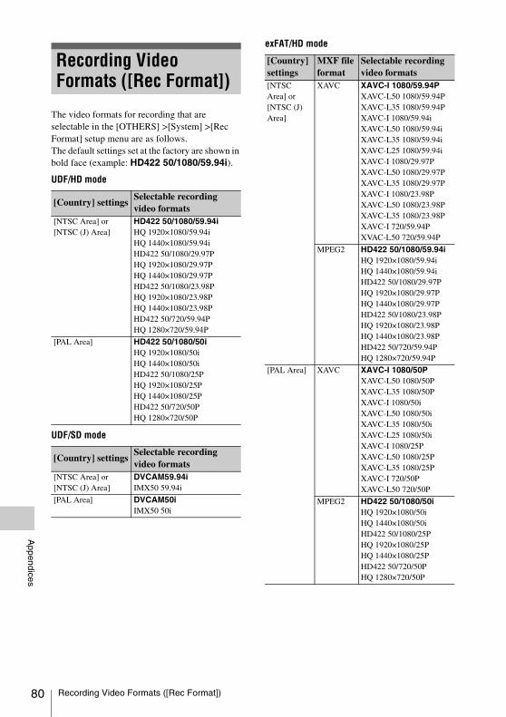
80
Appendices
The video formats for recording that are selectable in the [OTHERS] >[System] >[Rec Format] setup menu are as follows.The default settings set at the factory are shown in bold face (example: HD422 50/1080/59.94i).
UDF/HD mode
UDF/SD mode
exFAT/HD mode
Recording Video Formats ([Rec Format])
[Country] settingsSelectable recording video formats
[NTSC Area] or [NTSC (J) Area]
HD422 50/1080/59.94iHQ 1920×1080/59.94iHQ 1440×1080/59.94iHD422 50/1080/29.97PHQ 1920×1080/29.97PHQ 1440×1080/29.97PHD422 50/1080/23.98PHQ 1920×1080/23.98PHQ 1440×1080/23.98PHD422 50/720/59.94PHQ 1280×720/59.94P
[PAL Area] HD422 50/1080/50iHQ 1920×1080/50iHQ 1440×1080/50iHD422 50/1080/25PHQ 1920×1080/25PHQ 1440×1080/25PHD422 50/720/50PHQ 1280×720/50P
[Country] settingsSelectable recording video formats
[NTSC Area] or [NTSC (J) Area]
DVCAM59.94iIMX50 59.94i
[PAL Area] DVCAM50iIMX50 50i
[Country] settings
MXF file format
Selectable recording video formats
[NTSC Area] or [NTSC (J) Area]
XAVC XAVC-I 1080/59.94PXAVC-L50 1080/59.94PXAVC-L35 1080/59.94PXAVC-I 1080/59.94iXAVC-L50 1080/59.94iXAVC-L35 1080/59.94iXAVC-L25 1080/59.94iXAVC-I 1080/29.97PXAVC-L50 1080/29.97PXAVC-L35 1080/29.97PXAVC-I 1080/23.98PXAVC-L50 1080/23.98PXAVC-L35 1080/23.98PXAVC-I 720/59.94PXVAC-L50 720/59.94P
MPEG2 HD422 50/1080/59.94iHQ 1920×1080/59.94iHQ 1440×1080/59.94iHD422 50/1080/29.97PHQ 1920×1080/29.97PHQ 1440×1080/29.97PHD422 50/1080/23.98PHQ 1920×1080/23.98PHQ 1440×1080/23.98PHD422 50/720/59.94PHQ 1280×720/59.94P
[PAL Area] XAVC XAVC-I 1080/50PXAVC-L50 1080/50PXAVC-L35 1080/50PXAVC-I 1080/50iXAVC-L50 1080/50iXAVC-L35 1080/50iXAVC-L25 1080/50iXAVC-I 1080/25PXAVC-L50 1080/25PXAVC-L35 1080/25PXAVC-I 720/50PXAVC-L50 720/50P
MPEG2 HD422 50/1080/50iHQ 1920×1080/50iHQ 1440×1080/50iHD422 50/1080/25PHQ 1920×1080/25PHQ 1440×1080/25PHD422 50/720/50PHQ 1280×720/50P
Recording Video Formats ([Rec Format])
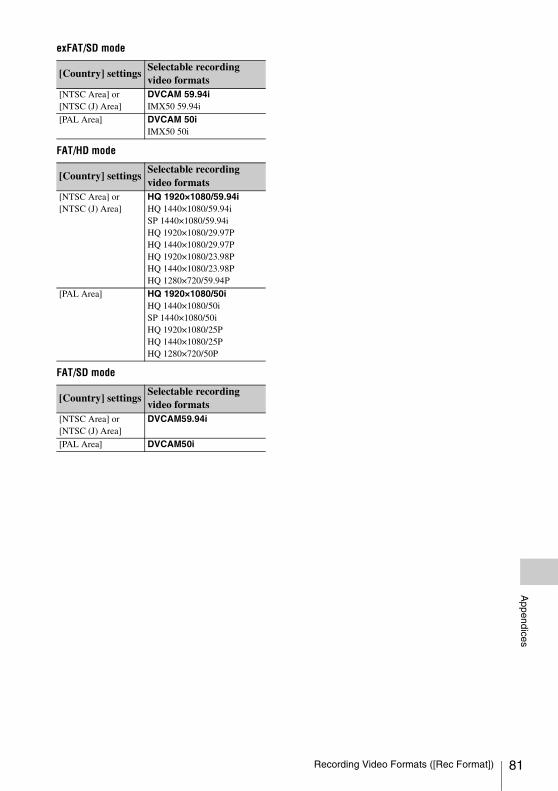
Appendices
exFAT/SD mode
FAT/HD mode
FAT/SD mode
[Country] settingsSelectable recording video formats
[NTSC Area] or [NTSC (J) Area]
DVCAM 59.94iIMX50 59.94i
[PAL Area] DVCAM 50iIMX50 50i
[Country] settingsSelectable recording video formats
[NTSC Area] or [NTSC (J) Area]
HQ 1920×1080/59.94iHQ 1440×1080/59.94iSP 1440×1080/59.94iHQ 1920×1080/29.97PHQ 1440×1080/29.97PHQ 1920×1080/23.98PHQ 1440×1080/23.98PHQ 1280×720/59.94P
[PAL Area] HQ 1920×1080/50iHQ 1440×1080/50iSP 1440×1080/50iHQ 1920×1080/25PHQ 1440×1080/25PHQ 1280×720/50P
[Country] settingsSelectable recording video formats
[NTSC Area] or [NTSC (J) Area]
DVCAM59.94i
[PAL Area] DVCAM50i
Recording Video Formats ([Rec Format]) 81

82
Appendices
SDI OUT 1/2 Connector Output Formats
Recording/standby (SDI input) (when [SDI/HDMI/i.LINK I/O Select] is [3G (SDI)])
Recording/standby (SDI input)
1) When [23.98P OUTPUT] is set to [59.94i (2-3 Pull Down)] in the [VIDEO SET] menu2) When [23.98P OUTPUT] is set to [23.98PsF] in the [VIDEO SET] menu3) Converted from 59.94P to 59.94i4) Converted from 50P to 50i
Recording/standby (i.LINK (HDV) input)Enabled in FAT mode only (i.LINK disabled in UDF and exFAT).
When [Rec Format] in [System] is set to [SP 1440/59.94i] in the [OTHERS] menu, the output format is as follows, according to the setting of
Formats and Limitations of Outputs
Input format Output format
[Rec Format] in [System] in [OTHERS] menu
SDI IN[SDI/HDMI/i.LINK I/O Select] in [VIDEO SET] menu3G (SDI)
59.94P (XAVC-I/XAVC-L) 1920×1080/59.94P 1920×1080/59.94P
59.94i (XAVC-I/XAVC-L/HD/HQ) 1920×1080/59.94i 1920×1080/59.94i
29.97P (XAVC-I/XAVC-L/HD/HQ)
23.98P (XAVC-I/XAVC-L/HD/HQ) 1920×1080/23.98PsF 1920×1080/59.94i 1)
1920×1080/23.98PsF 2)
59.94P (XAVC-I/XAVC-L/HD/HQ) 1280×720/59.94P 1280×720/59.94P
50P (XAVC-I/XAVC-L) 1920×1080/50P 1920×1080/50P
50i (XAVC-I/XAVC-L/HD/HQ) 1920×1080/50i 1920×1080/50i
25P (XAVC-I/XAVC-L/HD/HQ)
50P (XAVC-I/XAVC-L/HD/HQ) 1280×720/50P 1280×720/50P
Input format Output format[Rec Format] in [System] in [OTHERS] menu
SDI IN [SDI/HDMI/i.LINK I/O Select] in [VIDEO SET] menuHD/HD & HDV SD/SD & HDV/
SD & DVCAMSD P/SD P & HDV
59.94P (XAVC-I/XAVC-L) 1920×1080/59.94P 1920×1080/59.94i 3) SD 59.94i 3) N/A
59.94i (XAVC-I/XAVC-L/HD/HQ/SP)
1920×1080/59.94i 1920×1080/59.94i SD 59.94i
29.97P (XAVC-I/XAVC-L/HD/HQ)
23.98P (XAVC-I/XAVC-L/HD/HQ)
1920×1080/23.98PsF 1920×1080/59.94i 1)
1920×1080/23.98PsF 2)
59.94P (XAVC-I/XAVC-L/HD/HQ)
1280×720/59.94P 1280×720/59.94P SD 59.94i 3)
59.94i (DVCAM/IMX) SD/59.94i N/A SD 59.94i
50P (XAVC-I/XAVC-L) 1920×1080/50P 1920×1080/50i 4) SD 50i 4)
50i (XAVC-I/XAVC-L/HD/HQ/SP) 1920×1080/50i 1920×1080/50i SD 50i
25P (XAVC-I/XAVC-L/HD/HQ)
50P (XAVC-I/XAVC-L/HD/HQ) 1280×720/50P 1280×720/50P SD 50i 4)
50i (DVCAM/IMX) SD/50i N/A SD 50i
Formats and Limitations of Outputs

Appendices
[SDI/HDMI/i.LINK I/O Select] in the [VIDEO SET] menu.
HD & HDV: 1920×1080/59.94iSD & HDV: SD 59.94i
When [Rec Format] in [System] is set to [SP 1440/50i] in the [OTHERS] menu, the output format is as follows, according to the setting of [SDI/HDMI/i.LINK I/O Select] in the [VIDEO SET] menu.
HD & HDV: 1920×1080/50iSD & HDV: SD 50i
In all other cases, a blue screen is output or the setting is disabled.
Recording/standby (i.LINK (DVCAM) input)Enabled in FAT mode, UDF/SD mode only (i.LINK disabled in UDF/HD mode and exFAT mode).When [SDI/HDMI/i.LINK I/O Select] is set to [SD & DVCAM] (FAT mode) or [SD] (UDF/SD mode) in the [VIDEO SET] menu, the output format is set to “SD 59.94i/SD 50i” regardless of the input format.When [SDI/HDMI/i.LINK I/O Select] is set to other values, a blue screen is output or the setting is disabled.
Playback (when [SDI/HDMI/i.LINK I/O Select] is [3G (SDI)])
Playback
1) When the playback clip format is 720
Playback clip format Output format[SDI/HDMI/i.LINK I/O Select] in [VIDEO SET] menu3G (SDI)
59.94P (XAVC-I/XAVC-L) 1920×1080/59.94P
59.94i (XAVC-I/XAVC-L/HD/HQ) 1920×1080/59.94i
29.97P (XAVC-I/XAVC-L/HD/HQ) 1920×1080/59.94i1280×720/59.94P 1)
23.98P (XAVC-I/XAVC-L/HD/HQ) 1920×1080/59.94i 2)
1920×1080/23.98PsF 3)
1280×720/59.94P 1)
59.94P (XAVC-I/XAVC-L/HD/HQ) 1280×720/59.94P
50P (XAVC-I/XAVC-L) 1920×1080/50P
50i (XAVC-I/XAVC-L/HD/HQ) 1920×1080/50i
25P (XAVC-I/XAVC-L/HD/HQ) 1920×1080/50i1280×720/50P 1)
50P (XAVC-I/XAVC-L/HD/HQ) 1280×720/50P
Playback clip format Output format[SDI/HDMI/i.LINK I/O Select] in [VIDEO SET] menuHD/HD & HDV SD/SD & HDV/
SD & DVCAMSD P/SD P & HDV
59.94P (XAVC-I/XAVC-L) 1920×1080/59.94i 5) SD 59.94i 5) N/A
59.94i (XAVC-I/XAVC-L/HD/HQ/SP) 1920×1080/59.94i SD 59.94i
29.97P (XAVC-I/XAVC-L/HD/HQ) 1920×1080/59.94i1280×720/59.94P 1)
23.98P (XAVC-I/XAVC-L/HD/HQ) 1920×1080/59.94i 2)
1920×1080/23.98PsF 3)
1280×720/59.94P 1)
59.94P (XAVC-I/XAVC-L/HD/HQ) 1280×720/59.94P SD 59.94i 5)
59.94i (DVCAM/IMX) N/A SD 59.94i
50P (XAVC-I/XAVC-L) 1920×1080/50i 6) SD 50i 6)
50i (XAVC-I/XAVC-L/HD/HQ/SP) 1920×1080/50i SD 50i
25P (XAVC-I/XAVC-L/HD/HQ) 1920×1080/50i1280×720/50P 1)
50P (XAVC-I/XAVC-L/HD/HQ) 1280×720/50P SD 50i 6)
50i (DVCAM/IMX) N/A SD 50i
Formats and Limitations of Outputs 83

84
Appendices
2) When [23.98P OUTPUT] is set to [59.94i (2-3 Pull Down)] in the [VIDEO SET] menu and the playback clip format is 1080
3) When [23.98P OUTPUT] is set to [23.98PsF] in the [VIDEO SET] menu and the playback clip format is 1080
4) When the playback clip format is 720. Also, pulldown playback occurs automatically when playing a Pure P clip recorded in FAT/HQ1280/23.98P.
5) Converted from 59.94P to 59.94i6) Converted from 50P to 50i
On thumbnail screens (when [SDI/HDMI/i.LINK I/O Select] is [3G (SDI)])
On thumbnail screens
1) When [23.98P OUTPUT] is set to [59.94i (2-3 Pull Down)] in the [VIDEO SET] menu
2) When [23.98P OUTPUT] is set to [23.98PsF] in the [VIDEO SET] menu
3) Converted from 59.94P to 59.94i4) Converted from 50P to 50i
Input format Output format
[Rec Format] in [System] in [OTHERS] menu
[SDI/HDMI/i.LINK I/O Select] in [VIDEO SET] menu3G (SDI)
59.94P (XAVC-I/XAVC-L) 1920×1080/59.94i 3)
59.94i (XAVC-I/XAVC-L/HD/HQ) 1920×1080/59.94i
29.97P (XAVC-I/XAVC-L/HD/HQ)
23.98P (XAVC-I/XAVC-L/HD/HQ) 1920×1080/59.94i 1)
1920×1080/23.98PsF 2)
59.94P (XAVC-I/XAVC-L/HD/HQ) 1280×720/59.94P
50P (XAVC-I/XAVC-L) 1920×1080/50i 4)
50i (XAVC-I/XAVC-L/HD/HQ) 1920×1080/50i
25P (XAVC-I/XAVC-L/HD/HQ)
50P (XAVC-I/XAVC-L/HD/HQ) 1280×720/50P
[Rec Format] in [System] in [OTHERS] menu
Output format[SDI/HDMI/i.LINK I/O Select] in [VIDEO SET] menuHD/HD & HDV SD/SD & HDV/
SD & DVCAMSD P/SD P & HDV
59.94P (XAVC-I/XAVC-L) 1920×1080/59.94i 3) SD 59.94i 3) N/A
59.94i (XAVC-I/XAVC-L/HD/HQ/SP) 1920×1080/59.94i SD 59.94i
29.97P (XAVC-I/XAVC-L/HD/HQ)
23.98P (XAVC-I/XAVC-L/HD/HQ) 1920×1080/59.94i 1)
1920×1080/23.98PsF 2)
59.94P (XAVC-I/XAVC-L/HD/HQ) 1280×720/59.94P SD 59.94i 3)
59.94i (DVCAM/IMX) N/A SD 59.94i
50P (XAVC-I/XAVC-L) 1920×1080/50i 4) SD 50i 4)
50i (XAVC-I/XAVC-L/HD/HQ/SP) 1920×1080/50i SD 50i
25P (XAVC-I/XAVC-L/HD/HQ)
50P (XAVC-I/XAVC-L/HD/HQ) 1280×720/50P SD 50i 4)
50i (DVCAM/IMX) N/A SD 50i
Formats and Limitations of Outputs

Appendices
HDMI OUT Connector Output Formats
Recording/standby (SDI input) (when [SDI/HDMI/i.LINK I/O Select] is [3G (SDI)])
Recording/standby (SDI input)
1) When [23.98P OUTPUT] is set to [59.94i (2-3 Pull Down)] in the [VIDEO SET] menu2) Converted from interlaced to progressive3) Converted from progressive to interlaced
Recording/standby (i.LINK (HDV) input)Enabled in FAT mode only (i.LINK disabled in UDF and exFAT).When [Rec Format] in [System] is set to [SP 1440/59.94i] in the [OTHERS] menu, the output format is as follows.
HD & HDV: 1920×1080/59.94iSD & HDV: SD 59.94iSD P & HDV: SD 59.94P
When [Rec Format] in [System] is set to [SP 1440/50i] in the [OTHERS] menu, the output format is as follows.
HD & HDV: 1920×1080/50iSD & HDV: SD 50iSD P & HDV: SD 50P
In all other cases, a blue screen is output or the setting is disabled.
Input format Output format
[Rec Format] in [System] in [OTHERS] menu
SDI IN[SDI/HDMI/i.LINK I/O Select] in [VIDEO SET] menu3G (SDI)
59.94P (XAVC-I/XAVC-L) 1920×1080/59.94P 1920×1080/59.94i 3)
59.94i (XAVC-I/XAVC-L/HD/HQ) 1920×1080/59.94i 1920×1080/59.94i
29.97P (XAVC-I/XAVC-L/HD/HQ)
23.98P (XAVC-I/XAVC-L/HD/HQ) 1920×1080/23.98PsF 1920×1080/59.94i 1)
59.94P (XAVC-I/XAVC-L/HD/HQ) 1280×720/59.94P 1280×720/59.94P
50P (XAVC-I/XAVC-L) 1920×1080/50P 1920×1080/50i 3)
50i (XAVC-I/XAVC-L/HD/HQ) 1920×1080/50i 1920×1080/50i
25P (XAVC-I/XAVC-L/HD/HQ)
50P (XAVC-I/XAVC-L/HD/HQ) 1280×720/50P 1280×720/50P
Input format Output format[Rec Format] in [System] in [OTHERS] menu
SDI IN [SDI/HDMI/i.LINK I/O Select] in [VIDEO SET] menuHD/HD & HDV SD/SD & HDV/
SD & DVCAMSD P/SD P & HDV
59.94P (XAVC-I/XAVC-L) 1920×1080/59.94P 1920×1080/59.94i 3) SD 59.94i 3) SD 59.94P
59.94i (XAVC-I/XAVC-L/HD/HQ/SP)
1920×1080/59.94i 1920×1080/59.94i SD 59.94i SD 59.94P 2)
29.97P (XAVC-I/XAVC-L/HD/HQ)
SD 59.94P
23.98P (XAVC-I/XAVC-L/HD/HQ)
1920×1080/23.98PsF
1920×1080/59.94i 1)
59.94P (XAVC-I/XAVC-L/HD/HQ)
1280×720/59.94P 1280×720/59.94P SD 59.94i 3)
59.94i (DVCAM/IMX) SD/59.94i N/A SD 59.94i N/A
50P (XAVC-I/XAVC-L) 1920×1080/50P 1920×1080/50i 3) SD 50i 3) SD 50P
50i (XAVC-I/XAVC-L/HD/HQ/SP)
1920×1080/50i 1920×1080/50i SD 50i SD 50P 2)
25P (XAVC-I/XAVC-L/HD/HQ) SD 50P
50P (XAVC-I/XAVC-L/HD/HQ) 1280×720/50P 1280×720/50P SD 50i 3)
50i (DVCAM/IMX) SD/50i N/A SD 50i N/A
Formats and Limitations of Outputs 85

86
Appendices
Recording/standby (i.LINK (DVCAM) input)Enabled in FAT mode, UDF/SD mode only (i.LINK disabled in UDF/HD mode and exFAT mode).When [SDI/HDMI/i.LINK I/O Select] is set to [SD & DVCAM] (FAT mode) or [SD] (UDF/SD
mode) in the [VIDEO SET] menu, the output format is set to “SD 59.94i/SD 50i” regardless of the input format.When [SDI/HDMI/i.LINK I/O Select] is set to other values, a blue screen is output or the setting is disabled.
Playback (when [SDI/HDMI/i.LINK I/O Select] is [3G (SDI)])
Playback
1) When the playback clip format is 7202) When [23.98P OUTPUT] is set to [59.94i (2-3 Pull
Down)] in the [VIDEO SET] menu and the playback clip format is 1080
3) When the playback clip format is 720. Also, pulldown playback occurs automatically when playing a clip recorded in Pure P.
4) Converted from interlaced to progressive5) Converted from progressive to interlaced
Playback clip format Output format[SDI/HDMI/i.LINK I/O Select] in [VIDEO SET] menu3G (SDI)
59.94P (XAVC-I/XAVC-L) 1920×1080/59.94i 5)
59.94i (XAVC-I/XAVC-L/HD/HQ) 1920×1080/59.94i
29.97P (XAVC-I/XAVC-L/HD/HQ) 1920×1080/59.94i1280×720/59.94P 1)
23.98P (XAVC-I/XAVC-L/HD/HQ) 1920×1080/59.94i 2)
1280×720/59.94P 3)
59.94P (XAVC-I/XAVC-L/HD/HQ) 1280×720/59.94P
50P (XAVC-I/XAVC-L) 1920×1080/50i 5)
50i (XAVC-I/XAVC-L/HD/HQ) 1920×1080/50i
25P (XAVC-I/XAVC-L/HD/HQ) 1920×1080/50i1280×720/50P 1)
50P (XAVC-I/XAVC-L/HD/HQ) 1280×720/50P
Playback clip format Output format[SDI/HDMI/i.LINK I/O Select] in [VIDEO SET] menuHD/HD & HDV SD/SD & HDV/
SD & DVCAMSD P/SD P & HDV
59.94P (XAVC-I/XAVC-L) 1920×1080/59.94i 5) SD 59.94i 5) SD 59.94P
59.94i (XAVC-I/XAVC-L/HD/HQ/SP) 1920×1080/59.94i SD 59.94i SD 59.94P 4)
29.97P (XAVC-I/XAVC-L/HD/HQ) 1920×1080/59.94i1280×720/59.94P 1)
SD 59.94P
23.98P (XAVC-I/XAVC-L/HD/HQ) 1920×1080/59.94i 1)
1280×720/59.94P 3)
59.94P (XAVC-I/XAVC-L/HD/HQ) 1280×720/59.94P SD 59.94i 5)
59.94i (DVCAM/IMX) N/A SD 59.94i N/A
50P (XAVC-I/XAVC-L) 1920×1080/50i 5) SD 50i 5) SD 50P
50i (XAVC-I/XAVC-L/HD/HQ/SP) 1920×1080/50i SD 50i SD 50P 4)
25P (XAVC-I/XAVC-L/HD/HQ) 1920×1080/50i1280×720/50P 1)
SD 50P
50P (XAVC-I/XAVC-L/HD/HQ) 1280×720/50P SD 50i 5)
50i (DVCAM/IMX) N/A SD 50i N/A
Formats and Limitations of Outputs

Appendices
On thumbnail screens (when [SDI/HDMI/i.LINK I/O Select] is [3G (SDI)])
On thumbnail screens
1) When [23.98P OUTPUT] is set to [59.94i (2-3 Pull Down)] in the [VIDEO SET] menu
2) Converted from interlaced to progressive3) Converted from progressive to interlaced
VIDEO OUT Connector Output Formats
Recording/standby (SDI input)In SDI input mode, formats are the same as the SDI OUT 1/2 connectors output formats.
Recording/standby (i.LINK (HDV) input)In i.LINK (HDV) input mode, formats are the same as the SDI OUT 1/2 connectors output formats.
Recording/standby (i.LINK (DVCAM) input)In i.LINK (DVCAM) input mode, formats are the same as the SDI OUT 1/2 connectors output formats.
PlaybackFormats are the same as the SDI OUT 1/2 connectors output formats.
On thumbnail screensIn SDI input mode, formats are the same as the SDI OUT 1/2 connector output formats.
Note
When [VIDEO SET] >[SDI/HDMI/i.LINK I/O Select] is set to [3G (SDI)] in the setup menu, the same output format used during HD will be used.
i.LINK Connector Output Formats
Recording/standby (SDI input)Enabled in FAT mode only (i.LINK disabled in
UDF and exFAT).
Input format Output format
[Rec Format] in [System] in [OTHERS] menu
[SDI/HDMI/i.LINK I/O Select] in [VIDEO SET] menu3G (SDI)
59.94P (XAVC-I/XAVC-L) 1920×1080/59.94i 3)
59.94i (XAVC-I/XAVC-L/HD/HQ) 1920×1080/59.94i
29.97P (XAVC-I/XAVC-L/HD/HQ)
23.98P (XAVC-I/XAVC-L/HD/HQ) 1920×1080/59.94i 1)
59.94P (XAVC-I/XAVC-L/HD/HQ) 1280×720/59.94P
50P (XAVC-I/XAVC-L) 1920×1080/50i 3)
50i (XAVC-I/XAVC-L/HD/HQ) 1920×1080/50i
25P (XAVC-I/XAVC-L/HD/HQ)
50P (XAVC-I/XAVC-L/HD/HQ) 1280×720/50P
[Rec Format] in [System] in [OTHERS] menu
Output format[SDI/HDMI/i.LINK I/O Select] in [VIDEO SET] menuHD/HD & HDV SD/SD & HDV/
SD & DVCAMSD P/SD P & HDV
59.94P (XAVC-I/XAVC-L) 1920×1080/59.94i 3) SD 59.94i 3) SD 59.94P
59.94i (XAVC-I/XAVC-L/HD/HQ/SP) 1920×1080/59.94i SD 59.94i SD 59.94P 2)
29.97P (XAVC-I/XAVC-L/HD/HQ) SD 59.94P
23.98P (XAVC-I/XAVC-L/HD/HQ) 1920×1080/59.94i 1)
59.94P (XAVC-I/XAVC-L/HD/HQ) 1280×720/59.94P SD 59.94i 3)
59.94i (DVCAM/IMX) N/A SD 59.94i N/A
50P (XAVC-I/XAVC-L) 1920×1080/50i 3) SD 50i 3) SD 50P
50i (XAVC-I/XAVC-L/HD/HQ/SP) 1920×1080/50i SD 50i SD 50P 2)
25P (XAVC-I/XAVC-L/HD/HQ) SD 50P
50P (XAVC-I/XAVC-L/HD/HQ) 1280×720/50P SD 50i 3)
50i (DVCAM/IMX) N/A SD 50i N/A
Formats and Limitations of Outputs 87

88
Appendices
When [Country] is set to [NTSC Area] or [NTSC(J) Area], and [Rec Format] is set to [SP 1440/59.94i] in [System] in the [OTHERS] menu, the output format is as follows.
*** & HDV: HDV 59.94i*** & DVCAM: SD 59.94i
When [Country] is set to [NTSC Area] or [NTSC(J) Area], and [Rec Format] is not set to [SP 1440/59.94i] in [System] in the [OTHERS] menu, the output format is as follows.
*** & HDV: N/A*** & DVCAM: SD 59.94i (1920×1080/23.98P and 1440×1080/23.98P: N/A)
When [Country] is set to [PAL Area] and [Rec Format] is set to [SP 1440/59.94i] in [System] in the [OTHERS] menu, the output format is as follows.
*** & HDV: HDV 50i*** & DVCAM: SD 50i
When [Country] is set to [PAL Area] and [Rec Format] is not set to [SP 1440/59.94i] in [System] in the [OTHERS] menu, the output format is as follows.
*** & HDV: N/A*** & DVCAM: SD 50i
PlaybackEnabled in FAT mode and UDF/SD mode only (i.LINK disabled in UDF/HD and exFAT).When the playback clip format is set to [SP 1440/59.94i], with [Country] set to [NTSC Area] or [NTSC(J) Area] and [Rec Format] set to [SP 1440/59.94i] in [System] in the [OTHERS] menu, the output format is as follows.
*** & HDV: HDV 59.94i*** & DVCAM: DVCAM 59.94i
When a clip with a different format than that above is played, with [Country] set to [NTSC Area] or [NTSC(J) Area], the output format is as follows.
*** & HDV: N/A*** & DVCAM: DVCAM 59.94i (1920×1080/23.98P, 1440×1080/23.98P, 1280×720/23.98P: N/A)SD: DVCAM 59.94i (UDF/SD mode)
When the playback clip format is set to [SP 1440/50i], with [Country] set to [PAL Area] and [Rec Format] set to [SP 1440/50i] in [System] in the [OTHERS] menu, the output format is as follows.
*** & HDV: HDV 50i*** & DVCAM: DVCAM 50i
When a clip with a different format than that above is played, with [Country] set to [PAL Area], the output format is as follows.
*** & HDV: N/A*** & DVCAM: DVCAM 50iSD: DVCAM 50i (UDF/SD mode)
When [Rec Format] is set to [HQ 1080/23.98P] or [HQ 720/23.98P] (video format recorded in pure 23.98P), the playback video is not output on i.LINK (DVCAM).In UDF/SD mode, playback video is not output using i.LINK (DVCAM) when [Rec Format] is set to [IMX50].
Formats and Limitations of Outputs

Appendices
This recorder uses a backup battery to retain various setting data.A lithium battery (CR2032) for backup is mounted in the recorder at the factory.The backup battery retains the date, time, and timecode in Free Run mode even when no operating power is being supplied.
Service life of the backup batteryWhen the backup battery’s voltage falls, the backup battery low-voltage warning appears on the LCD monitor.If this warning appears, replace the battery as soon as possible.
• Battery may explode if mistreated. Do not recharge, disassemble, or dispose of in fire.
• Batteries shall not be exposed to excessive heat such as sunshine, fire or the like.
Danger of explosion if battery is incorrectly replaced. Replace only with the same or equivalent type recommended by the manufacturer.When you dispose of the battery, you must obey the law in the relative area or country.
Replacing the backup battery
Notes
• Be sure to turn the power to OFF when replacing the backup battery.
• Be careful not to drop the removed screw into the recorder.
1 Remove the screw of the backup battery holder, then remove the cover. Insert a nonmetallic item, such as a plastic toothpick, to the side of the battery and lever the battery out of its compartment.
2 Insert a new backup battery (CR2032) with the + symbol on the battery facing outside.
3 Attach the cover in the original position.
Backup Battery Replacement
WARNING
CAUTION
Backup Battery Replacement 89
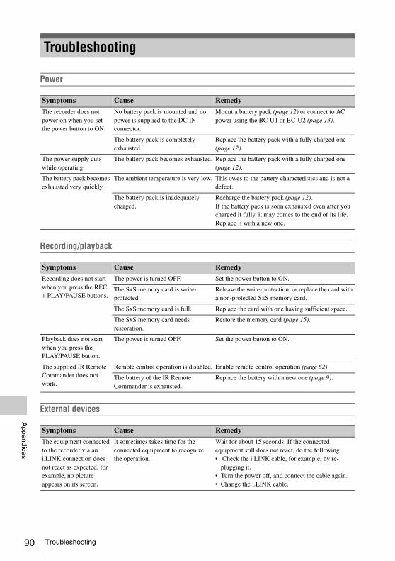
90
Appendices
Power
Recording/playback
External devices
Troubleshooting
Symptoms Cause Remedy
The recorder does not power on when you set the power button to ON.
No battery pack is mounted and no power is supplied to the DC IN connector.
Mount a battery pack (page 12) or connect to AC power using the BC-U1 or BC-U2 (page 13).
The battery pack is completely exhausted.
Replace the battery pack with a fully charged one (page 12).
The power supply cuts while operating.
The battery pack becomes exhausted. Replace the battery pack with a fully charged one (page 12).
The battery pack becomes exhausted very quickly.
The ambient temperature is very low. This owes to the battery characteristics and is not a defect.
The battery pack is inadequately charged.
Recharge the battery pack (page 12).If the battery pack is soon exhausted even after you charged it fully, it may comes to the end of its life.Replace it with a new one.
Symptoms Cause Remedy
Recording does not start when you press the REC + PLAY/PAUSE buttons.
The power is turned OFF. Set the power button to ON.
The SxS memory card is write-protected.
Release the write-protection, or replace the card with a non-protected SxS memory card.
The SxS memory card is full. Replace the card with one having sufficient space.
The SxS memory card needs restoration.
Restore the memory card (page 15).
Playback does not start when you press the PLAY/PAUSE button.
The power is turned OFF. Set the power button to ON.
The supplied IR Remote Commander does not work.
Remote control operation is disabled. Enable remote control operation (page 62).
The battery of the IR Remote Commander is exhausted.
Replace the battery with a new one (page 9).
Symptoms Cause Remedy
The equipment connected to the recorder via an i.LINK connection does not react as expected, for example, no picture appears on its screen.
It sometimes takes time for the connected equipment to recognize the operation.
Wait for about 15 seconds. If the connected equipment still does not react, do the following:• Check the i.LINK cable, for example, by re-
plugging it.• Turn the power off, and connect the cable again.• Change the i.LINK cable.
Troubleshooting
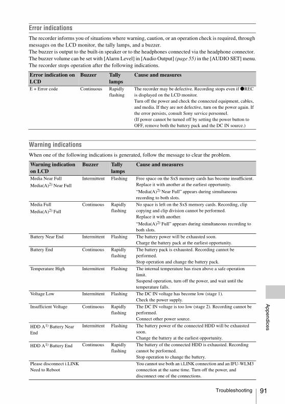
Appendices
Error indicationsThe recorder informs you of situations where warning, caution, or an operation check is required, through messages on the LCD monitor, the tally lamps, and a buzzer.The buzzer is output to the built-in speaker or to the headphones connected via the headphone connector. The buzzer volume can be set with [Alarm Level] in [Audio Output] (page 55) in the [AUDIO SET] menu.The recorder stops operation after the following indications.
Warning indicationsWhen one of the following indications is generated, follow the message to clear the problem.
Error indication on LCD
Buzzer Tally lamps
Cause and measures
E + Error code Continuous Rapidly flashing
The recorder may be defective. Recording stops even if zREC is displayed on the LCD monitor.Turn off the power and check the connected equipment, cables, and media. If they are not defective, turn on the power again. If the error persists, consult Sony service personnel.(If power cannot be turned off by setting the power button to OFF, remove both the battery pack and the DC IN source.)
Warning indication on LCD
Buzzer Tally lamps
Cause and measures
Media Near Full
Media(A)2) Near Full
Intermittent Flashing Free space on the SxS memory cards has become insufficient.Replace it with another at the earliest opportunity.
“Media(A)2) Near Full” appears during simultaneous recording to both slots.
Media Full
Media(A)2) Full
Continuous Rapidly flashing
No space is left on the SxS memory cards. Recording, clip copying and clip division cannot be performed.Replace it with another.
“Media(A)2) Full” appears during simultaneous recording to both slots.
Battery Near End Intermittent Flashing The battery power will be exhausted soon.Charge the battery pack at the earliest opportunity.
Battery End Continuous Rapidly flashing
The battery pack is exhausted. Recording cannot be performed.Stop operation and change the battery pack.
Temperature High Intermittent Flashing The internal temperature has risen above a safe operation limit.Suspend operation, turn off the power, and wait until the temperature falls.
Voltage Low Intermittent Flashing The DC IN voltage has become low (stage 1). Check the power supply.
Insufficient Voltage Continuous Rapidly flashing
The DC IN voltage is too low (stage 2). Recording cannot be performed.Connect other power source.
HDD A1) Battery Near End
Intermittent Flashing The battery power of the connected HDD will be exhausted soon.Change the battery at the earliest opportunity.
HDD A1) Battery End Continuous Rapidly flashing
The battery of the connected HDD is exhausted. Recording cannot be performed.Stop operation to change the battery.
Please disconnect i.LINKNeed to Reboot
You cannot use both an i.LINK connection and an IFU-WLM3 connection at the same time. Turn off the power, and disconnect one of the connections.
Troubleshooting 91
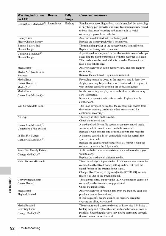
92
Appendices
Record Only Media (A)2) Intermittent Flashing Simultaneous recording to both slots is enabled, but recording is only being performed to one card. To simultaneously record to both slots, stop recording and insert cards to which recording is possible in both slots.
Battery ErrorPlease Change Battery
An error was detected with the battery pack.Replace the battery pack with a normal one.
Backup Battery EndPlease Change
The remaining power of the backup battery is insufficient.Replace the battery with a new one.
Unknown Media(A)2)
Please Change
A partitioned memory card or one that contains recorded clips exceeding the number permitted with this recorder is loaded.This card cannot be used with this recorder. Remove it and load a compatible card.
Media Error
Media(A)2) Needs to be Restored
An error occurred with the memory card. The card requires restoration.Remove the card, load it again, and restore it.
Media ErrorCannot Record to
Media(A)2)
Recording cannot be done, as the memory card is defective.As playback may be possible, it is recommended to replace it with another card after copying the clips, as required.
Media Error
Cannot Use Media(A)2)
Neither recording nor playback can be done, as the memory card is defective.It cannot be operated with this recorder. Replace it with another card.
Will Switch Slots Soon This is an advanced notice that the recorder will switch from the current memory card to the other memory card for continuous recording.
No Clip There are no clips on the media.Check the selected card.
Cannot Use Media(A)3)
Unsupported File System
A media of a different file system or an unformatted media was inserted. It cannot be used with this recorder. Replace it with another card or format it with this recorder.
In This File System
Cannot Use Media(A)2)
A memory card that is not compatible with the current file system is inserted.Replace the card from the respective slot, format it with the recorder, or switch the F.Sys. mode.
Same File Already Exists
Change Media(A)3)
A clip with the same name exists on the media to which you want to copy.Replace the media with different media.
Video Format Mismatch The external signal input via the i.LINK connection cannot be recorded, as the [Rec Format] setting is different from the signal format of the external input signal.Change [Rec Format] in [System] in the [OTHERS] menu to match it to that of the external signal.
Copy Protected InputCannot Record
The external signal input via the i.LINK connection cannot be recorded, as the stream is copy-protected.Check the input signal.
Media ErrorPlayback Halted
An error occurred in reading data from the memory card, and playback cannot be continued.If this frequently occurs, change the memory card after copying the clips, as required.
Media Reached Rewriting Limit
Change Media(A)2)
The memory card comes to the end of its service life. Make a backup copy and replace the card with another one as soon as possible. Recording/playback may not be performed properly if you continue to use the card.
Warning indication on LCD
Buzzer Tally lamps
Cause and measures
Troubleshooting
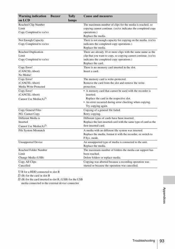
Appendices
1) B for a HDD connected to slot B2) (B) for the card in slot B3) (B) for the card inserted in slot B, (USB) for the USB
media connected to the external device connector
Reached Clip Number LimitCopy Completed to xx/xx
The maximum number of clips for the media is reached, so copying cannot continue. (xx/xx indicates the completed copy operations.)Replace the media.
Not Enough CapacityCopy Completed to xx/xx
There is not enough capacity for copying on the media. (xx/xx indicates the completed copy operations.)Replace the media.
Reached Duplication LimitCopy Completed to xx/xx
There are already 10 or more clips with the same name as the clip that you want to copy, so copying cannot continue. (xx/xx indicates the completed copy operations.)Replace the card.
Copy Error! (CANCEL:Abort)No Media!
There is no memory card inserted in the slot.Insert a card.
Copy Error! (CANCEL:Abort)Media Write Protected
The memory card is write-protected.Remove the card from the slot and remove the write-protection.
Copy Error! (CANCEL:Abort)
Cannot Use Media(A)3)
• A memory card that cannot be used with the recorder is inserted.Replace the card in the respective slot.
• An error occurred during error checking when copying.Try copying again.
Copy General FilesNG: Cannot Copy
Copying of a general file failed.Retry copying.
Different Media is Inserted
Cannot Use Media(A)2)
Different types of cards have been inserted.Replace the last-inserted card with the same type of card as the first-inserted card.
File System Mismatch A media with an different file system was inserted.Replace the media, format it with the recorder, or switch to F.Sys. mode.
Unsupported Device An unsupported type of media is connected to the unit.Replace the media.
Reached Folder Number LimitChange Media (USB)
The maximum number of folders the media can support has been reached. Delete folders or replace media.
Copy All ClipsCancelled
Copying was aborted because a recording operation was started or because the operation was cancelled.
Warning indication on LCD
Buzzer Tally lamps
Cause and measures
Troubleshooting 93

94
Appendices
THIS PRODUCT IS LICENSED UNDER THE AVC PATENT PORTFOLIO LICENSE FOR THE PERSONAL USE OF A CONSUMER OR OTHER USES IN WHICH IT DOES NOT RECEIVE REMUNERATION TO (i) ENCODE VIDEO IN COMPLIANCE WITH
THE AVC STANDARD (“AVC VIDEO”) AND/OR
(ii) DECODE AVC VIDEO THAT WAS ENCODED BY A CONSUMER ENGAGED IN A PERSONAL ACTIVITY AND/OR WAS OBTAINED FROM A VIDEO PROVIDER LICENSED TO PROVIDE AVC VIDEO.
NO LICENSE IS GRANTED OR SHALL BE IMPLIED FOR ANY OTHER USE. ADDITIONAL INFORMATION MAY BE OBTAINED FROM MPEG LA, L.L.C. SEE HTTP://WWW.MPEGLA.COM
This product uses RICOH Bitmap Fonts produced and sold by Ricoh Company, Ltd.
This product uses software to which the GPL version 2 applies. This informs you that you have a right to have access to, modify, and redistribute source code for these software programs under the conditions of the GPL version 2.The source code is provided on the internet. Use the following URL and follow the download instructions.http://www.sony.net/Products/Linux/common/search.htmlWe would prefer that you do not contact us about the contents of the source code.
Because it uses the OpenSSL Toolkit, this product uses software developed by the OpenSSL Project (http://www.openssl.org/).
OpenSSL License ---------------
/*============================* Copyright (c) 1998-2008 The OpenSSL * Project. All rights reserved.** Redistribution and use in source and * binary forms, with or without * modification, are permitted provided * that the following conditions are met:** 1. Redistributions of source code must * retain the above copyright notice, * this list of conditions and the * following disclaimer.** 2. Redistributions in binary form must * reproduce the above copyright * notice, this list of conditions and the * following disclaimer in the * documentation and/or other * materials provided with the * distribution.** 3. All advertising materials mentioning * features or use of this software must * display the following * acknowledgment:* "This product includes software * developed by the OpenSSL Project * for use in the OpenSSL Toolkit. * (http://www.openssl.org/)"** 4. The names "OpenSSL Toolkit" and * "OpenSSL Project" must not be used * to endorse or promote products * derived from this software without * prior written permission. For written * permission, please contact openssl-* [email protected].** 5. Products derived from this software * may not be called "OpenSSL" nor * may "OpenSSL" appear in their
Licenses
MPEG-4 AVC Patent Portfolio License
Bitmap Fonts
On accessing software to which the GPL applies
About OpenSSL
Licenses
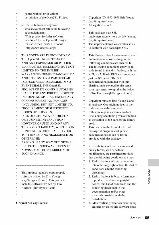
Appendices
* names without prior written * permission of the OpenSSL Project.** 6. Redistributions of any form * whatsoever must retain the following * acknowledgment:* "This product includes software * developed by the OpenSSL Project * for use in the OpenSSL Toolkit * (http://www.openssl.org/)"** THIS SOFTWARE IS PROVIDED BY * THE OpenSSL PROJECT ``AS IS'' * AND ANY EXPRESSED OR IMPLIED * WARRANTIES, INCLUDING, BUT NOT * LIMITED TO, THE IMPLIED * WARRANTIES OF MERCHANTABILITY * AND FITNESS FOR A PARTICULAR * PURPOSE ARE DISCLAIMED. IN NO * EVENT SHALL THE OpenSSL * PROJECT OR ITS CONTRIBUTORS BE * LIABLE FOR ANY DIRECT, INDIRECT, * INCIDENTAL, SPECIAL, EXEMPLARY, * OR CONSEQUENTIAL DAMAGES * (INCLUDING, BUT NOT LIMITED TO, * PROCUREMENT OF SUBSTITUTE * GOODS OR SERVICES;* LOSS OF USE, DATA, OR PROFITS; * OR BUSINESS INTERRUPTION) * HOWEVER CAUSED AND ON ANY * THEORY OF LIABILITY, WHETHER IN * CONTRACT, STRICT LIABILITY, OR * TORT (INCLUDING NEGLIGENCE OR * OTHERWISE) * ARISING IN ANY WAY OUT OF THE * USE OF THIS SOFTWARE, EVEN IF * ADVISED OF THE POSSIBILITY OF * SUCH DAMAGE.*
============================** This product includes cryptographic * software written by Eric Young * ([email protected]). This product * includes software written by Tim * Hudson ([email protected]).** /
Original SSLeay License -----------------------
* Copyright (C) 1995-1998 Eric Young * ([email protected])* All rights reserved.** This package is an SSL * implementation written by Eric Young * ([email protected]).* The implementation was written so as * to conform with Netscapes SSL.** This library is free for commercial and * non-commercial use as long as the * following conditions are aheared to. * The following conditions apply to all * code found in this distribution, be it the * RC4, RSA, lhash, DES, etc., code; not * just the SSL code. The SSL * documentation included with this * distribution is covered by the same * copyright terms except that the holder * is Tim Hudson ([email protected]).** Copyright remains Eric Young's, and * as such any Copyright notices in the * code are not to be removed.* If this package is used in a product, * Eric Young should be given attribution * as the author of the parts of the library * used.* This can be in the form of a textual * message at program startup or in * documentation (online or textual) * provided with the package.** Redistribution and use in source and * binary forms, with or without * modification, are permitted provided * that the following conditions are met:* 1. Redistributions of source code must * retain the copyright notice, this list of * conditions and the following * disclaimer.* 2. Redistributions in binary form must * reproduce the above copyright * notice, this list of conditions and the * following disclaimer in the * documentation and/or other * materials provided with the * distribution.* 3. All advertising materials mentioning * features or use of this software must
Licenses 95
96
Appendices
* display the following * acknowledgement:* "This product includes * cryptographic software written by * Eric Young ([email protected])"* The word 'cryptographic' can be left * out if the rouines from the library * being used are not cryptographic * related :-).* 4. If you include any Windows specific * code (or a derivative thereof) from * the apps directory (application * code) you must include an * acknowledgement:* "This product includes software * written by Tim Hudson * ([email protected])"** THIS SOFTWARE IS PROVIDED BY * ERIC YOUNG ``AS IS'' AND ANY * EXPRESS OR IMPLIED WARRANTIES, * INCLUDING, BUT NOT LIMITED TO, * THE IMPLIED WARRANTIES OF * MERCHANTABILITY AND FITNESS * FOR A PARTICULAR PURPOSE ARE * DISCLAIMED. IN NO EVENT SHALL * THE AUTHOR OR CONTRIBUTORS BE * LIABLE FOR ANY DIRECT, INDIRECT, * INCIDENTAL, SPECIAL, EXEMPLARY, * OR CONSEQUENTIAL DAMAGES * (INCLUDING, BUT NOT LIMITED TO, * PROCUREMENT OF SUBSTITUTE * GOODS OR SERVICES; LOSS OF USE, * DATA, OR PROFITS; OR BUSINESS * INTERRUPTION) * HOWEVER CAUSED AND ON ANY * THEORY OF LIABILITY, WHETHER IN * CONTRACT, STRICT LIABILITY, OR * TORT (INCLUDING NEGLIGENCE OR * OTHERWISE) ARISING IN ANY WAY * OUT OF THE USE OF THIS SOFTWARE, * EVEN IF ADVISED OF THE * POSSIBILITY OF SUCH DAMAGE.** The licence and distribution terms for * any publically available version or * derivative of this code cannot be * changed. i.e. this code cannot simply * be copied and put under another * distribution licence [including the GNU * Public Licence.]* /
This product uses the following software, released under MIT License.
jQuery JavaScript Library v1.7.2http://jquery.com/Copyright 2011, John Resig
Sizzle.jshttp://sizzlejs.com/Copyright 2011, The Dojo FoundationDate: Wed Mar 21 12:46:34 2012 -0700
MIT License
Permission is hereby granted, free of charge, to any person obtaining a copy of this software and associated documentation files (the "Software"), to deal in the Software without restriction, including without limitation the rights to use, copy, modify, merge, publish, distribute, sublicense, and/or sell copies of the Software, and to permit persons to whom the Software is furnished to do so, subject to the following conditions:
The above copyright notice and this permission notice shall be included in all copies or substantial portions of the Software.
THE SOFTWARE IS PROVIDED "AS IS", WITHOUT WARRANTY OF ANY KIND, EXPRESS OR IMPLIED, INCLUDING BUT NOT LIMITED TO THE WARRANTIES OF MERCHANTABILITY, FITNESS FOR A PARTICULAR PURPOSE AND NONINFRINGEMENT. IN NO EVENT SHALL THE AUTHORS OR COPYRIGHT HOLDERS BE LIABLE FOR ANY CLAIM, DAMAGES OR OTHER LIABILITY, WHETHER IN AN ACTION OF CONTRACT, TORT OR OTHERWISE, ARISING FROM, OUT OF OR IN CONNECTION WITH THE SOFTWARE OR THE USE OR OTHER DEALINGS IN THE SOFTWARE.
About JQuery,Sizzle.js
About JQuery,Sizzle.js

Appendices
When the unit is used with a PC connection, download any device drivers, plug-ins, and application software you require from the following websites.
Sony Professional products website:U.S.A. http://pro.sony.comCanada http://www.sonybiz.caLatin America http://sonypro-latin.comEurope, http://www.pro.sony.eu/proMiddle East, Africa http://sony-psmea.comRussia http://sony.ru/pro/Brazil http://sonypro.com.brAustralia http://pro.sony.com.auNew Zealand http://pro.sony.co.nzJapan http://www.sonybsc.comAsia Pacific http://pro.sony-asia.comKorea http://bp.sony.co.krChina http://pro.sony.com.cnIndia http://pro.sony.co.in
Sony Creative Software, software download page:http://www.sonycreativesoftware.com/download/software_for_sony_equipment
GeneralPower Requirements
DC 12 VPower Consumption
Approx. 13 W (while recording, LCD monitor On)Approx. 22.5 W (while recording, LCD monitor On, with CBK-WA100)
Inrush current (1) Maximum possible inrush current at initial switch-on (Voltage changes caused by manual switching): 50 A peak, 9.5 A r.m.s. (240 V AC)(2) Inrush current after a mains interruption of five seconds (Voltage changes caused at zero-crossing): 3 A peak, 0.7 A r.m.s. (240 V AC)
Operating Temperature0 °C to 40 °C (32 °F to 104 °F)
Storage Temperature–20 °C to +60 °C (–4 °F to +140 °F)
MassApprox. 1 kg (2 lb. 3.3 oz.) (without Audio Input Box)Approx. 1.2 kg (2 lb. 10 oz.) (with Audio Input Box)
Dimensions (W x H x D)Approx. 124 × 86 × 237 mm (5 × 3 1/2 × 9 3/8 in.) (without protrusions & Audio Input Box)Approx. 124 × 115 × 237 mm (5 × 4 5/8 × 9 3/8 in.) (with Audio Input Box & without protrusions)
Recording/Playback Format (Video)[exFAT]• XAVC-I mode: CBG, 223 Mbps max,
MPEG-4 AVC/H.264• XAVC-L50 mode: VBR, 50 Mbps max,
MPEG-4 AVC/H.264• XAVC-L35 mode: VBR, 35 Mbps max,
MPEG-4 AVC/H.264• XAVC-L25 mode: VBR, 25 Mbps max,
MPEG-4 AVC/H.264• HD422 mode: CBR, 50 Mbps, MPEG-2
422P@HL• HD420 mode: VBR, 35 Mbps, MPEG-2
MP@HL
Software Downloads Specifications
Software Downloads / Specifications 97

98
Appendices
• DVCAM mode: DVCAM• IMX 50 mode: CBR, 50 Mbps, MPEG-2
422P@ML Intra[UDF]• HD422 mode: CBR, 50 Mbps, MPEG-2
422P@HL• HD420 mode: VBR, 35 Mbps, MPEG-2
MP@HL• DVCAM mode: DVCAM• IMX 50 mode: CBR, 50 Mbps, MPEG-2
422P@ML Intra[FAT]• HQ mode: VBR, 35 Mbps, MPEG-2
MP@HL• SP mode: CBR, 25 Mbps, MPEG-2
MP@H14• DVCAM mode: DVCAM
Recording/Playback Format (Audio)[exFAT]• XAVC-I mode: LPCM 24 bits, 48 kHz,
4 channel• XAVC-L50 mode: LPCM 24 bits, 48 kHz,
4 channel• XAVC-L35 mode: LPCM 24 bits, 48 kHz,
4 channel• XAVC-L25 mode: LPCM 24 bits, 48 kHz,
4 channel• HD422 mode: LPCM 24 bits, 48 kHz,
4 channels• IMX 50 mode: LPCM 24/16 bits, 48 kHz,
4 channels• Other mode: LPCM 16 bits, 48 kHz,
4 channels[UDF]• HD422 mode: LPCM 24 bits, 48 kHz,
4 channels• IMX 50 mode: LPCM 24/16 bits, 48 kHz,
4 channels• Other mode: LPCM 16 bits, 48 kHz,
4 channels[FAT]• HD mode: LPCM 16 bits, 48 kHz,
4 channels• SD mode: LPCM 16 bits, 48 kHz,
2 channelsMaximum recording time (XAVC)
Note
The maximum recording time is equivalent to the duration of a single clip recording that fills the media. The recording time may become shorter, depending on the number of recorded clips.
[XAVC-I]Approx. 60 min with SBP-128B (128 GB) memory cardApprox. 30 min with SBP-64AB (64 GB)/ SBS-64G1A (64 GB) memory card[XAVC-L50]Approx. 240 min with SBP-128B (128 GB) memory cardApprox. 120 min with SBP-64AB (64 GB)/ SBS-64G1A (64 GB) memory card[XAVC-L35]Approx. 340 min with SBP-128B (128 GB) memory cardApprox. 170 min with SBP-64AB (64 GB)/ SBS-64G1A (64 GB) memory card[XAVC-L25]Approx. 440 min with SBP-128B (128 GB) memory cardApprox. 220 min with SBP-64AB (64 GB)/ SBS-64G1A (64 GB) memory card
Maximum recording time (MPEG HD422)[UDF]HD422 mode:Approx. 120 min with SBP-64A/ SBS-64G1A (64 GB) memory cardApprox. 60 min with SBP-32/ SBS-32G1A (32 GB) memory card
Maximum recording time (MPEG HD)[UDF]HD420 mode:Approx. 180 min with SBP-64A/ SBS-64G1A (64 GB) memory cardApprox. 90 min with SBP-32/ SBS-32G1A (32 GB) memory card[FAT]HQ mode:Approx. 200 min with SBP-64A/ SBS-64G1A (64 GB) memory cardApprox. 100 min with SBP-32/ SBS-32G1A (32 GB) memory cardSP Mode:Approx. 280 min with SBP-64A/ SBS-64G1A (64 GB) memory cardApprox. 140 min with SBP-32/ SBS-32G1A (32 GB) memory card
Maximum recording time (MPEG IMX)[UDF]IMX 50 mode:Approx. 120 min with SBP-64A/ SBS-64G1A (64 GB) memory cardApprox. 60 min with SBP-32/ SBS-32G1A (32 GB) memory card
Specifications

Appendices
Maximum recording time (DVCAM)[UDF]DVCAM mode:Approx. 220 min with SBP-64A/ SBS-64G1A (64 GB) memory cardApprox. 110 min with SBP-32/ SBS-32G1A (32 GB) memory card[FAT]DVCAM mode:Approx. 260 min with SBP-64A/ SBS-64G1A (64 GB) memory cardApprox. 130 min with SBP-32/ SBS-32G1A (32 GB) memory card
Battery Operating TimeApprox. 110 min with BP-U30 battery (while recording, LCD monitor On)Approx. 220 min with BP-U60 battery (while recording, LCD monitor On)Approx. 330 min with BP-U90 battery (while recording, LCD monitor On)
Media DriveMedia Type
ExpressCard/34 slot (2)
Input/OutputSD Output
BNC (2), 3G/HD/SD selectable, SMPTE 292M/259M/424M/425M standards
SD InputBNC (1), 3G/HD/SD automatically switched, SMPTE 292M/259M/424M/425M standards
Analog Audio InputXLR-3 pin (CH-1, CH-2), LINE: +4 dBu (Reference Level)
Analog Composite OutputBNC (1), NTSC, PAL or HD-Y
HDMI OutputType A 19-pin (1), output
Analog Audio OutputPhono jack (CH-1, CH-2) –10 dBu (Reference Level), 47 kO
Headphone OutputStereo mini jack (1)
i.LINKIEEE 1394, 4-pin (1), HDV stream input/output, DVCAM stream output, S400
USBUSB Type-A (1), USB Type-miniB (1)
DC Input (12 V)DC jack (12 V)
DC Output (12 V)UnReg (4-pin) for CBK-WA100
Other EquipmentBuilt-in Display
3.5-inch type color LCD monitor: 960 (H) × 3 (RGB) × 540 (V), 16:9
Supplied AccessoriesUSB cable (1)Infrared Remote Commander (1)BC-U1 battery charger (1)Lithium battery (CR2032 for backup) (1), Pre-
installed in the recorderLithium battery (CR2025 for the IR Remote
Commander) (1), Pre-installed to the IR Remote Commander
Leaflet: Before Using this Unit (1)Shoulder strap (1)Side spacer (1)CD-ROM: Operating Instructions in PDF (1)
Optional AccessoriesBattery pack
BP-U30, BP-U60, BP-U90Battery charger/AC adapter
BC-U1, BC-U2SxS memory cards
SxS PRO+ seriesSxS PRO seriesSxS-1 series
SxS memory card USB reader/writerSBAC-US20
Media adapterQDA-EX1 (for XQD memory cards)MEAD-SD02 (for SD cards)
USB wireless LAN moduleIFU-WLM3
Wireless adapterCBK-WA100
Design and specifications are subject to change without notice.
Specifications 99

100
Appendices
• XDCAM, SxS, SxS PRO, SxS-1, XQD, i.LINK , and Remote Commander are registered trademarks of Sony Corporation.
• The terms HDMI and HDMI High-Definition Multimedia Interface, and the HDMI Logo are trademarks or registered trademarks of HDMI Licensing LLC in the United States and other countries.
• The ExpressCard word mark and logos are owned by the Personal Computer Memory Card International Association (PCMCIA) and any use of such marks by Sony Corporation is under license. Other trademarks and trade names are those of their respective owners.
The products or system names appearing in this document are trademarks or registered trademarks of their respective owners.
Notes• Always make a test recording, and verify that
it was recorded successfully.SONY WILL NOT BE LIABLE FOR DAMAGES OF ANY KIND INCLUDING, BUT NOT LIMITED TO, COMPENSATION OR REIMBURSEMENT ON ACCOUNT OF FAILURE OF THIS UNIT OR ITS RECORDING MEDIA, EXTERNAL STORAGE SYSTEMS OR ANY OTHER MEDIA OR STORAGE SYSTEMS TO RECORD CONTENT OF ANY TYPE.
• Always verify that the unit is operating properly before use. SONY WILL NOT BE LIABLE FOR DAMAGES OF ANY KIND INCLUDING, BUT NOT LIMITED TO, COMPENSATION OR REIMBURSEMENT ON ACCOUNT OF THE LOSS OF PRESENT OR PROSPECTIVE PROFITS DUE TO FAILURE OF THIS UNIT, EITHER DURING THE WARRANTY PERIOD OR AFTER EXPIRATION OF THE WARRANTY, OR FOR ANY OTHER REASON WHATSOEVER.
• SONY WILL NOT BE LIABLE FOR CLAIMS OF ANY KIND MADE BY USERS OF THIS UNIT OR MADE BY THIRD PARTIES.
• SONY WILL NOT BE LIABLE FOR THE LOSS, REPAIR, OR REPRODUCTION OF ANY DATA RECORDED ON THE INTERNAL STORAGE SYSTEM, RECORDING MEDIA, EXTERNAL STORAGE SYSTEMS OR ANY OTHER MEDIA OR STORAGE SYSTEMS.
• SONY WILL NOT BE LIABLE FOR THE TERMINATION OR DISCONTINUATION OF ANY SERVICES RELATED TO THIS UNIT THAT MAY RESULT DUE TO CIRCUMSTANCES OF ANY KIND.
Specifications