Traversability, Reconfiguration, and Reachability in the ... - arXiv
http://pii.sagepub.com/Control Engineering
Engineers, Part I: Journal of Systems and Proceedings of the Institution of Mechanical
http://pii.sagepub.com/content/early/2011/09/08/0959651811410257The online version of this article can be found at:
DOI: 10.1177/0959651811410257
online 9 September 2011 publishedProceedings of the Institution of Mechanical Engineers, Part I: Journal of Systems and Control Engineering
V L Krishnan, P M Pathak, S C Jain and A K SamantarayReconfiguration of four-legged walking robot for actuator faults
Published by:
http://www.sagepublications.com
On behalf of:
Institution of Mechanical Engineers
can be found at:EngineeringProceedings of the Institution of Mechanical Engineers, Part I: Journal of Systems and ControlAdditional services and information for
http://pii.sagepub.com/cgi/alertsEmail Alerts:
http://pii.sagepub.com/subscriptionsSubscriptions:
http://www.sagepub.com/journalsReprints.navReprints:
http://www.sagepub.com/journalsPermissions.navPermissions:
What is This?
- Sep 9, 2011Version of Record >>
by P.M. Pathak on September 26, 2011pii.sagepub.comDownloaded from
Reconfiguration of four-legged walkingrobot for actuator faultsV L Krishnan*1, P M Pathak1, S C Jain1, and A K Samantaray2
1Robotics and Control Laboratory Mechanical and Industrial Engineering Department, Indian Institute of Technology,
Roorkee, India2Department of Mechanical Engineering, Indian Institute of Technology, Kharagpur, India
The manuscript was received on 9 December 2010 and was accepted after revision for publication on 21 April 2011.
DOI: 10.1177/0959651811410257
Abstract: This paper presents fault accommodation through the reconfiguration of a fourlegged (quadruped) walking robot. It is assumed that the walking robot is moving using abounding gait. A bond graph model to represent the robot’s locomotion in the sagittal plane isdeveloped. A novel and simple attitude control device based on a moving appendage is pro-posed. This appendage device serves as redundant hardware and is activated only when therobot experiences a locked joint failure. The bond graph model of the system is used to gener-ate the analytical redundancy relations which are then evaluated with actual measurements togenerate residuals. These residuals are used to perform structural fault isolation. Once thefault list is updated in the equipment availability database, an automaton selects the bestoption to reconfigure the system such that the given control objectives are achieved. Thedeveloped methodology is validated by considering the failure of a joint’s actuator.
Keywords: walking robot, locked joint failure, fault accommodation, reconfiguration, attitude
control, moving appendage
1 INTRODUCTION
Robots are increasingly being deployed in prefer-
ence to humans in situations that are extremely
complex and/or hazardous such as nuclear power
plant accidents, military operations, and space
exploration. To improve the probability of mission
success the tasked robot must be able to autono-
mously perform fault detection and isolation activi-
ties and take corrective/preventive maintenance
action in real-time. In the case of multi-legged walk-
ing robots the possible failure situations may be
broadly categorized as either a failure in the kine-
matic part of the leg or a communications failure
between the controller and the leg.
The failure in the kinematic part of the leg can be
one of two types:
(a) a free-swinging failure: in this failure the actua-
tor torque of a leg joint is lost and the joint
swings freely and thus it cannot support the
body of the robot;
(b) a locked joint failure: in this failure the joint is
locked in place. Consequently, the workspace/
reach of the leg tip is restricted; however, it can
still support the body of the robot. Thus, the
failed leg still partially contributes towards the
movement of the robot.
The locked joint failure is the more common of
these failure types due to its numerous causes
including the effects of an increased friction level in
bearings, clutch slippage, and erroneous application
of the brakes.
These failures can be rectified using either fault-
tolerant control or fault accommodation through
reconfiguration [1, 2]. In fault-tolerant control the
control laws and their associated control problem
are altered in order to maintain the desired output.
Fault accommodation through reconfiguration is
*Corresponding author: Robotics and Control Laboratory
Mechanical and Industrial Engineering Department, Indian
Institute of Technology,247667, Roorkee, India.
email: [email protected]
1
Proc. IMechE Vol. 225 Part I: J. Systems and Control Engineering
by P.M. Pathak on September 26, 2011pii.sagepub.comDownloaded from
accomplished by deploying alternate standby devices
called hardware redundancies in place of the faulty
components and suitable modifications of the con-
trol laws.
Most of the work done pertaining to fault-tolerant
control in walking robots [3–6] is based on the
assumption that the system does not have redun-
dancy and hence is concerned with the generation of
fault-tolerant gait patterns for the walking robot.
Jakimovski et al. [7] attempted to create fault tolerance
through reconfiguration using a swarm-intelligence-
based approach that did not require additional inverse
kinematics modelling. This concept is applicable to
robots with more then two legs provided that they are
spatially configured in a circle.
Recently, Abdi and Nahavandi [8] used the con-
cept of actuator fault accommodation through
reconfiguration in the case of a five-degree-of-
freedom robotic manipulator. Chi et al. [9] pre-
sented a method for the real-time diagnosis and
accommodation of sensor faults in a flight control
system using analytical redundancy. However, fault
accommodation through reconfiguration for quad-
ruped robots has not yet been reported in the litera-
ture except for an initial report on part of this work
that was presented at a recent conference [10]. The
present work proposes a scheme for fault accommo-
dation through reconfiguration for a quadruped
walking robot that experiences a locked joint failure.
This work proposes a novel attitude control device
for walking robots that allows the attitude of the
walking robot to be controlled with the help of a
moving appendage. The attitude control device acts
as a piece of redundant hardware in the system, that
is, it is not used in nominal or fault-free operation.
The scheme has been validated through simulations
carried out using Symbols [11], a bond graph mod-
elling and simulation software.
2 MODELLING OF THE WALKING ROBOT
The modelling of the quadruped robot consists in
modelling the translational and angular dynamics of
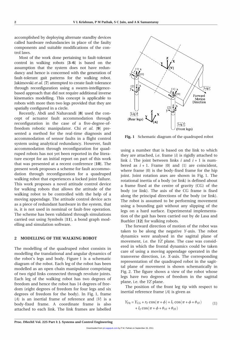
the robot’s legs and body. Figure 1 is a schematic
diagram of the robot. Each leg of the robot has been
modelled as an open chain manipulator comprising
of two rigid links connected through revolute joints.
Each leg of the walking robot has two degrees of
freedom and hence the robot has 14 degrees of free-
dom (eight degrees of freedom for four legs and six
degrees of freedom for the body). In Fig. 1, frame
{A} is an inertial frame of reference and {V} is a
body-fixed frame. A coordinate frame is also
attached to each link. The link frames are labelled
using a number that is based on the link to which
they are attached, i.e. frame {i} is rigidly attached to
link i. The joint between links i and i + 1 is num-
bered as i + 1. Frame {0} and {1} are coincident,
where frame {0} is the body-fixed frame for the hip
joint. Joint rotation axes are shown in Fig. 1. The
rotational inertia of a body (or link) is defined about
a frame fixed at the centre of gravity (CG) of the
body (or link). The axis of the CG frame is fixed
along the principal directions of the body (or link).
The robot is assumed to be performing movement
using a bounding gait without any slipping of the
legs on a hard surface. Experimental implementa-
tion of the gait has been carried out by de Lasa and
Buehler [12] for walking robots.
The forward direction of motion of the robot was
taken to be along the negative Y-axis. The robot
dynamics were analysed in the sagittal plane of
movement, i.e. the YZ plane. The case was consid-
ered in which the frontal dynamics could be taken
care of using a moving appendage operated in the
transverse direction, i.e. X-axis. The corresponding
representation of the quadruped robot in the sagit-
tal plane of movement is shown schematically in
Fig. 2. The figure shows a view of the robot whose
legs have two degrees of freedom in the sagittal
plane, i.e. the YZ plane.
The position of the front leg tip with respect to
inertial reference frame {A} is given as
YFlt = YCG + rF cos p + fð Þ+ l1 cos p + f + u1Fð Þ+ l2 cos p + f + u1F + u2Fð Þ
(1)
Fig. 1 Schematic diagram of the quadruped robot
2 V L Krishnan, P M Pathak, S C Jain, and A K Samantaray
Proc. IMechE Vol. 225 Part I: J. Systems and Control Engineering
by P.M. Pathak on September 26, 2011pii.sagepub.comDownloaded from
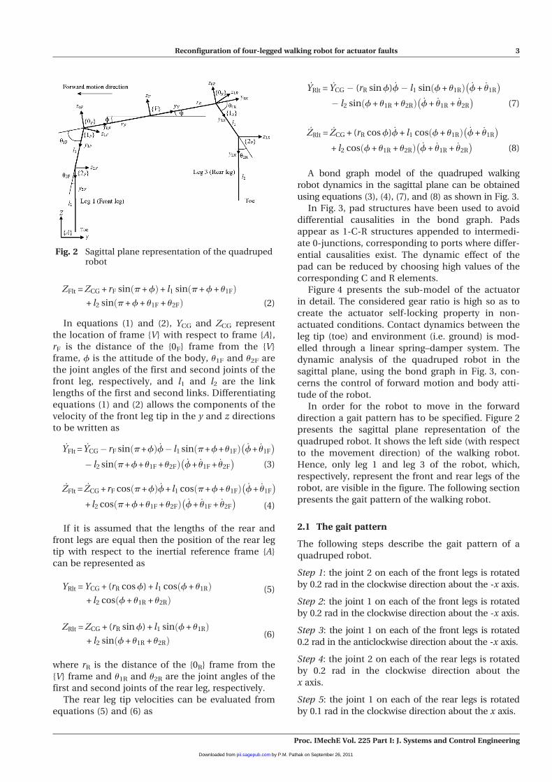
ZFlt = ZCG + rF sin p + fð Þ+ l1 sin p + f + u1Fð Þ+ l2 sin p + f + u1F + u2Fð Þ (2)
In equations (1) and (2), YCG and ZCG represent
the location of frame {V} with respect to frame {A},
rF is the distance of the {0F} frame from the {V}
frame, f is the attitude of the body, u1F and u2F are
the joint angles of the first and second joints of the
front leg, respectively, and l1 and l2 are the link
lengths of the first and second links. Differentiating
equations (1) and (2) allows the components of the
velocity of the front leg tip in the y and z directions
to be written as
_YFlt = _YCG� rF sin p + fð Þ _f� l1 sin p + f+ u1Fð Þ _f+ _u1F
� �
� l2 sin p + f+u1F +u2Fð Þ _f+ _u1F + _u2F
� �(3)
_ZFlt = _ZCG + rF cos p + fð Þ _f + l1 cos p + f + u1Fð Þ _f + _u1F
� �
+ l2 cos p + f + u1F + u2Fð Þ _f + _u1F + _u2F
� �(4)
If it is assumed that the lengths of the rear and
front legs are equal then the position of the rear leg
tip with respect to the inertial reference frame {A}
can be represented as
YRlt = YCG + (rR cos f) + l1 cos f + u1Rð Þ+ l2 cos f + u1R + u2Rð Þ
(5)
ZRlt = ZCG + (rR sin f) + l1 sin f + u1Rð Þ+ l2 sin f + u1R + u2Rð Þ (6)
where rR is the distance of the {0R} frame from the
{V} frame and u1R and u2R are the joint angles of the
first and second joints of the rear leg, respectively.
The rear leg tip velocities can be evaluated from
equations (5) and (6) as
_YRlt = _YCG � (rR sin f) _f� l1 sin f + u1Rð Þ _f + _u1R
� �
� l2 sin f + u1R + u2Rð Þ _f + _u1R + _u2R
� �(7)
_ZRlt = _ZCG + (rR cos f) _f + l1 cos f + u1Rð Þ _f + _u1R
� �
+ l2 cos f + u1R + u2Rð Þ _f + _u1R + _u2R
� �(8)
A bond graph model of the quadruped walking
robot dynamics in the sagittal plane can be obtained
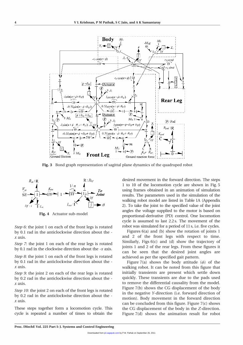
using equations (3), (4), (7), and (8) as shown in Fig. 3.
In Fig. 3, pad structures have been used to avoid
differential causalities in the bond graph. Pads
appear as 1-C-R structures appended to intermedi-
ate 0-junctions, corresponding to ports where differ-
ential causalities exist. The dynamic effect of the
pad can be reduced by choosing high values of the
corresponding C and R elements.
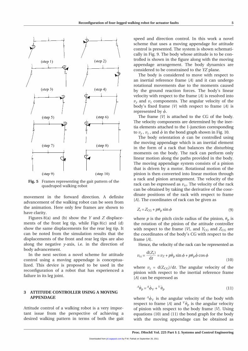
Figure 4 presents the sub-model of the actuator
in detail. The considered gear ratio is high so as to
create the actuator self-locking property in non-
actuated conditions. Contact dynamics between the
leg tip (toe) and environment (i.e. ground) is mod-
elled through a linear spring–damper system. The
dynamic analysis of the quadruped robot in the
sagittal plane, using the bond graph in Fig. 3, con-
cerns the control of forward motion and body atti-
tude of the robot.
In order for the robot to move in the forward
direction a gait pattern has to be specified. Figure 2
presents the sagittal plane representation of the
quadruped robot. It shows the left side (with respect
to the movement direction) of the walking robot.
Hence, only leg 1 and leg 3 of the robot, which,
respectively, represent the front and rear legs of the
robot, are visible in the figure. The following section
presents the gait pattern of the walking robot.
2.1 The gait pattern
The following steps describe the gait pattern of a
quadruped robot.
Step 1: the joint 2 on each of the front legs is rotated
by 0.2 rad in the clockwise direction about the -x axis.
Step 2: the joint 1 on each of the front legs is rotated
by 0.2 rad in the clockwise direction about the -x axis.
Step 3: the joint 1 on each of the front legs is rotated
0.2 rad in the anticlockwise direction about the -x axis.
Step 4: the joint 2 on each of the rear legs is rotated
by 0.2 rad in the clockwise direction about the
x axis.
Step 5: the joint 1 on each of the rear legs is rotated
by 0.1 rad in the clockwise direction about the x axis.
Fig. 2 Sagittal plane representation of the quadrupedrobot
Reconfiguration of four-legged walking robot for actuator faults 3
Proc. IMechE Vol. 225 Part I: J. Systems and Control Engineering
by P.M. Pathak on September 26, 2011pii.sagepub.comDownloaded from
Step 6: the joint 1 on each of the front legs is rotated
by 0.1 rad in the anticlockwise direction about the -
x axis.
Step 7: the joint 1 on each of the rear legs is rotated
by 0.1 rad in the clockwise direction about the -x axis.
Step 8: the joint 1 on each of the front legs is rotated
by 0.1 rad in the anticlockwise direction about the -
x axis.
Step 9: the joint 2 on each of the rear legs is rotated
by 0.2 rad in the anticlockwise direction about the -
x axis.
Step 10: the joint 2 on each of the front legs is rotated
by 0.2 rad in the anticlockwise direction about the -
x axis.
These steps together form a locomotion cycle. This
cycle is repeated a number of times to obtain the
desired movement in the forward direction. The steps
1 to 10 of the locomotion cycle are shown in Fig. 5
using frames obtained in an animation of simulation
results. The parameters used in the simulation of the
walking robot model are listed in Table 1A (Appendix
2). To take the joint to the specified value of the joint
angles the voltage supplied to the motor is based on
proportional-derivative (PD) control. One locomotion
cycle is assumed to last 2.2 s. The movement of the
robot was simulated for a period of 11 s, i.e. five cycles.
Figures 6(a) and (b) show the rotation of joints 1
and 2 of the front legs with respect to time.
Similarly, Figs 6(c) and (d) show the trajectory of
joints 1 and 2 of the rear legs. From these figures it
can be seen that the desired joint angles are
achieved as per the specified gait pattern.
Figure 7(a) shows the body attitude (f) of the
walking robot. It can be noted from this figure that
initially transients are present which settle down
quickly. These transients are due to the pads used
to remove the differential causality from the model.
Figure 7(b) shows the CG displacement of the body
in the negative Y-direction (i.e. forward direction of
motion). Body movement in the forward direction
can be concluded from this figure. Figure 7(c) shows
the CG displacement of the body in the Z-direction.
Figure 7(d) shows the animation result for robot
Fig. 4 Actuator sub-model
Fig. 3 Bond graph representation of sagittal plane dynamics of the quadruped robot
4 V L Krishnan, P M Pathak, S C Jain, and A K Samantaray
Proc. IMechE Vol. 225 Part I: J. Systems and Control Engineering
by P.M. Pathak on September 26, 2011pii.sagepub.comDownloaded from
movement in the forward direction. A definite
advancement of the walking robot can be seen from
the animation. Here only few frames are shown to
have clarity.
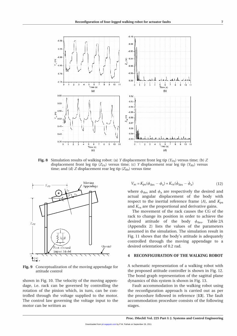
Figures 8(a) and (b) show the Y and Z displace-
ments of the front leg tip, while Figs 8(c) and (d)
show the same displacements for the rear leg tip. It
can be noted from the simulation results that the
displacements of the front and rear leg tips are also
along the negative y-axis, i.e. in the direction of
body advancement.
In the next section a novel scheme for attitude
control using a moving appendage is conceptua-
lized. This device is proposed to be used in the
reconfiguration of a robot that has experienced a
failure in its leg joint.
3 ATTITUDE CONTROLLER USING A MOVINGAPPENDAGE
Attitude control of a walking robot is a very impor-
tant issue from the perspective of achieving a
desired walking pattern in terms of both the gait
speed and direction control. In this work a novel
scheme that uses a moving appendage for attitude
control is presented. The system is shown schemati-
cally in Fig. 9. The body whose attitude is to be con-
trolled is shown in the figure along with the moving
appendage arrangement. The body dynamics are
considered to be constrained to the YZ plane.
The body is considered to move with respect to
an inertial reference frame {A} and it can undergo
rotational movements due to the moments caused
by the ground reaction forces. The body’s linear
velocity with respect to the frame {A} is resolved into
vy and vz components. The angular velocity of the
body’s fixed frame {V} with respect to frame {A} is
represented by _f.
The frame {V} is attached to the CG of the body.
The velocity components are determined by the iner-
tia elements attached to the 1-junction corresponding
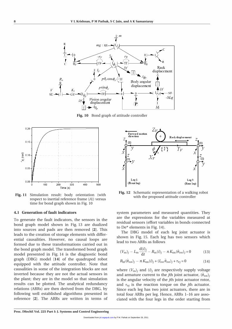
to vy , vz , and _f in the bond graph shown in Fig. 10.
The body orientation f can be controlled using
the moving appendage which is an inertial element
in the form of a rack that balances the disturbing
moments on the body. The rack can perform only
linear motion along the paths provided in the body.
The moving appendage system consists of a pinion
that is driven by a motor. Rotational motion of the
pinion is then converted into linear motion through
a rack and pinion arrangement. The velocity of the
rack can be expressed as vrz. The velocity of the rack
can be obtained by taking the derivative of the coor-
dinate positions of the rack with respect to frame
{A}. The coordinates of rack can be given as
Zr = ZCG + pup sin f (9)
where p is the pitch circle radius of the pinion, up is
the rotation of the pinion of the attitude controller
with respect to the frame {V}, and YCG and ZCG are
the coordinates of the body’s CG with respect to the
frame {A}.
Hence, the velocity of the rack can be represented as
vrz =d(Zr)
dt= vZ + p _up sin f + pup
_f cos f(10)
where vz = d(ZCG)/dt. The angular velocity of the
pinion with respect to the inertial reference frame
{A} can be expressed as
A _up = A _fV + V _up (11)
where A _fV is the angular velocity of the body with
respect to frame {A} and V _up is the angular velocity
of pinion with respect to the body frame {V}. Using
equations (10) and (11) the bond graph for the body
with the moving appendage can be obtained as
Fig. 5 Frames representing the gait pattern of thequadruped walking robot
Reconfiguration of four-legged walking robot for actuator faults 5
Proc. IMechE Vol. 225 Part I: J. Systems and Control Engineering
by P.M. Pathak on September 26, 2011pii.sagepub.comDownloaded from
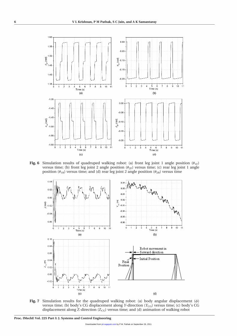
Fig. 6 Simulation results of quadruped walking robot: (a) front leg joint 1 angle position (u1F)versus time; (b) front leg joint 2 angle position (u2F) versus time; (c) rear leg joint 1 angleposition (u1R) versus time; and (d) rear leg joint 2 angle position (u2R) versus time
Fig. 7 Simulation results for the quadruped walking robot: (a) body angular displacement (f)versus time; (b) body’s CG displacement along Y-direction (YCG) versus time; (c) body’s CGdisplacement along Z-direction (ZCG) versus time; and (d) animation of walking robot
6 V L Krishnan, P M Pathak, S C Jain, and A K Samantaray
Proc. IMechE Vol. 225 Part I: J. Systems and Control Engineering
by P.M. Pathak on September 26, 2011pii.sagepub.comDownloaded from
shown in Fig. 10. The velocity of the moving appen-
dage, i.e. rack can be governed by controlling the
rotation of the pinion which, in turn, can be con-
trolled through the voltage supplied to the motor.
The control law governing the voltage input to the
motor can be written as
Vac = Kpa(fdes � fa) + Kva( _fdes � _fa) (12)
where fdes and fa are respectively the desired and
actual angular displacement of the body with
respect to the inertial reference frame {A}, and Kpa
and Kva are the proportional and derivative gains.
The movement of the rack causes the CG of the
rack to change its position in order to achieve the
desired attitude of the body fdes. Table 2A
(Appendix 2) lists the values of the parameters
assumed in the simulation. The simulation result in
Fig. 11 shows that the body’s attitude is adequately
controlled through the moving appendage to a
desired orientation of 0.2 rad.
4 RECONFIGURATION OF THE WALKING ROBOT
A schematic representation of a walking robot with
the proposed attitude controller is shown in Fig. 12.
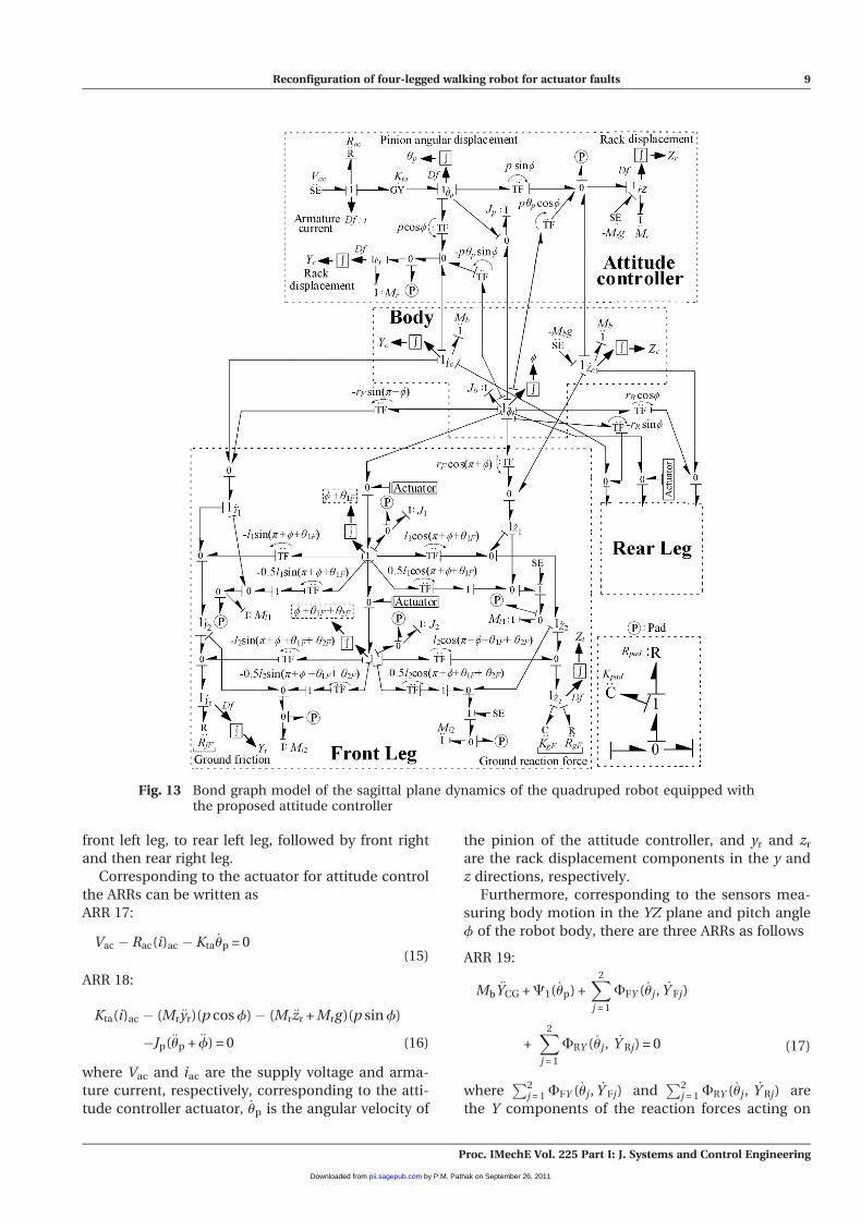
The bond graph representation of the sagittal plane
dynamics of this system is shown in Fig. 13.
Fault accommodation in the walking robot using
the reconfiguration approach is carried out as per
the procedure followed in reference [13]. The fault
accommodation procedure consists of the following
stages.
Fig. 8 Simulation results of walking robot: (a) Y displacement front leg tip (YFlt) versus time; (b) Zdisplacement front leg tip (ZFlt) versus time; (c) Y displacement rear leg tip (YRlt) versustime; and (d) Z displacement rear leg tip (ZRlt) versus time
Fig. 9 Conceptualization of the moving appendage forattitude control
Reconfiguration of four-legged walking robot for actuator faults 7
Proc. IMechE Vol. 225 Part I: J. Systems and Control Engineering
by P.M. Pathak on September 26, 2011pii.sagepub.comDownloaded from
4.1 Generation of fault indicators
To generate the fault indicators, the sensors in the
bond graph model shown in Fig. 13 are dualized
into sources and pads are then removed [2]. This
leads to the creation of storage elements with differ-
ential causalities. However, no causal loops are
formed due to these transformations carried out in
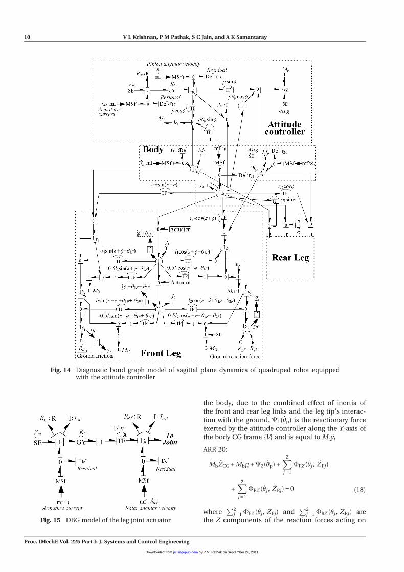
the bond graph model. The transformed bond graph
model presented in Fig. 14 is the diagnostic bond
graph (DBG) model [14] of the quadruped robot
equipped with the attitude controller. Note that
causalities in some of the integration blocks are not
inverted because they are not the actual sensors in
the plant; they are in the model so that simulation
results can be plotted. The analytical redundancy
relations (ARRs) are then derived from the DBG, by
following well established algorithms presented in
reference [2]. The ARRs are written in terms of
system parameters and measured quantities. They
are the expressions for the variables measured at
residual sensors (effort variables in bonds connected
to De* elements in Fig. 14).
The DBG model of each leg joint actuator is
shown in Fig. 15. Each leg has two sensors which
lead to two ARRs as follows
(Vm)j � Lm
d(i)j
dt� Rm(i)j � n Ktm( _urot)j = 0 (13)
Rbf ( _urot)j � n Ktm(i)j + (Irot€urot)j + tuj = 0 (14)
where (Vm)j and (i)j are respectively supply voltage
and armature current to the jth joint actuator, ( _urot)j
is the angular velocity of the jth joint actuator rotor,
and tuj is the reaction torque on the jth actuator.
Since each leg has two joint actuators, there are in
total four ARRs per leg. Hence, ARRs 1–16 are asso-
ciated with the four legs in the order starting from
Fig. 10 Bond graph of attitude controller
Fig. 11 Simulation result: body orientation (withrespect to inertial reference frame {A}) versustime for bond graph shown in Fig. 10
Fig. 12 Schematic representation of a walking robotwith the proposed attitude controller
8 V L Krishnan, P M Pathak, S C Jain, and A K Samantaray
Proc. IMechE Vol. 225 Part I: J. Systems and Control Engineering
by P.M. Pathak on September 26, 2011pii.sagepub.comDownloaded from
front left leg, to rear left leg, followed by front right
and then rear right leg.
Corresponding to the actuator for attitude control
the ARRs can be written as
ARR 17:
Vac � Rac(i)ac � Kta_up = 0
(15)
ARR 18:
Kta(i)ac � (Mr €yr)(p cos f)� (Mr€zr + Mrg)(p sin f)
�Jp(€up + €f) = 0 (16)
where Vac and iac are the supply voltage and arma-
ture current, respectively, corresponding to the atti-
tude controller actuator, _up is the angular velocity of
the pinion of the attitude controller, and yr and zr
are the rack displacement components in the y and
z directions, respectively.
Furthermore, corresponding to the sensors mea-
suring body motion in the YZ plane and pitch angle
f of the robot body, there are three ARRs as follows
ARR 19:
Mb€YCG + C1( _up) +
X2
j = 1
FFY ( _uj, _Y Fj)
+X2
j = 1
FRY ( _uj, _Y Rj) = 0 (17)
whereP2
j = 1 FFY ( _uj, _Y Fj) andP2
j = 1 FRY ( _uj, _Y Rj) are
the Y components of the reaction forces acting on
Fig. 13 Bond graph model of the sagittal plane dynamics of the quadruped robot equipped withthe proposed attitude controller
Reconfiguration of four-legged walking robot for actuator faults 9
Proc. IMechE Vol. 225 Part I: J. Systems and Control Engineering
by P.M. Pathak on September 26, 2011pii.sagepub.comDownloaded from
the body, due to the combined effect of inertia of
the front and rear leg links and the leg tip’s interac-
tion with the ground. C1( _up) is the reactionary force
exerted by the attitude controller along the Y-axis of
the body CG frame {V} and is equal to Mr €yr
ARR 20:
Mb€ZCG + Mbg + C2( _up) +
X2
j = 1
FFZ ( _uj, _ZFj)
+X2
j = 1
FRZ ( _uj, _ZRj) = 0 (18)
whereP2
j = 1 FFZ ( _uj, _ZFj) andP2
j = 1 FRZ ( _uj, _ZRj) are
the Z components of the reaction forces acting on
Fig. 14 Diagnostic bond graph model of sagittal plane dynamics of quadruped robot equippedwith the attitude controller
Fig. 15 DBG model of the leg joint actuator
10 V L Krishnan, P M Pathak, S C Jain, and A K Samantaray
Proc. IMechE Vol. 225 Part I: J. Systems and Control Engineering
by P.M. Pathak on September 26, 2011pii.sagepub.comDownloaded from
the body, due to the combined effect of the inertia
of the front and rear leg links and the leg tip’s inter-
action with the ground. C2( _up) is the reactionary
force exerted by the attitude controller along the
Z-axis of the body CG frame {V}. C2( _up) is equal to
(Mr€zr + Mrg)
ARR 21:
Jb€f+C3( _up)� rF sin(p+f)½ �
X2
j=1
FFY ( _uj, _Y Fj)
+ rF cos(p+f)½ �X2
j=1
FFZ ( _uj, _ZFj)
� (rR sinf)X2
j=1
FRY ( _uj, _Y Rj)+(rR cosf)X2
j=1
FRZ ( _uj, _ZRj)
+tuF( _uj, _Y Fj, _ZFj)+tuR( _uj, _Y Rj, _ZRj)=0 (19)
where tuF( _uj, _YFj, _ZFj) and tuR( _uj, _YRj, _ZRj) are the
components of the reactionary moment acting on
the body due to the combined effect of the inertia of
the front and rear leg links and the leg tip’s interac-
tion with the ground. C3( _up) is the reactionary
moment exerted by the attitude controller about the
X-axis of the robot’s body and it can be expressed as
C3( _up) = pup cos f(Mr€zr + Mrg)� pup sin f(Mr €yr)
+ Jp(€up + €f) (20)
4.2 Fault detection and isolation
Fault detection and isolation is a very important
step from the perspective of fault-tolerant control. A
detection and isolation scheme for actuator faults
and fault accommodation was developed in [14–17].
In that scheme the generated ARRs are structurally
analysed and are then used to generate the fault sig-
nature matrix (FSM) or a binary fault sensitivity
table. If at least one element of a row in the FSM is
non-zero, then the corresponding component can
be monitored. If all the rows of the FSM are unique,
i.e. there is no repetition of rows (unique fault sig-
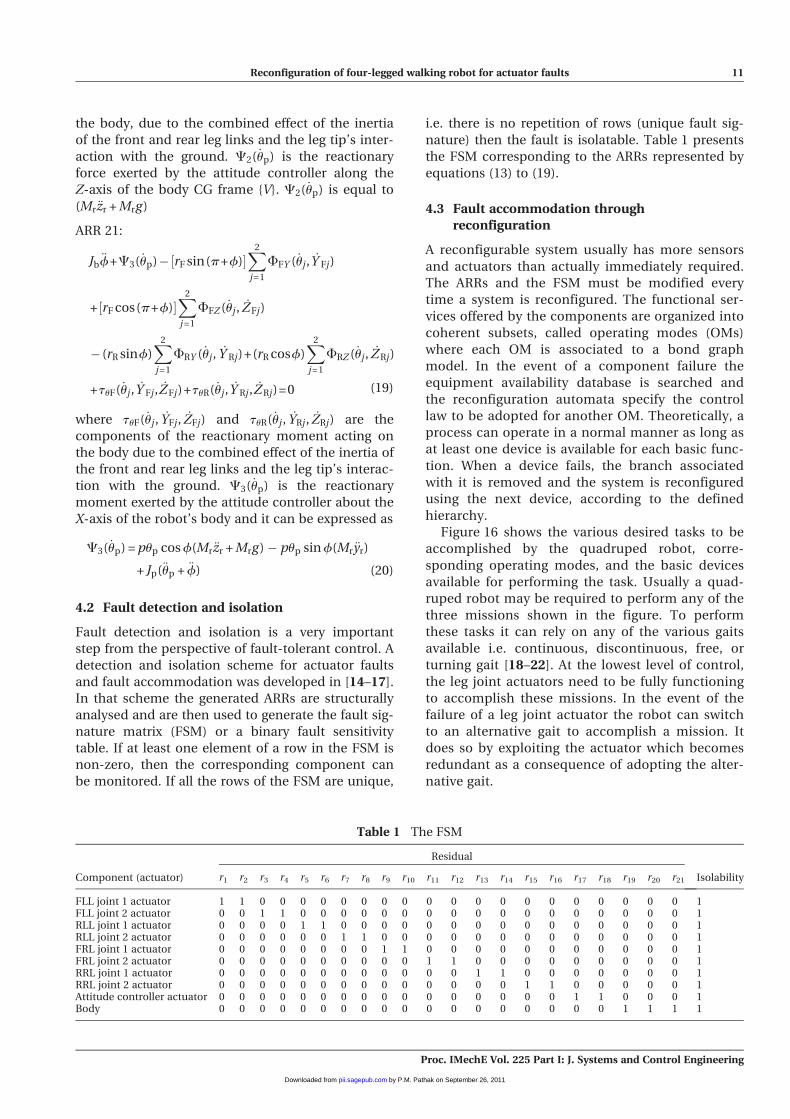
nature) then the fault is isolatable. Table 1 presents
the FSM corresponding to the ARRs represented by
equations (13) to (19).
4.3 Fault accommodation throughreconfiguration
A reconfigurable system usually has more sensors
and actuators than actually immediately required.
The ARRs and the FSM must be modified every
time a system is reconfigured. The functional ser-
vices offered by the components are organized into
coherent subsets, called operating modes (OMs)
where each OM is associated to a bond graph
model. In the event of a component failure the
equipment availability database is searched and
the reconfiguration automata specify the control
law to be adopted for another OM. Theoretically, a
process can operate in a normal manner as long as
at least one device is available for each basic func-
tion. When a device fails, the branch associated
with it is removed and the system is reconfigured
using the next device, according to the defined
hierarchy.
Figure 16 shows the various desired tasks to be
accomplished by the quadruped robot, corre-
sponding operating modes, and the basic devices
available for performing the task. Usually a quad-
ruped robot may be required to perform any of the
three missions shown in the figure. To perform
these tasks it can rely on any of the various gaits
available i.e. continuous, discontinuous, free, or
turning gait [18–22]. At the lowest level of control,
the leg joint actuators need to be fully functioning
to accomplish these missions. In the event of the
failure of a leg joint actuator the robot can switch
to an alternative gait to accomplish a mission. It
does so by exploiting the actuator which becomes
redundant as a consequence of adopting the alter-
native gait.
Table 1 The FSM
Component (actuator)
Residual
Isolabilityr1 r2 r3 r4 r5 r6 r7 r8 r9 r10 r11 r12 r13 r14 r15 r16 r17 r18 r19 r20 r21
FLL joint 1 actuator 1 1 0 0 0 0 0 0 0 0 0 0 0 0 0 0 0 0 0 0 0 1FLL joint 2 actuator 0 0 1 1 0 0 0 0 0 0 0 0 0 0 0 0 0 0 0 0 0 1RLL joint 1 actuator 0 0 0 0 1 1 0 0 0 0 0 0 0 0 0 0 0 0 0 0 0 1RLL joint 2 actuator 0 0 0 0 0 0 1 1 0 0 0 0 0 0 0 0 0 0 0 0 0 1FRL joint 1 actuator 0 0 0 0 0 0 0 0 1 1 0 0 0 0 0 0 0 0 0 0 0 1FRL joint 2 actuator 0 0 0 0 0 0 0 0 0 0 1 1 0 0 0 0 0 0 0 0 0 1RRL joint 1 actuator 0 0 0 0 0 0 0 0 0 0 0 0 1 1 0 0 0 0 0 0 0 1RRL joint 2 actuator 0 0 0 0 0 0 0 0 0 0 0 0 0 0 1 1 0 0 0 0 0 1Attitude controller actuator 0 0 0 0 0 0 0 0 0 0 0 0 0 0 0 0 1 1 0 0 0 1Body 0 0 0 0 0 0 0 0 0 0 0 0 0 0 0 0 0 0 1 1 1 1
Reconfiguration of four-legged walking robot for actuator faults 11
Proc. IMechE Vol. 225 Part I: J. Systems and Control Engineering
by P.M. Pathak on September 26, 2011pii.sagepub.comDownloaded from
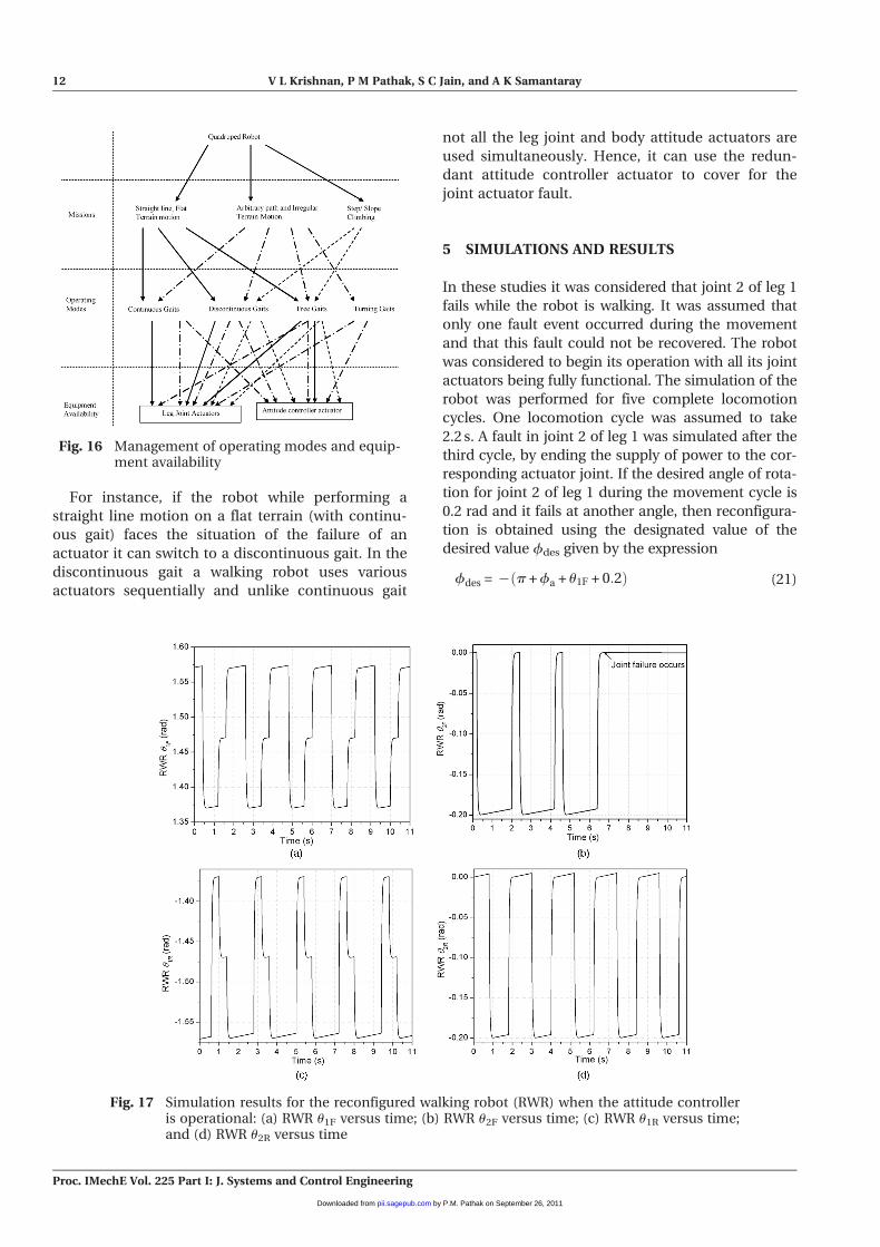
For instance, if the robot while performing a
straight line motion on a flat terrain (with continu-
ous gait) faces the situation of the failure of an
actuator it can switch to a discontinuous gait. In the
discontinuous gait a walking robot uses various
actuators sequentially and unlike continuous gait
not all the leg joint and body attitude actuators are
used simultaneously. Hence, it can use the redun-
dant attitude controller actuator to cover for the
joint actuator fault.
5 SIMULATIONS AND RESULTS
In these studies it was considered that joint 2 of leg 1
fails while the robot is walking. It was assumed that
only one fault event occurred during the movement
and that this fault could not be recovered. The robot
was considered to begin its operation with all its joint
actuators being fully functional. The simulation of the
robot was performed for five complete locomotion
cycles. One locomotion cycle was assumed to take
2.2 s. A fault in joint 2 of leg 1 was simulated after the
third cycle, by ending the supply of power to the cor-
responding actuator joint. If the desired angle of rota-
tion for joint 2 of leg 1 during the movement cycle is
0.2 rad and it fails at another angle, then reconfigura-
tion is obtained using the designated value of the
desired value fdes given by the expression
fdes = � p + fa + u1F + 0:2ð Þ (21)
Fig. 16 Management of operating modes and equip-ment availability
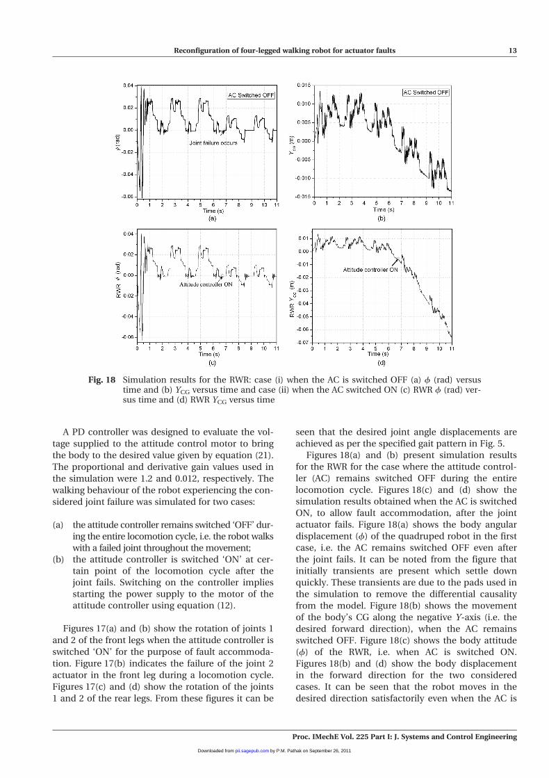
Fig. 17 Simulation results for the reconfigured walking robot (RWR) when the attitude controlleris operational: (a) RWR u1F versus time; (b) RWR u2F versus time; (c) RWR u1R versus time;and (d) RWR u2R versus time
12 V L Krishnan, P M Pathak, S C Jain, and A K Samantaray
Proc. IMechE Vol. 225 Part I: J. Systems and Control Engineering
by P.M. Pathak on September 26, 2011pii.sagepub.comDownloaded from
A PD controller was designed to evaluate the vol-
tage supplied to the attitude control motor to bring
the body to the desired value given by equation (21).
The proportional and derivative gain values used in
the simulation were 1.2 and 0.012, respectively. The
walking behaviour of the robot experiencing the con-
sidered joint failure was simulated for two cases:
(a) the attitude controller remains switched ‘OFF’ dur-
ing the entire locomotion cycle, i.e. the robot walks
with a failed joint throughout the movement;
(b) the attitude controller is switched ‘ON’ at cer-
tain point of the locomotion cycle after the
joint fails. Switching on the controller implies
starting the power supply to the motor of the
attitude controller using equation (12).
Figures 17(a) and (b) show the rotation of joints 1
and 2 of the front legs when the attitude controller is
switched ‘ON’ for the purpose of fault accommoda-
tion. Figure 17(b) indicates the failure of the joint 2
actuator in the front leg during a locomotion cycle.
Figures 17(c) and (d) show the rotation of the joints
1 and 2 of the rear legs. From these figures it can be
seen that the desired joint angle displacements are
achieved as per the specified gait pattern in Fig. 5.
Figures 18(a) and (b) present simulation results
for the RWR for the case where the attitude control-
ler (AC) remains switched OFF during the entire
locomotion cycle. Figures 18(c) and (d) show the
simulation results obtained when the AC is switched
ON, to allow fault accommodation, after the joint
actuator fails. Figure 18(a) shows the body angular
displacement (f) of the quadruped robot in the first
case, i.e. the AC remains switched OFF even after
the joint fails. It can be noted from the figure that
initially transients are present which settle down
quickly. These transients are due to the pads used in
the simulation to remove the differential causality
from the model. Figure 18(b) shows the movement
of the body’s CG along the negative Y-axis (i.e. the
desired forward direction), when the AC remains
switched OFF. Figure 18(c) shows the body attitude
(f) of the RWR, i.e. when AC is switched ON.
Figures 18(b) and (d) show the body displacement
in the forward direction for the two considered
cases. It can be seen that the robot moves in the
desired direction satisfactorily even when the AC is
Fig. 18 Simulation results for the RWR: case (i) when the AC is switched OFF (a) f (rad) versustime and (b) YCG versus time and case (ii) when the AC switched ON (c) RWR f (rad) ver-sus time and (d) RWR YCG versus time
Reconfiguration of four-legged walking robot for actuator faults 13
Proc. IMechE Vol. 225 Part I: J. Systems and Control Engineering
by P.M. Pathak on September 26, 2011pii.sagepub.comDownloaded from
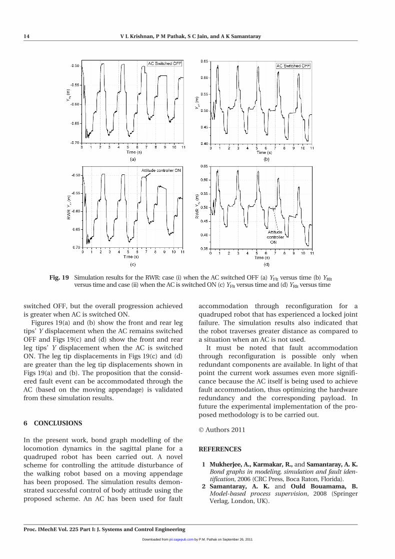
switched OFF, but the overall progression achieved
is greater when AC is switched ON.
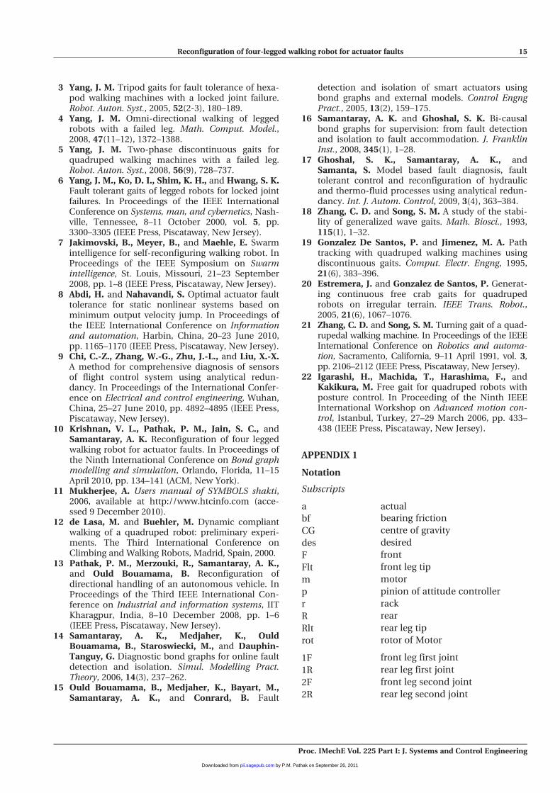
Figures 19(a) and (b) show the front and rear leg
tips’ Y displacement when the AC remains switched
OFF and Figs 19(c) and (d) show the front and rear
leg tips’ Y displacement when the AC is switched
ON. The leg tip displacements in Figs 19(c) and (d)
are greater than the leg tip displacements shown in
Figs 19(a) and (b). The proposition that the consid-
ered fault event can be accommodated through the
AC (based on the moving appendage) is validated
from these simulation results.
6 CONCLUSIONS
In the present work, bond graph modelling of the
locomotion dynamics in the sagittal plane for a
quadruped robot has been carried out. A novel
scheme for controlling the attitude disturbance of
the walking robot based on a moving appendage
has been proposed. The simulation results demon-
strated successful control of body attitude using the
proposed scheme. An AC has been used for fault
accommodation through reconfiguration for a
quadruped robot that has experienced a locked joint
failure. The simulation results also indicated that
the robot traverses greater distance as compared to
a situation when an AC is not used.
It must be noted that fault accommodation
through reconfiguration is possible only when
redundant components are available. In light of that
point the current work assumes even more signifi-
cance because the AC itself is being used to achieve
fault accommodation, thus optimizing the hardware
redundancy and the corresponding payload. In
future the experimental implementation of the pro-
posed methodology is to be carried out.
� Authors 2011
REFERENCES
1 Mukherjee, A., Karmakar, R., and Samantaray, A. K.Bond graphs in modeling, simulation and fault iden-tification, 2006 (CRC Press, Boca Raton, Florida).
2 Samantaray, A. K. and Ould Bouamama, B.Model-based process supervision, 2008 (SpringerVerlag, London, UK).
Fig. 19 Simulation results for the RWR: case (i) when the AC switched OFF (a) YFlt versus time (b) YRlt
versus time and case (ii) when the AC is switched ON (c) YFlt versus time and (d) YRlt versus time
14 V L Krishnan, P M Pathak, S C Jain, and A K Samantaray
Proc. IMechE Vol. 225 Part I: J. Systems and Control Engineering
by P.M. Pathak on September 26, 2011pii.sagepub.comDownloaded from
3 Yang, J. M. Tripod gaits for fault tolerance of hexa-pod walking machines with a locked joint failure.Robot. Auton. Syst., 2005, 52(2-3), 180–189.
4 Yang, J. M. Omni-directional walking of leggedrobots with a failed leg. Math. Comput. Model.,2008, 47(11–12), 1372–1388.
5 Yang, J. M. Two-phase discontinuous gaits forquadruped walking machines with a failed leg.Robot. Auton. Syst., 2008, 56(9), 728–737.
6 Yang, J. M., Ko, D. I., Shim, K. H., and Hwang, S. K.Fault tolerant gaits of legged robots for locked jointfailures. In Proceedings of the IEEE InternationalConference on Systems, man, and cybernetics, Nash-ville, Tennessee, 8–11 October 2000, vol. 5, pp.3300–3305 (IEEE Press, Piscataway, New Jersey).
7 Jakimovski, B., Meyer, B., and Maehle, E. Swarmintelligence for self-reconfiguring walking robot. InProceedings of the IEEE Symposium on Swarmintelligence, St. Louis, Missouri, 21–23 September2008, pp. 1–8 (IEEE Press, Piscataway, New Jersey).
8 Abdi, H. and Nahavandi, S. Optimal actuator faulttolerance for static nonlinear systems based onminimum output velocity jump. In Proceedings ofthe IEEE International Conference on Informationand automation, Harbin, China, 20–23 June 2010,pp. 1165–1170 (IEEE Press, Piscataway, New Jersey).
9 Chi, C.-Z., Zhang, W.-G., Zhu, J.-L., and Liu, X.-X.A method for comprehensive diagnosis of sensorsof flight control system using analytical redun-dancy. In Proceedings of the International Confer-ence on Electrical and control engineering, Wuhan,China, 25–27 June 2010, pp. 4892–4895 (IEEE Press,Piscataway, New Jersey).
10 Krishnan, V. L., Pathak, P. M., Jain, S. C., andSamantaray, A. K. Reconfiguration of four leggedwalking robot for actuator faults. In Proceedings ofthe Ninth International Conference on Bond graphmodelling and simulation, Orlando, Florida, 11–15April 2010, pp. 134–141 (ACM, New York).
11 Mukherjee, A. Users manual of SYMBOLS shakti,2006, available at http://www.htcinfo.com (acce-ssed 9 December 2010).
12 de Lasa, M. and Buehler, M. Dynamic compliantwalking of a quadruped robot: preliminary experi-ments. The Third International Conference onClimbing and Walking Robots, Madrid, Spain, 2000.
13 Pathak, P. M., Merzouki, R., Samantaray, A. K.,and Ould Bouamama, B. Reconfiguration ofdirectional handling of an autonomous vehicle. InProceedings of the Third IEEE International Con-ference on Industrial and information systems, IITKharagpur, India, 8–10 December 2008, pp. 1–6(IEEE Press, Piscataway, New Jersey).
14 Samantaray, A. K., Medjaher, K., OuldBouamama, B., Staroswiecki, M., and Dauphin-Tanguy, G. Diagnostic bond graphs for online faultdetection and isolation. Simul. Modelling Pract.Theory, 2006, 14(3), 237–262.
15 Ould Bouamama, B., Medjaher, K., Bayart, M.,Samantaray, A. K., and Conrard, B. Fault
detection and isolation of smart actuators usingbond graphs and external models. Control EngngPract., 2005, 13(2), 159–175.
16 Samantaray, A. K. and Ghoshal, S. K. Bi-causalbond graphs for supervision: from fault detectionand isolation to fault accommodation. J. FranklinInst., 2008, 345(1), 1–28.
17 Ghoshal, S. K., Samantaray, A. K., andSamanta, S. Model based fault diagnosis, faulttolerant control and reconfiguration of hydraulicand thermo-fluid processes using analytical redun-dancy. Int. J. Autom. Control, 2009, 3(4), 363–384.
18 Zhang, C. D. and Song, S. M. A study of the stabi-lity of generalized wave gaits. Math. Biosci., 1993,115(1), 1–32.
19 Gonzalez De Santos, P. and Jimenez, M. A. Pathtracking with quadruped walking machines usingdiscontinuous gaits. Comput. Electr. Engng, 1995,21(6), 383–396.
20 Estremera, J. and Gonzalez de Santos, P. Generat-ing continuous free crab gaits for quadrupedrobots on irregular terrain. IEEE Trans. Robot.,2005, 21(6), 1067–1076.
21 Zhang, C. D. and Song, S. M. Turning gait of a quad-rupedal walking machine. In Proceedings of the IEEEInternational Conference on Robotics and automa-tion, Sacramento, California, 9–11 April 1991, vol. 3,pp. 2106–2112 (IEEE Press, Piscataway, New Jersey).
22 Igarashi, H., Machida, T., Harashima, F., andKakikura, M. Free gait for quadruped robots withposture control. In Proceeding of the Ninth IEEEInternational Workshop on Advanced motion con-trol, Istanbul, Turkey, 27–29 March 2006, pp. 433–438 (IEEE Press, Piscataway, New Jersey).
APPENDIX 1
Notation
Subscripts
a actual
bf bearing friction
CG centre of gravity
des desired
F front
Flt front leg tip
m motor
p pinion of attitude controller
r rack
R rear
Rlt rear leg tip
rot rotor of Motor
1F front leg first joint
1R rear leg first joint
2F front leg second joint
2R rear leg second joint
Reconfiguration of four-legged walking robot for actuator faults 15
Proc. IMechE Vol. 225 Part I: J. Systems and Control Engineering
by P.M. Pathak on September 26, 2011pii.sagepub.comDownloaded from
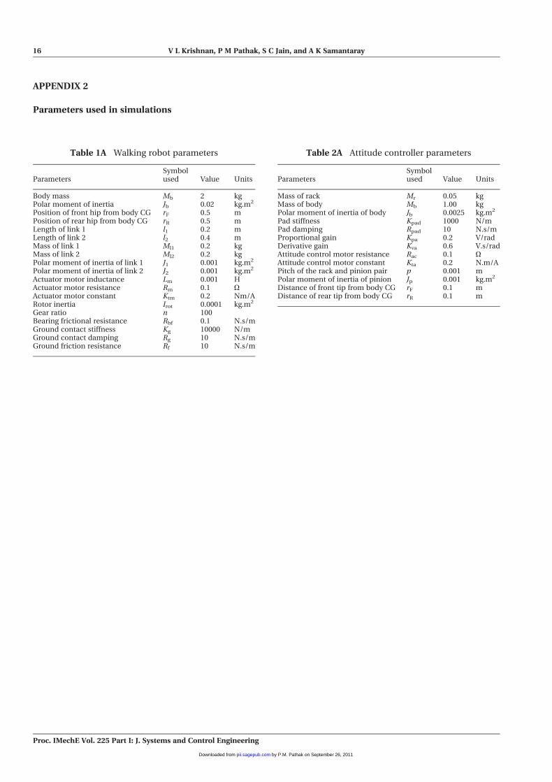
APPENDIX 2
Parameters used in simulations
Table 1A Walking robot parameters
ParametersSymbolused Value Units
Body mass Mb 2 kgPolar moment of inertia Jb 0.02 kg.m2
Position of front hip from body CG rF 0.5 mPosition of rear hip from body CG rR 0.5 mLength of link 1 l1 0.2 mLength of link 2 l2 0.4 mMass of link 1 Ml1 0.2 kgMass of link 2 Ml2 0.2 kgPolar moment of inertia of link 1 J1 0.001 kg.m2
Polar moment of inertia of link 2 J2 0.001 kg.m2
Actuator motor inductance Lm 0.001 HActuator motor resistance Rm 0.1 OActuator motor constant Ktm 0.2 Nm/ARotor inertia Irot 0.0001 kg.m2
Gear ratio n 100Bearing frictional resistance Rbf 0.1 N.s/mGround contact stiffness Kg 10000 N/mGround contact damping Rg 10 N.s/mGround friction resistance Rf 10 N.s/m
Table 2A Attitude controller parameters
ParametersSymbolused Value Units
Mass of rack Mr 0.05 kgMass of body Mb 1.00 kgPolar moment of inertia of body Jb 0.0025 kg.m2
Pad stiffness Kpad 1000 N/mPad damping Rpad 10 N.s/mProportional gain Kpa 0.2 V/radDerivative gain Kva 0.6 V.s/radAttitude control motor resistance Rac 0.1 OAttitude control motor constant Kta 0.2 N.m/APitch of the rack and pinion pair p 0.001 mPolar moment of inertia of pinion Jp 0.001 kg.m2
Distance of front tip from body CG rF 0.1 mDistance of rear tip from body CG rR 0.1 m
16 V L Krishnan, P M Pathak, S C Jain, and A K Samantaray
Proc. IMechE Vol. 225 Part I: J. Systems and Control Engineering
by P.M. Pathak on September 26, 2011pii.sagepub.comDownloaded from
Copyright © 2022 FDOKUMEN