Parker Pneumatic Actuator Products – Tie Rod Cylinders 4MA ...
23
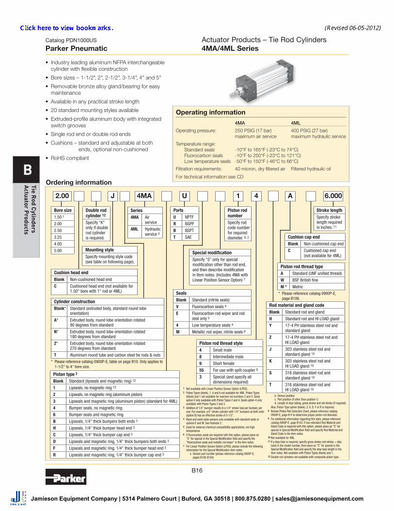
B16 Catalog PDN1000US Parker Pneumatic B Tie Rod Cylinders Actuator Products Actuator Products – Tie Rod Cylinders 4MA/4ML Series Operating information 4MA 4ML Operating pressure: 250 PSIG (17 bar) 400 PSIG (27 bar) maximum air service maximum hydraulic service Temperature range: Standard seals -10°F to 165°F (-23°C to 74°C) Fluorocarbon seals -10°F to 250°F (-23°C to 121°C) Low temperature seals -50°F to 150°F (-46°C to 66°C) Filtration requirements: 40 micron, dry filtered air Filtered hydraulic oil For technical information see CD • Industry leading aluminum NFPA interchangeable cylinder with flexible construction • Bore sizes – 1-1/2", 2", 2-1/2", 3-1/4", 4" and 5" • Removable bronze alloy gland/bearing for easy maintenance • Available in any practical stroke length • 20 standard mounting styles available • Extruded-profile aluminum body with integrated switch grooves • Single rod end or double rod ends • Cushions – standard and adjustable at both ends, optional non-cushioned • RoHS compliant Ordering information J U 1 4 A 6.000 2.00 1 Not available with Linear Position Sensor Option (LPSO). 2 Piston Types (blank), 1, 4 and 6 not available for 4ML. Piston Types (blank) and 1 not available for oversize rod numbers 2 and 3. Seals option V only available with Piston Types 2 and 4. Seals option 4 only available with Piston Types 2 and 3. 3 Addition of 1/4" bumper results in a 1/4" stroke loss per bumper, per end. For example, a 6" stroke cylinder with 1/4" bumpers at both ends (option B) has an effective stroke of 5-1/2". 4 Reed and solid-state sensors only available with standard seals or options E and M. See footnote 2. 5 Used for external chemical compatibility applications, not high temperature. 6 If fluorocarbon seals are required with this option, please place an “S” for special in the Special Modification field and specify the “fluorocarbon seals and metallic rod wiper” in the item notes. 7 For Linear Position Sensor Option (LPSO), please include the following information for the Special Modification item notes: a. Sensor part number (please reference catalog 0900P-E, pages B100-B104) b. Sensor position c. Port position (if other than position 1) d. Length of stop tubing, gross stroke and net stroke (if required) Also, Piston Type option (blank), 3, 6, D, F or R is required. 8 Review Piston Rod Selection Chart, please reference catalog 0900P-E, page A14 to determine proper piston rod diameter. 9 For additional information regarding this style, please reference catalog 0900P-E, page B105. If non-standard Rod Material and Gland Code is required with this option, please place an “S” for special in Special Modification field and specify Rod Material and Gland Code in the item notes. 10 Not available for 4ML. 11 If a stop tube is required, specify gross stroke (net stroke + stop tube) in the model number, then place an “S” for special in the Special Modification field and specify the stop tube length in the item notes. Not available with Piston Types (blank) and 1. 12 Double rod cylinders not available with composite piston type. Cylinder construction Blank* Standard (extruded body, standard round lobe orientation) A* Extruded body, round lobe orientation rotated 90 degrees from standard N* Extruded body, round lobe orientation rotated 180 degrees from standard Z* Extruded body, round lobe orientation rotated 270 degrees from standard T Aluminum round tube and carbon steel tie rods & nuts * Please reference catalog 0900P-E, table on page B10. Only applies to 1-1/2" to 4" bore size. Piston type 2 Blank Standard (lipseals and magnetic ring) 12 1 Lipseals, no magnetic ring 12 2 Lipseals, no magnetic ring (aluminum piston) 3 Lipseals and magnetic ring (aluminum piston) (standard for 4ML) 4 Bumper seals, no magnetic ring 6 Bumper seals and magnetic ring B Lipseals, 1/4" thick bumpers both ends 3 H Lipseals, 1/4" thick bumper head end 3 C Lipseals, 1/4" thick bumper cap end 3 D Lipseals and magnetic ring, 1/4" thick bumpers both ends 3 F Lipseals and magnetic ring, 1/4" thick bumper head end 3 R Lipseals and magnetic ring, 1/4" thick bumper cap end 3 Bore size 1.50 1 2.00 2.50 3.25 4.00 5.00 Stroke length Specify stroke length required in inches. 11 Mounting style Specify mounting style code (see table on following page). Double rod cylinder 12 Specify “K” only if double rod cylinder is required. Piston rod number Specify rod code number for required diameter. 8, 2 Ports U NPTF R BSPP B BSPT T SAE Cushion head end Blank Non-cushioned head end C Cushioned head end (not available for 1.50" bore with 1" rod or 4ML) Cushion cap end Blank Non-cushioned cap end C Cushioned cap end (not available for 4ML) Piston rod thread type A Standard (UNF unified thread) W BSF British fine M * Metric * Please reference catalog 0900P-E, page B106. Rod material and gland code Blank Standard rod and gland H Standard rod and HI LOAD gland Y 17-4 PH stainless steel rod and standard gland Z 17-4 PH stainless steel rod and HI LOAD gland J 303 stainless steel rod and standard gland 10 K 303 stainless steel rod and HI LOAD gland 10 S 316 stainless steel rod and standard gland 10 T 316 stainless steel rod and HI LOAD gland 10 Piston rod thread style 4 Small male 8 Intermediate male 9 Short female 55 For use with split coupler 9 3 Special (and specify all dimensions required) Seals Blank Standard (nitrile seals) V Fluorocarbon seals 4 E Fluorocarbon rod wiper and rod seal only 5 4 Low temperature seals 4 M Metallic rod wiper, nitrile seals 6 Series 4MA Air service 4ML Hydraulic service 2 Special modification Specify “S” only for special modification other than rod end, and then describe modification in item notes. (Includes 4MA with Linear Position Sensor Option) 7 4MA Jamieson Equipment Company | 5314 Palmero Court | Buford, GA 30518 | 800.875.0280 | [email protected]
-
Upload
khangminh22 -
Category
Documents
-
view
2 -
download
0
Transcript of Parker Pneumatic Actuator Products – Tie Rod Cylinders 4MA ...
B16
Catalog PDN1000US
Parker Pneumatic
B
Tie Rod C
ylinders A
ctuator Products
Actuator Products – Tie Rod Cylinders4MA/4ML Series
Operating information
4MA 4ML
Operating pressure: 250 PSIG (17 bar) 400 PSIG (27 bar) maximum air service maximum hydraulic service
Temperature range: Standard seals -10°F to 165°F (-23°C to 74°C) Fluorocarbon seals -10°F to 250°F (-23°C to 121°C) Low temperature seals -50°F to 150°F (-46°C to 66°C)
Filtration requirements: 40 micron, dry filtered air Filtered hydraulic oil
For technical information see CD
• Industry leading aluminum NFPA interchangeablecylinder with flexible construction
• Bore sizes – 1-1/2", 2", 2-1/2", 3-1/4", 4" and 5"
• Removable bronze alloy gland/bearing for easymaintenance
• Available in any practical stroke length
• 20 standard mounting styles available
• Extruded-profile aluminum body with integratedswitch grooves
• Single rod end or double rod ends
• Cushions – standard and adjustable at bothends, optional non-cushioned
• RoHS compliant
Ordering information
J U 1 4 A 6.0002.00
1 Not available with Linear Position Sensor Option (LPSO).2 Piston Types (blank), 1, 4 and 6 not available for 4ML. Piston Types
(blank) and 1 not available for oversize rod numbers 2 and 3. Seals option V only available with Piston Types 2 and 4. Seals option 4 only available with Piston Types 2 and 3.
3 Addition of 1/4" bumper results in a 1/4" stroke loss per bumper, per end. For example, a 6" stroke cylinder with 1/4" bumpers at both ends (option B) has an effective stroke of 5-1/2".
4 Reed and solid-state sensors only available with standard seals or options E and M. See footnote 2.
5 Used for external chemical compatibility applications, not high temperature.
6 If fluorocarbon seals are required with this option, please place an “S” for special in the Special Modification field and specify the “fluorocarbon seals and metallic rod wiper” in the item notes.
7 For Linear Position Sensor Option (LPSO), please include the following information for the Special Modification item notes:
a. Sensor part number (please reference catalog 0900P-E,pages B100-B104)
b. Sensor position c. Port position (if other than position 1) d. Length of stop tubing, gross stroke and net stroke (if required)
Also, Piston Type option (blank), 3, 6, D, F or R is required.8 Review Piston Rod Selection Chart, please reference catalog
0900P-E, page A14 to determine proper piston rod diameter.9 For additional information regarding this style, please reference
catalog 0900P-E, page B105. If non-standard Rod Material and Gland Code is required with this option, please place an “S” for special in Special Modification field and specify Rod Material and Gland Code in the item notes.
10 Not available for 4ML.11 If a stop tube is required, specify gross stroke (net stroke + stop
tube) in the model number, then place an “S” for special in the Special Modification field and specify the stop tube length in the item notes. Not available with Piston Types (blank) and 1.
12 Double rod cylinders not available with composite piston type.
Cylinder constructionBlank* Standard (extruded body, standard round lobe
orientation)
A* Extruded body, round lobe orientation rotated 90 degrees from standard
N* Extruded body, round lobe orientation rotated 180 degrees from standard
Z* Extruded body, round lobe orientation rotated 270 degrees from standard
T Aluminum round tube and carbon steel tie rods & nuts
* Please reference catalog 0900P-E, table on page B10. Only applies to 1-1/2" to 4" bore size.
Piston type 2
Blank Standard (lipseals and magnetic ring) 12
1 Lipseals, no magnetic ring 12
2 Lipseals, no magnetic ring (aluminum piston)
3 Lipseals and magnetic ring (aluminum piston) (standard for 4ML)
4 Bumper seals, no magnetic ring
6 Bumper seals and magnetic ring
B Lipseals, 1/4" thick bumpers both ends 3
H Lipseals, 1/4" thick bumper head end 3
C Lipseals, 1/4" thick bumper cap end 3
D Lipseals and magnetic ring, 1/4" thick bumpers both ends 3
F Lipseals and magnetic ring, 1/4" thick bumper head end 3
R Lipseals and magnetic ring, 1/4" thick bumper cap end 3
Bore size1.50 1
2.00
2.50
3.25
4.00
5.00
Stroke lengthSpecify stroke length required in inches. 11
Mounting styleSpecify mounting style code (see table on following page).
Double rod cylinder 12
Specify “K” only if double rod cylinder is required.
Piston rod numberSpecify rod code number for required diameter. 8, 2
PortsU NPTF
R BSPP
B BSPT
T SAE
Cushion head endBlank Non-cushioned head end
C Cushioned head end (not available for 1.50" bore with 1" rod or 4ML)
Cushion cap endBlank Non-cushioned cap end
C Cushioned cap end (not available for 4ML)
Piston rod thread typeA Standard (UNF unified thread)
W BSF British fine
M * Metric
* Please reference catalog 0900P-E, page B106.
Rod material and gland codeBlank Standard rod and gland
H Standard rod and HI LOAD gland
Y 17-4 PH stainless steel rod and standard gland
Z 17-4 PH stainless steel rod and HI LOAD gland
J 303 stainless steel rod and standard gland 10
K 303 stainless steel rod and HI LOAD gland 10
S 316 stainless steel rod and standard gland 10
T 316 stainless steel rod and HI LOAD gland 10
Piston rod thread style4 Small male
8 Intermediate male
9 Short female
55 For use with split coupler 9
3 Special (and specify all dimensions required)
SealsBlank Standard (nitrile seals)
V Fluorocarbon seals 4
E Fluorocarbon rod wiper and rod seal only 5
4 Low temperature seals 4
M Metallic rod wiper, nitrile seals 6
Series4MA Air
service
4ML Hydraulic service 2
Special modificationSpecify “S” only for special modification other than rod end, and then describe modification in item notes. (Includes 4MA with Linear Position Sensor Option) 7
4MA
Jamieson Equipment Company | 5314 Palmero Court | Buford, GA 30518 | 800.875.0280 | [email protected]

B17
Catalog PDN1000US
Parker Pneumatic
B
Tie
Rod
Cyl
inde
rs
Act
uato
r P
rodu
cts
Mounting style
NFPA mounting Description
Bore size
CB MS1 Side End Angle 1-1/2 - 5
G MS7 Side End Lug 1-1/2 - 4*
NB N/A Base Bar 1-1/2 - 4*
BB MP1 Cap Fixed Clevis 1-1/2 - 5
BC MP2 Cap Detachable Clevis 1-1/2 - 5
BE MP4 Cap Detachable Eye 1-1/2 - 5
D MT1 Head Trunnion 1-1/2 - 5*
DB MT2 Cap Trunnion 1-1/2 - 5
DD MT4 Intermediate Trunnion 1-1/2 - 5
KTEF † MDX5/MDS4 Double Rod End, TEF Mount
1-1/2 - 5
* Not available for 1-1/2" bore with 1" rod.† Double rod end cylinders can be ordered with head mountings, i.e. KJ.
Mounting style
NFPA mounting Description
Bore size
TEF MX5/MS4 Sleeve Nut with Side Tap (standard mount)
1-1/2 - 5*
T MX0 No Mount (same construction as TEF)
1-1/2 - 5
TE MX5 Sleeve Nut (same construction as TEF)
1-1/2 - 5
F MS4 Side Tap (same construction as TEF)
1-1/2 - 5*
J MF1 Head Rectangular Flange
1-1/2 - 5
H MF2 Cap Rectangular Flange
1-1/2 - 5
TB MX3 Tie Rods Extended Head End
1-1/2 - 5
TC MX2 Tie Rods Extended Cap End
1-1/2 - 5
TD MX1 Tie Rods Extended Both Ends
1-1/2 - 5
C MS2 Side Lug 1-1/2 - 5
Actuator Products – Tie Rod Cylinders4MA/4ML Series
4MA/4ML Mounting Styles for 1-1/2" to 5" Bore
SensorsFor sensors see page B296.
Jamieson Equipment Company | 5314 Palmero Court | Buford, GA 30518 | 800.875.0280 | [email protected]

B18
Catalog PDN1000US
Parker Pneumatic
B
Tie Rod C
ylinders A
ctuator Products
Single Rod Dimensioned Drawings (Styles TEF, T, TE and F)
* NOTE - 1-1/2" bore with 1" rod is TE mount, F mount not available.1-1/2" bore with 1" rod cannot have a cushion at head end.
Boresize
Rodno.
Roddia.MM
Thread
A AA
+.000-.002B BG BG1 C C1 C2 D D1 DD DH E
EE(NPTF) G
Style 8CC
Style 4 & 9KK
1-1/21 * 5/8 1/2-20 7/16-20 0.750 2.020 1.124 0.562 0.374 0.385 1.000 0.500 1/2 1 1/4-28 1/4 2.000 3/8 1.438
2 1 7/8-14 3/4-16 1.125 2.020 1.499 0.562 0.374 0.510 – 0.500 7/8 1-3/8 1/4-28 1/4 2.000 3/8 1.438
21 5/8 1/2-20 7/16-20 0.750 2.600 1.124 0.562 0.362 0.385 1.000 0.562 1/2 1 5/16-24 5/16 2.500 3/8 1.375
3 1 7/8-14 3/4-16 1.125 2.600 1.499 0.562 0.362 0.510 1.000 0.562 7/8 1-3/8 5/16-24 5/16 2.500 3/8 1.375
2-1/21 5/8 1/2-20 7/16-20 0.750 3.100 1.124 0.562 0.362 0.385 1.000 0.594 1/2 1 5/16-24 5/16 3.000 3/8 1.344
3 1 7/8-14 3/4-16 1.125 3.100 1.499 0.562 0.362 0.510 1.000 0.594 7/8 1-3/8 5/16-24 5/16 3.000 3/8 1.344
3-1/41 1 7/8-14 3/4-16 1.125 3.900 1.499 0.700 0.500 0.510 1.188 0.719 7/8 1-3/8 3/8-24 3/8 3.750 1/2 1.594
3 1-3/8 1-1/4-12 1-14 1.625 3.900 1.999 0.700 0.500 0.635 1.188 0.719 1-1/8 1-7/8 3/8-24 3/8 3.750 1/2 1.594
41 1 7/8-14 3/4-16 1.125 4.700 1.499 0.700 0.500 0.510 1.188 0.719 7/8 1-3/8 3/8-24 3/8 4.500 1/2 1.594
3 1-3/8 1-1/4-12 1-14 1.625 4.700 1.999 0.700 0.500 0.635 1.188 0.719 1-1/8 1-7/8 3/8-24 3/8 4.500 1/2 1.594
51 1 7/8-14 3/4-16 1.125 5.800 1.499 0.781 0.531 0.510 1.188 0.813 7/8 1-3/8 1/2-20 1/2 5.500 1/2 1.594
3 1-3/8 1-1/4-12 1-14 1.625 5.800 1.999 0.781 0.531 0.635 1.188 0.813 1-1/8 1-7/8 1/2-20 1/2 5.500 1/2 1.594
Boresize
Rodno.
Roddia.MM J LAF NA ND NT R
+.003-.003TH TN VF WF XT Y
Add stroke
LF P SN ZJ
1-1/2 1 * 5/8 0.938 1.750 0.563 0.375 1/4-20 1.430 0.993 0.625 0.615 1.000 1.938 1.875 3.625 2.313 2.250 4.625
2 1 0.938 2.500 0.938 - - 1.430 0.993 - 0.865 1.375 - 2.250 3.625 2.313 - 5.000
21 5/8 0.937 1.750 0.563 0.438 5/16-18 1.840 1.243 0.875 0.615 1.000 1.938 1.875 3.625 2.313 2.250 4.625
3 1 0.937 2.500 0.938 0.375 5/16-18 1.840 1.243 0.875 0.865 1.375 2.313 2.250 3.625 2.313 2.250 5.000
2-1/2 1 5/8 0.938 1.750 0.563 0.625 3/8-16 2.190 1.493 1.250 0.615 1.000 1.938 1.938 3.750 2.375 2.375 4.750
3 1 0.938 2.500 0.938 0.625 3/8-16 2.190 1.493 1.250 0.865 1.375 2.313 2.313 3.750 2.375 2.375 5.125
3-1/4 1 1 1.125 2.500 0.938 0.750 1/2-13 2.760 1.868 1.500 0.865 1.375 2.438 2.438 4.250 2.625 2.625 5.625
3 1 3/8 1.125 3.250 1.313 0.750 1/2-13 2.760 1.868 1.500 0.990 1.625 2.688 2.688 4.250 2.625 2.625 5.875
4 1 1 1.125 2.500 0.938 0.750 1/2-13 3.320 2.243 2.063 0.865 1.375 2.438 2.438 4.250 2.625 2.625 5.625
3 1-3/8 1.125 3.250 1.313 0.750 1/2-13 3.320 2.243 2.063 0.990 1.625 2.688 2.688 4.250 2.625 2.625 5.875
5 1 1 1.219 2.500 0.938 0.938 5/8-11 4.100 2.743 2.688 0.865 1.375 2.438 2.438 4.500 2.875 2.875 5.875
3 1-3/8 1.219 3.250 1.313 0.938 5/8-11 4.100 2.743 2.688 0.990 1.625 2.688 2.688 4.500 2.875 2.875 6.125
ØMM
C1 C2
TN
NT thread, ND deep4 tapped mtg. holes
R E
Y EE
XT SN + stroke
J
1
2
3
4
WF G
LF + stroke
ZJ + stroke
BGBG1
DD
DH (hex size)
TH±.003
P + stroke
KK or CCD wrench flats D1 wrench flats
WF
VF
C
LAF
A
ØNA ØBØMM
Styles TEF, T, TE and F
Actuator Products – Tie Rod Cylinders4MA/4ML Series
Jamieson Equipment Company | 5314 Palmero Court | Buford, GA 30518 | 800.875.0280 | [email protected]

Parker Hannifin CorporationPneumatic DivisionRichland, Michiganwww.parker.com/pneumatics
B19
Catalog PDN1000US
Parker Pneumatic
B
Tie
Rod
Cyl
inde
rs
Act
uato
r P
rodu
cts
KK
D wrench flats
WF
VF
C
A
KKD wrench flats D1 wrench flats
WF
VF
C
LAF
A
CCD wrench flats D1 wrench flats
WF
VF
C
LAF
A
D1 wrench flats D1 wrench flats
Groove has 1/16"internal radii at corners
VF
VS
ØMMR1/16
Ø AM
WGAD
AEØAF
ØNA ØBØMM ØBØMM
ØNA ØBØMM ØNA ØBØMM
Rod End Dimensions
4MA Rod End Dimensions
Thread Style 4(NFPA Style SM)Small Male
Thread Style 8(NFPA Style IM)Intermediate Male
Thread Style 9(NFPA Style SF)Short Female
Thread Style 55For use with Split Coupler(please reference catalog 0900P-E, page B105 for more information)
Thread Style 3 - “Special Thread”Special threads, rod extensions, rod eyes, blanks, etc. are also available.To order, specify “Style 3” and give desired dimensions for KK or CC, A and W or WF.If otherwise special, please supply dimensioned sketch.
Boresize
Rodno.
Roddia.MM
Thread
A AD AE AF AM
+.000-.002B C D D1 LAF NA VF WF WG
Style 8CC
Style 4 & 9KK
1-1/21 5/8 1/2-20 7/16-20 0.750 0.625 0.250 0.375 0.570 1.124 0.385 1/2 1 1.750 0.563 0.615 1.000 1.750
2 1 7/8-14 3/4-16 1.125 0.938 0.375 0.688 0.950 1.499 0.510 7/8 1-3/8 2.500 0.938 0.865 1.375 2.375
21 5/8 1/2-20 7/16-20 0.750 0.625 0.250 0.375 0.570 1.124 0.385 1/2 1 1.750 0.563 0.615 1.000 1.750
3 1 7/8-14 3/4-16 1.125 0.938 0.375 0.688 0.950 1.499 0.510 7/8 1-3/8 2.500 0.938 0.865 1.375 2.375
2-1/21 5/8 1/2-20 7/16-20 0.750 0.625 0.250 0.375 0.570 1.124 0.385 1/2 1 1.750 0.563 0.615 1.000 1.750
3 1 7/8-14 3/4-16 1.125 0.938 0.375 0.688 0.950 1.499 0.510 7/8 1-3/8 2.500 0.938 0.865 1.375 2.375
3-1/41 1 7/8-14 3/4-16 1.125 0.938 0.375 0.688 0.950 1.499 0.510 7/8 1-3/8 2.500 0.938 0.865 1.375 2.375
3 1-3/8 1-1/4-12 1-14 1.625 1.063 0.375 0.875 1.320 1.999 0.635 1-1/8 1-7/8 3.250 1.313 0.990 1.625 2.750
41 1 7/8-14 3/4-16 1.125 0.938 0.375 0.688 0.950 1.499 0.510 7/8 1-3/8 2.500 0.938 0.865 1.375 2.375
3 1-3/8 1-1/4-12 1-14 1.625 1.063 0.375 0.875 1.320 1.999 0.635 1-1/8 1-7/8 3.250 1.313 0.990 1.625 2.750
51 1 7/8-14 3/4-16 1.125 0.938 0.375 0.688 0.950 1.499 0.510 7/8 1-3/8 2.500 0.938 0.865 1.375 2.375
3 1-3/8 1-1/4-12 1-14 1.625 1.063 0.375 0.875 1.320 1.999 0.635 1-1/8 1-7/8 3.250 1.313 0.990 1.625 2.750
Actuator Products – Tie Rod Cylinders4MA/4ML Series
Jamieson Equipment Company | 5314 Palmero Court | Buford, GA 30518 | 800.875.0280 | [email protected]

B20
Catalog PDN1000US
Parker Pneumatic
B
Tie Rod C
ylinders A
ctuator Products
E
UF
R1
TF
E
FB4 Holes
FZJ + Stroke
1
2
3
4
W
LA LB + Stroke
E
UF
R1
TF
FB4 Holes
FZF + Stroke
1
2
3
4
ZJ + StrokeE
Head Rectangular FlangeStyle J(NFPA MF1)
Cap Rectangular FlangeStyle H (NFPA MF2)
Note: Style J has a W dimension instead of WF and a LA dimension instead of LAF because of the flange installation. Please use dimensions W and LA regarding rod ends only for Style J.
For reference, WF = W + F and LA = W + A.
Boresize
Rodno.
Roddia.MM A E F FB LA R1 TF UF W
Add stroke
LB ZF ZJ
1-1/21 5/8 0.750 2.000 0.375 0.313 1.375 1.430 2.750 3.375 0.625 4.000 5.000 4.625
2 1 1.125 2.000 0.375 0.313 2.125 1.430 2.750 3.375 1.000 4.000 5.375 5.000
21 5/8 0.750 2.500 0.375 0.375 1.375 1.840 3.375 4.125 0.625 4.000 5.000 4.625
3 1 1.125 2.500 0.375 0.375 2.125 1.840 3.375 4.125 1.000 4.000 5.375 5.000
2-1/21 5/8 0.750 3.000 0.375 0.375 1.375 2.190 3.875 4.625 0.625 4.125 5.125 4.750
3 1 1.125 3.000 0.375 0.375 2.125 2.190 3.875 4.625 1.000 4.125 5.500 5.125
3-1/41 1 1.125 3.750 0.625 0.438 1.875 2.760 4.688 5.500 0.750 4.875 6.250 5.625
3 1-3/8 1.625 3.750 0.625 0.438 2.625 2.760 4.688 5.500 1.000 4.875 6.500 5.875
41 1 1.125 4.500 0.625 0.438 1.875 3.320 5.438 6.250 0.750 4.875 6.250 5.625
3 1-3/8 1.625 4.500 0.625 0.438 2.625 3.320 5.438 6.250 1.000 4.875 6.500 5.875
51 1 1.125 5.500 0.625 0.563 1.875 4.100 6.625 7.625 0.750 5.125 6.500 5.875
3 1-3/8 1.625 5.500 0.625 0.563 2.625 4.100 6.625 7.625 1.000 5.125 6.750 6.125
Styles J and H
Actuator Products – Tie Rod Cylinders4MA/4ML Series
Jamieson Equipment Company | 5314 Palmero Court | Buford, GA 30518 | 800.875.0280 | [email protected]
B21
Catalog PDN1000US
Parker Pneumatic
B
Tie
Rod
Cyl
inde
rs
Act
uato
r P
rodu
cts
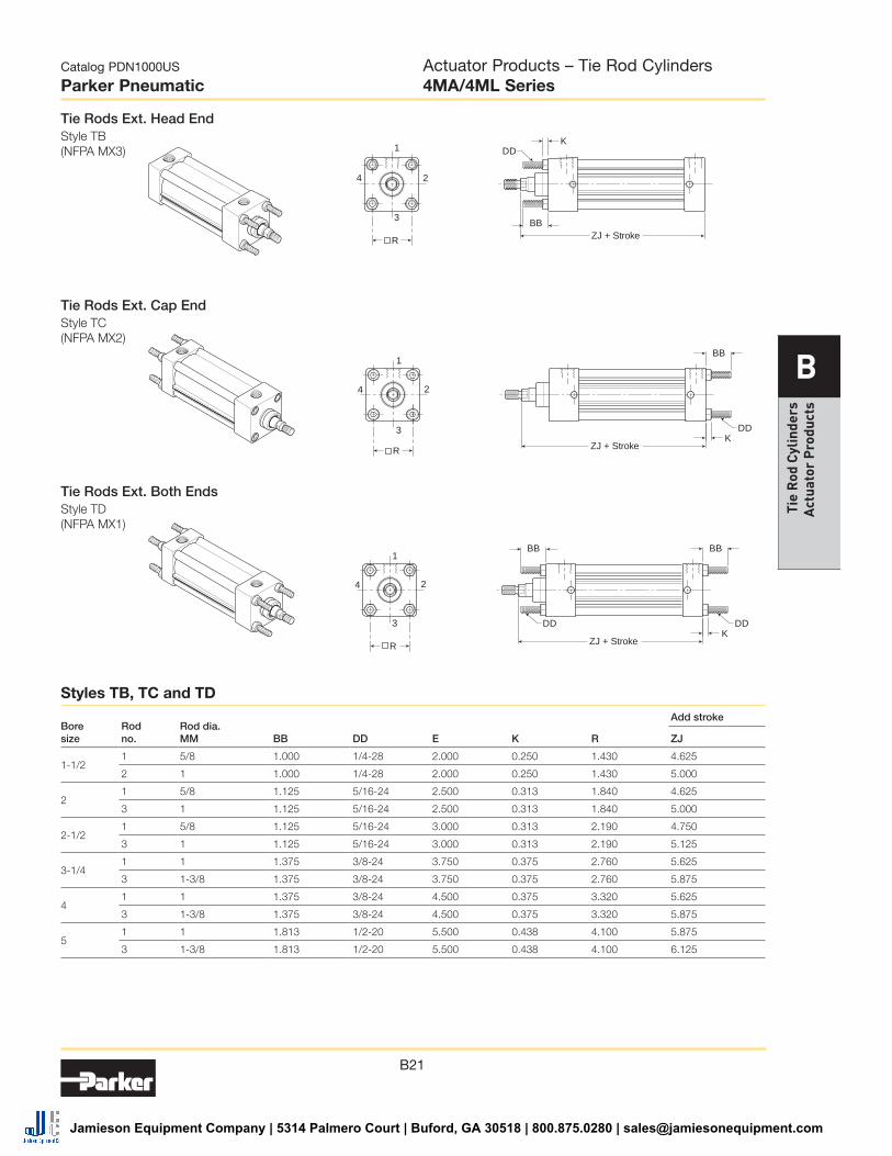
Tie Rods Ext. Head EndStyle TB (NFPA MX3)
1
2
3
4
BB
ZJ + Stroke
DDK
R
1
2
3
4
BBZJ + Stroke
DDK
R
1
2
3
4
BBBB
ZJ + Stroke
DDDDK
R
Tie Rods Ext. Both EndsStyle TD (NFPA MX1)
Tie Rods Ext. Cap EndStyle TC (NFPA MX2)
Bore size
Rod no.
Rod dia. MM BB DD E K R
Add stroke
ZJ
1-1/2 1 5/8 1.000 1/4-28 2.000 0.250 1.430 4.625
2 1 1.000 1/4-28 2.000 0.250 1.430 5.000
2 1 5/8 1.125 5/16-24 2.500 0.313 1.840 4.625
3 1 1.125 5/16-24 2.500 0.313 1.840 5.000
2-1/2 1 5/8 1.125 5/16-24 3.000 0.313 2.190 4.750
3 1 1.125 5/16-24 3.000 0.313 2.190 5.125
3-1/4 1 1 1.375 3/8-24 3.750 0.375 2.760 5.625
3 1-3/8 1.375 3/8-24 3.750 0.375 2.760 5.875
4 1 1 1.375 3/8-24 4.500 0.375 3.320 5.625
3 1-3/8 1.375 3/8-24 4.500 0.375 3.320 5.875
5 1 1 1.813 1/2-20 5.500 0.438 4.100 5.875
3 1-3/8 1.813 1/2-20 5.500 0.438 4.100 6.125
Styles TB, TC and TD
Actuator Products – Tie Rod Cylinders4MA/4ML Series
Jamieson Equipment Company | 5314 Palmero Court | Buford, GA 30518 | 800.875.0280 | [email protected]
B22
Catalog PDN1000US
Parker Pneumatic
B
Tie Rod C
ylinders A
ctuator Products
AT
AH
ATAO
ALF
AE
AO
AL1
AB6Holes
XA + StrokeZA + Stroke
1
2
3
4
SA + Stroke
S
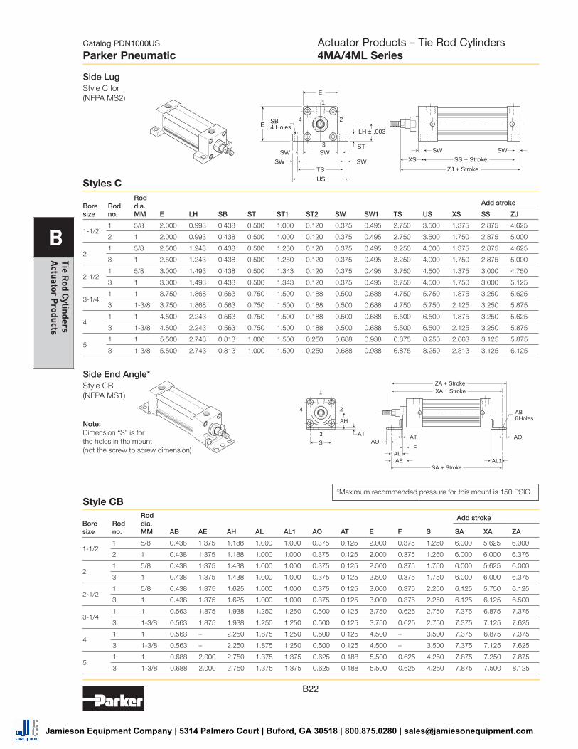
Side End Angle*Style CB (NFPA MS1)
Note: Dimension “S” is for the holes in the mount (not the screw to screw dimension)
*Maximum recommended pressure for this mount is 150 PSIG
Bore size
Rod no.
Rod dia. MM AB AE AH AL AL1 AO AT E F S
Add stroke
SA XA ZA
1-1/2 1 5/8 0.438 1.375 1.188 1.000 1.000 0.375 0.125 2.000 0.375 1.250 6.000 5.625 6.000
2 1 0.438 1.375 1.188 1.000 1.000 0.375 0.125 2.000 0.375 1.250 6.000 6.000 6.375
2 1 5/8 0.438 1.375 1.438 1.000 1.000 0.375 0.125 2.500 0.375 1.750 6.000 5.625 6.000
3 1 0.438 1.375 1.438 1.000 1.000 0.375 0.125 2.500 0.375 1.750 6.000 6.000 6.375
2-1/2 1 5/8 0.438 1.375 1.625 1.000 1.000 0.375 0.125 3.000 0.375 2.250 6.125 5.750 6.125
3 1 0.438 1.375 1.625 1.000 1.000 0.375 0.125 3.000 0.375 2.250 6.125 6.125 6.500
3-1/4 1 1 0.563 1.875 1.938 1.250 1.250 0.500 0.125 3.750 0.625 2.750 7.375 6.875 7.375
3 1-3/8 0.563 1.875 1.938 1.250 1.250 0.500 0.125 3.750 0.625 2.750 7.375 7.125 7.625
4 1 1 0.563 – 2.250 1.875 1.250 0.500 0.125 4.500 – 3.500 7.375 6.875 7.375
3 1-3/8 0.563 – 2.250 1.875 1.250 0.500 0.125 4.500 – 3.500 7.375 7.125 7.625
5 1 1 0.688 2.000 2.750 1.375 1.375 0.625 0.188 5.500 0.625 4.250 7.875 7.250 7.875
3 1-3/8 0.688 2.000 2.750 1.375 1.375 0.625 0.188 5.500 0.625 4.250 7.875 7.500 8.125
Style CB
SW
TS
US
LH ± .003
ST
E
E
XS
SB4 Holes
SWSW
SW SW
SW
ZJ + Stroke
SS + Stroke
3
1
24
Side LugStyle C for (NFPA MS2)
Bore size
Rod no.
Rod dia. MM E LH SB ST ST1 ST2 SW SW1 TS US XS
Add stroke
SS ZJ
1-1/2 1 5/8 2.000 0.993 0.438 0.500 1.000 0.120 0.375 0.495 2.750 3.500 1.375 2.875 4.625
2 1 2.000 0.993 0.438 0.500 1.000 0.120 0.375 0.495 2.750 3.500 1.750 2.875 5.000
2 1 5/8 2.500 1.243 0.438 0.500 1.250 0.120 0.375 0.495 3.250 4.000 1.375 2.875 4.625
3 1 2.500 1.243 0.438 0.500 1.250 0.120 0.375 0.495 3.250 4.000 1.750 2.875 5.000
2-1/2 1 5/8 3.000 1.493 0.438 0.500 1.343 0.120 0.375 0.495 3.750 4.500 1.375 3.000 4.750
3 1 3.000 1.493 0.438 0.500 1.343 0.120 0.375 0.495 3.750 4.500 1.750 3.000 5.125
3-1/4 1 1 3.750 1.868 0.563 0.750 1.500 0.188 0.500 0.688 4.750 5.750 1.875 3.250 5.625
3 1-3/8 3.750 1.868 0.563 0.750 1.500 0.188 0.500 0.688 4.750 5.750 2.125 3.250 5.875
4 1 1 4.500 2.243 0.563 0.750 1.500 0.188 0.500 0.688 5.500 6.500 1.875 3.250 5.625
3 1-3/8 4.500 2.243 0.563 0.750 1.500 0.188 0.500 0.688 5.500 6.500 2.125 3.250 5.875
5 1 1 5.500 2.743 0.813 1.000 1.500 0.250 0.688 0.938 6.875 8.250 2.063 3.125 5.875
3 1-3/8 5.500 2.743 0.813 1.000 1.500 0.250 0.688 0.938 6.875 8.250 2.313 3.125 6.125
Styles C
Actuator Products – Tie Rod Cylinders4MA/4ML Series
Jamieson Equipment Company | 5314 Palmero Court | Buford, GA 30518 | 800.875.0280 | [email protected]
B23
Catalog PDN1000US
Parker Pneumatic
B
Tie
Rod
Cyl
inde
rs
Act
uato
r P
rodu
cts
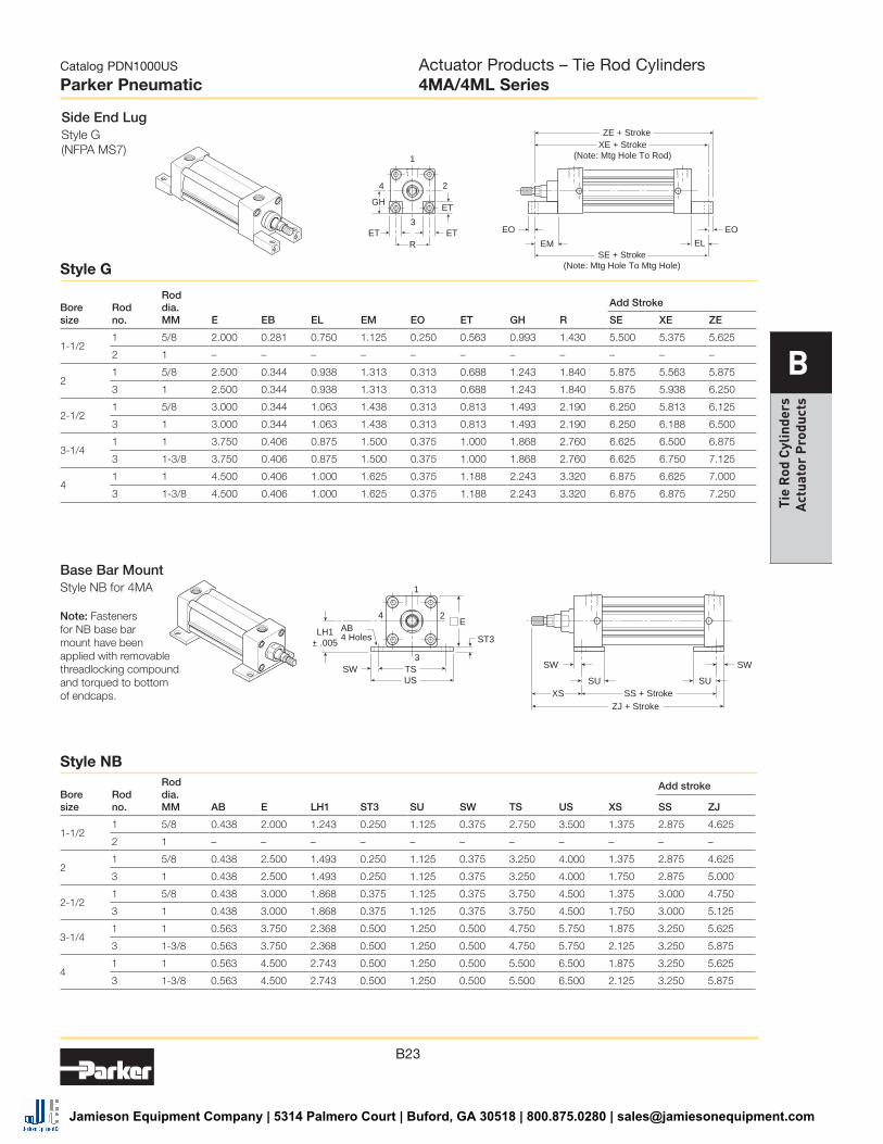
Side End LugStyle G (NFPA MS7)
GHET
ET ET EM
EOEO
EL
ZE + Stroke
1
2
3
4
RSE + Stroke
(Note: Mtg Hole To Mtg Hole)
XE + Stroke(Note: Mtg Hole To Rod)
Bore size
Rod no.
Rod dia. MM E EB EL EM EO ET GH R
Add Stroke
SE XE ZE
1-1/2 1 5/8 2.000 0.281 0.750 1.125 0.250 0.563 0.993 1.430 5.500 5.375 5.625
2 1 – – – – – – – – – – –
2 1 5/8 2.500 0.344 0.938 1.313 0.313 0.688 1.243 1.840 5.875 5.563 5.875
3 1 2.500 0.344 0.938 1.313 0.313 0.688 1.243 1.840 5.875 5.938 6.250
2-1/2 1 5/8 3.000 0.344 1.063 1.438 0.313 0.813 1.493 2.190 6.250 5.813 6.125
3 1 3.000 0.344 1.063 1.438 0.313 0.813 1.493 2.190 6.250 6.188 6.500
3-1/4 1 1 3.750 0.406 0.875 1.500 0.375 1.000 1.868 2.760 6.625 6.500 6.875
3 1-3/8 3.750 0.406 0.875 1.500 0.375 1.000 1.868 2.760 6.625 6.750 7.125
4 1 1 4.500 0.406 1.000 1.625 0.375 1.188 2.243 3.320 6.875 6.625 7.000
3 1-3/8 4.500 0.406 1.000 1.625 0.375 1.188 2.243 3.320 6.875 6.875 7.250
Style G
Base Bar MountStyle NB for 4MA
Note: Fasteners for NB base bar mount have been applied with removable threadlocking compound and torqued to bottom of endcaps.
AB4 Holes ST3
LH1± .005
E
SW TSSU SU
XS
SW
ZJ + Stroke
US
SW
SS + Stroke
1
2
3
4
Bore size
Rod no.
Rod dia. MM AB E LH1 ST3 SU SW TS US XS
Add stroke
SS ZJ
1-1/2 1 5/8 0.438 2.000 1.243 0.250 1.125 0.375 2.750 3.500 1.375 2.875 4.625
2 1 – – – – – – – – – – –
2 1 5/8 0.438 2.500 1.493 0.250 1.125 0.375 3.250 4.000 1.375 2.875 4.625
3 1 0.438 2.500 1.493 0.250 1.125 0.375 3.250 4.000 1.750 2.875 5.000
2-1/2 1 5/8 0.438 3.000 1.868 0.375 1.125 0.375 3.750 4.500 1.375 3.000 4.750
3 1 0.438 3.000 1.868 0.375 1.125 0.375 3.750 4.500 1.750 3.000 5.125
3-1/4 1 1 0.563 3.750 2.368 0.500 1.250 0.500 4.750 5.750 1.875 3.250 5.625
3 1-3/8 0.563 3.750 2.368 0.500 1.250 0.500 4.750 5.750 2.125 3.250 5.875
4 1 1 0.563 4.500 2.743 0.500 1.250 0.500 5.500 6.500 1.875 3.250 5.625
3 1-3/8 0.563 4.500 2.743 0.500 1.250 0.500 5.500 6.500 2.125 3.250 5.875
Style NB
Actuator Products – Tie Rod Cylinders4MA/4ML Series
Jamieson Equipment Company | 5314 Palmero Court | Buford, GA 30518 | 800.875.0280 | [email protected]

B24
Catalog PDN1000US
Parker Pneumatic
B
Tie Rod C
ylinders A
ctuator Products
Cap Fixed ClevisStyle BB (NFPA MP1)
Note: For maximum swivel angle of BB mount with rear mounting plate, see cylinder accessories
CW
CBCW
1
42
3
ZC + StrokeXC + Stroke
F
MR
ØCD
L
LR
Cap Detachable ClevisStyle BC (NFPA MP2)
CW
CBCW
1
42
3
ZD1 + StrokeXD + Stroke
F
MR1
L1
ØCD
Cap Detachable EyeStyle BE (NFPA MP4)
CB
1
42
3
ZD2 + StrokeXD + Stroke
F
MR2
L1
ØCD1
Bore size
Rod no.
Rod dia. MM CB
+.000 -.002 CD
+.002 +.004 CD1 CW E F L LR L1 MR MR1 MR2
Add stroke
XC XD ZC ZD1 ZD2
1-1/2 1 5/8 0.750 0.501 0.500 0.500 2.000 0.375 0.375 0.750 0.750 0.625 0.500 0.625 5.375 5.750 6.000 6.250 6.375
2 1 0.750 0.501 0.500 0.500 2.000 0.375 0.375 0.750 0.750 0.625 0.500 0.625 5.750 6.125 6.375 6.625 6.750
2 1 5/8 0.750 0.501 0.500 0.500 2.500 0.375 0.375 0.750 0.750 0.625 0.500 0.625 5.375 5.750 6.000 6.250 6.375
3 1 0.750 0.501 0.500 0.500 2.500 0.375 0.375 0.750 0.750 0.625 0.500 0.625 5.750 6.125 6.375 6.625 6.750
2-1/2 1 5/8 0.750 0.501 0.500 0.500 3.000 0.375 0.375 0.750 0.750 0.625 0.500 0.688 5.500 5.875 6.125 6.375 6.563
3 1 0.750 0.501 0.500 0.500 3.000 0.375 0.375 0.750 0.750 0.625 0.500 0.688 5.875 6.250 6.500 6.750 6.313
3-1/4 1 1 1.250 0.751 0.750 0.625 3.750 0.625 0.625 1.000 1.250 0.938 0.750 0.875 6.875 7.500 7.813 8.250 8.375
3 1-3/8 1.250 0.751 0.750 0.625 3.750 0.625 0.625 1.000 1.250 0.938 0.750 0.875 7.125 7.750 8.063 8.500 8.625
4 1 1 1.250 0.751 0.750 0.625 4.500 0.625 0.625 1.000 1.250 0.938 0.750 0.875 6.875 7.500 7.813 8.250 8.375
3 1-3/8 1.250 0.751 0.750 0.625 4.500 0.625 0.625 1.000 1.250 0.938 0.750 0.875 7.125 7.750 8.063 8.500 8.625
5 1 1 1.250 0.751 0.750 0.625 5.500 0.625 0.625 1.000 1.250 0.938 0.750 0.875 7.125 7.750 8.063 8.500 8.625
3 1-3/8 1.250 0.751 0.750 0.625 5.500 0.625 0.625 1.000 1.250 0.938 0.750 0.875 7.375 8.000 8.313 8.750 8.875
Styles BB, BC and BE
Actuator Products – Tie Rod Cylinders4MA/4ML Series
Jamieson Equipment Company | 5314 Palmero Court | Buford, GA 30518 | 800.875.0280 | [email protected]

B25
Catalog PDN1000US
Parker Pneumatic
B
Tie
Rod
Cyl
inde
rs
Act
uato
r P
rodu
cts
Head Trunnion*Style D (NFPA MT1)
Note: not available for 1-1/2" bore with 1" rod.
1
3
24
TL TL
ØTD
UT
ZJ + StrokeXG
E
1
3
24
TL TL
ØTD
UT
ZJ + StrokeXJ + Stroke
E
Cap TrunnionStyle DB (NFPA MT2)
UM
UV
TLE
TM
TL
ØTD
1
2
3
4
XI
BD
ZJ + Stroke
Intermediate TrunnionStyle DD (NFPA MT4)
Note: Tie rod nuts for Style DD have a slot instead of internal hex.
Bore size
Rod no.
Rod dia. MM E BD
+.000 –.001 TD TL TM UM UT UV XG
Min. XI
Add stroke
XJ ZJ
1–1/2 1 * 5/8 2.000 1.250 1.000 1.000 2.500 4.500 4.000 2.500 1.750 3.036 4.125 4.625
2 1 2.000 1.250 1.000 1.000 2.500 4.500 4.000 2.500 – 3.437 4.250 5.000
2 1 5/8 2.500 1.500 1.000 1.000 3.000 5.000 4.500 3.000 1.750 3.125 4.125 4.625
3 1 2.500 1.500 1.000 1.000 3.000 5.000 4.500 3.000 2.125 3.500 4.500 5.000
2-1/2 1 5/8 3.000 1.500 1.000 1.000 3.500 5.500 5.000 3.500 1.750 3.094 4.250 4.750
3 1 3.000 1.500 1.000 1.000 3.500 5.500 5.000 3.500 2.125 3.469 4.625 5.125
3-1/4 1 1 3.750 2.000 1.000 1.000 4.500 6.500 5.750 4.250 2.250 3.969 5.000 5.625
3 1-3/8 3.750 2.000 1.000 1.000 4.500 6.500 5.750 4.250 2.500 4.219 5.250 5.875
4 1 1 4.500 2.000 1.000 1.000 5.250 7.250 6.500 5.000 2.250 3.969 5.000 5.625
3 1-3/8 4.500 2.000 1.000 1.000 5.250 7.250 6.500 5.000 2.500 4.219 5.250 5.875
5 1 1 5.500 2.000 1.000 1.000 6.250 8.250 7.500 6.000 2.250 3.969 5.250 5.875
3 1-3/8 5.500 2.000 1.000 1.000 6.250 8.250 7.500 6.000 2.500 4.219 5.500 6.125
* Head trunnion style D not available for 1-1/2" bore with 1" rod
Styles D, DB and DD
Actuator Products – Tie Rod Cylinders4MA/4ML Series
(Revised 08-15-11)
Jamieson Equipment Company | 5314 Palmero Court | Buford, GA 30518 | 800.875.0280 | [email protected]

B26
Catalog PDN1000US
Parker Pneumatic
B
Tie Rod C
ylinders A
ctuator Products
Operating information
4MA 4ML
Operating pressure: 250 PSIG (17 bar) 400 PSIG (27 bar) maximum air service maximum hydraulic service
Temperature range: Standard seals -10°F to 165°F (-23°C to 74°C) Fluorocarbon seals -10°F to 250°F (-23°C to 121°C) Low temperature seals -50°F to 150°F (-46°C to 66°C)
Filtration requirements: 40 micron, dry filtered air Filtered hydraulic oil
For technical information see CD
• Industry leading NFPA interchangeable cylinderwith flexible construction
• Bore sizes – 6" and 8"
• Removable bronze alloy gland/bearing for easymaintenance
• Available in any practical stroke length
• Tube and tie rod construction for heavy duty use
• Single rod end or double rod ends
• Cushions – optional and adjustable at eitherend or both ends (N/A for 4ML hydraulic version)
• 20 standard mounting styles available
• RoHS compliant
Ordering information
J U 1 4 A 12.0006.00
Piston type Blank Standard
(lipseals and magnetic ring)
3 Lipseals and magnetic ring
Bore size6.00
8.00
Stroke lengthSpecify stroke length required in inches. 8
Mounting styleSpecify mounting style code (see table on following page).
Double rod cylinderSpecify “K” only if double rod cylinder is required.
Piston rod numberSpecify rod code number for required diameter. 8, 2
PortsU NPTF
R BSPP
B BSPT
T SAE
Cushion head endBlank Non-cushioned head end
C Cushioned head end (not available for 4ML)
Cushion cap endBlank Non-cushioned cap end
C Cushioned cap end (not available for 4ML)
Piston rod thread typeA Standard (UNF unified thread)
W BSF British fine
M * Metric
* Please reference catalog 0900P-E, page B106.
Rod material and gland codeBlank Standard rod and glandH Standard rod and HI LOAD glandY 17-4 PH stainless steel rod and
standard glandZ 17-4 PH stainless steel rod and
HI LOAD glandJ 303 stainless steel rod and
standard gland 7
K 303 stainless steel rod and HI LOAD gland 7
S 316 stainless steel rod and standard gland 7
T 316 stainless steel rod and HI LOAD gland 7
Piston rod thread style4 Small male
8 Intermediate male
9 Short female
55 For use with split coupler 6
3 Special (and specify all dimensions required)
SealsBlank Standard (nitrile seals)
V Fluorocarbon seals 1
E Fluorocarbon rod wiper and rod seal only 2
4 Low temperature seals 1
M Metallic rod wiper, nitrile seals 3
Series4MA Air service
4ML Hydraulic service
Special modificationSpecify “S” only for special modification other than rod end, and then describe modification in item notes. (Includes 4MA with Linear Position Sensor Option) 7
1 Reed and solid-state sensors only available with standard seals or options E and M.2 Used for external chemical compatibility applications, not high temperature.3 If fluorocarbon seals are required with this option, please place an “S” for
special in the Special Modification field and specify the “fluorocarbon seals and metallic rod wiper” in the item notes.4 For Linear Position Sensor Option (LPSO), please include the following
information for the Special Modification item notes:a. Sensor part number (please reference catalog 0900P-E,
pages B100-B104)b. Sensor positionc. Port position (if other than position 1)d. Length of stop tubing, gross stroke and net stroke (if required)
Also, Piston Type 3 is required.5 Review Piston Rod Selection Chart, please reference catalog 0900P-E, page A14 to determine proper piston rod diameter.6 For additional information regarding this style, please reference catalog
0900P-E, page B105. If non-standard Rod Material and Gland Code is required with this option, please place an “S” for special in Special Modification field and specify Rod Material and Gland Code in the item notes.
7 Not available for 4ML.8 If a stop tube is required, specify gross stroke (net stroke + stop tube) in
the model number, then place an “S” for special in the Special Modification field and specify the stop tube length in the item notes.
4MA
Actuator Products – Tie Rod Cylinders4MA/4ML Series
SensorsFor sensors see page B296.
Jamieson Equipment Company | 5314 Palmero Court | Buford, GA 30518 | 800.875.0280 | [email protected]

B27
Catalog PDN1000US
Parker Pneumatic
B
Tie
Rod
Cyl
inde
rs
Act
uato
r P
rodu
cts
Mounting style
NFPA mounting Description
Bore size
CB MS1 Side End Angle 6 - 8
BB MP1 Cap Fixed Clevis 6 - 8
BC MP2 Cap Detachable Clevis 6 - 8
BE MP4 Cap Detachable Eye 6
D MT1 Head Trunnion 6 - 8
DB MT2 Cap Trunnion 6 - 8
DD MT4 Intermediate Trunnion 6 - 8
JB ME3 Head Square 8
HB ME4 Cap Square 8
KT † MDX0 Double Rod End, No Mount 6 - 8
† Double rod end cylinders can be ordered with head mountings, i.e. KJ.
Mounting style
NFPA mounting Description
Bore size
T MX0 No Mount 6 - 8
J MF1 Head Rectangular Flange 6
H MF2 Cap Rectangular Flange 6
TB MX3 Tie Rods Extended Head End
6 - 8
TC MX2 Tie Rods Extended Cap End
6 - 8
TD MX1 Tie Rods Extended Both Ends
6 - 8
TE MX5 Sleeve Nut 6 - 8
TEF MX5/MS4 Sleeve Nut with Side Tap 6 - 8
C MS2 Side Lug 6 - 8
F MS4 Side Tap 6 - 8
4MA/4ML Mounting Styles for 6" to 8" Bore
Actuator Products – Tie Rod Cylinders4MA/4ML Series
Jamieson Equipment Company | 5314 Palmero Court | Buford, GA 30518 | 800.875.0280 | [email protected]

B28
Catalog PDN1000US
Parker Pneumatic
B
Tie Rod C
ylinders A
ctuator Products
Single Rod Dimensioned Drawings – (Style T)
1
2
3
4
ZJ + Stroke
Y EE
P+Stroke
G J
LF + StrokeK
ER ØMM
WF
For dimensions of all standard rod end styles, please see next page.
KK or CC
ØNA
D WrenchFlats
D1 WrenchFlats
ØMM
WFVF
C
LAFA
ØB
Bore size
Rod no.
Rod dia. MM J K LAF NA R VF WF Y
Add stroke
LF P ZJ
6 1 1-3/8 1.410 0.438 3.250 1.313 4.880 0.990 1.625 2.813 5.000 3.125 6.625
3 1-3/4 1.410 0.438 3.875 1.688 4.880 1.115 1.875 3.063 5.000 3.125 6.875
8 1 1-3/8 1.440 0.563 3.250 1.313 6.440 0.990 1.625 2.750 5.125 3.250 6.750
3 1-3/4 1.440 0.563 3.875 1.688 6.440 1.115 1.875 3.000 5.125 3.250 7.000
Bore size
Rod no.
Rod dia. MM
Thread
A AA
+.000 -.002 B C D D1 E
EE (NPTF) G
Style 8 CC
Style 4 & 9 KK
6 1 1-3/8 1-1/4-12 1-14 1.625 6.900 1.999 0.635 1-1/8 1-7/8 6.500 3/4 1.910
3 1-3/4 1-1/2-12 1-1/4-12 2.000 6.900 2.374 0.760 1-1/2 2-3/16 6.500 3/4 1.910
8 1 1-3/8 1-1/4-12 1-14 1.625 9.100 1.999 0.635 1-1/8 1-7/8 8.500 3/4 1.810
3 1-3/4 1-1/2-12 1-1/4-12 2.000 9.100 2.374 0.760 1-1/2 2-3/16 8.500 3/4 1.810
Style T
Actuator Products – Tie Rod Cylinders4MA/4ML Series
Jamieson Equipment Company | 5314 Palmero Court | Buford, GA 30518 | 800.875.0280 | [email protected]
B29
Catalog PDN1000US
Parker Pneumatic
B
Tie
Rod
Cyl
inde
rs
Act
uato
r P
rodu
cts
Bore size
Rod no.
Rod dia. MM
Thread
A AD AE AF AM
+.000 -.002 B C D D1 LAF NA VF WF WG
Style 8 CC
Style 4 & 9 KK
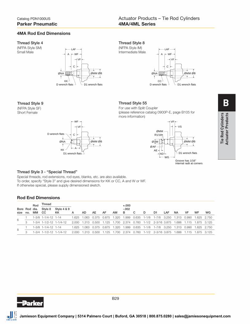
6 1 1-3/8 1-1/4-12 1-14 1.625 1.063 0.375 0.875 1.320 1.999 0.635 1-1/8 1-7/8 3.250 1.313 0.990 1.625 2.750
3 1-3/4 1-1/2-12 1-1/4-12 2.000 1.313 0.500 1.125 1.700 2.374 0.760 1-1/2 2-3/16 3.875 1.688 1.115 1.875 3.125
8 1 1-3/8 1-1/4-12 1-14 1.625 1.063 0.375 0.875 1.320 1.999 0.635 1-1/8 1-7/8 3.250 1.313 0.990 1.625 2.750
3 1-3/4 1-1/2-12 1-1/4-12 2.000 1.313 0.500 1.125 1.700 2.374 0.760 1-1/2 2-3/16 3.875 1.688 1.115 1.875 3.125
KK
D wrench flats
WF
VF
C
A
KKD wrench flats D1 wrench flats
WF
VF
C
LAF
A
CCD wrench flats D1 wrench flats
WF
VF
C
LAF
A
D1 wrench flats D1 wrench flats
Groove has 1/16"internal radii at corners
VF
VS
ØMMR1/16
Ø AM
WGAD
AEØAF
ØNA ØBØMM ØBØMM
ØNA ØBØMM ØNA ØBØMM
Rod End Dimensions
4MA Rod End Dimensions
Thread Style 4(NFPA Style SM)Small Male
Thread Style 8(NFPA Style IM)Intermediate Male
Thread Style 9(NFPA Style SF)Short Female
Thread Style 55For use with Split Coupler(please reference catalog 0900P-E, page B105 for more information)
Thread Style 3 - “Special Thread”Special threads, rod extensions, rod eyes, blanks, etc. are also available.To order, specify “Style 3” and give desired dimensions for KK or CC, A and W or WF.If otherwise special, please supply dimensioned sketch.
Actuator Products – Tie Rod Cylinders4MA/4ML Series
Jamieson Equipment Company | 5314 Palmero Court | Buford, GA 30518 | 800.875.0280 | [email protected]
B30
Catalog PDN1000US
Parker Pneumatic
B
Tie Rod C
ylinders A
ctuator Products
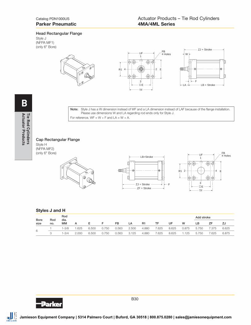
Head Rectangular FlangeStyle J (NFPA MF1) (only 6" Bore)
Cap Rectangular FlangeStyle H (NFPA MF2) (only 6" Bore)
1
2
3
4
TF
UF
R1
FB4 Holes
ZJ + Stroke
LB + StrokeF
LA
W
E
E
1
4
3
2
TF
UF
R1
FB4 Holes
ZF + StrokeZJ + Stroke
LB+Stroke
F
E
E
Boresize
Rodno.
Roddia.MM A E F FB LA R1 TF UF W
Add stroke
LB ZF ZJ
61 1-3/8 1.625 6.500 0.750 0.563 2.500 4.880 7.625 8.625 0.875 5.750 7.375 6.625
3 1-3/4 2.000 6.500 0.750 0.563 3.125 4.880 7.625 8.625 1.125 5.750 7.625 6.875
Note: Style J has a W dimension instead of WF and a LA dimension instead of LAF because of the flange installation. Please use dimensions W and LA regarding rod ends only for Style J.
For reference, WF = W + F and LA = W + A.
Styles J and H
Actuator Products – Tie Rod Cylinders4MA/4ML Series
Jamieson Equipment Company | 5314 Palmero Court | Buford, GA 30518 | 800.875.0280 | [email protected]

B31
Catalog PDN1000US
Parker Pneumatic
B
Tie
Rod
Cyl
inde
rs
Act
uato
r P
rodu
cts
Tie Rods Ext. Head EndStyle TB (NFPA MX3)
Tie Rods Ext. Cap EndStyle TC (NFPA MX2)
1
2
ØAA
3
4
ZJ + Stroke K
ER
BB
DD
1
2
ØAA
3
4
ZJ + Stroke K
ER
BB
DD
Tie Rods Ext. Both EndsStyle TD (NFPA MX1)
1
2
ØAA
3
4
ZJ + Stroke K
ER
BB
DD DD
BB
Bore size
Rod no.
Rod dia. MM AA BB DD E K R
Add stroke
ZJ
6 1 1-3/8 6.900 1.813 1/2-20 6.500 0.438 4.880 6.625
3 1-3/4 6.900 1.813 1/2-20 6.500 0.438 4.880 6.875
8 1 1-3/8 9.100 2.313 5/8-18 8.500 0.563 6.440 6.750
3 1-3/4 9.100 2.313 5/8-18 8.500 0.563 6.440 7.000
Styles TB, TC and TD
Actuator Products – Tie Rod Cylinders4MA/4ML Series
Jamieson Equipment Company | 5314 Palmero Court | Buford, GA 30518 | 800.875.0280 | [email protected]
B32
Catalog PDN1000US
Parker Pneumatic
B
Tie Rod C
ylinders A
ctuator Products
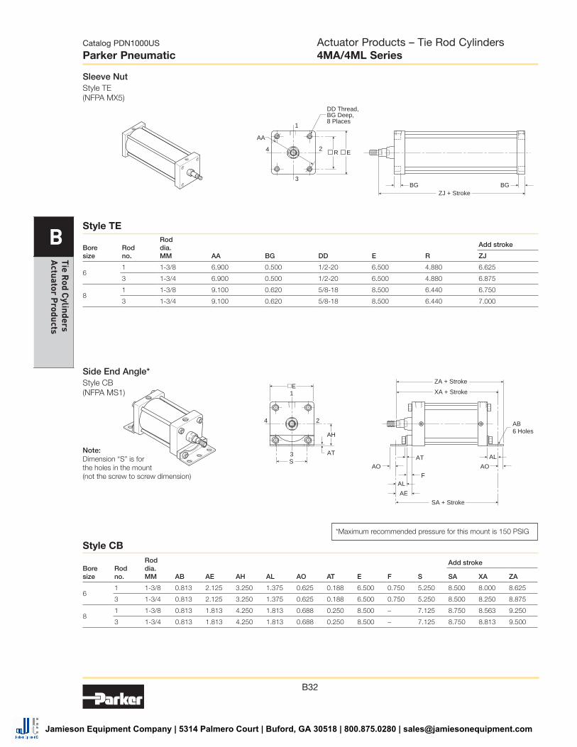
Sleeve NutStyle TE (NFPA MX5)
1
2
AA
3
4
ZJ + StrokeBG BG
ER
DD Thread,BG Deep,8 Places
Bore size
Rod no.
Rod dia. MM AA BG DD E R
Add stroke
ZJ
6 1 1-3/8 6.900 0.500 1/2-20 6.500 4.880 6.625
3 1-3/4 6.900 0.500 1/2-20 6.500 4.880 6.875
8 1 1-3/8 9.100 0.620 5/8-18 8.500 6.440 6.750
3 1-3/4 9.100 0.620 5/8-18 8.500 6.440 7.000
Bore size
Rod no.
Rod dia. MM AB AE AH AL AO AT E F S
Add stroke
SA XA ZA
6 1 1-3/8 0.813 2.125 3.250 1.375 0.625 0.188 6.500 0.750 5.250 8.500 8.000 8.625
3 1-3/4 0.813 2.125 3.250 1.375 0.625 0.188 6.500 0.750 5.250 8.500 8.250 8.875
8 1 1-3/8 0.813 1.813 4.250 1.813 0.688 0.250 8.500 – 7.125 8.750 8.563 9.250
3 1-3/4 0.813 1.813 4.250 1.813 0.688 0.250 8.500 – 7.125 8.750 8.813 9.500
Style TE
Style CB
Side End Angle*Style CB (NFPA MS1)
Note: Dimension “S” is for the holes in the mount (not the screw to screw dimension)
*Maximum recommended pressure for this mount is 150 PSIG
AB6 HolesAH
1
2
3
4
ZA + Stroke
SA + Stroke
XA + Stroke
AE
AL
AO AO
F
AT ALS
E
AT
Actuator Products – Tie Rod Cylinders4MA/4ML Series
Jamieson Equipment Company | 5314 Palmero Court | Buford, GA 30518 | 800.875.0280 | [email protected]

B33
Catalog PDN1000US
Parker Pneumatic
B
Tie
Rod
Cyl
inde
rs
Act
uato
r P
rodu
cts
Side LugStyle C (NFPA MS2)
Side TapStyle F (NFPA MS4)
LH±.003
SB4 Holes
1
2
3
4
ZJ + StrokeSS + Stroke
SWSW
XS
SWSWSWSW
USTS
E
E
ST
NT Thread, ND Deep4 Tapped Mounting Holes
1
2
3
4
ZJ + StrokeSN + Stroke
E
DD
XTTN
TH± .003
Bore size
Rod no.
Rod dia. MM E ND NT
+/-.003 TH TN XT
Add stroke
SN ZJ
6 1 1-3/8 6.500 1.125 3/4-10 3.243 3.250 2.813 3.125 6.625
3 1-3/4 6.500 1.125 3/4-10 3.243 3.250 3.063 3.125 6.875
8 1 1-3/8 8.500 1.125 3/4-10 4.243 4.500 2.813 3.250 6.750
3 1-3/4 8.500 1.125 3/4-10 4.243 4.500 3.063 3.250 7.000
Bore size
Rod no.
Rod dia. MM E
+/-.003 LH SB ST SW TS US XS
Add stroke
SS ZJ
61 1-3/8 6.500 3.243 0.813 1.000 0.688 7.875 9.250 2.313 3.625 6.625
3 1-3/4 6.500 3.243 0.813 1.000 0.688 7.875 9.250 2.563 3.625 6.875
8 1 1-3/8 8.500 4.243 0.813 1.000 0.688 9.875 11.250 2.313 3.750 6.750
3 1-3/4 8.500 4.243 0.813 1.000 0.688 9.875 11.250 2.563 3.750 7.000
Style C
Style F
Actuator Products – Tie Rod Cylinders4MA/4ML Series
Jamieson Equipment Company | 5314 Palmero Court | Buford, GA 30518 | 800.875.0280 | [email protected]

B34
Catalog PDN1000US
Parker Pneumatic
B
Tie Rod C
ylinders A
ctuator Products
Cap Detachable ClevisStyle BC (NFPA MP2)
Cap Detachable EyeStyle BE (NFPA MP4) (only 6" Bore)
1
4
3
2
ZD + StrokeXD + Stroke
F
CW
CB
CWL1
MR1
ØCD
1
4
3
2
ZD1 + StrokeXD + Stroke
FCBL1
MR2
ØCD1
Cap Fixed ClevisStyle BB (NFPA MP1)
1
4
3
2
ZC + StrokeXC + Stroke
F
CW
CB
CWL
MR
LR
ØCD
Note: For maximum swivel angle of BB mount with rear mounting plate, please reference catalog 0900P-E, cylinder accessories on page B108.
Bore size
Rod no.
Rod dia. MM CB
+.002 +.004 CD1 E F L1 MR2
Add stroke
XD ZD1
6 1 1-3/8 1.500 1.000 6.500 0.750 1.500 1.125 8.875 10.000
3 1-3/4 1.500 1.000 6.500 0.750 1.500 1.125 9.125 10.250
Bore size
Rod no.
Rod dia. MM CB
+.000 -.002 CD CW E F L LR L1 MR MR1
Add stroke
XC XD ZC ZD
6 1 1- 3/8 1.500 1.001 0.750 6.500 0.750 0.750 1.250 1.500 1.125 1.000 8.125 8.875 9.250 9.875
3 1-3/4 1.500 1.001 0.750 6.500 0.750 0.750 1.250 1.500 1.125 1.000 8.375 9.125 9.500 10.125
8 1 1-3/8 1.500 1.001 0.750 8.500 0.750 0.750 1.250 1.500 1.125 1.000 8.250 9.000 9.375 10.000
3 1-3/4 1.500 1.001 0.750 8.500 0.750 0.750 1.250 1.500 1.125 1.000 8.500 9.250 9.625 10.250
Styles BB and BC
Style BE
Actuator Products – Tie Rod Cylinders4MA/4ML Series
Jamieson Equipment Company | 5314 Palmero Court | Buford, GA 30518 | 800.875.0280 | [email protected]

B35
Catalog PDN1000US
Parker Pneumatic
B
Tie
Rod
Cyl
inde
rs
Act
uato
r P
rodu
cts
Cap TrunnionStyle DB (NFPA MT2)
Head TrunnionStyle D (NFPA MT1)
1
2
3TL TL
UT
4
ZJ + Stroke
XG
EØTD
1
4
3TL TL
UT
2
ZJ + Stroke
XJ
EØTD
Intermediate TrunnionStyle DD (NFPA MT4)
TL TM TL
1
3
24
UMZJ + Stroke
XI
BD
EUV ØTD
Bore size
Rod no.
Rod dia. MM E BD
+.000 -.001 TD TL TM UM UT UV XG
Min. XI
Add stroke
XJ ZJ
6
1 1-3/8 6.500 2.500 1.375 1.375 7.625 10.375 9.250 7.000 2.625 4.813 5.875 6.625
3 1-3/4 6.500 2.500 1.375 1.375 7.625 10.375 9.250 7.000 2.875 5.063 6.125 6.875
8
1 1-3/8 8.500 2.500 1.375 1.375 9.750 12.500 11.250 9.500 2.625 4.750 6.000 6.750
3 1-3/4 8.500 2.500 1.375 1.375 9.750 12.500 11.250 9.500 2.875 5.000 6.250 7.000
Styles D, DB and DD
Actuator Products – Tie Rod Cylinders4MA/4ML Series
Jamieson Equipment Company | 5314 Palmero Court | Buford, GA 30518 | 800.875.0280 | [email protected]

B36
Catalog PDN1000US
Parker Pneumatic
B
Tie Rod C
ylinders A
ctuator Products
Head SquareStyle JB (NFPA ME3)
1
2
3
4
ZJ + StrokeG
E
ØEB4 Holes
TE
Cap SquareStyle HB (NFPA ME4)
XK + Stroke J
1
4
3
2 E
ØEB4 Holes
TE
Bore size
Rod no.
Rod dia. MM E EB G J TE
Add stroke
XK ZJ
8 1 1-3/8 8.500 0.688 1.810 1.440 7.570 5.313 6.750
3 1-3/4 8.500 0.688 1.810 1.440 7.570 5.563 7.000
Styles JB and HB
Actuator Products – Tie Rod Cylinders4MA/4ML Series
Jamieson Equipment Company | 5314 Palmero Court | Buford, GA 30518 | 800.875.0280 | [email protected]
Before selecting or using Parker (The Company) cylinders or related accessories, it is important that you read, understand and follow the following safety information. Training is advised before selecting and using The Company’s products.
1.0 GeneralInstructions1.1 Scope– This safety guide provides instructions for selecting and using (including assembling, installing, and maintaining) cylinder products. This safety guide is a supplement to and is to be used with the specific Company publications for the specific cylinder products that are being considered for use.
1.2 FailSafe– Cylinder products can and do fail without warning for many reasons. All systems and equipment should be designed in a fail-safe mode so that if the failure of a cylinder product occurs people and property won’t be endangered.
1.3Distribution– Provide a free copy of this safety guide to each person responsible for selecting or using cylinder products. Do not select or use The Company’s cylinders without thoroughly reading and understanding this safety guide as well as the specific Company publications for the products considered or selected.
1.4UserResponsibility–Due to very wide variety of cylinder applications and cylinder operating conditions, The Company does not warrant that any particular cylinder is suitable for any specific application. This safety guide does not analyze all technical parameters that must be considered in selecting a product. The hydraulic and pneumatic cylinders outlined in this catalog are designed to The Company’s design guidelines and do not necessarily meet the design guideline of other agencies such as American Bureau of Shipping, ASME Pressure Vessel Code etc. The user, through its own analysis and testing, is solely responsible for:
• Making the final selection of the cylinders and related accessories.
• Determining if the cylinders are required to meet specific design requirements as required by the Agency(s) or industry standards covering the design of the user’s equipment.
• Assuring that the user’s requirements are met, OSHA requirements are met, and safety guidelines from the applicable agencies such as but not limited to ANSI are followed and that the use presents no health or safety hazards.
• Providing all appropriate health and safety warnings on the equipment on which the cylinders are used.
1.5AdditionalQuestions–Call the appropriate Company technical service department if you have any questions or require any additional information. See the Company publication for the product being considered or used, or call 1-800-CPARKER, or go to www.parker.com, for telephone numbers of the appropriate technical service department.
2.0 CylinderandAccessoriesSelection2.1Seals– Part of the process of selecting a cylinder is the selection of seal compounds. Before making this selection, consult the “seal information page(s)” of the publication for the series of cylinders of interest.
The application of cylinders may allow fluids such as cutting fluids, wash down fluids etc. to come in contact with the external area of the cylinder. These fluids may attack the piston rod wiper and or the primary seal and must be taken into account when selecting and specifying seal compounds.
Dynamic seals will wear. The rate of wear will depend on many operating factors. Wear can be rapid if a cylinder is mis-aligned or if the cylinder has been improperly serviced. The user must take seal wear into consideration in the application of cylinders.
2.2PistonRods– Possible consequences of piston rod failure orseparation of the piston rod from the piston include, but are not limited to are:• Piston rod and or attached load thrown off at high speed.
• High velocity fluid discharge.
• Piston rod extending when pressure is applied in the piston retract mode.
Piston rods or machine members attached to the piston rod may move suddenly and without warning as a consequence of other conditions occurring to the machine such as, but not limited to:
• Unexpected detachment of the machine member from the piston rod.
• Failure of the pressurized fluid delivery system (hoses, fittings, valves, pumps, compressors) which maintain cylinder position.
• Catastrophic cylinder seal failure leading to sudden loss of pressurized fluid.• Failure of the machine control system.
Follow the recommendations of the “Piston Rod Selection Chart and Data” in the publication for the series of cylinders of interest. The suggested piston rod diameter in these charts must be followed in order to avoid piston rod buckling.
Piston rods are not normally designed to absorb bending moments or loads which are perpendicular to the axis of piston rod motion. These additional loads can cause the piston rod to fail. If these types of additional loads are expected to be imposed on the piston rod, their magnitude should be made known to our engineering department.
The cylinder user should always make sure that the piston rod is securely attached to the machine member.
On occasion cylinders are ordered with double rods (a piston rod extended from both ends of the cylinder). In some cases a stop is threaded on to one of the piston rods and used as an external stroke adjuster. On occasions spacers are attached to the machine member connected to the piston rod and also used as a stroke adjuster. In both cases the stops will create a pinch point and the user should consider appropriate use of guards. If these external stops are not perpendicular to the mating contact surface, or if debris is trapped between the contact surfaces, a bending moment will be placed on the piston rod, which can lead to piston rod failure. An external stop will also negate the effect of cushioning and will subject the piston rod to impact loading. Those two (2) conditions can cause piston rod failure. Internal stroke adjusters are available with and without cushions. The use of external stroke adjusters should be reviewed with our engineering department.
The piston rod to piston and the stud to piston rod threaded connections are secured with an anaerobic adhesive. The strength of the adhesive decreases with increasing temperature. Cylinders which can be exposed to temperatures above +250°F (+121°C) are to be ordered with a non studded piston rod and a pinned piston to rod joint.
2.3Cushions–Cushions should be considered for cylinder applications when the piston velocity is expected to be over 4 inches/second.Cylinder cushions are normally designed to absorb the energy of a linear applied load. A rotating mass has considerably more energy than the same mass moving in a linear mode. Cushioning for a rotating mass application should be review by our engineering department.
2.4CylinderMountings– Some cylinder mounting configurations may have certain limitations such as but not limited to minimum stroke for side or foot mounting cylinders or pressure de-ratings for certain mounts. Carefully review the catalog for these types of restrictions.Always mount cylinders using the largest possible high tensile alloy steel socket head cap screws that can fit in the cylinder mounting holes and torque them to the manufacturer’s recommendations for their size.
2.5PortFittings– Hydraulic cylinders applied with meter out or deceleration circuits are subject to intensified pressure at piston rod end.The rod end pressure is approximately equal to:
operating pressure x effective cap end area
effective rod end piston area
Contact your connector supplier for the pressure rating of individual connectors.
3.0 CylinderandAccessoriesInstallationandMounting
3.1 Installation
3.1.1 – Cleanliness is an important consideration, and cylinders are shipped with the ports plugged to protect them from contaminants entering the ports. These plugs should not be removed until the piping is to be installed. Before making the connection to the cylinder ports, piping should be thoroughly cleaned to remove all chips or burrs which might have resulted from threading or flaring operations.
SafetyGuideforSelectingandUsingHydraulic,PneumaticCylindersandTheirAccessories
WARNING:FAIlUReoFTHeCylINdeR,ITSPARTS,ITSMoUNTING,ITSCoNNeCTIoNSTooTHeRobjeCTS,oRITSCoNTRolSCANReSUlTIN:
• Unanticipatedoruncontrolledmovementofthecylinderorobjectsconnectedtoit.• Fallingofthecylinderorobjectsheldupbyit.• Fluidescapingfromthecylinder,potentiallyathighvelocity.
THeSeeveNTSCoUldCAUSedeATHoRPeRSoNAlINjURyby,FoRexAMPle,PeRSoNSFAllINGFRoMHIGHloCATIoNS,beINGCRUSHedoRSTRUCkbyHeAvyoRFASTMovINGobjeCTS,beINGPUSHedINTodANGeRoUSeqUIPMeNToRSITUATIoNS,oRSlIPPINGoNeSCAPedFlUId.
!
G1
G
Safe
ty G
uide
, O
ffer
of S
ale
Pneumatic ProductsSafety Guide, Actuator Products
Catalog PDN1000US
ParkerPneumatics
Jamieson Equipment Company | 5314 Palmero Court | Buford, GA 30518 | 800.875.0280 | [email protected]
3.1.2 – Cylinders operating in an environment where air drying materials are present such as fast-drying chemicals, paint, or weld splatter, or other hazardous conditions such as excessive heat, should have shields installed to prevent damage to the piston rod and piston rod seals.
3.1.3 – Proper alignment of the cylinder piston rod and its mating component on the machine should be checked in both the extended and retracted positions. Improper alignment will result in excessive rod gland and/or cylinder bore wear. On fixed mounting cylinders attaching the piston rod while the rod is retracted will help in achieving proper alignment.
3.1.4 – Sometimes it may be necessary to rotate the piston rod in order to thread the piston rod into the machine member. This operation must always be done with zero pressure being applied to either side of the piston. Failure to follow this procedure may result in loosening the piston to rod-threaded connection. In some rare cases the turning of the piston rod may rotate a threaded piston rod gland and loosen it from the cylinder head. Confirm that this condition is not occurring. If it does, re-tighten the piston rod gland firmly against the cylinder head.
For double rod cylinders it is also important that when attaching or detaching the piston rod from the machine member that the torque be applied to the piston rod end of the cylinder that is directly attaching to the machine member with the opposite end unrestrained. If the design of the machine is such that only the rod end of the cylinder opposite to where the rod attaches to the machine member can be rotated, consult the factory for further instructions.
3.2 MountingRecommendations
3.2.1 – Always mount cylinders using the largest possible high tensile alloy steel socket head screws that can fit in the cylinder mounting holes and torque them to the manufacturer’s recommendations for their size.
3.2.2 – Side-Mounted Cylinders – In addition to the mounting bolts, cylinders of this type should be equipped with thrust keys or dowel pins located so as to resist the major load.
3.2.3 – Tie Rod Mounting – Cylinders with tie rod mountings are recommended for applications where mounting space is limited. The standard tie rod extension is shown as BB in dimension tables. Longer or shorter extensions can be supplied. Nuts used for this mounting style should be torqued to the same value as the tie rods for that bore size.
3.2.4 – Flange Mount Cylinders – The controlled diameter of the rod gland extension on head end flange mount cylinders can be used as a pilot to locate the cylinders in relation to the machine. After alignment has been obtained, the flanges may be drilled for pins or dowels to prevent shifting.
3.2.5 – Trunnion Mountings – Cylinders require lubricated bearing blocks with minimum bearing clearances. Bearing blocks should be carefully aligned and rigidly mounted so the trunnions will not be subjected to bending moments. The rod end should also be pivoted with the pivot pin in line and parallel to axis of the trunnion pins.
3.2.6 – Clevis Mountings – Cylinders should be pivoted at both ends with centerline of pins parallel to each other. After cylinder is mounted, be sure to check to assure that the cylinder is free to swing through its working arc without interference from other machine parts.
4.0 CylinderandAccessoriesMaintenance,TroubleshootingandReplacement
4.1Storage– At times cylinders are delivered before a customer is ready to install them and must be stored for a period of time. When storage is required the following procedures are recommended.
4.1.1 – Store the cylinders in an indoor area which has a dry, clean and noncorrosive atmosphere. Take care to protect the cylinder from both internal corrosion and external damage.
4.1.2 – Whenever possible cylinders should be stored in a vertical position (piston rod up). This will minimize corrosion due to possible condensation which could occur inside the cylinder. This will also minimize seal damage.
4.1.3 – Port protector plugs should be left in the cylinder until the time of installation.
4.1.4 – If a cylinder is stored full of hydraulic fluid, expansion of the fluid due to temperature changes must be considered. Installing a check valve with free flow out of the cylinder is one method.
4.1.5 – When cylinders are mounted on equipment that is stored outside for extended periods, exposed unpainted surfaces, e.g. piston rod, must be coated with a rust-inhibiting compound to prevent corrosion.
4.2CylinderTroubleShooting
4.2.1–ExternalLeakage
4.2.1.1 – Rod seal leakage can generally be traced to worn or damaged seals. Examine the piston rod for dents, gouges or score
marks, and replace piston rod if surface is rough.
Rod seal leakage could also be traced to gland wear. If clearance is excessive, replace rod bushing and seal. Rod seal leakage can also be traced to seal deterioration. If seals are soft or gummy or brittle, check compatibility of seal material with lubricant used if air cylinder, or operating fluid if hydraulic cylinder. Replace with seal material, which is compatible with these fluids. If the seals are hard or have lost elasticity, it is usually due to exposure to temperatures in excess of 165°F. (+74°C). Shield the cylinder from the heat source to limit temperature to 350°F. (+177°C.) and replace with fluorocarbon seals.
4.2.1.2 – Cylinder body seal leak can generally be traced to loose tie rods. Torque the tie rods to manufacturer’s recommendation for that bore size.
Excessive pressure can also result in cylinder body seal leak. Determine maximum pressure to rated limits. Replace seals and retorque tie rods as in paragraph above. Excessive pressure can also result in cylinder body seal leak. Determine if the pressure rating of the cylinder has been exceeded. If so, bring the operating pressure down to the rating of the cylinder and have the tie rods replaced.
Pinched or extruded cylinder body seal will also result in a leak. Replace cylinder body seal and retorque as in paragraph above.
Cylinder body seal leakage due to loss of radial squeeze which shows up in the form of flat spots or due to wear on the O.D. or I.D. – Either of these are symptoms of normal wear due to high cycle rate or length of service. Replace seals as per paragraph above.
4.2.2–InternalLeakage
4.2.2.1 – Piston seal leak (by-pass) 1 to 3 cubic inches per minute leakage is considered normal for piston ring construction. Virtually no static leak with lipseal type seals on piston should be expected. Piston seal wear is a usual cause of piston seal leakage. Replace seals as required.
4.2.2.2 – With lipseal type piston seals excessive back pressure due to over-adjustment of speed control valves could be a direct cause of rapid seal wear. Contamination in a hydraulic system can result in a scored cylinder bore, resulting in rapid seal wear. In either case, replace piston seals as required.
4.2.2.3 – What appears to be piston seal leak, evidenced by the fact that the cylinder drifts, is not always traceable to the piston. To make sure, it is suggested that one side of the cylinder piston be pressurized and the fluid line at the opposite port be disconnected. Observe leakage. If none is evident, seek the cause of cylinder drift in other component parts in the circuit.
4.2.3–CylinderFailstoMovetheLoad
4.2.3.1 – Pneumatic or hydraulic pressure is too low. Check the pressure at the cylinder to make sure it is to circuit requirements.
4.2.3.2 – Piston Seal Leak – Operate the valve to cycle the cylinder and observe fluid flow at valve exhaust ports at end of cylinder stroke. Replace piston seals if flow is excessive.
4.2.3.3 – Cylinder is undersized for the load – Replace cylinder with one of a larger bore size.
4.3ErraticorChatterOperation
4.3.1 – Excessive friction at rod gland or piston bearing due to load misalignment – Correct cylinder-to-load alignment.
4.3.2 – Cylinder sized too close to load requirements – Reduce load or install larger cylinder.
4.3.3 – Erratic operation could be traced to the difference between static and kinetic friction. Install speed control valves to provide a back pressure to control the stroke.
4.4CylinderModifications,Repairs,orFailedComponent–Cylindersas shipped from the factory are not to be disassembled and or modified. If cylinders require modifications, these modifications must be done at company locations or by The Company’s certified facilities. The Cylinder Division Engineering Department must be notified in the event of a mechanical fracture or permanent deformation of any cylinder component (excluding seals). This includes a broken piston rod, tie rod, mounting accessory or any other cylinder component. The notification should include all operation and application details. This information will be used to provide an engineered repair that will prevent recurrence of the failure.
It is allowed to disassemble cylinders for the purpose of replacing seals or seal assemblies. However, this work must be done by strictly following all the instructions provided with the seal kits.
G4
G
Safety Guide,
Offer of Sale
Pneumatic ProductsSafety Guide, Actuator Products
Catalog PDN1000US
ParkerPneumatics
Jamieson Equipment Company | 5314 Palmero Court | Buford, GA 30518 | 800.875.0280 | [email protected]