Pneumatics and hydraulics Hydraulic Cylinders and ...
26
Pneumatics and hydraulics Hydraulic Cylinders and Cushioning Devices Dr. Ahmad Al-Mahasneh
-
Upload
khangminh22 -
Category
Documents
-
view
0 -
download
0
Transcript of Pneumatics and hydraulics Hydraulic Cylinders and ...
Pneumatics and hydraulics
Hydraulic Cylinders and CushioningDevices
Dr. Ahmad Al-Mahasneh

Introduction
• Hydraulic cylinders and hydraulic motors extract energy from the fluid and convert it to mechanical energy to perform useful work.
• Hydraulic cylinders (also called linear actuators) extend and retract a piston rod to provide a push or pull force to drive the external load along a straight-line path.
• hydraulic motors (also called rotary actuators) rotate a shaft to provide a torque to drive the load along a rotary path.
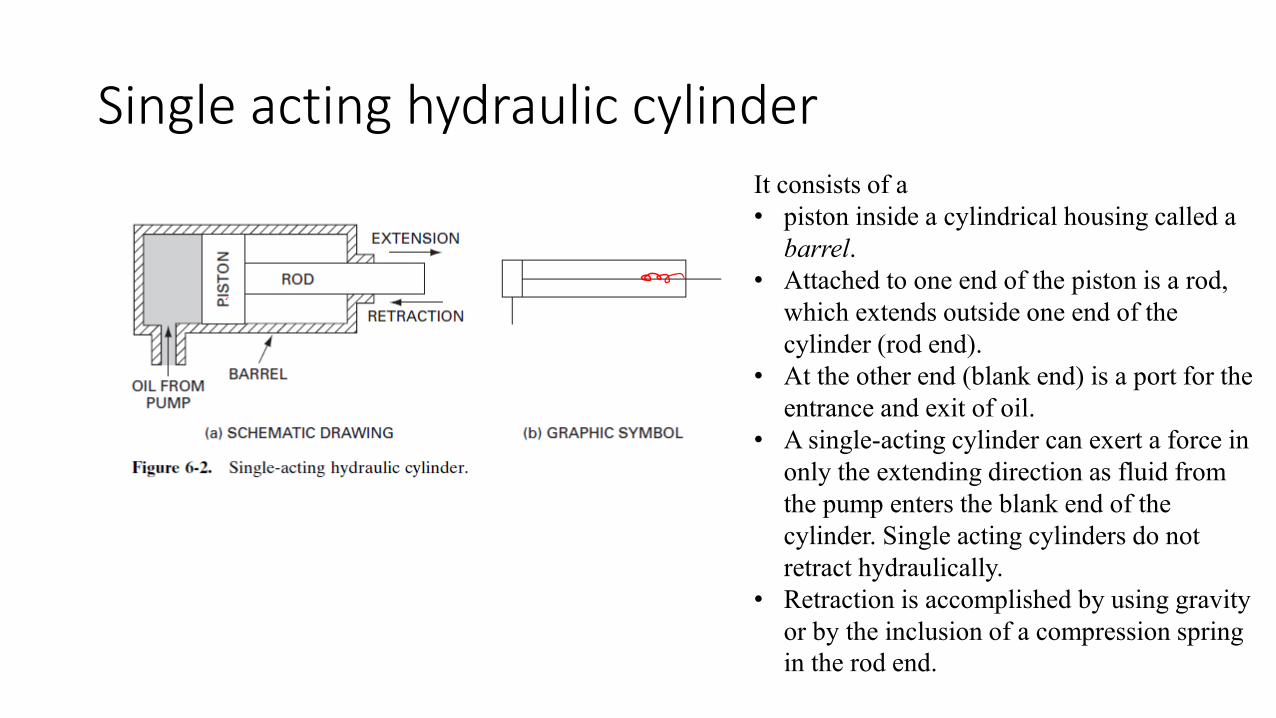
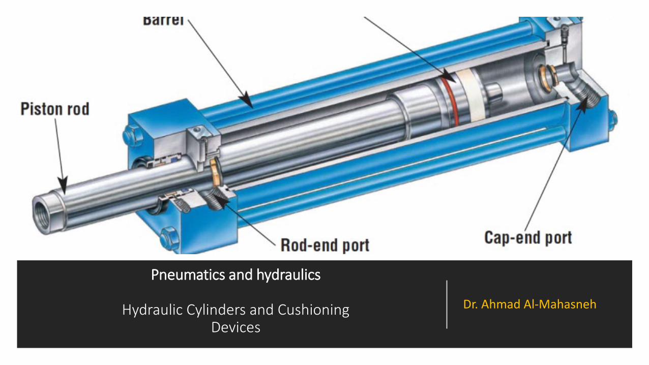
Single acting hydraulic cylinderIt consists of a• piston inside a cylindrical housing called a
barrel.• Attached to one end of the piston is a rod,
which extends outside one end of the cylinder (rod end).
• At the other end (blank end) is a port for the entrance and exit of oil.
• A single-acting cylinder can exert a force in only the extending direction as fluid from the pump enters the blank end of the cylinder. Single acting cylinders do not retract hydraulically.
• Retraction is accomplished by using gravity or by the inclusion of a compression spring in the rod end.
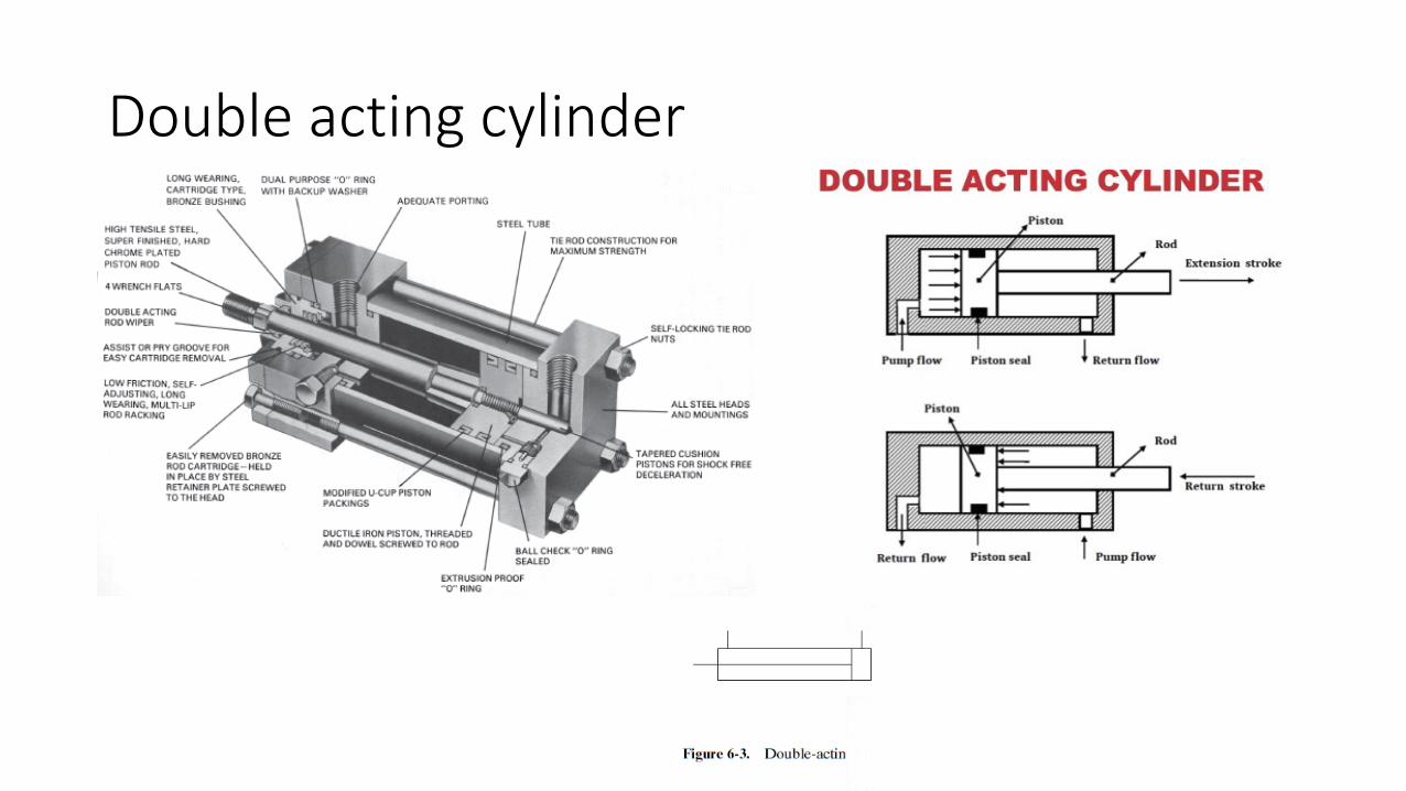
Double acting cylinder

CYLINDER MOUNTINGS
AND MECHANICAL
LINKAGES

MECHANICAL LINKAGEs LINKAGES

Cylinder misalignment • Much effort has been made by manufacturers of hydraulic
cylinders to reduce or eliminate the side loading of cylinders created as a result of misalignment.
• It is almost impossible to achieve perfect alignment even though the alignment of a hydraulic cylinder has a direct bearing on its life.
• A universal alignment mounting accessory designed to reduce misalignment problems .
• By using one of these accessory components and a mating clevis at each end of the cylinder, the following benefits are obtained:
1. Freer range of mounting positions2. Reduced cylinder binding and side loading3. Allowance for universal swivel4. Reduced bearing and tube wear5. Elimination of piston blow-by caused by misalignment

CYLINDER FORCE, VELOCITY, AND POWER• The output force (F) and piston velocity (v) of
double-acting cylinders are not the same for extension and retraction strokes.
• This is explained as follows:• During the extension stroke, fluid enters the
blank end of the cylinder through the entire circular area of the piston (Ap).
• However, during the retraction stroke, fluid enters the rod end through the smaller annular area between the rod and cylinder bore (Ap -Ar), where Ap equals the piston area and Arequals the rod area.
• This difference in flow-path cross-sectional area accounts for the difference in piston velocities.
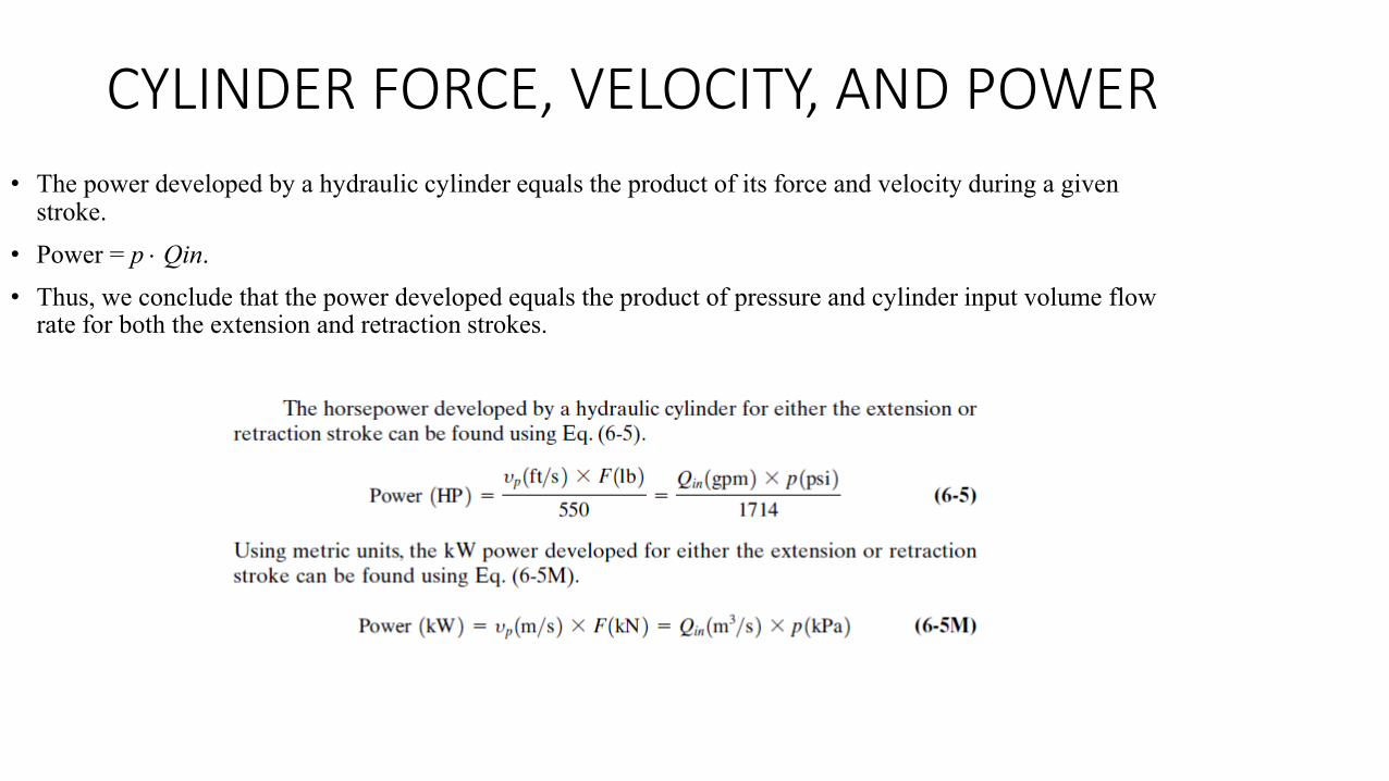
CYLINDER FORCE, VELOCITY, AND POWER• The power developed by a hydraulic cylinder equals the product of its force and velocity during a given
stroke.• Power = p ⋅ Qin.• Thus, we conclude that the power developed equals the product of pressure and cylinder input volume flow
rate for both the extension and retraction strokes.
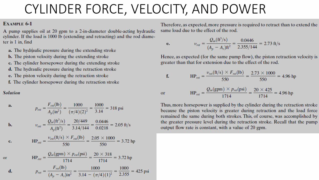
CYLINDER FORCE, VELOCITY, AND POWER

CYLINDER LOADS DUE TO MOVING OF WEIGHTS• The force a cylinder must produce equals the load the cylinder is required to overcome.
• In many cases the load is due to the weight of an object the cylinder is attempting to move.
• In the case of a vertical cylinder, the load simply equals the weight of the object because gravity acts in a downward, vertical direction.
• Sometimes a cylinder is used to slide an object along a horizontal surface. In this case, the cylinder load is theoretically zero. This is because there is no component of the object’s weight acting along the axis of the cylinder (a horizontal direction).
• However, as the object slides across the horizontal surface, the cylinder must overcome the frictional force created between the object and the horizontal surface.
• This frictional force, which equals the load acting on the cylinder, opposes the direction of motion of the moving object.
• If the cylinder is mounted in neither a vertical nor horizontal direction, the cylinder load equals the component of the object’s weight acting along the axis of the cylinder, plus a frictional force if the object is sliding along an inclined surface.
• Thus for an inclined cylinder, the load the cylinder must overcome is less than the weight of the object to be moved if the object is not sliding on an inclined surface.
• The cylinder loads described up to now are based on moving an object at a constant velocity.
• However, an object to be moved at a given velocity is initially at rest.
• Thus the object has to be accelerated from zero velocity up to a steady state (constant) velocity as determined by the pump flow rate entering the cylinder.
• This acceleration represents an additional force (called an inertial force) that must be added to the weight component and any frictional force involved.

CYLINDER LOADS DUE TO MOVING OF WEIGHTS

CYLINDER LOADS DUE TO MOVING OF WEIGHTS

SPECIAL CYLINDER DESIGNS
• Double-rod cylinder in which the rod extends out of the cylinder at both ends. For such a cylinder, the words extend and retract have no meaning.
• Since the force and speed are the same for either end, this type of cylinder is typically used when the same task is to be performed at either end.
• Since each end contains the same size rod, the velocity of the piston is the same for both strokes

SPECIAL CYLINDER DESIGNS
• Telescopic cylinder contains multiple cylinders that slide inside each other.
• They are used where long work strokes are required but the full retraction length must be minimized.
• One application for a telescopic cylinder is the high-lift fork truck, illustrated
• in Figure 6-11.• As shown, this lift truck is in the process of accessing materials
located inside a second-story storage area of a warehouse, from the outside.
CYLINDER LOADINGS THROUGH MECHANICAL LINKAGES
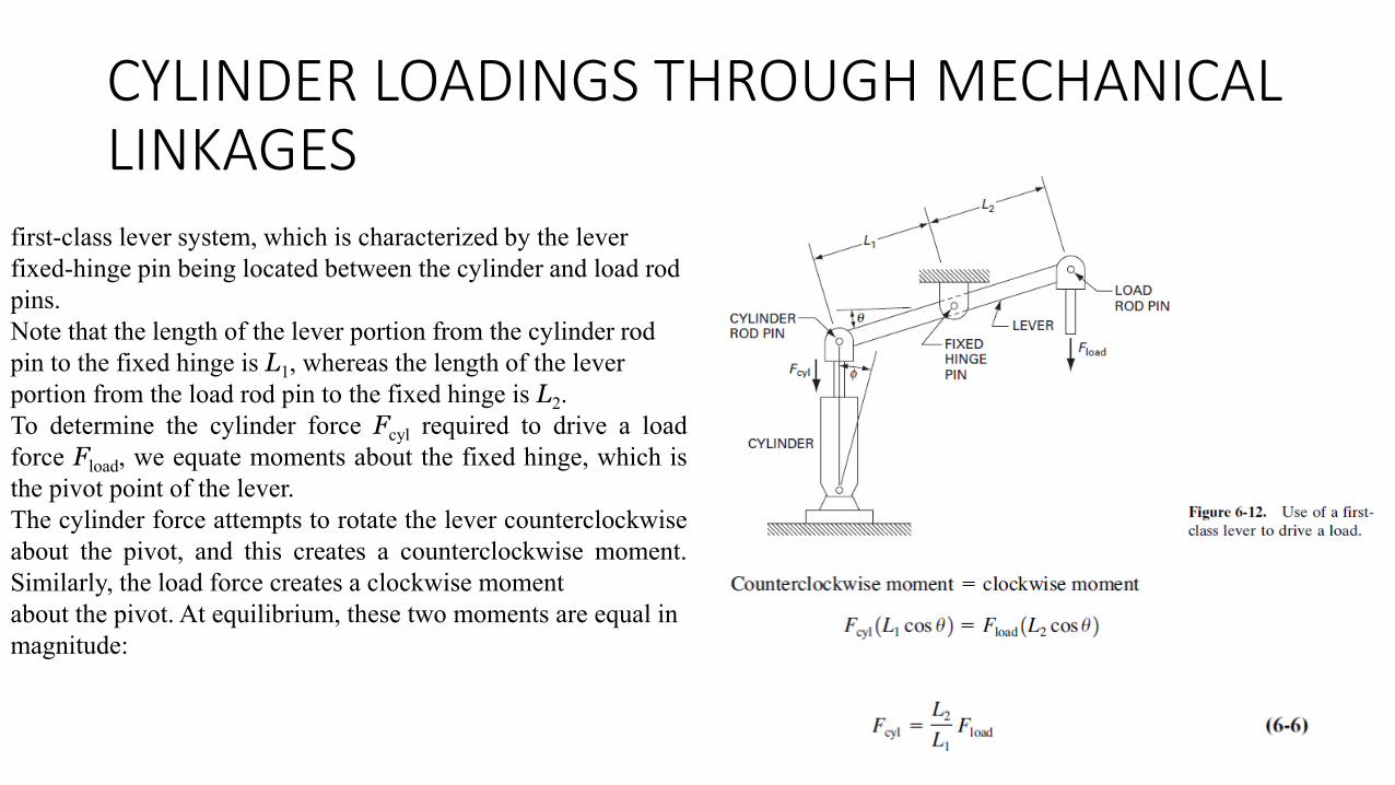
first-class lever system, which is characterized by the lever fixed-hinge pin being located between the cylinder and load rod pins. Note that the length of the lever portion from the cylinder rod pin to the fixed hinge is L1, whereas the length of the lever portion from the load rod pin to the fixed hinge is L2.To determine the cylinder force Fcyl required to drive a loadforce Fload, we equate moments about the fixed hinge, which isthe pivot point of the lever.The cylinder force attempts to rotate the lever counterclockwiseabout the pivot, and this creates a counterclockwise moment.Similarly, the load force creates a clockwise momentabout the pivot. At equilibrium, these two moments are equal in magnitude:

CYLINDER LOADINGS THROUGH MECHANICAL LINKAGES
If the centerline of the hydraulic cylinder becomes offset by an angle from the vertical, as shown in Figure 6-12, therelationship becomes:
CYLINDER LOADINGS THROUGH MECHANICAL LINKAGES
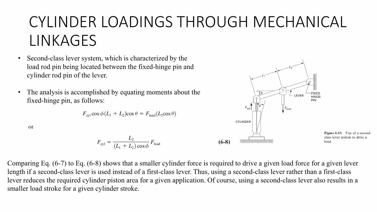
• Second-class lever system, which is characterized by the load rod pin being located between the fixed-hinge pin and cylinder rod pin of the lever.
• The analysis is accomplished by equating moments about the fixed-hinge pin, as follows:
Comparing Eq. (6-7) to Eq. (6-8) shows that a smaller cylinder force is required to drive a given load force for a given lever length if a second-class lever is used instead of a first-class lever. Thus, using a second-class lever rather than a first-classlever reduces the required cylinder piston area for a given application. Of course, using a second-class lever also results in a smaller load stroke for a given cylinder stroke.

CYLINDER LOADINGS THROUGH MECHANICAL LINKAGES• Third-class lever system the cylinder rod pin lies between the
load rod pin and fixed-hinge pin of the lever.• Equating moments about the fixed-hinge pin yields
Examination of Eq. (6-9) reveals that for a third-class lever, the cylinder force is greater than the load force. The reason for using a third-class lever system would be to produce a load stroke that is greater than the cylinder stroke, at the expense of requiring a larger cylinder diameter.

CYLINDER LOADINGS THROUGH MECHANICAL LINKAGES

HYDRAULIC CYLINDER CUSHIONS
• Double-acting cylinders sometimes contain cylinder cushions at the ends of the cylinder to slow the piston down near the ends of the stroke.
• This prevents excessive impact when the piston is stopped by the end caps.• Deceleration starts when the tapered plunger enters the opening in the cap. This
restricts the exhaust flow from the barrel to the port. • During the last small portion of the stroke, the oil must exhaust through an
adjustable opening.• The cushion design also incorporates a check valve to allow free flow to the
piston during direction reversal.• The maximum pressure developed by cushions at the ends of a cylinder must be
considered since excessive pressure buildup would rupture the cylinder.

HYDRAULIC CYLINDER CUSHIONS

HYDRAULIC CYLINDER CUSHIONS

HYDRAULIC SHOCK ABSORBERS• A hydraulic shock absorber is a device that brings a
moving load to a gentle rest through the use ofmetered hydraulic fluid.
• hydraulic shock absorber can provide a uniform gentle deceleration of any moving load from 25 to 25,000 lb or where the velocity and weight combination equals 3300 in · lb.
• Heavy-duty units are available with load capacities of over 11 million in · lb and strokes up to 20 in.

HYDRAULIC SHOCK ABSORBERS• These shock absorbers are filled completely with oil. Therefore, they may be
mounted in any position or at any angle. • The spring-return units are entirely self-contained, extremely compact types that
require no external hoses, valves, or fittings.• In this spring-returned type a built-in cellular accumulator accommodates oil
displaced by the piston rod as the rod moves inward. • Since the shock absorber is always filled with oil, there are no air pockets to
cause spongy or erratic action.• These shock absorbers are multiple-orifice hydraulic devices. • The orifices are simply holes through which a fluid can flow.• When a moving load strikes the bumper of the shock absorber, it sets the rod and
piston in motion.• The moving piston pushes oil through a series of holes from an inner high-
pressure chamber to an outer low-pressure chamber.• The resistance to the oil flow caused by the holes (restrictions) creates a pressure
that acts against the piston to oppose the moving load.• Holes are spaced geometrically according to a proven formula that produces
constant pressure on the side of the piston opposite the load (constant resisting force) from the beginning to nearly the end of the stroke.

end