Cylinders - Metro Hydraulic
92
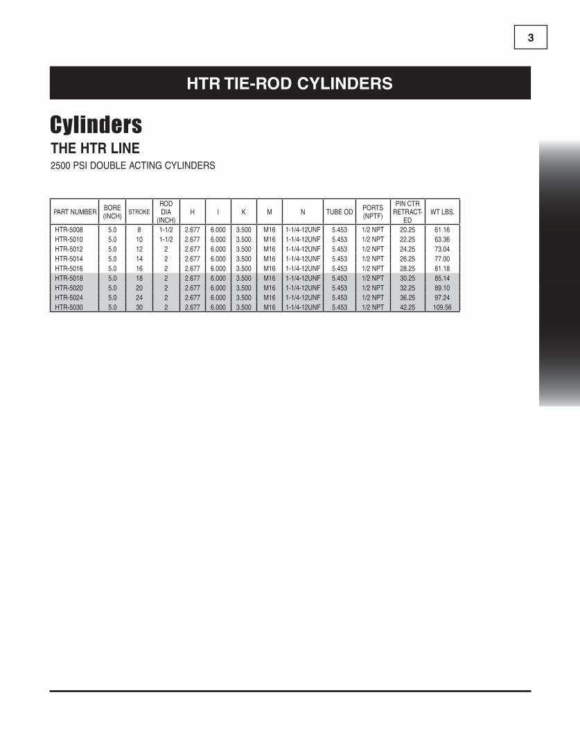
1 THE HTR LINE 2500 PSI DOUBLE ACTING CYLINDERS PART NUMBER BORE (INCH) STROKE ROD DIA (INCH) H I K M N TUBE OD PORTS (NPTF) PIN CTR RETRACT- ED WT LBS. HTR-2004 2.0 4 1-1/8 2.520 2.835 2.520 M10 1-1/8-12UNF 2.375 3/8 NPT 14.25 14.30 HTR-2006 2.0 6 1-1/8 2.520 2.835 2.520 M10 1-1/8-12UNF 2.375 3/8 NPT 16.25 15.84 HTR-2008 2.0 8 1-1/8 2.520 2.835 2.520 M10 1-1/8-12UNF 2.375 3/8 NPT 18.25 17.60 HTR-2008A 2.0 8 1-1/8 2.520 2.835 2.520 M10 1-1/8-12UNF 2.375 3/8 NPT 20.25 17.60 HTR-2010 2.0 10 1-1/8 2.520 2.835 2.520 M10 1-1/8-12UNF 2.375 3/8 NPT 20.25 18.70 HTR-2012 2.0 12 1-1/8 2.520 2.835 2.520 M10 1-1/8-12UNF 2.375 3/8 NPT 22.25 20.24 HTR-2014 2.0 14 1-1/8 2.520 2.835 2.520 M10 1-1/8-12UNF 2.375 3/8 NPT 24.25 22.00 HTR-2016 2.0 16 1-1/8 2.520 2.835 2.520 M10 1-1/8-12UNF 2.375 3/8 NPT 26.25 23.54 HTR-2018 2.0 18 1-1/8 2.520 2.835 2.520 M10 1-1/8-12UNF 2.375 3/8 NPT 28.25 25.08 HTR-2020 2.0 20 1-1/8 2.520 2.835 2.520 M10 1-1/8-12UNF 2.375 3/8 NPT 30.25 26.62 HTR-2024 2.0 24 1-1/8 2.520 2.835 2.520 M10 1-1/8-12UNF 2.375 3/8 NPT 34.25 29.70 HTR-2048 2.0 48 1-1/4 2.520 2.835 2.520 M10 1-1/8-12UNF 2.375 3/8 NPT 58.25 35.00 HTR-2504 2.5 4 1-1/8 2.520 3.150 2.520 M10 1-1/8-12UNF 2.875 3/8 NPT 14.25 16.28 HTR-2506 2.5 6 1-1/8 2.520 3.150 2.520 M10 1-1/8-12UNF 2.875 3/8 NPT 16.25 18.04 HTR-2508 2.5 8 1-1/8 2.520 3.150 2.520 M10 1-1/8-12UNF 2.875 3/8 NPT 18.25 20.24 HTR-2508A 2.5 8 1-1/4 2.520 3.150 2.520 M10 1-1/8-12UNF 2.875 3/8 NPT 20.25 22.00 HTR-2510 2.5 10 1-1/8 2.520 3.150 2.520 M10 1-1/8-12UNF 2.875 3/8 NPT 20.25 21.34 HTR-2512 2.5 12 1-1/8 2.520 3.150 2.520 M10 1-1/8-12UNF 2.875 3/8 NPT 22.25 23.10 HTR-2514 2.5 14 1-1/8 2.520 3.150 2.520 M10 1-1/8-12UNF 2.875 3/8 NPT 24.25 24.86 HTR-2516 2.5 16 1-1/8 2.520 3.150 2.520 M10 1-1/8-12UNF 2.875 3/8 NPT 26.25 26.62 HTR-2518 2.5 18 1-1/8 2.520 3.150 2.520 M10 1-1/8-12UNF 2.875 3/8 NPT 28.25 28.38 HTR-2520 2.5 20 1-1/8 2.520 3.150 2.520 M10 1-1/8-12UNF 2.875 3/8 NPT 30.25 30.14 HTR-2524 2.5 24 1-1/8 2.520 3.150 2.520 M10 1-1/8-12UNF 2.875 3/8 NPT 34.25 33.66 HTR-2536 2.5 36 1-1/4 2.520 3.150 2.520 M10 1-1/4-12UNF 2.875 3/8 NPT 46.25 38.25 HTR-3004 3.0 4 1-1/4 2.600 3.740 2.520 M12 1-1/4-12UNF 3.375 1/2 NPT 14.25 21.56 HTR-3006 3.0 6 1-1/4 2.600 3.740 2.520 M12 1-1/4-12UNF 3.375 1/2 NPT 16.25 23.76 HTR-3008 3.0 8 1-1/4 2.600 3.740 2.520 M12 1-1/4-12UNF 3.375 1/2 NPT 18.25 26.62 HTR-3008A 3.0 8 1-3/8 2.600 3.740 2.520 M12 1-1/4-12UNF 3.375 1/2 NPT 20.25 27.50 BORE (INCH) B C D E F G = J 2.0 1.015 2.125 1.625 1.000 1.000 1.142 2.5 1.015 2.125 1.625 1.000 1.000 1.142 3.0 1.015 2.125 1.625 1.125 1.000 1.142 3.5 1.015 2.125 1.625 1.125 1.125 1.142 4.0 1.015 2.125 1.625 1.125 1.125 1.142 5.0 1.015 2.125 2.250 1.250 1.500 1.260 Cylinders HTR TIE-ROD CYLINDERS FEATURES: • Ductile iron piston. • Ductile iron gland, drilled oil passages. • Honed steel tube, precision finished for extended seal life. • High tensile, hard chrome plated rod. • Ductile iron end mounts, female clevises with pins and clips included. • Tube Seal: O-ring • Rod Seal: Deep polypak with B lip design; metal canned wiper. • 2-Piece 93A urethane piston seal, with a 70A nitrile energizer. • All Seals: Manufactured to US specifications. CYLINDERS
-
Upload
khangminh22 -
Category
Documents
-
view
0 -
download
0
Transcript of Cylinders - Metro Hydraulic

1
THE HTR LINE2500 PSI DOUBLE ACTING CYLINDERS
PART NUMBER BORE (INCH)
STROKEROD DIA
(INCH)H I K M N TUBE OD PORTS
(NPTF)
PIN CTR RETRACT-
EDWT LBS.
HTR-2004 2.0 4 1-1/8 2.520 2.835 2.520 M10 1-1/8-12UNF 2.375 3/8 NPT 14.25 14.30HTR-2006 2.0 6 1-1/8 2.520 2.835 2.520 M10 1-1/8-12UNF 2.375 3/8 NPT 16.25 15.84HTR-2008 2.0 8 1-1/8 2.520 2.835 2.520 M10 1-1/8-12UNF 2.375 3/8 NPT 18.25 17.60HTR-2008A 2.0 8 1-1/8 2.520 2.835 2.520 M10 1-1/8-12UNF 2.375 3/8 NPT 20.25 17.60HTR-2010 2.0 10 1-1/8 2.520 2.835 2.520 M10 1-1/8-12UNF 2.375 3/8 NPT 20.25 18.70HTR-2012 2.0 12 1-1/8 2.520 2.835 2.520 M10 1-1/8-12UNF 2.375 3/8 NPT 22.25 20.24HTR-2014 2.0 14 1-1/8 2.520 2.835 2.520 M10 1-1/8-12UNF 2.375 3/8 NPT 24.25 22.00HTR-2016 2.0 16 1-1/8 2.520 2.835 2.520 M10 1-1/8-12UNF 2.375 3/8 NPT 26.25 23.54HTR-2018 2.0 18 1-1/8 2.520 2.835 2.520 M10 1-1/8-12UNF 2.375 3/8 NPT 28.25 25.08HTR-2020 2.0 20 1-1/8 2.520 2.835 2.520 M10 1-1/8-12UNF 2.375 3/8 NPT 30.25 26.62HTR-2024 2.0 24 1-1/8 2.520 2.835 2.520 M10 1-1/8-12UNF 2.375 3/8 NPT 34.25 29.70HTR-2048 2.0 48 1-1/4 2.520 2.835 2.520 M10 1-1/8-12UNF 2.375 3/8 NPT 58.25 35.00HTR-2504 2.5 4 1-1/8 2.520 3.150 2.520 M10 1-1/8-12UNF 2.875 3/8 NPT 14.25 16.28HTR-2506 2.5 6 1-1/8 2.520 3.150 2.520 M10 1-1/8-12UNF 2.875 3/8 NPT 16.25 18.04HTR-2508 2.5 8 1-1/8 2.520 3.150 2.520 M10 1-1/8-12UNF 2.875 3/8 NPT 18.25 20.24HTR-2508A 2.5 8 1-1/4 2.520 3.150 2.520 M10 1-1/8-12UNF 2.875 3/8 NPT 20.25 22.00HTR-2510 2.5 10 1-1/8 2.520 3.150 2.520 M10 1-1/8-12UNF 2.875 3/8 NPT 20.25 21.34HTR-2512 2.5 12 1-1/8 2.520 3.150 2.520 M10 1-1/8-12UNF 2.875 3/8 NPT 22.25 23.10HTR-2514 2.5 14 1-1/8 2.520 3.150 2.520 M10 1-1/8-12UNF 2.875 3/8 NPT 24.25 24.86HTR-2516 2.5 16 1-1/8 2.520 3.150 2.520 M10 1-1/8-12UNF 2.875 3/8 NPT 26.25 26.62HTR-2518 2.5 18 1-1/8 2.520 3.150 2.520 M10 1-1/8-12UNF 2.875 3/8 NPT 28.25 28.38HTR-2520 2.5 20 1-1/8 2.520 3.150 2.520 M10 1-1/8-12UNF 2.875 3/8 NPT 30.25 30.14HTR-2524 2.5 24 1-1/8 2.520 3.150 2.520 M10 1-1/8-12UNF 2.875 3/8 NPT 34.25 33.66HTR-2536 2.5 36 1-1/4 2.520 3.150 2.520 M10 1-1/4-12UNF 2.875 3/8 NPT 46.25 38.25HTR-3004 3.0 4 1-1/4 2.600 3.740 2.520 M12 1-1/4-12UNF 3.375 1/2 NPT 14.25 21.56HTR-3006 3.0 6 1-1/4 2.600 3.740 2.520 M12 1-1/4-12UNF 3.375 1/2 NPT 16.25 23.76HTR-3008 3.0 8 1-1/4 2.600 3.740 2.520 M12 1-1/4-12UNF 3.375 1/2 NPT 18.25 26.62HTR-3008A 3.0 8 1-3/8 2.600 3.740 2.520 M12 1-1/4-12UNF 3.375 1/2 NPT 20.25 27.50
BORE (INCH) B C D E F G = J
2.0 1.015 2.125 1.625 1.000 1.000 1.142
2.5 1.015 2.125 1.625 1.000 1.000 1.142
3.0 1.015 2.125 1.625 1.125 1.000 1.142
3.5 1.015 2.125 1.625 1.125 1.125 1.142
4.0 1.015 2.125 1.625 1.125 1.125 1.142
5.0 1.015 2.125 2.250 1.250 1.500 1.260
Cylinders
HTR Tie-Rod cylindeRs
FEATURES:• Ductileironpiston.• Ductileirongland,drilledoilpassages.• Honedsteeltube,precisionfinishedforextendedseallife.
• Hightensile,hardchromeplatedrod.• Ductileironendmounts,femalecleviseswithpinsandclipsincluded.
• TubeSeal:O-ring• RodSeal:DeeppolypakwithBlipdesign;metalcannedwiper.
• 2-Piece93Aurethanepistonseal,witha70Anitrileenergizer.
• AllSeals:ManufacturedtoUSspecifications.
cy
lin
de
Rs

2
PART NUMBER BORE (INCH)
STROKEROD DIA
(INCH)H I K M N TUBE OD PORTS
(NPTF)
PIN CTR RETRACT-
EDWT LBS.
HTR-3010 3.0 10 1-1/4 2.600 3.740 2.520 M12 1-1/4-12UNF 3.375 1/2 NPT 20.25 28.16HTR-3012 3.0 12 1-1/4 2.600 3.740 2.520 M12 1-1/4-12UNF 3.375 1/2 NPT 22.25 30.36HTR-3014 3.0 14 1-1/4 2.600 3.740 2.520 M12 1-1/4-12UNF 3.375 1/2 NPT 24.25 32.56HTR-3016 3.0 16 1-1/4 2.600 3.740 2.520 M12 1-1/4-12UNF 3.375 1/2 NPT 28.25 34.76HTR-3016A 3.0 16 1-3/8 2.600 3.740 2.520 M12 1-1/4-12UNF 3.375 1/2 NPT 31.50 42.90HTR-3018 3.0 18 1-1/4 2.600 3.740 2.520 M12 1-1/4-12UNF 3.375 1/2 NPT 28.25 36.96HTR-3020 3.0 20 1-1/4 2.600 3.740 2.520 M12 1-1/4-12UNF 3.375 1/2 NPT 30.25 39.16HTR-3024 3.0 24 1-1/4 2.600 3.740 2.520 M12 1-1/4-12UNF 3.375 1/2 NPT 34.25 43.34HTR-3030 3.0 30 1-1/4 2.600 3.740 2.520 M12 1-1/4-12UNF 3.375 1/2 NPT 40.25 48.00HTR-3036 3.0 36 1-1/2 2.600 3.740 2.520 M12 1-1/4-12UNF 3.375 1/2 NPT 46.25 54.55HTR-3048 3.5 48 1-1/2 2.600 4.130 2.520 M12 1-1/4-12UNF 3.875 1/2 NPT 58.25 74.69HTR-3504 3.5 4 1-1/4 2.600 4.134 2.520 M12 1-1/4-12UNF 3.875 1/2 NPT 14.25 23.32HTR-3506 3.5 6 1-1/4 2.600 4.134 2.520 M12 1-1/4-12UNF 3.875 1/2 NPT 16.25 25.52HTR-3508 3.5 8 1-1/4 2.600 4.134 2.520 M12 1-1/4-12UNF 3.875 1/2 NPT 18.25 28.82HTR-3508A 3.5 8 1-3/8 2.600 4.134 2.520 M12 1-1/4-12UNF 3.875 1/2 NPT 20.25 29.70HTR-3510 3.5 10 1-1/4 2.600 4.134 2.520 M12 1-1/4-12UNF 3.875 1/2 NPT 20.25 29.92HTR-3512 3.5 12 1-1/4 2.600 4.134 2.520 M12 1-1/4-12UNF 3.875 1/2 NPT 22.25 32.34HTR-3514 3.5 14 1-1/4 2.600 4.134 2.520 M12 1-1/4-12UNF 3.875 1/2 NPT 24.25 34.76HTR-3516 3.5 16 1-1/4 2.600 4.134 2.520 M12 1-1/4-12UNF 3.875 1/2 NPT 28.25 37.18HTR-3516A 3.5 16 1-3/8 2.600 4.134 2.520 M12 1-1/4-12UNF 3.875 1/2 NPT 31.50 50.60HTR-3518 3.5 18 1-1/4 2.600 4.134 2.520 M12 1-1/4-12UNF 3.875 1/2 NPT 28.25 39.60HTR-3520 3.5 20 1-1/4 2.600 4.134 2.520 M12 1-1/4-12UNF 3.875 1/2 NPT 30.25 42.02HTR-3524 3.5 24 1-1/2 2.600 4.134 2.520 M12 1-1/4-12UNF 3.875 1/2 NPT 34.25 51.70HTR-3530 3.5 30 1-1/2 2.600 4.130 2.520 M12 1-1/4-12UNF 3.875 1/2 NPT 40.25 55.00HTR-3532 3.5 32 1-1/2 2.600 4.130 2.520 M12 1-1/4-12UNF 3.875 1/2 NPT 42.25 58.00HTR-3536 3.5 36 1-1/2 2.600 4.130 2.520 M12 1-1/4-12UNF 3.875 1/2 NPT 46.25 62.00HTR-3548 3.5 48 1-1/2 2.600 4.130 2.600 M12 1-1/4-12UNF 3.875 1/2 NPT 58.25 74.69HTR-4004 4.0 4 1-1/4 2.600 4.724 2.600 M12 1-1/4-12UNF 4.375 1/2 NPT 14.25 29.48HTR-4006 4 6 1-1/4 2.600 4.724 2.600 M12 1-1/4-12UFN 4.375 1/2 NPT 16.25 33.60HTR-4008 4.0 8 1-1/4 2.600 4.724 2.600 M12 1-1/4-12UNF 4.375 1/2 NPT 18.25 35.86HTR-4008A 4.0 8 1-3/4 2.600 4.724 2.600 M12 1-1/4-12UNF 4.375 1/2NPT 20.25 37.40HTR-4010 4.0 10 1-1/4 2.600 4.724 2.600 M12 1-1/4-12UNF 4.375 1/2 NPT 20.25 37.84HTR-4012 4.0 12 1-1/4 2.600 4.724 2.600 M12 1-1/4-12UNF 4.375 1/2 NPT 22.25 40.70HTR-4014 4.0 14 1-1/4 2.600 4.724 2.600 M12 1-1/4-12UNF 4.375 1/2 NPT 24.25 43.56HTR-4016 4.0 16 1-1/4 2.600 4.724 2.600 M12 1-1/4-12UNF 4.375 1/2 NPT 26.25 46.42HTR-4016A 4.0 16 1-3/4 2.600 4.724 2.600 M12 1-1/4-12UNF 4.375 1/2NPT 31.50 57.20HTR-4018 4.0 18 1-1/2 2.600 4.724 2.600 M12 1-1/4-12UNF 4.375 1/2 NPT 28.25 50.60HTR-4020 4.0 20 1-1/2 2.600 4.724 2.600 M12 1-1/4-12UNF 4.375 1/2 NPT 30.25 53.46HTR-4024 4.0 24 1-1/2 2.600 4.724 2.600 M12 1-1/4-12UNF 4.375 1/2 NPT 32.25 59.18HTR-4024-2 4.0 24 2 2.600 4.724 2.600 M12 1-1/4-12UNF 4.375 1/2 NPT 34.25 68.00HTR-4026 4.0 26 1-3/4 2.600 4.724 2.600 M12 1-1/4-12UFN 4.375 1/2 NPT 36.25 72.00HTR-4030 4.0 30 1-3/4 2.600 4.724 2.600 M12 1-1/4-12UNF 4.375 1/2 NPT 40.25 75.00HTR-4030-2 4.0 30 2 2.600 4.724 2.600 M12 1-1/4-12UNF 4.375 1/2 NPT 40.25 78.00HTR-4036 4.0 36 1-3/4 2.600 4.724 2.600 M12 1-1/4-12UNF 4.375 1/2 NPT 46.25 82.00HTR-4048 4.0 48 1-3/4 2.600 4.724 2.600 M12 1-1/4-12UNF 4.375 1/2 NPT 48.25 98.00HTR-5004 5.0 4 1-1/2 2.677 6.000 3.500 M16 1-1/4-12UNF 5.453 1/2 NPT 16.25 53.46HTR-5006 5.0 6 1-1/2 2.677 6.000 3.500 M16 1-1/4-12UNF 5.453 1/2 NPT 18.25 56.76
THE HTR LINE2500 PSI DOUBLE ACTING CYLINDERS
Cylinders
HTR Tie-Rod cylindeRs
cy
lin
de
Rs
3
THE HTR LINE2500 PSI DOUBLE ACTING CYLINDERS
Cylinders
HTR Tie-Rod cylindeRs
PART NUMBER BORE (INCH)
STROKEROD DIA
(INCH)H I K M N TUBE OD PORTS
(NPTF)
PIN CTR RETRACT-
EDWT LBS.
HTR-5008 5.0 8 1-1/2 2.677 6.000 3.500 M16 1-1/4-12UNF 5.453 1/2 NPT 20.25 61.16HTR-5010 5.0 10 1-1/2 2.677 6.000 3.500 M16 1-1/4-12UNF 5.453 1/2 NPT 22.25 63.36HTR-5012 5.0 12 2 2.677 6.000 3.500 M16 1-1/4-12UNF 5.453 1/2 NPT 24.25 73.04HTR-5014 5.0 14 2 2.677 6.000 3.500 M16 1-1/4-12UNF 5.453 1/2 NPT 26.25 77.00HTR-5016 5.0 16 2 2.677 6.000 3.500 M16 1-1/4-12UNF 5.453 1/2 NPT 28.25 81.18HTR-5018 5.0 18 2 2.677 6.000 3.500 M16 1-1/4-12UNF 5.453 1/2 NPT 30.25 85.14HTR-5020 5.0 20 2 2.677 6.000 3.500 M16 1-1/4-12UNF 5.453 1/2 NPT 32.25 89.10HTR-5024 5.0 24 2 2.677 6.000 3.500 M16 1-1/4-12UNF 5.453 1/2 NPT 36.25 97.24HTR-5030 5.0 30 2 2.677 6.000 3.500 M16 1-1/4-12UNF 5.453 1/2 NPT 42.25 109.56

4c
yl
ind
eR
s
PART NUMBER BORE STROKE (INCH) ROD DIA (INCH)PIN CENTERS RETRACTED
(INCH)
PIN CENTERS EXTENDED
(INCH)WEIGHT LBS
HMW-1504 1.50 4 1” 12.00 16.00 9.04HMW-1506 1.50 6 1” 14.00 20.00 10.14HMW-1508 1.50 8 1” 16.00 24.00 11.47HMW-1510 1.50 10 1” 18.00 28.00 12.79HMW-2008 2.00 8 1-1/4” 16.00 24.00 13.45HMW-2010 2.00 10 1-1/4” 18.00 28.00 15.21HMW-2012 2.00 12 1-1/4” 20.00 32.00 16.98HMW-2014 2.00 14 1-1/4” 22.00 36.00 18.74HMW-2016 2.00 16 1-1/4” 24.00 40.00 20.51HMW-2018 2.00 18 1-1/4” 26.00 44.00 22.27HMW-2020 2.00 20 1-1/4” 28.00 48.00 24.03HMW-2024 2.00 24 1-1/4” 32.00 56.00 27.56HMW-2028 2.00 28 1-1/4” 36.00 64.00 31.09HMW-2030 2.00 30 1-1/4” 38.00 68.00 32.85HMW-2032 2.00 32 1-1/4” 40.00 72.00 34.84HMW-2036 2.00 36 1-1/4” 44.00 80.00 38.37HMW-2040 2.00 40 1-1/4” 48.00 88.00 41.90HMW-2048 2.00 48 1-1/4” 56.00 104.00 48.95HMW-2508 2.50 8 1-1/2” 16.00 24.00 19.85HMW-2510 2.50 10 1-1/2” 18.00 28.00 21.83HMW-2512 2.50 12 1-1/2” 20.00 32.00 24.03HMW-2514 2.50 14 1-1/2” 22.00 36.00 26.24HMW-2516 2.50 16 1-1/2” 24.00 40.00 28.44
FEATURES:• Honedtubing• Heavydutyweldedconstruction• Chromed,ground&polishedpistonrod• Castironpiston&gland• Pineyemountingonbothends• Loadedu-seal&urethanewiperingland• O-ring/backupwashers&u-sealsforpistonseals
• Threadedglandretainer• Standardcolorisblack
PortsGrease fitting
Retracted Length + Stroke
E
C
BB
D
Bore B C D E Ports(NPT)
1.50 0.77 2.25 2.00 2.0 1/4 NPT
2.00 1.02 2.75 2.25 2.5 3/8 NPT
2.50 1.02 3.25 2.25 3.0 1/2 NPT
3.00 1.02 3.75 2.25 3.5 1/2 NPT
3.50 1.27 4.25 2.25 4.0 1/2 NPT
4.00 1.52 4.75 2.50 4.5 1/2 NPT
5.00 1.77 5.75 3.25 5.5 1/2 NPT
CylindersTHE HMW LINE2500and3000PSIDOUBLEACTINGCYLINDERS(4”Bore=3000
PSI,5”Bore=2500PSI)
HMW MecHanical Welded cylindeRs
cy
lin
de
Rs

5c
yl
ind
eR
s
PART NUMBER BORE STROKE (INCH) ROD DIA (INCH)PIN CENTERS RETRACTED
(INCH)
PIN CENTERS EXTENDED
(INCH)WEIGHT LBS
HMW-2518 2.50 18 1-1/2” 26.00 44.00 30.65HMW-2520 2.50 20 1-1/2” 28.00 48.00 32.85HMW-2524 2.50 24 1-1/2” 32.00 56.00 37.26HMW-2528 2.50 28 1-1/2” 36.00 64.00 41.45HMW-2530 2.50 30 1-1/2” 38.00 68.00 43.66HMW-2532 2.50 32 1-1/2” 40.00 72.00 45.86HMW-2536 2.50 36 1-1/2” 44.00 80.00 50.27HMW-2540 2.50 40 1-1/2” 48.00 88.00 54.68HMW-2548 2.50 48 1-1/2” 56.00 104.00 63.28HMW-3008 3.00 8 1-1/2” 16.00 24.00 24.70HMW-3010 3.00 10 1-1/2” 18.00 28.00 27.12HMW-3012 3.00 12 1-1/2” 20.00 32.00 29.55HMW-3014 3.00 14 1-1/2” 22.00 36.00 31.97HMW-3016 3.00 16 1-1/2” 24.00 40.00 34.40HMW-3018 3.00 18 1-1/2” 26.00 44.00 36.82HMW-3020 3.00 20 1-1/2” 28.00 48.00 39.25HMW-3024 3.00 24 1-1/2” 32.00 56.00 44.10HMW-3028 3.00 28 1-1/2” 36.00 64.00 48.95HMW-3030 3.00 30 1-1/2” 38.00 68.00 51.38HMW-3032 3.00 32 1-1/2” 40.00 72.00 53.58HMW-3036 3.00 36 1-1/2” 44.00 80.00 58.43HMW-3040 3.00 40 1-1/2” 48.00 88.00 63.28HMW-3048 3.00 48 1-1/2” 56.00 104.00 72.99HMW-3508 3.50 8 1-3/4” 18.00 26.00 32.63HMW-3510 3.50 10 1-3/4” 20.00 30.00 35.72HMW-3512 3.50 12 1-3/4” 22.00 34.00 38.81HMW-3514 3.50 14 1-3/4” 24.00 38.00 41.67HMW-3516 3.50 16 1-3/4” 26.00 42.00 44.76HMW-3518 3.50 18 1-3/4” 28.00 46.00 47.63HMW-3520 3.50 20 1-3/4” 30.00 50.00 50.72HMW-3524 3.50 24 1-3/4” 34.00 58.00 56.67HMW-3528 3.50 28 1-3/4” 38.00 66.00 62.62HMW-3530 3.50 30 1-3/4” 40.00 70.00 65.71HMW-3532 3.50 32 1-3/4” 42.00 74.00 68.80HMW-3536 3.50 36 1-3/4” 46.00 82.00 74.75HMW-3540 3.50 40 1-3/4” 50.00 90.00 80.70HMW-3548 3.50 48 1-3/4” 58.00 106.00 92.61HMW-4008 4.00 8 2” 18.00 26.00 40.79HMW-4010 4.00 10 2” 20.00 30.00 44.54HMW-4012 4.00 12 2” 22.00 34.00 48.29HMW-4014 4.00 14 2” 24.00 38.00 51.82HMW-4016 4.00 16 2” 26.00 42.00 55.57HMW-4018 4.00 18 2” 28.00 46.00 59.09HMW-4020 4.00 20 2” 30.00 50.00 62.84HMW-4024 4.00 24 2” 34.00 58.00 70.12HMW-4028 4.00 28 2” 38.00 66.00 77.40HMW-4030 4.00 30 2” 40.00 70.00 81.14
HMW MecHanical Welded cylindeRs
CylindersTHE HMW LINE2500and3000PSIDOUBLEACTINGCYLINDERS(4”Bore=3000PSI,5”Bore=2500PSI)
cy
lin
de
Rs

6
PART NUMBER BORE STROKE (INCH) ROD DIA (INCH)PIN CENTERS RETRACTED
(INCH)
PIN CENTERS EXTENDED
(INCH)WEIGHT LBS
HMW-4032 4.00 32 2” 42.00 74.00 84.67HMW-4036 4.00 36 2” 46.00 82.00 91.95HMW-4040 4.00 40 2” 50.00 90.00 99.23HMW-4048 4.00 48 2” 58.00 106.00 114.00HMW-5008 5.00 8 2-1/2” 20.00 28.00 71.88HMW-5010 5.00 10 2-1/2” 22.00 32.00 76.07HMW-5012 5.00 12 2-1/2” 24.00 36.00 80.48HMW-5014 5.00 14 2-1/2” 26.00 40.00 84.67HMW-5016 5.00 16 2-1/2” 28.00 44.00 89.08HMW-5018 5.00 18 2-1/2” 30.00 48.00 93.49HMW-5020 5.00 20 2-1/2” 32.00 52.00 97.68HMW-5024 5.00 24 2-1/2” 36.00 60.00 106.28HMW-5028 5.00 28 2-1/2” 40.00 68.00 115.10HMW-5030 5.00 30 2-1/2” 42.00 72.00 119.29HMW-5032 5.00 32 2-1/2” 44.00 76.00 123.70HMW-5036 5.00 36 2-1/2” 48.00 84.00 132.30HMW-5040 5.00 40 2-1/2” 52.00 92.00 140.90HMW-5048 5.00 48 2-1/2” 60.00 108.00 158.10
HMW MecHanical Welded cylindeRs
CylindersTHE HMW LINE2500and3000PSIDOUBLEACTINGCYLINDERS(4”Bore=3000PSI,5”Bore=2500PSI)
cy
lin
de
Rs

7c
yl
ind
eR
s
THE HCW LINE2500and3000PSIDOUBLEACTINGCYLINDERS(4”Bore=
3000PSI,5”Bore=2500PSI)
Bore B C D E F Ports(NPT)
2.00 2.125 1.125 2.07 1.00 2.5 3/8 NPT
2.50 2.125 1.125 2.07 1.00 3.0 1/2 NPT
3.00 2.125 1.125 2.07 1.00 3.5 1/2 NPT
3.50 2.125 1.125 2.07 1.00 4.0 1/2 NPT
4.00 2.000 1.125 2.07 1.00 4.5 1/2 NPT
5.00 2.000 1.500 2.44 1.00 5.5 1/2 NPT
PART NUMBER BORE STROKE (INCH) ROD DIA (INCH)PIN CENTERS RE-TRACTED (INCH)
PIN CENTERS EXTENDED (INCH)
WEIGHT LBS
HCW-2004 2.00 4 1-1/4” 14.25 18.25 12.79HCW-2006 2.00 6 1-1/4” 16.25 22.25 14.55HCW-2008 2.00 8 1-1/4” 18.25 28.25 16.32HCW-2010 2.00 10 1-1/4” 20.25 30.25 17.86HCW-2012 2.00 12 1-1/4” 22.25 34.25 19.40HCW-2014 2.00 14 1-1/4” 24.25 38.25 21.17HCW-2016 2.00 16 1-1/4” 26.25 42.25 22.93HCW-2018 2.00 18 1-1/4” 28.25 46.25 24.48HCW-2020 2.00 20 1-1/4” 30.25 50.25 26.24HCW-2024 2.00 24 1-1/4” 34.25 58.25 29.55HCW-2028 2.00 28 1-1/4” 38.25 66.25 32.85HCW-2030 2.00 30 1-1/4” 40.25 70.25 34.62HCW-2032 2.00 32 1-1/4” 42.25 74.25 36.16HCW-2034 2.00 34 1-1/4” 44.25 78.25 37.93HCW-2036 2.00 36 1-1/4” 46.25 82.25 39.69HCW-2504 2.50 4 1-1/2” 14.25 18.25 16.98HCW-2506 2.50 6 1-1/2” 16.25 22.25 19.18HCW-2508 2.50 8 1-1/2” 20.25 28.25 21.39HCW-2510 2.50 10 1-1/2” 20.25 30.25 23.37HCW-2512 2.50 12 1-1/2” 22.25 34.25 25.58HCW-2514 2.50 14 1-1/2” 24.25 38.25 27.78HCW-2516 2.50 16 1-1/2” 26.25 42.25 29.77HCW-2518 2.50 18 1-1/2” 28.25 46.25 31.97HCW-2520 2.50 20 1-1/2” 30.25 50.25 34.18HCW-2524 2.50 24 1-1/2” 34.25 58.25 38.37HCW-2528 2.50 28 1-1/2” 38.25 66.25 42.56
FEATURES:• Skived,honedtubing• Heavydutyweldedconstruction• Chromed,ground&polishedpistonrodwilloperateatfullpressurethrough16”stroke
• Castironpiston,caststeelbutt,gland&clevis• Loadedu-seal&urethanewiperingland,u-sealonpiston
• Threadedgland• Pins&clipsincluded• Standardcolorisblack• Strokecontrolmaybeinstalledon8”strokes
Cylinders
clevis Welded cylindeRs

8
PART NUMBER BORE STROKE (INCH) ROD DIA (INCH)PIN CENTERS RE-TRACTED (INCH)
PIN CENTERS EXTENDED (INCH)
WEIGHT LBS
HCW-2530 2.50 30 1-1/2” 40.25 70.25 44.76HCW-2532 2.50 32 1-1/2” 42.25 74.25 46.97HCW-2534 2.50 34 1-1/2” 44.25 78.25 48.95HCW-2536 2.50 36 1-1/2” 46.25 82.25 51.16
HCW-3004 3.00 4 1-1/2” 14.25 18.25 21.83HCW-3006 3.00 6 1-1/2” 16.25 22.25 24.26HCW-3008 3.00 8 1-1/2” 18.25 28.25 26.90HCW-3010 3.00 10 1-1/2” 20.25 30.25 29.11HCW-3012 3.00 12 1-1/2” 22.25 34.25 31.53HCW-3014 3.00 14 1-1/2” 24.25 38.25 33.96HCW-3016 3.00 16 1-1/2” 26.25 42.25 36.60HCW-3018 3.00 18 1-1/2” 28.25 46.25 39.03HCW-3020 3.00 20 1-1/2” 30.25 50.25 41.45HCW-3024 3.00 24 1-1/2” 34.25 58.25 46.31HCW-3028 3.00 28 1-1/2” 38.25 66.25 51.16HCW-3030 3.00 30 1-1/2” 40.25 70.25 53.58HCW-3032 3.00 32 1-1/2” 42.25 74.25 56.23HCW-3034 3.00 34 1-1/2” 44.25 78.25 58.65HCW-3036 3.00 36 1-1/2” 46.25 82.25 61.08HCW-3504 3.50 4 1-3/4” 14.25 18.25 26.24HCW-3506 3.50 6 1-3/4” 16.25 22.25 29.33HCW-3508 3.50 8 1-3/4” 18.25 28.25 32.41HCW-3510 3.50 10 1-3/4” 20.25 30.25 35.50HCW-3512 3.50 12 1-3/4” 22.25 34.25 38.59HCW-3514 3.50 14 1-3/4” 24.25 38.25 41.67HCW-3516 3.50 16 1-3/4” 26.25 42.25 44.76HCW-3518 3.50 18 1-3/4” 28.25 46.25 48.07HCW-3520 3.50 20 1-3/4” 30.25 50.25 51.16HCW-3524 3.50 24 1-3/4” 34.25 58.25 57.33HCW-3528 3.50 28 1-3/4” 38.25 66.25 63.50HCW-3530 3.50 30 1-3/4” 40.25 70.25 66.59HCW-3532 3.50 32 1-3/4” 42.25 74.25 69.90HCW-3534 3.50 34 1-3/4” 44.25 78.25 72.99HCW-3536 3.50 36 1-3/4” 46.25 82.25 76.07HCW-4004 4.00 4 2” 14.25 18.25 30.65HCW-4006 4.00 6 2” 16.25 22.25 34.40HCW-4008 4.00 8 2” 18.25 28.25 39.25HCW-4010 4.00 10 2” 20.25 30.25 42.12HCW-4012 4.00 12 2” 22.25 34.25 46.08HCW-4014 4.00 14 2” 24.25 38.25 50.05HCW-4016 4.00 16 2” 26.25 42.25 53.80HCW-4018 4.00 18 2” 28.25 46.25 57.77HCW-4020 4.00 20 2” 30.25 50.25 61.52HCW-4024 4.00 24 2” 34.25 58.25 69.46HCW-4028 4.00 28 2” 38.25 66.25 77.18HCW-4030 4.00 30 2” 40.25 70.25 81.14HCW-4032 4.00 32 2” 42.25 74.25 84.89
THE HCW LINE2500and3000PSIDOUBLEACTINGCYLINDERS(4”Bore=3000PSI,5”Bore=2500PSI)
Cylinders
clevis Welded cylindeRs
cy
lin
de
Rs

9c
yl
ind
eR
s
PART NUMBER BORE STROKE (INCH) ROD DIA (INCH)PIN CENTERS RE-TRACTED (INCH)
PIN CENTERS EXTENDED (INCH)
WEIGHT LBS
HCW-4034 4.00 34 2” 44.25 78.25 88.86HCW-4036 4.00 36 2” 46.25 82.25 92.61HCW-5004 5.00 4 2-1/2” 16.25 20.25 63.95HCW-5006 5.00 6 2-1/2” 18.25 24.25 68.36HCW-5008 5.00 8 2-1/2” 18.25 28.25 72.77HCW-5010 5.00 10 2-1/2” 22.25 32.25 77.18HCW-5012 5.00 12 2-1/2” 24.25 36.25 81.59HCW-5014 5.00 14 2-1/2” 26.25 40.25 86.00HCW-5016 5.00 16 2-1/2” 28.25 44.25 90.41HCW-5018 5.00 18 2-1/2” 30.25 48.25 94.82HCW-5020 5.00 20 2-1/2” 32.25 52.25 99.23HCW-5024 5.00 24 2-1/2” 36.25 60.25 108.05HCW-5028 5.00 28 2-1/2” 40.25 68.25 116.87HCW-5030 5.00 30 2-1/2” 42.25 72.25 121.28HCW-5032 5.00 32 2-1/2” 44.25 76.25 125.69HCW-5034 5.00 34 2-1/2” 46.25 80.25 130.10HCW-5036 5.00 36 2-1/2” 48.25 84.25 134.51
clevis Welded cylindeRs
THE HCW LINE2500and3000PSIDOUBLEACTINGCYLINDERS(4”Bore=3000PSI,5”Bore=2500PSI)
Cylinders
THE HTC LINE3000 PSI SINGLE ACTING CYLINDERS
7Tonsand12TonsInverse
PART NUMBER CAPACITY STROKE CLOSED (A) B C D E F G H I PORTWEIGHT
LBS.
HTC-3378 7 TONS 78” 35.5” 4 2 1.0625 2.25 1.25 6.5 1.25 7 1/2” NPT 108 LBSHTC-3390 7 TONS 90” 39.5” 4 2 1.0625 2.5 1.25 6.5 1.25 7 1/2” NPT 100 LBSHTC-33108 7 TONS 108” 45” 4 2 1.0625 2.5 1.25 6.5 1.25 7 1/2” NPT 120 LBSHTC-4378 12 TONS 78” 34.75” 5 2 1.0625 2.25 1.5 7.5 1.5 7 1/2” NPT 129 LBS
HTC-4390 12 TONS 90” 38.75” 5 2 1.0625 2.25 1.5 7.5 1.5 7 1/2” NPT 129 LBS
HTC-43108 12 TONS 108” 44.75” 5 2 1.0625 2.25 1.5 7.5 1.5 7 1/2” NPT 156 LBS
HTC-43120 12 TONS 120” 48.75” 5 2 1.0625 2.25 1.5 7.5 1.5 7 1/2” NPT 167 LBS
TE
LE
SC
OP
IC C
YLIN
DE
RS
TELESCOPIC CYLINDERS7 tons and 12 tons inverse
Part # Capacity Stroke A B C D E F G H I Ports Weight (LBS) HTC-07833 7 tons 78 35.5 4 2 1.0625 2.25 1.25 6.5 1.25 7 1/2 NPT 100 HTC-09033 7 tons 90 39.5 4 2 1.0625 2.5 1.25 6.5 1.25 7 1/2 NPT 108 HTC-10833 7 tons 108 45 4 2 1.0625 2.5 1.25 6.5 1.25 7 1/2 NPT 120 Part # Capacity Stroke A B C D E F G H I Ports Weight (LBS) HTC-07843 12 tons 78 34.75 5 2 1.0625 2.25 1.5 7.5 1.5 7 1/2 NPT 129 HTC-09043 12 tons 90 38.75 5 2 1.0625 2.25 1.5 7.5 1.5 7 1/2 NPT 140 HTC-10843 12 tons 108 44.75 5 2 1.0625 2.25 1.5 7.5 1.5 7 1/2 NPT 156 HTC-12043 12 tons 120 48.75 5 2 1.0625 2.25 1.5 7.5 1.5 7 1/2 NPT 167
7 tons inverse
12 tons inverse
24
Top Quality Seals
3000 PSI WP
Exceptional quality/value

10
2008.07.23
SP-150
A±1/8 B±1/8 C/D E H DIA
17-7/8
12-5/8
14-5/8
16-5/8
16-5/8
18.00
13.00
15-1/4
17-1/4
17-1/2
11/16
11/16
11/16
11/16
11/16
2.00
2-3/4
2-3/4
2-3/4
2-3/4
5/8
3/4
3/4
3/4
1.00
A±1/8 B±1/8 C/D E H DIA
16-5/8
16-5/8
16-3/8
18-7/16
11-7/8
15-7/8
17.00
19.00
17-1/4
19-3/8
12.00
16-1/4
3/4
3/4
3/4
3/4
11/16
11/16
2-3/4
2-3/4
2-11/16
2-5/8
2.00
2.00
3/4
3/4
1.00
1.00
5/8
5/8
HASP-1510-0750
HASP-1512-0750
HFSP-1510-1000
HFSP-1512-1000
HMSP-1506-0625
HMSP-1510-0625
型 号
HMSP-1512-0625
HWSP-1506-0750
HWSP-1508-0750
HWSP-1510-0750
HWSP-1510-1000
型 号
D
H DIA H DIA2*1/4NPT
A±1/8
B±1/8C
φ1.75φ1.75 φ1.50
E
φ2.00 φ2.375
PART NUMBER DESCRIPTION A B C&D E H WT LBS.
HSPM-2012-0625 MYER 2.0" X 12" 17-1/4 18.00 3/4 2-3/16 5/8 18HSPW-2016-1000 WESTREN&DIAMOND2.0"X16" 22-5/8 23-5/8 11//16 2-3/4 1.00 21HSPW-2006-0750 WESTREN 2.0" X 6" 12-5/8 13-3/16 3/4 2-3/4 3/4 13HSPW-2010-1000 WESTREN 2.0" X 10" 16-5/8 17-1/4 11/16 2-3/4 1.00 16HSPF-2016-125 FISHER 2.0" X16" 22-1/2 23-1/4 7/8 2-3/4 1-1/4 20
PART NUMBER DESCRIPTION A B C&D E H WT LBS.
HSPM-1506-0625 MYER 1.5" X 6" 11-7/8 12.00 11/16 2.00 5/8 12HSPM-1510-0625 MYER 1.5" X 10" 15-7/8 16-1/4 11/16 2.00 5/8 14HSPM-1512-0625 MYER 1.5" X 12" 17-7/8 18.00 11/16 2.00 5/8 15HSPW-1506-0750 WESTREN 1.5" X 6" 12-5/8 13.00 11/16 2-3/4 3/4 12HSPW-1508-0750 WESTREN 1.5" X 8" 14-5/8 15-1/4 11/16 2-3/4 3/4 13HSPW-1510-0750 WESTREN 1.5" X 10" X 1" 16-5/8 17-1/4 11/16 2-3/4 3/4 14HSPW-1510-1000 WESTREN 1.5" X 10" X 1" 16-5/8 17-1/2 11/16 2-3//4 1.00 14HSPA-1510-0750 ARTIC 1.5" X 10" 16-5/8 17.00 3/4 2-3/4 3/4 14HSPA-1512-0750 ARTIC 1.5" X 12" 16-5/8 19.00 3/4 2-3/4 3/4 15HSPA-1512-1000 FISHER 1.5" X 12" 18-7/16 19-3/8 3/4 2-5/8 1.00 15HSPA-1510-1000 FISHER&DIAMOND1.5"X10" 16-3/8 17-1/4 3/4 2-11/16 1.00 14
Snow Plow Cylinders
snoW PloW cylindeRs
FEATURES:• Ductileironpiston.• Ductileirongland,drilledoilpassages.• Honedsteeltube,precisionfinishedforextendedseallife.
• Hightensile,hardchromeplatedrod.• Ductileironendmounts,femalecleviseswithpinsandclipsincluded.
• TubeSeal:O-ring• RodSeal:DeeppolypakwithBlipdesign;metalcannedwiper.
• 2-Piece93Aurethanepistonseal,witha70Anitrileenergizer.
• AllSeals:ManufacturedtoUSspecifications.
E
φ2.25 φ2.00
D
H DIA H DIA2*1/4NPT
A±1/8
B±1/8C
22-1/2
A±1/8型 号
HFSP-2016-1250
HMSP-2012-0625
HWSP-2006-0750
HWSP-2010-1000
HWSP-2016-1000
B±1/8 C/D E H DIA
φ2.25
φ2.50 φ2.875
23-1/4 7/8 2-3/4 1-1/4
2-3/4
17-1/4 18.00 3/4 2-3/16 5/8
12-5/8 13-3/16 3/4 2-3/4 3/4
16-5/8 17-1/4 11/16 1.00
22-5/8 23-5/8 11/16 2-3/4 1.00
2008.07.23
SP-200
SNOW PLOW
cy
lin
de
Rs

11c
yl
ind
eR
sPTRMFGR
NO.BORE STROKE
ROD DIA.
RE-TRACT. DIMEN.
AB/C PORT
SIZED E F G H J K M N O
SHIP WT.
PTR-2004 8404 2 4 1 14 1/4 1/8 3/4-16 SAE 1.015 2 5/16 2 7/16 1 13/16 3 1/4 1.06 15/16 1-14 7/8 2 1/4 18
PTR-2006 8406 2 6 1 16 1/4 1/8 3/4-16 SAE 1.015 2 5/16 2 7/16 1 13/16 3 1/4 1.06 15/16 1-14 7/8 2 1/4 19
PTR-2008 8408 2 8 1 20 1/4 1/8 3/4-16 SAE 1.015 2 5/16 2 7/16 1 13/16 3 1/4 1.06 15/16 1-14 7/8 2 1/4 20
PTR-2010 8410 2 10 1 20 1/4 1/8 3/4-16 SAE 1.015 2 5/16 2 7/16 1 13/16 3 1/4 1.06 15/16 1-14 7/8 2 1/4 21
PTR-2012 9012 2 12 1 1/8 22 1/4 1/8 3/4-16 SAE 1.015 2 7/16 2 3/8 1 13/16 3 1/4 1.06 15/16 1 1/8-12 7/8 2 3/8 25
PTR-2014 9014 2 14 1 1/8 24 1/4 1/8 3/4-16 SAE 1.015 2 7/16 2 3/8 1 13/16 3 1/4 1.06 15/16 1 1/8-12 7/8 2 3/8 26
PTR-2016A 9016 2 16 1 1/8 31 1/2 1/8 3/4-16 SAE 1.015 2 7/16 2 3/8 1 13/16 8 1/2 1.06 15/16 1 1/8-12 7/8 2 3/8 28
PTR-2018 9018 2 18 1 1/8 28 1/4 1/8 3/4-16 SAE 1.015 2 7/16 2 3/8 1 13/16 3 1/4 1.06 15/16 1 1/8-12 7/8 2 3/8 29
PTR-2020 9020 2 20 1 1/8 30 1/4 1/8 3/4-16 SAE 1.015 2 7/16 2 3/8 1 13/16 3 1/4 1.06 15/16 1 1/8-12 7/8 2 3/8 31
PTR-2024 9024 2 24 1 1/8 34 1/4 1/8 3/4-16 SAE 1.015 2 7/16 2 3/8 1 13/16 3 1/4 1.06 15/16 1 1/8-12 7/8 2 3/8 35
PTR-2030 9030 2 30 1 1/8 40 1/4 1/8 3/4-16 SAE 1.015 2 7/16 2 3/8 1 13/16 3 1/4 1.06 15/16 1 1/8-12 7/8 2 3/8 39
PTR-2506 7006 2 1/2 6 1 1/8 16 1/4 1/8 3/4-16 SAE 1.015 2 7/16 2 3/8 1 13/16 3 1/4 1.06 15/16 1 1/8-12 1 2 3/8 22
PTR-2508 9108 2 1/2 8 1 1/4 20 1/4 1/8 3/4-16 SAE 1.015 2 7/16 2 3/8 1 13/16 5 1/4 1.06 15/16 1 1/8-12 1 2 3/8 25
PTR-2510 9110 2 1/2 10 1 1/4 20 1/4 1/8 3/4-16 SAE 1.015 2 7/16 2 3/8 1 13/16 3 1/4 1.06 15/16 1 1/8-12 1 2 3/8 26
PTR-2512 9112 2 1/2 12 1 1/4 22 1/4 1/8 3/4-16 SAE 1.015 2 7/16 2 3/8 1 13/16 3 1/4 1.06 15/16 1 1/8-12 1 2 3/8 27
PTR-2514 9114 2 1/2 14 1 1/4 24 1/4 1/8 3/4-16 SAE 1.015 2 7/16 2 3/8 1 13/16 3 1/4 1.06 15/16 1 1/8-12 1 2 3/8 29
PTR-2516 9116 2 1/2 16 1 1/4 31 1/2 1/8 3/4-16 SAE 1.015 2 7/16 2 3/8 1 13/16 8 1/2 1.06 15/16 1 1/8-12 1 2 3/8 33
PTR-2518 9118 2 1/2 18 1 1/4 28 1/4 1/8 3/4-16 SAE 1.015 2 7/16 2 3/8 1 13/16 3 1/4 1.06 15/16 1 1/8-12 1 2 3/8 34
PTR-2520 9120 2 1/2 20 1 1/4 30 1/4 1/8 3/4-16 SAE 1.015 2 7/16 2 3/8 1 13/16 3 1/4 1.06 15/16 1 1/8-12 1 2 3/8 36
PTR-2524 9124 2 1/2 24 1 1/4 34 1/4 1/8 3/4-16 SAE 1.015 2 7/16 2 3/8 1 13/16 3 1/4 1.06 15/16 1 1/8-12 1 2 3/8 39
PTR-2530 9130 2 1/2 30 1 1/4 40 1/4 1/8 3/4-16 SAE 1.015 2 7/16 2 3/8 1 13/16 3 1/4 1.06 15/16 1 1/8-12 1 2 3/8 44
PTR-3006 7106 3 6 1 1/8 16 1/4 1/8 3/4-16 SAE 1.015 2 7/16 2 7/16 1 13/16 3 3/4 1.06 15/16 1 1/8-12 1 1 15/16 24
PTR-3008 9208 3 8 1 3/8 20 1/4 3/16 3/4-16 SAE 1.015 2 7/16 2 7/16 1 13/16 5 3/4 1.06 15/16 1 1/8-12 1 1 15/16 32
PTR-3010 9210 3 10 1 3/8 20 1/4 3/16 3/4-16 SAE 1.015 2 7/16 2 7/16 1 13/16 3 3/4 1.06 15/16 1 1/8-12 1 1 15/16 33
PTR-3012 9212 3 12 1 3/8 22 1/4 3/16 3/4-16 SAE 1.015 2 7/16 2 7/16 1 13/16 3 3/4 1.06 15/16 1 1/8-12 1 1 15/16 33
PTR-3014 9214 3 14 1 3/8 24 1/4 3/16 3/4-16 SAE 1.015 2 7/16 2 7/16 1 13/16 3 3/16 1.06 15/16 1 1/8-12 1 1 15/16 35
PTR-3016 10616 3 16 1 3/8 26 1/4 3/16 3/4-16 SAE 1.015 2 7/16 2 7/16 1 13/16 3 3/4 1.06 1 1/4 1 1/8-12 1 1 15/16 29
PTR-3016A 9216 3 16 1 3/8 31 1/2 3/16 3/4-16 SAE 1.015 2 7/16 2 7/16 1 13/16 9 1.06 15/16 1 1/8-12 1 1 15/16 39
PTR-3018 9218 3 18 1 3/8 28 1/4 3/16 3/4-16 SAE 1.015 2 7/16 2 7/16 1 13/16 3 3/4 1.06 15/16 1 1/8-12 1 1 15/16 42
PTR-3020 9220 3 20 1 3/8 30 1/4 3/16 3/4-16 SAE 1.015 2 7/16 2 7/16 1 13/16 3 3/4 1.06 15/16 1 1/8-12 1 1 15/16 45
PTR-3024 9224 3 24 1 3/8 34 1/4 3/16 3/4-16 SAE 1.015 2 7/16 2 7/16 1 13/16 3 3/4 1.06 15/16 1 1/8-12 1 1 15/16 47
PTR-3030 9230 3 30 1 3/8 40 1/4 3/16 3/4-16 SAE 1.015 2 7/16 2 7/16 1 13/16 3 3/4 1.06 15/16 1 1/8-12 1 1 15/16 53
PTR-3036 9236 3 36 1 3/8 46 1/4 3/16 3/4-16 SAE 1.015 2 7/16 2 7/16 1 13/16 3 3/4 1.06 15/16 1 1/8-12 1 1 15/16 61
PTR-3048 9248 3 48 1 3/8 58 1/4 3/16 3/4-16 SAE 1.015 2 7/16 2 7/16 1 13/16 3 3/4 1.06 15/16 1 1/8-12 1 1 15/16 66
PTR-3508A 9308A 3 1/2 8 1 3/8 20 1/4 3/16 3/4-16 SAE 1.015 2 3/8 2 7/16 1 13/16 5 3/4 1.06 1 1/4 1 1/8-12 1 1 13/16 35
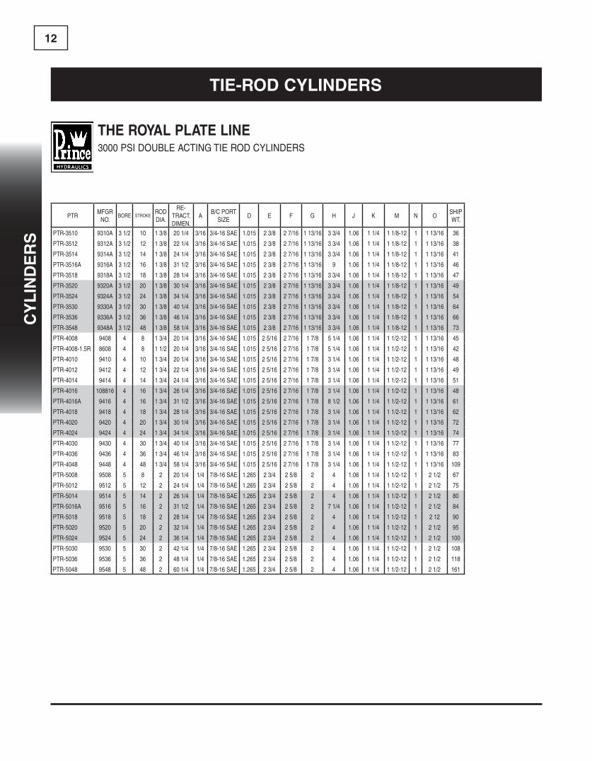
THE ROYAL PLATE LINE3000 PSI DOUBLE ACTING TIE ROD CYLINDERS
FEATURES:• Honedtubing(SAE-9000&SAE9100serieshavecylinderfinishtubing)
• Heavyduty,highstrengthtierods• Chromed,ground&polishedpistonrodwilloperateatfullpressurethrough16”stroke
• Castironpiston,ductileironbutt,gland&clevis
• Carboxilatednitrileu-cup&urethanewiperingland
• Pins&clipsincluded• Standardcolorisred• Strokecontrolmaybeinstalledon8”strokes
• Sideportsavailableonrequestatnoadditionalcost
A
D
BF
E
G
H
M
J (DISTANCE BETWEEN EARS
TYP.C
ON STROKERETRACTED
K
Tie-Rod cylindeRs
12
PTRMFGR
NO.BORE STROKE
ROD DIA.
RE-TRACT. DIMEN.
AB/C PORT
SIZED E F G H J K M N O
SHIP WT.
PTR-3510 9310A 3 1/2 10 1 3/8 20 1/4 3/16 3/4-16 SAE 1.015 2 3/8 2 7/16 1 13/16 3 3/4 1.06 1 1/4 1 1/8-12 1 1 13/16 36
PTR-3512 9312A 3 1/2 12 1 3/8 22 1/4 3/16 3/4-16 SAE 1.015 2 3/8 2 7/16 1 13/16 3 3/4 1.06 1 1/4 1 1/8-12 1 1 13/16 38
PTR-3514 9314A 3 1/2 14 1 3/8 24 1/4 3/16 3/4-16 SAE 1.015 2 3/8 2 7/16 1 13/16 3 3/4 1.06 1 1/4 1 1/8-12 1 1 13/16 41
PTR-3516A 9316A 3 1/2 16 1 3/8 31 1/2 3/16 3/4-16 SAE 1.015 2 3/8 2 7/16 1 13/16 9 1.06 1 1/4 1 1/8-12 1 1 13/16 46
PTR-3518 9318A 3 1/2 18 1 3/8 28 1/4 3/16 3/4-16 SAE 1.015 2 3/8 2 7/16 1 13/16 3 3/4 1.06 1 1/4 1 1/8-12 1 1 13/16 47
PTR-3520 9320A 3 1/2 20 1 3/8 30 1/4 3/16 3/4-16 SAE 1.015 2 3/8 2 7/16 1 13/16 3 3/4 1.06 1 1/4 1 1/8-12 1 1 13/16 49
PTR-3524 9324A 3 1/2 24 1 3/8 34 1/4 3/16 3/4-16 SAE 1.015 2 3/8 2 7/16 1 13/16 3 3/4 1.06 1 1/4 1 1/8-12 1 1 13/16 54
PTR-3530 9330A 3 1/2 30 1 3/8 40 1/4 3/16 3/4-16 SAE 1.015 2 3/8 2 7/16 1 13/16 3 3/4 1.06 1 1/4 1 1/8-12 1 1 13/16 64
PTR-3536 9336A 3 1/2 36 1 3/8 46 1/4 3/16 3/4-16 SAE 1.015 2 3/8 2 7/16 1 13/16 3 3/4 1.06 1 1/4 1 1/8-12 1 1 13/16 66
PTR-3548 9348A 3 1/2 48 1 3/8 58 1/4 3/16 3/4-16 SAE 1.015 2 3/8 2 7/16 1 13/16 3 3/4 1.06 1 1/4 1 1/8-12 1 1 13/16 73
PTR-4008 9408 4 8 1 3/4 20 1/4 3/16 3/4-16 SAE 1.015 2 5/16 2 7/16 1 7/8 5 1/4 1.06 1 1/4 1 1/2-12 1 1 13/16 45
PTR-4008-1.5R 8608 4 8 1 1/2 20 1/4 3/16 3/4-16 SAE 1.015 2 5/16 2 7/16 1 7/8 5 1/4 1.06 1 1/4 1 1/2-12 1 1 13/16 42
PTR-4010 9410 4 10 1 3/4 20 1/4 3/16 3/4-16 SAE 1.015 2 5/16 2 7/16 1 7/8 3 1/4 1.06 1 1/4 1 1/2-12 1 1 13/16 48
PTR-4012 9412 4 12 1 3/4 22 1/4 3/16 3/4-16 SAE 1.015 2 5/16 2 7/16 1 7/8 3 1/4 1.06 1 1/4 1 1/2-12 1 1 13/16 49
PTR-4014 9414 4 14 1 3/4 24 1/4 3/16 3/4-16 SAE 1.015 2 5/16 2 7/16 1 7/8 3 1/4 1.06 1 1/4 1 1/2-12 1 1 13/16 51
PTR-4016 108816 4 16 1 3/4 26 1/4 3/16 3/4-16 SAE 1.015 2 5/16 2 7/16 1 7/8 3 1/4 1.06 1 1/4 1 1/2-12 1 1 13/16 48
PTR-4016A 9416 4 16 1 3/4 31 1/2 3/16 3/4-16 SAE 1.015 2 5/16 2 7/16 1 7/8 8 1/2 1.06 1 1/4 1 1/2-12 1 1 13/16 61
PTR-4018 9418 4 18 1 3/4 28 1/4 3/16 3/4-16 SAE 1.015 2 5/16 2 7/16 1 7/8 3 1/4 1.06 1 1/4 1 1/2-12 1 1 13/16 62
PTR-4020 9420 4 20 1 3/4 30 1/4 3/16 3/4-16 SAE 1.015 2 5/16 2 7/16 1 7/8 3 1/4 1.06 1 1/4 1 1/2-12 1 1 13/16 72
PTR-4024 9424 4 24 1 3/4 34 1/4 3/16 3/4-16 SAE 1.015 2 5/16 2 7/16 1 7/8 3 1/4 1.06 1 1/4 1 1/2-12 1 1 13/16 74
PTR-4030 9430 4 30 1 3/4 40 1/4 3/16 3/4-16 SAE 1.015 2 5/16 2 7/16 1 7/8 3 1/4 1.06 1 1/4 1 1/2-12 1 1 13/16 77
PTR-4036 9436 4 36 1 3/4 46 1/4 3/16 3/4-16 SAE 1.015 2 5/16 2 7/16 1 7/8 3 1/4 1.06 1 1/4 1 1/2-12 1 1 13/16 83
PTR-4048 9448 4 48 1 3/4 58 1/4 3/16 3/4-16 SAE 1.015 2 5/16 2 7/16 1 7/8 3 1/4 1.06 1 1/4 1 1/2-12 1 1 13/16 109
PTR-5008 9508 5 8 2 20 1/4 1/4 7/8-16 SAE 1.265 2 3/4 2 5/8 2 4 1.06 1 1/4 1 1/2-12 1 2 1/2 67
PTR-5012 9512 5 12 2 24 1/4 1/4 7/8-16 SAE 1.265 2 3/4 2 5/8 2 4 1.06 1 1/4 1 1/2-12 1 2 1/2 75
PTR-5014 9514 5 14 2 26 1/4 1/4 7/8-16 SAE 1.265 2 3/4 2 5/8 2 4 1.06 1 1/4 1 1/2-12 1 2 1/2 80
PTR-5016A 9516 5 16 2 31 1/2 1/4 7/8-16 SAE 1.265 2 3/4 2 5/8 2 7 1/4 1.06 1 1/4 1 1/2-12 1 2 1/2 84
PTR-5018 9518 5 18 2 28 1/4 1/4 7/8-16 SAE 1.265 2 3/4 2 5/8 2 4 1.06 1 1/4 1 1/2-12 1 2 12 90
PTR-5020 9520 5 20 2 32 1/4 1/4 7/8-16 SAE 1.265 2 3/4 2 5/8 2 4 1.06 1 1/4 1 1/2-12 1 2 1/2 95
PTR-5024 9524 5 24 2 36 1/4 1/4 7/8-16 SAE 1.265 2 3/4 2 5/8 2 4 1.06 1 1/4 1 1/2-12 1 2 1/2 100
PTR-5030 9530 5 30 2 42 1/4 1/4 7/8-16 SAE 1.265 2 3/4 2 5/8 2 4 1.06 1 1/4 1 1/2-12 1 2 1/2 108
PTR-5036 9536 5 36 2 48 1/4 1/4 7/8-16 SAE 1.265 2 3/4 2 5/8 2 4 1.06 1 1/4 1 1/2-12 1 2 1/2 118
PTR-5048 9548 5 48 2 60 1/4 1/4 7/8-16 SAE 1.265 2 3/4 2 5/8 2 4 1.06 1 1/4 1 1/2-12 1 2 1/2 161
THE ROYAL PLATE LINE3000 PSI DOUBLE ACTING TIE ROD CYLINDERS
Tie-Rod cylindeRs
cy
lin
de
Rs
13c
yl
ind
eR
s
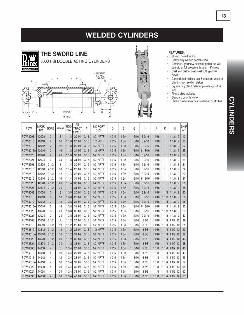
FEATURES:• Skived,honedtubing• Heavydutyweldedconstruction• Chromed,ground&polishedpistonrodwilloperateatfullpressurethrough16”stroke
• Castironpiston,caststeelbutt,gland&clevis
• Carboxilatednitrileu-cup&urethanewiperingland,crownsealonpiston
• Squareringglandretainerprovidespositivelock
• Pins&clipsincluded• Standardcoloriswhite• Strokecontrolmaybeinstalledon8”strokes
THE SWORD LINE3000 PSI DOUBLE ACTING CYLINDERS
DB A C
E HG
M
J (DISTANCE BETWEEN EAR TYP.)
K STROKE
RETRACT
PCWMFGR.
NO.BORE STROKE
ROD DIA.
RE-TRACT. DIMEN.
AB/C PORT
SIZED E G H J K M
SHIP WT.
PCW-2008 42008 2 8 1 1/8 20 1/4 3/16 1/2 NPTF 1.015 1 3/4 1 13/16 5 9/16 1 1/16 1 1 1/8 12 10
PCW-2010 42010 2 10 1 1/8 20 1/4 3/16 1/2 NPTF 1.015 1 3/4 1 13/16 3 9/16 1 1/16 1 1 1/8 12 20
PCW-2012 42012 2 12 1 1/8 22 1/4 3/16 1/2 NPTF 1.015 1 3/4 1 13/16 3 9/16 1 1/16 1 1 1/8 12 22
PCW-2016A 42016 2 16 1 1/8 31 1/2 3/16 1/2 NPTF 1.015 1 3/4 1 13/16 8 13/16 1 1/16 1 1 1/8 12 25
PCW-2020 42020 2 20 1 1/8 30 1/4 3/16 1/2 NPTF 1.015 1 3/4 1 13/16 3 9/16 1 1/16 1 1 1/8 12 28
PCW-2024 42024 2 24 1 1/8 34 1/4 3/16 1/2 NPTF 1.015 1 3/4 1 13/16 3 9/16 1 1/16 1 1 1/8 12 31
PCW-2508 42508 2 1/2 8 1 1/4 20 1/4 3/16 1/2 NPTF 1.015 1 3/4 1 13/16 5 9/16 1 1/16 1 1 1/8 12 21
PCW-2510 42510 2 1/2 10 1 1/4 20 1/4 3/16 1/2 NPTF 1.015 1 3/4 1 13/16 3 9/16 1 1/16 1 1 1/8 12 22
PCW-2512 42512 2 1/2 12 1 1/4 22 1/4 3/16 1/2 NPTF 1.015 1 3/4 1 13/16 3 9/16 1 1/16 1 1 1/8 12 23
PCW-2516 42516 2 1/2 16 1 1/4 31 1/2 3/16 1/2 NPTF 1.015 1 3/4 1 13/16 8 13/16 1 1/16 1 1 1/8 12 27
PCW-2520 42520 2 1/2 20 1 1/4 30 1/4 3/16 1/2 NPTF 1.015 1 3/4 1 13/16 3 9/16 1 1/16 1 1 1/8 12 31
PCW-2524 42524 2 1/2 24 1 1/4 34 1/4 3/16 1/2 NPTF 1.015 1 3/4 1 13/16 3 9/16 1 1/16 1 1 1/8 12 35
PCW-3008 43008 3 8 1 3/8 20 1/4 3/16 1/2 NPTF 1.015 1 3/4 1 13/16 5 9/16 1 1/16 1 1/8 1 1/8 12 23
PCW-3010 43010 3 10 1 3/8 20 1/4 3/16 1/2 NPTF 1.015 1 3/4 1 13/16 3 9/16 1 1/16 1 1/8 1 1/8 12 26
PCW-3012 43012 3 12 1 3/8 22 1/4 3/16 1/2 NPTF 1.015 1 3/4 1 13/16 3 9/16 1 1/16 1 1/8 1 1/8 12 28
PCW-3016A 43016 3 16 1 3/8 31 1/2 3/16 1/2 NPTF 1.015 1 3/4 1 13/16 8 13/16 1 1/16 1 1/8 1 1/8 12 33
PCW-3020 43020 3 20 1 3/8 30 1/4 3/16 1/2 NPTF 1.015 1 3/4 1 13/16 3 9/16 1 1/16 1 1/8 1 1/8 12 39
PCW-3024 43024 3 24 1 3/8 34 1/4 3/16 1/2 NPTF 1.015 1 3/4 1 13/16 3 9/16 1 1/16 1 1/8 1 1/8 12 43
PCW-3508 43508 3 1/2 8 1 1/2 20 1/4 3/16 1/2 NPTF 1.015 1 3/4 1 13/16 5 3/8 1 1/16 1 1/4 1 1/2 12 29
PCW-3510 43510 3 1/2 10 1 1/2 20 1/4 3/16 1/2 NPTF 1.015 1 3/4 1 13/16 3 3/8 1 1/16 1 1/4 1 1/2 12 31
PCW-3512 43512 3 1/2 12 1 1/2 22 1/4 3/16 1/2 NPTF 1.015 1 3/4 1 13/16 3 3/8 1 1/16 1 1/4 1 1/2 12 33
PCW-3516A 43516 3 1/2 16 1 1/2 31 1/2 3/16 1/2 NPTF 1.015 1 3/4 1 13/16 8 3/8 1 1/16 1 1/4 1 1/2 12 38
PCW-3520 43520 3 1/2 20 1 1/2 30 1/4 3/16 1/2 NPTF 1.015 1 3/4 1 13/16 3 3/8 1 1/16 1 1/4 1 1/2 12 43
PCW-3524 43524 3 1/2 24 1 1/2 34 1/4 3/16 1/2 NPTF 1.015 1 3/4 1 13/16 3 3/8 1 1/16 1 1/4 1 1/2 12 48
PCW-4008 44008 4 8 1 3/4 20 1/4 3/16 1/2 NPTF 1.015 1 3/4 1 13/16 5 3/8 1 1/8 1 1/4 1 1/2 12 40
PCW-4010 44010 4 10 1 3/4 20 1/4 3/16 1/2 NPTF 1.015 1 3/4 1 13/16 3 3/8 1 1/8 1 1/4 1 1/2 12 43
PCW-4012 44012 4 12 1 3/4 22 1/4 3/16 1/2 NPTF 1.015 1 3/4 1 13/16 3 3/8 1 1/8 1 1/4 1 1/2 12 45
PCW-4016A 44016 4 16 1 3/4 31 1/2 3/16 1/2 NPTF 1.015 1 3/4 1 13/16 8 3/8 1 1/8 1 1/4 1 1/2 12 54
PCW-4020 44020 4 20 1 3/4 30 1/4 3/16 1/2 NPTF 1.015 1 3/4 1 13/16 3 3/8 1 1/8 1 1/4 1 1/2 12 58
PCW-4024 44024 4 24 1 3/4 34 1/4 3/16 1/2 NPTF 1.015 1 3/4 1 13/16 3 3/8 1 1/8 1 1/4 1 1/2 12 60
PCW-4030 44030 4 30 1 3/4 40 1/4 3/16 1/2 NPTF 1.015 1 3/4 1 13/16 3 3/8 1 1/8 1 1/4 1 1/2 12 65
Welded cylindeRs
14
Welded cylindeRs
PMWMFGR.
NO.BORE STROKE
ROD DIA.
RE-TRACT. DIMEN.
PORT SIZE A D E G H L1 L2 N OSHIP WT.
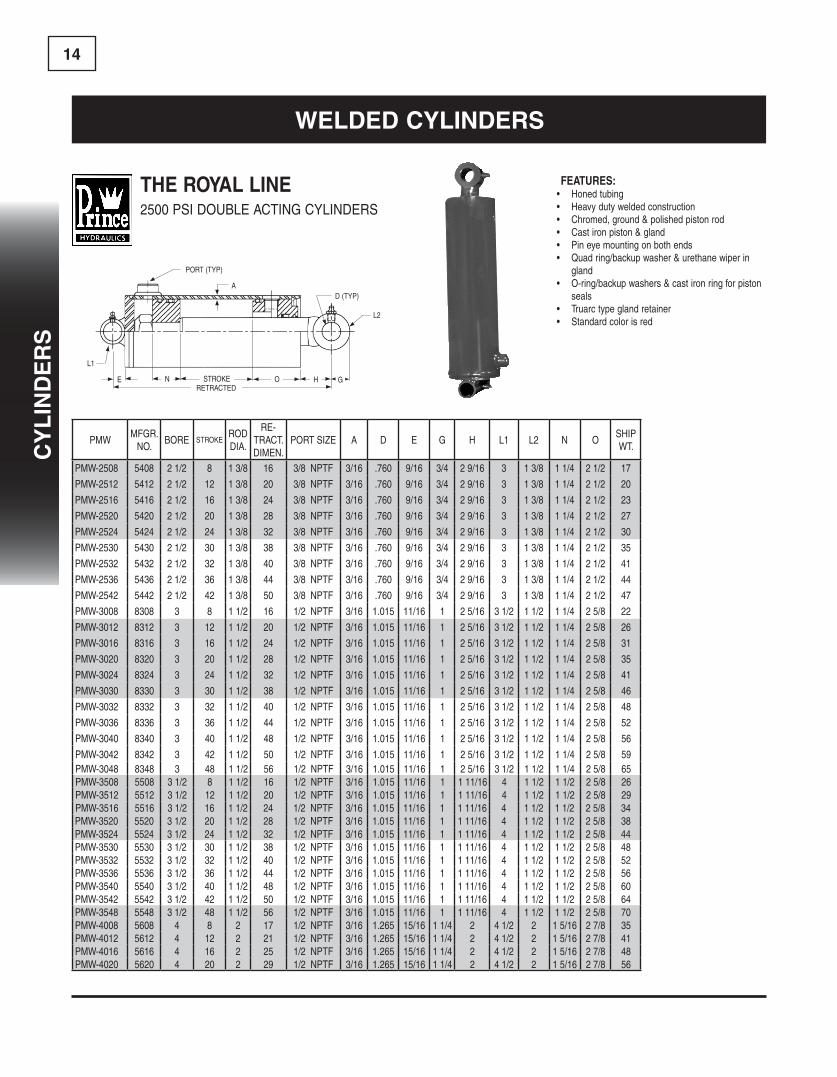
PMW-2508 5408 2 1/2 8 1 3/8 16 3/8 NPTF 3/16 .760 9/16 3/4 2 9/16 3 1 3/8 1 1/4 2 1/2 17
PMW-2512 5412 2 1/2 12 1 3/8 20 3/8 NPTF 3/16 .760 9/16 3/4 2 9/16 3 1 3/8 1 1/4 2 1/2 20
PMW-2516 5416 2 1/2 16 1 3/8 24 3/8 NPTF 3/16 .760 9/16 3/4 2 9/16 3 1 3/8 1 1/4 2 1/2 23
PMW-2520 5420 2 1/2 20 1 3/8 28 3/8 NPTF 3/16 .760 9/16 3/4 2 9/16 3 1 3/8 1 1/4 2 1/2 27
PMW-2524 5424 2 1/2 24 1 3/8 32 3/8 NPTF 3/16 .760 9/16 3/4 2 9/16 3 1 3/8 1 1/4 2 1/2 30
PMW-2530 5430 2 1/2 30 1 3/8 38 3/8 NPTF 3/16 .760 9/16 3/4 2 9/16 3 1 3/8 1 1/4 2 1/2 35
PMW-2532 5432 2 1/2 32 1 3/8 40 3/8 NPTF 3/16 .760 9/16 3/4 2 9/16 3 1 3/8 1 1/4 2 1/2 41
PMW-2536 5436 2 1/2 36 1 3/8 44 3/8 NPTF 3/16 .760 9/16 3/4 2 9/16 3 1 3/8 1 1/4 2 1/2 44
PMW-2542 5442 2 1/2 42 1 3/8 50 3/8 NPTF 3/16 .760 9/16 3/4 2 9/16 3 1 3/8 1 1/4 2 1/2 47
PMW-3008 8308 3 8 1 1/2 16 1/2 NPTF 3/16 1.015 11/16 1 2 5/16 3 1/2 1 1/2 1 1/4 2 5/8 22
PMW-3012 8312 3 12 1 1/2 20 1/2 NPTF 3/16 1.015 11/16 1 2 5/16 3 1/2 1 1/2 1 1/4 2 5/8 26
PMW-3016 8316 3 16 1 1/2 24 1/2 NPTF 3/16 1.015 11/16 1 2 5/16 3 1/2 1 1/2 1 1/4 2 5/8 31
PMW-3020 8320 3 20 1 1/2 28 1/2 NPTF 3/16 1.015 11/16 1 2 5/16 3 1/2 1 1/2 1 1/4 2 5/8 35
PMW-3024 8324 3 24 1 1/2 32 1/2 NPTF 3/16 1.015 11/16 1 2 5/16 3 1/2 1 1/2 1 1/4 2 5/8 41
PMW-3030 8330 3 30 1 1/2 38 1/2 NPTF 3/16 1.015 11/16 1 2 5/16 3 1/2 1 1/2 1 1/4 2 5/8 46
PMW-3032 8332 3 32 1 1/2 40 1/2 NPTF 3/16 1.015 11/16 1 2 5/16 3 1/2 1 1/2 1 1/4 2 5/8 48
PMW-3036 8336 3 36 1 1/2 44 1/2 NPTF 3/16 1.015 11/16 1 2 5/16 3 1/2 1 1/2 1 1/4 2 5/8 52
PMW-3040 8340 3 40 1 1/2 48 1/2 NPTF 3/16 1.015 11/16 1 2 5/16 3 1/2 1 1/2 1 1/4 2 5/8 56
PMW-3042 8342 3 42 1 1/2 50 1/2 NPTF 3/16 1.015 11/16 1 2 5/16 3 1/2 1 1/2 1 1/4 2 5/8 59PMW-3048 8348 3 48 1 1/2 56 1/2 NPTF 3/16 1.015 11/16 1 2 5/16 3 1/2 1 1/2 1 1/4 2 5/8 65PMW-3508 5508 3 1/2 8 1 1/2 16 1/2 NPTF 3/16 1.015 11/16 1 1 11/16 4 1 1/2 1 1/2 2 5/8 26PMW-3512 5512 3 1/2 12 1 1/2 20 1/2 NPTF 3/16 1.015 11/16 1 1 11/16 4 1 1/2 1 1/2 2 5/8 29PMW-3516 5516 3 1/2 16 1 1/2 24 1/2 NPTF 3/16 1.015 11/16 1 1 11/16 4 1 1/2 1 1/2 2 5/8 34PMW-3520 5520 3 1/2 20 1 1/2 28 1/2 NPTF 3/16 1.015 11/16 1 1 11/16 4 1 1/2 1 1/2 2 5/8 38PMW-3524 5524 3 1/2 24 1 1/2 32 1/2 NPTF 3/16 1.015 11/16 1 1 11/16 4 1 1/2 1 1/2 2 5/8 44PMW-3530 5530 3 1/2 30 1 1/2 38 1/2 NPTF 3/16 1.015 11/16 1 1 11/16 4 1 1/2 1 1/2 2 5/8 48PMW-3532 5532 3 1/2 32 1 1/2 40 1/2 NPTF 3/16 1.015 11/16 1 1 11/16 4 1 1/2 1 1/2 2 5/8 52PMW-3536 5536 3 1/2 36 1 1/2 44 1/2 NPTF 3/16 1.015 11/16 1 1 11/16 4 1 1/2 1 1/2 2 5/8 56PMW-3540 5540 3 1/2 40 1 1/2 48 1/2 NPTF 3/16 1.015 11/16 1 1 11/16 4 1 1/2 1 1/2 2 5/8 60PMW-3542 5542 3 1/2 42 1 1/2 50 1/2 NPTF 3/16 1.015 11/16 1 1 11/16 4 1 1/2 1 1/2 2 5/8 64PMW-3548 5548 3 1/2 48 1 1/2 56 1/2 NPTF 3/16 1.015 11/16 1 1 11/16 4 1 1/2 1 1/2 2 5/8 70PMW-4008 5608 4 8 2 17 1/2 NPTF 3/16 1.265 15/16 1 1/4 2 4 1/2 2 1 5/16 2 7/8 35PMW-4012 5612 4 12 2 21 1/2 NPTF 3/16 1.265 15/16 1 1/4 2 4 1/2 2 1 5/16 2 7/8 41PMW-4016 5616 4 16 2 25 1/2 NPTF 3/16 1.265 15/16 1 1/4 2 4 1/2 2 1 5/16 2 7/8 48PMW-4020 5620 4 20 2 29 1/2 NPTF 3/16 1.265 15/16 1 1/4 2 4 1/2 2 1 5/16 2 7/8 56
FEATURES:• Honedtubing• Heavydutyweldedconstruction• Chromed,ground&polishedpistonrod• Castironpiston&gland• Pineyemountingonbothends• Quadring/backupwasher&urethanewiperingland
• O-ring/backupwashers&castironringforpistonseals
• Truarctypeglandretainer• Standardcolorisred
THE ROYAL LINE2500 PSI DOUBLE ACTING CYLINDERS
A
HON
L1
STROKE
PORT (TYP)
D (TYP)
L2
GRETRACTED
E
cy
lin
de
Rs

15c
yl
ind
eR
s
THE ROYAL LINE2500 PSI DOUBLE ACTING CYLINDERS
Welded cylindeRs
PMWMFGR.
NO.BORE STROKE
ROD DIA.
RE-TRACT. DIMEN.
PORT SIZE A D E G H L1 L2 N OSHIP WT.
PMW-4024 5624 4 24 2 33 1/2 NPTF 3/16 1.265 15/16 1 1/4 2 4 1/2 2 1 5/16 2 7/8 62PMW-4030 5630 4 30 2 39 1/2 NPTF 3/16 1.265 15/16 1 1/4 2 4 1/2 2 1 5/16 2 7/8 72PMW-4032 5632 4 32 2 41 1/2 NPTF 3/16 1.265 15/16 1 1/4 2 4 1/2 2 1 5/16 2 7/8 74PMW-4036 5636 4 36 2 45 1/2 NPTF 3/16 1.265 15/16 1 1/4 2 4 1/2 2 1 5/16 2 7/8 80PMW-4040 5640 4 40 2 49 1/2 NPTF 3/16 1.265 15/16 1 1/4 2 4 1/2 2 1 5/16 2 7/8 85PMW-4042 5642 4 42 2 51 1/2 NPTF 3/16 1.265 15/16 1 1/4 2 4 1/2 2 1 5/16 2 7/8 92PMW-4048 5648 4 48 2 57 1/2 NPTF 3/16 1.265 15/16 1 1/4 2 4 1/2 2 1 5/16 2 7/8 100PMW-4060 5660 4 60 2 69 1/2 NPTF 3/16 1.265 15/16 1 1/4 2 4 1/2 2 1 5/16 2 7/8 120

16
cy
lin
de
Rs
Welded cylindeRs
FEATURES:• Heavydutyweldedconstruction• 3000PSI(2:1safetyfactorforbucklingon36”strokeandless.Longerstrokeconsultfactory)
• Steelglandcapretainerwithlockscrew• 3/4NPTFfull-flowports• Standardcolorishighwayyellow• Highgradegrayironpiston&gland• Precisionskivedtubeforlongseallife• Allsteelspacertubeforbearinglengthon48”ormoreofstroke
• GroundandpolishedchromeC-1045steelpistonrodformaximumlife
• Heavydutytorquedlocknutforpistonretainer• Polyurethane“U”cupandheavydutywiperingland.Crownsealwithbearingringsonpiston
THE GLADIATOR LINE3000 PSI DOUBLE ACTING CYLINDERS
AB
D
E
L1
H STROKE
RETRACT
H
D
B
O
L2
PMW2MFGR.
NO.BORE STROKE
ROD DIA.
RE-TRACT. DIMEN.
A B PORT SIZE D E H L1 O L2SHIP WT.
PMW-5008 21008 5 8 2 1/2 19 1/4 3/4 NPTF 1.515 1 1/4 1 7/8 5 3/4 2 15/16 4 75
PMW-5012 21012 5 12 2 1/2 23 1/4 3/4 NPTF 1.515 1 1/4 1 7/8 5 3/4 2 15/16 4 85
PMW-5016 21016 5 16 2 1/2 27 1/4 3/4 NPTF 1.515 1 1/4 1 7/8 5 3/4 2 15/16 4 90
PMW-5020 21020 5 20 2 1/2 31 1/4 3/4 NPTF 1.515 1 1/4 1 7/8 5 3/4 2 15/16 4 105
PMW-5024 21024 5 24 2 1/2 35 1/4 3/4 NPTF 1.515 1 1/4 1 7/8 5 3/4 2 15/16 4 115
PMW-5030 21030 5 30 2 1/2 41 1/4 3/4 NPTF 1.515 1 1/4 1 7/8 5 3/4 2 15/16 4 130
PMW-5036 21036 5 36 2 1/2 47 1/4 3/4 NPTF 1.515 1 1/4 1 7/8 5 3/4 2 15/16 4 145
PMW-5048 21048 5 48 2 1/2 61 1/4 3/4 NPTF 1.515 1 1/4 1 7/8 5 3/4 2 15/16 4 180
PMW-5054 21054 5 54 2 1/2 68 1/4 3/4 NPTF 1.515 1 1/4 1 7/8 5 3/4 2 15/16 4 195
PMW-5060 21060 5 60 2 1/2 75 1/4 3/4 NPTF 1.515 1 1/4 1 7/8 5 3/4 2 15/16 4 215
PMW-6008 22008 6 8 3 19 1/4 3/4 NPTF 1.515 1 1/4 2 6 3/4 3 1/8 4 100
PMW-6012 22012 6 12 3 23 1/4 3/4 NPTF 1.515 1 1/4 2 6 3/4 3 1/8 4 110
PMW-6016 22016 6 16 3 27 1/4 3/4 NPTF 1.515 1 1/4 2 6 3/4 3 1/8 4 125
PMW-6024 22024 6 24 3 35 1/4 3/4 NPTF 1.515 1 1/4 2 6 3/4 3 1/8 4 150
PMW-6030 22030 6 30 3 41 1/4 3/4 NPTF 1.515 1 1/4 2 6 3/4 3 1/8 4 170
PMW-6036 22036 6 36 3 47 1/4 3/4 NPTF 1.515 1 1/4 2 6 3/4 3 1/8 4 190
PMW-6048 22048 6 48 3 61 1/4 3/4 NPTF 1.515 1 1/4 2 6 3/4 3 1/8 4 240
PMW-6054 22054 6 54 3 68 1/4 3/4 NPTF 1.515 1 1/4 2 6 3/4 3 1/8 4 265
PMW-6060 22060 6 60 3 75 1/4 3/4 NPTF 1.515 1 1/4 2 6 3/4 3 1/8 4 290
cy
lin
de
Rs
cy
lin
de
Rs

17c
yl
ind
eR
s
WORLDWIDE SALES OFFICE HOURS NORTH AMERICAPHONE 1-727-796-1300 8 A.M. TO 8 P.M. EASTERN TIME PHONE 1-800-333-5617
FAX 1-727-797-8849 www.herculeshydraulics.com FAX 1-800-759-63916
CU
ST
OM
HO
IST
S
SINGLE ACTINGTELESCOPIC CYLINDERS
Cross Specific Operating PressuresPlunger Section
Dia. Area 1500 PSI 1800 PSI 2000 PSI 2500PSI(In.) (Sq. In.) (LBS) (LBS) (LBS) (LBS)
2 3.14 4,710 5,672 6,280 7,8503 7.06 10,590 12,708 14,120 17,6504 12.56 18,840 22,608 25,120 31,4005 19.63 29,445 35,334 39,260 49,0756 28.27 42,405 50,886 56,540 70,6757 38.48 57,720 69,264 76,960 96,2008 50.26 75,390 90,468 100,520 125,650
8-1/4 53.50 80,250 96,300 107,000 133,7509-1/8 65.40 98,100 117,720 130,800 163,5009-3/4 74.50 111,750 134,100 149,000 186,250
cylinder identification85 - 2 - 250
LARGEST MOVING STAGE
NUMBER OF MOVING STAGES
STROKE IN INCHES
CYLINDER SEQUENCE NUMBER
Features• Plunger diameters: 2” thru 9-3/4”• Strokes up to 400”• One thru six moving stages
available• Maximum pressure to 2,500 PSI• High-quality V-packing to seal high
and low pressures
• Externally threaded head nuts for extra strength, easy seal adjustment
• Special plunger stops assure full shoulder stop
• Easy-access bleeder screw, manual or automatic
• High quality glass-filled nylon oroptional bronze bearing rings
• Dual lip wiper to prevent contamination
• Wide range of cylinder mountings, including trunions
• Maximum overlap for stability• Chromed plungers available
ManUfacTUReRs seRvice ManUals aRe availaBle. call foR deTails.
individual Plunger lifting capacities for single-acting Telescopic cylinders
Single Acting Cylinders
ThesecylindersareavailablefromCustomHoists,Commercial,HycoandSHC.Requestthemanufactureryouwant.
single acTing TelescoPic cylindeRs
cy
lin
de
Rs
cy
lin
de
Rs
18
cy
lin
de
Rs
single acTing TelescoPic cylindeRs
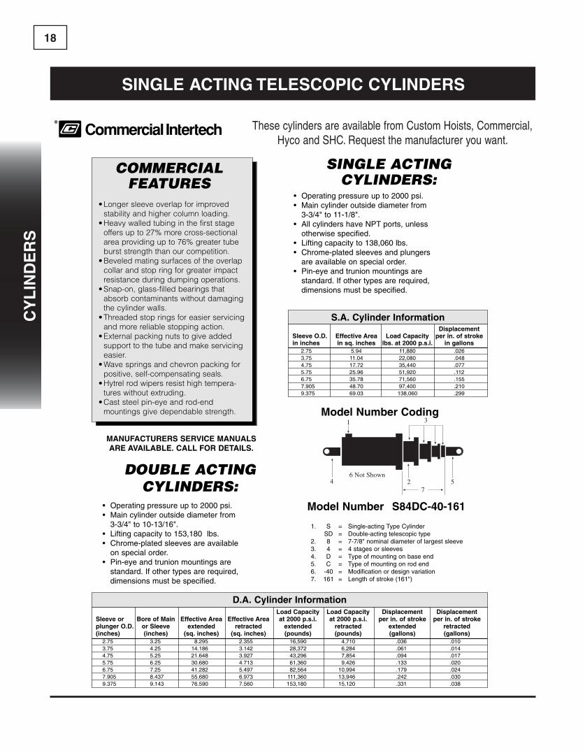
SINGLE ACTING CYLINDERS:
• Operating pressure up to 2000 psi.• Main cylinder outside diameter from
3-3/4" to 11-1/8".• All cylinders have NPT ports, unless
otherwise specified.• Lifting capacity to 138,060 lbs.• Chrome-plated sleeves and plungers
are available on special order.• Pin-eye and trunion mountings are
standard. If other types are required, dimensions must be specified.
NORTH AMERICA SALES OFFICE HOURS WORLDWIDEPHONE 1-800-333-5617 8 A.M. TO 8 P.M. EASTERN TIME PHONE 1-727-796-1300
FAX 1-800-759-6391 www.herculeshydraulics.com FAX 1-727-797-88495
CO
MM
ER
CIA
L
DOUBLE ACTINGCYLINDERS:
• Operating pressure up to 2000 psi.• Main cylinder outside diameter from
3-3/4" to 10-13/16".• Lifting capacity to 153,180 lbs.• Chrome-plated sleeves are available
on special order.• Pin-eye and trunion mountings are
standard. If other types are required, dimensions must be specified.
Model number s84dc-40-161
1. S = Single-acting Type CylinderSD = Double-acting telescopic type
2. 8 = 7-7/8" nominal diameter of largest sleeve3. 4 = 4 stages or sleeves4. D = Type of mounting on base end5. C = Type of mounting on rod end6. -40 = Modification or design variation7. 161 = Length of stroke (161")
load capacity load capacity displacement displacementsleeve or Bore of Main effective area effective area at 2000 p.s.i. at 2000 p.s.i. per in. of stroke per in. of strokeplunger o.d. or sleeve extended retracted extended retracted extended retracted(inches) (inches) (sq. inches) (sq. inches) (pounds) (pounds) (gallons) (gallons)
2.75 3.25 8.295 2.355 16,590 4,710 .036 .0103.75 4.25 14.186 3.142 28,372 6,284 .061 .0144.75 5.25 21.648 3.927 43,296 7,854 .094 .0175.75 6.25 30.680 4.713 61,360 9,426 .133 .0206.75 7.25 41.282 5.497 82,564 10,994 .179 .0247.905 8.437 55.680 6.973 111,360 13,946 .242 .0309.375 9.143 76.590 7.560 153,180 15,120 .331 .038
displacementsleeve o.d. effective area load capacity per in. of strokein inches in sq. inches lbs. at 2000 p.s.i. in gallons
2.75 5.94 11,880 .0263.75 11.04 22,080 .0484.75 17.72 35,440 .0775.75 25.96 51,920 .1126.75 35.78 71,560 .1557.905 48.70 97,400 .2109.375 69.03 138,060 .299
s.a. cylinder information
d.a. cylinder information
COMMERCIALFEATURES
• Longer sleeve overlap for improved stability and higher column loading.
• Heavy walled tubing in the first stageoffers up to 27% more cross-sectionalarea providing up to 76% greater tubeburst strength than our competition.
• Beveled mating surfaces of the overlapcollar and stop ring for greater impactresistance during dumping operations.
• Snap-on, glass-filled bearings thatabsorb contaminants without damagingthe cylinder walls.
• Threaded stop rings for easier servicingand more reliable stopping action.
• External packing nuts to give addedsupport to the tube and make servicingeasier.
• Wave springs and chevron packing forpositive, self-compensating seals.
• Hytrel rod wipers resist high tempera-tures without extruding.
• Cast steel pin-eye and rod-end mountings give dependable strength. Model number coding
ManUfacTUReRs seRvice ManUalsaRe availaBle. call foR deTails.
4 2 57
1 3
6 Not Shown
®
Telescopic Cylinders
SINGLE ACTING CYLINDERS:
• Operating pressure up to 2000 psi.• Main cylinder outside diameter from
3-3/4" to 11-1/8".• All cylinders have NPT ports, unless
otherwise specified.• Lifting capacity to 138,060 lbs.• Chrome-plated sleeves and plungers
are available on special order.• Pin-eye and trunion mountings are
standard. If other types are required, dimensions must be specified.
NORTH AMERICA SALES OFFICE HOURS WORLDWIDEPHONE 1-800-333-5617 8 A.M. TO 8 P.M. EASTERN TIME PHONE 1-727-796-1300
FAX 1-800-759-6391 www.herculeshydraulics.com FAX 1-727-797-88495
CO
MM
ER
CIA
L
DOUBLE ACTINGCYLINDERS:
• Operating pressure up to 2000 psi.• Main cylinder outside diameter from
3-3/4" to 10-13/16".• Lifting capacity to 153,180 lbs.• Chrome-plated sleeves are available
on special order.• Pin-eye and trunion mountings are
standard. If other types are required, dimensions must be specified.
Model number s84dc-40-161
1. S = Single-acting Type CylinderSD = Double-acting telescopic type
2. 8 = 7-7/8" nominal diameter of largest sleeve3. 4 = 4 stages or sleeves4. D = Type of mounting on base end5. C = Type of mounting on rod end6. -40 = Modification or design variation7. 161 = Length of stroke (161")
load capacity load capacity displacement displacementsleeve or Bore of Main effective area effective area at 2000 p.s.i. at 2000 p.s.i. per in. of stroke per in. of strokeplunger o.d. or sleeve extended retracted extended retracted extended retracted(inches) (inches) (sq. inches) (sq. inches) (pounds) (pounds) (gallons) (gallons)
2.75 3.25 8.295 2.355 16,590 4,710 .036 .0103.75 4.25 14.186 3.142 28,372 6,284 .061 .0144.75 5.25 21.648 3.927 43,296 7,854 .094 .0175.75 6.25 30.680 4.713 61,360 9,426 .133 .0206.75 7.25 41.282 5.497 82,564 10,994 .179 .0247.905 8.437 55.680 6.973 111,360 13,946 .242 .0309.375 9.143 76.590 7.560 153,180 15,120 .331 .038
displacementsleeve o.d. effective area load capacity per in. of strokein inches in sq. inches lbs. at 2000 p.s.i. in gallons
2.75 5.94 11,880 .0263.75 11.04 22,080 .0484.75 17.72 35,440 .0775.75 25.96 51,920 .1126.75 35.78 71,560 .1557.905 48.70 97,400 .2109.375 69.03 138,060 .299
s.a. cylinder information
d.a. cylinder information
COMMERCIALFEATURES
• Longer sleeve overlap for improved stability and higher column loading.
• Heavy walled tubing in the first stageoffers up to 27% more cross-sectionalarea providing up to 76% greater tubeburst strength than our competition.
• Beveled mating surfaces of the overlapcollar and stop ring for greater impactresistance during dumping operations.
• Snap-on, glass-filled bearings thatabsorb contaminants without damagingthe cylinder walls.
• Threaded stop rings for easier servicingand more reliable stopping action.
• External packing nuts to give addedsupport to the tube and make servicingeasier.
• Wave springs and chevron packing forpositive, self-compensating seals.
• Hytrel rod wipers resist high tempera-tures without extruding.
• Cast steel pin-eye and rod-end mountings give dependable strength. Model number coding
ManUfacTUReRs seRvice ManUalsaRe availaBle. call foR deTails.
4 2 57
1 3
6 Not Shown
®
Telescopic Cylinders ThesecylindersareavailablefromCustomHoists,Commercial,HycoandSHC.Requestthemanufactureryouwant.
cy
lin
de
Rs
cy
lin
de
Rs

19c
yl
ind
eR
s
NORTH AMERICA SALES OFFICE HOURS WORLDWIDEPHONE 1-800-333-5617 8 A.M. TO 8 P.M. EASTERN TIME PHONE 1-727-796-1300
FAX 1-800-759-6391 www.herculeshydraulics.com FAX 1-727-797-88499
HY
CO
- 70
,00
0
SINGLE ACTING TELESCOPIC CYLINDERS
70,000 Series
Fluid Capacity: Volume To Fully ExtendPlunger Effective Load Displacement
Dia. Area Capacity (Gal./In. of(Inches) (Sq. Inches) (Lbs. @ 2000 PSI) Stroke)
3 7.07 14,140 .0314 12.56 25,120 .0545 19.63 9,260 .0856 28.27 56,540 .1227 38.48 76,960 .166
8.12 51.78 103,560 .2248.25 53.46 106,920 .2319.38 69.10 138,200 .299
Follow example to determine displacement of the complete cylinder example: Model 824-200
8.12 in. plunger .2247 in. plunger .1666 in. plunger .1225 in. plunger .085
.597.597 x 200 = 29.8 Gallons to fully extend
4
cylinder identificationc70000-814-200d
PART NO.
FIRST PLUNGER DIA.(NOTE - EACH SMALLER PLUNGER DIA.
DECREASES IN 1” INCREMENTS)
PORT LOCATION
TOTAL STROKE
NO. OF PLUNGERS
FeaturesGENERAL DATAOperating pressures to 2000 psi. Plunger diameters range from 2”to 9.375”. Lifting capacities to 138,200 lbs. Pin-eye mountings standard—trunion type available. Chrome-platedplungers available.
AUTOMATIC AIR BLEEDERSEvery standard Hycotel single-acting telescopic cylinder comesequipped with an automatic air bleeder. This completely eliminates time-consuming and potentially hazardous manual air bleeding operation.
GUIDE RINGS & RETAINING RINGSHycotel® features replaceable plunger guide rings, designed andbalanced to be well lubricated and made of specially compounded material for long wearing performance.The retainer rings work in conjunction with the piston design to be positively locked into stop position grooveswhen the cylinder is fully extended.
“DUAL-LIP” WIPERThis dual lip design wiper of Hytrel is a more efficient “dirt wiper.” The dual lip provides an improved means of keeping dirt out.
ManUfacTUReRs seRvice ManUalsaRe availaBle. call foR deTails.
Dimension "A" is total stroke lengthDimension "C" is extended length
F G
BCLOSED LENGTH
"D" PORT "E" PORT
E
D
NOTE: “D” and “E” suffix in Part No. represents a specific port location.For dimensional data, consult our sales staff.A “T” suffix in Part No. represents Trunion Mount.
ThesecylindersareavailablefromCustomHoists,Commercial,HycoandSHC.Requestthemanufactureryouwant.
single acTing TelescoPic cylindeRs
cy
lin
de
Rs
cy
lin
de
Rs
20
cy
lin
de
Rs
NORTH AMERICA SALES OFFICE HOURS WORLDWIDEPHONE 1-800-333-5617 8 A.M. TO 8 P.M. EASTERN TIME PHONE 1-727-796-1300
FAX 1-800-759-6391 www.herculeshydraulics.com FAX 1-727-797-884911
SO
UT
HE
RN
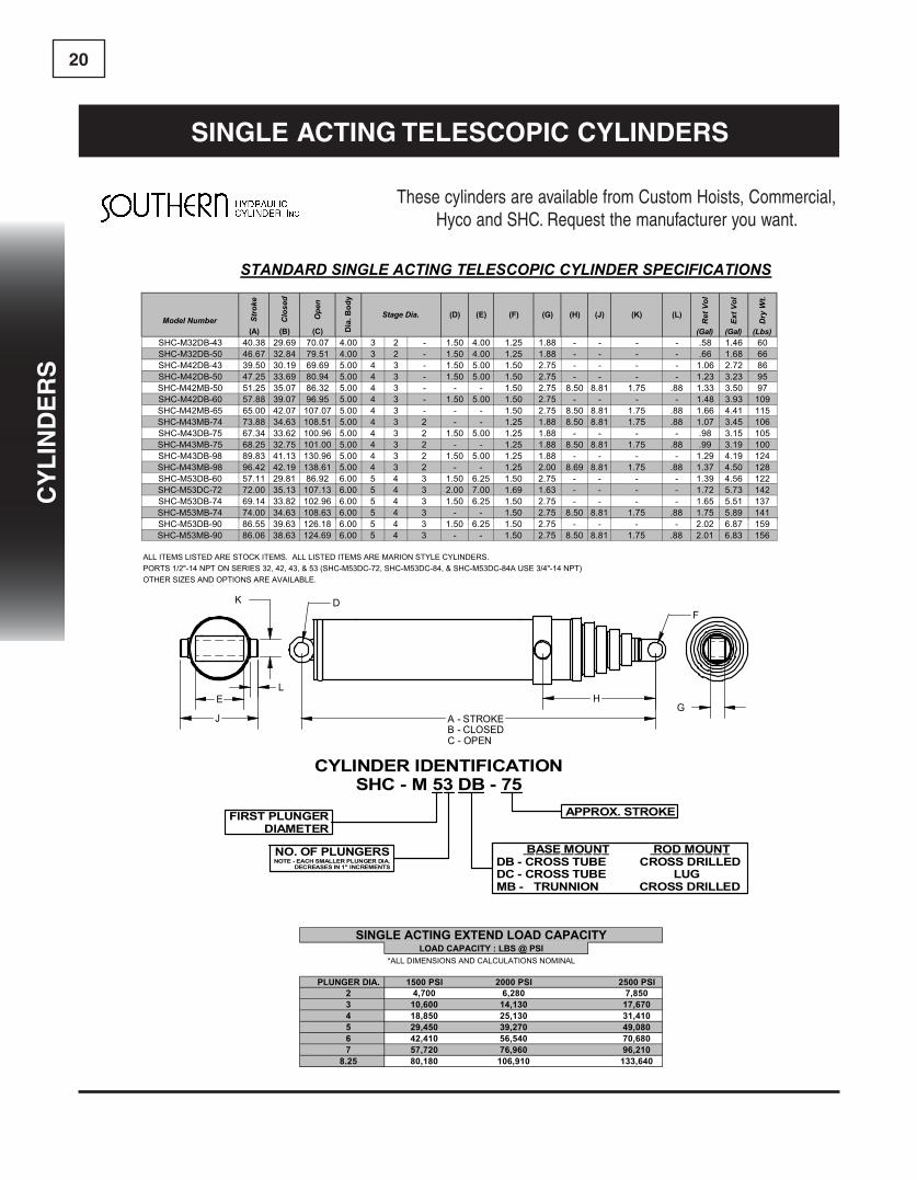
cylinder identificationsHc- M 53 dB - 75
Advantages• Rebuildable• High Operating Pressures - 2500 PSI• Adjustable Vee Packing that provides low pressure
and high pressure sealing• External Packing Nuts to give added support to the
tubes and makes servicing easier
Choice of Mounting Options• Cross Tube or Lug Mount at Base of Cylinder• Welded Trunion Mounts on Main Body or
Add Your Own Special Mount
Many Uses• Dump Bodies• Scissor Type Hi Lifts• Twin Underbody Hoists• Half Pack Front Loader &• Side Loader Refuse Bodies• Recycling Bodies• Farm Hoists
Load Lifting CapacitiesStage 1000 2000O.D. P.S.I. P.S.I.5” 17,721 35,4424” 11,045 22,0903” 5,939 11,8792” 2,761 5,522
MARION STYLE REPLACEMENT SERIESStandard Singe Acting Telescopic Cylinder Specifications
Model Body Plunger BaseNumber Stroke Closed Extended Stage Diameters Dia. Pin Dia. Pin Dia.
SHC-M32DB-43 40.13 29.69 69.82 3.00 2.00 4.00 1.25 1.50SHC-M32DB-50 47.94 33.47 81.41 3.00 2.00 4.00 1.25 1.50SHC-M42DB-43 39.50 30.19 69.69 4.00 3.00 5.00 1.50 1.50SHC-M42DB-50 51.25 36.13 87.38 4.00 3.00 5.00 1.50 1.50SHC-M42MB-50 51.25 35.07 86.32 4.00 3.00 5.00 1.50 TRSHC-M42DB-60 60.00 40.63 100.63 4.00 3.00 5.00 1.50 1.50SHC-M42MB-65 65.00 42.07 107.07 4.00 3.00 5.00 1.50 TRSHC-M43DB-75 68.62 33.69 102.31 4.00 3.00 2.00 5.00 1.25 1.50SHC-M43MB-75 68.25 32.50 100.75 4.00 3.00 2.00 5.00 1.25 TRSHC-M53DB-60 57.75 30.00 87.75 5.00 4.00 3.00 6.00 1.50 1.50SHC-M53DB-74 74.00 35.44 109.44 5.00 4.00 3.00 6.00 1.50 1.50SHC-M53MB-74 74.00 34.38 108.38 5.00 4.00 3.00 6.00 1.50 TRSHC-M53MB-90 86.06 38.63 124.69 5.00 4.00 3.00 6.00 1.50 TR
NOTE: Other base mounts available. Call for information.
FIRST PLUNGER DIA.NO. OF PLUNGERS
(NOTE - EACH SMALLER PLUNGER DIA.DECREASES IN 1” INCREMENTS)
TOTAL STROKE
Base MountDB=Cross Tube AB=No BaseMB=Trunion CB=Single Lug
ThesecylindersareavailablefromCustomHoists,Commercial,HycoandSHC.Requestthemanufactureryouwant.
single acTing TelescoPic cylindeRs
STANDARD SINGLE ACTING TELESCOPIC CYLINDER SPECIFICATIONS
Model Number Stro
ke
Clo
sed
Ope
n
Ret
Vol
Ext V
ol
Dry
Wt.
(A) (B) (C) (Gal) (Gal) (Lbs)SHC-M32DB-43 40.38 29.69 70.07 4.00 3 2 - 1.50 4.00 1.25 1.88 - - - - .58 1.46 60SHC-M32DB-50 46.67 32.84 79.51 4.00 3 2 - 1.50 4.00 1.25 1.88 - - - - .66 1.68 66SHC-M42DB-43 39.50 30.19 69.69 5.00 4 3 - 1.50 5.00 1.50 2.75 - - - - 1.06 2.72 86SHC-M42DB-50 47.25 33.69 80.94 5.00 4 3 - 1.50 5.00 1.50 2.75 - - - - 1.23 3.23 95SHC-M42MB-50 51.25 35.07 86.32 5.00 4 3 - - - 1.50 2.75 8.50 8.81 1.75 .88 1.33 3.50 97SHC-M42DB-60 57.88 39.07 96.95 5.00 4 3 - 1.50 5.00 1.50 2.75 - - - - 1.48 3.93 109SHC-M42MB-65 65.00 42.07 107.07 5.00 4 3 - - - 1.50 2.75 8.50 8.81 1.75 .88 1.66 4.41 115SHC-M43MB-74 73.88 34.63 108.51 5.00 4 3 2 - - 1.25 1.88 8.50 8.81 1.75 .88 1.07 3.45 106SHC-M43DB-75 67.34 33.62 100.96 5.00 4 3 2 1.50 5.00 1.25 1.88 - - - - .98 3.15 105SHC-M43MB-75 68.25 32.75 101.00 5.00 4 3 2 - - 1.25 1.88 8.50 8.81 1.75 .88 .99 3.19 100SHC-M43DB-98 89.83 41.13 130.96 5.00 4 3 2 1.50 5.00 1.25 1.88 - - - - 1.29 4.19 124SHC-M43MB-98 96.42 42.19 138.61 5.00 4 3 2 - - 1.25 2.00 8.69 8.81 1.75 .88 1.37 4.50 128SHC-M53DB-60 57.11 29.81 86.92 6.00 5 4 3 1.50 6.25 1.50 2.75 - - - - 1.39 4.56 122SHC-M53DC-72 72.00 35.13 107.13 6.00 5 4 3 2.00 7.00 1.69 1.63 - - - - 1.72 5.73 142SHC-M53DB-74 69.14 33.82 102.96 6.00 5 4 3 1.50 6.25 1.50 2.75 - - - - 1.65 5.51 137SHC-M53MB-74 74.00 34.63 108.63 6.00 5 4 3 - - 1.50 2.75 8.50 8.81 1.75 .88 1.75 5.89 141SHC-M53DC-84 84.20 39.19 123.39 6.00 5 4 3 2.00 7.00 1.69 1.63 - - - - 1.98 6.69 157
SHC-M53DC-84A 84.20 39.38 123.58 6.00 5 4 3 2.00 7.00 2.00 1.63 - - - - 1.98 6.69 165SHC-M53DB-90 86.55 39.63 126.18 6.00 5 4 3 1.50 6.25 1.50 2.75 - - - - 2.02 6.87 159SHC-M53MB-90 86.06 38.63 124.69 6.00 5 4 3 - - 1.50 2.75 8.50 8.81 1.75 .88 2.01 6.83 156
ALL ITEMS LISTED ARE STOCK ITEMS. ALL LISTED ITEMS ARE MARION STYLE CYLINDERS.PORTS 1/2"-14 NPT ON SERIES 32, 42, 43, & 53 (SHC-M53DC-72, SHC-M53DC-84, & SHC-M53DC-84A USE 3/4"-14 NPT)OTHER SIZES AND OPTIONS ARE AVAILABLE.
SINGLE ACTING EXTEND LOAD CAPACITYLOAD CAPACITY : LBS @ PSI
*ALL DIMENSIONS AND CALCULATIONS NOMINAL
PLUNGER DIA. 1500 PSI 2000 PSI 2500 PSI2 4,700 6,280 7,8503 10,600 14,130 17,6704 18,850 25,130 31,4105 29,450 39,270 49,0806 42,410 56,540 70,6807 57,720 76,960 96,210
8.25 80,180 106,910 133,640
(L)(G) (H) (J) (K)(F)
Dia
. Bod
y
Stage Dia. (D) (E)
A - STROKEB - CLOSEDC - OPEN
HG
K
J
E
DF
L
CYLINDER IDENTIFICATIONSHC - M 53 DB - 75
FIRST PLUNGERDIAMETER
NO. OF PLUNGERSNOTE - EACH SMALLER PLUNGER DIA.
DECREASES IN 1" INCREMENTS
BASE MOUNT ROD MOUNTDB - CROSS TUBE CROSS DRILLEDDC - CROSS TUBE LUGMB - TRUNNION CROSS DRILLED
APPROX. STROKE
cy
lin
de
Rs
cy
lin
de
Rs

21c
yl
ind
eR
s
StrokelengthsforHyco70,000seriescylindersmaybeslightlydifferentthanthoseshowninchart.Pleasecallourcompo-nentgroupforexact70,000seriesstrokelengths.
ThesecylindersareavailablefromCustomHoists,Commercial,HycoandSHC.Requestthemanufactureryouwant.Seepage17-20forspecifications.
CYLINDER NO. A B C D E F G
5372-SA 72.00 37.12 109.12 8.13 1.50 2.00 1.685384-SA 84.00 41.12 125.12 8.12 1.50 2.06 1.5653104-SA 104.00 47.75 151.75 8.13 1.50 2.00 1.686384-SA 84.00 41.00 125.00 7.62 2.00 2.12 2.0663104-SA 103.87 47.62 151.50 7.62 2.00 2.12 2.0663108-SA 108.00 49.00 157.00 7.625 2.00 2.12 2.0663111-SA 111.00 50.00 161.00 7.00 2.00 2.00 2.0063120-SA 120.00 53.00 173.00 7.625 2.00 2.12 2.0663120-TSA 120.00 53.375 173.375 TRIUNION MOUNT 4.00 N/A 1.5663126-SA 126.00 55.00 181.00 7.62 2.00 2.12 2.06D63128-SA 126.50 54.63 181.13 6.75 2.00 2.00 1.6363140-TSA 139.87 60.00 199.97 TRIUNION MOUNT 4.00 N/A 1.5664135-SA 134.88 47.13 182.00 8.00 2.69 1.75 1.5064156-SA 155.87 52.37 208.12 8.00 2.68 1.87 1.5673110-SA 110.63 50.06 160.69 8.25 2.00 2.00 2.0073120-SA 120.00 53.12 173.12 8.625 1.50 2.12 2.06D73126 125.25 55.12 180.37 6.75 2.00 2.00 1.6373130-SA 130.12 56.50 186.62 8.625 1.50 2.12 2.0673140-SA 140.00 60.00 200.00 8.25 2.00 2.00 2.00D73142-SA 142.13 60.75 202.88 6.75 2.00 2.00 1.6374120-SA 120.00 44.75 164.75 8.625 2.00 2.12 2.0674135-SA 135.00 48.25 183.25 8.625 2.00 2.12 2.0674140-SA 140.25 49.25 189.75 8.625 2.00 2.12 2.0674156-SA 156.00 53.37 209.37 8.625 2.00 2.12 2.0674161-SA 161.00 54.62 215.62 8.62 2.00 2.12 2.0674167-SA 167.25 56.25 223.50 8.62 2.00 2.12 2.0684148-SA 147.75 51.50 199.25 9.50 2.00 2.12 2.0684156-SA 155.75 53.50 209.25 9.50 2.00 2.12 2.0684170-SA 169.75 57.00 226.75 9.50 2.00 2.12 2.0684180-SA 179.75 59.50 239.25 9.50 2.00 2.12 2.0685170-SA 170.00 49.87 219.87 9.50 2.00 2.12 2.0685190-SA 190.00 54.00 244.00 9.50 2.00 2.12 2.0685197-SA 196.13 55.25 251.38 9.50 2.00 2.00 2.0085220-SA 220.00 60.00 280.00 9.50 2.00 2.12 2.0685220-TSA 218.25 60.38 278.63 TR 2.00 TR 2.0085235-SA 235.00 65.00 300.00 9.50 2.00 2.12 2.0685235-TSA 233.25 63.38 296.33 TR 2.00 TR 2.0085250-SA 250.00 68.00 318.00 9.50 2.00 2.12 2.0685250-TSA 248.25 68.38 316.63 TR 2.00 TR 2.0085265-SA 265.00 71.00 336.00 9.50 2.00 2.12 2.0685265-TSA 264.25 74.88 339.13 TR 2.00 TR 2.00
single acTing TelescoPic cylindeR sTock
cy
lin
de
Rs
cy
lin
de
Rs

22
cy
lin
de
Rs
single acTing TelescoPic cylindeR sTock
StrokelengthsforHyco70,000seriescylindersmaybeslightlydifferentthanthoseshowninchart.Pleasecallourcompo-nentgroupforexact70,000seriesstrokelengths.
ThesecylindersareavailablefromCustomHoists,Commercial,HycoandSHC.Requestthemanufactureryouwant.Seepage17-20forspecifications.
CYLINDER NO. A B C D E F G
825190-SA 190.00 54.00 244.00 10.25 2.00 2.12 2.06825220-SA 220.00 60.00 280.00 10.25 2.00 2.12 2.06825235-SA 235.00 65.00 300.00 10.25 2.00 2.12 2.06825250-SA 250.00 68.00 318.00 10.25 2.00 2.12 2.06825265-SA 264.62 74.50 339.12 10.25 2.00 2.12 2.06825280-SA 279.62 77.62 357.25 10.25 2.00 2.12 2.0695220-SA 219.75 60.12 279.87 10.75 2.00 2.12 2.0695235-SA 234.75 65.00 299.75 10.75 2.00 2.12 2.0695250-SA 249.75 72.62 322.37 10.75 2.00 2.12 2.0695265-SA 264.75 75.62 340.37 10.75 2.00 2.12 2.06975220-SA 219.75 60.00 280.00 12.00 2.00 2.12 2.06975235-SA 234.75 65.25 300.00 12.00 2.00 2.12 2.06975250-SA 249.75 72.62 322.37 12.00 2.00 2.12 2.06HPT53100 99.12 46.25 145.37 7.75 1.50 2.06 1.78HPT53110 105.12 47.87 153.00 7.75 1.50 2.06 1.78HPT53120 122.37 54.00 176.37 7.75 1.50 2.06 1.78HPT53130 127.62 54.50 182.12 7.75 1.50 2.06 1.78HPT63120 120.75 54.00 174.75 8.00 2.00 2.50 2.25HPT63130 125.25 55.50 180.75 8.00 2.00 2.50 2.25HPT63140 138.75 60.00 198.75 8.00 2.00 2.50 2.25HPT63160 160.12 69.12 229.25 8.00 2.00 2.50 2.25475 43.12 31.68 74.81 1.50 2.50 3.37 1.81495 64.75 31.75 96.50 1.50 2.50 3.37 1.81498 89.50 41.87 131.37 1.50 2.50 3.37 1.81SHC-M32DB-43 40.13 29.69 69.82 4.00 2.00 1.50 1.25SHC-M32DB-50 47.94 33.47 81.41 4.00 2.00 1.50 1.25SHC-M42DB-43 39.50 30.19 69.90 5.00 3.00 1.50 1.50SHC-M42DB-50 51.25 36.13 87.38 5.00 3.00 1.50 1.50SHC-M42MB-50 51.25 35.07 86.32 TR 3.00 TR 1.50SHC-M42DB-60 60.00 40.63 100.63 5.00 3.00 1.50 1.50SHC-M42MB-65 65.00 42.07 107.07 TR 3.00 TR 1.50SHC-M43DB-75 68.62 33.69 102.31 5.00 2.00 1.50 1.25SHC-M43MB-75 68.25 32.50 100.75 TR 2.00 TR 1.25SHC-M53DB-60 57.75 30.00 87.75 6.00 3.00 1.50 1.50SHC-M53DB-74 74.00 35.44 109.44 6.00 3.00 1.50 1.50SHC-M53MB-74 74.00 34.38 108.38 TR 3.00 TR 1.50SHC-M53MB-90 86.06 38.63 124.69 TR 3.00 TR 1.50
cy
lin
de
Rs
cy
lin
de
Rs
23c
yl
ind
eR
s
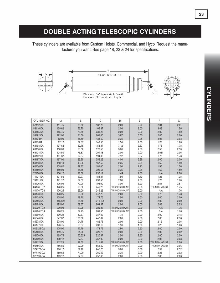
ThesecylindersareavailablefromCustomHoists,Commercial,andHyco.Requestthemanu-factureryouwant.Seepage18,23&24forspecifications.
CYLINDER NO. A B C D E F G
52112-DA 111.75 75.50 187.25 2.00 2.00 2.01 2.0153110-DA 109.62 56.75 166.37 2.00 2.00 3.03 1.5653155-DA 155.75 75.50 231.25 2.00 2.00 2.00 1.5053182-DA 182.00 81.00 263.00 3.87 6.50 2.00 2.006282-DA 82.00 56.50 138.50 2.25 2.25 3.03 3.036397-DA 97.12 52.37 149.50 1.50 1.50 1.28 1.2863108-DA 107.62 50.75 158.37 7.12 3.87 1.78 1.7863118-DA 118.00 58.50 176.50 3.00 4.00 2.50 2.5063124-DA 124.50 76.87 201.48 2.00 2.00 2.031 2.0663132-DA 131.62 62.37 194.00 7.12 3.87 1.78 1.7863167-DA 167.00 85.25 252.25 4.00 3.69 2.00 2.0064118-DA 118.13 49.38 167.50 2.25 2.25 1.50 1.5064136-DA 135.62 49.37 185.00 2.00 2.25 1.56 1.5664150-DA 150.00 56.56 206.56 2.25 2.25 1.50 1.5072156-DA 156.12 96.00 252.12 N/A 2.00 N/A 2.0674131-DA 131.50 53.37 184.87 1.50 1.50 1.28 1.2874171-DA 171.12 62.37 233.50 7.00 4.00 1.78 1.7883126-DA 126.00 72.00 198.00 3.00 3.00 2.51 2.5184176-TD2 176.25 69.00 245.25 TRIUNION MOUNT 2.00 TRIUNION MOUNT 1.7584176-TD3 176.25 69.00 245.25 TRIUNION MOUNT 2.00 N/A 1.7684178-DA 178.25 69.00 247.25 2.00 2.00 1.78 1.7885125-DA 125.00 49.75 174.75 2.50 2.50 2.00 2.0085156-DA 155.625 55.50 211.125 2.00 2.00 2.00 2.0085195-DA 195.00 69.37 264.87 2.00 2.00 2.03 2.0385220-TD2 220.00 69.25 289.25 TRIUNION MOUNT 2.00 N/A 1.7685220-TD3 220.25 69.25 289.50 TRIUNION MOUNT 2.00 N/A 1.7685300-DA 300.25 87.37 387.62 1.75 2.00 2.00 2.1885348-DA 347.87 100.00 447.87 2.00 2.00 2.06 2.1885378-DA 378.00 104.75 482.75 2.00 2.00 2.12 2.0686177-DA 176.75 53.37 230.12 1.50 1.50 1.28 1.28915125-DA 125.00 49.75 174.75 2.50 2.50 2.00 2.0095160-DA 159.75 61.00 220.75 2.00 2.00 2.02 2.0296170-DA 169.75 50.625 220.37 2.50 2.50 2.00 2.0096199-DA 199.12 57.87 257.00 2.00 2.00 2.03 2.0396412-DA 412.25 99.62 511.87 TRIUNION MOUNT 2.00 TRIUNION MOUNT 2.0696456-DA 456.50 107.00 563.50 TRIUNION MOUNT 2.00 TRIUNION MOUNT 2.06974176-DA 176.12 69.12 245.25 3.00 3.00 2.52 2.52974190-DA 189.62 71.00 260.62 2.25 2.00 2.25 2.02976199-DA 199.12 57.87 257.00 2.00 2.00 2.03 2.03
doUBle acTing TelescoPic cylindeRs
cy
lin
de
Rs
cy
lin
de
Rs

24
Po
We
R U
niT
s
ThesecylindersweightsareaverageweightsforCustomHoistsandHycomanufacturedcylinders.CylindersmanufacturedbyCommercialIntertechareusually50-70pounds
heavierthanweightslisted.
WORLDWIDE SALES OFFICE HOURS NORTH AMERICAPHONE 1-727-796-1300 8 A.M. TO 8 P.M. EASTERN TIME PHONE 1-800-333-5617
FAX 1-727-797-8849 www.herculeshydraulics.com FAX 1-800-759-639116
CY
L.
WE
IGH
TS
These cylinder weights are average weights for Custom Hoists and Hyco manufactured cylin-ders. Cylinders manufactured by Commercial Intertech are usually 50-70 pounds heavier thanweights listed.
5360-SA ......................1345372-SA ......................1605384-SA ......................17553104-SA ....................2006384-SA ......................21563104-SA ....................24963108-SA ....................25663111-SA ....................26063120-SA ....................27963120-TSA ..................27963126-SA ....................286D63128-SA..................27863140-TSA ..................33064135-SA ....................26064156-SA ....................31073110-SA ....................35073120-SA ....................336D73126 .......................35573130-SA ....................35873140-SA ....................404D73142-SA..................38374120-SA ....................31174135-SA ....................33574140-SA ....................34774156-SA ....................37074161-SA ....................39074167-SA ....................39084148-SA ....................45184156-SA ....................45584170-SA ....................49484180-SA ....................52485170-SA ....................45085190-SA ....................50685197-SA ....................52585220-SA ....................56785220-TSA ..................58585235-SA ....................61985235-TSA ..................63785250-SA ....................65485250-TSA ..................67285265-SA ....................67485265-TSA ..................692825190-SA ..................595825220-SA ..................667
825235-SA ..................725825250-SA ..................765825265-SA ..................795825280-SA ..................83595220-SA ....................78095235-SA ....................82595250-SA ....................86895265-SA ....................890975220-SA ..................858975235-SA ..................967975250-SA ................1076HPT53100 ...................190HPT53110 ...................193HPT53120 ...................230HPT53130 ...................214HPT63120 ...................267HPT63130 ...................270HPT63140 ...................288HPT63160 ...................32852112-DA....................31853110-DA....................24653155-DA....................30753182-DA....................3576282-DA......................2536397-DA......................27563108-DA....................28363118-DA....................31763124-DA....................38363132-DA....................33263167-DA....................32064118-DA....................28064136-DA....................27164150-DA....................30572156-DA....................63074131-DA....................33474171-DA....................57583126-DA....................55584176-TD2 ..................70084176-TD3 ..................55084178-DA....................56085125-DA....................51085156-DA....................49585195-DA....................62085220-TD2 ..................764
85220-TD3 ..................76485300-DA....................84885348-DA....................87585378-DA....................95286177-DA....................485915125-DA..................52895160-DA....................74096170-DA....................56896199-DA....................79596412-DA..................135096456-DA..................1408974176-DA..................978974190-DA..................995976199-DA..................864475..............................102495..............................102498..............................132D3021GDA....................55D3526GDA....................70D4021EDA ....................96D4028EDA ..................105D4030FDA ....................96D4035HDA..................125D4128EDA ....................91D4522JDA.....................84D4522EDA ..................100D4526BDA..................104D4548BDA..................165D5532EDA ..................135DD-BB8133-1..............188DD-BB8134-1..............150DD-BB8281-1..............114DD-BB8374-1..............174DD-BB8379-1..............110DD-BB8748-1................85DD-AB19461...............368DD-AB19774...............110DD-AB19775...............175HL-1-4070.....................83HL-1-4093...................150HL-1-4094...................125HL-1-4100.....................73HL-1-4101...................100HL-1-4103...................119
HL-1-4106.....................67HL-1-4108.....................90HL-1-4110...................105HL-1-4272.....................68HL-1-4305.....................50HL-1-4328...................185HL-1-4330...................192HL-1-4339...................104HL-1-4340...................175HL-1-4341.....................85HL-1-4348...................170HL-1-4884...................150HL-1-4887...................121LCH-15527....................97LCH-2R1006A.............168LCH-PO-1166 .............190LCH-PO-265 ...............102MX-401222..................260MX-401282..................105MX-401826....................51MX-404614..................176PG-3128C .....................67PG-6042BDA ..............239PG-7078DA.................442PKM-1341-LM...............61PKM-1351-LM.............214PKM-2162-LM...............24SHC-M32DB-43 ............57SHC-M32DB-50 ............63SHC-M42DB-43 ............81SHC-M42DB-50 ............91SHC-M42MB-50..........100SHC-M42DB-60 ..........115SHC-M42MB-65..........116SHC-M43DB-75 ............98SHC-M43MB-75..........107SHC-M53DB-60 ..........115SHC-M53DB-74 ..........137SHC-M53MB-74..........140SHC-M53MB-90..........154
CYLINDER # WT. (LBS.) CYLINDER # WT. (LBS.) CYLINDER # WT. (LBS.) CYLINDER # WT. (LBS.)
STOCK CYLINDER SHIPPING WEIGHTSdoUBle acTing TelescoPic cylindeRs
cy
lin
de
Rs
cy
lin
de
Rs
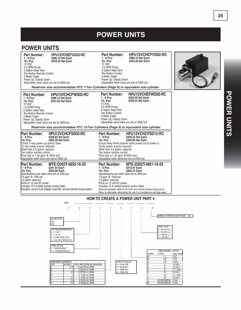
25P
oW
eR
Un
iTs
Part Number: HPU12VCHCFWD02-RC 1 - 9 Pcs: $386.10 Net Each10+ Pcs: $343.20 Net Each12 VDC 1.6GPMPump5GallonSteelTankTwoButtonRemoteControl3MeterCablePowerUp,GravityDownAdjustablereliefvalvepresetat2900psi
Part Number: HPU12VCHCFSD02-RC1 - 9 Pcs: $328.82 Net Each10+ Pcs: $292.28 Net EachCircuit3waypowerupgravitydown12vdcpowersourcerequiredSteeltank2.6galloncapacityTwobuttonremotecontrolFlowrateis1.45gpm@3450rpmAdjustablereliefvalvepresetat2900psi
Part Number: MTE-D202T-4850-16-251 - 9 Pcs: $341.64 Each10+ Pcs: $303.68 EachSpecificationsarereliefvalvesetat2000psi.1.6gpm@1500psi1.8gallonreservoirRunson12voltDCpowerIncludes15ftcordedremotecontrolcable Excellentusefortrucktailgate,boatlifts,andtowbehinddumptrailers
Part Number: HPU12VCHEFWD02-RC1 - 9 Pcs: $383.09 Net Each10+ Pcs: $340.52 Net Each12 VDC2.5GPMPump5GallonSteelTankTwoButtonControl3MeterCablePowerUp,GravityDownAdjustablereliefvalvepresetat2900psi
Part Number: HPU12VCHCFSD12-RC1 - 9 Pcs: $400.33 Net Each10+ Pcs: $355.85 Net EachCircuit4waythreepositionvalvepowerout&powerin12vdcpowersourcerequiredSteeltank2.6galloncapacityTwobuttonremotecontrolFlowrateis1.45gpm@3450rpmAdjustablereliefvalvepresetat2900psi
Part Number: MTE-D202T-4851-16-251 - 9 Pcs: $410.87 Each10+ Pcs: $365.22 EachSpecificationsarereliefvalvesetat2000psi.1.6gpm@1500psi1.8gallonreservoirRunson12voltDCpowerIncludes15ftcordedremotecontrolcable Solenoidoperationallowforlift,hold,andreversedoubleactingcircuit Motorisreversable,eliminatingtheuseofatroublesomecartridgevalve
Part Number: HPU12VCHEFVDO2-RC 1 - 9 Pcs: $386.10 Net Each 10+ Pcs: $343.20 Net Each12 VDC 2.5GPMPump3GallonSteelTankTwoButtonRemoteControl3MeterCablePowerUp,GravityDownAdjustablereliefvalvepresetat2900psi
Part Number: HPU12VCHCFVD02-RC1 - 9 Pcs: $386.10 Net Each10+ Pcs: $343.20 Net Each12 VDC1.6GPMPump3GallonSteelTankTwoButtonControl3MeterCablePowerUp,GravityDownAdjustablereliefvalvepresetat2900psi
POWER UNITS
PoWeR UniTs
Reservoir size accommodates HTc 7-Ton cylinders (Page 9) or equivalent size cylinder
Reservoir size accommodates HTc 12-Ton cylinders (Page 9) or equivalent size cylinder
HOW TO CREATE A POWER UNIT PART #
26
Po
We
R U
niT
scy
lin
de
Rs

26
PoWeR UniTs
Drawing of Circuits - Power Unit Hydraulic Schematic DiagramTwoPositionManualValveSpringCentered
Key
CheckValve
FlowControlAdjustable
TwoPositionSolenoidValve
PilotOperatedCheckValve
4Way3PositionSolenoidSpringCenteredValve
ReliefValve
HydraulicPump
Filter
12VDCElercticMotor
TwoPosition3WaySpringCenteredManualValve
TwoPosition4WaySpringCenteredManualValve
TwoPosition4WaySpring Centered SolenoidValve
PressureSwitch
Po
We
R U
niT
sP
oW
eR
Un
iTs

27
THE HTR LINEComponent Parts
PartNumber Rod Bore A B C D E F Port
HTR-2.0X1.125-GLAND 1.125 2.0 3.07 1.92 0.50 0.52 0.43 2.05 3/8" NPT
HTR-2.5X1.125-GLAND 1.125 2.5 3.35 1.92 0.50 0.62 0.43 2.36 3/8" NPT
HTR-3.0X1.250-GLAND 1.250 3.0 4.05 1.96 0.50 0.73 0.51 2.87 1/2" NPT
HTR-3.5X1.250-GLAND 1.250 3.5 4.33 1.95 0.50 0.74 0.51 3.19 1/2" NPT
HTR-3.5X1.500-GLAND 1.500 3.5 4.33 1.95 0.50 0.74 0.51 3.19 1/2" NPT
HTR-4.0X1.250-GLAND 1.250 4.0 4.72 1.89 0.51 0.98 0.51 3.62 1/2" NPT
HTR-4.0X1.500-GLAND 1.500 4.0 4.72 1.89 0.51 0.98 0.51 3.62 1/2" NPT
HTR-4.0X1.750-GLAND 1.750 4.0 4.72 1.89 0.51 0.98 0.51 3.62 1/2" NPT
HTR-5.0X1.500-GLAND 1.500 5.0 6.30 2.24 0.68 1.18 0.67 4.45 1/2" NPT
HTR-5.0X2.000-GLAND 2.000 5.0 6.30 2.24 0.68 1.18 0.67 4.45 1/2" NPT
HTR GLANDS
PartNumber Bore A B C D E F Ports CB CD CE CW L ER
HTR-2.0 CAP 2.0 3.07 1.50 0.50 0.50 0.43 2.05 3/8" NPT 1.14 1.01 2.84 0.69 1.63 1.00
HTR-2.5 CAP 2.5 3.35 1.77 0.50 0.50 0.43 2.36 3/8" NPT 1.14 1.01 2.84 0.69 1.63 1.00
HTR-3.0 CAP 3.0 4.05 2.28 0.50 0.50 0.51 2.87 1/2" NPT 1.14 1.01 2.84 0.69 1.63 1.00
HTR-3.5 CAP 3.5 4.33 2.56 0.50 0.69 0.51 3.19 1/2" NPT 1.14 1.01 2.84 0.69 1.63 1.00
HTR-4.0 CAP 4.0 4.72 3.00 0.51 0.75 0.51 3.62 1/2" NPT 1.14 1.01 2.88 0.73 1.63 1.13
HTR-5.0 CAP 5.0 6.30 3.94 0.69 0.75 0.67 4.45 1/2" NPT 1.26 1.01 3.95 1.12 2.25 1.50
HTR CAPS
cylindeR glands and caPs
co
MP
on
en
T Pa
RT
s
Po
We
R U
niT
s
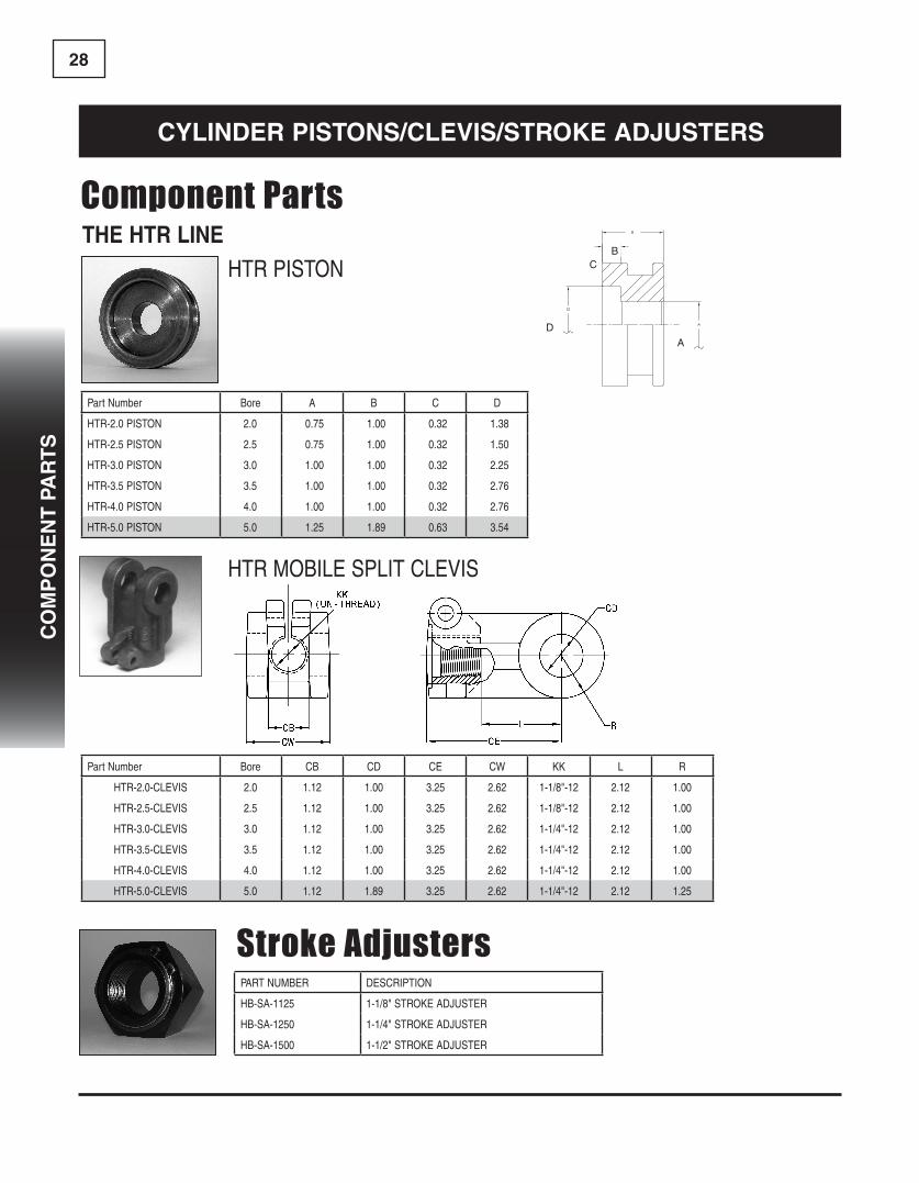
28
THE HTR LINEComponent Parts
PartNumber Bore A B C D
HTR-2.0 PISTON 2.0 0.75 1.00 0.32 1.38
HTR-2.5 PISTON 2.5 0.75 1.00 0.32 1.50
HTR-3.0 PISTON 3.0 1.00 1.00 0.32 2.25
HTR-3.5 PISTON 3.5 1.00 1.00 0.32 2.76
HTR-4.0 PISTON 4.0 1.00 1.00 0.32 2.76
HTR-5.0 PISTON 5.0 1.25 1.89 0.63 3.54
HTR PISTON
cylindeR PisTons/clevis/sTRoke adJUsTeRs
HTR MOBILE SPLIT CLEVIS
BC
A
D
Stroke AdjustersPART NUMBER DESCRIPTION
HB-SA-1125 1-1/8" STROKE ADJUSTER
HB-SA-1250 1-1/4" STROKE ADJUSTER
HB-SA-1500 1-1/2" STROKE ADJUSTER
PartNumber Bore CB CD CE CW KK L R
HTR-2.0-CLEVIS 2.0 1.12 1.00 3.25 2.62 1-1/8"-12 2.12 1.00
HTR-2.5-CLEVIS 2.5 1.12 1.00 3.25 2.62 1-1/8"-12 2.12 1.00
HTR-3.0-CLEVIS 3.0 1.12 1.00 3.25 2.62 1-1/4"-12 2.12 1.00
HTR-3.5-CLEVIS 3.5 1.12 1.00 3.25 2.62 1-1/4"-12 2.12 1.00
HTR-4.0-CLEVIS 4.0 1.12 1.00 3.25 2.62 1-1/4"-12 2.12 1.00
HTR-5.0-CLEVIS 5.0 1.12 1.89 3.25 2.62 1-1/4"-12 2.12 1.25
co
MP
on
en
T P
aR
Ts
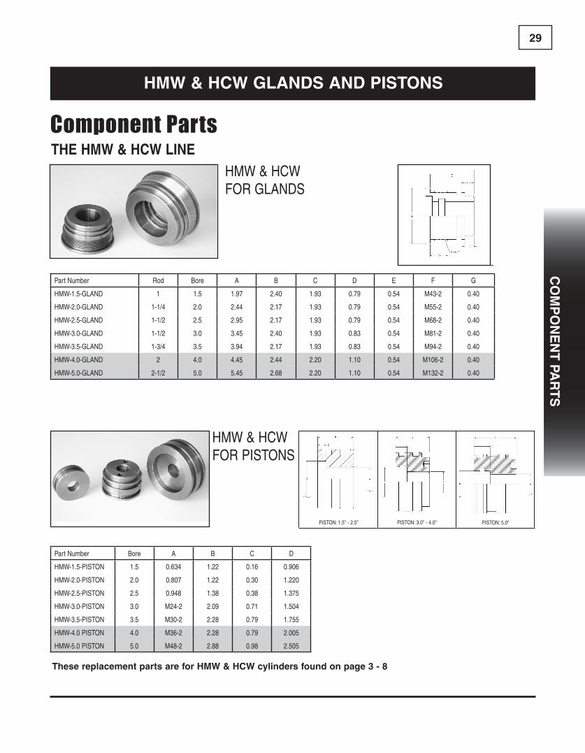
29
THE HMW & HCW LINEComponent Parts
HMW&HCWFOR GLANDS
HMW&HCWFOR PISTONS
co
MP
on
en
T Pa
RT
s
HMW & HcW glands and PisTons
PartNumber Rod Bore A B C D E F G
HMW-1.5-GLAND 1 1.5 1.97 2.40 1.93 0.79 0.54 M43-2 0.40
HMW-2.0-GLAND 1-1/4 2.0 2.44 2.17 1.93 0.79 0.54 M55-2 0.40
HMW-2.5-GLAND 1-1/2 2.5 2.95 2.17 1.93 0.79 0.54 M68-2 0.40
HMW-3.0-GLAND 1-1/2 3.0 3.45 2.40 1.93 0.83 0.54 M81-2 0.40
HMW-3.5-GLAND 1-3/4 3.5 3.94 2.17 1.93 0.83 0.54 M94-2 0.40
HMW-4.0-GLAND 2 4.0 4.45 2.44 2.20 1.10 0.54 M106-2 0.40
HMW-5.0-GLAND 2-1/2 5.0 5.45 2.68 2.20 1.10 0.54 M132-2 0.40
PartNumber Bore A B C D
HMW-1.5-PISTON 1.5 0.634 1.22 0.16 0.906
HMW-2.0-PISTON 2.0 0.807 1.22 0.30 1.220
HMW-2.5-PISTON 2.5 0.948 1.38 0.38 1.375
HMW-3.0-PISTON 3.0 M24-2 2.09 0.71 1.504
HMW-3.5-PISTON 3.5 M30-2 2.28 0.79 1.755
HMW-4.0 PISTON 4.0 M36-2 2.28 0.79 2.005
HMW-5.0 PISTON 5.0 M48-2 2.88 0.98 2.505
These replacement parts are for HMW & HcW cylinders found on page 3 - 8
PISTON:1.5"-2.5" PISTON:3.0"-4.0" PISTON:5.0"

30
Mo
Bil
e c
yl
ind
eR
He
ad
s
MoBile cylindeR Heads
Material:65-45-12DuctileIron
IT Head
PARTNUMBER
BORE +.003”-.003”
ROD +.003”-.003”
A B C D EF (BUT-TRESS)
SEAL KIT NUMBER
CM-H107277 1.500 1.000 2.00 2.00 1.50 0.75 0.28 1-3/4”-12 SK-H107277CM-H107597 2.000 1.000 2.50 2.12 1.94 1.00 0.12 2-1/4”-12 SK-H107597CM-H107598 2.000 1.125 2.50 2.00 1.75 0.75 0.19 2-1/4”-12 SK-H107598CM-H107595 2.000 1.250 2.50 2.25 2.00 1.00 0.19 2-1/4”-12 SK-H107595CM-H107193 2.500 1.125 3.00 2.00 1.75 0.75 0.19 2-3/4”-12 SK-H107193CM-H107194 2.500 1.250 3.00 2.00 1.75 0.75 0.19 2-3/4”-12 SK-H107194CM-H107463 2.500 1.500 3.00 2.38 2.00 1.00 0.19 2-3/4”-12 SK-H107463CM-H107673 2.500 1.750 3.00 2.25 1.88 0.88 0.28 2-3/4”-12 SK-H107673CM-H107157 3.000 1.000 3.50 2.25 2.00 1.00 0.19 3-1/4”-12 SK-H107157CM-H107196 3.000 1.250 3.50 2.25 2.00 1.00 0.19 3-1/4”-12 SK-H107196CM-H107131 3.000 1.500 3.50 2.25 2.00 1.00 0.19 3-1/4”-12 SK-H107131CM-H107189 3.000 1.750 3.50 2.25 2.00 1.00 0.19 3-1/4”-12 SK-H107189CM-H107359 3.000 2.000 3.50 2.50 2.00 1.00 0.19 3-1/4”-12 SK-H107359CM-H107591 3.250 1.500 3.75 2.25 2.00 1.00 0.19 3-1/2”-12 SK-H107591CM-H107592 3.250 1.750 3.75 2.25 2.00 1.00 0.19 3-1/2”-12 SK-H107592CM-H107197 3.500 1.250 4.00 2.25 2.00 1.00 0.19 3-3/4”-12 SK-H107197CM-H107198 3.500 1.500 4.00 2.25 2.00 1.00 0.19 3-3/4”-12 SK-H107198CM-H107108 3.500 1.750 4.00 2.25 2.00 1.00 0.19 3-3/4”-12 SK-H107108CM-H107112 3.500 2.000 4.00 2.25 2.00 1.00 0.19 3-3/4”-12 SK-H107112CM-H107462 3.500 2.500 4.00 2.50 2.12 1.00 0.25 3-3/4”-12 SK-H107462CM-H107130 4.000 1.500 4.50 2.25 2.00 1.00 0.19 4-1/4”-12 SK-H107130CM-H107124 4.000 1.750 4.50 2.25 2.00 1.00 0.19 4-1/4”-12 SK-H107124CM-H107311 4.000 2.000 4.50 2.25 2.00 1.00 0.19 4-1/4”-12 SK-H107311CM-H107331 4.000 2.250 4.50 2.25 2.00 1.00 0.19 4-1/4”-12 SK-H107331CM-H107386 4.000 2.500 4.50 2.50 2.12 1.12 0.19 4-1/4”-12 SK-H107386CM-H107525 4.000 3.000 4.50 2.50 2.12 1.00 0.25 4-1/4”-12 SK-H107525CM-H107199 4.500 1.750 5.00 2.25 2.00 1.00 0.19 4-3/4”-12 SK-H107199CM-H107200 4.500 2.000 5.00 2.25 2.00 1.00 0.19 4-3/4”-12 SK-H107200CM-H107201 4.500 2.250 5.00 2.25 2.00 1.00 0.19 4-3/4”-12 SK-H107201CM-H107528 4.500 3.500 5.00 2.38 2.00 1.00 0.19 4-3/4”-12 SK-H107528CM-H107234 5.000 1.750 5.50 2.25 2.00 1.00 0.19 5-1/4”-12 SK-H107234CM-H107212 5.000 2.000 5.50 2.25 2.00 1.00 0.19 5-1/4”-12 SK-H107212CM-H107204 5.000 2.500 5.50 2.50 2.12 1.12 0.19 5-1/4”-12 SK-H107204CM-H107205 5.000 3.000 5.50 2.50 2.12 1.12 0.19 5-1/4”-12 SK-H107205CM-H107345 6.000 2.000 6.50 2.50 2.12 1.12 0.19 6-1/4”-12 SK-H107345CM-H107206 6.000 2.500 6.50 2.50 2.12 1.12 0.19 6-1/4”-12 SK-H107206CM-H107207 6.000 3.000 6.50 2.50 2.12 1.12 0.19 6-1/4”-12 SK-H107207CM-H107178 6.000 3.500 6.50 2.50 2.12 1.12 0.19 6-1/4”-12 SK-H107178CM-H107328 7.000 3.000 7.50 2.88 2.50 1.12 0.59 7-1/4”-10 SK-H107328CM-H107493 7.000 3.500 7.50 2.88 2.50 1.12 0.59 7-1/4”-10 SK-H107493CM-H107467 7.000 4.000 7.50 2.88 2.50 1.12 0.59 7-1/4”-10 SK-H107467CM-H107466 8.000 4.000 9.00 3.75 3.25 1.50 0.88 8-1/4”-10 SK-H107466CM-H107494 8.000 4.500 9.00 3.75 3.25 1.50 0.88 8-1/4”-10 SK-H107494CM-H107475 8.000 5.000 9.00 3.75 3.25 1.50 0.88 8-1/4”-10 SK-H107475
Mo
Bil
e c
yl
ind
eR
He
ad
s
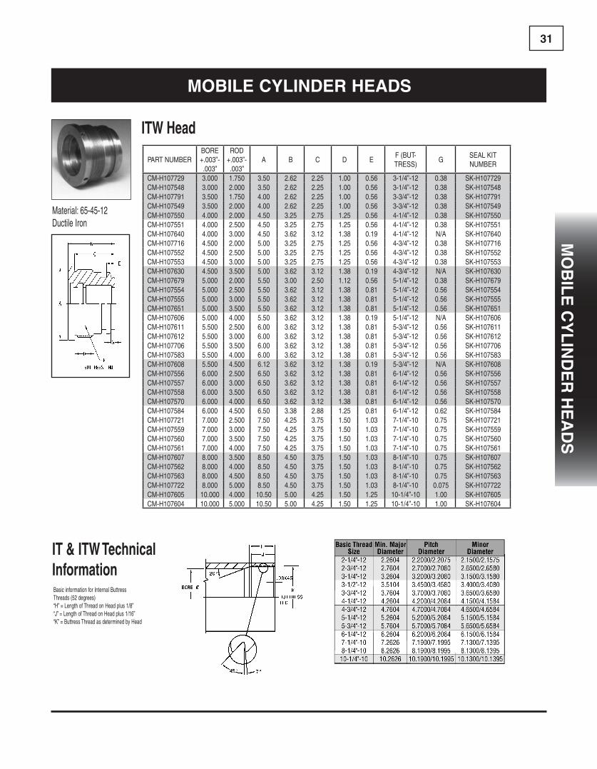
31M
oB
ile
cy
lin
de
R H
ea
ds
Material:65-45-12DuctileIron
ITW Head
IT & ITW Technical InformationBasicinformationforInternalButtress Threads(52degrees)“H”=LengthofThreadonHeadplus1/8”“J”=LengthofThreadonHeadplus1/16”“K”=ButtressThreadasdeterminedbyHead
PART NUMBERBORE +.003”-.003”
ROD +.003”-.003”
A B C D EF (BUT-TRESS)
GSEAL KIT NUMBER
CM-H107729 3.000 1.750 3.50 2.62 2.25 1.00 0.56 3-1/4”-12 0.38 SK-H107729CM-H107548 3.000 2.000 3.50 2.62 2.25 1.00 0.56 3-1/4”-12 0.38 SK-H107548CM-H107791 3.500 1.750 4.00 2.62 2.25 1.00 0.56 3-3/4”-12 0.38 SK-H107791CM-H107549 3.500 2.000 4.00 2.62 2.25 1.00 0.56 3-3/4”-12 0.38 SK-H107549CM-H107550 4.000 2.000 4.50 3.25 2.75 1.25 0.56 4-1/4”-12 0.38 SK-H107550CM-H107551 4.000 2.500 4.50 3.25 2.75 1.25 0.56 4-1/4”-12 0.38 SK-H107551CM-H107640 4.000 3.000 4.50 3.62 3.12 1.38 0.19 4-1/4”-12 N/A SK-H107640CM-H107716 4.500 2.000 5.00 3.25 2.75 1.25 0.56 4-3/4”-12 0.38 SK-H107716CM-H107552 4.500 2.500 5.00 3.25 2.75 1.25 0.56 4-3/4”-12 0.38 SK-H107552CM-H107553 4.500 3.000 5.00 3.25 2.75 1.25 0.56 4-3/4”-12 0.38 SK-H107553CM-H107630 4.500 3.500 5.00 3.62 3.12 1.38 0.19 4-3/4”-12 N/A SK-H107630CM-H107679 5.000 2.000 5.50 3.00 2.50 1.12 0.56 5-1/4”-12 0.38 SK-H107679CM-H107554 5.000 2.500 5.50 3.62 3.12 1.38 0.81 5-1/4”-12 0.56 SK-H107554CM-H107555 5.000 3.000 5.50 3.62 3.12 1.38 0.81 5-1/4”-12 0.56 SK-H107555CM-H107651 5.000 3.500 5.50 3.62 3.12 1.38 0.81 5-1/4”-12 0.56 SK-H107651CM-H107606 5.000 4.000 5.50 3.62 3.12 1.38 0.19 5-1/4”-12 N/A SK-H107606CM-H107611 5.500 2.500 6.00 3.62 3.12 1.38 0.81 5-3/4”-12 0.56 SK-H107611CM-H107612 5.500 3.000 6.00 3.62 3.12 1.38 0.81 5-3/4”-12 0.56 SK-H107612CM-H107706 5.500 3.500 6.00 3.62 3.12 1.38 0.81 5-3/4”-12 0.56 SK-H107706CM-H107583 5.500 4.000 6.00 3.62 3.12 1.38 0.81 5-3/4”-12 0.56 SK-H107583CM-H107608 5.500 4.500 6.12 3.62 3.12 1.38 0.19 5-3/4”-12 N/A SK-H107608CM-H107556 6.000 2.500 6.50 3.62 3.12 1.38 0.81 6-1/4”-12 0.56 SK-H107556CM-H107557 6.000 3.000 6.50 3.62 3.12 1.38 0.81 6-1/4”-12 0.56 SK-H107557CM-H107558 6.000 3.500 6.50 3.62 3.12 1.38 0.81 6-1/4”-12 0.56 SK-H107558CM-H107570 6.000 4.000 6.50 3.62 3.12 1.38 0.81 6-1/4”-12 0.56 SK-H107570CM-H107584 6.000 4.500 6.50 3.38 2.88 1.25 0.81 6-1/4”-12 0.62 SK-H107584CM-H107721 7.000 2.500 7.50 4.25 3.75 1.50 1.03 7-1/4”-10 0.75 SK-H107721CM-H107559 7.000 3.000 7.50 4.25 3.75 1.50 1.03 7-1/4”-10 0.75 SK-H107559CM-H107560 7.000 3.500 7.50 4.25 3.75 1.50 1.03 7-1/4”-10 0.75 SK-H107560CM-H107561 7.000 4.000 7.50 4.25 3.75 1.50 1.03 7-1/4”-10 0.75 SK-H107561CM-H107607 8.000 3.500 8.50 4.50 3.75 1.50 1.03 8-1/4”-10 0.75 SK-H107607CM-H107562 8.000 4.000 8.50 4.50 3.75 1.50 1.03 8-1/4”-10 0.75 SK-H107562CM-H107563 8.000 4.500 8.50 4.50 3.75 1.50 1.03 8-1/4”-10 0.75 SK-H107563CM-H107722 8.000 5.000 8.50 4.50 3.75 1.50 1.03 8-1/4”-10 0.075 SK-H107722CM-H107605 10.000 4.000 10.50 5.00 4.25 1.50 1.25 10-1/4”-10 1.00 SK-H107605CM-H107604 10.000 5.000 10.50 5.00 4.25 1.50 1.25 10-1/4”-10 1.00 SK-H107604
MoBile cylindeR Heads
Mo
Bil
e c
yl
ind
eR
He
ad
s

32
TK HEADBORE +.003”-.003”
ROD +.003”-.003”
A B C D E FSEAL KIT NUMBER
LOCK WIRE NUMBER
CM-H70181 1.500 0.750 1.88 2.00 1.63 0.38 0.63 0.38 SK-H70181 RR20030CM-H70184 1.500 1.000 1.88 2.00 1.12 0.31 0.19 N/A SK-H70184 RR20030CM-H70093 2.000 1.000 2.38 2.25 1.88 0.44 0.75 0.50 SK-H70093 RR20029CM-H70159 2.000 1.125 2.38 2.50 1.88 0.44 0.75 0.44 SK-H70159 RR20029CM-H70160 2.000 1.250 2.38 2.50 1.88 0.44 0.75 0.44 SK-H70160 RR20029CM-H70161 2.500 1.125 2.88 2.25 1.88 0.44 0.75 0.44 SK-H70161 RR20031CM-H70162 2.500 1.250 2.88 2.25 1.88 0.44 0.75 0.38 SK-H70162 RR20031CM-H70163 2.500 1.500 2.88 2.25 1.88 0.44 0.75 0.62 SK-H70163 RR20031CM-H70861 2.500 1.750 2.88 2.50 1.88 0.44 0.75 0.38 SK-H70861 RR20031CM-H70164 3.000 1.250 3.38 2.75 2.25 0.51 0.88 0.50 SK-H70164 RR20027CM-H70130 3.000 1.500 3.38 2.75 2.25 0.51 0.88 0.50 SK-H70130 RR20027CM-H70560 3.000 1.750 3.38 2.75 2.25 0.51 0.88 0.44 SK-H70560 RR20027CM-H70165 3.000 2.000 3.38 2.75 2.25 0.51 0.88 0.44 SK-H70165 RR20027CM-H70166 3.500 1.250 3.88 2.75 2.25 0.51 0.88 0.50 SK-H70166 RR20032CM-H70089 3.500 1.500 3.88 2.75 2.25 0.51 0.88 0.50 SK-H70089 RR20032CM-H70862 3.500 1.750 3.88 2.75 2.25 0.51 0.88 0.50 SK-H70862 RR20032CM-H70167 3.500 2.000 3.88 2.75 2.25 0.51 0.88 0.50 SK-H70167 RR20032CM-H70115 4.000 1.500 4.50 2.75 2.25 0.44 0.88 0.44 SK-H70115 RR20033CM-H70576 4.000 1.750 4.50 2.75 2.25 0.44 0.88 0.44 SK-H70576 RR20033CM-H70116 4.000 2.000 4.50 2.75 2.25 0.44 0.88 0.44 SK-H70116 RR20033CM-H70168 4.000 2.500 4.50 2.75 2.25 0.44 0.88 0.44 SK-H70168 RR20033CM-H70367 4.500 2.000 5.00 2.75 2.25 0.44 0.88 0.44 SK-H70367 RR20087CM-H70378 4.500 2.500 5.00 2.75 2.25 0.44 0.88 0.44 SK-H70378 RR20087CM-H70379 4.500 3.000 5.00 2.75 2.25 0.44 0.88 0.44 SK-H70379 RR20087CM-H70114 5.000 2.000 5.50 3.00 2.50 0.56 0.94 0.50 SK-H70114 RR20039CM-H70113 5.000 2.500 5.50 3.00 2.50 0.56 0.94 0.50 SK-H70113 RR20039CM-H70107 5.000 3.000 5.50 3.00 2.50 0.56 0.94 0.50 SK-H70107 RR20039CM-H70389 5.500 2.000 6.00 3.00 2.50 0.56 0.94 0.50 SK-H70389 RR20089CM-H70390 5.500 2.500 6.00 3.00 2.50 0.56 0.94 0.50 SK-H70390 RR20089CM-H70391 5.500 3.000 6.00 3.00 2.50 0.56 0.94 0.50 SK-H70391 RR20089CM-H70112 6.000 2.000 6.50 3.00 2.50 0.56 0.94 0.50 SK-H70112 RR20040CM-H70111 6.000 2.500 6.50 3.00 2.50 0.56 0.94 0.50 SK-H70111 RR20040CM-H70108 6.000 3.000 6.50 3.00 2.50 0.56 0.94 0.50 SK-H70108 RR20040
Material:DuctileIron
TK Head
*0.312For1”Rod
TK Technical InformationRetainingGrooveInformation
MoBile cylindeR Heads
BORE +.003"-.003"
H J KL
+.010"-.000"
M+.005"-.000"
N+.000"-.005"
1.500 0.25 0.25 0.28 1.625 0.125 0.3752.000 0.25 0.25 0.34 2.125 0.125 0.4382.500 0.25 0.25 0.34 2.625 0.125 0.4383.000 0.25 0.25 0.41 3.125 0.125 0.5003.500 0.25 0.25 0.41 3.625 0.125 0.5004.000 0.38 0.25 0.41 4.188 0.188 0.4384.500 0.38 0.25 0.41 4.688 0.188 0.4385.000 0.38 0.25 0.53 5.188 0.188 0.5625.500 0.38 0.25 0.53 5.688 0.188 0.5626.000 0.38 0.25 0.53 6.188 0.188 0.562
LOCK WIRES
Mo
Bil
e c
yl
ind
eR
He
ad
s

33M
oB
ile
cy
lin
de
R H
ea
ds
Material:DuctileIron
TH Head
MoBile cylindeR Heads
TH Head Technical Information
LOCK WIRE - PAGE REFERENCE TO 30
PART NUMBERBORE
+.003”-.003”ROD
+.003”-.003”A B C E F
SEAL KIT NUMBER
CM-H70154 2.000 1.000 2.25 2.38 1.94 0.81 0.62 SK-H70154CM-H70155 2.000 1.125 2.25 2.38 1.94 0.81 0.62 SK-H70155CM-H70156 2.000 1.250 2.25 2.38 1.94 0.81 0.62 SK-H70156CM-H70157 2.500 1.125 2.75 2.38 1.94 0.81 0.62 SK-H70157CM-H70076 2.500 1.250 2.75 2.38 1.94 0.81 0.62 SK-H70076CM-H70158 2.500 1.500 2.75 2.38 1.94 0.81 0.62 SK-H70158CM-H70462 2.500 1.750 2.75 2.38 2.19 0.81 0.62 SK-H70462CM-H70029 3.000 1.250 3.25 2.75 2.19 0.94 0.75 SK-H70029CM-H70011 3.000 1.500 3.25 2.75 2.19 0.94 0.75 SK-H70011CM-H70814 3.000 1.750 3.25 2.75 2.19 0.94 0.75 SK-H70814CM-H70012 3.000 2.000 3.25 2.75 2.56 0.94 0.69 SK-H70012CM-H70013 3.500 1.500 3.75 2.75 2.19 0.94 0.75 SK-H70013CM-H70504 3.500 1.750 3.75 2.75 2.19 0.94 0.75 SK-H70504CM-H70030 3.500 2.000 3.75 2.75 2.19 0.94 0.75 SK-H70030CM-H70031 3.500 2.500 3.75 2.75 2.56 0.94 0.75 SK-H70031CM-H70014 4.000 1.500 4.25 2.75 2.19 0.94 0.75 SK-H70014CM-H70488 4.000 1.750 4.25 2.75 2.19 0.94 0.75 SK-H70488CM-H70015 4.000 2.000 4.25 2.75 2.19 0.94 0.75 SK-H70015CM-H70032 4.000 2.500 4.25 2.75 2.19 0.94 0.75 SK-H70032CM-H70033 4.000 3.000 4.25 2.75 2.56 0.94 0.75 SK-H70033CM-H70276 4.500 2.000 4.75 2.75 2.19 0.94 0.75 SK-H70276CM-H70310 4.500 2.500 4.75 2.75 2.19 0.94 0.75 SK-H70310CM-H70377 4.500 3.000 4.75 2.75 2.19 0.94 0.69 SK-H70377CM-H70037 5.000 2.000 5.38 3.00 2.44 1.13 0.88 SK-H70037CM-H70038 5.000 2.500 5.38 3.00 2.44 1.13 0.88 SK-H70038CM-H70039 5.000 3.000 5.38 3.00 2.44 1.13 0.88 SK-H70039CM-H70153 5.500 2.000 5.88 3.00 2.44 1.13 0.88 SK-H70153CM-H70142 5.500 2.500 5.88 3.00 2.44 1.13 0.88 SK-H70142CM-H70143 5.500 3.000 5.88 3.00 2.44 1.13 0.88 SK-H70143CM-H70041 6.000 2.000 6.38 3.00 2.44 1.13 0.88 SK-H70041CM-H70042 6.000 2.500 6.38 3.00 2.44 1.13 0.88 SK-H70042CM-H70043 6.000 3.000 6.38 3.00 2.44 1.13 0.88 SK-H70043CM-H70180 7.000 2.500 7.50 4.00 3.13 1.75 1.50 SK-H70180CM-H70176 7.000 3.000 7.50 4.00 3.13 1.75 1.50 SK-H70176CM-H70186 7.000 3.500 7.50 4.00 3.13 1.75 1.50 SK-H70186CM-H70133 8.000 3.000 8.50 4.00 3.13 1.75 1.50 SK-H70133CM-H70195 8.000 3.500 8.50 4.00 3.13 1.75 1.50 SK-H70195CM-H70217 8.000 4.000 8.50 4.00 3.13 1.75 1.50 SK-H70217

34
MoBile cylindeR caPs
Material:1026CDSTubing
TH Cap PART NUMBERBORE
+.003”-.003”F G H J K L
CM-HC70074 2.000 1.13 0.88 0.69 2-3/8”-12 UN-2B 1.81 3.00CM-HC70075 2.500 1.13 0.88 0.69 2-7/8”-12 UN-2B 2.31 3.50CM-HC70008 3.000 1.38 1.00 0.75 3-1/2”-12 UN-2B 2.63 4.00CM-HC70009 3.500 1.38 1.00 0.75 4”-12 UN-2B 3.13 4.50CM-HC70034 4.000 1.38 1.00 0.75 4-1/2”-12 UN-2B 3.63 5.00CM-HC70277 4.500 1.38 1.00 0.75 5”-12 UN-2B 4.13 5.50CM-HC70040 5.000 1.38 1.00 0.75 5-1/2”-12 UN-2B 4.63 6.25CM-HC70140 5.500 1.38 1.00 0.75 6”-12 UN-2B 5.13 6.75CM-HC70044 6.000 1.38 1.00 0.75 6-5/8”-12 UN-2B 5.63 7.50CM-HC70174 7.000 2.00 1.38 1.13 7-7/8”-12 UN-2B 6.13 9.00CM-HC70132 8.000 2.00 1.38 1.13 8-7/8”-12 UN-2B 7.13 10.00
Material:A-36Plate
Base Plate (medium duty)
Material:A-36Plate
Base Plate (heavy duty)
PART NUMBER
BORE +.003”-.003”
A B C
CM-BP60056 1.500 1.88 0.50 0.25CM-BP60010 2.000 2.38 0.50 0.25CM-BP60011 2.500 2.88 0.50 0.25CM-BP60012 3.000 3.38 0.59 0.25CM-BP60013 3.500 3.88 0.69 0.38CM-BP60014 4.000 4.50 0.75 0.38CM-BP60437 4.500 5.00 0.88 0.38CM-BP60015 5.000 5.56 0.88 0.38CM-BP60124 5.500 6.00 0.88 0.38CM-BP60016 6.000 6.75 1.00 0.38CM-BP60157 7.000 8.00 1.00 0.38CM-BP60107 8.000 9.00 1.00 0.38
PART NUMBER
BORE +.003”-.003”
A B C
CM-BP112527 1.500 2.000 0.50 0.19CM-BP112292 2.000 2.500 0.50 0.12CM-BP112209 2.500 3.000 0.62 0.25CM-BP112210 3.000 3.500 0.75 0.25CM-BP112461 3.250 3.750 0.88 0.25CM-BP112211 3.500 4.000 0.88 0.25CM-BP112212 4.000 4.500 1.00 0.25CM-BP112414 4.000 4.620 1.00 0.25CM-BP112213 4.500 5.000 1.12 0.25CM-BP112234 5.000 5.500 1.25 0.25CM-BP112459 5.000 5.620 1.25 0.25CM-BP112214 5.000 5.750 1.25 0.25CM-BP112426 5.500 6.120 1.31 0.25CM-BP112236 6.000 6.500 1.38 0.25CM-BP112512 6.000 6.620 1.38 0.25CM-BP112215 6.000 6.750 1.38 0.25CM-BP112569 6.500 7.250 1.25 0.25CM-BP112364 7.000 8.000 1.44 0.25CM-BP112373 8.000 9.000 1.50 0.25CM-BP112496 9.000 10.000 1.50 0.38CM-BP112467 10.000 11.000 1.50 0.38
Material:A-36Plate
Base End (ported) PART NUMBERBORE
+.003”-.003”NPT SAE A B C D E F
CM-BEP112380 2.000 3/8” #6 2.50 1.56 0.25 1.00 1.25 1.45CM-BEP112381 2.500 3/8” #6 3.00 1.56 0.25 1.00 1.25 1.75CM-BEP112382 3.000 1/2” #8 3.50 1.69 0.25 1.12 1.75 2.19CM-BEP112383 3.500 1/2” #8 4.00 1.69 0.25 1.12 2.00 2.19CM-BEP112384 4.000 1/2” #8 4.50 1.81 0.25 1.35 2.12 2.62CM-BEP112385 4.500 1/2” #8 5.12 1.81 0.25 1.35 2.12 2.62CM-BEP112386 5.000 3/4” #12 5.62 1.94 0.25 1.35 2.38 3.03CM-BEP112398 5.500 3/4” #12 6.25 2.19 0.25 1.50 3.29 4.06CM-BEP112387 6.000 3/4” #12 6.75 2.19 0.25 1.50 3.29 4.06
Mo
Bil
e c
yl
ind
eR
ca
Ps

35M
oB
ile
Pis
Ton
s
MoBile PisTons
Material:DuctileIron
Material:65-45-12DuctileIron
IT (narrow) Piston
Material:DuctileIron
TM Piston
TH Piston
PART NUMBERBORE +.003”-.003”
A +.002”-.000”
B CSEAL KIT NUMBER
CM-P70079 1.50 0.626 0.88 N/A SK-P70079CM-P70055 2.00 0.751 1.00 N/A SK-P70055CM-P70065 2.50 0.751 1.00 N/A SK-P70065CM-P70841 3.00 0.751 1.00 0.25 SK-P70841CM-P70872 3.50 1.001 1.00 0.38 SK-P70872CM-P70067 4.00 1.001 1.00 N/A SK-P70067CM-P70384 4.50 1.251 1.50 N/A SK-P70384CM-P70090 5.00 1.251 1.50 N/A SK-P70090CM-P70385 5.50 1.501 1.50 N/A SK-P70385CM-P70139 6.00 1.501 1.50 N/A SK-P70139
PART NUMBERBORE +.003”-.003”
A +.002”-.000”
B CSEAL KIT NUMBER
CM-P70020 1.50 0.626 1.13 N/A SK-P70020CM-P70005 2.00 0.751 1.50 N/A SK-P70005CM-P70017 2.50 0.751 1.50 N/A SK-P70017CM-P70006 3.00 1.001 1.75 N/A SK-P70006CM-P70007 3.50 1.126 1.75 N/A SK-P70007CM-P70010 4.00 1.251 1.75 N/A SK-P70010CM-P70275 4.50 1.251 1.75 N/A SK-P70275CM-P70018 5.00 1.251 2.00 N/A SK-P70018CM-P70141 5.50 1.501 2.00 N/A SK-P70141CM-P70019 6.00 1.501 2.00 N/A SK-P70019CM-P70175 7.00 1.751 3.00 0.75 SK-P70175CM-P70134 8.00 2.001 3.00 0.75 SK-P70134
PART NUMBERBORE +.003”-.003”
A +.002”-.000”
B SEAL KIT NUMBER
CM-P110629 1.500 0.626 1.12 SK-P110629CM-P110238 2.000 0.751 1.25 SK-P110238CM-P110239 2.500 0.751 1.25 SK-P110239CM-P110240 3.000 0.876 1.25 SK-P110240CM-P110608 3.250 1.001 1.25 SK-P110608CM-P110241 3.500 1.001 1.25 SK-P110241CM-P110242 4.000 1.001 1.25 SK-P110242CM-P110384 4.500 1.126 1.50 SK-P110384CM-P110212 5.000 1.126 1.50 SK-P110212

36
MoBile PisTons
Piston Stub TechnicalInformation
Material:65-45-12DuctileIron
IT (wide) Piston
“D”=“A”DiameterofPiston,minus0.001”/0.003”“E”=NutLength+0.25”“F”=PistonWidth“B”minusCounterboreDepth“C”+NutLength+0.12”“G”=ThreadSizetobedeterminedbynutused“H”=LocatedundermiddleofPiston,0.098”/0.093”WideX0.050”/0.052”
Deepfor1/16crosssectionO-ring(000Series)
Note:Goodruleofthumbistosizethestubdiameteratleastonehalfthediameteroftherod.
*NOTE: P110479iscounterboredfora(-226)StubO-ring. P110634iscounterboredfora(-230)StubO-ring. P110683iscounterboredfora(-230)StubO-ring.
IT (WIDE) PISTON BORE +.003”-.003” A +.002”-.000” B SEAL KIT NUMBERCM-P110548 2.000 1.001 2.00 SK-P110548CM-P110596 2.500 0.751 1.88 SK-P110596CM-P110121 3.000 1.001 2.00 SK-P110121CM-P110288 3.500 1.126 2.00 SK-P110288CM-P110287 4.000 1.126 2.00 SK-P110287CM-P110537 4.500 1.251 2.00 SK-P110537CM-P110248 5.000 1.251 2.00 SK-P110248CM-P110511 5.500 1.251 2.12 SK-P110511CM-P110249 6.000 1.251 2.12 SK-P110249CM-P110607 6.000 1.501 2.12 SK-P110607CM-P110312 7.000 1.751 2.12 SK-P110312CM-P110479 8.000 2.001 3.12 SK-P110479CM-P110683 9.000 2.501 4.38 SK-P110683CM-P110634 10.000 2.500 4.38 SK-P110634
Mo
Bil
e P
isTo
ns

37M
oB
ile
Mo
Un
Ts
MoBile MoUnTs
Cross Tube Mount
PART NUMBER CD W B L DCM-CT251015 1.00 2.50 1.50 0.69 .250x.09CM-CT301015 1.00 3.00 1.50 0.69 .250x.09CM-CT351015 1.00 3.50 1.50 0.69 .250x.09CM-CT401015 1.00 4.00 1.50 0.69 .250x.09CM-CT451015 1.00 4.50 1.50 0.69 .250x.09CM-CT271017 1.00 2.75 1.75 0.81 .250x.15CM-CT321017 1.00 3.25 1.75 0.81 .250x.15CM-CT371017 1.00 3.75 1.75 0.81 .250x.15CM-CT421017 1.00 4.25 1.75 0.81 .250x.15CM-CT471017 1.00 4.75 1.75 0.81 .250x.15CM-CT521017 1.00 5.25 1.75 0.81 .250x.15CM-CT271220 1.25 2.75 2.00 0.88 .250x.15CM-CT321220 1.25 3.25 2.00 0.88 .250x.15CM-CT371220 1.25 3.75 2.00 0.88 .250x.15CM-CT421220 1.25 4.25 2.00 0.88 .250x.15CM-CT471220 1.25 4.75 2.00 0.88 .250x.15CM-CT521220 1.25 5.25 2.00 0.88 .250x.15CM-CT601220 1.25 6.00 2.00 0.88 .250x.15CM-CT701220 1.25 7.00 2.00 0.88 .250x.15CM-CT301525 1.50 3.00 2.50 1.13 .250x.19CM-CT421525 1.50 4.25 2.50 1.13 .250x.19CM-CT471525 1.50 4.75 2.50 1.13 .250x.19CM-CT551525 1.50 5.50 2.50 1.13 .250x.19CM-CT601525 1.50 6.00 2.50 1.13 .250x.19CM-CT701525 1.50 7.00 2.50 1.13 .250x.19CM-CT321727 1.75 3.25 2.75 1.25 .250x.19CM-CT471727 1.75 4.75 2.75 1.25 .250x.19CM-CT551727 1.75 5.50 2.75 1.25 .250x.19CM-CT601727 1.75 6.00 2.75 1.25 .250x.19CM-CT701727 1.75 7.00 2.75 1.25 .250x.19CM-CT352030 2.00 3.50 3.00 1.38 .250x.19CM-CT472030 2.00 4.75 3.00 1.38 .250x.19CM-CT552030 2.00 5.50 3.00 1.38 .250x.19CM-CT602030 2.00 6.00 3.00 1.38 .250x.19CM-CT702030 2.00 7.00 3.00 1.38 .250x.19

38
MoBile Welded MoUnTs
Welded Rod End Spherical Mount
Material:50KMin.YieldPlate
Welded Base End Spherical Mount
Material:50KMin.YieldPlate
PART NUMBER CD L RAD WPIN
DIAMETERDESIGNED
SPHERICAL #MAX PULL AT YEILD
CM-WBES-10 1.625 2.00 1.25 0.75 1.00 SB99100 15,000#CM-WBES-12 2.000 2.00 1.50 0.94 1.25 SB99125 20,000#CM-WBES-15 2.437 2.50 1.88 1.12 1.50 SB99150 35,000#CM-WBES-17 2.812 2.50 2.00 1.31 1.75 SB99175 35,000#CM-WBES-20 3.187 2.75 2.38 1.50 2.00 SB99200 55,000#CM-WBES-25 3.937 3.25 3.00 1.88 2.50 SB99250 95,000#
PART NUMBER
CD L RAD W D CB RLPIN
DIAM-ETER
DESIGNED SPHERICAL #
CM-WRES-10 1.625 2.750 1.25 0.75 .250 X .19 1.015 2.12 1.00 SB99100CM-WRES-12 2.000 3.000 1.50 0.94 .250 X .19 1.265 2.25 1.25 SB99125CM-WRES-15 2.437 3.250 1.88 1.12 .250 X .19 1.515 2.50 1.50 SB99150CM-WRES-17 2.812 3.750 2.00 1.31 .250 X .19 1.515 2.75 1.75 SB99175CM-WRES-20 3.187 4.000 2.38 1.50 .250 X .19 2.015 3.00 2.00 SB99200CM-WRES-25 3.937 4.750 3.00 1.88 .250 X .19 2.515 3.50 2.50 SB99250
Mo
Bil
e W
el
de
d M
oU
nT
s

39M
oB
ile
sP
He
Ric
al
Be
aR
ing
s
MoBile sPHeRical BeaRings
Spherical Bearing
PART NUMBER A B C DHOUSING DIAMETER
CM-SB99062 0.6245/0.6250 1.0625/1.0620 0.547/0.542 0.469/0.464 1.0614/1.0622CM-SB99075 0.7495/0.7500 1.2495/1.2500 0.656/0.651 0.562/0.557 1.2487/1.2497CM-SB99100 0.9995/1.0000 1.6250/1.6245 0.875/0.870 0.750/0.745 1.6237/1.6247CM-SB99125 1.2495/1.2500 2.0000/1.9995 1.093/1.087 0.937/0.932 1.9985/1.9997CM-SB99137 1.3745/1.3750 2.1875/2.1869 1.187/1.182 1.031/1.026 2.1860/2.1872CM-SB99150 1.4995/1.5000 2.4375/2.4369 1.312/1.307 1.125/1.120 2.4360/2.4372CM-SB99175 1.7495/1.7500 2.8125/2.8119 1.531/1.526 1.312/1.307 2.8110/2.8122CM-SB99200 1.9995/2.0000 3.1875/3.1869 1.750/1.745 1.500/1.495 3.1858/3.1871CM-SB99225 2.2495/2.2500 3.5625/3.5617 1.969/1.964 1.687/1.682 3.5607/3.5621CM-SB99250 2.4994/2.5000 3.9375/3.9367 2.187/2.182 1.875/1.870 3.9357/3.9371

40
MoBile Welded MoUnTs
Material:A-36Plate
Mounting LugPART NUMBER L R WCM-ML296 1.50 1.00 0.50CM-ML297 1.50 1.00 0.62CM-ML298 1.50 1.00 0.75CM-ML299 1.75 1.25 1.00CM-ML301 2.00 1.50 1.00CM-ML302 2.50 2.00 1.00CM-ML303 1.50 1.00 1.25CM-ML304 1.50 1.12 1.50CM-ML305 2.00 1.25 1.50CM-ML306 1.75 1.50 1.50CM-ML307 2.75 1.50 1.50CM-ML308 1.75 1.25 2.00CM-ML309 2.00 1.50 2.00CM-ML310 2.12 1.50 2.00CM-ML311 2.25 1.50 2.00CM-ML312 3.00 1.50 2.00CM-ML313 1.75 1.75 2.00CM-ML314 1.88 1.75 2.00CM-ML315 2.12 1.75 2.00CM-ML316 2.50 1.75 2.00CM-ML317 2.75 1.75 2.00CM-ML318 3.00 2.00 2.00CM-ML319 3.00 2.12 2.00CM-ML320 3.12 2.50 2.00CM-ML321 2.00 1.12 2.25CM-ML322 2.25 1.75 2.25CM-ML323 3.00 2.50 2.25CM-ML324 3.00 2.50 2.50CM-ML325 3.00 2.25 3.00CM-ML326 3.00 2.00 3.25
Material:A-36Plate
Mounting LugPART NUMBER CD L RAD W GREASE FITTINGCM-ML050100 1.00 2.00 1.00 0.50 N/ACM-ML062100 1.00 2.00 1.00 0.62 N/ACM-ML060333 1.00 2.12 1.00 0.75 N/ACM-ML100100 1.00 2.00 1.00 1.00 N/ACM-ML125100 1.00 2.00 1.00 1.25 1/8” NPTCM-ML062125 1.25 2.50 1.25 0.62 N/ACM-ML075125 1.25 2.50 1.25 0.75 N/ACM-ML100125 1.25 2.50 1.25 1.00 N/ACM-ML150125 1.25 2.50 1.25 1.50 1/8” NPTCM-ML200125 1.25 2.50 1.25 2.00 1/8” NPTCM-ML062150 1.50 2.50 1.50 0.62 N/ACM-ML075150 1.50 2.50 1.50 0.75 N/ACM-ML150150 1.50 2.50 1.50 1.50 1/8” NPTCM-ML200150 1.50 2.50 1.50 2.00 1/8” NPTCM-ML250150 1.50 2.50 1.50 2.50 1/8” NPTCM-ML200200 2.00 3.00 2.00 2.00 1/8” NPTCM-ML250200 2.00 3.00 2.00 2.50 1/8” NPT
Mo
Bil
e W
el
de
d M
oU
nT
s

41M
oB
ile
We
ld
ed
Mo
Un
Ts
MoBile Welded MoUnTs
Material:1040HFBar
Formed ClevisPART NUMBER CB CD CE CW L WCM-CL3011 0.75 0.50 1.50 0.38 2.25 1.25CM-CL7337 1.06 0.75 2.00 0.38 3.12 1.75CM-CL6547 1.25 1.00 2.50 0.50 3.62 2.00CM-CL8278 0.88 1.00 2.93 0.50 4.06 2.00CM-CL323 1.25 1.00 5.06 0.38 6.06 1.75CM-B120753 1.50 1.12 2.12 0.50 3.25 2.25CM-B120625 1.62 1.25 2.75 0.75 4.00 2.50CM-80003 0.50 N/A N/A 0.38 2.38 1.00CM-80010 1.12 N/A N/A 0.38 3.50 2.00CM-B120829 1.50 N/A N/A 0.50 3.25 2.50CM-80001 1.12 N/A N/A 0.50 4.00 2.00CM-B120672 1.50 N/A N/A 0.50 4.00 3.00CM-B120760 1.12 1.00 2.12 0.62 3.38 2.50CM-B120756 1.12 N/A N/A 0.62 4.25 3.00CM-80015 1.25 N/A N/A 0.62 4.62 2.50CM-B120613 1.62 N/A N/A 0.75 4.00 2.50CM-B120614 2.12 N/A N/A 1.00 5.00 3.00

42
O-ringBossHalfCouplingPort 90DegreeO-ringBossPort
90DegreePipeThreadPort
Ports
PART NUMBER
BAR SIZE
A B C D
CM-PO65604 #4 SAE 0.75 1.12 0.75 1.12CM-PO65606 #6 SAE 0.87 1.25 0.81 1.25CM-PO65608 #8 SAE 1.25 1.62 1.00 1.62CM-PO65610 #10 SAE 1.25 1.75 1.12 1.88CM-PO65612 #12 SAE 1.50 2.12 1.19 2.00CM-PO65616 #16 SAE 1.50 2.25 1.25 2.38
PART NUMBER
PORT SIZE
A B
CM-PO65304 #4 SAE 0.88 1.00CM-PO65305 #5 SAE 0.88 0.75CM-PO65306 #6 SAE 1.00 1.00CM-PO65308 #8 SAE 1.25 1.06CM-PO65310 #10 SAE 1.38 1.06CM-PO65312 #12 SAE 1.50 1.28CM-PO65314 #14 SAE 1.63 1.25CM-PO65316 #16 SAE 1.75 1.28CM-PO65320 #20 SAE 2.25 1.28CM-PO65324 #24 SAE 2.50 1.00
PART NUMBER
PORT SIZE
A B
CM-PO65225 1/4” NPT 0.75 1.00CM-PO65237 3/8” NPT 0.88 1.00CM-PO65250 1/2” NPT 1.12 1.25CM-PO65275 3/4” NPT 1.38 1.38CM-PO652751 1” NPT 1.75 1.62
PipeThreadHalfCoupling
PART NUMBER
PORT SIZE A B
CM-PO65025 1/4” NPT 0.88 1.06CM-PO65037 3/8” NPT 1.00 1.00CM-PO65050 1/2” NPT 1.25 1.06CM-PO65075 3/4” NPT 1.50 1.28CM-PO65100 1” NPT 1.75 1.28CM-PO65125 1-1/4” NPT 2.25 1.28CM-PO65150 1-1/2” NPT 2.75 1.28
PoRTs/lock nUTs
Po
RT
s/l
oc
k n
UT
s

43M
oB
ile
Mo
Un
Ts
Material:DuctileIron
Mobile Split ClevisPART NUMBER CB CD CE CW KK L RCM-RC10033 1.12 1.00 3.25 2.62 1-1/16”-12 2.12 1.00CM-RC10034 1.12 1.00 3.25 2.62 1-1/8”-12 2.12 1.00CM-RC10035 1.12 1.00 3.25 2.62 1-1/4”-12 2.12 1.00CM-RC11312 1.25 1.25 3.25 2.75 1-1/4”-12 2.12 1.25CM-RC11412 1.25 1.25 4.00 2.75 1-1/4”-12 2.75 1.25
MoBile MoUnTs
Mounting Ear
Mounting Ear
PART NUMBER
BAR SIZE A B C
CM-ME-100 1/2x1-1/4 1/2 1-1/4 1CM-ME-200 5/8x2 5/8 2 1-1/2CM-ME-300 3/4x2-1/2 3/4 2-1/2 2CM-ME-400 1x3-1/2 1 3-1/2 2-3/4CM-ME-500 1-1/4x4 1-1/4 4 3-1/2CM-ME-600 1-1/4x4 1-1/4 4-1/2 4
PART NUMBER
BAR SIZE A B C
CM-MEA-100 1/2x1-1/4 9/16 1-3/4 1-1/4CM-MEA-200 5/8x2 7/8 2-3/4 2CM-MEA-300 3/4x2-1/2 1-3/8 3-3/4 2-1/2CM-MEA-400 1x3-1/2 1-3/4 5 3-1/2CM-MEA-500 1-1/4x4 1-1/4 4 3-1/2CM-MEA-600 1-1/4x4 1-1/4 6-3/4 4-1/2
CanbeusedonHTRCylinders(page11)orequivalentsizecylinders.
90DegreeO-ringBossPort
PipeThreadHalfCoupling

44
indUsTRial MoUnTs
Rod Clevis
1/16RadialFloat2°SphericalMotion
Alignment Coupler
*=OtherThreadSizesAvailable
NOTE:MetricThreadSizesAlsoAvailable
PART NUMBER CB CD CE CH CW F L A KK ERCM-RC0500 0.765 1/2 1-1/2 1 1/2 1 3/4 3/4 7/16”-20 1/2CM-RC0750 1.265 3/4 2-3/8 1-1/4 5/8 1-1/4 1-1/4 1-1/8 3/4”-16 3/4CM-RC1000 1.515 1 3-1/8 1-1/2 3/4 1-1/2 1-1/2 1-5/8 1”-14 1CM-RC1375 2.032 1-3/8 4-1/8 2 1 2 2-1/8 2 1-1/4”-12 1-3/8CM-RC1750 2.531 1-3/4 4-1/2 2-3/8 1-1/4 2-3/8 2-1/4 2-1/4 1-1/2”-12 1-3/4CM-RC2000 2.531 2 5-1/2 2-15/16 1-1/4 2-15/16 2-1/2 3 1-7/8”-12 2CM-RC2500 3.032 2-1/2 6-1/2 3-1/2 1-1/2 3-1/2 3 3-1/2 2-1/4”-12 2-1/2CM-RC3000 3.032 3 6-3/4 3-7/8 1-1/2 3-7/8 3-1/4 3-1/2 2-1/2”-12 2-3/4CM-RC3500 4.032 3-1/2 8-1/2 5 2 5 4 4-1/2 3-1/4”-12 3-1/2CM-RC4000 4.532 4 10 6-1/8 2-1/4 6-1/8 4-1/2 5-1/2 4”-12 4
ALIGNMENT COUPLER
A B C D E F G HMAX PULL
YIELDCM-BD-437 7/16”-20 1-1/4 2 1/2 3/4 5/8 1/2 1 10,000CM-BD-500 1/2”-20 1-1/4 2 1/2 3/4 5/8 1/2 1 14,000CM-BD-625 5/8”-18 1-1/4 2 1/2 3/4 5/8 1/2 1 19,000CM-BD-750 3/4”-16 1-3/4 2-5/16 1/2 1-1/8 31/32 13/16 1-1/2 34,000CM-BD-875 7/8”-14 1-3/4 2-5/16 1/2 1-1/8 31/32 13/16 1-1/2 39,000CM-BD-1000 1”-14 2-1/2 2-15/16 1/2 1-5/8 1-3/8 1-5/32 2-1/4 64,000CM-BD-1250 1-1/4”-12 2-1/2 2-15/16 1/2 1-5/8 1-3/8 1-5/32 2-1/4 78,000CM-BD-1500 1-1/2”-12 3-1/4 4-3/8 13/16 2-1/4 1-3/4 1-1/2 3 134,000CM-BD-1750 1-3/4”-12 3-1/4 4-3/8 13/16 2-1/4 1-3/4 1-1/2 3 134,000CM-BD-1875 1-7/8”-12 3-3/4 5-7/16 7/8 3 2 1-7/8 3-1/2 240,000
Material:05,07,10Forging13&UpDuctileIronCasting
ind
Us
TR
ial
Mo
Un
Ts

45in
dU
sT
Ria
l M
oU
nT
s
Material:05thru 13,C.F.BarMaterial:17thru40,SteelPlate
Rod Eyes
Material:1144SteelNitrotecTreatedSurface
Pivot PinPART NUMBER PIN SIZE A B C DCM-PP0500 0.500 2.281 1.938 0.172 0.106CM-PP0750 0.750 3.094 2.719 0.188 0.140CM-PP1000 1.000 3.594 3.219 0.188 0.140CM-PP1375 1.375 4.656 4.250 0.203 0.173CM-PP1750 1.750 5.656 5.250 0.203 0.173CM-PP2000 2.000 5.719 5.281 0.219 0.204CM-PP2500 2.500 6.781 6.313 0.234 0.219
PART NUMBER A CA CB CD ER KKCM-RE0500 3/4 1-1/2 3/4 1/2 5/8 7/16”-20CM-RE0750 1-1/8 2-1/16 1-1/4 3/4 7/8 3/4”-16CM-RE1000 1-5/8 2-13/16 1-1/2 1 1-3/16 1”-14CM-RE1375 2 3-7/16 2 1-3/8 1-9/16 1-1/4”-12CM-RE1750 2-1/4 4 2-1/2 1-3/4 2 1-1/2”-12CM-RE2000 3 5 2-1/2 2 2-1/2 1-7/8”-12CM-RE2500 3-1/2 5-13/16 3 2-1/2 2-13/16 2-1/4”-12
indUsTRial MoUnTs
ALIGNMENT COUPLER
A B C D E F G HMAX PULL
YIELDCM-BD-437 7/16”-20 1-1/4 2 1/2 3/4 5/8 1/2 1 10,000CM-BD-500 1/2”-20 1-1/4 2 1/2 3/4 5/8 1/2 1 14,000CM-BD-625 5/8”-18 1-1/4 2 1/2 3/4 5/8 1/2 1 19,000CM-BD-750 3/4”-16 1-3/4 2-5/16 1/2 1-1/8 31/32 13/16 1-1/2 34,000CM-BD-875 7/8”-14 1-3/4 2-5/16 1/2 1-1/8 31/32 13/16 1-1/2 39,000CM-BD-1000 1”-14 2-1/2 2-15/16 1/2 1-5/8 1-3/8 1-5/32 2-1/4 64,000CM-BD-1250 1-1/4”-12 2-1/2 2-15/16 1/2 1-5/8 1-3/8 1-5/32 2-1/4 78,000CM-BD-1500 1-1/2”-12 3-1/4 4-3/8 13/16 2-1/4 1-3/4 1-1/2 3 134,000CM-BD-1750 1-3/4”-12 3-1/4 4-3/8 13/16 2-1/4 1-3/4 1-1/2 3 134,000CM-BD-1875 1-7/8”-12 3-3/4 5-7/16 7/8 3 2 1-7/8 3-1/2 240,000
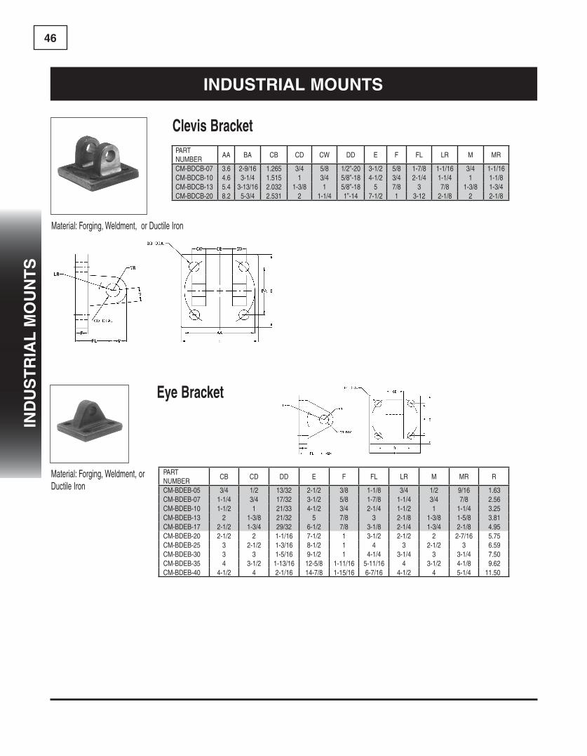
46
indUsTRial MoUnTs
Material:Forging,Weldment,orDuctileIron
Clevis BracketPART NUMBER
AA BA CB CD CW DD E F FL LR M MR
CM-BDCB-07 3.6 2-9/16 1.265 3/4 5/8 1/2”-20 3-1/2 5/8 1-7/8 1-1/16 3/4 1-1/16CM-BDCB-10 4.6 3-1/4 1.515 1 3/4 5/8”-18 4-1/2 3/4 2-1/4 1-1/4 1 1-1/8CM-BDCB-13 5.4 3-13/16 2.032 1-3/8 1 5/8”-18 5 7/8 3 7/8 1-3/8 1-3/4CM-BDCB-20 8.2 5-3/4 2.531 2 1-1/4 1”-14 7-1/2 1 3-12 2-1/8 2 2-1/8
Eye Bracket
Material:Forging,Weldment,orDuctileIron
PART NUMBER
CB CD DD E F FL LR M MR R
CM-BDEB-05 3/4 1/2 13/32 2-1/2 3/8 1-1/8 3/4 1/2 9/16 1.63CM-BDEB-07 1-1/4 3/4 17/32 3-1/2 5/8 1-7/8 1-1/4 3/4 7/8 2.56CM-BDEB-10 1-1/2 1 21/33 4-1/2 3/4 2-1/4 1-1/2 1 1-1/4 3.25CM-BDEB-13 2 1-3/8 21/32 5 7/8 3 2-1/8 1-3/8 1-5/8 3.81CM-BDEB-17 2-1/2 1-3/4 29/32 6-1/2 7/8 3-1/8 2-1/4 1-3/4 2-1/8 4.95CM-BDEB-20 2-1/2 2 1-1/16 7-1/2 1 3-1/2 2-1/2 2 2-7/16 5.75CM-BDEB-25 3 2-1/2 1-3/16 8-1/2 1 4 3 2-1/2 3 6.59CM-BDEB-30 3 3 1-5/16 9-1/2 1 4-1/4 3-1/4 3 3-1/4 7.50CM-BDEB-35 4 3-1/2 1-13/16 12-5/8 1-11/16 5-11/16 4 3-1/2 4-1/8 9.62CM-BDEB-40 4-1/2 4 2-1/16 14-7/8 1-15/16 6-7/16 4-1/2 4 5-1/4 11.50
ind
Us
TR
ial
Mo
Un
Ts

47in
dU
sT
Ria
ls
Mo
Un
Ts
Spherical Rod Eye
Material:Forging,Weldment,orDuctileIron
PART NUMBER
CD A CE EX ER LE KK JL REF LOAD CAPSPACER WIDTH
CM-RES-05 0.500 11/16 7/8 7/16 7/8 3/4 7/16”-20 7/8 2,600 0.150CM-RES-07 0.750 1 1-1/4 21/32 1-1/4 1-1/16 3/4”-16 1-5/16 9,400 0.250CM-RES-10 1.000 1-1/2 1-7/8 7/8 1-3/8 1-7/16 1”-14 1-1/2 16,800 0.250CM-RES-13 1.375 2 2-1/8 1-3/16 1-13/16 1-7/8 1-1/4”-12 2 28,600 0.375CM-RES-17 1.750 2-1/8 2-1/2 1-17/32 2-3/16 2-1/8 1-1/2”-12 2-1/4 43,000 0.416CM-RES-20 2.000 2-7/8 2-3/4 1-3/4 2-5/8 2-1/2 1-7/8”-12 2-3/4 70,000 0.375
indUsTRial MoUnTs
Spherical Clevis Brackets
Material:SteelWeldment
PART NUMBER
E F M R CD CF CW DD FL LR MR
CM-CBS-0500 3.00 .50 .50 2.05 .500 .44 .50 .41 1.50 .94 .62CM-CBS-0750 3.75 .62 .88 2.76 .750 .66 .62 .53 2.00 1.38 1.00CM-CBS-1000 5.50 .75 1.00 4.10 1.000 .88 .75 .53 2.50 1.69 1.19CM-CBS-1375 6.50 .88 1.38 4.95 1.375 1.19 1.00 .66 3.50 2.44 1.62CM-CBS-1750 8.50 1.25 1.75 6.58 1.750 1.53 1.25 .91 4.50 2.88 2.06CM-CBS-2000 10.62 1.50 2.00 7.92 2.000 1.75 1.50 .91 5.00 3.31 2.38
PART NUMBER
CB CD DD E F FL LR M MR R
CM-BDEB-05 3/4 1/2 13/32 2-1/2 3/8 1-1/8 3/4 1/2 9/16 1.63CM-BDEB-07 1-1/4 3/4 17/32 3-1/2 5/8 1-7/8 1-1/4 3/4 7/8 2.56CM-BDEB-10 1-1/2 1 21/33 4-1/2 3/4 2-1/4 1-1/2 1 1-1/4 3.25CM-BDEB-13 2 1-3/8 21/32 5 7/8 3 2-1/8 1-3/8 1-5/8 3.81CM-BDEB-17 2-1/2 1-3/4 29/32 6-1/2 7/8 3-1/8 2-1/4 1-3/4 2-1/8 4.95CM-BDEB-20 2-1/2 2 1-1/16 7-1/2 1 3-1/2 2-1/2 2 2-7/16 5.75CM-BDEB-25 3 2-1/2 1-3/16 8-1/2 1 4 3 2-1/2 3 6.59CM-BDEB-30 3 3 1-5/16 9-1/2 1 4-1/4 3-1/4 3 3-1/4 7.50CM-BDEB-35 4 3-1/2 1-13/16 12-5/8 1-11/16 5-11/16 4 3-1/2 4-1/8 9.62CM-BDEB-40 4-1/2 4 2-1/16 14-7/8 1-15/16 6-7/16 4-1/2 4 5-1/4 11.50

48
Material:Forging,Weldment,orDuctileIron
Spherical Eye Bracket
PART NUMBER
CB CD DD E F FL LR M MR R
CM-BDS-07 3/4 3/4 17/32 3-1/2 5/8 1-7/8 1-1/4 1-3/16 1-3/16 2.56CM-BDS-10 1 1 21/32 4-1/2 3/4 2-1/4 1-1/2 1-3/8 1-3/8 3.25CM-BDS-13 1-3/8 1-3/8 21/32 5 7/8 3 2-1/8 2 2 3.81
indUsTRial MoUnTs
PART NUMBER
CD CL
CM-PPS0500 .4997-.0004 1 9/16CM-PPS0750 .7497-.0005 2.1/32CM-PPS1000 .9997-.0005 2 1/2CM-PPS1375 1.3746-.0006 3 5/16CM-PPS1750 1.7496-.0006 4 7/32CM-PPS2000 1.9996-.0007 4 15/16
Pivot Pins for Spherical Clevis Brackets
Material:CD1144ind
Us
TR
ial
s M
oU
nT
s

49in
dU
sT
Ria
l c
oU
Pl
ing
s a
nd
nU
Ts
NylonInsertLockNut
PART NUMBER
BAR SIZE A B C
CM-LN45050 1/2”-20 0.60 0.75 0.84CM-LN45062 5/8”-18 0.75 0.94 1.06CM-LN45075 3/4”-16 0.88 1.06 1.19CM-LN45087 7/8”-14 1.00 1.25 1.40CM-LN45100 1”-14 1.06 1.44 1.62CM-LN45101 1”-14 0.88 1.62 1.83CM-LN45112 1-1/8”-12 1.19 1.62 1.83CM-LN45126 1-1/4”-12 1.38 1.81 2.06CM-LN45151 1-1/2”-12 1.62 2.19 2.44CM-LN45152 1-1/2”-12 0.81 2.19 2.44CM-LN45175 1-3/4”-12 1.50 2.75 3.06CM-LN45200 2”-12 1.62 3.12 3.50CM-LN45225 2-1/4”-12 1.94 3.50 3.94CM-LN45226 2-1/4”-12 2.81 3.50 3.94CM-LN45250 2-1/2”-12 2.25 4.00 4.60
indUsTRial coUPlings and nUTs
PART NUMBER
CB CD DD E F FL LR M MR R
CM-BDS-07 3/4 3/4 17/32 3-1/2 5/8 1-7/8 1-1/4 1-3/16 1-3/16 2.56CM-BDS-10 1 1 21/32 4-1/2 3/4 2-1/4 1-1/2 1-3/8 1-3/8 3.25CM-BDS-13 1-3/8 1-3/8 21/32 5 7/8 3 2-1/8 2 2 3.81
PART NUMBER
CD CL
CM-PPS0500 .4997-.0004 1 9/16CM-PPS0750 .7497-.0005 2.1/32CM-PPS1000 .9997-.0005 2 1/2CM-PPS1375 1.3746-.0006 3 5/16CM-PPS1750 1.7496-.0006 4 7/32CM-PPS2000 1.9996-.0007 4 15/16
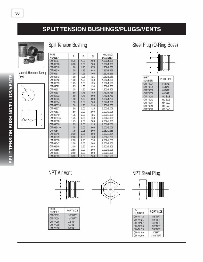
50
NPTSteelPlug
SteelPlug(O-RingBoss)
NPTAirVent
SplitTensionBushing
Material:HardenedSpringSteel
PART NUMBER
A B CHOUSING DIAMETER
CM-99507 0.75 1.00 2.00 1.002/1.006CM-99508 0.88 1.00 2.00 1.002/1.006CM-99510 1.00 1.25 0.75 1.252/1.256CM-99514 1.00 1.25 0.88 1.252/1.256CM-99511 1.00 1.25 1.00 1.252/1.256CM-99513 1.00 1.25 1.25 1.252/1.256CM-99512 1.00 1.25 1.50 1.252/1.256CM-99519 1.25 1.50 1.25 1.502/1.506CM-99522 1.25 1.50 1.50 1.502/1.506CM-99521 1.25 1.50 2.00 1.502/1.506CM-99531 1.50 1.75 1.50 1.752/1.756CM-99533 1.50 1.75 2.00 1.752/1.756CM-99535 1.50 1.75 3.00 1.752/1.756CM-99534 1.50 1.88 2.00 1.877/1.881CM-995335 1.50 1.75 2.50 1.752/1.756CM-99537 1.50 2.00 1.25 2.002/2.006CM-995371 1.50 2.00 2.00 2.002/2.006CM-99540 1.75 2.00 1.25 2.002/2.006CM-995375 1.75 2.00 1.50 2.002/2.006CM-99538 1.75 2.00 2.00 2.002/2.006CM-99539 1.75 2.00 2.25 2.002/2.006CM-995410 1.75 2.00 3.00 2.002/2.006CM-99541 1.75 2.25 2.00 2.252/2.256CM-99546 2.00 2.38 3.00 2.377/2.381CM-99549 2.00 2.25 1.50 2.252/2.256CM-99550 2.00 2.25 2.50 2.252/2.256CM-99547 2.00 2.50 2.00 2.502/2.506CM-99545 2.00 2.50 2.50 2.502/2.506CM-99556 2.50 3.00 2.00 3.002/3.006CM-99557 2.50 3.00 3.00 3.002/3.006CM-99565 3.00 3.50 2.50 3.502/3.506
PART NUMBER
PORT SIZE
CM-74004 #4 SAECM-74005 #5 SAECM-74006 #6 SAECM-74008 #8 SAECM-74010 #10 SAECM-74012 #12 SAECM-74014 #14 SAECM-74016 #16 SAECM-74020 #20 SAE
PART NUMBER
PORT SIZE
CM-74112 1/8” NPTCM-74125 1/4” NPTCM-74137 3/8” NPTCM-74150 1/2” NPTCM-74175 3/4” NPTCM-74199 1” NPTCM-74200 1-1/4” NPT
PART NUMBER
PORT SIZE
CM-77002 1/8” NPTCM-77004 1/4” NPTCM-77006 3/8” NPTCM-77008 1/2” NPTCM-77010 3/4” NPT
sPliT Tension BUsHings/PlUgs/venTs
sP
liT
Te
ns
ion
BU
sH
ing
/Pl
Ug
s/v
en
Ts

51d
isP
la
ce
Me
nT
cy
lin
de
R c
oM
Po
ne
nT
s
disPlaceMenT cylindeR coMPonenTs
Collar
Material:1026DOM
DisplacementCylinderComponents
Piston
Material:1018CD
PISTON DIA.
ROD DIA.
HEAD NUMBER
COLLAR NUMBERPISTON
NUMBER2.0 1.5 H107463 C132392 P1105392.5 2.0 H107359 C132463 P1105403.0 2.5 H107462 C132464 P1105413.5 3.0 H107525 C132454 P1105424.0 3.5 H107528 C132465 P110543
PART NUMBER
A B C D E
CM-C132392 2.311 2.44 2.06 2-3/4”-12 3.00CM-C132463 2.940 2.38 2.12 3-1/4”-12 3.50CM-C132464 3.436 2.50 2.25 3-3/4”-12 4.00CM-C132454 3.940 2.50 2.25 4-1/4”-12 4.50
PART NUMBER
A B C D E
CM-P110539 0.50 0.75 0.876 1.95 SK-P110539CM-P110540 0.50 0.75 1.126 2.45 SK-P110540CM-P110541 0.75 1.12 1.501 2.95 SK-P110541CM-P110542 0.75 1.12 1.751 3.45 SK-P110542CM-P110543 0.75 1.12 2.501 3.95 SK-P110543
WELDED STYLE PISTON
LOCK NUT STYLE PISTON
NOTE:SEE IT MOBILE HEADS PAGE

52
PistonWelding
CollarWeldingStub(LockNutStyle)
Stub(WeldedStyle)BarrelMachining
disPlaceMenT cylindeR TecHnical infoRMaTion
COLLAR NUMBER
A+.003"-.003
B+.001"-.001
C D
C132392 2.000 2.308 2.50 0.38C132463 2.500 2.937 3.00 0.25C132464 3.000 3.433 3.50 0.25C132454 3.500 3.937 4.00 0.25C132465 4.000 4.433 4.50 0.25
PISTONNUMBER
WELD SIZE
P110539 1/4"P110540 1/4"C110541 5/16"C110542 3/8"C110543 3/8"
PISTON NUMBER
A+.001"-.001
B CD
Dia.DrillxDepth
E Dia.DrillxDepth
P110539 0.874 1.12 1.31 0.25x0.75 0.25x1.44P110540 1.124 1.12 1.38 0.31x1.00 0.31x1.50C110541 1.499 1.56 1.81 0.31x1.25 0.31x2.00C110542 1.749 1.62 1.88 0.38x1.50 0.38x2.00C110543 2.499 1.62 1.88 0.38x1.75 0.38x2.00
PISTON NUMBER
AUN-THD
B CD
+.001-.001
E F
Dia.DrillxDepth
GDia.DrillxDepth
LOCK NUT NUMBER
P110539 7/8"-14 1.25 1.88 0.874 2.12 0.25x2.25 0.25x0.75 LN45087P110540 1-1/8"-12 1.44 2.06 1.124 2.38 0.31x2.56 0.31x1.00 LN45112C110541 1-1/2"-12 1.88 2.88 1.499 3.19 0.31x3.38 0.31x1.25 LN45151C110542 1-3/4"12 1.75 2.75 1.749 3.06 0.38x3.31 0.31x1.50 LN45175
COLLAR NUMBER
WELD SIZE
C132392 1/4"C132463 1/4"C132464 1/4"C132454 1/4"C132465 5/16"
dis
Pl
ac
eM
en
T c
yl
ind
eR
co
MP
on
en
Ts

53a
cc
es
so
Rie
s
Self Aligning Bearings
PART NUMBER A B W C DHH008ES 1/2 .875 .437 .375 .709HH010ES 5/8 1.062 .547 .469 .899HH012ES 3/4 1.250 .656 .562 1.803HH014ES 7/8 1.438 .765 .656 1.260HH100ES 1 1.625 .875 .750 1.417HH104ES 1-1/4 2.000 1.093 .937 1.772HH106ES 1-3/8 2.187 1.187 1.031 1.929HH108ES 1-1/2 2.438 1.312 1.125 2.165HH108ES2RS 1-1/2 2.438 1.312 1.125 2.165HH112ES 1-3/4 2.812 1.531 1.312 2.520HH112ES2RS 1-3/4 2.812 1.531 1.312 2.520HH200ES 2 3.187 1.750 1.500 2.874HH200ES2RS 2 3.187 1.750 1.500 2.874HH204ES 2-1/4 3.562 1.969 1.687 3.228HH204ES2RS 2-1/4 3.562 1.969 1.687 3.228HH208ES 2-1/2 3.937 2.187 1.875 3.583HH208ES2RS 2-1/2 3.937 2.187 1.875 3.583HH212ES 2-3/4 4.375 2.406 2.062 3.937HH212ES2RS 2-3/4 4.375 2.406 2.062 3.937HH300ES 3 4.750 2.625 2.250 4.331HH300ES2RS 3 4.750 2.625 2.250 4.331HH304ES 3-1/4 5.125 2.844 2.437 4.685HH308ES 3-1/2 5.500 3.062 2.625 5.039HH308ES2RS 3-1/2 5.500 3.062 2.625 5.039HH312ES 3-3/4 5.875 3.281 2.812 5.394HH400ES 4 6.250 3.500 3.000 5.748HH400ES2RS 4 6.250 3.500 3.000 5.748HH408ES 4-1/2 7.000 3.937 3.375 6.457HH500ES 5 7.750 4.375 3.750 7.205HH600ES 6 8.750 4.750 4.125 8.150
PartNumber A B W C DMHH20ES 20 35 16 12 29MHH20ES2RS 20 35 16 12 29MHH25ES 25 42 20 16 35.5MHH25ES2RS 25 42 20 16 35.5MHH30ES 30 47 22 18 40.7MHH30ES2RS 30 47 22 18 40.7MHH35ES 35 55 25 20 47MHH35ES2RS 35 55 25 20 47MHH40ES 40 62 28 22 53MHH40ES2RS 40 62 28 22 53MHH45ES2RS 45 68 32 25 60MHH50ES 50 75 35 28 66MHH50ES2RS 50 75 35 28 66MHH60ES 60 90 44 36 80MHH70ES 70 105 49 40 92MHH70ES2RS 70 105 49 30 92MHH80ES 80 120 55 45 105
Inch
Metric
accessoRies

54
ac
ce
ss
oR
ies
accessoRies
NOTE*(ABOVE FILLER BREATHERS ARE CHROME PLATED THAT ARE NOT WEATHER PROOFED)
SPECIFICATIONS:
• BlackepoxcoatedmetalshroudwithPolyamidsighttube• SuitableforusewithMineralandPetroleumbasedhydraulicfluids,lubri-cantsandgasoline
• Maximumoperatingtemperature194˚F 90˚C)• ThermometerCalibrationfrom-20˚Fto180˚F(-10˚Cto80˚C)• SNA076hasM10boltsasstandard• SNA127,SNA254hasM12boltsasstandard• TighteningTorque70”/lb(7.9Nm)
PART NUMBER DESCRIPTIONSTF-SNA076BS0-10 FLUIDLEVELGAUGE3”longwithoutthermometerSTF-SNA076BST-10 FLUIDLEVELGAUGE3”longwiththermometerSTF-SNA127BST-12 FLUIDLEVELGAUGE5”longwiththermometerSTF-SNA127BN012 FLUIDLEVELGAUGE5”longwithoutthermometer
Fluid Level Gauges
SPECIFICATIONS:
• Chrome-PlatedMetalCap• 30MeshMetalBasket• CorkGaskets• AirFlowto25cfm
PART NUMBER DESCRIPTIONSTF-SES6-P-40-N06 FILLER BREATHER WEATHER PROOFED MINI 40 MICRON 3/8” NPTSTF-SES3-P-40-S80 FILLER BREATHER WEATHER PROOFED 40 MICRON 80MM LONG BASKETSTF-SES3-40-S80 FILLER BREATHER 40 MICRON 80MM LONG BASKETSTF-SES3L-40-S80 FILLER BREATHER LOCKING TAB 40 MICRON 80MM LONG BASKETSTF-SES3-40-S150 FILLER BREATHER 40 MICRON 150MM LONG BASKETSTF-SES6-40-N04 FILLER BREATHER MINI 40 MICRON 1/4” NPTSTF-SES6-40-N06 FILLER BREATHER MINI 40 MICRON 3/8” NPTSTF-SES5-40-N12 FILLER BREATHER 40 MICRON 3/4” NPT
Filler Breather
ac
ce
ss
oR
ies
ac
ce
ss
oR
ies
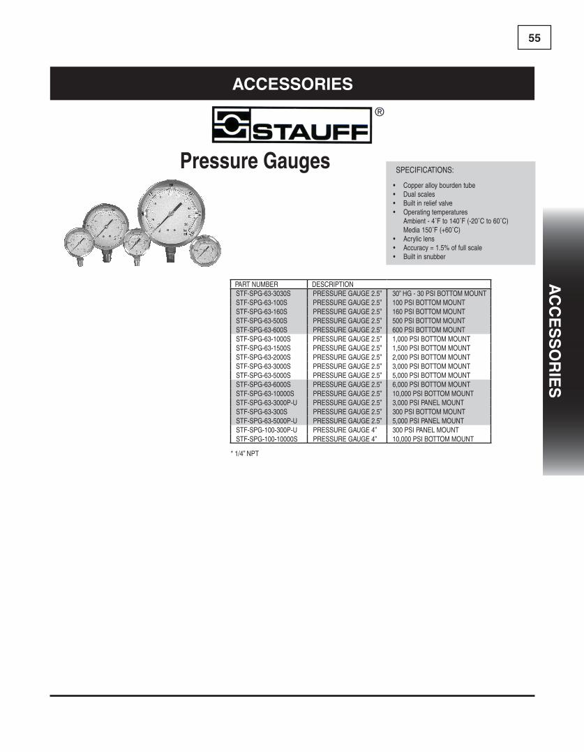
55a
cc
es
so
Rie
s
SPECIFICATIONS:
• Copperalloybourdentube• Dualscales• Builtinreliefvalve• Operatingtemperatures Ambient-4˚Fto140˚F(-20˚Cto60˚C) Media150˚F(+60˚C)• Acryliclens• Accuracy=1.5%offullscale• Builtinsnubber
Pressure Gauges
PART NUMBER DESCRIPTIONSTF-SPG-63-3030S PRESSURE GAUGE 2.5” 30” HG - 30 PSI BOTTOM MOUNTSTF-SPG-63-100S PRESSURE GAUGE 2.5” 100 PSI BOTTOM MOUNTSTF-SPG-63-160S PRESSURE GAUGE 2.5” 160 PSI BOTTOM MOUNTSTF-SPG-63-500S PRESSURE GAUGE 2.5” 500 PSI BOTTOM MOUNTSTF-SPG-63-600S PRESSURE GAUGE 2.5” 600 PSI BOTTOM MOUNTSTF-SPG-63-1000S PRESSURE GAUGE 2.5” 1,000PSIBOTTOMMOUNTSTF-SPG-63-1500S PRESSURE GAUGE 2.5” 1,500PSIBOTTOMMOUNTSTF-SPG-63-2000S PRESSURE GAUGE 2.5” 2,000PSIBOTTOMMOUNTSTF-SPG-63-3000S PRESSURE GAUGE 2.5” 3,000PSIBOTTOMMOUNTSTF-SPG-63-5000S PRESSURE GAUGE 2.5” 5,000PSIBOTTOMMOUNTSTF-SPG-63-6000S PRESSURE GAUGE 2.5” 6,000PSIBOTTOMMOUNTSTF-SPG-63-10000S PRESSURE GAUGE 2.5” 10,000PSIBOTTOMMOUNTSTF-SPG-63-3000P-U PRESSURE GAUGE 2.5” 3,000PSIPANELMOUNTSTF-SPG-63-300S PRESSURE GAUGE 2.5” 300 PSI BOTTOM MOUNTSTF-SPG-63-5000P-U PRESSURE GAUGE 2.5” 5,000PSIPANELMOUNTSTF-SPG-100-300P-U PRESSURE GAUGE 4” 300 PSI PANEL MOUNTSTF-SPG-100-10000S PRESSURE GAUGE 4” 10,000PSIBOTTOMMOUNT
* 1/4” NPT
accessoRies
ac
ce
ss
oR
ies
ac
ce
ss
oR
ies
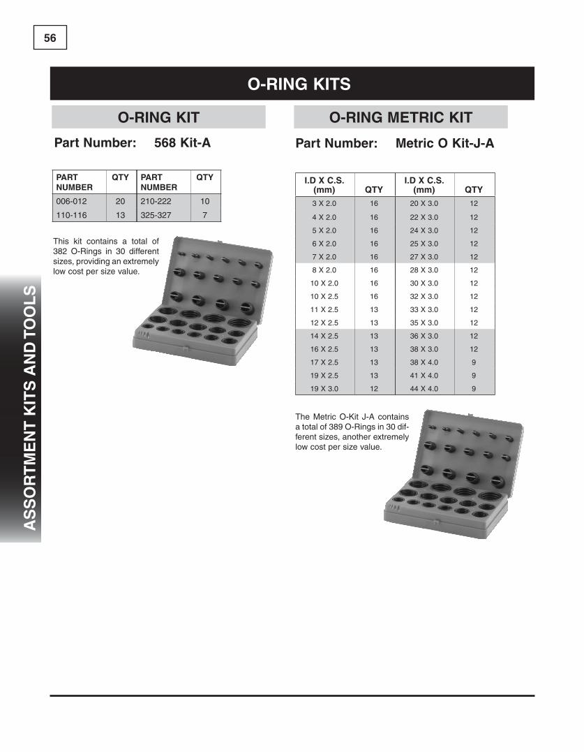
56
Part number: 568 kit-a
This kit contains a total of 382 O-Rings in 30 different sizes, providing an extremely low cost per size value.
PaRTnUMBeR
QTy
006-012 20
110-116 13
PaRTnUMBeR
QTy
210-222 10
325-327 7
o-Ring kiTs
i.d X c.s. (mm) QTy
3 X 2.0 16
4 X 2.0 16
5 X 2.0 16
6 X 2.0 16
7 X 2.0 16
8 X 2.0 16
10 X 2.0 16
10 X 2.5 16
11 X 2.5 13
12 X 2.5 13
14 X 2.5 13
16 X 2.5 13
17 X 2.5 13
19 X 2.5 13
19 X 3.0 12
i.d X c.s. (mm) QTy
20 X 3.0 12
22 X 3.0 12
24 X 3.0 12
25 X 3.0 12
27 X 3.0 12
28 X 3.0 12
30 X 3.0 12
32 X 3.0 12
33 X 3.0 12
35 X 3.0 12
36 X 3.0 12
38 X 3.0 12
38 X 4.0 9
41 X 4.0 9
44 X 4.0 9
The Metric O-Kit J-A contains a total of 389 O-Rings in 30 dif-ferent sizes, another extremely low cost per size value.
Part number: Metric o kit-J-a
o-Ring MeTRic kiTo-Ring kiT
as
so
RT
Me
nT
kiT
s a
nd
To
ol
s
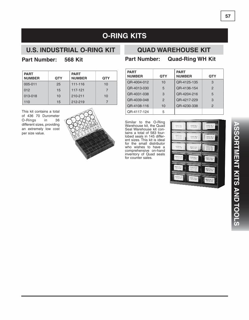
57a
ss
oR
TM
en
T k
iTs
an
d To
ol
s
o-Ring kiTs
Part number: 568 kit
This kit contains a total of 436 70 Durometer O-Rings in 36 different sizes, providing an extremely low cost per size value.
PaRTnUMBeR QTy
005-011 25
012 15
013-018 10
110 15
PaRTnUMBeR QTy
111-116 10
117-121 7
210-211 10
212-219 7
U.s. indUsTRial o-Ring kiT
Similar to the O-Ring Warehouse kit, the Quad Seal Warehouse kit con-tains a total of 583 four-lobed seals in 145 differ-ent sizes. This kit is ideal for the small distributor who wishes to have a comprehensive on-hand inventory of Quad seals for counter sales.
Part number: Quad-Ring WH kit
PaRTnUMBeR QTy
QR-4004-012 10
QR-4013-030 5
QR-4031-038 3
QR-4039-048 2
QR-4108-116 10
QR-4117-124 5
PaRTnUMBeR QTy
QR-4125-135 3
QR-4136-154 2
QR-4204-216 5
QR-4217-229 3
QR-4230-338 2
QUad WaReHoUse kiT

58
Our O-ring Warehouse kit is ideally suited for the repair shop that needs a large on-hand selection of O-rings to insure quick repair of all machine types. 1,110 O-Rings in 150 different sizes are included in this kit. Each size is individually packaged in heavy duty ziploc bags to protect against environmental exposure and contamination. All packages are then stored in a sturdy styrene cabinet with pull-out drawers for easy access to parts. Included card shows size, dimensions, and drawer location for each ring.
PaRTnUMBeR QTy
001-016 20
017-024 10
025-031 7
032-043 5
044-046 2
110-116 15
117-124 10
125-142 5
143-146 3
147-151 2
210-216 10
PaRTnUMBeR QTy
217-229 5
230-232 3
233-237 2
325-328 5
329-330 4
331-338 2
901-914 5
916, 918 5
920, 924 5
928, 932 5
Part number: 568 WH kit
Our 90 Durometer O-ring Warehouse kit is ideally suited for the repair shop that needs a large on-hand selection of O-Rings to insure quick repair of all machine types. 1,110 O-Rings in 150 different sizes are included in this kit.
PaRTnUMBeR QTy
001-016-90D 20
017-024-90D 10
025-031-90D 7
032-043-90D 5
044-046-90D 2
110-116-90D 15
117-124-90D 10
125-142-90D 5
143-146-90D 3
147-151-90D 2
210-216-90D 10
PaRTnUMBeR QTy
217-229-90D 5
230-232-90D 3
233-237-90D 2
325-328-90D 5
329-330-90D 4
331-338-90D 2
901-914-90D 5
916, 918-90D 5
920, 924-90D 5
928, 932-90D 5
Part number: 568 WH kit-90d
o-Ring WaReHoUse kiT
90 dURoMeTeR o-Ring WaReHoUse kiT
o-Ring kiTs
as
so
RT
Me
nT
kiT
s a
nd
To
ol
s

59a
ss
oR
TM
en
T k
iTs
an
d To
ol
s
Part number: 568 90d kit
This kit contains a total of 436 90 Durometer O-Rings in 36 different sizes, providing an extremely low cost per size value.
PaRTnUMBeR QTy
005-011-90D 25
012-90D 15
013-018-90D 10
110-90D 15
PaRTnUMBeR QTy
111-116-90D 10
117-121-90D 7
210-211-90D 10
212-219-90D 7
90 dURoMeTeR o-Ring kiT
o-Ring kiTs
Part number: 900 Boss kit
This 250 piece assortment contains the most popular size 90 Durometer Boss O-rings in 12 different fit-ting sizes, individually sep-arated, which will supply your shop, service truck, or parts counter with the sizes you need!
PaRTnUMBeR QTy
sae PoRT siZe
568-904 35 -4
568-905 30 -5
568-906 30 -6
568-907 20 -7
568-908 20 -8
568-909 20 -9
PaRTnUMBeR QTy
sae PoRT siZe
568-910 20 -10
568-911 15 -11
568-912 15 -12
568-913 15 -13
568-914 15 -14
568-916 15 -16
Part number: 568 fc kit
This kit contains a total of 436 75 Durometer Fluorocarbon O-Rings in 36 different sizes, providing an extremely low cost per size value.
PaRTnUMBeR QTy
005-011V 25
012V 15
013-018V 10
110V 15
PaRTnUMBeR QTy
111-116V 10
117-121V 7
210-211V 10
212-219V 7
flUoRocaRBon o-Ring kiT
sae 900 o-Ring Boss kiT

60
Part number: MaX 1381 kit
Part number: MaX 1381 kit-90d
These sturdy kits, packaged in a heavy duty box, contains 1415 O-Rings in the most popular sizes. Every service truck should have one of these. Five internal boxes contain 1/16” C/S, 3/32” C/S, 1/8” C/S, Boss and Flange fitting o-rings. Contents and quantities are listed below.
1/8” c/s o-Rings
o-RingnUMBeR QTy
210 - 214 20
215 - 222 15
223 - 224 10
226 10
o-RingnUMBeR QTy
228 10
232 10
236 10
3/32” c/s o-Rings
o-RingnUMBeR QTy
109 - 118 25
119 - 120 20
121 - 127 15
128 10
o-RingnUMBeR QTy
129 10
131 10
133 10
135 5
1/16” c/s o-Ringso-RingnUMBeR QTy
006 - 118 25
019 - 021 20
022 - 026 15
o-RingnUMBeR QTy
028 15
029 10
030 10
Boss o-RingsBossnUMBeR QTy
903 15
904 25
906 15
908 25
BossnUMBeR QTy
907 25
910 25
912 15
916 10
flange sealsflangenUMBeR QTy
8 10
12 10
16 10
flangenUMBeR QTy
20 5
24 5
32 5
MaX o-Ring kiT
o-Ring kiTs
as
so
RT
Me
nT
kiT
s a
nd
To
ol
s

61a
ss
oR
TM
en
T k
iTs
an
d To
ol
s
Part number: 900 Boss fc
Part number: 568 PTfe kit
Part number: Quad-Ring kit
This kit contains a total of 325 PTFE O-Rings ( 55 - 58 Shore D) in 36 different sizes. PTFE O-Rings can withstand tem-peratures up to 500° F and are impervious to a wide range of chemicals.
This kit contains a total of 226 Quad Seals in 36 different sizes, providing an extremely low cost per size value.
PaRTnUMBeR QTy
4005-4012 10
4013-4016 6
4017-4018 5
PaRTnUMBeR QTy
4110-4116 6
4117-4121 4
4210-4219 5
PaRTnUMBeR QTy
005-012T 15
013-018T 10
110-116T 10
117-121T 5
210-219T 5
QUad Ring kiT
PTfe o-Ring kiTsae 900 o-Ring Boss flUoRocaRBon kiT
o-Ring kiTs
PaRTnUMBeR QTy
sae PoRT siZe
568-904V 35 -4
568-905V 30 -5
568-906V 30 -6
568-907V 20 -7
568-908V 20 -8
568-909V 20 -9
PaRTnUMBeR QTy
sae PoRT siZe
568-910V 20 -10
568-911V 15 -11
568-912V 15 -12
568-913V 15 -13
568-914V 15 -14
568-916V 15 -16
This 250 piece assortment contains the most popular size 90 Durometer Viton™ Boss O-rings in 12 differ-ent fitting sizes, individu-ally separated, which will supply your shop, service truck, or parts counter with the sizes you need!
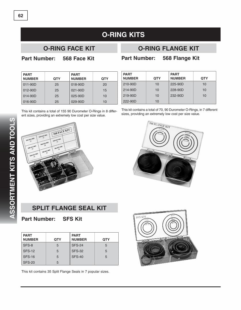
62
Part number: 568 face kit Part number: 568 flange kit
This kit contains a total of 70, 90 Durometer O-Rings, in 7 different sizes, providing an extremely low cost per size value.
This kit contains a total of 155 90 Durometer O-Rings in 8 differ-ent sizes, providing an extremely low cost per size value.
PaRTnUMBeR QTy
011-90D 25
012-90D 25
014-90D 25
016-90D 25
PaRTnUMBeR QTy
018-90D 20
021-90D 15
025-90D 10
029-90D 10
PaRTnUMBeR QTy
210-90D 10
214-90D 10
219-90D 10
222-90D 10
PaRTnUMBeR QTy
225-90D 10
228-90D 10
232-90D 10
This kit contains 35 Split Flange Seals in 7 popular sizes.
PaRTnUMBeR QTy
SFS-8 5
SFS-12 5
SFS-16 5
SFS-20 5
PaRTnUMBeR QTy
SFS-24 5
SFS-32 5
SFS-40 5
Part number: sfs kit
o-Ring face kiT o-Ring flange kiT
sPliT flange seal kiT
o-Ring kiTs
as
so
RT
Me
nT
kiT
s a
nd
To
ol
s

63a
ss
oR
TM
en
T k
iTs
an
d To
ol
s
sae PoRT siZePaRT nUMBeR QTy
-2 568-902 8
-3 568-903 8
-4 568-904 8
-5 568-905 8
-6 568-906 8
-8 568-908 8
-10 568-910 8
sae PoRT siZePaRT nUMBeR QTy
-12 568-912 8
-14 568-914 8
-16 568-916 8
-20 568-920 8
-24 568-924 8
-32 568-932 8
sae PoRT siZePaRT nUMBeR QTy
-8 568-210-90D 8
-12 568-214-90D 8
-16 568-219-90D 8
-20 568-222-90D 8
-24 568-225-90D 8
-32 568-228-90D 8
PoRT siZePaRT nUMBeR QTy
-4 568-011-90D 8-6 568-012-90D 8-8 568-014-90D 8
-10 568-016-90D 8-12 568-018-90D 8-16 568-021-90D 8-20 568-025-90D 8-24 568-029-90D 8
This handy kit contains 27 sizes and 216 pieces of 90A Durometer O-rings for boss, split flange and flat face hose end fittings and adapters. Each box has a graphic label identifying the type of application and dash number for the seal. A chart on the back of the box lists popular OEM part number matches for each O-ring. Due to popular demand, these kits are now available individually.
Part number: o-R fitting kit
Part number: sae flange seals
Part number: Boss & Tube fittings-1 Part number: Boss & Tube fittings-2
Part number: flat face o-Rings
sae flange seals flaT face seals
sae o-Ring Boss & TUBe seals
o-Ring kiTs
Hose end & adaPTeR kiT
Hose end & adaPTeR kiT PaRTs
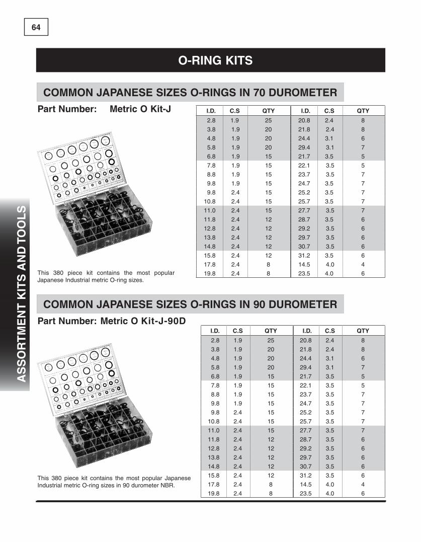
64
Part number: Metric o kit-J-90d
This 380 piece kit contains the most popular Japanese Industrial metric O-ring sizes.
This 380 piece kit contains the most popular Japanese Industrial metric O-ring sizes in 90 durometer NBR.
Part number: Metric o kit-J
coMMon JaPanese siZes o-Rings in 70 dURoMeTeR
coMMon JaPanese siZes o-Rings in 90 dURoMeTeR
i.d. c.s QTy
2.8 1.9 25
3.8 1.9 20
4.8 1.9 20
5.8 1.9 20
6.8 1.9 15
7.8 1.9 15
8.8 1.9 15
9.8 1.9 15
9.8 2.4 15
10.8 2.4 15
11.0 2.4 15
11.8 2.4 12
12.8 2.4 12
13.8 2.4 12
14.8 2.4 12
15.8 2.4 12
17.8 2.4 8
19.8 2.4 8
i.d. c.s QTy
20.8 2.4 8
21.8 2.4 8
24.4 3.1 6
29.4 3.1 7
21.7 3.5 5
22.1 3.5 5
23.7 3.5 7
24.7 3.5 7
25.2 3.5 7
25.7 3.5 7
27.7 3.5 7
28.7 3.5 6
29.2 3.5 6
29.7 3.5 6
30.7 3.5 6
31.2 3.5 6
14.5 4.0 4
23.5 4.0 6
i.d. c.s QTy
2.8 1.9 25
3.8 1.9 20
4.8 1.9 20
5.8 1.9 20
6.8 1.9 15
7.8 1.9 15
8.8 1.9 15
9.8 1.9 15
9.8 2.4 15
10.8 2.4 15
11.0 2.4 15
11.8 2.4 12
12.8 2.4 12
13.8 2.4 12
14.8 2.4 12
15.8 2.4 12
17.8 2.4 8
19.8 2.4 8
i.d. c.s QTy
20.8 2.4 8
21.8 2.4 8
24.4 3.1 6
29.4 3.1 7
21.7 3.5 5
22.1 3.5 5
23.7 3.5 7
24.7 3.5 7
25.2 3.5 7
25.7 3.5 7
27.7 3.5 7
28.7 3.5 6
29.2 3.5 6
29.7 3.5 6
30.7 3.5 6
31.2 3.5 6
14.5 4.0 4
23.5 4.0 6
o-Ring kiTs
as
so
RT
Me
nT
kiT
s a
nd
To
ol
s

65a
ss
oR
TM
en
T k
iTs
an
d To
ol
s
Part number: Metric o kit-e
Part number: Metric o kit-e-90d
This 500 piece kit contains the most popular European metric O-ring sizes.
This 500 piece kit contains the most popular European metric O-ring sizes.
coMMon eURoPean siZes o-Rings in 70 dURoMeTeR
coMMon eURoPean siZes o-Rings in 90 dURoMeTeR
i.d. c.s. QTy
5.0 1.5 20
13.0 1.5 15
16.0 1.5 10
2.2 1.6 20
3.1 1.6 20
4.1 1.6 20
7.1 1.6 20
9.1 1.6 15
10.1 1.6 15
13.1 1.6 15
4.0 2.0 20
6.0 2.0 20
8.0 2.0 15
9.0 2.0 15
10.0 2.0 15
12.0 2.0 15
14.0 2.0 10
16.0 2.0 10
i.d. c.s. QTy
19.0 2.0 10
20.0 2.0 10
4.3 2.4 15
5.3 2.4 15
5.6 2.4 15
7.6 2.4 15
8.3 2.4 15
8.6 2.4 15
10.0 2.5 10
13.0 2.5 10
14.0 2.5 10
15.0 2.5 10
17.0 2.5 10
18.0 2.5 10
19.0 2.5 10
9.0 3.0 10
10.0 3.0 10
11.0 3.0 10
i.d. c.s. QTy
5.0 1.5 20
13.0 1.5 15
16.0 1.5 10
2.2 1.6 20
3.1 1.6 20
4.1 1.6 20
7.1 1.6 20
9.1 1.6 15
10.1 1.6 15
13.1 1.6 15
4.0 2.0 20
6.0 2.0 20
8.0 2.0 15
9.0 2.0 15
10.0 2.0 15
12.0 2.0 15
14.0 2.0 10
16.0 2.0 10
i.d. c.s. QTy
19.0 2.0 10
20.0 2.0 10
4.3 2.4 15
5.3 2.4 15
5.6 2.4 15
7.6 2.4 15
8.3 2.4 15
8.6 2.4 15
10.0 2.5 10
13.0 2.5 10
14.0 2.5 10
15.0 2.5 10
17.0 2.5 10
18.0 2.5 10
19.0 2.5 10
9.0 3.0 10
10.0 3.0 10
11.0 3.0 10
o-Ring kiTs

66
Part number: 568 splice kit Part number: Met/inch splice kit
Part number: 568 fc splice kit
This kit can produce O-Rings of any standard inch size cross-section plus a wide variety of metric sizes. Each kit contains quick drying adhesive, cut-ting and splicing jig, razor blade and 14 lengths of 70 Durometer Buna-N cord stock as follows:
inch cross-sections: (inch)1/16" (.070), 3/32" (.103), 1/8" (.139),3/16" (.210), 1/4" (.275)Metric cross-sections: (mm)1.5, 2.0, 2.5, 3.0, 3.5, 4.0, 5.0, 5.7, 8.4
kit contains: 1. Stock of 70 Durometer Buna O-ring Cord 2. Razor Blade 3. Splicing tool 4. Tube of Adhesive
Replacement PartsParts: #568 Splice Tool #568 Adhesive 70 Duro. Cord
kit contains: 1. Stock of 75 Durometer Fluorocarbon Cord 2. Razor Blade 3. Splicing tool 4. Tube of Adhesive
Replacement PartsParts: #568 Splice Tool #568 Adhesive 75 Duro. Fluorocarbon Cord
These kits can produce O-Rings of any circumference. The 568 kit contains the most popular inch cross sectional sized O-ring cord. The Metric and Inch Kit has both standard inch size cross sectional cord plus a wide variety of metric sized cord. Both kits contain quick drying adhesive, a cutting and splicing jig, a razor blade and 70 Durometer Buna-N cord.
o-Ring sPlice kiTincH siZes
o-Ring sPlice kiTincH& MeTRic siZes
flUoRocaRBon o-Ring sPlice kiTincH siZes
o-Ring sPlice kiTs
as
so
RT
Me
nT
kiT
s a
nd
To
ol
s

67a
ss
oR
TM
en
T k
iTs
an
d To
ol
s
Part number: 574 kit
This 293 piece kit contains 36 of the most popular size “Parback®” Style Dished Cross Section back-up rings. Molded of 90A Durometer Buna-N Rubber, they stretch for installation and return quickly to their original size. SIZES CORRESPOND TO O-RING NUMBERS. Your shop and ser-vice truck should not be without this handy kit.
Part number: 575 kit
This 475 piece kit contains 24 of the most popular size Urethane Back-up Rings. This assortment is essential for parts counters, shop use, and service trucks.
PaRTnUMBeR QTy
575-111 25
575-112 25
575-113 25
575-114 25
575-115 25
575-116 25
575-210 25
575-211 25
575-212 25
575-213 25
575-214 25
575-215 25
PaRTnUMBeR QTy
575-216 25
575-217 15
575-218 15
575-219 15
575-220 15
575-221 15
575-222 15
575-223 15
575-224 15
575-325 10
575-326 10
575-327 10
PaRTnUMBeR QTy
574-005 10
574-006 10
574-007 10
574-008 10
574-009 10
574-010 10
574-011 10
574-012 10
574-013 10
574-014 10
574-015 10
574-016 10
574-017 10
574-018 10
574-110 10
574-111 10
574-112 10
574-113 10
PaRTnUMBeR QTy
574-114 10
574-115 10
574-116 10
574-117 5
574-118 5
574-119 5
574-120 5
574-121 5
574-210 7
574-211 7
574-212 7
574-213 7
574-214 5
574-215 5
574-216 5
574-217 5
574-218 5
574-219 5
574 Back-UP Ring kiT
575 Back-UP Ring kiT
Back-UP Ring kiTs

68
Part number: 575 PTfe kit s
This 325 piece kit contains 36 of the most popular size PTFE Back-up Rings. These rings are compatible with all hydraulic fluids, since they are virtually chemically inert, and can be used in applications involving elevated operating temperatures. These rings are scarf cut to facilitate installation.
PaRTnUMBeR QTy
575-005ST 15
575-006ST 15
575-007ST 15
575-008ST 15
575-009ST 15
575-010ST 15
575-011ST 15
575-012ST 15
575-013ST 10
575-014ST 10
575-015ST 10
575-016ST 10
575-017ST 10
575-018ST 10
575-110ST 10
575-111ST 10
575-112ST 10
575-113ST 10
PaRTnUMBeR QTy
575-114ST 10
575-115ST 10
575-116ST 10
575-117ST 5
575-118ST 5
575-119ST 5
575-120ST 5
575-121ST 5
575-210ST 5
575-211ST 5
575-212ST 5
575-213ST 5
575-214ST 5
575-215ST 5
575-216ST 5
575-217ST 5
575-218ST 5
575-219ST 5
The 870 Tri-Kit is packaged in three stur-dy cases that contain 180 U-Cups. The U-Cups conform to AN-6226 size stan-dards in 36 popular sizes ranging from 1/8" to 1-1/8" inside diameter. All of the seals are molded from 70A Durometer Buna-N rubber.
Part number: 870 TRi-kit
sTyle 870 kiT
PTfe Back-UP Ring kiT
Back-UP Ring kiTs
as
so
RT
Me
nT
kiT
s a
nd
To
ol
s
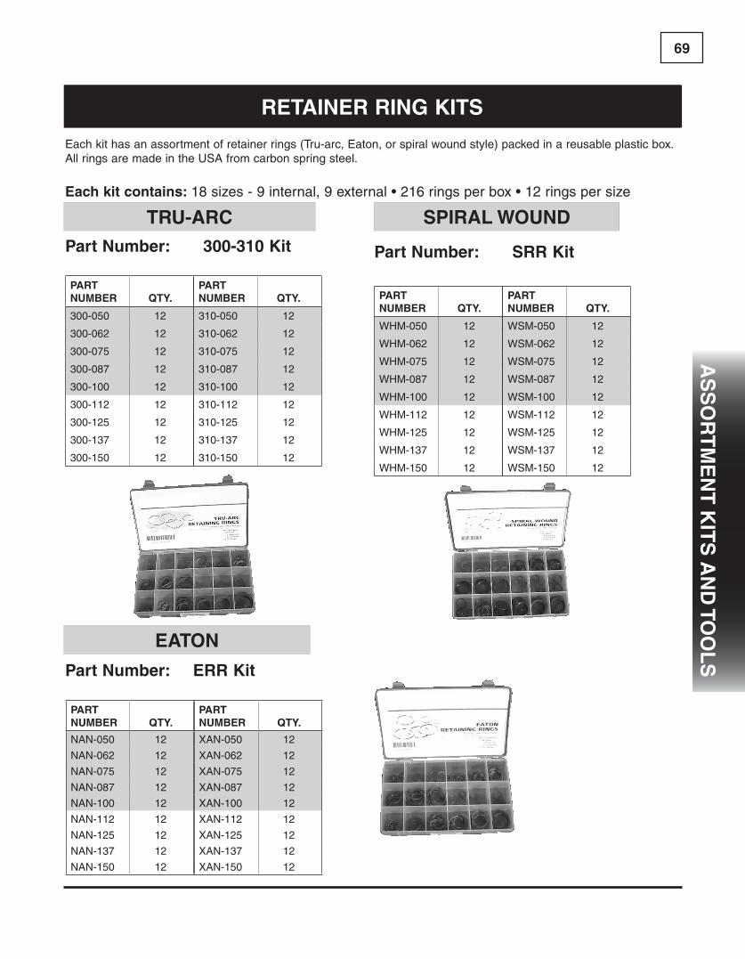
69a
ss
oR
TM
en
T k
iTs
an
d To
ol
s
Part number: eRR kit
Part number: 300-310 kit
Each kit has an assortment of retainer rings (Tru-arc, Eaton, or spiral wound style) packed in a reusable plastic box. All rings are made in the USA from carbon spring steel.
each kit contains: 18 sizes - 9 internal, 9 external • 216 rings per box • 12 rings per size
Part number: sRR kit
PaRTnUMBeR QTy.
NAN-050 12
NAN-062 12
NAN-075 12
NAN-087 12
NAN-100 12
NAN-112 12
NAN-125 12
NAN-137 12
NAN-150 12
PaRTnUMBeR QTy.
XAN-050 12
XAN-062 12
XAN-075 12
XAN-087 12
XAN-100 12
XAN-112 12
XAN-125 12
XAN-137 12
XAN-150 12
PaRTnUMBeR QTy.
300-050 12
300-062 12
300-075 12
300-087 12
300-100 12
300-112 12
300-125 12
300-137 12
300-150 12
PaRTnUMBeR QTy.
310-050 12
310-062 12
310-075 12
310-087 12
310-100 12
310-112 12
310-125 12
310-137 12
310-150 12
PaRTnUMBeR QTy.
WHM-050 12
WHM-062 12
WHM-075 12
WHM-087 12
WHM-100 12
WHM-112 12
WHM-125 12
WHM-137 12
WHM-150 12
PaRTnUMBeR QTy.
WSM-050 12
WSM-062 12
WSM-075 12
WSM-087 12
WSM-100 12
WSM-112 12
WSM-125 12
WSM-137 12
WSM-150 12
TRU-aRc
eaTon
sPiRal WoUnd
ReTaineR Ring kiTs

70
Part number: 300 kitPart number: 310 kit
These assortments con-tain the most popular size retainer rings, boxed in a handy storage and display case, which will supply your shop, service truck, or parts counter with the sizes you need!
Packaged in four plastic cases with a handy carrying case, our rotor pack kit contains approximately 50 each of 20 common internal/external retaining ring sizes. The internal rings fit hous-ings or bores from 3/8” internal diameter to 1-1/8”. External rings accommodate shaft sizes from 1/4” internal diameter to 1-1/8”. Two retainer ring installation pliers are also included.
PaRTnUMBeR
BoResiZe QTy.
300-075 0.750 10
300-087 0.875 10
300-100 1.000 10
300-112 1.125 10
300-125 1.250 10
300-137 1.375 10
300-150 1.500 10
300-162 1.625 10
300-175 1.750 10
PaRTnUMBeR
BoResiZe QTy.
300-200 2.000 10
300-225 2.250 5
300-250 2.500 5
300-275 2.750 5
300-300 3.000 5
300-350 3.500 5
300-400 4.000 5
300-450 4.500 2
300-500 5.000 2
PaRTnUMBeR
sHafTsiZe QTy.
310-100 1.000 5
310-125 1.250 5
310-137 1.375 5
310-150 1.500 5
310-175 1.750 5
PaRTnUMBeR
sHafTsiZe QTy.
310-200 2.000 5
310-225 2.250 5
310-250 2.500 5
310-275 2.750 3
310-300 3.000 3
Part number: RPk 4 kit
eXTeRnal ReTaineR Rings inTeRnal ReTaineR Rings
RoToR Pack kiT
ReTaineR Ring kiTs
as
so
RT
Me
nT
kiT
s a
nd
To
ol
s

71a
ss
oR
TM
en
T k
iTs
an
d To
ol
s
Part number: cTc-4c4782
Part number: cTc-4c8253
This handy kit, in an unbreakable box, contains 570 nitrile o-rings in the 32 most popular sizes used on Caterpillar® equipment.
This handy kit, in an unbreakable box, contains the 9 most popular sized D-Rings used on Caterpillar® equipment.
Part number: cTc-4c4784
Part number: cap Plug kit
cap Plug number QTyCAP-2-X 50
CAP-4 50
CAP-6-X 50
CAP-9 40
CAP-12-X 25
CAP-14 20
CAP-PD-60 25
CAP-PD-80 25
cap Plug number QTyCAP-PD-100 15
CAP-PD-120 10
CAP-PD-140 5
CAP-PD-160 10
CAP-G-2 20
CAP-G-8 20
CAP-G-14 20
CAP-G-18 20
cap Plug number QTyCAP-G-22 10
CAP-G-25 12
CAP-G-27 16
CAP-P-28 25
CAP-P-38 25
CAP-P-48 25
CAP-P-68-H 25
CAP-P-88-H 10
This sturdy kit, packaged in an unbreakable box, contains 553 cap plugs in the most popular sizes.
This handy kit, in an unbreakable box, contains 149 silicone o-rings in the 32 most popular sizes used on Caterpillar® equipment.
caP PlUg kiT caT® silicone o-Ring kiT
caT® niTRile o-Ring kiTcaT® o-Ring kiT
assoRTMenT kiTs

72
Part number: Woodruff keys kit
Part number: grease fitting kit
32 Pieces
1/8” NPTStraight6 pcs.
1/4” - 28Straight6 pcs.
1/8” NPT 451/8” NPT 903 pcs. ea.
3/16” DriveStraight4 pcs.
1/4” - 28 451/4” - 28 903 pc. ea.
5/16” DriveStraight4 pcs.
Part number: cotter Pin kit
555 Pieces
1/16” X 1”150 pcs.
3/32” X 1”150 pcs.
1/8” X 1 1/4”75 pcs.
3/32” X 1 1/2”100 pcs.
1/8” X 2”50 pcs.
5/32” X 2 1/2”30 pcs.
65 Pieces
1/8” X 1/2”No. 3
16 pcs.
1/8” X 5/8”No. 5
15 pcs.
3/16” X 3/4”No. 9
10 pcs.
3/32” X 5/8”No. 6
15 pcs.
1/4” X 7/8”No. A5 pcs.
1/4” X 1”No. 154 pcs.
coTTeR Pin kiT
gRease fiTTing kiT
WoodRUff key kiT
assoRTMenT kiTs
as
so
RT
Me
nT
kiT
s a
nd
To
ol
s
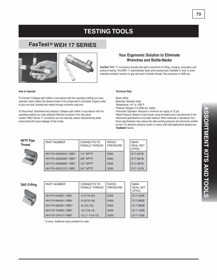
73
TesTing Tools
fasTest ® WeH 17 seRies
PART NUMBER CONNECTS TO FEMALE THREAD
RATED PRESSURE
MAIN SEAL SET 5/PKG
HH17H-40204041-1BB1 1/4" NPTF 5000 S17-041B
HH17H-40206061-1BB1* 3/8" NPTF 5000 S17-061B
HH17H-40208081-1BB1 1/2" NPTF 5000 S17-081B
HH17H-40212121-1BB1 3/4" NPTF 3500 S17-121B
PART NUMBER CONNECTS TO FEMALE THREAD
RATED PRESSURE
MAIN SEAL SET 5/PKG
HH17H-044021-1BB1 -4 (7/16-20) 5000 S17-042B
HH17H-064041-1BB1 -6 (9/16-18) 5000 S17-062B
HH17H-084061-1BB1* -8 (3/4-16) 5000 S17-082B
HH17H-104081-1BB1 -10 (7/8-14) 5000 S17-102B
HH17H-124121-1BB1 -12 (1 1/16-12) 3500 S17-122B
NPTF Pipe Thread
SAE O-Ring
Your Ergonomic Solution to Eliminate Wrenches and Bottle-Necks
FasTest®WEH17connectorsprovideleaktightconnectionsforfilling,charging,evacuationandpressuretesting.TheWEH17automaticallysealswhenpressurized.Availableinleverorpneu-maticallyactivatedversionstogripandsealtofemalethreads.Testpressuresto3500psi.
Technical Data
Seals:NitrileMaterials:StainlesssteelTemperature:-40°to+250°FPressureRanges:0to5000psi.(static)PneumaticOperation:Requiresaminimumairsupplyof75psi.RatedPressure:Basedontestresultsusingthreadedportsmanufacturedtothereferencedspecificationsandsteelmaterial.Othermaterialsordeviationsfromthosespecificationsmayreducethesafeworkingpressureandshouldbeverifiedbytest.Fordynamicpressurecyclesorheavyside-loadapplicationspleaseseeFasMate®Series.
How to Operate
ToConnect:Collapsesplitcolletsinaccordancewiththeoperatingmethodyouhaveselected.Insertcolletsintofemalethreadofthecomponenttobetested.Expandcollettogripandseal.Activatetestmediathroughconnectorsideport.
ToDisconnect:Deactivatetestpressure.Collapsesplitcolletsinaccordancewiththeoperatingmethodyouhaveselected.Removeconnectorfromtestpiece.Caution:WEHSeries17connectorsarenotinternallyvalved.Disconnectingwhilepressurizedwillcauseleakageoftestmedia.
*In-stock.Additionalsizesavailablefororder.
as
so
RT
Me
nT
kiT
s a
nd
Too
ls

74
TesTing Tools
TwistMate ® MiT seRies
PART NUMBER CONNECTS TO FEMALE THREAD
RATED PRESSURE
CONNECTOR TYPE
MAIN SEAL SET 5/PKG
HHMIT-022021 1/8" NPTF 5000 SWIVEL S1109-U70
HHMIT-042041 1/4" NPTF 5000 SWIVEL S1111-U70
HHMIT-062061 3/8" NPTF 5000 SWIVEL S1113-U70
HHMIT-082081 1/2" NPTF 5000 SWIVEL S1209-U70
HHMIT-122121X 3/4" NPTF 5000 CONNECTOR S1213-U70
HHMIT-162161X 1" NPTF 5000 CONNECTOR S1216-U70
HHMIT-202201X 1-1/2" NPTF 5000 CONNECTOR S1222-U70
HHMIT-242241X 2" NPTF 5000 CONNECTOR S1327-U70
PART NUMBER CONNECTS TO FEMALE THREAD
RATED PRESSURE
CONNECTOR TYPE
MAIN SEAL SET 5/PKG
HHMIT-044021X -04 (7/16-20) 5000 CONNECTOR S1109-U70
HHMIT-064041X -06 (9/16-18) 5000 CONNECTOR S1111-U70
HHMIT-084081X -08 (3/4-16) 4000 CONNECTOR S1209-U70
HHMIT-104081X -10 (7/8-14) 4000 CONNECTOR S1209-U70
HHMIT-124121X -12 (1 1/16-12) 4000 CONNECTOR S1213-U70
HHMIT-164161X -16 (1 5/16-12) 4000 CONNECTOR S1217-U70
HHMIT-204201X -20 (1 5/8-12) 4000 CONNECTOR S1222-U70
NPTF Pipe Thread
SAE O-Ring
No Wrenches Needed • Hand Tighten Your Port Adapters • Shortens Testing Time
Twistmate®MITmechanicalinternalthreadconnectorsandplugsprovidefastleaktightthreadedconnectionsfortesting,filling,flush-ing,plugging,calibratingorventingapplications.Thepatentedpressureassistedsealingeliminateswrenchtighteningandthreadsealantsforsafesecureconnectionsupto10,000psi.Withsizesupto4"NPTF,andhighflowdesign,theMITisidealforlargeunitruntesting.Fastandreliablesealingreducestesttimeandproductionlossesfromscrap,reworkandre-testing.Fullflowdesignforshort-estfillingandtesttimes.
SpinTwistmate®finger-tightontothreaduntilfacesealcontactstestpiece.Theysealautomaticallywhenthesystemispressurized.Air,gasorhydraulicpressureinthesystemprovidesasealingforcethatpressestheurethanemainsealagainstthefaceofthethreads.Thisautomaticinternalpistonactionmaintainsthesealwithminimumpressure.
Technical Data
Seals:UrethaneandNitrileMaterials:SteelwithQPQorStainlessSteelTemperature:-40°to+200°FPressure:Vacuumto10,000psiRatedPressure:Basedontestresultsusingthreadedportsmanu-facturedtothereferencedspecificationsandsteelmaterial.Othermaterialsordeviationsfromthosespecificationsmayreducethesafeworkingpressureandshouldbeverifiedbytest.
Operation
Step1. SpinTwistmate®intothetreadedport untilthesealmakescontact.
Step2. Introductthemediaandpressure.The externalsleeveautomaticallymoves towardthetestportenhancingtheseal squeeze.Vacuumapplicationswill requirefinger-tightening.Threaded port for hose
quick disconnect.
as
so
RT
Me
nT
kiT
s a
nd
To
ol
s

75
insTallaTion Tools
These tools aid U-seal installation, eliminating the risk of dama-ging the seal lip.
Rod U-seal insTallaTion Tools
Part number seal id Range
IT 100 3/4” to 1-1/4”
IT 150 1-3/8” to 1-7/8”
IT 200 2” to 3”
IT 100-NN 3/4” to 1-1/4”
IT 150-NN 1-3/8” to 1-7/8”
IT 200-NN 2” to 3”
as
so
RT
Me
nT
kiT
s a
nd
Too
ls
PART NUMBER CONNECTS TO FEMALE THREAD
RATED PRESSURE
CONNECTOR TYPE
MAIN SEAL SET 5/PKG
HHMIT-022021 1/8" NPTF 5000 SWIVEL S1109-U70
HHMIT-042041 1/4" NPTF 5000 SWIVEL S1111-U70
HHMIT-062061 3/8" NPTF 5000 SWIVEL S1113-U70
HHMIT-082081 1/2" NPTF 5000 SWIVEL S1209-U70
HHMIT-122121X 3/4" NPTF 5000 CONNECTOR S1213-U70
HHMIT-162161X 1" NPTF 5000 CONNECTOR S1216-U70
HHMIT-202201X 1-1/2" NPTF 5000 CONNECTOR S1222-U70
HHMIT-242241X 2" NPTF 5000 CONNECTOR S1327-U70
PART NUMBER CONNECTS TO FEMALE THREAD
RATED PRESSURE
CONNECTOR TYPE
MAIN SEAL SET 5/PKG
HHMIT-044021X -04 (7/16-20) 5000 CONNECTOR S1109-U70
HHMIT-064041X -06 (9/16-18) 5000 CONNECTOR S1111-U70
HHMIT-084081X -08 (3/4-16) 4000 CONNECTOR S1209-U70
HHMIT-104081X -10 (7/8-14) 4000 CONNECTOR S1209-U70
HHMIT-124121X -12 (1 1/16-12) 4000 CONNECTOR S1213-U70
HHMIT-164161X -16 (1 5/16-12) 4000 CONNECTOR S1217-U70
HHMIT-204201X -20 (1 5/8-12) 4000 CONNECTOR S1222-U70

76
Part number: o-Ring Pick
These Bronze O-ring Picks, w/ black vinyl case, aid in the installation and extraction of O-rings.
Part number: oRP-B Part number: oRP-ss
Available in brass (ORP-B) or stainless steel (ORP-SS), these tools have been specifically engineered to enhance o-ring removal and replacement. Coated handles increase the tools performance in less than perfect environments.
Part number: Maxi Pick set
Packaged in a plastic pouch, these highly visible picks feature screwdriver-type colored handles. Set includes awl, hook tip, 45° bent tip tool, and 90° bent tip tool.
Part number: o Pick set
Packaged in a clear vinyl pouch, kit contains a knurled handle and four screw-in picks with different hook configurations. Set includes straight tip, o-ring 90° tip, hook tip, and angle tip.
o-Ring Pick seT 3
o-Ring Pick seT 2
o-Ring Pick seT 4
o-Ring Pick seT 1
We have the packing removal tools to fit your needs.Try out these high quality tools in your shop.
Proper tools make the job of servicing cylinders easier and faster and reduce the possibility of damaging the finely machined sur-faces. The handy tools listed on this page aid in the repair of telescopic cylinders and make it easier to do a quality job.
ReMoval Tools
as
so
RT
Me
nT
kiT
s a
nd
To
ol
s

77
With a tempered tool steel cork-screw tip and a woven strand steel flexible shaft, this tool makes hard to reach packing easy to pull out. Works best by using two hooks at diametrically opposed points (180°).
cHevRon asseMBly Tool5 Piece Tool kiT seT
fleXiBle Packing Hooks
Part number: cH-Tk-1 Part number: cM-376-9067-001
Partnumber
Packingspace length
FPH-187 3/16”-up 6-1/2”
FPH-312R 5/16”-up 7-1/2”
FPH-437R 7/16”-up 10-1/2”
FPH-500R 1/2”-up 14-1/2”
We have the packing removal tools to fit your needs.Try out these high quality tools in your shop.
Proper tools make the job of servicing cylinders easier and faster and reduce the possibility of damaging the finely machined sur-faces. The handy tools listed on this page aid in the repair of telescopic cylinders and make it easier to do a quality job.
ReMoval Tools
as
so
RT
Me
nT
kiT
s a
nd
Too
ls

78
We have the packing removal tools to fit your needs.Try out these high quality tools in your shop.
Proper tools make the job of servicing cylinders easier and faster and reduce the possibility of damaging the finely machined sur-faces. The handy tools listed on this page aid in the repair of telescopic cylinders and make it easier to do a quality job.
Partnumber
Packingspace length
SSP-125 9-1/2”
SSP-312 5/16”-up 10”
Partnumber
Packingspace
FPH-RTC312 5/16”-up
FPH-RTC437 7/16”-up
FPH-RTC500 1/2”-up
Partnumber
Packingspace
FPH-RTW312 5/16”-up
FPH-RTW437 7/16”-up
RePlaceaBle WoodscReW TiPs
RePlaceaBle coRkscReW TiPs
solid sHafT Picks
ReMoval Tools
Formed from hardened steel, this tool’s length and sharp angled point gets at hard to reach o-rings, back-up rings & braided packing. You’ll be amazed at all the uses you find for this tool.
as
so
RT
Me
nT
kiT
s a
nd
To
ol
s
79a
ss
oR
TM
en
T k
iTs
an
d To
ol
s
We have the packing removal tools to fit your needs.Try out these high quality tools in your shop.
Proper tools make the job of servicing cylinders easier and faster and reduce the possibility of damaging the finely machined sur-faces. The handy tools listed on this page aid in the repair of telescopic cylinders and make it easier to do a quality job.
Part number: Pack Tool set-17Part number: Pack Tool set-11
11 Piece Packing Tool kiT 17 Piece Packing Tool kiT
ReMoval Tools
PaRTnUMBeR QTy
FPH-312R 2
FPH-437R 2
FPH-500R 2
SSP-125 1
SSP-187 1
SSP-312 1
FPH-RTC312 1
PaRTnUMBeR QTy
FPH-RTC437 1
FPH-RTC500 1
FPH-RTW312 1
FPH-RTW437 1
FPH-RTW500 1
WRENCH 1
BOX 1
PaRTnUMBeR QTy
FPH-312R 2
FPH-437R 2
SSP-125 1
SSP-187 1
SSP-312 1
PaRTnUMBeR QTy
FPH-RTC312 1
FPH-RTC437 1
WRENCH 1
BOX 1

80
disManTling Tools
sPanneR WRencHes
PaRkeR gland WRencHes
spanner Wrench (sold separately above)
gland Wrench
Rod dia. kit # id X od X HT
spanner (sold separately above)
1/2",5/8",12mm&14mm PKH-069590 11/16" X 1-1/8" X 1-3/8" SPAP-2.00X0.19
18mm PKH-084765 13/16" X 1-1/4" X 1-7/16" SPAP-2.00X0.19orSWP-3.00X0.19
1"&22mm PKH-069591 1-1/16" X 1-5/8" X 1-1/2" SPAP-2.00X0.19orSWP-3.00X0.19
28mm PKH-084766 1-1/4" X 1-11/16" X 9/16" SPAP-2.00X0.19orSWP-3.00X0.19
1-3/8"&36mm PKH-069592 1-7/16" X 1-7/8" X 1-5/8" SPAP-2.00X0.19orSWP-3.00X0.19
1-3/4"&45mm PKH-069593 1-13/16" X 2-1/4" X 1-5/8" SPAP-3.00X0.25orSWP-4.75X0.25
2" PKH-069594 2-1/16" X 2-1/2" X 2" SPAP-3.00X0.25orSWP-4.75X0.25
2-1/2"&56mm PKH-069595 2-9/16" X 3" X 2-1/8" SPAP-3.00X0.25orSWP-4.75X0.25
70mm PKH-069596 2-15/16" X 3-1/2" X 2-3/8" SPAP-4.75X0.25
PART NUMBER PART OD RANGE PIN DIA. PIN LGTH.SPAP-2.00X0.13 3/4"to2" (19mmto50mm) 1/8" 1/8"SPAP-2.00X0.19 3/4"to2" (19mmto50mm) 3/16" 5/32"SPAP-3.00X0.19 1-1/4"to3" (32mmto76mm) 3/16" 3/16"SPAP-3.00X0.25 1-1/4"to3" (32mmto76mm) 1/4" 7/32"SPAP-4.75X0.25 2"to4-3/4" (51mmto120mm) 1/4" 1/4"SPAP-6.25X0.38 4-1/2"to6-1/4" (115mmto159mm) 3/8" 1/4"
PART NUMBER PART OD RANGE HOOK WD. HOOK DP.SPAH-2.00 3/4"to2" (19mmto50mm) 11/32" 1/8"SPAH-3.00 1-1/4"to3" (32mmto76mm) 13/32" 5/32"SPAH-4.75 2"to4-3/4" (51mmto120mm) 15/32" 3/16"SPAH-6.25 4-1/2"to6-1/4" (115mmto159mm) 15/32" 1/4"SPAH-8.75 6-1/8"to8-3/4" (155mmto222mm) 15/32" 5/16"
PART NUMBER DIA. RANGE (CENTER TO CENTER) PIN DIA. PIN LGTH.SPAPF-2.00X0.19 5/8"to2"(16mmto50mm) 3/16" 1/8"SPAPF-3.00X0.25 5/8"to3"(16mmto76mm) 1/4" 3/16"SPAPF-4.00X0.31 5/8"to4"(16mmto101mm) 5/16" 1/4"
(1) ADJUSTABLE HEAD — PIN STYLE
(2) ADJUSTABLE HEAD — HOOK STYLE
(3) ADJUSTABLE FACE — PIN STYLE
1
2
3
as
so
RT
Me
nT
kiT
s a
nd
To
ol
s

81
MeasURing Tools
Part number: o-Ring cone-inch
o-Ring MeasURing cone
Handy cone provides o-ring dash numbers instantly. Measures 184 of the most widely used sizes in 5 standard widths, 1/4” ID to 5-5/8” ID. Made of high density polyurethane, the cone stands 17-1/2” high.
A high quality instrument, able to measure up to 150mm or 6”. A push of a button changes from inches to metric. A clear LCD display shows a reading with a resolution of 0.0005” (0.01mm) that is accurate to ±0.03mm). These calipers come in a sturdy, padded plas-tic case with instructions and a spare battery.
Part number HH-Caliper-6-P HH-Caliper-12-P
digiTal caliPeRs
Part number size PI-212 2” - 12”
This handy tool allows for quick accurate measuring of the out-side diameters (OD) of vee pack-ing, large U-Seals, Piston Rings, and metal parts such as cylinder stages, rams and rods. This tape comes with certificate of calibra-tion. Accurate to .001”.
Pi TaPes o-Ring gaUgePart number: oR- gaUge
Slide gauge for measuring standard cross-section o-rings with an inside diameter up to 13”.
as
so
RT
Me
nT
kiT
s a
nd
Too
ls

82
MeasURing Tools
o-Ring cHaRT
Part number: o-Ring chart nn
Durable, Accurate, and Fast, these charts allow for easy Standard O-ring size identification. No shop should be without one!
as
so
RT
Me
nT
kiT
s a
nd
To
ol
s
PoWeR PUncH MaXi seT
PaRT nUMBeR PUncH RangePunch Set 1/4, 5/16, 3/8, 7/16, 1/2,
16,5/8, 1/16, 3/4, 3/16, 7/8, 5/16, 1
This extremely high quality punch set includes 13 punch-es, power punch, centering pin, punch pad and carrying case. Durable cutting heads cut washers and bolt holes effortlessly. Guaranteed 100% satisfaction.
Part number: Maxi Punch set

83T
ec
Hn
ica
l in
fo
RM
aT
ion
contents PageCylinder Application Data Form 84Telescopic Cylinder Application Data Form 85Cylinder Push and Pull Forces 86Hydraulic Cylinder Speeds 87Electric Motor HorsePower 88Fluid Power Formulas 89 - 90Tech Tip - Surface Finish 91Front Mount Dump Body 92
Technical information
cU
sTo
M s
ea
ls

84T
ec
Hn
ica
l in
fo
RM
aT
ion
Cylinder application
Single - or Double-acting
Bore
Rod diameter
Head & gland design
Piston design
Mounting conditions Load holding requirements
Any side or eccentric loading possible
Special mounting (if applicable)
Extend port size and type Extend port location
Retract port size and type Retract port location
Special features or comments
Requested by: Firm Current Quan.AddressCityPhoneContact
Hercules Sealing Products1016 N. Belcher RdClearwater, FL 33765
Piston Rod Cylinder Application Data Form
Phone (800) 777-5617 Fax (800) 759-6391
FaxState Zip
Future Quan.
A : Total stroke
B : Closed length
C : Open length
D : Base mount type or code
I : Rod mount type or code
E : Base pin diameter
J : Rod pin diameter
F : Base mount width
K : Rod mount width
G : Base mount radius
L : Rod mount radius
H : Base Clevis Gap (if applicable)
M : Rod clevis gap (if applicable)
N : Base End Port Location
Rod End Port Location
Environmental condition
Vert. Horz. Incline angle
Fluid type
System operating temp. Normal Max.
System fl ow in G.P.M Min. Max.
Is there a relief valve in system Setting
System operating pressure Normal Max.
Cylinder application
Single - or Double-acting
Bore
Rod diameter
Head & gland design
Piston design
Mounting conditions Load holding requirements
Any side or eccentric loading possible
Special mounting (if applicable)
Extend port size and type Extend port location
Retract port size and type Retract port location
Special features or comments
Requested by: Firm Current Quan.AddressCityPhoneContact
Hercules Sealing Products1016 N. Belcher RdClearwater, FL 33765
Piston Rod Cylinder Application Data Form
Phone (800) 777-5617 Fax (800) 759-6391
FaxState Zip
Future Quan.
A : Total stroke
B : Closed length
C : Open length
D : Base mount type or code I : Plunger mount type or code
E : Base pin diameter J : Plunger pin diameter
F : Base mount width K : Plunger mount width
G : Base mount radius L : Plunger mount radius
H : Base Clevis Gap (if applicable) M : Plunger clevis gap (if applicable)
Environmental condition
Vert. Horz. Incline angle
Fluid type
System operating temp. Normal Max.
System fl ow in G.P.M Min. Max.
Is there a relief valve in system Setting
System operating pressure Normal Max.
cUsToM cylindeR aPPlicaTion daTa foRM
12
9 3
6
Rod End Port
Cap End Port
Port Location
BASE VIEW (N)ROD ENDBASE END

85T
ec
Hn
ica
l in
fo
RM
aT
ion
Cylinder application
Single - or Double-acting
O.D. of body
O.D. largest moving stageNumber of moving stages
Chrome or non-chrome stages
Mounting conditions Load holding requirements
Any side or eccentric loading possible
Special mounting (if applicable)
Extend port size and type Extend port location
Retract port size and type Retract port location
Special features or comments
Requested by: Firm Current Quan.AddressCityPhoneContact
Hercules Sealing Products1016 N. Belcher RdClearwater, FL 33765
Telescopic Cylinder Application Data Form
Phone (800) 777-5617 Fax (800) 759-6391
FaxState Zip
Future Quan.
A : Total stroke J : Plunger pin to trunnion C/L (if applicable)
B : Closed length K : Trunnion overall width
C : Open length L : Trunnion lug diameters
D : Base mount type or code M : Trunnion lug lengths
E : Base pin diameter N : Plunger pin to stage support (if applicable)
F : Base mount width O : Stage support width
G : Plunger mount type or code P : Stage support thickness
Q : Stage support bolt & thread sizeH : Plunger pin diameter
I : Plunger mount width R : Stage support bolt locations & C/L’s
Environmental condition
Vert. Horz. Incline angle
Fluid type
System operating temp. Normal Max.
System fl ow in G.P.M Min. Max.
Is there a relief valve in system Setting
System operating pressure Normal Max.
KE
L
A Stroke Closed
Center of trunnion to center of plunger pin
Open
Stage support C/L
B
JC
P
H
R
Q Bolt / thread size
N
F
D
O.D.
Base mountG
O
Plunger mount
TelescoPic cylindeR aPPlicaTion daTa foRM
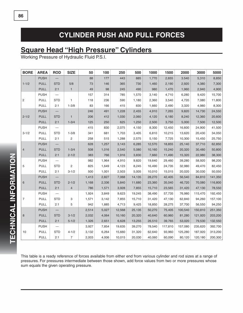
86T
ec
Hn
ica
l in
fo
RM
aT
ion
square Head “High Pressure” cylindersWorking Pressure of Hydraulic Fluid P.S.I.
BoRe aRea Rod siZe 50 100 250 500 1000 1500 2000 3000 5000
1-1/2
PUSH — 88 177 443 885 1,770 2,655 3.540 5,310 8,850
PULL STD 5/8 73 146 365 730 1,460 2,190 2,920 4,380 7,300
PULL 2:1 1 49 98 245 490 980 1,470 1,960 2,940 4,900
2
PUSH — 157 314 785 1,570 3,140 4,710 6,280 9,420 15,700
PULL STD 1 118 236 590 1,180 2,360 3,540 4,720 7,080 11,800
PULL 2:1 1-3/8 83 166 415 830 1,660 2,490 3,320 4,980 8,300
2-1/2
PUSH — 246 491 1,228 2,455 4,910 7,265 9,820 14,730 24,550
PULL STD 1 206 412 1,030 2,060 4,120 6,180 8,240 12,360 20,600
PULL 2:1 1-3/4 125 250 625 1,250 2,500 3,750 5,000 7,500 12,500
3-1/2
PUSH — 415 830 2,075 4,150 8,300 12,450 16,600 24,900 41,500
PULL STD 1-3/8 341 681 1,703 3,405 6,810 10,215 13,620 20,430 34,050
PULL 2:1 2 258 515 1,288 2,575 5,150 7,725 10,300 15,450 25,750
4
PUSH — 628 1,257 3,143 6,285 12,570 18,855 25,140 37,710 62,850
PULL STD 1-3/4 508 1,016 2,540 5,080 10,160 15,240 20,320 30,480 50,800
PULL 2:1 2-1/2 383 766 1,916 3,830 7,660 11,490 15,320 22,980 38,300
5
PUSH — 982 1,964 4,910 9,820 19,640 29,460 39,280 58,920 98,200
PULL STD 2 825 1,649 4,123 8,245 16,490 24,735 32,980 49,470 82,450
PULL 2:1 3-1/2 500 1,001 2,503 5,005 10,010 15,015 20,020 30,030 50,050
6
PUSH — 1,413 2,827 7,068 14,135 28,270 42,405 56,540 84,810 141,350
PULL STD 2-1/2 1,168 2,336 5,840 11,680 23,360 35,040 46,720 70,080 116,800
PULL 2:1 4 786 1,571 3,928 7,855 15,710 23,565 31,420 47,130 78,550
7
PUSH — 1,924 3,849 9,623 19,245 38,490 57,735 76,980 115,470 192,450
PULL STD 3 1,571 3,142 7,855 15,710 31,420 47,130 62,840 94,260 157,100
PULL 2:1 5 942 1,885 4,713 9,425 18,850 28,275 37,700 56,550 94,250
8
PUSH — 2,514 5,027 12,568 25,135 50,270 75,405 100,540 150,810 251,350
PULL STD 3-1/2 2,032 4,064 10,160 20,320 40,640 60,960 81,280 121,920 203,200
PULL 2:1 5-1/2 1,326 2,651 6,628 13,255 26,510 39,765 53,020 79,530 132,550
10
PUSH — 3,927 7,854 19,635 39,270 78,540 117,810 157,080 235,620 392,700
PULL STD 4-1/2 3,132 6,264 15,660 31,320 62,640 93,960 125,280 187,920 313,200
PULL 2:1 7 2,003 4,006 10,015 20,030 40,060 60,090 80,120 120,180 200,300
This table is a ready reference of forces available from either end from various cylinder and rod sizes at a range of pressures. For pressures intermediate between those shown, add force values from two or more pressures whose sum equals the given operating pressure.
cylindeR PUsH and PUll foRces

87T
ec
Hn
ica
l in
fo
RM
aT
ion
PISTONDIAMETER
RODDIAMETER
FLOW - GPM1 2 3 5 10 12 15 20 25 50 75
1— 298 596 894 14901/2 392 784 1176 1960
1-1/2— 130 260 392 654 13085/8 158 316 476 792 15841 235 470 706 1176 2352
2
— 73 146 221 368 736 883 11203/4 85 170 257 428 956 1025 12831 97 184 294 490 980 1175 1465
1-3/8 139 278 418 697 1394 1673 2090
2-1/2
— 47 94 141 235 470 565 675 940 11751 56 112 168 280 560 672 840 1120 1400
1-3/8 67 134 203 339 678 813 1015 1355 16951-3/4 92 184 277 463 926 1110 1385 1850 2310
3
— 32 64 98 163 326 392 490 653 8171 36 72 110 184 368 440 551 735 920
1-1/2 43 86 131 218 436 523 655 872 10902 58 116 176 294 588 705 882 1175 1470
3-1/2
— 24 48 72 120 240 288 360 480 600 12001-1/4 27 54 82 137 274 330 411 548 685 13701-3/4 32 64 96 160 320 384 480 640 800 1600
2 35 70 107 178 356 428 534 712 890 1780
4
— 18 36 55 92 184 220 276 368 460 9201-1/4 20 40 61 102 204 244 306 408 510 10201-3/4 22 44 68 113 226 273 339 452 565 1130
2 24 48 73 122 244 294 366 488 610 12202-1/2 30 60 90 150 300 362 450 600 750 1500
5
— 12 24 35 58 116 141 174 232 290 580 8701-1/2 13 26 39 64 128 155 193 258 320 640 960
2 14 28 42 70 140 168 210 280 350 700 10502-1/2 16 32 47 78 156 188 235 315 390 780 1170
3 18 36 55 92 184 220 275 365 460 920 13803-1/2 22 44 66 111 222 266 333 444 555 1110 1665
6
— 8 16 24 41 82 98 123 162 202 404 6061-3/4 9 18 27 45 90 107 135 180 225 450 6752-1/2 10 20 30 50 100 118 150 200 250 500 750
3 11 22 33 54 108 130 165 206 270 540 8103-1/2 12 24 37 62 124 148 185 245 310 620 930
4 15 30 44 73 146 176 220 295 365 730 1095
8
— 4 8 14 23 46 55 69 92 115 230 3453-1/2 5-1/2 11 17 28 56 68 85 115 140 280 420
4 6 12 18 30 60 73 90 122 150 300 4505 7-1/2 15 22 38 76 90 114 150 185 375 555
5-1/2 8-1/2 17 26 43 86 104 129 172 215 430 645
10
— 3 6 9 15 30 35 44 60 73 146 2204-1/2 3-1//2 7 11 18 36 44 55 75 92 184 275
5 4 8 12 20 40 47 60 80 100 200 3005-1/2 4-1/2 9 13 21 42 50 63 84 105 210 315
7 5-1/2 11 17 29 58 69 87 115 145 290 435
Inches / Minute
This chart is based on the formula V= 231 x GPM EFF. CYL. AREA (Sq. Inches)
HydRaUlic cylindeR sPeeds
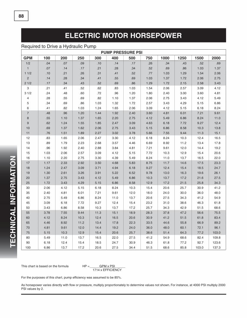
88T
ec
Hn
ica
l in
fo
RM
aT
ion
Required to Drive a Hydraulic PumpPUMP PRessURe Psi
gPM 100 200 250 300 400 500 750 1000 1250 1500 20001/2 .04 .07 .09 .10 .14 .17 .26 .34 .43 .52 .69
1 .07 .14 .17 .21 .28 .34 .52 .69 .86 1.03 1.37
1 1/2 .10 .21 .26 .31 .41 .52 .77 1.03 1.29 1.54 2.06
2 .14 .28 .34 .41 .55 .69 1.03 1.37 1.72 2.06 2.75
2 1/2 .17 .34 .43 .52 .69 .86 1.29 1.72 2.15 2.58 3.43
3 .21 .41 .52 .62 .83 1.03 1.54 2.06 2.57 3.09 4.12
3 1/2 .24 .48 .60 .72 .96 1.20 1.80 2.40 3.00 3.60 4.81
4 .28 .55 .69 .82 1.10 1.37 2.06 2.75 3.43 4.12 5.49
5 .34 .69 .86 1.03 1.32 1.72 2.57 3.43 4.29 5.15 6.86
6 .41 .82 1.03 1.24 1.65 2.06 3.09 4.12 5.15 6.18 8.24
7 .48 .96 1.20 1.44 1.92 2.40 3.60 4.81 6.01 7.21 9.61
8 .55 1.10 1.37 1.65 2.20 2.75 4.12 5.49 6.86 8.24 11.0
9 .62 1.24 1.55 1.85 2.47 3.09 4.63 6.18 7.72 9.27 12.4
10 .69 1.37 1.62 2.06 2.75 3.43 5.15 6.86 8.58 10.3 13.8
11 .76 1.51 1.89 2.27 3.02 3.78 5.66 7.55 9.44 11.3 15.1
12 .83 1.65 2.06 2.47 3.30 4.12 6.18 8.24 10.3 12.4 16.5
13 .89 1.79 2.23 2.68 3.57 4.46 6.69 8.92 11.2 13.4 17.8
14 .96 1.92 2.40 2.88 3.84 4.81 7.21 9.61 12.0 14.4 19.2
15 1.03 2.06 2.57 3.09 4.12 5.15 7.72 10.3 12.9 15.4 20.6
16 1.10 2.20 2.75 3.30 4.39 5.49 8.24 11.0 13.7 16.5 22.0
17 1.17 2.33 2.92 3.50 4.68 5.83 8.75 11.7 14.6 17.5 23.3
18 1.24 2.47 3.09 3.71 4.94 6.18 9.27 12.4 15.4 18.5 24.7
19 1.30 2.61 3.26 3.91 5.22 6.52 9.78 13.0 16.3 19.6 26.1
20 1.37 2.75 3.43 4.12 5.49 6.86 10.3 13.7 17.2 21.6 27.5
25 1.72 3.43 4.29 5.15 6.86 8.58 12.9 17.2 21.5 25.8 34.3
30 2.06 4.12 5.15 6.18 8.24 10.3 15.4 20.6 25.7 30.9 41.2
35 2.40 4.81 6.01 7.21 9.61 12.0 18.0 24.0 30.0 36.0 48.0
40 2.75 5.49 6.86 8.24 11.0 13.7 20.6 27.5 34.3 41.2 54.9
45 3.09 6.18 7.72 9.27 12.4 15.4 23.2 31.0 38.6 46.3 61.8
50 3.43 6.86 8.58 10.3 13.7 17.2 25.7 34.3 42.9 51.5 68.6
55 3.78 7.55 9.44 11.3 15.1 18.9 28.3 37.8 47.2 56.6 75.5
60 4.12 8.24 10.3 12.4 16.5 20.6 30.9 41.2 51.5 61.8 83.4
65 4.46 8.92 11.2 13.4 17.8 22.3 33.5 44.6 55.8 66.9 89.2
70 4.81 9.61 12.0 14.4 19.2 24.0 36.0 48.0 60.1 72.1 96.1
75 5.15 10.3 12.9 15.4 20.6 25.7 38.6 51.4 64.3 77.2 103.0
80 5.49 11.0 13.7 16.5 22.0 27.5 41.2 54.9 68.6 82.4 109.8
90 6.18 12.4 15.4 18.5 24.7 30.9 46.3 61.8 77.2 92.7 123.6
100 6.86 13.7 17.2 20.6 27.5 34.4 51.5 68.6 85.8 103.0 137.3
This chart is based on the formula HP = GPM x PSI 1714 x EFFICIENCY
For the purposes of this chart, pump efficiency was assumed to be 85%.
As horsepower varies directly with flow or pressure, multiply proportionately to determine values not shown. For instance, at 4000 PSI multiply 2000 PSI values by 2.
elecTRic MoToR HoRsePoWeR

89T
ec
Hn
ica
l in
fo
RM
aT
ion
PUMP foRMUlas
PUMP oUTleT floWIn Gallons/Minute
FLOW =RPM X PUMP DISPLACEMENT (Cu. In./Rev.)
231Q =
nd231
PUMP inPUT PoWeRIn Horsepower Required
HORSEPOWER INPUT =FLOW RATE OUTPUT (GPM) X PRESSURE (psi)
1714 X EFFICIENCY (Overall)HPIN =
QP1714 Eff
or GPM X psi 1714 Eff
PUMP efficiencyOverall in Percent
OVERALL EFFICIENCY =OUTPUT HORSEPOWERINPUT HORSEPOWER
X 100Ef-fOV
=HPOUTHPIN
X 100
OVERALL EFFICIENCY = VOLUMETRIC Eff. X MECHANICAL Eff.Ef-fOV
= EffVOL. X EffMECH.
PUMP efficiencyOverall in Percent
VOLUMETRIC EFFICIENCY =ACTUAL FLOW RATE OUTPUT (GPM)
THEORETICAL FLOW RATE OUTPUT (GPM)X 100
Ef-fVOL
=OACT.OTHEO.
X 100
PUMP efficiencyMechanical in Percent
MECHANICAL EFFICIENCY =THEORETICAL TORQUE TO DRIVE
ACTUAL TORQUE TO DRIVEX 100
Eff-
MEC =
TTHEO.TACT.
X 100
PUMP lifeB10 BEARING LIFE
B10 HOURS OF BEARING LIFE =
RATED SPEED (RPM) RATED PRESSURE (PSI) 3
RATED LIFE HOURS X
NEW SPEED (RPM) X
NEW PRESSURE (PSI)B10 = RPMR PR
3RATED HRS. X
RPMN X
PN
Basic foRMUlas
foRMUla foR: WoRd foRMUla leTTeR foRMUla
flUid PRessUReIn Pounds/Square Inch
PRESSURE =FORCE (pounds)
UNIT AREA (Square Inches)P =
F A
or psi = F A
flUid floW RaTeIn Gallons/Minute
FLOW RATE =VOLUME (Gallons)
UNIT TIME (Minutes)Q =
V T
flUid PoWeRIn Horsepower
HORSEPOWER =PRESSURE (PSI) X FLOW (GPM)
1714HP =
PQ1714
flUid foRMUlas
velociTy THRoUgH PiPingIn Feet/Second Velocity
VELOCITY =.3208 x FLOW RATE THROUGH I.D. (GPM)
INTERNAL AREA (Square Inches)V =
.3208Q A
coMPRessiBiliTy of oilIn Additional Required Oil To Reach Pressure
ADDITIONALVOLUME
=PRESSURE (PSI) x VOLUME OF OIL UNDER PRESSURE
250,000 (Approx.)VA
= PV *250,000
coMPRessiBiliTy of a flUid COMPRESSIBILITY =1
BULK MODULUS OF THE FLUIDC(ß)
= 1BM
sPecific gRaviTy of a flUid SPECIFIC GRAVITY =WEIGHT OF ONE CUBIC FOOT OF FLUIDWEIGHT OF ONE CUBIC FOOT OF WATER
SG = W62.4283
valve (cv) floW facToR VALVE FACTOR (CV) =FLOW RATE (GPM) x SPECIFIC GRAVITY
PRESSURE DROP (PSI)CV =
Q SG P
viscosiTy in cenTisTokes
For Viscosities of 32 to 100 Saybolt Universal Seconds:
CS = .2253 SUS – 194.4
SUSCENTISTOKES = .2253 x SUS – 194.4 SUS
viscosiTy in cenTisTokes
For Viscosities of 100 to 240 Saybolt Universal Seconds:
CS = .2193 SUS – 134.6 SUSCENTISTOKES = .2193 x SUS –
134.6 SUS
viscosiTy in cenTisTokes
For Viscosities Greater Than 240 Saybolt Universal Seconds:
CS =SUS4.635CENTISTOKES =
SUS4.635
noTe: Saybolt Universal Seconds is often abbreviated SSU.
*Approximately1/2%per1000psi
( ) ))
flUid PoWeR foRMUlas
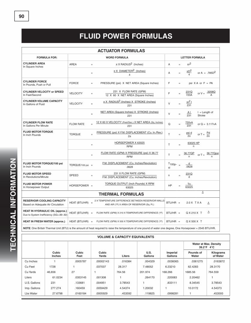
90T
ec
Hn
ica
l in
fo
RM
aT
ion
acTUaToR foRMUlas
foRMUla foR: WoRd foRMUla leTTeR foRMUla
cylindeR aReaIn Square Inches
AREA = π X RADIUS2 (Inches) A = πr2
=π X DIAMETER2 (Inches)
4A =
πD2
4or A = .785D2
cylindeR foRceIn Pounds, Push or Pull
FORCE = PRESSURE (psi) X NET AREA (Square Inches) F = psi X A or F = PA
cylindeR velociTy or sPeedIn Feet/Second
VELOCITY =231 X FLOW RATE (GPM)
12 X 60 X NET AREA (Square Inches)F =
231Q720A
or V =.3208Q A
cylindeR volUMe caPaciTyIn Gallons of Fluid VELOCITY =
π X RADIUS2 (Inches) X STROKE (Inches)231
V =πr2 l231
=NET AREA (Square Inches) X STROKE (Inches)
231V =
A l231
l = Length of Stroke
cylindeR floW RaTeIn Gallons Per Minute
FLOW RATE =12 X 60 X VELOCITY (Feet/Sec.) X NET AREA (Sq. Inches)
231Q =
720vA231
or Q = 3.117vA
flUid MoToR ToRQUeIn Inch Pounds TORQUE =
PRESSURE (psi) X F.M. DISPLACEMENT (Cu. In./Rev.)2π T =
psi d2π or T =
Pd2π
=HORSEPOWER X 63025
RPMT =
63025 HPn
=FLOW RATE (GPM) X PRESSURE (psi) X 36.77
RPMT =
36.77QPn
or T =36.77Qpsi n
flUid MoToR ToRQUe/100 psiIn Inch Pounds
TORQUE/100 psi =F.M. DISPLACEMENT (Cu. Inches/Revolution)
.0628T100p-si
=d
.0628
flUid MoToR sPeedIn Revolutions/Minute
SPEED =231 X FLOW RATE (GPM)
F.M. DISPLACEMENT (Cu. Inches/Revolution)n =
231Qd
flUid MoToR PoWeRIn Horsepower Output
HORSEPOWER =TORQUE OUTPUT (Inch Pounds) X RPM
63025HP =
Tn63025
THeRMal foRMUlasReseRvoiR cooling caPaciTyBased on Adequate Air Circulation
HEAT (BTU/HR) =2 X TEMPERATURE DIFFERENCE BETWEEN RESERVOIR WALLS
AND AIR (°F) X AREA OF RESERVOIR (Sq. Ft.)BTU/HR = 2.0 X T X A
HeaT in HydRaUlic oil (approx.)Due to System Inefficiency (SG=.89-.92)
HEAT (BTU/HR) = FLOW RATE (GPM) X 210 X TEMPERATURE DIFFERENCE (°F) BTU/HR = Q X 210 X T
HeaT in fResH WaTeR (approx.) HEAT (BTU/HR) = FLOW RATE (GPM) X 500 X TEMPERATURE DIFFERENCE (°F) BTU/HR = Q X 500 X T
noTe: One British Thermal Unit (BTU) is the amount of heat required to raise the temperature of one pound of water one degree. One Horsepower = 2545 BTU/HR.
volUMe & caPaciTy eQUivalenTs
cubicinches
cubicfeet
cubicyards liters
U.s.gallons
imperialgallons
Water at Max. density39.2°f 4°c
Pounds ofWater
kilogramsof Water
Cu Inches 1 .0005787 .00002143 .016384 .004329 .0036065 .0361275 .0163872
Cu Feet 1728 1 .037037 28.317 7.48052 6.23210 62.4283 28.3170
Cu Yards 46,656 27 1 764.56 201.974 168.266 1685.56 764.559
Liters 61.0234 .0353145 .001308 1 .264170 .220083 2.20462 1
U.S. Gallons 231 .133681 .004951 3.78543 1 .833111 8.34545 3.78543
Imp. Gallons 277.274 .160459 .0059429 4.54374 1.20032 1 10.0172 4.54373
Lbs Water 27.6798 .0160184 .0005929 .453592 .119825 .0998281 1 .453593
flUid PoWeR foRMUlas

91T
ec
Hn
ica
l in
fo
RM
aT
ion
TecH TiP - sURface finisH
The surface finish has a critical influence on excellent seal-ing performance, low friction and long seal life. A finish that is either too rough or very smooth will cause a negative result. The surface microstructures allow pockets of fluid in very small volumes to pass under the seal with each cycle. This lubricat-ing fluid lowers friction and extends seal life. Seal interface lubrication is reduced with a very fine surface finish and the seal will suffer increased friction and wear. In the case of rod sealing, a rougher finish may result in leakage if the fluid pass-es under the seal, is removed from the rod and not returned back into the cylinder. The wear rate is a major factor in the life of a dynamic application, and depends on the quality of the rod and the cylinder bore surface finish.
definiTionsThe most frequently specified parameters in the fluid power industry are Ra, Ry, Rt, Rz, Rq, and Rsk which are defined in ISO 4287 and ISO 4288.
Ra is defined as the arithmetical mean deviation of the assessed profile. The inch equivalent parameter is CLA (centre line average). A surface finish of 0.4 μm Ra is equivalent to 16 μin CLA. The “checkmark” symbol used on drawings to specify a surface texture control requirement is an Ra specification.
Ry (also Rmax) is the maximum roughness height in one cutoff length (L) of the profile.
Rt is the maximum roughness height in five cutoff lengths of the roughness profile.
Rz is the average of the five greatest peak-to-valley separa-tions crossing the mean line in a single cutoff length.
Rq is the root mean square deviation of the assessed pro-file. The equivalent term in inches is RMS (Root Mean Square). The Rq (RMS) of a surface is approximately 10% greater than the Ra (CLA) value.
Rsk is the assessed profile skewness or the measure of sym-metry about the mean. A negative Rsk indicates greater valleys than peaks and imparts a better sealmating surface.
RecoMMendaTionsA single parameter rating is not sufficient in assessing the sur-face irregularities. Several parameters should be specified to accurately evaluate the surface depth, shape and orientation and their affect on sealing performance, friction and wear.
Reciprocating Cylinder Rod Hydraulic and Low Pressure Pneumatic
Ra = 4 to 12 μin [0.1 to 0.3 μm] Rz 50 μin [1.3 μm] Rsk = -1.0 to -4.0
Reciprocating Cylinder Bore and Slow Rotary RodHydraulic and Low Pressure Pneumatic
Ra = 4 to 20 μin [0.1 to 0.5 μm] Rz 80 μin [2.0 μm] Rsk = -1.0 to -4.0
sURface finisHingThe surface roughness is dependent on the machining pro-cess employed. Scores, scratches, voids, concentric or linear machining marks are not permitted. Common production meth-ods result in a metal surface finish of between 1 μin to 140 μin [0.02 μm to 3.5 μm] Ra roughness as shown in the table below.
PRocess RoUgHness Ra (μin [μm])
Turning 40 - 140 [1.0 - 3.5]
Boring 24 - 95 0.6 - 2.4)
Broaching 16 - 63 (0.4 - 1.6)
Precision Rolling 8 - 48 (0.2 - 1.2)
Grinding 8 - 40 (0.2 - 1.0)
Smooth 3 - 12 (0.08 - 0.3)
Super Fine 0.5 - 3 (0.012 - 0.08)
Polished 0.5 - 3 (0.012 - 0.08)
CALL 1-800-777-5617www.HerculesUS.com
TECH TIP - SURFACE FINISHThe surface finish has a critical influence on excellentsealing performance, low friction and long seal life. Afinish that is either too rough or very smooth will cause anegative result. The surface microstructures allow pocketsof fluid in very small volumes to pass under the seal witheach cycle. This lubricating fluid lowers friction andextends seal life. Seal interface lubrication is reduced witha very fine surface finish and the seal will suffer increasedfriction and wear. In the case of rod sealing, a rougherfinish may result in leakage if the fluid passes under theseal, is removed from the rod and not returned back intothe cylinder. The wear rate is a major factor in the life ofa dynamic application, and depends on the quality of therod and the cylinder bore surface finish.
DefinitionsThe most frequently specified parameters in the fluidpower industry are Ra, Ry, Rt, Rz, Rq, and Rsk which aredefined in ISO 4287 and ISO 4288.
Ra is defined as the arithmetical mean deviation of theassessed profile. The inch equivalent parameter is CLA(centre line average). A surface finish of 0.4 µm Ra isequivalent to 16 µin CLA. The “checkmark” symbol usedon drawings to specify a surface texture control require-ment is an Ra specification.
Ry (also Rmax) is the maximum roughness height in onecutoff length (L) of the profile.
Rt is the maximum roughness height in five cutoff lengthsof the roughness profile.
Rz is the average of the five greatest peak-to-valley sepa-rations crossing the mean line in a single cutoff length.
Rq is the root mean square deviation of the assessed pro-file. The equivalent term in inches is RMS (Root MeanSquare). The Rq (RMS) of a surface is approximately10% greater than the Ra (CLA) value.
Rsk is the assessed profile skewness or the measure ofsymmetry about the mean. A negative Rsk indicatesgreater valleys than peaks and imparts a better sealmating surface.
RecommendationsA single parameter rating is not sufficient in assessing thesurface irregularities. Several parameters should be speci-fied to accurately evaluate the surface depth, shape andorientation and their affect on sealing performance, fric-tion and wear.
Reciprocating Cylinder RodHydraulic and Low Pressure Pneumatic
Ra = 4 to 12 µin [0.1 to 0.3 µm]Rz 50 µin [1.3 µm]Rsk = -1.0 to -4.0
Reciprocating Cylinder Bore and Slow Rotary RodHydraulic and Low Pressure Pneumatic
Ra = 4 to 20 µin [0.1 to 0.5 µm]Rz 80 µin [2.0 µm]Rsk = -1.0 to -4.0
Surface FinishingThe surface roughness is dependent on the machiningprocess employed. Scores, scratches, voids, concentric orlinear machining marks are not permitted. Common pro-duction methods result in a metal surface finish ofbetween 1 µin to 140 µin [0.02 µm to 3.5 µm] Ra rough-ness as shown in the table below.
Process Roughness Ra (µin [µm])
Turning 40 – 140 [1.0 - 3.5]Boring 24 – 95 [0.6 - 2.4]Broaching 16 – 63 [0.4 - 1.6]Precision Rolling 8 – 48 [0.2 - 1.2]Grinding 8 – 40 [0.2 - 1.0]Smooth 3 – 12 [0.08 - 0.3]Super Fine 0.5 – 3 [0.012 - 0.08]Polished 0.5 – 3 [0.012 - 0.08]

92T
ec
Hn
ica
l in
fo
RM
aT
ion
fRonT MoUnT dUMP Body
stroke & lifting calculations Mounting
NOTE: This guide is for use to determine approximate stroke and lifting requirements for a front mount dump body. Final dimensions should be determined by an engineering drawing.