Standard hydraulic cylinders TJ, TH, TM series - Tokyo Keiki ...
22
1-1 P Hydraulic Cylinders Standard hydraulic cylinders TJ, TH, TM series Functional Symbol • TJ series: These standard hydraulic cylinders satisfy the specifications of the JIS B 8354 standard, and they are destined for use in machine tools and other general sectors of industry. • TH series: Features higher pressure levels (21 MPa) than the TJ series. • TM series: Mill cylinders destined mainly for use in steel-making machinery. TJ(W)(3) -FA40(C)B100- (1537)(L70)(P1)(B)(W)(N)(M)(Z1) 8 1 10 7 5 6 14 9 Model Code 1 Series TJ: Used with working pressures up to 14 MPa (However, up to 7 MPa only for support unit models FA, FB and LB) TH: Used with working pressures up to 21 MPa TM: Mill standard type 2 Rod model Omitted for single rod type W: Double rod type (TJ series only) 3 Gasket material 4 Support unit models Note: Symbols (1 to 5) are to be entered in the sequence of the rods and piston if the rod gaskets and piston gaskets are made of different materials. Example: “12” is entered when nitrile rubber is to be used for the rod gaskets and urethane rubber is to be used for the piston gaskets. 5 Cylinder bore size * 7 MPa specification. 6 Type of rod diameter Omit: B series (56% of cylinder bore size) C: C series (45% of cylinder bore size); applicable only to TJ series A: A series (71% of cylinder bore size) ; applicable only to TM series 7 Cushion N: No cushion R: Cushion provided at rod side H: Cushion provided at head side B: Cushions provided at both sides Note: It is not possible to fit the cushion mechanisms on the rod and head sides of TJ ø30, rod side of the TH ø40, rod side of the TM ø40A to ø63A series or rod side of the TM ø40B series. 8 Stroke The stroke required within the maximum strokes set forth on page P1-3 is entered here. 9 Connection port, cushion valve/air release positions The rod side connection port, head side connection port, rod side cushion valve/air release and head side cushion valve/air release positions are entered here in sequence. 2 3 4 15 13 12 11 16 8 5 6 7 1 4 3 2 TJ TH TM 1 2 3 4 5 Metal Material Symbol Series Fluororubber Polytetrafluoroethylene (PTFE) Omitted Nitrile rubber (Nitrile rubber) Urethane rubber Urethane rubber Nitrile rubber (Urethane rubber) Nitrile rubber (Nitrile rubber) Urethane rubber TJ TH TM Series Support Unit SD: Basic FA: Rod side rectangular flange FB: Head side rectangular flange FC: Rod side square flange FD: Head side square flange FY: Rod side rectangular flange FZ: Head side rectangular flange LA: Foot in direction perpendicular to axis LB: Foot in axial direction TA: Rod side integrated trunnion TC: Intermediate fixed trunnion CA: Separated eye CB: Separated clevis CC: Fixed eye ○ ○ ○ ○ ○ ○ ○ ○ ○ ○ ○ ○ ○ - ○ ○ ○ - - - - ○ - - ○ - - ○ - ○ ○ - - - - ○ - - ○ ○ - - * * * TJ TH TM 30 ○ - - 40 ○ ○ ○ 50 ○ ○ ○ 63 ○ ○ ○ 80 ○ ○ ○ 100 ○ ○ ○ 125 ○ ○ ○ 140 ○ ○ ○ 150 ○ - - 160 ○ ○ ○ 180 ○ - ○ 200 ○ - ○ 224 ○ - ○ 250 ○ - ○ Series Bore Size mm
-
Upload
khangminh22 -
Category
Documents
-
view
0 -
download
0
Transcript of Standard hydraulic cylinders TJ, TH, TM series - Tokyo Keiki ...

1-1P
Hyd
raul
ic C
ylin
ders
Standard hydraulic cylinders TJ, TH, TM series
Functional Symbol
• TJ series: These standard hydraulic cylinders satisfy the specifications of the JIS B 8354 standard, and they are destined for use in machine tools and other general sectors of industry.
• TH series: Features higher pressure levels (21 MPa) than the TJ series.• TM series: Mill cylinders destined mainly for use in steel-making
machinery.
TJ(W)(3)-FA40(C)B100-(1537)(L70)(P1)(B)(W)(N)(M)(Z1)81 1075 6 149
Model Code
1 Series
TJ: Used with working pressures up to 14 MPa
(However, up to 7 MPa only for support unit models FA, FB
and LB)
TH: Used with working pressures up to 21 MPa
TM: Mill standard type
2 Rod model
Omitted for single rod type
W: Double rod type (TJ series only)
3 Gasket material
4 Support unit models
Note: Symbols (1 to 5) are to be entered in the sequence of the rods and piston if the rod gaskets and piston gaskets are made of different materials.
Example: “12” is entered when nitrile rubber is to be used for the rod gaskets and urethane rubber is to be used for the piston gaskets.
5 Cylinder bore size
* 7 MPa specification.
6 Type of rod diameterOmit: B series (56% of cylinder bore size)
C: C series (45% of cylinder bore size); applicable only to TJ series
A: A series (71% of cylinder bore size) ; applicable only to TM series
7 CushionN: No cushionR: Cushion provided at rod sideH: Cushion provided at head sideB: Cushions provided at both sidesNote: It is not possible to fit the cushion mechanisms on the
rod and head sides of TJ ø30, rod side of the TH ø40, rod side of the TM ø40A to ø63A series or rod side of the TM ø40B series.
8 StrokeThe stroke required within the maximum strokes set forth on page P1-3 is entered here.
9 Connection port, cushion valve/air
release positionsThe rod side connection port, head side connection port, rod side cushion valve/air release and head side cushion valve/air release positions are entered here in sequence.
2 3 4 15131211 16
8
5
6
7
1
4
3
2
TJ TH TM
12345 Metal
Material Symbol
Series
Fluororubber
Polytetrafluoroethylene (PTFE)
Omitted Nitrile rubber
(Nitrile rubber)
Urethane rubber
Urethane rubber
Nitrile rubber
(Urethane rubber)
Nitrile rubber
(Nitrile rubber)
Urethane rubber
TJ TH TMSeriesSupport Unit
SD: Basic
FA: Rod side rectangular flange
FB: Head side rectangular flange
FC: Rod side square flange
FD: Head side square flange
FY: Rod side rectangular flange
FZ: Head side rectangular flange
LA: Foot in direction perpendicular to axis
LB: Foot in axial direction
TA: Rod side integrated trunnion
TC: Intermediate fixed trunnion
CA: Separated eye
CB: Separated clevis
CC: Fixed eye
○○○○○○○○○○○○○-
○○○----○--○--○
-○○----○--○○--
*
*
*
TJ TH TM 30 ○ - - 40 ○ ○ ○ 50 ○ ○ ○ 63 ○ ○ ○ 80 ○ ○ ○100 ○ ○ ○125 ○ ○ ○140 ○ ○ ○150 ○ - -160 ○ ○ ○180 ○ - ○200 ○ - ○224 ○ - ○250 ○ - ○
SeriesBore Size mm

P1-2
Hyd
raul
ic C
ylin
ders
• Omitted (standard) when the connection port positions are ‘15’ as shown in the figure and when the cushion valve/air release positions are ‘26’.
• Only the port positions are entered if the cushion valve/air release positions are 90° to the right of the ports as seen from the rod side.
Example: Only ‘16’ is entered if the port positions are ‘16’ and the cushion valve/air release positions are ‘27’.
10 Intermediate trunnion position (applicable to support unit
model type TC)
Omit: standard (refer to dimensions on page P1-17)
L***: If a position other than the standard position is required,
enter the XF in the dimension.
11 Bellows (dust-proof cover)
Omit: not provided
P1: Nylon tarpaulin (heat resistance: 80°C)
P2: Neoprene (heat resistance: 130°C)
P3: Conex (heat resistance: 400°C)
12 End screw shape
Omit: standard
B: Special
13 Rod pop-out length
Omit: standard
W: Special
14 Lock nut
Omit: not provided
N: Lock nut provided
15 End fitting
Omit: not provided
M: Single thread end fitting
F: Double thread end fitting
16 Pin (for support unit model type CB and double thread end
fitting)
Omit: not provided
Z1: 1 pin
Z2: 2 pins
Note: Two split pins are provided for each pin.
Specifications
* This may refer to the flange provided for type SSA welding as stipulated in the JIS B 2291 standard or to the flange provided for connecting the taper threads for JIS pipes using the SSA mounting method stipulated in JIS B 2291.
• The ‘maximum allowable pressure’ is the allowable value of the surge pressure, the pressure that is generated in excess or any other pressure generated inside the cylinder during use in excess of the pressure set for the hydraulic circuit.
• The ‘nominal pressure’ is the pressure set for the relief valve in the hydraulic circuit that uses the cylinder.
• The minimum cylinder speed and minimum working pressure exclude the speed and pressure generated during the cushion stroke.
Port
Cushion valve
Air release
Standard (1526)
Max.Min.
φ30~φ63
φ80~φ125
φ140~φ250
φ30~φ63
φ80~φ125
φ140~φ250
φ40~φ63
φ80~φ125
φ140, φ160
φ40~φ140
φ160~φ250
0.9
0.95
JIS B 2291*
11/11.6
14/21
―
―
9/10.5
18/21
27/31.5
23/28
―
―
13.5/14.2
18/21
25/31.5
TJ
TH
7
14
21
14
FAFBLB
SD, FAFB, LACC, TC
―
500
8
Minimum Working Pressure
MPa
Ambient Temperature
˚C
0.3-5~+80
-10~+80
Rod Side
Maximum Allowable Pressure/Pressure Resistance MPa
FA, FBLA, CA
TC
Cylinder Speedmm/sec
TM
SD, FCFD, FYFZ, LACA, CBTA, TC
Head Side
Cylinder Bore Sizemm
SeriesSupport
Unit Model
Nominal Pressure
MPa Rod Diameter Symbol A
Rod Diameter Symbol B
Rod Diameter Symbol C
JIS pipe taper thread
Thrust Efficiency
Pipe Connection System
400300200
400
300
200
400300200
Type SSA welding flange provided
0.310
0.52023/28
• When the cylinder is to be used at the maximum cylinder speed, set the pressure generated inside the cylinder chamber as a result of the load inertia to below the maximum allowable pressure.
• The minimum working pressure refers to the pressure when the pressure is supplied from the head side.

1-3P
Hyd
raul
ic C
ylin
ders
Specifications ● Maximum strokes and cushion strokes
Stroke tolerance (JIS B 8354 class A)
Note: The maximum stroke is also limited by the buckling strength so select the rod diameter by referring to the “Quick reference table for buckling” on page P1-5.
● Piston surface area and velocity ratio (single rod type)
Note: In the case of the double rod type, the velocity ratio is 1:1, and the piston surface area is the rod side surface area given in the above table for both sides.
Weight
● TJ series (single rod type) Unit: kg
φ30 ― ―φ40φ50φ63φ80φ100φ125φ140φ150 ― ―φ160 2000φ180φ200φ224φ250
2000
―
2000
2500
2500
3000
1200
1600
2000
Maximum StrokeTJ TH TM
1200
1600
Cylinder Bore Size mm
― ― ―
20 20
30― ―30
35
40
25
Cushion StrokeTJ TH TM
30 ―50
25
3525
Stroke mm
Less than 100
101~ 250
251~ 630
631~1000
1001~1600
1601~2000
2001~2500
2501~3000
+0.80
+1.00
+1.250
+1.40
+1.60
+1.80
+2.20
+2.00
Tolerance mm
速度比 速度比
押 引 ヘッド側 ロッド側 押 引 ヘッド側 ロッド側
φ30 B φ18 1:1.55 7.0 4.5 A φ100 1:2.04 75.3
A φ28 1:1.96 6.4 B φ80 1:1.48 103.6
B φ22.4 1:1.46 8.6 C φ63 1:1.25 122.7
C φ18 1:1.25 10.0 B φ85 1:1.47 119.9
A φ35.5 1:2.02 9.7 C φ67 1:1.25 141.4
B φ28 1:1.46 13.4 A φ112 1:1.96 102.5
C φ22.4 1:1.25 15.6 B φ90 1:1.46 137.4
A φ45 1:2.04 15.2 C φ71 1:1.24 161.4
B φ35.5 1:1.47 21.2 A φ125 1:1.93 131.7
C φ28 1:1.24 25.0 B φ100 1:1.45 175.9
A φ56 1:1.96 25.6 C φ80 1:1.25 204.2
B φ45 1:1.46 34.3 A φ140 1:1.96 160.2
C φ35.5 1:1.24 40.3 B φ112 1:1.46 215.6
A φ71 1:2.02 38.9 C φ90 1:1.25 250.5
B φ56 1:1.46 53.9 A φ160 1:2.04 193
C φ45 1:1.25 62.6 B φ125 1:1.45 271.3
A φ90 1:2.08 59.1 C φ100 1:1.25 315.5
B φ71 1:1.48 83.1 A φ180 1:2.08 236.4
C φ56 1:1.25 98.0 B φ140 1:1.46 336.9
C φ112 1:1.25 392.3
φ100
φ125
ロッド径記号
シリンダ内径mm
φ40
φ50
φ63
ロッド径mm
ピストン面積
cm2
12.5
φ80
ピストン面積
cm2
122.7
シリンダ内径mm
ロッド径記号
ロッド径mm
19.6
31.1
50.2
78.5
φ200
φ224
φ250
153.9
176.7
201.0
254.4
314.1
394.0
490.8
φ140
φ150
φ160
φ180
Cylinder Bore Sizemm
Cylinder Bore Sizemm
Rod Diameter Symbol
Rod Diameter Symbol
Rod Diameter
mm
Rod Diameter
mm
Velocity Ratio
Velocity Ratio
Piston Surface Areacm2
Piston Surface Areacm2
Push Pull Push PullHead Side Head SideRod Side Rod Side
SD LA LB FA FB FC FD FY FZ CA CB TA TC 一山 ニ山
B 2.4 2.9 3.0 2.7 3.0 3.1 3.4 2.8 3.1 2.9 3.0 2.5 2.9 0.7 0.02
C ― ― ― ― ― ― ― ― ― ― ― ― ― ― ―
B 4.0 4.5 4.6 4.3 4.7 4.8 5.1 4.4 4.9 4.6 4.7 4.2 4.8 1.1 0.04
C 3.9 4.4 4.5 4.2 4.6 4.7 5.0 4.3 4.8 4.5 4.6 4.1 4.7 1.0 0.02
B 5.8 7.2 7.3 6.4 7.0 7.2 7.8 6.7 7.5 6.8 6.9 6.2 6.9 1.4 0.07
C 5.7 7.1 7.2 6.3 6.9 7.1 7.7 6.6 7.4 6.7 6.8 6.1 6.8 1.2 0.04
B 9.2 10.2 10.5 10.0 11.0 11.2 12.2 10.3 11.6 11.4 12.0 10.0 11.4 2.1 0.16
C 8.9 9.9 10.2 9.7 10.7 10.9 11.9 10.0 11.3 11.1 11.7 9.7 11.1 1.9 0.07
B 15.9 17.6 18.0 17.2 18.9 19.0 20.7 17.6 19.9 19.0 19.6 16.7 18.7 3.5 0.35
C 15.2 16.9 17.3 16.5 18.2 18.3 20.0 16.9 19.2 18.3 18.9 16.0 18.0 3.0 0.16
B 25.4 27.5 28.8 27.7 30.6 30.4 33.2 28.7 32.7 30.9 32.1 27.0 30.6 5.0 0.7
C 24.3 26.4 27.7 26.6 29.5 29.3 32.1 27.6 31.6 29.8 31.0 25.9 29.5 4.3 0.35
基本質量
支持部形式
0.6
1.2
付属品
先端金具ピン ナット
0.1
0.1
0.2
0.62.6
3.0
6.3
0.6
0.6
1.2
3.2
3.8
7.7
ストローク100mmあたり
の質量
0.4
0.5
0.9
ロッド径記号
シリンダ内径mm
φ30
φ40
φ50
φ63
φ80
φ100
Cylinder Bore Size
mm
Weight per 100 mm of
Stroke
Rod Diameter Symbol
Basic Weight AccessoriesEnd Fitting
Pin NutSingle Thread Double Thread
Support Unit Model

P1-4
Hyd
raul
ic C
ylin
ders
Weight
Unit: kg
● TJ series (double rod type) Unit: kg
● TH series Unit: kg
SD LA LB FA FB FC FD FY FZ CA CB TA TC 一山 ニ山
B 44.8 47.8 50.5 48.2 53.4 52.8 58.0 49.5 56.6 55.1 57.3 47.9 51.8 7.6 1.4
C 42.9 45.9 48.6 46.3 51.5 50.9 56.1 47.6 54.7 53.2 55.4 46.0 49.9 6.5 0.7
B 59.4 63.0 67.5 63.9 70.9 69.9 76.9 65.8 75.8 76.0 80.3 65.6 71.4 10.1 1.8
C 56.6 60.2 64.7 61.1 68.1 67.1 74.1 63.0 73.0 73.2 77.5 62.8 68.6 8.6 1.0
B 68.7 72.6 78.2 74.4 82.9 81.5 90.0 76.7 88.4 87.1 95.7 74.9 81.7 10.8 2.1
C 65.6 69.5 75.1 71.3 79.8 78.4 86.9 73.6 85.3 84.0 92.6 71.8 78.6 9.2 1.2
B 84.0 89.2 94.6 91.3 102.1 100.6 111.3 93.7 107.9 107.6 113.1 92.8 100.4 13.3 2.4
C 79.6 84.8 90.2 86.9 97.7 96.2 106.9 89.3 103.5 103.2 108.7 88.4 96.0 11.4 1.4
B 118.3 125.1 132.7 126.7 141.1 138.7 153 130 150 152.9 162 130.9 140.5 17.3 3.9
C 111.7 118.5 126.1 120.1 134.5 132.1 146.4 123.4 143.4 146.3 155.4 124.3 133.9 15.0 1.8
B 161.2 171.2 183.2 173.7 193.6 191.4 211.4 178.4 205.9 212.4 226.4 179.2 164.7 21.8 4.9
C 153.3 163.3 175.3 165.8 185.7 183.5 203.5 170.5 198 204.5 218.5 171.3 156.8 19.1 2.4
B 206.7 217.4 240.8 224.9 252.4 248.4 275.8 232.4 271.3 272 289.1 231.4 248.7 26.6 7.7
C 193.8 204.5 227.9 212 239.5 235.5 262.9 219.5 258.4 259.1 276.2 218.5 235.8 23.1 3.9
B 292 306.1 340 313.9 352.1 345.1 383.3 322.9 376.9 368 385.1 316.7 339.4 32.8 10
C 272.4 286.5 320.4 294.3 332.5 325.5 363.7 313.3 357.3 348.4 365.5 297.1 319.8 28.5 4.9
18.1
98.6 123.2 18.1
φ224
φ250
94.5 117.3
φ150
φ160
φ180
φ200
ロッド径記号
シリンダ内径mm
φ125
φ140
ストローク 100mmあたり
の質量
12.0
23.3
23.8
69.9
15.0
29.9
30.7
36.8
58.7
77.9
4.7
6.027.3
48.6
基本質量
支持部形式
9.6
13.6
付属品
先端金具ピンナット
2.4
4.7
Cylinder Bore Size
mm
Weight per 100 mm of
Stroke
Rod Diameter Symbol
Basic Weight AccessoriesEnd Fitting
Pin NutSingle Thread Double Thread
Support Unit Model
SD LA LB FA FC FY TA TC 一山 ニ山
B 3.3 3.8 3.9 3.6 4.0 3.7 3.4 3.8 0.9 0.02
C ― ― ― ― ― ― ― ― ― ―
B 4.9 5.4 5.5 5.2 5.7 5.3 5.1 5.7 1.4 0.04
C 4.8 5.3 5.4 5.1 5.6 5.2 5.0 5.6 1.2 0.02
B 7.2 8.6 8.7 7.8 8.6 8.1 7.6 8.3 1.9 0.07
C 7.0 8.4 8.5 7.6 8.4 7.9 7.4 8.1 1.5 0.04
B 11.5 12.5 12.8 12.3 13.5 12.6 12.3 13.7 2.9 0.16
C 11.1 12.1 12.4 11.9 13.1 12.2 11.9 13.3 2.4 0.07
B 20.0 21.7 22.1 21.3 23.1 21.7 20.8 22.8 4.8 0.35
C 19.1 20.8 21.2 20.4 22.2 20.8 19.9 21.9 3.8 0.16
B 32.1 34.2 35.5 34.4 37.1 35.4 33.7 37.3 6.9 0.7
C 30.5 32.6 33.9 32.8 35.5 33.8 32.1 35.7 5.6 0.35
B 55.5 58.5 61.2 58.9 63.5 60.2 58.6 62.5 10.7 1.4
C 51.7 54.7 57.4 55.1 59.7 56.4 54.8 58.7 8.4 0.7
B 73.7 77.3 81.8 78.2 84.2 80.1 79.9 85.7 14.1 1.8
C 68.1 71.7 76.2 72.6 78.6 74.5 74.3 80.1 11.1 1.0
B 85.3 89.2 94.8 91.0 98.1 93.3 91.5 98.3 15.3 2.1
C 79.1 83.0 88.6 84.8 91.9 87.1 85.3 92.1 12.0 1.2
B 114.3 119.5 124.9 121.6 130.9 124 123 130.7 18.3 2.4
C 105.5 110.7 116.1 112.8 122.1 115.2 114.2 121.9 14.5 1.4
基 本 質 量
支 持 部 形 式
1.2
付属品
先端金具ピン ナット
0.1
0.1
0.2
0.6 2.6
3.0 0.6
6.3
0.6
0.6
1.2
3.2
3.8
7.7
ストローク 100mmあたり
の質量
0.4
0.5
0.9
ロッド径記号
シリンダ内径mm
φ30
φ40
φ50
φ63
φ80
φ100
φ125
φ140
12.0 15.0 2.4
23.3 29.9 4.7
φ150
φ160
23.8 30.7 4.7
27.3 36.8 6.0
Cylinder Bore Sizemm
Weight per 100 mm of
Stroke
Rod Diameter Symbol
Basic Weight AccessoriesEnd Fitting
Pin NutSingle Thread Double Thread
Support Unit Model
SD LA FA FB CC TC 一山 ニ山
φ40 5.2 6.2 6.2 6.7 6.3 6.2 1.2 1.1 1.1 0.2 0.04
φ50 8.4 8.8 9.1 9.8 9.0 9.0 2.0 1.6 1.8 0.3 0.07
φ63 12.9 14.2 14.8 16.3 14.6 14.9 3.1 2.7 3.0 0.6 0.16
φ80 23.7 24.5 24.4 27.5 25.5 26.3 4.5 5.4 6.2 1.2 0.35
φ100 40.0 41.7 42.6 48.0 43.5 46.2 6.1 10.0 11.7 2.3 0.70
φ125 67.6 71.2 75.5 85.6 78.2 80.0 10.0 20.3 22.2 4.7 1.4
φ140 87.4 91.8 93.6 107.2 103.9 105.3 11.3 29.3 29.0 6.2 1.8
φ160 119.7 125 126.6 145.4 136.1 141.3 14.7 43.2 47.3 9.4 2.4
基 本 質 量
支 持 部 形 式シリンダ
内径mm
ストローク100mmあたり
の質量
付属品
先端金具ピン ナットNut
Cylinder Bore Sizemm
Weight per 100 mm of Stroke
Basic Weight AccessoriesEnd Fitting
PinSingle Thread Double Thread
Support Unit Model

1-5P
Hyd
raul
ic C
ylin
ders
Weight
● TM series (rod diameter symbol A) Unit: kg
● TM series (rod diameter symbol B) Unit: kg
Notes on Operation
● Cushion valve and air release
● Quick reference table for buckling
〇Cushion valve: Loosen the lock nut, and turn the adjustment screw to adjust. The cushioning effect is increased as the screw is turned clockwise.
〇Air release: Be absolutely sure to release the air when the cylinder has been installed. Failing to release the air completely may give rise to the stick-slip phenomenon. Also bear in mind that if any air is still left when a high pressure has been generated inside the cylinder, the lip of the rubber gasket may be damaged. To release the air, open the air release on the low-pressure side and keep releasing the air until the hydraulic fluid is no longer cloudy.
Follow the steps below to check the buckling strength as determined by the load, mounting length and rod diameter.1. Check which of the states shown in the figures below the
support unit model is in, and calculate the maximum mounting length d from the dimensions (when the end is extended).
2. Calculate buckling length / using the / and d relational expression in the figure below.
3. In the following table, use the load and rod diameter intersection point as L.
4. If / ≤ L, the buckling strength is sufficient.
● In the case of double-ended pin joint ● In the case of a fixed cylinder and rod end guide (pin joint)
Cushion valve Check valve-with-air release
Check valve
Air release
d
d
d
d
l( =d)l( =d) l( =d) l( =d)
d
d
d d
1 4( = )d
.l ( = )
d
1 4l ( = )
d
1 4l ( = )
d
1 4l
. . .
LA FA FB CA TC 一山 ニ山
φ40 12.1 10.1 11.1 11.1 11.2 1.1 0.1 1.2 1.4 0.1 0.07
φ50 15.8 13.9 15.5 15.2 14.8 1.5 0.2 2.0 2.2 0.2 0.16
φ63 24.6 22.5 24.9 24.4 24.0 2.3 0.3 3.2 3.6 0.5 0.35
φ80 37.0 34.1 37.4 38.6 37.0 3.6 0.5 6.0 6.0 0.9 0.7
φ100 60.7 57.4 63.4 65.5 62.0 6.6 1.2 11.6 11.4 1.8 1.4
φ125 109.4 104.7 115.6 120.7 115.8 8.3 2.2 22.5 25.2 3.2 2.4
φ140 139.9 135.5 150.6 156.6 149.1 11.4 3.9 32.5 32.3 5.2 3.9
φ160 169.1 179.1 188.5 197.6 186.8 14.4 4.3 46.4 47.4 6.2 4.6
φ180 239 251.9 265.4 283.1 262.1 19.2 7.5 78.8 77.4 10.7 8.0
φ200 325.3 339.8 356.8 373.4 352.4 23.4 9.4 101.3 92.5 14.8 11.1
φ224 427.9 455.8 477.9 504.7 477.1 28.8 14.5 140.2 135.9 22.5 16.9
φ250 573.4 610 639 676.4 638.9 36.4 21.3 199.7 187.6 32.4 24.3
シリンダ内径mm
ストローク100mmあたり
の質量
長ねじ加算質量
付属品
先端金具
基 本 質 量
支 持 部 形 式ピン ナットNut
Cylinder Bore Sizemm
Weight per 100 mm of Stroke
Added Weight of Threaded
Rod
Basic Weight AccessoriesEnd Fitting
PinSingle Thread Double Thread
Support Unit Model
LA FA FB CA TC 一山 ニ山
φ40 12.0 10.0 11.0 11.0 11.1 0.9 0.1 1.3 1.5 0.06 0.04
φ50 15.6 13.7 15.3 15.0 14.6 1.2 0.1 2.2 2.3 0.1 0.07
φ63 24.1 22.1 24.4 23.9 23.5 1.8 0.2 3.5 3.8 0.2 0.16
φ80 36.3 33.4 36.7 37.8 36.2 2.9 0.3 6.5 6.4 0.5 0.35
φ100 58.9 55.6 61.6 63.7 60.2 5.4 0.5 13.0 12.5 0.9 0.7
φ125 106.2 101.5 112.4 117.6 112.7 6.4 1.2 24.9 26.9 1.8 1.4
φ140 134.6 130.2 145.3 151.3 143.9 9.2 1.6 36.9 35.6 2.5 1.8
φ160 158.8 171.2 178.2 187.3 176.5 11.7 2.2 51.0 50.7 3.2 2.4
φ180 220.6 238.2 247 264.7 243.7 15.7 3.9 87.2 83.4 5.2 3.9
φ200 302.2 322.2 333.8 350.3 329.3 19.1 4.3 112.6 100.8 6.2 4.6
φ224 398.6 432.4 448.6 475.3 447.8 22.7 7.5 155.7 147.2 10.7 8.0
φ250 527.2 572.6 592.8 630.1 592.7 28.5 9.4 225.2 206.5 14.8 11.1
シリンダ内径mm
ストローク100mmあたり
の質量
長ねじ加算質量
付属品
先端金具
基 本 質 量
支 持 部 形 式ピン ナットNut
Cylinder Bore Sizemm
Weight per 100 mm of Stroke
Added Weight of Threaded
Rod
Basic Weight AccessoriesEnd Fitting
PinSingle Thread Double Thread
Support Unit Model

P1-6
Hyd
raul
ic C
ylin
ders
● In the case of a fixed cylinder and free rod end ● In the case of a fixed cylinder and rod end guide
● Value of “L” (maximum buckling length) for rod diameter and load
Dimensions (applicable pages for TJ series)
SD/SDW .......................................P1-7FA/FAW .........................................P1-8FB .................................................P1-9FC/FCW ........................................P1-10FD .................................................P1-11FY/FYW ........................................P1-12FZ .................................................P1-13LA/LAW ........................................P1-14LB/LBW ........................................P1-15TA/TAW .........................................P1-16
TC/TCW ........................................P1-17CA .................................................P1-18CB ................................................P1-19Cushion valve/air release .............P1-20Single thread end fitting ...............P1-20Double thread end fitting ..............P1-20Bellows .........................................P1-21Pin ................................................P1-21Lock nut ........................................P1-21 Consult Tokyo Keiki for the dimensions of the TM
and TH series.
Unit: mm
( =2d)l ( =d/2)l
d
d
d d d
( =2d)l ( =2d)l ( =2d)l
φ18φ22
(φ22.4)φ28
φ36(φ35.5)
φ45 φ56 φ63 φ67φ70
(φ71)φ80 φ85 φ90 φ100
φ110(φ112)
φ125 φ140 φ160 φ180
1000 1630 2530 3950
1500 1330 2070 3230 5190 8340
2000 1160 1790 2800 4490 7220 11180
2500 1030 1600 2500 4020 6460 10000 12660 14320
3000 940 1460 2280 3670 5900 9130 11560 13070 14680 18640 21040
3500 870 1350 2110 3400 5460 8450 10700 12100 13590 17250 19480 21840
4000 820 1270 1980 3180 5110 7910 10010 11320 12710 16140 18220 20430 25220 31630
4500 770 1190 1860 3000 4810 7460 9440 10670 11990 15220 17180 19260 23770 29820 37150 46600
5000 730 1130 1770 2840 4570 7070 8950 10130 11370 14440 16300 18270 22550 28290 35240 44210 57740 73080
6000 670 1030 1610 2600 4170 6460 8170 9240 10380 13180 14880 16680 20590 25830 32170 40360 52710 66710
7000 620 960 1490 2400 3860 5980 7570 8560 9610 12200 13770 15440 19060 23910 29780 37360 48800 61760
8000 580 900 1400 2250 3610 5590 7080 8010 8990 11410 12880 14440 17830 22370 27860 34950 45650 57770
9000 550 840 1320 2120 3400 5270 6670 7550 8470 10760 12150 13620 16810 21090 26270 32950 43040 54470
10000 520 800 1250 2010 3230 5000 6330 7160 8040 10210 11520 12920 15950 20010 24920 31260 40830 51670
15000 420 650 1020 1640 2640 4080 5170 5850 6560 8330 9410 10550 13020 16330 20350 25520 33340 42190
20000 370 570 880 1420 2280 3540 4480 5060 5690 7220 8150 9130 11280 14150 17620 22100 28870 36540
25000 330 510 790 1270 2040 3160 4000 4530 5090 6460 7290 8170 10090 12650 15760 19770 25820 32680
30000 300 460 720 1160 1870 2890 3660 4130 4640 5890 6650 7460 9210 11550 14390 18050 23570 29830
35000 280 430 670 1070 1730 2670 3380 3830 4300 5460 6160 6910 8530 10690 13320 16710 21820 27620
40000 260 400 630 1010 1620 2500 3170 3580 4020 5100 5760 6460 7970 10000 12460 15630 20410 25840
45000 240 380 590 950 1520 2360 2980 3380 3790 4810 5430 6090 7520 9430 11750 14740 19250 24360
50000 230 360 560 900 1440 2240 2830 3200 3600 4570 5150 5780 7130 8950 11140 13980 18260 23110
60000 210 330 510 820 1320 2040 2580 2920 3280 4170 4710 5270 6510 8170 10170 12760 16670 21100
70000 200 300 470 760 1220 1890 2390 2710 3040 3850 4360 4880 6030 7560 9420 11820 15430 19530
80000 180 280 440 710 1140 1770 2240 2530 2840 3610 4070 4570 5640 7070 8810 11050 14440 18270
90000 170 270 420 670 1080 1670 2110 2390 2680 3400 3840 4310 5320 6670 8310 10420 13610 17220
100000 160 250 400 640 1020 1580 2000 2260 2540 3230 3640 4090 5040 6330 7880 9890 12910 16340
150000 130 210 320 520 830 1290 1630 1850 2080 2640 2980 3340 4120 5170 6430 8070 10540 13340
200000 180 280 450 720 1120 1420 1600 1800 2280 2580 2890 3570 4470 5570 6990 9130 11550
250000 160 250 400 650 1000 1270 1430 1610 2040 2310 2580 3190 4000 4980 6250 8170 10340
300000 150 230 370 590 910 1160 1310 1470 1860 2100 2360 2910 3650 4550 5710 7450 9430
350000 210 340 550 850 1070 1210 1360 1730 1950 2180 2700 3380 4210 5280 6900 8730
400000 200 320 510 790 1000 1130 1270 1670 1820 2040 2520 3160 3940 4940 6460 8170
450000 190 300 480 750 940 1070 1200 1520 1720 1930 2380 2980 3720 4660 6090 7700
500000 280 460 710 900 1010 1140 1440 1630 1830 2260 2830 3520 4420 5770 7310
600000 260 420 650 820 930 1040 1320 1490 1670 2060 2580 3220 4040 5270 6670
700000 240 390 600 760 860 960 1220 1380 1540 1910 2390 2980 3740 4880 6180
800000 360 560 710 800 900 1140 1290 1440 1780 2240 2790 3500 4570 5780
900000 340 530 670 760 850 1080 1220 1360 1680 2110 2630 3300 4300 5450
1000000 320 500 630 720 800 1020 1150 1290 1600 2000 2490 3130 4080 5170
ロッド径
荷重N
Rod Diameter
Load N

1-7P
Hyd
raul
ic C
ylin
ders
Dimensions (TJ series, port position symbol ‘15’)
Unit: mmDimensions table
If the bore size of the cylinder is in the ø180 to ø250 mm range, the screw-in flange system is used to tighten the two covers and cylinder tube depending on the stroke.
•Type SD (single rod)
•Type SDW (double rod)
□D
□E
φM
M
N
A
W±1
P
F J
P
FJ
φM
M
N
A
W + stroke
ZF + stroke x 2
DD
Width across flats C
KK
2-EE
Width across flats C
KK
10 10
L + stroke
□D
φM
M
N
A ZA + stroke
W±1 Y + stroke
K
PP
F J□E
DD
Width across flats C
KK
2-EE
BB
10
Tie Rod System Screw-in Flange System
7 Less than 1500 1500~200014 Less than 800 800~2000
Nominal Pressure
MPa
Stroke mm
φ30 φ40 φ50 φ63 φ80 φ100 φ125 φ140 φ150 φ160 φ180 φ200 φ224 φ250
MM 18 22.4 28 35.5 45 56 71 80 85 90 100 112 125 140
KK M16×1.5 M20×1.5 M24×1.5 M30×1.5 M39×1.5 M48×1.5 M64×2 M72×2 M76×2 M80×2 M95×2 M100×2 M120×2 M130×2
A 25 30 35 45 60 75 95 110 115 120 140 150 180 195
B 36 40 46 55 65 80 95 105 110 115 125 140 150 170
C 14 19 24 30 41 50 65 75 80 85 95 105 115 130
N 10 11 13 15 18 21 25 30 32 35 35 38 41 44
MM ― 18 22.4 28 35.5 45 56 63 67 71 80 90 100 112
KK ― M16×1.5 M20×1.5 M24×1.5 M30×1.5 M39×1.5 M48×1.5 M56×2 M60×2 M64×2 M72×2 M80×2 M95×2 M100×2
A ― 25 30 35 45 60 75 80 85 95 110 120 140 150
B ― 36 40 46 55 65 80 85 90 95 105 115 125 140
C ― 14 19 24 30 41 50 55 63 65 75 85 95 105
N ― 10 11 13 15 18 21 23 25 25 30 35 35 38
D 40 46 54 66 82 100 126 138 150 160 182 200 225 250
E 55 65 75 90 110 135 165 185 196 210 235 262 292 325
F 11 11 13 15 18 20 24 26 28 31 33 37 41 46
J 42 42 46 48 58 58 68 68 68 69 85 95 95 115
K 28 28 32 32 38 38 48 48 48 49 71 79 79 95
P 15 15 17 17 20 20 25 25 25 26 43 47 47 55
W 30 30 30 35 35 40 45 50 50 55 55 55 60 65
Y 141 141 155 163 184 192 220 230 240 253 275 301 305 346
BB 10 11 11 13 16 18 21 22 25 25 27 29 34 37
DD M8×1.25 M10×1.5 M10×1.5 M12×1.5 M16×1.5 M18×1.5 M22×1.5 M24×1.5 M27×1.5 M27×1.5 M30×1.5 M33×1.5 M39×1.5 M42×1.5
EE Rc1-1/4 Rc2
― 35
171 171 185 198 219 232 265 280 290 308 330 356 365 411
226 226 242 264 292 312 354 376 388 414 432 464 482 542
166 166 182 194 222 232 264 276 288 304 322 354 362 412
ロツ
ド径記号B
ロツ
ド径記号C
共 通 寸 法
クッションストローク
ZA
ZF
L
20 3025
Rc3/8 Rc1/2 Rc3/4 Rc1-1/2Rc1
シリンダ内径記号
Cylinder Bore SizeSymbol
Rod
diam
eter
sym
bol B
Rod
diam
eter
sym
bol C
Cushion Stroke
Com
mon
dim
ensi
ons

P1-8
Hyd
raul
ic C
ylin
ders
•Type FA (single rod)
•Type FAW (double rod)
P
J
N
W + strokeA
F
φM
Mh8
P
N
J
A
W±1
FG
ZF + stroke x 2
L + stroke
φB
φM
M
10
□D
□E
TF
UF
TE
UA
φM
M
P P
Y + stroke
J K
A ZA + stroke
W±1
FG
φB h
8N
□D
□E
TF
UF
TE
UA
ff
t
t
*
DD
4-φAB
Width across flats C
KK
2-EE
BB
KK
Width across flats C
BB
10
2-EE
10
KK
Width across flats CDD
4-φAB
Dimensions (TJ series, port position symbol ‘15’)
Dimensions table Unit: mm
Unit: mm
If the screw-in flange system is used, the thickness dimension of the mounting flange is different.* These dimensions do not
vary.
If the bore size of the cylinder is in the ø180 to ø250 mm range, the screw-in flange system is used to tighten the two covers and cylinder tube depending on the stroke.
Cylinder Bore Size ff t
φ180 51 42φ200 56 47φ224 61 52φ250 66 57
Tie Rod System Screw-in Flange System
7 Less than 1500 1500~2000
Nominal Pressure
MPa
Stroke mm
φ30 φ40 φ50 φ63 φ80 φ100 φ125 φ140 φ150 φ160 φ180 φ200 φ224 φ250
MM 18 22.4 28 35.5 45 56 71 80 85 90 100 112 125 140
KK M16×1.5 M20×1.5 M24×1.5 M30×1.5 M39×1.5 M48×1.5 M64×2 M72×2 M76×2 M80×2 M95×2 M100×2 M120×2 M130×2
A 25 30 35 45 60 75 95 110 115 120 140 150 180 195
B 36 40 46 55 65 80 95 105 110 115 125 140 150 170
C 14 19 24 30 41 50 65 75 80 85 95 105 115 130
N 10 11 13 15 18 21 25 30 32 35 35 38 41 44
MM ― 18 22.4 28 35.5 45 56 63 67 71 80 90 100 112
KK ― M16×1.5 M20×1.5 M24×1.5 M30×1.5 M39×1.5 M48×1.5 M56×2 M60×2 M64×2 M72×2 M80×2 M95×2 M100×2
A ― 25 30 35 45 60 75 80 85 95 110 120 140 150
B ― 36 40 46 55 65 80 85 90 95 105 115 125 140
C ― 14 19 24 30 41 50 55 63 65 75 85 95 105
N ― 10 11 13 15 18 21 23 25 25 30 35 35 38
D 40 46 54 66 82 100 126 138 150 160 182 200 225 250
E 55 65 75 90 110 135 165 185 196 210 235 262 292 325
F 11 11 13 15 18 20 24 26 28 31 33 37 41 46
J 42 42 46 48 58 58 68 68 68 69 85 95 95 115
K 28 28 32 32 38 38 48 48 48 49 71 79 79 95
P 15 15 17 17 20 20 25 25 25 26 43 47 47 55
W 30 30 30 35 35 40 45 50 50 55 55 55 60 65
Y 141 141 155 163 184 192 220 230 240 253 275 301 305 346
BB 10 11 11 13 16 18 21 22 25 25 27 29 34 37
DD M8×1.25 M10×1.5 M10×1.5 M12×1.5 M16×1.5 M18×1.5 M22×1.5 M24×1.5 M27×1.5 M27×1.5 M30×1.5 M33×1.5 M39×1.5 M42×1.5
EE Rc1-1/4 Rc2
― 35
63 69 85 98 118 150 175 195 210 225 243 272 310 335
40±0.13 46±0.13 58±0.15 65±0.15 87±0.18 109±0.18 130±0.20 145±0.20 155±0.20 170±0.20 185±0.23 206±0.23 230±0.23 250±0.23
88±0.18 95±0.18 115±0.18 132±0.20 155±0.20 190±0.23 224±0.23 250±0.23 270±0.26 285±0.26 315±0.26 355±0.29 395±0.29 425±0.32
109 118 145 165 190 230 272 300 320 345 375 425 475 515
171 171 185 198 219 232 265 280 290 308 330 356 365 411
11±0.5 11±0.5 14±0.5 18±0.7 18±0.7 22±0.7 26±0.7 26±0.7 30±0.7 33±0.7 33±0.7 36±0.7 42±0.7 45±0.7
11±0.2 11±0.2 13±0.2 15±0.2 18±0.3 20±0.3 24±0.3 26±0.3 28±0.3 31±0.3 33±0.3 37±0.3 41±0.3 46±0.3
166 166 182 194 222 232 264 276 288 304 322 354 362 412
226 226 242 264 292 312 354 376 388 414 432 464 482 542
クッションストローク
ZA
ロツ
ド径記号B
ロツ
ド径記号C
共 通 寸 法
ZF
UA
TE
TF
UF
AB
FG
L
20 3025
Rc3/8 Rc1/2 Rc3/4 Rc1-1/2Rc1
シリンダ内径記号
Cylinder Bore SizeSymbol
Rod
diam
eter
sym
bol B
Rod
diam
eter
sym
bol C
Cushion Stroke
Com
mon
dim
ensi
ons

1-9P
Hyd
raul
ic C
ylin
ders
•Type FB (single rod)
t
t ff
TE
UA
□D
□E
TF
UF
P
K
Y + strokeW
A ZB + stroke
F J
PN
BB
φM
M
DD
4-φAB
Width across flats C
KK
10
2-EE
FG
*
Dimensions (TJ series, port position symbol ‘15’)
If the bore size of the cylinder is in the ø180 to ø250 mm range, the screw-in flange system is used to tighten the two covers and cylinder tube depending on the stroke.
Unit: mm
If the screw-in flange system is used, the thickness dimension of the mounting flange is different.* These dimensions do not vary.
Unit: mm
Dimensions table Unit: mm
Tie Rod System Screw-in Flange System
7 Less than 1500 1500~2000
Nominal Pressure
MPa
Stroke mm ZB + Stroke Tolerance
~ 300 301 ~ 1000 1001 ~
±1.25±1.6±2.0
Cylinder Bore Size ff t
φ180 51 42φ200 56 47φ224 61 52φ250 66 57
φ30 φ40 φ50 φ63 φ80 φ100 φ125 φ140 φ150 φ160 φ180 φ200 φ224 φ250
MM 18 22.4 28 35.5 45 56 71 80 85 90 100 112 125 140
KK M16×1.5 M20×1.5 M24×1.5 M30×1.5 M39×1.5 M48×1.5 M64×2 M72×2 M76×2 M80×2 M95×2 M100×2 M120×2 M130×2
A 25 30 35 45 60 75 95 100 115 120 140 150 180 195
B 36 40 46 55 65 80 95 105 110 115 125 140 150 170
C 14 19 24 30 41 50 65 75 80 85 95 105 115 130
N 10 11 13 15 18 21 25 30 32 35 35 38 41 44
MM ― 18 22.4 28 35.5 45 56 63 67 71 80 90 100 112
KK ― M16×1.5 M20×1.5 M24×1.5 M30×1.5 M39×1.5 M48×1.5 M56×2 M60×2 M64×2 M72×2 M80×2 M95×2 M100×2
A ― 25 30 35 45 60 75 80 85 95 110 120 140 150
B ― 36 40 46 55 65 80 85 90 95 105 115 125 140
C ― 14 19 24 30 41 50 55 63 65 75 85 95 105
N ― 10 11 13 15 18 21 23 25 25 30 35 35 38
D 40 46 54 66 82 100 126 138 150 160 182 200 225 250
E 55 65 75 90 110 135 165 185 196 210 235 262 292 325
F 11 11 13 15 18 20 24 26 28 31 33 37 41 46
J 42 42 46 48 58 58 68 68 68 69 85 95 95 115
K 28 28 32 32 38 38 48 48 48 49 71 79 79 95
P 15 15 17 17 20 20 25 25 25 26 43 47 47 55
W 30 30 30 35 35 40 45 50 50 55 55 55 60 65
Y 141 141 155 163 184 192 220 230 240 253 275 301 305 346
BB 10 11 11 13 16 18 21 22 25 25 27 29 34 37
DD M8×1.25 M10×1.5 M10×1.5 M12×1.5 M16×1.5 M18×1.5 M22×1.5 M24×1.5 M27×1.5 M27×1.5 M30×1.5 M33×1.5 M39×1.5 M42×1.5
EE Rc1-1/4 Rc2
― 35
63 69 85 98 118 150 175 195 210 225 243 272 310 335
40±0.13 46±0.13 58±0.15 65±0.15 87±0.18 109±0.18 130±0.20 145±0.20 155±0.20 170±0.20 185±0.23 206±0.23 230±0.23 250±0.23
88±0.18 95±0.18 115±0.18 132±0.20 155±0.20 190±0.23 224±0.23 250±0.23 270±0.26 285±0.26 315±0.26 355±0.29 395±0.29 425±0.32
109 118 145 165 190 230 272 300 320 345 375 425 475 515
182 182 198 213 237 252 289 306 318 339 363 393 406 457
11±0.5 11±0.5 14±0.5 18±0.7 18±0.7 22±0.7 26±0.7 26±0.7 30±0.7 33±0.7 33±0.7 36±0.7 42±0.7 45±0.7
11±0.2 11±0.2 13±0.2 15±0.2 18±0.3 20±0.3 24±0.3 26±0.3 28±0.3 31±0.3 33±0.3 37±0.3 41±0.3 46±0.3
AB
FG
ロツ
ド径記号B
ロツ
ド径記号C
共 通 寸 法
クッションストローク
ZB
UA
TE
TF
UF
20 3025
Rc3/8 Rc1/2 Rc3/4 Rc1-1/2Rc1
シリンダ内径記号
Cylinder Bore SizeSymbol
Rod
diam
eter
sym
bol B
Rod
diam
eter
sym
bol C
Cushion Stroke
Com
mon
dim
ensi
ons

P1-10
Hyd
raul
ic C
ylin
ders
•Type FC (single rod)
•Type FCW (double rod)
TE
TF
□UF
□D
TE
□E
TF
TE
TF
□UF
□D
TE
□E
TF
φM
MW±1
A
N
J J
N
φM
M
L + stroke W + strokeA
FG F
ZF + stroke x 2
PP
h8φ
B
φM
M
A ZA + stroke
K
PP
N
J
Y + strokeW±1
FG
φB h
8
DD
8-φABWidth across flats C
KK
10
2-EE
BB
DD
8-φABWidth across flats C
KK
10 2-EE
BB
Width across flats C
KK
10
Dimensions (TJ series, port position symbol ‘15’)
Note: For the dimensions of the screw-in flange system, refer to page P1-8.
Dimensions table Unit: mm
If the bore size of the cylinder is in the ø180 to ø250 mm range, the screw-in flange system is used to tighten the two covers and cylinder tube depending on the stroke.
Tie Rod System Screw-in Flange System
7 14
Less than 1500 1500~2000Less than 800 800~2000
Nominal Pressure
MPa
Stroke mm
φ30 φ40 φ50 φ63 φ80 φ100 φ125 φ140 φ150 φ160 φ180 φ200 φ224 φ250
MM 18 22.4 28 35.5 45 56 71 80 85 90 100 112 125 140
KK M16×1.5 M20×1.5 M24×1.5 M30×1.5 M39×1.5 M48×1.5 M64×2 M72×2 M76×2 M80×2 M95×2 M100×2 M120×2 M130×2
A 25 30 35 45 60 75 95 110 115 120 140 150 180 195
B 36 40 46 55 65 80 95 105 110 115 125 140 150 170
C 14 19 24 30 41 50 65 75 80 85 95 105 115 130
N 10 11 13 15 18 21 25 30 32 35 35 38 41 44
MM ― 18 22.4 28 35.5 45 56 63 67 71 80 90 100 112
KK ― M16×1.5 M20×1.5 M24×1.5 M30×1.5 M39×1.5 M48×1.5 M56×2 M60×2 M64×2 M72×2 M80×2 M95×2 M100×2
A ― 25 30 35 45 60 75 80 85 95 110 120 140 150
B ― 36 40 46 55 65 80 85 90 95 105 115 125 140
C ― 14 19 24 30 41 50 55 63 65 75 85 95 105
N ― 10 11 13 15 18 21 23 25 25 30 35 35 38
D 40 46 54 66 82 100 126 138 150 160 182 200 225 250
E 55 65 75 90 110 135 165 185 196 210 235 262 292 325
F 11 11 13 15 18 20 24 26 28 31 33 37 41 46
J 42 42 46 48 58 58 68 68 68 69 85 95 95 115
K 28 28 32 32 38 38 48 48 48 49 71 79 79 95
P 15 15 17 17 20 20 25 25 25 26 43 47 47 55
W 30 30 30 35 35 40 45 50 50 55 55 55 60 65
Y 141 141 155 163 184 192 220 230 240 253 275 301 305 346
BB 10 11 11 13 16 18 21 22 25 25 27 29 34 37
DD M8×1.25 M10×1.5 M10×1.5 M12×1.5 M16×1.5 M18×1.5 M22×1.5 M24×1.5 M27×1.5 M27×1.5 M30×1.5 M33×1.5 M39×1.5 M42×1.5
EE Rc1-1/4 Rc2
― 35
40±0.13 46±0.13 58±0.15 65±0.15 87±0.18 109±0.18 130±0.20 145±0.20 155±0.20 170±0.20 185±0.23 206±0.23 230±0.23 250±0.23
88±0.18 95±0.18 115±0.18 132±0.20 155±0.20 190±0.23 224±0.23 250±0.23 270±0.26 285±0.26 315±0.26 355±0.29 395±0.29 425±0.32
109 118 145 165 190 230 272 300 320 345 375 425 475 515
171 171 185 198 219 232 265 280 290 308 330 356 365 411
11±0.5 11±0.5 14±0.5 18±0.7 18±0.7 22±0.7 26±0.7 26±0.7 30±0.7 33±0.7 33±0.7 36±0.7 42±0.7 45±0.7
166 166 182 194 222 232 264 276 288 304 322 354 362 412
226 226 242 264 292 312 354 376 388 414 432 464 482 542
11±0.2 11±0.2 13±0.2 15±0.2 18±0.3 20±0.3 24±0.3 26±0.3 28±0.3 31±0.3 33±0.3 37±0.3 41±0.3 46±0.3
クッションストローク
ZA
共 通 寸 法
ロツ
ド径記号B
ロツ
ド径記号C
Rc3/8 Rc1/2 Rc3/4 Rc1-1/2Rc1
FG
20 3025
ZF
TE
TF
UF
AB
L
シリンダ内径記号
Cylinder Bore SizeSymbol
Rod
diam
eter
sym
bol B
Rod
diam
eter
sym
bol C
Cushion Stroke
Com
mon
dim
ensi
ons

1-11P
Hyd
raul
ic C
ylin
ders
•Type FD (single rod)
t
fft
φM
M
A
W
F J
N P
TE
TF
□UFT
F
□E
□D
K
P
ZB + stroke
Y + strokeT
E
Width across flats C
DD
8-φAB
BB
KK
10
2-EE
FG
*
Dimensions (TJ series, port position symbol ‘15’)
If the bore size of the cylinder is in the ø180 to ø250 mm range, the screw-in flange system is used to tighten the two covers and cylinder tube depending on the stroke.
Unit: mm
If the screw-in flange system is used, the thickness dimension of the mounting flange is different.* These dimensions do not
vary.
Dimensions table Unit: mm
Unit: mm
714
Less than 1500Less than 800
1500~2000800~2000
Tie Rod System Screw-in Flange System
Nominal Pressure
MPa
Stroke mm
Cylinder Bore Size ff t
φ180 51 42φ200 56 47φ224 61 52φ250 66 57
ZB + Stroke Tolerance
~ 300 301 ~ 1000 1001 ~
±1.25±1.6±2.0
φ30 φ40 φ50 φ63 φ80 φ100 φ125 φ140 φ150 φ160 φ180 φ200 φ224 φ250
MM 18 22.4 28 35.5 45 56 71 80 85 90 100 112 125 140
KK M16×1.5 M20×1.5 M24×1.5 M30×1.5 M39×1.5 M48×1.5 M64×2 M72×2 M76×2 M80×2 M95×2 M100×2 M120×2 M130×2
A 25 30 35 45 60 75 95 110 115 120 140 150 180 195
B 36 40 46 55 65 80 95 105 110 115 125 140 150 170
C 14 19 24 30 41 50 65 75 80 85 95 105 115 130
N 10 11 13 15 18 21 25 30 32 35 35 38 41 44
MM ― 18 22.4 28 35.5 45 56 63 67 71 80 90 100 112
KK ― M16×1.5 M20×1.5 M24×1.5 M30×1.5 M39×1.5 M48×1.5 M56×2 M60×2 M64×2 M72×2 M80×2 M95×2 M100×2
A ― 25 30 35 45 60 75 80 85 95 110 120 140 150
B ― 36 40 46 55 65 80 85 90 95 105 115 125 140
C ― 14 19 24 30 41 50 55 63 65 75 85 95 105
N ― 10 11 13 15 18 21 23 25 25 30 35 35 38
D 40 46 54 66 82 100 126 138 150 160 182 200 225 250
E 55 65 75 90 110 135 165 185 196 210 235 262 292 325
F 11 11 13 15 18 20 24 26 28 31 33 37 41 46
J 42 42 46 48 58 58 68 68 68 69 85 95 95 115
K 28 28 32 32 38 38 48 48 48 49 71 79 79 95
P 15 15 17 17 20 20 25 25 25 26 43 47 47 55
W 30 30 30 35 35 40 45 50 50 55 55 55 60 65
Y 141 141 155 163 184 192 220 230 240 253 275 301 305 346
BB 10 11 11 13 16 18 21 22 25 25 27 29 34 37
DD M8×1.25 M10×1.5 M10×1.5 M12×1.5 M16×1.5 M18×1.5 M22×1.5 M24×1.5 M27×1.5 M27×1.5 M30×1.5 M33×1.5 M39×1.5 M42×1.5
EE Rc1-1/4 Rc2
― 35
11±0.2 11±0.2 13±0.2 15±0.2 18±0.3 20±0.3 24±0.3 26±0.3 28±0.3 31±0.3 33±0.3 37±0.3 41±0.3 46±0.3
40±0.13 46±0.13 58±0.15 65±0.15 87±0.18 109±0.18 130±0.20 145±0.20 155±0.20 170±0.20 185±0.23 206±0.23 230±0.23 250±0.23
88±0.18 95±0.18 115±0.18 132±0.20 155±0.20 190±0.23 224±0.23 250±0.23 270±0.26 285±0.26 315±0.26 355±0.29 395±0.29 425±0.32
109 118 145 165 190 230 272 300 320 345 375 425 475 515
182 182 198 213 237 252 289 306 318 339 363 393 406 457
11±0.5 11±0.5 14±0.5 18±0.7 18±0.7 22±0.7 26±0.7 26±0.7 30±0.7 33±0.7 33±0.7 36±0.7 42±0.7 45±0.7AB
ロツ
ド径記号B
ロツ
ド径記号C
共 通 寸 法
ZB
FG
TE
TF
UF
20 3025クッションストローク
Rc3/8 Rc1/2 Rc3/4 Rc1-1/2Rc1
シリンダ内径記号
Cylinder Bore SizeSymbol
Rod
diam
eter
sym
bol B
Rod
diam
eter
sym
bol C
Cushion Stroke
Com
mon
dim
ensi
ons

P1-12
Hyd
raul
ic C
ylin
ders
Dimensions (TJ series, port position symbol ‘15’)
Dimensions table Unit: mm
If the bore size of the cylinder is in the ø180 to ø250 mm range, the screw-in flange system is used to tighten the two covers and cylinder tube depending on the stroke.
•Type FY (single rod)
•Type FYW (double rod)
TET
F
□E
□D
UAUF φM
M
A
K
PP
N
J
W±1
ZF + stroke
YA + stroke
φB h
8
TE
□D
□E
TFUF
UA
J
N
φM
M
W + stroke
A
BB
P
φM
MA
P
N
J
W±1 LL + stroke
ZZ + stroke x 2
φB h
8
FF
FF F
DD
4-φAB
Width across flats C
KK
10
2-EE
BB
DD
4-φAB
Width across flats C
KK
10
2-EE
Width across flats C
KK
10
714
1500~2000800~2000
Less than 1500Less than 800
Tie Rod System Screw-in Flange System
Nominal Pressure
MPa
Stroke mm
φ30 φ40 φ50 φ63 φ80 φ100 φ125 φ140 φ150 φ160 φ180 φ200 φ224 φ250
MM 18 22.4 28 35.5 45 56 71 80 85 90 100 112 125 140
KK M16×1.5 M20×1.5 M24×1.5 M30×1.5 M39×1.5 M48×1.5 M64×2 M72×2 M76×2 M80×2 M95×2 M100×2 M120×2 M130×2
A 25 30 35 45 60 75 95 110 115 120 140 150 180 195
B 36 40 46 55 65 80 95 105 110 115 125 140 150 170
C 14 19 24 30 41 50 65 75 80 85 95 105 115 130
N 10 11 13 15 18 21 25 30 32 35 35 38 41 44
MM ― 18 22.4 28 35.5 45 56 63 67 71 80 90 100 112
KK ― M16×1.5 M20×1.5 M24×1.5 M30×1.5 M39×1.5 M48×1.5 M56×2 M60×2 M64×2 M72×2 M80×2 M95×2 M100×2
A ― 25 30 35 45 60 75 80 85 95 110 120 140 150
B ― 36 40 46 55 65 80 85 90 95 105 115 125 140
C ― 14 19 24 30 41 50 55 63 65 75 85 95 105
N ― 10 11 13 15 18 21 23 25 25 30 35 35 38
D 40 46 54 66 82 100 126 138 150 160 182 200 225 250
E 55 65 75 90 110 135 165 185 196 210 235 262 292 325
F 11 11 13 15 18 20 24 26 28 31 33 37 41 46
J 42 42 46 48 58 58 68 68 68 69 85 95 95 115
K 28 28 32 32 38 38 48 48 48 49 71 79 79 95
P 15 15 17 17 20 20 25 25 25 26 43 47 47 55
W 30 30 30 35 35 40 45 50 50 55 55 55 60 65
YA 143 143 160 168 190 200 229 241 251 263 288 315 322 365
BB 10 11 11 13 16 18 21 22 25 25 27 29 34 37
DD M8×1.25 M10×1.5 M10×1.5 M12×1.5 M16×1.5 M18×1.5 M22×1.5 M24×1.5 M27×1.5 M27×1.5 M30×1.5 M33×1.5 M39×1.5 M42×1.5
EE Rc1-1/4 Rc2
― 35
63 69 85 98 118 150 175 195 210 225 243 272 310 335
40±0.13 46±0.13 58±0.15 65±0.15 87±0.18 109±0.18 130±0.20 145±0.20 155±0.20 170±0.20 185±0.23 206±0.23 230±0.23 250±0.23
88±0.18 95±0.18 115±0.18 132±0.20 155±0.20 190±0.23 224±0.23 250±0.23 270±0.26 285±0.26 315±0.26 355±0.29 395±0.29 425±0.32
109 118 145 165 190 230 272 300 320 345 375 425 475 515
173 173 190 203 225 240 274 291 301 318 343 370 382 430
11±0.5 11±0.5 14±0.5 18±0.7 18±0.7 22±0.7 26±0.7 26±0.7 30±0.7 33±0.7 33±0.7 36±0.7 42±0.7 45±0.7
13±0.2 13±0.2 18±0.3 20±0.3 24±0.3 28±0.3 33±0.3 37±0.3 39±0.3 41±0.3 46±0.3 51±0.3 58±0.3 65±0.5
168 168 187 199 228 240 273 287 299 314 335 368 379 431
228 228 247 269 298 320 363 387 399 424 445 478 499 561ZZ
FF
LL
ロツ
ド径記号B
ロツ
ド径記号C
共 通 寸 法
クッションストローク
AB
ZF
UA
TE
TF
UF
20 3025
Rc3/8 Rc1/2 Rc3/4 Rc1-1/2Rc1
シリンダ内径記号
Cylinder Bore SizeSymbol
Rod
diam
eter
sym
bol B
Rod
diam
eter
sym
bol C
Cushion Stroke
Com
mon
dim
ensi
ons

1-13P
Hyd
raul
ic C
ylin
ders
•Type FZ (single rod)
t
fft
A
W
F J
N P
Width across flats C
□E
TF
□D
TE
UA
UF
φM
M
K
P
ZG + stroke
Y + stroke
DD
4-φAB
KK
BB
10
2-EE
FF
*
Dimensions (TJ series, port position symbol ‘15’)
If the bore size of the cylinder is in the ø180 to ø250 mm range, the screw-in flange system is used to tighten the two covers and cylinder tube depending on the stroke.
Unit: mm
If the screw-in flange system is used, the thickness dimension of the mounting flange is different.* These dimensions do not
vary.
Unit: mm
Dimensions table Unit: mm
714
1500~2000800~2000
Less than 1500Less than 800
Tie Rod System Screw-in Flange System
Nominal Pressure
MPa
Stroke mm
Cylinder Bore Size ff tφ180 51 42φ200 56 47φ224 61 52φ250 66 57
ZG + Stroke Tolerance
~ 300 301 ~ 1000 1001 ~
±1.25±1.6±2.0
φ30 φ40 φ50 φ63 φ80 φ100 φ125 φ140 φ150 φ160 φ180 φ200 φ224 φ250
MM 18 22.4 28 35.5 45 56 71 80 85 90 100 112 125 140
KK M16×1.5 M20×1.5 M24×1.5 M30×1.5 M39×1.5 M48×1.5 M64×2 M72×2 M76×2 M80×2 M95×2 M100×2 M120×2 M130×2
A 25 30 35 45 60 75 95 110 115 120 140 150 180 195
B 36 40 46 55 65 80 95 105 110 115 125 140 150 170
C 14 19 24 30 41 50 65 75 80 85 95 105 115 130
N 10 11 13 15 18 21 25 30 32 35 35 38 41 44
MM ― 18 22.4 28 35.5 45 56 63 67 71 80 90 100 112
KK ― M16×1.5 M20×1.5 M24×1.5 M30×1.5 M39×1.5 M48×1.5 M56×2 M60×2 M64×2 M72×2 M80×2 M95×2 M100×2
A ― 25 30 35 45 60 75 80 85 95 110 120 140 150
B ― 36 40 46 55 65 80 85 90 95 105 115 125 140
C ― 14 19 24 30 41 50 55 63 65 75 85 95 105
N ― 10 11 13 15 18 21 23 25 25 30 35 35 38
D 40 46 54 66 82 100 126 138 150 160 182 200 225 250
E 55 65 75 90 110 135 165 185 196 210 235 262 292 325
F 11 11 13 15 18 20 24 26 28 31 33 37 41 46
J 42 42 46 48 58 58 68 68 68 69 85 95 95 115
K 28 28 32 32 38 38 48 48 48 49 71 79 79 95
P 15 15 17 17 20 20 25 25 25 26 43 47 47 55
W 30 30 30 35 35 40 45 50 50 55 55 55 60 65
Y 141 141 155 163 184 192 220 230 240 253 275 301 305 346
BB 10 11 11 13 16 18 21 22 25 25 27 29 34 37
DD M8×1.25 M10×1.5 M10×1.5 M12×1.5 M16×1.5 M18×1.5 M22×1.5 M24×1.5 M27×1.5 M27×1.5 M30×1.5 M33×1.5 M39×1.5 M42×1.5
EE Rc1-1/4 Rc2
― 35
13±0.2 13±0.2 18±0.3 20±0.3 24±0.3 28±0.3 33±0.3 37±0.3 39±0.3 41±0.3 46±0.3 51±0.3 58±0.3 65±0.5
63 69 85 98 118 150 175 195 210 225 243 272 310 335
40±0.13 46±0.13 58±0.15 65±0.15 87±0.18 109±0.18 130±0.20 145±0.20 155±0.20 170±0.20 185±0.23 206±0.23 230±0.23 250±0.23
88±0.18 95±0.18 115±0.18 132±0.20 155±0.20 190±0.23 224±0.23 250±0.23 270±0.26 285±0.26 315±0.26 355±0.29 395±0.29 425±0.32
109 118 145 165 190 230 272 300 320 345 375 425 475 515
184 184 203 218 243 260 298 317 329 349 376 407 423 476
11±0.5 11±0.5 14±0.5 18±0.7 18±0.7 22±0.7 26±0.7 26±0.7 30±0.7 33±0.7 33±0.7 36±0.7 42±0.7 45±0.7
3025
Rc1/2 Rc3/4 Rc1-1/2Rc1Rc3/8
UA
TE
TF
FF
20
AB
ZG
共 通 寸 法
クッションストローク
ロツ
ド径記号B
ロツ
ド径記号C
UF
シリンダ内径記号
Cylinder Bore SizeSymbol
Rod
diam
eter
sym
bol B
Rod
diam
eter
sym
bol C
Cushion Stroke
Com
mon
dim
ensi
ons
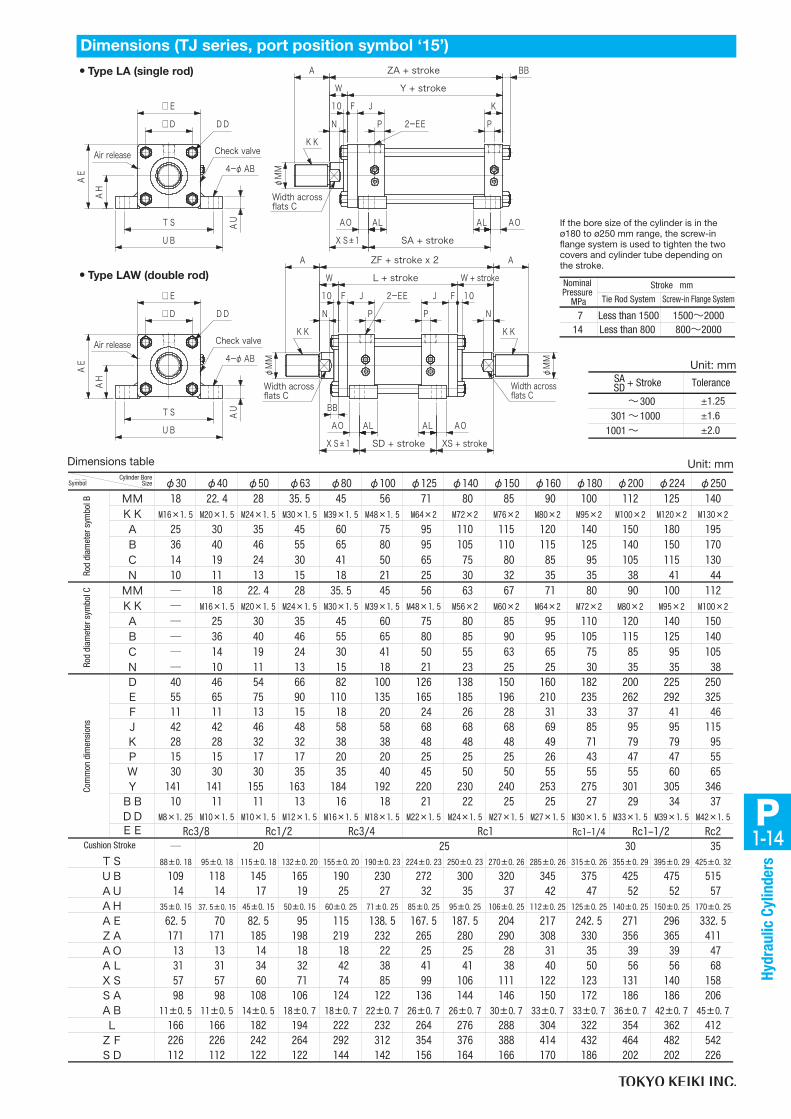
P1-14
Hyd
raul
ic C
ylin
ders
Dimensions (TJ series, port position symbol ‘15’)
Unit: mm
Unit: mm
If the bore size of the cylinder is in the ø180 to ø250 mm range, the screw-in flange system is used to tighten the two covers and cylinder tube depending on the stroke.
714
1500~2000800~2000
Less than 1500Less than 800
Tie Rod System Screw-in Flange System
Nominal Pressure
MPa
Stroke mm
Tolerance+ StrokeSASD
~ 300 301 ~ 1000 1001 ~
±1.25±1.6±2.0
•Type LA (single rod)
•Type LAW (double rod)
Air release
□D
□EA
H
AE
TS
UB
φM
M
N P P
KJ
SA + strokeXS±1
F
AL AL
Y + strokeW
ZA + strokeA
□D
□E
AH
AE
TS
UB
φM
MA
N P
J
NP
10FJF
L + stroke W + stroke
AZF + stroke x 2
SD + stroke
W
φM
M
XS + strokeXS±1
BB
AL AL
DD
Check valve
4-φAB
AU
BB
2-EE
10
KK
Width across flats C
AO AO
DD
Check valve
4-φAB
AU
Air release
Width across flats C
KK
10 2-EE
KK
Width across flats C
AOAO
Dimensions table
φ30 φ40 φ50 φ63 φ80 φ100 φ125 φ140 φ150 φ160 φ180 φ200 φ224 φ250
MM 18 22.4 28 35.5 45 56 71 80 85 90 100 112 125 140
KK M16×1.5 M20×1.5 M24×1.5 M30×1.5 M39×1.5 M48×1.5 M64×2 M72×2 M76×2 M80×2 M95×2 M100×2 M120×2 M130×2
A 25 30 35 45 60 75 95 110 115 120 140 150 180 195
B 36 40 46 55 65 80 95 105 110 115 125 140 150 170
C 14 19 24 30 41 50 65 75 80 85 95 105 115 130
N 10 11 13 15 18 21 25 30 32 35 35 38 41 44
MM ― 18 22.4 28 35.5 45 56 63 67 71 80 90 100 112
KK ― M16×1.5 M20×1.5 M24×1.5 M30×1.5 M39×1.5 M48×1.5 M56×2 M60×2 M64×2 M72×2 M80×2 M95×2 M100×2
A ― 25 30 35 45 60 75 80 85 95 110 120 140 150
B ― 36 40 46 55 65 80 85 90 95 105 115 125 140
C ― 14 19 24 30 41 50 55 63 65 75 85 95 105
N ― 10 11 13 15 18 21 23 25 25 30 35 35 38
D 40 46 54 66 82 100 126 138 150 160 182 200 225 250
E 55 65 75 90 110 135 165 185 196 210 235 262 292 325
F 11 11 13 15 18 20 24 26 28 31 33 37 41 46
J 42 42 46 48 58 58 68 68 68 69 85 95 95 115
K 28 28 32 32 38 38 48 48 48 49 71 79 79 95
P 15 15 17 17 20 20 25 25 25 26 43 47 47 55
W 30 30 30 35 35 40 45 50 50 55 55 55 60 65
Y 141 141 155 163 184 192 220 230 240 253 275 301 305 346
BB 10 11 11 13 16 18 21 22 25 25 27 29 34 37
DD M8×1.25 M10×1.5 M10×1.5 M12×1.5 M16×1.5 M18×1.5 M22×1.5 M24×1.5 M27×1.5 M27×1.5 M30×1.5 M33×1.5 M39×1.5 M42×1.5
EE Rc1-1/4 Rc2
― 35
88±0.18 95±0.18 115±0.18 132±0.20 155±0.20 190±0.23 224±0.23 250±0.23 270±0.26 285±0.26 315±0.26 355±0.29 395±0.29 425±0.32
109 118 145 165 190 230 272 300 320 345 375 425 475 515
14 14 17 19 25 27 32 35 37 42 47 52 52 57
35±0.15 37.5±0.15 45±0.15 50±0.15 60±0.25 71±0.25 85±0.25 95±0.25 106±0.25 112±0.25 125±0.25 140±0.25 150±0.25 170±0.25
62.5 70 82.5 95 115 138.5 167.5 187.5 204 217 242.5 271 296 332.5
171 171 185 198 219 232 265 280 290 308 330 356 365 411
13 13 14 18 18 22 25 25 28 31 35 39 39 47
31 31 34 32 42 38 41 41 38 40 50 56 56 68
57 57 60 71 74 85 99 106 111 122 123 131 140 158
98 98 108 106 124 122 136 144 146 150 172 186 186 206
11±0.5 11±0.5 14±0.5 18±0.7 18±0.7 22±0.7 26±0.7 26±0.7 30±0.7 33±0.7 33±0.7 36±0.7 42±0.7 45±0.7
166 166 182 194 222 232 264 276 288 304 322 354 362 412
226 226 242 264 292 312 354 376 388 414 432 464 482 542
112 112 122 122 144 142 156 164 166 170 186 202 202 226
AB
L
AO
AL
XS
SA
Rc3/8 Rc1/2 Rc3/4 Rc1-1/2Rc1
AU
AH
AE
ZA
20 3025
TS
ロツ
ド径記号B
ロツ
ド径記号C
共 通 寸 法
クッションストローク
UB
ZF
SD
シリンダ内径記号
Cylinder Bore SizeSymbol
Rod
diam
eter
sym
bol B
Rod
diam
eter
sym
bol C
Cushion Stroke
Com
mon
dim
ensi
ons
1-15P
Hyd
raul
ic C
ylin
ders
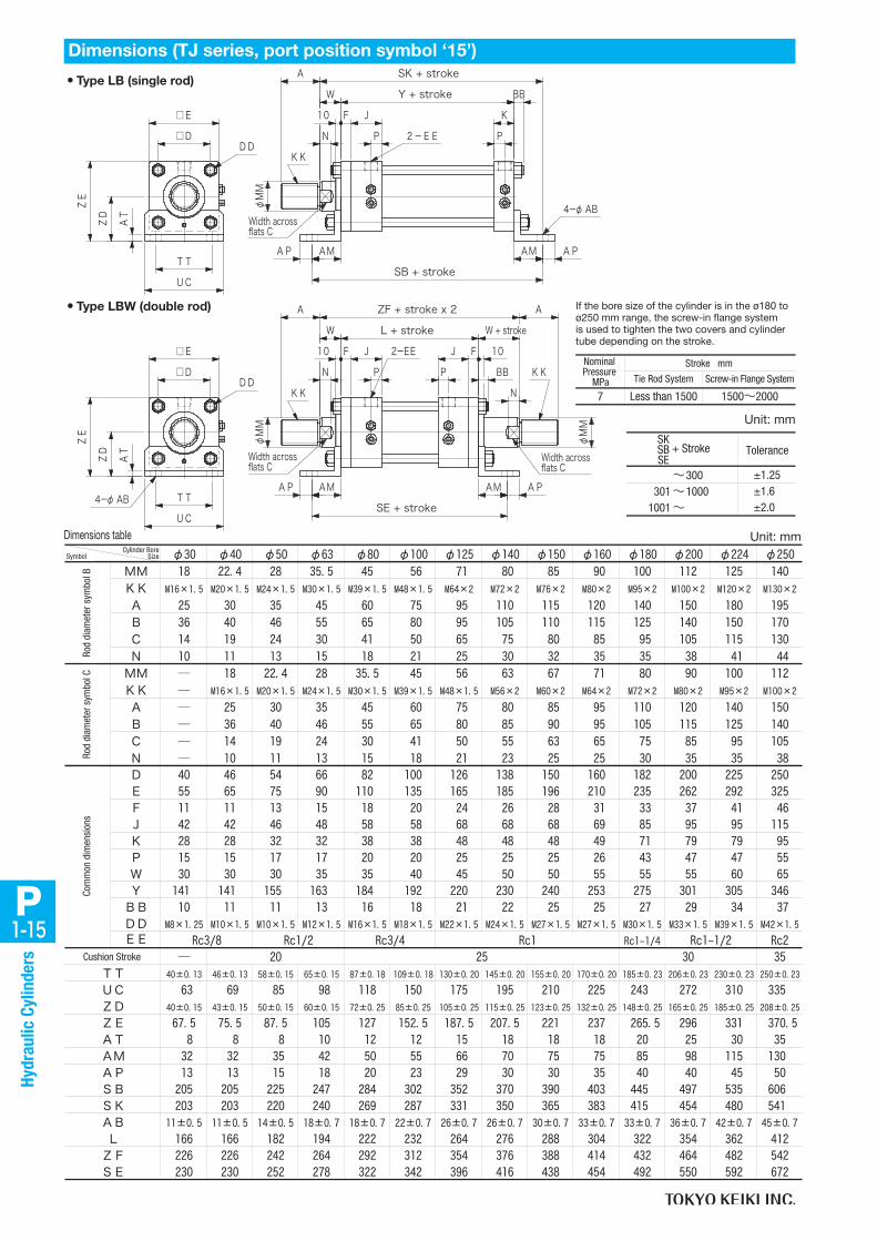
•Type LB (single rod)
•Type LBW (double rod)
4-φAB
ZF + stroke x 2
□D
□EZ
D
ZE
UC
φM
MAM AM AP
SB + stroke
N P
KF J
Y + stroke
10
BB
P
φM
M
AM
N
F J
P
10
AM AP
P
φM
M
J F
L + stroke
N
W + stroke
SE + stroke
A
□D
□E
ZD
ZE
UC
TT
TT
Width across flats C
DD
AT
KK
2-EE
4-φAB
KKBB
102-EE
KKDD
AT
Width across flats C
AP
A SK + stroke
W
AP
A
W
Width across flats C
Dimensions (TJ series, port position symbol ‘15’)
Dimensions table Unit: mm
If the bore size of the cylinder is in the ø180 to ø250 mm range, the screw-in flange system is used to tighten the two covers and cylinder tube depending on the stroke.
Unit: mm
Tie Rod System Screw-in Flange System
Nominal Pressure
MPa
Stroke mm
7 1500~2000Less than 1500
Tolerance+ StrokeSKSBSE
~ 300 301 ~ 1000 1001 ~
±1.25±1.6±2.0
φ30 φ40 φ50 φ63 φ80 φ100 φ125 φ140 φ150 φ160 φ180 φ200 φ224 φ250
MM 18 22.4 28 35.5 45 56 71 80 85 90 100 112 125 140
KK M16×1.5 M20×1.5 M24×1.5 M30×1.5 M39×1.5 M48×1.5 M64×2 M72×2 M76×2 M80×2 M95×2 M100×2 M120×2 M130×2
A 25 30 35 45 60 75 95 110 115 120 140 150 180 195
B 36 40 46 55 65 80 95 105 110 115 125 140 150 170
C 14 19 24 30 41 50 65 75 80 85 95 105 115 130
N 10 11 13 15 18 21 25 30 32 35 35 38 41 44
MM ― 18 22.4 28 35.5 45 56 63 67 71 80 90 100 112
KK ― M16×1.5 M20×1.5 M24×1.5 M30×1.5 M39×1.5 M48×1.5 M56×2 M60×2 M64×2 M72×2 M80×2 M95×2 M100×2
A ― 25 30 35 45 60 75 80 85 95 110 120 140 150
B ― 36 40 46 55 65 80 85 90 95 105 115 125 140
C ― 14 19 24 30 41 50 55 63 65 75 85 95 105
N ― 10 11 13 15 18 21 23 25 25 30 35 35 38
D 40 46 54 66 82 100 126 138 150 160 182 200 225 250
E 55 65 75 90 110 135 165 185 196 210 235 262 292 325
F 11 11 13 15 18 20 24 26 28 31 33 37 41 46
J 42 42 46 48 58 58 68 68 68 69 85 95 95 115
K 28 28 32 32 38 38 48 48 48 49 71 79 79 95
P 15 15 17 17 20 20 25 25 25 26 43 47 47 55
W 30 30 30 35 35 40 45 50 50 55 55 55 60 65
Y 141 141 155 163 184 192 220 230 240 253 275 301 305 346
BB 10 11 11 13 16 18 21 22 25 25 27 29 34 37
DD M8×1.25 M10×1.5 M10×1.5 M12×1.5 M16×1.5 M18×1.5 M22×1.5 M24×1.5 M27×1.5 M27×1.5 M30×1.5 M33×1.5 M39×1.5 M42×1.5
EE Rc1-1/4 Rc2
― 35
40±0.13 46±0.13 58±0.15 65±0.15 87±0.18 109±0.18 130±0.20 145±0.20 155±0.20 170±0.20 185±0.23 206±0.23 230±0.23 250±0.23
63 69 85 98 118 150 175 195 210 225 243 272 310 335
40±0.15 43±0.15 50±0.15 60±0.15 72±0.25 85±0.25 105±0.25 115±0.25 123±0.25 132±0.25 148±0.25 165±0.25 185±0.25 208±0.25
67.5 75.5 87.5 105 127 152.5 187.5 207.5 221 237 265.5 296 331 370.5
8 8 8 10 12 12 15 18 18 18 20 25 30 35
32 32 35 42 50 55 66 70 75 75 85 98 115 130
13 13 15 18 20 23 29 30 30 35 40 40 45 50
205 205 225 247 284 302 352 370 390 403 445 497 535 606
203 203 220 240 269 287 331 350 365 383 415 454 480 541
11±0.5 11±0.5 14±0.5 18±0.7 18±0.7 22±0.7 26±0.7 26±0.7 30±0.7 33±0.7 33±0.7 36±0.7 42±0.7 45±0.7
166 166 182 194 222 232 264 276 288 304 322 354 362 412
226 226 242 264 292 312 354 376 388 414 432 464 482 542
230 230 252 278 322 342 396 416 438 454 492 550 592 672
AB
L
ZF
ロツ
ド径記号B
ロツ
ド径記号C
UC
SE
AP
SB
20 3025
TT
Rc3/8 Rc1/2 Rc3/4 Rc1-1/2Rc1
SK
共 通 寸 法
クッションストローク
ZD
ZE
AT
AM
シリンダ内径記号
Cylinder Bore SizeSymbol
Rod
diam
eter
sym
bol B
Rod
diam
eter
sym
bol C
Cushion Stroke
Com
mon
dim
ensi
ons

P1-16
Hyd
raul
ic C
ylin
ders
Dimensions (TJ series, port position symbol ‘15’)
The rod side connection port is positioned at the standard position in the figure above (or on the side opposite to the one shown).
Dimensions table Unit: mm
If the bore size of the cylinder is in the ø180 to ø250 mm range, the screw-in flange system is used to tighten the two covers and cylinder tube depending on the stroke.
•Type TA (single rod)φ
TD e
8
□D
□E
TLTCTL
φM
M
N P
KF10
P
YY + stroke
ZT + stroke
JJ
XF
T
DDWidth across flats C
KK
A
2-EE
BB
G2
W
G1
•Type TAW (double rod)
φT
D e8
TL TC TL
□E
□D
φM
M
N
F JJ10
P
XF
P
J F
W + stroke
φM
M
A
N
LT + stroke
ZW + stroke x 2
Width across flats C
T
DD
KK
Width across flats C
G2G1
A
KK
BB
2-EE
10
W
Tie Rod System Screw-in Flange System
Nominal Pressure
MPa
Stroke mm
714
1500~2000800~2000
Less than 1500Less than 800
φ30 φ40 φ50 φ63 φ80 φ100 φ125 φ140 φ150 φ160 φ180 φ200 φ224 φ250
MM 18 22.4 28 35.5 45 56 71 80 85 90 100 112 125 140
KK M16×1.5 M20×1.5 M24×1.5 M30×1.5 M39×1.5 M48×1.5 M64×2 M72×2 M76×2 M80×2 M95×2 M100×2 M120×2 M130×2
A 25 30 35 45 60 75 95 110 115 120 140 150 180 195
B 36 40 46 55 65 80 95 105 110 115 125 140 150 170
C 14 19 24 30 41 50 65 75 80 85 95 105 115 130
N 10 11 13 15 18 21 25 30 32 35 35 38 41 44
MM ― 18 22.4 28 35.5 45 56 63 67 71 80 90 100 112
KK ― M16×1.5 M20×1.5 M24×1.5 M30×1.5 M39×1.5 M48×1.5 M56×2 M60×2 M64×2 M72×2 M80×2 M95×2 M100×2
A ― 25 30 35 45 60 75 80 85 95 110 120 140 150
B ― 36 40 46 55 65 80 85 90 95 105 115 125 140
C ― 14 19 24 30 41 50 55 63 65 75 85 95 105
N ― 10 11 13 15 18 21 23 25 25 30 35 35 38
D 40 46 54 66 82 100 126 138 150 160 182 200 225 250
E 55 65 75 90 110 135 165 185 196 210 235 262 292 325
F 11 11 13 15 18 20 24 26 28 31 33 37 41 46
J 42 42 46 48 58 58 68 68 68 69 85 95 95 115
K 28 28 32 32 38 38 48 48 48 49 71 79 79 95
P 15 15 17 17 20 20 25 25 25 26 43 47 47 55
W 30 30 30 35 35 40 45 50 50 55 55 55 60 65
YY 141 141 155 163 184 192 220 230 240 263 275 301 315 346
BB 10 11 11 13 16 18 21 22 25 25 27 29 34 37
DD M8×1.25 M10×1.5 M10×1.5 M12×1.5 M16×1.5 M18×1.5 M22×1.5 M24×1.5 M27×1.5 M27×1.5 M30×1.5 M33×1.5 M39×1.5 M42×1.5
EE Rc1-1/4 Rc2
― 35
58 69 85 98 118 145 175 195 206 218 243 272 300 335
20±0.3 20±0.3 25±0.3 31.5±0.3 31.5±0.3 40±0.3 50±0.3 63±0.3 63±0.3 71±0.5 80±0.5 90±0.5 100±0.5 100±0.5
20 20 25 31.5 31.5 40 50 63 63 71 80 90 100 100
171 171 185 198 219 232 265 280 290 318 330 356 375 411
62 62 66 74 82 89 103 112 112 126 130.5 139.5 153.5 168.5
21 21 23 24 29 29 34 36 34 40 42.5 47.5 52.5 57.5
21 21 23 24 29 29 34 32 34 39 42.5 47.5 52.5 57.5
R2 R2 R2.5 R2.5 R2.5 R3 R3 R4 R4 R4 R4 R5 R5 R5
42 42 46 48 58 58 68 68 68 79 85 95 105 115
166 166 182 194 222 232 264 276 288 314 322 354 372 412
226 226 242 264 292 312 354 376 388 424 432 464 492 542
LT
ZW
ロツ
ド径記号B
ロツ
ド径記号C
共 通 寸 法
3025
TC
クッションストローク
TL
20
Rc1/2 Rc3/4 Rc1-1/2Rc1
G2
T
JJ
Rc3/8
TD
ZT
XF
G1
シリンダ内径記号
0-0.30
0-0.30
0-0.35
0-0.35
0-0.35
0-0.40
0-0.40
0-0.46
0-0.46
0-0.46
0-0.46
0-0.52
0-0.52
0-0.57
Cylinder Bore SizeSymbol
Rod
diam
eter
sym
bol B
Rod
diam
eter
sym
bol C
Cushion Stroke
Com
mon
dim
ensi
ons

1-17P
Hyd
raul
ic C
ylin
ders
Dimensions (TJ series, port position symbol ‘15’)
Standard position XG + stroke/2: When the bellows (dust-proof cover) is attached, the XG dimension will differ.
Dimensions table Unit: mm
If the bore size of the cylinder is in the ø180 to ø250 mm range, the screw-in flange system is used to tighten the two covers and cylinder tube depending on the stroke.
Unit: mm
•Type TC (single rod)
•Type TCW (double rod)
T
φT
D e8
□D
□E
TLTCTL
N P
KF10
P
ZA + stroke
Y + stroke
φM
M
Stroke2
V
J
φT
D e8
TL TC TL
□E
□D
T
φM
M
N
F10
2-EEP P
J F
W + stroke
A
N
10
Width across flats C
φM
M
L + stroke
Width across flats C
VStroke
2
ZF + stroke x 2
J
XG+
XG+
DDWidth across flats C
KK
A
W
2-EE
BB
A
W
KK
BB
KK
DD
Tie Rod System Screw-in Flange System
Nominal Pressure
MPa
Stroke mm
714
1500~2000800~2000
Less than 1500Less than 800
ToleranceXF=XG + Stroke/2
~ 300 301 ~ 1000 1001 ~
±1.25±1.6±2.0
φ30 φ40 φ50 φ63 φ80 φ100 φ125 φ140 φ150 φ160 φ180 φ200 φ224 φ250
MM 18 22.4 28 35.5 45 56 71 80 85 90 100 112 125 140
KK M16×1.5 M20×1.5 M24×1.5 M30×1.5 M39×1.5 M48×1.5 M64×2 M72×2 M76×2 M80×2 M95×2 M100×2 M120×2 M130×2
A 25 30 35 45 60 75 95 110 115 120 140 150 180 195
B 36 40 46 55 65 80 95 105 110 115 125 140 150 170
C 14 19 24 30 41 50 65 75 80 85 95 105 115 130
N 10 11 13 15 18 21 25 30 32 35 35 38 41 44
MM ― 18 22.4 28 35.5 45 56 63 67 71 80 90 100 112
KK ― M16×1.5 M20×1.5 M24×1.5 M30×1.5 M39×1.5 M48×1.5 M56×2 M60×2 M64×2 M72×2 M80×2 M95×2 M100×2
A ― 25 30 35 45 60 75 80 85 95 110 120 140 150
B ― 36 40 46 55 65 80 85 90 95 105 115 125 140
C ― 14 19 24 30 41 50 55 63 65 75 85 95 105
N ― 10 11 13 15 18 21 23 25 25 30 35 35 38
D 40 46 54 66 82 100 126 138 150 160 182 200 225 250
E 55 65 75 90 110 135 165 185 196 210 235 262 292 325
F 11 11 13 15 18 20 24 26 28 31 33 37 41 46
J 42 42 46 48 58 58 68 68 68 69 85 95 95 115
K 28 28 32 32 38 38 48 48 48 49 71 79 79 95
P 15 15 17 17 20 20 25 25 25 26 43 47 47 55
W 30 30 30 35 35 40 45 50 50 55 55 55 60 65
Y 141 141 155 163 184 192 220 230 240 253 275 301 305 346
BB 10 11 11 13 16 18 21 22 25 25 27 29 34 37
DD M8×1.25 M10×1.5 M10×1.5 M12×1.5 M16×1.5 M18×1.5 M22×1.5 M24×1.5 M27×1.5 M27×1.5 M30×1.5 M33×1.5 M39×1.5 M42×1.5
EE Rc1-1/4 Rc2― 35
58 69 85 98 118 145 175 195 206 218 243 272 300 335
20±0.3 20±0.3 25±0.3 31.5±0.3 31.5±0.3 40±0.3 50±0.3 63±0.3 63±0.3 71±0.5 80±0.5 90±0.5 100±0.5 100±0.5
20 20 25 31.5 31.5 40 50 63 63 71 80 90 100 100
171 171 185 198 219 232 265 280 290 308 330 356 365 411
113 113 121 132 146 156 177 188 194 207 216 232 241 271
28 28 33 43 43 53 58 78 78 88 98 108 117 117
R2 R2 R2.5 R2.5 R2.5 R3 R3 R4 R4 R4 R4 R5 R5 R5
166 166 182 194 222 232 264 276 288 304 322 354 362 412
226 226 242 264 292 312 354 376 388 414 432 464 482 542
Rc3/8 Rc1/2クッションストローク
Rc1-1/2Rc13025
T
XG
Rc3/4
V
20
共 通 寸 法
TC
TD
ZA
ロツ
ド径記号B
ロツ
ド径記号C
TL
L
ZF
シリンダ内径記号
0-0.30
0-0.30
0-0.35
0-0.35
0-0.35
0-0.40
0-0.40
0-0.46
0-0.46
0-0.46
0-0.46
0-0.52
0-0.52
0-0.57
Cylinder Bore SizeSymbol
Rod
diam
eter
sym
bol B
Rod
diam
eter
sym
bol C
Cushion Stroke
Com
mon
dim
ensi
ons

P1-18
Hyd
raul
ic C
ylin
ders
•Type CA (single rod)
t
t
bb
φM
M
N P P
K
WA
F J LR
RY + stroke
ZC + stroke
M
FW1
□D
□E
Width across flats C
KK
10
2-EE
DDφCDH10
BB
ll
*
Dimensions (TJ series, port position symbol ‘15’)
Unit: mm
Dimensions table Unit: mm
If the bore size of the cylinder is in the ø180 to ø250 mm range, the screw-in flange system is used to tighten the two covers and cylinder tube depending on the stroke.
Unit: mm
Nominal Pressure
MPa
Stroke mm
Tie Rod System Screw-in Flange System
714
1500~2000800~2000
Less than 1500Less than 800
Cylinder Bore Size bb ll tφ180 27 114 42φ200 29 130 47φ224 34 141 52φ250 37 135 57
ToleranceZC + Stroke
~ 300 301 ~ 1000 1001 ~
±1.25±1.6±2.0
If the screw-in flange system is used, the bolt head will protrude as shown in the figure on the left.* These dimensions do not
vary.
φ30 φ40 φ50 φ63 φ80 φ100 φ125 φ140 φ150 φ160 φ180 φ200 φ224 φ250
MM 18 22.4 28 35.5 45 56 71 80 85 90 100 112 125 140
KK M16×1.5 M20×1.5 M24×1.5 M30×1.5 M39×1.5 M48×1.5 M64×2 M72×2 M76×2 M80×2 M95×2 M100×2 M120×2 M130×2
A 25 30 35 45 60 75 95 110 115 120 140 150 180 195
B 36 40 46 55 65 80 95 105 110 115 125 140 150 170
C 14 19 24 30 41 50 65 75 80 85 95 105 115 130
N 10 11 13 15 18 21 25 30 32 35 35 38 41 44
MM ― 18 22.4 28 35.5 45 56 63 67 71 80 90 100 112
KK ― M16×1.5 M20×1.5 M24×1.5 M30×1.5 M39×1.5 M48×1.5 M56×2 M60×2 M64×2 M72×2 M80×2 M95×2 M100×2
A ― 25 30 35 45 60 75 80 85 95 110 120 140 150
B ― 36 40 46 55 65 80 85 90 95 105 115 125 140
C ― 14 19 24 30 41 50 55 63 65 75 85 95 105
N ― 10 11 13 15 18 21 23 25 25 30 35 35 38
D 40 46 54 66 82 100 126 138 150 160 182 200 225 250
E 55 65 75 90 110 135 165 185 196 210 235 262 292 325
F 11 11 13 15 18 20 24 26 28 31 33 37 41 46
J 42 42 46 48 58 58 68 68 68 69 85 95 95 115
K 28 28 32 32 38 38 48 48 48 49 71 79 79 95
P 15 15 17 17 20 20 25 25 25 26 43 47 47 55
W 30 30 30 35 35 40 45 50 50 55 55 55 60 65
Y 141 141 155 163 184 192 220 230 240 253 275 301 305 346
BB 10 11 11 13 16 18 21 22 25 25 27 29 34 37
DD M8×1.25 M10×1.5 M10×1.5 M12×1.5 M16×1.5 M18×1.5 M22×1.5 M24×1.5 M27×1.5 M27×1.5 M30×1.5 M33×1.5 M39×1.5 M42×1.5
EE Rc1-1/4 Rc2
― 35
209 209 230 261 291 316 365 400 412 445 480 526 550 596
38 38 45 63 72 84 100 120 122 137 150 170 185 185
20 20 25 40 40 50 63 80 80 90 100 115 125 125
16 16 20 31.5 31.5 40 50 63 63 71 80 90 100 100
25 25 31.5 40 40 50 63 80 80 80 100 125 125 125
R16 R16 R20 R31.5 R31.5 R40 R50 R63 R63 R71 R80 R90 R100 R100
ロツ
ド径記号B
ロツ
ド径記号C
共 通 寸 法
クッションストローク
R
Rc3/4 Rc1-1/2Rc1
3025
M
20
Rc3/8
LR
CD
FW1
Rc1/2
ZC
シリンダ内径記号
-0.1-0.4
-0.1-0.4
-0.1-0.4
-0.1-0.4
-0.1-0.4
-0.1-0.4
-0.1-0.4
-0.1-0.6
-0.1-0.6
-0.1-0.6
-0.1-0.6
-0.1-0.6
-0.1-0.6
-0.1-0.6
Cylinder Bore SizeSymbol
Rod
diam
eter
sym
bol B
Rod
diam
eter
sym
bol C
Cushion Stroke
Com
mon
dim
ensi
ons
F W 1

1-19P
Hyd
raul
ic C
ylin
ders
Dimensions (TJ series, port position symbol ‘15’)
Dimensions table Unit: mm
Unit: mm
Only the tie rod system can be used with this mounting type.
•Type CB (single rod)
A W Y + stroke R
P
K
PN
φM
M
ZC + stroke
F J LR
M
□D
□E
G FW2 G
Width across flats C
KK
BB
10
2-EE
DDφCDH10
ToleranceZC + Stroke ~ 300 301 ~ 1000 1001 ~
±1.25±1.6±2.0
φ30 φ40 φ50 φ63 φ80 φ100 φ125 φ140 φ150 φ160 φ180 φ200 φ224 φ250
MM 18 22.4 28 35.5 45 56 71 80 85 90 100 112 125 140
KK M16×1.5 M20×1.5 M24×1.5 M30×1.5 M39×1.5 M48×1.5 M64×2 M72×2 M76×2 M80×2 M95×2 M100×2 M120×2 M130×2
A 25 30 35 45 60 75 95 110 115 120 140 150 180 195
B 36 40 46 55 65 80 95 105 110 115 125 140 150 170
C 14 19 24 30 41 50 65 75 80 85 95 105 115 130
N 10 11 13 15 18 21 25 30 32 35 35 38 41 44
MM ― 18 22.4 28 35.5 45 56 63 67 71 80 90 100 112
KK ― M16×1.5 M20×1.5 M24×1.5 M30×1.5 M39×1.5 M48×1.5 M56×2 M60×2 M64×2 M72×2 M80×2 M95×2 M100×2
A ― 25 30 35 45 60 75 80 85 95 110 120 140 150
B ― 36 40 46 55 65 80 85 90 95 105 115 125 140
C ― 14 19 24 30 41 50 55 63 65 75 85 95 105
N ― 10 11 13 15 18 21 23 25 25 30 35 35 38
D 40 46 54 66 82 100 126 138 150 160 182 200 225 250
E 55 65 75 90 110 135 165 185 196 210 235 262 292 325
F 11 11 13 15 18 20 24 26 28 31 33 37 41 46
J 42 42 46 48 58 58 68 68 68 69 85 95 95 115
K 28 28 32 32 38 38 48 48 48 49 71 79 79 95
P 15 15 17 17 20 20 25 25 25 26 43 47 47 55
W 30 30 30 35 35 40 45 50 50 55 55 55 60 65
Y 141 141 155 163 184 192 220 230 240 253 275 301 305 346
BB 10 11 11 13 16 18 21 22 25 25 27 29 34 37
DD M8×1.25 M10×1.5 M10×1.5 M12×1.5 M16×1.5 M18×1.5 M22×1.5 M24×1.5 M27×1.5 M27×1.5 M30×1.5 M33×1.5 M39×1.5 M42×1.5
EE Rc1-1/4 Rc2― 35
209 209 230 261 291 316 365 400 412 445 480 526 550 596
38 38 45 63 72 84 100 120 122 137 150 170 185 185
20 20 25 40 40 50 63 80 80 90 100 115 125 125
16 16 20 31.5 31.5 40 50 63 63 71 80 90 100 100
25 25 31.5 40 40 50 63 80 80 80 100 125 125 125
12.5 12.5 16 20 20 25 31.5 40 40 40 50 50 63 63
R16 R16 R20 R31.5 R31.5 R40 R50 R63 R63 R71 R80 R90 R100 R100
Rc1/2
ZC
共 通 寸 法
Rc3/8クッションストローク
M
20
LR
CD
FW2
G
Rc3/4 Rc1-1/2Rc13025
ロツ
ド径記号B
ロツ
ド径記号C
R
シリンダ内径記号
+0.4+0.1
+0.4+0.1
+0.4+0.1
+0.4+0.1
+0.4+0.1
+0.4+0.1
+0.4+0.1
+0.6+0.1
+0.6+0.1
+0.6+0.1
+0.6+0.1
+0.6+0.1
+0.6+0.1
+0.6+0.1
Cylinder Bore SizeSymbol
Rod
diam
eter
sym
bol B
Rod
diam
eter
sym
bol C
Cushion Stroke
Com
mon
dim
ensi
ons
F W 2

P1-20
Hyd
raul
ic C
ylin
ders
Dimensions (TJ series)Unit: mm
Unit: mmDimensions table
Unit: mmDimensions table
Accessories (TJ series)
•Cushion valve/check valve-cum-air release
Cushion valve Check valve-cum-air release
□A
L2
Screw b
L
Screw a
L
RcB
Max
. L1
Hexagon opposite side C
Air release
Check valve
Single thread end fitting
R
45゜
φN
A
GB
C
E
H10
H LM
Q
φF φD
P
Double thread end fitting
R
L
A
JH
C
F
H10
G
E
M
BB
φD
Dimensions table
Rod Side Head Sideφ30φ40φ50φ63φ80φ100φ125φ140φ150φ160φ180φ200φ224φ250
M1013
10
79
13
15
20
25
Cushion ValveL1
ca
Check Valve-cum-Air Release
17
12
A B b L2
M5
M8
L
1/8
3/8
19 1
9
11
12
7
9 1/4 M6 10
14 1/2
M10×1.5
11
17
141211131113
131211131113
M16×1.53/4
17
26
11
17
Cylinder Bore Size
φ30 φ40 φ50 φ63 φ80 φ100 φ125 φ140 φ150 φ160 φ180 φ200 φ224 φ250
25 25 31.5 40 40 50 63 80 80 80 100 125 125 125
50 55 65 92 107 135 168 210 215 230 260 285 330 345
16 16 20 31.5 31.5 40 50 63 63 71 80 90 100 100
35 35 45 65 65 85 105 130 130 150 170 190 210 210
16 16 20 31.5 31.5 40 50 63 63 71 80 90 100 100
20 20 25 40 40 50 63 80 80 90 100 115 125 125
15 15 15 15 15 20 20 20 20 20 30 30 30 30
M8 M8 M8 M8 M8 M10 M10 M10 M10 M10 M12 M12 M12 M12
25 25 32 40 40 55 68 85 85 95 105 130 130 130
5 5 5 5 5 5 8 8 8 8 8 8 8 8
2 2 2.5 2.5 2.5 3 3 4 4 4 4 5 5 5
B 27 32 37 47 62 78 98 113 118 123 144 154 185 200
E M16×1.5 M20×1.5 M24×1.5 M30×1.5 M39×1.5 M48×1.5 M64×2 M72×2 M76×2 M80×2 M95×2 M100×2 M120×2 M130×2
B ― 27 32 37 47 62 78 83 88 98 113 123 144 154
E ― M16×1.5 M20×1.5 M24×1.5 M30×1.5 M39×1.5 M48×1.5 M56×2 M60×2 M64×2 M72×2 M80×2 M95×2 M100×2
M8×8l M8×8l M8×8l M8×8l M8×8l M10×15l M10×15l M10×20l M10×20l M10×20l M12×25l M12×25l M12×25l M12×25l
― ― φ6×2.5l φ6×9.5l φ6×5l φ8×3.5l φ8×5.5l φ8×9l φ8×7l φ8×15l φ10×12.5l φ10×20l φ10×20l φ10×15l
Q
G
H
L
M
C
ロツ
ド径記号
ソケット止めねじ
スペーサ
B
F
N
P
A
C
D
-0.1-0.4
-0.1-0.4
-0.1-0.4
-0.1-0.4
-0.1-0.4
-0.1-0.4
-0.1-0.4
-0.1-0.6
-0.1-0.6
-0.1-0.6
-0.1-0.6
-0.1-0.6
-0.1-0.6
-0.1-0.6
記号シリンダ内径Cylinder Bore
SizeSymbol
Socket set screw
Spacer
Rod
diam
eter
sy
mbo
l
φ30 φ40 φ50 φ63 φ80 φ100 φ125 φ140 φ150 φ160 φ180 φ200 φ224 φ250
25 25 31.5 40 40 50 63 80 80 80 100 125 125 125
12.5 12.5 16 20 20 25 31.5 40 40 40 50 50 63 63
50 55 65 92 107 135 168 210 215 230 260 285 330 345
16 16 20 31.5 31.5 40 50 63 63 71 80 90 100 100
32 32 40 63 63 80 100 126 126 142 160 180 200 200
16 16 20 31.5 31.5 40 50 63 63 71 80 90 100 100
20 20 25 40 40 50 63 80 80 90 100 115 125 125
15 15 15 15 15 20 20 20 20 20 30 30 30 30
M8 M8 M8 M8 M8 M10 M10 M10 M10 M10 M12 M12 M12 M12
E M16×1.5 M20×1.5 M24×1.5 M30×1.5 M39×1.5 M48×1.5 M64×2 M72×2 M76×2 M80×2 M95×2 M100×2 M120×2 M130×2
J 27 32 37 47 62 78 98 113 118 123 143 153 183 198
E ― M16×1.5 M20×1.5 M24×1.5 M30×1.5 M39×1.5 M48×1.5 M56×2 M60×2 M64×2 M72×2 M80×2 M95×2 M100×2
J ― 27 32 37 47 62 78 83 88 98 113 123 143 153M8×12l M8×12l M8×12l M8×12l M8×12l M10×20l M10×20l M10×25l M10×25l M10×25l M12×35l M12×35l M12×35l M12×35l
φ6×5l φ6×3l φ6×7l φ6×13l φ6×8.5l φ8×6l φ8×11l φ8×19l φ8×17l φ8×15l φ10×17.5l φ10×27.5l φ10×30.5l φ10×25.5l
M
B
G
H
L
スペーサ
F
A
ソケット止めねじ
ロツ
ド径記号
B
C
C
D
記号シリンダ内径
+0.4+0.1
+0.4+0.1
+0.4+0.1
+0.4+0.1
+0.4+0.1
+0.4+0.1
+0.4+0.1
+0.6+0.1
+0.6+0.1
+0.6+0.1
+0.6+0.1
+0.6+0.1
+0.6+0.1
+0.6+0.1
Cylinder Bore SizeSymbol
Socket set screw
Spacer
Rod
diam
eter
sy
mbo
l

1-21P
Hyd
raul
ic C
ylin
ders
Accessories (TJ series)
Dimensions table Unit: mm
• When calculating the MIN dimension, round off all the decimal places.• If the bellows is made of Conex, consult Tokyo Keiki for a different dimensions table.
Dimensions table
Unit: mm
Unit: mm
Dimensions table
Bellows (dust-proof cover)
Pin
φa
MIN
W’
15
10
10
8
Split pin hole
d9
2-φE
A
B CC
φD
Lock nut (material: SS400)
C
B H
H
φD
d
d
4-øDD drill depth Z
d M16×1.5 M20×1.5 M24×1.5 M30×1.5 M39×1.5 M48×1.5 M56×2 M60×2 M64×2 M72×2 M76×2 M80×2 M95×2
H 10 12 14 18 23 29 34 36 38 42 46 48 57
B 24 30 36 46 60 75 85 90 95 105 110 115 135
C 27.7 34.6 41.6 53.1 69.3 86.3 98.1 104 110 121 127 133 156
d M100×2 M120×2 M130×2
H 60 72 78
D 150 180 200
DD 15 15 20
Z 18 18 25
φ30 φ40 φ50 φ63 φ80 φ100 φ125 φ140 φ150 φ160 φ180 φ200 φ224 φ250
ロッド径記号B 50 50 60 70 80 100 115 125 135 140 150 170 180 200
ロッド径記号C ― 45 50 60 70 80 100 105 110 115 125 140 150 170
1/3.5×ストローク 1/4×ストローク 1/6×ストローク1/5×ストローク
MIN+80MIN+65MIN+55MIN+45
a
MIN
W'
記号シリンダ内径Cylinder Bore
SizeSymbol
Rod diameter symbol B
Rod diameter symbol C
1/3.5 × stroke 1/4 × stroke 1/6 × stroke1/5 × stroke
φ30 φ40 φ50 φ63 φ80 φ100 φ125 φ140 φ150 φ160 φ180 φ200 φ224 φ250
A 66 66 79.5 101 101 126 152.5 191.5 191.5 191.5 242 267 293 293
B 54 54 67.5 85 85 106 132.5 167.5 167.5 167.5 210 235 261 261
C 6 6 6 8 8 10 10 12 12 12 16 16 16 16
D 16 16 20 31.5 31.5 40 50 63 63 71 80 90 100 100
E 3 3 3 4 4 5 5 6 6 6 8 8 8 8
割りピン呼び寸法 φ3×22l φ3×22l φ3×28l φ4×40l φ4×40l φ5×50l φ5×60l φ6×75l φ6×75l φ6×85l φ8×95l φ8×10⁵l φ8×120l φ8×120l
シリンダ内径記号
Split pin nominal dimensions
Cylinder Bore SizeSymbol

P1-22
Hyd
raul
ic C
ylin
ders
Constructions (TJ series)
*1: The quantities of these parts is 0 if there is no cushion.*2: The numerical values given for these parts indicate the size of the steel balls. (JIS B 1501)
Type SD (basic type)
Cylinder bore sizeφ180~φ250 φ100~φ250
Cylinder bore size17
457 205414684344164243 2
Cushion valve Check valve-cum-air release
Rod diameter symbol C
φ63~φ250
22
23
21
24
25
26
43 42 47 45
27
28
18
Type FAType FCType FY
10 14 16Type TCType CA
Type FBType FDType FZ
11 15
19
9
Type LBType CB
No.
1
2
3
Qty
1
1
1
No.
4
5
6
Qty
1
1
1
No.
7
*8
9
Qty
1
1
2
No.
10
11
14
Qty
1
1
1
No.
15
16
17
Qty
1
1
4 to 8
No.
18
19
20
Qty
4 to 8
2
1
Part Name
Lock cover
Head cover
Cylinder tube
Part Name
Piston rod
Piston
Clamp plate
Part Name
Bushing
Cushion ring
Foot
Part Name
Rod flange
Head flange
Separated eye
Part Name
Separated clevis
Trunnion
Tie rod
Part Name
Hexagon nut
Spring pin
Set screw
Part Name
Cushion adjuster
Nut
Seal
Check plug
Check plug (LA)
Check spring
Check ball
Air release screw
Air release ball
Air release assembly
Seal nut
No.
21
22
23
24
25
26
27
28
24
27
28
22
23
Qty
2
2
2
2
2
2
2
2
2
2
2
*1
*1
*1
*1
*1
*1 *2
*2
*1
2
1
1
2
1
1
2
1
1
2
1
1
1
41
42
43
44
45
46
41
42
43
44
45
46
47
Cylinder Bore Size mm
Piston gasket
Rod gasket
Dust wiper
O-ring for cover
O-ring for bushing
O-ring for piston
Piston gasket
Rod gasket
Dust wiper
O-ring for cover
O-ring for bushing
O-ring for piston
O-ring for spacer
Rod
diam
eter
sym
bol B
Rod
dia
met
er s
ymbo
l C
φ30 φ40 φ50 φ63 φ80 φ100 φ125 φ140 φ150 φ160 φ180 φ200 φ224 φ250
―――
―――
―
―――
――
― ― ―
TJ-01-1 TJ-01-2 TJ-01-3 TJ-01-4 TJ-01-5
TJ-04-1 TJ-04-2 TJ-04-3 TJ-04-4 TJ-04-5 TJ-04-6
VCJ0760A-01
SKY-22.4
SKY-18
SDR-18
1B-G25
1A-G30
1A-P14
SKY-30
SKY-22.4
SDR-22.4
1B-G35
1A-G30
1A-P15
SKY-30
SKY-18
SDR-18
1B-G35
1A-G30
1A-P15
SKY-40
SKY-28
SDR-28
1B-G45
1A-G35
1A-P20
SKY-40
SKY-22.4
SDR-22.4
1B-G45
1A-G35
1A-P20
SKY-53
SKY-35.5
SDR-35.5
1B-G58(G55)
1A-G45
1A-G25
SKY-53
SKY-28
SDR-28
1B-G58(G55)
1A-G45
1A-G25
1A-G35
SKY-71
SKY-45
SDR-45
1B-G75
1A-G55
1A-P32
SKY-71
SKY-35.5
SDR-35.5
1B-G75
1A-G55
1A-P32
1A-G45
SKY-85
SKY-56
SDR-56
1B-G95
1A-G65
1A-G35
SKY-85
SKY-45
SDR-45
1B-G95
1A-G65
1A-G35
1A-G55
SKY-136
SKY-85
SDR-85
1B-G145
1A-G95
1A-G55
SKY-136
SKY-67
SDR-67
1B-G145
1A-G95
1A-G55
1A-G80
SKY-125
SKY-80
SDR-80
1B-G135
1A-G90
1A-G50
SKY-125
SKY-63
SDR-63
1B-G135
1A-G90
1A-G50
1A-G75
SKY-112
SKY-71
SDR-71
1B-G120
1A-G80
1A-G45
SKY-112
SKY-56
SDR-56
1B-G120
1A-G80
1A-G45
1A-G65
SKY-145
SKY-90
SDR-90
1B-G150
1A-G100
1A-G60
SKY-145
SKY-71
SDR-71
1B-G150
1A-G100
1A-G60
1A-G80
SKY-165
SKY-100
SDR-100
1B-G170
1A-G115
1A-G70
SKY-165
SKY-80
SDR-80
1B-G170
1A-G115
1A-G70
1A-G90
SKY-180
SKY-112
SDR-112
1B-G190
1A-G125
1A-G80
SKY-180
SKY-90
SDR-90
1B-G190
1A-G125
1A-G80
1A-G100
SKY-204
SKY-125
SDR-125
1B-G210
1A-G140
1A-G90
SKY-204
SKY-100
SDR-100
1B-G210
1A-G140
1A-G90
1A-G115
SKY-230
SKY-140
SDR-140
1B-G240
1A-G155
1A-G100
SKY-230
SKY-112
SDR-112
1B-G240
1A-G155
1A-G100
1A-G125
VCJ0760A-
02
VCJ0760A-
04
VCJ0760A-
06VCJ0760A-03
420180010-1 420180010-2
VCJ0760A-05
TJ-05-1 TJ-05-2 TJ-05-3 TJ-05-4
1/8 4 6 7
TJ-06-1 TJ-06-2 TJ-06-3 TJ-06-4 TJ-06-5 TJ-06-6 TJ-06-7 TJ-06-8 TJ-06-9
Rc1/8 Rc1/4 Rc3/8 Rc1/2 Rc3/4 Rc1
7 10 1/2 5/8 7/8 1-1/16
TJ-02-1
TJ-03-1
TJ-02-2
TJ-03-2