Piston Rings Cylinders - Marv Golden
6
114 alloy forging, casehardened and ground. The piston pin is sometimes called a wristpin because of the similarity between the relative motions of the piston and the articulated rod and that of the human arm. The piston pin used in modern aircraft engines is the full-floating type, so called because the pin is free to rotate in both the piston and in the connecting rod piston-pin bearing. The piston pin must be held in place to prevent the pin ends from scoring the cylinder walls. A plug of relatively soft aluminum in the pin end provides a good bearing surface against the cylinder wall. 2KUVQP 4KPIU The piston rings prevent leakage of gas pressure from the combustion chamber and reduce to a minimum the seepage of oil into the combustion chamber. [Figure 1-15] The rings fit into the piston grooves but spring out to press against the cylinder walls; when properly lubricated, the rings form an effective gas seal. 2KUVQP 4KPI CQPUVTWEVKQP Most piston rings are made of high-grade cast iron. [Figure 1-14] After the rings are made, they are ground to the cross-section desired. Then they are split so that they can be slipped over the outside of the piston and into the ring grooves that are machined in the piston wall. Since their purpose is to seal the clearance between the piston and the cylinder wall, they must fit the cylinder wall snugly enough to provide a gastight fit. They must exert equal pressure at all points on the cylinder wall, and must make a gastight fit against the sides of the ring grooves. Gray cast iron is most often used in making piston rings. In some engines, chrome-plated mild steel piston rings are used in the top compression ring groove because these rings can better withstand the high temperatures present at this point. Chrome rings must be used with steel cylinder walls. Never use chrome rings on chrome cylinders. CQORTGUUKQP 4KPI The purpose of the compression rings is to prevent the escape of combustion gases past the piston during engine operation. They are placed in the ring grooves immediately below the piston head. The number of compression rings used on each piston is determined by the type of engine and its design, although most aircraft engines use two compression rings plus one or more oil control rings. The cross-section of the ring is either rectangular or wedge shaped with a tapered face. The tapered face presents a narrow bearing edge to the cylinder wall, which helps to reduce friction and provide better sealing. OKN CQPVTQN 4KPIU Oil control rings are placed in the grooves immediately below the compression rings and above the piston pin bores. There may be one or more oil control rings per piston; two rings may be installed in the same groove, or they may be installed in separate grooves. Oil control rings regulate the thickness of the oil film on the cylinder wall. If too much oil enters the combustion chamber, it burns and leaves a thick coating of carbon on the combustion chamber walls, the piston head, the spark plugs, and the valve heads. This carbon can cause the valves and piston rings to stick if it enters the ring grooves or valve guides. In addition, the carbon can cause spark plug misfiring as well as detonation, preignition, or excessive oil consumption. To allow the surplus oil to return to the crankcase, holes are drilled in the bottom of the oil control piston ring grooves or in the lands next to these grooves. OKN 5ETCRGT 4KPI The oil scraper ring usually has a beveled face and is installed in the groove at the bottom of the piston skirt. The ring is installed with the scraping edge away from the piston head or in the reverse position, depending upon cylinder position and the engine series. In the reverse position, the scraper ring retains the surplus oil above the ring on the upward piston stroke, and this oil is returned to the crankcase by the oil control rings on the downward stroke. C[NKPFGTU The portion of the engine in which the power is developed is called the cylinder. [Figure 1-16] The cylinder provides a combustion chamber where the burning and expansion of gases take place, and it houses the piston and the connecting rod. There are four major factors that need to be considered in the design and construction of the cylinder assembly. It must: 1. Be strong enough to withstand the internal pressures developed during engine operation. 2. Be constructed of a lightweight metal to keep down engine weight. 3. Have good heat-conducting properties for efficient cooling. 4. Be comparatively easy and inexpensive to manufacture, inspect, and maintain. The cylinder head of an air cooled engine is generally made of aluminum alloy because aluminum alloy is a good conductor of heat and its light weight reduces the overall engine weight. Cylinder heads are forged or die-cast for greater strength. The inner shape of a cylinder head is generally semispherical. The semispherical shape is stronger than conventionalist design and aids in a more rapid and thorough scavenging of the exhaust gases.
-
Upload
khangminh22 -
Category
Documents
-
view
0 -
download
0
Transcript of Piston Rings Cylinders - Marv Golden
1 14
alloy forging, casehardened and ground. The piston pin is sometimes called a wristpin because of the similarity between the relative motions of the piston and the articulated rod and that of the human arm. The piston pin used in modern aircraft engines is the full-floating type, so called because the pin is free to rotate in both the piston and in the connecting rod piston-pin bearing. The piston pin must be held in place to prevent the pin ends from scoring the cylinder walls. A plug of relatively soft aluminum in the pin end provides a good bearing surface against the cylinder wall.
The piston rings prevent leakage of gas pressure from the combustion chamber and reduce to a minimum the seepage of oil into the combustion chamber. [Figure 1-15] The rings fit into the piston grooves but spring out to press against the cylinder walls; when properly lubricated, the rings form an effective gas seal.
CMost piston rings are made of high-grade cast iron. [Figure 1-14] After the rings are made, they are ground to the cross-section desired. Then they are split so that they can be slipped over the outside of the piston and into the ring grooves that are machined in the piston wall. Since their purpose is to seal the clearance between the piston and the cylinder wall, they must fit the cylinder wall snugly enough to provide a gastight fit. They must exert equal pressure at all points on the cylinder wall, and must make a gastight fit against the sides of the ring grooves.
Gray cast iron is most often used in making piston rings. In some engines, chrome-plated mild steel piston rings are used in the top compression ring groove because these rings can better withstand the high temperatures present at this point. Chrome rings must be used with steel cylinder walls. Never use chrome rings on chrome cylinders.
CThe purpose of the compression rings is to prevent the escape of combustion gases past the piston during engine operation. They are placed in the ring grooves immediately below the piston head. The number of compression rings used on each piston is determined by the type of engine and its design, although most aircraft engines use two compression rings plus one or more oil control rings.
The cross-section of the ring is either rectangular or wedge shaped with a tapered face. The tapered face presents a narrow bearing edge to the cylinder wall, which helps to reduce friction and provide better sealing.
O COil control rings are placed in the grooves immediately below the compression rings and above the piston pin bores. There may be one or more oil control rings per piston; two rings may be installed in the same groove, or they may be installed in separate grooves. Oil control rings regulate the thickness of the oil film on the cylinder wall. If too much oil enters the combustion chamber, it burns and leaves a thick coating of carbon on the combustion chamber walls, the piston head, the spark plugs, and the valve heads. This carbon can cause the valves and piston rings to stick if it enters the ring grooves or valve guides. In addition, the carbon can cause spark plug misfiring as well as detonation, preignition, or excessive oil consumption. To allow the surplus oil to return to the crankcase, holes are drilled in the bottom of the oil control piston ring grooves or in the lands next to these grooves.
OThe oil scraper ring usually has a beveled face and is installed in the groove at the bottom of the piston skirt. The ring is installed with the scraping edge away from the piston head or in the reverse position, depending upon cylinder position and the engine series. In the reverse position, the scraper ring retains the surplus oil above the ring on the upward piston stroke, and this oil is returned to the crankcase by the oil control rings on the downward stroke.
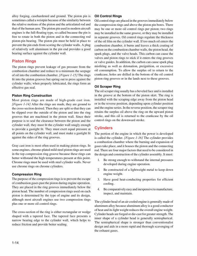
CThe portion of the engine in which the power is developed is called the cylinder. [Figure 1-16] The cylinder provides a combustion chamber where the burning and expansion of gases take place, and it houses the piston and the connecting rod. There are four major factors that need to be considered in the design and construction of the cylinder assembly. It must:
1. Be strong enough to withstand the internal pressures developed during engine operation.
2. Be constructed of a lightweight metal to keep down engine weight.
3. Have good heat-conducting properties for efficient cooling.
4. Be comparatively easy and inexpensive to manufacture, inspect, and maintain.
The cylinder head of an air cooled engine is generally made of aluminum alloy because aluminum alloy is a good conductor of heat and its light weight reduces the overall engine weight. Cylinder heads are forged or die-cast for greater strength. The inner shape of a cylinder head is generally semispherical. The semispherical shape is stronger than conventionalist design and aids in a more rapid and thorough scavenging of the exhaust gases.
1 1
An example of an engine cylinder.
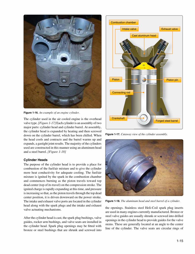
Piston
Cast aluminum head
Exhaust valveIntake valve
Connecting rod
Forged steel barrel
Combustion chamber
Crankshaft
Piston pin
Cutaway view of the cylinder assembly.
The aluminum head and steel barrel of a cylinder.
The cylinder used in the air cooled engine is the overhead valve type. [Figure 1-17] Each cylinder is an assembly of two major parts: cylinder head and cylinder barrel. At assembly, the cylinder head is expanded by heating and then screwed down on the cylinder barrel, which has been chilled. When the head cools and contracts and the barrel warms up and expands, a gastight joint results. The majority of the cylinders used are constructed in this manner using an aluminum head and a steel barrel. [Figure 1-18]
CThe purpose of the cylinder head is to provide a place for combustion of the fuel/air mixture and to give the cylinder more heat conductivity for adequate cooling. The fuel/air mixture is ignited by the spark in the combustion chamber and commences burning as the piston travels toward top dead center (top of its travel) on the compression stroke. The ignited charge is rapidly expanding at this time, and pressure is increasing so that, as the piston travels through the top dead center position, it is driven downward on the power stroke. The intake and exhaust valve ports are located in the cylinder head along with the spark plugs and the intake and exhaust valve actuating mechanisms.
After the cylinder head is cast, the spark plug bushings, valve guides, rocker arm bushings, and valve seats are installed in the cylinder head. Spark plug openings may be fitted with bronze or steel bushings that are shrunk and screwed into
the openings. Stainless steel Heli-Coil spark plug inserts are used in many engines currently manufactured. Bronze or steel valve guides are usually shrunk or screwed into drilled openings in the cylinder head to provide guides for the valve stems. These are generally located at an angle to the center line of the cylinder. The valve seats are circular rings of
1 1
Single-Row Radial Double-Row Radial Opposed
4 3
2 1
6 5
1
2
7
8
5
4
9
3
6
1
3
13
15
9
7
17
5
11
2
4
14
16
10
8
18
6
12
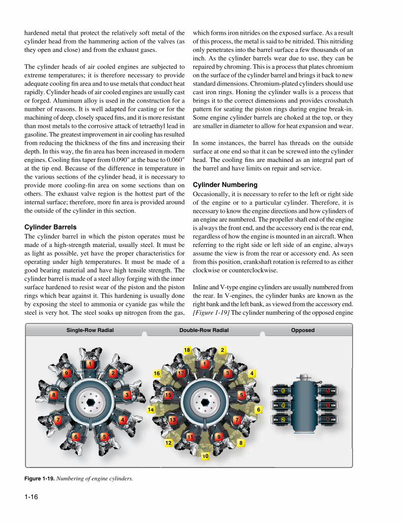
Numbering of engine cylinders.
hardened metal that protect the relatively soft metal of the cylinder head from the hammering action of the valves (as they open and close) and from the exhaust gases.
The cylinder heads of air cooled engines are subjected to extreme temperatures; it is therefore necessary to provide adequate cooling fin area and to use metals that conduct heat rapidly. Cylinder heads of air cooled engines are usually cast or forged. Aluminum alloy is used in the construction for a number of reasons. It is well adapted for casting or for the machining of deep, closely spaced fins, and it is more resistant than most metals to the corrosive attack of tetraethyl lead in gasoline. The greatest improvement in air cooling has resulted from reducing the thickness of the fins and increasing their depth. In this way, the fin area has been increased in modern engines. Cooling fins taper from 0.090" at the base to 0.060" at the tip end. Because of the difference in temperature in the various sections of the cylinder head, it is necessary to provide more cooling-fin area on some sections than on others. The exhaust valve region is the hottest part of the internal surface; therefore, more fin area is provided around the outside of the cylinder in this section.
CThe cylinder barrel in which the piston operates must be made of a high-strength material, usually steel. It must be as light as possible, yet have the proper characteristics for operating under high temperatures. It must be made of a good bearing material and have high tensile strength. The cylinder barrel is made of a steel alloy forging with the inner surface hardened to resist wear of the piston and the piston rings which bear against it. This hardening is usually done by exposing the steel to ammonia or cyanide gas while the steel is very hot. The steel soaks up nitrogen from the gas,
which forms iron nitrides on the exposed surface. As a result of this process, the metal is said to be nitrided. This nitriding only penetrates into the barrel surface a few thousands of an inch. As the cylinder barrels wear due to use, they can be repaired by chroming. This is a process that plates chromium on the surface of the cylinder barrel and brings it back to new standard dimensions. Chromium-plated cylinders should use cast iron rings. Honing the cylinder walls is a process that brings it to the correct dimensions and provides crosshatch pattern for seating the piston rings during engine break-in. Some engine cylinder barrels are choked at the top, or they are smaller in diameter to allow for heat expansion and wear.
In some instances, the barrel has threads on the outside surface at one end so that it can be screwed into the cylinder head. The cooling fins are machined as an integral part of the barrel and have limits on repair and service.
COccasionally, it is necessary to refer to the left or right side of the engine or to a particular cylinder. Therefore, it is necessary to know the engine directions and how cylinders of an engine are numbered. The propeller shaft end of the engine is always the front end, and the accessory end is the rear end, regardless of how the engine is mounted in an aircraft. When referring to the right side or left side of an engine, always assume the view is from the rear or accessory end. As seen from this position, crankshaft rotation is referred to as either clockwise or counterclockwise.
Inline and V-type engine cylinders are usually numbered from the rear. In V-engines, the cylinder banks are known as the right bank and the left bank, as viewed from the accessory end. [Figure 1-19] The cylinder numbering of the opposed engine
1 1
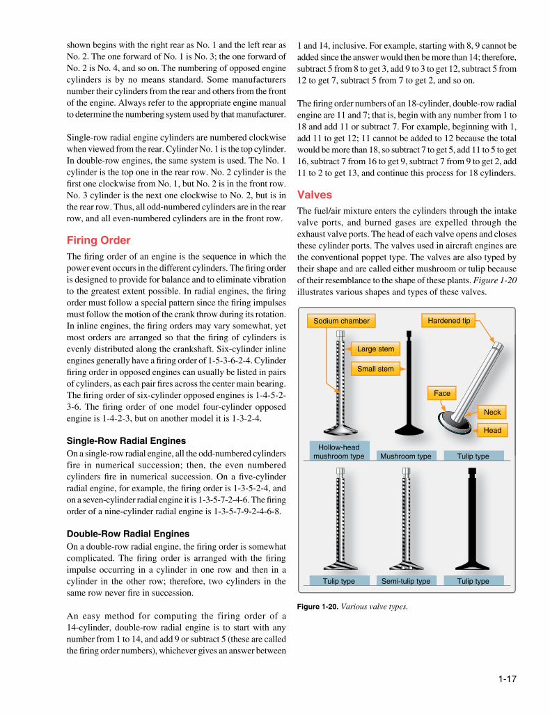
Tulip type Semi-tulip type Tulip type
Hollow-head mushroom type Mushroom type Tulip type
Large stem
Sodium chamber
Small stem
Hardened tip
Neck
Face
Head
Various valve types.
shown begins with the right rear as No. 1 and the left rear as No. 2. The one forward of No. 1 is No. 3; the one forward of No. 2 is No. 4, and so on. The numbering of opposed engine cylinders is by no means standard. Some manufacturers number their cylinders from the rear and others from the front of the engine. Always refer to the appropriate engine manual to determine the numbering system used by that manufacturer.
Single-row radial engine cylinders are numbered clockwise when viewed from the rear. Cylinder No. 1 is the top cylinder. In double-row engines, the same system is used. The No. 1 cylinder is the top one in the rear row. No. 2 cylinder is the first one clockwise from No. 1, but No. 2 is in the front row. No. 3 cylinder is the next one clockwise to No. 2, but is in the rear row. Thus, all odd-numbered cylinders are in the rear row, and all even-numbered cylinders are in the front row.
OThe firing order of an engine is the sequence in which the power event occurs in the different cylinders. The firing order is designed to provide for balance and to eliminate vibration to the greatest extent possible. In radial engines, the firing order must follow a special pattern since the firing impulses must follow the motion of the crank throw during its rotation. In inline engines, the firing orders may vary somewhat, yet most orders are arranged so that the firing of cylinders is evenly distributed along the crankshaft. Six-cylinder inline engines generally have a firing order of 1-5-3-6-2-4. Cylinder firing order in opposed engines can usually be listed in pairs of cylinders, as each pair fires across the center main bearing. The firing order of six-cylinder opposed engines is 1-4-5-2-3-6. The firing order of one model four-cylinder opposed engine is 1-4-2-3, but on another model it is 1-3-2-4.
EOn a single-row radial engine, all the odd-numbered cylinders fire in numerical succession; then, the even numbered cylinders fire in numerical succession. On a five-cylinder radial engine, for example, the firing order is 1-3-5-2-4, and on a seven-cylinder radial engine it is 1-3-5-7-2-4-6. The firing order of a nine-cylinder radial engine is 1-3-5-7-9-2-4-6-8.
D EOn a double-row radial engine, the firing order is somewhat complicated. The firing order is arranged with the firing impulse occurring in a cylinder in one row and then in a cylinder in the other row; therefore, two cylinders in the same row never fire in succession.
An easy method for computing the firing order of a 14-cylinder, double-row radial engine is to start with any number from 1 to 14, and add 9 or subtract 5 (these are called the firing order numbers), whichever gives an answer between
1 and 14, inclusive. For example, starting with 8, 9 cannot be added since the answer would then be more than 14; therefore, subtract 5 from 8 to get 3, add 9 to 3 to get 12, subtract 5 from 12 to get 7, subtract 5 from 7 to get 2, and so on.
The firing order numbers of an 18-cylinder, double-row radial engine are 11 and 7; that is, begin with any number from 1 to 18 and add 11 or subtract 7. For example, beginning with 1, add 11 to get 12; 11 cannot be added to 12 because the total would be more than 18, so subtract 7 to get 5, add 11 to 5 to get 16, subtract 7 from 16 to get 9, subtract 7 from 9 to get 2, add 11 to 2 to get 13, and continue this process for 18 cylinders.
The fuel/air mixture enters the cylinders through the intake valve ports, and burned gases are expelled through the exhaust valve ports. The head of each valve opens and closes these cylinder ports. The valves used in aircraft engines are the conventional poppet type. The valves are also typed by their shape and are called either mushroom or tulip because of their resemblance to the shape of these plants. Figure 1-20 illustrates various shapes and types of these valves.
1 1
View of valve guide installed on a cylinder head.
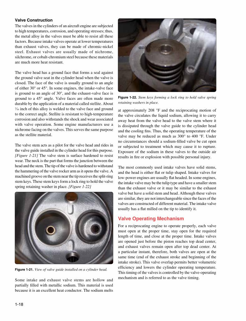
Stem keys forming a lock ring to hold valve spring retaining washers in place.
CThe valves in the cylinders of an aircraft engine are subjected to high temperatures, corrosion, and operating stresses; thus, the metal alloy in the valves must be able to resist all these factors. Because intake valves operate at lower temperatures than exhaust valves, they can be made of chromic-nickel steel. Exhaust valves are usually made of nichrome, silchrome, or cobalt-chromium steel because these materials are much more heat resistant.
The valve head has a ground face that forms a seal against the ground valve seat in the cylinder head when the valve is closed. The face of the valve is usually ground to an angle of either 30° or 45°. In some engines, the intake-valve face is ground to an angle of 30°, and the exhaust-valve face is ground to a 45° angle. Valve faces are often made more durable by the application of a material called stellite. About 1⁄16 inch of this alloy is welded to the valve face and ground to the correct angle. Stellite is resistant to high-temperature corrosion and also withstands the shock and wear associated with valve operation. Some engine manufacturers use a nichrome facing on the valves. This serves the same purpose as the stellite material.
The valve stem acts as a pilot for the valve head and rides in the valve guide installed in the cylinder head for this purpose. [Figure 1-21] The valve stem is surface hardened to resist wear. The neck is the part that forms the junction between the head and the stem. The tip of the valve is hardened to withstand the hammering of the valve rocker arm as it opens the valve. A machined groove on the stem near the tip receives the split-ring stem keys. These stem keys form a lock ring to hold the valve spring retaining washer in place. [Figure 1-22]
Some intake and exhaust valve stems are hollow and partially filled with metallic sodium. This material is used because it is an excellent heat conductor. The sodium melts
at approximately 208 °F and the reciprocating motion of the valve circulates the liquid sodium, allowing it to carry away heat from the valve head to the valve stem where it is dissipated through the valve guide to the cylinder head and the cooling fins. Thus, the operating temperature of the valve may be reduced as much as 300° to 400 °F. Under no circumstances should a sodium-filled valve be cut open or subjected to treatment which may cause it to rupture. Exposure of the sodium in these valves to the outside air results in fire or explosion with possible personal injury.
The most commonly used intake valves have solid stems, and the head is either flat or tulip shaped. Intake valves for low-power engines are usually flat headed. In some engines, the intake valve may be the tulip type and have a smaller stem than the exhaust valve or it may be similar to the exhaust valve but have a solid stem and head. Although these valves are similar, they are not interchangeable since the faces of the valves are constructed of different material. The intake valve usually has a flat milled on the tip to identify it.
OFor a reciprocating engine to operate properly, each valve must open at the proper time, stay open for the required length of time, and close at the proper time. Intake valves are opened just before the piston reaches top dead center, and exhaust valves remain open after top dead center. At a particular instant, therefore, both valves are open at the same time (end of the exhaust stroke and beginning of the intake stroke). This valve overlap permits better volumetric efficiency and lowers the cylinder operating temperature. This timing of the valves is controlled by the valve-operating mechanism and is referred to as the valve timing.
1 1
Cam ramps
Camshaft
Typical cam lobes.
Cam track
Cam lobe
Roller
Cam ring
Cam roller
Pressure oil
Case
Tappet
Adjusting screw Rocker arm
Return oil
Lock screw
Push rod tube
Tappet guide
Seat
Port Valve guide
Valve spring
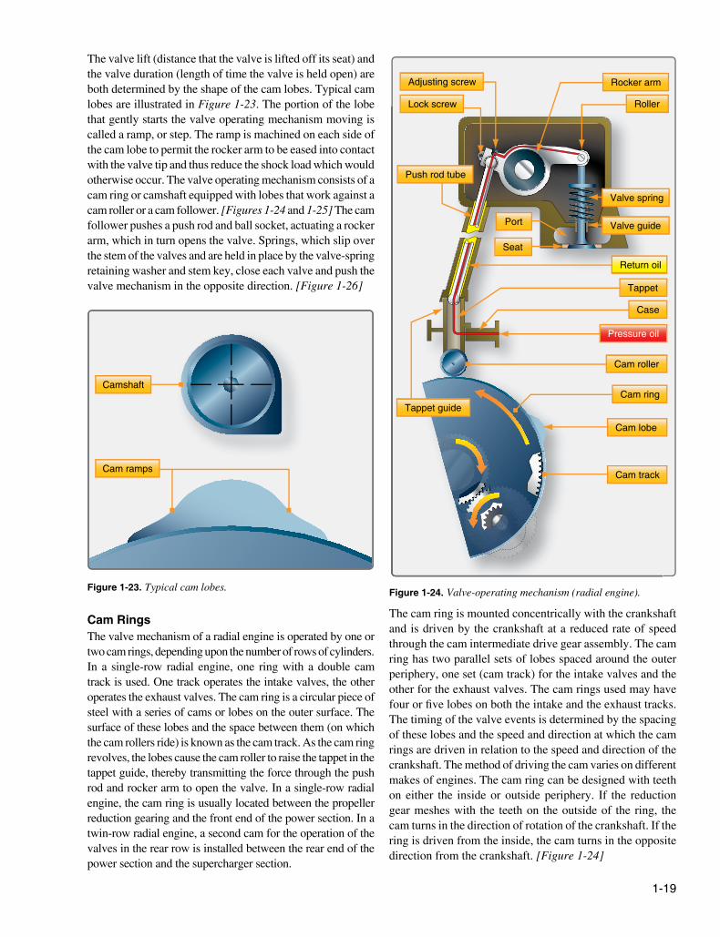
Valve-operating mechanism (radial engine).
The valve lift (distance that the valve is lifted off its seat) and the valve duration (length of time the valve is held open) are both determined by the shape of the cam lobes. Typical cam lobes are illustrated in Figure 1-23. The portion of the lobe that gently starts the valve operating mechanism moving is called a ramp, or step. The ramp is machined on each side of the cam lobe to permit the rocker arm to be eased into contact with the valve tip and thus reduce the shock load which would otherwise occur. The valve operating mechanism consists of a cam ring or camshaft equipped with lobes that work against a cam roller or a cam follower. [Figures 1-24 and 1-25] The cam follower pushes a push rod and ball socket, actuating a rocker arm, which in turn opens the valve. Springs, which slip over the stem of the valves and are held in place by the valve-spring retaining washer and stem key, close each valve and push the valve mechanism in the opposite direction. [Figure 1-26]
CThe valve mechanism of a radial engine is operated by one or two cam rings, depending upon the number of rows of cylinders. In a single-row radial engine, one ring with a double cam track is used. One track operates the intake valves, the other operates the exhaust valves. The cam ring is a circular piece of steel with a series of cams or lobes on the outer surface. The surface of these lobes and the space between them (on which the cam rollers ride) is known as the cam track. As the cam ring revolves, the lobes cause the cam roller to raise the tappet in the tappet guide, thereby transmitting the force through the push rod and rocker arm to open the valve. In a single-row radial engine, the cam ring is usually located between the propeller reduction gearing and the front end of the power section. In a twin-row radial engine, a second cam for the operation of the valves in the rear row is installed between the rear end of the power section and the supercharger section.
The cam ring is mounted concentrically with the crankshaft and is driven by the crankshaft at a reduced rate of speed through the cam intermediate drive gear assembly. The cam ring has two parallel sets of lobes spaced around the outer periphery, one set (cam track) for the intake valves and the other for the exhaust valves. The cam rings used may have four or five lobes on both the intake and the exhaust tracks. The timing of the valve events is determined by the spacing of these lobes and the speed and direction at which the cam rings are driven in relation to the speed and direction of the crankshaft. The method of driving the cam varies on different makes of engines. The cam ring can be designed with teeth on either the inside or outside periphery. If the reduction gear meshes with the teeth on the outside of the ring, the cam turns in the direction of rotation of the crankshaft. If the ring is driven from the inside, the cam turns in the opposite direction from the crankshaft. [Figure 1-24]