
Fuel Injection System for Opposed-Piston Gasoline ...
15
2019-01-0287 Published 02 Apr 2019 © 2019 SAE International. All Rights Reserved. Fuel Injection System for Opposed-Piston Gasoline Compression-Ignited (OP-GCI) Engines Mark Sellnau formerly Delphi Technologies Inc. Kevin Hoyer, Jean Herve Petot, Erol Kahraman, and Guillaume Meissonnier Delphi Technologies Inc. Rodrigo Zermeno, Donovan Quimby, Clark Klyza, and Fabien Redon Achates Power Inc. Citation: Sellnau, M., Hoyer, K., Petot, J.H., Kahraman, E. et al., “Fuel Injection System for Opposed-Piston Gasoline Compression-Ignited (OP-GCI) Engines,” SAE Technical Paper 2019-01-0287, 2019, doi:10.4271/2019-01-0287. Abstract O pposed-piston engines have been in production since before the 1930’s because of their inherent low heat losses and high thermal efficiency. Now, opposed- piston gasoline compression ignition (OP-GCI) engines are being developed for automotive transportation with stringent emissions targets. Due to the opposed-piston architecture and the absence of a cylinder head, fuel injection requirements and packaging are significantly different than conventional 4-stroke engines with central-mounted injectors. e injection process and spray characteristics are fundamental to achieving a successful combustion system with high efficiency, low emis- sions, and low combustion noise. In this paper, the fuel injection system for the Achates 2.7L, 3-cylinder OP-GCI engine is described. e fuel system was designed for 1800 bar maximum fuel pressure with two injectors mounted diametrically opposed in each cylinder. Two fuel rails were mounted on each side of the engine and were supplied independently from two crank-driven unit pumps mounted at the front of the engine. CFD tools were used to investigate nozzle design and spray characteristics for minimal wall wetting and good air utilization. Simulation results indicated that relatively narrow spray angles of 10 to 30 degrees performed well. e fuel system was designed and built at Delphi Technologies and successfully tested on a dyna- mometer engine at Achates Power. Introduction H istorically since the introduction of exhaust emissions regulations, most of the diesel fuel injection equip- ment (FIE) development has been for conventional 4-stroke, central-injected, axially symmetric combustion systems with multi-hole injectors. For decades, injection pres- sures have trended higher and injector performance has increased to combine with high in-cylinder swirl and squish for emissions compliance. ese engines exhibit good output, high air utilization, and very high fuel efficiency. Opposed-piston engines (OPE) feature a pair of pistons operating in each cylinder and do not require conventional cylinder heads. Due to the resulting low chamber surface-to- volume ratio and reduced heat losses, OPE have fundamental efficiency advantages over conventional engines [1]. However, OPE require side-mounting of fuel injectors for which spray plume(s) enter the cylinder transversely across the bore. While the spray distances are longer than conventional diesel engines with central injector mounting, much less is known and very little is published about how to optimize OPE fuel systems and sprays. e fuel injection process and spray characteristics are very important factors to achieve a successful combustion system with high efficiency, low emissions, and low combustion noise. Probably the most famous opposed-piston diesel engine is the Junkers Jumo 205 2-stroke, 6-cylinder engine used in German aircraſt prior to and during World War II [1]. Each cylinder was fueled by four injectors connected to two unit pumps that were driven by the camshaſt. e injectors were unique and produced wide fan sprays oriented at 45 degrees to the cylinder axis (Figure 1). e Jumo 205E engine achieved remarkable efficiency of 35.5% and high power to weight ratio for its time [1]. Delphi Technologies (formerly Lucas CAV) has a history of supplying FIE systems for OP diesel engines. Fuel injection systems were supplied for British OP diesel engines in the 1950’s and 1960’s, such as the Tilling Stevens TS-3, the Rolls Royce R-60, the Napier Deltic, and the Leyland L-60 engines. Table 1 lists these engines and their basic attributes. ey typically used one side-mounted injector for each cylinder and all used pump-line-nozzle (PLN) injection systems with single hole nozzles. Since 2004, Achates Power has been leading the industry developing new opposed-piston engines for military, power generation, and light-duty (LD) through heavy-duty (HD) transport sectors. One preferred injection system utilizes two side-mounted, diametrically-opposed injectors located at the mid-plane of the cylinder. Unlike conventional 4-stroke diesel Downloaded from SAE International by Fabien Redon, Friday, March 22, 2019
-
Upload
khangminh22 -
Category
Documents
-
view
4 -
download
0
Transcript of Fuel Injection System for Opposed-Piston Gasoline ...

2019-01-0287 Published 02 Apr 2019
© 2019 SAE International. All Rights Reserved.
Fuel Injection System for Opposed-Piston Gasoline Compression-Ignited (OP-GCI) EnginesMark Sellnau formerly Delphi Technologies Inc.
Kevin Hoyer, Jean Herve Petot, Erol Kahraman, and Guillaume Meissonnier Delphi Technologies Inc.
Rodrigo Zermeno, Donovan Quimby, Clark Klyza, and Fabien Redon Achates Power Inc.
Citation: Sellnau, M., Hoyer, K., Petot, J.H., Kahraman, E. et al., “Fuel Injection System for Opposed-Piston Gasoline Compression-Ignited (OP-GCI) Engines,” SAE Technical Paper 2019-01-0287, 2019, doi:10.4271/2019-01-0287.
Abstract
Opposed-piston engines have been in production since before the 1930’s because of their inherent low heat losses and high thermal efficiency. Now, opposed-
piston gasoline compression ignition (OP-GCI) engines are being developed for automotive transportation with stringent emissions targets. Due to the opposed-piston architecture and the absence of a cylinder head, fuel injection requirements and packaging are significantly different than conventional 4-stroke engines with central-mounted injectors. The injection process and spray characteristics are fundamental to achieving a successful combustion system with high efficiency, low emis-sions, and low combustion noise.
In this paper, the fuel injection system for the Achates 2.7L, 3-cylinder OP-GCI engine is described. The fuel system was designed for 1800 bar maximum fuel pressure with two injectors mounted diametrically opposed in each cylinder. Two fuel rails were mounted on each side of the engine and were supplied independently from two crank-driven unit pumps mounted at the front of the engine. CFD tools were used to investigate nozzle design and spray characteristics for minimal wall wetting and good air utilization. Simulation results indicated that relatively narrow spray angles of 10 to 30 degrees performed well. The fuel system was designed and built at Delphi Technologies and successfully tested on a dyna-mometer engine at Achates Power.
Introduction
Historically since the introduction of exhaust emissions regulations, most of the diesel fuel injection equip-ment (FIE) development has been for conventional
4-stroke, central-injected, axially symmetric combustion systems with multi-hole injectors. For decades, injection pres-sures have trended higher and injector performance has increased to combine with high in-cylinder swirl and squish for emissions compliance. These engines exhibit good output, high air utilization, and very high fuel efficiency.
Opposed-piston engines (OPE) feature a pair of pistons operating in each cylinder and do not require conventional cylinder heads. Due to the resulting low chamber surface-to-volume ratio and reduced heat losses, OPE have fundamental efficiency advantages over conventional engines [1]. However, OPE require side-mounting of fuel injectors for which spray plume(s) enter the cylinder transversely across the bore. While the spray distances are longer than conventional diesel engines with central injector mounting, much less is known and very little is published about how to optimize OPE fuel systems and sprays. The fuel injection process and spray characteristics are very important factors to achieve a successful combustion system with high efficiency, low emissions, and low combustion noise.
Probably the most famous opposed-piston diesel engine is the Junkers Jumo 205 2-stroke, 6-cylinder engine used in German aircraft prior to and during World War II [1]. Each cylinder was fueled by four injectors connected to two unit pumps that were driven by the camshaft. The injectors were unique and produced wide fan sprays oriented at 45 degrees to the cylinder axis (Figure 1). The Jumo 205E engine achieved remarkable efficiency of 35.5% and high power to weight ratio for its time [1].
Delphi Technologies (formerly Lucas CAV) has a history of supplying FIE systems for OP diesel engines. Fuel injection systems were supplied for British OP diesel engines in the 1950’s and 1960’s, such as the Tilling Stevens TS-3, the Rolls Royce R-60, the Napier Deltic, and the Leyland L-60 engines. Table 1 lists these engines and their basic attributes. They typically used one side-mounted injector for each cylinder and all used pump-line-nozzle (PLN) injection systems with single hole nozzles.
Since 2004, Achates Power has been leading the industry developing new opposed-piston engines for military, power generation, and light-duty (LD) through heavy-duty (HD) transport sectors. One preferred injection system utilizes two side-mounted, diametrically-opposed injectors located at the mid-plane of the cylinder. Unlike conventional 4-stroke diesel
Downloaded from SAE International by Fabien Redon, Friday, March 22, 2019

© 2019 SAE International. All Rights Reserved.
FUEL INJECTION SYSTEM FOR OPPOSED-PISTON GASOLINE COMPRESSION-IGNITED (OP-GCI) ENGINES 2
engines, the sprays for opposed piston engines typically have few holes (three or four) with very narrow spray angles. Figure 2 shows an arrangement in which each injector has four symmetric spray plumes and the injectors are clocked to inter-digitate the spray plumes for good mixing and air utili-zation [2]. A system similar to this was tested on a 2-stroke 1.6L single-cylinder opposed-piston research engine and produced over 50 percent indicated thermal efficiency for a wide operating load range [3].
In parallel to these developments, progress was being made on gasoline direct-injection compression-ignition (GDCI) engines. GDCI represents the intersection of gasoline and diesel engine technology and uses partially-premixed compression ignition in a low temperature combustion process [4]. With ARPA-E sponsorship, a three-year program lead by Achates Power, Inc. was launched to combine the high efficiency of opposed-piston engines with the low emissions of GDCI [5]. The objective was to develop a 2.7L, 3-cylinder, opposed-piston, gasoline compression ignition (OP-GCI) engine for operation on US E10 pump gasoline. Argonne National Labs and Delphi Technologies partnered in the effort with expertise in combustion, simulation, and fuel injection systems.
This paper presents work for the fuel injection system. Key development steps included defining requirements for the fuel injection system, selecting the system architecture, integrating the system on engine, and designing the injection
system components. CFD simulation was performed to study the injection process and spray characteristics for side-mounted, diametrically-opposed injectors in an opposed-piston configuration. CFD was used to study the effects of main design parameters such as spray angle, clocking angle, and injection rate (hole size) on chamber wetting and air utili-zation. To address gasoline fuel property effects (viscosity, lubricity, volatility) on fuel system durability, a preliminary 500-hour durability test of the fuel system was conducted without lubricity additive.
Fuel Injection System Requirements and ArchitectureHigh-level fuel system requirements are shown in Table 2. The injection pressure requirement of 1800 bar is higher than gasoline fuel systems at this time. Therefore, a diesel fuel system was specified for operation on US E10 gasoline with a lubricity additive.
FIGURE 1 Fan spray for four injectors per cylinder on Junkers Jumo 205E engine (circa 1930 to 1945) [1].
© 2
019
SA
E In
tern
atio
nal.
All
Rig
hts
Res
erve
d.
TABLE 1 Production opposed-piston engines using Delphi-Lucas diesel fuel injection equipment.
Engine Manuf Designation # Cyls Bore (mm) Displ (L) FIE System Prod YearCoventry Climax H30 3 55 1 In-line Pump; Pintle Nozzle 1961-1979
Tilling Stevens TS3/TS4 3 85.7 3.5 Rotary Pump 1956
Rolls Royce K60
K60 Turbo 6 87.4 6.6 In-line Pump 1962-1968
Leyland L60 6 117.6 19 In-line Pump 1964
Napier Deltic 9 130.2 88.3 Unit Pump 1957-1964 © 2
019
SA
E In
tern
atio
nal.
A
ll R
ight
s R
eser
ved
.
FIGURE 2 Inter-digitated spray plumes from two diametrically-opposed injectors in an opposed-piston engine [2].
© 2019 SAE International. All Rights Reserved.
TABLE 2 High-level requirements for fuel system.
Parameter ValueFuel US E10 RON91 Gasoline
Fuel Pressure 1800 bar
No. of Injectors two per cylinder diametrically opposed
No. of Holes 3© 2019 SAE International. All Rights Reserved.
Downloaded from SAE International by Fabien Redon, Friday, March 22, 2019

© 2019 SAE International. All Rights Reserved.
FUEL INJECTION SYSTEM FOR OPPOSED-PISTON GASOLINE COMPRESSION-IGNITED (OP-GCI) ENGINES 3
A schematic of the fuel system for a 3-cylinder opposed-piston engine is shown in Figure 3 based on a patent filing by Dingle [6]. It is comprised of two independent fuel systems, with one pump, one rail, high pressure lines, and three injec-tors for each side of the engine. A fuel system was designed and fabricated for the Achates 2.7L 3-cylinder, OP-GCI engine based on this architecture. A CAD rendering of the system is shown in Figure 4.
As shown in Figure 3, two injectors are mounted diamet-rically-opposed in each cylinder on a common axis. The two fuel rails may be operated at different pressures. This may be advantageous, for example, if one bank of injectors was used for early injections at lower pressure. Two diesel unit pumps (DUP) with engine-oil-lubricated roller lifters are driven simultaneously by the intake crankshaft with a three-lobe cam. This provides one pumping event for each injection event. Overall, this system configuration provides great flex-ibility in the injection process for fuel quantity, timing, and splits.
Fuel InjectorThe injector selected for the 2.7L OP-GCI engine is the high performance DFI 1.22sv solenoid injector developed for LD diesel engines. This injector has evolved over recent years from the production DFI 1.5 and DFI 1.20 injectors in a modular format [7]. Figure 5 shows the main features of this injector family. All injectors shown incorporate a small 2-way hydraulic control valve located close to the needle valve. This combined with a body diameter of 19mm makes this injector family compact and easy to package in engines [7].
The hydraulic architecture results in an injector with very fast response. To reduce the dynamic leakage and increase the maximum operating pressure, the nozzle needle and seat diameters were reduced. In parallel to these design modifica-tions, some optimization in hydraulics were performed, resulting in improved injector controllability, especially at very low delivery.
Figure 6 shows a comparison of injection rate at various injection pressures for the DFI 1.22 injector and a high-perfor-mance servo-piezo injector. The data shows similar trends for opening and closing speed and on the maximum rate. The high performance of the solenoid injector is obtained through fast hydraulic response and nozzle design.
As a main evolution from the production DFI 1.20 injector, the static leakage of the DFI 1.22 injector has been practically eliminated. This is important for OP-GCI applica-tions because gasoline has much lower viscosity than diesel
FIGURE 3 Fuel system schematic for 3-cylinder, opposed-piston engine [5].
© 2
019
SA
E In
tern
atio
nal.
All
Rig
hts
Res
erve
d.
FIGURE 4 CAD rendering of fuel system designed for the Achates 2.7L, 3-cylinder, opposed-piston engine.
© 2
019
SA
E In
tern
atio
nal.
All
Rig
hts
Res
erve
d.
FIGURE 5 Solenoid injector family for LD diesel engines.
© 2
019
SA
E In
tern
atio
nal.
All
Rig
hts
Res
erve
d.
FIGURE 6 Comparison of new DFI 1.22 solenoid injector and a high-performance servo-piezo injector for various injection pressures.
© 2019 SAE International. All Rights Reserved.
Downloaded from SAE International by Fabien Redon, Friday, March 22, 2019

© 2019 SAE International. All Rights Reserved.
FUEL INJECTION SYSTEM FOR OPPOSED-PISTON GASOLINE COMPRESSION-IGNITED (OP-GCI) ENGINES 4
fuel. Back leak flows are approximately inversely proportional to fuel viscosity and should be minimized to achieve high system efficiency. The evolution consists of the addition of a sleeve inside the CVA (Control Valve Adaptor-Plate). The sleeve guides the control valve armature and also reduces leakage by lowering the clearance between the stem and the guide as fuel pressure increases. This feature makes static leakage insensitive to pressure (Figure 7) resulting in a back-leak flow reduction of up to 10 ml/min and a back-leak temper-ature decrease of 10 degree C, as measured on an injector test bench.
Injector Sleeve AssemblyThe injector sleeve assembly is designed for threading into the cylinder liner at the mid-plane of each cylinder (Figure 8). Injector clamping load is accomplished by a gland nut that loads two split rings onto the injector flats. This keeps all clamping load within the sleeve assembly and eliminates distortion of the cylinder liner due to external clamping loads.
For opposed piston engine applications, a very short injector with top feed fuel connection is preferred. This is important for compact packaging and to keep the overall engine width to a minimum. The DFI 1.22sv injector shown in Figure 8 has an overall length of 137 mm, as measured from cap nut to injector top, and is near the minimum length for this injector family.
Injector cooling is accomplished by engine cooling water that surrounds the lower portion of the injector sleeve. Cooling the injector tip is important in this 2-stroke application since the cylinder liner and injector tip are subject to higher thermal loading than conventional 4-stroke engines. An O-ring and a copper gasket on the sleeve seal the water jacket. A locking collar, shown in Figure 8, insures that the injector sleeve does not unwind when the injectors are removed.
Nozzle DesignNozzle design for an opposed piston engine with two diamet-rically-opposed injectors in each cylinder is much different than that for typical 4-stroke diesel engines. Generally, the spray angle is narrower and the number of holes per injector is less (3 or 4) than conventional 4-stroke diesel engines (7 or 8).
Initially, work was done using multi-hole gasoline direct injectors (GDi) with 400 bar maximum operating pressure (MOP). Injectors with various sprays were designed, simu-lated, and fabricated as shown in Figure 9. One injector featured a semi-flat fan spray using 6 holes. While interesting, tests on a single-cylinder OPE with gasoline were not successful and it was concluded that higher injection pressure
© 2
019
SA
E In
tern
atio
nal.
All
Rig
hts
Res
erve
d.
FIGURE 7 Back leak flow and temperature as a function of rail pressure for the DFI 1.22sv and DFI 1.5 injectors.
FIGURE 8 Injector sleeve assembly showing external gland nut, split rings, sleeve, locking collar, electrical connector, and gaskets.
© 2
019
SA
E In
tern
atio
nal.
All
Rig
hts
Res
erve
d.
FIGURE 9 GDi spray concepts evaluated for OP-GCI engine.
© 2
019
SA
E In
tern
atio
nal.
All
Rig
hts
Res
erve
d.
Downloaded from SAE International by Fabien Redon, Friday, March 22, 2019

© 2019 SAE International. All Rights Reserved.
FUEL INJECTION SYSTEM FOR OPPOSED-PISTON GASOLINE COMPRESSION-IGNITED (OP-GCI) ENGINES 5
was needed to achieve high-load efficiency, emissions and noise targets.
Work focused on diesel-based injection systems with 1800 bar pressure capability. As an example, the design of a 3-hole symmetric nozzle with spray angle of 43 degrees (included angle) is shown in Figure 10. The narrow spray angle has a large effect on the hole entrance geometry at the sac wall. CFD tools were used to position the holes vertically on the sac walls for best flow characteristics. The narrow spray angle also affects the hole length. Hole length is significantly increased and the holes exit lower on the injector tip almost at the nozzle point. This has the benefit of increasing the hole L/D for good flow and cavitation characteristics. CFD tools were used to study the effect of spray angle, clocking angle, and injection rate on the injection and mixing processes, and are presented in the last section of this paper.
Preliminary spray chamber tests were performed on a DFI 1.22sv injector equipped with the nozzle shown in Figure 10. Tests were conducted using back lit imaging at 600 bar fuel pressure and chamber pressure and temperature of 55 bar and 23 degree C, respectively (Figure 11). In the image, one of the three spray plumes is obscured by the left spray plume. The image shows well defined, coherent spray plumes with good penetration characteristics.
Fuel PumpThe second-generation DUP 2.20 (diesel unit pump) was selected for application on the 2.7L OP engine [8]. This pump was developed for high efficiency at system pressures of 2000 bar and above. Key merits for the design include compact design, low mass, high hydraulic efficiency by inlet flow metering, and robustness due to engine oil lubrication. Figure 12 shows a CAD rendering of the DUP 2.20 pump. The pump was evolved from the DUP 1.16 pump that has been in production since 2010 (Figure 13) [8].
Patented inlet and outlet valves have been integrated in the pumping head to allow higher pumping pressure in the pumping chamber by eliminating mechanical stresses due to assembly load of additional valve cartridges (Figure 14). An integral damper, shown in Figure 14, enables full filling of the pumping chamber at high speeds without increasing the LP supply pressure. The damper is located between the inlet
FIGURE 10 Exemplary nozzle hole layout with three holes and narrow spray angle of 43 degrees (included).
© 2019 SAE International. All Rights Reserved.
FIGURE 11 DFI 1.22sv spray plumes imaged using back lit method in a spray chamber at 55 bar and 23 degree C for injection pressure of 600 bar at 1.5 ms after start of injection.
© 2019 SAE International. All Rights Reserved.
FIGURE 12 Unit pump with inlet metering valve (IMV) and roller lifter.
© 2
019
SA
E In
tern
atio
nal.
All
Rig
hts
Res
erve
d.
FIGURE 13 Evolution of DUP 1 and DUP 2 unit pumps.
© 2019 SAE International. All Rights Reserved.
FIGURE 14 DUP 2.20 pump head showing inlet and outlet valves.
© 2019 SAE International. All Rights Reserved.
Downloaded from SAE International by Fabien Redon, Friday, March 22, 2019

© 2019 SAE International. All Rights Reserved.
FUEL INJECTION SYSTEM FOR OPPOSED-PISTON GASOLINE COMPRESSION-IGNITED (OP-GCI) ENGINES 6
metering valve (IMV) and the inlet valve and smooths pressure pulsations caused by intermittent flow.
Fuel metering is accomplished via a solenoid-driven proportional IMV (Figure 15). The valve provides significant reduction in fuel consumption by avoiding unnecessary pumping work at partial load conditions. It is controlled by a pulse-width modulated (PWM) signal generated by the engine control unit (ECU) and is the primary means for rail pressure control in a system.
Lubrication of the pump is critical to achieving a robust design. The lubrication scheme of the pump lifter and roller assembly has been adapted with extra lubrication features to allow effective lubrication throughout the engine speed range (Figure 16). Pressurized engine oil is supplied to the lifter bore and lifter body through a drilling. Grooves in the outer surface of the lifter body distribute oil in the high load regions of the lifter. Cross drillings in the lifter insure adequate lubrication of the roller needle bearings.
With oil lubrication, there is greater risk of fuel-oil and oil-fuel dilution. A plunger seal and back leak gallery were incorporated in the pump to route any fuel leakage back to the fuel tank. Bench tests indicated extremely low dilution [9].
Additional development work was conducted to adapt the DUP 2.20 pump for OP-GCI applications using E10 gasoline. Reduced clearances between the pumping plunger and bore were enabled by improved machining tolerances and surface coatings. This clearance reduction reduced plunger leakage and offset the effects of low viscosity for gasoline fuels. Fuel return temperature was lowered and associated hydro-carbon fuel cracking and FIE component lacquering were minimized (Figures 17 and 18).
Another major contributor to plunger leakage is the pumping duration for each pumping cycle. The cam design for the OP-GCI engine incorporated a shorter pumping time to utilize this benefit (Figure 19). Additionally, the associated longer filling time allows more time for fuel to fill the pumping chamber for higher volumetric efficiency.
FIGURE 15 Third generation inlet metering valve (IMV).
© 2
019
SA
E In
tern
atio
nal.
A
ll R
ight
s R
eser
ved
.
FIGURE 16 Pump roller lifter assembly.
© 2
019
SA
E In
tern
atio
nal.
All
Rig
hts
Res
erve
d.
FIGURE 17 Back leak flow as a function of pump clearance for upper specification limit (USL) and lower specification limit (LSL).
© 2
019
SA
E In
tern
atio
nal.
All
Rig
hts
Res
erve
d.
FIGURE 18 Back leak temperature as a function of pump clearance for upper specification limit (USL) and lower specification limit (LSL).
© 2
019
SA
E In
tern
atio
nal.
All
Rig
hts
Res
erve
d.
FIGURE 19 “Short” pump cam profile.
© 2
019
SA
E In
tern
atio
nal.
All
Rig
hts
Res
erve
d.
Downloaded from SAE International by Fabien Redon, Friday, March 22, 2019

© 2019 SAE International. All Rights Reserved.
FUEL INJECTION SYSTEM FOR OPPOSED-PISTON GASOLINE COMPRESSION-IGNITED (OP-GCI) ENGINES 7
DUP Pump MountingUnit pumps offer a variety of options for integration on engine. The pump can be mounted in an engine-driven cam box, or for minimum weight and cost, may be engine mounted and driven by the camshaft or crankshaft. For the 2.7L OP-GCI engine, the two DUP pumps were integrated in the engine front cover and driven by a three-lobe cam on the upper intake crankshaft. The pumps were mounted with 120 degree spacing for simultaneous pumping. A CAD rendering of the pump mount is shown in Figure 20; a photograph of the pump mount on engine is shown in Figure 21.
Fuel Rail AssemblyThe fuel rail selected for the 2.7L OP-GCI engine is shown in Figure 22. This rail was selected due to its short overall length (227 mm) and the in-line arrangement of the fuel connections. Both features are necessary for compact packaging on the engine. Inlet and outlet orifices were machined onto the rail
fittings to minimize fuel pressure pulsations. Each rail is equipped with a rail pressure sensor (RPS) and a high-pres-sure valve (HPV) at the rail ends. For compact routing of the HPV return hose, the return fitting for the HPV was brazed onto the rail in the same orientation as the fuel inlet/outlet fittings. For consistent fuel delivery among all cylinders, both rails were equipped with equal length drop tubes to the injectors.
Preliminary Fuel System Durability TestIn this work, diesel fuel injection equipment was used with gasoline fuel for gasoline compression ignition in an opposed-piston engine. The components of the system were originally designed for diesel fuel and have not been previously validated for gasoline fuels. The properties of gasoline are much different than for diesel (Table 3) and could lead to durability and other functional issues [10]. Lower viscosity may increase injector and pump leakage, low lubricity may cause accelerated wear and erosion of sealing surfaces, gasoline fuel may be incom-patible with certain materials and increase the propensity for corrosion, and higher volatility combined with lower viscosity may lead to fuel vaporization within the system and cavitation induced erosion.
In collaboration with Aramco Services Company- Detroit, a preliminary 500-hour durability test was conducted on the system using E10 certification gasoline without lubricity additives. The test sequence was based on the 10-mode LA4 cycle and included additional tests at best BTE, peak torque, and peak power operating conditions, which comprised one third of the total test time. Test hardware included both the low-pressure (LP) and high-pressure (HP) systems, as shown in Figure 23. A photograph of the bench setup with instru-mentation is shown in Figure 24.
Overall results of the tests were successful and confirmed at a preliminary level that the FIE system operated normally on E10 gasoline without additives. For the DFI 1.22sv injectors at end of test, the injector flows, back-leak flows and tempera-tures were comparable to levels at start of test. For the DUP 2.20 pump at end of test, the pump torque, leakage flow, and leakage temperature were also comparable to levels at start of test.
FIGURE 20 Unit pump with inlet metering valve (IMV) and roller lifter.
© 2019 SAE International. All Rights Reserved.
FIGURE 21 Photograph of two DUP 2.20 pumps mounted on front cover of 2.7L OP-GCI engine.
© 2019 SAE International. All Rights Reserved.
FIGURE 22 Fuel rail with rail pressure sensor (RPS) and high-pressure valve (HPV).
© 2019 SAE International. All Rights Reserved.
TABLE 3 Fuel property comparison for US E10 gasoline and ULSD diesel fuel.
Parameter E10 Gasoline US ULSD ASTM TestViscosity (cSt) 0.3-0.6 1.9-4.1 D445 40C
Lubricity -HFRR Z(um)
700-750 <520 D6079 mod.
Volatility (T90 deg C distillation)
~150 282-338 D86
Density at 15.6 deg C (mg/ml)
0.72 <.876 D4052
© 2019 SAE International. All Rights Reserved.
Downloaded from SAE International by Fabien Redon, Friday, March 22, 2019

© 2019 SAE International. All Rights Reserved.
FUEL INJECTION SYSTEM FOR OPPOSED-PISTON GASOLINE COMPRESSION-IGNITED (OP-GCI) ENGINES 8
Injection Process and Spray SimulationThe fuel injection process in an opposed-piston engine with two side-mounted, diametrically-opposed injectors is very different from conventional 4-stroke engines with a single central-mounted injector and axial symmetry. To aid in understanding and as a design tool, CFD simulations were conducted for the combustion system of the Achates 2.7L OP-GCI engine [11]. The analysis was used to study the effect of spray angle, injector clocking angle, and injection rate on fuel wetting and air utilization.
The simulations were performed at the best BTE oper-ating condition of 2100 rpm- 10.5 bar IMEP (Table 4) using CONVERGE software [12] for the closed-cycle portion from intake port closure (IPC) to exhaust port opening (EPO). Injector and spray design information used for baseline simu-lations is listed in Table 5. Non-reacting simulations were chosen to focus the study on spray evaporation and mixing independent of reaction chemistry uncertainties.
Sub-models chosen within CONVERGE include blob injection and KH-RT breakup models. Model constants that affect the spray breakup are modified along with spray cone angle data to match spray chamber data obtained over a range of chamber and injector operating conditions. Liquid and fuel vapor penetration behaviors are captured by the models.
Other sub-models, such as RNG k-epsilon turbulence model, the NTC collision model, and wall film models are used with constants deemed appropriate for in-cylinder modeling. Based on spray chamber testing, the observed differences between iso-octane and E10 fuel sprays were quite small at the tested conditions. This enabled simplification of the fuel model using single-component fuel properties and a boiling point of E10 gasoline.
An overview of the injection process at these conditions is presented in Figure 25. The first injection, referred to as the pilot injection, contains a fraction of the total fuel mass. Injections for the two injectors occur simultaneously. Fuel vaporizes and mixes, yet some stratification remains at crank position of -24 CAD bMV (before minimum volume). The second injection, referred to as the main injection, contains the majority of fuel. The main injection occurs with pistons in close proximity and at higher gas temperature and pressure. Fuel from the main injection combines with the partially-premixed fuel from the first injection to create a stratified mixture. Combustion duration may be controlled by the timing and duration of the main injection.
Figure 26 shows a closer visualization of pilot injection and mixing processes at 36 CAD bMV. The size of fuel droplets, depicted as colored spheres, decreases as the spray penetration increases. Fuel droplets at the spray periphery evaporate and mix with cylinder gases to produce fuel vapor. Cut planes shown in the figure show fuel vapor concentration. Fuel droplets at the leading edge of the spray vaporize and spread fastest and give the fuel spray plume a general cone shape. Due to in-cylinder swirl, the spray plumes and liquid droplets are displaced in the swirl direction.
The purpose of injecting the fuel is to create a suitable mixture for combustion. Exact requirements for the fuel mixture and stratification are difficult to define, however
FIGURE 24 Photograph of bench test setup for FIE durability testing.
© 2
019
SA
E In
tern
atio
nal.
All
Rig
hts
Res
erve
d.
FIGURE 23 Schematic of Low-Pressure and High-Pressure Systems showing return flows for injector, pump, and HPV with instrumentation for bench testing.
© 2019 SAE International. All Rights Reserved.
TABLE 4 Engine operating conditions used for simulations.
Parameter ValueEngine Speed 2100 rpm
Engine IMEP 10.5 bar
Fuel Pressure 1200 bar
Fuel Delivered 27.62 mg/injector
Fuel Split 4.34/23.46 mg
Pilot SOI 43 CAD bMV
Main SOI 12 CAD bMV
Pressure @ SOI 1.83/8.83 MPa
Temperature @ SOI 675/987 K © 2
019
SA
E In
tern
atio
nal.
All
Rig
hts
Res
erve
d.
TABLE 5 Injector and spray information used for baseline simulations.
Parameter ValueInjector DFI 1.22sv
No. of Holes 3
Hole Outlet Diameter 140 um
Spray Half Angle 18.5 deg
Fuel Properties Iso-octane
Fuel Temperature 363 K© 2019 SAE International. All Rights Reserved.
Downloaded from SAE International by Fabien Redon, Friday, March 22, 2019

© 2019 SAE International. All Rights Reserved.
FUEL INJECTION SYSTEM FOR OPPOSED-PISTON GASOLINE COMPRESSION-IGNITED (OP-GCI) ENGINES 9
simulations can be used to avoid known detrimental spray behavior. Fuel penetration is a key performance factor that must be neither too short nor too excessive. Very short liquid penetration limits air utilization and allows liquid fuel to be deposited into wall surfaces by in cylinder mixture motion
before the droplets can evaporate. Excessive liquid penetration can also result in surface impingement across the chamber at the cylinder liner or piston surfaces. Wetting of liquid fuel on combustion chamber surfaces must be avoided to achieve the most efficient combustion with low emissions.
It is also desirable for an injector to deliver a fuel spray in which the vaporization occurs rapidly. Vaporization rate, like penetration, depends on the cylinder pressure and tempera-ture, quantity of fuel injected, and details of the spray itself.
Figure 27 shows injected fuel mass with liquid and vapor portions as a function of crank position for the baseline case. The pilot injection is shown to vaporize very rapidly and is essentially 100 percent vaporized within a few crank degrees after end of injection (dashed curve in Figure 27). The main injection occurs closer to cylinder minimum volume (MV) when gas temperature and pressure are higher, however piston surfaces are also much closer. Results indicate very fast vapor-ization with virtually no liquid wetting at this condition.
There are many injector design parameters that affect spray characteristics and combustion. In this work, three key design parameters were simulated including spray angle, injector clocking angle, and injection rate. Simulation results are presented in the following sections.
Effect of Spray AngleSpray angle (SA) is defined as the angle between the injector axis to hole centreline and is a very important design factor for optimization of the injection process. Simulations were
FIGURE 26 Close up view of simulated injection process for a 3-hole nozzle at 36 CAD bMV.
© 2019 SAE International. All Rights Reserved.
FIGURE 25 Injection process for double injection showing vapor plumes and fuel droplets. Fuel droplets are colored by diameter; fuel vapor plume is indicated by gray iso-surface.
© 2
019
SA
E In
tern
atio
nal.
All
Rig
hts
Res
erve
d.
FIGURE 27 Timing and mass of pilot and main injections for the baseline case.
© 2
019
SA
E In
tern
atio
nal.
All
Rig
hts
Res
erve
d.
Downloaded from SAE International by Fabien Redon, Friday, March 22, 2019

© 2019 SAE International. All Rights Reserved.
FUEL INJECTION SYSTEM FOR OPPOSED-PISTON GASOLINE COMPRESSION-IGNITED (OP-GCI) ENGINES 10
conducted for SA from 10 to 30 degrees. Results are shown in Figures 28 through 31.
Figure 28 shows simulation results for a relatively wide spray angle of 25 degrees. Wetting can occur in varying amounts on different surfaces and at different times. Initially, the liner may become lightly wetted due to low velocity pilot fuel that is pushed to the liner by air motion. This fuel depos-ited on the liner has relatively longer time to vaporize prior to combustion. At about 10 CAD bMV, the simulation indi-cates that the main injection significantly wets the exhaust piston. By design, the exhaust piston leads the intake piston
and is closer to the spray plumes. At 3 CAD aMV, the main injection encounters the intake piston surface. This is rela-tively late in the injection process and leaves little time for vaporization to avoid surface related emissions.
Figure 29 shows overall results for fuel wetting on intake piston, exhaust piston, and cylinder liner for the range of spray angles. For the same injection timings and quantities, wide spray angles produce more surface wetting with the majority of wetting occurring on the piston surfaces. In all cases, the wetting is a very small fraction of the total injected fuel. Injectors with narrow spray angles exhibit much less wetting although wetting is not entirely eliminated. For excessively narrow spray angles, the spray plumes may overlap or inter-fere, and air utilization and power may be compromised.
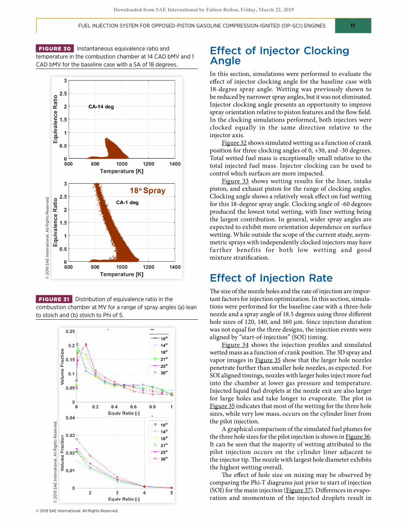
The simulation results can also be used to study the influ-ence of nozzle design on fuel stratification. Figure 30 shows an evaluation of fuel-mixing as illustrated using Phi-T plots. The injection and mixing processes are time dependent so the Phi-T plot is constantly changing. This snapshot depicts the state of the mixture at 14 CAD and 1 CAD bMV.
The upper graph in Figure 30 shows that for the pilot injection there is a significant amount of the chamber volume at low equivalence ratio Phi< 0.1 and some stratified up to Phi 0.75. The temperature range is about 750 - 1050 K. This indi-cates that the pilot fuel does not become homogenous in the short amount of time between the pilot and main injections. The lower graph in Figure 30 shows the Phi-T distribution midway during the main injection. Gas temperature has increased due to piston compression.
At the MV position for the range of spray angles simu-lated, the distribution of the fuel is as shown in Figure 31. Overall, the mixtures appear to have similar distribution with some dependence on spray angle.
These simulation results provide insight into the effect of spray angle on the injection and mixing processes, and demonstrate how injectors with nozzle spray angles in the range of 10 to 30 degrees behave at this operating condition. It has been shown that nozzles with a spray angle of 10 to 18 degrees are similar in wetting propensity. Nozzles with sprays narrower than 18 degrees show significantly reduced wetting but not zero for this operating condition. Nozzles with wider sprays are very prone to wetting of piston surfaces.
FIGURE 28 Timing and mass of liquid fuel wetting on chamber surfaces for the baseline case with SA equal 25 degrees.
© 2
019
SA
E In
tern
atio
nal.
All
Rig
hts
Res
erve
d.
FIGURE 29 Simulated mass of liquid fuel as a percentage of total injected fuel that impinged on combustion chamber surfaces for various spray angles.
© 2
019
SA
E In
tern
atio
nal.
All
Rig
hts
Res
erve
d.
Downloaded from SAE International by Fabien Redon, Friday, March 22, 2019
© 2019 SAE International. All Rights Reserved.
FUEL INJECTION SYSTEM FOR OPPOSED-PISTON GASOLINE COMPRESSION-IGNITED (OP-GCI) ENGINES 11
Effect of Injector Clocking AngleIn this section, simulations were performed to evaluate the effect of injector clocking angle for the baseline case with 18-degree spray angle. Wetting was previously shown to be reduced by narrower spray angles, but it was not eliminated. Injector clocking angle presents an opportunity to improve spray orientation relative to piston features and the flow field. In the clocking simulations performed, both injectors were clocked equally in the same direction relative to the injector axis.
Figure 32 shows simulated wetting as a function of crank position for three clocking angles of 0, +30, and -30 degrees. Total wetted fuel mass is exceptionally small relative to the total injected fuel mass. Injector clocking can be used to control which surfaces are more impacted.
Figure 33 shows wetting results for the liner, intake piston, and exhaust piston for the range of clocking angles. Clocking angle shows a relatively weak effect on fuel wetting for this 18-degree spray angle. Clocking angle of -60 degrees produced the lowest total wetting, with liner wetting being the largest contribution. In general, wider spray angles are expected to exhibit more orientation dependence on surface wetting. While outside the scope of the current study, asym-metric sprays with independently clocked injectors may have further benef its for both low wetting and good mixture stratification.
Effect of Injection RateThe size of the nozzle holes and the rate of injection are impor-tant factors for injection optimization. In this section, simula-tions were performed for the baseline case with a three-hole nozzle and a spray angle of 18.5 degrees using three different hole sizes of 120, 140, and 160 μm. Since injection duration was not equal for the three designs, the injection events were aligned by “start-of-injection” (SOI) timing.
Figure 34 shows the injection profiles and simulated wetted mass as a function of crank position. The 3D spray and vapor images in Figure 35 show that the larger hole nozzles penetrate further than smaller hole nozzles, as expected. For SOI aligned timings, nozzles with larger holes inject more fuel into the chamber at lower gas pressure and temperature. Injected liquid fuel droplets at the nozzle exit are also larger for large holes and take longer to evaporate. The plot in Figure 35 indicates that most of the wetting for the three hole sizes, while very low mass, occurs on the cylinder liner from the pilot injection.
A graphical comparison of the simulated fuel plumes for the three hole sizes for the pilot injection is shown in Figure 36. It can be seen that the majority of wetting attributed to the pilot injection occurs on the cylinder liner adjacent to the injector tip. The nozzle with largest hole diameter exhibits the highest wetting overall.
The effect of hole size on mixing may be observed by comparing the Phi-T diagrams just prior to start of injection (SOI) for the main injection (Figure 37). Differences in evapo-ration and momentum of the injected droplets result in
FIGURE 30 Instantaneous equivalence ratio and temperature in the combustion chamber at 14 CAD bMV and 1 CAD bMV for the baseline case with a SA of 18 degrees.
© 2
019
SA
E In
tern
atio
nal.
All
Rig
hts
Res
erve
d.
FIGURE 31 Distribution of equivalence ratio in the combustion chamber at MV for a range of spray angles (a) lean to stoich and (b) stoich to Phi of 5.
© 2
019
SA
E In
tern
atio
nal.
All
Rig
hts
Res
erve
d.
Downloaded from SAE International by Fabien Redon, Friday, March 22, 2019

© 2019 SAE International. All Rights Reserved.
FUEL INJECTION SYSTEM FOR OPPOSED-PISTON GASOLINE COMPRESSION-IGNITED (OP-GCI) ENGINES 12
mixture differences. The differences in mixing are subtle and all three sprays appear capable of delivering fuel mixtures that are expected to provide acceptable combustion.
Overall, the CFD results shown illustrate how three key nozzle design variables: spray angle, injector clocking angle, and nozzle hole diameter affect fuel mixing and chamber wetting in an opposed- piston engine. Among the sprays studied using CFD analysis, generally, fast vaporization, low
wetting, good mixing, and good air utilization can be achieved. Recommended spray angles are in the 14-18-degree range, with clocking index of -60 degrees, and hole diameter of 140 um. These simulations provide insight into the complex injection and mixing processes and when combined with experiment, are a guide in the optimization of the FIE system.
FIGURE 33 Total mass of liquid fuel impinged on combustion chamber surfaces for range of clocking orientations for a spray angle of 18 degrees.
© 2
019
SA
E In
tern
atio
nal.
All
Rig
hts
Res
erve
d.
FIGURE 34 Comparison of injection profiles for the baseline case with three hole diameters of 120, 140, and 160 μm.
© 2
019
SA
E In
tern
atio
nal.
All
Rig
hts
Res
erve
d.
FIGURE 32 Timing and mass of fuel wetting on chamber surfaces for three clocking angles of 0, +30, and -30 degrees for the baseline case.
© 2
019
SA
E In
tern
atio
nal.
All
Rig
hts
Res
erve
d.
Downloaded from SAE International by Fabien Redon, Friday, March 22, 2019

© 2019 SAE International. All Rights Reserved.
FUEL INJECTION SYSTEM FOR OPPOSED-PISTON GASOLINE COMPRESSION-IGNITED (OP-GCI) ENGINES 13
Summary and ConclusionsAn advanced FIE system has been developed for the Achates 2.7L, 3-cylinder OP-GCI engine. The system features two diametrically-opposed injectors in each cylinder. The system enables partially-premixed compression ignition using US E10 pump gasoline for high fuel efficiency and low emissions.
A high-performance injector based on solenoid tech-nology was developed for 1800 bar injection pressure with
FIGURE 35 3D spray and vapor images at 36 CAD bMV and wetted fuel mass for the baseline case with three hole diameters of 120, 140, and 160 μm.
© 2
019
SA
E In
tern
atio
nal.
All
Rig
hts
Res
erve
d.
FIGURE 36 Mass of liquid fuel impinged on chamber surfaces by the pilot injection for the baseline case for hole diameters of 120, 140, and 160μm.
© 2
019
SA
E In
tern
atio
nal.
All
Rig
hts
Res
erve
d.
FIGURE 37 Temperature and equivalence ratio plot of pilot injected fuel for three nozzle hole diameters at start of main injection pulse, 14 CAD bMV
© 2
019
SA
E In
tern
atio
nal.
All
Rig
hts
Res
erve
d.
Downloaded from SAE International by Fabien Redon, Friday, March 22, 2019

© 2019 SAE International. All Rights Reserved.
FUEL INJECTION SYSTEM FOR OPPOSED-PISTON GASOLINE COMPRESSION-IGNITED (OP-GCI) ENGINES 14
very low back leak. The injector has short overall length for good on-engine packaging. The nozzle features a 3-hole design with narrow spray angle.
A compact, low cost, efficient unit pump with oil lubrica-tion was adapted for use with E10 gasoline. Two pumps were integrated on the engine front cover and driven by the intake crankshaft.
While not previously validated on gasoline fuel, a prelimi-nary 500-hour durability test was conducted on the FIE system without use of fuel additives. Injectors and pumps showed no indication of deterioration in this preliminary test.
CFD tools were used to study the effect of injector spray angle, injector clocking angle, and nozzle hole diameter on fuel mixing and chamber wetting. Among the sprays studied, results showed that fast vaporization, low wetting, good mixing, and good air utilization can be achieved. These simu-lations provide insight into the complex injection and mixing processes, and when combined with experiment, are a guide for optimization of the FIE and combustion systems.
References 1. Pirault, J.P. and Flint, M., Opposed Piston Engines -
Evolution, Use, and Future Applications, No. R-378 (Warrandale, SAE International Publication, 2010).
2. Fuqua, K., Redon, F., Shen, H., and Wahl, M., “Fuel Injection Spray Patterns for Opposed-Piston Engines,” US Patent Application US2012073541, US Patent and Trademark Office, 2012.
3. Redon, F., Kalebjian, C., Kessler, J., Rakovec, N. et al., “Meeting Stringent 2025 Emissions and Fuel Efficiency Regulations with an Opposed-Piston, Light-Duty Diesel Engine,” SAE Paper 2014-01-1187, 2014, doi:10.4271/2014-01-1187.
4. Sellnau, M., Foster, M., Moore, W., Sinnamon, J. et al., “Pathway to 50% Brake Thermal Efficiency Using Gasoline Direct Injection Compression Ignition,” SAE Paper 2019-01-1154, 2019.
5. Green Car Congress, “Achates OP-GCI Project Targeting 50% Fuel Efficiency Gains Over Downsized GDI Engines at Reduced Cost,” Dec. 17, 2015.
6. Dingle, P., “Fuel Injection Equipment,” UK Patent Application GB 2530761 A, Filed Jan. 10, 2014.
7. Beduneau, JL., Bercher, P., Cardon, C. Meissonnier, G. et al., ‘Delphi New Diesel Common Rail Injector Family,’ in SIA Powertrain Conference, Rouen, FR, 2014.
8. Beduneau, J-L., Cardon, C., Meissonnier, G., Bona, M. et al., “Delphi New Diesel Common Rail System Family,” in 2014 Vienna International Symposium.
9. Meissonnier, G., Bercher, P., Bouloc, R., Cardon, C. et al., “Delphi Diesel 2000 Bar Unit Pump Common Rail (UPCR) System,” in 22nd Aachen Colloquium, Aachen, Germany, 2013.
10. Tzanetakis, T., Voice, A., and Traver, M., “Durability Study of a High-Pressure Common Rail Fuel Injection System Using Lubricity Additive Dosed Gasoline-Like Fuel,” SAE Technical Paper 2018-01-0270, 2018, doi:10.4271/2018-01-0270.
11. Salvi, A., Hanson, R., Zermeno, R., Regner, G. et al., “Initial Results on a New Light-Duty 2.7L Opposed-Piston Gasoline Compression Ignition Multi-Cylinder Engine,” in ASME Internal Combustion Engine Fall Technical Conference, Paper ICEF2018-9610, Nov. 4, 2018.
12. CONVERGE Software v2.20, Convergent Science, Inc., Madison, Wisconsin.
Contact InformationMark [email protected]
AcknowledgementsThis work was supported by the US Department of Energy, Advanced Research Projects Agency (ARPA-E) under Award Number DE-AR0000657. The authors thank Chris Atkinson and Gokul Vishwanathan for their support of this program. The authors gratefully acknowledge contributions to this work from program partners Achates Power, Inc. and Argonne National Labs.
At Delphi Technologies, contributions to this work are gratefully acknowledged from Bill Klemm, Paul Ruterbusch, Julien Sabater, Leyla Arslan, Mehmet Donmez, Tony Williams, Paul Lacey, Dan Mellors, Joe Kazour, Allan Wells, Dan Pobuda, Ed Suh, and Jason Short.
The authors thank Philip Dingle (formerly of Delphi Technologies) for useful discussions about injection systems for diesel and opposed-piston engines. Contributions from and useful discussions with Steve Ciatti (formerly of Argonne National Labs) are also acknowledged.
The authors also thank Tom Tzanetakis at Aramco Services Company-Detroit and Patrick Tirbs at IAV GmbH for their support conducting the FIE durability tests.
Definitions/AbbreviationsaMV - After Minimum VolumeB - Bore Diameter (mm)bMV - Before Minimum VolumeBTE - Brake Thermal EfficiencyCAD - Crank Angle DegreesCFD - Computational Fluid DynamicsCV - Control ValveDUP - Diesel Unit PumpE10 - Gasoline with 10% EthanolECU - ECUEPO - Exhaust Port OpeningFIE - Fuel Injection EquipmentGDCI - Gasoline Direct Injection Compression IgnitionGDi - Gasoline Direction InjectionHP - High PressureHPV - High Pressure Valve
Downloaded from SAE International by Fabien Redon, Friday, March 22, 2019

© 2019 SAE International. All rights reserved. No part of this publication may be reproduced, stored in a retrieval system, or transmitted, in any form or by any means, electronic, mechanical, photocopying, recording, or otherwise, without the prior written permission of SAE International.
Positions and opinions advanced in this work are those of the author(s) and not necessarily those of SAE International. Responsibility for the content of the work lies solely with the author(s).
ISSN 0148-7191
FUEL INJECTION SYSTEM FOR OPPOSED-PISTON GASOLINE COMPRESSION-IGNITED (OP-GCI) ENGINES 15
IMEP - Indicated Mean Effective PressureIMV - Inlet Metering ValveIPC - Intake Port ClosingLP - Low PressureLSL - Lower Specification LimitL/D - Length over DiameterMOP - Maximum Operating PressureMV - Minimum VolumeOP-GCI - Opposed Piston Gasoline Compression IgnitionPhi - Equivalence Ratio
Pinj - Injection PressurePLN - Pump Line NozzlePPCI - Partially Premixed Compression IgnitionPWM - Pulse Width ModulatedRON - Research Octane NumberRPS - Rail Pressure SensorSOI - Start of InjectionULSD - Ultra Low Sulfur DieselUSL - Upper Specification LimitUS - United States
Downloaded from SAE International by Fabien Redon, Friday, March 22, 2019