ARIEL - Heavy Duty Balanced Opposed Compressors - Tulsa ...
178
ARIEL Heavy Duty Balanced Opposed Compressors TECHNICAL MANUAL For Models: JGM, JGN, JGP and JGQ; and JGI Vertical Non-Balanced ARIEL CORPORATION 35 BLACKJACK ROAD, MOUNT VERNON, OHIO 43050 TELEPHONE: 740-397-0311 FAX: 740-397-3856 VISIT OUR WEB SITE: www.arielcorp.com REV: 1/99
-
Upload
khangminh22 -
Category
Documents
-
view
3 -
download
0
Transcript of ARIEL - Heavy Duty Balanced Opposed Compressors - Tulsa ...

ARIELHeavy Duty
Balanced OpposedCompressors
TECHNICAL MANUALFor Models:
JGM, JGN, JGP and JGQ;and JGI Vertical Non-Balanced
ARIEL CORPORATION35 BLACKJACK ROAD, MOUNT VERNON, OHIO 43050
TELEPHONE: 740-397-0311 FAX: 740-397-3856VISIT OUR WEB SITE: www.arielcorp.com
REV: 1/99

THIS PAGE LEFT INTENTIONALLY BLANK

WHEN THIS SYMBOL APPEARS ON THE COMPRESSOR OR CON-TROL PANEL, THIS TECHNICAL MANUAL IS TO BE CONSULTED FOR SPECIFIC INFORMATION BEFORE PROCEEDING. IF MORE INFORMATION IS NEEDED CONTACT YOUR PACKAGER AND/OR ARIEL CORPORATION.
CAUTIONGAS COMPRESSOR UNITS ARE COMPLICATED AND DANGEROUS PIECES OF EQUIPMENT, IF YOU ARE NOT FULLY TRAINED AND FAMILIAR WITH THEIR OPERATION.
BEFORE STARTING THIS UNIT:
FAMILIARIZE YOURSELF WITH THE UNIT.
READ AND STUDY START-UP AND SHUT-DOWN INFORMATION FOR BOTH PACKAGE AND COMPRESSOR CAREFULLY!
A GAS/AIR MIXTURE UNDER PRESSURE CAN EXPLODE! YOU CAN BE SEVERELY INJURED OR KILLED. MAKE SURE THE COMPRESSOR IS SUFFICIENTLY PURGED OF ANY EXPLOSIVE MIXTURE BEFORE LOADING.
AFTER COMPLETING THE ABOVE, BEGIN PROPER STARTING PROCEDURE.
CAUTIONDO NOT ATTEMPT TO START-UP UNIT WITHOUT REFERRING TO THIS MANUAL SECTION 1 -“START UP”. IT IS ALSO ESSENTIAL TO REFER TO THE PACKAGER’S OPERATING MANUAL.
CAUTIONTHIS MANUAL EDITION IS BASED ON THE CURRENT DESIGN AND BUILD PRACTICES. THIS MANUAL MAY NOT BE APPLICABLE TO EQUIPMENT BUILT PRIOR TO THE DATE ON FRONT COVER AND IS SUBJECT TO CHANGE WITHOUT NOTICE. CONTACT ARIEL WITH ANY QUESTIONS. REFER TO LAST PAGE OF THIS MANUAL FOR CONTACT INFORMATION.
!
!
!

THIS PAGE LEFT INTENTIONALLY BLANK

FOR MODELS: JGI, JGM, JGN, JGP AND JGQ TABLE OF CONTENTS
TABLE OF CONTENTS
Design Specifications & Data ........................................................... 1-1General ................................................................................................................... 1-1Specifications ......................................................................................................... 1-3Opposed Throw - Reciprocating Weight Balancing ................................................ 1-5Product Information and Safety Plates ................................................................... 1-6
Important Safety & Data Information ................................................................. 1-7Clearances ........................................................................................................... 1-10
Piston Ring and Packing Ring Side Clearance, Inches (mm) ......................... 1-11Fastener Tightening Torque ................................................................................. 1-15
Tightening Torque Procedures ........................................................................ 1-19Ariel Bolting .......................................................................................................... 1-21Zone 1 Environment ............................................................................................. 1-21
Installation ........................................................................................... 2-1The Skid or Package ......................................................................................... 2-1Lifting the Compressor ...................................................................................... 2-1Setting the Compressor .................................................................................... 2-2Leveling Limits for Compressors ....................................................................... 2-3Aligning Main Bearing Bores ............................................................................. 2-3Alignment - to Driver ......................................................................................... 2-6Electrical Grounding ........................................................................................ 2-11Pneumatically Actuated Unloaders & Clearance Devices ............................... 2-11Vents and Drains ............................................................................................. 2-11BICERA Type Crankcase Over-Pressure Relief Valves ................................. 2-12
Start Up ............................................................................................... 3-1General ................................................................................................................... 3-1Start Up Check List ................................................................................................. 3-1
Warranty Notification - Installation List Data and Start Up Check Lists for JG:A:M:N:P:Q:R:J:H:E:K:T:C:D Reciprocating Compressors ........................... 3-2
Maximum Allowable Working Pressure ................................................................ 3-10Relief Valve Settings ............................................................................................ 3-11Filling Sump & Priming a Main Oil Lube Oil System - Before Starting ................. 3-11
Filling The Sump ............................................................................................. 3-11Priming - Main Lube Oil System ...................................................................... 3-12
Compressor Prelube ............................................................................................. 3-12Force Feed Lubricator Adjustment ....................................................................... 3-12Compressor Re-Application .................................................................................. 3-12
Lubrication ......................................................................................... 4-1General ................................................................................................................... 4-1Lubrication Functions ............................................................................................. 4-1
9/08 i

FOR MODELS: JGI, JGM, JGN, JGP AND JGQ TABLE OF CONTENTS
Lubricant Characteristics ........................................................................................4-2Viscosity ............................................................................................................4-2Viscosity Index ...................................................................................................4-3Pour Point ..........................................................................................................4-3Flash Point .........................................................................................................4-3
Lubricant Base Stock ..............................................................................................4-3Petroleum-Based Lubricants (also referred to as mineral oils) ..........................4-3Synthetic Lubricants ..........................................................................................4-4
Lubricant Formulations ...........................................................................................4-5Compounded Cylinder Oils ................................................................................4-5R&O Oil .............................................................................................................4-5Engine Oil ..........................................................................................................4-5Used Engine Oil .................................................................................................4-6Gear Oil .............................................................................................................4-6
FRAME OIL SYSTEM .............................................................................................4-7COMPONENTS .................................................................................................4-7Oil Strainer .........................................................................................................4-7Oil Pump ............................................................................................................4-7Oil Cooler ...........................................................................................................4-7Oil Temperature Control Valve ..........................................................................4-8Oil Filtration .......................................................................................................4-8Compressor Prelube Pump ...............................................................................4-9Oil Heaters .........................................................................................................4-9Lube Oil Analysis Sampling Point ....................................................................4-10Cold Starting ....................................................................................................4-11Dry Sump .........................................................................................................4-12
FRAME OIL OPERATING CONDITIONS .............................................................4-13Compressor Frame Lubricant ..........................................................................4-13Oil Viscosity .....................................................................................................4-14Oil Pressure .....................................................................................................4-14Oil Temperature ...............................................................................................4-14Oil Maintenance ...............................................................................................4-15Oil Sampling ....................................................................................................4-15
Oil System Cleanliness .........................................................................................4-15Cylinder and Packing Lubrication .........................................................................4-17
Independent Force Feed Lubricator Systems .................................................4-17Common Oil Supply .........................................................................................4-17Independent Oil Supply ...................................................................................4-18
Force Feed Lubrication System Components .......................................................4-18Gas Inlet Debris Screens to Maintain Lube Performance ...............................4-18Injection Oil Inlet Filter .....................................................................................4-19Oil Dilution .......................................................................................................4-19Cylinder Oil Lubrication Examples ...................................................................4-19Under/Over Lube .............................................................................................4-19Inadequate Lubrication Symptoms ..................................................................4-20Lubrication Quantity - Paper Test Method .......................................................4-20Lubricator Cycle Time ......................................................................................4-20Cycle Time Indication ......................................................................................4-21Force Feed Lubrication System Monitoring: ....................................................4-21
ii 9/08

FOR MODELS: JGI, JGM, JGN, JGP AND JGQ TABLE OF CONTENTS
Minimum Requirements .................................................................................. 4-21Devices ........................................................................................................... 4-21Choosing a Lube System Monitor ................................................................... 4-22Break-in Rate .................................................................................................. 4-25Liquids in Gas ................................................................................................. 4-25Lube Type & Rate Recommendations ............................................................ 4-26RATE CALCULATION NOTES ....................................................................... 4-28
Water-Cooled Packing .......................................................................................... 4-30Coolant System Requirements ....................................................................... 4-31
Force Feed Lubrication System - Description ...................................................... 4-31Force Feed Lubricator Adjustment .................................................................. 4-32Blow-Out Fittings, Rupture Disks and Tubing ................................................. 4-32Divider Valves ................................................................................................. 4-34Description ...................................................................................................... 4-34
Divider Valve Block Assembly Instructions ........................................................... 4-35Operation - (see Figure 4-13 and Figure 4-14) ............................................... 4-35Pressure Testing For Divider Valve By-Passing ............................................. 4-38
Electronic Lubricator Fluid-Flow Monitor/No-Flow Timer Switch - Proflo PF1 ...... 4-39Proflo PF1 Monitor wiring identification and instructions for electronic indication: 4-40Proflo PF1 Button Operation: .......................................................................... 4-41Downloading Proflo PF1 Data: ........................................................................ 4-41Proflo PF1 Setup Alarm Time and Mode: ....................................................... 4-42Proflo PF1 Battery Replacement: .................................................................... 4-43Proflo PF1 Display Errors: ............................................................................... 4-44Proflo PF1 Operation Notes: ........................................................................... 4-45Proflo Normally Open and Normally Closed Definition: .................................. 4-46Proflo PF1 - Using Pulse Output and Alarm Circuit at Same Time: ................ 4-47Proflo PF1 - Using PLC to Calculate Oil Consumption: .................................. 4-48Proflo PF1 Accessories Available: .................................................................. 4-49
Protection of Electronics & the Compressor When Arc Welding .......................... 4-49Electronic-Lubricator Digital No-Flow Timer Switch (DNFT) ................................ 4-49
Replacing the (Field-Replaceable) Battery in the DNFT: ................................ 4-50Oil Head at Lube Points ........................................................................................ 4-51Force Feed Lubrication System and Running Conditions .................................... 4-51
Force Feed Lubrication System ...................................................................... 4-51Running Conditions ......................................................................................... 4-52System Design Considerations and Operating Parameters ............................ 4-52
Force Feed Balance Valves ................................................................................. 4-52Setting and Maintaining Balance Valves ......................................................... 4-52Checking/Adjusting Balance Valves on Subsequent Start-up ......................... 4-53
Frame Lubricating System - Description .............................................................. 4-54Lube Oil Strainer, Filter & Filter Installation Instructions ....................................... 4-54
Lube Oil Strainer ............................................................................................. 4-54Lube Oil Filter .................................................................................................. 4-55Oil Filter Installation for Spin-On Type Filters ................................................. 4-55Oil Filter Element Installation for Cartridge Type Filters .................................. 4-55
Lube Oil Pump & Lube Oil Pressure ..................................................................... 4-57Description & Adjustment ................................................................................ 4-57Lube Oil Pressure Regulating Valve ............................................................... 4-57
9/08 iii

FOR MODELS: JGI, JGM, JGN, JGP AND JGQ TABLE OF CONTENTS
Low Oil Pressure Shutdown ..................................................................................4-58
Maintenance ....................................................................................... 5-1General Introduction ...............................................................................................5-1
Compressor Components ..................................................................................5-3Positioning a Throw for Maintenance ......................................................................5-3Connecting Rod ......................................................................................................5-4
Connecting Rod (Crank Pin) Bearing ................................................................5-4Connecting Rod - Removal ...............................................................................5-6Connecting Rod Bushing Replacement .............................................................5-7Connecting Rod - Installation ............................................................................5-8
Crosshead............................................................................................................. 5-11Crosshead - Removal ......................................................................................5-11Crosshead - Installation ...................................................................................5-13
Crankshaft .............................................................................................................5-14Main Bearings - Checking Clearances ............................................................5-14Crankshaft - Removal ......................................................................................5-17Oil Slinger - Removal .......................................................................................5-18Oil Slinger - Installation ....................................................................................5-18Chain Sprocket - Removal ...............................................................................5-18Chain Sprocket - Installation ............................................................................5-19Fan Shaft Assembly Procedure .......................................................................5-19Main Bearings - Removal and Installation w/Crankshaft Removed .................5-20Main Bearings - Removal and Installation w/Crankshaft In Place ...................5-21
Crankshaft - Installation ........................................................................................5-22Chain Drive System ..............................................................................................5-23
Description .......................................................................................................5-23Chain Adjustment ............................................................................................5-24Chain and Sprocket Replacement ...................................................................5-24Chain Idler Sprocket Replacement - (Eccentric Adjustment Cap) ...................5-25Lube Oil Pump Chain Sprocket Replacement .................................................5-25Force Feed Lubricator Chain Sprocket Replacement .....................................5-26
Piston and Rod .....................................................................................................5-27Piston and Rod - Removal ...............................................................................5-27Piston and Rod Disassembly ...........................................................................5-28Piston and Rod Reassembly ...........................................................................5-29Piston and Rod - Installation ............................................................................5-30
Piston Rod Run Out ..............................................................................................5-31Piston Rings ..........................................................................................................5-32
Determining Ring Wear: ..................................................................................5-32Removal: .........................................................................................................5-32Piston Rings - Installation ................................................................................5-32
Wear Bands ..........................................................................................................5-32Determining Wear Band Wear: ........................................................................5-33Wear Band - Installation ..................................................................................5-33
Piston Rod Pressure Packing - Removal ..............................................................5-33Piston Rod Packing - Reassembly ........................................................................5-34Types of Piston Rod Packing Rings ......................................................................5-35
iv 9/08

FOR MODELS: JGI, JGM, JGN, JGP AND JGQ TABLE OF CONTENTS
Type "P" Pressure Breaker ............................................................................. 5-35Type "BTR" Single Acting Seal Set ................................................................. 5-36Type “AL” Double Acting Seal Set .................................................................. 5-36Type "BD" Double Acting Seal Set .................................................................. 5-36Type "3RWS" Oil Wiper Set ............................................................................ 5-37
Typical Arrangement of Piston Rod Packing Rings .............................................. 5-37Piston Rod Packing Ring Material ........................................................................ 5-37Water-Cooled Piston Rod Packing ....................................................................... 5-38
Reassembly .................................................................................................... 5-38Testing ............................................................................................................ 5-38
Valves ................................................................................................................... 5-39Valves - Removal ............................................................................................ 5-39Valves - Maintenance ...................................................................................... 5-40Valves - Reassembly ...................................................................................... 5-41
Bolt Tightening for Valve Caps ............................................................................. 5-42VVCP - Head-End Variable Volume Clearance Pocket ........................................ 5-43
VVCP - Removal ............................................................................................. 5-44VVCP - Disassembly ....................................................................................... 5-44VVCP - Maintenance ....................................................................................... 5-45VVCP - Adjustment ......................................................................................... 5-45
Compressor Cylinder Re-Boring & Bore Restoration Guidelines ......................... 5-46Ethylene Glycol Contamination ............................................................................ 5-47
Technical Assistance ........................................................................ 6-1Recommended Maintenance Intervals ................................................................... 6-1
Daily .................................................................................................................. 6-1Monthly (in addition to Daily Requirements) ..................................................... 6-2Every 6 Months or 4000 Hours (plus Daily/Monthly) ......................................... 6-3Yearly or 8000 Hours (plus Daily/Monthly/6 Months) ........................................ 6-3Every 2 Years or 16,000 Hours (plus Daily/Monthly/6 Months/Yearly) ............. 6-4Every 4 Years or 32,000 Hours (plus Daily/Monthly/6 Months/1 & 2 Years) ..... 6-4Every 6 Years or 48,000 hours (plus Daily/Monthly/6 Months/1, 2 & 4 Years) . 6-5
Trouble Shooting .................................................................................................... 6-5
Appendices ......................................................................................... 7-1Ariel Tools ............................................................................................................... 7-1
Ariel Furnished Tools ........................................................................................ 7-1Ariel Tools - Purchased Separately From Authorized Dealer ........................... 7-3
Minimum Hand & Commercial Tools Required ...................................................... 7-3Gas Analysis Common Abbreviations .................................................................... 7-7Technical and Service Schools on Ariel Compressors ........................................... 7-7Ariel Customer Technical Bulletins ......................................................................... 7-8Vendor Literature .................................................................................................... 7-8Ariel Contact Information ........................................................................................ 7-8
9/08 v

FOR MODELS: JGI, JGM, JGN, JGP AND JGQ TABLE OF CONTENTS
vi 9/08

FOR MODELS: JGI, JGM, JGN, JGP AND JGQ
SECTION 1 - DESIGN SPECIFICATIONS & DATA
GeneralAriel compressors are designed for ease of operation and maintenance. Experience has shown that an Ariel compressor will normally provide years of satisfactory performance with minimal maintenance.
While Ariel compressors share many similarities, each model has aspects that are unique to the particular type. If you as an operator are familiar with Ariel compressors, it is still impor-tant to review this manual to determine the differences. If you are new to Ariel compressors it is critical that you become very familiar with this manual prior to operating the compressor.
This manual is designed to provide information on installation, start up, operation and main-tenance of a JGI, JGM, JGN, JGP or JGQ compressor. If you have any questions please contact your Packager. If they are unable to provide resolution, they will refer your concerns to Ariel Corporation. If you prefer, you may always contact Ariel directly. Contact your Pack-ager or the Ariel Response Center for detailed information. Refer to the last page of this manual for contact information.
This manual provides design specifications for standard current production equipment at publication date. Do not exceed data plates ratings for a particular compressor.
The location of the throws and the information shown on the Data Plates is very important when communicating questions concerning an Ariel compressor.
FIGURE 1-1 TYPICAL COMPRESSOR THROW NUMBERING AND FRAME DATA PLATE LOCATION - JGM:N:N:Q/1 THROW (TOP VIEW)
Auxiliary End
Engine/Motor Drive End
Throw #1
Frame Data Plate
JGM/1, JGN/1, JGP/1 & JGQ/1
Oil Filter
Breather
Lifting Eye Bolts
9/08 PAGE 1-1
FOR MODELS: JGI, JGM, JGN, JGP AND JGQ SECTION 1 - DESIGN SPECIFICATIONS & DATA
FIGURE 1-2 TYPICAL COMPRESSOR THROW NUMBERING AND FRAME DATA PLATE LOCATION - JGM:N:P:Q/2 THROW (TOP VIEW)
FIGURE 1-3 COMPRESSOR THROW NUMBERING AND FRAME DATA PLATE LOCATION JGI/1 THROW - VERTICAL NON-BALANCED COMPRESSOR (SIDE VIEW)
Engine/Motor Drive End
Throw #2
Throw #1
Frame Data/ Information Plate
Auxiliary EndJGM/2, JGN/2, JGP/2 & JGQ/2
Oil FilterBreather
Lifting Eye Bolts
Engine/Motor Drive End (Reverse Rotation from JGM:N:P:Q)
Throw #1
Lift Frame Here using Two 3/4”-10 Forged Steel Eye Bolts Furnished By Ariel
Frame Data/Information Plate is Located on Opposite Side
Caution Plates
PAGE 1-2 9/08

FOR MODELS: JGI, JGM, JGN, JGP AND JGQ SECTION 1 - DESIGN SPECIFICATIONS & DATA
SpecificationsTABLE 1-1 JGI, JGM & JGP FRAME SPECIFICATIONS
MODELa
a. For more information, refer to the Electronic Data, available in the Ariel Performance Program.
JGI/1 JGM/1 JGM/2 JGP/1 JGP/2Stroke, in. (mm) 3-1/2 (89) 3-1/2 (89) 3-1/2 (89) 3 (76) 3 (76)
Maximum Allowable Speedb, RPM
b. Maximum allowable speed is the highest (potential) speed at which the compressor frame design will permit continuous operation. Compressor frame data plate "Frame Rated Speed (RPM)" is application specific, and may be lower than Maximum Allowable Speed. The lower of the Frame Rated Speed, lowest cylinder rated (RPM) or driver rated speeds is not to be exceeded. If a JGI is to be run at higher speeds, the skid must have adequate mass for the vertical forces.
800 1500 1500 1800 1800
Minimum Speedc, RPM
c. Minimum Speed is the minimum frame speed to provide adequate oil flow to the compressor bear-ings.
400 750 750 900 900
Average Piston Speedd, FPM (m/s)
d. Average piston speed as is based on the maximum allowable speed (RPM) of the frame. The cylin-der data-plate rated speed (RPM) or frame rated speed may be less, resulting in a lower piston speed rating.
To 467 (2.37)
To 875 (4.45)
To 875 (4.45)
To 900 (4.57)
To 900 (4.57)
Number of Throws 1 1 2 1 2Horsepower, to hp (kW) 55 (41) 84 (63) 168 (125) 85 (63) 170 (127)Height - Bottom to Crankshaft Cen-terline, in. (mm)
10.250 (260.35)
9.250 (234.95)
9.250 (234.95)
9.250 (234.95)
9.250 (234.95)
Connecting Rod Centerline To Centerline, in. (mm)
8.250 (209.55)
8.250 (209.55)
8.250 (209.55)
8.250 (209.55)
8.250 (209.55)
Maximum Width with Cylinders, in. (m)
26 (0.66)
62 (1.58)
83 (2.11)
62 (1.58)
83 (2.11)
Maximum Length, in. (m) 31 (0.79) 35 (0.89) 35 (0.89) 35 (0.89) 35 (0.89)
Overall Height, in. (m) 53 (1.35) w/cylinder 17 (0.43) To Top of Aluminum Cover
Approximate Weight with Cylinders, lb. (kg)
1300 (590)
1400 (640)
2000 (900)
1400 (640)
2000 (900)
Oil Pump Flow Ratee, GPM (L/s)
e. Flow rate is based on the maximum allowable frame speed rating and 180°F (82°C) oil.
4 (0.25) 4 (0.25) 4 (0.25) 5 (0.32) 5 (0.32)
Oil Heat Rejection, BTU/hr (kW) 5600 (1.6) 8400 (2.5) 8400 (2.5) 16,800 (4.9) 16,800 (4.9)Sump Capacity, US gallons (L) 4 (15) 2.5 (9) 2.5 (9) 2.5 (9) 2.5 (9)Piston Rod Diameter, in. (mm) 1.125 (28.58)
Internal Rod Load - Double Acting:Compression + Tension, lbf (kN) 12,000 (53) 12,000 (53) 12,000 (53) 12,000 (53) 12,000 (53)
Tension, lbf (kN) 6000 (27) 6000 (27) 6000 (27) 6000 (27) 6000 (27)
Compression, lbf (kN) 7000 (31) 7000 (31) 7000 (31) 7000 (31) 7000 (31)
Internal Rod Load - Single Acting:Tension, lbf (kN) 6000 (27) 6000 (27) 6000 (27) 6000 (27) 6000 (27)
9/08 PAGE 1-3

FOR MODELS: JGI, JGM, JGN, JGP AND JGQ SECTION 1 - DESIGN SPECIFICATIONS & DATA
TABLE 1-2 JGN & JGQ FRAME SPECIFICATIONS
MODELa
a. For more information, refer to the Electronic Data, available in the Ariel Performance Program.
JGN/1 JGN/2 JGQ/1 JGQ/2Stroke, in. (mm) 3-1/2 (89) 3-1/2 (89) 3 (76) 3 (76)
Maximum Allowable Speedb, RPM
b. Maximum allowable speed is the highest (potential) speed at which the compressor frame design will permit continuous operation. Compressor frame data plate "Frame Rated Speed (RPM)" is applica-tion specific, and may be lower than Maximum Allowable Speed. The lower of the Frame Rated Speed, lowest cylinder rated (RPM) or driver rated speeds is not to be exceeded.
1500 1500 1800 1800
Minimum Speedc, RPM
c. Minimum Speed is the minimum frame speed to provide adequate oil flow to the compressor bear-ings.
750 750 900 900
Average Piston Speedd, FPM (m/s)
d. Average piston speed as is based on the maximum allowable speed (RPM) of the frame. The cylinder data-plate rated speed (RPM) or frame rated speed may be less, resulting in a lower piston speed rat-ing.
To 875 (4.45) To 875 (4.45) To 900 (4.57) To 900 (4.57)
Number of Throws 1 2 1 2Horsepower, to hp (kW) 126 (94) 252 (188) 140 (104) 280 (209)Height - Bottom to Crankshaft Center-line, in. (mm) 9.250 (234.95) 9.250 (234.95) 9.250 (234.95) 9.250 (234.95)
Connecting Rod Centerline To Center-line, in. (mm) 8.250 (209.55) 8.250 (209.55) 8.250 (209.55) 8.250 (209.55)
Maximum Width with Cylinders, in. (m)
62 (1.58)
83 (2.11)
62 (1.58)
83 (2.11)
Maximum Length, in. (m) 35 (0.89) 35 (0.89) 35 (0.89) 35 (0.89)Overall Height, in. (m) 17 (0.43) To Top of Aluminum CoverApproximate Weight with Cylinders, lb. (kg)
1400 (640)
2000 (900)
1400 (640)
2000 (900)
Oil Pump Flow Ratee, GPM (L/s)
e. Flow rate is based on the maximum allowable frame speed rating and 180°F (82°C) oil.
4 (0.25) 4 (0.25) 5 (0.32) 5 (0.32)
Oil Heat Rejection, BTU/hr (kW) 8400 (2.5) 8400 (2.5) 16,800 (4.9) 16,800 (4.9)Sump Capacity, US gallons (L) 2.5 (9) 2.5 (9) 2.5 (9) 2.5 (9)Piston Rod Diameter, in. (mm) 1.125 (28.63)
Internal Rod Load - Double Acting:Compression + Tension, lbf (kN) 18,000 (80) 18,000 (80) 20,000 (89) 20,000 (89)
Tension, lbf (kN) 9000 (40) 9000 (40) 10,000 (44) 10,000 (44)
Compression, lbf (kN) 10,000 (44) 10,000 (44) 11,000 (49) 11,000 (49)
Internal Rod Load - Single Acting:Tension, lbf (kN) 9000 (40) 9000 (40) 10,000 (44) 10,000 (44)
PAGE 1-4 9/08
FOR MODELS: JGI, JGM, JGN, JGP AND JGQ SECTION 1 - DESIGN SPECIFICATIONS & DATA
Opposed Throw - Reciprocating Weight BalancingAriel recommends that the reciprocating weight differential between opposing throws be 1.0 pound (0.45 kg) or less for JGM:N:P:Q compressors. JGI compressors are not balanced.
If replacing any major reciprocating component, that is; a connecting rod assembly, piston, piston & rod assembly, crosshead-balance nuts or crosshead, weigh component parts on a calibrated scale to 0.1 pounds (0.05 kg) and compare to the Compressor Balancing Record sheet that comes in the parts manual with each compressor. If there are weight changes, recalculate opposing throw reciprocating weight differentials. If not within the recommended limit, new balance nuts and/or crossheads are to be selected to provide the least possible differential.
If it is desirable to exchange opposing throw compressor cylinder locations, all reciprocating components must be exchanged to the opposite throw, except the connecting rod assemblies. Check the Balancing Record sheet and recalculate reciprocating weight differential, with the connecting rod weights included. If not within the recommended limit, new crosshead-balance nuts are to be selected to provide the least possible differential.
If opposing throws can not be balanced within the recommended reciprocating weight differential limit, contact your packager and/or Ariel. When applying or re-applying a different cylinder to a throw, the opposing throw reciprocating weight differential must be re-calculated and new balance nuts or crossheads may be required. The force feed oil distribution system may also need to be resized.
Contact your Packager or the Ariel Response Center for detailed information, if reciprocating weights change and exceed the recommended reciprocating weight differential between opposing throws, when exchanging opposing throw compressor cylinder locations or when applying or re-applying a different cylinder to a throw. Refer to the last page of this manual for contact information
9/08 PAGE 1-5

FOR MODELS: JGI, JGM, JGN, JGP AND JGQ SECTION 1 - DESIGN SPECIFICATIONS & DATA
Product Information and Safety Plates
FIGURE 1-4 TOP COVER - TYPICAL JGM:N:P:Q
SEVE
RE P
ERSO
NAL I
NJUR
Y AND
PRO
PERT
Y DA
MAGE
WILL
RES
ULT I
F SU
CTIO
N AN
D DI
SCHA
RGE
VALV
ESAR
E NO
T INS
TALL
ED IN
THEI
R PR
OPER
LOCA
TION
.
CAUT
ION
A-04
64
SEVERE PERSONAL INJURY AND PROPERTYDAMAGE CAN RESULT IF PRESSURE SYSTEM ISNOT COMPLETELY VENTED BEFORE LOOSENINGTHE BOLTS ON FLANGES, HEADS, VALVE CAPS,PACKING. CONSULT ARIEL TECHNICAL MANUALBEFORE PERFORMING ANY MAINTENANCE.
CAUTION
A-0463
www.arielcorp.com
ROTATIONA-719
A-07
13FI
LTER
INST
ALLA
TION
INST
RUCT
IONS
(1)
CH
ANG
E FI
LTER
EVE
RY 6
MO
NTHS
- 40
00 H
RS O
R 10
PSI
D (0
.7 B
ARD)
AT
NORM
AL O
PERA
TING
TEM
PERA
TURE
.(2
)
CLEA
N FI
LTER
BAS
E SU
RFAC
E - B
E CE
RTAI
N O
LD G
ASKE
T IS
REM
OVE
D.(3
)
REPL
ACE
ONL
Y W
ITH
AN A
RIEL
OEM
FIL
TER.
(4)
FI
LL F
ILTE
R W
ITH
CLEA
N O
IL -
SAM
E AS
IN T
HE U
NIT
CRAN
KCAS
E.(5
)
APPL
Y CL
EAN
LUBE
OIL
TO
FIL
TER
GAS
KET.
(6)
TI
GHT
EN O
NE T
URN
AFTE
R FI
LTER
GAS
KET
CONT
ACTS
BAS
E.(7
)
AFTE
R ST
ARTI
NG U
NIT,
CHE
CK F
OR
LEAK
S - R
ETIG
HTEN
IF N
ECES
SARY
.
ARIEL CORPORATIONARIEL FRAME MODEL
FRAME SERIAL NUMBERSTROKE*FRAME RATED SPEED (RPM)
MINIMUM SPEED (RPM)MAXIMUM ROD LOAD TENSIONMAXIMUM ROD LOAD COMPRESSIONARIEL SHIPPING DATENORMAL LUBE OIL PRESSURE
MAXIMUM LUBE OIL TEMPERATURELUBE OIL PRESSURESHUTDOWN SETTING
*MAXIMUM UNIT SPEED IS THE LOWER OF FRAME OR CYLINDER RATED SPEED
CONSULT ARIEL TECHNICAL MANUAL BEFOREOPERATING UNIT OR PERFORMING MAINTENANCE.
A-14766
ARIEL LOGO NAME PLATE AND ADDRESS
Aluminum Top Cover
Direction of Rotation Plate, Located At The Drive End - Standard Rotation Shown for JGM:N:P:Q
Manual Lifting Handles
Breather
CAUTION! Severe Personal Injury and Property Damage will Result if Suction and Discharge Valves are not Installed in their Proper Location.
CAUTION! Severe Personal Injury and Property Damage can Result if Pressure System is not Completely Vented Before Loosening Bolts on Flanges, Heads, Valve Caps. Consult Ariel Technical Manual Before Performing any Maintenance.
Filter Installation Instructions: 1. Change Filter every 6 Months - 4000 Hours or
10 psid (1.0 bard) at Normal Operating Temperature.
2. Clean Filter Base Surface - Be Certain Old Gasket is Removed.
3. Replace Only with an Ariel Original Equipment Manufacturer Filter.
4. Fill Filter with Clean Oil - Same as in Unit Crankcase.
5. Apply Clean Lube Oil to Filter Gasket. 6. Tighten One Turn After Filter Gasket
Contacts Base. 7. After Starting Unit, Check for Leaks -
Retighten if necessary.
Ariel Frame Model Number
Stroke of Piston
*Frame Rated Speed (RPM)
Minimum Speed (RPM)Maximum Rod Load TensionMaximum Rod Load CompressionAriel Shipping Date, Month, YearNormal Lube Oil PressureMaximum Lube Oil TemperatureLube Oil Pressure Shutdown Setting
*Maximum Unit Speed is the Lower of Frame or Cylinder Rated Speed
Consult Ariel Technical Manual Before Operating Unit or Performing Maintenance
Frame Serial Number
FRAME DATA/INFORMATION PLATE:
PAGE 1-6 9/08

FOR MODELS: JGI, JGM, JGN, JGP AND JGQ SECTION 1 - DESIGN SPECIFICATIONS & DATA
Important Safety & Data Information
CAUTIONSEVERE PERSONAL INJURY AND PROPERTY DAMAGE CAN RESULT IF PRESSURE SYSTEM IS NOT COMPLETELY VENTED BEFORE LOOSENING THE BOLTS ON FLANGES, HEADS, VALVE CAPS, OR PACKING. CONSULT ARIEL TECHNICAL MANUAL BEFORE PERFORMING ANY MAINTENANCE.
CAUTIONSEVERE PERSONAL INJURY AND PROPERTY DAMAGE WILL RESULT IF SUCTION AND DISCHARGE VALVES ARE NOT INSTALLED IN THEIR PROPER LOCATION.
CAUTIONNOISE GENERATED BY RECIPROCATING MACHINERY CAN BE A SOURCE FOR HEARING INJURY. SEE PACKAGER’S INFORMATION FOR ANY SPECIFIC RECOMMENDATIONS. WEAR HEARING PROTECTION WHEN UNIT IS RUNNING.
CAUTIONHOT (OR COLD) GAS TEMPERATURES ESPECIALLY THE CYLINDER DISCHARGE AREAS, 190°F (88°C) OIL AND HIGH FRICTION AREAS CAN BE A SOURCE FOR BURNS OR FROST BITE. WEAR PROPER INSULATION WHEN WORKING AROUND THESE AREAS. SHUT DOWN UNIT AND ALLOW TO COOL (OR WARM) BEFORE DOING MAINTENANCE IN THESE AREAS.
!
!
!
!
9/08 PAGE 1-7

FOR MODELS: JGI, JGM, JGN, JGP AND JGQ SECTION 1 - DESIGN SPECIFICATIONS & DATA
The Force Feed Lubricator provides oil to the piston rod packing and the compressor pis-tons. The Lubricator Data Plate provides cycle time values and directions for adjusting the pump stroke to control the flow rate of the lube oil and the cycle time. If this plate is missing, please contact Ariel Corporation, Mount Vernon, Ohio for a replacement and specific direc-tions.
NOTE: THE FORCE FEED LUBRICATOR BOX CONTAINS APPROXIMATELY 1/3 GALLON (1L) OF LUBRICANT. LUBE BOX OIL IS FOR LUBRICATING THE INTERNAL PARTS OF THE BOX, AND NOT A SOURCE OF OIL FOR THE FORCE FEED LUBE SYSTEM.
FIGURE 1-1 HOT & COLD SURFACES - CAUTION SYMBOLS
FIGURE 1-5 FORCE FEED LUBRICATOR DATA PLATE - TYPICAL
“Hot Surfaces” “Cold Surfaces”
Where these CAUTION symbols appear on the compressor, the surfaces are hot or cold when compressor is operating and can cause injury if touched without proper insulated protective clothing. If servicing the compressor, allow these surfaces to cool or warm to safe temperatures or wear protective clothing before proceeding. When applied to compressor cylinders, the temperature CAUTION applies to all connected piping and equipment.
DIST. BLK.
INCREASE
PUMP STROKE
A-3854
INDICATORPIN CYCLE TIME
BREAK-IN
NORMAL
SEC
SEC
DIST. BLK.
INCREASE
PUMP STROKE
A-3854
INDICATORPIN CYCLE TIME
BREAK-IN
NORMAL
SEC
SEC
Lubricator Data Plate
Break-In (Cycle Time in) Seconds
Normal (Cycle Time in) Seconds)
Increase Pump Stroke (Turning Plunger Stroke Adjustment Screw Counter-Clockwise Increases Lube Rate and Reduces Cycle Time; Turning Clockwise Reduces Lube Rate and Increases Cycle Time)
Distribution Block (Part Number)
Indicator Pin Cycle Time
Top View
Lubricator Data Plate cycle time values (seconds) are at maximum rated speed. At reduced speeds, the cycle time will increase. See Section 4 for calculating increased cycle times for reduced speeds. If pump stroke/cycle time was properly adjusted at maximum rated speed, little or no adjustment should be required at reduced speeds.
PAGE 1-8 9/08
FOR MODELS: JGI, JGM, JGN, JGP AND JGQ SECTION 1 - DESIGN SPECIFICATIONS & DATA
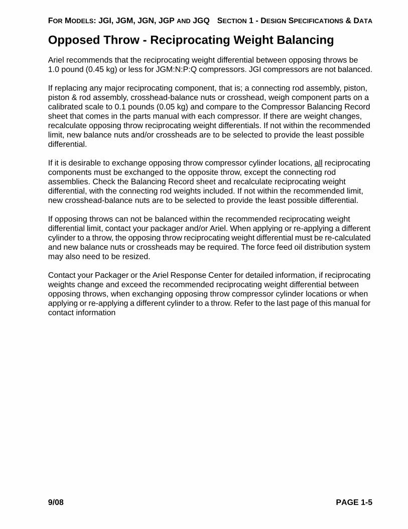
If any plate is missing, please contact Ariel Corporation, Mount Vernon, Ohio for a replace-ment and specific directions.
FIGURE 1-2 IDENTIFICATION PLATE LOCATIONS - COMPRESSOR DRIVE END VIEW
ARIEL CORPORATIONFULLY CLOSED A =
FULLY OPEN A =VVCP S.N.REMOVE ALUMINUM THREAD PROTECTOR WHERE APPLICABLE
A A
A-12927
A-6936
MECHANICAL INSPECTIONJOHN DOE
Variable Volume Clearance Pocket Serial Number
Fully Closed Dimension A, inches or cm
Fully Open Dimension A, inches or cm
Remove aluminum thread protector where applicable
VVCP Instruction Plate
VVCP S.N.BASE VOL.
VVCP MAWP
A-0755
VARIABLE VOL.TOTAL TRAV. TURNSOR
ARIEL CORPORATIONCYL. BORE
BORE
STROKE
PIST. END CL.
MIN. VOL. CL. (%)
CYLINDER SERIAL NO.
HE
HE
CE
CE
CLASS
RATED RPMMAX. ALLOWABLE WORKING PRESS.
(MAX. RELIEF VALVE SETTING)
ARIEL CORPORATION
A-0465
Cylinder Identification/Data Plate
“Suction” Valve Pocket Identification
Plate
“Discharge” Valve Pocket Identification
Plate
Serial number, MAWP, part number, work order number, hydrostatic test pressure, test date, and tester’s personal stamp are stamped on the end of each cylinder.
Customer work order number and hydrotest pressure stamped near VVCP plates on top of VVCP body.
Variable Volume Clearance Pocket Serial Number
Base Volume in cubic in. or cubic cm (with VVCP closed)
Nominal Cylinder Bore diameter, in. or mm
Variable Volume, cubic in. or cubic cm
Total Travel in. or cm, or number of turns
VVCP Maximum Allowable Working Pressure (maximum relief valve setting), pounds per square inch gauge or barg
VVCP - Variable Volume Clearance Pocket Data Plate
Nominal Bore Diameter, in. or mm
Stroke, in. or mm
Piston End Clearance, head end, in. or mm
Cylinder Serial Number
Minimum Volumetric Clearance, head end, percentage
Maximum Allowable Working Pressure (maximum reliefvalve setting), pounds per square inch gauge or barg
Class Rated Revolutions Per Minute
Piston End Clearance, crank end, in. or mm
Minimum Volumetric Clearance, crank end, percentage
Cylinder Identification Plates appear on each cylinder. The serial number is also stamped on the end of each cylinder.
NOTE: USE CYLINDER AND FRAME SERIAL NUMBERS IN ALL CORRESPONDENCE
SUCTIONA-0
640-
A DISCHARGEA-0
640-
B
Frame serial number is stamped on frame machined surface (above Mechanical Inspector’s Plate - this plate is not provided if compressor was mechanically incomplete at factory testing) on drive end, throw #2 side.
9/08 PAGE 1-9

FOR MODELS: JGI, JGM, JGN, JGP AND JGQ SECTION 1 - DESIGN SPECIFICATIONS & DATA
ClearancesTABLE 1-3 CLEARANCES
0.008 to 0.010 (0.20 to 0.25)0.0035 to 0.0110 (0.089 to 0.279)0.0090 to 0.0250 (0.229 to 0.635)0.0005 to 0.0035 (0.013 to 0.089)
0.0015 to 0.0040 (0.038 to 0.102)0.0070 to 0.0160 (0.178 to 0.406)0.0090 to 0.0150 (0.229 to 0.381)0.0014 to 0.0031 (0.036 to 0.079)0.0014 to 0.0036 (0.036 to 0.091)0.0015 to 0.0025 (0.038 to 0.064)0.0015 to 0.0025 (0.038 to 0.064)0.004 to 0.008 (0.10 to 0.20)
0.006 to 0.010 (0.15 to 0.25)
0.006 to 0.010 (0.15 to 0.25)
0.090 to 0.145 (2.29 to 3.68)0.035 (0.89)
0.055 to 0.110 (1.40 to 2.79)0.090 to 0.180 (2.29 to 4.57)
0.035 (0.89)0.055 to 0.145 (1.40 to 3.68)
0.010 (0.25)
NOTE: MEASURED CLEARANCES WILL NOT NECESSARILY AGREE BECAUSE OF OIL FILMS, ASSEMBLY TOLERANCES, WEAR, ETC. PLASTIGAGES, SOL-DER, ETC. ARE NOT TO BE USED.
DESCRIPTIONCLEARANCE
in. (mm)
Crankshaft Dust Seal (Feeler Gauge - Centered)a
a. Not applicable to JGI.
Crankshaft Thrust (End) JGM:N:P:QCrankshaft Thrust (End) JGI
Crankshaft Journal Bearing (Jack)1
Crankshaft Pin to Connecting Rod Bearing (Jack)1
Connecting Rod Thrust (Side) JGM:N:P:QConnecting Rod Thrust (Side) JGIConnecting Rod Bushing to Crosshead PinCrosshead Bushing to Crosshead Pin - JGN:QCrosshead (Bronze) to Crosshead PinCrosshead (Gray Iron) to Crosshead Pin - JGI:M:P
Crosshead (Babbitted Ductile Iron) to Guide b - JGN:Q
b. Crosshead guide to crosshead clearance at the top (at side, top and bottom ends for JGI) is to be checked by inserting a standard 0.500 inch (13 mm) wide feeler stock from one side edge of the cross-head across to the opposite side. This is to be done at both ends. The bottom clearance is to be checked with 0.0015 inch (0.038 mm) feeler stock at the 4 corners. If the feeler can be inserted more than 0.500 inches (13 mm), the assembly is not acceptable.
Crosshead (Babbitted Bronze) to Guide 2
Crosshead (Gray Iron) to Guide 2 - JGI:M:P
Total Piston End Clearance - Double Acting c
c. If total piston end clearance is not within table tolerance, crank end + head end as measured, contact Packager or Ariel.
Piston End Clearance - Crank End (Double Acting)Piston End Clearance - Head End (Double Acting)
Total Piston End Clearance - Tandem 3
Piston End Clearance - Crank End (Tandem)Piston End Clearance - Head End (Tandem)Fan Shaft Total Indicator reading (TIR) max.
PAGE 1-10 9/08

FOR MODELS: JGI, JGM, JGN, JGP AND JGQ SECTION 1 - DESIGN SPECIFICATIONS & DATA
T
Piston Ring and Packing Ring Side Clearance, Inches (mm)The standard side clearance in inches (mm) for JG, M, P and SP class cylinders - piston rings and packing rings, when new, are as follows:
TABLE 1-4 NEW CONVENTIONAL PISTON RING SIDE CLEARANCE, INCHES (mm)
3/16 (4.76) 0.187 to 0.189(4.75 to 4.80)
0.005 to 0.009(0.13 to 0.23)
0.004 to 0.008(0.10 to 0.20)
1/4 (6.35) 0.250 to 0.252(6.35 to 6.40)
0.005 to 0.009(0.13 to 0.23)
0.004 to 0.008(0.10 to 0.20)
3/8 (9.53) 0.375 to 0.377(9.53 to 9.58)
0.007 to 0.011(0.18 to 0.28)
0.004 to 0.008(0.10 to 0.20)
3/4 (19.05) 0.750 to 0.752(19.05 to 19.10)
0.014 to 0.019(0.36 to 0.48)
0.006 to 0.010(0.15 to 0.25)
TABLE 1-5 NEW RIDER RING PISTON RING SIDE CLEARANCE, INCHES (mm)
3/16 (4.76) 0.187 to 0.189 (4.75 to 4.80) 0.007 to 0.012 (0.18 to 0.30)1/4 (6.35) 0.250 to 0.252 (6.35 to 6.40) 0.008 to 0.013 (0.20 to 0.33)3/8 (9.53) 0.375 to 0.377 (9.53 to 9.58) 0.008 to 0.013 (0.20 to 0.33)1/2 (12.70) 0.500 to 0.502 (12.70 to 12.75) 0.008 to 0.013 (0.20 to 0.33)3/4 (19.05) 0.750 to 0.752 (19.05 to 19.10) 0.008 to 0.013 (0.20 to 0.33)
ABLE 1-6 PACKING RING SIDE CLEARANCE, INCHES (mm)
0.375 to 0.377(9.53 to 9.58)
0.011 to 0.014(0.28 to 0.36)
0.011 to 0.015(0.28 to 0.38) N/A
0.006 to 0.008
(0.15 to 0.20)
0.447 to 0.449(11.35 to 11.41) N/A N/A 0.013 to 0.018
(0.33 to 0.46)0.562 to 0.564
(14.28 to 14.33) N/A N/A 0.017 to 0.022(0.43 to 0.56)
0.936 to 0.938(23.77 to 23.82) N/A Zero (0)a N/A
NOMINAL WIDTH
ACTUAL GROOVE WIDTH TEFLON ONE-PIECE BRONZE
NOMINAL WIDTH ACTUAL GROOVE WIDTH TWO-PIECE
ACTUAL GROOVE WIDTH
1 - RING/GROOVENON-METAL or CI
2 - RINGS GROOVENON-METAL or CI
3 - RINGS/GROOVENON-METAL or CI BRONZE
a. Side loaded “AL” (5) ring type
9/08 PAGE 1-11

FOR MODELS: JGI, JGM, JGN, JGP AND JGQ SECTION 1 - DESIGN SPECIFICATIONS & DATA
TABLE 1-7 PISTON TO BORE CLEARANCE AND CONVENTIONAL PISTON RING END GAP, IN. (mm) - M, P & SP CLASS CYLINDERS
BORE DIAMETERa
a. Conventional piston rings are standard for all M, P and SP Class Cylinders, except for 1-3/4M-FS Class Cylinder with bore diameters of 1.625” (41mm) and 1.75” (44) where piston/rider rings are standard. Piston/rider rings are optional for all other M, P and SP Class Cylinders.
PISTON TO BORE CLEARANCE
PISTON RING END GAP - TFE
NEW MAXIMUM2.0625 (52) 0.007 to 0.011 (0.18 to 0.28) 0.025 to 0.030 (0.64 to 0.76) 0.120 (3.05)2.25 (57) 0.007 to 0.011 (0.18 to 0.28) 0.027 to 0.032 (0.69 to 0.81) 0.128 (3.18)2.5 (64) 0.007 to 0.011 (0.18 to 0.28) 0.030 to 0.036 (0.76 to 0.91) 0.144 (3.66)
2.75 (70) 0.007 to 0.011 (0.18 to 0.28) 0.033 to 0.040 (0.84 to 1.02) 0.160 (3.71)3 (76) 0.007 to 0.011 (0.18 to 0.28) 0.036 to 0.044 (0.91 to 1.12) 0.176 (4.47)
3.25 (83) 0.009 to 0.013 (0.23 to 0.33) 0.039 to 0.047 (0.99 to 1.19) 0.188 (4.76)3.5 (89) 0.009 to 0.013 (0.23 to 0.33) 0.042 to 0.052 (1.07 to 1.30) 0.208 (5.28)
3.75 (95) 0.010 to 0.014 (0.25 to 0.36) 0.046 to 0.056 (0.17 to 1.42) 0.224 (5.69)3.875 (98) 0.010 to 0.014 (0.25 to 0.36) 0.047 to 0.057 (0.19 to 1.45) 0.228 (5.79)
4.125 (105) 0.010 to 0.014 (0.25 to 0.36) 0.049 to 0.060 (1.24 to 1.52) 0.240 (6.10)4.375 (111) 0.011 to 0.015 (0.28 to 0.38) 0.052 to 0.064 (1.32 to 1.63) 0.255 (6.48)4.75 (121) 0.012 to 0.017 (0.30 to (0.43) 0.057 to 0.077 (1.45 to 1.96) 0.308 (7.82)
5.125 (130) 0.012 to 0.017 (0.30 to 0.43) 0.061 to 0.081 (1.55 to 2.06) 0.324 (8.23)5.5 (140) 0.013 to 0.018 (0.33 to 0.46) 0.065 to 0.085 (1.65 to 2.16) 0.340 (8.64)5.75 (146) 0.013 to 0.018 (0.33 to 0.46) 0.068 to 0.088 (1.73 to 2.24) 0.352 (8.94)
6.125 (156) 0.014 to 0.020 (0.36 to 0.51) 0.073 to 0.093 (1.85 to 2.36) 0.372 (9.45)6.5 (165) 0.014 to 0.020 (0.36 to 0.51) 0.077 to 0.097 (1.96 to 2.46) 0.388 (9.86)7.5 (191) 0.016 to 0.022 (0.41 to 0.56) 0.089 to 0.109 (2.26 to 2.77) 0.430 (10.92)8 (203) 0.016 to 0.022 (0.41 to 0.56) 0.095 to 0.115 (2.41 to 2.87) 0.460 (11.68)
8.5 (216) 0.017 to 0.023 (0.43 to 0.58) 0.102 to 0.122 (2.59 to 3.10) 0.488 (12.40)8.875 (225) 0.018 to 0.024 (0.46 to 0.61) 0.106 to 0.126 (2.69 to 3.20) 0.504 (12.80)10.5 (267) 0.021 to 0.027 (0.53 to 0.69) 0.125 to 0.145 (3.18 to 3.68) 0.580 (14.73)11 (279) 0.022 to 0.028 (0.56 to 0.71) 0.131 to 0.151 (3.33 to 3.84) 0.604 (15.34)13 (330) 0.026 to 0.032 (0.66 to 0.81) 0.155 to 0.175 (3.94 to 4.45) 0.700 (17.78)
13.5 (343) 0.027 to 0.033 (0.69 to 0.84) 0.162 to 0.182 (4.12 to 4.63) 0.728 (18.49)
PAGE 1-12 9/08
FOR MODELS: JGI, JGM, JGN, JGP AND JGQ SECTION 1 - DESIGN SPECIFICATIONS & DATA
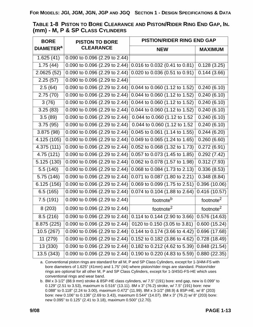
TABLE 1-8 PISTON TO BORE CLEARANCE AND PISTON/RIDER RING END GAP, IN. (mm) - M, P & SP CLASS CYLINDERS
BORE DIAMETERa
PISTON TO BORE CLEARANCE
PISTION/RIDER RING END GAP
NEW MAXIMUM1.625 (41) 0.090 to 0.096 (2.29 to 2.44)1.75 (44) 0.090 to 0.096 (2.29 to 2.44) 0.016 to 0.032 (0.41 to 0.81) 0.128 (3.25)
2.0625 (52) 0.090 to 0.096 (2.29 to 2.44) 0.020 to 0.036 (0.51 to 0.91) 0.144 (3.66)2.25 (57) 0.090 to 0.096 (2.29 to 2.44)2.5 (64) 0.090 to 0.096 (2.29 to 2.44) 0.044 to 0.060 (1.12 to 1.52) 0.240 (6.10)2.75 (70) 0.090 to 0.096 (2.29 to 2.44) 0.044 to 0.060 (1.12 to 1.52) 0.240 (6.10)
3 (76) 0.090 to 0.096 (2.29 to 2.44) 0.044 to 0.060 (1.12 to 1.52) 0.240 (6.10)3.25 (83) 0.090 to 0.096 (2.29 to 2.44) 0.044 to 0.060 (1.12 to 1.52) 0.240 (6.10)3.5 (89) 0.090 to 0.096 (2.29 to 2.44) 0.044 to 0.060 (1.12 to 1.52 0.240 (6.10)3.75 (95) 0.090 to 0.096 (2.29 to 2.44) 0.044 to 0.060 (1.12 to 1.52 0.240 (6.10)
3.875 (98) 0.090 to 0.096 (2.29 to 2.44) 0.045 to 0.061 (1.14 to 1.55) 0.244 (6.20)4.125 (105) 0.090 to 0.096 (2.29 to 2.44) 0.049 to 0.065 (1.24 to 1.65) 0.260 (6.60)4.375 (111) 0.090 to 0.096 (2.29 to 2.44) 0.052 to 0.068 (1.32 to 1.73) 0.272 (6.91)4.75 (121) 0.090 to 0.096 (2.29 to 2.44) 0.057 to 0.073 (1.45 to 1.85) 0.292 (7.42)5.125 (130) 0.090 to 0.096 (2.29 to 2.44) 0.062 to 0.078 (1.57 to 1.98) 0.312 (7.93)5.5 (140) 0.090 to 0.096 (2.29 to 2.44) 0.068 to 0.084 (1.73 to 2.13) 0.336 (8.53)
5.75 (146) 0.090 to 0.096 (2.29 to 2.44) 0.071 to 0.087 (1.80 to 2.21) 0.348 (8.84)6.125 (156) 0.090 to 0.096 (2.29 to 2.44) 0.069 to 0.099 (1.75 to 2.51) 0.396 (10.06)6.5 (165) 0.090 to 0.096 (2.29 to 2.44) 0.074 to 0.104 (1.88 to 2.64) 0.416 (10.57)7.5 (191) 0.090 to 0.096 (2.29 to 2.44) footnoteb footnote2
8 (203) 0.090 to 0.096 (2.29 to 2.44) footnote2 footnote2
8.5 (216) 0.090 to 0.096 (2.29 to 2.44) 0.114 to 0.144 (2.90 to 3.66) 0.576 (14.63)8.875 (225) 0.090 to 0.096 (2.29 to 2.44) 0120 to 0.150 (3.05 to 3.81) 0.600 (15.24)10.5 (267) 0.090 to 0.096 (2.29 to 2.44) 0.144 to 0.174 (3.66 to 4.42) 0.696 (17.68)11 (279) 0.090 to 0.096 (2.29 to 2.44) 0.152 to 0.182 (3.86 to 4.62) 0.728 (18.49)13 (330) 0.090 to 0.096 (2.29 to 2.44) 0.182 to 0.212 (4.62 to 5.39) 0.848 (21.54)
13.5 (343) 0.090 to 0.096 (2.29 to 2.44) 0.190 to 0.220 (4.83 to 5.59) 0.880 (22.35)a. Conventional piston rings are standard for all M, P and SP Class Cylinders, except for 1-3/4M-FS with
bore diameters of 1.625” (41mm) and 1.75” (44) where piston/rider rings are standard. Piston/rider rings are optional for all other M, P and SP Class Cylinders, except for 1-3/4SG-FS-HE which uses conventional rings and wear band.
b. 8M x 3-1/2” (88.9 mm) stroke & 8SP-HE class cylinders, w/ 7.5” (191) bore: end gap, new is 0.099” to 0.129” (2.51 to 3.53), maximum is 0.516” (13.11). 8M x 3” (76.2) stroke, w/ 7.5” (191) bore: new 0.088” to 0.118” (2.24 to 3.00), maximum 0.472” (11.99). 8M x 3-1/2” (88.9) & 8SP-HE, w/ 8” (203) bore: new 0.106” to 0.136” (2.69 to 3.43), maximum 0.544” (14.07). 8M x 3” (76.2) w/ 8” (203) bore: new 0.095” to 0.125” (2.41 to 3.18), maximum 0.500” (12.70).
9/08 PAGE 1-13
FOR MODELS: JGI, JGM, JGN, JGP AND JGQ SECTION 1 - DESIGN SPECIFICATIONS & DATA
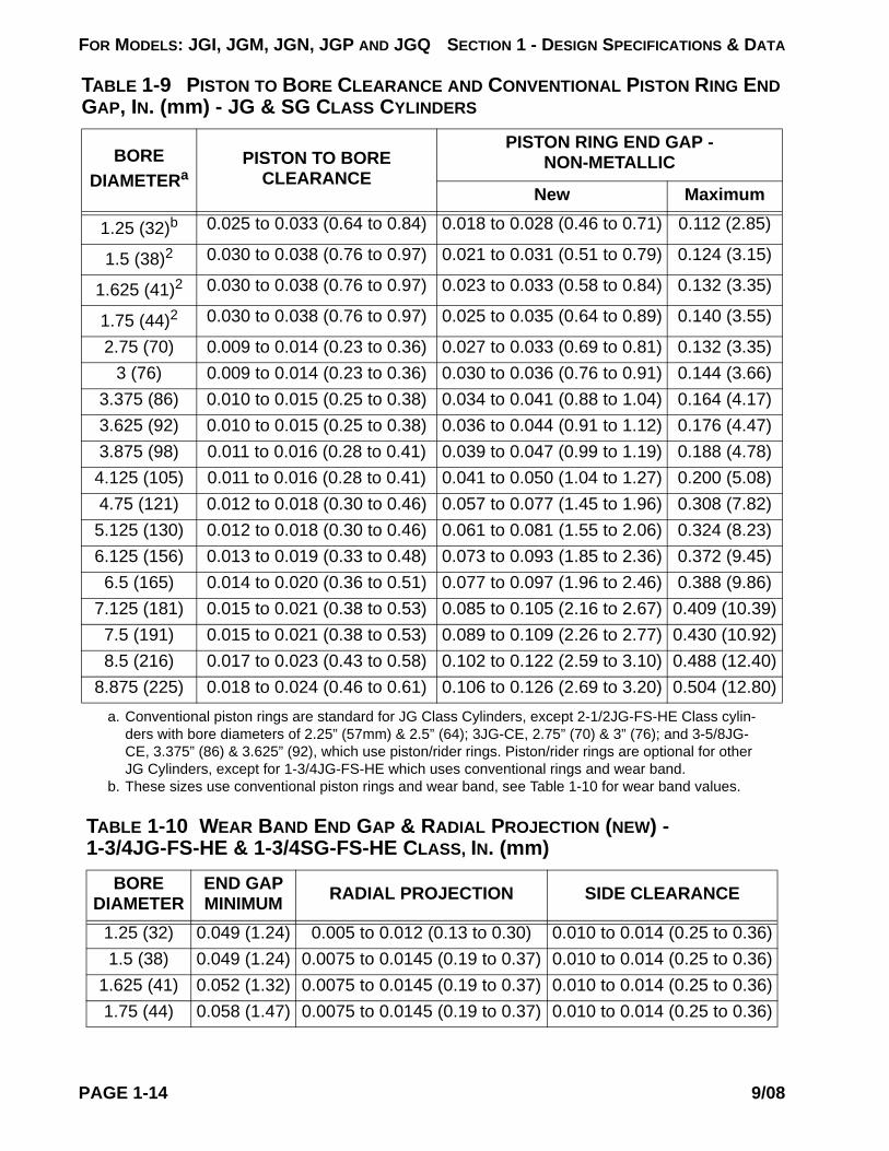
TABLE 1-9 PISTON TO BORE CLEARANCE AND CONVENTIONAL PISTON RING END GAP, IN. (mm) - JG & SG CLASS CYLINDERS
BORE DIAMETERa
PISTON TO BORE CLEARANCE
PISTON RING END GAP - NON-METALLIC
New Maximum
1.25 (32)b 0.025 to 0.033 (0.64 to 0.84) 0.018 to 0.028 (0.46 to 0.71) 0.112 (2.85)
1.5 (38)2 0.030 to 0.038 (0.76 to 0.97) 0.021 to 0.031 (0.51 to 0.79) 0.124 (3.15)
1.625 (41)2 0.030 to 0.038 (0.76 to 0.97) 0.023 to 0.033 (0.58 to 0.84) 0.132 (3.35)
1.75 (44)2 0.030 to 0.038 (0.76 to 0.97) 0.025 to 0.035 (0.64 to 0.89) 0.140 (3.55)
2.75 (70) 0.009 to 0.014 (0.23 to 0.36) 0.027 to 0.033 (0.69 to 0.81) 0.132 (3.35)3 (76) 0.009 to 0.014 (0.23 to 0.36) 0.030 to 0.036 (0.76 to 0.91) 0.144 (3.66)
3.375 (86) 0.010 to 0.015 (0.25 to 0.38) 0.034 to 0.041 (0.88 to 1.04) 0.164 (4.17)3.625 (92) 0.010 to 0.015 (0.25 to 0.38) 0.036 to 0.044 (0.91 to 1.12) 0.176 (4.47)3.875 (98) 0.011 to 0.016 (0.28 to 0.41) 0.039 to 0.047 (0.99 to 1.19) 0.188 (4.78)4.125 (105) 0.011 to 0.016 (0.28 to 0.41) 0.041 to 0.050 (1.04 to 1.27) 0.200 (5.08)4.75 (121) 0.012 to 0.018 (0.30 to 0.46) 0.057 to 0.077 (1.45 to 1.96) 0.308 (7.82)5.125 (130) 0.012 to 0.018 (0.30 to 0.46) 0.061 to 0.081 (1.55 to 2.06) 0.324 (8.23)6.125 (156) 0.013 to 0.019 (0.33 to 0.48) 0.073 to 0.093 (1.85 to 2.36) 0.372 (9.45)6.5 (165) 0.014 to 0.020 (0.36 to 0.51) 0.077 to 0.097 (1.96 to 2.46) 0.388 (9.86)
7.125 (181) 0.015 to 0.021 (0.38 to 0.53) 0.085 to 0.105 (2.16 to 2.67) 0.409 (10.39)7.5 (191) 0.015 to 0.021 (0.38 to 0.53) 0.089 to 0.109 (2.26 to 2.77) 0.430 (10.92)8.5 (216) 0.017 to 0.023 (0.43 to 0.58) 0.102 to 0.122 (2.59 to 3.10) 0.488 (12.40)
8.875 (225) 0.018 to 0.024 (0.46 to 0.61) 0.106 to 0.126 (2.69 to 3.20) 0.504 (12.80)a. Conventional piston rings are standard for JG Class Cylinders, except 2-1/2JG-FS-HE Class cylin-
ders with bore diameters of 2.25” (57mm) & 2.5” (64); 3JG-CE, 2.75” (70) & 3” (76); and 3-5/8JG-CE, 3.375” (86) & 3.625” (92), which use piston/rider rings. Piston/rider rings are optional for other JG Cylinders, except for 1-3/4JG-FS-HE which uses conventional rings and wear band.
b. These sizes use conventional piston rings and wear band, see Table 1-10 for wear band values.
TABLE 1-10 WEAR BAND END GAP & RADIAL PROJECTION (NEW) - 1-3/4JG-FS-HE & 1-3/4SG-FS-HE CLASS, IN. (mm)
BORE DIAMETER
END GAP MINIMUM RADIAL PROJECTION SIDE CLEARANCE
1.25 (32) 0.049 (1.24) 0.005 to 0.012 (0.13 to 0.30) 0.010 to 0.014 (0.25 to 0.36)1.5 (38) 0.049 (1.24) 0.0075 to 0.0145 (0.19 to 0.37) 0.010 to 0.014 (0.25 to 0.36)
1.625 (41) 0.052 (1.32) 0.0075 to 0.0145 (0.19 to 0.37) 0.010 to 0.014 (0.25 to 0.36)1.75 (44) 0.058 (1.47) 0.0075 to 0.0145 (0.19 to 0.37) 0.010 to 0.014 (0.25 to 0.36)
PAGE 1-14 9/08

FOR MODELS: JGI, JGM, JGN, JGP AND JGQ SECTION 1 - DESIGN SPECIFICATIONS & DATA
Fastener Tightening TorqueListed in the following tables are fastener tightening torque values required for proper assembly of Ariel JGI, JGM, JGN, JGP and JGQ compressors. Refer to the section concern-ing a subject component for detailed assembly procedures.
Threads are to be clean and free of burrs.
Torque values are based on the use of petroleum type lubricants on both the threads and seating surfaces. Use lubricating oil or Lubriplate 630, except for compressor piston rods, crosshead-balance nuts and piston-nuts; and stainless steel fasteners which use Never-Seez, Regular Grade (by Bostik, available from industrial suppliers, such as www.neverseezproducts.com), and except where Loctite is specified. Molybdenum disulfide lubricants and Never-Seez are not otherwise to be used for fastener lubrication unless spec-ified, or excessive stresses can result with the listed values. When anti-seize lubricants are
TABLE 1-11 PISTON TO BORE CLEARANCE AND PISTON/RIDER RING END GAP, IN. (mm) - JG & SG CLASS CYLINDERS
BORE DIAMETERa
a. Conventional piston rings are standard for JG Class Cylinders, except 2-1/2JG-FS-HE Class cylin-ders with bore diameters of 2.25” (57mm) & 2.5” (64); 3JG-CE, 2.75” (70) & 3” (76); and 3-5/8JG-CE, 3.375” (86) & 3.625” (92), which use piston/rider rings. Piston/rider rings are optional for other JG Cylinders, except for 1-3/4JG-FS-HE, which uses conventional rings and wear band.
PISTON TO BORE CLEARANCE
PISTON/RIDER RING END GAP
New Maximum2.25 (57) 0.090 to 0.096 (2.29 to 2.44) 0.023 to 0.039 (0.58 to 0.99) 0.156 (3.96)2.5 (64) 0.090 to 0.096 (2.29 to 2.44) 0.030 to 0.046 (0.76 to 1.17) 0.184 (4.67)2.75 (70) 0.090 to 0.096 (2.29 to 2.44) 0.044 to 0.060 (1.12 to 1.52) 0.240 (6.10)
3 (76) 0.090 to 0.096 (2.29 to 2.44) 0.044 to 0.060 (1.12 to 1.52) 0.240 (6.10)3.375 (86) 0.090 to 0.096 (2.29 to 2.44) 0.044 to 0.060 (1.12 to 1.52) 0.240 (6.10)3.625 (92) 0.090 to 0.096 (2.29 to 2.44) 0.047 to 0.063 (1.19 to 1.60) 0.252 (6.40)3.875 (98) 0.090 to 0.096 (2.29 to 2.44) 0.051 to 0.067 (1.30 to 1.70) 0.268 (6.81)4.125 (105) 0.090 to 0.096 (2.29 to 2.44) 0.055 to 0.071 (1.40 to 1.80) 0.284 (7.21)4.75 (121) 0.090 to 0.096 (2.29 to 2.44) 0.057 to 0.073 (1.45 to 1.85) 0.292 (7.42)5.125 (130) 0.090 to 0.096 (2.29 to 2.44) 0.062 to 0.078 (1.57 to 1.98) 0.312 (7.93)6.125 (156) 0.090 to 0.096 (2.29 to 2.44) 0.069 to 0.099 (1.75 to 2.51) 0.396 (10.06)6.5 (165) 0.090 to 0.096 (2.29 to 2.44) 0.074 to 0.104 (1.88 to 2.64) 0.416 (10.57)
7.125 (181) 0.090 to 0.096 (2.29 to 2.44) 0.083 to 0.113 (2.11 to 2.87) 0.452 (11.48)7.5 (191) 0.090 to 0.096 (2.29 to 2.44) 0.088 to 0.118 (2.24 to 3.00) 0.472 (11.99)8.5 (216) 0.090 to 0.096 (2.29 to 2.44) 0.114 to 0.144 (2.90 to 3.66) 0.576 (14.63)
8.875 (225) 0.090 to 0.096 (2.29 to 2.44) 0.120 to 0.150 (3.05 to 3.81) 0.600 (15.24)
9/08 PAGE 1-15

FOR MODELS: JGI, JGM, JGN, JGP AND JGQ SECTION 1 - DESIGN SPECIFICATIONS & DATA
required, use very sparingly as excessive amounts will result in oil analysis indication con-tamination and unnecessarily increase maintenance costs.
For latest available torque values, see ER-63 at www.arielcorp.com.
TABLE 1-12 FASTENER TIGHTENING VALUES
FASTENERNOMINAL
SIZE,INCH - TPI
TYPE TORQUE,LB-FT (N·m)
Main Bearing Cap - Cap Screw 1/2 - 13 12 Point - Grade 8 58 (79)JGI Bearing Carrier to Frame - Cap Screw 1/2 - 13 12 Point - Grade 8 44 (60)
Connecting Rod Cap - Cap Screw 1/2 - 13 12 Point - Grade 8/Socket Head
58 (79)1/2 - 20 67 (91)
Crosshead Pin Through Bolt 3/8 - 24 Hex - Lock Nut 25 (34)Frame to Cylinder - Cap Screw 1/2 - 13 12 Point - Grade 8 48 (65)Crosshead Guide to Support - Cap Screw
5/8 - 11 Hex - Grade 8 or 9 90 (120)
Eccentric Vernier Cap - Cap Screw 5/16 - 18 Hex - Grade 8 Hand-wrench TightIdler Sprocket Through Bolt - Lock Nut 1/2 - 20 Hex - Lock Nut 41 (55)
Rod Packing - Cap Screw 1/2 - 13 12 Point - Grade 8 35 (48)
Piston Nuta 7/8 - 12 Ariel Design 222 (300)
Crosshead-Balance Nut 1 - 12 Ariel Design Sluggedb
Piston Rod Oil Slinger - Lock Nut 1/4 - 28 lock Nut 96 lb-in. (11)Rupture Disk - Blow-Out Fitting Cap 1/4 Nom. Tube Hex - Tube Fitting 40 lb-in. (4.4)Hold Down - Stud-Nut 5/8 - 11 Hex Stud-Nut 100c (130)
3/4 - 10 1753 (235)Valve Cap; Cylinder Head; Gas Passage Cap; Unloader; Ariel Supplied Companion Flanges - Cap Screw
3/8 - 16 Hex - Grade 8 or 9 or
12Point - Grade B7M or 8
193 lb-in. (22)7/16 - 14 26 (35)1/2 - 13 40 (54)
9/16 - 12 57 (77)5/8 -11 79 (105)5/8 - 18 92 (125)3/4 - 10 140 (190)3/4 - 16 160 (215)7/8 - 9 230 (310)7/8 -14 260 (350)1 - 8 345 (465)
1 - 16 395 (535)
PAGE 1-16 9/08

FOR MODELS: JGI, JGM, JGN, JGP AND JGQ SECTION 1 - DESIGN SPECIFICATIONS & DATA
Tandem Cylinder to Cylinder - Cap Screwc
1/2 - 13 Hex - Grade 8 or 9 or
12 Point - Grade 8
44 (60)5/8 - 11 88 (120)3/4 - 10 160 (215)3/4 - 16 180 (245)
Fanshaft to Crankshaft - Central Stud 3/4 - 16 Ariel Design 250 (340)
Seating Studs in Cylinder 3/8 - 16 Dog Point 107 lb-in. (12)7/16 - 14 172 lb-in. (19)1/2 - 13 22 (30)
9/16 - 12 32 (43)5/8 - 11 44 (60)5/8 - 18 51 (70)3/4 - 10 79 (105)3/4 - 16 90 (120)7/8 - 9 130 (170)7/8 - 14 145 (195)
1 & Larger 200 (270)Spacer Bar 5/8 -11 Cap Screw Gr. 8 92 (125)Distribution Block Tie Rod - Nut 1/4 - 28 Hex 68 lb-in. (7.7)Distribution Block Divider Valve - Screw 1/4 - 28 Socket Head 75 lb-in. (8.5)
Force Feed Lubricator 1 - 14 Hex Jam Nut 75 (100)Grade 5 - Hex Cap Screw All Hex - Grade 5 Hand-wrench Tight
a. Tighten, loosen, and re-tighten the Piston Nut to ensure proper tightening.b. Use the Ariel Tried and True Slugging Method, see Section 5.c. Minimum torque for recommended, 5/8” - 11TPI for JGM, JGN, JGP, JGQ and 3/4”-10TPI for JGI, hold
down stud size to provide stress in stud of 55,000 psi (380 MPa). Stud must have an ultimate strength of 100,000 psi (690 MPa) or greater. If greater, increase torque to stress stud to about 55% of ultimate strength of stud material, as specified by packager.
TABLE 1-12 FASTENER TIGHTENING VALUES
FASTENERNOMINAL
SIZE,INCH - TPI
TYPE TORQUE,LB-FT (N·m)
Dog Point Stud
9/08 PAGE 1-17

FOR MODELS: JGI, JGM, JGN, JGP AND JGQ SECTION 1 - DESIGN SPECIFICATIONS & DATA
TABLE 1-13 HOERBIGER VALVE ASSEMBLY FASTENERS - TIGHTENING VALUES
FASTENER NOMINALINCH - TPI TYPE TORQUE,
LB-FT (N·m)Center Cap Screw
12-Point Cap Screw threads for Valve Assem-blies not marked SPL (without Spiralock Threads), must be cleaned with Loctite Safety solvent and locked with one to two drops of Loctite #272. Cap Screws for Assem-blies marked SPL (see Figure 1-6 on page 19) are lubricated, both threads and seating surfaces, with a petroleum type lubri-cant only.
5/16 - 24 12 Point- Steel Grade 5
Material Parts: SPL3 & 4
144 lb-in. (16)3/8 - 24 21 (28)7/16 - 20 30 (41)5/16 - 24 12 Point- Steel Grade 5
Material Parts: SPL5
18 (24)3/8 - 24 32 (43)7/16 - 20 50 (68)5/16 - 24 12 Point - Stainless Steel
Grade B8MMaterial Parts: SPL6
120 lb-in. (14)3/8 - 24 192 lb-in. (22)7/16 - 20 24 (33)5/16 - 24 12 Point - Steel Grade 8
Out of Production
18 (24)3/8 - 24 32 (43)7/16 - 20 50 (68)
Center Stud - Drake Lock Nut
*Use 29 lb x ft (39 N·m) for 1/2 - 20 Bottom Half - Drake Lock Nut with non-metallic Plates in Liftwasher Type Valves.
1/4 - 28 Bottom Half 103 lb x in. (11.6)
Top Half 66 lb x in. (7.5)
5/16 - 24 Bottom Half 120 lb x in. (13.6)
Top Half 66 lb x in. (7.5)
3/8 - 24 Bottom Half 192 lb x in. (21.7)
Top Half 96 lb x in. (10.8)
1/2 - 20 Bottom Half *36 (*49)Top Half 20 (27)
5/8 - 18 Bottom Half 73 (99)Top Half 40 (54)
3/4 - 16 Bottom Half 130 (176)Top Half 70 (95)
Top Half
Bottom Half
PAGE 1-18 9/08

FOR MODELS: JGI, JGM, JGN, JGP AND JGQ SECTION 1 - DESIGN SPECIFICATIONS & DATA
Tightening Torque ProceduresListed below are some procedures which make fastener tightening more accurate and will help to be sure that the proper torque is being applied.
1. Be sure that the torque wrench is properly calibrated and used by qualified personnel to achieve the required fastener tightening torque for all critical parts. The exception is the crosshead-balance lock nut which may be tightened using the Ariel tried and true slugging method.
2. Always check to determine over what range the torque wrench is accurate, since
Peripheral Cap Screws 10 - 32 Hex Socket Head 25 lb x in. (2.8)
12 - 28 43 lb x in. (4.9)
1/4 - 20 110 lb x in. (12.4)
5/16 - 18 176 lb x in. (19.9)
3/8 - 16 21 (28)
FIGURE 1-6 SPIRALOCK THREADED VALVE ASSEMBLY - MARKED SPL
TABLE 1-13 HOERBIGER VALVE ASSEMBLY FASTENERS - TIGHTENING VALUES
FASTENER NOMINALINCH - TPI TYPE TORQUE,
LB-FT (N·m)
Bottom Views
Suction GuardDischarge Seat
9/08 PAGE 1-19

FOR MODELS: JGI, JGM, JGN, JGP AND JGQ SECTION 1 - DESIGN SPECIFICATIONS & DATA
most torque wrenches are not accurate over their entire range.3. Tighten all multi-bolt assemblies in steps (need not apply to Grade 5 cap screws).
Tighten each cap screw until snug using an alternating (criss-cross) pattern. Next, tighten each cap screw to 25 percent of full torque, moving across from cap screw to cap screw, in an alternating (criss-cross) pattern. Repeat this step for 50, 75, and 100 percent of full torque. For main bearing and connecting rod bolts repeat the 100 percent step to be sure that all fasteners are properly torqued.
4. Always apply a steady slow force to a torque wrench, do not jerk it. When a torque wrench is jerked the amount of torque applied can be as much as one and a half times the amount set on the wrench. For example, if a wrench is set at 80 lbf-ft (108 N·m) but is jerked, 120 lbf-ft (163 N·m) torque can be applied.
5. Always do the final tightening with a torque wrench. Do not tighten the fastener with a ratchet or impact wrench and then “check” the torque with a torque wrench.
6. Do not double tap a torque wrench. Rapidly double tapping a torque wrench will make the torque on the bolt more than what is set by a significant amount.
7. When checking a tightened fastener torque, set torque wrench to proper required torque value and slowly apply a steady force until the click is felt.
8. Always reset the torque wrench to its lowest setting when the job is complete. If the torque wrench is left in a high setting the spring in it is stressed and will become inaccurate with time. If the torque wrench is put back to its lowest setting the spring will relax and retain its accuracy.
9. Do not use a torque wrench to break fasteners loose as it may overload the torque wrench and/or cause loss of calibration.
10. For applications requiring the use of a boxed end or crowsfoot adapter with a torque wrench to reach not readily accessible fasteners, the torque wrench setting will not be the actual torque applied to the fastener. The exception is when the adapter is 90 degrees to the torque wrench. The torque will be the same as on the wrench scale.
11. The ratio of actual torque at the fas-tener with that on the wrench scale is a function of the adapter's length and its position in relation to the torque wrench beam and the location on that at which the force is applied, see fig-ure.
LA
FIGURE 1-3 TORQUE WRENCH WITH ANGLED ADAPTER
Force
Tw Ta LL A+-------------⎝ ⎠
⎛ ⎞=
Tw = Torque wrench setting, lbf-ft or N·mTa = Torque required at fastener, lbf-ft or N·mL = Length of wrench, ft or m (from square drive end to center point of force on
handle)A = Length of adapter, ft or m (measured through end of adapter on a line
parallel to the center line of the wrench)12. When studs are specified for cylinder applications, tighten stud-nuts to the same
PAGE 1-20 9/08

FOR MODELS: JGI, JGM, JGN, JGP AND JGQ SECTION 1 - DESIGN SPECIFICATIONS & DATA
values as cap screws in similar applications.13. Pipe threads and main cap plugs are to be installed using Loctite 565 Thread
Sealant. Synthetic oils may require Loctite 545 and Loctite Activator 7649 (N).These are general guidelines to assist in the proper use of torque wrenches. Consult with your torque wrench dealer for more detailed information.
Ariel BoltingBolting has been selected that meet Ariel's strength, elongation, sealing, and locking requirements. Proper bolting must be used and tightened to the values listed in Table 1-12 on page 1-16. Figure 1-4 is provided to assist in the identification of bolts used in an Ariel compressor.
Connecting rod, valve cap and suction/discharge nozzle - Ariel supplied speciality companion flange - bolting is designed to resist fatigue and cannot be replaced with standard cap screws. If attempting to replace other bolting with standard cap screws and there is any question, contact your packager or Ariel. Ariel supplied replacement bolting is recommended.
CAUTION: WHEN RE-ASSEMBLING OR REPLACING BOLTING, SEE THE PARTS LIST TO DETERMINE THE PROPER FASTENER GRADE AND PART NUMBER. DO NOT USE A LESSER OR GREATER MATERIAL GRADE. ALL SPECIAL FASTENERS AND ALL BOLTING THAT HAS BEEN MADE TO REDUCE THE BODY DIAMETER FOR FATIGUE RESISTANCE, MUST BE REPLACED WITH ARIEL PARTS.
Zone 1 EnvironmentA Zone 1 environment requires the installation of proper intrinsically safe or equivalent protection to fulfill the electrical requirements, where applicable.
FIGURE 1-4 BOLT IDENTIFICATION
Hex head Grade 8
Hex head Grade 9
Hex head Grade 5
12 Point Grade 8
12 Point Interim Grade 5
12 Point Stainless Steel Grade 17-4PH
Hex Socket Head Grade 8
12 Point Grade 5
17-4
9/08 PAGE 1-21

FOR MODELS: JGI, JGM, JGN, JGP AND JGQ SECTION 1 - DESIGN SPECIFICATIONS & DATA
NOTES:
PAGE 1-22 9/08

FOR MODELS: JGI, JGM, JGN, JGP AND JGQ
SECTION 2 -INSTALLATIONThe installation of the compressor with the associated driver and piping, is to be done with care and precision. This section addresses some of the more critical installation consider-ations and requirements, but does not attempt to address all of the concerns that can arise.
The Skid or PackageManufacture and install the skid or package in conformance to Ariel Packager Standards.
Lifting the CompressorDetermine the weight of the compressor, prior to lifting. For an accurate value, see the Ariel Performance Program to determine frame and cylinder weights or for an approximate weight of the compressor with cylinders see Technical Manual Section 1, Frame Specifica-tions tables. Also account for any extra weight such as a flywheel, etc. Spreader bars should be used to provide for a more vertical pull on the eyebolts or lifting lugs. Be sure that the eyebolts or lifting lugs, lifting tackle, spreader bars and crane capacity are adequate and properly rigged for the load. Keep the compressor level when lifting and setting. Heavier cyl-inders and/or blank throws can significantly affect the center of gravity.
Do not attempt lifting by hooking to a compressor when the compressor is attached to the skid, driver or piping. If you are not experienced in lifting large compressors, the use of qual-ified professional riggers/movers is recommended.
On compressor frames designed for lifting lugs, install the lugs (4) with the proper Grade 8 cap screws and tighten to the torque value given in the Technical Manual Section 1 or the tool box torque chart (the ER-63 chart is also available electronically at the Ariel web site: www.arielcorp.com), for lifting the compressor. If lifting lugs are already installed, recheck fastener tightening torque. JGZ:U/4, KBB:V/4 and all 6-throw compressors have lifting lugs.
When lifting a compressor not designed with lifting lugs, lift by the eyebolts installed by Ariel at the crosshead guides. Eyebolts installed in the crosshead guides by the Ariel Shop are locked with Loctite to help prevent them from turning. Inspect eyebolts to be sure they are free of any visual defects, such as bending, that could affect serviceability. Remove and physically destroy any defective eyebolts. Replacement eyebolts are to be forged steel and meet the requirements of ASME B18.15 latest edition (available at www.asme.org). Clean threads and install a replacement eyebolt with Loctite #262 (available at www.loctite.com) in the same orientation as original eyebolt. Allow Loctite to cure before using a replaced eye-bolt for lifting. For eyebolt load capacity rating and if pulling on an eyebolt in a direction other than along the threaded axis, consult ASME B18.15.
The standard lifting lug and eyebolt materials can fail when subjected to shock loads at low ambient temperature conditions. Follow the guidelines in ASME B18.15. If deemed neces-sary by the customer or lifting professional, eyebolts may be replaced with forged eyebolts of materials more suitable for low temperatures, in accordance with ASME B18.15 and
9/08 PAGE 2-1
FOR MODELS: JGI, JGM, JGN, JGP AND JGQ SECTION 2 - INSTALLATION
ASTM F541 (available atwww.astm.org). Standard lifting lugs and bolting may also be replaced with materials more suitable for low temperatures. Contact Ariel for more informa-tion.
Setting the Compressor1. Be sure the skid is level.2. Move the compressor into place on the skid. 3. Level stationary compressors to Table 2-1 requirements. For compressors sub-
ject to transient motion on ships or offshore platforms, level compressors to table requirements when at rest. Be sure the pre-grout alignment is relatively close so that the equipment movement will be minimal and within the bolting, foot, push pads or grout box allowance.
4. Grout as required and allow grout to set.With the compressor cylinders mounted but unsupported and with no piping or pulsation damping bottles attached, tighten the frame foot hold down bolting to skid at full fastener torque. Refer to Ariel ER-26, Appendix A in the Ariel Packager’s Standards for proper frame foot torque values.
CAUTION: When lifting a compressor designed for lifting lugs, use ONLY Ariel provided or approved lugs. Be sure the lugs are held In place with the proper grade of cap screws, and properly tightened. Lifting cable spreaders are required perpendicular to crankshaft axis. Be sure the crane capacity is adequate.
PAGE 2-2 9/08

FOR MODELS: JGI, JGM, JGN, JGP AND JGQ SECTION 2 - INSTALLATION
Leveling Limits for CompressorsThe limits in Table 2-1 assume that the running oil level is maintained between one half and two-thirds the height of the sight glass, except for dry sump compressors. Length leveling limits apply axially (parallel to crankshaft) and width limits apply horizontally (parallel to the piston rod) within the length and width of the frame.
TABLE 2-1 Maximum Angle from a Horizontal Plane for Leveling Compressors
Aligning Main Bearing BoresTo maximize main bearing life expectancy and help avoid crankshaft failures, it is essential that compressor frames be installed and remain in position so that main bearing bores can be maintained in proper alignment. Ariel has established this procedure in an effort to facili-tate the proper installation of compressor frames and provide a means of periodic inspec-tion.
1. The top cover mounting surface of an Ariel compressor frame is manufactured in a flat plane to a close tolerance. This surface is also held to a close tolerance with the main bearing bores and the bottom of the compressor feet. When the frame feet are supported so that the top-cover-mounting surface is flat "in plane", the main bearing bores are in alignment.
2. Top-cover-mounting surface flatness or soft foot check may be used for frame sizes up to and including JGU:Z/2-throw frames to be sure main bearing bores are in proper alignment, except for the JGI which uses only soft foot.
3. On JGU:Z:B:V:KBB:V/4-throw and /6-throw frames the top plane flatness and soft foot checks are both required to be sure the main bearing bores are in proper alignment.
FrameMaximum Angle from a Horizontal Plane - In/Ft of Distance (mm/m) [ ° ]
1 or 2 Throw 4 Throw 6 ThrowLength Width Length Width Length Width
JGM:N 0.420 (35) [2°] 0.500 (42) [2.4°] N/A
JGP:Q 0.500 (42) [2.4°] 0.500 (42) [2.4°] N/A
JG 0.460 (38) [2.2°] 0.500 (42) [2.4°] 0.215 (18) [1.0°] 0.500 (42) [2.4°] N/A
JGA 0.500 (42) [2.4°] 0.500 (42) [2.4°] 0.310 (26) [1.5°] 0.500 (42) [2.4°] 0.190 (16) [0.9] 0.500 (42) [2.4°]
JGW:R 0.095 (7.9) [0.45°] 0.500 (42) [2.4°] 0.025 (2.1) [0.1°] 0.500 (42) [2.4°] N/A
JGJ 0.420 (35) [2°] 0.500 (42) [2.4°] 0.105 (8.7) [0.5°] 0.450 (37) [2.1°] 0.065 (5.4) [0.3°] 0.460 (38) [2.2°]
JGH 0.375 (31) [2°] 0.500 (42) [2.4°] 0.160 (13) [0.8°] 0.500 (42) [2.4°] N/A
JGE:T 0.440 (37) [2.1°] 0.500 (42) [2.4°] 0.155 (13) [0.7°] 0.500 (42) [2.4°] 0.090 (7.5) [0.4°] 0.310 (26) [1.5°]
JGK 0.105 (8.7) [0.5°] 0.500 (42) [2.4°] 0.035 (2.9) [0.2°] 0.500 (42) [2.4°] 0.020 (1.7) [0.1°] 0.310 (26) [1.5°]
JGC 0.270 (22) [1.3°] 0.460 (38) [2.2°] 0.100 (8.3) [0.5°] 0.460 (38) [2.2°] 0.060 (5.0) [0.3°] 0.180 (15) [0.9°]
JGD 0.500 (42) [2.4°] 0.460 (38) [2.2°] 0.205 (17) [1.0°] 0.460 (38) [2.2°] 0.125 (10) [0.6°] 0.180 (15) [0.9°]
JGZ 0.500 (42) [2.4°] 0.500 (42) [2.4°] 0.380 (25) [1.8°] 0.500 (42) [2.4°] 0.240 (20) [1.1°] 0.500 (42) [2.4°]
JGU 0.500 (42) [2.4°] 0.500 (42) [2.4°] 0.475 (40) [2.3°] 0.500 (42) [2.4°] 0.300 (25) [1.4°] 0.500 (42) [2.4°]
JGB N/A 0.250 (21) [1.2°] 0.075 (6.2) [0.4°] 0.180 (15) [0.9°] 0.075 (6.2) [0.4°]
JGV N/A 0.235 (20) [1.1°] 0.075 (6.2) [0.4°] 0.150 (12) [0.7°] 0.075 (6.2) [0.4°]
KBB:V N/A 0.165 (14) [0.8°] 0.500 (42) [2.4°] 0.120 (10) [0.6°] 0.500 (42) [2.4°]
9/08 PAGE 2-3

FOR MODELS: JGI, JGM, JGN, JGP AND JGQ SECTION 2 - INSTALLATION
4. Measurements for flatness are to be taken on the top surface of both sides of the frame rails at each anchor bolt or for frames with pairs of anchor bolts between each pair of anchor bolts, with top covers and gaskets removed (see Figure 2-1). Readings between any two adjacent points are to be within .002 in. (0.05 mm). The total accumulated out of plane flatness for proper alignment is to be within the flatness tolerances listed in Table 2-1.
5. In preparation for frame plane measurements be sure that the compressor frame hold down bolting is properly installed and tightened. Either remove or reposition the top cover(s) and gasket(s) to expose the frame's top-cover-mounting surface. With new unit installations it is recommended that the frame plane be initially checked prior to the guide feet being shimmed and after the ini-tial rough coupling alignment. On KBB:V/6, or other model compressors shipped disassembled, the initial check can be carried out prior to the guide & cylinder assemblies being installed. Take the appropriate corrective shimming, or other height adjustment, action to have the top-cover-mounting surface fall within the specified plane tolerance. Subsequent reading should be taken and recorded after the guides and cylinders have been fully installed and then again after any vessels have been installed and shimmed. Corrective action is to be taken if guide, cylinder and/or vessel installation results in the frame top rail measure-
TABLE 2-1 TOP-COVER-MOUNTING SURFACE - FLATNESS TOLERANCE
COMPRESSOR FRAMEA
a. Underlined frames are required to use both top plane flatness and soft foot checks.
TOLERANCE FOR ALIGNMENT
INCHES (mm)JGM:N:P:Q/1/2, JG:A/2/4, JGR:J/2 0.004 (0.10)
JGA/6, JGR/4, JGJ/4/6, JGH:E:K:T/2/4, JGC:D/2/4, JGU:Z/2/4, JGB:V/4, KBB:V/4 0.006 (0.15)
JGE:K:T/6, JGC:D/6, JGU:Z/6, JGB:V/6, KBB:V/6 0.008 (0.20)
Take Measurements Here
FIGURE 2-1 FLATNESS CHECK LOCATIONS - TYPI-
PAGE 2-4 9/08

FOR MODELS: JGI, JGM, JGN, JGP AND JGQ SECTION 2 - INSTALLATION
ments not meeting the specified tolerances 6. Refer to Ariel ER-26, Appendix A in the Ariel Packagers Standard for proper
frame foot and crosshead guide bolt size and torque values.7. Standard "wet-sump" compressors must be level within the "Maximum Angle
from Horizontal Allowed without Dry Sump" to the Ariel Packager's Standards, ER-56.06.
8. The top-cover-mounting surface should be measured for flatness and/or soft foot check be done as required:a. When setting a new compressor.b. After reinstalling a compressor frame.c. When loose hold down fasteners are found.d. Every 6 months or 4000 hours as recommended maintenance inspection.
9. The Equipment used for flatness measurements should have a published accu-racy of 0.0005 inches/foot (0.042 mm/m) over the required distance to measure the entire length of both frame rails. One example of such equipment is the "LEVALIGN Flatness application with ROTALIGN PRO" manufactured and sup-ported by PRUFTECHNIK (www.pruftechnik.com) which can be used to carry out the flatness inspection outlined above.
10. To check soft foot, the compressor frame hold down bolting is to be properly installed and tightened. Loosen each hold down bolt individually while checking the frame foot to skid deflection with a calibrated dial indicator. Correct any hold down position that deflects more than 0.002 inches (0.05 mm) when released. Re-torque the hold down bolt and repeat at each frame to skid bolt.
Setting Crosshead GuidesWith crosshead guides and cylinders unsupported, prior to bottle installation:
1.
Shim Thickness =Unsupported + Deflection Thicknesses to paragraph 4. above
Crosshead Guide Foot
Crosshead Guide Skid Support(Connected to Skid)
FIGURE 2-2 CROSSHEAD GUIDE FOOT TO SKID-SUPPORT SHIM - TYPICAL
Measure the clearances between each cross-head guide foot and the guide support. Except for JGZ:U and KBB:V frames when equipped with long two compart-ment (L2) crosshead guides, measure clear-ance at the outboard feet under the guide exten-sion, which are used to support the guide and the feet under the guide are to be unsupported.
2. Completely fill the clear-ances with shim stock (reference Figure 2-2).
3. Tighten the crosshead guide foot (or long two compartment guide extension foot) to guide support hold-down bolting to full fastener torque. Refer to Ariel ER-26.
9/08 PAGE 2-5
FOR MODELS: JGI, JGM, JGN, JGP AND JGQ SECTION 2 - INSTALLATION
4. Loosen the bolting while checking with a dial indicator to be sure that the clear-ance is completely filled and there is no deflection.
5. Using the information from the current Ariel Performance Program, determine the estimated crosshead guide foot deflection for JGH:E:K:T:C:D:Z:U:KBB:V frames. This calculated value is required to compensate for the deflection or droop of the cantilevered weight of the guide and cylinder. For the JG:A:M:N:P:Q:R:W:J frames, the guide and cylinder weights are not sufficient to deflect the guide.
6. Lift or jack cylinder, just slightly to allow insertion of additional shims based on the calculated value.
7. Re-tighten the crosshead guide hold down bolting to full fastener torque. 8. Repeat for each crosshead guide support.9. Shims may need to be adjusted so that the crosshead to guide top and bottom
clearances, and piston rod run-out measurements are within the tolerance requirements. Reference Section 5 for checking crosshead clearances and pis-ton rod run-out, and Section 1 for tolerance limits.
10. For some applications, head-end cylinder supports may be desirable for larger classes of cylinders (bosses and tapped holes are provided on all K:T:C:D:Z:U:B:V class cylinders). See Ariel cylinder outline drawings for dimen-sional details. These supports must be adjusted and set when the components are at operating temperature.
Setting - Miscellaneous1. Reference Technical Manual Section 4 for protection of electronic equipment
when arc welding.2. Comply with the Ariel Start Up Check List, see Technical Manual Section 3.
Alignment - to DriverProper alignment to the driver is necessary for satisfactory performance. A flexible coupling will not make up for poor alignment. Misalignment can result in:
• High bending moment on the crankshaft.• Large axial forces.• Excessive bearing wear.• And if severe, probable damage to various components.
Procedural Requirements for Aligning a unit:
• Check the compressor frame, crosshead guide and driver hold-down bolting fastener torques.
• Check and correct the alignment of the compressor main bearing bores by the top-cover mounting surface flatness and/or soft foot, as applicable. The compressor and driver are to be laying flat. Check the driver’s technical information for detailed instructions and determine that driver is laying flat.
• Correct the cold alignment readings with the predicted thermal growth values for both the compressor and the driver.
• Pre-lube the compressor frame using the compressor pre-lube pump prior to turning
PAGE 2-6 9/08

FOR MODELS: JGI, JGM, JGN, JGP AND JGQ SECTION 2 - INSTALLATION
the crankshaft.•
0
0.012
0.010
0.008
0.006
0.004
0.002
0.00010 20 30 40 50
Hub Diameter, in.
Ang
ular
TIR
Lim
it, in
.
FIGURE 2-3 ANGULAR COUPLING-HUB ALIGNMENT TIR LIMITS
To ensure parallel and concentric drive train alignment, position connected equipment so total indicator (TIR) is as close to zero as possible on the coupling hub faces and rim diameters at nor-mal operating temperature. Do not exceed 0.005 inches (0.13 mm) on the face and rim diameter. Except for coupling hubs with outside diameters above 17 in. (43 cm), the angular face TIR limit is 0° 1’ or 0.0167°. See Figure 2-3. Correct for “Cold Alignment” on page 2-10.
Hub O.D. >17 in. x 0.00029 = angular TIR, in. max. Hub O.D. >43 cm x 0.0029 = angular TIR, mm max.
• Center the coupling between the driver and the compressor so that it does not thrust or force the crankshaft against either thrust face.
9/08 PAGE 2-7

FOR MODELS: JGI, JGM, JGN, JGP AND JGQ SECTION 2 - INSTALLATION
TABLE 2-2 Rexnord AMR/CMR Couplings - Face Angular TIR
Coupling Size Flange OD, In. (cm) Angular TIR, max., In. (mm)162 4.594 (11.7) 0.005 (0.13)200 5.750 (14.6) 0.005 (0.13)225 6.000 (15.2) 0.005 (0.13)262 6.875 (17.5) 0.005 (0.13)312 8.125 (20.6) 0.005 (0.13)350 9.125 (23.2) 0.005 (0.13)375 10.063 (25.6) 0.005 (0.13)425 11.000 (27.9) 0.005 (0.13)450 11.875 (30.2) 0.005 (0.13)500 13.438 (34.1) 0.005 (0.13)550 15.000 (38.1) 0.005 (0.13)600 16.750 (42.6) 0.005 (0.13)700 18.938 (48.1) 0.0055 (0.14)750 20.625 (52.4) 0.0059 (0.15)800 22.375 (56.8) 0.0064 (0.16)850 23.750 (60.3) 0.0068 (0.17)925 25.750 (65.4) 0.0074 (0.19)
1000 28.250 (71.8) 0.0081 (0.211100 30.250 (76.8) 0.0087 (0.22)1200 33.375 (84.8) 0.0096 (0.24)1300 36.000 (91.4) 0.0104 (0.26)1550 39.250 (99.7) 0.0113 (0.29)
PAGE 2-8 9/08
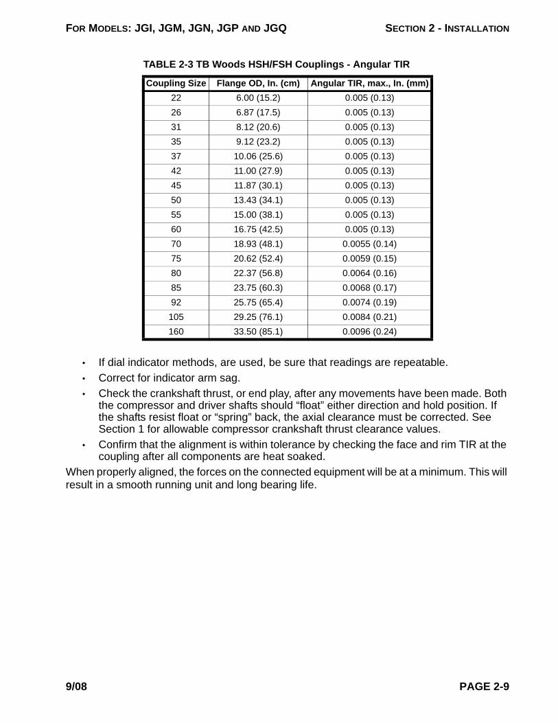
FOR MODELS: JGI, JGM, JGN, JGP AND JGQ SECTION 2 - INSTALLATION
• If dial indicator methods, are used, be sure that readings are repeatable.• Correct for indicator arm sag.• Check the crankshaft thrust, or end play, after any movements have been made. Both
the compressor and driver shafts should “float” either direction and hold position. If the shafts resist float or “spring” back, the axial clearance must be corrected. See Section 1 for allowable compressor crankshaft thrust clearance values.
• Confirm that the alignment is within tolerance by checking the face and rim TIR at the coupling after all components are heat soaked.
When properly aligned, the forces on the connected equipment will be at a minimum. This will result in a smooth running unit and long bearing life.
TABLE 2-3 TB Woods HSH/FSH Couplings - Angular TIR
Coupling Size Flange OD, In. (cm) Angular TIR, max., In. (mm)22 6.00 (15.2) 0.005 (0.13)26 6.87 (17.5) 0.005 (0.13)31 8.12 (20.6) 0.005 (0.13)35 9.12 (23.2) 0.005 (0.13)37 10.06 (25.6) 0.005 (0.13)42 11.00 (27.9) 0.005 (0.13)45 11.87 (30.1) 0.005 (0.13)50 13.43 (34.1) 0.005 (0.13)55 15.00 (38.1) 0.005 (0.13)60 16.75 (42.5) 0.005 (0.13)70 18.93 (48.1) 0.0055 (0.14)75 20.62 (52.4) 0.0059 (0.15)80 22.37 (56.8) 0.0064 (0.16)85 23.75 (60.3) 0.0068 (0.17)92 25.75 (65.4) 0.0074 (0.19)105 29.25 (76.1) 0.0084 (0.21)160 33.50 (85.1) 0.0096 (0.24)
9/08 PAGE 2-9
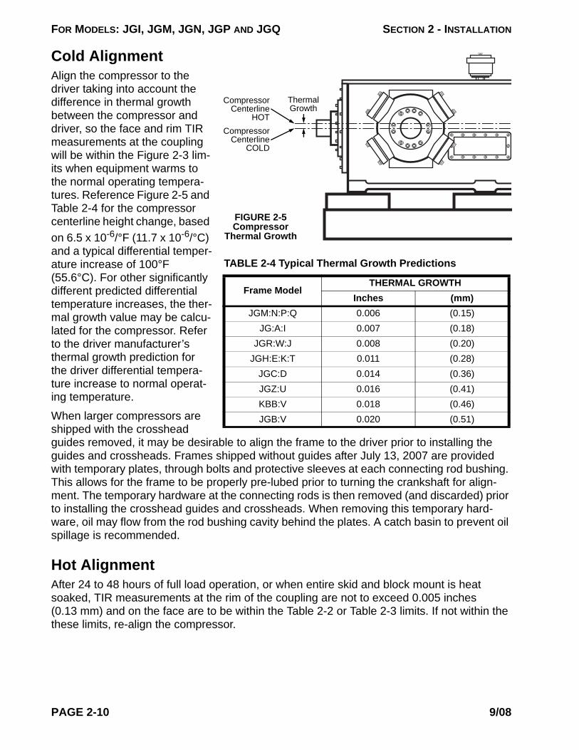
FOR MODELS: JGI, JGM, JGN, JGP AND JGQ SECTION 2 - INSTALLATION
Thermal Growth
Compressor Centerline
HOTCompressor
Centerline COLD
FIGURE 2-5 Compressor
Thermal Growth
TABLE 2-4 Typical Thermal Growth Predictions
Frame ModelTHERMAL GROWTH
Inches (mm)JGM:N:P:Q 0.006 (0.15)
JG:A:I 0.007 (0.18)JGR:W:J 0.008 (0.20)
JGH:E:K:T 0.011 (0.28)JGC:D 0.014 (0.36)JGZ:U 0.016 (0.41)KBB:V 0.018 (0.46)JGB:V 0.020 (0.51)
Cold AlignmentAlign the compressor to the driver taking into account the difference in thermal growth between the compressor and driver, so the face and rim TIR measurements at the coupling will be within the Figure 2-3 lim-its when equipment warms to the normal operating tempera-tures. Reference Figure 2-5 and Table 2-4 for the compressor centerline height change, based on 6.5 x 10⁻⁶/°F (11.7 x 10⁻⁶/°C) and a typical differential temper-ature increase of 100°F (55.6°C). For other significantly different predicted differential temperature increases, the ther-mal growth value may be calcu-lated for the compressor. Refer to the driver manufacturer’s thermal growth prediction for the driver differential tempera-ture increase to normal operat-ing temperature.
When larger compressors are shipped with the crosshead guides removed, it may be desirable to align the frame to the driver prior to installing the guides and crossheads. Frames shipped without guides after July 13, 2007 are provided with temporary plates, through bolts and protective sleeves at each connecting rod bushing. This allows for the frame to be properly pre-lubed prior to turning the crankshaft for align-ment. The temporary hardware at the connecting rods is then removed (and discarded) prior to installing the crosshead guides and crossheads. When removing this temporary hard-ware, oil may flow from the rod bushing cavity behind the plates. A catch basin to prevent oil spillage is recommended.
Hot AlignmentAfter 24 to 48 hours of full load operation, or when entire skid and block mount is heat soaked, TIR measurements at the rim of the coupling are not to exceed 0.005 inches (0.13 mm) and on the face are to be within the Table 2-2 or Table 2-3 limits. If not within the these limits, re-align the compressor.
PAGE 2-10 9/08

FOR MODELS: JGI, JGM, JGN, JGP AND JGQ SECTION 2 - INSTALLATION
Alignment Methods1. Laser - the preferred method for JGC:D:Z:U:B:V and KBB:V frames.2. Face/Rim Dial Indicator Measurements at Coupling.3. Reverse Indicator.4. Optical.5. Mechanical direct to computer.
Electrical Grounding
CAUTION: The compressor skid must be wired to a suitable earth ground to reduce the potential for electric shock injury, while protecting the equipment. Refer to the local elec-trical codes to determine a suitable ground rod.
Pneumatically Actuated Unloaders & Clearance DevicesWhen compressor cylinders are equipped with pneumatically actuated unloaders or clear-ance devices, care must be taken to be sure that the actuating air or gas system is appropri-ately vented, and that the system incorporates provisions that will not allow the process gas to back flow into the actuating air or gas system.
The control media supply system and vent system for the unloader must provide for the safe and effective operation of the unloader throughout the full range of compressor operating conditions. ACI, an Ariel supplier, has published a document outlining system design and requirements. Please reference this document for system design and evaluation. The docu-ment may be found at support/vendor literature/reciprocating compressors/ACI on the Ariel web site: www.arielcorp.com.
Vents and DrainsIt is critical, for the safe operation of the compressor, to be sure that all vents and drains are open, functional and, if necessary, tubed off of the skid or out of the building to a safe atmo-sphere. The venting of gases and vapors, and the disposal of drained fluids should be envi-ronmentally safe. Depending upon your climate and insect population it can be necessary to install screens over the vents and drains to be sure that they do not become blocked. This can be essential if the compressor is shutdown for a long period of time.
Some other points are:
1. A blow-down vent must be provided to safely relieve pressure from the system for maintenance purposes. Any vent or blowdown line connected to a common vent or flare header must have a back-flow prevention check valve.
2. Adequate vents and drains will be provided for the distance piece, and primary packing vent. Primary vents and drains shall be independently vented from the secondary vents and drains. All vents and drains shall be installed in such a manner as to prevent the collection of liquids that could cause the build-up of either gas or liquid. When a heavier than air gas is involved, vent and drain
9/08 PAGE 2-11

FOR MODELS: JGI, JGM, JGN, JGP AND JGQ SECTION 2 - INSTALLATION
design must be accommodating.3. When the crankcase breather is mounted remotely, the piping must be config-
ured so there is no back pressure and so condensation in the piping does not drain into the crankcase.
BICERA Type Crankcase Over-Pressure Relief ValvesCompressors supplied with optional BICERA type valves, are shipped with standard solid crosshead guide covers installed to provide a 100% seal and prevent any exchange of atmosphere during shipping or storage. The BICERA valves are boxed and shipped sepa-rately. The BICERA valves are to be installed on the compressor crosshead guides just prior to startup.
• A valve may be placed on any throw by replacing a standard crosshead guide cover, except when one valve per throw pair is supplied, then each pair of throws is to have a valve.
• Replacement paper gaskets are provided, if needed. Before installing the valves, apply an anti-seize lubricant to both sides of new gasket surfaces, when replacement gaskets are needed. This will ease future removal.
• Tighten cap screws hand wrench tight. • The crosshead guide covers which are replaced with BICERA relief valve assem-
blies, may be put into the customer’s parts inventory or scrapped as desired.
PAGE 2-12 9/08

FOR MODELS: JGI, JGM, JGN, JGP AND JGQ SECTION 2 - INSTALLATION
FIGURE 2-4 PACKING, TUBING AND DISTANCE PIECE VENTING
Eye Bolt
Packing
SecondaryVent
Packing Lubrication(From Distribution Block)
CrossheadGuide
VentedSpace
MetallicGasket
PistonRod
Oil
Oil and Gas
Gas
Tube This Drain Off of Skidor Out of the BuildingPrimary Vent, Tube Off of
Skid or Out of the Building
Primary Vent
O-Ring Seal
Drain
9/08 PAGE 2-13

FOR MODELS: JGI, JGM, JGN, JGP AND JGQ SECTION 2 - INSTALLATION
FIGURE 2-5 PACKING LUBRICATION AND VENTING
Primary Vent/Drain
Packing LubricationO-Ring Seal
Lubricating Oil
Gas and Oil
Gas
Purge Gas(Optional)
Secondary Vent
Optional Purge Gas Connection
Section A-A Section A-A
Piston Rod
Seal Gasket
PAGE 2-14 9/08

FOR MODELS: JGI, JGM, JGN, JGP AND JGQ
SECTION 3 - START UPGeneral
To be sure that start up goes smoothly, it is important that the items in the Start Up Check List, provided in this section, be positively satisfied. It is also important that the operator understand how to operate the compressor in a safe and efficient manner, prior to start up.
Start Up Check List
For the latest available Start Up Check List, refer to ER-10.4.01 at www.arielcorp.com.
CAUTIONBEFORE STARTING A NEW COMPRESSOR, OR AFTER RELOCATING OR REAPPLYING A COMPRESSOR, OR AFTER MAJOR OVERHAUL, BE SURE TO COMPLETE AND CHECK OFF ALL THE ITEMS ON THE START UP CHECK LIST IN THIS SECTION. THIS LIST IS DESIGNED TO MAXIMIZE SAFETY IN STARTING AND OPERATING THE COMPRESSOR.
CAUTIONFOR SAFE OPERATION, DO NOT ATTEMPT TO START-UP THE UNIT WITHOUT BEING COMPLETELY KNOWLEDGEABLE OF THE INFORMATION CONTAINED IN THIS SECTION. IT IS ALSO ESSENTIAL TO REFER TO THE PACKAGER’S OPERATING MANUAL.
!
!
9/08 PAGE 3-1

FOR MODELS: JGI, JGM, JGN, JGP AND JGQ SECTION 3 - START UP
Warranty Notification - Installation List Data and Start Up Check Lists for JG:A:M:N:P:Q:R:J:H:E:K:T:C:D Reciprocating CompressorsThe following forms are designed to ensure a successful start-up of smaller Ariel reciprocating com-pressor models. Ariel warranty coverage requires these completed forms sent to:Administrative Assistant - Sales, Ariel Corporation35 Blackjack Road • Mount Vernon, Ohio 43050 USAPhone: 740-397-0311 • FAX: 740-397-3856
Warranty Notification - Installation List DataDate:__________________ Name: __________________________________________________ Unassigned Resale Direct Sale Lease-Purchase Rental/Lease Unit
Compressor FrameFrame Model:___________________________ Frame Serial #:_________________________________Frame Lubricant Make and Grade:___________________________________________________________Package Startup Date:_________________________
Distributor/FabricatorCompany:__________________________________ Name:_________________________________Address:__________________________________________________________________________City:_______________________ State:_____ Zip:_______________ Country:____________________Fabricator Unit Number:_______________________________________
Application
Air/Nitrogen CNG/GNC FPSO Gathering Fuel Gas Booster
Refrigeration Pipeline PRC Injection Storage/Withdrawal Miscellaneous
Elevation:_____________________________H2S%:_____________ CO2%:_____________ Specific Gravity:_____________ Non-Lube: Yes No
PAGE 3-2 9/08
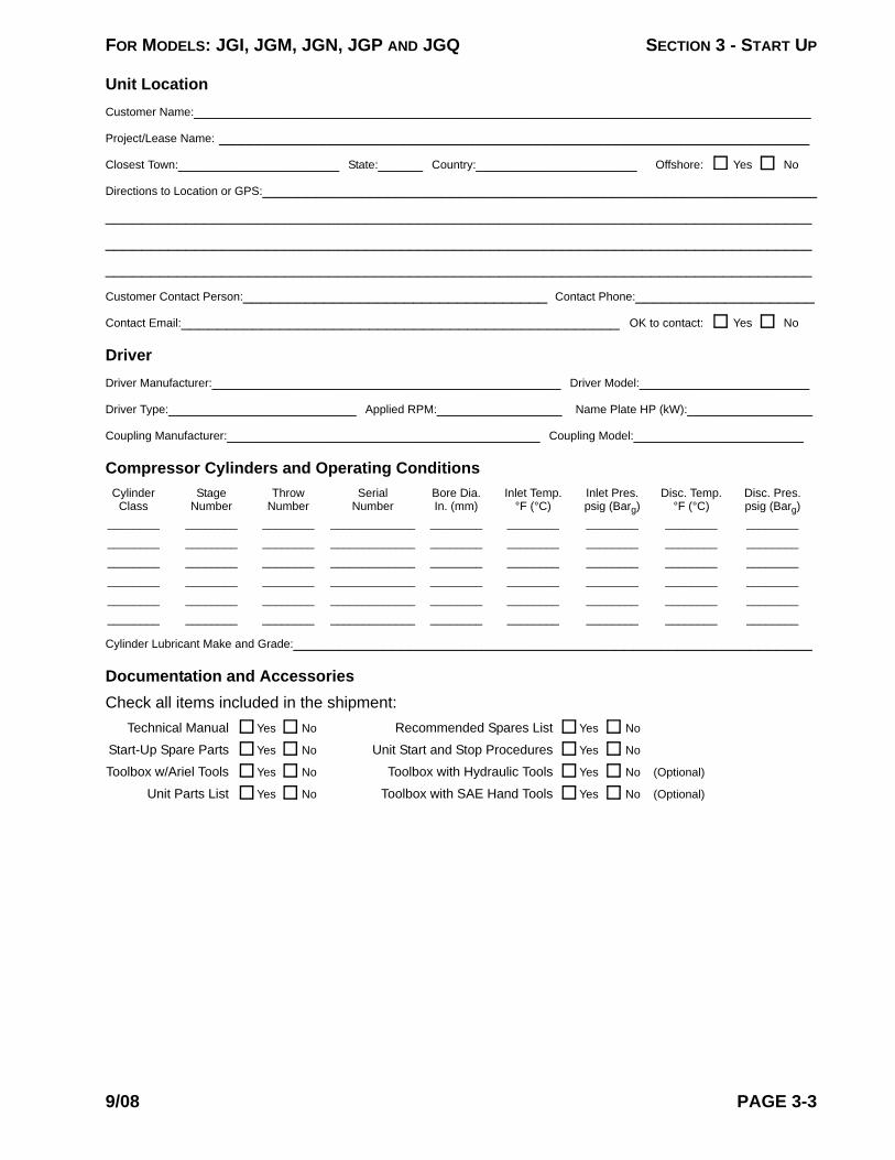
FOR MODELS: JGI, JGM, JGN, JGP AND JGQ SECTION 3 - START UP
Unit LocationCustomer Name:_____________________________________________________________________Project/Lease Name: __________________________________________________________________Closest Town:__________________ State:_____ Country:__________________ Offshore: Yes No
Directions to Location or GPS:___________________________________________________________________________________________________________________________________________________________________________________________________________________________________________________________________________________________________________Customer Contact Person:__________________________________ Contact Phone:____________________Contact Email:_________________________________________________ OK to contact: Yes No
DriverDriver Manufacturer:_______________________________________ Driver Model:___________________Driver Type:_____________________ Applied RPM:______________ Name Plate HP (kW):______________Coupling Manufacturer:___________________________________ Coupling Model:___________________
Compressor Cylinders and Operating Conditions Cylinder Stage Throw Serial Bore Dia. Inlet Temp. Inlet Pres. Disc. Temp. Disc. Pres. Class Number Number Number In. (mm) °F (°C) psig (Barg) °F (°C) psig (Barg)________ ________ ________ _____________ ________ ________ ________ ________ ________________ ________ ________ _____________ ________ ________ ________ ________ ________________ ________ ________ _____________ ________ ________ ________ ________ ________________ ________ ________ _____________ ________ ________ ________ ________ ________________ ________ ________ _____________ ________ ________ ________ ________ ________________ ________ ________ _____________ ________ ________ ________ ________ ________
Cylinder Lubricant Make and Grade:__________________________________________________________
Documentation and AccessoriesCheck all items included in the shipment:
Technical Manual Yes No Recommended Spares List Yes No
Start-Up Spare Parts Yes No Unit Start and Stop Procedures Yes No
Toolbox w/Ariel Tools Yes No Toolbox with Hydraulic Tools Yes No (Optional)
Unit Parts List Yes No Toolbox with SAE Hand Tools Yes No (Optional)
9/08 PAGE 3-3

FOR MODELS: JGI, JGM, JGN, JGP AND JGQ SECTION 3 - START UP
START-UP CHECK LIST - ITEMS TO CHECK IN THE FIELD AT COMMISSIONING
Description Date Checked Date Verified
1. Check and verify the top cover data plate of the compres-sor frame for compressor design limitations such as rod load, maximum and minimum speed, and maximum lube oil temperature.
Commissioning Agent: __________________ Distributor:___________
2. Check and verify the availability of correct start-up spares, hand tools, special tools, compressor parts list and draw-ings, and technical manuals at installation.
Commissioning Agent: __________________ Distributor:___________
3. Check and verify the Ariel lube sheet and Lubrication Specification matches the recommended oil grade and vis-cosity for the service.
Commissioning Agent: __________________ Distributor:___________
4. Check and verify all lube oil piping cleanliness per Ariel lubrication specifications (see Technical Manual, Section 4).
Commissioning Agent: __________________ Distributor:___________
5. Verify lube oil storage and supply line cleanliness per ER-56.06. Verify crankcase oil supply isolation valve is open.
Commissioning Agent: __________________ Distributor:___________
6. Verify prelube piping cleanliness per ER-56.06 and correct circuit operation.
Commissioning Agent: __________________ Distributor:___________
7. Verify there is an oil cooler and high temperature shut-down for the oil into the compressor frame.
Commissioning Agent: __________________ Distributor:___________
8. Verify whether the temperature control valve installation is blending or diverting (blending preferred). _____________
Commissioning Agent: __________________ Distributor:___________
9. Check compressor crankcase oil level controller for proper installation, operation, levelness, and venting.
Commissioning Agent: __________________ Distributor:___________
10. If applicable, check cooling water circuit cleanliness for the oil cooler and cooled packing per Technical Manual. Verify correct routing and test pump rotation. Set pressure appro-priately per Technical Manual and leak test.
Commissioning Agent: __________________ Distributor:___________
11. Verify correct filter element installation. Prime the oil filter element and all lube oil piping with oil.
Commissioning Agent: __________________ Distributor:___________
12. Verify proper compressor crankcase oil level before start-ing (about 7/8 full in site glass).
Commissioning Agent: __________________ Distributor:___________
13. Verify correct installation of a low oil pressure shutdown tubed to the downstream side of the oil filter.
Commissioning Agent: __________________ Distributor:___________
14. Operate pre-lube system. Commissioning Agent: __________________ Distributor:___________
15. OPTIONAL STEP: Record “out of plane” readings (pre-grout) - see ER-82.Drive End _________ _________ _________ _________ _________ _________ Auxiliary End
_________ _________ _________ _________ _________ _________
Commissioning Agent: __________________ Distributor:___________
16. Record soft foot readings. More than 0.002 inches (0.05 mm) pull-down on any frame foot requires cor-rection. See Technical Manual.Drive End _________ _________ _________ _________ _________ _________ Auxiliary End
_________ _________ _________ _________ _________ _________
Commissioning Agent: __________________ Distributor:___________
PAGE 3-4 9/08

FOR MODELS: JGI, JGM, JGN, JGP AND JGQ SECTION 3 - START UP
17. Check crosshead guide shimming for correct pre-load and hold down bolt torque.
Commissioning Agent: __________________ Distributor:___________
18. Record piston end clearances with feeler gages (see Technical Manual, Section 1, Clearances).Throw 1 2 3 4 5 6Head End _________ _________ _________ _________ _________ _________Crank End _________ _________ _________ _________ _________ _________
NOTE: Pre-lube compressor before turning crank-shaft.
Commissioning Agent: __________________ Distributor:___________
19. Measure and record rod run out (see Technical Manual, Section 5 for maximum acceptable readings).Throw 1 2 3 4 5 6
Vertical:Piston @ CE _________ _________ _________ _________ _________ _________Mid-Stroke _________ _________ _________ _________ _________ _________Piston @ HE _________ _________ _________ _________ _________ _________
Horizontal:Piston @ CE _________ _________ _________ _________ _________ _________Mid-Stroke _________ _________ _________ _________ _________ _________Piston @ HE _________ _________ _________ _________ _________ _________
NOTE: Pre-lube compressor before turning crank-shaft.
Commissioning Agent: __________________ Distributor:___________
20. Measure crosshead clearances with cylinders mounted. To check top, insert 0.5 inch (12.7 mm) wide feelers from one side edge across to the opposite side, at both ends. See Technical Manual, Section 1 for limits. To check bot-tom, insert a 0.0015 inches (0.038 mm) feeler at the four corners; feeler should insert no more than 0.50 (13 mm). Record feeler values below:
Throw Top Min. Top Max. Bottom Max. (Corners)1 _________ _________ _________2 _________ _________ _________3 _________ _________ _________4 _________ _________ _________5 _________ _________ _________6 _________ _________ _________
Commissioning Agent: __________________ Distributor:___________
21. For electric motor drivers, check and verify the motor shaft is set at its magnetic center before positioning axial clear-ance. With the coupling disconnected, check and verify driver rotation matches the compressor rotation arrow.
Commissioning Agent: __________________ Distributor:___________
22. Check coupling bolt torque to coupling manufacturer recommendations.
Commissioning Agent: __________________ Distributor:___________
START-UP CHECK LIST - ITEMS TO CHECK IN THE FIELD AT COMMISSIONING
Description Date Checked Date Verified
9/08 PAGE 3-5
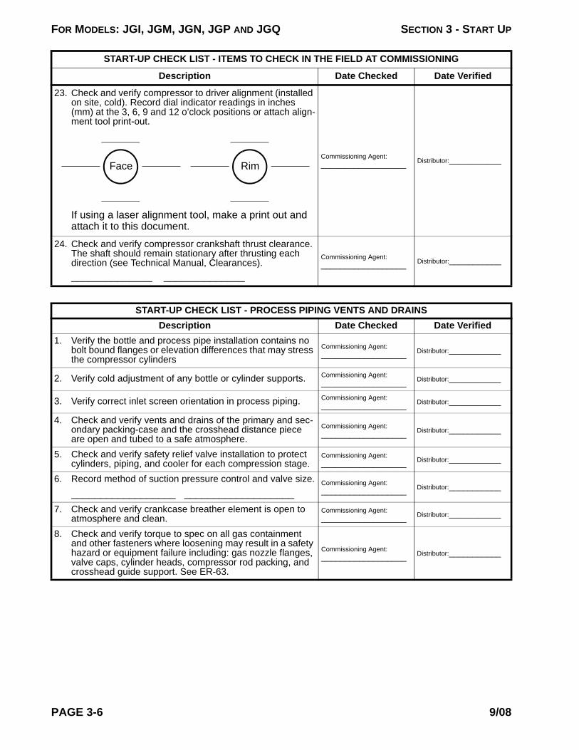
FOR MODELS: JGI, JGM, JGN, JGP AND JGQ SECTION 3 - START UP
23. Check and verify compressor to driver alignment (installed on site, cold). Record dial indicator readings in inches (mm) at the 3, 6, 9 and 12 o’clock positions or attach align-ment tool print-out.
If using a laser alignment tool, make a print out and attach it to this document.
Commissioning Agent: __________________ Distributor:___________
24. Check and verify compressor crankshaft thrust clearance. The shaft should remain stationary after thrusting each direction (see Technical Manual, Clearances).______________ ______________
Commissioning Agent: __________________ Distributor:___________
START-UP CHECK LIST - PROCESS PIPING VENTS AND DRAINSDescription Date Checked Date Verified
1. Verify the bottle and process pipe installation contains no bolt bound flanges or elevation differences that may stress the compressor cylinders
Commissioning Agent: __________________ Distributor:___________
2. Verify cold adjustment of any bottle or cylinder supports. Commissioning Agent: __________________ Distributor:___________
3. Verify correct inlet screen orientation in process piping. Commissioning Agent: __________________ Distributor:___________
4. Check and verify vents and drains of the primary and sec-ondary packing-case and the crosshead distance piece are open and tubed to a safe atmosphere.
Commissioning Agent: __________________ Distributor:___________
5. Check and verify safety relief valve installation to protect cylinders, piping, and cooler for each compression stage.
Commissioning Agent: __________________ Distributor:___________
6. Record method of suction pressure control and valve size. __________________ ___________________
Commissioning Agent: __________________ Distributor:___________
7. Check and verify crankcase breather element is open to atmosphere and clean.
Commissioning Agent: __________________ Distributor:___________
8. Check and verify torque to spec on all gas containment and other fasteners where loosening may result in a safety hazard or equipment failure including: gas nozzle flanges, valve caps, cylinder heads, compressor rod packing, and crosshead guide support. See ER-63.
Commissioning Agent: __________________ Distributor:___________
START-UP CHECK LIST - ITEMS TO CHECK IN THE FIELD AT COMMISSIONING
Description Date Checked Date Verified
Face Rim
PAGE 3-6 9/08

FOR MODELS: JGI, JGM, JGN, JGP AND JGQ SECTION 3 - START UP
START-UP CHECK LIST - INSTRUMENTATION
Description Date Checked Date Verified
1. Check and verify the set point for the high compressor oil temperature shutdown at 190°F (88°C) maximum.
Commissioning Agent: __________________ Distributor:___________
2. Check and verify proper vibration shutdown installation and operation. Record alarm and shut down settings.
________________________________________ ________________________________________ ________________________________________ ________________________________________
Commissioning Agent: __________________ Distributor:___________
3. Verify operation of suction pressure, inter-stage pressure, and discharge pressure shutdowns. Record alarm and shutdown settings.
________________________________________ ________________________________________ ________________________________________ ________________________________________
Commissioning Agent: __________________ Distributor:___________
4. Verify gas discharge temperature shutdowns operation. Record alarm and shutdown settings.
________________________________________ ________________________________________ ________________________________________ ________________________________________
Commissioning Agent: __________________ Distributor:___________
5. Check, verify, and record the over speed setting. _____________________
Commissioning Agent: __________________ Distributor:___________
START-UP CHECK LIST - FORCE FEED LUBRICATION SYSTEM
Description Date Checked Date Verified
1. Check and verify force feed lubricator box for proper oil level.
Commissioning Agent: __________________ Distributor:___________
2. Prime the force feed lubrication system through the purge port at the force feed pump discharge manifold. Check and verify each tube connection for tightness
Commissioning Agent: __________________ Distributor:___________
3. Check and verify operation of force feed lubrication system no flow shutdowns.
Commissioning Agent: __________________ Distributor:___________
4. Record color of force feed blow out discs (see Customer Technical Bulletin CTB-137 for disc ratings).
________________Commissioning Agent: __________________ Distributor:___________
5. Check, verify, and record recommended lube feed rates from lubricator data plate or “Parts Book” Cylinder Lubrica-tion sheet.
____________________
Commissioning Agent: __________________ Distributor:___________
9/08 PAGE 3-7

FOR MODELS: JGI, JGM, JGN, JGP AND JGQ SECTION 3 - START UP
FINAL PRE-START CHECK LIST
Description Date Checked Date Verified
1. Operate pre-lube system. Record pre-lube pressure.______________________
2. For engine driven units, disable the ignition and roll the engine with the starter to check and verify the compressor rolls freely. Check and verify oil pressure increases notice-ably while rolling on the starter.
Commissioning Agent: __________________ Distributor:___________
3. For electric motors, bar the compressor over manually to check and verify it rolls freely.
Commissioning Agent: __________________ Distributor:___________
4. For machines compressing a combustible gas, purge the entire system including the piping, by-pass, recycle line, and compressor cylinders of all air.
Commissioning Agent: __________________ Distributor:___________
5. Review start-up instructions for all other package compo-nents.
Commissioning Agent: __________________ Distributor:___________
6. Complete the required review of the Start-Up and Operat-ing Instructions for the unit with the unit operator.
Commissioning Agent: __________________ Distributor:___________
INITIAL POST START-UP CHECK LIST
Description Date Checked Date Verified
1. Check and verify immediate oil pressure increase. Enable oil pressure shutdown and bearing temperature shut-downs. Record initial pressure at operating speed.______________________
Commissioning Agent: __________________ Distributor:___________
2. Check and verify oil filter pressure gauges. Record initial differential.
___________________Commissioning Agent: __________________ Distributor:___________
3. Check and verify the low oil pressure shutdown is active and set at 45 psig (3.1 barg).
Commissioning Agent: __________________ Distributor:___________
4. Check and verify lube oil pressure set at 50 to 60 psig (3.5 to 4.2 barg) at operating speed and temperature (see Tech-nical Manual, Section 4). Record final setting.______________________
Commissioning Agent: __________________ Distributor:___________
5. Record oil filter maximum differential reference value listed on the compressor top cover filter data plate.
___________________Commissioning Agent: __________________ Distributor:___________
6. Listen and feel for any strange noises or vibration in the compressor or piping. Record any occurrences.
________________________________________ ________________________________________ ________________________________________ ________________________________________
Commissioning Agent: __________________ Distributor:___________
7. Check and verify high discharge gas temperature shut-downs are set about 10% above normal operating temper-ature (350 °F (177 °C) maximum) and functioning.
Commissioning Agent: __________________ Distributor:___________
PAGE 3-8 9/08

FOR MODELS: JGI, JGM, JGN, JGP AND JGQ SECTION 3 - START UP
8. Check and verify distribution block cycle time indicator and set lubricator pump for proper break-in rate.
Commissioning Agent: __________________ Distributor:___________
9. Check and verify the unit and piping is free from any gas or fluid leaks. Record any occurrences.
________________________________________ ________________________________________ ________________________________________ ________________________________________
Commissioning Agent: __________________ Distributor:___________
10. Check and verify scrubber high level shutdowns operation and check scrubber dumps operation and frequency.
Commissioning Agent: __________________ Distributor:___________
11. Check, verify, and record tank levels that indicate the amount of liquids removed from the gas. __________________________
Commissioning Agent: __________________ Distributor:___________
12. Check and verify piston rod packings seal properly in the primary packing vents.
Commissioning Agent: __________________ Distributor:___________
13. Check and verify operation of all safety functions to ensure unit shutdown upon indication.
Commissioning Agent: __________________ Distributor:___________
14. If applicable, check and verify main bearing temperatures and record. Watch for even bearing temperature increase.
Commissioning Agent: __________________ Distributor:___________
15. During various operational conditions, use the Ariel perfor-mance program to check and verify operational character-istics of various load steps.
Commissioning Agent: __________________ Distributor:___________
INITIAL POST START-UP CHECK LIST
Description Date Checked Date Verified
9/08 PAGE 3-9

FOR MODELS: JGI, JGM, JGN, JGP AND JGQ SECTION 3 - START UP
Maximum Allowable Working PressureAll Ariel Compressor Cylinders have a “Maximum Allowable Working Pressure (MAWP)”. The MAWP, the hydrostatic test pressure, and the test date are stamped on the end of every Ariel cylinder.
24-HOUR POST START-UP CHECK LIST
Description Date Checked Date Verified
1. Record "hot" alignment readings after reaching normal operating temperatures and components become heat soaked. Shutdown and vent gas system. Within 30 min-utes and while components are still hot, record dial indica-tor readings in inches (mm) at the 3, 6, 9 and 12 o’clock positions on lines provided below:
If using a laser alignment tool, make a print out and attach it to this document.
Commissioning Agent: __________________ Distributor:___________
2. If using a discharge bottle or head end cylinder supports, adjust when components are heat soaked to ensure no excessive forces exist to cause detrimental cylinder deflec-tion.
Commissioning Agent: __________________ Distributor:___________
3. Check and verify torque on gas nozzle flange, valve cap, cylinder head, compressor rod packing flange, and guide to frame bolting.
Commissioning Agent: __________________ Distributor:___________
4. Complete Ariel’s “Compressor Warranty Notification - Installation List Data” (pages 1 and 2).
Commissioning Agent: __________________ Distributor:___________
750-HOUR POST START-UP CHECK LIST
Description Date Checked Date Verified
1. Check and verify torque on gas nozzle flange, valve cap, cylinder head, and compressor rod packing flange bolting.
Commissioning Agent: __________________ Distributor:___________
2. Send completed form and check lists (pages 1-12) to Ariel as noted on page 1.
Commissioning Agent: __________________ Distributor:___________
CAUTIONOPERATING CONDITIONS MUST NOT EXCEED CYLINDER DESIGN LIMITATIONS.
Face Rim
!
PAGE 3-10 9/08

FOR MODELS: JGI, JGM, JGN, JGP AND JGQ SECTION 3 - START UP
Maximum allowable working pressure is the maximum continuous gauge pressure for which the compressor manufacturer has designed the equipment (or relevant part thereof) when handling the specified fluid at the specified temperature.
Maximum allowable working pressure of compressor cylinders shall exceed the rated dis-charge pressure by at least 10 %, or 25 psi (1.7 bar), whichever is greater. The maximum allowable working pressure shall be at least equal to the specified relief valve set pressure including accumulation. The rated discharge pressure (RDP) is the highest pressure required to meet the conditions specified by the purchaser for the intended service.
Relief Valve SettingsIt is the responsibility of the packager to provide relief valves for every stage of compression in compliance with ISO 13631. Relief valve location and settings, including accumulation, shall take into consideration all possible types of equipment failure, mal-operation and the protection of piping systems. Relief valves shall be set to operate at not more than the max-imum allowable working pressure, but not less than the values listed in ISO 13631:
Filling Sump & Priming a Main Oil Lube Oil System - Before Starting
Filling The Sump1. For compressors with automated lubricating oil fill systems, activate to fill the oil
sump. 2. For compressors without automated fill which use the crankcase as the oil
sump, remove breather and fill compressor sump with lubricating oil through top cover. When the sump is filled to the proper level, replace and snug up the breather cap by hand, to facilitate later removal.
3. Check sight glass on auxiliary end. Oil level at start-up should be near the top of
CAUTIONWHEN A BYPASS IS FURNISHED, A RELIEF VALVE MUST BE INSTALLED IMMEDIATELY DOWNSTREAM OF THE BYPASS VALVE OR ON THE INLET SCRUBBER OF THE DOWNSTREAM CYLINDER. THIS RELIEF VALVE MUST NOT BE SET HIGHER THAN THE MAXIMUM ALLOWABLE WORKING PRESSURE OF THE CYLINDER WHICH HAS THE LOWEST MAWP OF THOSE IN THE BYPASS CIRCUIT. THIS IS TO PROTECT AGAINST DISCHARGE CHECK-VALVE FAILURE WHEN OPERATING ON BYPASS.
!
9/08 PAGE 3-11

FOR MODELS: JGI, JGM, JGN, JGP AND JGQ SECTION 3 - START UP
the glass. DO NOT OVERFILL SUMP. The crankshaft will dip into the oil, churn it, and make it difficult to pump and to control the proper level. (After the machine is running, it may be necessary to add oil to bring up oil level to one-half the height of the sight glass; but it must never exceed two-thirds height while running.)
4. For compressors with separate oil sump, fill sump with lubricating oil as required.
Priming - Main Lube Oil SystemBE SURE THE OIL SYSTEM FROM THE LUBE OIL PUMP THROUGH THE COOLER
AND OIL FILTER IS FILLED WITH OIL.Remove cover doors and operate the prelube pump to verify that oil is dripping from the bearing and crosshead positions.
Compressor PrelubeSee Section 4 “Compressor Prelube” for the prelube requirements for starting the compres-sor.
Force Feed Lubricator AdjustmentBe sure that the force feed lubricator pumps are set at the break-in rate shown on the force feed lubricator data plates. Reference Section 1 for data plate location and legend illustra-tion. Indicators on the distributor blocks show the rate at which a block is cycling. To adjust, loosen locknut and turn the feed regulator (plunger stroke adjustment screw) on the pump at the lubricator box, until the indicator strokes at the proper rate, seconds per cycle. Refer-ence Section 5 lubricator box chain sprocket illustration for component legend. Re-tighten locknut. Run at this break-in setting for the first 200 hours of operation. The lubricator cycle time may then be increased to the normal operating rate. Reference Section 4 for more information on force feed lube rates.
Compressor Re-Application
IF ANY OF THE CONDITIONS LISTED BELOW CHANGE, CONSULT YOUR PACKAGER AND/OR ARIEL FOR ANY HARDWARE AND/OR DOCUMENTATION CHANGES THAT ARE REQUIRED. PERFORMANCE, OPERATING PRESSURES AND LUBrication RATE MUST BE RECALCULATED. A TORSIONAL VIBRATION ANALYSIS IS RECOMMENDED.
• GAS PRESSURES, TEMPERATURES OR FLOW REQUIREMENTS• GAS PROPERTIES• DRIVER TYPE, SPEED OR TORQUE• RE-LOCATION OF COMPRESSOR TO A DIFFERENT SITE• CYLINDER RE-CONFIGURATION; FRAME OR CYLINDER RE-RATE• CHANGE OF CYLINDER AND PACKING LUBRICANT TYPE
PAGE 3-12 9/08

FOR MODELS: JGI, JGM, JGN, JGP AND JGQ
SECTION 4 LUBRICATION
GeneralLubrication is vital for successful operation of a compressor. Adequate lubrication of the proper type in the proper place at the proper time is the key to successful lubrication. Although lubrication is an ongoing concern throughout the life of the compressor, the initial package design is very important and deserves special attention.
There are two independent systems for lubricating the compressor; the frame oil system and the force feed system. The frame oil system is a pressurized circulating system that supplies a constant pressurized supply of oil to the crankshaft, connecting rods and crossheads. The force feed system is a low volume high pressure injection system that supplies small quanti-ties of oil at regular intervals to lubricate the piston rod packings and the piston rings. In many applications these two systems can use the same lubricant, but in some applications the lubricants must be different.
Lubrication FunctionsLubrication performs at least six functions in a compressor.
1. Reduce friction:A lubricant decreases the resistance to movement between contacting compo-nents. The lubricant allows the components to slide on an oil film rather than directly on the component surfaces to reduce friction.
2. Reduce wear:A proper lubricating film minimizes contact between sliding components which reduces wear to increase equipment life expectancy and decrease maintenance costs.
3. Remove heat:Frictional heat is generated between the moving parts and the lubricating film. Circulating oil allows for heat removal to maintain working tolerances and extend oil life.
4. Prevent corrosion:Keeping air and moisture from the surfaces reduces corrosion to decrease debris particles, frictional heat, and component wear. Corrosion prevention is generally provided by additives rather than the base lubricant.
5. Seal and reduce contaminant buildup:A liquid lubricant fills small spaces to improve the gas seal on piston rings and packing rings, and flushes away contaminants from moving parts.
6. Dampen shock:
9/08 PAGE 4-1

FOR MODELS: JGI, JGM, JGN, JGP AND JGQ SECTION 4 LUBRICATION
A lubricant of a proper viscosity helps to cushion shock loads or pulsations to reduce vibration and noise, and increase component life.
Lubricant Characteristics
ViscosityViscosity is a measurement of the resistance of a fluid to flow. Viscosity measurement is temperature dependent and decreases with increasing temperature. Most commonly used are units of dynamic viscosity, which is expressed in units of Saybolt Universal Seconds (SUS) in English units and by centistoke (cSt) in metric. Proper viscosity is the most impor-tant aspect of compressor lubrication. The chart below illustrates the viscosity differences between base stock types.
Oil viscosity will increase when the oil begins to oxidize or when it is contaminated with oil or another liquid with higher viscosity. Oil viscosity will decrease when it is contaminated with hydrocarbon gas condensate or another liquid with lower viscosity. Oil will not "break-down"
10 20 30 40 50 60 70 80 90 100 110 120 130 1404.0
5.0
6.0
7.08.0
20
9.010
15
40
30
75
50
150
100
300
200
400500
500030002000
1000
10000
4.0
5.0
6.0
7.08.0
20
9.010
15
40
30
75
50
150
100
300
200
400500
500030002000
1000
10000
Temperature, Degrees Celsius (°C)
Kin
emat
ic V
isco
sity
, Cen
tisto
ke (c
St)
VISCOSITY INDEX:1. PAG = > 200 (Synthetic) 2. PAO = approx. 150 (Synthetic) 3. Paraffinic Mineral Oil = approx. 100 4. Diester = approx. 70 (Synthetic) 5. Napthenic Mineral Oil = < 80 Note: Curves are based on specific oils.
1.
3.4.
5.
2.
FIGURE 4-1 VISCOSITY VS. TEMPERATURE GRAPH SHOWING DIFFERENT TYPES OF LUBRICANTS
PAGE 4-2 9/08

FOR MODELS: JGI, JGM, JGN, JGP AND JGQ SECTION 4 LUBRICATION
or "degrade" to a lower viscosity, unless it is a multi-viscosity oil (such as SAE 10w40). In the case of multi-viscosity oils, the viscosity improvers are breaking down, not the base oil itself.
Viscosity IndexA scale used to indicate the magnitude of viscosity changes with respect to temperature. The higher the viscosity index, the less the viscosity decreases as the temperature increases.
Pour PointPour point is the lowest temperature at which the oil will just barely flow. It becomes very important in cold weather starting applications and in cylinder and packing lubrication with very cold suction temperatures.
Flash PointFlash point is the lowest temperature at which the oil will vaporize to create a combustible mixture in air. If exposed to flame, the mixture will flash into flame and then extinguish itself. This is important in high temperature applications when the oil may come in contact with air.
Lubricant Base StockLiquid lubricants commonly used in compressors include petroleum based oils and synthetic fluids. All lubricant formulations start with base stock and lubricant additives are used to improve specific properties such as:
• Increase the viscosity index• Inhibit oxidation• Depress the lubricant pour point• Inhibit rust formation• Improve detergency • Provide anti-wear protection • Provide extreme pressure protection• Alter the friction characteristics• Decrease the effects of gas dilution to resist "washing" of the lubricant due to water,
wet or saturated gas, or dilutent properties of the gas stream.
Petroleum-Based Lubricants (also referred to as mineral oils)PARAFFINIC OILS
• Solvent refined or hydro-treated• West Texas Intermediate or Arab Light
9/08 PAGE 4-3
FOR MODELS: JGI, JGM, JGN, JGP AND JGQ SECTION 4 LUBRICATION
• Higher wax content• Viscosity Index, greater than 90• Pour point around 25°F (-4°C)• This is the most common mineral oil base stock.
NAPTHENIC OILS • Solvent refined or hydro-treated• South Louisiana crude• Lower Wax content• Viscosity Index, less than 80• Lower pour point than paraffinic oils• Better additive solvency
Synthetic LubricantsSynthetic lubricants are man-made materials with more consistent, controlled chemical structures than petroleum lubricants. This improves predictability of viscosity and thermal stability that results in much higher viscosity indexes than mineral oils. Additives can be used to modify all the common lubrication characteristics to meet or exceed the perfor-mance of mineral oils. There are three major types of synthetic fluids used for lubrication. They are commonly referred to as PAO, Diester, and PAG.
NOTE: Most synthetic lubricants with the proper viscosity are acceptable for use in the compressor frame. Check with your lubricant supplier or Ariel before using ANY lubricant, if you have any questions about the applicability of the lubricant in the frame.
POLYALPHAOLEFINS (PAO) - SYNTHESIZED HYDROCARBONS• Compatible with mineral oils• Most of the same properties as mineral oils• Requires additives to improve detergent action and improve seal compatibility• Soluble in hydrocarbon gases• High viscosity index, approximately 150• Low pour point• High flash point
ORGANIC ESTERS - DIESTERS AND POLYOLESTERS• Compatible with mineral oils, PAO and PAG oils• Incompatible with some rubbers (O-rings), plastics, and paints; compatible with Viton• Primarily used in air compressors• Leaves a soft carbon deposit when oxidized• Breaks down in water• Higher flash point than mineral oils• Can be made only to a viscosity of approximately (85-90 cSt at 40°C)• Higher viscosity achieved with additives or blending with heavier oils• Low viscosity index, approximately 70
PAGE 4-4 9/08

FOR MODELS: JGI, JGM, JGN, JGP AND JGQ SECTION 4 LUBRICATION
POLYALKYLENE GLYCOLS (PAG) • Very good lubricant for high pressure applications• Does not foul reservoirs. Excellent for any reinjection application• Resistant to hydrocarbon gas dilution• Most are water soluble, verify application with lubricant supplier• Not compatible with mineral or PAO oils, some plastics and paints• Requires complete system flush when changing to or from mineral or PAO oils• Compatible with Viton and HNBR• Poor inherent oxidation stability and corrosion protection - requires additives• Not recommended for air compressors.• Very high viscosity index, greater than 200
Lubricant FormulationsMany different oils are made from the same type of base stock by changing the additives. Most oils can be formulated with either a mineral oil base or a synthetic base. The types of additives can significantly alter the lubricant's physical characteristics and suitability for it's intended service. Additives can account for up to 30% of the volume of the oil.
Compounded Cylinder OilsCompounded oils are formulated for use in steam cylinders and/or compressor cylinders. These lubricants enhance oil film strength to counter the effects of water, wet gases, sol-vents, etc., present in the gas.
Additives can be animal or vegetable fats, or synthetic based. Animal and vegetable based additives have a very low oxidation resistance and do not perform well at high temperatures. However, most compounded oils today use some type of synthetic chemical instead of the natural additives. Compounded oil should not be used in the compressor frame. Historically, the additives have not been compatible with lead based bearing materials.
R&O OilRust and oxidation inhibited (R&O) oil is a very simple oil comprised of base stock, corrosion inhibitors, anti-wear and antioxidant additives. The viscosity of the base stock determines the viscosity of the finished product. This oil is a very good selection for use in the compres-sor frame and for most force feed systems.
Engine OilEngine oil is formulated for use in internal combustion engines. Its purpose is to counteract the negative effects of combustion and help keep the products of combustion (heat, soot, water, CO2) away from the moving parts of the engine. It is designed to attract water and soot and help keep it in suspension until it can be removed by the filter. These qualities are
9/08 PAGE 4-5

FOR MODELS: JGI, JGM, JGN, JGP AND JGQ SECTION 4 LUBRICATION
not required in the compressor frame and in fact may prove detrimental to the lubrication of the cylinders and packing.
ENGINE OIL ADDITIVES MAY INCLUDE:• Detergents for removing deposits around the moving parts• Dispersants for preventing deposits from forming and soot from agglomerating• Corrosion inhibitors to prevent rust and corrosion• Antioxidants to neutralize radicals that cause oxidation of the oil• Anti-wear additives to help prevent metal to metal contact • Viscosity improvers to improve the viscosity characteristics (primarily for multi-viscos-
ity oil)• Pour point depressants to reduce the temperature at which the oil solidifies• Anti-foam agents to help break up foam from air entrainment
Ash is not an additive. It is the heavy metal residue left over when the oil burns. Some of the additives, such as the detergents, dispersants and anti-wear additives contain heavy metals such as calcium (Ca), barium (Ba), magnesium (Mg), phosphorous (P), Zinc (Zn) or sodium (Na). When the oil is burnt on hot parts of the engine, these heavy metals are left behind and build a barrier that helps prevent wear such as valve seat recession.
Engine oil will work satisfactorily in the compressor frame and in many force feed systems in gathering or transmission applications since viscosity is the most important aspect of com-pressor lubrication. Although engine oil is generally not the best choice for compressor lubri-cation, operational aspects such as previous experience, inventory control, or simplicity of maintenance practices may outweigh the benefits of using a different type of oil.
EMULSIONOne common problem with engine oil is the formation of emulsions in the compressor and/or downstream equipment. The detergents in the oil allow the oil and water to mix. If the gas contains enough water, it will mix with the detergents in the oil and emulsify. Usually the emulsions will accumulate in the downstream equipment such as the scrubbers, but can also be found in the cylinders and coolers.
To eliminate an emulsion problem, the emulsions must be completely removed and all equipment thoroughly cleaned. Re-start the compressor using a R&O oil or some other appropriate non-detergent based oil.
Used Engine OilIf used engine oil is supplied for lubrication of the cylinders and packings, it must meet the listed requirements for cylinder and packing lubrication. The oil must be appropriately filtered (ß5=10 and ß12=75 and have an ISO 4406 cleanliness code of 17:16:14 ). Oil viscosity must be monitored and tested to be sure of adequate quality.
Gear OilGear oils are formulated for use in gear boxes or other components where components make frequent contact (boundary lubrication). The primary difference between these and other oils is the extreme pressure (EP) additives. The EP additives are usually sulfur or
PAGE 4-6 9/08

FOR MODELS: JGI, JGM, JGN, JGP AND JGQ SECTION 4 LUBRICATION
phosphorous based chemicals that bond with the iron and creates a material that has a low melting point. When the components contact each other, the new material easily breaks away to reduce wear.
The reaction of forming the new material takes place at very high local temperatures. These high temperatures are non existent in the compressor and therefore, the compressor does not need gear oil. However, it is commonly used in instances where a high viscosity oil is required such as ISO 460 or ISO 680.
If gear oil is used in the frame, it will be necessary to be sure the additives are not corrosive to lead or copper based bearing materials.
FRAME OIL SYSTEM
COMPONENTS
Oil StrainerAn oil strainer, installed upstream of the pump will prevent very large particles and objects from getting into the pump. Ariel supplies a 30 mesh (595 microns) strainer on all JGM:N:P:Q:JG:J:A:R:W:H:E:K:T compressors and a 40 mesh (400 microns) strainer on all JGC:D:U:Z:B:V, KBB:V compressors.
Oil PumpThe oil pump constantly supplies oil to all the journal bearings, bushings and crosshead slid-ing surfaces. The pump is direct coupled to the crankshaft by a chain and sprocket and is designed to provide adequate oil flow to the bearings when the compressor is operating at one-half of maximum rated speed.
The compressor frame driven lube oil pumps maintain oil pressure with a spring loaded reg-ulating valve within the pump head (some models have a separate pressure regulator). Lube system pressure can be raised or lowered by adjusting the spring tension on this valve.
Oil CoolerAn oil cooler is required and the packager is responsible for sizing the oil cooler. Ariel can supply the oil cooler as a purchased separately item. Factors that must be taken into account while sizing a cooler, are the cooling medium, cooling medium temperature, cooling medium flow rate, lube oil temperature, and lube oil flow rate. Oil heat rejection data for each frame is available in the Ariel Electronic Data Book (contact your Packager or Ariel when you need this information). The Data Book also specifies the required flow rate and temperature of cooling water necessary to properly cool the oil with Ariel supplied coolers. Insufficient cooling water flow rate is the primary cause of high oil temperatures.
The cooler should be mounted as close to the compressor as possible, with piping of ade-quate size to minimize pressure drop of both the lubricating oil and the cooling medium.
9/08 PAGE 4-7

FOR MODELS: JGI, JGM, JGN, JGP AND JGQ SECTION 4 LUBRICATION
Oil Temperature Control Valve
Thermostatic Control Valve
Lube Oil from Main Oil Pump
Lube Oil to Main Oil Filter
Lube Oil Cooler
Thermostatic control valve configuration may vary from this sche-matic, depending on valve size. In mixing mode, B connection is lube oil from main oil pump with tee connection to lube oil cooler inlet, C is from lube oil cooler outlet and A is to main oil filter. Valve connections A-B-C are marked on the valve.
AB
C
FIGURE 4-2 LUBE OIL THERMOSTATIC VALVE IN MIXING MODE
Thermostatic valves are required in conjunction with the cooler to con-trol the oil temperature in the com-pressor. The thermostatic valve is a three way valve that has a tempera-ture sensitive element. As the oil is heated the sensing element will open the third port in the valve.
There are two configurations for installing a thermostatic valve: diverting mode and mixing mode. Ariel recommends installation of the thermostatic valve in the mixing mode. In the mixing mode, as the oil heats up, the element opens a port in the thermostatic valve that allows oil from the cooler to mix with the hot oil from the bypass. In the diverting mode, the oil is diverted to the cooler when the oil from the compres-sor is hot enough to open the valve. The diverting mode monitors the temperature of the oil coming out of the compressor. The mixing mode monitors the temperature of the oil going into the compressor.
Oil FiltrationOil filters are required on all compressor frames to remove contamination that can damage the equipment and contamination that can damage the oil.
Contaminants that damage the equipment can be:
• Wear particles from the equipment• Airborne particles such as dust or sand• Solid particles from the gas stream• Dirt from new oil from the refinery
Contaminants that damage the oil can be:
• Soot (commonly from combustion in an engine)• Oxidized oil components• Air bubbles
The JGC/4, JGD/4, JGU/4, JGZ/4, JGB/4, JGV/4, KBB/4, KBV/4, JGE/6, JGK/6, JGT/6, JGC/6, JGD/6, JGU/6, JGZ/6, JGB/6, JGV/6 KBB/6 and KBV/6 compressors are equipped with simplex, cartridge style pleated synthetic type filters as standard. Cartridge filters are rated as 1 micron nominal and 12 micron absolute filters. The Beta ratings are ß1 = 2, ß5 = 10 and ß12 = 75.
All other Ariel frames are equipped with simplex, spin-on resin-impregnated type filters as standard. Spin on filters have a 5 micron nominal and 17 micron absolute rating. The Beta ratings are ß5 = 2 and ß17 = 75.
PAGE 4-8 9/08

FOR MODELS: JGI, JGM, JGN, JGP AND JGQ SECTION 4 LUBRICATION
There are many spin on filters that will fit an Ariel compressor, but very few meet the filtration ratings of Ariel filters. For this reason, Ariel does not recommend after market filters. Exer-cise caution if an after market filter is installed.
Pressure gauges are provided for monitoring pressure drop across the filter. Differential pressure is the primary indication of a plugged filter.
Compressor Prelube PumpAn automated compressor pre-lube system is strongly recommended for all Ariel compres-sors to extend bearing life and reduce operating costs. Compressors that meet any of the following criteria are required to have an automated pre-lube system to provide oil flow prior to start-up:
1. Electric motor driven compressors.
2. Unattended-start compressors, regardless of driver type.
3. All large frame compressor models (JGC, JGD, JGZ, JGU, JGB, JGV, KBB and KBV).
Automated compressor pre-lube systems must be designed and sized to provide 10 psig (0.7 barg) minimum pressure for a minimum of 30 seconds prior to starting, at the inlet to the oil gallery (after the filter), with minimum start-up oil viscosity and maximum allowable filter differential pressure. It is suggested that the prelube pump be sized at approximately 25% of the frame oil pump capacity. Reference Technical Manual, Section 1, Frame Specification Tables for frame oil pump flow rates, or see the Electronic Databook in the Ariel Perfor-mance Program. The purpose is to be sure there is oil flow to all bearings and bushings, and the clearances are filled with oil prior to start-up. A start permissive is desirable to sense for minimum required pressure/time at the inlet to the oil gallery.
Automated systems are to provide for shutdown if 35 psig (2.4 barg) oil pressure is not achieved within 10 seconds after the initiation of start-up (from when crankshaft starts to turn). If a compressor will not start or shuts down at start-up due to low oil pressure, do not attempt to re-start until the cause of low pressure is corrected.
Engine driven compressors with manual pre-lube pumps are to be adequately pre-lubed prior to starting. If 35 psig (2.4 barg) oil pressure is not achieved within 10 seconds after reaching engine idle speed, shutdown the compressor and correct the cause. Repeat man-ual pre-lube prior to each cranking for start-up.
Pre-lube pumps are to be located prior to the oil filter. When oil pressure exceeds 35 psig (2.4 barg) at start-up, a low oil pressure shutdown set at 35 psig (2.4 barg) must be active for all compressors.
Oil HeatersFrame oil heaters may be needed if the compressor must be started in cold weather applica-tions. Depending on the operational aspects of the compressor, one possible heating mode is to maintain the temperature in the compressor frame to a minimum temperature so that the compressor can be started immediately if needed, see Table 4-4. Another mode is to
9/08 PAGE 4-9

FOR MODELS: JGI, JGM, JGN, JGP AND JGQ SECTION 4 LUBRICATION
heat the oil from ambient to a minimum temperature prior to starting, see Table 4-5. The spe-cific application requirements will determine which heating mode is necessary.
Circulation type heaters are recommended. All compressor models have at least one con-nection for a heater. Four and Six throw frames have two locations. The maximum allowable wattage per unit area for an immersion heater is 15 W/in2 (2.3 W/cm2). This limit will prevent oil from coking on the heater element and reducing the efficiency of the heater. It will also prevent the coked oil particles from contaminating the remaining oil. JGU:Z, JGB:V and KBB:V models are designed to use circulation heating only.
Lube Oil Analysis Sampling PointA sampling point should be installed at a convenient location between the oil pump and the filter. This should be installed at an easily accessible location and designed to minimize the amount of dirt or debris that can collect around the dispensing point. A needle valve should be used to better control the flow of the pressurized oil.
TABLE 4-4 HEAT REQUIRED TO MAINTAIN MINIMUM FRAME TEMPERATURE
MODEL
MULTIPLY TIMES DIFFERENTIAL BETWEEN OIL & AMBIENT TEMPERATURE
2-THROW 4-THROW 6-THROW
kW/°F (kW/°C) kW/°F (kW/°C) kW/°F (kW/°C)
JGM:N:Q:P 0.0086 (0.0155) --- --- --- ---JG:A 0.0094 (0.0170) 0.0179 (0.0322) 0.0261 (0.0470)
JGW:R:J 0.0147 (0.0265) 0.0289 (0.0520) 0.0419 (0.0754)JGH:E:K:T 0.0252 (0.0454) 0.0492 (0.0886) 0.0731 (0.1316)
JGC:D 0.0392 (0.0706) 0.0722 (0.1300) 0.1044 (0.1880)JGU:Z 0.0534 (0.0961) 0.0944 (0.1700) 0.1319 (0.2374)
JGB:V & KBB:V --- --- 0.1295 (0.2331) 0.1768 (0.3182)
TABLE 4-5 HEAT REQUIRED TO WARM COLD COMPRESSOR FRAME & OIL
MODEL
MULTIPLY TIMES TEMPERATURE RISE DIVIDED BY TIME (h)
2-THROW 4-THROW 6-THROW
kW-h/°F (kW-h/°C) kW-h/°F (kW-h/°C) kW-h/°F (kW-h/°C)
JGM:N:Q:P 0.0275 (0.0495) --- --- --- ---JG:A 0.0352 (0.0634) 0.0818 (0.1472) 0.1347 (0.3425)
JGW:R:J 0.0591 (0.1064) 0.1212 (0.2182) 0.1832 (0.3298)JGH:E 0.1368 (0.2462) 0.2962 (0.5332) 0.4526 (0.8147)JGK:T 0.1494 (0.2689) 0.3024 (0.5832) 0.4526 (0.8147)JGC:D 0.2684 (0.4831) 0.5614 (1.0105) 0.8074 (1.4533)JGU:Z 0.4496 (0.8093) 0.8900 (1.6020) 1.2421 (2.2358)
JGB:V & KBB:V --- --- 1.4176 (2.5517) 2.0224 (3.6403)
PAGE 4-10 9/08
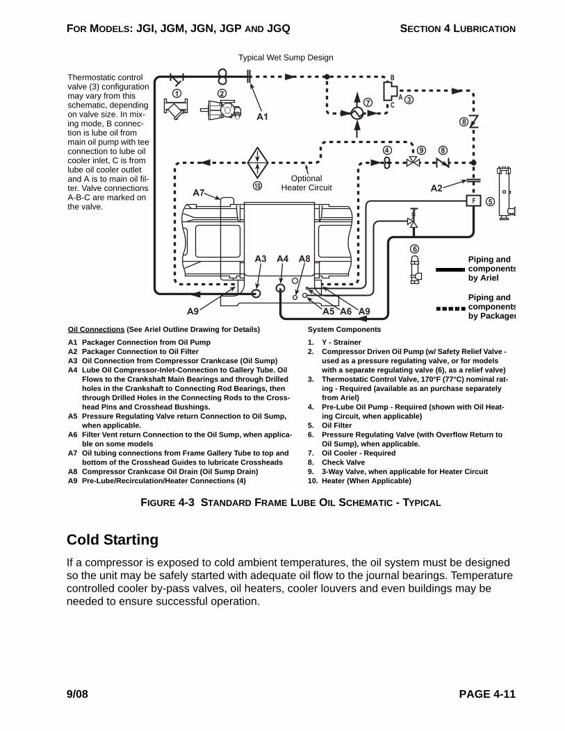
FOR MODELS: JGI, JGM, JGN, JGP AND JGQ SECTION 4 LUBRICATION
Cold StartingIf a compressor is exposed to cold ambient temperatures, the oil system must be designed so the unit may be safely started with adequate oil flow to the journal bearings. Temperature controlled cooler by-pass valves, oil heaters, cooler louvers and even buildings may be needed to ensure successful operation.
1 2
4 8
8
7 3
B
CA
5
6
A1
A2
A3 A4 A8
A5 A6
A7F
9
10
A9A9
Piping and componentsby Ariel
Piping and componentsby Packager
Typical Wet Sump Design
Oil Connections (See Ariel Outline Drawing for Details)
A1 Packager Connection from Oil PumpA2 Packager Connection to Oil FilterA3 Oil Connection from Compressor Crankcase (Oil Sump)A4 Lube Oil Compressor-Inlet-Connection to Gallery Tube. Oil
Flows to the Crankshaft Main Bearings and through Drilled holes in the Crankshaft to Connecting Rod Bearings, then through Drilled Holes in the Connecting Rods to the Cross-head Pins and Crosshead Bushings.
A5 Pressure Regulating Valve return Connection to Oil Sump, when applicable.
A6 Filter Vent return Connection to the Oil Sump, when applica-ble on some models
A7 Oil tubing connections from Frame Gallery Tube to top and bottom of the Crosshead Guides to lubricate Crossheads
A8 Compressor Crankcase Oil Drain (Oil Sump Drain)A9 Pre-Lube/Recirculation/Heater Connections (4)
System Components
1. Y - Strainer2. Compressor Driven Oil Pump (w/ Safety Relief Valve -
used as a pressure regulating valve, or for models with a separate regulating valve (6), as a relief valve)
3. Thermostatic Control Valve, 170°F (77°C) nominal rat-ing - Required (available as an purchase separately from Ariel)
4. Pre-Lube Oil Pump - Required (shown with Oil Heat-ing Circuit, when applicable)
5. Oil Filter6. Pressure Regulating Valve (with Overflow Return to
Oil Sump), when applicable.7. Oil Cooler - Required8. Check Valve9. 3-Way Valve, when applicable for Heater Circuit10. Heater (When Applicable)
Optional Heater Circuit
Thermostatic control valve (3) configuration may vary from this schematic, depending on valve size. In mix-ing mode, B connec-tion is lube oil from main oil pump with tee connection to lube oil cooler inlet, C is from lube oil cooler outlet and A is to main oil fil-ter. Valve connections A-B-C are marked on the valve.
FIGURE 4-3 STANDARD FRAME LUBE OIL SCHEMATIC - TYPICAL
9/08 PAGE 4-11
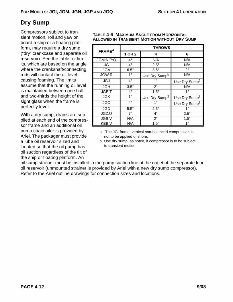
FOR MODELS: JGI, JGM, JGN, JGP AND JGQ SECTION 4 LUBRICATION
Dry Sump
TABLE 4-6 MAXIMUM ANGLE FROM HORIZONTAL ALLOWED IN TRANSIENT MOTION WITHOUT DRY SUMP
FRAMEA
a. The JGI frame, vertical non-balanced compressor, is not to be applied offshore.
THROWS1 OR 2 4 6
JGM:N:P:Q 4° N/A N/AJG 4° 2.5° N/A
JGA 6.5° 3.5° 2°JGW:R 1° Use Dry Sumpb
b. Use dry sump, as noted, if compressor is to be subject to transient motion.
N/AJGJ 4° 1° Use Dry Sump2
JGH 3.5° 2° N/AJGE:T 4° 1.5° 1°JGK 1° Use Dry Sump2 Use Dry Sump2
JGC 4° 1° Use Dry Sump2
JGD 5.5° 2.5° 1°JGZ:U 7° 4° 2.5°JGB:V N/A 2° 1.5°KBB:V N/A 1.5° 1°
Compressors subject to tran-sient motion, roll and yaw on board a ship or a floating plat-form, may require a dry sump (“dry” crankcase and separate oil reservoir). See the table for lim-its, which are based on the angle where the crankshaft/connecting rods will contact the oil level causing foaming. The limits assume that the running oil level is maintained between one half and two-thirds the height of the sight glass when the frame is perfectly level.
With a dry sump, drains are sup-plied at each end of the compres-sor frame and an additional oil pump chain oiler is provided by Ariel. The packager must provide a lube oil reservoir sized and located so that the oil pump has oil suction regardless of the tilt of the ship or floating platform. An oil sump strainer must be installed in the pump suction line at the outlet of the separate lube oil reservoir (unmounted strainer is provided by Ariel with a new dry sump compressor). Refer to the Ariel outline drawings for connection sizes and locations.
PAGE 4-12 9/08

FOR MODELS: JGI, JGM, JGN, JGP AND JGQ SECTION 4 LUBRICATION
FRAME OIL OPERATING CONDITIONS
Compressor Frame LubricantAriel recommends for use in the compressor frame, an ISO 150 grade paraffinic mineral oil that provides oxidation inhibition, rust and corrosion inhibition, and anti-wear properties. This is commonly called R&O oil.
8
1 2
4 88
7 3
B
CA
5
6
9
A1
A2
A3 A4 A8
A3
A5 A6
A7F
Piping and components by Ariel
Piping and components by Packager
Typical Dry Sump Design (“Dry” Crankcase)
- From drive end of frame.
Packager Connection toCompressor Driven Oil Pump
Install Check Valve (8) if over 3 Ft. (0.9 m) verti-cal run to Oil Sump (9)
Oil Connections (See Ariel Outline Drawing for Details)
A1 Packager Connection from Compressor Driven Oil PumpA2 Packager Connection to Oil FilterA3 Packager Connection - Oil from Compressor CrankcaseA4 Lube Oil Compressor-Inlet-Connection to Gallery Tube. Oil
Flows to the Crankshaft Main Bearings and through Drilled holes in the Crankshaft to Connecting Rod Bearings. From there, through Drilled Holes in the Connecting Rods to the Crosshead Pins and Crosshead Bushings.
A5 Pressure Regulating Valve Return Connection to Crank-case, when applicable on some models
A6 Filter Vent Return Connection to the Crankcase, when appli-cable on some models
A7 Oil Tubing Connections from Frame Gallery Tube to Top & Bottom of the Crosshead Guides to Lubricate Crossheads
A8 Compressor Crankcase Oil Drain
System Components
1. Y - Strainer - Required (supplied unmounted by Ariel)2. Compressor Driven Oil Pump (w/ Safety Relief Valve -
used as a pressure regulating valve, or for some models when a separate regulating valve (6) is pro-vided, as a relief valve)
3. Thermostatic Control Valve, 170°F (77°C) nominal rat-ing - Required (available as an option from Ariel)
4. Pre-Lube Oil Pump - Required (with oil heating circuit when applicable)
5. Oil Filter6. Pressure Regulating Valve (w/ Overflow Return to
Crankcase), when applicable for some models7. Oil Cooler - Required8. Check Valve9. Separate Lube Oil Reservoir (Oil Sump) - Required
Thermostatic con-trol valve (3) config-uration may vary from this schematic, depending on valve size. In mixing mode, B connec-tion is lube oil from main oil pump with tee connection to lube oil cooler inlet, C is from lube oil cooler outlet and A is to main oil filter. Valve connections A-B-C are marked on the valve.
FIGURE 4-4 OPTIONAL DRY-SUMP FRAME LUBE OIL SCHEMATIC - TYPICAL
9/08 PAGE 4-13

FOR MODELS: JGI, JGM, JGN, JGP AND JGQ SECTION 4 LUBRICATION
SAE 40 wt engine oil is also acceptable in the frame, but contains significant amounts of additives that are not necessary in a compressor.
In limited circumstances and with prior approval from Ariel, cold weather installations may use multi-viscosity oils in the compressor frame if the oil supplier can certify that the oil is shear stable. The viscosity of shear stable oil degrades less through use. Most oil suppliers will certify their oil as shear stable if the viscosity degrades less than a certain percentage in specific tests. As a result, multi-viscosity oils are subject to a shorter oil life than single straight grade oils by 30% to 50%.
Synthetics such as PAG, PAO, or ester based lubricants are acceptable in the compressor frame provided they meet the operating viscosity requirements as outlined below.
Compounded lubricants are prohibited in the frame.
Oil ViscosityThe minimum allowable viscosity of the oil going into the frame is 82.6 SUS (16 cSt). Typi-cally this is the viscosity of ISO 150 grade oil at about 190°F (88°C).
The maximum viscosity of the lube oil for cold ambient temperature starting is 15,000 SUS (3300 cSt). Typically this is the viscosity of ISO 150 grade oil at about 25°F (-4°C).
Oil PressureNormal pressure on the discharge side of the lube oil filter is factory set for 60 psig (4.1 barg) for compressors that were tested mechanically complete (has inspector tag). If tested at fac-tory as mechanically incomplete (without inspector tag), normal oil pressure must be set by packager or at initial start-up to 60 psig (4.1 barg) at full rated speed and normal operating temperature. If the lube oil pressure drops below 50 psig (3.4 barg), the cause should be found and corrected. A low lube oil pressure shutdown, set at 35 psig (2.4 barg), is required for protection of the compressor during a sudden loss of oil pressure. The compressor should not operate for prolonged periods of time at less than 50 psig (3.4 barg) oil pressure.
For proper operation of the thermostatic control valve, the maximum differential pressure between the hot oil supply line and the cooled oil return line is 10 psid (0.7 bard).
Oil TemperatureThe minimum lube oil operating temperature is 150°F (66°C). This is the minimum tempera-ture required to drive off water vapor.
Maximum allowable oil temperature into the compressor frame is 190°F (88°C).
A thermostatic control valve supplied by Ariel is set at 170°F (77°C). The oil temperature should be maintained as close to this temperature as possible. Higher temperatures increase the oxidation rate of the oil. For every 18°F (10°C) over 150°F (66°C), the oxidation rate of the oil doubles.
PAGE 4-14 9/08

FOR MODELS: JGI, JGM, JGN, JGP AND JGQ SECTION 4 LUBRICATION
Oil MaintenanceCompressor frame lubricating oil should be changed as indicated in the regular maintenance intervals or with a filter change or when oil analysis results indicate the need. A more fre-quent oil change interval may be required if operating in an extremely dirty environment without sampling and analysis or if the oil supplier recommends it.
Oil SamplingOil samples should be collected on a regular basis and analyzed to verify suitability of oil for continued service. Consistent oil analysis can identify when to change the oil on the basis of need rather than on a scheduled interval. Depending on the service, the length of time between oil changes can be significantly extended through oil analysis. Oil analysis should include:
• Viscosity testing should be performed at 100°F (40°C) and 212°F (100°C). This is to be sure that the oil has not mixed with cylinder oils or process gas.
• Particle counting to the latest version of ISO 4406.• Spectroscopy to determine wear metals, contaminants, and additives.• FTIR (Fourier Transform Infrared Spectroscopy) to check for oxidation, water or cool-
ant contamination, and additive depletion. This is more important if a separate lube oil is used for the force feed system.
Oil System CleanlinessThe compressor frame oil piping system and components are to be free of foreign matter including, but not limited to dirt, sand, rust, mill scale, metal chips, weld spatter, grease and paint. It is recommended that a commercial pipe cleaning service be used to clean the oil piping system. If that is not practical, proper cleaning procedures using cleaners, acids, and/or mechanical cleaning are to be used to meet the cleanliness requirements. Cleaning by-products are to be properly disposed; a disposal service is recommended. It is also recom-mended that all oil-piping systems be flushed using an electric or pneumatic driven pump and filtered clean production oil. All compressor frame cavities are thoroughly cleaned prior to assembly and compressors are test run with a filtered closed loop lube system at the Ariel factory.
Note: Ariel recommends that the lube oil piping downstream of the installed oil filter not be disturbed as contaminants that enter that piping or open ports will be flushed into the bearings causing catastrophic damage. If the piping must be removed or altered, great care must be taken to cover the inlets to the oil gal-leRy, the ends of the piping, and the filter outlet so that no contaminants may enter. Before reinstallation, chemical and mechanical cleaning is required. The pipe must then be flushed in accordance with Ariel’s stated cleanliness requirements.
For all compressors that are installed with an electric or pneumatic powered pre-lube pump, which have less than 50 feet (15 m) of oil piping are to be flushed as follows, prior to starting the compressor. The cooler oil passages are to be included in the flushing loop. Oil systems for compressors without an electric or pneumatic powered pre-lube pump, which have less
9/08 PAGE 4-15
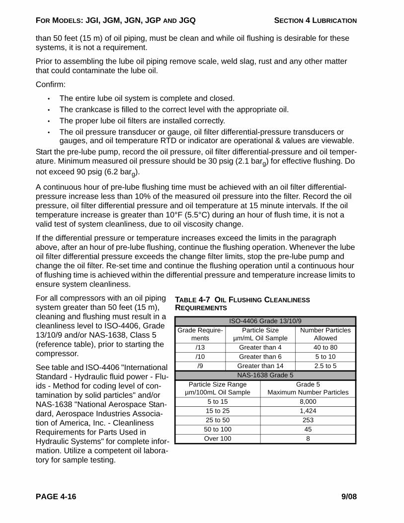
FOR MODELS: JGI, JGM, JGN, JGP AND JGQ SECTION 4 LUBRICATION
than 50 feet (15 m) of oil piping, must be clean and while oil flushing is desirable for these systems, it is not a requirement.
Prior to assembling the lube oil piping remove scale, weld slag, rust and any other matter that could contaminate the lube oil.
Confirm:
• The entire lube oil system is complete and closed.• The crankcase is filled to the correct level with the appropriate oil.• The proper lube oil filters are installed correctly.• The oil pressure transducer or gauge, oil filter differential-pressure transducers or
gauges, and oil temperature RTD or indicator are operational & values are viewable.Start the pre-lube pump, record the oil pressure, oil filter differential-pressure and oil temper-ature. Minimum measured oil pressure should be 30 psig (2.1 barg) for effective flushing. Do not exceed 90 psig (6.2 barg).
A continuous hour of pre-lube flushing time must be achieved with an oil filter differential-pressure increase less than 10% of the measured oil pressure into the filter. Record the oil pressure, oil filter differential pressure and oil temperature at 15 minute intervals. If the oil temperature increase is greater than 10°F (5.5°C) during an hour of flush time, it is not a valid test of system cleanliness, due to oil viscosity change.
If the differential pressure or temperature increases exceed the limits in the paragraph above, after an hour of pre-lube flushing, continue the flushing operation. Whenever the lube oil filter differential pressure exceeds the change filter limits, stop the pre-lube pump and change the oil filter. Re-set time and continue the flushing operation until a continuous hour of flushing time is achieved within the differential pressure and temperature increase limits to ensure system cleanliness.
TABLE 4-7 OIL FLUSHING CLEANLINESS REQUIREMENTS
ISO-4406 Grade 13/10/9Grade Require-
mentsParticle Size
µm/mL Oil SampleNumber Particles
Allowed/13 Greater than 4 40 to 80/10 Greater than 6 5 to 10/9 Greater than 14 2.5 to 5
NAS-1638 Grade 5Particle Size Range
µm/100mL Oil SampleGrade 5
Maximum Number Particles5 to 15 8,00015 to 25 1,42425 to 50 253
50 to 100 45Over 100 8
For all compressors with an oil piping system greater than 50 feet (15 m), cleaning and flushing must result in a cleanliness level to ISO-4406, Grade 13/10/9 and/or NAS-1638, Class 5 (reference table), prior to starting the compressor.
See table and ISO-4406 "International Standard - Hydraulic fluid power - Flu-ids - Method for coding level of con-tamination by solid particles" and/or NAS-1638 "National Aerospace Stan-dard, Aerospace Industries Associa-tion of America, Inc. - Cleanliness Requirements for Parts Used in Hydraulic Systems" for complete infor-mation. Utilize a competent oil labora-tory for sample testing.
PAGE 4-16 9/08
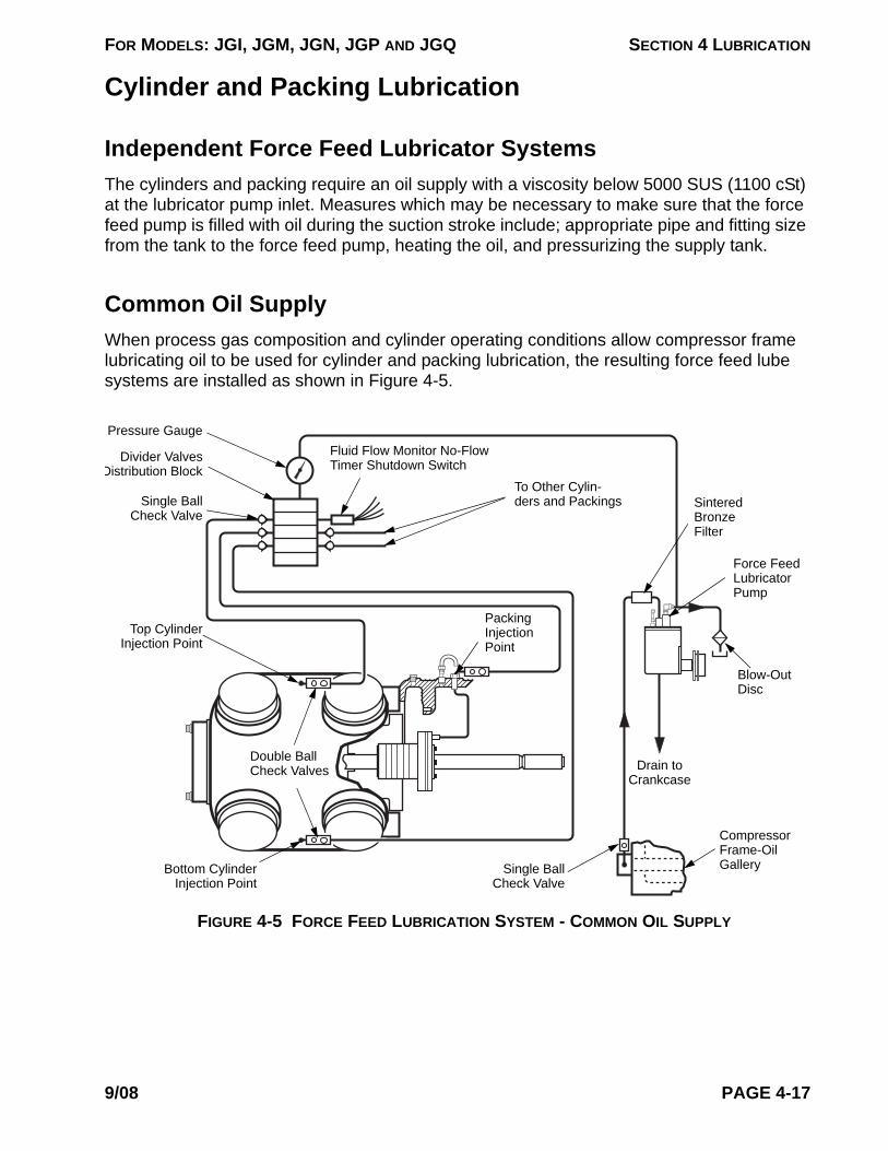
FOR MODELS: JGI, JGM, JGN, JGP AND JGQ SECTION 4 LUBRICATION
Cylinder and Packing Lubrication
Independent Force Feed Lubricator SystemsThe cylinders and packing require an oil supply with a viscosity below 5000 SUS (1100 cSt) at the lubricator pump inlet. Measures which may be necessary to make sure that the force feed pump is filled with oil during the suction stroke include; appropriate pipe and fitting size from the tank to the force feed pump, heating the oil, and pressurizing the supply tank.
Common Oil SupplyWhen process gas composition and cylinder operating conditions allow compressor frame lubricating oil to be used for cylinder and packing lubrication, the resulting force feed lube systems are installed as shown in Figure 4-5.
Fluid Flow Monitor No-Flow Timer Shutdown Switch
To Other Cylin-ders and Packings Sintered
Bronze Filter
Blow-Out Disc
Compressor Frame-Oil Gallery
Force Feed Lubricator Pump
Drain to Crankcase
Single Ball Check Valve
Double Ball Check Valves
Bottom Cylinder Injection Point
Packing Injection Point
Single Ball Check Valve
Divider Valves Distribution Block
Pressure Gauge
Top Cylinder Injection Point
FIGURE 4-5 FORCE FEED LUBRICATION SYSTEM - COMMON OIL SUPPLY
9/08 PAGE 4-17

FOR MODELS: JGI, JGM, JGN, JGP AND JGQ SECTION 4 LUBRICATION
Independent Oil Supply
NOTE: System must pro-vide positive pressure to
force feed lubricator pump.
Pump Suction1/4 inch NFT (Female)Customer Connection
Divider Valves - Distribution Block
Fluid Flow Moni-tor No-Flow Timer Shutdown Switch
To Appropriate Drain 1/4 inch NPT (Female) Customer Connection
Do Not Drain to Crankcase
Blow-OutDisc
Force Feed Lubicator Pump
Oil Filter
Sintered Bronze
Filter
Pressure Gauge
FIGURE 4-6 FORCE FEED LUBRICATION SYSTEM - INDEPENDENT OIL SUPPLY
Oil Supply Tank
When process gas composition and cylinder operating conditions require an independent cyl-inder and packing oil supply, the resulting separate force feed lube sys-tems require an oil supply. Lubricator oil is supplied under pressure from an elevated tank. To prevent the compressor frame oil from being con-taminated by the force feed oil, be sure that the lubri-cator box over flow does not drain into the crankcase. The lubricator box over flow tubing must be disconnected from the compressor frame and directed to an appropriate drain system.
Independent force feed lube systems require oil with a viscosity below 5000 SUS (1100 cSt) at the lubricator pump inlet. Measures which may be necessary to make sure that the force feed pump is filled with oil during the suction stroke include; appropriate pipe and fitting size from the tank to the force feed pump, heating the oil, and pressurizing the supply tank. An in-line oil filter or fine screen is required between the supply tank and the force feed lubricator pumps. Recommended filtration is 5 micron nominal.
Force Feed Lubrication System Components
Gas Inlet Debris Screens to Maintain Lube PerformanceEven when the proper rate and lubricating medium are in use, dirt and foreign matter in the gas will prevent the lubricant from performing properly. Prior to start-up, cone type inlet gas debris strainers with 100 mesh per inch (150 micron) screen and perforated metallic backing are to be installed in a pipe spool between the inlet scrubber and cylinder suction flange. In
PAGE 4-18 9/08
FOR MODELS: JGI, JGM, JGN, JGP AND JGQ SECTION 4 LUBRICATION
order to protect the compressor cylinder, any piping or vessels downstream of the screen must be thoroughly cleaned to be sure that no debris is present. Proper maintenance of the inlet screens is required. Inlet debris strainers should be monitored by differential pressure and cleaned before the differential pressure approaches the collapse pressure of the screens.
High differential pressure alarm/shutdown switches can be used to protect against screen collapse.
Injection Oil Inlet FilterAn in-line oil filter or fine screen is required between the oil supply or supply tank and the force feed lubricator pumps. Ariel recommended filtration is 5 micron nominal. The compres-sor filtration system is adequate for systems that use frame lube oil for the force-feed cylin-der and packing injection. For separate force-feed lube oil supplies, a filter must be installed by the packager.
Oil DilutionCylinder lubrication requirements will vary with the operating conditions and the composition of the gas to be compressed. Careful consideration must be given to proper cylinder lubrica-tion selection. The degree of cylinder oil lubrication dilution/saturation by the process gas stream is influenced by the following factors:
1. Process gas composition/Specific Gravity (SG) - usually the higher the SG, the greater the oil dilution.
2. Discharge gas pressure - the higher the pressure, the greater the oil dilution.3. Discharge gas temperature - the higher the cylinder discharge temperature, the
less the oil dilution.4. Lubricant selection - some types of oil are more prone to dilution than others.
Cylinder Oil Lubrication ExamplesRefer to Table 4-9 for lubrication recommendations for various gas compositions and various operating conditions. Note that lubrication rates can change with operating conditions. Lubri-cating oil type will also vary with the composition of the gas which is to be compressed.
Independent force feed lube systems require oil with a viscosity below 5000 SUS (1100 cSt) at the lubricator pump inlet. Measures which may be necessary to make sure that the force feed pump is filled with oil during the suction stroke include; appropriate pipe and fitting size from the tank to the force feed pump, heating the oil, and pressurizing the supply tank.
Under/Over LubeInadequate - (under) lubrication. This condition results in extremely rapid breakdown of pis-ton and packing ring materials. Black, gummy deposits which can be found in the distance piece, packing case, cylinder and valves are indicators of under lubrication.
9/08 PAGE 4-19
FOR MODELS: JGI, JGM, JGN, JGP AND JGQ SECTION 4 LUBRICATION
Excessive - (over) lubrication can result in excessive oil carryover into the gas stream, and increased quantities of deposits in the valves and gas passages. Valve plate breakage and packing failure may also be symptoms of over lubrication.
Inadequate Lubrication SymptomsWhen observed symptoms indicate inadequate lubrication; first verify that the force feed lubricator pumps are operating properly. Confirm that the distribution block cycle time matches the lube sheet or lubrication box information plate provided by Ariel, and double check that all tubing and fittings are tight and no leaks are present. Do not overlook the fit-tings inside the cylinder gas passages. Pressure test or replace divider valves to be sure they are not bypassing.
Lubrication Quantity - Paper Test MethodTo check cylinders for the proper lubrication rates, the cigarette paper test method can pro-vide a practical indication. Relieve and vent all pressure from all cylinders. Remove the head end head and position piston at about inner center, for the cylinder to be checked. “Lock out” so that crankshaft can not be accidentally turned; see the “CAUTION” in Technical Manual Section 5 and refer to the Packager’s Operation Manual for details. Use two layers of regular unwaxed commercial cigarette paper, together. Wipe the cylinder bore at top with both papers using light pressure in circumferential motion through about 20°. The paper next to the bore should be stained (wetted with oil), but the second paper should not be soaked through.
Repeat the test at both sides of the bore at about 90° from the top, using two new clean papers for each side. When the paper next to the bore is not stained through, it may be an indication of under lubrication. When both papers are stained through, it may be an indica-tion of over lubrication. In either case, it is normally recommended that the lubrication rate be changed accordingly and that all cigarette paper tests be repeated until passed. Repeat for all cylinders. If a reduction or increase of the lubrication rate is indicated for a cylinder, change in 5% increments by adjusting cycle time at the force feed lube pump as discussed in “Force Feed Lubricator Adjustment” in Technical Manual Section 3. Repeat oil film testing, for the cylinders affected, after 24 hours of operation.
NOTE: THE CIGARETTE PAPER TEST ONLY GIVES AN INDICATION OF OIL FILM QUANTITY. AFTERMARKET DEVICES THAT MEASURE FLOW ARE ALSO AVAILABLE. NEITHER METHOD GIVES AN INDICATION OF VISCOSITY QUAL-ITY. OILS DILUTED WITH WATER, HYDROCARBONS OR OTHER CONSTITU-ENTS MAY PRODUCE WHAT APPEARS TO BE AN ADEQUATE FILM OR FLOW. BUT THE OIL FILM MAY NOT HAVE THE REQUIRED LOAD-CARRYING CAPABILITY DUE TO THE DILUTION.
Lubricator Cycle TimeThe lubricant flow rates (measured in seconds per cycle) are generally so low that all of the required flow to a lube point may be observed as a drip at a loosened supply fitting. The break-in and normal lube timing rates which are stamped on the lubricator box information
PAGE 4-20 9/08

FOR MODELS: JGI, JGM, JGN, JGP AND JGQ SECTION 4 LUBRICATION
plate are calculated according to the Ariel Lube Specifications, as given in this document, to match the gas and operating conditions as supplied to Ariel with the compressor order. The lube sheets supplied in the Ariel Parts Book state gas conditions and list the base rate multi-plier at each lube point. If gas conditions were not supplied with the compressor order, the information plate/lube sheets rates are for clean, dry, 0.65 specific gravity, sweet gas at rated speed and discharge pressures.
If the compressor operating conditions change (such as gas properties, gas pressures, tem-peratures or flow requirements or cylinder re-configuration) the lubrication rates must be recalculated and hardware changes may be necessary to the force-feed lubrication system. Consult Table 4-9 and your Packager and/or Ariel.
Cycle Time IndicationTo set the proper force-feed lubricator pump flow rate, read the cycle time on the Proflo elec-tronic lubricator fluid-flow monitor/no-flow timer switch located at the distribution block or in control panel, reference Technical Manual Section 5. Or if a digital no-flow timer switch (DNFT) is provided, time the cycle from flash to flash, or for a magnetic cycle indicator assembly, time the cycle from initial movement of the indicator pin at the fully retracted posi-tion to the time when the pin returns to the fully retracted position and just begins initial movement back out again. Adjust the lubricator pump to provide the required cycle time-flow rate.
NOTE: WHEN ADJUSTING THE FORCE FEED LUBRICATION PUMP SETTING FOR THE APPROPRIATE CYCLE TIME, DO NOT SET THE FLOW RATE TOO LOW. THE PUMPS CAN BECOME INCONSISTENT WHEN SET TOO LOW.
Force Feed Lubrication System Monitoring:
Minimum RequirementsAriel requires the unit control panel to shutdown the unit if the master lube distribution block stops cycling while the compressor is running. The control panel is to wait for a maximum time of 3 minutes after the distribution block stops cycling to issue the shutdown. This is a class B shutdown. A class B shutdown is defined as a shutdown that is not armed until a short time after the compressor is started. Typically 2 minutes. This gives the divider blocks time to cycle the first time before the shutdown is activated.
DevicesAriel offers several devices that can be used to obtain the lube system shutdown. There are two basic types. Note that some devices have both functions built in.
9/08 PAGE 4-21

FOR MODELS: JGI, JGM, JGN, JGP AND JGQ SECTION 4 LUBRICATION
T
C
Choosing a Lube System MonitorWhen ordering an Ariel compressor the packager must choose a lube system monitor. See the following table for the specifications on available types. For further information about each device visit the vendor literature section of the Ariel web site.
I. Shutdown switch - This is a device that monitors the position of the divider block pin and supplies a shutdown contact. If the divider block stops cycling for a given time a shutdown signal will be sent to the control system.
APPLICATION NOTES - Shutdown Switch
Normally open (NO) vs. Normally closed (NC) Shutdown switch
ABLE 4-8 FORCE FEED LUBE SYSTEM MONITORS - SPECIFICATIONS
ITEM PROFLO KENCO DNFT DNFT - PROGRAMMABLE
Shutdown Signal YES NO YES YESProximity Signal YES (0.5 sec pulse) YES (switch) YES (switch) YES (switch)
Local Data Storage YES NO NO Count DisplayInfrared Port YES NO NO NOPLC Creates
ShutdownNO YES NO NO
Remote Mounting YES NO NO NOArea Classification CSA CSA CSA, CE, EX, ATEX CSA, CE
CSA 203633 Class I, Div 2, Groups
ABCD T4A
044787 Class I, Groups ABCD:
Class II, Groups EFG:Class III
108334 Class I, Div 1 Groups ABCD T5; &/or Class I, Zone 1
Ex md IIC T5
108334 Class I, Div 1 Groups ABCD T5; &/or Class I, Zone 1 Ex md
IIC T5CE N/A N/A 0344 Class I Div 1;
Groups ABCD T40344 Class I Div 1; Groups ABCD T4
EX N/A N/A II 2G EEx mIIB T5 N/AKEMA N/A N/A 00ATEX1090X/
AMB. -40°C to +85°C
N/A
Battery (2) Standard Alka-line “AA” Size
None Ariel P/N A-10807 Ariel P/N A-10807
ost Factor New Unit $0 Standard Minus $ $0 Standard for CE Plus $Shutdown Time Programmable PLC 3 minutes Programmable
20 sec. to 4 minutesTemperature to185°F (85°C) to 220°F (104°C) -40°F to +185°F (-
40°C to +85°C)-40°F to +185°F(-40°C to +85°C)
Max. Switch Voltage 36 VDC 200 VAC/VDC 240 VDC 10 to 120 VACMax. Switch Current 0.5 Amps 0.5 Amps N/A N/AMax. Switch Power N/A 10 Watts DC 2.5 VA 2.5 VA
Local Cycle Indicator YES - LCD Separate Indicator YES - Flashing LED YES - LCD Display +LED
De-bounce Included NO NO YES YES
PAGE 4-22 9/08

FOR MODELS: JGI, JGM, JGN, JGP AND JGQ SECTION 4 LUBRICATION
Divider block monitoring devices define their operation opposite from other industries. Most other industries define the switch state as the state the switch is in when it is on the shelf. (That is: If a momentary push button switch is NO, then when it is taken out of the box the switch will be open until the button is pushed and the contact will close. If a momentary push button switch is NC then when it is taken out of the box the switch will be closed until the button is pushed.) This does not apply to divider block monitoring devices.
Divider block device manufacturers have "simplified" things for the mechanic. Normally Open (NO) refers to the state the switch is in when the divider block is cycling or the unit is running. An NO switch means that when the unit is running the shutdown switch is open or non-failsafe. If a wire falls off or is cut while the unit is running the control system will never stop the unit. If the device is damaged or a wire has come loose at startup the control system would never know there is a problem. An NC switch means that when the unit is running the shutdown switch is closed or failsafe. Now if a wire falls off or is cut the control system will detect that the switch is open and shutdown the unit.
Ariel recommends using a NC (failsafe) switch. However, when a NO (non-failsafe) switch is used, Ariel recommends testing the shutdown circuits at least once a month.
II. Proximity switch - This is a device that will sense the position of the divider block piston and will produce a switch change of state or a pulse every time the pin changes position. This device must be combined with a PLC or some other counter/timer device to produce the shutdown. Some devices on the market will open the switch when the pin is toward the left and close when the pin is toward the right. Others will produce a 0.5 second pulse when the pin moves from left to right. If this is used it is the responsibility of the control system to sense the switch cycling and stop the unit if a block stops cycling.
APPLICATION NOTES - Proximity Switch
Ariel recommends setting up the control system to find the time between cycles triggered when the switch transitions from off to on. See Figure 4-7 suggested control system block diagram.
1. Shutdown time with no lubrication - The distribution block cycle times will vary slightly from cycle to cycle. Seeing 12 seconds one cycle then 15 seconds the next then 14 the next is normal. The recommended shutdown time is: 2 times the design cycle time + 30 seconds limited between 30 seconds and 3 minutes.
LIMIT (2 x design cycle time + 30 seconds) 30, 180
Design cycle time is found on the compressor lube sheets or tag on the com-pressor.
2. DE-BOUNCE and latching circuits - Depending on the device and control sys-tem scan time it may be necessary to include de-bounce hardware and/or soft-ware. Some of the devices do not have built in de-bounce circuits and can cause a fast control system to double or triple count. Other times it may be necessary latch the input thus allowing the control system to detect only the first transition from low to high. This becomes significant when displaying the cycle time for the operator to set the pump flow rates and when calculating the total oil through the divider block.
3. Suggested Operator Displays:
9/08 PAGE 4-23

FOR MODELS: JGI, JGM, JGN, JGP AND JGQ SECTION 4 LUBRICATION
Divider block cycle time - The operator will need to set the lube system pumps according to the recommended divider block cycle times. It is helpful for the operator to have a display of divider block cycle time in seconds. This will be used to adjust the lube pumps as the pumps wear out and when the pumps are replaced to set divider block cycle times.
Time since last Pulse - It is helpful to have a display of the timer timing so the operator can see a change and show that something is happening.
Average Cycle Time - Cycle time will vary a few seconds from cycle to cycle. It is sometimes helpful to display a cycle time that has been averaged over 5 to 10 cycles.
Total Oil Consumed - Total oil consumed can be useful to the operator to know how much oil is being used for the lube system and thus how much oil to order.
4. EXAMPLE FLOW DIAGRAM TO CREATE SHUTDOWNFigure 4-7 flow diagram is a suggested method of creating a shutdown within the PLC from a cycling digital input. This is only a suggestion as there is no way of providing logic for all control systems.
PAGE 4-24 9/08

FOR MODELS: JGI, JGM, JGN, JGP AND JGQ SECTION 4 LUBRICATION
Break-in RateThe force feed lubrication pumps should be capable of delivering 150% minimum of the “normal” required lube rate for the break in period (set as close as possible to twice the “nor-mal” rate for 200 hours). Please contact Ariel for assistance if the existing pump is not capa-ble of the minimum flow rate required.
Liquids in GasThe use of higher viscosity lubricants or specially compounded lubricants can compensate somewhat for the presence of liquids in the gas stream.
FIGURE 4-7 SUGGESTED FORCE FEED LUBE CONTROL SYSTEM PROXIMITY SWITCH SHUTDOWN LOGIC DIAGRAM
Start Reset Timer
Send Shutdown Signal Output
Unit Running Class B Timer?
Is Timer >3 Minutes?
No Shutdown to Output
T = True
F = False
Prox. Switch OFF to ON?
Increment Counter
Stop Timer
Read Lube Digital Input
Initialize Timer
Start
End
Calculate Total Oil Flow
F
TT
T
F F
9/08 PAGE 4-25
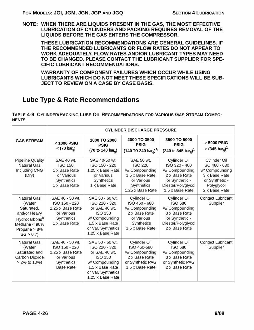
FOR MODELS: JGI, JGM, JGN, JGP AND JGQ SECTION 4 LUBRICATION
TABNEN
G
PiN
In g
N
a HMeP
nt
N
SCa>
nt
NOTE: WHEN THERE ARE LIQUIDS PRESENT IN THE GAS, THE MOST EFFECTIVE LUBRICATION OF CYLINDERS AND PACKING REQUIRES REMOVAL OF THE LIQUIDS BEFORE THE GAS ENTERS THE COMPRESSOR. THESE LUBRICATION RECOMMENDATIONS ARE GENERAL GUIDELINES. IF THE RECOMMENDED LUBRICANTS OR FLOW RATES DO NOT APPEAR TO WORK ADEQUATELY, FLOW RATES AND/OR LUBRICANT TYPES MAY NEED TO BE CHANGED. PLEASE CONTACT THE LUBRICANT SUPPLIER FOR SPE-CIFIC LUBRICANT RECOMMENDATIONS.WARRANTY OF COMPONENT FAILURES WHICH OCCUR WHILE USING LUBRICANTS WHICH DO NOT MEET THESE SPECIFICATIONS WILL BE SUB-JECT TO REVIEW ON A CASE BY CASE BASIS.
Lube Type & Rate Recommendations
LE 4-9 CYLINDER/PACKING LUBE OIL RECOMMENDATIONS FOR VARIOUS GAS STREAM COMPO-TS
AS STREAM
CYLINDER DISCHARGE PRESSURE
< 1000 PSIG< (70 barg)
1000 TO 2000PSIG
(70 to 140 barg)
2000 TO 3500PSIG
(140 TO 240 barg)A
3500 TO 5000PSIG
(240 to 345 barg)1> 5000 PSIG> (345 barg)1
peline Qualityatural Gas
cluding CNG(Dry)
SAE 40 wt.ISO 150
1 x Base Rate or VariousSynthetics
1 x Base Rate
SAE 40-50 wt.ISO 150 - 220
1.25 x Base Rateor VariousSynthetics
1 x Base Rate
SAE 50 wt.ISO 220
w/ Compounding1.5 x Base Rate
or VariousSynthetics
1.25 x Base Rate
Cylinder OilISO 320 - 460
w/ Compounding2 x Base Rateor Synthetic -
Diester/Polyglycol1.5 x Base Rate
Cylinder OilISO 460 - 680
w/ Compoundin3 x Base Rateor Synthetic -
Polyglycol2 x Base Rate
atural Gas(Water
Saturated,nd/or Heavyydrocarbonsb
thane < 90%ropane > 8%SG > 0.7)
SAE 40 - 50 wt.ISO 150 - 220
1.25 x Base Rateor VariousSynthetics
1 x Base Rate
SAE 50 - 60 wt.ISO 220 - 320or SAE 40 wt.
ISO 150w/ Compounding1.5 x Base Rate
or Var. Synthetics1.25 x Base Rate
Cylinder OilISO 460 - 680
w/ Compounding2 x Base Rate
or Various Synthetics
1.5 x Base Rate
Cylinder OilISO 680
w/ Compounding3 x Base Rateor Synthetic -
Diester/Polyglycol2 x Base Rate
Contact LubricaSupplier
atural Gas(Water
aturated and rbon Dioxide 2% to 10%)
SAE 40 - 50 wt.ISO 150 - 220
1.25 x Base Rateor VariousSyntheticsBase Rate
SAE 50 - 60 wt.ISO 220 - 320or SAE 40 wt.
ISO 150w/ Compounding1.5 x Base Rate
or Var. Synthetics1.25 x Base Rate
Cylinder OilISO 460-680
w/ Compounding2 x Base Rate
or Synthetic PAG1.5 x Base Rate
Cylinder OilISO 680
w/ Compounding3 x Base Rate
or Synthetic PAG 2 x Base Rate
Contact LubricaSupplier
PAGE 4-26 9/08

FOR MODELS: JGI, JGM, JGN, JGP AND JGQ SECTION 4 LUBRICATION
N
SCa
nt
N
Sa>
g
N
Sa g
orwit
ter
50
TABNEN
G
atural Gas(Water
aturated and rbon Dioxide
> 10%)
SAE 40 - 50 wt.ISO 150 - 220
1.5 x Base Rateor VariousSynthetics
1.25 Base Rate
SAE 50 - 60 wt.ISO 220 - 320
or SAE 40 weightISO 150
w/ Compounding2 x Base Rate
or Var. Synthetics1.5 x Base Rate
Cylinder OilISO 460-680
w/ Compounding3 x Base Rate
or Synthetic PAG2 x Base Rate
Cylinder OilISO 680
w/ Compounding4 x Base Rate
or Synthetic PAG3 x Base Rate
Contact LubricaSupplier
atural Gas(Water
turated & H2S 2% to 30%)
SAE 40 wt.ISO 150
w/ Compounding 1.25 x Base Rate
or VariousSynthetics
1 x Base Rate
SAE 40 - 50 wt.ISO 150 - 220
w/ Compounding1.5 x Base Rate
or VariousSynthetics
1.25 x Base Rate
SAE 50 wt.ISO 220
w/ Compounding2 x Base Rate
or VariousSynthetics
1.5 x Base Rate
SAE 60 wt.ISO 320
w/ Compounding3 x Base Rate
or VariousSynthetics
2 x Base Rate
Cylinder OilISO 460 - 680
w/ Compoundin4 x Base Rate
or VariousSynthetics
3 x Base Rate
atural Gas(Water
turated & H2S> 30%)
SAE 40 wt.ISO 150
w/ Compounding1.5 x Base Rate
or Various Synthetics
1.25 Base Rate
SAE 40 - 50 wt.ISO 150 - 220
w/ Compounding2 x Base Rate
or VariousSynthetics
1.5 x Base Rate
SAE 50 wt.ISO 220
w/ Compounding2.5 x Base Rate
or VariousSynthetics
2 x Base Rate
SAE 60 wt.ISO 320
w/ Compounding3.5 x Base Rate
or VariousSynthetics
2.5 x Base Rate
Cylinder OilISO 460 - 680
w/ Compoundin5 x Base Rate
or VariousSynthetics
3 x Base Rate
Air gas mixtures h greater than 4% oxygen
content
Synthetic - Diesteror Polyolester
1.5 x Base RateMinimum ISO 100
Synthetic - Diesteror Polyolester2 x Base Rate
Minimum ISO 150
Synthetic - Diesteror Polyolester3 x Base Rate
Minimum ISO 150
Synthetic - Diesteror Polyolester3 x Base Rate
Minimum ISO 150
Synthetic - Diesor Polyolester3 x Base Rate
Minimum ISO 1
NOTE: For compressors w/1500 RPM Speed Rating & 1.5” (38 mm) or Greater Piston Rod Diameter, use:
3 x Base Rate 4 x Base Rate 4 x Base Rate 4 x Base Rate 4 x Base Rate
NOTE: For compressors w/1800 RPM Speed Rating & 1.5” (38 mm) or Greater Piston Rod Diameter, use:
4 x Base Rate 6 x Base Rate 6 x Base Rate 6 x Base Rate 6 x Base Rate
LE 4-9 CYLINDER/PACKING LUBE OIL RECOMMENDATIONS FOR VARIOUS GAS STREAM COMPO-TS
AS STREAM
CYLINDER DISCHARGE PRESSURE
< 1000 PSIG< (70 barg)
1000 TO 2000PSIG
(70 to 140 barg)
2000 TO 3500PSIG
(140 TO 240 barg)A
3500 TO 5000PSIG
(240 to 345 barg)1> 5000 PSIG> (345 barg)1
9/08 PAGE 4-27

FOR MODELS: JGI, JGM, JGN, JGP AND JGQ SECTION 4 LUBRICATION
(lnt
TABNEN
G
RATE CALCULATION NOTESPacking Lube Rate - Piston rod diameter is doubled and treated like a cylinder for calculat-ing packing lube rate. For cylinders with a tail rod, the lube rate for each of the (two) pack-ings is to be calculated separately and both values added toward the recommended total daily lube rate.
Lube Points - Cylinders for JG:A:I:M:P:N:Q:R:W:H:E:J and ACF frames with bore diame-ters less than 13" (<330 mm) have one point bore lube as standard; top and bottom bore lube is available as an original purchase option, (except for all Class T cylinders and 1-3/4JG-FS-HE class cylinders, which have multi-point lube as standard). For all other frames, the cylinders have multiple bore lube points as standard. Piston rod packings for high-pres-sure cylinders have two point lube. For multiple lube points, the required lubricant for the cyl-inder or packing is divided equally among the lube points.
Nitrogen SAE 40 wt.ISO 150
1 x Base Rateor VariousSynthetics
1 x Base Rate
SAE 40 - 50 wt.ISO 150 - 2201 x Base Rate
or VariousSynthetics
1 x Base Rate
SAE 50 wt.ISO 220
1 x Base Rateor VariousSynthetics
1 x Base Rate
SAE 60 wt.ISO 320
1 x Base Rateor VariousSynthetics
1 x Base Rate
Cylinder OilISO 460 - 6801 x Base Rate
or VariousSynthetics
1 x Base Rate
Propanec
Refrigerant)SAE 40 wt.
ISO 150or Refrigerant Oil0.5 x Base Rate
or VariousSynthetics
0.5 x Base Rate
SAE 40 wt.ISO 150
or Refrigerant Oil1 x Base Rate
or VariousSynthetics
1 x Base Rate
Refrigerant OilContact Lubricant
Supplier
Refrigerant OilContact Lubricant
Supplier
Refrigerant OiContact Lubrica
Supplier
a. Also requires water-cooled packing (except cylinders on JG, JGA, JGM, JGN, JGP, JGQ & JGI).b. Lean burn engine oils contain detergents, dispersants and ash additives, which hold water in suspension. This
suspension does not provide adequate lubrication in the cylinder and packings.c. Verify oil pour point temperature is below inlet gas temperature.4. Reference Table 4-10 for base rate.
TABLE 4-10 CYLINDER/PACKING LUBE OIL BASE RATE
FRAME MODEL US PINTS/DAY/INCH OF BORE DIAMETER
LITERS/DAY/mm OF BORE DIAMETER
JG:A:I:M:P:N:Q:R:S:W 0.3 0.0056JGH:E:J:ACF 0.4 0.0074
JGK:T:C:D:Z:U:B:V:KBB:V 0.5 0.0093
LE 4-9 CYLINDER/PACKING LUBE OIL RECOMMENDATIONS FOR VARIOUS GAS STREAM COMPO-TS
AS STREAM
CYLINDER DISCHARGE PRESSURE
< 1000 PSIG< (70 barg)
1000 TO 2000PSIG
(70 to 140 barg)
2000 TO 3500PSIG
(140 TO 240 barg)A
3500 TO 5000PSIG
(240 to 345 barg)1> 5000 PSIG> (345 barg)1
PAGE 4-28 9/08

FOR MODELS: JGI, JGM, JGN, JGP AND JGQ SECTION 4 LUBRICATION
Break-in Lube Rate - The break-in lube rate should be approximately twice the recom-mended daily rate (150% minimum); i.e. the break-in cycle time should be approximately half the normal cycle time (67% max.) to increase lube rate. Break-in rate should be main-tained for 200 hours of operation for new equipment, or when replacing packing and/or pis-ton rings.
Lube Rate and Speed - The recommended lube rates for break-in or normal operation, in cycles per second (as stamped on the lubricator box information plate and in Lube sheets), are calculated at maximum rated compressor speed (as stamped on the compressor infor-mation plate). The lube rate is reduced with speed, (as compressor actual running speed is reduced, cycle time increases to reduce lube rate):
(RPMmax ÷ RPMactual) x cycle time seconds from lube plate = cycle time seconds, at actual running speed.
Or reference the “Lubrication sheets” in the Ariel "Parts Book" for the Cycle Time (seconds) vs. RPM (compressor speed) Table at various running speeds for your compressor, at the stated gas operating conditions and lubricant.
Special Lubricant Certification - Special lubricant formulations are available from lubricant suppliers for specific applications. Suppliers who will certify suitability of the formulation for site conditions should provide appropriate documentation. Contact Ariel for verification of warranty coverage.
Calculation Example, recommended daily lube rate:
JGJ/2, with Pipeline Quality Natural Gas, and following cylinder bore diameters (actual bore diameter as shown on cylinder data plate), and 1.5 inches (38.1 mm) diameter piston rod, with mineral oil type lubricant:
13.00"J (330 mm) at 100 psi discharge pressure (6.89 bar). Table 4-9 factor = 1.
9.75"J-CE (248 mm) at 577 psi discharge pressure (39.8 bar), Crank End. Factor = 1.
5.125"J-HE (130 mm) at 1636 psi discharge pressure (112.8 bar), Head End. Factor = 1.25.
TABLE 4-11 EXAMPLE CYLINDER & PACKING LUBE CALCULATION
US pints per day; ppdCylinder Bore Packing Sub
1 x 13.00 in. x 0.4 ppd/in. = 5.2 2 x 1.5 in. x 0.4 ppd/in. = 1.2 6.41 x 9.75 in. x 0.4 ppd/in. = 3.9 2 x 1.5 in. x 0.4 ppd/in. = 1.2 5.1
1.25 x 5.125 in. x 0.4 ppd/in. = 2.6 N/A 2.6Recommended Total, ppd = 14.1
(Liters per day; L/day)Cylinder Bore Packing Sub
1 x 330 mm x 0.0074 L/day/mm = 2.4 2 x 38.1 mm x 0.0074 L/day/mm = 0.56 (3.0)1 x 248 mm x 0.0074 L/day/mm = 1.8 2 x 38.1 mm x 0.0074 L/day/mm = 0.56 (2.4)
9/08 PAGE 4-29
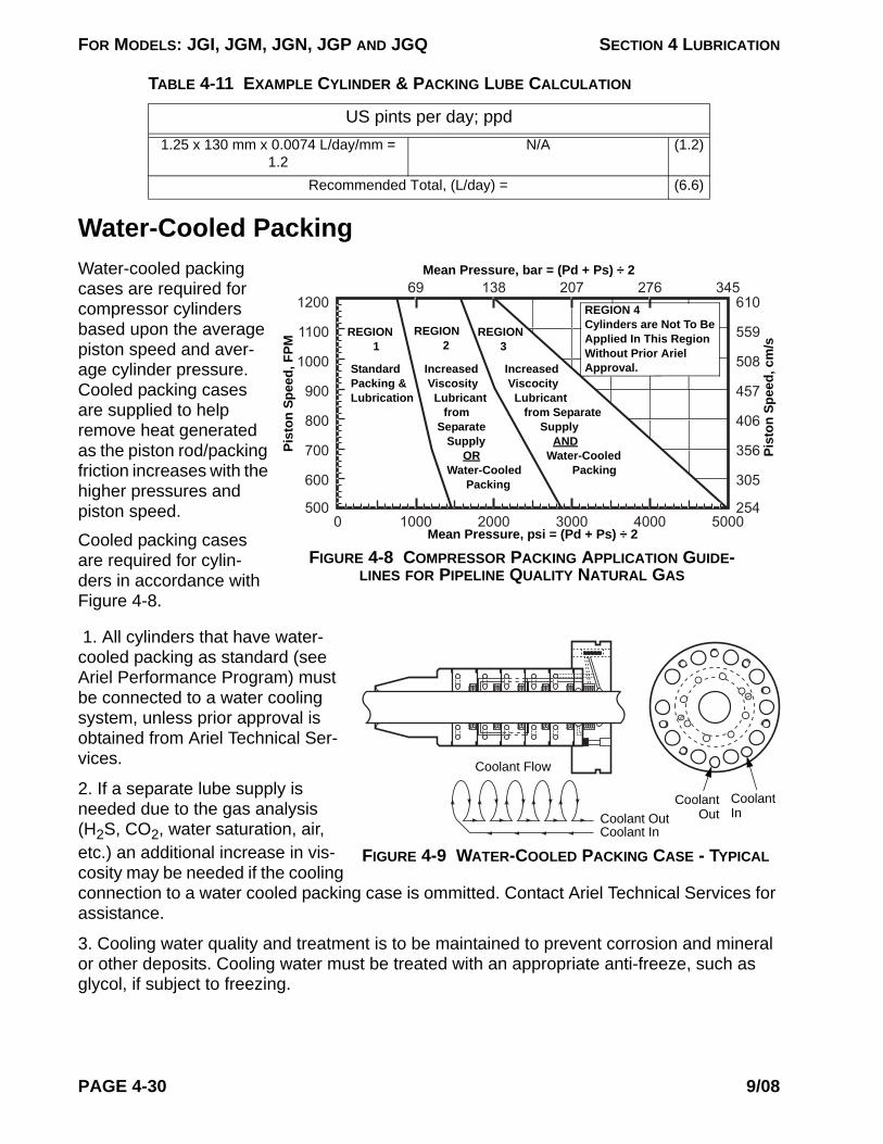
FOR MODELS: JGI, JGM, JGN, JGP AND JGQ SECTION 4 LUBRICATION
Water-Cooled Packing
0 1000 2000 3000 4000 5000500
600
700
800
900
1000
1100
120069 138 207 276 345
254
305
356
406
457
508
559
610
Standard Packing & Lubrication
REGION 2
Increased Viscocity Lubricant from Separate Supply AND Water-Cooled Packing
Mean Pressure, psi = (Pd + Ps) ÷ 2
Pist
on S
peed
, FPM
REGION 1
FIGURE 4-8 COMPRESSOR PACKING APPLICATION GUIDE-LINES FOR PIPELINE QUALITY NATURAL GAS
Increased Viscosity Lubricant from Separate Supply OR Water-Cooled Packing
REGION 4 Cylinders are Not To Be Applied In This Region Without Prior Ariel Approval.
REGION 3
Pist
on S
peed
, cm
/s
Mean Pressure, bar = (Pd + Ps) ÷ 2Water-cooled packing cases are required for compressor cylinders based upon the average piston speed and aver-age cylinder pressure. Cooled packing cases are supplied to help remove heat generated as the piston rod/packing friction increases with the higher pressures and piston speed.
Cooled packing cases are required for cylin-ders in accordance with Figure 4-8.
FIGURE 4-9 WATER-COOLED PACKING CASE - TYPICAL
Coolant In
Coolant Out
Coolant InCoolant Out
Coolant Flow
1. All cylinders that have water-cooled packing as standard (see Ariel Performance Program) must be connected to a water cooling system, unless prior approval is obtained from Ariel Technical Ser-vices.
2. If a separate lube supply is needed due to the gas analysis (H2S, CO2, water saturation, air, etc.) an additional increase in vis-cosity may be needed if the cooling connection to a water cooled packing case is ommitted. Contact Ariel Technical Services for assistance.
3. Cooling water quality and treatment is to be maintained to prevent corrosion and mineral or other deposits. Cooling water must be treated with an appropriate anti-freeze, such as glycol, if subject to freezing.
1.25 x 130 mm x 0.0074 L/day/mm = 1.2
N/A (1.2)
Recommended Total, (L/day) = (6.6)
TABLE 4-11 EXAMPLE CYLINDER & PACKING LUBE CALCULATION
US pints per day; ppd
PAGE 4-30 9/08
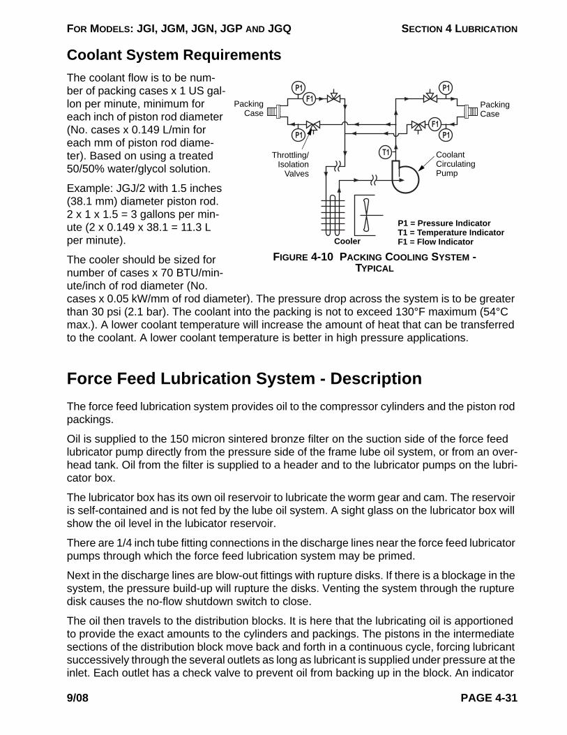
FOR MODELS: JGI, JGM, JGN, JGP AND JGQ SECTION 4 LUBRICATION
Coolant System Requirements
P1
P1
P1
P1
T1
F1
F1
Packing Case
FIGURE 4-10 PACKING COOLING SYSTEM - TYPICAL
Packing Case
Coolant Circulating Pump
Throttling/ Isolation
Valves
Cooler
P1 = Pressure IndicatorT1 = Temperature IndicatorF1 = Flow Indicator
The coolant flow is to be num-ber of packing cases x 1 US gal-lon per minute, minimum for each inch of piston rod diameter (No. cases x 0.149 L/min for each mm of piston rod diame-ter). Based on using a treated 50/50% water/glycol solution.
Example: JGJ/2 with 1.5 inches (38.1 mm) diameter piston rod. 2 x 1 x 1.5 = 3 gallons per min-ute (2 x 0.149 x 38.1 = 11.3 L per minute).
The cooler should be sized for number of cases x 70 BTU/min-ute/inch of rod diameter (No. cases x 0.05 kW/mm of rod diameter). The pressure drop across the system is to be greater than 30 psi (2.1 bar). The coolant into the packing is not to exceed 130°F maximum (54°C max.). A lower coolant temperature will increase the amount of heat that can be transferred to the coolant. A lower coolant temperature is better in high pressure applications.
Force Feed Lubrication System - DescriptionThe force feed lubrication system provides oil to the compressor cylinders and the piston rod packings.
Oil is supplied to the 150 micron sintered bronze filter on the suction side of the force feed lubricator pump directly from the pressure side of the frame lube oil system, or from an over-head tank. Oil from the filter is supplied to a header and to the lubricator pumps on the lubri-cator box.
The lubricator box has its own oil reservoir to lubricate the worm gear and cam. The reservoir is self-contained and is not fed by the lube oil system. A sight glass on the lubricator box will show the oil level in the lubicator reservoir.
There are 1/4 inch tube fitting connections in the discharge lines near the force feed lubricator pumps through which the force feed lubrication system may be primed.
Next in the discharge lines are blow-out fittings with rupture disks. If there is a blockage in the system, the pressure build-up will rupture the disks. Venting the system through the rupture disk causes the no-flow shutdown switch to close.
The oil then travels to the distribution blocks. It is here that the lubricating oil is apportioned to provide the exact amounts to the cylinders and packings. The pistons in the intermediate sections of the distribution block move back and forth in a continuous cycle, forcing lubricant successively through the several outlets as long as lubricant is supplied under pressure at the inlet. Each outlet has a check valve to prevent oil from backing up in the block. An indicator
9/08 PAGE 4-31

FOR MODELS: JGI, JGM, JGN, JGP AND JGQ SECTION 4 LUBRICATION
on the block shows the rate at which the block is cycling.
From the distribution blocks, oil travels to the cylinders and packings. The system provides 1 inch min. (25 mm) of head at the guide and cylinder inlets to help ensure long check valve life.
Some of the oil to the packing travels through to the cylinders, but the bulk of it is drained out through the pressure vent/drain fitting on the bottom of the crosshead guide and through the atmospheric drain also in the bottom of the guide.
An oil level control valve, supplied by the packager and mounted on the skid, maintains prop-er level in the crankcase sump to replace oil used in cylinder lubrication.
Force Feed Lubricator AdjustmentSee instructions under “Force Feed Lubricator Adjustment” in Technical Manual Section 3.
NOTE: THE FORCE FEED SYSTEM MUST HAVE A BLOW-OUT FITTING WITH A PROPERLY RATED RUPTURE DISK, INSTALLED IN THE TUBING LINE BETWEEN THE FORCE FEED LUBRICATOR PUMP AND THE NO-FLOW SHUTDOWN. THE DISK COLOR SHOULD SHOW AT THE FITTING BLOW-OUT HOLE. THE FORCE FEED SYSTEM MUST HAVE A WORKING NO-FLOW SHUTDOWN SET TO ACTUATE WITHIN THREE TO FIVE MINUTES AFTER INTERRUPTION OF THE LUBRICATOR OIL FLOW.
CAUTION!: USE A MIRROR TO VISUALLY INSPECT FOR PROPER RUPTURE DISK COLOR, IF THE FORCE FEED SYSTEM IS PRESSURIZED. A RUPTURING DISK OR HIGH PRESSURE OIL CAN POTENTIALLY CAUSE PERSONAL INJURY.
Blow-Out Fittings, Rupture Disks and TubingFitting Rupture
Disk
1/8 in. (3 mm) Blow-Out Hole
Cap
1/4 in. (6 mm) Blow-Out Hole
Lubriquip FittingLincoln St. Louis Fitting
FIGURE 4-11 BLOW-OUT FITTING ASSEMBLY
TABLE 4-12 BLOW-OUT FITTINGS, REPLACEMENT RUPTURE DISKS & TUBING
BLOW-OUT FITTINGA REPLACEMENT RUPTURE DISKB STANDARD TUBING - 304 SSC
TYPE ARIELP/N
RATINGpsig (barg) ARIEL P/N COLOR SIZE
in. (mm)RATING
psig (barg)ARIEL
P/N
Lincoln A-0080 3250 (224) A-0124 Purple 1/4 x 0.035wall
(6.4 x 0.9)5100 (352) PT0200CBLubriquip A-3531 3700 (255) A-3536 Yellow
Lubriquip A-3532 4600 (317) A-3537 Red
PAGE 4-32 9/08

FOR MODELS: JGI, JGM, JGN, JGP AND JGQ SECTION 4 LUBRICATION
Lubriquip A-3533 5500 (379) A-3538 Orange 1/4 x 0.065wall
(6.4 x 1.7)10,200 (703) PT0201CDLubriquip A-3534 6400 (441) A-3539 Pinkd
Lubriquip A-3535 7300 (503) A-3540 Blue
a. Be sure to apply the proper rupture disk to match your blow-out fitting type, see Figure 4-11, and application pressure. Generally the rupture disk should be rated about 1000 psig (70 barg) greater than the highest MAWP cylinder.
b. See Technical Manual Section 1, Fastener Tightening Values Table or the toolbox torque tables (ER-63) for blow-out fitting cap tightening torque. Do not over tighten cap or rupture pressure can be reduced.
c. All tubing down stream from a force feed pump for a pump circuit rated 5500 psig (380 barg) or greater (orange, pink and blue disks), that is circuits with any cylinders greater than 3600 psig MAWP (248 barg), should be 1/4 inch x 0.065 (6.4 x1.7 mm) heavy wall stainless steel high pres-sure tubing. Rated tubing pressures are calculated from equations in ASME/ANSI B31.3 code for pressure piping, based on maximum outside diameter and minimum wall thickness. When grade 316 stainless steel tubing is specified on new compressor sales orders, 1/4 inch x 0.065 (6.4 x 1.7 mm) tubing is provided, regardless of rupture disk or cylinder ratings.
d. Color code changed to pink (3/20/05) was uncoated aluminum.
TABLE 4-12 BLOW-OUT FITTINGS, REPLACEMENT RUPTURE DISKS & TUBING
BLOW-OUT FITTINGA REPLACEMENT RUPTURE DISKB STANDARD TUBING - 304 SSC
TYPE ARIELP/N
RATINGpsig (barg) ARIEL P/N COLOR SIZE
in. (mm)RATING
psig (barg)ARIEL
P/N
9/08 PAGE 4-33

FOR MODELS: JGI, JGM, JGN, JGP AND JGQ SECTION 4 LUBRICATION
Inlet Block
Intermediate Blocks
Discharge Port (Outlet) Correct Port Position is Off-Center Toward Inlet Block
End Block
Inlet
Cross Port Plate
Divider Valve Block
Piston
O-Rings
Check Valve
Tie Rod
Distribution Block Divider Valve - Cap Screw
FIGURE 4-12 DIVIDER VALVES DISTRIBUTION BLOCK - TYPICAL
Divider ValvesNOTE: REFER TO PARTS
BOOK FOR THE FRAME BEING SER-VICED FOR ASSEM-BLY DRAWINGS, PARTS LIST AND REPAIR KITS THAT ARE AVAILABLE FOR DIVIDER VALVES.
DescriptionDivider valves are comprised of three to eight valve blocks fas-tened to a segmented baseplate. O-rings are used to seal be-tween the valve blocks and the base plate and between the base plate segments. These di-vider valves are used in a single line, progressive lubrication sys-tem and can be used for dis-pensing oil or grease. Valves and base plate segments are supplied with Viton O-rings (90 Durometer).
Check valves are installed at the outlets of all lube ports.
Valve blocks containing metering pistons discharge a predetermined amount of lubricant with each cycle. Valve blocks can be single or twin and can be externally singled or cross-ported. Outlets not to be used when singling or cross-porting must be plugged.
A by-pass block can be used in any position on the base plate. The use of a by-pass block allows the addition or deletion of lubrication points without disturbing existing tubing. Both out-lets under a by-pass block must be plugged.
The valve blocks and by-pass blocks are fastened to a base plate mounted on the machine to be lubricated. The base plate contains the divider valve's inlet and outlet connections, in-terrelated passageways and built-in check valves. All piping of lubricant to and from the di-vider valve is connected to the base plate.
The base plate consists of one inlet block, three to eight intermediate blocks, one end block and three tie rods. O-ring seals are included with the base plate segments. The valve block capacity of each base plate is dependent upon the number of intermediate blocks in the base-plate. There must be a minimum of three working valves on each valve and base plate as-sembly.
PAGE 4-34 9/08
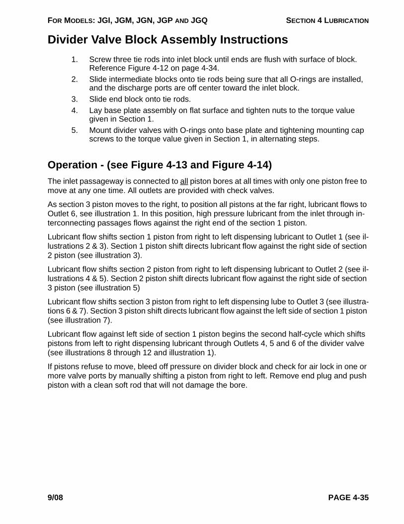
FOR MODELS: JGI, JGM, JGN, JGP AND JGQ SECTION 4 LUBRICATION
Divider Valve Block Assembly Instructions1. Screw three tie rods into inlet block until ends are flush with surface of block.
Reference Figure 4-12 on page 4-34.2. Slide intermediate blocks onto tie rods being sure that all O-rings are installed,
and the discharge ports are off center toward the inlet block.3. Slide end block onto tie rods.4. Lay base plate assembly on flat surface and tighten nuts to the torque value
given in Section 1.5. Mount divider valves with O-rings onto base plate and tightening mounting cap
screws to the torque value given in Section 1, in alternating steps.
Operation - (see Figure 4-13 and Figure 4-14)The inlet passageway is connected to all piston bores at all times with only one piston free to move at any one time. All outlets are provided with check valves.
As section 3 piston moves to the right, to position all pistons at the far right, lubricant flows to Outlet 6, see illustration 1. In this position, high pressure lubricant from the inlet through in-terconnecting passages flows against the right end of the section 1 piston.
Lubricant flow shifts section 1 piston from right to left dispensing lubricant to Outlet 1 (see il-lustrations 2 & 3). Section 1 piston shift directs lubricant flow against the right side of section 2 piston (see illustration 3).
Lubricant flow shifts section 2 piston from right to left dispensing lubricant to Outlet 2 (see il-lustrations 4 & 5). Section 2 piston shift directs lubricant flow against the right side of section 3 piston (see illustration 5)
Lubricant flow shifts section 3 piston from right to left dispensing lube to Outlet 3 (see illustra-tions 6 & 7). Section 3 piston shift directs lubricant flow against the left side of section 1 piston (see illustration 7).
Lubricant flow against left side of section 1 piston begins the second half-cycle which shifts pistons from left to right dispensing lubricant through Outlets 4, 5 and 6 of the divider valve (see illustrations 8 through 12 and illustration 1).
If pistons refuse to move, bleed off pressure on divider block and check for air lock in one or more valve ports by manually shifting a piston from right to left. Remove end plug and push piston with a clean soft rod that will not damage the bore.
9/08 PAGE 4-35

FOR MODELS: JGI, JGM, JGN, JGP AND JGQ SECTION 4 LUBRICATION
FIGURE 4-13 DIVIDER VALVE OPERATION SCHEMATIC - 1 THROUGH 6
Inle tSection
EndSection
SectionNo. 1
SectionNo. 2
SectionNo. 3 O-Ring
Inle tSection
EndSection
SectionNo. 1
SectionNo. 2
SectionNo. 3 O-Ring
Inle tSection
EndSection
SectionNo. 1
SectionNo. 2
SectionNo. 3 O-Ring
Inle tSection
EndSection
SectionNo. 1
SectionNo. 2
SectionNo. 3 O-Ring
Inle tSection
EndSection
SectionNo. 1
SectionNo. 2
SectionNo. 3 O-Ring
Inle tSection
EndSection
SectionNo. 1
SectionNo. 2
SectionNo. 3 O-Ring
Inlet
Illustration 1
Illustration 3
Illustration 2
Illustration 4
Outlet1
Outlet5
Outlet6
Outlet4
Outlet2
Outlet3
Illustration 5 Illustration 6
Outlet1
Outlet2
Outlet3
Outlet1
Outlet2
PAGE 4-36 9/08

FOR MODELS: JGI, JGM, JGN, JGP AND JGQ SECTION 4 LUBRICATION
FIGURE 4-14 DIVIDER VALVE OPERATION SCHEMATIC - 7 THROUGH 12
Inle tSection
EndSection
SectionNo. 1
SectionNo. 2
SectionNo. 3 O-Ring
InletSection
EndSection
SectionNo. 1
SectionNo. 2
SectionNo. 3 O-Ring
Inle tSection
EndSection
SectionNo. 1
SectionNo. 2
SectionNo. 3 O-Ring
Inle tSection
EndSection
SectionNo. 1
SectionNo. 2
SectionNo. 3 O-Ring
Inle tSection
EndSection
SectionNo. 1
SectionNo. 2
SectionNo. 3 O-Ring
Inle tSection
EndSection
SectionNo. 1
SectionNo. 2
SectionNo. 3 O-Ring
Illustration 7 Illustration 8
Illustration 9 Illustration 10
Illustration 11 Illustration 12
Outlet3
Outlet4
Outlet4
Outlet5
Outlet5
Outlet6
9/08 PAGE 4-37

FOR MODELS: JGI, JGM, JGN, JGP AND JGQ SECTION 4 LUBRICATION
Pressure Testing For Divider Valve By-PassingDivider valve piston to bore are metal to metal sealing surfaces. Lubricant by-passing can result from excessive clearance between the piston and bore due to wear. Pressure test all divider blocks that are in service yearly, and replace any divider valves that fail to pass. Test-ing helps to ensure the piston to bore clearances are close enough to build adequate pres-sure to force oil into the injection point. All new Ariel divider valves are provided pressure tested by the supplier.
To test divider blocks for valve by-passing, a manual purge pump equipped with a pressure gauge, and capable of developing 5000 psig (350 barg) is necessary. Such a force feed lubrication system purge gun (hand pump kit) with a pressure gauge is available from Ariel as an optional purchase tool. For pressure testing the divider block use a 10-weight oil at room temperature to simulate a hot lubricant. Test each divider block assembly complete with pin indicators installed. Test only one divider valve at a time.
Place the divider block assembly in an open container with all base outlets open. Connect the purge pump to the inlet of the divider block assembly. Operate the purge pump to cycle the divider block several times to purge air from the assembly and verify that oil will flow freely from all outlets. Divider blocks should cycle at less than 300 psig (21 barg). See Figure 4-15 “Divider Block All Outlets Open”.
Divider valves stamped with a “T” are to have only one outlet on the base plugged during testing of that side of the piston. Each base outlet of the divider valves stamped with a “T” must be plugged and tested one side at a time. See Figure 4-15 “Testing “T” Divider Valve”. Individual testing of each outlet ensures both sides of the piston will build adequate pres-sure. All divider valves stamped with an “S” on the front are to have both outlets on the base plugged to test for by-passing. See Figure 4-15 “Testing “S” Divider Valve”. This will test both sides of the piston at the same time.
Plug the outlet on the base behind the divider valve being tested with a 1/8 inch pipe plug. If a tubing fitting is installed in the base, plug the fitting with a tubing plug. Leave all other out-lets open. Operate the purge gun until the pressure gauge indicates 3000 psig (207 barg). The block may cycle once or twice, but should pressurize to 3500 psig (241 barg) immedi-ately. Stop pumping oil into the divider block at 3500 psig (241 barg). Check the plug(s) in the discharge outlet(s) to confirm there are no external leaks. If the pressure gauge on the purge gun drops suddenly and oil squirts from the other outlets, a by-pass condition exists. The piston is worn and is allowing oil to by-pass. The pressure gauge should not lose more than 1000 psig (69 barg) during a 30-second test period. Note: Testing the divider blocks at higher pressures is necessary if the application dictates a higher system operating pressure.
If a divider valve does not pass, it must be replaced. Discard worn divider valves. If the tested valve does not lose more than 1000 psig (69 barg) in 30 seconds, relieve the pres-sure, move the plug to the next outlet and repeat the test for all divider valves. When divider valves have passed pressure testing to this procedure or have been replaced, a divider block may be reassembled, purged with the proper force feed lubricant being used and put into service.
By the nature of this divider block pressure testing procedure, in a static position through the divider valves above, it is not infallible. Periodic testing for proper lubrication rates in the cyl-inder bore and/or aftermarket devices that measure flow are recommended.
PAGE 4-38 9/08

FOR MODELS: JGI, JGM, JGN, JGP AND JGQ SECTION 4 LUBRICATION
Electronic Lubricator Fluid-Flow Monitor/No-Flow Timer Switch - Proflo PF1
REFER TO MANUAL FOR PROPER OPERATION & BATTERY TYPE.WARNING - EXPLOSION HAZARD - DO NOT DISCONNECT WHILE CIRCUITIS LIVE UNLESS AREA IS KNOWN TO BE NON-HAZARDOUS. BATTERIESMUST ONLY BE CHANGED IN AN AREA KNOWN TO BE NON-HAZARDOUS.
®
Magnetic Pin Housing - Attaches to Divider Block
(2) 1/4” x 20 Set Screws
Liquid Crystal Display (LCD) Window
Infrared Wireless Connection IrDA Port for Downloading Data to a Palm Pilot Type Hand Held Computer
Ariel Part Number
Mode ButtonSet Button
FIGURE 4-16 ELECTRONIC LUBRICATOR FLUID-FLOW MONITOR & NO-FLOW TIMER SWITCH -
PROFLO PF1
The Proflo PF1 is a battery powered programmable electronic micropro-cessor-based switch used to sense slow-flow or no-flow conditions in the compressor cylinder force feed lubri-cation system to facilitate alarm and/or shutdown. It also has many fea-tures that can help ease the opera-tion of the force feed lube system by allowing accurate monitoring of the cycle time and system performance. This information may be used to opti-mize force feed lube and reduce operating costs. The Proflo PF1 fluid-flow monitor is shown in the Figure.
If a DNFT (electronic-lubricator digital no-flow timer switch) is supplied in lieu of a Proflo, see “Electronic-Lubri-cator Digital No-Flow Timer Switch (DNFT)” on page 4-49.
The Proflo PF1 monitor works through a magnetic pin that cycles back and forth as the divider valve piston moves. The magnetic pin housing is normally screwed into the divider valve block, the monitor box housing slides on to the pin housing and is held in place by two (2) hexagon-socket set screws.
The front face of the monitor box housing has a liquid crystal display (LCD) window to provide
FIGURE 4-15 PRESSURE TESTING DIVIDER BLOCKS
24T
12S
12T
24T
12S
12T
24T
12S
12T
Testing “T” Divider Valve
Divider Block All Outlets Open Testing “S” Divider Valve
Base Outlets Open - Oil Flowing Freely
Manual Purge Gun (Pump)
Divider Block w/ “S” Valve
Divider Block Inlet
Plugged to Test One Side of a “T” Valve - All Other Out-lets Open
Both Sides Plugged to Test a “S” Valve - All Other Out-lets Open
Testing “T” Divider Valve
9/08 PAGE 4-39

FOR MODELS: JGI, JGM, JGN, JGP AND JGQ SECTION 4 LUBRICATION
a visual indication of the following:
1. Total operating time of the force feed lube system in hours.2. "Average", "Last" and "Current" cycle time of the divider block in seconds.3. Total divider block cycles.4. Remaining battery power life in percent.5. Alarm set time for no-flow indication (programmable 30 to 240 seconds).6. Alarm wiring mode: Normally Open or Normally Closed.
Proflo PF1 Monitor wiring identification and instructions for electronic indication:NOTE: IF THE PULSE OUTPUT (BLUE WIRES) AND ALARM CIRCUIT (RED WIRES)
ARE TO BE USED AT THE SAME TIME, PLEASE REFER TO “Proflo PF1 - Using Pulse Output and Alarm Circuit at Same Time:” on page 4-47.
Blue Wires:
Pulse output. The two (2) blue wires can be used to send a transistor pulse output for each divider block cycle to a PLC (Programmable Logic Controller), Scada System, Digital Counter or Digital Control Panel. Maximum switching load is 36 Vdc @ 500mA. Insulate blue wire ends from each other and conduit or compressor ground when not in use. Pulse dura-tion is 500 milliseconds. Switch output operation: Pulse represents 1 divider block cycle or period.
White Wires:
Switch input. Remote mounting Proflo PF1 display. The two (2) white wires can be con-nected to a dry contact proximity switch. This allows remote mounting of the monitor box housing in a convenient location on the compressor frame or in the control panel. Ariel rec-ommends distance between proximity switch and the panel mounted Proflo should not ex-ceed 600 feet (183 m). Please refer to Proflo PF1 operating notes for more information. Insulate white wire ends, from each other and from ground, when not in use. For panel mount kit, see “Proflo PF1 Accessories Available:” on page 4-49.
Red Wires:
Alarm switch output. The two (2) red wires are for a no-flow alarm contact. This can be used for alarm or shutdown no-flow indication at a control panel. When the divider block cycles this contact closes when in Normally Closed (NC) operation and opens when in Normally Open (NO) operation. The contact returns to static state when the preset timer times out. Switching Capacity: 36 Vdc @ 500 mA max. Insulate red wire ends from each other and from ground when not in use. This output operation is programmable as NO or NC. Ariel recom-mends using a NC system for fail-safe operation. Red wires are not polarity sensitive. See “Proflo Normally Open and Normally Closed Definition:” on page 4-46.
Green Wire:
The green wire must be securely grounded to an "earth ground" on the compressor frame or in the control panel. Do not ground to the electrical conduit. Improper grounding can result in unreliable operation of the monitor.
PAGE 4-40 9/08

FOR MODELS: JGI, JGM, JGN, JGP AND JGQ SECTION 4 LUBRICATION
NOTE: TO SWITCH TO 120/240 VAC LOAD USING THE PROFLO PF1 OUTPUTS, A RELAY INTERFACE MUST BE USED. SEE “Proflo PF1 Accessories Avail-able:” ON PAGE 4-49.
Proflo PF1 Button Operation:Following is a description of how an operator can use the Proflo PF1 buttons.
1. First push set button on the front of the monitor box housing to clear ALARM and the LCD will display LAST and AVG. When this is done the alarm output con-tact will go to the as running state. If the operation is set to NC then the output alarm contact will close.LAST is the last divider block cycle time in seconds. AVG is the average time of the last six (6) divider block cycles in seconds.
2. Push the mode button once and the LCD will display NOW. NOW is the current divider block cycle time in seconds.This mode allows the operator to accurately change the cycle time by adjusting the force feed lubricator pump. Break-in and normal lube timing in seconds per cycle is given on the force feed lubricator data plate on the lubricator box at maximum rated speed, based on the gas operating conditions provided to Ariel (or clean, dry 0.65 S.G. sweet natural gas, rated speed and discharge pressures if no conditions were provided), when plate was installed. At reduced compres-sor speeds cycle time may be increased in a directly proportional relationship. At 50% rated speed the lube cycle time is doubled (see lube sheets provided in the Ariel Parts Manual for table of speeds vs. cycle timing).
3. Push the mode button again and the LCD will display RUN TIME.RUN TIME is the total run time of the lube system in hours since the last reset.
4. Push the mode button a third time and the LCD will display CYCLE TOTAL.CYCLE TOTAL is the total divider block cycles since the last reset.
5. Push the mode button a fourth time and the LCD will display BATTERY - PCNT If battery voltage drops below safe operating levels the monitor will go into ALARM mode.BATTERY - PCNT indicates percent of remaining battery life.
The display mode will change to alarm when the Proflo PF1 goes into alarm. The display will default to LAST and AVG display when the divider block is cycling.
Downloading Proflo PF1 Data:A hand held Palm operating system computer equipped with an infrared (IrDA) port and run-ning Palm Operating System can be used to interface with the Proflo PF1. CCT Incorporated, Fluid Flow Trending (FFT) software can be used to download operating data. Using this fea-ture is not essential for compressor operation, but recommended for evaluating the force feed lube operation and reducing operating costs. See “Proflo PF1 Accessories Available:” on page 4-49, for more info on the FFT software. The following information may be obtained:
1. Oil consumption for each 30-minute interval, of compressor operation. 2. Days of over and under lubrication.
9/08 PAGE 4-41

FOR MODELS: JGI, JGM, JGN, JGP AND JGQ SECTION 4 LUBRICATION
3. Total oil consumption of compressor lube system4. Daily and total lost dollars (US) for over lubricating. 5. Total divider block cycles, 6. Total run time of the compressor.
The Proflo PF1 monitor can store one year’s worth of operating data in a first in, first out (FIFO) memory.
The FFT software can be used to reset Proflo PF1 memory. The reset time and date is re-corded to the Proflo PF1's Electrical Erasable Programmable Read Only Memory, (EE-PROM).
To start the download push the SET button then push the mode button 5 times until the LCD displays SEND DATA? then push the SET button. Set the FFT software to accept the Proflo PF1 data and hold the handheld computer in a position to communicate with the IrDA port. The LCD will display SENDING. If there is no devise to receive the data the LCD will display FAILURE and after 30 seconds return to LAST and AVG default display.
The software provides for conversion to Microsoft Excel files for trending and graphing.
Hand held Palm operating system computers are available at most electronic or discount stores or on the Internet.
For more details on this product and other Proflo PF1 accessories, see the Ariel web at www.arielcorp.com and/or contact your packager or Ariel.
Proflo PF1 Setup Alarm Time and Mode:To setup the Alarm contact output operation, red wires, first push the SET button. Push mode button six (6) times until LCD displays SETUP?. Push SET button and the LCD will scroll to 1. SET ALARM TIME. Push and release set button to change alarm-shutdown from 30 to 240 seconds. When the compressors leave Ariel this time is set to 120 seconds. Ariel recom-mends setting the alarm time to 2 times the normal cycle time rounded up to the near-est 5 seconds. This time should not be less than 30 seconds or greater than 180 seconds. Normal design cycle time can be found on a nameplate on the lube oil pump box.
The control system must be configured to shutdown the compressor for a no-flow indication. Push the mode button, two (2) more times and the LCD will scroll to SET ALARM MODE. Push set button to toggle from N/O normally open or N/C normally closed. Ariel recom-mends using the NC operation.
After wiring mode is set the monitor will automatically return to the LAST and AVG display in 30 seconds.
PAGE 4-42 9/08

FOR MODELS: JGI, JGM, JGN, JGP AND JGQ SECTION 4 LUBRICATION
Proflo PF1 Battery Replacement:
! CAUTIONEXPLOSION HAZARD. DISCONNECT/LOCKOUT ELECTRICAL POWER TO CONTROL CIRCUITS BEFORE REMOVING BAT-TERY COVER. BATTERIES MUST ONLY BE CHANGED IN A NON-HAZARDOUS AREA.
Battery life is expected to be 2 to 3 years (with Energizer Lithium L91) under constant nor-mal operation.
When replacing any Proflo PF1 batteries, it is highly recommended that two (2) new AA Energizer Lithium/FeS2, model number L91 batteries be used to reduce maintenance costs. This is a true Lithium battery, where other brands might not be. While not recommended, replacement alkaline batteries can still be used when Lithium batteries are not available. Be sure that new batteries are fresh and battery cases are not scratched.
FIGURE 4-17 PROFLO PF1 REAR BATTERY COMPARTMENT
To replace the batteries, remove the screws, cover and gasket from the battery compart-ment on the back of the Proflo PF1. Remove the old batteries; remove the clear plastic pro-
Battery Clips(+)
Two “AA” Energizer Lithium L91 Batteries with Plastic Protective Sleeves
Battery Compartment Cover with Gasket
Proflo PF1 Body
(-)
(-) (+)
9/08 PAGE 4-43

FOR MODELS: JGI, JGM, JGN, JGP AND JGQ SECTION 4 LUBRICATION
tective sleeves from the old batteries and save the sleeves. Discard old batteries in a responsible manner.
Press the Proflo PF1 buttons for 45 seconds to a minute without batteries installed to dissi-pate the monitor’s stored energy and allow for updating the battery display immediately after new batteries are installed. This step is optional as the monitor will automatically update bat-tery display within 30 minutes of operation.
Put the plastic protective sleeves on the new batteries. Be sure that the battery negative/positive orientation to the battery compartment is correct and the batteries are tight as installed. Be careful not to scratch or damage the new battery cases during installation. Re-assemble the cover, gasket and screws. Note that the cover holes will line up with the six threaded holes in the monitor body only in one direction, so be sure that it is installed prop-erly. Attempting to install the cover upside down will result in stripping the screw threads and compromise the battery compartment seal. Do not over-tighten the (six) screws. If screws on battery cover are lost, replace with 4-40 x 3/16 inch pan head machine screws.
After the batteries are replaced and if stored energy was dissipated, press the set button once and continue to press the mode button, four times until the LCD displays BATTERY to allow the monitor to check battery voltage, reset and display the actual remaining new bat-tery power percentage. The monitor will automatically search for the battery voltage at the next 30 minute read/write interval and update to the new battery power percentage at that time.
All trending and configuration data are stored in the Proflo PF1's EEPROM. Memory is not lost due to battery failure or battery replacement.
Component damage due to battery leakage is not normally covered under warranty.
Do not attempt to remove the front cover or warranty is void.
Proflo PF1 Display Errors:ALARM - Displayed when divider blocks are not cycling. This is normal when the divider block is not cycling. Programmed divider block cycle time has expired.
OVERLOAD - The Proflo PF1 electronics are protected using self-resetting fuses on the in-puts. This error indicates there is a short in the wiring or the circuit is switching too large a load. To correct this, check wiring insulation for bare wires that are touching ground or each other. Insulate un-used wires or re-terminate wires. Proflo PF1 fuses will auto reset 45 sec-onds after a short is corrected.
LOW BATT - Indicates the batteries need to be changed. Refer to “Proflo PF1 Battery Re-placement:” on page 4-43.
RESET x - This is an internal Proflo PF1 fault, the alarm condition will not be issued. The Pro-flo PF1 is still counting divider block cycles and controlling the inputs and outputs. When the divider block is cycling the Proflo PF1 counts pulses and measures the time between divider block cycles. At 30-minute intervals the processor takes the data stored in memory and writes this to the on board EEPROMS. If there is a problem with this the Proflo PF1 will issue a Reset error.
Try to correct the problem by:
PAGE 4-44 9/08

FOR MODELS: JGI, JGM, JGN, JGP AND JGQ SECTION 4 LUBRICATION
1. Removing Proflo PF1 batteries.2. Hold down the set button for 45 seconds. Holding the set button discharges
internal capacitors and ensures a complete reset.3. Re-insert the batteries to reboot the Proflo PF1.
*If the error was a one-time problem the Proflo PF1 will reboot as normal.*If on reboot the diagnostics detect an error, the Proflo PF1 will display the con-stant RESET error again. Replace the Proflo PF1 and contact Ariel Corporation. Sometimes on reboot the Proflo PF1 will flash reset. This is normal.
RESET 1 -The Proflo PF1 processor was not able to determine if the EEPROM contains valid configuration information. Reset 1 is most likely to occur after a RESET 3 is reported. Upon Proflo PF1 reboot the stored configuration data will be lost and the programmed information will need to be reentered.
RESET 2 - The Proflo PF1 processor was not able to determine if any data has been stored or where the next data should go. Upon Proflo PF1 reboot the stored data will be lost. Con-figuration data will still be there and the programmed information will not need to be reen-tered.
RESET 3 - This is an internal Proflo PF1 fault. The Proflo PF1 processor tried and failed three resets. The most likely cause is failure to write to the EEPROM.
NOTE: THE MOST LIKELY CAUSE OF RESET ERRORS IS MOISTURE ON THE PRO-FLO PF1 CIRCUIT BOARD. SEVERAL DESIGN PRECAUTIONS HAVE BEEN TAKEN TO KEEP WATER AND MOISTURE OUT OF THE CIRCUIT BOARD CHAMBER. THESE INCLUDE:
1. The Proflo PF1 housing has been completely sealed in a low humidity room and will survive a 2300 psi (160 bar) power wash.
2. There is a desiccant pack in the circuit board chamber.3. The circuit boards have a protective conformal coating.
Proflo PF1 Operation Notes:1. If the alarm output is set for NC operation and the batteries are removed or go
dead the Proflo PF1 will open the alarm contact. If the alarm operation is set to NO operation and the batteries are removed the alarm contact will remain in the open condition and the control system will not be told to alarm. For this reason Ariel recommends using the NC contact operation.
2. Proflo PF1 Default programmable settings. This is as delivered to Ariel or reset using the FFT software. Alarm trip time = 120 secondsNC/NO settings = NO or non-fail safeAriel shop work instructions set outputs to:Alarm trip time = 120 secondsNC/NO settings = NC or fail-safePlease see “Proflo Normally Open and Normally Closed Definition:” on page 4-46.Also see “Proflo PF1 Setup Alarm Time and Mode:” on page 4-42.
9/08 PAGE 4-45
FOR MODELS: JGI, JGM, JGN, JGP AND JGQ SECTION 4 LUBRICATION
3. Remote mounted Proflo PF1 and proximity switch. The Proflo will excite the proximity switch circuit with 3 volt battery power to detect the state of the proxim-ity switch. Ariel has defined a maximum wire distance between the proximity switch and the remote mounted Proflo:Maximum DistanceCondition600 feet (183 m)Using standard Proflo PF1 batteries10,000 feet (3050 m)Powering Proflo PF1 from other power sourceThe above distances are conservatively calculated based on the following assumptions/considerations:1. Standard 22 gage instrumentation wire at 68°F (20°C) in a continuous run.2. Not significantly degrading battery life.No electrical noise injected into wire run.If the Proflo PF1 is to be panel mounted, Ariel recommends removing the batter-ies and using the power supply from CCT. See “Proflo PF1 Accessories Avail-able:” on page 4-49.
4. The Proflo PF1 will record any setup changes to the EEPROM. 5. The white wires on the Proflo PF1 can be used for other applications than read-
ing divider block cycle times. The Proflo can record history of any dry contact switch. Example: history of a liquid dump valve, history of a high temperature switch, history of a valve limit switch.
6. The Proflo PF1 electronics is equipped with reverse polarity protection/correc-tion. The electronics will automatically correct a reverse polarity output connec-tion on both the pulse and alarm outputs.
Proflo Normally Open and Normally Closed Definition:There has been some confusion among PLC programmers and electrical people over the def-inition of Normally Open (NO) and Normally Closed (NC) as applied to the Proflo and DNFT. Most electrical components define NO or NC operation as the default state or on the shelf state. Example: A NO solenoid valve is open when the coil is not energized. When the coil is energized the valve will close. A NC solenoid valve is closed when the coil is not energized. When the coil is energized the valve will open. This logic is not used when defining the DNFT or Proflo electrical contacts. The DNFT and the Proflo use the same definition of NO and NC switch contacts. Definitions for Proflo and DNFT contact are switch states after the divider block has cycled.
NO = Normally Open when Running. Switch is open when the divider block is cycling. This is a non-fail-safe operation because if the unit is running and a wire falls off, the control system will not alarm/shutdown.NC = Normally Closed when Running. Switch is closed when the divider block is cycling. This is the fail-safe operation because if the unit is running and a wire falls off the control system will alarm/shutdown.
Proflo PF1Ariel recommends using Normally Closed (NC) configuration. The Ariel Pro-flo is provided from the Ariel factory programmed for NC operation.
The reason NO and NC are defined this way is that it is easier for mechanics and operators who do not have an electrical background to understand the switch state when the divider block is cycling.
PAGE 4-46 9/08

FOR MODELS: JGI, JGM, JGN, JGP AND JGQ SECTION 4 LUBRICATION
Proflo PF1 - Using Pulse Output and Alarm Circuit at Same Time:If the control system needs to read both the block cycling, proximity switch, and the alarm contact the following things must be taken into consideration.
1. The Proflo PF1 has an on board processor and data acquisition system (DAQ). The DAQ system records the time for each divider block cycle and stores this data to EEPROM. The data is accessible and can be downloaded through the Proflo infrared port to a Palm Operating System handheld computer with FFT software. Therefore, it may not be necessary to have the control system read and count the number of times the divider block cycles.
2. If a PLC is used to read the pulse output, the PLC may be programmed to watch for the divider block cycling and issue a shutdown if the block does not cycle for a given time. This may eliminate the need to wire to both Proflo PF1 outputs and save on field wiring connections.
3. The Proflo PF1 alarm output, red wires, and the divider block cycle output, blue wires, are not isolated from each other. If it is necessary to read both Proflo out-puts, the isolation must take place on the equipment that is reading the contacts. If the PLC input card is not isolated between channels both the alarm and pulse outputs will act as the alarm contact. These contacts must also be isolated from other inputs. See Figure 4-18
4. If Isolated inputs are not an option, another way to achieve the output signal iso-lation is to connect the alarm/shutdown contact to the safety system and install another proximity switch for the control system to read and calculate oil con-sumption. Refer to the “Proflo PF1 accessories” section below for a proximity switch part number.
5. If Isolated PLC inputs are not an option, yet another method of achieving isola-tion between the Proflo PF1 outputs and the PLC is to wire the Proflo to the "coil" side of a relay. Then use the contact side of the relay to the control system. There are relays on the market that are very cost effective. Ariel recommends using a solid state type relay for long life. See Figure 4-19
FIGURE 4-18 EXAMPLE DIAGRAM TO READ BOTH PULSE & ALARM CONTACTS
Proflo PF1
Ch 2
Ch 1
Power
Power
Input Card
BlueGND +V
Return
Return
Inputs must be isolated between channels
Red
Red
Blue
Optical Iso
control line
power mosfets
Reverse Polarity circuits
Reverse Polarity circuits
power mosfetscontrol
line
Mounted on Compressor, Outputs are not isolated
Red
9/08 PAGE 4-47
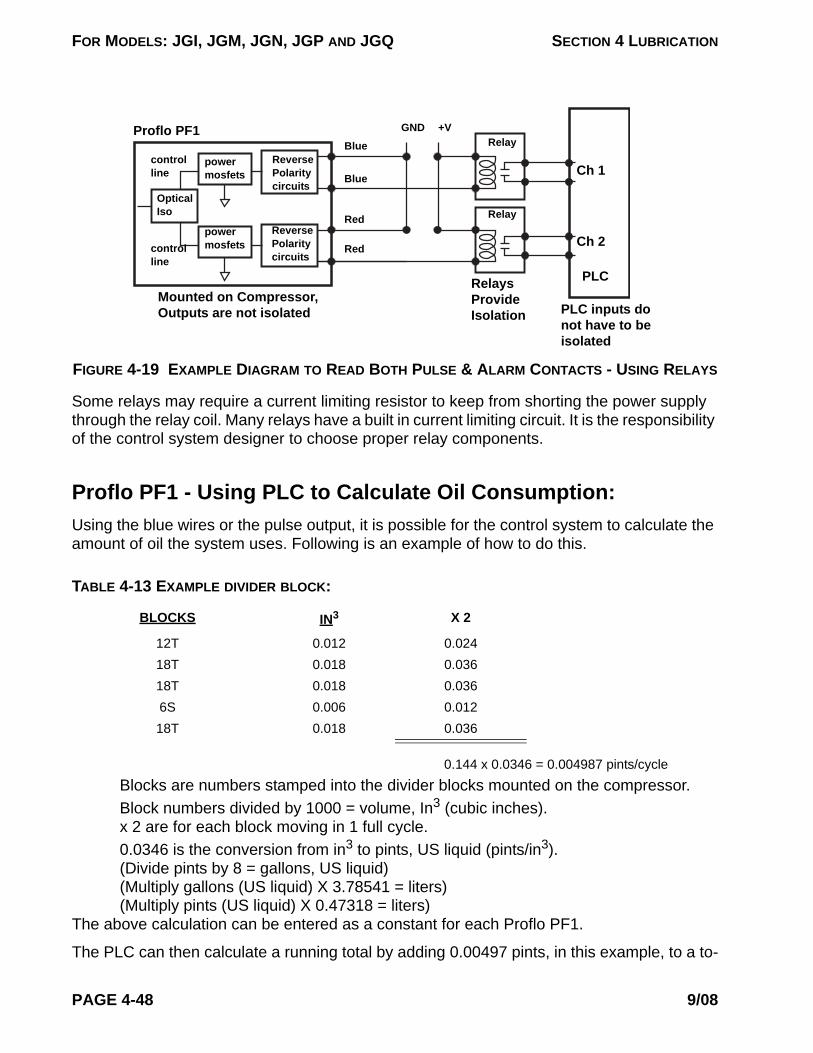
FOR MODELS: JGI, JGM, JGN, JGP AND JGQ SECTION 4 LUBRICATION
Some relays may require a current limiting resistor to keep from shorting the power supply through the relay coil. Many relays have a built in current limiting circuit. It is the responsibility of the control system designer to choose proper relay components.
Proflo PF1 - Using PLC to Calculate Oil Consumption:Using the blue wires or the pulse output, it is possible for the control system to calculate the amount of oil the system uses. Following is an example of how to do this.
0.144 x 0.0346 = 0.004987 pints/cycleBlocks are numbers stamped into the divider blocks mounted on the compressor.Block numbers divided by 1000 = volume, In3 (cubic inches).x 2 are for each block moving in 1 full cycle.0.0346 is the conversion from in3 to pints, US liquid (pints/in3).(Divide pints by 8 = gallons, US liquid)(Multiply gallons (US liquid) X 3.78541 = liters)(Multiply pints (US liquid) X 0.47318 = liters)
The above calculation can be entered as a constant for each Proflo PF1.
The PLC can then calculate a running total by adding 0.00497 pints, in this example, to a to-
FIGURE 4-19 EXAMPLE DIAGRAM TO READ BOTH PULSE & ALARM CONTACTS - USING RELAYS
TABLE 4-13 EXAMPLE DIVIDER BLOCK:
BLOCKS IN3 X 2
12T 0.012 0.02418T 0.018 0.03618T 0.018 0.0366S 0.006 0.01218T 0.018 0.036
Proflo PF1Blue
GND +V
Red
Blue
Optical Iso
control line
power mosfets
Reverse Polarity circuits
Reverse Polarity circuits
power mosfetscontrol
line
Mounted on Compressor, Outputs are not isolated
Red
PLC inputs do not have to be isolated
Relays Provide Isolation
Ch 2
Ch 1
PLC
Relay
Relay
PAGE 4-48 9/08
FOR MODELS: JGI, JGM, JGN, JGP AND JGQ SECTION 4 LUBRICATION
talizer the whole time the compressor is running. This information can be used to track how much oil the compressor is using.
Proflo PF1 Accessories Available:The following parts are available.
1. AC power supply for panel mount. Panel mount power supply is for safe area only.
2. Panel mount kit. This kit includes the panel mount bracket and a proximity switch.
3. Relay interface module. Use this module if you want to switch an AC load 120/240 VAC @ 10 Amps.
4. Additional proximity switch.5. Palm interface Fluid Flow Trending (FFT) software.
For more details on the Proflo PF1 and available accessories, see the vendor literature on the Ariel web site at www.arielcorp.com and/or contact your packager or Ariel.
Protection of Electronics & the Compressor When Arc WeldingAny arc welding on the skid and/or associated equipment and piping can permanently dam-age solid-state electronic equipment. Welding can cause immediate failure or reduced life of such electronic equipment.
Protect the force feed lube flow monitor(s) prior to doing any arc welding (including repair welding) as follows: Disconnect all connections to the flow monitor including ground, and remove the batteries. Or completely remove the flow monitor from the compressor.
It is good practice to attach the welding ground clamp as close as possible to the area where the welding will occur and to use the lowest practical welder output setting. Welding must not cause a current flow across any compressor bearing surface, including but not limited to crankshaft and crosshead bearing surfaces.
Electronic-Lubricator Digital No-Flow Timer Switch (DNFT)When an Ariel DNFT microprocessor-based switch is supplied, it is used to sense no-flow or slow-flow conditions in the compressor cylinder lubrication system to facilitate alarm and/or shutdown. The DNFT also contains an amber light-emitting diode (LED) cycle indicator to provide a positive visual indication of system operation. The Ariel DNFT includes a proximity switch. The Ariel DNFT, usually supplied, is factory set for (3) three minutes from no-flow to alarm/shutdown signal and is not adjustable. Optional programmable models are also avail-able. Introduced in September of 1996, the DNFT replaced the traditional mechanical no-flow switch and is optional on all new units. Since its introduction, the DNFT has undergone
9/08 PAGE 4-49
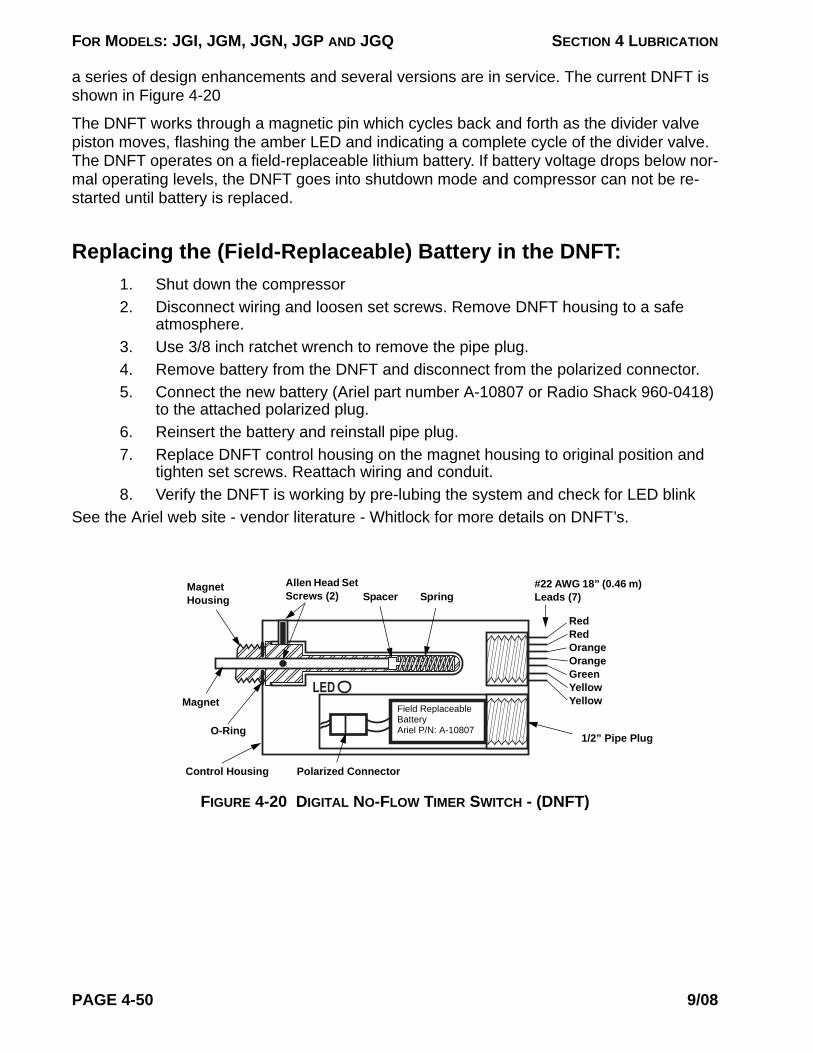
FOR MODELS: JGI, JGM, JGN, JGP AND JGQ SECTION 4 LUBRICATION
a series of design enhancements and several versions are in service. The current DNFT is shown in Figure 4-20
The DNFT works through a magnetic pin which cycles back and forth as the divider valve piston moves, flashing the amber LED and indicating a complete cycle of the divider valve. The DNFT operates on a field-replaceable lithium battery. If battery voltage drops below nor-mal operating levels, the DNFT goes into shutdown mode and compressor can not be re-started until battery is replaced.
Replacing the (Field-Replaceable) Battery in the DNFT:1. Shut down the compressor2. Disconnect wiring and loosen set screws. Remove DNFT housing to a safe
atmosphere.3. Use 3/8 inch ratchet wrench to remove the pipe plug.4. Remove battery from the DNFT and disconnect from the polarized connector. 5. Connect the new battery (Ariel part number A-10807 or Radio Shack 960-0418)
to the attached polarized plug.6. Reinsert the battery and reinstall pipe plug.7. Replace DNFT control housing on the magnet housing to original position and
tighten set screws. Reattach wiring and conduit.8. Verify the DNFT is working by pre-lubing the system and check for LED blink
See the Ariel web site - vendor literature - Whitlock for more details on DNFT’s.
FIGURE 4-20 DIGITAL NO-FLOW TIMER SWITCH - (DNFT)
LED
Polarized Connector
Magnet Housing
Allen Head Set Screws (2)
1/2” Pipe Plug
Control Housing
#22 AWG 18” (0.46 m) Leads (7)
Magnet
SpringSpacer
O-Ring
Field Replaceable Battery Ariel P/N: A-10807
Red Red Orange Orange Green Yellow Yellow
PAGE 4-50 9/08

FOR MODELS: JGI, JGM, JGN, JGP AND JGQ SECTION 4 LUBRICATION
To Check Valve
To Lube Point
FIGURE 4-21 OIL HEAD TRAP FITTING
1 in. (25 mm)Head
Oil Head at Lube PointsThe force feed system provides a minimum of 1-inch (25 mm) of oil head at lube points to extend check valve life. Where the 1-inch (25 mm) of head is not inherent, an oil trap fitting is provided, see the Figure.
NOTE: PRESSURE IN FORCE FEED LUBE LINES IS, AS A MINIMUM, 110% OF THE CYLINDER SUCTION GAS PRES-SURE.
Force Feed Lubrication System and Running Conditions
Force Feed Lubrication System1. Check sight glass on lubricator reservoir to make sure it is properly filled with oil.
The oil in the reservoir is used to lubricate the worm gear and cam; it does not flow through the system. The reservoir also catches lube pump overflow. Oil is added only if it becomes necessary to raise the reservoir oil level.
2. The force feed system has been filled with mineral oil at the factory. If piping has been removed, or if the system has been drained, it can be filled and primed through a 1/8 inch plug on the discharge end of the lubricator pump.
3. Prime the force feed lubrication system just prior to starting the compressor using a proper priming pump; refer to “Ariel Tools - Purchased Separately” in Technical Manual Section 7. Use clean force feed lubricating oil of same type and grade as being used in service. Do not use any other type or grade of fluid for priming.
4. If the unit has just been overhauled, adjust the lubricator for maximum delivery. Reference Technical Manual Sections 3 and 5. Loosen the adjusting screw lock-nut. Turn the plunger stroke adjustment screw to the full up position. Tighten the adjusting screw locknut. Proper feed rate may be set after the machine is started.
5. When there are two or more pumps manifolded and feeding one distribution block, the best way to adjust them is equally. Start with pumps wide open, and adjust them together so that when the break-in cycle time is set, the pumps are stroking about the same. After break-in period, adjust the pumps in the same
TABLE 4-14 FORCE FEED LUBRICATOR RESERVOIR OIL CAPACITY
LUBRICATOR TYPE - ARIEL DESIGNS US GALLONS LITERS
Single Pump 0.25 1Dual Pump 0.5 1.75Four Pump 0.8 3
9/08 PAGE 4-51

FOR MODELS: JGI, JGM, JGN, JGP AND JGQ SECTION 4 LUBRICATION
manner, provided that the final pump stroke is not too short. Try and keep the stroke greater than 20% of maximum; if set for less, the pump is not very reli-able. If need be, one pump can be closed to stop its flow and the other pump(s) opened to make the “normal” cycle time, to maintain a stroke greater than 20% in the functioning pump(s).
Running ConditionsWhen the machine is running, make sure that the oil level in the lubricator reservoir is at least one-half way up the sight level, but does not exceed two-thirds.
See your packager's specific data to determine the normal operating conditions, the cylinder working pressures, and the rated speed.
System Design Considerations and Operating ParametersTo optimize force-feed lubrication system operation, Ariel uses the following general guide-lines:
1. Maintain lube ratios within prescribed limits and cycle times as low as possible (normally 10 sec minimum) to provide each point with lubrication as frequently as possible.
2. Multiple pumps with manifolding are used to ensure that 150% of the normal lubrication rate can be provided during break-in.
3. Pumps are not allowed to operate below 20% of full stroke, the point at which they become unreliable.
4. In some applications, to optimize operation of the lubrication system, a single divider section is used to deliver lubrication to both a packing and a cylinder.
5. In some applications, cross-porting of divider valves is used to deliver the proper proportion of lubricant to a given point.
Force Feed Balance Valves
FIGURE 4-22 FORCE FEED BALANCE VALVE
Balance Valves may be used in high differential-pressure dis-tribution-block applications to reduce system problems such as bypassing, no-flow switch errors or blown rupture discs. The force feed balance valve is shown in the Figure.
Setting and Maintaining Balance ValvesBalance valves cannot be set prior to operating the unit. Ensure that all fittings are tight and any known leaks have been fixed.
Purge the force feed lube system with a high-pressure hand pump, using the same injection oil that is used in service, to remove any trapped air or gas in the system. See Technical Manual Section 7 for pump illustration and part number. DO NOT
PAGE 4-52 9/08

FOR MODELS: JGI, JGM, JGN, JGP AND JGQ SECTION 4 LUBRICATION
USE ANY OTHER FLUIDS FOR PURGING!
Start up the compressor and bring up to normal operating pressure. After the operating pres-sures have stabilized, adjust the cap on the top of the balance valve if necessary. Loosen the locking nut on the top of the balance valve directly under the cap. Turn the cap clockwise to increase the pressure and counter clockwise to decrease the pressure. Retighten the locking nut against the cap.
Set the balance valves and maintain at approximately same pressure on each pressure gauge in the injection lines of the pump system affected. A system should be set and main-tained within 500 psi (3400 kPa) total or less. The closer the individual line pressures are maintained, the more reliable the system will become.
Once the balance valves have been set, they should be checked 4 to 6 hours later to ensure the pressures have not changed and caused another imbalance. If readjustment is neces-sary the gauges should be checked again in 4 to 6 hours. If a pressure gauge in a line with a balance valve is reading more than 500 psi (3400 kPa) higher than the others, try to reduce the pressure on that particular injection line. If reducing the balancing pressure on the bal-ance valve does not drop the pressure, then the other balance valves will need to be adjusted to match the highest pressure.
To set balance valves equipped with a distribution block inlet gauge only:
1. Start up the compressor and bring up to normal operating pressure. After the operating pressures have stabilized, with all balance valves backed off (zero spring load), note the highest gauge pressure reached in a complete block cycle.
2. Slowly increase the spring load on one balance valve, being careful to not exceed rupture disk rated pressure. Watch the gauge and if the maximum pres-sure increases, reduce the spring load until the highest pressure falls to the pressure noted in step 1, above. Tighten the lock nut against the cap, hand wrench tight.
3. Repeat step 2, for the remaining valve(s).Maintain the system by recording the pressures and cycle times of the lubrication system at least once a day.
Checking/Adjusting Balance Valves on Subsequent Start-upBe sure that all fittings are tight and any known leaks have been fixed. Purge the force feed system with a purge gun (hand pump kit, available from Ariel purchased separately), using the same injection oil that is used in service.
Start the compressor and bring up to normal operating pressure. After the operating pres-sures have stabilized, check the pressure gauges to ensure the system is still balanced. If one or more line pressures are out of balance, wait for 2 to 3 hours to see if they become balanced. DO NOT adjust the balancing valves immediately. It is possible that some lube points will increase in injection pressure after a short period of run time and the system will become balanced if it is not balanced on start up.
If a balance valve(s) was installed, but is not required, leave (or set) the spring adjustment at zero. If back-pressure on an unused balance valve is high enough, it may eventually begin
9/08 PAGE 4-53
FOR MODELS: JGI, JGM, JGN, JGP AND JGQ SECTION 4 LUBRICATION
to leak oil. In this case, replace the balance valve internal assembly with a plug assembly, Ariel Part Number A-10330. DO NOT RUN UNIT WITH LEAKY BALANCE VALVES. A valve seal repair kit, Ariel Part Number A-8005-K, is also available.
Maintain the system by recording the pressures and cycle times of the lubrication system at least once a day. Readjust valves as required to keep pump systems pressure balanced for best results.
Frame Lubricating System - DescriptionThe frame lubricating system supplies oil to the internal frame running gear. The cylinders are supplied with lubrication by the force feed system (see “Force Feed Lubrication System - De-scription” on page 4-31). The oil level regulator outside of the crankcase, or separate oil sump in the case of a dry sump crankcase, maintains the proper oil level in the sump.
Frame lubrication is drawn from the sump through the suction strainer into the oil pump that is mounted on the crankcase auxiliary end cover. The pump's discharge is piped to an oil cooler mounted on the compressor skid and is temperature controlled with a thermostatic control valve. Oil returns from the cooler to the oil filter mounted on the auxiliary end of the crankcase. Pressure gauges are provided on the filter inlet and outlet. Normal pressure drop through a clean filter is 2 to 6 PSID (0.15 to 0.4 bard), at normal operating temperature.
From the filter, oil travels through a pressure regulator to an oil gallery cast in the crankcase and running the length of the crankcase.
Drilled holes from the gallery through the bearing saddles deliver oil to the crankshaft bear-ings.
Passages drilled diagonally through the crankshaft from the crank journals to the crank pins deliver oil to the connecting rod bearings.
Holes drilled through the length of the connecting rods deliver oil to the connecting rod bush-ing.
Oil travels from the bushing through holes drilled in the middle of the crosshead pin to the hollow crosshead pins, and from there to the crosshead bushings.
Drilled passages from the oil gallery deliver oil at full system pressure through external tubing to lubricate the top and bottom of each crosshead. Run-off from the shoes, crosshead, and connecting rod bushings collects in the crosshead guide and drains back to the crankcase.
Lube Oil Strainer, Filter & Filter Installation Instructions
Lube Oil StrainerThe strainer is located on the auxiliary end of the crankcase below the oil level. It is provided to protect the oil pump from debris that might cause damage. The strainer basket should be taken out and washed in an appropriate solvent whenever the lubricating oil is changed. For dry sump frames the lube oil strainer is shipped loose (not installed) from the Ariel factory.
PAGE 4-54 9/08

FOR MODELS: JGI, JGM, JGN, JGP AND JGQ SECTION 4 LUBRICATION
Lube Oil FilterAriel recommends replacing the lube oil filter every 6 months, or 4000 hours, or when oil filter differential pressure reaches the value given in Table 4-15 or on the oil filter information plate located on the compressor frame top cover, at normal operating temperature; whichever comes first. Also clean the sintered element in the small oil filter supplied on the force feed lubrication system on the same schedule or every time main oil filter is changed.
Oil Filter Installation for Spin-On Type Filters1. For compressors supplied with spin-on type oil filters, remove the old filter by
unscrewing it, with the compressor stopped. Be sure that the old filter gasket is removed. Clean the filter manifold base surfaces.
2. Fill a new filter with clean oil, using the same grade and type of oil as in the sump.
3. Apply clean oil to the filter gasket.4. Screw on the new filter, after the filter gasket contacts the base tighten one full
turn.5. After starting the compressor, check for leaks and retighten the filter if neces-
sary.6. Do not run the compressor with a damaged filter canister. It can fracture or leak. 7. Replace the filter only with an Ariel approved non-bypass type filter.
Oil Filter Element Installation for Cartridge Type Filters1. For compressors supplied with cartridge type oil filters, remove the filter vessel
drain plug and completely drain the vessel, with the compressor stopped.2. During draining, remove the flowing vent line and 1/16 in. (2 mm) orifice fitting
and blow out the line with compressed air. Clean the orifice with a 1/32 in. (1 mm) diameter wire or a standard paper clip (20/21 gage wire). Loosen the nuts and remove the top cover.
NOTE: REMOVAL OF THE ELEMENT PRIOR TO COMPLETELY DRAINING THE VES-SEL WILL ALLOW TRAPPED DEBRIS TO ENTER THE OIL HEADER AND CAN CAUSE SEVERE DAMAGE TO THE COMPRESSOR.
3. After the oil has completely drained, remove the spring plate assembly, strainer
TABLE 4-15 MAXIMUM DIFFERENTIAL PRESSURE TO CHANGE OIL FILTER OR ELEMENT(S)
TYPE FILTERMAXIMUM PD TO CHANGE FILTER A
a. Or every six months, or 4000 hours, whichever comes first.2. On start-up differential pressure may exceed the tabled limits until the oil reaches operating tem-
perature.
PSID barg
Spin-On Filter 10 (0.7)Cartridge Type Element(s) 15 (1.0)
9/08 PAGE 4-55
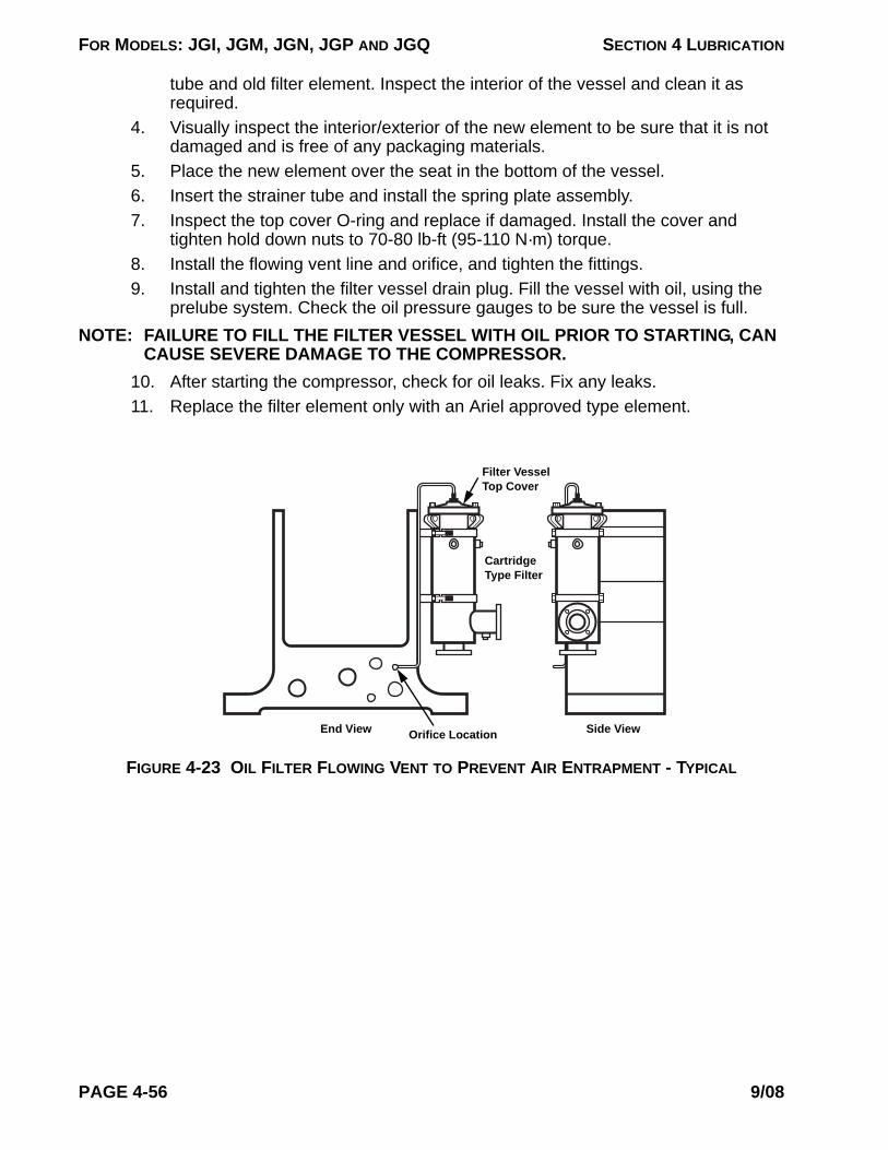
FOR MODELS: JGI, JGM, JGN, JGP AND JGQ SECTION 4 LUBRICATION
tube and old filter element. Inspect the interior of the vessel and clean it as required.
4. Visually inspect the interior/exterior of the new element to be sure that it is not damaged and is free of any packaging materials.
5. Place the new element over the seat in the bottom of the vessel.6. Insert the strainer tube and install the spring plate assembly.7. Inspect the top cover O-ring and replace if damaged. Install the cover and
tighten hold down nuts to 70-80 lb-ft (95-110 N·m) torque.8. Install the flowing vent line and orifice, and tighten the fittings.9. Install and tighten the filter vessel drain plug. Fill the vessel with oil, using the
prelube system. Check the oil pressure gauges to be sure the vessel is full.NOTE: FAILURE TO FILL THE FILTER VESSEL WITH OIL PRIOR TO STARTING, CAN
CAUSE SEVERE DAMAGE TO THE COMPRESSOR.10. After starting the compressor, check for oil leaks. Fix any leaks.11. Replace the filter element only with an Ariel approved type element.
FIGURE 4-23 OIL FILTER FLOWING VENT TO PREVENT AIR ENTRAPMENT - TYPICAL
Orifice Location Side ViewEnd View
Filter Vessel Top Cover
Cartridge Type Filter
PAGE 4-56 9/08

FOR MODELS: JGI, JGM, JGN, JGP AND JGQ SECTION 4 LUBRICATION
Lube Oil Pump & Lube Oil Pressure
FIGURE 4-24 LUBE OIL PUMP - TYPICAL
Description & AdjustmentIf there is a separate regulating valve down stream from the pump, the spring-loaded safety relief valve within the pump head is set at the Ariel factory on a new compressor to the max-imum pressure with the adjusting screw turned in all the way. Even though the adjusting screw is turned in all the way, the relief valve will still open at approximately 100 psig (7 barg) to protect the pump from high pressure damage. In this case, do not adjust the pump safety-relief valve unless installing a new pump, then set the relief valve to maximum pressure by turning the adjusting screw clockwise in all the way.
If there is no separate regulating valve, the pump safety relief valve is set by the Ariel factory on a new compressor to regulate pressure at 60 psig (4.1 barg) into the compressor when crankshaft speed equals or exceeds minimum normal operating speed. If oil pressure into the compressor while running at minimum operating speed and normal operating temperature does not read approximately 60 psig (4.1 barg), adjust the pump safety relief valve. With com-pressor running at minimum rated speed, remove the dust cap and adjust the screw to pro-vide oil pressure into the compressor at 60 psig (4.1 barg). Turning the adjustment screw clockwise increases the pressure setting.
Lube Oil Pressure Regulating ValveIf there is a separate lube oil pressure regulating valve, normal oil pressure into the compres-sor is set at the regulating valve by the factory at 60 psig (4.1 barg) when crankshaft speed equals or exceeds minimum normal operating speed.
NOTE: IF OIL PRESSURE DROPS BELOW 50 PSIG (3.5 barg) WHEN CRANKSHAFT SPEED EQUALS OR EXCEEDS MINIMUM RATED OPERATING SPEED, THE CAUSE MUST BE FOUND AND CORRECTED.
Suction
Discharge
Remove Dust Cap to Expose Safety Relief Valve Adjusting Screw (Turning Screw Clockwise Increases Pressure Setting)
Smaller Compressor Models Have Threaded Connections
9/08 PAGE 4-57
FOR MODELS: JGI, JGM, JGN, JGP AND JGQ SECTION 4 LUBRICATION
Low Oil Pressure ShutdownThe low oil pressure shutdown is normally mounted by the packager and is supplied to cus-tomer specifications. Ariel provides an oil pressure pickup fitting on the oil gallery located after the cooler and filter. The electric or pneumatic oil pressure switch is to be set to actuate when oil pressure falls below 35 psig (2.4 barg). An alarm set to actuate when oil pressure falls be-low 50 psig (3.4 barg) is desirable.
NOTE:1. THE COMPRESSOR MUST HAVE A WORKING LOW OIL PRESSURE SHUT-
DOWN. WHEN SHUTDOWN AS RESULT OF LOW OIL PRESSURE, DO NOT ATTEMPT TO RE-START UNTIL FAULT IS FOUND AND CORRECTED.
2. DO NOT ATTEMPT TO ADD OIL TO THE CRANKCASE THROUGH THE BREATHER HOLE WHILE THE UNIT IS RUNNING. THIS WILL CAUSE OIL FOAMING, AND UNNECESSARY NO-FLOW SHUTDOWNS IN THE FORCE FEED LUBRICATION SYSTEM.
3. WHEN THE FORCE FEED LUBRICATION SYSTEM HAS A COMMON SUP-PLY (FROM THE CRANKCASE), IT IS CONSTANTLY USING OIL FROM THE CRANKCASE, A WORKING OIL SUMP LEVEL CONTROLLER IS NECES-SARY. THIS MUST BE DESIGNED TO ALLOW OIL TO FLOW INTO THE CRANKCASE FROM AN OVERHEAD TANK AT ALL AMBIENT TEMPERA-TURE CONDITIONS.
PAGE 4-58 9/08
FOR MODELS: JGI, JGM, JGN, JGP AND JGQ
SECTION 5 - MAINTENANCE
General IntroductionThe major components of the frame assembly are the frame (or crankcase) with integral crosshead guides, crankshaft and bearings, connecting rods, chain drive system and cross-heads.
A cast-in oil gallery runs the length of the crankcase. Drilled oil passages feed lubricating oil to the running gear.
The removable top cover on horizontally opposed models, (and connecting rod and chain access covers on the JGI), and crosshead guide side covers provide generous access for inspecting and removing internal components. The top cover is made of aluminum for easy handling.
Absolute cleanliness, including the use of lint-free wiping cloths, is a necessity during any maintenance on the compressor. When access covers have been removed, keep the frame covered to protect the interior from dust except when actually working on it. Any components that have been removed should be protected from falling objects that might mar or chip run-ning surfaces.
Whenever the machine is dismantled, gaskets at non-pressure positions are to be carefully inspected before reuse. Damaged gaskets must be replaced. Gaskets at pressure locations should be replaced. Before installing a gasket, apply an antiseize lubricant to both sides or to the metal seating surfaces. This will help to hold the gasket in place during assembly and aid in easy of removal.
If replacing any major reciprocating component, that is; a connecting rod assembly, piston, piston and rod assembly, crosshead-balance nuts or crosshead, weigh component parts and compare to the Compressor Balancing Record sheet that comes in the parts manual with each compressor. If there are weight changes, recalculate opposing throw reciprocating
9/08 PAGE 5-1

FOR MODELS: JGI, JGM, JGN, JGP AND JGQ SECTION 5 - MAINTENANCE
weight differential, refer to “Opposed Throw - Reciprocating Weight Balancing” on page 1-5.
CAUTIONTO PREVENT PERSONAL INJURY, BE SURE THAT COMPRESSOR CRANKSHAFT CANNOT BE TURNED BY THE DRIVER OR COMPRESSOR CYLINDER GAS PRESSURE DURING MAINTENANCE: — ON ENGINE-DRIVEN COMPRESSORS, REMOVE THE CENTER COUPLING OR LOCK THE FLYWHEEL. — ON ELECTRIC MOTOR-DRIVEN COMPRESSORS, IF IT IS INCONVENIENT TO DETACH THE DRIVER FROM THE COMPRESSOR, THE DRIVER SWITCH GEAR MUST BE LOCKED OUT DURING MAINTENANCE.
BEFORE STARTING ANY MAINTENANCE OR REMOVING ANY COMPONENTS, RELIEVE ALL PRESSURE FROM THE COMPRESSOR CYLINDERS. (REFER TO PACKAGER’S INSTRUCTIONS FOR COMPLETELY VENTING THE SYSTEM.)
CAUTIONAFTER PERFORMING ANY MAINTENANCE, THE ENTIRE SYSTEM MUST BE PURGED WITH GAS PRIOR TO OPERATION, TO AVOID A POTENTIALLY EXPLOSIVE AIR/GAS MIXTURE.
!
!
PAGE 5-2 9/08
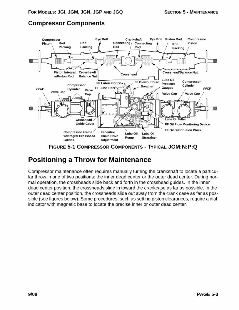
FOR MODELS: JGI, JGM, JGN, JGP AND JGQ SECTION 5 - MAINTENANCE
Compressor Components
Positioning a Throw for MaintenanceCompressor maintenance often requires manually turning the crankshaft to locate a particu-lar throw in one of two positions: the inner dead center or the outer dead center. During nor-mal operation, the crossheads slide back and forth in the crosshead guides. In the inner dead center position, the crossheads slide in toward the crankcase as far as possible. In the outer dead center position, the crossheads slide out away from the crank case as far as pos-sible (see figures below). Some procedures, such as setting piston clearances, require a dial indicator with magnetic base to locate the precise inner or outer dead center.
FIGURE 5-1 COMPRESSOR COMPONENTS - TYPICAL JGM:N:P:Q
Compressor Piston
CrankshaftConnecting Rod
Crosshead Crosshead/Balance Nut
Eye Bolt
Lube Oil Filter
Piston Integral w/Piston Rod
Compressor Cylinder
Breather
FF Oil Distribution Block
Crosshead Guide Cover
Valve CapVVCP
Compressor PistonRod
Packing
Piston RodRod Packing
Connecting Rod
Eye Bolt
Crosshead/ Balance Nut
VVCPValve CapValve Cap
Valve Cap
Compressor Cylinder
Compressor Frame w/Integral Crosshead Guides
FF Oil Flow Monitoring Device
Eccentric Chain Drive Adjustment
Lube Oil Pressure Gauges
FF Blowout Disc
FF Lube FilterFF Lubricator Box
Lube Oil Pump
Lube Oil Strarainer
Rod Packing
9/08 PAGE 5-3
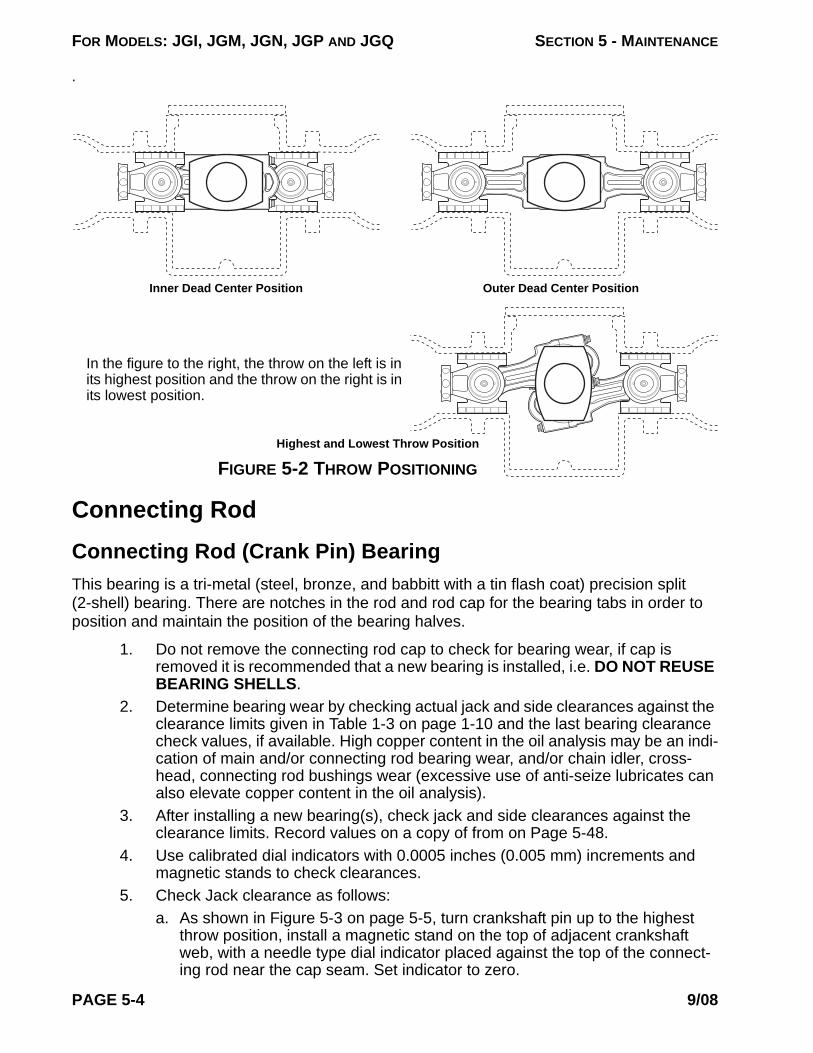
FOR MODELS: JGI, JGM, JGN, JGP AND JGQ SECTION 5 - MAINTENANCE
.
In the figure to the right, the throw on the left is in its highest position and the throw on the right is in its lowest position.
Inner Dead Center Position Outer Dead Center Position
Highest and Lowest Throw Position
FIGURE 5-2 THROW POSITIONING
Connecting RodConnecting Rod (Crank Pin) BearingThis bearing is a tri-metal (steel, bronze, and babbitt with a tin flash coat) precision split (2-shell) bearing. There are notches in the rod and rod cap for the bearing tabs in order to position and maintain the position of the bearing halves.
1. Do not remove the connecting rod cap to check for bearing wear, if cap is removed it is recommended that a new bearing is installed, i.e. DO NOT REUSE BEARING SHELLS.
2. Determine bearing wear by checking actual jack and side clearances against the clearance limits given in Table 1-3 on page 1-10 and the last bearing clearance check values, if available. High copper content in the oil analysis may be an indi-cation of main and/or connecting rod bearing wear, and/or chain idler, cross-head, connecting rod bushings wear (excessive use of anti-seize lubricates can also elevate copper content in the oil analysis).
3. After installing a new bearing(s), check jack and side clearances against the clearance limits. Record values on a copy of from on Page 5-48.
4. Use calibrated dial indicators with 0.0005 inches (0.005 mm) increments and magnetic stands to check clearances.
5. Check Jack clearance as follows:a. As shown in Figure 5-3 on page 5-5, turn crankshaft pin up to the highest
throw position, install a magnetic stand on the top of adjacent crankshaft web, with a needle type dial indicator placed against the top of the connect-ing rod near the cap seam. Set indicator to zero.
PAGE 5-4
9/08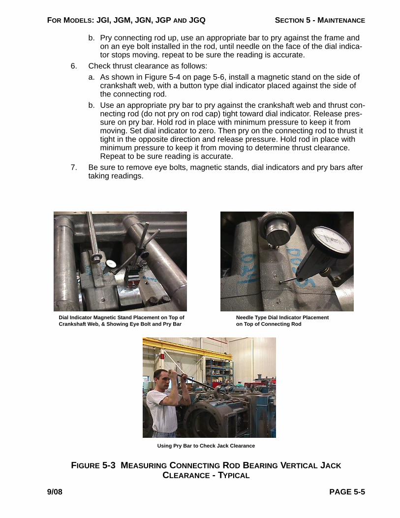
FOR MODELS: JGI, JGM, JGN, JGP AND JGQ SECTION 5 - MAINTENANCE
b. Pry connecting rod up, use an appropriate bar to pry against the frame and on an eye bolt installed in the rod, until needle on the face of the dial indica-tor stops moving. repeat to be sure the reading is accurate.
6. Check thrust clearance as follows:a. As shown in Figure 5-4 on page 5-6, install a magnetic stand on the side of
crankshaft web, with a button type dial indicator placed against the side of the connecting rod.
b. Use an appropriate pry bar to pry against the crankshaft web and thrust con-necting rod (do not pry on rod cap) tight toward dial indicator. Release pres-sure on pry bar. Hold rod in place with minimum pressure to keep it from moving. Set dial indicator to zero. Then pry on the connecting rod to thrust it tight in the opposite direction and release pressure. Hold rod in place with minimum pressure to keep it from moving to determine thrust clearance. Repeat to be sure reading is accurate.
7. Be sure to remove eye bolts, magnetic stands, dial indicators and pry bars after taking readings.
FIGURE 5-3 MEASURING CONNECTING ROD BEARING VERTICAL JACK CLEARANCE - TYPICAL
Dial Indicator Magnetic Stand Placement on Top of Crankshaft Web, & Showing Eye Bolt and Pry Bar
Using Pry Bar to Check Jack Clearance
Needle Type Dial Indicator Placement on Top of Connecting Rod
9/08 PAGE 5-5
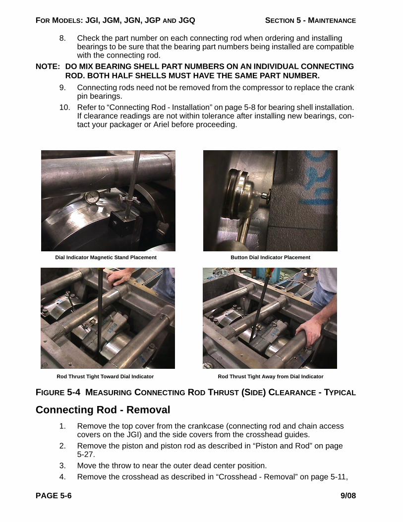
FOR MODELS: JGI, JGM, JGN, JGP AND JGQ SECTION 5 - MAINTENANCE
8. Check the part number on each connecting rod when ordering and installing bearings to be sure that the bearing part numbers being installed are compatible with the connecting rod.
NOTE: DO MIX BEARING SHELL PART NUMBERS ON AN INDIVIDUAL CONNECTING ROD. BOTH HALF SHELLS MUST HAVE THE SAME PART NUMBER.
9. Connecting rods need not be removed from the compressor to replace the crank pin bearings.
10. Refer to “Connecting Rod - Installation” on page 5-8 for bearing shell installation. If clearance readings are not within tolerance after installing new bearings, con-tact your packager or Ariel before proceeding.
Connecting Rod - Removal1. Remove the top cover from the crankcase (connecting rod and chain access
covers on the JGI) and the side covers from the crosshead guides.2. Remove the piston and piston rod as described in “Piston and Rod” on page
5-27.3. Move the throw to near the outer dead center position.4. Remove the crosshead as described in “Crosshead - Removal” on page 5-11,
FIGURE 5-4 MEASURING CONNECTING ROD THRUST (SIDE) CLEARANCE - TYPICAL
Dial Indicator Magnetic Stand Placement Button Dial Indicator Placement
Rod Thrust Tight Away from Dial IndicatorRod Thrust Tight Toward Dial Indicator
PAGE 5-6 9/08

FOR MODELS: JGI, JGM, JGN, JGP AND JGQ SECTION 5 - MAINTENANCE
while supporting the connection rod so that it does not drop.5. Turn the crankshaft until the throw is near to its highest point position. Com-
pletely loosen the connecting-rod-cap bolting and remove the top two cap-screws.
6.
FIGURE 5-5 ROD AND ROD CAP SEPARATION
Connecting Rod Cap
Gently Tap Here when Separating Cap
Rod-Cap Cap-Screws (4)
Connecting Rod
Separate the rod cap from the rod. Use the bottom two rod-cap cap-screws as a han-dles to pull on the bot-tom of the rod cap while tapping the top face of the rod cap with a semi-soft faced hammer. Do not pull or strike the rod cap too hard; it may break the rod cap dowels. Work the rod cap away from rod as evenly as possible. Separating the two parts unevenly may break the rod cap dowels or cause them to bind in the rod dowel holes. See Figure above.
7. Remove the rod cap and its bearing half shell.8. The bearing shell may fall out when separating the connecting rod and cap from
the crankshaft pin. If bearing shells do not come loose, rotate/slide them out of the connecting rod and/or cap.
9. Turn the crankshaft throw to near the inner dead center position and remove the rod through the crosshead guide opening (or connecting rod access hole on the JGI).
10. After the removal of the connecting rods, be sure to protect the crank pins from being nicked or scratched.
NOTE: IF ALL CONNECTING RODS ARE TO BE REMOVED, IT MAY BE MORE EXPE-DIENT TO REMOVE THE CRANKSHAFT PRIOR TO REMOVING THE RODS.
Connecting Rod Bushing Replacement1. Check crosshead pin to connecting rod bushing clearance (see Table 1-3 on
page 1-10 for recommended clearance.) Inspect the pin for wear and replace it if necessary.
2. To replace a rod bushing file or hack saw the existing bushing to reduce the tightness of the shrink fit. From the inside diameter file or saw across the length of the bushing to within 1/32 inch (1 mm) of its radial thickness. It can then be easily drifted out. Be careful, not to file or saw into the connecting rod, as any rod bore damage makes the rod unusable.
3. Use a hydraulic press in a qualified machine shop to install the new bushing. Do not hammer the bushing into place as this distorts the bushing bore. Before
9/08 PAGE 5-7

FOR MODELS: JGI, JGM, JGN, JGP AND JGQ SECTION 5 - MAINTENANCE
installation, cool the new bushing in a 95% alcohol solution, with dry ice solution. Leave the bushing in the solution long enough to reach the solution tempera-ture, about -110°F (-80°C).
CAUTION!: DO NOT TOUCH COLD SURFACES WITHOUT PROPER INSULATION TO PREVENT INJURY. ALCOHOL IS FLAMMABLE AND SHOULD ONLY BE USED IN OPEN AIR OR A WELL VENTILATED BUILDING. AVOID SPARKS AND OPEN FLAME. AVOID ALCOHOL VAPORS WHICH MAY CAUSE INJURY TO THE TISSUES OF THE NOSE AND EYES. AVOID EYE AND SKIN CONTACT. USE NEOPRENE OR BUTYL GLOVES, MONO-GOGGLES OR FACE-MASK AND IMPERMEABLE APRON. IT CONTAINS METHYL ALCOHOL AND IS POISONOUS IF INGESTED. SEE MANUFACTURER'S MATERIAL SAFETY DATA SHEETS FOR MORE INFORMATION. DO NOT RETURN SOLUTION TO A CLOSED CONTAINER UNTIL IT HAS REACHED ROOM TEMPERATURE OR THE CONTAINER MAY EXPLODE.
NOTE: ABSOLUTE CLEANLINESS IS REQUIRED OF BOTH THE BUSHING AND THE CONNECTING ROD TO PREVENT DIRT FROM ACCUMULATING BETWEEN THEM. ASSEMBLY MUST BE IMMEDIATE SO THAT THE BUSHING DOES NOT WARM-UP AND STICK BEFORE IT IS IN PLACE. IF STICKING A NEW BUSH-ING, REMOVE BY NOTCHING AS IN REMOVAL INSTRUCTIONS, AND START OVER WITH ANOTHER NEW BUSHING. DO NOT SEAT A STUCK BUSHING WITH A PRESS OR HAMMER.
4.
FIGURE 5-6 ROD BUSHINGINSTALLATION
Bushing Oil Hole
Bushing Exterior Annular GrooveBushing
Oil Passage
Connecting Rod
Position the connecting rod on the press table so that the chamfered edge of the rod bushing hole is on top. Install the bushing quickly while it is very cold. Be sure to locate the bushing oil hole at the connecting rod oil passage before pressing it in. The bushing has exterior and interior annular grooves in line with the oil hole. Should the bushing shift circumferentially during operation oil can still travel to its inner surface and to the cross-head pin. However, during installation of a new bushing, no more than 1/3 of the oil pas-sage hole in the rod should be covered by the bushing.
Connecting Rod - Installation1. If installing a new replacement connecting rod, stamp throw number on the tops
of the connecting rod and bearing cap, (with bearing notches up), matching its throw location, see Figure 5-7 on Page 5-9.
2. Check new bearing shells to see they are free of handling damage, scratches, burrs, and loose material at the tabs. DO NOT RUB BEARING SURFACE WITH FINGERNAIL. Check the part number on each connecting rod when ordering and installing bearings to be sure that the bearing part numbers being installed are compatible with the connecting rod.
NOTE: DO MIX BEARING SHELL PART NUMBERS ON AN INDIVIDUAL CONNECTING ROD. BOTH HALF SHELLS MUST HAVE THE SAME PART NUMBER.
3. New bearing shells and crankshaft crank pin bearing surfaces must be abso-
PAGE 5-8 9/08

FOR MODELS: JGI, JGM, JGN, JGP AND JGQ SECTION 5 - MAINTENANCE
lutely clean. Snap new dry half bearing shells into the rod and bearing cap with the bearing tabs properly located in the notches. With the crankcase top cover and crosshead guide covers off, turn the throw to near the inner dead center position. Apply new clean lubricating oil, same type as is used in the frame, lib-erally to rod bearing shell face. Slide the properly numbered rod matching the throw number, with bearing shell installed, into the crosshead guide space toward the crankshaft while supporting the rod.
NOTE: THE CAPS AND RODS ARE NUMBERED BY THROW BEGINNING WITH NUM-BER ONE AT THE DRIVE END. SEE FIGURE 1-1, FIGURE 1-2 AND FIGURE 1-3 FOR THROW NUMBERING SEQUENCE. ALWAYS INSTALL RODS AND CAPS WITH THE NUMBERS UP (OR TOWARD ACCESS OPENING IN THE JGI). BE SURE TO PROTECT CRANK PIN AT ALL TIMES.
FIGURE 5-7 CONNECTING ROD ASSEMBLY INSTALLATION
Adjacent Crankshaft Web
Stamped Throw Numbers Up
Connecting Rod
Connecting Rod Cap
Rod-Cap Cap-Screws (4)
Bushing
Connecting Rod
Dowels
Bearing Shell
Connecting Rod Cap
Bearing Shell
Oil Passage
Tab Notch
Tab
Tab NotchDowel Hole
Tab
Dowel Hole
4. Fit the rod to the crank pin and turn the crankshaft to position the crank pin up, near to the highest position, while supporting the rod. Oil the crankshaft crank pin bearing surfaces with new clean lubricating oil, same type as is used in the frame, before installing the connecting rod cap. Lubricate cap bolting threads and seating surfaces with a thin coating of oil. Insert cap-screws into the cap. Slide bolting out of the cap until ends of all bolts are even with the cap parting face. Use the top bolts as handles to move the cap into place. Place the properly numbered cap matching the throw number on to the top of the crank pin with the parting face parallel to the rod face, and with numbered matching number up (the tab side of the bearing toward the throw). Align the rod cap dowels with the rod dowel holes and push into the rod. Screw all cap bolting into the connecting rod and snug up. Do not tighten the bolting at this point.
5. Install the crosshead and attach to the connecting rod. See “Crosshead - Instal-lation” on Page 5-13.
6. Tighten the connecting rod bolting an alternating (criss-cross) pattern in 25% increments for each cap to full torque, to the values listed in Table 1-12 on page 1-16.
7. Measure each crankshaft to connecting rod bearing jack clearance and connect-ing rod thrust (side) clearance. See “Connecting Rod (Crank Pin) Bearing” on Page 5-4. Record readings on the form on Page 5-48. Also check crosshead pin bushing clearance to Table 1-3 on page 1-10. If readings are not within tolerance
9/08 PAGE 5-9

FOR MODELS: JGI, JGM, JGN, JGP AND JGQ SECTION 5 - MAINTENANCE
after installing new bearings, bushings, etc., contact your packager or Ariel before proceeding.
8. Examine the top cover or access cover gaskets. If there is any doubt about their condition, install new gaskets. Before installing a gasket, apply an antiseize lubricant to both sides or to the metal seating surfaces. This will help to hold the gasket in place during assembly and aid in easy of removal. Additional lubrica-tion to provide for gasket release, is not required. Replace the top cover or access cover and crosshead guide covers. Tighten all cover cap screws hand wrench tight.
PAGE 5-10 9/08

FOR MODELS: JGI, JGM, JGN, JGP AND JGQ SECTION 5 - MAINTENANCE
Crosshead
Crosshead - Removal1.
FIGURE 5-8 CROSSHEAD - TYPICAL
Locknut Crosshead- Balance Nut
Set Screws - Loosen Before Turning NutEnd
PlateThrough Bolt
Bushing
Roll Pin
Crosshead Pin
Through Bolt
Shoe Area
Roll Pin End Plate
Loosen all cylin-der heads to the Caution note above to be sure cylinders are completely vented.
2. Remove cross-head guide side covers.
3. Remove the cyl-inder head (or VVCP). In the case of tandem cylinders where the outboard cyl-inder bore is smaller than the inboard bore, it is necessary to remove the outboard cylinder. Support such cylinders during removal and installation, as to not put excessive weight on the piston and rod assembly which might cause bending.
4. Turn the crankshaft to position the crosshead to near its inner dead center posi-tion and back off, but do not remove, the crosshead-balance nut set screws. Loosen the nut with the special slugging Peg or Open End Wrench shown in Figure 7-1 on page 7-2, depending on nut style.
5. Turn the crosshead-balance nut off the piston rod, while removing the piston and
CAUTIONBEFORE REMOVING THE CYLINDER HEAD, BACK OFF ALL CAP SCREWS 1/8 INCH (3 mm). MAKE SURE THAT THE HEAD IS LOOSE AND THE CYLINDER IS VENTED. SEE IMPORTANT SAFETY INFORMATION PLATES ON COMPRESSOR TOP COVER, REFER TO TABLE 1-4 ON PAGE 1-6 FOR LOCATION.
CAUTIONCROSSHEADS ARE HEAVY. CARE MUST BE TAKEN WHEN HANDLING TO AVOID PERSONAL INJURY. THE WEIGHT OF EACH CROSSHEAD IS LISTED IN THE BALANCE SHEET THAT COMES IN THE MANUAL WITH EACH COMPRESSOR.
!
!
9/08 PAGE 5-11
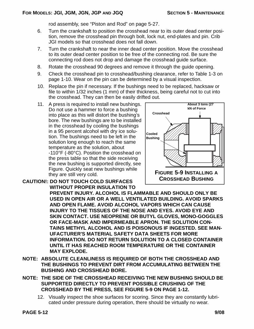
FOR MODELS: JGI, JGM, JGN, JGP AND JGQ SECTION 5 - MAINTENANCE
rod assembly, see “Piston and Rod” on page 5-27.6. Turn the crankshaft to position the crosshead near to its outer dead center posi-
tion, remove the crosshead pin through bolt, lock nut, end-plates and pin. Crib JGI models so that crosshead does not fall down.
7. Turn the crankshaft to near the inner dead center position. Move the crosshead to its outer dead center position to be free of the connecting rod. Be sure the connecting rod does not drop and damage the crosshead guide surface.
8. Rotate the crosshead 90 degrees and remove it through the guide opening.9. Check the crosshead pin to crosshead/bushing clearance, refer to Table 1-3 on
page 1-10. Wear on the pin can be determined by a visual inspection. 10. Replace the pin if necessary. If the bushings need to be replaced, hacksaw or
file to within 1/32 inches (1 mm) of their thickness, being careful not to cut into the crosshead. They can then be easily drifted out.
11.
FIGURE 5-9 INSTALLING A CROSSHEAD BUSHING
About 3 tons (27 kN of Force
Crosshead
Cooled Bushing
A press is required to install new bushings. Do not use a hammer to force a bushing into place as this will distort the bushing’s bore. The new bushings are to be installed in the crosshead by cooling the bushings in a 95 percent alcohol with dry ice solu-tion. The bushings need to be left in the solution long enough to reach the same temperature as the solution, about -110°F (-80°C). Position the crosshead on the press table so that the side receiving the new bushing is supported directly, see Figure. Quickly seat new bushings while they are still very cold.
CAUTION!: DO NOT TOUCH COLD SURFACES WITHOUT PROPER INSULATION TO PREVENT INJURY. ALCOHOL IS FLAMMABLE AND SHOULD ONLY BE USED IN OPEN AIR OR A WELL VENTILATED BUILDING. AVOID SPARKS AND OPEN FLAME. AVOID ALCOHOL VAPORS WHICH CAN CAUSE INJURY TO THE TISSUES OF THE NOSE AND EYES. AVOID EYE AND SKIN CONTACT. USE NEOPRENE OR BUTYL GLOVES, MONO-GOGGLES OR FACE-MASK AND IMPERMEABLE APRON. THE SOLUTION CON-TAINS METHYL ALCOHOL AND IS POISONOUS IF INGESTED. SEE MAN-UFACTURER'S MATERIAL SAFETY DATA SHEETS FOR MORE INFORMATION. DO NOT RETURN SOLUTION TO A CLOSED CONTAINER UNTIL IT HAS REACHED ROOM TEMPERATURE OR THE CONTAINER MAY EXPLODE.
NOTE: ABSOLUTE CLEANLINESS IS REQUIRED OF BOTH THE CROSSHEAD AND THE BUSHINGS TO PREVENT DIRT FROM ACCUMULATING BETWEEN THE BUSHING AND CROSSHEAD BORE.
NOTE: THE SIDE OF THE CROSSHEAD RECEIVING THE NEW BUSHING SHOULD BE SUPPORTED DIRECTLY TO PREVENT POSSIBLE CRUSHING OF THE CROSSHEAD BY THE PRESS, SEE FIGURE 5-9 ON PAGE 1-12.
12. Visually inspect the shoe surfaces for scoring. Since they are constantly lubri-cated under pressure during operation, there should be virtually no wear.
PAGE 5-12 9/08
FOR MODELS: JGI, JGM, JGN, JGP AND JGQ SECTION 5 - MAINTENANCE
Crosshead - InstallationNOTE: BE SURE CROSSHEADS ARE RETURNED TO THEIR ORIGINAL THROW
LOCATION.1. With the throw positioned near to its inner dead center position, turn the cross-
head on its side and slip it into the crosshead guide. Rotate the crosshead 90° into place. Make sure it does not become cocked. Should the crosshead become wedged, do not force it. Ease it off and start again. Be careful not to damage the crosshead shoe surface during installation.
2. Lift the crosshead end of the connecting rod and turn the crankshaft to near the outer dead center position to locate the connecting rod in the crosshead. Align connecting rod bushing with the crosshead bushings and insert the crosshead pin.
3. Install the end plates, through bolt and locknut. Tighten the locknut to the torque value listed in Table 1-12 on page 1-16.
4. Be sure that the crosshead-balance nut seating surfaces are flat and free of burrs. Dress with a flat stone as required. The piston rod threads are to be lubri-cated with a thin coat of Never Seez, regular grade, and the crosshead-balance nut seating surfaces with new oil (same grade as used in the frame).
5. Re-install the crosshead-balance nut on the piston rod. Be sure to have set-screw cup points on the crosshead side of the nut. Install the piston and rod assembly in the cylinder. See “Piston and Rod - Installation” on page 5-30.
NOTE: PISTON END CLEARANCE MUST NOW BE SET OR SERIOUS DAMAGE COULD OCCUR. SEE THE REQUIRED PISTON CRANK END CLEARANCE AS SHOWN ON THE CYLINDER IDENTIFICATION PLATE, REFER TO TABLE 1-3 ON PAGE 1-10.
6. Position the crankshaft to the exact inner dead center position of the throw.NOTE: UTILIZE A DIAL INDICATOR WITH A MAGNETIC BASE TO INDICATE THE
LOCATION OF THE CROSSHEAD WHEN FINDING EXACT INNER DEAD CEN-TER POSITION.
7. Determine the required piston crank end clearance from the cylinder identifica-tion plate, refer to Table 1-3 on page 1-10. Insert a feeler gage, equal to the required crank end clearance, through an open valve pocket. For 13 in. (330 mm) and larger cylinders, insert the feeler gage through a bottom valve pocket. For 2-3/4M, 3M, 2-3/4P-CE and 3-1/4P-CE class cylinders, use the Ariel fur-nished clearance setting tool A-13801 as a feeler gage, see Figure 7-1 on page 7-2 (this tool must be inserted horizontally with end notch side toward the crank end and rotated 90° to position the end notch up, prior to performing step 6. above). 2-1/4P-CE class cylinders use clearance setting tool A-11344. Screw the piston rod into the crosshead until piston is tight against the feeler gage, so that the feeler gage can not be removed by hand.
8. Use the Ariel furnished special slugging peg or open end wrench shown in Fig-ure 7-1 on page 7-2 and a dead blow semi-soft faced hammer to tighten the crosshead-balance nut by the tried and true slugging method. Strike the wrench with the hammer until an audible difference can be heard, and/or on seeing the wrench “bounce” indicating that the nut is tight. Some mechanics can obtain the desired tightness in 3 to 4 strikes, while others may require more hammer blows.
9. When the nut is tight, the feeler gage can be removed by hand.
9/08 PAGE 5-13

FOR MODELS: JGI, JGM, JGN, JGP AND JGQ SECTION 5 - MAINTENANCE
10. Be sure all tools are removed and install the cylinder head (or unloader) and tighten fasteners to Table 1-12 on page 1-16.
11. With the cylinder head or unloader (closed position) properly installed, rotate the crankshaft to the exact outer dead center position of the throw.
NOTE: UTILIZE A DIAL INDICATOR WITH A MAGNETIC BASE TO INDICATE THE LOCATION OF THE CROSSHEAD WHEN FINDING EXACT OUTER DEAD CEN-TER POSITION.
12. Remove a top head end valve.13. Determine the required piston head end clearance limits from the cylinder identi-
fication plate, refer to Figure 1-4 on page 1-6. Measure head end clearance at the top of the head end. Using feeler gages through the open valve pocket, check the head end clearance. Determine that the measured clearance is within the required clearance limits. If clearance is out of limits, contact your packager or Ariel.
14. Remove dial indicator and base.15. Tighten the set screws in the crosshead-balance nut.16. Install the valve assemblies and properly tighten fasteners, refer to “Valves -
Reassembly” on page 5-41 and “Bolt Tightening for Valve Caps” on page 5-42.17. Check piston rod run out and crosshead clearances upon re-assembly, any time
a piston rod is removed, see “Piston Rod Run Out” on page 5-31, and Table 1-3 on page 1-10 for crosshead clearances and checking procedure. If clearances are out of limits, contact your packager or Ariel.
18. Replace the crosshead guide side covers and gaskets, tighten all cover cap screws hand wrench tight. Before installing a gasket, apply an antiseize lubri-cant to both sides or to the metal seating surfaces. This will help to hold the gas-ket in place during assembly and aid in easy of removal.
CrankshaftMain Bearings - Checking Clearances
1. Do not remove main bearing caps to check for bearing wear, if a cap is removed it is recommended that a new bearing be installed, i.e. DO NOT REUSE BEAR-ING SHELLS.
2. Determine main bearing wear by checking actual journal bearing vertical jack, at each bearing, and crankshaft thrust clearances against the clearance limits given in Table 1-3 on page 1-10, and last new bearing clearance values if avail-able. High copper content in the oil analysis may be an indication of bearing wear. Use calibrated dial indicators with 0.0005 inch (0.005 mm) increments and magnetic stands to check clearances. Measure main bearing vertical jack clear-ances:a. As shown in Figure 5-10 on Page 5-15, turn an adjacent throw up to the high-
est position.b. Place lifting strap completely around the crankshaft at the adjacent web and
attach strap to a crane or a long pry bar.c. Install a magnetic stand on the top of the main bearing cap, with a needle
type dial indicator placed against the top of the crankshaft web of the adja-
PAGE 5-14 9/08

FOR MODELS: JGI, JGM, JGN, JGP AND JGQ SECTION 5 - MAINTENANCE
cent turned up throw. Push down and set indicator to zero.d. Gently lift crankshaft with the strap until the needle on dial indicator stops
moving, repeat to be sure the reading is accurate. This is best done before the connecting rods are installed by putting a clean lifting strap around the adjacent pin and pulling up on the crankshaft with the strap.
e. Repeat Paragraphs a. through d. for each main bearing.
3. Measure the crankshaft thrust clearance as follows:a. As shown in Figure 5-11 on Page 5-16, install a magnetic stand on the top of
#1 main bearing cap, with a button type dial indicator placed against the side of the adjacent crankshaft web.
b. Use an appropriate pry bar against the compressor frame and thrust the crankshaft tight toward the dial indicator. Release pressure on the pry bar. Hold crankshaft in place with minimum pressure to keep it from moving. Set the dial indicator to zero. Then pry on the crankshaft to thrust in the opposite direction tight and release pressure. Hold the crankshaft in place with mini-mum pressure to keep it from moving to determine thrust clearance. Repeat to be sure the reading is accurate. Note that crankshaft thrust clearance can also be checked externally with the coupling disconnected and without removing the top covers.
c. If thrust clearance is out of limits, replace thrust plates at #1 main bearing
FIGURE 5-10 MEASURING CRANKSHAFT JOURNAL BEARING VERTICAL JACK CLEARANCE - TYPICAL
Dial Indicator Magnetic Stand Placementon Top of the Main Bearing Cap
Needle Type Dial Indicator Placement on Top of Crankshaft Web
Lifting Strap Placement, Completely around Crankshaft Web - Attach Lifting Straps to Crane
9/08 PAGE 5-15

FOR MODELS: JGI, JGM, JGN, JGP AND JGQ SECTION 5 - MAINTENANCE
cap. 4. After installing new bearings, check jack and thrust clearances against the clear-
ance limits. If clearances are out of limits, contact your packager or Ariel. Record values on a copy of the form on Page 5-48.
FIGURE 5-11 MEASURING CRANKSHAFT THRUST CLEARANCE
Dial Indicator Magnetic Stand Placementon Top of Main Bearing Cap
Button Type Dial Indicator Placement against the side of Crankshaft Web
Use a Pry Bar against Compressor Frame, Thrusting Crankshaft Back & Forth
PAGE 5-16 9/08
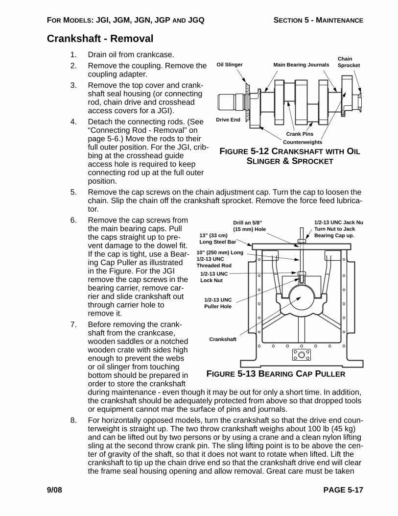
FOR MODELS: JGI, JGM, JGN, JGP AND JGQ SECTION 5 - MAINTENANCE
Crankshaft - Removal1.
FIGURE 5-12 CRANKSHAFT WITH OIL SLINGER & SPROCKET
Drive End
Oil Slinger Main Bearing Journals
Crank Pins
Chain Sprocket
Counterweights
Drain oil from crankcase.2. Remove the coupling. Remove the
coupling adapter.3. Remove the top cover and crank-
shaft seal housing (or connecting rod, chain drive and crosshead access covers for a JGI).
4. Detach the connecting rods. (See “Connecting Rod - Removal” on page 5-6.) Move the rods to their full outer position. For the JGI, crib-bing at the crosshead guide access hole is required to keep connecting rod up at the full outer position.
5. Remove the cap screws on the chain adjustment cap. Turn the cap to loosen the chain. Slip the chain off the crankshaft sprocket. Remove the force feed lubrica-tor.
6. Remove the cap screws from the main bearing caps. Pull the caps straight up to pre-vent damage to the dowel fit. If the cap is tight, use a Bear-ing Cap Puller as illustrated in the Figure. For the JGI remove the cap screws in the bearing carrier, remove car-rier and slide crankshaft out through carrier hole to remove it.
FIGURE 5-13 BEARING CAP PULLER
Crankshaft
13” (33 cm) Long Steel Bar
1/2-13 UNC Puller Hole
10” (250 mm) Long 1/2-13 UNC Threaded Rod
Drill an 5/8” (15 mm) Hole
1/2-13 UNC Lock Nut
1/2-13 UNC Jack NuTurn Nut to Jack Bearing Cap up.
7. Before removing the crank-shaft from the crankcase, wooden saddles or a notched wooden crate with sides high enough to prevent the webs or oil slinger from touching bottom should be prepared in order to store the crankshaft during maintenance - even though it may be out for only a short time. In addition, the crankshaft should be adequately protected from above so that dropped tools or equipment cannot mar the surface of pins and journals.
8. For horizontally opposed models, turn the crankshaft so that the drive end coun-terweight is straight up. The two throw crankshaft weighs about 100 lb (45 kg) and can be lifted out by two persons or by using a crane and a clean nylon lifting sling at the second throw crank pin. The sling lifting point is to be above the cen-ter of gravity of the shaft, so that it does not want to rotate when lifted. Lift the crankshaft to tip up the chain drive end so that the crankshaft drive end will clear the frame seal housing opening and allow removal. Great care must be taken
9/08 PAGE 5-17

FOR MODELS: JGI, JGM, JGN, JGP AND JGQ SECTION 5 - MAINTENANCE
during this operation since the shaft could bind and become damaged. Wear gloves to avoid being cut by the slinger and to achieve a good grip. (As with each operation, the gloves should be clean to avoid marring of the running sur-face.)
NOTE: THE LOWER HALF BEARING SHELLS SOMETIMES HAVE A TENDENCY TO STICK TO THE SHAFT JOURNALS BECAUSE OF THE CLOSE FITTING OILY SURFACES OF THE TWO PARTS. THEREFORE, WHEN THE SHAFT HAS BEEN LIFTED CLEAR OF THE SADDLES, APPROXIMATELY 1/4 INCH (6 mm), CHECK TO MAKE SURE THAT THE LOWER HALF BEARING SHELLS HAVE NOT COME OUT WITH THE SHAFT. IF SO, THE BEARING SHELLS SHOULD BE TAPPED BACK ONTO THE SADDLES BEFORE LIFTING THE SHAFT ANY FURTHER.
Oil Slinger - RemovalAlthough the slinger should last indefinitely with proper care, it can become nicked. Should it need replacement, suspend the crankshaft on a sling with the auxiliary end up, and heat the slinger to 400° F (240°C). It will attain a yellow glow at this temperature. When it has expanded it should fall off by itself. Do not over heat.
CAUTION!: DO NOT TOUCH HOT SURFACES WITHOUT PROPER INSULATION TO PREVENT INJURY.
Oil Slinger - InstallationPut the crankshaft in the horizonal position. Put a rod of at least 1/2 inches (13 mm) in diam-eter through the slinger. (Special care should be exercised when handling the slinger, not only to keep its surfaces unmarred, but to avoid being cut by the outer sharp edge.) With the slinger suspended from the rod, heat it with a small torch. When it has attained a yellow glow, approximately 400°F (240°C), it can be slipped over the drive end of the crankshaft. Do not over heat the oil slinger. Be sure it is properly oriented before installing. Hold the slinger in position with high temperature gloves or two pieces of clean wood, rotating it slightly to make sure it is square and tight against the shoulder, until it has cooled enough to shrink onto the crankshaft.
CAUTION!: DO NOT TOUCH HOT SURFACES WITHOUT PROPER INSULATION TO PREVENT INJURY.
Chain Sprocket - Removal1. Hit Here with
Chisel & Hammer
FIGURE 5-14 CRANKSHAFT CHAIN SPROCKET - TYPICAL
Drill Hole to Remove a Worn Sprocket
Examine the sprocket carefully for signs of wear. If it has been in operation for five years or more, it may be convenient to replace it if the crankshaft is removed from the frame.
2. Drill a hole in the sprocket hub. This hole should be parallel to the shaft centerline and big enough that it removes most of the hub cross section, see Figure. Be careful not to touch the shaft with the drill. Mark the drill with tape so you do not drill
PAGE 5-18 9/08

FOR MODELS: JGI, JGM, JGN, JGP AND JGQ SECTION 5 - MAINTENANCE
through the sprocket and into the crankshaft face.3. The drilled hole will relieve most of the shrink, and a couple of good radial hits
with a hammer and chisel will open the sprocket enough so it can be easily removed.
Chain Sprocket - InstallationEncircle the sprocket with wire. Suspend the sprocket from the wire and heat it with a small propane torch. When it has attained a yellow glow, approximately 400°F (240°C), it can be slipped over the auxiliary end of the crankshaft. Do not over heat the sprocket. Hold the sprocket in position with high temperature gloves or two pieces of clean wood, rotating it slightly to make sure it is square, until it has cooled enough to shrink on the crankshaft.
CAUTION!: DO NOT TOUCH HOT SURFACES WITHOUT PROPER INSULATION TO PREVENT INJURY.
Fan Shaft Assembly ProcedureFor JG:A/2/4 and JGM:N:P:Q/2 compressors with a fan shaft, install on the crankshaft:
1. Use Loctite primer “T” and apply Loctite 620 (Green) Retaining Compound to the stud threads, on one end only.
2. Work quickly before Loctite begins to harden and thread the stud end with the Loctite into the fan shaft until fully seated, hand tight, in the bottom of the hole. Do not torque the stud in the fan shaft.
3. Do not apply Loctite to the crankshaft end of the stud.4. Lubricate the crankshaft end stud threads and the fan shaft shoulder seating
surfaces with oil.5. Thread the stud into the crankshaft and snug up the fan shaft.6. Use a calibrated torque wrench with an open end 1-5/8 in. crowfoot, such
as “Snap-On” SCO52 (1/2 in. drive) or equal positioned at a right angle, on the wrench flats to tighten the fan shaft. If the crowfoot is not at a right angle to the torque wrench, adjust the torque wrench reading to provide the desired torque value on the fan shaft. Refer to the Ariel Technical Manual, Section 1, for tightening procedures.
FIGURE 5-15 OPEN END CROWFOOT WRENCH
7. Tighten the fan shaft to the torque value in Table 1-12 on page 1-16. Loosen the fan shaft to hand tight. Repeat the tightening torque and loosening before the final tightening torque to Table 1-12 on page 1-16, (for a total of three tighten-ings).
8. Check the fan shaft runout at the keyway. Runout should be less than 0.010 in.
9/08 PAGE 5-19

FOR MODELS: JGI, JGM, JGN, JGP AND JGQ SECTION 5 - MAINTENANCE
(0.25 mm) TIR.
FIGURE 5-16 FAN SHAFT
Main Bearings - Removal and Installation w/Crankshaft RemovedDo not remove a main bearing cap to check for bearing wear, if cap is removed it is recom-mended that a new bearing is installed, i.e. DO NOT REUSE BEARING SHELLS. Deter-mine bearing wear by checking actual jack and crankshaft thrust clearances against the clearance limits given in Table 1-3 on page 1-10. See "Main Bearings - Checking Clear-ances" on Page 5-14. High copper content in the oil analysis may be an indication of main and/or connecting rod bearing wear, and/or chain idler, crosshead, connecting rod bushings wear (excessive use of anti-seize lubricates can also elevate copper content in the oil analy-sis).
There are notches in the frame and bearing cap for the bearing tabs in order to position and maintain the position of the bearing halves. Check the new bearing shells for handling dam-age, scratches, burrs, and loose material at the tab. DO NOT RUB BEARING SURFACE WITH FINGERNAIL. The bearing shells must be absolutely clean. Be sure that bearing shell part numbers on both halves match.
The old bearings halves are easily slid out, tab end first. Be sure both the main bearing sad-dles and crankshaft are absolutely clean, and free from nicks and burrs. New bearings are to be slid in (untabbed end first), and snapped into place. Locate tabs in the notches in the bearing saddles and bearing caps.
On JGI models, remove the carrier bearing using a hydraulic press or jack. Remove the frame bearing using a hydraulic jack. A pushing tool with a shoulder is needed. Install new bearings by cooling the bushings and using the hydraulic tools. Do not use a hammer to force the bushings into place as this will distort the bearing's bore. The new bushings are to be installed into the connecting rod by cooling the bushing in a 95 percent alcohol solution with dry ice solution. The bushing needs to be left in the solution long enough to reach the same temperature as the solution, about -110°F (-80°C). Oil holes on bearing must be aligned with holes in frame and carrier. The bushings must be pressed 3/16 in. (4.8 mm)
Crankshaft
Wrench Flat
Fan Shaft
Loctite this end only
Chain Sprocket Stud
Fan Shaft Keyway
Check Fan Shaft Runout here
PAGE 5-20 9/08

FOR MODELS: JGI, JGM, JGN, JGP AND JGQ SECTION 5 - MAINTENANCE
below flush of the thrust faces, no more than 1/3 of the oil passage hole in the rod can be covered by the bushing.
CAUTION!: DO NOT TOUCH COLD SURFACES WITHOUT PROPER INSULATION TO PREVENT INJURY. ALCOHOL IS FLAMMABLE AND SHOULD ONLY BE USED IN OPEN AIR OR A WELL VENTILATED BUILDING. AVOID SPARKS AND OPEN FLAME. AVOID ALCOHOL VAPORS WHICH MAY CAUSE INJURY TO THE TISSUES OF THE NOSE AND EYES. AVOID EYE AND SKIN CONTACT. USE NEOPRENE OR BUTYL GLOVES, MONO-GOGGLES OR FACE-MASK AND IMPERMEABLE APRON. IT CONTAINS METHYL ALCOHOL AND IS POISONOUS IF INGESTED. SEE MANUFACTURER'S MATERIAL SAFETY DATA SHEETS FOR MORE INFORMATION. DO NOT RETURN SOLUTION TO A CLOSED CONTAINER UNTIL IT HAS REACHED ROOM TEMPERATURE OR THE CONTAINER MAY EXPLODE.
NOTE: ABSOLUTE CLEANLINESS IS REQUIRED. ASSEMBLY MUST BE IMMEDIATE SO THAT THE BEARING DOES NOT WARM-UP AND STICK BEFORE IT IS IN PLACE. DO NOT SEAT A STUCK BUSHING WITH A PRESS OR HAMMER.
Main Bearings - Removal and Installation w/Crankshaft In PlaceNOTE: REPLACE ONE MAIN BEARING AT A TIME. REMOVE THE CAP ON THE
BEARING BRING CHANGED, CHANGE THAT BEARING AND REPLACE THE CAP AND TIGHTEN THE BOLTING PRIOR TO STARTING THE NEXT BEAR-ING.
1. Follow instructions in "CAUTION" on Page 5-2. Remove coupling spacer or oth-erwise lockout.
2. Remove the top cover. 3. Remove the cap screws from main (journal) bearing cap #1. Pull the cap straight
up to prevent damage to the dowel fit. If the cap is tight, use a Bearing Cap Puller as illustrated in Figure 5-13 on Page 5-17.
4. If necessary, attach clean nylon lifting straps around the crankshaft and lift slightly to take some of the weight off the bearings and allow for easier disas-sembly of a bearing shell.
5. Remove the shell from the main bearing cap. Remove the main journal bearing shell from under the crankshaft, by rotating out. Start rotating the shell under the crankshaft tab side out first, by pushing or tapping with a non-metallic tool on the opposite split face side. Once the bearing shell is completely loose, use pur-chased separately Main Bearing Pusher Removal Tool (part number G-10706 or may be made from prints supplied by Ariel) to push out bearing shells, see Fig-ure 7-2 on page 7-3. Once started the shell may be rotated out, by releasing the lifting straps and turning the crankshaft. Be careful not to damage the crankshaft bearing surfaces.
6. Clean and dry main bearing cap to bearing surfaces.7. Check the new bearing shells for handling damage, scratches, burrs, and loose
material at the tab. DO NOT RUB BEARING SURFACE WITH FINGERNAIL. The bearing shells must be absolutely clean. Install new bearing shells in cap, and frame journal, properly located in the tab notch, (rotate in the untabbed end first), keeping the backs of the shells dry and clean.
9/08 PAGE 5-21

FOR MODELS: JGI, JGM, JGN, JGP AND JGQ SECTION 5 - MAINTENANCE
NOTE: DO MIX BEARING SHELL PART NUMBERS ON AN INDIVIDUAL MAIN OR CONNECTING ROD. BOTH HALF SHELLS MUST HAVE THE SAME PART NUMBER.
8. Oil crankshaft bearing surfaces with new clean lubricating oil, same type as is used in the frame, before installing the main bearing cap.
9. Replace thrust plates on bearing cap #1, if crankshaft thrust clearance is not within tolerance.
10. Install the bearing cap, containing a new half bearing shell. Be sure the dowels in the bearing caps are aligned with the holes in the crankcase base. A set screw on top of each dowel prevents it from backing out. Install the cap screws and tighten them in an alternating (criss-cross) pattern to the torque value given in Table 1-12 on page 1-16.
11. Repeat one throw at a time for each bearing until all main bearings are replaced. 12. Check crankshaft journal bearing jack (at each bearing) and crankshaft thrust
clearances to values in Table 1-3 on page 1-10. See "Main Bearings - Checking Clearances" on Page 5-14. Record readings on a copy of form on Page 5-48.
13. If readings are not within tolerance after installing new bearings, contact your packager or Ariel before proceeding.
14. Account for all tools, measuring and lifting equipment, supplies, replaced parts, etc. to be sure they have all been removed from inside the crankcase and then re-install the gaskets and top cover. Before installing a gasket, apply an anti-seize lubricant to both sides or to the metal seating surfaces. This will help to hold the gasket in place during assembly and aid in easy of removal. Tighten cover bolts hand wrench tight.
15. Replace coupling spacer to packager’s recommendations or remove lockout.16. After replacing bearings, thoroughly pre-lube compressor to be sure that bear-
ings are lubricated and to help remove foreign materials from the lube system.17. When starting the compressor after the first 10 minutes of run time, after one
hour, and after four hours, shutdown compressor and remove the frame top cover. Check the bearing cap temperatures using a temperature probe (hand held thermocouple probe or infrared thermometer), record on a copy of form on Page 5-48. DO NOT PLACE ANY PART OF YOUR BODY INSIDE THE CRANKCASE WITHOUT OBSERVING THE “CAUTION” ON PAGE 5-2. Com-plete remaining information on the “Bearing Log / Conditions After Replacing Bearings” form and fax copy to Ariel Technical Services. Keep a copy with the compressor records.
Crankshaft - Installation1. Put new bearing shells in place on the saddles in the frame and in the bearing
caps to "Main Bearings - Removal and Installation w/Crankshaft Removed" on Page 5-20. Move the connecting rods to their full outer position. Oil crankshaft bearing surfaces with new clean lubricating oil, same type as is used in the frame, before installing. While the crankshaft is being lowered very slowly into the crankcase (if suspended by a crane with a nylon sling, use second throw crank pin), maneuver the drive end into the crankcase to clear the seal housing opening. Use clean gloves as during removal. Lower crankshaft into place so that both drive end and auxiliary end journals touch the bearing saddles at the
PAGE 5-22 9/08

FOR MODELS: JGI, JGM, JGN, JGP AND JGQ SECTION 5 - MAINTENANCE
same time. (For JGI models, slide crankshaft into position through the bearing carrier opening and then replace bearing carrier).
2. When the crankshaft is resting on the bearing saddles, install all bearing caps with their new bearing half shells. Bearing caps are match-marked to corre-spond with the throw position on the frame, be sure they are in the proper loca-tions. Lubricate the bearing cap bolting threads and seating surfaces with oil and instal lightly snugged.
3. Be sure the dowels in the bearing caps are aligned with the holes in the crank-case base. A set screw on top of each dowel prevents it from backing out.
4. Then, starting at the thrust end, tighten the bolts in an alternating (criss-cross) pattern in 25% increments to the recommended torque value in Table 1-12 on page 1-16.
5. Check crankshaft journal bearing jack (at each bearing) and crankshaft thrust clearances to values in Table 1-3 on page 1-10. See "Main Bearings - Checking Clearances" on Page 5-14. Record readings on a copy of the form on Page 5-48.
6. Replace connecting rods bearings and re-attach the connecting rods refer to “Connecting Rod - Installation” on page 1-8). Re-install the packing diaphragms, piston and rod, and unloaders/head end heads, if removed.
7. Re-install the force feed lubricator and chain drive. (See “Chain Drive System” on page 5-23).
8. Examine the top cover gasket. If there is any doubt that it is not in good usable condition, install a new gasket. Before installing a gasket, apply an antiseize lubricant to both sides or to the metal seating surfaces. This will help to hold the gasket in place during assembly and aid in easy of removal.
9. Re-install covers, crankshaft seal housing and the top cover. Tighten cap screws hand wrench tight. Align crankshaft dust seal to clearance requirements in Table 1-3 on page 1-10.
Chain Drive SystemDescriptionThe chain drive system is crankshaft-driven at the auxiliary end of the frame. The chain runs the lube oil pump and force feed lubricator. Chain tightness is controlled by an idler sprocket attached to the eccentric adjustment cap. The chain dips into the crankcase oil and, as a
9/08 PAGE 5-23

FOR MODELS: JGI, JGM, JGN, JGP AND JGQ SECTION 5 - MAINTENANCE
result, is constantly lubricated. See Figure for the auxiliary end components and chain drive system.
FIGURE 5-17 CHAIN DRIVE SYSTEM - TYPICAL
Chain AdjustmentFor proper chain adjustment procedures, see engineering reference ER-74 on the Ariel web-site at www.arielcorp.com, or contact the Ariel Response Center.
Chain and Sprocket ReplacementThe chain should be replaced if the elongation exceeds 0.084 inches (2.13 mm) over a 10 pitch length. The section of chain to be measured should be stretched tight, in place, in the compressor and measured with vernier calipers. A reading made outside of the rollers at 10 pitches should be added to a reading between the inside of the same rollers and then be divided by two. If this calculation exceeds 3.834 inches (97.38 mm) for 3/8 pitch, the chain should be replaced. Any sprocket showing any undercutting should be replaced.
EccentricCap Screws
Plastic DustPlug
Chain
Force Feed Lubricator Sprocket
Lube OilPump Sprocket
CrankshaftSprocket
PAGE 5-24 9/08

FOR MODELS: JGI, JGM, JGN, JGP AND JGQ SECTION 5 - MAINTENANCE
Chain Idler Sprocket Replacement - (Eccentric Adjustment Cap)1.
Sprocket
Capscrew (2)
Plain Washer
Through Bolt
Self Lock Nut
Stat-O-Seal-Washer
Oil O-Ring Before Assembly
FIGURE 5-18 CHAIN IDLER SPROCKET (ECCENTRIC)
Eccentric Adjustment Cap
Remove the frame top cover (or chain access cover for JGI). Remove the two cap screws that hold the eccentric adjustment cap to the end cover. Rotate the eccentric cap to loosen the chain. After dropping the chain off the idler sprocket, the entire assembly can be removed from the frame.
2. Remove the lock nut, cap screw, sprocket, Stat-O-Seal washer and the cap O-ring. Discard these items since they must be replaced with new parts.
3. Reassemble all parts using a new cap screw, Stat-O-Seal washer, sprocket, and lock nut. Tighten the idler lock nut to the recommended torque given in Table 1-12 on page 1-16.
4. Apply oil to and install a new O-ring on the eccentric adjustment cap.5. Install the assembly and adjust the chain according to the instructions given in
“Chain Adjustment” on page 5-24.
Lube Oil Pump Chain Sprocket Replacement1.
FIGURE 5-19 LUBE OIL PUMP AND SPROCKET
Sprocket
No. 204 WoodruffKey
Set Screws
Adapter
Pump
Gaskets
Remove the cap screws from the drive chain eccentric adjustment cap and rotate cap to loosen the chain. Remove all piping (tubing) from the pump. Remove fasteners from pump mounting adaptor, and the pump with sprocket will come free through the hole in the end cover after the removing the chain from the pump sprocket.
2. With a good machinist rule, measure the distance from the sprocket drive face to the pump mounting adaptor face to the nearest 0.01 inch or 1/64 inch or 0.5 mm, to provide for positioning the new sprocket. Record this measurement for reference.
3. With the oil pump on a bench, use an Allen Wrench to remove the sprocket set screw. Then, pull the sprocket from the pump shaft.
4. Remove the No. 204 Woodruff key.5. If the pump is to be separated from the adapter, such as when replacing the
pump, re-assemble using a new gasket. Before installing a gasket, apply an antiseize lubricant to both sides or to the metal seating surfaces. This will help to hold the gasket in place during assembly and aid in easy of removal.
6. Install a new No. 204 Woodruff key, after checking to be sure that it will fit into
9/08 PAGE 5-25

FOR MODELS: JGI, JGM, JGN, JGP AND JGQ SECTION 5 - MAINTENANCE
the new sprocket and shaft key-slots. If the key is too thick, it can be polished with emery cloth on a flat surface until it will slide into the slots for a snug fit. If the key is too high, file of the top edge for a snug fit.
7. Install the new sprocket to the original measurement between the sprocket drive face and the pump adapter flange face. When it is in the proper position, tighten the set screw. If the original measurement is not available, position sprocket as close as reasonably possible to the running position.
8. Install a new gasket. Before installing a gasket, apply an antiseize lubricant to both sides or to the metal seating surfaces. This will help to hold the gasket in place during assembly and aid in easy of removal.
9. Re-install the pump onto the frame and tighten the cap screws. Check the align-ment to crankshaft drive sprocket, with crankshaft centered in end play, using a good straight edge and a good machinist rule to within 1/32 inch (1 mm). If not in alignment, loosen the set screw and adjust the sprocket position as necessary. Retighten the set screw when the sprocket is properly aligned.
10. Re-install and adjust the chain according to the instructions in “Chain Adjust-ment” on page 5-24.
11. Re-install all piping (tubing) to the pump.
Force Feed Lubricator Chain Sprocket Replacement1. Remove the cap screws from the drive chain eccentric adjustment cap and
rotate cap to loosen the chain.2.
Drain Plug
Sight Glass
Lock Nut
Inlet Header
Pump Plunger Stroke Adjustment Screw
Lubricator Oil Fill Connection
Priming Stem
Pump Inlet from Header
Priming Pump Connection
Pump Outlet to Distribution Block
Lubricator Box
Sprocket
No. 204 Woodruff Key
Setscrew
Sprocket Face to FaceThickness
Oil O-Ring before Assembly
Rupture Disc Assembly
FIGURE 5-20 FORCE FEED LUBRICATOR CHAIN SPROCKET - TYPICAL
Refer to the Figure.3. After removing the
chain from the lube sprocket, remove the sprocket set screw and sprocket. Detach all tubing to the lubricator.
4. Remove the four mounting bracket cap screws and remove the lubricator.
5. With the lubricator on the bench, remove the Woodruff Key from the shaft and file the shaft to remove any burrs raised by the cup point of the set screw. Install a new O-ring.
6. Install a new No. 204 Woodruff Key after first checking to make sure the key will fit into the new sprocket. If it is too thick, it can be polished with an emery cloth on
PAGE 5-26 9/08

FOR MODELS: JGI, JGM, JGN, JGP AND JGQ SECTION 5 - MAINTENANCE
a flat surface until it can easily slide into the slots for a snug fit. If the key is too high, file of the top edge for a snug fit.
7. After the new key has been installed and it has been determined that the new sprocket will fit, oil the new O-ring and remount the lubricator on the frame.
8. Put the new sprocket onto the shaft.9. Check alignment to the crankshaft drive sprocket with crankshaft centered in
end play, using a straight edge, to within 1/32 inch (1 mm). Tighten the set screw.
10. Install chain and adjust using the instructions given in “Chain Adjustment” on page 5-24.
11. Re-attach all tubing to the lubricator.
Piston and RodNOTE: UTILIZE A DIAL INDICATOR WITH A MAGNETIC BASE TO INDICATE THE
LOCATION OF THE CROSSHEAD WHEN FINDING EXACT INNER AND OUTER DEAD CENTER LOCATIONS.
Piston and Rod - Removal
1. Follow steps 1. through 5. at “Crosshead - Removal” on page 5-11.2. With the cylinder head/unloader removed and the cross-head balance nut loos-
ened, use the piston turning/piston nut torquing tool (Ariel furnished tool) and a speed wrench to screw the piston and rod assembly out of the crosshead. The two dowels on the piston nut tool fit the holes in the piston nut. Turn the cross-head nut off the piston rod.
3. As the piston leaves the cylinder, be careful in handling the piston rings. Despite
CAUTIONTO PREVENT PERSONAL INJURY, BE SURE THAT COMPRESSOR CRANKSHAFT CANNOT BE TURNED BY THE DRIVER OR COMPRESSOR CYLINDER GAS PRESSURE DURING MAINTENANCE: -- ON ENGINE-DRIVEN COMPRESSORS, REMOVE THE CENTER COUPLING OR LOCK THE FLYWHEEL. -- ON ELECTRIC MOTOR-DRIVEN COMPRESSORS, IF IT IS INCONVENIENT TO DETACH THE DRIVER FROM THE COMPRESSOR, THE DRIVER SWITCH GEAR MUST BE LOCKED OUT DURING MAINTENANCE.
BEFORE PERFORMING ANY MAINTENANCE, COMPLETELY VENT SYSTEM. BEFORE REMOVING A CYLINDER HEAD OR VVCP, BACK OFF ALL CAP SCREW 1/8 INCH (3 mm). MAKE SURE THE HEAD IS LOOSE AND THE CYLINDER OR VVCP IS COMPLETELY VENTED.
!
9/08 PAGE 5-27

FOR MODELS: JGI, JGM, JGN, JGP AND JGQ SECTION 5 - MAINTENANCE
their toughness in service, rings are fragile with regard to removal. Always han-dle them with clean tools and hands protecting the rings from nicks, marring, and bending. Move the piston out of the cylinder until a fraction of the first ring clears the cylinder. Encircle the ring by hand until it is clear and remove it. Use this same procedure to remove the succeeding rings and wear band, if applica-ble.
4. Slide the piston rod out of the head end. The threaded crosshead end of the rod is 1/8 inches (3 mm) smaller in diameter than the inside diameter of the packing. Using extreme care, slowly slide the piston rod through the packing to avoid damaging the rod threads or the packing rings.
Piston and Rod DisassemblyThe Piston and Rod Clamping Fixture shown in the Figure will be useful for the piston and rod disassembly and reassembly operations. This fixture may be purchased from Ariel.
1.
FIGURE 5-21 PISTON AND ROD CLAMPING FIXTURE
Piston Rod Clamping Fixture D-0961
Spanner - bolts onto piston nut using (2) 5/16”-18 x 1-1/4” long Cap Screws
Compressor Piston
Piston Nut
Key Wrench (Two Required for each Tight-ening of Set Screws)
Clamp the piston and rod assembly in the special Clamping Fixture (D-0961), using the bushing for a 1-1/8” rod size (see Figure). Tighten the four 12-point cap screws to prevent the rod from turn-ing. The fixture will properly hold the piston rod to prevent damage to the parts and pro-mote safety during disas-sembly and reassembly. The Clamping Fixture must be securely bolted down to pre-vent it from turning with the piston rod. It should be at a convenient height of approximately three feet or 0.9 meters. Remove the setscrews from the piston nut. Although the piston nut has been staked to lock the setscrews, they can be forced out, by turning with an Allen key wrench, past the small lip that has been formed.
2. Remove piston nut using the piston turning/piston nut torquing tool (see Figure 7-1 on page 7-2). Two 5/16-18 x 1-1/4 in. bolts should be used to secure the tool
CAUTIONTRAPPED GAS PRESSURE IN HOLLOW PISTONS CAN PRESENT A PERSONAL SAFETY HAZARD WHEN SERVICING THE PISTON AND ROD ASSEMBLY. WORK IN A WELL VENTILATED, NON SPARKING AREA. DO NOT BREATHE GAS EMITTED FROM PISTONS WHEN VENTING TRAPPED GAS.
!
PAGE 5-28 9/08

FOR MODELS: JGI, JGM, JGN, JGP AND JGQ SECTION 5 - MAINTENANCE
to the nut3. After the piston nut has been removed, the piston and collar will slip off the end
of the rod.
Piston and Rod Reassembly1. Clean all piston and rod assembly parts thoroughly. Be sure piston is internally
clean and dry.2. Inspect each part for nicks, burrs or scratches and dress surfaces with a fine grit
stone as required.3. Inspect the piston rod threads and collar shoulder. Threads should be clean and
free of burrs. Fit collar and nut into piston to verify the outside diameter fits, and turn freely by hand in the piston. Install the collar and nut onto the piston rod to verify that the inside diameter fits and rotates freely. Run the piston nut down by hand until the rod threads protrude to verify freedom of thread engagement. Remove nut and collar.
4. Check piston rings to determine wear (see “Determining Ring Wear:” on page 5-32). Replace piston rings as required.
5. Clamp the piston rod in Torque Fixture D-0961. See Figure 5-21 on Page 5-28.6. Apply a thin coat of Never-Seez, regular grade, to piston rod shoulder and rod
collar locating band, and collar face in contact with the piston, then slide collar onto rod.
7. Apply a thin coat of Never-Seez, regular grade, to the piston rod threads at the piston end, then slide piston onto rod and collar.
NOTE: IF ONE END OF SINGLE PIECE PISTONS ARE MACHINED 0.001 IN. (0.03 mm) UNDERSIZE ACROSS A 3/4 IN. (20 mm) WIDE BAND (FOR MANUFACTURING PURPOSES); THIS IS THE HEAD END OF THE PISTON.
8. Apply a thin coat of Never-Seez, regular grade, to the piston nut threads and piston mating face. Install nut and hand tighten to make up the piston and rod assembly.
9. Use the piston turning/piston nut torquing tool and a torque wrench to tighten the piston nut. The two dowels on the turning tool fit holes in the nut and two 5/16-18 x 1-1/4 in. bolts should be used to secure the tool to the nut. Tighten the piston nut to the recommended torque in Table 1-12 on page 1-16.
10. After tightening nut, the piston rod should not protrude more than 0.010 in. (0.25 mm) past the piston face.
11. Apply a thin coat of Never-Seez, Regular Grade, to two new Allen set screws. Two new Allen key wrenches are also required per nut at each tightening and are discarded after their one time destructive use. Install the set screws and tighten so that the Allen wrench is permanently deformed by tightening past its yield point (twisted through an additional 15° arc). A piece of heavy wall tubing or equal of a proper inside diameter to fit over the Allen wrench is required to extend the “handle” end of the wrench to achieve proper tightening. The Allen wrenches used must conform to ASME B18.3 requirements for hexagonal keys.
12. Use a 60° center punch to prick-punch the piston nut, within 1/16 in. (1.5 mm) of the set screw threads, to stake the set screws in place. Prick-punch marks should deform the nut to lock the set screws without deforming the set screw. The staked piston nut must not exhibit any cracks or torn material that might
9/08 PAGE 5-29

FOR MODELS: JGI, JGM, JGN, JGP AND JGQ SECTION 5 - MAINTENANCE
allow chips to come loose in service. See Figure 5-22 on Page 5-30.
13. Weigh the piston rod assembly with piston rings, and wear bands if applicable, included. Weigh parts on a calibrated scale to 0.1 pounds (0.05 kg). Stamp the weight on the piston’s head end. Remove any raised lips caused by stamping using a fine grit flat stone to avoid clearance measurement errors. Record this weight for future reference.
Piston and Rod - Installation1. With the crosshead, wiper packing and piston rod packing case installed, install
the piston rod assembly with piston rings into the cylinder. The threaded cross-head end of the rod is 1/8 inches (3 mm) smaller than the inside diameter of the packing. It is not necessary to use an entering sleeve if reasonable care is taken, but a plastic sleeve may be helpful to be sure packing rings are not dam-aged. A piston rod entering sleeve is available from Ariel as a purchased sepa-rately tool, see Figure 7-2 on page 7-3. See “Piston Rings - Installation” on page 5-32 and “Wear Band - Installation” on page 5-33.
2. As the piston enters the cylinder, encircle the first ring by hand to allow it to enter the cylinder without damage. Use the same procedure for succeeding rings, and wear band if applicable.
3. Be sure that the crosshead-balance nut seating surfaces are flat and free of burrs. Dress with a fine grit flat stone as required. The piston threads are to be lubricated with a thin coat of Never Seez, regular grade, and the crosshead-bal-ance nut seating surfaces with new oil (same grade as used in the frame).
4. With the setscrew cup points on the crosshead side of the crosshead-balance nut, re-install the nut onto the piston rod. Turn nut on to rod threads to allow enough clearance to attach the rod to the crosshead.
5. Use the piston turning/piston nut torquing tool a speed wrench to screw the pis-ton rod into the crosshead. The two dowels on the turning tool fit holes in the pis-ton nut or piston/rod as applicable.
6. Follow the instructions in “Crosshead - Installation” on page 5-13 for tightening the crosshead-balance nut and setting piston end clearance to secure the piston rod to the crosshead, and for closing the cylinder and crosshead guide. Check piston end clearance, piston rod run-out and crosshead clearance to specifica-tions.
FIGURE 5-22 STAKING COMPRESSOR PISTON NUT TO LOCK SET SCREWS
Piston Nut
Punch Mark within 1/16 in. (1.5 mm) of Threads to Deform Piston Nut to Lock Set Screw w/o Deforming Set Screw
Set Screw
No Cracks or Torn Material Allowed
PAGE 5-30 9/08

FOR MODELS: JGI, JGM, JGN, JGP AND JGQ SECTION 5 - MAINTENANCE
Piston Rod Run OutCheck piston rod run out after installing a new unit, after relocating a unit or after any main-tenance that could affect rod run out.
Verify that the crosshead guides are properly shimmed to level. Verify that the crossheads are in direct contact with the bottom guide. A 0.0015 inches (0.04 mm) feeler stock should not be able to be inserted more than 1/2 inches (13 mm) at all four corners of the crosshead.
Position the dial indicator1 stem against the piston rod, close to the packing case. Set the indicator to zero with the piston toward the crank end. Readings are to be taken in both the vertical and horizontal directions. When measuring vertical rod moment, upward movement will be recorded as positive, downward movement will be recorded as negative. When mea-suring horizontal rod movement, rod movement toward the auxiliary end of the frame, will be recorded as a positive reading, movement toward the drive end of the frame will be recorded as a negative reading. Copy Table 5-1 to record readings. Bar over crankshaft by hand and record readings at mid-stroke and with piston at the head end.
TABLE 5-1 PISTON ROD RUN OUT
Compare readings to Table 5-2.
TABLE 5-2 MAXIMUM ACCEPTABLE PISTON ROD RUN OUT READINGS
If a vertical reading is greater than the maximum acceptable reading, the following proce-dure is used to determine acceptability: With the piston at the head end, use feeler gages to determine clearance at the top of the piston. On rider ring pistons this clearance is over the band. Feeler top clearance is divided by (÷) 2 and then the following amount is subtracted: (-)0.003 inches (0.08 mm). Place a feeler of this calculated thickness under the bottom of the piston. Place the feeler under the wear band on wear band pistons. This feeler should be long enough to stay under the piston as the piston is moved throughout its stroke. Re-mea-sure vertical run out and compare to acceptable limits in the table above. The horizontal
1. Use a 0.0001 inches (0.001 mm) increment dial indicator.
THROW NUMBER: 1 2
VerticalPiston @ CE 0 0Mid-Stroke
Piston @ HE
HorizontalPiston @ CE 0 0Mid-Stroke
Piston @ HE
DIRECTIONJGM, JGN, JGP & JGQ
JGIINCHES (mm)
Vertical 0.0010 (0.025) N/AHorizontal 0.0005 (0.013)
9/08 PAGE 5-31

FOR MODELS: JGI, JGM, JGN, JGP AND JGQ SECTION 5 - MAINTENANCE
readings, taken without the use of feelers are to be used for acceptance. Copy Table 5-3 and record calculations and readings.
TABLE 5-3 FEELER THICKNESS TO CORRECT FOR PISTON WEIGHT
If readings are not within acceptable limits after replacing worn parts and correcting any pip-ing misalignment, the piston rod assembly should be replaced.
Piston RingsJGI, JGM, JGP, JGN and JGQ cylinders use one-piece angle cut filled Teflon piston rings.
Determining Ring Wear:Ariel recommends replacing rings when the end gap has increased three times the new dimension. To measure the end gaps, insert the rings in the cylinders without pistons. (See Table 1-7 on page 1-12 or Table 1-9 on page 1-14 for new end gap dimensions.)
Removal:See paragraph 3. at “Piston and Rod” on page 5-27 for piston ring removal.
Piston Rings - Installation1. Place the rings over the grooves in the piston. Compress the Teflon one-piece
rings by hand.2. With the rings fully compressed in the grooves, insert the rod and piston into the
cylinder. Make sure the rings stay in place while inserting the piston and rod.NOTE: RING GAPS ARE TO BE STAGGERED AROUND THE PISTON, RATHER THAN
IN LINE.3. Follow the steps under “Piston and Rod - Installation” on page 5-30.
Wear Bands1-3/4JG-FS-HE and 1-3/4SG-FS-HE cylinder class pistons use a one-piece angle cut Teflon wear band.
LINE THROW NUMBER: 1 21. Top Feeler Clearance2. Line 1 (Divided by 2)
3. Line 2 - 0.003 in.(-0.08 mm)
- 0.003 in.(-0.08 mm)
- 0.003 in.(-0.08 mm)
4. Bottom Feeler Thickness5. Vertical - Piston @ CE 0 06. Vertical - Piston @ HE
PAGE 5-32 9/08

FOR MODELS: JGI, JGM, JGN, JGP AND JGQ SECTION 5 - MAINTENANCE
Determining Wear Band Wear:Since the wear band does not work as a sealing ring, end gap is not critical. The amount of wear band projection beyond the outer diameter of the piston is important. Wear band pro-jection can be checked by measuring piston to cylinder bore clearance at the bottom of the bore. This can be done without removing the piston from the cylinder. Replace the wear band before it has worn enough to allow the piston to touch the cylinder bore.
Wear Band - InstallationInstall the wear band as if it was another piston ring as above. Wear bands are only used on 1-3/4JG-FS-HE and 1-3/4SG-FS-HE cylinder class pistons.
Piston Rod Pressure Packing - RemovalCAUTION!: BE SURE THAT ALL PRESSURE IS RELIEVED FROM THE COMPRESSOR
CYLINDERS PRIOR TO REMOVING PACKING.1. Remove the piston and piston rod. See “Piston and Rod - Removal” on page
5-27.2. Remove packing diaphragm and oil wiper packing.3. Disconnect all tubing connections from the top of the packing flange and the pri-
mary vent tube from the bottom of the flange. Remove the twelve point cap screws that hold the pressure packing flange to the cylinder.
4. At this point do not remove the small nuts from the studs. These studs hold the entire packing case together so it can be removed as an assembly.
5. Screw two short 3/8-16 UNC cap screws into the two tapped holes provided in the crankend face of the packing flange. An appropriate prybar under the heads of the cap screws can be used to pull the entire pressure packing out into the crosshead guide. It will then come out through the side opening of the guide. The pressure packing may now be taken to a clean place for disassembly.
6. Set the pressure packing on a clean surface on its nose cup or cylinder end. Three long tie studs hold the pressure packing together. The stud holes are not equally spaced. This prevents the stack of parts from being aligned incorrectly. Remove the stud nuts and the pressure packing can be unstacked. Replace these nuts each time the pressure packing is serviced.
7. Ring wear can be determined by placing the assembled rings, (note match-marks), on the piston rod. Check end gap clearance. If the ends butt, or nearly butt, they should be replaced by new rings. See “Types of Piston Rod Packing Rings” on page 5-35.
8. Fins or wire edges on the rings due to wear should be carefully filed off so that all matching edges will be square.
9. The metal gasket on the end cup can be pried loose with a sharp awl. Be careful not to scratch the sides of the gasket groove.
10. Before reassembly be certain all parts are perfectly clean.
9/08 PAGE 5-33
FOR MODELS: JGI, JGM, JGN, JGP AND JGQ SECTION 5 - MAINTENANCE
Piston Rod Packing - Reassembly1. Be sure to refer to the pressure packing assembly in the Ariel Parts Book.
Please contact your distributor if you do not have a Parts Book. A pressure packing assembly drawing also is packaged with each pressure packing re-build kit.
2. Care must be taken to prevent scratching the mating surfaces of the cups, which can cause problems. Cup surfaces must be clean and dry when being re-assembled.
3. If installing a new set of rod rings in an existing packing case, the case parts need to be inspected for wear. Cups should be smooth and flat on the back side where the rod rings must seal. If the cups or grooves have worn concave or tapered, they should be reground or relapped. Do not reduce the cup thickness to less than the rework dimension shown on the packing assembly drawing in the Ariel Parts Book. It is rarely necessary to alter the crosshead side of the cups, however, if this is found necessary, care must be taken so that the correct side clearance for the renewal rings is not destroyed.
NOTE: IF PREMATURE WEAR IS SUSPECTED, REFER TO THE ARIEL "LUBE TYPE & RATE RECOMMENDATIONS" ON PAGE 4-26.
4. Before a packing case is installed, it should always be disassembled and thor-oughly cleaned in an appropriate solvent for the intended service.
5. Before assembling the rings into the case, the following is recommended: Put each ring set individually onto the rod and check the total end gap. See “Types of Piston Rod Packing Rings” on page 5-35 for end gap tolerances. File at a gap to restore total end gap within tolerance. With the ring set on the rod, shine a light from behind the ring, if any light is observed between the ring and the rod, the ring set is not acceptable.
6. Make sure that each rod ring and cup is properly positioned and that rings are liberally coated with a clean lubricant before reassembly. Only use the same lubricant that is used in the force feed lube system. Examine all parts for unusual nicks or burrs which might interfere with the free floating of the rod ring in the cups. Particular care should be taken with rod rings made of soft materials, such as bronze or TFE, and it is extremely important that wiper rings be handled and installed so as to prevent damage to the scraping edges.
7. Parts should be laid out on a work bench so that they can be installed progres-sively with each in its correct position and the rod rings with their proper faces toward the pressure. Be sure that the tie studs are completely screwed into the end cup. The stud holes are not equally spaced. This prevents the stack of parts from being aligned incorrectly. Note that all rod ring segments are carefully let-tered and must be assembled accordingly. This is most important for proper sealing. Center, side-loaded AL rings prior to tightening tie stud nuts. Tighten the tie stud nuts to the recommended torque value given in Table 1-12 on page 1-16. Make sure that all rings move freely, radially, in their grooves using your fingers. Side loaded rings will be snug, but should still move using your fingers. Be sure these rings are centered. If the packing is water cooled, see “Water-Cooled Piston Rod Packing” on page 5-38.
8. For new installations, care must be given to the cleaning of all accumulated dirt in the lines and compressor because foreign material will lodge in the packing to become destructively abrasive. Refer to "Oil System Cleanliness" on Page 4-15.
PAGE 5-34 9/08

FOR MODELS: JGI, JGM, JGN, JGP AND JGQ SECTION 5 - MAINTENANCE
9. Prior to installing the packing case into the cylinder, the end cup gasket must be inspected for nicks and damage that would cause it to leak in service. When in doubt, replace the gasket with a new one.
10. Prior to installing the packing case into the cylinder, be sure the gasket surfaces in the packing counter bore on the crank end of the cylinder are clean and not scratched.
11. Re-install the complete packing case assembly with the oil supply point on top. Use the rod packing bolts to pull the packing into place, but do not tighten at this time.
12. Re-install the packing diaphragm and wiper packing.13. Re-install the piston and rod. Follow the steps under “Piston and Rod - Installa-
tion” on page 5-30.14. After the crosshead-balance nut has been tightened, tighten the rod packing
bolts evenly in 25% increments to the recommended torque in Table 1-12 on page 1-16. This procedure will bring the pressure packing up square on its nose gasket. Alignment is readily accomplished by the use of feelers to maintain a uniform clearance all around between the case bore and the rod.
NOTE: THE FINAL TORQUE FOR THE ROD PACKING BOLTS SHOULD BE REPEATED UNTIL NO TURNING OF THE FASTENERS IS OBSERVED. THE TORQUE ON THESE FASTENERS SHOULD BE RE-CHECKED AT THE NEXT SERVICE INTERVAL.
15. Retighten the small tie stud nuts. Re-install the tubing connections for the oil supply, primary vent and/or coolant. Take care not to cross-thread the tubing nuts. Tubing nuts must be tight. Refer to the Swaglock “Tube Fitting Instructions” on the Ariel web site in Vendor Literature.
NOTE: AFTER INSTALLING THE NEW PRESSURE PACKING RINGS, REFER TO “FORCE FEED LUBRICATION SYSTEM” ON PAGE 4-51 FOR INSTRUCTIONS FOR PRIMING THE FORCE FEED LUBE SYSTEM. PRIMING SHOULD BE REPEATED EACH TIME A COMPRESSOR IS STARTED BECAUSE OIL LINES MAY HAVE BEEN BLED DURING DOWN TIME. FOLLOW INSTRUCTIONS IN “FORCE FEED LUBRICATOR ADJUSTMENT” ON PAGE 3-12 FOR LUBRICA-TION RATES THAT ARE RECOMMENDED FOR BREAK-IN OF A NEW MACHINE. BREAK-IN LUBE RATES ARE TWICE THE NORMAL RATES - OR ONE-HALF THE NORMAL INDICATOR PIN CYCLE TIME.
Types of Piston Rod Packing Rings
FIGURE 5-23 TYPE “P” PRESSURE BREAKER
Letters toward pressure/cylinder
Type "P" Pressure BreakerThis is a single ring. It is cut radially into three equal seg-ments. Total end clearance for the ring is 0.023 to 0.029 inches (0.6 to 0.7 mm) for PEEK rings and 0.011 to 0.017 inches (0.3 to 0.4 mm) for bronze and cast iron rings. Maintain the end gap by adjusting ring gap or replacing the ring. This ring breaks down or slows the gas flow without sealing it completely.
9/08 PAGE 5-35

FOR MODELS: JGI, JGM, JGN, JGP AND JGQ SECTION 5 - MAINTENANCE
Type "BTR" Single Acting Seal Set M
MM
A
A
A
D
DD
FIGURE 5-24 TYPE “BTR” SINGLE ACTING SEAL SET
Pressure
This set is made up of three rings. It seals in one direction only. The first ring (pressure side) is radially cut. The second ring is a tangentially step cut ring. The first two rings are doweled so the cuts are staggered from one ring to the other. The installed total end gap is 1/8 to 5/32 inches (3 to 4 mm) for Teflon and 7/32 to 1/4 inches (5 to 6 mm) for bronze and PEEK. Maintain the end gap by adjusting ring gap or replacing the ring. The third ring is called a back-up ring and is radially cut. The bore in this ring is larger than the rod diameter. This allows the radial joints to be tight together forming a gas seal. No dowel is necessary for this ring.
Type “AL” Double Acting Seal Set A
A
A
A
A
A
FIGURE 5-25 TYPE “AL” DOUBLE ACTING SEAL SET
Pressure
This set is made up of five Teflon rings. The center three are radial cut and the two outboard rings are step-tangent cut. The last two rings on each end are dow-eled together to stagger the cuts. The center ring, along with the two adjacent rings, form a wedge that overcomes rod friction and forces the set to have con-stant contact against both groove faces during either direction of rod travel. The installed total end gap is 1/8 to 5/32 inches (3 to 4 mm) for rings 1,2, 4 and 5. This ring set is designed for gas purge applications. Maintain end gap by adjusting ring gap or replacing the ring. “AL” rings must be centered when installed in the packing case. Since the AL ring set seals end-to-end in the cup and with the low lube rate, newly installed rings could run virtually dry for the first few hours of operation. To avoid damage to the rings and rod, copiously oil the ring set during installation, before the rod is installed. Only use the same lubricant that is used in the force feed lube system.
FIGURE 5-26 TYPE “BD” DOUBLE ACTING
V
V
VType "BD" Double Acting Seal SetThis set consists of two tangentially step cut rings. The rings are doweled so the tangential cuts are staggered from one ring to the other. The installed total end gap is 1/8 to 5/32 inches (3 to 4 mm) for Teflon and 7/32 to1/4 inches (5 to 6 mm) for bronze and PEEK. Main-tain end gap by adjusting ring gap or replacing the ring. The set is double acting in that it will seal in either direction. It is used in cylinders operating near atmo-spheric pressure to prevent air from entering the cylin-der. Install with the match mark letters facing the pressure.
PAGE 5-36 9/08

FOR MODELS: JGI, JGM, JGN, JGP AND JGQ SECTION 5 - MAINTENANCE
FIGURE 5-27 TYPE “3RWS” WIPER SET
Type "3RWS" Oil Wiper SetThe three cast iron rings in this set are radially cut and doweled to stagger the cuts from one ring to the other. They keep crankcase oil out of the packing and cylinder. Assemble with the blank face towards the oil (crankcase) and the slotted side towards the pressure packing. Total end gap installed is 3/16 to 7/32 in. (5 to 6 mm). Maintain end gap by adjusting ring gap or replacing the ring.
Typical Arrangement of Piston Rod Packing RingsThe general arrangement of the oil supply, seal ring and vent locations is shown below:
The oil wiper rings and a seal ring set are carried on a separate diaphragm in the crosshead guide when a “two compartment distance piece” is supplied.
NOTE: REFER TO THE PACKING ASSEMBLY IN THE ARIEL PARTS BOOK. SEE FIG-URE 2-4 ON PAGE 2-13 FOR PACKING TUBING AND DISTANCE PIECE VENT-ING AND FIGURE 2-5 ON PAGE 2-14 FOR PACKING LUBRICATION AND VENTING.
Piston Rod Packing Ring MaterialIn the past, bronze was the standard material for Ariel packing rings. Bronze, however, is unsatisfactory for sour gas service, (hydrogen sulfide in the gas). PEEK, cast iron and Teflon provide outstanding service with sour gas, and since they perform equally well with sweet gas, they are now the standard materials.
A typical packing will have a PEEK pressure breaker, Teflon/cast iron single acting rings, all Teflon double acting rings, and a cast iron wiper set. The Teflon is glass reinforced and impregnated with molybdenum disulfide. This provides a strong, slick material to reduce fric-tion and wear.
PRES
SUR
E SI
DE
PRES
SUR
E B
REA
KER
RIN
G
1-SI
NG
LE S
EAL
RIN
G S
ET
OIL
SU
PPLY
3-SI
NG
LE S
EAL
RIN
G S
ETS
PRIM
AR
Y VE
NT
DO
UB
LE S
EAL
RIN
G S
ET
WIP
ER S
ET
CR
AN
KC
ASE
SID
E
9/08 PAGE 5-37

FOR MODELS: JGI, JGM, JGN, JGP AND JGQ SECTION 5 - MAINTENANCE
FIGURE 5-28 “WATER”-COOLED PACKING CASE TURNAROUND CUP
Coolant Turnaround Cup Circumferential Identification Groove (All - beginning in 2006)
O-Ring Groove
Water-Cooled Piston Rod PackingWhen any disassembly of a “water”-cooled rod packing case is required from the as supplied - as received condition from the manufacturer, proper reassembly and testing is required. This is to test the cases for leaks.
ReassemblyRefer to “Piston and Rod Reassembly” on page 5-29 and “Types of Piston Rod Packing Rings” on page 5-35.
Be sure to refer to the pressure packing assembly in the Ariel Parts Book. Ariel provides a Parts Book for each unit. Please contact your distributor if you do not have the Parts Book. A pressure packing assembly drawing also is packaged with each pressure packing re-build kit.
“Water”-cooled cases are lapped, and special care must be taken to prevent scratching the mating surfaces of the cups, which can cause significant problems. Cup surfaces must be clean and dry when being re-assembled.
The cups are numbered on the outside diameter and are to be assembled in consecutive order, starting with the end cup. Refer to the pressure packing assembly the Ariel Parts Book and Figure 5-28 on Page 5-38. The studs are offset so the cups will only fit one way.
Make sure the tie studs are completely screwed into the end cup. Put the proper ring in the groove and facing the proper direction. Long tie studs hold the pressure packing together. The stud holes are not equally spaced. This prevents the stack of parts from being aligned incorrectly. Be careful when sliding parts onto the tie studs to be sure that no scratching occurs to the lapped faces. Unless non-lube, rings are to be lightly coated with new clean lubricant before reassembly. Only use the same lubricant that is used in the force feed lube system.
Install second cup next, put the rings in place, and make sure the two (2) small O-rings are in place around the coolant holes.
Continue assembling the remaining parts in the proper configuration to the packing case drawing, in consecutive order, by repeating the above step.
Install tie stud-nuts and tighten to the values given in Table 1-12 on page 1-16. Make sure that all rings move freely, radially, in their grooves using fingers.
Testing100 percent verification of function is required for all internal passages.
The passages are to be checked by blowing clean, dry compressed air through the connec-tion taps on the flange and verifying that air is exiting at the proper holes. When air is applied to the connection tap stamped “Coolant In”, air should be exiting the connection tap stamped
PAGE 5-38 9/08

FOR MODELS: JGI, JGM, JGN, JGP AND JGQ SECTION 5 - MAINTENANCE
“Coolant Out”, or if air is applied to the connection tap stamped “Lube”, air should be exiting at the appropriate cup on the inside diameter of the case.
Pressure leak test packing cases as follows:
1. Apply 60 to 100 psi (4 to 7 bar) dry, compressed air pressure to the connection tap stamped “Coolant In”. For water cooled rod packing cases in non-lube ser-vice, compressed air is to be oil free. Air should exit at the connection tap stamped “Coolant Out”. Air applied to the connection tap stamped “Lube” should exit at the appropriate cup on the inside diameter of the case.
2. Plug the connection tap stamped “Coolant Out” and apply 60 to 100 psi (4 to 7 bar) dry, compressed air pressure to the connection tap stamped “Coolant In” through a ball valve with a calibrated pressure gauge located between the ball valve and packing case. Close the ball valve and disconnect the air supply. There should be no pressure drop for five minutes minimum. Cases which fail this testing procedure are to be disassembled, inspected, repaired, re-assem-bled and re-tested. Packing cases may be bolted into place in a cylinder head to aid sealing, using proper bolting and tightening torques.
Valves
Valves - Removal1. Slightly loosen all of the bolts on each valve cap. With all the bolts loose, the cap
should stay in its original position. If it pushes out on its own accord, STOP! Take steps to completely vent the cylinder. See Caution above. A typical valve assembly is shown in Figure 5-29 on Page 5-41.
2. After all the above safety checks and with cap screws still in place but loosened, move the valve-cap out until the O-ring clears the cylinder to be sure that the cyl-inder is properly vented. A pair of appropriate pry bars, one on each side of the cap, will help pry it out.
3. Remove cap screws and valve cap.CAUTION!: BE CAREFUL TO PREVENT THE VALVE CAP, RETAINER AND/OR VALVE
FROM FALLING OUT OF BOTTOM VALVE POCKETS TO PREVENT THE POTENTIAL OF PERSONAL INJURY.
CAUTIONBEFORE ATTEMPTING TO REMOVE ANY VALVE CAP, BE CERTAIN THAT ALL PRESSURE HAS BEEN VENTED FROM THE COMPRESSOR CYLINDER. THE PRESSURE MUST BE COMPLETELY VENTED FROM BOTH THE SUCTION AND DISCHARGE PASSAGES OF THE CYLINDER. SEE FIGURE 1-4 ON PAGE 1-6 FOR LOCATION OF IMPORTANT SAFETY INFORMATION PLATES.
!
9/08 PAGE 5-39

FOR MODELS: JGI, JGM, JGN, JGP AND JGQ SECTION 5 - MAINTENANCE
4. With the retainer still in place, screw a valve puller tool over the valve center bolt. See Figure 7-1 on page 7-2.
5. It may be necessary to loosen the plastic thumb screw retainer-keeper in the valve retainers.
6. For high pressure applications that use a metallic gasket seal, the cylinder will vent when cap screws are first loosened.
7. Now the valve and retainer can be pulled out together. For cylinder class 1-3/4JG-FS-HE and 2-1/2JG-FS-HE tandem cylinders, the suction and dis-charge piping and cylinder head must be removed to gain access to the concen-tric valve. A concentric valve combines the suction and discharge valves in one assembly. See Caution at “Piston and Rod” on page 5-27.
8. In most cases the flat metal gasket will remain in the pocket. It is difficult to see. A flashlight and a small mirror on an adjustable rod are the best tools to see the gasket clearly. On cylinders with horizontal valves, the gasket may fall into the gas passage. A small magnet on a flexible extension rod will help fish it out. This gasket should be replaced if damaged.
Valves - MaintenanceAriel uses valves manufactured by Hoerbiger Corporation. Before servicing any valve refer to the correct valve assembly drawing and parts list and Hoerbiger's literature in the Ariel Parts Book. On the valve assembly drawing you will notice that valves have different spring-ing for different pressure levels. The cylinder cover sheet in the Parts Book lists the valve originally supplied with each cylinder. If different operating pressures are encountered, then different springs may be required.
The suction valve must be selected on the basis of operating suction pressure and the dis-charge valve for operating discharge pressure. Proper valve spring selection is also based upon the operating speed (RPM), gas specific gravity and the suction temperature of the gas.
Contact Ariel in Mount Vernon, for assistance in valve selection.
PAGE 5-40 9/08
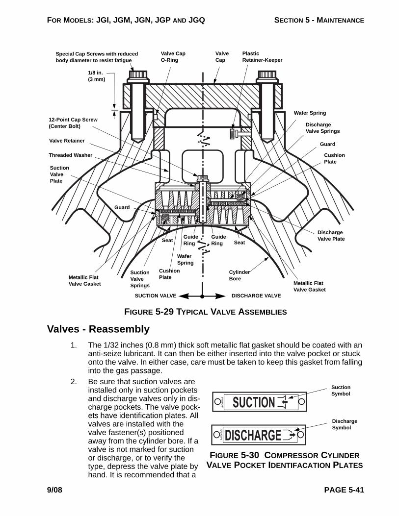
FOR MODELS: JGI, JGM, JGN, JGP AND JGQ SECTION 5 - MAINTENANCE
Valves - Reassembly1. The 1/32 inches (0.8 mm) thick soft metallic flat gasket should be coated with an
anti-seize lubricant. It can then be either inserted into the valve pocket or stuck onto the valve. In either case, care must be taken to keep this gasket from falling into the gas passage.
2.
DISCHARGEA-0
640-
B
SUCTIONA-0
640-
A
FIGURE 5-30 COMPRESSOR CYLINDER VALVE POCKET IDENTIFACATION PLATES
Suction Symbol
Discharge Symbol
Be sure that suction valves are installed only in suction pockets and discharge valves only in dis-charge pockets. The valve pock-ets have identification plates. All valves are installed with the valve fastener(s) positioned away from the cylinder bore. If a valve is not marked for suction or discharge, or to verify the type, depress the valve plate by hand. It is recommended that a
FIGURE 5-29 TYPICAL VALVE ASSEMBLIES
Cylinder Bore
Wafer Spring
Cushion Plate
Guard
Discharge Valve Springs
Wafer Spring
Plastic Retainer-Keeper
Valve Cap
Metallic Flat Valve Gasket
Suction Valve Plate
Valve Retainer
Threaded Washer
12-Point Cap Screw (Center Bolt)
Discharge Valve Plate
SeatGuide Ring
Cushion Plate
Valve Cap O-Ring
Guard
Seat
1/8 in. (3 mm)
Suction Valve Springs
DISCHARGE VALVESUCTION VALVE
Guide Ring
Metallic Flat Valve Gasket
Special Cap Screws with reduced body diameter to resist fatigue
9/08 PAGE 5-41

FOR MODELS: JGI, JGM, JGN, JGP AND JGQ SECTION 5 - MAINTENANCE
tool which is softer than the valve plate material be used or care be exercised to prevent damage to the plate. A suction valve plate can only be depressed from the valve fastener (bolting) side of the valve, and a discharge valve plate can only be depressed from the side of the valve that goes toward the cylinder bore. Reference Figure 5-29 on page 5-41.
3. Using the proper valve puller/installation tool, illustrated in Figure 7-1 on page 7-2, the valve and the retainer may be inserted into the pocket together. Be sure the valve is properly seated in the pocket. When installed correctly the valve should rotate freely when turned by hand, and the distance from the outer retainer face to the surface of the valve boss on the cylinder will be 1/8 inch (3 mm) shorter than the length of the nose on the valve cap.
4. The retainer keeper is a plastic thumb screw in a threaded hole in the bottom valve retainers. This should be screwed through just far enough to provide fric-tion so that bottom retainers will not fall out while the cap is being installed.
5. Inspect the valve cap o-ring for cuts or gashes and replace it if necessary. Lubri-cate the o-ring and the nose of the valve cap. Some high pressure cylinders use a soft metallic wire gasket in lieu of the o-ring design. Insert the cap and tighten the bolting evenly to the recommended torque in Table 1-12 on page 1-16. See “Bolt Tightening for Valve Caps” on page 5-42. If the assembly is correct, the dis-tance from the underside of the cap to the valve boss surface on the cylinder will be 1/8 inches (3 mm).
NOTE: BE CERTAIN ALL PARTS, GASKET FACES, AND MATING SURFACES ARE ABSOLUTELY CLEAN AND ALWAYS USE CLEAN, FRESH OIL ON THE THREADS BEFORE RE-INSTALLING BOLTS.
Bolt Tightening for Valve CapsProper fastener tightening technique is essential for sealing of valve caps with soft metallic wire gaskets used in some high pressure cylinders. It is important to draw up bolting to full torque in even and gradual steps. Do not allow the valve cap to be tightened with bias on one bolt or to become cocked in the bore. Such bias or cocking can cause uneven crush of the gasket, which could cause a leak and could also cause bolt failure. This step tightening procedure is also recommended for all valve caps.
Valve Cap Metallic Wire Gasket
Valve Retainer
Pre-formed Metallic Gasket
Valve Assembly
FIGURE 5-31 HIGH PRESSURE VALVE CAP ASSEMBLY
Install the valve assembly (and high clearance spacer, when applicable), with the flat gaskets(s) and valve retainer, in the valve pocket. See “Valves - Reassembly” on page 5-41. For high pressure applica-tions, place a new, proper, soft metallic wire gasket on the retainer and install the valve cap. Be careful not to gouge the bore, distort or damage the wire gasket. Always use a new metallic wire gasket; wire gas-kets are not reusable.
Lubricate threads and bolt seating surfaces with petroleum type lubricant (except for stainless steel bolting, use a thin coating
PAGE 5-42 9/08
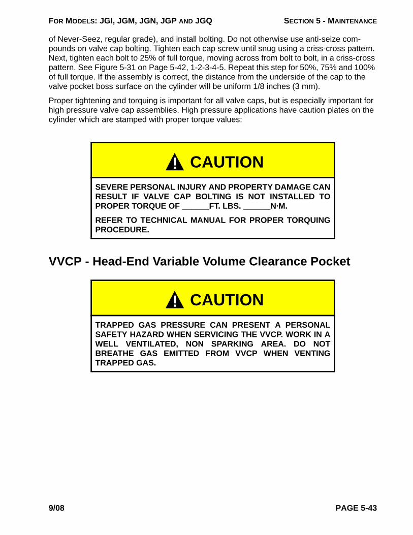
FOR MODELS: JGI, JGM, JGN, JGP AND JGQ SECTION 5 - MAINTENANCE
of Never-Seez, regular grade), and install bolting. Do not otherwise use anti-seize com-pounds on valve cap bolting. Tighten each cap screw until snug using a criss-cross pattern. Next, tighten each bolt to 25% of full torque, moving across from bolt to bolt, in a criss-cross pattern. See Figure 5-31 on Page 5-42, 1-2-3-4-5. Repeat this step for 50%, 75% and 100% of full torque. If the assembly is correct, the distance from the underside of the cap to the valve pocket boss surface on the cylinder will be uniform 1/8 inches (3 mm).
Proper tightening and torquing is important for all valve caps, but is especially important for high pressure valve cap assemblies. High pressure applications have caution plates on the cylinder which are stamped with proper torque values:
VVCP - Head-End Variable Volume Clearance Pocket
CAUTIONSEVERE PERSONAL INJURY AND PROPERTY DAMAGE CAN RESULT IF VALVE CAP BOLTING IS NOT INSTALLED TO PROPER TORQUE OF ______FT. LBS. ______N·M.
REFER TO TECHNICAL MANUAL FOR PROPER TORQUING PROCEDURE.
CAUTIONTRAPPED GAS PRESSURE CAN PRESENT A PERSONAL SAFETY HAZARD WHEN SERVICING THE VVCP. WORK IN A WELL VENTILATED, NON SPARKING AREA. DO NOT BREATHE GAS EMITTED FROM VVCP WHEN VENTING TRAPPED GAS.
!
!
9/08 PAGE 5-43

FOR MODELS: JGI, JGM, JGN, JGP AND JGQ SECTION 5 - MAINTENANCE
VVCP - RemovalCAUTION!: BE SURE THAT ALL PRESSURE IS RELIEVED FROM THE COMPRESSOR
CYLINDERS PRIOR TO REMOVING VVCP.Disconnect VVCP packing vent. Remove the VVCP from the cylinder using similar proce-dures as when removing a cylinder head. The approximate weights of VVCP’s for handling purposes can be found in the current Ariel Performance Program.
VVCP - DisassemblyFor larger VVCP’s, unsnap thread protector bellows from the slot in adjusting handle. With the locking handle locked, remove nylon-insert locknut and adjusting handle. Smaller VVCP’s are not equipped with an adjusting handle, but have wrench flats on the stem for adjustment. Some smaller VVCP’s have a dust cover. The smallest VVCP’s have a locking nut in lieu of a locking handle. A hammer or puller may be required to break adjusting handle to stem tapered fit. Loosen the locking handle (or locknut) and unscrew to remove. Remove head bolting to remove VVCP from cylinder. Remove socket head screws at inside of bolt flange and separate the halves of the VVCP. Unscrew the VVCP stem and piston assembly to remove.
FIGURE 5-32 COMPRESSOR CYLINDER WITH VVCP - TYPICAL
Compressor Cylinder
Backup Ring
V-Packing
VVCP Assembly
Trapped Gas Pressure
Locking Handle or Locknut
Vent to Safe Atmosphere
O-Ring
VVCP Piston Ring (not gas tight seal)
Thread Protector Bel-lows or Dust Cover Over End of Stem
Adjusting Handle or on smaller VVCP’s, Wrench Flats on Stem for Adjusting
VVCP Stem and Piston Assembly
Grease Fitting
VVCP PackingCompression Spring
VVCP PistonSnap Ring
Nylon Insert Locknut to Secure Adjusting Handle
See the Ariel Parts Book for the VVCP Assem-bly Drawing and Parts List that applies.
PAGE 5-44 9/08

FOR MODELS: JGI, JGM, JGN, JGP AND JGQ SECTION 5 - MAINTENANCE
VVCP - MaintenanceTo replace or clean the VVCP packing, mechanically depress the packing assembly spring and remove the snap ring. A piece of threaded rod, two hex nuts and two heavy washers may be used to compress the packing assembly. The inner washer must be large enough to catch the packing assembly, and small enough to allow the snap ring to be compressed and removed. Use proper snap ring pliers. Replace the VVCP packing when excessive leakage is noted at the vent. Remove the VVCP piston ring; replace as necessary.
Clean all parts to remove all debris, rust, etc. The stem and piston are permanently attached to each other, do not attempt to disassemble. When replacing the VVCP packing, place new packing between two flat surfaces, such as two pieces of wood and tap wood with hammer to relax the packing elements prior to assembly.
Reassemble the VVCP in reverse order, lubricate and install a new O-ring at the bolt flange between the two-halves. Refer to Section 1 for bolting tightening torque value. Lubricate stem with three to four pumps of all-purpose petroleum grease with a hand pump grease gun at the grease fitting.
To re-install the VVCP on the cylinder, use a new head gasket. Lubricate threads and bolting seating surfaces with petroleum type lubricant and install bolting. Tighten each cap screw until snug using a criss-cross pattern. Next tighten each cap screw to 25 percent of full torque, moving from cap screw to cap screw in a criss-cross pattern. Repeat this step for 50, 75, and 100 percent of full torque. Refer to Section 1 for tightening torque value.
Reconnect VVCP packing vent. Re-install and tighten locking handle (or locknut), install bel-lows, adjusting handle and Nylon-insert locknut, if applicable. Be sure that thread protector bellows are properly aligned when installing adjusting handle. Tighten Nylon-insert locknut. Refer to Section 1 for tightening torque value. When installing a new VVCP, check total pis-ton end clearance, check crank end/head end feeler gage clearances with VVCP completely closed. Refer to Section 1 for clearances.
VVCP - AdjustmentVVCP clearance volume may be changed with the compressor running or stopped. Consult the Packager’s instructions regarding where to set the VVCP. Also refer to the VVCP data sheet in the Ariel Technical Manual Parts Book.
The VVCP piston ring is designed not to be gas tight, to allow a nearly balanced gas pres-sure for ease of VVCP adjustment with the cylinder pressurized. Gas pressure behind the VVCP piston normally vents when cylinder is vented. Process debris or rust around the pis-ton ring can make a seal that takes some time to vent. If gas is trapped behind the piston, the VVCP can be adjusted when the cylinder is pressurized, but difficult to turn when cylin-der is vented. This problem is corrected by disassembling the VVCP and cleaning.
To adjust volume, loosen stem locking handle (or locknut), so that stem is free to turn. Turn stem by use of adjusting handle on outboard end of shaft (or wrench flats). Turn clockwise to load; counterclockwise to unload the compressor cylinder. See the VVCP instruction plate on the equipment for the dimensional positions for fully closed (load) and fully open (unload). Reference Section 1 for an illustration. Re-tighten stem locking handle (or locknut) to hold stem in place.
9/08 PAGE 5-45

FOR MODELS: JGI, JGM, JGN, JGP AND JGQ SECTION 5 - MAINTENANCE
Compressor Cylinder Re-Boring & Bore Restoration GuidelinesCompressor cylinder re-boring and bore restoration guidelines are to be followed for cylinder maintenance to provide efficient, cost-effective operation:
1. If the cylinder bore surface is blemished or gouged, affecting efficiency or caus-ing rapid ring wear, or is more than 0.001 inches per inch of cylinder bore diam-eter (0.001 mm/mm) out of round or tapered, the cylinder body should be replaced or the bore restored to the guidelines below.
2. It is essential that a cylinder has counterbores to allow for ring over-travel, or future wear would make piston removal very difficult. Ariel compressor cylinders are provided with counterbores that are 0.050 inches (1.27 mm) larger than the nominal cylinder bore. The maximum over-bore on an Ariel cylinder bore diam-eter is 0.044 inches (1.12 mm) larger than the nominal bore diameter, provided the new main bore is concentric with both counterbores, leaving 0.003 inches (0.08 mm) minimum steps to the counterbores.
3. If the cylinder is bored more than 0.020 inches (0.51 mm) larger than the nomi-nal bore diameter, a special oversize wear band and/or sealing rings may be required depending on pressures and gas conditions. This is more applicable for light gases, such as Hydrogen. Oversize wear bands and piston rings are not available from Ariel. See Section 1 (Ariel Technical Manual) for maximum ring end gaps.
4. In a given cylinder class, a smaller-bore cylinder can be re-machined to the larger-bore diameter and counterbores. (New piston, piston rings, wear band if applicable, re-stamping cylinder data tag, and hydro-testing are required). Re-boring can expose internal casting shrinkage, which would render the cylin-der body unusable.
NOTE: CAUTION: ANY RE-MACHINING OF THE COUNTERBORES IN ORDER TO RESTORE THE BORE OF A SMALLER-BORE CYLINDER OF A GIVEN CYLINDER CLASS REQUIRES HYDRO-TESTING THE CYLINDER BODY AT 1.5 TIMES THE MAWP RATING ON THE CYLINDER DATA TAG BY A QUALIFIED FACILITY, BEFORE RETURNING THE CYLINDER TO SERVICE.
5. Cylinder design is based on the wall thickness at the counterbores of the larger cylinder bore for any given cylinder class. Therefore, the larger-bore cylinder counterbores of a cylinder class cannot be machined larger. In this case, the cylinder should either be replaced or reconditioned. Reconditioning may include aftermarket application of metal spray. Ariel does not provide this ser-vice. Contact Ariel for a copy of Reference ER-40 "Thermal Spraying Compres-sor Cylinder Bores to Return to OEM Dimensions" for additional information.
6. Any re-boring operation will remove the hard nitrided layer in ductile iron cylin-ders, which is provided to extend the service life of the bore. The user should determine the cylinder bore hardness required for the application. To maintain the OEM hardness level, re-machined iron bore surfaces should be hardened after finish machining by nitriding or other hardening process that does not result in distortion or changes in the bore that are detrimental to operation of the com-pressor. Resulting bore hardness is to be taken into consideration when metal spraying. Contact Ariel for assistance on cylinder bore hardness requirements.
7. Cylinder re-boring and bore restoration must be done by qualified suppliers and
PAGE 5-46 9/08
FOR MODELS: JGI, JGM, JGN, JGP AND JGQ SECTION 5 - MAINTENANCE
take into consideration the resulting bore diameters, geometry, surface hard-ness and finish. Contact Ariel for the applicable dimensions and tolerance limits to help determine inspection limits when restoring cylinder bores and to ensure a mechanically sound product.
Ethylene Glycol Contamination
Ethylene glycol contamination of a compressor can result from water-cooled compressor rod packing or oil cooler leaks.
Ethylene glycol anti-freeze coolant mixture leaking into the compressor crankcase oil can cause crankshaft seizure due to lack of adequate lubrication. Crankcase oil should be changed as recommended in Section 6, while being routinely sampled and analyzed by a qualified laboratory to verify suitability for continued use, including checking for ethylene glycol contamination.
Even small quantities of ethylene glycol in the oil can be detrimental. If contamination is less than 5 percent, drain oil, replace filters and flush oil system with a 50/50 mixture of butoxyethanol (Dow Chemical Co. Dowanol EB or equal) and 10W oil using a motor driven pump. Flushing should be done on a warm compressor. Bearings should be continuously flushed for 1/2 hour while barring over crankshaft. All surfaces that come in contact with crankcase oil are to be flushed which includes spraying all interior surfaces in the crankcase. Completely drain cleaning mixture, being sure to drain all components of the oil system. Repeat flushing operation using a 60/40 mixture of 10W oil and kerosene or fuel oil. Completely drain system, install new filters and fill crankcase and filters with the proper oil. The coolant leak is to be found and repaired.
If sampling indicates that glycol contamination is greater than 5 percent or the compressor has seized due to contamination, the unit is to be torn down, cleaned with 100 percent butoxyethanol, flushed with kerosene or fuel oil and repaired as required. All surfaces that come in contact with the crankcase oil must be cleaned with butoxyethanol, including all passages and piping, and then flushed with kerosene or fuel oil. Oil and filters must be changed. Coolant leak is to be found and repaired.
Butoxyethanol presents health and safety hazards. Use proper eye and skin protection and adequate ventilation. Do not use near open flame or sparks. See manufacturer's Material Safety Data Sheet for complete details.
Ethylene glycol, butoxyethanol, contaminated oils, and solvents must be properly disposed. A chemical disposal service should be used.
9/08 PAGE 5-47

FOR MODELS: JGI, JGM, JGN, JGP AND JGQ SECTION 5 - MAINTENANCE
SERIAL NO. F- MODEL Date
CRANKSHAFT THRUST (END) CLEARANCE:
CRANKSHAFT SERIAL NUMBER THRUST CLEARANCE, IN. (mm)
CONNECTING ROD THRUST (SIDE) CLEARANCE, IN. (mm)
THROW NUMBER:
1 2 3 4 5 6
JACK CLEARANCES, IN. (mm)
THROW NUMBER: 1 2 3 4 5 6
MAIN BEARINGS
CONN. ROD
BEARINGS
If measured clearances exceed the tolerances in Table 1-3 on page 1-10, after installing new bearings, contact your packager or Ariel before proceeding.
DATE TIME RPM
OIL PRESSURE
FILTER INLETPSIG (barg)
OIL PRESSURE
FILTER OUTLET
PSIG (barg)
OIL TEMPERATURE
INTO FRAME°F (°C)
REMARKS
BEARING CAP TEMPERATURES, °F (°C), AFTER RUN TIME OF:
THROW10 MINUTES 1 HOUR 4 HOURS
MAIN ROD MAIN ROD MAIN ROD
123456
PAGE 5-48 9/08

FOR MODELS: JGI, JGM, JGN, JGP AND JGQ
SECTION 6 - TECHNICAL ASSISTANCE
Recommended Maintenance Intervals
Like all equipment, Ariel compressors do require maintenance. The frequency of mainte-nance is dictated by the environment in which the compressor is placed, the loads the user imposes on the compressor and the cleanliness of the gas.
First and foremost on the preventative maintenance list is the completion and compliance with the Ariel Corporation Packagers Standard and Compressor Start Up Check List. All items must be adhered to, both before and after start up.
The following is a guide only and, as stated above, may vary due to operating conditions. The time intervals start from the start up date of the unit. If your oil supplier's recommended oil service changes are more frequent than the Ariel recommendations, the supplier’s inter-vals should be followed. Regular oil analysis is recommended. If problems develop the oil should be changed immediately and the cause of the problem determined and corrected.
A log book should be kept with each unit. Every maintenance item can be entered with exacting detail in order that records will be available for tracking maintenance costs per unit and for trouble-shooting.
Operator logs should be reviewed by qualified personnel to determine trends in compressor performance and/or maintenance.
CAUTION! BE SURE THAT THE COMPRESSOR IS COMPLETELY VENTED TO RELIEVE ALL GAS PRESSURE, AND THE DRIVER WILL NOT EXERT TORQUE ON THE COMPRESSOR CRANKSHAFT THAT COULD RESULT IN INJURY, PRIOR TO TAKING COUPLING READINGS, RE-CHECKING BOLTING TORQUES ON PRESSURE CONTAINING COMPONENTS OR REMOVING ACCESS COVERS FOR PERFORMING INTERNAL INSPECTION OR MAINTENANCE ON THE COMPRESSOR. IN THE CASE OF A DIRECT DRIVE MOTOR, THE BREAKER IS LOCKED OUT. FAILURE TO FOLLOW THESE STEPS CAN RESULT IN SERIOUS PERSONAL INJURY OR DEATH.
DailyAfter running a new compressor (or after a re-location, re-configuring or major overhaul) for the first 24 hours, shutdown, vent gas system and perform a hot alignment check at coupling within 30 minutes, while barring driver shaft to packager’s recommendations. Realign if nec-essary to hold coupling hub face and rim hot alignment within 0.005 inch (0.13 mm) TIR, except for hub O.D. >17 in. (>43 cm) angular hub-face limit is increased to 0°1’ (0.0167°). Also check fastener torque on gas nozzle flange, valve cap, cylinder head, compressor rod
9/08 PAGE 6-1

FOR MODELS: JGI, JGM, JGN, JGP AND JGQ SECTION 6 - TECHNICAL ASSISTANCE
packing flange and, if applicable, crosshead guide to frame bolting. Reference Ariel Techni-cal Manual, Fastener Torque Tightening Values or Toolbox Torque Chart, ER-63. After the first week or 150 hours, repeat this fastener torque check.
If bearing temperatures increase or a visual inspection of the crankcase indicates bearing wear, check main, connecting rod and crankshaft-thrust bearing clearances. Replace affected bearings if clearances are out of tolerances. See the Ariel Technical Manual for instructions and clearance tolerances.
1. Check frame oil pressure. It should be 50 to 60 psig (3.5 to 4.2 barg) when at operating temperature. Compressor inlet oil temperature is 190°F (88°C) maximum.
2. Check frame oil level. It should be visible in the sight glass and approximately mid-level when running, if not, determine and correct cause. Do not overfill. Check oil makeup tank for sufficient oil supply.
3. Check lubricator block cycle time. Refer to information plate on top of lubricator box for correct cycle time. Very dirty or wet gas may require a more frequent cycle time than normal.
4. Check primary and secondary packing vents for blowing. If blowing, determine cause and, if necessary, replace packing internal parts.
5. Check and correct any gas leaks.6. Check and correct any oil leaks.7. Check operating pressure and temperatures. If not normal, determine cause of
abnormality and correct. It is recommended that a daily log of operating temper-atures and pressure be kept for reference.
8. Check shutdown set points.9. Low oil pressure shutdown 45 psig (3.1 barg) minimum.10. High discharge gas temperature shutdowns are to be set within 10% or as close
as practical above the normal operating discharge temperatures, but not to exceed the “Maximum Discharge Temperature Shutdown Setting” for the service in which the compressor is operating.
11. High and low pressure shutdowns are to be set as close as practical. Consider-ation should be given to the rod load capacity of the machine.
12. Check lubricator box oil level.13. Check for unusual noises or vibrations.
Monthly (in addition to Daily Requirements)After running a new compressor (or after a re-location, re-configuring or major overhaul) for the first month or 650 hours, shutdown, vent gas system and check fastener torque on gas nozzle flanges, valve caps, cylinder heads and compressor rod packing flanges. Reference Ariel Technical Manual, Fastener Torque Tightening Values or Toolbox Torque Chart, ER-63. Fasteners that turn at the first month check, should be re-checked after the second month or 1300 hours. If loosening persists, consult your packager or Ariel to help determine the cause and recommend the correction.
1. Check and confirm safety shutdown functions.
PAGE 6-2 9/08

FOR MODELS: JGI, JGM, JGN, JGP AND JGQ SECTION 6 - TECHNICAL ASSISTANCE
2. Take a frame oil sample and send to a reputable lubricant laboratory for analy-sis. See the Ariel Packager’s Standards or Technical Manual Lube Section for a listing of what an oil analysis should provide. If the oil analysis results indicate, change oil. If an oil analysis indicates lead, tin or copper particles in the oil, check main, connecting rod and crankshaft-thrust bearing clearances. If bearing clearances are outside of the limits, replace the affected bearings. See the Ariel Technical Manual for instructions and clearance tolerances.
Every 6 Months or 4000 Hours (plus Daily/Monthly)1. Drain and replace lubricator box oil.2. Change oil filter or when oil filter differential pressure exceeds the filter change
value, see filter information plate on the top cover or Ariel Technical Manual, Lube Section for value.
3. Change oil. A more frequent oil change interval may be required if operating in an extremely dirty environment or if the oil supplier recommends it or if an oil analysis dictates it. A less frequent oil change interval may be allowed if the oil is replenished on a regular basis due to force feed lubricator usage.
4. Clean sintered element in the small oil filter supplied on the force feed lubrica-tion system or every time main oil filter is changed.
5. Clean strainer when oil is changed.6. Open frame when oil is changed and visually inspect for foreign material. Disas-
sembly is not recommended unless a reason for it is found.7. Check fluid level in torsional vibration damper (if applicable). Take fluid sample
for viscosity testing.8. Re-tighten hold down stud-nuts to proper torque values. Inspect for frame twist
or bending to be sure the main bearing bores are in alignment. Check frame top cover mounting surface flatness tolerance and/or soft foot (reference Ariel docu-ment ER-82 or Technical Manual Section 2). For soft foot check, more than 0.002 inch (0.05 mm) pull down requires re-shimming.
9. Realign if necessary to hold coupling hub face and rim hot alignment within 0.005 inch (0.13 mm) TIR, except for hub O.D. >17 in. (>43 cm) angular face limit is increased to 0°1’ (0.0167°).
10. Check cylinders for the proper lubrication rates. Reference Ariel Technical Man-ual, Lube Section for a practical indication using the paper test method.
Yearly or 8000 Hours (plus Daily/Monthly/6 Months)1. Check main, connecting rod, and crankshaft-thrust bearing clearances with a
pry bar and dial indicator. See the Ariel Technical Manual for instructions and clearance tolerances. Any time bearing clearances are outside the limits, replace the affected bearings. Disassembly to check clearances is not recom-mended. Disassembly should be performed if the pry bar check indicates exces-sive clearance.
2. Check crosshead guide clearance with feelers and if outside the limits listed in the Ariel Technical Manual, Clearances Table, replace the affected parts.
3. Inspect valves for broken plates and loose center bolts, replace broken parts
9/08 PAGE 6-3

FOR MODELS: JGI, JGM, JGN, JGP AND JGQ SECTION 6 - TECHNICAL ASSISTANCE
and tighten center bolts. Reference Ariel Technical Manual, Fastener Torque Tightening Values or Toolbox Torque Chart, ER-63.
4. Inspect cylinder bores for damage or wear. If the cylinder bore surface is blem-ished or gouged, efficiency can be affected and/or rapid ring wear can result, or is more than 0.001 inch per inch of cylinder bore diameter (0.001 mm/mm) out of round or tapered, the cylinder body should be replaced or the bore restored. Contact Ariel for re-boring and bore restoration guidelines.
5. Inspect piston ring end gap. Replace rings that are outside the maximum limit listed in the Ariel Technical Manual, Clearance Tables.
6. Inspect piston rods for damage and excessive wear. If gouged or scratched, replace the rod. If the rod is more than 0.005 inch (0.13 mm) under size, out of round more than 0.001 inch (0.03 mm), or tapered more than 0.002 inch (0.05 mm) replace the rod.
7. Rebuild cylinder packing cases.8. Check and re-calibrate all temperature and pressure gauges.9. Check and record compressor rod run out.10. Grease VVCP stem threads at grease fitting, with 2 to 3 pumps of multi-purpose
grease using a standard hand pump grease gun.11. Clean crankcase breather filter.12. Adjust drive chains.13. Pressure test distribution blocks.14. Check gas nozzle flange, valve cap, cylinder heads, compressor rod packing,
crosshead pin through bolt, crosshead guide to frame, crosshead guide to cylin-der, cylinder mounting flange to forged steel cylinder, distance piece to cylinder, distance piece to crosshead guide and tandem cylinder to cylinder fastener torque.
15. If the compressor is equipped with crankcase over-pressure relief valves, inspect and exercise valves to the manufacturer’s recommendations.
Every 2 Years or 16,000 Hours (plus Daily/Monthly/6 Months/Yearly)
1. Check auxiliary end chain drive for sprocket teeth undercutting and chain for excessive stretching.
2. Rebuild oil wiper cases.
Every 4 Years or 32,000 Hours (plus Daily/Monthly/6 Months/1 & 2 Years)
1. Check crosshead pin to crosshead pin bore and connecting rod bushing bore by removing crosshead pins.
2. Check for excessive wear in the auxiliary end drive chain tightener.3. Check for excessive ring groove wear in pistons.
PAGE 6-4 9/08

FOR MODELS: JGI, JGM, JGN, JGP AND JGQ SECTION 6 - TECHNICAL ASSISTANCE
Low
No
Every 6 Years or 48,000 hours (plus Daily/Monthly/6 Months/1, 2 & 4 Years)
1. Replace lubricator distribution blocks.2. Replace crosshead bushings.
Trouble ShootingMinor problems can be expected during the routine operation of an Ariel compressor. These troubles are most often traced to liquid, dirt, improper adjustment or to operating personnel being unfamiliar with Ariel compressors. Difficulties of this type can usually be corrected by cleaning, proper adjustment, elimination of an adverse condition, replacement of a relatively minor part or proper training of the operating personnel.
Major problems can usually be traced to long periods of operation with unsuitable lubrica-tion, careless operation, lack of routine maintenance or the use of the compressor for pur-poses for which it was not intended.
Recording of the interstage pressures and temperatures on multistage units is valuable because any variation, when operating at a given load point, indicates trouble in one of the stages. Normally, if the interstage pressure drops the trouble is in the lower pressure cylin-der. If it rises, the problem is normally in the higher pressure cylinder.
While it would be impossible to compile a complete list of every possible problem, listed below are some of the more common ones with their possible causes.
Problem Possible Causes
Oil Pressure Oil pump failure.Oil foaming, as shown in sight glass, from counterweights striking oil surface (oil level too high) or from vortex at strainer inlet (oil level too low) or leaks in pump suction line.Cold oil.Dirty oil filter.Interior frame oil leaks.Excessive leakage at bearings.Improper low oil pressure switch setting.Oil pump relief valve set too low.Defective pressure gauge.Plugged oil sump strainer.Improper end clearance in oil pump.
ise in Cylinder Loose piston.Piston hitting cylinder head end head or crank end head.Loose crosshead balance nut.Broken or leaking valve(s).Worn or broken piston rings or wear bands.Valve improperly seated or damaged gasket seat.Liquids in cylinder.
9/08 PAGE 6-5

FOR MODELS: JGI, JGM, JGN, JGP AND JGQ SECTION 6 - TECHNICAL ASSISTANCE
Exc
Pac
Exc
Rel
Hig
Fra
DrivLea
Pist
essive Packing Leakage Worn packing rings.Improper lube oil and or insufficient lube rate.Dirt in packing.Packing rings assembled incorrectly.Improper ring side or end gap clearance.Plugged packing vent system.Scored, tapered or out of round piston rod.Excessive piston rod run-out.Packing not seated or properly run in.
king Over Heating Lubrication failure.Improper lube oil and/or insufficient lube rate.Worn packing rings.Dirt in packing.Improper ring side or end gap clearance.Scored, tapered or out of round piston rod.Excessive piston rod runout.
essive Carbon on Valves Excessive lube oil.Improper lube oil.Oil carry-over from inlet system or previous stage.Broken or leaking valves causing high temperature.Excessive temperature due to high pressure ratio across cylinders.
ief Valve Popping Faulty relief valve.Leaking suction valves or rings on next higher stage.Obstruction, bind or valve closed in discharge line.
h Discharge Temperature Excessive ratio across cylinder due to leaking inlet valves or rings on next higher stage.Fouled intercooler piping.Leaking discharge valves or piston rings.High inlet temperature.Improper lube oil and or lube rate.
me Knocks Loose crosshead pin or pin caps.Loose or worn main, crankpin or crosshead bearings.Low oil pressure.Cold oil.Incorrect oil.Knock is actually from cylinder end.Low fluid level in damper.
e End of Crankshaft Oil k
Clogged vent or vent piping.Excessive cylinder packing leakage.
on Rod Oil Wiper Leaks Worn wiper rings.Wipers incorrectly assembled.Worn/scored rod.Improper fit of rings to rod/side clearance.
Problem Possible Causes
PAGE 6-6 9/08
FOR MODELS: JGI, JGM, JGN, JGP AND JGQ
SECTION 7 - APPENDICES
Ariel ToolsAriel Furnished ToolsAriel provides Tool Kit G-0038 with every JGI:M:N:P:Q compressor. It contains the tools shown in the figure below. These tools are specifically designed for use on Ariel compres-sors. Clean all tools before use and verify full tool engagement with the part being removed or installed. If the Tool Kit is missing or if a tool is missing, worn, or broken, call your Ariel
9/08 PAGE 7-1
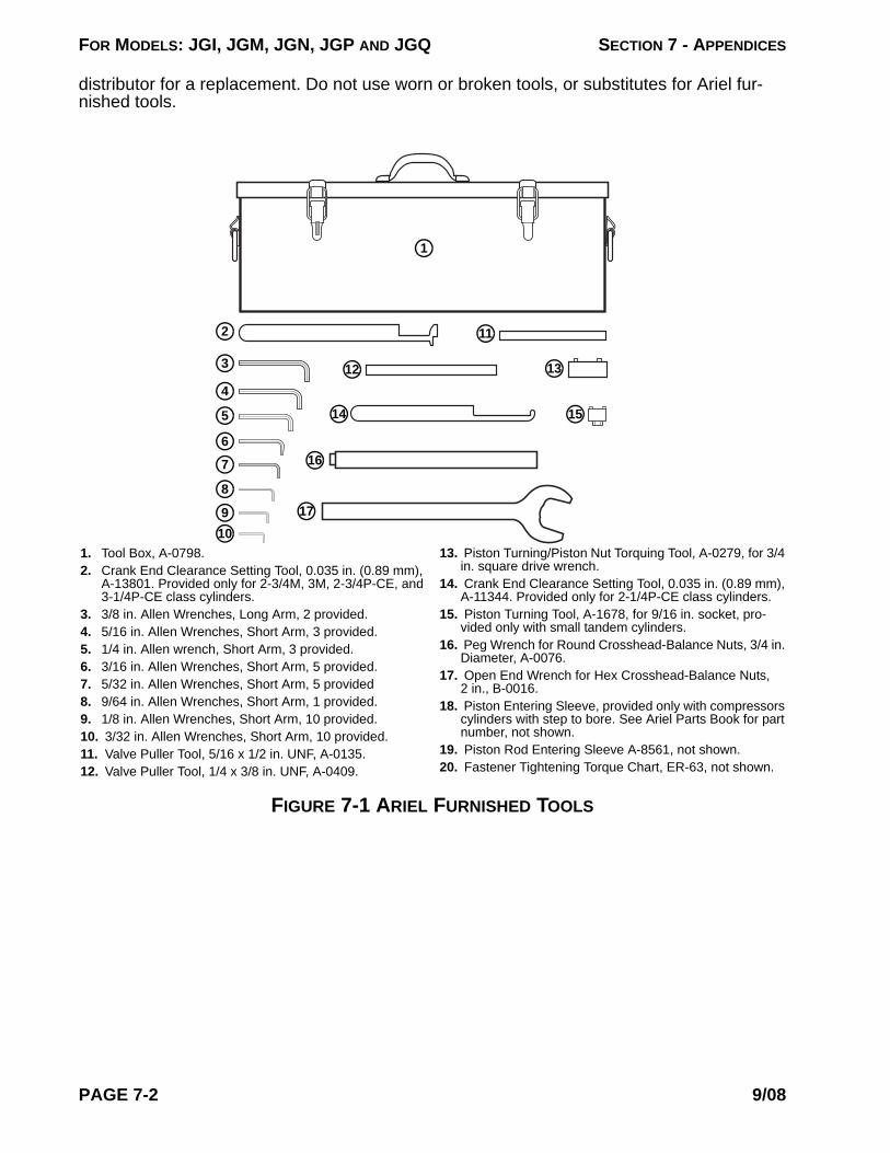
FOR MODELS: JGI, JGM, JGN, JGP AND JGQ SECTION 7 - APPENDICES
distributor for a replacement. Do not use worn or broken tools, or substitutes for Ariel fur-nished tools.
FIGURE 7-1 ARIEL FURNISHED TOOLS
1. Tool Box, A-0798.2. Crank End Clearance Setting Tool, 0.035 in. (0.89 mm),
A-13801. Provided only for 2-3/4M, 3M, 2-3/4P-CE, and 3-1/4P-CE class cylinders.
3. 3/8 in. Allen Wrenches, Long Arm, 2 provided.4. 5/16 in. Allen Wrenches, Short Arm, 3 provided.5. 1/4 in. Allen wrench, Short Arm, 3 provided.6. 3/16 in. Allen Wrenches, Short Arm, 5 provided.7. 5/32 in. Allen Wrenches, Short Arm, 5 provided8. 9/64 in. Allen Wrenches, Short Arm, 1 provided.9. 1/8 in. Allen Wrenches, Short Arm, 10 provided.10. 3/32 in. Allen Wrenches, Short Arm, 10 provided.11. Valve Puller Tool, 5/16 x 1/2 in. UNF, A-0135.12. Valve Puller Tool, 1/4 x 3/8 in. UNF, A-0409.
13. Piston Turning/Piston Nut Torquing Tool, A-0279, for 3/4 in. square drive wrench.
14. Crank End Clearance Setting Tool, 0.035 in. (0.89 mm), A-11344. Provided only for 2-1/4P-CE class cylinders.
15. Piston Turning Tool, A-1678, for 9/16 in. socket, pro-vided only with small tandem cylinders.
16. Peg Wrench for Round Crosshead-Balance Nuts, 3/4 in. Diameter, A-0076.
17. Open End Wrench for Hex Crosshead-Balance Nuts, 2 in., B-0016.
18. Piston Entering Sleeve, provided only with compressors cylinders with step to bore. See Ariel Parts Book for part number, not shown.
19. Piston Rod Entering Sleeve A-8561, not shown.20. Fastener Tightening Torque Chart, ER-63, not shown.
1
3
4
9
8
7
6
5
13
11
12
10
14
16
17
15
2
PAGE 7-2 9/08

FOR MODELS: JGI, JGM, JGN, JGP AND JGQ SECTION 7 - APPENDICES
Ariel Tools - Purchased Separately From Authorized Dealer
FIGURE 7-2 PURCHASED SEPARATELY TOOLS
Minimum Hand & Commercial Tools RequiredThe following standard tools are normally all that is required to work on Ariel reciprocating compressors. These tools are in addition to the Ariel furnished and optional tools listed above. Acquiring high-quality tools and user-friendly, secure tool storage facilities are cost effective. Please contact Ariel if you have questions about tools on Ariel units.
• Tool boxes for hand tools.• 15 - 18 in. Adjustable Wrench (Crescent Type).• Combination Open/Boxed End Wrench Set - including sizes up through 1-1/8 in.• Screw Driver Set, Flat and Phillips - including 2 - Medium; 1 - Extra Large; 1 - Extra
Long Sizes.• Forged Steel Punch and Chisel Set, including a 60° Center Punch.• 3/8 in. Square Drive Wrench Set, including:
1. 12 Point Socket Set w/ Breaker Bar, Ratchet, Speed Wrench, Extensions.2. Universal Joint, Impact Type (Ball).3. Adapter to 1/2 in. Drive.4. 12 Point Box-End "Torque Adapter" Extension Wrench Set, including 1/2 & 5/8
in. sizes, for tandem forged steel cylinder mounting bolts on smaller frame sizes.5. Calibrated Torque Wrench, 10 Lb-In to 250 Lb-In (1 to 30 N·m) range.
• 1/2 in. Square Drive Wrench Set, including:1. 12 Point Socket Set w/ Breaker Bar, Ratchet, Speed Wrench, Extensions.2. Universal Joint, Impact Style (Ball).
1. Ratchet-Wrench-Extension Support for turning the piston and rod assembly, B-1240. Shown assembled for stor-age in tool box. Useful for large bore cylinders.
2. Force Feed Lubrication System Purge Gun (Hand Pump Kit), G-7162.
3. Piston and Rod Clamping Fixture, D-0961.4. Piston Rod Entering Sleeve G-7194.5. Main-Bearing Plastic Removal Tool, G-10706.6. Force Feed Lubricator Bearing-Housing (left hand
thread) Spanner Wrench, A-8158. 1” hex.
2
3
4
5
1
6
9/08 PAGE 7-3

FOR MODELS: JGI, JGM, JGN, JGP AND JGQ SECTION 7 - APPENDICES
3. Adapters to 3/8 in. and 3/4 in. Drive.4. 1-1/4 and 1-5/8 in. Open End Crowfoot "Torque Adapter" Extension Wrenches.5. 1-1/2 and 2-1/4 in. boxed end "Torque Adapter" Extension Wrenches.6. 1/4, 1/2, and 5/8 in. Hex Key (Allen) Socket.7. Calibrated Torque Wrench, 50 LB-FT to 250 LB-FT (65 to 350 N·m) range, for
use with right and left hand threads.• 3/4 in. Square Drive Wrench Set, including:
1. 12 Point Socket Set w/ Breaker Bar, Ratchet, Extensions.2. Adapters to 1/2" and 1" Drive.3. Calibrated Torque Wrench to 600 LB-FT (800 N·m) range.
• 1 in. Square Drive Wrench set, including:1. 12 Point Socket Set (w/ Sockets up through 2-5/8 in.).2. Calibrated Torque Wrench to 1000 Lb-Ft (1400 N·m) range.
• Two (2) Dead Blow Semi-Soft Faced Hammers, Primarily for Slugging the Cross-head-Balance Nut Wrench, approximately 100 ounce or 6 lb (3 kg) for JGC:D frames and 56 ounce or 3.5 lb (1.5 kg) for smaller frames.
• Long Blade Feeler Gage Pack in Assorted Thickness’.• Pry Bar - 3 feet (1 m) Long.• Hexagon Allen-Type Key-Wrenches (to ANSI/ASTM B18.3) for Piston-Nut
Set-Screws. Two Hex Wrenches are Consumed (Destroyed) with each Tightening of a Piston Nut. A quantity of hex wrenches needs to be kept on hand, considering the consumption during maintenance. Hex Allen-type-wrench sizes for piston-nut set-screws - nominal inch sizes:1. JG:A:M:N:P:Q:I 3/322. JGR:J:W:B:V:KBB:V 1/83. JGH:E:K:T 5/324. JGC:D:Z:U 3/16
• Tape Measure.• Flashlight.• Small Mirror on a Flexible Extension Rod.• Small Magnet on a Flexible Extension Rod.• Small Gas Torch.• Electric and/or Pneumatic Drill• Twist Drill Set• Machinist scale with 0.01 inch or 0.5 mm increments.• Calibrated Button and Needle type Dial Indicators with 0.0005 inches (0.005 mm)
increments, magnetic stands and mounting hardware.• Torque Multiplier and/or Hydraulic Torque Wrench for larger frame sizes.
PAGE 7-4 9/08

FOR MODELS: JGI, JGM, JGN, JGP AND JGQ SECTION 7 - APPENDICES
TABLE 7-1: SI METRIC CONVERSION
MEASUREMENT CONVERSION
Area • square inch or in2 x 0.00064516 = meter2 or m2
• square inch or in2 x 6.4516 = centimeter2 or cm2
Flow - Gas
• Million standard cubic feet/day or MMSCFD (at 14.696 psia & 60°F) x 0.310 = normal meter3/second (at 1.01325 bar & 0°C), or m3/sn
• Standard cubic feet/minute or SCFM (at 14.696 psia & 60°F) x 1.607 = normal meter3/hour (at 1.01325 bar & 0°C), or m3/hn
Flow - Liquid• US gallons per minute or GPM x 0.0630902 = liter/second or L/s =
dm3/s• US gallons per minute or GPM x 0.227125 = meter3/hour or m3/h
Force • lbf or pound (force) x 4.44822 = Newton or NHeat • British Thermal Units or BTU x 1.05506 = kilojoule or kJ
Length • inches or in or " x 25.4000 = millimeters or mm• feet or ft x 0.304800 = meter or m
Mass • pound (mass) or lbm x 0.453592 = kilogram or kg
Moment or Torque • Lb x Ft or pound-foot (force) x 1.35583 = Newton-meter or N·m• Lb x In or pound-inch (force) x 0.112985 = Newton-meter or N·m
Power(Horsepower based
on 550 ft-lb/sec.)• Horsepower or HP x 0.745700 = kilowatt or kW
Pressure or StressG or g suffix = gauge
pressure; A or a = absolute;
D or d = differential
• psi x 6894.757 = Pascal or Pa • bar x 100 = kPa• Pa x 0.000145 = psi • kPa x 0.01 = bar• psi x 6.894757 = kiloPascal or kPa• psi x 68.94757 = millibar or mbar• kPa x 0.145 = psi • mbar x 0.0145 = psi• bar x 100 000 = Pa • psi x 0.06894757 = bar• Pa x 0.00001 = bar • bar x 14.5 = psi
Speed• feet per minute or FPM x 0.005080 = meter per second or m/s• revolutions per minute or RPM or r/min x 60 = revolutions per second
or rev/sTemperature • (degrees Fahrenheit or °F - 32) ÷ 1.8 = degrees Celsius or °C
Time • sec or s = second • hour or hr or h x 60 = min• minute or min x 60 = s • h x 3600 = s
Viscosity (Dynamic) • Saybolt Universal seconds or SUS or SSU x 0.22 - (180 ÷ SUS) = mm2/s = centistoke or cSt (for a range of 33 through 200,000 SUS)
9/08 PAGE 7-5

FOR MODELS: JGI, JGM, JGN, JGP AND JGQ SECTION 7 - APPENDICES
TABLE 7-2: USEFUL SI METRIC MULTIPLE AND SUBMULTIPLE FACTORS
FACTOR PREFIX SI SYMBOL (Maintain Case)
1 000 000 = 106 mega M
1 000 = 103 kilo k
100 = 102 hecto (not recommended) h
10 = 101 deka (not recommended) da
0.1 = 10-1 deci (not recommended) d
0.01 = 10-2 centi c
0.001 = 10-3 milli m
0.000 001 = 10-6 micro µ
PAGE 7-6 9/08
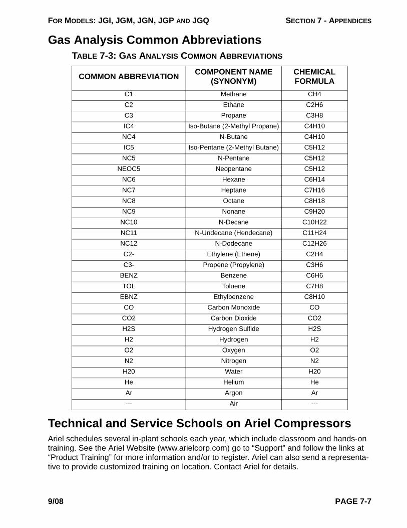
FOR MODELS: JGI, JGM, JGN, JGP AND JGQ SECTION 7 - APPENDICES
Gas Analysis Common AbbreviationsTABLE 7-3: GAS ANALYSIS COMMON ABBREVIATIONS
Technical and Service Schools on Ariel CompressorsAriel schedules several in-plant schools each year, which include classroom and hands-on training. See the Ariel Website (www.arielcorp.com) go to “Support” and follow the links at “Product Training” for more information and/or to register. Ariel can also send a representa-tive to provide customized training on location. Contact Ariel for details.
COMMON ABBREVIATION COMPONENT NAME (SYNONYM)
CHEMICALFORMULA
C1 Methane CH4C2 Ethane C2H6C3 Propane C3H8IC4 Iso-Butane (2-Methyl Propane) C4H10NC4 N-Butane C4H10IC5 Iso-Pentane (2-Methyl Butane) C5H12NC5 N-Pentane C5H12
NEOC5 Neopentane C5H12NC6 Hexane C6H14NC7 Heptane C7H16NC8 Octane C8H18NC9 Nonane C9H20NC10 N-Decane C10H22NC11 N-Undecane (Hendecane) C11H24NC12 N-Dodecane C12H26C2- Ethylene (Ethene) C2H4C3- Propene (Propylene) C3H6
BENZ Benzene C6H6TOL Toluene C7H8
EBNZ Ethylbenzene C8H10CO Carbon Monoxide CO
CO2 Carbon Dioxide CO2H2S Hydrogen Sulfide H2SH2 Hydrogen H2O2 Oxygen O2N2 Nitrogen N2H20 Water H20He Helium HeAr Argon Ar--- Air ---
9/08 PAGE 7-7
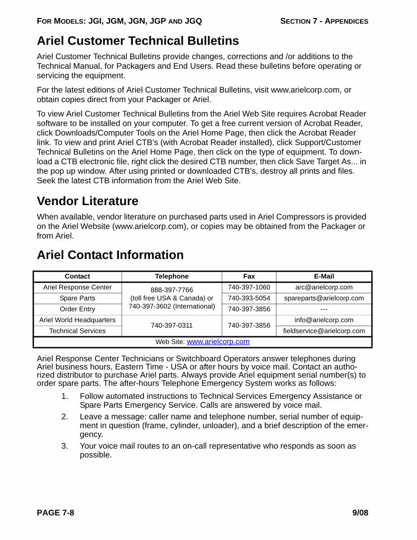
FOR MODELS: JGI, JGM, JGN, JGP AND JGQ SECTION 7 - APPENDICES
Ariel Customer Technical BulletinsAriel Customer Technical Bulletins provide changes, corrections and /or additions to the Technical Manual, for Packagers and End Users. Read these bulletins before operating or servicing the equipment.
For the latest editions of Ariel Customer Technical Bulletins, visit www.arielcorp.com, or obtain copies direct from your Packager or Ariel.
To view Ariel Customer Technical Bulletins from the Ariel Web Site requires Acrobat Reader software to be installed on your computer. To get a free current version of Acrobat Reader, click Downloads/Computer Tools on the Ariel Home Page, then click the Acrobat Reader link. To view and print Ariel CTB’s (with Acrobat Reader installed), click Support/Customer Technical Bulletins on the Ariel Home Page, then click on the type of equipment. To down-load a CTB electronic file, right click the desired CTB number, then click Save Target As... in the pop up window. After using printed or downloaded CTB’s, destroy all prints and files. Seek the latest CTB information from the Ariel Web Site.
Vendor LiteratureWhen available, vendor literature on purchased parts used in Ariel Compressors is provided on the Ariel Website (www.arielcorp.com), or copies may be obtained from the Packager or from Ariel.
Ariel Contact Information
Ariel Response Center Technicians or Switchboard Operators answer telephones during Ariel business hours, Eastern Time - USA or after hours by voice mail. Contact an autho-rized distributor to purchase Ariel parts. Always provide Ariel equipment serial number(s) to order spare parts. The after-hours Telephone Emergency System works as follows:
1. Follow automated instructions to Technical Services Emergency Assistance or Spare Parts Emergency Service. Calls are answered by voice mail.
2. Leave a message: caller name and telephone number, serial number of equip-ment in question (frame, cylinder, unloader), and a brief description of the emer-gency.
3. Your voice mail routes to an on-call representative who responds as soon as possible.
Contact Telephone Fax E-MailAriel Response Center 888-397-7766
(toll free USA & Canada) or 740-397-3602 (International)
740-397-1060 [email protected] Parts 740-393-5054 [email protected] Entry 740-397-3856 ---
Ariel World Headquarters740-397-0311 740-397-3856
[email protected] Services [email protected]
Web Site: www.arielcorp.com
PAGE 7-8 9/08