
Redraft Of Liberal Abortion Bill Opposed - St. Thomas University
Upload
khangminh22Category
view
0download
0
energies
Article
The Potential of Wobble Plate Opposed Piston AxialEngines for Increased Efficiency
Paweł Mazuro and Barbara Makarewicz *
Department of Aircraft Engines, Faculty of Power and Aeronautical Engineering, Warsaw University ofTechnology, 00-665 Warsaw, Poland; [email protected]* Correspondence: [email protected]
Received: 29 September 2020; Accepted: 22 October 2020; Published: 26 October 2020�����������������
Abstract: Recent announcements regarding the phase out of internal combustion engines indicatethe need to make major changes in the automotive industry. Bearing in mind this innovation trend,the article proposes a new approach to the engine design. The aim of this paper is to shed a new lighton the forgotten concept of axial engines with wobble plate mechanism. One of their most importantadvantages is the ease of use of the opposed piston layout, which has recently received muchattention. Based on several years of research, the features determining the increase in mechanicalefficiency, lower heat losses and the best scavenging efficiency were indicated. Thanks to the appliedVariable Compression Ratio (VCR), Variable Angle Shift (VAS) and Variable Port Area (VPA) systems,the engine can operate on various fuels in each of the Spark Ignition (SI), Compression Ignition (CI)and Homogeneous Charge Compression Ignition (HCCI)/Controlled Auto Ignition (CAI) modes.In order to quantify the potential of the proposed design, an initial research of the newest PAMAR 4engine was presented to calculate the torque curve at low rotational speeds. The achieved torque of500 Nm at 500 rpm is 65% greater than the maximum torque of the OM 651 engine of the same 1.8 Lcapacity. The findings lead to the conclusion that axial engines are wrongfully overlooked and cansignificantly improve research on new trends in pollutant elimination.
Keywords: axial engines; wobble plate; opposed piston engine; uniflow scavenging; variablecompression ratio; variable valve timing; downsizing; downspeeding; multifuel potential
1. Introduction
In the light of climate change and further negative ecological forecasts, the lawmakers from all overthe world are trying to reduce the impact of human activity on the environment. In case of the engineindustry, they aim at limiting the emission of harmful gases into the atmosphere. The regulationsplanned to be introduced in some countries are very strict. A recent review of this matter [1] reports,that the most ambitious country (Norway) projects that all cars and light vans sold from 2025 onwardare going to be zero-emission vehicles. Denmark set a target to stop the sales of new gasoline and dieselcars by 2030. That same year, Iceland is going to outlaw the registration of such vehicles and Irelandproposed to ban the sale of new fossil-fuel cars by this date. According to the International Councilof Clean Transportation (ICCT) briefing, ten European countries have made commitments regardingthe phase-out of combustion engine passenger cars by 2040. Related to this are announcements frommajor manufacturers regarding the planned market launch of a significant amount of electric cars.Investments of tens of billions of euros are also planned with regards to the electrification of theirvehicle portfolio.
Validity of departing from internal combustion engines is a subject of separate publicationsand will not be discussed in this article. As others have highlighted [2], electricity can be producedin various ways that may be more or less environmentally friendly. The issues that must be resolved
Energies 2020, 13, 5598; doi:10.3390/en13215598 www.mdpi.com/journal/energies
Energies 2020, 13, 5598 2 of 22
are also the extraction of elements for the production of batteries and their storage at the end of theirservice life. Nevertheless, the abovementioned declarations of the engine manufacturers clearly showthe willingness to introduce significant changes in their production profile. Bearing in mind the globaltrend for huge investments and innovation, the authors of this article would like to present a certaindirection in the development of internal combustion engines, which may advance research aimed atreducing the air pollution. The paper takes a new look at the crank-piston mechanism and proposesa different design which could be a vital factor in emission control.
The subject of nearly two decades of research at the Warsaw University of Technology (WUT) isan axial engine (referred also as barrel engine) with a wobble-plate mechanism, working in an opposedpiston layout. It is not a new concept, as the first engines of this type appeared in the late 19th and early20th century. However, after the Second World War, axial engines haven’t been getting much attentionas they were pushed out of the market by technologically simpler engines with a crank mechanism [3].For a long time, designers were unnecessarily averse to axial engines. It was caused by the opinionabout gross errors in kinematics, which prevented their correct work [4]. The manufacturing issueswere also a significant limitation.
In our opinion, this reasoning relies too heavily on the design capabilities of the last century.The technology has advanced considerably since the first axial engines were built-an example couldbe the spherical plain bearings, which are essential for the proper operation of many wobble platemechanisms. The team at the Warsaw University of Technology has reassessed the benefits andproblems that may arise during the operation of barrel engines. As the research shows, manyhypotheses regarding the axial engines have been oversimplistic. This is probably the reason forthe fact that the idea to return to this forgotten concept arose in a few research centers. Already atthe end of the 20th century, there were attempts to classify and gather knowledge about axial engineswith wobble plate mechanisms.
Publication [5] reviews US patents for wobble plate engines and their assessment based on severalparameters related to their kinematics. The authors stated that as of the year of publication of theirarticle (1986), there was no systematic knowledge about axial engines and methods of their design.In [4] attention was paid to the benefits of using wobble plate mechanisms, mainly the simplicity ofusing the Variable Compression Ratio system. The lack of experience in understanding the operationof such engines was again highlighted.
This knowledge gap was partially filled in the doctoral dissertation [3], where the kinematics ofvarious mechanisms of the axial engines, with particular emphasis on the wobble plate, was analyzedin detail. The mechanisms with the lowest mechanical losses have been selected. Then, for over twentyyears, during various projects, prototypes with the most promising kinematics were built. The aimof the article is to present the conclusions of many years of analysis and research on barrel enginesin the context of their efficiency and environmental impact. The initial test results of the PAMAR4 engine were presented, which clearly show that the barrel engines fit in the trends of modernautomotive research with particular attention to downsizing and downspeeding.
Interest in axial engines is also arising in other research centers. The projects carried out includethe Duke engine [6] from New Zealand and the Covaxe engine [7] from the UK.
1.1. Unconventional Internal Combustion Engine Designs
For years, engineers have seen the limitations of using classic internal combustion engines andthey are trying to create alternative designs. One of the most interesting inventions are rotary engines,a comprehensive review of which was carried out in the publication [8]. This type of engine can bedivided into three main types: vane, toothed gear and oscillatory engines, the most famous example ofwhich is the Wankel design. The undoubted advantages of these engines include a compact design,barrel shape, and a significantly limited number of parts (no complicated timing system). One ofthe latest constructions of this type is the twin rotor piston engine, design of which is describedin the publication [9]. The engine works on the principle of cooperation between quadrant vane pistons

Energies 2020, 13, 5598 3 of 22
mounted on two oscillating rotors. It has been noted that this engine has a number of power strokesequal to the square of the number of vanes on each rotor. For the design presented in [9] with sixpistons on one rotor, the engine will work with 36 power strokes per revolution. Rotary engines haveunfortunately some fundamental disadvantages, such as the shape of the combustion chambers witha low volume to surface ratio which causes greater heat loss. The flame quenching in narrow spacescan cause increased emissions of hydrocarbons. There is also the so far unsolved problem of sealingbetween individual working chambers.
Another idea for reducing disadvantages of internal combustion engines is the free piston concept.This mechanism has no connecting rod or crankshaft-the movement of the piston is a result of gas forcesfrom the combustion chamber and the reaction from a load device, such as an electrical power generator,gas compressor or oil pump. Such a system has many advantages-fewer parts and the possibility ofintegrating an electric generator directly in the engine with magnets in the piston and coil windingsin the housing. Due to the completely different movement mechanism of the piston, no side pistonforce is generated. Simple implementation of a Variable Compression Ratio system is also possible.The patent review [10] showed that key automotive players are interested in this technology. GeneralMotors, Toyota, Volvo, Ford, Honda and Mazda have filed patents for various free piston designs suchas single piston, dual piston and opposed piston types. Research effort is motivated, among others,by the possibility of using the free piston engine as a power generator for hybrid electric vehicles.The future of this technology depends above all on solving one of the main challenges of the precisepiston motion control. As stated in the review, there is not enough operational experience to predictthe viability of free piston engines and develop satisfactory solutions for starting, continuous operationand engine cooling.
The abovementioned designs have many advantages, while the engineers will probably have towait for further technology development to solve the challenges related to them. That is not the casewith wobble plate engines, for which the current state of technology already allows solving the issuesconsidered historically as defects. The historical outline of the construction of these engines is presentedin the publications [11,12] and [3]. From the 1910s to the 1930s, designs that could be used in the military,aviation and automotive industries were developed around the world. Their classification is shownin Figure 1.
Figure 1. Classification of mechanisms used in axial engines [3].

Energies 2020, 13, 5598 4 of 22
The disadvantages mentioned in the descriptions of historical designs include: failure of lubrication,cooling, mechanical failures of wobble plate and pistons joints, high friction losses. The crankshaftmechanisms with bevel gears were abandoned due to an overly complicated mechanism and difficultiesin servicing. Cylindrical cam engines are also a large group of mechanisms with the possibility of almostfreely choosing the piston motion equation. According to the authors, however, such constructionsshould be abandoned in internal combustion engines, because they are characterized by greater sidepiston force, which has been shown later in this article.
As [11] states, some of the mechanisms have not been thoroughly tested because of changingthe financing policy, other ready-made solutions appearing faster on the market or change of prioritiesduring the war. That was the case with Almen wobble plate design (1917–1920), where the fundingwas cut after five prototypes were already designed. A highly developed state of design has reachedalso a German construction discovered after the Second World War by the Allies (1945). It is likelythat the German designers were developing an idea previously presented in the Alfaro engine fromthe USA.
1.2. Challenges Concerning Introduction of Wobble Plate Engines to the Market
The article presents the concept of an unconventional engine, which, according to the authors, hasthe best chance of being an alternative to engines with a crankshaft. However, it cannot be ignoredthat the market launch of a new engine is quite an ambitious and difficult task. It presents engineerswith many challenges that can temporarily be perceived as flaws and discourage both research teamsand investors. The following subsection presents the issues that, according to the authors, constitutethe greatest obstacles for further research on the discussed engines.
A widely understood fact is that the costs of manufacturing components in serial production aremuch lower than in unit production. As the proposed mechanism is completely different, it is notpossible to easily switch production lines from the production of current engine parts to componentsnecessary for the assembly of the barrel engine. At the stage of prototype research, the cost of sucha transition was not estimated. It is a subject for future work, when the application of barrel engines isdetermined and prototype tests for specific customer groups are carried out. Then, a simpler enginedesign for series production will be developed and production costs can be reliably determined.It should be remembered that thanks to a large number of axisymmetric parts and a reductionin the number of important, complex components (cylinder head, camshaft with the valvetrain,crankshaft), production can be relatively profitable. Much more parts can be manufactured by turningthan by milling.
Another challenge with unit production of opposed piston engines is the need to inject fuelperpendicularly to the cylinder axis. It would be ideal to have the possibility to optimize the spacingand diameter of the holes in the injector, but the unit production of such a complex element is alsounprofitable. In high-volume production, this should not be a problem.
Another important issue in the context of the discussed application is the achievable scale ofproduction of these engines. In order to notice a clear improvement in the overall vehicles’ emission,it would be necessary to convince most drivers to buy such an unconventional design. This wouldmean that the approach we propose would have to be recognized around the world. The decision tointroduce wobble plate engines to the automotive industry would have to be associated with an updateof the car structure to fit an engine with a new shape. There would be no need to develop new roadinfrastructure, as is the case with electric cars, where the rapid development of vehicle charging stationswould be necessary. Instead, it would be essential to invest in training of mechanics who have notencountered wobble plate engines in their work so far.
A popular opinion regarding two-stroke engines is the excessive use of oil and its combustion,which prevents such engines from meeting current emission standards. This issue is very well discussedin [13] where Achates Power shows that their opposed piston two stroke (OP2S) engine achievesoil consumption levels similar to a four-stroke (4S) engine. Tests on PAMAR engines confirm this

Energies 2020, 13, 5598 5 of 22
observation, as during the tests no excessive oil consumption by the engine was observed. This isbecause the uniflow scavenged engine does not mix the lubricating oil with the fuel. Such an enginehas two sets of rings-oil and compression rings, which work in the same way as in a four-stroke engine.Another frequently mentioned disadvantage of two-stroke engines is the wear of the piston rings,which occurs due to their contact with the intake or exhaust ports. Work with the PAMAR engineshowed that the proper finishing of the ports’ edges is enough to prevent ring failure. It’s also worthnoting that the oil rings do not come into contact with the ports.
2. Advantages of the PAMAR Engines
The further discussion of the advantages of PAMAR engines is based on the test results of previousprototypes. So far, four engines have been developed, and the fifth is currently under construction.Extensive tests were carried out on the most advanced PAMAR 3 and PAMAR 4 engines, the basicparameters and capabilities of which are collected in Table 1. The engines are presented in Figure 2.
Table 1. Information summary about the most advanced wobble plate axial engines built at the WarsawUniversity of Technology.
Engine Details PAMAR 3 PAMAR 4
Year of Manufacture 2009 2016Engine Displacement (cm3) 3000 1792
Cylinder Number 6 2Nominal power (kW) 340 (3000 rpm) 157 (3000 rpm) 2
Torque (Nm) 1200 (1400 rpm) 720 (700–1500 rpm)Mechanism used Wobble plate blocked by bevel gear Wobble plate blocked by two sliders
Ignition type SI/CI/HCCI SI/CI/HCCI
Fuel Gasoline, diesel fuel, propane, LNGGasoline, diesel fuel
(already tested)Low calorific gas fuels, biogas (possible)
Additional systems
Variable Port Area 1 and VariableCompression Ratio modificationpossible after engine shutdown
Variable Angle Shift modificationpossible during the engine’s work
Variable Compression Ratio, VariableAngle Shift and Variable Port Area
possible during engine’s work
Results and main conclusions
Achieved stable operation in HCCImode at full load [14].
Very high-power density:0.56 kg/kW
Correct operation of all additionalvariability systems confirmedThe engine is currently under
investigation1 The variability systems and their operation will be discussed in later sections; 2 Nominal power and torque valuesfor PAMAR 4 engine are estimated from the calculations.
Figure 2. Two latest PAMAR engines built at Warsaw University of Technology: (a) PAMAR 3 (2004);(b) PAMAR 4 (2016).
At Warsaw University of Technology, the research on barrel engines began in 2000 withthe construction of the PAMAR 1—a 50 cm3 SI engine with wobble plate blocked by piston. The problems

Energies 2020, 13, 5598 6 of 22
that arose during the preliminary tests gave direction to the further development of the analyzes,especially the need to study the course of the piston side force for individual mechanisms. The second600 cm3 engine was the first in the series to use an opposed piston layout as well as Variable AngleShift and Variable Port Area possible to modify after engine shutdown. The PAMAR 2 design wasbased on a complete mechanical analysis performed in [3], resulting in the selection of the crossheadmechanism for wobble plate rotation blocking.
Parallel to the research on the PAMAR 4 engine, the PAMAR 5 is being built, which is to bean engine for distributed energy generation. Thanks to the additional fourth variability system, it willbe possible to control the delivery of gaseous fuel to a large extent. It will enable operation on fuelsof variable composition and low calorific value. The engine is designed for the power of 400 kW forfuels with a calorific value of about 6 MJ/m3, up to 2MW for diesel. The first tests are planned for2021. It would be a great success to confirm the engine operation on alternative fuels, as it can bean interesting research direction to reduce emissions. A review on this matter is presented in [2].
Based on many years of research, the authors have identified the most promising direction forthe development of barrel engines as distributed energy sources as well as military vehicles and drones.However, in the face of clearly changing trends on the car engine market, it was decided to showthe advantages of the designed engines in the context of the automotive industry.
The innovation of PAMAR engines lies in the combination of the benefits of two ideas-wobbleplate mechanisms and opposed piston layout. They will be discussed in the following subsections.
2.1. Wobble Plate Benefits
In barrel engines, the sliding motion of the pistons can be converted into the rotary motionof the shaft in various ways. This is usually done using a special plate. There are two typesof plates—swash and wobble plate. It is very important to distinguish between these two types,as calculations have shown that wobble plate mechanisms have the potential to achieve much greatermechanical efficiency than swash plates. It should also be taken into account that there are manyvarieties of wobble plate mechanisms. It is necessary to carefully analyze the dynamics of thesemechanisms in order to decide whether to choose them for the design. It is impossible to talk aboutthe advantages and disadvantages of barrel engines without fully understanding how they differ fromeach other.
Moreover, the lack of a precise kinematic analysis of the mechanisms may lead to failures orcompletely prevent operation. Such a situation took place in the frequently quoted Bristol engine [4],where the plate movement did not meet the uniform precession condition. The publication [5] noted thatamong the mechanisms patented in the US, some of them could not operate on the basis of the analysisof degrees of freedom. According to [5] the most representative group among the mechanismsappearing in the US patent database is the wobble plate blocked by bevel gear.
2.1.1. Lower Piston Side Force
The dominant source of engine rubbing friction is the piston assembly [15]. The reduction ofthe piston side force can significantly increase the mechanical efficiency. It is worth mentioning thatin order to limit the frictional work generated by the side piston force, engineers decide on variousmodifications. An example is the shift of the cylinder axis from the axis of the crankshaft in the newestfamily of Mercedes engines OM 654. Importantly, the only compelling competition for engineswith a crank mechanism are the engines with lower mechanical losses. Therefore, after analyzingthe kinematics of the mechanism, the course of this force should be estimated. The calculation resultsfor the above-mentioned mechanisms are shown in Figure 3. The maximum force in the classiccrank mechanism (red dashed line) was taken as the reference value (100%). Significantly, in somemechanisms this force can be much greater (swashplate, cam mechanism, wobble plate blocked bypiston). This may be the reason for the popular belief that axial engines are not worth consideringbecause of their low efficiency. It should be noted, however, that there are mechanisms that are very

Energies 2020, 13, 5598 7 of 22
competitive with the classical construction. These are mainly designs based on bevel gears or crosshead.The lateral piston force can be as much as 50% lower here than in a conventional engine. This is one ofthe reasons why these two types of engines were selected for use in the actual test prototypes.
Figure 3. The course of the absolute value of different mechanisms’ piston side force for the sameoperating parameters [3].
2.1.2. Piston and Connecting Rod Bearings
The kinematics of the wobble plate mechanism requires the use of spherical plain bearingsin the connecting rod-piston and connecting rod-wobble plate joints (Figure 4). This type of bearing ischaracterized by a much higher load capacity than the configuration in which the force is transmittedthrough ordinary slide bearings and the piston pin. An example of the use of a spherical bearing in aninternal combustion engine was provided by the Sulzer company, which patented the rotating pistonin 1937. After a long period of testing, it was first used in 1964 in Z-type engines, and in 1995 the ideawas adopted by GMT (Grandi Motori Trieste) in the VA55.
Figure 4. High capacity spherical plain bearings used in PAMAR engine designs: (a) wobbleplate—connecting rod assembly of PAMAR 3 engine; (b) size comparison between the bearings usedin PAMAR 4 and PAMAR 5 engines.
Energies 2020, 13, 5598 8 of 22
Experience has shown that this solution has the following advantages [16]:
• 40% more bearing area than a gudgeon pin bearing.• More even distribution of load and temperature in axis symmetrical pistons.• Symmetrical deformations of the piston which allow smallest running clearance between piston
and cylinder liner.• Possible use of the rotation mechanism, which will ensure lower wear of the piston.
In PAMAR engines, no additional piston rotation mechanism was used. However, duringthe inspection of parts, after some time of engine operation, spiral lines were observed on the pistonskirt surface. It proves the existence of low revolutions of the piston during engine operation and may bea result of the velocity components of the connecting rod that do not appear in the classical mechanism.
2.1.3. Additional Engine Control Systems
The ability to adjust the engine operation to varying loads has become an important issuein the automotive industry. As summarized in [17], research was conducted towards systems such asvariable valve timing, variable length intake manifold, variable spark timing and variable compressionratio. The use of these systems was expected to have a beneficial effect on engine performance alongwith reduced fuel consumption and lower CO2 and NOx emissions. However, one of the main designgoals is to make as few changes to the engine as possible, preferably to only slightly modify a stockengine, to ensure reduced introduction to market time.
In barrel engines, the implementation of such additional mechanical control systems is relativelysimple. The design of the systems in PAMAR engines is extremely flexible due to the combination ofthree assumptions: the wobble plate mechanism, opposed piston layout and two stroke work cycle.As also noted in [5], systems of variation would not be so simple to implement on the basis of classicalcrank and connecting rod assembly. This has been confirmed in the research of PAMAR engines andthe simplicity of the implementation of these systems is one of their crucial advantages. Alreadytested system designs will be the subject of patents filed in the near future, therefore their detailedoperating principle is out of scope of this paper. The systems used in the PAMAR 4 engine are: VariableCompression Ratio, Variable Angle Shift and Variable Port Area.
Variable Compression Ratio
The Variable Compression Ratio system has been under engineers’ consideration sincethe beginning of the 20th century. The results of their work could be divided into followingcategories [18]: unconventional cranktrains (NISSAN), systems with variable head-crankshaft distance(SAAB) and variable kinematic lengths (FEV conrod).
Various approaches have been described to alter the compression ratio and their advantages aswell as disadvantages have been examined. The system used in PAMAR engines will not be describedin detail, as it will be the subject of a patent in the next few years. However, assessing it on the basis ofthe parameters proposed in [17], it can be certainly stated that in opposed piston wobble plate enginesit is possible to implement a VCR system, with:
• preserved combustion chamber integrity and engine overall rigidity,• no changes in crankshaft-piston assembly kinematics,• no significant influence on mechanical losses due to the possibility of using a well-lubricated
tribological pairs,• no variations on engine displacement,• very good control accuracy. The compression ratio may vary smoothly from 1:10 to 1:20 while
the engine is running.
Energies 2020, 13, 5598 9 of 22
Variable Angle Shift and Variable Port Area
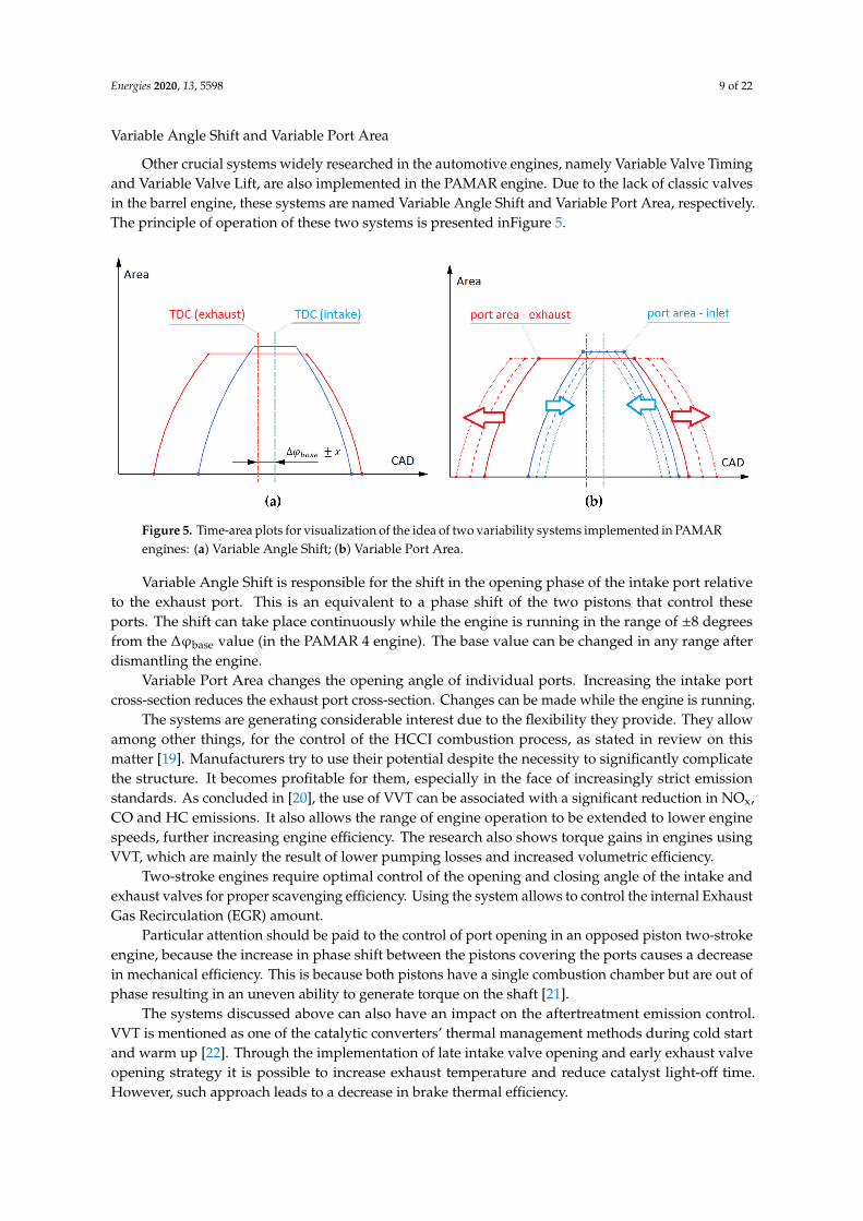
Other crucial systems widely researched in the automotive engines, namely Variable Valve Timingand Variable Valve Lift, are also implemented in the PAMAR engine. Due to the lack of classic valvesin the barrel engine, these systems are named Variable Angle Shift and Variable Port Area, respectively.The principle of operation of these two systems is presented inFigure 5.
Figure 5. Time-area plots for visualization of the idea of two variability systems implemented in PAMARengines: (a) Variable Angle Shift; (b) Variable Port Area.
Variable Angle Shift is responsible for the shift in the opening phase of the intake port relativeto the exhaust port. This is an equivalent to a phase shift of the two pistons that control theseports. The shift can take place continuously while the engine is running in the range of ±8 degreesfrom the ∆ϕbase value (in the PAMAR 4 engine). The base value can be changed in any range afterdismantling the engine.
Variable Port Area changes the opening angle of individual ports. Increasing the intake portcross-section reduces the exhaust port cross-section. Changes can be made while the engine is running.
The systems are generating considerable interest due to the flexibility they provide. They allowamong other things, for the control of the HCCI combustion process, as stated in review on thismatter [19]. Manufacturers try to use their potential despite the necessity to significantly complicatethe structure. It becomes profitable for them, especially in the face of increasingly strict emissionstandards. As concluded in [20], the use of VVT can be associated with a significant reduction in NOx,CO and HC emissions. It also allows the range of engine operation to be extended to lower enginespeeds, further increasing engine efficiency. The research also shows torque gains in engines usingVVT, which are mainly the result of lower pumping losses and increased volumetric efficiency.
Two-stroke engines require optimal control of the opening and closing angle of the intake andexhaust valves for proper scavenging efficiency. Using the system allows to control the internal ExhaustGas Recirculation (EGR) amount.
Particular attention should be paid to the control of port opening in an opposed piston two-strokeengine, because the increase in phase shift between the pistons covering the ports causes a decreasein mechanical efficiency. This is because both pistons have a single combustion chamber but are out ofphase resulting in an uneven ability to generate torque on the shaft [21].
The systems discussed above can also have an impact on the aftertreatment emission control.VVT is mentioned as one of the catalytic converters’ thermal management methods during cold startand warm up [22]. Through the implementation of late intake valve opening and early exhaust valveopening strategy it is possible to increase exhaust temperature and reduce catalyst light-off time.However, such approach leads to a decrease in brake thermal efficiency.

Energies 2020, 13, 5598 10 of 22
2.1.4. Barrel Shape and Axial Symmetry
The characteristic barrel shape of the axial engine (Figure 6) has also its advantages. One ofthem-especially important in aviation-is the small frontal area. From a thermodynamic point ofview, axial symmetry can enable the same filling, lubrication and cooling conditions for all cylinders.This makes the process of controlling optimal engine operation easier. An important aspect alsodiscussed when assessing the variability systems described in the previous subsection is the ability tocontrol them in all cylinders. This problem does not occur in barrel engines, where the conditions in allcylinders are the same by default. It is a desired feature, especially considering the implementation ofsophisticated combustion strategies as HCCI, which is a subject of interest of engine manufacturersdue to its low NOx and particulate matter (PM) emissions [19].
Figure 6. The characteristic shape of an axial engine: (a) a simple CAD model of wobble-plate crankassembly; (b) The axissymmetrical shape of the PAMAR 3 engine.
2.1.5. Torsional Vibrations
Time-varying gas forces and inertia forces act on the crankshaft, causing it to vibrate. There arethree types of vibrations in the crankshaft: longitudinal, bending and torsional, the latter of whichare the most dangerous. The torsional deflection is not limited by anything other than the stiffness ofthe shaft, which can lead to high vibration amplitudes. This may cause an increase in fatigue stress andstructure failure. For this reason, a vibration calculation of the crankshaft is necessary, with particularattention to the natural frequency, to prevent resonance. In order to reduce the harmful effects of thisphenomenon, vibration dampers of various designs are used.
The problem of torsional vibrations is a big challenge for designers of opposed piston engines,especially engines with two crankshafts connected by a gear train. If the crank angle offset system isused—similarly to the previously discussed Variable Angle Shift, the load is not evenly distributedover both shafts. This can be seen in historical designs of opposed piston engines, using dual vibrationdampers (Leyland L60) on one of the shafts or using one of the shafts only to drive the accessories, tolimit the flow of variable torque through the transmission connecting the shafts (Junkers) [21].
In an engine with a wobble plate mechanism, the problem of torsional vibrations is significantlyreduced. The gas and inertia forces are first transferred to the rigid wobble plate and then transmittedto the shaft. It is worth noting that due to the significant difference in the method of transmission ofthe drive in the wobble plate mechanism, the shaft has a much higher torsional stiffness than the classiccrankshaft.Figure 7shows a schematic cross-section of the PAMAR 4 engine with the rigid componentsresponsible for transmitting the torque marked in green.

Energies 2020, 13, 5598 11 of 22
Figure 7. The wobble plate mechanism of PAMAR 4 engine.
2.2. Opposed Piston Benefits
The arrangement of opposed piston layout began to attract the interest of designers and investors,who want to adapt to the restrictive requirements faced by modern engines. The largest companypromoting this type of engine is Achates Power, which has already been very successful in usingopposed piston engines in a variety of industries—from passenger cars to military vehicles [23].A massive investment has also been made in the OPOC engine—opposed piston opposed cylinder-keyfinancial backers are Vinod Khosla and Bill Gates [24].
In the recent years there has been growing interest in opposed-piston engines, particularlythe two-stroke engines. The advantages of such a solution have been described in detail in manypublications, including [25,26] and [14]—especially concerning PAMAR engines built at the WarsawUniversity of Technology. The recurring interest in opposed piston engines is due to the numerousadvantages that are important in view of the increasingly stringent emission standards. The oldproblems that pushed this idea aside can be solved with modern technology, and the efficiency gain isworth the adaptation to the completely new cylinder layout. As confirmed by theoretical analyzes [25],the most advantageous system in terms of configuration is the opposed piston engine operatingin a two-stroke cycle.
In [25] comparison was made between three types of engines: classic four-stroke (4S), four-strokeopposed piston (OP4S) and two-stroke opposed piston (OP2S) with the closest geometric characteristicspossible. For all the engines indicated power, engine speed, and maximum pressure rise rate wereassumed constant. The analysis showed clear benefits of the opposed piston system, calculated assignificantly lower energy losses related to the parameters determining the differences in the actualcourse of the cycle and the ideal Carnot cycle. These parameters are heat transfer, finite durationof the combustion and variable specific heats of the working fluid. A particularly large gain wasseen in the two-stroke engine in parameter related to the combustion duration, which results fromthe doubled firing frequency. More detailed calculations showed approximately 10% lower fuelconsumption in comparison to the four-stroke opposed piston engine. The possible reasons of theseadvantages, widely described in literature, are briefly discussed below.
2.2.1. Less Heat Rejection to the Cooling System
The internal combustion engine has a strictly defined efficiency limit which is caused by the secondlaw of thermodynamics. Attempts to approach this border consist mainly in modifications aimed atlimiting the heat exchange between the working medium and its surroundings, i.e., mainly piston crown,cylinder head, poppet valves and cylinder liner. Designers are limited by the strength of materials atelevated temperatures. Taking into account that the temperature peak during the combustion processis up to 2500 K, cooling the most thermally loaded parts of the engine is necessary. The heat rejected tothe cooling system is a waste of energy which, to some extent, could be converted into useful workperformed by the engine.
Energies 2020, 13, 5598 12 of 22
The engineers were able to use continuously better materials and insulating coatings, but coolingparts such as the cylinder head or poppet valves was still a necessity and contributed to heat loss.Opposed piston layout might be the answer to this problem. The engine timing based on the pistonmovement means that it is not necessary to cool or drive additional poppet valves. A great advantageis also the lack of classic cylinder head.
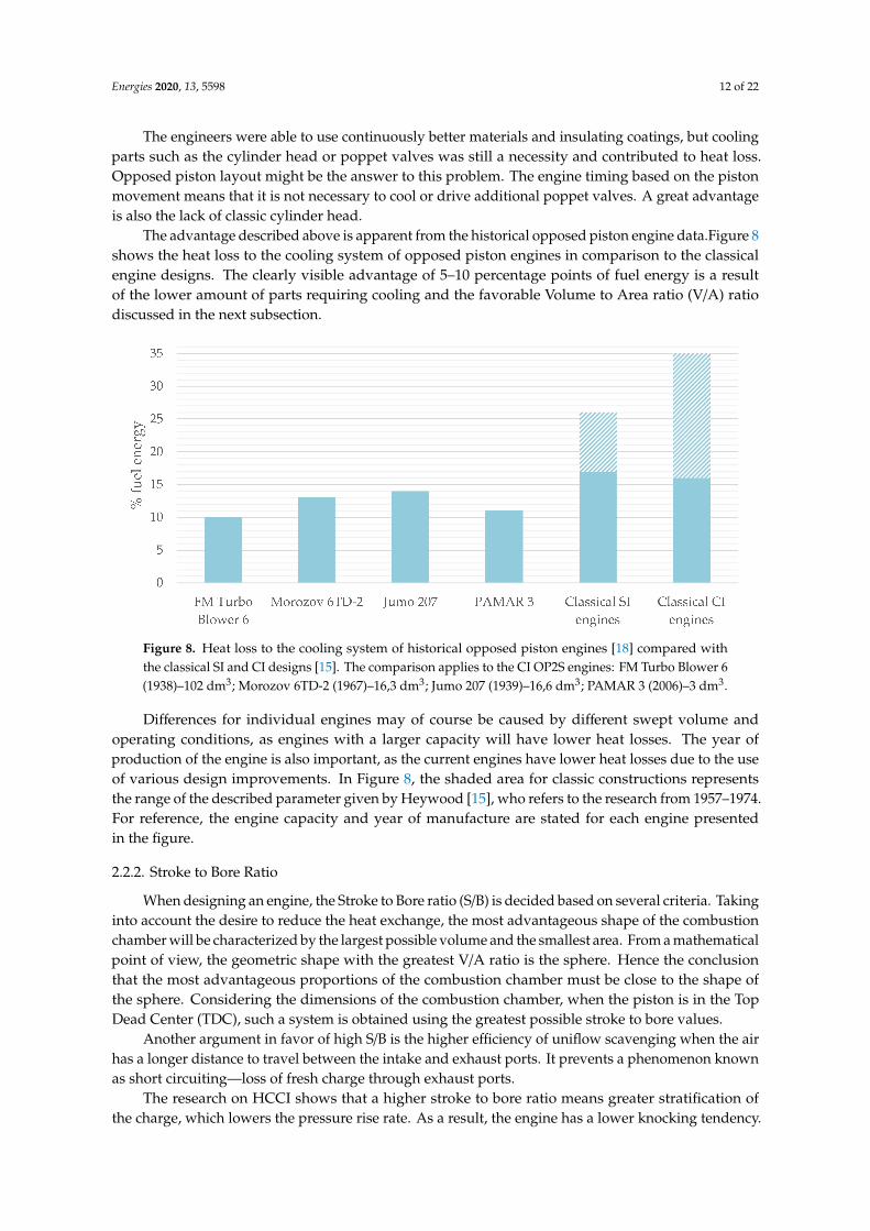
The advantage described above is apparent from the historical opposed piston engine data.Figure 8shows the heat loss to the cooling system of opposed piston engines in comparison to the classicalengine designs. The clearly visible advantage of 5–10 percentage points of fuel energy is a resultof the lower amount of parts requiring cooling and the favorable Volume to Area ratio (V/A) ratiodiscussed in the next subsection.
Figure 8. Heat loss to the cooling system of historical opposed piston engines [18] compared withthe classical SI and CI designs [15]. The comparison applies to the CI OP2S engines: FM Turbo Blower 6(1938)–102 dm3; Morozov 6TD-2 (1967)–16,3 dm3; Jumo 207 (1939)–16,6 dm3; PAMAR 3 (2006)–3 dm3.
Differences for individual engines may of course be caused by different swept volume andoperating conditions, as engines with a larger capacity will have lower heat losses. The year ofproduction of the engine is also important, as the current engines have lower heat losses due to the useof various design improvements. In Figure 8, the shaded area for classic constructions representsthe range of the described parameter given by Heywood [15], who refers to the research from 1957–1974.For reference, the engine capacity and year of manufacture are stated for each engine presentedin the figure.
2.2.2. Stroke to Bore Ratio
When designing an engine, the Stroke to Bore ratio (S/B) is decided based on several criteria. Takinginto account the desire to reduce the heat exchange, the most advantageous shape of the combustionchamber will be characterized by the largest possible volume and the smallest area. From a mathematicalpoint of view, the geometric shape with the greatest V/A ratio is the sphere. Hence the conclusionthat the most advantageous proportions of the combustion chamber must be close to the shape ofthe sphere. Considering the dimensions of the combustion chamber, when the piston is in the TopDead Center (TDC), such a system is obtained using the greatest possible stroke to bore values.
Another argument in favor of high S/B is the higher efficiency of uniflow scavenging when the airhas a longer distance to travel between the intake and exhaust ports. It prevents a phenomenon knownas short circuiting—loss of fresh charge through exhaust ports.
The research on HCCI shows that a higher stroke to bore ratio means greater stratification ofthe charge, which lowers the pressure rise rate. As a result, the engine has a lower knocking tendency.

Energies 2020, 13, 5598 13 of 22
Calculation of the optimal S/B ratio is out of scope of this paper, but it should be borne in mind thatthe values of this parameter obtained in currently produced engines are not the result of thermodynamicoptimization alone. The upper value of this parameter is limited, among others, due to the limit ofthe allowed piston speed and the collision of the connecting rod with the cylinder surface.
The opposed piston arrangement may be the answer to some of these limitations, as here twopistons move in one cylinder. As a result, the stroke value is double the displacement value of a singlepiston. Thus, an increase in the S/B ratio does not increase the linear speed of the piston. Approximatevalues of this parameter for the opposed piston crankshaft engine can be estimated on the basis of datafrom Achates Power, with stroke to bore ratio is within 2.2–2.6 [27].
The second limitation is the size limitation, which is the result of a possible collision ofthe connecting rod with the cylinder. For this reason, the highest S/B values are characteristicfor low-speed marine engines, where a collision cannot occur because of the crosshead mechanism used.As reported by [16], the parameter value for Sulzer marine engines in the late 1970s was around 2 (RLBengine) and has doubled by the early 1990s, continuously growing (Wartsila X35-4.43). The changein this parameter over the years is presented in Figure 9.
Figure 9. Stroke to bore values for low speed marine engines (adapted from [28]). PAMAR 4 datafor comparison.
It is worth noting that the size limitation is less significant in wobble plate engines than in classicengines with a crank mechanism, because the connecting rod deviation angles from the cylinderaxis are smaller. This is expressed in the lower value of the piston side force discussed earlier andin the possibility of obtaining higher S/B ratios. Thanks to this, the PAMAR 4 engine managed toachieve a stroke to bore ratio of 6.85 at a mean piston speed of about 9.4 m/s at a nominal rotationalspeed of 1500 rpm. The stroke to bore proportions of the PAMAR 4 engine are clearly visible in Figure 7.
2.2.3. Uniflow Scavenging
The possibility of controlling the opening of the intake and exhaust ports by opposed pistonscreates ideal conditions for uniflow scavenging. This type of scavenging is characterized by the greatestefficiency [15].
As shown by the calculations [29], there is also a relationship between the scavenging efficiency andthe previously mentioned stroke to bore ratio. For the four S/B geometries analyzed there in the rangefrom 1.08 to 2.5, it turns out that the highest parameter value corresponds to almost ideal scavengingconditions, with the efficiency increasing from 0.813 to 0.934. The analysis of the distribution ofvelocity vectors shows that with an increase in S/B it is possible to obtain uniform flow field with norecirculation zones. Due to the shorter axial distance between the inlet ports and the cylinder axis,the air has time to form a uniform front which pushes residual gas out of the cylinder more efficiently.

Energies 2020, 13, 5598 14 of 22
2.3. Downsizing and Downspeeding as PAMAR Engine Potential Demonstration
All of the above features of barrel engines mean that its performance can be significantly higherthan in the case of classic designs. In order to support this thesis experimentally, the research ofthe PAMAR 4 engine conducted at low rotational speed was presented in the further part of thispaper. The tests were aimed at determining the torque curve for the low speed range and presentingthe engine performance in the context of two trends widely present in the automotive industry, i.e.,downsizing and downspeeding.
Downspeeding is a procedure aimed at shifting the engine’s operating point towards lowerrotational speed. The advantage of such action is the increase in mechanical efficiency and reductionof pumping losses. At lower speeds, the coefficient of friction decreases. The piston will performfewer work cycles, which results in less friction work. Filling the cylinder is more efficient by loweringthe flow velocity, which reduces the time frame when the inlet velocity is close to the speed of sound.
As presented in the publication [30], in commercial trucks for highway cruise speeds, the decreasein engine speed by every 100 rpm translates into one percentage point of fuel efficiency increase.Carbon dioxide emissions reduction was estimated at 12,000 lbs (5443 kg) per truck annually.
Downsizing is one of the most discussed design improvement directions when it comes tothe review of technology progress concerning the introduction of greenhouse gas emissions and fueleconomy standards. As the International Council of Clean Transportation estimates, the market shareof downsized engines will be increasing significantly in the coming years [31]. The turbochargedvehicle sales have increased from 3.3% in 2004 to about 20% in 2015. A study prepared by ICCTconcluded that the main advantage of downsized engines is low incremental cost compared to theirfuel efficiency benefit.
Downsizing requires designers to allow higher power density, ensuring reliability achievedin larger units of the same power. Working with a higher Break Mean Effective Pressure (BMEP) allowsto achieve lower throttling losses under normal driving conditions. Smaller displacement engine islikely to have smaller friction losses and lower weight.
The trend of downsizing is related to research on the most effective turbocharging methods, wherethe most interesting concepts include e-boosting and Variable Geometry Turbocharger. The advantageof turbochargers is the partial energy recovery of exhaust gases.
The variable compression ratio is advantageous for downsized engines. This system will ensurethat knocking combustion is controlled at a higher load, while allowing for greater efficiency undernormal driving conditions.
3. Experimental Setup for Torque Curve Calculation
The research was conducted on the PAMAR 4—the last in a series of engines built at the WarsawUniversity of Technology. Its parameters are presented in Table 2 in juxtaposition with the data oftwo Mercedes engines, which will be used to compare the performance of the three power units.The additional information on the systems used in the axial engine under consideration is providedin the Table 1 at the beginning of this article. The engine ran in the CI mode; however, the SI is alsopossible after changing the compression ratio and slightly modifying the experimental setup.

Energies 2020, 13, 5598 15 of 22
Table 2. The PAMAR 4 engine parameters compared to the Mercedes engines [32,33].
Engine Details OM651 DE18 OM654 DE16 PAMAR 4
Engine displacement (cm3) 1796 1598 1792
Bore (mm) 83 78 55
Stroke (mm) 83 83.6 188.6
Stroke/bore ratio (–) 1.0 1.07 2 × 3.43 = 6.86
Nominal power (kW) (at speed (rpm)) 100(3400–4400)
118(3800)
157(3000)
Max torque (Nm) (at speed (rpm)) 300(1600–3000)
360(1600–2600)
720(700–1500)
Compression ratio 16.2 15.5 10–20
The experiments were aimed at testing the engine operation at low rotational speed. The parameterschanged during the tests included: compression ratio (VCR system), time-area plots of the inlet andexhaust ports and their overlap (VAS and VPA systems), fuel dose, number of injections and theirtiming, charging pressure, Variable Turbine Geometry VTG ( turbine blades angles). The articlepresents ten series of tests that allowed for the analysis of engine operation for various values ofthe parameters mentioned above. Details of each test series are presented in Table 3. During eachseries, based on the observation of engine operation, the control values were changed in the rangesgiven in the table. The goal was to achieve stable operation and the highest possible torque.

Energies 2020, 13, 5598 16 of 22
Table 3. Experiment details for ten test series presented in the article
Test Series Compression Ratio Angle Shift Port Area 1 Inlet ManifoldAbsolute Pressure (bar)
Number ofInjections Injection Angles (◦) 2 VTG Angle (%) 3 Maximal Torque 4 Speed Range (rpm)
A 19.8–17.3 9.8–17.5 0–4.8 1.4–2.6 3 −2.1/−3.1 70–100 377 410–610
B 18.1–14.8 9.1–15.5 0–4.3 1.7–3.1 4 −1.8/+1.8 60–95 363 410–565
C 17.5–15.6 8.8–14.6 0–5.5 1.5–2.8 3 −17.3/+1.4 70–90 337 440–560
D 16.8–14.8 8.2–12.6 0–2.8 1.8–3.4 5 −20.8/+4.1 65–100 407 320–450
E 17.2–14.5 10.2–18.1 0–6.8 1.6–3.6 2 −25.7/+3.1 30–70 414 420–660
F 16.1–13.4 8.8–16.3 0–4.2 2.2–4.1 2 −20.3/+4.2 40–80 503 430–530
G 17.7–15.3 8.2–14.7 0–5.1 1.4–3.2 3 −21.2/+2.4 60–100 427 400–570
H 16.3–13.9 9.3–13.9 0–6.1 1.8–3.6 2 −16.8/+1.8 50–90 466 340–450
I 15.5–14.1 9.9–17.2 0–6.4 1.5–3.7 3 −19.5/+0.5 45–100 470 500–570
J 18.2–16.1 8.5–16.5 0–4.8 1.4–2.8 4 −16.2/+1.5 65–95 402 465–5201 Port area parameter is possible to set in the range of 0–8. A zero value of parameter corresponds to the base value of exhaust port area. Parameter equal to 8 means increasing exhaustport area by approximately 20%. 2 For each series, a range of angles represents the period from the start of the first injection to the end of the last injection. 0 ◦Corresponds with the TDC(in OP engines defined as the angle of minimal volume between two cylinders) 3 The range from 0 to 100% represents the ratio of turbine blade angle in the range made possible bythe turbocharger manufacturer. 0% means the maximum width of the slots and the minimum inflow velocity to the turbine. 4 The maximal torque value obtained from averaging over100 cycles.
Energies 2020, 13, 5598 17 of 22
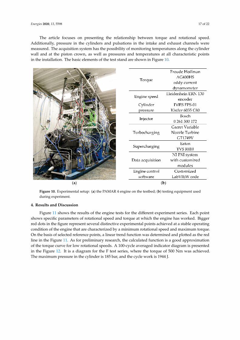
The article focuses on presenting the relationship between torque and rotational speed.Additionally, pressure in the cylinders and pulsations in the intake and exhaust channels weremeasured. The acquisition system has the possibility of monitoring temperatures along the cylinderwall and at the piston crown, as well as pressures and temperatures at all characteristic pointsin the installation. The basic elements of the test stand are shown in Figure 10.
Figure 10. Experimental setup: (a) the PAMAR 4 engine on the testbed; (b) testing equipment usedduring experiment.
4. Results and Discussion
Figure 11 shows the results of the engine tests for the different experiment series. Each pointshows specific parameters of rotational speed and torque at which the engine has worked. Biggerred dots in the figure represent several distinctive experimental points achieved at a stable operatingcondition of the engine that are characterized by a minimum rotational speed and maximum torque.On the basis of selected reference points, a linear trend function was determined and plotted as the redline in the Figure 11. As for preliminary research, the calculated function is a good approximationof the torque curve for low rotational speeds. A 100-cycle averaged indicator diagram is presentedin the Figure 12. It is a diagram for the F test series, where the torque of 500 Nm was achieved.The maximum pressure in the cylinder is 185 bar, and the cycle work is 1944 J.

Energies 2020, 13, 5598 18 of 22
Figure 11. Engine operating points achieved during tests.
Figure 12. Averaged indicator diagram for the maximal torque in F test series. The maximal pressurerise rate was about 10 bar/◦.
The conducted research allowed to update the predicted engine parameters, as shownin the Figure 13. The red points on the graph correspond to the reference points in Figure 11.On their basis, the updated torque curve was determined, which is shifted by about 80 Nm comparedto the design prediction. At the design stage, assumptions were made regarding some key parameters,which allowed to estimate the maximum torque expected in the PAMAR 4 engine. The maximumallowed pressure in the combustion chamber was assumed to be 300 bar. The preliminary assumptionsincluded the maximum compression ratio of 1:20, the maximum absolute boost pressure of 4.5 bar

Energies 2020, 13, 5598 19 of 22
provided by both the supercharger and turbocharger. Constant volume heat addition pressure ratiowas estimated to be around 3, and the maximal pressure was expected to appear 5◦ before TDC.The heat flux lost from the combustion chamber has been limited by the special design of the piston,allowing the maximum temperature at its crown at 700 ◦C and for the combustion chamber walls at600 ◦C. Basing on these parameters (solid green line on the graph), the stable operation of the enginewas to be achieved at a speed of about 400 rpm and reached the nominal value of 720 Nm at 800 rpm.The experiment has shown that these expectations can be raised, as shown by the dashed green linein the figure. The torque of 240 Nm was successfully achieved at the rotational speed of around300 rpm, which provides powerful evidence for the engine’s downspeeding capability. Taking intoaccount the maximum torque of 500 Nm obtained during the experiment with as much as 180 bar,it was found that with a very high probability the result of 800 Nm can be achieved without exceedingthe maximum allowable pressure in the cylinder.
Figure 13. Torque-speed curves of the PAMAR 4 engine. The characteristics of the tested engine forthe range of 500–3000 rpm comes from theoretical calculations. The results are compared with the datafrom OM651 engine [32] and OM654 (estimated from [34]).
The published results are primarily intended to show quantitatively how the design advantages ofPAMAR engines described in the article affect their performance. In order to refer the results obtainedon the testbed to the state of the art, they were compared with the torque curve provided by Mercedesfor the OM 651 DE 18 engine. This engine was selected due to its similar capacity, the same type ofignition and good reputation of the manufacturer.
When comparing the two power units, it should be noted that the OM651 DE18 engine wasreleased in 2011, five years earlier than the PAMAR 4. Its successor, the OM 654 engine family,was launched in 2016. It includes, among others unit OM 654 DE16 with a capacity of 1597 cm3,

Energies 2020, 13, 5598 20 of 22
which develops a maximum torque of 360 Nm. For reference, the most powerful engine in the series,the 1950 cm3 OM 654 DE20 achieves a record 500 Nm of torque and 180 kW of power [33].
The difference in the torque curve as a function of rotational speed, visible in the graphs, cannotbe explained by the time interval only. The high torque value at low rotational speed is the result ofthe advantage that the design of the barrel engine has over classic engines. The most important rolehere was played by the possibility of smooth control of the variability systems, which is not availablein the series of Mercedes engines presented in the paper.
Looking at the torque diagrams for two engines released over several years, one can clearly seethe downsizing trend towards achieving the highest possible performance from the smallest capacityunit. There is also an intention to shift the torque curve towards lower rotational speeds. PAMARengines are in line with these trends, offering torque that has not yet been achieved in any other carengine of similar capacity.
5. Conclusions and Future Work
According to the authors, the type of engine presented in this paper may be an interestingdirection in the development of internal combustion engines in the face of the threat of their completewithdrawal. The article proves that, thanks to a precise kinematic analysis, it is possible to buildan opposed piston wobble plate engine, which will not have the disadvantages historically attributedto it. Additionally, the unconventional shape of the designed engines allows for the implementationof variability systems that are the subject of research by key engine manufacturers. These systemsare: Variable Compression Ratio, Variable Angle Shift and Variable Port Area. The tests presentedin the article were carried out with various settings of these systems changed during engine operation,which proves that their control has been achieved.
The article demonstrates that the PAMAR 4 engine is able to generate significantly more torquethan a Mercedes power unit of the same capacity. It has been proven that the engine can run at verylow speeds in the range of 300–500 rpm. The maximum torque of 500 Nm achieved during the testsdoes not correspond to the nominal parameters-it was achieved at a rotational speed of only 500 rpm.The maximal torque value assumed at the design stage was 720 Nm. Due to the mechanical design ofthe engine with the maximum pressure in the combustion chamber of 300 bar and the high permissibletemperatures of the piston crown and cylinder, the test results allow the assumption that the nominalparameters will be exceeded.
The analysis of the designed engine based on theoretical calculations and the results of the researchpresented in the referenced publications shows that PAMAR engines have a chance to achievecompetitive values of mechanical and thermodynamic efficiency.
Future work on the PAMAR 4 engine will focus, among other things, on the experimentaldemonstration of the high efficiency of the engine. Torque tests for higher rotational speeds will becarried out first. Then, after installing a precision fuel flow meter on the stand, it will be possible todetermine the fuel consumption map. Subsequent tests will be carried out on new fuels, the first ofwhich will be methanol and ethanol. The research will also be carried out for the implementationof the HCCI combustion, which has already been carried out in PAMAR 3. The interest in HCCIcombustion is mainly due to its low NOx and PM emissions. For 2021 there are tests of the currentlyassembled PAMAR 5 planned, in which one of the designed systems is to be responsible for dosinggaseous fuel with different calorific values.
The advantages of barrel engines presented in the article result only from their mechanicaldesign. This means that they can be an excellent basis for further research, guaranteeing from the verybeginning a higher efficiency than engines with a classic crank mechanism. Work on further reductionof emissions can be directed-as in other engines–towards researching ecological fuels, additionalinjection of various additives (water, urea) into the combustion chamber and manifolds or the use ofcatalytic converters.

Energies 2020, 13, 5598 21 of 22
Author Contributions: Conceptualization, P.M. and B.M.; methodology, P.M., B.M.; formal analysis, B.M.;investigation, P.M.; writing—original draft preparation, B.M.; writing—review and editing, P.M.; visualization,B.M.; supervision, P.M.; project administration, P.M.; funding acquisition, P.M. All authors have read and agreedto the published version of the manuscript.
Funding: This work is a part of Applied Research Programme of the National Centre for Research and Developmentwithin the scope of applied research in industry branches (programme path B) „Badania wysokosprawnego silnikawykorzystujacego technologie HCCI do zastosowan w energetyce rozproszonej” (GENEKO)-contract numberPBS3/B4/16/2015.
Conflicts of Interest: The authors declare no conflict of interest.
Abbreviations
VCR Variable Compression RatioSI Spark IgnitionCI Compression IgnitionHCCI Homogenuous Charge Compression IgnitionCAI Controlled Auto IgnitionICCT International Council of Clean TransportationVVT Variable Valve TimingEGR Exhaust Gas RecirculationV/A Volume-Area ratioS/B Stroke to Bore ratioTDC Top Dead CenterVAS Variable Angle ShiftVPA Variable Port Angle
References
1. Wappelhorst, S. The End of the Road? An Overview of Combustion-Engine Car Phase-Out Announcementsacross Europe. ICCT. 2020. Available online: https://theicct.org/publications/combustion-engine-car-phase-out-EU (accessed on 24 August 2020).
2. Martins, J.; Brito, F.P. Alternative Fuels for Internal Combustion Engines. Energies 2020, 13, 4086. [CrossRef]3. Mazuro, P. Reciprocating Engines with Cylinder Axis Parallel to the Drive Shaft—Theory and Practice.
Ph.D. Thesis, Warsaw University of Technology, Warsaw, Poland, 2006. (In Polish).4. Yu, Z.; Lee, T.W. Kinematic Structural and Functional Analysis of Wobble-Plate Engines. ASME J. Mech.
Trans. Autom. 1986, 108, 226–236. [CrossRef]5. Kutenev, V.; Romanchev, Y.; Zlenko, M. Axial Internal Combustion Engine—Practical Prospects for the Future;
SAE Technical Paper 940204; SAE International: Pittsburgh, PA, USA, 1994. [CrossRef]6. Duke Engines. Available online: http://www.dukeengines.com (accessed on 26 August 2020).7. Covaxe. Available online: https://www.covaxe.com (accessed on 26 August 2020).8. Thompson, G.; Wowczuk, Z.; Smith, J. Rotary Engines—A Concept Review; SAE Technical Paper 2003-01-3206;
SAE International: Pittsburgh, PA, USA, 2003. [CrossRef]9. Deng, H.; Pan, C.; Wang, X.; Zhang, L.; Deng, L. Comparison of two types of twin-rotor piston engine
mechanisms. J. Cent. South Univ. 2013, 20, 363–371. [CrossRef]10. Hanipah, M.; Mikalsen, R.; Roskilly, T. Recent commercial free-piston engine developments for automotive
applications. Appl. Therm. Eng. 2013, 75, 493–503. [CrossRef]11. McLanahan, J. Barrel Aircraft Engines: Historical Anomaly or Stymied Innovation? SAE Technical Paper 985597;
SAE International: Pittsburgh, PA, USA, 1998. [CrossRef]12. Axial Internal Combustion Engines. Available online: http://www.douglasself.com/MUSEUM/POWER/
unusualICeng/axial-ICeng/axial-IC.htm#cd (accessed on 18 October 2020).13. Chown, D.; Koszewnik, J.; MacKenzie, R.; Pfeifer, D.; Callahan, B.; Vittal, M.; Froelund, K. Achieving Ultra-Low
Oil Consumption in Opposed Piston Two-Stroke Engines; SAE Technical Paper 2019-01-0068; SAE International:Pittsburgh, PA, USA, 2019. [CrossRef]
14. Mazuro, P.; Jasinski, D.; Teodorczyk, A. On the High IMEP Potential of Barrel Engines. In Proceedings ofthe PTNSS Congress, Radom, Poland, 16–17 June 2011; p. PTNSS-2011.
Energies 2020, 13, 5598 22 of 22
15. Heywood, J.B. Internal Combustion Engine Fundamentals; McGraw-Hill: New York, NY, USA, 1988.16. Woodyard, D.; Latarche, M. Pounder’s Marine Diesel Engines and Gas Turbines; Elsevier Science & Technology:
Oxford, UK, 2009.17. Asthana, S.; Bansal, S.; Jaggi, S.; Kumar, N. A Comparative Study of Recent Advancements in the Field of Variable
Compression Ratio Engine Technology; SAE Technical Paper 2016-01-0669; SAE International: Pittsburgh, PA,USA, 2016. [CrossRef]
18. Tomazic, D.; Tomazic, D.; Kleeberg, H.; Bowyer, S.; Dohmen, J.; Wittek, K.; Haake, B. Two-Stage VariableCompression Ratio (VCR) System to Increase Efficiency in Gasoline Powertrains. In Proceedings of the DEERConference, Dearborn, MI, USA, 16 October 2012.
19. Gowthaman, S.; Sathiyagnanam, A.P. Performance and Emission characteristics of Homogeneous chargecompression ignition (HCCI) engine—A review. Int. J. Ambient Energy 2016, 38, 672–684. [CrossRef]
20. Dresner, T.; Barkan, P. A Review of Variable Valve Timing Benefits and Modes of Operation; SAE Technical Paper891676; SAE International: Pittsburgh, PA, USA, 1989. [CrossRef]
21. Morton, R.; Riviere, R.; Geyer, S. Understanding Limits to the Mechanical Efficiency of Opposed Piston Engines;SAE Technical Paper 2017-01-1026; SAE International: Pittsburgh, PA, USA, 2017. [CrossRef]
22. Gao, J.; Tian, G.; Sorniotti, A.; Karci, A.; Palo, R. Review of thermal management of catalytic converters todecrease engine emissions during cold start and warm up. Appl. Therm. Eng. 2018, 147, 177–187. [CrossRef]
23. Achates Power: Industry Leading Engine Solutions. Available online: https://achatespower.com/ (accessedon 26 August 2020).
24. Khosla Ventures and Bill Gates Invest in opoc Engine Developer EcoMotors. Available online: https://www.greencarcongress.com/2010/07/opoc-20100712.html (accessed on 28 September 2020).
25. Herold, R.; Wahl, M.; Regner, G.; Lemke, J.; Foster, D.E. Thermodynamic Benefits of Opposed-Piston Two-StrokeEngines; SAE Technical Paper 2011-01-2216; SAE International: Pittsburgh, PA, USA, 2011. [CrossRef]
26. Pirault, J.-P.; Flint, M. Opposed Piston Engines—Evolution, Use and Future Applications; R-378; SAE International:Pittsburgh, PA, USA, 2010; ISBN 978-0-7680-1800-4.
27. Stroke-To-Bore Ratio: A Key to Engine Efficiency. Available online: https://achatespower.com/stroke-to-bore/
(accessed on 27 September 2020).28. Kyrtatos, A.; Spahni, M.; Hensel, S.; Züger, R.; Sudwoj, G. The Development of the Modern Low-Speed
Two-Stroke Marine Diesel Engine. In Proceedings of the CIMAC Congress, Helsinki, Finland, 6–10 June 2016;Available online: https://www.wingd.com/en/documents/general/papers/the-development-of-the-modern-2-stroke-marine-diesel-engine-(cimac).pdf/ (accessed on 28 September 2020).
29. Zhu, Y.; Savonen, C.; Johnson, N.; Amsden, A. Three-Dimensional Computations of the Scavenging Process in anOpposed-Piston Engine; SAE Technical Paper 941899; SAE International: Pittsburgh, PA, USA, 1994. [CrossRef]
30. Nieman, A. The Right Solution for Downsped Engines Dana Commercial Vehicle Technologies White Paper.Available online: https://leangreenfleet.com/documents/Dana%20Corp.%20downspeeding%20white%20paper.pdf (accessed on 28 September 2020).
31. Isenstadt, A.; German, J.; Dorobantu, M.; Boggs, D.; Watson, T. Downsized, Boosted Gasoline Engines.ICCT Working Paper. 2016. Available online: https://theicct.org/sites/default/files/publications/Downsized-boosted-gasoline-engines_working-paper_ICCT_27102016.pdf (accessed on 28 September 2020).
32. Lückert, P.; Schommers, J.; Werner, P.; Roth, T. The New Four-Cylinder Diesel Engine for the Mercedes-BenzB-class. MTZ Worldw. eMag. 2011, 72, 18–25. [CrossRef]
33. Mercedes-Benz OM 654. Available online: https://de.wikipedia.org/wiki/Mercedes-Benz_OM_654 (accessedon 27 September 2020).
34. Lückert, P.; Eder, T.; Kemmner, M.; Sass, H. OM 654—Launch of a New Engine Family by Mercedes-Benz.MTZ Worldw. 2016, 77, 60–67. [CrossRef]
Publisher’s Note: MDPI stays neutral with regard to jurisdictional claims in published maps and institutionalaffiliations.
© 2020 by the authors. Licensee MDPI, Basel, Switzerland. This article is an open accessarticle distributed under the terms and conditions of the Creative Commons Attribution(CC BY) license (http://creativecommons.org/licenses/by/4.0/).
Copyright © 2022 FDOKUMEN