Challenges and Solutions for High-Speed Aviation Piston ...
25
aerospace Review Challenges and Solutions for High-Speed Aviation Piston Pumps: A Review Chenchen Zhang, Chenhang Zhu, Bin Meng * and Sheng Li Citation: Zhang, C.; Zhu, C.; Meng, B.; Li, S. Challenges and Solutions for High-Speed Aviation Piston Pumps: A Review. Aerospace 2021, 8, 392. https://doi.org/10.3390/aerospace 8120392 Academic Editor: Khamis Essa Received: 23 November 2021 Accepted: 9 December 2021 Published: 10 December 2021 Publisher’s Note: MDPI stays neutral with regard to jurisdictional claims in published maps and institutional affil- iations. Copyright: © 2021 by the authors. Licensee MDPI, Basel, Switzerland. This article is an open access article distributed under the terms and conditions of the Creative Commons Attribution (CC BY) license (https:// creativecommons.org/licenses/by/ 4.0/). College of Mechanical Engineering, Zhejiang University of Technology, Hangzhou 310023, China; [email protected] (C.Z.); [email protected] (C.Z.); [email protected] (S.L.) * Correspondence: [email protected] Abstract: As a core power component, aviation piston pumps are widely used in aircraft hydraulic systems. The piston pump’s power-to-weight ratio is extremely crucial in the aviation industry, and the “ceiling effect” of the PV value (product of compressive stress and linear velocity) limits the piston pump’s ability to increase working pressure. Therefore, increasing the piston pump’s speed has been a real breakthrough in terms of further enhancing the power-to-weight ratio. However, the piston pump’s design faces several challenges under the extreme operating conditions at high speeds. This study reviews several problems aviation axial piston pumps face under high-speed operating conditions, including friction loss, cavitation, cylinder overturning, flow pressure pulsation, and noise. It provides a detailed description of the research state of the art of these problems and potential solutions. The axial piston pump’s inherent sliding friction pair, according to the report, considerably restricts further increasing of its speed and power-to-weight ratio. With its mature technology and deep research base, the axial piston pump will continue to dominate the aviation pumps. Furthermore, breaking the limitation of the sliding friction pair on speed and power density, thus innovating a novel structure of the piston pump, is also crucial. Therefore, this study also elaborates on the working principle and development process of the two-dimensional (2D) piston pump, which is a representative of current high-speed pump structure innovation. Keywords: aviation piston pump; friction pair; cavitation; cylinder overturning; pulsation; noise; 2D piston pump 1. Introduction The aviation hydraulic pump is the core of an aircraft’s hydraulic system, converting mechanical energy into hydraulic energy to power aircraft actuators such as altitude control, landing gear retraction, and braking. The axial piston pump fits the development and application needs of airborne hydraulic power sources that require high power-to- weight ratio owing to its compact structure, high pressure, high speed, and large flowrate. Therefore, it is widely used in aircraft hydraulic systems. The current design and manufacturing technology for aviation piston pumps in China lags behind the needs of rapid aircraft development, particularly in the civil aircraft industry. The focus is on resolving “stuck neck” technology and where only foreign products, which are expensive and have a long supply cycle, may be used. As a result, mastering the key design theory and technology of the aircraft piston pump is crucial to implementing localization and import substitution. Aviation piston pumps have superior high-speed and power-to-weight ratio characteristics as compared to those of industrial axial piston pumps. The rated speed of industrial piston pumps is generally 1500 r/min, while the operating speed of aviation piston pumps exceeds 3000 r/min. For example, the average speed of the high-speed aviation pumps provided by Parker Hannifin for Airbus and Boeing exceeds 3500 r/min, and some aviation piston pumps can reach 22,500 r/min [1]. Furthermore, industrial piston pump housings are usually made of cast iron, but aviation Aerospace 2021, 8, 392. https://doi.org/10.3390/aerospace8120392 https://www.mdpi.com/journal/aerospace
-
Upload
khangminh22 -
Category
Documents
-
view
1 -
download
0
Transcript of Challenges and Solutions for High-Speed Aviation Piston ...
aerospace
Review
Challenges and Solutions for High-Speed Aviation PistonPumps: A Review
Chenchen Zhang, Chenhang Zhu, Bin Meng * and Sheng Li
�����������������
Citation: Zhang, C.; Zhu, C.; Meng,
B.; Li, S. Challenges and Solutions for
High-Speed Aviation Piston Pumps:
A Review. Aerospace 2021, 8, 392.
https://doi.org/10.3390/aerospace
8120392
Academic Editor: Khamis Essa
Received: 23 November 2021
Accepted: 9 December 2021
Published: 10 December 2021
Publisher’s Note: MDPI stays neutral
with regard to jurisdictional claims in
published maps and institutional affil-
iations.
Copyright: © 2021 by the authors.
Licensee MDPI, Basel, Switzerland.
This article is an open access article
distributed under the terms and
conditions of the Creative Commons
Attribution (CC BY) license (https://
creativecommons.org/licenses/by/
4.0/).
College of Mechanical Engineering, Zhejiang University of Technology, Hangzhou 310023, China;[email protected] (C.Z.); [email protected] (C.Z.); [email protected] (S.L.)* Correspondence: [email protected]
Abstract: As a core power component, aviation piston pumps are widely used in aircraft hydraulicsystems. The piston pump’s power-to-weight ratio is extremely crucial in the aviation industry, andthe “ceiling effect” of the PV value (product of compressive stress and linear velocity) limits thepiston pump’s ability to increase working pressure. Therefore, increasing the piston pump’s speedhas been a real breakthrough in terms of further enhancing the power-to-weight ratio. However,the piston pump’s design faces several challenges under the extreme operating conditions at highspeeds. This study reviews several problems aviation axial piston pumps face under high-speedoperating conditions, including friction loss, cavitation, cylinder overturning, flow pressure pulsation,and noise. It provides a detailed description of the research state of the art of these problems andpotential solutions. The axial piston pump’s inherent sliding friction pair, according to the report,considerably restricts further increasing of its speed and power-to-weight ratio. With its maturetechnology and deep research base, the axial piston pump will continue to dominate the aviationpumps. Furthermore, breaking the limitation of the sliding friction pair on speed and power density,thus innovating a novel structure of the piston pump, is also crucial. Therefore, this study alsoelaborates on the working principle and development process of the two-dimensional (2D) pistonpump, which is a representative of current high-speed pump structure innovation.
Keywords: aviation piston pump; friction pair; cavitation; cylinder overturning; pulsation; noise; 2Dpiston pump
1. Introduction
The aviation hydraulic pump is the core of an aircraft’s hydraulic system, convertingmechanical energy into hydraulic energy to power aircraft actuators such as altitudecontrol, landing gear retraction, and braking. The axial piston pump fits the developmentand application needs of airborne hydraulic power sources that require high power-to-weight ratio owing to its compact structure, high pressure, high speed, and large flowrate.Therefore, it is widely used in aircraft hydraulic systems.
The current design and manufacturing technology for aviation piston pumps in Chinalags behind the needs of rapid aircraft development, particularly in the civil aircraft industry.The focus is on resolving “stuck neck” technology and where only foreign products, whichare expensive and have a long supply cycle, may be used. As a result, mastering thekey design theory and technology of the aircraft piston pump is crucial to implementinglocalization and import substitution. Aviation piston pumps have superior high-speedand power-to-weight ratio characteristics as compared to those of industrial axial pistonpumps. The rated speed of industrial piston pumps is generally 1500 r/min, while theoperating speed of aviation piston pumps exceeds 3000 r/min. For example, the averagespeed of the high-speed aviation pumps provided by Parker Hannifin for Airbus andBoeing exceeds 3500 r/min, and some aviation piston pumps can reach 22,500 r/min [1].Furthermore, industrial piston pump housings are usually made of cast iron, but aviation
Aerospace 2021, 8, 392. https://doi.org/10.3390/aerospace8120392 https://www.mdpi.com/journal/aerospace
Aerospace 2021, 8, 392 2 of 25
piston pump housings are typically made of aluminum alloy to increase the power-to-weight ratio. Furthermore, the piston pump’s pressure pulsation and mechanical vibrationmust be as low as possible to ensure high reliability in aircraft hydraulic systems. Militaryaircraft require pressure pulsation within ±10%. To ensure reliability, the piston pumphas considerable structural strength requirements because the NVH (noise, vibration,harshness) gets worse at high speeds [1].
Due to the extreme power-to-weight ratio demands in the aviation field, the aviationpiston pump inherently tends toward high-speed development, and the increase in workingpressure is limited by the “ceiling effect” of the PV value (product of pressure and velocity).For designers, the crucial issue is whether or not the aviation piston pump can maintain itsworking efficiency under high pressure and speed conditions. To improve mechanical andvolumetric efficiencies at high speeds, the friction and leakage losses of the friction pairneed to be decreased as much as possible. However, high speeds have caused challengesin the design and operation of the piston pump. Moreover, the centrifugal force of thepiston and slipper increases sharply, which changes the resultant force and affects thebearing characteristic of the oil film. The dynamic pressure effect of the oil film increases athigh speeds, which impacts the oil film thickness of the hydrostatic support of the valveand slipper–swashplate pairs. Moreover, the rise in the centrifugal force of the pistonand the slipper may cause the slipper and the cylinder block to overturn. In addition,high rotational speeds also lead to adverse effects such as cavitation, flow pulsation,pressure pulsation, and noise. The aforementioned problems influence the volumetricand mechanical efficiencies of the piston pump, causing failure of the piston pump insevere cases. Therefore, this article reviews several technical challenges that aviation pistonpumps endure at high speeds, including friction loss, cavitation, cylinder overturning, flowpressure pulsation, and noise. It also describes the current research status of global scholarsin these fields and summarizes the potential solutions to these challenges. In addition, theworking principle and development process of a typical two-dimensional piston pump inthe existing high-speed pump structure innovation are also elaborated.
2. Friction Pairs2.1. Overview
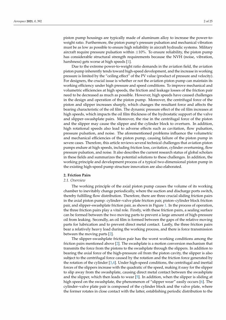
The working principle of the axial piston pump causes the volume of its workingchamber to inevitably change periodically, where the suction and discharge ports switch,thereby fulfilling flow distribution. Therefore, there are three crucial sliding friction pairsin the axial piston pump: cylinder–valve plate friction pair, piston–cylinder block frictionpair, and slipper–swashplate friction pair, as shown in Figure 1. In the process of operation,the three friction pairs play a vital role. Firstly, with these friction pairs, a sealing surfacecan be formed between the two moving parts to prevent a large amount of high-pressureoil from leaking. Secondly, an oil film is formed between the gaps of the relative movingparts for lubrication and to prevent direct metal contact. Lastly, the three friction pairsbear a relatively heavy load during the working process, and there is force transmissionbetween the moving parts [2].
The slipper–swashplate friction pair has the worst working conditions among thefriction pairs mentioned above [2]. The swashplate is a motion conversion mechanism thattransmits the force from the pistons to the swashplate through the slippers. In addition tobearing the axial force of the high-pressure oil from the piston cavity, the slipper is alsosubject to the centrifugal force caused by the rotation and the friction force generated bythe rotation of the cylinder [3,4]. Under high-speed conditions, the centrifugal and inertialforces of the slippers increase with the quadratic of the speed, making it easy for the slipperto slip away from the swashplate, causing direct metal contact between the swashplateand the slipper, which then leads to wear [5]. In addition, when the slipper is sliding athigh speed on the swashplate, the phenomenon of “slipper wear” easily occurs [6]. Thecylinder–valve plate pair is composed of the cylinder block and the valve plate, wherethe former rotates in close contact with the latter, establishing periodic distribution to the

Aerospace 2021, 8, 392 3 of 25
oil suction and oil discharging. The cylinder–valve plate pair is the friction pair with thelargest single structure and the largest mating area in the axial piston pump, and its leakageoccupies more than one-half of the total leakage of the pump [7]. The piston–cylinderblock pair is composed of the piston and the cylinder, where the piston reciprocates in thecylinder block, causing the volume of the piston cavity to periodically change to completethe process of oil suction and discharging [8].
Figure 1. Schematic diagram of three friction pairs of the axial piston pump. 1. Valve plate. 2. Cylinder.3. Piston. 4. Slipper. 5. Swashplate. 6. Transmission shaft.
2.2. Research Progress
The oil film of the friction pair is a key feature of the piston pump design, which has asignificant impact on the friction pair’s working performance. If the oil film is too thin ornot formed, the friction pair is easy to wear and even fail. On the contrary, if the oil filmis too thick, the leakage will increase, which results in a decrease in volumetric efficiencyand even inability to transmit force. In addition, the oil temperature is a primary factoraffecting the lubrication performance, changing the oil’s viscosity and, thus, affecting thepressure distribution and load capacity [9]. In order to ensure the high power-to-weightratio of the aviation piston pump and reduce leakage and wear, the thickness and pressuredistribution of the oil film has become a research hotspot. For example, Hooke et al.built two noncontinuous measurement devices for the oil film of the slipper–swashplatepair. Results showed that the thickness of the oil film measured inside the slipper wassmaller than that of the outside, and it was prone to overturn inward. Moreover, underthe action of an eccentric load, the slipper with an orifice would overturn to some extents,resulting in a minor oil film thickness, which is prone to wear [10–12]. The thickness ofthe oil film is also closely related to the working pressure of the piston pump. When theworking pressure increases, the force acting on the piston also increases, and the oil filmthickness is smaller when the load between the friction pairs is significant. Harris et al.used the Bathfp simulation tool to predict the oil film thickness of the slipper–swashplatepair at different speeds and found that the oil film thickness in the high-pressure zonewas smaller than that in the low-pressure zone [13]. Using modeling, Ivantysynova et al.claimed that the oil film thickness of the slipper in the low-pressure area is great, andit is more sensitive to the overturning torque, where overturning is more likely to occurunder high-speed conditions [14,15]. They also studied the thermal elasto-hydrodynamiceffect of the friction pair and obtained the thickness field distribution of the friction pairoil film after considering the thermal elasto-hydrodynamic effect [16–20]. In addition,they established a thermo-fluid–solid coupling model of the piston–cylinder block pairto obtain the temperature and pressure distribution of the oil film of the piston–cylinderblock pair [21–24]. Manring et al. analyzed the force of the high-speed slipper and pistonand claimed that the overturning phenomenon of the slipper appeared most seriously in
Aerospace 2021, 8, 392 4 of 25
the high–low-pressure transition zone [25–27]. It was also pointed out that the overturningtorque came from the centrifugal force and the reciprocating inertial force of the piston,and the overturning of the rotating component affected the operational performance of thepiston pump or even failed [28]. Xu et al. established a rigid body model of the slipper andobtained the pressure field and thickness field of the oil film of the slipper. It was proventhat the centrifugal and frictional torques of the slipper were the main causes of the slipperoverturning, and the overturning degree of the slipper was the largest in the transition areaof oil suction and discharge [29,30]. Wang et al. used numerical and analytical methods tosolve the dynamic pressure distribution of the oil film at the sealing zone [31,32]. UsingHertz theory and the Reynolds equation, they revealed the whole lubrication process ofthe port pair from full lubrication to mixed lubrication to wear [33].
Aiming at the wear issue of the sliding friction pair under high-speed conditions,the improvements proposed by the researchers are mainly divided into several aspects.The first approach is to optimize the size of the slippers. The load-carrying capacity ofthe slipper–swashplate pair can be improved without changing the slipper’s structureand by optimizing its key dimensions, such as the diameter and length of the dampinghole and the radius of the sealing band. Xu et al. analyzed the dynamic characteristics ofthe wedge-shaped oil film of the slipper–swashplate pair under isothermal conditions [5].They concluded that appropriately increasing the slipper sealing belt and measuring theappropriate chamfering inside the slipper sealing belt could improve the load-bearingcapacity of the sliding slipper pair and anti-overturning ability. Furthermore, this methodcould also successfully solve the “slipper wear” problem of slipper–swashplate pairs [34].Fu and Tang improved the bearing capacity of the slipper–swashplate pair by optimizingthe diameter and length of the orifice of the slipper and the radius of the oil chamber,thereby offsetting the overturning torque [35,36].
The second approach is the novel structure of the sliding friction pair. Kim et al.compared the lubrication characteristics of the spherical port pair and the plane port pairsboth with and without auxiliary support. It was confirmed that the spherical port pairhas the best effect in improving the lubrication [37]. Kakoullis et al. used a back-coatedstructure of the ball head and piston ball socket of the slipper to reduce the centrifugaloverturning torque of the slipper by reducing the distance from the center of mass of theslipper to the center of the ball hinge [38]. Liu et al. proposed a multicavity-independentsupport slipper to improve the anti-overturning ability of the slipper, thereby avoiding thephenomenon of partial wear of the slipper [39].
The third approach is to improve the surface micromorphology of the sliding frictionpair. Improving the surface micromorphology of the friction pair can enhance the pressurefield distribution of the friction pair. Beale et al. designed an ideal microscopic appearanceof the bottom surface of the slipper, whose shape is slightly convex to improve the pressurefield distribution of the slipper–swashplate pair [40]. Nanocoating on the slipper anddiamond coating were also used in order to reduce the friction coefficient of the slipper–swashplate pair and improve its antifriction ability [41–43]. Murrenhoff et al. proposed aspecial coating on the surface of the friction pair to reduce the surface friction coefficient toenhance its wear resistance and decrease friction loss [44–46]. The surface texture of thefriction pair can also reduce the wear. Deng et al. claimed that micropits on the surface ofthe cylinder–valve plate pair could reduce the friction coefficient [47], which was verifiedthrough numerical analysis. Ivantysynova et al. [48,49] applied the wavy surface texture tothe surface of the cylinder sealing belt and the valve plate, and Manring et al. [50] appliedthe ellipsoid surface texture to the surface of the valve plate, both of which achievedsatisfied results.
In summary, the sliding friction pair is the main factor restricting the further im-provement of axial piston pump’s speed and power-to-weight ratio. The abovementionedmethods can all reduce the wear of the sliding friction pair. The performance of slidingslippers can be improved in a certain range of working conditions after reasonable struc-tural optimization, but it is still difficult to meet the operating conditions of the aviation
Aerospace 2021, 8, 392 5 of 25
pump in a wide range of speeds. The lubrication effect can also be improved using a novelsliding friction pair configuration, but the manufacturing process of a spherical port pair ismore complicated than that of its planar counterpart. The surface texture of the frictionpair is currently a worldwide research hotpot. The development of new coating materialsand micro-texture configurations can also reduce the friction coefficient. However, theseapproaches have not changed the inherent nature of the sliding friction pair that has ahigh frictional coefficient and is prone to wear at high speeds. For the pump design, if thesliding friction pair can be replaced by a rolling friction pair, it is expected to significantlyreduce the friction coefficient and wear.
3. Cavitation3.1. Overview
Pump cavitation refers to the phenomenon that, when the oil pressure inside thepump drops to the air separation pressure, a large amount of air dissolved in the oil beginsto precipitate to form bubbles or cavities [51]. According to Bernoulli’s law, a higheroperating speed of the hydraulic pump leads to lower pressure during the suction process;hence, the aviation piston pump is more likely to cause cavitation at high speed. Airbubbles destroy the continuity of oil suction and discharge of the piston pump, therebyreducing the volumetric efficiency of the piston pump [52,53]. The instantaneous impactforce generated by bubble collapse has a tremendous destructive effect on the pump’smechanical components. The free bubbles decrease the elastic modulus of the oil andfurther affect the internal pressure of the piston cavity [54]. Cavitation seriously reducesthe working efficiency and stability of the piston pump, resulting in severe vibrationand noise.
The origin of cavitation can be divided into three situations [55]. The first one occursat the oil suction stage. When the piston is pulled out of the piston cavity, the increasedvoid volume in the sealed cavity of the cylinder requires sufficient oil to flow inside andfill. When the filled oil flows into the port window of the valve plate from the pump inlet,the pump’s inlet pressure needs to be consumed to compensate for the partial throttlingloss [56–58]. Moreover, when the hydraulic oil flows into the flow channel, the pump’sinlet pressure is also needed to supplement the loss along parallel pipe and local loss.Under high-speed conditions, the pump’s inlet pressure is not sufficient to make up forthe above losses, resulting in the piston cavity not being filled with oil in time, therebycausing cavitation [59]. The second one occurs in the pre-boost and pre-depressurizationphase of the piston cavity. Due to the pressure difference between the two ends of thedamping groove of the valve plate, oil backflow occurs. Such flow forms a high-speed jet,which induces cavitation [60–62]. Tsukiji et al. used a high-speed camera to observe thehigh-speed jet near the damping groove of the valve plate. Cavitation was detected nearthe damping groove, which confirmed that high-speed jets would cause cavitation [63].The third type of cavitation is caused by centrifugal force. At the oil suction stage, thecentrifugal force tends to push the “heavy” hydraulic oil to the outer wall of the pistoncavity and then leave “light” air bubbles on the inner wall. While at the oil discharge stage,due to the high pressure in the piston cavity, the local pressure drop resulting from thecentrifugal effect is insufficient to cause cavitation [52,64]. Chao et al. established a CFDmodel of the EHA (electro-hydrostatic actuator) axial piston pump to study the influenceof the centrifugal effect on the cavitation of the piston cavity [65]. The results revealed thatthe closer the piston cavity is to the rotation center of the cylinder, the smaller the localpressure is, and the more liable it is for cavitation to occur.
3.2. Research Progress
In order to suppress the cavitation phenomenon of the axial piston pump, variousfeasible solutions have been proposed. Increasing the inlet pressure of the piston pump isa common approach to ensure that the piston cavity is fully supplied with oil in time, aswell as to reduce both the jet velocity and the pressure difference between the two ends
Aerospace 2021, 8, 392 6 of 25
of the damping groove of the valve plate [56,66,67]. One method to increase the pump’sinlet pressure is to provide a centrifugal booster turbine at the suction port, as shown inFigure 4. The centrifugal supercharger turbine gives a boost compensation pressure tothe suction port of the pump. This pressure increases with the increase in pump speed,which can compensate for the suction pressure drop under high-speed conditions [68,69].However, an extra turbine would inevitably reduce the pump’s power density. Anothermethod is to use a pressurized tank in the primary hydraulic system of the aircraft [68].When the pump works, the high-pressure oil enters the pressurization chamber of the tank.Under the action of the boost pressure, the oil tank piston moves to the oil storage chamber,thereby performing boost pressure. The piston continuously reciprocates accordingly sothat the oil storage chamber maintains a constant pressure to meet the needs of the inletpressure of the hydraulic pump [70].
The second approach is to reduce the pressure loss during the suction process. Thepreferred solutions are either to optimize the oil suction channel [71] or to apply a sphericalport plate pair instead of its planar counterpart [72,73]. When oil flows from the pumpsuction port to the piston cavity, the curved suction channel can reduce the pressure loss bymore than 50% [74]. Moreover, according to Bernoulli’s law, reducing the circumferentialspeed of the cylinder is also effective to reduce the pressure loss. The decrease in speedresults in a decrease in kinetic energy. Since the sum of kinetic energy, gravitationalpotential energy, and pressure energy is constant, the pressure energy increases, therebyreducing pressure loss [27]. For piston pumps with the same displacement, the radius ofthe distribution circle of the waist groove of the spherical port plate pair is smaller than thatof the plane counterpart. Therefore, the tangential velocity of the oil entering the pistoncavity and pressure loss can be reduced. Bügener and Heiduser proposed to rotate thedirection of the suction port downward by 90◦, as shown in Figure 5. The suction pressureloss is reduced by aligning the oil flow direction with the direction of the tangential velocityof the cylinder. However, this method is only suitable for single-acting pumps, not fordouble-acting pumps [75]. Ji et al. used a genetic algorithm to optimize the flow channel ofthe valve plate and the structural size of the cylinder’s waist groove to suppress the pistonpump’s cavitation and achieved remarkable results [76].
The third approach is to reduce the oil backflow. Reducing the oil backflow of thepiston cavity in the pre-boost and pre-depressurization phase can inhibit the occurrenceof cavitation. An effective method is to optimize the shape of the valve plate, which canreduce the oil backflow by decreasing the pressure difference between the two ends of thevalve plate damping groove. Mandal et al. considered the compressibility and inertia ofthe oil and optimized the pre-compression angle of the valve plate and the wrap angleof the waist groove of the cylinder. Then, the best combination of the pre-compressionangle and the waist groove was determined. Such a combination can not only minimizeoil backflow and pulsation, but also avoid cavitation during the optimization processby setting a dual-parameter objective function [77]. Berta et al. found that, when thepre-boost angle increased, the flow rate of the piston cavity would gradually decrease [78].Edge et al. proposed a method called the “pre-expansion volume”, shown in Figure 2.By designing a closed pre-expansion cavity (PEV) in the transition area between the oilsuction waist groove of the valve plate and the cylinder waist groove, the pressure of thepiston cavity can be smoothly transitioned to the oil suction pressure to avoid oil backflownear the inner dead center of the piston cavity [79]. Similarly, Pettersson et al. proposeda pre-compression cavity (PCFV) method to avoid oil backflow in the piston cavity nearthe outer dead center [80]. There are other approaches to suppress cavitation. Tsukiji et al.found that increasing the number of damping grooves at the valve plate can reduce thecavitation area at the waist groove of the cylinder [63]. Liu et al. suggested that an orificeat the outlet of the damping slot should be machined to avoid cavitation damage causedby the high-speed jet at the damping slot sticking to either the surface of the valve plate orthe inner wall of the piston cavity [81], as shown in Figure 3. Chao et al. studied the effect

Aerospace 2021, 8, 392 7 of 25
of the tilting direction of the cylinder port on cavitation and suggested that this methodcan effectively utilize the centrifugal effect from oil rotation to reduce cavitation [82].
Figure 2. Pre-expansion cavity (Obtained from [83]).
Figure 3. Orifice (Obtained from [83]).
Figure 4. Supercharger turbine (Obtained from [83]).
Aerospace 2021, 8, 392 8 of 25
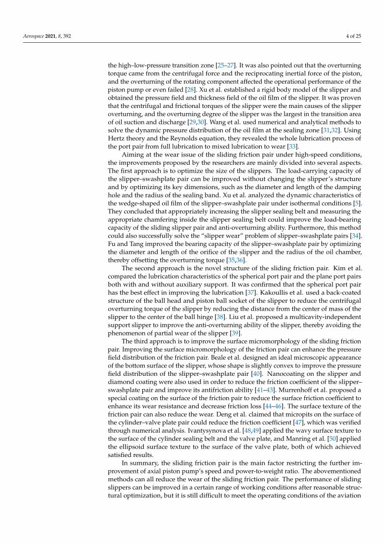
Figure 5. Drag reduction runner (Obtained from [83]).
In summary, the use of supercharged turbines and pressurized oil tanks is the standardapproach to suppress cavitation, but adding additional devices influences the power-to-weight ratio of the pump. Optimizing the suction channel and using a spherical port platepair can reduce the pressure loss in the suction process. However, offsetting the suctionport is only suitable for single-acting pumps, and manufacturing a spherical port platepair is both expensive and cumbersome. Optimizing the valve plate and using pressurepre-increasing or pressure pre-decreasing can reduce the oil backflow, thereby effectivelysuppressing the cavitation, but this is highly dependent on the operating conditions of thepiston pump. In general, the demands for high speed and high power-to-weight ratio ofaviation piston pumps are in conflict with the existing techniques of suppressing cavitation;thus, it is difficult to achieve them in the short term.
4. Cylinder Overturning4.1. Overview
The rotating components of the aviation piston pump mainly include the cylinderblock, piston, and slippers. When the piston pump rotates at high speed, the centrifugalforce and inertial force of the piston–slipper assembly increase with the quadratic power ofthe rotation speed, which causes the cylinder body to tilt. The bending torque caused bythe cylinder body tilt acts on the pump shaft, causing large deflection and deformation ofthe pump shaft and even fracture or failure [1].
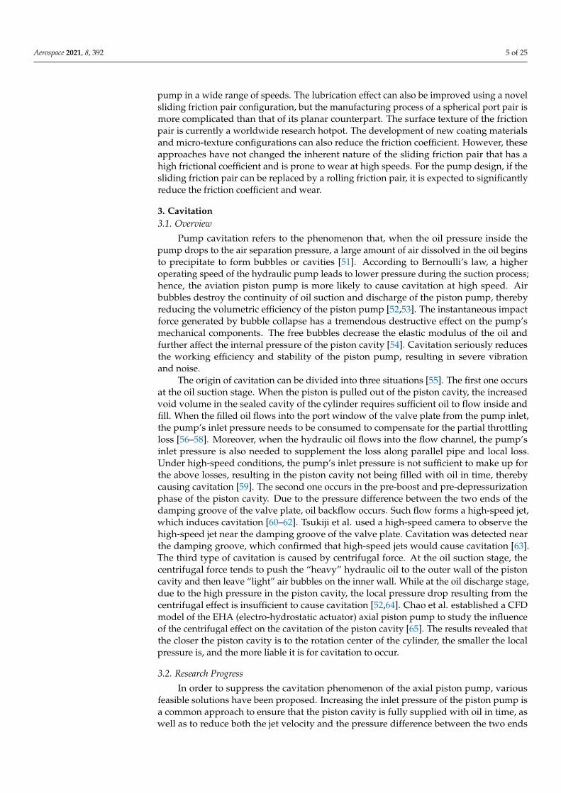
As shown in Figure 6, the centrifugal force generated by the piston–slipper–cylinderblock assembly at high speeds acts on the cylinder block to produce an overturningtorque on the cylinder block [84,85]. The inclination of the cylinder block causes unevendistribution of the oil film thickness of the port pair, which forms a wedge-shaped oil film.The minimum thickness of the oil film is prone to rupture, which leads to contact wearbetween the valve plate and the cylinder. When the speed is too high, the temperature ofthe oil film rises, and its viscosity decreases, which also results in the wear of the frictionpair surface. With the increase in temperature, the flow-distribution plate locally generatesa large amount of heat; therefore, the so-called “plate wear” phenomenon occurs. Therefore,people researched the tilting movement and failure mechanism of the cylinder. Wegner et al.established a simulation model of the friction pair contact and tested the cylinder–valveplate pair’s micromotion and friction torque through experiments. The results showedthat the cylinder block and the valve plate were prone to metal contact at the thinnest partof the oil film [86,87]. Wieczorek et al. analyzed the microscopic pressure distributionbetween the cylinder block and the valve plate and claimed that the asymmetric pressuredistribution in the suction and discharge chamber caused the cylinder block to tilt tothe high-pressure side [88]. In addition, by establishing an elasto-hydro-dynamic model

Aerospace 2021, 8, 392 9 of 25
to calculate the cylinder–valve plate pair’s oil film thickness field analysis, they foundthat the difference between the cylinder block’s inner and outer dead center directionswas insignificant, where there was no obvious tilting movement. However, the tiltingmovement along the high-pressure side was apparent. Manring pointed out that thecylinder was tilted under various conditions. Through the mathematical modeling of thecylinder block tilt, Hooke et al. analyzed the cause of the cylinder block overturning andproposed a solution to prevent the cylinder block of the piston pump from overturningunder high-speed rotation [89]. Wang et al. used the relaxation iteration method and finitedifference method to study the wedge-shaped oil film thickness, temperature, and pressuredistribution of the axial piston pump cylinder–valve plate pair. They also compared andanalyzed the lubrication characteristics of the cylinder in the tilted and non-tilted stateand pointed out that the oil film thickness varied when the cylinder was tilted relativeto the valve plate. In addition, the structural parameters of the valve plate affect thelubrication characteristics [90,91]. From a structural perspective, since the cylinder blockand the main shaft are connected by splines, the assembly gap between the two allows thecylinder block to move along the Z-axis and rotate around the X-axis and Y-axis with amicroscopic angle [86,87,92]. Zhang et al. found that, when the rotation speed was too high,the centrifugal torque of the piston–cylinder assembly caused the cylinder to tilt extremelytoward the outer dead center of the valve plate, which increased the possibility of flowleakage between the cylinder–valve plate pairs and metal contact between the cylinder andthe valve plate [93]. In addition, the size and geometric errors of the cylinder block androtating components also aggravated the overturning torque of the cylinder block [94,95].Therefore, to ensure the excellent performance, it is necessary to control the dimensionalerror and geometric error of the cylinder and rotating components.
Figure 6. Tilting movement of the cylinder due to centrifugal effect (Obtained from [64]).
4.2. Research Progress
To restrain the overturning movement of the cylinder block of the axial pistonpump under high-speed conditions and reduce the adverse effect of cylinder block over-turning on the performance of the piston pump, researchers have proposed severalimprovement approaches.
The first one is to improve the support condition of the cylinder. This approach canreduce the overturning torque acting on the cylinder. Monika et al. proposed to install
Aerospace 2021, 8, 392 10 of 25
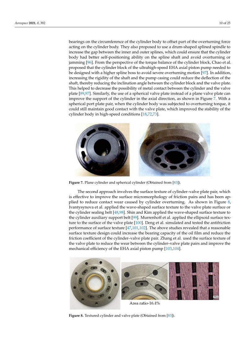
bearings on the circumference of the cylinder body to offset part of the overturning forceacting on the cylinder body. They also proposed to use a drum-shaped splined spindle toincrease the gap between the inner and outer splines, which could ensure that the cylinderbody had better self-positioning ability on the spline shaft and avoid overturning orjamming [96]. From the perspective of the torque balance of the cylinder block, Chao et al.proposed that the cylinder block of the ultrahigh-speed EHA axial piston pump needed tobe designed with a higher spline boss to avoid severe overturning motion [97]. In addition,increasing the rigidity of the shaft and the pump casing could reduce the deflection of theshaft, thereby reducing the inclination angle between the cylinder block and the valve plate.This helped to decrease the possibility of metal contact between the cylinder and the valveplate [89,97]. Similarly, the use of a spherical valve plate instead of a plane valve plate canimprove the support of the cylinder in the axial direction, as shown in Figure 7. With aspherical port plate pair, when the cylinder body was subjected to overturning torque, itcould still maintain good contact with the valve plate, which improved the stability of thecylinder body in high-speed conditions [18,72,73].
Figure 7. Plane cylinder and spherical cylinder (Obtained from [83]).
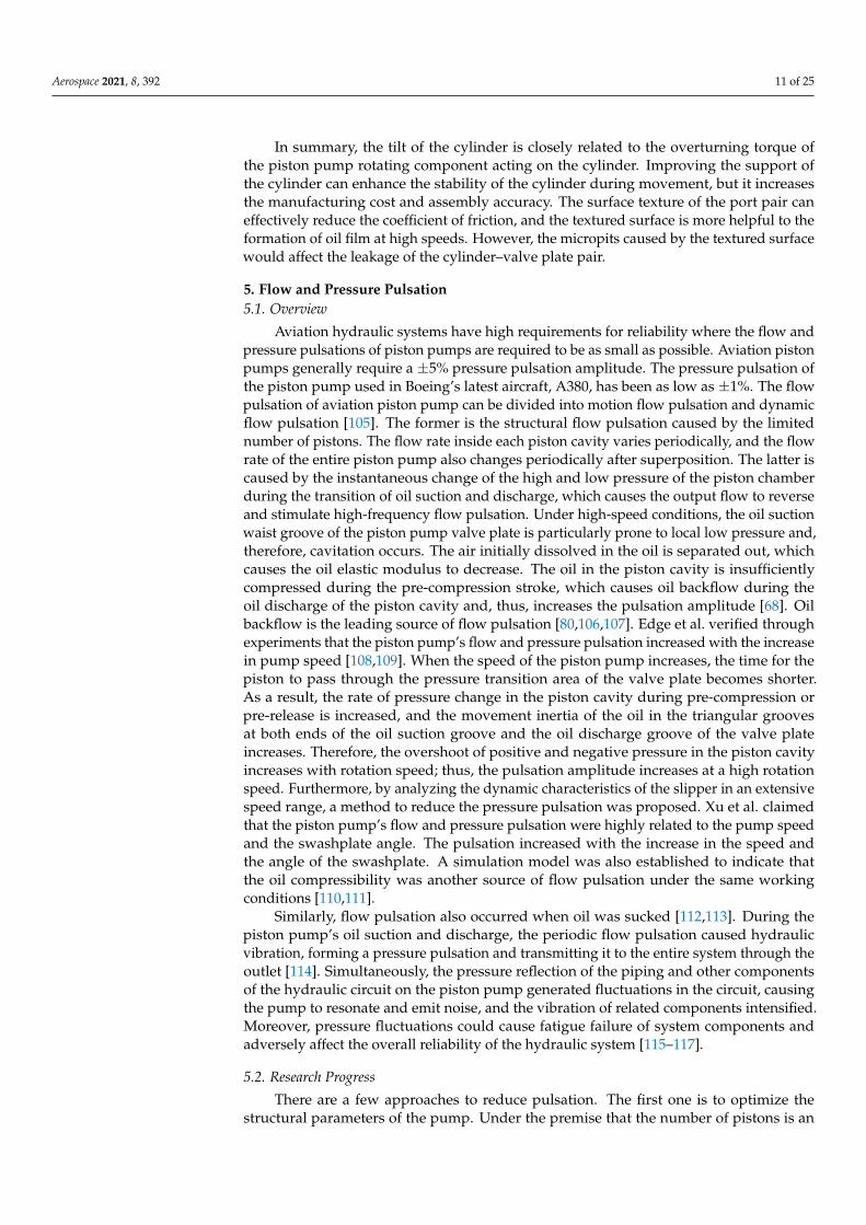
The second approach involves the surface texture of cylinder–valve plate pair, whichis effective to improve the surface micromorphology of friction pairs and has been ap-plied to reduce contact wear caused by cylinder overturning. As shown in Figure 8,Ivantysynova et al. applied the wave-shaped surface texture to the valve plate surface orthe cylinder sealing belt [48,98]. Shin and Kim applied the wave-shaped surface texture tothe cylinder auxiliary support belt [99]. Murrenhoff et al. applied the ellipsoid surface tex-ture to the surface of the valve plate [100]. Deng et al. simulated and tested the antifrictionperformance of surface texture [47,101,102]. The above studies revealed that a reasonablesurface texture design could increase the bearing capacity of the oil film and reduce thefriction coefficient of the cylinder–valve plate pair. Zhang et al. used the surface texture ofthe valve plate to reduce the wear between the cylinder–valve plate pairs and improve themechanical efficiency of the EHA axial piston pump [103,104].
Figure 8. Textured cylinder and valve plate (Obtained from [83]).
Aerospace 2021, 8, 392 11 of 25
In summary, the tilt of the cylinder is closely related to the overturning torque ofthe piston pump rotating component acting on the cylinder. Improving the support ofthe cylinder can enhance the stability of the cylinder during movement, but it increasesthe manufacturing cost and assembly accuracy. The surface texture of the port pair caneffectively reduce the coefficient of friction, and the textured surface is more helpful to theformation of oil film at high speeds. However, the micropits caused by the textured surfacewould affect the leakage of the cylinder–valve plate pair.
5. Flow and Pressure Pulsation5.1. Overview
Aviation hydraulic systems have high requirements for reliability where the flow andpressure pulsations of piston pumps are required to be as small as possible. Aviation pistonpumps generally require a ±5% pressure pulsation amplitude. The pressure pulsation ofthe piston pump used in Boeing’s latest aircraft, A380, has been as low as ±1%. The flowpulsation of aviation piston pump can be divided into motion flow pulsation and dynamicflow pulsation [105]. The former is the structural flow pulsation caused by the limitednumber of pistons. The flow rate inside each piston cavity varies periodically, and the flowrate of the entire piston pump also changes periodically after superposition. The latter iscaused by the instantaneous change of the high and low pressure of the piston chamberduring the transition of oil suction and discharge, which causes the output flow to reverseand stimulate high-frequency flow pulsation. Under high-speed conditions, the oil suctionwaist groove of the piston pump valve plate is particularly prone to local low pressure and,therefore, cavitation occurs. The air initially dissolved in the oil is separated out, whichcauses the oil elastic modulus to decrease. The oil in the piston cavity is insufficientlycompressed during the pre-compression stroke, which causes oil backflow during theoil discharge of the piston cavity and, thus, increases the pulsation amplitude [68]. Oilbackflow is the leading source of flow pulsation [80,106,107]. Edge et al. verified throughexperiments that the piston pump’s flow and pressure pulsation increased with the increasein pump speed [108,109]. When the speed of the piston pump increases, the time for thepiston to pass through the pressure transition area of the valve plate becomes shorter.As a result, the rate of pressure change in the piston cavity during pre-compression orpre-release is increased, and the movement inertia of the oil in the triangular groovesat both ends of the oil suction groove and the oil discharge groove of the valve plateincreases. Therefore, the overshoot of positive and negative pressure in the piston cavityincreases with rotation speed; thus, the pulsation amplitude increases at a high rotationspeed. Furthermore, by analyzing the dynamic characteristics of the slipper in an extensivespeed range, a method to reduce the pressure pulsation was proposed. Xu et al. claimedthat the piston pump’s flow and pressure pulsation were highly related to the pump speedand the swashplate angle. The pulsation increased with the increase in the speed andthe angle of the swashplate. A simulation model was also established to indicate thatthe oil compressibility was another source of flow pulsation under the same workingconditions [110,111].
Similarly, flow pulsation also occurred when oil was sucked [112,113]. During thepiston pump’s oil suction and discharge, the periodic flow pulsation caused hydraulicvibration, forming a pressure pulsation and transmitting it to the entire system through theoutlet [114]. Simultaneously, the pressure reflection of the piping and other componentsof the hydraulic circuit on the piston pump generated fluctuations in the circuit, causingthe pump to resonate and emit noise, and the vibration of related components intensified.Moreover, pressure fluctuations could cause fatigue failure of system components andadversely affect the overall reliability of the hydraulic system [115–117].
5.2. Research Progress
There are a few approaches to reduce pulsation. The first one is to optimize thestructural parameters of the pump. Under the premise that the number of pistons is an
Aerospace 2021, 8, 392 12 of 25
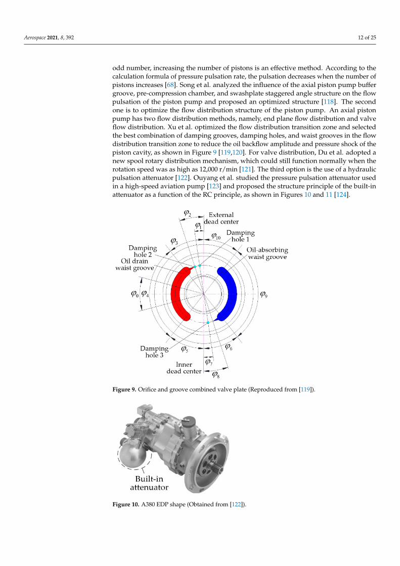
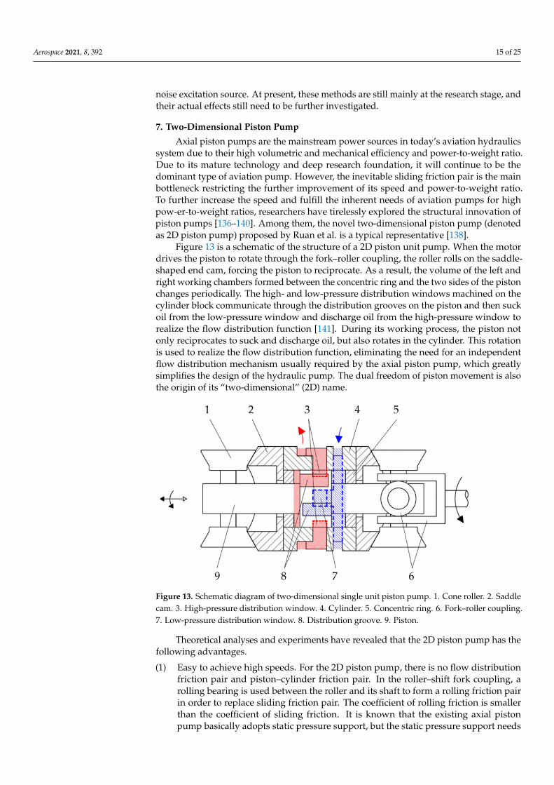
odd number, increasing the number of pistons is an effective method. According to thecalculation formula of pressure pulsation rate, the pulsation decreases when the number ofpistons increases [68]. Song et al. analyzed the influence of the axial piston pump buffergroove, pre-compression chamber, and swashplate staggered angle structure on the flowpulsation of the piston pump and proposed an optimized structure [118]. The secondone is to optimize the flow distribution structure of the piston pump. An axial pistonpump has two flow distribution methods, namely, end plane flow distribution and valveflow distribution. Xu et al. optimized the flow distribution transition zone and selectedthe best combination of damping grooves, damping holes, and waist grooves in the flowdistribution transition zone to reduce the oil backflow amplitude and pressure shock of thepiston cavity, as shown in Figure 9 [119,120]. For valve distribution, Du et al. adopted anew spool rotary distribution mechanism, which could still function normally when therotation speed was as high as 12,000 r/min [121]. The third option is the use of a hydraulicpulsation attenuator [122]. Ouyang et al. studied the pressure pulsation attenuator usedin a high-speed aviation pump [123] and proposed the structure principle of the built-inattenuator as a function of the RC principle, as shown in Figures 10 and 11 [124].
Figure 9. Orifice and groove combined valve plate (Reproduced from [119]).
Figure 10. A380 EDP shape (Obtained from [122]).

Aerospace 2021, 8, 392 13 of 25
Figure 11. RC principle built-in attenuator (Obtained from [124]).
In summary, the method to reduce the pulsation of the piston pump is mainly tooptimize the structural parameters of the pump and add a pressure pulsation attenuator.However, the former increases the manufacturing difficulty and processing cost, whilethe latter increases the weight of the piston pump, which is inconsistent with the inherentdemand of the high power-to-weight ratio of the aviation piston pump. Therefore, meth-ods that can efficiently and economically reduce flow and pressure pulsation need to befurther studied.
6. Noise6.1. Overview
The axial piston pump has movement flow pulsation and dynamic flow pulsation.The flow pulsation at the inlet and outlet interacts with the system load, causing thevibration of hydraulic pipes and hydraulic valves, exciting the vibration of the surroundingair, and generating noise due to the flow pulsation at the inlet and outlet of the pistonpump [125]. The flow pulsation here is called the fluid noise excitation source [126]. Duringthe movement of the piston, the oil pressure in the piston cavity follows the periodicmovement of the piston for periodic high- and low-pressure switching. Furthermore, thepressure in the cavity is transmitted to the piston and cylinder through the piston–cylinderblock pair on the one hand and is transmitted to the valve plate through the cylinder–valveplate pair on the other hand [127]. The transmission path of intracavity pressure is shown inFigure 12. There are three major paths for force transmission. The force of the piston cavityis transmitted to the main shaft and bearings 1 and 2 through the cylinder block, and the oilfilm on the bearing transmits the force to the housing and the end cover. After the pistontransmits the pressure in the cavity to the slipper, the oil film of the slipper–swashplatepair transmits the force to the swashplate and finally to the housing and the end cover. Inthe same way, the cylinder–valve plate pair oil film transmits the pressure in the cavity tothe valve plate and then to the shell and the end cover. In summary, the three pressuretransmission methods eventually transmit force and torque to the shell and end cover,causing them to vibrate, excite the surrounding air, and generate noise [128]. In addition,the cavitation of the fluid inside the axial piston pump in a local area causes noise [129–131].When the vapor bubble flows into the high-pressure area with the liquid, it produces severepressure shock and a high-speed jet when it collapses near the wall of the part. Pits areformed on the metal surface [54,131], accompanied by vibration and noise [67].

Aerospace 2021, 8, 392 14 of 25
Figure 12. Mechanism of axial piston pump noise (Reproduced from [127]): (a) the generation and transmission of noiseexcitation source of axial piston pump; (b) transmission path of noise excitation source of axial piston pump.
6.2. Research Progress
The primary purpose of the noise reduction of the axial piston pump is to reduce thenoise excitation source. Moreover, the valve plate structure has an important influence onthe intensity of the excitation source of both fluid noise and structure noise [108,132,133].Firstly, the design of the pre-boost and pre-depressurization angles can directly affect thevibration and noise of the piston pump [108]. In order to realize the smooth transition ofpiston cavity pressure from low pressure to high pressure and high pressure to low pressure,a pre-boost area can be designed between the oil suction waist groove and the oil dischargegroove, and a pre-depressurization area can be designed between the oil discharge waistgroove and the oil suction waist groove. Kim et al. compared the influence of the valveplate structure on the pressure pulsation and noise sound pressure at the outlet of the pistonpump with and without the pre-boost angle. It was proven that using the pre-boost anglecould reduce the pulsation of the outlet pressure and the noise level [115]. On this basis,Mandal et al. conducted a theoretical analysis on the flow pulsation of the axial pistonpump and optimized the pre-boost angle and pre-depressurization angle [77]. Moreover,the manufacture of damping grooves in the pre-boost area and the pre-depressurizationarea can reduce the impact generated when the piston cavity is connected to the oil suctionand discharge waist groove. Pettersson et al. found that when there was a damping groove,the outlet flow pulsation and vibration level of the axial piston pump in the transitionarea of the valve plate were significantly reduced [134]. Edge et al. found that a triangularcross-section damping groove could sufficiently reduce the positive and negative overshootof the piston cavity pressure [108]. Manring et al. found that when the flow area increasedlinearly, the pressure in the piston cavity could be prevented from overshooting [135].However, the damping groove valve plate also has defects. When the speed increases,cavitation is prone to occur in the transition area from the oil suction groove to the oildischarge groove of the piston pump. Johansson et al. adopted a damping hole connectedwith the shell in the pre-depressurization area to reduce the occurrence of cavitation at thebeginning of the oil suction waist groove [130]. Another approach is to use a pre-boostcavity structure. Pettersson et al. proposed the structure of the pre-boost chamber [134].The simulation and test results proved that it can significantly reduce the outlet flowpulsation of the axial piston pump [130]. Similarly, there are methods to reduce the noiseexcitation source of the axial piston pump through the check valve structure and activecontrol approaches to reduce oil backflow or pressure shock. Research has demonstratedthat these methods have excellent noise reduction effects.
In summary, flow pulsation is one of the leading sources of fluid noise in piston pumps,and noise reduction is highly related to reducing pulsation. By designing the preboost andpre-depressurization angles and using the pre-boost chamber structure, the oil backflowand pressure shock during the flow distribution process can be reduced, decreasing the
Aerospace 2021, 8, 392 15 of 25
noise excitation source. At present, these methods are still mainly at the research stage, andtheir actual effects still need to be further investigated.
7. Two-Dimensional Piston Pump
Axial piston pumps are the mainstream power sources in today’s aviation hydraulicssystem due to their high volumetric and mechanical efficiency and power-to-weight ratio.Due to its mature technology and deep research foundation, it will continue to be thedominant type of aviation pump. However, the inevitable sliding friction pair is the mainbottleneck restricting the further improvement of its speed and power-to-weight ratio.To further increase the speed and fulfill the inherent needs of aviation pumps for highpow-er-to-weight ratios, researchers have tirelessly explored the structural innovation ofpiston pumps [136–140]. Among them, the novel two-dimensional piston pump (denotedas 2D piston pump) proposed by Ruan et al. is a typical representative [138].
Figure 13 is a schematic of the structure of a 2D piston unit pump. When the motordrives the piston to rotate through the fork–roller coupling, the roller rolls on the saddle-shaped end cam, forcing the piston to reciprocate. As a result, the volume of the left andright working chambers formed between the concentric ring and the two sides of the pistonchanges periodically. The high- and low-pressure distribution windows machined on thecylinder block communicate through the distribution grooves on the piston and then suckoil from the low-pressure window and discharge oil from the high-pressure window torealize the flow distribution function [141]. During its working process, the piston notonly reciprocates to suck and discharge oil, but also rotates in the cylinder. This rotationis used to realize the flow distribution function, eliminating the need for an independentflow distribution mechanism usually required by the axial piston pump, which greatlysimplifies the design of the hydraulic pump. The dual freedom of piston movement is alsothe origin of its “two-dimensional” (2D) name.
Figure 13. Schematic diagram of two-dimensional single unit piston pump. 1. Cone roller. 2. Saddlecam. 3. High-pressure distribution window. 4. Cylinder. 5. Concentric ring. 6. Fork–roller coupling.7. Low-pressure distribution window. 8. Distribution groove. 9. Piston.
Theoretical analyses and experiments have revealed that the 2D piston pump has thefollowing advantages.
(1) Easy to achieve high speeds. For the 2D piston pump, there is no flow distributionfriction pair and piston–cylinder friction pair. In the roller–shift fork coupling, arolling bearing is used between the roller and its shaft to form a rolling friction pairin order to replace sliding friction pair. The coefficient of rolling friction is smallerthan the coefficient of sliding friction. It is known that the existing axial pistonpump basically adopts static pressure support, but the static pressure support needs
Aerospace 2021, 8, 392 16 of 25
additional devices. Furthermore, the oil film thickness of hydrostatic support isdifficult to control. Therefore, 2D piston pump based on rolling friction pair entirelybreaks through the restriction of the traditional sliding friction pair on the pumpperformance. Additionally, an axisymmetric structure is adopted in the design of the2D piston pump, where the piston is always in a state of radial force balance duringthe rotation and axial reciprocating movement. Thus, it is naturally easier to achievea high operating speed [142].
(2) High efficiency. The efficiency (including volumetric and mechanical efficiency) of ahigh-pressure 2D piston fuel pump using a low-viscosity medium is as high as 90% ata speed of 4000 rpm [143].
(3) Easier to achieve high pressure. Due to the small leakage and high volumetricefficiency, it is easier to achieve high output pressure. Experiments have shown thatthe maximum pressure of the pump can reach about 42 MPa [144].
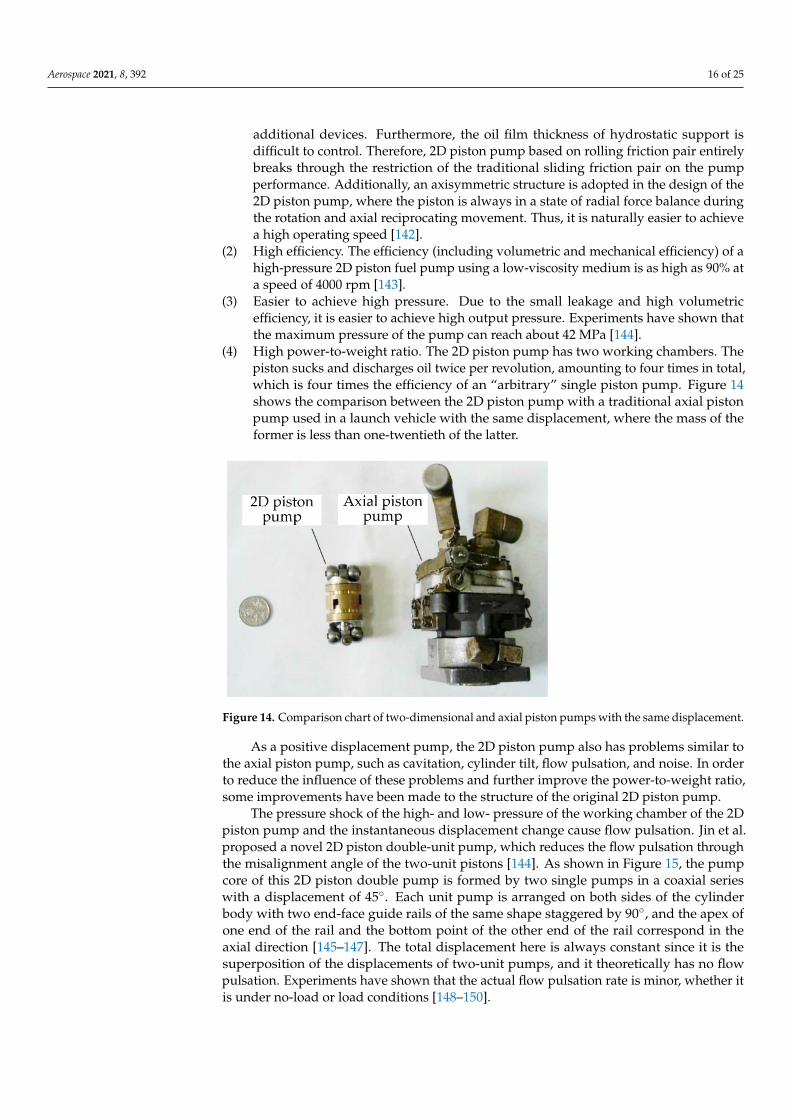
(4) High power-to-weight ratio. The 2D piston pump has two working chambers. Thepiston sucks and discharges oil twice per revolution, amounting to four times in total,which is four times the efficiency of an “arbitrary” single piston pump. Figure 14shows the comparison between the 2D piston pump with a traditional axial pistonpump used in a launch vehicle with the same displacement, where the mass of theformer is less than one-twentieth of the latter.
Figure 14. Comparison chart of two-dimensional and axial piston pumps with the same displacement.
As a positive displacement pump, the 2D piston pump also has problems similar tothe axial piston pump, such as cavitation, cylinder tilt, flow pulsation, and noise. In orderto reduce the influence of these problems and further improve the power-to-weight ratio,some improvements have been made to the structure of the original 2D piston pump.
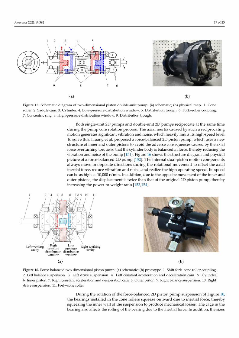
The pressure shock of the high- and low- pressure of the working chamber of the 2Dpiston pump and the instantaneous displacement change cause flow pulsation. Jin et al.proposed a novel 2D piston double-unit pump, which reduces the flow pulsation throughthe misalignment angle of the two-unit pistons [144]. As shown in Figure 15, the pumpcore of this 2D piston double pump is formed by two single pumps in a coaxial serieswith a displacement of 45◦. Each unit pump is arranged on both sides of the cylinderbody with two end-face guide rails of the same shape staggered by 90◦, and the apex ofone end of the rail and the bottom point of the other end of the rail correspond in theaxial direction [145–147]. The total displacement here is always constant since it is thesuperposition of the displacements of two-unit pumps, and it theoretically has no flowpulsation. Experiments have shown that the actual flow pulsation rate is minor, whether itis under no-load or load conditions [148–150].
Aerospace 2021, 8, 392 17 of 25
Figure 15. Schematic diagram of two-dimensional piston double-unit pump: (a) schematic; (b) physical map. 1. Coneroller. 2. Saddle cam. 3. Cylinder. 4. Low-pressure distribution window. 5. Distribution trough. 6. Fork–roller coupling.7. Concentric ring. 8. High-pressure distribution window. 9. Distribution trough.
Both single-unit 2D pumps and double-unit 2D pumps reciprocate at the same timeduring the pump core rotation process. The axial inertia caused by such a reciprocatingmotion generates significant vibration and noise, which heavily limits its high-speed level.To solve this, Huang et al. proposed a force-balanced 2D piston pump, which uses a newstructure of inner and outer pistons to avoid the adverse consequences caused by the axialforce overturning torque so that the cylinder body is balanced in force, thereby reducing thevibration and noise of the pump [151]. Figure 16 shows the structure diagram and physicalpicture of a force-balanced 2D pump [152]. The internal dual-piston motion componentsalways move in opposite directions during the rotational movement to offset the axialinertial force, reduce vibration and noise, and realize the high operating speed. Its speedcan be as high as 10,000 r/min. In addition, due to the opposite movement of the inner andouter pistons, the displacement is twice than that of the original 2D piston pump, therebyincreasing the power-to-weight ratio [153,154].
Figure 16. Force-balanced two-dimensional piston pump: (a) schematic; (b) prototype. 1. Shift fork–cone roller coupling.2. Left balance suspension. 3. Left drive suspension. 4. Left constant acceleration and deceleration cam. 5. Cylinder.6. Inner piston. 7. Right constant acceleration and deceleration cam. 8. Outer piston. 9. Right balance suspension. 10. Rightdrive suspension. 11. Fork–cone roller.
During the rotation of the force-balanced 2D piston pump suspension of Figure 10,the bearings installed in the cone rollers squeeze outward due to inertial force, therebysqueezing the inner wall of the suspension to produce mechanical losses. The cage in thebearing also affects the rolling of the bearing due to the inertial force. In addition, the sizes

Aerospace 2021, 8, 392 18 of 25
of the tapered rollers and rolling bearings used in the pump are limited, their antipollutionability is poor, and their mechanical efficiency is low under heavy load. In order to improvethe load capacity and antipollution ability, Wang et al. proposed a force-balanced 2D pistonpump with cam rotation, as shown in Figure 17. Its moving parts are driving and balancingrails. Using this structure, the sizes of the tapered roller and the bearing installed in thetapered roller can be largely increased, improving the load capacity and reliability. Inaddition, the diameter of the high- and low-pressure oil ports increases with the increasein the size of the cone roller, which is not easy to be blocked. In addition, the continuouscircumferential rotation of the piston is also less likely to be blocked by the particles in theoil; thus, it has excellent antipollution ability. Both theoretical analyses and experimentsproved that the volumetric efficiency of the force-balanced 2D piston pump with camrotation can reach 96% under the working conditions of 10 MPa and 10,000 r/min.
Figure 17. Force-balanced two-dimensional piston pump with cam rotation: (a) schematic; (b) prototype. 1. Left fork shaft.2. Left rail group. 3. Cylinder. 4. Suction column. 5. Right guide rail group. 6. Right fork. 7. Case. 8. Right working cavity.9. Cone roller. 10. Oil drain. 11. Two-dimensional piston. 12. Left working cavity.
For the aforementioned 2D piston pumps, there is a gap between the roller and theguide rail, which results in a collision between these two components under high-speedconditions, generating noise and affecting the pump’s mechanical efficiency. To eliminatethe effect of the clearance on the efficiency of the piston pump and further increase itsspeed, Zhu et al. proposed a stacked-roll 2D piston pump, as shown in Figure 18 [155]. Itrealizes the bidirectional force balance support of the double-piston hydrostatic pressureand inertial force through the mutual support and friction transmission of the double-layer tapered roller dislocation and overlap to realize the high speed and heavy load ofthe two-dimensional movement of the piston. This structure solves the bearing capacitychallenge of the rolling bearing and increases the number of strokes and displacementby increasing the number of rollers. Both simulations and experiments have confirmedthat the rolling 2D piston pump has low vibration and noise during operation, realizesthe reciprocating movement of the piston without clearance, and has high volumetric andmechanical efficiency. With the pressure and rotating speed of 10 MPa and 12,000 r/min,the volumetric efficiency of this pump could reach 96%, and the total efficiency couldreach 90%.
Aerospace 2021, 8, 392 19 of 25
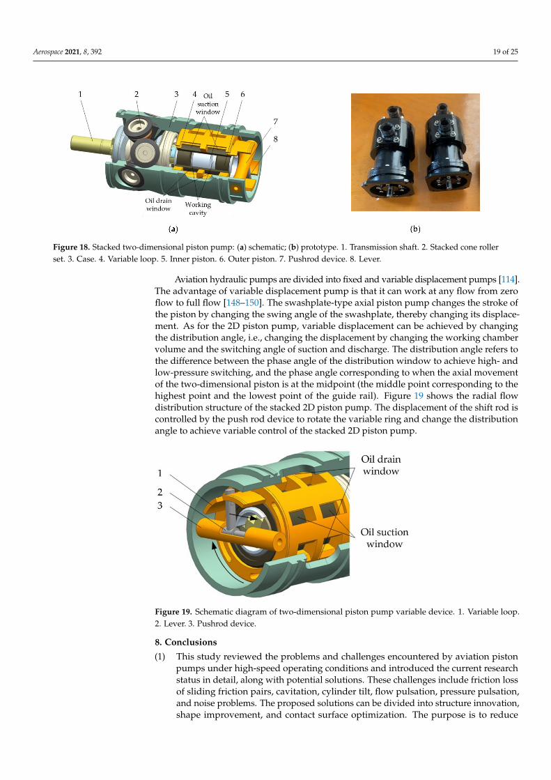
Figure 18. Stacked two-dimensional piston pump: (a) schematic; (b) prototype. 1. Transmission shaft. 2. Stacked cone rollerset. 3. Case. 4. Variable loop. 5. Inner piston. 6. Outer piston. 7. Pushrod device. 8. Lever.
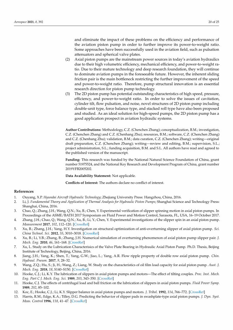
Aviation hydraulic pumps are divided into fixed and variable displacement pumps [114].The advantage of variable displacement pump is that it can work at any flow from zeroflow to full flow [148–150]. The swashplate-type axial piston pump changes the stroke ofthe piston by changing the swing angle of the swashplate, thereby changing its displace-ment. As for the 2D piston pump, variable displacement can be achieved by changingthe distribution angle, i.e., changing the displacement by changing the working chambervolume and the switching angle of suction and discharge. The distribution angle refers tothe difference between the phase angle of the distribution window to achieve high- andlow-pressure switching, and the phase angle corresponding to when the axial movementof the two-dimensional piston is at the midpoint (the middle point corresponding to thehighest point and the lowest point of the guide rail). Figure 19 shows the radial flowdistribution structure of the stacked 2D piston pump. The displacement of the shift rod iscontrolled by the push rod device to rotate the variable ring and change the distributionangle to achieve variable control of the stacked 2D piston pump.
Figure 19. Schematic diagram of two-dimensional piston pump variable device. 1. Variable loop.2. Lever. 3. Pushrod device.
8. Conclusions
(1) This study reviewed the problems and challenges encountered by aviation pistonpumps under high-speed operating conditions and introduced the current researchstatus in detail, along with potential solutions. These challenges include friction lossof sliding friction pairs, cavitation, cylinder tilt, flow pulsation, pressure pulsation,and noise problems. The proposed solutions can be divided into structure innovation,shape improvement, and contact surface optimization. The purpose is to reduce
Aerospace 2021, 8, 392 20 of 25
and eliminate the impact of these problems on the efficiency and performance ofthe aviation piston pump in order to further improve its power-to-weight ratio.Some approaches have been successfully used in the aviation field, such as pulsationattenuators and spherical valve plates.
(2) Axial piston pumps are the mainstream power sources in today’s aviation hydraulicsdue to their high volumetric efficiency, mechanical efficiency, and power-to-weight ra-tio. Due to their mature technology and deep research foundation, they will continueto dominate aviation pumps in the foreseeable future. However, the inherent slidingfriction pair is the main bottleneck restricting the further improvement of the speedand power-to-weight ratio. Therefore, pump structural innovation is an essentialresearch direction for piston pump technology.
(3) The 2D piston pump has potential outstanding characteristics of high speed, pressure,efficiency, and power-to-weight ratio. In order to solve the issues of cavitation,cylinder tilt, flow pulsation, and noise, novel structures of 2D piston pump includingdouble-unit type, force balance type, and stacked roll type have also been proposedand studied. As an ideal solution for high-speed pumps, the 2D piston pump has agood application prospect in aviation hydraulic systems.
Author Contributions: Methodology, C.Z. (Chenchen Zhang); conceptualization, B.M.; investigation,C.Z. (Chenchen Zhang) and C.Z. (Chenhang Zhu); resources, B.M.; software, C.Z. (Chenchen Zhang)and C.Z. (Chenhang Zhu); validation, B.M.; data curation, C.Z. (Chenchen Zhang); writing—originaldraft preparation, C.Z. (Chenchen Zhang); writing—review and editing, B.M.; supervision, S.L.;project administration, S.L.; funding acquisition, B.M. and S.L. All authors have read and agreed tothe published version of the manuscript.
Funding: This research was funded by the National Natural Science Foundation of China, grantnumber 51975524, and the National Key Research and Development Program of China, grant number2019YFB2005202.
Data Availability Statement: Not applicable.
Conflicts of Interest: The authors declare no conflict of interest.
References1. Ouyang, X.P. Hyundai Aircraft Hydraulic Technology; Zhejiang University Press: Hangzhou, China, 2016.2. Li, J. Fundamental Theory and Application of Thermal Analysis for Hydraulic Piston Pumps; Shanghai Science and Technology Press:
Shanghai, China, 2016.3. Chao, Q.; Zhang, J.H.; Wang, Q.N.; Xu, B.; Chen, Y. Experimental verification of slipper spinning motion in axial piston pumps. In
Proceedings of the ASME/BATH 2017 Symposium on Fluid Power and Motion Control, Sarasota, FL, USA, 16–19 October 2017.4. Zhang, J.H.; Chao, Q.; Wang, Q.N.; Xu, B.; Li, Y.; Chen, Y. Experimental investigations of the slipper spin in an axial piston pump.
Measurement 2017, 102, 112–120. [CrossRef]5. Xu, B.; Zhang, J.H.; Yang, H.Y. Investigation on structural optimization of anti-overturning slipper of axial piston pump. Sci.
China Technol. Sci. 2012, 55, 3010–3018. [CrossRef]6. Xu, B.; Li, Y.B.; Zhang, B.; Zhang, J.H. Numerical simulation of overturning phenomenon of axial piston pump slipper pair. J.
Mech. Eng. 2010, 46, 161–168. [CrossRef]7. Xu, L. Study on the Lubrication Characterisics of the Valve Plate Bearing in Hydraulic Axial Piston Pump. Ph.D. Thesis, Beijing
Institute of Technology, Beijing, China, 2016.8. Jiang, J.H.; Yang, K.; Shen, T.; Yang, G.W.; Jiao, L.; Yang, A.R. Flow ripple property of double row axial piston pump. Chin.
Hydraul. Pneum. 2017, 9, 28–32.9. Wang, Z.Q.; Hu, S.; Ji, H.; Wang, Z.; Liang, W. Study on the characteristics of oil film load capacity for axial piston pump. Aust. J.
Mech. Eng. 2018, 18, S140–S150. [CrossRef]10. Hooke, C.J.; Li, K.Y. The lubrication of slippers in axial piston pumps and motors—The effect of tilting couples. Proc. Inst. Mech.
Eng. Part C J. Mech. Eng. Sci. 1989, 203, 343–350. [CrossRef]11. Hooke, C.J. The effects of centrifugal load and ball friction on the lubrication of slippers in axial piston pumps. Fluid Power Symp.
1989, 202, 85–102.12. Koc, E.; Hooke, C.J.; Li, K.Y. Slipper balance in axial piston pumps and motors. J. Tribol. 1992, 114, 766–772. [CrossRef]13. Harris, R.M.; Edge, K.A.; Tilley, D.G. Predicting the behavior of slipper pads in swashplate-type axial piston pumps. J. Dyn. Syst.
Meas. Control 1996, 118, 41–47. [CrossRef]

Aerospace 2021, 8, 392 21 of 25
14. Schenk, A.; Ivantysynova, M. A transient thermoelastohydrodynamic lubrication model for the slipper/swashplate in axialpiston machines. J. Tribol. 2015, 137, 031701. [CrossRef]
15. Schenk, A. Predicting Lubrication Performance between the Slipper and Swashplate in Axial Piston Hydraulic Machines. Ph.D.Thesis, Purdue University, West Lafayette, IN, USA, 2014.
16. Zecchi, M.; Ivantysynova, M. A novel fluid structure interaction model for the cylinder block/valve plate interface of axial pistonmachines. In Proceedings of the 52nd National Conference on Fluid Power, Las Vegas, NV, USA, 23-25 March 2011.
17. Zecchi, M.; Ivantysynova, M. Cylinder block/valve plate interface—A novel approach to predict thermal surface loads. InProceedings of the Eighth International Fluid Power Conference, Dresden, Germany, 26–28 March 2012.
18. Zecchi, M. A Novel Fluid Structure Interaction and Thermal Model to Predict the Cylinder Block/Valve Plate Interface Perfor-mance in Swash Plate Type Axial Piston Machines. Ph.D. Thesis, Purdue University, West Lafayette, IN, USA, 2013.
19. Schenk, A.; Zecchi, M.; Ivantysynova, M. Accurate prediction of axial piston machine’s performance through a thermo-elasto-hydrodynamic simulation model. In Proceedings of the ASME/BATH 2013 Symposium on Fluid Power and Motion Control,Sarasota, FL, USA, 6–9 October 2013.
20. Chacon, R.; Ivantysynova, M. An investigation of the impact of the elastic deformation of the end case/housing on axial pistonmachines cylinder block/valve plate lubricating interface. In Proceedings of the 10th International Fluid Power Conference,Dresden, Germany, 8–10 March 2016.
21. Ivantysynova, M.; Lasaar, R. An investigation into micro-and macrogeometric design of piston/cylinder assembly of swash platemachines. Int. J. Fluid Power 2004, 5, 23–36. [CrossRef]
22. Pelosi, M.; Ivantysynova, M. A geometric multigrid solver for the piston–cylinder interface of axial piston machines. Tribol. Trans.2012, 55, 163–174. [CrossRef]
23. Pelosi, M.; Ivantysynova, M. A new fluid structure interaction model for the slipper-swashplate interface. In Proceedings of the5th FPNI-PhD Symposium on Fluid Power, Krakow, Poland, 1–5 July 2008.
24. Schenk, A.; Ivantysynova, M. An investigation of the impact of elastohydrodynamic deformation on power loss in theslipper swashplate interface. In Proceedings of the 8th JFPS International Symposium on Fluid Power, Okiniwa, Japan,25–28 October 2011.
25. Manring, N.D. Slipper tipping within an axial-piston swash-plate type hydrostatic pump. In Proceedings of the ASME In-ternational Mechanical Engineering Congress and Exposition, Fluid Power Systems and Technology, Anaheim, CA, USA,15–18 November 1998.
26. Manring, N.D. Predicting the required slipper hold-down force within an axial-piston swash-plate type hydrostaticpump. In Proceedings of the ASME International Mechanical Engineering Congress and Exposition, New York, NY, USA,11–16 November 2001.
27. Manring, N.D.; Mehta, V.S.; Nelson, B.E.; Graf, K.E.; Kuehn, J.L. Scaling the speed limitations for axial-piston swash-plate typehydrostatic machines. J. Dyn. Syst. Meas. Control 2014, 136, 031004. [CrossRef]
28. Murrenhoff, H.; Scharf, S. Wear and friction of ZRCG-coated pistons of axial piston pumps. Int. J. Fluid Power 2006, 7, 13–20.[CrossRef]
29. Li, Y.B.; Xu, B. Axial piston pump slipper pads dynamic characteristics of wedge oil film. Chin. Hydraul. Pneum. 2010, 9, 87–91.30. Chao, Q.; Zhang, J.H.; Xu, B. Test rigs and experimental studies of the slipper bearing in axial piston pumps: A review.
Measurement 2019, 132, 135–149. [CrossRef]31. Hu, X.; Wang, S.P.; Han, L. Modeling and simulation on pressure distribution of plane port pair in axial piston pump. Hydraul.
Pneum. Seals 2012, 32, 68–71.32. Zhang, C.; Huang, S.K.; Du, J. A new dynamic seven-stage model for thickness prediction of the film between valve plate and
cylinder block in axial piston pumps. Adv. Mech. Eng. 2016, 8, 1687814016671446. [CrossRef]33. Zhang, C.; Wang, S.; Tomovic, M. Performance degradation analysis of aviation hydraulic piston pump based on mixed wear
theory. Tribol. Ind. 2017, 39, 248–254. [CrossRef]34. Xu, B.; Chao, Q.; Zhang, J.H.; Li, Y. Slipper optimization model based on equilibrium coefficient. J. Zhejiang Univ. 2015, 49,
1009–1014.35. Tang, H.S.; Yan, Y.B.; Li, J. Heat transfer characteristics of axial piston pump slipper pair. J. Beijing Univ. Aeronaut. Astronaut. 2016,
42, 489–496.36. Fu, J.F.; Li, H.C.; Zeng, X.Q. Numerical simulation of hybrid lubrication characteristics of slipper pair of aviation fuel piston
pump. J. Beijing Univ. Aeronaut. Astronaut. 2018, 44, 939–950.37. Kim, J.K.; Kim, H.E.; Lee, Y.B. Measurment of fluid film thickness on the valve plate in oil hydraulic axial piston pumps (Part II:
Spherical design effects). J. Mech. Sci. Technol. 2005, 19, 655–663. [CrossRef]38. Kakoullis, Y.P. Slipper Lubrication in Axial Piston Pumps. Ph.D. Thesis, University of Birmingham, Birmingham, UK, 1979.39. Liu, H.L.; Kim, H.E.; Lee, Y.B. Lubrication characteristics of the water hydraulic sliding shoe pairs. J. Mech. Eng. 2006, 42, 36–39.
[CrossRef]40. Beale, J. An Investigation of the Slipper/Swashplate Interface of Swashplate-Type Axial Piston Machines. Ph.D. Thesis, Purdue
University, West Lafayette, IN, USA, 2017.41. Rizzo, G.; Massarotti, G.P.; Bonanno, A. Axial piston pumps slippers with nanocoated surfaces to reduce friction. Int. J. Fluid
Power 2015, 16, 1–10. [CrossRef]
Aerospace 2021, 8, 392 22 of 25
42. Rizzo, G.; Rizzo, G.; Massarotti, G.P. Energy efficiency improvement by the application of nano-structured coatings on axialpiston pump slippers. In Proceedings of the Tenth International Fluid Power Conference, Dresden, Germany, 8–10 March 2016.
43. Schuhler, G.; Jourani, A.; Bouvier, S. Efficacy of coatings and thermochemical treatments to improve wear resistance of axialpiston pumps. Tribol. Int. 2018, 126, 376–385. [CrossRef]
44. Vatheuer, N.; Murrenhoff, H.; Bräckelmann, U. Mechanical losses in the piston-bushing contact of axial piston units. JFPS Int. J.Fluid Power Syst. 2014, 8, 24–29. [CrossRef]
45. Van Bebber, D.; Murrenhoff, H. Improving the wear resistance of hydraulic machines using PVD-coating technology. Oþ POlhydraul. Pneum. 2002, 46, 1–35.
46. Fatemi, A.; Wohlers, A.; Murrenhoff, H. Simulation of elastohydrodynamic contact between piston and cylinder in axial pistonpumps. In Proceedings of the 6th International Fluid Power Conference, 31 March–2 April 2008.
47. Deng, H.S.; Qi, S.; Yu, H.W. Numerical analysis for textured port plate of axial piston pump. Trans. Chin. Soc. Agric. Mach. 2011,42, 203–207.
48. Chacon, R.; Ivantysynova, M. An investigation of the impact of micro surface on the cylinder block/valve plate interfaceperformance. In Proceedings of the 8th FPNI Ph.D Symposium on Fluid Power, Lappeenranta, Finland, 11–13 June 2014.
49. Chacon, R. Cylinder Block/Valve Plate Interface Performance Investigation through the Introduction of Micro-Surface Shaping.Ph.D. Thesis, Purdue University, West Lafayette, IN, USA, 2014.
50. Mehta, V.S.; Manring, N.D. Piston pump noise attenuation through modification of piston travel trajectory. In Proceedings of theASME 2010 International Mechanical Engineering Congress and Exposition, Vancouver, BC, Canada, 12–18 November 2010.
51. Totten, G.E.; Sun, Y.H.; Bidhop, R.J., Jr. Hydraulic system cavitation: A review. SAE Trans. 1998, 107, 368–380.52. Kunkis, M.; Weber, J. Experimental and numerical assessment of an axial piston pump’s speed limit. In Proceedings of the
BATH/ASME 2016 Symposium on Fluid Power and Motion Control, Bath, UK, 7–9 September 2016.53. Gullapalli, S.; Michael, P.; Kensler, J. An investigation of hydraulic fluid composition and aeration in an axial piston pump. In
Proceedings of the ASME/BATH 2017 Symposium on Fluid Power and Motion Control, Sarasota, FL, USA, 16–19 October 2017.54. Schleihs, C.; Viennet, E.; Deeken, M. 3D-CFD simulation of an axial piston displacement unit. In Proceedings of the Ninth
International Fluid Power Conference, Aachen, Germany, 24–26 March 2014.55. Kunimoto, E.; Ogawara, T. Cavitation detection in the oil hydraulic equipments. Proc. JFPS Int. Symp. Fluid Power. Jpn. Fluid
Power Syst. Soc. 1996, 3, 461–466. [CrossRef]56. Bishop, R.J.; Totten, G.E. Effect of pump inlet conditions on hydraulic pump cavitation: A review. ASTM Spec. Tech. 2001, 339,
318–322.57. Hibi, A.; Ibuki, T.; Ichikawa, T. Suction performance of axial piston pump: 1st Report, Analysis and Fundamental Experiments.
Bull. JSME 1977, 20, 79–84. [CrossRef]58. Ibuki, T.; Hibi, A.; Ichikawa, T. Suction performance of axial piston pump: 2nd report, experimental results. Bull. JSME 1977, 20,
827–833. [CrossRef]59. Kollek, W.; Kudzma, Z.; Stosiak, M. Possibilities of diagnosing cavitation in hydraulic systems. Arch. Civ. Mech. Eng. 2007, 7,
61–73. [CrossRef]60. Kosodo, H.; Nara, M.; Kakehida, S. Experimental research about pressure-flow characteristics of V-notch. Proc. JFPS Int. Symp.
Fluid Power. Jpn. Fluid Power Syst. Soc. 1996, 3, 73–78. [CrossRef]61. Yamaguchi, A.; Takabe, T. Cavitation in an axial piston pump. Bull. JSME 1983, 26, 72–78. [CrossRef]62. Shi, Y.X.; Lin, T.R.; Meng, G.Y. A study on the suppression of cavitation flow inside an axial piston pump. In Proceedings of the
2016 Prognostics and System Health Management Conference, Chengdu, China, 19–21 October 2016.63. Tsukiji, T.; Nakayama, K.; Saito, K. Study on the cavitating flow in an oil hydraulic pump. In Proceedings of the 2011 International
Conference on Fluid Power and Mechatronics, Beijing, China, 17–20 August 2011.64. Chao, Q.; Zhang, J.H.; Xu, B. A review of high-speed electro-hydrostatic actuator pumps in aerospace applications: Challenges
and solutions. J. Mech. Des. 2019, 141, 050801. [CrossRef]65. Chao, Q.; Zhang, J.H.; Xu, B. Centrifugal effects on cavitation in the cylinder chambers for high-speed axial piston pumps.
Meccanica 2019, 54, 815–829. [CrossRef]66. Totten, G.E.; Bishop, R. The hydraulic pump inlet condition: Impact on hydraulic pump cavitation. SAE Tech. Pap. 1999, 1, 1877.67. Yin, F.L.; Nie, S.L.; Xiao, S.H. Numerical and experimental study of cavitation performance in sea water hydraulic axial piston
pump. Proc. Inst. Mech. Eng. Part I J. Syst. Control Eng. 2016, 230, 716–735. [CrossRef]68. Ouyang, X.P.; Wang, T.Z.; Fang, X. Research status of the high speed aircraft piston pump. Chin. Hydraul. Pneum. 2018, 2, 1–8.69. Zhang, Z.S. Research on the Dynamic Characteristics of the High Speed Piston Pump. Ph.D. Thesis, Zhejiang University,
Hangzhou, China, 2015.70. Yang, C.; Du, L.L.; Qing, H. The design of pressurized tank test bench for a certain airplane hydraulic system. Chin. Hydraul.
Pneum. 2012, 2, 103–105.71. Mohn, D.I.G.; Nafz, I.T. Swash plate pumps–the key to the future. In Proceedings of the 10th International Fluid Power Conference,
Dresden, Germany, 8–10 March 2016.72. Kosodo, H. Development of micro pump and micro-HST for hydraulics. JFPS Int. J. Fluid Power Syst. 2012, 5, 6–10. [CrossRef]
Aerospace 2021, 8, 392 23 of 25
73. Zecchi, M.; Ivantysynova, M. Spherical valve plate design in axial piston machines—A novel thermoelasto-hydrodynamicmodel to predict the lubricating interface performance. In Proceedings of the Eighth International Conference on Fluid PowerTransmission and Control, Hangzhou, China, 9–11 April 2013.
74. Bügener, N.; Klecker, J.; Weber, J. Analysis and improvement of the suction performance of axial piston pumps in swash platedesign. Int. J. Fluid Power 2014, 15, 153–167. [CrossRef]
75. Bügener, N.; Helduser, S. Analysis of the suction performance of axial piston pumps by means of computational fluid dynamics(CFD). In Proceedings of the Seventh International Fluid Power Conference, Aachen, Germany, 22–24 March 2010.
76. Ji, H.; Wang, Y. Numerical analysis of oil-suction caviation in cylinder chamber of axial piston pump. J. Lanzhou Univ. Technol.2013, 39, 34–37.
77. Mandal, N.P.; Saha, R.; Santal, D. Effects of flow inertia modelling and valve-plate geometry on swash-plate axial-piston pumpperformance. Proc. Inst. Mech. Eng. Part I J. Syst. Control Eng. 2012, 226, 451–465. [CrossRef]
78. Berta, G.; Casoli, P.; Vacca, A. Simulation model of an axial piston pump inclusive of cavitation. In Proceedings of the ASME 2002International Mechanical Engineering Congress and Exposition, New Orleans, LA, USA, 17–22 November 2002.
79. Harris, R.; Eage, K.; Tilley, D. Reduction of piston pump cavitation by means of a pre-expansion volume. In Proceedings of theFifth Bath International Fluid Power Workshop, Bath, UK, 16–19 September 1992.
80. Pettersson, M.E.; Weddfelt, K.G.; Palmberg, J.S. Methods of reducing ripple from fluid power pumps-a theoretical approach. SAETech. Pap. 1991, 100, 158–167.
81. Liu, X.H.; Yu, L.Y.; Liu, H.L. Cavitation erosion mechanism of port plate of hydraulic axial plunger pump. Chin. J. Mech. Eng.2008, 44, 203–208. [CrossRef]
82. Chao, Q.; Zhang, J.H.; Xu, B.; Huang, H.P.; Zhai, J. Effects of inclined cylinder ports on gaseous cavitation of high-speedelectro-hydrostatic actuator pumps: A numerical study. Eng. Appl. Comput. Fluid Mech. 2019, 13, 245–253. [CrossRef]
83. Chao, Q. Research on Some Key Technologies of High-Speed Rotation for Axial Piston Pumps used in EHAs. Ph.D. Thesis,Zhejiang University, Hangzhou, China, 2019.
84. Manring, N.D. Tipping the cylinder block of an axial-piston swash-plate type hydrostatic machine. J. Dyn. Syst. Meas. Control2000, 122, 216–221. [CrossRef]
85. Ivantysyn, R. Computational Design of Swash Plate Type Axial Piston Pumps a Framework for Computational Design. Ph.D.Thesis, Purdue University, West Lafayette, IN, USA, 2011.
86. Wegner, S.; Gels, S.; Jang, D.S. Experimental investigation of the cylinder block movement in an axial piston machine. InProceedings of the ASME/BATH 2015 Symposium on Fluid Power and Motion Control, Chicago, IL, USA, 12–14 October 2015.
87. Wegner, D.I.S.; Löschner, F.; Gels, I.S. Validation of the physical effect implementation in a simulation model for the cylinderblock/valve plate contact supported by experimental investigations. In Proceedings of the 10th International Fluid PowerConference, Dresden, Germany, 8–10 March 2016.
88. Wieczorek, U.; Ivantysynova, M. Computer aided optimization of bearing and sealing gaps in hydrostatic machines—Thesimulation tool CASPAR. Int. J. Fluid Power 2002, 3, 7–20. [CrossRef]
89. Hooke, C.; Foster, K.; Madera, G. A note on the effect of shaft and casing stiffness on the port plate lubrication film of aparticular slipper-pad axial piston pump. In Proceedings of the Fourth International Fluid Power Symposium, Sheffield, UK,21–28 February 1975.
90. Wang, Z.; Hu, S.; Ji, H. Analysis of lubricating characteristics of valve plate pair of a piston pump. Tribol. Int. 2018, 126, 49–64.[CrossRef]
91. Wang, Z.Q.; Yang, J.; Zhang, H.Y. Flow filed character analysis of piston pump valve plate. Hydraul. Pneum. Seals 2016, 36, 41–44.92. Achten, P.; Eggenkamp, S. Barrel tipping in axial piston pumps and motors. In Proceedings of the 15th Scandinavian International
Conference on Fluid Power, Linköping, Sweden, 7–9 June 2017.93. Zhang, J.H.; Chao, Q.; Xu, B. Analysis of the cylinder block tilting inertia moment and its effect on the performance of high-speed
electro-hydrostatic actuator pumps of aircraft. Chin. J. Aeronaut. 2018, 31, 169–177. [CrossRef]94. Xu, B.; Chao, Q.; Zhang, J.H. Effects of the dimensional and geometrical errors on the cylinder block tilt of a high-speed EHA
pump. Meccanica 2017, 52, 2449–2469. [CrossRef]95. Zhang, J.H.; Chao, Q.; Xu, B. Effect of piston-slipper assembly mass difference on the cylinder block tilt in a high-speed
electro-hydrostatic actuator pump of aircraft. Int. J. Precis. Eng. Manuf. 2017, 18, 995–1003. [CrossRef]96. Ivantysyn, J.; Ivantysynova, M. Hydrostatic Pumps and Motors: Principles, Design, Performance, Modelling, Analysis, Control and
Testing; Tech Books International: New Delhi, Inda, 2003.97. Chao, Q.; Zhang, J.H.; Xu, B. Spline design for the cylinder block within a high-speed electro-hydrostatic actuator pump of
aircraft. Meccanica 2018, 53, 395–411. [CrossRef]98. Ivantysynova, M.; Baker, J. Power loss in the lubricating gap between cylinder block and valve plate of swash plate type axial
piston machines. Int. J. Fluid Power 2009, 10, 29–43. [CrossRef]99. Shin, J.H.; Kim, K.W. Effect of surface non-flatness on the lubrication characteristics in the valve part of a swash-plate type axial
piston pump. Meccanica 2014, 49, 1275–1295. [CrossRef]100. Murrenhoff, H.; Eneke, C.; Gels, S. Efficiency improvement of fluid power components focusing on tribological systems. In
Proceedings of the Seventh International Fluid Power Conference, Aachen, Germany, 22–24 March 2010.
Aerospace 2021, 8, 392 24 of 25
101. Qi, S.; Deng, H.S.; Zhang, E.Y. Experiental research on friction characteristics of testured axial piston pump port plate. Chin.Hydraul. Pneum. 2011, 9, 105–107.
102. Li, Y.; Deng, H.S.; Wang, X.L. Experiment on friction and wear performance of textured port plate pair. J. Aerosp. Power 2014, 29,1591–1597.
103. Chen, Y.; Zhang, J.H.; Xu, B. Investigation of Laser Surface Texturing for Integrated PV (Pressure×Velocity)-Value-Decreased Retainer inan EHA Pump; Universitätsbibliothek der RWTH Aachen: Aachen, Germany, 2018.
104. Zhang, J.H.; Chen, Y.; Xu, B. Effect of surface texture on wear reduction of the tilting cylinder and the valve plate for a high-speedelectro-hydrostatic actuator pump. Wear 2018, 414, 68–78. [CrossRef]
105. Viral, M. Torque Ripple Attenuation for an Axial Piston Swashplate Type Hydrostatic Pump: Noise Considerations. Ph.D. Thesis,University of Missouri, Columbia, MO, USA, 2006.
106. Darling, J. Piston-Cylinder Dynamics in Oil Hydraulic Axial Piston Pumps. Ph.D. Thesis, University of Bath, Bath, UK, 1985.107. Manring, N.D. The discharge flow ripple of an axial-piston swash-plate type hydrostatic pump. J. Dyn. Syst. Meas. Control 2000,
122, 263–268. [CrossRef]108. Edge, K.; Darling, J. Cylinder pressure transients in oil hydraulic pumps with sliding plate valves. Proc. Inst. Mech. Eng. Part B
Manag. Eng. Manuf. 1986, 200, 45–54. [CrossRef]109. Edge, K.A. A theoretical model of axial piston pump flow ripple. In Proceedings of the First Bath International Fluid Power
Workshop, Bath, UK, 8 September 1988.110. Xu, B.; Hu, M.; Zhang, J.H. Impact of typical steady-state conditions and transient conditions on flow ripple and its test accuracy
for axial piston pump. Chin. J. Mech. Eng. 2015, 28, 1012–1022. [CrossRef]111. Xu, B.; Lee, K.M.; Song, Y.C. A numerical and experimental investigation of parametric effect on flow ripple. Proc. Inst. Mech.
Eng. Part C J. Mech. Eng. Sci. 2015, 229, 2939–2951. [CrossRef]112. Edge, K.A.; Freitas, F. Fluid borne pressure ripple in positive displacement pump suction lines. In Proceedings of the Relay
Conference, Cambridge, UK, 1 January 1981.113. Freitas, F. The Generation and Transmission of Pressure Fluctuations in Pump Suction Lines. Ph.D. Thesis, University of Bath,
Bath, UK, 1982.114. Edge, K.A.; Wing, T.J. The measurement of the fluid borne pressure ripple characteristics of hydraulic components. Proc. Inst.
Mech. Eng. Part B Manag. Eng. Manuf. 1983, 197, 247–254. [CrossRef]115. Kim, J.K.; Kim, H.E.; Jung, J.Y. Relation between pressure variations and noise in axial type oil piston pumps. KSME Int. J. 2004,
18, 1019–1025. [CrossRef]116. Wang, Z.M.; Tan, S.K. Vibration and pressure fluctuation in a flexible hydraulic power systemon an aircraft. Comput. Fluids 1998,
27, 1–9. [CrossRef]117. Ouyang, X.P.; Fang, X.; Yang, H.Y. An investigation into the swash plate vibration and pressure pulsation of piston pumps based
on full fluid-structure interactions. J. Zhejiang Univ.-SCIENCE A 2016, 17, 202–214. [CrossRef]118. Song, Y.C. Investigation on Test Method and Noise Reduction Structure with Large Operating Conditions for Piston Pump Flow
Rate. Ph.D. Thesis, Zhejiang University, Hangzhou, China, 2013.119. Xu, B.; Zhang, J.H.; Yang, H.Y. Multi-objective drive forward design with damping orifice and groove for axial piston pump.
Trans. Chin. Soc. Agric. Mach. 2013, 44, 279–285.120. Zhang, J.H. Study on Valve Plate and Flow-Distribution Method for Noise Reduction of Axial Piston Pump. Ph.D. Thesis,
Zhejiang University, Hangzhou, China, 2013.121. Du, R.L.; Chen, Y.L.; Zhou, H. New distributing mechanism for high speed single-piston axial piston pump. J. Zhejiang Univ.
2016, 50, 1902–1910.122. Hargreaves, B. Hydraulic systems keep evolving; MRO options expand. Aviation Week Network, 12 May 2017.123. Ouyang, X.P.; Li, L.; Fang, X. Research status and prospects of resonant-type hydraulic pulsation attenuators. J. Mech. Eng. 2015,
51, 168–175. [CrossRef]124. Gao, F.; Ouyang, X.P.; Yang, H.Y. A novel pulsation attenuator for aircraft piston pump. Mechatronics 2013, 23, 566–572. [CrossRef]125. Ericson, L. On Fluid Power Pump and Motor Design: Tools for Noise Reduction. Ph.D. Thesis, Linköping University, Linköping,
Sweden, 2012.126. Fiebig, W. Location of noise sources in fluid power machines. Int. J. Occup. Saf. Ergon. 2007, 13, 441–450. [CrossRef]127. Ye, S.G. Prediction of Vibro-Asoustic Characteristics and Structure Optimization for Noise Reduction of Axial Piston Pumps.
Ph.D. Thesis, Zhejiang University, Hangzhou, China, 2016.128. Johanson, A. Design Principles for Noise Reduction in Hydraulic Piston Pumps: Simulation, Optimisation and Experimental
Verification. Ph.D. Thesis, Linköping University, Linköping, Sweden, 2005.129. Pettersson, M.; Weddfelt, K.; Palmberg, J.O. Modelling and measurement of cavitation and air release in a fluid power piston
pump. In Proceedings of the Third Scandinavian International Conference on Fluid Power, Linköping, Sweden, 25–26 May 1993.130. Johansson, A.; Palmberg, J.O. The importance of suction port timing in axial piston pumps. In Proceedings of the 9th International
Conference on Fluid Powers, Linköping, Sweden, 1–3 July 1993.131. Ding, H.; Visser, F.; Jiang, Y. Demonstration and validation of a 3D CFD simulation tool predicting pump performance and
cavitation for industrial applications. J. Fluids Eng. 2011, 133, 011101. [CrossRef]
Aerospace 2021, 8, 392 25 of 25
132. Edge, K.; Darling, J. The pumping dynamics of swash plate piston pumps. J. Dyn. Syst. Meas. Control 1989, 111, 307–312.[CrossRef]
133. Ivantysynova, M.; Seenirag, G.K.; Huang, C. Comparison of different valve plate designs focusing on oscillating forces and flowpulsation. In Proceedings of the Ninth Scandinavian International Conference on Fluid Power, Linköping, Sweden, 1–3 June 2005.
134. Pettersson, M. Design of Fluid Power Piston Pumps: With Special Reference to Noise reduction; Division of Fluid Power Technology,Department of Mechanical Engineering, Linköping University: Linköping, Sweden, 1995.
135. Manring, N.D. Valve-plate design for an axial piston pump operating at low displacements. J. Mech. Des. 2003, 125, 200–205.[CrossRef]
136. Lin, C.; Wei, Y.Q.; Zhao, X.L.; Manring, N.D. Design and analysis of new type of piston pump. J. Southwest Jiaotong Univ. 2018, 53,602–609.
137. Zhang, Z.T.; Cao, S.P.; Luo, X.H. Design and research on the new type water hydraulic Axis piston pump. J. Press. Vessel. Technol.2016, 138, 031203.
138. Ericson, L.; Forssell, J. A novel axial piston pump/motor principle with floating pistons. In Proceedings of the BATH/ASME2018 Symposium on Fluid Power and Motion Control, Bath, UK, 12–14 September 2018.
139. Altare, G.; Vacca, A.; Richter, C. A novel pump design for an efficient and compact Electro-Hydraulic Actuator IEEE aerospaceconference. In Proceedings of the 2014 IEEE Aerospace Conference, Big Sky, MT, USA, 1–8 March 2014.
140. Wang, H.J.; Shi, G.L. Study of a novel axial piston pump with adjustable tilting piston. In Proceedings of the 2019 IEEE 8thInternational Conference on Fluid Power and Mechatronics, Wuhan, China, 10–13 April 2019.
141. Xing, T.; Xu, Y.Z.; Ruan, J. Two-dimensional piston pump: Principle, design, and testing for aviation fuel pumps. Chin. J. Aeronaut.2020, 33, 1349–1360. [CrossRef]
142. Ruan, J.; Li, J.Y.; Jin, D.C. Research and feasibility verification of two-dimensional(2D) piston pump. J. Zhejiang Univ. Technol.2017, 45, 264–269.
143. Jin, D.C. Research on Design Method and Experimental Verification of Two-Dimensional Piston Pump. Ph.D. Thesis, ZhejiangUniversity of Technology, Hangzhou, China, 2019.
144. Jin, D.C.; Ruan, J. Design and research of two-dimensional fuel pump. Acta Aeronaut. Astronaut. Sin. 2019, 40, 318–327.145. Qian, J.Y.; Shentu, S.N.; Ruan, J. Volumetric efficiency analysis of two-dimensional piston aviation fuel pump. Acta Aeronaut.
Astronaut. Sin. 2020, 41, 271–283.146. Shentu, S.N.; Ruan, J.; Qian, J.Y. Optimization analysis of flow characteristic and distribution window of 2D pump. Trans. Chin.
Soc. Agric. Mach. 2019, 50, 403–410.147. Jin, D.C.; Ruan, J.; Li, S. Modelling and validation of a roller-cam rail mechanism used in a 2D piston pump. J. Zhejiang Univ.-Sci.
A 2019, 20, 201–217. [CrossRef]148. Ruan, J.; Jin, D.C.; Shentu, S.N. Research and feasibility verification of two-dimensional(2D) tandem pump. Chin. Hydraul. Pneum.
2017, 11, 1–5.149. Li, J.Y.; Jin, D.C.; Tong, C.W. Design and an error compensation of end cam for two dimensional(2D) axial piston pump. Hydraul.
Pneum. Seals 2017, 37, 18–22.150. Shentu, S.N.; Ruan, J.; Qian, J.Y. Study of flow ripple characteristics in an innovative two-dimensional fuel piston pump. J. Braz.
Soc. Mech. Sci. Eng. 2019, 41, 1–15. [CrossRef]151. Huang, Y.; Ding, C.; Wang, H.Y. Numerical and experimental study on the churning losses of 2D high-speed piston pumps. Eng.
Appl. Comput. Fluid Mech. 2020, 14, 764–777. [CrossRef]152. Ruan, J.; Wang, H.Y.; Wu, S. Heavy-Duty Force-Balanced Two-Dimensional Piston Unit Pump. China Patent CN111502952A,
7 October 2020.153. Huang, Y.; Ruan, J.; Zhang, C.C. Research on the mechanical efficiency of high-speed 2D piston pumps. Processes 2020, 8, 853.
[CrossRef]154. Huang, Y.; Ruan, J.; Chen, Y. Research on the volumetric efficiency of 2D piston pumps with a balanced force. Energies 2020,
13, 4796. [CrossRef]155. Ruan, J.; Zhu, K.; Li, S. Stacked Rolling Heavy-Duty Two-Dimensional Piston Pump. China Patent CN212454718U,
2 February 2021.