Technical Information - Axial Piston Motors - HMC Hydraulics
17
-
Upload
khangminh22 -
Category
Documents
-
view
4 -
download
0
Transcript of Technical Information - Axial Piston Motors - HMC Hydraulics

(11) 4174-3300 - (11) 4765-6775www.hmc.com.br
Catálogos Online
Distribuíção,revendae manutenção

powersolutions.danfoss.com
MAKING MODERN LIVING POSSIBLE
Technical Information
Axial Piston MotorsSeries 20

Technical Information Axial Piston Motors Series 20
L1003465 • Rev BA • Jun 20142
General Information
Introduction
Description
Typical markets
Danfoss a world leader in hydraulic power systems has developed a family of axial piston motors.
Danfoss axial pistons fixed displacement motors are of swash plate design with preset displacement suitable for hydrostatic transmissions with closed loop circuit.The output speed is proportional to the motor’s input flow.The output torque is proportional to the differential pressure applied to the main pressure ports.The direction of motor (output) shaft rotation depends on flow input to the main pressure ports.
Danfoss axial piston fixed displacement motors are well engineered and easy to handle.The full-length shaft with a highly efficient tapered roller bearing arrangement offers a high loading capacity for external radial forces.High case pressures can be achieved without leakage even at the lowest temperatures by using suitable shaft seals.Danfoss axial piston units are designed for easy servicing. Complete dismantling and reassembly can be carried out with standard hand tools, and all components or sub-assemblies are replaceable.Axial piston fixed displacement motors of the Danfoss pattern are made by licensed producers worldwide, providing consistent service and fully inter-changeable parts.
y Industrial y Mining y Transit Mixer y Utility Vehicles

Technical Information Axial Piston Motors Series 20
L1003465 • Rev BA • Jun 2014 3
Contents
General Description
Sectional View
System Circuit Description
Technical Specification
Dimensions – Frame Size 070 and 089
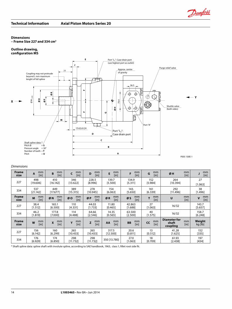
Dimensions – Frame Size 227 and 334
Introduction ................................................................................................................................................................................ 2Description .................................................................................................................................................................................. 2Typical markets .......................................................................................................................................................................... 2
Axial piston fixed displacement motor ............................................................................................................................. 4
Pump and motor circuit description .................................................................................................................................. 5Motor circuit schematic .......................................................................................................................................................... 5
Technical parameters .............................................................................................................................................................. 6Design ..................................................................................................................................................................................... 6Type of mounting ............................................................................................................................................................... 6Pipe connections................................................................................................................................................................. 6Direction of rotation and flow ........................................................................................................................................ 6Installation position ........................................................................................................................................................... 6External drain fluid loss .................................................................................................................................................... 6
Hydraulic parameters .............................................................................................................................................................. 7System pressure range, input p1 .................................................................................................................................... 7System pressure range, output p2................................................................................................................................. 7Case pressure ........................................................................................................................................................................ 7Hydraulic fluid ...................................................................................................................................................................... 7Hydraulic fluid temperature range ............................................................................................................................... 7Viscosity range ..................................................................................................................................................................... 7Filtration ................................................................................................................................................................................. 7Shaft load ............................................................................................................................................................................... 7Determination of nominal motor size ......................................................................................................................... 8
Outline drawing, configuration ms .................................................................................................................................... 9Outline drawing, basic model ............................................................................................................................................ 11Outline drawing, motor configuration am 01000 ....................................................................................................... 11Outline drawing, motor configuration mr ..................................................................................................................... 12Circuit diadrams ....................................................................................................................................................................... 13
Configuration MR .............................................................................................................................................................. 13Basic model and motor configuration AM 01000 ................................................................................................. 13
Outline drawing, configuration ms .................................................................................................................................. 14

Technical Information Axial Piston Motors Series 20
L1003465 • Rev BA • Jun 20144
P005 118E
Outputshaft
Shaft sealCylinder blockassembly
High pressurerelief valves(adjustable)
Purgerelief valve
Valve block
Shuttle valve Swashplate
Sectional View
Axial piston fixed displacement motor
General Description
Technical Information Axial Piston Motors Series 20
L1003465 • Rev BA • Jun 2014 5
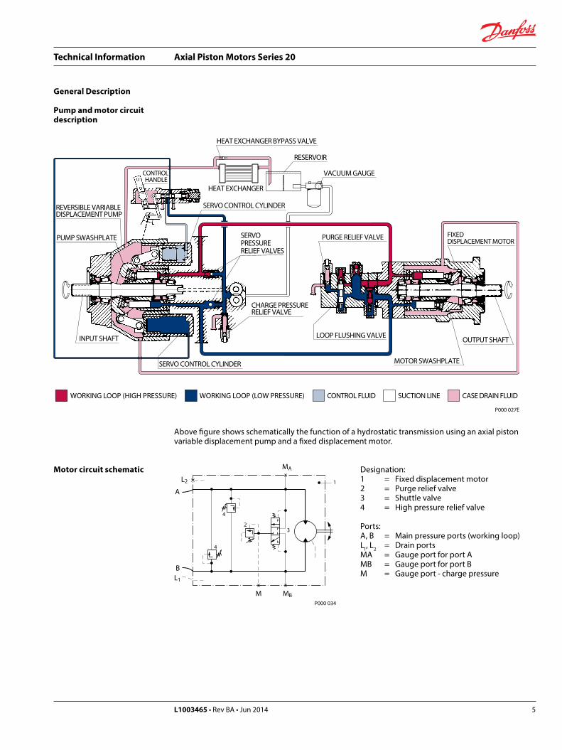
Pump and motor circuit description
Motor circuit schematic
HEAT EXCHANGER BYPASS VALVE
RESERVOIR
VACUUM GAUGE
HEAT EXCHANGER
OUTPUT SHAFT
MOTOR SWASHPLATE
FIXEDDISPLACEMENT MOTOR
LOOP FLUSHING VALVE
PURGE RELIEF VALVE
CHARGE PRESSURERELIEF VALVE
SERVOPRESSURERELIEF VALVES
SERVO CONTROL CYLINDER
SERVO CONTROL CYLINDER
PUMP SWASHPLATE
REVERSIBLE VARIABLEDISPLACEMENT PUMP
CONTROL HANDLE
INPUT SHAFT
WORKING LOOP (LOW PRESSURE) SUCTION LINE CASE DRAIN FLUIDCONTROL FLUIDWORKING LOOP (HIGH PRESSURE)
P000 027E
Designation:1 = Fixed displacement motor2 = Purge relief valve3 = Shuttle valve4 = High pressure relief valve
Ports:A, B = Main pressure ports (working loop)L1, L2 = Drain portsMA = Gauge port for port AMB = Gauge port for port BM = Gauge port - charge pressure
A
BL1
L2
M MB
MA
1
4
4
23
P000 034
Above figure shows schematically the function of a hydrostatic transmission using an axial piston variable displacement pump and a fixed displacement motor.
General Description

Technical Information Axial Piston Motors Series 20
L1003465 • Rev BA • Jun 20146
Technical Specification
Technical parameters DesignAxial piston motor with fixed displacement and swash plate design.
Type of mountingSAE four bolt flanges.
Pipe connectionsMain pressure ports: SAE split flangeRemaining ports: SAE O-ring boss
Direction of rotation and flowClockwise or counterclockwise (viewing from the output shaft).
Direction of rotation Port A Port BClockwise (R) Output Input
Counterclockwise (L) Input Output
Installation positionOptional; motor housing must be always filled with hydraulic fluid.
External drain fluid loss
P005 105E
Driveshaft speed n (min-1) (rpm)
Exte
rnal
dra
in fl
uid
loss
(l/m
in)
Typical values for 350 bar [5076 psi]and 18° swashplate angle
1000 2000 3000 400000
4
8
12
16
20
24
28334
089
070
(US
gal/m
in)
0
1
2
3
4
5
6
7
227
Technical Information Axial Piston Motors Series 20
L1003465 • Rev BA • Jun 2014 7
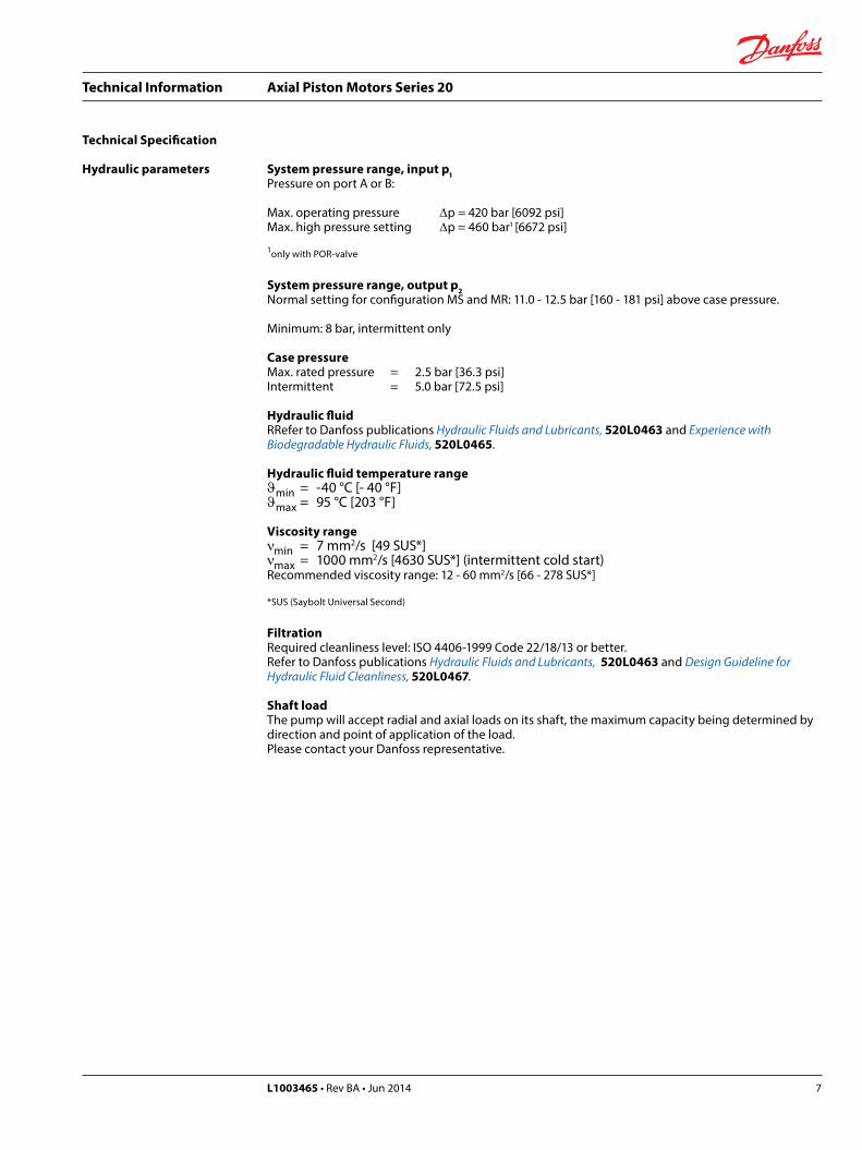
Hydraulic parameters System pressure range, input p1Pressure on port A or B:
Max. operating pressure ∆p = 420 bar [6092 psi]Max. high pressure setting ∆p = 460 bar1 [6672 psi]
1only with POR-valve
System pressure range, output p2Normal setting for configuration MS and MR: 11.0 - 12.5 bar [160 - 181 psi] above case pressure.
Minimum: 8 bar, intermittent only
Case pressureMax. rated pressure = 2.5 bar [36.3 psi]Intermittent = 5.0 bar [72.5 psi]
Hydraulic fluid RRefer to Danfoss publications Hydraulic Fluids and Lubricants, 520L0463 and Experience with Biodegradable Hydraulic Fluids, 520L0465.
Hydraulic fluid temperature rangeϑmin = -40 °C [- 40 °F]ϑmax = 95 °C [203 °F]
Viscosity rangeνmin = 7 mm2/s [49 SUS*]νmax = 1000 mm2/s [4630 SUS*] (intermittent cold start)Recommended viscosity range: 12 - 60 mm2/s [66 - 278 SUS*]
*SUS (Saybolt Universal Second)
FiltrationRequired cleanliness level: ISO 4406-1999 Code 22/18/13 or better.Refer to Danfoss publications Hydraulic Fluids and Lubricants, 520L0463 and Design Guideline for Hydraulic Fluid Cleanliness, 520L0467.
Shaft loadThe pump will accept radial and axial loads on its shaft, the maximum capacity being determined by direction and point of application of the load.Please contact your Danfoss representative.
Technical Specification

Technical Information Axial Piston Motors Series 20
L1003465 • Rev BA • Jun 20148
Technical Specification
Hydraulic parameters (continued)
Technical data
Frame size070 089 227 334
Max. displacement cm3
[in3]69.8
[4.26]89.0
[5.43]227.3
[13.87]333.7
[20.36]Rated speed 1 min-1 (rpm) 3200 2900 2100 1900
Theoretical torque Nm/bar[in lb/1000 psi]
1.11[677]
1.42[867]
3.62[2209]
5.31[3240]
Mass moment of inertia of rotating group
kg m2 • 10 -3
[lbf•ft2 • 10 -3]12.34
[292.8]17.77
[421.7]86.80
[2059.8]161.40
[3830.0]
1 for higher speeds contact your Danfoss representative
Determination of nominal motor size
Unit: Metric System: Inch System
Vg • n Vg • nInput flow Qe = l/min Qe = [gpm] 1000 • ηv 231 • ηv
Vg • ∆p • ηm Vg • ∆p • ηmOutput torque Me = Nm Me = [lbf•in] 20 • π 2 • π
Qe • ∆p • ηt Vg • n • ∆p • ηtOutput power Pe = kW Pe = [hp] 600 396 000
Qe • 1000 • ηv Qe • 231 • ηvSpeed n = min-1 n = (rpm) Vg Vg
Efficiency characteristic curves available on request.
Vg = Moror displacement per revolution cm3 [in3]n = Motor speed min-1 (rpm)∆p = Hydraulic pressure differential bar [psid] ∆p = pHD - pNDηv = Moror volumetric efficiencyηm = Moror mechanical efficiencyηt = Moror total efficiencypHD = High pressure bar [psid]pND = Low pressure bar [psid]

Technical Information Axial Piston Motors Series 20
L1003465 • Rev BA • Jun 2014 9
Outline drawing, configuration MS
* Shaft spline data: spline shaft with involute spline, according to SAE handbook, 1963, class 1, fillet root side fit.
Frame size Port A and B Port L1 and L2 Port MA and MB Port M
070SAE flange, size 1
SAE split flange boss5000 psi4 threads
3/8-16 UNC-2B18 deep
7/8-14 UNF-2BSAE straight thread
O-ring boss
7/16-20 UNF-2BSAE straight thread
O-ring boss089
K
J
E
Coupling may not protrudebeyond L mm maximumlenght of full spline
Port "L1": Case drain port(use highest port as outlet)
Approx. centreof gravity
26.2
Purge relief valve
Shuttle valve(both sides)
Port "A"
Port "L2":Case drain port
M
12.45±0.24
D
C
B
A
Shaft spline data: *Pitch Ø = SPressure angle = 30˚Number of teeth = TPitch = U
X
Ø N
-0.0
5
Ø O Ø P
Ø R
FF G
Ø H
52.4 Y
View YFlange design2/070
Gauge port "MA"
Port "A"
High pressure reliefvalve for port "B"
VPort "A"
VPort "B"
219
High pressure reliefvalve for port "A"
Port "B"
Gauge port "M"charge pressure
Gauge port "MB"
Dimensions – Frame Size 070 and 089 cm3

Technical Information Axial Piston Motors Series 20
L1003465 • Rev BA • Jun 201410
Dimensions – Frame Size 070 and 089 cm3
Outline drawing, configuration MS(continued)
W
45°
Ø162
Ø15+ 0.8– 0.3
Rotation
L R
Approx. centreof gravity
P005 119E
View X (for SMF 2/070 only)
168
168
142.
8
Ø19
3.5
Ø162
Rotation
L R
Approx. centreof gravity
Ø15 + 0,8– 0,3
168
156
168
View X (for SMF 2/089 only)
45° W
P005 120

Technical Information Axial Piston Motors Series 20
L1003465 • Rev BA • Jun 2014 11
Dimensions – Frame Size 070 and 089 cm3
Dimensions
Frame size A mm
[in] B mm [in] C mm
[in] D mm [in] E mm
[in] F mm [in] G mm
[in] Ø H mm [in] J mm
[in] K mm [in] L mm
[in] M mm [in]
070 378[14.882]
290[11.417]
255[10.039]
165[6.496]
108 [4.252]
86.5[3.406]
98[3.858]
161[6.339]
16[0.630]
56[2.205]
48[1.890]
28.4[1.118]
089 395[15.551]
307[12.087]
273[10.748]
170[6.693]
118[4.646]
96.0[3.780]
107[4.213]
181[7.126]
18[0.709]
56[2.205]
48[1.890]
28.4[1.118]
Frame size Ø N mm
[in] Ø O mm [in] Ø P mm
[in] Ø R mm [in] Ø S mm
[in] T mm [in] U mm
[in] V mm [in] W mm
[in]Diameter for
shaft coupling
mm [in]
Weightkg [lb]
070 127[5.000]
84[3.307]
34.50 -0.17
[1.358 -0.0067]8.5
[0.335]33.338[1.313]
21[0.827] 16/32 85.8
[3.378]101
[3.976]31.75 +0.062
[1.250 +0.0024]40
[88]
089 127[5.000]
98[3.858]
37.68 -0.17
[1.483 -0.0067]8.5
[0.335]36.513[1.438]
23[0.906] 16/32 95.2
[3.748]114
[4.488]34.95 +0.062
[1.376 +0.0024]47
[104]
Outline drawing, basic model
Outline drawing, motor configuration AM 01000
Dimensions
Frame size A mm [in] B mm [in] C mm [in] D mm [in] Weight kg [lb]070 290 [11.417] 30 [1.181] 12 [0.472]
2 [0.079]34 [75]
089 307 [12.087] 44 [1.732] 6 [0.236] 41 [90]
For further dimensions see previous pages.
Dimensions
Frame size A mm [in] Weight 1 kg [lb]070 315 [12.402] 36 [79]089 332 [13.071] 43 [95]
1 Light weight and short options available on requestFor further dimensions see previous pages.
P000 568E
CA B
A
D
B
Return from purge reliefvalve to motor case R3/4
P000 569E
12
A B
A
1.5
25
Return from purgerelief valve to motorcase 7/8 - 14 UNF - 2B
100
110
Outline drawing, configuration MS (continued)

Technical Information Axial Piston Motors Series 20
L1003465 • Rev BA • Jun 201412
Dimensions – Frame Size 070 and 089 cm3
Outline drawing, motor configuration MR
A
ABypass - handle
Purge relief valve
Shuttle valve(both sides)
B
129.
4 ±
0.25
Gauge port "MA"
Port "A"
High pressure reliefvalve for port "B"
High pressure reliefvalve for port "A"
Port "B"
Gauge port "M"charge pressure
Gauge port "MB"
58.5550.8
41.28
25.4
3 x Ø 6.5
19.0
5
Bypass valveopened
Partial View A-A
Bypass valveclosed
90°
90°
P005 104E
Dimensions
Frame size A mm[in] B mm
[in] Weight kg[lb] Port MA and MB Port M
070 426[16.772]
391[15.394]
42[93] 7/16-20 UNF-2B
SAE straight thread O-ring boss089 443
[17.441]408
[16.063]49
[108]
For further dimensions see previous pages.

Technical Information Axial Piston Motors Series 20
L1003465 • Rev BA • Jun 2014 13
Dimensions – Frame Size 070 and 089 cm3
Circuit diadrams Configuration MR
Basic model and motor configuration AM 01000
A
B
L1
L2
M MB
MA
1
4
5
4
2
3
P000 035
A
B
L2
L1
1
Return from purge reliefvalve to motor case
P000 038E
Designation:1 = Fixed displacement motor2 = Purge relief valve3 = Shuttle valve4 = High pressure relief valve5 = Bypass valve
Ports:A,B = Main pressure ports (working loop)L1, L2 = Drain portsMA = Gauge port for port AMB = Gauge port for port BM = Gauge port - charge pressure
Technical Information Axial Piston Motors Series 20
L1003465 • Rev BA • Jun 201414
Frame size A mm
[in] B mm [in] C mm
[in] D mm [in] E mm
[in] F mm [in] G mm
[in] Ø H mm [in] J mm
[in]
227498
[19.606]410
[16.142]346
[13.622]228.5
[8.996]139.7
[5.500]134.9
[5.311]152
[5.984]264
[10.394]27
[1.063]
334 537 [21.142]
449 [17.677]
389 [15.315]
278 [10.945]
154[6.063]
143.[5.650]
161[6.339]
292[11.496]
38[1.496]
Frame size M mm
[in] Ø N mm [in] Ø O mm
[in] Ø P mm [in] Ø R mm
[in] Ø S mm [in] T mm
[in] U mm [in] V mm
[in]
227 38.4[1.512]
165.1 [6.500]
110[4.331]
44.03 [1.733]
11.80 [0.465]
42.863[1.688]
27[1.063] 16/32 143.7
[5.657]
334 46.2[1.819]
177.8 [7.000]
114[4.488]
64.66[2.546]
14.35 [0.565]
63.500[2.500]
40[1.575] 16/32 158.7
[6.248]
Frame size W mm
[in] X mm [in] Y mm
[in] Z mm [in] AA mm
[in] BB mm [in] CC mm
[in]Diameter for
shaft coupling
mm [in]
Weightkg [lb]
227 156[6.142]
160[6.299]
265[10.433]
265 [10.433]
317.5 [12.500]
20.6[0.811]
13[0.512]
41.28[1.625]
152[335]
334 176[6.929]
174[6.850]
298 [11.732]
298 [11.732] 350 [13.780] 27.0
[1.063]18
[0.709]61.93
[2.438]197
[434]
Dimensions – Frame Size 227 and 334 cm3
Outline drawing, configuration MS
* Shaft spline data: spline shaft with involute spline, according to SAE handbook, 1963, class 1, fillet root side fit.
77
J
E
Coupling may not protrudebeyond L mm maximumlenght of full spline
Port "L1": Case drain port(use highest port as outlet)
Approx. centreof gravity
36.5
Purge relief valve
Shuttle valve(both sides)
Port "A"
Port "L2":Case drain port
M
15.62±0.24
D
C
B
A
Shaft spline data: *Pitch Ø = SPressure angle = 30°Number of teeth = TPitch = U
X Ø N
-0.0
5
Ø O
Ø P
Ø R
FF G
Ø H
79.4
Y
P005 100E-1
Dimensions

Technical Information Axial Piston Motors Series 20
L1003465 • Rev BA • Jun 2014 15
View Y View X
Gauge port "MA"
Port "A"
High pressure reliefvalve for port "B"
VPort "A"
VPort "B"
Z
High pressure reliefvalve for port "A"
Port "B"
Gauge port "M"charge pressure
Gauge port "MB"
Rotation
L R
Approx. centreof gravity
AA
45°
CC
Y
X W
BB
P005 100E-2
Dimensions – Frame Size 227 and 334 cm3
Outline drawing, configuration MS (continued)
Frame size Port A and B Port L1 and L2 Port MA and MB Port M
227SAE flange, size 1 1/2SAE split flange boss
6000 psi4 threads
5/8-11 UNC-2B35 mm deep
1 7/8-12 UNF-2BSAE straight thread
O-ring boss
7/16-20 UNF-2BSAE straight thread
O-ring boss334

Comatrolwww.comatrol.com
Schwarzmüller-Inverterwww.schwarzmueller-inverter.com
Turolla www.turollaocg.com
Valmovawww.valmova.com
Hydro-Gear www.hydro-gear.com
Daikin-Sauer-Danfosswww.daikin-sauer-danfoss.com
Danfoss Power Solutions is a global manufacturer and supplier of high-quality hydraulic and electronic components. We specialize in providing state-of-the-art technology and solutions that excel in the harsh operating conditions of the mobile off -highway market. Building on our extensive applications expertise, we work closely with our customers to ensure exceptional performance for a broad range of off -highway vehicles.
We help OEMs around the world speed up system development, reduce costs and bring vehicles to market faster. Danfoss – Your Strongest Partner in Mobile Hydraulics.
Go to www.powersolutions.danfoss.com for further product information.
Wherever off -highway vehicles are at work, so is Danfoss.
We off er expert worldwide support for our customers, ensuring the best possible solutions for outstanding performance. And with an extensive network of Global Service Partners, we also provide comprehensive global service for all of our components.
Please contact the Danfoss Power Solution representative nearest you.
Products we off er:
Bent Axis Motors
Closed Circuit Axial Piston Pumps and Motors
Displays
Electrohydraulic Power Steering
Electrohydraulics
Hydraulic Power Steering
Integrated Systems
Joysticks and Control Handles
Microcontrollers and Software
Open Circuit Axial Piston Pumps
Orbital Motors
PLUS+1® GUIDE
Proportional Valves
Sensors
Steering
Transit Mixer Drives
Local address:
Danfoss can accept no responsibility for possible errors in catalogues, brochures and other printed material. Danfoss reserves the right to alter its products without notice. This also applies to products already on order provided that such alterations can be made without changes being necessary in specifications already agreed.All trademarks in this material are property of the respective companies. Danfoss and the Danfoss logotype are trademarks of Danfoss A/S. All rights reserved.
Danfoss Power Solutions GmbH & Co. OHGKrokamp 35D-24539 Neumünster, GermanyPhone: +49 4321 871 0
Danfoss Power Solutions ApSNordborgvej 81DK-6430 Nordborg, DenmarkPhone: +45 7488 2222
Danfoss Power Solutions (US) Company2800 East 13th StreetAmes, IA 50010, USAPhone: +1 515 239 6000
Danfoss Power Solutions Trading(Shanghai) Co., Ltd.Building #22, No. 1000 Jin Hai RdJin Qiao, Pudong New DistrictShanghai, China 201206Phone: +86 21 3418 5200
L1003465 • Rev BA • Jun 2014 www.danfoss.com © Danfoss A/S, 2014-06