Radial piston hydraulic motor Hägglunds CB
80
Contents 1 Ordering code .......................................................... 2 2 Functional description ............................................. 4 3 Fluid connections ..................................................... 5 4 Technical data .......................................................... 7 5 Type of seal ............................................................ 50 6 Increased robustness ............................................. 50 7 Through hole kit ..................................................... 51 8 Dimensions / Interface ........................................... 52 9 Mounting alternatives............................................. 57 10 Accessories ............................................................ 62 11 Circuit design ......................................................... 75 12 Related documents ................................................ 77 RE 15302, Edition: 11.2017, Bosch Rexroth AB Radial piston hydraulic motor Features ▶ High power density ▶ High torque density ▶ Energy efficient ▶ Flexible, many sizes, few mechanical interfaces. ▶ Insensitive for shock loads ▶ Very low moment of inertia ▶ Small footprint (total occupied volume) ▶ Freewheeling possibility ▶ Through hole diameter 110 mm ▶ Torque range: up to 370 kNm [up to 272 898 lb-ft] ▶ Speed:range: up to 125 rpm ▶ Power range: up to 1000 kW ▶ Maximum operating pressure: 350 bar [5 076 psi] ▶ Frame size: 280, 400, 560, 840 and 1120 ▶ Displacement: 15 100 to 70 400 cm3/rev [921 to 4 296 in3/rev] ▶ Specific torque: 240 to 1120 Nm/bar [12 204 to 56 952 ft-lbs/1 000 psi] RE 15302 Edition: 12.2017 Replace: EN693-18h 2011 Hägglunds CB
-
Upload
khangminh22 -
Category
Documents
-
view
2 -
download
0
Transcript of Radial piston hydraulic motor Hägglunds CB

Contents
1 Ordering code ..........................................................22 Functional description .............................................43 Fluid connections .....................................................54 Technical data ..........................................................75 Type of seal ............................................................506 Increased robustness .............................................507 Through hole kit .....................................................518 Dimensions / Interface ...........................................529 Mounting alternatives .............................................5710 Accessories ............................................................6211 Circuit design .........................................................7512 Related documents ................................................77
RE 15302, Edition: 11.2017, Bosch Rexroth AB
Radial piston hydraulic motor
Features
▶ High power density ▶ High torque density ▶ Energy efficient ▶ Flexible, many sizes, few mechanical interfaces. ▶ Insensitive for shock loads ▶ Very low moment of inertia ▶ Small footprint (total occupied volume) ▶ Freewheeling possibility ▶ Through hole diameter 110 mm
▶ Torque range: up to 370 kNm [up to 272 898 lb-ft] ▶ Speed:range: up to 125 rpm ▶ Power range: up to 1000 kW ▶ Maximum operating pressure: 350 bar [5 076 psi] ▶ Frame size: 280, 400, 560, 840 and 1120 ▶ Displacement: 15 100 to 70 400 cm3/rev
[921 to 4 296 in3/rev] ▶ Specific torque: 240 to 1120 Nm/bar
[12 204 to 56 952 ft-lbs/1 000 psi]
RE 15302Edition: 12.2017Replace: EN693-18h 2011
Hägglunds CB


Radial piston hydraulic motor | Hägglunds CB 3/80
RE 15302, Edition: 12.2017, Bosch Rexroth AB
09 Through hole kit (see section 7)
No ● 0
Yes ● H
10 Increased robustness (see section 6)
No ● 0
Yes ● C
11 Modification *)
00-99
12 Design
Standard 00
Special index *) 01-99
● = Available – Not available
*) To be filled in by Bosch Rexroth DC-HD/ENG


Radial piston hydraulic motor | Hägglunds CB 5/80
RE 15302, Edition: 12.2017, Bosch Rexroth AB
3 Fluid connections
3.1 Hydraulic symbol
Fig. 2: Hydraulic symbol
A1 C1
T1
D3
F1
C2A2
F2
D4
D1
T1
T4
T3T2
D2
F3
T4
DD00087594
Port locations and dimensions, see Table 1: Port dimensions
6/80 Hägglunds CB | Radial piston hydraulic motor
Bosch Rexroth AB, RE 15302, Edition: 12.2017
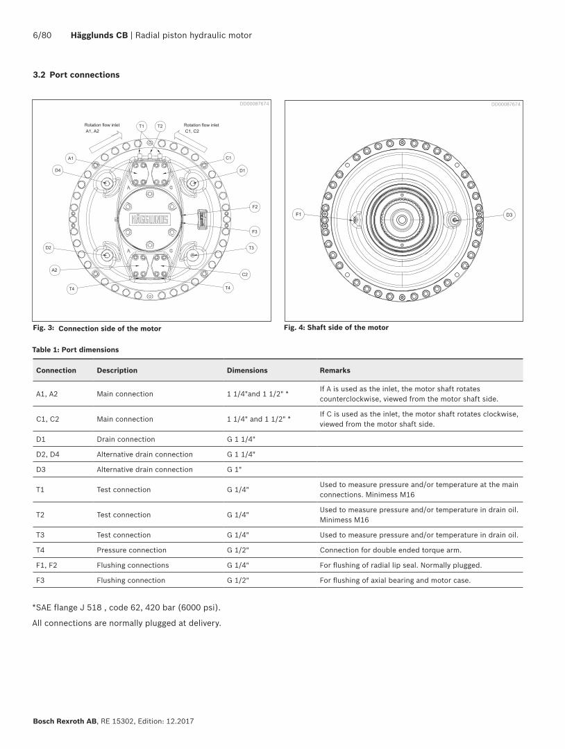
Fig. 3: Connection side of the motor Fig. 4: Shaft side of the motor
Table 1: Port dimensions
DD00087674DD00087674
Connection Description Dimensions Remarks
A1, A2 Main connection 1 1/4"and 1 1/2" *If A is used as the inlet, the motor shaft rotates counterclockwise, viewed from the motor shaft side.
C1, C2 Main connection 1 1/4" and 1 1/2" *If C is used as the inlet, the motor shaft rotates clockwise, viewed from the motor shaft side.
D1 Drain connection G 1 1/4"
D2, D4 Alternative drain connection G 1 1/4"
D3 Alternative drain connection G 1"
T1 Test connection G 1/4"Used to measure pressure and/or temperature at the main connections. Minimess M16
T2 Test connection G 1/4"Used to measure pressure and/or temperature in drain oil. Minimess M16
T3 Test connection G 1/4" Used to measure pressure and/or temperature in drain oil.
T4 Pressure connection G 1/2" Connection for double ended torque arm.
F1, F2 Flushing connections G 1/4" For flushing of radial lip seal. Normally plugged.
F3 Flushing connection G 1/2" For flushing of axial bearing and motor case.
*SAE flange J 518 , code 62, 420 bar (6000 psi).
All connections are normally plugged at delivery.
3.2 Port connections

Radial piston hydraulic motor | Hägglunds CB 7/80
RE 15302, Edition: 12.2017, Bosch Rexroth AB
4 Technical data
4.1 Calculation fundamentals
Table 2: Calculation fundamentals.
Quantity Symbol Metric US
Power P = kW hp
Output torque T = Nm lbf·ft
Specific torque Ts = Nm/bar lbf·ft/1000 psi
Rotational speed n = rpm rpm
Required pressure p = bar psi
Pressure loss ∆pl = bar psi
Charge pressure pc = bar psi
Flow rate required q = l/min gpm
Total volumetric loss ql = l/min gpm
Displacement Vi = cm3/rev in3/rev
Mechanical efficiency
ηm = 0,98 1)
1) Not valid as starting efficiency
Metric US
Output power P=T ⋅ n
(kW) on driven shaft P=T ⋅ n
(hp) on driven shaft9549 5252
Output torque (ηm=98%)
T= Ts⋅(p-∆pl-pc )⋅ηm (Nm) T=Ts⋅(p-∆pl-pc )⋅ηm
(ibf⋅ft)1000
Pressure required (ηm=98%)
p=T
+∆pl+pc (bar) p=T⋅1000
+∆pl+pc (psi)Ts⋅ηm Ts⋅ηm
Flow rate required q=n ⋅ Vi
+ql (l/min) q=n ⋅ Vi
+ql (gpm)1000 231
Output speed n=q - ql
⋅1000 (rpm) n=q - ql
⋅231 (rpm)Vi Vi
Inlet power Pin=q⋅(p-pc )
(kW) Pin=q⋅(p-pc )
(hp)600 1714

8/80 Hägglunds CB | Radial piston hydraulic motor
Bosch Rexroth AB, RE 15302, Edition: 12.2017
Table 3: General data (metric)
Frame size
CB 280 CB 400 CB 560 CB 840 CB 1120
Type of mounting See section 9: Mounting alternatives
Port connections See section 3.2: Port connections
External loads See section 4.14: Permissible external loads
Hydraulic fluids See section 4.5: Hydraulic fluids
Pressure Maximum operating pressure bar 350 350 3) 350 350 350
Maximum peak pressure 1) bar 420 420 420 420 420
Charge pressure bar See section 4.4: Recommended charge pressure
Maximum case pressure bar 3 3 3 3 3
Maximum case peak pressure 2) bar 8 8 8 8 8
Temperature limits of case drain oilSeal type: NBR (Nitrile)
Minimum °C -35 -35 -35 -35 -35
Maximum °C +70 +70 +70 +70 +70
Seal type: FPM (Viton)
Minimum °C -20 -20 -20 -20 -20
Maximum °C +100 +100 +100 +100 +100
Oil volume in motor case l 15 21 19 25 32
Moment of inertia for rotary group
Motor with splines kg·m2 7.2 15.0 18.1 31.1 42.1
Motor with shaft coupling kg·m2 9.1 18.3 22.7 35.7 72.7 4)
Weight
Motor with splines kg 705 1060 1115 1445 1770
Motor with shaft coupling kg 800 1160 1290 1620 2340 4)
1) Peak pressure 420 bar maximum, allowed to occur up to 10 000 times.2) Momentary pressure spikes t< 0.1 s of up to 8 bar are permitted.3) Pressure limitations in some nominal motor sizes see Table 54) Motor including coupling adapter
4.2 General data

Radial piston hydraulic motor | Hägglunds CB 9/80
RE 15302, Edition: 12.2017, Bosch Rexroth AB
Table 4: General data (US)
Frame size
CB 280 CB 400 CB 560 CB 840 CB 1120
Type of mounting See section 9: Mounting alternatives
Port connections See section 3.2: Port connections
External loads See section 4.14: Permissible external loads
Hydraulic fluids See section 4.5: Hydraulic fluids
Pressure Maximum operating pressure psi 5076 5076 3) 5076 5076 5076
Maximum peak pressure 1) psi 6091 6091 6091 6091 6091
Charge pressure psi See section 4.4: Recommended charge pressure
Maximum case pressure psi 44 44 44 44 44
Maximum case peak pressure 2) psi 116 116 116 116 116
Temperature limits of case drain oilSeal type: NBR (Nitrile)
Minimum °F -31 -31 -31 -31 -31
Maximum °F +158 +158 +158 +158 +158
Seal type: FPM (Viton)
Minimum °F -4 -4 -4 -4 -4
Maximum °F +212 +212 +212 +212 +212
Oil volume in motor case US gal 4.0 5.6 5.0 6.6 8.5
Moment of inertia for rotary group
Motor with splines lb·ft2 170.859 355.955 429,520 738.014 999.048
Motor with shaft coupling lb·ft2 215.946 434.266 538.679 847.174 1725.197 4)
Weight
Motor with splines lb 1555 2335 2450 3185 3900
Motor with shaft coupling lb 1760 2555 2840 3570 10692 4)
1) Peak pressure 6091 psi maximum, allowed to occur up to 10 000 times.2) Momentary pressure spikes t< 0.1 s of up to 116 psi are permitted3) Pressure limitations in some nominal motor sizes see Table 64) Motor including coupling adapter

10/80 Hägglunds CB | Radial piston hydraulic motor
Bosch Rexroth AB, RE 15302, Edition: 12.2017
4.3 Motor data
Frame size Nominal size
Specific torque DisplacementMaximum torque 1)
Maximum speed
Maximum operating pressure 2)
Maximum operating power 3)
Nm/bar cm3/rev kNm rpmp
barkW
CB 280 240 240 15100 79 68 350 530
280 280 17600 92 58 350 530
CB 400 240 240 15100 79 125 5) 350 970
280 280 17600 92 105 350 950
320 320 20100 110 94 350 970
360 360 22600 120 82 350 960
400 400 25100 130 75 350 970
440 440 27600 131 65 320 4) 820
480 480 30200 129 62 290 4) 660
520 520 32700 130 57 270 4) 670
560 560 35200 129 53 250 4) 630
CB 560 440 440 27600 140 65 350 930
480 480 30200 160 62 350 970
520 520 32700 170 57 350 960
560 560 35200 180 53 350 970
CB 840 600 600 37700 200 45 350 880
640 640 40200 210 41 350 850
680 680 42700 220 40 350 890
720 720 45200 240 37 350 870
760 760 47800 250 34 350 840
800 800 50300 260 34 350 890
840 840 52800 280 32 350 870
CB 1120 880 880 55300 290 34 350 970
920 920 57800 300 33 350 980
960 960 60300 315 32 350 990
1000 1000 62800 330 31 350 1000
1040 1040 65300 340 29 350 980
1080 1080 67900 355 28 350 980
1120 1120 70400 370 27 350 980
1) Calculated as: Metric= Ts • (350-15) • 0,982) The motors are designed according to DNV-rules. Test pressure 420 bar. Peak pressure 420 bar maximum , allowed up to 10 000 times.3) Flushing of motor case is required. See section 4.10: Flushing4) Note! Max pressure <350 bar5) Viton seals are recommended for speeds above 110 rpm
Table 5: Specific data, metric

Radial piston hydraulic motor | Hägglunds CB 11/80
RE 15302, Edition: 12.2017, Bosch Rexroth AB
Frame size Nominal size
Specific torque DisplacementMaximum torque 1)
Maximum speed
Maximum operating pressure 2)
Maximum operating power 3)
lbf·ft/1000 psi in3/rev lbf·ft rpmp
psihp
CB 280 240 12200 920 5700 68 5000 710
280 14200 1070 67000 58 5000 710
CB 400 240 12200 920 57000 125 5) 5000 1300
280 14200 1070 67000 105 5000 1300
320 16300 1230 76000 94 5000 1300
360 18300 1380 86000 82 5000 1300
400 20300 1530 95000 75 5000 1300
440 22400 1690 97000 65 4600 4) 1100
480 24400 1840 95000 62 4200 4) 890
520 26400 1990 96000 57 3900 4) 900
560 28500 2150 95000 53 3600 4) 840
CB 560 440 22400 1690 100000 65 5000 1300
480 24400 1840 110000 62 5000 1300
520 26400 1990 140000 67 5000 1300
560 28500 2150 130000 53 5000 1300
CB 840 600 30500 2300 140000 45 5000 1200
640 32500 2450 150000 41 5000 1100
680 34600 2610 160000 40 5000 1200
720 36600 2760 170000 37 5000 1200
760 38700 2910 180000 34 5000 1100
800 40700 3070 190000 34 5000 1200
840 42700 3220 200000 32 5000 1200
CB 1120 880 44700 3370 210000 34 5000 1300
920 46700 3520 220000 33 5000 1300
960 48800 3680 230000 32 5000 1300
1000 50800 3830 240000 31 5000 1300
1040 52800 3980 250000 29 5000 1300
1080 54900 4140 260000 28 5000 1300
1120 56900 4290 270000 27 5000 1300
Table 6: Specific data, US
1) Calculated as: US= Ts • (5076-215) • 0,982) The motors are designed according to DNV-rules. Test pressure 6000 psi. Peak pressure 6000 psi maximum , allowed up to 10 000 times.3) Flushing of motor case is required. See section 4.10: Flushing4) Note! Max pressure <350 bar5) Viton seals are recommended for speeds above 110 rpm

12/80 Hägglunds CB | Radial piston hydraulic motor
Bosch Rexroth AB, RE 15302, Edition: 12.2017
Notice!The diagrams is valid for 1 bar (14,5 psi) case pressure. With increasing case pressure the charge pressure must be increased accordingly.
4.4 Recommended charge pressureThe hydraulic system must be such that the motor will recieve sufficient charge pressure at the charge pressure port. This applies to all types of installations.
4.4.1 The motor working in driving mode onlyThe pressure at the charge pressure port, should, during operation of the motor, be at least one bar above the case pressure independent of numbers of ports that are connect-ed. Two cases to be considered:
Case 1: No shock loads.Required charge pressure = case pressure + 1 bar (14.5 psi) during operation, but shall not be below 2 bar (29.0 psi)
Case 2: With shock loads.Required charge pressure at the outlet port corresponds to 30% of value given in diagram. See Fig. 5.and Fig. 6
--
DD00090230
4.4.2 The motor working in braking modeRequired charge pressure at the inlet port is accordingto diagram. See Fig. 5 and Fig. 6.
Fig. 5: Recommended charge pressure for motor workning in braking mode, Hägglunds CB 280, 2-port connection. Valid for oil viscosity 40 cSt.

Radial piston hydraulic motor | Hägglunds CB 13/80
RE 15302, Edition: 12.2017, Bosch Rexroth AB
- -
Fig. 6: Recommended charge pressure for motor workning in braking mode, Hägglunds CB 280, 4-port connection. Valid for oil viscosity 40 cSt.
DD00087686

14/80 Hägglunds CB | Radial piston hydraulic motor
Bosch Rexroth AB, RE 15302, Edition: 12.2017
---------
Fig. 7: Recommended charge pressure for motor workning in braking mode, Hägglunds CB 400 to CB 560, 2-port connection. Valid for oil viscosity 40 cSt.
Fig. 8: Recommended charge pressure for motor workning in braking mode, Hägglunds CB 400 to CB 560, 4-port connection. Valid for oil viscosity 40 cSt.
DD00090231
DD00090232
---------

Radial piston hydraulic motor | Hägglunds CB 15/80
RE 15302, Edition: 12.2017, Bosch Rexroth AB
-------
-------
Fig. 9: Recommended charge pressure for motor workning in braking mode, Hägglunds CB 840, 2-port connection. Valid for oil viscosity 40 cSt.
Fig. 10: Recommended charge pressure for motor workning in braking mode, Hägglunds CB 840, 4-port connection. Valid for oil viscosity 40 cSt.
DD00090235
DD00090236

16/80 Hägglunds CB | Radial piston hydraulic motor
Bosch Rexroth AB, RE 15302, Edition: 12.2017
-------
Fig. 11: Recommended charge pressure for motor workning in braking mode, Hägglunds CB 1120, 2-port connection. Valid for oil viscosity 40 cSt.
DD00090239
-------
Fig. 12: Recommended charge pressure for motor workning in braking mode, Hägglunds CB 1120, 4-port connection. Valid for oil viscosity 40 cSt.
DD00090240


Radial piston hydraulic motor | Hägglunds CB 19/80
RE 15302, Edition: 12.2017, Bosch Rexroth AB
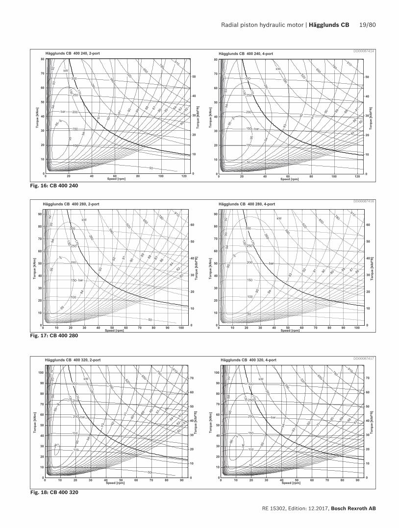
Fig. 16: CB 400 240
Fig. 18: CB 400 320
Fig. 17: CB 400 280
DD00087416
DD00087417
DD00087414

20/80 Hägglunds CB | Radial piston hydraulic motor
Bosch Rexroth AB, RE 15302, Edition: 12.2017
Fig. 19: CB 400 360
Fig. 20: CB 400 400
Fig. 21: CB 560 440. CB 400 440
DD00087418
DD00087419
DD00087421

Radial piston hydraulic motor | Hägglunds CB 21/80
RE 15302, Edition: 12.2017, Bosch Rexroth AB
Fig. 23: CB 560 520, CB 400 520
Fig. 24: CB 560 560, CB 400 560
DD00087422
DD00087429
Fig. 22: CB 560 480, CB 400 480
DD00087430

22/80 Hägglunds CB | Radial piston hydraulic motor
Bosch Rexroth AB, RE 15302, Edition: 12.2017
Fig. 25: CB 840 600
Fig. 26: CB 840 640
Fig. 27: CB 840 680
DD00087431
DD00087432
DD00087433

Radial piston hydraulic motor | Hägglunds CB 23/80
RE 15302, Edition: 12.2017, Bosch Rexroth AB
Fig. 28: CB 840 720
Fig. 29: CB 840 760
DD00087441
DD00087442
Fig. 30: CB 840 800
DD00090243

24/80 Hägglunds CB | Radial piston hydraulic motor
Bosch Rexroth AB, RE 15302, Edition: 12.2017
Fig. 31: CB 840 840
DD00087450
Fig. 32: CB 1120 880
DD00087451
Fig. 33: CB 1120 920
DD00090244

Radial piston hydraulic motor | Hägglunds CB 25/80
RE 15302, Edition: 12.2017, Bosch Rexroth AB
Fig. 34: CB 1120 960
Fig. 35: CB 1120 1000
DD00087454
DD00087458
Fig. 36: CB 1120 1040
DD00087462

26/80 Hägglunds CB | Radial piston hydraulic motor
Bosch Rexroth AB, RE 15302, Edition: 12.2017
Fig. 37: CB 1120 1080
Fig. 38: CB 1120 1120
DD00087472
DD00077356

Radial piston hydraulic motor | Hägglunds CB 27/80
RE 15302, Edition: 12.2017, Bosch Rexroth AB
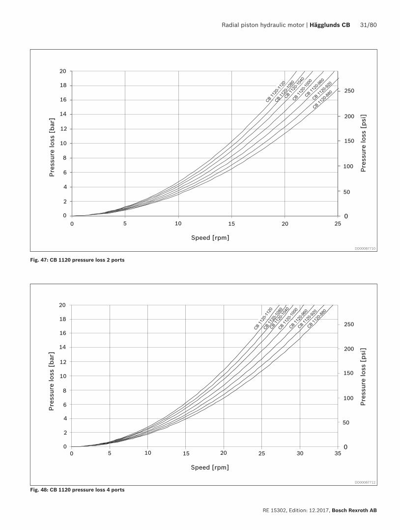
4.7 Pressure loss diagramsPressure loss, oil viscosity 40 cSt
Pres
sure
loss
[ps
i]
Pres
sure
loss
[ba
r]
20
18
16
14
12
10
8
6
4
2
0
0 10 20 30 40 50 60 70 800
50
100
150
200
250
CB 280-2
40
CB 28
0-28
0
Speed [rpm]
Speed [rpm]
Pres
sure
loss
[ba
r]
Pres
sure
loss
[ps
i]
20
18
16
14
12
10
8
6
4
2
0
0 10 20 30 40 50 60 70 80
0
50
100
150
200
250
CB 280
-240
CB 28
0-28
0
Fig. 39: CB 280 pressure loss 2 ports
Fig. 40: CB 280 pressure loss 4 ports
∆p =T
+ ∆plTs ⋅ηm
Actual pressure difference = output torque
+ pressure lossspecific torque ⋅ mechanichal effiency
DD00087699
DD00087702

28/80 Hägglunds CB | Radial piston hydraulic motor
Bosch Rexroth AB, RE 15302, Edition: 12.2017
Pres
sure
loss
[ba
r]
20
18
16
14
12
10
8
6
4
2
00 20 40 60 80
Speed [rpm]
100 140120
Pres
sure
loss
[ps
i]
0
50
100
150
200
250
CB 4
00-4
00CB
400
-360
CB 4
00-3
20CB
400-
280
CB 400-2
40
Pres
sure
loss
[ba
r]
20
18
16
14
12
10
8
6
4
2
00 10 20 30 40 50 60 70 80
Speed [rpm]
10090 110
Pres
sure
loss
[ps
i]
0
50
100
150
200
250
CB 4
00-4
00CB
400
-360
CB 4
00-3
20CB
400-
280
CB 400-2
40
Fig. 41: CB 400-240 to CB 400-400 pressure loss 2 ports
Fig. 42: CB 400240 to CB 400-400 pressure loss 4 ports
DD00087703
DD00087704

Radial piston hydraulic motor | Hägglunds CB 29/80
RE 15302, Edition: 12.2017, Bosch Rexroth AB
Pres
sure
loss
[ba
r]
20
18
16
14
12
10
8
6
4
2
0
Pres
sure
loss
[ps
i]
0
50
100
150
200
250
0 10 40 6020
Speed [rpm]
30 50 70
Pres
sure
loss
[ba
r]
20
18
16
14
12
10
8
6
4
2
00 10 40 6020
Speed [rpm]
30 50
Pres
sure
loss
[ps
i]
0
50
100
150
200
250
Fig. 43: CB 400-440 to CB 400-560, CB 560 pressure loss 2 ports
Fig. 44: CB 400-440 to CB 400-560, CB 560 pressure loss 4 ports
DD00087705
DD00087706

30/80 Hägglunds CB | Radial piston hydraulic motor
Bosch Rexroth AB, RE 15302, Edition: 12.2017
Pres
sure
loss
[ba
r]
20
18
16
14
12
10
8
6
4
2
0
0 10 155 4035
Speed [rpm]
302520 45 50
Pres
sure
loss
[ps
i]
0
50
100
150
200
250
Pres
sure
loss
[ba
r]
20
18
16
14
12
10
8
6
4
2
0
0 10 155
Pres
sure
loss
[ps
i]
0
50
100
150
200
250
4035
Speed [rpm]
302520
Fig. 45: CB 840 pressure loss 2 ports
Fig. 46: CB 840 pressure loss 4 ports
DD00087707
DD00087709
Radial piston hydraulic motor | Hägglunds CB 31/80
RE 15302, Edition: 12.2017, Bosch Rexroth AB
Pres
sure
loss
[ba
r]
20
18
16
14
12
10
8
6
4
2
00 10 155
Speed [rpm]
2520 3530
Pres
sure
loss
[ps
i]
0
50
100
150
200
250
Pres
sure
loss
[ba
r]
20
18
16
14
12
10
8
6
4
2
00 10 155
Speed [rpm]
2520
Pres
sure
loss
[ps
i]
0
50
100
150
200
250
Fig. 47: CB 1120 pressure loss 2 ports
Fig. 48: CB 1120 pressure loss 4 ports
DD00087710
DD00087712

32/80 Hägglunds CB | Radial piston hydraulic motor
Bosch Rexroth AB, RE 15302, Edition: 12.2017
Fig. 49: Quick selection diagram
4.8 Quick selection diagram
Rated life for Hägglunds CB is calculated according to DIN ISO 281 Apendix 1.
The diagram below represents the torque and speed, corresponding to a modified rating life L10mh = 40 000 h. Oil viscosity in motor case 40 cSt. Contamination level not exceeding ISO 4406 18/16/13 (NAS 1638, class 7). The diagram is based on a charge pressure of 15 bar (218 psi).
Notice!Higher case oil viscosity increases the motor rating life considerably. Reduced temperature in the motor case, increase rating life for the motor.
--
- - ---
--
--
--
-
-
-
-
-
-
-
-
-
-
--
DD00087713


34/80 Hägglunds CB | Radial piston hydraulic motor
Bosch Rexroth AB, RE 15302, Edition: 12.2017
4.9.2 Vertical mountingWhen the motor is mounted vertically, the highest of four drain ports D1 to D4 must be used. Flushing (lubrication) of radial seal from charge pressure is necessary.
A) Motor shaft pointing upwards The drain line must be connected to the drain port D3 in the housing cover (See Fig. 51, alt.: A) Shaft side upwards).The flushing connection F1 on the housing cover should be connected to the charge pressure. With bidirectional drives, use the connection with lowest average pressure. (Connecting to high pressure will increase the motor drain flow).
A) Shaft side upwards B) Shaft side downwards Flushing flow inlet
DD00087722
B) Motor shaft pointing downwards
The drain line must be connected to one of the drain ports D1 to D4 in the connection block. (See Fig. 51 alt.: B) Shaft side downwards).The flushing connection F2 shall be connected to charge pressure. With bidirectional drives, use the connection with lowest average pressure. (Connecting to high pressure will increase the motor drain flow).
Fig. 51: Vertical mounting
Charge pressure
Orifice ⌀ 1 mm
Charge pressure
Drain lineconnection
Radial seal Radial sealDust seal
Drain lineconnection
G1/4", Flushing
connection F1
G1/4", Flushingconnection F2

Radial piston hydraulic motor | Hägglunds CB 35/80
RE 15302, Edition: 12.2017, Bosch Rexroth AB
Required flushing to keep motor case maximum 10°C (18°F) warmer than flushing oil: q flushing = 3.4 · (E1 + E2 - Heat transmitted to air) l/min. q flushing US = 0.67 · (E1US + E2US - Heat transmitted to air) gpm.Viscosity in the motor case must be controlled according to diagram, Fig. 13. Exemple: Hägglunds CB 400-400 working at 250 bar and n = 20 rpm.
The CB motors have very high overall efficiency, and they are frequently used in applications with high power.To avoid high temperature in the case, the losses generated in the motors must be cooled away. High temperature gives lower viscosity and this gives reduction in basic rating life and max allowed power for the motor. Flushing flow inlets, see Fig. 50 and Fig. 51.For continuous duty the motors must be flushed when the shaft power exceed the following max power:
Flushing of motor case
E1 = 0.01 · 209.2 = 2.1 kW (2.8 hp)
When the motor have to be flushed, the required flushing flow can be calculated according to following:E1 = Power loss due to mechanical losses = c ⋅ motor powerE2 = Power loss due to volumetric losses
Total power =phigh ⋅ n ⋅ Vi
=250 ⋅ 20 ⋅ 25100
= 209.2 kW . The motor case must be flushed600 ⋅ 1000 600 ⋅ 1000
E2 =7 ⋅ 250
= 2.9 kW (3.9 hp)600
q flushing = 3.4 · (E1 + E2 - Heat transmitted to air) = 3.4 · (2.1 + 2.9 - 0.9) = 14 l/minq flushing US = 0.67 · (E1US + E2US - Heat transmitted to air) = 0.67 · (2.8 + 3.9 - 1.2) = 3.7 gpm
E1 =c ⋅ phigh ⋅ n ⋅ Vi
(kW)600 ⋅ 1000
E1US
c ⋅ phigh ⋅ n ⋅ Vi(hp)
1714 ⋅ 231
E2 =q1 ⋅ phigh
(kW)600
E2US
q1 ⋅ phigh(hp)
1714
phigh = motor high pressure [bar] [psi] n = motor speed [rpm] Vi = motor displacement [cm3/rev] [in3/rev] ql = motor leakage [l/min] [gpm] (see Fig. 52)c = 0,01
Table 8: Maximum motor power without flushing
Frame size Flushing limit power, EFL
kW hp
CB 280 120 160
CB 400/560/840/1120 170 227
4.10 Flushing
Table 9: Heat transmitted to air at ambient temperature +20°C (68°F) and motor case temperature +50°C (122°F)
Frame size Heat transmitted to air
kW hp
CB 280 0.6 0.8
CB 400/560/840/1120 0.9 1.2

36/80 Hägglunds CB | Radial piston hydraulic motor
Bosch Rexroth AB, RE 15302, Edition: 12.2017
4.11 External leakageExternal leakage is from the distributor to the motor case and from the piston assembly to the motor case. Valid for 40 cSt and at 1/3 of max speed.
Fig. 52: External leakage
Fig. 53: Viscosity factor K
DD00087808
qUS=n ⋅ Vi
+ qi ⋅ K231
[gpm]Variation in external leakage at different oil viscosities. When calculating external leakage using other viscosities than 40 cSt, multiply the value given in the external leakage diagram by the factor K.
K1.5
1.0
0.5
10 20 40 60 100 200 400 600 1000n cSt
4.12 Viscosity factor KThe diagram shows the avarage values. Actual flow rate = speed ⋅ displacement + external leakage
DD00087726
q =n ⋅ Vi
+ qi ⋅ K1000
[l/min]

Radial piston hydraulic motor | Hägglunds CB 37/80
RE 15302, Edition: 12.2017, Bosch Rexroth AB
Hägglunds CB motors can be operated in freewheeling mode.Principally this is performed by disengaging the pistons, allowing the rotating group to rotate as a flywheel on its main bearings. The piston units are not engaged and thus there is no oil flow to cause a flow loss, Hägglunds motors of standard design are suitable for this performance due to the following facts:1. Pistons are not actuated by any return springs.2. The motor case can withstand sufficient case pressure
to force the pistons toward the bottom of each cylinder bore and keep them in this position.
The basic function of the freewheeling is to have the drain ports D1 - D4 lightly pressurized (see Fig. 56) while main ports A and C are without restriction drained directly to the fluid reservoir. See Fig. 55. The case pressure introduced in the normal drain connection will then act on the outer surface of each piston assembly pressing them towards the motor centre.
The rotating part of the motor (cylinder block with piston and cam roller) can now rotate on its main bearings wit-hout any pumping of oil, as the piston with cam rollers have lost any contact with the cam ring. See Fig. 54.
During freewheeling periods, the following functions must be performed:1. Main connections A & C of the motor drained to reservoir.2. Fail-safe type brake released, if used.3. An adequate pressure introduced into the drain ports of
the motor. See Fig. 56 (required case pressure).
Notice!It is not allowed for the pistons to extend back to the camring, until the motor has reached a complete standstill.
4.13 Freewheeling
4.13.1 The function of freewheeling
Fig. 54: Freewheeling
Fig. 55: Schematic principle freewheeling.
DD00075541
DD00077405
4.13.2 Circuit designThe following schematic explains a system (closed/open) with freewheeling (activated mode illustrated) as a perma-nent feature for the application.
Freewheeling valve function, see section 10.6.6 page 71.
A C
P A
P C1-3 bar
D2
D1
Flushing flow inlet

38/80 Hägglunds CB | Radial piston hydraulic motor
Bosch Rexroth AB, RE 15302, Edition: 12.2017
To use Hägglunds CB motor in freewheeling mode must following be maintained:
• The motor must be pressurized all the time when the motor is in freewheeling mode, see Fig. 56.
• The motor must be flushed all the time when the motor is in frewheeling mode, see Fig. 56.
An accumulator can be added into the circuit to shorten the time to retract all the pistons completely, see Fig. 56.
An accumulator can be added into the circuit to reduce the pressure spikes in the motor case when the pistons are extracted, see Fig. 55.
VF =Vi
2 NL
Freewheeling conditions are obtained by pressurizing the case via the drain connections and drain the main ports to tank. To retract all pistons completely, a certain oil volume is required depending upon motor type. This oil volume can be calculated from the following:
VF = Needed Freewheeling volume [cm3] or(in3)
Vi = Total displacement of the motor [cm3] or(in3)NL = 10 (No of lobes for one camring)
4.13.3 Oil volume for freewheeling

Radial piston hydraulic motor | Hägglunds CB 39/80
RE 15302, Edition: 12.2017, Bosch Rexroth AB
Freewheeling > 150 rpm only for emergency use*
Required case pressure1.0 bar
Required case pressure 1.5 bar
Required case pressure 2.5 bar
Required case pressure 3.0 bar
Power loss
Required Case flow
Pow
er lo
ss (
kW),
Cas
e flo
w (
l/m
in)
Pow
er lo
ss (
hp)
Cas
e flo
w (
US
gal/
min
)
13
12
11
10
9
8
7
6
5
4
3
2
1
00
5
10
15
20
25
30
35
40
45
50
55
60
65
40035030025020015010050Speed (rpm)
00
5
10
15
20
25
30
35
40
45
50
Notice! Freewheeling will require exchange of oil in the housing to prevent overheating.
In order to accomplish proper freewheeling, a case pressure according to Fig. 56 has to be maintained. On the other hand, a higher casing pressure than 2 bar (29 psi) should be avoided in order to achieve good life of the main radial shaft seal.
4.13.4 Power loss freewheelingEven if the freewheeling operation takes place with lowest possible friction in the main bearings and with no flow losses in the main ports of the motor, a powerloss must take place in the motor case due to viscous friction between moving and fixed parts. This powerloss is expressed in diagram, Fig. 56.Case flushing is required to prevent overheating, see diagram Fig. 56Required case pressure 1-3 bar (15-44 psi). Case oil temperatur to be below 50°C (122°F).
Fig. 56: Power loss freewheeling, oil viscosity 40 cSt (187 SSU)
DD00089889
*) Viton seals are recomended for speeds above 110 rpm.

40/80 Hägglunds CB | Radial piston hydraulic motor
Bosch Rexroth AB, RE 15302, Edition: 12.2017
4.14 Permissible external loads
4.14.1 External load with torque arm mounting
If non standard torque arms TC A are used, forces must be checked for main bearings and coupling.
Shaft mounted motor with torque arm.
Fr =T Fr = Total radial force on fixed motor mounting
l T = Output torque for motor
l = Lever length
a = The axial distance for action point of radial force
DD00087811
Fig. 57: Shaft mounted motor with torque arm.

Radial piston hydraulic motor | Hägglunds CB 41/80
RE 15302, Edition: 12.2017, Bosch Rexroth AB
Permissible external dynamic loads Hägglunds CB 280
Axial loads: Permissible axial load for intermittent duty Fa = 30 000 N (6 750 lbf).
Remark: For continuous axial load applications, please contact your Bosch Rexroth representative.
Bending: Permissible bending moment Mb for motor with shrink disk coupling is 30 000 Nm (22 110 lbf·ft).
4.14.2 Permissible external dynamic loads
Torque arm mounted motor. (Figure and diagram are not scaled to each other).Viscosity 40 cSt/187 SSU, speed 20 rpm.
Notice! When flange mounted motor, please contact Bosch Rexroths representative.
DD00087814
Fig. 58: Permissable external dynamic loads Hägglunds CB 280

42/80 Hägglunds CB | Radial piston hydraulic motor
Bosch Rexroth AB, RE 15302, Edition: 12.2017
Permissible external dynamic loads Hägglunds CB 400
Torque arm mounted motor. (Figure and diagram are not scaled to each other).Viscosity 40 cSt/187 SSU, speed 25 rpm.
Axial loads: Permissible axial load for intermittent duty Fa = 30 000 N (6 750 lbf).
Remark: For continuous axial load applications, please contact your Bosch Rexroth representative.
Bending: Permissible bending moment Mb for motor with shrink disk coupling is 30 000 Nm (22 110 lbf·ft).
Notice! When flange mounted motor, please contact Bosch Rexroths representative.
DD00087817
Fig. 59: Permissable external dynamic loads Hägglunds CB 400
Radial piston hydraulic motor | Hägglunds CB 43/80
RE 15302, Edition: 12.2017, Bosch Rexroth AB
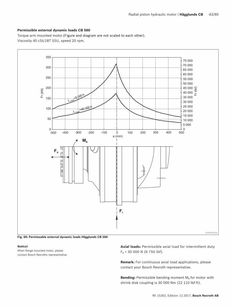
Permissible external dynamic loads CB 560Torque arm mounted motor.(Figure and diagram are not scaled to each other).Viscosity 40 cSt/187 SSU, speed 20 rpm.
Axial loads: Permissible axial load for intermittent dutyFa = 30 000 N (6 750 lbf).
Remark: For continuous axial load applications, please contact your Bosch Rexroth representative.
Bending: Permissible bending moment Mb for motor with shrink disk coupling is 30 000 Nm (22 110 lbf·ft).
Notice! When flange mounted motor, please contact Bosch Rexroths representative.
DD00087819
Fig. 60: Permissable external dynamic loads Hägglunds CB 560
44/80 Hägglunds CB | Radial piston hydraulic motor
Bosch Rexroth AB, RE 15302, Edition: 12.2017
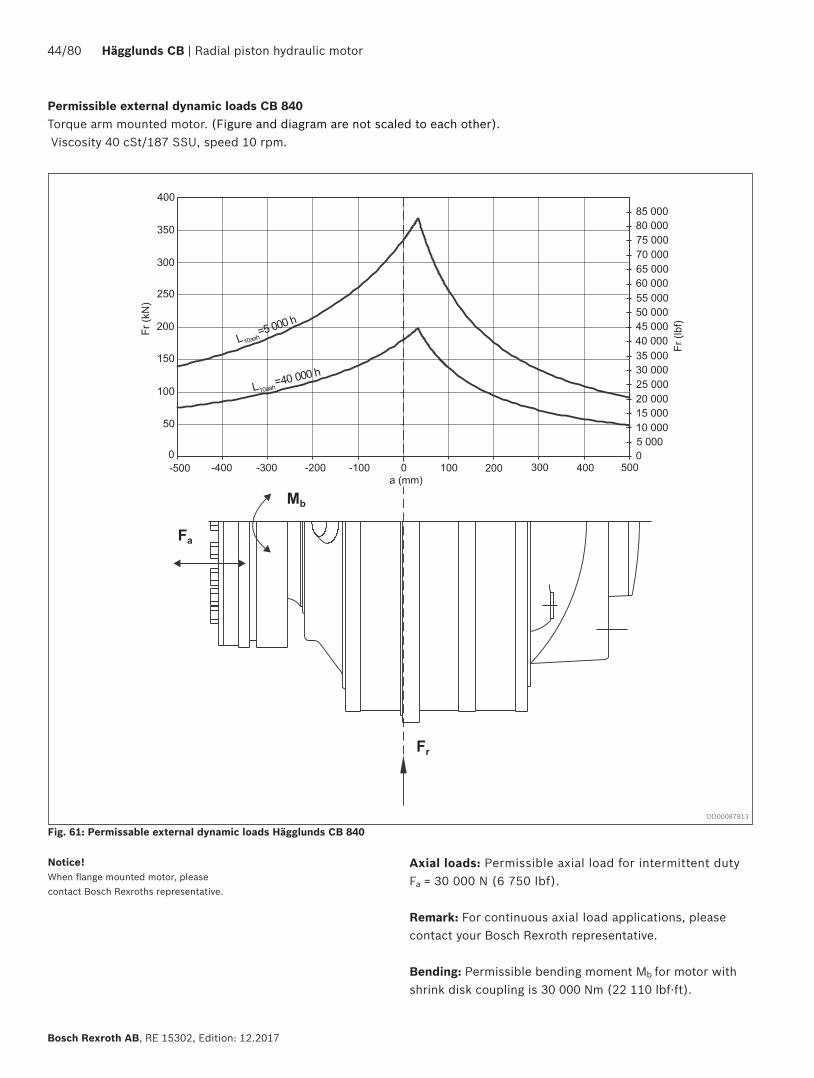
Permissible external dynamic loads CB 840Torque arm mounted motor. (Figure and diagram are not scaled to each other). Viscosity 40 cSt/187 SSU, speed 10 rpm.
Axial loads: Permissible axial load for intermittent dutyFa = 30 000 N (6 750 lbf).
Remark: For continuous axial load applications, please contact your Bosch Rexroth representative.
Bending: Permissible bending moment Mb for motor with shrink disk coupling is 30 000 Nm (22 110 lbf·ft).
Notice! When flange mounted motor, please contact Bosch Rexroths representative.
DD00087813
Fig. 61: Permissable external dynamic loads Hägglunds CB 840

Radial piston hydraulic motor | Hägglunds CB 45/80
RE 15302, Edition: 12.2017, Bosch Rexroth AB
Permissible external dynamic loads CB 1120
Torque arm mounted motor.(Figure and diagram are not scaled to each other).Viscosity 40 cSt/187 SSU, speed 10 rpm.
Axial loads: Permissible axial load for intermittent dutyFa = 30 000 N (6 750 lbf).
Remark: For continuous axial load applications, please contact your Bosch Rexroth representative.
Bending: Permissible bending moment Mb for motor with shrink disk coupling is 30 000 Nm (22 110 lbf·ft).
Notice! When flange mounted motor, please contact Bosch Rexroths representative.
DD00087820
Fig. 62: Permissable external dynamic loads Hägglunds CB 1120

46/80 Hägglunds CB | Radial piston hydraulic motor
Bosch Rexroth AB, RE 15302, Edition: 12.2017
4.14.3 Permissible external static load
Fig. 63: Permissible external static load Hägglunds CB 280
Fig. 64: Permissible external static load Hägglunds CB 400
DD00087821
DD00087823

Radial piston hydraulic motor | Hägglunds CB 47/80
RE 15302, Edition: 12.2017, Bosch Rexroth AB
Fig. 65: Permissible external static load Hägglunds CB 560
Fig. 66: Permissible external static load Hägglunds CB 840
DD00087827
DD00087828

48/80 Hägglunds CB | Radial piston hydraulic motor
Bosch Rexroth AB, RE 15302, Edition: 12.2017
Fig. 67: Permissible external static load Hägglunds CB 1120DD00087829

Radial piston hydraulic motor | Hägglunds CB 49/80
RE 15302, Edition: 12.2017, Bosch Rexroth AB
Exemple:Presume: nav = 1 rpm and pmax = 200 bar nav = 1 gives i = 0,1 (see Fig. 68) and A = 1 · 0,1 = 0,1 rpm.Obtained amplitude value shall be reduced to two decimals. nmax = 1,0 + 0,1 = 1,1nmin = 1,0 - 0,1 = 0,9
Speed variation data was acquired according to ISO 4392-3 where torque on the shaft and flow into the motor is held constant.
In order to obtain smooth operation at low speed it is important to understand that the mechanisms behind speed variation are governed by leakage and friction variation in the motor together with characteristics of the load and the hydraulic system.
When the theoretical flow needed to rotate the motor is in the same order of magnitude or less than the leakage flow there is a risk for speed variation. Friction losses in the motor will increase at low speed due to reduced oil film thickness. Any variation in these friction losses may result in speed variation.
• Speed variation resulting from both friction and leakage will be lower with high case oil viscosity. Recomendation is to have a case oil viscosity between 100-150 cSt. The load characteristics on the shaft will also affect speed variation, for example moment of inertia, friction effects and natural frequency.
• Smooth operation at low speed is enhanced by a constant flow source, like a flow control valve or a small pump that is not operating in its lower displacement range. Compressibility of hydraulic oil volume between flow source and motor and deformation of hoses may also result in speed variation, especially if the natural frequency of the hydraulic system and the load is close to each other.
• Therefore, smooth operation is enhanced by a stiff hydraulic system connecting the flow source and the motor, i.e. using short pipings with small dimension.
4.15 Low speed performanceFor Hägglunds CB 280 to CB 1120
Fig. 68 and Fig. 69 shows speed deviation factor "i" as function of nav. A is max. deviation from average speed in r/min. nav is average speed in r/min.A = nav · i (rpm) nmax = nav + A (rpm) nmin = nav - A (rpm)
The figures refers to 40 cSt viscosity, and moment of inertia 36 kgm2 (850 lb·ft2).
DD00090247
Fig. 68: Speed deviation CB 280
Fig. 69: Speed deviation CB 400, CB 560, CB 840, CB 1120
Exemple:Presume: nav = 1 rpm and pmax = 200 bar nav = 1 gives i = 0,05 (see Fig. 69) and A = 1 · 0,05 = 0,05 rpm.Obtained amplitude value shall be reduced to two decimals. nmax = 1,0 + 0,05 = 1,05nmin = 1,0 - 0,1 = 0,95
DD00090251

50/80 Hägglunds CB | Radial piston hydraulic motor
Bosch Rexroth AB, RE 15302, Edition: 12.2017
4.16 Painting system
Corrosion protection
The painting system of Hägglunds motors and accessories are avalible in two different corrosivity categories regarding corrosion protection in accordance with SS-EN ISO 12944:
• C3 - Corrosivity category Medium - which is recom-mended for normal urban and industrial atmosphere.
• C5M - Corrosivity category Very High - which is recommended for marine environment with high salt load or other aggressive atmosphere.
ColourStandard colour for Hägglunds motors and accessories is orange (RAL 2002)
Option N:
NBR (Nitrile) Preferred alternative at low ambient tempera-tures and moderate case oil temperatures.See section 4.2: General data
Option V:
FPM (Viton) Preferred alternative at higher case oil temper-atures and freewheeling at higher speed (> 110 rpm) or operating with fire resistant fluids. See section 4.2: General data, 4.13.4: Power loss freewheeling and 4.5: Hydraulic fluids
5 Type of seal
6 Increased robustness
Option 0:
CB has un-coated piston assemblies and DLC-coated piston rings as standard.
Option C:
DLC-coated piston assemblies shall always be used in the following cases: - If operating speed ≤3rpm - If operating parameters (eg. viscosity) are unclear
DLC-coated piston assemblies is recommended to be used in the following cases: - When replacing an existing MB-motor with a CB-motor- If there is a risk for cavitation in combination with chock loads

Radial piston hydraulic motor | Hägglunds CB 51/80
RE 15302, Edition: 12.2017, Bosch Rexroth AB
Fig. 70: Example: Hägglunds CB 400 with through hole kit.
7 Through hole kit
This device makes it possible to flush through the driven shaft or to draw electric cables through the motor. The through hole kit is prepared for rotation speed sensor.
Dimension drawingSee chapter12: Related documents
Ordering codeSee ordering code for Hägglunds CB section 1: Ordering code.
Ø 1
10.5
mm
[4.
350
in]
V-ring
O-ring
Oil filling for lubrication of spline G 1/4" (2x)
L1 with through hole (shrink disk)
L1
Splines Shrink disk
Motor mm in mm in
CB 280 490 19.29 599 23.58
CB 400 608 23.94 726 28.58
CB 560 658 25.91 752 29.61
CB 840 776 30.55 870 34.25
CB 1120 894 35.20 988 38.90
DD00087834
L1 with through hole (splines)
Table 10: Dimensions Hägglunds CB with through hole kit

52/80 Hägglunds CB | Radial piston hydraulic motor
Bosch Rexroth AB, RE 15302, Edition: 12.2017
Fig. 71: CB 280
For dimensional drawings CB 280, see chapter 12: Related documents
Dimensions
Splines Shrink disk
mm in mm in
D1 Pitch diameter 742 29.21 742 29.21
D2 Outer diameter 782 30.79 782 30.79
D4 Guide diameter 680 26.77 680 26.77
D5 Spline size DIN 5480 N200 x 5 x 30 x 38 x 9H - -
D6 Shrink disk diameter - - 405 15.94
L1 Total length Without through hole 494 19.45 603 23.74
L2 Length to hollow shaft 130 16.38 227 8.94
L3 Length to spline end 6 0.24 - -
L4 Length to spline 76 2.99 - -
L5 Protruding length of screws 36 1.42 36 1.42
Table 11: Dimensions CB 280
8 Dimensions / Interface
8.1 DimensionsDD00087852
Spline Shrink disk

Radial piston hydraulic motor | Hägglunds CB 53/80
RE 15302, Edition: 12.2017, Bosch Rexroth AB
Fig. 72: CB 400
Dimensions
Splines Shrink disk
mm in mm in
D1 Pitch diameter 742 29.21 742 29.21
D2 Outer diameter 782 30.79 782 30.79
D4 Diameter of guide edge 680 26.77 680 26.77
D5 Spline size DIN 5480 N200 x 5 x 30 x 38 x 9H - -
D6 Shrink disk diameter - - 440 17.32
L1 Total length Without through hole 612 24.09 729 28.70
L2 Length to hollow shaft 189 7.44 237 9.33
L3 Length to spline end 40 1.57 - -
L4 Length to spline 135 5.31 - -
L5 Produting length of screws 38 1.50 38 1.50
Table 12: Dimensions CB 400
For dimensional drawings CB 400, see chapter 12: Related documents
DD00087853
Spline Shrink disk

54/80 Hägglunds CB | Radial piston hydraulic motor
Bosch Rexroth AB, RE 15302, Edition: 12.2017
Fig. 73: CB 560
Table 13: Dimensions CB 560
Dimensions
Splines Shrink disk
mm in mm in
D1 Pitch diameter 870 34.25 870 34.25
D2 Outer diameter 940 37.01 940 37.01
D3 Screw hole 26 1.02 26 1.02
D4 Guide diameter 800 31.50 800 31.50
D5 Spline size DIN 5480 N260 x 5 x 30 x 50 x 9H - -
D6 Shrink disk diameter - - 520 20.47
L1 Total length Without through hole 662 26.06 576 22.68
L2 Length to hollow shaft 298 11.73 381 15,00
L3 Length to spline end 124 4.88 - -
L4 Length to spline 244 9.61 - -
L6 Thickness of mounting ring 35 1.38 35 1.38
DD00087854
For dimensional drawings CB 560, see chapter 12: Related documents
Spline Shrink disk

Radial piston hydraulic motor | Hägglunds CB 55/80
RE 15302, Edition: 12.2017, Bosch Rexroth AB
Fig. 74: CB 840
Dimensions
Splines Shrink disk
mm in mm in
D1 Pitch diameter 870 34.25 870 34.25
D2 Outer diameter 940 37.01 940 37.01
D3 Screw hole 26 1.02 26 1.02
D4 Guide diameter 800 31.50 800 31.50
D5 Spline size DIN 5480 N260 x 5 x 30 x 50 x 9H - -
D6 Shrink disk diameter - - 520 20.47
L1 Total length Without through hole 780 30,71 874 34.41
L2 Length to hollow shaft 298 11.73 381 15,00
L3 Length to spline end 124 4.88 - -
L4 Length to spline 244 9.61 - -
L6 Thickness of mounting ring 35 1.38 35 1.38
Table 14: Dimensions CB 840
DD00087858
For dimensional drawings CB 840, see chapter 12: Related documents
Spline Shrink disk

56/80 Hägglunds CB | Radial piston hydraulic motor
Bosch Rexroth AB, RE 15302, Edition: 12.2017
Fig. 75: CB 1120
Table 15: Dimensions CB 1120
Dimensions
Splines
mm in
D1 Pitch diameter 870 34.25
D2 Outer diameter 940 37.01
D3 Screw hole 26 1.02
D4 Guide diameter 800 31.50
D5 Spline size DIN 5480 N260 x 5 x 30 x 50 x 9H
L1 Total length Without through hole 897 35.31
L2 Length to hollow shaft 297 11.69
L3 Length to spline end 123 4.84
L4 Length to spline 243 9.57
L6 Thickness of mounting ring 35 1.38
DD00087859
For dimensional drawings CB 1120, see chapter 12: Related documents
Spline

Radial piston hydraulic motor | Hägglunds CB 57/80
RE 15302, Edition: 12.2017, Bosch Rexroth AB
9 Mounting alternatives
9.1 General information
With splines for flange or torque arm mounting.The splines shall be lubricated, and filled with hydraulic oil at assembly, or filled with transmission oil from the con-nected gearbox. To avoid wear in the splines, the installa-tion must be within the specified tolerances in Fig. 76For requirements of spline shaft, see chapter 12: Related documents
9.1.1 Flange mounting with splines
Fig. 76: Flange mounting for CB 280 to CB 1120.
Features
▶ Possibility to use the motor as a one side shaft support bearing.
▶ Oil lubrication of splines give no wear. ▶ Easy mounting of motor to driven shaft.
DD00090256
For installation drawings spline shaft flange mounting, see chapter 12: Related documents
O-ring delivered with the motor.Hydraulic oil must be filled
for spline lubrication to eliminate wear.
Note!
Note! Flange mounting gives high risk for overloading of motor main bearings. Always check that the shaft and motor bearings are statically determined.

58/80 Hägglunds CB | Radial piston hydraulic motor
Bosch Rexroth AB, RE 15302, Edition: 12.2017
Table 16: Recommended material in the spline shaft
Drive Steel with yield strenght
Unidirectional drive Relmin = 450 N/mm2 (65 000 lb/ft2)
Bidirectional drive Relmin = 700 N/mm2 (101800 lb/ft2)
Table 17: Spline designation shaft
Spline
Frame size CB 280 CB 400 CB 560 CB 860 CB 1120
Designation: Standard DIN 5480 W200x5x30x38x9H W260x5x30x50x9H
Fig. 77: Flange mounted motor with splines and low radial load from driven shaft.
Fig. 78: Flange mounted motor with splines to avoid high radial load from driven shaft.
DD00087934 DD00087935

Radial piston hydraulic motor | Hägglunds CB 59/80
RE 15302, Edition: 12.2017, Bosch Rexroth AB
9.1.2 Torque arm mounting with splines
DD00089488
For installation and dimensional drawings, spline shaft
torque arm mounting, see chapter 12: Related docu-ments
Mounting kit must be orederedseperately, see Table 18
Torque arm mounting, see chapter 10: Accessories
O-ring delivered with the motor.
Hydraulic oil must be filled for spline lubrication to eliminate wear.
Note!
Recommended material in the shaft, see Table 16.Spline designation shaft, see Table 17.
Fig. 79: Torque arm mounting motor with splines
Motor type Material ID Mounting kit(Must be ordered separatly)
CB 280 R939002612
CB 400 R939002613
CB 560 R939002614
CB 840 R939002615
Table 18: Material ID mounting kit for CB 280 to CB 840
60/80 Hägglunds CB | Radial piston hydraulic motor
Bosch Rexroth AB, RE 15302, Edition: 12.2017
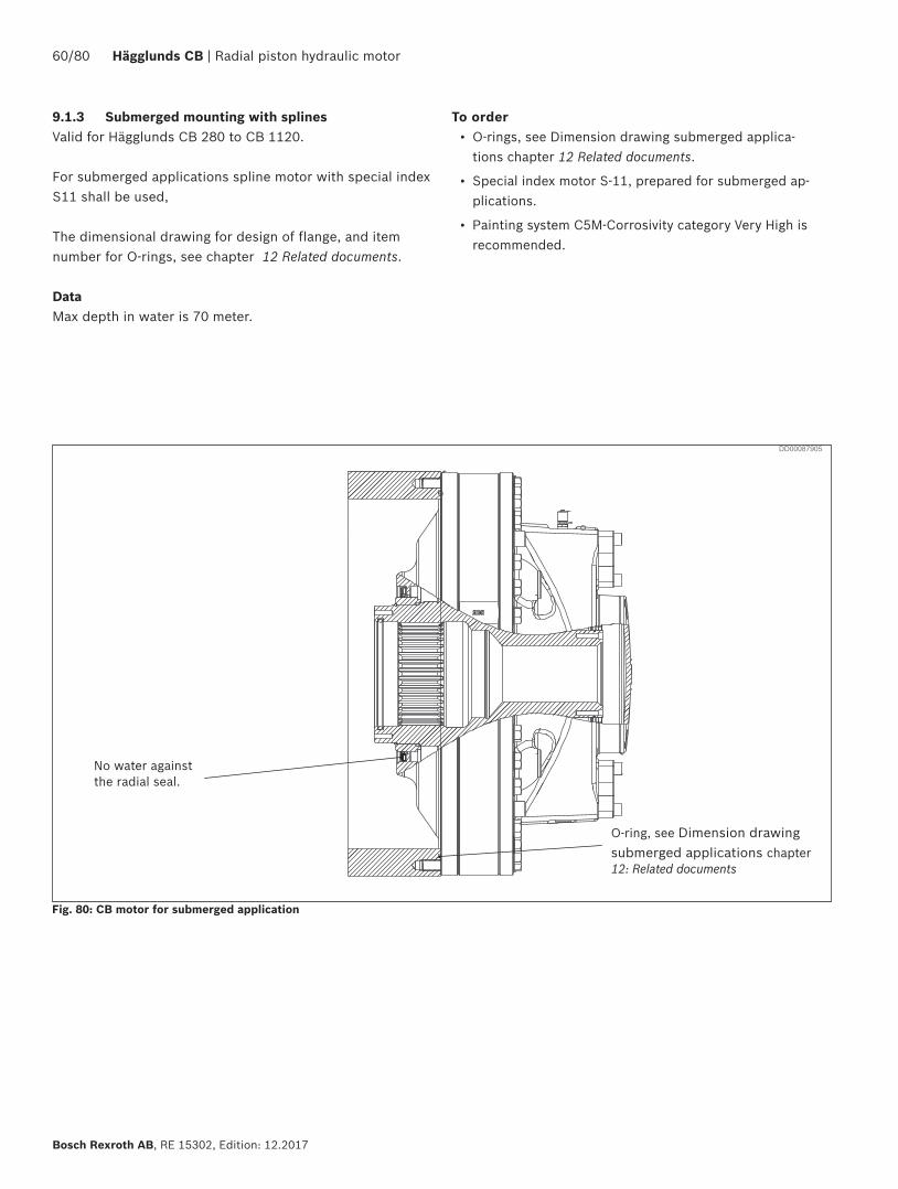
9.1.3 Submerged mounting with splinesValid for Hägglunds CB 280 to CB 1120.
For submerged applications spline motor with special index S11 shall be used,
The dimensional drawing for design of flange, and item number for O-rings, see chapter 12 Related documents.
DataMax depth in water is 70 meter.
No water against the radial seal.
O-ring, see Dimension drawing submerged applications chapter 12: Related documents
Fig. 80: CB motor for submerged application
To order• O-rings, see Dimension drawing submerged applica-
tions chapter 12 Related documents.
• Special index motor S-11, prepared for submerged ap-plications.
• Painting system C5M-Corrosivity category Very High is recommended.
DD00087905

Radial piston hydraulic motor | Hägglunds CB 61/80
RE 15302, Edition: 12.2017, Bosch Rexroth AB
9.1.4 Torque arm mounting on plain shaft
Design of driven shaft end on normally loaded shaftIn drives with only one direction of rotation and/or load where the stresses in the shaft are moderate, the shaft can be plain.
Design of driven shaft end on heavily loaded shaft.Where the driven shaft is heavily loaded and is subject to high stresses, for example for changes in the direction of rotation and/or load, it is recommended that the driven shaft should have a stress relieving groove.
Fig. 81: Torque arm mounted motor with shrink disk.
Fig. 82: Shaft end, normally loaded
Stressrelieving groove
DD00058217 DD00058218
Fig. 83: Shaft end, heavily loaded
DD00087938
Dimensions and material for shaft end, plain shaft
Table 19: Shaft recommendations
Dim CB 280 CB 400 CB 560/840/1120
A
mm ø180-0,014
ø200-0,015
ø260-0,017
-0,054 -0,061 -0,069
in ø7,0866-0,00055
ø18,1102-0,00059
ø10,2362-0,00067
-0,00215 -0,00240 -0,00272
Bmm 106 117 153
in 4,17 4,61 6,02
Cmm 174 194 254
in 6,85 7,64 10,00
Note! The dimensions are valid at +20 °C (68 °F)
Drive Steel with yield strenght
Unidirectional drive Relmin = 300 N/mm2
Bidirectional drives Relmin = 450 N/mm2
Measures Dimensions, threads for assembly tool
D M20 UNC 5/8"
E >17 mm 0,67 in >13,5 mm 0,53 in
F 25 mm 0,98 in 22 mm 0,87 in
G 50 mm 1,97 in 30 mm 1,18 in
Table 20: Threads for assembly tool (plain shaft)
Table 21: Recommended material in the shaft

62/80 Hägglunds CB | Radial piston hydraulic motor
Bosch Rexroth AB, RE 15302, Edition: 12.2017
10 Accessories
10.1 Torque arms
Mounting alternatives Dimensions, techical data, order code and material ID for torque arms, see separate data sheet: RE 15355
Features
▶ Easy mounting i.e. no alignment problems. ▶ Quick mounting of motor to driven shaft ▶ Robust torque-transmitting. ▶ Controlled external forces on driven shaft. ▶ Space saving. i.e. close mounting to the driven machine.
Features
▶ Easy mounting i.e. no alignment problems. ▶ Simplified machining of customer shaft. ▶ Controlled external forces on driven shaft.
Features
▶ Easy mounting i.e. no alignment problems. ▶ Quick mounting of motor to driven shaft ▶ Robust Torque-transmitting. ▶ Reduction of external forces on driven shaft.
Features
▶ Easy mounting i.e. no alignment problems.. ▶ Simplified machining of customer shaft. ▶ Reduction of external forces on driven shaft.
Fig. 84: Single ended torque arm mounting for spline shaft Fig. 85: Single ended torque arm mounting for plain shaft
+ For spline shaft on driven machine(spline motor)
For plain shaft on driven machine(coupling motor)
Plain shaft on driven machine
+
Fig. 86: Double ended torque arm mounting for spline shaft Fig. 87: Double ended torque arm mounting with plain shaft
Mounting kit
Mounting kit
Torque armTorque arm
Torque arm
For spline shaft on driven machine(spline motor)
Torque arm

Radial piston hydraulic motor | Hägglunds CB 63/80
RE 15302, Edition: 12.2017, Bosch Rexroth AB
10.2 Flushing set and Early warning kit
For technical data, see document nr: RE 15359For inspection and maintenance routines, see Installation and maintenance manual: RE 15302-WA.
Fig. 88: Magnetic plug mounted on CB
DD00087924
Description
The flushing set is basically a magnetic plug installed in the drain line. By regularly inspecting the magnetic plug a malfunction of the hydraulic motor can be detected and corrected and a total breakdown can be avoided. It can be used for HägglundsCB 280 to CB 1120.
Features
▶ Easy inspection of motor condition ▶ Early detection of potential failures

Radial piston hydraulic motor | Hägglunds CB 65/80
RE 15302, Edition: 12.2017, Bosch Rexroth AB
10.4 Temperature sensor
Fig. 91: Temperature sensor
Fig. 92: Temperature sensor
Table 24: Technical data, Pt 100/4-20 mA sensor
DD00070291
Function
The temperature sensor is mounted in port T3, see Fig. 92 and messure fluid temperature in the motor case. The sensor element is a Pt100 resistance sensor, which change resistance in relation to the fluid temperature in the motor case.
Sensor length l 60 mm (2.36“)
Process connection G 1/4“ 100
Degree of protection IP65
Ambient temperature - 40...+85 ºC (-40...185 ºF)
Type of sensor element Pt 100
Output 4-20 mA / 0..100 ºC (32...212 ºF)
Connector DIN 43650 screw terminals
Cable connection Pg9 cable Ø6-8 mm
Electrical connection 2-wire connection
ConnectionPin 1 - Ub Pin 2 – 4-20 mA output
Supply voltage Ub 7.5 - 30 VDC
Reverse polarity protection Yes
Max, load 750 Ω at 24 V ((Ub - 7.5 V)/0.022)
l
DD00089490
Technical data, Pt 100/4-20 mA sensor
Material ID: R939005085 Temperature sensor
66/80 Hägglunds CB | Radial piston hydraulic motor
Bosch Rexroth AB, RE 15302, Edition: 12.2017
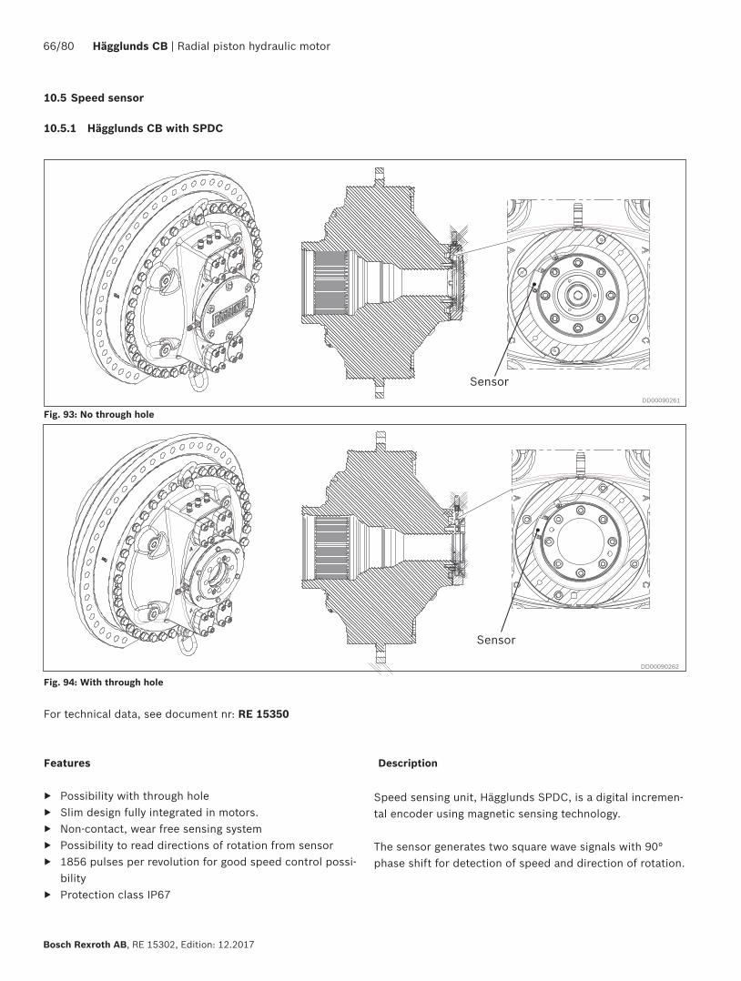
10.5 Speed sensor
10.5.1 Hägglunds CB with SPDC
Speed sensing unit, Hägglunds SPDC, is a digital incremen-tal encoder using magnetic sensing technology.
The sensor generates two square wave signals with 90° phase shift for detection of speed and direction of rotation.
Features
▶ Possibility with through hole ▶ Slim design fully integrated in motors. ▶ Non-contact, wear free sensing system ▶ Possibility to read directions of rotation from sensor ▶ 1856 pulses per revolution for good speed control possi-
bility ▶ Protection class IP67
For technical data, see document nr: RE 15350
Fig. 93: No through hole
Fig. 94: With through hole
Description
DD00090261
DD00090262
Sensor
Sensor

Radial piston hydraulic motor | Hägglunds CB 67/80
RE 15302, Edition: 12.2017, Bosch Rexroth AB
DD00087917
10.5.2 Explosion proof speed sensor SPDB 2
Fig. 95: SPDB 2
Features
▶ ATEX/IECEx approved ▶ 1000 and 3600 pulses per revolution for good speed
control possibility. ▶ Possibility to read directions of rotation from sensor ▶ Sensor is equipped with zero pulse ▶ Protection class IP65 ▶ Optional cable set with juction box to simplify
connection
For technical data, see document nr: RE 15352
Description
Digital incremental hollow shaft sensor with torque arm mounting.
Recommendations:
1000 pulses for speed 6 rpm and above. 3600 pulses for speed below 6 rpm.

68/80 Hägglunds CB | Radial piston hydraulic motor
Bosch Rexroth AB, RE 15302, Edition: 12.2017
Fig. 96: Inductive speed sensor SPDE with trough hole unit
For technical data, see document nr: RE 15351
10.5.3 Inductive speed sensor SPDE with through hole unit.
Material ID
Standard type R939002764
ATEX/IECEx type R393054489
Inductive speed sensor SPDE
The sensor is mainly intended for speed indication. Direction of rotation cannot be indicated.
Mounting is done by replacing a plug on the motor with the sensor and tighten to 35 Nm.
Features
▶ Non-contact, wear free system ▶ Robust design ▶ ATEX/IECEx -version available ▶ Through hole version available ▶ 40 pulses per revolution
Description
Two types of sensors are available.
• The standard type has a PNP output for direct driving of load or digital input.
• The ATEX/IECEx type (explosion proof) needs an isolation amplifier outside explosive area.
To order:
DD00080520
Ø 1
10.5
mm
[4.
350
in]

Radial piston hydraulic motor | Hägglunds CB 69/80
RE 15302, Edition: 12.2017, Bosch Rexroth AB
DD00090266
10.6 Valves
10.6.1 Counter balance valve, VCBCA 1000.
Fig. 97: Hydraulic circuit VCBCA 480 00 00 A
P C
910
920
Am CmA C
Features
▶ Compact and robust design ▶ Mounted directly on Hägglunds motors ▶ Counter balance function with low pilot pressure ▶ Pilot pressure independent of load pressure
The VCBCA 1000 valve is designed for Hägglunds motors and provides counter balance functions on the motor high pressure line and straight through connection on the motor charge pressure line. The maximum operating pressure is 350 bar (5076 psi) and maximum flow 1000 l/min (264 gpm).
For technical data, see document nr: RE 15379
DD00076214
10.6.2 Counter balance valve, VCBCA 480.
Features
▶ Compact and robust design ▶ Mounted directly on Hägglunds motors ▶ Counter balance function with low pilot pressure ▶ Pilot pressure independent of load pressure
The VCBCA 480 valve is designed for Hägglunds motors and provides counter balance function on one or both motor lines depending on the configuration. The maximum operating pressure is 350 bar (5076 psi) and maximum flow 480 l/min (127 gpm).
For technical data, see document nr: RE 15378
P CxPx C
Am Cm
Fig. 98: Hydraulic circuit VCBCA 1000 00DD00076176
DD00090269

70/80 Hägglunds CB | Radial piston hydraulic motor
Bosch Rexroth AB, RE 15302, Edition: 12.2017
Fig. 99: Hydraulic circuit COCB 1000 1
10.6.3 Cross-over valves, COCB 700 and COCB 1000
Features
▶ Compact and robust design ▶ Mounted directly on Hägglunds motors ▶ Oil exchange system for closed loop (COCB 1000-3) ▶ Protect the motor from high pressure peaks ▶ Provides cavitation protection
The valve COCB is designed for Hägglunds motors and provides cross-line relief at pressure shocks and cavitation protection. The relief valves has a standard setting of 350 bar (5076 psi) but can be delivered with preset level 280 bar (4061 psi), 300 bar (4351 psi) and 330 bar (4786 psi). Pressure setting is made without charge pres-sure.The charge pressure relief valve has a standard setting of 15 bar (218 psi) but is adjustable down to 3 bar (44 psi).
For technical data, see document nr: RE 15376
DD00074805
Fig. 100: Hydraulic circuit CTCA 1000
10.6.4 Constant tension valve, CTCA 1000
Features
▶ Compact and robust design ▶ Mounted directly on Hägglunds motors ▶ Possible for remote control of constant tension pressure ▶ Multi-functional ▶ Constant tension function via high performance cartridge ▶ Dynamic braking with hot oil exchange ▶ Free circulation function with minimal pressure drop ▶ Provided with an anti-cavitation check valve
The CTCA valve is designed for Hägglunds Compact motors and provides many functions in one valve unit. In addition to the constant tension function it provides possibilities for dynamic breaking as well as free-circulation function. The maximum operating pressure is 350 bar (5076 psi). The valve can be delivered with preset level 280 bar (4061 psi), 300 bar (4351 psi), 330 bar (4786 psi) and 350 bar (5076 psi)
For technical data, see document nr: RE 15377
DD00075297
DD00090271 DD00090273

Radial piston hydraulic motor | Hägglunds CB 71/80
RE 15302, Edition: 12.2017, Bosch Rexroth AB
The VFCCCA valve is designed for Hägglunds motors and provides free circulation or freewheeling functions.The maximum operating pressure is 350 bar (5076 psi) and maximum flow 1000 l/min (264 gpm).
The valve is available in four configurations:Free circulation valve Hydraulic operated with drive operat-ing mode or freewheeling mode as defaultFree circulation valve Electric operated 24VDC with drive operating mode or freewheeling mode as default
Features
▶ Compact and robust design ▶ Mounted directly on Hägglunds motors ▶ Free circulation function with minimal pressure drop ▶ Free circulation shift allowed up to 40 rpm ▶ Freewheeling function ▶ Shifting from drive operation into freewheeling allowed
up to 10 rpm ▶ Free circulation- or drive operating mode as default
For technical data, see document nr: RE 15381
10.6.5 Free circulation valve with freewheeling, VFCCA 1000
Fig. 101: Hydraulic circuit VFCCA 1000 HDD00076443
Fig. 102: Hydraulic circuit VFWCB 600
10.6.6 Freewheeling valve VFWCB 600
Features
▶ Compact and robust design ▶ Multifunctional ▶ Mounted directly on Hägglunds motors ▶ Detent function on pilot valve ▶ Possible for remote control
For technical data, see document nr: RE 15380
The VFWCB 600 valve is designed for Hägglunds motors and provides freewheeling of the motor by means of disconnecting the motor from the main lines and connect both motor ports to T which has to be drained to tank. The valve can be mounted directly onto the motor and can be used in both open and closed loop applications.Maximum operating pressure is 350 bar (5076 psi) and maximum flow 1000 l(min (264 gpm). Nominal flow is 600 l/min (156 gpm).The valve is available in three main configurations:VFWCB 600 E Freewheeling valve electrically operatedVFWCB 600 H Freewheeling valve hydraulically operatedVFWCB 600 M Freewheeling valve manually operated
DD00076119
DD00090274 DD00090275

72/80 Hägglunds CB | Radial piston hydraulic motor
Bosch Rexroth AB, RE 15302, Edition: 12.2017
Fig. 103: Hydraulic circuit V4WCA 1000
10.6.7 Four-way valve, V4WCA 1000
Features
▶ Compact and robust design ▶ Mounted directly on Hägglunds motors ▶ Fast response time
For technical data, see document nr: RE 15375
The VQCB 800 valve is designed for Hägglunds motors and provides quick stop for a roll mill rolls without stopping the electric motor and without any need of mechanical brake. A very short braking time is possible due to the small moment of inertia and quick response from hydraulic valve.Maximum operating pressure is 350 bar (5076 psi) and maximum flow 800 l/min (211 gpm). .
DD00057836Fig. 104: Hydraulic circuit VQCB 800
10.6.8 Hydraulic quick stop valve, VQCB 800
Features
▶ Compact and robust design ▶ Mounted directly on Hägglunds motors ▶ Four way directional and flow control of motor ▶ Proportionally controlled flow of the motor ▶ Counter balance function on motor pressure line
For technical data, see document nr: RE 15382
The V4WCA valve is designed for Hägglunds motors and provides four way directional and flow control of the motor. The flow is controlled proportional by external pilot pres-sure applied to ports X1 and X2. The valve includes a counter balance function on the motor pressure line. Maximum operating pressure is 350 bar (5076 psi) and maximum flow 1000 l/min (264 gpm).
The valve is available in one configuration:V4WCA-1000 including adapter
DD00076474
DD00090276 DD00090277

Radial piston hydraulic motor | Hägglunds CB 73/80
RE 15302, Edition: 12.2017, Bosch Rexroth AB
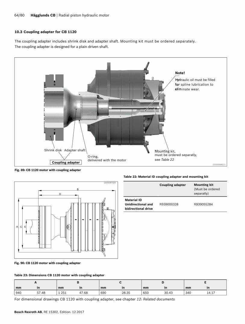
10.7 Hägglunds BICA
DD00088617
For technical data, see document nr: RE 15366
Description
The brakes are designed for industrial applications together with Hägglunds CB motors. The brake is made for dry operation of the discs and is not allowed for hanging load applications. BICA brakes are designed to be mounted on motors CB 280 - CB 1120. The brake is designed to be used as parking brake only.
Fig. 105: CB motor with BICA brake
Features
▶ Robust design, industrial HD design ▶ Possibility for on – off sensor ▶ Torque range between 48 – 160 kNm
74/80 Hägglunds CB | Radial piston hydraulic motor
Bosch Rexroth AB, RE 15302, Edition: 12.2017
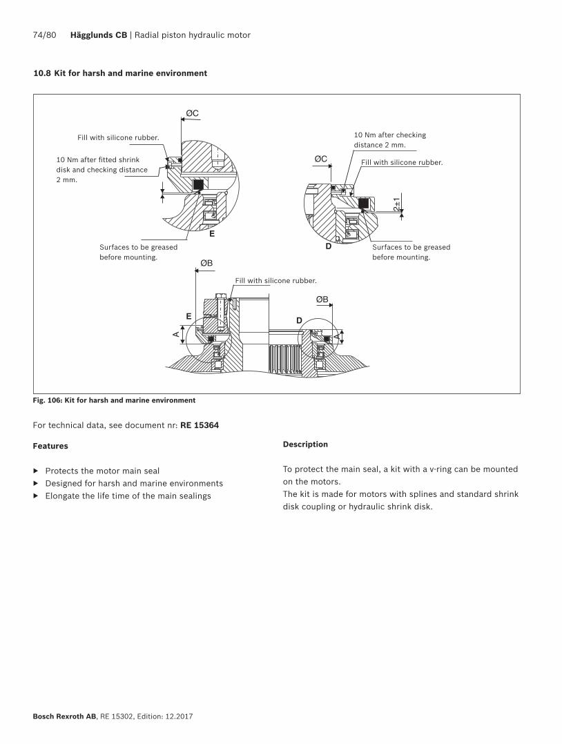
Description
To protect the main seal, a kit with a v-ring can be mounted on the motors.The kit is made for motors with splines and standard shrink disk coupling or hydraulic shrink disk.
10.8 Kit for harsh and marine environment
ØB
ØB
E D
A A
ØC
2±1
D
ØC
E
Features
▶ Protects the motor main seal ▶ Designed for harsh and marine environments ▶ Elongate the life time of the main sealings
Fig. 106: Kit for harsh and marine environment
For technical data, see document nr: RE 15364
Surfaces to be greased before mounting.
Fill with silicone rubber.
Surfaces to be greased before mounting.
10 Nm after fitted shrink disk and checking distance 2 mm.
10 Nm after checking distance 2 mm.
Fill with silicone rubber.
Fill with silicone rubber.

Radial piston hydraulic motor | Hägglunds CB 75/80
RE 15302, Edition: 12.2017, Bosch Rexroth AB
11 Circuit design
11.1 Closed circuit
Things to consider:1. Level of charge pressure.2. Case drain flow3. Filter4. Cooler
Fig. 107: Closed circuitDD00077068

76/80 Hägglunds CB | Radial piston hydraulic motor
Bosch Rexroth AB, RE 15302, Edition: 12.2017
Things to consider:1. Counter pressure required minimum 2 bar to ensure
recommended charge pressure. 2. Cross over relief valves for reduction of pressure
spikes.3. Anticavitation valves.4. Return line filter.5. Case flushing6. Cooler
11.2 Open circuit
Fig. 108: Open circuitDD00077074

Radial piston hydraulic motor | Hägglunds CB 77/80
RE 15302, Edition: 12.2017, Bosch Rexroth AB
Title Document no Document type
Hägglunds CB RE 15302-WA Installation & maintenance manual
CB 280 S 078 5006 Dimension drawing
CB 400 S 078 5007 Dimension drawing
CB 560 S 078 5008 Dimension drawing
CB 840 S 078 5009 Dimension drawing
CB 1120 S 078 5012 Dimension drawing
CB 280 C 078 5002 Dimension drawing
CB 400 C 078 5003 Dimension drawing
CB 560 C 078 5004 Dimension drawings
CB 840 C 078 5005 Dimension drawings
CB 1120 splines, with coupling adapter 078 5011 Dimension drawings
Speed sensor, Hägglunds SPDC RE 15350 Data Sheet
Speed sensor inductiv, Hägglunds SPDE RE 15351 Data Sheet
Speed sensor explosion proof, Hägglunds SPDB 2 with mounting set RE 15352 Data Sheet
Torque arms Hägglunds TCA, DTCA, DTCB RE 15355 Data Sheet
Flushing set and Early warning kit RE 15359 Data Sheet
Kit for harsh and marin environment RE 15364 Data Sheet
Disc brake for Compact motors, Hägglunds BICA RE 15366 Data Sheet
Hydraulic quick stop valve, Hägglunds VQCB 800 RE 15375 Data Sheet
Cross-over valve, Hägglunds COCB 500, COCB 1000 RE 15376 Data Sheet
Constant tension valve Hägglunds CTCA 1000 RE 15377 Data Sheet
Counter balance valve Hägglunds VCBCA 480 RE 15378 Data Sheet
Counter balance valve, Hägglunds VCBCA 1000 RE 15379 Data Sheet
Freewheeling valve, Hägglunds VFWCB 600 RE 15380 Data Sheet
Free circulation valve, Hägglunds VFCCA 1000 RE 15381 Data Sheet
Four-way valve including counter balance on load line, Hägglunds V4WCA 1000
RE 15382 Data Sheet
Hydraulic fluid quick reference RE 15414 Data sheet
12 Related documents

78/80 Hägglunds CB | Radial piston hydraulic motor
Bosch Rexroth AB, RE 15302, Edition: 12.2017

Radial piston hydraulic motor | Hägglunds CB 79/80
RE 15302, Edition: 12.2017, Bosch Rexroth AB

Bosch Rexroth AB895 80 Mellansel, SwedenTel: +46 (0) 660 870 00Fax: +46 (0) 660 871 [email protected] www.boschrexroth.com
The data specified above only serve to describe the product.As our products are constantly being further developed, no statements con-cering a certain condition or suitability for certain application can be derived from our information. The information given does not release the user from the obligation of own judgement and verification. It must be remembered that our products are subject to a natural process of wear and aging.
Bosch Rexroth AB, RE 15302, Edition: 12.2017
80/80 Hägglunds CB | Radial piston hydraulic motor