ELECTROMAGNETIC PISTON ENGINE - EP 0870923 B1
43
Note: Within nine months from the publication of the mention of the grant of the European patent, any person may give notice to the European Patent Office of opposition to the European patent granted. Notice of opposition shall be filed in a written reasoned statement. It shall not be deemed to have been filed until the opposition fee has been paid. (Art. 99(1) European Patent Convention). Printed by Jouve, 75001 PARIS (FR) Europäisches Patentamt European Patent Office Office européen des brevets (19) EP 0 870 923 B1 *EP000870923B1* (11) EP 0 870 923 B1 (12) EUROPEAN PATENT SPECIFICATION (45) Date of publication and mention of the grant of the patent: 07.05.2003 Bulletin 2003/19 (21) Application number: 96942635.2 (22) Date of filing: 24.12.1996 (51) Int Cl. 7 : F03G 7/00, H02K 33/00, H02K 33/16 (86) International application number: PCT/JP96/03770 (87) International publication number: WO 97/023728 (03.07.1997 Gazette 1997/29) (54) ELECTROMAGNETIC PISTON ENGINE ELEKTROMAGNETISCHER KOLBENMOTOR MOTEUR A PISTON ELECTROMAGNETIQUE (84) Designated Contracting States: DE FR GB NL (30) Priority: 25.12.1995 JP 33742295 (43) Date of publication of application: 14.10.1998 Bulletin 1998/42 (73) Proprietor: TAKARA, Muneaki Naha-shi, Okinawa 901-0152 (JP) (72) Inventor: TAKARA, Muneaki Naha-shi, Okinawa 901-0152 (JP) (74) Representative: Zinnecker, Armin, Dipl.-Ing. et al Lorenz-Seidler-Gossel, Widenmayerstrasse 23 80538 München (DE) (56) References cited: JP-A- 5 022 894 JP-A- 8 326 646 JP-A- 50 056 511 JP-A- 57 034 762
-
Upload
khangminh22 -
Category
Documents
-
view
3 -
download
0
Transcript of ELECTROMAGNETIC PISTON ENGINE - EP 0870923 B1

Note: Within nine months from the publication of the mention of the grant of the European patent, any person may givenotice to the European Patent Office of opposition to the European patent granted. Notice of opposition shall be filed ina written reasoned statement. It shall not be deemed to have been filed until the opposition fee has been paid. (Art.99(1) European Patent Convention).
Printed by Jouve, 75001 PARIS (FR)
Europäisches Patentamt
European Patent Office
Office européen des brevets
(19)
EP
0 87
0 92
3B
1*EP000870923B1*(11) EP 0 870 923 B1
(12) EUROPEAN PATENT SPECIFICATION
(45) Date of publication and mentionof the grant of the patent:07.05.2003 Bulletin 2003/19
(21) Application number: 96942635.2
(22) Date of filing: 24.12.1996
(51) Int Cl.7: F03G 7/00, H02K 33/00,H02K 33/16
(86) International application number:PCT/JP96/03770
(87) International publication number:WO 97/023728 (03.07.1997 Gazette 1997/29)
(54) ELECTROMAGNETIC PISTON ENGINE
ELEKTROMAGNETISCHER KOLBENMOTOR
MOTEUR A PISTON ELECTROMAGNETIQUE
(84) Designated Contracting States:DE FR GB NL
(30) Priority: 25.12.1995 JP 33742295
(43) Date of publication of application:14.10.1998 Bulletin 1998/42
(73) Proprietor: TAKARA, MuneakiNaha-shi, Okinawa 901-0152 (JP)
(72) Inventor: TAKARA, MuneakiNaha-shi, Okinawa 901-0152 (JP)
(74) Representative: Zinnecker, Armin, Dipl.-Ing. et alLorenz-Seidler-Gossel,Widenmayerstrasse 2380538 München (DE)
(56) References cited:JP-A- 5 022 894 JP-A- 8 326 646JP-A- 50 056 511 JP-A- 57 034 762

EP 0 870 923 B1
2
5
10
15
20
25
30
35
40
45
50
55
Description
TECHNINCAL FIELD
[0001] The present invention relates to an electro-magnetic piston engine adapted to produce driving pow-er by the electromagnetic force created by a reciprocalmovement of a piston in a cylinder, as described in thepreamble of claim 1. Such an engine is known fromJP-A-57034762.
BACKGROUND TECHNOLOGY
[0002] In the recent years, the development of electricvehicles is exploding. Such electric vehicles use anelectric drive motor as a power source. Conventionalelectric drive motors are designed to pick up rotationalenergy of a rotor as a power by directly rotating the rotorby electromagnetic force.[0003] The electric drive motors of such a type, how-ever, lead naturally to an increase in the weight of a rotorin order to pick up greater outputs and, as a conse-quence, suffer from the disadvantages that the weightof the portion corresponding to a rotary assembly sec-tion becomes heavy. The such electric drive motors re-quire a power transmission mechanism for transmittingthe driving power from a power source to the wheels tobe designed to be adapted to the features of the suchelectric drive motors. Power transmission mechanismsfor internal combustion piston engines, which have beengenerally used for conventional vehicles, cannot alwaysbe applied to electric vehicles as they are. These prob-lems impose greater burdens upon the designing ofelectric vehicles.[0004] For internal combustion piston engines, thereare a variety of resistance that result from their struc-tures. They may include, for example,
(1) Air intake resistance of an air cleaner;(2) Resistance of a cam shaft;(3) Compression resistance in a cylinder;(4) Resistance of a piston to an inner wall of a cyl-inder;(5) Resistance of a cooling fan;(6) Resistance of a water pump; and(7) Resistance of an oil pump.
The loss of energy due to those resistances are thecauses of reducing the energy efficiency of the internalcombustion piston engines. An overall system assemblyof the internal combustion piston engine further has theadditional problem with an increase in the entire weightdue to the necessity of installment of a mechanism forcooling the internal combustion piston engine becausethe internal combustion piston engine cannot avoid thegeneration of a considerably large amount of heat bythe principles of the engine themselves.[0005] Given the foregoing problems inherent in con-
ventional internal combustion piston engines, thepresent invention has the object to provide an electro-magnetic piston engine which can offer the effects ofeliminating the various resistances inherent in the con-ventional internal combustion piston engines, reducingthe weight corresponding to a rotary assembly sectioneven if greater outputs can be taken, further makingready applications to power transmission mechanismsfor use with conventional internal combustion piston en-gines, and achieving improved efficiency in utilizing en-ergy.
DISCLOSURE OF THE INVENTION
[0006] The electromagnetic piston engine accordingto the present invention in one aspect comprises a cyl-inder and a piston, each made of a magnetic material,a cylinder electromagnet having an inner wall of the cyl-inder magnetizable, to a one magnetic pole, and a pistonmagnetization unit for magnetizing a portion of the pis-ton engageable with the cylinder to a single magneticpole in a fixed manner, in which the piston is transferredin a one direction by creating a magnetic attraction forcebetween the cylinder and the piston by exciting the cyl-inder electromagnet; and the piston is then transferredin the opposite direction by creating a magnetic repellentforce therebetween, followed by repeating this series ofthe actions of alternately creating the magnetic attrac-tion force and the magnetic repellent force to allow thepiston to perform a reciprocal movement. The pistonmagnetization unit comprises an electromagnet with acoil wound about the base end side of the piston in amanner that current is fed to the piston electromagnetthrough a slidable contact mechanism.[0007] The electromagnetic piston engine accordingto the present invention in an advantageous aspect isconstructed by arranging a combination of the cylinderwith the piston in the aspects described above as a oneassembly, arranging the one assembly in plural num-bers and operating the plural assemblies in a parallelway, and converting a reciprocal movement of the pistonin each of the plural assemblies into a rotary movementof a single crank shaft by a crank mechanism.
BRIEF DESCRIPTION OF THE ACCOMPANYINGDRAWINGS
[0008]
Fig 1 is a transverse view in section showing a elec-tromagnetic piston engine according to an embod-iment of the present invention.Fig. 2 is views showing an appearance of a cylinderportion and a piston portion of the electromagneticpiston engine according to the above embodimentof the present invention.Fig. 3 is views showing a variation of a brush ac-cording to the embodiment of the present invention.
1 2

EP 0 870 923 B1
3
5
10
15
20
25
30
35
40
45
50
55
Fig. 4 is a table showing brief experimental resultsrelating to magnetic force.Fig. 5 is views showing a cylinder and piston as-sembly according to the embodiment of the presentinvention.Fig. 6 is views showing a variation in a cylinder andpiston assembly according to the embodiment ofthe present invention.Fig. 7 is views showing a cooling device accordingto the embodiment of the present invention.Fig. 8 is a view showing a non-contact type boostercoil excitation mechanism of the electromagneticpiston engine according to the embodiment of thepresent invention.Fig. 9 is views showing outer poles of the non-con-tact type booster coil excitation mechanism of theelectromagnetic piston engine according to the em-bodiment of the present invention.Fig. 10 is a view showing inner poles of non-contacttype booster coil excitation mechanism of the elec-tromagnetic piston engine according to the embod-iment of the present invention.Fig. 11 is a view showing an electromagnetic pistonengine according to another embodiment of thepresent invention.Fig. 12 is views showing examples of engagementof a cylinder with a piston.Fig. 13 is a view showing an electromagnetic pistonengine having a 6-series assembly according to anembodiment of the present invention.Fig. 14 is views for describing a procedure of drivingthe electromagnetic piston engine with a 6-seriesassembly by a three-phase alternating electric pow-er.Fig. 15 is views for describing another procedure ofdriving the electromagnetic piston engine with 6-se-ries assemblies by a three-phase alternating elec-tric power.Fig. 16 is views for describing a procedure of drivingthe electromagnetic piston engine with 6-series as-semblies by a battery using a mechanical rectifier.Fig. 17 is views for describing directions of excita-tion currents of an exciting coil according to the em-bodiment of Fig. 16.Fig. 18 is a view showing another example of a me-chanical rectifier according to the embodiment ofFig. 16.Fig. 19 is views showing an electromagnet mecha-nism for two assemblies according to another em-bodiment of the present invention.Fig. 20 is views for describing another procedure ofdriving the electromagnetic piston engine with 6-se-ries assemblies by a battery using a mechanicalrectifier.Fig. 21 is views showing a variation of the mechan-ical rectifier of Fig. 20.Fig. 22 is a view showing a rotary switch of the elec-tromagnetic piston engine with 6-series assem-
blies.Fig. 23 is a view showing a wiring way of each elec-tric pole in the rotary switch.Fig. 24 is a view showing a non-contact type two-part ring in a non-contact type rotary switch.Fig. 25 is views each showing a non-contact typering in a non-contact type rotary switch.
BEST MODES OF CARRYING OUT THE INVENTION
[0009] The present invention will be described in moredetail by way of examples with reference to the accom-panying drawings.[0010] Fig. 1 is a transverse view in section showingan example of the electromagnetic piston engine ac-cording to the present invention. Fig. 2 shows an ap-pearance of the cylinder and piston portion of the elec-tromagnetic piston engine. In Fig. 1, reference numeral1 stands for a piston, reference numeral 2 for a cylinder,reference numeral 3 for an outer cylinder, and referencenumerals 4 and 9 each for a connecting portion, eachmade of a silicon steel plate. The cylinder 2 and the outercylinder 3 are each of a shape having its top portionclosed. An outer wall at the top portion of the cylinder 2is formed integrally with a connecting portion 4. The cyl-inder 2 is disposed in the interior of the outer cylinder 3with the connecting portion 4 arranged so as to comeinto abutment with an inner wall at the top portion of theouter cylinder 3. The connecting portion 4 is fixed to thetop portion of the outer cylinder 3 with a mounting screw16. An exciting coil 5 is wound about the connecting por-tion 4. On an outer side of the top portion of the outercylinder 3 are mounted two electrodes 6 which in turnpass over the entire length to the inner wall side of theouter cylinder 3 and are connected to lead wires at theboth ends of the exciting coil 5, respectively, to excitethe exciting coil 5 through the electrode 5.[0011] The piston 1 is of a hollow shape which has anopening on a one side thereof and has a permanentmagnet 7 fixed on a base end side thereof so as for theS pole side to be directed to the base end surface of thepiston. To the surface of the N pole side of the perma-nent magnet 7 is fixed a connecting portion 9. An axialhole 9a of the connecting portion 9 is supported axiallywith a crank shaft of a connecting rod 10 which in turnis axially supported at an axial hole 10a on its other endwith a crank mechanism (not shown). The connectingportion 9 is wound with an exciting coil 8 for a booster(herein referred to as "booster coil"). The lead wires onthe both sides of the booster coil 8 are connected eachto a copper plate electrode 12 embedded extending inthe axial direction on the outer wall side surface of thepiston.[0012] The piston 1 is supported in the interior of thecylinder 2 with a bearing 15 to enable a smooth recip-rocal movement (vertical movement) in the axial direc-tion of the cylinder. The piston 1 is arranged to recipro-cally move in the distance indicated by "L" in the draw-
3 4

EP 0 870 923 B1
4
5
10
15
20
25
30
35
40
45
50
55
ing. The bearing 15 is disposed each in the upper andlower positions along a circumferential direction of theinner wall of the cylinder 2 (i.e. the outer wall of the pis-ton 1) and is made of ceramics so as for the piston 1 tofail to be connected magnetically to the cylinder 2. Thebearing 15 may be replaced with a so-called roller.[0013] The cylinder 2 has a brush electrode 14 (here-inafter referred to simply as "a brush") pass there-through over its whole length from its outer wall side toits inner wall side and a topside end of the brush 14 isdisposed to come slidably into contact with the copperplate electrode 12. The other topside end of the brush14 is further disposed to pass all the way through theouter cylinder 3 so as to permit a flow of current fromthe outside. The brush 14 may be made of carbon andthe topside end portion of the brush 14 may be formedin the shape of a so-called roller to reduce wear by thesliding movement. Fig. 3 shows an example of the brush14 formed at its topside end portion in the shape of sucha so-called roller. As shown in the drawing, the brush 14is mounted at its topside end portion with a cylinder-shaped electrode 14a so as to be rotatable and the cyl-inder-shaped electrode 14a is disposed to come intocontact with the surface of the copper plate electrode12 while being rotated.[0014] It is to be understood that a contact mechanismfor feeding electricity to the booster coil 8 in accordancewith the present invention is not restricted to a contactmechanism with the copper plate electrode 12 and thebrush 14 and a variety of contact mechanisms may in-clude, for example, such as a slidable contact mecha-nism in which the connecting rod 10 is made hollow, thelead wire of the booster coil 8 passes through the hollowportion of the connecting rod 10, a ring electrode ismounted on the crank shaft side so as to make a turn inthe circumferential direction of a crank shaft, and abrush is disposed to slide together with the ring elec-trode.[0015] Now, the actions of the electromagnetic pistonengine will be described hereinafter.[0016] In operation of the electromagnetic piston en-gine, a current is fed through the booster coil 8 in thedirection in which the magnitude of the magnetic pole ofthe permanent magnet 7 is increased. Although the pis-ton 1 moves reciprocally in the cylinder 2 in a manneras will be described hereinafter, the feeding of electricityto the booster coil 8 can be performed by supplying acurrent to the copper plate electrode 12 through the slid-ing copper plate electrode 14. This feeding can excitethe whole area of the piston 1 to the S pole by the mag-netic forces of the permanent magnet 7 and the boostercoil 8.[0017] The excitation of the exciting coil 5 can be per-formed in a manner as will be described hereinafter. Acurrent is fed in the direction of exciting the cylinder 2to the S pole and the outer cylinder 3 to the N pole duringa period of time during which the piston 1 moves fromthe top dead center to the bottom dead center (in the
direction from bottom to top in the drawing). On the otherhand, the current is fed in the direction of magnetizingthe cylinder 2 to the N pole and the outer cylinder 3 tothe S pole during a period of time during which the pistonis being directed to the top dead center from the bottomdead center (from to the top from the bottom in the draw-ing). The feeding of the exciting current is performed re-peatedly in a periodical way.[0018] By exciting the exciting coil 5 in the manner asdescribed hereinabove, the S pole of the piston 1 andthe N pole of the cylinder 2 become attracting each otherduring the time during which the piston 1 moves towardthe top dead center from the bottom dead center, there-by raising the piston 1 toward the top dead center by theattracting force. As the piston 1 has reached the topdead center, the exciting current of the exciting coil 5 isinverted. The inversion of the exciting current then ex-cites the cylinder 2 to the S pole to repel the S pole ofthe piston 1 and the S pole of the cylinder 2 from eachother and the repellent force pushes down the piston 1downwardly toward the bottom dead center. As the pis-ton 1 has reached the bottom dead center, the excitingcurrent of the exciting coil 5 is inverted again. This re-petitive actions create a reciprocal movement of the pis-ton 1 in the cylinder 2 and the reciprocal movement isthen converted into a rotary movement of a crank shaft11 through the connecting rod 10.[0019] Fig. 4 shows brief experimental results for adescription on the magnetic forces that are created withthe exciting coil 5 on the side of the cylinder 2. This ex-periment has been carried out using an iron nail havinga diameter of 3 mm and a length of 65 mm as an ironcore by winding a coil having a set size on the nail in apredetermined number of windings and by feeding acurrent by a direct voltage of 10 volts. Measurement hasbeen made by inspecting the magnitude of a magneticforce in each case by adjusting the magnitude of the cur-rent with a variable resistance and the like. In the draw-ing, there are indicated the sectional area (mm2), thenumber of windings, the fed current value (A), and thecreated magnetic force (g), with respect to each size(mm) of the exciting coil 5. As the magnitude of the mag-netic force of the coil is generally determined by the mul-tiplication of the exciting current by the number of wind-ings, the experimental results indicate as a matter ofcourse that the magnetic force becomes greater as thenumber of windings is larger or as the exciting currentis greater.[0020] As is apparent from the experimental results,the electromagnetic piston engine according to thepresent invention can create great magnetic forces (at-tracting force and repellent force) between the cylinder2 and the piston 1 when the number of windings on theexciting coil 5 is sufficiently large even if the exciting cur-rent would be low. The electromagnetic piston engineaccording to the present invention causes no problemseven if the number of windings is extremely large be-cause it can readily ensure a sufficiently greater space
5 6

EP 0 870 923 B1
5
5
10
15
20
25
30
35
40
45
50
55
for winding the exciting coil 5 from the structural pointof view as compared with conventional electric motorsor the like. Further, it is very advantageous from the en-ergy-saving point of view because it can create a greatermagnetic force, that is, a driving force, by a smaller cur-rent, that is, a lower consumption power, than those con-ventional electric motors.[0021] As it generates the magnetic force acting in theaxial direction of the piston, the electromagnetic pistonengine according to the present invention can also pickup a greater magnetic force from this point of view. Morespecifically, usual electric motors are arranged for a ro-tor to rotate by the magnetic force between the rotor anda stator, which is acting in the circumferential directionof the rotor, so that the way of applying the magneticforce is not always effective. On the other hand, as theelectromagnetic piston engine according to the presentinvention utilizes the magnetic force in the axial directionof the electromagnet in which the magnetic force of theelectromagnet becomes the strongest as it is for a re-ciprocal movement of the piston 1, it can use the mag-netic force in a very efficient way.[0022] The electromagnetic piston engine as shownin Fig. 1 can take a variety of modifications. Although ittakes a configuration as in an embodiment, for example,in which the piston 1 is in a hollow shape and its topsideend portion is open, as shown in Fig. 5, the shape of thepiston 1 is not limited to the such shape and may includeembodiments, for example, in which the piston 1 is of ashape with its topside end portion is closed and in whichthe piston is of the form of a truncated cone and hollowon the inside, as indicated in section by Fig. 6. The cyl-inder can also be made hollow on the inside so as toadapt to the shape of the piston 1. It is also possible toenhance the magnetic force at a predetermined locationby selecting the shapes of the piston and/or the cylinderin an appropriate way. Moreover, although the piston ismade hollow in order to make it lightweight, it may alsobe made of a solid mass of iron or a silicon steel plate.In this case, the piston can be provided in itself with theactions as a flywheel mounted on a crank shaft of a usu-al internal combustion type piston engine.[0023] Although the outer cylinder 3 is disposed out-side the cylinder 2 in the above embodiment, it is notalways required to locate the outer cylinder 3 outsidethe cylinder 2 and the cylinder 2 is not limited to theshape in the above embodiment as long as it is madeof a magnetic material in an amount sufficient enoughto enable the formation of a one magnetic pole on theside sandwiched with the exciting coil 5 when the cylin-der 2 is excited to the other magnetic pole.[0024] Further, in the above embodiment, the pistonis excited to a one magnetic pole in a fixed manner withthe permanent magnet and the booster coil. In accord-ance with the present invention, the piston may also beexcited to a one magnetic pole in a fixed manner with apermanent magnet or an electromagnet alone.[0025] Moreover, when a great amount of heat gen-
erates at the portion of the exciting coil 5, the excitingcoil 5 may be cooled by locating a cooling pipe 20 be-tween the cylinder 2 and the outer cylinder 3, as shownin Fig. 7, and circulating a cooling liquid from a coolingunit 21.[0026] In addition, in the above embodiment, the feed-ing of electric power to the booster coil 8 is performedby allowing the brush 14 to slidably come into contactwith the copper plate electrode 12, however, the way offeeding electric power is not limited to this mode of feed-ing. The feeding may also be performed in a non-contactmanner by utilizing electromagnetic induction. The em-bodiment as shown in Fig. 8 indicates an example inwhich a side wall of the outer cylinder 3 is disposed ex-tending in a length longer than the length of the cylinder2 and an outer pole 23 is disposed on an inner wall sur-face thereof and, on the other hand, an inner pole 26 onthe side of the piston 1 is disposed beneath the boostercoil 8.[0027] As shown in Fig. 9(A), the outer pole 23 maytake a cylindrical shape having a length L in which thepiston 1 is movable reciprocally and be made of a mag-netic material such as a silicon steel plate or the like. Asshown in Fig. 9(B), the outer pole 23 may be of a shapein which a number of projecting poles 24 are disposedprojecting toward the inside. Further, as shown in Fig. 9(D), each of the projecting pole 24 may be divided intoplural pole parts extending in the axial direction of thecylinder or may be of one linear shape extending in theaxial direction thereof. Moreover, as shown in Fig. 9(C),each of the projecting poles 24 is wound with a coil 25.In this example, the coils 25 of the projecting poles 24are arranged in series with each other and the directionsof winding the coils are identical to each other. There-fore, the flow of an exciting current through the coils 24can excite all the inner top end sides of the projectingpoles 24 (i.e. the inner side surface of the outer pole 23)to the S pole and all the base end sides of the projectingpoles 24 (i.e. the outer side surface of the outer pole 23)to the N pole.[0028] On the other hand, as shown in Fig. 10, theinner pole 26 may be of a ring shape and be made of amagnetic material such as a silicon steel plate. The innerpole may comprise a number of projecting poles 27 pro-jecting toward the outside. Each of the projecting poles27 is wound with a coil 28 in the identical direction andthe coils 28 are connected to each other in series. Theboth ends of the in-line coils 28 are connected to leadwires at the respective ends of the booster coil 8.[0029] With the above arrangement of the construc-tion in which the outer pole 23 is mounted on the sideof the outer cylinder 3 and the inner pole 26 is mountedon the side of the piston 1, a direct current is inducedthrough the coil 28 of the inner pole 26 by the electro-magnetic induction to the inner pole 26 from the outerpole 23 when the piston 1 is transferred reciprocallywhile flowing the exciting current through the coils 25 ofthe outer pole 23. The direct current induces flows to the
7 8

EP 0 870 923 B1
6
5
10
15
20
25
30
35
40
45
50
55
booster coil 8 and enhances the magnetic force of thepermanent magnet 7. It is also to be noted herein that,although the coil is wound about each of the projectingpoles 24 in the identical direction in the above embodi-ment, the present invention is not limited to this directionof winding and the coils may be wound alternately onthe adjacent projecting poles in an inverted manner. Inthis case, as an alternate current is induced through thecoils 28 of the inner pole 26, the induced current maybe fed to the booster coil 8 through a rectifier.[0030] Further, the present invention is not limited tothe specific configurations of the cylinder and the pistonas described in the above embodiments and may en-compass embodiments within the scope of the inven-tion, for example, as shown in Fig. 11, in which a cylinder30 is made of a magnetic material, a magnetic pole 31is disposed on the top end side in the cylinder 30, anda connecting portion 38 thereof is wound with an excitingcoil 32. In this embodiment, a permanent magnet 33 ofa disc shape may be used as a piston and a bottom endside of the permanent magnet 33 is supported axiallywith a connecting rod through a connecting bar 34. Theconnecting bar 34 is disposed winding a booster coil 35for enhancing magnetic force and current is fed to thebooster coil 35 through a copper plate electrode 36 anda brush 37, thereby magnetizing an exciting coil 32 andarranging the magnetic pole 31 so as to be shifted al-ternately to the S pole and the N pole to move the pistonreciprocally.[0031] Each of the surfaces facing the inner wall onthe topside end portion of the cylinder and the topsideend portion of the piston may be made flat as shown inFig. 12(1) or curved inwardly toward the center of eachof the members as shown in Fig. 12(2) or curved out-wardly for one of the members and inwardly for the otherof the members as shown in Fig. 12(3).[0032] In another embodiment, an outer circumfer-ence of the cylinder 2 may be wound directly with anexciting coil.[0033] In the embodiments of the present invention,the attracting force and the repellent force are acted onthe piston to cause the piston to move reciprocally byinverting the current through the exciting coil 5 disposedon the cylinder side. It is as a matter of course to benoted herein that the present invention is not limited tothe specific mode as described hereinabove and mayinclude other variations. In a variation, for example, acombination of a permanent magnet with a booster coilis disposed on the cylinder side and excited to a onemagnetic pole in a fixed manner while an exciting coil isdisposed on the piston side and current passing throughthe exciting coil is inverted to create the attracting forceand the repellent force and allow them to act on the pis-ton to provide the piston with a reciprocal movement. Inanother embodiment, the combination of the permanentmagnet with the booster coil on the cylinder side maybe replaced with an permanent magnet only or an elec-tromagnet only. Further, in another embodiment, when
both of the cylinder side and the piston side are consti-tuted each by an electromagnet only, the excitation ofthe exciting coil for each electromagnet may be control-led in various manner so as to permit the repellent forceand the attracting force to alternately act between thepiston and the cylinder.[0034] Fig. 13 shows an embodiment in which theelectromagnetic piston engine according to the presentinvention is constituted by a combination of a pluralityof electromagnetic piston engines. In the following de-scription, a combination of one cylinder with one pistonis referred to as an assembly for convenience of expla-nation. This embodiment referred to herein indicates anelectromagnetic piston engine of six assemblies. Asshown in the drawing, the six assemblies are disposedin series and the outer cylinder 3 of each assembly ismagnetically connected to each other. In the followingdescription, the six-series assemblies are referred to ina numerical order from the left-hand side to the right-hand side in the drawing for brevity of explanation, thatis, they are referred to as from a first assembly for theassembly located on the most left-hand side through asecond assembly, a third assembly, a fourth assembly,and a fifth assembly to a sixth assembly for the mostright-hand side.[0035] For each of the first-to-sixth assemblies, thepermanent magnet 7 is disposed and the booster coil 8is excited so as to excite the topside end of the respec-tive piston 1 to the S pole. The pistons of the first-to-sixth assemblies are arranged in such a way that theyare mounted each on a crank shaft 40 in an equally an-gularly spaced relationship at the top dead center of a60 degree crank angle from each other with referenceto the first assembly (0 degree). In this case, a phasedifference of the crank angles between the first and sec-ond assemblies and between the third and fourth as-semblies and between the fifth and sixth assemblieseach is set each to 180 degree. Further, a phase differ-ence of the crank angles between the first and third as-semblies and between the third and fifth assemblieseach is set to 120 degree. The crank shaft 40 is rotatablysupported on the main body of the engine with a bearing41.[0036] To each exciting coil 5 of the first-to-sixth as-semblies is supplied an exciting current from an inverter42 which converts the direct output from a battery 43into a three-phase alternating output and supplies it toeach of the exciting coils 5. The frequency of the three-phase alternating output can be altered with freedom.To each of the booster coils 8 of the first-to-sixth assem-blies is supplied a direct current from the battery 43through the brush 14. The direct current is supplied toexcite the topside end of the piston 1 of each assemblyto the S pole.[0037] Fig. 14(A) indicates the procedure of feedingelectric power to each exciting coil 5 from the inverter42. As shown in the drawing, the R-S phase of the three-phase alternating output is connected to the exciting
9 10

EP 0 870 923 B1
7
5
10
15
20
25
30
35
40
45
50
55
coils 5 of the first and second assemblies in an invertedmanner from each other, the S-T phase of the three-phase alternating output is connected to the excitingcoils 5 of the third and fourth assemblies in an invertedmanner from each other, and the T-R phase of the three-phase alternating output is connected to the excitingcoils 5 of the fifth and sixth assemblies in an invertedmanner from each other. Fig. 14(B) indicates the posi-tion of each piston of the first-to-sixth assemblies rela-tive to the crank angle with reference to the first assem-bly (0 degree). Fig. 14(C) shows a relationship of thethree-phase alternating output with the crank angle.[0038] When the exciting coils 5 are connected in themanner as described hereinabove, the exciting currentflows through the exciting coil 5 in each assembly in themaximal magnitude at the central position of the recip-rocal movement of each piston and allows its flow direc-tion to be inverted at the top dead center or the bottomdead center of the piston. As a consequence, for exam-ple, at the crank angle of 0 degree, both of the attractingforce and the repellent force start working on the firstand second assemblies at the crank angle close to 0degree, both of the attracting force and the repellentforce which are increasing close to their respective peakvalues are working on the third and fourth assemblies,and both of the attracting force and the repellent forcewhich are decreasing close to their respective peak val-ues are working on the third and fourth assemblies. Al-so, for example, at the crank angle of 60 degree, bothof the attracting force and the repellent force which areincreasing close to their respective peak values areworking on the first and second assemblies, both of theattracting force and the repellent force which are de-creasing close to their respective peak values are work-ing on the third and fourth assemblies, and both of theattracting force and the repellent force start working onthe fifth and sixth assemblies at the crank angle closeto 0 degree. By taking advantage of the relationship ofthe attraction with the repulsion, which shift the first-to-sixth assemblies in the order in accordance with thecrank angle, a periodical cycle of the reciprocal move-ment of the piston of each assembly can be synchro-nized with the frequency of the three-phase alternatingcurrent smoothly in substantially the same manner asthe principles of a synchronous motor. Therefore, byvariably controlling the frequency of the three-phase al-ternating current generated by the inverter 42, thenumber of revolutions of the electromagnetic piston en-gine can be variably controlled in accordance with thefrequency of the two-phase alternating current.[0039] It is to be understood herein that, in the aboveembodiment, the position of each piston of the first-to-sixth assemblies relative to the crank angle is deviatedat the crank angle of every 60 degree, however, as amatter of course, the present invention is not limited tothis specific mode. For instance, as shown in Fig. 15,the piston positions of two cylinders may be set each toan identical crank angle as adopted in many recent pis-
ton engines of a 6-cylinder internal combustion type.More specifically, for instance, as shown in Fig. 15,when the piston position of the first assembly is set to 0degree, the piston position of the six assembly is set tothe same crank angle as that of the first assembly, thepiston positions of the second and fifth assemblies areset to the crank angle of 120 degree, and the piston po-sitions of the third and fourth assemblies are set to thecrank angle of 240 degree. The exciting coil 5 of eachof the first-to-sixth assemblies is excited in accordancewith the crank angles set in the manner as describedhereinabove.[0040] Fig. 16 shows another embodiment of an elec-tromagnetic piston engine of a six-assembly type. Fig.17 indicates a polarity of an exciting current through theexciting coil 5 in order to generate the S pole or the Npole in the cylinder 2 with respect to a polarity of themagnetic pole of the piston 1. This embodiment indi-cates a procedure in which no three-phase alternatingcurrent is fed to the exciting coil 5. In this embodiment,the first, third and fifth assemblies are set in the identicalpiston positions, that is, at the identical crank angles,while the second, fourth and sixth assemblies are set inthe identical piston positions. Further, the piston posi-tions of the first, third and fifth assemblies are invertedfrom the piston positions of the second, fourth and sixthassemblies.[0041] On the crank shaft are mounted six ring-shaped electrodes 51 to 56, inclusive, and the elec-trodes 51 to 54 each are not divided while the electrodes55 and 56 are each divided in a diameter direction intoa two-part ring. Each of the tow-part ring electrodes 55and 56 is divided at the identical crank angle into tworing parts 55a and 55b as well as two ring parts 56a and56b, respectively.[0042] The ring electrodes 51 to 54 are disposed toslidably come into contact with the brushes (electrodes)61 to 64, respectively. The brush 61 is connected to theexciting coil 5 of each of the first, third and fifth assem-blies and likewise the brush 62 is connected to the ex-citing coil 5 of each of the first, third and fifth assemblies.On the other hand, the brush 63 is connected to the ex-citing coil 5 of each of the second, fourth and sixth as-semblies and likewise the brush 64 is connected to theexciting coil 5 of each of the second, fourth and sixthassemblies. The two-part ring electrode 55 is disposedso as to slidably come into contact with the brushes 65and 67 in the line across the diameter while the two-partring electrode 56 is disposed so as to slidably come intocontact with the brushes 66 and 68 in the line across thediameter. The brushes 65 and 68 are in turn connectedeach to a terminal with plus (+) polarity of the batteryand the brushes 66 and 67 are connected to a terminalwith minus (-) polarity of the battery. The respective ringparts 55a and 56a of the two-part ring electrodes 55 and56 are connected to the ring electrodes 51 and 52 andthe respective ring parts 55b and 56b thereof are con-nected to the ring electrodes 53 and 54, respectively.
11 12

EP 0 870 923 B1
8
5
10
15
20
25
30
35
40
45
50
55
Through the booster coils 8 on the piston side of the first-to-sixth assemblies is flown the direct current from thebattery 43 in parallel and identical direction.[0043] In the arrangement of connection in the man-ner as described hereinabove, whenever the flow of thecurrent is inverted in the two-part ring electrodes 55 and56 by the rotation of the crank shaft at every 180 degree,the directions of the exciting current which flows throughthe exciting coils 5 of the first-to-sixth assemblies arealso inverted, thereby inverting the magnetic field so asto shift the attracting force and the repellent force alter-nately in the cylinder 2.[0044] It is to be noted herein that in this embodimentthe adjacent assemblies generate the attracting forceand the repellent force in an opposite way, that is, morespecifically, for example, in the first and second assem-blies, one of the adjacent assemblies generates the at-tracting force while the other assembly generates therepellent force. In this case, when the polarity of the out-er cylinders 3 of the first and second assemblies is takeninto account, for instance, the outer cylinder 3 of the firstassembly is magnetized to the S pole and the outer cyl-inder 3 of the second assembly is magnetized to the Npole. In this case, however, the modes of generating themagnetic pole on the side of the outer cylinder 3 becomecomplicated because the outer cylinder 3 of the first as-sembly is magnetically connected to the outer cylinder3 of the second assembly. As a technique for causingno magnetic poles to generate in a complicated manner,there may be adopted a procedure, for example, whichcomprises rotating the electromagnetic piston engine byexciting the outer cylinders so as to generate the repel-lent force alone without carrying out the excitation ofgenerating the attracting force.[0045] Fig. 18 shows an example for embodying theabove technique. In this case, each of the ring-shapedelectrodes 51 to 54 as shown in Fig. 16 is replaced witha two-part ring and one of the ring parts is used so asto cause the current in the direction of generating theattracting force to fail to flow through the exciting coil 5.This construction of the ring-shaped electrodes can op-erate the piston engine by the repellent force. In thiscase, too, for instance, when the exciting coil 5 is excitedso as to cause the repellent force to be generated in thefirst assembly, that is, to cause the cylinder 2 to be mag-netized to the S pole, the outer cylinder 3 becomes mag-netized to the N pole. However, in this case, as the outercylinder 3 of the first assembly is magnetically connect-ed to the outer cylinder 3 of the second assembly, theouter cylinder 3 of the second assembly becomes mag-netized to the N pole. This north pole, however, appearsas it is in the cylinder 2 of the second assembly becausethe exciting coil 5 of the second assembly is not excitedso that, as a consequence, a weak magnitude of the at-tracting force is caused to act on the piston (S pole) ofthe second assembly. Such a measure can also be tak-en against the embodiment in which the three-phase al-ternating current is employed in the manner as de-
scribed hereinabove and, in this case, control to causeno exciting current to flow in the direction of generatingthe attracting force can be exercised by the inverter 42.[0046] As an alternative way, an embodiment indicat-ed in Fig. 16 can be adopted, in which all the pistons ofthe first, third and fifth assemblies are set so as to havetheir topside ends magnetized always to the S pole whileall the pistons of the second, fourth and sixth assembliesare set so as to have their topside ends magnetized al-ways to the N pole. In this arrangement of the magneticpoles on the topside ends of the pistons, for instance,when the repellent force is generated in the first assem-bly, the outer cylinders 3 of the first and second assem-blies are both magnetized to the N pole. Therefore, evenif the exciting current is allowed to flow through the ex-citing coil 5 of the second assembly in the direction ofmagnetizing the cylinder 2 to the S pole, it is to be con-sidered that the first and second assemblies are not op-erated so as to act on each other in the manner of can-celing their own magnetic power. Thus, the S pole of thecylinder 2 can attract the N pole of the piston in the sec-ond assembly.[0047] As a further technique, there may be employeda process, as shown in Fig. 19(A), which comprises fab-ricating outer cylinders of the adjacent assemblies, forexample, outer cylinders 31 and 32 of the first and sec-ond assemblies, by a non-magnetic material so as to failto act as the other magnetic pole of exciting coils 51 and52, respectively, and instead connecting the excitingcoils 51 and 52 to the respective two assemblies to eachother through a connecting column 4. More specifically,a cylinder 21 of the first assembly to a cylinder 22 of thesecond assembly through the connecting column 4. Theconnecting column 4 may be made of a silicon steelplate or the like. In this arrangement, the pistons 11 and12 of the respective first and second assemblies allowthe magnetic poles of the identical polarity, for example,the S pole in this embodiment, to be directed each tothe respective cylinders 21 and 22.[0048] In this construction, when the exciting coils 51and 52 of the respective first and second assemblies areto be excited simultaneously, the exciting current maybe flown through each of the exciting coils 51 and 52 soas to alternately invert the magnetic polarity in substan-tially the same manner as in the embodiment as shownin Fig. 16. An inversion mechanism of the exciting cur-rent, that is, a mechanism for inverting the magnetic po-larity of the exciting current, may be the same as thatindicated in Fig. 16.[0049] On the other hand, in the construction asshown in Fig 19(A), it is possible to alternately excite theexciting coils 51 and 52 of the first and second assem-blies. Specifically, one of the exciting coils is being ex-cited while the excitation of the other is suspended, thenfollowed by exciting the one exciting coil while the exci-tation of the one is suspended and alternately repeatingthis series of the operations. More specifically, in thiscase, the exciting coil 51 of the first assembly is excited
13 14

EP 0 870 923 B1
9
5
10
15
20
25
30
35
40
45
50
55
to generate the S pole in the cylinder 21 and to allow therepellent force to act onto the piston 11. On the otherhand, during that period of time during which the firstassembly is operated, the excitation of the exciting coil52 of the second assembly is being suspended. This op-eration generates the N pole in the cylinder 22 of thesecond assembly and creates the attracting force in thepiston 12 thereof. In the next cycle of the actions, theexciting coil 52 of the second assembly is excited to gen-erate the S pole in the cylinder 22 and to allow the re-pellent force to act onto the piston 12. On the other hand,during that period of time during which the second as-sembly is operated, the excitation of the exciting coil 51of the first assembly is being suspended. This operationallows the cylinder 21 of the first assembly to generatethe N pole to thereby create the attracting force in thepiston 11 thereof. By implementing the actions in the cy-cles as described hereinabove in a repeated way, evenif only either one of the exciting coils 5 of the first andsecond assemblies is excited, the attracting force canbe generated in one of the first and second assemblieswhen the repellent force is generated in the other there-of.[0050] The process of alternately magnetizing the as-semblies, e.g. the first and second assemblies, in themanner as described hereinabove offers the advantag-es that, as the amount of the exciting current requiredfor the first and second assemblies is sufficient enoughto excite either one of the exciting coils 5 of the first andsecond assemblies, the amount of consumption of theexciting current can be reduced and, as a consequence,energy can be saved. Further, in the construction as de-scribed hereinabove, it is possible to ensure a widerspace for winding exciting coils about the exciting coil 5than the previous embodiments as described herein-above, thereby enabling the exciting coils to be woundthereon in a larger number of windings and obtaininggreater magnetic force by a smaller electric power in themanner as described hereinabove with reference to Fig.4. Further, this construction can utilize the magneticforce without useless consumption and save energy inan extremely useful fashion.[0051] Further, the process of alternately magnetizingthe assemblies can present the merit that the inversionof the magnetic polarity of the exciting current is no long-er required when the directions of winding the excitingcoils 51 and 52 of the respective first and second assem-blies are inverted from each other, because in this con-struction the exciting current that flows through the ex-citing coils 51 and 52 can always flow in a one direction.Therefore, this construction can simplify the inversionmechanism as indicated in the embodiment as shownin Fig. 16 above. Specifically, this construction can allowthe brushes 67 and 68 to be removed from the embod-iment indicated in Fig. 16.[0052] In the embodiment of Fig. 19(A), for brevity ofexplanation of the concept involved in the present in-vention, it is shown the case that the exciting coils 51
and 52 are wound about the connecting column 4 at theportions close to the respective cylinders 21 and 22. Ina more preferred mode, the exciting coils 51 and 52 maybe wound about the whole body of the connecting col-umn 4 so as for the exciting coils to overlap with eachother. In this construction, when the exciting coil 51 istaken into account, the cylinder 21 is in a one pole whilethe cylinder 22 is in the other pole. Likewise, when theexciting coil 52 is taken into account, the cylinder 22 isin a one pole while the cylinder 21 is in the other pole.In other words, the cylinders 21 and 22 can be said tobe in the coupled poles when looking at the exciting coils51 and 52.[0053] In instances where the exciting coils are woundin an overlapping manner in the manner as describedabove, it is meaningless if the magnetic forces createdare caused to cancel each other by simultaneously ex-citing the exciting coils. Further, in order to excite theexciting coils 51 and 52 in such a manner that the mag-netic forces fail to cancel each other, it is preferred thata single exciting coil be employed in a manner as willbe described hereinafter in connection with an embod-iment as shown in Fig. 19(B). Therefore, as a generalrule, it is preferred to fail to excite the exciting coils si-multaneously. The same thing can be applied to theprocesses for alternately exciting the exciting coils, thatis, in which the excitation of one exciting coil is suspend-ed while the other exciting coil is excited. As a specificway of wiring, the brushes 67 and 68 are removed in theembodiment as shown in Fig. 16. Further, in instanceswhere the exciting coils are wound in an overlappingmanner, it may be possible to utilize the magnetic forceefficiently because very strong coupled poles are al-lowed to occur in the cylinders 21 and 22 by exciting theexciting coils 51 and 52, respectively.[0054] As an alternative embodiment of Fig. 19(A), itmay be illustrated such that the exciting coils 51 and 52are wound each about the half portion of the connectingcolumn 4 so as to fail to overlap with each other. In thiscase, for example, the exciting coil 51 can be excited soas to cause the cylinder 21 to be magnetized to the Spole when the exciting coil 52 is excited to magnetizethe cylinder 22 to the N pole.[0055] Moreover, as shown in Fig. 19(B), the connect-ing column 4 connecting the cylinder 21 to the cylinder22 may be wound with a single exciting coil 5 alone andthe exciting current may be fed to the single exciting coilwith the inversion mechanism so as to invert the mag-netic polarity. Although this process requires the inver-sion of the exciting current, this construction can offerthe merit that the number of structuring parts can be re-duced because only one exciting coil 5 can be employedsufficiently for the two assemblies. As a specific wiring,the brushes 67 and 68 as used in the embodiment ofFig. 16 are removed and the wiring between the brushes61 and 64 is connected to each other and the wiring be-tween the brushes 62 and 63 are connected to each oth-er, thereby making the wiring simple. Further, the
15 16

EP 0 870 923 B1
10
5
10
15
20
25
30
35
40
45
50
55
number of windings per one exciting coil 5 can be furtherincreased as compared with the embodiment as shownin Fig. 19(A) because in this embodiment only the singleexciting coil 5 is wound about the connecting column 4,unlike in the embodiment as shown in Fig. 19(A) wherethe two exciting coils 21 and 21 are wound about theconnecting column 4. Therefore, the magnetic forces tobe generated can be made further greater and the ex-citing current can be made lower by that portion, therebyassisting in saving energy to a greater extent.[0056] In the embodiment as shown in Fig. 16, theevery three assemblies out of the first-to-sixth assem-blies are so disposed as to deviate their crank shafts by180 degree. The embodiment as shown in Fig. 16 canalso be applied to an embodiment as shown in Fig. 13where each crank angle of the first-to-sixth assembliesis disposed so as to be deviated by 60 degree from eachother. Fig. 20 shows such an embodiment, for example,in which a ring (electrode) is mounted on each of bothends of the exciting coil 5 of each of the first-to-sixthassemblies, that is, a total number of twelve ring elec-trodes are mounted on the exciting coils 5 of the first-to-sixth assemblies and six out of the twelve ring elec-trodes are constituted each by a two-part ring. Further,the position of division of each two-part ring with respectto the position of the crank angle is set as indicated inthe drawing. By connecting the exciting coils 5 of thefirst-to-sixth assemblies to each other in the manner asshown in Fig. 20 so as for the current flowing throughthe exciting coils 5 to be inverted at every 180 degreeof the crank angle with the rings and the two-part rings,the excitation by the three-phase current can also beconducted. The such connection can be performed inan appropriate way by a current of whatever phase inaccordance with the number of assemblies. Further, inorder to perform the excitation for generating the repel-lent force alone in the manner as described herein-above, the total number of twelve ring electrodes areeach replaced with a two-part ring electrode, as shownin Fig. 21, and the part of each two-part ring electrode,which is otherwise used at the timing of exciting the at-tracting force, is disposed so as to be not employed ina manner as described hereinabove.[0057] Figs. 16 to 21, inclusive, are directed to eachan embodiment in which no variable control over a ro-tational speed is performed. It is to be understood hereinthat it is possible to use a method, for example, for con-ducting a variable control over a direct voltage of a bat-tery with a DC-DC converter or the like if the variablecontrol of the rotational speed is to be performed inthose embodiments. As other processes, there may beemployed embodiments in which the control over the ro-tational speed is performed in a positive way. Fig. 22shows an embodiment in which the portion of the rings51 to 54 and the two-part rings 55 and 56, each used inthe embodiment as shown in Fig. 16, is separated fromthe crank shaft and a rotary shaft is mounted insteadwhich can be rotated with a motor that can control the
rotational speed. The such construction is referred to asa rotary switch merely for convenience of explanation.On the rotary shaft of the rotary switch is mounted themotor via a pulley or a sprocket. This embodiment hasthe other construction that are the same as in the em-bodiment as shown in Fig. 16. More specifically, a rotaryshaft 60 is rotatably supported to a casing 57 via a bear-ing 58 and the two-part rings 55 and 56 as well as therings 51 to 64 are mounted on the rotary shaft 60. Thebrushes 61 to 68 are disposed projecting from the cas-ing 57 while depressing each of the rings 51 to 56 witha spring 59. The electrical connection between the rings51 to 54 and the two-part rings 55 and 56 is performedin a manner as shown in Fig. 23, more specifically, inwhich an insulating member 69 is disposed inside eachof the rings and it is provided with an appropriate aper-ture through which a wiring passes over the entirelength. In the above construction, the rotational speedof the rotary shaft can be controlled with freedom withthe motor, thereby enabling control over the rotationalspeed of the electromagnetic piston engine in accord-ance with the rotational speed of the rotary shaft. As thisconstruction does not require high torque for the motor,a motor of a compact size can be used for the electro-magnetic piston engine according to the present inven-tion.[0058] In each of the embodiments as shown in Fig.16 to 22, the current is fed to the exciting coils 5 in aslidable contact system where the rings and the brushesare employed. It is to be understood, however, that thepresent invention is not limited to such a slidable contactsystem and the current can be fed to the exciting coils5 in a non-contact system where electrical induction isapplied and the brushes can be removed. Figs. 24 and25 show such embodiments in which there is employeda member that can be substituted for the rotary switchof Fig. 22 and it is referred to herein as a non-contacttype rotary switch for brevity of explanation. Fig. 24 in-dicates a mechanism that can play a role as the two-part ring 55 or 56 in the embodiment of Fig. 22 and themechanism is referred to herein as a non-contact typetwo-part ring for brevity of explanation. Fig. 25 indicatesa mechanism that can play a role as the ring 51, 52, 53or 54 in the embodiment of Fig. 22 and the mechanismis referred to herein as a non-contact type ring for brevityof explanation. For the non-contact type rotary switch,two of the non-contact type two-part rings as shown inFig. 24 are provided so as to correspond to the two-partrings 55 and 56 and four of the non-contact type ringsas shown in Fig. 25 are provided so as to correspond tothe rings 51 to 54.[0059] A description will now be made of the non-con-tact type two-part rings as shown in Fig. 24. The casing57 is made of a non-magnetic material and the rotaryshaft 60 is supported in the inside thereof so as to berotatable. On the rotary shaft 60 are mounted a two-partrotor constituted by two parts 70 and 71. The two-partrotor part 70 is of a half-ring shape and made of a mag-
17 18

EP 0 870 923 B1
11
5
10
15
20
25
30
35
40
45
50
55
netic material. The rotor part 70 has a plurality of pro-jecting poles 701 disposed projecting outwardly in thedirections of the diameter of the ring. The projectingpoles 701 are each wound with a coil in the identicaldirection and the coils are connected to each other inseries. The two-part rotor part 71 has the same con-struction as the rotor part 70.[0060] On the casing 57 are mounted two stators 72and 73 which face each other and are located in oppo-site positions present in the line extending across thediameter of the casing. The stator 72 accommodates aprojecting pole 721 projecting toward the inside of thecasing and a coil 722 wound about the projecting polein its coil cover 724 made of a non-magnetic material.The projecting pole 721 is constructed such that a per-manent magnet 723 made of a rare earth element andhaving a strong magnitude of magnetic force is disposedon the other side of the projecting pole 721. The perma-nent magnet 723 is mounted so as for its surface facingthe projecting pole 721 to be magnetized to the N pole.The both ends of the coil 722 are connected to terminalswith plus (+) polarity and minus (-) polarity of the battery43. This construction allows the direct current to flow inthe coil 722 in the direction in which the topside end ofthe projecting pole 721 becomes magnetized to the Npole. The coil cover 724 is mounted on the casing 57 byscrewing. On the other hand, the stator 73 has substan-tially the same construction as the stator 72 with the ex-ception that the permanent magnet is disposed in thedirection in which the surface thereof directed to the pro-jecting pole is magnetized to the S pole and the directcurrent is allowed to flow in the coil in the direction inwhich the topside end of the projecting pole becomesmagnetized to the S pole.[0061] Next, a description will be made of the non-contact type ring as shown in Fig. 25. The non-contacttype ring comprises a rotor 74 fixed to the rotary shaft60, and a stator 75 fixed to the inner wall of the casing57. Both of the rotor 74 and the stator 75 are each madeof a magnetic material and the rotor 74 is mounted co-axially in the inside of the stator 75. The rotor 74 is of aring shape and has a plurality of projecting poles 741each projecting outwardly in the direction extendingacross the diameter of the ring, and each of the project-ing poles 741 is wound with a coil 742 in the identicaldirection. The coils 742 are connected to each other inseries. On the other hand, the stator 75 is of a ring shapeand has a plurality of projecting poles 751 each project-ing outwardly in the direction extending across the di-ameter of the ring, and each of the projecting poles 751is wound with a coil 752 in the identical direction. Thecoils 752 are connected to each other in series.[0062] The electrical connection between two of thenon-contact type two-part rings and four of the non-con-tact type rings in the non-contact type rotary switch isperformed in substantially the same manner as shownin Fig. 16. More specifically, the both ends of each of thewires wound about the rotor parts 70 and 71 of the non-
contact type two-part ring corresponding to the two-partring 55 are connected to the respective ends of each ofthe wires wound about the non-contact type ring corre-sponding to the rings 51 and 53, respectively. Further,the both ends of each of the wires wound about the rotorparts 70 and 71 of the non-contact type two-part ringcorresponding to the two-part ring 56 are connected tothe respective ends of each of the wires wound aboutthe non-contact type ring corresponding to the rings 52and 54, respectively. The wires wound about the non-contact type rings corresponding to the rings 51 and 52are connected to each other in series, while they areconnected to the exciting coils 5 of the first, third andfifth assemblies in a parallel relationship. Likewise, thewires wound about the non-contact type rings corre-sponding to the rings 53 and 54 are connected to eachother in series, while they are connected to the excitingcoils 5 of the second, fourth and sixth assemblies in aparallel relationship.[0063] In the arrangement of the connection in themanner as described hereinabove, when the crank shaftis rotated, electromotive force is electromagnetically in-duced in each of the rotating rotor part parts 70 and 71by the magnetic field created by the magnetization ofthe stators 72 and 73 of the non-contact type two-partring by the output of the battery 43. The electromotiveforce allows the current to flow through the wire woundabout the rotor 74 of the non-contact type ring connect-ed to each of the rotor parts 70 and 71, and the rotor 74is magnetized to this current. The magnetization is per-formed in such a manner, for instance, that the outsideportions of all the rotors 74 are magnetized to the N polein the range of crank angles of, for example, 0 degreeto 180 degree while the outside portions thereof areshifted to the S pole in the range of crank angles of, forexample, 180 degree to 360 degree. As the rotor 74 isbeing rotated, the electromotive force is electromagnet-ically induced on the side of the stator 75 by the mag-netic field of the rotor 74 and it excites the exciting coils5 of the first-to-sixth assemblies. The exciting current isa direct current and inverts its direction at every half-cycle (180 degree) of the crank angle.[0064] In accordance with the present invention, therotational speed of the electromagnetic piston enginecan be controlled by various other methods in additionto the methods as described hereinabove. For instance,there may be employed a method using a detectormounted on the crank shaft for detecting the crank an-gle, which may comprise a plurality of magnets disposedin plural locations, for example, along the circumferen-tial direction of the crank shaft and Hall elements dis-posed nearby the locations of the magnets in a fixedmanner and which is disposed to detect the positions ofthe magnets located on the crank shaft by the Hall ele-ments. In accordance with the crank angle detected bythe detector, the current can be fed from an exciting coildrive circuit constituted by electronics to the exciting coil5 so as to allow the attracting force and the repellent
19 20

EP 0 870 923 B1
12
5
10
15
20
25
30
35
40
45
50
55
force to alternately act on each assembly in the corre-sponding piston position.
INDUSTRIAL UTILIZABILITY
[0065] The electromagnetic piston engine accordingto the present invention is operated by the electromag-netic action and can generate greater magnetic force bya smaller exciting current because the number of wind-ings of exciting coils can be increased to a large extentby its structure. Further, the magnetic force so producedcan be utilized as a driving force so that this piston en-gine is extremely superior from the energy-saving pointof view to usual electric drive motors and that it is suit-able as a driving source particularly for electric vehiclesand so on.[0066] Where the magnetic force so produced is uti-lized as a driving force for electric vehicles in the manneras described hereinabove, a variety of technology de-veloped for internal combustion piston engines for vehi-cles, such as power transmission mechanisms and soon, may also be used for electric vehicles with ease.Therefore, the current plants and equipment for manu-facturing vehicles can also be applied to manufacturingelectric vehicles and the technology involved in thepresent invention can also greatly contribute to facilitat-ing the development of electric vehicles.[0067] Further, the electromagnetic piston engine ac-cording to the present invention is not of the type rotatingthe rotor directly by the electromagnetic action as withconventional electric drive motors so that the problemswith the heavy weight of a portion corresponding to therotary assembly portion and so on, which are involvedin conventional electric drive motors for vehicles; maybe solved at once.[0068] Moreover, the electromagnetic piston engineaccording to the present invention does not generatesuch a large amount of heat from its principles as withconventional internal combustion piston engines so thatno cooling mechanism for cooling engines for vehiclesis required, thereby contributing to making electric vehi-cles lightweight and compact in size. Also, as the elec-tromagnetic piston engine according to the present in-vention can eliminate various mechanical resistancewhich is otherwise caused naturally from the structureitself of internal combustion piston engines, efficiency ofenergy consumption can be increased.[0069] In addition, the electromagnetic piston engineaccording to the present invention is higher in efficiencyof energy consumption as compared with gasoline en-gines, so that it is extremely advantageous over gaso-line engines in terms of saving energy. Furthermore, asthe electromagnetic piston engine uses electricity thatis clean energy, it is extremely useful in terms of pres-ervation of the environment of the earth.
Claims
1. An electromagnetic piston engine adapted to recip-rocally move a piston (1) in a cylinder (2) by mag-netic force, wherein:
the cylinder (2) and the piston (1) are eachmade of a magnetic material;a cylinder electromagnet (5) comprises an in-ner wall of the cylinder magnetizable to a mag-netic pole; anda piston magnetization unit (8) for magnetizinga portion of the piston (1) engageable with thecylinder to a single magnetic pole in a fixedmanner;the cylinder electromagnet is excited to createa magnetically attracting force between the cyl-inder (2) and the piston (1) to transfer the piston(1) in one direction;a magnetically repellent force is created tomove the piston (1) in the opposite direction;anda movement of the piston (1) in the one direc-tion and a movement of the piston (1) in the op-posite direction are repeated to produce a con-tinuously reciprocal movement of the piston,
characterized in thatthe piston magnetization unit comprises an electro-magnet (8) with a coil (8) wound about the base endside of the piston (1) in a manner that current is fedto the piston electromagnet through a slidable con-tact mechanism (12, 14; 51-54, 61-64).
2. The electromagnetic piston engine as claimed inclaim 1, wherein:
the piston magnetization unit comprises a per-manent magnet (7) mounted on the base endside of the piston; andthe said electromagnet (8) is a booster electro-magnet for enhancing magnetic force of thepermanent magnet (7).
3. The electromagnetic piston engine as claimed inclaim 1 or 2, wherein:
an electromotive force generation coil (28) forgenerating electromotive force for feeding cur-rent to the electromagnet (8) is disposed on thebase end side of the piston (1), in place of feed-ing current to the electromagnet (8) through theslidable contact mechanism;a magnetic force generation unit (23) for gen-erating magnetic force is disposed in a positionon the side of the cylinder (2) opposite to theelectromotive force generation coil (28); andthe electromagnet (8) is excited by the electro-
21 22
EP 0 870 923 B1
13
5
10
15
20
25
30
35
40
45
50
55
motive force produced in the electromotiveforce generation coil (28) by electromagneticinduction in the electromotive force generationcoil (28) from the magnetic force generationunit (23), without using the slidable contactmechanism.
4. The electromagnetic piston engine as claimed inone of the preceding claims, wherein a shift of gen-eration of repellent force and attracting force by thecylinder electromagnet (5) is performed in such amanner that the attracting force acts during a periodof time during which the piston (1) moves from thebottom dead center to the top dead center and therepellent force acts during a period of time duringwhich the piston (1) moves from the top dead centerto the bottom dead center.
5. The electromagnetic piston engine as claimed inone of the preceding claims, wherein:
the cylinder electromagnet has an outer cylin-der (3) made of a magnetic material for accom-modating the cylinder (2) in its interior;the cylinder (2) and the outer cylinder (3) areeach connected on a respective top side there-of to a connecting portion (4) made of a mag-netic material; andthe connecting portion (4) is wound with an ex-citing coil (5) so as to magnetize the cylinder(2) to a one magnetic pole and the outer cylin-der (3) to an other magnetic pole.
6. The electromagnetic piston engine as claimed inclaim 5, wherein a cooling mechanism (20) for cool-ing the cylinder (2) is interposed between the cylin-der (2) and the outer cylinder (3).
7. An electromagnetic piston engine comprising acombination of a cylinder (2) with a piston (1) of theelectromagnetic piston engine as claimed in anyone of claims 1 to 9 is set as an assembly;wherein such an assembly is disposed in pluralnumbers and a plurality of assemblies are operatedin a parallel arrangement; andwherein a reciprocal movement of the piston (1) ofeach assembly is converted into a rotary movementof a single crank shaft (40) by a crank mechanism.
8. The electromagnetic piston engine as claimed inclaim 7, further comprising an inverter (42) for gen-erating alternating electric power;wherein each phase of the alternating electric pow-er from the inverter (42) is fed to a cylinder electro-magnet of each assembly so as to allow the attract-ing force to act on the piston (1) when the piston isbeing directed to the top dead center from the bot-tom dead center and to allow the repellent force to
act on the piston when the piston is being directedto the bottom dead center from the top dead center.
9. The electromagnetic piston engine as claimed inclaim 7, further comprising a mechanical rectifiermounted on the crank shaft (40);wherein a direct electric power is fed from a directcurrent battery (43) through the mechanical rectifierto a cylinder electromagnet (5) of each assembly soas to allow the attracting force to act on the piston(1) when the piston (1) is being directed to the topdead center from the bottom dead center and to al-low the repellent force to act on the piston (1) whenthe piston (1) is being directed to the bottom deadcenter from the top dead center.
10. The electromagnetic piston engine as claimed inclaim 7, further comprising a mechanical rectifiermounted on a rotary shaft (60) rotatable with a mo-tor capable of controlling a rotational speed at anoptional speed;wherein a direct electric power is fed from a directcurrent battery (43) through the mechanical rectifierto a cylinder electromagnet (5) of each assembly soas to allow the attracting force to act on the piston(1) when the piston (1) is being directed to the topdead center from the bottom dead center and to al-low the repellent force to act on the piston (1) whenthe piston (1) is being directed to the bottom deadcenter from the top dead center.
11. The electromagnetic piston engine as claimed inclaim 9 or claim 10, further comprising a non-con-tact type rectifier of an electromagnetic inductionsystem, in place of the mechanical rectifier, the non-contact type rectifier comprising a first stator (72)and a second stator (73) each with a coil (722),which are disposed on the side of a housing (57),and a first rotor (70) and a second rotor (71) eachwith a coil constituting a loop, which are disposedon the side of the crank shaft (40) or the rotary shaft(60), in a manner that current is fed from the directcurrent battery (43) to the coil of the first stator toallow the first stator to create a magnetic field; thatthe magnetic field causes the magnetic field to elec-tromagnetically induce a current in the coil of thefirst rotor; that the current is then fed to the secondrotor; and that electromotive force is created in thecoil of the second stator by electromagnetic induc-tion from the second rotor.
12. The electromagnetic piston engine as claimed inone of the preceding claims,wherein the bottom dead centers of the pistons (1)of the plurality of the assemblies are disposed in po-sitions of rotation of the crank shaft (40) at everyequal interval to provide a smooth rotary move-ment.
23 24

EP 0 870 923 B1
14
5
10
15
20
25
30
35
40
45
50
55
13. The electromagnetic piston engine as claimed inclaim 7, wherein:
the cylinder electromagnets of two assembliesare magnetically connected to each other onthe side of magnetic poles opposite to the cyl-inders;the pistons (1) of the two assemblies are dis-posed for their positions to be inverted fromeach other;the pistons (1) of the two assemblies are mag-netized each other to a magnetic pole of equalpolarity; andthe two assemblies are arranged such that acylinder electromagnet thereof produces therepellent force and excitation of the other cylin-der electromagnet thereof is suspended duringa period of time during which the one cylinderelectromagnet thereof is producing the repel-lent force.
14. The electromagnetic piston engine as claimed inclaim 7, wherein:
the cylinder electromagnets of two assembliesare magnetically connected to each other onthe side of magnetic poles opposite to the cyl-inders;the pistons (1) of the two assemblies are dis-posed for their positions to be inverted fromeach other;one piston of the pistons of the two assembliesis magnetized to the S pole and the other pistonthereof is magnetized to the N pole; andthe cylinder electromagnets of the two assem-blies are excited in synchronization with eachother so as to magnetize the cylinders to mag-netic poles of equal polarity.
15. The electromagnetic piston engine as claimed inclaim 7, wherein:
the cylinder electromagnets of two assembliesare arranged by connecting the cylinders of thetwo assemblies to each other at a connectingportion and winding two exciting coils about theconnecting portion;the pistons of the two assemblies are set to al-low their positions to be inverted from each oth-er and the pistons of the two assemblies aremagnetized to magnetic poles of equal polarity;andthe two assemblies are arranged such that aone cylinder electromagnet thereof producesthe repellent force and excitation of the othercylinder electromagnet thereof is suspendedduring a period of time during which the one cyl-inder electromagnet thereof is producing the re-
pellent force by simultaneously or alternatelyexciting the two exciting coils.
16. The electromagnetic piston engine as claimed inclaim 7, wherein:
the cylinder electromagnets of two assembliesare arranged by connecting the cylinders of thetwo assemblies to each other at a connectingportion and winding an exciting coil about theconnecting portion;the pistons of the two assemblies are set to al-low their positions to be inverted from each oth-er and the pistons of the two assemblies aremagnetized to magnetic poles of equal polarity;andthe two assemblies are arranged such that aone cylinder electromagnet thereof producesthe repellent force and excitation of the othercylinder electromagnet thereof is suspendedduring a period of time during which the one cyl-inder electromagnet thereof is producing the re-pellent force by exciting the exciting coil whileinverting the polarity of the exciting current at aperiodical interval.
17. The electromagnetic piston engine as claimed inclaim 7, further comprising:
a position detection unit for detecting a positionof rotation of the crank shaft; andan exciting current drive unit for feeding a directelectric power from a direct current battery (42)to the cylinder electromagnet of each assemblyso as to provide the piston with attracting forceat the time when the piston is being directed tothe top dead center from the bottom dead cent-er and to provide the piston with repellent forceat the time when the piston is being directed tothe bottom dead center from the top dead cent-er.
Patentansprüche
1. Elektromagnetischer Kolbenmotor, geeignet, umeinen Kolben (1) durch magnetische Kraft in einemZylinder (2) hin und her zu bewegen, wobei:
der Zylinder (2) und der Kolben (1) jeweils auseinem magnetischen Material bestehen;
ein Zylinderelektromagnet (5) eine innereWand des Zylinders umfaßt, die auf einen Ma-gnetpol magnetisierbar ist; und
eine Kolbenmagnetisierungseinheit (8) zumMagnetisieren eines Abschnitts des Kolbens
25 26

EP 0 870 923 B1
15
5
10
15
20
25
30
35
40
45
50
55
(1) mit dem Zylinder zu einem einzigen Magnet-pol fest verbunden werden kann;
der Zylinderelektromagnet erregt wird, um einemagnetische Anziehungskraft zwischen demZylinder (2) und dem Kolben (1) zu erzeugen,um den Kolben (1) in eine Richtung zu bewe-gen;
eine magnetische Abstoßungskraft erzeugtwird, um den Kolben (1) in die Gegenrichtungzu bewegen; und
die Bewegung des Kolbens (1) in die eine Rich-tung und die Bewegung des Kolbens (1) in dieGegenrichtung wiederholt wird, um eine konti-nuierliche Hin- und Herbewegung des Kolbenszu erhalten,
dadurch gekennzeichnet, daßdie Kolbenmagnetisierungseinheit einen Elektro-magnet (8) mit einer Spule (8) umfaßt, die so umdie Bodenendseite des Kolbens (1) gewickelt ist,daß der Kolbenelektromagnet über einen ver-schiebbaren Kontaktmechanismus (12, 14; 51-54;61-64) mit Strom versorgt wird.
2. Elektromagnetischer Kolbenmotor nach Anspruch1, wobei:
die Kolbenmagnetisierungseinheit einen Per-manentmagnet (7) umfaßt, der auf der Boden-endseite des Kolbens befestigt ist; und
der Elektromagnet (8) ein Verstärkerelektroma-gnet ist, um die magnetische Kraft des Perma-nentmagnets (7) zu verstärken.
3. Elektromagnetischer Kolbenmotor nach Anspruch1 oder 2, wobei:
eine elektromotorische Krafterzeugungsspule(28) zum Erzeugen einer elektromotorischenKraft zur Stromversorgung des Elektromagnets(8) auf der Bodenendseite des Kolbens (1) an-geordnet ist, statt daß der Elektromagnet (8)durch einen verschiebbaren Kontaktmechanis-mus mit Strom versorgt wird;
eine magnetische Krafterzeugungseinheit (23)zum Erzeugen einer magnetischen Kraft an ei-ner Position auf der Seite des Zylinders (2) an-geordnet ist, die der elektromotorischen Kraft-erzeugungsspule (28) entgegengesetzt ist; und
der Elektromagnet (8) durch die elektromotori-sche Kraft erregt wird, die in der elektromotori-schen Krafterzeugungsspule (28) erzeugt wird,
durch elektromagnetische Induktion in derelektromotorischen Krafterzeugungsspule (28)aus der magnetischen Krafterzeugungseinheit(23), ohne den verschiebbaren Kontaktmecha-nismus zu verwenden.
4. Elektromagnetischer Kolbenmotor nach einem derobigen Ansprüche, wobei eine Umschaltung der Er-zeugung der Abstoßungskraft und der Anziehungs-kraft durch den Zylinderelektromagnet (5) so durch-geführt wird, daß die Anziehungskraft während ei-ner Zeitperiode wirkt, in welcher der Kolben (1) sichvom unteren Totpunkt zum oberen Totpunkt be-wegt, und die Abstoßungskraft während einer Zeit-periode wirkt, in welcher der Kolben (1) sich vomoberen Totpunkt zum unteren Totpunkt bewegt.
5. Elektromagnetischer Kolbenmotor nach einem derobigen Ansprüche, wobei:
der Zylinderelektromagnet einen Außenzylin-der (3) aufweist, der aus einem magnetischenMaterial besteht, um den Zylinder (2) in seinemInneren aufzunehmen;der Zylinder (2) und der Außenzylinder (3) anihrer jeweiligen Oberseite durch ein Verbin-dungsstück (4) miteinander verbunden sind,das aus einem magnetischen Material besteht;unddas Verbindungsstück (4) mit einer Erregerspu-le (5) umwickelt ist, um den Zylinder (2) auf ei-nen Magnetpol und den Außenzylinder (3) aufeinen anderen Magnetpol zu magnetisieren.
6. Elektromagnetischer Kolbenmotor nach Anspruch5, wobei ein Kühlmechanismus (20) zum Kühlendes Zylinders (2) zwischen dem Zylinder (2) unddem Außenzylinder (3) angeordnet ist.
7. Elektromagnetischer Kolbenmotor, umfassend eineKombination aus einem Zylinder (2) mit einem Kol-ben (1) des elektromagnetischen Kolbenmotorsnach einem der Ansprüche 1 bis 9, die eine Bau-gruppe bilden;wobei solch eine Baugruppe mehrmals vorgesehenist und eine Vielzahl von Baugruppen in einer par-allelen Anordnung betrieben wird; undwobei eine Hin- und Herbewegung des Kolbens (1)jeder Baugruppe durch ein Kurbelgetriebe in eineRotationsbewegung einer einzigen Kurbelwelle(40) umgewandelt wird.
8. Elektromagnetischer Kolbenmotor nach Anspruch7, außerdem umfassend einen Inverter (42) zum Er-zeugen von Wechselstrom;wobei jede Phase des Wechselstroms aus dem In-verter (42) so an einen Zylinderelektromagnet jederBaugruppe angelegt wird, daß die Anziehungskraft
27 28

EP 0 870 923 B1
16
5
10
15
20
25
30
35
40
45
50
55
auf den Kolben (1) wirken kann, wenn der Kolbensich vom unteren Totpunkt zum oberen Totpunkt be-wegt, und daß die Abstoßungskraft auf den Kolbenwirken kann, wenn der Kolben sich vom oberen Tot-punkt zum unteren Totpunkt bewegt.
9. Elektromagnetischer Kolbenmotor nach Anspruch7, außerdem umfassend einen mechanischenGleichrichter, der auf der Kurbelwelle (40) befestigtist;wobei ein Gleichstrom aus einer Gleichstrombatte-rie (43) durch den mechanischen Gleichrichter anein Zylinderelektromagnet (5) jeder Baugruppe an-gelegt wird, damit die Anziehungskraft auf den Kol-ben (1) wirken kann, wenn der Kolben (1) sich vomunteren Totpunkt zum oberen Totpunkt bewegt, unddamit die Abstoßungskraft auf den Kolben (1) wir-ken kann, wenn der Kolben (1) sich vom oberen Tot-punkt zum unteren Totpunkt bewegt.
10. Elektromagnetischer Kolbenmotor nach Anspruch7, außerdem umfassend einen mechanischenGleichrichter, der auf einer Rotationswelle (60) miteinem Motor befestigt ist, der in der Lage ist, eineDrehzahl auf einen optionalen Drehzahlwert zu re-geln;wobei ein Gleichstrom aus einer Gleichstrombatte-rie (43) durch den mechanischen Gleichrichter anein Zylinderelektromagnet (5) jeder Baugruppe an-gelegt wird, damit die Anziehungskraft auf den Kol-ben (1) wirken kann, wenn der Kolben (1) sich vomunteren Totpunkt zum oberen Totpunkt bewegt, unddamit die Abstoßungskraft auf den Kolben (1) wir-ken kann, wenn der Kolben (1) sich vom oberen Tot-punkt zum unteren Totpunkt bewegt.
11. Elektromagnetischer Kolbenmotor nach Anspruch9 oder 10, außerdem umfassend einen kontaktlo-sen Gleichrichter eines elektromagnetischen In-duktionssystems, anstelle des mechanischenGleichrichters, wobei dieser kontaktlose Gleichrich-ter einen ersten Stator (72) und einen zweiten Sta-tor (73) jeweils mit einer Spule (722) umfaßt, die aufden Seiten eines Gehäuses (57) angeordnet sind,und einen ersten Rotor (70) und einen zweiten Ro-tor (71) jeweils mit einer Spule umfaßt, die eineSchleife bildet, welche auf der Seite der Kurbelwelle(40) oder der Rotationswelle (60) so angeordnetsind, daß Strom aus der Gleichstrombatterie (43)an die Spule des ersten Stators angelegt wird, da-mit der erste Stator ein Magnetfeld erzeugen kann;daß das Magnetfeld das Magnetfeld veranlaßt,elektromagnetisch einen Strom in der Spule des er-sten Rotors zu induzieren; daß der Strom dann anden zweiten Rotor angelegt wird; und daß eine elek-tromotorische Kraft in der Spule des zweiten Sta-tors durch elektromagnetische Induktion aus demzweiten Rotor erzeugt wird.
12. Elektromagnetischer Kolbenmotor nach einem derobigen Ansprüche, wobei die unteren Totpunkte derKolben (1) der Vielzahl von Baugruppen in gleichenAbständen an den Rotationspositionen der Kurbel-welle (40) angeordnet sind, um eine gleichmäßigeRotationsbewegung zu gewährleisten.
13. Elektromagnetischer Kolbenmotor nach Anspruch7, wobei:
die Zylinderelektromagnete zweier Baugrup-pen jeweils auf der Magnetpolseite, die den Zy-lindern entgegengesetzt ist, magnetisch mit-einander verbunden sind;
die Kolben (1) der zwei Baugruppen so ange-ordnet sind, daß ihre Position jeweils umge-kehrt ist;
die Kolben (1) der zwei Baugruppen jeweils aufeinen Magnetpol mit gleicher Polarität magne-tisiert werden; und
die zwei Baugruppen so angeordnet sind, daßeiner dieser Zylinderelektromagnete die Absto-ßungskraft erzeugt und die Erregung des an-deren Zylinderelektromagnets abgeschaltet ist,solange der eine Zylinderelektromagnet dieAbstoßungskraft erzeugt.
14. Elektromagnetischer Kolbenmotor nach Anspruch7, wobei:
die Zylinderelektromagnete zweier Baugrup-pen jeweils auf der Magnetpolseite, die den Zy-lindern entgegengesetzt ist, magnetisch mit-einander verbunden sind;
die Kolben (1) der zwei Baugruppen so ange-ordnet sind, daß ihre Position jeweils umge-kehrt ist;
ein Kolben der Kolben der zwei Baugruppenauf den S-Pol magnetisiert wird und der andereKolben auf den N-Pol magnetisiert wird; und
die Zylinderelektromagnete der zwei Baugrup-pen im Gleichlauf miteinander erregt werden,so daß die Zylinder auf Magnetpole gleicherPolarität magnetisiert werden.
15. Elektromagnetischer Kolbenmotor nach Anspruch7, wobei:
die Zylinderelektromagnete zweier Baugrup-pen so angeordnet sind, daß die Zylinder derzwei Baugruppen an einem Verbindungsstückmiteinander verbunden sind und zwei Erreger-
29 30

EP 0 870 923 B1
17
5
10
15
20
25
30
35
40
45
50
55
spulen um das Verbindungsstück gewickeltsind;
die Kolben der zwei Baugruppen so angeord-net sind, daß ihre Position jeweils umgekehrtist und die Kolben der zwei Baugruppen aufMagnetpole mit gleicher Polarität magnetisiertwerden; und
die zwei Baugruppen so angeordnet sind, daßeiner der Zylinderelektromagnete die Absto-ßungskraft erzeugt und die Erregung des an-deren Zylinderelektromagnets abgeschaltet ist,solange der eine Zylinderelektromagnet dieAbstoßungskraft erzeugt, indem er die zwei Er-regerspulen gleichzeitig oder abwechselnd er-regt.
16. Elektromagnetischer Kolbenmotor nach Anspruch7, wobei:
die Zylinderelektromagnete zweier Baugrup-pen so angeordnet sind, daß die Zylinder derzwei Baugruppen an einem Verbindungsstückmiteinander verbunden sind und eine Erreger-spule um das Verbindungsstück gewickelt ist;
die Kolben der zwei Baugruppen so angeord-net sind, daß ihre Position jeweils umgekehrtist und die Kolben der zwei Baugruppen aufMagnetpole mit gleicher Polarität magnetisiertwerden; und
die zwei Baugruppen so angeordnet sind, daßeiner der Zylinderelektromagnete die Absto-ßungskraft erzeugt und die Erregung des an-deren Zylinderelektromagnets abgeschaltet ist,solange der eine Zylinderelektromagnet dieAbstoßungskraft erzeugt, indem er die Erreger-spule erregt, wobei die Polarität des Erreger-stroms in einem periodischen Abstand umge-kehrt wird.
17. Elektromagnetischer Kolbenmotor nach Anspruch7, außerdem umfassend:
eine Positionserkennungseinheit zum Erken-nen einer Rotationsposition der Kurbelwelle;und
eine Erregerstrom-Treibereinheit, um einenGleichstrom aus der Gleichstrombatterie (42)an den Zylinderelektromagnet jeder Baugrup-pe anzulegen, um eine Anziehungskraft aufden Kolben auszuüben, wenn der Kolben sichvom unteren Totpunkt zum oberen Totpunkt be-wegt, und um eine Abstoßungskraft auf denKolben auszuüben, wenn der Kolben sich vom
oberen Totpunkt zum unteren Totpunkt bewegt.
Revendications
1. Moteur à piston électromagnétique adapté pour unmouvement de va et vient d'un piston (1) dans uncylindre (2) au moyen d'une force magnétique, danslequel :
le cylindre (2) et le piston (1) sont faits chacundans un matériau magnétique ;
un cylindre électromagnétique (5) comprendune paroi interne du cylindre magnétisable à unpole magnétique ; et
une unité de magnétisation de piston (8) pourmagnétiser une partie du piston (1) engageableavec le cylindre vers un seul pôle magnétiqued'une façon fixe ;
le cylindre électromagnétique est excité pourcréer une force d'attraction entre le cylindre (2)et le piston (1) dans une direction ;
on crée une force de répulsion magnétiquepour déplacer le piston (1) dans la directionopposée ; et
on répète un mouvement du piston (1) dans laune direction et un mouvement du piston (1)dans la direction opposée pour produire unmouvement continu de va et vient du piston,
caractérisé en ce quel'unité de magnétisation du piston comprend unélectro-aimant (8) avec un bobinage (8) enrouléautour de la base latérale du bout du piston (1) detelle façon que le courant alimente l'électro-aimantdu piston à travers un mécanisme de contact à glis-sière (12, 14 ; 51 à 54, 61 à 64).
2. Moteur de piston électromagnétique selon la reven-dication 1, dans lequel :
l'unité de magnétisation du piston comprend unaimant permanent (7) monté sur la base laté-rale du bout du piston ; et ledit électro-aimant(8) est un amplificateur électromagnétique pourrenforcer la force magnétique de l'aimant per-manent (7).
3. Moteur de piston électromagnétique selon la reven-dication 1 ou 2, dans lequel :
on dispose un bobinage de génération de forceélectromagnétique (28) pour générer une force
31 32

EP 0 870 923 B1
18
5
10
15
20
25
30
35
40
45
50
55
électromotrice pour alimenter l'électro-aimant(8) avec un courant, sur la base latérale du boutdu piston (1), positionné pour alimenterl'électro-aimant (8) en courant à travers le mé-canisme de contact à glissière ;
on dispose une unité de génération d'une forcemagnétique (23) pour générer une force ma-gnétique dans une position sur le côté du cylin-dre (2) à l'opposé du bobinage (28) de généra-tion de force électromotrice ; et
on excite l'électroaimant (8) au moyen de la for-ce électromotrice produite dans le bobinage(28) de génération de force électromotrice parinduction électromagnétique dans le bobinage(28) de génération de force électromotrice àpartir de l'unité (23) de génération de force ma-gnétique, sans utiliser le mécanisme de contactà glissière.
4. Moteur de piston électromagnétique selon l'une desrevendications précédentes, dans lequel on réaliseun décalage de génération d'une force de répulsionet d'une force d'attraction par le cylindre électroma-gnétique (5) de telle façon que la force d'attractionagisse pendant une durée de temps pendant la-quelle le piston (1) se déplace du point mort hautvers le point mort bas.
5. Moteur de piston électromagnétique selon l'une desrevendications précédents, dans lequel le cylindreélectromagnétique a un cylindre externe (3) consti-tué d'un matériau magnétique pour loger le cylindre(2) dans son intérieur ;le cylindre (2) et le cylindre externe (3) sont chacunreliés sur leur côté respectif à une partie de coupla-ge (4) constituée d'un matériau magnétique ; et lapartie de couplage (4) est enroulée avec un bobi-nage d'excitation (5) de façon à magnétiser le cy-lindre (2) au un pôle magnétique et le cylindre ex-terne (3) à un autre pôle magnétique.
6. Moteur de piston électromagnétique selon la reven-dication 5, dans lequel on intercale un mécanismede refroidissement (20) pour refroidir le cylindre (2)entre le cylindre (2) et le cylindre externe (3).
7. Moteur de piston électromagnétique comprenantune combinaison d'un cylindre (2) avec un piston(1) du moteur de piston électromagnétique selonl'une quelconque des revendications 1 à 9 pris com-me un ensemble ;dans lequel on dispose un tel ensemble dans unepluralité de nombres et une pluralité d'ensemblesconduites dans un arrangement parallèle ; etdans lequel on convertit le mouvement de va etvient du piston (1) de chaque ensemble en un mou-
vement rotatoire à vilebrequin unique (40) aumoyen d'un mécanisme de manivelle.
8. Moteur de piston électromagnétique selon la reven-dication 7, comprenant de plus un convertisseur(42) pour générer une alimentation de courant élec-trique alternatif ;dans lequel chaque phase de l'alimentation en cou-rant électrique alternatif du convertisseur (42) ali-mente un cylindre électromagnétique pour chaqueensemble de telle façon à permettre à la force d'at-traction d'agir sur le piston (1) quand le piston estdirigé vers le point mort haut à partir du point mortbas et à permettre à la force de répulsion d'agir surle piston quand le piston est dirigé vers le point mortbas à partir du point mort haut.
9. Moteur de piston électromagnétique selon la reven-dication 7, comprenant de plus un redresseur mé-canique monté sur le vilebrequin (40);dans lequel on fournit une alimentation électriquedirecte à partir d'une batterie de courant (43) à tra-vers le redresseur mécanique à un cylindre électro-magnétique (5) de chaque ensemble de telle façonà permettre à la force d'attraction d'agir sur le piston(1) quand le piston (1) est dirigé vers le point morthaut à partir du point mort bas et à permettre à laforce de répulsion d'agir sur le piston (1) quand lepiston (1) est dirigé vers le point mort bas à partirdu point mort haut.
10. Moteur de piston électromagnétique selon la reven-dication 7, comprenant de plus un redresseur mé-canique monté sur un arbre rotatif (60) qui tourneavec un moteur capable de contrôler une vitesse derotation à une vitesse facultative ;dans lequel on fournit une alimentation électriquedirecte à partir d'une batterie de courant directe (43)à travers le redresseur mécanique à un cylindreélectromagnétique (5) de chaque ensemble de tellefaçon à permettre à la force d'attraction d'agir surle piston (1) quand le piston (1) est dirigé vers lepoint mort haut à partir du point mort bas et à per-mettre à la force de répulsion d'agir sur le piston (1)quand le piston (1) est dirigé vers le point mort basà partir du point mort haut.
11. Moteur de piston électromagnétique selon la reven-dication 9 ou la revendication 10; comprenant deplus un redresseur de type sans contact d'un sys-tème d'induction électromagnétique, à la place duredresseur mécanique, le redresseur de type sanscontact comprenant un premier stator (72) et undeuxième stator (73) chacun avec un bobinage(722), qui sont disposés sur le côté d'un boîtier (57),et un premier rotor (70) et un deuxième rotor (71)chacun avec un bobinage constituant une boucle,qui sont disposés sur le côté du vilebrequin (40) ou
33 34

EP 0 870 923 B1
19
5
10
15
20
25
30
35
40
45
50
55
de l'arbre rotatif (60), de façon à ce que le courantsoit fourni à partir de la batterie de courant direct(43) au bobinage du premier stator pour permettreau premier stator de créer un champ magnétique ;et que le champ magnétique permette au champmagnétique d'induire de façon électromagnétiqueun courant dans le bobinage du premier rotor, etque le courant soit alors fourni au deuxième rotor,et que la force électromotrice soit créée dans le bo-binage du deuxième stator par induction électroma-gnétique à partir du deuxième rotor.
12. Moteur de piston électromagnétique selon l'une desrevendications précédentes, dans lequel les pointsmorts bas des pistons (1) de la pluralité des ensem-bles sont disposés dans des positions de rotationdu vilebrequin (40) à chaque intervalle égal pourfournir un mouvement de rotation doux.
13. Moteur de piston électromagnétique selon la reven-dication 7, dans lequel :
les électro-aimants des cylindres de deux en-sembles sont reliés magnétiquement l'un àl'autre sur le côté des pôles magnétiques op-posés aux cylindres ;
les pistons (1) des deux ensembles sont ma-gnétisés les uns et les autres à un pôle magné-tique de polarité égale ; et
on arrange les deux ensembles de telle façonque l'électro-aimant d'un cylindre produise laforce de répulsion et d'excitation pour suspen-dre celle de l'électro-aimant de l'autre cylindrependant une période de temps pendant laquel-le le un électro-aimant du cylindre produit la for-ce répulsive.
14. Moteur de piston électromagnétique selon la reven-dication 7, dans lequel :
on relie magnétiquement les électro-aimantsdes cylindres de deux ensembles l'un à l'autresur le côté des pôles magnétiques opposés auxcylindres ;
on dispose les pistons (1) des deux ensemblesdans des positions inversées l'une par rapportà l'autre ;
on magnétise un piston des pistons des deuxensembles est pôle S et on magnétise l'autrepiston au pôle N ; et
on excite les électro-aimants des cylindres desdeux ensembles en synchronisation l'un parrapport à l'autre de telle façon à magnétiser les
cylindres aux pôles magnétiques de polaritéégale.
15. Moteur de piston électromagnétique selon la reven-dication 7, dans lequel :
on dispose les électro-aimants des cylindres dedeux ensembles en reliant les cylindres desdeux ensembles l'un à l'autre à une partie deliaison et en enroulant deux bobinages d'exci-tation près de la partie de liaison ;
on positionne les pistons des deux ensemblespour permettre d'inverser leurs positions l'unepar rapport à l'autre et on magnétise les pistonsdes deux ensembles aux pôles magnétiquesde polarité égale ; et
on dispose les deux ensembles de telle façonque l'électro-aimant d'un cylindre produise laforce de répulsion et d'excitation pour suspen-dre celle de l'électro-aimant de l'autre cylindrependant une durée de temps pendant laquellele un électro-aimant du cylindre produit la forcede répulsion en excitant les deux bobinagesd'excitation simultanément ou alternativement.
16. Moteur de piston électromagnétique selon la reven-dication 7, dans lequel :
on dispose les électro-aimants des cylindres dedeux ensembles en reliant les cylindres desdeux ensembles l'un à l'autre à une partie deliaison et en enroulant un bobinage d'excitationprès de la partie de liaison ;
on positionne les pistons des deux ensemblespour permettre d'inverser leurs positions l'unepar rapport à l'autre et on magnétise les pistonsdes deux ensembles aux pôles magnétiquesde polarité égale ; et
on dispose les deux ensembles de telle façonque l'électro-aimant d'un cylindre produise laforce de répulsion et d'excitation pour suspen-dre celle de l'électro-aimant de l'autre cylindrependant une durée de temps pendant laquellel'électro-aimant du un cylindre produit la forcede répulsion en excitant le bobinage d'excita-tion tout en inversant la polarité du courantd'excitation à un intervalle périodique.
17. Moteur de piston électromagnétique selon la reven-dication 7, comprenant de plus :
une unité de détection de position pour détecterune position de rotation du vilebrequin ; et
35 36

EP 0 870 923 B1
20
5
10
15
20
25
30
35
40
45
50
55
une unité de courant conducteur d'excitationpour fournir une alimentation électrique directeà partir d'une batterie de courant direct (42)vers l'électro-aimant du cylindre de chaque en-semble de telle façon à fournir au piston uneforce d'attraction au moment où le piston estdirigé vers le point mort haut à partir du pointmort bas et à fournir au piston une force de ré-pulsion lorsque le piston est dirigé vers le pointmort bas à partir du point mort haut.
37 38

EP 0 870 923 B1
21

EP 0 870 923 B1
22

EP 0 870 923 B1
23

EP 0 870 923 B1
24

EP 0 870 923 B1
25

EP 0 870 923 B1
26

EP 0 870 923 B1
27

EP 0 870 923 B1
28

EP 0 870 923 B1
29

EP 0 870 923 B1
30

EP 0 870 923 B1
31

EP 0 870 923 B1
32

EP 0 870 923 B1
33

EP 0 870 923 B1
34

EP 0 870 923 B1
35

EP 0 870 923 B1
36

EP 0 870 923 B1
37

EP 0 870 923 B1
38

EP 0 870 923 B1
39
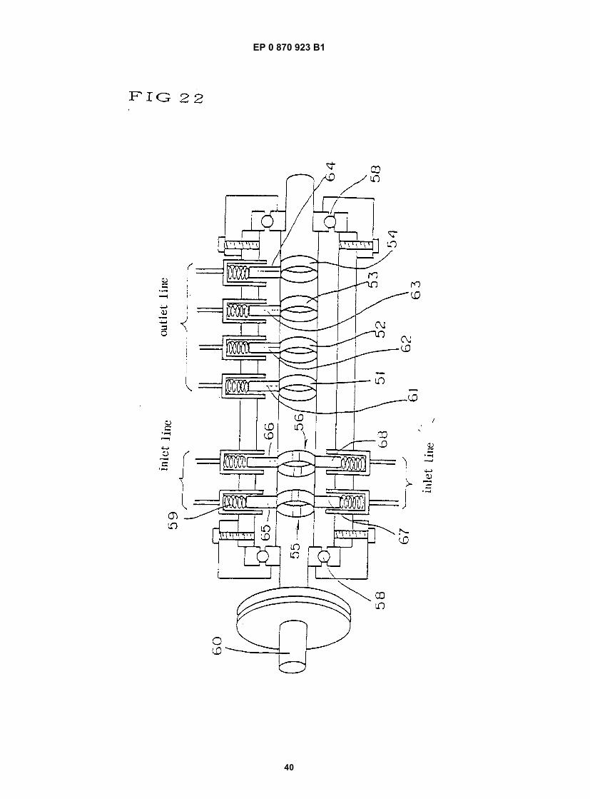
EP 0 870 923 B1
40

EP 0 870 923 B1
41

EP 0 870 923 B1
42

EP 0 870 923 B1
43