Visbreaking process - European Patent Office - EP 0133774 B1
17
3 Europaisches Patentamt European Patent Office Office europeen des brevets 0 1 33 774 B1 (jn Publication number: EUROPEAN PATENT SPECIFICATION mtci.4: C 10 G 47/34 (45) Date of publication of patent specification: 04.05.88 (Jj) Application number: 84305082.4 (§) Date of filing: 26.07.84 Visbreaking process. (§) Priority: 01.08.83 US 519625 Proprietor: MOBIL OIL CORPORATION 150 East 42nd Street New York New York 1 001 7 (US) Date of publication of application: 06.03.85 Bulletin 85/10 Inventor: Choi, Byung Chang 1017 Lowber Drive Cherry Hill New Jersey 08034 (US) Inventor: Mailadi, Madhava 40 Tattersall Drive West Deptford New Jersey 08051 (US) Inventor: Gross, Benjamin 1693 Blue Jay Lane Cherry Hill New Jersey 08003 (US) (§) Publication of the grant of the patent: 04.05.88 Bulletin 88/18 (84) Designated Contracting States: AT BE CH DE FR GB IT LI IMLSE (58) References cited: FR-A-2 381093 US-A-2900 327 US-A-2953 513 US-A-4389 302 Representative: Cooper, John Anthony et al Mobil Court 3 Clements Inn London WC2A 2EB (GB) OQ CO CO Note: Within nine months from the publication of the mention of the grant of the European patent, any person may give notice to the European Patent Office of opposition to the European patent granted. Notice of opposition shall be filed in a written reasoned statement. It shall not be deemed to have been filed until the opposition fee has been paid. (Art. 99(1) European patent convention). Courier Press, Leamington Spa, England. LU
-
Upload
khangminh22 -
Category
Documents
-
view
0 -
download
0
Transcript of Visbreaking process - European Patent Office - EP 0133774 B1

3 Europaisches Patentamt
European Patent Office
Office europeen des brevets
0 1 3 3 7 7 4
B 1
(jn Publication number:
EUROPEAN PATENT SPECIFICATION
mtci.4: C 10 G 4 7 / 3 4 (45) Date of publication of patent specification: 04.05.88
(Jj) Application number: 84305082.4
(§) Date of filing: 26.07.84
Visbreaking process.
(§) Priority: 01.08.83 US 519625 Proprietor: MOBIL OIL CORPORATION 150 East 42nd Street New York New York 1 001 7 (US)
Date of publication of application: 06.03.85 Bulletin 85/10
Inventor: Choi, Byung Chang 1017 Lowber Drive Cherry Hill New Jersey 08034 (US) Inventor: Mailadi, Madhava 40 Tattersall Drive West Deptford New Jersey 08051 (US) Inventor: Gross, Benjamin 1693 Blue Jay Lane Cherry Hill New Jersey 08003 (US)
(§) Publication of the grant of the patent: 04.05.88 Bulletin 88/18
(84) Designated Contracting States: AT BE CH DE FR GB IT LI IML SE
(58) References cited: FR-A-2 381093 US-A-2900 327 US-A-2953 513 US-A-4389 302
Representative: Cooper, John Anthony et al Mobil Court 3 Clements Inn London WC2A 2EB (GB)
OQ
CO CO
Note: Within nine months from the publication of the mention of the grant of the European patent, any person may give notice to the European Patent Office of opposition to the European patent granted. Notice of opposition shall be filed in a written reasoned statement. It shall not be deemed to have been filed until the opposition fee has been paid. (Art. 99(1) European patent convention).
Courier Press, Leamington Spa, England. LU

0 133 7 7 4
Description
This invention relates to the processing of residual petroleum stocks by visbreaking in the presence of certain highly aromatic hydrogen-donor materials.
5 Visbreaking, or viscosity breaking, is a well known petroleum refining process in which reduced crudes are pyrolyzed, or cracked, under comparatively mild conditions to provide products having lower viscosities and pour points, thus reducing the amounts of less viscous and more valuable blending oils required to make the residual stocks useful as fuel oils. The visbreaker feedstock usually consists of a mixture of two or more refinery streams derived from sources such as atmospheric residuum, vacuum
w residuum, furfural-extract, propane-deasphalted tar and catalytic cracker bottoms. Most of these feedstock components, except the heavy aromatic oils, behave independently in the visbreaking operation. Consequently, the severity of the operation for a mixed feed is limited greatly by the least desirable (highest coke-forming) components. In a typical visbreaking process, the crude or resid feed is passed through a heater and heated to about 425 to about 525°C at about 450 to about 7000 kPa. Light gas-oil may
15 be recycled to lower the temperature of the effluent to about 260 to about 370°F. Cracked products from the reaction are flash distilled with the vapor overhead being fractionated into a light distillate overhead product, for example gasoline and light gas-oil bottoms, and the liquid bottoms are vacuum fractionated into heavy gas-oil distillate and residual tar. Examples of such visbreaking methods are described in Beuther et al, "Thermal Visbreaking of Heavy Residues," The Oil and Gas Journal, 57:46, November 9,
20 1959, pp. 151—157; Rhoe et al, "Visbreaking: A Flexible Process," Hydrocarbon Processing, January 1979, pp. 131—136; and U.S. Patent 4,233,138.
Various visbreaking processes have been proposed in which residual oils are added at the visbreaking stage with or without added hydrogen or hydrogen-donors. For example, U.S. Patent 3,691,058 describes the production of single ring aromatic hydrocarbons (70— 220°C) by hydrocracking a heavy hydrocarbon
25 feed (565°C-) and recycling 32— 70°C and 220°C+ product fractions to extinction. This is integrated with visbreaking of residua in the presence of 1 to 28 weight% free radical acceptor at 370 — 480°C in the presence or absence of hydrogen (to enhance residua depolymerization). U.S. Patent 4,067,757 describes a process which involves passing a resid up through a bed of inert solids (packed bed reactor) in the absence of hydrogen or presence of 9—1800 Nm3 hydrogen per m3 resid at 400 — 540°C to enhance production of
30 middle distillate (175— 345°C). U.S. Patent 2,953,513, proposes the production of hydrogen-donors by partial hydrogenation of certain
distillate thermal and catalytic tars, boiling above 370°C, containing a minimum of 40 weight% aromatics, to contain H/C ratios of 0.7—1.6. The resid feed is then mixed with 9—83 volume% of hydrogen donor and thermally cracked at 427 — 482°C to produce low boiling products. U.S. Patent 4,090,947 describes a thermal
35 cracking process (425— 540°C) for converting resids to lighter products in the presence of 10—500 volume% hydrogen-donor. The hydrogen-donor is produced by hydrotreating premium coker gas oil (345 — 480°C) alone or blended with gas oil produced in the thermal cracker. U.S. Patent 4,292,168 proposes upgrading heavy hydrocarbon oils without substantial formation of char by heating the oil with hydrogen and a hydrogen transfer solvent without a catalyst at temperatures of about 320 to 500cC and a
40 pressure of 2200 to 18000 kPa for a time of about 3 to 30 minutes. Examples of hydrogen-donor transfer solvents include pyrene, fluoranthene, anthracene and benzanthracene. U.S. Patent 4,292,686 describes a process for contacting a resid with a hydrogen-donor at 350 to 500°C and a pressure of 2 to 7 MPa with liquid hourly space velocities ranging from 0.5 to 10.
In U.S. Patent 4,428,828, there is described a process for visbreaking a deasphalted oil, and 45 subsequently reblending it with the asphaltic fraction to produce a product of low viscosity and pour point.
This process reduces the amount of cutter stock required to make relatively low viscosity products. The reduction in cutter stock requirement is achieved by minimizing coke formation in the visbreaker, by excluding the worst coke formers, permitting more severe operation of the visbreaker. Although this approach helps, it does not provide a complete solution, moreover, it requires a solvent deasphalting unit.
50 The present invention is based on the observation that by visbreaking heavy petroleum resids in the presence of certain hydrogen-donor solvents, visbreaking severity can be greatly increased without significant coke or sediment formation.
Accordingly, the present invention provides a process for visbreaking a heavy petroleum residual oil which comprises subjecting the oil to an elevated temperature for a period of time corresponding to an
55 equivalent reaction time of 250 to 1500 ERT seconds at 427°C, in the presence of from 0.1 to 50 weight percent, based on the residual oil, of a hydro-aromatic solvent having a content of HAr and Ha hydrogen each of at least 20 percent of the total hydrogen content, and recovering a fuel oil product having a viscosity lower than that of the starting residual oil.
The hydro-aromatic solvent used in the process of the invention is a thermaMy stable, polycyclic, eo aromatic/hydroaromatic distillate hydrogen donor material, preferably one which results from one or more
petroleum refining operations. The hydrogen-donor solvent nominally has an average boiling point of 200 to 500°C, and a density of 0.85 to 1.1 g/cc.
Examples of suitable hydrogen-donors are highly aromatic petroleum refinery streams, such as fluidized catalytic cracker (FCC) "main column" bottoms, FCC "light cycle oil," and thermofor catalytic
65 cracker (TCC) "syntower" bottoms, all of which contain a substantial proportion of polycyclic aromatic

0 133 7 7 4
hydrocarbon constituents such as naphthalene, dimethylnaphthalene, anthracene, phenanthrene, fluorene, chrysene, pyrene, perylene, diphenylt benzothiophene, tetralin and dihydronaphthalene, for example. Such refractory petroleum materials are resistant to conversion to lighter (lower molecular weight) products by conventional non-hydrogenative procedures. Typically, these petroleum refinery
5 residual and recycle fractions are hydrocarbonaceous mixtures having an average carbon to hydrogen ratio above about 1:1, and an average boiling point above 230°C.
An FCC main column bottoms refinery fraction is a highly preferred hydrogen donor solvent for use in the process of the invention. Atypical FCC main column bottoms (or FCC clarified slurry oil (CSO)) contains a mixture of constituents as represented in the following mass spectrometric analysis:
w Naphthenic/
Compounds Aromatics Aromatics Labile H2%
Alkyl-Benzene 0.4 — ' 0.00 Naphthene-Benzenes — 1.0 0.03 Dinapthene-Benzenes — 3.7 0.16
Naphthalenes 0.1 — 0.00 Acenaphthenes (biphenyls) — 7.4 0.08 Fluorenes — 10.1 0.11
Phenanthrenes 13.1 — — Naphthene-phenanthrenes — 11.0 0.18
Pyrenes, fluoranthenes 20.5 — 0.00 Chrysenes 10.4 — 0.00
Benzofluoranthenes 6.9 — 0.00 Perylenes 5.2 — 0.00
Benzothiophenes 2.4 — — Dibenzothiophenes 2.4 — —
Naphthobenzothiophenes — 2.4 —
Total 64.4 35.6 0.60
15
20
25
30
35 Total 64.4 35.6 0.60
A typical FCC main column bottoms or clarified slurry oil has the following analysis and properties:
40 Elemental Analysis, Weight%
C 89.93
H 7.35
O 0.99
N 0.44
S 1.09
Total 99.80
Pour Point, °C: 10 CCR, %: 9.96 Distillation:
IBP, °C: 254
5% °C: 338
95%, °C: 485
45
50
55
SO
Another preferred hydrogen-donor material is a light cycle oil (LCO) taken from the main tower 65 fractionator of a FCC operation of the riser type in which the LCO results from a distillation cut point not

0 133 7 7 4
substantially above about 370°C. A typical FCC LCO has the following analysis and properties:
Boiling Point Distribution, weight% FCC LCO
215°F 4.8
215— 343°F 87.9
343— 427°F 7.3
427— 538°F —
538°F+ —
H, weight% 10.64
S, weight% 1.01
N, weight% 0.24
Ni + V, PPM by weight —
CCR, weight% —
Paraffins, weight% 12.7
Mononaphthenes 11.7
Polynaphthenes 12.8
Monoaromatics 24.7
Diaromatics 21.7
Polyaromatics 14.3
10
15
20
25
30
35 Polyaromatics 14.3
Aromatic sulfur type 2.1
40 Total hydrogen, weight% 9.0 — 9.5
FCC main tower bottoms and light cycle oils are obtained by the catalytic cracking of gas oil in the presence of a solid porous catalyst. More complete descriptions of the production of these petroleum fractions are described in U.S. Patents 3,725,240 and 4,302,323, for example.
45 A process closely related to FCC is TCC, or thermofor catalytic cracking. Thermofor catalytic cracking is roughly analogous to FCC; both processes operate without addition of hydrogen, both operate at relatively low pressure, and both require frequent regeneration of catalyst. The products of thermofor catalytic cracking will have hydrogen contents and distribution very similar to those obtained as a result of FCC. Accordingly, light cycle oils obtained as product streams from a TCC process, or main column bottoms
50 streams obtained as a result of a TCC process, are also suitable for use in the process of the invention. Another source hydrogen donor solvent for use in the process of the invention is the heavy fraction
normally associated with lubricating oil. The lubricating oil may be either a paraffin based oil or a naphthenic based oil. Preferably the lubricating oil is first subjected to aromatics extraction, so that the extract will have more ideal properties.
55 It is also possible to use the aromatic extract from a lube oil plant. By itself, this material will be too highly aromatic and will not be a very good hydrogen-donor; however, it may be subjected to conventional hydrogenation to produce a hydrogen-donor diluent with the right hydrogen content and distribution.
Hydrotreating the aromatic extract from a lube oil plant is a very expensive operation but this may be justified when the total cost of using hydrotreated-aromatic extract is less than the cost of using lubricating
60 oil base stock. Diluents or solvents with the right hydrogen content and distribution are produced also by the catalytic
dewaxing of lubricating oil stocks and the catalytic dewaxing of fuels. Another suitable hydrogen donor solvent source is the highly aromatic tars produced in olefin
crackers. 65 Further sources of suitable hydrogen' donor solvents are the various coal liquifaction processes.
4

0 133 7 7 4
Particularly preferred hydrogen-donor solvents are those which are recovered from liquified coal extract, hydrogenated and recycled back to the coal liquifaction step. Coal liquifaction processes are, of course, exceedingly expensive, and a coal liquifaction plant would not normally be constructed merely to generate solvent for addition to a visbreaker. Coal liquifaction plants may, however, be operated adjacent to a convention refinery with a visbreaker, and in these special situations a solvent stream derived from coal liquifaction may be used with good effect.
Normally it will be most economic to use whatever solvents can be found in a refinery, without hydrotreating, for use in the process of the invention. It is also possible, although usually more expensive, to take a hydrogen-donor solvent which is not entirely satisfactory, and subject it to conventional hydrogenation treatments to increase its hydrogen content and/or alter its hydrogen distribution. If such a charge stock is very highly aromatic, quite a substantial amount of hydrogen must be added to make the hydrogen-donor solvent suitable for use in the process of the invention. Excessive hydrogenation should be avoided, however, since it is not beneficial to saturate all of the aromatic rings in the hydrocarbon solvent. The reasons for this will be understood from the following discussion of hydrogen-donor properties.
Critical features of the hydrogen-donor solvent are its particular proportions of aromatic, naphthenic and paraffinic moieties and the type and quantity of hydrogen associated therewith. A high content of aromatic and naphthenic structures together with a high content of alpha hydrogen provides a superior hydrogen-donor material.
All solvents used according to the invention are hydro-aromatic solvents. The hydrogen transfer ability of a donor material can be expressed in terms of specific types of
hydrogen content as determined by proton nuclear magnetic resonance spectral analysis. Nuclear magnetic resonance characterization of heavy hydrocarbon oils is well developed. The spectra are divided into four bands (Ha, Hp, HY and HAr) according to the following frequencies in Hertz (Hz) and chemical shift (5):
10
15
20
25
HAr Hv Ha Hn
Hz 0—60 60—100 120—200 360—560
5 0—1.0 1.0—1.8 2.0—3.3 6.0—9.2
The HAr protons are attached directly to aromatic rings and are a measure of aromaticity of a material. Ha protons are attached to non-aromatic carbon atoms themselves attached directly to an aromatic ring structure, for example alkyl groups and naphthenic ring structures. H0 protons are attached to carbon atoms which are in a second position away from an aromatic ring, and HY protons are attached to carbon atoms which are in a third position or more away from an aromatic ring structure. This can be illustrated by the following:
30
35
40
CH2-CH2-CH3 o r
45
Ar
50
55
(4) 60
55

0 133 7 7 4
10 H.
15
Some alpha hydrogens are not donatable, for example the alpha hydrogen in toluene. The alpha hydrogens shown in compound (8) above, for example, also are not donatable. Compound (8) is not, therefore, a hydro-aromatfc solvent.
The HAr protons are important because of their strong solvency power. A high content of Ha protons is particularly significant because Ha protons are labile and are potential hydrogen-donors.
The hydrogen-donor material employed in the process of the invention has a hydrogen content distribution such that the HAr proton content is at least 20 percent, preferably from 20 to 50 percent, and the Ha proton content is at least 20 percent, preferably from 20 to 50 percent. For example, in H-donor streams containing 9.5 weight% total hydrogen, the a-hydrogen content should be at least 1.9weight% (20% of total hydrogen content). The balance of the hydrogen is non-o. hydrogen.
Hydrogen-donors possessing the desired hydrogen content distribution may frequently be obtained as a bottoms fraction from the catalytic cracking or hydrocracking of gas oil stocks in the moving bed or fluidized bed reactor processes. In general, depending upon such conditions as temperature, pressure, catalyst-to-oil ratio, space velocity and catalyst nature, a high severity cracking process results in a petroleum residuum solvent having an increased content of HAr and Ha protons and a decreased content of the less desirable non-a-hydrogen.
The proton distribution of examples of various highly aromatic hydrocarbon by-product streams are shown below.
20
25
30
35
40
45
50
55
60
65

0 133 7 7 4
Ha Non-a-Hydrogen HAr H Total ExamPle (weight%) (weight%) (weight%) (weight%)
FCC/LCO
#1 (used in Table 4) 22.2 (2.07) 57.8 20.0 9.34 #2 (used in Table 5) 34.1 (3.18) 36.8 29.1 9.32 #3 34.3 (3.19) 35.5 30.2 9.30
10 (Note the values ( ) are absolute percentage amounts and all three LCO streams are effeci
FCC/CSO
#1 (used in Table 3) 34.0(2.43) 33.0 33.0 7.15 15 #2 30.0 (2.15) 35.0 35.0 7.17
#3 19.4(1.39) 65.0 5.0 7.16
FCC/MCB
,0 #1 36.0 (2.65) 32.0 32.0 #2 36.4(2.68) 18.8 44.8 #3 18.5 (1.36) 64.3 17.2 #4 18.1 (1.33) 67.7 ' 14.2
25 TCC/Syntower Bottoms #1 29.8(2.78) 28.8 41.4 #2 18.2(1.70) 58.8 23.0 #3 16.3(1.52) 68.1 15.6
30 SRC Recycle Oil 27.1 21.6 46.3
TCC Distillate
35 #1 21.5(2.39) 58.4 20.1 #2 20 (2.07) 58 22 #3 6.9 (0.89) 85.1 8
All of the values reported above are for non-hydrotreated materials. 40 From the data given above, it will be seen that hydrocarbons having the same general process
derivation may or may not have the desired proton distribution. For example, FCC/MCB #1 and #2 and FCC/CSO #1 and #2 have the desired proton distribution while FCC/MCB #3 and #4 and FCC/CSO #3 do not. Furthermore, although it is preferred that the highly aromatic hydrogen donor component is derived from petroleum, it will be noted that the SRC recycle solvent closely resembles FCC/MCB #1 and #2.
45 In most hydrocarbon processes, there is a tradeoff between reaction temperature and residence time of reactants. Because visbreaking is a well-known and widely practiced process, however, sophisticated correlations have been developed so that it is possible to express precisely the severity of the visbreaking process.
An expression of the "severity" of a particular visbreaking operation does not mean that a certain 50 degree of conversion can be predicted or obtained or that a certain amount of coke or sediment will be
formed; rather it means that it is possible to predict that if all other reaction parameters are unchanged (feed composition, reactor pressure, for example) except for the temperature and residence time in the reactor, two operations can be compared and it can be determined whether one process is more severe than the other.
55 Fairly elegant equations and tables have been developed for this purpose. Typical of such presentations is the discussion of "soaking factor" in Petroleum Refinery Engineering-Thermocracking and Decomposition Process — Equation 19 — 23 and Table 19 — 18, in Nelson — Modern Refining Technology, Chapter 19.
Although that text uses the term "soaking factor", the term "ERT" or "Equivalent Reaction Time" in 60 seconds as measured at 427°C is used herein to express visbreaking severity; numerically, soaking factor is
the same as ERT. ERT refers to the severity of the operation, expressed as seconds of residence time in a reactor
operating at 427°C. In very general terms, the reaction rate doubles for every 12 to 13°C increase in temperature. Thus, 60 seconds of residence time at 427°C is equivalent to 60 ERT, and increasing the
65 temperature to 456°C would make the operation five times as severe, i.e. 300 ERT. Expressed in another

0 133 7 7 4
way, 300 seconds at 427°C is equivalent to 60 seconds at 456°C, and the same product mix and distribution should be obtained under either set of conditions.
Most visbreakers operate with a coil, some operate with a combination of a coil and a drum, and a few operate primarily with a drum. As fas as product distribution is concerned, it is believed that it is of no great
5 significance whether the residence time is obtained in a coil, drum, or combination of both. Frequently, visbreaker units are built with a coil,- and when an expansion of the unit's capacity is
desired it is cheaper to add a soaking drum (and increase the oil's residence time) than to build and operate a bigger furnace and achieve a higher reactor temperature.
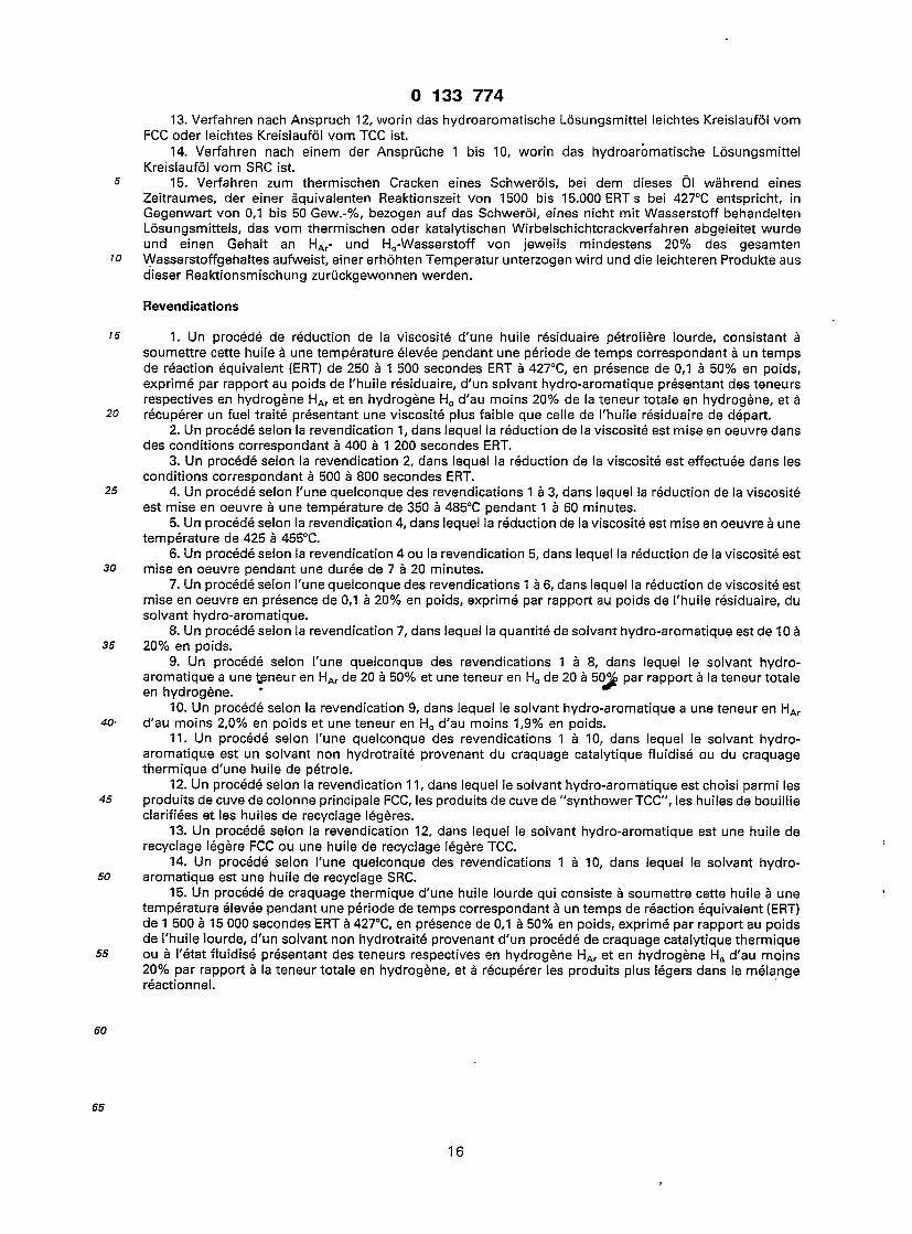
Typical of the coil/soaking drum combinations is the process described in U.S. Patent 4,247,387. w The process of the invention is advantageously carried out in refinery facilities of the type shown
diagrammatically in the accompanying drawing. Referring to the drawing, a viscous hydrocarbon oil feed, typified by a 496°C+ Arab Heavy resid, is supplied by line 22 to visbreaking heater 25. The feed is blended with hydrogen-donor material supplied through line 50 in an amount 0.1 to 50 weight%, preferably 0.1 to 20 weight%, based on the resid charge, (a weight ratio of hydrogen-donor to resid of 0.001 to 0.5,
15 preferably 0.001 to 0.2). Mild thermal cracking of the resid under visbreaking conditions occurs in visbreaker 25 and produces a visbreaker effluent stream carried by line 28. This stream is cooled by admixture with a quench stream from line 31, and the visbreaker effluent continues through line 29 to distillation column 30 where it is fractionated to obtain Cs-gases (C3, C4 and lower) and a CS-135°C naphtha fraction from the top through line 34. A 220 — 370°C gas oil fraction is taken off as a bottoms stream through
20 line 33 where portions may be recycled as a quench stream through line 31, recovered as heavy fuel oil 32 or, via line 33, blended with cutter stock to meet fuel oil product specifications.
The overhead fraction removed from the distillation column in line 34 is passed through a cooler separator 36 which is operated under conditions effective to separate the incoming liquid into a C5- off-gas stream 38, mainly C3 or C4 and lower, and a C5-1 35°C naphtha fraction which is taken off via line 40. Because
25 of the boiling range and quality of the hydrogen-donor, it can simply be allowed to remain with the bottom fraction and used directly as heavy fuel oil, thus avoiding the need for separation.
The process of the invention is not, of course, limited to the visbreaker/distillation scheme discussed above. Any visbreaker arrangement can be used, ranging from a tubular reactor which is entirely in the heater, to a soaking drum reactor wherein most of the visbreaking reaction occurs in the soaking drum. Any
30 combination of the two processes may also be used, i.e. much of the visbreaking reaction may be accomplished in a coil, while the remainder of the visbreaking occurs in a soaking drum down-stream of the coil.
Any distillation scheme known in the art may be used to process the visbreaker reactor effluent. In conventional visbreaking operations, it is preferred to quench the visbreaker effluent with a quench stream
35 as shown in the drawing, but it is also possible to use heat exchange, fin fan coolers, or some other conventional means of cooling the visbreaker effluent. However, since there is a risk of coking up the heat exchanger tubes in such an arrangement, use of a quench stream is preferred.
The light products which are obtained as by-products in the visbreaking process are not particularly desirable for blending with other refinery streams. Usually, the visbroken product will be processed to
40 produce the maximum amount of fuel oil, and this means that as much of the resulting light ends that can be tolerated in the product, will be left in. Usually the limiting factor on light ends is the flash point of the fuel.
Although a blending operation is shown in the drawing, in which cutter stock is blended with heavy fuel oil from line 33, the process of the invention has the great advantage of minimizing the amount of
45 cutter stock required. Blending is not an expensive or difficult unit operation, but it may be eliminated, in some circumstances, by simply adding the hydrogen-donor and/or cutter stock to the visbreaker feed.
The visbreaker may also be integrated with a deasphalting unit, either upstream or downstream of the unit, as described in U.S. Patent 4,428,824. When a combination of deasphalting and visbreaking is practiced, it will usually be possible to push the visbreaker a little harder than could otherwise be tolerated.
so In some instances, it may be preferable to subject deasphalted oil to conventional visbreaking, operated without hydrogen-donor solvent, while subjecting the asphaltic fraction to hydrogen-donor visbreaking. Alternatively, the process described in U.S. Patent 4,428,824 may be practiced, wherein the only visbreaking that occurs is on deasphalted oil. in this instance, addition of hydrogen-donor solvent to the visbreaker feed (consisting of a deasphalted oil) will permit improved operation.
55 The process of the invention is suitable for upgrading a wide variety of heavy liquid hydrocarbon oils at least 75 weight percent of the components of which boil at above 370°C. Included in this class of materials are residual fractions obtained by catalytic cracking of gas oils, solvent extracts obtained during the processing of lube oil stocks, asphalt precipitates obtained from deasphalting operations, high boiling bottoms or resids obtained during vacuum distillation of petroleum oils and tar sand bitumen feedstocks.
60 Visbreaking process conditions can vary widely based on the nature of the heavy oil material, the hydrogen-donor material and other factors. In general, the process is carried out at temperatures ranging from 350 to 485°C, preferably 425 to 455°C, at residence times ranging from 1 to 60 minutes, preferably 7 to 20 minutes. Expressed as ERT, the process of the invention operates at and Equivalent Reaction Time at of 250 to 1500 ERT seconds, and preferably 400 to 1200 ERT seconds and more preferably 500 to 800 ERT
65 seconds, at 427°C.

0 133 7 7 4
The limit of severity is determined primarily by product quality. Visbreaking is a good and inexpensive process, and once a visbreaker has been installed, it does not cost much to run it at high severity in order to achieve the maximum viscosity reduction possible with a given feed stock. However, the two limiting factors in the visbreaker operation are the formation of coke (which tends to plug the coil and/or soaking
5 drum used in the visbreaking operation and also take the product out of specification) and sediment formation in the product.
Sediment formation is a very complex phenomenon. As a generalization, it can be stated that, if the fuel composition is changed enough, the asphaltic materials no longer dissolve in the product and hence settle out as sediment. The problem becomes worse when cutter stocks or blending stocks are added to the
w visbreaker product; asphaltics or other materials that would remain dissolved in the visbreaker product are no longer soluble upon blending the visbreaker product with other materials.
The pressure employed in a visbreaker will usually be sufficient to maintain most of the material in the reactor coil and/or soaker drum in the liquid phase. Normally the pressure is not considered as a control variable, although attempts are made to keep the pressure high enough to maintain most of the material in
15 the visbreaker in the liquid phase. Some vapor formation in the visbreaker is not harmful, and is frequently inevitable because of the production of some light ends in the visbreaking process.
Some visbreaker units operate with 20 — 40% vaporization materiaf at the visbreaker coil outlet. Lighter solvents will vaporize more and the vapor will not do much good towards improving the cracking of the liquid phase material. Accordingly, liquid phase operation is preferred, but significant amounts of
20 vaporization can be tolerated. The pressures commonly encountered in visbreakers range from 170 to 10450 kPa, with a vast majority
of units operating with pressures of 1480 to 7000 kPa. Such pressures will usually be sufficient to maintain liquid phase conditions and the desired degree of conversion.
An important aspect of the invention is the improvement of visbreaker performance by optimizing 25 operational severity for heavy oil feedstocks. In general, as severity is increased, increased yields of
distillate and gaseous hydrocarbons are obtained with a reduction in the amount of cutter oil required for blending to obtain specification-viscosity residual fuel oil. At high severities, however, there is an increased tendency to form coke deposits which result in plugged heater tubes and/or the production of unstable fuel oils as measured by sediment formation. By means of the process of the invention, the use of certain
30 hydrogen-donors has been found to suppress the formation of sedimentation species and thus permit a higher severity operation than is otherwise possible without adding hydrogen donors, while still producing stable fuel oil. As an example, the visbreaking of a heavy petroleum feed stock conventionally carried out at a severity of 500 ERT seconds may be increased to a higher severity of 800 ERT seconds to obtain a fuel oil product free of sedimenting species. At high severities, the cutter stock requirement is substantially
35 reduced which thus represents a considerable financial saving. According to a further aspect of the invention, non-hydrotreated solvents derived from thermal and
fluidized catalytic cracking processes can also be used with advantage in the thermal cracking of heavy oils at higher severities in order to convert significant quantities of the heavy oil into lighter products.
Thus, the present invention also provides a process for the thermal cracking a heavy oil which 40 comprises subjecting the oil to an elevated temperature for a period of time corresponding to an equivalent
reaction time of 1 500 to 1 5,000 ERT seconds at 427°C, in the presence of from 0.1 to 50 weight%, based on the heavy oil, of a non-hydrotreated solvent derived from a thermal or fluidized catalytic cracking process having a content of HAr and Ha hydrogen each of at least 20 percent of the total hydrogen content, and recovering lighter products from the reaction mixture.
4S The following Examples illustrate the invention.
Examples A series of visbreaking experiments on heavy residual stocks was carried out at a severity of 800 ERT
seconds in the presence of 2.5 and 5.0 weight% of the FCC/CSO #1 hydrogen-donor identified above. 50 The feed was an Arab Heavy residual stock which had been fractionated to two slightly different cut
points. Feed properties were as follows (Table 1):
ss
60
ss

0 133 7 7 4
TABLE 1
Nominal initial boiling point, °C 454 496
Viscosity, mnvVS at 38°C 1079.4 4789.2 66°C 89.6 957.4
Pour point, °C 38 48
APT 7.4 5.9
Specific gravity, 15°C 1-0184 1.0295
Aromatics sulfur content, weight% 5.16 5.4
CCR, weight% 16.3 18.3
10
15
The cutter stock used to dilute the product to meet viscosity specifications had the properties given in 20 Table 2.
TABLE 2
API 37.4
Specific gravity, 15°C 0.8377
ASTM— D86 Distillation, °C 10% 245 30% 254 50% 264
25
30
Conventional visbreaking of these Arab Heavy feeds is limited by sediment formation. Table 3 below 3S shows the effect of solvent addition upon visbreaking. Viscosity reduction was significantly better for
visbreaking in the presence of CSO. The feed used in this experiment was the 496°C+ Arab Heavy. The experimental apparatus used was a
laboratory visbreaker, basicallfy a batch reactor which closely simulated a commercial visbreaker. The data in Table 3 do not show a simple dilution or thinning effect due to the addition of hydrogen
40 donor. It would be expected that adding a relatively thin solvent to the visbreaker product would reduce somewhat the viscosity of the product. To compensate for this thinning effect, the same amount of hydrogen-donor added to the feed in accordance with the invention, was added to the product of the prior art process. Some small amount of viscosity reduction clearly occurred because of the addition of 2.5% clarified slurry oil, but it was added in both the test illustrating the process of the invention and the test
45 showing the prior art method. Accordingly the viscosity, pour point and sedimentation values reported in Table 3 are all on a uniform basis, i.e., the stated amount of FCC/CSO was added before any viscosity, pour point or sedimentation tests were run.
The viscosity and pour point test were conducted before cutter stock was added. The sedimentation test was conducted after cutter stock was added. Usually enough cutter stock is added to reduce the
so viscosity and/or pour point of the product to the desired level. A problem encountered with severe visbreaking is that after addition of cutter stock, sediment forms. The sediment is probably asphalt that is soluble in the visbreaker product, but relatively insoluble in the cutter stock. In general, as more cutter stock is added (to meet viscosity requirements of the product) more asphalt or other sediment will precipitate. Refiners would like to achieve product specifications without any cutter stock addition, but frequently
55 addition of 10, 20 or even 30 weight% cutter stock to visbreaker products is necessary to meet viscosity specifications, or occasionally, density specifications. Addition of 10 and 20weight% cutter stock is believed representative of amounts of cutter stock frequently added in refinery installations.
so
65
10

0 133 7 7 4
TABLE 3 Clarified Slurry Oil Hydrogen Donor
Added before visbreaking Added after visbreaking 5
Weight% LCO Hydrogen-donor 2.5 5.0 2.5 5.0
Viscosity, mm2/s at 82°C 757 667 6472 1619
10 Pour Point, °C 24 18 49 43
Weight% Cutter Stock added to: Blend of CSO with visbroken resid 10 20 10 20
is Visbroken blend of CSO and resid 10 20 10 20
Sediment, volume%* Tr Tr Tr 3.3 .85 16 .9 14.5
20 * Tr = trace.
The benefits of adding, for example 2.5 weight% FCC clarified slurry oil to the visbreaker feed are evident. The viscosity has been profoundly reduced by the addition of only 2.5 weight% hydrogen-donor to the feed, rather than to the product of the visbreaker.
2s The pour point of the product has been significantly reduced also; 2.5 weight% clarified slurry oil reduce the pour point from 49°C to 24°C. Similar results are obtained due to the addition of 5 weight% CSO, reducing the pour point from 43°C to 18°C.
The sediment test used was the centrifuge method used to determine the compatibility of sediment in blended marine fuel oil. This method is used to predict the volume% of incompatible sediment in blended
30 marine fuel oils. A 100 ml sample of the blended fuel oil is centrifuged in a heated centrifuge (65.5°C ± 1°C) centrifuged
for 3 hours at a relative centrifugal force of 700 units. Further details of the centrifuge operation can be taken from ASTM D— 96.
There is another test method commonly referred to as a hot filtration test, which gives weight% 35 sediment after hot filtration and washing with normal hexane. A fuel with 1 volume% sediment will
usually, but not always, have about 0.5 weight% sediment. All testing reported herein uses the hot centrifuge method so results are reported in volume% sediment.
In the sediment test used herein, there is no dilution of the sample with virgin gas oil; rather the sample is charged to the centrifuge without dilution. There is nothing wrong with adding virgin gas oil to achieve
40 the standardized viscosity before running the test, but every addition of a new hydrocarbon species makes it harder to interpret experimental results. The significance of the results shown in Table 3 is the dramatic reduction in sediment formation obtained by adding 2.5 weight% CSO to the visbreaker feed.
Even when blended with 20 weight% cutter stock, the visbroken product of the invention had only a trace, or acceptable, amount of sediment. In contrast, the prior art method, in which 2.5 weight% CSO was
45 added after visbreaking, produced 16 volume% sediment after addition of 20 weight% cutter stock. The advantages of adding 2.5 weight% CSO to the visbreaker feed may be summarized as follows. (i) lower viscosity (ii) lower pour point (iii) more cutter stock tolerated.
50 Another series of tests was run using the slightly lighter Arab Heavy resid, having a 454°C IBP. In this test, significantly larger amounts of light cycle oil hydrogen-donor were added, namely 10 and 20 weight%, light cycle oil. In this example, both the feed and the hydrogen-donor diluent are slightly lighter, or lower in molecular weight, as compared to the feed and hydrogen-donor used in the examples reported in Table 3. The hydrogen content and distribution of the hydrogen-donor used in this example is given above under
55 the discussion of FCC/LCO #1. The test procedure used, and a visbreaking severity (800 ERT seconds) were identical to those used for
the testing reported in Table 3.
60
65
11

0 133 7 7 4
TABLE 4 Light Cycle Oil Hydrogen Donor
Added before visbreaking Added after visbreaking
Weight% LCO hydrogen donor 10 20 10 20
Viscosity, mm2/s at 54°C 189.9 79.8 259.2 110.9
Pour point, °C -7 -15 2 -1
Weight% Cutter Stock added to:
Blend of LCO with visbroken resid 15 15 Visbroken blend of LCO and resid 15 15
Sediment, volume% 1 0.5 3 5
10
15
These data show that a significant reduction in the amount of sediment in the visbreaker product after addition of cutter stock can be obtained by the practice of the invention.
Table 5 below illustrates that an increase in visbreaking severity in the presence of 10 weight% LCO 25 translates into a considerable savings in the cutter stock required to make a 120 mm2/s (50°C) fuel oil
product. By visbreaking at 800 ERT seconds in the presence of 10 weight% LCO, a 191 m3/day reduction in cutter stock requirement is achieved, in comparison to conventional visbreaking at 500 ERT seconds.
TABLE 5 30 454°C + Arab Heavy Resid
Conventional H-donor Visbreaking Visbreaking
500 800
2020 2020 0 202
1.58 2.3 3.00 4.6
95.42 93.1
3S Severity, ERT seconds 500 800
Feed Rate, m3/day Resid 2020 2020 H-Donor (LCO) 0 202
40 Products, weight%
C4- • 1.58 2.3 C5-149°C 3.00 4.6 149°C+ Bottoms 95.42 93.1
45 Viscosity of 149°C+ Bottoms, mm2/s at 50°C 1560 160
Cutter Stock required to make 120 mm2/s heavy fuel oil, m3/day 445 52
50 Total Cutter Stock required including H-Donor, m3/day 445 254
Additional testing was carried out on the 496°C+ Arab Heavy resid, and the results obtained are set out in Table 6. 55
60
65
12

0 133 7 7 4
TABLE 6 496 C+ Arab Heavy Resid: 800 ERT seconds
LCO Added to Feed
LCO Added to Visbroken Bottoms
Amount LCO Added, weight%
Mixture Viscosity, mm2/s at 82°C
Sediment, volume%
10 20 10 20
177 53.5 939 246
GT0.05 GT0.05 1.6 17.0 10
Additional tests were conducted on a different feedstock, a heavy Nigerian resid feed. Feed and cutter is stock properties were as set out in Table 7, and test results are set out in Table 8.
TABLE 7
510°C + Nigerian Heavy Resid Cutter Stock
APT 10.5 24.6
Specific Gravity (15°C) 0.9965 0.9065
Pour Point, °C 100 - 7
Viscosity, mm2/s at 50°C 38 2.2 80°C 1859.8 1.24
100°C 565.9 —
Distillation, °C D1160— 1 D86
5% 500 189
10% 528 198
30% 591 231
50% 598 (@ 33%) 270
95% — 373
20
25
30
35
40
45
50
55
BO
65
13

0 133 7 7 4
TABLE 8 510cC + Heavy Nigerian Resid
20% TCC Distillate #1 Added to Feed BASE
Severity, ERT Seconds 1200 1500
Feed Rate, m3/day Resid 636 636 H-Donor (TCC Distillate #1) 0 127
Product Yields, weight% (m3/day) C4- 1.7 2.0 Naphtha (C5-166°C) 4.8(41) 5.3 Distillate (166— 343°C) 11.2(80) 27.6(223) Bottoms (343°C+) 82.4 (512) 65.2 (483)
10
15
Viscosity of bottoms, mm2/s at 50°C
Cutter Stock required for 120 mm2/s product, m3/day
Overall yields, m3/day Naphtha Distillate
Comparison, m3/day Naphtha Distillate
12456 15687 20
222 244
47 (126)
41 (164)
25
6 38
BASE 30
NOTE: In both cases, the viscosity of the bottoms (343°C+) increased at higher severity.
Table 9 below sets out the results of a test conducted using Durban Visbreaker feed. 35
TABLE 9 Durban Visbreaker Feed
Base H-Donor
630 800
1294 1294 0 94
5.8 6.0 2.7 4.4
91.5 89.6
2739 819 1.0184 1.0115
40 Severity, ERT Seconds
Feed Rate, m3/day Resid H-Donor (FCC LCO)
Product Yield, weight% c4- CS-132°C
132°C+ Bottoms
132°C+ Properties: Kinematic Viscosity, mm2/s at 50°C Specific Gravity at 15°C
Cutter Stock required for 150 mm2/s product, m3/day
Total Cutter Stock including H-Donor, m3/day
Comparison, m3/day
45
50
55
352
446
(86)
532
532
BASE
60
65
14

0 133 7 7 4
Claims
1. A process for visbreaking a heavy petroleum residual oil which comprises subjecting the oil to an elevated temperature for a period of time corresponding to an equivalent reaction time of 250 to 1 500 ERT
5 seconds at 427°C, in the presence of from 0.1 to 50 weight percent, based on the residual oil, of a hydro- aromatic solvent having a content of HAr and Ha hydrogen each of at least 20 percent of the total hydrogen content, and recovering a fuel oil product having a viscosity lower than that of the starting residual oil.
2. A process according to claim 1, wherein visbreaking is carried out at 400 to 1200 ERT seconds. 3. A process according to claim 2, wherein visbreaking is carried out at 500 to 800 ERT seconds.
'0 4. A process according to any one of claims 1 to 3, wherein visbreaking is carried out at 350 to 485°C for 1 to 60 minutes.
5. A process according to claim 4, wherein visbreaking is carried out at 425 to 455°C. 6. A process according to claim 4 or claim 5, wherein visbreaking is carried out for 7 to 20 minutes. 7. A process according to any one of claims 1 to 6, wherein visbreaking is carried out in the presence of
is 0.1 to 20 weight percent, based on the residual oil, of the hydro-aromatic solvent. 8. A process according to claim 7, wherein the amount of hydro-aromatic solvent is 10 to 20 weight
percent. 9. A process according to any one of claims 1 to 8, wherein the hydro-aromatic solvent has a HAr
content from 20 to 50% and a Ha content from 20 to 50%, based on total hydrogen content. 20 1 o. A process according to claim 9, wherein the hydro-aromatic solvent has a HAr content of at least 2.0
weight percent and a Ha of at least 1.9 weight percent. 11. A process according to any one of claims 1 to 10, wherein the hydro-aromatic solvent is a non-
hydrotreated solvent derived from thermal or fluidized catalytic cracking of a petroleum oil. 12. A process according to claim 11, wherein the hydro-aromatic solvent is selected from FCC main
25 column bottoms, TCC syntower bottoms, clarified slurry oil and light cycle oil. 13. A process according to claim 12, wherein the hydro-aromatic solvent is FCC light cycle oil or TCC
light cycle oil. 14. A process according to any one of claims 1 to 10, wherein the hydro-aromatic solvent is SRC recycle
oil. 30 15. A process for thermal cracking a heavy oil which comprises subjecting the oil to an elevated
temperature for a period of time corresponding to an equivalent reaction time of 1500 to 15,000 ERT seconds at 427°C, in the presence of from 0.1 to 50 weight%, based on the heavy oil, of a non-hydrotreated solvent derived from a thermal or fluidized catalytic cracking process having a content of HAr and Ha hydrogen each of at least 20 percent of the total hydrogen content, and recovering lighter products from
35 the reaction mixture.
Patentanspruche
1. Verfahren zum Visbreaking eines schweren Erdol-Ruckstandsols, bei dem dieses Ol wahrend eines 40 Zeitraumes, der einer aquivalenten Reaktionszeit von 250—1500 ERT s bei 427°C entspricht, in Gegenwart
von 0,1 bis 50 Gew.-%, bezogen auf das Riickstandsol, eines hydroaromatischen Losungsmittels mit einem Gehalt an HAr- und Ha-Wasserstoff von jeweils mindestens 20% des gesamten Wasserstoffgehaltes einer erhohten Temperatur unterzogen wird und ein Heizolprodukt mit einer Viskositat zuriickgewonnen wird, die geringer als die des Ausgangs-Ruckstandsols ist.
45 2. Verfahren nach Anspruch 1, worin das Visbreaking bei 400 bis 1200 ERT s durchgefuhrt wird. 3. Verfahren nach Anspruch 2, worin das Visbreaking bei 500 bis 800 ERT s durchgefuhrt wird. 4. Verfahren nach einem der Anspruche 1 bis 3, worin das Visbreaking 1 bis 60 Minuten lang bei 350 bis
485°C durchgefuhrt wird. 5. Verfahren nach Anspruch 4, worin das Visbreaking bei 425 bis 455°C durchgefuhrt wird.
50 6. Verfahren nach Anspruch 4 oder 5, worin das Visbreaking 7 bis 20 Minuten lang durchgefuhrt wird. 7. Verfahren nach einem der Anspruche 1 bis 6, worin das Visbreaking in Gegenwart von 0,1 bis
20 Gew.-% an hydroaromatischem Losungsmittel, bezogen auf das Riickstandsol, durchgefuhrt wird. 8. Verfahren nach Anspruch 7, worin die Menge des hydroaromatischen Losungsmittels 10 bis
20 Gew.-% betragt. 55 9. Verfahren nach einem der Anspruche 1 bis 8, worin das hydroaromatische Losungsmittel einen HAr-
Gehalt von 20 bis 50% und einen Ha-Gehalt von 20 bis 50%, bezogen auf den gesamten Wasserstoffgehalt, aufweist.
10. Verfahren nach Anspruch 9, worin das hydroaromatische Losungsmittel einen HAr-Gehalt von mindestens 2.0 Gew.-% und einen Ha-Gehalt von mindestens 1,9 Gew.-% aufweist.
so 11. Verfahren nach einem der Anspruche 1 bis 10, worin das hydroaromatische Losungsmittel ein nicht mit Wasserstoff behandeltes Losungsmittel ist, das vom thermischen oder katalytischen Wirbelschichtcracken von Erdol abgeleitet ist.
12. Verfahren nach Anspruch 11, worin das hydroaromatische Losungsmittel von Ruckstanden der Hauptkolonne des FCC, Ruckstanden vom Syntower, vom TCC, einer geklarten Olaufschlammung und
65 leichten Kreislaufolen ausgewahlt ist.
15
0 133 7 7 4
13. Verfahren nach Anspruch 12, worin das hydroaromatische Losungsmittel leichtes Kreislaufol vom FCC oder leichtes Kreislaufol vom TCC ist.
14. Verfahren nach einem der Anspriiche 1 bis 10, worin das hydroaromatische Losungsmittel Kreislaufol vom SRC ist.
5 15. Verfahren zum thermischen Cracken eines Schwerols, bei dem dieses Ol wahrend eines Zeitraumes, der einer aquivalenten Reaktionszeit von 1500 bis 15.000 ERTs bei 427°C entspricht, in Gegenwart von 0,1 bis 50 Gew.-%, bezogen auf das Schwerol, eines nicht mit Wasserstoff behandelten Losungsmittels, das vom thermischen oder katalytischen Wirbelschichtcrackverfahren abgeleitet wurde und einen Gehalt an HAr- und Ha-Wasserstoff von jeweils mindestens 20% des gesamten
w Wasserstoffgehaltes aufweist, einer erhohten Temperatur unterzogen wird und die leichteren Produkte aus dieser Reaktionsmischung zuruckgewonnen werden.
Revendications
15 1. Un procede de reduction de la viscosite d'une huile residuaire petroliere lourde, consistant a soumettre cette huile a une temperature elevee pendant une periode de temps correspondant a un temps de reaction equivalent (ERT) de 250 a 1 500 secondes ERT a 427°C, en presence de 0,1 a 50% en poids, exprime par rapport au poids de I'huile residuaire, d'un solvant hydro-aromatique presentant desteneurs respectives en hydrogene HAr et en hydrogene Ha d'au moins 20% de la teneur totale en hydrogene, et a
20 recuperer un fuel traite presentant une viscosite plus faible que celle de I'huile residuaire de depart. 2. Un procede selon la revendication 1, dans lequel la reduction de la viscosite est mise en oeuvre dans
des conditions correspondant a 400 a 1 200 secondes ERT. 3. Un procede selon la revendication 2, dans lequel la reduction de la viscosite est effectuee dans les
conditions correspondant a 500 a 800 secondes ERT. 25 4. Un procede selon Tune quelconque des revendications 1 a 3, dans lequel la reduction de la viscosite
est mise en oeuvre a une temperature de 350 a 485°C pendant 1 a 60 minutes. 5. Un procede selon la revendication 4, dans lequel la reduction de la viscosite est mise en oeuvre a une
temperature de 425 a 455°C. 6. Un procede selon la revendication 4 ou la revendication 5, dans lequel la reduction de la viscosite est
30 mise en oeuvre pendant une duree de 7 a 20 minutes. 7. Un procede selon I'une quelconque des revendications 1 a 6, dans lequel la reduction de viscosite est
mise en oeuvre en presence de 0,1 a 20% en poids, exprime par rapport au poids de I'huile residuaire, du solvant hydro-aromatique.
8. Un procede selon la revendication 7, dans lequel la quantite de solvant hydro-aromatique estde 10 a 35 20% en poids.
9. Un procede selon I'une quelconque des revendications 1 a 8, dans lequel le solvant hydro- aromatique a une teneur en HAr de 20 a 50% et une teneur en Ha de 20 a 50% par rapport a la teneur totale en hydrogene. *
10. Un procede selon la revendication 9, dans lequel le solvant hydro-aromatique a une teneur en HAr 40- d'au moins 2,0% en poids et une teneur en Ha d'au moins 1,9% en poids.
11. Un procede selon I'une quelconque des revendications 1 a 10, dans lequel le solvant hydro- aromatique est un solvant non hydrotraite provenant du craquage catalytique fluidise ou du craquage thermique d'une huile de petrole.
12. Un procede selon la revendication 11, dans lequel le solvant hydro-aromatique est choisi parmi les 45 produitsdecuvedecolonne principale FCC, les produitsdecuvede"synthowerTCC", les huilesde bouillie
clarifiees et les huiles de recyclage legeres. 13. Un procede selon la revendication 12, dans lequel le solvant hydro-aromatique est une huile de
recyclage legere FCC ou une huile de recyclage legere TCC. 14. Un procede selon I'une quelconque des revendications 1 a 10, dans lequel le solvant hydro-
50 aromatique est une huile de recyclage SRC. 15. Un procede de craquage thermique d'une huile lourde qui consiste a soumettre cette huile a une
temperature elevee pendant une periode de temps correspondant a un temps de reaction equivalent (ERT) de 1 500 a 15 000 secondes ERT a 427°C, en presence de 0,1 a 50% en poids, exprime par rapport au poids de I'huile lourde, d'un solvant non hydrotraite provenant d'un procede de craquage catalytique thermique
55 ou a I'etat fluidise presentant des teneurs respectives en hydrogene HAr et en hydrogene Ha d'au moins 20% par rapport a la teneur totale en hydrogene, et a recuperer les produits plus legers dans le melange reactionnel.
60
65
16

0 133 7 7 4
GAS
3 6 4 0 COOLER
SEPARATOR •NAPHTHA
H-DONOR FEED
5 0 -
3 < K 3 0 25
1 28 2 9
RESID F E E 0 ~ T
2 2 VISBREAKER DISTILLATION
•33 31-
-HFO
3 2 QUENCH STREAM •33
CUTTER STOCK " BLENDING -@-HFO