AHM Series CB Certs - XP Power
122
1/2 Ref. Certif. No. US-22407-UL IEC SYSTEM FOR MUTUAL RECOGNITION OF TEST CERTIFICATES FOR ELECTRICAL EQUIPMENT (IECEE) CB SCHEME SYSTEME CEI D’ACCEPTATION MUTUELLE DE CERTIFICATS D’ESSAIS DES EQUIPEMENTS ELECTRIQUES (IECEE) METHODE OC CB TEST CERTIFICATE CERTIFICAT D’ESSAI OC Product Produit Switching Power Supply Name and address of the applicant Nom et adresse du demandeur XP POWER L L C Suite 150, 1241 E DYER RD Santa Ana CA 92705, USA Name and address of the manufacturer Nom et adresse du fabricant XP POWER L L C Suite 150, 1241 E DYER RD Santa Ana CA 92705, USA Name and address of the factory Nom et adresse de l’usine Note: When more than one factory, please report on page 2 Note: Lorsque il y plus d'une usine, veuillez utiliser la 2ème page XP POWER INC 990 BENECIA AVE SUNNYVALE CA 94085-2804 USA Additional Information on page 2 Ratings and principal characteristics Valeurs nominales et caractéristiques principales See Page 2 Trademark (if any) Marque de fabrique (si elle existe) Type of Manufacturer's Testing Laboratories used Type de programme du laboratoire d'essais constructeur Model / Type Ref. Ref. De type AHM85PSXXYY-ZZ See Page 2 Additional information (if necessary may also be reported on page 2) Les informations complémentaires (si nécessaire,, peuvent être indiqués sur la 2ème page National Differences specified in the CB Test Report Additional Information on page 2 A sample of the product was tested and found to be in conformity with Un échantillon de ce produit a été essayé et a été considéré conforme à la IEC 60601-1(ed.2), IEC 60601-1(ed.2);am1, IEC 60601-1(ed.2);am2 As shown in the Test Report Ref. No. which forms part of this Certificate Comme indiqué dans le Rapport d’essais numéro de référence qui constitue partie de ce Certificat E146893-A46-CB-1 issued on 2013-10-28 This CB Test Certificate is issued by the National Certification Body Ce Certificat d’essai OC est établi par l’Organisme National de Certification UL (US), 333 Pfingsten Rd IL 60062, Northbrook, USA UL (Demko), Borupvang 5A DK-2750 Ballerup, DENMARK UL (JP), Marunouchi Trust Tower Main Building 6F, 1-8-3 Marunouchi, Chiyoda-ku, Tokyo 100-0005, JAPAN UL (CA), 7 Underwriters Road, Toronto, M1R 3B4 Ontario, CANADA For full legal entity names see www.ul.com/ncbnames Date: 2013-10-28 Signature: Jolanta M. Wroblewska
-
Upload
khangminh22 -
Category
Documents
-
view
1 -
download
0
Transcript of AHM Series CB Certs - XP Power

1/2
Ref. Certif. No.
US-22407-UL
IEC SYSTEM FOR MUTUAL RECOGNITION OF TEST CERTIFICATES FOR ELECTRICAL EQUIPMENT (IECEE) CB SCHEME
SYSTEME CEI D’ACCEPTATION MUTUELLE DE CERTIFICATS D’ESSAIS DES EQUIPEMENTS ELECTRIQUES (IECEE) METHODE OC
CB TEST CERTIFICATE CERTIFICAT D’ESSAI OC
Product Produit
Switching Power Supply
Name and address of the applicant Nom et adresse du demandeur
XP POWER L L C Suite 150, 1241 E DYER RD Santa Ana CA 92705, USA
Name and address of the manufacturer Nom et adresse du fabricant
XP POWER L L C Suite 150, 1241 E DYER RD Santa Ana CA 92705, USA
Name and address of the factory Nom et adresse de l’usine Note: When more than one factory, please report on page 2 Note: Lorsque il y plus d'une usine, veuillez utiliser la 2ème page
XP POWER INC 990 BENECIA AVE SUNNYVALE CA 94085-2804 USA
Additional Information on page 2Ratings and principal characteristics Valeurs nominales et caractéristiques principales
See Page 2
Trademark (if any) Marque de fabrique (si elle existe)
Type of Manufacturer's Testing Laboratories usedType de programme du laboratoire d'essais constructeur
Model / Type Ref. Ref. De type
AHM85PSXXYY-ZZ See Page 2
Additional information (if necessary may also be reported on page 2) Les informations complémentaires (si nécessaire,, peuvent être indiqués sur la 2ème page
National Differences specified in the CB Test Report Additional Information on page 2
A sample of the product was tested and found to be in conformity with Un échantillon de ce produit a été essayé et a été considéré conforme à la
IEC 60601-1(ed.2), IEC 60601-1(ed.2);am1, IEC 60601-1(ed.2);am2
As shown in the Test Report Ref. No. which forms part of this Certificate Comme indiqué dans le Rapport d’essais numéro de référence qui constitue partie de ce Certificat
E146893-A46-CB-1 issued on 2013-10-28
This CB Test Certificate is issued by the National Certification Body Ce Certificat d’essai OC est établi par l’Organisme National de Certification
UL (US), 333 Pfingsten Rd IL 60062, Northbrook, USA
UL (Demko), Borupvang 5A DK-2750 Ballerup, DENMARK
UL (JP), Marunouchi Trust Tower Main Building 6F, 1-8-3 Marunouchi, Chiyoda-ku, Tokyo 100-0005, JAPAN
UL (CA), 7 Underwriters Road, Toronto, M1R 3B4 Ontario, CANADA
For full legal entity names see www.ul.com/ncbnames
Date: 2013-10-28
Signature: Jolanta M. Wroblewska

2/2
Ref. Certif. No.
US-22407-UL
Model Details:
AHM85PSXXYY-ZZ (where XX is any number between 12-24 designating output voltage and YY can be blank or "C2", -ZZ can be "-A", "-6", "-6A", "8"," -8A", or blank)
Factories:
XP POWER (KUNSHAN) LTD
230 BIN JIANG NAN RD
ZHANGPU TOWN
KUNSHAN, JIANGSU 215321
CHINA
Ratings:
Input Rated: 100-240 Vac, 50/60 Hz, 1.0 A
Output Rated: See refer to output rating below and Model Differences for additional details.
Model AHM85PS12: 12 Vdc, 7.08 A
Model AHM85PS15: 15 Vdc, 5.67 A
Model AHM85PS19: 19 Vdc, 4.47 A
Model AHM85PS24: 24 Vdc, 3.54 A
Additional information (if necessary)
Information complémentaire (si nécessaire)
UL (US), 333 Pfingsten Rd IL 60062, Northbrook, USA
UL (Demko), Borupvang 5A DK-2750 Ballerup, DENMARK
UL (JP), Marunouchi Trust Tower Main Building 6F, 1-8-3 Marunouchi, Chiyoda-ku, Tokyo 100-0005, JAPAN
UL (CA), 7 Underwriters Road, Toronto, M1R 3B4 Ontario, CANADA
For full legal entity names see www.ul.com/ncbnames
Signature: Jolanta M. Wroblewska
Date: 2013-10-28

Issue Date: 2013-10-28 Page 1 of 71 Report Reference # E146893-A46-CB-1
TRF No.: IEC60601_1C This report issued under the responsibility of UL
Test Report issued under
the responsibility of:
TEST REPORT IEC 60601-1
Medical Electrical Equipment Part 1:General requirements for safety
Report Reference No .................. : E146893-A46-CB-1
Date of issue ................................. : 2013-10-28
Total number of pages .................. : 71
CB Testing Laboratory ............... : UL Camas
Address ......................................... : 2600 N.W. Lake Road, Camas, WA, 98607, USA
Applicant's name ........................ :
Address ......................................... :
XP POWER L L C Suite 150 1241 E DYER RD Santa Ana CA 92705 UNITED STATES
Test specification:
Standard ........................................ : IEC 60601-1:1988 + A1:1991 + A2:1995
Test procedure .............................. : CB Scheme
Non-standard test method ............ : N/A
Test Report Form No. ................. : IEC60601_1c/97-04
Test Report Form originator .......... : UL LLC
Master TRF ................................... : dated 97-04
Copyright © 2008 IEC System for Conformity Testing and Certification of Electrical Equipment (IECEE), Geneva, Switzerland. All rights reserved. This publication may be reproduced in whole or in part for non-commercial purposes as long as the IECEE is acknowledged as copyright owner and source of the material. IECEE takes no responsibility for and will not assume liability for damages resulting from the reader's interpretation of the reproduced material due to its placement and context. If this test Report is used by non-IECEE members, the IECEE/IEC logo and the reference to the CB Scheme procedure shall be removed. This report is not valid as a CB Test Report unless signed by an approved CB Testing Laboratory and appended to a CB Test Certificate issued by an NCB in accordance with IECEE 02.

Issue Date: 2013-10-28 Page 2 of 71 Report Reference # E146893-A46-CB-1
TRF No.: IEC60601_1C This report issued under the responsibility of UL
Test item description .................. : Switching Power Supply
Trade Mark .................................... :
Manufacturer ................................. : XP POWER L L C Suite 150 1241 E DYER RD Santa Ana CA 92705 UNITED STATES
Model/Type reference ................... : AHM85PSXXYY-ZZ (where XX is any number between 12-24 designating output voltage and YY can be blank or "C2", -ZZ can be "-A", "-6", "-6A", "8"," -8A", or blank)
Ratings .......................................... : Input Rated: 100-240 Vac, 50/60 Hz, 1.0 A Output Rated: See refer to output rating below and Model Differences for additional details. Model AHM85PS12: 12 Vdc, 7.08 A Model AHM85PS15: 15 Vdc, 5.67 A Model AHM85PS19: 19 Vdc, 4.47 A Model AHM85PS24: 24 Vdc, 3.54 A
Issue Date: 2013-10-28 Page 3 of 71 Report Reference # E146893-A46-CB-1
TRF No.: IEC60601_1C This report issued under the responsibility of UL
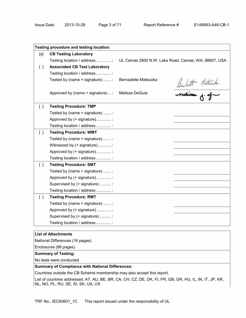
Testing procedure and testing location:
[x] CB Testing Laboratory
Testing location / address .............. : UL Camas 2600 N.W. Lake Road, Camas, WA, 98607, USA
[ ] Associated CB Test Laboratory
Testing location / address .............. :
Tested by (name + signature) ....... : Bernadette Matsuoka
Approved by (name + signature) ... : Melissa DeGuia
[ ] Testing Procedure: TMP
Tested by (name + signature) ....... :
Approved by (+ signature) ............. :
Testing location / address .............. :
[ ] Testing Procedure: WMT
Tested by (name + signature) ....... :
Witnessed by (+ signature) ............ :
Approved by (+ signature) ............. :
Testing location / address .............. :
[ ] Testing Procedure: SMT
Tested by (name + signature) ....... :
Approved by (+ signature) ............. :
Supervised by (+ signature) .......... :
Testing location / address .............. :
[ ] Testing Procedure: RMT
Tested by (name + signature) ....... :
Approved by (+ signature) ............. :
Supervised by (+ signature) .......... :
Testing location / address .............. :
List of Attachments
National Differences (16 pages)
Enclosures (86 pages)
Summary of Testing:
No tests were conducted
Summary of Compliance with National Differences:
Countries outside the CB Scheme membership may also accept this report.
List of countries addressed: AT, AU, BE, BR, CA, CH, CZ, DE, DK, FI, FR, GB, GR, HU, IL, IN, IT, JP, KR, NL, NO, PL, RU, SE, SI, SK, UA, US

1/2
Ref. Certif. No.
US-16953-A1-UL
IEC SYSTEM FOR MUTUAL RECOGNITION OF TEST CERTIFICATES FOR ELECTRICAL EQUIPMENT (IECEE) CB SCHEME
SYSTEME CEI D'ACCEPTATION MUTUELLE DE CERTIFICATS D'ESSAIS DES EQUIPEMENTS ELECTRIQUES (IECEE) METHODE OC
CB TEST CERTIFICATE CERTIFICAT D'ESSAI OCProductProduit
Switching Power Supply
Name and address of the applicantNom et adresse du demandeur
XP POWER LLC SUITE 150, 1241 E DYER RD SANTA ANA CA 92705, USA
Name and address of the manufacturerNom et adresse du fabricant
XP POWER LLC SUITE 150, 1241 E DYER RD SANTA ANA CA 92705, USA
Name and address of the factoryNom et adresse de l'usine
Note: When more than one factory, please report on page 2Note: Lorsque il y plus d'une usine, veuillez utiliser la 2ème page
XP POWER INC990 BENECIA AVE SUNNYVALE CA 94085USA
Additional Information on page 2Ratings and principal characteristicsValeurs nominales et caractéristiques principales
See Page 2
Trademark (if any)Marque de fabrique (si elle existe)
Type of Manufacturer's Testing Laboratories usedType de programme du laboratoire d'essais constructeur
SMT
Model / Type Ref.Ref. De type
AHM85PSXXYY-ZZSee Page 2
Additional information (if necessary may also be reported on page 2)Les informations complémentaires (si nécessaire,, peuvent être indiqués sur la 2ème page
Additionally evaluated to EN 60601-1:2006; National Differences specified in the CB Test Report
Additional Information on page 2
A sample of the product was tested and found to be in conformity withUn échantillon de ce produit a été essayé et a été considéré conforme à la
IEC 60601-1(ed.3)
As shown in the Test Report Ref. No. which forms part of this CertificateComme indiqué dans le Rapport d'essais numéro de référence qui constitue partie de ce Certificat
10ME02258 issued on 2012-06-04
This CB Test Certificate is issued by the National Certification BodyCe Certificat d'essai OC est établi par l'Organisme National de Certification
UL (US), 333 Pfingsten Rd IL 60062, Northbrook, USA
UL (Demko), Borupvang 5A DK-2750 Ballerup, DENMARK
UL (JP), Marunouchi Trust Tower Main Building 6F, 1-8-3 Marunouchi, Chiyoda-ku, Tokyo 100-0005, JAPAN
UL (CA), 7 Underwriters Road, Toronto, M1R 3B4 Ontario, CANADA
For full legal entity names see www.ul.com/ncbnames
Date: 2012-06-06Original Issue Date: 2011-04-21
Signature:
Jolanta M. Wroblewska

2/2
Ref. Certif. No.
US-16953-A1-ULModel Details:AHM85PSXXYY-ZZ (where XX is any number between 12-24designating output voltage and YY can be blank or "C2", -ZZcan be "-A", "-6", "-6A", "8"," -8A", or blank)
Factories:XP POWER (KUNSHAN) LTD230 BIN JIANG NAN RD ZHANGPU TOWN KUNSHAN JIANGSU 215321CHINA
Ratings:Input Rated: 100-240 Vac, 50/60 Hz, 1.0 A Output Rated: See below for 40°C ambient output rating below and Test Report Model Differences for additional details.
Model AHM85PS12: 12 Vdc, 7.08 A Model AHM85PS15: 15 Vdc, 5.67 A Model AHM85PS19: 19 Vdc, 4.47 A Model AHM85PS24: 24 Vdc, 3.54 A
Additional Information:The original report was modified to include the following changes/additions:Minor revisions to Critical Components List, added alternate generic RTV material and corrected manufacturer name to XP Power LLC, see Test Report.
Additional information (if necessary)Information complémentaire (si nécessaire)
UL (US), 333 Pfingsten Rd IL 60062, Northbrook, USA
UL (Demko), Borupvang 5A DK-2750 Ballerup, DENMARK
UL (JP), Marunouchi Trust Tower Main Building 6F, 1-8-3 Marunouchi, Chiyoda-ku, Tokyo 100-0005, JAPAN
UL (CA), 7 Underwriters Road, Toronto, M1R 3B4 Ontario, CANADA
For full legal entity names see www.ul.com/ncbnames
Signature: Jolanta M. Wroblewska
Date: 2012-06-06Original Issue Date: 2011-04-21
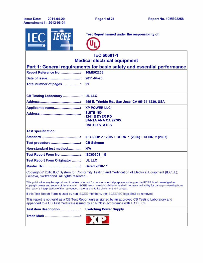
Issue Date: 2011-04-20 Page 1 of 21 Report No. 10ME02258 Amendment 1: 2012-06-04
12 Test Report issued under the responsibility of:
IEC 60601-1 Medical electrical equipment
Part 1: General requirements for basic safety and essential performanceReport Reference No. ..................... : 10ME02258
Date of issue ................................... : 2011-04-20 Total number of pages ................... : 21
CB Testing Laboratory ................... : UL LLC
Address ........................................... : 455 E. Trimble Rd., San Jose, CA 95131-1230, USA
Applicant’s name ............................ : XP POWER LLC
Address ........................................... : SUITE 150 1241 E DYER RD SANTA ANA CA 92705 UNITED STATES
Test specification: Standard .......................................... : IEC 60601-1: 2005 + CORR. 1 (2006) + CORR. 2 (2007) Test procedure ............................... : CB Scheme
Non-standard test method………..: N/A
Test Report Form No. ..................... : IEC60601_1G
Test Report Form Originator ......... : UL LLC
Master TRF ...................................... : Dated 2010-11
Copyright © 2010 IEC System for Conformity Testing and Certification of Electrical Equipment (IECEE), Geneva, Switzerland. All rights reserved.
This publication may be reproduced in whole or in part for non-commercial purposes as long as the IECEE is acknowledged as copyright owner and source of the material. IECEE takes no responsibility for and will not assume liability for damages resulting from the reader's interpretation of the reproduced material due to its placement and context.
If this Test Report Form is used by non-IECEE members, the IECEE/IEC logo shall be removed
This report is not valid as a CB Test Report unless signed by an approved CB Testing Laboratory and appended to a CB Test Certificate issued by an NCB in accordance with IECEE 02.
Test item description ..................... : Switching Power Supply
Trade Mark ...................................... :

Issue Date: 2011-04-20 Page 2 of 21 Report No. 10ME02258 Amendment 1: 2012-06-04
Manufacturer ................................... : XP POWER LLC SUITE 150 1241 E DYER RD SANTA ANA CA 92705 UNITED STATES
Model/Type reference..................... : AHM85PSXXYY-ZZ (where XX is any number between 12-24 designating output voltage and YY can be blank or "C2", -ZZ can be "-A", "-6", "-6A", "8"," -8A", or blank)
Ratings ............................................ : Input Rated: 100-240 Vac, 50/60 Hz, 1.0 A Output Rated: See below for 40°C ambient output rating below and Model Differences for additional details. Model AHM85PS12: 12 Vdc, 7.08 A Model AHM85PS15: 15 Vdc, 5.67 A Model AHM85PS19: 19 Vdc, 4.47 A Model AHM85PS24: 24 Vdc, 3.54 A

Issue Date: 2011-04-20 Page 3 of 21 Report No. 10ME02258 Amendment 1: 2012-06-04
TRF No. IEC60601_1G
Testing procedure and testing location:
CB Testing Laboratory: Testing location/ address .................. :
Associated CB Test Laboratory: Testing location/ address .................. :
Tested by (name + signature) .. : Approved by (+ signature) ....... :
Testing procedure: TMP
Tested by (name + signature) .. :
Approved by (+ signature) ........ : Testing location/ address .................. :
Testing procedure: WMT
Tested by (name + signature) .. :
Witnessed by (+ signature) ....... :
Approved by (+ signature) ....... : Testing location/ address .................. :
Testing procedure: SMT
Tested by (name + signature) .. : Rodney Reyes Approved by (+ signature) ....... : Tac Pham
Supervised by (+ signature) .... : Michael J. Howell
Testing location/ address .................. : XP Power/ 1241 E. Dyer Rd #150, Santa Ana, CA 92705, USA
Testing procedure: RMT
Tested by (name + signature) .. :
Approved by (+ signature) ....... :
Supervised by (+ signature) .... : Testing location/ address .................. :

Issue Date: 2011-04-20 Page 4 of 21 Report No. 10ME02258 Amendment 1: 2012-06-04
TRF No. IEC60601_1G
List of Attachments (including a total number of pages in each attachment): National Differences (0 pages)
Enclosures (0 pages)
Summary of testing No tests were conducted.
Summary of compliance with National Differences List of countries addressed:
US, CAN
The product fulfils the requirements of IEC 60601-1: 2005 + CORR. 1 (2006) + CORR. 2 (2007)

Issue Date: 2011-04-20 Page 5 of 21 Report No. 10ME02258 Amendment 1: 2012-06-04
TRF No. IEC60601_1G
GENERAL INFORMATION
Test item particulars (see also Clause 6):
Classification of installation and use ................................. : External Transportable
Device type (component/sub-assembly/ equipment/ system) ................................................................................... :
Component, Power Supply
Intended use (Including type of patient, application location) .................................................................................. :
To supply regulated power.
Mode of operation ................................................................ : Continuous
Supply connection ............................................................... : For Building-in
Accessories and detachable parts included ...................... : N/A
Other options include ........................................................... : N/A
Testing
Date of receipt of test item(s) ................................................ : N/A
Dates tests performed ........................................................... : N/A
Possible test case verdicts:
- test case does not apply to the test object ................... : N/A
- test object does meet the requirement ........................... : Pass (P)
- test object was not evaluated for the requirement .......... : N/E
- test object does not meet the requirement .................... : Fail (F)
Abbreviations used in the report: - normal condition ................................................... : N.C. - single fault condition................... : S.F.C. - means of Operator protection ............................. : MOOP - means of Patient protection ...... : MOPP
General remarks: "(see Attachment #)" refers to additional information appended to the report. "(see appended table)" refers to a table appended to the report. The tests results presented in this report relate only to the object tested. This report shall not be reproduced except in full without the written approval of the testing laboratory. List of test equipment must be kept on file and available for review. Additional test data and/or information provided in the attachments to this report. Throughout this report a comma / point is used as the decimal separator.
Manufacturer’s Declaration per sub-clause 6.2.5 of IECEE 02:
The application for obtaining a CB Test Certificate includes more than one factory location and a declaration from the Manufacturer stating that the sample(s) submitted for evaluation is (are) representative of the products from each factory has been provided ....................................................... :
Yes Not applicable

Issue Date: 2011-04-20 Page 6 of 21 Report No. 10ME02258 Amendment 1: 2012-06-04
TRF No. IEC60601_1G
When differences exist; they shall be identified in the General product information section.
Name and address of factory (ies) ......................... : XP POWER INC 990 BENECIA AVE SUNNYVALE CA 94085 UNITED STATES XP POWER (KUNSHAN) LTD 230 BIN JIANG NAN RD ZHANGPU TOWN KUNSHAN
JIANGSU 215321 CHINA

Issue Date: 2011-04-20 Page 7 of 21 Report No. 10ME02258 Amendment 1: 2012-06-04
TRF No. IEC60601_1G
Report Summary The original report was modified on 2012-06-04 to include the following changes/additions: 1. Minor revisions to Critical Components List 2. Add alternate generic RTV material 3. Corrected manufacturer name to XP Power LLC Product Description Products covered are external power supplies intended to be used with Medical Electrical Equipment. Units may be either Class I or Class II. Double insulated symbol provided on Class II units. General product information:
Model Differences All models in the Model AHM85PSXXYY-ZZ series are identical with exception to the Mains Transformer, T1, and minor secondary components that allow for different output voltage ratings. See below for Model Ratings Table Below for 40°C: Model AHM85PS12: 12 Vdc, 7.08 A Model AHM85PS15: 15 Vdc, 5.67 A Model AHM85PS19: 19 Vdc, 4.47 A Model AHM85PS24: 24 Vdc, 3.54 A See Enclosure - Miscellaneous for de-rated output values for higher ambient. Models may have an additional YY identifier which can be blank or "C2" to designate a Class II configuration. Models may have an additional -ZZ identifier which can be "-A", "-6", "-6A", "-8", "-8A", or blank to designate the type of input connector: blank = C14 style input connector (Class I construction) or C18 input connector (Class II construction); "-A" = C14 style input connector with optional IEC cable retention; "-6" = C6 style input connector (Class I or Class II construction); "-6A" = C6 style input connector with optional IEC cable retention; "-8" = C8 style input connector (Class I or Class II construction) "-8A" = C8 style input connector with optional IEC cable retention. Additional Information The schematics are kept on file at the CBTL and can be provided by the manufacturer upon request by NCB's/CBTL's.
When submitting this Test Report to other Certification Body, the manufacturer is responsible for providing any additional information that the Body may need in order to issue its Mark, including testing for compliance with the applicable collateral standards.
Technical Considerations
The product was investigated to the following additional standards: ANSI/AAMI ES60601-1:2005/C1:2009 (includes National Differences for USA); CAN/CSA-C22.2 No. 60601-1:08 (includes National Differences for Canada), EN 60601-1:2006

Issue Date: 2011-04-20 Page 8 of 21 Report No. 10ME02258 Amendment 1: 2012-06-04
TRF No. IEC60601_1G
Scope of Power Supply evaluation defers the following clauses to the be determined as part of the end product: Clause 7.5 (Safety Signs), Clause 7.9 (Accompanying Documents), Clause 9 (ME Hazard), Clause 10 (Radiation), Clause 14 (PEMS), Clause 16 (ME Systems)
Scope of Power Supply evaluation excludes the following: Patient applied parts clauses: 4.6, 7.2.10, 8.3, 8.5.2, 8.5.5, 8.7.4.7-8.7.4.9, 8.9.1.15 Battery related clauses: 7.3.3, 15.4.3 Hand Control related clauses: 8.10.4 Oxygen related clauses: 11.2.2 Fluids related clauses: 11.6.2 – 11.6.4 Sterilization clause: 11.6.7 Biocompatibility Clause: 11.7 (ISO 10993) Motor related clauses: 13.2.13.3, 13.4 Heating Elements related clause: 13.2 Flammable Anaesthetic Mixtures Protection: Annex G The product is evaluated only to the following hazards: Casualty, Fire, Shock The degree of protection against harmful ingress of water is: Ordinary Software is relied upon for meeting safety requirements related to mechanical, fire and shock: No Unit also complied with spacing requirements of UL60601-1 (1st), CSA C22.2 No. 60601-1 (2nd), and
IEC 60601-1 (2nd) for Basic for 250 Vac from Primary to Ground, Double/Reinforced for 250Vac from Primary to Secondary, and Supplementary for 250 Vac from Secondary to Earth.
Risk Controls/ Engineering Condition of Acceptability
The component shall be provided in compliance with the Marking (clause 7) and Separation (clause 8) requirements of the end use application.
The product was submitted and evaluated for use at the maximum ambient temperature (Tmra) permitted by the manufacturer's specification of: 40°C output loaded to 100% rated, 60°C output loaded to 60% rated (See De-rating Curve, Enclosure 7-01 for details)
Repeating Leakage current testing should be considered as part of the end product application.
This power supply was evaluated with Two MOPP between Primary and Secondary; One MOPP primary and Earth/Secondary Reference Conductor; and One MOPP between Secondary and Earth/ Secondary Reference Conductor.
This power supply has been evaluated as a continuous operation, ordinary equipment and has not been evaluated for use in the presence of a flammable anesthetic mixture with air, oxygen, or nitrous oxide. The output circuits have not been evaluated for direct patient connection (Type B, BF or CF).
The end product should ensure that the requirements related to accompanying documents, clause 7.9, are met.
The available voltage for the secondary outputs does not exceed 25 Vac or 60 Vdc, under normal and single fault conditions.
The output connectors are not acceptable for field connections; they are only intended for connection to mating connectors of the end-use machine.
The Electric Strength Test conducted on this power supply was based upon a maximum working voltage of: Primary-Earthed Dead Metal (Class I units): 416 Vpk, 240 Vrms; Primary-SEC: 416 Vpk, 240 Vrms.
The following magnetic devices (e.g. transformers or inductor) are provided with an OBJY2 insulation system with the indicated rating greater than Class A (105°C): L1-L4, L6, and T1 are Class B (130°C).

Issue Date: 2011-04-20 Page 9 of 21 Report No. 10ME02258 Amendment 1: 2012-06-04
TRF No. IEC60601_1G
Accompanying documents to be provided as part of the end-product.
Cleaning test to be considered as part of end product evaluation.
Marking Durability was conducted, however the need for Marking Durability and Marking Legibility Testing to be considered as part of the end product installation.
Power cord suitable for the application to be provided as part of the end product evaluation.

1/2
Ref. Certif. No.
US-15297-A3-UL
IEC SYSTEM FOR MUTUAL RECOGNITION OF TEST CERTIFICATES FOR ELECTRICAL EQUIPMENT (IECEE) CB SCHEME
SYSTEME CEI D’ACCEPTATION MUTUELLE DE CERTIFICATS D’ESSAIS DES EQUIPEMENTS ELECTRIQUES (IECEE) METHODE OC
CB TEST CERTIFICATE CERTIFICAT D’ESSAI OC
Product Produit
Switching Power Supply
Name and address of the applicant Nom et adresse du demandeur
XP POWER L L C SUITE 150 1241 E DYER RD SANTA ANA CA 92705, USA
Name and address of the manufacturer Nom et adresse du fabricant
XP POWER LLC SUITE 150 1241 E DYER RD SANTA ANA CA 92705, USA
Name and address of the factory Nom et adresse de l’usine Note: When more than one factory, please report on page 2 Note: Lorsque il y plus d'une usine, veuillez utiliser la 2ème page
XP POWER LLC 990 BENECIA AVE SUNNYVALE CA 94085 USA
Additional Information on page 2
Ratings and principal characteristics Valeurs nominales et caractéristiques principales
See Page 2
Trademark (if any) Marque de fabrique (si elle existe)
Type of Manufacturer's Testing Laboratories usedType de programme du laboratoire d'essais constructeur
Model / Type Ref. Ref. De type
AHM100PS24 XD0112A, AHM100PSXXYY-ZZ See Page 2
Additional information (if necessary may also be reported on page 2) Les informations complémentaires (si nécessaire,, peuvent être indiqués sur la 2ème page
National Differences specified in the CB Test Report.
Additional Information on page 2
A sample of the product was tested and found to be in conformity with Un échantillon de ce produit a été essayé et a été considéré conforme à la
IEC 60601-1(ed.2), IEC 60601-1(ed.2);am1, IEC 60601-1(ed.2);am2
As shown in the Test Report Ref. No. which forms part of this Certificate Comme indiqué dans le Rapport d’essais numéro de référence qui constitue partie de ce Certificat
E146893-A6-CB-1 issued on 2013-11-18
This CB Test Certificate is issued by the National Certification Body Ce Certificat d’essai OC est établi par l’Organisme National de Certification
UL (US), 333 Pfingsten Rd IL 60062, Northbrook, USA
UL (Demko), Borupvang 5A DK-2750 Ballerup, DENMARK
UL (JP), Marunouchi Trust Tower Main Building 6F, 1-8-3 Marunouchi, Chiyoda-ku, Tokyo 100-0005, JAPAN
UL (CA), 7 Underwriters Road, Toronto, M1R 3B4 Ontario, CANADA
For full legal entity names see www.ul.com/ncbnames
Date: 2013-11-18 Original Issue Date: 2010-07-06
Signature: Jolanta M. Wroblewska

2/2
Ref. Certif. No.
US-15297-A3-UL
Model Details:
AHM100PSXXYY-ZZ (where XX is any number between 12-48 designating output voltage and YY can be blank or "C2", -ZZ can be "-A", "-6", "-6A", "8"," -8A", or blank)
Factories:
XP POWER (KUNSHAN) LTD
230 BIN JIANG NAN RD ZHANGPU TOWN KUNSHAN JIANGSU 215321
CHINA
Ratings:
Input Rated: 100-240 Vac, 50/60 Hz, 1.2 A
Output Rated: See reference to output rating below and Test Report - Model Differences for additional details.
Model AHM100PS12: 12 Vdc, 8.33 A
Model AHM100PS15: 15 Vdc, 6.67 A
Model AHM100PS19: 19 Vdc, 5.26 A
Model AHM100PS24: 24 Vdc, 4.16 A
Model AHM100PS48: 48 Vdc, 2.08 A
Additional Information:
The original report was modified to include the following changes/additions:
Add alternate component, modify applicant/manufacturer/factory name, see test report.
Additional information (if necessary)
Information complémentaire (si nécessaire)
UL (US), 333 Pfingsten Rd IL 60062, Northbrook, USA
UL (Demko), Borupvang 5A DK-2750 Ballerup, DENMARK
UL (JP), Marunouchi Trust Tower Main Building 6F, 1-8-3 Marunouchi, Chiyoda-ku, Tokyo 100-0005, JAPAN
UL (CA), 7 Underwriters Road, Toronto, M1R 3B4 Ontario, CANADA
For full legal entity names see www.ul.com/ncbnames
Signature: Jolanta M. Wroblewska
Date: 2013-11-18 Original Issue Date: 2010-07-06

Issue Date: 2010-07-06 Page 1 of 19 Report Reference # E146893-A6-CB-1
Amendment 3 2013-11-18
TRF No.: IEC60601_1C This report issued under the responsibility of UL
Test Report issued under
the responsibility of:
TEST REPORT IEC 60601-1
Medical Electrical Equipment Part 1:General requirements for safety
Report Reference No .................. : E146893-A6-CB-1
Date of issue ................................. : 2010-07-06
Total number of pages .................. : 19
CB Testing Laboratory ............... : UL San Jose
Address ......................................... : 455 E. Trimble Rd., San Jose, CA, 95131-1230, USA
Applicant's name ........................ :
Address ......................................... :
XP POWER L L C SUITE 150 1241 E DYER RD SANTA ANA CA 92705 UNITED STATES
Test specification:
Standard ........................................ : IEC 60601-1:1988 + A1:1991 + A2:1995
Test procedure .............................. : CB Scheme
Non-standard test method ............ : N/A
Test Report Form No. ................. : IEC60601_1c/97-04
Test Report Form originator .......... : UL LLC
Master TRF ................................... : dated 97-04
Copyright © 2008 IEC System for Conformity Testing and Certification of Electrical Equipment (IECEE), Geneva, Switzerland. All rights reserved. This publication may be reproduced in whole or in part for non-commercial purposes as long as the IECEE is acknowledged as copyright owner and source of the material. IECEE takes no responsibility for and will not assume liability for damages resulting from the reader's interpretation of the reproduced material due to its placement and context. If this test Report is used by non-IECEE members, the IECEE/IEC logo and the reference to the CB Scheme procedure shall be removed. This report is not valid as a CB Test Report unless signed by an approved CB Testing Laboratory and appended to a CB Test Certificate issued by an NCB in accordance with IECEE 02.

Issue Date: 2010-07-06 Page 2 of 19 Report Reference # E146893-A6-CB-1
Amendment 3 2013-11-18
TRF No.: IEC60601_1C This report issued under the responsibility of UL
Test item description .................. : Switching Power Supply
Trade Mark .................................... :
Manufacturer ................................. : XP POWER LLC SUITE 150 1241 E DYER RD SANTA ANA CA 92705 UNITED STATES
Model/Type reference ................... : AHM100PSXXYY-ZZ (where XX is any number between 12-48 designating output voltage and YY can be blank or "C2", -ZZ can be "-A", "-6", "-6A", "8"," -8A", or blank), AHM100PS24 XD0112A
Ratings .......................................... : Input Rated: 100-240 Vac, 50/60 Hz, 1.2 A Output Rated: See reference to output rating below and Model Differences for additional details. Model AHM100PS12: 12 Vdc, 8.33 A Model AHM100PS15: 15 Vdc, 6.67 A Model AHM100PS19: 19 Vdc, 5.26 A Model AHM100PS24: 24 Vdc, 4.16 A Model AHM100PS48: 48 Vdc, 2.08 A

Issue Date: 2010-07-06 Page 3 of 19 Report Reference # E146893-A6-CB-1
Amendment 3 2013-11-18
TRF No.: IEC60601_1C This report issued under the responsibility of UL
Testing procedure and testing location:
[x] CB Testing Laboratory
Testing location / address .............. : UL San Jose 455 E. Trimble Rd., San Jose, CA, 95131-1230, USA
[ ] Associated CB Test Laboratory
Testing location / address .............. :
Tested by (name + signature) ....... : Timothy L. Gambrell
Approved by (name + signature) ... : Melissa DeGuia
[ ] Testing Procedure: TMP
Tested by (name + signature) ....... :
Approved by (+ signature) ............. :
Testing location / address .............. :
[ ] Testing Procedure: WMT
Tested by (name + signature) ....... :
Witnessed by (+ signature) ............ :
Approved by (+ signature) ............. :
Testing location / address .............. :
[ ] Testing Procedure: SMT
Tested by (name + signature) ....... :
Approved by (+ signature) ............. :
Supervised by (+ signature) .......... :
Testing location / address .............. :
[ ] Testing Procedure: RMT
Tested by (name + signature) ....... :
Approved by (+ signature) ............. :
Supervised by (+ signature) .......... :
Testing location / address .............. :
List of Attachments
National Differences (3 pages)
Enclosures (0 pages)
Summary of Testing:
No tests were conducted
Summary of Compliance with National Differences:
Countries outside the CB Scheme membership may also accept this report.
List of countries addressed: AT, AU, BE, BR, CA, CH, CZ, DE, DK, FI, FR, GB, GR, HU, IL, IN, IT, KR, NL, PL, RU, SE, SI, SK, UA, US

Issue Date: 2010-07-06 Page 4 of 19 Report Reference # E146893-A6-CB-1
Amendment 3 2013-11-18
TRF No.: IEC60601_1C This report issued under the responsibility of UL
Copy of Marking Plate - Refer to Enclosure titled Marking Plate for copy.

Issue Date: 2010-07-06 Page 5 of 19 Report Reference # E146893-A6-CB-1
Amendment 3 2013-11-18
TRF No.: IEC60601_1C This report issued under the responsibility of UL
Test item particulars :
Classification of installation and use ....................: Transportable
Supply connection ................................................: Appliance coupler
Accessories and detachable parts included in the evaluation .............................................................: None
Options included ..................................................: None
Possible test case verdicts:
- test case does not apply to the test object ........... : N / A
- test object does meet the requirement ................. : P(Pass)
- test object does not meet the requirement ........... : F(Fail)
Abbreviations used in the report:
- normal condition ............................................ : N.C. - single fault condition ................ : S.F.C.
- operational insulation ..................................... : OP - basic insulation ........................ : BI
- basic insulation between parts of opposite polarity:
BOP - supplementary insulation ......... : SI
- double insulation ............................................ : DI - reinforced insulation ................ : RI
Testing:
Date(s) of receipt of test item ...............................: N/A
Date(s) of Performance of tests ...........................: N/A
General remarks:
The test results presented in this report relate only to the object tested. This report shall not be reproduced, except in full, without the written approval of the testing laboratory. List of test equipment must be kept on file and be available for review. "(see Enclosure #)" refers to additional information appended to the report. "(see appended table)" refers to a table appended to the report. Throughout this report a point is used as the decimal separator.
Manufacturer's Declaration per Sub Clause 6.2.5 of IECEE 02: The application for obtaining a CB Test Certificate includes more than one factory and a declaration from the Manufacturer stating that the sample(s) submitted for evaluation is (are) representative of the products from each factory has been provided ...... When differences exist, they shall be identified in the General Product Information section.
Yes
Name and address of Factory(ies): XP POWER LLC 990 BENECIA AVE SUNNYVALE CA 94085 UNITED STATES XP POWER (KUNSHAN) LTD 230 BIN JIANG NAN RD ZHANGPU TOWN KUNSHAN

Issue Date: 2010-07-06 Page 6 of 19 Report Reference # E146893-A6-CB-1
Amendment 3 2013-11-18
TRF No.: IEC60601_1C This report issued under the responsibility of UL
JIANGSU 215321 CHINA
GENERAL PRODUCT INFORMATION:
Report Summary
The original report was modified on 2013-11-18 to include the following changes/additions: Add alternate insulating tape to T2 manufactured by 3M, type 1350F. Additionaly revised Applicant/Manufacturer/Factory name from XP Power Inc to XP Power LLC.
Product Description
Products covered are external power supplies intended to be used with Medical Electrical Equipment. Units may be either Class I or Class II. Double insulated symbol is optionally provided on units Class II units. Earthing symbol may only be provided for Class I power supplies.
Model Differences
All models in the Model AHM100PSXXYY-ZZ series are identical with exception to the Mains Transformer, T2, and minor secondary components that allow for different output voltage ratings. See below for Model Ratings Table Below for 40°C: Model AHM100PS12: 12 Vdc, 8.33 A Model AHM100PS15: 15 Vdc, 6.67 A Model AHM100PS19: 19 Vdc, 5.26 A Model AHM100PS24: 24 Vdc, 4.16 A Model AHM100PS48: 48 Vdc, 2.08 A See Enclosure - Miscellaneous for de-rated output values for higher ambient. Models may have an additional YY identifier which can be blank or "C2" to designate a Class II configuration. Models may have an additional -ZZ identifier which can be "-A", "-6", "-6A", "-8", "-8A", or blank to designate the type of input connector: blank = C14 style input connector (Class I construction) or C18 input connector (Class II construction); "A" = C14 style input connector with optional IEC cable retention; "6" = C6 style input connector (Class I or Class II construction); "6A" = C6 style input connector with optional IEC cable retention; "8" = C8 style input connector (Class I or Class II construction) "8A" = C8 style input connector with optional IEC cable retention. Model AHM100PS24 XD0112A is identical to Model AHM100PS24 with exception to the addition of an alternate input connector.
Additional Information
Marking label is representative of all models. The nameplate labels included in this report depict the draft artwork for the marking plate pending approval by National Certification Bodies and it will not be affixed to products prior to such approval. Multiple Location Manufacturer Codes:

Issue Date: 2010-07-06 Page 7 of 19 Report Reference # E146893-A6-CB-1
Amendment 3 2013-11-18
TRF No.: IEC60601_1C This report issued under the responsibility of UL
"K" XP Power, Jiangsu, China "FS" XP Power, Sunnyvale, Ca Receiving NCB may challenge CB Test Certificates, which are based on reports that are more than 3 years old.
Technical Considerations
The product was investigated to the following additional standards: UL 60601-1, 1st Edition, 2006-04-26 (includes National Differences for USA), EN 60601-1: 1990 + A1:1993 + A2:1995, CAN/CSA-C22.2 No. 601.1-M90 (R2005) (includes National Differences for Canada), (except EMC limitations, EN 60601-1-2, Biocompatibility, EN 10993-1, Programmable Electronic Systems, IEC 60601-1-4)
The product was not investigated to the following standards or clauses: Clause 36, Electromagnetic Compatibility (IEC 601-1-2) , Clause 48, Biocompatibility (ISO 10993-1) , Clause 52.1, Programmable Electronic Systems (IEC 601-1-4)
The product is Classified only to the following hazards: Casualty , Fire , Shock
The degree of protection against harmful ingress of water is: Ordinary
The mode of operation is: Continuous
Software is relied upon for meeting safety requirements related to mechanical, fire and shock: No
The product is suitable for use in the presence of a flammable anesthetics mixture with air or oxygen or with nitrous oxide: No
Engineering Conditions of Acceptability
When installed in an end-product, consideration must be given to the following:
This component has been judged on the basis of the required spacings in the Second Edition of the Standards for Medical Electrical Equipment, Part 1: General Requirements for Safety, UL 60601-1, which covers the end use product for which the component is designed. --
Repeating leakage current testing should be considered in the end product application. --
This power supply was evaluated as having: Basic Insulation between Primary to Earth (For Class I units), Reinforced insulation between Primary and Secondary (For All Units), Basic from Secondary to Earth (For Class I units). --
The available voltage for the secondary outputs does not exceed 25 Vac or 60 Vdc, under normal and single fault conditions. --
The end product should ensure that the requirements related to accompanying documents, clause 6.8, are met. --
The product was submitted and evaluated for use at the maximum ambient temperature (Tmra) permitted by the manufacturer's specification of: 40°C (See De-rating Curve, Enclosure 7-01 for details) --
The output circuits have not been evaluated for direct patient connection (Type B, BF or CF). --
The Electric Strength Test conducted on this power supply was based upon a maximum working voltage of: Primary-Earthed Dead Metal (Class I units): 240 Vrms, Primary-SEC: 243 Vrms. --
The following magnetic devices (e.g. transformers or inductor) are provided with an OBJY2 insulation system with the indicated rating greater than Class A (105°C): L1, L2, L3, L4, and T2 are Class B (130°C) --
Accompanying documents to be provided as part of the end-product. --

Issue Date: 2010-07-06 Page 8 of 19 Report Reference # E146893-A6-CB-1
Amendment 3 2013-11-18
TRF No.: IEC60601_1C This report issued under the responsibility of UL
Cleaning test to be considered as part of end product evaluation. --

1/2
Ref. Certif. No.
US-18097-A1-UL
IEC SYSTEM FOR MUTUAL RECOGNITION OF TEST CERTIFICATES FOR ELECTRICAL EQUIPMENT (IECEE) CB SCHEME
SYSTEME CEI D'ACCEPTATION MUTUELLE DE CERTIFICATS D'ESSAIS DES EQUIPEMENTS ELECTRIQUES (IECEE) METHODE OC
CB TEST CERTIFICATE CERTIFICAT D'ESSAI OCProductProduit
Switching Power Supply
Name and address of the applicantNom et adresse du demandeur
XP POWER LLC.SUITE 1501241 E DYER RDSANTA ANA CA 92705, USA
Name and address of the manufacturerNom et adresse du fabricant
XP POWER LLC.SUITE 1501241 E DYER RDSANTA ANA CA 92705, USA
Name and address of the factoryNom et adresse de l'usine
Note: When more than one factory, please report on page 2Note: Lorsque il y plus d'une usine, veuillez utiliser la 2ème page
XP POWER LLC990 BENECIA AVESUNNYVALE CA 94085USA
Additional Information on page 2Ratings and principal characteristicsValeurs nominales et caractéristiques principales
Input Rated: 100-240 Vac, 50/60 Hz, 1.2 A Output Rated: See test report for details.
Trademark (if any)Marque de fabrique (si elle existe)
Type of Manufacturer's Testing Laboratories usedType de programme du laboratoire d'essais constructeur
SMT
Model / Type Ref.Ref. De type
AHM100PS24 XD0112A, AHM100PSXXYY-ZZSee Page 2
Additional information (if necessary may also be reported on page 2)Les informations complémentaires (si nécessaire,, peuvent être indiqués sur la 2ème page
The original report was modified to include the following changes/additions:Modifying critical component table.
Additional Information on page 2A sample of the product was tested and found to be in conformity withUn échantillon de ce produit a été essayé et a été considéré conforme à la
IEC 60601-1(ed.3)
As shown in the Test Report Ref. No. which forms part of this CertificateComme indiqué dans le Rapport d'essais numéro de référence qui constitue partie de ce Certificat
11CA41872 issued on 2012-05-17
This CB Test Certificate is issued by the National Certification BodyCe Certificat d'essai OC est établi par l'Organisme National de Certification
UL (US), 333 Pfingsten Rd IL 60062, Northbrook, USA
UL (Demko), Borupvang 5A DK-2750 Ballerup, DENMARK
UL (JP), Marunouchi Trust Tower Main Building 6F, 1-8-3 Marunouchi, Chiyoda-ku, Tokyo 100-0005, JAPAN
UL (CA), 7 Underwriters Road, Toronto, M1R 3B4 Ontario, CANADA
For full legal entity names see www.ul.com/ncbnames
Date: 2012-05-21Original Issue Date: 2011-11-21
Signature:
Jolanta M. Wroblewska

2/2
Ref. Certif. No.
US-18097-A1-ULModel Details: AHM100PSXXYY-ZZ (where XX is any number between 12-48 designating output voltage and YY can be blank or "C2", -ZZ can be "-A", "-6", "-6A", "8"," -8A", or blank)
Factories:XP POWER (KUNSHAN) LTD230 BIN JIANG NAN RD, ZHANGPU TOWNKUNSHAN, JIANGSU 215321CHINA
Additional information (if necessary)Information complémentaire (si nécessaire)
UL (US), 333 Pfingsten Rd IL 60062, Northbrook, USA
UL (Demko), Borupvang 5A DK-2750 Ballerup, DENMARK
UL (JP), Marunouchi Trust Tower Main Building 6F, 1-8-3 Marunouchi, Chiyoda-ku, Tokyo 100-0005, JAPAN
UL (CA), 7 Underwriters Road, Toronto, M1R 3B4 Ontario, CANADA
For full legal entity names see www.ul.com/ncbnames
Signature: Jolanta M. Wroblewska
Date: 2012-05-21Original Issue Date: 2011-11-21

Issue Date: 2011-11-21 Page 1 of 20 Report No. 11CA41872 Amendment 1: 2012-05-17
12 Test Report issued under the responsibility of:
IEC 60601-1 Medical electrical equipment
Part 1: General requirements for basic safety and essential performanceReport Reference No. ..................... : 11CA41872
Date of issue ................................... : 2011-11-21
Total number of pages ................... : 20
CB Testing Laboratory ................... : UL LLC
Address ........................................... : 455 E. Trimble Rd., San Jose, CA 95131-1230, USA
Applicant’s name ............................ : XP POWER LLC.
Address ........................................... : SUITE 150 1241 E DYER RD SANTA ANA CA 92705
UNITED STATES
Test specification:
Standard .......................................... : IEC 60601-1: 2005 + CORR. 1 (2006) + CORR. 2 (2007)
Test procedure ............................... : CB Scheme
Non-standard test method………..: N/A
Test Report Form No. ..................... : IEC60601_1G
Test Report Form Originator ......... : UL LLC
Master TRF ...................................... : Dated 2010-11
Copyright © 2010 IEC System for Conformity Testing and Certification of Electrical Equipment (IECEE), Geneva, Switzerland. All rights reserved.
This publication may be reproduced in whole or in part for non-commercial purposes as long as the IECEE is acknowledged as copyright owner and source of the material. IECEE takes no responsibility for and will not assume liability for damages resulting from the reader's interpretation of the reproduced material due to its placement and context.
If this Test Report Form is used by non-IECEE members, the IECEE/IEC logo shall be removed
This report is not valid as a CB Test Report unless signed by an approved CB Testing Laboratory and appended to a CB Test Certificate issued by an NCB in accordance with IECEE 02.
Test item description ..................... : Switching Power Supply
Trade Mark ...................................... :

Issue Date: 2011-11-21 Page 2 of 20 Report No. 11CA41872 Amendment 1: 2012-05-17
Manufacturer ................................... : XP POWER LLC SUITE 150 1241 E DYER RD SANTA ANA CA 92705
UNITED STATES
Model/Type reference..................... : AHM100PSXXYY-ZZ (where XX is any number between 12-48 designating output voltage and YY can be blank or "C2", -ZZ can be "-A", "-6", "-6A", "8"," -8A", or blank), AHM100PS24 XD0112A
Ratings ............................................ : Input Rated: 100-240 Vac, 50/60 Hz, 1.2 A Output Rated: See Model Differences for details.

Issue Date: 2011-11-21 Page 3 of 20 Report No. 11CA41872 Amendment 1: 2012-05-17
TRF No. IEC60601_1G
Testing procedure and testing location:
CB Testing Laboratory:
Testing location/ address .................. :
Associated CB Test Laboratory:
Testing location/ address .................. :
Tested by (name + signature) .. :
Approved by (+ signature) ....... :
Testing procedure: TMP
Tested by (name + signature) .. :
Approved by (+ signature) ........ :
Testing location/ address .................. :
Testing procedure: WMT
Tested by (name + signature) .. :
Witnessed by (+ signature) ....... :
Approved by (+ signature) ....... :
Testing location/ address .................. :
Testing procedure: SMT
Tested by (name + signature) .. : Chin Chee Siang
Approved by (+ signature) ....... : Tac Pham
Supervised by (+ signature) .... : Michael J. Howell
Testing location/ address .................. : XP Power, 1241 E. Dyer Rd #150, Santa Ana, CA 92705/XP Power, 401 Commonwealth Dr., Haw Par Technocentre, Lobby B, #02-02, Singapore 149598
Testing procedure: RMT
Tested by (name + signature) .. :
Approved by (+ signature) ....... :
Supervised by (+ signature) .... :
Testing location/ address .................. :

Issue Date: 2011-11-21 Page 4 of 20 Report No. 11CA41872 Amendment 1: 2012-05-17
TRF No. IEC60601_1G
List of Attachments (including a total number of pages in each attachment):
National Differences (0 pages)
Enclosures (0 pages)
Summary of testing
No tests were conducted.
Summary of compliance with National Differences
List of countries addressed:
US, CAN
The product fulfils the requirements of IEC 60601-1: 2005 + CORR. 1 (2006) + CORR. 2 (2007)

Issue Date: 2011-11-21 Page 5 of 20 Report No. 11CA41872 Amendment 1: 2012-05-17
TRF No. IEC60601_1G
GENERAL INFORMATION
Test item particulars (see also Clause 6):
Classification of installation and use ................................. : External Transportable
Device type (component/sub-assembly/ equipment/ system) ................................................................................... :
Component, Power Supply
Intended use (Including type of patient, application location) .................................................................................. :
To supply regulated power.
Mode of operation ................................................................ : Continuous
Supply connection ............................................................... : Appliance coupler
Accessories and detachable parts included ...................... : N/A
Other options include ........................................................... : N/A
Testing
Date of receipt of test item(s) ................................................ : N/A
Dates tests performed ........................................................... : N/A
Possible test case verdicts:
- test case does not apply to the test object ................... : N/A
- test object does meet the requirement ........................... : Pass (P)
- test object was not evaluated for the requirement .......... : N/E
- test object does not meet the requirement .................... : Fail (F)
Abbreviations used in the report:
- normal condition ................................................... : N.C. - single fault condition................... : S.F.C.
- means of Operator protection ............................. : MOOP - means of Patient protection ...... : MOPP
General remarks: "(see Attachment #)" refers to additional information appended to the report. "(see appended table)" refers to a table appended to the report. The tests results presented in this report relate only to the object tested. This report shall not be reproduced except in full without the written approval of the testing laboratory. List of test equipment must be kept on file and available for review. Additional test data and/or information provided in the attachments to this report. Throughout this report a comma / point is used as the decimal separator.
Manufacturer’s Declaration per sub-clause 6.2.5 of IECEE 02:
The application for obtaining a CB Test Certificate includes more than one factory location and a declaration from the Manufacturer stating that the sample(s) submitted for evaluation is (are) representative of the products from each factory has been provided ....................................................... :
Yes
Not applicable
When differences exist; they shall be identified in the General product information section.

Issue Date: 2011-11-21 Page 6 of 20 Report No. 11CA41872 Amendment 1: 2012-05-17
TRF No. IEC60601_1G
Name and address of factory (ies) ......................... XP POWER LLC 990 BENECIA AVE SUNNYVALE CA 94085 UNITED STATES XP POWER (KUNSHAN) LTD 230 BIN JIANG NAN RD ZHANGPU TOWN KUNSHAN
JIANGSU 215321 CHINA

Issue Date: 2011-11-21 Page 7 of 20 Report No. 11CA41872 Amendment 1: 2012-05-17
TRF No. IEC60601_1G
Report Summary The original report was modified on 2012-05-17 to include the following changes/additions: 1. Minor revisions to Critical Components List 2. Add alternate generic RTV material Product Description Products covered are external power supplies intended to be used with Medical Electrical Equipment. Units may be either Class I or Class II. Double insulated symbol is optionally provided on units Class II units.
Earthing symbol may only be provided for Class I power supplies.
General product information:
Model Differences
All models in the Model AHM100PSXXYY-ZZ series are identical with exception to the Mains Transformer, T2, and minor secondary components that allow for different output voltage ratings. See Table below for Model Ratings at 40°C: Model AHM100PS12: 12 Vdc, 8.33 A Model AHM100PS15: 15 Vdc, 6.67 A Model AHM100PS19: 19 Vdc, 5.26 A Model AHM100PS24: 24 Vdc, 4.16 A Model AHM100PS48: 48 Vdc, 2.08 A See Enclosure - Miscellaneous for de-rated output values for higher ambient. Models may have an additional YY identifier which can be blank or "C2" to designate a Class II configuration. Models may have an additional -ZZ identifier which can be "-A", "-6", "-6A", "-8", "-8A", or blank to designate the type of input connector: blank = C14 style input connector (Class I construction) or C18 input connector (Class II construction); "A" = C14 style input connector with optional IEC cable retention; "6" = C6 style input connector (Class I or Class II construction); "6A" = C6 style input connector with optional IEC cable retention; "8" = C8 style input connector (Class I or Class II construction) "8A" = C8 style input connector with optional IEC cable retention. Model AHM100PS24 XD0112A is identical to Model AHM100PS24 with exception to the addition of an alternate input connector. Additional Information The schematics are kept on file at the CBTL and can be provided by the manufacturer upon request by NCB's/CBTL's.
When submitting this Test Report to other Certification Body, the manufacturer is responsible for providing any additional information that the Body may need in order to issue its Mark, including testing for compliance with the applicable collateral standards.

Issue Date: 2011-11-21 Page 8 of 20 Report No. 11CA41872 Amendment 1: 2012-05-17
TRF No. IEC60601_1G
Marking label is representative of all models. The nameplate labels included in this report depict the draft artwork for the marking plate pending approval by National Certification Bodies and it will not be affixed to products prior to such approval. Multiple Location Manufacturer Codes: "K" XP Power, Jiangsu, China "FS" XP Power, Sunnyvale, Ca
Technical Considerations
The product was investigated to the following additional standards: ANSI/AAMI ES60601-
1:2005/C1:2009 (includes National Differences for USA); CAN/CSA-C22.2 No. 60601-1:08 (includes National Differences for Canada), EN 60601-1:2006
Scope of Power Supply evaluation defers the following clauses to the be determined as part of the end product: Clause 7.5 (Safety Signs), Clause 7.9 (Accompanying Documents), Clause 9 (ME Hazard), Clause 10 (Radiation), Clause 14 (PEMS), Clause 16 (ME Systems)
The product is evaluated only to the following hazards: Casualty, Fire, Shock The degree of protection against harmful ingress of water is: Ordinary Software is relied upon for meeting safety requirements related to mechanical, fire and shock: No Unit also complied with spacing requirements of UL60601-1 (1st), CSA C22.2 No. 60601-1 (2nd), and
IEC 60601-1 (2nd) for Basic for 250 Vac from Primary to Ground, Double/Reinforced for 250Vac from Primary to Secondary, and Supplementary for 250 Vac from Secondary to Earth.
Risk Controls/ Engineering Condition of Acceptability
The component shall be provided in compliance with the Marking (clause 7) and Separation (clause
8) requirements of the end use application.
The power supply was evaluated for use in 40°C ambient at Full Rated Output and 60% of the Rated Output in 60°C ambient. (See De-rating Curve, Enclosure 7-01 for details)
Repeating leakage current testing should be considered in the end product application.
This power supply was evaluated with Two MOPP between Primary and Secondary; One MOPP primary and Earth/Secondary Reference Conductor; and One MOPP between Secondary and Earth/ Secondary Reference Conductor.
This power supply has been evaluated as a continuous operation, ordinary equipment and has not been evaluated for use in the presence of a flammable anesthetic mixture with air, oxygen, or nitrous oxide. The output circuits have not been evaluated for direct patient connection (Type B, BF or CF).
The end product should ensure that the requirements related to accompanying documents, clause 7.9, are met.
The available voltage for the secondary outputs does not exceed 25 Vac or 60 Vdc, under normal and single fault conditions.
The output connectors are not acceptable for field connections; they are only intended for connection to mating connectors of the end-use machine.
The Electric Strength Test conducted on this power supply was based upon a maximum working voltage of: Primary-Earthed Dead Metal (Class I units): 430 Vpk, 240 Vrms; Primary-SEC: 430 Vpk, 240 Vrms.
The following magnetic devices (e.g. transformers or inductor) are provided with an OBJY2

Issue Date: 2011-11-21 Page 9 of 20 Report No. 11CA41872 Amendment 1: 2012-05-17
TRF No. IEC60601_1G
insulation system with the indicated rating greater than Class A (105°C): L1-L4 and T2 are Class B (130°C).
Cleaning test to be considered as part of end product evaluation.
The need for Marking Durability and Marking Legibility Testing to be considered as part of the end product installation.
Power cord suitable for the application to be provided as part of the end product evaluation.
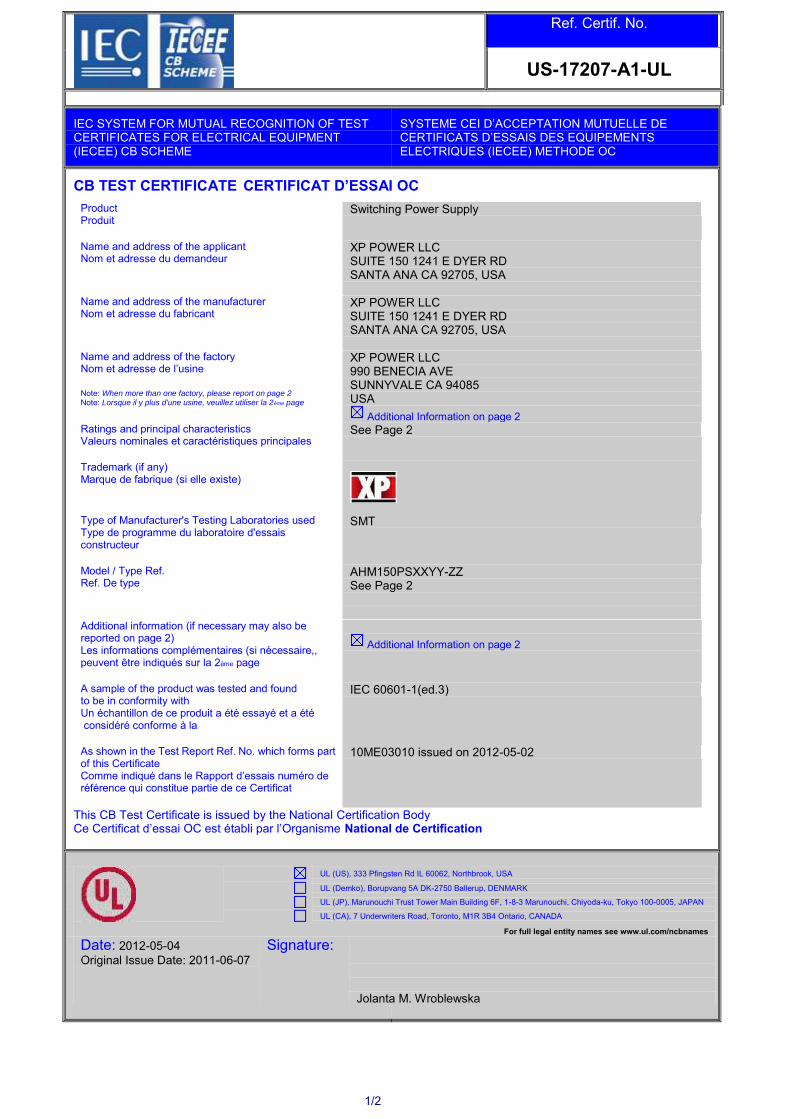
1/2
Ref. Certif. No.
US-17207-A1-UL
IEC SYSTEM FOR MUTUAL RECOGNITION OF TEST CERTIFICATES FOR ELECTRICAL EQUIPMENT (IECEE) CB SCHEME
SYSTEME CEI D’ACCEPTATION MUTUELLE DE CERTIFICATS D’ESSAIS DES EQUIPEMENTS ELECTRIQUES (IECEE) METHODE OC
CB TEST CERTIFICATE CERTIFICAT D’ESSAI OC
Product Produit
Switching Power Supply
Name and address of the applicant Nom et adresse du demandeur
XP POWER LLC SUITE 150 1241 E DYER RD SANTA ANA CA 92705, USA
Name and address of the manufacturer Nom et adresse du fabricant
XP POWER LLC SUITE 150 1241 E DYER RD SANTA ANA CA 92705, USA
Name and address of the factory Nom et adresse de l’usine Note: When more than one factory, please report on page 2 Note: Lorsque il y plus d'une usine, veuillez utiliser la 2ème page
XP POWER LLC 990 BENECIA AVE SUNNYVALE CA 94085 USA
Additional Information on page 2 Ratings and principal characteristics Valeurs nominales et caractéristiques principales
See Page 2
Trademark (if any) Marque de fabrique (si elle existe)
Type of Manufacturer's Testing Laboratories used Type de programme du laboratoire d'essais constructeur
SMT
Model / Type Ref. Ref. De type
AHM150PSXXYY-ZZ See Page 2
Additional information (if necessary may also be reported on page 2) Les informations complémentaires (si nécessaire,, peuvent être indiqués sur la 2ème page
Additional Information on page 2
A sample of the product was tested and found to be in conformity with Un échantillon de ce produit a été essayé et a été considéré conforme à la
IEC 60601-1(ed.3)
As shown in the Test Report Ref. No. which forms part of this Certificate Comme indiqué dans le Rapport d’essais numéro de référence qui constitue partie de ce Certificat
10ME03010 issued on 2012-05-02
This CB Test Certificate is issued by the National Certification Body Ce Certificat d’essai OC est établi par l’Organisme National de Certification
UL (US), 333 Pfingsten Rd IL 60062, Northbrook, USA
UL (Demko), Borupvang 5A DK-2750 Ballerup, DENMARK
UL (JP), Marunouchi Trust Tower Main Building 6F, 1-8-3 Marunouchi, Chiyoda-ku, Tokyo 100-0005, JAPAN
UL (CA), 7 Underwriters Road, Toronto, M1R 3B4 Ontario, CANADA
For full legal entity names see www.ul.com/ncbnames
Date: 2012-05-04
Original Issue Date: 2011-06-07
Signature: Jolanta M. Wroblewska

2/2
Ref. Certif. No.
US-17207-A1-UL
Model Details:
AHM150PSXXYY-ZZ (where XX is any number between 12-48 designating output voltage, where YY can be "C2" or blank, and -ZZ can be "-A", "-6", "-6A", "8"," -8A", or blank)
Factories:
XP POWER (KUNSHAN) LTD
230 BIN JIANG NAN RD
ZHANGPU TOWN KUNSHAN JIANGSU 215321
CHINA
Ratings:
Input Rated: 100-240 Vac, 50/60 Hz, 1.8 A
Output Rated: See below for 40°C ambient output rating below and Model Differences for additional details.
Model AHM150PS12: 12 Vdc, 12.5 A
Model AHM150PS15: 15 Vdc, 10.0 A
Model AHM150PS19: 19 Vdc, 7.89 A
Model AHM150PS24: 24 Vdc, 6.25 A
Model AHM150PS48: 48 Vdc, 3.13 A
Additional Information:
The original report was modified to update the model designation, Critical Components List, test tables and marking label.
National Differences specified in the CB Test Report.
Additional information (if necessary)
Information complémentaire (si nécessaire)
UL (US), 333 Pfingsten Rd IL 60062, Northbrook, USA
UL (Demko), Borupvang 5A DK-2750 Ballerup, DENMARK
UL (JP), Marunouchi Trust Tower Main Building 6F, 1-8-3 Marunouchi, Chiyoda-ku, Tokyo 100-0005, JAPAN
UL (CA), 7 Underwriters Road, Toronto, M1R 3B4 Ontario, CANADA
For full legal entity names see www.ul.com/ncbnames
Signature: Jolanta M. Wroblewska
Date: 2012-05-04 Original Issue Date: 2011-06-07
Issued: 2011-06-07 Page 1 of 45 Report No. 10ME03010 Amendment 1: 2012-05-02
12 Test Report issued under the responsibility of:
IEC 60601-1
Medical electrical equipment
Part 1: General requirements for basic safety and essential performance Report Reference No. ..................... : 10ME03010
Date of issue ................................... : 2011-06-07
Total number of pages ................... : 45
CB Testing Laboratory ................... : UL San Jose
Address ........................................... : 455 E. Trimble Rd., San Jose, CA 95131-1230, USA
Applicant’s name ............................ : XP POWER LLC
Address ........................................... : SUITE 150 1241 E DYER RD SANTA ANA CA 92705
UNITED STATES
Test specification:
Standard .......................................... : IEC 60601-1: 2005 + CORR. 1 (2006) + CORR. 2 (2007)
Test procedure ............................... : CB Scheme
Non-standard test method………..: N/A
Test Report Form No. ..................... : IEC60601_1G
Test Report Form Originator ......... : Underwriters Laboratories Inc.
Master TRF ...................................... : Dated 2010-11
Copyright © 2010 IEC System for Conformity Testing and Certification of Electrical Equipment (IECEE), Geneva, Switzerland. All rights reserved.
This publication may be reproduced in whole or in part for non-commercial purposes as long as the IECEE is acknowledged as copyright owner and source of the material. IECEE takes no responsibility for and will not assume liability for damages resulting from the reader's interpretation of the reproduced material due to its placement and context.
If this Test Report Form is used by non-IECEE members, the IECEE/IEC logo shall be removed
This report is not valid as a CB Test Report unless signed by an approved CB Testing Laboratory and appended to a CB Test Certificate issued by an NCB in accordance with IECEE 02.
Test item description ..................... : Switching Power Supply
Trade Mark ...................................... :

Issued: 2011-06-07 Page 2 of 45 Report No. 10ME03010 Amendment 1: 2012-05-02
Manufacturer ................................... : XP POWER LLC SUITE 150 1241 E DYER RD SANTA ANA CA 92705
UNITED STATES
Model/Type reference .................... : AHM150PSXXYY-ZZ (where XX is any number between 12-48 designating output voltage, where YY can be ―C2‖ or blank, and -ZZ can be "-A", "-6", "-6A", "8"," -8A", or blank)
Ratings ............................................ : Input Rated: 100-240 Vac, 50/60 Hz, 1.8 A Output Rated: See below for 40°C ambient output rating below and Model Differences for additional details. Model AHM150PS12: 12 Vdc, 12.5 A Model AHM150PS15: 15 Vdc, 10.0 A Model AHM150PS19: 19 Vdc, 7.89 A
Model AHM150PS24: 24 Vdc, 6.25 A
Model AHM150PS48: 48 Vdc, 3.13 A

Issue Date: 2011-06-07 Page 3 of 45 Report No. 10ME03010
Amendment 1: 2012-05-02
TRF No. IEC60601_1G
Testing procedure and testing location:
CB Testing Laboratory:
Testing location/ address .................. :
Associated CB Test Laboratory:
Testing location/ address .................. :
Tested by (name + signature).. :
Approved by (+ signature) ....... :
Testing procedure: TMP
Tested by (name + signature).. :
Approved by (+ signature) ........ :
Testing location/ address .................. :
Testing procedure: WMT
Tested by (name + signature).. :
Witnessed by (+ signature)....... :
Approved by (+ signature) ....... :
Testing location/ address .................. :
Testing procedure: SMT
Tested by (name + signature).. : Rodney Reyes
Approved by (+ signature) ....... : Tac Pham
Supervised by (+ signature) .... : Michael J. Howell
Testing location/ address .................. : XP Power, 1241 E. Dyer Rd #150, Santa Ana, CA
92705, USA
Testing procedure: RMT
Tested by (name + signature).. :
Approved by (+ signature) ....... :
Supervised by (+ signature) .... :
Testing location/ address .................. :

Issue Date: 2011-06-07 Page 4 of 45 Report No. 10ME03010
Amendment 1: 2012-05-02
TRF No. IEC60601_1G
List of Attachments (including a total number of pages in each attachment):
Enclosures (11 pages)
Summary of testing
Unless otherwise indicated, all tests were conducted at XP Power, 1241 E. Dyer Rd #150, Santa Ana, CA 92705, USA. The tests were conducted as part of the UL60601-1, 1
st Edition/ IEC 60601-1, 2
nd Edition Evaluation and
the results were considered representative of the following tests:
Tests performed (name of test and test clause): Testing location:
Touch Current (8.7.4.6)
Dielectric Strength (8.8.3)
Summary of compliance with National Differences
List of countries addressed:
US, CAN
The product fulfils the requirements of IEC 60601-1: 2005 + CORR. 1 (2006) + CORR. 2 (2007)

Issue Date: 2011-06-07 Page 5 of 45 Report No. 10ME03010
Amendment 1: 2012-05-02
TRF No. IEC60601_1G
Copy of marking plate
The artwork below may be only a draft. The use of certification marks on a product must be authorized by the respective NCBs that own these marks. Labels provided are considered representative of the entire series.

Issue Date: 2011-06-07 Page 6 of 45 Report No. 10ME03010
Amendment 1: 2012-05-02
TRF No. IEC60601_1G
GENERAL INFORMATION
Test item particulars (see also Clause 6):
Classification of installation and use ................................. : External Transportable
Device type (component/sub-assembly/ equipment/ system) ................................................................................... :
Component, Power Supply
Intended use (Including type of patient, application location) .................................................................................. :
To supply regulated power.
Mode of operation ................................................................ : Continuous
Supply connection ............................................................... : Appliance coupler
Accessories and detachable parts included ...................... : N/A
Other options include ........................................................... : N/A
Testing
Date of receipt of test item(s) .................................................: 2012-04-06
Dates tests performed ............................................................: 2012-04-06
Possible test case verdicts:
- test case does not apply to the test object ................... : N/A
- test object does meet the requirement ........................... : Pass (P)
- test object was not evaluated for the requirement ......... : N/E
- test object does not meet the requirement .................... : Fail (F)
Abbreviations used in the report:
- normal condition ................................................... : N.C. - single fault condition................... : S.F.C.
- means of Operator protection ............................. : MOOP - means of Patient protection ...... : MOPP
General remarks:
"(see Attachment #)" refers to additional information appended to the report. "(see appended table)" refers to a table appended to the report. The tests results presented in this report relate only to the object tested. This report shall not be reproduced except in full without the written approval of the testing laboratory. List of test equipment must be kept on file and available for review. Additional test data and/or information provided in the attachments to this report. Throughout this report a comma / point is used as the decimal separator.
Manufacturer’s Declaration per sub-clause 6.2.5 of IECEE 02:
The application for obtaining a CB Test Certificate includes more than one factory location and a declaration from the Manufacturer stating that the sample(s) submitted for evaluation is (are) representative of the products from each factory has been provided ....................................................... :
Yes
Not applicable

Issue Date: 2011-06-07 Page 7 of 45 Report No. 10ME03010
Amendment 1: 2012-05-02
TRF No. IEC60601_1G
When differences exist; they shall be identified in the General product information section.
Name and address of factory (ies) ......................... : XP POWER LLC 990 BENECIA AVE SUNNYVALE CA 94085 UNITED STATES XP POWER (KUNSHAN) LTD 230 BIN JIANG NAN RD ZHANGPU TOWN KUNSHAN
JIANGSU 215321 CHINA

Issue Date: 2011-06-07 Page 8 of 45 Report No. 10ME03010
Amendment 1: 2012-05-02
TRF No. IEC60601_1G
Report Summary The original report was modified on 2012-05-02 to include the following changes/additions: 1. Updated the model designation and added Class II models provided with additional suffix ―C2‖ 2. Minor revisions to Critical Components List 3. Update to test tables. 4. Added alternate generic RTV material 5. Updated the marking label Product Description Products covered are external power supplies intended to be used with Medical Electrical Equipment. Units are Class I or Class II.
General product information:
Model Differences
All models in the Model AHM150PSXXYY-ZZ series are identical with exception to the Mains Transformer, T1, and minor secondary components that allow for different output voltage ratings. See below for Model Ratings Table Below for 40°C: Model AHM150PS12: 12 Vdc, 12.5 A Model AHM150PS15: 15 Vdc, 10.0 A Model AHM150PS19: 19 Vdc, 7.89 A Model AHM150PS24: 24 Vdc, 6.25 A Model AHM150PS48: 48 Vdc, 3.13 A See Enclosure - Miscellaneous for de-rated output values for higher ambient. Models may have an additional -ZZ identifier which can be "-A", "-6", "-6A", "-8", "-8A", or blank to designate the type of input connector: blank = C14 style input connector (Class I construction) ; "-A" = C14 style input connector with optional IEC cable retention; "-6" = C6 style input connector (Class I); "-6A" = C6 style input connector with optional IEC cable retention; "-8" = C8 style input connector (Class I) "-8A" = C8 style input connector with optional IEC cable retention. Models may have an additional YY identifier which can be blank or ―C2‖. Units designated ―C2‖ have a Class II configuration. Additional Information The schematics are kept on file at the CBTL and can be provided by the manufacturer upon request by NCB's/CBTL's.
When submitting this Test Report to other Certification Body, the manufacturer is responsible for providing any additional information that the Body may need in order to issue its Mark, including testing for compliance

Issue Date: 2011-06-07 Page 9 of 45 Report No. 10ME03010
Amendment 1: 2012-05-02
TRF No. IEC60601_1G
with the applicable collateral standards.
Technical Considerations
The product was investigated to the following additional standards: ANSI/AAMI ES60601-1:2005/C1:2009 (includes National Differences for USA); CAN/CSA-C22.2 No. 60601-1:08 (includes National Differences for Canada), EN 60601-1:2006
Scope of Power Supply evaluation defers the following clauses to the be determined as part of the end product: Clause 7.5 (Safety Signs), Clause 7.9 (Accompanying Documents), Clause 9 (ME Hazard), Clause 10 (Radiation), Clause 14 (PEMS), Clause 16 (ME Systems)
The product is evaluated only to the following hazards: Casualty, Fire, Shock
The degree of protection against harmful ingress of water is: Ordinary
Software is relied upon for meeting safety requirements related to mechanical, fire and shock: No
Unit also complied with spacing requirements of UL60601-1 (1st), CSA C22.2 No. 60601-1 (2
nd), and
IEC 60601-1 (2nd
) for Basic for 250 Vac from Primary to Ground, Double/Reinforced for 250Vac from Primary to Secondary, and Supplementary for 250 Vac from Secondary to Earth.
Risk Controls/ Engineering Condition of Acceptability
The component shall be provided in compliance with the Marking (clause 7) and Separation (clause 8) requirements of the end use application.
The power supply was evaluated for use in 40°C ambient at Full Rated Output and 60% of the Rated Output in 60°C ambient.
Repeating leakage current testing should be considered in the end product application.
This power supply was evaluated with Two MOPP between Primary and Secondary; One MOPP primary and Earth/Secondary Reference Conductor; and One MOPP between Secondary and Earth/ Secondary Reference Conductor.
This power supply has been evaluated as a continuous operation, ordinary equipment and has not been evaluated for use in the presence of a flammable anesthetic mixture with air, oxygen, or nitrous oxide. The output circuits have not been evaluated for direct patient connection (Type B, BF or CF).
The end product should ensure that the requirements related to accompanying documents, clause 7.9, are met.
The available voltage for the secondary outputs does not exceed 25 Vac or 60 Vdc, under normal and single fault conditions.
The output connectors are not acceptable for field connections; they are only intended for connection to mating connectors of the end-use machine.
The Electric Strength Test conducted on this power supply was based upon a maximum working voltage of: Primary-Earthed Dead Metal (Class I units): 432 Vpk, 244 Vrms; Primary-SEC: 432 Vpk, 244 Vrms.
The following magnetic devices (e.g. transformers or inductor) are provided with an OBJY2 insulation system with the indicated rating greater than Class A (105°C): L1-L4, L5, L7 and T1 are min. Class B (130°C).
Cleaning test to be considered as part of end product evaluation.
The need for Marking Durability and Marking Legibility Testing to be considered as part of the end product installation.
Power cord suitable for the application to be provided as part of the end product evaluation.

1/2
Ref. Certif. No.
US-17220-A2-UL
IEC SYSTEM FOR MUTUAL RECOGNITION OF TEST CERTIFICATES FOR ELECTRICAL EQUIPMENT (IECEE) CB SCHEME
SYSTEME CEI D’ACCEPTATION MUTUELLE DE CERTIFICATS D’ESSAIS DES EQUIPEMENTS ELECTRIQUES (IECEE) METHODE OC
CB TEST CERTIFICATE CERTIFICAT D’ESSAI OC
Product Produit
Switching Power Supply
Name and address of the applicant Nom et adresse du demandeur
XP POWER LLC SUITE 150, 1241 E DYER RD SANTA ANA, CA 92750, USA
Name and address of the manufacturer Nom et adresse du fabricant
XP POWER LLC SUITE 150, 1241 E DYER RD SANTA ANA, CA 92750, USA
Name and address of the factory Nom et adresse de l’usine Note: When more than one factory, please report on page 2 Note: Lorsque il y plus d'une usine, veuillez utiliser la 2ème page
XP POWER LLC 990 BENECIA AVE SUNNYVALE CA 94085 USA
Additional Information on page 2 Ratings and principal characteristics Valeurs nominales et caractéristiques principales
See Page 2
Trademark (if any) Marque de fabrique (si elle existe)
Type of Manufacturer's Testing Laboratories used Type de programme du laboratoire d'essais constructeur
SMT
Model / Type Ref. Ref. De type
AHM180PSXXYY-ZZ See Page 2
Additional information (if necessary may also be reported on page 2) Les informations complémentaires (si nécessaire,, peuvent être indiqués sur la 2ème page
National Differences specified in the CB Test Report.
Additional Information on page 2
A sample of the product was tested and found to be in conformity with Un échantillon de ce produit a été essayé et a été considéré conforme à la
IEC 60601-1(ed.3)
As shown in the Test Report Ref. No. which forms part of this Certificate Comme indiqué dans le Rapport d’essais numéro de référence qui constitue partie de ce Certificat
10ME03009 issued on 2013-07-11
This CB Test Certificate is issued by the National Certification Body Ce Certificat d’essai OC est établi par l’Organisme National de Certification
UL (US), 333 Pfingsten Rd IL 60062, Northbrook, USA
UL (Demko), Borupvang 5A DK-2750 Ballerup, DENMARK
UL (JP), Marunouchi Trust Tower Main Building 6F, 1-8-3 Marunouchi, Chiyoda-ku, Tokyo 100-0005, JAPAN
UL (CA), 7 Underwriters Road, Toronto, M1R 3B4 Ontario, CANADA
For full legal entity names see www.ul.com/ncbnames
Date: 2013-07-15
Original Issue Date: 2011-06-09
Signature: Jolanta M. Wroblewska
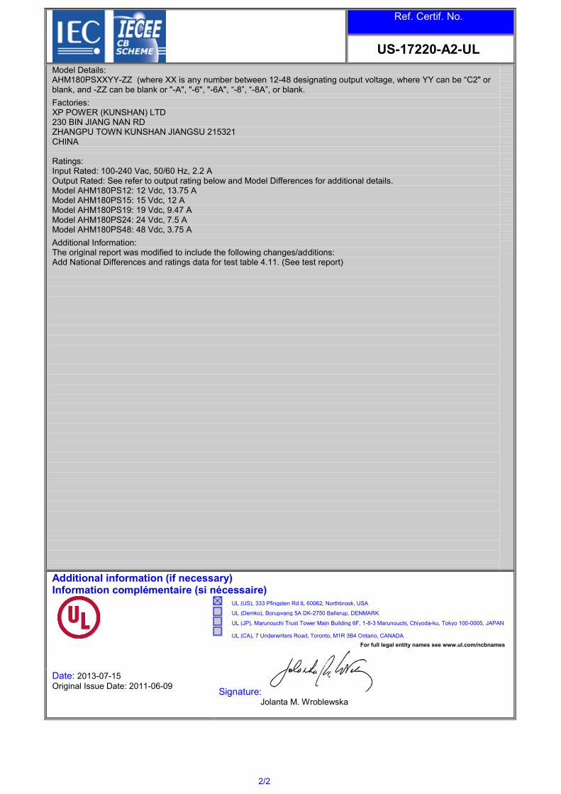
2/2
Ref. Certif. No.
US-17220-A2-UL
Model Details:
AHM180PSXXYY-ZZ (where XX is any number between 12-48 designating output voltage, where YY can be “C2" or blank, and -ZZ can be blank or "-A", "-6", "-6A", “-8”, “-8A”, or blank.
Factories:
XP POWER (KUNSHAN) LTD
230 BIN JIANG NAN RD
ZHANGPU TOWN KUNSHAN JIANGSU 215321
CHINA
Ratings:
Input Rated: 100-240 Vac, 50/60 Hz, 2.2 A
Output Rated: See refer to output rating below and Model Differences for additional details.
Model AHM180PS12: 12 Vdc, 13.75 A
Model AHM180PS15: 15 Vdc, 12 A
Model AHM180PS19: 19 Vdc, 9.47 A
Model AHM180PS24: 24 Vdc, 7.5 A
Model AHM180PS48: 48 Vdc, 3.75 A
Additional Information:
The original report was modified to include the following changes/additions:
Add National Differences and ratings data for test table 4.11. (See test report)
Additional information (if necessary)
Information complémentaire (si nécessaire)
UL (US), 333 Pfingsten Rd IL 60062, Northbrook, USA
UL (Demko), Borupvang 5A DK-2750 Ballerup, DENMARK
UL (JP), Marunouchi Trust Tower Main Building 6F, 1-8-3 Marunouchi, Chiyoda-ku, Tokyo 100-0005, JAPAN
UL (CA), 7 Underwriters Road, Toronto, M1R 3B4 Ontario, CANADA
For full legal entity names see www.ul.com/ncbnames
Signature: Jolanta M. Wroblewska
Date: 2013-07-15 Original Issue Date: 2011-06-09

12 Test Report issued under the responsibility of:
IEC 60601-1
Medical electrical equipment
Part 1: General requirements for basic safety and essential performance Report Reference No. ..................... : 10ME03009
Date of issue ................................... : 2011-06-07
Amendment 2: 2013-07-11
Total number of pages ................... : 27
CB Testing Laboratory ................... : Underwriters Laboratories Inc.
Address ........................................... : 455 E. Trimble Rd., San Jose, CA 95131-1230, USA
Applicant’s name ............................ : XP Power LLC
Address ........................................... : Suite 150, 1241 E Dyer Rd, Santa Ana, CA 92750, USA
Test specification:
Standard .......................................... : IEC 60601-1: 2005 + CORR. 1 (2006) + CORR. 2 (2007)
Test procedure................................ : CB Scheme
Non-standard test method………..:
Test Report Form No. ..................... : IEC60601_1G
Test Report Form Originator ......... : UL
Master TRF ...................................... : Dated 2010-11
Copyright © 2010 IEC System for Conformity Testing and Certification of Electrical Equipment (IECEE), Geneva, Switzerland. All rights reserved.
This publication may be reproduced in whole or in part for non-commercial purposes as long as the IECEE is acknowledged as copyright owner and source of the material. IECEE takes no responsibility for and will not assume liability for damages resulting from the reader's interpretation of the reproduced material due to its placement and context.
If this Test Report Form is used by non-IECEE members, the IECEE/IEC logo shall be removed
This report is not valid as a CB Test Report unless signed by an approved CB Testing Laboratory and appended to a CB Test Certificate issued by an NCB in accordance with IECEE 02.
Test item description .....................: Switching Power Supply
Trade Mark ......................................:

Issued: 2011-06-07 Page 2 of 27 Report No. 10ME03009
Amendment 2: 2013-07-11
Manufacturer ...................................: XP Power LLC
Suite 150, 1241 E Dyer Rd, Santa Ana, CA 92705, USA
Model/Type reference.....................: AHM180PSXXYY-ZZ (where XX is any number between 12-48 designating output voltage, where YY can be “C2” or blank, and -ZZ can be "-A", "-6", "-6A", "-8"," -8A", or blank)
Ratings ............................................: Input Rated: 100-240 Vac, 50/60 Hz, 2.2 A Output Rated: See refer to output rating below and Model Differences for additional details. Model AHM180PS12: 12 Vdc, 13.75 A Model AHM180PS15: 15 Vdc, 12 A Model AHM180PS19: 19 Vdc, 9.47 A Model AHM180PS24: 24 Vdc, 7.5 A
Model AHM180PS48: 48 Vdc, 3.75 A

Issued: 2011-06-07 Page 3 of 27 Report No. 10ME03009
Amendment 2: 2013-07-11
Testing procedure and testing location:
CB Testing Laboratory:
Testing location/ address .................. :
Associated CB Test Laboratory:
Testing location/ address .................. :
Tested by (name + signature) .. :
Approved by (+ signature) ....... :
Testing procedure: TMP
Tested by (name + signature) .. :
Approved by (+ signature) ........ :
Testing location/ address .................. :
Testing procedure: WMT
Tested by (name + signature) .. :
Witnessed by (+ signature) ....... :
Approved by (+ signature) ....... :
Testing location/ address .................. :
Testing procedure: SMT
Tested by (name + signature) .. : Rodney Reyes
Approved by (+ signature) ....... : Tac Pham
Supervised by (+ signature) .... : Michael J. Howell
Testing location/ address .................. : XP Power LLC Suite 150, 1241 E Dyer Rd., Santa Ana, CA 92705, USA
Testing procedure: RMT
Tested by (name + signature) .. :
Approved by (+ signature) ....... :
Supervised by (+ signature) .... :
Testing location/ address .................. :

Issued: 2011-06-07 Page 4 of 27 Report No. 10ME03009
Amendment 2: 2013-07-11
TRF No. IEC60601_1G
List of Attachments (including a total number of pages in each attachment):
Test Table (1 page)
National Differences (14 pages)
Summary of testing
All testing conducted by XP Power LLC located at Suite 150, 1241 E Dyer Rd., Santa Ana, CA 92705, USA under their SMT status.
Tests performed (name of test and test clause): Testing location:
Input Test (clause 4.11) XP Power LLC

Issued: 2011-06-07 Page 5 of 27 Report No. 10ME03009
Amendment 2: 2013-07-11
TRF No. IEC60601_1G
Summary of compliance with National Differences
List of countries addressed: US, CA, CH, JP
The product fulfils the requirements of IEC 60601-1:2005 + CORR.1 (2006) + CORR. 2 (2007)

Issued: 2011-06-07 Page 6 of 27 Report No. 10ME03009
Amendment 2: 2013-07-11
TRF No. IEC60601_1G
Copy of marking plate
The artwork below may be only a draft. The use of certification marks on a product must be authorized by the respective NCBs that own these marks.

Issued: 2011-06-07 Page 7 of 27 Report No. 10ME03009
Amendment 2: 2013-07-11
TRF No. IEC60601_1G
GENERAL INFORMATION
Test item particulars (see also Clause 6):
Classification of installation and use ................................. : External transportable
Device type (component/sub-assembly/ equipment/ system) ................................................................................... :
Component, Power supply
Intended use (Including type of patient, application location) .................................................................................. :
To supply regulated power
Mode of operation ................................................................ : Continuous
Supply connection ............................................................... : Appliance coupler
Accessories and detachable parts included ...................... : N/A
Other options include ........................................................... : N/A
Testing
Date of receipt of test item(s) .................................................: 2010-02-24, 2010-10-10, 2010-04-26, 2010-02-28, 2012-02-04
Dates tests performed ............................................................: 2011-05-25 to 2011-05-26, 2011-03-02 to 2011-03-10, 2010-11-01 to 2010-11-25,
2010-03-23 to 2010-05-27, 2012-03-26
Possible test case verdicts:
- test case does not apply to the test object ................... : N/A
- test object does meet the requirement ........................... : Pass (P)
- test object was not evaluated for the requirement ......... : N/E
- test object does not meet the requirement .................... : Fail (F)
Abbreviations used in the report:
- normal condition ................................................... : N.C. - single fault condition................... : S.F.C.
- means of Operator protection ............................. : MOOP - means of Patient protection ...... : MOPP
General remarks:
"(see Attachment #)" refers to additional information appended to the report. "(see appended table)" refers to a table appended to the report. The tests results presented in this report relate only to the object tested. This report shall not be reproduced except in full without the written approval of the testing laboratory. List of test equipment must be kept on file and available for review. Additional test data and/or information provided in the attachments to this report. Throughout this report a comma / point is used as the decimal separator.

Issued: 2011-06-07 Page 8 of 27 Report No. 10ME03009
Amendment 2: 2013-07-11
TRF No. IEC60601_1G
Manufacturer’s Declaration per sub-clause 6.2.5 of IECEE 02:
The application for obtaining a CB Test Certificate includes more than one factory location and a declaration from the Manufacturer stating that the sample(s) submitted for evaluation is (are) representative of the products from each factory has been provided ....................................................... :
Yes
Not applicable
When differences exist; they shall be identified in the General product information section.
Name and address of factory (ies) ......................... : XP POWER LLC 990 BENECIA AVE SUNNYVALE CA 94085 UNITED STATES XP POWER (KUNSHAN) LTD 230 BIN JIANG NAN RD ZHANGPU TOWN KUNSHAN
JIANGSU 215321 CHINA

Issued: 2011-06-07 Page 9 of 27 Report No. 10ME03009
Amendment 2: 2013-07-11
TRF No. IEC60601_1G
Report SummaryThe original report was modified on 2013-07-11 to include the following changes/additions:
1. Add missing data from original investigation for 50 Hz testing to Table 4.112. Add Switzerland National Differences3. Add Japan National Differences
General product information:
Product DescriptionProducts covered are external power supplies intended to be used with Medical Electrical Equipment. Unitsare Class I or Class II.
Model Differences
All models in the Model AHM180PSXXYY-ZZ series are identical with exception to the Mains Transformer,T1, and minor secondary components that allow for different output voltage ratings. See below for ModelRatings Table Below for 40°C:Model AHM180PS12: 12 Vdc, 13.75 AModel AHM180PS15: 15 Vdc, 12 AModel AHM180PS19: 19 Vdc, 9.47 AModel AHM180PS24: 24 Vdc, 7.5 AModel AHM180PS48: 48 Vdc, 3.75 ASee Enclosure - Miscellaneous for de-rated output values for higher ambient.Models may have an additional -ZZ identifier which can be "-A", "-6", "-6A", "-8", "-8A", or blank to designatethe type of input connector:blank = C14 style input connector (Class I construction) ;"-A" = C14 style input connector with optional IEC cable retention;"-6" = C6 style input connector (Class I);"-6A" = C6 style input connector with optional IEC cable retention;"-8" = C8 style input connector (Class I)"-8A" = C8 style input connector with optional IEC cable retention.
Models may have an additional YY identifier which can be blank or "C2". Units designated “C2” have a ClassII configuration.
Additional Information
The schematics are kept on file at the CBTL and can be provided by the manufacturer upon request byNCB's/CBTL's.When submitting this Test Report to other Certification Body, the manufacturer is responsible for providingany additional information that the Body may need in order to issue its Mark, including testing for compliancewith the applicable collateral standards.
Technical Considerations
The product was investigated to the following additional standards: ANSI/AAMI ES60601-
1:2005/C1:2009 (includes National Differences for USA); CAN/CSA-C22.2 No. 60601-1:08 (includesNational Differences for Canada), EN 60601-1:2006
Scope of Power Supply evaluation defers the following clauses to the be determined as part of the end
product: Clause 7.5 (Safety Signs), Clause 7.9 (Accompanying Documents), Clause 9 (ME Hazard),Clause 10 (Radiation), Clause 14 (PEMS), Clause 16 (ME Systems)
The product is evaluated only to the following hazards: Casualty, Fire, Shock
The degree of protection against harmful ingress of water is: Ordinary

Issued: 2011-06-07 Page 10 of 27 Report No. 10ME03009
Amendment 2: 2013-07-11
TRF No. IEC60601_1G
Software is relied upon for meeting safety requirements related to mechanical, fire and shock: No
Unit also complied with spacing requirements of UL60601-1 (1st), CSA C22.2 No. 60601-1 (2nd), and
IEC 60601-1 (2nd) for Basic for 250 Vac from Primary to Ground, Double/Reinforced for 250Vac fromPrimary to Secondary, and Supplementary for 250 Vac from Secondary to Earth.
Risk Controls/ Engineering Condition of Acceptability
The component shall be provided in compliance with the Marking (clause 7) and Separation (clause
8) requirements of the end use application.
The power supply was evaluated for use in 40°C ambient at Full Rated Output and 60% of the Rated
Output in 60°C ambient.
Leakage current testing should be conducted in the end product application.
This power supply was evaluated with Two MOPP between Primary and Secondary; One MOPP
primary and Earth/Secondary Reference Conductor; and One MOPP between Secondary and Earth/Secondary Reference Conductor.
This power supply has been evaluated as a continuous operation, ordinary equipment and has not
been evaluated for use in the presence of a flammable anesthetic mixture with air, oxygen, or nitrousoxide. The output circuits have not been evaluated for direct patient connection (Type B, BF or CF).
The end product should ensure that the requirements related to accompanying documents, clause
7.9, are met.
The available voltage for the secondary outputs does not exceed 25 Vac or 60 Vdc, under normal
and single fault conditions.
The output connectors are not acceptable for field connections; they are only intended for connection
to mating connectors of the end-use machine.
The Electric Strength Test conducted on this power supply was based upon a maximum working
voltage of: Primary-Earthed Dead Metal (Class I units): 440 Vpk, 240 Vrms; Primary-SEC: 440 Vpk,240 Vrms.
The following magnetic devices (e.g. transformers or inductor) are provided with an OBJY2 insulation
system with the indicated rating greater than Class A (105°C): L1-L4, L5, L7 and T1 are min. Class B(130°C).
Cleaning test to be considered as part of end product evaluation.
The need for Marking Durability and Marking Legibility Testing to be considered as part of the end
product installation.
Power cord suitable for the application to be provided as part of the end product evaluation.General
product information:
Products covered are external power supplies intended to be used with Medical Electrical Equipment. Units
are Class I.

1/2
Ref. Certif. No.
US-18020-A1-UL
IEC SYSTEM FOR MUTUAL RECOGNITION OF TEST CERTIFICATES FOR ELECTRICAL EQUIPMENT (IECEE) CB SCHEME
SYSTEME CEI D'ACCEPTATION MUTUELLE DE CERTIFICATS D'ESSAIS DES EQUIPEMENTS ELECTRIQUES (IECEE) METHODE OC
CB TEST CERTIFICATE CERTIFICAT D'ESSAI OCProductProduit
Switching Power Supply
Name and address of the applicantNom et adresse du demandeur
XP POWER LLCSUITE 1501241 E DYER RDSANTA ANA CA 92705, USA
Name and address of the manufacturerNom et adresse du fabricant
XP POWER LLCSUITE 1501241 E DYER RDSANTA ANA CA 92705, USA
Name and address of the factoryNom et adresse de l'usine
Note: When more than one factory, please report on page 2Note: Lorsque il y plus d'une usine, veuillez utiliser la 2ème page
XP POWER LLC990 BENECIA AVESUNNYVALE CA 94085USA
Additional Information on page 2Ratings and principal characteristicsValeurs nominales et caractéristiques principales
Input Rated: 100-240 Vac, 50/60 Hz, 3 A
Output Rated: See Model Differences for details.Trademark (if any)Marque de fabrique (si elle existe)
Type of Manufacturer's Testing Laboratories usedType de programme du laboratoire d'essais constructeur
SMT
Model / Type Ref.Ref. De type
AHM250PSXX-ZZSee Page 2
Additional information (if necessary may also be reported on page 2)Les informations complémentaires (si nécessaire,, peuvent être indiqués sur la 2ème page
The original report was modified to include the following changes/additions:Modifying critical component table
Additional Information on page 2A sample of the product was tested and found to be in conformity withUn échantillon de ce produit a été essayé et a été considéré conforme à la
IEC 60601-1(ed.3)
As shown in the Test Report Ref. No. which forms part of this CertificateComme indiqué dans le Rapport d'essais numéro de référence qui constitue partie de ce Certificat
11CA41865 issued on 2012-06-04
This CB Test Certificate is issued by the National Certification BodyCe Certificat d'essai OC est établi par l'Organisme National de Certification
UL (US), 333 Pfingsten Rd IL 60062, Northbrook, USA
UL (Demko), Borupvang 5A DK-2750 Ballerup, DENMARK
UL (JP), Marunouchi Trust Tower Main Building 6F, 1-8-3 Marunouchi, Chiyoda-ku, Tokyo 100-0005, JAPAN
UL (CA), 7 Underwriters Road, Toronto, M1R 3B4 Ontario, CANADA
For full legal entity names see www.ul.com/ncbnames
Date: 2012-06-07Original Issue Date: 2011-11-04
Signature:
Jolanta M. Wroblewska

2/2
Ref. Certif. No.
US-18020-A1-ULModel Details:AHM250PSXX-ZZ (where XX is any number between 12-48 designating output voltage, ZZ can be blank, "A", "6", or"6A" )
Factories:XP POWER (KUNSHAN) LTD230 BIN JIANG NAN RDZHANGPU TOWN, KUNSHAN, JIANGSU 215321CHINA
Additional information (if necessary)Information complémentaire (si nécessaire)
UL (US), 333 Pfingsten Rd IL 60062, Northbrook, USA
UL (Demko), Borupvang 5A DK-2750 Ballerup, DENMARK
UL (JP), Marunouchi Trust Tower Main Building 6F, 1-8-3 Marunouchi, Chiyoda-ku, Tokyo 100-0005, JAPAN
UL (CA), 7 Underwriters Road, Toronto, M1R 3B4 Ontario, CANADA
For full legal entity names see www.ul.com/ncbnames
Signature: Jolanta M. Wroblewska
Date: 2012-06-07Original Issue Date: 2011-11-04

Issued: 2011-11-03 Page 1 of 22 Report No. 11CA41865 Amendment 1: 2012-06-04
12 Test Report issued under the responsibility of:
IEC 60601-1 Medical electrical equipment
Part 1: General requirements for basic safety and essential performanceReport Reference No. ..................... : 11CA41865
Date of issue ................................... : Original: 2011-11-03
Amendment 1: 2012-06-04
Total number of pages ................... : 22
CB Testing Laboratory ................... : UL LLC
Address ........................................... : 455 E. Trimble Rd., San Jose, CA 95131-1230, USA
Applicant’s name ............................ : XP POWER LLC.
Address ........................................... : SUITE 150 1241 E DYER RD SANTA ANA CA 92705
UNITED STATES
Test specification:
Standard .......................................... : IEC 60601-1: 2005 + CORR. 1 (2006) + CORR. 2 (2007)
Test procedure ............................... : CB Scheme
Non-standard test method………..: N/A
Test Report Form No. ..................... : IEC60601_1G
Test Report Form Originator ......... : UL LLC
Master TRF ...................................... : Dated 2010-11
Copyright © 2010 IEC System for Conformity Testing and Certification of Electrical Equipment (IECEE), Geneva, Switzerland. All rights reserved.
This publication may be reproduced in whole or in part for non-commercial purposes as long as the IECEE is acknowledged as copyright owner and source of the material. IECEE takes no responsibility for and will not assume liability for damages resulting from the reader's interpretation of the reproduced material due to its placement and context.
If this Test Report Form is used by non-IECEE members, the IECEE/IEC logo shall be removed
This report is not valid as a CB Test Report unless signed by an approved CB Testing Laboratory and appended to a CB Test Certificate issued by an NCB in accordance with IECEE 02.
Test item description ..................... : Switching Power Supply
Trade Mark ...................................... :

Issued: 2011-11-03 Page 2 of 22 Report No. 11CA41865 Amendment 1: 2012-06-04
Manufacturer ................................... : XP POWER LLC SUITE 150 1241 E DYER RD SANTA ANA CA 92705
UNITED STATES
Model/Type reference..................... : AHM250PSXX-ZZ (where XX is any number between 12-48 designating output voltage, ZZ can be blank, "A", "6", or "6A" )
Ratings ............................................ : Input Rated: 100-240 Vac, 50/60 Hz, 3 A Output Rated: See Model Differences for details.

Issued: 2011-11-03 Page 3 of 22 Report No. 11CA41865 Amendment 1: 2012-06-04
TRF No. IEC60601_1G
Testing procedure and testing location:
CB Testing Laboratory:
Testing location/ address .................. :
Associated CB Test Laboratory:
Testing location/ address .................. :
Tested by (name + signature) .. :
Approved by (+ signature) ....... :
Testing procedure: TMP
Tested by (name + signature) .. :
Approved by (+ signature) ........ :
Testing location/ address .................. :
Testing procedure: WMT
Tested by (name + signature) .. :
Witnessed by (+ signature) ....... :
Approved by (+ signature) ....... :
Testing location/ address .................. :
Testing procedure: SMT
Tested by (name + signature) .. : Rodney Reyes
Approved by (+ signature) ....... : Tac Pham
Supervised by (+ signature) .... : Michael J. Howell
Testing location/ address .................. : XP Power, 1241 E. Dyer Rd #150, Santa Ana, CA 92705, USA
Testing procedure: RMT
Tested by (name + signature) .. :
Approved by (+ signature) ....... :
Supervised by (+ signature) .... :
Testing location/ address .................. :

Issued: 2011-11-03 Page 4 of 22 Report No. 11CA41865 Amendment 1: 2012-06-04
TRF No. IEC60601_1G
List of Attachments (including a total number of pages in each attachment):
National Differences (0 pages)
Enclosures (0 pages)
Summary of testing
No tests were conducted.
Summary of compliance with National Differences
List of countries addressed:
US, CAN
The product fulfils the requirements of IEC 60601-1: 2005 + CORR. 1 (2006) + CORR. 2 (2007)

Issued: 2011-11-03 Page 5 of 22 Report No. 11CA41865 Amendment 1: 2012-06-04
TRF No. IEC60601_1G
GENERAL INFORMATION
Test item particulars (see also Clause 6):
Classification of installation and use ................................. : External Transportable
Device type (component/sub-assembly/ equipment/ system) ................................................................................... :
Component, Power Supply
Intended use (Including type of patient, application location) .................................................................................. :
To supply regulated power.
Mode of operation ................................................................ : Continuous
Supply connection ............................................................... : Appliance coupler
Accessories and detachable parts included ...................... : N/A
Other options include ........................................................... : N/A
Testing
Date of receipt of test item(s) ................................................ : N/A
Dates tests performed ........................................................... : N/A
Possible test case verdicts:
- test case does not apply to the test object ................... : N/A
- test object does meet the requirement ........................... : Pass (P)
- test object was not evaluated for the requirement .......... : N/E
- test object does not meet the requirement .................... : Fail (F)
Abbreviations used in the report:
- normal condition ................................................... : N.C. - single fault condition................... : S.F.C.
- means of Operator protection ............................. : MOOP - means of Patient protection ...... : MOPP
General remarks: "(see Attachment #)" refers to additional information appended to the report. "(see appended table)" refers to a table appended to the report. The tests results presented in this report relate only to the object tested. This report shall not be reproduced except in full without the written approval of the testing laboratory. List of test equipment must be kept on file and available for review. Additional test data and/or information provided in the attachments to this report. Throughout this report a comma / point is used as the decimal separator.
Manufacturer’s Declaration per sub-clause 6.2.5 of IECEE 02:
The application for obtaining a CB Test Certificate includes more than one factory location and a declaration from the Manufacturer stating that the sample(s) submitted for evaluation is (are) representative of the products from each factory has been provided ....................................................... :
Yes
Not applicable
When differences exist; they shall be identified in the General product information section.

Issued: 2011-11-03 Page 6 of 22 Report No. 11CA41865 Amendment 1: 2012-06-04
TRF No. IEC60601_1G
Name and address of factory (ies) ......................... XP POWER LLC 990 BENECIA AVE SUNNYVALE CA 94085 UNITED STATES XP POWER (KUNSHAN) LTD 230 BIN JIANG NAN RD ZHANGPU TOWN KUNSHAN
JIANGSU 215321 CHINA

Issued: 2011-11-03 Page 7 of 22 Report No. 11CA41865 Amendment 1: 2012-06-04
TRF No. IEC60601_1G
Report Summary The original report was modified on 2012-06-04 to include the following changes/additions: Minor revisions to Critical Components List Product Description
Products covered are external power supplies intended to be used with Medical Electrical Equipment. Units are Class I.
General product information:
Model Differences
All models in the Model AHM250PSXX-ZZ series are identical with exception to the Mains Transformer, T2, and minor secondary components that allow for different output voltage ratings. See Table below for Model Ratings at 40°C: Model AHM250PS12: 12 Vdc, 17.5 A Model AHM250PS15: 15 Vdc, 16.67 A Model AHM250PS19: 19 Vdc, 13.16 A Model AHM250PS24: 24 Vdc, 10.41 A Model AHM250PS48: 48 Vdc, 5.21 A See Enclosure - Miscellaneous for de-rated output values for higher ambient. Suffix -ZZ when provided denotes the following: A - Optional Retention Clamp provided 6 - Optional C6 Type appliance inlet provided 6A - Both Optional Retention Clamp and C6 Type appliance inlet provided Additional Information The schematics are kept on file at the CBTL and can be provided by the manufacturer upon request by NCB's/CBTL's.
When submitting this Test Report to other Certification Body, the manufacturer is responsible for providing any additional information that the Body may need in order to issue its Mark, including testing for compliance with the applicable collateral standards.
Marking label is representative of all models. The nameplate labels included in this report depict the draft artwork for the marking plate pending approval by National Certification Bodies and it will not be affixed to products prior to such approval.

Issued: 2011-11-03 Page 8 of 22 Report No. 11CA41865 Amendment 1: 2012-06-04
TRF No. IEC60601_1G
Technical Considerations
The product was investigated to the following additional standards: ANSI/AAMI ES60601-
1:2005/C1:2009 (includes National Differences for USA); CAN/CSA-C22.2 No. 60601-1:08 (includes National Differences for Canada), EN 60601-1:2006
Scope of Power Supply evaluation defers the following clauses to the be determined as part of the end product: Clause 7.5 (Safety Signs), Clause 7.9 (Accompanying Documents), Clause 9 (ME Hazard), Clause 10 (Radiation), Clause 14 (PEMS), Clause 16 (ME Systems)
Supply connection: OVC II The product is evaluated only to the following hazards: Casualty, Fire, Shock The degree of protection against harmful ingress of water is: Ordinary The mode of operation is: Continuous Software is relied upon for meeting safety requirements related to mechanical, fire and shock: No The product is suitable for use in the presence of a flammable anesthetics mixture with air or oxygen
or with nitrous oxide: No Unit also complied with spacing requirements of UL60601-1 (1st), CSA C22.2 No. 60601-1 (2nd), and
IEC 60601-1 (2nd) for Basic for 240 Vac from Primary to Ground, Double/Reinforced for 279 Vac from Primary to Secondary, and Supplementary for 240 Vac from Secondary to Earth.
Risk Controls/ Engineering Condition of Acceptability
The component shall be installed in compliance with the Marking (clause 7) and Separation (clause
8) requirements of the end use application.
The power supply was evaluated for use in 40°C ambient at Full Rated Output and 60% of the Rated Output in 60°C ambient. (See De-rating Curve, Enclosure 7-01 for details)
Repeating leakage current testing should be considered in the end product application.
This power supply was evaluated with Two MOPP between Primary and Secondary; One MOPP primary and Earth; and One MOPP between Secondary and Earth.
This power supply has been evaluated as a continuous operation, ordinary equipment and has not been evaluated for use in the presence of a flammable anesthetic mixture with air, oxygen, or nitrous oxide. The output circuits have not been evaluated for direct patient connection (Type B, BF or CF).
The end product should ensure that the requirements related to accompanying documents, clause 7.9, are met.
The available voltage for the secondary outputs does not exceed 25 Vac or 60 Vdc, under normal and single fault conditions.
The output connectors are not acceptable for field connections; they are only intended for connection to mating connectors of the end-use machine.
The Electric Strength Test conducted on this power supply was based upon a maximum working voltage of: Primary-Earthed Dead Metal (Class I units): 430 Vpk, 240 Vrms; Primary-SEC: 591 Vpk, 279 Vrms.
The following magnetic devices (e.g. transformers or inductor) are provided with an OBJY2 insulation system with the indicated rating greater than Class A (105°C): L1-L4 and T1 are Class B (130°C).
Cleaning test to be considered as part of end product evaluation.

Issued: 2011-11-03 Page 9 of 22 Report No. 11CA41865 Amendment 1: 2012-06-04
TRF No. IEC60601_1G
The need for Marking Durability and Marking Legibility Testing to be considered as part of the end product installation.
Power cord suitable for the application to be provided as part of the end product evaluation.

1/2
Ref. Certif. No.
US-20899-A2-UL
IEC SYSTEM FOR MUTUAL RECOGNITION OF TEST CERTIFICATES FOR ELECTRICAL EQUIPMENT (IECEE) CB SCHEME
SYSTEME CEI D'ACCEPTATION MUTUELLE DE CERTIFICATS D'ESSAIS DES EQUIPEMENTS ELECTRIQUES (IECEE) METHODE OC
CB TEST CERTIFICATE CERTIFICAT D'ESSAI OCProductProduit
Switching Brick Power Supply
Name and address of the applicantNom et adresse du demandeur
XP POWER L L CSUITE 1501241 E DYER RDSANTA ANA, CA 92705 United States
Name and address of the manufacturerNom et adresse du fabricant
XP POWER L L CSUITE 1501241 E DYER RDSANTA ANA, CA 92705 United States
Name and address of the factoryNom et adresse de l'usine
Note: When more than one factory, please report on page 2Note: Lorsque il y plus d'une usine, veuillez utiliser la 2ème page
XP POWER (KUNSHAN) LTD230 BIN JIANG NAN RD ZHANGPU TOWN KUNSHAN JIANGSU 215321CHINA
Additional Information on page 2Ratings and principal characteristicsValeurs nominales et caractéristiques principales
Input Rated: 100-240 Vac, 50/60 Hz, 1.0 AOutput Rated: See Model Differences in CB Test Report for details.
Trademark (if any)Marque de fabrique (si elle existe)
Type of Manufacturer's Testing Laboratories usedType de programme du laboratoire d'essais constructeur
Model / Type Ref.Ref. De type
AHM85PSXXYY-ZZSee Page 2
Additional information (if necessary may also be reported on page 2)Les informations complémentaires (si nécessaire,, peuvent être indiqués sur la 2ème page
Additional Information on page 2
A sample of the product was tested and found to be in conformity withUn échantillon de ce produit a été essayé et a été considéré conforme à la
IEC 60950-1(ed.2), IEC 60950-1(ed.2);am1
As shown in the Test Report Ref. No. which forms part of this CertificateComme indiqué dans le Rapport d'essais numéro de référence qui constitue partie de ce Certificat
E139109-A57-CB-2 issued on 2013-06-20
This CB Test Certificate is issued by the National Certification BodyCe Certificat d'essai OC est établi par l'Organisme National de Certification
UL (US), 333 Pfingsten Rd IL 60062, Northbrook, USA
UL (Demko), Borupvang 5A DK-2750 Ballerup, DENMARK
UL (JP), Marunouchi Trust Tower Main Building 6F, 1-8-3 Marunouchi, Chiyoda-ku, Tokyo 100-0005, JAPAN
UL (CA), 7 Underwriters Road, Toronto, M1R 3B4 Ontario, CANADA
For full legal entity names see www.ul.com/ncbnames
Date: 2013-06-20Original Issue Date: 2013-02-15
Signature:
Jolanta M. Wroblewska

2/2
Ref. Certif. No.
US-20899-A2-ULModel Details:AHM85PSXXYY-ZZ (where XX is any number between 12-24 designating output voltage, YY can be blank or "C2" designating Class II configuration, and Z can be blank or "A", "6", "6A", "8", "8A")
Factories:XP POWER L L C990 BENECIA AVE SUNNYVALE CA 94085UNITED STATES
Additional Information:Additionally evaluated to EN 60950-1:2006/A11:2009/A1:2010/ A12:2011; National Differences specified in the CB Test Report.
The original report was modified to include the following changes/additions:Report updated to include Taiwan national differences.
Additional information (if necessary)Information complémentaire (si nécessaire)
UL (US), 333 Pfingsten Rd IL 60062, Northbrook, USA
UL (Demko), Borupvang 5A DK-2750 Ballerup, DENMARK
UL (JP), Marunouchi Trust Tower Main Building 6F, 1-8-3 Marunouchi, Chiyoda-ku, Tokyo 100-0005, JAPAN
UL (CA), 7 Underwriters Road, Toronto, M1R 3B4 Ontario, CANADA
For full legal entity names see www.ul.com/ncbnames
Signature: Jolanta M. Wroblewska
Date: 2013-06-20Original Issue Date: 2013-02-15

Issue Date: 2013-02-15 Page 1 of 8 Report Reference # E139109-A57-CB-2
Amendment 2 2013-06-20
TRF No. : IEC60950_1B This report issued under the responsibility of UL
Test Report issued under
the responsibility of:
TEST REPORT IEC 60950-1
Information technology equipment - Safety - Part 1: General requirements
Report Reference No .................. : E139109-A57-CB-2
Date of issue ................................. : 2013-02-15
Total number of pages .................. : 8
CB Testing Laboratory ............... : UL RTP
Address ......................................... : 12 Laboratory Drive, Research Triangle Park , NC, 27709, USA
Applicant's name ........................ :
Address ......................................... :
XP POWER L L C SUITE 150 1241 E DYER RD SANTA ANA CA 92705 UNITED STATES
Test specification:
Standard ........................................ : IEC 60950-1:2005 (2nd Edition); Am 1:2009
Test procedure .............................. : CB Scheme
Non-standard test method ............ : N/A
Test Report Form No. ................. : IEC60950_1B
Test Report Form originator .......... : SGS Fimko Ltd
Master TRF ................................... : 2010-04
Copyright © 2010 IEC System for Conformity Testing and Certification of Electrical Equipment (IECEE), Geneva, Switzerland. All rights reserved. This publication may be reproduced in whole or in part for non-commercial purposes as long as the IECEE is acknowledged as copyright owner and source of the material. IECEE takes no responsibility for and will not assume liability for damages resulting from the reader's interpretation of the reproduced material due to its placement and context. If this test Report is used by non-IECEE members, the IECEE/IEC logo and the reference to the CB Scheme procedure shall be removed. This report is not valid as a CB Test Report unless signed by an approved CB Testing Laboratory and appended to a CB Test Certificate issued by an NCB in accordance with IECEE 02.

Issue Date: 2013-02-15 Page 2 of 8 Report Reference # E139109-A57-CB-2
Amendment 2 2013-06-20
TRF No. : IEC60950_1B This report issued under the responsibility of UL
Test item description .................. : Switching Brick Power Supply
Trade Mark .................................... :
Manufacturer ................................. : XP POWER L L C SUITE 150 1241 E DYER RD SANTA ANA CA 92705 UNITED STATES
Model/Type reference ................... : AHM85PSXXYY-ZZ (where XX is any number between 12-24 designating output voltage, YY can be blank or "C2" designating Class II configuration, and Z can be blank or "A", "6", "6A", "8", "8A")
Ratings .......................................... : Input Rated: 100-240 Vac, 50/60 Hz, 1.0 A Output Rated: See Model Differences in CB Test Report for details.

Issue Date: 2013-02-15 Page 3 of 8 Report Reference # E139109-A57-CB-2
Amendment 2 2013-06-20
TRF No. : IEC60950_1B This report issued under the responsibility of UL
Testing procedure and testing location:
[x] CB Testing Laboratory
Testing location / address .............. : UL RTP 12 Laboratory Drive, Research Triangle Park , NC, 27709, USA
[ ] Associated CB Test Laboratory
Testing location / address .............. :
Tested by (name + signature) ....... : Michael Lockhart
Approved by (name + signature) ... : Dean Baker
[ ] Testing Procedure: TMP
Tested by (name + signature) ....... :
Approved by (+ signature) ............. :
Testing location / address .............. :
[ ] Testing Procedure: WMT
Tested by (name + signature) ....... :
Witnessed by (+ signature) ............ :
Approved by (+ signature) ............. :
Testing location / address .............. :
[ ] Testing Procedure: SMT
Tested by (name + signature) ....... :
Approved by (+ signature) ............. :
Supervised by (+ signature) .......... :
Testing location / address .............. :
[ ] Testing Procedure: RMT
Tested by (name + signature) ....... :
Approved by (+ signature) ............. :
Supervised by (+ signature) .......... :
Testing location / address .............. :
List of Attachments
National Differences (0 pages)
Enclosures (5 pages)
Summary of Testing:
No tests were conducted
Summary of Compliance with National Differences:
Countries outside the CB Scheme membership may also accept this report.
List of countries addressed: AT, BE, CA, CH, CN, CZ, DE, DK, ES, EU, FI, FR, GB, GR, HU, IE, IT, JP, KR, NL, PL, PT, SE, SG, SI, SK, US

Issue Date: 2013-02-15 Page 4 of 8 Report Reference # E139109-A57-CB-2
Amendment 2 2013-06-20
TRF No. : IEC60950_1B This report issued under the responsibility of UL
The product fulfills the requirements of: CSA C22.2 No. 60950-1-07 + A1:2011, EN 60950-1:2006 + A1:2010 + A11:2009 + A12:2011, IEC 60950-1:2005 + A1:2009, UL 60950-1 2nd Ed. Revised 2011-12-19
Copy of Marking Plate - Refer to Enclosure titled Marking Plate for copy.
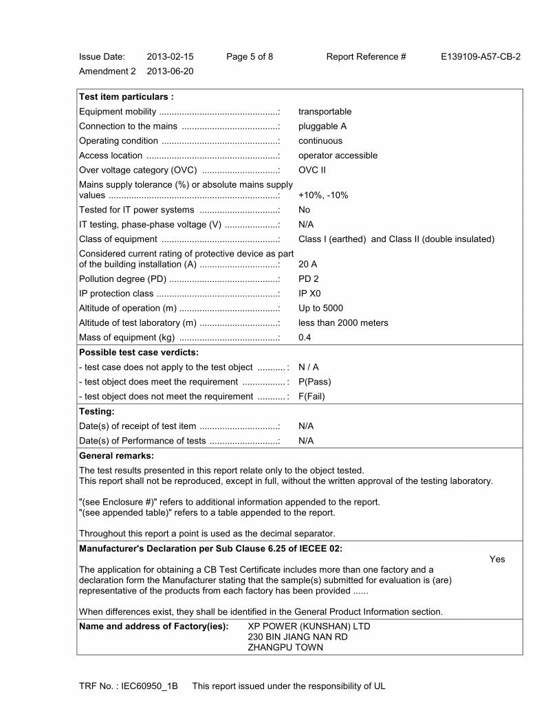
Issue Date: 2013-02-15 Page 5 of 8 Report Reference # E139109-A57-CB-2
Amendment 2 2013-06-20
TRF No. : IEC60950_1B This report issued under the responsibility of UL
Test item particulars :
Equipment mobility ...............................................: transportable
Connection to the mains ......................................: pluggable A
Operating condition ..............................................: continuous
Access location ....................................................: operator accessible
Over voltage category (OVC) ..............................: OVC II
Mains supply tolerance (%) or absolute mains supply values ...................................................................: +10%, -10%
Tested for IT power systems ...............................: No
IT testing, phase-phase voltage (V) .....................: N/A
Class of equipment ..............................................: Class I (earthed) and Class II (double insulated)
Considered current rating of protective device as part of the building installation (A) ...............................: 20 A
Pollution degree (PD) ...........................................: PD 2
IP protection class ................................................: IP X0
Altitude of operation (m) .......................................: Up to 5000
Altitude of test laboratory (m) ...............................: less than 2000 meters
Mass of equipment (kg) .......................................: 0.4
Possible test case verdicts:
- test case does not apply to the test object ........... : N / A
- test object does meet the requirement ................. : P(Pass)
- test object does not meet the requirement ........... : F(Fail)
Testing:
Date(s) of receipt of test item ...............................: N/A
Date(s) of Performance of tests ...........................: N/A
General remarks:
The test results presented in this report relate only to the object tested. This report shall not be reproduced, except in full, without the written approval of the testing laboratory. "(see Enclosure #)" refers to additional information appended to the report. "(see appended table)" refers to a table appended to the report. Throughout this report a point is used as the decimal separator.
Manufacturer's Declaration per Sub Clause 6.25 of IECEE 02: The application for obtaining a CB Test Certificate includes more than one factory and a declaration form the Manufacturer stating that the sample(s) submitted for evaluation is (are) representative of the products from each factory has been provided ...... When differences exist, they shall be identified in the General Product Information section.
Yes
Name and address of Factory(ies): XP POWER (KUNSHAN) LTD 230 BIN JIANG NAN RD ZHANGPU TOWN

Issue Date: 2013-02-15 Page 6 of 8 Report Reference # E139109-A57-CB-2
Amendment 2 2013-06-20
TRF No. : IEC60950_1B This report issued under the responsibility of UL
KUNSHAN JIANGSU 215321 CHINA XP POWER L L C 990 BENECIA AVE SUNNYVALE CA 94085 UNITED STATES
GENERAL PRODUCT INFORMATION:
Report Summary
The original report was modified on 2013-06-20 to include the following changes/additions: Report updated to include Taiwan national differences.
Product Description
The devices are a series of brick power supplies to be used to power ITE equipment.
Model Differences
All models within the series are identical with exception to power transformer (T1) winding and other minor changes to secondary circuit to accommodate different output voltages and current ratings. Models may have an additional YY identifier which can be blank or "C2" to designate a Class II configuration. Models may have an additional ZZ identifier which can be black or "A", "6", "6A", "8", "8A" to designate the type of input connector: - blank designates a C14 input connector (Class I construction) or C18 input connector (Class II construction); - "A" designates a C14 input connector with optional IEC cable retention; - "6" designates a C6 input connector; - "6A" designates a C6 input connector with optional IEC cable retention; - "8" designates a C8 input connector; - "8A" designates a C8 input connector with optional IEC cable retention. Output Ratings: Model AHM85PS12: 12 Vdc, 7.08 A Model AHM85PS15: 15 Vdc, 5.67 A Model AHM85PS19: 19 Vdc, 4.47 A Model AHM85PS24: 24 Vdc, 3.54 A
Additional Information
This report is a reissue of CBTR Ref. No. E139109-A57-CB-1, CB Test Certificate Ref. No. US/15675/UL and US/15675/A1/UL. Based on the previously conducted testing and the review of product technical documentation including photos, schematics, wiring diagrams and similar, has been determined that the product complies with the upgrade of the Second Edition of the Standard to Amendment 1. No tests were conducted under this investigation due to reissue of CB Test Report Ref. No. E139109-A57-

Issue Date: 2013-02-15 Page 7 of 8 Report Reference # E139109-A57-CB-2
Amendment 2 2013-06-20
TRF No. : IEC60950_1B This report issued under the responsibility of UL
CB-1. All required tests were carried out under the original investigation Marking label is representative of all models. The nameplate labels included in this report depict the draft artwork for the marking plate pending approval by National Certification Bodies and it will not be affixed to products prior to such approval.
Technical Considerations
The product was submitted and evaluated for use at the maximum ambient temperature (Tma) permitted by the manufacturer’s specification of: 40°C (at 100% rated load); 60°C (at 60% rated load),
The means of connection to the mains supply is: Detachable power cord, Pluggable A,
The product is intended for use on the following power systems: TN
The equipment disconnect device is considered to be: Appliance inlet
The product was investigated to the following additional standards: EN 60950-1:2006 + A11:2009 + A1:2010 + A12:2011 (which includes all European national differences, including those specified in this test report).
The following are available from the Applicant upon request: Installation (Safety) Instructions / Manual
The equipment employs Functional Earthing per 2.6.2. As anticipated by the NOTE for 1.2.4, it does not conform to one of the common Classes (I, II, or III). The following insulation is provided between the primary and accessible dead metal parts and circuits: Double/Reinforced (configurations with a ground pin in the appliance inlet),
The Clearances and Creepage Distances have additionally been assessed for suitability up to 5000m elevation. --
Abbreviations used in the report:
- normal condition ............................................ : N.C. - single fault condition ....................................... : S.F.C
- operational insulation ..................................... : OP - basic insulation .............................................. : BI
- basic insulation between parts of opposite polarity:
BOP
- supplementary insulation ............................... : SI
- double insulation ............................................ : DI - reinforced insulation ...................................... : RI
Indicate used abbreviations (if any)

1/2
Ref. Certif. No.
US-21324-UL
IEC SYSTEM FOR MUTUAL RECOGNITION OF TEST CERTIFICATES FOR ELECTRICAL EQUIPMENT (IECEE) CB SCHEME
SYSTEME CEI D’ACCEPTATION MUTUELLE DE CERTIFICATS D’ESSAIS DES EQUIPEMENTS ELECTRIQUES (IECEE) METHODE OC
CB TEST CERTIFICATE CERTIFICAT D’ESSAI OC
Product Produit
Switching Brick Power Supply
Name and address of the applicant Nom et adresse du demandeur
XP POWER LLC SUITE 150 1241 E DYER RD SANTA ANA CA 92705 USA
Name and address of the manufacturer Nom et adresse du fabricant
XP POWER LLC SUITE 150 1241 E DYER RD SANTA ANA CA 92705 USA
Name and address of the factory Nom et adresse de l’usine Note: When more than one factory, please report on page 2 Note: Lorsque il y plus d'une usine, veuillez utiliser la 2ème page
XP POWER (KUNSHAN) LTD 230 BIN JIANG NAN RD ZHANGPU TOWN KUNSHAN JIANGSU 215300 CHINA
Additional Information on page 2Ratings and principal characteristics Valeurs nominales et caractéristiques principales
Input Rated: 100-240 Vac; 50/60 Hz; 1.2 A Output Rated: See Test Report for details
Trademark (if any) Marque de fabrique (si elle existe)
Type of Manufacturer's Testing Laboratories usedType de programme du laboratoire d'essais constructeur
Model / Type Ref. Ref. De type
AHM100PS24 -XD0112A, AHM100PSXXYY-ZZ See Page 2
Additional information (if necessary may also be reported on page 2) Les informations complémentaires (si nécessaire,, peuvent être indiqués sur la 2ème page
Additionally evaluated to EN 60950-1:2006/ A11:2009/ A1:2010/ A12:2011; National Differences specified in the CB Test Report.
Additional Information on page 2
A sample of the product was tested and found to be in conformity with Un échantillon de ce produit a été essayé et a été considéré conforme à la
IEC 60950-1(ed.2), IEC 60950-1(ed.2);am1
As shown in the Test Report Ref. No. which forms part of this Certificate Comme indiqué dans le Rapport d’essais numéro de référence qui constitue partie de ce Certificat
E139109-A45-CB-2 issued on 2013-04-04
This CB Test Certificate is issued by the National Certification Body Ce Certificat d’essai OC est établi par l’Organisme National de Certification
UL (US), 333 Pfingsten Rd IL 60062, Northbrook, USA
UL (Demko), Borupvang 5A DK-2750 Ballerup, DENMARK
UL (JP), Marunouchi Trust Tower Main Building 6F, 1-8-3 Marunouchi, Chiyoda-ku, Tokyo 100-0005, JAPAN
UL (CA), 7 Underwriters Road, Toronto, M1R 3B4 Ontario, CANADA
For full legal entity names see www.ul.com/ncbnames
Date: 2013-04-05
Signature: Jolanta M. Wroblewska

2/2
Ref. Certif. No.
US-21324-UL
Model Details:
AHM100PSXXYY-ZZ (where XX is any number between 12-48 designating output voltage and YY can be blank or "C2" designating Class II configuration, and -ZZ can be blank or "-A", "-6", "-6A", "-8", "-8A")
Factories:
XP POWER LLC
990 BENECIA AVE SUNNYVALE CA 94085
USA
Additional information (if necessary)
Information complémentaire (si nécessaire)
UL (US), 333 Pfingsten Rd IL 60062, Northbrook, USA
UL (Demko), Borupvang 5A DK-2750 Ballerup, DENMARK
UL (JP), Marunouchi Trust Tower Main Building 6F, 1-8-3 Marunouchi, Chiyoda-ku, Tokyo 100-0005, JAPAN
UL (CA), 7 Underwriters Road, Toronto, M1R 3B4 Ontario, CANADA
For full legal entity names see www.ul.com/ncbnames
Signature: Jolanta M. Wroblewska
Date: 2013-04-05

Issue Date: 2013-04-04 Page 1 of 67 Report Reference # E139109-A45-CB-2
TRF No. : IEC60950_1B This report issued under the responsibility of UL
Test Report issued under
the responsibility of:
TEST REPORT IEC 60950-1
Information technology equipment - Safety - Part 1: General requirements
Report Reference No .................. : E139109-A45-CB-2
Date of issue ................................. : 2013-04-04
Total number of pages .................. : 67
CB Testing Laboratory ............... : UL San Jose
Address ......................................... : 455 E. Trimble Rd., San Jose, CA, 95131-1230, USA
Applicant's name ........................ :
Address ......................................... :
XP POWER LLC SUITE 150 1241 E DYER RD SANTA ANA CA 92705 UNITED STATES
Test specification:
Standard ........................................ : IEC 60950-1:2005 (2nd Edition); Am 1:2009
Test procedure .............................. : CB Scheme
Non-standard test method ............ : N/A
Test Report Form No. ................. : IEC60950_1B
Test Report Form originator .......... : SGS Fimko Ltd
Master TRF ................................... : 2010-04
Copyright © 2010 IEC System for Conformity Testing and Certification of Electrical Equipment (IECEE), Geneva, Switzerland. All rights reserved. This publication may be reproduced in whole or in part for non-commercial purposes as long as the IECEE is acknowledged as copyright owner and source of the material. IECEE takes no responsibility for and will not assume liability for damages resulting from the reader's interpretation of the reproduced material due to its placement and context. If this test Report is used by non-IECEE members, the IECEE/IEC logo and the reference to the CB Scheme procedure shall be removed. This report is not valid as a CB Test Report unless signed by an approved CB Testing Laboratory and appended to a CB Test Certificate issued by an NCB in accordance with IECEE 02.

Issue Date: 2013-04-04 Page 2 of 67 Report Reference # E139109-A45-CB-2
TRF No. : IEC60950_1B This report issued under the responsibility of UL
Test item description .................. : Switching Brick Power Supply
Trade Mark .................................... :
Manufacturer ................................. : XP POWER LLC SUITE 150 1241 E DYER RD SANTA ANA CA 92705 UNITED STATES
Model/Type reference ................... : AHM100PSXXYY-ZZ (where XX is any number between 12-48 designating output voltage and YY can be blank or "C2" designating Class II configuration, and -ZZ can be blank or "-A", "-6", "-6A", "-8", "-8A") AHM100PS24 -XD0112A
Ratings .......................................... : Input Rated: 100-240 Vac, 50/60 Hz, 1.2 A Output Rated: See Model Differences in CB Test Report for details.

Issue Date: 2013-04-04 Page 3 of 67 Report Reference # E139109-A45-CB-2
TRF No. : IEC60950_1B This report issued under the responsibility of UL
Testing procedure and testing location:
[ ] CB Testing Laboratory
Testing location / address .............. :
[x] Associated CB Test Laboratory
Testing location / address .............. : UL Brea 2929 Imperial Hwy, Ste 100, Brea, CA, 92821, USA
Tested by (name + signature) ....... : Sal Oseguera
Approved by (name + signature) ... : Dean Baker
[ ] Testing Procedure: TMP
Tested by (name + signature) ....... :
Approved by (+ signature) ............. :
Testing location / address .............. :
[ ] Testing Procedure: WMT
Tested by (name + signature) ....... :
Witnessed by (+ signature) ............ :
Approved by (+ signature) ............. :
Testing location / address .............. :
[ ] Testing Procedure: SMT
Tested by (name + signature) ....... :
Approved by (+ signature) ............. :
Supervised by (+ signature) .......... :
Testing location / address .............. :
[ ] Testing Procedure: RMT
Tested by (name + signature) ....... :
Approved by (+ signature) ............. :
Supervised by (+ signature) .......... :
Testing location / address .............. :
List of Attachments
National Differences (35 pages)
Enclosures (143 pages)
Summary Of Testing Unless otherwise indicated, all tests were conducted at UL Brea 2929 Imperial Hwy, Ste 100, Brea, CA, 92821, USA.
Tests performed (name of test and test clause) Testing location / Comments
Guide Information Page - Maximum Output Voltage, Current, and Volt Ampere Measurement (1.2.2.1)
Evaluated under original CB Scheme investigation.
Input: Single-Phase (1.6.2) Evaluated under original CB Scheme

Issue Date: 2013-04-04 Page 4 of 67 Report Reference # E139109-A45-CB-2
TRF No. : IEC60950_1B This report issued under the responsibility of UL
investigation.
Durability of Marking (1.7.11) Evaluated under original CB Scheme investigation.
Energy Hazard Measurements (2.1.1.5, 2.1.2, 1.2.8.10) Evaluated under original CB Scheme investigation.
Capacitance Discharge (2.1.1.7) Evaluated under original CB Scheme investigation.
SELV Reliability Test Including Hazardous Voltage Measurements (2.2.2, 2.2.3, 2.2.4, Part 22 6.1)
Evaluated under original CB Scheme investigation.
Limited Current Circuit Measurement (2.4.1, 2.4.2) Evaluated under original CB Scheme investigation.
Limited Power Source Measurements (2.5) Evaluated under original CB Scheme investigation.
Protective Bonding II (2.6.3.4, 2.6.1) Evaluated under original CB Scheme investigation.
Humidity (2.9.1, 2.9.2, 5.2.2) Evaluated under original CB Scheme investigation.
Determination of Working Voltage; Working Voltage Measurement (2.10.2)
Evaluated under original CB Scheme investigation.
Thin Sheet Material (2.10.5.9, 2.10.5.10, 2.10.5.6) Evaluated under original CB Scheme investigation.
Transformer and Wire /Insulation Electric Strength (2.10.5.13)
Evaluated under original CB Scheme investigation.
Strain Relief (3.2.6, 4.2.1, 4.2.7) Evaluated under original CB Scheme investigation.
Steady Force (4.2.1 - 4.2.4) Evaluated under original CB Scheme investigation.
Impact (4.2.5, 4.2.1, Part 22 10.2) Evaluated under original CB Scheme investigation.
Drop (4.2.6, 4.2.1) Evaluated under original CB Scheme investigation.
Stress Relief (4.2.7, 4.2.1) Evaluated under original CB Scheme investigation.
Heating (4.5.1, 1.4.12, 1.4.13) Evaluated under original CB Scheme investigation.
Ball Pressure (4.5.5, 4.5) Evaluated under original CB Scheme investigation.
Touch Current (Single-Phase; TN/TT System) (5.1, Annex D)
Evaluated under original CB Scheme investigation.
Electric Strength (5.2.2) Evaluated under original CB Scheme investigation.
Component Failure (5.3.1, 5.3.4, 5.3.7) Evaluated under original CB Scheme investigation.
Abnormal Operation (5.3.1 - 5.3.9) Evaluated under original CB Scheme investigation.

Issue Date: 2013-04-04 Page 5 of 67 Report Reference # E139109-A45-CB-2
TRF No. : IEC60950_1B This report issued under the responsibility of UL
Transformer Abnormal Operation (5.3.3, 5.3.7b, Annex C.1)
Evaluated under original CB Scheme investigation.
Power Supply Output Short-Circuit/Overload (5.3.7) Evaluated under original CB Scheme investigation.
Summary of Compliance with National Differences:
Countries outside the CB Scheme membership may also accept this report.
List of countries addressed: AT, BE, CA, CH, CZ, DE, DK, ES, EU, FI, FR, GB, GR, HU, IE, IT, JP, KR, NL, PL, PT, SE, SI, SK, US
The product fulfills the requirements of: CSA C22.2 No. 60950-1-07 + A1:2011, EN 60950-1:2006 + A1:2010 + A11:2009 + A12:2011, IEC 60950-1:2005 + A1:2009, UL 60950-1 2nd Ed. Revised 2011-12-19
Copy of Marking Plate - Refer to Enclosure titled Marking Plate for copy.

Issue Date: 2013-04-04 Page 6 of 67 Report Reference # E139109-A45-CB-2
TRF No. : IEC60950_1B This report issued under the responsibility of UL
Test item particulars :
Equipment mobility ...............................................: transportable
Connection to the mains ......................................: pluggable A
Operating condition ..............................................: continuous
Access location ....................................................: operator accessible
Over voltage category (OVC) ..............................: OVC II
Mains supply tolerance (%) or absolute mains supply values ...................................................................: +10%, -10%
Tested for IT power systems ...............................: No
IT testing, phase-phase voltage (V) .....................: N/A
Class of equipment ..............................................: Class I (earthed) or Class II (double insulated)
Considered current rating of protective device as part of the building installation (A) ...............................: 20
Pollution degree (PD) ...........................................: PD 2
IP protection class ................................................: IP X0
Altitude of operation (m) .......................................: up to 3048
Altitude of test laboratory (m) ...............................: less than 2000 meters
Mass of equipment (kg) .......................................: 0.45
Possible test case verdicts:
- test case does not apply to the test object ........... : N / A
- test object does meet the requirement ................. : P(Pass)
- test object does not meet the requirement ........... : F(Fail)
Testing:
Date(s) of receipt of test item ...............................: 2010-02-03
Date(s) of Performance of tests ...........................: 2010-03-08, 2010-03-22
General remarks:
The test results presented in this report relate only to the object tested. This report shall not be reproduced, except in full, without the written approval of the testing laboratory. "(see Enclosure #)" refers to additional information appended to the report. "(see appended table)" refers to a table appended to the report. Throughout this report a point is used as the decimal separator.
Manufacturer's Declaration per Sub Clause 6.25 of IECEE 02: The application for obtaining a CB Test Certificate includes more than one factory and a declaration form the Manufacturer stating that the sample(s) submitted for evaluation is (are) representative of the products from each factory has been provided ...... When differences exist, they shall be identified in the General Product Information section.
Yes
Name and address of Factory(ies): XP POWER (KUNSHAN) LTD 230 BIN JIANG NAN RD ZHANGPU TOWN
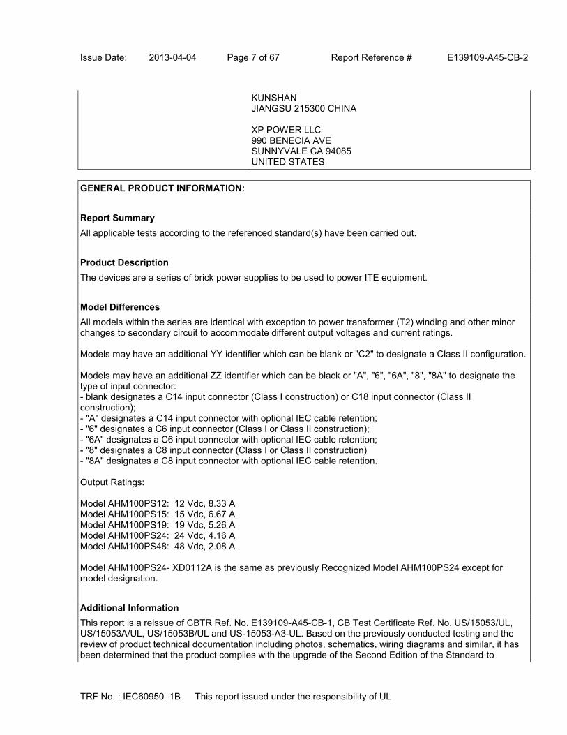
Issue Date: 2013-04-04 Page 7 of 67 Report Reference # E139109-A45-CB-2
TRF No. : IEC60950_1B This report issued under the responsibility of UL
KUNSHAN JIANGSU 215300 CHINA XP POWER LLC 990 BENECIA AVE SUNNYVALE CA 94085 UNITED STATES
GENERAL PRODUCT INFORMATION:
Report Summary
All applicable tests according to the referenced standard(s) have been carried out.
Product Description
The devices are a series of brick power supplies to be used to power ITE equipment.
Model Differences
All models within the series are identical with exception to power transformer (T2) winding and other minor changes to secondary circuit to accommodate different output voltages and current ratings. Models may have an additional YY identifier which can be blank or "C2" to designate a Class II configuration. Models may have an additional ZZ identifier which can be black or "A", "6", "6A", "8", "8A" to designate the type of input connector: - blank designates a C14 input connector (Class I construction) or C18 input connector (Class II construction); - "A" designates a C14 input connector with optional IEC cable retention; - "6" designates a C6 input connector (Class I or Class II construction); - "6A" designates a C6 input connector with optional IEC cable retention; - "8" designates a C8 input connector (Class I or Class II construction) - "8A" designates a C8 input connector with optional IEC cable retention. Output Ratings: Model AHM100PS12: 12 Vdc, 8.33 A Model AHM100PS15: 15 Vdc, 6.67 A Model AHM100PS19: 19 Vdc, 5.26 A Model AHM100PS24: 24 Vdc, 4.16 A Model AHM100PS48: 48 Vdc, 2.08 A Model AHM100PS24- XD0112A is the same as previously Recognized Model AHM100PS24 except for model designation.
Additional Information
This report is a reissue of CBTR Ref. No. E139109-A45-CB-1, CB Test Certificate Ref. No. US/15053/UL, US/15053A/UL, US/15053B/UL and US-15053-A3-UL. Based on the previously conducted testing and the review of product technical documentation including photos, schematics, wiring diagrams and similar, it has been determined that the product complies with the upgrade of the Second Edition of the Standard to

Issue Date: 2013-04-04 Page 8 of 67 Report Reference # E139109-A45-CB-2
TRF No. : IEC60950_1B This report issued under the responsibility of UL
Amendment 1. No tests were conducted under this investigation due to reissue of CB Test Report Ref. No. E139109-A45-CB-1. All required tests were carried out under the original investigation. Required values for clearance are adjusted for 3048 m (1.15 correction factor as per IEC 60664-1, Table A2). The following alternate components with equivalent ratings and certification were added as part of reissue: - X Capacitor - Panasonic, Type ECQUA, ECQUG and ECQUL Series. - X Capacitor - Epcos/Siemen, Type B32921, B32922, B32923 E, B32924 E/F, B32926 E/F Series. - Y Capacitor - Kemet, Type ERP610 Series. - Y Capacitor - TDK, Type CD Series. - Y Capacitor - Vishay, Type VY1 Series. Marking label is representative of all models. The nameplate labels included in this report depict the draft artwork for the marking plate pending approval by National Certification Bodies and it will not be affixed to products prior to such approval. The attached Licenses for the Critical Components effective for three years from the date of issue noted on the License. A Recognizing National Certification Body (NCB) may challenge the CB Test Certificate when it is more than three years old.
Technical Considerations
The product was submitted and evaluated for use at the maximum ambient temperature (Tma) permitted by the manufacturer’s specification of: 40°C (at 100% rated load); 60°C (at 60% rated load),
The means of connection to the mains supply is: Detachable power cord, Pluggable A,
The product is intended for use on the following power systems: TN
The equipment disconnect device is considered to be: Appliance inlet
The product was investigated to the following additional standards: EN 60950-1:2006 + A11:2009 + A1:2010 + A12:2011 (which includes all European national differences, including those specified in this test report).
The following accessible locations (with circuit/schematic designation) are within a limited current circuit: Load side of CY3 (Pri to Sec bridging capacitor)
The following are available from the Applicant upon request: Installation (Safety) Instructions / Manual,
The equipment employs Functional Earthing per 2.6.2. As anticipated by the NOTE for 1.2.4, it does not conform to one of the common Classes (I, II, or III). The following insulation is provided between the primary and accessible dead metal parts and circuits: Double/Reinforced (configurations with a ground pin in the appliance inlet),
Abbreviations used in the report:
- normal condition ............................................ : N.C. - single fault condition ....................................... : S.F.C
- operational insulation ..................................... : OP - basic insulation .............................................. : BI
- basic insulation between parts of opposite polarity:
BOP
- supplementary insulation ............................... : SI
Issue Date: 2013-04-04 Page 9 of 67 Report Reference # E139109-A45-CB-2
TRF No. : IEC60950_1B This report issued under the responsibility of UL
- double insulation ............................................ : DI - reinforced insulation ...................................... : RI
Indicate used abbreviations (if any)

1/2
Ref. Certif. No.
US-21343-UL
IEC SYSTEM FOR MUTUAL RECOGNITION OF TEST CERTIFICATES FOR ELECTRICAL EQUIPMENT (IECEE) CB SCHEME
SYSTEME CEI D’ACCEPTATION MUTUELLE DE CERTIFICATS D’ESSAIS DES EQUIPEMENTS ELECTRIQUES (IECEE) METHODE OC
CB TEST CERTIFICATE CERTIFICAT D’ESSAI OC
Product Produit
AC/DC Power Adapter
Name and address of the applicant Nom et adresse du demandeur
XP POWER L L C SUITE 150 1241 E DYER RD SANTA ANA CA 92705, USA
Name and address of the manufacturer Nom et adresse du fabricant
XP POWER L L C SUITE 150 1241 E DYER RD SANTA ANA CA 92705, USA
Name and address of the factory Nom et adresse de l’usine Note: When more than one factory, please report on page 2 Note: Lorsque il y plus d'une usine, veuillez utiliser la 2ème page
XP POWER (KUNSHAN) LTD 230 BIN JIANG NAN RD ZHANGPU TOWN KUNSHAN JIANGSU 215300 CHINA
Additional Information on page 2 Ratings and principal characteristics Valeurs nominales et caractéristiques principales
Input: 100-240 Vac, 50/60 Hz, 1.8 A Output: See Model Differences section
Trademark (if any) Marque de fabrique (si elle existe)
Type of Manufacturer's Testing Laboratories used Type de programme du laboratoire d'essais constructeur
Model / Type Ref. Ref. De type
AHM150PSXXYY-ZZ See Page 2
Additional information (if necessary may also be reported on page 2) Les informations complémentaires (si nécessaire,, peuvent être indiqués sur la 2ème page
Additionally evaluated to EN 60950-1:2006/A11:2009/A1:2010/ A12:2011; National Differences specified in the CB Test Report.
Additional Information on page 2
A sample of the product was tested and found to be in conformity with Un échantillon de ce produit a été essayé et a été considéré conforme à la
IEC 60950-1(ed.2), IEC 60950-1(ed.2);am1
As shown in the Test Report Ref. No. which forms part of this Certificate Comme indiqué dans le Rapport d’essais numéro de référence qui constitue partie de ce Certificat
E139109-A62-CB-2 issued on 2013-04-05
This CB Test Certificate is issued by the National Certification Body Ce Certificat d’essai OC est établi par l’Organisme National de Certification
UL (US), 333 Pfingsten Rd IL 60062, Northbrook, USA
UL (Demko), Borupvang 5A DK-2750 Ballerup, DENMARK
UL (JP), Marunouchi Trust Tower Main Building 6F, 1-8-3 Marunouchi, Chiyoda-ku, Tokyo 100-0005, JAPAN
UL (CA), 7 Underwriters Road, Toronto, M1R 3B4 Ontario, CANADA
For full legal entity names see www.ul.com/ncbnames
Date: 2013-04-05
Signature: Jolanta M. Wroblewska

2/2
Ref. Certif. No.
US-21343-UL
Model Details:
AHM150PSXXYY-ZZ (where XX is any number between 12-48 designating output voltage, where YY can be "C2" or blank, and ZZ can be blank or "A", "6", "8", "6A", or "8A", may be provided with or without "-")
Factories:
XP POWER LLC
990 BENECIA AVE
SUNNYVALE CA 94085
USA
Additional information (if necessary)
Information complémentaire (si nécessaire)
UL (US), 333 Pfingsten Rd IL 60062, Northbrook, USA
UL (Demko), Borupvang 5A DK-2750 Ballerup, DENMARK
UL (JP), Marunouchi Trust Tower Main Building 6F, 1-8-3 Marunouchi, Chiyoda-ku, Tokyo 100-0005, JAPAN
UL (CA), 7 Underwriters Road, Toronto, M1R 3B4 Ontario, CANADA
For full legal entity names see www.ul.com/ncbnames
Signature: Jolanta M. Wroblewska
Date: 2013-04-05

Issue Date: 2013-04-05 Page 1 of 73 Report Reference # E139109-A62-CB-2
TRF No. : IEC60950_1B This report issued under the responsibility of UL
Test Report issued under
the responsibility of:
TEST REPORT IEC 60950-1
Information technology equipment - Safety - Part 1: General requirements
Report Reference No .................. : E139109-A62-CB-2
Date of issue ................................. : 2013-04-05
Total number of pages .................. : 73
CB Testing Laboratory ............... : UL San Jose
Address ......................................... : 455 E. Trimble Rd., San Jose, CA, 95131-1230, USA
Applicant's name ........................ :
Address ......................................... :
XP POWER L L C SUITE 150 1241 E DYER RD SANTA ANA CA 92705 UNITED STATES
Test specification:
Standard ........................................ : IEC 60950-1:2005 (2nd Edition); Am 1:2009
Test procedure .............................. : CB Scheme
Non-standard test method ............ : N/A
Test Report Form No. ................. : IEC60950_1B
Test Report Form originator .......... : SGS Fimko Ltd
Master TRF ................................... : 2010-04
Copyright © 2010 IEC System for Conformity Testing and Certification of Electrical Equipment (IECEE), Geneva, Switzerland. All rights reserved. This publication may be reproduced in whole or in part for non-commercial purposes as long as the IECEE is acknowledged as copyright owner and source of the material. IECEE takes no responsibility for and will not assume liability for damages resulting from the reader's interpretation of the reproduced material due to its placement and context. If this test Report is used by non-IECEE members, the IECEE/IEC logo and the reference to the CB Scheme procedure shall be removed. This report is not valid as a CB Test Report unless signed by an approved CB Testing Laboratory and appended to a CB Test Certificate issued by an NCB in accordance with IECEE 02.

Issue Date: 2013-04-05 Page 2 of 73 Report Reference # E139109-A62-CB-2
TRF No. : IEC60950_1B This report issued under the responsibility of UL
Test item description .................. : AC/DC Power Adapter
Trade Mark .................................... :
Manufacturer ................................. : XP POWER L L C SUITE 150 1241 E DYER RD SANTA ANA CA 92705 UNITED STATES
Model/Type reference ................... : AHM150PSXXYY-ZZ (where XX is any number between 12-48 designating output voltage, where YY can be "C2" or blank, and ZZ can be blank or "A", "6", "8", "6A", or "8A", may be provided with or without "-")
Ratings .......................................... : Input: 100-240 Vac, 50/60 Hz, 1.8 A Output: See Model Differences section

Issue Date: 2013-04-05 Page 3 of 73 Report Reference # E139109-A62-CB-2
TRF No. : IEC60950_1B This report issued under the responsibility of UL
Testing procedure and testing location:
[ ] CB Testing Laboratory
Testing location / address .............. :
[x] Associated CB Test Laboratory
Testing location / address .............. : UL Brea 2929 Imperial Hwy, Ste 100, Brea, CA, 92821, USA
Tested by (name + signature) ....... : Sal Oseguera
Approved by (name + signature) ... : Kevin Tang
[ ] Testing Procedure: TMP
Tested by (name + signature) ....... :
Approved by (+ signature) ............. :
Testing location / address .............. :
[ ] Testing Procedure: WMT
Tested by (name + signature) ....... :
Witnessed by (+ signature) ............ :
Approved by (+ signature) ............. :
Testing location / address .............. :
[ ] Testing Procedure: SMT
Tested by (name + signature) ....... :
Approved by (+ signature) ............. :
Supervised by (+ signature) .......... :
Testing location / address .............. :
[ ] Testing Procedure: RMT
Tested by (name + signature) ....... :
Approved by (+ signature) ............. :
Supervised by (+ signature) .......... :
Testing location / address .............. :
List of Attachments
National Differences (37 pages)
Enclosures (55 pages)
Summary Of Testing Unless otherwise indicated, all tests were conducted at UL Brea 2929 Imperial Hwy, Ste 100, Brea, CA, 92821, USA.
Tests performed (name of test and test clause) Testing location / Comments
Guide Information Page - Maximum Output Voltage, Current, and Volt Ampere Measurement (1.2.2.1)
Evaluated under original CB Scheme investigation.
Input: Single-Phase (1.6.2) Evaluated under original CB Scheme

Issue Date: 2013-04-05 Page 4 of 73 Report Reference # E139109-A62-CB-2
TRF No. : IEC60950_1B This report issued under the responsibility of UL
investigation.
Durability of Marking (1.7.11) Evaluated under original CB Scheme investigation.
Energy Hazard Measurements (2.1.1.5, 2.1.2, 1.2.8.10) Evaluated under original CB Scheme investigation.
Capacitance Discharge (2.1.1.7) Evaluated under original CB Scheme investigation.
SELV Reliability Test Including Hazardous Voltage Measurements (2.2.2, 2.2.3, 2.2.4, Part 22 6.1)
Evaluated under original CB Scheme investigation.
Limited Current Circuit Measurement (2.4.1, 2.4.2) Evaluated under original CB Scheme investigation.
Protective Bonding II (2.6.3.4, 2.6.1) Evaluated under original CB Scheme investigation.
Humidity (2.9.1, 2.9.2, 5.2.2) Evaluated under original CB Scheme investigation.
Determination of Working Voltage; Working Voltage Measurement (2.10.2)
Evaluated under original CB Scheme investigation.
Thin Sheet Material (2.10.5.9, 2.10.5.10, 2.10.5.6) Evaluated under original CB Scheme investigation.
Transformer and Wire /Insulation Electric Strength (2.10.5.13)
Evaluated under original CB Scheme investigation.
Strain Relief (3.2.6, 4.2.1, 4.2.7) Evaluated under original CB Scheme investigation.
Steady Force (4.2.1 - 4.2.4) Evaluated under original CB Scheme investigation.
Impact (4.2.5, 4.2.1, Part 22 10.2) Evaluated under original CB Scheme investigation.
Drop (4.2.6, 4.2.1) Evaluated under original CB Scheme investigation.
Stress Relief (4.2.7, 4.2.1) Evaluated under original CB Scheme investigation.
Heating (4.5.1, 1.4.12, 1.4.13) Evaluated under original CB Scheme investigation.
Touch Current (Single-Phase; TN/TT System) (5.1, Annex D)
Evaluated under original CB Scheme investigation.
Electric Strength (5.2.2) Evaluated under original CB Scheme investigation.
Component Failure (5.3.1, 5.3.4, 5.3.7) Evaluated under original CB Scheme investigation.
Transformer Abnormal Operation (5.3.3, 5.3.7b, Annex C.1)
Evaluated under original CB Scheme investigation.
Power Supply Output Short-Circuit/Overload (5.3.7) Evaluated under original CB Scheme investigation.
Summary of Compliance with National Differences:

Issue Date: 2013-04-05 Page 5 of 73 Report Reference # E139109-A62-CB-2
TRF No. : IEC60950_1B This report issued under the responsibility of UL
Countries outside the CB Scheme membership may also accept this report.
List of countries addressed: AT, BE, BG, CA, CH, CZ, DE, DK, ES, EU, FI, FR, GB, GR, HU, IE, IL, IT, JP, KR, NL, PL, PT, RO, SE, SI, SK, UA, US
The product fulfills the requirements of: CSA C22.2 No. 60950-1-07 + A1:2011, EN 60950-1:2006 + A11:2009 + A1:2010 + A12:2011, UL 60950-1 2nd Ed. Revised 2011-12-19, IEC 60950-1:2005 + A1:2009
Copy of Marking Plate - Refer to Enclosure titled Marking Plate for copy.
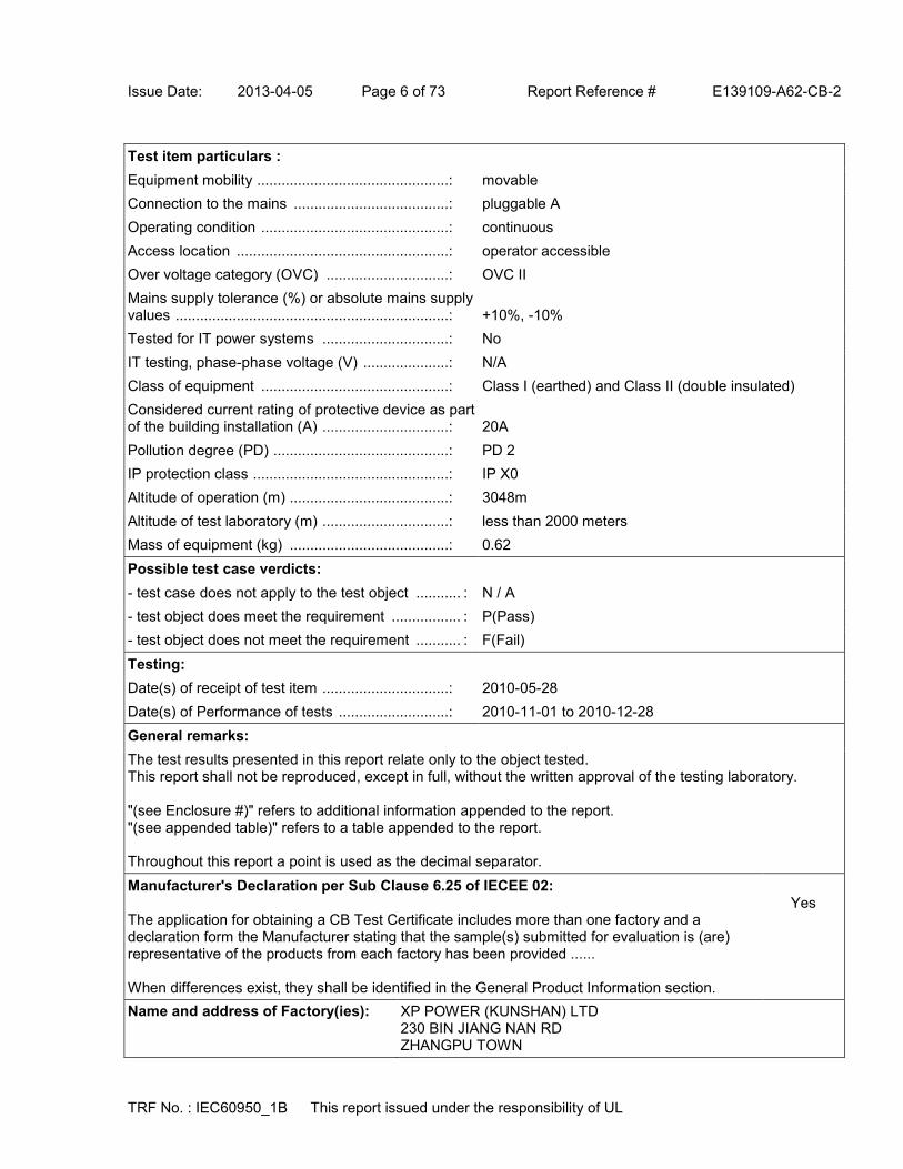
Issue Date: 2013-04-05 Page 6 of 73 Report Reference # E139109-A62-CB-2
TRF No. : IEC60950_1B This report issued under the responsibility of UL
Test item particulars :
Equipment mobility ...............................................: movable
Connection to the mains ......................................: pluggable A
Operating condition ..............................................: continuous
Access location ....................................................: operator accessible
Over voltage category (OVC) ..............................: OVC II
Mains supply tolerance (%) or absolute mains supply values ...................................................................: +10%, -10%
Tested for IT power systems ...............................: No
IT testing, phase-phase voltage (V) .....................: N/A
Class of equipment ..............................................: Class I (earthed) and Class II (double insulated)
Considered current rating of protective device as part of the building installation (A) ...............................: 20A
Pollution degree (PD) ...........................................: PD 2
IP protection class ................................................: IP X0
Altitude of operation (m) .......................................: 3048m
Altitude of test laboratory (m) ...............................: less than 2000 meters
Mass of equipment (kg) .......................................: 0.62
Possible test case verdicts:
- test case does not apply to the test object ........... : N / A
- test object does meet the requirement ................. : P(Pass)
- test object does not meet the requirement ........... : F(Fail)
Testing:
Date(s) of receipt of test item ...............................: 2010-05-28
Date(s) of Performance of tests ...........................: 2010-11-01 to 2010-12-28
General remarks:
The test results presented in this report relate only to the object tested. This report shall not be reproduced, except in full, without the written approval of the testing laboratory. "(see Enclosure #)" refers to additional information appended to the report. "(see appended table)" refers to a table appended to the report. Throughout this report a point is used as the decimal separator.
Manufacturer's Declaration per Sub Clause 6.25 of IECEE 02: The application for obtaining a CB Test Certificate includes more than one factory and a declaration form the Manufacturer stating that the sample(s) submitted for evaluation is (are) representative of the products from each factory has been provided ...... When differences exist, they shall be identified in the General Product Information section.
Yes
Name and address of Factory(ies): XP POWER (KUNSHAN) LTD 230 BIN JIANG NAN RD ZHANGPU TOWN
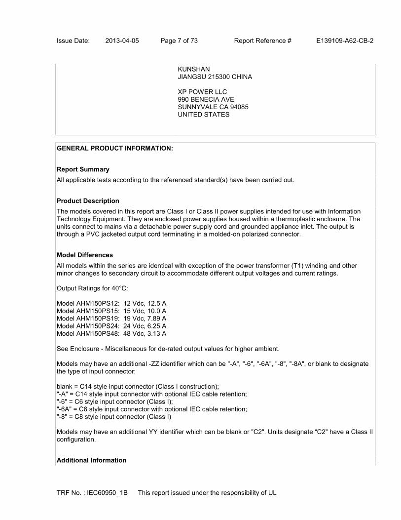
Issue Date: 2013-04-05 Page 7 of 73 Report Reference # E139109-A62-CB-2
TRF No. : IEC60950_1B This report issued under the responsibility of UL
KUNSHAN JIANGSU 215300 CHINA XP POWER LLC 990 BENECIA AVE SUNNYVALE CA 94085 UNITED STATES
GENERAL PRODUCT INFORMATION:
Report Summary
All applicable tests according to the referenced standard(s) have been carried out.
Product Description
The models covered in this report are Class I or Class II power supplies intended for use with Information Technology Equipment. They are enclosed power supplies housed within a thermoplastic enclosure. The units connect to mains via a detachable power supply cord and grounded appliance inlet. The output is through a PVC jacketed output cord terminating in a molded-on polarized connector.
Model Differences
All models within the series are identical with exception of the power transformer (T1) winding and other minor changes to secondary circuit to accommodate different output voltages and current ratings. Output Ratings for 40°C: Model AHM150PS12: 12 Vdc, 12.5 A Model AHM150PS15: 15 Vdc, 10.0 A Model AHM150PS19: 19 Vdc, 7.89 A Model AHM150PS24: 24 Vdc, 6.25 A Model AHM150PS48: 48 Vdc, 3.13 A See Enclosure - Miscellaneous for de-rated output values for higher ambient. Models may have an additional -ZZ identifier which can be "-A", "-6", "-6A", "-8", "-8A", or blank to designate the type of input connector: blank = C14 style input connector (Class I construction); "-A" = C14 style input connector with optional IEC cable retention; "-6" = C6 style input connector (Class I); "-6A" = C6 style input connector with optional IEC cable retention; "-8" = C8 style input connector (Class I) Models may have an additional YY identifier which can be blank or "C2". Units designate “C2" have a Class II configuration.
Additional Information

Issue Date: 2013-04-05 Page 8 of 73 Report Reference # E139109-A62-CB-2
TRF No. : IEC60950_1B This report issued under the responsibility of UL
This report is a reissue of CBTR Ref. No. E139109-A62-CB-1, CB Test Certificate Ref. Nos. US/16498/UL and US-16498-A1-UL. Based on the previously conducted testing and the review of product technical documentation including photos, schematics, wiring diagrams and similar, has been determined that the product complies with the upgrade of the Second Edition of the Standard to Amendment 1. No tests were conducted under this investigation due to reissue of CB Test Report Ref. No. E139109-A62-CB-1. All required tests were carried out under the original investigation. The following alternate components with equivalent ratings and certification were added as part of reissue: - X Capacitor - Panasonic, Type ECQUA, ECQUG and ECQUL Series. - X Capacitor - Epcos/Siemen, Type B32921, B32922, B32923 E, B32924 E/F, B32926 E/F Series. - Y Capacitor - Kemet, Type ERP610 Series. - Y Capacitor - TDK, Type CD Series. - Y Capacitor - Vishay, Type VY1 Series Required values for clearance are adjusted for 3048 m (1.15 correction factor as per IEC 60664-1, Table A2). Marking label is representative of all models. The nameplate labels included in this report depict the draft artwork for the marking plate pending approval by National Certification Bodies and it will not be affixed to products prior to such approval. The attached Licenses for the Critical Components effective for three years from the date of issue noted on the License. A Recognizing National Certification Body (NCB) may challenge the CB Test Certificate when it is more than three years old.
Technical Considerations
The product was submitted and evaluated for use at the maximum ambient temperature (Tma) permitted by the manufacturer’s specification of: 40°C (at 100% rated load); 60°C (at 60% rated load) ,
The means of connection to the mains supply is: Pluggable A, Detachable power cord,
The product is intended for use on the following power systems: TN
The equipment disconnect device is considered to be: Appliance inlet
The product was investigated to the following additional standards: EN 60950-1:2006 + A11:2009 + A1:2010 + A12:2011 (which includes all European national differences, including those specified in this test report).
The following accessible locations (with circuit/schematic designation) are within a limited current circuit: Load side of Capacitor CY3 and CY4,
The following are available from the Applicant upon request: Specific data sheets for LED indicators that are class I and operate at wavelength in the 400-710 nm range., Installation (Safety) Instructions / Manual.,
The equipment employs Functional Earthing per 2.6.2. As anticipated by the NOTE for 1.2.4, it does not conform to one of the common Classes (I, II, or III). The following insulation is provided between the primary and accessible dead metal parts and circuits: Double/Reinforced (configuration with a ground pin in the appliance inlet) ,
LEDs provided in the product are considered low power devices: Yes
Abbreviations used in the report:

Issue Date: 2013-04-05 Page 9 of 73 Report Reference # E139109-A62-CB-2
TRF No. : IEC60950_1B This report issued under the responsibility of UL
- normal condition ............................................ : N.C. - single fault condition ....................................... : S.F.C
- operational insulation ..................................... : OP - basic insulation .............................................. : BI
- basic insulation between parts of opposite polarity:
BOP
- supplementary insulation ............................... : SI
- double insulation ............................................ : DI - reinforced insulation ...................................... : RI
Indicate used abbreviations (if any)

1/2
Ref. Certif. No.
US-21391-UL
IEC SYSTEM FOR MUTUAL RECOGNITION OF TEST CERTIFICATES FOR ELECTRICAL EQUIPMENT (IECEE) CB SCHEME
SYSTEME CEI D'ACCEPTATION MUTUELLE DE CERTIFICATS D'ESSAIS DES EQUIPEMENTS ELECTRIQUES (IECEE) METHODE OC
CB TEST CERTIFICATE CERTIFICAT D'ESSAI OCProductProduit
Power supply, switch mode type
Name and address of the applicantNom et adresse du demandeur
XP POWER L L CSUITE 1501241 E DYER RDSANTA ANA CA 92705UNITED STATES
Name and address of the manufacturerNom et adresse du fabricant
XP POWER L L CSUITE 1501241 E DYER RDSANTA ANA CA 92705UNITED STATES
Name and address of the factoryNom et adresse de l'usine
Note: When more than one factory, please report on page 2Note: Lorsque il y plus d'une usine, veuillez utiliser la 2ème page
XP POWER LLC990 BENECIA AVESUNNYVALE CA 94085UNITED STATES
Additional Information on page 2Ratings and principal characteristicsValeurs nominales et caractéristiques principales
Input: 100-240 Vac, 2.2 A, 50/60 Hz;Output: See Enclosure - Miscellaneous Ratings Table for details.
Trademark (if any)Marque de fabrique (si elle existe)
Type of Manufacturer's Testing Laboratories usedType de programme du laboratoire d'essais constructeur
WMT
Model / Type Ref.Ref. De type
AHM180PSXXYY-ZZSee Page 2
Additional information (if necessary may also be reported on page 2)Les informations complémentaires (si nécessaire,, peuvent être indiqués sur la 2ème page
Additionally evaluated to EN 60950-1:2006/A11:2009/ A1:2010/ A12:2011; National Differences specified in the CB Test Report.
Additional Information on page 2
A sample of the product was tested and found to be in conformity withUn échantillon de ce produit a été essayé et a été considéré conforme à la
IEC 60950-1(ed.2), IEC 60950-1(ed.2);am1
As shown in the Test Report Ref. No. which forms part of this CertificateComme indiqué dans le Rapport d'essais numéro de référence qui constitue partie de ce Certificat
E139109-A48-CB-2 issued on 2013-04-16
This CB Test Certificate is issued by the National Certification BodyCe Certificat d'essai OC est établi par l'Organisme National de Certification
UL (US), 333 Pfingsten Rd IL 60062, Northbrook, USA
UL (Demko), Borupvang 5A DK-2750 Ballerup, DENMARK
UL (JP), Marunouchi Trust Tower Main Building 6F, 1-8-3 Marunouchi, Chiyoda-ku, Tokyo 100-0005, JAPAN
UL (CA), 7 Underwriters Road, Toronto, M1R 3B4 Ontario, CANADA
For full legal entity names see www.ul.com/ncbnames
Date: 2013-04-16
Signature:
Jolanta M. Wroblewska

2/2
Ref. Certif. No.
US-21391-ULModel Details:AHM180PSXXYY-ZZ where XX is any number between 12-48 designating output voltage, where YY can be "C2" or blank, and ZZ can be blank or "A" designating optional clamp retention, or "6" or "6A" designating optional type C6 appliance inlet and clampretention.
Factories:XP POWER (KUNSHAN) LIMITED230, BIN JIANG NAN ROADZHANG PU TOWNKUNSHAN, JIANGSU 215300CHINA
Additional information (if necessary)Information complémentaire (si nécessaire)
UL (US), 333 Pfingsten Rd IL 60062, Northbrook, USA
UL (Demko), Borupvang 5A DK-2750 Ballerup, DENMARK
UL (JP), Marunouchi Trust Tower Main Building 6F, 1-8-3 Marunouchi, Chiyoda-ku, Tokyo 100-0005, JAPAN
UL (CA), 7 Underwriters Road, Toronto, M1R 3B4 Ontario, CANADA
For full legal entity names see www.ul.com/ncbnames
Signature: Jolanta M. Wroblewska
Date: 2013-04-16

Issue Date: 2013-04-16 Page 1 of 78 Report Reference # E139109-A48-CB-2
TRF No. : IEC60950_1B This report issued under the responsibility of UL
Test Report issued under
the responsibility of:
TEST REPORT IEC 60950-1
Information technology equipment - Safety - Part 1: General requirements
Report Reference No .................. : E139109-A48-CB-2
Date of issue ................................. : 2013-04-16
Total number of pages .................. : 78
CB Testing Laboratory ............... : UL San Jose
Address ......................................... : 455 E. Trimble Rd., San Jose, CA, 95131-1230, USA
Applicant's name ........................ :
Address ......................................... :
XP POWER LLC SUITE 150 1241 E DYER RD SANTA ANA CA 92705 UNITED STATES
Test specification:
Standard ........................................ : IEC 60950-1:2005 (2nd Edition); Am 1:2009
Test procedure .............................. : CB Scheme
Non-standard test method ............ : N/A
Test Report Form No. ................. : IEC60950_1B
Test Report Form originator .......... : SGS Fimko Ltd
Master TRF ................................... : 2010-04
Copyright © 2010 IEC System for Conformity Testing and Certification of Electrical Equipment (IECEE), Geneva, Switzerland. All rights reserved. This publication may be reproduced in whole or in part for non-commercial purposes as long as the IECEE is acknowledged as copyright owner and source of the material. IECEE takes no responsibility for and will not assume liability for damages resulting from the reader's interpretation of the reproduced material due to its placement and context. If this test Report is used by non-IECEE members, the IECEE/IEC logo and the reference to the CB Scheme procedure shall be removed. This report is not valid as a CB Test Report unless signed by an approved CB Testing Laboratory and appended to a CB Test Certificate issued by an NCB in accordance with IECEE 02.

Issue Date: 2013-04-16 Page 2 of 78 Report Reference # E139109-A48-CB-2
TRF No. : IEC60950_1B This report issued under the responsibility of UL
Test item description .................. : Power supply, switch mode type
Trade Mark .................................... :
Manufacturer ................................. : XP POWER LLC SUITE 150 1241 E DYER RD SANTA ANA CA 92705 UNITED STATES
Model/Type reference ................... : AHM180PSXXYY-ZZ (where XX is any number between 12-48 designating output voltage, where YY can be “C2” or blank, and ZZ can be blank or "A" designating optional clamp retention, or "6" or "6A" designating optional type C6 appliance inlet and clamp retention)
Ratings .......................................... : Input: 100-240 Vac, 2.2 A, 50/60 Hz Output: See Enclosure - Miscellaneous Ratings Table for details.

Issue Date: 2013-04-16 Page 3 of 78 Report Reference # E139109-A48-CB-2
TRF No. : IEC60950_1B This report issued under the responsibility of UL
Testing procedure and testing location:
[ ] CB Testing Laboratory
Testing location / address .............. :
[ ] Associated CB Test Laboratory
Testing location / address .............. :
Tested by (name + signature) ....... :
Approved by (name + signature) ... :
[ ] Testing Procedure: TMP
Tested by (name + signature) ....... :
Approved by (+ signature) ............. :
Testing location / address .............. :
[x] Testing Procedure: WMT
Tested by (name + signature) ....... : Rodney Reyes
Witnessed by (+ signature) ............ : Sal Oseguera
Approved by (+ signature) ............. : Benjamin Mapes
Testing location / address .............. : XP Power LLC, Suite 150, 1241 E Dyer Rd, Santa Ana, 92705 USA
[ ] Testing Procedure: SMT
Tested by (name + signature) ....... :
Approved by (+ signature) ............. :
Supervised by (+ signature) .......... :
Testing location / address .............. :
[ ] Testing Procedure: RMT
Tested by (name + signature) ....... :
Approved by (+ signature) ............. :
Supervised by (+ signature) .......... :
Testing location / address .............. :
List of Attachments
National Differences (35 pages)
Enclosures (149 pages)
Summary Of Testing Unless otherwise indicated, all tests were conducted at XP Power LLC, Suite 150, 1241 E Dyer Rd, Santa Ana, 92705 USA.
Tests performed (name of test and test clause) Testing location / Comments
Guide Information Page - Maximum Output Voltage, Evaluated under original CB Scheme

Issue Date: 2013-04-16 Page 4 of 78 Report Reference # E139109-A48-CB-2
TRF No. : IEC60950_1B This report issued under the responsibility of UL
Current, and Volt Ampere Measurement (1.2.2.1) investigation.
Input: Single-Phase (1.6.2) Evaluated under original CB Scheme investigation.
Energy Hazard Measurements (2.1.1.5, 2.1.2, 1.2.8.10) XP Power LLC, Suite 150, 1241 E Dyer Rd, Santa Ana, 92705 USA - WMT/WTDP
Capacitance Discharge (2.1.1.7) Evaluated under original CB Scheme investigation.
SELV Reliability Test Including Hazardous Voltage Measurements (2.2.2, 2.2.3, 2.2.4, Part 22 6.1)
Evaluated under original CB Scheme investigation.
Limited Current Circuit Measurement (2.4.1, 2.4.2) Evaluated under original CB Scheme investigation.
Protective Bonding II (2.6.3.4, 2.6.1) Evaluated under original CB Scheme investigation.
Humidity (2.9.1, 2.9.2, 5.2.2) Evaluated under original CB Scheme investigation.
Determination of Working Voltage; Working Voltage Measurement (2.10.2)
Evaluated under original CB Scheme investigation.
Thin Sheet Material (2.10.5.9, 2.10.5.10, 2.10.5.6) Evaluated under original CB Scheme investigation.
Transformer and Wire /Insulation Electric Strength (2.10.5.13)
Evaluated under original CB Scheme investigation.
Strain Relief (3.2.6, 4.2.1, 4.2.7) Evaluated under original CB Scheme investigation.
Steady Force (4.2.1 - 4.2.4) Evaluated under original CB Scheme investigation.
Impact (4.2.5, 4.2.1, Part 22 10.2) Evaluated under original CB Scheme investigation.
Drop (4.2.6, 4.2.1) Evaluated under original CB Scheme investigation.
Stress Relief (4.2.7, 4.2.1) Evaluated under original CB Scheme investigation.
Heating (4.5.1, 1.4.12, 1.4.13) Evaluated under original CB Scheme investigation.
Ball Pressure (4.5.5, 4.5) Evaluated under original CB Scheme investigation.
IT Touch Current (Single-Phase) (5.1, Annex D) Evaluated under original CB Scheme investigation.
Electric Strength (5.2.2) Evaluated under original CB Scheme investigation.
Component Failure (5.3.1, 5.3.4, 5.3.7) Evaluated under original CB Scheme investigation.
Transformer Abnormal Operation (5.3.3, 5.3.7b, Annex C.1)
Evaluated under original CB Scheme investigation.
Power Supply Output Short-Circuit/Overload (5.3.7) Evaluated under original CB Scheme

Issue Date: 2013-04-16 Page 5 of 78 Report Reference # E139109-A48-CB-2
TRF No. : IEC60950_1B This report issued under the responsibility of UL
investigation.
Summary of Compliance with National Differences:
Countries outside the CB Scheme membership may also accept this report.
List of countries addressed: AT, BE, BG, CA, CH, CZ, DE, DK, ES, EU, FI, FR, GB, GR, HU, IE, IT, JP, KR, NL, PL, PT, RO, SE, SI, SK, UA, US
The product fulfills the requirements of: CSA C22.2 No. 60950-1-07 + A1:2011, EN 60950-1:2006 + A1:2010 + A11:2009 + A12:2011, IEC 60950-1:2005 + A1:2009, UL 60950-1 2nd Ed. Revised 2011-12-19
Copy of Marking Plate - Refer to Enclosure titled Marking Plate for copy.

Issue Date: 2013-04-16 Page 6 of 78 Report Reference # E139109-A48-CB-2
TRF No. : IEC60950_1B This report issued under the responsibility of UL
Test item particulars :
Equipment mobility ...............................................: movable
Connection to the mains ......................................: pluggable A
Operating condition ..............................................: continuous
Access location ....................................................: operator accessible
Over voltage category (OVC) ..............................: OVC II
Mains supply tolerance (%) or absolute mains supply values ...................................................................: +10%, -10%
Tested for IT power systems ...............................: No
IT testing, phase-phase voltage (V) .....................: N/A
Class of equipment ..............................................: Class I (earthed) and Class II (double insulated)
Considered current rating of protective device as part of the building installation (A) ...............................: 20
Pollution degree (PD) ...........................................: PD 2
IP protection class ................................................: IPX0
Altitude of operation (m) .......................................: 3048
Altitude of test laboratory (m) ...............................: 107
Mass of equipment (kg) .......................................: 0.62
Possible test case verdicts:
- test case does not apply to the test object ........... : N / A
- test object does meet the requirement ................. : P(Pass)
- test object does not meet the requirement ........... : F(Fail)
Testing:
Date(s) of receipt of test item ...............................: 2013-04-12, 2010-02-08, 2010-04-26, 2010-10-10
Date(s) of Performance of tests ...........................: 2013-04-12, 2010-03-23 to 2010-05-27, 2010-11-01 to 2010-11-25
General remarks:
The test results presented in this report relate only to the object tested. This report shall not be reproduced, except in full, without the written approval of the testing laboratory. "(see Enclosure #)" refers to additional information appended to the report. "(see appended table)" refers to a table appended to the report. Throughout this report a point is used as the decimal separator.
Manufacturer's Declaration per Sub Clause 6.25 of IECEE 02: The application for obtaining a CB Test Certificate includes more than one factory and a declaration form the Manufacturer stating that the sample(s) submitted for evaluation is (are) representative of the products from each factory has been provided ...... When differences exist, they shall be identified in the General Product Information section.
Yes
Name and address of Factory(ies): XP POWER LLC 990 BENECIA AVE

Issue Date: 2013-04-16 Page 7 of 78 Report Reference # E139109-A48-CB-2
TRF No. : IEC60950_1B This report issued under the responsibility of UL
SUNNYVALE CA 94085 UNITED STATES XP POWER (KUNSHAN) LIMITED 230, BIN JIANG NAN ROAD, ZHANG PU TOWN KUNSHAN, JIANGSU 215300 CHINA
GENERAL PRODUCT INFORMATION:
Report Summary
All applicable tests according to the referenced standard(s) have been carried out.
Product Description
The models covered in this report are Class I or Class II power supplies intended for use with Information Technology Equipment. They are enclosed power supplies housed within a thermoplastic enclosure. The units connect to mains via a detachable power supply cord and grounded appliance inlet. The output is through a PVC jacketed output cord terminating in a molded-on polarized connector.
Model Differences
All models in the Model AHM180PSXXYY-ZZ Series are identical with exception of the Main Transformer, T1, and minor secondary components changes that allow for different output voltage ratings. See below for Models and Ratings for 40°C ambient. Model AHM180PS12: Output Rated: 12 Vdc, 13.75 A Model AHM180PS15: Output Rated: 15 Vdc, 12 A Model AHM180PS19: Output Rated: 19 Vdc, 9.47 A Model AHM180PS24: Output Rated: 24 Vdc, 7.5 A Model AHM180PS48: Output Rated: 48 Vdc, 3.75 A See Enclosure 7-01 for details. Models may have an additional -ZZ identifier which can be "-A", "-6", "-6A", "-8", "-8A", or blank to designate the type of input connector: blank = C14 style input connector (Class I construction); "-A" = C14 style input connector with optional IEC cable retention; "-6" = C6 style input connector (Class I); "-6A" = C6 style input connector with optional IEC cable retention; "-8" = C8 style input connector (Class I) Models may have an additional YY identifier which can be blank or "C2". Units designate “C2" have a Class II configuration.
Additional Information
This report is a reissue of CBTR Ref. No. E139109-A48-CB-1, CB Test Certificate Ref. No. US/16502/UL and US-16502-A1-UL. Based on the previously conducted testing and the review of product construction, only

Issue Date: 2013-04-16 Page 8 of 78 Report Reference # E139109-A48-CB-2
TRF No. : IEC60950_1B This report issued under the responsibility of UL
limited testing was deemed necessary for the upgrade of the Second Edition of the Standard to Amendment 1. Required values for clearance are adjusted for 3048 m (1.15 correction factor as per IEC 60664-1, Table A2). Marking label is representative of all models. The nameplate labels included in this report depict the draft artwork for the marking plate pending approval by National Certification Bodies and it will not be affixed to products prior to such approval. The attached Licenses for the Critical Components effective for three years from the date of issue noted on the License. A Recognizing National Certification Body (NCB) may challenge the CB Test Certificate when it is more than three years old.
Technical Considerations
The product was submitted and evaluated for use at the maximum ambient temperature (Tma) permitted by the manufacturer’s specification of: 40°C full load. De-rated to 60% load at 60°C ,
The means of connection to the mains supply is: Detachable power cord, Pluggable A,
The product is intended for use on the following power systems: TN
The equipment disconnect device is considered to be: Appliance inlet
The product was investigated to the following additional standards: EN 60950-1:2006 + A11:2009 + A1:2010 + A12:2011 (which includes all European national differences, including those specified in this test report).
The following accessible locations (with circuit/schematic designation) are within a limited current circuit: Load side of CY3 (Pri to Sec bridging capacitor),
The following are available from the Applicant upon request: Installation (Safety) Instructions / Manual.,
The equipment employs Functional Earthing per 2.6.2. As anticipated by the NOTE for 1.2.4, it does not conform to one of the common Classes (I, II, or III). The following insulation is provided between the primary and accessible dead metal parts and circuits: Double/Reinforced (configurations with a ground pin in the appliance inlet)
LEDs provided in the product are considered low power devices: Yes
Abbreviations used in the report:
- normal condition ............................................ : N.C. - single fault condition ....................................... : S.F.C
- operational insulation ..................................... : OP - basic insulation .............................................. : BI
- basic insulation between parts of opposite polarity:
BOP
- supplementary insulation ............................... : SI
- double insulation ............................................ : DI - reinforced insulation ...................................... : RI
Indicate used abbreviations (if any)

1/2
Ref. Certif. No.
US-20647-A1-UL
IEC SYSTEM FOR MUTUAL RECOGNITION OF TEST CERTIFICATES FOR ELECTRICAL EQUIPMENT (IECEE) CB SCHEME
SYSTEME CEI D'ACCEPTATION MUTUELLE DE CERTIFICATS D'ESSAIS DES EQUIPEMENTS ELECTRIQUES (IECEE) METHODE OC
CB TEST CERTIFICATE CERTIFICAT D'ESSAI OCProductProduit
AC/DC Power Adapter
Name and address of the applicantNom et adresse du demandeur
XP POWER L L CSUITE 1501241 E DYER RDSANTA ANA CA 92705UNITED STATES
Name and address of the manufacturerNom et adresse du fabricant
XP POWER L L CSUITE 1501241 E DYER RDSANTA ANA CA 92705UNITED STATES
Name and address of the factoryNom et adresse de l'usine
Note: When more than one factory, please report on page 2Note: Lorsque il y plus d'une usine, veuillez utiliser la 2ème page
XP POWER (KUNSHAN) LTD230 BIN JIANG NAN RDZHANGPU TOWNKUNSHAN JIANGSU 215321CHINA
Additional Information on page 2Ratings and principal characteristicsValeurs nominales et caractéristiques principales
Input: 100-240Vac, 50/60 Hz, 3.0AOutput: See test report for details.
Trademark (if any)Marque de fabrique (si elle existe)
Type of Manufacturer's Testing Laboratories usedType de programme du laboratoire d'essais constructeur
WMT
Model / Type Ref.Ref. De type
AHM250PSXX-T-ZZSee Page 2
Additional information (if necessary may also be reported on page 2)Les informations complémentaires (si nécessaire,, peuvent être indiqués sur la 2ème page
Additional Information on page 2
A sample of the product was tested and found to be in conformity withUn échantillon de ce produit a été essayé et a été considéré conforme à la
IEC 60950-1(ed.2), IEC 60950-1(ed.2);am1
As shown in the Test Report Ref. No. which forms part of this CertificateComme indiqué dans le Rapport d'essais numéro de référence qui constitue partie de ce Certificat
E139109-A53-CB-2 issued on 2013-12-13
This CB Test Certificate is issued by the National Certification BodyCe Certificat d'essai OC est établi par l'Organisme National de Certification
UL (US), 333 Pfingsten Rd IL 60062, Northbrook, USA
UL (Demko), Borupvang 5A DK-2750 Ballerup, DENMARK
UL (JP), Marunouchi Trust Tower Main Building 6F, 1-8-3 Marunouchi, Chiyoda-ku, Tokyo 100-0005, JAPAN
UL (CA), 7 Underwriters Road, Toronto, M1R 3B4 Ontario, CANADA
For full legal entity names see www.ul.com/ncbnames
Date: 2013-12-13Original Issue Date: 2013-01-17
Signature:
Jolanta M. Wroblewska

2/2
Ref. Certif. No.
US-20647-A1-ULModel Details:AHM250PSXX-T-ZZ (where XX is any number between 12-48 designating output voltage, ZZ can be blank, "A", "6", or "6A" designating the type of input connector)
Factories:XP POWER LLC990 BENECIA AVESUNNYVALE CA 94085UNITED STATES
Additional Information:Additionally evaluated to EN 60950-1:2006/A11:2009/A1:2010/A12:2011;National Differences specified in the CB Test Report.
The original report was modified to include the following changes/additions:1. Added suffix "-T" to indicate ITE version. (PCD UPDATED) 2. Add alternate output connector description. 3. Revised output ratings.
Additional information (if necessary)Information complémentaire (si nécessaire)
UL (US), 333 Pfingsten Rd IL 60062, Northbrook, USA
UL (Demko), Borupvang 5A DK-2750 Ballerup, DENMARK
UL (JP), Marunouchi Trust Tower Main Building 6F, 1-8-3 Marunouchi, Chiyoda-ku, Tokyo 100-0005, JAPAN
UL (CA), 7 Underwriters Road, Toronto, M1R 3B4 Ontario, CANADA
For full legal entity names see www.ul.com/ncbnames
Signature: Jolanta M. Wroblewska
Date: 2013-12-13Original Issue Date: 2013-01-17

Issue Date: 2013-01-17 Page 1 of 17 Report Reference # E139109-A53-CB-2
Amendment 1 2013-12-12
TRF No. : IEC60950_1C This report issued under the responsibility of UL
Test Report issued under
the responsibility of:
TEST REPORT IEC 60950-1
Information technology equipment - Safety - Part 1: General requirements
Report Reference No .................. : E139109-A53-CB-2
Date of issue ................................. : 2013-01-17
Total number of pages .................. : 17
CB Testing Laboratory ............... : UL San Jose
Address ......................................... : 455 E. Trimble Rd., San Jose, CA, 95131-1230, USA
Applicant's name ........................ :
Address ......................................... :
XP POWER L L C SUITE 150 1241 E DYER RD SANTA ANA CA 92705 UNITED STATES
Test specification:
Standard ........................................ : IEC 60950-1:2005 (2nd Edition); Am 1:2009
Test procedure .............................. : CB Scheme
Non-standard test method ............ : N/A
Test Report Form No. ................. : IEC60950_1C
Test Report Form originator .......... : SGS Fimko Ltd
Master TRF ................................... : 2012-08
Copyright © 2012 Worldwide System for Conformity Testing and Certification of Electrotechnical Equipment and Components (IECEE), Geneva, Switzerland. All rights reserved. This publication may be reproduced in whole or in part for non-commercial purposes as long as the IECEE is acknowledged as copyright owner and source of the material. IECEE takes no responsibility for and will not assume liability for damages resulting from the reader's interpretation of the reproduced material due to its placement and context. If this test Report is used by non-IECEE members, the IECEE/IEC logo and the reference to the CB Scheme procedure shall be removed. This report is not valid as a CB Test Report unless signed by an approved CB Testing Laboratory and appended to a CB Test Certificate issued by an NCB in accordance with IECEE 02.

Issue Date: 2013-01-17 Page 2 of 17 Report Reference # E139109-A53-CB-2
Amendment 1 2013-12-12
TRF No. : IEC60950_1C This report issued under the responsibility of UL
Test item description .................. : AC/DC Power Adapter
Trade Mark .................................... :
Manufacturer ................................. : XP POWER L L C SUITE 150 1241 E DYER RD SANTA ANA CA 92705 UNITED STATES
Model/Type reference ................... : AHM250PSXX-T-ZZ (where XX is any number between 12-48 designating output voltage, ZZ can be blank, "A", "6", or "6A" designating the type of input connector)
Ratings .......................................... : Input: 100-240Vac, 50/60 Hz, 3.0A Output: See Model Differences section

Issue Date: 2013-01-17 Page 3 of 17 Report Reference # E139109-A53-CB-2
Amendment 1 2013-12-12
TRF No. : IEC60950_1C This report issued under the responsibility of UL
Testing procedure and testing location:
[ ] CB Testing Laboratory
Testing location / address .............. :
[ ] Associated CB Test Laboratory
Testing location / address .............. :
Tested by (name + signature) ....... :
Approved by (name + signature) ... :
[ ] Testing Procedure: TMP
Tested by (name + signature) ....... :
Approved by (+ signature) ............. :
Testing location / address .............. :
[x] Testing Procedure: WMT
Tested by (name + signature) ....... : Chin Chee Siang
Witnessed by (+ signature) ............ : Nathan Escalante
Approved by (+ signature) ............. : David E. Drewes
Testing location / address .............. : XP Power Ltd / 401 Commonwealth Drive, Haw Par Technocentre, Lobby B, #02-02, Singapore 149598
[ ] Testing Procedure: SMT
Tested by (name + signature) ....... :
Approved by (+ signature) ............. :
Supervised by (+ signature) .......... :
Testing location / address .............. :
[ ] Testing Procedure: RMT
Tested by (name + signature) ....... :
Approved by (+ signature) ............. :
Supervised by (+ signature) .......... :
Testing location / address .............. :
List of Attachments
National Differences (2 pages)
Enclosures (3 pages)
Summary of Testing:
No tests were conducted
Summary of Compliance with National Differences:
Countries outside the CB Scheme membership may also accept this report.
List of countries addressed: AT, BE, BG, BY, CA, CH, CN, CZ, DE, DK, ES, EU, FI, FR, GB, GR, HU, IE, IL,

Issue Date: 2013-01-17 Page 4 of 17 Report Reference # E139109-A53-CB-2
Amendment 1 2013-12-12
TRF No. : IEC60950_1C This report issued under the responsibility of UL
IT, JP, KR, NL, NO, PL, PT, RO, SE, SG, SI, SK, UA, US
The product fulfills the requirements of: EN 60950-1:2006 + A1:2010 + A11:2009 + A12:2011

Issue Date: 2013-01-17 Page 5 of 17 Report Reference # E139109-A53-CB-2
Amendment 1 2013-12-12
TRF No. : IEC60950_1C This report issued under the responsibility of UL
Copy of Marking Plate The artwork below may be only a draft. The use of certification marks on a product must be authorized by the respective NCBs that own these marks.

Issue Date: 2013-01-17 Page 6 of 17 Report Reference # E139109-A53-CB-2
Amendment 1 2013-12-12
TRF No. : IEC60950_1C This report issued under the responsibility of UL
Test item particulars :
Equipment mobility ...............................................: movable
Connection to the mains ......................................: pluggable A
Operating condition ..............................................: continuous
Access location ....................................................: operator accessible
Over voltage category (OVC) ..............................: OVC II
Mains supply tolerance (%) or absolute mains supply values ...................................................................: +10%, -10%
Tested for IT power systems ...............................: Yes
IT testing, phase-phase voltage (V) .....................: 230
Class of equipment ..............................................: Class I (earthed)
Considered current rating of protective device as part of the building installation (A) ...............................: 20
Pollution degree (PD) ...........................................: PD 2
IP protection class ................................................: IP X0
Altitude of operation (m) .......................................: Up to 5000 m
Altitude of test laboratory (m) ...............................: Less than 2000 m
Mass of equipment (kg) .......................................: 0.97
Possible test case verdicts:
- test case does not apply to the test object ........... : N / A
- test object does meet the requirement ................. : P(Pass)
- test object does not meet the requirement ........... : F(Fail)
Testing:
Date(s) of receipt of test item ...............................: 2010-02-19, 2013-01-13
Date(s) of Performance of tests ...........................: 2010-05-10, 2010-07-09, 2013-01-09 to 2013-01-14
General remarks:
The test results presented in this report relate only to the object tested. This report shall not be reproduced, except in full, without the written approval of the testing laboratory. "(see Enclosure #)" refers to additional information appended to the report. "(see appended table)" refers to a table appended to the report. Throughout this report a point is used as the decimal separator.
Manufacturer's Declaration per Sub Clause 4.2.5 of IECEE 02: The application for obtaining a CB Test Certificate includes more than one factory and a declaration from the Manufacturer stating that the sample(s) submitted for evaluation is (are) representative of the products from each factory has been provided ...... When differences exist, they shall be identified in the General Product Information section.
Yes
Name and address of Factory(ies): XP POWER (KUNSHAN) LTD 230 BIN JIANG NAN RD ZHANGPU TOWN

Issue Date: 2013-01-17 Page 7 of 17 Report Reference # E139109-A53-CB-2
Amendment 1 2013-12-12
TRF No. : IEC60950_1C This report issued under the responsibility of UL
KUNSHAN JIANGSU 215321 CHINA XP POWER LLC 990 BENECIA AVE SUNNYVALE CA 94085 UNITED STATES
GENERAL PRODUCT INFORMATION:
Report Summary
The original report was modified on 2013-12-12 to include the following changes/additions: 1. Add suffix "-T" to indicate ITE version. 2. Add alternate output connector description. 3. Add alternate tape, 3M, 1350 to Transformer T1. 4. Revise output ratings in model differences to include output voltage ranges.
Product Description
The devices are a series of brick power supplies to be used to power ITE equipment.
Model Differences
All models within the series are identical with exception to power transformer (T1) winding and other minor changes to secondary circuit to accommodate different output voltages and current ratings. Models may have an additional ZZ identifier which can be blank or "A", "6", "6A", "8", "8A" to designate the type of input connector: - "A" designates a C14 input connector with optional IEC cable retention; - "6" designates a C6 input connector; - "6A" designates a C6 input connector with optional IEC cable retention; - "8" designates a C8 input connector; - "8A" designates a C8 input connector with optional IEC cable retention. Output Ratings: Model AHM250PS12: 10.1-13.5 Vdc, 17.5 A max, 250 W max. Model AHM250PS15: 13.6-17 Vdc, 14.66 A max, 250 W max. Model AHM250PS19: 17.1-21 Vdc, 12.63 A max, 250 W max. Model AHM250PS24: 21.1-26 Vdc, 10.41 A max, 250 W max. Model AHM250PS48: 42.1-54 Vdc, 5.21 A max, 250 W max.
Additional Information
No tests conducted under this investigation due to ammendment of CB Test Report Ref. No. E139109-A53-CB-2. All required tests were carried out under the original investigation. This report is a reissue of CBTR Ref. No.: E139109-A53-CB-1, CB Test Certificate Ref. No. US-15420-A1-UL. Based on the previously conducted testing and the review of product technical documentation including photos, schematics, wiring diagrams and similar, has been determined that the product continues to comply

Issue Date: 2013-01-17 Page 8 of 17 Report Reference # E139109-A53-CB-2
Amendment 1 2013-12-12
TRF No. : IEC60950_1C This report issued under the responsibility of UL
with the standard. Required values for clearance are adjusted for 5000 m (1.48 correction factor as per IEC 60664-1, Table A2). Marking label is representative of all models. The nameplate labels included in this report depict the draft artwork for the marking plate pending approval by National Certification Bodies and it will not be affixed to products prior to such approval.
Technical Considerations
The product was submitted and evaluated for use at the maximum ambient temperature (Tma) permitted by the manufacturer’s specification of: 40°C (at 100% rated load); 60°C (at 60% rated load)
The means of connection to the mains supply is: Pluggable A, Detachable power cord
The product is intended for use on the following power systems: TN
The equipment disconnect device is considered to be: Appliance inlet
The product was investigated to the following additional standards: EN 60950-1:2006 + A11:2009 + A1:2010 + A12:2011 (which includes all European national differences, including those specified in this test report).
The following are available from the Applicant upon request: Specific data sheets for LED indicators that are class I and operate at wavelength in the 400-710 nm range, Installation (Safety) Instructions / Manual
The equipment employs Functional Earthing per 2.6.2. As anticipated by the NOTE for 1.2.4, it does not conform to one of the common Classes (I, II, or III). The following insulation is provided between the primary and accessible dead metal parts and circuits: Double/Reinforced (configurations with a ground pin in the appliance inlet)
Abbreviations used in the report:
- normal condition ............................................ : N.C. - single fault condition ....................................... : S.F.C
- operational insulation ..................................... : OP - basic insulation .............................................. : BI
- basic insulation between parts of opposite polarity:
BOP
- supplementary insulation ............................... : SI
- double insulation ............................................ : DI - reinforced insulation ...................................... : RI
Indicate used abbreviations (if any)