3DXpert Xp - Oqton
8
-
Upload
khangminh22 -
Category
Documents
-
view
0 -
download
0
Transcript of 3DXpert Xp - Oqton

All-in-One Integrated Software
for Additive Manufacturing (AM)
3DXpertXp

3DXpertXp
3DXpertXp3D CAD Software Printer
Minimize Lead Time to High Quality Printed Parts3DXpert is an all-in-one integrated software to prepare, optimize and manufacture 3D CAD models using
additive manufacturing (AM). Supporting every step of the additive manufacturing workflow from design to
post-processing, 3DXpert streamlines your process to quickly and efficiently transition from a 3D model to a
successfully printed part.
This powerful software enables you tov
u Achieve successful, quality prints - Prepare designs for additive manufacturin^
u Optimize design structure - Get the most out of additive manufacturing with lighter weights, enhanced
functional properties, etcT
u Shorten design to manufacturing lead time - Streamline your preparation and optimization workfloe
u Minimize manufacturing Total Cost of Operation (TCO) - reduce print time, material consumption and
failed builds.
3DXpert Workflow – from Design to Manufacturing
A single, integrated software solution simplifies your workflow and removes barriers to production. 3DXpert
gives you complete flexibility and control over the entire of additive manufacturing process to develop and
produce parts costeffectively.
Design Print
DfAM Prepare
Position and Modify
Import Data Light Weight Create Support Simulate Build

Manufacture
Setting Printing Strategies
Arrange Build Platform
Calculate Scan-Path
Stabilize Thermal Behavior
All-In-One Integrated AM Software
Avoid lengthy iterative process across multiple
software solutions with all-in-one integrated
software.
Greater Agility, Quality and Speed with Hybrid CAD
Seamlessly work with both B-rep (solids and surfaces
— e.g. STEP, IGES as well as direct read from all
major CAD vendors), mesh formats (e.g. STL, 3MF,
etc.) and Voxels (VDB). This eliminates the need to
convert solid or surface data into mesh and
improves data quality and integrity.
Facilitate Changes at Any Stage with History-based CAD Tools
Easily apply changes and edits to the model at any
stage of the process, using history-based
parametric CAD tools to avoid losing the work you
have done so far.
Reduce Weight and Material Usage with DfAM (Design for Additive Manufacturing)
Lower part weight, material usage and printing time
and enhance functional part properties while
complying with the part mechanical specifications
with Generative Design, Implicit Modeling, and fast
creation, editing and visual manipulation of lattice-
based structures (volume and surface texture).
The Ultimate Combination of Automation and Full User Control
Get an ideal mix of full automation using a
programing free scripting environment, along with
unprecedented manual control to optimize the
entire design and manufacturing process. Use pre-
defined parameters specific to each printer,
material, and print strategy or develop your own,
controlling scan-path calculation methods and
parameters.
Minimize Tryouts with Build Simulation
Integrated build simulation in the design
environment provides fault prediction for the entire
manufacturing process, and allows corrections to be
applied easily before sending parts to print.
Minimizing the costly and time-consuming number
of tryouts ensures a repeatable and accurate
manufacturing process with lower cost and time.
Shorten Print Time and Ensure Quality with Optimized Printing Strategies
Assign optimal print strategies to different zones of
the part and automatically fuse them into a single
scan-path to minimize print time while maintaining
part integrity. Optimized printing strategies take into
account the design intent and part geometry to
create an effective scan-path that addresses the
challenges of 3D printing.

Position & ModifyENSURE PRINTABLE GEOMETRY
Orient and Position\ Real time analysis - receive immediate feedback on how part orientation impacts
support areas, down-facing areas, approximated stress, print time and material
consumptionF
\ Set orientation constraints - select faces or facets that should receive no supports or
should not face downwards to ensure best surface qualityF
\ Automated best fit positioning - follow automated suggestions for part orientation
that comply with predefined minimum criteria (e.g tray area usage, amount of
supports, printing time, stress) or provide user-defined settings for each criterion
priorityF
\ Visualize print environment - view build tray volume, gas flow and recoater/roller
directions.
Modify\ Parametric and history-based hybrid CAD toolset - use a rich set of parametric and history-based hybrid (b-rep and mesh) CAD tools as
well as advanced direct modeling tools to improve part printability and prepare for post-processing operations (e.g., close holes and add
material for machining)F
\ Facilitate ECO (Engineering Change Order) - automatically apply all design operations performed on a previous model version to an
imported updated one, replacing time consuming manual operations with a fast, automated process.
DfAMOPTIMIZE YOUR DESIGN FOR ADDITIVE MANUFACTURING
Import DataIMPORT PART AND MAINTAIN CAD INTEGRITY
\ Any CAD format - import data from all CAD formats (STEP, IGES, VDA, DXF, Parasolid
(including binary), SAT, SAB (ACIS)), native read formats including PMI data (such as
SolidWorks, CATIA, Creo Elements/Pro, Siemens NX, Autodesk Inventor, and
SolidEdge) as well as virtually all mesh formats (e.g. STL, 3MF, OBJ, PLY, JT), and Voxal
data (through the VDB format)F
\ Maintain CAD integrity - continue working with B-rep data (solids and surfaces)
without downgrading to mesh, maintain data integrity including analytic geometry,
part topology and color-codingF
\ Analyze for printability - printability checks and automated healing of both STL and
B-rep geometry.

Optimize StructureSAVE ON WEIGHT, MATERIAL AND PRINTING TIME
L Volumetric lattice and infill structures - hollow out parts while maintaining their
shape and meeting their mechanical specifications3
L Surface texture - apply printable and conformal textures to achieve the required
texture for each surfac6
L Lightning-fast optimization - groundbreaking volume representation technology
(V-Rep) allows for extremely fast creation, editing, and visual manipulation of lattice
structures, combined with history-based parametric features3
L Flexible automation - use a rich library of pre-defined lattice structures; design your
own unit cell lattice structures and cell progression or import lattice structures
designed in other systems3
L Lattice optimization - run an FEA stress analysis on lattice structure and surrounding,
and optimize lattice elements based on that analysis to meet functional properties
requirements while keeping weight, material usage and printing time to a minimum.
PrepareOPTIMIZE DESIGN STRUCTURE AND PRINT TECHNOLOGY TO LOWER THE COST
Light-WeightingSAVE ON WEIGHT, MATERIAL AND PRINTING TIME
L Generative design - dramatically reduce the volume and mass of your parts, while
maintaining or enhancing physical and functional properties, using an automated
iterative design process and cutting-edge technology3
L Implicit modeling - design extremely complex geometries using the most efficient
tools available utilizing mathematical functions to describe shapes3
L Volumetric lattice and infill structures - hollow out parts while maintaining their shape
and meeting their mechanical specifications. Use conformal structures that can take
on the shape of the part3
L Surface texture - apply printable and conformal textures to achieve the required
texture for each surface. Use web-lines to add structural strength to the part3
L Lightning-fast optimization - groundbreaking technology allows for extremely fast
creation, editing, and visual manipulation of lattice structures, combined with history-
based parametric features3
L Flexible automation - use a rich library of pre-defined lattice structures; design your
own unit cell lattice structures and cell progression or import lattice structures
designed in other systems3
L Lattice optimization - run an FEA stress analysis on lattice structures, and optimize
lattice elements based on that analysis to meet functional properties requirements
while keeping weight, material usage and printing time to a minimum.

Simulate BuildMINIMIZE TRYOUTS TO SHORTEN LEAD TIME AND CUT PRODUCTION COST
R End-to-end fault prediction - predict issues that might result in build failure or
damage to the printer before sending the part to print. Verify proper part orientation
and support design, and analyze the effects of taking the part off the build plate,
removing supports, and applying heat treatment1
R Integrated within the design environment - easily apply corrections without going
back-and-forth between multiple software solutions1
R Offload simulation - offload calculations to a separate computing platform and
continue with your design work1
R Detect defects early on - receive layer-by-layer simulation results without waiting for
the entire simulation process to complete1
R Compensated model - use a geometrical model that offsets the deviations created
during printing, as a reference for adjustments to ensure the printed part matches the
digital model.
Optimize Printing StrategiesSHORTEN PRINTING TIME WHILE ENSURING DESIRED QUALITY
R Easily define areas - utilize the patent pending 3D Zoning to define virtual volumes
using objects created with automated feature recognition tools, or by standard CAD
operations, and assign specific print strategies to those volumes1
R Shorten printing time - automatically and manually assign optimal print strategies
to relevant objects (e.g. supports, lattices, internal volumes, small features, high
quality surface, circular area), matching required quality with printing speed and
accuracy1
R Maintain part integrity - eliminate the need to divide the part into separate objects
and use automated fusion of zones with different printing strategies to avoid weak
spots and seam lines1
R Supportless printing - eliminate supports by setting multi-exposure special printing
strategies to ensure printing integrity without support generation.
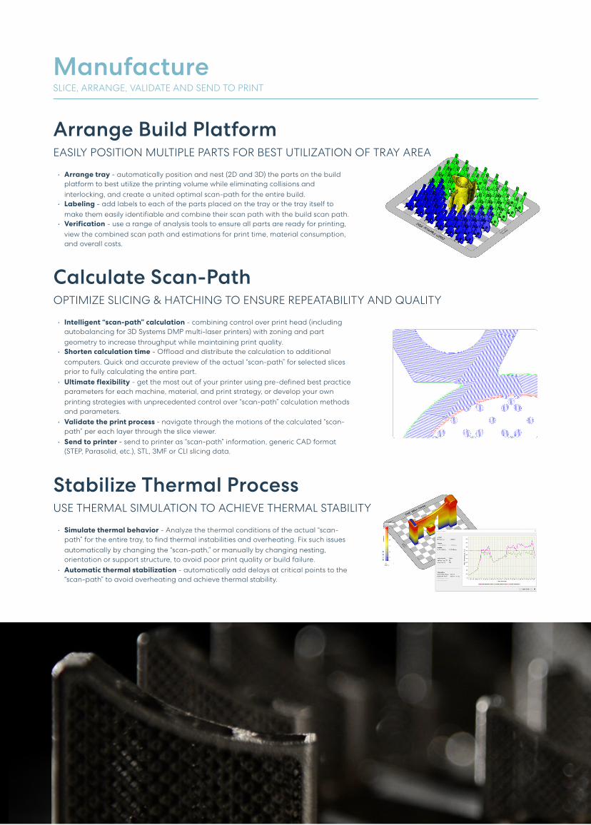
ManufactureSLICE, ARRANGE, VALIDATE AND SEND TO PRINT
Arrange Build PlatformEASILY POSITION MULTIPLE PARTS FOR BEST UTILIZATION OF TRAY AREA
W Arrange tray - automatically position and nest (2D and 3D) the parts on the build
platform to best utilize the printing volume while eliminating collisions and
interlocking, and create a united optimal scan-path for the entire buildL
W Labeling - add labels to each of the parts placed on the tray or the tray itself to
make them easily identifiable and combine their scan path with the build scan pathL
W Verification - use a range of analysis tools to ensure all parts are ready for printing,
view the combined scan path and estimations for print time, material consumption,
and overall costs.
Calculate Scan-PathOPTIMIZE SLICING & HATCHING TO ENSURE REPEATABILITY AND QUALITY
W Intelligent “scan-path” calculation - combining control over print head (including
autobalancing for 3D Systems DMP multi-laser printers) with zoning and part
geometry to increase throughput while maintaining print qualityL
W Shorten calculation time - Offload and distribute the calculation to additional
computers. Quick and accurate preview of the actual “scan-path” for selected slices
prior to fully calculating the entire partL
W Ultimate flexibility - get the most out of your printer using pre-defined best practice
parameters for each machine, material, and print strategy, or develop your own
printing strategies with unprecedented control over “scan-path” calculation methods
and parametersL
W Validate the print process - navigate through the motions of the calculated “scan-
path” per each layer through the slice viewerL
W Send to printer - send to printer as “scan-path” information, generic CAD format
(STEP, Parasolid, etc.), STL, 3MF or CLI slicing data.
Stabilize Thermal ProcessUSE THERMAL SIMULATION TO ACHIEVE THERMAL STABILITY
W Simulate thermal behavior - Analyze the thermal conditions of the actual “scan-
path” for the entire tray, to find thermal instabilities and overheating. Fix such issues
automatically by changing the “scan-path,” or manually by changing nesting,
orientation or support structure, to avoid poor print quality or build failureL
W Automatic thermal stabilization - automatically add delays at critical points to the
“scan-path” to avoid overheating and achieve thermal stability.

A New Additive Manufacturing Experience
T We reduced file processing times by up to 75% and increased productivity by up to 40%.
3DXpert also allows us to better analyze and plan the part, so we can use less supports
and less material which further reduces cost and time.
- Metal Technology Inc"
T With 3DXpert we didn’t just shift from using multiple software solutions into one, but we
completely changed and streamlined our entire workflow.
- Sharon Tuvia (1982) Ltd"
T 3DXpert is a game changer! Having full control over the printing parameters with the
ability to develop our own printing strategies, will take our productivity to a new level.
- Scarlett Inc"
T We chose 3D Systems because of its expertise in all - 3D ProMetal
CUT FILE PROCESSING
TIME BY UP TO
75%Increase in
Productivity
40%
From three differentsoftware systems to one
3 1
3DXpertXp
Get In TouchContact us for a demo at [email protected]
22V1 © 2022, Oqton