XP-Builder 3.40 - LS Electric
816
Human Machine Interface XP-Builder 3.40 XGT Panel
-
Upload
khangminh22 -
Category
Documents
-
view
0 -
download
0
Transcript of XP-Builder 3.40 - LS Electric

Human Machine Interface
XP-Builder 3.40
XGT Panel

Reviesion History
i
Revision History
Version Date Major Change Revised Page
V 1.30 ‘13.11 1st edition -
V 1.33 ‘15.08 Revised to version 1.33 Full revision
V 2.00 ‘15.12 Revised to version 2.00 Full revision
V 2.01 ‘17.01 Revised to version 2.01 Full revision
Add IPC Series Full revision
2.2.2.6 Resize font when it use Text Table if the width of rectangle is greater than the text width
P2-17
2.2.2.9 Don’t show communication error after it is closed
P2-22
2.2.2.12 wipe Settings P2-28
2.2.3.2 Check ‘Include Upload Project file’ on Project Download as Default
P2-31
2.3.10 Renaming a Tag to add as a New Tag
P2-80
V2.11 ’18.08 Window 10 home edition not supported Add iXP2 Series Add HDMI expanded Settings Add Resize font in case object region is larger than the text length while Text Table or Device Address Show is used Add Device type in Global Script Settings Add Screen change gesture option Add HDMI Screen Settings Add HDMI screen insert method Add HDMI Initial Screen Setting Method Add Don’t allow change this screen by gesture
Add Registering Figures/Objects Add Formatting Text in an Object/Objects Add Finding and Replacing All Fonts Add Execute Project at Local wXP Add Error Messages (2030 ~ 2037) Add _T500MS on/off system tag Add _Alarm_Norecovery_Device_Num, _Alarm_Norconfirm_Device_Num Add Extended File Recipe

Revision History
ii
Add Char. Spacing, Line Spacing Add Setting Device Size per Col. At Logging
viewer Add Fit to the max header length at
Logging viewer Add Gesture&Multi-Touch Add Caution
V2.20 ’19.04 Add iXP2H-07XXD Add details on the iXP2 HDMI Extension features Add password mode locked on screen feature when switching screen Add global external switcn feature Add description for the iXP2H-07XXD H/W KEY Add find/replace all fonts feature Add find/replace all strings feature Add details of how to used find/replace string from text table feature Add description for extended file recipe 1. File No./Name device 2. Block count device 3. Add data format setting description Word Lamp 1. Increased word lamp conditional statements up to 64 2. Add copy&paste feature 3. Add only caption continuous copy feature 4. Add copy only property feature Special Switch 1. Add multimedia special switch 2. Explorer and Editor: File Explorer – Add Write selected file name in to the device, Copy to specified path feature 3. Explorer and Editor: Add extended file Recipe explorer details.
4. Add password mode locked on screen. 5. Add multimedia on operation device 6. Add note for multimedia. Word Message 1. Add message number and text table number features. Realtime Scatter Graph 1. Add line type File Explorer 1. Add initial path 2. Add extended file recipe features.
P1-16, P2-3 P2-14 P2-17 P2-28 P2-94 P141 P142 P145
P4-58 P4-58 P4-58 P4-162 P4-162 P4-166 P4-166

Reviesion History
iii
Add multimedia object Add explorer gesture feature Add screen change gesture option.
V3.00 ’19.10 1. XP series not supported in V3.00 because of discontinued 2. Add font size unit feature 3. Add features about XP-Runtime 4. Add USB barcode feature 5. Add discontinued project conversion feature 6. Add keyboard input tags 7. Add create logging no. directory feature 8. Add delimiter feature 9. Add description on screen change switch 10. Add notes about appendix 5. 11. Add include path description 12. Add description of close window 13. Add scale type of device and constant 14. Add description on input max value 15. Add features of change status color 16. Add NC program monitor feature 17. Add Object Display Rule before Communication Connection
P1-12 P2-22 P2-28 P2-34 P2-188 P4-8 P4-24 P4-56 P4-197 P4-218 P4-225 P4-264, 4-294 P4-304 P4-403 App-40 App-70
V3.10 ’20.03 1. Image Update, words and misspeling correction 2. 2.2.2.9 Add Smooth edges of font feature 3. 2.2.2.10 Modified USB Barcode reader 4. 2.3.5.1 Improved obecject select feature 5. 2.6.6.7 Modified Viewing cross reference feature 6. 4.1.1 Add HS0503.1 VNC Server Control Tag 7. 4.1.2 Increased number of text table items 8. 4.1 Modified Common Data switch object display 9. 4.3.8.2 Add improvement of Pie graph feature 10. 4.3.22 Add FTP Client feature
V3.10 ’20.05 Revision due to the change of company name
V3.20 ’20.08 2.3.5.4 Multicopy: Add caption copy feature 4.1.3 Logging: Add CSV+PDF feature 4.3.4 Numeric/Text Display: Modified numeric display scaling feature Appendix 3: Add Autoscan feature
V3.40 ’21.02 Add eXP 2 series Add Time Synchronization Add Slider Control object Add space feature to switch/lamp object

Revision History
iv
Add number of decimal digts read from the device Add a feature to specify the text format of the numeric display from the text table Add selecting text format from the text table Add feature of setting global window position Improved project print Increased global script
V3.40, 2021.02

Table of Contents
v
Revision History .................................................................................... i 1. About XP-Builder ............................................................................ 1
1.1 Overview ....................................................................................................... 1
1.2 Installing and Updating ............................................................................... 3
1.3 Interface and Features ................................................................................ 5
Customizing Toolbars .................................................................... 9 Customizing Keyboard Shortcuts ................................................. 11 Customizing Menu Options.......................................................... 12 Customizing Pane Positions ........................................................ 12 Customizing Other Options.......................................................... 13
2. Project Development....................................................................... 1 2.1 Creating a project ........................................................................................ 1
2.2 Configuring Project Properties ................................................................... 7
Changing Basic Project Properties .............................................. 10 Changing XGT Panel Settings ...................................................... 11 Changing Screen Settings ........................................................... 14 Changing Security Settings ......................................................... 17 Changing Key Window Settings .................................................. 19 Changing Languages .................................................................. 20 Changing Storage Settings .......................................................... 24 Changing Global Script Settings .................................................. 26 Changing Extended Device Settings ........................................... 27 Changing Operation Log Settings .............................................. 32 wXP Settings ............................................................................. 36 Time Synchronization Settings .................................................. 37 Changing Auxiliary Settings ....................................................... 38
Changing default editing options ................................................. 42 Changing default project options ................................................. 43
2.3 Developing an Interface ............................................................................ 45
Opening or Closing a Screen ....................................................... 47 Setting a Screen as the Start Screen ........................................... 47 Renaming a Screen ..................................................................... 48 Changing Screen Properties ........................................................ 50

Table of Contents
vi
Drawing Figures .......................................................................... 53 Inserting Images from the Graphic Library ................................... 57 Drawing Objects .......................................................................... 58 Inserting Objects from the Object Library ..................................... 60
Selecting Objects ........................................................................ 62 Grouping and Ungrouping Objects .............................................. 64 Locking and Unlocking Objects ................................................... 65 Copying Multiple Objects ............................................................. 67 Arranging Objects ........................................................................ 70 Rotating Objects .......................................................................... 71 Resizing or Relocating Objects .................................................... 73 Setting Viewing Options .............................................................. 77 Registering Figures/Objects ........................................................ 83 Draw from Figure to Object ........................................................ 84 Deleting an Object/Objects ........................................................ 85 Undoing and Redoing a Change................................................ 86 Object & Text Format ................................................................. 86
Import Screen Dialog Box ............................................................ 93
2.4 Managing Libraries .................................................................................. 108
Creating a User Graphic Library ................................................. 110 Exporting a User Graphic Library ............................................... 113 Importing a User Graphic Library ................................................ 114 Editing a User Graphic Library .................................................... 116 Applying Options to the Images .................................................. 118
Creating a User Object Library ...................................................124 Exporting a User Object Library ..................................................126 Importing a User Object Library ..................................................128 Editing a User Object Library ......................................................130
2.5 Connecting Controllers ........................................................................... 132
Using RS232C............................................................................135 Using RS485/RS422 ..................................................................138
2.6 Simulating & Debugging ......................................................................... 141
Monitoring Devices .....................................................................144 Changing Device Values ............................................................145

Table of Contents
vii
Finding and Replacing Devices on the Active Screen .................151 Finding and Replacing All Devices..............................................152 Finding and Replacing All Fonts .................................................153 Finding & Replacing All Strings. ..................................................155 Finding and Replacing Devices, Fonts, and Tags from a List ......157 Viewing Cross-References .........................................................162 Viewing Cross-References .........................................................162
2.7 Running XP-Simulators with other PLC Simulators ............................. 163
2.8 Managing a Project .................................................................................. 179
Using a Serial (RS-232C) Connection ........................................185 Using an Ethernet Connection ....................................................186 Using a USB Connection (XP models)........................................188 Using a USB Connection (iXP/eXP/iXP2/eXP2 models) .............190
2.9 Configuring Advanced Communication Settings ................................. 202
Token Hold .................................................................................207 N:1 System Devices ...................................................................208
3. Error Messages ............................................................................... 1 3.1 Resolving Error Codes Found in the Results Pane .................................. 1 3.2 Resolving Error Messages in Pop-up Windows ........................................ 9
4. Reference ......................................................................................... 1 4.1 Common Data .............................................................................................. 1
Basic Recipes ............................................................................. 32 File Recipes ................................................................................ 43 Extended File Recipe .................................................................. 52

Table of Contents
viii
4.2 Scripts ........................................................................................................ 91
Understanding Script Commands ................................................ 93 Understanding Device Address Expressions .............................. 115 Understanding Constants and Data Types ................................. 116 Understanding Temporary Variables in a Script .......................... 119 Viewing the Script Cross Reference ...........................................121
Inserting Scripts ..........................................................................123 Using the Script Tool box ............................................................124 Specifying Local Scripts .............................................................125 Specifying Display Change Scripts .............................................127 Specifying Scheduler Scripts ......................................................128 Creating Object Scripts ...............................................................130 Editing Scripts ............................................................................131 Understanding Script Error Handling ..........................................133 Understanding the Script Watchdog Function .............................133
Understanding System Functions ...............................................134 Understanding Print Functions ...................................................135 Understanding Screen Change Functions ..................................135 Understanding Script Functions ..................................................136 Understanding String Functions .................................................137 Understanding Device Functions ................................................138 Understanding Communication Functions ..................................140 Understanding Memory Functions ..............................................142 Understanding Data Conversion Functions ................................144 Understanding Other Functions ................................................146
4.3 Objects ..................................................................................................... 148
Bit Lamp .....................................................................................150 Word Lamp .................................................................................157 N-State Lamp .............................................................................167
Bit Switch ...................................................................................174 Word Switch ...............................................................................182 Change Screen Switch ...............................................................193 Special Switch ............................................................................202 Multi Switch ................................................................................231
Bit Message ...............................................................................240 Word Message ...........................................................................245
Numeric Input .............................................................................255 Numeric Display .........................................................................275 Text Input ....................................................................................287 Text Display ................................................................................295

Table of Contents
ix
Bit Window .................................................................................301 Word Window .............................................................................304
Bit Part ....................................................................................... 311 Word Part ...................................................................................315
Bar Graph ...................................................................................325 Pie Graph ...................................................................................331 Meter Graph ...............................................................................338 Closed Graph .............................................................................343 Trend Graph ...............................................................................349 Logging Trend Graph..................................................................359 Scatter Graph – Logging Scatter ................................................372 Scatter Graph - Realtime Scatter ................................................380
4.4 Viewing or Changing XGT Panel Information ........................................ 454 4.5 Using the HTML Device Copier ............................................................... 457 4.6 Using the CSV Converter ........................................................................ 459 4.7 Managing External Storage Sources for Backup .................................. 460
File Path for Logging Backup ......................................................461 Path for Recipe Backup ..............................................................462 Path for Screen Backup ..............................................................462 Path for Memo Backup ...............................................................463
When there is Insufficient Memory or Exceeds the Limit .............464
5. Other features.................................................................................. 1 5.1 Gestures & Multi-Touch............................................................................... 1

Table of Contents
x
Appendix ............................................................................................... 1 1 Program Monitor ............................................................................................. 1
1.1.1 PLCs that Support Monitoring........................................................... 1 1.1.2 Properties by HMI devices ................................................................ 3 1.1.3 The Program Monitor Window .......................................................... 4
1.2.1 Monitoring Programs from the XGT Panel Menu .............................. 6 1.2.2 Monitoring Programs with a Special Switch Object ........................... 6 1.2.3 Selecting Programs to Monitor ......................................................... 7 1.2.4 Managing Programs ......................................................................... 9 1.2.5 Viewing the Monitoring Data ........................................................... 10 1.2.6 Changing the Display Format .......................................................... 11 1.2.7 Changing the Current Device Value ................................................ 12
1.3.1 Managing Devices .......................................................................... 15
1.4.1 Searching for Devices .................................................................... 19 1.4.2 Searching for Labels ...................................................................... 26 1.4.3 Searching for Sub-routines ............................................................. 27 1.4.4 Searching for Steps ........................................................................ 28 1.4.5 Searching with Touch ..................................................................... 30 1.4.6 Searching for Labels with Touch ..................................................... 30 1.4.7 Searching for Sub-routines with Touch ........................................... 33 1.4.8 Searching for Devices with Touch ................................................... 35
2 NC Program Monitor ..................................................................................... 40
2.3.1 NC monitoring program description ................................................ 43 2.3.2 User Device Setting ........................................................................ 44 2.3.3 NC file Management ....................................................................... 44 2.3.4 Import NC file ................................................................................. 46 2.3.5 Change View Mode ........................................................................ 47
2.4.1 Preparation ..................................................................................... 48 2.4.2 Overview ........................................................................................ 50
3 Autoscan ....................................................................................................... 52
3.1.1 Overview ........................................................................................ 52 3.1.2 Add special switch to operate Autoscan program............................ 53

Table of Contents
xi
3.3.1 Autoscan program menu ................................................................ 56 3.3.2 IP setting and monitoring period setting .......................................... 57 3.3.3 Save network status ....................................................................... 58 3.3.4 Slave Diagnostic............................................................................. 59 3.3.5 Goto Local ...................................................................................... 59 3.3.6 Compare ........................................................................................ 60 3.3.7 Cable Distance ............................................................................... 60 3.3.8 Monitoring ...................................................................................... 61 3.3.9 Remote module status information diagnostic ................................ 62
4 XP-VSP .......................................................................................................... 69
4.1.1 Overview ........................................................................................ 69 4.1.2 Supported PLC Drivers................................................................... 71
4.2.1 Installing XP-VSP ........................................................................... 72 4.2.2 Updating XP-VSP ........................................................................... 73
4.4.1 Registering Virtual Com Port .......................................................... 75 4.4.2 Connecting PLC and Ladder Program via Virtual Com Port ............ 78 4.4.3 Unregistering Virtual Com Port ....................................................... 79
5 wXP ................................................................................................................ 81
5.1.1 Requirements ................................................................................. 81
5.2.1 Project ............................................................................................ 82 5.2.2 Screen ............................................................................................ 83 5.2.3 Offline Setting ................................................................................. 83 5.2.4 Help................................................................................................ 85
6 Object Display Rule before Communication Connection ......................... 87 7 Glossary ........................................................................................................ 88 8 List of Acronyms .......................................................................................... 91 9 Caution .......................................................................................................... 93

1. About XP-Builder
1-1
1. About XP-Builder XP-Builder is software that allows you to create and manage projects for machine control devices. You can use XP-Builder to create projects for the XGT Panel. XP-Builder includes multiple features that allow you to design and edit projects conveniently, such as:
Customizable toolbars and hotkeys Customizable tool, project, and editing panes Functions to import and export common data Tabs for viewing multiple screens easily Previews of project screens Customizable image and object libraries Scripts and advanced functions, such as alarms, logs, schedules, and recipes Support for multiple languages
1.1 Overview This section describes the basic concept of using XP-Builder to create interfaces for machine control devices and the types of hardware that XP-Builder supports.
XP-Builder Concept XP-Builder is the starting point for creating human-machine interfaces (HMIs) for industrial applications. With XP-Builder, you can design user-friendly interfaces for XGT Panels that allow end users to control machine functions through configurable controllers, such as programmable logic controllers (PLCs), inverters, or servos.
With the XGT Panel, you can monitor information from each controller via a graphical user interface (GUI). In addition, simple control is possible with switch and writing objects. The XGT Panel supports additional programmable functions, such as scripts, loggings, recipes, and alarms, which allow you to fully customize the control environment.
As illustrated by the graphic that follows, the interface running on an XGT Panel provides input controls on the screen in the form of GUI objects that are linked to controller routines, such as a ladder program, or other parameters. The controller parameters dictate the operation of connected machinery and may also provide feedback to the XGT Panel.

1. About XP-Builder
1-2
Supported Hardware Types
XP-Builder supports XP, iXP, eXP and IPC series XGT Panels and a wide range of controllers. Projects can only be transferred from XP-Builder to XGT Panel. To view specifications for XGT Panels, in XP-Builder, click [PROJECT] ► [New Project], and then select a series and model number from the drop-down lists.
Note
• Available memory for XP series XGT Panels is 10 MB for TTA and BTA models, with the exception of the XP90 model (20 MB), and 4 MB for TTE and BTE models.
• 64 MB memory is available for eXP XGT Panels, and 128 MB for iXP/IPC series XGT Panels.
• XP Series is not supported on XP-Builder V3.00. If you want to use XP series, please use previous version of XP-Builder V3.00

1. About XP-Builder
1-3
1.2 Installing and Updating This section explains how to install and update the XP-Builder software, as well as the operating system software for an XGT Panel.
Installing XP-Builder You may install XP-Builder on a PC that meets the following minimum system requirements:
Processor: Pentium 4 or higher Memory: 512MB or more free memory COM Ports: RS-232C serial port, Ethernet port, or USB port Hard Disk: 1GB capacity or higher Monitor: Minimum resolution of 1024x768 OS: Windows Vista, Windows 7,Windows 8, or Windows 10 Peripherals: Mouse and keyboard
To install XP-Builder in Windows XP:
1 Run the XP-Builder setup file. You can download the file from the LS ELECTRIC website (https://www.ls-electric.com/support/download-center).
2 Select an installation language (Chinese [Simplified], English, Japanese or Korean).
3 Follow the instructions in the installation wizard to complete the installation.
To install XP-Builder in Windows Vista:
1 Log in to your computer with an administrator account.
2 On your computer, click [Start] ► [Control Panel] ► [User Accounts and Family Safety].
3 Click [User Accounts] ► [Turn User Account Control on or off], and uncheck the checkbox next to Use User Account Control (UAC) to help protect your computer.
4 Run the XP-Builder setup file. You can download the file from the LS ELECTRIC website (https://www.ls-electric.com/support/download-center).
5 Select an installation language (Chinese [Simplified], English, Japanese or Korean).
6 Follow the instructions in the installation wizard to complete the installation.

1. About XP-Builder
1-4
To install XP-Builder in Windows 7 or Windows 8:
1 Log in to your computer with an administrator account.
2 On your computer, click [Start] ► [Control Panel] ► [User Accounts and Family Safety].
3 Click [User Accounts] ► [Change User Account Control Settings], and drag the slider to never notify.
4 Run the XP-Builder setup file. You can download the file from the LS ELECTRIC website (https://www.ls-electric.com/support/download-center).
5 Select an installation language (Chinese [Simplified], English, Japanese or Korean).
6 Follow the instructions in the installation wizard to complete the installation.
To install XP-Builder in Windows 10:
1 Log in to your computer with an administrator account.
2 Run the XP-Builder setup file. You can download the file from the LS ELECTRIC website (https://www.ls-electric.com/support/download-center).
3 Select an installation language (Chinese [Simplified], English, or Korean).
4 Follow the instructions in the installation wizard to complete the installation.
Updating XP-Builder To check the version of your XP-Builder software, click [HELP] ► [About XP-Builder]. To update XP-Builder, refer to the LS ELECTRIC website (https://www.ls-electric.com/support/download-center).
Note You can update an XGT Panel automatically in XP-Builder version 1.30 or higher. If you use a version lower than 1.24, you must update the XGT Panel manually.

1. About XP-Builder
1-5
1.3 Interface and Features XP-Builder offers a wide range of customizable options that allow you to efficiently create and manage projects. This section describes the XP-Builder interface and explains how to customize it to suit your needs.
The XP-Builder Interface The XP-Builder interface is similar to that of many Windows-based programs. You can customize the interface by selecting various toolbar and window options, as described in <1.3.2 Controls and Options>.
Main Interface: Interface Description
Toolbars Use tools or menus to perform tasks and specify options.
Project/ Screen pane
The Project pane shows the elements contained in the project in a cascading tree, or shows the screens by screen type in a cascading tree. The Screen pane shows all the screens used included in the current project. You can add or edit each component from these panes.

1. About XP-Builder
1-6
Interface Description
<Project pane> <Screen pane> <Graphic Library pane> <Object Library pane>
You can open, reposition, or dock other windows, such as the Graphic Library, Object Library, Device Map, Script Toolbox, and Data Viewer windows. You can also select Data Viewer, Graphic library, and Object library from the VIEW menu to open them in the pane.
Editing area The center of the window, where you can add and manipulate objects, figures, and images to create an interface.
Toolbox Use the Toolbox to create, view and modify a project. Project Viewer and Screen Viewer are displayed by default when you first run the software. • By default, figures and objects are displayed in the pane as small images. To
view figures or objects in a tree type list, select [TOOLBOX] ► [Tree Type ToolBox] or select in the ToolBox pane.
• By default, figures and objects are set to Single Insert Mode, which allows you to insert one figure or object at a time. To insert figures or objects continuously, select [TOOLBOX] ► [Continuous Insert Mode] or select in the ToolBox pane.
Output and results tabs
These tabs allow you to view interface messages, error messages, and search results.
Status bar The status bar displays additional project-related information. Description A System message B Panel type C Controller type D Cursor position E Object position (top left) F Object size: Width/height G Caps lock/number lock/scroll lock status
Note Screens in XP-Builder Projects Screens contain objects and figures that XP-Builder provides. There are three different types of

1. About XP-Builder
1-7
screens available: • Base screens allow users to edit the objects and figures. Base screens have fixed screen sizes
and color specifications based on the panel types.
Panel type XGT Panel model names Screen size and color spec.
XP XP30-BTA 320 X 240 px, 8 Grayscale colors
XP30-TTA 320 X 240 px, 65,000 colors
XP30-BTE 320 X 240 px, 8 Grayscale colors
XP30-TTE 320 X 240 px, 256 colors
XP40-TTE 800 X 480 px, 65,536 colors
XP40-TTA 800 X 480 px, 65,536 colors
XP50-TTE 640 X 480 px, 256 colors
XP50-TTA 640 X 480 px, 65,000 colors
XP70-TTA 640 X 480 px, 65,000 colors
XP80-TTA 800 X 600 px, 65,000 colors
XP90-TTA 1024 X 768 px, 65,000 colors
iXP iXP50-TTA 800 X 600 px, 16.7M colors
iXP70-TTA 800 X 600 px, 16.7M colors
iXP80-TTA 800 X 600 px, 16.7M colors
iXP90-TTA 1024 X 768 px, 16.7M colors
iXP2
iXP2-0800 800 X 600 px, 16.7M colors
iXP2-1000 1024 X 768 px, 16.7M colors
iXP2-1200 1024 X 768 px, 16.7M colors
iXP2-1500 1024 X 768 px, 16.7M colors
iXP2H-0702D 1024 X 600 px, 16.7M colors
iXP2H-0704D 1024 X 600 px, 16.7M colors
eXP eXP20-TTA 480 X 272 px, 16.7M colors
eXP30-TTA 680 X 480 px, 65,536 colors
eXP30-TTE 680 X 480 px, 65,536 colors
eXP40-TTA 800 X 480 px, 16.7M colors
eXP40-TTE 800 X 480 px, 16.7M colors
eXP60-TTA 800 X 480 px, 65,536 colors
eXP2 eXP2-0400 480 X 272 px, 16.7M colors
eXP2-0500 640 X 480 px, 262,144 colors

1. About XP-Builder
1-8
eXP2-0502 640 X 480 px, 262,144 colors
eXP2-0700 800 X 480 px, 16.7M colors
eXP2-0701 800 X 480 px, 16.7M colors
eXP2-0702 800 X 480 px, 16.7M colors
eXP2-1000 1024 X 600 px, 16.7M colors
eXP2-1001 1024 X 600 px, 16.7M colors
IPC(wXP) AT/PC User-designated attribute (Width/Height: 200–3840) 16.7M colors
• Window screens are used for displaying Window screens over a Base screen. • Part screens are used as parts for Bit or Word Part objects.

1. About XP-Builder
1-9
Controls and Options Customize toolbars, keyboard shortcuts, menus, and other options in the XP-Builder interface.
Customizing Toolbars In the XP-Builder interface, you can create custom toolbars, add or remove icons on toolbars, and select which toolbars to show.
To create a toolbar:
1 Click [TOOL] ► [Customization] ► [Toolbars].
2 Click [New].

1. About XP-Builder
1-10
3 Enter a name for the toolbar and click [OK]. The new toolbar will be added to the list of available toolbars on the left of the Customize window. You can drag icons from the toolbars at the top of the XP-Builder window to the new toolbar.
To add or remove icons on toolbars:
1 Click [TOOL] ► [Customization] ► [Commands].
2 Click a tool category on the left, and then drag and drop a command onto an existing toolbar. Or, to remove an icon, drag it from a toolbar to the Customize window.

1. About XP-Builder
1-11
To select which toolbars to show:
1 Click [TOOL] ► [Customization] ► [Toolbars].
2 Check the checkboxes to the left of the toolbars to select which to show (checked) and which to hide (unchecked).
Customizing Keyboard Shortcuts
To customize keyboard shortcuts (hotkeys):
1 Click [TOOL] ► [Customization] ► [Keyboard].
2 Click a tool category from the drop-down list, and then click a command.
3 Click the Press New Shortcut field and then press a key combination on the keyboard. If you press a combination that is already in use, the action that is assigned to the shortcut will appear below this field.

1. About XP-Builder
1-12
4 Click [Assign].
5 To remove a shortcut, select one from the Current field and then click [Remove].
6 When you are finished customizing keyboard shortcuts, click [Close].
Customizing Menu Options In the Customize window, you can select which Application Frame windows and Context menus to show. To customize menu options, click [TOOL] ► [Customization] ► [Menu], and then select the desired options from the drop-down menus.
Customizing Pane Positions To view or hide panes, click [VIEW], and then click the name of a pane. You can drag and drop panes in new positions within the XP-Builder window. To change the properties of a pane, right-click the pane and click an option. You can set panes to dock or float, and set whether or not the pane will hide automatically.
To dock the pane, move the pane to the desired location indicator. A shadow will appear to provide a preview of the docking location. To set a pane to float, on the pane, click ► [Floating]. To hide a pane, on the pane, click .
1. About XP-Builder
1-13
Customizing Other Options In the Customize window, you can customize additional options, such as whether or not to show tooltips and show shortcuts with tips. To customize these options, click [TOOL] ► [Customization] ► [Options], and then check the checkboxes next to the desired options.

2. Project Development
2-1
2. Project Development XP-Builder allows you to develop complex but simple-to-use interfaces for controlling machines. You can add figures, objects, and graphics to represent functions, or use scripts to define processes. XP-Builder also allows you to simulate projects and debug them before transferring them to an XGT Panel.
2.1 Creating a project Learn how to start or open a project.
Starting a New Project
To create a new project:
1 When you launch XP-Builder, the Select Project window appears. Click [Create Project] to create a project.
To open a saved file, select [Open Project]. To enable the Select Project window to appear every time you launch XP-Builder, check the
checkbox next to Show this Dialog at Startup. You can also create a file by selecting [PROJECT] ► [New Project].
Note
• XP-Builder supports multiple instances of the software running simultaneously. Users can run more than one XP-builder window on a PC to edit projects more efficiently.
• If you try to save a read-only project file, XP-builder displays the error message below.
• If you try to open a project file that is already open in another editor, XP-builder displays
the error message below.
2. Project Development
2-2
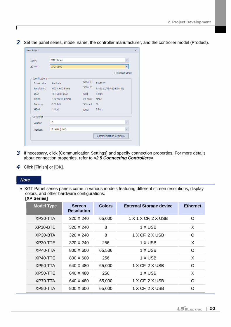
2 Set the panel series, model name, the controller manufacturer, and the controller model (Product).
3 If necessary, click [Communication Settings] and specify connection properties. For more details about connection properties, refer to <2.5 Connecting Controllers>.
4 Click [Finish] or [OK].
Note
• XGT Panel series panels come in various models featuring different screen resolutions, display colors, and other hardware configurations. [XP Series]
Model Type Screen Resolution
Colors External Storage device Ethernet
XP30-TTA 320 X 240 65,000 1 X 1 X CF, 2 X USB O
XP30-BTE 320 X 240 8 1 X USB X
XP30-BTA 320 X 240 8 1 X CF, 2 X USB O
XP30-TTE 320 X 240 256 1 X USB X
XP40-TTA 800 X 600 65,536 1 X USB O
XP40-TTE 800 X 600 256 1 X USB X
XP50-TTA 640 X 480 65,000 1 X CF, 2 X USB O
XP50-TTE 640 X 480 256 1 X USB X
XP70-TTA 640 X 480 65,000 1 X CF, 2 X USB O
XP80-TTA 800 X 600 65,000 1 X CF, 2 X USB O

2. Project Development
2-3
XP90-TTA 1024 X 768 65,000 1 X CF, 2 X USB O
[iXP Series]
Model Type Screen Resolution
Colors External Storage device Ethernet
iXP50-TTA 800 X 600 65,536 3 X USB, 1 X SD card slot O
iXP70-TTA 800 X 600 65,536 3 X USB, 1 X SD card slot O
iXP80-TTA 800 X 600 65,536 3 X USB, 1 X SD card slot O
iXP90-TTA 1024 X 768 65,536 3 X USB, 1 X SD card slot O
[iXP2 Series
Model Type Screen Resolution
Colors External Storage device Ethernet
iXP2-0800 800 X 600 16.7M 3 X USB, 1 X SD O
iXP2-1000 1024 X 768 16.7M 3 X USB, 1 X SD O
iXP2-1200 1024 X 768 16.7M 3 X USB, 1 X SD O
iXP2-1500 1024 X 768 16.7M 3 X USB, 1 X SD O
iXP2H-0702D 1024 X 600 16.7M 1 X USB, 1 X SD O
iXP2H-0704D 1024 X 600 16.7M 1 X USB, 1 X SD O
[eXP Series]
Model Type Screen Resolution
Colors External Storage device Ethernet
eXP20-TTA 480 X 272 16.7M 1 X USB O
eXP30-TTA 680 X 480 65,536 1 X USB O
eXP30-TTE 680 X480 65,536 1 X USB X
eXP40-TTA 800 X 480 16.7M 1 X USB O
eXP40-TTE 800 X 480 16.7M 1 X USB X
eXP60-TTA 800 X 480 65,536 1 X USB O

2. Project Development
2-4
[eXP2 Series]
Model Type Screen Resolution
Colors External Storage device Ethernet
eXP2-0400 480 X 272 16.7M 1 X USB O
eXP2-0500 640 X 480 65,536 1 X USB O
eXP2-0502 640 X 480 65,536 1 X USB X
eXP2-0700 800 X 480 16.7M 1 X USB O
eXP2-0701 800 X 480 16.7M 1 X USB, 1 X MircoSD O
eXP2-0702 800 X 480 16.7M 1 X USB X
eXP2-1000 1024 X 600 16.7M 1 X USB O
eXP2-1001 1024 X 600 16.7M 1 X USB, 1 X MircoSD O
[IPC Series]
Model Type Screen Resolution
Colors External Storage device Ethernet
PC/AT Customizable 16.7M Varies by PC O • IPC can set any value in resolution.
For example, 800x600, 1024x760, and so one. You can set the resolution from 200x200 to 3840x3840.
• XP-Builder allows model type changes to other panel models with the same or higher color
specifications. However, XP-Builder does not allow project conversion from color to monochrome XGT Panels, or vice versa.
• BTE and TTE type models support only BMP, GIF, JPG, and WMF image file formats. Run a data check to ensure that only the supported image types are used in a project.
• You can view a summary of XGT Panel specifications when you create a project by selecting the XGT Panel series and model.

2. Project Development
2-5
• If the computer or panel you are working with does not have the desired font installed, text information,
such as captions for objects or figures may not be displayed properly. To solve this problem, install or export fonts as needed: click [TOOL] ► [Install Font] or [Export Font], specify a file location, and click [OK].
• Project files in XP-Builder are saved with the extension “.xpd.” You can only import these types of
project files to XP-Builder. • The file extension for the user object library is “.xpo.” • The file extension for the user graphic library is “.xpg.” • The extensions for exported files (backup files) are shown in the following table:
Item File Extension Text table, Recipe, and Tag *.CSV
History alarm *.HAL Flow alarm *.FAL
Logging *.LOG Schedule *.SCH
Script *.SPT

2. Project Development
2-6
Saving a Project
To save a project:
1 Click [PROJECT] ► [Save Project].
You can also select the save project icon from the toolbar. To save the file with another name, select [PROJECT] ► [Save As Project]
2 Select a destination for the saved file, enter a file name, and then click [Save].
3 To close the project, click [PROJECT] ► [Close Project].
Note
• When you save a project, two other files are created: - Backup file: The extensions for the backup files are “.bak” and “.bak1–bak9.” - OSTS file: The extension for the OSTS file is “.OSTS.” This file includes information about your
project workspace, such as the current screen, docked windows, and toolbar information. • When your project contains unsaved changes, the Project pane shows an asterisk (*) next to the
project name.

2. Project Development
2-7
2.2 Configuring Project Properties Set the properties or parameters of the project file. Specify properties for connecting with XGT Panels, screen settings, security levels, languages, and more.
Protecting the Project with a Password You can prevent others from opening a project by setting a password.
To set a password:
1 Click [PROJECT] ► [Project Password].
2 Enter a password and re-enter it to confirm.
3 Click [Apply].
Note
• XP-Builder supports only Latin characters in passwords. Passwords are case sensitive and can be up to 12 characters long.
• Be careful not to forget the password. If you forget the password, you cannot open the project file.
To change a password:

2. Project Development
2-8
1 Click [PROJECT] ► [Project Password].
2 Enter the current password in the Old Password field.
3 Enter a new password in the New Password field and re-enter it to confirm.
4 Click [Apply].
To delete a password:
1 Click [PROJECT] ► [Project Password].
2 Enter the current password in the Old Password field.
3 Click [Delete].

2. Project Development
2-9
Viewing and Editing Properties XP-Builder allows you to view and edit general properties of projects. To view or edit project properties, click [COMMON] ► [Project Property Setting]. From the Project Property window, you can view or edit the following properties:
Tab Description
Project Summary Basic information of the project file, such as the project name and author
XGT Panel Settings XGT Panel information and communication methods
Screen Settings Screen change options
Security Settings Permissions for connected XGT Panels
Key Window Settings Settings for key windows
Language Options for editing language and runtime language
Storage Settings Destination and backup locations of project components and XGT Panel data
Global Script Settings Options to apply to global scripts
Extended Device Settings Settings for printers and barcode readers
Operation Log Settings for saving logs of user operations
wXP Settings Settings for the IPC series panels.
Time synchronization Settings for the time synchronization of XGT Panel
Auxiliary Settings Options for printing, capturing screens, displaying flow alarms, sending email alerts, displaying system alarms, and displaying communication errors

2. Project Development
2-10
Changing Basic Project Properties The Project Summary tab in the Project Property window contains basic information, such as the project name, file path, author, creation date, modification date, last download date, version, and project description. To change basic project properties, edit the information in the appropriate field and click [OK].
Item Description
Project Name The project name does not have to match the file name. The file name you specify will appear at the top of the project or screen tree in the Project/Screen pane.
File Path The location of the project file (this cannot be edited)
Author The creator of the file
Description A description of the project
Created The date the file was first created (this cannot be edited)
Modified The date the file was last modified (this cannot be edited)
Downloaded The date the project was last downloaded to an XGT Panel (this cannot be edited)
Version The version of the XP-Builder software (you can change this information to create a unique identifier for customized properties)

2. Project Development
2-11
Changing XGT Panel Settings Edit the XGT Panel and model type. You can also set the connection method settings for connecting to controllers. The options vary by the connection method. To change XGT Panel settings, edit the information in the appropriate field and click [OK]:
XGT Panel Settings Description
Series Select an XGT Panel type. The initial information is the same as you selected when you created the project. Refer to the hardware manual for detailed specifications.
Model Select a model number based on the XGT Panel type you selected.
24 BIT Color Mode This mode is supported only by the iXP series. Select this option to use 24-bit color instead of the default setting (65,536 colors). The use of 24-bit mode improves the appearance of images on the screen, but may result in slower screen refresh speeds.
Portrait Mode (Available in iXP Series and eXP20, eXP2 Series, iXP2 Series Panels only)
Select this option to use the XGT Panel in portrait. If you have already created the XGT Panel in landscape and select the Portrait mode, the figures and objects may be resized or positioned outside of the screen. The user downloads the project to the HMI and when it is different between current state and before state (Landscape mode/ portrait mode), your device will reboot. The setting is applied immediately. Refer to the hardware manual for installation precautions.
RS-232C 5V Power Supply This mode is supported only by the iXP series. Select this option to use the RS232C connection (5 V, 250 mA) as the power supply.
Add Controller & Delete Controller
You can connect controllers with multiple protocols, including RS232C, RS422/485, or Ethernet.

2. Project Development
2-12
XGT Panel Settings Description
• Click [Add Controller] to insert a new controller tab. The connection number for the new controller will automatically be one higher than the previous controller’s connection number. XP series panels support up to four connection numbers (0-3) and the eXP/iXP/iXP2/IPC series support up to 16 connection numbers, depending on the connection protocol you use. For more information, refer to <2.9.1 Using 1:N Communication with Multiple Protocols>
• Click a controller tab and then click [Delete Controller] to delete it. This option is active only after you have added at least one controller.
• Connection numbers are automatically renumbered when a controller is deleted. For example, if you have three controllers (numbered 0-2) and you delete controller 1, the last controller will be renumbered from 2 to 1 automatically.
• The IPC series does not support serial controllers or serial drivers.
Controller Settings Set the controller manufacturer and controller type (Product).
Refer to Manual Click to open the reference manual for the selected controller.
Protocol Set the connection method between the XGT Panel and the controller. Ensure that the setting matches the actual connection between the XGT Panel and the controller.
Serial Port This option can be selected for serial communication connections. Port selection is not required if the model has only one available port. If there are multiple ports, check the port name on the XGT Panel port and set the port number.
Detail Settings Click to set detailed connection parameters. If a controller is selected, the default properties will be set automatically. The options available vary by the connection type.
Timeout Set a network timeout.
Wait to Send Set the length of time to wait for network communication between the XGT Panel and the controller.
Retry Count Set the number of times to retry when communication fails between the XGT Panel and the controller.
Use PLC Simulator Set whether or not to use the simulator. To run the simulator, click [TOOL] ► [Simulation]. For more information, refer to <2.6.1 Simulating an Interface>.
Program Monitor Set whether or not to view controller data with the Program Monitor. This feature is supported by all XGK series PLCs and some XGB series PLCs only. For more information about using the Program Monitor, refer to the <Program Monitor> section of the Appendix. This feature is not supported by the IPC series.

2. Project Development
2-13
Note
• You can change the XGT Panel type to another type which supports the mode selected in the XGT Property.
• When changing the XGT Panel type, the height and width of objects on the screen may vary depending on the screen size. Objects with fixed sizes and fonts are not affected by changes of the panel type.
• If you transfer projects composed in 65,535 colors to XGT panels that support only 256 colors, the color of objects and figures may slightly vary. Color palettes are automatically adjusted and the objects and figures are displayed using the nearest colors to the original.
• Projects developed for color XGT Panels cannot be used in monochrome XGT Panels, and vice versa.

2. Project Development
2-14
Changing Screen Settings
You can specify the startup screen that appears when an XGT Panel is turned on and the conditions for changing the screens. To change screen settings, edit the information in the appropriate field and click [OK]:
Screen Settings Description
Initial Screen Number Set the number of the screen that appears when the XGT Panel is turned on. If no screen is specified, an error will occur. To specify the start screen, click [Browse] ► select a screen, and then click ► [OK].
Change Screen by Device Set whether or not to switch base screens based on the device value.
Change to Screen Number Set the device to switch to a specified screen. When the device value changes, the screen specified by the device value will be activated (unsigned, 16-bit).
Current Screen Number Set a number for the current base screen.
Global Window 1 Number Global Window 2 Number
Specify one or two windows that will be activated “globally” (across the entire interface) based on the device value. Windows specified here are called based on the specified device values and have no priority over each other.

2. Project Development
2-15
Screen Settings Description - Use User Window Position: The user can directly designate the location of the global window.
HDMI Setting When connecting the HMI with HDMI on multiple monitors, HDMI screens can be monitored with Cloning and Expanding through the HMI. When accessing Cloning and Expanding on HMI devices, please refer to Manual 5.1.4 Environment Settings
Clone When in Clone mode, the HMI screen can be monitored via HDMI screen.
Extension When in Expand mode, connect display via HMI and HDMI to show HDMI screens setup by XP-Builder. You can set up to 1- 4 HDMI monitors depending on the model. For more information about forming HDMI screens, refer to <2.3 Developing an Interface>.
Expanded Properties : Initial HDMI screen
Select a starting HDMI screen number to monitor. Numbers between 1 through 65534 can be selected.
Expanded Properties : Change to screen number
Designate a screen transition device for HDMI screen monitoring.
Expanded Properties : Current screen number
Designate the screen device to monitor with HDMI screen monitoring.
Expanded Properties : Screen Resolution
Choose screen resolution for HDMI screens.
HDMI Screen Output Use If [HDMI Screen Output Use] is disabled, connected HDMI cables will not display screens. This will be enabled by default.
Monitor Resolution You can select a resolution for HMI connected display monitors. This can only be selected by devices that support this feature.
Note
• HDMI Screen settings can only be selected by devices that support HDMI feature .

2. Project Development
2-16
• In portrait mode, it is impossible to set the mode to HDMI extension. • If the project is changed from Extended mode to Clone mode or the HDMI function is not supported,
the HDMI screen will be deleted, so must be taken caution • When changing the resolution, care must be taken as it affects the resolution of existing HDMI
screens.

2. Project Development
2-17
Changing Security Settings You can change security settings for a connected XGT Panel to regulate access for different types of users. XGT Panels support ten security levels (0 or not set: no access restriction, 9: highest security level). In the Security Settings, it can be set to unset or level 1~9. In the object, you can set the security level to restrict access to individual objects. Higher-level security can unsecure lower-level security. Lower-level security cannot unsecure higher-level security.
Security Settings Description
Password Mode Set to protect a panel with a password. Enter the passwords in the Password field for the corresponding security level.
Password Device Mode
Set to use a word device to control access to the XGT Panel. Authentication is initiated by user input, but the data contained in the first six word devices specifies the password.

2. Project Development
2-18
Security Settings Description
User ID Mode Set a user ID and a password to access the panel. The user ID character string can have a maximum of 16 characters. Only alphanumeric and special characters can be used for the password or user ID. A password must be entered after the user ID is entered.
[User ID Mode Input Sequence] (1) Select [User ID mode]. (2) Input the ID in the [User ID] column. (3) Select a level between 1 and 9. (4) Input the password.
Security Level Set passwords for security levels as desired. Level 0 allows access for all users, so it is not possible to specify a password (only levels 1-9 are configurable). After entering a password for a certain security level, you automatically gain access to all the objects with lower security levels.
Password Set a password. XP-Builder supports only Latin characters in passwords. Passwords are case sensitive and can be up to 12 characters long.
Password Device Set a word device to control access to the XGT Panel. Enter a device address or click the field, and then click the keypad icon on the right side of the field to specify a device address.
Password Input Interval(min)
• Set the length of time to grant access after entering the password. The permission will expire based on your setting and will require the password to be re-entered. The default unit is minutes and you can set an interval from 0 to 30 minutes.
• If you set the interval to “0,” a password must be entered for every operation where a security level is applied.
• Use shorter intervals for highly sensitive operations.
Password mode locked on screen
When the item is checked, the password mode is locked regardless of the security level retention time even when the screen is changed, Therefore, you must disable the security by entering the password in the protected object to disable security for use. For more information, refer to the security mode locking function of the special switch.
Note You can apply security settings to the following objects: bit switch, word switch, change screen switch, special switch, multi switch, numeric input, and text input.

2. Project Development
2-19
Changing Key Window Settings You can set the key window number for input devices. The key window set here is applied as the default for all key windows. To change key window settings, click the arrow buttons ( or ) to select a new window number, or click [Browse] and then click a key window type.

2. Project Development
2-20
Changing Languages The following language types are used in a project to display different information.
Language types Description
Editing language Editing language is the language that users can configure and use to create multilingual text tables. You can choose different fonts to add entries in different languages. The fonts for editing languages are included in the project, but are not transmitted to the XGT panel.
Runtime language Runtime language is the language that is downloaded to the XGT panel. The runtime language fonts are transmitted to the XGT panel as TTF (true-type font) files. In the Project Property settings, you can select up to 12 different runtime languages.
From the Language tab, you can edit both editing and runtime language settings. To change language settings, edit the information in the appropriate field and click [OK]:
Language Settings Description
Editing Language • Set the languages used in XP-builder. • Languages shown in text tables are set here.
Add New Click to add additional display languages to the interface. Select a

2. Project Development
2-21
Language Settings Description language from the list and then click [OK] to add it to the Editing Language List.
Delete Select a language, and then click to remove it.
Editing Languages Settings
Change the default font for each editing language.
Runtime Language List View and specify runtime languages to use with the project. You can
modify the font list by adding fonts from a list of editing fonts or deleting them.
Multilingual Font
• Set a font to transfer with the project file. This function is useful when
the XGT Panel does not support Asian characters, such as in the case of XP series panels that run the Windows CE operating system.
• If you select this option, the entire font will be transferred to the panel. Ensure that the size of the font file does not exceed the available memory of the XGT panel model.
• Multilingual fonts are also used for table headers in text input, text display and logging backup CSV files. Refer to <4.3.4.4 Text Display>.
Language Change by Device
Set the runtime language to change for specific devices. The XGT Panel reads the value from the device and displays the interface in the

2. Project Development
2-22
Language Settings Description language you specify in the Runtime Language List.
Device Select a word device (language change device).
Default Runtime Language Set the runtime language that will be used by default on the XGT Panel.
XGT Panel The language for the XGT Panel menu screen is selected. The default language is English. In the IPC series, the menu screen language depends on the setup file languages.
Resize Font The length of an object’s character string, calculated from the character string table, will vary based on the language. If the length of the character string is larger than the width of the object, the font size of the character string is automatically reduced when displayed. The minimum font size is 9.
Resize font in case object region is larger than the text length while Text Table or Device Address Show is used
This feature applies to objects that use text tables, or to the device addresses of text display objects. When the language is changed, if the length of the character string is larger than the width of the object, the font size of the text or address is automatically reduced when it is displayed. (The minimum font size is 9.)
Internal Device Skip on Device Address show
This function excludes internal devices when displaying device addresses in an object. If this option is checked, the address is not displayed in the text indicator in which [Bit Device Address] or [Word Device Address] is set. Refer to <4.3.4.4 Text Display> for detailed information.
Font Size Unit In general, when displaying the font size, it can be displayed in pixel units and point units. Set the font size unit to be displayed. In the case of MS S/W (MS Word, MS Excel, etc.), the font size is displayed in point unit. In case of XP-Builder, the unit is displayed in pixel as default. Even with the same font size, the font size displayed may vary depending on the display units. For example, the same [Sample] letter as shown in the table below is 16px for pixel units, but 12pt for point units.

2. Project Development
2-23
Language Settings Description
Note
• The font used in a text table is set by the default settings of the editing language. Text may not be displayed properly if the text of a text table cannot be represented by the default font.
• If you set the language to change by device, you must designate a language for the device or nothing will be shown in the XGT Panel. Refer to <2.2.2.6 Changing Languages> for detailed information.

2. Project Development
2-24
Changing Storage Settings Set the storage locations for image and font files, as well as the locations for backing up logging data recipes and screen captures from an XGT Panel.
Storage Settings Description
Image Files XGT Panel has a fixed amount of memory for saving project files. If you want to download XGT Panel data that exceeds the size of the allocated memory, you can save files on removable media. Use the entire path to specify the storage file path on the XGT Panel. In the IPC series, only a flash memory drive or hard disk drive can be used for storing the data.
Upload Project File Sound Files Recipe Data
Specify locations where files will be stored. In the IPC series, only a flash memory drive or hard disk drive can be used for storing the data.
Alarm Data Logging Data Recipe Data Capture Image Memo File Operation Log
Specify an external location where the data will be saved.
Delete Old File If Disk Select this option to overwrite existing data if the disk is full. The oldest data

2. Project Development
2-25
Storage Settings Description is Full will be deleted.
Create Directory Backup data such as alarm, logging, and recipe are backed up with a unique folder name. If you uncheck “Create Directory”, you can back up files to the root of the backup directory without creating a unique folder. Note that only one of the backup items such as alarm, logging, or recipe can be unchecked “Create Directory”.
Note
• XGT Panels support three types of removable storage devices: USB devices, CF cards, and SD cards (Only supported in the iXP/IPC series).
• X30-BTE, XP30-TTE, XP40-TTE, XP40-TTA, XP50-TTE, iXP, iXP2, eXP, eXP2 models do not support CF cards.

2. Project Development
2-26
Changing Global Script Settings Global script conditions are monitored through an XGT Panel and executed if the conditions are met. Up to 32 global scripts can be created. If two or more conditions are met simultaneously, scripts are executed based on the priority that you specify.
Global Script Settings Description
Name Set a script name.
Device Set a bit device that meets the conditions required to execute the script.
Type Choose a trigger type for executing the script (Rising edge or Falling Edge).
Second Only available when scripts are repeated regularly, and will set the interval to seconds.
Insert, Delete, Modify Click to insert, delete, or modify global scripts.
Up Down
Specify the execution priority for when two or more conditions are met simultaneously.

2. Project Development
2-27
Changing Extended Device Settings
You can connect a barcode reader to an XGT Panel’s RS-232C port (COM2) and use printer functions.
From the Project Property window, you can view or edit the following properties of a barcode reader that is connected to an XGT Panel:
Item Description
Barcode Settings Set to connect barcode reader to XGT Panel.
Connection Property Set to use the barcode through the RS-232C / USB protocol.
tail Settings Set detail connection options: • Bytes to read: Set the amount of data to read from a barcode. If you
set the number of bytes, the XGT Panel reads only the specified number of bytes. If you do not specify this setting, the XGT Panel reads the entire barcode.
• Save data in: Set a location for saving barcode data. Data is saved from the specified device continuously.
• Data storage: Enter the first device to receive data from the barcode. • Read complete device: Assign a bit device to set when all data has
been read. • Set the RS-232C communication parameter, such as the baud rate,

2. Project Development
2-28
Item Description data bits, and flow control.
• COM port: Set the communication port. This setting is supported by the IPC series only.
Note
The baud rate must match the setting in the XGT Panel. To change the baud rate on the XGT Panel, tap and hold the screen to access the menu. Then, tap [Setting] ► [PC Conn Setting].
Note
• For USB barcode, don’t need to set connection options depending on the usage environment. (See how to use the USB barcode reader at the bottom)
• For USB barcode, input value of USB is saved in [Data Storage] only when the connection option is set and the HS501.2 device is ON.
• After the waiting time for the barcode input, the input is saved after initializing the [Data Storage] value.
Use Printer Set to use the printer option. The IPC series does not support printing.
Vendor Select a vendor for the printer type.
Port Select the printer port.
Direction Set the directions.
Color Set the color type.
High Quality Print Set the properties for printing quality.
External Object Setting It can be set only in handy model (e.g. iXP2H). This is the setting for the globally operable HW key for the handy. For information on setting the Handy HW key that can operate on the local screen within on screen, refer to <2.3.11 Setting HW Key for Handy on screen>. When you press the button, the following dialog box appear. You can set external lamp or external multiple switch. For details, refer to the corresponding object or HW manual.

2. Project Development
2-29
Item Description
To connect a barcode reader:
1 Select [COMMON] ► [Project Property Setting] ► [Extended Device Settings].
2 Check the checkbox next to Barcode settings.
3 Click [Detail Settings] and specify the following settings:
To connect a USB barcode reader:
4 Select [COMMON] ► [Project Property Setting] ► [Extended Device Settings].
5 Check the checkbox next to Barcode settings and select USB.
6 Click [Detail Settings] and specify the following settings:

2. Project Development
2-30
The method of USB barcode reader:
1 In case of the text input or numeric input is in the input state as in the above screen (1)
Even without [Detail Settings] setting, the information of the entered barcode is saved in the device of the corresponding input device.

2. Project Development
2-31
If [Detail Settings] is set and the internal device HS0501.2 is ON, it is simultaneously saved to the device set in [Data Storage].
2 In case of the text input or numeric input is not in the input state as in the above screen (2)
In this case, set as USB after checking [Barcode Settings] on [Project Property] – [Extended Device Settings]
Set [Data Storage] in the [Detail Settings]
In case of the internal device HS0501.2 is ON: The entered barcode value is saved in [Data Storage]. For example, in the above screen, press the switch of HS0501.2 to turn it On, and then enter the input barcode value.
In case of the internal device HS0501.2 is OFF: Input is not possible. To receive input data while maintaining the OFF state, make an input state as (1) and scan it.
3 Utilization of waiting time for barcode input
Input within the barcode waiting time (unit ms) is continuously stored in [Data Storage].
Since [Barcode input initialize time] is 1000ms on the above screen, all inputs within 1000ms interval are entered in [Data Storage].
If barcodes are scanned continuously within 1000ms, they are recognized as one barcode and all are saved. If the interval between consecutive scans is 1000ms or more, it is entered after initializing the [Data Storage].
The time can be adjusted with the internal device (HS0507) in addition to [Detail Settings].

2. Project Development
2-32
Changing Operation Log Settings
You can use the Operation Log function to record the operations on the XGT panel. This function enables you to check which operation was performed, and when or where it was performed. With this function, you can analyze the causes of errors or other problems from the recorded log.
Item Description
Operation Log Enable Set whether or not to use the Operation Log function.
Operation Log Condition Set when to record logs. • Continuous: Logs are recorded continuously. • On Bit 'ON': Logs are recorded when a bit device is set to ON.
Status Device Set a word device to control log recording.
NVRAM DEL Device Set a device to delete the operation log area of the NVRAM.
Operation On NVRAM Full Set the action that occurs when the NVRAM is full. • Stop: Logs will not be recorded if the NVRAM is full. • Use Ring Buffer: If the NVRAM is full, the oldest record will be
deleted and logs will be recorded accordingly.
User String Device Set a word device to control user strings. A maximum of 16 bytes can be recorded.

2. Project Development
2-33
Item Description
Operation Log List Select which operations will be recorded.
Backup Device Set a device to store the operation log.
Automatic Backup on NVRAM Full
Set whether or not to execute backup automatically when the NVRAM is full.
Backup File Name Device Set a device to store the names of backup files. A maximum of 8 bytes can be stored.
Append Backup Content at Same File
Set whether or not to append another backup set to the existing backup file. If this option is checked, the previous contents of the backup file remain intact, and the new backup will be written after the end of the last backup. A maximum of 1024 backup records can be stored in a single file. If this option is not checked, the new backup will be saved as a new file.
Backup File (CSV) Encoding Set whether or not to encode a backup file (CSV or Encrypted CSV file).
Date/Time Set the date or time format to use for a backup file.
Note
• The Operation Log function is available on iXP/iXP2/IPC series panels only. (XP is only
available in V2.20) • The following diagram briefly explains how an operation log is recorded.

2. Project Development
2-34
• Describes the value information for the state device.
16bit Lower Byte
Off(0) On(1)
Bit 0 End of Progress Proceeding

2. Project Development
2-35
Bit 1 Backup device is inserted backup device is not inserted
Bit 2 Log SRAM area write failed Log SRAM area write successful
Bit 3 There is free space in the log SRAM area.
The log SRAM area is full
Bit 4 Clear log SRAM area Completion of clear of log SRAM area
Bit 5 Failed to write log backup Log backup successful
Bit 6 There is free space in the write log area.
The log write area is full.
Bit 7 Clear a log backup Log Backup Delete Complete
• Maximum per device.
Maximum number of
backups
XP General 490
iXP/iXP2/IPC 983

2. Project Development
2-36
wXP Settings
Set the wXP drive path for the CF/USB/SD memory you selected in the storage settings. This feature is supported by the IPC series only.
Item Description Backup Path Setting: CF Card
Set the wXP hard disk drive path to store backup files when you have selected ‘CF Card’ as the storage device.
Backup Path Setting: USB Storage
Set the wXP hard disk drive path to store backup files when you have selected ‘USB Storage’ as the storage device.
Backup Path Setting: SD Card
Set the wXP hard disk drive path to store backup files when you have selected ‘SD Card’ as the storage device.

2. Project Development
2-37
Time Synchronization Settings You can set the function to synchronize the HMI time to the PLC time.
Item Description
Trigger condition - Time Interval: Synchronize HMI time with PLC time according to the set (time) interval. - Device: When the set device is turned on, the HMI time is synchronized with the PLC time.
PLC datetime To change a specific value among year/month/day/hour/minute/second.
Note
• If [Time synchronization] is set, synchronization with PLC time is performed unconditionally once when monitoring XGT Panel starts.
• Synchronization is not performed for less than 5 seconds after the first synchronization from the start of monitoring.
• When monitoring is restarted, the elapsed time is recalculated. • In consideration that the value of “Year” in PLC is usually 1 byte of BCD, it is converted and operated
as follows. Year Input Value (value read) Year Setting Value
00 - 99 2000 - 2099 Other range Corresponding Value

2. Project Development
2-38
Changing Auxiliary Settings
You can set the screen capture action and properties of the system alarm display.
Auxiliary Settings Description
Screen Capture Set the action that occurs when the screen is captured on the XGT Panel. You can save the image in a file or print it. The IPC series does not support screenshot printing.
Script Watchdog Time Set the Watchdog time for a script. A script will end if it is not run within the maximum time set.
Flow Alarm Display Mode • Set to display the alarm message for the states of the flow alarm. • When a flow alarm occurs and is then reset while the alarm
message is displayed, you can specify one of two actions to occur: - Redraw at occurrence: The alarm message is replaced
automatically with a new message. - After current display list: The alarm message remains on the
screen and new alarms or cleared alarms will be shown by subsequent messages.
E-mail Property Set whether or not to use email alerts.
Server Settings Set email settings. For more information, refer to the note below.
System Alarm Window Set whether or not to display system alarm messages.

2. Project Development
2-39
Auxiliary Settings Description
Communication Error Display
Set whether or not to display communication error messages on top of other screens. If the buzzer activation option is checked, the buzzer is activated when an error pop-up message is displayed. To stop or resume the buzzer’s sound, check or uncheck Buzzer On at the right side of the communication error window.
The IPC series does not support buzzer sounds.
Don’t show communication error after it is closed
Select this option to stop viewing error messages after you close the first communication error notification.
Screen change gesture option (Available from version 2.11)
Choose a screen transition gesture between screen number transition and the Next/Return screen transition. - Change by screen number • The screen will move based on the screen number. • When going to the next screen on the last screen, it will move you to the first numbered screen. • When going to the previous screen on the first screen, it will move you to the last numbered screen.
- Change by screen change order (Similar to web browser) • Screens will be shifted based on their screen history. (Similar to the undo/redo mechanic of web browsers.) ▶For example, if you perform the return gesture on screen 20 after accessing screens 1, 10, and 20, you will return to screen 10.
Prioritize the operation of XP-Runtime
Precedence of drawing priority: When displaying the object immediately after screen changing in XGT Panel, the object is displayed based on the previously communicated value even if communication is not completed. In this case, the value displayed on the object may be different from the actual controller value until communication 1 scan is complete.
Switch Action Setting on XP-Runtime
Synchronous mode: • The method of synchronize external input processing and communication operation in the conventional way. • If the communication operation is performed by external input, other

2. Project Development
2-40
Auxiliary Settings Description external input processing is impossible before the communication operation is completed. Asynchronous mode: • The method of handling communication operation and external input processing separately. • If the communication operation is performed by external input, other external input operation is possible before the communication operation is completed. • In asynchronous mode, there is no guarantee of multi switch operation order. • Applies only to bit switches, word switches, and multi switches.
Smooth edges of font (Except eXP Series)
Change the text-shaped options displayed on the XGT Panel. • Anti-aliasing: Text is displayed smoothly. • ClearType: The text shape is clearly displayed.
Note
• Click [Server Settings] ► [E-mail] to configure the email settings.
Function Description
From Set the sender. You can specify only one sender.
To Set the recipient. Use a semicolon (;) to divide the email addresses between multiple recipients.
CC Set the secondary recipient(s). Use a semicolon (;) to divide the email addresses between multiple recipients.
BCC Set the hidden secondary recipient(s). The addresses in this field will not be shown on the email content. Use a semicolon (;) to divide the email addresses between multiple recipients.
Subject Enter the subject of an email. You can enter up to 128 Latin characters.

2. Project Development
2-41
• Click [Server Settings] ► [Mail Server] to configure the email server.
Function Description
IP Address or SMTP Server Name
Enter the IP address or SMTP server name.
SMTP Server Port Enter the port number of the SMTP server. If you use an anonymous SMTP account service in the intranet, the port number is 25.
Use SSL/TLS Encode data when transferring it to the mail server.
Validate Server Certificate View the certificate of the mail server.
My SMTP Server Requires Authentication
Unless you use an anonymous SMTP mail service in the intranet, you need authentication for the user information.
User Name Set the name for authentication.
Password Set the password for authentication.
- To configure the Mail Server Settings using an Anonymous SMTP, the mail server must be on the same intranet as the XGT Panel.
- The email is encoded in Unicode. Set the port number to 25 in this case (25 is the default port number for Anonymous SMTP service).
- To use the mail server URL instead of an IP address in the Mail Server Settings, you must set the DNS server IP in the XGT Panel Start menu.

2. Project Development
2-42
Editing default settings You can edit default settings in XP-Builder.
Changing default editing options Change the editing options. Click [TOOL] ► [Option] ► [Edit Option].
Item Description
Object ID/Address Text Color
Set the default color for device and object IDs. The setting is applied immediately.
Background Alpha Blend Use
Set a semi-transparent background for device or object IDs. The setting is applied immediately.
Object ID/Address Font Size
Set the default font size for device and object IDs. The setting is applied immediately.
Default Text Color of Figure/Object
Set the default font color for character strings in figures or objects. The setting is applied when you create new figures or objects.
Default Line Color of Figure/Object
Set the default line color for character strings in figures or objects. The setting is applied when you create new figures or objects.
Use Background Color from New Screen
Set a background color to use for new screens. The setting is applied when you create a new screen.
Default BG Color from New Screen
Select the default background color. The setting is applied when you create a new screen.
Screen Limit Check on Object/Figure’s Editing
Prevents figures and objects from extending beyond the boundaries of the editing area. The setting is applied immediately.
Page Margin X Set the screen’s margin line on the X axis by pixel.
Page Margin Y Set the screen’s margin line on the Y axis by pixel.
Move/Resize Pixel(X) Set the pixel size for moving or resizing an object using the arrow keys on the X axis.

2. Project Development
2-43
Item Description
Move/Resize Pixel(Y) Set the pixel size for moving or resizing an object using the arrow keys on the Y axis.
Changing default project options To edit project management properties, click [TOOL] ► [Option] ► [Project].
Item Description Show File Dialog at Start Up
Set whether or not to show the Select Project screen when you launch XP-Builder.
Recent Files Set the maximum number of recent files to show.
Auto Save Set whether or not to save project files automatically.
Interval Set how often XP-Builder will automatically save project files. The default unit is minutes.
Show Property Dialog on New Figure/Object
Set to show the properties window when you create a new figure or object.
Show Warning On Data Check or Script Check
Set whether or not to show a warning message and list of errors in the following instances. If you do not use this option, only the warning message will appear.

2. Project Development
2-44
Item Description
• When you run a data check ([TOOL] ► [Data Check]). • When you download a project file to an XGT Panel. • When you run a script check ([TOOL] ► [Script Check]).
Create .bak Whenever Saving Project File
This option determines if an existing project will be saved as a “.bak“ file when a project file is created. If this option is checked, the content of an existing project file is saved as a BAK file before a new project file is saved. Changes to the project’s data are saved in an XPD file. If the option is unchecked, the BAK file is not created, and the project is saved only as an XPD file.
Max Backup File No.
You can set XP-Builder to create up to ten backup files. The extensions for the backup files are “.bak” and “.bak1–bak9.” Click [TOOL] ► [Option], [Project] to adjust the number of backup files.
Check ‘Include Upload Project file’ on Project Download as Default
Check to select the “Check ‘Include Upload Project file’ on Project Download as Default” feature. This option is selected by default. When this option is selected, the ‘Include Upload Project File’ option is applied by default. Uncheck this option to manually decide whether to include the upload project each time you download a project.

2. Project Development
2-45
2.3 Developing an Interface You can use different types of screens when creating a project, and draw or insert figures, objects, and graphs on screens. The following table describes available screen types.
Type Description
Base Screen • The main area for drawing and editing a project. • The screen size varies by XGT panel model.
Window Screen • Windows that overlap or pop-up on the Base screen. • A project can support up to 65,534 screens, but screens 65,531-65,534 are
reserved for system key information. • You can insert figures and objects, and up to eight window objects (16 window
objects for the iXP/iXP2/IPC series). • To view the bit device status (on or off), click [VIEW] ► [Show/hide Object
On/Off]. • To view the word device status for the screen number assigned to the
conditional statement, change the value of the word status combo box on the toolbar.
• A shift key does not appear on Window screens by default. To activate the shift key, click anywhere on the Window screen.
• Refer to <4.3.5 Window Objects> for detailed information.
Key Window • Key windows are pre-defined Window screens that allow you to insert four types of keypads: decimal, ASCII, hexadecimal, and float.
• To use a user-defined keypad, use the Special Switch Function or import one of the provided object libraries, and then insert it into the screen.
• To change the key window settings, click [COMMON] ► [Project Property Setting] ► [Key Window Settings].
Part Screen • You can use a Part screen to control how figures (such as lines, circles, and images) behave on a Base screen.
• Drag and drop the Part screen from the Screen pane to the editing area to copy all objects from the Part screen into the Base screen.
• The Part screen is used as a part of the part object, the bit part, and the word part.
• You can create up to 65,534 Part screens. • You cannot register an object to a Part screen. • Refer to <4.3.6 Part Objects> for detailed information.
HDMI Screen • You can only create HDMI screen on models that support HDMI • You can create an HDMI screen by switching from [Project property] ▶
[Screen Settings] ▶ [HDMI Screen Setting]. • You can create up to 1 to 65534 screens per HDMI connection. • You can set initial screen and screen resolution in [Project Property] ▶[Screen Settings] ▶ [HDMI Screen Settings]

2. Project Development
2-46
Global window settings allow you to define up to two windows that can be activated across the entire interface, based on device values. To set the addresses for the global windows, click [COMMON] ► [Project Property Setting] ► [Screen Settings].
Note
A project can support a total of 65,534 Base, Part, or Window screens. However, Window screens 65,531-65,534 are reserved for decimal, HEX, ASCII, and real keypads, respectively. You can adjust the size of a Base screen, but not the sizes of other screens.
Adding Screens
You can insert three types of screens from the Screen pane. You can also drag and drop a Base, Window, or Part screen onto a Base screen. When you insert a Base or Window screen, the screen itself will be inserted. When you insert a Part screen, the objects on the Part screen will be copied to the Base screen. The following table describes how to add screens:
Type Description
Base Screen Right-click [Base Screen] and click [Insert].
Window Screen Right-click [Window Screen] and click [Insert].
Part Screen Right-click [Part Screen] and click [Insert].
HDMI Screen Right-click [HDMI Screen] and click [Insert] Double-click [Insert HDMI Screen].

2. Project Development
2-47
Configuring Screens
XP-Builder allows you to customize screen properties, such as which screen appears when the interface is started from the XGT panel.
Opening or Closing a Screen To open a screen, double-click the screen name in the Screen pane. To close a screen, right-click the screen name and click [Close].
To view thumbnails of all the project screens, click [VIEW] ► [Screen Thumbnails].
Setting a Screen as the Start Screen The start screen is the screen that appears when the interface is run on the XGT Panel. The start screen must be a Base screen, and it will appear in boldface in the Screen pane.
To set the start screen:

2. Project Development
2-48
1 In the Screen pane, right-click one of the Base screens.
2 Click [As Startup Screen].
Renaming a Screen
1 In the Screen pane, right-click a screen.
2 Click [Rename].
3 Enter a new name and press the Enter key.
Note

2. Project Development
2-49
• Screen names are composed of numbers, spaces, and text characters. You must separate the screen number and name with a space or the screen name will not be recognized (for example, if you enter “1Base screen,” the name will not be recognized).
• Keypad windows have fixed numbers: DEC (65531), HEX (65532), ASCII (65533), and FLOAT (65534).
• On the screen pane, you can select multiple screens and change the screen property options at the same time. Click the screens while holding down the Ctrl or Shift key to select multiple screens, and then right-click over the selected screen to open the context menu and select [Property].

2. Project Development
2-50
Changing Screen Properties
1 Right-click anywhere on a Base screen.
2 Click [Screen Property].
3 Set the following properties:

2. Project Development
2-51
Category Description
General • Set basic information, such as type, number, name, or screen size. If you specify window titles from a text table, the text will be applied, but additional font properties will not. The window titles will appear in a fixed format: white, 15-point font.
• To change properties for multiple screens at the same time, hold the Ctrl key and click the screen names. Then, right-click any of the selected screen names and click [Property]. The values you specify will be applied to all the selected screens at the same time.
Background • Set the background pattern, color, or image. To select a background image from your computer, check the checkbox next to Use BG Image, click [Library], and then locate the image file. For more information, refer to <2.4.1 Manaing Graphic Libraries>.
• You can set a background to include a color and image, but the color setting takes priority over the image setting.
• Supported background image formats include BMP, JPG, GIF, TGA, PNG, TIF, WMF, ICO, and PCX. The BTE and TTE models support only BMP, GIF, JPG, and WMF formats.
Local Script Setting
• Set scripts to execute when the Base screen appears or switches. The script is executed according to the selected condition when the screen changes.
• Scripts must be created before they can be applied to screens. For more information about scripts, refer to <4.2 Scripts>.
• To apply a script, select a script name and execution condition, and then click [Insert].
• You can specify an execution condition for a script (Consecutive, Periodic, On Bit Rising, On Bit Falling, or On Bit Changed) or specify a device to control the execution of the script.
Etc. • Check the checkbox next to Run Script at Open Screen or Run Script at Close Screen, and select a script for each case.
• Check the checkbox next to Show Flow Alarm to set whether or not to show flow alarms at the bottom of the XGT Panel screen.
Note
Although an execution condition is fulfilled while processing a script, there might be a slight delay because the conditions are rechecked after the script is completed.
4 When you are finished configuring properties, click [OK] to save your changes.

2. Project Development
2-52
Editing Screens You can edit the screens with standard functions, such as cut, copy, and paste. To edit windows:
1 In the Screen pane, right-click a screen name.
2 Click an option, such as [Copy], [Paste], [Cut], or [Delete].
3 Click [OK] (if necessary).
Note When you paste a screen into the project, you can set the number of the screen.

2. Project Development
2-53
Inserting Figures or Objects You can add figures, objects, or text to screens. You can also set properties, such as width, height, color, or pattern, and insert images from the graphic library.
Drawing Figures You can draw figures, such as lines, circles, and rectangles.
To draw a figure:
1 In the Toolbox pane, click [Figure].
2 Click a figure type.
3 Click the editing area and specify options for the figure.
Type Description
Line Multiline
• To draw multiple lines, click multiple points and then double-click to insert the figure.
• To delete part of a multiline, press and hold the Ctrl key while clicking a
point.
• To draw a line, drag the line on the editing area. If you want to draw a
Click Click Double-click
Click Click

2. Project Development
2-54
Type Description straight line, press and hold the Shift key while dragging.
Circle Pie Chord Ellipse Rectangle RoundRect
• To draw a perfect circle or square, press and hold the Shift key while dragging.
• To draw a figure from the center point, click the figure, and then click [EDIT] ► [First Point As Center] on the toolbar.
Note
When you enable the First Point As Center option, it is applied to all the screens in the same project.
• When drawing circles, pies, or chords, draw a circle first, then click the circle to mark the start and end points.
• Draw the circle again until you complete the circle, pie, or chord.
<Pie> <Chord> • To draw an ellipse, rectangle, or rounded rectangle, click and draw the
figure.
Polygon • To draw a polygon, click multiple points and then double-click to insert the figure.
• To delete part of the multiline, press and hold the Ctrl key while clicking
a point.
Double-click
Click
Click Click
Click
Click
Click

2. Project Development
2-55
Type Description
Image • To import images from the System Graphic Library or User Graphic
Library, refer to <2.4.1 Manaing Graphic Libraries>. • To change an image, double-click it.
Scale • You can select the location and direction (horizontal or vertical) of scales.
• Set the scale properties, including the number of tick marks, tick size, and tick intervals.
• Set the appearance of the scale with the color options. • You can create a table with the scale.
Text • Draw a text box on the screen, and then enter text in the text input box. • To insert text from a text table, check the check box next to From Text
Table, and then click [Text Table].
4 When you are finished specifying figure properties, click [OK].

2. Project Development
2-56
Note
• The default size of figures varies by figure type. • You can apply 28 types of textures to figures, except for line, multiline, image, scale and text
figures. • Monochrome XGT panels do not support texture for the objects or figures. • The textures displayed by an XGT panel may differ slightly from their appearance in XP Builder.

2. Project Development
2-57
Inserting Images from the Graphic Library You can insert images from the Graphic Library. For more information about the Graphic Library, refer to <2.4.1 Manaing Graphic Libraries>.
To insert images from the Graphic Library:
1 Click [VIEW] ► [Graphic Library].
2 In the Graphic Library pane, click the System or User tab, and then click an object category from the drop-down list.
3 In the Graphic Library pane, drag and drop an image onto the editing area.

2. Project Development
2-58
Drawing Objects You can draw objects, such as switches, windows, parts, and graphs. These objects are the most important components for operating a control system based on device values or condition. For more information about objects, refer to <2.4.2 Managing Object Libraries>.
To draw an object:
1 In the Toolbox pane, click [Object].
2 Click an object type.
3 Click or drag in the editing area and specify options for the figure:
Type Drawing Options
Bit/Word Switch Change Screen Switch Special Switch Multi Switch Bit/Word Lamp N-State Lamp Clock Bit Message Word Message Numeric Display Numeric Input Text Display Text Input Animation
Draw the object in the editing area or click the editing area to insert the object in its default size.
Bit Window Word Window
• To draw the object, click a point in the editing area. • The sizes of these objects are fixed.
Bit Part • Choose a movement type, such as [Fixed], [XY],

2. Project Development
2-59
Type Drawing Options Word Part [Line], or [Route].
• Draw a line or route method, similar to a line or multiline figure respectively.
• The sizes of these objects are fixed, but the line and route types are customizable.
Bar Graph Pie Graph Meter Graph Trend Graph Logging Trend Graph Scatter Graph
Draw the object in the editing area or click the editing area to insert the object in its default size.
Closed Graph • Choose a graph type: Ellipse or Polygon. • Draw the closed graph, based on the ellipse or
polygon-type you selected. When drawing a polygon-type closed graph, click multiple points to draw the polygon then double-click the drawing to complete it.
History Alarm Viewer Datalist Logging Viewer Alarm Navigator MemoPad Explorer Datalist Editor File Recipe Editor PDF Viewer VNC Viewer
• Draw the object in the editing area or click the editing area to insert the object in its default size.
• The size of the Logging Viewer or Datalist is fixed.
4 When you are finished editing properties, click [OK]. To change the properties of an object, double-click it.

2. Project Development
2-60
Note
• The following table describes limits when creating objects. Type Limit History Alarm Viewer 1: You can insert only one object per screen.
Logging Viewer
Alarm Navigator Bit Window 8 (16 for iXP series): There is no limit for
overlapping windows. Word Window
MemoPad 1: You can insert only one object per screen. Recipe Navigator • 1 for basic recipe
• 1 for file recipe • You can choose the recipe type in the
properties window. • If you exceed the limit, an error will occur
when transferring the project to a panel.
Datalist Editor 1: You can insert only one object per screen. File Recipe Editor Figure and other objects Unlimited
• An object cannot be created when: - It is inserted in a Part screen - A Window object is inserted into a Window screen - One of the following objects is already on the screen:
Alarm Viewer, Logging Viewer, Alarm Navigator, Logging Trend Graph, Datalist Editor, File Recipe Editor, MemoPad, PDF Viewer, VNC Viewer object
Inserting Objects from the Object Library You can insert figures or objects from the Object Library. For more information about libraries, refer to <2.4 Managing Libraries>.
To insert images from the Graphic Library:
1 Click [VIEW] ► [Object Library].

2. Project Development
2-61
2 In the Object Library pane, click a desired tab, and then click an object category.
3 In the Object List, drag and drop an object into the editing area.
4 Double-click the object and change the properties if necessary.
5 When you are finished changing properties, click [OK].

2. Project Development
2-62
Editing Objects Learn how to edit objects that you have inserted into a project.
Selecting Objects You can move, resize, copy, paste, or delete objects, or adjust the object properties after making selections. XP-Builder provides several options to help users select the on-screen components more efficiently.
Basic Selections You can select an object on the screen by clicking on it. To select multiple objects, drag the pointer over the objects on the screen, or press and hold the Ctrl
or Shift key while clicking the objects.
- If you drag the pointer to the right and downwards, only the objects which are completely covered
by the rectangle will be selected.
- If you drag the pointer to the left and upwards, the objects in the rectangle and other objects
partially covered by the rectangle are selected together.
To select all of the objects on a screen at once, click [EDIT] ► [Select All], or press “Ctrl+A.”

2. Project Development
2-63
Note Inside a selection, you can decide the primary object by clicking one of the selected objects while pressing the Ctrl key.
When you arrange a selection of multiple objects, the objects are aligned based on the position of the primary object in the selection.
Selecting Overlapping Objects To select one of the overlapping objects, right-click the front object while pressing the Ctrl key. Then continue right-clicking while pressing control to cycle through the selection of objects individually from front to back.
Note
• When you cycle through the selection of overlapping objects in a group, the cycle takes place only within the boundary of the group.
• To select an object that is hidden behind another object or to select an overlapping area between multiple objects, press the Alt key while you drag the pointer to make a selection.
• When you select an object that is overlapped by another object, the selection is maintained when
you click on the overlapped area.

2. Project Development
2-64
Canceling a Selection To cancel a selection, click an empty area on the screen, or press and hold the Alt or Shift key while clicking anywhere on the screen.
Grouping and Ungrouping Objects You can edit multiple objects more easily by grouping them first.
To group objects:
1 Select multiple objects.
2 Right-click the selection and click [Group].
To ungroup objects:
1 Select a group.
2 Right-click the selection and click [Ungroup].

2. Project Development
2-65
Note
• To select an object inside a group, click the object for 0.5 seconds. A selection is made when you release the mouse button.
• After selecting an object in a group, you can click and select other objects in
the same group.
Locking and Unlocking Objects You can lock or unlock objects to enable or disable the selection.
To lock objects:
1 Select the objects to lock.
2 Right-click the selection and select 'Select Lock' from the menu.

2. Project Development
2-66
To unlock objects:
1 Right-click the locked object(s).
2 Select 'Release Select Lock' from the menu.
Note
To disable selection lock for all objects and figures on the screen, on the main menu, click [EDIT] ► [Release Selection Lock of All Objects and Figures on Screen.
You can enable or disable the selection lock from the Data Viewer by clicking

2. Project Development
2-67
the lock icon on the right side of the object information.
You can lock or unlock a group but not the individual objects inside a group.
Ungroup the objects to lock or unlock the individual objects in a group.
Copying Multiple Objects You can use the Multicopy function to insert multiple objects with the same properties.
1 Select multiple objects.
Note You can copy and paste different objects at the same time.
2 Click [EDIT] ► [Multi Copy].
3 Specify the following properties as desired:

2. Project Development
2-68
Type Description
Copy No. Set how many objects to paste by specifying the number of rows and columns of the new objects. The number of rows and columns cannot exceed the maximum number displayed on the screen. Also, this setting cannot be applied if “Screen Limit Check on Object/Figure’s Editing” is checked under [TOOL] ► [Option] ► [Edit Option].
Space Set the vertical and horizontal space between each object.
Copy Direction Set the pasting direction of new objects.
Caption Copy - Do Not Copy: The object is copied, but only the address is copied, and the text string is not used. - Copy: The address of the object increases as much as the [Offset] value, and the text string is copied without increasing. - Multi Copy: Text is also copied with increment values. For example, it works as follows.
• If the currently selected object’s text string is a direct text. Creates and copies a text string that has increased as much as [Offset] in the entered text string. (Ex. If the string is “Bit 1” and [Offset] is 1, the string is created and copied in order of “Bit 2” and then “Bit 3”.)
• If the text string of currently selected object is a text table: The selected text table: The selected text number is copied by increasing [Offset]. (Ex. After selecting the string number 1, if [Offset] is 1, the number is copied by incrementing each of 2, 3, 4…)

2. Project Development
2-69
Type Description
Comment Copy Set to copy the description of an object.
Offset Set an offset to specify the new device addresses automatically.
Apply All Set to apply the offset number to every object.
Address Increment one by one
Apply a different offset to each device. If you want to paste objects with different addresses, set the offset number manually.
4 Click [OK].
Note
• If the number of input columns or rows exceeds the maximum number, the objects cannot be copied.
• You cannot copy tags with the Multicopy function.

2. Project Development
2-70
Arranging Objects You can arrange objects or change the drawing order in the editing area. The last object created is shown at the top level. When you arrange a selection of multiple objects, the objects are aligned based on the position of the primary object in the selection.
To arrange objects:
1 Select multiple objects on the screen.
2 Right-click the selection.
3 Click [Align] and select an alignment option.
Note
• You cannot align the individual objects in a group. Right-click the grouped objects and click [Ungroup] before aligning the objects on the screen.
• You can also move all of the objects to the center of the editing area. Select the objects to move, and then click [EDIT] ► [Center in Page] ► [Horizontal] or [Vertical].

2. Project Development
2-71
To change the drawing order:
1 Right-click an object.
2 Click [Order] and select an order option.
The object order is changed.
Rotating Objects You can rotate or flip objects in a desired direction.
To rotate objects:
1 Right-click an object.

2. Project Development
2-72
2 Click [Rotate or Flip] and select a rotation or flip option.
The object is rotated or flipped.
Object types Availability for Rotation and Flipping
Switches (5 types) Supports rotation and flipping. Captions cannot be flipped.
Lamps (3 types) Images and captions can be rotated. Captions cannot be flipped.
Clock Images and the time display can be rotated. The time display cannot be flipped.
Message objects (2 types)
Background images and messages can be rotated. Messages cannot be flipped.
Text and numeric objects
Background images and numeric characters can be rotated. Numeric characters cannot be flipped.
Part and window objects
Supports neither rotation nor flipping.
Animation objects Supports neither rotation nor flipping.
Graph objects(9 types)
Background images can be rotated, but the direction of the graph does not support rotation or flipping.

2. Project Development
2-73
Object types Availability for Rotation and Flipping
History alarm viewer, data list, alarm navigator, memo pad, file recipe editor, data list editor, PDF viewer, VNC viewer
Supports neither rotation nor flipping.
Note • The XP30-BTE, XP30-TTE, XP40-TTE, and XP50-TTE models do not support font rotation.
Resizing or Relocating Objects You can resize or relocate objects.
To resize or move objects:
1 Right-click an object.
2 Click [Position/Scale Change].
3 Set values for a new location or size. You can move an object to a precise position or specify its size.

2. Project Development
2-74
Note
• To move an object by one pixel, select an object, and then press the desired arrow keys.
• To resize an object by single pixel increments/decrements, press the desired arrow keys while pressing the Shift key.
• You can configure a preset value (number of pixels) for moving and resizing object. Go to [TOOL] ► [Option] ► [Edit Option], adjust Move/Resize Pixel(X) and Move/Resize Pixel(Y)] values, and then: - To move an object by the preset number of pixels, press the desired arrow
keys while pressing the Ctrl key. - To resize an object by the preset number of pixels, press the desired arrow
keys while pressing the Ctrl and Shift keys. • To resize an object while maintaining a fixed center point, hold the Ctrl key
while resizing an object. • To resize an object while maintaining the same ratio, hold the Shift key while
resizing an object. • Certain objects, such as Logging Viewer, Datalist, and Window/Part objects
do not support resizing. They are provided by the system in fixed sizes.
4 Click [OK].

2. Project Development
2-75
To resize multiple objects:
1 Select the objects to resize.
2 Click [EDIT] ► [Make Same Size] ► [Width], [Height], or [Both].
The objects are all resized in the same way.

2. Project Development
2-76
To space objects evenly:
1 Select multiple objects.
2 Click [Edit] ► [Space Evenly] ► [Across] or [Down].
The objects are all spaced evenly.

2. Project Development
2-77
Setting Viewing Options You can set viewing options as described in the following table:
Type Description
Thumbnail • You can show all screens in a project on a single screen. Double-click a screen to select it.
• Click [VIEW] ► [Screen Thumbnails].
Pan Window • You can view the current screen in a birds-eye view and scroll through the
screens. • Click [VIEW] ► [Pan Window].
Zooming • You can zoom in or out on the current screen.
• Click the magnifier icon on the toolbar. You can also enter a magnification percentage in the toolbar or select one of the presets (50%-400%) in the dropdown list.
Property Viewer • You can view and edit information about windows, figures, or objects on the

2. Project Development
2-78
Type Description current screen without opening a dialog box.
• Click [VIEW] ► [Property Viewer], then select an object or screen.
You can also set options for the editing area, as described in the following table:
Type Description
Ruler • To show or hide the ruler, click [VIEW] ► [Ruler]. • Scales are displayed in pixels.
Grid Setting • You can move and arrange objects conveniently with the grids in the editing
area. • To show or hide gridlines, click [VIEW] ► [Grid].

2. Project Development
2-79
Type Description
• You can set the color, width, and height of the dots on the grid. To change
the settings, click [VIEW] ► [Grid Setting].
• You can also change settings to display the dots over or below the objects
from the Grid Setting.
• To allow an object to snap to the nearest intersection of lines in the grid
while moving or resizing it, click [EDIT] ► [Snap to grid]. • To disable or enable the Snap to grid function during moving or resizing an
object, press the Alt key while moving or resizing an object.
Margin Line • The margin line is the boundary of the editing area.
• To show or hide the lines, click [VIEW] ► [Margin Line]. • To set the margin sizes, click [TOOL] ► [Option], and then select Edit
Option.

2. Project Development
2-80
Type Description
Help Line • The help line is used as a reference when you draw or arrange objects on
the screen.
• To show or hide the help lines, click [VIEW] ► [Help Line]. • To draw help lines, move the pointer to the border of the screen frame, and
then drag the line to the editing area.
• To lock or unlock the help lines, right-click the line and then click [Help Line] ► [Lock Help Line].
• To delete a help line, right-click the line and then select [Help Line] ► [Delete Help Line].
• To allow an object to be attached to the help lines while moving or resizing it, click [EDIT] ► [Glue to Help Line].

2. Project Development
2-81
Type Description
Guide line • When you move an object on the screen, the guidelines are displayed to
provide additional guidance about the object’s position in relation to the object’s previous position or the position of other objects on the screen. The guidelines are displayed when the moving object and an existing object are aligned in the center, edge, intersection, etc.
• To show or hide the guidelines, click [VIEW] ► [Guide Line].
Show/Hide Object ID
• Every object has an ID which makes the object unique.
• To show or hide an object’s ID, click [VIEW] ► [Show/hide Object ID]. • You can determine the type of object by its object ID. For example, an ID
that begins with “SD” refers to a Word Switch.
Show/Hide Object Address
• To show or hide an object’s address, click [VIEW] ► [Show/hide Object Address]. If multiple addresses exist, they will be displayed together.
Show/Hide Object Status
• To show or hide an object’s status, click [VIEW] ► [Show/hide Object On/Off].
• An object with a bit or word address can appear differently depending on its On/Off state or the preset condition. You can preview the states before

2. Project Development
2-82
Type Description transferring the data to an XGT Panel.
<Bit device>
<Word device>
Data Viewer • The Data Viewer shows object type, ID, and location information, along with selection lock status. You can copy, cut, and paste items in the Data Viewer window, or enable or disable selection lock by clicking the lock icon on the right side of the object information.
• To open the Data Viewer, click [VIEW] ► [Data Viewer].
• Grouped objects are shown as a “Group,” and their sizes are shown as the
maximum boundaries. • A dropdown filter is provided at the bottom of the Data Viewer pane to allow
you to view objects by type (all, figure, or object).

2. Project Development
2-83
Registering Figures/Objects
This function saves Figure and Object settings that are used often to enable users to recreate them easily.
1 Open a Figure or Object.
2 Change the Figure or Object based on the user settings.
3 Register as a new Figure/Object.
The newly made bit switch will have the same properties as the registered bit switch.

2. Project Development
2-84
Draw from Figure to Object This function uses the drawing sequence of “Draw from Figure to Object” to make figures consistent with the drawing sequence of the XGT panel. This enables the device and editor screens to be displayed in the same way.
1 Register the object on the screen.
2 Register the figure at the top of the object.
3 Click [VIEW] – [Draw from Figure to Object].
4 Confirm that the figure is placed below the object as shown in the following screenshot.

2. Project Development
2-85
Note
• The Draw from Shape (Figure) to Object function enables the same drawing sequence to be used on the HMI device. It allows users to preview how the object will be displayed on the HMI device.
• When the Draw from Figure to Object function is used, the Selection and the Send Forward/Backward functions do not operate properly. This occurs because the order of creation and the order of display do match. To select a figure that is in the background when using this function, right-click it while pressing the Ctrl key.
Deleting an Object/Objects To delete an object or multiple objects, click an object, or drag the pointer over multiple objects to make a selection, and then press the Delete key on the keyboard.
You can also right-click the selection, and then click [Delete].

2. Project Development
2-86
Undoing and Redoing a Change To undo the changes, click [EDIT] ► [Undo] and select the last change made, or press CTRL+ Z.
The most recent change is canceled.
To redo the changes, click [EDIT] ► [Redo] and select the last change that has been undone, or press CTRL+ Y.
Object & Text Format You can change the text properties of an object or several objects in a batch.
The following text formats can be changed:
Note
• In the case of 5 switches and Bit lamps, both text properties corresponding to On / Off are applied. • For Word lamps / N-State lamps, all text properties corresponding to the number of registered
status / condition statements apply. • For Clock / History Alarm Viewer / Datalist / Logging Viewer / Datalist Editor / File Recipe Editor, it
applies to the properties of the text item. However, since the object does not have [Vertical Alignment], its properties are not applied.
• The text properties set in [Conditional Statement] are not applied. It is applied to text formatting, and conditional property is not applied. For example, Numeric Display / Numeric Input only applies to the property for the text item.
• For Bit Message / Word Messages, only the size and alignment are applied. However, if [ Change property selected in text table] is set, the item set in the toolbar is applied.
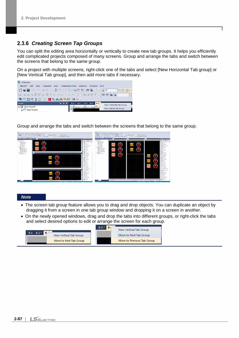
2. Project Development
2-87
Creating Screen Tap Groups You can split the editing area horizontally or vertically to create new tab groups. It helps you efficiently edit complicated projects composed of many screens. Group and arrange the tabs and switch between the screens that belong to the same group.
On a project with multiple screens, right-click one of the tabs and select [New Horizontal Tab group] or [New Vertical Tab group], and then add more tabs if necessary.
Group and arrange the tabs and switch between the screens that belong to the same group.
Note
• The screen tab group feature allows you to drag and drop objects. You can duplicate an object by dragging it from a screen in one tab group window and dropping it on a screen in another.
• On the newly opened windows, drag and drop the tabs into different groups, or right-click the tabs and select desired options to edit or arrange the screen for each group.

2. Project Development
2-88
Exporting and Importing Fonts When editing a project on a PC after receiving it from the XGT panel, the characters may not be displayed properly if the font used in the project is not installed on the PC. In this case, you can export the font from the project and import (install) it to the PC to solve the problem.
To export a font and install it on a PC:
1 Click [TOOL] ► [Export Font].
2 Choose the path and folder to save the font file, and then click [OK].
3 Click [TOOL] ► [Install Font].
4 Select the folder where the font file is saved, and then click [OK].

2. Project Development
2-89
Exporting and Importing Screens The screen exporting and importing functions are used to save the current screen and the text tables, user images as well as tag elements that are related to the screen as a file or to retrieve it from another XP-Builder project on another PC.
The screen export procedure is as follows.
1 Select the screen(s) to export from the screen tree and click the right mouse button. Then, select [Export] from the menu.
2 In the dialog box, select the folder to save the file in. Then, enter the file name and click [Save]. When the screen is exported, the following elements are also exported.
Item Description
Screen Data All objects and figures used on the screen
Text Tables Text tables used by the objects on the screen
Tags Tags used by the objects on the screen
User Images User images used by the objects and figures on the screen
Note The file extension for screen export files is “.xscr.”

2. Project Development
2-90
To import a screen:
1 Right-click the screen you want to import from the screen tree and select [Import] from the menu.
2 Click the file selection button at the top of the [Import] screen to select the file to import (as shown in the screenshot below).
3 The list of screens in the file to be imported is displayed in the preview window at the left side of the window.
4 Select a screen to add from the list on the left side of the window and click [Add].
5 The added screen is displayed in the grid on the right side of the window as shown in the screenshot below.

2. Project Development
2-91
6 Change the value of the screen number, the name, the tag, and the text table as required.
7 Click [OK] and then confirm that the selected screen and related text tables and tags are successfully added to the project.

2. Project Development
2-92
Note
• The pop-up message shown below is displayed when the same file number exists on the screen or if two or more screens have the same screen numbers in the grid.
• Drag (AutoFill) the reference row from the grid to copy the screen data. The screen number
increases by 1 if it is dragged down and decreases by 1 if it is dragged up based on the value of the reference row.

2. Project Development
2-93
Import Screen Dialog Box This section contains more information about the screen import dialog box.
Type Description
Select File Select a file to import (.xscr).
Preview Screen Display the screen list of the selected file.
Add Select a screen to add to the project and click "Add" to add the screen data to the grid on the right side of the window.
List Mode Displays screen data as text if list mode is checked.
Screen Number Displays the screen number of a screen added using the [Add] button. The screen can be edited and a number from 1 to 65534 can be entered.
Screen Name Displays the screen name of a screen added using the [Add] button. The screen name can be edited.
Screen Type Displays the screen type of a screen added using the [Add] button. The screen type cannot be edited.
Screen Switch Offset Change the screen number of the screen change switch when a screen is added to the project. A number from 0-65,534 can be added to the original screen number. The screen switch offset value can be edited.
OK Add a screen to the grid in the project by clicking [OK].
Cancel Cancel any changes to the project by clicking [Cancel].

2. Project Development
2-94
Screen Import Option Dialog Box:
Type Description
Tag Name Duplicated
This option is used when an existing tag in the project has the same name as a new tag to be added to the screen. There are two options available, [Overwrite] and [Skip]. The default is [Overwrite].
Image Category/Name Duplicated
This option is used when an image category or image name is duplicated in the project. There are two options available: [Overwrite] or [Skip]. The default option is [Overwrite].
Text Table Name Duplicated
This option is used when a duplicate text table name and number matches a table in the project. There are two options available: [Overwrite] or [Skip]. The default option is [Overwrite]. It is added when items used in keyword editing and character strings are changed.
Object/Figure on Different Screen Resolution
This option is used to determine if the objects and figures on the screen will be scaled to fit the current project. Alternatively, they will retain their current format to ensure the resolution of the screen to be added is different from the resolution of the project. There are two options available, [Scale] and [Skip]. The default is [Scale].
Import Default Path Click to select the default location of imported files.

2. Project Development
2-95
Replace Tag/Text Table Dialog Box:
Type Description
Tag • This function replaces a part of a tag name with a new character string when a screen is imported. The following example shows a tag change. The replacement character string is enclosed between “#” and “#”. The objects that use the tag are registered on the screen to be exported. [Setting Export Projects]
• If “Basic” is entered as the replacement character string, the tag names will
be changed as shown below. It shows that “#LOC#” is replaced by “Basic”. If the same group name and number exist on the screen, a new tag is created and added.
[Import Results]
Text Table • This function replaces a part of the character strings in the text table with a new character string when a screen is imported. The following example shows the process of changing a text table. The replacement character string is enclosed between “#”and “#”.The objects using the text table are registered on the screen to be exported.

2. Project Development
2-96
Type Description [Setting Export Projects]
• If “01” is entered as the replacement character string, the tag names will be
changed as shown below. It shows that “#NO#” is replaced with “01”. If the same text table name and number exists, a new text table item is created and added.
[Import Results]

2. Project Development
2-97
Printing a Project You can save detailed project information in an MS Excel file format for documentation and reviewing.
To save the project information in an MS Excel file:
1 Click [PROJECT] ► [Project Print].
2 In the Content tab, select the items to include.

2. Project Development
2-98
Note
• In the Selected Print Items pane, you can rearrange the order of each selected item.
• It is saved in Excel format even if Excel is no installed.
• If Excel is installed, check the Open in Excel item to automatically open the Excel format document. • In an environment where Excel is not installed, a folder containing Excel format documents will be
opened.
3 In the Header/Footer tab, specify options for a header or footer, and then click [OK].
An MS Excel file including the selected project data opens on the computer screen automatically.

2. Project Development
2-99
Renaming a Tag to add as a New Tag You can rename a tag that is already on the screen and add it as a new tag.
To rename a tag and add it as a new tag:
1 Place an object, register a tag with a name (‘TagOld’), and assign it to a device in the object.
2 Click [TOOL] ▶ [Replace Tag Name and Register as a New Tag].
3 In the pop-up window, enter the tag name to search and a new name to replace it.

2. Project Development
2-100
Note
• By default, the newly registered tag is added to the same tag group as the one the original tag belongs to. You can select a different tag group, or create a new tag group and select it.
• By default, the tag replacement range is set as the entire project. You can click “Replace At” to specify the range.
• The new tag name must be in a valid format. The following message will be displayed if the tag name is missing, if the first character is a number, or if the tag name contains control characters or device addresses.
• If the tag name already exists, the following message will be displayed. You can click [Yes] to replace the existing tag, or [No] to cancel. Note that the tag will not be replaced even if you click [Yes] if the device types are different for the new and existing tags.
4 Click [Yes]. The new tag name (‘TagNew’) is listed in the properties window, and the object’s tag name has been changed to ‘TagNew.’

2. Project Development
2-101
Setting HW Key for Handy on Screen The handy model HMI (example: iXP2H) provides an object for connecting to the operation of an external mounted button or lamp and an external object setting window docked on the screen. The following describes how to set up an external object that works only on the screen. Refer to <2.2.2.10 Changing Extended Device Settings> in the project properties for setting the globally operating external object. Setting an external object to work on the screen:
1 [Base Screen] ▶ Double-click [Insert Base Screen]
If the external object docking window appears on the right side of the screen, click on the title and the following setting window appears.
Then click the Auto hide button to hide the setting window on the right of the screen..
2 Double-click the circular button on the docking window to add an external object.
You can only add external multiple switches within the screen, but you can also add external lamps in the global window. For detailed object attributes and settings, refer to the corresponding object description.

2. Project Development
2-102
3 After adding an object to the Data Viewer window it is shown as follows:
4 Select the object to delete from the external object setting window and click Delete button to delete the object.
The object can be deleted from the Data Viewer window can be deleted using the same method.

2. Project Development
2-103
5 In the External Object Settings window, select the object to change and then click or double-click Change.
If the object's attribute box appears, change the properties and click OK.
You can change the properties in the Data Viewer window in the same way as before.
Note
• The real object that is edited is not shown on the actual screen so there may be some discrepancy in the changes. The following operations cannot be edited:. Move / resize / drag / drop, change position and size, copy / cut / paste to same size / screen centering / spacing equally

2. Project Development
2-104
Print This feature allows you to print the contents of the screen. 1 [Project] ▶ click [Print]
2 After selecting the print on the print screen, select [OK]
3 The figure below is the result of printing by selecting the [Microsoft Print to PDF] option. The base screen, window screen, part screen, and HDMI screen created in project are all output. If the size of the screen is larger than the print paper size, the output is adjusted to fit the paper size.

2. Project Development
2-105
4 If the orientation is set to landscape on the print screen, it will be printed in landscape format.

2. Project Development
2-106
Print Preview This feature allows you to preview the printed screen contents. 1 [Project] ▶ click [Print Preview]
2 The screen print preview screen is displayed. The base screen, window screen, part screen, and HDMI screen created in the project are all displayed. If the screen size is larger than the print paper size, it is adjusted to fit the paper size and displayed.

2. Project Development
2-107
3 If the orientation is set to landscape in [Print Setting], the preview screen is displayed in horizontal format.
4 If you select the [Print] button, the screen will be printed to the set print in the same way as the [Print] function.

2. Project Development
2-108
2.4 Managing Libraries
Managing Graphic Libraries Learn how to manage image libraries. Both the system and user image libraries can be managed, but only the user image library can be edited.
Type Description
System Graphic Library About 8,000 images in 40 categories are included in the System Graphic Library. This library cannot be edited. You can select raster (256-color) or vector (65,535-color) images, depending on the color capabilities of the XGT Panels you are using. The following table describes characteristics of raster and vector images.
Type Description Raster Displayed in pixels as a bitmap image.
Distorts when you zoom in or out. If used as a background image in an object, the pattern and color cannot be changed.
Vector Expressed by connected lines. Not distorted when you zoom in or out. Not recommended to use a vector image as a background image of an object. Excessive use of vector images slows down the panel operation speed.
User Graphic Library You can register, modify or delete images. The images are saved in the current project and not in the XP-Builder program. You can import a User Graphic Library from another project or export it from the current project to use in other projects.

2. Project Development
2-109
To open the Graphic Library pane, click [VIEW] ► [Graphic Library]. The Graphic Library pane will appear, as shown in the following image:
In the Graphic Library pane, you can drag and drop an image into the editing area.
Note
• A tooltip (max 320 x 320 px.) is displayed to show the enlarged image, along with its full name, file size, and image size, when you move the mouse pointer over the images in the library.
• Dropdown filters are provided at the top of the Graphic Library pane to allow you to easily find the
specific images that you are looking for. You can set the image category and sub-category, image color, image type (vector or raster), colors (All, 256, 65536), and on/off status of the image for viewing.

2. Project Development
2-110
• You can also zoom in or out of images by selecting one of the magnification presets in the
dropdown list. • Vector images maintain their shape even if you change their size. Raster images may be distorted if
you enlarge or reduce their size. • When you drag an image to the editing area, it is created in its default size. The default sizes of
images are variable.
Creating a User Graphic Library You can create your own user image library.
To create a library:
1 In the Graphic Library pane, click the User tab.

2. Project Development
2-111
2 Enter the name of the library and click . A new image category will be created.
3 Right-click an empty area in the Graphic Library pane, and then select [Insert Image].
4 Select the image files in the browsing window, and then click [Open].
Images have been added to the new graphic library.

2. Project Development
2-112
Note
You can also drag the image from the browsing window and drop it to the User Graphic Library pane.
To delete an image, right-click an image and then click [Delete Image].
Note
• The WMF format is used only in XP-Builder. You can draw figures in XP-Builder and directly add it to a user graphic library in WMF image format. WMF images are not distorted when you resize them. To add WMF (vector) figures to a library: 1. In the editing area, right-click a figure to save it. 2. Click [Insert the selected shapes to active graphic library].
The image is added to the library in WMF format.
• Figures filled with patterns #3-41 and figures with textures cannot be inserted to a user graphic library in WMF format.
• You cannot save WMF images as image files.

2. Project Development
2-113
Exporting a User Graphic Library You can share libraries between projects.
To export your user object library after creating it:
1 In the Graphic Library pane, click the User tab.
2 Select a library to export from the drop-down list and click or right-click an empty area in the Graphic Library pane and click [Export].
3 Enter a name for the file and set the file destination.
4 Click [Save].
Note
• The exported library is saved as an .xpg file. • If there are no images in the library, you cannot export the graphic library.
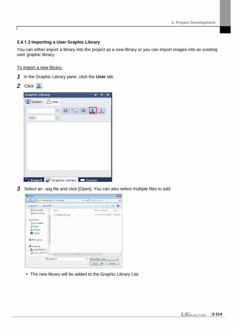
2. Project Development
2-114
Importing a User Graphic Library You can either import a library into the project as a new library or you can import images into an existing user graphic library.
To import a new library:
1 In the Graphic Library pane, click the User tab.
2 Click .
3 Select an .xpg file and click [Open]. You can also select multiple files to add.
The new library will be added to the Graphic Library List.

2. Project Development
2-115
To import images into an existing user library:
1 In the Graphic Library pane, click a user graphic library name.
2 In the Graphic Library pane, right-click an empty area, and then click [Insert Image].
3 Select image files and click [Open]. The selected images will be added to your user library.
Note If an image file with the same name exists in the graphic library, a pop-up window is displayed to ask you for a new file name. Enter a new name and click [OK] to proceed.
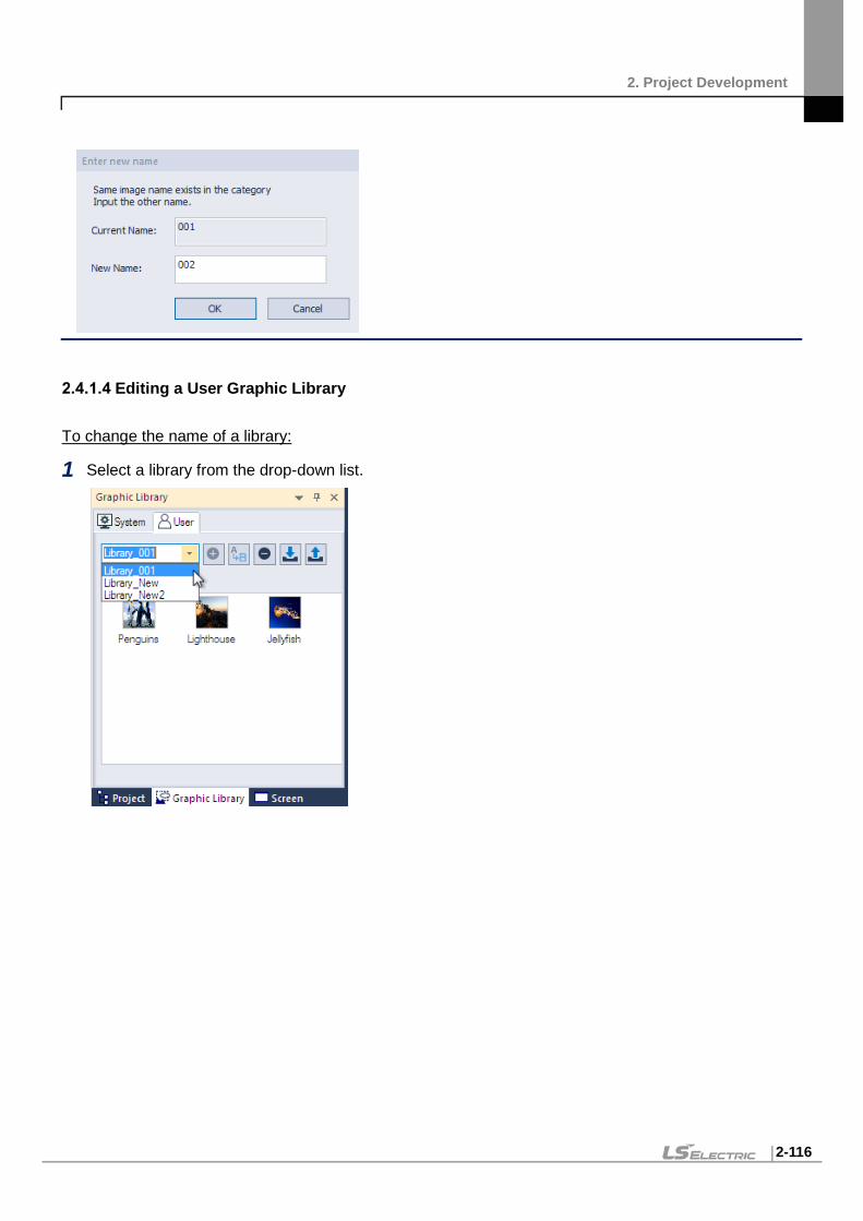
2. Project Development
2-116
Editing a User Graphic Library
To change the name of a library:
1 Select a library from the drop-down list.

2. Project Development
2-117
2 Enter a new name, and then click to save it.
Graphic library “Library_001” has changed to “Library_001A.”
Note
• User graphic libraries are sorted in ascending order by name. • The name of a system graphic library cannot be changed. • Supported image types include BMP, JPEG, GIF, WMF, TGA, PNG, TIF, ICO, and
PCX. • Users can create a maximum of 2047 categories, from category number 2049 to 4095.
An error message is displayed if you try to create categories exceeding the limit.
• Each category can have 500 images. An error message is displayed if you try to add
more images to a category exceeding the limit.

2. Project Development
2-118
To delete a library:
1 In the Graphic Library pane, click the User tab.
2 Select a library from the drop-down list and click .
Applying Options to the Images Several options are available when editing, such as setting the transparency value of images and saving them in WMF format so that they maintain resolution when enlarged.
To apply changes to an image, right-click it and select from the following options.
Functions Description
As Background Image
Set the image as the background image of the current screen. To set an image as a background:

2. Project Development
2-119
Functions Description
1. Select a category from the Graphic Library. 2. Right-click an image and click [As Background Image].
For more information about specifying background images, refer to <2.3.2.4 Changing Screen Properties>.
To remove a background image: 1. Right-click the image that is currently set as the background image. 2. Click [Screen Property] ► [Background]. 3. Clear the checkbox next to Use BG Image, and then click [OK].
Delete Deletes an image from the graphic library.
Rename Changes an image name.

2. Project Development
2-120
Functions Description
Replace Image Replaces an existing image with a new image file selected by the user.
Save as File Exports an image to save it as a file.
Apply Transparent Color
Applies a transparent color to the image (see the following procedure). To set the transparency of the image and apply it to XP-Builder: 1. Open an image in Paint and set the RGB color properties of the part of the
image to 255, 0, and 255, to make it transparent.
2. Register the image in the Graphic library. 3. Right-click the image and click [Apply Transparent Color].
4. Apply the image to the editing area to view the transparency settings.

2. Project Development
2-121
Functions Description
Select Transparent Color
Set the transparency value of an existing color in the image (see the following procedure). To set the transparency of an existing image: 1. Right-click an image and click [Select Transparent Color].
2. Select the part of the image that you want to make transparent, and then click
[OK]. Then, the RGB value for the transparent color will be changed.
Dither Image to 256 Colors
Change the color value of the image to 256 colors to reduce the size of the file. To dither the image to 256 colors: 1. Add the image to the User graphic library.
2. Right-click an image and click [Dither Image to 256 Colors].

2. Project Development
2-122
Functions Description
3. Click [OK].
Note Once an image is dithered, its color value cannot be restored.
Note
• The default transparent color is RGB (255, 0, 255). • Setting a transparent color is not a default option. • You can select multiple images and apply transparency to them simultaneously if the image
properties are the same. If the image formats are different or if one of the images has a transparency already applied, the function will not work.
• You can use the dithering function only in projects for color mode panels. After TGA and JPG files are dithered, they are saved as BMP files.
• The image dithering function substitutes colors to the 256 color palette to reduce the image size and number of colors.

2. Project Development
2-123
Managing Object Libraries Learn how to manage object libraries. Both the system and user object libraries can be managed, but only user object libraries can be edited. For more information about inserting or editing objects, refer to <2.3.4.4 Inserting Objects from the Object Library> and <2.3.5 Editing Objects>.
Type Description
System Object Library Includes seven categories: Alarm and Logging, Keypad, Lamp, Pushdown_Switch, Rotary_Switch, Slide_Switch, Toggle_Switch. The system objects cannot be edited.
User Object Library You can register, modify or delete objects. The objects are saved in the current project and not in the XP-Builder program. You can import a user object library from another project or export it from the current project to use in other projects.
To open the Object Library pane, click [VIEW] ► [Object Library]. The Object Library pane will appear, as shown in the following image:
Note
• A dropdown filter is provided at the top of the Object Library pane to allow you to find specific objects you are looking for. Select an object category to view.
• You can also zoom in or out of object images by selecting one of the magnification presets from the
dropdown list. • A tooltip is displayed to show the object information and the object is magnified for a detailed view

2. Project Development
2-124
when you move the mouse cursor over images in the library.
• After inserting an object on the screen, you can double-click it, select it, and press the ENTER key,
or right-click it and select [Object Property] to modify the object properties. • When you drag an object to the editing area, the object is created at the default size. The default
sizes of objects vary.
Creating a User Object Library
To create a user library:
1 In the Object Library pane, click the User tab.
2 Enter a category name and click . A new object category will be created.

2. Project Development
2-125
3 Drag objects from the editing area to the Object Library pane. You can select multiple objects/figures and register them as one object.
4 Right-click the newly added object and select [Rename] to change the name of the object.

2. Project Development
2-126
Note To delete objects, right-click an object and then click [Delete]. To delete all objects, right-click an empty area in the Object Library pane, and then click [Delete All Objects].
Exporting a User Object Library
To export the user object library after creating it:
1 In the Object Library pane, click the User tab.

2. Project Development
2-127
2 Select a library to export from the drop-down list and click .
3 Enter a name for the file and set the file destination.
4 Click [Save].
Note
• The exported library is saved as an .xpo file. • You can also export the current category (library) by right-clicking an empty area in the Object
Library pane, and then clicking [Export].

2. Project Development
2-128
Importing a User Object Library You can either import a library into a project as a new library or you can import objects into an existing user object library.
To import a new library:
1 In the Object Library pane, click the User tab.
2 Click .
3 Select an .xpo file and click [Open]. You can also select multiple files to add.

2. Project Development
2-129
The new library will be added to the Object Library List.
To import objects into an existing library:
1 In the Object Library pane, click a user object library name.
2 In the Object Library pane, right-click an empty area, and then click [Import].
3 Select an .xpo file and click [Open]. The objects in the library file you selected will be added to the existing library.
Note
• Users can create a maximum of 57,343 categories, from category number 8,193 to 65,535. An error message is displayed if you try to create categories exceeding the limit.
• Each category can have 500 images. An error message is displayed if you try to add more images
to a category exceeding the limit.

2. Project Development
2-130
• User object libraries and the objects in the library are sorted by names in ascending order when you add or rename a library.
Editing a User Object Library
To change the name of the library:
1 Select a library from the drop-down list.
2 Enter a new name, and then click to save it.
Object library “object08195” has changed to “Library_002.”
To delete a library:
1 In the Object Library pane, click the User tab.
2 Select a library from the drop-down list and click .

2. Project Development
2-131

2. Project Development
2-132
2.5 Connecting Controllers Configure the communication settings for the XGT Panel and controller. To connect an XGT Panel to the controller, use an Ethernet connection and the serial port. In the serial ports, there are three connection methods: RS232C, RS485, and RS422. This section describes how to set the communication method. For more details about XGT Panel settings, refer to <2.2.2.2 Changing XGT Panel Settings>.
Connecting via an Ethernet Cable Connect the XGT Panel to the controller with an Ethernet cable.
To set the configure Ethernet options:
1 Click [COMMON] ► [Project Property Setting] ► [XGT Panel Settings].
2 Select the XGT Panel series and model name.
3 Set the controller manufacturer and the controller model (Product). Select a product with “Ethernet” at the end of the controller name.

2. Project Development
2-133
4 Set the protocol to Ethernet.
5 Select Detail Settings, configure the IP settings, and click [OK].
6 Set the additional connection properties in the Connection Property section and click [OK].

2. Project Development
2-134

2. Project Development
2-135
Connecting via a Serial Port Connect the XGT Panel to the controller via a serial port. You can select RS232C, RS485, or RS422.
Using RS232C
1 Click [COMMON] ► [Project Property Setting] ► [XGT Panel Settings].
2 Select the XGT Panel series and model name.
3 Set the controller manufacturer and the controller model (Product). Select a product with “LINK” at the end of the controller name.

2. Project Development
2-136
4 Set the protocol to RS232C and select a serial port.
5 Select Detail Settings, configure the properties, and click [OK].
Note
• The baud rate must match the setting in the XGT Panel. To change the baud rate on the XGT Panel, tap and hold the screen to access the menu. Then, tap [PLC Information], select a driver from the Driver list, tap [Settings], and set the baud rate.
• Station stands for the station ID of the PLC. HMI station number is used only in N:1 communication settings.
6 Set the additional connection properties and click [OK].

2. Project Development
2-137

2. Project Development
2-138
Using RS485/RS422
1 Click [COMMON] ► [Project Property Setting] ► [XGT Panel Settings].
2 Select the XGT Panel series and model name.
3 Set the controller manufacturer and the controller model (Product). Select a product with “LINK” at the end of the controller name.

2. Project Development
2-139
4 Set the protocol to RS485 or RS422 and select a serial port.
5 Select Detail Settings, configure the properties, and click [OK].
Note
• The baud rate must match the setting in the XGT Panel. To change the baud rate on the XGT Panel, tap and hold the screen to access the menu. Then, tap [PLC Information], select a driver from the Driver list, tap [Settings], and set the baud rate.
• Station stands for the station ID of the PLC. HMI station number is used only in N:1 communication settings.
6 Set the additional connection properties and click [OK].

2. Project Development
2-140

2. Project Development
2-141
2.6 Simulating & Debugging After developing an interface, it is a good idea to test it before putting it to use. XP-Builder offers multiple ways to check the integrity of your data, including an interface simulator, data check and device map functions, and a script cross-reference that can help you debug your program.
Simulating an Interface The simulator provided in XP-Builder allows you to verify the functionality and appearance of your interface before you transfer it to an XGT Panel. By testing your project, you can correct errors and verify system operations and responses in advance.
To run the simulator:
1 Click [Tool] ► [Simulation].
Note
• Except for the menu and title, the simulation window will use the same resolution as when it is exported to an XGT Panel.
• Only one simulator can be run at a time. If you are running the simulator, you cannot execute another one.
• The size of simulator window may vary according to the set XGT Panel size. • Click and move the Simulation window borders to control screen size. Note that the
display resolution remains the same and may make margins.

2. Project Development
2-142
• The OPC UA Client and OMRON NX/NJ Ethernet/IP do not support simulators.
2 Verify operations by clicking or selecting objects and activating functions in the interface. As shown in the following example, you can virtually input the value and review the operation via the simulation.
The simulator interface includes the following functions:
Function Description
File Exit Ends the simulation and closes the window.
Tool Virtual Device Start Monitors and controls a device for simulation. For more information, refer to <2.6.2 Inputting Simulated Data>.
Screen Capture Captures an image of the current

2. Project Development
2-143
Function Description
screen.
Help XP simulator Information (A) Displays the current version information.

2. Project Development
2-144
Inputting Simulated Data Learn how to create the simulated data and change the values to check the process.
Monitoring Devices Use the simulator to generate sample data that you can use to monitor devices.
1 Click [Tool] ► [Simulation].
2 In the simulator, click [Tool] ► [Virtual Device Start].
Device lists with simulated data will appear.

2. Project Development
2-145
Data Type Description
a Sets the type of screen and number of screens that you want to monitor. All base screens with objects and window screens can be selected from the combo box, but you cannot monitor common data devices. The simulator changes the display based on the number of screens you select.
User Device List Sets the device value manually to simulate the project.
Common Device List Displays a list of common data, such as History Alarms, Recipes, and Flow Alarms.
Screen Device List Displays a list of all the edited objects in the base screen.
Object Description Displays the object name of the device.
Device Size Displays the size of the device: Bit, 16-bit (word), or 32-bit (double word).
Device Addr. Displays the address of the device.
Device Value Displays the value of the current device.
Type of Connected PLC
Displays the controller type.
Changing Device Values Set device information and change values in the User Device List. You can set bit devices to On or Off and manually enter device values for word devices. Values are applied to the simulator as soon as you change them.

2. Project Development
2-146
Note To use the XG5000 with the simulator, click the checkbox next to Use XG5000 simulator in the XGT Panel Settings.

2. Project Development
2-147
Running a Data Check The data check allows you to locate and correct data errors before transferring a project to an XGT Panel. You can verify deleted image numbers, tags, display numbers, existing addresses, and errors unique to objects or common items. For more information about the messages that are displayed during a data check, refer to <3. Error Messages>.
To run a data check, click [Tool] ► [Data Check]. Error numbers and their descriptions will appear in the output window.
Note If you close all the project screens and double-click on an item in the output window, you can activate screens or objects that correspond to error messages, so that you can modify them. Refer to <3.1 Resolving Error Codes Found in the Results Pane> for detailed information.

2. Project Development
2-148
Viewing the Device Map The Device Map allows you to view the locations, addresses, or tag names of devices in the project.
To view the device map:
1 Click [View] ► [Device Map].
2 Click the drop-down list to select a device type (Bit or Word).

2. Project Development
2-149
3 Enter a device address or click the keypad icon to the right of the device input area to specify a device address.
4 <By address> <By tag>
Item Description
a. Device Type Inputs a device type to search for (Bit or Word).
b. Device Address Input a device address to search for and then press the Enter key.
c. Device Map Displays the device addresses in use.
d. Device Reference Displays the currently selected device and its position in the device map.
e. Address or Tag Tabs Displays information by address or by tag.
f. Tag List Displays the tags registered to each device.

2. Project Development
2-150
Evaluating Project Size (Memory Usage) When the current project data is transferred to an XGT Panel, the files are saved and transferred as .HMI files. The size of an HMI file must not exceed the memory limit of the XGT Panel, so it is important to know the size of the HMI files and components of the current project.
To evaluate the project size:
1 Create a project, as described in <2. Project Development>.
2 Select [Tool] ► [Memory Statistics]. The memory size of each element is shown, including screens and common data.
Note
• The memory size of the screen element includes the sizes of figure and objects and does not include the sizes of images and fonts used on the screen. Image and font sizes show their sizes for the entire project. If an image is used more than once in a project, the information of a single image is transferred to the XGT Panel.
• If the memory required for images, projects, sounds, or recipe data is quite large, you can set the storage location for those files to an external drive that is connected to the XGT Panel.
• Additional information includes the information of various drivers such as the communication driver module.

2. Project Development
2-151
Finding and Replacing Devices This function allows you to locate the addresses of objects used in a project and, if necessary, relocate them to a new address.
Finding and Replacing Devices on the Active Screen
To find and replace devices on the active screen:
1 Click [Tool] ► [Find in Active Screen]. The object’s address is shown in the Find Device window.
2 Click [Find Next] to find another object with the same address.
3 To change the address of a device, click [Replace]. The Replace Device window will appear.
4 Enter a new address in the Replace With field or click the keypad to the right of the field to specify a device address.
5 After entering the new device address, click [Close].
Note
• You can also click [Tool] ► [Replace in Active Screen] to directly access the Replace Device window.
• By default, the Find function locates either device addresses or tags, based on the type of information that you specify. To search for device addresses and tags, check the check box next to

2. Project Development
2-152
Find All Addresses/Tags. • To locate a range of addresses, set the range in the Range Search field. By default, the range is
“1,” which returns a single device address. You can also replace addresses automatically in a range from a specified starting point, for as many devices as you specify in the Range Search.
Finding and Replacing All Devices
To find all devices used in objects of a particular type at once:
1 Click an object to select it, and then click [Tool] ► [Find/Replace All] ► [Device].The current object’s device address is shown in the Find All window.
2 Click device types and enter the device address to find in the Find What field. By default, the search range is the entire project.

2. Project Development
2-153
Click [Find All]. The output window shows the results of the search. You can double-click a column to view details about the object.
To replace all objects in a range of addresses at once:
1 Click an object to select it, and then click [Tool] ► [Find/Replace All]► [Device]. The current object’s device address is shown in the Find All window.
2 Click [Replace].
3 Enter the original device address in the Find what field and the new address in the Replace with field.
4 Click [Replace All].
5 Click [Yes] to confirm the address replacement. The output window shows the number of the replaced addresses.
Note To replace addresses in a specified range, change the Device Count setting. Addresses will be replaced for the number of devices you specify. For example, if the original device address is P0 and the Device Count is 7, then 7 devices, including P0, are replaced.
Finding and Replacing All Fonts

2. Project Development
2-154
To find all fonts used in the project at once:
1 Click an object to select it, and then click [Tool] ► [Find/Replace All] ► [Font]. The Find/Replace Font window opens.
2 In the Find field, choose a font from the dropdown menu. The entire project is selected by default.
3 Select [Find All] to display the search results in the output window. Double-click the object to check to see the object.

2. Project Development
2-155
To replace all fonts in a range of addresses at once:
1 Click an object to select it, and then click [Tool] ► [Find/Replace All] ► [Font]. The Find/Replace Font window opens.
2 Choose the fonts from the dropdown menu for the Find and Replace with fields.
3 Click [Replace All].
4 Click [Yes] to confirm the address replacement. The output window shows the number of the replaced addresses.
Finding & Replacing All Strings. Find strings:
1 From the menu, select [Tools] ► [Find / Replace All] ► [Strings].

2. Project Development
2-156
2 Select the string you want to find. If no objects are selected by default, they are found in the entire project. By default, it looks for the string that contains the string you are looking for, not including comments.
3 Select [Find All] to display the search results in the output window. Double-click the object to check to see the object.
Replace All:
1 From the menu, select [Tools] ► [Find / Replace All] ► [Strings]. Enter the string to be replaced with the string to be found in the activated tool box.
2 Select [Replace All], all then select [Yes] in the message below to execute the replacement.

2. Project Development
2-157
3 Select The number of changed strings is displayed in the output window.
Finding and Replacing Devices, Fonts, and Tags from a List
To find and replace devices used in specific items in a project:
1 Click [Tool] ► [Find/Replace an item] ► [Device].
2 In the left pane, select the specific items in the project to search.
3 Find the devices in Before Dev. column, and click the value in After Dev. column.
4 Enter new value, or open a keypad by clicking and input a value.

2. Project Development
2-158
5 Repeat steps 3 and 4, and then click Convert when done.
Note Check the Selected Object option to find device address from the objects you selected on the screen. If the selected object exists on the screen, "Selected object" is automatically checked in the search area.
If you check "From Text table" in Find/Replace String, you can search or replace in string unit. If you check the "Block by block" check box, you can change it by the page of the Text table page (block). For example, it is possible to change the elements of a project using "Text table_01" as shown below, keeping the number in block with "Text table_02".

2. Project Development
2-159
To find and replace fonts used in specific items in a project:
1 Click [Tool] ► [Find/Replace an item] ► [Font].
2 In the left pane, select the specific items in a project to search.
3 Find the font in Before Dev. column, and click the After Dev. column.
4 Select a new font from the dropdown list.
5 Repeat steps 3 and 4, and then click Convert when done.

2. Project Development
2-160
To find and replace devices using a specific tag:
1 Click [Tool] ► [Find/Replace an item] ► [Tag address].
2 In the left pane, select the specific items in a project to search.
3 Select/Enter the “After Device.”
4 Enter a device address, or assign an address using the keypad to the right.
5 Click [OK] after entering the device address.

2. Project Development
2-161
Note
• You can view and select individual objects that do not use tags. Unlike the “finding and replacing a device” feature (Click [Tool] ► [Find/Replace an item] ► [Device]) which replaces all the specific device address in the project at once, the “finding and replacing a device using a specific tag” feature allows for selective replacement .
• By dragging downward on the “After Device” column, you can fill the table with ascending device numbers (from the first device address, each number becomes greater by 1). By dragging upward on the “After Device” row, you can fill the table with descending device numbers (from the last device address, each number becomes smaller by 1).
• You can click “Tag name”, “Before Device,” or “After Device” items on the title bar, to sort the table by ascending or descending order.
• You can double-click on the right edge of the title line items to adjust the cell size to fit the longest string in the row.
• You can click on the edge of a cell and drag to manually adjust the width and height of the cell.

2. Project Development
2-162
Viewing Cross-References You can view cross references to see device, tag, or script information for the entire project at once. To view device, tag, or script cross-references, click [Tool] ► [Cross Reference], and then select [Device], [Font], or [Script]. Device addresses, tag names, positions, object type, and descriptions are shown in the Output pane. You can double-click an entry in the cross reference to view device or script details.
Viewing Cross-References By using Cross Reference in Active screen, you can check the entire information of devices, tags, scripts, etc. used on the screen at once. To use on-screen cross-references, select [Tools] ► [Cross Reference in Active screen] from the toolbar menu, and then select [Device], [Font], or [Script]. The device address, tag name, location, object type, and description are displayed in the output window. Double-clicking on a specific row activates the object with that address in the screen.
Switching Project Screens To switch project screens conveniently, you can use the Next/Previous function. This allows you to scroll through screens in order. To switch project screens, click [Tool] ► [Previous Screen/Next Screen]. You can also click the Next or Previous icons on the toolbar.

2. Project Development
2-163
2.7 Running XP-Simulators with other PLC Simulators Before downloading a file edited using XP-Builder for XGT Panel, it can be simulated on a PC. The ladder program from another PLC simulator can be used to prepare device values for the XP-Simulator. In other words, the ladder program edited by another PLC program can be run in XP-Simulator to link the PLC simulator values and XP-Builder simulator values. This feature is supported on AB, Siemens, LS ELECTRIC, and Mitsubishi PLC simulators only.
XG5000 Simulator and XP Simulator Before checking the XG5000 simulator, confirm that a supported version of software is used. The program may terminate abnormally if the specified version is not used.
1 Run the XG5000 software and edit the ladder diagram.
2 Run the XG5000 simulator.
3 Edit the data to run in XGT Panel using the XP-Builder editor.
4 In XP Builder, check the check box next to [Use PLC Simulator] in [Common] ► [Project Property Setting] ► [XGT Panel Setting].
5 Run the simulator in XP-Builder.

2. Project Development
2-164
6 Operate or change the device values either in XG5000 or XP-Builder simulator and monitor the operation.
Note
• XP-Builder does not support multiple instances of the simulator. Only one simulator can be run at a time.
• Run the XG5000 simulator first, and then run the XP-Builder simulator. • During simulation, the PLC type setting affects the operation.

2. Project Development
2-165
S7-PLCSIM Simulator and XP-Simulator Before checking the S7-PLCSIM simulator, confirm that a supported version of the software is used. The program may terminate abnormally if the specified version is not used.
1 Run [S7-PLCSIM]
2 Edit data to run in XGT Panel using the XP-Builder editor.
3 In XP Builder, select [Use PLC Simulator] in [Common] ► [Project Property Setting] ► [XGT Panel Setting].
4 If a device value is changed in S7-PLCSIM, the changed value is saved and displayed on the XP-Simulator.
Note
• S7-PLCSIM Version 5.4 or later • PLC Driver Device Addresses Supported by S7-PLCSIM. - Data Block Devices - Flag Devices, Internal Memory - Output Devices (QI, QW, etc.) - Input Devices (I, IW, etc.)
• PLC Driver inaccessible Device Addresses Supported by S7-PLCSIM. - Timer Device (TW, etc.) - Counter Device (CW, etc.)
• If an input device is used in an object as a read device, the object will not be displayed correctly. Also, writing a value to a read device may result in abnormal operation. - A bit switch object uses an input device. Reversal of the device value cannot be applied
with a bit switch, because the device value cannot be read. - For On/Off operation at a bit switch, only the selected bit works while other bits are
reset. • The PPI MD device is a 32-bit device. It can be interfaced with the PLC simulator in 32
bits. It is recommended to use the 32-bit version. • The DB block can be normally interfaced to the XP-Simulator after it is set in SIMATIC
Manager, downloaded to the PLC simulator, and then can be run properly in the PLC simulator. It will not work properly if it is not downloaded to the simulator even if it is added in SIMATIC Manager. - Input the name and type in SIMATIC Manager as shown in the screenshot below.
- Download the added DB to the simulator.

2. Project Development
2-166

2. Project Development
2-167
RSLogix Emulator and XP-Simulator Before checking the RSLogix emulator, confirm that the program used is the RSLinx Classic version and that it supports the OPC server function. The program may terminate abnormally if the specified version is not used. The settings are described in the following procedure.
Configuring RS Logix5000:
1 Create the project.
2 Set the slot number to be used by the emulator.

2. Project Development
2-168
3 Select [New Module], as shown in the following screenshot, to set the I/O Configuration.
4 Set the Assembly Instance for the New Module to “2,” “1”, and “16.”

2. Project Development
2-169
Configuring RS Emulator:
1 Right-click on the slot (“slot 1” in the example above) identified if the emulator was created in RS Logix.
2 Select the slot’s Module Type as “Emulate5000 Controller” as shown in the figure below. Then, check the slot number.
3 For other parameters, use the default values provided by the Tools.
4 Create the I/O Configuration slot in the same way. Right-click on the second slot in the list to create a slot. Then, specify the Module Type as 1789-SIM 32 Point Input/output Simulator.
5 The following details are displayed when the emulator settings are completed.

2. Project Development
2-170
Configuring RSLink:
1 Select [RSLinx Classic Gateway] ► [Communications] ► [Configure Drivers].
2 Select Virtual Backplane from the dropdown list.
3 Select [RSLinx Classic Gateway] ► [DDE/OPC] ► [Topic Configuration]. The name of the project created in RS Logix 5000 is displayed in a list to the right of the window. Select the project and specify the topic in the left pane. Click [Apply] and then click [Done].

2. Project Development
2-171
Running RS Emulator:
1 After the previous procedure is finished, run the emulator in RSLogix500. Select [RSLogix5000] ► [Communication] ► [Who Active] to run it.
2 Select the emulator in the Who Active window, as shown in the screenshot below, and click [Download].
3 Execute Run Mode when these steps have been completed.

2. Project Development
2-172
4 Register the tag in [RSLogix5000] ► [Logic] ► [Monitor Tags].
5 Edit the data to run in XGT Panel with the XP-Builder editor.
6 Select [Use PLC simulator] in [Common] ► [Project Property Setting] ► [XGT panel Setting] on the XP-Builder.
7 When the XP-Simulator runs, the list of projects created by RSLogix5000 is displayed as shown in the screenshot below. Select the project for the topic that was set in the procedure above.
8 If the variables for PIC_101_SPProg are changed in RSLogix5000, as shown in the screenshot below, the target device value will be displayed in XP-Simulator.

2. Project Development
2-173
Note All three tools must be set for the simulation in the data interface for the RSLogix emulator. • RSLogix Emulate 5000 Classic Monitor 21.00.00 version or later. • RSLinx Classic GateWay 3.51.00 or later (OEM and Single Node versions are not supported). • Studio 5000 Logix Designer 21.00 version or later.

2. Project Development
2-174
The GX Simulator and XP-Simulator Before running the GX Developer or GX Works2 simulator, check the following items. The program may terminate abnormally if the specified version is not used.
GX Simulator Version 7.30 or later GX Works 1.5 or later MX Component Version 3.08 or later The procedure to configure a data interface for simulation between the GX Simulator and the XP-Simulator is detailed below.
1 Set the COM connection target to GX Simulator in [MX Component]–[Communication Setup Utility].

2. Project Development
2-175
To connect with simulator running on GX Works2, you need to connect to GX Simulator2.
Item Description
PC side I/F Sets the COM Server target. Specify the GX Simulator as the target for the simulator.
CPU Sets the CPU type for the simulator. The target CPU type for the ladder program edited in the GX Simulator is generally specified. Only the memory domain for a specified CPU type can be simulated. For example, if Q06H is specified in the Q02H CPU type or the GX Component Wizard, the GX Simulator can monitor only memory corresponding to the Q06H CPU.

2. Project Development
2-176
2 After the Communication Setup is completed in MX Component, create a ladder program using GX Developer.
3 After the ladder program is created, select [Tools] ► [Start ladder logic test] in GX Developer to run the simulator.
4 Edit the data to input into XGT Panel with the XP-Builder editor.
5 In XP-Builder, check the [Use PLC simulator] checkbox in [Common] ► [Project Property Setting].
6 Run XP-Builder simulator. The CPU that is connected must be set when the GX Simulator and the XP-Simulator are connected. Set the CPU type that is same as GX Simulator’s ladder program in the checkbox, as shown in the screenshot below.

2. Project Development
2-177
7 Set or modify the device value in XP-Simulator or GX Simulator.
If the X0 device value is set to 0x21 in GX Simulator, the same value will be displayed in the XP-
Simulator.
Note
• Supported PLC Drivers 1. SIEMENS Simulator Interfaces - Siemens: SIMATIC S7 300/400 Ethernet - Siemens: SIMATIC S7 3964(R)/RK512 - Siemens: SIMATIC S7 MPI - Siemens: SIMATIC S7 PPI 2. Rockwell Simulator Interfaces - Rockwell: EtherNet/IP ControlLogix/CompactLogix Series Native 3. Mitsubishi Simulator Interfaces

2. Project Development
2-178
- MITSUBISHI: MELSEC-A(LINK) - MITSUBISHI: MELSEC-FX(CPU) - MITSUBISHI: MELSEC-FX(ETHERNET) - MITSUBISHI: MELSEC-FX(LINK) - MITSUBISHI: MELSEC-Q(CPU) - MITSUBISHI: MELSEC-QnA, Q(ETHERNET) - MITSUBISHI: MELSEC-QnU CPU(ETHERNET) - MITSUBISHI: MELSEC-QnA, Q(LINK)
• XP-Simulator must be run only after another PLC simulator is run.

2. Project Development
2-179
2.8 Managing a Project Learn about project management functions, including transferring data to XGT Panels or removable memory devices, and receiving projects from HMI.
Transferring to an XGT Panel The GUI you design in XP-Builder must be transferred to an XGT Panel. You can transfer the interface by using one of two methods: full transfer or modification transfer. By default, XP-Builder determines whether or not a previous version of the project exists on the XGT Panel and then transfers either the entire project or only modified parts of the project accordingly. However, you can force XP-Builder to transfer the full project, if desired.
Before transferring a project, you must select a connection method, as described in the following sections. There are three connection methods available: RS232C, USB, and Ethernet. The connection methods available will vary based on the XGT Panel model you are using.
To transfer a project:
1 Click [Communication] ► [Send] or select the download icon ( ) from the toolbar.

2. Project Development
2-180
2 Set the following options, as necessary.
Function Description
Download to XGT Panel Select this option to transfer a project to an XGT Panel. This is the default option. Click [Settings] to change the communication settings.
Download Project All Forcedly
By default, XP-Builder determines if a previous version of the project exists on the panel and determines whether or not to transfer the full project or only to update data. However, you can select this option to force XP-Builder to transfer the entire project.
Save to Removable Device
Select this option to transfer a project to a removable memory device that is connected to your computer. For more details, refer to <2.8.2 Transferring to a removable Device>. This feature is not supported by the IPC series.
File Location Displays the file path for a file that is saved in an external storage device. A folder type and a compressed file type can be selected. If the folder type is selected, multiple files to be downloaded to the input folder are generated. If a compressed file type is selected, multiple files are compressed and stored in a file that has a file name you specified. For file management purposes, the compressed file type is more convenient but it may take longer to compress the files. For example, files to be downloaded in the folder are saved to the G: \XP_Project\AAA folder. If a compressed file is used, files to be downloaded are saved as AAA.xpd file in

2. Project Development
2-181
Function Description the G: \XP_Project folder.
Update XP-Runtime Forcedly
By default, XP-Builder determines whether or not the runtime files need to be updated on the XGT Panel. However, you can select this option to force XP-Builder to update the runtime files on the panel. This feature is not supported by the IPC series. For the IPC series, you must run a setup file manually to update XP-Runtime.
Delete All Monitoring Data
Select this option to delete alarms, logging, recipe data, and operation logs stored in the NVRAM of the XGT Panel.
Include Upload Project File
Select this option to transfer a compressed project file to the XGT Panel in addition to the normal project files. This option is recommended when you do not have a project file on your computer and want to transfer it from the XGP Panel onto your computer. You can use a removable storage device to download a compressed project file.
Download Click to transfer the data to the XGT Panel.
3 If necessary, click [Settings] to view or change the connection settings.
Function Description
Connect Type Set the connection type between your computer and the XGT Panel.
Details You can specify the detailed connection settings for Ethernet, RS-232C, and USB connections. For the RS-232 connection, set the serial port and baud rate.

2. Project Development
2-182
Function Description
For an Ethernet connection, set the IP address, port number, and network adapter.
• In Windows XP, a virtual IP address is
automatically created for an Ethernet connection. • In Windows 7 or Windows 8, you must set the IP
address manually for an Ethernet connection. For a USB connection, set the XGT Panel type.

2. Project Development
2-183
Function Description
Scan XGT Panel Click to scan for XGT Panels connected via Ethernet.
4 Verify that your computer and the XGT Panel are both properly connected via your chosen connection method, and then click [Download]
Note
• Viewing Available Memory before Sending a Project View the available memory before sending the project file to ensure the file can be transferred successfully. You can compare Flash and USB/CF/SD memory capacities to the size of the project file before transferring it, as shown below.

2. Project Development
2-184
Memory type Case Description Flash memory Downloading the
whole project Compare the project file size to the total memory available, because the memory will be erased prior to downloading the project.
Downloading the revised parts only
Compare the project file size to the available memory.
USB/CF/SD memory
Compare the project file size to the available memory of an external device.
• Downloading the Entire Project You can download the entire project only when the entire memory on the external device is larger than or same as the size of the project file.
• Downloading Only the Revised Parts of a Project • You can download a revised part of a project only when the size of the available memory on the
external device is larger or same as the size of the project file. - If you attempt to transfer a project file when there is insufficient memory, the following pop-up
window will appear. It shows the total memory capacity and the size of the project file.
- If the available memory is insufficient to download only the revised part, download the entire
project.
Note
• To set the password, in XP-Builder, click [Communication] ► [XGT Panel Information] ► [Password]. When you set the password for the first time, enter the new password again to confirm it. Your password can contain up to 10 characters in length.
• XP-Builder transfers only the updated portion of a project, except in the following cases:

2. Project Development
2-185
- You are transferring the project to the panel for the first time. - You have changed the project properties, which can affect data throughout the entire project. - The project ID has been deleted on the panel due to a communication error. Therefore, the
project IDs cannot be compared between your computer and the panel. • If the transfer is unsuccessful, it may be due to different runtime versions between XP-Builder and
the XGT Panel. If the runtime version of the XP-Builder is later than that of the panel, update the runtime file on the panel to match XP-Builder and try the transfer again.
Using a Serial (RS-232C) Connection A serial connection provides a 1:1 communication method between the control device and a computer. A 6-pin cable is required to make a serial connection, but this cable is not provided with the XGT Panel.
To use a serial connection:
1 Connect the serial cable to the TOOL port on the XGT Panel and RS-232C port on a computer.
2 On the XGT Panel, close any open programs.
3 Tap and hold the screen to open the menu.
4 Tap [Settings] ► [PC Conn Setting].
5 In RS232 Baud Rate, select a baud rate.
Note Only XP series panels support connections via RS-232 ports. eXP/eXP2/iXP/iXP2/IPC series panels do not support it.
6 In XP-Builder, select [Communication] ► [Send] ► [Settings] ► [RS232C].

2. Project Development
2-186
7 Select the same baud rate that you set on the XGT Panel. If the transfer rates do not match, the transfer will fail.
8 Select the serial port connected to the XGT Panel. The COM port number must be the same as the one used by your computer for the RS-232C connection. To set the COM port number on your computer, open the Control Panel, locate the Device Manager, and modify the Ports’ (COM&LPT) settings.
Using an Ethernet Connection An Ethernet connection is typically much faster than a serial connection; so using an Ethernet connection is highly recommended.
To use an Ethernet connection:
1 Connect a computer and an XGT Panel to a network via Ethernet cables. You can also use a cross cable connection if a network is unavailable. The IP addresses of the XGT Panel and the connected computer must be in the same Subnet mask.
2 On the XGT Panel, close any open programs.
3 Tap and hold the screen to open the menu.
4 Tap [Settings]► [Ethernet Setting].
5 Set the Ethernet IP, Gateway, and Subnet mask.
6 Tap [Go to Main Menu].
7 In XP-Builder, click [Communication] ► [Send] ► [Settings] ► [Ethernet].

2. Project Development
2-187
8 Set the IP address and port number to match the ones that are set in the panel.
Note
• You can use the automatic search function in XP-Builder (Scan XGT Panel) to locate and connect XGT Panels on a network. The feature uses the UDP protocol to retrieve information about the XGT Panel and returns it via broadcast messages to a default address (255.255.255.255). This search is performed only on the local network. If a gateway exists between the search computer and the XGT Panel, the message may be blocked.
• By default, the last address used will remain in the settings until you replace it manually or update it by performing a scan for connected XGT Panels.
• If you are transferring information to multiple XGT Panels, the data will be transferred in order by IP address. When you view IP addresses as shown in the following example, they appear in ascending order.
• The XGT series uses port 2143, and the IPC series uses port 2144. When downloading a project, port setting is not required because the port number is automatically selected based on the selected panel specifications.

2. Project Development
2-188
Using a USB Connection (XP models) To use a USB connection, you must use an XPO-USBC cable, manufactured by LS ELECTRIC. The USB cable is not provided with the XGT Panel, so you must purchase one separately. A USB connection provides 1:1 communication between a computer and a panel.
Note
• The procedures described in this section apply only to XP series panels. Refer to <2.8.1.4 Using a USB Connection (iXP/eXP/iXP2 models)> for information on USB connections with iXP/eXP series panels.
• The USB connection is supported by XGT Panel operating software versions 1.24 and higher.
To use a USB connection:
1 Run XP-Builder, and then create and save the project to be transmitted.
2 Connect PC and XGT Panel by Ethernet or serial.
3 Click [Communication]-[XGT Panel Information], then go to the setting tab and click Install/Update XGT Panel USB driver to download USB driver to XGT Panel.
4 Connect the USB cable (XPO-USBC) to each port on the PC and XGT Panel. When USB cable is connected to the XGT Panel, the USB icon is displayed at the bottom-left corner.
5 Click [COMMUNICATION] ► [Send] to open the Download screen.
6 Click [Settings] to open the Communication Settings screen.
7 Select the [USB] icon from the [Connection Type] selection list. Select XP Series as the type in the Details.

2. Project Development
2-189
Note
• Once you initially download the XGT Panel USB driver installation/update, you can download via USB without installing a separate USB driver

2. Project Development
2-190
Using a USB Connection (iXP/eXP/iXP2/eXP2 models) The mini-USB cable that supports USB 2.0 communication is available for iXP, iXP2, eXP,eXP2 Series. The cable configuration procedure is detailed below.
1 Run XP-Builder when the cables are properly connected and the XGT Panel settings are complete.
2 Create and save the project to be transmitted.
3 Click [COMMUNICATION] ► [Send] to open the Download screen.
4 Click [Settings] to open the Communication Settings screen.
5 Select the [USB] icon from the [Connect Type] selection list. Select iXP/iXP2/eXP/eXP2 Series as the type in the Details.
Note
1) The OTG cable connected to the XGT Panel must be USB 2.0 or higher
2) When installing XP-Builder, rNDIS driver is installed automatically, so there is no need
to re-install the driver unless it was deleted intentionally.
3) Take the actions below if the following message appears.

2. Project Development
2-191
A. Make sure that the cable between PC and HMI is connected properly. B. If there is no communication even after connection is established, unplug the USB cable and
repeat 1 or 2 times. C. If you cannot communicate even after trying the solutions, press the [PC USB,
Driver Reinstallation] button in [Communication] - [Transfer Settings]. Then install the RNDIS Driver and unplug the USB cable 1 or 2 times until the [Remote NDIS based Device] in [Device Manager] – [Network Adapter] is displayed properly.
D. If the driver does not load properly after installation, remove the USB cable from

2. Project Development
2-192
the PC and HMI, reboot the PC, and reconnect the USB cable to see if the driver loads as above.
4) Take the actions below if the following message appears. The rNDIS driver is normally loaded, or the rNDIS network adapter's IP setting is in progress or it is not set up properly.
A. Wait for 1 ~ 2 minutes and try connecting again. B. If the message appears even when connecting after standby, manually set the IP
address to 184.114.58.254 in [Control Panel] - [Network and Internet] - [Network Connection] and retry communication.
Transferring to a Removable Device For convenience, you can transfer the project to a removable drive and then connect the drive to an XGT Panel to update it.
To transfer the project to a removable drive:
1 Click [Communication] ► [Send] or select the download icon ( ) from the toolbar.
2 Check the checkbox next to Save as file and select the location of the removable device. By default, the project will be saved in the Drive name\XP_Project\Folder name folder, unless you specify a different folder name. To download the project file, you must create a folder inside the XP_Project folder. The folder will be created automatically.

2. Project Development
2-193
3 Click [Download].
Note Ensure that your removable drive has sufficient space to store your selected project files. If the drive has insufficient space available, an error message will appear that describes the available memory and the total memory required to transfer the project files. If there is no folder with the same name when saving as file in XP-Builder or as a storage device in the XGT Panel, the default path is “\XP_Project~”, which is case-sensitive and saved. Therefore, if there is already a lowercase letter “xp_project~” in the path to be saved, it is saved as the corresponding folder.

2. Project Development
2-194
Starting a Project File from a Local wXP Setup, Send, and a Start XP-Builder compatible version of wXP and send wXP projects written by XP-Builder. Start project in local wXP
1 Click [Communication] ► [Send] or select the download icon ( ) from the toolbar.
2 Select [Execute Project at Local wXP]
3 Click [Download]. The project and wXP will start automatically.

2. Project Development
2-195
4 If the option ( ) is selected, it will go into monitoring mode.
Note You can only start wXP projects on local wXP. The wXP must be a compatible version with the XP-Builder or it must be updated.

2. Project Development
2-196
Receiving a Project File from an XGT Panel You can transfer project file from an XGT Panel to your computer.
To receive a project file:
1 In XP-Builder, click [Communication] ► [Receive] or select the upload icon ( ) from the toolbar.
2 If necessary, click [Settings] to change the communication settings.
3 Click [Browse] to select a destination folder for the project file. If you do not set the destination, you cannot receive the project file from an XGT Panel.

2. Project Development
2-197
4 Select Project file to transfer the entire project. Select Backup data to specify which types of data to transfer.
5 Click [Upload].
Note You cannot receive images unless you have selected the Include Upload Project File option when transferring the project to the XGT Panel.

2. Project Development
2-198
Backing up Project Data You can back up project data from a removable storage drive in an XGT Panel to your computer, including logging and alarm data, recipes, screen captures, operation logs, and memos.
To back up project data:
1 In XP-Builder, click [Communication] ► [Receive] or select the upload icon ( ) from the toolbar.
2 Click [Backup data].
3 Click [Browse] to select a destination folder for the project data.

2. Project Development
2-199
4 Select Backup data. You can click the checkboxes in the list to specify which types of data to transfer.
5 Click [Upload].
6 If a communication password is set, enter the password for the XGT Panel and click [OK]. In XP-Builder, the transfer progress will be shown in the output window.
Note Logging, alarm, operation log and recipe data are stored in CSV format. Memos and screen captures are saved in BMP format.

2. Project Development
2-200
Discontinued Project Conversion As XP series is discontinued, XP-Builder (V3.00 or later) will no longer be able to edit, save and download the model. Therefore, supporting to provide the ability to change the discontinued model to another model.
Convert project:
1 Open XP project.
2 Click [OK] on the message below.
If you click [Cancel], project will be closed.
3 Select other series model instead of XP series model on [Project Property] – [ XGT Panel Settings] after click [OK]
If you click [Cancel], project will be closed.
4 Click [Save Project] or [Save As Project] to save the project.

2. Project Development
2-201
Note When uploading XP project, model conversion is done as above.

2. Project Development
2-202
2.9 Configuring Advanced Communication Settings XP-Builder supports several communication types to allow for flexible controller and panel configurations. This section describes the communication types available.
Multiple controllers can be monitored from a single XGT Panel. The XP series panels support up to 4 connection numbers (0-3) and the iXP/IPC series panels support up to 16 connection numbers (0-15) for different types of controllers, when connected to multiple protocols (RS232C, RS422/485, and Ethernet).
Using 1: N Communication with Multiple Protocols When setting up 1: N communication with multiple protocols, you can connect various types of controllers via the different protocols. The RS485/RS422 supports multi-drop connection, which allows you to connect one XGT Panel to multiple controllers. The Ethernet connection also allows connection of multiple controllers.
You can connect up to 4 different controllers for XP/eXP series panels or up to 16 different controllers for eXP/iXP/IPC/iXP2 series panels. A multi-channel setup of 1: N communication is illustrated by the following image (XP Series).
Note
• When you connect controllers via RS232C only, you can connect only one controller from each series.
• When you connect controllers via Ethernet only, you can connect 4 XP series controllers, and 16 eXP/iXP/iXP2/eXP2/IPC series controllers.

2. Project Development
2-203
To use 1: N communication:
1 In XP-Builder, click [Common] ► [Project Property Setting] ►[XGT Panel Settings] ►[Add Controller].
2 Select the PLC and manufacturer from the drop-down list. If necessary, click [Detail Settings] and change the properties.
Note To delete a controller, select it from the list and click [Delete Controller].
Using 1: N Communication with RS485/RS422 When setting up 1: N communication with RS485, you can connect a large number of controllers, as long as they are all the same type and manufacturer of controller. With a RS485 connection, you can also set station numbers for devices in the advanced communication settings, so that the same device can be referenced by multiple controllers with unique station IDs. A multi-drop setup of 1: N communication with RS485 is illustrated by the following image.

2. Project Development
2-204
To use 1: N communication:
1 In XP-Builder, click [Common] ► [Project Property Setting] ►[XGT Panel Settings].
2 In the connection properties, select RS485.
3 In the object settings, click to set the properties.
4 Check the box next to Custom setting.
5 Set the station number.

2. Project Development
2-205
Using N: 1 Communication This is a useful way to make several XGT Panels to communicate with one PLC. N: 1 communication is available only with the RS-485 communication protocol and uses a token ring bus to regulate communication. Only one XGT Panel can hold the token at a time and the token is passed after a defined holding time. The XGT Panel that you set to station “0” is the starting point for communication. After the token is released, it is delivered to station “1” and so on.
To use N: 1 communication, set the communication parameters:
1 In XP-Builder, click [Common] ► [Project Property Setting] ► [XGT Panel Settings].
2 In the Connection Property area, set [Protocol] to RS485.
3 Click [N: 1 Settings].
4 Click the checkbox next to Use N: 1 Communication and input the following parameters:

2. Project Development
2-206
N: 1 Settings Description Use N: 1 Communication
Select whether or not to use N: 1 communication.
N: 1 Station Number Select a station number (0-15) for the HMI. The first station must be set to “0.” Station numbers must be continuous, or communication will fail. Duplicated station numbers are not allowed.
Number of XGT Panel Select the total number of XGT panels you are using (up to 16).
Max. Token Holding Time
Select the maximum time that each panel can hold the token (up to 60 seconds). The token is automatically released when the maximum time is reached.
Note
• The total number of XGT Panels you specify must match the total number of stations exactly.
• The N: 1 Settings option appears when you select a controller that supports N: 1 communication.
• The more XGT panels you connect, the slower the communication speed will be. • All XGT Panels participating in N: 1 communication should have the same controller
settings and parameter settings (except for station numbers). • When using N: 1 communication, the Program Monitor function is not supported and the
controller monitor protocol cannot be used, which results in decreased communication speed.
• N: 1 communication does not function in the simulator.
The following drivers support N: 1 communication.
Manufacturer Driver
LS LS: XGK(LINK)
LS: XGI/XGR/XEC(LINK)

2. Project Development
2-207
Manufacturer Driver
LS: XGB(LINK)
LS: GM(LINK)
LS: MASTER-K(80, 120, 200, 300, 1000)S(LINK)
LS: Inverter (LSBus)
LS: Inverter (MODBUS)
LS: XEC (LINK)
LS: XGB (LINK)-VCB Trip Control
LS Mecapion LS Mecapion: VS/VP Servo Drive
Mitsubishi Electric Corporation
MITSUBISHI: MELSEC-A(LINK)
MITSUBISHI: MELSEC-QnA, Q(LINK)
MITSUBISHI: MELSEC-FX(LINK)
Token Hold The N:1 communication provides slower communication speed than the 1:1 connection. To enhance the communication speed on a temporary basis, you can set an XGT Panel to hold the token for a specified time before it passes the token to the next XGT panel.
To set the Token Hold function:
1 Create a projects for N:1 communication.
2 Configure the communication setting for N:1 connection.
3 Add a switch on a base screen.
4 Assign the “_N1_Token_Hold” tag to the switch’s device.

2. Project Development
2-208
5 Download the project to an XGT Panel. You can press the switch to perform a token hold and enhance the connection speed.
Note
• You can enable the token hold using a script. • Token Hold takes effect after the XGT Panel obtains the token. • Token Hold can be used on a temporary basis only.
N:1 System Devices The following table lists system devices for use with N:1 communication.
Tag Name Device Type Description _N1_Token HS0070.0 BIT When a token is held by XGT Panels, this
system device is either On or OFF. Read-only device.
_N1_Token_Hold HS0501.0 BIT N:1 Token Hold is available. Read/Write device.
_N1_Token_Station HS0071 WORD N:1 station ID of an XGT Panel holding a token. Read-only.
_N1_Token_Count HS0072 WORD The number of times an N:1 token is held. Read-only.
_N1_Station HS0073 WORD The N:1 station ID of an XGT Panel.
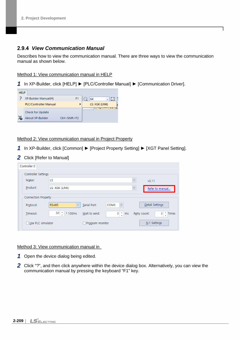
2. Project Development
2-209
View Communication Manual
Describes how to view the communication manual. There are three ways to view the communication manual as shown below.
Method 1: View communication manual in HELP
1 In XP-Builder, click [HELP] ► [PLC/Controller Manual] ► [Communication Driver].
Method 2: View communication manual in Project Property
1 In XP-Builder, click [Common] ► [Project Property Setting] ► [XGT Panel Setting].
2 Click [Refer to Manual]
Method 3: View communication manual in
1 Open the device dialog being edited.
2 Click “?”, and then click anywhere within the device dialog box. Alternatively, you can view the communication manual by pressing the keyboard “F1” key.

2. Project Development
2-210

3. Error Messages
3-1
3. Error Messages In XP-Builder, you may be notified of an error via a code in the Results pane or a message in a pop-up window. In these cases, locate the error in the corresponding sections that follow and take the appropriate steps to resolve the error.
3.1 Resolving Error Codes Found in the Results Pane The following table lists error codes that appear in the Results pane. The errors and suggestions for resolving them are listed in order by code number.
Code Error Message How to Resolve the Error
1000 There is no background image. The image set for the background does not exist. Choose another image for the background.
1001 There is (are) shape(s) that is out of the screen area.
Check the project in XP-Builder and make sure that all the shapes and objects are placed within the base screen.
1002 The “XX” screen No. “XX” is incorrect. Screen No. should be below 65535.
The screen number exceeded the limit. Specify a screen number smaller than “65535.”
1003 Invalid script “XX” is selected. The selected script does not exist. Replace the script with another one or create and register a new script.
1004 It is impossible to place more than “XX” popup window object onto the screen.
More than 8 window objects have been registered. Delete window objects until 8 or fewer remain.
1005 The size of the window exceeds maximum one of the HMI screen.
A window cannot be larger than the dimensions supported by the XGT Panel type specified. Set the window size to fit within the maximum dimensions allowed by the XGT Panel type.
2000 The image information is incorrect. (ex. 1. The image is not selected. 2. The image format is not valid.)
The specified image has been deleted or the file extension is incorrect. Select another image or select an image type that is supported.
2001 “XX” is incorrect. The specified display does not exist. Change the display type and number of the object.
2002 The address is incorrect. The device type is incorrect or the device address has not been set. Set or change the device address.
2004 A deleted or incorrect text table is used.
The specified text table does not exist. Specify another text table.
2005 The script “XX” that is not set is selected.
The specified script does not exist. Specify another script.

3. Error Messages
3-2
Code Error Message How to Resolve the Error
2007 The selected font “XX” cannot represent all of headers set “XX”.
The font you selected cannot be found or does not support the double-byte characters you used in the heading. You must reinstall the font, select a font that supports the characters in the heading, or change the heading.
2008 There is an object or figure that is out of the screen area.
The object is outside the boundaries of the window. Relocate the object or adjust the size until it fits within the window boundaries.
2009 The selected font “XX” is not installed in the system.
The font you selected cannot be found. You must reinstall the font.
2011 The selected image is of the type that is not supported.
The specified image type is not supported. Delete the image or select an image type that is supported.
2012 In the selected “XX”, the monitor address exists. Unexpected results may occur.
The variable type is incorrect in the script. Change the variable to a temporary variable to display a result without writing it in the standard device.
2013 The selected history alarm to print does not exist.
The history alarm list in a special switch or multi switch has been deleted. Specify another history alarm list.
2014 The maximum device address is exceeded (“XX” rows, “XX” columns)
The number of rows and lines you set exceed the maximum device range. Set the number of rows and lines to fall within the maximum device range.
2015 [“XX”] device is read-only. You have set a read-only device where a write device is required. Specify a write device for the object.
2016 There is no lamp case. Default case will be showed.
The specified condition for a word lamp does not exist. Add a condition for the word lamp.
2017 The keypad position is out of screen.
The key window location is outside the dimensions of the window boundaries. Change the window location to fit within the window boundaries.
2018 The Selected Logging Group ID : [“XX”] does not exist
The specified logging group does not exist. Register the logging group in the logging properties.
2019 Object that has same cursor group ID and input order exists. Arrange its order.
Two objects have the same automatic cursor and input order numbers. Change the automatic cursor and input order to unique numbers or remove the object with the redundant setting.
2021 The number of connected plc type is invalid
The specified controller does not support program monitoring. Change the function of the special switch or specify a controller that supports program monitoring.
2022 The ladder monitoring option is not set. Please check ladder monitoring option in [Common]-
The program monitor function has not been set for the object. Change the function of the special switch or activate program monitoring in the device

3. Error Messages
3-3
Code Error Message How to Resolve the Error [Project Property Setting]-[XGT Panel Settings]
settings.
2024 There is no (trend) item. At least, one (trend) item must be added.
Trend item has not been added. Add trend item(s)
2025 There is an object or figure that is out of the screen area.
An object or image location is outside the dimensions of the window boundaries. Change the object or image location to fit within the window boundaries.
2026 The range of Group Num. is from 1 to 253.
The specified number is beyond the allowable range for a group number. Specify a number from 1 to 253.
2027 The device address must be Internal device address.
Only an internal device type can be specified for this function. Change the device type to an internal device.
2028 The font of code page is not valid. Please check the [common]-[Project Property Setting]-[Language]-[multilingual font].
No font is specified for the selected language. Specify a font in the language settings.
2029 The program path, parameter or file path is not valid.
The path and filename are incorrect for an external program. Enter the correct path and filename.
2030 The selected object or feature it not supported in the current model.
This error occurs when an unsupported feature is selected in a project (e.g., when a PDF viewer object is used in an XP series panel). The following command will be cleared or deleted: The following option is not supported on the XP30-BTE, XP30-TTE, XP40-TTE, or the XP50-TTE. Rotate Object text Numeric input and Switch operation log Text display bit/word address Lamp and switch text blink If the N-state lamp object exceeds 6. (Only when
changed by bit.) VNC/ PDF viewer and associated special switch File browser and associated special switches Set parameters for an external program start
switch. View character string function in view history
alarm. If the N-state lamp object exceeds 6. (Only when

3. Error Messages
3-4
Code Error Message How to Resolve the Error
changed by bit.)
Select [Setting device size per Col.], [Setting of
cell size] in View Logging
Show lamp and switch trigger Bookmark Logging Trend Graph Word switch increase/decrease repeat. Set text intervals and line spacing for Figures
and Word Form Character/spacing cannot be set when the
length of the character string is set for switches/lamps.
2031 The following external storage devices are not supported:
This error occurs when an SD card is assigned as the external storage in an unsupported device, such as an XP series panel. The XP series is set on the SD storage device or the storage device is not supported. Change the external storage path to clear the error.
2032 The number of characters allowed is 1–4. (16 bits: 1–2, 32bits: 1–4)
This error occurs in a logging viewer object when the number of ASCII characters exceeds the allowed range. Change the number of ASCII characters to stay within the allowed range.
2034 Exceeded the maximum number of characters. ([0–255])
This error occurs in switch and lamp objects when the caption length exceeds 255 characters. Resize the caption length.
2036 Available in multilingual mode - Initializes keypad settings. Check the settings at [Language]-[Multilingual font], and [Keypad].
To use the Korean keypad for a text input object, set the language to Korea in the properties window ([Language]-[Multilingual font]-[Korean]).
2037 The language setting is invalid. This error occurs in [special switch] and [multi switch] objects, if a language used in the language change feature is deleted. Check [Language]-[Runtime language list] in the project properties, or change the language settings.
3000 The initial screen setting “XX” is incorrect.
The specified start screen does not exist. Specify an existing screen or create a new screen to use as the start screen.
3002 The key window [“XX”] is incorrect.
The specified key window does not exist. Specify an existing window or create a new window to use as the key window.
3003 The default screen-converting The window change device has not been specified.

3. Error Messages
3-5
Code Error Message How to Resolve the Error device is incorrect. Specify the device in the project properties window.
3004 The Global window 1-converting device is incorrect.
The window change device has not been specified. Specify the device in the project properties window.
3005 The Global window 2-converting device is incorrect.
The window change device has not been specified. Specify the device in the project properties window.
4000 The trigger device of the logging “XX” is incorrect.
The device has not been specified. Specify the device in the logging properties.
4001 The sampling device of the logging “XX” is incorrect.
The device has not been specified. Specify the device in the logging properties.
4002 The progress device of the logging “XX” is incorrect.
The device has not been specified. Specify the device in the logging properties.
4003 The cancel device of the logging “XX” is incorrect.
The device has not been specified. Specify the device in the logging properties.
4004 The file full device of the logging “XX” is incorrect.
The device has not been specified. Specify the device in the logging properties.
4005 The data clear device of the logging “XX” is incorrect.
The device has not been specified. Specify the device in the logging properties.
4006 The backup trigger device of the logging “XX” is incorrect.
The device has not been specified. Specify the device in the logging properties.
4007 The backup complete device of the logging “XX” is incorrect.
The device has not been specified. Specify the device in the logging properties.
4008 The logging area setting is incorrect.
The logging storage area has not been specified. Specify the storage area in the logging area settings.
4009 The maximum logging size is exceeded.(“XX” bytes).
The sum of the specified storage areas exceeds the maximum logging area size. Adjust the storage areas to fit within the maximum size.
4010 The logging area is not set. The logging storage area has not been specified. Specify the storage area in the logging area settings.
4014 The backup path of the logging is not selected.
The logging backup path has not been specified. Specify the backup path in the logging properties.
4015 The setting of the logging sampling device is incorrect. The maximum device size that is able to be set by the number of the sampling devices is exceeded.
The maximum number of devices to log has been exceeded. Reduce the number of device to log until it is within the maximum.
4016 The control device of the logging “XX” has a duplicated setting. The duplication of a control device is
Two logging control devices have the same number. Change one of the devices to a unique number.

3. Error Messages
3-6
Code Error Message How to Resolve the Error not permitted.
5000 The setting of the occurred alarm count device is incorrect.
The device has not been specified. Specify the device in the alarm properties.
5001 The setting of the monitoring device is incorrect or not applied to all registered alarms.
All required devices have not been specified or a device address is incorrect. Specify a device or verify specified devices in the flow alarm settings.
5002 The monitoring device is duplicated.
Two flow alarm devices have the same number. Change one of the devices to a unique number.
5003 [Flow alarm “XX”] The message setting is incorrect.
No alarm message has been selected. Select an alarm message.
7000 The setting of the not restored alarm count device is incorrect.
The device has not been specified. Specify the device in the history alarm properties.
7001 The setting of the alarm data clear device is incorrect.
The device has not been specified. Specify the device in the history alarm properties.
7002 The setting of the alarm print trigger device is incorrect.
The device has not been specified. Specify the device in the history alarm properties.
7003 The setting of the alarm print end device is incorrect.
The device has not been specified. Specify the device in the history alarm properties.
7004 The setting of the history alarm data obtaining-period is incorrect.
The specified history alarm acquisition cycle contains an error. Verify the cycle in the history alarm properties.
7005 There is no content of the string of the alarm group “XX”.
The alarm group display text has not been selected. Select display text in the group properties window.
7006 The string table setting of the alarm list “XX” is incorrect.
No text has been selected in the alarm list. Select a text table or create and specify a new text table for the alarm list.
7007 The monitoring device setting of the alarm list “XX” is incorrect.
The device has not been specified. Specify the device in the alarm list settings.
7008 The range setting of the alarm list “XX” is incorrect.
The specified conditional expression in the alarm list contains an error. Verify the expression in the alarm list settings.
7009 The detail window number setting of the alarm list “XX” is incorrect.
The detailed display setting in the alarm list contains an error. Verify the setting in the alarm list settings.
7010 The message setting of the alarm list “XX” is incorrect.
No alarm message has been set. Select a text string from a text table in the alarm list to use as the alarm message.
7011 The alarm lists “XX” and “XX” are set to watch the same device.
Two history alarms are set to monitor the same device. Specify a unique device for one of the alarms or delete one of the alarms.

3. Error Messages
3-7
Code Error Message How to Resolve the Error
7012 All the sampling devices of the alarm list “XX” should be set.
Some devices in the alarm list have not been specified. Specify all devices in the alarm list.
7013 The monitoring device of the alarm list “XX” is duplicated.
Two history alarms are set to monitor the same device. Specify a unique device for one of the alarms or delete one of the alarms.
7014 The word condition information setting of the monitoring device of the alarm list “XX” is incorrect.
The specified conditional expression in the alarm list contains an error. Verify the expression in the alarm list settings.
8000 The setting of the write trigger device is incorrect.
The device has not been specified. Specify the device in the recipe properties window.
8001 The setting of the read trigger device is incorrect.
The device has not been specified. Specify the device in the recipe properties window.
8002 The backup device setting is incorrect.
The device has not been specified. Specify the device in the recipe properties window.
8003 The setting of the recipe number device is incorrect.
The device has not been specified. Specify the device in the recipe properties window.
8004 The setting of the recipe block number device is incorrect.
The device has not been specified. Specify the device in the recipe properties window.
8005 The setting of the recipe data transfer complete device is incorrect.
The device has not been specified. Specify the device in the recipe properties window.
8006 The setting of the recipe data transfer error device is incorrect.
The device has not been specified. Specify the device in the recipe properties window.
8007 The setting of the recipe sampling device is incorrect.
The device has not been specified. Specify the device in the recipe properties window.
8008 The maximum recipe setting size (“XX” KB) is exceeded.
The sum of the specified recipes exceeds the maximum memory size. Adjust the number of data blocks within the recipes to fit within the maximum size.
8009 The backup path of the recipe is not selected.
Set the recipe backup path in the recipe properties window.
8010 The setting of the recipe sampling device is incorrect. Check whether the maximum device setting size is exceeded by the number of the recipe devices.
The device has not been specified or the number of devices exceeds the maximum allowed. Verify the specified devices in the recipe entry window.
9000 The download data size (“XX” bytes) exceeds the maximum size (“XX” bytes).
The total size of the selected data exceeds the maximum memory available for download to the XGT Panel. Unselect items to reduce the total data size and try again.
9001 The font used in the project (“XX”) The specified font is not installed on the system.

3. Error Messages
3-8
Code Error Message How to Resolve the Error is not installed in the system. Change to a font installed in the system. Otherwise, strings may not appear.
Install the font on the system or specify another font in the project properties.
11000 Cannot find the font file [“XX”]. The specified font cannot be found or is not installed on the system. Try restarting XP-Builder. If the problem reoccurs, install the font on the system or specify another font in the project properties.
11001 There is a character that cannot be printed with the font [“XX”]. Check whether a character that is of the incompatible font is used.
The selected font cannot display the special characters you are using. You must select another font that is capable of displaying the special characters.
13001 There is no script selected as operation.
The specified script does not exist. Specify another script or create a new script.
15000 Backup file conversion: Cannot open backup file.
The file may be in use. Ensure that the file is closed and try again.
15001 Backup file conversion: Cannot create output file.
The file may be in use. Ensure that the file is closed and try again.
15002 Backup file conversion: Cannot access backup file.
The file may be in use. Ensure that the file is closed and try again.
15003 Backup file conversion: Cannot read backup file.
The file may be in use. Ensure that the file is closed and try again.
15004 Backup file conversion: Cannot write to backup file.
The file may be in use. Ensure that the file is closed and try again.
16001 The write-prohibited device is used as a write device, in the script.
You have set a read-only device where a write device is required. Specify a write device for the script.
16002 The read-prohibited device is used as a read device, in the script.
You have set an input device where a read device is required. Specify a read device for the script.

3. Error Messages
3-9
3.2 Resolving Error Messages in Pop-up Windows The following table shows how to resolve error messages that appear in pop-up windows within the XP-Builder interface. These error messages have no error codes. They are listed in the following table alphabetically.
Error Message How to Resolve the Error
“XX” cannot be specified as an interval. The scale interval is between 0 and 10.
Set the scale interval for the graph between 0 and 10.
“XX” cannot be specified as the number of scale. The scale number is between 0 and 255.
Set the number of scales in the graph object between 0 and 255.
“XX” is not a 16 BCD data type. Enter a value between 0~9999.
If the size and form of the device is 16 bit BCD, you must set the conditional range between 0 and 9,999.
“XX” is not a 16 bit signed data type. Enter a value between - 32768~32767.
If the device size and type is signed 16 bit, you must set the conditional range between 32,768 and 32,767.
“XX” is not a 16 bit unsigned data type. Enter a value between 0~65535.
If the device size and type is unsigned 16 bit, you must set the conditional range between 0 and 65,535.
“XX” is not a 32 bit BCD data type. Enter a value between 0~99999999.
If the device size and type is 32 bit BCD, you must set the conditional range between 0 and 99,999,999.
“XX” is not a 32 bit signed data type. Enter a value between - 2147483648 and 2147483647.
If the device size and type is signed 32 bit, you must set the conditional range between -2,147,483,648 and 2,147,483,647.
A mobile GIF cannot be used as an image of an object/figure.
Select another image type.
A temporary directory is a place to store a temporary XGT file, so you cannot save or open a file here.
You cannot save or open files in the temporary directory. Specify another file location.
Caption “XX” cannot be all displayed with the currently set font “YY.” Choose the font meeting the entered contents.
This error occurs when the selected font cannot display the double-byte characters used in the caption. Change the font or translate the caption into a language that is supported by the selected font.
Changed into an indirect method. All the expressions of the built conditional sentences are deleted.
This message appears when the method of selecting the message or display for the word message, word component, or word window has been changed from [Status] to [Condition].
Communication connection has been failed.
There is no connection to the XGT Panel. Check the connection to the XGT Panel and the communication settings.
Connection passwords are different.
The password you entered is incorrect. Re-enter the connection password for the XGT Panel.

3. Error Messages
3-10
Error Message How to Resolve the Error
Disconnected. Try again after connection.
This error occurs when the XGT Panel is disconnected. Check the connection between your computer and the XGT Panel and ensure that the communication settings are correct.
Edit device is Read-Only. Use writable device.
Device input fails when the object does not support writing. Some objects support both reading and writing, but other devices, such as lamps, are read-only devices. To support device input, you must use a writable device, such as a switch, number input, or character input object. For more information about object types, refer to <4.3 Objects>.
File transformation error This error occurs when the file to be transferred cannot be read, due to an error in the file. Download the project to the XGT Panel again. Refer to <2.8.1 Transferring to an XGT Panel>.
Graphic library load has been failed.
The image library is corrupt or damaged. You must create a new image library.
More than 10M cannot be downloaded.
The XGT panel that is currently connected has only 10 MB of available memory. You cannot transfer a file larger than 10 MB.
No reply within the set period or disconnected
This error may occur during data transfer. Check the connection between your computer and the XGT Panel and the power cable for the XGT Panel.
Object library load has been failed. The object library is corrupt or damaged. You must create a new object library.
Password setting has been failed. The new password cannot be set. Check the connection to the XGT Panel and the communication settings.
Problem with data This error occurs when incorrect data is included in the transfer. Try the transfer again.
Save the project file. Enter a file name and save the project file.
Save the project first. This error occurs when you attempt to transfer a project without saving it first. Save the project and try again.
Shift to the XGT Panel program update mode.
This error occurs when you attempt to update the XGT Panel while the panel is in the normal operating mode, instead of the update mode. On the XGT Panel, touch and hold the screen to access the XGT Panel menu, and then select the update mode.
The “XX” set lines exceed the maximum display range.
The number of lines set in the object exceeds the horizontal dimensions of the screen.
The “XX” set rows exceed the maximum display range.
The number of rows set in the object exceeds the vertical dimensions of the screen. Set the number of rows below the maximum.
The backup data you want to download is not in XGT Panel.
This error occurs when there is no backup data in the XGT Panel.
The backup path has been incorrectly designated.
The download path for the font or image file is incorrect. Ensure that a USB drive is connected or a CF card is installed in the

3. Error Messages
3-11
Error Message How to Resolve the Error XGT Panel and then modify the download path in the project properties information.
The color is a user library larger than the number of colors that an XGT model can have now.
The XGT Panel that is currently connected does not support color. You must change the project settings to black and white or connect to an XGT Panel that supports color.
The compressed project file you want to download is not in the XGT Panel.
This error occurs when a compressed project file does not exist on the XGT Panel. To include the compressed project file when transferring a project to an XGT Panel, refer to <2.8.1 Transferring to an XGT Panel>.
The executable file in the device and the executable file to send are not the same.
The executable file has been modified. Transfer the entire project to the XGT Panel.
The file already exists. Would you overwrite?
A file with the same name exists in the directory you specified. Click [Yes] to select another destination for the file or [Cancel] to discontinue saving the file.
The file cannot be read. Check whether another program is being used.
The download file is locked. This may occur if the project file is being accessed by another connected computer. If that is case, ensure that the project is not open by more than one computer and try again.
The file is not writable. Check the disk memory.
This error occurs when there is insufficient memory in the XGT Panel to store the file. Check the memory in the XGT Panel and make additional memory available, if necessary.
The maximum value must be larger than the minimum value.
Set the maximum value to be larger than the minimum value.
The number of characters that can be displayed should be an even number.
Set the number of characters in the character indicator and character input/output units to an even number.
The number of the X axis displays that can be selected is between 3 and 120. Check and enter again.
The range of acceptable display numbers has been exceeded. Set the number of X axis displays in the trend graph [Display] between 3 and 120.
The password is incorrect. Enter the correct password.
The previous project information is not available.
An earlier version of the project does not exist on the XGT Panel. Transfer the entire project to the XGT Panel. Refer to <2.8.1 Transferring to an XGT Panel>.
The print template file does not exist.
The excel template for printing does not exist. You must create a new template.
The project header information is wrong.
The project header information is corrupt or incorrect.
The project ID is not correct. The project IDs in XP-Builder and the XGT Panel are different. Transfer the entire project to the XGT Panel. Refer to <2.8.1 Transferring to an XGT Panel>.

3. Error Messages
3-12
Error Message How to Resolve the Error
The selectable display numbers are from 1 to 4095. Check the number and enter again.
The range of acceptable display numbers has been exceeded. Specify a display number between 1 and 4,095.
The simulator cannot be executed. The simulator file does not exist. You must create a new simulator file.
The total number of figures should be larger than the number of figures below the decimal point.
Set the total number of figures larger than the number of figures below the decimal point.
The upload file is the same as the opened project file and cannot be saved. Do you want to specify another directory?
You cannot overwrite the project file, because it is open. Click [Yes] to select another destination for the file or [Cancel] to discontinue saving the file. To overwrite the project file, ensure the original file is closed and then try again.
The XGT Panel model does not match the model set in the editor.
This error occurs when you attempt to transfer a project to an XGT Panel model that is not the same as you have set in the project properties. Change the XGT Panel model n the project properties or transfer the project to the same type of panel you have specified in the project properties. Refer to <2.2.2 Viewing and Editing Properties>.
There is no executable file in the device. Send the entire XGT file first.
The executable file has been modified or is incomplete. Transfer the entire project to the XGT Panel.
This is not a 32 bit unsigned data type. Enter a value between 0~4294967295.
If the device size and type is 32 bit decimal, you must set the conditional range between 0 and 4,294,967,295.
This project has an error. Check the tool-data.
Recheck your data and correct any errors before transferring the project.
[Working]/[Engine connection status is in early stage]. Try again.
The XGT Panel is in the operational mode, instead of the update mode. Tap and hold the XGT Panel screen to open the menu. Then, tap [Update HMI Engine] and select the engine download mode.
Wrong display number. A display with the same number exists or the range of acceptable display numbers has been exceeded. Change the display number.
XGT INI file open error The initialization file for transferring the XGT Panel engine is missing or in use. Ensure that the initialization file is not in use and try transferring the project again.
XGT model types are not the same.
Change the XGT Panel model in the project properties or transfer the project to a different XGT Panel.
XGT Panel is not ready to receive. XGT Panel is carrying out another operation. Wait a moment and try again.
You can select only mobile GIF images.
Select a mobile GIF image.

4. Reference
4-1
4. Reference
4.1 Common Data Common data properties apply to the entire project. The following table describes common data types and their limitations.
Type Description Limit
Tag
Allows convenient management of devices when you register device addresses and enter tags for commonly-used functions.
10,000 per tag
Text Table Stores commonly used text. You can invoke text from the text table with various objects.
255 tables 10,001 entries per text table
Logging Records and saves monitored data in a file.
32 logs Bit: 64, Word: 100
Recipe Sets write or read values based on the conditions specified.
10,000 device recipes 255 basic recipes/ 65,535 recipe data 5,000 file recipe conditions
Flow Alarm Streams text across the bottom of the XGT Panel screen when a certain condition is met.
10,000 devices
History Alarm Saves the device value when a certain condition is met. You can also use this function with the special switch object.
10,000 • up to 8 groups at the root • each group supports 4
structure levels (depth 4) • up to 8 child per group
Scheduler Executes operations at specified times.
32
Script Controls objects and functions with program commands.
N/A
Sound Emits sounds from the XGT Panel. 512

4. Reference
4-2
Tags You can use tags to perform various functions. Tags can be used anywhere a device address can be entered and, when you change the value of a tag, the change will be applied to all devices with the same tag.
In the device field, you can enter a tag manually or click the keypad to the right of the field to specify the tag. When you enter a tag name manually, enter “=” as the first character. The checkmark icon will change to a “T” to indicate a tag.
To create a tag:
1 In the Project pane, double-click [Tag]. This will open a Tag tab in the editing area.
2 In the Tag Group tree, click the Default tag group (System tags cannot be edited).
3 In the tag list, set the tag name, device type, address, and a description for the tag.
Type Description
Numbers A name cannot begin with a number (e.g., “3ABCD”).
Special Character The following special characters are allowed in the tag names: “_(underscore)”, “%”, “$”, “#”, ”@”, “&”, “*”.
Blank Character Blank characters before or after the name are not regarded as a part of the tag name.
Device Name A device address expression cannot be used as a name (e.g., “D0012,” or “%MW123”).
Hexadecimal Number A hexadecimal number (ex. H234) cannot be used as a name.
Note
• Tag names must be unique. The below table describes rules for tag names. • All tags are registered on a single table. The changes made to the table affect all the objects
where the tag is used. • Consecutive copying is not performed when you specify a device address with a tag. • You can double-click the title column in the table to sort the list in ascending or descending
order. • “ : ”(colon), which is the separator between “group name” and “tag name”, cannot be used for
tag name. • You can insert a row by pressing the Enter key in the name cell of the last row or by using the
pop-up menu/drag and drop.
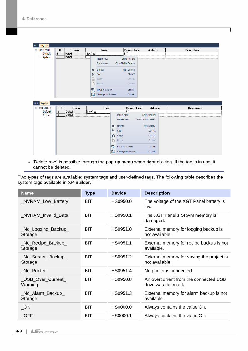
4. Reference
4-3
• “Delete row” is possible through the pop-up menu when right-clicking. If the tag is in use, it cannot be deleted.
Two types of tags are available: system tags and user-defined tags. The following table describes the system tags available in XP-Builder.
Name Type Device Description
_NVRAM_Low_Battery BIT HS0950.0 The voltage of the XGT Panel battery is low.
_NVRAM_Invalid_Data BIT HS0950.1 The XGT Panel’s SRAM memory is damaged.
_No_Logging_Backup_ Storage
BIT HS0951.0 External memory for logging backup is not available.
_No_Recipe_Backup_ Storage
BIT HS0951.1 External memory for recipe backup is not available.
_No_Screen_Backup_ Storage
BIT HS0951.2 External memory for saving the project is not available.
_No_Printer BIT HS0951.4 No printer is connected.
_USB_Over_Current_ Warning
BIT HS0950.8 An overcurrent from the connected USB drive was detected.
_No_Alarm_Backup_ Storage
BIT HS0951.3 External memory for alarm backup is not available.
_ON BIT HS0000.0 Always contains the value On.
_OFF BIT HS0000.1 Always contains the value Off.

4. Reference
4-4
Name Type Device Description
_T200MS BIT HS0000.6 Alternates between On and Off every 200 milliseconds.
_T1S BIT HS0000.7 Alternates between On and Off every second.
_T2S BIT HS0000.8 Alternates between On and Off every 2 seconds.
_T5S BIT HS0000.9 Alternates between On and Off every 5 seconds.
_T10S BIT HS0000.A Alternates between On and Off every 10 seconds.
_T30S BIT HS0000.B Alternates between On and Off every 30 seconds.
_T60S BIT HS0000.C Alternates between On and Off every 60 seconds.
_OSVER_MAJ WORD HS0001 Display the OS version info (Major) of the XGT Panel.
_OSVER_MIN WORD HS0002 Display the OS version info (Minor) of the XGT Panel.
_YEAR WORD HS0004 Time info [Year] for the XGT Panel.
_MON WORD HS0005 Time info [Month] for the XGT Panel.
_DAY WORD HS0006 Time info [Day] for the XGT Panel.
_HOUR WORD HS0007 Time info [Hour] for the XGT Panel.
_MIN WORD HS0008 Time info [Minute] for the XGT Panel.
_SEC WORD HS0009 Time info [Second] for the XGT Panel.
_BASESCREEN_NO WORD HS0010 Display the number of the current Base screen.
_GLOBALWNG1_NO WORD HS0011 Display the number of the #1 global window.
_GLOBALWNG2_NO WORD HS0012 Display the number of the #2 global window.
_SECURITY_NO WORD HS0013 Display a defined security level.
_ZERO WORD HS0014 Always contain the value of zero.
_C500MS WORD HS0015 Increase value by 1 every 500 milliseconds.
_C1S WORD HS0016 Increase value by 1 every second.
_C2S WORD HS0017 Increase value by 1 every 2 seconds.

4. Reference
4-5
Name Type Device Description
_C5S WORD HS0018 Increase value by 1 every 5 seconds.
_C10S WORD HS0019 Increase value by 1 every 10 seconds.
_Change_to_Screen WORD HS0500 The device to change the Base screen (operates in window change mode).
_DAY_OF_WEEK WORD HS0003 Time info [Day of week] for the XGT Panel (Sun=0 to Sat=6).
_T50MS BIT HS0000.4 Alternates between On and Off every 50 milliseconds.
_T100MS BIT HS0000.5 Alternates between On and Off every 100 milliseconds.
_T500MS BIT HS0000.F Alternates between On and Off every 500 milliseconds.
_No_Memo_Backup_ Storage
BIT HS0951.5 No external backup memory available.
_XPLinkParam_Load_ Error
BIT HS0100.2 Failed to process the parameter uploaded from XP-Manager.
_XP_VNC_Sever_ON BIT HS0100.1 XP-VNC server is running.
_Web_Sever_ON BIT HS0100.2 Web server is running.
_Size_All_Flash_Low WORD HS0027 The total flash memory capacity (low-order, double word).
_Size_All_Flash_High WORD HS0029 The total flash memory capacity (high-order, double word).
_Size_Available_Flash_ Low
WORD HS0031 The available flash memory capacity (low-order, double word).
_Size_Available_Flash_ High
WORD HS0033 The available flash memory capacity (high-order, double word).
_Size_All_USB_Low WORD HS0035 The total USB memory capacity (low-order, double word).
_Size_All_USB_High WORD HS0037 The total USB memory capacity (high-order, double word).
_Size_Available_USB_ Low
WORD HS0039 The available capacity of USB storage (Low-order, double word).
_Size_Available_USB_ High
WORD HS0041 The available capacity of USB memory (High-order, double word).
_Size_All_CF_Low WORD HS0043 The total CF card memory capacity (low-order, double word).
_Size_All_CF_High WORD HS0045 The total CF card memory capacity (high-

4. Reference
4-6
Name Type Device Description order, double word).
_Size_Available_CF_Low WORD HS0047 The available CF card memory capacity (low-order, double word).
_Size_Available_CF_ High
WORD HS0049 The available CF card memory capacity (high-order, double word).
_USB_Attatched BIT HS0051.0 Display whether or not the USB storage device is connected.
_CF_Attatched BIT HS0051.1 Display whether or not the CF card is connected.
_N1_Token BIT HS0070.0 Connected with a token during N: 1 communication.
_N1_Token_Hold BIT HS0501.0 Set the panel to hold the token for a specified time.
_N1_Token_Station WORD HS0071 Display the station number of the node holding the token during N: 1 communication.
_IDLE_TIME_COUNTER WORD HS0502 Increase the count every second that you do not touch the panel or use the mouse pointer.
_XP_VNC_INTERLOCK BIT HS0503.0 When turned on, a user connected via XP-VNC cannot make inputs with a mouse or keyboard.
_N1_Token_Count WORD HS0072 Display the acquired number of the token during N: 1 communication.
_N1_Station WORD HS0073 Display the station number of the XGT Panel during N: 1 communication.
_1_ON BIT HS0000.D Set to turn on the first time devices are scanned. The tag is skipped on subsequent scans. You can use this tag to initialize a program.
_Enable_XP_Remote BIT HS0504.0 Display whether or not the device can be operated with XP-Remote.
_Has_Ctrl_Right BIT HS0075.0 Display whether or not the XGT Panel has the right to operate. If XP-Remote has the right, it turns off.
_XP_Remote_Count WORD HS0076 Display the number of XP-Remote instances that are connected to an XGT Panel.
_Ctrl_Right_XP_Remote_ID WORD HS0077 Display the ID of an XP-Remote instance that has the right to operate.

4. Reference
4-7
Name Type Device Description
_Ctrl_Right_XP_Remote_IP WORD HS0078 Display the IP address of an XP-Remote instance that has the right to operate (32-bit).
_RS232C_Over_Current_Warning
BIT HS0950.9 Overcurrent detected in an XGT Panel from a PLC connected via RS-232C (only for the iXP series).
_VM_Mod_Over_ Current_Warning
BIT HS0950.A Overcurrent detected in an XGT Panel from a PLC connected via the VM module (only for the iXP series).
_EXT_Mod_Over_ Current_Warning
BIT HS0950.B Overcurrent detected in an XGT Panel from a PLC connected via the expanded mode (only for the iXP series).
_No_Sound_File_ Storage
BIT HS0951.8 No external memory for saving the sound file is available.
_SD_Attatched BIT HS0051.2 Display whether or not the SD card is connected.
_Size_All_SD_Low WORD HS0058 The total SD card memory capacity (low-order, double word).
_Size_All_SD_High WORD HS0060 The total SD card memory capacity (high-order, double word).
_Size_Available_SD_Low WORD HS0062 The available SD card memory capacity (low-order, double word).
_Size_Available_SD_ High
WORD HS0064 The available SD card memory capacity (high-order, double word).
_Alarm_ Norecovery_Device_Num
WORD HS0093 Device shows number of unrecovered alarms.
_Alarm_Norconfirm_ Device_Num
WORD HS0084 Device shows number of unconfirmed alarms.
_BARCODE_SAVEIN_KEYCODE
BIT HS0501.2 Save keyboard input to barcode device
_BARCODE_INITIAL_TIME WORD HS0507 Wait timeout for storing keyboard input data.
_XP_VNC_Server_Control BIT HS0503.1 VNC Server Control

4. Reference
4-8
To set a tag as a device address:
1 Double-click on an object to open the properties window.
2 In the device field, enter a tag manually or click the keypad to the right of the field to specify the tag. When you enter a tag name manually, enter “=” as the first character. The checkmark icon will change to a “T” to indicate a tag.
3 Check the checkbox next to Tag.
4 Select a tag group and a tag. You can view the available tag list.
5 Click [OK]. The tag icon will appear in the device field.

4. Reference
4-9
Note
• When registering a new tag, enter “ = “ in front of the tag name to be registered and enter it in the device address window to register a new tag. If the tag group is not “Default” or “System”, the group name must be entered together in the address window, such as “Group Name” + “ : “ + “Tag Name”.
• Changing the tag type (bit or word) can cause errors. • You can change the tag address in the edit box at the bottom of the tag dialog box. The address
changes when the focus of the cursor is released in the edit box.
To delete a tag:
1 Select tags in the tag table.
2 Press the Delete key on the keyboard.
However, if the tag is used in the project, the following message is displayed and it is not deleted. In this case, you must use Find / Change to find the object or element being used in the system to delete the tag or delete after changing the tag.
With XG5000 software, you can export all the tags used in a project, and then import them into XP-Builder.
To import a file of tags from the XG5000:
1 Right-click a tag group.
2 Click [Import XG5000 Variable].

4. Reference
4-10
3 Click and open a file containing tag data (*.csv).
4 Click [Open].
This will create a new tag group (“NewPLC”).
Note
• Follow the instructions to export tag data to a CSV file.

4. Reference
4-11
1. Run an XG5000 program of version 3.0 or higher. 2. Click [Project] ▶ [Save as Variables/Comment]. 3. Select the variables and click [OK].
• If the PLC type is different when you import the data, an error will occur. • Other than bit and word devices are not imported properly.

4. Reference
4-12
Text Tables Text tables allow you to store and manage text for reuse, translation, and simplified management. The advantage of using text tables is that you can register text strings and then use them throughout the project. For example, you can fetch text from a text table to use as an object caption and format the color, size, and other font properties. You can also create multilingual interfaces by adding language columns to the text table and registering translations for the text strings.
The following are examples of text table applications for bit and word messages based on the device conditions.
<Bit message>
<Word message>

4. Reference
4-13
To create a text table:
1 In the Project pane, right-click [Text Table].
2 Click [Insert].
3 Enter text and set properties, such as font color and typeface.
Note
• Window title: When a string for a window title is taken from a text table, text properties of the text string in the table, such as font size, colors, and other text styles (italic, underlined, bold, etc.), are ignored. The selected string is displayed in the title section of the window in white 15 px characters.
• Sorting the text table: You can double-click the title column in the table (except for the color column) to sort the list in ascending or descending order.
When you enter text in a text table, the text appears in the language currently set in the project
properties.
To specify languages in a text table:
1 In the Project pane, double-click a text table to open it.
2 Right-click anywhere in the text table and click [Property].

4. Reference
4-14
3 Click languages from the language list and then click [OK]. Columns for alternate text will be added for as many languages as you select in the language list.
4 Enter the translation of the string in the appropriate field.
It will be available for display in objects when the user selects the alternative language from the
drop-down list on the XP-Builder toolbar. To add additional languages to the list of supported languages, refer to <2.2.2.6 Changing Languages>.

4. Reference
4-15
Note To support multiple languages, the operating system you are using must support the language as well.
To apply text from a text table:
1 Create an object that supports the use of text tables (see the table that follows).
2 Click [Text] in the object property window or click [Header] for a History Alarm Viewer object. To apply the text table to a Flow Alarm or History Alarm, select one of the text tables from the Text Table Name field in the Flow Alarm editing area or the Text Table field in the History Alarm editing area.
3 Select a text table:
Type Description
Bit Message Click [On] or [Off] ▶ [Text Table].
Word Message Select the message on Basic tab.
[Message Device]: Selecting message number on the text table to display. - Indirect: Displays message of the number corresponding to the device value on the text table. - Case: Displays message that meets the conditions set in the Text

4. Reference
4-16
Type Description tab. - Fixed: Displays the message on the text table selected. - Device: Select the text table corresponding to the device value.
Bit Switch Word Switch Change Screen Switch Special Switch Multi Switch Bit Lamp Word Lamp N-State Lamp
Check the checkbox next to Use Caption, check the checkbox next to From Text Table, and then click [Text Table].
History Alarm Viewer
Click [From Text Table in Header Edit] and double-click the Title area.
4 Select a text string (if necessary).
Note You can set the text to appear differently based on the value of the device.
You can automatically add object captions to a text table.

4. Reference
4-17
To create a text table of captions:
1 Create objects with text captions on the editing area.
2 Click [Tool] ▶ [Register Object Caption to Text Table Automatically].
3 Enter a name for the text table, select an editing language, and click [OK]. The text table will appear in the Project pane.
You can double-click the name of the text table in the Project pane to ensure that the captions
have been listed on the text table.
Note
• Up to 10,001 strings can be registered to the text table. To add more than 10,001 entries, you must create a new text table.
• A total of 255 string pages can be created in the Text table, and IDs and names can be changed directly on the tree. The ID is from 1 to 65534 (1 to 255 for economic type).
• If the following message appears when you delete the text table page from the tree or change the ID, it means that the table is being used in the project. In this case, you need to first find out the elements used for deletion by Find/Replace All, or change them to a text table with a different ID.

4. Reference
4-18
Logging You can use up to 32 logs to record and save device values to a file when specified conditions are met. Logging can be used to trace device trends. You can view the logs in the Logging Viewer or Logging Trend Graph object. Refer to <4.3.11 Logging Viewer Object> for detailed information.
Type Description Periodical Logging (Time)
Logging starts on a specified schedule and is repeated periodically, as specified in the scheduler. The log can repeat up to 100 times. When the repetition timer reaches the specified limit, the device values are saved in the file. The example below shows three logging data in 10-minute intervals.
Periodical Logging (Bit Device)
When the logging device turns on, logging begins. You can set the logging intervals and repetition numbers.
Conditional Logging (Bit Device)
Logging begins when the logging device is changed, or when it is turned on or off. Logging does not repeat, unless the device is changed, or it is turned on or off again.

4. Reference
4-19
To create a log:
1 In the Project pane, double-click [Logging]. This will open a Logging tab in the editing area.
2 Double-click anywhere in a field to specify the following settings. Logging Device:
Function Description
No. The number of the log.
Target Device Specify the device to read. Enter the device address manually or click the keypad to the right of the field to specify a device.
Device Count Specify the number of devices to read consecutively from the start device - In case of target device is Bit: maximum of 64 bits - In case of target device is word: maximum 100 words.
Description Enter a description for the logging process.
Logging Condition:

4. Reference
4-20
Function Description
Period Specify a period for logging: every hour, every day, every week, every month, or once. Use the dropdown menu to set a specific operating interval. For example, if you select “Every hour”, you can set the specific minute when the logging will occur. If you do not specify the minute, the logging will occur every hour, on the hour.
Device (BIT) Specify a bit device and condition to trigger periodic logging (rising edge or falling edge).
Repeat By Set the number of repetitions for the logging operation (max. 255 times). The starting point for repeating the logging operation is when the device condition is met.
Repeat Period Set the file recording cycle, if logging conditions are met.
Device(BIT) from Conditional Logging
Specify a bit device and condition to trigger conditional logging (rising edge, falling edge, or on change).
Logging Progress Specify the device that will display the logging process. The bit device stays turned on until the cycle is completed.
Stop Logging Specify a device to stop logging. Logging stops when the specified devices turns on. Once logging stops, it does not continue on the next cycle or repetition. The stop logging device operates on the rising edge.
Logging Area Full Specify a device to activate when the storage area (NVRAM) for logging data is full.
Clear Logging Area Specify a device to clear the storage area for logging data. When the device turns on, data in the specified area is

4. Reference
4-21
Function Description deleted.
Logging Area Clear Complete
Specify a device to activate when data in the storage area for logging data is deleted.
Note
• If you set the periodic logging setting to Period, you can set the logging to repeat up to 255 times. Logging starts at the time you set and repeats as many times as specified at the designated period.
• If you set the periodic logging setting to Device (Bit Device), logging starts when the bit device is turned on or off and repeats as many times as specified at the designated period.
Repetition cycle
Logging
Examples of periodic conditional operation Setting: Repeat 4 times
Logging start timer ON
Repetition timer ON
Logging progress
Logging start timer ON

4. Reference
4-22
Backup Area/Buffer Manage/Backup CSV Format:
Function Description
Storage for Backup Data
Set a storage area for logging backup data. Refer to <4.7.1.1 File Path for Logging Backup> for detailed information about storing backup files.
Use Ring Buffer Set this option to overwrite logging data when the storage area is full. Otherwise logs cannot be saved even if the condition is met.
Overwriting occurs from the oldest file.

4. Reference
4-23
Function Description
This option cannot be used in conjunction with the Auto backup if area full option.
Do Not Clear Log Area at Backup
Set to retain logging data when data is backed up to the area specified in the project properties. When logging data is backed up, the data in the internal memory is deleted. However, some specific objects, such as the logging trend object, need to retain data even though it is backed up. At this time, set this option to retain the data. If you set this option, the logging area setting is changed to Use Ring Buffer automatically.
Auto Backup if Area Full
Set to back up logging data automatically when the storage area for logging data is full. This option cannot be used in conjunction with the Use ring buffer option. When the storage for logging data is full, it is backed up to the specified location. After backup, the data is deleted, and then the new data is saved from the first space.
.
.
.
.
.
Logging data n
Logging data 5
Logging data 4
Logging data 3
Logging data 2
Logging data 1
Storage location is shifted and the logging data is recorded from the first space.

4. Reference
4-24
Function Description
Backup Device Specify a device to trigger the backing up of logging data.
Send E-mail after Backup Done
Set to send an email when logging data is backed up.
Complete Device Specify a device to activate when logging data is backed up.
Setting CSV File Format
Click to specify the layout of backup data in a CSV file. Refer to the <Logging Common Property> section that follows for detailed information.
File Type Select a backup file type (CSV, Encrypted CSV, CSV+PDF). A CSV file can be opened using applications such as Memo Pad and MS Excel. An encrypted CSV file (with the file extension CSVE) can be converted to a CSV file using the CSV Converter ([Tool]-[CSV file converter]). Refer to <4.6 Using the CSV Converter> for more details.
File Name Device
Specify a device to contain the file name of backup data. From the specified device, four consecutive word devices are used as the file name. If the device fails to read the data or the name string does not exist in the data, the backup file is saved as “noname.CSV.”
BYTE Swap of File Name
Set to run a byte swap for the string value when using the file name device.
File Name Length
Set the length (in bytes) of the file name.
Append Data to CSV File
Set to add new backup data to the end of the previous CSV file. By default, the logs that are backed up as the appendix to a CSV file are stored without creating the date folder. You can select the ‘File Generation as Date/Time Folder structure’ option to create new folders by dates and store the backup files in the folders.

4. Reference
4-25
Function Description Creating folder structures by dates is explained in <4.7 Managing External Storage Sources for Backup>.
Number of Backup Data in CSV File
Set the number of logs to save in a CSV file (maximum of 65,000).
Create Logging No. Directory
When logging, number directory is created and backed up below. If this feature is disabled (unchecked), backup file is created without creating number directory. However, only one of several loggings can be disabled (unchecked) “Create Logging No. Directory.”
CSV + PDF File BackUp (Version 3.20 or later applied):
* PDF file backup is only available on the iXP, iXP2, wXP models.
Function Description
File Type Select a backup file type (CSV, Encrypted CSV, CSV+PDF). A CSV file can be opened using applications such as Memo Pad and MS Excel. An encrypted CSV file (with the file extension CSVE) can be converted to a CSV file using the CSV Converter ([Tool]-[CSV file converter]). Refer to

4. Reference
4-26
Function Description <4.6 Using the CSV Converter> for more details.
Backup Device If the file type set as “CSV + PDF”, • CSV file: The data saved in the logging data
storage area (NVRAM) is saved to the designated storage.
• PDF file: adds the contents of the CSV file to the template file (.xls format) entered by the user and backs it up as a pdf file. The PDF file name and path are the same as the CSV file and the extension is PDF.
If the “Auto Backup if area full” option is set, CSV file backup is performed when the storage space is used up and PDF files are also backed up.
Complete Device Turns on when both CSV file and PDF backup to the designated storage are successful.
Setting CSV File Format Click to specify the layout of backup data in a CSV file. Refer to the <Logging Common Property> section that follows for detailed information.
File Name Device Specify a device to contain the file name of backup data. From the specified device, four consecutive word devices are used as the file name. If the device fails to read the data or the name string does not exist in the data, the backup file is saved as “noname.CSV.”
File Name Length Set the length (in bytes) of the file name.
Byte Swap of File Name Set to run a byte swap for the string value when using the file name device.
PDF Report – Device in Progress of Backup
Displays the backup status of PDF files. If the PDF file is being backed up, the device turns “ON” and when it is completed, it turns “OFF”. Unlike CSV backup, PDF file backup cannot be backed up to multiple files at the same time, and the next PDF backup is performed only when the previous PDF backup is completed. Therefore, when a PDF file backup is requested, if the device is “ON” during backup, the PDF backup function is not performed.
PDF Report – Template File
This is a form file to output the contents backed up in the CSV file. The template file format only supports .xls (97-2003 excel) format. The user can output the data to be printed as a PDF file by entering reserved words in the template file. - List of available reserved words Reserved Word Input Value Required
or Not
#FILEDATE Date of the PDF file was X

4. Reference
4-27
Function Description
created
#NUMBER Total number of times logging has occurred (Num. of log value in CSV file)
X
#DATE Time when logging was performed (Value of Data line in CSV file)
X
#STATUS Whether logging is successful (Status line value is CSV file)
X
#DATA0, DATA1, …
Logging Data (Ex. #DATA0 =< logging value of index 0)
O
- Import (…): Import the template file on the project using [Import]. If the set template file is re-edited or changed, it is applied to the project until [Import] is performed again. The last application date and time of the template file are displayed on the screen when [Import] is performed. - Export: User can [Export] the template file set/saved in the project to the path that user wants to save.
PDF Report - Font Set the font used for PDF backup. Only 1 font can be set regardless of the number of CSV + PDF file backups. Depending on the font, Korean, English, or multilingual support is different. If the font you set does not support the language in the template file, the characters may be broken or not visible.
Delete old file if disk is full
The oldest CSV and PDF files will be deleted if the option “Delete old file if disk is full” is set in the logging data area.
PDF Backup Model PDF file backup is only available on the iXP, iXP2, wXP models.
Note
• Template file - Reserved words (#NUMBER, #DATE, #STATUS, #DATA0, #DATA…, etc.) for outputting CSV file data in the template file must all be entered on the same line. - Only the first sheet of the template file can be converted to PDF
• PDF size and data output size. - The converted PDF size is A4 size, and the orientation is based on the orientation of the template file(.xls) file can be modified in print settings). - The maximum number of columns that can be printed is 255. If the line exceeds the A4 size, it continues the next page. - The text, image size, etc. in the cells displayed in the PDF are determined in proportion to the fixed size (A4 standard).
• Font - Some Korean fonts are not compatible with the PDF conversion, so Korean

4. Reference
4-28
characters may not be output properly. In this case, use a compatible font as shown below. - Korean compatible fonts: Gulim, Batang, Dodum, Malgun Gothic, Gungseo
• PDF conversion items - Some character formats (text color, fill color, etc.) are supported, and character styles such as Bold and Italic are not supported. - Support for merged cells. - Image files (bmp, png, gif, jpg format) are supported. - Data such as functions, charts, graphs, etc. other than text and images are not converted to PDF.
Logging Common Property:
The total size of all logging areas cannot exceed the size of each type of logging area.
Function Description
a. Logging Area Set the size of the data saving area for each log. The logging area can be calculated by the number, size, and frequency of devices.
b. Logging Area Size Calculate the size of the area required to save logging data: • Bit: [(Repeat count + 1) * 24]. The storage size that occurs at one time is fixed to 24bytes. Bit is unconditional(DWORD64), regardless of the device count. • Word: [(Repeat count + 1) * (Device count *2 + 16)]. In case of word, one header of 16bytes is recorded before logging. • Double word: [[(Repeat count + 1) * (Device count *4 +
16)].
a b

4. Reference
4-29
Note The maximum size of a logging area varies by the panel type: • iXP/IPC/iXP2 Series: 510 KB • XP Series TTA model: 256 KB • XP Series BTE/TTE models and eXP, eXP2 Series: 64 KB

4. Reference
4-30
To set an external location for backing up log data:
1 Click [Common] ▶ [Project Property Setting] ▶ [Storage Settings].
2 Set the backup storage location in Logging data.
To specify the format for backup data:
1 In the Project pane, double-click [Logging].
2 Double-click a log entry to open the Logging window.
3 Click [Backup Area/Buffer Manage/Backup CSV Format].
4 Set the location for backup data in the Storage for backup data field.
5 Click [Setting CSV file format].
6 Specify the following options:
Data Information

4. Reference
4-31
Function Description
From Text Table Set to import header information from a text table.
Header Specify a header for the backup file. If you select the From Text Table option, click [Header] to locate the table.
Data Format Set the format for displaying the time and date.
Digits Set how many digits are used for data.
Decimal Digits Set how many decimal digits are used for data.
Zero Fill If you have selected right justification, select this option to insert zeros (0) before the number.
Apply all the Logging Click to change the backup format for all log data.
Close Save your changes and close the dialog box
Data Information The number of data columns shown varies based on the number of logging devices specified.
Store as a Single String The logged data is not interpreted as numbers but as character strings when they are saved as a file.
Language Select the language to use for the saved logging data. If the logged data is saved as character strings during a backup of logging data, the data is interpreted as Unicode values and saved as character strings. Character strings are saved on a device in multibyte format and a conversion table (also referred to as a code page) is needed to convert the multibyte format to Unicode format. One language in [Project Property setting]–[Language]–[Multilingual font] can be selected at a time. Therefore, if a Korean font is specified in [Project Property setting]–[Language]–[Multilingual font], Korean must be selected as the language for logging backup before Korean language logging data can be displayed during logging backup. Refer to <2.2.2.6 Changing Languages> for more information.

4. Reference
4-32
Recipes You can use recipes to save and reuse process data. You can write or read data to a large number of consecutive devices with recipes. You must set both read and write devices to execute recipes.
Two types of recipes are available: basic and file recipes.
Type Description
Basic Export data to non-volatile internal memory in an XGT Panel or to external memory devices. If the power supply to the XGT Panel is interrupted, the most recent data is saved on the NVRAM. The saved data is used for reading or writing operation when monitoring resumes.
File The data is stored in a CSV file. You can store the file on an external device, such as a USB drive or CF card, to run it on an HMI. The name of the file recipe is written as shown below: • /Storage Card_root/XP_Recipe/XPR00000.CSV • /USB Storage_root/XP_Recipe/XPR00000.CSV Refer to <4.7.1.2 Path for Recipe Backup> for detailed information about storing the backup files. When you open the CSV file, you can view the data as shown below:
Basic Recipes The following examples explain the read and write operation using basic recipes.
Read device operation When the read device is in a rising or falling edge, data is read from the specified starting device address for as many devices as have been specified.

4. Reference
4-33

4. Reference
4-34
Write device operation When the write device is in a rising or falling edge, data is written from the specified starting device address to as many devices as have been specified.

4. Reference
4-35

4. Reference
4-36
To create a basic recipe:
1 In the Project pane, right-click [Basic Recipe].
2 Click [Insert].
3 Set the following properties:
Option Description
Name The name of the recipe. You can register up to 255 recipes (1 to 255). If you want to change the name, right-click the recipe name in the Project pane and click [Rename].
Device Set the device address to transfer the recipe data.
Data type View the data type of the device. When you enter the value in the data block, the data type is changed according to the data type.
Description Enter a description for the recipe.
No. of Device Set the number of devices. Recipe data will be transferred consecutively from as many devices as you specify.
Block count Set the number of data blocks. The maximum number of available blocks is 255 (0–254).
a. Device View the device list. Recipes use consecutive data sets, so you cannot set each device address.
b. Data The block number is assigned starting from 0 and you cannot change it. If you reduce the block number, the data set with biggest block number is deleted first.
Note The writing and reading functions cannot be executed simultaneously. When two devices meet the same condition simultaneously, writing will be performed first.
a b

4. Reference
4-37
Updating and Maintaining Default Recipe Data Recipe data files are stored in the XGT Panel’s non-volatile memory or on an external storage device. The most recently saved data is retained even when the power is turned off. When the power is turned on again and device monitoring begins, the last stored data is used for subsequent read and write operations.
If the recipe data is set to be saved on an external storage device and not in SRAM, the recipe data is recorded in a file format on the storage device when monitoring begins. The file content is updated when the recipe data read operation is performed. Changes are retained as long as the file remains on the storage device, and the file is generated again when it is deleted or another storage unit is mounted. In this situation, the previously updated data is not retained and is reset to the recipe data that is initially set in XP-Builder.
The recipe data is not deleted when there is a partial download or when the download is only of the changes in the project. However, the stored recipe data is deleted in all downloads if the [Delete all monitoring data] option is selected.

4. Reference
4-38
Backup and Restoration of Default Recipe Data The default recipe data can be backed up in the CSV file format. One backup file is generated for each recipe. To restore default recipe data to a selected file, select a backup file from the File Explorer object and click the [Restoration of Basic Recipe Backup] special switch.
Refer to <4.7.1.2 Path for Recipe Backup> for detailed information about storing recipe backup files.
The process of restoring the default recipe data may fail in the following situations. For information about data transmission errors, go to [Error Device].
The recipe file selected from File Explorer is the backup file generated by another project. The recipe setting changed after the selected backup file in File Explorer was created. A user modified the recipe backup file or the file is corrupted due to a storage device error.

4. Reference
4-39
To set Basic recipe properties:
1 In the Project pane, double-click [Recipe Property]. This will open a Recipe Property tab in the editing area.
2 Set the following properties: <Recipe Common Settings>
Option Description Trigger Device to Write
Set to specify a device for writing data. Set the condition to trigger the action (rising edge or falling edge). Enter the device address manually or click the keypad to the right of the device field.
Trigger Device to Read
Set to specify a device for reading data. Set the condition to trigger the action (rising edge or falling edge). Enter the device address manually or click the keypad to the right of the device field.
Recipe Type Device Specify the device that will control the recipe type. If the lowest bit of the device is 0, a basic recipe will be executed. If the lowest bit of the device is 1, a file recipe will be executed. Enter the device address manually or click the keypad to the right of the device field.

4. Reference
4-40
Option Description
Read/Write Complete Device
Specify a bit device to turn on when data transfer is completed. Enter the device address manually or click the keypad to the right of the device field.
Basic recipe Storage Set a storage location for data from a basic recipe (Flash, CF Card, USB, or SD card). You can also configure storage options in Storage Settings in the Project Property window.
Error Device Specify a bit device to turn on when a problem occurs with the data transfer. Enter the device address manually or click the keypad to the right of the device field.
Error No. Device Specify a device to return a pre-defined error number if a problem occurs with the data transfer. The error numbers include:
No. Description 1 There is missing data.
2 The data does not match the current transmission condition.
3 The data count exceeds the count specified by the transmission condition.
4 The decimal point position used in the data exceeds the decimal point position specified by the transmission condition.
5 The data value exceeds the maximum value of the format specified by the transmission condition.
6 The data value is less than the minimum value of the format specified by the transmission condition.
11 The recipe number of the default recipe was not read.
12 There is no recipe that corresponds to the currently specified number.
13 The block number of the default recipe was not read.
14 There is no recipe block corresponding to the currently specified number.
15 The transmission condition number of the file recipe was not read.
16 There is no file recipe transmission condition that corresponds to the currently specified number.
17 The file number of the file recipe was not read.
18 There is no recipe file that corresponds to the currently specified number.
19 The data in the file recipe is not valid.
20 The total data count in the file recipe is less than the data count specified by the transmission condition.

4. Reference
4-41
Option Description
21 The file recipe data was not recorded.
22 The specified default recipe backup file is the backup file created by another project.
23 The content of the specified default recipe backup file is not valid.
24 The recipe number of the specified default recipe backup file is not valid.
25 The block size of the specified default recipe backup file is not valid.
26 The block status of the specified default recipe backup file is not normal.
27 The content of the specified default recipe backup file in the data area was not written.
28 The memory for the readable content of the specified default recipe was not allocated.
<Basic Recipe Settings>
Option Description
Recipe No. Device Specify a device with a block number that will execute the recipe when the condition is met. The recipe is executed by reading the word value (unsigned 16-bit) from the device. Enter the device address manually or click the keypad to the right of the device field.
Block No. Device Specify a word device that the data will be transferred to when the condition is met. The recipe is executed by reading the word value (unsigned 16-bit) from the device. This option can be used only with basic recipes. Enter the device address manually or click the keypad to the right of the device field.
Backup Trigger Device
Specify a device to back up the recipe data saved in a removable memory device, such as a USB drive or CF card. Set a condition for backing up the data (rising edge or falling edge).
Backup Complete Device
Specify a bit device to turn on when the backup is complete.
Backup Data Storage The backup location of the default recipe data is specified. The backup files are located in the same place as the recipe data backup files that are in [Storage Settings] in the Project

4. Reference
4-42
Option Description Property window. Refer to <4.7.1.2 Path for Recipe Backup> for detailed information about storing backup files.
Basic Recipe Storage The location to save the default recipe is specified. If SRAM memory is selected, data is saved in the XGT Panel. If other options are selected, data is saved to a relevant external storage device.
File Recipe NO. Device
Set a word device for the file recipe number.
File NO. Device Set a word device for the data file number.
File recipe Storage Set a storage location for data from a file recipe (CF card, USB device, or SD card).

4. Reference
4-43
File Recipes File recipe conditions and data is edited separately. A file recipe is operated when the recipe common setting for [Recipe Type Device] is 1.
The following examples explain the read and write operation using file recipes.
Read device operation The file recipe reading operation begins when the [Read begin] device has a recipe common setting of On. The sequence for reading the file recipe is described as follows: read and write actions cannot be executed at the same time. When recipe read and write operations are performed at the same time, the read operation is executed first.

4. Reference
4-44
File Recipe Read operation sample:
[Settings]
(1) [Recipe type device]: 1 (0: Basic Recipe, 1: File Recipe, 2: Extended File Recipe)
(2) [File Recipe No. device]: 2
(3) [File No. device]: 3
(4) File recipe storage: USB Memory
In the case of setting as above, when the device set in [Trigger device to read] in recipe property is On, it is selected as follows.
Reads unsigned decimal data stored in 8 devices starting from HW200 designated in file recipe number 2 and saves it as XPR00003.CSV file in the USB memory designated as the file recipe storage apth. The phrase set in the “Name” column of the file recipe data is included in the file name and displayed.
Refer to <4.7.1.2 Path for Recipe Backup> for detailed information about storing the recipe backup files.

4. Reference
4-45
Write device operation Writing data for a file recipe starts when the [Write begin] device in a recipe common setting is set to “On” (rising edge) or “Off” (falling edge). The data writing sequence is shown in the below flow chart.
File Recipe Write operation sample:
[Settings]
(1) [Recipe type device]: 1 (0: Basic Recipe, 1: File Recipe, 2: Extended File Recipe)
(2) [File Recipe No. device]: 2
(3) [File No. device]: 3
(4) File recipe storage: USB Memory

4. Reference
4-46
In the case of setting as above, when the device set in [Trigger device to write] in recipe property is On, it is selected as follows.
The data saved in the XPR00003.CSV file of the USB memory set as the file recipe saving path is read and saved in 8 devices starting from HW200.

4. Reference
4-47
To set file recipe properties:
1 In the Project pane, double-click [Recipe Property]. This will open a Recipe Property tab in the editing area.
2 Set the following properties:

4. Reference
4-48
<Recipe Common Settings>
Option Description Trigger Device to Write
Set to specify a device for writing data. Set the condition to trigger the action (rising edge or falling edge). Enter the device address manually or click the keypad to the right of the device field.
Trigger Device to Read
Set to specify a device for reading data. Set the condition to trigger the action (rising edge or falling edge). Enter the device address manually or click the keypad to the right of the device field.
Recipe Type Device Specify the device that will control the recipe type. If the lowest bit of the device is 0, a basic recipe will be executed. If the lowest bit of the device is 1, a file recipe will be executed. Enter the device address manually or click the keypad to the right of the device field.
Read/Write Complete Device
Specify a bit device to turn on when data transfer is completed. Enter the device address manually or click the keypad to the right of the device field.
Basic recipe Storage Set a storage location for data from a basic recipe (Flash, CF Card, USB, or SD card). You can also set storage options in Storage Settings in the Project Property window.
Error Device Specify a bit device to turn on when a problem occurs with the data transfer. Enter the device address manually or click the keypad to the right of the device field.
Error No. Device Specify a device to return a pre-defined error number if a problem occurs with the data transfer. The error numbers are listed below.
No. Description 1 There is missing data.
2 The data does not match the current transmission condition.
3 The data count exceeds the count specified by the transmission condition.
4 The decimal point position used in the data exceeds the decimal point position specified by the transmission condition.
5 The data value exceeds the maximum value of the format specified by the transmission condition.
6 The data value is less than the minimum value of the format specified by the transmission condition.
11 The recipe number of the default recipe was not read.
12 There is no recipe that corresponds to the

4. Reference
4-49
Option Description currently specified number.
13 The block number of the default recipe was not read.
14 There is no recipe block that corresponds to the currently specified number.
15 The transmission condition number of the file recipe was not read.
16 There is no file recipe transmission condition that corresponds to the currently specified number.
17 The file number of the file recipe was not read.
18 There is no file recipe file that corresponds to the currently specified number.
19 The data in the file recipe is not valid.
20 The total data count in the file recipe is less than the data count specified by the transmission condition.
21 The file recipe data was not recorded.
22 The specified default recipe backup file is the backup file created by another project.
23 The content of the specified default recipe backup file is not valid.
24 The recipe number of the specified default recipe backup file is not valid.
25 The block size of the specified default recipe backup file is not valid.
26 The block status of the specified default recipe backup file is not normal.
27 The content of the specified default recipe backup file in the data area was not written.
28 The memory for the readable content of the specified default recipe was not allocated.
<File Recipe Settings>
Option Description
File Recipe NO. Device
Set a word device for the file recipe number.
File NO. Device Set a word device for the data file number.
File recipe Storage Set a storage location for data from a file recipe (CF card, USB device, or SD card).
To view the File Recipe Condition screen:

4. Reference
4-50
In the Project pane, double-click [Recipe] ▶ [File recipe] ▶ [File Recipe Condition].
Option Description
Recipe No. Enter the file recipe number. The number cannot be duplicated.
Device Enter the device that will receive the recipe data. Read and write actions are performed by reading the data received in this device and writing it to a file. Enter a word device.
Device Count Set the number of contiguous devices from the corresponding device that will be read or written.
Device Size Select 16 bits or 32 bits.
Data Format Specify a format for device value-character sting conversion. During a read operation using a file recipe, the device value in the controller is converted to a character string for reading, and the character string is reverted to the device value when it is written.
Digit Count Specify the number of places for a value. The device value in the file recipe data is converted to a character string for reading, and the character string is reverted to a writing value. The part of a number exceeding the specified places will be displayed as asterisks ('*').
Decimal Place Enter the decimal place for the data to be displayed at.
Zero Fill Blank digits are filled with a 0 based on the data type.
Name Enter the name.
Comment Enter the description
Note
• The valid file recipe number range is 0 – 5,000. • The valid device count range is 1 – 10,000. • The valid number count range is 1 - 64. • The valid decimal place range is 0 - 63. • The decimal place setting cannot be larger than the number count.

4. Reference
4-51
To view the File Recipe Data screen:
In the Project pane, double-click [Recipe] ▶ [File Recipe] ▶ [File Recipe Condition].
Option Description File No. Enter the file data number.
Data Count Enter the number of data to be stored in the file.
Name Enter the name of the recipe file. The file name is displayed in versions prior to 1.30.
Add “Name” Field to File Name on Export
Select this option to include the Name field when exporting the recipe.
Comment Enter the description.
File Name File searches automatically use the default file name format: "XPR + file number.csv”. This file name is used when exporting the file.
Data The data in the file selected from [File list] is displayed. Data in this file can be edited. However, ensure that the data meets the conditions (such as data type) that are set for the read/write operation of the recipe when you edit the data. A recipe error will occur if the condition is not met.
Export Files All file recipe data is saved using CSV file format. Select an external storage drive, such as a USB drive. If an "XP_Recipe" folder does not exist on the storage drive, it is automatically created on the selected device and the CSV file is saved in the folder.
Import Files This function retrieves a selected CSV file and loads the values in the file data. Duplicated items are overwritten.
Note
• The valid file number range is 1–65,535. • The valid data count range is 1–10,000. • A CSV file can be imported only if its name format is the same as the file name format.

4. Reference
4-52
Extended File Recipe Extended File Recipe conditions and data are edited separately. XP-Builder does not support the edit data function and should be stored in the CSV format. Refer to [Extended File Recipe Data File Edit] for detailed information. A file recipe is operated when the recipe common setting for [Recipe type device] is 2. The following examples explain the read and write operation using Extended File Recipes. Read Device Operation When [Trigger device to read] device is On, Extended File Recipes will be activated. The sequence for reading the file recipe is described as follows: Read and Write actions cannot be executed at the same time. The read action is executed first when two devices satisfy the same time conditions.

4. Reference
4-53
Extended File Recipe Read operation sample: [Settings]
(1) [Recipe type device]: 2 (0: Basic Recipe, 1: File Recipe, 2: Extended File Recipe)
(2) Extended File Recipe [Condition No. device]: 2
(3) Extended File Recipe [File No./Name device]: 3
(4) Extended File Recipe [Block No. device]: 4
(5) Extended File Recipe [Block count device] 3
(6) Extended File Recipe storage: USB memory
In the case of setting as above, when the device set in [Trigger device to read] in the recipe property is On, 3 data from HW100 set in condition number 2 are read and updated in the 4th block of the XPREX003.CSV file of USB memory as follows.
[Data Format Setting]
Set the data format setting for condition number 2 as follows. For a total of 14 bytes data, set unsigned decimal/real/string as the display format and other formats as follows.
[CSV Data File Setting] Set CSV data file as the following: Refer to [Extended File Recipe Data File Edit] for detailed information. Extended File Recipes will be saved on <Storage Device Root Path >\XP_RecipeExt\, files will be named XPREX001.csv, XPREX002.csv ~ XPREX999.csv. In this example, the XPREX003.csv file value

4. Reference
4-54
is updated as the File number device value is 3. The title line should always be a header. Data will start from the second column, meaning the first column will be block number 0, the second column will be block number 1, and the third column will be block number 2. Thus, in the following picture, column 6 will be counted as block 4 and updated.
If the XPREX003.csv file does not exist, an empty column will fill blocks 0 to 3 and data will show on block 4. Refer to <4.7.1.2 Path for Recipe Backup>for detailed information about storing the recipe backup files.

4. Reference
4-55
Write device operation Writing data for an Extended File Recipe starts when the [Trigger device to write] device in a recipe common setting is set to “On” (rising edge) or “Off” (falling edge). The data writing sequence is shown in the flow chart below.

4. Reference
4-56
Extended File Recipe Write operation sample: [Settings]
(1) [Recipe type device]: 2 (0: Basic Recipe, 1: File Recipe, 2: Extended File Recipe)
(2) Extended File Recipe [Condition No. device]: 2
(3) Extended File Recipe [File No./Name device]: 3
(4) Extended File Recipe [Block No. device]: 4
(5) Extended File Recipe [Block count device] 3
(6) Extended File Recipe storage: USB memory
In the case of setting as above, when the device set in [Use write start device] in the recipe property is On, 3 data of block 4 in line 6 of the USB memory XPREX003.csv file are designated as the device of the extended file recipe condition number 2. It will be updated on HW100.
[Data Format Setting] Set the data format setting for condition number 2 as follows. For a total of 14 bytes data, set unsigned decimal/real/string as the display format and other formats as follows.
[CSV Data File Setting] Set CSV data file as the following: Refer to [Extended File Recipe Data File Edit] for detailed information. Extended File Recipes will be saved on <Storage Device Root Path >\XP_RecipeExt\, files will be

4. Reference
4-57
named XPREX001.csv, XPREX002.csv ~ XPREX999.csv. In this example, the XPREX003.csv file value is updated as the File number device value is 3. Title line should always be a header. Data will start from the second column, meaning the first column will be block number 0, the second column will be block number 1, and the third column will be block number 2. Column 6 will be counted as Block 4, and rewritten as binary data to the PLC device.
If the XPREX003.csv file does not exist, the Write action will fail. Refer to <4.7.1.2 Path for Recipe Backup>for detailed information about storing the recipe backup files.

4. Reference
4-58
To set Extended File Recipe properties:
1 In the Project pane, double-click [Recipe Property]. This will open a [Recipe Property] tab in the editing area.
2 Set the following properties: Refer to File Recipes for more information on <Recipe Property>. The following refers to Extended File Recipes.
Option Description
Condition No. device Set a word device for the Extended File Recipe condition number.
File No./name device
Set a word device to save the extended file recipe number. By default, it is used as a file number device, but if you check "Use as a file name device," it is recognized as a name device and you can specify a recipe file by saving the file name according to the specified byte.

4. Reference
4-59
Block No. device
Set a word device for the extended file recipe block number. When the block number device is used, the recipe can be read or written by the number of blocks stored in the block number device from the block number stored in the device. By default, the block number device is not used much. This means that a single block designated by the block number device is read or written.
Extended File Recipe Storage
Set a storage location for data from an Extended File Recipe. (CF card, USB memory, SD card)
To view the Extended File Recipe condition screen: In the Project pane, double-click [Recipe] ▶ [Extended File Recipe] ▶ [Condition No. Device].
Option Description
Condition No. Enter Extended File Recipe number. The valid range is 1 - 100.
Device Select the file recipe condition device. The Read/Write Device writes data into a file or a condition device. Enter Word Device.
Data Format Setting Select the device data format manually.
Name Enter file name.
Comment Enter a description for the device.

4. Reference
4-60
The following refers to Setup box after clicking the [Data Format Setting] button.
Option Description
NO.
The checkbox in the number indicates the skip column. This means that if you do not check the box, the data in that column is skipped and read or written. By default, the data in all columns is read or written.
Data size Choose from 16-bit or 32-bit.
Display format Specify a format for device value-character string conversion. Set the data type and choose between Unsigned Decimals/Signed Decimals/Octal/Hexadecimal/Binary/Float/Text.
Digits Set how many digits to display. If the number of digits is less than the capacity of the device, empty spaces are filled with placeholders (“*”).
Decimal digits Set how many places to put it to the right of the decimal point.
Zero fill If you have selected right justification, select this option to insert zeros (0) before the number.
String length(Bytes) Can only be written in bytes in text format. Can enter from 1-255.
Delimiter Can specify the character that separates the data. Can choose from , ; :.

4. Reference
4-61
Note
• The valid Extended File Recipe number range is 1-100. • Maximum device data cannot exceed 2048 bytes when setting data format. • The valid number count range is 1 - 64. • The valid decimal place range is 0 - 63. • The decimal place setting cannot be larger than the number count.
Extended File Recipe data file Edit: CSV files are normal text files with texts divided with commas. So it can be written with text input such as Notepad or Notepad++, and also on Microsoft Excel. When saving content be sure to select [Save As Project…].
The rules for naming extended file recipes are as follows, and a total of 999 extended file recipe files from 001 to 999 can be used. The file location path is <storage device root path>\XP_RecipeExt\.

4. Reference
4-62
The following is an example for Extended File Recipe setup.
If the Extended File Recipe is setup, the Extended File Recipe data file (CSV file) can be input as such. If column spaces are left empty errors may occur.
If the display format is specified as a string, it can be left black, in which case it is treated as NULL-string. However, if the display format is specified as a number such as decimal/hexadecimal/float it is treated as an error because the value cannot be determined if it is left black. When you edit Extended File Recipe data, please follow instructions. Note
• A maximum of 255 data can be setup and input. • A maximum of 999 data can be input into a single file. • The maximum file size is 1MB. • The maximum number of characters is 100. • Block data cannot exceed 10240 characters. • When editing with Microsoft Excel, if there are too many digits they will automatically convert to a
floating point format, into a significand, and a base. In this case, set to change output data to word form.

4. Reference
4-63
An error may occur if CSV file data does not match XP-Builder setup, does not fit aforementioned [Note] format, or other device setup formats. In this case, error code [Error Device] will appear.
Error Number
Summary Remarks
1 NULL Data If the output data is a number and data file column is empty.
2 Inappropriate Data The data cannot be switched to a chosen output data format. For example, 12F is conversed into Unsigned decimals.
3 Digit exceeded. When there is 6 digits while maximum digits are set to 5.
4 The maximum number of decimals is exceeded.
The figure below the decimal point should be 3, but is not.
5 Exceeded The Maximum Value. When you input a value that exceeds the output data format.
6 Under The Minimum Value. When you input a value that is smaller than the minimum output data format.
29 The Extended File Recipe block number exceeded the limit.
The number of block data set exceeds the horizontal dimensions and cannot exceed 1000.
30 The maximum number of Extended File Recipe data is exceeded.
If block data is set to horizontal, the maximum number is 255.
31 The maximum number of Extended File Recipe Block Character Strings exceeded.
The maximum number of block data character is 10*1024 characters.
32 The maximum number of Extended File Recipe Value Character String
The value character cannot exceed 100 characters.
33 The maximum number of Extended File Recipe file limit Exceeded.
The maximum recipe data file size is 1MB.
34 Extended File Recipe not found. When the input recipe, the recipe data file, the directory, or the storage device is not found.
35 Extended File Recipe File access denied.
If the Recipe Data file exists but is inaccessible due to the system.
36 The Extended File Recipe cannot be formed.
When View or Input Recipe failed to make a Recipe Data file.

4. Reference
4-64
Error Number
Summary Remarks
37 The Extended File Recipe cannot be saved to the storage device.
If Extended File Recipe starts and takes over recipe files, it is occupied until monitoring is finished. Click Remove Safety Switch to release the held storage device. If the Recipe Data file fails to occupy the storage device, it will fail to load.
38 Failed to read Extended File Recipe 'Recipe Number.'
Failed to read Extended File Recipe condition number, file number device value.
39 Wrong Extended File Recipe 'Recipe Number.’
If successful in reading the Extended File Recipe condition number and the file number device value, but the file or setup format does not exist.
40 Failed to read Extended File Recipe 'Block Number.'
If failed to read the Extended File Recipe block number device value.
41 Wrong Extended File Recipe 'Block Number'
When writing Extended File Recipes, succeeded in reading block number device, but block does not exist.
42 Insufficient buffer during Serializing Extended File Recipe.
Insufficient internal buffer for the Extended File Recipe feature.
43 Extended File Recipe Data Number Incorrect.
When viewing the Extended File Recipe, the written recipe data file does not match the original data.
44 Extended File Recipe Entity Number cannot be read.
When reading, the writing Extended File Recipe and the Block number of the Recipe data block number string cannot be read.
45 The Input Extended File Recipe function does not fit the buffer size.
When writing Extended File Recipes, Buffer does not fit Recipe data file character string binary conversion.
46 The recipe data file was not recorded. Recipe data file value does not match XP-Builder User defined output format.
47 No data in Extended File Recipe file. Extended File Recipe Entity Number cannot be read.

4. Reference
4-65
Flow Alarms You can use flow alarms to display text at the bottom of the screen in the XGT Panel when the specified condition is met, as shown in the following figure:
[Example: Flow alarm based on multiple bit device conditions]
Flow alarm

4. Reference
4-66
To create a flow alarm:
1 In the Project pane, double-click [Flow Alarm].
2 Specify the following properties.
Option Description
Device Count Set the number of alarm devices to monitor.
Alarm Device Set a range (continuous) or a single device to monitor.
No. of Alarm Occurred Set a word device to save the number of alarms. It shows the total number of alarms that have occurred.
Background color Set the background color for the flow alarm area
Message Position Set the position of the flow alarm message (Below screen, Center screen, Above screen, or Set Y Position). When using the ‘Set Y Position’ option, the top-left pixel of the screen is ‘0’ on the Y axis.
Display Mode Set the display option for flow alarm changes. • Redraw at occurrence: The alarm message is replaced
automatically with a new message. • After current display list: The alarm message remains on
the screen and New or Reset alarms will be shown in subsequent messages.
Flow Speed Set the renewal frequency of the flow alarm (2–1000 ms). The lower the number, the faster the renewal frequency.
Move pixel Set the value for scrolling the flow alarm message (1–50 px).

4. Reference
4-67
Option Description The larger the number, the faster the message scrolls.
Font size Set the font size for the flow alarm message.
Message Space Set the space between messages.
Device Specify the device to monitor. Only bit devices can be monitored by the flow alarm.
Data type Set the data type for the flow alarm device. If set to read-only, only the current bit device can be registered as the alarm device.
Bit Condition Set the condition for turning the alarm on or off.
Text Table Name Specify a text table where the flow alarm message is stored.
Text Index Specify a text string number in the text table to use for the flow alarm message.
Preview A preview of the flow alarm message is shown.
Note
• By default, flow alarms appear on every screen when the XGT Panel is operating. • Up to 10,000 flow alarms can be added. • The specified bit device is monitored continuously by the flow alarm. When the bit device
is “ON”, the alarm occurs and when the bit device is “OFF”, the alarm is cleared. • If more than two flow alarms occur simultaneously, the message at the bottom of the
screen shows the messages in sequence. • A flow alarm message displays text in the language specified in the project settings. The
message can be shown in different languages if strings in other languages exist in the text table.
• You can set each screen not to execute a specified alarm. • The ‘Message Space’ option sets the number of space characters between messages.
The size of a space character may vary depending on the selected font and font size.

4. Reference
4-68
To set to hide flow alarms from a specific screen on the XGT Panel:
1 Right-click anywhere on the screen.
2 Click [Screen Property].
3 Click the Etc. tab and uncheck the check box next to Show Flow Alarm.
Flow alarm messages can be set in a text table and are referred from the Flow Alarm settings screen. Properties such as color or italic font can be set in a text table. A flow alarm message displays on the panel screen with the properties that are set in a text table and with a size that is set in the Flow Alarm settings screen. When you set the background color, the flow alarm area is filled with the background color.
Below is an example where the device, Flow alarm #1 (%MX1000, is ON and an alarm has occurred.
You can see that the flow alarm message is displayed with light green italic characters according to the settings in a text table.

4. Reference
4-69

4. Reference
4-70
History Alarms You can use history alarms to monitor or review data for the state of a device. You can view and manage history alarms with the History Alarm Viewer or Alarm Navigator objects. The History Alarm Viewer object displays a list of the alarms that have occurred and allows you to manage it. With the Alarm Navigator, you can view a list of alarms that have occurred. If there are too many alarms to view, you can filter the list by alarm group.
History alarms are organized in alarm lists and groups. When an alarm is triggered or cleared, the time, device address, and alarm details are saved to non-volatile memory.
If you select the second level Alarm group 2 on the Alarm Viewer, the alarms that have occurred in Alarm list 1 will be displayed. If you select Alarm group 1, the alarms that have occurred in Alarm list 1 and Alarm list 2 will be displayed.

4. Reference
4-71
Note
• Up to 8 alarm groups can be created in the root structure. • Each group in the root structure may have up to 8 alarm groups/lists. • The maximum depth level allowed for any alarm group is 4.
To set general properties for history alarms:
1 In the Project pane, double-click [History Alarm]. This will open the History Alarm Property tab in the editing area.

4. Reference
4-72
2 Specify the following properties.
Option Description
Backup Storage Path Set a location for the history alarm backup. Refer to <4.7.1 Managing the File Path for Backup Files> for more information about storing backup files.
Clear Alarm Area Device
Specify a device to initialize the history alarm area in the NVRAM.
Clear Alarm Area Complete Device
Specify a device to activate after initializing the history alarm area in the NVRAM is complete.
No. of Alarms Occurred Specify a device to save the number of alarms that have occurred.
Alarm Memory Full Device
The device is set to ON when there is insufficient memory in the history alarm domain.
Non-recoverable alarm device after powering on
Designate the device to show the unrecovered of the alarms that occurred after power on.
Alarm backup Click the checkbox to configure the Backup Start/Complete devices.
Backup Start Device Specify a device to begin backup of alarm data. Backup will only be performed if the backup location in the project properties is set to a USB device or CF card.
Backup Complete Device
Specify a device to activate when alarm data backup is complete.

4. Reference
4-73
Option Description
File type Select the type of backup file (CSV or CSVE). A CSV file can be opened using applications such as Memo Pad and MS Excel. An encrypted CSV file (with the file extension CSVE) can be converted to a CSV file Using the CSV Converter ([Tool] ▶ [CSV file converter]). Refer to <4.6 Using the CSV Converter> for more details.
File Name Device The name of the backup file can be changed. The character string of the device is used as the file name.
BYTE Swap of File Name
When a file is saved, the bytes are swapped. For example, if the value stored in the device is “H12345678”, the swapped bytes will be “H21436587”.
File Name Length Specifies the number of character strings in the file name.
Send E-mail After Backup Complete
Set to send an email when backup of alarm data is complete. To use this function, you must specify backup start and backup complete devices. An email address specified in [Project Properties] ▶[Others] ▶ [Email].
Clear Restored Alarm After Backup Complete
Set to allow cleared alarms to be removed from the NVRAM after a backup is completed.
Automatic Backup when Memory Full
If there is not enough memory capacity in the alarm area, the alarms are automatically backed up.
Append/Modify Data to Backup CSV File
The alarm back up is added to the most recently saved CSV file.
Alarm Entry Count of CSV File
The maximum number of alarms in the backup file is specified.
Always Backup even if there were NO Alarm Log
The alarm backup file is created even when there is no alarm history.
Do Not Backup Removed Alarm
Deleted alarms in the history alarm are not included in the alarm backup.
Alarm Print Set to print history alarm data.
Print Start Device Specify a device to start printing history alarm data.
Print Complete Device Specify a device to activate when printing history alarm data is complete.
Top, Bottom, Left, and Specify margins for printing history alarm data.

4. Reference
4-74
Option Description Right margins
Acquisition Time Table Set intervals for collecting history alarm data.
Note About the Acquisition Rate Table:
• Set up to 10 different sampling time for collecting history alarm data. • The sampling time can be set between 1–10 seconds with a minimum unit scale of 0.1
seconds. • In the alarm list, you can select the sampling times you set here, to allow for flexible
acquisition cycles for different types of devices. • An XGT Panel inspects the alarm list and acquisition cycles together. Therefore, a large
number of acquisition cycles in a project can slow performance.
To define the range for an alarm expression, specify the following settings.
Symbol Function Description
a Style Select a form for the expression. Examples for each style are as follows: • A B (2 Terms): 0 < 0

4. Reference
4-75
Symbol Function Description
• A B C (3 Terms, And): 0 ≤ Device Value < 100 • A B C (3 Terms, Or): 10 > Device Value
OR Device Value > 100
b Preview Conditional Sentence
Displays a preview of the conditional expression.
c Conditional Expression Editing item
Select the operand you want to modify and set the operator.
d Constant Set the operand type at a fixed value.
e $V (Standard Device)
Use the current alarm monitoring device as an operand in the expression. Displayed as $V in the preview.
f $ (Other Device) Specify another device value as an operand in the expression.
Note
If a word device is set as the alarm monitoring device, an alarm condition is required. The alarm condition is a single conditional expression consisting of two or three terms, linked by and or conditions. Conditional expressions must meet the following requirements: • Each term should be separated by a blank space. • The standard device address is expressed by “$V.” If “$V” is entered, it is automatically recognized
as the standard device when the project is transferred to an XGT Panel. The current alarm monitoring device must be included at least once in the expression.
• Each conditional expression must include at least one direct variable (device variable). • The available operators are: < ,> , <= , >= , =, and !=

4. Reference
4-76
To add an alarm group:
1 In the Project pane, right-click [History Alarm].
2 Click [Insert]. An Alarm Group tab will appear in the editing area.
3 Specify the following properties for the alarm group:
Option Description
Group Name The name of the alarm group.
Group ID The ID number of the alarm group.
Display Name Select either From Text Table to fetch a group name from a text table, or Manually Input to provide a group name manually. If you fetch a name from a text table, set the No. (String number) value to identify the correct string in the table. The group name will appear in the Preview field. Click the checkbox next to Synchronize manually input name… to update the alarm group name in the Project pane.

4. Reference
4-77
To create a history alarm:
1 In the Project pane, right-click a history alarm group.
2 Click [Insert]. An Alarm List tab will appear in the editing area.
3 Set the following properties for the alarm list:
Option Description
Name The name of the alarm list.
Data Type Set the device type (bit or word).
No. of alarm Set the number of alarms (maximum 10,000).
Text Table Select a text table to fetch text from.
Sampling Time Set how often to check for alarm conditions (1–10 seconds). The dropdown list provides time values as configured in the Acquisition Rate Table.
Backup Alarm Log By default, history alarm data is cleared if you check Delete all monitoring data when you partially download a project, or when you download an entire project.

4. Reference
4-78
Option Description To save history alarm data in the SRAM, set the Backup alarm log function. The Backup alarm log function saves the alarm data as a CSV file when the alarm backup device is turned on. If a power interruption to the panel occurs, you cannot trace the alarm via the History Alarm Viewer when the power is resumed although it has not been cleared, and it is listed in the CSV file as “Untraceable.”
Show Current Selected Alarm
Specify a device to display the most recent alarm. You can enter the device address manually or click the keypad icon to the right of the device field.
Send E-mail Set to enable an email notification for the history alarm
(Occur/Restore/Both) or to disable it (No). For more details about email settings, refer to <2.2.2.9 Changing Auxiliary Setting>. The Following is the email for alarm occurrence/restoration notification.
An email notification for alarm is backed up is as follows.
* History alarm Information [Device Alias] ... [Alarm group name] ... [Alarm message] ... [Alarm State] Occurred [Time] ----/--/-- --/--/--

4. Reference
4-79
Option Description
Assign Alarm Device
Set the method for specifying alarm devices.
Text Table Index Set the method for specifying strings in text tables.
Show Detailed Window
Set the method for specifying windows and whether or not to show detailed information.
Use Alarm Count Device
Set whether or not to use a device to save alarm count data and the method for specifying devices.
Count of Reference Device
Set the number of the reference device (0-10).
Parameter This option specifies whether a parameter will be used. If it is checked, the parameter can be edited in the alarm list. The stored parameters are sent to an external program if the external program is run by a special switch for the external program. Refer to <4.3.2.4 Special Switch> for more information. After selecting Parameter, you can set the following options. • Save at: It specifies the device to store the input parameters when a
history alarm record is selected in the view history alarm object. • Type: Set the parameter type (file name, text, or number) and the
device to store the parameter data. If File name is selected, you can also set the external storage where the file is located.
• File Name Position: Set the user input parameter to be stored as a file on a USB drive, CF or SD cards (availability may vary depending on the XGT Panel model).
• Text: Set the user input parameter in the history alarm list to be stored in a text format.
• Number: The user input parameters in the history alarm list are converted into a number based on the user’s selected number type. Then, it is stored in the storage device. The number type can be selected among unsigned 16 bits, signed 16 bits, unsigned 32 bits, or signed 32 bits.
Device Enter alarm device addresses.
Alarm Condition Set the alarm condition. For bit devices, the condition is either on or off. For word devices, the condition is an expression.
Window No. The number of the detailed window is displayed if you selected View
* Alarm data has saved as CSV. [Device alias] ..... [File Path] .....

4. Reference
4-80
Option Description detail window option.
Text Index Specify the index of a string from a text table.
Alarm Count Device
The alarm count device is displayed if you selected the Use alarm count device option.
Reference Device Set the number of reference devices and define them.
Preview The selected text string for the alarm, if applicable.
When a monitoring device detects that the alarm condition is met (on or off states for bit devices, specific expression for word devices), a history alarm occurs, and the time and content of the alarm is displayed in a history alarm viewer object. When a monitoring device detects that the alarm condition is cleared, the time of alarm clearance will be displayed in a history alarm viewer object.

4. Reference
4-81
History alarms are saved in the order of occurrence. If the same alarm occurs more than once, it will be saved several times in the alarm count device.
Because the acquisition time for each history alarm and the number of registered devices do not match, the time of alarm occurrence may differ.

4. Reference
4-82
The History Alarm Viewer object displays a list of the alarms that have occurred. If many alarms occurred and you want to refer to only a certain group, you can use the alarm Navigator object to view only the desired alarm group.
You can add a window to view the detailed information of an alarm.

4. Reference
4-83
To add a window:
1 From the alarm list, click the check box next to Show detail window.
2 Enter a window number for each alarm.
3 In the Project pane, edit the detailed window.
4 Create a special switch for the alarm list edit window, and select Go to History Alarm Viewer Detail in the Special Switch Function settings.
5 Select an alarm from the alarm viewer object, and click the special switch to open the detailed information window.

4. Reference
4-84
Note Alarm messages for history alarms are referred from text tables. Text properties, such as font color, that are set in a text table will also be applied.
You can print the list of history alarms using a special switch after connecting a USB printer to the device. Refer to <4.3.2.4 Special Switch> for more information.

4. Reference
4-85
Schedules You can use schedules to specify actions in advance. Available functions for schedules include Bit On, Bit Off, Word value setting, script execution, and more. You can create up to 32 schedules and each schedule can specify up to 8 actions.
The following example explains how scheduling works:
[The Bit On function switches on the device based on a schedule]
[The Bit Off function switches off the device on the schedule]

4. Reference
4-86
[The WORD Set function writes a value on the word device at the scheduled time.]
[The Script function executes a designated script at the scheduled time.]

4. Reference
4-87
To create a schedule:
1 Click an object in the editing area.
2 In the Project pane, double-click [Scheduler]. This will open the Scheduler tab in the editing area.
3 Double-click anywhere in the Scheduler tab to open the Property window.
4 Specify the following properties:
Type Description
Type Set the operation interval (Every minute/hour/day/week/month/year, or Once).
Detail Condition
Set the detailed operation time, based on the operation interval (seconds, minutes, hours, date, week of the day, etc.).
Description Enter a description for the schedule.
Function Click a function and then click [>>] to add the function to the schedule. Click a function and then click [<<] to remove a function from the schedule. You can specify up to 8 functions in a schedule.
• Device: Set the bit or word (16-bit or 32-bit) device to enter a value when
the function starts.

4. Reference
4-88
Type Description
• Data type: Set the data type to enter to the device. • Value: Set the value to enter in the device.
Up/Down Click [Up] or [Down] to arrange the operation sequence by prioritizing functions.

4. Reference
4-89
Sounds You can specify a maximum of 512 WAV or MP3 files to play when conditions are met for the XGT Panels other than the iXP/IPC series models. To hear sounds, you must connect a speaker to the sound output port.
Below is an example of how a sound is used.
To create a sound:
1 In the Project pane, double-click [Sound]. This will open a Sound tab in the editing area.
2 Specify the following conditions:
Function Description
Destination Storage Select a storage location for the sound file. You can also set the location at the Project Property window.
Data Type Enter the data type (e.g., 16-bit signed).
Device Enter the device that will activate the sound file.
Condition Enter a condition for running the sound file. Choose ON/OFF for bit devices and enter a condition formula for other types of

4. Reference
4-90
Function Description devices.
File No. Enter the file number of the sound file.
Play Select a play mode for the sound file.
/ Play or stop the sound file.
Size Display the size of the sound file (KB/MB).
Sound File You can select the sound file to play from the browsing window. The file path and file name are displayed after you have selected the file.
Note
• MP3 files may not play if the sound codec is not supported by your PC. Install the proper codecs to play sound files.
• MP3 files must have the following characteristics: MPEG 1, Layer III, Sample rate: 32-48 KHz, Bit rate: 32-320 kbps.
• WAV files must have the following characteristics: Raw PCM Audio, 8/16 bit, signed/unsigned, Stereo/Mono.
• Sound files cannot exceed 10 MB.

4. Reference
4-91
4.2 Scripts Instead of creating individual objects and assigning operations to them, you can program global operations using scripts in the XP-Builder interface.
About Scripts Scripts perform specified actions based on inputs from a user or from the system. You can control the system entirely with figures and objects in the XP-Builder interface, but using scripts allows you to organize the project more conveniently and effectively. Script characteristics include:
Easy system management Control of screens with clearly defined functions and complex mathematical operations Simplified programming (based on a limited form of the C language) Simplified editing, provided by a general program editor Debugging in the program editor for verifying grammatical errors in scripts Utilizes user-defined protocol drivers to transfer data to and from a controller
Scripts are executed as shown in the following table.
Script Type Execution Method
Global When the conditions are met, the script controls or manages the entire project and its components.
Display Change When the current screen is closed and before a new screen is opened.

4. Reference
4-92
Script Type Execution Method
When the current screen is closed
Before a new screen is opened
Script isexecuted.
Local Settings • When the script conditions set in the current screen are met.
• Set the scripts only for the screen.
Scheduler Operation at the specified time
Objects Based on the action defined for the object only in the current screen.

4. Reference
4-93
Understanding Script Commands Learn how to write commands with scripts. The following table describes the control statements and operators available for programming scripts:
Command Expression Description
• Control Statements
if if (Condition) { Statement; } else { Statement; }
This command performs the statement if true (a value other than 0) as a result of judgment of the condition and shifts to the location next to the statement if false. [Example]
for for(Expression; Condition;
Expression) { Statement; }
This command repeats the statement if true (a value other than 0) as a result of judgment of the condition and shifts to the location next to the statement if false. [Example]
while while(Condition)
{ Statement; }
This command repeats the statement if true (a value other than 0) as a result of judgment of the condition and shifts to the location next to the statement if false. [Example]
do while do
{ Statement; } while(Condition);
This command shifts to the Do location and performs the statement if true (a value other than 0) as a result of judgment of the condition and shifts to another location if false. [Example]

4. Reference
4-94
Command Expression Description
return return; Ends the script.
[Example]
break break; • The break statement within the loop gets out of the
loop wrapping the break. • If the break statement is within the nested loop, it
only affects the loop which is furthest inward in the program.
[Example]
continue continue; • Skips the remaining part within the loop and shifts to
the next loop execution. • The continue statement is within the nested loop, it
only affects the internal loop structure containing it. [Example]

4. Reference
4-95
Command Expression Description
• Logical Operators
&& <Term 1>&&<Term 2> Provides 1 if both <Term 1> and <Term 2> are true and 0 otherwise. [Example] Named variable
Direct variable
Temporary variable
|| <Term 1> || <Term 2> Provides 1 if both <Term 1> and <Term 2> are false and 0 otherwise. [Example] Named variable
Direct variable

4. Reference
4-96
Command Expression Description
Temporary variable
! ! <Term> Provides 1 if <Term> is 0 and otherwise 0. [Example] Named variable
Direct variable
Temporary variable

4. Reference
4-97
Command Expression Description
• Relational Operators
< <Term 1><<Term 2> Provides 1 if <Term 1> is smaller than <Term 2> and otherwise 0. [Example] Named variable
Direct variable
Temporary variable
<= <Term 1><= <Term 2> Provides 1 if <Term 1> is smaller than or equal to <Term 2> and otherwise 0. [Example] Named variable

4. Reference
4-98
Command Expression Description
Direct variable
Temporary variable
> <Term 1>><Term 2> Provides 1 if <Term 1> is larger than <Term 2> and otherwise 0. [Example] Named variable
Direct variable

4. Reference
4-99
Command Expression Description
Temporary variable
>= <Term 1>>= <Term 2> Provides 1 if <Term 1> is larger than or equal to <Term 2> and otherwise 0. [Example] Named variable
Direct variable
Temporary variable

4. Reference
4-100
Command Expression Description
!= <Term 1> != <Term 2> Provides 1 if <Term 1> is not equal to <Term 2> and otherwise 0. [Example] Named variable
Direct variable
Temporary variable
== <Term 1> == <Term 2> Provides 1 if <Term 1> is equal to <Term 2> and otherwise 0. [Example] Named variable
Direct variable

4. Reference
4-101
Command Expression Description
Temporary variable
• Mathematical Operators
+ <Term> + <factor> Adds <Term> to <factor>. [Example] Named variable
Direct variable
Temporary variable
- <Term> - <factor> Subtracts <factor> from <Term>. [Example]

4. Reference
4-102
Command Expression Description Named variable
Direct variable
Temporary variable
* <Term> * <factor> Multiplies <Term> by <factor>. [Example] Named variable
Direct variable
Temporary variable
/ <Term> / <factor> Divides <Term> by <factor>. [Example] Named variable

4. Reference
4-103
Command Expression Description
Direct variable
Temporary variable
% <Term> % <factor> Divides <Term> by <factor> and takes the residual. [Example] Named variable
Direct variable
Temporary variable
• Bit Operators
& <Term>&<factor> Performs the bit operation (AND) of <Term> and

4. Reference
4-104
Command Expression Description <factor>. [Example] Named variable
Direct variable
Temporary variable
| <Term> | <factor> Performs the bit operation (OR) of <Term> or <factor>. [Example] Named variable
Direct variable

4. Reference
4-105
Command Expression Description
Temporary variable
~ ~ <bit> Reverses the <bit> value. [Example] Named variable
Direct variable
Temporary variable

4. Reference
4-106
Command Expression Description
^ <Term> ^ <factor> Performs the bit operation (EOR) of <Term> or <factor>. [Example] Named variable
Direct variable
Temporary variable
<< <Term><<<factor> Shifts <Term> to the left by the value of <factor>. [Example] Named variable

4. Reference
4-107
Command Expression Description
Direct variable
Temporary variable
>> <Term>>><factor> Shifts <Term> to the right by the value of <factor>. [Example] Named variable
Direct variable
Temporary variable

4. Reference
4-108
Command Expression Description
• Assignment Operators
= <Device> = <term> Assigns the value of <term> to <Device>. [Example] Named variable
Direct variable
Temporary variable
+= <Device> += <term> Adds <term> to <Device> and assigns the value of the result of the operation to <Device>. [Example] Named variable

4. Reference
4-109
Command Expression Description Direct variable
Temporary variable
-= <Device> -= <term> Subtracts <term> from <Device> and assigns the value of the result of the operation to <Device>. [Example] Named variable
Direct variable
Temporary variable

4. Reference
4-110
Command Expression Description
*= <Device> *= <term> Multiplies <Device> by <term> and assigns the value of the result of the operation to <Device>. [Example] Named variable
Direct variable
Temporary variable
/= <Device> /= <term> Divides <Device> by <term> and assigns the value of the result of the operation to <Device>. [Example] Named variable
Direct variable
Temporary variable

4. Reference
4-111
Command Expression Description
%= <Device> %= <term> Divides <Device> by <term> and takes the residue and then assigns the value of the result of the operation to <Device>. [Example] Named variable
Direct variable
Temporary variable
|= <Device> |= <term> Performs the bit operation (AND) of <term> to <Device> and assigns the value of the result of the operation to <Device>. [Example] Named variable

4. Reference
4-112
Command Expression Description
Direct variable
&= <Device>&= <term> Performs the bit operation (OR) of <term> to <Device> and assigns the value of the result of the operation to <Device>. [Example] Direct variable
^= <Device> ^= <term> Performs the bit operation (EOR) of <term> to <Device>
and assigns the value of the result of the operation to <Device>. [Example] Named variable
Direct variable

4. Reference
4-113
Command Expression Description
Temporary variable
<<= <Device><<= <term> Shifts <Device> to the left by <term> and assigns the value of the result of the operation to <Device>. [Example] Named variable
Direct variable
Temporary variable

4. Reference
4-114
Command Expression Description
>>= <Device>>>= <term> Shifts <Device> to the right by <term> and assigns the value of the result of the operation to <Device>. [Example] Named variable
Direct variable
Temporary variable
• Increment/Decrement Operators
++ ++<Device>; <Device>++;
Increases <Device> by 1. [Example]
-- --<Device>;
<Device>--; Decreases <Device> by 1. [Example]

4. Reference
4-115
Understanding Device Address Expressions To express a device address in a script, use this format: @[Device type: Connection number: Station address: Tag name or Device address], with the data inside the brackets describing the physical address of the device in the PLC. Examples of device address formats are shown in the table below:
Note
• In the sample expressions that follow, “1” refers to the direct device address, which varies by PLC type. For more information, refer to <4.2.1.3 Understanding Constants and Data Types>.
• Connection numbers range from 0 to 3.
Device Device Address Format Device Address Examples
Bit (Device type=X) @[X: Address] @[X: Conn#: Address] @[X: Stn#: Address] @[X: Conn#: Stn#: Address]
@[X: %MX1] @[X: 0: %MX1] @[X: #1: %MX1] @[X: 0: #1: %MX1]
Short (Device type=S) @[S: Address] @[S: Conn#: Address] @[S: Stn#: Address] @[S: Conn#: Stn#: Address]
@[S: %MW000] @[S: 0: %MW000] @[S: #1: %MW000] @[S: 2: #1: %MW000]
Integer (Device type=L) @[L: Address] @[L: Conn#: Address] @[L: Stn#: Address] @[L: Conn#: Stn#: Address]
@[L: %MW000] @[L: 0: %MW000] @[L: #1: %MW000] @[L: 2: #1: %MW000]
Unsigned Short (Device type=W)
@[W: Address] @[W: Conn#: Address] @[W: Stn#: Address] @[W: Conn#: Stn#: Address]
@[W: %MW000] @[W: 0: %MW000] @[W: #1: %MW000] @[W: 2: #1: %MW000]
Unsigned Integer (Device type=D)
@[D: Address] @[D: Conn#: Address] @[D: Stn#: Address] @[D: Conn#: Stn#: Address]
@[D: %MW000] @[D: 0: %MW000] @[D: #1: %MW000] @[D: 2: #1: %MW000]
Float (Device type=F) @[F: Address] @[F: Conn#: Address] @[F: Stn#: Address] @[F: Conn#: Stn#: Address]
@[F: %MW000] @[F: 0: %MW000] @[F: #1: %MW000] @[F: 2: #1: %MW000]

4. Reference
4-116
Understanding Constants and Data Types Scripts employ a systematic expression of data. The table below describes the constants used by scripts in XP-Builder.
Constant Examples
Decimal Numbers 124, -34, 0, 2334454
Real Numbers 0.123, 10.45E12, 0.0
Hexadecimal Numbers 0x45FA, 0xfff
Binary Numbers true, false
Characters “a”, “1”, “0”, “%”
Strings “123abc”
Script functions can express and return various data types. The table below describes the data types used by scripts in XP-Builder.
Type Description Data range Example
Boolean (1 bit)
• Expresses either “true or false” • The abbreviation “bool” comes
first, followed by the variable name.
• Initializes as “true” or “false”
0 to 1 bool bState = true;
Character (8 bit)
• Expresses a character • To initialize a variable, place
“=” after the variable name and specify a value.
-127 to 127
char cValue =-10 ;
Short (16 bit)
• This data type uses less memory than an integer.
• To initialize a variable, place “=” after the variable name and specify a value.
-32768 to 32767
short nValue = -10 ;

4. Reference
4-117
Type Description Data range Example
Integer (32 bit)
• A signed integer can be a positive number, a negative number, or 0.
• To declare multiple variables, place “int” first, followed by the variables separated by commas.
• To initialize a variable, place “=” after the variable name and specify a value.
-2147483648 to 2147483647
Int nValue = -100 ;
Unsigned Short (16 bit)
To initialize a variable, place “=” after the variable name and specify a value.
0 to 65535
unsigned short nValue = 10 ;
Unsigned Integer (32 bit)
• This data type is used for a positive number including 0.
• To initialize a variable, place “=” after the variable name and specify a value.
0 to 4294967295
unsigned int nValue = 100 ;

4. Reference
4-118
Type Description Data range Example
Float (32 bit)
To initialize a variable, place “=” after the variable name and specify a value.
1.175494351 E – 38 to 3.402823466 E + 38
float fValue = 10.01 ;
Note A bit is the basic unit of computer memory. It is represented as either a 0 or 1. The two values can also be interpreted as activation states (On/Off).
You can declare an array variable the same way as other variables. When initializing variables after an array declaration, the variables should be placed in brace brackets. You can also place a string in quotation marks for the character type. If you do not initialize an array variable, the variable may have a value other than 0. It is advised to initialize an array variable before use.
The table below shows examples of the data types used by scripts in XP-Builder.
Type Example Initialization Examples
Boolean bool bState[3]; bool bState[3] = {true, false, true} bool bState[3] = {1, 0, 1};
Short short nValue[3]; short nValue[3] = {1, 2, 3};
Character char cValue[3]; char cValue[3] = {‘a’, ‘b’, ‘c’}; or char cValue[5] = “1234”
Integer int nValue[4]; int nValue[4] = {-100, -200, 100, 200};
Unsigned Short
unsigned short nValue[3];
unsigned short nValue[3] = {0, 100, 200};
Unsigned Integer
unsigned int nValue[5]; unsigned int nValue[5] = {10, 11, 12, 13, 15};
Float float fValue[2]; float fValue[2] = {10.0, 20.0}; or float fValue[2] = {1.175494351e-38 , -1.175494351e-38};

4. Reference
4-119
Note
• If you initialize a larger number than the number of the declared array, an error will occur: int nValue[3] = {1, 2, 3, 4};
• If you initialize a smaller number than the number of the declared array, some variables will not be initialized: In case of bool bValue[2] = {true}; , bValue[0] is true but bValue[1] may be either true or false.
• When you initialize an array variable of the character type with quotation marks, you can initialize one smaller number than the number of the declared array. That is because a string variable should have a null value at the end to be used for a string: char cValue[5] = “1234”;
• When you initialize an array variable of the character type with quotation marks, you can initialize it with Latin characters, numbers, or special characters. You cannot use Korean characters or other languages.
Understanding Temporary Variables in a Script Standard variables are used as temporary variables. Temporary variables may be defined and used for script operation in objects.
While an operation with a direct (physical) address is reflected and written to the PLC’s memory as soon as the operation is run, changes made to the temporary variables are written to the PLC’s memory only after the script is completely run.
Only objects with the Input function can write temporary variable values to a direct address (PLC memory).
In the example below, a switch object is assigned with the direct address “%mw10”, and the following scripts are run when the switch is pressed. The current value saved at “%mw10” is 100.
Script with the direct address “%mw10”: ------------------------------------------------------ Script runs If (@[w:%mw10] == 100) {
@[w:%mw10]= 20; /* true*/ }
Else {
@[w:%mw10]= 40; }
@[w:%mw10] = @[w:%mw10]+1; /*%mw10 = 21 */ ------------------------------------------------------ Script ends Resulting %mw10 value = 21
Script with the direct address “%mw10” and a temporary variable $S:
------------------------------------------------------ Script runs /* $S is initialized to 100 */ If ($S == 100) {
@[w:%mw10]= 20; /* true*/ } Else {
@[w:%mw10]= 40; }

4. Reference
4-120
$S = $S+1; /* $S = 101, @[w:%mw10] = 20 */ /* $S value will be written to @[w:%mw10] when the script ends*/ ------------------------------------------------------ Script ends Resulting “%mw10” value = 101
Each data type has a corresponding temporary variable type. The table below shows the standard variable types available.
Variable Type Example Value Range
Short $S
-32768 to 32767
Integer $L
-2147483648 to 2147483647
Unsigned Short $W
0 to 65535
Unsigned Integer $D
0 to 4294967295

4. Reference
4-121
Variable Type Example Value Range
Float $F
-1.175494351e-38, to 3.402823466e+38
Viewing the Script Cross Reference The Script Cross Reference function displays object or common properties used for scripts in the output screen. When a project is executed in the XGT Panel, unexpected script errors may occur. This function allows you to detect script errors without checking individual items that are affected by global or local scripts.
To view the script cross reference, click [Tool] ▶ [Cross Reference], and then select [Script].
Script names, positions, object types (if they are used), and explanations are displayed in the output pane.
Note
• If you double-click a result in the cross reference, the affected object or screen will open in the editing area.
• If you want to find script information that is applied to objects in the Base screen, click [Tool] ▶ [Find All Script].

4. Reference
4-122

4. Reference
4-123
Creating Scripts Learn how to create scripts. You can create scripts from the Project pane, and add functions and variables in the Script Tool box. To apply global settings to scripts, refer to <2.2.2.8 Changing Global Script Settings >.
Inserting Scripts
To insert a script from the Project pane:
1 In the Project pane, double-click [Insert script]. A Script tab will open in the editing area.
2 Create your script in the editing area. Right-click the Script tab and then click [Close] to return to normal screen editing.

4. Reference
4-124
Using the Script Tool box The Script Tool box allows you to create and manage scripts easily. You can select functions and commands from lists instead of entering them manually.
To register the scripts using the Function List:
1 Insert a script, as described in <4.2.2.1 Inserting Scripts >.
2 Click [View] ▶ [Script Toolbox].
3 Click [Function List] to select from lists of pre-defined functions, such as device, screen, and communication operations. Select an operation, set the properties, and then click [Insert], or double-click the operation to insert it into the script.
4 Check that the selected operation is inserted in the script editing area. You can enter or edit values for the operation directly from the editing area.

4. Reference
4-125
5 In the Script Tool box, click [Control Word] to select from lists of commands, device settings, and operators. Double-click an item to insert it into the script.
6 Check that the selected control word is inserted in the script editing area, and add operands or the rest of the control words as necessary.
Specifying Local Scripts Local scripts run operations on the relevant screen the condition is met. It can only be configured for Base screens.
To configure a local script:
1 Create a script, as described in <4.2.2.1 Inserting Scripts>.
2 Double-click a screen from the Project pane.
3 In the editing area, right-click and then click [Screen Property].
4 Click [Local Script Setting].

4. Reference
4-126
5 Select a script and execution condition from the drop-down lists. If you choose an execution condition other than Consecutive or Periodic, specify the device condition address.
6 Click [Insert] and, if necessary, click [Up] or [Down] to prioritize the script.
7 Click [OK].

4. Reference
4-127
Specifying Display Change Scripts Display scripts are executed when the screen is changed. It can only be configured for Base screens.
To configure a display change script:
1 Create a script, as described in <4.2.2.1 Inserting Scripts>.
2 Double-click a screen from the Project pane.
3 In the editing area, right-click and then click [Screen Property].
4 Click [Etc.].
5 If desired, check the checkbox next to Run Script at Open Screen or Run Script at Close Screen, and then select a script to execute, based on the screen status.
6 Click [OK].

4. Reference
4-128
Specifying Scheduler Scripts
To specify scripts that run on specified schedules:
1 Create a script, as described in <4.2.2.1 Inserting Scripts>.
2 In the Project pane, double-click [Scheduler].
3 In the editing area, double-click a cell in the Scheduler tab.
4 In the Property window, specify the schedule type, detail condition, and description as desired.
5 In the Function Settings, click [Script] ▶ [>>].
6 Select a script from the drop-down list and click [OK].

4. Reference
4-129
7 If necessary, click [Up] or [Down] to prioritize the script.
8 Close the Property window or specify additional scheduler scripts, as desired. Your changes are saved automatically.

4. Reference
4-130
Creating Object Scripts
1 Create a script, as described in sections 4.2.2.1 and 4.2.2.2 .
2 Create an object. For more information about creating objects, refer to <2.3.4 Inserting Figures or Objects>. After creating an object, the Properties window will appear for the object.
3 Click [Operation] in the Properties window.
4 Check the checkbox next to Use Script.
5 Select a script.
6 Click [OK].
Note
• Scripts can only be configured for certain types of objects. The [Use Script] option is not available if the object does not support use of scripts.
• If you delete a script that is applied to objects in your project, an error will occur during the data check.

4. Reference
4-131
Editing Scripts
To find part of a script:
1 With the Script tab open in the editing area, click [Tool] ▶ [Find in Active Screen].
2 Specify the data to find in the pop-up window.
3 Specify matching and direction options, as desired.
4 Click [Find Next] to find the next instance of the data.
To replace part of a script:
1 With the Script tab open in the editing area, click [Tool] ▶ [Replace in Active Screen].
2 Specify the data to find in the pop-up window.
3 Specify matching options, as desired.
4 Click [Replace] to replace data instances one at a time or you can click [Replace All] to replace all data instances that match your search at once.
To move to a specific line in the script:
1 With the script tab open, right-click on the script editing area.
2 Click [Goto].

4. Reference
4-132
3 Enter a line number and click [Goto].
Note You can add single-line or multi-line comments to your scripts. To add a single-line comment, enter two backslashes (//) in front of the comment. To add a multi-line comment, enter backslashes and asterisks (/* */) at the start and end of the comment, as shown in the below example.
// This is a single line comment.
/* This is line 1 of a multi-line comment. This is line 2 of a multi-line comment. This is line 3 of a multi-line comment. */

4. Reference
4-133
Understanding Script Error Handling If an error occurs during a script execution, statements after the error are skipped without processing. Then, the processing is resumed after an ERROR control statement is encountered, as shown in the screenshot below.
Statements within the ERROR control statement are executed only when an error occurs during the script execution.
Script errors and descriptions are displayed in the Output tab at the bottom of the XP-Builder screen.
Understanding the Script Watchdog Function The Watchdog function exists to avoid infinite loops or prevent scripts that are too long from hanging up processes. When a script exceeds the default time allotted (5 seconds), the Watchdog function is activated automatically and forces the script to end.
You can adjust the script watchdog time in the Project Property settings window.
Script execution takes longer than any other action, so use conditional statements with care. Pay special attention to statements for which the run time is hard to predict, such as for, while, and do-while statements.
Executed Executed
Divided by 0 ERROR Not executed
Script execution resumes here.
Executed

4. Reference
4-134
Using Scripts to Control XGT Panel Functions Several scripts are available for controlling XGT panel functions, including system, print, and device functions.
Understanding System Functions The table below describes script properties of the system functions.
Function Description Parameters
HMIExit The XGT Panel closes the monitor and moves to the menu screen. Example: HMIExit();
None
InitHistoricalAlarm Initializes the alarm area of the NVRAM. Existing alarms will be deleted. Example: InitHistoricalAlarm();
None
InitLogging Initializes the logging area of the NVRAM. Logged content will be deleted. If one of the history alarm numbers is invalid, this function will not work. Example: InitLogging(1);
Return value None
Parameter 1 intn LogNum: the logging number to be initialized
SetTime Changes the XGT Panel’s clock. Example: SetTime(@[W: %MW1000], @[W: %MW1001], @[W: : %MW1002], @[W: %MW1003], @[W: %MW1004], @[W: %MW1005]); SetTime(2013, 1, 30, 8, 10, 0);
Return value None Parameter 1 intn Year: Year
Parameter 2 intn Month: Month (1-12)
Parameter 3 intn Day: Day (0-31)
Parameter 4 IntnTime: Hour (0-23)
Parameter 5 intn Min: Minute (0-59)
Parameter 6 IntnSec: Second (0-59)
ResetUSB Resets the power to the USB ports on the XGT Panels. This function is not supported by the IPC series. Example: if(@[X: HX00000] == true) ResetUSB ( );
None

4. Reference
4-135
Understanding Print Functions The table below describes script properties of the print functions.
Function Description Parameters PrintAlarm Prints the alarm list. This
function is not supported by the IPC series. Example: if(@[X: %MX0] == true) { PrintAlarm(); }
None
PrintScreen Prints the current screen of the XGT Panel. Set the print option in the Auxiliary Settings tab of the project properties. The IPC series only supports printing to a file. Example: if(@[X: %MX1] == true) { PrintScreen(); }
None
Understanding Screen Change Functions
Function Description Parameters
ChangeBaseScreen Changes the current screen to the screen number specified by the device. If the screen number is not assigned in the Project pane, the screen will not be changed. Example: if(@[W: %MW000] >= 0) ChangeBaseScreen(10); else ChangeBaseScreen(@[W: %MW10]); //Constant is 10. Device is %MW10.
Intn Base Screen Number: Input the screen number to change. You can input a real number or designate a word device to provide the value.

4. Reference
4-136
Understanding Script Functions
The table below describes properties of the script function.
Function Description Parameters
GetLastError Return errors that occur during script execution. Example: intn um =0, a = 10, b = 0; int error; num = a/b; ERROR: { error = GetLastError(); }
See the following table.
The GetLastError function returns the values listed in the table below.
Value Description
0: Steady State Set a steady state.
1: Shut down The program was shut down normally.
2: Memory error A stack address value was not properly read or written.
3: Direct Variable Memory error A direct variable address was not properly read or written.
4: Temporary Variable Memory error
A temporary variable address was not properly read or written.
5: Internal Function Processing An internal function defined in XP-Builder did not perform correctly.
6: Data error A variable data value is invalid (used for debugging).
7: Invalid Data A data value is invalid when writing variables (used for debugging).
8: Divide by 0 Error Illegal operation: division by zero.
9: Opcode Error Invalid opcode
10: Arrangement Subscript Excess
An arrangement subscript exceeds the maximum size.
11: Range Excess Not used.
12: Function Error Not used.
13: Semi Error Not used.
14: Watchdog Time Error The watchdog time has been exceeded.
15: Duplication Function Number Error(10)
More than 10 scripts called.
16: Dead lock State Not used.

4. Reference
4-137
Value Description
17: Memory Error An attempt was made to reference something outside of the global variable area (g_DataBuffer).
18: Memory Error The pointer’s memory exceeds the range of the assigned variable.
19: Memory Error The pointer’s class is incorrect (available only for global variables or stack variables).
20: Memory Error The wrong type was entered (when a value other than the declared variable type was entered).
Understanding String Functions The following table describes properties of the string functions.
Function Description Parameters
Strcat Adds a source string behind a target string. When the target string plus the source string is bigger than the character type’s variable, the string is not added (false is returned). Example: char szSrc[10] = “12345”, szDst[10] = “abcd”; Strcat(&szDst, &szSrc); //The value of szDst is “abcd12345”.
Return value bool: Whether or not the string is added.
Parameter 1
char* pszDst: The target string (the address of the character type’s variable).
Parameter 2
char* pszSrc: The source string (the address of the character type’s variable).
Strcmp Compares two texts and, if they are the same, returns 0. Example: char szStr1[10] = “12345”; char szStr2[10] = “12345”; intn Result; nResult = Strcmp(&szStr1, &szStr2); //The value of nResult is 0.
Return value
int: Return the result of the comparison: • Negative:
pszString1 < pszString2
• 0: Same string • Positive:
pszString1 > pszString2
Parameter 1
char* pszDst: The target string (the address of the character type’s variable).
Parameter 2 char* pszSrc: The source string (the address of the

4. Reference
4-138
Function Description Parameters character type’s variable).
Strcpy Copies a string from the source string to the target string. If the length of the source string is longer than the character type’s variable, it cannot be copied (false is returned). Example: char szSrc[10] = “12345”, szDst[10]; Strcpy(&szDst, &szSrc);
Return value bool: Whether or not the string is copied.
Parameter 1
char* pszDst: The target string (the address of the character type’s variable).
Parameter 2
char* pszSrc: The source string (the address of the character type’s variable).
Strlen Lengthens the string. Example: char buf[10] = “12345”; intn Len; nLen = Strlen(&buf); //The value of nLen is 5.
Return value int: The length of string
Parameter 1
char* pszString: The address of the character type’s variable.
Understanding Device Functions The table below describes properties of the device functions.
Function Description Parameters
CopyData Reads data from the source device and inputs it into a destination device. Example: CopyData(@[W: %MW000], @[W: %MW100], 10);
Return value None
Parameter 1 DEVICE src: The source device to copy from
Parameter 2 DEVICE dst: The destination device
Parameter 3 intn Count: The number of devices
CopyDataEx Reads data from the source device up to the source offset and inputs it into the destination device up to the destination offset. Example: int index; if(@[X: %IX0.0.0] == true)
Return value
BOOL: If the device address is exceeded, FALSE will be returned.
Parameter 1 DEVICE src: The source device to

4. Reference
4-139
Function Description Parameters { index = 0; } else { index = 100; } CopyData(@[W: %MW000], 0, @[W: %MW100], index, 10); /* If statement is true, offsets 10 word values, from %MW000 to %MW100. If statement is false, offsets 10 word values from %MW000 to %MW200. */
copy from
Parameter 2 intn SrcOffset: Offset of the source device
Parameter 3 DEVICE dst: The destination device
Parameter 4
intn DstOffset: Offset of the destination device
Parameter 5 intn CopyCount: The number of devices
SetData Input values to a device. Example: intn Loop; for(nLoop = 0; nLoop<10; nLoop++) SetData(@[W: %MW100], nLoop, 0); //Set “0” in devices from %MW100 to %MW109.
Return value
BOOL: If the device address is exceeded, FALSE will be returned.
Parameter 1 DEVICE src: The source device
Parameter 2 intn SrcOffset: Offset of the source device
Parameter 3 intn Value: Value
GetData Retrieves and adds values from a device. Example: intn Loop, nValue; for(nLoop = 0; nLoop<10; nLoop++) { GetData(@[W: %MW100], nLoop, &nValue); nValue += nValue; } //Retrieve and add values from %MW100 to %MW109.
Return value
BOOL: If the device address is exceeded, FALSE will be returned.
Parameter 1 DEVICE src: The source device
Parameter 2 intn SrcOffset: Offset of the source device
Parameter 3
int* pRetValue: The value returned from the device.

4. Reference
4-140
Function Description Parameters
SetStrData Copies a specified length of text string from a character type variable to a device. Example: Char a[6] = “abcde”; // Device “HW0000” has character value “abcde” SetStrData ( @[W:HW00000], 0, &a );l
Return value
BOOL: If the device address is exceeded, or if the device is read-only, FALSE will be returned.
Parameter 1 DEVICE dst: The target device
Parameter 2 intn nDstOffset: Offset of the target device
Parameter 3
Char*patrValue: Char array address variable where the source string is located.
Note
• When copying data, the source and destination devices must be of the same type. Otherwise, communication will fail.
• If a device address exceeds the upper limit, data will not be copied.
Understanding Communication Functions The table below describes properties of the communication functions.
Function Description Parameters
ADD_SUM Calculates and returns the sum of entered data. Example: intn Result; char buf[5] = {1, 2, 3, 4, 5}; ADD_SUM(&buf[0], 5, &nResult);
Return value
BOOL: If the number is beyond the range of the buffer, FALSE is returned.
Parameter 1 char* pBuffer: The buffer for calculation
Parameter 2 intn Count: The byte number to be calculated
Parameter 3 int* nResult: The calculated value
ADD_SUM_1S Calculates and returns the sum in one’s complement. Example: intn Result; char buf[5] = {1, 2, 3, 4, 5};
Return value
BOOL: If the number is beyond the range of the buffer, FALSE is returned.

4. Reference
4-141
Function Description Parameters ADD_SUM_1S(&buf[0], 5, &nResult); Parameter 1
char* pBuffer: The buffer for calculation
Parameter 2 intn Count: The byte number to be calculated
Parameter 3 int* nResult: The calculated value
ADD_SUM_2S Calculates and returns the sum in two’s complement. Example: intn Result; char buf[5] = {1, 2, 3, 4, 5}; ADD_SUM_2S(&buf[0], 5, &nResult);
Return value
BOOL: If the number is beyond the range of the buffer, FALSE is returned.
Parameter 1 char* pBuffer: The buffer for calculation
Parameter 2 intn Count: The byte number to be calculated
Parameter 3 int* nResult: The calculated value
CRC16 Calculates and returns the 16-bit CRC value of entered data. Example: intn Result; char buf[5] = {1, 2, 3, 4, 5}; CRC16(&buf[0], 5, &nResult);
Return value
BOOL: If the number is beyond the range of the buffer, FALSE is returned.
Parameter 1 char* pBuffer: The buffer for calculation
Parameter 2 intn Count: The byte number to be calculated
Parameter 3 int* nResult: The calculated value
XOR_SUM Calculates and returns the XOR sum of entered data. Example: intn Result; char buf[5] = {1, 2, 3, 4, 5}; XOR_SUM(&buf[0], 5, &nResult);
Return value
BOOL: If the number is beyond the range of the buffer, FALSE is returned.
Parameter 1 char* pBuffer: The buffer for calculation
Parameter 2 intn Count: The byte number to be calculated
Parameter 3 int* nResult: The

4. Reference
4-142
Function Description Parameters calculated value
ReadFromIO If “nToRead” is “0”, data is read from the I/O device of a designated controller for the timeout specified in the communication settings. If “nToRead” is not “0”, the number of data specified is read, or data is read until the timeout is reached. Example: char Response[32]; intReadSize; memset(&Response[0], 0, 32); ReadSize = ReadFromIO(0, &Response[0], 32 );
Return value int: The byte number of the read data
Parameter 1 intn Ctlr: The controller number (0-3)
Parameter 2
char* pBuffer: The buffer that will store the read data
Parameter 3 intn ToRead: The size of the data to be read
WriteToIO Transmit data to the I/O device of a designated PLC. Example: char Command[6] = "ABCDEF"; intn SentSize; nSentSize = WriteToIO(0, &Command[0], 6 );
Return value int: The byte number of the transmitted data
Parameter 1 intn Ctlr: The PLC number (0-3)
Parameter 2 char* pBuffer: The data buffer to be transmitted.
Parameter 3 intn Size: The buffer size
Understanding Memory Functions The table below describes properties of the memory functions.
Function Description Parameters
HIBYTE Obtains the upper byte of the entered word values. Example: intn Value = 0x1234; char nResult; nResult = HIBYTE(nValue);
Return value char: Upper byte
Parameter 1 intn Value: The entered data
LOBYTE Obtains the lower byte of the entered word values. Example: intn Value = 0x1234; char nResult; nResult = LOBYTE(nValue);
Return value char: Lower byte
Parameter 1 intn Value: The entered data

4. Reference
4-143
Function Description Parameters
MAKEWORD Obtains word values with two entered byte values. Example: char cLow = 0x12, cHigh = 0x34; intn Result; nResult = MAKEWORD(cLow, cHigh); //The result is 0x3412.
Return value int: Word Value
Parameter 1 char cLow: Lower byte
Parameter 2 char cHigh: Upper byte
Memcpy Copies the data from the source buffer to the destination buffer. Example: char src[9] = “123456789”, dst[4]; Memcpy(&src[2], &dst[0], 4);
Return value
BOOL: If the number is beyond the range of the buffer, FALSE is returned.
Parameter 1 char * pDstData: The destination buffer
Parameter 2 char * pSrcData: The source buffer to be copied
Parameter 3
intn DataSize: The data number to be copied (char number)
Memset Initializes the buffer with a designated value. Example: char src[9]; Memset(&src[0], 0, 10);
Return value
BOOL: If the number is beyond the range of the buffer, FALSE is returned.
Parameter 1 char * pSrcData: The source buffer to be copied
Parameter 2 char byData: Value to be initialized
Parameter 3
intn DataSize: The data number to be initialized (char number)
Memcmp Compares two buffers. Example: char src[9] = “123456789”, dst[4] = “3456”; intn Result; Memcmp(&src[2], &dst[0], 4, &nResult);
Return value
BOOL: If the number is beyond the range of the buffer, FALSE is returned.
Parameter 1 char* pBuffer1: buffer 1
Parameter 2 char* pBuffer2: buffer 2

4. Reference
4-144
Function Description Parameters
Parameter 3
intn DataSize: The data number to be compared (char number)
Parameter 4
int* nResult: If the two buffers are the same, 0 is returned. If they are different, 1 is returned.
SwapWord Swap upper and lower byte data values of Word data. Example: intn Src = 0x1234, nResult; nResult = SwapWord(nSrc); //The value of nResult is 0x3412.
Return value int: The swapped data value
Parameter 1 intn SrcData: The data value to be swaped
SwapDWord Swap upper and lower word data values of DWord data. Example: intn Src = 0x12345678, nResult; nResult = SwapDWord(nSrc); //The value of nResult is 0x56781234.
Return value int: The swapped data value
Parameter 1 intn SrcData: The data value to be swapped
Understanding Data Conversion Functions The table below describes properties of the data conversion functions.
Function Description Parameters
ASCII2HEX Converts ASCII data to hexadecimal data. Example: char buf[4] = “1234”; intn Result; ASCII2HEX(&buf[0], nResult, 4); //The value of nResult is 0x1234.
Return value
BOOL: If the number is beyond the range of the buffer, FALSE is returned.
Parameter 1 char* pSrcBuffer: The source buffer to be converted
Parameter 2
int* pRetValue: The variable that will store the data to be converted
Parameter 3
intn Count: The number of bytes to be converted (1-8)
HEX2ASCII Converts hexadecimal data to ASCII
Return value BOOL: If the data

4. Reference
4-145
Function Description Parameters data. Example: char buf[4]; intn Src = 0x1234; HEX2ASCII (nSrc, &buf[0], 4);
number to be converted is not between 1 and 8, or the size of the pDstBuffer is lower than that number, FALSE is returned.
Parameter 1 intn Value: The value to be converted
Parameter 2
char* pDstBuffer: The destination buffer that will store the data to be converted
Parameter 3
intn Count: Number of bytes to be converted (1-8)
ASCII2DEC Converts ASCII data to decimal data. Example: char buf[4] = “1234”; intn Result; ASCII2HEX(&buf[0], nResult, 4); //The value of nResult is 1234.
Return value
BOOL: If the number is beyond the range of the buffer, FALSE is returned.
Parameter 1 char* pSrcBuffer: The source buffer to be converted
Parameter 2
int* pRetValue: The variable that will store the data to be converted
Parameter 3
intn Count: The number of bytes to be converted (1-10)
DEC2ASCII Converts decimal data to ASCII data. Example: char buf[4]; intn Src = 1234; HEX2ASCII (nSrc, &buf[0], 4);
Return value
BOOL: If the data number to be converted is not between 1 and 8 or the size of pDstBuffer is lower than that number, FALSE is returned.
Parameter 1 intn Value: The value to be

4. Reference
4-146
Function Description Parameters converted
Parameter 2
char* pDstBuffer: The destination buffer that will store the converted data
Parameter 3
intn Count: The number of bytes to be converted (1-10)
Note If data that cannot be converted is encountered in the buffer, data conversion will stop. For example, when converting {“1”,”A,”B”,”3”,”K”,”2”,”8”,} from ASCII to hexadecimal, the result is {0x1AB3}, because the conversion cannot be completed.
Understanding Other Functions The following table describes properties of other functions.
Function Description Parameters
BacklightOn Turns the XGT Panel LCD on or off. This function is not supported by the IPC series. Example: if(@[X: HX100] == true) BacklightOn(true);
Bool bOn: Backlight is turned on or off.
Buzzer Sound the buzzer for a specified time (50 ms). This function is not supported by the IPC series. Example: if(@[X: HX100] == true) Buzzer();
None
SetBuzzerEnable Turn the buzzer on or off. This function is not supported by the IPC series. Example: if(@[X: HX100] == true) { SetBuzzerEnable(true); Buzzer(); }
Bool bEnable: Buzzer is turned on or off.
ShowStatusbar Show or hide the status bar. The status bar appears and then disappears automatically after a
Bool bShow: Show the status bar.

4. Reference
4-147
Function Description Parameters specified time. This function is not supported by the IPC series. Example: if(@[X: HX100] == true) ShowStatusbar();
Sleep Pause scripts for a specified time. Example: Int nLoop; for(nLoop = 0; nLoop<10; nLoop++) { Buzzer(); Sleep(500); }
Int nSleepTime: Time to be stopped temporally (ms)
RunExtProgram Runs external program. Set as char array. Example: char a[100] =
"\\FlashDisk\\FILETEST.exe";
char b[5] = "";
if(@[x:HS0000.D] == true)
{
RunExtProgram ( &a, &b );
}
First: Path of the program. Second: Parameter (eg. –silent)

4. Reference
4-148
4.3 Objects Objects can change appearance, based on monitored data values. The subsections that follow explain what each object in XP-Builder can do and how to change its settings. For more information about drawing objects, refer to <2.3.4.3 Drawing Objects>.
You can set conditional settings for objects to change properties, such as the background color, frame color, outline, text display, and more, as shown in the below table.
Object Settings
Switch Object Operation condition/Lamp condition
Word Lamp Image and text properties
Word Message Image color/Image background color/Text color/Text
Numeric Input Numeric Display
Image background color/Text color/Flashing
Word Window The window number to move
Word Part The part number to move
Bar Graph The background color to be filled/The color to be filled
Pie Graph The background color to be filled/The color to be filled
Meter Graph The pointer color
Closed Graph The background color to be filled/The color to be filled
To set a conditional expression, click in the object property window to register it.
The Range Edit window will appear, as shown below. The window may appear different for each object.
a
b

4. Reference
4-149
Function Description
Style Select a format for inputting conditional expressions (two terms or three terms).
a. Preview Expressions Preview the conditional expression.
b. Operand Set the operand and operator to set the range.
Constant Set the number directly for the operand.
$V(Standard Device) Set the standard device value that the object is monitoring as the operand.
Other Device Set the other device value as the operand.
Note
Refer to the below table for the minimum and maximum constant values based on the device size. Device size Device type Minimum Maximum
16 bit Signed decimal -32768 32767 16 bit Unsigned decimal 0 65535 16 bit BCD 0 9999 32 bit Signed decimal -2147483648 2147483647 32 bit Unsigned decimal 0 4294967295 32 bit BCD 0 99999999

4. Reference
4-150
Lamp Objects Lamp objects change shape or form based on the state of the PLC devices that they are connected to. Lamp objects come in three types: bit lamps, word lamps, and N-state lamps. Bit lamps change based on the on/off state, word lamps change based on the text value, and N-state lamps change based on up to five device statuses.
Note
• If a lamp object is not connected to a PLC device, the lamp is not displayed on the XGT Panel. • The lamp displays the default image if the connection with PLC device fails before 1 scan is
completed.
※ For details, refer to <Appendix 5. Object Display Rule before Communication Connection>.
• Do not overlay lamps on top of other objects. They may not be displayed correctly.
Bit Lamp The form of a bit lamp changes based on the on/off state of the connected device. This section describes available settings for bit lamp objects.
Basic: The basic settings for bit lamp objects are shown in the screenshots below.
- Device: Enter a device or tag address directly into the input field or click the keypad icon to the
right to specify a device or tag address. When you click the keypad icon to open the Device window you can also specify network settings, if necessary.
- Description: Enter a description for the object.

4. Reference
4-151
Display: The display settings for bit lamp objects are shown in the screenshot below.
- Transparent BG Image: Check the checkbox to make the image background transparent. You
cannot use a transparent background and the reverse image setting at the same time. - On: Click to configure options for the object in the “On” state. - Off: Click to configure options for the object in the “Off” state. - Image Type: Set whether or not to change colors and patterns when switching between “On” and
“Off” states. If you select the change color or pattern option, you must select a vector image for the object. To view characteristics of raster or vector images, refer to <2.4.1 Managing Graphic Libraries>.
Not Change Color/Pattern Use the original image. You can apply the pattern or color to the image. Select the image to display for the “On” or ”Off” status from raster, vector, or user-registered images.
Same Image & Change Color/Pattern in On/Off
Select a vector image. You cannot select a raster image. Apply a pattern or color to the image.
- Library: Click to select an image from an image library. - Open: Click to browse images on your computer. When you select an image from your computer, it
will be added to the image library automatically. - Pattern: Click a pattern to apply to the image. This option is available only when you select the
change color or pattern option in Image Type. Patterns are applied to specific parts of objects, but not to the frames. The frames are different for each image. Refer to the below examples.
Pattern
Frame

4. Reference
4-152
- Pattern FG Color: Set a color for the foreground pattern. - Pattern BG Color: Set a color for the background pattern. - Frame Color: Set a frame color. - Blink: Set a blink speed for the object:
Not use The object will not blink. Slow The object will blink every three seconds. Normal The object will blink every two seconds. Fast The object will blink every second.
Pattern
Frame
Pattern
Frame

4. Reference
4-153
Text: The text settings for bit lamp objects are shown in the screenshot below.
- Use Caption: Check the checkbox to use a text caption with the object. When you select this
option, you can input text from a text table. - On: Click to configure options for the object in the “On” state. You must input the text in a text table. - Off: Click to configure options for the object in the “Off” state. You must input the text in a text table. - From Text Table: Check the checkbox to add text from a text table. The Text Table option will be
activated and the text input area will close. Add the required text to the text table before editing the object. You must select text for the “On” and “Off” states from the same text table.
- Text Table: Click to open the text table and select text. The color and font properties set in the text table will be imported with the text.
- On <-> Off Copy: Click to copy the text and formatting from the “on” state to the “off” state or vice
versa.
Select a text table and language
Registered text table list

4. Reference
4-154
- Copy Only Caption: You can open the dropdown menu next to [On -> Off] to select [Copy Only Caption]. This feature allows you to copy only the currently selected text string to another state.
- Copy Only Property: You can open the dropdown menu next to [On -> Off] to select [Copy Only
Property]. This feature allows you to copy all properties except the currently selected text string are copied to another state.
- Delete On/Off Caption: Click to clear text settings for the current state. - Font: Select a font from the drop-down list. - Size: Set a text size from the drop-down list or enter a value directly into the field. - Width Ratio: Expand or condense the text by selecting a ratio from the drop-down list or entering a
value directly in to the field. You can set a rate of 1%-600%. - Blink: Set a blink speed for the caption.
XP30-BTE, XP30-TTE, XP40-TTE, and XP50-TTE are not supported.
Not use The caption will not blink.
Slow The caption will blink every three seconds.
Normal The caption will blink every two seconds.
Fast The caption will blink every second.
- Space: Set the space on the object. If you select Left align in Horizontal Alignment, you can set the left space, and if you select Right Align, you can set the right space.
- Char. Spacing: Set text intervals. If the value is a negative number, the spacing will decrease and if the value is a very small negative number, it can be overlaid or have the same effect as a positive number.
- Line Spacing: Set line spacing. If the value is a negative number, the spacing will decrease, and if the value is a very small negative number, it can be overlaid of have the same effect as a positive number.
- Change the Property of Text Table: Click to use different color and font properties for the text than what is specified in the text table. This option is active only when you fetch text from the text table.
- Color: Set a font color.

4. Reference
4-155
- Font Style: Set a font style (bold, italic, strikeout, or underline). You can apply more than one option at a time.
- Horizontal Alignment: Set the horizontal alignment (Left, Center, or Right). - Vertical Alignment: Set the vertical alignment (Top, Middle, or Bottom).
Detail: The detail settings for bit lamp objects include the following.
- Offset: Click the checkbox to use the Offset function. You can offset the device address based on
the value of the offset device. For example, if the starting device address is P100, XP-Builder reads the value from the offset device and offsets the address by that value. If the offset value is 10, for example, then the referenced device address is P110.
- Device: Enter a device or tag address directly into the input field or click the keypad icon to the right to specify a device or tag address. When you click the keypad icon to open the Device window you can also specify network settings, if necessary.

4. Reference
4-156
Display Trigger: The display trigger setting for bit lamp objects.
- Use Condition: Set whether or not to specify a condition for the display trigger. - Type: Select the type of condition to be set.
Bit On The object will display when the device is on.
Bit Off The object will display when the device is off.
Range The object will display when the range condition of the device is satisfied.
Multi Bit The object will display when the logical operation results of multiple device are satisfied.
- Device: Enter a device or tag address directly into the input field or click the keypad icon to the right to specify a device or tag address. When you click the keypad icon to open the Device window you can also specify network settings, if necessary.
- Range: Sets the range condition when you select it.
Size 16bit or 32bit.
Type Signed DEC, Unsigned DEC, BCD, or float.
Expression Click to designate the expression as conditional.
- Multi Bit: If you select the multi bit condition, specify the number of bits and click [Setting] to specify the bit conditions.

4. Reference
4-157
Word Lamp The form of a word lamp changes based on the text value of the connected device. This section describes available settings for word lamp objects.
Below is an example of how to create and set a word lamp.
1 Insert a word lamp on the screen.
2 Double-click the word lamp to open the properties window.
3 Set the device to IW0.0.2 from the Basic setting.
4 Create four conditional expressions from the Basic setting. ($V is a standard device.)
5 Set the images for conditions 1 to 4 in the Display setting.
6 Set the text for conditions 1 to 4 in the Text setting.
$V == 1 $V == 2 $V == 3 $V == 4

4. Reference
4-158
Basic: The basic settings for word lamp objects include the following.
- Device: Enter a device or tag address directly into the input field or click the keypad icon to the
right to specify a device or tag address. When you click the keypad icon to open the Device window, you can also specify network settings, if necessary.
- Size: Set the data size for the device (16 bit upper byte, 16 bit lower byte, 16 bit, or 32 bit). - Type: Set the data type for the device (signed decimal, unsigned decimal, BCD, or float). - Case List: Create, delete, or reorganize conditional expressions:
(Create) Click to create a new range condition. You can create up to eight conditions. Clicking this button opens the Range Edit window, which allows you to create a condition. For more information, refer to <4.2.1.3 Understanding Constants and Data Types>.
(Delete) Click a condition and then click this icon to delete the condition.
(Up) Click a condition and then click this icon to move it higher up the list.
(Down) Click a condition and then click this icon to move it lower down the list.
(Copy&Paste) Select the conditional statement and click the corresponding button to add a new conditional statement. However, new conditional statements are not added if the number of conditional statements reach 64.
- Description: Enter a description for the object.
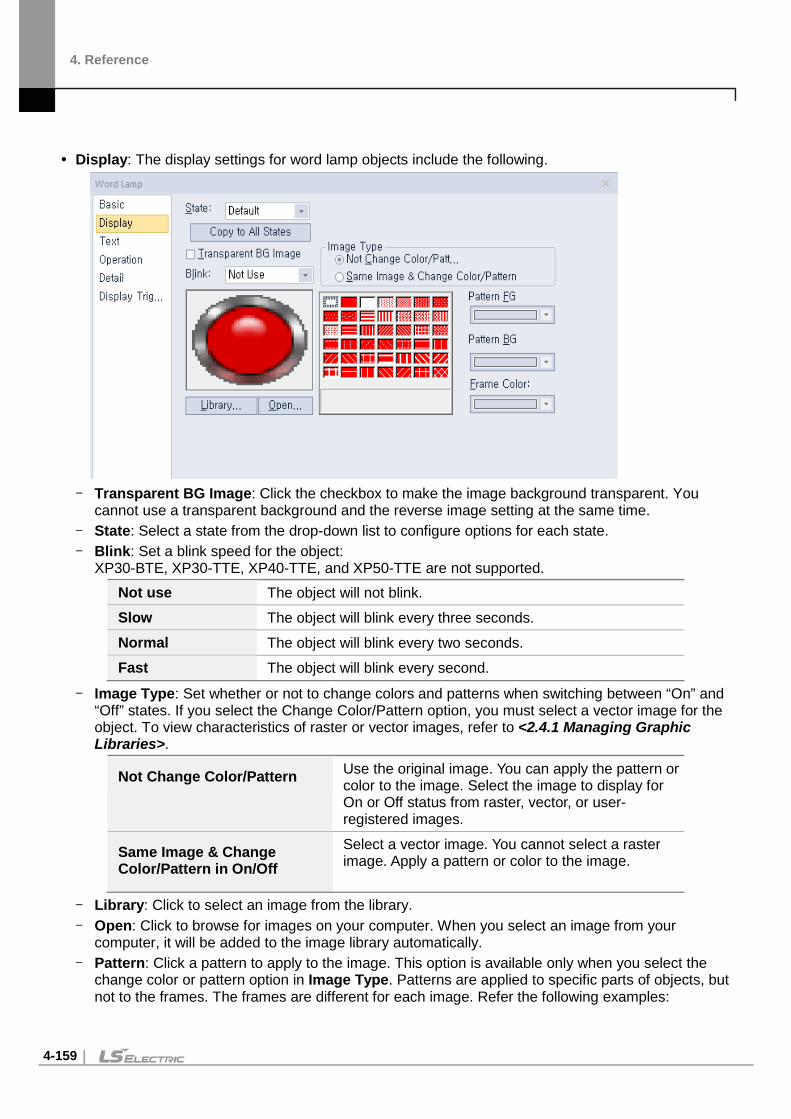
4. Reference
4-159
Display: The display settings for word lamp objects include the following.
- Transparent BG Image: Click the checkbox to make the image background transparent. You
cannot use a transparent background and the reverse image setting at the same time. - State: Select a state from the drop-down list to configure options for each state. - Blink: Set a blink speed for the object:
XP30-BTE, XP30-TTE, XP40-TTE, and XP50-TTE are not supported. Not use The object will not blink. Slow The object will blink every three seconds. Normal The object will blink every two seconds. Fast The object will blink every second.
- Image Type: Set whether or not to change colors and patterns when switching between “On” and “Off” states. If you select the Change Color/Pattern option, you must select a vector image for the object. To view characteristics of raster or vector images, refer to <2.4.1 Managing Graphic Libraries>.
Not Change Color/Pattern Use the original image. You can apply the pattern or color to the image. Select the image to display for On or Off status from raster, vector, or user-registered images.
Same Image & Change Color/Pattern in On/Off
Select a vector image. You cannot select a raster image. Apply a pattern or color to the image.
- Library: Click to select an image from the library. - Open: Click to browse for images on your computer. When you select an image from your
computer, it will be added to the image library automatically. - Pattern: Click a pattern to apply to the image. This option is available only when you select the
change color or pattern option in Image Type. Patterns are applied to specific parts of objects, but not to the frames. The frames are different for each image. Refer the following examples:

4. Reference
4-160
- Pattern FG Color: Set a color for the foreground pattern. - Pattern BG Color: Set a color for the background pattern. - Frame Color: Set a frame color.
Pattern
Frame
Pattern
Frame
Pattern
Frame

4. Reference
4-161
Text: The text settings for word lamp objects include the following.
- Use Caption: Click the checkbox to use a text caption with the object. When you select this option,
you can input text from a Text Table. - On: Click to configure options for the object in the “On” state. You must input the text in a text table. - Off: Click to configure options for the object in the “Off” state. You must input the text in a text table. - From Text Table: Click the checkbox to add text from a text table. The Text Table option will be
activated and the text input area will close. Add the required text to the text table before editing the object. You must select text for the “On” and “Off” states from the same text table.
- Text Table: Click to open the text table and select text. The color and font properties set in the text table will be imported with the text.
- Copy to other state: Click to copy the text string and the text style of the current state to all other
states.
Select a text table and language
Registered text table list

4. Reference
4-162
- Copy Only Caption: You can open the dropdown menu next to [Copy to other state] to select [Copy Only Caption]. This feature allows you to copy only the currently selected text string to other states.
- Copy only property: You can set [Copy only property]. In this case, all properties except the
currently set string are copied to another state. - Only caption continuous copy: Captions are copied consecutively to different states based on
the current state caption. If you input directly.
Add the numbers entered directly behind captions to automatically copy to another state. For example, if the caption is set to [Control 1] in the state 1, the caption 0 is automatically set to [Control 0] and the caption 2 is set to [Control 2].
If selected as a text table
The index of the text table is automatically incremented by one. For example, if the caption of state 0 is as follows ([0] is stopped), state 1 caption is automatically set to ([1] in standby), and sate 2 caption is automatically set to ([2] start).
Slow The caption will blink every three seconds.
Normal The caption will blink every two seconds.
Fast The caption will blink every second.

4. Reference
4-163
- Caption Continuous Copy: Captions are copied continuously by the above method, and the set property information (alignment, font, size, etc.) is also copied together.
- Delete Caption: Click to clear text settings for the current state. - Font: Select a font from the drop-down list. - Size: Set a text size from the drop-down list or enter a value directly into the field. - Width Ratio: Expand or condense the text by selecting a ratio from the drop-down list or entering a
value directly in to the field. You can set a rate of 1%-600%. - Blink: Set the blink speed for the caption.
XP30-BTE, XP30-TTE, XP40-TTE, and XP50-TTE are not supported.
Not use The caption will not blink.
Slow The caption will blink every three seconds.
Normal The caption will blink every two seconds.
Fast The caption will blink every second.
- Space: Set the space on the object. If you select Left align in Horizontal Alignment, you can set the left space, and if you select Right Align, you can set the right space.
- Char. Spacing: Set text intervals. If the value is a negative number, the spacing will decrease and if the value is a very small negative number, it can be overlaid or have the same effect as a positive number.
- Line Spacing: Set line spacing. If the value is a negative number, the spacing will decrease, and if the value is a very small negative number, it can be overlaid of have the same effect as a positive number.
- Change the Property of Text Table: Click to use different color and font properties for the text than what is specified in the text table. This option is active only when you fetch text from the text table.
- Color: Set a font color. - Font Style: Set a font style (bold, italic, strikeout, or underline). You can apply more than one
option at a time. - Horizontal Alignment: Set the horizontal alignment (Left, Center, or Right). - Vertical Alignment: Set the vertical alignment (Top, Middle, or Bottom).

4. Reference
4-164
Operation: Operation settings for word lamp objects include the following.
- Use Script: Check the checkbox to use a script with the object. - Select Script: Select a script from the drop-down list. - Script: When you select a script, it appears here. To modify a script, refer to <4.2 Scripts>.

4. Reference
4-165
Detail: The detail settings for word lamp objects include the following.
- Offset: Check the checkbox to use the Offset function. You can offset the device address based
on the value of the offset device. For example, if the starting device address is P100, XP-Builder reads the value from the offset device and offsets the address by that value. If the offset value is 10, for example, then the referenced device address is P110.
- Device: Enter a device or tag address directly into the input field or click the keypad icon to the right to specify a device or tag address. When you click the keypad icon to open the Device window, you can also specify network settings, if necessary.
Display Trigger: The display trigger setting for word lamp objects.
- Use Condition: Set whether or not to specify a condition for the display trigger. - Type: Select the type of condition to be set.
Bit On The object will display when the device is on.
Bit Off The object will display when the device is off.
Range The object will display when the range condition of the device is

4. Reference
4-166
satisfied.
Multi Bit The object will display when the logical operation results of multiple device are satisfied.
- Device: Enter a device or tag address directly into the input field or click the keypad icon to the right to specify a device or tag address. When you click the keypad icon to open the device window you can also specify network settings, if necessary.
- Range: Sets the range condition when you select it.
Size 16bit or 32bit.
Type Signed DEC, Unsigned DEC, BCD, or float.
Expression Click to designate the expression as conditional
- Multi Bit: If you select the multi bit condition, specify the number of bits and click [Setting] to the bit condition.

4. Reference
4-167
N-State Lamp This section describes available settings for N-State lamp objects. The form of an N-State lamp changes based on the statuses of up to 16 controllers. Refer to the following examples:
Monitoring device (Bit device): P0000, M0000
Priority Status No. Bit Device Status
Image Color Displayed Text Flashing Speed
High Status 0 P0000: OFF M0000: OFF
Blue Normal operation No flashing
Status 1 P0000: ON M0000: OFF
Red Stop Fast
Status 2 P0000: OFF M000: ON
Yellow Caution Slow
Low Status 3 P0000: ON M0000: ON
Purple Alarm Normal
P0000: OFF / M0000: OFF P0000: ON / M0000: OFF
P0000: OFF / M0000: ON P0000: ON / M0000: ON

4. Reference
4-168
Basic: The basic settings for N-State lamp objects include the following.
- The Num. of State: Select the number of statuses to display for the object (from 3 to 16). - State Change Condition: Set a method for changing device statuses.
Change Condition by Bit
Display the On/Off status for up to four controllers with one lamp. The maximum number of statuses is five. Refer to the following example:
Type P0 P1 P2 P3 Display example
Status 1 OFF OFF OFF OFF Status 2 ON OFF OFF OFF Status 3 OFF ON OFF OFF Status 4 OFF OFF ON OFF Status 5 OFF OFF OFF ON
Change Condition by Bit Combination
Displays the combined On/Off status for up to four controllers with one lamp. The maximum number of statuses is 16. Refer to the following example:
Type P0 P1 P2 P3 Display example
Status 1 OFF OFF OFF OFF Status 2 ON OFF OFF OFF Status 3 OFF ON OFF OFF Status 4 ON ON OFF OFF Status 5 OFF OFF ON OFF
- Device Setting: Enter a device or tag address directly into the input field or click the keypad icon to the right to specify a device or tag address. When you click the keypad icon to open the Device window, you can also specify network settings, if necessary.
- Description: Enter a description for the object.

4. Reference
4-169
Display: The display settings for word lamp objects include the following.
- Transparent BG Image: Click the checkbox to make the image background transparent. - State: Select a state from the drop-down list to configure options for each state. - Blink: Set a blink speed for the object:
Not use The object will not blink. Slow The object will blink every three seconds. Normal The object will blink every two seconds. Fast The object will blink every second.
- Image Type: Set whether or not to change colors and patterns when switching between “On” and “Off” states. If you select the change color or pattern option, you must select a vector image for the object. To view characteristics of raster or vector images, refer to <2.4.1 Managing Graphic Libraries>.
Not Change Color/Pattern Use the original image. You can apply the pattern or color to the image. Select the image to display for On or Off status from raster, vector, or user registered images.
Same Image & Change Color/Pattern in On/Off
Select a vector image. You cannot select a raster image. Apply a pattern or color to the image.
- Library: Click to select an image from the library. - Open: Click to browse for images on your computer. When you select an image from your
computer, it will be added to the image library automatically. - Pattern: Click a pattern to apply to the image. This option is available only when you select the
change color or pattern option in Image Type. Patterns are applied to specific parts of objects, but not to the frames. The frames are different for each image. Refer the following examples:

4. Reference
4-170
- Pattern FG Color: Set a color for the foreground pattern. - Pattern BG Color: Set a color for the background pattern. - Frame Color: Set a frame color.
Text Settings: The text settings for word lamp objects include the following.
- Use Caption: Check the checkbox to use a text caption with the object. When you select this
option, you can input text from a Text Table. - On: Click to configure options for the object in the “On” state. You must input the text in a text table. - Off: Click to configure options for the object in the “Off” state. You must input the text in a text table. - From Text Table: Check the checkbox to add text from a text table. The Text Table option will be
activated and the text input area will close. Add the required text to the text table before editing the object. You must select text for each state from the same text table.
Pattern
Frame
Pattern
Frame
Pattern
Frame

4. Reference
4-171
- Text Table: Click to open the text table and select text. The color and font properties set in the text table will be imported with the text.
- Delete Caption: Click to clear text settings for the current state. - Copy to other state: Click to copy the current caption to another state’s caption properties. - Copy Only Caption: You can open the dropdown menu next to [Copy to other state] to select
[Copy Only Caption]. This feature allows you to copy only the currently selected text string to another state.
- Copy Only Caption: You can open the dropdown menu next to [Copy to other state] to select [Copy Only Caption]. This feature allows you to copy only the currently selected text string to another state.
- Copy only property: You can set [Copy only property]. In this case, all properties except the currently set string are copied to another state.
Select a text table and language
Registered text table list

4. Reference
4-172
- Only caption continuous copy: Captions are copied consecutively to different states based on the current state caption.
If you input directly.
Add the numbers entered directly behind captions to automatically copy to another state. For example, if the caption is set to [Control 1] in the state 1, the caption 0 is automatically set to [Control 0] and the caption 2 is set to [Control 2].
If selected as a text table
The index of the text table is automatically incremented by one. For example, if the caption of state 0 is as follows ([0] is stopped), state 1 caption is automatically set to ([1] in standby), and sate 2 caption is automatically set to ([2] start).
Slow The caption will blink every three seconds.
Normal The caption will blink every two seconds.
Fast The caption will blink every second.
- Caption Continuous Copy: Captions are copied continuously by the above method, and the set property information (alignment, font, size, etc.) is also copied together.
- Font: Select a font from the drop-down list. - Size: Set a text size from the drop-down list or enter a value directly into the field. - Width Ratio: Expand or condense the text by selecting a ratio from the drop-down list or entering a
value directly in to the field. You can set a rate of 1%-600%. - Blink: Set the blink speed for the caption.
XP30-BTE, XP30-TTE, XP40-TTE, and XP50-TTE are not supported Not use The caption will not blink. Slow The caption will blink every three seconds. Normal The caption will blink every two seconds. Fast The caption will blink every second.
- Space: Set the space on the object. If you select Left align in Horizontal Alignment, you can set the left space, and if you select Right Align, you can set the right space.
- Char. Spacing: Set text intervals. If the value is a negative number, the spacing will decrease and if the value is a very small negative number, it can be overlaid or have the same effect as a positive number.
- Line. Spacing: Set line spacing. If the value is a negative number, the spacing will decrease, and if the value is a very small negative number, it can be overlaid of have the same effect as a positive number.

4. Reference
4-173
- Change the Property of Text Table: Click to use different color and font properties for the text than what is specified in the text table. This option is active only when you fetch text from the text table.
- Color: Set a font color. - Font Style: Set a font style (bold, italic, strikeout, or underline). You can apply more than one
option at a time. - Horizontal Alignment: Set the horizontal alignment (Left, Center, or Right). - Vertical Alignment: Set the vertical alignment (Top, Middle, or Bottom).
Display Trigger: The display trigger setting for word lamp objects.
- Use Condition: Set whether or not to specify a condition for the display trigger. - Type: Select the type of condition to be set.
Bit On The object will display when the device is on.
Bit Off The object will display when the device is off.
Range The object will display when the range condition of the device is satisfied.
Multi Bit The object will display when the logical operation results of multiple device are satisfied.
- Device: Enter a device or tag address directly into the input field or click the keypad icon to the right to specify a device or tag address. When you click the keypad icon to open the Device window you can also specify network settings, if necessary.
- Range: Sets the range condition when you select it.
Size 16bit or 32bit.
Type Signed DEC, Unsigned DEC, BCD, or float.
Expression Click to designate the expression as conditional.
- Multi Bit: If you select the multi bit condition, specify the number of bits and click [Setting] to specify the bit conditions.

4. Reference
4-174
Switch Objects Switches execute one or more functions, based on the switch type. Five switch types are available: Bit, Word, Change screen, Special, and Multi. Bit switches control On/Off states, Word switches execute scripts or change values, Change screen switches change screens in the XGT Panel interface. Special switches perform storage-related actions. Multi switches carry out multiple functions.
Note
• If the switch is not connected to PLC device when using lamp condition, it is not displayed on XGT Panel.
• The lamp displays the default image if the connection with PLC device fails before 1 scan is
completed.
※ For details, refer to <Appendix 5. Object Display Rule before Communication Connection>.
Bit Switch Bit switches control On/Off states of bit devices. This section describes available settings for bit switch objects.
Basic: The basic settings for bit switches include the following.
- Device: Enter a device or tag address directly into the input field or click the keypad icon to the
right to specify a device or tag address. When you click the keypad icon to open the Device window, you can also specify network settings, if necessary.
- Copy to Lamp: Click to copy the device address from a bit switch to a lamp condition address. - Action Type: Set an operation to perform when the switch is activated.
On Turns on the relevant bit device in the PLC when the switch is activated. The state is preserved until changed by another action.

4. Reference
4-175
Off Turns off the relevant bit device in the PLC when the switch is activated. The state is preserved until changed by another action.
Momentary Turns on the relevant bit device in the PLC only while the switch object is held. The state returns to “Off” when the switch is released.
Alternative Switches the relevant bit device value to the opposite state when the switch is activated. If the object is on when the switch is activated, it will turn off and vice versa.
- Use Lamp Condition: If you want to control a lamp with a method other than simply turning it on when the switch is activated, you can select a different action.
Bit Device When the device state is “On”, the lamp is on. Copy to Main The lamp condition’s bit device address is copied to the basic
device of a bit switch. Word Device When the condition is met, the lamp is on. Size 16 bit upper byte, 16 bit lower byte, 16 bit, or 32 bit. Type Signed decimal, unsigned decimal, BCD, or float. Exp. Click to designate the expression as conditional.
- Use Lamp Offset: Click to set an offset for the lamp. - Description: Enter a description for the object.
Display: The display settings for bit switch objects include the following.
- Transparent BG Image: Check the checkbox to make the image background transparent. You
cannot use a transparent background and the reverse image setting at the same time. - Use Image Reverse: The switch image is reversed when you tap the object or a condition is met.
If you set this option, you cannot use the Transparent BG Image option or the On/Off image. If you set the Transparent BG Image option, you cannot use this option.
- On: Click to configure options for the object in the “On” state. - Off: Click to configure options for the object in the “Off” state.

4. Reference
4-176
- Off->On Copy: Copies all image properties in the Off state to On. - On->Off Copy: Copies all image properties in On status to Off. - Image Type: Set whether or not to change colors and patterns when switching between “On” and
“Off” states. If you select the change color or pattern option, you must select a vector image for the object. To view characteristics of raster or vector images refer to <2.4.1 Managing Graphic Libraries>.
Not Change Color/Pattern Use the original image. You can apply the pattern or color to the image. Select the image to display for On/Off status from raster, vector, or user registered images.
Same Image & Change Color/Pattern in On/Off
Select a vector image. You cannot select a raster image. Apply a pattern or color to the image.
- Library: Click to select an image from the library. - Open: Click to browse for images on your computer. When you select an image from your
computer, it will be added to the image library automatically. - Pattern: Click a pattern to apply to the image. This option is available only when you select the
Change color or Pattern option in Image Type. Patterns are applied to specific parts of objects, but not to the frames. The frames are different for each image. Refer the following examples:
- Pattern FG Color: Set a color for the foreground pattern. - Pattern BG Color: Set a color for the background pattern. - Frame Color: Set a frame color. - Blink: Set a blink speed for the object. To use the blink function, you must set the Use Lamp
Condition option in the Basic settings. Not use The object will not blink. Slow The object will blink every three seconds. Normal The object will blink every two seconds. Fast The object will blink every second.
Pattern
Frame
Pattern
Frame
Pattern
Frame

4. Reference
4-177
Text: The text settings for bit switch objects include the following.
- Use Caption: Check the checkbox to use a text caption with the object. When you select this
option, you can input text from a text table. - On: Click to configure options for the object in the “On” state. You must input text in a text table. - Off: Click to configure options for the object in the “Off” state. You must input text in a text table. - From Text Table: Check the checkbox to add text from a text table. The Text Table option will be
activated and the text input area will close. Add the required text to the text table before editing the object. You must select text for the “On” and “Off” states from the same text table.
- Text Table: Click to open the text table and select text. The color and font properties set in the text table will be imported with the text.
- On <-> Off Copy: Click to copy the text and formatting from the “On” state to the “Off” state or vice
versa. - Copy Only Caption: You can open the dropdown menu next to [On -> Off] to select [Copy Only
Caption]. This feature allows you to copy only the currently selected text string to another state.
Select a text table and language
Registered text table list

4. Reference
4-178
- Copy Only Property: You can open the dropdown menu next to [On -> Off] to select [Copy Only
Property]. This feature allows you to copy all properties except the currently selected text string are copied to another state.
- Delete On/Off Caption: Click to clear text settings for the current state. - Font: Select a font from the drop-down list. - Size: Set a text size from the drop-down list or enter a value directly into the field. - Width Ratio: Expand or condense the text by selecting a ratio from the drop-down list or entering a
value directly in to the field. You can set a rate of 1%-600%. - Blink: Set the blink speed for the caption.
XP30-BTE, XP30-TTE, XP40-TTE, and XP50-TTE are not supported.
Not use The caption will not blink.
Slow The caption will blink every three seconds.
Normal The caption will blink every two seconds.
Fast The caption will blink every second.
- Space: Set the space on the object. If you select Left align in Horizontal Alignment, you can set the left space, and if you select Right Align, you can set the right space.
- Char. Spacing: Set text intervals. If the value is a negative number, the spacing will decrease and if the value is a very small negative number, it can be overlaid or have the same effect as a positive number.
- Line. Spacing: Set line spacing. If the value is a negative number, the spacing will decrease, and if the value is a very small negative number, it can be overlaid of have the same effect as a positive number.
- Change the Property of Text Table: Click to use different color and font properties for the text than what is specified in the text table. This option is active only when you fetch text from the text table.
- Color: Set a font color.

4. Reference
4-179
- Font Style: Set a font style (bold, italic, strikeout, or underline). You can apply more than one option at a time.
- Horizontal Alignment: Set the horizontal alignment (Left, Center, or Right). - Vertical Alignment: Set the vertical alignment (Top, Middle, or Bottom).
Detail: The detail settings for bit switch objects include the following.
- Security Level: Set whether or not to require a password to use the object. - Level: Set the security level for the object. The higher the security level is, the shorter the
authorization time becomes when the password is entered. When the authorization time expires, the user must enter the password again to use the object.
- Action Delay: Set to delay the action triggered by the switch by a specified time. - Type: Set the type of action delay.
On Delay When the switch is activated, the action is performed after the delay time that you specify.
Off Delay When the switch is released, the action is performed after the delay time that you specify.
Press Twice When the switch is activated once, a dialog box is invoked to allow the user to verify the operation. When the switch is activated a second time, the action is performed after the delay time that you specify.
- Time: Set the length of time for the action delay. - Offset in [Write] Operation: Set to use the Offset function. - Device: Enter a device or tag address directly into the input field or click the keypad icon to the
right to specify a device or tag address. When you click the keypad icon to open the Device window, you can also specify network settings, if necessary.
- Use Operation Log: Set to allow the device to be monitored in an operation log. XP30-BTE, XP30-TTE, XP40-TTE, and XP50-TTE are not supported.
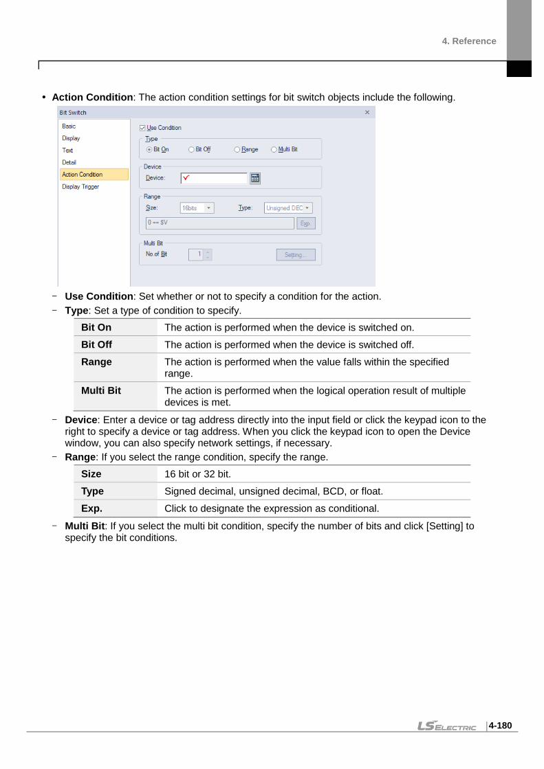
4. Reference
4-180
Action Condition: The action condition settings for bit switch objects include the following.
- Use Condition: Set whether or not to specify a condition for the action. - Type: Set a type of condition to specify.
Bit On The action is performed when the device is switched on. Bit Off The action is performed when the device is switched off. Range The action is performed when the value falls within the specified
range. Multi Bit The action is performed when the logical operation result of multiple
devices is met.
- Device: Enter a device or tag address directly into the input field or click the keypad icon to the right to specify a device or tag address. When you click the keypad icon to open the Device window, you can also specify network settings, if necessary.
- Range: If you select the range condition, specify the range. Size 16 bit or 32 bit. Type Signed decimal, unsigned decimal, BCD, or float. Exp. Click to designate the expression as conditional.
- Multi Bit: If you select the multi bit condition, specify the number of bits and click [Setting] to specify the bit conditions.

4. Reference
4-181
Display Trigger: The display trigger settings for bit switch objects include the following.
- Use Condition: Set whether or not to specify a condition for the display trigger. - Type: Set a type of condition to specify.
Bit On The object will display when the device is on. Bit Off The object will display when the device is off Range The object will display when the range condition of the device is
satisfied. Multi Bit The object will display when the logical operation results of multiple
device are satisfied.
- Device: Enter a device or tag address directly into the input field or click the keypad icon to the right to specify a device or tag address. When you click the keypad icon to open the Device window, you can also specify network settings, if necessary.
- Range: If you select the range condition, specify the range. Size 16 bit or 32 bit. Type Signed decimal, unsigned decimal, BCD, or float. Exp. Click to designate the expression as conditional.
- Multi Bit: If you select the multi bit condition, specify the number of bits and click [Setting] to specify the bit conditions.

4. Reference
4-182
Word Switch Word switch executes the script, enters a fixed value, and adds or reduces the value. This section describes available settings for word switch objects.
Basic: The Basic settings for word switch objects include the following.
- Device: Enter a device or tag address directly into the input field or click the keypad icon to the
right to specify a device or tag address. When you click the keypad icon to open the Device window, you can also specify network settings, if necessary.
- Size: Set the data size of the device (16-bit upper byte, 16-bit lower byte, 16 bit, or 32 bit). - Type: Set the data form of the device (signed decimal, unsigned decimal, or float). - Action Type: Set the type of the action to perform.
Set Write the specified value in the device. Add Add the specified value to the device value. Sub Subtract the specified value from the device value. Script Execute a script. Digit Add Increase the bit value of a specific location in a word device. The
value is added to the current value with as many operands as you specify, but the bit value of the location increases only by the value specified here. 0 0 0 0 1 0 0 0
3rd digit 0 0 0 0 1 01 0 0 For example, if the device value is as above and the digit is 3, the device value will change as shown above when you operate the word switch on the XGT Panel.
Digit Sub Decrease the bit value of a specific location in a word device. The value is subtracted from the current value with as many operands as you specify, but the bit value of the location decreases only by the value specified here.

4. Reference
4-183
Continuous Add / Continuous Sub
This option is available for only [Add], [Sub], [Digit Add], and [Digit Sub] operations. When the switch is pressed for more than 1 second, the value increases or decreases by the increment or decrement settings made in [Constant Value]-[Value] in 0.5 second intervals. If the device value exceeds its value range (see the Note below), it is expressed as a carried number. For example, if it is a 16 bit signed decimal, subtracting 1 from -32768 makes 32767.
- Operand: Set the value to write to the device. The operand can be set as one of the following
types. Constant Set a fixed value to use as an operand in the expression.
Indirect Set to us the device value as an operand in the expression.
Script No. Specify a script when performing actions other than adding, subtracting, writing a specific device value, or writing a fixed value.
Data Type Set the data type to be increased or decreased. When you select BCD as the data type, if the value returned by the specified device exceeds the numeric range of BCD data (0-9), the word switch will not execute.
Digit Set the number of digit to increase or decrease. For 16 bit devices, you can set it from 1-4. For 32-bit devices, you can set it from 1-8.
If the operand is saved as a script, the final value will be applied to the device after completing the calculation. The description below shows how it works. 1. Read the value from the device specified in the word switch and save the value
to the temporary variable referring to the device. 2. Operate the script on the read value. 3. Apply the value saved on the temporary variable after operating the script.
- From the flow chart above, the script result means “the value of the temporary variable when
the script ends.” If the device value changes during operating the script, it will not affect the script.
- If you change the device value using a direct variable while the script is in operation, the change will not remain because the value of the temporary variable after the script ends will be written to the device. If you use the device within a script, a message such as “2012: The standard device exists in the specified ‘SCRIPT.’ An unexpected result might occur.” will be displayed.
Read the value from the device.
Operate the script using the entered value.
Apply the script result to the device.

4. Reference
4-184
Note If you set a fixed constant operand, the range of the constant varies based on the size and type of the device, as described in the following table.
Device Size Device Type Minimum Maximum 16-bit upper byte Signed decimal -128 127
16-bit upper byte Unsigned decimal, binary, hexadecimal, octal
0 255
16-bit lower byte Signed decimal -128 127
16-bit lower byte Unsigned decimal, binary, hexadecimal, octal
0 255
16 bit
Signed decimal -32,768 32,767
Unsigned decimal 0 65,535
BCD 0 9,999
32 bit Signed decimal -2147,483,648 2,147,483,647 Unsigned decimal 0 4,294,967,295 BCD 0 99999999
- Description: Enter a description for the object.

4. Reference
4-185
Display: The display settings for word switch objects include the following.
- Transparent BG Image: Check the checkbox to make the image background transparent. You
cannot use a transparent background and the reverse image setting at the same time. - Use Image Reverse: The switch image is reversed when you tap the object or a condition is met.
If you set this option, you cannot use the Transparent BG Image option or the On/Off image. If you set the Transparent BG Image option, you cannot use this option.
- On: Click to configure options for the object in the “On” state. - Off: Click to configure options for the object in the “Off” state. - Off->On Copy: Copies all image properties in the Off state to On. - On->Off Copy: Copies all image properties in On status to Off. - Image Type: Set whether or not to change colors and patterns when switching between “On” and
“Off” states. If you select the change color or pattern option, you must select a vector image for the object. To view characteristics of raster or vector images, refer to <2.4.1 Managing Graphic Libraries>.
Not Change Color/Pattern Use the original image. You can apply the pattern or color to the image. Select the image to display for On/Off status from raster, vector, or user registered images.
Same Image & Change Color/Pattern in On/Off
Select a vector image. You cannot select a raster image. Apply a pattern or color to the image.
- Library: Click to select an image from the library. - Open: Click to browse for images on your computer. When you select an image from your
computer, it will be added to the image library automatically. - Pattern: Click a pattern to apply to the image. This option is available only when you select the
change color or pattern option in Image Type. Patterns are applied to specific parts of objects, but not to the frames. The frames are different for each image. Refer the following examples:

4. Reference
4-186
- Pattern FG Color: Set a color for the foreground pattern. - Pattern BG Color: Set a color for the background pattern. - Frame Color: Set a frame color. - Blink: Set a blink speed for the object. You can use this option when you check Use Lamp
Condition in the Lamp Condition settings. Not use The object will not blink. Slow The object will blink every three seconds. Normal The object will blink every two seconds. Fast The object will blink every second.
Pattern
Frame
Pattern
Frame
Pattern
Frame

4. Reference
4-187
Text: The text settings for word switch objects include the following.
- Use Caption: Check the checkbox to use a text caption with the object. When you select this
option, you can input text from a text table. - On: Click to configure options for the object in the “On” state. You must input the text in a text table. - Off: Click to configure options for the object in the “Off” state. You must input the text in a text table. - From Text Table: Click the checkbox to add text from a text table. The Text Table option will be
activated and the text input area will close. Add the required text to the text table before editing the object. You must select text for the “On” and “Off” states from the same text table.
- Text Table: Click to open the text table and select text. The color and font properties set in the text table will be imported with the text.
- On <-> Off Copy: Click to copy the text and formatting from the “On” state to the “Off” state or vice
versa. - Copy Only Caption: You can open the dropdown menu next to [On -> Off] to select [Copy Only
Caption]. This feature allows you to copy only the currently selected text string to another state.
Select a text table and language
Registered text table list

4. Reference
4-188
- Copy Only Property: You can open the dropdown menu next to [On -> Off] to select [Copy Only
Property]. This feature allows you to copy all properties except the currently selected text string are copied to another state.
- Delete On/Off Caption: Click to clear text settings for the current state. - Font: Select a font from the drop-down list. - Size: Set a text size from the drop-down list or enter a value directly into the field. - Width Ratio: Expand or condense the text by selecting a ratio from the drop-down list or entering a
value directly in to the field. You can set a rate of 1%-600%. - Blink: Set the blink speed for the caption.
XP30-BTE, XP30-TTE, XP40-TTE, and XP50-TTE are not supported. Not use The caption will not blink. Slow The caption will blink every three seconds.
Normal The caption will blink every two seconds. Fast The caption will blink every second.
- Space: Set the space on the object. If you select Left align in Horizontal Alignment, you can set the left space, and if you select Right Align, you can set the right space.
- Char. Spacing: Set text intervals. If the value is a negative number, the spacing will decrease and if the value is a very small negative number, it can be overlaid or have the same effect as a positive number.
- Line. Spacing: Set line spacing. If the value is a negative number, the spacing will decrease, and if the value is a very small negative number, it can be overlaid of have the same effect as a positive number
- Change the Property of Text Table: Click to use different color and font properties for the text than what is specified in the text table. This option is active only when you fetch text from the text table.
- Color: Set a font color.

4. Reference
4-189
- Font Style: Set a font style (bold, italic, strikeout, or underline). You can apply more than one option at a time.
- Horizontal Alignment: Set the horizontal alignment (Left, Center, or Right). - Vertical Alignment: Set the vertical alignment (Top, Middle, or Bottom).
Detail: The detail settings for word switch objects include the following.
- Security Level: Set whether or not to require a password to use the object. - Level: Set the security level for the object. The higher the security level, the shorter the
authorization time when the password is entered. When the authorization time expires, the user must enter the password again to use the object.
- Action Delay: Set to delay the action triggered by the switch by a specified time. - Type: Set the type of action delay.
On Delay When the switch is activated, the action is performed after the delay time that you specify.
Press Twice When the switch is activated once, a dialog box is invoked to allow the user to verify the operation. When the switch is activated a second time, the action is performed after the delay time that you specify.
- Time: Set the length of time for the action delay. - Offset in [Write] Operation: Set to use the Offset function. - Device: Enter a device or tag address directly into the input field or click the keypad icon to the
right to specify a device or tag address. When you click the keypad icon to open the Device window, you can also specify network settings, if necessary.
- Use Operation Log: Set to allow the device to be monitored in an operation log. XP30-BTE, XP30-TTE, XP40-TTE, and XP50-TTE are not supported.

4. Reference
4-190
Lamp Condition: The lamp condition settings for word switch objects include the following.
- Use Lamp Condition: If you want to control a lamp with a method other than simply turning it on
when the switch is activated, you can select a different action. - Type: Select a condition for lamp control.
Bit When the device state is “On”, the lamp is on.
Word When the condition is met, the lamp is on.
- Bit: If you selected the bit condition type, specify a bit device.
Device Enter a device or tag address directly into the input field or click the keypad icon to the right to specify a device or tag address. When you click the keypad icon to open the Device window, you can also specify network settings, if necessary.
- Word: If you selected the word condition type, specify a word device.
Device Enter a device or tag address directly into the input field or click the keypad icon to the right to specify a device or tag address. When you click the keypad icon to open the Device window, you can also specify network settings, if necessary.
Size 16-bit upper byte, 16-bit lower byte, 16 bit, or 32 bit.
Type Signed decimal, unsigned decimal, BCD, or float.
Exp. Click to designate the expression as conditional.
- Use Lamp Offset: Click to set an offset for the lamp.

4. Reference
4-191
Action Condition: The action condition settings for word switch objects include the following.
- Use Condition: Set whether or not to specify a condition for the action. - Type: Set a type of condition to specify.
Bit On The action is performed when the device is switched on.
Bit Off The action is performed when the device is switched off.
Range The action is performed when the value falls within the specified range.
Multi Bit The action is performed when the logical operation result of multiple devices is met.
- Device: Enter a device or tag address directly into the input field or click the keypad icon to the right to specify a device or tag address. When you click the keypad icon to open the Device window, you can also specify network settings, if necessary.
- Range: If you select the range condition, specify the range. Size 16 bit or 32 bit. Type Signed decimal, unsigned decimal, BCD, or float. Exp. Click to designate the expression as conditional.
- Multi Bit: If you select the multi bit condition, specify the number of bits and click [Setting] to specify the bit conditions.

4. Reference
4-192
Display Trigger: The display trigger settings for word switch objects include the following.
- Use Condition: Set whether or not to specify a condition for the display trigger. - Type: Set a type of condition to specify.
Bit On The object will display when the device is on. Bit Off The object will display when the device is off Range The object will display when the range condition of the device is
satisfied. Multi Bit The object will display when the logical operation results of multiple
device are satisfied.
- Device: Enter a device or tag address directly into the input field or click the keypad icon to the right to specify a device or tag address. When you click the keypad icon to open the Device window, you can also specify network settings, if necessary.
- Range: If you select the range condition, specify the range. Size 16 bit or 32 bit. Type Signed decimal, unsigned decimal, BCD, or float. Exp. Click to designate the expression as conditional.
- Multi Bit: If you select the multi bit condition, specify the number of bits and click [Setting] to specify the bit conditions.

4. Reference
4-193
Change Screen Switch The Change screen switch allows the user to switch screens in the interface. You can specify the type of screen to change to when the switch is activated. This section describes available settings for change screen switch objects.
Basic: The basic settings for change screen switch objects include the following.
- Screen: Select a type of screen to change to. - Type: Set how the screen changes.
Device The screen switches to the screen number that matches the device value. If no screen matches the device value, the screen does not change.
Const The screen switches to a specified screen, regardless of the device value.
Screen No. Set the screen number or click [Browse] to locate a screen.
If [Project Properties > Screen Settings > Change Screen by Device] is set, the screen change switch will first attempt to write the screen number to the corresponding ‘Change to Screen Number’ device. If the communication is normal, the value is written to the relevant device and the screen is switched. However, if the communication is disconnected, the communication will be repeated as much as the [Timeout * Retry count] time entered in [Project Property > XGT Panel Settings]. And even if the time fails to write the value to screen change device, the screen is changed. In this state, if communication is resumed and the value of screen change device is read, it returns to the screen corresponding to the value.
- Screen Change Type: Select a method for changing screens.
Fixed The screen switches to a specified screen.
Previous The screen switches to the previous screen.
- Description: Enter a description for the object. - Offset When Using Import: Set to apply an offset to the screen number when importing a screen
that contains a change screen switch. When you do not select this option, the screen number will not change after importing.

4. Reference
4-194
The screen number does not change and retains the screen number 1 that is set when exporting.
When you select this option, the screen number, plus the offset, will be set to the change screen switch.

4. Reference
4-195
Display: The display settings for change screen switch objects include the following.
- Transparent BG Image: Click the checkbox to make the image background transparent. You
cannot use a transparent background and the reverse image setting at the same time. - Use Image Reverse: The switch image is reversed when you tap the object or a condition is met.
If you set this option, you cannot use the Transparent BG Image option or the On/Off image. If you set the Transparent BG Image option, you cannot use this option.
- On: Click to configure options for the object in the “On” state. - Off: Click to configure options for the object in the “Off” state. - Off->On Copy: Copies all image properties in the Off state to On. - On->Off Copy: Copies all image properties in On status to Off. - Image Type: Set whether or not to change colors and patterns when switching between “On” and
“Off” states. If you select the change color or pattern option, you must select a vector image for the object. To view characteristics of raster or vector images, refer to <2.4.1 Managing Graphic Libraries>.
Not Change Color/Pattern Use the original image. You can apply the pattern or color to the image. Select the image to display for On or Off status from raster, vector, or user-registered images.
Same Image & Change Color/Pattern in On/Off
Select a vector image. You cannot select a raster image. Apply a pattern or color to the image.
- Library: Click to select an image from the library. - Open: Click to browse for images on your computer. When you select an image from your
computer, it will be added to the image library automatically. - Pattern: Click a pattern to apply to the image. This option is available only when you select the
Change Color or Pattern option in Image Type. Patterns are applied to specific parts of objects, but not to the frames. The frames are different for each image. Refer the following examples:
Pattern
Frame

4. Reference
4-196
- Pattern FG Color: Set a color for the foreground pattern. - Pattern BG Color: Set a color for the background pattern. - Frame Color: Set a frame color.
Text: The text settings for screen change object include the following.
- Use Caption: Click the checkbox to use a text caption with the object. When you select this option,
you can input text from a text table. - On: Click to configure options for the object in the “On” state. You must input the text in a text table. - Off: Click to configure options for the object in the “Off” state. You must input the text in a text table. - From Text Table: Click the checkbox to add text from a text table. The Text Table option will be
activated and the text input area will close. Add the required text to the text table before editing the object. You must select text for the “On” and “Off” states from the same text table.
- Text Table: Click to open the text table and select text. The color and font properties set in the text table will be imported with the text.
Pattern
Frame
Pattern
Frame

4. Reference
4-197
- On <-> Off Copy: Click to copy the text and formatting from the “On” state to the “Off” state or vice
versa. - Copy Only Caption: You can open the dropdown menu next to [Copy to other state] to select
[Copy Only Caption]. This feature allows you to copy only the currently selected text string to another state.
- Copy Only Property: You can open the dropdown menu next to [On -> Off] to select [Copy Only
Property]. This feature allows you to copy all properties except the currently selected text string are copied to another state.
- Delete On/Off Caption: Click to clear text settings for the current state. - Font: Select a font from the drop-down list. - Size: Set a text size from the drop-down list or enter a value directly into the field. - Width Ratio: Expand or condense the text by selecting a ratio from the drop-down list or entering a
value directly in to the field. You can set a rate of 1%-600%.
Select a text table and language
Registered text table list

4. Reference
4-198
- Blink: Set the blink speed for the caption. XP30-BTE, XP30-TTE, XP40-TTE, and XP50-TTE are not supported.
Not use The caption will not blink.
Slow The caption will blink every three seconds.
Normal The caption will blink every two seconds.
Fast The caption will blink every second.
- Space: Set the space on the object. If you select Left align in Horizontal Alignment, you can set the left space, and if you select Right Align, you can set the right space.
- Char. Spacing: Set text intervals. If the value is a negative number, the spacing will decrease and if the value is a very small negative number, it can be overlaid or have the same effect as a positive number.
- Line. Spacing: Set line spacing. If the value is a negative number, the spacing will decrease, and if the value is a very small negative number, it can be overlaid of have the same effect as a positive number.
- Change the Property of Text Table: Click to use different color and font properties for the text than what is specified in the text table. This option is active only when you fetch text from the text table.
- Color: Set a font color. - Font Style: Set a font style (bold, italic, strikeout, or underline). You can apply more than one
option at a time. - Horizontal Alignment: Set the horizontal alignment (Left, Center, or Right). - Vertical Alignment: Set the vertical alignment (Top, Middle, or Bottom).

4. Reference
4-199
Detail: The detail settings for change screen switch objects include the following.
- Security Level: Set whether or not to require a password to use the object. - Level: Set the security level for the object. The higher the security level, the shorter the
authorization time when the password is entered. When the authorization time expires, the user must enter the password again to use the object.
- Action Delay: Set to delay the action triggered by the switch by a specified time. - Type: Set the type of action delay.
On Delay When the switch is activated, the action is performed after the delay time that you specify.
Press Twice When the switch is activated once, a dialog box is invoked to allow the user to verify the operation. When the switch is activated a second time, the action is performed after the delay time that you specify.
- Offset in [Write] Operation: Set to use the Offset function. The change screen switch does not support this function.
- Device: Enter a device or tag address directly into the input field or click the keypad icon to the right to specify a device or tag address. When you click the keypad icon to open the Device window, you can also specify network settings, if necessary.
- Use Operation Log: Set to allow the device to be monitored in an operation log. XP30-BTE, XP30-TTE, XP40-TTE, and XP50-TTE are not supported.

4. Reference
4-200
Action Condition: The action condition settings for change screen switch objects include the following.
- Use Condition: Set whether or not to specify a condition for the action. - Type: Set a type of condition to specify.
Bit On The action is performed when the device is switched on.
Bit Off The action is performed when the device is switched off.
Range The action is performed when the value falls within the specified range.
Multi Bit The action is performed when the logical operation result of multiple devices is met.
- Device: Enter a device or tag address directly into the input field or click the keypad icon to the right to specify a device or tag address. When you click the keypad icon to open the Device window, you can also specify network settings, if necessary.
- Range: If you select the range condition, specify the range.
Size 16 bit or 32 bit.
Type Signed decimal, unsigned decimal, BCD, or float.
Exp. Click to designate the expression as conditional.
- Multi Bit: If you select the multi bit condition, specify the number of bits and click [Setting] to specify the bit conditions.

4. Reference
4-201
Display Trigger: The display trigger settings for change screen switch objects include the following.
- Use Condition: Set whether or not to specify a condition for the display trigger. - Type: Set a type of condition to specify.
Bit On The object will display when the device is on. Bit Off The object will display when the device is off Range The object will display when the range condition of the device is
satisfied. Multi Bit The object will display when the logical operation results of multiple
device are satisfied.
- Device: Enter a device or tag address directly into the input field or click the keypad icon to the right to specify a device or tag address. When you click the keypad icon to open the Device window, you can also specify network settings, if necessary.
- Range: If you select the range condition, specify the range. Size 16 bit or 32 bit. Type Signed decimal, unsigned decimal, BCD, or float. Exp. Click to designate the expression as conditional.
- Multi Bit: If you select the multi bit condition, specify the number of bits and click [Setting] to specify the bit conditions.

4. Reference
4-202
Special Switch This switch is for carrying out key code, alarm, logging, printing, language switching, script operation, and other storage-related actions. This section describes available settings for special switch objects.
Basic: The basic settings for special switch objects include the following. You can select the function for the special switch and set the properties in the Special Switch Function settings.
- History Alarm Viewer Function Description
Alarm Group Filtering Set to filter the history alarms by the group.
Check All Alarm Data in Alarm Page
Set to view all alarm data or only specified alarm data by selecting the alarm. The view time is recorded for both cases. • When checking all data
Check Selected Alarm Data in Alarm Viewer

4. Reference
4-203
Function Description
• When checking the selected alarm data
Delete All Occurrence No.
Set to delete data for triggered alarms when the switch is activated.
Delete Occurrence No. of Selected Alarm
Set to delete selected history alarm data on the current page when the switch is activated.
Delete Recovered Alarm Data in Alarm Viewer Page
Set to delete all recovered data when the switch is activated.
Delete Recovered All Data in Alarm Viewer
Set to delete all recovered data when the switch is activated.
Delete Selected Recovered in Alarm Viewer
Set to delete the specified data, except for unrecovered alarm data when the switch is activated.
Go to History Alarm Viewer Detail
When an alarm occurs, additional information related to the alarm may be required to solve the problem. In that case, a window can be invoked with information from other objects. Set this function to see detailed history alarm data when the switch is activated. To set the function to show detailed data: 1. Edit the detailed Window screen.

4. Reference
4-204
Function Description
2. Check the box next to Show detail window. 3. In History Alarm Viewer, set options under Use Detailed
Window Position. 4. In the XGT panel, select an alarm, and then tap the
special switch.
History Alarm Filter Set to filter history alarm data and display it with the history
alarm viewer object. There are five types of filters: Occurrence, Check, Restoration, Uncheck, and Unrestoration (unrestored alarms).
Type Description
Occurrence View the every history alarm data occurred.
Check View the checked history alarm data with the special switch.
Restoration View the restored history alarm data.
Example of checked history alarm data
History Alarm Viewer Line Down
Set to scroll history alarm data in the specified direction when the switch is activated.
History Alarm Viewer Line up

4. Reference
4-205
Function Description
History Alarm Viewer Page Down
History Alarm Viewer Page Up
Print History Alarm Set to print the selected history alarm data when the switch is activated. An alarm group can be chosen from the history alarm list.
Selected History Alarm Viewer Line Down
Set to change the line of the history alarm data when the switch is activated.
Selected History Alarm Viewer Line Up
- History Alarm Row Scroll: Set to move to the specified area of the history alarm data when the
switch is activated. If the number of data columns exceeds the columns supported by the XGT panel, this function allows you to view more data.

4. Reference
4-206
For the history alarms data such as above, the descriptions below show how each function operates:
Function Description
Next Column Use this function when there are more columns to view than are displayed on the XGT-Panel. Fixed columns retain and the next column will be displayed on the area of unfixed column.
History alarm data displayed on the XGT-Panel
In the example above, data exists in the right-hand column but there is not enough area to show the all the data so some columns are displayed in part.
Pre. Column Use this function when there are more columns to view than
are displayed on the XGT-Panel. Fixed columns retain and the previous column will be displayed on the area of unfixed column.
First Column Among the history alarm data, the history alarm on the first column of the history alarm viewer on the XGT-Panel will be displayed.
Last Column The history alarm on the last column of the history alarm viewer on the XGT-Panel will be displayed.
History alarm data displayed on the XGT-Panel
Fixed Unfixed
Actual history alarm data
Fixed

4. Reference
4-207
Function Description
If the total object area is greater than the width of the columns, the part that exceeds the width of the columns is shown in gray.
- Logging Viewer
Function Description Logging Viewer Line Down Set to scroll logging data up or down when the
switch is activated. Logging Viewer Line Up Logging Viewer Page Down Logging Viewer Page Up
- Logging Row Scroll
Function Description
First Column Set to move to the specified area of the logging data when the switch is activated. If the number of data columns exceeds the columns supported by the XGT panel, this function allows you to view more data. As the following example illustrates, fixed columns never move, but the unfixed areas can be moved, so that you can view more data.
Time Location Process 3 Process 4
2013/03/29 Line 1 21 31
2013/03/30 Line 2 22 32
2013/03/31 Line 3 23 33
2013/04/01 Line 4 24 34 If the total object area is greater than the width of the columns, the part that exceeds the width of the columns is shown in gray.
Last Column
Next Column
Previous Column
Next Page
Previous Page
- Alarm Navigator
Function Description
Alarm Navigator Viewer Line Down
Set to move up or down a line in the alarm search results when the switch is activated.
Fixed Unfixed

4. Reference
4-208
Function Description
Alarm Navigator Viewer Line Up
- Logging Trend
Function Description
Next Log Trend Data View the next log. You can set the number of logs to display. For example, if the number is set to “8”, the graph will display the trend for the next eight logs.
Previous Log Trend Data
View the previous log. You can set the number of logs to display. For example, if the number is set to “8”, the graph will display the trend for the previous eight logs.
The First Log Trend Data
View the first or last logged data.
The Last Log Trend Data
BookMark Set/Reset This function sets the user’s specified data area in the logging trend graph as a bookmark. The data areas in the graph can be navigated freely and have access to return to the bookmarked location. For example, two bookmarks can be set as shown below.
Current logging data

4. Reference
4-209
Function Description
After the bookmarks are set, the user can navigate the graph to the area enclosed by dotted lines in the graph below. Then, the user can return to the area enclosed by the solid lines (Bookmark1) by clicking the Bookmark special switch.
Dotted line: Indicates an area on the logging trend
before moving to the bookmark. Solid line: Indicates an area on the logging trend
after moving to Bookmark1. 1. A maximum of five bookmarks can be selected. 2. If more than five bookmarks are selected, the oldest
bookmark is deleted. 3. If the [Bookmark setting/release] button is clicked while
a bookmarked logging data set is displayed, the bookmark is released.
4. If the previous data set is deleted after the logging area reaches its full capacity with [Use cycling buffer in storage area], the data set and its bookmark are deleted.
5. If a bookmarked data set is displayed in the graph area, the bookmark is indicated in the zero position as shown in the screenshot below.

4. Reference
4-210
Function Description
Go to BookMark This function enables the user to navigate to a bookmarked
position. 1. When the [BookMark] special switch is clicked for the
first time, the graph area moves to the oldest bookmarked position. Bookmarked positions cycle sequentially in chronological order from oldest to the most recent.
2. When the most recent bookmarked position is displayed, the oldest bookmarked position is the next screenshot to be displayed in the cycle.
3. Even if current logging data is generated when the graph area moves to a bookmarked position, the current logging data is not displayed in the graph area. The user must move to the latest logging area by selecting [Last Log Trend Data] or [Next Log Trend Data].

4. Reference
4-211
- Memo
Function Description
Change Memo Mode Set to switch the memo mode when the switch is activated. In active mode, memo input is allowed. In non-active mode, only memo viewing is allowed. When switching from active to non-active mode, any unsaved memo inputs are discarded. Then, the first saved memo is displayed.
Delete All Memo Set to delete all or selected memos. The third bit of the memo pad status device indicates whether or not the memos were deleted successfully. Delete Memo
Next Memo Set to move to the next or previous memo when the switch is activated.
Previous Memo
Pen Setting Set the color and thickness of the pen to be used for memos. You can also set a special switch to apply the color and line thickness you specify.
Redo Memo Set to restore a recently canceled memo when the switch is activated.
Reset Memo Set to delete all memo files from storage devices when the switch is activated. The third bit of the memo pad status device indicates whether or not the memos were deleted successfully.
Save Memo Set to save memos in a storage location when the switch is activated. The storage location must be designated in [Common] ▶ [Project Property Setting] ▶ [Storage Settings].
Undo Memo Set to undo the last action in a memo when the switch is activated.

4. Reference
4-212
- Explorer and Editor: Data List Editor
Function Description
Line Up Press this button to view the line directly above the currently selected line.
Line Down Press this button to view the line directly below the currently selected line.
Page Up If the number of files or folders displayed in the list on the XGT Panel’s screen exceeds the maximum limit, the files and the folder lists are created on multiple pages. Press this button to view the previous page in the file or folder list.
Page Down If the number of files or folders displayed in the list on the XGT Panel’s screen exceeds the maximum number, the files and the folder lists are created on multiple pages. Press this button to view the next page in the file or folder list.
- Explorer and Editor: Extended File Recipe
Function Description
Transfer from PLC->XP Press this button to transfer Extended file recipes in the PLC to XP-Builder.
Transfer from XP->PLC Press this button to transfer Extended file recipes in XP-Builder to the PLC.
Line Up Press this button to view the folder or file in the line directly above the currently selected folder or file.
Line Down Press this button to view the folder or file in the line directly below the currently selected folder or file.
Page Up If the number of files or folders displayed in the list on the XGT Panel’s screen exceeds the maximum number, the files and the folder lists are created on multiple pages. Press this button to view the previous page in the file or folder list.
Page Down If the number of files or folders displayed in the list on the XGT Panel’s screen exceeds the maximum number limit, the files and the folder lists are created on multiple pages. Press this button to view the next page in the file or folder list.
Show the Selected File Press this button to show the recipe data of the selected item on the Extended file recipe editor when the user selects a certain item from the Extended file recipe list displayed on Recipe Explorer.
- Explorer and Editor: File Explorer
Function Description

4. Reference
4-213
Function Description
Line Up Press this button to view the folder or file in the line directly above the currently selected folder or file.
Line Down Press this button to view the folder or file in the line directly below the currently selected folder or file.
Page Up If the number of files or folders displayed in the list on the XGT Panel’s screen exceeds the maximum limit, the files and the folder lists are created on multiple pages. Press this button to view the previous page in the file or folder list.
Page Down If the number of files or folders displayed in the list on the XGT Panel’s screen exceeds the maximum limit, the files and the folder lists are created on multiple pages. Press this button to view the next page in the file or folder list.
Copy Cut a selected file or folder from File Explorer.
Cut Cut a selected file or folder from File Explorer.
Paste Paste a selected file or folder from File Explorer in a selected folder. If there is a file or folder with the same name, "copy_" is prefixed to the copied file or folder.
Delete Delete a selected file or folder from File Explorer. When a folder is deleted, all files in the folder are also deleted.
Select All Select all valid files in a selected File Explorer folder.
Execute Opens the files in the registered video player or the recipe editor when the video or the CSV files are selected.
Cancel Cancels the selection of a file or folder from File Explorer.
Go Up to Directory Moves to the parent directory of the currently selected file or folder.
Go to Root Directory Moves to the root directory of the current storage device.
Favorites Moves to a bookmark set by the user.
Restoration of Basic Recipe Backup files
Restores the basic recipe data. The data is read from the recipe backup file in File Explorer that is specified by the user. A recipe backup file is a CSV file saved in a storage device when the basic recipe backup device is set to “on”. The basic recipe data cannot be restored if the basic recipe setting is changed after the backup file is created, or if the backup file is created in another project.
Write selected file name in to the device
File name device: Write selected file name in the file explorer on the device. Write path and file name on the device. Device length: Designate byte size including path and file name. 1 character is 2 bytes.

4. Reference
4-214
Function Description For example, the selected file name is abc.csv. Designate HW0000 as device and 14 bytes as byte. Then the valued of abc.csv is saved to HW0000.
Copy to specified path Specify the path to copy: If the feature is not set, copy and paste the selected file in the file explorer. If the feature is set, copy and paste to the specified path regardless of whether the file explorer exists and its status. Path to copy: Set a file/path to copy: Copy and paste the copied file to the set path. If the path is not set, copy and paste to the file path selected in the file explorer. Include Path (Full Path): Specify whether to include the path when saving the selected file name on the device. For example, if the selected file name and path is FlashDisk \\ abc.csv. Checked Include path: FlashDisk\\abc.csv Unchecked Include path: abc.csv
- Explorer and Editor: File Recipe Editor
Function Description
Line Up Press this button to view the folder or file in the line directly above the currently selected folder or file.
Line Down Press this button to view the folder or file in the line directly below the currently selected folder or file.
Page Up If the number of files or folders displayed in the list on the XGT Panel’s screen exceeds the maximum limit, the files and the folder lists are created on multiple pages. Press this button to view the previous page in the file or folder list.
Page Down If the number of files or folders displayed in the list on the XGT Panel’s screen exceeds the maximum limit, the files and the folder lists are created on multiple pages. Press this button to view the next page in the file or folder list.
Storage Save the data of the file recipe editor that is currently displayed on the XGT-Panel to the file selected in Recipe Explorer.
- Explorer and Editor: File Recipe Explorer and Transfer
Function Description Transfer from PLC->XP
Press this button to transfer file recipes in the PLC to XP-Builder.
Transfer from XP->PLC
Press this button to transfer file recipes in XP-Builder to the PLC.

4. Reference
4-215
Function Description
Line Up Press this button to view the folder or file in the line directly above the currently selected folder or file.
Line Down Press this button to view the folder or file in the line directly below the currently selected folder or file.
Page Up If the number of files or folders displayed in the list on the XGT Panel’s screen exceeds the maximum number, the files and the folder lists are created on multiple pages. Press this button to view the previous page in the file or folder list.
Page Down If the number of files or folders displayed in the list on the XGT Panel’s screen exceeds the maximum number limit, the files and the folder lists are created on multiple pages. Press this button to view the next page in the file or folder list.
Show the Selected File Press this button to show the recipe data of the selected item on the file recipe editor when the user selects a certain item from the file recipe list displayed on Recipe Explorer.
- Explorer and Editor: General Recipe Explorer and Transfer
Function Description
Line Up Press this button to view the folder or file in the line directly above the currently selected folder or file.
Line Down Press this button to view the folder or file in the line directly below the currently selected folder or file.
Transfer from PLC->XP Transfer from XP->PLC
Press these buttons to transfer recipes from one device to another. When the basic recipe edited in XP-Builder is transferred to the XGT Panel, it will be backed up in the NVRAM. The diagram below shows how recipes are transferred between the NVRAM, an internal device and PLC.
When a special switch is set to Transfer from NVRAM to PLC, recipe is transferred in the direction ⓐ described in the illustration above. To do this: 1. Select a recipe item to transfer from Recipe Explorer. 2. Press the special switch for transferring from NVRAM to
PLC.
PLC
General Recipe
Internal Device NVRAM
ⓐ
ⓑ ⓒ

4. Reference
4-216
Function Description
Transfer from PLC to NVRAM
When a special switch is set to Transfer from PLC to NVRAM, a recipe is transferred in the direction labeled ⓐ as shown in the diagram above. To do this: 1. Select a recipe item. 2. Press the special switch for transferring from a PLC to
the NVRAM. 3. A basic recipe from a PLC moves to the NVRAM
allocated in the recipe.
Transfer from NVRAM to Internal Device
When a special switch is set to Transfer from NVRAM to Internal Device, recipe is transferred in the direction labeled ⓑ as shown in the diagram above. In order to edit the basic recipe backed up in the NVRAM, the recipe saved in the NVRAM should be moved to the internal device. Therefore, it should be moved to the internal device to edit the data and the address of the internal device to move can be set in the internal device of the recipe editor.
Transfer from Internal Device to NVRAM
When a special switch is set to Transfer from Internal Device to NVRAM, a recipe is transferred in the direction labeled ⓑ as shown in the diagram above. A basic recipe edited in the internal device is moved to the NVRAM.
Transfer from Internal Device to PLC
When a special switch is set to Transfer from Internal Device to PLC, a recipe is transferred in the direction labeled ⓒ as shown in the diagram above.
Transfer from PLC to Internal Device
When a special switch is set to Transfer from PLC to Internal Device, a recipe is transferred in the direction labeledⓒ as shown in the diagram above.
Show the Selected Recipe
Shows a selected recipe on the data list editor.

4. Reference
4-217
- Multimedia
Function Description
Play
Direct: Enter file name. There is no need to enter the extension of the video file Device: Set a device to enter the file name. Play: Play in ascending order based on the file name. You can play video files with the extension type of MP4, AVI, and WMV.,
Stop Stops the video file being played.
Pause / Restart Pauses the video file being played and restarts it.
Fast Forward Moves forward by the set time.
Backward Moves backward by the set time.
Next file Plays the next file in ascending order based on the file name.
Previous file Play previous file in ascending order based on the file name.
- PDF Viewer
Function Description
File Open The selected PDF file is displayed in the PDF file view object. The file can be selected by manually entering the file name or by reading the file name set in the device. If /# (number) is entered after the file name, the specified page number is displayed when the PDF viewer runs. For example, USB Storage\LS.pdf/#5 will display page 5 of the LS.pdf file at first. Manual setting: The name of the PDF file to be displayed is manually entered. Device setting: The value of the parameter length (byte unit) is read from the specified device to use as the PDF file name.

4. Reference
4-218
Function Description
File Close Closes the file displayed in the PDF file view object.
Zoom In Zooms in on the file displayed in the PDF file view object.
Zoom Out Zooms out of the file displayed in the PDF file view object.
Anticlockwise Rotation Rotates the view of the file displayed in the PDF file view object 90° in a counterclockwise direction.
Clockwise Rotation Rotates the view of the file displayed in the PDF file view object 90° in a clockwise direction.
Previous Page Displays the previous page in the currently open file in the PDF file view object. If there is no previous page, the current page is displayed.
Next Page Displays the next page in the currently open file in the PDF file view object. If there is no next page, the current page is displayed.
First Page Displays the first page in the currently open file in the PDF file view object.
Last Page Displays the last page in the currently open file in the PDF file view object.
- VNC Viewer
Function Description
Zoon In Zooms in on the viewer screen.
Zoom Out Zoom out of the viewer screen.
Start Begins a virtual network computing session.
Stop Ends the current virtual network computing session.
- ETC
Function Description Change Runtime Set to change the runtime language when the switch is activated.

4. Reference
4-219
Function Description Language Select a language in the Function Setting field.
You can specify runtime languages in the project properties. Click [Common] ▶ [Project Property Setting] ▶ [Language] and edit the available runtime language.
Close Window Place it on the window screen and touch it during monitoring to
close the window screen. It operates when placed on the window connected to the bit window object, the history alarm detail window, and the keypad window screen. It does not work on the window connected to the word window object.
Key Switch Set to open an input window when the switch is activated. Select the function in the Function Setting field, and set a key code if necessary.
You can apply text, numbers, or special functions (clear, space, enter, caps lock, and more). When you select the special switch in the XGT Panel, the key code is entered into the numeric or text input device. If an ASCII character or Unicode character is selected, a user can input only one text value.

4. Reference
4-220
Function Description To use uppercase characters, users can enter the text value by entering uppercase characters.
Note
To enter uppercase characters: • ASCII: You cannot input uppercase characters directly.
To input uppercase characters, turn on the caps lock switch and the letter input switch (A= the caps lock switch + the “a” input switch).
• UNICODE: Set the uppercase characters in advance. You need only one switch.
Next Cursor Set to move the cursor in numeric or text input objects to the next or previous field.
Previous Cursor
Print Screen Set to print a screen capture of the XGT Panel when the switch is activated. The file can be printed to a file or to a printer, as specified in the project properties. To set the properties, click [Common] ▶ [Project Property Setting] ▶ [Auxiliary Settings] and set a print option from the Output drop-down list under Screen Capture:
Option Description
Save�as File
Save the image as a Bitmap file. You can set the file path in [Common] ▶ [Project Property Setting] ▶ [Storage Setting] ▶ [Capture image].
Runtime print
Print a screenshot with a printer connected via USB.

4. Reference
4-221
Function Description
Save and Print
Save an image as a file and print it with a printer connected via USB. If a printer is not connected to the XGT Panel, a system alarm will occur. When the user connects the printer again and attempts to print, the system alarm will be restored. To set the system alarm, click [Common] ▶ [Project Property Setting] ▶ [Auxiliary Settings] and check the checkbox next to Alarm window pop-up.
Program Monitoring Set to launch the program monitor when the switch is activated. To run the program monitor, use the XGT, XGI, or XGB series. Specify the program monitor settings in the project properties. Click [Common] ▶ [Project Property Setting] ▶ [XGT Panel Settings] ▶ [Program monitor].
Run Other Application This function runs an application program set in the program path. For example, the command, Memopad.exe runs the Memopad program from the “Flashdisk” folder using the following settings.
• Program interaction with HMI: Select a controller to interact
with when using program monitoring.

4. Reference
4-222
Function Description
• Program Path: Set a path for the program file to execute. • Use parameter: Set the transfer factor to be used as the
parameter of the program when an application program, set in the program path, is run. For example, if PDF Viewer is set as the external application program, as shown in the screenshot below, the pdf file, set as the parameter in the file path, is opened by the PDF viewer. Some application programs may not support spaces (ASCII code: Space) in the parameter values.
Runtime Exit Set to quit program monitoring when the switch is activated.
Safe Removal Switch The safe removal switch performs the same function as the safe hardware removal switch. Click the safe removal switch and the storage unit (SD) detaches when the current operation is completed. The special device address for the sensor that detects that the storage device has detached is contained in the following table.
Storage Device Special Device Address SD card HS51.2
This function is supported only by iXP70/80/90 models.
Security mode lock For a secured object, security is usually locked again after a certain period of time has elapsed from the time the security was disabled. This is a function to switch back to the security mode when the special switch is pressed before a certain time.
XP-Remote Set to enable remote monitoring of the XGT Panel. You can specify functions for obtaining and terminating authorization for remote monitoring.
Update Download project from storage device: Updates the current XGT Panel with the project in the path set by the user. If set as below, update to the test project in the XP_Project folder of USB Storage.

4. Reference
4-223
Display: The display settings for special switch objects include the following.
- Transparent BG Image: Check the checkbox to make the image background transparent. You
cannot use a transparent background and the reverse image setting at the same time. - Use Image Reverse: The switch image is reversed when you tap the object or a condition is met.
If you set this option, you cannot use the Transparent BG Image option or the On/Off image. If you set the Transparent BG Image option, you cannot use this option.
- On: Click to configure options for the object in the “On” state. - Off: Click to configure options for the object in the “Off” state. - Off->On Copy: Copies all image properties in the Off state to On. - On->Off Copy: Copies all image properties in On status to Off. - Image Type: Set whether or not to change colors and patterns when switching between “On” and
“Off” states. If you select the change color or pattern option, you must select a vector image for the object. To view characteristics of raster or vector images, refer to <2.4.1 Managing Graphic Libraries>.
Not Change Color/Pattern Use the original image. You can apply the pattern or color to the image. Select the image to display for the “On” or ”Off” states from raster, vector, or user registered images.
Same Image & Change Color/Pattern in On/Off
Select a vector image. You cannot select a raster image. Apply a pattern or color to the image.
- Library: Click to select an image from the library. - Open: Click to browse images on your computer. When you select an image from your computer, it
will be added to the image library automatically. - Pattern: Click a pattern to apply to the image. This option is available only when you select the
change color or pattern option in Image Type. Patterns are applied to specific parts of objects, but not to the frames. The frames are different for each image. Refer to the screenshots below.
Pattern
Frame

4. Reference
4-224
- Pattern FG Color: Select a color for the foreground pattern. - Pattern BG Color: Select a color for the background pattern. - Frame Color: Select a frame color.
Text: The text settings for special switch objects are shown in the screenshot below.
- Use Caption: Check the checkbox to use a text caption with the object. When you select this
option, you can input text from a text table. - On: Click to configure options for the object in the “On” state. You must input the text in a text table. - Off: Click to configure options for the object in the “Off” state. You must input the text in a text table. - From Text Table: Check the checkbox to add text from a text table. The Text Table option will be
activated and the text input area will close. Add the required text to the text table before editing the object. You must select text for the “On” and “Off” states from the same text table.
- Text Table: Click to open the text table and select text. The color and font properties set in the text table will be imported with the text.
Pattern
Frame
Pattern
Frame

4. Reference
4-225
- On <-> Off Copy: Click to copy the text and formatting from the “On” state to the “Off” state or vice
versa. - Copy Only Caption: You can open the dropdown menu next to [On -> Off] to select [Copy Only
Caption]. This feature allows you to copy only the currently selected text string to another state.
- Copy Only Property: You can open the dropdown menu next to [On -> Off] to select [Copy Only
Property]. This feature allows you to copy all properties except the currently selected text string are copied to another state.
- Delete On/Off Caption: Click to clear text settings for the current state. - Font: Select a font from the drop-down list. - Size: Select a text size from the drop-down list or enter a value directly into the field. - Width Ratio: Expand or condense the text by selecting a ratio from the drop-down list or entering a
value directly into the field. You can set a ratio of 1%-600%. - Blink: Set the blink speed for the caption.
XP30-BTE, XP30-TTE, XP40-TTE, and XP50-TTE are not supported.
Select a text table and language
Registered text table list

4. Reference
4-226
Not use The caption will not blink.
Slow The caption will blink every three seconds.
Normal The caption will blink every two seconds.
Fast The caption will blink every second.
- Space: Set the space on the object. If you select Left align in Horizontal Alignment, you can set the left space, and if you select Right Align, you can set the right space.
- Char. Spacing: Set text intervals. If the value is a negative number, the spacing will decrease and if the value is a very small negative number, it can be overlaid or have the same effect as a positive number.
- Line. Spacing: Set line spacing. If the value is a negative number, the spacing will decrease, and if the value is a very small negative number, it can be overlaid of have the same effect as a positive number.
- Change the Property of Text Table: Click to copy different color and font properties to the text than those specified in the text table. This option is active only when you fetch text from the text table.
- Color: Select a font color. - Font Style: Select a font style (bold, italic, strikeout, or underline). You can apply more than one
option at a time. - Horizontal Alignment: Set the horizontal alignment (left, center, or right). - Vertical Alignment: Set the vertical alignment (top, middle, or bottom).
Detail: The detail settings for special switch objects are shown in the screenshot below.
- Security Level: Set whether or not to require a password to use the object. - Level: Set the security level for the object. The higher the security level, the shorter the
authorization time when the password is entered. When the authorization time expires, the user must enter the password again to use the object.
- Action Delay: Set to delay the action triggered by the switch by a specified time. - Type: Set the type of action delay.
On Delay When the switch is activated, the action is performed after the delay time that you specify.

4. Reference
4-227
Press Twice When the switch is activated once, a dialog box is invoked to allow the user to verify the operation. When the switch is activated a second time, the action is performed after the delay time that you specify.
- Time: Set the length of time for the action delay. - Offset in [Write] Operation: Set to use the Offset function. The special switch does not support
this function. - Device: Enter a device or tag address directly into the input field or click the keypad icon to the
right to specify a device or tag address. When you click the keypad icon to open the Device window, you can also specify network settings, if necessary.
- Action Trigger (Only for History Alarm Viewer/ Multimedia): Set whether or not to use an action trigger with the history alarm viewer object and multimedia display. The Special Switch function is activated when the special switch is pressed on the XGT Panel or when the specified device is turned on.
Note Where there are two or more “Play” switches for the same operating device when there are more than two multimedia objects on one screen (main screen/popup window/overlay window, etc.), it is not guaranteed that the video file will play at that point. Therefore, it is not recommenced to use the same device for an operating device.
- Device: Enter a device or tag address directly into the input field or click the keypad icon to the
right to specify a device or tag address. When you click the keypad icon to open the Device window, you can also specify network settings, if necessary.
- Use Operation Log: Set to allow the device to be monitored in an operation log. XP30-BTE, XP30-TTE, XP40-TTE, and XP50-TTE are not supported.

4. Reference
4-228
Lamp Condition: The lamp condition settings for special switch objects are shown in the screenshot below.
- Use Lamp Condition: If you want to control a lamp with a method other than simply turning it on
when the switch is activated, you can select a different action. - Type: Select a condition for lamp control.
Bit When the device state is on, the lamp is on.
Word When the condition is met, the lamp is on.
- Bit: If you selected the bit condition type, specify a bit device.
Device Enter a device or tag address directly into the input field or click the keypad icon to the right to specify a device or tag address. When you click the keypad icon to open the Device window, you can also specify network settings, if necessary.
- Word: If you selected the word condition type, specify a word device.
Device Enter a device or tag address directly into the input field or click the keypad icon to the right to specify a device or tag address. When you click the keypad icon to open the Device window, you can also specify network settings, if necessary.
Size 16-bit upper byte, 16-bit lower byte, 16-bit, or 32-bit.
Type Signed decimal, unsigned decimal, or BCD, or float.
Exp. Click to designate the expression as conditional.
- Use Lamp Offset: Click to set an offset for the lamp.

4. Reference
4-229
Action Condition: The action condition settings for special switch objects are shown in the screenshot below.
- Use Condition: Set whether or not to specify a condition for the action. - Type: Set a type of condition to specify.
Bit On The action is performed when the device is switched on.
Bit Off The action is performed when the device is switched off.
Range The action is performed when the value falls within the specified range.
Multi Bit The action is performed when the logical operation result of multiple devices is met.
- Device: Enter a device or tag address directly into the input field or click the keypad icon to the right to specify a device or tag address. When you click the keypad icon to open the Device window, you can also specify network settings, if necessary.
- Range: If you select the range condition, specify the range.
Size 16-bit or 32-bit.
Type Signed decimal, unsigned decimal, BCD, or float.
Exp. Click to designate the expression as conditional.
- Multi Bit: If you select the multi bit condition, specify the number of bits and click [Setting] to specify the bit conditions.

4. Reference
4-230
Display Trigger: The display trigger settings for special switch objects include the following.
- Use Condition: Set whether or not to specify a condition for the display trigger. - Type: Set a type of condition to specify.
Bit On The object will display when the device is on. Bit Off The object will display when the device is off Range The object will display when the range condition of the device is
satisfied. Multi Bit The object will display when the logical operation results of multiple
device are satisfied.
- Device: Enter a device or tag address directly into the input field or click the keypad icon to the right to specify a device or tag address. When you click the keypad icon to open the Device window, you can also specify network settings, if necessary.
- Range: If you select the range condition, specify the range. Size 16 bit or 32 bit. Type Signed decimal, unsigned decimal, BCD, or float. Exp. Click to designate the expression as conditional.
- Multi Bit: If you select the multi bit condition, specify the number of bits and click [Setting] to specify the bit conditions.

4. Reference
4-231
Multi Switch A multi switch object is a switch that can operate a combination of functions of the bit switch, word switch, change screen switch and special switch. You can set the sequence of each operation and up to 20 functions can be carried out at a time. This section describes available settings for multi switch objects.
Basic: The basic settings for multi switch objects are shown in the screenshot below.
- Set Script in Up or Down Action: Set scripts for up or down states of the switch.
Down Act. Script Select a script to execute when the switch is depressed.
Up Act. Script Select a script to execute when the switch is released.
- Operation Type: Select and manage operations.
(Delete) Click a condition and then click this icon to delete the condition.
(Up) Click a condition and then click this icon to move it higher up the list.
(Down) Click a condition and then click this icon to move it lower down the list.
- Bit Operation: Click to set a condition for a bit switch. For more information about bit switches, refer to <4.3.2.1 Bit Switch>.
- Word Operation: Click to set a condition for a word switch. For more information about word switches, refer to <4.3.2.2 Word Switch>.
- Change Screen: Click to set a condition for a screen change switch. For more information about screen change switches, refer to <4.3.2.3 Change Screen Switch>
Note The change screen switch must be the last switch when using multiple switches. This switch will be moved to the end of the operation list automatically. This is to ensure that all the user operations on the current screen are performed before switching to another screen.

4. Reference
4-232
- Print Screen: Click to set a condition for a print screen switch. For more information about print screen switches, refer to <4.3.2.4 Special Switch>.
- Change Language: Click to set a condition for a change language switch. For more information about change language switches, refer to <4.3.2.4 Special Switch>.
- Special Operation: Click to set a condition for a special operation switch. For more information about special operation switches, refer to <4.3.2.4 Special Switch>.
Note Language and screen switching operate independently, even though both are special switches.
- Description: Enter a description for the object. Display: The display settings for multi switch objects are shown in the screenshot below.
- Transparent BG Image: Check the checkbox to make the image background transparent. You
cannot use a transparent background and the reverse image setting at the same time. - Use Image Reverse: The switch image is reversed when you tap the object or a condition is met.
If you set this option, you cannot use the Transparent BG Image option or the On/Off image. If you set the Transparent BG Image option, you cannot use this option.
- On: Click to configure options for the object in the “On” state. - Off: Click to configure options for the object in the “Off” state. - Off->On Copy: Copies all image properties in the Off state to On. - On->Off Copy: Copies all image properties in On status to Off. - Image Type: Set whether or not to change colors and patterns when switching between “On” and
“Off” states. If you select the change color or pattern option, you must select a vector image for the object. To view characteristics of raster or vector images, refer to <2.4.1 Managing Graphic Libraries>.
Not Change Color/Pattern Use the original image. You can apply the pattern or color to the image. Select the image to display for the “On” or “Off” states from raster, vector, or user registered images.
Same Image & Change Color/Pattern in On/Off
Select a vector image. You cannot select a raster image. Apply a pattern or color to the image.

4. Reference
4-233
- Library: Click to select an image from the library. - Open: Click to browse images on your computer. When you select an image from your computer, it
will be added to the image library automatically. - Pattern: Click a pattern to apply to the image. This option is available only when you select the
change color or pattern option in Image Type. Patterns are applied to specific parts of objects, but not to the frames. The frames are different for each image. Refer to the screenshots below.
- Pattern FG Color: Set a color for the foreground pattern. - Pattern BG Color: Set a color for the background pattern. - Frame Color: Set a frame color.
Pattern
Frame
Pattern
Frame
Pattern
Frame

4. Reference
4-234
Text: The text settings for multi switch objects are shown in the screenshot below.
- Use Caption: Check the checkbox to use a text caption with the object. When you select this
option, you can input text from a text table. - On: Click to configure options for the object in the “On” state. You must input text from a text table. - Off: Click to configure options for the object in the “Off” state. You must input text from a text table. - From Text Table: Check the checkbox to add text from a text table. The Text Table option will be
activated and the text input area will close. Add the required text to the text table before editing the object. You must select text for the “On” and “Off” states from the same text table.
- Text Table: Click to open the text table and select text. The color and font properties set in the text table will be imported with the text.
- On <-> Off Copy: Click to copy the text and formatting from the “On” state to the “Off” state or vice
versa. - Copy Only Caption: You can open the dropdown menu next to [Copy to other state] to select
[Copy Only Caption]. This feature allows you to copy only the currently selected text string to another state.
Select a text table and language
Registered text table list

4. Reference
4-235
- Copy Only Property: You can open the dropdown menu next to [On -> Off] to select [Copy Only
Property]. This feature allows you to copy all properties except the currently selected text string are copied to another state.
- Delete On/Off Caption: Click to clear text settings for the current state. - Font: Select a font from the drop-down list. - Size: Select a text size from the drop-down list or enter a value directly into the field. - Width Ratio: Expand or condense the text by selecting a ratio from the drop-down list or entering a
value directly into the field. You can set a ratio of 1%-600%. - Blink: Set the blink speed for the caption.
XP30-BTE, XP30-TTE, XP40-TTE, and XP50-TTE are not supported.
Not use The caption will not blink.
Slow The caption will blink every three seconds.
Normal The caption will blink every two seconds.
Fast The caption will blink every second.
- Space: Set the space on the object. If you select Left align in Horizontal Alignment, you can set the left space, and if you select Right Align, you can set the right space.
- Char. Spacing: Set text intervals. If the value is a negative number, the spacing will decrease and if the value is a very small negative number, it can be overlaid or have the same effect as a positive number.
- Line. Spacing: Set line spacing. If the value is a negative number, the spacing will decrease, and if the value is a very small negative number, it can be overlaid of have the same effect as a positive number.
- Change the Property of Text Table: Click to apply different color and font properties to the text from those specified in the text table. This option is active only when you fetch text from the text table.
- Color: Select a font color.

4. Reference
4-236
- Font Style: Select a font style (bold, italic, strikeout, or underline). You can apply more than one option at a time.
- Horizontal Alignment: Set the horizontal alignment (left, center, or right). - Vertical Alignment: Set the vertical alignment (top, middle, or bottom).
Detail: The detail settings for multi switch objects are shown in the screenshot below.
- Security Level: Set whether or not to require a password to use the object. - Level: Set the security level for the object. The higher the security level, the shorter the
authorization time when the password is entered. When the authorization time expires, the user must enter the password again to use the object.
- Action Delay: Set to delay the action triggered by the switch by a specified time. - Type: Set the type of action delay.
On Delay When the switch is activated, the action is performed after the delay time that you specify.
Press Twice When the switch is activated once, a dialog box is invoked to allow the user to verify the operation. When the switch is activated a second time, the action is performed after the delay time that you specify.
- Time: Set the length of time for the action delay. - Offset in [Write] Operation: Set to use the Offset function. The MultiAction Switch does not
support this function. - Device: Enter a device or tag address directly into the input field or click the keypad icon to the
right to specify a device or tag address. When you click the keypad icon to open the Device window, you can also specify network settings, if necessary.
- Use Operation Log: Set to allow the device to be monitored in an operation log.

4. Reference
4-237
Lamp Condition: The lamp condition settings for multi switch objects are shown in the screenshot below.
- Use Condition: If you want to control a lamp with a method other than simply turning it on when
the switch is activated, you can select a different action. - Type: Select a condition for lamp control.
Bit When the device state is on, the lamp is on. Word When the condition is met, the lamp is on.
- Bit: If you selected the bit condition type, specify a bit device. Device Enter a device or tag address directly into the input field or click the
keypad icon to the right to specify a device or tag address. When you click the keypad icon to open the Device window, you can also specify network settings, if necessary.
- Word: If you selected the word condition type, specify a word device. Device Enter a device or tag address directly into the input field or click the
keypad icon to the right to specify a device or tag address. When you click the keypad icon to open the Device window, you can also specify network settings, if necessary.
Size 16 bit or 32 bit. Type Signed decimal, unsigned decimal, or BCD, or float. Exp. Click to designate the expression as conditional.
- Use Lamp Offset: Click to set an offset for the lamp.

4. Reference
4-238
Action Condition: The action condition settings for multi switch objects are shown in the screenshot below.
- Use Condition: Set whether or not to specify a condition for the action. - Type: Set a type of condition to specify.
Bit On The action is performed when the device is switched on.
Bit Off The action is performed when the device is switched off.
Range The action is performed when the value falls within the specified range.
Multi Bit The action is performed when the logical operation result of multiple devices is met.
- Device: Enter a device or tag address directly into the input field or click the keypad icon to the right to specify a device or tag address. When you click the keypad icon to open the Device window, you can also specify network settings, if necessary.
- Range: If you select the range condition, specify the range. Size 16 bit or 32 bit. Type Signed decimal, unsigned decimal, BCD, or float. Exp. Click to designate the expression as conditional.
- Multi Bit: If you select the multi bit condition, specify the number of bits and click [Setting] to specify the bit conditions.

4. Reference
4-239
Display Trigger: The display trigger settings for multi switch objects include the following.
- Use Condition: Set whether or not to specify a condition for the display trigger. - Type: Set a type of condition to specify.
Bit On The object will display when the device is on. Bit Off The object will display when the device is off Range The object will display when the range condition of the device is
satisfied. Multi Bit The object will display when the logical operation results of multiple
device are satisfied.
- Device: Enter a device or tag address directly into the input field or click the keypad icon to the right to specify a device or tag address. When you click the keypad icon to open the Device window, you can also specify network settings, if necessary.
- Range: If you select the range condition, specify the range. Size 16 bit or 32 bit. Type Signed decimal, unsigned decimal, BCD, or float Exp. Click to designate the expression as conditional.
- Multi Bit: If you select the multi bit condition, specify the number of bits and click [Setting] to specify the bit conditions.

4. Reference
4-240
Message Objects You can use message objects to display messages based on specified conditions of bit or word devices. You must add the messages to a text table to invoke them with a message object.
Note
• If the message object is not connected with PLC device, only background image is displayed.
※ For details, refer to <Appendix 5. Object Display Rule before Communication Connection>.
Bit Message This section describes available settings for bit message objects.
Basic: The basic settings for bit message objects are shown in the screenshot below.
- Device: Enter a device or tag address directly into the input field or click the keypad icon to the
right to specify a device or tag address. When you click the keypad icon to open the Device window you can also specify network settings, if necessary.
- Description: Enter a description for the object.

4. Reference
4-241
Display: The display settings for bit message objects are shown in the screenshot below.
- Library: Click to select an image from the library. - Open: Click to browse images on your computer. When you select an image from your computer, it
will be added to the image library automatically. - Transparent BG Image: Check the checkbox to make the image background transparent. You
cannot use a transparent background and the reverse image setting at the same time. - Frame Color: Select a frame color. - Plate Color: Select a plate color. - Use Border: Set whether or not to apply a border to the message area. - Border Color: Select a border color.

4. Reference
4-242
Text: The text settings for bit message objects are shown in the screenshot below.
- On: Click to configure options for the object in the “On” state. You can input text only from a text
table. - Off: Click to configure options for the object in the “Off” state. You can input text only from a text
table. - Text Table: Click to open the text table and select text. The color and font properties set in the text
table will be imported with the text. - On <-> Off Copy: Click to copy the text and formatting from the “On” state to the “Off” state or vice
versa. - Delete On/Off Msg.: Click to delete the text for the selected state. - Size: Select a text size from the drop-down list or enter a value directly into the field. - Blink: Set a blink speed for the object:
XP30-BTE, XP30-TTE, XP40-TTE, and XP50-TTE are not supported.
Not use The object will not blink.
Slow The object will blink every three seconds.
Normal The object will blink every two seconds.
Fast The object will blink every second.
- Char. Spacing: Set text intervals. If the value is a negative number, the spacing will decrease and if the value is a very small negative number, it can be overlaid or have the same effect as a positive number.
- Line Spacing: Set line spacing. If the value is a negative number, the spacing will decrease, and if the value is a very small negative number, it can be overlaid of have the same effect as a positive number.
- Change the Property of Text Table: Click to apply different color and font properties to the text from those specified in the text table. This option is active only when you fetch text from the text table.
Color Select a font color.

4. Reference
4-243
Font Style Select a font style (bold, italic, strikeout, or underline). You can apply more than one option at a time.
- Horizontal Alignment: Set the horizontal alignment (left, center, or right). - Vertical Alignment: Set the vertical alignment (top, middle, or bottom).
Detail: The detail settings for bit message objects are shown in the screenshot below.
- Offset: Check the checkbox to use the Offset function. You can offset the device address based
on the value of the offset device. For example, if the starting device address is P100, XP-Builder reads the value from the offset device and offsets the address by that value. If the offset value is 10, for example, then the referenced device address is P110.
- Device: Enter a device or tag address directly into the input field or click the keypad icon to the right to specify a device or tag address. When you click the keypad icon to open the Device window you can also specify network settings, if necessary.
- Display Mode: Set an option for the color of the message based on the background color. Transparent Display the message transparently, in contrast to the
background image.
XOR Display the message in a color that is easily distinguishable from the background image.

4. Reference
4-244
Display Trigger: The display trigger settings for bit message objects are shown in the screenshot below.
- Use Condition: Set whether or not to specify a condition for the action. - Type: Set a type of condition to specify.
Bit On The action is performed when the device is switched on.
Bit Off The action is performed when the device is switched off.
Range The action is performed when the value falls within the specified range.
Multi Bit The action is performed when the logical operation result of multiple devices is met.
- Device: Enter a device or tag address directly into the input field or click the keypad icon to the right to specify a device or tag address. When you click the keypad icon to open the Device window, you can also specify network settings, if necessary.
- Range: If you select the range condition, specify the range. Size 16 bit or 32 bit.
Type Signed decimal, unsigned decimal, BCD, or float.
Exp. Click to designate the expression as conditional.
- Multi Bit: If you select the multi bit condition, specify the number of bits and click [Setting] to specify the bit conditions.

4. Reference
4-245
Word Message This section describes available settings for word message objects.
Basic: The basic settings for word message objects are shown in the screenshot below.
- Device: Enter a device or tag address directly into the input field or click the keypad icon to the
right to specify a device or tag address. When you click the keypad icon to open the Device window you can also specify network settings, if necessary.
- Size: Select a data size (16 bit or 32 bit). Changing the data size for an existing object will delete the conditions specified in the case settings.
- Type: Select a data type (Signed decimal number, unsigned decimal number, or BCD). - Message Num: Set the message type. Changing the message type for an existing object will
delete the conditions specified in the case settings. Message number is the number for each row on the edit window of the text table.

4. Reference
4-246
Indirect A value is read from the referenced device to invoke the message
from the table.
Case If the reference device meets the conditions specified in the case settings, the message is invoked. Set the conditional statement from the text tab.
Fixed Displays the message of selected number.
If set to a ‘Fixed’, the [Offset] device cannot be used.

4. Reference
4-247
Text table number: Sets the method for selecting the text table number. The text table number is the number in front of a text table, as shown below.
Fixed Set the text table number to be displayed manually.
Device Displays the text table number of the value of the set device. For example, if the value of the device is 7, use [7 Text Table_7].
Number of continuous display rows: Displays the messages of the number of continuous rows from the first message number. For example, it is shown as follows if the text table is like below, the value of the message device HW0000 is 3, and the number of continuous display of rows is 6.

4. Reference
4-248
Set as above, display as below.
If displays continuous rows, the property of text table is based on first rows set value. If the message type is set to Case, conditional expressions can be set in the case settings. If the message type is set to Indirect, conditional expressions cannot be set in the case settings. If the size or type of data changes, all the conditional expressions that are set in the case settings when the data was created will be deleted. If you change the message type from Case to Indirect, all the conditional expressions in the case settings will be deleted.
- Description: Enter a description for the object.
A-UMAC ERROR ACK
A-PC처리중ERROR ACK
A-VISION ERROR ACK
B-UMAC ERROR ACK
B-PC처리중ERROR ACK
B-VISION ERROR ACK

4. Reference
4-249
Display: The display settings for word message objects are shown in the screenshot below.
- Library: Click to select an image from the library. - Open: Click to browse images on your computer. When you select an image from your computer,
it will be added to the image library automatically. - Transparent BG Image: Check the checkbox to make the image background transparent. You
cannot use a transparent background and the reverse image setting at the same time. - Frame Color: Select a frame color. - Plate Color: Select a plate color. - Use Border: Set whether or not to apply a border to the message area. - Border Color: Select a border color.

4. Reference
4-250
Text: The text settings for word message objects are shown in the screenshot below.
- [Basic]-[Text Table]: Displays the text table set in the Basic tab. - Font: The font settings for a message cannot be set by the user. A message displayed in a word
message object shares the default settings of a pre-created text table. Therefore, the font for the message corresponds with the font of the current editing language that is set in [COMMON] ▶ [Project Property Setting] ▶ [Language].
- Size: Select a text size from the drop-down list or enter a value directly into the field. - Horizontal Alignment: Set the horizontal alignment (left, center, or right). - Vertical Alignment: Set the vertical alignment (top, middle, or bottom). - Case: Show the text set as default for the object when message num is set as Case. You can
change it by selecting it from the text table. - Text Table: Click to open the text table and select text. The color and font properties set in the text
table will be selected with the text. - Delete All Message: Delete any existing messages assigned to the object. - Case Property: Set the properties of the text to be displayed in the default state. - Char. Spacing: Set text intervals. If the value is a negative number, the spacing will decrease and
if the value is a very small negative number, it can be overlaid or have the same effect as a positive number.
- Line Spacing: Set line spacing. If the value is a negative number, the spacing will decrease, and if the value is a very small negative number, it can be overlaid of have the same effect as a positive number.

4. Reference
4-251
Change the Property of Text Table: Click to apply different color and font properties to the text from those specified in the text table. This option is active only when you fetch text from the text table. This option is available only when the message type is set to Case in the basic settings. The text to be set here is displayed in the message object by default when all the conditions that are set in the case settings are not met. In the Indirect type where the text string number for a device is designated, the message will not be displayed in the message object when the text string number for the device does not exist. That is, text cannot be selected from a text table when the message type is Indirect and text can be selected from a text table when the message type is Case.
- Color: Select a font color. - Blink: Select a blink speed for the object:
XP30-BTE, XP30-TTE, XP40-TTE, and XP50-TTE are not supported.
Not use The object will not blink.
Slow The object will blink every three seconds.
Normal The object will blink every two seconds.
Fast The object will blink every second.
- Font Style: Select a font style (bold, italic, strikeout, or underline). You can apply more than one option at a time.
- Range: Insert conditions when [Case] is selected in [Basic]-[Message Num]. Click the button to the right of the cell in the [Range] column to display a dialog box for inserting conditions.
When character strings are selected, click the button to the right of the cell in the [Text] column to display a dialog box for inserting a text table. [Color] is displayed as set in [Text Table]. You can change [Color] by checking the [Change Property] checkbox.
To copy and paste an item, select the row containing the item and press Ctrl+C, then press Ctrl+V to paste it into the desired row. To remove an item, click the row or column to remove and press the Delete key. For vector images, the frame color column and the background color column are added.

4. Reference
4-252
To change the order of [Range], click and drag the row to where you want to relocate, and release the mouse button.
For example, to move the third row to the second row, click and drag the third row to the second row and release the mouse button when the pointer is positioned between the rows as shown below.

4. Reference
4-253
Operation: The operation settings for word message objects are shown in the screenshot below.
- Use Script: Check the checkbox to use a script with the object. - Select Script: Select a script from the drop-down list. - Script: When you select a script, it appears here. To modify a script, refer to <4.2 Scripts>.
Detail: The detail settings for word message objects are shown in the screenshot below.
- Offset: Check the checkbox to use the Offset function. You can offset the device address based
on the value of the offset device. For example, if the starting device address is P100, XP-Builder reads the value from the offset device and offsets the address by that value. If the offset value is 10, for example, then the referenced device address is P110. Offset cannot be set when [Basic]-[Message Number] selection method is [Fixed].
- Device: Enter a device or tag address directly into the input field or click the keypad icon to the right to specify a device or tag address. When you click the keypad icon to open the Device window you can also specify network settings, if necessary.
- Display Mode: Select an option for the color of the message based on the background color. Transparent Set the message to be transparent and contrast with the
background image.
XOR Display the message in a color that is easily distinguishable from the background image.

4. Reference
4-254
Display Trigger: The display trigger settings for word message objects are shown in the screenshot below.
- Use Condition: Set whether or not to specify a condition for the action. - Type: Set a type of condition to specify.
Bit On The action is performed when the device is switched on.
Bit Off The action is performed when the device is switched off.
Range The action is performed when the value falls within the specified range.
Multi Bit The action is performed when the logical operation result of multiple devices is met.
- Device: Enter a device or tag address directly into the input field or click the keypad icon to the right to specify a device or tag address. When you click the keypad icon to open the Device window, you can also specify network settings, if necessary.
- Range: If you select the range condition, specify the range.
Size 16 bit or 32 bit.
Type Signed decimal, unsigned decimal, BCD, or float.
Exp. Click to designate the expression as conditional.
- Multi Bit: If you select the multi bit condition, specify the number of bits and click [Setting] to specify the bit conditions.

4. Reference
4-255
Numeric/Text Objects Numeric and text objects show values from devices or input values from keypads to devices. Four types of numeric/text objects are available and are described in the below table.
Type Description
Numeric Input Enters and displays the value in the word device connected to the PLC on the XGT Panel.
Numeric Display Displays the word device data connected to the PLC in numbers on the XGT Panel.
Text Input Writes the entered text in the word device in ASCII code.
Text Display Displays the text recognizing the data saved in the word device as the ASCII code value.
Note
• If the numeric/text objects are not connected with PLC device, only background image is
displayed.
※ For details, refer to <Appendix 5. Object Display Rule before Communication Connection>.
Numeric Input You can use numeric input devices to enter values in word devices. This section describes available settings for numeric input objects.
Basic: The basic settings for numeric input objects are shown in the screenshot below.

4. Reference
4-256
- Device: Enter a device or tag address directly into the input field or click the keypad icon to the right to specify a device or tag address. When you click the keypad icon to open the Device window you can also specify network settings, if necessary.
- Use Input Function: Uncheck this option to change the numeric input object to a numeric display object. Object property setting options automatically change to fit the object type. Refer to <4.3.4.2 Numeric Display> for detailed information.
- Size: Set a data size (16 bit upper byte, 16 bit lower type, 16 bit, or 32 bit). If you change the data size of an existing object, the input and display conditions will automatically change to match the new data size. XP30-BTE, XP-30TTE, XP40-TTE, and the XP50-TTE do not support 16bit upper/lower byte.
- Display Format: Set the display format.
Numeric Format Set the number format. Format Example
Signed decimal -2184 Unsigned decimal 2184
Octal 4210 Hexadecimal 888
Binary 10010001000 BCD 888 Float 2184.0
The Float format can be selected only when the data size is 32 bit.
No. of Display Digits Set how many digits to display (up to 64). If the number of digits is less than the capacity of the device, empty spaces are filled with placeholders (“*”). If the device value cannot be displayed in BCD format, it is expressed as “~”.
No. of Decimal Digits Set how many places to put to the right of the decimal point when you select formats other than binary, octal, and hexadecimal.
Fixed Enter the number of decimal digits directly.
Device The number of decimal digits changes dynamically according to the device value.
Format Set the display format of numbers and texts. User can specify the text format yourself or choose from the text table. You can enter text directly, but numbers are marked with *. The number of * is the number of numbers and is determined by the number of truncated digits.
Directly The text format is manually entered by the

4. Reference
4-257
user.
From Text Table
Select the text format from the text table. In this case, you can change the text format according to the language switch.
Example)
In the case of setting as above, the result displayed on the XGT Panel differs depending on the device.
• If device value is 12345
1 2 3 4 5
• If device value is 1234 •
1 2 3
→ 12cm 34mm
Numbers: 5
Truncated digtis: 1
Numbers: 5
Truncated digits: 1
→ cm 12mm

4. Reference
4-258
Note When the text format is specified in the text table, the text format (bold, strikethrough, etc.), color and font of the [Text Table] are not applied. In this case, each property set in the [Text] tab is applied.
Truncated Digits Set a number of digits to truncate from the numerical value. Truncation occurs in order from the most significant bit (MSB) to the least significant bit (LSB).
- Use Scaling: When a user scales and inputs random values into an established PLC device address, this function can be applied. Actual PLC values and displayable values differ by data size and display type. If the value input by a user exceeds the maximum value, the maximum value is input into the device instead. If the value input by a user is lower than the minimum value, the minimum value is input into the device instead. If the input value is out of the input max/min value range of scaling, it is not entered. Min Device Value Input the minimum data value of PLC device to scale.
Device: Able to set the minimum value as the device address. Constant: Able to set the minimum value as constant according to data size and numeric type.
Max Device Value Input the maximum data value of PLC device to scale. Device: Able to set the maximum value as the device address. Constant: Able to set the maximum value as constant according to data size and numeric type.
Min. Input Value Input the minimum data value to be displayed at scale. Device: Able to set the minimum value as the device address. Constant: Able to set the minimum value as constant according to data size and numeric type.
Max. Input Value Input the maximum data value to be displayed at scale. Device: Able to set the maximum value as the device address. Constant: Able to set the maximum value as constant according to data size and numeric type.
Use Round Off This option activates or deactivates rounding up to the scaled value.

4. Reference
4-259
[Device value] [Indicated value] -10 -2
50 10 (decimal point to be always discarded)
53 10
86 17 (decimal point to be always discarded)
100 20
204 40 (decimal point to be always discarded)
If “Rounding up” is set, the values are rounded up as shown in the table below.
[Device value] [Indicated value] -10 -2 50 10 (decimal point to be rounded up) 53 11 86 17 (decimal point to be rounded up)
100 20 204 41 (decimal point to be rounded up)
In the below example, the maximum input value and the maximum device value are set to 1,000 and 100 respectively, while the actual input value is 2,000.
However, in the case of a number input device, after entering a value, when displaying it on an object, it outputs in the same way as a number output device. Therefore, the value may be displayed differently from the entered value. After entering the values as above, the object is displayed in the following way. { ( Max Out – Min out ) / ( Max Dev. – Min Dev. ) } * Device { ( 1000 – 0 ) / ( 100 – 0 ) } * 10 = 100
Any value above the maximum input value is recognized as the maximum value (1,000), so the device value becomes 100. Likewise, if you enter an input value under 0, the value is still recognized as 0 and the device value becomes 0.

4. Reference
4-260
Note
• The available device value range and displayable data value range differ by the size and type of the device, as shown in the below table.
Device Size Device Type Minimum Maximum
16 bit upper type
Signed decimal -128 127
Unsigned decimal, binary, octal, hexadecimal
0 255
16 bit lower type
Signed decimal -128 127
Unsigned decimal, binary, octal, hexadecimal
0 255
16 bit
Signed decimal -32768 32767
Unsigned decimal 0 65535
BCD 0 9999
32 bit Signed decimal -2147483648 2147483647 Unsigned decimal 0 4294967295 BCD 0 99999999
• When you input a number, the errors shown in the table below can occur. Message Condition Solution
Can’t Write Data
When the communication fails between the controller and the XGT Panel.
Check the cable connection or the power of the XGT Panel.
Exceeded The Maximum
Value!
When you input a value that exceeds the device size or data limit.
Input an exact value. Refer to the available device value range.
• If the device size is changed, the existing input condition and display condition are deleted.
• If the communication with the controllers fails while inputting or reading the data, only the background image is displayed on the XGT Panel. The number is not displayed.
• If you want to enter a decimal place, press the period on the keypad and then enter the numbers.
- Use Cipher: Set to encode the numeric value that a user inputs. The input value will appear as “*” in the interface.
- Description: Enter a description for the object.

4. Reference
4-261
Display: The display settings for numeric input objects include the following.
- Library: Click to select an image from the library. - Open: Click to browse for images on your computer. When you select an image from your
computer, it will be added to the image library automatically. - Transparent BG Image: Click the checkbox to make the image background transparent. You
cannot use a transparent background and the reverse image setting at the same time.
Frame Color Set a frame color (only available with vector images).
Plate Color Set a plate color (only available with vector images).

4. Reference
4-262
Text: The text settings for numeric input objects include the following.
- Font: Select a font from the drop-down list. - Size: Set a text size from the drop-down list or enter a value directly into the field. - Color: Set a font color. - Blink: Set a blink speed for the object:
Not use The object will not blink.
Slow The object will blink every three seconds.
Normal The object will blink every two seconds.
Fast The object will blink every second.
- Width Ratio: Expand or condense the text by selecting a ratio from the drop-down list or entering a value directly in to the field. You can set a rate of 1%-600%.
- Text Plate Color: Click to set the background color for figures.
Text plate color is not in use Text plate color in use (blue)
- Space: Set the indent from the margin of the object. If you select left alignment, you can set the left indent. If you select right alignment, you can set the right indent.
- Font Style: Set a font style (bold, italic, strikeout, or underline). You can apply more than one option at a time.
- Horizontal Alignment: Set the horizontal alignment (Left, Center, or Right). - Display Mode: Set to display the background color of figures in an XOR (exclusive Or) color or in
transparent.
Transparent XOR

4. Reference
4-263
Input Case: The input case settings for numeric input objects include the following.
- Input Case List: Create, delete, or reorganize conditional expressions. You can create only one
condition for numeric input.
(Create) Click to create a new range condition. You can create up to eight conditions. Clicking this button opens the Range Edit window, which allows you to create a condition. For more information, refer to <4.2.1.3 Understanding Constants and Data Types>.
(Delete) Click a condition and then click this icon to delete the condition.
(Up) Click a condition and then click this icon to move it higher up the list.
(Down) Click a condition and then click this icon to move it lower down the list.

4. Reference
4-264
Display Case: The display case settings for numeric input objects include the following.
- Display Case List: Create, delete, or reorganize conditional expressions. If the device value
meets multiple conditions, the display settings will be based on the first condition met.
(Create) Click to create a new range condition. You can create up to eight conditions. Clicking this button opens the Range Edit window, which allows you to create a condition. For more information, refer to <4.2.1.3 Understanding Constants and Data Types>.
(Delete) Click a condition and then click this icon to delete the condition.
(Up) Click a condition and then click this icon to move it higher up the list.
(Down) Click a condition and then click this icon to move it lower down the list.
<An example of an input condition or display condition> $V is a value of a device to monitor. If an input condition is $V > 0 and a display condition is as follows.
Setting Condition Background color
Text color Blink
Condition 1 200 <= $V < 300 Blue Yellow Not use Condition 2 $V > 1000 Yellow Black Slow General Do not set. Gray Black Not use
Changes of the number input on the XGT Panel according to the changes in the value of the device to monitor are as follow.
Status Result
Device value = -200 Not supported

4. Reference
4-265
Status Result
Device value = 199
Device value = 250
Device value = 1010
Note If a value of a device meets multiple conditions, it is displayed according to the settings of the first condition. In the example above, if the device value is 250, it will be displayed with the settings of the condition 1 although it meets both the condition 1 and the condition 2.
In the Range Edit window, you can adjust the settings for the plate color, text color, and blinking.
Plate Color Set the background color of an image selected in the Display settings.
If a raster image is selected, this option is not available.
A raster image is selected
A vector image is selected
Text Color Set the color of a figure to be displayed in a numeric input object.
Blink Set a blink speed for the object (Not use, Slow, Normal, fast).

4. Reference
4-266
Operation: The operation settings for numeric input objects include the following.
- Use Input Script: Set whether or not to use a script for numeric input. - Input Script No.: Select a script for numeric input. - Use Display Script: Set whether or not to use a script for numeric display. - Display Script No.: Select a script for numeric display. - Input Script Name: Expresses the most recent selected script contents.

4. Reference
4-267
Note
• Input Script Process:
- Values entered by the user are always regarded as decimal numbers, so they are
not converted. - The maximum and minimum values differ according to the size and type of the
device. - When an action fails during script execution, the next action in the sequence is
carried out. - When an action fails during script execution and a temporary variable ($ variable)
is changed at the point of failure, the next step is carried out with the changed value.
- If a script result value does not meet the specified condition, the message “Invalid at Input Case” appears and the action fails.
- If communication fails while writing a value, the message “Can’t Write Data” appears and the action fails.

4. Reference
4-268
• Output Script Process:
- If communication fails when a value is read from a device, the next action in a
sequence is not performed. - If an action fails during execution of the script, the next action in the sequence is
carried out. - When an action fails during script execution and a temporary variable ($ variable)
is changed at the point of failure, the next step is carried out with the changed value.
- If the device type does not match the BCD style, the type is replaced with a tilde (~).
- If the result value exceeds the number of figures you set, the extra numbers on the left are displayed are replaced with asterisks (*).
- If communication fails while writing a value, the message “Can’t Write Data” appears and the action fails.

4. Reference
4-269
Detail: The detail settings for numeric input objects include the following.
- Security Level: Set the security level for the object. The higher the security level, the shorter the
authorization time when the password is entered. When the authorization time expires, the user must enter the password again to use the object.
- Zero Fill: If you have selected right justification, select this option to insert zeroes (0) before the number.
- Zero Display: Set whether or not to show zeroes. If you do not set this option, the object displays
nothing when the device value is 0. - Offset: Click the checkbox to use the offset function. You can offset the device address based on
the value of the offset device. For example, if the starting device address is P100, XP-Builder reads the value from the offset device and offsets the address by that value. If the offset value is 10, for example, then the referenced device address is P110. The offset function behaves differently if a read device is set. When a read device is set, the offset is only applied to the writing device. If a read device is not set, the offset is applied to both read and write devices.

4. Reference
4-270
<Read device is set>
<Read device is not set>
- Offset Device: Enter a device or tag address directly into the input field or click the keypad icon to the right to specify a device or tag address. When you click the keypad icon to open the Device window, you can also specify network settings, if necessary.
- Read Device: Set whether or not to use a separate device for reading data. When you set the read device, even if it is same as the reference device in the Basic setting, the offset is only applied to the write device. If the read device is different from the reference device, the value is written to the write device during the input process. In contrast, when the input process is stopped, the value is read from the read device and the data is displayed. For example, if the device value is as follows,
Type Device address Device value
Reference Device D10 100
Read Device D20 200
The result of writing 500 to the numeric input object is as follows.
Condition Value from controller Value displayed in XGT Panel
Read not set D10 500 500
D20 200
Read set D10 500 200
D20 200
The values in the controller are same, but the data displayed in the XGT Panel is different. - Write Check Device: Set a device to verify the returned device value. Set this option when the bit
device is ON after inputting the number. - Write Device Off: Set when to turn off the write check device, if the data cannot be verified. - Use Operation Log: Set to allow the device to be monitored in an operation log.
XP30-BTE, XP30-TTE, XP40-TTE, XP50-TTE is not supported.

4. Reference
4-271
Keypad Option: The keypad options settings for numeric input objects include the following.
- Cursor: Set the movement type for using the automatic cursor.
<About cursor movement> If the focus type is set to Touch, input objects for continuous inputs can be grouped together. Continuous inputs are performed in each group. If there is an interlocked object with an input order, the input cursor will skip the locked unit and move automatically to the next unit in the sequence. If you press a cursor moving special switch while on input, current input will be canceled and the data will return to the status before input. And the previous or next input object will be ready for input.
Focus Type Set a method for moving the cursor. If you select Touch, the user must touch the input field to move the cursor. The flow for the Touch method is as follows:
If you select Input Permit Device, the cursor moves only when the input permit bit device is on.
Input Permit Bit Device
Set the input permit bit device when Input Permit Device is selected.
Input Permit Bit Device: ON
OFF OFF
Display mode Input mode Display mode Touch Enter

4. Reference
4-272
Clear Type Set whether or not to clear input data automatically when switching to input mode.
Auto Clear OFF Shows the previous data in input mode.
Auto Clear On Clears input data automatically when switching to input mode.
- Keypad Settings: Set the key window options for data input. If you don’t use the key window, you can also set the key switches using the special switch object on the same screen. Keypad Type Set whether or not to use the Window Keypad Screen. Use Keypad set in Input Object
Set whether or not to use the keypad specified in the key window settings. Enter the number of the key window or click [Browse] to locate the key window. If this option is not selected, the keypads set in [COMMON] ▶ [Project Property Setting] ▶ [Key Window Settings] will be used.
Use User Keypad Position
Set whether or not to specify a location for the key window. Set the coordinates for the X and Y axes. If you do not specify the location, the key window will appear at the upper left or upper right of the screen.
- Use Auto Cursor: Set whether or not to use the auto cursor function. When the user touches [Enter] while entering data in a key window, the cursor moves to the next input field automatically.
Input Order Specify the sequence number of the window to control cursor
movement.
Use Group Specify the same sequence number of a group of windows to control cursor movement.
- Use Interlock: Set to prevent input when the interlock device meets the specified condition (device ON or OFF). The input cursor will skip the locked unit and move automatically to the next unit in the sequence.
720
0
0
☞
290
720
0
☞
5
720
290
☞

4. Reference
4-273
Action Condition: The action condition settings for numeric input objects include the following.
- Use Condition: Set whether or not to specify a condition for the action. - Type: Set a type of condition to specify.
Bit On The action is performed when the device is switched on. Bit Off The action is performed when the device is switched off. Range The action is performed when the value falls within the
specified range.
Multi Bit The action is performed when the logical operation result of multiple devices is met.
- Device: Enter a device or tag address directly into the input field or click the keypad icon to the right to specify a device or tag address. When you click the keypad icon to open the Device window, you can also specify network settings, if necessary.
- Range: If you select the range condition, specify the range. Size 16 bit or 32 bit. Type Signed decimal, unsigned decimal, BCD, or float Exp. Click to designate the expression as conditional.
- Multi Bit: If you select the multi bit condition, specify the number of bits and click [Setting] to specify the bit conditions.

4. Reference
4-274
Display Trigger: The display trigger settings for numeric input objects include the following.
- Use Condition: Set whether or not to specify a condition for the action. - Type: Set a type of condition to specify.
Bit On The action is performed when the device is switched on.
Bit Off The action is performed when the device is switched off.
Range The action is performed when the value falls within the specified range.
Multi Bit The action is performed when the logical operation result of multiple devices is met.
- Device: Enter a device or tag address directly into the input field or click the keypad icon to the right to specify a device or tag address. When you click the keypad icon to open the Device window, you can also specify network settings, if necessary.
- Range: If you select the range condition, specify the range.
Size 16 bit or 32 bit.
Type Signed decimal, unsigned decimal, BCD, or Float
Exp. Click to designate the expression as conditional.
- Multi Bit: If you select the multi bit condition, specify the number of bits and click [Setting] to specify the bit conditions.

4. Reference
4-275
Numeric Display This section describes available settings for numeric display objects.
Basic: The basic settings for numeric display objects include the following.
- Device: Enter a device or tag address directly into the input field or click the keypad icon to the
right to specify a device or tag address. When you click the keypad icon to open the Device window you can also specify network settings, if necessary.
- Use Input Function: Check this option to change the numeric display object to a numeric input object. Object property setting options automatically change to fit the object type. Refer to <4.3.4.1 Numeric Input> for detailed information.
- Size: Set a data size (16 bit upper byte, 16 bit lower byte, 16 bit, or 32 bit). If you change the data size of an existing object, the input and display conditions will automatically change to match the new data size. XP30-BTE, XP-30TTE, XP40-TTE, and the XP50-TTE do not support 16bit upper/lower byte.
- Display Format: Set the display format.
Numeric Format Set the number format. Format Example
Signed decimal -2184 Unsigned decimal 2184
Octal 4210 Hexadecimal 888
Binary 10010001000 BCD 888 Float 2184.0
The Float format can be selected only when the data size is 32 bit.
No. of Display Digits
Set how many digits to display (up to 64). If the number of digits is less than the capacity of the device, empty spaces are filled with placeholders (“*”). If the device value cannot be displayed in BCD format, it is expressed as “~”.

4. Reference
4-276
No. of Decimal Digits
Set how many places to put to the right of the decimal point when you select formats other than binary, octal, and hexadecimal numbers.
Fixed Enter the number of decimal digits directly.
Device The number of decimal digits changes dynamically according to the device value.
Format Set the display format of numbers and texts. User can specify the text format yourself or choose from the text table. You can enter text directly, but numbers are marked with *. The number of * is the number of numbers and is determined by the number of truncated digits.
Directly The text format is manually entered by the
user.
From Text Table
Select the text format from the text table. In this case, you can change the text format according to the language switch.
Example)
In the case of setting as above, the result displayed on the XGT Panel differs depending on the device.
• If device value is 12345
1 2 3 4 5
→ 12cm 34mm Numbers: 5
Truncated digtis: 1

4. Reference
4-277
• If device value is 12345678
1 2 3 4 5 6 7 8
Basically, numbers are discarded from the back of the input device value, but if the text format is set and the number of device values is larger than the set number, the numbers are discarded from the front. Note When the text format is specified in the text table, the text format (bold, strikethrough, etc.), color and font of the [Text Table] are not applied. In this case, each property set in the [Text] tab is applied.
Truncated Digits Set a number of digits to truncate from the numerical value. Truncation occurs in order from the most significant bit (MSB) to the least significant bit (LSB).
Numbers: 5
Truncated digits: 1
→ cm 12mm

4. Reference
4-278
- Use Scaling: When a user scales and inputs random values to an established PLC device address, this function can be applied. Actual PLC values and displayable values differ by data size and display type. If the value input by a user exceeds the maximum value, the maximum value is input to the device instead. If the value input by a user is lower than the minimum value, the minimum value is input to the device instead.
Min Device Value Input the minimum data value of PLC device to scale. Device: Able to set the minimum value as the device address. Constant: Able to set the minimum value as constant according to data size and numeric type.
Max Device Value Input the maximum data value of PLC device to scale. Device: Able to set the maximum value as the device address. Constant: Able to set the maximum value as constant according to data size and numeric type.
Min. Input Value Input the minimum data value to be displayed at scale. Device: Able to set the minimum value as the device address. Constant: Able to set the minimum value as constant according to data size and numeric type.
Max. Input Value Input the maximum data value to be displayed at scale. Device: Able to set the maximum value as the device address. Constant: Able to set the maximum value as constant according to data size and numeric type.
Use Round Off This option activates or deactivates rounding up to the scaled value.
[Device value] [Indicated value] -10 -2 50 10 (decimal point to be always discarded) 53 10 86 17 (decimal point to be always discarded)
100 20 204 40 (decimal point to be always discarded)
If “Rounding up” is set, the followings are successful. [Device value] [Indicated value]
-10 -2 50 10 (decimal point to be rounded up) 53 11 86 17 (decimal point to be rounded up)
100 20 204 41 (decimal point to be rounded up)
For example, if the maximum display value is 1000, the minimum value is 0, the device maximum value is 100, and the minimum value is 0, and the actual device value is 100, it operates as follows. { ( Max out – min out ) / ( max dev. – min dev. ) } * Device { ( 100 – 0) / ( 100 – 0 ) } * 100 = 10

4. Reference
4-279
Note
• The available device value range and displayable data value range differ by size and type of the device, as described in the following table.
Device Size Device Type Minimum Maximum
16 bit upper type
Signed decimal -128 127
Unsigned decimal, binary, octal, hexadecimal
0 255
16 bit lower type
Signed decimal -128 127
Unsigned decimal, binary, octal, hexadecimal
0 255
16bit
Signed decimal -32768 32767
Unsigned decimal 0 65535
BCD 0 9999
32 bit Signed decimal -2147483648 2147483647 Unsigned decimal 0 4294967295 BCD 0 99999999
• When you input a number, the following errors can occur: Message Condition Solution

4. Reference
4-280
Can’t Write Data
When the communication fails between the controller and XGT Panel.
Check the cable connection or the power of XGT Panel.
Exceeded The Maximum
Value!
When you input a value that exceeds the device size or data limit.
Input an exact value. Refer to the available device value range.
• If the device size is changed, the existing input condition and display condition are deleted.
• If the communication with the controllers fails while inputting or reading the data, only the background image is displayed on the XGT Panel. The number is not displayed.
• If you want to enter a decimal place, press the period on the keypad and then enter the numbers.
- Description: Enter a description for the object. Display: The display settings for numeric display objects include the following.
- Library: Click to select an image from the library. - Open: Click to browse for images on your computer. When you select an image from your
computer, it will be added to the image library automatically. - Transparent BG Image: Click the checkbox to make the image background transparent.
Frame Color Set a frame color (only available with vector images).
Plate Color Set a plate color (only available with vector images).

4. Reference
4-281
Text: The text settings for numeric display objects include the following.
- Font: Select a font from the drop-down list. - Size: Set a text size from the drop-down list or enter a value directly into the field. - Color: Set a font color. - Blink: Set a blink speed for the object:
Not use The object will not blink.
Slow The object will blink every three seconds.
Normal The object will blink every two seconds.
Fast The object will blink every second.
- Width Ratio: Expand or condense the text by selecting a ratio from the drop-down list or entering a value directly in to the field. You can set a rate of 1%-600%.
- Text Plate Color: Click to set the background color for figures.
Text plate color is not in use Text plate color in use (blue)
- Space: Set the indent from the margin of the object. If you select left alignment, you can set the left indent. If you select right alignment, you can set the right indent.
- Font Style: Set a font style (bold, italic, strikeout, or underline). You can apply more than one option at a time.
- Horizontal Alignment: Set the horizontal alignment (Left, Center, or Right). - Display Mode: Set an option for the color of the message based on the background color.
Transparent Display the message transparently, in contrast to the background image.
XOR Display the message in a color that is easily distinguished from the background image.

4. Reference
4-282
Display Case: The display case settings for numeric display objects include the following.
- Display Case List: Create, delete, or reorganize conditional expressions. If the device value
meets multiple conditions, the display settings will be based on the first condition met.
(Create) Click to create a new range condition. You can create up to eight conditions. For more information, <4.2.1.3 Understanding Constants and Data Types>.
(Delete) Click a condition and then click this icon to delete the condition.
(Up) Click a condition and then click this icon to move it higher up the list.
(Down) Click a condition and then click this icon to move it lower down the list.
<An example of an input condition or display condition> $V is a value of a device to monitor. If an input condition is $V > 0 and a display condition is as follows.
Setting Condition Background color
Text color Blink
Condition 1 200 <= $V < 300
Blue Yellow Not use
Condition 2 $V > 1000 Yellow Black Slow
General Do not set. Gray Black Not use
Changes of the number input on the XGT Panel according to the changes in the value of the device to monitor are as follow.
Status Result
Device value = -200 Not supported

4. Reference
4-283
Status Result
Device value = 199
Device value = 250
Device value = 1010
Note If a value of a device meets multiple conditions, it is displayed according to the settings of the first condition. In the example above, if the device value is 250, it will be displayed with the settings of the condition 1 although it meets both the condition 1 and the condition 2.
In the Range Edit window, you can adjust the settings for the plate color, text color, and blinking.
Plate Color Set the background color of an image selected in the Display settings. If a raster image is selected, this option is not available.
A raster image is selected
A vector image is selected
Text Color Set the color of a figure to be displayed in a numeric input object.
Blink Set a blink speed for the object (Not use, Slow, Normal, Fast).

4. Reference
4-284
Operation: The operation settings for numeric display objects include the following.
- Use Script: Click the checkbox to use a script with the object. - Select Script: Select a script from the drop-down list. - Script: When you select a script, it appears here. To modify a script, refer to <4.2 Scripts >.

4. Reference
4-285
Detail: The detail settings for numeric display objects include the following.
- Offset: Click the checkbox to use the offset function. You can offset the device address based on
the value of the offset device. For example, if the starting device address is P100, XP-Builder reads the value from the offset device and offsets the address by that value. If the offset value is 10, for example, then the referenced device address is P110.
- Device: Enter a device or tag address directly into the input field or click the keypad icon to the right to specify a device or tag address. When you click the keypad icon to open the Device window you can also specify network settings, if necessary.
- Zero Fill: If you have selected right justification, select this option to insert zeroes (0) before the number.
- Zero Display: Set whether or not to show zeroes. If you do not set this option, the object displays
nothing when the device value is 0.

4. Reference
4-286
Display Trigger: The display trigger settings for numeric display objects include the following.
- Use Condition: Set whether or not to specify a condition for the action. - Type: Set a type of condition to specify.
Bit On The action is performed when the device is switched on.
Bit Off The action is performed when the device is switched off.
Range The action is performed when the value falls within the specified range.
Multi Bit The action is performed when the logical operation result of multiple devices is met.
- Device: Enter a device or tag address directly into the input field or click the keypad icon to the right to specify a device or tag address. When you click the keypad icon to open the Device window, you can also specify network settings, if necessary.
- Range: If you select the range condition, specify the range.
Size 16 bit or 32 bit.
Type Signed decimal, unsigned decimal, BCD, or float.
Exp. Click to designate the expression as conditional.
- Multi Bit: If you select the multi bit condition, specify the number of bits and click [Setting] to specify the bit conditions.

4. Reference
4-287
Text Input You can write the entered texts in the word device in ASCII code. This section describes available settings for text input objects.
Basic: The basic settings for text input objects include the following.
- Use Input Function: Uncheck this option to change the text input object to a text display object.
Object property setting options automatically change to fit the object type. Refer to <4.3.4.4 Text Display> for detailed information.
- Device: Enter a device or tag address directly into the input field or click the keypad icon to the right to specify a device or tag address. When you click the keypad
- Display Format: Set the display format.
No. of BYTE Set the number of characters to display (2 to 64).
- Use Data Byte Swap: Set to change output data into word form. For example, if ABCD is input, BADC is output in the device.
- Use Cipher: Set to encode the numeric value that a user inputs. The input value will appear as “*” in the interface.
- Description: Enter a description for the object.
Note
• Spaces are counted in the number of bytes allowed for text input. • 16 bit word devices allow entry of double-byte characters. • The starting address of the specified reference device is the memory location for
text input. The amount of text that can be input is the same as the volume of the memory location.
• An odd number of characters can be input and the remaining areas will be filled with 0. For example, if the number of characters is set to 4 and only 3 characters are input, the remaining area in the memory will be filled with 0.

4. Reference
4-288
Display: The display settings for text input objects include the following.
- Library: Click to select an image from the library. - Open: Click to browse for images on your computer. When you select an image from your
computer, it will be added to the image library automatically. - Transparent BG Image: Click the checkbox to make the image background transparent.
Frame Color Set a frame color (only available with vector images).
Plate Color Set a plate color (only available with vector images). Text: The text settings for text input objects include the following.
- Font: Select a font from the drop-down list. - Size: Set a text size from the drop-down list or enter a value directly into the field. - Color: Set a font color. - Blink: Set a blink speed for the object:
Not use The object will not blink.
Slow The object will blink every three seconds.

4. Reference
4-289
Normal The object will blink every two seconds.
Fast The object will blink every second.
- Width Ratio: Expand or condense the text by selecting a ratio from the drop-down list or entering a value directly in to the field. You can set a rate of 1%-600%.
- Text Plate Color: Click to set the background color for figures.
Text plate color is not in use Text plate color in use (blue)
- Space: Set the indent from the margin of the object. If you select left alignment, you can set the left indent. If you select right alignment, you can set the right indent.
- Font Style: Set a font style (bold, italic, strikeout, or underline). You can apply more than one option at a time.
- Horizontal Alignment: Set the horizontal alignment (Left, Center, or Right). - Display Mode: Set an option for the color of the message based on the background color.
Transparent Display the message transparently, in contrast to the background image.
XOR Display the message in a color that is easily distinguished from the background image.
Detail: The detail settings for text input objects include the following.
- Security Level: Set the security level for the object. The higher the security level, the shorter the
authorization time when the password is entered. When the authorization time expires, the user must enter the password again to use the object.
- Offset: Click the checkbox to use the offset function. You can offset the device address based on the value of the offset device. For example, if the starting device address is P100, XP-Builder reads the value from the offset device and offsets the address by that value. If the offset value is 10, for example, then the referenced device address is P110. The offset function behaves differently if a read device is set. When a read device is set, the offset is only applied to the writing device. If a read device is not set, the offset is applied to both read and write devices.

4. Reference
4-290
<Read device set> <Read device not set>
- Offset Device: Enter a device or tag address directly into the input field or click the keypad icon to the right to specify a device or tag address. When you click the keypad icon to open the Device window, you can also specify network settings, if necessary.
- Read Device: Set whether or not to use a separate device for reading data. When you set the read device, even if it is same as the reference device in the Basic setting, the offset is only applied to the write device. If the read device is different from the reference device, the value is written to the write device during the input process. In contrast, when the input process is stopped, the value is read from the read device and the data is displayed. For example, if the device value is as follows:
Type Device address Device value
Reference Device D10 0 (0x00)
Reading Device D20 CD (0x4443)
The result of writing AB(0x4241) to the numeric input object is as follows:
Condition Value from controller Value displayed in XGT Panel
Read not set D10 AB(0x4241) AB(0x4241)
D20 CD(0x4443)
Read set D10 AB(0x4241) CD(0x4443)
D20 CD(0x4443)
The values in the controller are same, but the data displayed in the XGT Panel is different. - Write Check Device: Set a device to verify the returned device value. Set this option when the bit
device is On after inputting the number. - Write Device Off: Set when to turn off the write check device, if the data cannot be verified. - Use Log: Set to allow the device to be monitored in an operation log.
XP30-BTE, XP30-TTE, XP40-TTE, XP50-TTE is not supported.

4. Reference
4-291
Keypad Option: The keypad options settings for text input objects include the following.
- Cursor: Set the movement type for using the automatic cursor.
<About cursor movement> If the focus type is set to Touch, input objects for continuous inputs can be grouped together. Continuous inputs are performed in each group. If there is an interlocked object with an input order, the input cursor will skip the locked unit and move automatically to the next unit in the sequence. If you press a cursor moving special switch while on input, current input will be canceled and the data will return to the status before input. And the previous or next input object will be ready for input.
Focus Type Set a method for moving the cursor. If you select Touch, the user must touch the input field to move the cursor. The flow for the Touch method is as follows:
If you select Input Permit Device, the cursor moves only when the Input Permit Bit Device is on.
Input Permit Bit Device
Set the input permit bit device when Input Permit Device is selected.
Input Permit Bit Device:
OFF OFF
Display mode Input mode Display mode Touch Enter

4. Reference
4-292
Clear Type Set whether or not to clear input data automatically when switching to input mode. • Auto Clear OFF: Shows the previous data in input mode. • Auto Clear On: Clears input data automatically when switching to input
mode.
- Keypad Settings: Set the key window options for data input. If you don’t use the key window, you can also set the key switches using the special switch object. Keypad Type Set whether or not to use the Window Keypad Screen.
Use Keypad set in Input Object
Set whether or not to use the keypad specified in the key window settings. Enter the number of the key window or click [Browse] to locate the key window.
Use User Keypad Position
Set whether or not to specify a location for the key window. Set the coordinates for the X and Y axes. If you do not specify the location, the key window will appear at the upper left or upper right of the screen.
- Use Auto Cursor: Set whether or not to use the auto cursor function. When the user touches [Enter] while entering data in a key window, the cursor moves to the next input field automatically.
Input Order Specify the sequence number of the window to control cursor
movement.
Use Group Specify the same sequence number of a group of windows to control cursor movement.
- Use Interlock: Set to prevent input when the interlock device meets the specified condition (device ON or OFF). The input cursor will skip the locked unit and move automatically to the next unit in the sequence.
720
0
0
☞
290
720
0
☞
5
720
290
☞

4. Reference
4-293
Display Trigger: The display trigger settings for text input objects include the following.
- Use Condition: Set whether or not to specify a condition for the action. - Type: Set a type of condition to specify.
Bit On The action is performed when the device is switched on.
Bit Off The action is performed when the device is switched off.
Range The action is performed when the value falls within the specified range.
Multi Bit The action is performed when the logical operation result of multiple devices is met.
- Device: Enter a device or tag address directly into the input field or click the keypad icon to the right to specify a device or tag address. When you click the keypad icon to open the Device window, you can also specify network settings, if necessary.
- Range: If you select the range condition, specify the range. Size 16 bit or 32 bit.
Type Signed decimal, unsigned decimal, BCD, or float.
Exp. Click to designate the expression as conditional.
- Multi Bit: If you select the multi bit condition, specify the number of bits and click [Setting] to specify the bit conditions.

4. Reference
4-294
Action Condition: The action condition settings for text input objects include the following.
- Use Condition: Set whether or not to specify a condition for the action. - Type: Set a type of condition to specify.
Bit On The action is performed when the device is switched on.
Bit Off The action is performed when the device is switched off.
Range The action is performed when the value falls within the specified range.
Multi Bit The action is performed when the logical operation result of multiple devices is met.
- Device: Enter a device or tag address directly into the input field or click the keypad icon to the right to specify a device or tag address. When you click the keypad icon to open the Device window, you can also specify network settings, if necessary.
- Range: If you select the range condition, specify the range. Size 16 bit or 32 bit.
Type Signed decimal, unsigned decimal, BCD, or float.
Exp. Click to designate the expression as conditional.
- Multi Bit: If you select the multi bit condition, specify the number of bits and click [Setting] to specify the bit conditions.

4. Reference
4-295
Text Display You can display text from a word device that is saved in ASCII code. For example, you can display four letters with the M00 device as the reference device, as shown here:
The data is read by word unit, with the low byte of the device value read first and the high byte read next:
When you input the four-letter ASCII code, the value is displayed in the four bytes of the reading range from the device address.
This section describes available settings for text display objects.
Basic: The basic settings for text display objects include the following.
- Use Input Function: Check this option to change the text display object to a text input object.
Object property setting options automatically change to fit the object type. Refer to <4.3.4.3 Text Input > for detailed information.

4. Reference
4-296
- Device: Enter a device or tag address directly into the input field or click the keypad icon to the right to specify a device or tag address. When you click the keypad icon to open the Device window you can also specify network settings, if necessary.
- Display Format: Set the display format. Num. of Byte Set the byte number of characters to display (2 to 64).
- Use Data Byte Swap: Set to change output data into word form. - Display Type: Set the display type.
Device Value Use the value from the device address set in the Basic settings.
Input Value Display the value entered with the keypad on the current screen. If you set this option, you cannot use the Device, Display Format, and Use Data Byte Swap options.
Input Max. Value Display the maximum value in the text display according to the data type of the numeric input object currently inputting a value. If you set this option, you cannot use the Device, Display Format, and Use Data Byte Swap options. If the scaling feature or input condition is set in the numeric input object where the current value is being input, the maximum value of the intersection range of the input range restricted by the two features in displayed.
Input Min. Value Display the minimum value in the text display according to the data type of the numeric input object currently inputting a value. If you set this option, you cannot use the Device, Display Format, and Use Data Byte Swap options. The range of the maximum and minimum input values differ by device size and the shape of the object generated by the pop-up keypad. Furthermore, if the input condition is set, the maximum and minimum values also differ, depending on the ranges of the input condition. If the scaling feature or input condition is set in the numeric input object where the current value is being input, the minimum value of the intersection range of the input range restricted by the two features in displayed.
Bit Device Address
Display the device address no the device value. If the settings are as follows, the value saved in the HW9 device will be displayed.
If Bit Device Address is selected, the address of the device is displayed as follows.

4. Reference
4-297
XP30-BTE, XP30-TTE, XP40-TTE, XP50-TTE is not supported.
Word Device Address
Display the device address no the device value.
If you select Internal Device Skip on Device Address show in [COMMON] ▶ [Project Property Setting] ▶ [Language], an internal device address will not be displayed in a text display object in that Bit Device Address or Word Device Address is selected.
XP30-BTE, XP30-TTE, XP40-TTE, XP50-TTE is not supported.
- Description: Enter a description for the object. Note
• Spaces are counted in the number of bytes allowed for text input. • 16 bit word devices allow entry of double-byte characters. • The starting address of the specified reference device is the memory location for
text input. The amount of text that can be input is the same as the volume of the memory location.

4. Reference
4-298
Display: The display settings for text display objects include the following.
- Library: Click to select an image from the library. - Open: Click to browse for images on your computer. When you select an image from your
computer, it will be added to the image library automatically. - Transparent BG Image: Click the checkbox to make the image background transparent. You
cannot use a transparent background and the reverse image setting at the same time. Frame Color Set a frame color (only available with vector images).
Plate Color Set a plate color (only available with vector images). Text: The text settings for text display objects include the following.
- Font: Select a font from the drop-down list. - Size: Set a text size from the drop-down list or enter a value directly into the field. - Color: Set a font color. - Blink: Set a blink speed for the object:
Not use The object will not blink.
Slow The object will blink every three seconds.
Normal The object will blink every two seconds.
Fast The object will blink every second.

4. Reference
4-299
- Width Ratio: Expand or condense the text by selecting a ratio from the drop-down list or entering a value directly in to the field. You can set a rate of 1%-600%.
- Multilingual: Set an option for a second language (ASCII). If you select a language other than English, you cannot change the font. Fonts for other languages are displayed as set in the Language option of the Project Property settings. Refer to <2.2.2.6 Changing Languages> for more information.
- Text Plate Color: Click to set the background color of the figures at XGT Panel. - Space: Set the indent from the margin of the object. If you select left alignment, you can set the left
indent. If you select right alignment, you can set the right indent. - Font Style: Set a font style (bold, italic, strikeout, or underline). You can apply more than one
option at a time. - Horizontal Alignment: Set the horizontal alignment (Left, Center, or Right). - Display Mode: Set an option for the color of the message based on the background color.
Transparent Display the message transparently, in contrast to the background image.
XOR Display the message in a color that is easily distinguished from the background image.
Detail: The detail settings for text display objects include the following.
- Offset: Click the checkbox to use the offset function. You can offset the device address based on
the value of the offset device. For example, if the starting device address is P100, XP-Builder reads the value from the offset device and offsets the address by that value. If the offset value is 10, for example, then the referenced device address is P110.
- Device: Enter a device or tag address directly into the input field or click the keypad icon to the right to specify a device or tag address. When you click the keypad icon to open the Device window you can also specify network settings, if necessary.
Display Trigger: The display trigger settings for text display objects include the following.

4. Reference
4-300
- Use Condition: Set whether or not to specify a condition for the action. - Type: Set a type of condition to specify.
Bit On The action is performed when the device is switched on.
Bit Off The action is performed when the device is switched off. Range The action is performed when the value falls within the specified
range. Multi Bit The action is performed when the logical operation result of multiple
devices is met.
- Device: Enter a device or tag address directly into the input field or click the keypad icon to the right to specify a device or tag address. When you click the keypad icon to open the Device window, you can also specify network settings, if necessary.
- Range: If you select the range condition, specify the range.
Size 16 bit or 32 bit.
Type Signed decimal, unsigned decimal, BCD, or float.
Exp. Click to designate the expression as conditional.
- Multi Bit: If you select the multi bit condition, specify the number of bits and click [Setting] to specify the bit conditions.

4. Reference
4-301
Window Objects Window objects allow you to invoke windows based on the conditions of the device.
Bit Window This section describes available settings for bit window objects.
Basic: The basic settings for bit window objects include the following.
- Device: Enter a device or tag address directly into the input field or click the keypad icon to the
right to specify a device or tag address. When you click the keypad icon to open the Device window you can also specify network settings, if necessary.
- Window Screen No.: Set the window number to invoke or click [Browse] to locate the window. - Bit Condition: Set the bit condition for invoking the window (on or off). - Window Type: Set the type of window to invoke.
Popup Set to open a new window on top of the existing window.
Overlap Set to overlay a new window in an area where no figures or objects exist on the Base screen, so that the Base screen can still be seen.
- Placement: Set the location where the new window will appear on the screen (top-left, center, top-right, bottom-right, or bottom-left). For example, if you set the location to “Top-Left”, the window will appear aligned to the upper-left corner of the object.
<Window>

4. Reference
4-302
<Example of a “Top-Left” placement>
Below are the descriptions for the placement options.
Placement Description
Top-Left Align the upper left corners of the window and the object.
Center Align the centers of the window and the object.
Top-Right Align the upper right corners of the window and the object.
Bottom-Right Align the lower right corners of the window and the object.
Bottom-Left Align the lower left corners of the window and the object.
Note
• If the input window area exceeds the borders of the Base screen, it is not displayed in the XGT Panel. In this case, the project download will not start. If the window object area partially extends beyond the right or bottom of the Base screen, only the portion of the object that is inside the borders will be displayed.
• There are two ways to close the bit window when the condition is met.
1. Reverse the reference device status. 2. For a pop-up window, click the close button. The device status is converted automatically. If the windows overlap, the close button is not displayed.
The placement points for Window and Part objects are listed in the table below. Object Placement Point
Window Object The start point of the edited Window screen
Part Object The start point where the parts are drawn in the edited Part screen.
- Description: Enter a description of the object.

4. Reference
4-303
Detail: The detail settings for bit window objects are shown in the screenshot below.
- Offset: Check the checkbox to use the Offset function. You can offset the device address based
on the value of the offset device. For example, if the starting device address is P100, XP-Builder reads the value from the offset device and offsets the address by that value. If the offset value is 10, for example, then the referenced device address is P110.
- Device: Enter a device or tag address directly into the input field or click the keypad icon to the right to specify a device or tag address. When you click the keypad icon to open the Device window you can also specify network settings, if necessary.
- Use Border: Set the border color of a window object in XP-Builder. If the border color is not set, a window object will be displayed in the color you set in [TOOL] ▶ [Option] ▶ [Edit Option] ▶ [Default Line Color of Figure/Object]. The border is not displayed on the XGT Panel screen. It is displayed only in XP builder.

4. Reference
4-304
Word Window This section describes available settings for word window objects.
Basic: The basic settings for word window objects are shown in the screenshot below.
- Control Device:
Device Enter a device or tag address directly into the input field or click the keypad icon to the right to specify a device or tag address. When you click the keypad icon to open the Device window you can also specify network settings, if necessary.
Size Set the data size for the object (16 or 32 bit). If Display Part Screen is set to “Indirect”, the size is fixed to 16 bit and cannot be changed.
Type Set the data type for the object (signed decimal, Unsigned decimal, or BCD).
- Window Type: Set the type of window to invoke.
Popup Set to open a new window on top of the existing window.
Overlap Set to overlay a new window in an area where no figures or objects exist on the Base screen, so that the Base screen can still be seen.
- Display Window: Set the method for invoking the window.
Indirect Invoke the window based on the device value.
Case Invoke the window when the condition is met. Conditional expressions can be created only when Case is selected.
- Placement: Set the location where the new window will appear on the screen (top-left, center, top-right, bottom-right, or bottom-left). For example, if you set the location to “Top-Left”, the window will appear aligned to the upper-left corner of the object.

4. Reference
4-305
<Window>
<Example of a “Top-Left” placement>
Below are the descriptions for the placement options.
Placement Description Top-Left Align the upper left corners of the window and the object.
Center Align the centers of the window and the object.
Top-Right Align the upper right corners of the window and the object.
Bottom-Right Align the lower right corners of the window and the object.
Bottom-Left Align the lower left corners of the window and the object.
Note
• If the data size or type are changed, the input and display condition are deleted. • If the Display Window setting changes to Indirect, the input and display condition
are deleted. • If the input window area exceeds the borders of the Base screen, it is not displayed
in the XGT Panel. In this case, the project download will not start. If the window object area partially extends beyond the right or bottom of the Base screen, the portion of the object that is inside the borders will be displayed.
• The Word Window object is always displayed on the basic screen and you cannot

4. Reference
4-306
close the window, as there is no close button. The Word Window object can be allocated two or more states, so it cannot be determined how the reference device state should change even if the present Window screen is closed.
• The placement points for the Window and Part objects are listed in the table below. Object Placement Point
Window Object The start point of the edited Window screen.
Part Object The start point where the parts are drawn in the edited Part screen.
- Description: Enter a description for the object. Case: The case settings for word window objects are shown in the screenshot below.
- Case List: Create, delete, or reorganize conditional expressions:
(Create) Click to create a new range condition. You can create up to eight conditions. Clicking this icon opens the Range Edit window, which allows you to create a condition. For more information, refer to <4.2.1.3 Understanding Constants and Data Types>.
(Delete) Click a condition and then click this icon to delete the condition.
(Up) Click a condition and then click this icon to move it higher up the list.
(Down) Click a condition and then click this icon to move it lower down the list.
A number can be set for a window screen that pops up or overlaps when a condition is met. You can directly set the number or browser for a window screen. If you click the Browser button, all the window screens created will be displayed in thumbnails as shown below. Select a window screen to set the number.

4. Reference
4-307
Operation: The operation settings for word window objects are shown in the screenshot below.
- Use Script: Check the checkbox to use a script with the object. - Select Script: Select a script from the drop-down list. - Script: When you select a script, it appears here. To modify a script, refer to <4.2 Scripts >

4. Reference
4-308
Detail: The detail settings for word window objects are shown in the screenshot below.
- Offset: Check the checkbox to use the offset function. You can offset the device address based on
the value of the offset device. For example, if the starting device address is P100, XP-Builder reads the value from the offset device and offsets the address by that value. If the offset value is 10, for example, then the referenced device address is P110. The Offset function behaves differently if a read device is set. When a read device is set, the offset is only applied to the writing device. If a read device is not set, the offset is applied to both read and write devices.
- Device: Enter a device or tag address directly into the input field or click the keypad icon to the right to specify a device or tag address. When you click the keypad icon to open the Device window you can also specify network settings, if necessary.
- Use Border: Set the border color of a window object on XP-Builder. If the border color is not set, a window object will be displayed in the color you set in [TOOL] ▶ [Option] ▶ [Edit Option] ▶ [Default Line Color of Figure/Object]. This function is only for the XGT Panel and does not affect editing. <Examples>

4. Reference
4-309
Part Objects You can use part objects to invoke parts based on the device condition. There are four movement types of the part objects: Fixed, XY, Line, and Route.
Fixed: Display the part according to the registered location condition in XP-Builder. XY: Display the part on the dot registered as the device value. The XY coordinates are set based on
the device value regardless of the current XY coordinates of that object.
In this case, the X location value is the same as the device address (P100) and the Y location value is the device address plus 1 (P101). In the below example, the device value is shown in the table.
Device (1) (2) (3)
X coordinate (P100) 20 130 180
Y coordinate (P101) 80 200 18
The bit object movement for the above example is shown below.
Line: Display the movement of the object through the straight line. Set the minimum value as the
starting point, and the maximum value as the ending point.

4. Reference
4-310
In this case, the X and Y location are relative based on the maximum and minimum value. The X location value is the same as the device address (P100) and the Y location value is the device address plus 1 (P101). If the XY device value is as below:
Device (1) (2) (3)
Device Value 0 50 100
Then the bit object movement is as below:
A starting point has a dot, whereas an ending point does not.
Route: Display the movement of the object according to the point you set in advance. You can set the
point to display the part.
If the location device value is 6, the part moves along path (6). If the location device value is 1 and 4, it moves along paths (1) and (4) respectively.
Ending point
Starting point

4. Reference
4-311
Bit Part This section describes available settings for bit part objects.
Basic: The basic settings for bit part objects are shown in the screenshot below.
- Device: Enter a device or tag address directly into the input field or click the keypad icon to the
right to specify a device or tag address. When you click the keypad icon to open the Device window you can also specify network settings, if necessary.
- No. of Part Screen: Set the parts to invoke. On Set the part to invoke when the device is set to “On”.
Off Set the part to invoke when the device is set to “Off”.
On Blink Set the part to blink when the device is set to “On” (not use, slow, normal, and fast).
Off Blink Set the part to blink when the device is set to “Off” (not use, slow, normal, and fast).
- Placement: Set the location where the new part will appear on the screen (top-left, center, top-right, bottom-right, or bottom-left). For example, if you set the location to “Top-Left”, the part will appear in the upper-left corner of the object.

4. Reference
4-312
<Part>
<Example of a “Top-Left” placement>
Type Description
Top-Left Align the upper-left corner of the part with the upper-left corner of the object.
Center Center the part over the object.
Top-Right Align the upper-right corner of the part with the upper-right corner of the object.
Bottom-Right Align the lower-right corner of the part with the lower-right corner of the object.
Bottom-Left Align the lower-left corner of the part with the lower-left corner of the object.
Note
• If an area of the part extends beyond the borders of the Base screen, only the area inside the window borders will be displayed.
• The placement points for Window and Part objects are as follows:
Object Placement Point Window Object The start point of the edited Window screen.
Part Object The start point where the parts are drawn in the
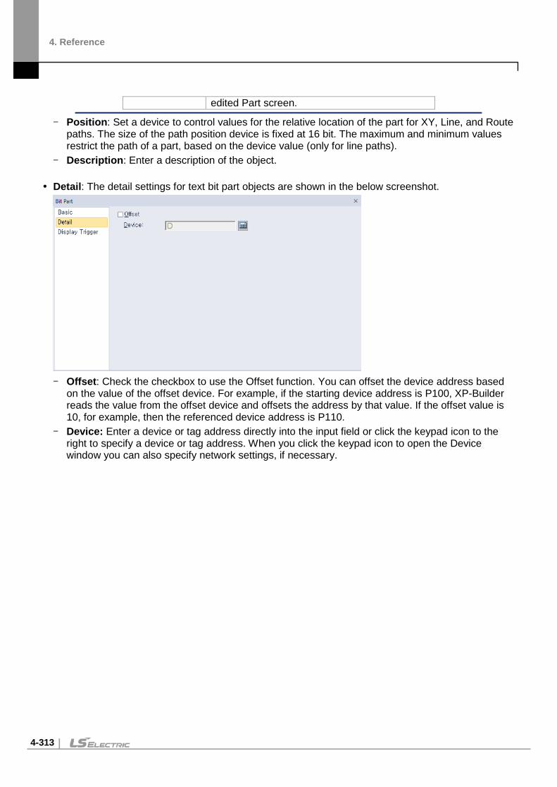
4. Reference
4-313
edited Part screen.
- Position: Set a device to control values for the relative location of the part for XY, Line, and Route paths. The size of the path position device is fixed at 16 bit. The maximum and minimum values restrict the path of a part, based on the device value (only for line paths).
- Description: Enter a description of the object. Detail: The detail settings for text bit part objects are shown in the below screenshot.
- Offset: Check the checkbox to use the Offset function. You can offset the device address based
on the value of the offset device. For example, if the starting device address is P100, XP-Builder reads the value from the offset device and offsets the address by that value. If the offset value is 10, for example, then the referenced device address is P110.
- Device: Enter a device or tag address directly into the input field or click the keypad icon to the right to specify a device or tag address. When you click the keypad icon to open the Device window you can also specify network settings, if necessary.

4. Reference
4-314
Display Trigger: The display trigger settings for bit part objects are shown in the below screenshot.
- Use Condition: Set whether or not to specify a condition for the action. - Type: Set a type of condition to specify.
Bit On The action is performed when the device is switched on.
Bit Off The action is performed when the device is switched off.
Range The action is performed when the value falls within the specified range.
Multi Bit The action is performed when the logical operation result of multiple devices is met.
- Device: Enter a device or tag address directly into the input field or click the keypad icon to the right to specify a device or tag address. When you click the keypad icon to open the Device window, you can also specify network settings, if necessary.
- Range: If you select the range condition, specify the range.
Size 16 bit or 32 bit.
Type Signed decimal, unsigned decimal, BCD, or float.
Exp. Click to designate the expression as conditional.
- Multi Bit: If you select the multi bit condition, specify the number of bits and click [Setting] to specify the bit conditions.

4. Reference
4-315
Word Part This section describes available settings for word part objects.
Basic: The basic settings for word part objects are shown in the below screenshot.
- Control Device:
Device Enter a device or tag address directly into the input field or click the keypad icon to the right to specify a device or tag address. When you click the keypad icon to open the Device window you can also specify network settings, if necessary.
Size Set the data size for the object (16 or 32 bit). If Display Part Screen is set to “Indirect”, the size is fixed to 16 bit and cannot be changed.
Type Set the data type for the object (Signed decimal, unsigned decimal, BCD, or float).
- Screen Type: Set the type of part to invoke.
Part Screen Set to invoke a part.
Storage Image Set to invoke an image from a storage location, such as a CF card or USB device. Images can only be invoked from a folder titled “XP_User Image.” Image filenames must be formatted with the prefix, img, followed by a five digit number, for example, “ImgXXXXX.bmp” or”ImgXXXXX.jpg. ” If the filename is such as “Img00000.bmp” or “img00000.jpg,” then the device value is “0,”and the image will not be invoked.
- Display Part Screen: Set the method for invoking the window.
Indirect Invoke the window based on the device value. It is either the window number or the image file name that the device value invokes. For example, if the device value is “1” and the screen type is set to Part Screen, Part Screen 1 will be invoked. If the screen type is set to Storage Image, the file “img00001.bmp” will be invoked.

4. Reference
4-316
Case Invoke the window when the condition is met.
- Placement: Set the location where the new part will appear on the screen (top-left, center, top-right, bottom-right, or bottom-left). For example, if you set the location to “Top-Left”, the part will appear in the upper-left corner of the object.
<Part>
<Example of a “Top-Left” placement>
Type Description
Top-Left Align the upper-left corner of the part with the upper-left corner of the object.
Center Center the part over the object.
Top-Right Align the upper-right corner of the part with the upper-right corner of the object.
Bottom-Right Align the lower-right corner of the part with the lower-right corner of the object.
Bottom-Left Align the lower-left corner of the part with the lower-left corner of the object.

4. Reference
4-317
Note
• If the data size or type is changed, the input and display conditions are deleted. • If the Display Part Screen setting changes to Indirect, the input and display
conditions are deleted. • If an area of the part extends beyond the borders of the Base screen, only the area
inside the borders will be displayed.
• The placement points for the Window and Part objects are as follows:
Object Placement Point Window Object The start point of the edited Window screen.
Part Object The start point where the parts are drawn in the edited Part screen.
• When the Screen Type setting is Storage Image and the Display Part Screen setting is Indirect, the image from the storage device that corresponds to the current control device is displayed.
- Position: Set a device to control values for the relative location of the part for XY, Line, and Route paths. The size of the path position device is fixed at 16 bit. The maximum and minimum values restrict the path of a part based on the device value (only for line paths).
- Storage Image Setting: Set options for using images from a storage location.
Width Set the width of the image when you import an image from the storage device. The image size is reduced or expanded to fit the width you set. When you set the Original size option, you can view as much of the original image as fits within the width you set.
Height Set the height of the image when you import an image from the storage device. The image size is reduced or expanded to fit the height you set. When you set the Original size option, you can view as much of the original image as fits within the height you set.
Storage Path Select the storage location for the image.
Original size Set to show the image in its original size. If the image size is larger than the Base screen, only as much of the image as fits within the Base screen will be displayed, as shown below.
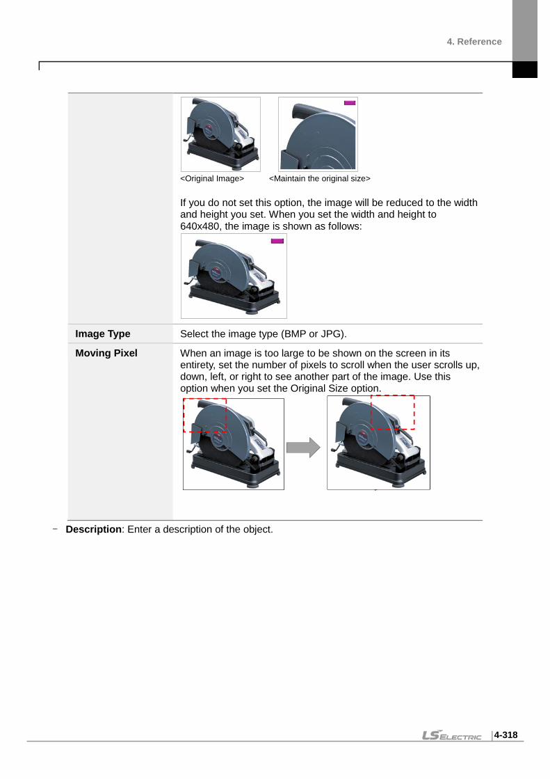
4. Reference
4-318
<Original Image> <Maintain the original size> If you do not set this option, the image will be reduced to the width and height you set. When you set the width and height to 640x480, the image is shown as follows:
Image Type Select the image type (BMP or JPG).
Moving Pixel When an image is too large to be shown on the screen in its entirety, set the number of pixels to scroll when the user scrolls up, down, left, or right to see another part of the image. Use this option when you set the Original Size option.
- Description: Enter a description of the object.

4. Reference
4-319
Case: The case settings for word part objects are shown in the screenshot below.
- Case List: Create, delete, or reorganize conditional expressions:
(Create) Click to create a new range condition. You can create up to eight conditions. Clicking this icon opens the Range Edit window, which allows you to create a condition. For more information, refer to <4.2.1.3 Understanding Constants and Data Types>.
(Delete) Click a condition and then click this icon to delete the condition.
(Up) Click a condition and then click this icon to move it higher up the list.
(Down) Click a condition and then click this icon to move it lower down the list.
A number can be set for a part screen that pops up or overlaps when a condition is met. You can directly set the number or browser for a part screen. If you click the Browser button, all the part screens created will be displayed in thumbnails as shown below. Select a part screen to set the number.

4. Reference
4-320
Note Browser button is not provided if the Screen type is set to Storage Image in Basic property window.
Operation: The operation settings for word part objects are shown in the below screenshot.
- Use Script: Check the checkbox to use a script with the object. - Select Script: Select a script from the drop-down list. - Script: When you select a script, it appears here. To modify a script, refer to <4.2 Scripts>.

4. Reference
4-321
Detail: The detail settings for word part objects are shown in the below screenshot.
- Offset: Check the checkbox to use the Offset function. You can offset the device address based
on the value of the offset device. For example, if the starting device address is P100, XP-Builder reads the value from the offset device and offsets the address by that value. If the offset value is 10, for example, then the referenced device address is P110.
- Device: Enter a device or tag address directly into the input field or click the keypad icon to the right to specify a device or tag address. When you click the keypad icon to open the Device window you can also specify network settings, if necessary.
Display Trigger: The display trigger settings for word part objects are shown in the below screenshot.
- Use Condition: Set whether or not to specify a condition for the action. - Type: Set a type of condition to specify.
Bit On The action is performed when the device is switched on.
Bit Off The action is performed when the device is switched off.
Range The action is performed when the value falls within the specified range.

4. Reference
4-322
Multi Bit The action is performed when the logical operation result of multiple devices is met.
- Device: Enter a device or tag address directly into the input field or click the keypad icon to the right to specify a device or tag address. When you click the keypad icon to open the Device window, you can also specify network settings, if necessary.
- Range: If you select the range condition, specify the range.
Size 16 bit or 32 bit.
Type Signed decimal, unsigned decimal, BCD, or float.
Exp. Click to designate the expression as conditional.
- Multi Bit: If you select the multi bit condition, specify the number of bits and click [Setting] to specify the bit conditions.

4. Reference
4-323
Animation Object Animation objects allow you to display moving images (GIFs) based on the device conditions.
Animation: The animation settings for animation objects are shown in the below screenshot.
- Loop: Set whether or not to repeat the animation. If you set this option, you cannot set the
Start/End or Pause/Restart devices. - Start/End: Set a bit device to start and end the animation. - Pause/Restart: Set a device to pause or resume the animation halfway. - Library: Click to select an animation from the user or system graphic libraries. - Open: Click to select a GIF file from your computer. - Speed: Set the speed of the animation.
Slow 400 ms
Normal 250 ms
Fast 100 ms
- Description: Enter a description of the relevant object. Note Depending on the operation speed and the image size, animation objects can overload the system and affect the overall performance. In projects other than WXP, animated gifs "The original image cannot exceed 256 pixels in width and length, and the number of frames cannot exceed 16. Check the above constraints when registering with the library or checking for data errors. If the animation object is not connected to PLC device when setting Start / End, Pause / Restart device, it displays the image of stop status. ※ For details, refer to <Appendix 5. Object Display Rule before Communication Connection>.

4. Reference
4-324
Display Trigger: The display trigger settings for animation objects are shown in the below screenshot.
- Use Action Condition: Set whether or not to specify a condition for the action. - Type: Set a type of condition to specify.
Bit On The action is performed when the device is switched on.
Bit Off The action is performed when the device is switched off.
Range The action is performed when the value falls within the specified range.
Multi Bit The action is performed when the logical operation result of multiple devices is met.
- Device: Enter a device or tag address directly into the input field or click the keypad icon to the right to specify a device or tag address. When you click the keypad icon to open the Device window, you can also specify network settings, if necessary.
- Range: If you select the range condition, specify the range.
Size 16 bit or 32 bit.
Type Signed decimal, unsigned decimal, BCD, or float.
Exp. Click to designate the expression as conditional.
- Multi Bit: If you select the multi bit condition, specify the number of bits and click [Setting] to specify the bit conditions.

4. Reference
4-325
Graph Objects You can use graph objects to express various device values. Eight types of graphs are available, including bar, pie, meter, closed, trend, logging trend, logging scatter, and real-time scatter graphs.
Note
• If the graph object is not connected to a PLC device, only graph background and scale are displayed. ※ For details, refer to <Appendix 5. Object Display Rule before Communication Connection>.
Bar Graph The following sections describe options available for bar graphs.
Basic: The basic settings for bar graph objects are shown in the below screenshot.
- Control Device: Specify the following options for the control device.
Device Enter a device or tag address directly into the input field or click the keypad icon to the right to specify a device or tag address. When you click the keypad icon to open the Device window, you can also specify network settings, if necessary.
Size Set the data size of the device (16 bit or 32 bit). If you change the data size of an existing object, the conditional statement will be deleted.
Type Set the data form at the device (signed decimal, unsigned decimal, BCD, or float). If you change the data type of an existing object, the

4. Reference
4-326
conditional statement will be deleted.
- Upper/Lower Limit Value: Set the maximum and minimum values of the data to display. The maximum and minimum values must be within the range supported by the device type. Otherwise, only the minimum or maximum value supported by the device will be displayed.
Device Set the specified device value as the maximum and minimum value.
Constant Set the specified fixed value as the maximum and minimum value.
Note
Refer to the following table for the minimum and maximum constant values based on the device size:
Device size Device type Minimum Maximum 16bit Signed decimal -32768 32767 16bit Unsigned decimal 0 65535 16bit BCD 0 9999 32bit Signed decimal -2147483648 2147483647 32 bit Unsigned decimal 0 4294967295 32 bit BCD 0 99999999
- Description: Enter a description of the relevant object. Display: The display settings for bar graph objects are shown in the below screenshot.
- Transparent BG Image: Set whether or not to make the background of the graph transparent. - Library: Click to select a background image for the graph from an image library. - Open: Click to search for a background image for the graph on your computer. - Direction: Set the direction of the graph (top > bottom, bottom > top, left > right, or right > left). - Hatch: Set a pattern for the ranges in the graph. - Transparent Border: Set whether or not to use a transparent border for the graph. - Frame Display: Specify the following options for the frame.
Border Color Select a border color.

4. Reference
4-327
Plate Color Select the background for areas not filled by value ranges.
- Fill Type: Specify the following options for the fill.
Pattern FG Color Select a foreground color for the pattern.
Pattern BG Color Select a background color for the pattern.
- Scale: Specify the following options for the scale.
Point Set the number of points in the scale. The number can be set from 0 to 255. Every fifth point is displayed longer than other points and the size of the points differ by graph. If the number of points is 0, other options cannot be set.
Interval Set the space between points on the graph (0 to 10).
Location Set the location of the scale in the graph.
Alignment Set the alignment of points in the scale. If the location of the scale is to the left or right, the alignment can be set as left or right. If the location of the scale is at the top or bottom, the alignment can be set as top or bottom.
Color Set the color of the scales.
Plate Color
Fill Color

4. Reference
4-328
Case: The case settings for bar graph object are shown in the below screenshot.
- Case List: Create, delete, or reorganize conditional expressions.
(Create) Click to create a new range condition. You can create up to eight conditions. Clicking this icon opens the Range Edit window, which allows you to create a condition. For more information, refer to <4.2.1.3 Understanding Constants and Data Types>.
(Delete) Click a condition and then click this icon to delete the condition.
(Up) Click a condition and then click this icon to move it higher up the list.
(Down) Click a condition and then click this icon to move it lower down the list.
When you create a range condition, you can also set the fill type of the graph.
Pattern FG Color Set the foreground color of the graph to display when the condition is met.
Pattern BG Color Set the background color of the graph to display when the condition is met.

4. Reference
4-329
Operation: The operation settings for bar graph objects are shown in the screenshot below.
- Use Script: Check the checkbox to use a script with the object. - Select Script: Select a script from the drop-down list. - Script: When you select a script, it appears here. To modify a script, refer <4.2 Scripts>
Detail: The detail settings for bar graph objects are shown in the below screenshot.
- Offset: Check the checkbox to use the Offset function. You can offset the device address based
on the value of the offset device. For example, if the starting device address is P100, XP-Builder reads the value from the offset device and offsets the address by that value. If the offset value is 10, for example, then the referenced device address is P110.
- Device: Enter a device or tag address directly into the input field or click the keypad icon to the right to specify a device or tag address. When you click the keypad icon to open the Device window, you can also specify network settings, if necessary.

4. Reference
4-330
Display Trigger: The display trigger settings for bar graph objects are shown in the below screenshot.
- Use Condition: Set whether or not to specify a condition for the action. - Type: Set a type of condition to specify.
Bit On The action is performed when the device is switched on.
Bit Off The action is performed when the device is switched off.
Range The action is performed when the value falls within the specified range.
Multi Bit The action is performed when the logical operation result of multiple devices is met.
- Device: Enter a device or tag address directly into the input field or click the keypad icon to the right to specify a device or tag address. When you click the keypad icon to open the Device window, you can also specify network settings, if necessary.
- Range: If you select the range condition, specify the range.
Size 16 bit or 32 bit.
Type Signed decimal, unsigned decimal, BCD, or float.
Exp. Click to designate the expression as conditional.
- Multi Bit: If you select the multi bit condition, specify the number of bits and click [Setting] to specify the bit conditions.

4. Reference
4-331
Pie Graph The following sections describe the available options for pie graph objects.
Basic: The basic settings for pie graph objects are shown in the below screenshot.
- Control Device: Specify the following options for the control device.
Device Enter a device or tag address directly into the input field or click the keypad icon to the right to specify a device or tag address. When you click the keypad icon to open the Device window, you can also specify network settings, if necessary.
Size Set the data size of the device (16 bit or 32 bit). If you change the data size of an existing object, the conditional statement will be deleted.
Type Set the data form at the device (signed decimal, unsigned decimal, BCD, or float). If you change the data type of an existing object, the conditional statement will be deleted.
- Upper/Lower Limit Value: Set the maximum and minimum values of the data to display. The maximum and minimum values must be within the range supported by the device type. Otherwise, only the minimum or maximum value supported by the device will be displayed.
Device Set the specified device value as the maximum and minimum value.
Constant Set the specified fixed value as the maximum and minimum value.

4. Reference
4-332
Note
Refer to the following table for the minimum and maximum constant values based on the device size:
Device size Device type Minimum Maximum 16bit Signed decimal -32768 32767 16bit Unsigned decimal 0 65535 16bit BCD 0 9999 32bit Signed decimal -2147483648 2147483647 32 bit Unsigned decimal 0 4294967295 32 bit BCD 0 99999999
• If the number of channels is 2 or more, the device of each channel is set as a continuous device based on the input device. - Example) Input device: HW00000, if the size is 16bit, set the second channel device
to HW00001 - Example) Input device: HW00000, if the size is 32bit, set the second channel device
to HW00002 • If the number of channels is 2 or more, only the positive number greater than 0 can be entered for device input.
- Description: Enter a description of the relevant object.
Display: The display settings for pie graph objects are shown in the below screenshot.
- Channels: Input the number of items to display on pie graph. - Library: Click to select a background image for the graph from an image library. - Open: Click to search for a background image for the graph on your computer. - Hatch: Set a pattern for the ranges in the graph. - Transparent BG Image: Set whether or not to make the background of the graph transparent.

4. Reference
4-333
- Transparent Border: Set whether or not to use a transparent border for the graph. - Frame Display: Specify the following options for the frame.
Border Color Select a border color.
Plate Color Select the background for areas not filled by value ranges.
- Fill Type: Specify the following options for the fill.
Pattern FG Color Set a foreground color for the pattern.
Pattern BG Color Set a background color for the pattern.
- Shape and Direction: Specify the following options for the shape and direction.
Shape Set the shape of the pie chart (circle, top-half circle, bottom-half circle, left-half circle, right-half circle, top-fan, bottom-fan, left-fan, right-fan, and 3/4 fan).
Direction Set the direction for filling the pie graph (clockwise or counter-clockwise).
Start Position When using a circle shape, set the start position of the pointer. If the direction is clockwise, the start position is as follows.
Top Bottom Left Right
- Scale: Specify the following options for the scale.
Point Set the number of points in the scale.
Color Set the color of the scales.

4. Reference
4-334
Setting when the number of channels is 2 or more:
- Select fill-type channel: Enter the channel number to set the fill color, or select the channel
number from the drop-down list. - Use Data display: Displays the ratio of the value of each channel to the value of all channels is %.
Text size Set the size of the displayed text.
Text color Set the color of the displayed text.
Use text BG color Set the background color of the displayed text.
- Fill Color: Set the fill color of pie portion of each channel.

4. Reference
4-335
Case: The case settings for pie graph objects are shown in the below screenshot.
- Case List: Create, delete, or reorganize conditional expressions.
(Create) Click to create a new range condition. You can create up to eight conditions. Clicking this icon opens the Range Edit window, which allows you to create a condition. For more information, refer to <4.2.1.3 Understanding Constants and Data Types>.
(Delete) Click a condition and then click this icon to delete the condition.
(Up) Click a condition and then click this icon to move it higher up the list.
(Down) Click a condition and then click this icon to move it lower down the list.
When you create a range condition, you can also set the fill type of the graph.
Pattern FG Color Set the foreground color of the graph to display when the
condition is met.
Pattern BG Color Set the background color of the graph to display when the condition is met.

4. Reference
4-336
Operation: The operation settings for pie graph objects are shown in the below screenshot.
- Use Script: Check the checkbox to use a script with the object. - Select Script: Select a script from the drop-down list. - Script: When you select a script, it appears here. To modify a script, refer to <4.2 Scripts>.
Detail: The detail settings for pie graph objects are shown in the below screenshot.
- Offset: Check the checkbox to use the Offset function. You can offset the device address based
on the value of the offset device. For example, if the starting device address is P100, XP-Builder reads the value from the offset device and offsets the address by that value. If the offset value is 10, for example, then the referenced device address is P110.
- Device: Enter a device or tag address directly into the input field or click the keypad icon to the right to specify a device or tag address. When you click the keypad icon to open the Device window, you can also specify network settings, if necessary.

4. Reference
4-337
Display Trigger: The display trigger settings for pie graph objects are shown in the below screenshot.
- Use Condition: Set whether or not to specify a condition for the action. - Type: Set a type of condition to specify.
Bit On The action is performed when the device is switched on.
Bit Off The action is performed when the device is switched off.
Range The action is performed when the value falls within the specified range.
Multi Bit The action is performed when the logical operation result of multiple devices is met.
- Device: Enter a device or tag address directly into the input field or click the keypad icon to the right to specify a device or tag address. When you click the keypad icon to open the Device window, you can also specify network settings, if necessary.
- Range: If you select the range condition, specify the range.
Size 16 bit or 32 bit.
Type Signed decimal, unsigned decimal, BCD, or float.
Exp. Click to designate the expression as conditional.
- Multi Bit: If you select the multi bit condition, specify the number of bits and click [Setting] to specify the bit conditions.

4. Reference
4-338
Meter Graph The following sections describe available options for meter graphs.
Basic: The basic settings for meter graph objects are shown in the below screenshot.
- Control Device: Specify the following options for the control device.
Device Enter a device or tag address directly into the input field or click the keypad icon to the right to specify a device or tag address. When you click the keypad icon to open the Device window, you can also specify network settings, if necessary.
Size Set the data size of the device (16 bit or 32 bit). If you change the data size of an existing object, the conditional statement will be deleted.
Type Set the data form at the device (signed decimal, unsigned decimal, BCD, or float). If you change the data type of an existing object, the conditional statement will be deleted.
- Upper/Lower Limit Value: Set the maximum and minimum values of the data to display. The maximum and minimum values must be within the range supported by the device type. Otherwise, only the minimum or maximum value supported by the device will be displayed.
Device Set the specified device value as the maximum and minimum value.
Constant Set the specified fixed value as the maximum and minimum value.
Note
Refer to the following table for the minimum and maximum constant values based on the device size:

4. Reference
4-339
Device size Device type Minimum Maximum 16bit Signed decimal -32768 32767 16bit Unsigned decimal 0 65535 16bit BCD 0 9999 32bit Signed decimal -2147483648 2147483647 32 bit Unsigned decimal 0 4294967295 32 bit BCD 0 99999999
- Description: Enter a description of the relevant object. Display: The display settings for meter graph objects are shown in the below screenshot.
- Library: Click to select a background image for the graph from an image library. - Open: Click to search for a background image for the graph on your computer. - Frame Display: Specify the following options for the frame.
Border Color Select a border color.
Plate Color Select the background for areas not filled by value ranges.
Needle Color Select the pointer color.
- Transparent BG Image: Set whether or not to make the background of the graph transparent. - Transparent Border: Set whether or not to use a transparent border. - Shape and Direction: Specify the following options for the shape and direction:
Shape Set the shape of the graph.
Direction Set the direction for filling the graph.
Start Position When using a circle shape, set the starting position of the pointer. When using a circle shape, set the starting position of the pointer. If the direction is clockwise, the start position is as follows.

4. Reference
4-340
Top Bottom Left Right
- Scale: Specify the following options for the scale.
Point Set the number of points in the scale.
Color Set the color of the scales. Case: The case settings for meter graph objects are shown in the below screenshot.
- Case List: Create, delete, or reorganize conditional expressions.
(Create) Click to create a new range condition. You can create up to eight conditions. Clicking this icon opens the Range Edit window, which allows you to create a condition. For more information, refer to <4.2.1.3 Understanding Constants and Data Types>.
(Delete) Click a condition and then click this icon to delete the condition.
(Up) Click a condition and then click this icon to move it higher up the list.
(Down) Click a condition and then click this icon to move it lower down the list.
When you create a range condition, you can also set the needle color of the graph to display when the condition is met.
Operation: The operation settings for meter graph objects are shown in the below screenshot.

4. Reference
4-341
- Use Script: Check the checkbox to use a script with the object. - Select Script: Select a script from the drop-down list. - Script: When you select a script, it appears here. To modify a script, refer to <4.2 Scripts>.
Detail: The detail settings for meter graph objects are shown in the below screenshot.
- Offset: Check the checkbox to use the Offset function. You can offset the device address based
on the value of the offset device. For example, if the starting device address is P100, XP-Builder reads the value from the offset device and offsets the address by that value. If the offset value is 10, for example, then the referenced device address is P110.
- Device: Enter a device or tag address directly into the input field or click the keypad icon to the right to specify a device or tag address. When you click the keypad icon to open the Device window, you can also specify network settings, if necessary.

4. Reference
4-342
Display Trigger: The display trigger settings for the meter graph object include the following.
- Use Condition: Set whether or not to specify a condition for the action. - Type: Set a type of condition to specify.
Bit On The action is performed when the device is switched on.
Bit Off The action is performed when the device is switched off.
Range The action is performed when the value falls within the specified range.
Multi Bit The action is performed when the logical operation result of multiple devices is met.
- Device: Enter a device or tag address directly into the input field or click the keypad icon to the right to specify a device or tag address. When you click the keypad icon to open the Device window, you can also specify network settings, if necessary.
- Range: If you select the range condition, specify the range.
Size 16 bit or 32 bit.
Type Signed decimal, unsigned decimal, BCD, or float.
Exp. Click to designate the expression as conditional.
- Multi Bit: If you select the multi bit condition, specify the number of bits and click [Setting] to specify the bit conditions.

4. Reference
4-343
Closed Graph The following sections describe the options available for closed graph objects.
Basic: The basic settings for closed graph objects include the following.
- Control Device: Specify the following options for the control device.
Device Enter a device or tag address directly into the input field or click the keypad icon to the right to specify a device or tag address. When you click the keypad icon to open the Device window, you can also specify network settings, if necessary.
Size Set the data size of the device (16 bit or 32 bit). If you change the data size of an existing object, the conditional statement will be deleted.
Type Set the data form of the device (signed decimal, unsigned decimal, BCD, or float). If you change the data type of an existing object, the conditional statement will be deleted.
- Upper/Lower Limit Value: Set the maximum and minimum values of the data to display. The maximum and minimum values must be within the range supported by the device type. Otherwise, only the minimum or maximum value supported by the device will be displayed.
Device Set the specified device value as the maximum and minimum value.
Constant Set the specified fixed value as the maximum and minimum value.

4. Reference
4-344
Note
Refer to the following table for the minimum and maximum constant values based on the device size:
Device size Device type Minimum Maximum 16bit Signed decimal -32768 32767 16bit Unsigned decimal 0 65535 16bit BCD 0 9999 32bit Signed decimal -2147483648 2147483647 32 bit Unsigned decimal 0 4294967295 32 bit BCD 0 99999999
- Description: Enter description in the relevant object. Display: The display settings for closed graph objects include the following.
- Transparent BG Image: Set whether or not to make the background of the graph transparent. - Library: Click to select a background image for the graph from a library. - Open: Click to locate background image for the graph on your computer. - Direction: Set the direction for filling the graph (Top > Bottom, Bottom > Top, Left > Right, or Right
> Left). - Hatch: Select the pattern for the filled areas of the graph. - Transparent Border: Set whether or not to use a transparent border. - Frame Display: Specify the following options for the frame.
Border Color Set a border color.
Plate Color Set the background for areas not filled by value ranges.
- Fill Type: Specify the following options for the fill.
Pattern FG Color Set the foreground color for the pattern.
Pattern BG Color Set the background color for the pattern.

4. Reference
4-345
- Scale: Specify the following options for the scale.
Point Set the number of points in the scale. The number can be set from 0 to 255. Every fifth point is displayed longer than other points and the size of the points differ by graph. If the number of points is 0, other options cannot be set.
Interval Set the space between points on the graph (0 to 10).
Location Set the location of the scale in the graph.
Alignment Set the alignment of points in the scale. If the location of the scale is left or right, the alignment can be set in left or right. If the location of the scale is top or bottom, the alignment can be set in top or bottom.
Color Set the color of the scales. Case: The case settings for closed graph object include the following.
- Case List: Create, delete, or reorganize conditional expressions:
(Create) Click to create a new range condition. You can create up to eight conditions. Clicking this button opens the Range Edit window, which allows you to create a condition. For more information, refer to <4.2.1.3 Understanding Constants and Data Types>.
(Delete) Click a condition and then click this icon to delete the condition.
(Up) Click a condition and then click this icon to move it higher up the list.
(Down) Click a condition and then click this icon to move it lower down the list.
When you create a range condition, you can also set the fill type of the graph.

4. Reference
4-346
Pattern FG Color Set the foreground color of the graph to display when the
condition is met.
Pattern BG Color Set the background color of the graph to display when the condition is met.
Operation: The operation settings for closed graph object include the following.
- Use Script: Click the checkbox to use a script with the object. - Select Script: Select a script from the drop-down list. - Script: When you select a script, it appears here. To modify a script, refer to refer to <4.2 Scripts>.

4. Reference
4-347
Detail: The detail settings for closed graph object include the following.
- Offset: Click the checkbox to use the offset function. You can offset the device address based on
the value of the offset device. For example, if the starting device address is P100, XP-Builder reads the value from the offset device and offsets the address by that value. If the offset value is 10, for example, then the referenced device address is P110.
- Device: Enter a device or tag address directly into the input field or click the keypad icon to the right to specify a device or tag address. When you click the keypad icon to open the Device window, you can also specify network settings, if necessary.
Display Trigger: The display trigger settings for the closed graph object include the following.
- Use Condition: Set whether or not to specify a condition for the action. - Type: Set a type of condition to specify.
Bit On The action is performed when the device is switched on.
Bit Off The action is performed when the device is switched off.
Range The action is performed when the value falls within the specified range.
Multi Bit The action is performed when the logical operation result of multiple devices is met.

4. Reference
4-348
- Device: Enter a device or tag address directly into the input field or click the keypad icon to the right to specify a device or tag address. When you click the keypad icon to open the Device window, you can also specify network settings, if necessary.
- Range: If you select the range condition, specify the range.
Size 16 bit or 32 bit.
Type Signed decimal, unsigned decimal, BCD, or float.
Exp. Click to designate the expression as conditional.
- Multi Bit: If you select the multi bit condition, specify the number of bits and click [Setting] to specify the bit conditions.

4. Reference
4-349
Trend Graph The following sections describe available options for trend graphs.
Note
• Only the data points on the X axis (time axis) that are collected most recently according to the current time will be displayed on the screen. That is, the previous values of the current time (acquisition interval X the number of points on the X axis) will be displayed.
• When the screen shifts, communication may stop and resume. If a communication delay occurs,
graphs may not appear correctly. If communication fails for a short time because of environmental factors such as nose, graphs may not appear correctly.

4. Reference
4-350
Basic: The basic settings for the trend graph object include the following.
- Device: Specify the following options for the device.
Size Set the data size of the device (16 bit or 32 bit).
Type Set the data form of the device (signed decimal, unsigned decimal, BCD, or float).
Note
The data size, data form, maximum alarm value, minimum alarm value, maximum data value, minimum data value are equally applied to all the devices.
- Alarm Value: Set whether or not to trigger an alarm if the data value exceeds the maximum or minimum limits.
Device Set the specified device value as the alarm limit.
Constant Set the specified fixed value as the alarm limit.
As you see in the example below that compares the production volume and the target volume, the maximum alarm value and the minimum alarm value are displayed in straight lines.
- Device: Click to specify a device to be referenced by the object or enter the device address. When
you specify a device, a new device input row will be created automatically, where you can specify more devices to be referenced (up to 8).

4. Reference
4-351
To remove a device, click the row number and press delete on the keypad.
- Line Color: Set the line color for the graph. - Line Type: Set the line type (dash or solid). - Line Thickness: Sets the line thickness.
Solid line 1 through 10 can be set.
dotted line Only 1 is available.

4. Reference
4-352
Max/Min: The Max/Min settings for the trend graph object include the following.
- Max/Min Setting: This option specifies the maximum and minimum values for the data to display.
The maximum and minimum values are set by selecting with a device or by entering the constant values. In the graph below, the minimum value is set at 0 and the maximum value is set at 150 within a range of 0-150.If a device to be monitored has a value outside the maximum or minimum values, it is displayed as the maximum or minimum value on the graph.
100%
0%
50%
Not displayed

4. Reference
4-353
Individual If the maximum and minimum values are set to [Individual], they are applied respectively based on the device address listed in [Basic].If the devices P0000, P0001, and P0002 are registered in [Basic] as shown in the screenshot below, the maximum and minimum values are specified:
[Default Settings]
[Maximum/Minimum Value Settings]
When the maximum and minimum values are specified separately as shown above, both values for the first device, P0000, are set to 0 and 150 on the graph. The maximum and minimum values for the second device, P0001, are set to 100 and 200 on the graph. The maximum and minimum values for the third device, P0002, are set to 50 and 250 on the graph.
Note
If The Setting Type of Min/Max is set to [Individual], Reference Line menu option is not displayed.
Block If the maximum and minimum values are set to [Block], all indices that are set in [Basic] will have the same values. Therefore, indices 1, 2, and 3 will all have the same maximum and minimum values in the example above. Only one maximum and minimum value each can be entered for whole setting configurations. The reference line can be set only when the maximum and minimum values are specified.
Display: The display settings for the trend graph object include the following.
150
0
200
0
250
50
(1)(2)(3)

4. Reference
4-354
- Library: Click to select a background image for the graph from a library. - Open: Click to locate background image for the graph on your computer. - Transparent BG: Set whether or not to make the background of the graph transparent. - Transparent Border: Set whether or not to use a transparent border. - No. of Display in X axis: Set the number of data points to be displayed on the graph (more than
3).
- Frame Display: Specify the following options for the frame.
Border Color Set a border color.
Plate Color Set the background for areas not filled by value ranges.
- Sampling Time x100ms: Set the cycle for collecting the data, in milliseconds
Constant For a constant, the cycle can be set between 1 and 6,000.
Device For a device, the cycle is set from a device value. However, if a device value is 0, the cycle is changed to 100 ms forcefully.
- Starting Point Location: Set a starting point for the scales (left bottom or right bottom).

4. Reference
4-355
- The Scroll Points: Set the speed that the graph will scroll across the screen, by setting the
number of points that the graph will scroll each time. The higher the number, the faster the graph will scroll. Previous data are deleted by the number of points that you set and the new data are displayed in the direction of the graph.
- Scale: Specify the following options for the scale.
No. of Horizontal Point Set the number of points on the X axis.
No. of Vertical Point Set the number of points on the Y axis.
X-axis Height Set the height of the X axis scale.
Y-axis Width Set the width of the Y axis scale.
Scale Color Set the color of the scales.
Left Right
Graph direction Graph direction

4. Reference
4-356
Operation: The operation settings for trend graph object include the following.
- Use Script: Click the checkbox to use a script with the object.
Select Script Select a script from the drop-down list.
Script When you select a script, it appears here. To modify a script, refer to <4.2 Scripts>.
Detail: The detail settings for trend graph object include the following.
- Offset: Click the checkbox to use the offset function. You can offset the device address based on
the value of the offset device. For example, if the starting device address is P100, XP-Builder reads the value from the offset device and offsets the address by that value. If the offset value is 10, for example, then the referenced device address is P110.
- Device: Enter a device or tag address directly into the input field or click the keypad icon to the right to specify a device or tag address. When you click the keypad icon to open the Device window, you can also specify network settings, if necessary.

4. Reference
4-357
Display Trigger: The display trigger settings for the trend graph object include the following.
- Use Condition: Set whether or not to specify a condition for the action. - Type: Set a type of condition to specify.
Bit On The action is performed when the device is switched on.
Bit Off The action is performed when the device is switched off.
Range The action is performed when the value falls within the specified range.
Multi Bit The action is performed when the logical operation result of multiple devices is met.
- Device: Enter a device or tag address directly into the input field or click the keypad icon to the right to specify a device or tag address. When you click the keypad icon to open the Device window, you can also specify network settings, if necessary.
- Range: If you select the range condition, specify the range.
Size 16 bit or 32 bit.
Type Signed decimal, unsigned decimal, BCD, or float.
Exp. Click to designate the expression as conditional.
- Multi Bit: If you select the multi bit condition, specify the number of bits and click [Setting] to specify the bit conditions.

4. Reference
4-358
Reference Line: The reference settings for the trend graph object include the following.
Note
In the Max/Min setting window, if The Setting Type of Min/Max is set to [Individual], Reference Line menu option is not displayed.
- Use Reference: Click the checkbox to use a reference line for the graph. A reference line refers to
a line displaying the location of a specific value set by the user other than the maximum or minimum value.
A reference line can be set as a fixed value or device value and it can be set only when the maximum and minimum values are set to [Block].
Num of Reference Set the number of reference lines. When you enter the number of lines and move to the properties table of the reference lines, the corresponding number rows will be created to allow you adjust the properties. 1 to 8 reference lines can be created.
Reference Properties You can set the properties only when Use Reference is checked. If the Value Type is set to Constant, you cannot enter a device. If the Value Type is set to Device, you cannot enter a fixed value. The number column is a reference line number. It cannot be edited and its location cannot be changed. If the line type of a reference line is set to Dash, the thickness can only be set to 1.

4. Reference
4-359
Display Value Select this option to display reference line values in a text. The text color is the same as the color of the reference line, and the text size is adjusted based on the size of the trend graph.
Logging Trend Graph The following sections describe available options for logging trend graph objects.
Note
• Only the data points on the X axis (time axis) that are collected most recently according to the current time will be displayed on the screen.
• When the logging is in progress, communication may stop for a short time because of
environmental factors such as nose and the logging fails. The data of such time are not normal and are not displayed on the logging trend graph. Therefore, the graph appears intermittently.

4. Reference
4-360
Basic: The basic settings for the logging trend graph object include the following.
- Logging Device: Specify the following options for the logging device.
Size Set the data size of the device (16 bit or 32 bit). You can change the data size only in the Logging data from the project pane.
Type Set the data form of the device (signed decimal, unsigned decimal, BCD, or float).
- Alarm Value: Set whether or not to trigger an alarm if the data value exceeds the maximum or minimum limits.
Device Set the specified device value as the alarm limit.
Constant Set the specified fixed value as the alarm limit.
As you see in the example below that compares the production volume and the target volume, the maximum alarm value and the minimum alarm value are displayed in straight lines.
- Logging Group: Set the number of the logging group, which is set in the Logging.

4. Reference
4-361
- Display: Set the condition for displaying the graph.
Always Display Set to display always.
Display when Bit On/Off
Set to display only specific index based on the device value. For example, if the conditional device is set to P0100 and four indices are set as shown in the screenshot below,
The following graphs are displayed based on the status of the four contiguous bit devices starting from P0100.
- Sort: Set a sort option (oldest first or latest first). - Cont. Add: Click to enter a starting index and range. Up to 20 items can be entered. - Delete All: Click to delete all input data at once. - Index: Shows the index number of the device. An index number increases by 1 starting from 1 of
logging device as the device address increases. As you see in the example below, when 32 devices from P0100 are edited to be logged, the indices numbers of the four devices, P0001, P0005, P0010, and P0018, from the 32 devices are as follow.

4. Reference
4-362
Device address Logging index
P0001 (logging device) 1
P0002 2
… …
P0005 5
… …
P0010 10
… …
P0018 18
To add a new item, enter the index number for the item on the index column. When a new item is added, a blank index column is created on the next row to add a next item. Up to 20 items can be added.
To remove an item, click the row number and press delete on the keypad.
- Device Add.: Shows the starting address for the logging group and logging index. The device
address cannot be input and is displayed according to the logging index. - Line Color: Set the line color for the graph. - Line Type: Set the line type (dash or solid). - Line Thickness: Sets the line thickness.
Solid line 1 through 10 can be set.

4. Reference
4-363
dotted line Only 1 is available.
- Description: Enter a description for the object. Max/Min: The Max/Min settings for the trend graph object include the following.
- Max/Min Setting: This option specifies the maximum and minimum values for the data to display.
The maximum and minimum values are set by selecting with a device or by entering the constant values. In the graph below, the minimum value is set at 0 and the maximum value is set at 150 within a range of 0-150.If a device to be monitored has a value outside the maximum or minimum values, it is displayed as the maximum or minimum value on the graph.
Individual If the maximum and minimum values are set to [Individual], they are applied respectively based on the device address listed in [Basic].If the devices P0000, P0001, and P0002 are registered in [Basic] as shown in the screenshot below, the maximum and minimum values are specified:
[Default Settings]
100%
0%
50%
Not displayed

4. Reference
4-364
[Maximum/Minimum Value Settings]
When the maximum and minimum values are specified separately as shown above, both values for the first device, P0000, are set to 0 and 150 on the graph. The maximum and minimum values for the second device, P0001, are set to 100 and 200 on the graph. The maximum and minimum values for the third device, P0002, are set to 50 and 250 on the graph.
Note
If The Setting Type of Min/Max is set to [Individual], Reference Line menu option is not displayed.
Block If the maximum minimum values are set to [Block], all indices that are set in [Default] will have the same values. Therefore, indices 1, 2, and 3 will all have the same maximum and minimum values in the example above. Only one maximum and minimum value each can be entered for whole setting configurations. The reference line can be set only when the maximum and minimum values are specified.
150
0
200
0
250
50
(1)(2)(3)

4. Reference
4-365
Display: The display settings for the logging trend graph object include the following.
- Library: Click to select a background image for the graph from a library. - Open: Click to locate background image for the graph on your computer. - Transparent BG: Set whether or not to make the background of the graph transparent. - Transparent Border: Set whether or not to use a transparent border. - No. of Display in X axis: Set the number of data points to be displayed on the graph (3 to 120).
Device Set the specified device value as the X axis point.
Constant Set the specified fixed value as the X axis point.
- Frame Display: Specify the following options for the frame.
Border Color Set a border color.
Plate Color Set the background for areas not filled by value ranges.
- No. of Samples to Scroll: A user can refer to the data of his intended position with the special switch; Previous Data/Next Data View. However, in the below two cases (The latest data tracking mode/the oldest data tracking mode), a window is automatically updated and it displays the data since the present time. Through this option, you can set how many data units will be applied to transfer a screen.
The latest data tracking mode
When you edit and download logging trend graph after setting Preferred View Mode as the latest data tracking mode, logging trend is set as the latest data tracking mode and it updates a screen every time logging is performed newly and then, it tracks and shows the latest logging data.
The oldest data The logging type linked to logging trend graph is set as

4. Reference
4-366
tracking mode circular buffer, the data displayed at the current screen will be removed someday with continuous logging process. Then, the equipment updates a screen automatically and displays the oldest data.
- Starting Point Location: Set a starting point for the scales (Left Bottom, Right Bottom, Left Top, or Right Top).
- Data Order: Specify the following options for the data order, for example:
Time Data
8: 10 10
8: 20 20
8: 30 30
8: 40 40
8: 50 50
Latest -> Oldest Show data in order from most recent to oldest. The starting point is on the left:
The Starting Point Location is on the right:
Oldest -> Latest Show data in order from oldest to most recent.
The Starting Point Location is on the left:
The Starting Point Location is on the right:
- Scale: Specify the following options for the scale.
No. of Horizontal Point Set the number of points on the X axis.
No. of Vertical Point Set the number of points on the Y axis.
X-axis Height Set the height of the X axis scale.

4. Reference
4-367
Y-axis Width Set the width of the Y axis scale.
Scale Color Set the color of the scales. Cursor: The cursor settings for logging trend graph object include the following.
- Cursor: Specify the following options for the cursor.
Use Cursor Set whether or not to display the cursor on the XGT screen, as illustrated below.
Storage Cursor Information
Set whether or not to save cursor data (logging time of the current cursor position and related values). Cursor data is saved at device and the size of the device is always 32 bit. The cursor information is saved as follows, based on the device set:
<Logging device size: 16bit>

4. Reference
4-368
<Logging device size: 32bit>
The cursor information is saved in the specified device whenever the data from the current location of the cursor is changed or the cursor is moved.
Color Set a color for the cursor.
Line Set a line type for the cursor (solid or dash).
Note
• To show or hide the cursor, click the Logging Trend Graph area. • The location of the cursor is at the center of the current data.
Saved at 32bit
The maximum number of logging groups (20)
Saved as unsigned 16bit
The maximum number of logging groups (20)
Saved in the lower 16bit

4. Reference
4-369
< The current data value: 3> < The current data value: 8>
• If the data to be displayed is deleted, because the area is deleted in the cursor display mode, the cursor will also disappear. When the logging is restarted, the cursor will reappear.
• The cursor cannot be moved. To move the cursor, use the Next Log Trend Data or Previous Log Trend Data option from the Special Switch object.
• If there is no data before or after the current data, the cursor is moved to the previous or next data.

4. Reference
4-370
Display Trigger: The display trigger settings for the logging trend graph object include the following.
- Use Condition: Set whether or not to specify a condition for the action. - Type: Set a type of condition to specify.
Bit On The action is performed when the device is switched on.
Bit Off The action is performed when the device is switched off.
Range The action is performed when the value falls within the specified range.
Multi Bit The action is performed when the logical operation result of multiple devices is met.
- Device: Enter a device or tag address directly into the input field or click the keypad icon to the right to specify a device or tag address. When you click the keypad icon to open the Device window, you can also specify network settings, if necessary.
- Range: If you select the range condition, specify the range.
Size 16 bit or 32 bit.
Type Signed decimal, unsigned decimal, BCD, or float.
Exp. Click to designate the expression as conditional.
- Multi Bit: If you select the multi bit condition, specify the number of bits and click [Setting] to specify the bit conditions.

4. Reference
4-371
Reference Line: The reference line settings for the logging trend graph object include the following.
Note
In the Max/Min setting window, if The Setting Type of Min/Max is set to [Individual], Reference Line menu option is not displayed.
- Use Reference: Click the checkbox to use a reference line for the graph. A reference line refers to
a line displaying the location of a specific value set by the user other than the maximum or minimum value.
A reference line can be set as a fixed value or device value and it can be set only when the maximum and minimum values are set to [Block].
Num of Reference Set the number of reference lines. When you enter the number of lines and move to the properties table of the reference lines, the corresponding number rows will be created to allow you adjust the properties. 1 to 8 reference lines can be created.
Reference Properties You can set the properties only when Use Reference is checked. If the Value Type is set to Constant, you cannot enter a device. If the Value Type is set to Device, you cannot enter a fixed value. The number column is a reference line number. It cannot be edited and its location cannot be changed. If the line type of a reference line is set to Dash, the thickness can only be set to 1.

4. Reference
4-372
Display Value Select this option to display reference line values in a text. The text color is the same as the color of the reference line, and the text size is adjusted based on the size of the logging trend graph.
Scatter Graph – Logging Scatter
The following sections describe available options for logging scatter graph objects. When the Scatter Graph Type window appears, select Logging Scatter and click OK.
Basic: The basic settings for the logging scatter graph objects include the following.
- Type of Scatter: Set the type of scatter chart.
Y Scatter Shows device addresses, including the logging start device, in order along the X-axis. The data displays in a loop, so you do not need to designate the minimum or maximum value.

4. Reference
4-373
X-Y Scatter For two continuous device addresses from starting device, shows the previous device value along the X-axis and the next device value along the Y-axis and displays dot or value where the two coordinates intersect. You must designate a minimum and maximum value for the axes.
- Scatter Basic Setting: Specify the following options for the scatter chart.
Group ID The logging group No. to be displayed can be established among 1~32. You can fix the logging group number from Logging in the Project pane. To add a new item to logging scatter chart, input logging group number to logging group window and press the Enter key. If a new item is added, the screen for logging group number is added to the next row and you can also add another item up to 20. To delete the item, select the number of item and press the Delete key.
Start Device It displays a starting device that is applicable to input logging group number. Register the start device from the Logging in the Project pane. Each control device data is initialized as 0 after completing each operation.
Type It sets the data type of device.
Size It displays the size of device to be logged. The value established at logging of common data is applied to the size of logging device and you cannot set it up.
- Description: Enter a description for the object.

4. Reference
4-374
Max./Min.: The maximum and minimum value settings for the logging scatter graph object include the following.
- Max./Min. Setting: Specify the following options for the maximum/minimum setting.
Y Axis Type / X Axis Type
You can set the minimum and maximum value as many as the items of logging distribution charts added at Basic Settings. Namely, you cannot add or delete the items on the minimum and maximum value. The type of the minimum and maximum value can be established as Constant or Device.
Y Axis. Max / Y Axis. Min
You can set the minimum and maximum values of data to be displayed on the Y-axis. You can use a device value or a constant. If the device value exceeds the minimum or maximum, it is displayed as the minimum or maximum value of the graph.
X Axis. Max / X Axis. Min
You can set the minimum and maximum values of data to be displayed on the X-axis. You can use a device value or a constant. If the device value exceeds the minimum or maximum value, it is displayed as the minimum or maximum value of the graph. The X-axis displays the device values in order, so you do not need to designate a minimum or maximum value.

4. Reference
4-375
Note
If The Setting Type of Min/Max is set to [Individual], Reference Line menu option is not displayed.
Line and Dot: The line and dot settings for the logging scatter graph object include the following.
- Setting of Line: Specify the following options for the line.
Use Line Set to use a line to display the data.
Line Color Set the color of the line.
Line Type Set the type of the line (solid or dash).
Use Dot Set to use dots for displaying the data.
Dot Color Set the color of the dots.
Dot Type Set the type of the dots.

4. Reference
4-376
Alarm: The alarm settings for the logging scatter graph object include the following.
- Alarm Setting (Only Y Scatter Graph): Specify the following options for the alarm.
Use Alarm Set whether to use a value or not. It is only available for the Y Scatter graph.
Max Value / Min Value
It establishes a warning upper bound and warning lower bound for a logging trend graph. If the device value is more than the warning upper bound, it is not shown as the established line or dot color but displayed as the upper bound line or dot color. However, if the device value is less than the lower bound, it is displayed as the established lower bound line or dot color.
Max Line / Min Line
You can set the color of a line to be applied when it is more or less than the warning upper bound of a logging distribution graph. If the device value exceeds the warning upper bound, it is displayed as upper bound line color. However, if it is less than the warning upper bound, it is displayed as the lower bound line color.
Max. Dot / Min. Dot
You can set the color of a dot to be applied when it is more or less than the warning upper bound of a logging distribution graph. If the device value exceeds the warning upper bound, it is displayed as the upper bound dot color. However, if it is less than the warning upper bound, it is displayed as the lower bound dot color.

4. Reference
4-377
Display: The display settings for the logging scatter graph objects are shown in the below screenshot.
- Library: Click to select a background image for the graph from an image library. - Open: Click to search for a background image for the graph on your computer. - Transparent BG: Set whether or not to make the background of the graph transparent. - Transparent Border: Set whether or not to use a transparent border. - No. of Display Data: It fixes the number of dots to be displayed on a screen.
X-Y Scatter indicates a dot as two device values. Y Scatter indicates each device value with a dot.
- Frame Display: Specify the following options for the frame.
Border Color Select a border color.
Plate Color Select the background for areas not filled by value ranges.
- Starting Point Location: Set a starting point for the scales (left bottom or right bottom). - Scale: Specify the following options for the scale.
No. of Horizontal Point Set the number of points on the X axis.
No. of Vertical Point Set the number of points on the Y axis.
X-axis Height Set the height of the X axis scale.
Y-axis Width Set the width of the Y axis scale.
Scale Color Set the color of the scales.

4. Reference
4-378
Note
• The logging scatter graph is to mainly show how data are distributed and once data are displayed on the screen, they will not be deleted. The logging type linked to logging scatter graph is set as circular buffer, the data displayed at the current screen will be removed someday with continuous logging process. In this case, the dots and lines corresponding to the deleted data will not be deleted.
• The dots and lines distributed on the screen are initialized when the logging area is deleted. That is, you can use the logging area deleting device to initialize the scatter screen.
• If you use multiple logging groups by connecting them, a short delay may occur in displaying data of each group. Each logging group operates independently with its own execution condition, monitoring device, and monitoring area. Therefore, a time difference occurs between collected data when executing even if execution conditions of multiple logging groups are met at the same time. Also, a short time delay occurs between displayed data by each group on the data distribution.
• The logging function communicates with priority on the device connected to the previous object when acquiring data. Therefore, lots of logging groups and shorter acquisition cycles highly affect the overall communication speed. It is recommended to use the logging function when necessary.
Display Trigger: The display trigger settings for logging scatter objects are shown in the below screenshot.
- Use Condition: Set whether or not to specify a condition for the action. - Type: Set a type of condition to specify.
Bit On The action is performed when the device is switched on.
Bit Off The action is performed when the device is switched off.
Range The action is performed when the value falls within the specified range.
Multi Bit The action is performed when the logical operation result of multiple devices is met.

4. Reference
4-379
- Device: Enter a device or tag address directly into the input field or click the keypad icon to the right to specify a device or tag address. When you click the keypad icon to open the Device window, you can also specify network settings, if necessary.
- Range: If you select the range condition, specify the range.
Size 16 bit or 32 bit.
Type Signed decimal, unsigned decimal, BCD, or float.
Exp. Click to designate the expression as conditional.
- Multi Bit: If you select the multi bit condition, specify the number of bits and click [Setting] to specify the bit conditions.
Reference Line: The reference line settings for the logging trend graph object include the following.
Note
In the Max/Min setting window, if The Setting Type of Min/Max is set to [Individual], Reference Line menu option is not displayed.
- Use Reference: Click the checkbox to use a reference line for the graph. A reference line refers to a line displaying the location of a specific value set by the user other than the maximum or minimum value.
A reference line can be set as a fixed value or device value and it can be set only when the maximum and minimum values are set to [Block].
Num of Reference Set the number of reference lines. When you enter the number of lines and move to the properties table of the reference lines, the corresponding number rows will be

4. Reference
4-380
created to allow you adjust the properties. 1 to 8 reference lines can be created.
Reference Properties You can set the properties only when Use Reference is checked. If the Value Type is set to Constant, you cannot enter a device. If the Value Type is set to Device, you cannot enter a fixed value. The number column is a reference line number. It cannot be edited and its location cannot be changed. If the line type of a reference line is set to Dash, the thickness can only be set to 1.
Scatter Graph - Realtime Scatter The following sections describe available options for realtime scatter objects.
When the Scatter Graph Type window appears, select Realtime Scatter and click OK.

4. Reference
4-381
Basic: The basic settings for the realtime scatter graph object include the following.
- Type of Scatter: Set the type of scatter chart.
Y Scatter Shows device addresses, including the logging start device, in order along the X-axis. The data displays in a loop, so you do not need to designate the minimum or maximum value.
X-Y Scatter For two continuous device addresses from starting device, shows
the previous device value along the X-axis and the next device value along the Y-axis and displays dot or value where the two coordinates intersect. You must designate a minimum and maximum value for the axes.
- Scatter Basic Setting: Specify the following options for the scatter.

4. Reference
4-382
Setting of Device num.
Set the number of devices to be monitored (1 to 1,000). You can specify device numbers individually or designate a control device to specify device addresses. The example below shows when you specify a device number individually.
When you do not specify a device number, the device address, control device +1, is set as the device number.
Control Device
If the first bit of word control device is On, it displays the number of continuous devices from a starting device at a graph. If the second bit is On, it removes the current graph area. Each control device data is initialized into 0 after completing each operation. If a new item is added, the blank control device window is created to next row and you can add another item up to 8.
Size Set the data size of the object.
Type Set the data type of the object.
Device Num. Set the device number.
Offset Set whether to use the offset. - In case of not using offset
In case of not using offset
Address Description Display
HW00000 Control Device -
HW00001 Reserved -
HW00002 Start Device Display
- …(10) Display

4. Reference
4-383
HW00011 Device number of start device
Display
- In case of using offset
When using offset, the device (HW0002) is used as the offset device as shown below. If the value of HW00002 is5, 10 consecutively from HW00007 separated by 5words from HW00002 are displayed.
In case of using offset Address Description Display HW00000 Control Device -
HW00001 Reserved -
HW00002 Used as the offset value (if value is 5)
Not display
- …(Start from the offset distance)
-
HW00007 Start Device Display
- Remarks If the size is 32bit, it is calculated as much as DWORD.
In case of not using offset
Address Description Display HW00000 Control Device -
HW00001~HW00002 Reserved -
HW00003 Start Device Display
- …(10) Display
HW00022 Device number of start device
Display
Description Enter a description for the object.

4. Reference
4-384
Max./Min.: The maximum and minimum value settings for the realtime scatter graph object include the following.
- Max./Min. Setting: Specify the following options for the maximum/minimum setting.
Y Axis Type / X Axis Type
You can set the minimum and maximum value as many as the items of logging distribution charts added at Basic Settings. Namely, you cannot add or delete the items on the minimum and maximum value. The type of the minimum and maximum value can be established as Constant or Device.
Y Axis. Max / Y Axis. Min
You can set the minimum and maximum values of data to be displayed on the Y-axis. You can use a device value or a constant. If the device value exceeds the minimum or maximum, it is displayed as the minimum or maximum value of the graph.
X Axis. Max / X Axis. Min
You can set the minimum and maximum values of data to be displayed on the X-axis. You can use a device value or a constant. If the device value exceeds the minimum or maximum value, it is displayed as the minimum or maximum value of the graph. The X-axis displays the device values in order, so you do not need to designate a minimum or maximum value.

4. Reference
4-385
Note
If The Setting Type of Min/Max is set to [Individual], Reference Line menu option is not displayed.
Line and Dot: The line and dot settings for the realtime scatter graph object include the following.
- Setting of Line: Specify the following options for the line.
Use Line Set to use a line to display the data.
Line Color Set the color of the line.
Line Type Set the type of the line (solid or dash).
Use Dot Set to use dots for displaying the data.
Dot Color Set the color of the dots.
Dot Type Set the type of the dots.

4. Reference
4-386
Alarm: The alarm settings for the realtime scatter graph object include the following.
- Alarm Setting (Only Y Scatter Graph): Specify the following options for the alarm.
Use Alarm Set whether using warning value or not. It is only available for the Y Scatter graph.
Max Value / Min Value
It establishes warning upper bound and warning lower bound for logging trend graph. If the device value is more than warning upper bound, it is not shown as established line or dot color but displayed as upper bound line or dot color. On the other hand, if the device value is less than lower bound, it is displayed as established lower bound line or dot color.
Max Line / Min Line
You can set the color of a line to be applied when it is more or less than the warning upper bound of logging distribution graph. If the device value exceeds warning upper bound, it is displayed as upper bourn line color. On the other hand, if it is less than warning upper bound, it is displayed as lower bound line color.
Max. Dot / Min. Dot
You can set the color of a dot to be applied when it is more or less than the warning upper bound of logging distribution graph. If the device value exceeds warning upper bound, it is displayed as upper bound dot color. On the other hand, if it is less than warning upper bound, it is displayed as lower bound dot color.

4. Reference
4-387
Display: The display settings for the realtime scatter graph object include the following.
- Library: Click to select a background image for the graph from a library. - Open: Click to locate background image for the graph on your computer. - Transparent BG: Set whether or not to make the background of the graph transparent. - Transparent Border: Set whether or not to use a transparent border. - No of Display data: It fixes the number of dots to be displayed at a screen. If Type of Scatter is
set to X-Y Scatter in the Basic settings, the number of dots cannot be set and up to 500 dots can be displayed. X-Y Scatter indicates a dot as two device values. Y Scatter indicates respectively each device value with a dot.
- Frame Display: Specify the following options for the frame.
Border Color Set a border color.
Plate Color Set the background for areas not filled by value ranges.
- Starting Point Location: Set a starting point for the scales (Left Bottom or Right Bottom). - Scale: Specify the following options for the scale.
No. of Horizontal Point Set the number of points on the X axis.
No. of Vertical Point Set the number of points on the Y axis.
X-axis Height Set the height of the X axis scale.
Y-axis Width Set the width of the Y axis scale.
Scale Color Set the color of the scales.
Display Trigger: The display trigger settings for realtime scatter objects are shown in the below screenshot.

4. Reference
4-388
- Use Condition: Set whether or not to specify a condition for the action. - Type: Set a type of condition to specify.
Bit On The action is performed when the device is switched on.
Bit Off The action is performed when the device is switched off.
Range The action is performed when the value falls within the specified range.
Multi Bit The action is performed when the logical operation result of multiple devices is met.
- Device: Enter a device or tag address directly into the input field or click the keypad icon to the right to specify a device or tag address. When you click the keypad icon to open the Device window, you can also specify network settings, if necessary.
- Range: If you select the range condition, specify the range.
Size 16 bit or 32 bit.
Type Signed decimal, unsigned decimal, BCD, or float.
Exp. Click to designate the expression as conditional.
- Multi Bit: If you select the multi bit condition, specify the number of bits and click [Setting] to specify the bit conditions.

4. Reference
4-389
Reference Line: The reference line settings for the logging trend graph object include the following.
Note
In the Max/Min setting window, if The Setting Type of Min/Max is set to [Individual], Reference Line menu option is not displayed.
- Use Reference: Click the checkbox to use a reference line for the graph. A reference line refers to
a line displaying the location of a specific value set by the user other than the maximum or minimum value.
A reference line can be set as a fixed value or device value and it can be set only when the maximum and minimum values are set to [Block].
Num of Reference Set the number of reference lines. When you enter the number of lines and move to the properties table of the reference lines, the corresponding number rows will be created to allow you adjust the properties. 1 to 8 reference lines can be created.
Reference Properties You can set the properties only when Use Reference is checked. If the Value Type is set to Constant, you cannot enter a device. If the Value Type is set to Device, you cannot enter a fixed value. The number column is a reference line number. It cannot be edited and its location cannot be changed. If the line type of a reference line is set to Dash, the thickness can only be set to 1.

4. Reference
4-390
History Alarm Viewer Object This section describes available settings for history alarm viewer objects.
Note
• The XGT Panel collects and stores history alarm data regularly even when a history alarm viewer object is not edited on the screen.
• You can use a special switch to delete history alarm data. Unrestored data cannot be deleted. • When there is an insufficient number of history alarm viewer objects, use the History Alarm Viewer
Page Down function of a special switch to move to the next page. You can also use the History Alarm Viewer Page Up function to move to the previous page.
• You can use the Print History Alarm function of a special switch to print history alarm data on the current screen.
Basic: The basic settings for history alarm viewer objects are shown below.
- Alarm Form: Set the form at the alarm.
No. of Row Set the number of rows to be displayed.
Sort Set a sort method for the logging data (oldest first or newest first).
- Use Detailed Window Position: Specify the location of the details window.

4. Reference
4-391
Axis [Detail window] is displayed at fixed positon (X, Y)
Device [Detail window] is displayed at each X and Y position according to the device value.
- Show detail window when DoubleClick: Instead of displaying the [Detail window] through a special switch, when double-clicking the history alarm that occurred in the history alarm view object, the [Detail window] is displayed.
- Frame Display: Specify options for the frame of the alarm viewer.
Frame Color Select the frame color.
Plate Color Select the background color for the table.
- Line: Set the color and width of the line.
Line Color Select the line color of the frame.
Line Width Set the line width of the frame.
- Description: Enter a description of the object. State: The state settings for history alarm viewer objects are shown in the below screenshot.
- Initial Filtering Type: Check the checkboxes to select the types of filters to use for the alarm data:
Restoration Set to show history data for restored alarms.
No Restoration Set to show history data for unrestored alarms.
Check Set to show history data for checked alarms.

4. Reference
4-392
Uncheck Set to show history data for unchecked alarms.
Initial Alarm Group Set to show history data for a specific alarm group. After
checking the checkbox, select an alarm group from the drop-down list. If you select an alarm navigator group, history data for all alarms will be shown.
<All occurred alarms>
<Alarm Group1 filtered>
- Change Color by States: Set the color of the rows based on the alarm state.
Change Colors of Check State
Sets whether background color / text color is changed in case of checked status alarm among XGT Panel.
Check Plate Color Select a background color for rows of checked alarms. If you do not select a color, the default color set in the Frame Color option in Basic settings will be applied.
Check Text Color Select a text color for rows of checked alarms. If you do not select a color, the default color set in the Color option in Text settings will be applied.
Change Colors of Restoration State
Sets whether background color / text color is changed in case of restored status alarm among XGT Panel.
Restoration Plate Set a background color for rows of restored alarms. If you do not select a color, the default color set in the Plate Color

4. Reference
4-393
Color option in Basic settings will be applied.
Restoration Text Color
Select a text color for rows of restored alarms. If you do not select a color, the default color set in the Color option in Text settings will be applied.
<All occurred alarms>
<Different colored alarms>
Header: The header settings for history alarm viewer objects are shown in the below screenshot.
- Use Header: Set whether or not to use a header.
Plate Color Select the background color for the header. When you set not to use the background color, it will be displayed as transparent.
Text Color Select the text color for the header.
- Header Edit: Set additional header options.
From Text Table in Header Edit
Set to fetch header labels from a text table. When you set this option, the Title row is shown as below. Double-click the title area to select the appropriate text string from a text table.

4. Reference
4-394
No. of fixed ref. val. Set the number of reference value rows to show at one
time on the XGT Panel display. To see additional rows, use the History Alarm Row Scroll function provided by a Special Switch. In the below example, the options are set as follows:
This allows you to view two reference rows at one time on the XGT Panel display:
Note To view the next rows, you can use a special switch. Create the special switch in the editing area, and click [History Alarm Row Scroll] ▶ [Next row]. The rows are moved to the next rows as shown below:
If the reference rows are different sizes, some rows can be cut off as below:

4. Reference
4-395
To view the total data in the row, use the special switch again. Create the special switch in the editing area, and click [History Alarm Row Scroll] ▶ [Next �ow].
Fit to a max. header length
Set to fit the longest header length when you use the text table to input header titles. If you do not set this option, the header length changes whenever the runtime language is changed. For example, refer to Character String 343 highlighted in the screenshot below for the heading Alarm History. If the language is set to Korean, “날짜및시간” will be displayed. If the language is set to English, “Date and Time” will be displayed. The size of the object is not fixed to allow variable character string lengths to be used for different languages.
If “Fit to the max header length” is set, the width of a character string is always set to the longest heading (“Date and Time” in this case) regardless of the language.
Setting of Cell Size Set to adjust the size of each column. The size of reference columns can be set in the number of characters. The size of the other columns can be set in pixels. If you do not set this option, you can set only the length of the Message and Group columns. The rest of the columns differ by header type and font. When you change the size of the history alarm viewer object, the Message and Group columns are changed based on the value you set in Cell Size. In the below example, the sizes of the Message and Group columns are set as follows.
In this case, the cell sizes of the Message and Group columns are changed to “5” and “3”, respectively:
5 : 3

4. Reference
4-396
Note
• You can change the order of headers (Occurrence, Message, Group, Restoration, Check, and more). Drag and drop a header to the desired place.
• You cannot reduce the row size below the size of
the header text. The minimum row size is the same as the header text length.
• Rows cannot be reduced to the extent that the data or header of the selected row cannot be displayed. That is, the minimum size is when the data and header of all the selected rows can be displayed.
• The address display string displays the devices set in the Project pane - [History Alarm]-[Alarm Group]-[Alarm List].
Reference Value of Fixed Column
The reference value for generated history alarms can be set in the Project pane - [History Alarm]-[Alarm Group]-[Alarm List].

4. Reference
4-397
Text: The text settings for history alarm viewer objects are shown in the below screenshot.
- Font: Select a font from the drop-down list. - Size: Select a text size from the drop-down list or enter a value directly into the field. - Color: Select a font color. - Font Style: Select a font style (bold, italic, strikeout, or underline). You can apply more than one
option at a time. - Horizontal Alignment: Set the horizontal alignment (left, center, or right).
Display Trigger: The display trigger settings for history viewer alarm objects are shown in the below
screenshot.
- Use Condition: Set whether or not to specify a condition for the action. - Type: Set a type of condition to specify.
Bit On The action is performed when the device is switched on.
Bit Off The action is performed when the device is switched off.
Range The action is performed when the value falls within the specified

4. Reference
4-398
range.
Multi Bit The action is performed when the logical operation result of multiple devices is met.
- Device: Enter a device or tag address directly into the input field or click the keypad icon to the right to specify a device or tag address. When you click the keypad icon to open the Device window, you can also specify network settings, if necessary.
- Range: If you select the range condition, specify the range.
Size 16 bit or 32 bit.
Type Signed decimal, unsigned decimal, BCD, or float.
Exp. Click to designate the expression as conditional.
- Multi Bit: If you select the multi bit condition, specify the number of bits and click [Setting] to specify the bit conditions.

4. Reference
4-399
Data List Object Data list objects allow you to read consecutive values and display them in a table. This section describes available settings for data list object.
Basic: The basic settings for data list objects are shown in the below screenshot.
- Control Device: Specify the following options for the control device.
Device Enter a device or tag address directly into the input field or click the keypad icon to the right to specify a device or tag address. When you click the keypad icon to open the Device window, you can also specify network settings, if necessary.
Size Set the data size of the device (16 bit or 32 bit).
Note
• If the size and type of data are changed, the case settings will be deleted. • If communication with the PLC fails, the data values will not be displayed. • If the device number exceeds the maximum device range, the values on the data
list may differ from the actual values of the PLC.
- Display Format: Set the display format.
Numeric Format Set the number format (signed decimal, unsigned decimal, octal, hexadecimal, and binary, BCD, or float).
No. of Display Digits Set how many digits to display (up to 64). If the number of digits is less than the capacity of the device, empty spaces are filled with placeholders (“*”). If the device value cannot be displayed in the BCD format, it is expressed as “~”.
No. of Decimal Digits Set how many places to put to the right of the decimal point when you select formats other than binary, octal, and hexadecimal.

4. Reference
4-400
Zero Fill If you have selected right justification, select this option to insert zeros (0) before the number.
- Description: Enter a description of the object.
Display: The display settings for data list objects are shown in the below screenshot.
- List Form: Specify the form at the list.
No. of Row Set the number of rows.
No. of Col. Set the number of columns.
Space Specify the size of the area where the data will be shown (0 to 32 for each axis)
Direction Set the direction to display the data (top > bottom or left > right).
- Frame Display: Set whether or not to use a frame.
Frame Color Select the frame color.
Plate Color Select the background color for the table.
Line Color Select the line color for the frame.
Line Width Set the line width for the frame.
- Use Header: Set whether or not to use a header.
Plate Color Select the background color for the header.
Text Color Select the text color for the header.
- Header Edit: Click column headers to select text strings from a text table.

4. Reference
4-401
Text: The text settings for data list objects are shown in the screenshot below.
- Font: Select a font from the drop-down list. - Size: Select a text size from the drop-down list or enter a value directly into the field. - Color: Select a font color. - Font Style: Select a font style (bold, italic, strikeout, or underline). You can apply more than one
option at a time. - Horizontal Alignment: Set the horizontal alignment (left, center, or right).

4. Reference
4-402
Case: The case settings for data list objects are shown in the screenshot below.
- Case List: Create, delete, or reorganize conditional expressions:
(Create) Click to create a new range condition. You can create up to eight conditions. Clicking this icon opens the Range Edit window, which allows you to create a condition. For more information, refer to <4.2.1.3 Understanding Constants and Data Types>.
(Delete) Click a condition and then click this icon to delete the condition.
(Up) Click a condition and then click this icon to move it higher up the list.
(Down) Click a condition and then click this icon to move it lower down the list.
In the Range Edit window, you can adjust the settings for the plate color and text color.
Plate Color Select the background color of a data list.
Text Color Select the text color of data in a data list.

4. Reference
4-403
Display Trigger: The display trigger settings for data list objects are shown in the below screenshot.
- Use Action Condition: Set whether or not to specify a condition for the action. - Type: Set a type of condition to specify.
Bit On The action is performed when the device is switched on.
Bit Off The action is performed when the device is switched off.
Range The action is performed when the value falls within the specified range.
Multi Bit The action is performed when the logical operation result of multiple devices is met.
- Device: Enter a device or tag address directly into the input field or click the keypad icon to the right to specify a device or tag address. When you click the keypad icon to open the Device window, you can also specify network settings, if necessary.
- Range: If you select the range condition, specify the range.
Size 16 bit or 32 bit.
Type Signed decimal, unsigned decimal, BCD, or float.
Exp. Click to designate the expression as conditional.
- Multi Bit: If you select the multi bit condition, specify the number of bits and click [Setting] to specify the bit conditions.

4. Reference
4-404
Logging Viewer Object This section describes available settings for logging viewer objects.
Main: The main settings for logging viewer objects are shown in the screenshot below.
- Select Logging Group: Set the number of the logging group to monitor. A number of a logging
group refers to the number that you set in [COMMON] ▶ [Logging Setting]. - Description: Enter a description of the object.
Display: The display settings for logging viewer objects are shown in the below screenshot.
- List Form: Specify the form at the list.
No. of Row Set the number of rows.

4. Reference
4-405
No. of Col. Set the number of columns.
Space Specify the size of the area where the data will be shown (0 to 32 for each axis).
Format Set the data format. Item Description
Date/Time Date and time Date Date Time Time
Date Set the date format. Item Description
YYYY/MM/DD Year/Month/Date (4-digit year) YY/MM/DD Year/Month/Date (2-digit year)
MM/DD/YYYY Month/Date/Year (4-digit year) MM/DD Month/Date
MM/DD/YY Month/Date/Year (2-digit year) DD/MM/YYYY Date/Month/Year (4-digit year)
DD/MM/YY Date/Month/Year (2-digit year)
Time Set the time format. Item Description
HH:MM:SS Hour:Minute:Second HH:MM Hour:Minute
Sort Set the sorting method (oldest data first or most recent data first).
- Frame Display: Set whether or not to use a frame.
Frame Color Select the frame color.
Plate Color Select the background color for the table.
Line Color Select the line color for the frame.
Line Width Set the line width for the frame.
Note
• Only one logging viewer object can be set in one screen. • When “#” or “*” is displayed in a logging viewer object, refer to [COMMON] ▶
[Logging Setting].

4. Reference
4-406
Header: The header settings for logging viewer objects are shown in the below screenshot.
- Use Header: This option enables or disables the heading in Logging view. If the heading is
disabled, it cannot be entered and is not displayed on the XGT Panel.
Plate Color Select the background color for the header.
Text Color Select the text color for the header.
Bold Set the text in the header to appear in boldface.
Italic Set the text in the header to appear in italics.
Strikeout Adds a line through the middle of the selected text.
Underline Adds a line under the selected text.
- Common Display Format: Set this option to apply the settings to all index data. To change the data, use the Header Edit option.
Data Format Set the display type.
Digits Set how many digits to display (up to 64). If the number of digits is less than the capacity of the device, empty spaces are filled with placeholders (“*”). If the device value cannot be displayed in BCD format, it is expressed as “~”.
Zero Fill If you have selected right justification, select this option to insert zeros (0) before the number.
No. of Decimal Digits
Set how many places to put to the right of the decimal point when you select formats other than binary, octal, and hexadecimal.
- Header Edit: Click column headers to select text strings from a text table.

4. Reference
4-407
From Text Table in Header Edit
Set to fetch header labels from a text table. Click a column header to select the appropriate text string from a text table.
Multilingual If the output format is set to text, show in chosen language.
[Setting of Cell Size] and [Setting Device Size per Col.]
You can display the logged values in different device sizes by column. For example, after defining 15 values from M0 (as shown below), you can set the “Load” and “Estimated shipment” columns to have an 8 byte (32 bits) format; the “Inlet temperature” column to have a 4 byte (16 bits) format; and the “Ship name” column to have a 20 byte text string format.
For example, If every logging column has a different device size(16 bit, 32 bit, repeated text) used together
Number Date Value1 (Device : M0, M1)
Value2 (Device : M2, M3)
Value3 (Devic
e :
Value4 (Device : M5–M15)

4. Reference
4-408
M4)
1 19/08/2018 20:10
0x31438891
0x13567701
0x1356
BALASHIP 19
The settings to display a table as above are shown in the screenshot below.
The following features not supported by XP30-BTE, XP30-TTE, and XP40-TTE, XP50-TTE.
Fit to a max. header length
Set to fit the longest header length when you use the text table to input header titles. If you do not set this option, the header length changes whenever the runtime language is changed. For example, in the character string highlighted in the screenshot below, string no. 2 is specified as the heading in logging view. If the editing language is set to [English], it displays “Ballast”. If the editing language is set to [Korean], it displays “밸러스트탑재”. The object size is adjusted automatically based on the string length.
[If the Fit to a max. heading length option is set, the object sizes change regardless of the editing language.]

4. Reference
4-409
[If the Fit to a max. heading length option is not set, the object size does not change regardless of the editing language.]
Switched to Korean language (variable
size)
Width: 240 Width: 332
Width: 332

4. Reference
4-410
- Logging index: Shows the index number of the device. The index numbers of logging devices
starts at “1” and increases by one as the device address increases. As you can see in the example below, when 32 devices from P0100 are edited to be logged, the index numbers of the four devices - P0001, P0005, P0010, and P0018 - from the 32 devices are as follows.
Switched to Korean language (fixed size)
Width: 332
Width: 332

4. Reference
4-411
Device address Logging index
P0001 (logging device) 1
P0002 2
… …
P0005 5
… …
P0010 10
… …
P0018 18
Note If the target device of a logging group is not 32-bit, an error occurs while checking the data when the data type of a logging viewer object is set to “Float”.

4. Reference
4-412
Text: The text settings for logging viewer objects are shown in the below screenshot.
- Font: Select a font from the drop-down list. - Size: Select a text size from the drop-down list or enter a value directly into the field. - Color: Select a font color. - Font Style: Select a font style (bold, italic, strikeout, or underline). You can apply more than one
option at a time. - Horizontal Alignment: Set the horizontal alignment (left, center, or right).
Display Trigger: The display trigger settings for the logging viewer objects are shown in the below
screenshot.
- Use Condition: Set whether or not to specify a condition for the action. - Type: Set a type of condition to specify.
Bit On The action is performed when the device is switched on.
Bit Off The action is performed when the device is switched off.

4. Reference
4-413
Range The action is performed when the value falls within the specified range.
Multi Bit The action is performed when the logical operation result of multiple devices is met.
- Device: Enter a device or tag address directly into the input field or click the keypad icon to the right to specify a device or tag address. When you click the keypad icon to open the Device window, you can also specify network settings, if necessary.
- Range: If you select the range condition, specify the range.
Size 16 bit or 32 bit.
Type Signed decimal, unsigned decimal, BCD, or float.
Exp. Click to designate the expression as conditional.
- Multi Bit: If you select the multi bit condition, specify the number of bits and click [Setting] to specify the bit conditions.

4. Reference
4-414
Alarm Navigator Object The alarm navigator object allows you to conveniently view the alarm history. This section describes available settings for alarm navigator objects.
Note Alarm group names displayed in an alarm navigator object are the group names that have been set when creating history alarms. Therefore, the text color and properties are shared from those of the text table that has been set as the group number.
Basic: The basic settings for alarm navigator objects are shown in the below screenshot.
- Frame Display: Set whether or not to use a frame.
Frame Color Select the frame color.
Plate Color Select the background color for the table.
No. of Col. Set the number of columns to show.
- Line: Set the line properties. - Font: Set the font size. - Description: Enter a description of the object.

4. Reference
4-415
Display Trigger: The display trigger settings for recipe navigator objects are shown in the screenshot below.
- Use Action Condition: Set whether or not to specify a condition for the action. - Type: Set a type of condition to specify.
Bit On The action is performed when the device is switched on.
Bit Off The action is performed when the device is switched off.
Range The action is performed when the value falls within the specified range.
Multi Bit The action is performed when the logical operation result of multiple devices is met.
- Device: Enter a device or tag address directly into the input field or click the keypad icon to the right to specify a device or tag address. When you click the keypad icon to open the Device window, you can also specify network settings, if necessary.
- Range: If you select the range condition, specify the range.
Size 16 bit or 32 bit.
Type Signed decimal, unsigned decimal, BCD, or float.
Exp. Click to designate the expression as conditional.
- Multi Bit: If you select the multi bit condition, specify the number of bits and click [Setting] to specify the bit conditions.

4. Reference
4-416
Explorer This object displays a list of the file recipes saved in the storage device (USB, CF Card) or the basic recipes edited in XP-Builder. You can write the recipe data shown in the recipe navigator object directly to the controller. This section describes available settings for Recipe Explorer. For more details about recipes, refer to <4.1.4 Recipes>.
Basic: The basic settings for recipe navigator objects are shown in the screenshot below.
- Type: Set the type of recipe to display.
File Recipe Set to show the XPRXXXXX.csv list in the folder “XP_Recipe” on a storage device, such as a USB drive, CF card, or SD card.
Basic Recipe Set to show the basic recipe list.
Internal Device Specify the internal device that is used for transferring edited basic recipes from NVRAM. You should move the basic recipes from NVRAM to the internal device to edit them. For example, if the basic recipe is set in XP-Builder, the value should be moved to the internal device to transfer the device value from the D400 to the PLC or from the PLC to the D400.

4. Reference
4-417
File Explorer File Explorer displays all the files and the folder lists except for the
hidden files and folders that are saved in the storage devices (USB drive, CF Card and SD Card).
- Frame Display: Set whether or not to use a frame.
Frame Color Select the frame color.
Plate Color Select the background color for the table.
No. of Col. Set the number of columns to show.
- Line: Set the line properties. - Manager Display Format: Set the data format for the recipe navigator object.
File Name Set to show the recipe file name. The file recipe displays the name of the CSV file saved in the storage device. The basic recipe displays the data generated in XP-Builder in numerical order. For example, <RCP 1>, <RCP2>, and so on.

4. Reference
4-418
File Des. Set to show the recipe description. The description of the file recipe is the title of the CSV file or the name of the basic recipe in XP-Builder.
- Description: Enter a description of the object.
- File Explorer Setting.
Root Plate Specify the background color of the section displaying the parent
path in File Explorer. Users can navigate between folders or move to the previous directory through the parent path.
Root Text Specify the color of the text in the section displaying the parent
path in File Explorer.
Use Status Bar This option sets whether the status bar will be used. The status bar shows the current status of File Explorer. The current action will be displayed as shown in the screenshot below.
Parent Path Display Section

4. Reference
4-419
Plate Color Specify the background color of the section displaying the status
bar in File Explorer.
Text Color Specify the text color in the section displaying the status bar in File Explorer.
Note
• If multiple items are selected in File Explorer, the first of the selected items is operated. For example, if<DIR> My Documents is selected and then <DIR> Program Files is also selected and the Copy button is clicked, the files in <DIR> My Documents are copied.
• File Explorer cannot be used with some models. The following models do not provide File Explorer: XP30-BTE, XP30-TTE, XP40-TTE, XP50-TTE
• Folders and files are displayed in a file recipe as follows. Directory To move to the directory, select the row and select Show the Selected Recipe under General Recipe Explorer and Transfer from a special switch.
File Name To view the file, select the row and select Show the Selected Recipe under General Recipe Explorer and Transfer from a special switch.
Status Bar

4. Reference
4-420
Text: The text settings for recipe navigator objects are shown in the screenshot below.
- Font: Select a font from the drop-down list. - Size: Select a text size from the drop-down list or enter a value directly into the field. - Color: Select a font color. - Font Style: Select a font style (bold, italic, strikeout, or underline). You can apply more than one
option at a time.

4. Reference
4-421
Display Trigger: The display trigger settings for recipe navigator objects are shown in the screenshot below.
- Use Action Condition: Set whether or not to specify a condition for the action. - Type: Set a type of condition to specify.
Bit On The action is performed when the device is switched on.
Bit Off The action is performed when the device is switched off.
Range The action is performed when the value falls within the specified range.
Multi Bit The action is performed when the logical operation result of multiple devices is met.
- Device: Enter a device or tag address directly into the input field or click the keypad icon to the right to specify a device or tag address. When you click the keypad icon to open the Device window, you can also specify network settings, if necessary.
- Range: If you select the range condition, specify the range.
Size 16 bit or 32 bit.
Type Signed decimal, unsigned decimal, BCD, or float.
Exp. Click to designate the expression as conditional.
- Multi Bit: If you select the multi bit condition, specify the number of bits and click [Setting] to specify the bit conditions.

4. Reference
4-422
Data List Editor Object The data list editor object interprets PLC device values continuously and displays them in a table for editing. This section describes available settings for the data list editor object.
Basic: The basic settings for the data list editor objects are shown in the screenshot below.
- Control Device: Specify a device to monitor values.
Device Enter a device or tag address directly into the input field or click the keypad icon to the right to specify a device or tag address. When you click the keypad icon to open the Device window you can also specify network settings, if necessary.
Size Set the data size for the device (16 bit or 32 bit).
No. of Edit Device
Set the number of devices to be shown (up to 255). Clicking a desired cell in a data list editor will open the keypad. Press the Enter key to move the focus of the keypad to the next cell automatically to allow you to edit the value of the next cell. Press the ESC key on the keypad to stop editing.
- Display Format: Set the display format.
Numeric Format Set the number format (signed decimal, unsigned decimal, octal, hexadecimal, and binary, BCD, or float).
No. of Display Digits
Set how many digits to display (up to 64). If the number of digits is less than the capacity of the device, empty spaces are filled with placeholders (“*”). If the device value cannot be displayed in BCD format, it is expressed as “~”.
No. of Decimal Digits
Set how many places to put to the right of the decimal point when you select number formats other than binary, octal, and hexadecimal.
Zero Fill If you have selected right justification, select this option to insert zeros (0) before the number.

4. Reference
4-423
- Description: Enter a description of the object.
Display: The display settings for the data list editor objects are shown in the screenshot below.
- Recipe Form: Set the display options for recipe data.
No. of Row Set the number of rows to display.
No. of Col. Set the number of columns to display.
Direction Set the display direction (top > bottom or left > right).
- Frame Display: Set the display options for the frame.
Use Set whether or not to use a frame.
Frame Color Select the frame color.
Plate Color Select the background color.
Line Color Select the line color.
Line Width Set the line width.
- Index Form: Set the header format for the data list. Plate Color Select the background color.
Text Color Select the text color.

4. Reference
4-424
Keypad Option: The keypad option settings for the data list editor objects are shown in the
screenshot below.
- Use Keypad: Set whether or not to use a keypad.
Use Keypad set in Input Object
Set whether or not to use a keypad specified in an object. Enter the key window number or click [Browse] to locate the window.
Use User Keypad Position
Set whether or not to specify the location of the keypad on the screen.
- Use Interlock: Set to prevent input when the interlock device meets the specified condition. The input cursor will skip the locked unit and move automatically to the next unit in the sequence.
Not allowed on ON When the device is on, input is not allowed.
Not allowed on OFF When the device is off, input is not allowed.
- Use Log: Set to allow the device to be monitored in an operation log. XP30-BTE, XP30-TTE, XP40-TTE, XP50-TTE is not supported.

4. Reference
4-425
Text: The text settings for the data list editor objects are shown in the screenshot below.
- Font: Select a font from the drop-down list. - Size: Select a text size from the drop-down list or enter a value directly into the field. - Color: Select a font color. - Font Style: Select a font style (bold, italic, strikeout, or underline). You can apply more than one
option at a time. - Horizontal Alignment: Set the horizontal alignment (left, center, or right).
Display Trigger: The display trigger settings for the data list editor objects are shown in the
screenshot below.
- Use Action Condition: Set whether or not to specify a condition for the action. - Type: Set a type of condition to specify.
Bit On The action is performed when the device is switched on.
Bit Off The action is performed when the device is switched off.
Range The action is performed when the value falls within the specified range.

4. Reference
4-426
Multi Bit The action is performed when the logical operation result of multiple devices is met.
- Device: Enter a device or tag address directly into the input field or click the keypad icon to the right to specify a device or tag address. When you click the keypad icon to open the Device window, you can also specify network settings, if necessary.
- Range: If you select the range condition, specify the range.
Size 16 bit or 32 bit.
Type Signed decimal, unsigned decimal, BCD, or float.
Exp. Click to designate the expression as conditional.
- Multi Bit: If you select the multi bit condition, specify the number of bits and click [Setting] to specify the bit conditions.

4. Reference
4-427
File Recipe Editor Object The file recipe editor object allows you to view and edit recipes. This section describes available settings for the file recipe editor object.
Display: The display settings for the file recipe editor objects are shown in the screenshot below.
- Recipe Form: Set the display options for the recipe data.
No. of Row Set the number of rows to display.
No. of Col. Set the number of columns to display.
Direction Set the display direction (top > bottom or left > right).
- Frame Display: Set the display options for the frame.
Use Set whether or not to use a frame.
Frame Color Select the frame color.
Plate Color Select the background color.
Line Color Select the line color.
Line Width Set the line width.
- Index Form: Set the header format for the data list. Plate Color Select the background color.
Text Color Select the text color.
- Description: Enter a description of the object.

4. Reference
4-428
Keypad Option: The keypad option settings for the file recipe editor objects are shown in the screenshot below.
- Use Keypad: Set whether or not to use a keypad.
Use Keypad set in Input Object
Set whether or not to use a keypad specified in an object. Enter the key window number or click [Browse] to locate the window.
Use User Keypad Position
Set whether or not to specify the location of the keypad on the screen.
- Use Interlock: Set to prevent input when the interlock device meets the specified condition. The input cursor will skip the locked unit and move automatically to the next unit in the sequence.
Not allowed on ON When the device is on, input is not allowed.
Not allowed on OFF When the device is off, input is not allowed.
- Use Log: Set to allow the device to be monitored in an operation log. XP30-BTE, XP30-TTE, XP40-TTE, XP50-TTE is not supported.

4. Reference
4-429
Text: The text settings for the file recipe editor objects are shown in the screenshot below.
- Font: Select a font from the drop-down list. - Size: Select a text size from the drop-down list or enter a value directly into the field. - Color: Select a font color. - Font Style: Select a font style (bold, italic, strikeout, or underline). You can apply more than one
option at a time. - Horizontal Alignment: Set the horizontal alignment (left, center, or right).
Display Trigger: The display trigger settings for the file recipe editor objects are shown in the
screenshot below.
- Use Condition: Set whether or not to specify a condition for the action. - Type: Set a type of condition to specify.
Bit On The action is performed when the device is switched on.
Bit Off The action is performed when the device is switched off.
Range The action is performed when the value falls within the specified range.
Multi Bit The action is performed when the logical operation result of

4. Reference
4-430
multiple devices is met.
- Device: Enter a device or tag address directly into the input field or click the keypad icon to the right to specify a device or tag address. When you click the keypad icon to open the Device window, you can also specify network settings, if necessary.
- Range: If you select the range condition, specify the range. Constants are based on device size.
Size 16 bit or 32 bit.
Type Signed decimal, unsigned decimal, BCD, or float.
Exp. Click to designate the expression as conditional.
- Multi Bit: If you select the multi bit condition, specify the number of bits and click [Setting] to specify the bit conditions.

4. Reference
4-431
Clock Object This section describes available settings for the clock object.
Basic: The basic settings for the clock objects are shown in the screenshot below.
- Format: Set the data format.
Item Description
Date/Time Date and time
Date Date
Time Time
- Date: Set the date format.
Item Description
YYYY/MM/DD Year/Month Number/Date (4-digit year)
YY/MM/DD Year/Month Number/Date (2-digit year)
MM/DD/YYYY Month Number/Date/Year (4-digit year)
MM/DD Month Number /Date
MM/DD/YY Month Number /Date/Year (2-digit year)
DD/MM/YYYY Date/Month Number /Year (4-digit year)
DD/MM/YY Date/Month Number /Year (2-digit year)
DD/MMM/YYYY Date/Month Name/Year (4-digit year)
DD/MMM/YY Date/Month Name/Year (2-digit year)
- Time: Set the time format.
Item Description

4. Reference
4-432
Item Description
HH:MM:SS Hour:Minute:Second
HH:MM Hour:Minute
- Display Day: Set whether or not to show the day of the week. - Zero Fill: If the date or time includes a single digit number, select this option to insert a zero before
the number. For example, 23/3/2010 15:15:3 ▶ 23/03/2010 15:15:03
- Preview: Shows a preview of the data format. - Clock Type: Set a clock type.
System Clock Set to show the system time in the clock. Logging Trend Clock
Set to show logging data in the clock. Set a logging trend option (most recent time, oldest time, or cursor time). If a logging trend object does not exist in a screen, “-“ will be displayed in the time format because the time cannot be displayed.
- Description: Enter a description of the object. Display: The display settings for the clock objects are shown in the screenshot below.
- Library: Click to select an image from an image library. - Open: Click to browse images on your computer. When you select an image from your computer, it
will be added to the image library automatically. - Transparent BG Image: Set whether or not to make the background transparent. - Frame Color: Select a frame color (only available with vector images). - Plate Color: Select a background color from the image.

4. Reference
4-433
Text: The text settings for the clock objects are shown in the screenshot below.
- Font: Select a font from the drop-down list. - Size: Select a text size from the drop-down list or enter a value directly into the field. - Width Ratio: Expand or condense the text by selecting a ratio from the drop-down list or entering a
value directly in to the field. You can set a ratio of 1%-600%. - Color: Select a font color. - Font Style: Select a font style (bold, italic, strikeout, or underline). You can apply more than one
option at a time. Display Trigger: The display trigger settings for the clock objects are shown in the screenshot below.
- Use Condition: Set whether or not to specify a condition for the action. - Type: Set a type of condition to specify.
Bit On The action is performed when the device is switched on. Bit Off The action is performed when the device is switched off. Range The action is performed when the value falls within the specified
range. Multi Bit The action is performed when the logical operation result of multiple

4. Reference
4-434
devices is met.
- Device: Enter a device or tag address directly into the input field or click the keypad icon to the right to specify a device or tag address. When you click the keypad icon to open the Device window, you can also specify network settings, if necessary.
- Range: If you select the range condition, specify the range. Constants are based on the device size.
Size 16 bit or 32 bit.
Type Signed decimal, unsigned decimal, BCD, or float. Exp. Click to designate the expression as conditional.
- Multi Bit: If you select the multi bit condition, specify the number of bits and click [Setting] to specify the bit conditions.

4. Reference
4-435
Embedded Screen Object You can use the embedded screen object to open other screens on the Base screen. You can insert a frequently-used page without additional editing through this object. This section describes available settings for embedded screen object.
To embed a screen into the Base screen, in the Project pane, drag and drop a window (Base screen, window, or Part screen) onto the editing area.
The window will be embedded as follows:
Basic: Basic settings for the embedded screen object include the following.
- Screen Type: Set the type of screen to be opened. - Go to screen: Set whether or not to open an existing screen. - Screen Number: Set the screen number to open.

4. Reference
4-436
Inserting a screen to use an object as the background of another screen, follow the steps below. For example, to insert the "B2" screen as the background on the "B1" screen, open the B1 screen and insert Select the screen (B2) and right-click it. Settings' menu. As a result, the screen of B2 is displayed in the form of an insert object, It will be created and inserted in the future. At this time, the screen insertion object has a selection lock. It will be in the state and cannot be selected. To unlock the selection, press the "Unlock Selected" menu it’s possible
Inserting a Screen To use an object as a background on all other main screens, do the following: For example, to insert "B2" screen as background in all basic screens, select the screen (B2) to insert and then right-click and select "Set as background screen of all basic screens". As a result, the screen of B2 is inserted in the form of an inserted object on all the basic screens except B2, and is created at the top of the screen. At this time, the selection objects can not be selected because the selection lock is applied. To unlock the selection, press the "Unlock" menu.
Note
• When you insert a Base screen into another Base screen: - Background settings will not be applied. - Set scripts cannot be used. - The inserted Base screen cannot be imported from another Base screen to itself. - The same number Base screen cannot be inserted.
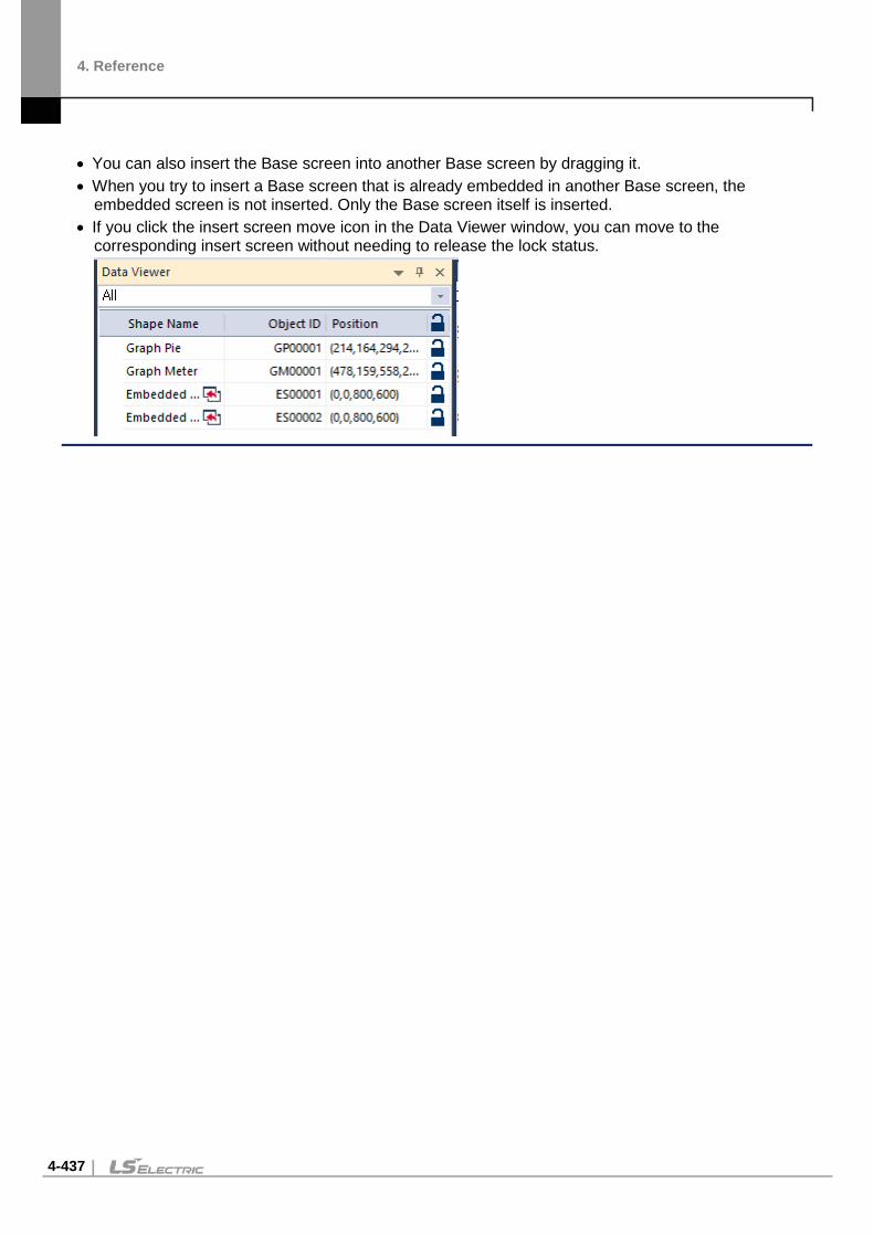
4. Reference
4-437
• You can also insert the Base screen into another Base screen by dragging it. • When you try to insert a Base screen that is already embedded in another Base screen, the
embedded screen is not inserted. Only the Base screen itself is inserted. • If you click the insert screen move icon in the Data Viewer window, you can move to the
corresponding insert screen without needing to release the lock status.

4. Reference
4-438
Memo Pad Object This section describes available settings for the memo pad object.
Basic: The basic settings for the memo pad object include the following.
- Storage Confirm: Set whether or not to use a device to view current memo status. Enter the
device address in the field or click the icon to the right of the field to specify a device address. The first three bits of the device address specify the function of the memo pad.
Device Bit Description
00 Indicates the status of the object (on in active mode; off in non-active mode).
01 Shows whether or not the memo was saved successfully. The Saving function of a special switch saves a memo currently on the XGT Panel.
02 Shows whether or not the memo was deleted successfully. The Deleting function of a special switch deletes a memo currently on the XGT Panel.
- Pen: Set the pen options. Pen Width Set the pen width (1 to 30).
Pen Color Set the pen color.
- Display: Set the display options.
Plate Color Set the background color of the memo pad.
Use Border Set whether or not to use a border.
Border Color Set the border color.
Border Width Set the border width.
- Description: Enter a description for the object.

4. Reference
4-439
Display Trigger: The display trigger settings for the memo pad object include the following.
- Use Condition: Set whether or not to specify a condition for the action. - Type: Set a type of condition to specify.
Bit On The action is performed when the device is switched on. Bit Off The action is performed when the device is switched off. Range The action is performed when the value falls within the
specified range. Multi Bit The action is performed when the logical operation result of
multiple devices is met.
- Device: Enter a device or tag address directly into the input field or click the keypad icon to the right to specify a device or tag address. When you click the keypad icon to open the Device window, you can also specify network settings, if necessary.
- Range: If you select the range condition, specify the range. Constants are based on device size.
Size 16 bit or 32 bit.
Type Signed decimal, unsigned decimal, BCD, or float.
Exp. Click to designate the expression as conditional.
- Multi Bit: If you select the multi bit condition, specify the number of bits and click [Setting] to specify the bit conditions.

4. Reference
4-440
PDF Viewer Object This section describes available settings for the PDF viewer object.
You can either use File Explorer to search for a PDF file and open it in the PDF viewer object on the screen, or configure a special switch for PDF viewing. Refer to the PDF viewer section in <4.3.2.4 Special Switch> for detailed information.
Basic: The basic settings for the PDF viewer object include the following.
- Device of page No.: Set a device to assign the page number of a PDF file that is currently open. - Open File: Set whether to open a PDF file using a file path, or a device.
- Description: Enter a description for the object.
Note
• You can place only one PDF viewer on a screen. • PDF viewer function is not supported in the simulator. • The PDF document is displayed to fit the width of the object. You can scroll down to
see the rest of the document outside the viewing area.

4. Reference
4-441
VNC Viewer Object This section describes available settings for the VNC viewer object.
You can remotely monitor the hot computer’s screen using the VNC viewer. Refer to the VNC viewer section in <4.3.2.4 Special Switch> for detailed information.
VNC Viewer: The basic settings for the VNC viewer object include the following.
- Remote: Enter the host name of the remotely connected HMI device for monitoring. - Port: Enter the TCP/IP port number to use for the monitoring. - Use password: Click the checkbox to set a password for the monitoring operation. - Option: Set the following options. - Use Popup Window: Select this option to display the remote screen in a popup window. - Disable Touch Inputs: Select to disable touch inputs for the remote screen. - Description: Enter a description for the object.

4. Reference
4-442
Display Trigger: The display trigger settings for the VNC viewer object include the following.
- Use Condition: Set whether or not to specify a condition for the action. - Type: Set a type of condition to specify.
Bit On The action is performed when the device is switched on.
Bit Off The action is performed when the device is switched off.
Range The action is performed when the value falls within the specified range.
Multi Bit The action is performed when the logical operation result of multiple devices is met.
- Device: Enter a device or tag address directly into the input field or click the keypad icon to the right to specify a device or tag address. When you click the keypad icon to open the Device window, you can also specify network settings, if necessary.
- Range: If you select the range condition, specify the range. Constants are based on device size.
Size 16 bit or 32 bit.
Type Signed decimal, unsigned decimal, BCD, or float.
Exp. Click to designate the expression as conditional.
- Multi Bit: If you select the multi bit condition, specify the number of bits and click [Setting] to specify the bit conditions.
Note
• You can place only one VNC viewer on a screen. • PDF viewer function is not supported in the simulator.

4. Reference
4-443
Multimedia object This section describes multimedia objects. You can play the video file using multimedia objects. For more information, please refer to <4.3.2.4 Special Switch>. Multimedia: This is the Basic setting of multimedia objects.
- Video folder: Enter the folder name where the video file is located. - Repeat: Set the video file to repeat playback. - Status Device: Enter the device value to read the current status value of the multimedia object.
Status Device Value
Description
0 Normal 1 No external Storage 2 File Open Error 4 Movie File Play Error 8 Movie Play Finished
3, 5, 6, 7, 9~16 Reserved
- Description: Enter the description of the object. Multimedia objects have the below restrictions.
Item Description Video File Supports MP4, AVI, and WMW files. HDMI Extended Screen (iXP2 only)
Not support video play on HDMI extended screen.
Play Speed High-quality, high-capacity videos can take a long time to load or may break when playing. For iXP2 model, the 1024 x 768 resolution is recommended.
Number of multimedia object
Only 1 multimedia object can be created in each screen and window.

4. Reference
4-444
Video Play Video play is only possible in one place. The currently playing video will stop when playing a video through a multimedia object on a popup window while playing a video on the main screen.
Note
• If the video cannot be played, take the following measures.. -iXP2 Play after encoding video file set as below through video encoding program.
• iXP2-08XXA model Resolution: 800 x 600, Codec: H264
• Other iXP2 models Resolution: 1024 x 768, Codec: H264
-wXP • Please install the external video integrated codec on the PC where wXP is installed.

4. Reference
4-445
FTP Client The FTP client is an object that connects to an FTP server, displays a list of files and directories on the FTP server, and downloads selected files. PDF files on an FTP server can be displayed using a PDF viewer object. FTP client object is available only for iXP2 and iXP models. Basic: FTP client basic setting.
- FTP Server: Enter the IP address of the FTP server to connect to. The FTP server address can be
used by entering a fixed value or by using a device. - Port number: Enter the FTP server port to connect to. The default port number is 21. The port
number can be changed by entering a fixed value or using a device. - User ID: Enter the User ID of the FTP server to connect to. If anonymous mode connection is used,
the ID is set to anonymous. The ID can be changed by entering a fixed value or by using a device. - Password: Enter the password of the FTP server account to access. The password can be
changed by entering a fixed value or by using the device. - FTP server anonymous mode connection: Connect to the FTP server using the Anonymous
account. The ID is disabled so that it cannot be changed. - Use Passive Mode: When set, accesses in passive mode. - FTP server charset settings: Set the character set of the FTP server. The default value is UTF-8.
Note
• If the set character set is different from the character set on the server, it may happen that the

4. Reference
4-446
Korean display is not normally performed. • When connecting to an FTP server running on iXP2/eXP2, the file and folder names may not be
displayed in Korean.
- Status Device: Set the device that records the value to display the operation status of the FTP client .
0 Default value
1 IP address is incorrect.
2 FTP server connection success
3 FTP server connection failure
4 File download success
5 File download failure.
6 FTP server connection termination.
- Description: Enter the description of the object. Display: This is the screen for setting the FTP client display. This is the same as the file explorer's
frame shape, line, and file explorer settings.
- Use Frame: Select whether to use the frame.
Frame Color
Set frame color
Plate Color Set plate color of FTP client.
Col.number Set the number of rows to be displayed on the screen.

4. Reference
4-447
- Line: Set the line color and width.
BG Color of Root
Specifies the background color of the area that displays the parent path on FTP clients. You can go to the previous folder or previous directory through the parent path.
Text Color of Root
Specifies the text color of the area that parent path in the FTP client.
Use Status Bar
Enable or disable the status bar. The status bar displays the current FTP client’s operational connection status and the server address to which it is connected.
BG Color Specifies the background color of the area where the FTP
client displays the status bar.
Text Specifies the text color of the area that displays the status bar on the FTP client.
Note
• If multiple cells are selected in the FTP client, the cell selected first operates. For example, if you select A.PDF, B.PDF in order, and then press the Execute special switch, the selected A.PDF file is displayed in the PDF viewer first.

4. Reference
4-448
Text: Set the text for FTP Client. It is the same as the character setting function of File Explorer.
- Font: Select the font. - Size: Select the font size. - Color: Set the text color - Font style: Set the text style. Bold, italic, strikeout, underline). 2 or more can be selected.

4. Reference
4-449
Display trigger: Sets the display trigger for the FTP Client. This is the same as the display trigger setting function of File Explorer.
- Use Condition: Select whether to use the display trigger. - Type: Set the type of the condition.
Bit On Displayed when the device is on
Bit Off Displayed when the device is off
Range Displayed when the value is included in the set area
Multi Bit It operates when the result of multiple devices satisfies the logical command.
- Device: Enter the device or tag address directly in the input area or use the keypad buttons. Network settings are also possible when you press the keypad button to open the device window.
- Range: If you select the range condition, specify the range.
Size 16 bit or 32 bit.
Type Signed decimal, unsigned decimal, BCD, or Float
Exp. Click to designate the expression as conditional.
- Multi Bit: If you select the multi bit condition, specify the number of bits and click [Setting] to specify the bit conditions.
Note
• If connection to the FTP server fails, check the following. - Check if the FTP server IP address is correctly entered and connected to the network by ping test. - Check if the entered ID and password are correct - When connecting with an anonymous account, you must enter a password according to the FTP server settings. Please enter your email address in the password.
• If Korean file and directory names are not displayed, check the following. - The character set must be set to match that of the FTP server. - If you cannot check the character set of the FTP server, change the UTF-8 and CP949 and reconnect.

4. Reference
4-450
Slider
Description of the slider control object. [Name of the slider control object item]
Basic: This is the basic setting for the slider control object.
- Control Device: Set options for the control device.
Device Directly enter the device or tag address in the input area, or click the keyboard button on the right to set. In case of setting through the keyboard, network setting is also possible if necessary.
Size Set the device data size (16-bit or 32-bit).
Type Set the data type of the device (signed decimal, unsigned decimal, BCD).

4. Reference
4-451
- Upper/Lower: Set the upper/lower value of the data to be displayed. The upper/lower values should be set within the range supported by the device type. If it is out of range, the lower or upper value supported by the device is displayed.
Device Set the specified device value as the upper and lower values.
Constant Set a fixed value specified by the user as the upper and lower values.
Note
• Refer to the table below for the upper and lower fixed value depending on the device size: Device size Device type Lower Value Upper Value
16bit Signed decimal -32768 32767
16bit Unsigned decimal 0 65535
16bit BCD 0 9999
32bit Signed decimal -2147483648 2147483647
32bit Unsigned decimal 0 4294967295
32bit BCD 0 99999999
- Description: Enter a description of the object. Display: The display setting for the slider control
- Transparent BG Image: Set whether to display the bar graph background image.

4. Reference
4-452
- Library: Select the background image from the library. - Open: Select background image to be displayed on the graph on your computer. - Direction: Set the direction to move the slider control (Up to Down, Down to Up, Left to Right,
Right to Left) - Space: Set the space of the slider control. - Scroll Pointer: Set options for the scroll pointer.
Image Displays the image of the scroll pointer.
Library Select the scroll pointer imager from the library
Open Select the scroll pointer image on your computer
Width Set the width.
- Frame Display: Set options for the scroll pointer.
Transparent Border Set whether to use the border of the slider control.
Border Color Set the border color
Plate Color Set the background color
- Track Bar: Set options for the track bar.
Display Set whether to display the track bar of the slider control.
Width Set the track bar width.
Color Set the color of track bar.
Border Set the border color.
- Text: Set options for text.
Display Set whether to display text.
Size Set the font size.
X Interval Set the X-axis distance from the scroll pointer
Y Interval Set the Y-axis distance from the scroll pointer
Color Set the text color.
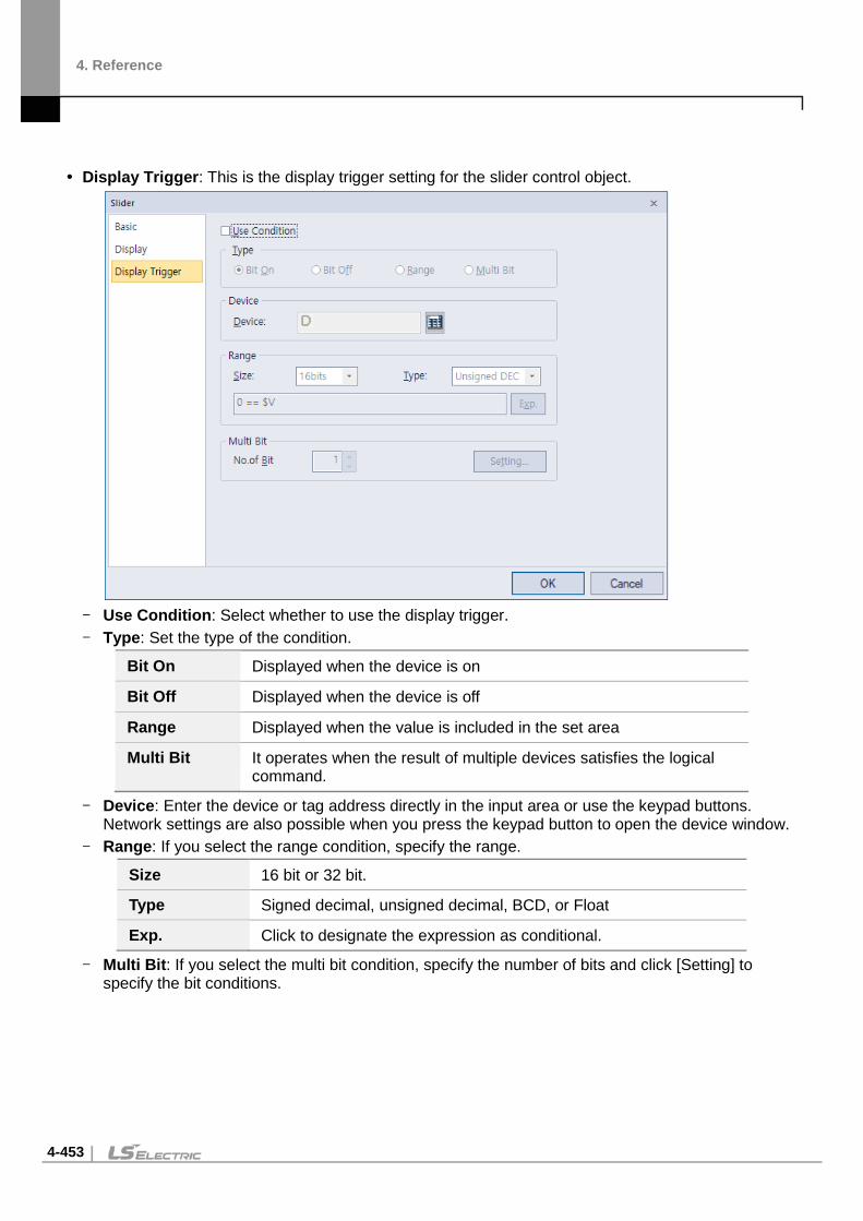
4. Reference
4-453
Display Trigger: This is the display trigger setting for the slider control object.
- Use Condition: Select whether to use the display trigger. - Type: Set the type of the condition.
Bit On Displayed when the device is on
Bit Off Displayed when the device is off
Range Displayed when the value is included in the set area
Multi Bit It operates when the result of multiple devices satisfies the logical command.
- Device: Enter the device or tag address directly in the input area or use the keypad buttons. Network settings are also possible when you press the keypad button to open the device window.
- Range: If you select the range condition, specify the range.
Size 16 bit or 32 bit.
Type Signed decimal, unsigned decimal, BCD, or Float
Exp. Click to designate the expression as conditional.
- Multi Bit: If you select the multi bit condition, specify the number of bits and click [Setting] to specify the bit conditions.

4. Reference
4-454
4.4 Viewing or Changing XGT Panel Information
To view or change XGT Panel information:
1 In XP-Builder, click [COMMUNICATION] ▶ [XGT Panel Information].
2 Click a tab to view or change the following information:
General: The General tab allows you to view properties for the XGT Panel.
- XGT Panel: The XGT Panel model number. - State: The operational state of the XGT Panel. - Version: The XGT Panel version. - File version: The file version. - Flash memory: Used and available flash memory. - CF Card: Used and available memory on an installed CF card. - USB Memory: Used and available memory on an installed USB device. - SD Card: Used and available memory on an installed SD card (For iXP/IPC series only). - Project Compare with XGT Panel: Check if the modified download is enabled. The check
compares the project’s ID in the HMI with the current project ID. If the project IDs differ, a full download is required. Even if the two projects are the same, they may be considered as different projects. Errors occur if a project is deleted from the HMI because of communication errors or if the project ID is changed when the project is sent to another HMI device for completion of the project. The following screenshots show messages for projects that are the same and different.

4. Reference
4-455
Settings: The Settings tab allows you to specify the following settings:
- Touch Buzzer Sound: Set whether or not to use audible feedback when a user touches the
XGT Panel screen. This feature is not supported by the IPC series. - Keep-Alive Time: Set how long the server will keep the communication port open if there is
no response from the XGT Panel. - Alias Name: Specify an alias to use when scanning for or connecting to the XGT Panel.

4. Reference
4-456
Clock: The Clock tab allows you to specify the following settings:
- Date: Specify the date. Click [Set] to apply your settings to the XGT Panel. - Time: Specify the time. Click [Set] to apply your settings to the XGT Panel. - Synchronize with PC Time: Click to apply the computer’s time to the XGT Panel.
Password: The Password tab allows you to specify or delete the password that is required when
transferring a project to the XGT Panel.
- Previous Password: Enter the current password and click [Delete] to delete it. - New Password: Enter a new password and click [Set]. - Confirm Password: Re-enter the new password and click [Set].

4. Reference
4-457
4.5 Using the HTML Device Copier You can use the HTML Device Copier to copy and paste the device values onto a web page to monitor the devices on the web.
To copy and paste the devices:
1 Create a project.
2 Click [TOOL] ▶ [HTML Device Copier].
3 Specify the action type and size, and enter the device address.
4 Click [Copy] to copy the device value.
5 Paste it on an HTML editor to use it on a web page.
Note HTML functions related to the device monitoring

4. Reference
4-458
• GetXPData [Parameter 1] [Parameter 2] [Parameter 3] [Parameter 1] device value read in text string [Parameter 2] 4 byte device address in hexadecimal numbers [Parameter 3] return data type (1–7)*
• SetXPData [Parameter 1] [Parameter 2] [Parameter 3] [Parameter 1] device value to be written [Parameter 2] 4 byte device address in hexadecimal numbers [Parameter 3] return data type (1–7)* * Return data types are: 1. Signed decimal, 2. Unsigned decimal, 3. Octonary,
4. Hexadecimal, 5. Binary, 6. BCD, 7.Real number

4. Reference
4-459
4.6 Using the CSV Converter You can use the CSV converter to convert an encrypted CSV (CSVE) file into regular CSV file.
To convert a CSVE file to CSV format:
1 Click [TOOL] ▶ [CSV Converter].
2 Click [Add CSVE Files], and then select the CSVE files in the file browser window.
3 Click […] on the right side of the Output folder field, and select the destination folder for the converted CSV files.
4 Click [Convert] to start conversion.

4. Reference
4-460
4.7 Managing External Storage Sources for Backup This section describes how to control external storage sources when making file backups, such as logging, recipe, and screen image data. You can manage the backup data in this way:
You can back up data, such as logging, recipe, and screen image data by saving them to a CF card, SD card, or a USB storage source, according to the settings contained in XP-Builder.
If there is insufficient memory in the external storage source, the data will be deleted and the backup process will stop. Settings that control this situation are adjusted in XP-Builder.
You can monitor if the external backup storage source has been recognized or not. When you are backing up data make sure that external storage sources are only removed when the
safe removal switch is turned on and after the LED lamp turns off. Failure to observe these precautions may result in backup failure.
Managing the File Path for Backup Files The file path shown below describes how backup files are routed:
Logging
YYYY.MM.BeginDay.EndDay.0
DD.BeginHour.EndHour.0 (Filled storage limit per folder)
HH.BeginMinute.FF
Lhhmmss0.CSV
Recipe
Rhhmmss0.CSV (each logging number has the same sub structure)
DD.BeginHour.EndHour.1 (Filled storage limit per folder, and share the same start and end time.)
DD.BeginHour. FF (Storage limit not reached)
1 (Logging number)
2 (Sub directory_ same as 1)
Screen Image
Shhmmss0.BMP (each logging number has the same sub structure)
The root directory of CF or USB storage

4. Reference
4-461
File Path for Logging Backup The ‘Logging’ subdirectory will be created under the root directory of the USB/CF/SD storage source. Under the ‘Logging’ directory, a subdirectory will be created with a filename generated by the logging
number. Under the logging number directory, a subdirectory will be created with a filename by Year/Month.
- The date directory will be included as a subdirectory. - Up to 500 date directories can be created. - The ‘Year/Month’ directory will not only contain year and month information, but will also record the
date the directory was created. As an example, the name of a directory created in October 2010 with subdirectories created since 15 October would be: 2010.10.15.FF. The FF at the end of the directory name represents that there is more data space to store for October, 2010. (This means that the subdirectory currently holds less than 500 date directories).
- When there is a change of Month, the directory name will be changed and saved to the last date in the month when information was logged. As an example, if the directory contains date directories created between October 15 and October 30, and was created in October 2010, the directory name would be 2010.10.15.30.0 when the month changes to November 2010.
- If a month directory is carrying more than 500 date subdirectories before the month ends, the directory name will change to the last date in the sub directory. For example, if the number of date sub directories created from 1 October to 15 October 2010 is greater than 500 the file name will be: 2010.10.01.15.0.
- If the month ends or the total number of sub directories exceeds 500, or the directory has the same starting/ending date name, then the last index number is added to identify the directories. As an example, if the directory created in October 2010 has 3 directories each holding 500 sub directories, then the directory names would be: : 2010.10.01.01.0 : 2010.10.01.01.1 : 2010.10.01.01.2
Under the Year-/Month directory, a subdirectory with a date name will be created. - The date directory contains an hour subdirectory. - The date directory can hold up to 500 hour subdirectories. - The filenames of date directories contain date and hour information, for the first subdirectory that
was created. - The rest of the directory creation procedure is identical to the Year/Month directory creation
procedure. Under the Date directory, a directory will be created that will store time information created.
- The Hour directory will contain backup files. - Each Hour directory can hold up to 500 backup files. - The Hour directory contains hour and minute information for the first file that was created. - The rest of the directory creation procedure is identical to the Year/Month directory creation
procedure. Logging backup files have hour, minute, and second information as their file names.
- Backup files will be created in CSV format. - The names of the files will begin with ‘L’, representing 'logging', and the rest of the name will
contain hour, minute, and second index information.

4. Reference
4-462
- If the backup files are created simultaneously in the same second, additional index information will be added at the end of the file name.
Path for Recipe Backup A directory named ‘Recipe’ will be created under the USB/CF/SD storage root directory. A subdirectory will be created with filenames identified by Year/Month. The rest of the directory structure is the same as the logging backup file structure. Recipe backup files have hour, minute, and second information as their file name.
- Backup files will be created in CSV format. - The filenames will begin with ‘R’, representing 'recipe', and the rest of the name will contain hour,
minute, and second index information. - If backup files are created simultaneously in the same second, additional index information will be
added at the end of file name.
Path for Screen Backup A directory named ‘Screen Image’ will be created in the USB/CF/SD storage directory. A subdirectory named by Year/Month will be created in the Screen Image directory. The rest of the directory structure is the same as the logging backup file structure. Screen Image backup files use hour, minute, and second information as their file names.
- The backup files will be created in bitmap format. - The filenames will begin with ‘S’ , representing 'Screen Image', and the rest of the name will
contain hour, minute, and second index information. - If backup files are created simultaneously in the same second, additional index information will be
added at the end of filename.

4. Reference
4-463
Path for Memo Backup A directory named ‘Memo’ will be created in the USB/CF/SD storage directory. A subdirectory named by Year/Month will be created in the Memo directory. The rest of the directory structure is the same as the logging backup file structure. Memo back up files use hour, minute, and second information as their file name.
- The backup files will be created in bitmap format. - The filenames will begin with ‘M’, representing 'Memo', and the rest of the name will contain hour,
minute, and second index information. - If backup files are created simultaneously in the same second, additional index information will be
added at the end of the filename.
Note
• If time is set ahead of present time, normal operation is guaranteed. However, if time is set behind present time, normal operation is not guaranteed. If this situation arises, hour unit directories and all subdirectories should be deleted to resume normal operation. For example, if the date setting had been changed from 10th December to 5th December, Year/Month directories including 5th December will have to be deleted to enable normal operation to resume.
• Logging, Recipe, Screen Image, and Memo functions do not support project classification. For instance, if Project A has logging groups numbered 1,2 and 3, and each logging group creates a file backup, 1,2,3 directory will be created and each file will be saved in a subdirectory. Then, if Project B has logging groups numbered 1 and 2, downloads the projects and creates file backups, these files can be mixed with Project A’s backed up files. In this situation, the operator should classify Project A’s and Project B’s backup files by their download time.

4. Reference
4-464
Managing Memory for Backups If there is insufficient memory in the external storage sources, data is deleted or backup processes stop depending on XP-Builder’s configuration.
Using XP-Builder to delete the oldest data for backup, click [Common] ▶ [Project Property Setting] ▶ [Storage Settings], set the Backup Storage location for each file, and then click the checkbox next to Delete old file if disk full.
When you back up the file by erasing the oldest files:
If there is insufficient backup space, look for the earliest Year/Month subdirectories in Logging, Recipe, and Screen Image directories. When looking at Logging, look for subdirectories under the current back up logging number. For example, if Logging number 2 is on the current back up list but does not have data in the file’s directory, data in logging number 1 directory will remain untouched.
Look for the earliest date directory in the earliest Year/Month directory. Look for the earliest hour directory in the earliest date directory. Delete the earliest backed up files from the earliest hour directory. If more data space is needed, repeat the above steps and check available data space. When deleting files, if the whole hour directory has been cleared, remove the hour directory. When deleting hour directories, if a whole date directory has been cleared, remove the date directory. When deleting date directories, if a whole month directory has been cleared, remove the month
directory.
Note
• If an unreadable directory or file (operator file or directory) is found, leave the directory or file and locate normal backup files.
• If the current directory contains only operator data, it will cause a backup failure. The XGT Panel cannot delete operator data, therefore it will stop any further action.
When there is Insufficient Memory or Exceeds the Limit Storage properties are configured in XP-Builder, project properties. By checking Delete old file if
disk full, the earliest video files will be automatically located and deleted. If Delete old file if disk full is unchecked, then XP-Builder will stop and prompt the user with an error message.

4. Reference
4-465
When the total number of files reaches 1000, delete the earliest created file from the earliest created directory. As files are deleted and the directory is emptied, the directory will then be deleted.
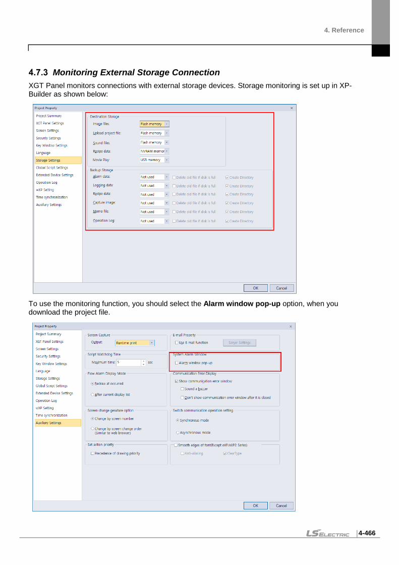
4. Reference
4-466
Monitoring External Storage Connection XGT Panel monitors connections with external storage devices. Storage monitoring is set up in XP-Builder as shown below:
To use the monitoring function, you should select the Alarm window pop-up option, when you download the project file.

4. Reference
4-467
When the external storage device for logging, recipe, and screen image backup is removed from XGT Panel while the device is running, a system alarm is turned on. The alarm is reset when an external storage device is reconnected to the XGT Panel.
You can check system alarms and their device addresses in the System Alarm menu located in XP-Builder as shown below:

4. Reference
4-468
Safe Removal Switch The safe removal switch is used to remove external storage devices without any loss of backup data.
When the safe removal switch is on, and the storage device is not processing data, the LED lamp will turn off. If the storage device is processing data, the LED lamp will turn off after the backup is completed, automatically disengaging the storage device. This means that when the LED lamp is turned off no backup action will be completed and the data in the storage device is inaccessible.
When the safe removal switch is activated and the LED lamp is off, the storage device must be removed and reconnected to ensure that it is recognized. The minimum time delay for removing and reconnecting storage devices after their safe removal is 5 seconds.
The actions listed below describe situations where theLEDlamp will not turn off even if the safe removal switch is turned on. The LED lamp will only go off after the described actions are fully completed:
While a backup file is being created or XP-Builder is reading data If the images stored in the XP_User Image from an external storage device is being used as a part
image and being loaded in the program While reading or writing a file recipe While reading backup data from the XP-server through an XP-Link connection While browsing backup lists to upload from XP-Builder While loading a sound file or an image that belongs to a project While transferring project backup data to a storage device or from XP-Builder While downloading a project using XP-Builder or a storage device While changing an image in the start menu While ladder program monitoring is being saved in a storage device
Function Sub Classification Action
Data Backup Alarm Writing
Logging Writing
Recipe Writing
Screen Writing
Memo Writing
Video Writing
Still Shot Writing
Data Upload Alarm Reading
Logging Reading
Recipe Reading
Screen Reading
Memo Reading

4. Reference
4-469
Function Sub Classification Action
Video Reading
Still Shot Reading
Data by Function Part Image Reading
Edit File Recipe Reading/Writing
Send File Recipe Reading/Writing
Web Server Create Webpage Writing
Sending XP-Link File Reading
Inquire file list Reading
Project Upload Project Backup Communication Reading
Project Backup - Storage Writing
Download Project Image Writing
Sound Writing
Project Backup Writing
Ladder Monitor Download Writing
Execute Reading
Change Start Menu Image Reading
Download Storage Project Data Reading

5. Other features
5-1
5. Other features 5.1 Gestures & Multi-Touch
Gesture definition
1 Flick
You can quickly move up/down/left/right while maintaining contact with one finger.
2 Swipe
Slowly move up/down/left/right while maintaining contact with one finger
Note
• When using the gesture function without transitions, the touch position must be within the object to use the gesture function.
Screen Transition Gesture Function
1 The screen transition gesture function is performed only when there is no other object in the gesture motion range. It operates under the following conditions.
2 The screen transition gesture function works as soon as you release your hand after performing the flick operation.
Note
• The screen switching function is based on the screen number created by XP-Builder. As a result, the next screen changes to the next number screen on the current screen, and the previous screen changes the same way.
Logging Trend Graph Gesture Function

5. Other features
5-2
1 Logging Trend Graph The gesture function can recognize the gesture from the moment you touch the logging trend graph object. It operates under the following conditions.
Gesture Direction Gesture Type Action Performed Left Swipe View next data 3 times Left Flick View next data 1 time
Right Swipe View previous data 3 times Right Flick View previous data 1 time
Note
• If you touch the Logging Trend Graph object, you can perform the gesture function and the blue frame will be displayed. This allows you to check whether the gesture is recognizable.
Logging View Gesture Function
1 Logging View Gesture function allows you to recognize the gesture from the moment you touch the Logging View object.
Gesture Direction Gesture Type Action Performed Left Swipe View next column 1 time Left Flick View next column 3 times
Right Swipe View previous column 1 time Right Flick View previous column 3 times Down Swipe View one line up 1 time Down Flick View one line up 3 times
UP Swipe View one line down 1 time UP Flick View one line down 3 times
Note
• History Alarm View when you touch an object, you can perform a gesture function and a blue frame is displayed. This allows you to check whether the gesture is recognizable.

5. Other features
5-3
History Alarm View Gesture Function
1 History Alarm View Gesture Function can recognize the gesture from the moment you touch the History Alarm View object. It operates under the following condition:
Gesture Direction Gesture Type Action Performed Left Swipe View next column 1 time Left Flick View next column 3 times Right Swipe View previous column 1 time Right Flick View previous column 3 times Down Swipe View one line up 1 time Down Flick View one line up 3 times UP Swipe View one line down 1 time UP Flick View one line down 3 times
Note
• When you touch the Logging View object, it becomes possible to perform the gesture function and a blue border is displayed. This allows you to check whether the gesture is recognizable.
Explorer/FTP Client gesture function Alarm / File / Basic Recipe / File Recipe explorer gesture object recognition is possible from the moment you touch an object. It operates under the following conditions.
1 Alarm Explorer Gesture Direction Gesture Type Action Performed
Down Swipe View one line up 1 time Up Swipe View one line down 1 time
2 File Explorer Gesture Direction Gesture Type Action Performed
Down Swipe View one line up 1 time Up Swipe View one line down 1 time
3 Basic Recipe Explorer Gesture Direction Gesture Type Action Performed
Down Swipe View one line up 1 time Up Swipe View one line down 1 time
4 File Recipe Explorer Gesture Direction Gesture Type Action Performed
Down Swipe View one line up 1 time Up Swipe View one line down 1 time
5 FTP Client Gesture Direction Gesture Type Action Performed
Down Swipe View one line up 1 time Up Swipe View one line down 1 time

5. Other features
5-4
Multi-touch function
1 Up to 2 points can be simultaneously touched by the user at the same time.
2 Multi-touch function works on both normal screen and pop-up window (window screen, etc.).
Note
• The first touch input will automatically disappear when you perform an operation (Ex: numeral input device) that loses existing focus as the second touch input will open a new window when performing multi touch.
• Since the second touch coordinates are calculated based on the first touch input, if the first touch is released while the two points are touched at the same time, the second touch input value disappears. (On the other hand, if you remove your finger from the second touch and touch it again, it will work normally.)
• Multi-touch function is supported only in iXP2

5. Other features
5-5
Screen change gesture options
1 Screen change gesture method can be set as “Change by screen number,” “Change by screen-change order (Similar to web browser)”
Change by screen number
Perform the screen-changing gesture in the default set method to change to the previous or next screen based on the screen number.
Change by screen change order(Similar to web browser)
When performing the screen change gesture option, it changes to previous/next screen based on the order of the screen as moved by the user.
E.g If the user changed screen in order to 1->10->20 by screen-change switch, move to screen number 10 by performing previous screen change gestures on screen number 20.
2 Setting Method Possible to set the “Screen change gesture method” option in [Project Property]-[Auxiliary Settings] of XP-Builder

5. Other features
5-6
Gesture function On/Off
1 The user can select whether the gesture function is activated or not.
2 XP-Runtime menu - Settings - Touch Setting, you can check the "Gesture Function" check box as below.
3 If you check the "Gesture Function" check box, the gesture function will be on. If you uncheck it, the gesture and multi touch will be off

Appendix
App-1
Appendix
1 Program Monitor The Program Monitor allows you to check the status of the system and diagnose PLC errors.
1.1 About Program Monitor The Program Monitor works with PLCs that support the monitoring function, as described in <5. 1.1.1 PLCs that Support Monitoring >. The function shows the ladder diagrams for each PLC that can be monitored, as described in <5. 1.1.3 The Program Monitor Window>.
1.1.1 PLCs that Support Monitoring You can only monitor PLCs that use the ladder diagram (LD) language. If a program uses the IL language, it will be converted to LD for display in the Program Monitor window. The following table describes PLC types manufactured by LS ELECTRIC that support monitoring.
Series PLC Type Maximum Program Capacity (Steps)
XGK XGK-CPUA 32K
XGK-CPUE 16K
XGK-CPUH 64K
XGK-CPUS 32K
XGK-CPUU 128K
XGK-CPUSN 64K
XGK-CPUHN 128K
XGK-CPUUN 256K
XGB XGB-XBCE 4K
XGB-DR16C3 10K
XGB-XBCSU 15K
XGB-XBCH 15K
XGB-XBMS 10K
XGB-XBMH 64K
XGB-XBCU 32K
The following table describes connection types that support monitoring.

Appendix
App-2
Series Connection Type
XGK CPU connection
Link connection
Ethernet connection
XGB CPU connection
Link connection
Ethernet connection
Note
Link connection and Ethernet connection are only for modules that has the XGT server function. Refer to the module’s user manual to learn more about each module.
The following table describes device types that support displaying monitoring data or changing current values.
Device XGK XGB
Monitoring Data Display
Current Value Change
Monitoring Data Display
Current Value Change
P ● ● ● ●
M ● ● ● ●
K ● ● ● ●
F ● ◐ ● ◐
T ● ● ● ●
C ● ● ● ●
U ● ● ● ●
Z ● ● ● ●
S ● ● ● ●
L ● ● ● ●
N ● ● ● X
D ● ● ● ●
R ● ● △ △
ZR ● ● △ △
(●: Supports all areas, ◐: Supports some areas, △: Supports some models, X: Not supported)

Appendix
App-3
Note
Refer to the PLC’s user manual to learn more about the device sizes and properties.
1.1.2 Properties by HMI devices The following table shows the devices the support monitoring or the standard display lines.
HMI device Resolution Standard Display Line
XP30 320X240 7 lines
XP50 640X480 14 lines
XP70 640X480 14 lines
XP80 800X600 18 lines
XP90 1024X768 18 lines

Appendix
App-4
1.1.3 The Program Monitor Window The basic Program Monitor window appears below.
Item Description
a The top row shows fundamental information about the program and the connected PLC.
b The monitoring area shows the LD program.
c Set to scroll the screen by line or page.
Scroll upward.
Scroll to the left.
Scroll to the right.
Scroll downward.
Move to the previous touch point.
Move to the next touch point.
Move to the next search result.
Click to start or stop monitoring.
Program/Variable Switch
Displays programs only.
Displays devices/variables only.
Displays the monitoring areas for programs and devices/variables in a split- view mode. Drag the line between the two areas to adjust the heights.
When you click the program/variable switch, you can monitor variables in the program as well.
a
b
c

Appendix
App-5
Item Description
d Add, remove, or edit devices to monitor. Up to 16 devices can be monitored.
e The monitoring area shows the devices.
d
e

Appendix
App-6
1.2 Monitoring Program You can monitor programs manually from the XGT Panel’s menu or via a special switch object on a UI window. When you monitor programs via a special switch object, the objects on the screen will not communicate until the Program Monitor stops.
1.2.1 Monitoring Programs from the XGT Panel Menu
To start the Program Monitor from the XGT Panel menu:
1 Touch and hold the XGT Panel screen to open the main menu.
2 Touch [PLC Information].
3 Select a connection number from the drop-down list and touch [Program Monitor].
Note
If you have not selected the program monitor function in the XP-Builder project, the Program Monitor function will not be active. For more information, refer to <2.2.2.2 Changing XGT Panel Settings>.
To stop the program monitor:
1 In XP-Builder, click [COMMON] ▶ [Project Property Setting] ▶ [XGT Panel Settings].
2 Touch the checkbox next to Program monitor.
1.2.2 Monitoring Programs with a Special Switch Object

Appendix
App-7
To start the Program Monitor with a special switch object:
1 Create a special switch object in XP-Builder and transfer the project to the XGT Panel. For more information about special switch objects, refer to <2.3.4 Inserting Figures or Objects> and <4.3.2.4 Special Switch>.
2 On the XGT Panel, access the window that contains the special switch.
3 Touch the special switch to activate the Program Monitor.
Note
While the Program Monitor is active, objects on the current screen cannot be monitored, but scripts and logging functions will work normally.
1.2.3 Selecting Programs to Monitor Once you activate the Program Monitor, you must select which programs to monitor.
To select programs
1 In the Program Monitor window, touch a program from the program list and then touch [Select].
2 To begin monitoring the program, touch [Mon]. The LD program will appear in the monitoring area of the window.

Appendix
App-8
3 If the command is longer than the window can display, you can double-tap [PUT] to the right of the command to expand it. Tap [Close] to return to normal monitoring.

Appendix
App-9
1.2.4 Managing Programs You can save or delete programs from the Program Monitor.
To manage programs:
1 Touch the program list button at the top left of the window. To update the program list, touch [Update].
2 Touch a program to monitor ▶ [Select] to move to the monitoring window.
3 To read comments, touch [Comment] ▶ [Read].
4 To save a program as a file, touch a program and then touch [Save]. When the program is saved “Match” appears in the Status column. If the file cannot be saved to the PLC, “Mismatch” appears in the Status column.

Appendix
App-10
5 To delete a file, touch a program and then touch [Delete]. When the program is deleted, “Removed” appears in the Status column.
Note
The file saving or deleting functions are available only when the file saving option is checked.
1.2.5 Viewing the Monitoring Data Monitoring data appear differently depending on contact, coil, and command.
Monitoring data of contacts are displayed as shown below.
Contact type ON OFF
Normally open contact
Normally closed contact
Positive transition-sensing contact
Negative transition-sensing contact

Appendix
App-11
Monitoring data of coils are displayed as shown below.
Item ON OFF
Coil
Negated coil
Set coil
Reset coil
Positive transition-sensing coil
Negative transition-sensing coil
Monitoring value of each device is displayed on the top of a command. Monitoring values are displayed differently depending on the data type used in a command.
Command type Monitoring data display
Compared command
Command
1.2.6 Changing the Display Format In the Program Monitor, you can choose from four display formats for data, as described in the following table.
Format Description
Unsigned decimal Displays the current device value as an unsigned decimal number.
Signed decimal Displays the current device value as a signed decimal number.
Hexadecimal number Displays the current device value as a hexadecimal number.
Depending on command Displays the current value based on the command properties.

Appendix
App-12
To change the display format:
1 On the XGT Panel, touch and hold the screen to open the main menu.
2 Touch [Option] ▶ [Monitor].
3 In the Options window, touch a display format.
4 Touch [OK] to save your changes.
Note
Real number and string data types are displayed as real numbers and strings, respectively, of display format you choose. For more information about data types for each PLC command, refer to the PLC user manual.
1.2.7 Changing the Current Device Value You can change the current device value from the Program Monitor. The Program Monitor must be running to change the device value.
To change the current value of a PLC device:
1 From the Program Monitor window, select a device.

Appendix
App-13
2 Tap [Menu] to display a menu dialog box.
3 Tap [Test] to change the value.
4 Enter a value in the Value field and tap [OK].
You can also change current device value from the Device Monitor window.
5 From the Device Monitor window, tap the Value field of a device to change.
6 Enter a value in the Value field and tap [OK].

Appendix
App-14
Note
When you select bit type device, the dialog box to select ON/OFF will be displayed. Number input unit or string input unit will be displayed depending on the inputted data type. After selecting the device to be changed, you can select the current device value.

Appendix
App-15
1.3 Monitoring Devices You can monitor devices that are not currently used by the program and check the status off the PLC.
1.3.1 Managing Devices
To add a device:
1 In the Device Monitor window, tap [Add].
2 Tap the Device field to open the Add Device window.
3 Enter a device and tap [OK] in the Device Input window.
4 Tap the currently select device data type.

Appendix
App-16
5 Select the desired device data type.
6 Tap [OK] to finish.
When you insert a device, the device will be added to the currently selected point. The procedure of inserting a device is the same as the procedure of inserting a device except that the point to insert a device is selected.
To insert a device:
1 In the Device Monitor window, select a point to insert a device and tap [Ins.].

Appendix
App-17
2 Enter a device and select a device data type.
3 Tap [OK] to finish.
You can change the device or the device data type.
To edit a device:
1 In the Device Monitor window, tap [Edit].
2 Change the device or the device data type, and tap [OK].
To remove a device:
1 Select a device to remove.
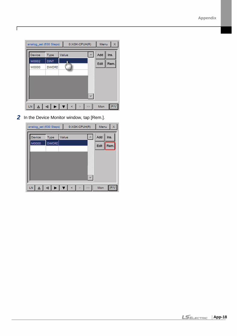
Appendix
App-18
2 In the Device Monitor window, tap [Rem.].

Appendix
App-19
1.4 Using the Search Functions You can use various search functions to find devices, labels, sub-routines, or cross references, or you can move to the desired step directly.
1.4.1 Searching for Devices You can search for devices by setting the data type or the search range.
1 In the Program Monitor window, tap [Menu].
2 Tap [Search] to open the Device Search window.
3 Enter a device to search for.

Appendix
App-20
To enter a general device (for example, M0000):
1 Tap the device input field.
2 Enter the device address and tap [OK].
For an index device, two devices should be entered in the format of “Default Device [Index Device]”. The procedure for entering a default device is the same as the procedure for entering a general device.

Appendix
App-21
To enter an index device (for example, M0000[Z000]):
1 Check the checkbox next to [Z].
2 Tap the device input field.
3 Enter the device address and tap [OK].
An indirect device is displayed in the format of “# + Default Device”.
The procedure for entering a default device is the same as the procedure for entering a general device.

Appendix
App-22
To enter an indirect device (for example, #P0000):
1 Check the check box next to “#”.
2 Tap the device input field.
3 Enter the device address and tap [OK].
An indirect index device is displayed in the format of “# + Default Device [Index Device]”.
To enter an indirect index device (for example, #P0000[Z00]):
1 Check the checkbox next to “#”.

Appendix
App-23
2 Check the checkbox next to [Z].
3 Tap the device input field.
4 Enter the device address and tap [OK].

Appendix
App-24
You can select a device type (Bit, Word, or Word with bit).
Device type Description
Bit Search for a match from bit devices.
Word Search for a match from word devices.
Word with bits Search for a match from word devices and a device containing a word device from bit devices. For example, if you enter “M0000” and select Word with bit type, the following devices will be searched. Word device: M0000 Bit devices: M00000, M00001, M00002- M0000F
Note
When you search for a device, devices of the same device type will be searched. For example, if you enter “M0000”, devices such as M0000[Z000], #M0000, #M0000[Z000] will not be searched.
After entering the device, tap [OK] to search for devices. The pointer will appear at the first search result.

Appendix
App-25
Tap to move to the next search result.

Appendix
App-26
1.4.2 Searching for Labels
1 You can search for labels that are used in programs and move to the corresponding point directly.
2 In the Program Monitor window, tap [Menu].
3 Tap [Search Label] to open the Label List window.
4 Tap the desired label and tap [OK].
5 Confirm the search result.

Appendix
App-27
1.4.3 Searching for Sub-routines You can search for sub-routines that are used in programs and move to the corresponding point directly.
1 In the Program Monitor window, tap [Menu].
2 Tap [Search SBRT] to open the Sub-routine List window.
3 Tap the desired sub-routine and tap [OK].

Appendix
App-28
4 Confirm the search result.
1.4.4 Searching for Steps You can search for a step and move to the corresponding point directly.
1 In the Program Monitor window, tap [Menu].
2 Tap [Move to Step] to open the Move to Step window.

Appendix
App-29
3 Tap the step number field to open the Number Input window.
4 Enter the step number and tap [OK].
5 Confirm the search result.

Appendix
App-30
1.4.5 Searching with Touch You can search for labels, sub-routines, or devices with touch.
1.4.6 Searching for Labels with Touch You can search for a JMP command that a selected label refers to. You can also move directly to a label that a JMP command refers to.
Because more than one JMP command can exist for one label, you can move to the next search result.
To search for a JMP command that a label refers to:
1 Select a desired label.
2 Tap and hold the label command for a second.

Appendix
App-31
3 Confirm the search result.
Because only one label exists for one program block, you cannot move to the next search result.
To search for a label that is used as an operand for a JMP command:
1 Select a desired JMP command
2 Tap the JMP command or the operand for a second.

Appendix
App-32
3 Confirm the search result.

Appendix
App-33
1.4.7 Searching for Sub-routines with Touch You can search for a CALL or CALLP command that a selected sub-routine refers to. You can also search for a sub-routine that is used as an operand for a CALL or CALLP command.
Because more than one CALL or CALLP command can exist for one sub-routine, you can move to the next search result.
To search for a CALL or CALLP command that a sub-routine refers to:
1 Select a desired sub-routine.
2 Tap and hold the sub-routine command or the operand for a second.
3 Confirm the search results.

Appendix
App-34
Because sub-routines exist in the entire PLC program, search results may not appear in the selected program.
To search for a sub-routine that a CALL or CALLP command refers to:
1 Select a desired CALL or CALLP command.
2 Tap the CALL or CALLP command or the operand for a second.

Appendix
App-35
3 Confirm the search result.
1.4.8 Searching for Devices with Touch You can search for a device with touch to find out whether an input device is used for output or an output device is used for input.
To search for a command that uses a selected input device for output:
1 Select a desired input device.
2 Tap the device for a second.

Appendix
App-36
3 Confirm the nearest output device upward from the selected device.
4 Tap to move to the next output device.
To search for a command that uses a selected output device for input:

Appendix
App-37
1 Select a desired output device.
2 Tap the device for a second.
3 Confirm the nearest input device downward from the selected device.
Note
This function uses the inclusion relationship between the data types of commands for searching. For the data types of command, refer to PLC user’s manual.

Appendix
App-38
1.5 Configuring Options Configure various settings of the Program Monitor.
To configure the options:
1 In the Program Monitor window, tap [Menu].
2 Tap [Option] to open the Option window.
3 Touch a tab to view or change the following information. File: The File tab allows you to set where to save files.
- Save Option: Set where to save files.
Monitor: The Monitor tab allows you to choose a display format.

Appendix
App-39
- Monitor Display Options: Set the display format.
View: The View tab allows you to change the LD options.
- Color: Set the color for the LD program. - Display Options: Set the display type of a device in the Program Monitor. - Line: Set the number of lines to display devices, variables, or descriptions. If you select
Variable, all data are displayed. If you select a certain line, only that line will be displayed. If the total number of lines is bigger than the selected number of lines, …… will be displayed.
- Column: Set the number of columns to display on the screen. If you select the minimum number of columns, all items will be displayed except the output descriptions.
- Monitor Line: Set the monitor display line of commands. If you select 0 Line, the current monitor value of commands will not be displayed. This option is useful when you want to monitor only ON/OFF of a contact.

Appendix
App-40
2 NC Program Monitor By monitoring the NC program of the PLC connected to the HMI, can easily diagnose the PLC program status and errors.
2.1 Start
1 NC Program drive download.
Download NC monitor program using XP-Manager.
2 Add switch for NC program execution

Appendix
App-41
After downloading NC Program monitor, create special switch to execute NC monitor program through XP-Builder.
- Program Interaction with HMI: Check it.
- Program Path: Run NCMonitor.exe in the path downloaded in step 1 above. For example, if you downloaded the program to FlashDisk, set it to \FlashDisk\NCMonitor\NCMonitor.exe.

Appendix
App-42
2.2 Run at wXP
1 Install XG5000. (XG5000 V4.20 or later)
2 Add switch for NC program execution
- Program Interaction with HMI: Uncheck it.
- Program Path: Run NCMonitor.exe in the path location where wXP is installed. For example, if the program is installed in C:\program files\LS\wXP\NCMonitor\NCMonitor.exe
3 IP setting
Specify the IP in the UserSettings.inf file in the path where wXP is installed. For example, if you installed wXP in C:\Program Files\LS\wXP\NCMonitor\UserSettings.inf.
Special switch: Set as shown below.
- Program Interaction with HMI: Check it.
- Program Path: Run NCMonitor.exe in the path downloaded in step 1 above. For example, if you downloaded the program to FlashDisk, set it to \FlashDisk\NCMonitor\NCMonitor.exe.

Appendix
App-43
2.3 NC Monitoring Program Features Able to monitor the devices not currently used in the program and check the status of the
PLC.
2.3.1 NC monitoring program description
1 Display the currently running NC program.
2 Display connected PLC type and operation status.
3 Display the toolpath program.
4 The NC program currently running is displayed.
5 Display the current position value of the work piece coordinate.
6 Change the view mode of the toolpath graph. IS090 – XY – YZ – ZX is displayed in sequence.
7 Re-read NC programs and parameters from the PLC. It is used when NC program is newly downloaded from XG5000.
8 Manage NC files.
9 Set the device to connect with the function button.

Appendix
App-44
2.3.2 User Device Setting
It is used when you want to control PLC program by button.
Specify the device to name the selected NC program.
2.3.3 NC file Management
Manage NC files saved in the PLC. Using this feature, you can select NC program to operate
and delete, load and export files.

Appendix
App-45
1 Display file list.
2 Write the selected NC program to the program name specified in [Preferences].
3 Deleted the selected NC file.
4 Import the NC file from the removable storage device.
5 Export the selected NC file to a removable storage device.
6 Close the dialog.

Appendix
App-46
2.3.4 Import NC file
1 Display the drive list in the XGT Panel.
2 Displays a list of subfolders and NC files in the currently selected folder.
3 Select the NC file to import and close the dialog.
4 Cancel the load operation.
Deleting and importing loads the NC program again. NC program is applied only in the stop
mode and needs to be converted. However, it can be operated normally only when the key
switch of PLC is remote mode.

Appendix
App-47
2.3.5 Change View Mode
The NC monitor supports four viewing modes. Each time you press the View Type button, the for modes, ISO90 – XY – YX – ZX, change in sequence.

Appendix
App-48
2.4 Edit NC Program Edit NC program is only available at wXP.
2.4.1 Preparation Program editing is a separate external program. Notepad++ is recommended to take advantage of the Syntax Highlight feature of NC code (notepad++ is freeware available for download from https://notepad-plus-plus.org).
1 Enable NC Syntax Highlight feature
Select menu in Notepad++ [Language] – [Define Your Language …]. In the dialog below, click the button [Import…] to select the NC language definition file for XMC (file name G-CODE_XG.XML). The file exists in the installed NC monitor program installation path.
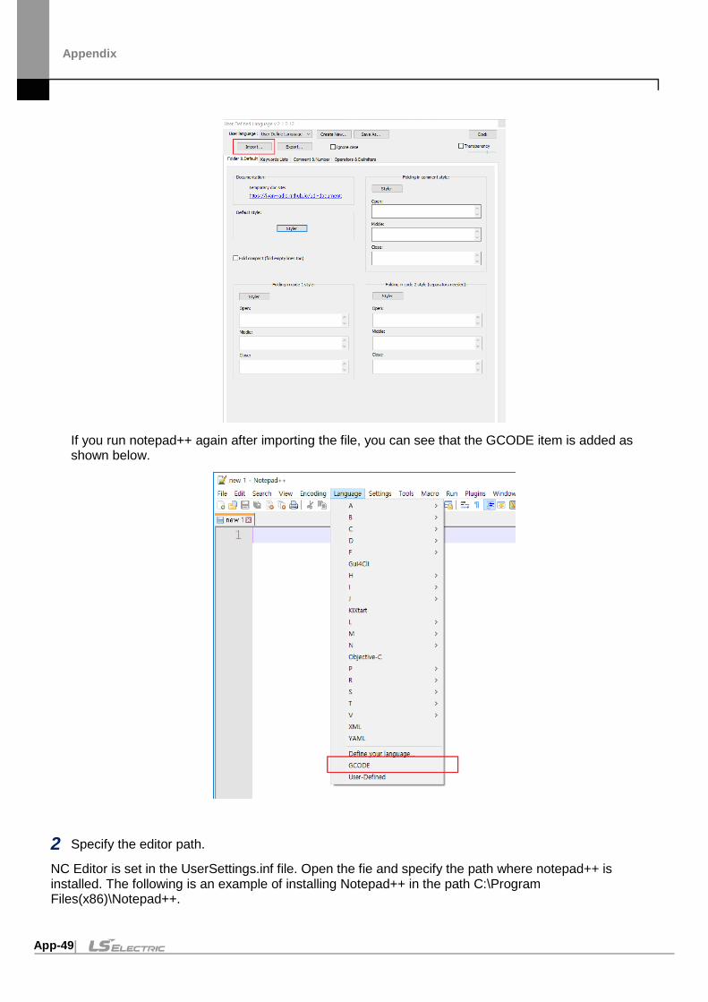
Appendix
App-49
If you run notepad++ again after importing the file, you can see that the GCODE item is added as shown below.
2 Specify the editor path.
NC Editor is set in the UserSettings.inf file. Open the fie and specify the path where notepad++ is installed. The following is an example of installing Notepad++ in the path C:\Program Files(x86)\Notepad++.

Appendix
App-50
3 Select the NC file to import and close the dialog.
4 Cancel the import operation.
[Editor] PATH = C:\Program Files(X86)\Notepad++\NotePad++.exe ARG1=-nosession
ARGE=-nosession –n%d
2.4.2 Overview
Click menu [NC File] to display the file list. Select the program you want to edit from the file
list and click the [Edit] button.
If the file is edited and you exit the NC File Manager, you check whether the changed file is
written to the PLC. The procedure below is the same as importing an NC file.
If there is a contact error in the NC file, an error dialog box appears as shown below.
After selecting the line where the error occurred, click the [Edit] button to edit it again.

Appendix
App-51

Appendix
App-52
3 Autoscan Autoscan is able to check the configuration and module status of the network system consisting of RAPIEnet I/F modules of the PLC connected to the HMI device, and measure the cable distance.
Note
Cable distance measurement may vary depending on the configuration of the network system. For the details, please refer to RAPIEnet I/F module user manual.
3.1 Start Autoscan 3.1.1 Overview
Download Autoscan program using XP-Manager. After selecting the Manager Driver of the device to use Autoscan in XP-Manager, select Autoscan. When running the Autoscan program in Korean: After setting [Download Font File], set it to
[ANSI/OEM Korean Unified Hangul 949], and then specify a font that supports Korean, such as [Gulim].
When running the Autoscan program in English: After setting [Download Font File], set it to [ANSI Latin 1 1252], and then specify a font that supports English such as [Tahoma]. If the selected font file and whether the font is Korean or English do not match, the language of the autoscan program may appear broken on the machine.

Appendix
App-53
3.1.2 Add special switch to operate Autoscan program
After downloading the Autoscan program, create a special switch that can executed Autoscan through XP-Builder. If downloaded to FlashDisk from XP-Manager, the program path is \FlashDisk\AutoScan.exe.
- Program Interaction with HMI: Do no set.
- Program Path: Run AutoScan.exe in the path downloaded in step 1 above. For example, if you downloaded the program to FlashDisk, set it to \FlashDisk\AutoScan\AutoScan.exe.
- Use Parameter: Set when registering PLC IP connect. If the parameter is not used, the default IP is 192.168.1.2, Port is 2004. The monitoring period is 1 second.

Appendix
App-54
- Direct: Register the IP and port number of the PLC to be connected. For example, if you connect with IP: 192.168.1.2, Port: 2004, set –h 192.168.1.2 –p 2004. When setting the monitoring period, specify the period (unit: second) after –t. If the period is 2 seconds, set –h 192.168.1.2 –p 2004 –t2.
Note
When setting the Program Interaction with HMI, the runtime running on the machine is stopped and only external programs set by the user are executed. If the setting is checked, it may appear that the machine is malfunctioning when executing an external program, but in reality only the set external program is executed and the runtime is not operated.
3.2 Using in wXP
1 Install XG5000 (XG5000 version 4.20 or later).
2 Add a special switch to executed Autoscan program.
- Program Interaction with HMI: Do no set.
- Program Path: Run AutoScan.exe from the location where wXP is installed. For example, if you installed the program in C:\Program Files\LS, set it to \C:\Program Files\LS\AutoScan\AutoScan.exe.
- Parameter: Set when registering PLC IP connect. If the parameter is not used, the default IP is 192.168.1.2, Port is 2004. The monitoring period is 1 second.
- Direct: Register the IP and port number of the PLC to be connected. For example, if you connect with IP: 192.168.1.2, Port: 2004, set –h 192.168.1.2 –p 2004. When setting the monitoring, specify the period (unit: second) after –t. If the period is 2 seconds, set –h 192.168.1.2 –p 2004 –t2.
3 IP Setting
When adding a special switch for running the Autoscan program, you can set the PLC and IP to be connected, but you can also set the IP through the IP setting screen by clicking the setting button after running the Autoscan program. The default IP is 192.168.1.2 and the port number is 2004. After registering the IP of PLC to be connected in the IP setting screen, click the Apply button to save it as a file. For example, if you installed wXP in C:\Program Files\LS, it will be saved in the \C:\Program Files\LS\wXP\AutoScan\IPList.xml file.

Appendix
App-55

Appendix
App-56
3.3 Features of Autoscan Able to check the network system configuration status consisting of the RAPIEnet I/O module of the PLC connected to the HMI. 3.3.1 Autoscan program menu
Item Description
AutoScan – IP: Port: Period Displays the IP, Port number and monitoring period of the connected PLC.
Network Information - Station No. Displays the quantity of the RAPIEnet I/F modules of the connected network. - Range: 0~63
Network Information - Topology/Set Displays setting of the system network configuration status and user topology setting. - LINE: Line type network configuration. - RING: Ring type network configuration. The network configuration is depend on the RAPIEnet protocol. For details, please refer to the RAPIEnet I/F user manual.
Network Information – Collision When two or more of the modules to be connected on the network have the same station number, the collision station number is displayed.

Appendix
App-57
Item Description
Setting Set the IP, Port number and monitoring period of the PLC to be connected.
Save Save the current network system configuration status.
Slave Diagnostic Executes the slave diagnostic.
Goto Local Change the MRS autoscan screen to the local autoscan screen.
Compare The status of the added/deleted/changed is displayed by comparing the previously saved network system configuration status with the current network configuration status.
Cable Distance Displays the cable distance between the RAPIEnet I/F of the PLC that connected to HMI.
Autoscan status screen Displays network status on screen.
Progress Bar Displays the progress on the progress bar.
Cable Deletion/Cable Addition Displays index for the Autoscan screen. Red when the cable is removed, and blue when a cable is added.
Show User Topology Displays the compare result of the user topology when it checked.
Monitoring The current network system configuration status is periodically updated and displayed.
Retry Displays the current network system configuration status by updating once.
Close Closes the Autoscan program screen. 3.3.2 IP setting and monitoring period setting It is used when setting the IP and port number of the PLC to be connected and the monitoring period. After running the Autoscan program, click the [Setting] button to display the setting screen.

Appendix
App-58
Item Description
Label The label for IP and port number of the PLC to be registered is displayed. When touched, the keyboard screen is displayed and you can set the label.
IP Displays the IP of the PLC to be registered.
Set Displays the IP input. When IP input is complete, IP setting items are changed.
Port The port information of the PLC to be registered is displayed. When touched, the keyboard screen is displayed and the port number can be set.
List Displays the PLC list.
Add/Edit Label, IP, Port number contents are applied in PLC list. If the same label exists in the list, it is edited, otherwise it is added to the list.
Delete Deletes the selected information from the registered PLC list.
Monitoring Period Displays monitoring period. Unit is seconds and the range is 1 to 10.
Apply Save the settings and close the dialog box. If the same label exists in the PLC list, it is changed to the set contents.
Close Closed the dialog without saving the settings. 3.3.3 Save network status

Appendix
App-59
Saves the current network system configuration status. Clicking the [Save] button saves the current network system configuration status, and the progress is displayed as a progress bar. In the MAR autoscan screen, it is not possible to save the network system configuration status, so the [Save] button is disabled.
3.3.4 Slave Diagnostic Executes slave diagnostic. Click the [Slave Diagnostic] button to diagnose the current network system configuration and display the error details.
3.3.5 Goto Local Changes from the MRS autoscan screen to the local autoscan screen. The [Goto Local] button is activated only in the MRS autoscan screen mode. Clicking the button changes to the local autoscan screen. The figure below shows the MRS autoscan screen.

Appendix
App-60
3.3.6 Compare Compares the previously saved network system configuration status with the current network system configuration status and displays the status of addition/deletion/change. Clicking the [Compare] button changes to the [Stop] and displays the comparison result. Clicking the [Stop] button ends the Compare function. In the MRS Auto Scan screen, it is not possible to save the network system configuration status, so the [Compare] button is disabled.
3.3.7 Cable Distance You can measure the cable distance between the HMI device and the RAPIEnet I/F module of the connected PLC. Clicking [Cable Distance] displays the measured cable distance along with the measured date as shown below. Optical cables cannot be measured, so they are marked as Fiber Optic.

Appendix
App-61
To display the measured cable distance, first do as follows. If you display the cable distance in Autoscan without following the method below, the cable distance may be displayed incorrectly. <Method of measuring cable distance> (a) Configure the system and connect cables. (b) Turn on the power and check if the Link LEDs of all RAPIEnet I/F modules to which cables are connected are on. (c) Remove the cable from the electrical port of the module where the Link Led is on, and reconnect after 5~10 seconds. (d) Carry out (c) for all modules on the network or modules to measure cable distance. However, do not attach or detach both ports at the same time. (e) After performing (c) on the cable to measure the distance, click [Cable Distance] on the Auto Scan screen. 3.3.8 Monitoring The current network system configuration status is periodically updated and displayed. If you click the [Monitoring] button, it changes to the [Stop] button, and the network status is periodically updated and displayed, and the progress is displayed as a progress bar. The update period is set in the monitoring period (unit: second) in the setting screen. Click the [Stop] button to end the monitoring function.

Appendix
App-62
3.3.9 Remote module status information diagnostic Diagnosis service is performed on the module of the station number displayed on the autoscan. If you click the station number to perform diagnosis service on the auto scan screen, the diagnosis service button is displayed at the bottom as shown in the figure below. The figure below show the clicked MRS node.
Item Description
Module Info. Displays remote communication module information. If you click the [Module info.] button, the communication mode information dialog box for the MRS node is displayed as shown below. Clicking the [Retry] button changes the communication module information to the latest status. Clicking the [Close] button closes the dialog box.

Appendix
App-63
Item Description
Media Info. Displays remote media information. Clicking the [Media Info.] button displays the
media information dialog box for the remote I/O node as shown below. If you click the [Monitoring] button, the media information is periodically updated. Click the [Retry] button to update the media information. Clicking the [Close] button closes the dialog box.
Autoscan Perform MRS auto scan. Switches to the screen showing the IP list connected
under the selected MRS. Click the [Goto Local] button to switch to the local autoscan screen.

Appendix
App-64
Item Description
The figure below show the clicked remote I/O node.
Item Description
Module Info. Displays remote communication module information. If you click the [Module info.] button, the communication mode information dialog box for the remote I/O node is displayed as shown below. Clicking the [Retry] button changes the communication module information to the latest status. Clicking the [Close] button closes the dialog box.

Appendix
App-65
Item Description
Media Info. Displays remote media information. In case of the remote I/O note, the button will
deactivated. The figure below show the clicked local node.
Item Description
Module Info. Displays remote communication module information. If you click the [Module info.] button, the communication mode information dialog box for the local node is displayed as shown below. Clicking the [Retry] button changes the communication module information to the latest status. Clicking the [Close] button closes the dialog box.

Appendix
App-66
Item Description
Media Info. Displays remote media information. Clicking the [Media Info.] button displays the
media information dialog box for the local note as shown below. If you click the [Monitoring] button, the media information is periodically updated. Click the [Retry] button to update the media information. Clicking the [Close] button closes the dialog box.
Item Details Description
Service Status Information
XGT Server Total number of frames transmitted/received by XGT server service.
HS. Link Total number of frames transmitted/received by high speed link service.
P2P(EIP) Total number of frames transmitted/received by P2P service
Etc Total number of frames transmitted and received by other services
Media Status Broadcast The number of packets per second for

Appendix
App-67
Item Description Information (packet/sec)
frames sent and received by broadcast
Multicast The number of packets per second of frames transmitted and received by multicast
Unicast The number of packets per second of frames sent and received by unicast
Group Trans. The number of packets per second of frames transmitted and received by group transmission
Packet Monitoring (packet/sec)
Transmit The number of packets per second in frames sent on each port
Receive Packets per second of frames received on each port
Relay Packets per second of frames relayed on each port
Error The number of packets per second of errors that occur during transmission/reception on each port
When an error occurs in the frame transmitted or received from the RAPIEnet I/F module, you can check the detailed information of the error. Media information screen If the error count is 1 or more among the contents of packet monitoring, the [Detail Error] button is activated. Clicking the [Detail Error] button opens the packet monitoring details screen. For each error, you can check the number of error packets per port.
Item Description
Tx_Retry_Over Cnt Number of frames that cannot be transmitted even after 16 retransmissions
Delay Collision Detect Cnt Number of delayed collisions on the line after transmission

Appendix
App-68
Item Description
Lost Carrier Cnt Number of times carrier loss occurred during transmission
Carrier Not Detected Cnt Number of times a carrier was not detected during preamble transmission
CRC Error Frame Receive Cnt Number of occurrences of frames in which CRC errors were received
Frame Receive Error Cnt Number of frames with reception error
Too-Short Frame Cnt Number of received frames less than 64 bytes
Too-Long Frame Cnt Number of received frames greater than 1518 bytes
Residual-Bit Frame Cnt Number of received frames including Residual-Bit

Appendix
App-69
4 XP-VSP
4.1 About XP-VSP XP-VSP is software that enables data communication between the ladder software of a remote PC and the PLC connected to the XGP panel. The features of XP-VSP include the following.
Supports virtual seral ports Supports TCP/IP technology Supports various COM ports at the same time Allows using of user-created files that are already downloaded Shows the availability of drivers
4.1.1 Overview XP-VSP enables data communication between the ladder software and the PLC using the TCP/IP technology and the Virtual serial port technology.
The illustration below describes how the ladder software and the PLC communicate using the TCP/IP technology.

Appendix
App-70
1 The ladder software of the computer uses a virtual com port.
2 The virtual com port sends data to TCP/IP.
3 The XGT panel receives data from the TCP/IP server.
4 The data is sent to and received from the PLC via RS232C.
5 The TCP/IP server of the XGT panel sends data to the computer.
6 The ladder software receives data.

Appendix
App-71
4.1.2 Supported PLC Drivers XP-VSP supports the drivers that support the PLC loader protocol.
The following drivers are supported.
Manufacturer Driver
LS GLOFA GM series CPU Direct
Master-K series CPU Direct
XGK series CPU Direct
XGB series CPU Direct
XGI series CPU Direct
XGR series CPU Direct
Omron Corporation CS/CJ Host Link serial
YASKAWA MEMOBUS RTU Master

Appendix
App-72
4.2 Installing and Updating This section explains how to install and update the XP-VSP software.
4.2.1 Installing XP-VSP You may install XP-VSP on a PC that meets the following minimum system requirements.
Processor: Pentium 4 or higher Memory: 512MB or more free memory COM Ports: Ethernet port Hard Disk: 1GB capacity or higher Monitor: Minimum resolution of 1024x768 OS: Windows XP, Windows 2000, Windows 7, Windows 8, Windows 10 Peripherals: Mouse and keyboard
To install XP-VSP:
1 Run the XP-VSP setup file.
2 Follow the instructions in the installation wizard to complete the installation.

Appendix
App-73
4.2.2 Updating XP-VSP
To update XP-VSP:
1 Run the XP-VSP setup file of a new version with the old version already installed.
2 Select Reinstall and click Next.
3 Follow the instructions in the installation wizard to complete the installation.

Appendix
App-74
4.3 Interfaces and Features This section describes the XP-VSP interface.
Interface Description
XP List Window Shows the online status or the previously registered XP information. • XP Connection Status: Online/Offline • XP Status: Shows the current mode or version of XP. • XP Type: Shows the type of XP. • PLC1-PLC4: Specifies the PLC driver that is built in XP. • Manufacturer: Shows the manufacturer of the PLC driver. • Driver: Shows the PLC driver.
Communication Port For the PLC drivers that do not support XP-VSP, ‘XP-VSP not supported’ is displayed. It the PCL driver supports XP-VSP, the port number is displayed. You can change the port number.
Manually Add Set the virtual com of XP that is no online.
Setup Set the options for XP-VSP.
Exit End XP-VSP.

Appendix
App-75
4.4 Using XP-VSP This section describes how to use the XP-VSP software.
4.4.1 Registering Virtual Com Port
To register a virtual com port:
1 Download “LS:XGK(CPU)” project using XP-Builder.
2 Change the Communication Port from Do not use to a random port.
If the project does not support XP-VSP, you cannot select a virtual com port as shown below.

Appendix
App-76
To register a virtual com port directly:
1 Click [Manually Add].
2 Enter the following information and click [OK].

Appendix
App-77
Item Description
XGT-Panel IP Address
Enter the IP address the virtual com port is registered.
PLC Driver XGT panel supports 16 PLC drivers at the same time. Select one of the 16 drivers.
Communication Port Select the number of the virtual com port to register.
Note
• Once a virtual com port is registered, you can use the port afterward. You do not have to register it each time.
• XP-VSP is supported from XGT-Panel V1.11

Appendix
App-78
4.4.2 Connecting PLC and Ladder Program via Virtual Com Port You can connect the PLC and the ladder program using the virtual com port that is previously registered. Before connecting, the XGT panel and the PLC must be connected via RS232C.
To connect the PLC and the ladder program via virtual com port:
1 Tap [Start] rom the XGT panel’s menu to start monitoring.
2 Start XG5000.
3 Access the menu of XG5000 and select [Online] ▶ [Connection Settings].
4 Set the Method to RS-232C and click [Settings].
5 Set the Connection Port to the virtual com port.

Appendix
App-79
6 Click [Connect] to connect to the PLC.
4.4.3 Unregistering Virtual Com Port
To unregister a virtual com port:
1 Change the Communication Port to Do not use.
2 Click [Yes] on the pop-up.

Appendix
App-80
4.5 Editing Default Settings You can edit default settings in XP-VSP.
To open the settings windows:
1 Click [Setup].
2 Change the following information.
Item Description
Auto Start XP-VSP on Start
Set to start XP-VSP automatically when the Windows starts.
Start on System Tray Set to start XP-VSP on the system tray.
XGT-Panel Search Interval
Set the interval to search for XGT-panel on the network.

Appendix
App-81
5 wXP
5.1 About wXP wXP is an application designed for LS ELECTRIC’s PC-based devices and is used to run the projects designed in XP-Builder.
5.1.1 Requirements The minimum hardware requirements for a PC to run wXP are listed below.
Hardware Requirements Remarks Processor Pentium4 or above
RAM 512MB or above HDD 1GB or above OS Windows7 or above

Appendix
App-82
5.2 wXP Interface
The screen configuration of wXP is as shown below. The meaning of each function is as shown below. (Inserted number for each item.)
5.2.1 Project
Item Description
Start monitoring Start monitoring using the currently downloaded project.
Stop Stop monitoring.
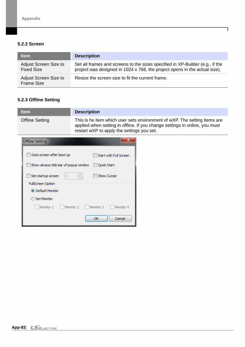
Appendix
App-83
5.2.2 Screen
Item Description
Adjust Screen Size to Fixed Size
Set all frames and screens to the sizes specified in XP-Builder (e.g., if the project was designed in 1024 x 768, the project opens in the actual size).
Adjust Screen Size to Frame Size
Resize the screen size to fit the current frame.
5.2.3 Offline Setting
Item Description
Offline Setting This is he item which user sets environment of wXP. The setting items are applied when setting in offline. If you change settings in online, you must restart wXP to apply the settings you set.

Appendix
App-84
Item Description
Goto screen after boot up
Start monitoring using the currently downloaded project as soon as wXP is launched.
Quick Start Set to display the monitoring screen without showing the progress bar for image loading. Since images are loaded when necessary while switching between screens, screen switching may become slightly slower.
Show always title bar of popup window
Set to allow all pop-up windows to be displayed with title bars while monitoring (pop-up window objects, global windows, pop-up numeric keypad windows). When this feature is disabled, the title bar is displayed only when you touch an empty area on the screen.
Start with Full Screen Set to start wXP in full screen mode. The top menu and frame are hidden from the screen. You can enable this feature when monitoring is stopped to resume monitoring in full screen mode.
Set startup screen If start screen numbers are assigned, monitoring begins in the order specified by the start screen numbers. Use this option to set your own screen numbers. The original screen numbers will be used if you specify a screen number that does not exist.
Show Cursor Set to hide the mouse cursor during monitoring.
Gesture / Multi Touch • Set the gesture / multi-touch function. • The default gesture / multi-touch operation (maximum touch point, etc.) is
the same as iXP2 (except Handy model). • If the multi-touch / gesture function is disabled on the hardware running
wXP, the “Gesture / Multi-touch function” check box is disabled. • Gesture / multi-touch support can be checked in “Pen and Touch” item in
“System” information on Windows below.
<When multi-touch / gesture function is supported>
Full Screen Option: Default Monitor
When multiple monitors are in use, set to enter full screen mode on the monitor where the majority of the original screen is displayed.
Full Screen Option: Set Monitor
When multiple monitors are in use, set to specify full screen mode display options. The following are principles used for the display options. • The top-left corner of the 1st monitor becomes the top-left corner of the
monitoring screen. • The monitoring screen size is adjusted to include all the monitor screens.

Appendix
App-85
Item Description
• You cannot view the areas of the monitoring screen beyond the areas covered by the monitor screens.
Refer to the following figure for actual application. The orange outline specifies the entire monitoring screen, while the green blocks are the unseen areas. When 2 monitors are used:
When 3 monitors are used:
When 4 monitors are used:
5.2.4 Help
Item Description
Help Displays the version information of wXP

Appendix
App-86
5.3 wXP Restrictions
You may experience the following restrictions when working with wXP.
Item Description
Unsupported service wXP does not support printing, XP-Remote, Web server, VNC server, or PLC program monitoring services.
Special switch wXP does not support safety interlock switch, program monitor switch, or other special switches related to XP_Remote.
Script function wXP does not support backlight settings, USB power reset, buzzer, buzzer activation, alarm, or screen print script functions.
License Key The license key provided at the time of purchase of wXP must be connected to the device to use software normally.

Appendix
App-87
6 Object Display Rule before Communication Connection
Object Before 1 scan completed Time Out
Lamp Object Not Displayed Display Default Image
Message Object Display Image Display Image
Numeric/Text Object
Display Image Display Image
Graph Object Display Graph Display Graph
Animation Object Display Image Display Image
Window Object Not Displayed Not Displayed
Part Object Not Displayed Not Displayed

Appendix
App-88
7 Glossary
Term Description
1: 1 “one to one” communication; a communication mode; in 1: 1 communication, one panel is used to send commands to one controller
1: N “one to many” communication; a communication mode; in 1: N communication, one panel is used to send commands to multiple controllers
baud baud and bits per second are not necessarily the same, so do not use "bits per second" or "bps" as a synonym for baud; modems are conventionally designated by bits per second or kilobits per second; a 28.8 kbps modem runs at a different baud, depending on how events are coded for transmission
bit object an object in an XP-builder project that is controlled by a bit device
bitmap refers to a specific file format for online art
case a selection control mechanism that exists in most imperative programming languages, such as Pascal, C/C++, C# and Java; it allows the value of a variable or expression to control the flow of program execution via a multi-way branch (or “go to,” one of several labels); in XP-Builder, cases are used to control the operations assigned for individual objects, by providing multiple conditional expressions where the object’s device value is one of the operands.
condition a Boolean expression used to control conditionals and loops; it affects the programming or operating of control statements, such as WHILE, FOR, and IF; in XP-Builder, conditions are used to control the operations assigned for individual objects, by providing a condition or conditional expression where the object’s device value is one of the operands.
controller the physical unit that delivers instructions to machinery; XP-Builder supports numerous types of controllers; see also programmable logic controller
DEC keypad a Window screen for user input of decimal characters
editing area the main part of the XP-Builder interface, where objects can be placed to create a project
Ethernet a connection method; the maximum throughput for an Ethernet connection is 100mbps
falling edge the bit at which the device turns off is the falling edge
FLOAT keypad a Window screen for user input of float characters
HEX keypad a Window screen for user input of hexadecimal characters

Appendix
App-89
Term Description
IL language intermediate language; the language of an abstract machine designed to aid in the analysis of computer programs
inverter an electrical power converter that changes direct current (DC) to alternating current (AC); the converted AC can be delivered at any required voltage and frequency with the use of appropriate transformers, switching, and control circuits
log Automatically produced and time-stamped documentation of events relevant to a particular system. In XP-Builder, you can enable logging option in a particular object’s property setting window to track and record the operation
N: 1 “Many to one” communication; a communication mode; in N: 1 communication, multiple panels are used to send commands to the same controller; this is an atypical configuration.
offset function a function to specify a device address by referencing an “offset” from the starting address
operator a symbol used to connect expressions; logical operators are used to create a test expression that controls program flow; relational operators test or define some kind of relation between two entities
range the set of values to be included in a function
raster image a bitmap image with a dot matrix data structure representing a generally-rectangular grid of pixels or points of color; a raster image can be in varying formats, such as GIF, JPG, and BMP
rising edge the bit at which the device turns on is the rising edge
RS232 A series of standards for serial binary single-ended data and control signals connecting between data terminal equipment (DTE) and data circuit-terminating equipment (DCE). The maximum throughput for an RS232 connection is 115Kbps.
RS485 A standard for defining the electrical characteristics of drivers and receivers for use in balanced digital multipoint systems. RS485 offers data transmission speeds of 35 Mbit/s up to 10 m and 100 Kbit/s at 1200 m.
screen the basic component of an XP-Builder project, where user interfaces (objects) are placed
script a small program written for a command interpreter or another scripting language
servo Servomechanism; a device used for control of a desired operation through the use of feedback; the term correctly applies only to systems where the feedback or error-correction signals help control mechanical position, speed, or other parameters.
token a credential used to control usage rights; the node that holds the token has the current usage rights

Appendix
App-90
Term Description
toolbar part of the XP-Builder interface where menu shortcuts are designated by icons and buttons
unsigned decimal a system for expressing negative numbers
vector image an image based on paths or strokes, for the representation of geometrical primitives, such as points, lines, curves, and shapes or polygons; because vector-based images are not made up of a specific number of dots, they can be scaled to a larger size without losing image quality
window either the windows of the operating system (MS Windows) or partial screens that are created and used in XP-builder
word object an object in an XP-builder project that is controlled by a word device
XG5000 Simulator A simulator for testing PLC logic programs. It can be run with XP-Simulator to test operation of an XP-builder projects

Appendix
App-91
8 List of Acronyms Acronym Definition
A/V audio/video
ASCII American standard code for information interchange
BCD binary code decimal
CF compact flash
CMY cyan-magenta-yellow
CMYK cyan-magenta-yellow-black
COM communications
CPU central processing unit
DEC decimal
GIF graphic interchange format
GUI graphical user interface
H/W hardware
HEX hexadecimal
I used in device expressions to represent input
IB used in device expressions to represent byte input
IEC International Electrotechnical Commission
IL intermediate language
IP internet protocol
IP ingress protection
IW used in device expressions to represent word input
JPEG joint photographic experts group
LAN local area network
LC liquid crystal display
LD ladder diagram
LED light emitting diode
M metadata
MPEG moving picture experts group
PC personal computer
PDF portable document format
PIN personal identification number

Appendix
App-92
Acronym Definition
PIR passive infrared
PLC programmable logic controller
Q output
QB bit output
QCIF quarter common intermediate format
QVGA quarter video graphics
QW word output
RAM random access memory
RGB red-green-blue
ROM read-only memory
S/W software
SD secure digital
SDK software development kit
SMTP simple mail transfer protocol
SRAM static random access memory
TCP transmission control protocol
TIFF tagged image file format
UDP user datagram protocol
UI user interface
URL uniform resource locator
USB universal serial bus
VGA video graphics array
VM virtual memory
VSP virtual serial port
WAN wide area network

Appendix
App-93
9 Caution LS ELECTRIC's HMI device must only use the font included with Microsoft's WinCE license (link below), the user is responsible if any other font is used. XP Series: https://docs.microsoft.com/en-us/previous-versions/windows/embedded/ms901084(v%3dmsdn.10) iXP/eXP Series : https://docs.microsoft.com/en-us/previous-
versions/windows/embedded/ee489823(v%3dwinembedded.60) iXP2 Series/eXP2 Series : https://docs.microsoft.com/en-us/previous-
versions/windows/embedded/ee489874(v%3dwinembedded.70).

■ Headquarter LS-ro 127(Hogye-dong) Dongan-gu, Anyang-si, Gyeonggi-Do, 14119,
Korea
■ Seoul Office LS Yongsan Tower, 92, Hangang-daero, Yongsan-gu, Seoul, 04386,
Korea
Tel: 82-2-2034-4033, 4888, 4703 Fax: 82-2-2034-4588
E-mail: [email protected]
■ Factory 56, Samseong 4-gil, Mokcheon-eup, Dongnam-gu, Cheonan-si,
Chungcheongnam-do, 31226, Korea
©2017. LS ELECTRIC Co., Ltd. All Rights Reserved.
■ Overseas Subsidiaries • LS ELECTRIC Japan Co., Ltd. (Tokyo, Japan)
Tel: 81-3-6268-8241 E-Mail: [email protected]
• LS ELECTRIC (Dalian) Co., Ltd. (Dalian, China) Tel: 86-411-8730-6495 E-Mail: [email protected]
• LS ELECTRIC (Wuxi) Co., Ltd. (Wuxi, China) Tel: 86-510-6851-6666 E-Mail: [email protected]
• LS ELECTRIC Shanghai Office (China) Tel: 86-21-5237-9977 E-Mail: [email protected]
• LS ELECTRIC Vietnam Co., Ltd. Tel: 84-93-631-4099 E-Mail: [email protected] (Hanoi)
Tel: 84-28-3823-7890 E-Mail: [email protected] (Hochiminh)
• LS ELECTRIC Middle East FZE (Dubai, U.A.E.) Tel: 971-4-886-5360 E-Mail: [email protected]
• LS ELECTRIC Europe B.V. (Hoofddorf, Netherlands) Tel: 31-20-654-1424 E-Mail: [email protected]
• LS ELECTRIC America Inc. (Chicago, USA) Tel: 1-800-891-2941 E-Mail: [email protected]
www.ls-electric.com
2021.02