CB SERIES - Climate Solutions, Inc.
32
CB SERIES CONDENSING UNITS INSTALLATION, OPERATION & MAINTENANCE If the information in this manual is not followed exactly, a fire or explosion may result causing property damage, personal injury or loss of life. FOR YOUR SAFETY Do not store or use gasoline or other flammable vapors and liquids in the vicinity of this or any other appliance. WARNING WARNING
-
Upload
khangminh22 -
Category
Documents
-
view
4 -
download
0
Transcript of CB SERIES - Climate Solutions, Inc.

CB SERIES
CONDENSING UNITS
INSTALLATION OPERATION amp
MAINTENANCE
If the information in this manual is not followed exactly a fire or explosion may result causing property damage personal injury or loss of life
FOR YOUR SAFETY Do not store or use gasoline or other flammable vapors and liquids in the vicinity of this or any other appliance
WARNING WARNING
2
3
TABLE OF CONTENTS SECTION Page
GENERAL DESCRIPTIONhelliphelliphelliphelliphelliphelliphelliphelliphelliphelliphelliphelliphelliphelliphelliphelliphelliphelliphelliphelliphelliphelliphelliphelliphelliphelliphelliphelliphelliphelliphelliphelliphelliphelliphelliphelliphellip Unpackinghelliphelliphelliphelliphelliphelliphelliphelliphelliphelliphelliphelliphelliphelliphelliphelliphelliphelliphelliphelliphelliphelliphelliphelliphelliphelliphelliphelliphelliphelliphelliphelliphelliphelliphelliphelliphelliphelliphelliphelliphelliphelliphelliphellip
5 5
OWNERrsquoS INFORMATIONhelliphelliphelliphelliphelliphelliphelliphelliphelliphelliphelliphelliphelliphelliphelliphelliphelliphelliphelliphelliphelliphelliphelliphelliphelliphellip Wiring Diagramshelliphelliphelliphelliphelliphelliphelliphelliphelliphelliphelliphelliphelliphelliphelliphelliphelliphelliphelliphelliphelliphelliphelliphelliphelliphellip General Maintenancehelliphelliphelliphelliphelliphelliphelliphelliphelliphelliphelliphelliphelliphelliphelliphelliphelliphelliphelliphelliphelliphelliphelliphelliphelliphelliphelliphelliphelliphelliphelliphelliphelliphelliphelliphelliphelliphelliphellip
5 5 6
INSTALLATIONhelliphelliphelliphelliphelliphelliphelliphelliphelliphelliphelliphelliphelliphelliphelliphelliphelliphelliphelliphelliphelliphelliphelliphelliphelliphelliphelliphelliphelliphelliphelliphelliphelliphelliphelliphelliphelliphelliphelliphellip Lifting and Handlinghelliphelliphelliphelliphelliphelliphelliphelliphelliphelliphelliphelliphelliphelliphelliphelliphelliphelliphelliphelliphelliphelliphelliphelliphelliphelliphelliphelliphelliphelliphelliphelliphelliphelliphelliphelliphelliphelliphellip Condensing Unit Placementhelliphelliphelliphelliphelliphelliphelliphelliphelliphelliphelliphelliphelliphelliphelliphelliphelliphelliphelliphelliphelliphelliphelliphelliphelliphelliphelliphelliphelliphelliphelliphelliphelliphelliphelliphelliphellip Service Clearance helliphelliphelliphelliphelliphelliphelliphelliphelliphelliphelliphelliphelliphelliphelliphelliphelliphelliphelliphelliphelliphelliphelliphelliphelliphelliphelliphelliphelliphelliphelliphelliphelliphelliphelliphelliphelliphelliphelliphelliphellip Mounting Isolationhelliphelliphelliphelliphelliphelliphelliphelliphelliphelliphelliphelliphelliphelliphelliphelliphelliphelliphelliphelliphelliphelliphelliphelliphelliphelliphelliphelliphelliphelliphelliphelliphelliphelliphelliphelliphelliphelliphelliphellip Low Ambient Operationhelliphelliphelliphelliphelliphelliphelliphelliphelliphelliphelliphelliphelliphelliphelliphelliphelliphelliphelliphelliphelliphelliphelliphelliphelliphelliphelliphelliphelliphelliphelliphelliphelliphelliphelliphelliphellip Electricalhelliphelliphelliphelliphelliphelliphelliphelliphelliphelliphelliphelliphelliphelliphelliphelliphelliphelliphelliphelliphelliphelliphelliphelliphelliphelliphelliphelliphelliphelliphelliphelliphelliphelliphelliphelliphelliphelliphelliphelliphelliphelliphellip Thermostat helliphelliphelliphelliphelliphelliphelliphelliphelliphelliphelliphelliphelliphelliphelliphelliphelliphelliphelliphelliphelliphelliphelliphelliphelliphelliphelliphelliphelliphelliphelliphelliphelliphelliphelliphelliphelliphelliphelliphellip
6 6 6 7 7 7 7 8
STARTUPhelliphelliphelliphelliphelliphelliphelliphelliphelliphelliphelliphelliphelliphelliphelliphelliphelliphelliphelliphelliphelliphelliphelliphelliphelliphelliphelliphelliphelliphelliphelliphelliphelliphelliphelliphelliphelliphelliphelliphelliphelliphelliphelliphelliphellip Pre Startuphelliphelliphelliphelliphelliphelliphelliphelliphelliphelliphelliphelliphelliphelliphelliphelliphelliphelliphelliphelliphelliphelliphelliphelliphelliphelliphelliphelliphelliphelliphelliphelliphelliphelliphelliphelliphelliphelliphelliphelliphelliphelliphelliphellip Startuphelliphelliphelliphelliphelliphelliphelliphelliphelliphelliphelliphelliphelliphelliphelliphelliphelliphelliphelliphelliphelliphelliphelliphelliphelliphelliphelliphelliphelliphelliphelliphelliphelliphelliphelliphelliphelliphelliphelliphelliphelliphelliphelliphellip
8 8 8
SERVICING amp MAINTENANCEhelliphelliphelliphelliphelliphelliphelliphelliphelliphelliphelliphelliphelliphelliphelliphelliphelliphelliphelliphelliphelliphelliphelliphelliphelliphelliphelliphelliphelliphelliphelliphelliphellip General helliphelliphelliphelliphelliphelliphelliphelliphelliphelliphelliphelliphelliphelliphelliphelliphelliphelliphelliphelliphelliphelliphelliphelliphelliphelliphelliphelliphelliphelliphelliphelliphelliphelliphelliphelliphelliphelliphelliphelliphellip Compressorshelliphelliphelliphelliphelliphelliphelliphelliphelliphelliphelliphelliphelliphelliphelliphelliphelliphelliphelliphelliphelliphelliphelliphelliphelliphelliphelliphelliphelliphelliphelliphelliphelliphelliphelliphelliphelliphelliphellip Refrigerant Filter Driershelliphelliphelliphelliphelliphelliphelliphelliphelliphelliphelliphelliphelliphelliphelliphelliphelliphelliphelliphelliphelliphelliphelliphelliphelliphelliphelliphelliphelliphelliphelliphelliphelliphelliphelliphelliphelliphellip Charging Refrigerant helliphelliphelliphelliphelliphelliphelliphelliphelliphelliphelliphelliphelliphelliphelliphelliphelliphelliphelliphelliphelliphelliphelliphelliphelliphelliphelliphelliphelliphelliphelliphelliphelliphelliphelliphelliphelliphelliphelliphellip Checking Liquid Sub-Coolinghelliphelliphelliphelliphelliphelliphelliphelliphelliphelliphelliphelliphelliphelliphelliphelliphelliphelliphelliphelliphelliphelliphelliphelliphelliphelliphelliphelliphelliphelliphelliphelliphelliphelliphelliphellip Checking Evaporator Superheathelliphelliphelliphelliphelliphelliphelliphelliphelliphelliphelliphelliphelliphelliphelliphelliphelliphelliphelliphelliphelliphelliphelliphelliphelliphelliphelliphelliphelliphelliphelliphelliphelliphelliphelliphellip Adjusting Sub-cooling and Superheat Temperatures helliphelliphelliphelliphelliphelliphelliphelliphelliphelliphelliphelliphelliphelliphelliphelliphelliphelliphelliphelliphelliphelliphellip Lubricationhelliphelliphelliphelliphelliphelliphelliphelliphelliphelliphelliphelliphelliphelliphelliphelliphelliphelliphelliphelliphelliphelliphelliphelliphelliphelliphelliphelliphelliphelliphelliphelliphelliphelliphelliphelliphelliphelliphelliphelliphelliphelliphellip Condenser Coil helliphelliphelliphelliphelliphelliphelliphelliphelliphelliphelliphelliphelliphelliphelliphelliphelliphelliphelliphelliphelliphelliphelliphelliphelliphelliphelliphelliphelliphelliphelliphelliphelliphelliphelliphelliphelliphelliphelliphelliphellip Service Information helliphelliphelliphelliphelliphelliphelliphelliphelliphelliphelliphelliphelliphelliphelliphelliphelliphelliphelliphelliphelliphelliphelliphelliphelliphelliphelliphelliphelliphelliphelliphelliphelliphelliphelliphellip
8 8 9 9 9 9 9 9 10 10 10
REFRIGERANT PIPING FOR CB SERIEShelliphelliphelliphelliphelliphelliphelliphelliphelliphelliphelliphelliphelliphelliphelliphelliphelliphelliphelliphelliphelliphelliphelliphelliphelliphelliphelliphellip Equivalent Line Lengthhelliphelliphelliphelliphelliphelliphelliphelliphelliphelliphelliphelliphelliphelliphelliphelliphelliphelliphelliphelliphelliphelliphelliphelliphelliphelliphelliphelliphelliphelliphelliphelliphelliphelliphelliphelliphelliphelliphellip Liquid Line Sizinghelliphelliphelliphelliphelliphelliphelliphelliphelliphelliphelliphelliphelliphelliphelliphelliphelliphelliphelliphelliphelliphelliphelliphelliphelliphelliphelliphelliphelliphelliphelliphelliphelliphelliphellip Suction Line Sizinghelliphelliphelliphelliphelliphelliphelliphelliphelliphelliphelliphelliphelliphelliphelliphelliphelliphelliphelliphelliphelliphelliphelliphelliphelliphelliphelliphelliphelliphelliphelliphelliphelliphelliphelliphellip Hot Gas Bypass Line Sizinghelliphelliphelliphelliphelliphelliphelliphelliphelliphelliphelliphelliphelliphelliphelliphelliphelliphelliphelliphelliphelliphelliphelliphelliphelliphelliphelliphellip Hot Gas Reheat Line Sizinghelliphelliphelliphelliphelliphelliphelliphelliphelliphelliphelliphelliphelliphelliphelliphelliphelliphelliphelliphelliphelliphelliphelliphelliphelliphelliphelliphelliphelliphelliphelliphelliphelliphelliphelliphelliphellip Predetermined Line Sizeshelliphelliphelliphelliphelliphelliphelliphelliphelliphelliphelliphelliphelliphelliphelliphelliphelliphelliphelliphelliphelliphelliphelliphelliphelliphelliphelliphelliphelliphelliphelliphelliphelliphellip TABLE RP-1 Predetermined Line sizes for CB units with two step compressors and R-410Ahelliphelliphelliphelliphelliphelliphellip FIGURE RP-1 Riser Height versus total equivalent length for CB units with R-410Ahelliphelliphelliphelliphelliphelliphelliphelliphelliphelliphelliphelliphellip FIGURE RP-2 Hot Gas Reheat piping diagram with air handler above condensing unit helliphelliphelliphelliphelliphelliphelliphelliphelliphelliphelliphellip FIGURE RP-3 Hot Gas Reheat piping diagram with air handler below condensing unit helliphelliphelliphelliphelliphelliphelliphelliphelliphelliphelliphelliphellip FIGURE RP-4 Hot Gas Reheat piping diagram with air handler above condensing unit amp optional accumulator helliphelliphellip FIGURE RP-5 Hot Gas Reheat piping diagram with air handler below condensing unit amp optional accumulator helliphelliphellip FIGURE RP-6 Heat Pump piping with indoor unit above outdoor unithelliphelliphelliphelliphelliphelliphelliphelliphelliphelliphelliphelliphelliphelliphelliphelliphelliphelliphelliphellip FIGURE RP-7 Heat Pump Piping with outdoor unit above indoor unithelliphelliphelliphelliphelliphelliphelliphelliphelliphelliphelliphelliphelliphelliphelliphelliphelliphelliphelliphellip FIGURE RP-8 Heat Pump Piping with Reheat amp indoor unit above outdoor unithelliphelliphelliphelliphelliphelliphelliphelliphelliphelliphelliphelliphelliphelliphelliphellip FIGURE RP-9 Heat Pump Piping with Reheat amp outdoor unit above indoor unithelliphelliphelliphelliphelliphelliphelliphelliphelliphelliphelliphelliphelliphelliphelliphellip FIGURE RP-10 Hot Gas Reheat piping diagram with hot gas bypass amp air handler below condensinghelliphelliphelliphelliphelliphelliphelliphellip FIGURE RP-11 Hot Gas Reheat piping diagram with Hot Gas Bypass amp air handler above condensing unit helliphelliphelliphelliphellip FIGURE RP-12 Hot Gas Bypass piping diagram with air handler below condensing unit helliphelliphelliphelliphelliphelliphelliphelliphelliphelliphellip FIGURE RP-13 Hot Gas Bypass piping diagram with air handler above condensing unithelliphelliphelliphelliphelliphelliphelliphelliphelliphelliphellip
10 11 11 12 13 13 14 15 15 16 17 18 19 20 21 22 23 24 25 26 27
CB SERIES STARTUP FORMShelliphelliphelliphelliphelliphelliphelliphelliphelliphelliphelliphelliphelliphelliphelliphelliphelliphelliphelliphelliphelliphelliphelliphelliphelliphelliphelliphelliphelliphelliphelliphelliphelliphelliphelliphelliphellip R-410A Saturated TemperaturePressure Charthelliphelliphelliphelliphelliphelliphelliphelliphelliphelliphelliphelliphelliphelliphelliphelliphelliphelliphelliphelliphelliphelliphelliphelliphelliphelliphelliphelliphelliphelliphelliphellip
28 30
4
It is the intent of AAON to provide accurate and current product information However in the interest of product improvement AAON Inc reserves the right to change pricing specifications andor design of its products without notice obligation or liability
Copyright copy 2008 AAON Inc all rights reserved throughout the world AAONreg amp AAONAIREreg are registered trademarks of AAON Inc Tulsa OK
R57610 Rev B 080702
(ACP 29023)
5
GENERAL DESCRIPTION All AAON CB Series condensing units are factory assembled and wired including a full charge of R-410A refrigerant for up to 25rsquo of line set Refrigeration systems are factory installed with a liquid line filter drier provided for field installation and a fully hermetic scroll compressor Compressors are equipped with a positive pressure forced lubrication system The air-cooled condenser coil is constructed of copper tubes with aluminum fins (copper fins optional) Note Systems with the modulating hot gas reheat option will require refrigerant to be field added because of the additional refrigerant components and piping associated with the system Unpacking When received remove all shipping packages and dispose of properly Check the unit for damage that might have occurred in transit If damage is found it should be noted on the carrierrsquos Freight Bill A request for inspection by carrierrsquos agent should be made in writing at once Check the unit nameplate to ensure that the correct model size and voltage have been received to match the job requirements OWNERS INFORMATION
Warning bull Failure to observe the following instructions will result in premature failure of your system and possible voiding of the product warranty bull Never cut off the main power supply to the unit except for complete shutdown When power is cut off from the unit any compressors using crankcase heaters cannot prevent refrigerant
migration This means the compressor will cool down and liquid refrigerant may accumulate in the compressor Since the compressor is designed to pump refrigerant gas damage may occur when power is restored bull Before unit operation the main power switch must be turned on for at least twenty four hours for units with compressor crankcase heaters This will give the crankcase heater time to clear any liquid accumulation out of the compressor before it is required to run bull Always control the system from the thermostat and never from the main power supply (except for emergency or for complete shutdown of the system) bull Improper installation adjustment alteration service or maintenance can cause property damage personal injury or loss of life Installation and service must be performed by a qualified installer or service agency Refer to installation instructions included in this manual bull The compressor must be off for a minimum of 5 minutes after any power interruption bull If the unit has been off for over an hour restore power to the unit and wait two hours before turning the thermostat on
The compressor life will be seriously shortened by reduced lubrication and the pumping of excessive amounts of liquid oil and refrigerant Wiring Diagrams bull A complete set of unit specific wiring diagrams are laminated in plastic and located inside the control compartment cover
6
General Maintenance After the initial unit startup and on a periodic schedule during operation it is necessary to perform routine service checks on the performance of the condensing unit This includes reading and recording suction pressures and checking for normal sub-cooling and superheat The ECM condenser fan motor is factory preprogrammed and requires no maintenance INSTALLATION Lifting and Handling bull You are encouraged to use dollies andor carts to lift and place the unit to prevent damage to the equipment or injury to the installer bull Care should be taken if using spreader bars blocking or other lifting devices to prevent any damage to the coil or the cabinet of the condensing unit bull Before lifting unit be sure that all shipping material has been removed from unit bull All CB Series condensing units have channels underneath the base to provide lifting access to the underside of the equipment and allow moving and placement without physical damage bull Hoist unit to a point directly above the pad and lower unit into the proper place (unit may also be positioned with a dolly) When the unit is in place remove the dolly or lifting device Make sure the unit is properly seated and level Condensing Unit Placement bull The AAON condensing unit is designed for outdoor applications and mounting at ground level or on a rooftop It must be placed on a level and solid foundation that has been prepared to support its weight When rooftop mounted a steel frame must be provided that will support the unit above the roof itself When installed at ground level a one-piece concrete slab should be used with footings that extend below the frost line (a substantial base that will not settle) bull With ground level installation care must be taken to protect the coil fins from damage due to vandalism or other hazards bull The placement relative to the building air intakes and other structures must be carefully selected Airflow to and from the condensing
unit must not be restricted Obstruction to air flow will result in decreased performance and efficiency bull The installation position must provide at least one (1) foot of clearance from the wall for proper air flow to the coils When units are mounted adjacent to each other the clearance required between them is three (3) feet bull Condensing units should not be installed in an enclosure or pit that is deeper than the height of the unit When recessed installation is necessary the clearance to maintain proper airflow is at least three (3) feet
bull CB-024 through CB-060 are all single circuit models with vertical air discharge There must be no obstruction above the equipment Do not place the unit under an overhang bull Condenser coils and fans must be free of any obstructions in order to start and operate properly with a correct amount of airflow bull For proper unit operation the immediate area around condenser must remain free of debris or grass that may be drawn in and obstruct airflow in the condensing section
7
bull Consideration must be given to obstruction caused by snow accumulation when placing the unit Additional Placement Considerations Consider the affect of outdoor fan noise on conditioned space and any adjacent occupied space It is recommended that the unit be placed so that discharge does not blow toward windows less than 25 feet away The outdoor unit should be set on a solid level foundation - preferably a concrete slab at least 4 inches thick The slab should be above ground level and surrounded by a graveled area for good drainage Any slab used as a units foundation should not adjoin the building as it is possible that sound and vibration may be transmitted to the structure For rooftop installation steel or treated wood beams should be used as unit support for load distribution Heat pumps require special location consideration in areas of heavy snow accumulation andor areas with prolonged continuous subfreezing temperatures Heat pump unit bases are cutout under the outdoor coil to permit drainage of frost accumulation The unit must be situated to permit free unobstructed drainage of the defrost water and ice A minimum 3 clearance under the outdoor coil is required in the milder climates In more severe weather locations it is recommended that the unit be elevated to allow unobstructed drainage and airflow The following elevation minimums are recommended
Design Temperature Suggest Minimum Elevation +15deg F and above 3rdquo
-5deg F to +17deg F 8rdquo Below -5deg F 12rdquo
Service Clearance An access panel is provided to the electrical service compartment The CB Series condensing unit service compartment must be accessible for periodic servicing of controls safety devices and refrigerant serviceshutoff valves At least two (2) feet of clearance on this corner of the unit is recommended for service
Mounting Isolation bull For roof mounted applications or anytime vibration transmission is a factor vibration isolators may be used Low Ambient Operation bull The AAON low ambient (condenser fan cycling) system is used to operate a refrigerant system down to 35degF outside air temperature As the ambient temperature drops the condenser becomes more effective therefore lowering the head pressure When the head pressure gets too low there will be insufficient pressure to operate the expansion valve properly During low ambient temperatures it is difficult to start a system because the refrigerant will migrate to the cold part of the system (condenser) and make it difficult for refrigerant to flow bull The AAON zero degree ambient system maintains normal head pressure during periods of low ambient by effectively reducing the heat transfer surface area reducing capacity and increasing condensing pressure allowing the system to operate properly During periods with higher ambient temperatures the entire condenser is required to condense refrigerant Electrical bull The single point electrical power connections are made in the electrical control compartment bull Check the unit name plate to make sure it agrees with the power supply Connect power to the unit according to the wiring diagram provided with the unit bull The power and control wiring may be brought in through the utility entry Protect the branch circuit in accordance with code requirements If the control wires are to run inside the same conduit 600 volt wires should be used or as required by applicable codes The unit must be electrically grounded in accordance with the National Electric Code bull Units are factory wired for 230V 1 ph 60Hz application For 208V applications the transformer wire taps should be changed for 208V operation bull Power wiring is to the unit terminal block or compressor contactor All wiring beyond this point has been done by the manufacturer and
8
cannot be modified without effecting the units agencysafety certification
Note Startup technician must check motor amperage to ensure that the amperage listed on the motor nameplate is not exceeded Thermostat Units without the neutral air dehumidification feature will operate with most common thermostats Units with the neutral air dehumidification feature must use thermostats with a normally closed (NC) dehumidification option The following stats have been approved for usage with the dehumidification feature
Robertshaw Honeywell 9825i2 VisionPROregIAQ
STARTUP Pre Startup NOTE Crankcase Heater Operation All units are equipped with a crankcase heater which should be energized at least 24 hours prior to setting the thermostat for cooling operation with the compressor After the installation and immediately before the startup of the condensing unit be sure that these items have been checked 1 Verify that electrical power is available to the unit 2 Verify that the thermostat is in the cooling mode and the ldquofanrdquo switch is in the ON position While performing the Startup use the CB Startup Form at the back of this booklet to record motor amps and any other comments
Startup bull Use the General Check List at the top of the Startup Form to make a last check that all the components are in place and the power supply is energized bull CHECK COMPRESSOR FOR PROPER ROTATION BY STARTING UNIT ONLY AFTER CONNECTING PRESSURE GAUGES TO SUCTION AND DISCHARGE VALVES THE COMPRESSOR WILL FAIL IF OPERATED IN THE WRONG DIRECTION bull Turn cooling on ndash check to see that the compressor(s) is operating within tolerance bull When unit is running observe the system for a complete operation cycle to verify that all systems are functioning properly
bull While performing the check use the CB Startup Form to record observations of amps and refrigerant pressures
SERVICING AND MAINTENANCE General bull Qualified technicians must perform routine service checks and maintenance This includes reading and recording the condensing and suction pressures and checking for normal sub-
9
cooling and superheat (see Charging Refrigerant section) Compressors Scroll compressors are fully hermetic and require no maintenance except for keeping the shell clean Refrigerant Filter Driers Each refrigerant circuit should contain a built in liquid line filter drier that is shipped loose with the unit for field installation The unit does not include a liquid line solenoid valve This must be field furnished and installed if required by job conditions Charging Refrigerant bull The unit comes with full charge based on a 25 foot line set Charging a system in the field must be based on determination of liquid sub-cooling and evaporator superheat On a system with a thermostatic expansion valve liquid sub-cooling is more representative of the charge than evaporator superheat but both measurements must be taken
Before Charging bull The unit being charged must be at or near full load conditions before adjusting the charge bull Units equipped with hot gas reheat must have the hot gas reheat valves closed to get the proper charge bull Units equipped with hot gas reheat must be charged with the hot gas valve closed while the unit is in cooling mode bull After adding or removing charge the system must be allowed to stabilize typically 10-15 minutes before making any other adjustments bull The type of unit and options determine the ranges for liquid sub-cooling and evaporator
superheat Refer to TABLE 1 when determining the proper sub-cooling bull The vertical rise of the liquid line must be known in order to adjust the sub-cooling range for proper charge Checking Liquid Sub-cooling 1 Measure the temperature of the liquid line as it leaves the condenser coil 2 Read the gauge pressure reading of the liquid line close to the point where the temperature was taken You must use liquid line pressure as it will vary from discharge pressure due to condenser coil pressure drop 3 Convert the pressure obtained in Step 2 to a saturated temperature using the refrigerant temperature-pressure chart at the back of this manual 4 Subtract the measured liquid line temperature in Step 1 from the saturated temperature in Step 3 to determine the liquid sub-cooling 5 Compare calculated sub-cooling to TABLE 1 for the appropriate unit type and options Checking Evaporator Superheat 1 Measure the temperature of the suction line close to the compressor 2 Read gauge pressure at the suction line close to the compressor 3 Convert the pressure obtained in Step 2 to a saturated temperature using the appropriate refrigerant temperature-pressure chart 4 Subtract the saturated temperature in Step 3 from the measured suction line temperature in Step 1 to determine the evaporator superheat 5 Compare calculated superheat to TABLE 1 for the appropriate unit type and options Adjusting Sub-cooling and Superheat Temperatures The system is overcharged if 1 the sub-cooling temperature is too high and 2 the evaporator is fully loaded (low loads on the evaporator result in increased sub-cooling) and 3 the evaporator superheat is within the temperature range as shown in TABLE 1 (high superheat results in increased sub-cooling)
10
TABLE 1
Sub-
cooling (degF)
Superheat (degF)
Sub-cooling WHot Gas Reheat (degF)
Air-Cooled
Condenser 12-18 8-15 15-22
Sub-cooling must be increased by 2degF per 20 feet of vertical liquid line rise for R- 410A Superheat will increase with long suction line runs Correct an overcharged system by reducing the amount of refrigerant in the system to lower the sub-cooling
The system is undercharged if 1 the superheat is too high and 2 the sub-cooling is too low bull Correct an undercharged system by adding refrigerant to the system to reduce superheat and raise sub-cooling bull If the sub-cooling is correct and the superheat is too high the TXV may need adjustment to correct the superheat Lubrication bull All original motors and bearings are furnished with factory lubrication They require no lubrication Condenser Coil bull The air-cooled condenser rejects heat by passing outdoor air over the fin tube coils for cooling of the hot refrigerant gas from the compressors The heated air will discharge from the unit through the axial flow fans bull The condenser coils should be inspected yearly to ensure unrestricted airflow If the installation has a large amount of airborne dust or other material the condenser coils should be cleaned
with a water spray in a direction opposite to airflow Care must be taken to prevent bending of the aluminum fins on the copper tube bull Before attempting to clean the coils set thermostat to the OFF position turn the electrical power to the unit to the OFF position at the disconnect switch outside by the unit The condenser coil can be thoroughly cleaned by washing from the inside out with water and a coil cleaner If coil is extremely dirty with clogged fins a service professional specializing in coil cleaning should be called Service Information bull If the unit will not operate correctly and a service company is required only a company with service technicians qualified and experienced in both condensing units and air conditioning are permitted to service the systems to keep warranties in effect If assistance is required the service technician must contact AAON Note Service technician must provide the model and serial number of the unit in all correspondence with AAON bull Replacement parts for AAON equipment may be obtained from AAON When ordering parts always reference the unit model number serial number and part number To order parts from the AAON parts store online go to wwwaaonpartscom REFRIGERANT PIPING FOR THE CB SERIES Note This section is for information only and is not intended to provide all details required by the designer or installer of the refrigerant piping between the condensing unit and air handling equipment AAON is not responsible for interconnecting refrigerant piping Consult ASHRAE Handbook ndash Refrigeration and ASME Standards
11
General bull Piping from the condensing unit to the air handler is the responsibility of the installing contractor bull Use only clean type ldquoACRrdquo copper tubing that has been joined with high temperature brazing alloy bull All CB series condensing units have factory furnished liquid and suction line shutoff valves bull The pipe sizes must be selected to meet the actual installation conditions and not simply based on the connection sizes at the evaporator andor condensing unit bull Condensing units are provided with in-line shutoff valves on both the liquid and suction lines These should remain closed until the system is ready for start-up after piping and vacuuming bull Piping should conform to generally accepted practices and codes bull Upon completion of piping connection the interconnecting piping and air handler MUST BE evacuated to 500 microns or less leak checked and charged with R-410A refrigerant Determining Refrigerant Line size The piping between the condenser and low side must assure 1 Minimum pressure drop and 2 Continuous oil return and 3 Prevention of liquid refrigerant slugging or carryover bull Minimizing the refrigerant line size is favorable from an economic perspective reducing installation costs and reducing the potential for leakage However as pipe diameters narrow pressure-reducing frictional forces increase bull Excessive suction line pressure drop causes loss of compressor capacity and increased power usage resulting in reduced system efficiency Excessive pressure drops in the liquid line can cause the liquid refrigerant to flash resulting in faulty expansion valve operation and improper system performance In order to operate efficiently and cost effectively while avoiding malfunction refrigeration systems must be designed to minimize both cost and pressure loss
The pipe sizes must be selected to meet the actual installation conditions and not simply based on the connection sizes at the evaporator andor condensing unit Refer to TABLE RP-1 for connection size information Equivalent Line Length All line lengths discussed in this manual unless specifically stated otherwise are Equivalent Line Lengths The frictional pressure drop through valves fittings and accessories is determined by establishing the equivalent length of straight pipe of the same diameter Always use equivalent line lengths when calculating pressure drop Special piping provisions must be taken when lines are run underground up vertical risers or in excessively long line runs Liquid line sizing bull When sizing the liquid line it is important to minimize the refrigerant charge to reduce installation costs and improve system reliability This can be achieved by minimizing the liquid line diameter However reducing the pipe diameter will increase the velocity of the liquid refrigerant which increases the frictional pressure drop in the liquid line and causes other undesirable effects such as noise Maintaining the pressure in the liquid line is critical to ensuring sufficient saturation temperature avoiding flashing upstream of the TXV and maintaining system efficiency Pressure losses through the liquid line due to frictional contact installed accessories and vertical risers are inevitable Maintaining adequate sub-cooling at the condenser to overcome these losses is the only method to ensure that liquid refrigerant reaches the TXV bull Liquid refrigerant traveling upwards in a riser loses head pressure If the evaporator section is below the condenser and the liquid line does not include risers the gravitational force will increase the pressure of the liquid refrigerant This will allow the refrigerant to withstand greater frictional losses without the occurrence of flashing prior to the TXV bullA moisture-indicating sight glass may be field installed in the liquid line to indicate the occurrence of premature flashing or moisture in the line The sight glass should not be used to
12
determine if the system is properly charged Use temperature and pressure measurements to determine liquid sub-cooling not the sight glass Liquid Line Routing Care should be taken with vertical risers When the system is shut down gravity will pull liquid down the vertical column and back to the condenser when it is below the evaporator This could potentially result in compressor flooding A check valve can be installed in the liquid line where the liquid column rises above the condenser to prevent this The liquid line is typically pitched along with the suction line or hot gas line in the direction of the compressor to minimize the complexity of the configuration Liquid Line Insulation When the liquid line is routed through regions where temperature losses are expected no insulation is required as this may provide additional sub-cooling to the refrigerant When routing the liquid line through high temperature areas insulation of the line is appropriate to avoid loss of sub-cooling through heat gain Liquid Line Guidelines bull In order to ensure liquid at the TXV frictional losses must not exceed available sub-cooling A commonly used guideline to consider is a system design with pressure losses due to friction through the line not to exceed a corresponding 1-2degF change in saturation temperature bull If the velocity of refrigerant in the liquid line is too great it could cause excessive noise or piping erosion The recommended maximum velocities for liquid lines are 100 fpm from the condenser to a receiver tank when used to discourage fluid backup and 300 fpm from receiver tank to the evaporator to minimize valve induced liquid hammer Liquid Line Accessories Liquid line shut off valves are factory installed while filter drier is shipped loose for field installation The total length equivalent of pressure losses through valves elbows and fittings must be considered when adding additional components in the field It is a good
practice to utilize the fewest elbows that will allow the mating units to be successfully joined Suction Line Sizing The suction line is more critical than the liquid line from a design and construction standpoint More care must be taken to ensure that adequate velocity is achieved to return oil to the compressor at minimum loading conditions However reducing the piping diameter to increase the velocity at minimal load can result in excessive pressure losses capacity reduction and noise at full load Suction Line Routing bull Pitch the suction line in the direction of flow (about 1 ft per 100 ft of length) to maintain oil flow towards the compressor and keep it from flooding back into the evaporator Crankcase heaters are provided to keep any condensed refrigerant that collects in the compressor from causing damage or wear Make sure to provide support to maintain suction line positioning and insulate completely between the evaporator and condensing unit bull It is important to consider part load operation when sizing suction lines At minimum capacity refrigerant velocity may not be adequate to return oil up the vertical riser Decreasing the diameter of the vertical riser will increase the velocity but also the frictional loss A double suction riser can be applied in this situation The double suction riser is designed to return oil at minimum load while not incurring excessive frictional losses at full load The double suction riser consists of a small diameter riser in parallel with a larger diameter riser and a trap at the base of the large riser At minimum capacity refrigerant velocity is not sufficient to carry oil up both risers and it collects in the trap effectively closing off the larger diameter riser and diverting refrigerant up the small riser where velocity of the refrigerant is sufficient to maintain oil flow At full load the mass flow clears the trap of oil and refrigerant is carried through both risers The smaller diameter pipe should be sized to return oil at minimum load while the larger diameter pipe should be sized so that flow through both pipes provides acceptable pressure drop at full load
13
Suction Line Insulation The entire suction line should be insulated This prevents condensation from forming on the line and reduces any potential loss in capacity associated with heat gain placing additional load on the system Suction Line Guidelines bull For proper performance suction line velocities less than a 4000 fpm maximum are recommended The minimum velocity required to return oil is dependent on the pipe diameter however a general guideline of 1000 fpm minimum may be applied bull In a fashion similar to the liquid line a common guideline to consider is a system design with pressure losses due to friction through the line not to exceed a corresponding 1-2degF change in saturation temperature bull At points where small pipe size can be used to provide sufficient velocity to return oil in vertical risers at part loads greater pressure losses are incurred at full loads This can be compensated for by over sizing the horizontal runs and vertical drop sections This will however require additional refrigerant charge Suction Line Accessories If the job requirements specify suction accumulators they must be separately purchased and installed Hot Gas Bypass Line bull Hot Gas Bypass is available for use with DX systems that may experience low suction pressure during the operating cycle This may be due to varying load conditions associated with VAV applications or units supplying a large percentage of outside air The system is designed to divert refrigerant from the compressor discharge to the low-pressure side of the system in order to keep the evaporator from freezing and to maintain adequate refrigerant velocity for oil return at minimum load bull Hot discharge gas is redirected to the evaporator inlet via an auxiliary side connector (ASC) to false load the evaporator when reduced suction pressure is sensed Field piping between the condensing unit and the evaporator is required
Hot Gas Bypass Piping Considerations for Evaporator Above Condensing Unit bull Pitch the hot gas bypass line downward in the direction of refrigerant flow toward the evaporator bull When installing hot gas bypass risers a drain leg must be provided at the lowest point in the system The drain leg must be vertical its diameter should be the same as the diameter of the riser and it should be 1 foot long Install a sight glass in the drain leg for observation Run an oil return line using 18 inch capillary tube 10 feet in length from the drain leg to the suction line Connect the oil return line below the sight glass 1 inch above the bottom of the drain leg bull HGBP valves are adjustable Factory HGBP valve settings will be sufficient for most applications but may require slight adjustments for some make up air or other process cooling applications bull Insulate the entire length of the HGBP line with a minimum 1 inch thick Armaflex insulation Hot Gas Bypass Piping Considerations for Evaporator Below Condensing Unit bull The line must slope downward from the hot gas bypass valve toward the evaporator Hot Gas Bypass Line Guidelines bull Choose a small size line to ensure oil return and minimize refrigerant charge bull Maintain velocities below a maximum of 4000 fpm A general minimum velocity guideline to use is approximately 1000 fpm Hot Gas Reheat bull The AAON modulating hot gas reheat system diverts hot discharge gas from the condenser to the air handling unit through the hot gas line Field piping between the condensing unit and the evaporator is required bull The line delivers the hot discharge gas to the reheat coil andor the hot gas bypass valve so it is sized as a discharge line bull Discharge lines should be sized to ensure adequate velocity of refrigerant to ensure oil return avoid excessive noise associated with velocities that are too high and to minimize efficiency losses associated with friction
14
bull Pitch the hot gas line in the direction of flow for oil return bull When installing hot gas reheat risers a drip leg must be provided at the lowest point in the system The drip leg must be vertical its diameter should be the same as the diameter of the riser and it should be 1 foot long Run a drip line using 18 inch capillary tube 10 feet in length from the drip leg to the suction line Connect the drip line a minimum of 1-inch above the bottom of the drain leg bull Insulate the entire length of the hot gas line with a minimum 1 inch thick Armaflex insulation Hot Gas Reheat Guidelines bull Maintain velocities below a maximum of 3500 fpm A general minimum velocity guideline is 2000 fpm Predetermined Line Sizes bull To aid in line sizing and selection AAON has predetermined line sizes for the liquid and suction lines in comfort cooling applications bull In order to generate this information the following cycle assumptions are made Saturated suction temperature = 50degF Saturated condensing temperature = 125degF Sub-cooling = 10degF Superheat = 15degF bull The liquid lines have been chosen to maintain velocities between 100 and 350 fpm The suction line diameters are selected to limit velocities to a 4000 fpm maximum while a minimum velocity restriction is imposed by the ability to entrain oil up vertical suction risers (ASHRAE Handbook - Refrigeration) bull Acceptable pressure loss criteria are applied to each of the lines The total equivalent length of the liquid line available is determined such that 3degF of liquid sub-cooling remain at the TXV This includes the pressure losses in horizontal and vertical sections accessories elbows etc bull Recall that the available sub-cooling for the cycle is assumed as 10degF To maintain at least 3degF sub-cooling as a factor of safety to avoid flashing at the TXV we consider a maximum pressure loss equivalent to a 7degF change in saturation temperature Pressure losses in the suction line are not to exceed 2degF
When to use predetermined line sizing The line sizes presented are not the only acceptable pipe diameters they are however appropriate for general comfort cooling applications and satisfy common job requirements Examine the conditions assumptions and constraints used in the generation of the predetermined pipe diameters to ensure that this method is applicable to a particular case Do not assume that these line sizes are appropriate for every case Consult ASHRAE Handbook ndash Refrigeration for generally accepted system practices How to use predetermined line sizing bull First read the previous section entitled (When to use predetermined line sizing) to decide if this method is applicable bull Next consult TABLE RP-1 for pipe diameters bull Examine Figure RP-1 to determine the acceptable line dimensions associated with the pipe diameters determined in TABLE RP-1 The figure is shown as total available riser height versus total equivalent line length for the liquid line This curve identifies a region of acceptable piping configuration when the predetermined line sizes are selected for any model in the table A piping configuration above the curve falls outside the assumptions used to determine the line size and will result in a loss of sub-cooling and additional pressure losses in the suction and hot gas bypass lines bull The total equivalent line length definition includes the height of vertical rise pressure drop through elbows and accessories and horizontal line length so elbows accessories and vertical rise must be considered when determining horizontal length available from the total equivalent line length bull Figure RP-1 is presented in terms of the liquid line but it assumes that the line lengths for the suction and hot gas bypass are similar as these lines will commonly be routed together to minimize the space and cost required for split system installation
15
TABLE RP-1 Predetermined Line sizes for CB units with two step compressors and R-410A
Connection Sizes Predetermined Line Size Model Liquid Suction Hot Gas Liquid Suction HGBP HGRH
CB-024 38 inch 34 inch 38 inch 38 inch 34 inch 38 inch 38 inch CB-036 38 inch 34 inch 38 inch 38 inch 34 inch 38 inch 12 inch CB-048 38 inch 78 inch 12 inch 38 inch 78 inch 12 inch 12 inch CB-060 38 inch 78 inch 12 inch 12 inch 78 inch 12 inch 12 inch
Hot Gas Bypass line Hot Gas Reheat line
FIGURE RP-1 Riser height versus total equivalent line length for R-410A split system applications with two-step compressor CB-024 through CB-060 units The region of acceptable riser height is the lighter area Select the corresponding predetermined line size from TABLE RP-1 above
16
FIGURE RP-2 HOT GAS REHEAT PIPING DIAGRAM WITH AIR HANDLER ABOVE
CONDENSING UNIT
17
FIGURE RP-3 HOT GAS REHEAT PIPING DIAGRAM WITH AIR HANDLER BELOW
CONDENSING UNIT
18
FIGURE RP-4 HOT GAS REHEAT PIPING DIAGRAM WITH AIR HANDLER ABOVE
CONDENSING UNIT amp OPTIONAL ACCUMULATOR
19
FIGURE RP-5 HOT GAS REHEAT PIPING DIAGRAM WITH AIR HANDLER BELOW
CONDENSING UNIT amp OPTIONAL ACCUMULATOR
20
FIGURE RP-6 HEAT PUMP PIPING WITH INDOOR UNIT ABOVE OUTDOOR UNIT
21
FIGURE RP-7 HEAT PUMP PIPING WITH OUTDOOR UNIT ABOVE INDOOR UNIT
22
FIGURE RP-8 HEAT PUMP PIPING WITH REHEAT amp INDOOR UNIT ABOVE OUTDOOR UNIT
23
FIGURE RP-9 HEAT PUMP PIPING WITH REHEAT amp OUTDOOR UNIT ABOVE INDOOR UNIT
24
FIGURE RP-10 HOT GAS REHEAT PIPING DIAGRAM WITH HOT GAS BYPASS amp AIR
HANDLER BELOW CONDENSING UNIT
25
FIGURE RP-11 HOT GAS REHEAT PIPING DIAGRAM WITH HOT GAS BYPASS amp AIR
HANDLER ABOVE CONDENSING UNIT
26
FIGURE RP-12 HOT GAS BYPASS PIPING DIAGRAM WITH AIR HANDLER BELOW
CONDENSING UNIT
27
FIGURE RP-13 HOT GAS BYPASS PIPING DIAGRAM WITH AIR HANDLER ABOVE
CONDENSING UNIT
28
CB STARTUP FORM PAGE 1 of 1
DATE___________________ JOB NAME_________________________________________________________________________________________ ADDRESS_________________________________________________________________ MODEL No______________ CITY STATE______________________________________________________________ SERIAL No______________ START-UP CONTRACTOR___________________________________________________ TAG____________________
PRE STARTUP CHECKLIST
Installing contractor shall verify the following items (cross out items that do not apply) 1 Is there any visible shipping damage________________________________________________________ Yes No 2 Is the unit installation level________________________________________________________________ Yes No 3 Are the unit clearances adequate for service and operation_______________________________________ Yes No 4 Do all access panels removable freely_______________________________________________________ Yes No 5 Have all shipping braces been removed______________________________________________________ Yes No 6 Have all electrical connections been tested for tightness_________________________________________ Yes No 7 Does the electrical service correspond to the unit nameplate______________________________________ Yes No 8 Has the over current protection been installed to match unit nameplate requirement___________________ Yes No 9 Have all set screws on fans (if applicable) been tightened________________________________________ Yes No 10 Does condenser fan rotate freely___________________________________________________________ Yes No
COOLING TEST COMPRESSORS CRANKCASE
AMPS HEATER NUMBER MODEL L1 L2 L3 AMPS
1
AMBIENT TEMPERATURE AMBIENT DRY BULB TEMP_______________degF
AMBIENT WET BULB TEMP_______________degF
REFRIGERATION SYSTEM 1
SATURATED LINE PRESSURE TEMPERATURE TEMPERATURE
SUB-COOLING SUPERHEAT
DISCHARGE SUCTION LIQUID
CONDENSER FAN AMPS
ALIGNMENT________ CHECK ROTATION__________ NAMEPLATE AMPS________
NUMBER HP L1 L2 L3 1
29
NOTES
30
R-410A Saturation PressureTemperature Chart
(degF) PSIG (degF) PSIG (degF) PSIG (degF) PSIG (degF) PSIG 20 783 50 1422 80 2349 110 3641 140 5401 21 80 51 1448 81 2386 111 3691 141 547 22 818 52 1474 82 2423 112 3742 142 5539 23 836 53 1501 83 246 113 3794 143 5609 24 854 54 1528 84 2498 114 3846 144 5679 25 872 55 1555 85 2537 115 3899 145 5751 26 891 56 1582 86 2575 116 3952 146 5823 27 91 57 161 87 2614 117 4005 147 5896 28 929 58 1638 88 2654 118 4059 148 5969 29 949 59 1667 89 2694 119 4114 149 6044 30 968 60 1696 90 2735 120 4169 150 6119 31 988 61 1725 91 2776 121 4225 32 1009 62 1754 92 2817 122 4282 33 1029 63 1784 93 2859 123 4339 34 105 64 1815 94 2901 124 4396 35 1071 65 1845 95 2944 125 4454 36 1092 66 1876 96 2987 126 4513 37 1114 67 1907 97 303 127 4573 38 1136 68 1939 98 3075 128 4632 39 1158 69 1971 99 3119 129 4693 40 1181 70 2004 100 3164 130 4754 41 1203 71 2036 101 321 131 4816 42 1227 72 207 102 3256 132 4878 43 125 73 2103 103 3302 133 4941 44 1274 74 2137 104 3349 134 5005 45 1298 75 2171 105 3396 135 5069 46 1322 76 2206 106 3444 136 5134 47 1347 77 2241 107 3493 137 520 48 1372 78 2277 108 3542 138 5266 49 1397 79 2313 109 3591 139 5333
31
CB SERIES CONDENSING UNITS
INSTALLATION OPERATION amp
MAINTENANCE
R57610 Rev B 080702 (ACP 29023)
AAON 2425 South Yukon Ave Tulsa OK 74107-2728 Phone (918) 583-2266
Fax (918) 583-6094 wwwaaoncom
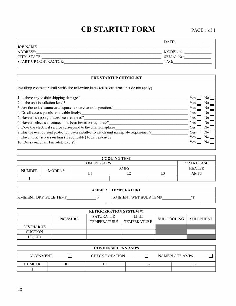

31
CB SERIES CONDENSING UNITS
INSTALLATION OPERATION amp
MAINTENANCE
R57610 Rev B 080702 (ACP 29023)
AAON 2425 South Yukon Ave Tulsa OK 74107-2728 Phone (918) 583-2266
Fax (918) 583-6094 wwwaaoncom
CB SERIES CONDENSING UNITS
INSTALLATION OPERATION amp
MAINTENANCE
R57610 Rev B 080702 (ACP 29023)
AAON 2425 South Yukon Ave Tulsa OK 74107-2728 Phone (918) 583-2266
Fax (918) 583-6094 wwwaaoncom