CB 240 Climbing Formwork - PERI Ltd
104
Edition 11 | 2014 CB 240 Climbing Formwork Instructions for Assembly and Use – Standard Configuration UK edition with reference to Lifting Beam 9t - 04/2019
-
Upload
khangminh22 -
Category
Documents
-
view
0 -
download
0
Transcript of CB 240 Climbing Formwork - PERI Ltd
Edition 11 | 2014
CB 240
Climbing Formwork
Instructions for Assembly and Use – Standard ConfigurationUK edition with reference to Lifting Beam 9t - 04/2019

B3 Formwork Utilisation
CB Carriage Operations 50
Formwork Alignment 51
Inclination Adjustment 52
Horizontal Movement – VARIO 52
B4 Crane-Assisted Climbing
Preparation 53
Moving procedure 55
C1 Planning and Work Preparation
Static System 56
Platform Dimensioning 57
Platform Decking 58
Handrails and Guardrails 61
Connecting VARIO GT 24 Formwork 62
Connecting TRIO Formwork 64
Moving the Units 66
Drawings and Plans 67
Use on Circular Structures 68
Corner Platforms 69
Components
Components 70
CB 240 Climbing Formwork
Instructions for Assembly and Use – Standard Configuration
Content
Introduction
Overview, Main Components 1
Key 4
Intended Use 5
Instructions for Use 5
General Safety Instructions 6
Storage and Transportation 6
System-Specific Safety Instructions 7
Additional Technical Documentation 7
Load Models 8
Standard Work Flow 10
A1 Assembly of the CB 240 Platform
Required Resources 12
Assembly of CB 240 Brackets 13
Girder Assembly 14
Assembly of CB 240 Carriage 16
Assembly of Decking for the
Working Platform 18
Assembly of Guardrails 20
A2 Other Assembly Work
Assembly of End Guardrail Posts 22
Assembly of Foldable Hatch 23
Assembly of Finishing Platform 24
Assembly of Finishing Tasks 25
B1 Work on the Construction Site
Anchoring 26
Mounting the Platform Unit 32
Mounting the Finishing Platform 34
Assembly of Wind Bracing 37
Removal of Climbing Cones 39
Dismantling of the Climbing Unit 39
Ladder Assembly 40
B2 Assembly of the Formwork Elements
VARIO GT 24 Element 42
TRIO Element 46
1
Overview, Main Components
CB 240 Climbing Formwork
Instructions for Assembly and Use – Standard Configuration
Introduction
Concreting platform
Concreting height hB
Form
work height hs
Intermediate platform
Working platform
Finishing platform
9
7
6
11
1
8
3
4
10
5
5
2
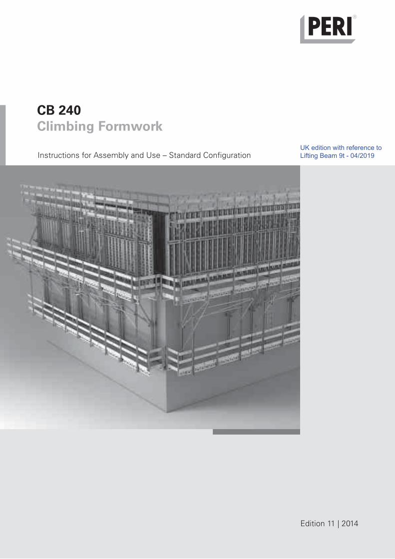
Climbing Formwork CB 240 with
VARIO GT 24 Girder Wall Formwork
– Concreting height 5.40 m.
– Extended suspension of finishing
platform.
– Tension Anchor CB with DW 15 as
wind bracing.
– Intermediate platform on formwork.
*Formwork height =
concreting height + formwork projection
(max. 5.40 m)
2CB 240 Climbing Formwork
Instructions for Assembly and Use – Standard Configuration
Introduction
Overview, Main Components
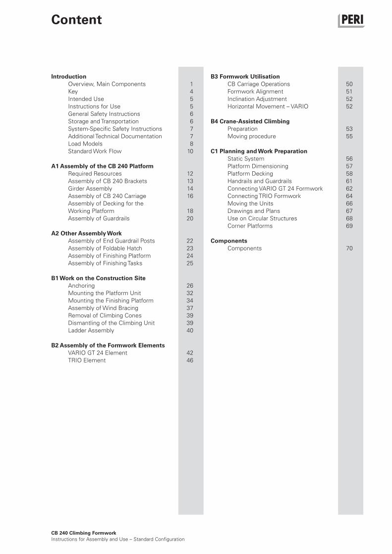
1 Working platform with Climbing Bracket CB 240
2 Carriage CB 240 with Rack CB 240
3 Adjustable Brace CB 164-224
4 Strongback CB 270 or CB 380
5 Anchoring and Leading Anchor
6 Bracing Shoe Wall CB M24
7 Wind bracing with tension belt or tie rod
8 Finishing Platform with Platform Beam CB
9 Suspension of finishing platform
10 VARIO GT 24 or TRIO formwork with concreting scaffold
11 Bracing with scaffold tubes
Climbing Formwork CB 240 with TRIO
Panel Formwork
– Concreting height 3.60 m.
– Suspension of finishing platform,
single.
– Tension Belt CB as wind bracing.
*Formwork height =
concreting height + formwork projection
(max. 5.40 m)
Concreting height hB
Form
work height hs
Finishing platform
Concreting platform
Working platform
3
4
10
5
9
8
7
6
11
2 1

3
L1
L2
5.2 5.1 5.75.6
5.4 5.5 5.65.3 5.7
5.8
CB 240 Climbing Formwork
Instructions for Assembly and Use – Standard Configuration
Introduction
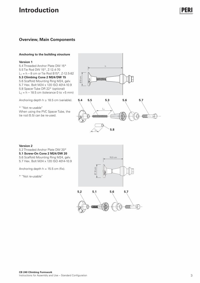
Anchoring to the building structure
Version 1
5.4 Threaded Anchor Plate DW 15*
5.5 Tie Rod DW 15*, Z-12.4-70
L1 = h – 8 cm or Tie Rod B15*, Z-12.5-82
5.3 Climbing Cone 2 M24/DW 15
5.6 Scaffold Mounting Ring M24, galv.
5.7 Hex. Bolt M24 x 120 ISO 4014-10.9
5.8 Spacer Tube DR 22* (optional)
L2 = h – 18.5 cm (tolerance 0 to +5 mm)
Anchoring depth h ≥ 18.5 cm (variable).
* “Not re-usable”
When using the PVC Spacer Tube, the
tie rod (5.5) can be re-used.
Version 2
5.2 Threaded Anchor Plate DW 20*
5.1 Screw-On Cone 2 M24/DW 20
5.6 Scaffold Mounting Ring M24, galv.
5.7 Hex. Bolt M24 x 120 ISO 4014-10.9
Anchoring depth h = 15.5 cm (fix).
* “Not re-usable”
Overview, Main Components
15,5 cm
Ø 1
0 c
m
h
Ø 8
cm
4CB 240 Climbing Formwork
Instructions for Assembly and Use – Standard Configuration
Introduction
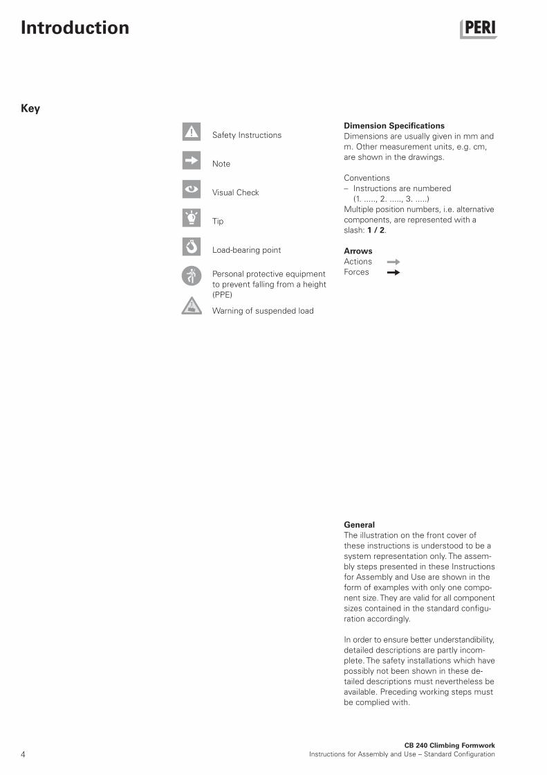
Dimension Specifications
Dimensions are usually given in mm and
m. Other measurement units, e.g. cm,
are shown in the drawings.
Conventions
– Instructions are numbered
(1. ....., 2. ....., 3. .....)
Multiple position numbers, i.e. alternative
components, are represented with a
slash: 1 / 2.
Arrows
Actions
Forces
Key
General
The illustration on the front cover of
these instructions is understood to be a
system representation only. The assem-
bly steps presented in these Instructions
for Assembly and Use are shown in the
form of examples with only one compo-
nent size. They are valid for all component
sizes contained in the standard configu-
ration accordingly.
In order to ensure better understandibility,
detailed descriptions are partly incom-
plete. The safety installations which have
possibly not been shown in these de-
tailed descriptions must nevertheless be
available. Preceding working steps must
be complied with.
Safety Instructions
Visual Check
Load-bearing point
Personal protective equipment
to prevent falling from a height
(PPE)
Warning of suspended load
Note
Tip
5
General
The use in a way not intended, deviating
from the standard configuration or the
intended use according to the Instruc-
tions for Assembly and Use, represents
a misapplication with a potential safety
risk, e.g. risk of falling.
Only PERI original components may be
used. The use of other products and
spare parts is not allowed.
Changes to PERI components are not
permitted.
The working platform can be supple-
mented with:
– formwork carriage, strongbacks and
adjustable braces for accommodating
the VARIO and TRIO formwork sys-
tems.
– a height-adjustable finishing platform
complete with access ladder which is
attached to posts.
– end-to-end guardrails on the working
and finishing platforms in accordance
with respective national guidelines.
– a tension anchor which prevents tip-
ping inwards.
Technical Data
– width of bracket: 2.40 m
– static height: 1.80 m
– retraction distance: 75 cm
– max. formwork height: 5.40 m
Product Description
PERI products have been exclusively
designed for use in the industrial and
commercial sectors by suitably trained
personnel.
The CB 240 climbing formwork system
is normally used as shoring in order to
support anchored wall formwork in ac-
cordance with EN 12812. The formwork
is firmly connected with the climbing
bracket and is moved as a single unit
suspended on a crane. The climbing
formwork can also be used as a working
platform. The working platform for ope-
rating the formwork consists of plan-
king, platform beams and two fixed
climbing brackets. These transfer the
loads deriving from the dead weight, live
loads and prevailing wind loads via the
anchorage and bottom pressure point
into the structure.
Intended Use
Instructions for Use
CB 240 Climbing Formwork
Instructions for Assembly and Use – Standard Configuration
Introduction

6CB 240 Climbing Formwork
Instructions for Assembly and Use – Standard Configuration
Introduction
General
These assembly instructions serve as
basis for the project-related risk assess-
ment and the instructions for the provisi-
on and use of the system by the con-
tractor.
However, they do not replace them.
The contractor must ensure that the
Instructions for Assembly and Use provi-
ded by PERI are available at all times for
the users and that they are also fully un-
derstood.
Safety instructions and permissible
loads must be observed at all times.
For the application and inspection of our
products, the current safety regulations
and guidelines in the respective coun-
tries where they are being used must be
observed at all times.
In order to guarantee the safety against
falling, the contractor must carry out a
site-specific risk assessment based on
these Instructions for Assembly and Use
and the included safety and warning in-
formation during each respective assem-
bly, modification and dismantling proce-
dure, as well as every time the system
is used! Based on the risk assessment,
appropriate measures regarding safety
against falling are to be implemented on
site.
The contractor must ensure that the
required personal protective equipment
required for the assembly, modification
or dismantling is available and used as
intended.
Storage and Transportation
Store and transport components ensu-
ring that no unintentional change in their
position is possible. Detach lifting gear
from the lowered components only if
they are in a stable position and no unin-
tentional change is possible.
Do not drop the components.
Safety Instructions
Safety Instructions
Materials and working areas are to be in-
spected on a regular basis especially be-
fore each use and assembly, and che-
cked for signs of damage as well as sta-
bility and functionality. Damaged
components must be exchanged imme-
diately on site and may no longer be
used.
The contractor has to provide safe wor-
king areas for site personnel which are
to be reached through the provision of
safe access ways. Areas of risk must be
cordoned off and clearly marked.
Safety components are removed only
when they are no longer required.
The contractor must guarantee the sta-
bility during all stages of construction
especially during assembly, modification
and dismantling. He must ensure and
prove that all loads can be safely trans-
ferred.
Any deviations from the standard confi-
guration may only be carried out after a
separate risk assessment has been
done by the contractor (user).
On this basis, appropriate measures for
the working and operational safety as
well as the stability are to be implemen-
ted. Appropriate proof of stability can be
provided by PERI if the risk assessment
and measures deriving from this are
readily available.
Use only suitable load-carrying equip-
ment to move the components as well
as the designated load-bearing points.
During the moving procedure, ensure
that components are picked up and set
down so that unintentional falling over,
falling apart, sliding or rolling is avoided.
When moving pre-assembled units by
crane, always use ropes to guide the
load.
Components provided by the contractor
must conform with the characteristics
required in these Instructions for Assem-
bly and Use as well as with all valid
construction guidelines and standards.
In particular, the following applies if
nothing else is specified:
– Timber components: Strength Class
C24 for Solid Wood according to
EN 338.
– Scaffold tubes: galvanised steel tubes
with minimum dimensions of
Ø 48.3 x 3.2 mm according to
EN 12811-1:2003 4.2.1.2.
– Scaffold tube couplings according to
EN 74.
In the event of unfavourable weather
conditions, e.g.
– poor visibility (fog),
– strong winds,
– snow,
suitable precautions and measures are
to be taken in order to ensure both work
and operational safety as well as stability.
In case of extraordinary events which
could compromise safety, e.g.
– storms,
– earthquakes,
– accidents,
– longer downtimes,
the system must be comprehensively
checked by a qualified person on behalf
of the contractor regarding the working
and operational safety as well as the sta-
bility. The results of the inspection are to
be documented.
The access areas on the jobsite must be
free of obstacles and tripping hazards as
well as being slip-resistant.
For transportation, the surface must
have sufficient load-bearing capacity.
Use original PERI storage and transport
systems, e.g. crate pallets, pallets or
stacking devices.
7
System-Specific
Retract components only when the con-
crete has sufficiently hardened and the
person in charge has given the go-ahead
for striking to take place.
Anchoring is to take place only if the an-
chorage has sufficient concrete
strength.
Inspection of the anchoring and associa-
ted components must be carried out by
the contractor (user).
Enclosure of the platform or mounting
of additional surfaces which are exposed
to the influences of the wind changes
the stability and must therefore be che-
cked. If necessary, additional measures
must be implemented.
The platforms are to be inspected for
signs of damage by authorised person-
nel at regular intervals.
During operating conditions, working
areas at great heights are always to be
secured against falling objects through
the use of suitable construction
measures.
Hatches and openings on accessible
working areas must be kept closed
during working operations.
Concrete residue and other soiling that
could impair or cause the function to fail
must be removed. The platforms are to
be kept clean at all times.
As a result of the moving procedure,
falling edges are formed between the
platforms. Corresponding areas of risk
are to be secured.
In case the access hatches are blocked
when retracting the formwork as well as
during the entire moving procedure,
ensure that site personnel can still use
the emergency escape route.
Site personnel, construction materials or
tools may not be transported with the
crane during moving operations. Excep-
tions to this can be determined through
the operational working and assembly
instructions.
Safety Instructions
Introduction
CB 240 Climbing Formwork
Instructions for Assembly and Use – Standard Configuration
– CB 240 Dimensioning Information
– CB 240 Climbing scaffold type test
– CB 240 and CB 160 Climbing System Brochures
– Instructions for Use for the Crane Splice 24
– Instructions for Use: MAXIMO Lifting Hook
– PERI design tables
Additional Technical Documentation
8CB 240 Climbing Formwork
Instructions for Assembly and Use – Standard Configuration
Introduction
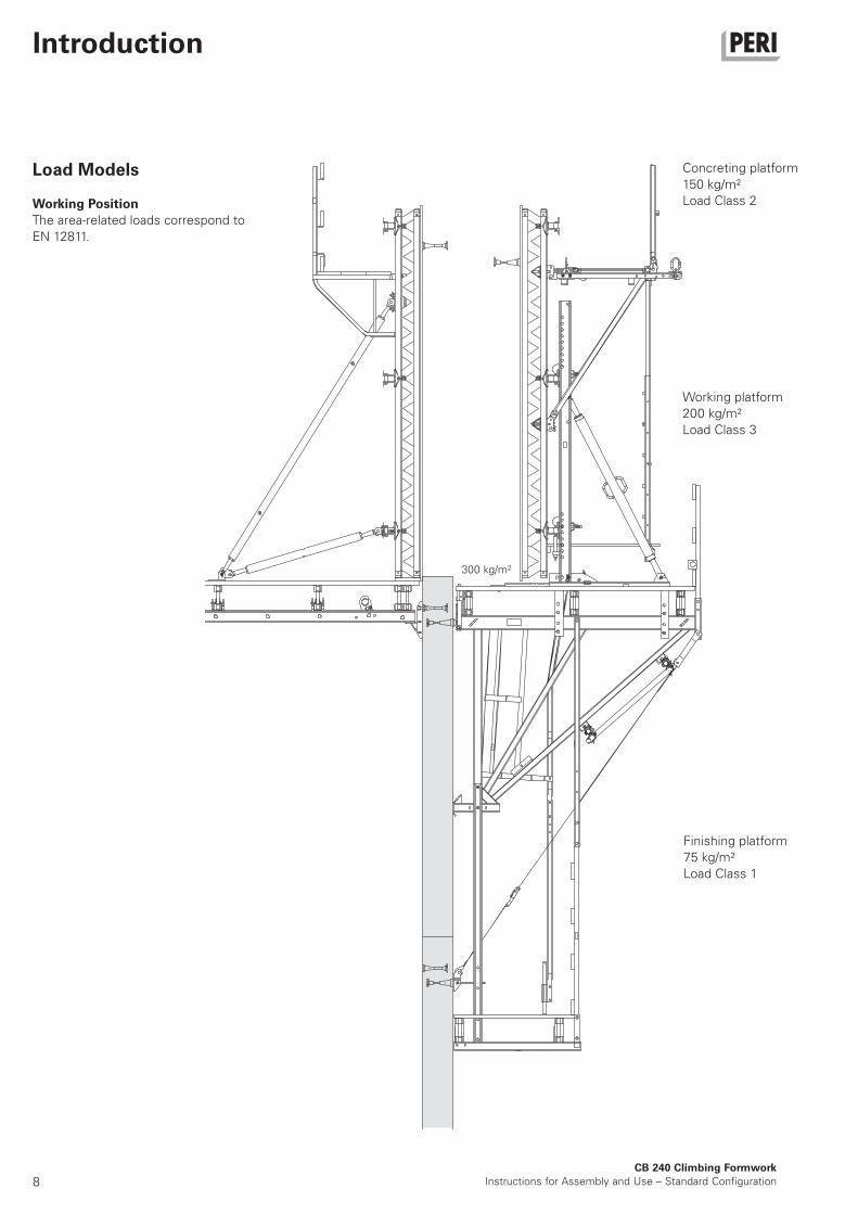
Load Models
Working Position
The area-related loads correspond to
EN 12811.
Concreting platform
150 kg/m²
Load Class 2
Working platform
200 kg/m²
Load Class 3
Finishing platform
75 kg/m²
Load Class 1
300 kg/m2
9CB 240 Climbing Formwork
Instructions for Assembly and Use – Standard Configuration
Introduction
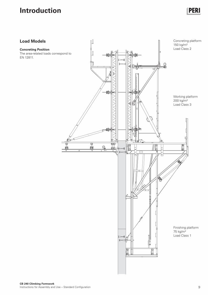
Finishing platform
75 kg/m²
Load Class 1
Concreting platform
150 kg/m²
Load Class 2
Working platform
200 kg/m²
Load Class 3
Load Models
Concreting Position
The area-related loads correspond to
EN 12811.
10
Introduction
CB 240 Climbing Formwork
Instructions for Assembly and Use – Standard Configuration
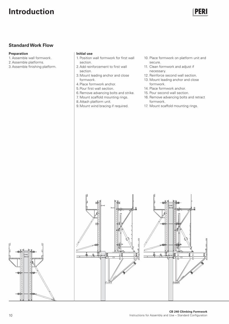
Preparation
1. Assemble wall formwork.
2. Assemble platforms.
3. Assemble finishing platform.
Standard Work Flow
10. Place formwork on platform unit and
secure.
11. Clean formwork and adjust if
necessary.
12. Reinforce second wall section.
13. Mount leading anchor and close
formwork.
14. Place formwork anchor.
15. Pour second wall section.
16. Remove advancing bolts and retract
formwork.
17. Mount scaffold mounting rings.
Initial use
1. Position wall formwork for first wall
section.
2. Add reinforcement to first wall
section.
3. Mount leading anchor and close
formwork.
4. Place formwork anchor.
5. Pour first wall section.
6. Remove advancing bolts and strike.
7. Mount scaffold mounting rings.
8. Attach platform unit.
9. Mount wind bracing if required.
11
Introduction
CB 240 Climbing Formwork
Instructions for Assembly and Use – Standard Configuration
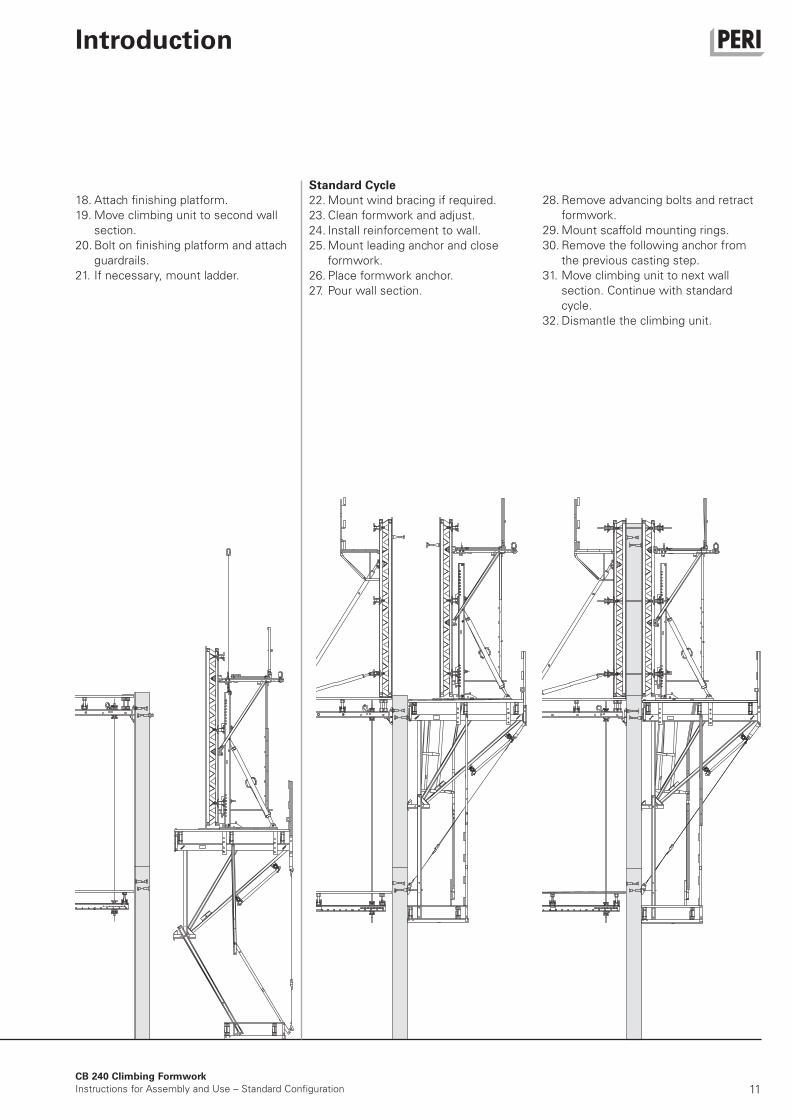
28. Remove advancing bolts and retract
formwork.
29. Mount scaffold mounting rings.
30. Remove the following anchor from
the previous casting step.
31. Move climbing unit to next wall
section. Continue with standard
cycle.
32. Dismantle the climbing unit.
18. Attach finishing platform.
19. Move climbing unit to second wall
section.
20. Bolt on finishing platform and attach
guardrails.
21. If necessary, mount ladder.
Standard Cycle
22. Mount wind bracing if required.
23. Clean formwork and adjust.
24. Install reinforcement to wall.
25. Mount leading anchor and close
formwork.
26. Place formwork anchor.
27. Pour wall section.
12CB 240 Climbing Formwork
Instructions for Assembly and Use – Standard Configuration
A1 Assembly of the CB 240 Platform
0.3
Fig. A1.03
83 mm 80 mm
24
0
2,398 m120 mm
82 mm 82 mm
C Fig. A1.02
Fig. A1.01
0.5
0.2
0.2
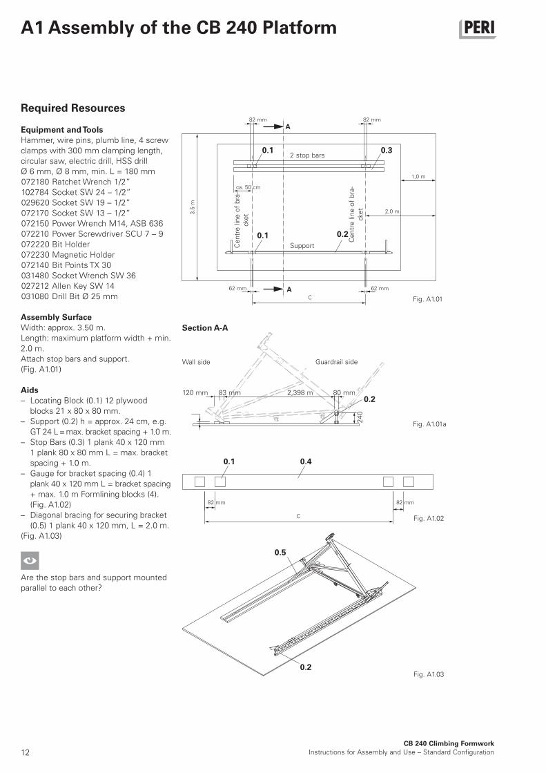
Required Resources
Equipment and Tools
Hammer, wire pins, plumb line, 4 screw
clamps with 300 mm clamping length,
circular saw, electric drill, HSS drill
Ø 6 mm, Ø 8 mm, min. L = 180 mm
072180 Ratchet Wrench 1/2”
102784 Socket SW 24 – 1/2”
029620 Socket SW 19 – 1/2”
072170 Socket SW 13 – 1/2”
072150 Power Wrench M14, ASB 636
072210 Power Screwdriver SCU 7 – 9
072220 Bit Holder
072230 Magnetic Holder
072140 Bit Points TX 30
031480 Socket Wrench SW 36
027212 Allen Key SW 14
031080 Drill Bit Ø 25 mm
Assembly Surface
Width: approx. 3.50 m.
Length: maximum platform width + min.
2.0 m.
Attach stop bars and support.
(Fig. A1.01)
Aids
– Locating Block (0.1) 12 plywood
blocks 21 x 80 x 80 mm.
– Support (0.2) h = approx. 24 cm, e.g.
GT 24 L = max. bracket spacing + 1.0 m.
– Stop Bars (0.3) 1 plank 40 x 120 mm
1 plank 80 x 80 mm L = max. bracket
spacing + 1.0 m.
– Gauge for bracket spacing (0.4) 1
plank 40 x 120 mm L = bracket spacing
+ max. 1.0 m Formlining blocks (4).
(Fig. A1.02)
– Diagonal bracing for securing bracket
(0.5) 1 plank 40 x 120 mm, L = 2.0 m.
(Fig. A1.03)
Are the stop bars and support mounted
parallel to each other?
82 mm 82 mm
1,0 m
2,0 m3,5
m
62 mm 62 mm
C
ca. 50 cm
2 stop bars
SupportCe
ntr
e lin
e o
f b
ra-
cke
t
Ce
ntr
e lin
e o
f b
ra-
cke
tWall side
Section A-A
Guardrail side
A
A
Fig. A1.01a
0.2
0.1
0.1
0.1 0.4
13CB 240 Climbing Formwork
Instructions for Assembly and Use – Standard Configuration
A1 Assembly of the CB 240 Platform
6. Lift in second bracket and align using
bracket spacing gauge. Fix gauge
using screw clamps. Check bracket
spacing. (Fig. A1.07)
Fig. A1.04
Fig. A1.05
Fig. A1.06
Fig. A1.07
Fig. A1.08
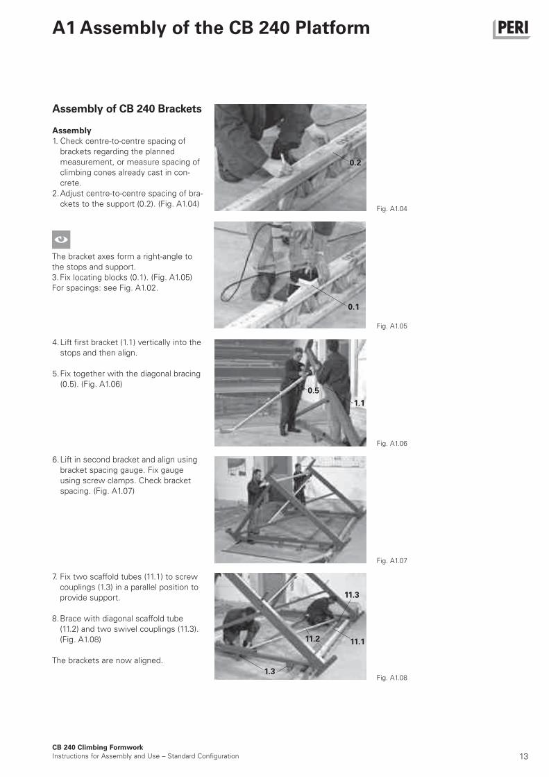
Assembly of CB 240 Brackets
Assembly
1. Check centre-to-centre spacing of
brackets regarding the planned
measurement, or measure spacing of
climbing cones already cast in con-
crete.
2. Adjust centre-to-centre spacing of bra-
ckets to the support (0.2). (Fig. A1.04)
The bracket axes form a right-angle to
the stops and support.
3. Fix locating blocks (0.1). (Fig. A1.05)
For spacings: see Fig. A1.02.
4. Lift first bracket (1.1) vertically into the
stops and then align.
5. Fix together with the diagonal bracing
(0.5). (Fig. A1.06)
7. Fix two scaffold tubes (11.1) to screw
couplings (1.3) in a parallel position to
provide support.
8. Brace with diagonal scaffold tube
(11.2) and two swivel couplings (11.3).
(Fig. A1.08)
The brackets are now aligned.
0.2
0.1
0.5
1.1
1.3
11.1
11.3
11.2
14CB 240 Climbing Formwork
Instructions for Assembly and Use – Standard Configuration
A1 Assembly of the CB 240 Platforms
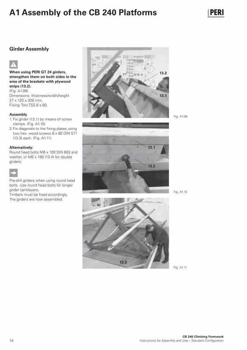
Girder Assembly
When using PERI GT 24 girders,
strengthen them on both sides in the
area of the brackets with plywood
strips (13.2).
(Fig. A1.09)
Dimensions: thickness/width/height
27 x 120 x 300 mm.
Fixing: Torx TSS 6 x 60.
Assembly
1. Fix girder (13.1) by means of screw
clamps. (Fig. A1.10)
2. Fix diagonals to the fixing plates using
two hex. wood screws 6 x 80 DIN 571
(13.3) each. (Fig. A1.11)
Alternatively:
Round head bolts M6 x 100 DIN 603 and
washer, or M6 x 180 (13.4) for double
girders.
Pre-drill girders when using round head
bolts. Use round head bolts for longer
girder cantilevers.
Timbers must be fixed accordingly.
The girders are now assembled.
Fig. A1.09
Fig. A1.10
Fig. A1.11
13.2
13.1
13.1
13.2
13.3
15
13.6
13.3
13.2
13.7
13.3
13.6
13.4
13.213.2
13.4
CB 240 Climbing Formwork
Instructions for Assembly and Use – Standard Configuration
A1 Assembly of the CB 240 Platform
Fig. A1.12 Fig. A1.13
Fig. A1.14 Fig. A1.15
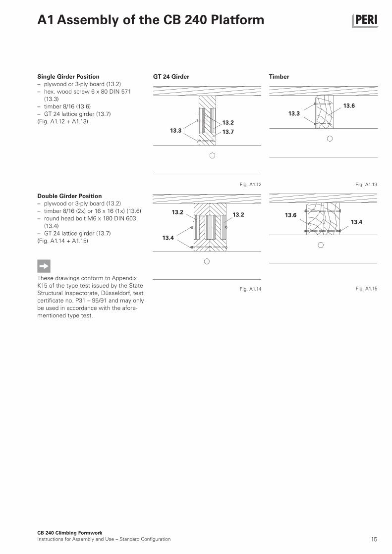
Double Girder Position
– plywood or 3-ply board (13.2)
– timber 8/16 (2x) or 16 x 16 (1x) (13.6)
– round head bolt M6 x 180 DIN 603
(13.4)
– GT 24 lattice girder (13.7)
(Fig. A1.14 + A1.15)
These drawings conform to Appendix
K15 of the type test issued by the State
Structural Inspectorate, Düsseldorf, test
certificate no. P31 – 95/91 and may only
be used in accordance with the afore-
mentioned type test.
Single Girder Position
– plywood or 3-ply board (13.2)
– hex. wood screw 6 x 80 DIN 571
(13.3)
– timber 8/16 (13.6)
– GT 24 lattice girder (13.7)
(Fig. A1.12 + A1.13)
GT 24 Girder Timber
16CB 240 Climbing Formwork
Instructions for Assembly and Use – Standard Configuration
A1 Assembly of the CB 240 Platforms
2.2
2.4
2.4
2.4 2.3, 2.4
2.3, 2.4 2.3, 2.4
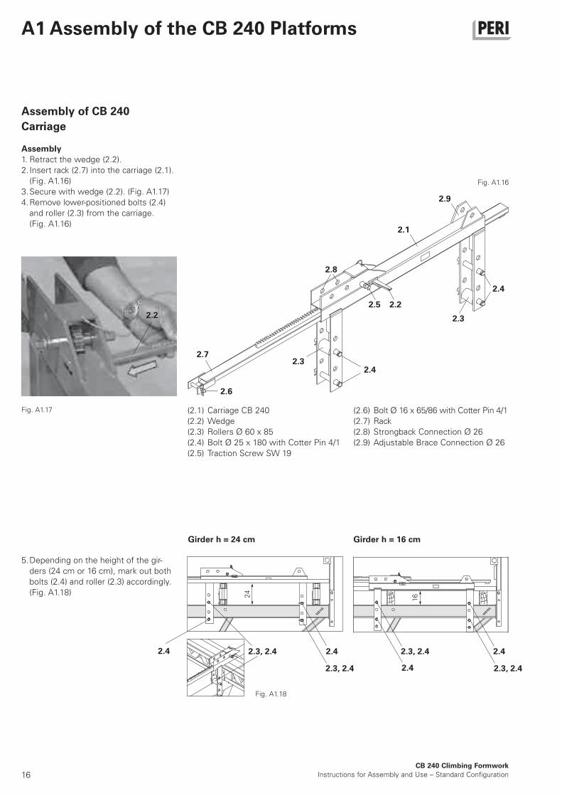
Assembly of CB 240
Carriage
Assembly
1. Retract the wedge (2.2).
2. Insert rack (2.7) into the carriage (2.1).
(Fig. A1.16)
3. Secure with wedge (2.2). (Fig. A1.17)
4. Remove lower-positioned bolts (2.4)
and roller (2.3) from the carriage.
(Fig. A1.16)
Fig. A1.16
Fig. A1.17
Fig. A1.18
5. Depending on the height of the gir-
ders (24 cm or 16 cm), mark out both
bolts (2.4) and roller (2.3) accordingly.
(Fig. A1.18) 24
16
(2.1) Carriage CB 240
(2.2) Wedge
(2.3) Rollers Ø 60 x 85
(2.4) Bolt Ø 25 x 180 with Cotter Pin 4/1
(2.5) Traction Screw SW 19
2.7
2.8
2.9
2.1
2.6
2.32.4
2.22.5
2.42.3, 2.4
(2.6) Bolt Ø 16 x 65/86 with Cotter Pin 4/1
(2.7) Rack
(2.8) Strongback Connection Ø 26
(2.9) Adjustable Brace Connection Ø 26
Girder h = 24 cm Girder h = 16 cm
2.3
2.4
17CB 240 Climbing Formwork
Instructions for Assembly and Use – Standard Configuration
A1 Assembly of the CB 240 Platforms
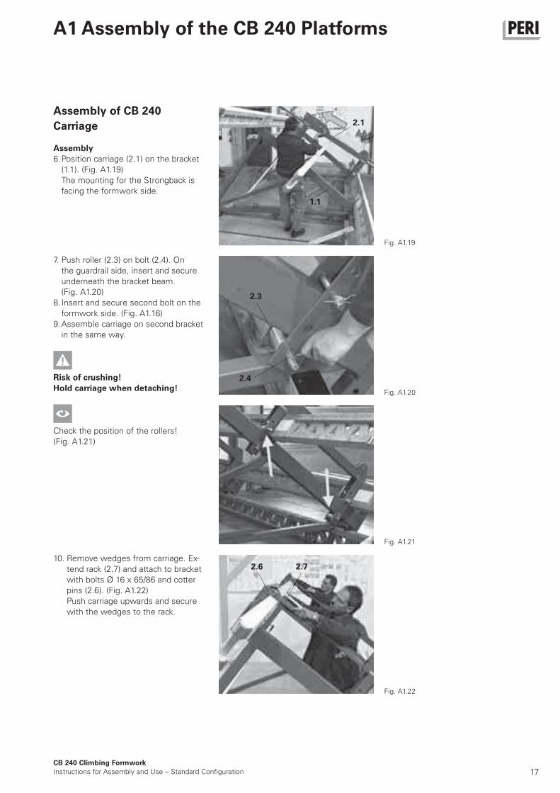
Assembly of CB 240
Carriage
Assembly
6. Position carriage (2.1) on the bracket
(1.1). (Fig. A1.19)
The mounting for the Strongback is
facing the formwork side.
7. Push roller (2.3) on bolt (2.4). On
the guardrail side, insert and secure
underneath the bracket beam.
(Fig. A1.20)
8. Insert and secure second bolt on the
formwork side. (Fig. A1.16)
9. Assemble carriage on second bracket
in the same way.
Risk of crushing!
Hold carriage when detaching!
Check the position of the rollers!
(Fig. A1.21)
10. Remove wedges from carriage. Ex-
tend rack (2.7) and attach to bracket
with bolts Ø 16 x 65/86 and cotter
pins (2.6). (Fig. A1.22)
Push carriage upwards and secure
with the wedges to the rack.
Fig. A1.19
Fig. A1.20
Fig. A1.21
Fig. A1.22
2.1
1.1
2.4
2.72.6
2.3
18
13.513.1
81 mm
CB 240 Climbing Formwork
Instructions for Assembly and Use – Standard Configuration
A1 Assembly of the CB 240 Platforms
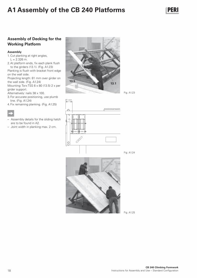
Assembly of Decking for the
Working Platform
Assembly
1. Cut planking at right angles,
L = 2.326 m.
2. At platform ends, fix each plank flush
to the girders (13.1). (Fig. A1.23)
Planking is flush with bracket front edge
on the wall side.
Projecting length: 81 mm over girder on
the wall side. (Fig. A1.24)
Mounting: Torx TSS 6 x 80 (13.5) 2 x per
girder support.
Alternatively: nails 38 x 100.
3. For accurate positioning, use plumb
line. (Fig. A1.24)
4. Fix remaining planking. (Fig. A1.25)
– Assembly details for the sliding hatch
are to be found in A2.
– Joint width in planking max. 2 cm.
Fig. A1.23
Fig. A1.24
Fig. A1.25
19
8 cm
10 c
m
≥10
cm
≥10
cm
13
cm
1.5
CB 240 Climbing Formwork
Instructions for Assembly and Use – Standard Configuration
A1 Assembly of the CB 240 Platforms
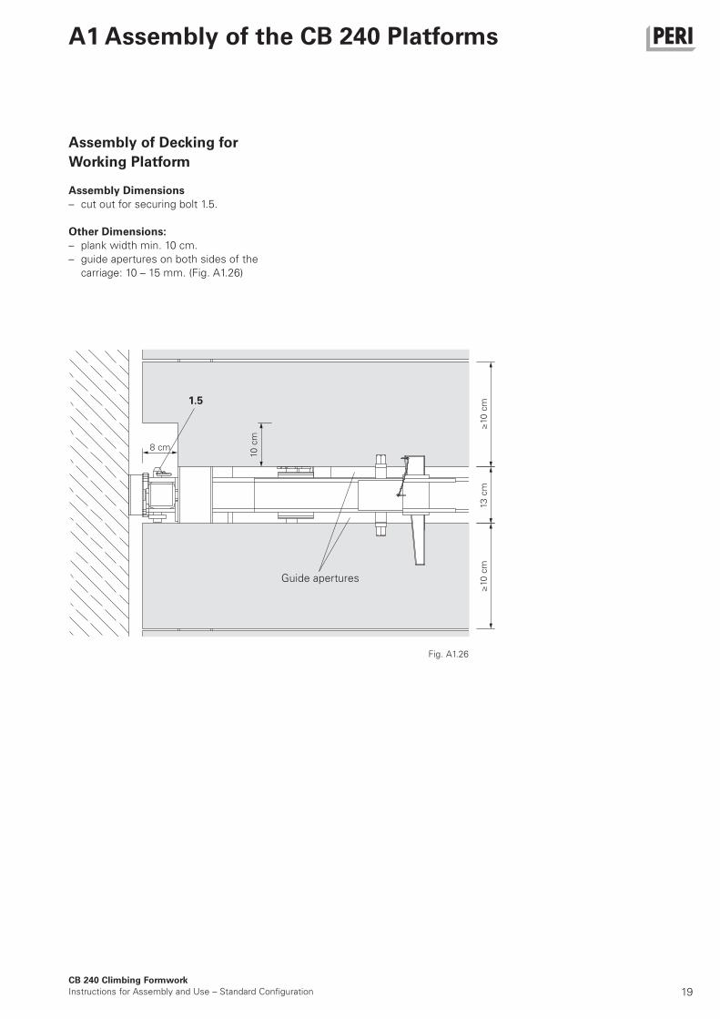
Assembly of Decking for
Working Platform
Assembly Dimensions
– cut out for securing bolt 1.5.
Other Dimensions:
– plank width min. 10 cm.
– guide apertures on both sides of the
carriage: 10 – 15 mm. (Fig. A1.26)
Fig. A1.26
Guide apertures

20CB 240 Climbing Formwork
Instructions for Assembly and Use – Standard Configuration
A1 Assembly of the CB 240 Platforms
Assembly of Guardrails
Guardrail Post CB
1. Loosen bolt (1.6), SW 24, and take out
guardrail post (1.2). (Fig. A1.27)
2. Insert Guardrail Post into the holder.
The Crane Eye (1.4) is pointing in the
direction of the platform. Fix with bolt
(1.6), spring washer and nut.
(Fig. A1.28)
3. Proceed in the same way with the
second Guardrail Post.
Fig. A1.27
24
cm
16
cm
Fig. A1.28
Fig. A1.29
Depending on the height of the girders,
use the following:
24 cm = top drilled hole a
16 cm = bottom drilled hole b.
(Fig. A1.29)
a
b
Assembly of Guardrails
1. Cut guardrail boards (12.1) to match
platform width.
2. Attach guardrail boards to Guardrail
Post with screw clamps. Height:
50 cm and 100 cm above planking.
(Fig. A1.30a)
3. Fix guardrail boards and toe board
(12.2) with round head bolts M8 x 100
DIN 603 (12.5).
Pre-drill boards!
Guardrail boards flush with the planking.
Guardrail Post Extension CB (12.9)
It serves to extend the CB Guardrail
Post by 50 cm. Guardrail board and/or
scaffold tube connection. (Fig. A1.30b)
Fig. A1.30a
Fig. A1.30b
12.5
12.9
12.6
1.6
12.5
12.2
12.1
21CB 240 Climbing Formwork
Instructions for Assembly and Use – Standard Configuration
A1 Assembly of the CB 240 Platforms
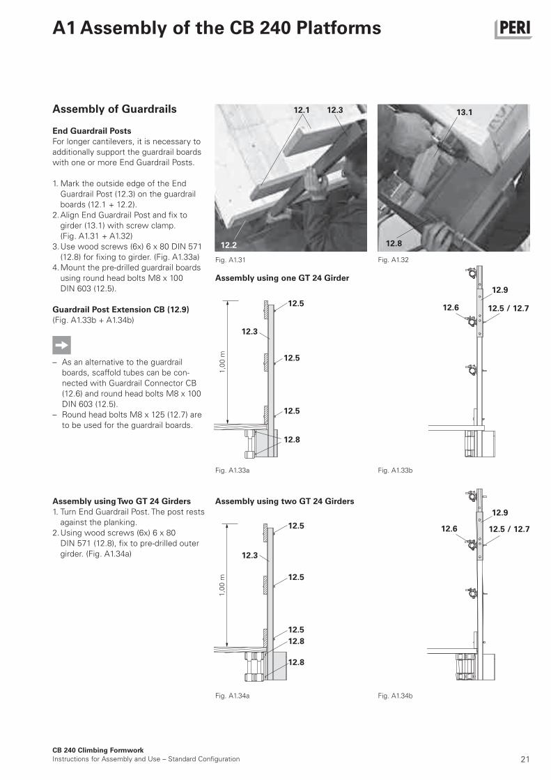
13.1Assembly of Guardrails
End Guardrail Posts
For longer cantilevers, it is necessary to
additionally support the guardrail boards
with one or more End Guardrail Posts.
1. Mark the outside edge of the End
Guardrail Post (12.3) on the guardrail
boards (12.1 + 12.2).
2. Align End Guardrail Post and fix to
girder (13.1) with screw clamp.
(Fig. A1.31 + A1.32)
3. Use wood screws (6x) 6 x 80 DIN 571
(12.8) for fixing to girder. (Fig. A1.33a)
4. Mount the pre-drilled guardrail boards
using round head bolts M8 x 100
DIN 603 (12.5).
Guardrail Post Extension CB (12.9)
(Fig. A1.33b + A1.34b)
– As an alternative to the guardrail
boards, scaffold tubes can be con-
nected with Guardrail Connector CB
(12.6) and round head bolts M8 x 100
DIN 603 (12.5).
– Round head bolts M8 x 125 (12.7) are
to be used for the guardrail boards.
Assembly using Two GT 24 Girders
1. Turn End Guardrail Post. The post rests
against the planking.
2. Using wood screws (6x) 6 x 80
DIN 571 (12.8), fix to pre-drilled outer
girder. (Fig. A1.34a)
Fig. A1.31 Fig. A1.32
Fig. A1.33a Fig. A1.33b
Fig. A1.34bFig. A1.34a
Assembly using one GT 24 Girder
Assembly using two GT 24 Girders
12.3
12.5
12.5
12.5
12.8
12.8
12.3
12.5
12.5 / 12.7
12.5 / 12.7
12.6
12.6
12.5
12.5
12.8
12.1 12.3
12.2 12.8
1,0
0 m
1,0
0 m
12.9
12.9
22
12.5 / 12.712.6
CB 240 Climbing Formwork
Instructions for Assembly and Use – Standard Configuration
A2 Other Assembly Work
Fig. A2.01
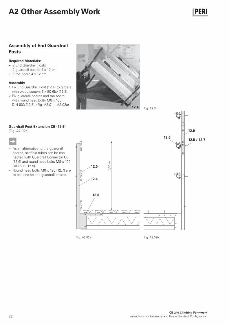
Assembly of End Guardrail
Posts
Required Materials:
– 2 End Guardrail Posts
– 2 guardrail boards 4 x 12 cm
– 1 toe board 4 x 12 cm
Assembly
1. Fix End Guardrail Post (12.4) to girders
with wood screws 6 x 80 (5x) (12.8).
2. Fix guardrail boards and toe board
with round head bolts M8 x 100
DIN 603 (12.5). (Fig. A2.01 + A2.02a)
Guardrail Post Extension CB (12.9)
(Fig. A2.02b)
– As an alternative to the guardrail
boards, scaffold tubes can be con-
nected with Guardrail Connector CB
(12.6) and round head bolts M8 x 100
DIN 603 (12.5).
– Round head bolts M8 x 125 (12.7) are
to be used for the guardrail boards.
Fig. A2.02a Fig. A2.02b
12.4
12.8
12.5
12.4
1,0
0 m
12.9
23CB 240 Climbing Formwork
Instructions for Assembly and Use – Standard Configuration
A2 Other Assembly Work
14.9 14.9
14.8
13B
14.1
14.2
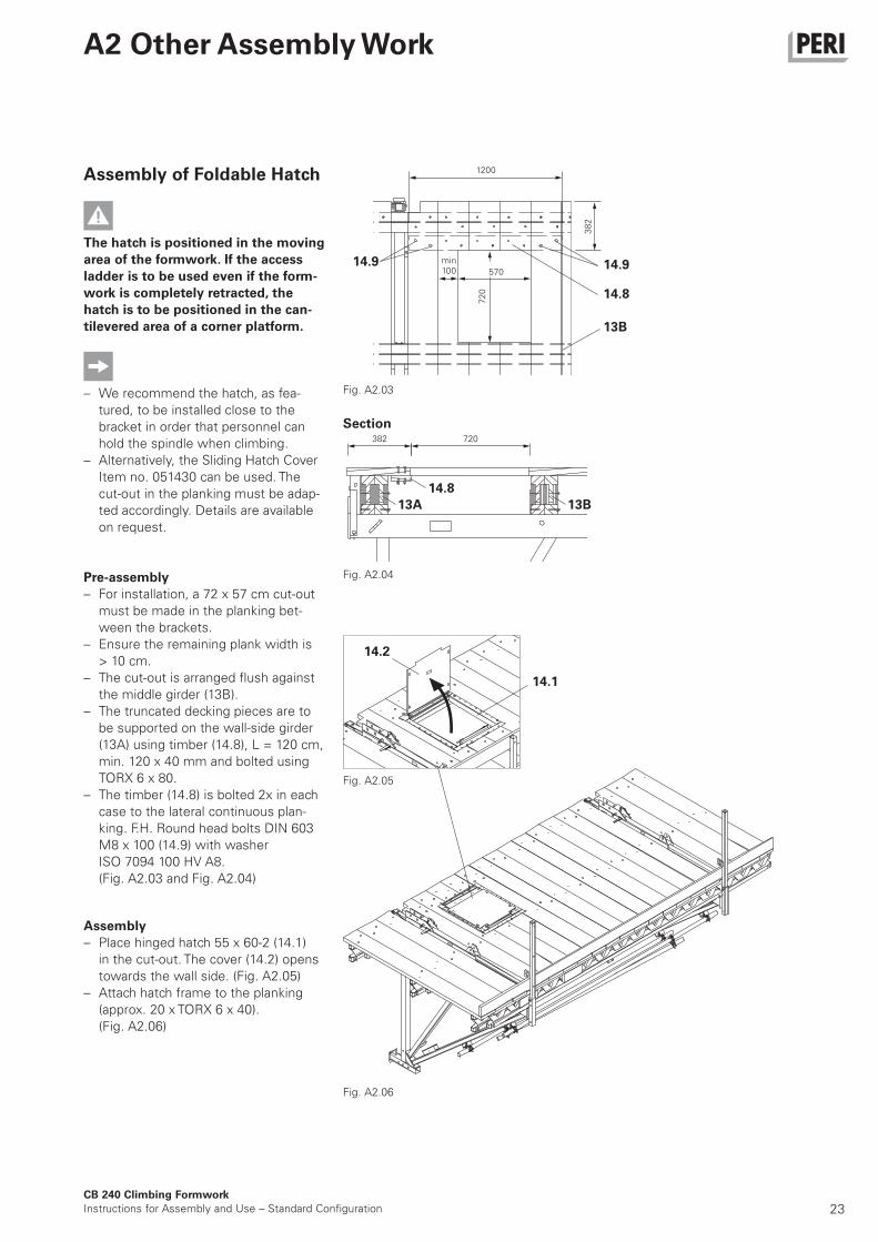
Assembly of Foldable Hatch
The hatch is positioned in the moving
area of the formwork. If the access
ladder is to be used even if the form-
work is completely retracted, the
hatch is to be positioned in the can-
tilevered area of a corner platform.
– We recommend the hatch, as fea-
tured, to be installed close to the
bracket in order that personnel can
hold the spindle when climbing.
– Alternatively, the Sliding Hatch Cover
Item no. 051430 can be used. The
cut-out in the planking must be adap-
ted accordingly. Details are available
on request.
Pre-assembly
– For installation, a 72 x 57 cm cut-out
must be made in the planking bet-
ween the brackets.
– Ensure the remaining plank width is
> 10 cm.
– The cut-out is arranged flush against
the middle girder (13B).
– The truncated decking pieces are to
be supported on the wall-side girder
(13A) using timber (14.8), L = 120 cm,
min. 120 x 40 mm and bolted using
TORX 6 x 80.
– The timber (14.8) is bolted 2x in each
case to the lateral continuous plan-
king. F.H. Round head bolts DIN 603
M8 x 100 (14.9) with washer
ISO 7094 100 HV A8.
(Fig. A2.03 and Fig. A2.04)
Assembly
– Place hinged hatch 55 x 60-2 (14.1)
in the cut-out. The cover (14.2) opens
towards the wall side. (Fig. A2.05)
– Attach hatch frame to the planking
(approx. 20 x TORX 6 x 40).
(Fig. A2.06)
Fig. A2.03
1200
Fig. A2.06
Fig. A2.05
Section
Fig. A2.04
570
382 720
72
0
38
2
min100
14.8
13A 13B
24
13.2
13.1
14 mm 13.5
13.5
8.1
CB 240 Climbing Formwork
Instructions for Assembly and Use – Standard Configuration
A2 Other Assembly Work
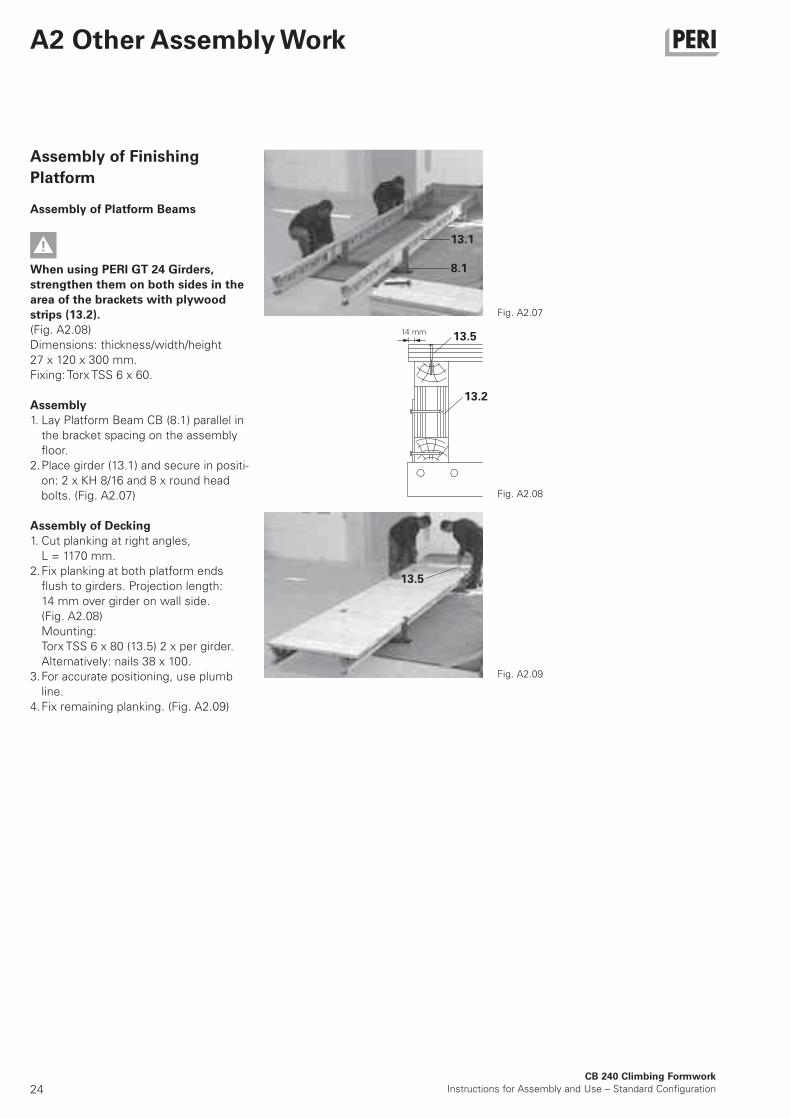
Assembly of Finishing
Platform
Assembly of Platform Beams
When using PERI GT 24 Girders,
strengthen them on both sides in the
area of the brackets with plywood
strips (13.2).
(Fig. A2.08)
Dimensions: thickness/width/height
27 x 120 x 300 mm.
Fixing: Torx TSS 6 x 60.
Assembly
1. Lay Platform Beam CB (8.1) parallel in
the bracket spacing on the assembly
floor.
2. Place girder (13.1) and secure in positi-
on: 2 x KH 8/16 and 8 x round head
bolts. (Fig. A2.07)
Assembly of Decking
1. Cut planking at right angles,
L = 1170 mm.
2. Fix planking at both platform ends
flush to girders. Projection length:
14 mm over girder on wall side.
(Fig. A2.08)
Mounting:
Torx TSS 6 x 80 (13.5) 2 x per girder.
Alternatively: nails 38 x 100.
3. For accurate positioning, use plumb
line.
4. Fix remaining planking. (Fig. A2.09)
Fig. A2.07
Fig. A2.09
Fig. A2.08
25
1,17 m
14 mm
18 cm18 cm 10 cm
21
cm
21
cm
≥ 1
0 c
m
9.1 8.3 8.1
CB 240 Climbing Formwork
Instructions for Assembly and Use – Standard Configuration
A2 Other Assembly Work
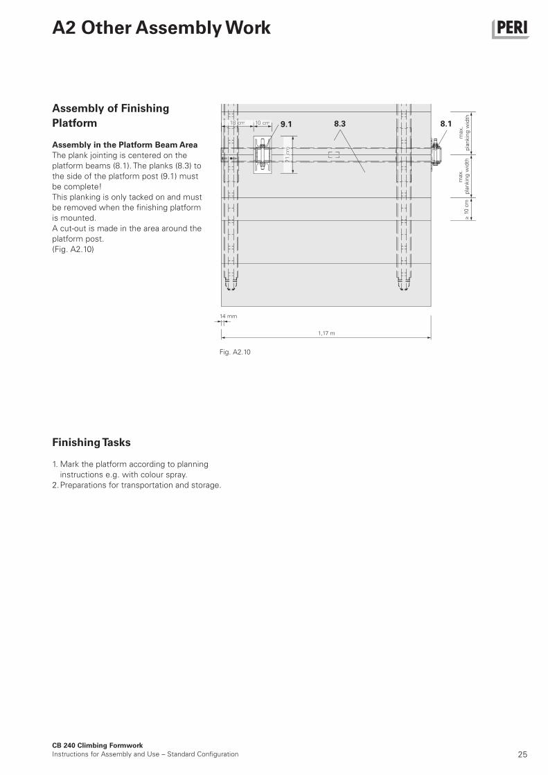
Assembly of Finishing
Platform
Assembly in the Platform Beam Area
The plank jointing is centered on the
platform beams (8.1). The planks (8.3) to
the side of the platform post (9.1) must
be complete!
This planking is only tacked on and must
be removed when the fi nishing platform
is mounted.
A cut-out is made in the area around the
platform post.
(Fig. A2.10)
Finishing Tasks
1. Mark the platform according to planning
instructions e.g. with colour spray.
2. Preparations for transportation and storage.
Fig. A2.10
max.
pla
nkin
g w
idth
max.
pla
nkin
g w
idth
26CB 240 Climbing Formwork
Instructions for Assembly and Use – Standard Configuration
B1 Work on the Construction Site
Fig. B1.01
Fig. B1.03
Top view
horizontal offset
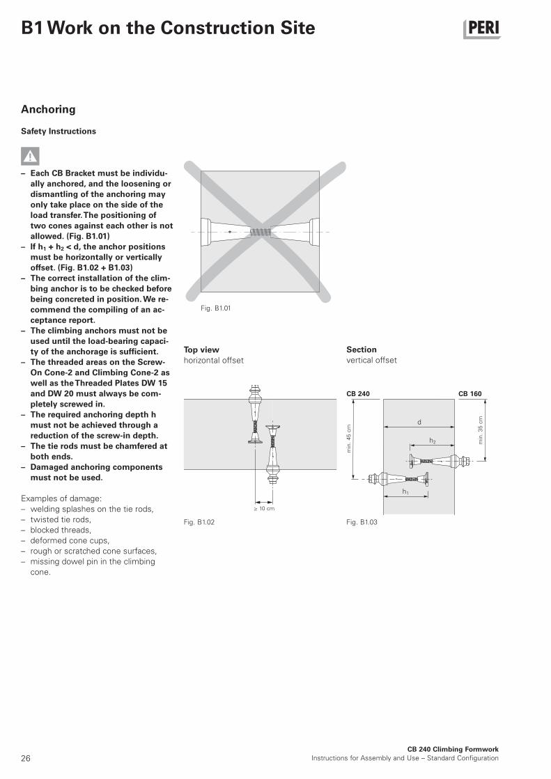
Anchoring
Safety Instructions
– Each CB Bracket must be individu-
ally anchored, and the loosening or
dismantling of the anchoring may
only take place on the side of the
load transfer. The positioning of
two cones against each other is not
allowed. (Fig. B1.01)
– If h1 + h2 < d, the anchor positions
must be horizontally or vertically
offset. (Fig. B1.02 + B1.03)
– The correct installation of the clim-
bing anchor is to be checked before
being concreted in position. We re-
commend the compiling of an ac-
ceptance report.
– The climbing anchors must not be
used until the load-bearing capaci-
ty of the anchorage is sufficient.
– The threaded areas on the Screw-
On Cone-2 and Climbing Cone-2 as
well as the Threaded Plates DW 15
and DW 20 must always be com-
pletely screwed in.
– The required anchoring depth h
must not be achieved through a
r eduction of the screw-in depth.
– The tie rods must be chamfered at
both ends.
– Damaged anchoring components
must not be used.
Examples of damage:
– welding splashes on the tie rods,
– twisted tie rods,
– blocked threads,
– deformed cone cups,
– rough or scratched cone surfaces,
– missing dowel pin in the climbing
cone.
Section
vertical offset
CB 240 CB 160
min
. 4
5 c
m
≥ 10 cm
min
. 3
5 c
m
Fig. B1.02
h2
d
h1
27
CB 240 Climbing Formwork
Instructions for Assembly and Use – Standard Configuration
B1 Work on the Construction Site
5.2 5.1
5.4 5.5 5.35.8
Fig. B1.04
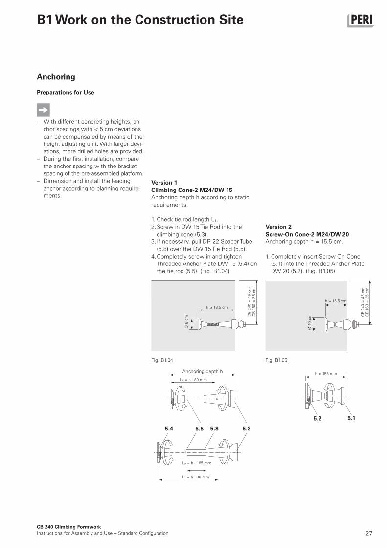
Version 2
Screw-On Cone-2 M24/DW 20
Anchoring depth h = 15.5 cm.
1. Completely insert Screw-On Cone
(5.1) into the Threaded Anchor Plate
DW 20 (5.2). (Fig. B1.05)
Version 1
Climbing Cone-2 M24/DW 15
Anchoring depth h according to static
requirements.
1. Check tie rod length L1.
2. Screw in DW 15 Tie Rod into the
climbing cone (5.3).
3. If necessary, pull DR 22 Spacer Tube
(5.8) over the DW 15 Tie Rod (5.5).
4. Completely screw in and tighten
Threaded Anchor Plate DW 15 (5.4) on
the tie rod (5.5). (Fig. B1.04)
Ø 1
0 c
m
h = 15,5 cm
h ≥ 18,5 cm
Ø 8
cm
Anchoring depth h
CB
24
0 =
45
cm
CB
16
0 =
35
cm
Anchoring
Preparations for Use
– With different concreting heights, an-
chor spacings with < 5 cm deviations
can be compensated by means of the
height adjusting unit. With larger devi-
ations, more drilled holes are provided.
– During the first installation, compare
the anchor spacing with the bracket
spacing of the pre-assembled platform.
– Dimension and install the leading
anchor according to planning require-
ments.
h = 155 mm
L1 = h - 80 mm
L2 = h - 185 mm
L1 = h - 80 mm
CB
24
0 =
45
cm
CB
16
0 =
35
cm
Fig. B1.05
28CB 240 Climbing Formwork
Instructions for Assembly and Use – Standard Configuration
B1 Work on the Construction Site
5.12
5.11
5.2
5
5.115.12
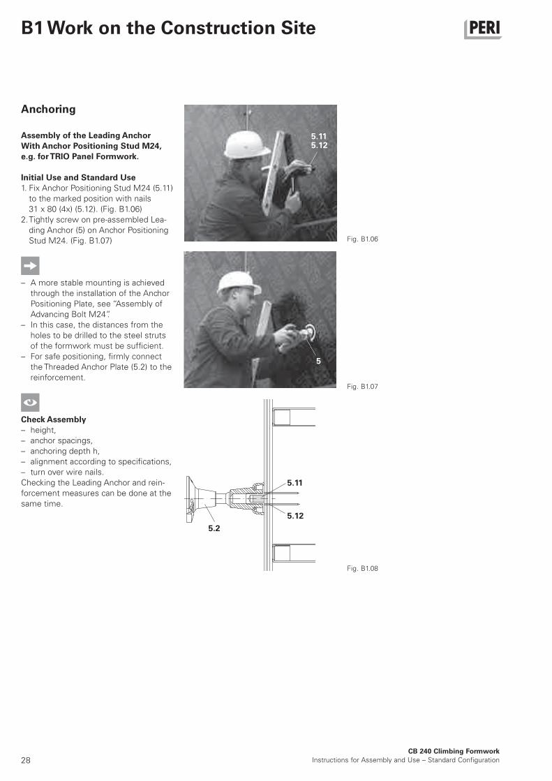
Anchoring
Assembly of the Leading Anchor
With Anchor Positioning Stud M24,
e.g. for TRIO Panel Formwork.
Initial Use and Standard Use
1. Fix Anchor Positioning Stud M24 (5.11)
to the marked position with nails
31 x 80 (4x) (5.12). (Fig. B1.06)
2. Tightly screw on pre-assembled Lea-
ding Anchor (5) on Anchor Positioning
Stud M24. (Fig. B1.07)
– A more stable mounting is achieved
through the installation of the Anchor
Positioning Plate, see “Assembly of
Advancing Bolt M24”.
– In this case, the distances from the
holes to be drilled to the steel struts
of the formwork must be sufficient.
– For safe positioning, firmly connect
the Threaded Anchor Plate (5.2) to the
reinforcement.
Check Assembly
– height,
– anchor spacings,
– anchoring depth h,
– alignment according to specifications,
– turn over wire nails.
Checking the Leading Anchor and rein-
forcement measures can be done at the
same time.
Fig. B1.06
Fig. B1.07
Fig. B1.08
29CB 240 Climbing Formwork
Instructions for Assembly and Use – Standard Configuration
B1 Work on the Construction Site
5.10
3 cm
4 c
m
5
5.10
5.9
5.13
3 cm
4 c
m
5.4
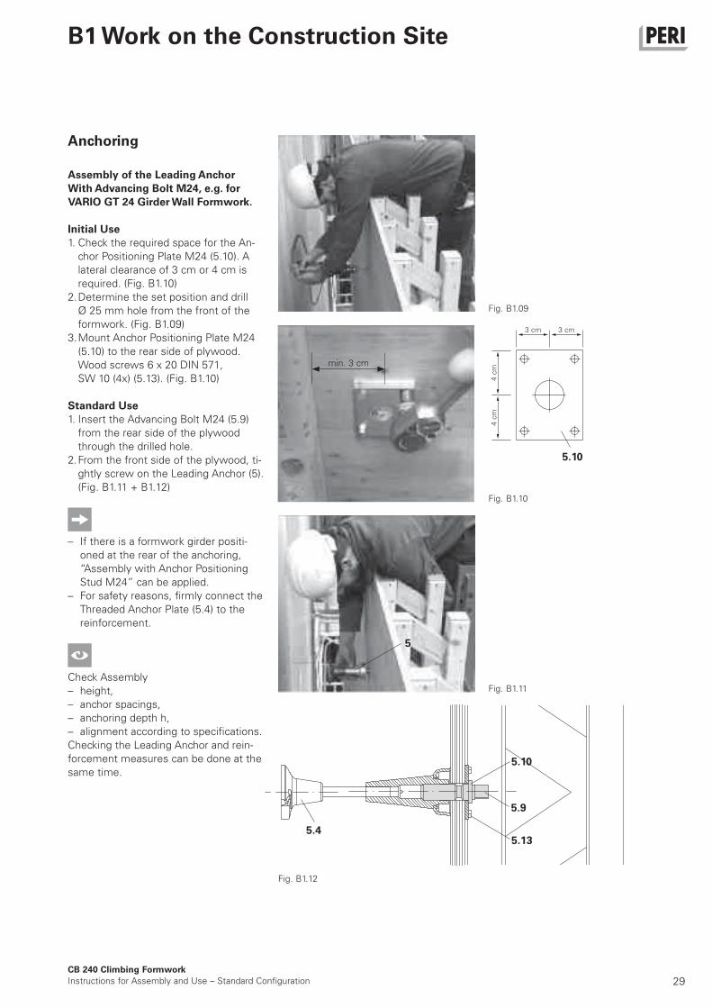
Anchoring
Assembly of the Leading Anchor
With Advancing Bolt M24, e.g. for
VARIO GT 24 Girder Wall Formwork.
Initial Use
1. Check the required space for the An-
chor Positioning Plate M24 (5.10). A
lateral clearance of 3 cm or 4 cm is
required. (Fig. B1.10)
2. Determine the set position and drill
Ø 25 mm hole from the front of the
formwork. (Fig. B1.09)
3. Mount Anchor Positioning Plate M24
(5.10) to the rear side of plywood.
Wood screws 6 x 20 DIN 571,
SW 10 (4x) (5.13). (Fig. B1.10)
Standard Use
1. Insert the Advancing Bolt M24 (5.9)
from the rear side of the plywood
through the drilled hole.
2. From the front side of the plywood, ti-
ghtly screw on the Leading Anchor (5).
(Fig. B1.11 + B1.12)
– If there is a formwork girder positi-
oned at the rear of the anchoring,
“Assembly with Anchor Positioning
Stud M24” can be applied.
– For safety reasons, firmly connect the
Threaded Anchor Plate (5.4) to the
reinforcement.
Check Assembly
– height,
– anchor spacings,
– anchoring depth h,
– alignment according to specifications.
Checking the Leading Anchor and rein-
forcement measures can be done at the
same time.
Fig. B1.09
Fig. B1.10
Fig. B1.11
Fig. B1.12
min. 3 cm
30CB 240 Climbing Formwork
Instructions for Assembly and Use – Standard Configuration
B1 Work on the Construction Site
2.2 2
3.1
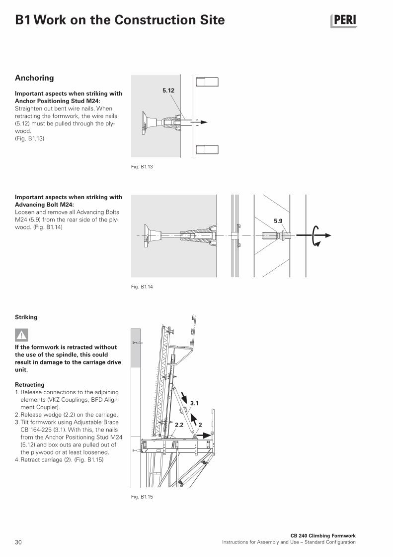
Anchoring
Important aspects when striking with
Anchor Positioning Stud M24:
Straighten out bent wire nails. When
retracting the formwork, the wire nails
(5.12) must be pulled through the ply-
wood.
(Fig. B1.13)
Fig. B1.15
Striking
If the formwork is retracted without
the use of the spindle, this could
r esult in damage to the carriage drive
unit.
Retracting
1. Release connections to the adjoining
elements (VKZ Couplings, BFD Align-
ment Coupler).
2. Release wedge (2.2) on the carriage.
3. Tilt formwork using Adjustable Brace
CB 164-225 (3.1). With this, the nails
from the Anchor Positioning Stud M24
(5.12) and box outs are pulled out of
the plywood or at least loosened.
4. Retract carriage (2). (Fig. B1.15)
Important aspects when striking with
Advancing Bolt M24:
Loosen and remove all Advancing Bolts
M24 (5.9) from the rear side of the ply-
wood. (Fig. B1.14)
5.12
5.9
Fig. B1.13
Fig. B1.14
31CB 240 Climbing Formwork
Instructions for Assembly and Use – Standard Configuration
B1 Work on the Construction Site
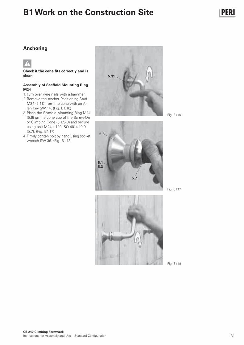
Anchoring
Check if the cone fits correctly and is
clean.
Assembly of Scaffold Mounting Ring
M24
1. Turn over wire nails with a hammer.
2. Remove the Anchor Positioning Stud
M24 (5.11) from the cone with an Al-
len Key SW 14. (Fig. B1.16)
3. Place the Scaffold Mounting Ring M24
(5.6) on the cone cup of the Screw-On
or Climbing Cone (5.1/5.3) and secure
using bolt M24 x 120 ISO 4014-10.9
(5.7). (Fig. B1.17)
4. Firmly tighten bolt by hand using socket
wrench SW 36. (Fig. B1.18)
Fig. B1.16
Fig. B1.17
Fig. B1.18
5.11
5.6
5.1
5.7
5.3
32CB 240 Climbing Formwork
Instructions for Assembly and Use – Standard Configuration
B1 Work on the Construction Site
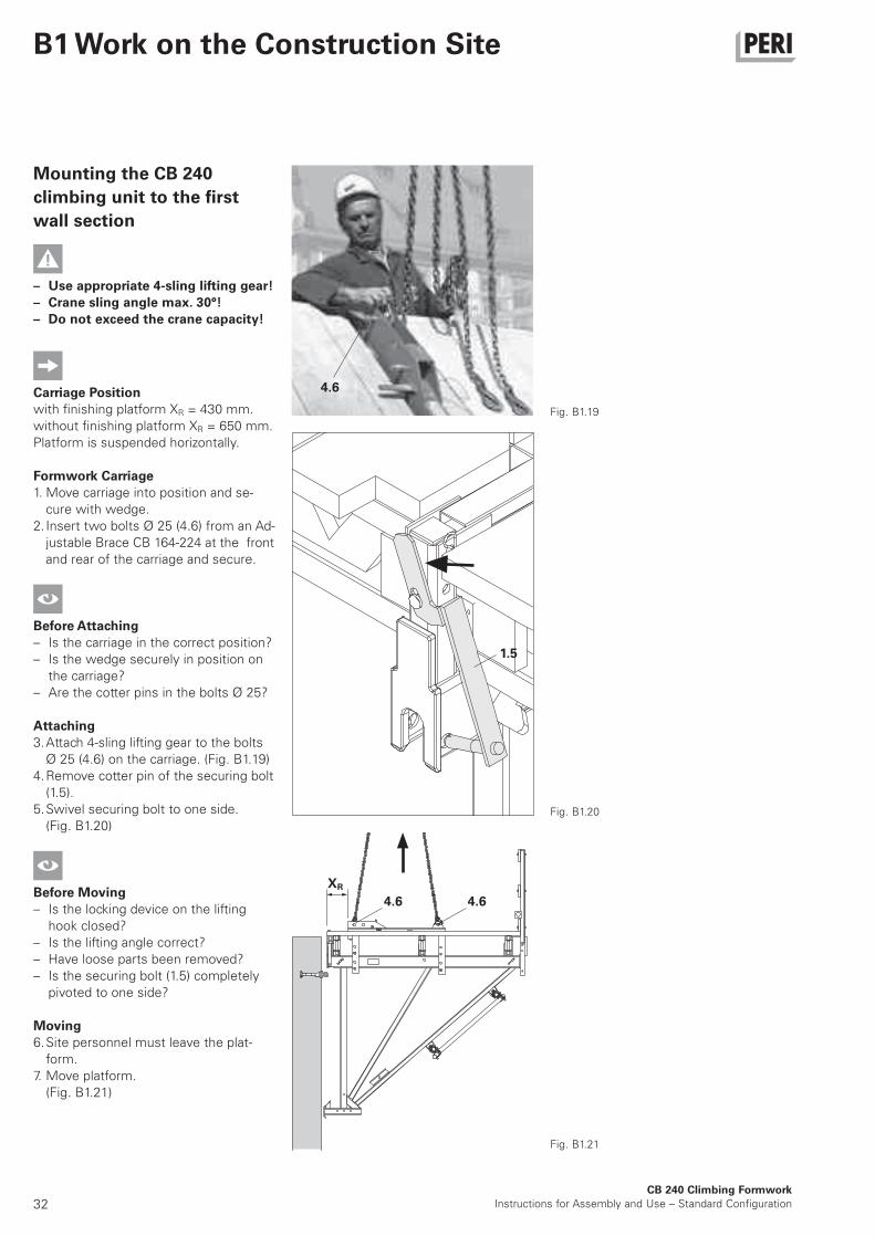
4.6
1.5
Fig. B1.19
Fig. B1.20
Fig. B1.21
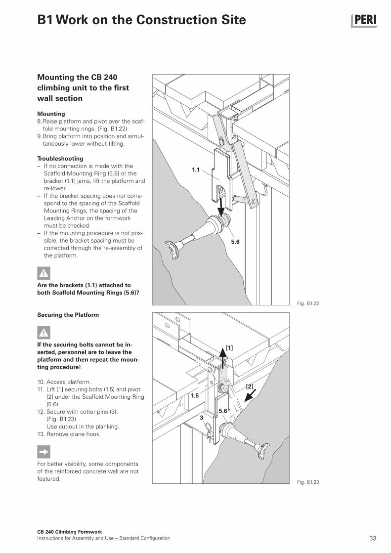
Mounting the CB 240
climbing unit to the first
wall section
– Use appropriate 4-sling lifting gear!
– Crane sling angle max. 30°!
– Do not exceed the crane capacity!
Carriage Position
with finishing platform XR = 430 mm.
without finishing platform XR = 650 mm.
Platform is suspended horizontally.
Formwork Carriage
1. Move carriage into position and se-
cure with wedge.
2. Insert two bolts Ø 25 (4.6) from an Ad-
justable Brace CB 164-224 at the front
and rear of the carriage and secure.
Before Attaching
– Is the carriage in the correct position?
– Is the wedge securely in position on
the carriage?
– Are the cotter pins in the bolts Ø 25?
Attaching
3. Attach 4-sling lifting gear to the bolts
Ø 25 (4.6) on the carriage. (Fig. B1.19)
4. Remove cotter pin of the securing bolt
(1.5).
5. Swivel securing bolt to one side.
(Fig. B1.20)
Before Moving
– Is the locking device on the lifting
hook closed?
– Is the lifting angle correct?
– Have loose parts been removed?
– Is the securing bolt (1.5) completely
pivoted to one side?
Moving
6. Site personnel must leave the plat-
form.
7. Move platform.
(Fig. B1.21)
4.6 4.6
XR
33CB 240 Climbing Formwork
Instructions for Assembly and Use – Standard Configuration
B1 Work on the Construction Site
1.1
5.6
5.6
1.5
[1]
[2]
3
Mounting the CB 240
climbing unit to the first
wall section
Mounting
8. Raise platform and pivot over the scaf-
fold mounting rings. (Fig. B1.22)
9. Bring platform into position and simul-
taneously lower without tilting.
Troubleshooting
– If no connection is made with the
Scaffold Mounting Ring (5.6) or the
bracket (1.1) jams, lift the platform and
re-lower.
– If the bracket spacing does not corre-
spond to the spacing of the Scaffold
Mounting Rings, the spacing of the
Leading Anchor on the formwork
must be checked.
– If the mounting procedure is not pos-
sible, the bracket spacing must be
corrected through the re-assembly of
the platform.
Are the brackets (1.1) attached to
both Scaffold Mounting Rings (5.6)?
Fig. B1.22
Fig. B1.23
Securing the Platform
If the securing bolts cannot be in-
serted, personnel are to leave the
platform and then repeat the moun-
ting procedure!
10. Access platform.
11. Lift [1] securing bolts (1.5) and pivot
[2] under the Scaffold Mounting Ring
(5.6).
12. Secure with cotter pins (3).
(Fig. B1.23)
Use cut-out in the planking.
13. Remove crane hook.
For better visibility, some components
of the reinforced concrete wall are not
featured.
34CB 240 Climbing Formwork
Instructions for Assembly and Use – Standard Configuration
B1 Work on the Construction Site
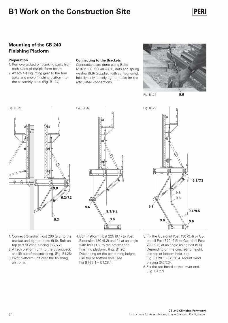
Mounting of the CB 240
Finishing Platform
Preparation
1. Remove tacked on planking parts from
both sides of the platform beam.
2. Attach 4-sling lifting gear to the four
bolts and move finishing platform to
the assembly area. (Fig. B1.24)
Connecting to the Brackets
Connections are done using Bolts
M16 x 130 ISO 4014-8.8, nuts and spring
washer (9.6) (supplied with components).
Initially, only loosely tighten bolts for the
articulated connections.
1. Connect Guardrail Post 200 (9.3) to the
bracket and tighten bolts (9.6). Bolt on
top part of wind bracing (6.2/7.2).
2. Attach platform unit to the Strongback
and lift out of the anchoring. (Fig. B1.25)
3. Pivot platform unit over the finishing
platform.
4. Bolt Platform Post 225 (9.1) to Post
Extension 180 (9.2) and fix at an angle
with bolt (9.6) to the bracket and
finishing platform. (Fig. B1.26)
Depending on the concreting height,
use top or bottom hole, see
Fig B1.28.1 – B1.28.4.
5. Fix the Guardrail Post 190 (9.4) or Gu-
ardrail Post 370 (9.5) to Guardrail Post
200 (9.3) at an angle using bolt (9.6).
Depending on the concreting height,
use top or bottom hole, see
Fig. B1.28.1 – B1.28.4. Mount wind
bracing (6.3/7.3).
6. Fix the toe board at the lower end.
(Fig. B1.27)
Fig. B1.25 Fig. B1.26 Fig. B1.27
9.6Fig. B1.24
9.6
9.3
6.2/7.2
9.6 9.6
9.1/9.2
9.6 9.6
9.4/9.5
6.3/7.3
9.6
9.3
9.6
35
CB 240 Climbing Formwork
Instructions for Assembly and Use – Standard Configuration
B1 Work on the Construction Site
Fig. B1.28.1
Fig. B1.28.2
Fig. B1.28.3
Fig. B1.28.4
9.69.6
9.1
9.1
9.2
9.5
9.2
9.69.6
9.1
9.6
9.4
9.6
9.6
9.6
3,6
54
2
9.1
9.6
9.4
9.6
9.6
9.6
m
1,69 5m
1,75m
1,5
0
4,1
5m
1,89 5
2,05 m1,2
0m
m
5,4
5m
3,49 5m
3,55m
2,2
0m
5,9
5m
3,69 5m
3,85 m2,0
0m
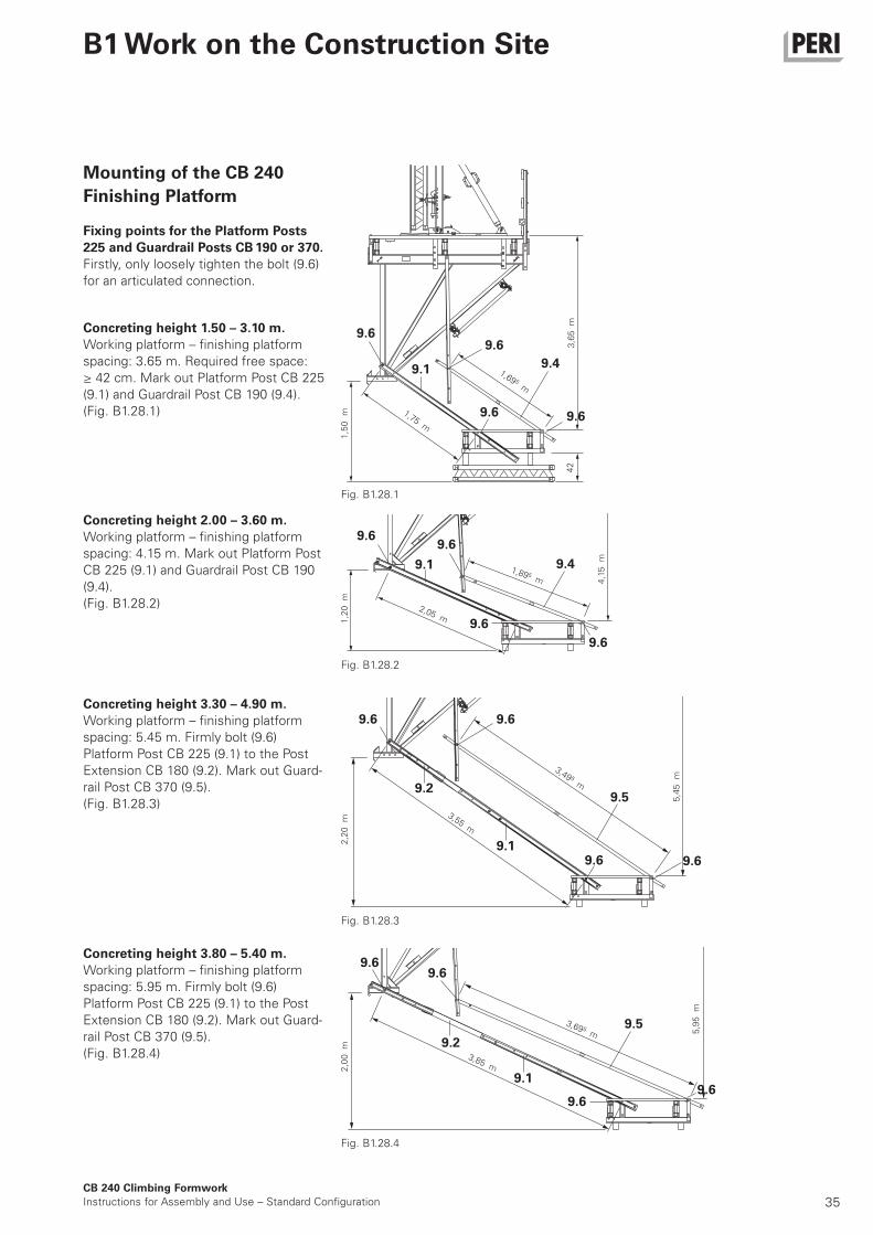
Concreting height 1.50 – 3.10 m.
Working platform – finishing platform
spacing: 3.65 m. Required free space:
≥ 42 cm. Mark out Platform Post CB 225
(9.1) and Guardrail Post CB 190 (9.4).
(Fig. B1.28.1)
Concreting height 2.00 – 3.60 m.
Working platform – finishing platform
spacing: 4.15 m. Mark out Platform Post
CB 225 (9.1) and Guardrail Post CB 190
(9.4).
(Fig. B1.28.2)
Concreting height 3.30 – 4.90 m.
Working platform – finishing platform
spacing: 5.45 m. Firmly bolt (9.6)
Platform Post CB 225 (9.1) to the Post
Extension CB 180 (9.2). Mark out Guard-
rail Post CB 370 (9.5).
(Fig. B1.28.3)
Concreting height 3.80 – 5.40 m.
Working platform – finishing platform
spacing: 5.95 m. Firmly bolt (9.6)
Platform Post CB 225 (9.1) to the Post
Extension CB 180 (9.2). Mark out Guard-
rail Post CB 370 (9.5).
(Fig. B1.28.4)
9.6
9.6
9.5
9.6
9.6
Mounting of the CB 240
Finishing Platform
Fixing points for the Platform Posts
225 and Guardrail Posts CB 190 or 370.
Firstly, only loosely tighten the bolt (9.6)
for an articulated connection.
m
36
8
8
12.1
1
5.6
9.6
7
6
CB 240 Climbing Formwork
Instructions for Assembly and Use – Standard Configuration
B1 Work on the Construction Site
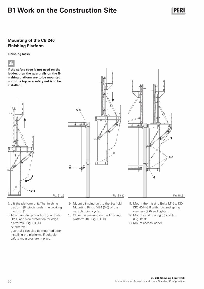
Mounting of the CB 240
Finishing Platform
Finishing Tasks
If the safety cage is not used on the
ladder, then the guardrails on the fi-
nishing platform are to be mounted
up to the top or a safety net is to be
installed!
7. Lift the platform unit. The finishing
platform (8) pivots under the working
platform (1).
8. Attach anti-fall protection: guardrails
(12.1) and side protection for edge
platforms. (Fig. B1.26)
Alternative:
guardrails can also be mounted after
installing the platforms if suitable
safety measures are in place.
Fig. B1.29 Fig. B1.30 Fig. B1.31
11. Mount the missing Bolts M16 x 130
ISO 4014-8.8 with nuts and spring
washers (9.6) and tighten.
12. Mount wind bracing (6) and (7).
(Fig. B1.31)
13. Mount access ladder.
9. Mount climbing unit to the Scaffold
Mounting Rings M24 (5.6) of the
next climbing cycle.
10. Close the planking on the finishing
platform (8). (Fig. B1.30)
37
7.1
6.2
7.2
1.2
5.65.14
6.1
7.1 7.1
6.1 6.3
CB 240 Climbing Formwork
Instructions for Assembly and Use – Standard Configuration
B1 Work on the Construction Site
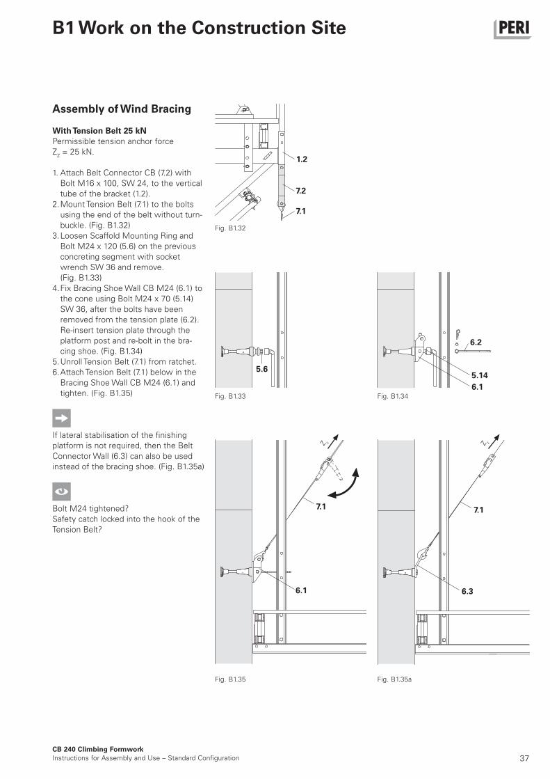
Assembly of Wind Bracing
With Tension Belt 25 kN
Permissible tension anchor force
ZZ = 25 kN.
1. Attach Belt Connector CB (7.2) with
Bolt M16 x 100, SW 24, to the vertical
tube of the bracket (1.2).
2. Mount Tension Belt (7.1) to the bolts
using the end of the belt without turn-
buckle. (Fig. B1.32)
3. Loosen Scaffold Mounting Ring and
Bolt M24 x 120 (5.6) on the previous
concreting segment with socket
wrench SW 36 and remove.
(Fig. B1.33)
4. Fix Bracing Shoe Wall CB M24 (6.1) to
the cone using Bolt M24 x 70 (5.14)
SW 36, after the bolts have been
removed from the tension plate (6.2).
Re-insert tension plate through the
platform post and re-bolt in the bra-
cing shoe. (Fig. B1.34)
5. Unroll Tension Belt (7.1) from ratchet.
6. Attach Tension Belt (7.1) below in the
Bracing Shoe Wall CB M24 (6.1) and
tighten. (Fig. B1.35)
If lateral stabilisation of the finishing
platform is not required, then the Belt
Connector Wall (6.3) can also be used
instead of the bracing shoe. (Fig. B1.35a)
Bolt M24 tightened?
Safety catch locked into the hook of the
Tension Belt?
Fig. B1.32
Fig. B1.33
Z z Z z
Fig. B1.34
Fig. B1.35 Fig. B1.35a
38
6.4
1.2
7.3
7.3
7.4
7.6
7.5
6.6
6.1
7.4
Z z
Z z
CB 240 Climbing Formwork
Instructions for Assembly and Use – Standard Configuration
B1 Work on the Construction Site
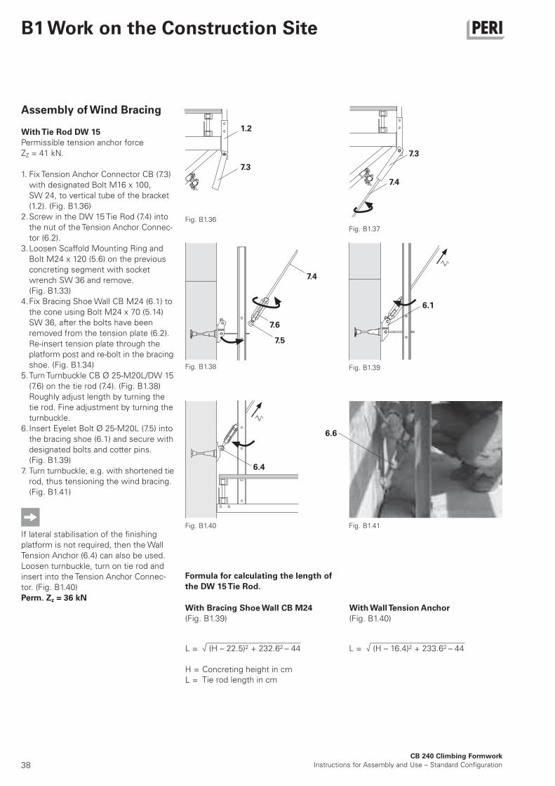
Assembly of Wind Bracing
With Tie Rod DW 15
Permissible tension anchor force
ZZ = 41 kN.
1. Fix Tension Anchor Connector CB (7.3)
with designated Bolt M16 x 100,
SW 24, to vertical tube of the bracket
(1.2). (Fig. B1.36)
2. Screw in the DW 15 Tie Rod (7.4) into
the nut of the Tension Anchor Connec-
tor (6.2).
3. Loosen Scaffold Mounting Ring and
Bolt M24 x 120 (5.6) on the previous
concreting segment with socket
wrench SW 36 and remove.
(Fig. B1.33)
4. Fix Bracing Shoe Wall CB M24 (6.1) to
the cone using Bolt M24 x 70 (5.14)
SW 36, after the bolts have been
removed from the tension plate (6.2).
Re-insert tension plate through the
platform post and re-bolt in the bracing
shoe. (Fig. B1.34)
5. Turn Turnbuckle CB Ø 25-M20L/DW 15
(7.6) on the tie rod (7.4). (Fig. B1.38)
Roughly adjust length by turning the
tie rod. Fine adjustment by turning the
turnbuckle.
6. Insert Eyelet Bolt Ø 25-M20L (7.5) into
the bracing shoe (6.1) and secure with
designated bolts and cotter pins.
(Fig. B1.39)
7. Turn turnbuckle, e.g. with shortened tie
rod, thus tensioning the wind bracing.
(Fig. B1.41)
If lateral stabilisation of the finishing
platform is not required, then the Wall
Tension Anchor (6.4) can also be used.
Loosen turnbuckle, turn on tie rod and
insert into the Tension Anchor Connec-
tor. (Fig. B1.40)
Perm. Zz = 36 kN
L = √ (H – 22.5)2 + 232.62 – 44 L = √ (H – 16.4)2 + 233.62 – 44
Formula for calculating the length of
the DW 15 Tie Rod.
With Bracing Shoe Wall CB M24
(Fig. B1.39)
With Wall Tension Anchor
(Fig. B1.40)
H =
L =
Concreting height in cmTie rod length in cm
Fig. B1.36
Fig. B1.37
Fig. B1.38 Fig. B1.39
Fig. B1.41Fig. B1.40
39
4.6 4.6
XR
1.5
CB 240 Climbing Formwork
Instructions for Assembly and Use – Standard Configuration
B1 Work on the Construction Site
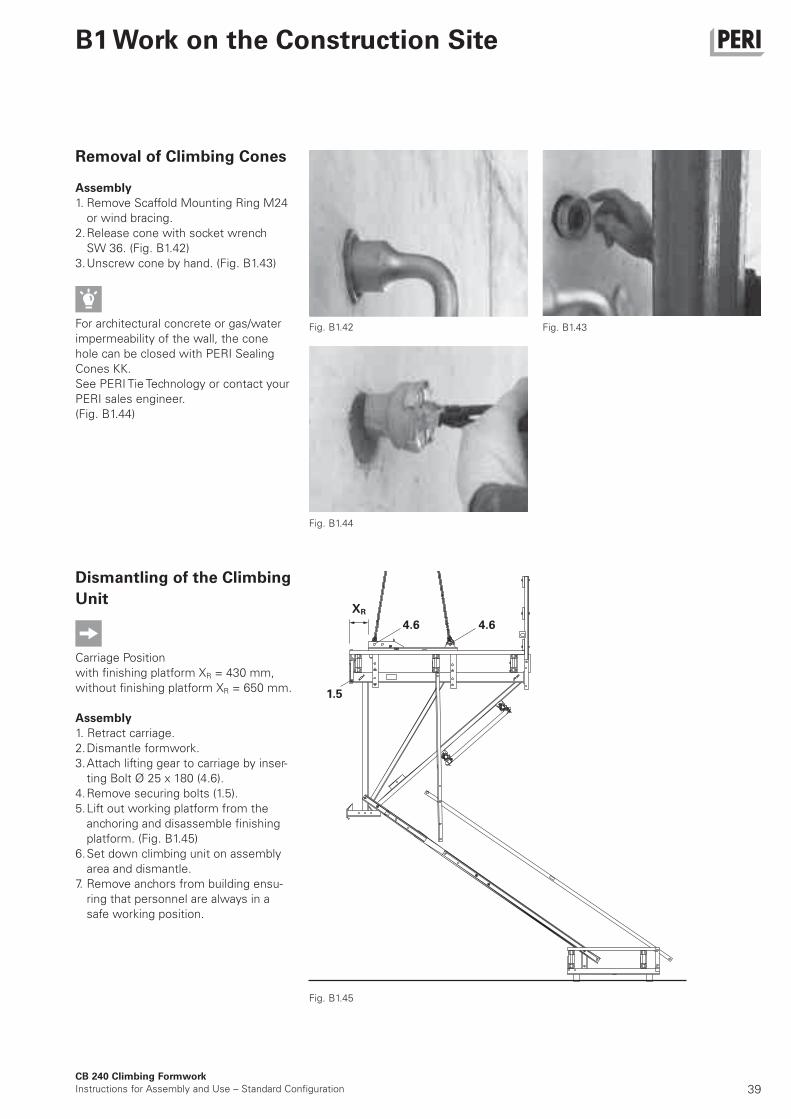
Removal of Climbing Cones
Assembly
1. Remove Scaffold Mounting Ring M24
or wind bracing.
2. Release cone with socket wrench
SW 36. (Fig. B1.42)
3. Unscrew cone by hand. (Fig. B1.43)
For architectural concrete or gas/water
impermeability of the wall, the cone
hole can be closed with PERI Sealing
Cones KK.
See PERI Tie Technology or contact your
PERI sales engineer.
(Fig. B1.44)
Dismantling of the Climbing
Unit
Carriage Position
with finishing platform XR = 430 mm,
without finishing platform XR = 650 mm.
Assembly
1. Retract carriage.
2. Dismantle formwork.
3. Attach lifting gear to carriage by inser-
ting Bolt Ø 25 x 180 (4.6).
4. Remove securing bolts (1.5).
5. Lift out working platform from the
anchoring and disassemble finishing
platform. (Fig. B1.45)
6. Set down climbing unit on assembly
area and dismantle.
7. Remove anchors from building ensu-
ring that personnel are always in a
safe working position.
Fig. B1.45
Fig. B1.42 Fig. B1.43
Fig. B1.44
40
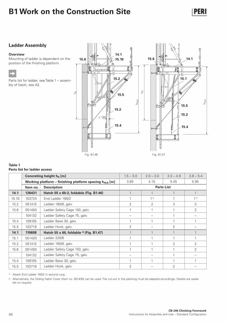
1.5 – 3.0 2.0 – 3.0 3.3 – 4.9 3.8 – 5.4
3.65 4.15 5.45 5.95
14.1 126431 1 1 1 1
15.10 103724 1 11) 1 11)
15.2 051410 2 2 3 3
15.6 051450 1 1 1 2
104132 – – 1 –
15.4 109105 1 1 1 1
15.5 103718 2 – 2 –
14.1 110608 1 1 1 1
15.1 051420 1 1 1 1
15.2 051410 1 1 2 2
15.6 051450 1 1 1 2
104132 – – 1 –
15.4 109105 1 1 1 1
15.5 103718 2 – 2 –
CB 240 Climbing Formwork
Instructions for Assembly and Use – Standard Configuration
B1 Work on the Construction Site
Ladder Assembly
Overview
Mounting of ladder is dependent on the
position of the finishing platform.
Parts list for ladder, see Table 1 – assem-
bly of hatch, see A2.
Fig. B1.46
≥ 150
Fig. B1.47
15.1
14.1
14.1
15.2
15.5
15.2
15.2
15.5
15.10
15.415.4
15.615.6
hB
hB
hN
LB
hN
LB
Table 1
Parts list for ladder access
2)
Attach End Ladder 180/2 in second rung.
Alternatively, the Sliding Hatch Cover (Item no. 051430) can be used. The cut-out in the planking must be adapted accordingly. Details are availa-
ble on request.
1)
Working platform – finishing platform spacing hNLB [m]
Item no.
Hatch 55 x 60-2, foldable (Fig. B1.46)
End Ladder 180/2
Ladder 180/6, galv.
Ladder Safety Cage 150, galv.
Concreting height hB [m]
Description Parts List
Ladder Safety Cage 75, galv.
Ladder Base 30, galv.
Hatch 55 x 60, foldable 2) (Fig. B1.47)
Ladder 220/6
Ladder 180/6, galv.
Ladder Safety Cage 150, galv.
Ladder Safety Cage 75, galv.
Ladder Base 30, galv.
Ladder Hook, galv.
Ladder Hook, galv.
41CB 240 Climbing Formwork
Instructions for Assembly and Use – Standard Configuration
B1 Work on the Construction Site
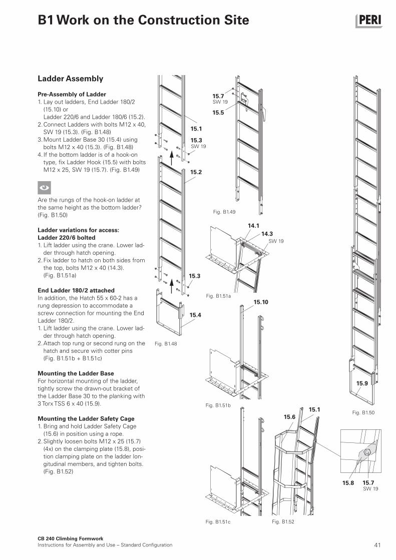
Ladder Assembly
Pre-Assembly of Ladder
1. Lay out ladders, End Ladder 180/2
(15.10) or
Ladder 220/6 and Ladder 180/6 (15.2).
2. Connect Ladders with bolts M12 x 40,
SW 19 (15.3). (Fig. B1.48)
3. Mount Ladder Base 30 (15.4) using
bolts M12 x 40 (15.3). (Fig. B1.48)
4. If the bottom ladder is of a hook-on
type, fix Ladder Hook (15.5) with bolts
M12 x 25, SW 19 (15.7). (Fig. B1.49)
Are the rungs of the hook-on ladder at
the same height as the bottom ladder?
(Fig. B1.50)
Ladder variations for access:
Ladder 220/6 bolted
1. Lift ladder using the crane. Lower lad-
der through hatch opening.
2. Fix ladder to hatch on both sides from
the top, bolts M12 x 40 (14.3).
(Fig. B1.51a)
End Ladder 180/2 attached
In addition, the Hatch 55 x 60-2 has a
rung depression to accommodate a
screw connection for mounting the End
Ladder 180/2.
1. Lift ladder using the crane. Lower lad-
der through hatch opening.
2. Attach top rung or second rung on the
hatch and secure with cotter pins
(Fig. B1.51b + B1.51c)
Mounting the Ladder Base
For horizontal mounting of the ladder,
tightly screw the drawn-out bracket of
the Ladder Base 30 to the planking with
3 Torx TSS 6 x 40 (15.9).
Mounting the Ladder Safety Cage
1. Bring and hold Ladder Safety Cage
(15.6) in position using a rope.
2. Slightly loosen bolts M12 x 25 (15.7)
(4x) on the clamping plate (15.8), posi-
tion clamping plate on the ladder lon-
gitudinal members, and tighten bolts.
(Fig. B1.52)
15.2
15.1
15.3
15.4
15.7
15.5
15.3
15.9
Fig. B1.48
Fig. B1.49
Fig. B1.50
SW 19
SW 19
14.3
14.1
15.10
15.1
15.6
15.8 15.7
Fig. B1.51a
Fig. B1.51b
Fig. B1.51c Fig. B1.52
SW 19
SW 19
42CB 240 Climbing Formwork
Instructions for Assembly and Use – Standard Configuration
B2 Assembly of the Formwork Elements
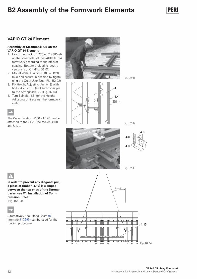
VARIO GT 24 Element
Assembly of Strongback CB on the
VARIO GT 24 Element
1. Lay Strongback CB 270 or CB 380 (4)
on the steel waler of the VARIO GT 24
formwork according to the bracket
spacing. Bottom projecting length:
see plans or C1. (Fig. B2.01)
2. Mount Waler Fixation U100 – U120
(4.4) and secure in position by tighte-
ning the Quick Jack Nut. (Fig. B2.02)
3. Fix Height Adjusting Unit (4.3) with
bolts Ø 25 x 180 (4.6) and cotter pin
to the Strongback CB. (Fig. B2.03)
4. Turn Spindle (4.8) for the Height
Adjusting Unit against the formwork
waler.
The Waler Fixation U100 – U120 can be
attached to the SRZ Steel Waler U100
and U120.
Fig. B2.01
In order to prevent any diagonal pull,
a piece of timber (4.10) is clamped
between the top ends of the Strong-
backs, see C1, Installation of Com-
pression Brace.
(Fig. B2.04)
Alternatively, the Lifting Beam RCS 10 t
(Item no. 112986) can be used for the
moving procedure.
Fig. B2.02
Fig. B2.03
4
4.8
4
4.4
4.3
4.6
≤ 45°
Fig. B2.04
4.10
9t112986)

43CB 240 Climbing Formwork
Instructions for Assembly and Use – Standard Configuration
B2 Assembly of the Formwork Elements
2.2 2
3.1
3.2
10.3
4
4.6
10
3.2
3.1
2.2
2
Fig. B2.05 Fig. B2.06
Fig. B2.07
Fig. B2.08 Fig. B2.09
VARIO GT 24 Element
Assembly of VARIO GT 24 Formwork
Element on CB 240 Bracket
1. Retract Carriage CB 240 (2) and
secure with wedge (2.2). (Fig. B2.05)
2. Fix Adjustable Brace 164-224 (3.1) to
Carriage using bolts and cotter pins
(3.2). Spindle out to the approximate
length and attach to ladder cage to
prevent tipping over. (Fig. B2.06)
3. Open concreting platform decking
(10.3) above the strongback. Secure
loose decking components.
4. Attach complete formwork element
to the Strongback (4) and position on
the CB 240 platform. (Fig. B2.07)
5. Mount Strongback CB (4) to Carriage
using bolts Ø 25 x 180 and cotter
pins (4.6). Holes in Carriage, see
Details. (Fig. B2.07)
6. Fix Adjustable Brace (3.1) to Strong-
back with bolts Ø 25 x 180 and cotter
pins (3.2). (Fig. B2.08)
7. Detach lifting gear.
8. Close decking (10.3) on concreting
platform.
9. Move Carriage (2) with formwork for-
ward to the wall and secure Carriage
with wedge (2.2).
10. Align formwork. (Fig. B2.09)
Detail
44
4.4
2.2
2
10.510.6
10.2
CB 240 Climbing Formwork
Instructions for Assembly and Use – Standard Configuration
B2 Assembly of the Formwork Elements
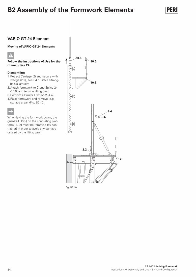
VARIO GT 24 Element
Moving of VARIO GT 24 Elements
Follow the Instructions of Use for the
Crane Splice 24!
Dismantling
1. Retract Carriage (2) and secure with
wedge (2.2), see B4.1. Brace Strong-
backs laterally.
2. Attach formwork to Crane Splice 24
(10.6) and tension lifting gear.
3. Remove all Waler Fixation-2 (4.4).
4. Raise formwork and remove (e.g.
storage area). (Fig. B2.10)
When laying the formwork down, the
guardrail (10.5) on the concreting plat-
form (10.2) must be removed (by con-
tractor) in order to avoid any damage
caused by the lifting gear.
Fig. B2.10
45
10.2
10.3
10.4
3.1
4.3
2
10
4
4.4
3.2
4.6
2.2
2
CB 240 Climbing Formwork
Instructions for Assembly and Use – Standard Configuration
B2 Assembly of the Formwork Elements
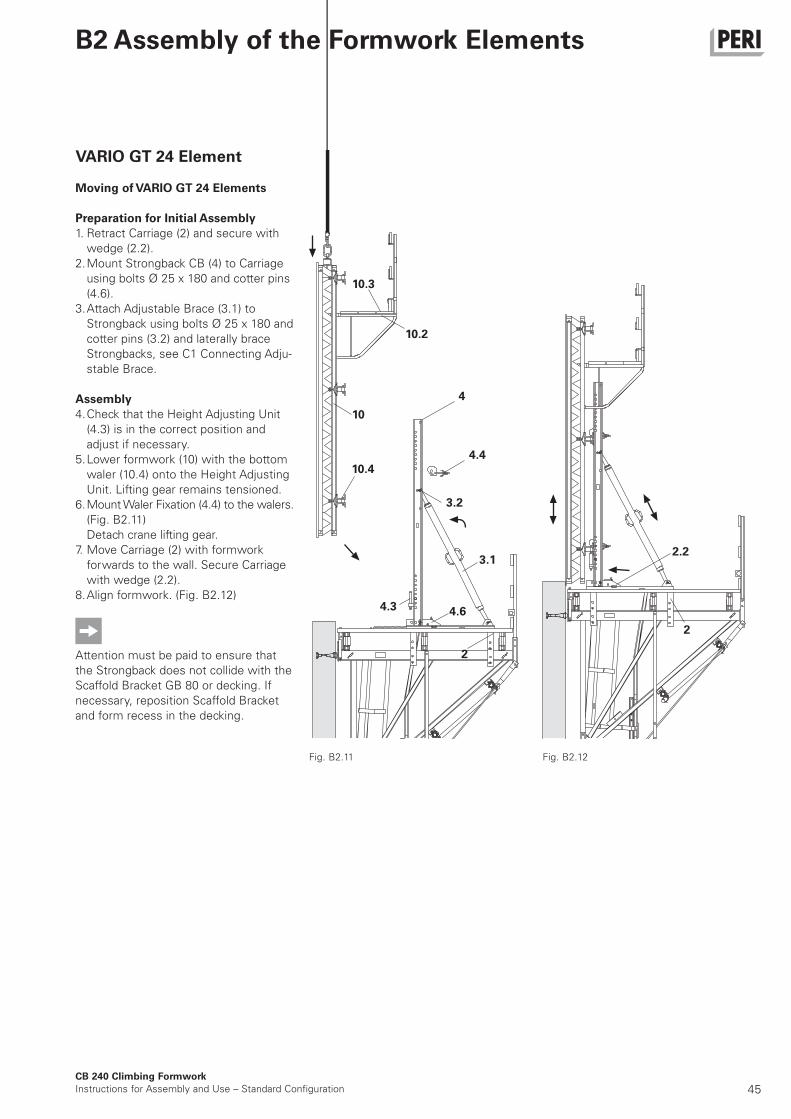
VARIO GT 24 Element
Moving of VARIO GT 24 Elements
Preparation for Initial Assembly
1. Retract Carriage (2) and secure with
wedge (2.2).
2. Mount Strongback CB (4) to Carriage
using bolts Ø 25 x 180 and cotter pins
(4.6).
3. Attach Adjustable Brace (3.1) to
Strongback using bolts Ø 25 x 180 and
cotter pins (3.2) and laterally brace
Strongbacks, see C1 Connecting Adju-
stable Brace.
Assembly
4. Check that the Height Adjusting Unit
(4.3) is in the correct position and
adjust if necessary.
5. Lower formwork (10) with the bottom
waler (10.4) onto the Height Adjusting
Unit. Lifting gear remains tensioned.
6. Mount Waler Fixation (4.4) to the walers.
(Fig. B2.11)
Detach crane lifting gear.
7. Move Carriage (2) with formwork
forwards to the wall. Secure Carriage
with wedge (2.2).
8. Align formwork. (Fig. B2.12)
Attention must be paid to ensure that
the Strongback does not collide with the
Scaffold Bracket GB 80 or decking. If
necessary, reposition Scaffold Bracket
and form recess in the decking.
Fig. B2.11 Fig. B2.12
46CB 240 Climbing Formwork
Instructions for Assembly and Use – Standard Configuration
B2 Assembly of the Formwork Elements
TRIO Element
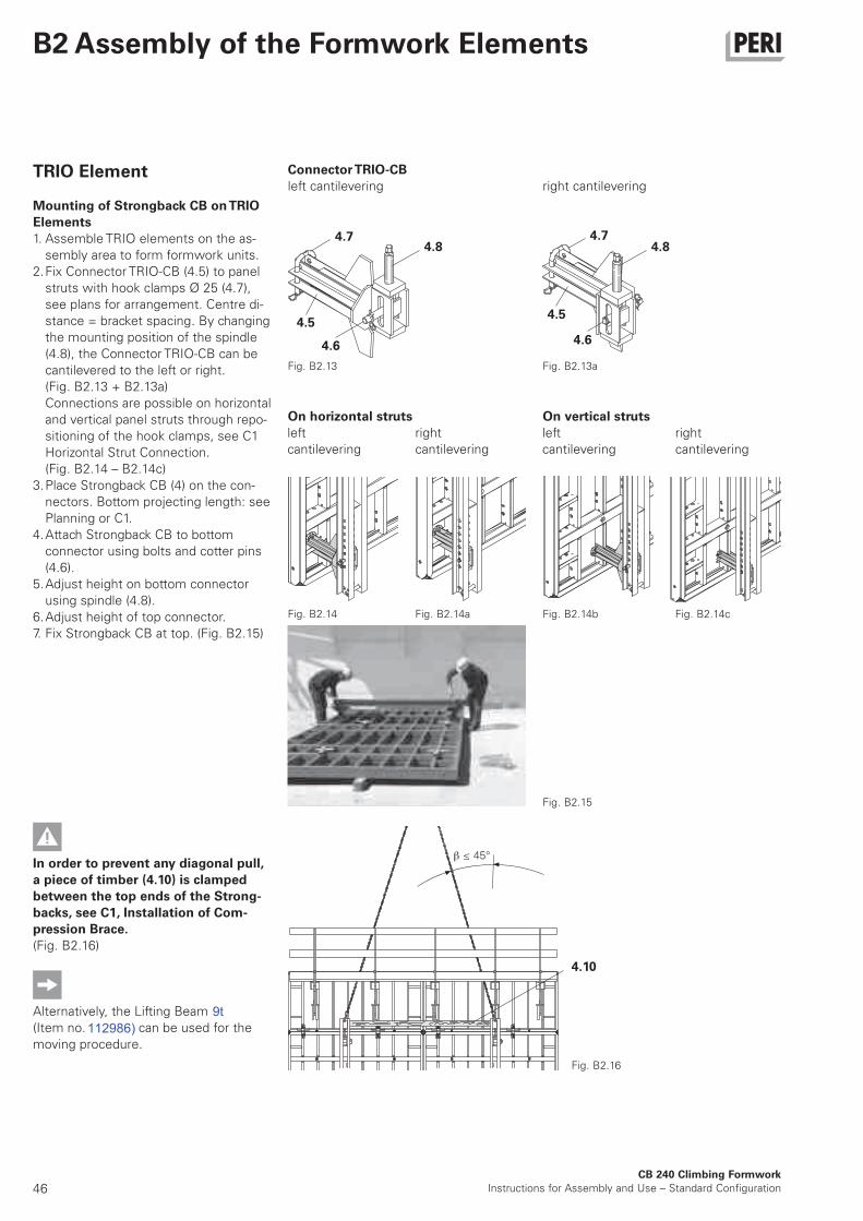
Mounting of Strongback CB on TRIO
Elements
1. Assemble TRIO elements on the as-
sembly area to form formwork units.
2. Fix Connector TRIO-CB (4.5) to panel
struts with hook clamps Ø 25 (4.7),
see plans for arrangement. Centre di-
stance = bracket spacing. By changing
the mounting position of the spindle
(4.8), the Connector TRIO-CB can be
cantilevered to the left or right.
(Fig. B2.13 + B2.13a)
Connections are possible on horizontal
and vertical panel struts through repo-
sitioning of the hook clamps, see C1
Horizontal Strut Connection.
(Fig. B2.14 – B2.14c)
3. Place Strongback CB (4) on the con-
nectors. Bottom projecting length: see
Planning or C1.
4. Attach Strongback CB to bottom
connector using bolts and cotter pins
(4.6).
5. Adjust height on bottom connector
using spindle (4.8).
6. Adjust height of top connector.
7. Fix Strongback CB at top. (Fig. B2.15)
In order to prevent any diagonal pull,
a piece of timber (4.10) is clamped
between the top ends of the Strong-
backs, see C1, Installation of Com-
pression Brace.
(Fig. B2.16)
Alternatively, the Lifting Beam RCS 10 t
(Item no. 112986) can be used for the
moving procedure.
On horizontal struts
Connector TRIO-CB
left cantilevering right cantilevering
Fig. B2.15
Fig. B2.14 Fig. B2.14a Fig. B2.14b Fig. B2.14c
Fig. B2.13
Fig. B2.16
≤ 45°
left
cantilevering
right
cantilevering
On vertical struts
left
cantilevering
right
cantilevering
4.10
4.8 4.84.7 4.7
4.54.5
4.6 4.6
Fig. B2.13a
112986)9t
47CB 240 Climbing Formwork
Instructions for Assembly and Use – Standard Configuration
B2 Assembly of the Formwork Elements
3.2
TRIO Element
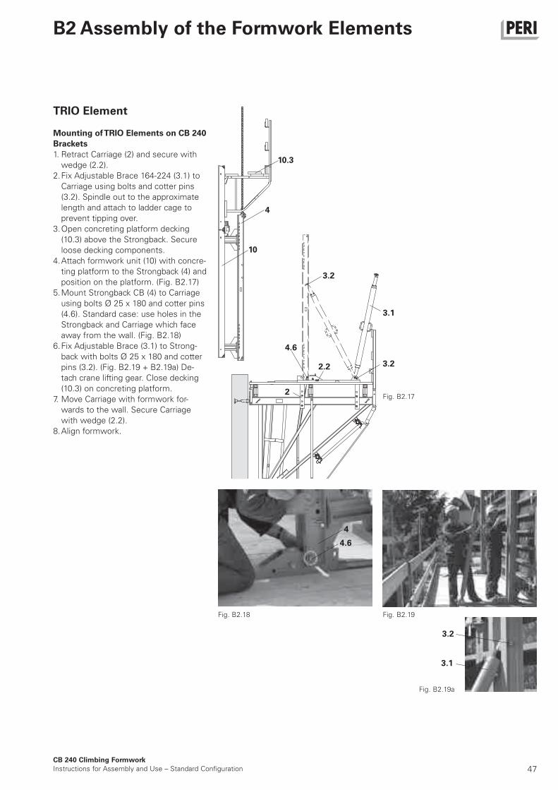
Mounting of TRIO Elements on CB 240
Brackets
1. Retract Carriage (2) and secure with
wedge (2.2).
2. Fix Adjustable Brace 164-224 (3.1) to
Carriage using bolts and cotter pins
(3.2). Spindle out to the approximate
length and attach to ladder cage to
prevent tipping over.
3. Open concreting platform decking
(10.3) above the Strongback. Secure
loose decking components.
4. Attach formwork unit (10) with concre-
ting platform to the Strongback (4) and
position on the platform. (Fig. B2.17)
5. Mount Strongback CB (4) to Carriage
using bolts Ø 25 x 180 and cotter pins
(4.6). Standard case: use holes in the
Strongback and Carriage which face
away from the wall. (Fig. B2.18)
6. Fix Adjustable Brace (3.1) to Strong-
back with bolts Ø 25 x 180 and cotter
pins (3.2). (Fig. B2.19 + B2.19a) De-
tach crane lifting gear. Close decking
(10.3) on concreting platform.
7. Move Carriage with formwork for-
wards to the wall. Secure Carriage
with wedge (2.2).
8. Align formwork.
Fig. B2.17
Fig. B2.18
Fig. B2.19a
Fig. B2.19
3.2
3.1
10.3
4
10
3.1
2
3.22.2
4.6
4
4.6
48CB 240 Climbing Formwork
Instructions for Assembly and Use – Standard Configuration
B2 Assembly of the Formwork Elements
Fig. B2.20
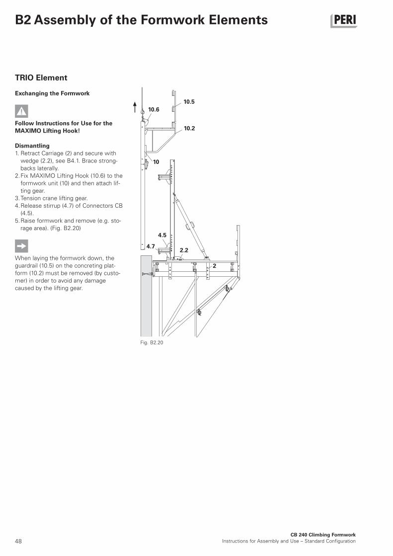
TRIO Element
Exchanging the Formwork
Follow Instructions for Use for the
MAXIMO Lifting Hook!
Dismantling
1. Retract Carriage (2) and secure with
wedge (2.2), see B4.1. Brace strong-
backs laterally.
2. Fix MAXIMO Lifting Hook (10.6) to the
formwork unit (10) and then attach lif-
ting gear.
3. Tension crane lifting gear.
4. Release stirrup (4.7) of Connectors CB
(4.5).
5. Raise formwork and remove (e.g. sto-
rage area). (Fig. B2.20)
When laying the formwork down, the
guardrail (10.5) on the concreting plat-
form (10.2) must be removed (by custo-
mer) in order to avoid any damage
caused by the lifting gear.
10.6
10.5
10.2
10
4.5
4.72.2
2
49CB 240 Climbing Formwork
Instructions for Assembly and Use – Standard Configuration
B2 Assembly of the Formwork Elements
4.5
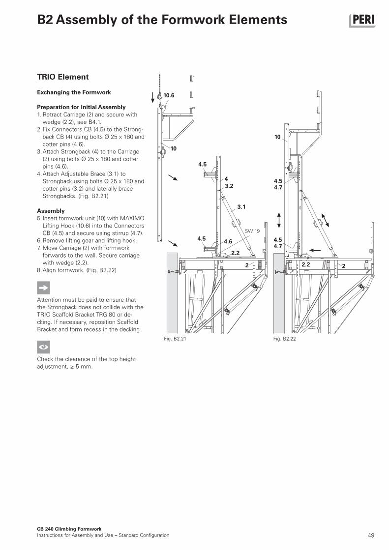
TRIO Element
Exchanging the Formwork
Preparation for Initial Assembly
1. Retract Carriage (2) and secure with
wedge (2.2), see B4.1.
2. Fix Connectors CB (4.5) to the Strong-
back CB (4) using bolts Ø 25 x 180 and
cotter pins (4.6).
3. Attach Strongback (4) to the Carriage
(2) using bolts Ø 25 x 180 and cotter
pins (4.6).
4. Attach Adjustable Brace (3.1) to
Strongback using bolts Ø 25 x 180 and
cotter pins (3.2) and laterally brace
Strongbacks. (Fig. B2.21)
Assembly
5. Insert formwork unit (10) with MAXIMO
Lifting Hook (10.6) into the Connectors
CB (4.5) and secure using stirrup (4.7).
6. Remove lifting gear and lifting hook.
7. Move Carriage (2) with formwork
forwards to the wall. Secure carriage
with wedge (2.2).
8. Align formwork. (Fig. B2.22)
Attention must be paid to ensure that
the Strongback does not collide with the
TRIO Scaffold Bracket TRG 80 or de-
cking. If necessary, reposition Scaffold
Bracket and form recess in the decking.
Check the clearance of the top height
adjustment, ≥ 5 mm.
Fig. B2.21 Fig. B2.22
SW 19
4.5
2
4.6
2.2
4
3.2
3.1
4.54.7
4.54.7
10
10.6
10
22.2
50
2.5
2.2
CB 240 Climbing Formwork
Instructions for Assembly and Use – Standard Configuration
B3 Formwork Utilisation
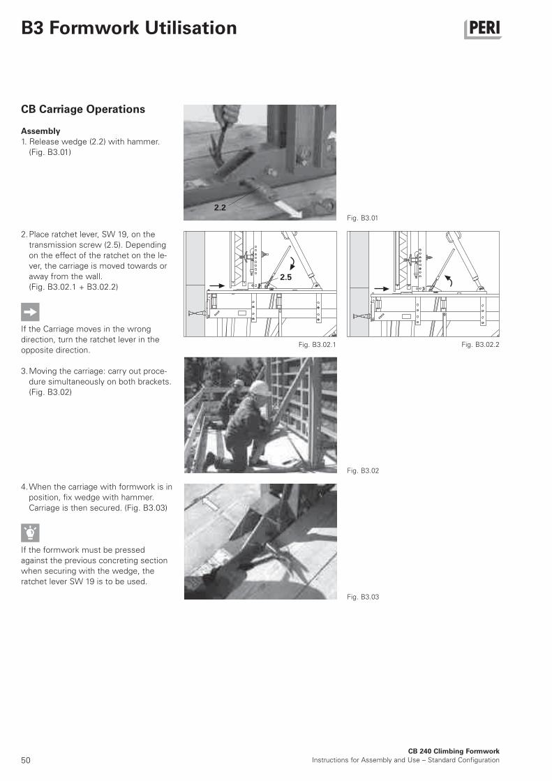
2. Place ratchet lever, SW 19, on the
transmission screw (2.5). Depending
on the effect of the ratchet on the le-
ver, the carriage is moved towards or
away from the wall.
(Fig. B3.02.1 + B3.02.2)
If the Carriage moves in the wrong
direction, turn the ratchet lever in the
opposite direction.
3. Moving the carriage: carry out proce-
dure simultaneously on both brackets.
(Fig. B3.02)
CB Carriage Operations
Assembly
1. Release wedge (2.2) with hammer.
(Fig. B3.01)
4. When the carriage with formwork is in
position, fix wedge with hammer.
Carriage is then secured. (Fig. B3.03)
If the formwork must be pressed
against the previous concreting section
when securing with the wedge, the
ratchet lever SW 19 is to be used.
Fig. B3.02
Fig. B3.01
Fig. B3.02.1 Fig. B3.02.2
Fig. B3.03
51
4.5
4.8
4.6
4.3
4.7
10
4.3
4.8
4.4
4.8
4.6
CB 240 Climbing Formwork
Instructions for Assembly and Use – Standard Configuration
B3 Formwork Utilisation
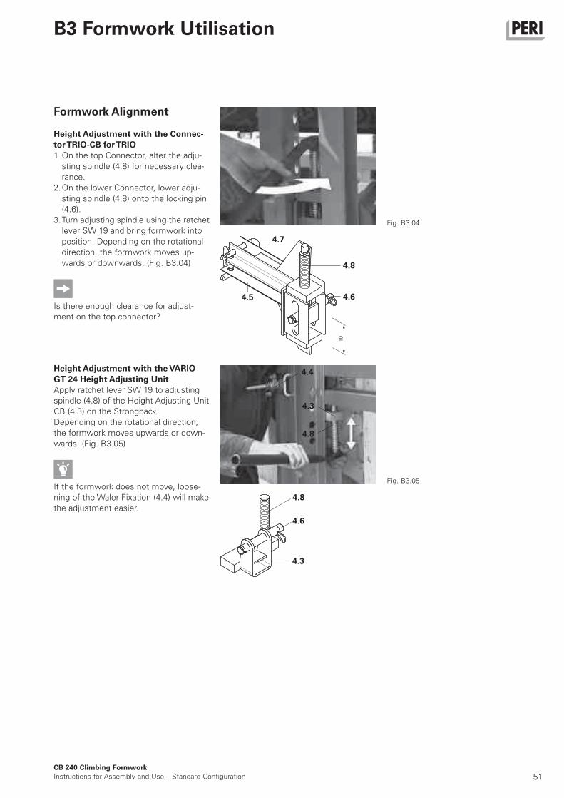
Formwork Alignment
Height Adjustment with the Connec-
tor TRIO-CB for TRIO
1. On the top Connector, alter the adju-
sting spindle (4.8) for necessary clea-
rance.
2. On the lower Connector, lower adju-
sting spindle (4.8) onto the locking pin
(4.6).
3. Turn adjusting spindle using the ratchet
lever SW 19 and bring formwork into
position. Depending on the rotational
direction, the formwork moves up-
wards or downwards. (Fig. B3.04)
Is there enough clearance for adjust-
ment on the top connector?
Height Adjustment with the VARIO
GT 24 Height Adjusting Unit
Apply ratchet lever SW 19 to adjusting
spindle (4.8) of the Height Adjusting Unit
CB (4.3) on the Strongback.
Depending on the rotational direction,
the formwork moves upwards or down-
wards. (Fig. B3.05)
If the formwork does not move, loose-
ning of the Waler Fixation (4.4) will make
the adjustment easier.
Fig. B3.05
Fig. B3.04
52CB 240 Climbing Formwork
Instructions for Assembly and Use – Standard Configuration
B3 Formwork Utilisation
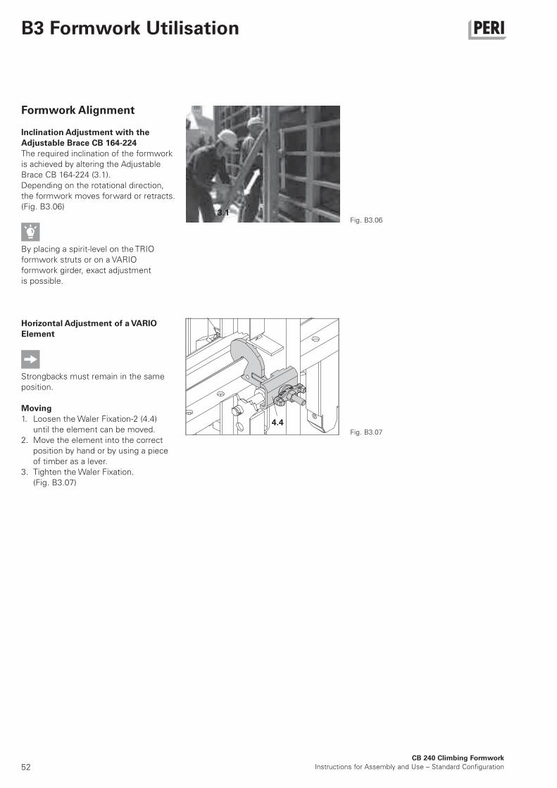
Formwork Alignment
Inclination Adjustment with the
Adjustable Brace CB 164-224
The required inclination of the formwork
is achieved by altering the Adjustable
Brace CB 164-224 (3.1).
Depending on the rotational direction,
the formwork moves forward or retracts.
(Fig. B3.06)
By placing a spirit-level on the TRIO
formwork struts or on a VARIO
formwork girder, exact adjustment
is possible.
Horizontal Adjustment of a VARIO
Element
Strongbacks must remain in the same
position.
Moving
1. Loosen the Waler Fixation-2 (4.4)
until the element can be moved.
2. Move the element into the correct
position by hand or by using a piece
of timber as a lever.
3. Tighten the Waler Fixation.
(Fig. B3.07)
Fig. B3.06
Fig. B3.07
3.1
4.4
53CB 240 Climbing Formwork
Instructions for Assembly and Use – Standard Configuration
B4 Crane-Assisted Climbing
6
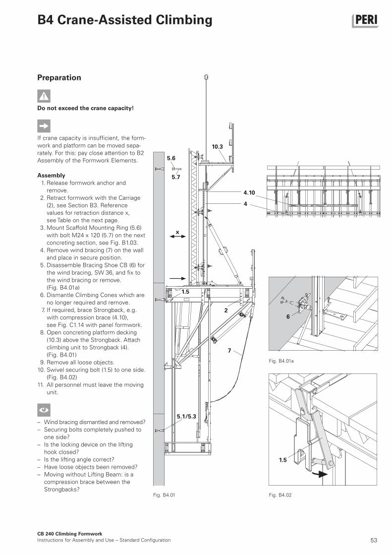
Preparation
Do not exceed the crane capacity!
If crane capacity is insufficient, the form-
work and platform can be moved sepa-
rately. For this: pay close attention to B2
Assembly of the Formwork Elements.
Assembly
1. Release formwork anchor and
remove.
2. Retract formwork with the Carriage
(2), see Section B3. Reference
values for retraction distance x,
see Table on the next page.
3. Mount Scaffold Mounting Ring (5.6)
with bolt M24 x 120 (5.7) on the next
concreting section, see Fig. B1.03.
4. Remove wind bracing (7) on the wall
and place in secure position.
5. Disassemble Bracing Shoe CB (6) for
the wind bracing, SW 36, and fix to
the wind bracing or remove.
(Fig. B4.01a)
6. Dismantle Climbing Cones which are
no longer required and remove.
7. If required, brace Strongback, e.g.
with compression brace (4.10),
see Fig. C1.14 with panel formwork.
8. Open concreting platform decking
(10.3) above the Strongback. Attach
climbing unit to Strongback (4).
(Fig. B4.01)
9. Remove all loose objects.
10. Swivel securing bolt (1.5) to one side.
(Fig. B4.02)
11. All personnel must leave the moving
unit.
– Wind bracing dismantled and removed?
– Securing bolts completely pushed to
one side?
– Is the locking device on the lifting
hook closed?
– Is the lifting angle correct?
– Have loose objects been removed?
– Moving without Lifting Beam: is a
compression brace between the
Strongbacks?Fig. B4.02Fig. B4.01
Fig. B4.01a
10.3
5.6
5.7
4
4.10
x
1.5
7
2
5.1/5.3
1.5
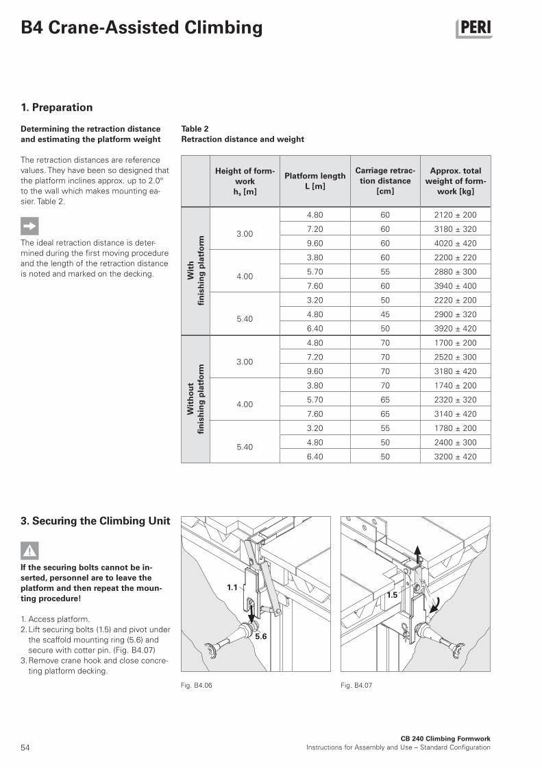
54
3.00
4.80 60 2120 ± 200
7.20 60 3180 ± 320
9.60 60 4020 ± 420
4.00
3.80 60 2200 ± 220
5.70 55 2880 ± 300
7.60 60 3940 ± 400
5.40
3.20 50 2220 ± 200
4.80 45 2900 ± 320
6.40 50 3920 ± 420
3.00
4.80 70 1700 ± 200
7.20 70 2520 ± 300
9.60 70 3180 ± 420
4.00
3.80 70 1740 ± 200
5.70 65 2320 ± 320
7.60 65 3140 ± 420
5.40
3.20 55 1780 ± 200
4.80 50 2400 ± 300
6.40 50 3200 ± 420
1.1
5.6
1.5
CB 240 Climbing Formwork
Instructions for Assembly and Use – Standard Configuration
B4 Crane-Assisted Climbing
1. Preparation
Determining the retraction distance
and estimating the platform weight
The retraction distances are reference
values. They have been so designed that
the platform inclines approx. up to 2.0°
to the wall which makes mounting ea-
sier. Table 2.
The ideal retraction distance is deter-
mined during the first moving procedure
and the length of the retraction distance
is noted and marked on the decking.
3. Securing the Climbing Unit
If the securing bolts cannot be in-
serted, personnel are to leave the
platform and then repeat the moun-
ting procedure!
1. Access platform.
2. Lift securing bolts (1.5) and pivot under
the scaffold mounting ring (5.6) and
secure with cotter pin. (Fig. B4.07)
3. Remove crane hook and close concre-
ting platform decking.
Fig. B4.07Fig. B4.06
Table 2
Retraction distance and weight
Height of form-
work
hs [m]
Platform length
L [m]
Carriage retrac-
tion distance
[cm]
Approx. total
weight of form-
work [kg]With
finishing platform
Without
finishing platform
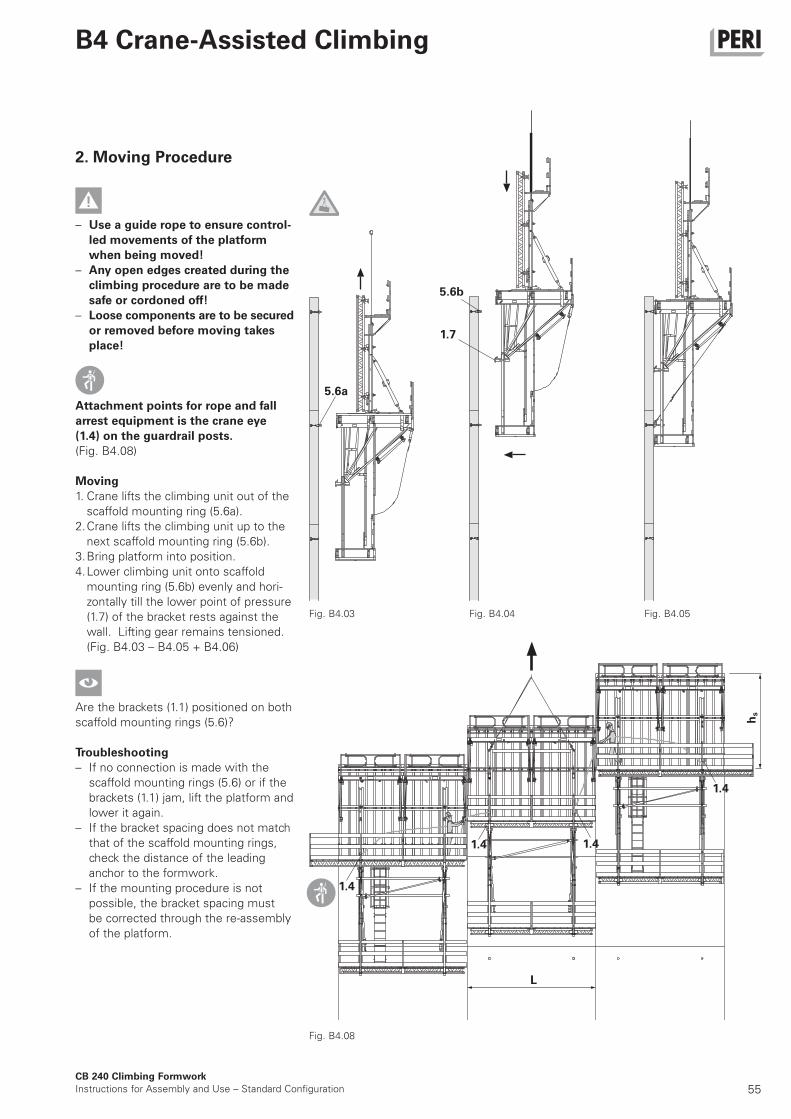
55
1.4
1.7
5.6b
L
hs
5.6a
1.4 1.4
1.4
CB 240 Climbing Formwork
Instructions for Assembly and Use – Standard Configuration
B4 Crane-Assisted Climbing
2. Moving Procedure
– Use a guide rope to ensure control-
led movements of the platform
when being moved!
– Any open edges created during the
climbing procedure are to be made
safe or cordoned off!
– Loose components are to be secured
or removed before moving takes
place!
Attachment points for rope and fall
arrest equipment is the crane eye
(1.4) on the guardrail posts.
(Fig. B4.08)
Moving
1. Crane lifts the climbing unit out of the
scaffold mounting ring (5.6a).
2. Crane lifts the climbing unit up to the
next scaffold mounting ring (5.6b).
3. Bring platform into position.
4. Lower climbing unit onto scaffold
mounting ring (5.6b) evenly and hori-
zontally till the lower point of pressure
(1.7) of the bracket rests against the
wall. Lifting gear remains tensioned.
(Fig. B4.03 – B4.05 + B4.06)
Are the brackets (1.1) positioned on both
scaffold mounting rings (5.6)?
Troubleshooting
– If no connection is made with the
scaffold mounting rings (5.6) or if the
brackets (1.1) jam, lift the platform and
lower it again.
– If the bracket spacing does not match
that of the scaffold mounting rings,
check the distance of the leading
anchor to the formwork.
– If the mounting procedure is not
possible, the bracket spacing must
be corrected through the re-assembly
of the platform.
Fig. B4.08
Fig. B4.03 Fig. B4.04 Fig. B4.05
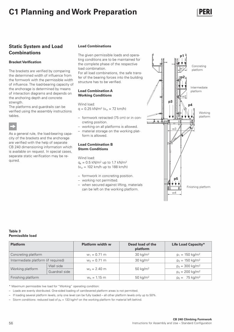
56CB 240 Climbing Formwork
Instructions for Assembly and Use – Standard Configuration
C1 Planning and Work Preparation
Static System and Load
Combinations
Bracket Verification
The brackets are verified by comparing
the determined width of influence from
the formwork with the permissible width
of influence. The load-bearing capacity of
the anchorage is determined by means
of interaction diagrams and depends on
the anchoring depth and concrete
strength.
The platforms and guardrails can be
verified using the assembly instructions
tables.
As a general rule, the load-bearing capa-
city of the brackets and the anchorage
are verified with the help of separate
CB 240 dimensioning information which
is available on request. In special cases,
separate static verification may be re-
quired.
Load Combinations
The given permissible loads and opera-
ting conditions are to be maintained for
the complete phase of the respective
load combination.
For all load combinations, the safe trans-
fer of the bearing forces into the building
structure has to be verified.
Load Combination A
Working Conditions
Wind load:
q = 0.25 kN/m2 (vw = 72 km/h)
– formwork retracted (75 cm) or in con-
creting position.
– working on all platforms is allowed.
– material storage on the working plat-
form is allowed.
Load Combination B
Storm Conditions
Wind load:
q = 0.5 kN/m2 up to 1.7 kN/m2
(vw = 102 km/h up to 188 km/h)
– formwork in concreting position.
– working not permitted.
– when secured against lifting, materials
can be left on the working platform.
Concreting
platform
Intermediate
platform
Working
platform
Finishing platform
w1
p1
p2
p3p4
p5
w2
w3
w4
Table 3
Permissible load
* Maximum permissible live load for “Working” operating condition:
– Loads are evenly distributed. One-sided loading of cantilevered platform areas is not permitted.
– If loading several platform levels, only one level can be fully loaded – all other platform levels only up to 50%.
– Storm conditions: reduced load of p4 = 133 kg/m² on the working platform for material left behind.
Platform Platform width w Dead load of the
platform
Life Load Capacity*
Concreting platform w1 = 0.71 m 30 kg/m2 p1 = 150 kg/m2
Intermediate platform (if required) w2 = 0.71 m 30 kg/m2 p2 = 150 kg/m2
Working platformWall side
w3 = 2.40 m 50 kg/m2p3 = 300 kg/m2
Guardrail side p4 = 200 kg/m2
Finishing platform w4 = 1.15 m 50 kg/m2 p5 = 75 kg/m2
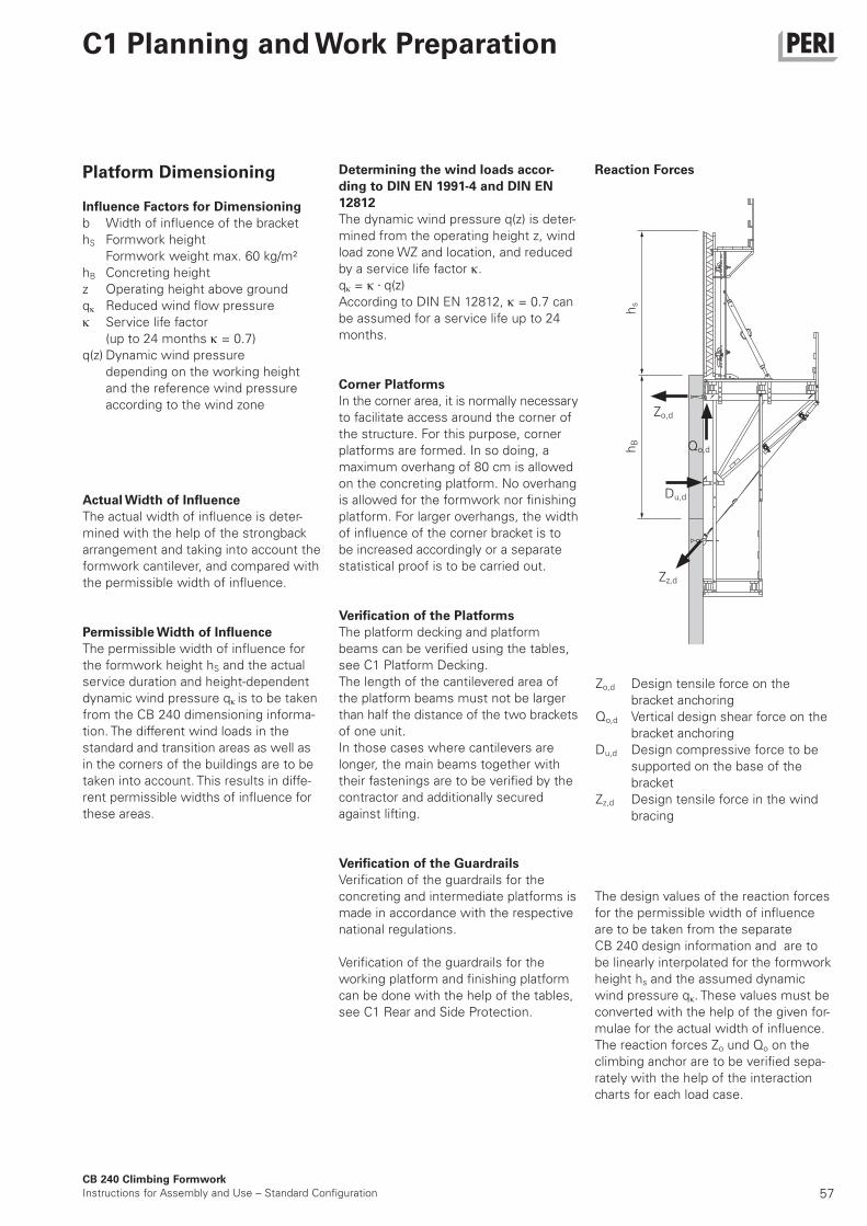
57
Zo,d
Qo,d
Zz,d
hs
hB
Du,d
CB 240 Climbing Formwork
Instructions for Assembly and Use – Standard Configuration
C1 Planning and Work Preparation
Platform Dimensioning
Influence Factors for Dimensioning
b Width of influence of the bracket
hS Formwork height
Formwork weight max. 60 kg/m²
hB Concreting height
z Operating height above ground
q Reduced wind flow pressure
Service life factor
(up to 24 months = 0.7)
q(z) Dynamic wind pressure
depending on the working height
and the reference wind pressure
according to the wind zone
Zo,d Design tensile force on the
bracket anchoring
Qo,d Vertical design shear force on the
bracket anchoring
Du,d Design compressive force to be
supported on the base of the
bracket
Zz,d Design tensile force in the wind
bracing
Determining the wind loads accor-
ding to DIN EN 1991-4 and DIN EN
12812
The dynamic wind pressure q(z) is deter-
mined from the operating height z, wind
load zone WZ and location, and reduced
by a service life factor .
q = q(z)
According to DIN EN 12812, = 0.7 can
be assumed for a service life up to 24
months.
Corner Platforms
In the corner area, it is normally necessary
to facilitate access around the corner of
the structure. For this purpose, corner
platforms are formed. In so doing, a
maximum overhang of 80 cm is allowed
on the concreting platform. No overhang
is allowed for the formwork nor finishing
platform. For larger overhangs, the width
of influence of the corner bracket is to
be increased accordingly or a separate
statistical proof is to be carried out.
Verification of the Platforms
The platform decking and platform
beams can be verified using the tables,
see C1 Platform Decking.
The length of the cantilevered area of
the platform beams must not be larger
than half the distance of the two brackets
of one unit.
In those cases where cantilevers are
longer, the main beams together with
their fastenings are to be verified by the
contractor and additionally secured
against lifting.
Verification of the Guardrails
Verification of the guardrails for the
concreting and intermediate platforms is
made in accordance with the respective
national regulations.
Verification of the guardrails for the
working platform and finishing platform
can be done with the help of the tables,
see C1 Rear and Side Protection.
Actual Width of Influence
The actual width of influence is deter-
mined with the help of the strongback
arrangement and taking into account the
formwork cantilever, and compared with
the permissible width of influence.
Permissible Width of Influence
The permissible width of influence for
the formwork height hS and the actual
service duration and height-dependent
dynamic wind pressure q is to be taken
from the CB 240 dimensioning informa-
tion. The different wind loads in the
standard and transition areas as well as
in the corners of the buildings are to be
taken into account. This results in diffe-
rent permissible widths of influence for
these areas.
Reaction Forces
The design values of the reaction forces
for the permissible width of influence
are to be taken from the separate
CB 240 design information and are to
be linearly interpolated for the formwork
height hs and the assumed dynamic
wind pressure q . These values must be
converted with the help of the given for-
mulae for the actual width of influence.
The reaction forces Zo und Qo on the
climbing anchor are to be verified sepa-
rately with the help of the interaction
charts for each load case.

58CB 240 Climbing Formwork
Instructions for Assembly and Use – Standard Configuration
C1 Planning and Work Preparation
Fig. C1.02
Platform Decking
– Platform decking must be chosen in
accordance with respective national
regulations.
– Tripping hazards, unnecessary box
outs and openings in the decking are
to be avoided or covered.
– The distance between the decking
and the structure should be
max. 5 cm.
– Gaps in the decking are not permissi-
ble. Planks are to be fitted tightly to-
gether.
– The spacing between the decking of
adjacent platforms must not exceed
2 cm. Larger gaps are to be covered
with non-movable suitable materials
or safety nets (8.4) with a max. mesh
size of 2 cm are to be used.
– Any openings in the decking, which
are required for normal working pro-
cedures, must be covered with non-
movable suitable materials.
– Safe working conditions for tie instal-
lation are to be provided by intermedi-
ate platforms. (Fig. C1.02)
– Minimum dimensions of plankings
see Table 4.
– Permissible span of girders
see Table 5.
Markings
We recommend that each platform is
distinctly marked as well as creating a
document with the following data:
– company name
– construction site
– name of the planner
– marking in accordance with the plans
– dimensions
– weight of the unit with formwork
– weight of the unit without formwork
– maximum formwork height
– permissible loads
8.4
max. 5 cm
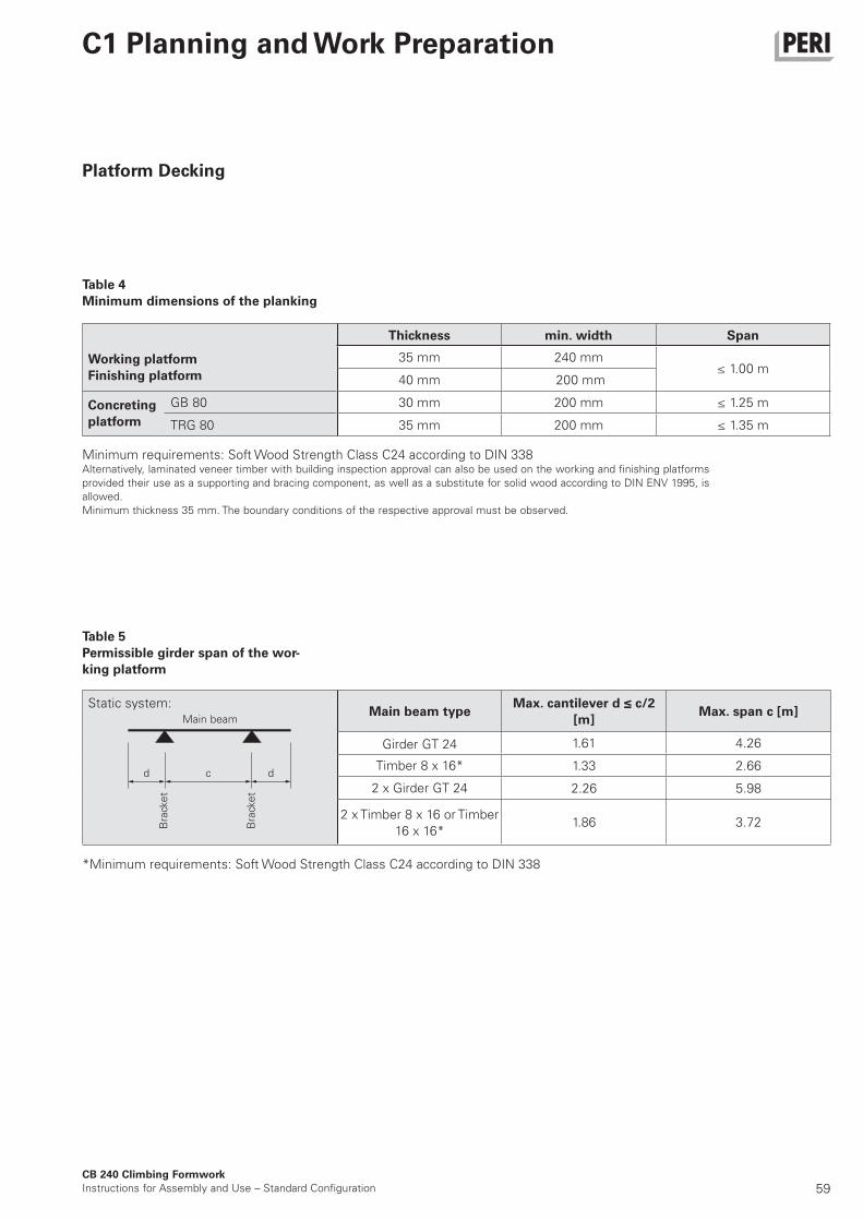
59
1.61 4.26
1.33 2.66
2.26 5.98
1.86 3.72
35 mm 240 mm≤ 1.00 m
40 mm 200 mm
GB 80 30 mm 200 mm ≤ 1.25 m
TRG 80 35 mm 200 mm ≤ 1.35 m
CB 240 Climbing Formwork
Instructions for Assembly and Use – Standard Configuration
C1 Planning and Work Preparation
Platform Decking
Table 4
Minimum dimensions of the planking
Thickness min. width Span
Working platform
Finishing platform
Concreting
platform
Table 5
Permissible girder span of the wor-
king platform
Main beam
Bra
cke
t
Bra
cke
t
Static system:
Girder GT 24
2 x Timber 8 x 16 or Timber
16 x 16*
2 x Girder GT 24
Timber 8 x 16*
Main beam typeMax. cantilever d ≤ c/2
[m]Max. span c [m]
d dc
Minimum requirements: Soft Wood Strength Class C24 according to DIN 338Alternatively, laminated veneer timber with building inspection approval can also be used on the working and finishing platforms
provided their use as a supporting and bracing component, as well as a substitute for solid wood according to DIN ENV 1995, is
allowed.
Minimum thickness 35 mm. The boundary conditions of the respective approval must be observed.
*Minimum requirements: Soft Wood Strength Class C24 according to DIN 338
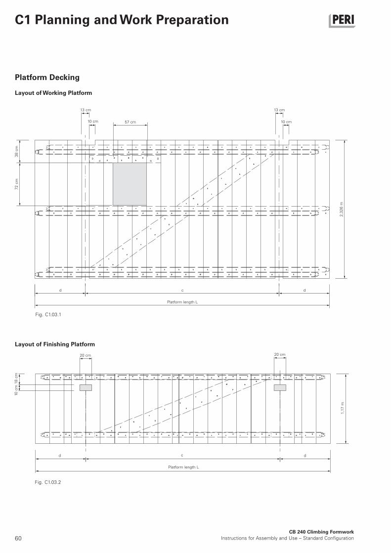
60CB 240 Climbing Formwork
Instructions for Assembly and Use – Standard Configuration
C1 Planning and Work Preparation
Platform Decking
Layout of Working Platform
Layout of Finishing Platform
72
cm
13 cm
10 cm 57 cm
2,3
26
m
d c
Platform length L
d
10 c
m18
cm
d c
Platform length L
d
Fig. C1.03.1
Fig. C1.03.2
1,1
7 m
20 cm
38
cm
20 cm
13 cm
10 cm
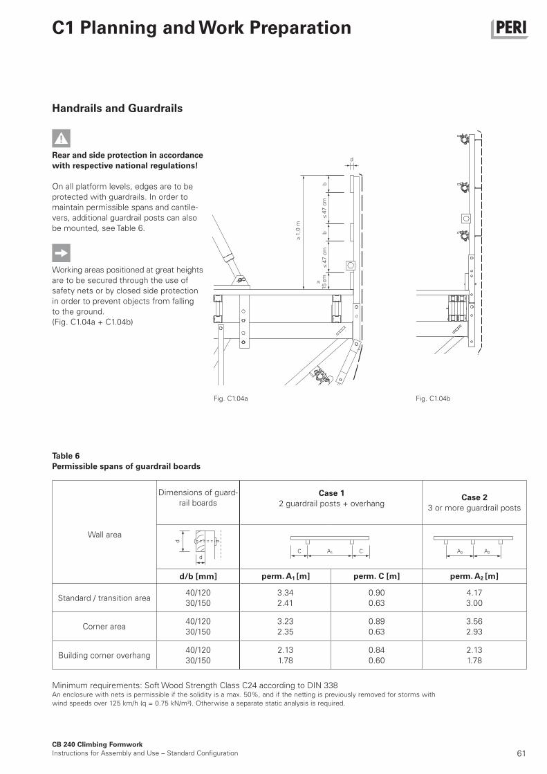
61CB 240 Climbing Formwork
Instructions for Assembly and Use – Standard Configuration
C1 Planning and Work Preparation
Handrails and Guardrails
Rear and side protection in accordance
with respective national regulations!
On all platform levels, edges are to be
protected with guardrails. In order to
maintain permissible spans and cantile-
vers, additional guardrail posts can also
be mounted, see Table 6.
Working areas positioned at great heights
are to be secured through the use of
safety nets or by closed side protection
in order to prevent objects from falling
to the ground.
(Fig. C1.04a + C1.04b)
Table 6
Permissible spans of guardrail boards
b
d
Fig. C1.04a Fig. C1.04b
b1,0
m≥
47
cm
≤4
7 c
m≤
≥15
cm
Minimum requirements: Soft Wood Strength Class C24 according to DIN 338An enclosure with nets is permissible if the solidity is a max. 50%, and if the netting is previously removed for storms with
wind speeds over 125 km/h (q = 0.75 kN/m²). Otherwise a separate static analysis is required.
d/b [mm]
40/120
30/150
3.34
2.41
0.90
0.63
4.17
3.00
40/120
30/150
3.23
2.35
0.89
0.63
3.56
2.93
40/120
30/150
2.13
1.78
0.84
0.60
2.13
1.78
Case 1
2 guardrail posts + overhangCase 2
3 or more guardrail posts
Dimensions of guard-
rail boards
Standard / transition area
Corner area
Building corner overhang
Wall area
perm. A1 [m] perm. C [m] perm. A2 [m]
d
d
C CA1 A2 A2
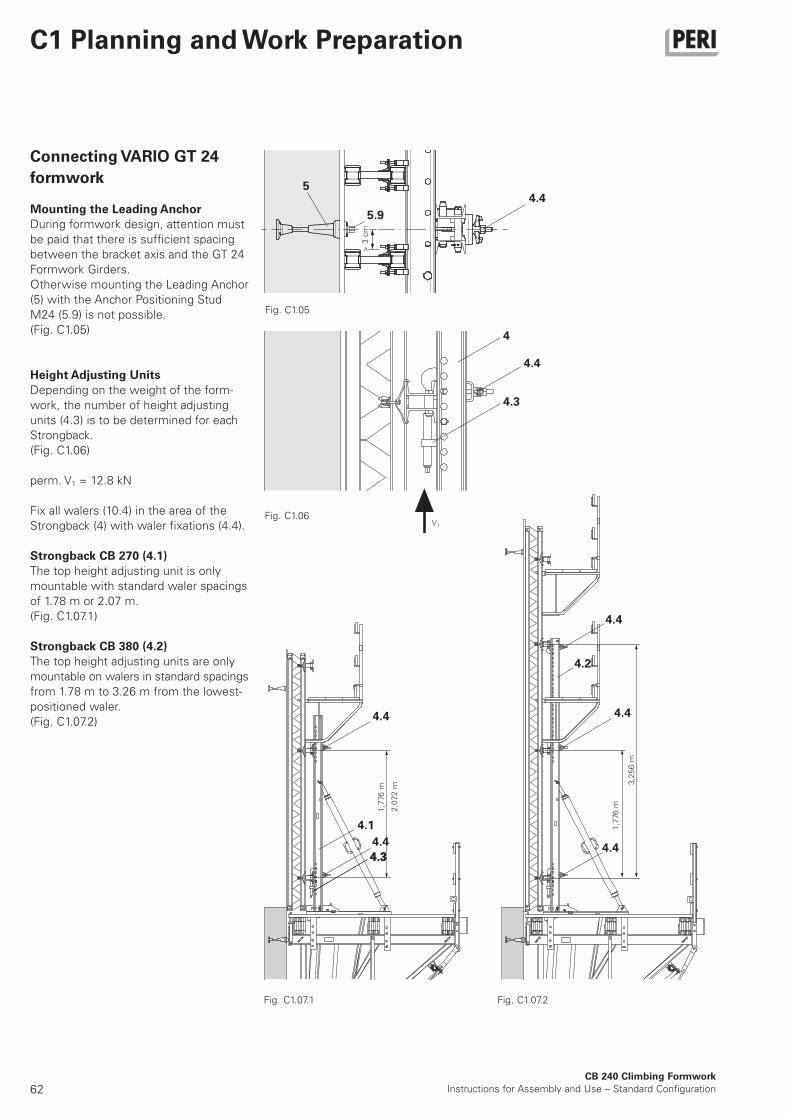
62CB 240 Climbing Formwork
Instructions for Assembly and Use – Standard Configuration
C1 Planning and Work Preparation
V1
Connecting VARIO GT 24
formwork
Mounting the Leading Anchor
During formwork design, attention must
be paid that there is sufficient spacing
between the bracket axis and the GT 24
Formwork Girders.
Otherwise mounting the Leading Anchor
(5) with the Anchor Positioning Stud
M24 (5.9) is not possible.
(Fig. C1.05)
Height Adjusting Units
Depending on the weight of the form-
work, the number of height adjusting
units (4.3) is to be determined for each
Strongback.
(Fig. C1.06)
perm. V1 = 12.8 kN
Fix all walers (10.4) in the area of the
Strongback (4) with waler fixations (4.4).
Strongback CB 270 (4.1)
The top height adjusting unit is only
mountable with standard waler spacings
of 1.78 m or 2.07 m.
(Fig. C1.07.1)
Strongback CB 380 (4.2)
The top height adjusting units are only
mountable on walers in standard spacings
from 1.78 m to 3.26 m from the lowest-
positioned waler.
(Fig. C1.07.2)
Fig. C1.05
Fig. C1.07.1 Fig. C1.07.2
1,7
76 m
2,0
72
m
1,7
76 m
3,2
56
m
4.1
4.3
4.4
5
5.9
3cm
>
Fig. C1.06
4
4.4
4.4
4.2
4.4
4.4
4.4
4.4
4.3
4.3
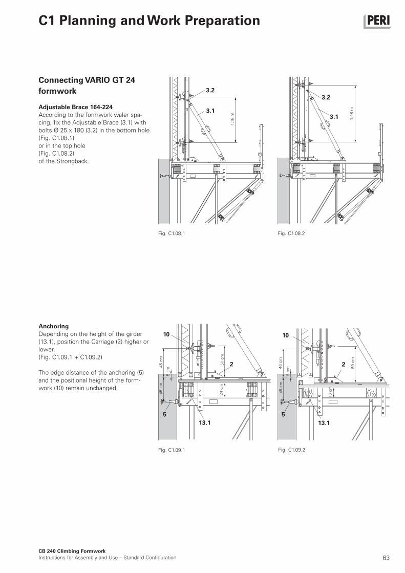
63CB 240 Climbing Formwork
Instructions for Assembly and Use – Standard Configuration
C1 Planning and Work Preparation
10
3.2
3.1
3.2
3.1
Connecting VARIO GT 24
formwork
Adjustable Brace 164-224
According to the formwork waler spa-
cing, fix the Adjustable Brace (3.1) with
bolts Ø 25 x 180 (3.2) in the bottom hole
(Fig. C1.08.1)
or in the top hole
(Fig. C1.08.2)
of the Strongback.
Anchoring
Depending on the height of the girder
(13.1), position the Carriage (2) higher or
lower.
(Fig. C1.09.1 + C1.09.2)
The edge distance of the anchoring (5)
and the positional height of the form-
work (10) remain unchanged.
1,1
8 m
Fig. C1.08.1 Fig. C1.08.2
1,4
8 m
45
cm
46
cm
46
cm
51
cm
Fig. C1.09.1
45
cm
16
cm
59
cm
Fig. C1.09.2
5 c
m
5 c
m
24
cm
13.1
5
10
13.1
5
2 2
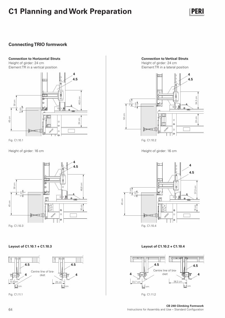
64
45
cm
30
cm
5 c
m
40
,5 c
m2
4 c
m 50
cm
15
cm
5 c
m 34
,3 c
m2
4 c
m
45
cm
30
cm
5 c
m
48
,6 c
m16
cm
45
cm
15
cm
5 c
m 37
,3 c
m16
cm
12,5 cm
6,3 cm
25 cm
6,3 cm
23,7 cm
6,3 cm
36,2 cm
6,3 cm
4
4.5 4.5
4
4.5
4
4.5
4
4.5 4.5
4 4
4.5 4.5
4 4
CB 240 Climbing Formwork
Instructions for Assembly and Use – Standard Configuration
C1 Planning and Work Preparation
Connecting TRIO formwork
Connection to Horizontal Struts
Height of girder: 24 cm
Element TR in a vertical position
Height of girder: 16 cm
Layout of C1.10.1 + C1.10.3
Connection to Vertical Struts
Height of girder: 24 cm
Element TR in a lateral position
Height of girder: 16 cm
Layout of C1.10.2 + C1.10.4
Fig. C1.10.1 Fig. C1.10.2
Fig. C1.10.3 Fig. C1.10.4
Fig. C1.11.1 Fig. C1.11.2
Centre line of bra-
cket
Centre line of bra-
cket
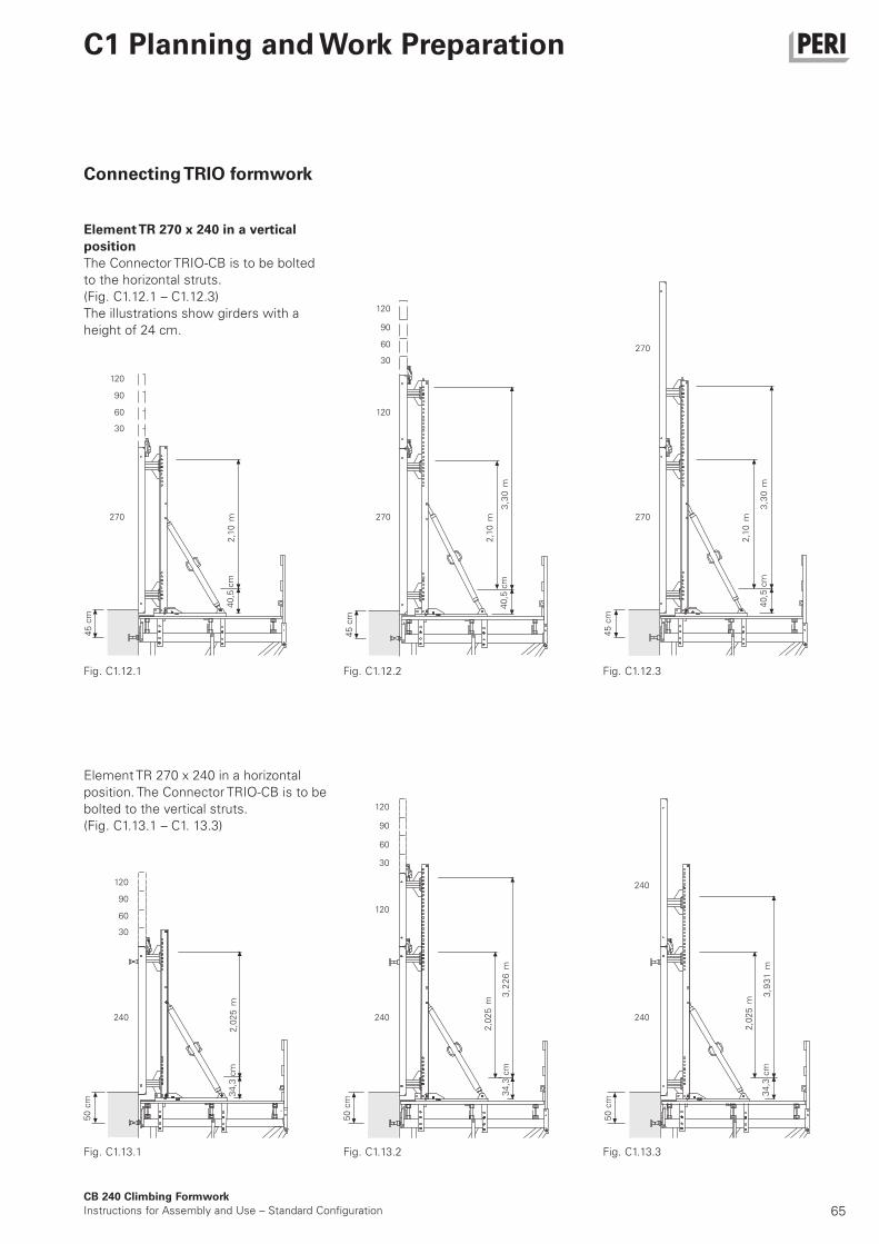
65
270
45
cm
40
,5 c
m
30
60
90
120
270
45
cm
40
,5 c
m
30
60
90
120
270
45
cm
40
,5 c
m
240
50
cm
34
,3 c
m
30
60
90
120
240
50
cm
34
,3 c
m
30
60
90
120
120
240
50
cm
34
,3 c
m
240
270
120
2,1
0m
2,1
0m
3,3
0m
2,1
0m
3,3
0m
2,0
25
m
2,0
25
m
3,2
26
m
2,0
25
m
3,9
31
m
CB 240 Climbing Formwork
Instructions for Assembly and Use – Standard Configuration
C1 Planning and Work Preparation
Element TR 270 x 240 in a vertical
position
The Connector TRIO-CB is to be bolted
to the horizontal struts.
(Fig. C1.12.1 – C1.12.3)
The illustrations show girders with a
height of 24 cm.
Connecting TRIO formwork
Element TR 270 x 240 in a horizontal
position. The Connector TRIO-CB is to be
bolted to the vertical struts.
(Fig. C1.13.1 – C1. 13.3)
Fig. C1.12.1 Fig. C1.12.2 Fig. C1.12.3
Fig. C1.13.1 Fig. C1.13.2 Fig. C1.13.3
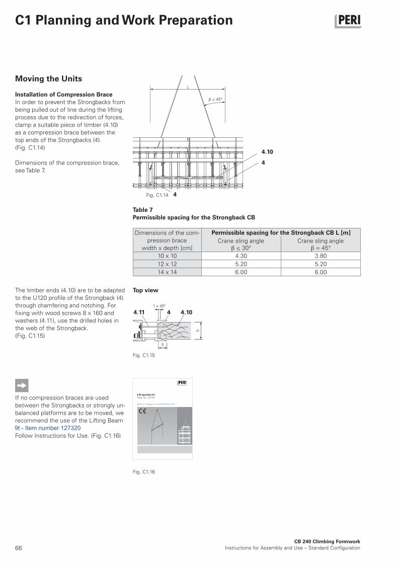
66
Klettertraverse RCS 10 t
Art.-Nr. 112986
Ausgabe 01 | 2013
Originalbetriebsanleitung
b
5
≤ 45°
L
4.11 4 4.10
4.10
4
4
1 x 45°
≤ 30° = 45°
10 x 10 4.30 3.80
12 x 12 5.20 5.20
14 x 14 6.00 6.00
CB 240 Climbing Formwork
Instructions for Assembly and Use – Standard Configuration
C1 Planning and Work Preparation
Moving the Units
Installation of Compression Brace
In order to prevent the Strongbacks from
being pulled out of line during the lifting
process due to the redirection of forces,
clamp a suitable piece of timber (4.10)
as a compression brace between the
top ends of the Strongbacks (4).
(Fig. C1.14)
Dimensions of the compression brace,
see Table 7.
The timber ends (4.10) are to be adapted
to the U120 profile of the Strongback (4)
through chamfering and notching. For
fixing with wood screws 8 x 160 and
washers (4.11), use the drilled holes in
the web of the Strongback.
(Fig. C1.15)
If no compression braces are used
between the Strongbacks or strongly un-
balanced platforms are to be moved, we
recommend the use of the Lifting Beam
RCS 10 t, Item no. 112986.
Follow Instructions for Use. (Fig. C1.16)
Crane sling angle Crane sling angle
Permissible spacing for the Strongback CB L [m]Dimensions of the com-
pression brace
width x depth [cm]
Fig. C1.14
Table 7
Permissible spacing for the Strongback CB
Top view
Fig. C1.15
Fig. C1.16
9t - Item number 127320
67CB 240 Climbing Formwork
Instructions for Assembly and Use – Standard Configuration
C1 Planning and Work Preparation
Drawings and Plans
Assembly Drawings
The following points at least should
be featured in the drawings:
– bracket spacing and bracing
– dimensions of the working and
finishing platform
– dimensions, arrangement and number
of concreting and intermediate plat-
forms
– erection of girders and guardrails
– layout of end guardrail posts
– layout of lateral guardrails
– position of access ladders
– material requirements (parts list)
General Arrangement Drawings
The following points at least should
be featured:
– position of the climbing anchor in the
plan view and sectional view
– which climbing unit is used on which
part of the building
– associated formwork and finishing
platform
– installation of wind bracing
– distance of finishing platform to the
working platform
– formwork and strongback connection
points
– timber brace position between the
strongbacks
– reference values for retraction di-
stance during moving (see Table 2,
Section B4)
– possible special measures in case of
irregular concreting heights
– details of modifications
– material requirements (parts list)
– weight of the climbing unit
Appropriate, easy-to-read as well as suf-
ficient drawings in both number and for-
mat are to be made available to the site
management. The drawings are to be
created clearly and professionally in the
language of the country where construc-
tion is taking place.
We recommend including a plan view
and sectional view of the scaffold as
well as an overview plan for positioning
purposes.
We recommend including a plan view
and a top view of the platform.
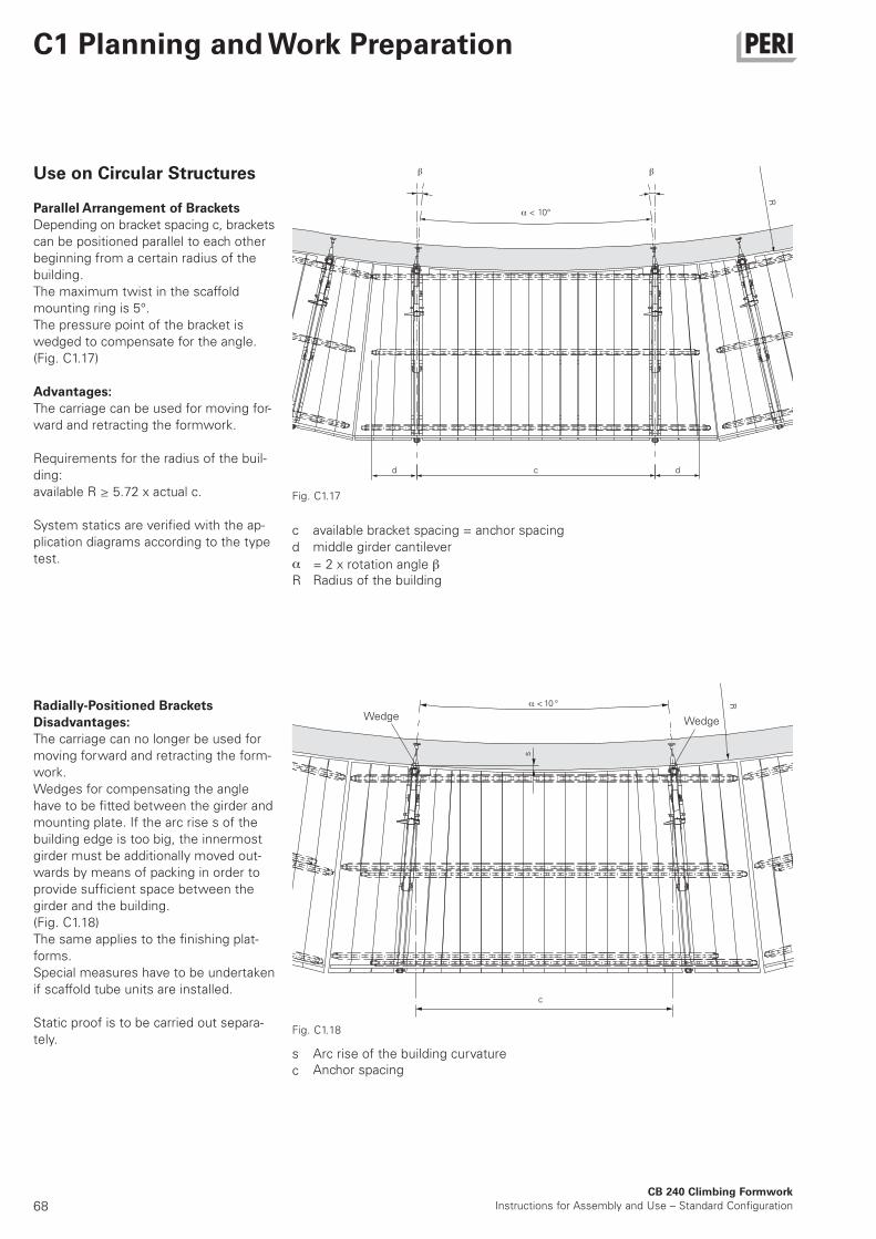
68CB 240 Climbing Formwork
Instructions for Assembly and Use – Standard Configuration
C1 Planning and Work Preparation
Use on Circular Structures
Parallel Arrangement of Brackets
Depending on bracket spacing c, brackets
can be positioned parallel to each other
beginning from a certain radius of the
building.
The maximum twist in the scaffold
mounting ring is 5°.
The pressure point of the bracket is
wedged to compensate for the angle.
(Fig. C1.17)
Advantages:
The carriage can be used for moving for-
ward and retracting the formwork.
Requirements for the radius of the buil-
ding:
available R ≥ 5.72 x actual c.
System statics are verified with the ap-
plication diagrams according to the type
test.
c
d
R
s
c
Fig. C1.17
R
cd d
Fig. C1.18
R
c
Wedge Wedge
available bracket spacing = anchor spacing
middle girder cantilever
= 2 x rotation angle Radius of the building
Arc rise of the building curvatureAnchor spacing
Radially-Positioned Brackets
Disadvantages:
The carriage can no longer be used for
moving forward and retracting the form-
work.
Wedges for compensating the angle
have to be fitted between the girder and
mounting plate. If the arc rise s of the
building edge is too big, the innermost
girder must be additionally moved out-
wards by means of packing in order to
provide sufficient space between the
girder and the building.
(Fig. C1.18)
The same applies to the finishing plat-
forms.
Special measures have to be undertaken
if scaffold tube units are installed.
Static proof is to be carried out separa-
tely.
< 10°
10< °
s
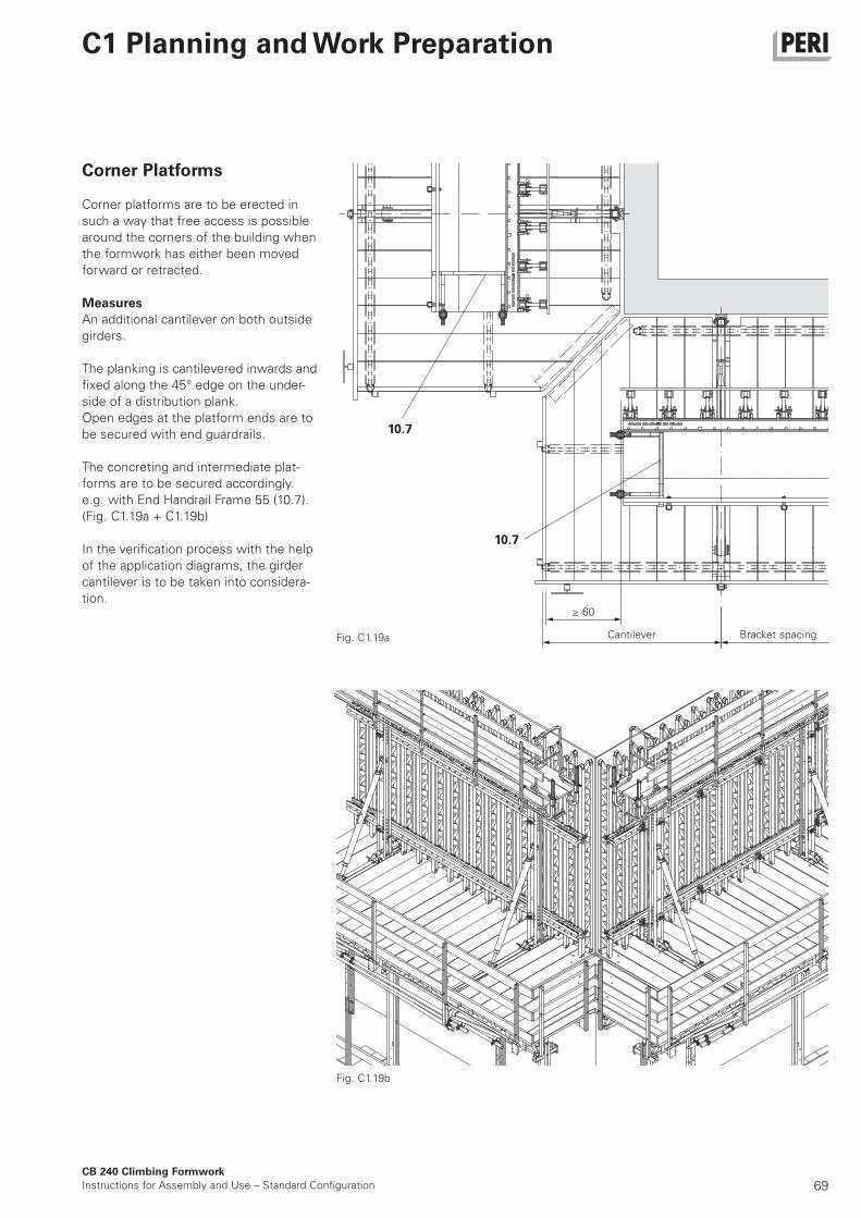
69
CB 240 Climbing Formwork
Instructions for Assembly and Use – Standard Configuration
C1 Planning and Work Preparation
Corner Platforms
Corner platforms are to be erected in
such a way that free access is possible
around the corners of the building when
the formwork has either been moved
forward or retracted.
Measures
An additional cantilever on both outside
girders.
The planking is cantilevered inwards and
fixed along the 45° edge on the under-
side of a distribution plank.
Open edges at the platform ends are to
be secured with end guardrails.
The concreting and intermediate plat-
forms are to be secured accordingly.
e.g. with End Handrail Frame 55 (10.7).
(Fig. C1.19a + C1.19b)
In the verification process with the help
of the application diagrams, the girder
cantilever is to be taken into considera-
tion.
Cantilever
≥ 60
Bracket spacingFig. C1.19a
Fig. C1.19b
10.7
10.7
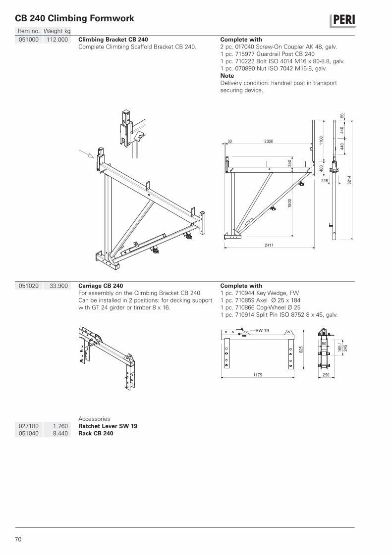
CB 240 Climbing Formwork
70
Item no. Weight kg
051020 33.900 Carriage CB 240
For assembly on the Climbing Bracket CB 240.
Can be installed in 2 positions: for decking support
with GT 24 girder or timber 8 x 16.
Complete with
1 pc. 710944 Key Wedge, FW
1 pc. 710859 Axel Ø 25 x 184
1 pc. 710866 Cog-Wheel Ø 25
1 pc. 710914 Split Pin ISO 8752 8 x 45, galv.
1175
625
90
250
165
/24
5
SW 19
027180
051040
1.760
8.440
Accessories
Ratchet Lever SW 19
Rack CB 240
051000 112.000 Climbing Bracket CB 240
Complete Climbing Scaffold Bracket CB 240.
Complete with
2 pc. 017040 Screw-On Coupler AK 48, galv.
1 pc. 715977 Guardrail Post CB 240
1 pc. 710222 Bolt ISO 4014 M16 x 80-8.8, galv.
1 pc. 070890 Nut ISO 7042 M16-8, galv.
Note
Delivery condition: handrail post in transport
securing device.
1100
5044
044
032
14
30 2326
400
228
2411
1800
350
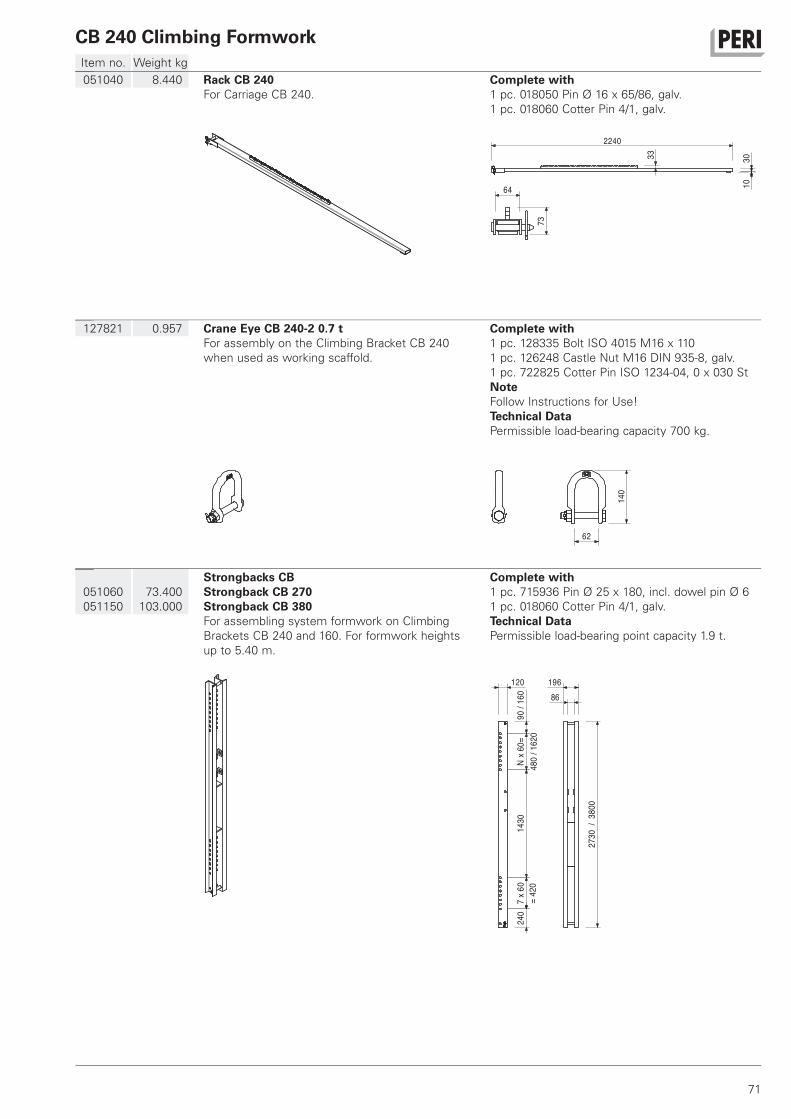
CB 240 Climbing Formwork
71
Item no. Weight kg
051060
051150
73.400
103.000
Strongbacks CB
Strongback CB 270
Strongback CB 380
For assembling system formwork on Climbing
Brackets CB 240 and 160. For formwork heights
up to 5.40 m.
Complete with
1 pc. 715936 Pin Ø 25 x 180, incl. dowel pin Ø 6
1 pc. 018060 Cotter Pin 4/1, galv.
Technical Data
Permissible load-bearing point capacity 1.9 t.
12086
196
160
90/
Nx6
0=14
307
x60
240
=42
048
0/1
620
2730
/38
00
127821 0.957 Crane Eye CB 240-2 0.7 t
For assembly on the Climbing Bracket CB 240
when used as working scaffold.
Complete with
1 pc. 128335 Bolt ISO 4015 M16 x 110
1 pc. 126248 Castle Nut M16 DIN 935-8, galv.
1 pc. 722825 Cotter Pin ISO 1234-04, 0 x 030 St
Note
Follow Instructions for Use!
Technical Data
Permissible load-bearing capacity 700 kg.
140
62
051040 8.440 Rack CB 240
For Carriage CB 240.
Complete with
1 pc. 018050 Pin Ø 16 x 65/86, galv.
1 pc. 018060 Cotter Pin 4/1, galv.
3010
33
2240
64
73
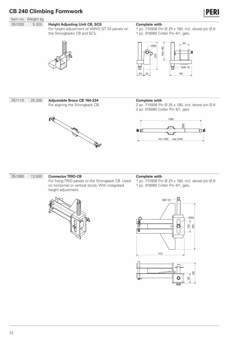
CB 240 Climbing Formwork
72
Item no. Weight kg
051090 13.500 Connector TRIO-CB
For fixing TRIO panels to the Strongback CB. Used
on horizontal or vertical struts. With integrated
height adjustment.
Complete with
1 pc. 715936 Pin Ø 25 x 180, incl. dowel pin Ø 6
1 pc. 018060 Cotter Pin 4/1, galv.10
040
082
180
Ø25
415
SW 19
051110 25.200 Adjustable Brace CB 164-224
For aligning the Strongback CB.
Complete with
2 pc. 715936 Pin Ø 25 x 180, incl. dowel pin Ø 6
2 pc. 018060 Cotter Pin 4/1, galv.
1580
min 1640 max 2240
89Ø
051030 5.320 Height Adjusting Unit CB, SCS
For height adjustment of VARIO GT 24 panels on
the Strongbacks CB and SCS.
Complete with
1 pc. 715936 Pin Ø 25 x 180, incl. dowel pin Ø 6
1 pc. 018060 Cotter Pin 4/1, galv.
240
60 55
82
190
max
182Ø25
SW 19
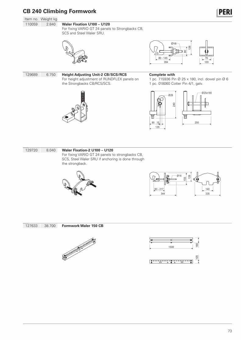
CB 240 Climbing Formwork
73
Item no. Weight kg
127633 38.700 Formwork Waler 150 CB
180
120
1500
129720 8.040 Waler Fixation-2 U100 – U120
For fixing VARIO GT 24 panels to strongbacks CB,
SCS, Steel Waler SRU if anchoring is done through
the strongback.
80 - 217344
155 12
6Ø16
335140
129689 6.750 Height Adjusting Unit-2 CB/SCS/RCS
For height adjustment of RUNDFLEX panels on
the Strongbacks CB/RCS/SCS.
Complete with
1 pc. 715936 Pin Ø 25 x 180, incl. dowel pin Ø 6
1 pc. 018060 Cotter Pin 4/1, galv.
250
240
13590 15
Ø26Ø25x180
110059 2.840 Waler Fixation U100 – U120
For fixing VARIO GT 24 panels to Strongbacks CB,
SCS and Steel Waler SRU.
284
8012
6
Ø16
80 - 145 76120
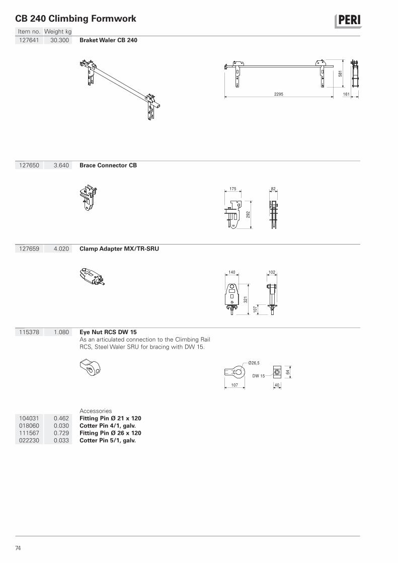
CB 240 Climbing Formwork
74
Item no. Weight kg
115378 1.080 Eye Nut RCS DW 15
As an articulated connection to the Climbing Rail
RCS, Steel Waler SRU for bracing with DW 15.
107 40
64
Ø26,5
DW 15
104031
018060
111567
022230
0.462
0.030
0.729
0.033
Accessories
Fitting Pin Ø 21 x 120
Cotter Pin 4/1, galv.
Fitting Pin Ø 26 x 120
Cotter Pin 5/1, galv.
127659 4.020 Clamp Adapter MX/TR-SRU32
1
140
107
102
127650 3.640 Brace Connector CB
292
175 82
127641 30.300 Braket Waler CB 240
581
1612295
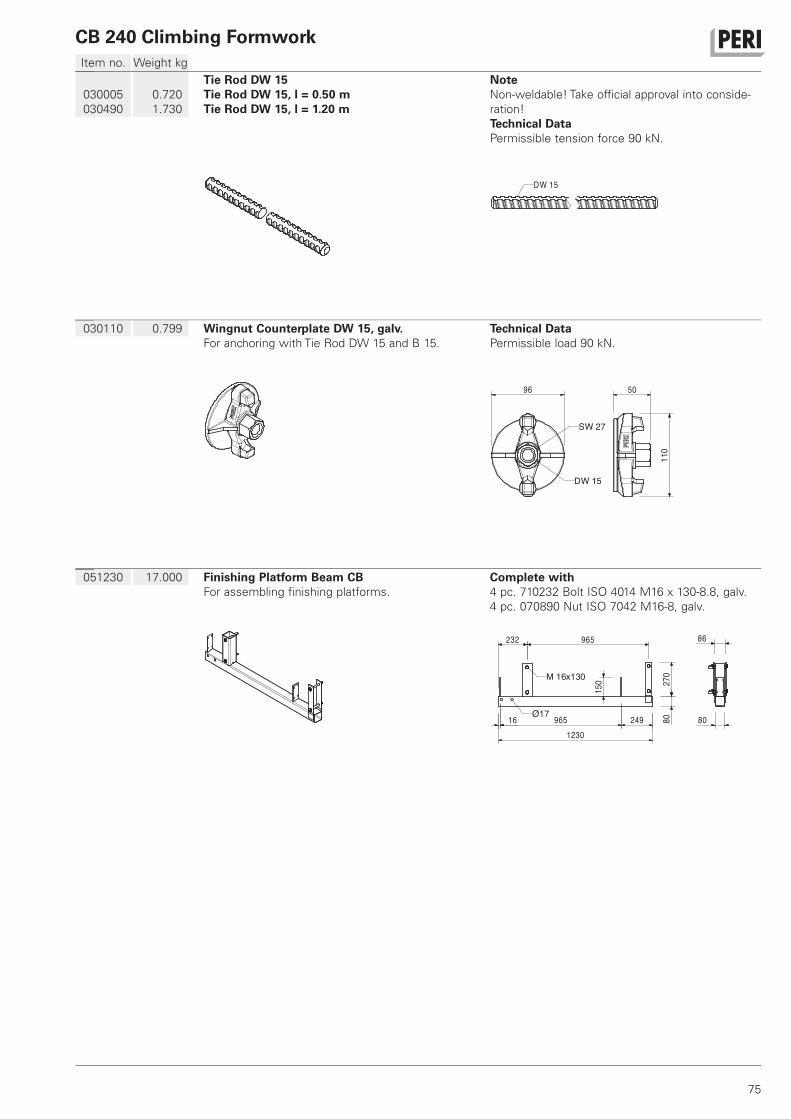
CB 240 Climbing Formwork
75
Item no. Weight kg
051230 17.000 Finishing Platform Beam CB
For assembling finishing platforms.
Complete with
4 pc. 710232 Bolt ISO 4014 M16 x 130-8.8, galv.
4 pc. 070890 Nut ISO 7042 M16-8, galv.
232 965
1230
8027
0
16 965 249
M 16x130
150
80
86
Ø17
030110 0.799 Wingnut Counterplate DW 15, galv.
For anchoring with Tie Rod DW 15 and B 15.
Technical Data
Permissible load 90 kN.
96
110
50
SW 27
DW 15
030005
030490
0.720
1.730
Tie Rod DW 15
Tie Rod DW 15, l = 0.50 m
Tie Rod DW 15, l = 1.20 m
Note
Non-weldable! Take official approval into conside-
ration!
Technical Data
Permissible tension force 90 kN.
DW 15
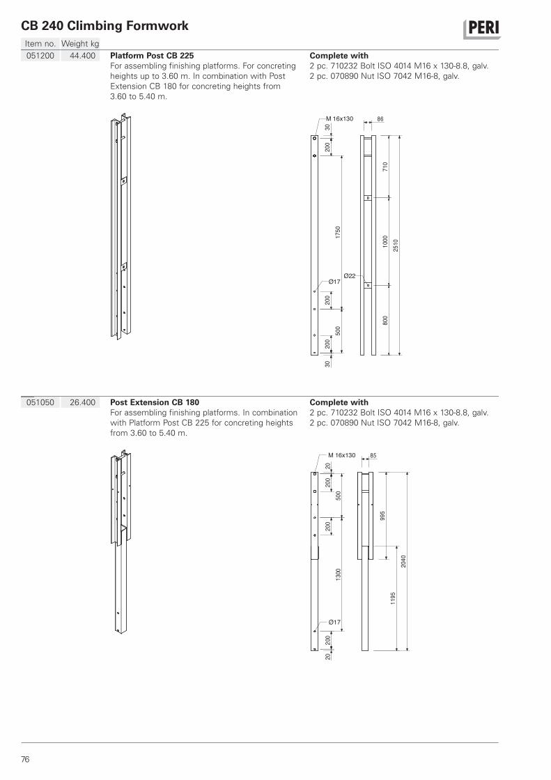
CB 240 Climbing Formwork
76
Item no. Weight kg
051050 26.400 Post Extension CB 180
For assembling finishing platforms. In combination
with Platform Post CB 225 for concreting heights
from 3.60 to 5.40 m.
Complete with
2 pc. 710232 Bolt ISO 4014 M16 x 130-8.8, galv.
2 pc. 070890 Nut ISO 7042 M16-8, galv.
500
200
2013
0020
020
020
995
1195
2040
Ø17
M 16x130 85
051200 44.400 Platform Post CB 225
For assembling finishing platforms. For concreting
heights up to 3.60 m. In combination with Post
Extension CB 180 for concreting heights from
3.60 to 5.40 m.
Complete with
2 pc. 710232 Bolt ISO 4014 M16 x 130-8.8, galv.
2 pc. 070890 Nut ISO 7042 M16-8, galv.
200
3020
020
030
500
1750
710
1000
800
2510
Ø17Ø22
86M 16x130
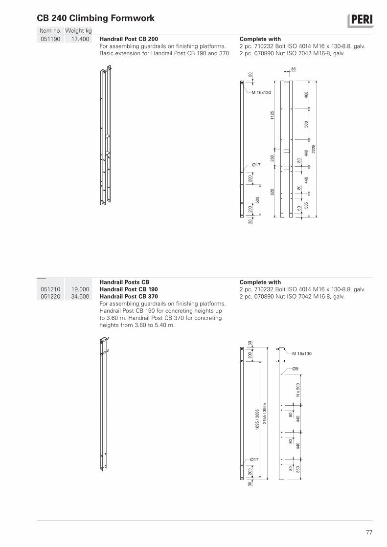
CB 240 Climbing Formwork
77
Item no. Weight kg
051210
051220
19.000
34.600
Handrail Posts CB
Handrail Post CB 190
Handrail Post CB 370
For assembling guardrails on finishing platforms.
Handrail Post CB 190 for concreting heights up
to 3.60 m. Handrail Post CB 370 for concreting
heights from 3.60 to 5.40 m.
Complete with
2 pc. 710232 Bolt ISO 4014 M16 x 130-8.8, galv.
2 pc. 070890 Nut ISO 7042 M16-8, galv.
200
200
3030
1895
/369
521
55/3
955
8080
80 330
440
440
500
Nx
Ø17
M 16x130
Ø9
051190 17.400 Handrail Post CB 200
For assembling guardrails on finishing platforms.
Basic extension for Handrail Post CB 190 and 370.
Complete with
2 pc. 710232 Bolt ISO 4014 M16 x 130-8.8, galv.
2 pc. 070890 Nut ISO 7042 M16-8, galv.
200
200
500
3030
8080
60 385
440
440
500
460
2225
1125
280
820
M 16x130
Ø17
86
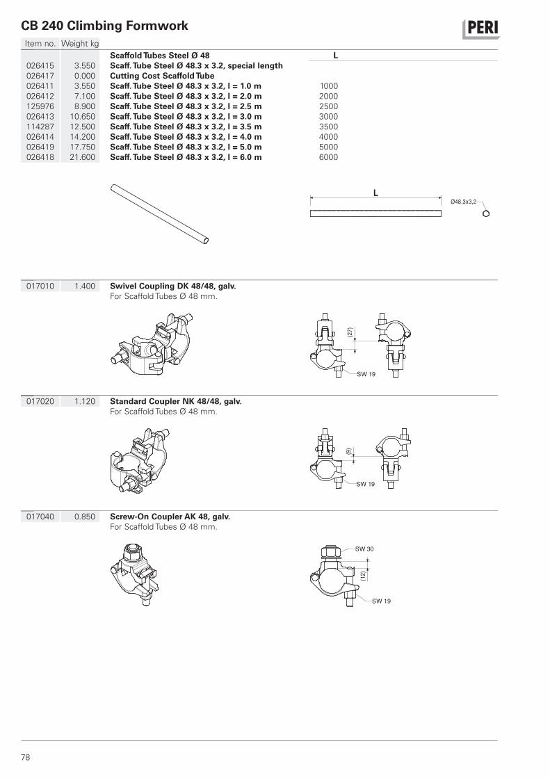
CB 240 Climbing Formwork
78
Item no. Weight kg
017040 0.850 Screw-On Coupler AK 48, galv.
For Scaffold Tubes Ø 48 mm.
SW 30
SW 19
12()
017020 1.120 Standard Coupler NK 48/48, galv.
For Scaffold Tubes Ø 48 mm.
SW 19
9()
017010 1.400 Swivel Coupling DK 48/48, galv.
For Scaffold Tubes Ø 48 mm.
(27)
SW 19
026415
026417
026411
026412
125976
026413
114287
026414
026419
026418
3.550
0.000
3.550
7.100
8.900
10.650
12.500
14.200
17.750
21.600
Scaffold Tubes Steel Ø 48
Scaff. Tube Steel Ø 48.3 x 3.2, special length
Cutting Cost Scaffold Tube
Scaff. Tube Steel Ø 48.3 x 3.2, l = 1.0 m
Scaff. Tube Steel Ø 48.3 x 3.2, l = 2.0 m
Scaff. Tube Steel Ø 48.3 x 3.2, l = 2.5 m
Scaff. Tube Steel Ø 48.3 x 3.2, l = 3.0 m
Scaff. Tube Steel Ø 48.3 x 3.2, l = 3.5 m
Scaff. Tube Steel Ø 48.3 x 3.2, l = 4.0 m
Scaff. Tube Steel Ø 48.3 x 3.2, l = 5.0 m
Scaff. Tube Steel Ø 48.3 x 3.2, l = 6.0 m
L
1000
2000
2500
3000
3500
4000
5000
6000
Ø48,3x3,2L
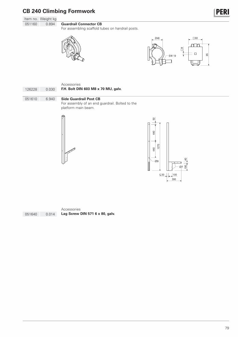
CB 240 Climbing Formwork
79
Item no. Weight kg
051610 6.940 Side Guardrail Post CB
For assembly of an end guardrail. Bolted to the
platform main beam.
440
5044
0 1270
10050
Ø9
Ø7
4019
0
390
051640 0.014
Accessories
Lag Screw DIN 571 6 x 80, galv.
051160 0.894 Guardrail Connector CB
For assembling scaffold tubes on handrail posts.
95
60
9
Ø48
SW 19
126228 0.030
Accessories
F.H. Bolt DIN 603 M8 x 70 MU, galv.
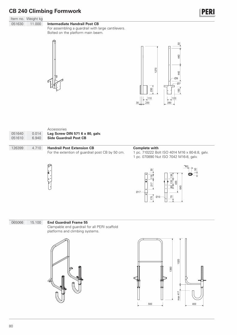
CB 240 Climbing Formwork
80
Item no. Weight kg
065066 15.100 End Guardrail Frame 55
Clampable end guardrail for all PERI scaffold
platforms and climbing systems.
560 400
1360
1020
max
417
126399 4.710 Handrail Post Extension CB
For the extention of guardrail post CB by 50 cm.
Complete with
1 pc. 710222 Bolt ISO 4014 M16 x 80-8.8, galv.
1 pc. 070890 Nut ISO 7042 M16-8, galv.
645
136
135
8070
435
3011
921
717
0
60
50Ø10
Ø17
051630 11.000 Intermediate Handrail Post CB
For assembling a guardrail with large cantilevers.
Bolted on the platform main beam.
1270
50110
30
440
440
50
Ø9
230
190
120280
Ø7
051640
051610
0.014
6.940
Accessories
Lag Screw DIN 571 6 x 80, galv.
Side Guardrail Post CB
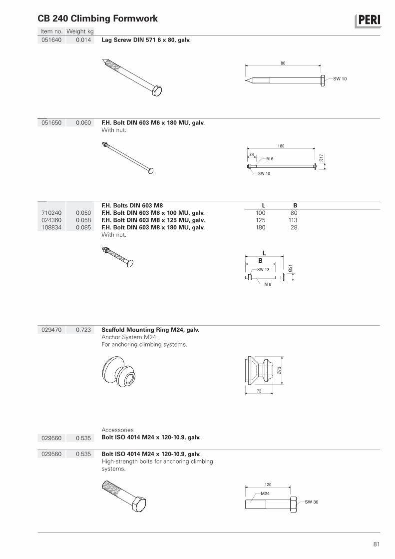
CB 240 Climbing Formwork
81
Item no. Weight kg
029560 0.535 Bolt ISO 4014 M24 x 120-10.9, galv.
High-strength bolts for anchoring climbing
systems.
120
SW 36
M24
029470 0.723 Scaffold Mounting Ring M24, galv.
Anchor System M24.
For anchoring climbing systems.
73
73Ø
029560 0.535
Accessories
Bolt ISO 4014 M24 x 120-10.9, galv.
710240
024360
108834
0.050
0.058
0.085
F.H. Bolts DIN 603 M8
F.H. Bolt DIN 603 M8 x 100 MU, galv.
F.H. Bolt DIN 603 M8 x 125 MU, galv.
F.H. Bolt DIN 603 M8 x 180 MU, galv.
With nut.
L B
100 80
125 113
180 28
L
B
M 821ØSW 13
051650 0.060 F.H. Bolt DIN 603 M6 x 180 MU, galv.
With nut.
180
M 6 1724
SW 10
051640 0.014 Lag Screw DIN 571 6 x 80, galv.
SW 10
80
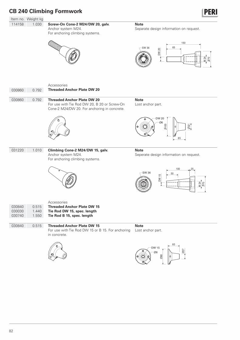
CB 240 Climbing Formwork
82
Item no. Weight kg
030840 0.515 Threaded Anchor Plate DW 15
For use with Tie Rod DW 15 or B 15. For anchoring
in concrete.
Note
Lost anchor part.
60DW 15
Ø6
80Ø
27Ø
031220 1.010 Climbing Cone-2 M24/DW 15, galv.
Anchor system M24.
For anchoring climbing systems.
Note
Seperate design information on request.
50100 25
M24
DW15
70
SW 36
030840
030030
030740
0.515
1.440
1.550
Accessories
Threaded Anchor Plate DW 15
Tie Rod DW 15, spec. length
Tie Rod B 15, spec. length
030860 0.792 Threaded Anchor Plate DW 20
For use with Tie Rod DW 20, B 20 or Screw-On
Cone-2 M24/DW 20. For anchoring in concrete.
Note
Lost anchor part.
100
32
DW 20Ø6
65
114158 1.030 Screw-On Cone-2 M24/DW 20, galv.
Anchor system M24.
For anchoring climbing systems.
Note
Separate design information on request.
20DW
65150
7024M
SW 36
030860 0.792
Accessories
Threaded Anchor Plate DW 20
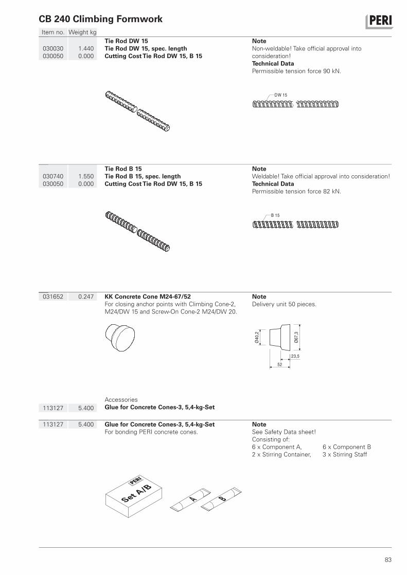
CB 240 Climbing Formwork
83
Item no. Weight kg
113127 5.400 Glue for Concrete Cones-3, 5,4-kg-Set
For bonding PERI concrete cones.
Note
See Safety Data sheet!
Consisting of:
6 x Component A, 6 x Component B
2 x Stirring Container, 3 x Stirring Staff
031652 0.247 KK Concrete Cone M24-67/52
For closing anchor points with Climbing Cone-2,
M24/DW 15 and Screw-On Cone-2 M24/DW 20.
Note
Delivery unit 50 pieces.
40,2
Ø 67,3
Ø
23,552
113127 5.400
Accessories
Glue for Concrete Cones-3, 5,4-kg-Set
030740
030050
1.550
0.000
Tie Rod B 15
Tie Rod B 15, spec. length
Cutting Cost Tie Rod DW 15, B 15
Note
Weldable! Take official approval into consideration!
Technical Data
Permissible tension force 82 kN.
B 15
030030
030050
1.440
0.000
Tie Rod DW 15
Tie Rod DW 15, spec. length
Cutting Cost Tie Rod DW 15, B 15
Note
Non-weldable! Take official approval into
consideration!
Technical Data
Permissible tension force 90 kN.
DW 15
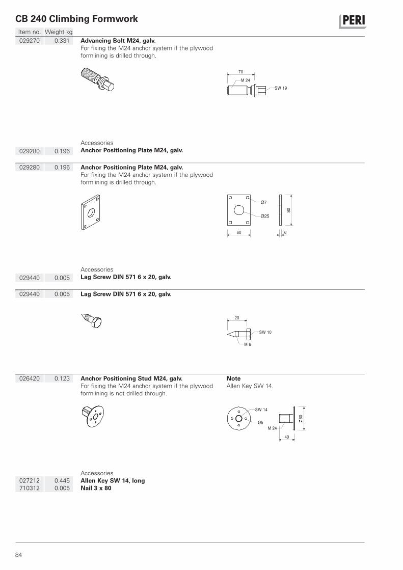
CB 240 Climbing Formwork
84
Item no. Weight kg
026420 0.123 Anchor Positioning Stud M24, galv.
For fixing the M24 anchor system if the plywood
formlining is not drilled through.
Note
Allen Key SW 14.
60
40
M 24Ø5
SW 14
027212
710312
0.445
0.005
Accessories
Allen Key SW 14, long
Nail 3 x 80
029440 0.005 Lag Screw DIN 571 6 x 20, galv.
20
M 6
SW 10
029280 0.196 Anchor Positioning Plate M24, galv.
For fixing the M24 anchor system if the plywood
formlining is drilled through.
60
Ø25
Ø7
80
6
029440 0.005
Accessories
Lag Screw DIN 571 6 x 20, galv.
029270 0.331 Advancing Bolt M24, galv.
For fixing the M24 anchor system if the plywood
formlining is drilled through.
70
M 24SW 19
029280 0.196
Accessories
Anchor Positioning Plate M24, galv.
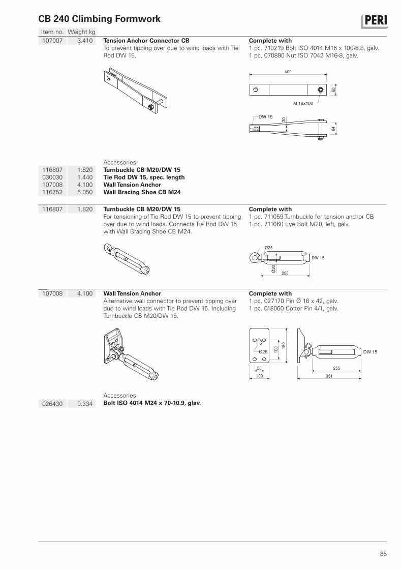
CB 240 Climbing Formwork
85
Item no. Weight kg
107008 4.100 Wall Tension Anchor
Alternative wall connector to prevent tipping over
due to wind loads with Tie Rod DW 15. Including
Turnbuckle CB M20/DW 15.
Complete with
1 pc. 027170 Pin Ø 16 x 42, galv.
1 pc. 018060 Cotter Pin 4/1, galv.
331
180
100
100
255
DW 15Ø26
50
026430 0.334
Accessories
Bolt ISO 4014 M24 x 70-10.9, glav.
116807 1.820 Turnbuckle CB M20/DW 15
For tensioning of Tie Rod DW 15 to prevent tipping
over due to wind loads. Connects Tie Rod DW 15
with Wall Bracing Shoe CB M24.
Complete with
1 pc. 711059 Turnbuckle for tension anchor CB
1 pc. 711060 Eye Bolt M20, left, galv.
255
Ø25
DW 15
20Ø
107007 3.410 Tension Anchor Connector CB
To prevent tipping over due to wind loads with Tie
Rod DW 15.
Complete with
1 pc. 710219 Bolt ISO 4014 M16 x 100-8.8, galv.
1 pc. 070890 Nut ISO 7042 M16-8, galv.
400
6064
M 16x100
30
DW 15
116807
030030
107008
116752
1.820
1.440
4.100
5.050
Accessories
Turnbuckle CB M20/DW 15
Tie Rod DW 15, spec. length
Wall Tension Anchor
Wall Bracing Shoe CB M24
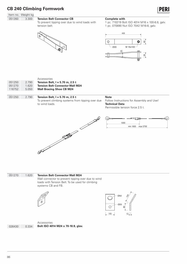
CB 240 Climbing Formwork
86
Item no. Weight kg
051270 1.620 Tension Belt Connector Wall M24
Wall connector to prevent tipping over due to wind
loads with Tension Belt. To be used for climbing
systems CB and FB.
100 12
8012
0
Ø25
Ø50
026430 0.334
Accessories
Bolt ISO 4014 M24 x 70-10.9, glav.
051250 2.790 Tension Belt, l = 5.70 m, 2.5 t
To prevent climbing systems from tipping over due
to wind loads.
Note
Follow Instructions for Assembly and Use!
Technical Data
Permissible tension force 2.5 t.
1000
5700min 1600 max
051260 3.300 Tension Belt Connector CB
To prevent tipping over due to wind loads with
tension belt.
Complete with
1 pc. 710219 Bolt ISO 4014 M16 x 100-8.8, galv.
1 pc. 070890 Nut ISO 7042 M16-8, galv.
400
6059
25
Ø20 M 16x100
051250
051270
116752
2.790
1.620
5.050
Accessories
Tension Belt, l = 5.70 m, 2.5 t
Tension Belt Connector Wall M24
Wall Bracing Shoe CB M24
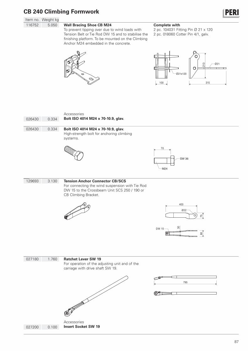
CB 240 Climbing Formwork
87
Item no. Weight kg
027180 1.760 Ratchet Lever SW 19
For operation of the adjusting unit and of the
carriage with drive shaft SW 19.
795
027200 0.100
Accessories
Insert Socket SW 19
129693 3.130 Tension Anchor Connector CB/SCS
For connecting the wind suspension with Tie Rod
DW 15 to the Crossbeam Unit SCS 250 / 190 or
CB Climbing Bracket.
40075
30DW 15
80
Ø22
026430 0.334 Bolt ISO 4014 M24 x 70-10.9, glav.
High-strength bolt for anchoring climbing
systems.
70
M24
SW 36
116752 5.050 Wall Bracing Shoe CB M24
To prevent tipping over due to wind loads with
Tension Belt or Tie Rod DW 15 and to stabilise the
finishing platform. To be mounted on the Climbing
Anchor M24 embedded in the concrete.
Complete with
2 pc. 104031 Fitting Pin Ø 21 x 120
2 pc. 018060 Cotter Pin 4/1, galv.
100
213
315
Ø21
Ø21x120
026430 0.334
Accessories
Bolt ISO 4014 M24 x 70-10.9, glav.
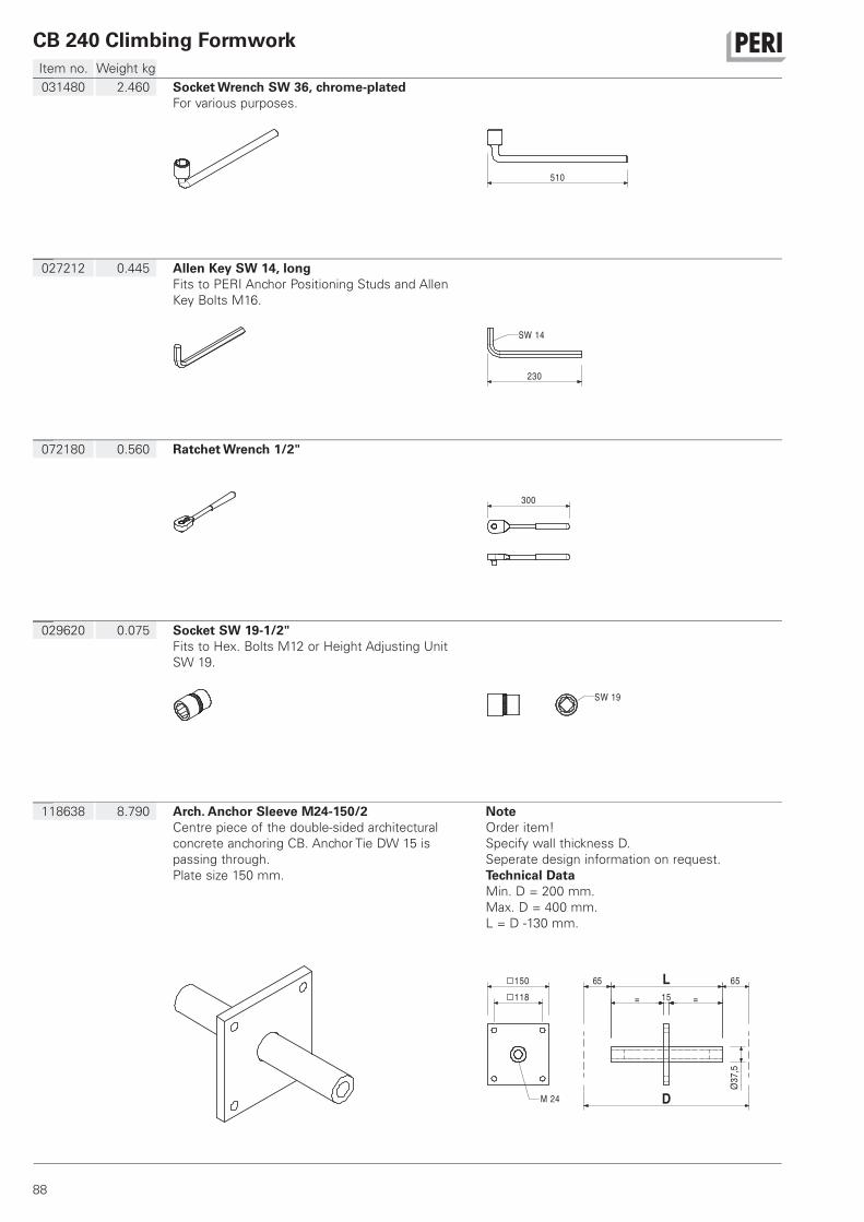
CB 240 Climbing Formwork
88
Item no. Weight kg
118638 8.790 Arch. Anchor Sleeve M24-150/2
Centre piece of the double-sided architectural
concrete anchoring CB. Anchor Tie DW 15 is
passing through.
Plate size 150 mm.
Note
Order item!
Specify wall thickness D.
Seperate design information on request.
Technical Data
Min. D = 200 mm.
Max. D = 400 mm.
L = D -130 mm.
150 118
L
= 15 =
D
65 65
37,5
Ø
M 24
029620 0.075 Socket SW 19-1/2"
Fits to Hex. Bolts M12 or Height Adjusting Unit
SW 19.
SW 19
072180 0.560 Ratchet Wrench 1/2"
300
027212 0.445 Allen Key SW 14, long
Fits to PERI Anchor Positioning Studs and Allen
Key Bolts M16.
230
SW 14
031480 2.460 Socket Wrench SW 36, chrome-plated
For various purposes.
510
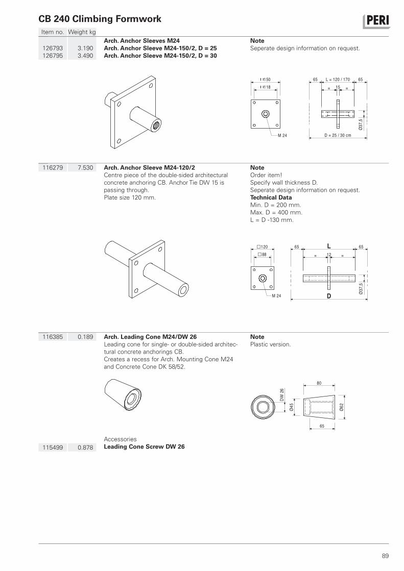
CB 240 Climbing Formwork
89
Item no. Weight kg
116385 0.189 Arch. Leading Cone M24/DW 26
Leading cone for single- or double-sided architec-
tural concrete anchorings CB.
Creates a recess for Arch. Mounting Cone M24
and Concrete Cone DK 58/52.
Note
Plastic version.
80
62Ø45Ø
26DW
65
115499 0.878
Accessories
Leading Cone Screw DW 26
116279 7.530 Arch. Anchor Sleeve M24-120/2
Centre piece of the double-sided architectural
concrete anchoring CB. Anchor Tie DW 15 is
passing through.
Plate size 120 mm.
Note
Order item!
Specify wall thickness D.
Seperate design information on request.
Technical Data
Min. D = 200 mm.
Max. D = 400 mm.
L = D -130 mm.
120 88
L
= 12 =
65 65
D
37,5
ØM 24
126793
126795
3.190
3.490
Arch. Anchor Sleeves M24
Arch. Anchor Sleeve M24-150/2, D = 25
Arch. Anchor Sleeve M24-150/2, D = 30
Note
Seperate design information on request.
150
M 24
118 15 ==
Ø37,
5
L = 120 / 17065 65
D = 25 / 30 cm
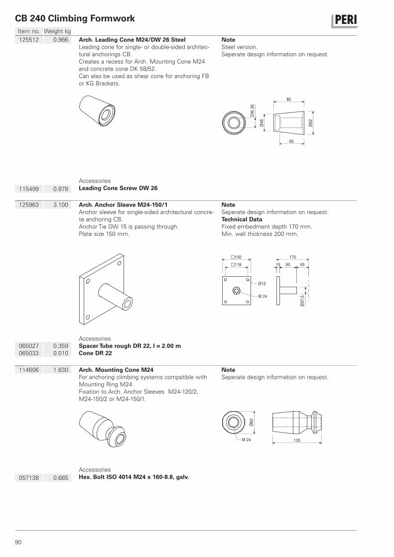
CB 240 Climbing Formwork
90
Item no. Weight kg
114606 1.630 Arch. Mounting Cone M24
For anchoring climbing systems compatible with
Mounting Ring M24.
Fixation to Arch. Anchor Sleeves M24-120/2,
M24-150/2 or M24-150/1.
Note
Seperate design information on request.
130
60Ø
M 24
057138 0.665
Accessories
Hex. Bolt ISO 4014 M24 x 160-8.8, galv.
125963 3.100 Arch. Anchor Sleeve M24-150/1
Anchor sleeve for single-sided architectural concre-
te anchoring CB.
Anchor Tie DW 15 is passing through.
Plate size 150 mm.
Note
Seperate design information on request.
Technical Data
Fixed embedment depth 170 mm.
Min. wall thickness 200 mm.
150 118 15 90
37,5
Ø
Ø12
M 24
65170
065027
065033
0.359
0.010
Accessories
Spacer Tube rough DR 22, l = 2.00 m
Cone DR 22
125512 0.966 Arch. Leading Cone M24/DW 26 Steel
Leading cone for single- or double-sided architec-
tural anchorings CB.
Creates a recess for Arch. Mounting Cone M24
and concrete cone DK 58/52.
Can also be used as shear cone for anchoring FB
or KG Brackets.
Note
Steel version.
Seperate design information on request.
26DW
80
62Ø45Ø
65
115499 0.878
Accessories
Leading Cone Screw DW 26
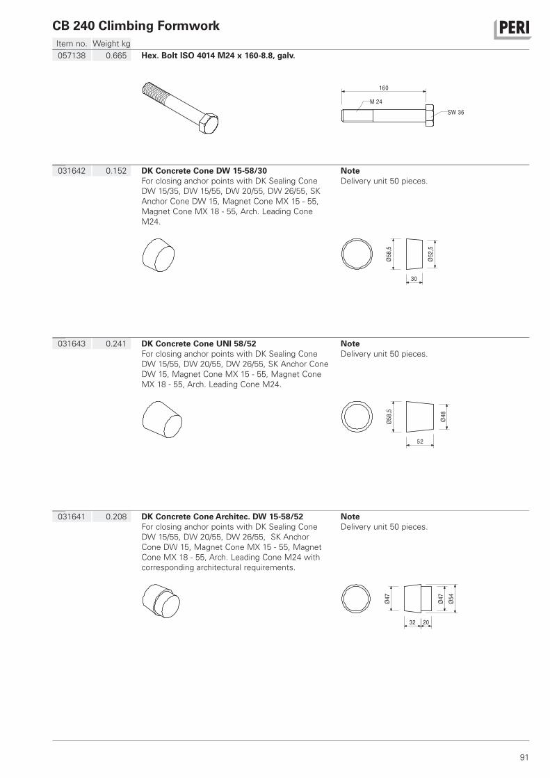
CB 240 Climbing Formwork
91
Item no. Weight kg
031641 0.208 DK Concrete Cone Architec. DW 15-58/52
For closing anchor points with DK Sealing Cone
DW 15/55, DW 20/55, DW 26/55, SK Anchor
Cone DW 15, Magnet Cone MX 15 - 55, Magnet
Cone MX 18 - 55, Arch. Leading Cone M24 with
corresponding architectural requirements.
Note
Delivery unit 50 pieces.
32 20
47Ø 54Ø47Ø
031643 0.241 DK Concrete Cone UNI 58/52
For closing anchor points with DK Sealing Cone
DW 15/55, DW 20/55, DW 26/55, SK Anchor Cone
DW 15, Magnet Cone MX 15 - 55, Magnet Cone
MX 18 - 55, Arch. Leading Cone M24.
Note
Delivery unit 50 pieces.
52
58,5
Ø
48Ø
031642 0.152 DK Concrete Cone DW 15-58/30
For closing anchor points with DK Sealing Cone
DW 15/35, DW 15/55, DW 20/55, DW 26/55, SK
Anchor Cone DW 15, Magnet Cone MX 15 - 55,
Magnet Cone MX 18 - 55, Arch. Leading Cone
M24.
Note
Delivery unit 50 pieces.
52,5
Ø58,5
Ø
30
057138 0.665 Hex. Bolt ISO 4014 M24 x 160-8.8, galv.
160
M 24SW 36
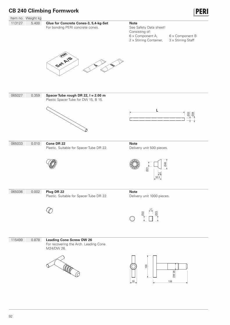
CB 240 Climbing Formwork
92
Item no. Weight kg
115499 0.878 Leading Cone Screw DW 26
For recovering the Arch. Leading Cone
M24/DW 26.
30 156
100
DW26
065036 0.002 Plug DR 22
Plastic. Suitable for Spacer Tube DR 22.
Note
Delivery unit 1000 pieces.
23Ø22Ø
17
065033 0.010 Cone DR 22
Plastic. Suitable for Spacer Tube DR 22.
Note
Delivery unit 500 pieces.21Ø
46Ø
1532,5
065027 0.359 Spacer Tube rough DR 22, l = 2.00 m
Plastic Spacer Tube for DW 15, B 15.
L
22Ø 26Ø
113127 5.400 Glue for Concrete Cones-3, 5,4-kg-Set
For bonding PERI concrete cones.
Note
See Safety Data sheet!
Consisting of:
6 x Component A, 6 x Component B
2 x Stirring Container, 3 x Stirring Staff
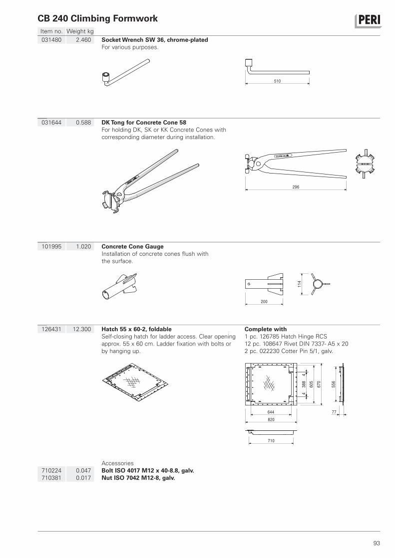
CB 240 Climbing Formwork
93
Item no. Weight kg
126431 12.300 Hatch 55 x 60-2, foldable
Self-closing hatch for ladder access. Clear opening
approx. 55 x 60 cm. Ladder fixation with bolts or
by hanging up.
Complete with
1 pc. 126785 Hatch Hinge RCS
12 pc. 108647 Rivet DIN 7337- A5 x 20
2 pc. 022230 Cotter Pin 5/1, galv.
670
820
710
556
77
388
4
644
460
5
710224
710381
0.047
0.017
Accessories
Bolt ISO 4017 M12 x 40-8.8, galv.
Nut ISO 7042 M12-8, galv.
101995 1.020 Concrete Cone Gauge
Installation of concrete cones flush with
the surface.
20011
4
031644 0.588 DK Tong for Concrete Cone 58
For holding DK, SK or KK Concrete Cones with
corresponding diameter during installation.
296
031480 2.460 Socket Wrench SW 36, chrome-plated
For various purposes.
510
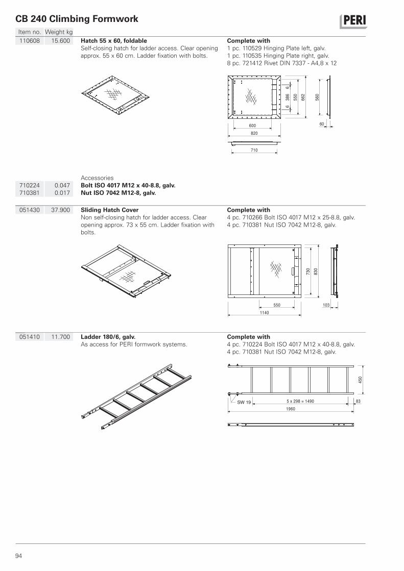
CB 240 Climbing Formwork
94
Item no. Weight kg
051410 11.700 Ladder 180/6, galv.
As access for PERI formwork systems.
Complete with
4 pc. 710224 Bolt ISO 4017 M12 x 40-8.8, galv.
4 pc. 710381 Nut ISO 7042 M12-8, galv.
14905 x 298 = 831960
450
SW 19
051430 37.900 Sliding Hatch Cover
Non self-closing hatch for ladder access. Clear
opening approx. 73 x 55 cm. Ladder fixation with
bolts.
Complete with
4 pc. 710266 Bolt ISO 4017 M12 x 25-8.8, galv.
4 pc. 710381 Nut ISO 7042 M12-8, galv.
730
830
5501140
103
110608 15.600 Hatch 55 x 60, foldable
Self-closing hatch for ladder access. Clear opening
approx. 55 x 60 cm. Ladder fixation with bolts.
Complete with
1 pc. 110529 Hinging Plate left, galv.
1 pc. 110535 Hinging Plate right, galv.
8 pc. 721412 Rivet DIN 7337 - A4,8 x 12
820
662
60
560
710
386
66
600
550
710224
710381
0.047
0.017
Accessories
Bolt ISO 4017 M12 x 40-8.8, galv.
Nut ISO 7042 M12-8, galv.
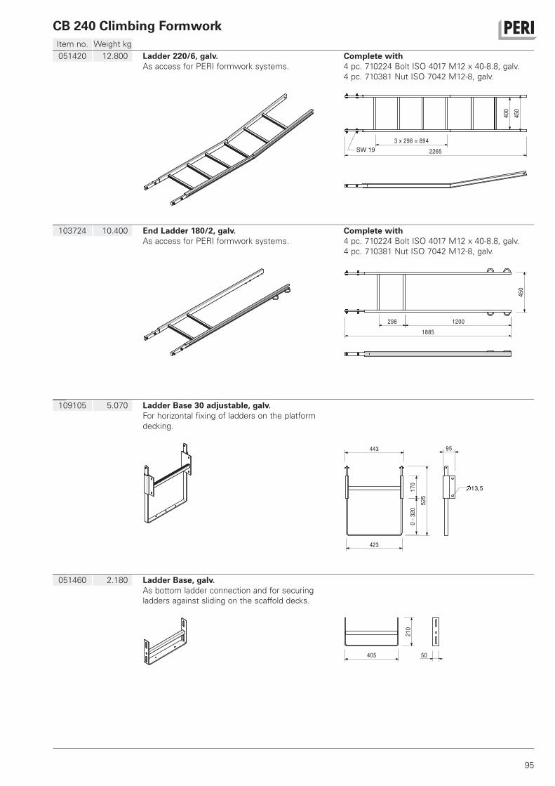
CB 240 Climbing Formwork
95
Item no. Weight kg
051460 2.180 Ladder Base, galv.
As bottom ladder connection and for securing
ladders against sliding on the scaffold decks.
405
210
50
109105 5.070 Ladder Base 30 adjustable, galv.
For horizontal fixing of ladders on the platform
decking.
0-3
2052
5
443
423
95
170
13,5
103724 10.400 End Ladder 180/2, galv.
As access for PERI formwork systems.
Complete with
4 pc. 710224 Bolt ISO 4017 M12 x 40-8.8, galv.
4 pc. 710381 Nut ISO 7042 M12-8, galv.
298 12001885
450
051420 12.800 Ladder 220/6, galv.
As access for PERI formwork systems.
Complete with
4 pc. 710224 Bolt ISO 4017 M12 x 40-8.8, galv.
4 pc. 710381 Nut ISO 7042 M12-8, galv.
8943 x 298 = 2265
400
450
SW 19
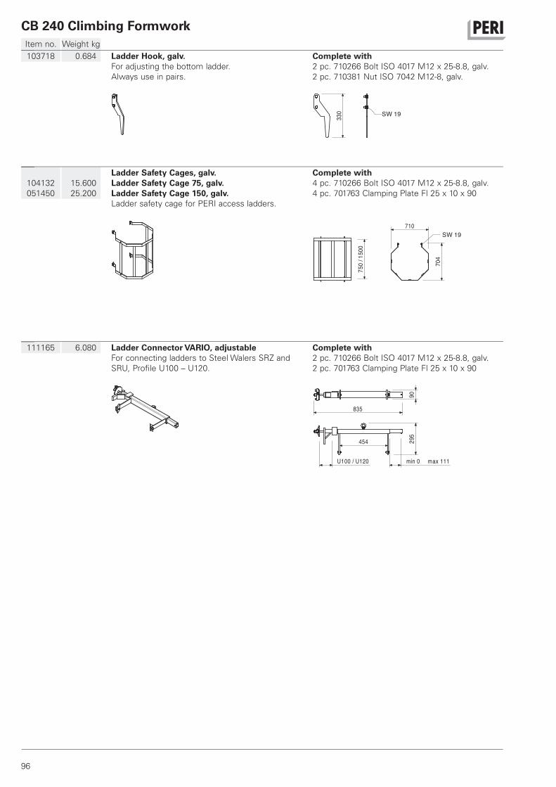
CB 240 Climbing Formwork
96
Item no. Weight kg
111165 6.080 Ladder Connector VARIO, adjustable
For connecting ladders to Steel Walers SRZ and
SRU, Profile U100 – U120.
Complete with
2 pc. 710266 Bolt ISO 4017 M12 x 25-8.8, galv.
2 pc. 701763 Clamping Plate Fl 25 x 10 x 90
83590
454 295
min 0 max 111 U100 / U120
104132
051450
15.600
25.200
Ladder Safety Cages, galv.
Ladder Safety Cage 75, galv.
Ladder Safety Cage 150, galv.
Ladder safety cage for PERI access ladders.
Complete with
4 pc. 710266 Bolt ISO 4017 M12 x 25-8.8, galv.
4 pc. 701763 Clamping Plate Fl 25 x 10 x 90
750
/150
0
710
704
SW 19
103718 0.684 Ladder Hook, galv.
For adjusting the bottom ladder.
Always use in pairs.
Complete with
2 pc. 710266 Bolt ISO 4017 M12 x 25-8.8, galv.
2 pc. 710381 Nut ISO 7042 M12-8, galv.
330 SW 19
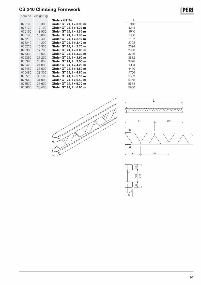
CB 240 Climbing Formwork
97
Item no. Weight kg
075100
075120
075150
075180
075210
075240
075270
075300
075330
075360
075390
075420
075450
075480
075510
075540
075570
075600
5.300
7.100
8.900
10.600
12.400
14.200
15.900
17.700
19.500
21.200
23.000
24.800
26.600
28.300
30.100
31.900
33.600
35.400
Girders GT 24
Girder GT 24, l = 0.90 m
Girder GT 24, l = 1.20 m
Girder GT 24, l = 1.50 m
Girder GT 24, l = 1.80 m
Girder GT 24, l = 2.10 m
Girder GT 24, l = 2.40 m
Girder GT 24, l = 2.70 m
Girder GT 24, l = 3.00 m
Girder GT 24, l = 3.30 m
Girder GT 24, l = 3.60 m
Girder GT 24, l = 3.90 m
Girder GT 24, l = 4.20 m
Girder GT 24, l = 4.50 m
Girder GT 24, l = 4.80 m
Girder GT 24, l = 5.10 m
Girder GT 24, l = 5.40 m
Girder GT 24, l = 5.70 m
Girder GT 24, l = 6.00 m
L
918
1214
1510
1806
2102
2398
2694
2990
3286
3582
3878
4174
4470
4766
5062
5358
5654
5950
311 296
163 296
2880
6012
060
240
L

TN
ID
JP
TH
SG
MY
KR
PHVN
AU
AE
LB
TR
MA IL
KZ
RU
ZA
EG
AZ
IN
MZ
TZ
NA
AO
SA
IR
DZJO
NG
OM
US
AR
BR
CO
CL
CA
MX
PE
PA
QAKW
HK
CA
PERI Formwork Systems, Inc. www.peri.ca
MX PERI Cimbras y Andamios, S.A. de C.V. www.peri.com.mx
PA PERI Panama Inc. www.peri.com.pa
US PERI Formwork Systems, Inc. www.peri-usa.com
AR
PERI S.A. www.peri.com.ar
BR PERI Formas e Escoramentos Ltda. www.peribrasil.com.br
CL PERI Chile Ltda. www.peri.cl
CO PERI S.A.S. www.peri.com.co
PE PERI Peruana S.A.C. www.peri.com.pe
AO
Pericofragens, Lda. www.peri.pt
DZ S.A.R.L. PERI www.peri.dz
EG Egypt Branch Office www.peri.com.eg
MA PERI S.A. www.peri.ma
MZ PERI (Pty.) Ltd. www.peri.co.mz
NA PERI (Pty.) Ltd. www.peri.na
NG PERI Nigeria Ltd. www.peri.ng
TN PERI S.A.U. www.peri.es
TZ PERI Formwork and Scaffolding Ltd www.peri.co.tz ZA PERI Formwork Scaffolding (Pty) Ltd www.peri.co.za
AE
PERI (L.L.C.) www.peri.ae
AZ PERI Repesentative Office www.peri.com.tr
HK PERI (Hong Kong) Limited www.perihk.com
ID PT Beton Perkasa Wijaksana www.betonperkasa.com
IL PERI F.E. Ltd. www.peri.co.il
IN PERI (India) Pvt Ltd www.peri.in
IR PERI Pars. Ltd. www.peri.ir
JO PERI GmbH – Jordan www.peri.com
JP PERI Japan K.K. www.peri.co.jp
KR PERI (Korea) Ltd. www.perikorea.com
KW PERI Kuwait W.L.L. www.peri.com.kw
KZ TOO PERI Kazakhstan www.peri.kz
LB PERI Lebanon Sarl [email protected]
MY PERI Formwork Malaysia Sdn. Bhd. www.perimalaysia.com
OM PERI (L.L.C.) www.peri.ae
PH PERI-Asia Philippines, INC. www.peri.com.ph
QA PERI Qatar LLC www.peri.qa
SA PERI Saudi Arabia Ltd. www.peri.com.sa
SG PERI Asia Pte Ltd www.periasia.com
TH Peri (Thailand) Co., Ltd. www.peri.co.th
TR PERI Kalıp ve İskeleleri www.peri.com.tr
VN PERI ASIA PTE LTD www.peri.com.vn
North America
Canada
Mexico
Panama
USA
South America
Argentina
Brazil
Chile
Colombia
Peru
Africa
Angola
Algeria
Egypt
Morocco
Mozambique
Namibia
Nigeria
Tunisia
Tanzania
South Africa
Asia
United Arab Emirates
Azerbaijan
Hong Kong
Indonesia
Israel
India
Iran
Jordan
Japan
Korea
Kuwait
Kazakhstan
Lebanon
Malaysia
Oman
Philippines
Qatar
Saudi Arabia
Singapore
Thailand
Turkey
Vietnam
PERI International

FR
DE
CH
ES
BE
NL
IT
GB
LU
IR
TR
HUAT
CZ
DK
FI
NO
SE
PL
PT
ROSI
SK
EE
GR
LV
LT
BG
IS
UA
RS
BY
RU
HR
BA
AL
AU
PERI Australia Pty. Ltd. www.periaus.com.au
AL PERI Kalıp ve İskeleleri www.peri.com.tr
AT PERI Ges.mbH www.peri.at
BA PERI oplate i skele d.o.o www.peri.com.hr
BE PERI N.V. www.peri.be
BG PERI Bulgaria EOOD www.peri.bg
BY IOOO PERI www.peri.by
CH PERI AG www.peri.ch
CZ PERI spol. s r.o. www.peri.cz
DE PERI GmbH www.peri.de
DK PERI Danmark A/S www.peri.dk
EE PERI AS www.peri.ee
ES PERI S.A.U. www.peri.es
FI PERI Suomi Ltd. Oy www.perisuomi.fi
FR PERI S.A.S. www.peri.fr
GB PERI Ltd. www.peri.ltd.uk
GR PERI Hellas Ltd. www.perihellas.gr
HR PERI oplate i skele d.o.o. www.peri.com.hr
HU PERI Kft. www.peri.hu
IR Siteserv Access & Formwork www.siteservaccess.ie
IS Armar ehf. www.armar.is
IT PERI S.r.l. www.peri.it
LT PERI UAB www.peri.lt
LU N.V. PERI S.A. www.peri.lu
LV PERI SIA www.peri-latvija.lv
NL PERI b.v. www.peri.nl
NO PERI Norge AS www.peri.no
PL PERI Polska Sp. z o.o. www.peri.com.pl
PT Pericofragens Lda. www.peri.pt
RO PERI România SRL www.peri.ro
RS PERI oplate d.o.o. www.peri.rs
RU OOO PERI www.peri.ru
SE PERI Sverige AB www.peri.se
SI PERI oplate i skele d.o.o www.peri.com.hr
SK PERI spol. s. r.o. www.peri.sk
UA TOW PERI www.peri.ua
Oceania
Australia
Europe
Albania
Austria
Bosnia and Herzegovina
Belgium
Bulgaria
Belorussia
Switzerland
Czech Republic
Germany
Denmark
Estonia
Spain
Finland
France
United Kingdom
Greece
Croatia
Hungary
Ireland
Iceland
Italy
Lithuania
Luxembourg
Latvia
Netherlands
Norway
Poland
Portugal
Romania
Serbia
Russia
Sweden
Slovania
Slovakia
Ukraine
PERI GmbH
Formwork Scaffolding Engineering
Rudolf-Diesel-Strasse 1989264 WeissenhornGermanyTel. +49 (0)7309.950-0Fax +49 (0)[email protected]
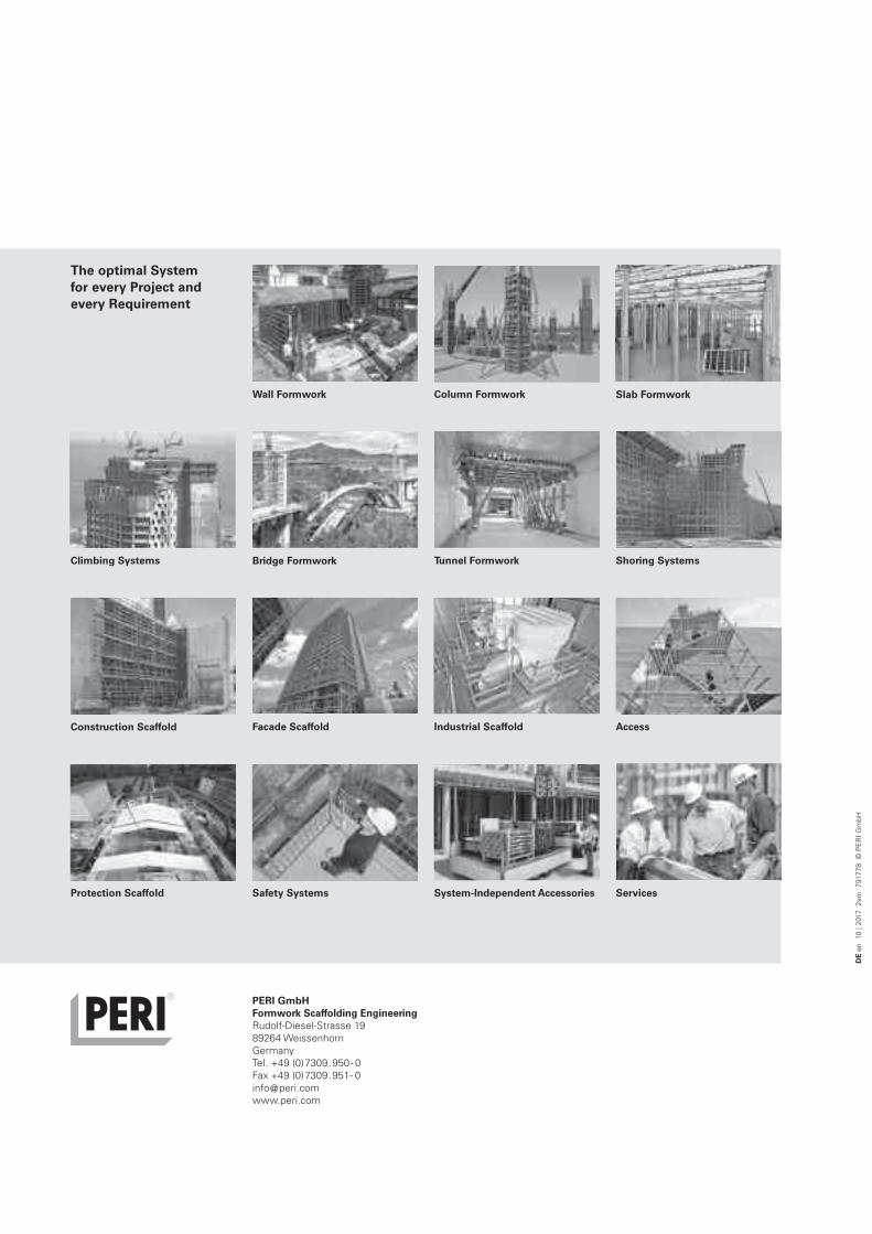
DE en 10
| 2017 2sm 7917
78 © PERI GmbH
The optimal System
for every Project and
every Requirement
PERI GmbH
Formwork Scaffolding Engineering
Rudolf-Diesel-Strasse 1989264 WeissenhornGermanyTel. +49 (0)7309.950- 0Fax +49 (0)7309.951- [email protected]
System-Independent Accessories
Column FormworkWall Formwork Slab Formwork
Climbing Systems Bridge Formwork Tunnel Formwork Shoring Systems
Construction Scaffold Industrial ScaffoldFacade Scaffold Access
Protection Scaffold Safety Systems Services


![Quad 240[1737]](https://static.fdokumen.com/doc/165x107/633b2fc5c007a38db701fb49/quad-2401737.jpg)