240 260 Owner's Manual.pdf - Marlow-Hunter
106
HUNTER OWNER’S MANUAL TABLE OF CONTENTS 1 of 3 INTRODUCTION PAGE Warranty Registration Form……………………………………… Hunter Warranty………………………………………….………… Brief History…………………………………………………………. Glossary of Sailing Terms….……………………………………… Explanation of Symbols and Labels……………………………… 1 2-4 5 6-9 10 GENERAL HANDLING AND OPERATION Safe Boating Tips………………………………………………….. Pre-Departure Checklist…………………………………………… Float Plan…………………………………………………………… After Sailing Check List………………………………….………… Docking and Anchoring……………………………………………. Mast Raising and Lowering System……………………………… Launching and Retrieving Procedures…………………………… Getting Ready to Sail………………………………………………. Cook Stove………………………………………………………….. Toilet…….…………………………………………………………… Pumps…………….…………………………………………………. Water System Operation………………………………….………. Outboard Engine and Motoring…………………………………… Electrical System…………………………………………………… Environmental Considerations……………………………………. 11-12 13 14 15 16 17 18 19 20 20 21 21 22 22 23 MAINTENANCE Instructions for Preparation for Bottom Painting………………... Engine Maintenance…………………..…………………………… Electrical Systems…………………………………………………. Plumbing Systems…………………………………………………. Protecting Your Rigging…………………………………………… Trailer Maintenance……………………………………………….. General Care……………………………………………………….. General Hardware Maintenance…………………………………. Vinyl and Fabric Care……………………………………………… Electrolysis and Galvanic Protection…………………………….. Teak Care…………………………………………………………… Water Ballast Tank Winterization………………………………… Storage/Winterization……………………………………………... 24 25 25 25 26 27 28 28 29 30 31 32 33-34
-
Upload
khangminh22 -
Category
Documents
-
view
1 -
download
0
Transcript of 240 260 Owner's Manual.pdf - Marlow-Hunter

HUNTER OWNER’S MANUAL TABLE OF CONTENTS
1 of 3
INTRODUCTION PAGE Warranty Registration Form……………………………………… Hunter Warranty………………………………………….………… Brief History…………………………………………………………. Glossary of Sailing Terms….……………………………………… Explanation of Symbols and Labels………………………………
1 2-4 5 6-9 10
GENERAL HANDLING AND OPERATION Safe Boating Tips………………………………………………….. Pre-Departure Checklist…………………………………………… Float Plan…………………………………………………………… After Sailing Check List………………………………….………… Docking and Anchoring……………………………………………. Mast Raising and Lowering System……………………………… Launching and Retrieving Procedures…………………………… Getting Ready to Sail………………………………………………. Cook Stove………………………………………………………….. Toilet…….…………………………………………………………… Pumps…………….…………………………………………………. Water System Operation………………………………….………. Outboard Engine and Motoring…………………………………… Electrical System…………………………………………………… Environmental Considerations…………………………………….
11-12 13 14 15 16 17 18 19 20 20 21 21 22 22 23
MAINTENANCE Instructions for Preparation for Bottom Painting………………... Engine Maintenance…………………..…………………………… Electrical Systems…………………………………………………. Plumbing Systems…………………………………………………. Protecting Your Rigging…………………………………………… Trailer Maintenance……………………………………………….. General Care……………………………………………………….. General Hardware Maintenance…………………………………. Vinyl and Fabric Care……………………………………………… Electrolysis and Galvanic Protection…………………………….. Teak Care…………………………………………………………… Water Ballast Tank Winterization………………………………… Storage/Winterization……………………………………………...
24 25 25 25 26 27 28 28 29 30 31 32 33-34

HUNTER OWNER’S MANUAL TABLE OF CONTENTS (CONT’D)
2 of 3
DESCRIPTION OF MODEL Lightning Warning…………………………………………………. Profile with Rig and Sail Dimensions…………………………….. Dimensions, Capacities, etc………………………………………. Deck Plan and Hardware…………………………………………. Deck Hardware and Listing………..……………………………… Interior Plan..………………………..……………………………… Running Rigging Deck Plan…….………………………………. Mainsheet and Jibsheet Rigging…………………………………. Proper Cleat Knot………………………………………………….. Reef Rigging and Instructions……………………………………. Rigging Specifications…………………………………………….. Standing Rigging Layout……...…………………………………… Spreader Details……………………………………………………. Spinnaker Details…………………………………………………. Ballast Tank Valve……………….……………………………….. Centerboard Detail…………………………………………………. Rudder Detail…………….………………………………………….
PAGE 35 36 37 38 39 40 41 42 43 44-45 46 47 48 49 50 51 52
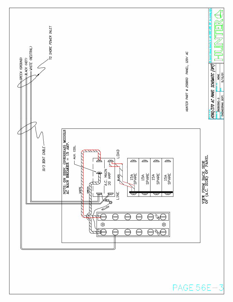
SYSTEMS AND CIRCUITS Potable Water System…………………………………………….. Bilge Pumping System…………………………………………….. Mast Wiring…………………………….…………………………… Electrical Schematics……………………………………………… Optional Inboard Engine (260 Only)……………………………… Optional Waste System (260 Only)………………………………. Anchoring Arrangement……………………………………………
PAGE 53 54 55 56 57 58 59

HUNTER OWNER’S MANUAL TABLE OF CONTENTS (CONT’D)
3 of 3
EQUIPMENT MANUALS AND INFORMATION Warranty Registration Marine Rigging Guide VHF Radio (except where not provided) Sail Maker Information Mast Information Bilge Pump Toilet Manual Stove Manual Trailer Axle Service Manual Tire Warranty Card Drum Braker Service Manual Brake Actuator Service Manual Camper Canvas (Where Ordered) Other:

Welcome to
THE HUNTER MARINE FAMILY
PAGE 1
Congratulations on your new sailing yacht manufactured by Hunter Marine. We have engineered and constructed your boat to be as fine a yacht as any afloat. In order to get the best performance and most enjoyment from your boat you should be familiar with its various elements and their functions. For your sailing pleasure and safety, please take time to study this manual. We stand behind the quality of your boat with a warranty, which you should review. To insure the validity of your warranty, please complete the attached card and send it to us within ten (10) days of the purchase date. Section 15 of the U.S. Federal Boat Safety Act requires registration of a boat’s first owner. The warranty data should also be recorded in the space below for your own reference. This manual has been compiled to help you operate your craft with safety and pleasure. It contains details of the craft;
equipment supplied or fitted, systems, and information on operation and maintenance. Please read it carefully, and familiarize yourself with the craft before using it. If this is your first sailboat or you are changing to a type of craft you are not familiar with, please ensure that you obtain proper handling and operating experience before you assume command of the craft. Your dealer or national sailing federation or yacht club will be pleased to advise you of local sea schools or competent instructors. PLEASE KEEP THIS MANUAL IN A SAFE PLACE AND HAND IT OVER TO THE NEW OWNER IF YOU SELL THE CRAFT. You should also complete the warranty cards for your engine, stove, head, electric water pump and other accessories. These are enclosed in the manufacturers’ manuals that are packaged with your owner’s manual.
OWNER INFORMATION CARD
HULL IDENTIFICATION NUMBER IS ON THE STARBOARD AFT SIDE OF THE HULL OR TRANSOM. THIS NUMBER MUST BE GIVEN IN ALL NECESSARY CORRESPONDENCE.
HULL NO. DATE DELIVERED TO OWNER YACHT NAME OWNER NAME STREET ADDRESS CITY STATE/COUNTRY ZIP CODE HOME PORT ENGINE MODEL SERIAL NO. PROPELLER SIZE DEALER PHONE STREET ADDRESS CITY STATE/COUNTRY ZIP CODE

HUNTER MARINE LIMITED WARRANTY
PAGE 2
LIMITED ONE-YEAR WARRANTY
Hunter Marine warrants to the first-use purchaser and any subsequent owner during the warranty period, that any part manufactured by Hunter will be free of defects caused by faulty workmanship or materials for a period of twelve (12)
months from the date of delivery to the first-use purchaser under normal use and service. During this period, Hunter will repair or replace any part judged to be defective by Hunter.
LIMITED FIVE-YEAR HULL STRUCTURE
AND BOTTOM BLISTER WARRANTY Hunter warrants to the first-use purchaser and any subsequent owner during the warranty period that the hull of each boat will be free from structural defects in materials and workmanship for a period of five (5) years from the date of delivery to the first-use purchaser under normal use and service. This limited warranty applies only to the structural integrity of the hull and supporting pan/grid or stringer system. Hulls, pan/grid or stringers modified in any way or powered with engines other than the type and size installed or specified by Hunter are not covered by this limited warranty. The obligation of Hunter under this limited warranty is restricted to the repair or replacement of hulls that are determined to be structurally defective. Hunter also warrants to the first-use purchaser and any subsequent owner during the warranty period that the boat will be free from gel-coat blistering on underwater surfaces of the hull, excluding the keel and rudder, for a period of five (5) years from the date of delivery to the first-use purchaser under
normal use and service. During this period, Hunter will supply or reimburse an authorized Hunter dealer for all of the parts and labor required to repair a blistered underwater surface of the hull. The labor cost reimbursement will be based on the Labor Allowance Schedule established by Hunter. However, if a non-Hunter dealer performs the repair, the repair cost must be authorized by Hunter in advance and be based on a reasonable number of hours as determined by Hunter. Transportation, hauling, launching, bottom paint, storage, dockage, cradling rental, rigging and derigging, or other similar costs will not be paid by Hunter. We recommend that the repair be done during a seasonal haul out for service or storage. The bottom blister warranty is void under the following circumstances: (1) If the gel-coat has been sanded, sandblasted, or subjected to abrasion or impact. (2) If the instructions provided in the Hunter Owner’s manual regarding bottom preparation techniques are not followed.

HUNTER MARINE LIMITED WARRANTY
PAGE 3
RESTRICTIONS APPLICABLE TO WARRANTIES
These limited warranties do not cover the following: (1) Paint, window glass, gel-coat, upholstery, engines, engine parts, bilge pumps, stoves, blowers, pressure water pumps, propellers, shafts, rudders, controls, instruments, keels and equipment not manufactured by Hunter. Any warranty made by the manufacturer of such items will be, if possible, given on to the first-use purchaser. (2) Problems caused by improper maintenance, storage, cradling, blocking, normal wear and tear, misuse, neglect, accident, corrosion, electrolysis or improper operation. THIS WARRANTY IS EXPRESSLY IN LIEU OF ANY AND ALL OTHER REMEDIES AND WARRANTIES EXPRESSED AND IMPLIED, INCLUDING THE WARRANTIES OF MERCHANTABILITY AND FITNESS.
SOME STATES OR COUNTRIES DO NOT ALLOW LIMITATIONS ON HOW LONG AN IMPLIED WARRANTY LAST, SO THE ABOVE LIMITATION MAY NOT APPLY TO YOU. THE PURCHASER ACKNOWLEDGES THAT NO OTHER REPRESENTATIONS WERE MADE TO HIM OR HER WITH RESPECT TO THE QUALITY AND FUNCTION OF THE BOAT. ANY CONSEQUENTIAL DAMAGES THAT MAY BE INCURRED ARE EXCLUDED AND JUDGED DEFECTIVE BY HUNTER. SOMESTATES OR COUNTRIES DO NOT ALLOW THE EXCLUSION OF INCIDENTAL OR CONSEQUENTIAL DAMAGES, SO THE ABOVE LIMITATION OR EXCLUSION MAY NOT APPLY TO YOU. THIS WARRANTY GIVES YOU SPECIFIC LEGAL RIGHTS, AND YOU MAY ALSO HAVE OTHER RIGHTS THAT VARY FROM STATE TO STATE OR COUNTRY TO COUNTRY.
WARRANTY REGISTRATION
These limited warranties shall not be effective unless the Hunter Warranty Registration Form and Pre-Delivery Service Record, which are furnished with each new boat, are filled out completely and returned to Hunter within fifteen (15) days of delivery. Responsibility for sending the completed Registration Form remains with the dealer. It is critical that the Warranty Registration Form is signed by both the dealer and the owner and returned to Hunter. Warranty coverage cannot be initiated until Hunter receives the completed form. All repairs
and/or replacements will be made by an authorized Hunter dealer, or at the option of Hunter, at the Hunter plant. If the repairs are of such a nature that the warranty work must be performed at the Hunter plant, the owner shall pay transportation costs to and from the Hunter plant. The labor cost reimbursement will be based on a labor allowance schedule established by Hunter and where not applicable, on a reasonable number of hours as determined by Hunter. An authorized Hunter service representative must approve any repairs and replacements in advance.
TRANSFER OF LIMITED WARRANTIES
Limited warranties will be transferred to a subsequent purchaser of the boat if: (1) The subsequent purchaser gives Hunter written notice of transfer of ownership within thirty (30) days of the transfer. (2) The notice shall include the name, address and telephone number of the
subsequent purchaser, the date of purchase, the hull number, and the name of the seller of the boat. Hunter will mail notice of expiration dates of the limited warranties to the subsequent owner. The transfer of the ownership of the will not extend the expiration dates of the limited warranties.

HUNTER MARINE LIMITED WARRANTY
PAGE 4
EPOXY BARRIER COAT
Should a customer wish to have an epoxy barrier applied to the hull, ( ex. Interlux Interprotect 1000/2000, West Systems, VC Tar), this will not void the five-year blister warranty. This refers to epoxy barrier coatings as mentioned above, not epoxy primer paints.
If an epoxy barrier coat is applied to a Hunter vessel, it must be registered with the Warranty Department prior to application of the product. If the dealer applies bottom paint only, sanding will not be allowed and the no sanding system must be used.
CUSTOMER SATISFACTION SURVEY During the first year of ownership, the first purchaser will receive two Customer Satisfaction Surveys: the first (CSS #1) will be received shortly after taking delivery and focuses on the customer’s experience with the dealer and commissioning of the boat, and the owner’s initial satisfaction. The second survey (CSS #2) is given nine to ten
months into ownership, and primarily gives the customer an opportunity to evaluate dealer service capability and the boat’s functional systems and characteristics. Both surveys are contingent upon receipt of the first purchaser’s Warranty Registration form.

HUNTER MARINE’S OWNER AND FOUNDER WARREN R. LUHRS
BRIEF BACKGROUND
PAGE 5
Warren Luhrs was born in East Orange, New Jersey in 1944 into a family with an established tradition in the maritime and transportation industries. His great-grandfather, Henry, was a railroad and clipper-shipping pioneer in America, while his great-uncle John helped build the famous St. Petersburg to Moscow railroad for Czar Alexander II. Henry Luhrs owned shares in twenty-two different ocean-going vessels – barks, brigs, and schooners - and was the principal owner of the bark Sophia R. Luhrs, named for his wife. He was also a partner with Albert Sprout, who managed the shipyard where the Sophia R. Luhrs was built in Melbridge, Maine. Warren Luhrs’ father Henry worked at a small boat manufacturer in Morgan, New Jersey, and later started his own company, continuing the Luhrs’ family sea tradition during the great depression. During World War II he repaired boats and installed ice sheathing on their bows for the Coast Guard. After the War, Henry built 27-foot fishing boats and in 1948 began to construct custom-built pleasure craft. He then turned to skiffs and in 1952 incorporated as Henry Luhrs Sea Skiffs, where he constructed lapstrake sea skiffs using assembly-line techniques. Henry personally “shook down” his prototypes on family trips up the Hudson River to Lake Champlain. The sea skiff is a class of boat that has been very popular, owing to its seaworthiness. It features a sharp bow, which reduces pounding in surf or
choppy seas, and a hull whose forward section is rounded below the waterline to increase stability in rough water or a following sea. Such skiffs can either be smooth sided or of a lapstrake construction. Inspired by Henry Ford, Henry Luhrs’ aimed to give the average man the opportunity to enjoy the luxury of boating by building an affordable and reliable boat. He was both designer and engineer, and his progressive new models exhibited his talent for innovation. He successfully changed the line of the bow from straight to curved at a time when the industry trend was a straight square effect, and he is believed to be the first designer-builder to popularize a small boat with a fly bridge. In 1960, Luhrs acquired the Ulrichsen Boat Company of Marlboro, New Jersey. It was here that Luhrs’ Alura fiberglass division was located. In 1965, Henry sold his company to Bangor Arrostook Railroad, which was to become the recreational conglomerate Bangor-Punta. It was also during this period that Silverton of Tom’s River, New Jersey was purchased by John and Warren Luhrs. Today, Warren R. Luhrs and his brother John own the Luhrs Group of marine manufacturers, which consists of Silverton Marine, Mainship Motor Yachts, and Luhrs Fishing Boats with its Alura division, as well as Hunter Marine, which exclusively manufactures sailboats. In January of 1996, the Luhrs family transferred a portion of the Luhrs Group to its employees through an ESOP program.

GLOSSARY OF SAILING TERMS
PAGE 6
A Aback: describes a sail when the wind strikes it on the lee side. Abaft: towards the boat’s stern. Abeam: at right angles to the center-line of the boat. Aft: at or near the stern. Amidships: the center of the boat, athwartships and fore and aft. Anti-fouling: a poisonous paint compound used to protect the underwater part of a hull from marine growths. Apparent wind: The direction and speed of the wind felt by the crew. It is a combination of true wind and that created by the movement of the boat. Astern: behind the boat; to go astern is to drive the boat in reverse. Athwartships: at right angles to the fore and aft line of the boat.
B Back: when a wind backs, it shifts anticlockwise. Back a sail: to sheet it to windward so that the wind fills on the side that is normally to leeward. Backstay: a stay that supports the mast from aft and prevents its forward movement. Ballast: extra weight, usually lead or iron, placed low in the boat or externally on the keel to provide stability. Ballast keel: a mass of ballast bolted to the keel to increase stability and prevent a keel boat from capsizing. Batten: a light, flexible strip fed into a batten pocket at the leech of the sail to support the roach. Beam: 1, the maximum breadth of a boat; 2, a transverse member that supports the deck; 3, on the beam means that an object is at right angles to the centerline. Bear away: to steer the boat away from the wind. Bearing: the direction of an object from an observer, measured in degrees true or magnetic. Beat: to sail a zigzag course towards the wind, close-hauled on alternate tacks.
Delay: to make fast a rope around a cleat, usually with a figure-of-eight knot. Bend: 1, to secure a sail to a spar before hoisting; 2, to moor a boat; 3, a sleeping place on board. Bight: a bend or loop in a rope. Bilge: the lower, round part inside the hull where the water collects. Block: a pulley in a wooden or plastic case, consisting of a sheave around which a rope runs. It is used to change the direction of pull. Boot-topping: a narrow colored stripe painted between the bottom paint and the topside enamel. Bottlescrew: see Rigging screw. Broach: when a boat running downwind slews broadside to the wind and heels dangerously. It is caused by heavy following seas or helmsman’s error. Broad reach: the point of sailing between a beam reach and a run, when the wind blows over a quarter. Bulkhead: a partition wall in a boat normally fitted athwartships
C Caulk: to make the seams between wooden planks watertight by filling with cotton, oakum or a compound. Cavitation: the formation of a vacuum around a propeller, causing a loss in efficiency. Center-board: a board lowered through a slot in the keel to reduce leeway. Center-line: center of the boat in a fore and aft line. Center of effort (COE): the point at which all the forces acting on the sails are concentrated. Center of lateral resistance (CLR): the underwater center of pressure about which a boat pivots when changing course. Chain pawl: a short lug which drops into a toothed rack to prevent the anchor chain running back. Chain plate: a metal plate bolted to the boat to which the shrouds or backstays are attached. Chart datum: reference level on a chart below which the tide is unlikely to fall. Soundings are given below
chart datum. The datum level varies according to country and area. Chine: the line where the bottom of the hull meets the side at an angle. Cleat: a wooden, metal or plastic fitting around which rope is secured. Clevis pin: a locking pin through which a split ring is passed to prevent accidental withdraw. Clew: the after, lower center of a sail where the foot and leech meet. Close-hauled: the point of sailing closest to the wind; see also beat. Close reach: the point of sailing between close-hauled and a beam reach, when the wind blows forward of the beam. Close-winded: describes a boat able to sail very close to the wind. Coaming: the raised structure surrounding a hatch, cockpit, etc., which prevents water entering. Cotter pin: soft, metal pin folded back on itself to form an eye. Course: the direction in which a vessel is steered, usually given in degrees; true, magnetic or compass. Cringle: 1, a rope loop, found at either end of a line of reef points; 2, an eye in a sail.
D Dead run: running with the wind blowing exactly aft, in line with the center-line. Deviation: the difference between the direction indicated by the compass needle and the magnetic meridian; caused by object aboard. Displacement: 1, the weight of water displaced by a boat is equal to the weight of the boat; 2, a displacement hull is one that displaces its own weight in water and is only supported by buoyancy, as opposed to a planning hull which can exceed its hull, or displacement, speed. Downhaul: a rope fitted to pull down a sail or spar. Draft: the vertical distance from the waterline to the lowest point of the keel. Drag: 1, an anchor drags when it fails to hole; 2, the force of wind on the sails, or water on the hull, which impedes the boat’s progress.

GLOSSARY OF SAILING TERMS
PAGE 7
Drift: 1, to float with the current or wind; 2, US the speed of a current (rate UK); 3, UK: the distance a boat is carried by a current in a given time. Drogue: a sea anchor put over the stern of a boat or life raft to retard drift. Drop keel: a retractable keel which can be drawn into the hull, when entering shallow waters and recovering on to a trailer.
E Eye of the wind: direction from which the true wind blows.
F Fair: well-faired line or surface is smoother with no bumps, hollows or abrupt changes in directions. Fairlead: a fitting through which a line is run to alter the lead of the line. Fathom: the measurement used for depths of water and lengths or rope. 1 fathom = 6 ft. or 1.83m. Fid: a tapered tool used for splicing heavy rope and for sail-making, often hollow. Fiddle: a raised border for a cabin table, chart table etc., to prevent objects falling off when the boat heels. Fix: the position of the vessel as plotted from two or more position lines. Forestay: the foremost stay, running from the masthead to the stemhead, to which the headsail is hanked. Freeboard: vertical distance between the waterline and the top of the deck.
G Genoa: a large headsail, in various sizes, which overlaps the mainsail and is hoisted in light to fresh winds on all points of sailing. Gimbals: two concentric rings, pivoted at right angles, which keeps objects horizontal despite the boat’s motion, e. g. compass and cooker. Go about: to turn the boat through the eye of the wind to change tack. Gooseneck: the fitting attaching the boom to the mast, allowing it to move in all directions. Goosewing: to boom-out the headsail to windward on a run by using a
whisker pole to hold the sail on the opposite side to the mainsail. Ground tackle: general term used for anchoring gear. Guard rail: a metal rail fitted around the boat to prevent the crew falling overboard. Gudgeon: a rudder fitting. It is the eye into which the pintle fits. Guy: a steadying rope for a spar; a spinnaker guy controls the fore and aft position of the spinnaker pole; the foreguy holds the spinnaker pole forward and down. Gybe: to change from one tack to another by turning the stern through the wind.
H Halyard: rope used to hoist and lower sails. Hank: fitting used to attach the luff of a sail to a stay. Hatch: an opening in the deck giving access to the interior. Hawes pipe: see Navel pipe. Head-topwind: when the bows are pointing right into the wind. Headfoil: a streamlined surround to a forestay, with a groove into which a headsail luff slides. Heads: the toilet. Headway: the forward movement of a boat through the water. Heave-to: to back the jib and lash the tiller to leeward; used in heavy weather to encourage the boat to lie quietly and to reduce headway. Heaving line: a light line suitable for throwing ashore. Heel: to lean over to one side.
I Isobars: lines on a weather map joining places of equal atmospheric pressure. J Jackstay: a line running fore and aft, on both sides of the boat, to which safety harnesses are clipped. Jury: a temporary device to replace lost or damaged gear.
K Keel: the main backbone of the boat to which a ballast keel is bolted or
through which the centerboard passes. Kicking strap: a line used to pull the boom down, to keep it horizontal, particularly on a reach or run.
L Lanyard: a short line attached to one object, such as a knife, with which it is secured to another. Leech: 1, the after edge of a triangle sail; 2, both side edges of a square sail. Leehelm: the tendency of a boat to bear away from the wind. Lee shore: a shore on to which the wind blows. Leeward: away from the wind; the direction to which the wind blows. Leeway: the sideways movement of a boat off its course as a result of the wind blowing on one side of the sails. Lifeline: a wire or rope rigged around the deck to prevent the crew falling overboard. Limber holes: gaps left at the lower end of frames above the keel to allow water to drain to the lowest point of the bilges. List: a boat’s more or less permanent lean to one side, owing to the improper distribution of weight, e.g., ballast or water. Log: 1, an instrument for measuring a boat’s speed and distance traveled through the water; 2, to record in a book the details of a voyage, usually distances covered and weather. Luff: the forward edge of a sail. To luff up is to turn a boat’s head right into the wind. Luff groove: a groove in a wooden or metal spar into which the luff of a headsail is fed. Lurch: the sudden roll of a boat.
M Marlin spike: a pointed steel or wooden spike used to open up the strands of rope or wire then splicing. Mast Step: the socket in which the base of the mast is located. Measured mile: a distance of one nautical mile measured between buoys or transits/ranges ashore, and marked on the chart.

GLOSSARY OF SAILING TERMS
PAGE 8
Member: a part of the skeleton of the hull, such as a stringer laminated into fiberglass hull to strengthen it. Meridian: an imaginary line encircling the Earth that passes through the poles and cuts at right angles through the Equator. All lines of longitude are meridians. Mizzen: 1, the shorter, after-mast on a ketch or yawl; 2, the fore and aft sail set on this mast.
N Navel pipe: a metal pipe in the foredeck through which the anchor chain passes to the locker below. Noon Sight: a vessel’s latitude can be found, using a sextant, when a heavenly body on the observer’s meridian is at its greatest altitude. The sight of the sun at noon is the one most frequently taken.
O Off the wind: with the sheets slacked off, not close-hauled. On the wind: close-hauled. Out haul: a rope used to pull out the foot of a sail. Overall length (LOA): the boat’s extreme length, measured from the foremost past of the bow to the aftermost part of the stern, excluding bowspirt, self-steering gear etc.
P Painter: the bow line by which a dinghy, or tender, is towed or made fast. Pintle: a rudder fitting with a long pin that fits into the gudgeon to form a hinged pivot for the rudder. Pitch: 1, the up and down motion of the bows of a boat plunging over the waves; 2, the angle of the propeller blades. Point of sailing: the different angles from which a boat may sail; the boat’s course relative to the direction of the wind. Port: the left-hand side of the boat, looking forward (opp. of starboard). Port tack: a boat is on a port tack when the wind strikes the port side first and the mainsail is out to starboard. A boat on the port tack
gives way to a boat on a starboard tack. Position line/ Line of position: a line drawn on a chart, as a result of taking a bearing, along which the boat’s position must be i.e. Two position lines give a fix. Pulpit: a metal guard rail fitted at the bows of a boat to provide safety for the crew. Pushpit: a metal guard rail fitted at the stern.
Q Quarter: the portion of the boat midway between the stern and the beam; on the quarter means about 45 degrees abaft the beam.
R Rake: the fore and aft deviation from the perpendicular of a mast or other feature of a boat. Range: 1, see transit; 2, of tides, the difference between the high and low water levels of a tide; 3, the distance at which a light can be seen. Rating: a method of measuring certain dimensions of a yacht to enable it to take part in handicap races. Reach: to sail with the wind approximately on the beam; all sailing points between running and close-hauled. Reef: to reduce the sail area by folding or rolling surplus material on the boom or forestay. Reefing pennant: strong line with which the luff or leech cringle is pulled down to the boom when reefing. Rhumb line: a line cutting all meridians at the same angle; the course followed by a boat sailing in a fixed direction. Riding light to anchor light: an all-around white light, usually hoisted on the forestay, to show that a boat under 50 ft. (15m.)is at anchor. It must be visible for 2 mls. (3 km.). Rigging screw: a deck fitting with which the tensions of standing rigging, e.g. stays, shrouds, etc. are adjusted. Roach: the curved part of the leech of a sail that extends beyond the direct line from head to clew.
Run: to run with the wind aft and with the sheets eased well out. Running rigging: all the moving lines, such as sheets and halyards, used in the setting and trimming of sails.
S Scope: the length of rope or cable paid out when mor anchoring. Scuppers: 1, holes in the toe rail that allow water to drain off the deck; 2, drain cockpit through hull. Seacock: a valve that shuts off an underwater inlet or outlet passing through the hull. Seize: to bind two ropes together, or a rope to a spar, with a light line. Serve: to cover and protect a splice or part of a rope with twine bound tightly against the lay. Serving mallet: tool with a grooved head, used when serving a rope to keep the twine at a constant and high tension. Set: 1, to hoist a sail; 2, the way in which the sails fit; 3, the direction of tidal current or steam. Shackle: a metal link with a removable bolt across the end; of various shapes: D, U. Sheave: a grooved wheel in a block or spar for a rope to run on. Sheet: the rope attached to the clew of a sail or to the boom, enabling it to be controlled or trimmed. Shrouds: ropes or wires, usually in pairs, led from the mast to the chain plates at deck level to prevent the mast falling sideways; part of the standing rigging. Sloop: a single-masted sailing boat with a mainsail and one head sail. Spar: a general term for any wooden or metal pole, e.g., mast or boom, used to carry or give shape to sails. Spindrift: spray blown along the surface of the sea. Spinnaker: a large, light, balloon shaped sail set when reaching or running. Splice: to join ropes or wire by unlaying the strands and interweaving them. Split pin: see cotter pin.

GLOSSARY OF SAILING TERMS
PAGE 9
Spreaders: horizontal struts attached to the mast, which extends to the shrouds and help to support the mast. Stall: a sail stalls when the airflow over it breaks up, causing the boat to lose way. Stanchion: upright metal post bolted to the deck to support guardrails or lifelines. Standing part: the part of a line not used when making a knot; the part of a rope that is made fast, or around which the knot is tied. Standing rigging: the shrouds and stays that are permanently set up and support the mast. Starboard: right-hand side of a boat looking forward (opp. of port). Starboard tack: a boat is the starboard tack when the wind strikes the starboard side first and the boom is out to the port. Stay: wire or rope which supports the mast in a fore and aft direction; part of the standing rigging. Steerage way: a boat has steerage way when it has sufficient speed to allow it to be steered, or to answer the helm. Stem: the timer at the bow, from the keel upward, to which the planking is attached. Sternway: the backward, stern-first movement of a boat. Stringer: a fore and aft member, fitted to strengthen the frames.
T Tack: 1, the lower forward corner of a sail; 2, to turn the boat through the wind so that it blows on the opposite sides of the sails. Tacking: working to windward by sailing close-hauled on alternate courses so that the wind is first on one side of the boat, then on the other. Tack pennant: a length of wire with an eye in each end, used to raise the tack of a headsail some distance off the deck. Tackle: a purchase system comprising of rope and blocks that is used to gain mechanical advantage. Tang: a strong metal fitting by which standing rigging is attached to the mast or other spar.
Tender of dinghy: a small boat used to ferry stores and people to a yacht. Terminal fitting: fitting at the end of a wire rope by which a shroud or stay can be attached to the mast, a tang or a rigging screw/ turnbuckle. Tide: the vertical rise and fall of the oceans caused by the gravitational attraction of the moon. Toe rail: a low strip of metal or molding running around the edge of the deck. Topping lift: a line from the masthead to a spar, normally the boom, which is used to raise it. Topsides: the part of a boat’s hull that is above the waterline. Track: 1, the course a boat has made good; 2, a fitting on the mast or boom into which the slides on a sail fit; 3, a fitting along which a traveller runs, used to alter the angle of the sheets. Transit: two fixed objects are in transit when seen in line; two transit give position fix. Traveller: 1, a ring or hoop that can be hauled along a spar; 2, a fitting that slides in a track and is used to alter the angle of the sheets. Trim: 1, to adjust the angle of the sails, by means of sheets, so that they work most efficiently; 2, to adjust the boat’s load, and thus the fore and aft angle at which it floats. True wind: the direction and speed of the wind felt when stationary, at anchor or on land. Turnbuckle: see Rigging screw.
U Under way: a boat is under way when it is not made fast to shore, at anchor or aground. Uphaul: a line used to raise something vertically, e.g., the spinnaker pole.
V Veer: 1, the wind veers when it shifts in clockwise direction; 2, to pay out anchor cable or rope in a gradual, controlled way.
W Wake: the disturbed water left astern of a boat.
Waterline: the line along the hull at which a boat floats. Waterline length (WL): the length of a boat from stem to stern at the waterline. It governs the maximum speed of displacement hull and effects a boats rating. Weather helm: ( opp. of lee helm). Weather side: the side of a boat on which the wind is blowing. Wetted surface: the area of the hull under water. Whisker pole: a light pole used to hold out the clew of a headsail when running. Winch: a mechanical device, consisting usually of a metal drum turned by a handle, around which a line is wound to give the crew more purchasing power when hauling taut a line, e.g. a jib sheet. Windage: those parts of a boat that increase drag, e.g., rigging, spars, crew, etc. Windlass: a winch with a horizontal shaft and a vertical handle, used to haul up the anchor chain. Windward: the direction from which the wind blows; towards the wind (opp. of leeward).
Y Yawl: a two masted boat with a mizzen stepped aft of the rudder stock/ post.
EXPLANATION OF SAFETY PRECAUTIONS
PAGE
10
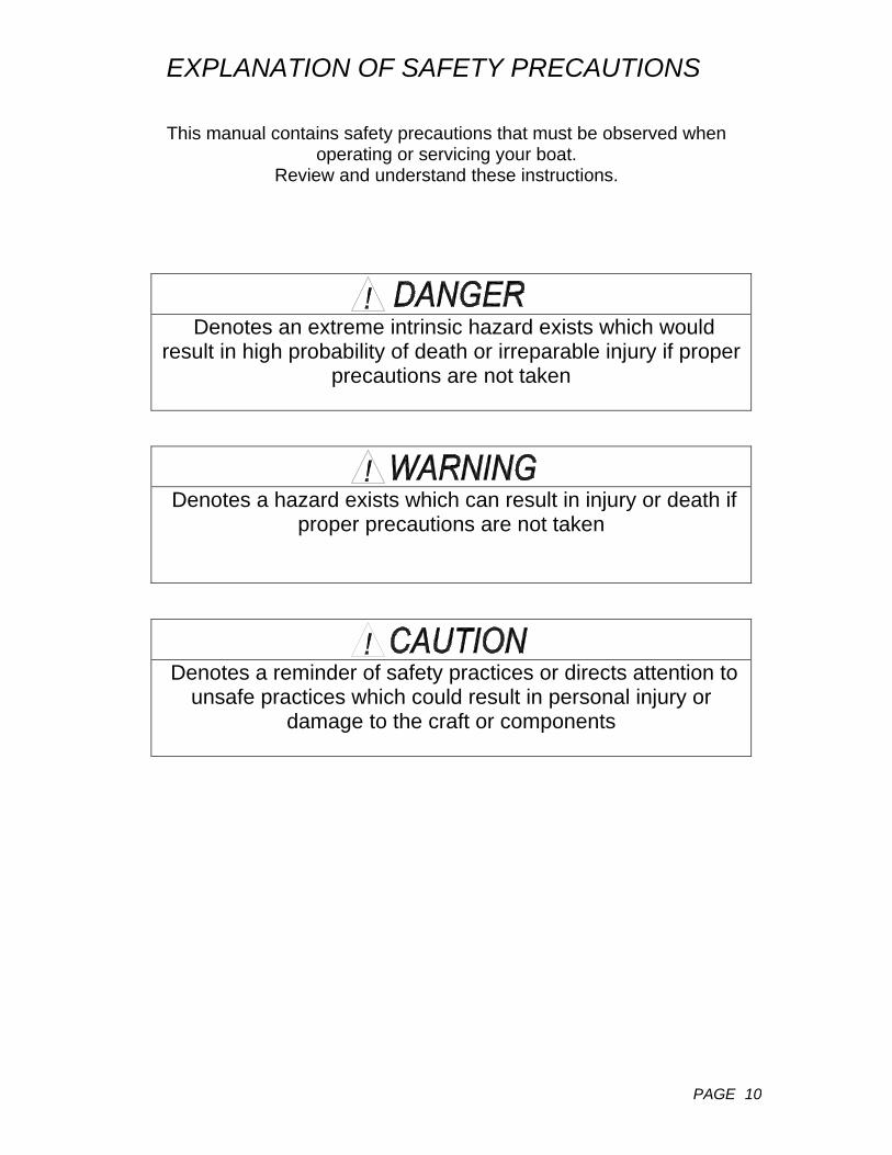
This manual contains safety precautions that must be observed when operating or servicing your boat.
Review and understand these instructions.
Denotes an extreme intrinsic hazard exists which would
result in high probability of death or irreparable injury if proper precautions are not taken
Denotes a hazard exists which can result in injury or death if
proper precautions are not taken
Denotes a reminder of safety practices or directs attention to
unsafe practices which could result in personal injury or damage to the craft or components

SAFE BOATING TIPS
PAGE
11
BE PREPAREDTake a safe boating course. In the U.S., contact your local Boating Industry for details. Carry all safety equipment required by the laws that apply to your area. Requirements are generally available from the Coast Guard or your local boating industry.
As the owner of the craft, obtaining and maintaining
necessary safety equipment is your responsibility. For more
information about equipment required, contact local boating
authorities
MINIMUM RECOMMENDED SAFETY EQUIPMENT Required life saving equipment,
including life vests and throwables.
First Aid kit Anchor with sufficient line and/or
chain Flashlight with good batteries Binoculars Appropriate navigational charts Flares Noise emitting device
Sufficient food and water provisions
Sunglasses and block Blanket Oar(s) The legally required on-board safety equipment may vary by region or body of water. Please check with local authorities prior to departure for a safety examination.
LIFE JACKETS
A life jacket may save your life, but only if you wear it. Keep jackets in a readily accessible place – not in a closed compartment or stored under other gear. Remove them from any packaging, and keep throwable floatation devices ready for immediate use.
It is very important that children,
handicapped people, and non-swimmers wear lifejackets at all times. Make sure all passengers are properly instructed in use
of life saving gear
FIRE EXTINGUISHERSApproved fire extinguishers are required on most boats, local authorities can provide details. All passengers should know the location and operating procedure of each fire
extinguisher. Fire extinguishers are normally classified according to fire type. Be familiar with the type of fire extinguishers you have on board.

SAFE BOATING TIPS
PAGE
12
FLARES Most boats operating on coastal waters are required to carry approved visual distress signals, therefore check with your local authorities as to which types are required.
FIRE/EXPLOSION HAZARD; Pyrotechnic signaling devices can cause injury and property damage if not handled properly. Follow manufacturer’s directions regarding the proper use of signaling devices.
DRUGS AND BOATING
Consumption of alcohol while boating is not recommended. The combination of noise, sun, wind, and motion act to produce fatigue on the water, and can exaggerate the effects of alcohol.
IMPAIRED OPERATION HAZARD
Operating any boat while is intoxicated or under the influence of drugs is both
dangerous and illegal. Impaired vision or judgment on the water can lead to
accidents and personal injury
BEFORE GETTING UNDERWAY
Leave a float plan (example included).
Perform a pre-departure checklist (example included).
Check the weather. Do not venture out if the weather is, or will be, threatening.
WHILE UNDERWAY
Keep a good lookout. Keep a watch to the leeward under the headsail. Keep away from swimmers, divers, and skiers.
Know and obey local boating laws. Respect bad weather, and be
prepared for quickly changing conditions.
COLLISION HAZARD
Use extra caution in shallow water or where underwater/floating objects may be
present. Hitting an object at speed or severe angle can seriously injure people
and damage your boat

PRE-DEPARTURE CHECKLIST
PAGE
13
Check bilge for extra water
Check weather conditions and tides
Check food supply
Foul weather gear
Linen, sleeping bags
Fuel
Water
Sunscreens and sunglasses
Tools
Docking and anchor gear
Check radio operations
Navigation charts and instruments
Float plans to a friend or Coast Guard (see next page)
Fuel for stove
Cooking and eating utensils
Check battery water level
Oil level, tight Vp-belts
Check for loose electrical connections in engine compartment
Secure tools or any loose equipment in engine compartment so as not to get fouled in engine
AC systems off; electrical cord stowed
Doors and drawers secured
Check steering lock to lock
Check mast for rigging irregularities and tightness
Halyards and sheets are clear and ready to run
No lines or other obstructions near propeller or bow
Anchor ready to run
Check lifelines for tightness
Turn on fuel and waterlines
Stow all loose gear
Open engine cooling water intake thru-hull valve

FLOAT PLAN
PAGE
14
1. Name of person reporting and telephone number: 2. Description of boat NAME TYPE MAKE LENGTH REGISTRATION# HULL COLOR STRIPE COLOR DECK COLOR OTHER DISTINGUISHING MARKS 3. Number of Persons aboard NAME AGE PHONE # ADDRESS NAME AGE PHONE # ADDRESS NAME AGE PHONE # ADDRESS 4. Engine TYPE H.P. FUEL CAPACITY 5. Safety equipment PFDs Flares Mirror Flashlight Food Water EPIRB Raft/Dinghy 6. Radio TYPE FREQUENCIES 7. Trip Expectations DEPARTURE TIME DATE FROM DESTINATION RETURN DATE NO LATER THAN 8. Automobile: LICENSE # STATE MAKE COLOR PARKED AT 9. If not returned by- Contact the Coast Guard or- CALL - AT-

AFTER SAILING CHECK LIST
PAGE
15
When leaving your Hunter at the dock for more than a short time, it is a good idea to review the following checklist to make sure everything is in order. This
will help protect the various parts of your boat and add to their attractiveness and usable life.
Flake or furl mainsail and cover, or remove and bag.
Remove and stow all portable deck hardware such as snatch blocks, winch
handles, etc.
Secure the boom to the topping lift and set it firmly amidships with the mainsheet purchase. (It is a good idea to rig a line from the steering wheel or tiller to a convenient cleat to keep the rudder from swinging back and forth with the motion of the water or employ the wheel brake if so equipped.
Attach the shackle ends of all halyards to convenient fittings and take up slack. Find a location leading away from the mast to keep the halyard from slapping the mast.
Coil and stow all lines in line lockers.
Cover the winches and steering pedestal when leaving the boat for several days or more.
Close all fuel lines and seacocks.
Switch off the electrical system.
Pump out the bilge.
Check air vents, secure ports and hatches, swab the deck, and clean deck stainless, particularly if you have operated in saltwater.
Make a final check of mooring lines, chafing gear, fenders, etc.
SAFE BOATING TIPS
PAGE 16
DOCKING Docking your boat should be handled carefully to avoid potential damage. Under normal wind and water conditions, the following considerations should be made: 1. Whenever possible, your approach should be made against the prevailing wind and current to assist in stopping the boat. Where these conditions are contrary, the strongest should be used to determine approach. 2. Approaching the dock: dock lines should be at ready, loose gear stowed and decks cleared. Determine the direction of the wind and current and when you decide which side of the boat will be against the dock, rig dock lines and fenders on the appropriate side.
One dock line should be attached to the bow cleat, another to the stern cleat opposite the side that will lie against the dock. NOTE: If the boat is to lie against a piling, rig a fender board across two or more pilings. 3. Tying up: attach bow and stern lines to dock, hauling boat in with fenders against dock. Rig crossing spring lines to limit motion forward and aft. Be sure to allow some slack in all lines to compensate for tidal activity if present. Never use bow rail, stern rail, or stanchions to secure a vessel, even for brief periods. For other types of moorings, or for abnormal wind or water conditions, consult an approved boating guide.
ANCHORING
Your Hunter comes with an on-deck anchor well and a Danforth type anchor as standard equipment. The anchor is selected to suit the size and weight of your boat under normal anchoring conditions, and provides its best holding characteristic in muddy or sandy bottoms. When anchoring, pay particular attention to the slope of your anchor rode (i.e., the relationship between the depth of the water and the length of the rode). A good rule of thumb is to allow a scope of about 7:1 (a rode seven times as long as the vertical distance from the bow to the bottom). A helpful aid is to mark the rode every 20 feet or so with knots or other types of indicators. Before dropping anchor, make sure the bitter end is secured to the cleat in the anchor well.
Also, be sure to consider wind direction, currents, mean low tide depths and other local conditions when anchoring, as well as the positions of any boats already anchored nearby.
Anchoring in unusual water and/or weather conditions will require additional precautions. Consult an approved guide for suggestions.
To weigh anchor, motor or sail (under main only) forward slowly. When at a point directly above the anchor, a quick tug should free it from the bottom. Take care not to damage the topsides when hauling.

MAST RAISING & LOWERING SYSTEM
PAGE 17A
WARNING: MAKE SURE THAT THE MAST AND RIGGING IS CLEAR OF ALL OVERHEAD ELECTRICAL CABLES WHEN BEING RASIED OR LOWERED OR MANEUVERED ABOUT THE LAUNCH AREA. CONTACT WITH AN ELECTRICAL CABLE CAN CAUSE SEVERE INJURY OR DEATH. 1. Confirm that all standing rigging and spreaders are connected to the spar as per the drawings in this owner’s manual. The spreader retaining pins should be installed and pinned, the spreader tip tightened in the correct location and all black rubber retainer plugs installed in the rigging terminals on the mast. These plugs prevent the shrouds from falling out of the mast when the mast is lowered. All halyards should be installed and the mast light installed. 2. Confirm that the white “boots” are installed over each shroud turnbuckle and that the turnbuckles are attached to the chain plate “U” bolts with the cotter pins located inboard. The boots must be forced down over the turnbuckle toggles to prevent the turnbuckles binding on the “U” bolts and bending during the stepping process. 3. Untie the mast from the bow pulpit and support crutch, and slide the mast aft on the support crutch roller until the base of the mast is over the mast step. At this point the mast will be balanced on the roller only, so do not let go of the mast base. The mast struts remain attached during this procedure. 4. Remove the stainless steel mast step pin from the mast step casting, being careful not to lose the boom vang strap. 5. Push the mast base down until the retaining pin holes in the base align with the corresponding holes in the step, and reinstall the stainless steel retaining pin, being careful to reinstall the boom vang strap at this time. Install the split ring to the retaining pin. 6. Open the anchor locker and attach the lower end of the mainsheet tackle (the end with the jam cleat) to the “U” bolt inside the locker.
7. Connect the mast raising tube to the pin in front of the spar. 8. Holding the pole in a vertical position, connect the jib halyard shackle to the aft loop at the top end of the pole. Tension the halyard by pulling it from the exit at the line stopper (make sure that the jib halyard is being tensioned, and not the main halyard) until the mast raising pole is angled aft approximately 10 degrees. Lock down the line stopper and securely cleat the halyard to the black plastic cleat on the side of the deck outboard of the line stopper. 9. While still holding the mast raising pole at the ten degree aft angle, connect the upper end of the mainsheet tackle to the forward loop at the end of the mast raising pole and take out the slack through the jam on the lower block of the mainsheet. 10. Check to make sure that the forestay is not twisted around the jib halyard, that the upper and lower shrouds are not twisted around each other and are outside the life lines, that the turnbuckles are vertical on the “U” bolts, the spar is clear of all overhead electrical wiring, all shrouds, mast raising bridles and forestays are properly attached to the spar, all shackles on the mainsheet and jib halyards are properly closed, the jib cleat is properly cleated to the spar, no one is standing in the cockpit or under the mast and, in all respects, the mast is ready to raise. 11. Pull on the mainsheet tackle to raise the spar making sure that the mainsheet always runs through, and is being held by the jam cleat. With the mast struts installed, the mast is prevented from moving side to side, so you can rest between pulls and it is not necessary to have anyone pushing the spar up from behind as you are pulling on the tackle, although this will reduce the load on the tackle and speed up the process. The load on the tackle will be at a maximum at the beginning of the raising process and will reduce progressively as the spar is raised, reducing to almost nothing when the spar is up. With the anchor locker open, the bow of the boat has limited space in which to work, so be careful and watch your footing. There is no need to hurry.

MAST RAISING & LOWERING SYSTEM
PAGE 17B
12. When raised, leave the mainsheet jammed and tensioned. Take the forestay forward and connect to the forward of the two holes in the stemhead fitting. 13. Connect mast wiring plug to deck fitting at starboard base of spar. 14. Refer to GETTING READY TO SAIL.
MAST LOWERING 1. Remove sails, boom vang and boom. 2. Install mast support crutch to transom, if not already done. 3. Install mast raising pole. 4. Attach jib halyard shackle to upper spliced eye at forward end of mast raising pole. 5. Tension jib halyard (again confirming that it is the jib halyard being tensioned and not the main halyard—check the color coding) so that the pole angles up at the front end approximately 10 degrees. Secure halyard to cleat on side of deck, and lock down the line stopper. 6. Attach bottom end of mainsheet to “U” bolt in anchor locker and top end to bottom loop at end of mast raising pole. Tension mainsheet tackle so jib halyard takes the load. Make sure mainsheet is jammed and for extra security secure to bow mooring cleat.
7. Loosen forestay turnbuckle and remove forestay from stemhead fitting. 8. Check for overhead electrical cables, make sure that no one is standing in the cockpit or under the spar, and confirm that the spar is in all respects ready to lower. 9. Allowing the mainsheet to hook around the bow mooring cleat, unjam the mainsheet and, holding the mainsheet tail in one hand, ease tension on the mainsheet tackle while pushing the spar aft with your other hand. Retaining the deflection of the mainsheet around the cleat, ease the mainsheet further until the spar begins to hinge aft. 10. Continue lowering the spar, remembering that the load on the tackle will increase as the spar is being lowered, until the spar rests in the mast crutch. 11. Disconnect the mast raising pole, mast electrical wiring and uncleat halyards aft so the spar can slide forward. 12. Remove mast step pin and disconnect mast base from step while restraining bottom end of mast and retaining boom vang strap. Replace pin, vang strap and cotter pin. 13. Slide mast forward on mast crutch roller until base of mast rest in bow pulpit. Secure mast in place at pulpit and at mast crutch. Take slack out of shrouds and secure forestay forward.


LAUNCHING & RETRIEVING PROCEDURES
PAGE 18A
LAUNCHING
1. Extend the trailer tongue, if necessary, by lowering the forward support wheel, chocking the main wheels, unplugging the electrical connection, removing the tongue positioning pin and cotter pin and sliding the tongue out to its full extended length and reinstalling the pin and cotter pin. This can be done with the vehicle still connected to the trailer, using the vehicle to slowly move the extension while a second person watches the trailer, but should at all times be done with the trailer on level ground. Whether the tongue needs extending will depend on the slope of the launch ramp and the depth of water available when the boat is backed in. In the majority of cases, for launching, the tongue may not need extending. However, for recovery, because the boat is floating lower with the full ballast tank, the tongue may need extending. 2. Remove any and all tie down straps and ropes securing the boat to the trailer, as well as any lines securing the rudder in the upright position or on centerline. The only attachment of the boat to the trailer should be the strap from the bow eye to the trailer winch. 3. The spar can be raised before or after launch, depending on the time available before and the docking facilities available after launch. Beware of nearby power lines before raising spar. 4. Attach the necessary bow and stern mooring lines and fenders if necessary. Do not lower the fenders over the side until the boat is clear of the trailer. 5. Initially slacken the trailer winch and familiarize yourself with its gear switch action and return the winch to the locked position. 6. Load all loose gear and provisions aboard by lowering the swim ladder in the transom.
7. Open the ballast tank valve located under the step of the companionway ladder. This valve loosens counter-clockwise but must be pushed down to force the sealing plate and gasket away from the recessed portion of the hull. Remove the vent plug located next to the valve from its hole in the vent box. 8. Back the boat and trailer down the ramp until the back wheels of the vehicle are just clear of the water, Retrieve the bow and stern lines as necessary. Loosen the trailer winch and bow strap. 9. Once the boat is floating free, push the boat clear of the trailer guides to the available dock, maintaining control with the mooring lines. 10. Slowly pull the empty trailer out of the water, being careful that boat and people stay clear. 11. Park the trailer and vehicle and return to the boat. 12. Check to make sure the ballast tank is full by sighting through the vent hole or by using a short length of dowel or wood as a “dip stick”. Sometimes the “venturi effect” of water rushing past the valve plate requires the continued filling of the ballast tank. 13. When full, close the valve by turning clockwise until it is tight and reinstall the vent plug in the down position. Close the step. NOTE: DO NOT leave water in ballast tank during freezing conditions. Water expands when it becomes ice and will do severe damage to the hull or ballast tank or both.

LAUNCHING & RETRIEVING PROCEDURES
PAGE 18B
RETRIEVING
1. Raise centerboard and rudder. 2. Back trailer into water, remembering boat will be floating lower with ballast tank full than when it was launched. Extend trailer tongue if needed. 3. Maneuver boat between trailer guides and up to the winch. 4. Connect bow strap and with winch in correct gear, winch boat up and snug against bow stop. 5. Center boat between upright aft trailer guides.
6. Slowly pull boat from water until the weight of the boat is on the trailer. 7. Confirm alignment on trailer. Put trailer back in water if necessary to realign boat. 8. Make sure that rudder is pinned or tied in upright position so that the tip doesn’t drag on ground. 9.De-rig and unstep mast if not already done. Beware of nearby power lines when lowering mast. 10. Tie boat to trailer, and secure mast.

GETTING READY TO SAIL
PAGE 19A
NOTE: The mast may be raised while the boat is on the trailer or after the boat is launched. However, if the mast is raised after launching, make sure (on water ballast models) that the ballast tank is full before the mast is raised. Also make sure that all halyards and reefing lines are installed using the messenger lines already run in the spar.
1. After the rig has been raised, attach the forestay turnbuckle to the most forward of the two holes in the stem fitting. Turnbuckle should be about ¾ open. Confirm that the upper and lower shrouds are supporting the spar. 2. Remove the mast-raising pole. The mast crutch may be left on the transom or removed, as you prefer. 3. Return the mainsheet to its aft position, attaching the block with the jam the “U” bolt at the front end of the cockpit. Install the forward end of the boom to the gooseneck fitting on the mast. Tie the bottom end of the topping lift rope (the other end is fixed to the top of the mast) to the casting at the bottom of the boom, which is immediately above the mainsheet “u” bolt in the cockpit. 4. Attach the jam block of the boom vang to the stainless steel bail on the mast step with the small shackle provided. The block should be oriented so that the line exits the vee jam on the bottom aft side. Attach the upper block of the vang to the eye on the boom. 5. If not already done on the H240 and H260, lead the main and jib halyards from the exits in the spar, through the sheaves molded into the mast base (main halyard through the aft sheave), around the deck organizer blocks to the inner of the two jams on the house top.
6. Using the main halyard, center the rig in the middle of the boat by first jamming the halyard in a position so that the halyard shackle just contacts a known point on the toe rail adjacent to the spar on the port side. Transfer the halyard to the starboard side and applying the same amount of tension, see if the shackle contacts the corresponding position on the starboard toe rail. If the shackle falls short, ease the port upper shroud turnbuckle and tension the starboard, always maintaining some tension on each shroud so they are not slack. If the shackle overshoots the mark on the toe rail, ease the starboard upper shroud turnbuckle and shorten the opposite side until the halyard shackle does contact both points on the opposite toe rail uniformly. 7. After the rig is centered, set the amount of mast rake to approximately one degree of aft angle. This can be measured by hanging a weight, such as an adjustable wrench from the main halyard shackle and adjusting the halyard so the wrench is suspended immediately above the boom. With the boat level, this wrench when hanging from the main halyard above the gooseneck should be 6” (15cm) from the aft face of the mast. Adjust the forestay turnbuckle as necessary to achieve this position. 8. Tension the upper shrouds uniformly, alternately taking six turns on one, then the other, until the upper shrouds are tight. The upper shrouds maintain tension on the forestay. The tighter the shrouds are, the tighter the forestay will be and the less forestay “sag” there will be. A turnbuckle is tensioned by turning the center portion counter clockwise and loosened by turning it clockwise. The upper swage on the wire should be held with pliers, vice grips, or wrench to prevent it from turning as the turnbuckle rotates.
ELECTROCUTION HAZARD
Make sure that the mast and rigging are clear of all overhead electrical cables when being raised or lowered or maneuvered about a launching area. Contact with an overhead electrical cable can cause severe injury or death.

GETTING READY TO SAIL
PAGE 19B
9. Tension the lower shrouds until the mast appears straight when sighted up the trailing edge, using the bolt rope slot as a guide. If the mast appears to bow to one side, ease the lower shroud on that side and tension the shroud on the opposite side until the mast appears straight. 10. Once the mast is straightened transversely, sight up the mast from the side to see if there is any fore and aft bend. The mast should be bowed forward at the spreaders by approximately 2’ (5cm). Ease or tension the lower shrouds uniformly until this slight amount of bend is achieved. When finished, the lower shroud should be slightly less tight than the main shrouds. If you sail in a predominately heavy air region, slightly more mast bend, in the 3” to 4” (4-10cm) range, may be desirable in order to flatten and depower the main sail. 11. After tuning the rig, install cotter pins in all turnbuckles to prevent them from backing off while sailing. 12. Install the battens in the mainsail and install the mainsail onto the boom from the forward end. Remove the stop pin in the mast and install the luff slides into the track on the back of the spar. Reinstall the stop pin to prevent the slides from falling back out again. 13. Install the out haul rope (the shorter of the two) in the boom with the messenger line provided and lead from the sheave at the back of the boom through the lower cringle at the back of the sail and aft to the end of the casting. 14.Install reefing line (the longer of the two) in the boom with the messenger line provided and lead from the sheave through the upper cringle at the back of the sail and then down to the sliding eye on the bottom of the boom. Pull enough slack into the reef line so that the sail can be fully raised unimpeded by the reef line. Tie the mainsail onto the boom with the sail ties provided. 15. Install the jib sheet onto the jib as illustrated in the owner’s manual (page 42A) and lead the
sheets inside the shrouds to the lead blocks on the cabin top and aft to the jams or winches on the house top. Tie figure eight knots in the end of the sheets to prevent them from running back through the jams. Shackle the bottom of the jib to the aft of the two holes in the stemhead fitting and hank the jib onto the forestay. Bunch and tie to prevent it blowing overboard before it is ready to hoist. 16. Attach jib and main halyards to their respective sails. 17. Lower the rudder blade, if depth of water permits, to full down position. If water depth does not permit this before leaving the dock or ramp, make sure the rudder is lowered before raising sail. The rudder must be down to achieve the correct balance for the proper helm loading. A rudder, which is not lowered, will load up excessively in severe conditions preventing the helmsman from responding to puffs and thus allowing the boat to “round up”. The cleat is provided to retain the blade in the upright position for the launch, retrieval and trailering. Helm “feel” can be fine tuned by adjusting the fore and aft angle of the rudder in the down position. 18. Install the tiller extension to the tiller (if not already installed from factory). 19. Raise sails, beginning with the main and then the jib while powering into the wind. Remember to lower the centerboard before you raise sail and confirm that the water ballast is full and sealed. Once each halyard, beginning with the main, is tensioned by the winch, the halyard can be pushed down into its respective jam and the halyard removed from the winch, freeing the winch for the next halyard and, in the case of the H240 and H260, ultimately for the jib sheets. However, care should be taken not to inadvertently pull the halyards out of the jams, since the sails will lower rapidly if this is done. When the sails are raised, the boat can be laid off and the engine turned off and tilted upward to clear the water. 20. Once the main is sheeted in and you are sailing upwind, confirm the main topping lift position. The
GETTING READY TO SAIL
PAGE 19C
main should be capable of sheeting in hard without the topping lift being tight. With the main sheeted in hard, the topping lift should have eight to ten inches of sag and should be adjusted accordingly. When at dock or at mooring, the topping lift can be readjusted to raise the boom to a comfortable height above the cockpit. 21. Final conformation of the mast tune as well as finer tuning, if you desire it, will take place when sailing by sighting up the spar while going upwind in about ten to twelve knots of breeze. The mast should maintain its 2” (5cm) fore and aft bend, but should also still appear straight transversely with the leeward main shroud still retaining its tension and not going noticeable slack. If the leeward rigging does go slack when sailing, apply more tension uniformly to both shrouds by first tightening the leeward rigging three half turns and then after tacking, tension the new leeward rigging the same amount. Continue this procedure, as necessary until the leeward upper
shrouds no longer appear slack and forestay sag has been reduced. Removal and reinstallation of the turnbuckle cotter pins will be necessary to make these fine tuning adjustments. 22. Once the upper shrouds are tensioned, again sight up the spar to make sure that the middle of the spar at the spreaders is not falling to leeward or bending to weather. Adjust and uniformly retension the lower shrouds as necessary. NOTE: Standing rigging will stretch slightly when initially loaded. Therefore, the rigging may have to be further tensioned slightly after a few sails in a strong breeze to compensate for this initial stretch. Once the mast is tuned and initial stretch is taken out, the rig should need retuning only at the beginning of each season. 23. After a day of sailing, the sails should be lowered while again powering into the wind, with the jib lowered first and then the main.

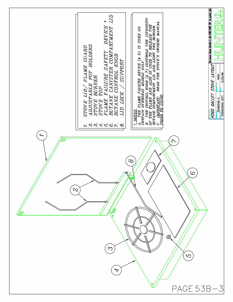
COOKING STOVE
PAGE 20
Carefully read and understand the manufacturer’s instructions prior to operating your stove. Save the instructions for review, and also to pass on to any subsequent owners. Use only the fuel recommended by the manufacturer, and store the fuel in an approved container. Do not smoke while working with fuel. Immediately clean up any spilled fuel.
EXPLOSION/FIRE/ASPHYXIATION HAZARD Open flame cooking appliances consume
oxygen. This can cause asphyxiation or death.
Maintain open ventilation. Liquid fuel may ignite, causing severe
burns. Use fuel appropriate for type of stove. Turn off stove burner before filling. Do not use stove for comfort heating. Use special care with flames or high
temperatures near urethane foam. Once ignited, it burns rapidly, producing extreme heat, releasing hazardous gasses and consuming a large amount of oxygen.
TOILET
Do not add holding tank deodorant
to the top fresh water tank Avoid adding holding tank deodorant
through bowl. Use tank on rear of bottom tank. Slide valve must be opened fully before adding deodorant through bowl, and avoid spilling or splashing deodorants on slide valve seals or bowl. Rinse off any spilled or splashed deodorant immediately.
Atmospheric pressure and temperature changes may cause pressure
FOR OPTIONAL H-260 MARINE HEAD, SEE PG 58A & B FOR WASTE SYSTEM DRAWINGS
Your Hunter 240 or 260 comes standard with a portable, self-contained marine toilet. Please refer to the manufacturers instructions to familiarize yourself with the correct operation of your toilet. Be sure to keep your toilet secure by connecting it to supplied hold down brackets. Add a holding tank deodorant to the lower unit of the tank, which is the holding tank. The upper unit is the fresh water tank for flushing. Empty the holding tank at an approved permanent toilet facility by first removing the holding tank, ensuring that the valve is closed, and carrying by the built-in handle. Rinse with fresh water and reassemble.
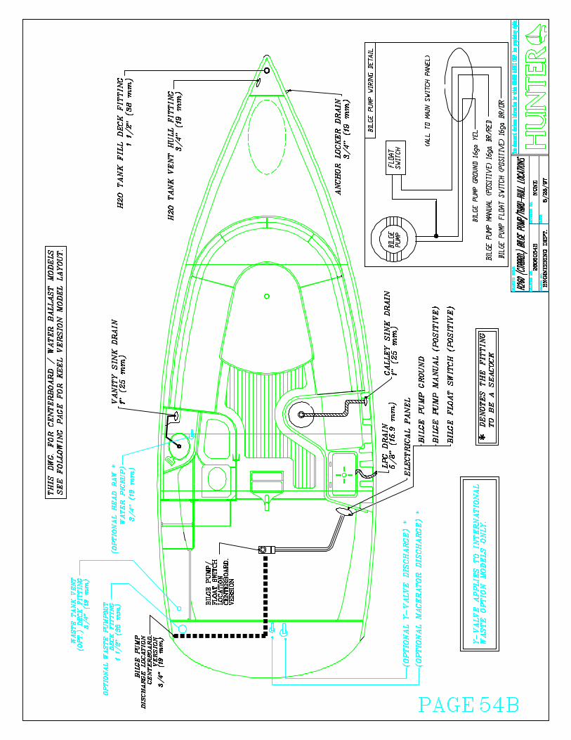
PUMPS
PAGE 21
All pumps should be checked frequently to insure proper operation. This is an especially important regular maintenance item since a properly operating pump could save your vessel from serious damage.
Run pump only as long as necessary to remove water. Dry running can damage the pump motor
SINKING HAZARD – Ensure proper bilge pump operation
Inspect all bilge pump hoses for chafing and dry rot. See that all hose clamps are tight. Check that the bilge pump impeller area is clean and free of obstructions. Inspect electrical wiring for corrosion. Ensure that the float switch functions properly.
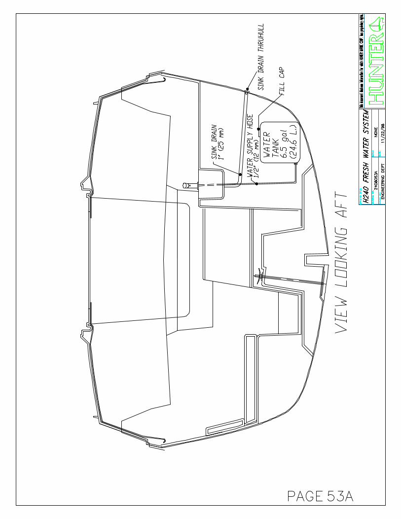
WATER SYSTEM OPERATION
Your Hunter is equipped with a manual pump water system, incorporating a water tank and a level actuated manual pump. After sitting for some time, the pump will need a few strokes to prime the system. Be aware of the quality of the
water on board, if you are using it for drinking or washing. Periodically, flush the water tank to keep it clean. When storing your boat for the winter, empty the water tank, and pump the lines dry.
OUTBOARD ENGINE AND MOTORING
PAGE 22
As the outboard is an option on your Hunter, you have numerous choices of brands available to you. This motor should be between 5hp and 8hp for the 240 and 8hp to 10hp for the 260. An engine owner’s manual should be supplied with your outboard motor. This manual will contain technical specifications, running instructions and a maintenance schedule on lubricants and other important functions. For longer engine life, follow the routine maintenance schedule recommended by the manufacturer. Run the engine at a low speed for about three minutes for warm-up operation before cruising, permitting the oil to circulate throughout the machine. Otherwise, the life of the engine will be shortened greatly. During warm-up operation, confirm that cooling water is discharged from its check port. Under power (without sails up) your boat may be maneuvered with the rudder only, or in tight turning situations, you can shorten your turning radius by turning the outboard in the same direction as the rudder. This directs the propulsion forces in a complementary direction to the way the rudder is steering the boat. The engine will generate some “prop walk” which will exert force to push the transom relative to the direction of the rotation of the propeller. You can test your prop walk direction by putting the boat in reverse while you are parallel to the dock,
and see if the stern swings toward or away from the dock.
If cooling water is not discharged, and operation continues, the engine will be
overheated, causing mechanical troubles
When fueling your engine, be sure to use fresh fuel. Fuel that has been in a tank too long can form gum and varnish, which can affect performance. Use oil as recommended by the manufacturer. Two stroke engines require a special oil to be either mixed with gasoline or injected from a remote tank. This lubrication is essential for the operation of the engine.
EXPLOSION/FIRE HAZARD
Store flammable material in safety approved containers. Keep containers in an n area designed for that purpose. Never store in an unvented space.
Observe no-smoking while fueling Fill to less than the capacity of the
tank. Allow for fuel expansion. Inspect fuel system regularly for
leaks.
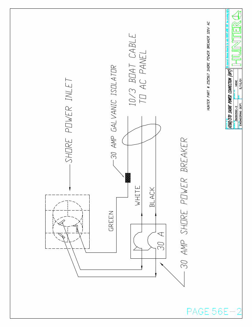
ELECTRICAL SYSTEM Your DC power source is a 12v battery, just as with your automobile, and it must be charged regularly. Some outboard motors include a small alternator, which will assist in recharging you battery. Otherwise you must use a battery charger. Perform regular visual inspections to insure proper water level and inspect terminals for corrosion. If your boat sits for long periods without use, it is a good idea to remove the battery(s)
And connect them with a trickle charger to keep them fully charged and ready for use.
Carefully follow safety instructions
included with battery Always charge battery in a ventilated
location

ENVIRONMENTAL CONSIDERATIONS
PAGE 23
FUEL AND OIL SPILLAGEThe spilling of fuel or oil into our waterways contaminates the environment and is dangerous to wildlife. Never discharge or dispose of fuel or oil into the water. It is dangerous and unlawful. Two common types of accidental discharge are overfilling the fuel tank and pumping contaminated bilge water into the sea.
EXPLOSION/FIRE/POLLUTION HAZARD:
Fill fuel tank to less than rated capacity. Overfill forces fuel out the tank vents, which can cause explosion fire, or environmental pollution. Also
allow for fuel expansion
DISCHARGE AND DISPOSAL OF WASTEWaste means all forms of garbage, plastics, recyclables, food wood, detergents, sewage, and even fish parts in certain waters. We recommend that you bring back everything you take out with you for proper disposal ashore.
Your marine holding tank (if so equipped) must, in many areas, be pumped out by an approved pump-out facility normally found at marinas.
EXHAUST EMISSIONSHydrocarbon exhaust emissions pollute our water and air. Keep your engine properly tuned to reduce
emissions and improve performance and economy.
ANTI-FOULING PAINTS
The use of anti-fouling paints is common for boats kept in water. Be aware of environmental regulations that may govern your paint choice. These regulations may affect which paint may be used, and also the application or removal. Contact your local boating authorities for more information
EXPLOSION/FIRE/HAZARD:
Ventilate when painting or cleaning. Ingredients may be flammable and/or explosive.
CLEANING CHEMICALSCleaning chemicals should be used sparingly and not discharged into waterways. Never mix cleaners and be sure to use plenty of ventilation in enclosed areas. Do not use products that contain phosphates, chlorine, solvents, non-biodegradable or petroleum-based products.
Common households cleaning agents may cause hazardous reactions. Fumes can last for hours, and chemical ingredients can attack people, property and the environment.

INSTRUCTIONS FOR PREPARATION FOR BOTTOM PAINTING
PAGE
24
WARNING!Do not use any sanding, sandblasting or other abrasive preparation of the bottom, as this will void your hull blistering warranty. See the
warranty information at the beginning of this manual.
BOTTOM PAINTINGChoose a bottom paint system that suits the environment in your area. Follow the procedure recommended by the manufacturer of the paint, while making sure not
to void the Hunter Hull Blistering Warranty. The procedure for preparing and painting the bottom varies between paint manufacturers, but should always include dewaxing, etching and sometimes priming of the surface.
EPOXY BARRIER COAT
Sanding of the gel coat bottom surface will be permitted should a customer wish to have an epoxy barrier coat applied to the hull, (example Interlux Interprotect 1000, 2000, West System or VCTar). This will not void the Five-Year Blister Warranty. Hunter Marine refers to epoxy barrier coatings as mentioned above, not epoxy primer paints. If an epoxy barrier coat is applied to a Hunter vessel, it must be registered with the Warranty Department prior to application of the product. If the dealer applies bottom paint only, sanding
will not be allowed and the no sanding system must be used.
Cleaning agents and paint ingredients may be flammable and/or explosive, or dangerous to inhale. Be sure to use adequate ventilation,
and appropriate safety clothing. (gloves, safety glasses, respiration, etc)
ENGINE MAINTENANCE
PAGE 25A
Follow the fuel and lubrication requirements in the engine manual provided by the manufacturer. Check oil levels prior to starting, and use lubricants as recommended by the engine manufacturer. Always check fuel lines and connections for possible leaks, which may create a dangerous situation. If you use your outboard in salt water, wash down the exposed drive unit after every use to limit corrosion. Also, it’s a good idea to attach a water hose to a flushing device on an outboard and completely flush out the raw water cooling system. Regularly check the propeller and drive unit for any damage or other signs of serious
wear. Propeller damage will reduce performance, as well as contribute to other potential engine problems.
EXPLOSION/FIRE HAZARD
Fuel system connections that are too loose or too tight can leak, resulting in fuel loss, environmental pollution and explosion or fire hazards.
ELECTRICAL SYSTEMS
The electrical system is a 12-volt, negative ground installation. On a weekly basis, the owner should inspect batteries, terminals and cables for signs of corrosion, cracks, and
electrolyte leakage. Battery terminals are to be kept clean and greased. Refer to specific instructions on batteries, wiring diagrams, and electronics.
PLUMBING SYSTEM All pumps should be checked frequently to insure proper operation. This is an especially important regular maintenance item since a properly operating pump could save your vessel from serious damage. Inspect all bilge pump hoses for chafing and dry rot. See that all hose clamps are tight. Check
that the bilge pump impeller area is clean and free of obstructions. Inspect electrical wiring for corrosion. Ensure that the float switch functions properly.
260,270 Inboard Engine (optional on 260) ENGINE, TRANSMISSION & DRIVETRAIN
PAGE 25B
Follow the fuel and lubrication requirements in the Engine Manual. Check the engine oil level before and after operation and use a quality motor oil (refer to Engine Manual). Be certain the proper amount of oils is in the crankcase at all times Engine Alignment: the engine should be aligned by experienced marine service personnel. Final alignment should be done after launching, with all normal gear aboard. A description of the procedure follows: The coupling flanges must come together evenly at all points, a feeler gauge is used to check the gap. If adjustment is necessary, the engine is tilted up or down and/or side-to-side until the flanges meet evenly. Severe vibration will result from misalignment and can cause strut bearing and shaft damage. Alignment should be checked again after several weeks of use. Routine checks of coupling bolts are a must to ensure they are tight.
Shaft Alignment: (see page 27B) 1. Separate the coupling, move the shaft end back to clear the pilot in the center. 2. Establish the shaft in the center of the shaft log by raising the shaft until it touches the top of the log – note position – lower the shaft until it touches the bottom of the log – note position – repeat sideways and locate shaft in the center; block shaft in this position, using a block of wood under the shaft packing gland. 3. Now, adjust the engine mounts to allow the pilot on the coupling halves to slip together without moving shaft up down or sideways. 4. Adjust the engine mounts as necessary until a .004” feeler gauge will not enter anywhere along the edge of the flange between the faces. 5. Tighten the locks on the adjustable mounts 6. Recheck coupling with feeler, readjust if necessary. 7. Check stuffing box (allow to drip 3 to 5 drops per minute).
TRANSMISSION
Follow the lubrication requirements of the Engine Manual. The oil level should be checked
immediately after operation.
STUFFING BOX
The stuffing box is held to the stern bearing by a rubber hose secured with hose clamps. (See the Shaft and Propeller section). The clamps should be tight and no water should leak from this location. While underway a slight drip from the stuffing box at the shaft exit is necessary (three to five drops a minute) and is normal. To adjust, loosen the locknut, tighten the gland nut
one-quarter turn, a retighten the locknut. If excessive water flow persists after adjustment, replace the packing with 3/16” (or 5mm) square flax packing and then adjust as above. NOTE: Some models use a packless sealing system. Page 57C reflects the type of stuffing box used on this model.

PROTECTING YOUR RIGGING
PAGE 26
No matter how good your rigging is, without careful inspection and proper maintenance it is subject to fatigue, wear, discoloration, and therefore, product failure. Remember: regular inspection and cleaning will increase the life of your investment and secure your rigging. We suggest the following: Always rinse your rigging with fresh water
after sailing, especially salt-water sailing. Salt can create corrosion pits, causing cracks and deterioration.
Clean with a water-soluble chlorine-free detergent. Nonabrasive cleansers are best for hard white vinyl coated cables.
Inspect rigging for stains. Rust stains may indicate stress cracks or corrosion. Remove stains with synthetic or brass pads. Never use steel wool pads.
Look for broken wires- a sign of fatigue in rigging. Replace standing rigging if wires are broken.
Never mix stainless steel and galvanized metals on cable, fittings, pins, cotter keys, etc. If mixing dissimilar metals, electric currents may conduct between metal causing rapid deterioration
After unstopping, make sure to release all standing rigging to avoid bending, crushing and kinking.
Store rigging in a dry place. Never store in a plastic bag, which can cause corrosion.

TRAILER MAINTENANCE
PAGE 27
BEFORE USING YOUR TRAILER
1. Check all bolts and nuts for tightness, including the lug nuts for the wheels.
2. Check to insure that all lights
are working properly. 3. Always maintain the tires’
recommended air pressure. 4. For improved tire life, have your
tires spin balanced by a qualified tire service center.
5. When the trailer has been
hitched to your vehicle, remove the two-speed winch handle before departing.
6. Always check hitch and safety
chain connection and boat tie downs prior to departing.
PROTECTING AND MAINTAINING YOUR TRAILER
1. Before launching your boat, we recommend that the light harness be disconnected from your vehicle with enough time to allow bulbs to cool. This will greatly extend the life of your bulbs.
2. This trailer has a galvanized
frame, however, some parts including the brakes, axles, hubs, springs, U bolts, and plates are not galvanized. Most of these parts have been sprayed with a high gloss black rust resistant paint, plus a clear
coating. After launching, (especially in salt water locations), rinse your trailer, including the painted components. As a continuing measure to protect your trailer, you should from time to time, refinish and repaint surfaces that show signs of rusting.
3. Periodically and regularly check
your wheel bearings for sufficient grease and tightness. The more launching you do, the more likely for the need to regrease these bearings.
Proper maintenance and care will help insure more trouble free trailering for you. IMPORTANT: Be sure to thoroughly familiarize yourself with the trailering regulations in your state and in any others through which you will be traveling with your boat. Regulations vary from state to state regarding the trailering of sailboats, governing both the width of the load and the length of mast overhang at the rear of the trailer. Special permits may be required, and other regulations may apply. Consult your local authorities for more information.

GENERAL CARE
PAGE 28
CLEANING FIBERGLASS SURFACESFiberglass surfaces should be cleaned regularly. Normal accumulations of surface dirt can be removed simply by occasional rinsings with water. If you operate your boat in salt water, more frequent rinsing will be required. To remove stubborn dirt, grease or oil, use a mild detergent and a soft brush. Rinse with fresh clean water. Avoid the plexiglass companionway slider, windshield, deck hatches and fixed ports when using a deck brush, since these surfaces can scratch. It is a good idea to wax the fiberglass once or twice a year to maintain a deep, glossy appearance. Your
local marine supply should be able to provide an appropriate wax.
EXPLOSION/FIRE HAZARD
Cleaning agents and paint ingredients may be flammable and/or explosive, and dangerous to inhale. Be sure to use adequate ventilation, and appropriate safety clothing (gloves, safety glasses, respirator, etc.)
CLEANING ACRYLICUse only mild soap and water to clean acrylics. Do not use products containing solvents such as ammonia, which is found in many window cleaners.
Use care when cleaning acrylic. Dry cloth and many glass cleaners will scratch. Solvents will attack the surface.
SAIL CARESunlight is a sail’s worst enemy, so cover the mainsail when not in use. An ultraviolet guard, fitted down the leech of a roller headsail will protect the exposed part from the weathering effect of the sun and from dirt and grit. Mildew, can be prevented by storing sails dry and by hand washing twice a season. Check all sails regularly for chafe, particularly where they chafe on
deck fittings or rigging, at reef points, batten sleeves and the foot of the headsail. Sail batten pockets should be inspected on a regular basis. To stow the mainsail, start at the leech and flake it onto the boom, left and right, in about 18-in. (46 cm) folds, while pulling the leech aft. Secure with a sail tie and continue to the luff. Lash to the boom with sail ties or shock cord.
GENERAL HARDWARE MAINTENANCECheck all fittings regularly to be sure screws are tight. Occasionally lubricate (use silicone lubricants) all moving parts on such fittings as blocks, turnbuckles and cam cleats, as well as the locking pins of snatch blocks, track slides, spinnaker poles, etc. Inspect cleat and fairleads for roughness and
smooth with fine-grained emery paper if necessary. Also, replace any missing or damaged cotter pins in turnbuckles and shackles, and either tape them or use them or use protective covers manufactured for that purpose. Grease winches a minimum of once yearly.
WINCH MAINTENANCEFollow the maintenance instructions prescribed by winch manufacturer. We recommend a minimum of
an annual cleaning and light greasing.

VINYL
PAGE 29
These patterns, like all upholstery fabrics and vinyl, require a regularly scheduled cleaning program. A thorough cleaning should be administered on a daily, weekly or monthly basis depending on use and exposure to dirt and/or staining agents. It is important to begin treatment of a stain as soon as possible after a spill. It is important that efforts begin immediately after a spill to remove any potential staining agent. It is advisable to clean these products as soon as the first signs of dinginess occur, otherwise, delaying clean up will require a much greater effort to restore the product to its original appearance. Regular cleaning requires the use of a mild cleaner such as Murphy’s Oil soap and water. In situations where the vinyl has not been washed regularly and there is a build up of dirt, stronger vinyl cleaners such as Simonize’s Tuff Stuff or Turtle Wax’s vinyl/fabric cleaner are recommended. We do not recommended the use of any other cleaners. The use of cleaners
other than those recommended may result in irreparable damage to the product. In order for the above listed cleaning solutions to work effectively on stubborn stains, please allow time for the cleaning solution to soak in thoroughly. Be sure to remove the cleaning solution before it has time to dry. Regardless of the type of cleaner used, it is necessary to finish up with a thorough rinse using fresh water on a clean sponge or rag. A soft bristled nylon or natural fiber brush can be used to remove built-up dirt and staining agents. Finally, please remember that all our fabric grain vinyls require a greater cleaning effort to maintain than comparable smooth grain vinyls. These products will provide an attractive and durable alternative to conventional fabrics and vinyls if properly maintained. One must realize that the proper installation and use of our fabric grain vinyls require additional attention to the establishment and maintenance of a well thought out cleaning program.
FABRIC CAREVinyl: Clean with mild soap and water. Wipe with vinyl or upholstery cleaner monthly, and especially before and after storage. Leather: Mild soap water. Blot dry. Do not scrub as this will stretch and scratch. Wipe with leather cleaner/oil to preserve and help prevent cracks before and after storage. Fabric: Blot dry. Do not machine wash. Use only mild soap and water. Wipe with a clean white cloth. If stain persists, dry clean. Be sure to treat cleaned surfaces with scotch guard.
Stretched or loose covers may be steam leaned. If foam is removed, it will restuff more easily if wrapped with thin plastic. Storage: Cover with airflow fabric to reduce dust build up. Do not use plastic, as this will cause cushions to sweat and mildew. Cushions: If wet, prop cushions vertically to promote airflow around each cushion. Cushions can be cleaned by most dry cleaners. Dry clean only.

ELECTROLYSIS AND GALVANIC PROTECTION
PAGE 30
Salt water allows electric current to flow from anodic to cathodic material. For any two metals from two components, their relative positions in the galvanic rating table, will determine which loses material (the anode) and which remains largely undisturbed (the cathode). The distance between the two metals on the galvanic table determines the rate of wear. Thus a sacrificial zinc anode is often fitted to the underwater area of a boat to attract any destructive currents away from bronze or steel propeller shafts, for example. It is not enough to know that your boat does not suffer from electrolysis; a newcomer in the
adjacent marina berth may start a too-friendly association with metal components on it. An easy place to fit an anode is on the propeller shaft, or covering the propeller nut. The anode should not be painted; this would render it ineffective. To prevent electrolysis in seawater, the difference between the voltages of the two adjacent metals should not exceed 0.20 V. For example, zinc and carbon steel used together risk corrosion, while lead and active stainless steel are compatible. Metals with a high voltage corrode faster and need a larger area to diffuse the electrochemical reaction.

TEAK CARE
PAGE 31
Teak wood is a high quality, extremely durable wood with a high oil content. In order to help you protect the original beauty of your teak interior, we have sealed the wood with a 3 to 4 coat system of high quality Seafin Teak Oil, manufactured by Dalys. This material is penetrating oil that dries to a low sheen to seal and protect the wood from moisture and
weathering. It creates a durable, nonslip surface to repel water and resist wear. It won’t chip, peel or blister. It reduces work and maintenance cost because it is easy to repair and maintain and repair. With proper maintenance it will outlive urethane varnish on interior and even exterior surfaces.
MAINTENENCEWhen oiled surfaces require renewing, simply wipe the surface area free of loose dirt, dust or other contaminants. Dampen a cloth with the
Seafin Teal Oil and wipe on. Let stand for 5-15 minutes, then polish dry. If your dinette table has an epoxy finish, clean with furniture polish.
REPAIRSWhen woodwork is damaged from scrapes or abrasions that go into or thru the finish, take the following steps: 1. Take 180 to 200 grit wet/dry sand paper to smooth out rough spots. 2. Wipe clean of dust and dirt with a clean rag. Note: before applying oil, wood surface must be dry. 3. Wipe or brush on oil, allow to penetrate 5-15 minutes while surface is still wet. 4. Sand until smooth with 400A wet/dry sandpaper.
5. Wipe dry with a clean rag. Allow 8-12 hours drying time. 6. Apply second coat, sand, and repeat procedure. This procedure may be repeated as many times as needed to bring damaged area back to its original finish. If you have trouble with getting the same sheen, you may use a soaked and rung out cloth to apply a very light coat to get an even sheen.

WATER BALLAST TANK FREEZING
PAGE 32
This information is presented to prevent you from having problems or causing destructive damage to your new H240 or H260 water ballast sailboat built by Hunter Marine. When your water ballast tank is empty or has been drained and the valve left in the open position, there will never be a problem with freezing. The damage exists when the water ballast tank has water inside it. If subjected to freezing conditions, causing the water inside the tank to freeze and expand. The expansion will cause the tank to rupture or will break the joint where the tank is sealed to the hull. This damage will render the boat unusable.
Because the hulls are constructed with end grain balsa coring for stiffness, strength and lasting integrity, they also act as insulators. The temperature of the surrounding water will not (because of the insulating qualities of the balsa core) prevent the tank from freezing when air temperatures drop below the freezing point. For safety and reliability considerations, Hunter Marine does not recommend heating the interior of the boat. Hunter recommends that the boat is removed from the water during freezing conditions; and that the ballast tank is drained and the valve left in the open position.

STORAGE/WINTERIZATION
PAGE 33
IMPORTANT Winter storage is recommended to be done in one of the following three ways, either: 1) by blocking the boat via a cradle 2) with chained stands on level ground; or 3) by storing the boat in the water with a bubbler system to prevent icing. Damage to your boat, including engine misalignment caused by twisting, is not covered by the warranty. SAILS Sails should be properly folded and stowed in a dry, well-ventilated place. Many sailboat owners send their sails back to the sail manufacturer at the end of each season. The sailmaker will check the stitching and sailcloth for wear and store the sails until the start of the next season. ELECTRICAL Remove battery from boat (Refer to Engine Manual) and charge. It is a good idea to also remove the electronics (radio, radar, etc) and store in a safe place. CUSHIONS Cushions should be removed and stored at home if possible. If not, prop them vertically to promote air flow around each cushion. Dry clean only! HATCHES Tenting the deck during storage will help prevent ice from forming and damaging hatches and deck fittings. The installation of a passive vent will help with ventilation while the boat is in storage. WATER SYSTEM Open a faucet and allow the pump to empty the tank. Then add approximately two gallons (7.6L) of non-toxic antifreeze solution to the tank and repeat the pumping out procedure. A second method is to disconnect the hoses at the pump, allowing them to drain. Find the lowest point in the system and disconnect the fitting. Open all faucets to allow the lines to drain. If possible, use a short of hose on the faucet to blow through the lines to clear all water. A diluted solution with baking soda will help freshen the system. WATER SYSTEM Open valve and drain fully leave valve open during lay-up time. TOILET AND HOLDING TANK Drain and flush toilet. Using non toxic antifreeze in a 50/50 mixture with water, pump through toilet and into holding tank. OUTBOARD ENGINE Take it home and store it in a safe place. Be very careful storing the gas tank as the gasoline is very
flammable. Refer to Engine Manual for specific maintenance schedule. INBOARD ENGINE Winterizing Fresh Water Cooled Diesel Engines 1. Drain crankcase and transmission and refill with fresh lubricant as specified in Engine Manual. 2. Drain and clean all fuel filters and change elements, gaskets, and seals. Bleed all air from fuel systems. 3. Start engine and bring up to operating temperature. 4. Close the sea cock, remove the raw water pickup hose from the raw water pump and immerse one end into a 5-gallon (19L) bucket of antifreeze solution. Start engine and run till antifreeze solution comes out exhaust stack or until bucket is empty. Attach the raw water pickup hose to the raw water pump. Tighten all clamps. NOTE: This procedure bypasses the sea strainer to prevent antifreeze from crystallizing in sea strainer, which warranty will not over. 5. Loosen water pump and alternator belts to lessen tension on belts during winter. 6. For engines equipped with a hand crank: pull compression release levers and turn engine slowly with the hand crank. Slowly pour about 2 ounces of engine oil into the intake pipe or manifold while hand cranking the engine. This will allow for a thin coat of oil on the valves and upper cylinder. DO NOT USE starter to turn engine or serious engine damage may result. 7. Tape the openings of the intake and exhaust manifolds with duct tape to help prevent corrosion of the upper cylinder during layup. 8. Scrape all rust or corrosion from exposed metal parts and surfaces. Scrub all metal surfaces with detergent and rinse thoroughly. Paint any bare metal. 9. Place a dust cover over engine. Do not leave the engine exposed to rain and sea breeze. 10. Disconnect the battery cables; remove the battery from the boat. Clean the terminal ends and
STORAGE/WINTERIZATION (CONT.)
PAGE 34
battery with a solution of baking soda and water, and then rinse thoroughly with clean water. Apply a light coat of grease on the terminal end of the battery and cables. Store the battery in a cool dry place. Use a trickle charger to keep battery charged. Do not charge battery near any open flame or a confined area. CAUTION: Wear safety goggles and rubber gloves to protect your skin. Winterizing Raw Water Cooled Diesel Engines 1. Drain crankcase and transmission and refill with fresh oil as specified in the engine manual. Change oil filters. 2. Close seacock, remove raw water pickup hose from water pump, attach 4-foot (1.2m) length of hose to water pump and immerse in a 5 gallon(19L) bucket of anti freeze solution. Remove hose from engine or manifold that leads to exhaust elbow. Attach about a 4-foot length of hose and immerse one end in the bucket of antifreeze solution. Start engine and run until water begins to warm up (about 3-5 min.) and the thermostat opens. Stop engine. Replace hose that leads to exhaust elbow. Star engine and let run till water comes out exhaust pipe. Stop engine, remove hose from water pump to bucket, attach hose from seacock to water pump and tighten all hose clamps. NOTE: this procedure bypasses the sea strainer to prevent antifreeze from crystallizing sea strainer, which warranty will not cover. 3. Loosen water pump and alternator to lessen tensions on belts during winter. 4. Drain and clean all fuel filters and change elements, gaskets and seals. Bleed all air from fuel systems. 5.Pull compression release lever and turn engine slowly with hand crank. Slowly pour about 2 ounces of engine oil into the intake pipe or manifold while engine is turning. DO NOT USE the starter to turn engine or serious engine damage may result. 6. Tape the openings of the intake and exhaust manifolds with duct tape to help prevent corrosion of the upper cylinder during lay-up. 7. Scrape all rust or corrosion from exposed metal parts and surfaces. Scrub all metal surfaces with
detergent and rinse thoroughly. Paint any bare metal. 8. Place a dust cover over engine. Do not leave engine exposed to rain and sea breeze. 9. Disconnect the battery cables; remove the battery from the boat. Clean the terminal ends and battery with a solution of baking soda and water and rinse thoroughly with lean water. Apply a light coat of grease on the terminal end of the battery and cables. Store the battery in a cool dry place. Use a trickle charger to keep battery charged. Do not charge battery near any open flame or in a confined area. CAUTION: Wear safety goggles and rubber gloves to protect your eyes and skin. DEPARTURE FROM THE BOAT The check list for leaving a boat unattended is very important because items overlooked often will not be remembered until you are far from the boat and corrective actions are impractical or impossible. Primary choices for this list are items relating to the safety and security of the unattended craft: turning off fuel valves, properly setting electrical switches , pumping out bilge and leaving the switch on automatic (or arrange for periodic pumping out). It is recommended that the power be turned off when leaving the boat. Other departure checklist items are securing ports, windows, hatches and doors. ROUTINE MAINTENANCE Routine maintenance checklists should include items based on how much the boat is used (usually in terms of engine hours) and on calendar dates (weekly, monthly or seasonal checks). Typical of the former are oil level checks and changes, and oil and fuel filter changes. On a calendar basis the lists should note such matters as electrolyte levels in storage batteries, pressure gauges on dry chemical fire extinguishers, and all navigation lights. Check the operation of automatic bilge alarms or pump switches by running water into the boat. Periodically close and open sea cocks several times to ensure their free and easy operation in case they are needed in an emergency. Equipment and supplies carried on board for emergencies should be inspected for any signs of deterioration.


DIM
EN
SIO
NS
, C
AP
AC
ITIE
S,
ET
C.
HU
NT
ER
240
LEN
GT
H O
VE
RA
LL (
LOA
)…………………………
......
......
......
......
.24
' 1"
7.35
mLE
NG
TH
OF
WA
TER
LIN
E (
LWL)…………………
......
......
......
......
.22
' 1"
6.72
mB
EA
M (
MA
X)…
………………………………………
......
......
......
......
.8'
3"
2.50
m
DR
AF
T (
BO
AR
D U
P)…
………
.……………………
......
......
......
......
1' 6
".4
6 m
DR
AF
T (
BO
AR
D D
OW
N).
....…
.……………………
......
......
......
......
5 '6
"1.
68 m
DIS
PLA
CE
ME
NT
(W
/O B
ALL
AS
T).…………
..……
......
......
......
......
2,30
0 lb
s.1,
043
kg.
WA
TE
R B
ALL
AS
T (
FULL
TA
NK
)………
..…………
......
......
......
......
1,30
0 lb
s.59
0 kg
.
SA
IL A
RE
A (
100%
TR
IAN
GLE
S)…
…………………
......
......
......
.....
236
sq. f
t.21
.9 s
q.m
SA
IL A
RE
A (
AC
TU
AL
W/ S
TA
ND
AR
D S
AIL
S)…
…...
......
......
......
....
245
sq. f
t.22
.8 s
q.m
I…………………………………………………………
......
......
......
.....
25' 6
"7.
77m
J ………………………………………………………
......
......
......
......
.8'
6"
2.59
mP…………………………………………………………
......
......
......
...24
' 3"
7.39
mE…………………………………………………………
......
......
......
...10
' 6"
3.20
mM
AS
T H
EIG
HT
(FR
OM
WA
TE
RLI
NE
)………………
......
......
......
.....
32' 6
"9.
91m
WA
TE
R C
AP
AC
ITY…………………………………
......
......
......
......
.6.
5 U
.S. g
al.
24.6
lite
rsH
OLD
ING
TA
NK
CA
PA
CIT
Y (
PO
RT
A-P
OT
TY)…
…………
......
......
2.8
U S
gal
.10
.5 li
ters
FU
EL
TA
NK
CA
PA
CIT
Y ..
......
......
.....…
……………
......
......
......
......
OP
TIO
NA
L W
/ OU
TB
OA
RD
BA
TTE
RY
CA
PA
CIT
Y………………………………
......
......
......
......
.D
EA
LER
SU
PP
LIE
DE
LEC
TR
ICA
L V
OLT
AG
ES…………………………
......
......
......
......
.S
EE
ELE
CT
RIC
AL
DR
AW
ING
SO
UT
BO
AR
D E
NG
INE…………………………
......
......
......
......
......
......
.O
PT
ION
AL
W/ O
UT
BO
AR
DM
AX
IMU
M L
OA
DIN
G…………………………………
......
......
......
......
8 P
EO
PLE
840
kg(I
NC
LUD
ING
LU
GG
AG
E)
EX
CE
L270
8037
BP
AG
E 3
7B

DIM
EN
SIO
NS
, C
AP
AC
ITIE
S,
ET
C.
HU
NT
ER
260
LEN
GT
H O
VE
RA
LL (
LOA
)…………………………
......
......
......
......
.26
' 3"
8.00
mLE
NG
TH
OF
WA
TE
RLI
NE
(LW
L)…………………
......
......
......
......
.23
' 3"
7.09
mB
EA
M (
MA
X)…
………………………………………
......
......
......
......
.8'
11
1/2"
2.73
m
DR
AF
T (
BO
AR
D U
P)…
………
.……………………
......
......
......
......
1' 9
".5
3 m
DR
AF
T (
BO
AR
D D
OW
N).
....…
.……………………
......
......
......
......
6 '0
"1.
83 m
DIS
PLA
CE
ME
NT
(W
/O B
ALL
AS
T).…………
..……
......
......
......
......
3,00
0 lb
s.1,
361
kg.
WA
TE
R B
ALL
AS
T (
FU
LL T
AN
K)…
……
..…………
......
......
......
......
2,00
0 lb
s.90
7 kg
.
SA
IL A
RE
A (
100%
TR
AIN
GLE
S)…
…………………
......
......
......
.....
298.
5 sq
. ft.
27.7
4 sq
.mS
AIL
AR
EA
(A
CT
UA
L W
/ ST
AN
DA
RD
SA
ILS
)……
......
......
......
......
.32
0 sq
. ft.
29.8
sq.
mI…
………………………………………………………
......
......
......
.....
29' 2
1/2
"8.
90m
J ………………………………………………………
......
......
......
......
.9'
5 1
/2"
2.88
mP…………………………………………………………
......
......
......
...30
' 6 1
/2"
9.31
mE…………………………………………………………
......
......
......
...10
' 6"
3.2m
MA
ST
HE
IGH
T (
FR
OM
WA
TE
RLI
NE
)………………
......
......
......
.....
40' 0
"12
.19m
WA
TE
R C
AP
AC
ITY…………………………………
......
......
......
......
.20
U.S
. gal
.76
lite
rsH
OLD
ING
TA
NK
CA
PA
CIT
Y (
PO
RT
A-P
OT
TY
)……………
......
......
2.8
U S
gal
.10
.5 li
ters
HO
LDIN
G T
AN
K C
AP
AC
ITY
(O
PT
ION
AL
MA
RIN
E H
EA
D)…
…...
...13
US
gal
.49
.2 li
ters
FU
EL
TA
NK
CA
PA
CIT
Y ..
......
......
.....…
……………
......
......
......
......
OP
TIO
NA
L W
/ OU
TB
OA
RD
BA
TT
ER
Y C
AP
AC
ITY………………………………
......
......
......
......
.D
EA
LER
SU
PP
LIE
DE
LEC
TR
ICA
L V
OLT
AG
ES…………………………
......
......
......
......
.S
EE
ELE
CT
RIC
AL
DR
AW
ING
SO
UT
BO
AR
D E
NG
INE…………………………
......
......
......
......
......
......
.O
PT
ION
AL
W/ O
UT
BO
AR
DM
AX
IMU
M L
OA
DIN
G…………………………………
......
......
......
......
8 P
EO
PLE
840
kg(I
NC
LID
ING
LU
GG
AG
E)
EX
CE
L270
8037
BP
AG
E 3
7B

DIM
EN
SIO
NS
, C
AP
AC
ITIE
S,
ET
C.
HU
NT
ER
270
LEN
GT
H O
VE
RA
LL (
LOA
)…………………………
......
......
......
......
.26
' 3"
8.00
mLE
NG
TH
OF
WA
TER
LIN
E (
LWL)…………………
......
......
......
......
.23
' 3"
7.09
mB
EA
M (
MA
X)…
………………………………………
......
......
......
......
.8'
11
1/2"
2.73
mD
RA
FT
…………
.……………………………………
......
......
......
......
3' 6
"1.
07m
DIS
PLA
CE
ME
NT……………………………………
......
......
......
......
.5,
207
lbs.
2,36
7 kg
SA
IL A
RE
A (
100%
TR
AIN
GLE
S)…
…………………
......
......
......
.....
298.
5 sq
. ft.
27.7
4 sq
.mS
AIL
AR
EA
(A
CT
UA
L W
/ ST
AN
DA
RD
SA
ILS
)……
......
......
......
......
.32
0 sq
. ft.
29.8
sq.
mI…
………………………………………………………
......
......
......
.....
29' 2
1/2
"8.
90m
J ………………………………………………………
......
......
......
......
.9'
5 1
/2"
2.88
mP…………………………………………………………
......
......
......
...30
' 6 1
/2"
9.31
mE…………………………………………………………
......
......
......
...10
' 6"
3.2m
MA
ST
HE
IGH
T (F
RO
M W
AT
ER
LIN
E)…
……………
......
......
......
.....
40' 0
"12
.19m
WA
TE
R C
AP
AC
ITY…………………………………
......
......
......
......
.20
U.S
. gal
.76
lite
rsH
OLD
ING
TA
NK
CA
PA
CIT
Y (
PO
RT
A-P
OT
TY)…
…………
......
......
2.8
U S
gal
.10
.5 li
ters
HO
LDIN
G T
AN
K C
AP
AC
ITY
(O
PT
ION
AL
MA
RIN
E H
EA
D)…
…...
...13
US
gal
.49
.2 li
ters
FU
EL
TA
NK
CA
PA
CIT
Y ..
......
......
.....…
……………
......
......
......
......
13 U
S g
al.
49.2
lite
rsB
AT
TER
Y C
AP
AC
ITY………………………………
......
......
......
......
.D
EA
LER
SU
PP
LIE
DE
LEC
TR
ICA
L V
OLT
AG
ES…………………………
......
......
......
......
.S
EE
ELE
CT
RIC
AL
DR
AW
ING
SIN
BO
AR
D E
NG
INE…………………………
......
......
......
......
......
......
. 9
hp
DE
ISE
L6.
7 kw
MA
XIM
UM
LO
AD
ING…………………………………
......
......
......
......
8 P
EO
PLE
840
kg(I
NC
LID
ING
LU
GG
AG
E)
LIF
TIN
G P
OIN
TS
......
......
......
......
......
......
......
......
......
......
......
......
......
IND
ICA
TE
D B
Y "
SLI
NG
" LA
BE
LS
ON
HU
LL
EX
CE
L270
8037
CP
AG
E 3
7C


H240 DECK HARDWARE LIST
ITEM QTY DESCRIPTION DWG# PART# COMMENTS
1 1 BOW RAIL H23B2022 304150 HUNTER2 1 BOW ROLLER (OPTIONAL) HWO987 SEA DOG
3 12 HINGE 315130 #1167
4 1 ANCHOR DEAD END U-BOLT 308030 3/8" SS U-BOLT 5A 1 ANCHOR LOCKER LATCH 315680 S.S.
5B 1 STRIKER PLATE 306350 S.S. 5C 2 EYE STRAP (CHROME) 315590 FOR BUNGEE CORD
6A 1 FRONT HATCH H23A2415 CC090010 FIBERGLASS
6B 1 HATCH ARM W/DOG 301260 6C 1 HATCH LATCH 301720
6D 1 HATCH GASKET 310800 .5" X .5" D-SECTION SILICO7 1 ANCHOR LOCKER LID H23A2417 CC030050 SAME AS H23.5
8 1 PORT FWD WINDOW 318884 N. FLA. GLASS & MIRROR
9 1 FORWARD WINDSHIELD CC090080 N. FLA. GLASS & MIRROR10 2 CENTERBOARD RAISING SHEAVE 302600 SINGLE 03-03
11 1 THREE PRONG PLUG 25154012 1 MAST BASE 24020009 401971 S.S.
13 4 FWD STANCHION 24020014 305250 S.S.
14 2 HALYARD CHEEK BLOCKS 302610 SCHAEFER 30-2715 2 JIB LEAD BLOCKS 301895 SCHAEFER 03-62
16 1 STBD FWD WINDOW 318883 N. FLA. GLASS & MIRROR17A 4 CHAINPLATES H23B2028 318010 3/8" U-BOLTS
17B 2 CHAINPLATE BACKUP PLATES 303240 1/4" X 3/4" S.S.
18 2 RACING CLAM CLEATS 303000 CL23819 4 PAD-EYE 303770 SCHAEFER WELD RING 78-05
20 1 XA/2 SHEET STOPPER 304050 EASY LOCK DOUBLE21 1 XA/1 SHEET STOPPER 304040 EASY LOCK SINGLE
22A 1 SLIDER RETAINER CF85XW07 STBD. SIDE
22B 1 SLIDER RETAINER CF85XW08 PORT SIDE23 2 JIB SHEET CLEATS 303360 SCHAEFER 70-79
24 1 BOW LIGHT 255806 BI-COLOR #62246B25 2 HALYARD WINCHES 308560 LEWMAR 6A
26A 1 STEP ON PORT SIDE 314271 TEAK
26B 1 STEP ON STBD. SIDE 314271 TEAK27 1 STERN LIGHT ELO390 #62243B
28A 1 WHITE HATCH 300750 #927-210028B 1 TRIM RING 300760 #926 GREY ENT.
28C 1 SCREEN HW0060B #GS927-28
29A 1 UPPER RUDDER BEARING CF85XW04 KING STARBOARD29B 1 LOWER RUDDER BEARING CF85XW05 KING STARBOARD
30 2 RUDDER STOPS CF85XG13 KING STARBOARD31 1 TILLER EXTENSION 332780 RONSTAN
32 2 6" MOORING CLEAT HW0228 PLASTIC
33 1 ENGINE MOUNTING BRKT. CF85XW12 KING STARBOARD34 1 RUDDER ASSEMBLY 24020002 HW2882 HUNTER
35A 1 SWIM LADDER 303640 TDLX335B 1 SWIM LADDER (WEDGE) CF85XW06 KING STARBOARD
36 1 6" FOUR HOLE CLEATS 302301 S.S.
37A 1 SEAHOOD CA270040 GLASS PART37B SEAHOOD SUPPORT LEGS HW1725 S.S.
38 2 STBD. AFT WINDOWS 317878 N. FLA. GLASS & MIRROR39 2 PORT AFT WINDOWS 317878 N. FLA. GLASS & MIRROR
40 1 GAS SEAT LID NEW DWG CC030290 GLASS PART
41 2 STRUT BRACKETS 24030002 305200 MADE BY HUNTER42 1 MAINSHEET U-BOLT WITH NUTS 318010 3/8" S.S.
43 1 6" MOORING CLEAT (OPTIONAL) HW0228 PLASTIC44 1 SPINN. DOUBLE ORG. (OPTIONAL) HW SCHAEFFER 33303-29
45A 1 LOWER PINBOARD 428061 N. FLA. GLASS & MIRROR
45B 1 MIDDLE PINBOARD 428180 N. FLA. GLASS & MIRROR45C 1 UPPER PINBOARD 428200 N. FLA. GLASS & MIRROR
45D 1 PINBOARD HASP 315610 CHROME45E 1 STBD. PINBOARD TRACK CF85XW09 KING STARBOARD
45F 1 PORT PINBOARD TRACK CF85XW10 KING STARBOARD
46 1 C-WAY SLIDER PX2170 N. FLA. GLASS & MIRROR47 1 MAINSHEET ASSEMBLY HW0251 SCHAEFFER35-03
48 1set COCKPIT TABLE BRACKETS 24040001 303980 SOUTHCOAST49 3 BUNGEE CORD 20" 318530 FOR DECK HATCHES
50 4 RUBBER BUMPERS 467870 PT. & ST. COCKPIT HATCHES51 2 STERN RAILS HW2254 S.S. (PAIR)
PAGE 39A

H260 DECK HARDWARE LIST
ITEM # DESCRIPTION QTY. PART#
1 BOW LIGHT 1 2555062 BOW RAIL 1 3041503 ANCHOR WELL U-BOLT 1 3180304 HATCH HINGES 12 3151305 LIFE LINES 1 SET PR2770
6A ANCHOR WELL HANDLE 1 3157006B ANC. WELL STRIKER PLATE 1 3063507 V-BERTH HATCH 1 FRP PART
8A PORT WINDSHIELD 1 3006558B STBD. WINDSHIELD 1 3006519 MAST STEP PLATE 1 36239910 STANCHIONS (FWD) 2 30525010 STANCHIONS (AFT) 2 305260
11A STBD. FWD. FIXED WINDOW 1 31888311B PORT. FWD. FIXED WINDOW 1 31888412 DECK ORGANIZERS 2 30115113 JIB SHEET STAND UP BLOCKS 2 30189514 CHAIN PLATE U-BOLTS 4 31324016 SEAHOOD 1 FRP PART17 SEAHOOD SUPPORT ARMS 2 HW1725
18A STBD SMALL FIXED PORTS 2 31787818B PORT SMALL FIXED PORTS 2 31787819A STBD LARGE FIXED PORTS 1 31888219B PORT LARGE FIXED PORTS 1 31888221 JIB SHEET JAM CLEATS 2 30300022 PORT SHEET STOPPER 1 (XA-2) 30404023 WINCHES 2 308560
24A PLEXI UPPER PINBOARD 1 PR276124B PLEXI LOWER PINBOARD 1 31787124C TEAK UPPER PINBOARD 1 ZF85T50224D TEAK LOWER PINBOARD 1 ZF85T50325 MAINSHEET U-BOLT 1 31801027 PORT C-PIT SEAT HATCH 1 300750
28A P&S STERN RAILS 1 SET PR272228B AFT STERN RAIL 1 HW225129 HELM SEAT 1 FRP PART31 RUDDER POST ASEMBLY 1 HW288232 STERN LIGHT 1 25587833 6" S.S. CLEATS 4 30230134 SWIM LADDER 1 30364037 STBD. C-PIT SEAT HATCH 1 FRP PART38 Q-BERTH HATCH 1 30075039 STBD. SHEET STOPPER 1 (XA-1) 30404040 MAIN SLIDING HATCH 1 PR276841 STRUT BRACKETS 2 31860142 MAST WIRING PLUG 1 25154043 H2O FILL DECK FITTING 1 PL113044 BOW EYE U-BOLT 1 31801045 ANCHOR WELL LID 1 FRP PART46 JIB SHEET CLEATS 2 30336047 OPTIONAL ANCHOR ROLLER 1 HW098748 OPTIONAL SPINN. SHEET STOPPER 1 (XA-1) 30404049 ANCHOR RODE CLEAT 1 30230150 LIFE LINE PAD EYES 2 HW0851
EXCEL/DWG/260/8OWNMAN/HDWELIST.XLS PAGE 39B

H270 DECK HARDWARE LIST
ITEM # DESCRIPTION QTY. PART#
1 BOW LIGHT 1 2555062 BOW RAIL 1 3041503 ANCHOR WELL U-BOLT 1 3180304 HATCH HINGES 12 3151305 LIFE LINES 1 SET PR2770
6A ANCHOR WELL HANDLE 1 3157006B ANC. WELL STRIKER PLATE 1 3063507 V-BERTH HATCH 1 FRP PART
8A PORT WINDSHIELD 1 3006558B STBD. WINDSHIELD 1 3006519 MAST STEP PLATE 1 36239910 STANCHIONS (FWD) 2 30525010 STANCHIONS (AFT) 2 305260
11A STBD. FWD. FIXED WINDOW 1 31888311B PORT. FWD. FIXED WINDOW 1 31888412 DECK ORGANIZERS 2 30115113 JIB SHEET STAND UP BLOCKS 2 30189514 CHAIN PLATE U-BOLTS 4 31324016 SEAHOOD 1 FRP PART17 SEAHOOD SUPPORT ARMS 2 HW1725
18A STBD SMALL FIXED PORTS 2 31787818B PORT SMALL FIXED PORTS 2 31787819A STBD LARGE FIXED PORTS 1 31888219B PORT LARGE FIXED PORTS 1 31888221 JIB SHEET JAM CLEATS 2 30300022 PORT SHEET STOPPER 1 (XA-2) 30404023 WINCHES 2 308560
24A PLEXI UPPER PINBOARD 1 PR276124B PLEXI LOWER PINBOARD 1 31787124C TEAK UPPER PINBOARD 1 ZF85T50224D TEAK LOWER PINBOARD 1 ZF85T50325 MAINSHEET U-BOLT 1 31801026 HELM STEERING PEDISTAL 1 31118227 PORT C-PIT SEAT HATCH 1 300750
28A P&S STERN RAILS 1 SET PR272228B AFT STERN RAIL 1 HW225129 HELM SEAT 1 FRP PART30 DIESEL FILL PLATE 1 35621731 RUDDER POST ASEMBLY 1 HW288232 STERN LIGHT 1 25587833 6" S.S. CLEATS 4 30230134 SWIM LADDER 1 30364036 SHIFTER CONTROL 1 HW357237 STBD. C-PIT SEAT HATCH 1 FRP PART38 Q-BERTH HATCH 1 30075039 STBD. SHEET STOPPER 1 (XA-1) 30404040 MAIN SLIDING HATCH 1 PR276841 STRUT BRACKETS 2 31860142 MAST WIRING PLUG 1 25154043 H2O FILL DECK FITTING 1 PL113044 BOW EYE U-BOLT 1 31801045 ANCHOR WELL LID 1 FRP PART46 JIB SHEET CLEATS 2 30336047 OPTIONAL ANCHOR ROLLER 1 HW098748 OPTIONAL SPINN. SHEET STOPPER 1 (XA-1) 30404049 ANCHOR RODE CLEAT 1 30230150 LIFE LINE PAD EYES 2 HW0851
EXCEL2708039C.XLS PAGE 39C


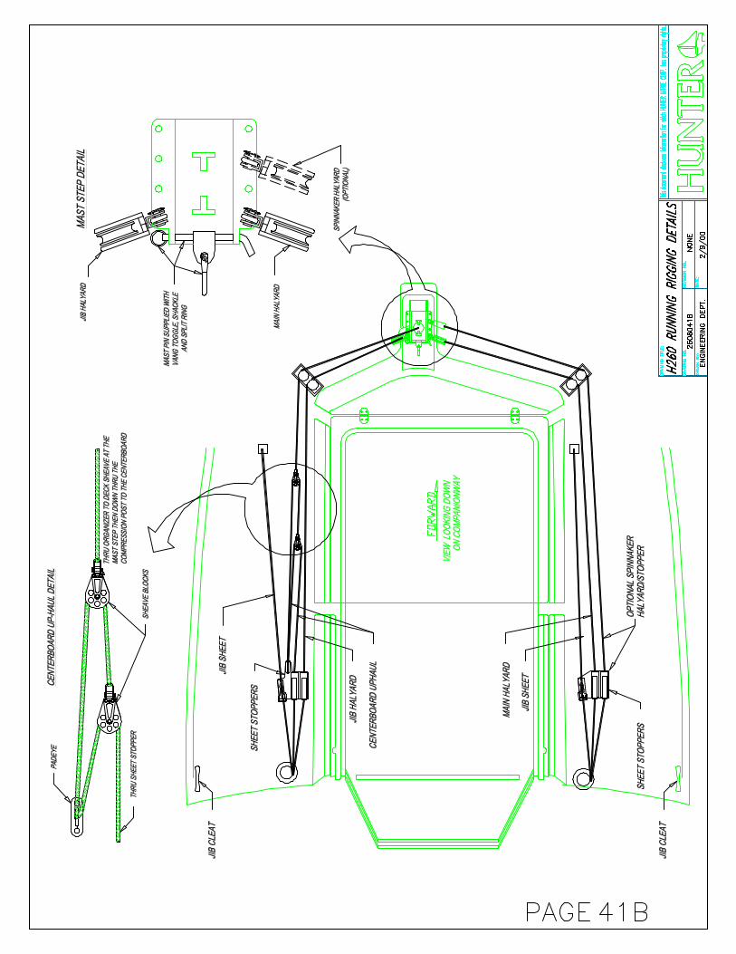
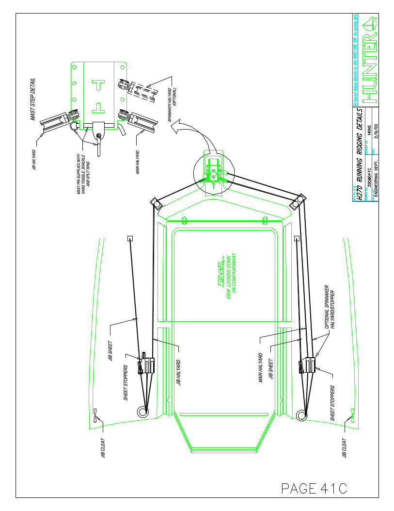


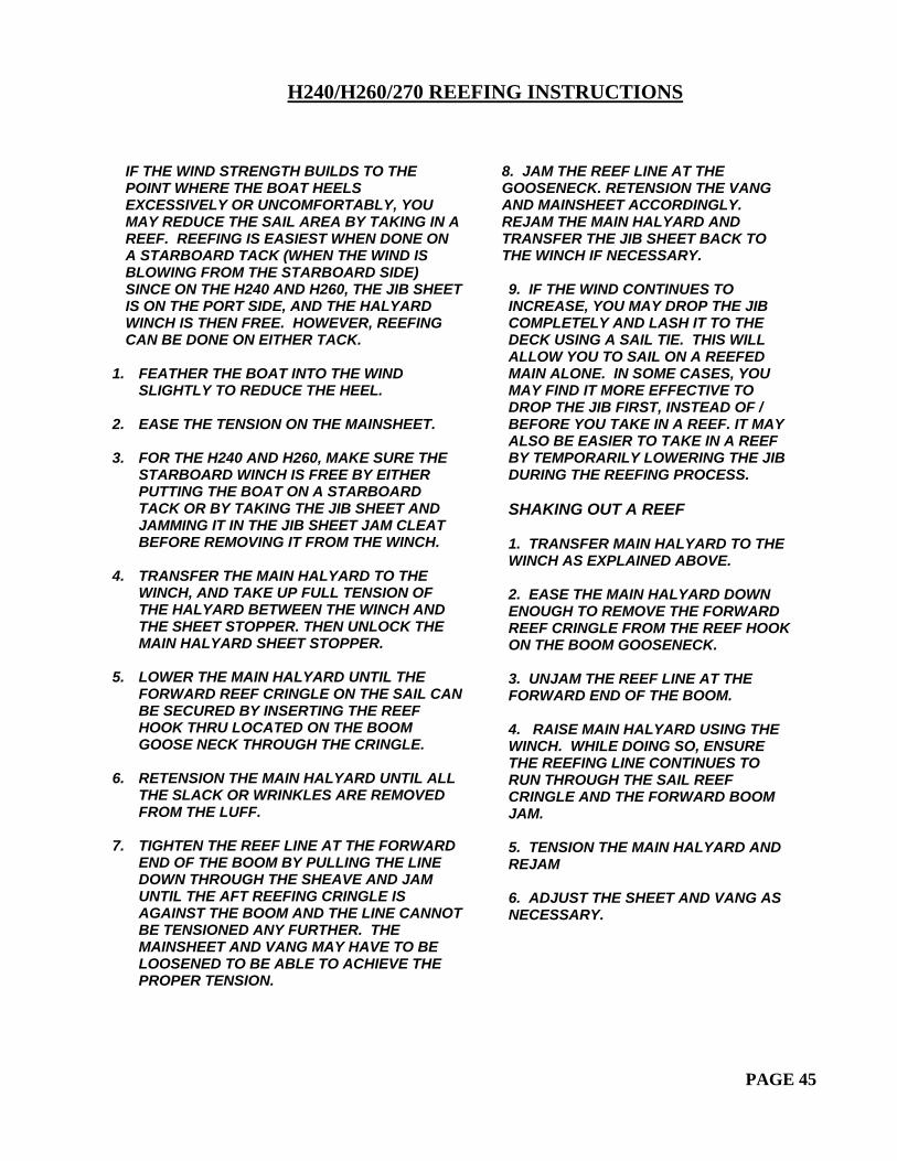
H240/H260/270 REEFING INSTRUCTIONS
PAGE 45
IF THE WIND STRENGTH BUILDS TO THE POINT WHERE THE BOAT HEELS EXCESSIVELY OR UNCOMFORTABLY, YOU MAY REDUCE THE SAIL AREA BY TAKING IN A REEF. REEFING IS EASIEST WHEN DONE ON A STARBOARD TACK (WHEN THE WIND IS BLOWING FROM THE STARBOARD SIDE) SINCE ON THE H240 AND H260, THE JIB SHEET IS ON THE PORT SIDE, AND THE HALYARD WINCH IS THEN FREE. HOWEVER, REEFING CAN BE DONE ON EITHER TACK.
1. FEATHER THE BOAT INTO THE WIND
SLIGHTLY TO REDUCE THE HEEL. 2. EASE THE TENSION ON THE MAINSHEET.
3. FOR THE H240 AND H260, MAKE SURE THE
STARBOARD WINCH IS FREE BY EITHER PUTTING THE BOAT ON A STARBOARD TACK OR BY TAKING THE JIB SHEET AND JAMMING IT IN THE JIB SHEET JAM CLEAT BEFORE REMOVING IT FROM THE WINCH.
4. TRANSFER THE MAIN HALYARD TO THE
WINCH, AND TAKE UP FULL TENSION OF THE HALYARD BETWEEN THE WINCH AND THE SHEET STOPPER. THEN UNLOCK THE MAIN HALYARD SHEET STOPPER.
5. LOWER THE MAIN HALYARD UNTIL THE
FORWARD REEF CRINGLE ON THE SAIL CAN BE SECURED BY INSERTING THE REEF HOOK THRU LOCATED ON THE BOOM GOOSE NECK THROUGH THE CRINGLE.
6. RETENSION THE MAIN HALYARD UNTIL ALL
THE SLACK OR WRINKLES ARE REMOVED FROM THE LUFF.
7. TIGHTEN THE REEF LINE AT THE FORWARD
END OF THE BOOM BY PULLING THE LINE DOWN THROUGH THE SHEAVE AND JAM UNTIL THE AFT REEFING CRINGLE IS AGAINST THE BOOM AND THE LINE CANNOT BE TENSIONED ANY FURTHER. THE MAINSHEET AND VANG MAY HAVE TO BE LOOSENED TO BE ABLE TO ACHIEVE THE PROPER TENSION.
8. JAM THE REEF LINE AT THE GOOSENECK. RETENSION THE VANG AND MAINSHEET ACCORDINGLY. REJAM THE MAIN HALYARD AND TRANSFER THE JIB SHEET BACK TO THE WINCH IF NECESSARY. 9. IF THE WIND CONTINUES TO INCREASE, YOU MAY DROP THE JIB COMPLETELY AND LASH IT TO THE DECK USING A SAIL TIE. THIS WILL ALLOW YOU TO SAIL ON A REEFED MAIN ALONE. IN SOME CASES, YOU MAY FIND IT MORE EFFECTIVE TO DROP THE JIB FIRST, INSTEAD OF / BEFORE YOU TAKE IN A REEF. IT MAY ALSO BE EASIER TO TAKE IN A REEF BY TEMPORARILY LOWERING THE JIB DURING THE REEFING PROCESS. SHAKING OUT A REEF 1. TRANSFER MAIN HALYARD TO THE WINCH AS EXPLAINED ABOVE. 2. EASE THE MAIN HALYARD DOWN ENOUGH TO REMOVE THE FORWARD REEF CRINGLE FROM THE REEF HOOK ON THE BOOM GOOSENECK. 3. UNJAM THE REEF LINE AT THE FORWARD END OF THE BOOM. 4. RAISE MAIN HALYARD USING THE WINCH. WHILE DOING SO, ENSURE THE REEFING LINE CONTINUES TO RUN THROUGH THE SAIL REEF CRINGLE AND THE FORWARD BOOM JAM. 5. TENSION THE MAIN HALYARD AND REJAM 6. ADJUST THE SHEET AND VANG AS NECESSARY.

H24
0 R
UN
NIN
G R
IGG
ING
SP
EC
IFIC
ATI
ON
S
OP
T/S
TD
ITE
MQ
UA
NT
ITY
LIN
E S
IZE
LIN
E T
YP
EC
OLO
RE
ND
1LE
NG
TH
EN
D 2
1S
TD
MA
IN H
ALY
AR
D1
5/16
" (8
mm
)X
LSB
LUE
BA
RE
22.9
m75
ftB
AR
E
2S
TD
JIB
HA
LYA
RD
15/
16"
(8m
m)
LSR
ED
BA
RE
22.2
5 m
73 ft
BA
RE
3S
TD
MA
INS
HE
ET
13/
8" (
9.5m
m)
LSB
LUE
FLE
CK
SM
ALL
EY
E17
.0 m
56 ft
BA
RE
4S
TD
RE
EF
ING
LIN
E1
5/16
" (8
mm
)T
RA
CE
RG
RE
EN
FLE
CK
BA
RE
11.3
m37
ftB
AR
E
5S
TD
JIB
SH
EE
T2
3/8"
(9.
5mm
)LS
RE
D F
LEC
KB
AR
E9.
75 m
32 ft
BA
RE
6O
PT
SP
INN
. SH
EE
T2
3/8"
(9.
5mm
)LS
BLA
CK
FLE
CK
BA
RE
14.6
m48
ftB
AR
E
7O
PT
SP
INN
AK
ER
HA
LYA
RD
13/
8" (
9.5m
m)
XLS
BLA
CK
BA
RE
22.2
5 m
73 ft
BA
RE
8S
TD
VA
NG
15/
16"
(8m
m)
LSW
HIT
ES
MA
LL E
YE
5.9
m19
ftB
AR
E
9S
TD
CE
NT
ER
BO
AR
D L
INE
11
3/8"
(9.
5mm
)X
LSW
HIT
EE
YE
2.2
m7.
25 ft
BA
RE
10S
TD
CE
NT
ER
BO
AR
D L
INE
21
5/16
" (8
mm
)LS
WH
ITE
EY
E0.
9 m
3 ft
BA
RE
11S
TD
CE
NT
ER
BO
AR
D L
INE
31
5/16
" (8
mm
)LS
WH
ITE
EY
E2.
4 m
8 ft
BA
RE
12S
TD
TO
PP
ING
LIF
T1
1/8"
PV
CW
HIT
E7.
6 m
25 ft
BA
RE
PAGE 46A-1

H24
0 S
TA
ND
ING
RIG
GIN
G S
PE
CIF
ICA
TIO
NS
OP
T/S
TD
ITE
MQ
UA
NT
ITY
WIR
E S
IZE
UP
PE
R E
ND
LEN
GT
HLO
WE
R E
ND
1S
TD
FOR
ES
TA
Y1
5/32
" (4
mm
) 1x
19T
-BA
LL8.
61m
28' 3
"JA
W T
OG
GLE
2S
TD
D1
25/
32"
(4m
m)
1x19
T-B
ALL
4.7m
15' 5
"JA
W T
OG
GLE
3S
TD
V1
25/
32"
(4m
m)
1x19
JAW
TO
GG
LE4.
72m
15' 6
"JA
W T
OG
GLE
4S
TD
D2
25/
32"
(4m
m)
1x19
T-B
ALL
3.55
m11
' 8"
MA
RIN
E E
YE
5S
TD
RD
12
1/8"
(3.
2mm
) 1x
19E
YE
(FO
R 8
mm
PIN
)2.
83m
9' 3
1/2
"T
-BA
LL
PAGE 46A-2

H26
0/27
0 R
UN
NIN
G R
IGG
ING
SP
EC
IFIC
ATI
ON
S
OP
T/S
TDIT
EM
QU
AN
TITY
LIN
E S
IZE
LIN
E T
YP
EC
OLO
RE
ND
1LE
NG
THE
ND
2
1S
TDM
AIN
HA
LYA
RD
15/
16"
(8m
m)
XLS
BLU
EB
AR
E25
.9m
85'
BA
RE
2S
TDJI
B H
ALY
AR
D1
5/16
" (8
mm
)LS
RE
DB
AR
E24
.4m
80'
BA
RE
3S
TDM
AIN
SH
EE
T1
3/8"
(9.
5mm
)LS
BLU
E F
LEC
KS
MA
LL E
YE
17m
56'
BA
RE
4S
TDR
EE
FIN
G L
INE
15/
16"
(8m
m)
TRA
CE
RG
RE
EN
FLE
CK
BA
RE
11.3
m37
'B
AR
E
5S
TDJI
B S
HE
ET
23/
8" (
9.5m
m)
LSR
ED
FLE
CK
BA
RE
10.7
m37
'B
AR
E
6O
PT
SP
INN
AK
ER
SH
EE
T (O
PT)
23/
8" (
9.5m
m)
LSB
LAC
K F
LEC
KB
AR
E18
m59
'B
AR
E
7O
PT
SP
INN
AK
ER
HA
LYA
RD
(O
PT)
13/
8" (
9.5m
m)
XLS
BLA
CK
FLE
CK
BA
RE
18m
59'
BA
RE
8S
TDV
AN
G1
5/16
" (8
mm
)LS
WH
ITE
SM
ALL
EY
E5.
8m19
'B
AR
E
9S
TDC
EN
TER
BO
AR
D L
INE
11
3/8"
(9.
5mm
)X
LSW
HIT
EE
YE
2.2m
7.25
'B
AR
E
10S
TDC
EN
TER
BO
AR
D L
INE
21
5/16
" (8
mm
)LS
WH
ITE
EY
E.9
m3'
BA
RE
11S
TDC
EN
TER
BO
AR
D L
INE
31
5/16
" (8
mm
)LS
WH
ITE
EY
E2.
4m8'
BA
RE
12S
TDTO
PP
ING
LIF
T1
1/8"
PV
CW
HIT
EE
YE
9.1m
30'
EY
E W
/BLO
CK
PAGE 46B-1

H26
0/27
0 S
TAN
DIN
G R
IGG
ING
SP
EC
IFIC
ATI
ON
S
OP
T/S
TD
ITE
MQ
UA
NT
ITY
WIR
E S
IZE
UP
PE
R E
ND
LE
NG
TH
LO
WE
R E
ND
1S
TD
FO
RE
ST
AY
25/
32"
(4m
m)
1x19
T-B
AL
L9.
12m
29' 1
1 1/
4"JA
W T
OG
GL
E
2S
TD
D1
25/
32"
(4m
m)
1x19
T-B
AL
L5.
13m
16' 1
0"JA
W T
OG
GL
E
3S
TD
V1
25/
32"
(4m
m)
1x19
JAW
TO
GG
LE
5.15
m16
' 10
3/4"
JAW
TO
GG
LE
4S
TD
D2
25/
32"
(4m
m)
1x19
T-B
AL
L3.
66m
12' 1
/4"
MA
RIN
E E
YE
5S
TD
RD
11
5/32
" (4
mm
) 1x
19E
YE
(FO
R 8
mm
PIN
)2.
89m
9' 6
"T
-BA
LL
PAGE 46B-2

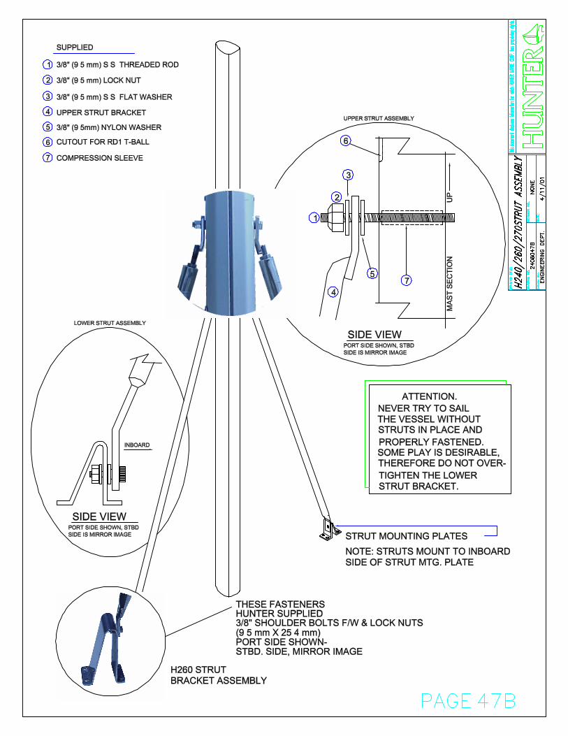
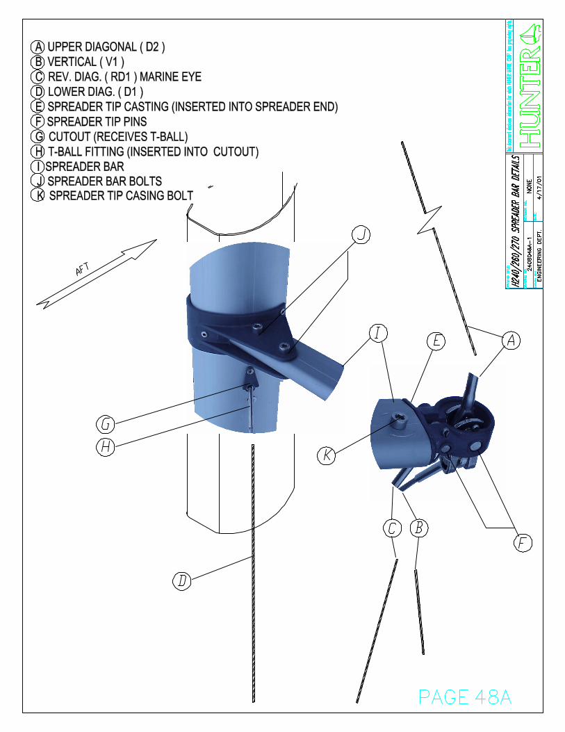

D-2
MA
RIN
E E
YE
V-1
JA
W T
OG
GL
E
CO
TT
ER
PIN
FO
R
SP
RE
AD
ER
TIP
P
IN
SP
RE
AD
ER
TIP
P
IN F
IXE
S V
-1
AN
D D
-2
CO
TT
ER
PIN
FO
R
SP
RE
AD
ER
TIP
P
IN
SP
RE
AD
ER
TIP
P
IN F
IXE
S R
D-1
RD
-1 M
AR
INE
EY
E
PAGE 48B
H24
0/26
0/27
0 S
PR
EA
DE
R T
IP D
ETA
ILS
VIE
W IS
OF
PO
RT
SID
E L
OO
KIN
G A
FT
H u
n t
e r