Extron XMP 240 C AT User Guide
139
User Guide XMP 240 C AT Audio Products Mixers and Processors Expansion Matrix Processor 68-3434-01 Rev. A 06 20
-
Upload
khangminh22 -
Category
Documents
-
view
0 -
download
0
Transcript of Extron XMP 240 C AT User Guide

User Guide
XMP 240 C AT
Audio ProductsMixers and Processors
Expansion Matrix Processor
68-3434-01 Rev. A06 20

Safety InstructionsSafety Instructions • English
WARNING: This symbol, , when used on the product, is intended to alert the user of the presence of uninsulated dangerous voltage within the product’s enclosure that may present a risk of electric shock.
ATTENTION: This symbol, , when used on the product, is intended to alert the user of important operating and maintenance (servicing) instructions in the literature provided with the equipment.
For information on safety guidelines, regulatory compliances, EMI/EMF compatibility, accessibility, and related topics, see the Extron Safety and Regulatory Compliance Guide, part number 68-290-01, on the Extron website, www.extron.com.
Sicherheitsanweisungen • Deutsch
WARNUNG: Dieses Symbol auf dem Produkt soll den Benutzer darauf aufmerksam machen, dass im Inneren des Gehäuses dieses Produktes gefährliche Spannungen herrschen, die nicht isoliert sind und die einen elektrischen Schlag verursachen können.
VORSICHT: Dieses Symbol auf dem Produkt soll dem Benutzer in der im Lieferumfang enthaltenen Dokumentation besonders wichtige Hinweise zur Bedienung und Wartung (Instandhaltung) geben.
Weitere Informationen über die Sicherheitsrichtlinien, Produkthandhabung, EMI/EMF-Kompatibilität, Zugänglichkeit und verwandte Themen finden Sie in den Extron-Richtlinien für Sicherheit und Handhabung (Artikelnummer 68-290-01) auf der Extron-Website, www.extron.com.
Instrucciones de seguridad • Español
ADVERTENCIA: Este símbolo, , cuando se utiliza en el producto, avisa al usuario de la presencia de voltaje peligroso sin aislar dentro del producto, lo que puede representar un riesgo de descarga eléctrica.
ATENCIÓN: Este símbolo, , cuando se utiliza en el producto, avisa al usuario de la presencia de importantes instrucciones de uso y mantenimiento recogidas en la documentación proporcionada con el equipo.
Para obtener información sobre directrices de seguridad, cumplimiento de normativas, compatibilidad electromagnética, accesibilidad y temas relacionados, consulte la Guía de cumplimiento de normativas y seguridad de Extron, referencia 68-290-01, en el sitio Web de Extron, www.extron.com.
Instructions de sécurité • Français
AVERTISSEMENT : Ce pictogramme, , lorsqu’il est utilisé sur le produit, signale à l’utilisateur la présence à l’intérieur du boîtier du produit d’une tension électrique dangereuse susceptible de provoquer un choc électrique.
ATTENTION : Ce pictogramme, , lorsqu’il est utilisé sur le produit, signale à l’utilisateur des instructions d’utilisation ou de maintenance importantes qui se trouvent dans la documentation fournie avec le matériel.
Pour en savoir plus sur les règles de sécurité, la conformité à la réglementation, la compatibilité EMI/EMF, l’accessibilité, et autres sujets connexes, lisez les informations de sécurité et de conformité Extron, réf. 68-290-01, sur le site Extron, www.extron.com.
Istruzioni di sicurezza • Italiano
AVVERTENZA: Il simbolo, , se usato sul prodotto, serve ad avvertire l’utente della presenza di tensione non isolata pericolosa all’interno del contenitore del prodotto che può costituire un rischio di scosse elettriche.
ATTENTZIONE: Il simbolo, , se usato sul prodotto, serve ad avvertire l’utente della presenza di importanti istruzioni di funzionamento e manutenzione nella documentazione fornita con l’apparecchio.
Per informazioni su parametri di sicurezza, conformità alle normative, compatibilità EMI/EMF, accessibilità e argomenti simili, fare riferimento alla Guida alla conformità normativa e di sicurezza di Extron, cod. articolo 68-290-01, sul sito web di Extron, www.extron.com.
I

Copyright© 2020 Extron Electronics. All rights reserved. www.extron.com
TrademarksAll trademarks mentioned in this guide are the properties of their respective owners.The following registered trademarks (®), registered service marks (SM), and trademarks (TM) are the property of RGB Systems, Inc. or Extron Electronics (see the current list of trademarks on the Terms of Use page at www.extron.com):
Registered Trademarks (®)
Extron, Cable Cubby, ControlScript, CrossPoint, DTP, eBUS, EDID Manager, EDID Minder, Flat Field, FlexOS, Glitch Free. Global Configurator, Global Scripter, GlobalViewer, Hideaway, HyperLane, IP Intercom, IP Link, Key Minder, LinkLicense, LockIt, MediaLink, MediaPort, NAV, NetPA, PlenumVault, PoleVault, PowerCage, PURE3, Quantum, ShareLink, Show Me, SoundField, SpeedMount, SpeedSwitch, StudioStation, System INTEGRATOR, TeamWork, TouchLink, V-Lock, VideoLounge, VN-Matrix, VoiceLift, WallVault, WindoWall, XPA, XTP, XTP Systems, and ZipClip
Registered Service Mark(SM) : S3 Service Support Solutions
Trademarks (™)
AAP, AFL (Accu-RATE Frame Lock), ADSP (Advanced Digital Sync Processing), Auto-Image, AVEdge, CableCover, CDRS (Class D Ripple Suppression), Codec Connect, DDSP (Digital Display Sync Processing), DMI (Dynamic Motion Interpolation), Driver Configurator, DSP Configurator, DSVP (Digital Sync Validation Processing), eLink, EQIP, Everlast, FastBite, Flex55, FOX, FOXBOX, IP Intercom HelpDesk, MAAP, MicroDigital, Opti-Torque, PendantConnect, ProDSP, QS-FPC (QuickSwitch Front Panel Controller), Room Agent, Scope-Trigger, SIS, Simple Instruction Set, Skew-Free, SpeedNav, Triple-Action Switching, True4K, True8K, Vector™ 4K, WebShare, XTRA, and ZipCaddy

FCC Class A NoticeThis equipment has been tested and found to comply with the limits for a Class A digital device, pursuant to part 15 of the FCC rules. The Class A limits provide reasonable protection against harmful interference when the equipment is operated in a commercial environment. This equipment generates, uses, and can radiate radio frequency energy and, if not installed and used in accordance with the instruction manual, may cause harmful interference to radio communications. Operation of this equipment in a residential area is likely to cause interference. This interference must be corrected at the expense of the user.
ATTENTION:
• The Twisted Pair Extension technology works with unshielded twisted pair (UTP) or shielded twisted pair (STP) cables; but to ensure FCC Class A and CE compliance, STP cables and STP Connectors are required.
• La technologie extension paires torsadées fonctionne avec les câbles paires torsadées blindées (UTP) ou non blindées (STP). Afin de s’assurer de la compatibilité entre FCC Classe A et CE, les câbles STP et les connecteurs STP sont nécessaires.
NOTES:
• This unit was tested with shielded I/O cables on the peripheral devices. Shielded cables must be used to ensure compliance with FCC emissions limits.
• For more information on safety guidelines, regulatory compliances, EMI/EMF compatibility, accessibility, and related topics, see the Extron Safety and Regulatory Compliance Guide on the Extron website.
Battery NoticeThis product contains a battery. Do not open the unit to replace the battery. If the battery needs replacing, return the entire unit to Extron (for the correct address, see the Extron Warranty section on the last page of this guide).
CAUTION: Risk of explosion. Do not replace the battery with an incorrect type. Dispose of used batteries according to the instructions.
ATTENTION : Risque d’explosion. Ne pas remplacer la pile par le mauvais type de pile. Débarrassez-vous des piles usagées selon le mode d’emploi.

XMP 240 C AT • Introduction iii
Conventions Used in this Guide
NotificationsThe following notifications are used in this guide:
CAUTION: Risk of minor personal injury.
ATTENTION : Risque de blessure mineure.
ATTENTION:
• Risk of property damage.
• Risque de dommages matériels.
NOTE: A note draws attention to important information.
TIP: A tip provides a suggestion to make working with the application easier.
Software CommandsCommands are written in the fonts shown here:
^AR Merge Scene,,0p1 scene 1,1 ̂ B 51 ̂ W^C.0[01] R 0004 00300 00400 00800 00600 [02] 35 [17] [03]E X! *X1&* X4!* X5@* X2! CE}
NOTE: For commands and examples of computer or device responses used in this guide, the character “0” is used for the number zero and “O” is the capital letter “o.”
Computer responses and directory paths that do not have variables are written in the font shown here:
Reply from 208.132.180.48: bytes=32 times=2ms TTL=32C:\Program Files\Extron
Variables are written in slanted form as shown here:
ping xxx.xxx.xxx.xxx —tSOH R Data STX Command ETB ETX
Selectable items, such as menu names, menu options, buttons, tabs, and field names are written in the font shown here:
From the File menu, select New.Click the OK button.
Specifications AvailabilityProduct specifications are available on the Extron website, www.extron.com.
Extron Glossary of TermsA glossary of terms is available at http://www.extron.com/technology/glossary.aspx.

ivXMP 240 C AT • Contents
Contents
Introduction ................................................1About this Guide .................................................. 1About the XMP 240 C AT .................................... 1Features .............................................................. 1Application Diagram ............................................ 3
Installation ..................................................4Mounting ............................................................. 4Rear Panel Features and Cabling ......................... 5Front Panel Features ............................................ 8Hardware Reset Modes ....................................... 9
Mode 1 — Firmware Reset .............................. 9Mode 4 — IP Reset ......................................... 9Mode 5 — Factory Default Reset ..................... 9
DSP Configurator Software .......................10Downloading and Installing DSP Configurator .... 10Accessing the DSP Configurator Help File ......... 11DSP Configurator Main Workspace ................... 11Menu Bar .......................................................... 12
File ................................................................ 12Edit ................................................................ 13View .............................................................. 13Tools .............................................................. 14Window ......................................................... 15Help .............................................................. 15Macros Drop-Down ....................................... 16Presets Drop-Down ....................................... 16DSP Configurator Status Panel ...................... 16Live and Emulate Panel.................................. 17
DSP Configurator Inputs .................................... 20Inputs ................................................................ 20
Renaming an Input ........................................ 20Inputs Overview ............................................. 21Input Building Blocks ..................................... 22
Input Processing ................................................ 23Input Gain Block ............................................ 24
Input Filter Block ............................................ 25Input AEC Block ............................................ 27Input Dynamics Blocks .................................. 30Input Delay Block ........................................... 35Input Ducking Block ...................................... 36Input Automix Block ...................................... 39Input Pre-Mixer Gain Block ............................ 40
Virtual Returns ................................................... 41Renaming a Virtual Return ............................. 42Virtual Return Building Blocks ........................ 42
Virtual Return Processing .................................. 42Virtual Return Feedback Suppressor Block .... 43Virtual Return Filter Block ............................... 47Virtual Return Dynamics Block ....................... 47Virtual Return Delay Block ............................. 47Virtual Return Pre-Mixer Gain Block ............... 47
Mix-Points ......................................................... 47Mix-Point Dialog Box ..................................... 49Mix-Point Context Menu ................................ 50
DSP Configurator Outputs ................................. 50Outputs ............................................................. 51
Naming an Output ......................................... 51Output Building Blocks .................................. 51
Output Processing ............................................. 53Output Trim Block .......................................... 53Output Delay Block ........................................ 54Output Filter Block ......................................... 54Output Dynamics Block ................................. 54Output Attenuation Block............................... 54
Virtual Send Bus ................................................ 55

XMP 240 C AT • Contents v
Configuration Tools ...................................67Presets .............................................................. 67
Methods for Marking Items ............................ 68Configuring Presets ....................................... 68
Groups .............................................................. 69Configuring Groups ....................................... 70
Macros .............................................................. 72Configuring a Macro ...................................... 73
Device Manager ................................................ 76Managing Devices in Device Manager ............ 77
Connect to or Disconnect from Device .............. 78Firmware Loader ............................................... 79
Downloading Firmware Updates .................... 79Organize Building Blocks ................................... 82Device Settings.................................................. 83
Unit Info ......................................................... 83IP Settings .................................................... 84Passwords .................................................... 84Serial Settings ............................................... 85Date/Time .................................................... 85Dante Device ................................................ 86
Options ............................................................. 87Expansion Bus .................................................. 88
Connecting the EXP Ports ............................. 88
Dante Controller ........................................89Overview ........................................................... 89Downloading and Installing Dante Controller ...... 90Configuring the XMP 240 C AT in Dante Controller ............................................... 90
Device Name ................................................. 90Receiver and Transmitter Names ................... 91Dante Controller Naming Conventions ........... 91Renaming the XMP 240 C AT in Dante Controller ........................................... 91
Renaming a Receiver or Transmitter............... 93Finding a Dante Device IP Address ................ 95
Physical Dante Network Setup .......................... 96Redundant Configuration ............................... 96
Dante Controller Operation ................................ 98Dante Transmitters and Receivers .................. 98Dante Routing Operation ............................... 98Routing Devices............................................. 98Disconnecting Inputs from Outputs .............. 100Sending SIS Commands to Dante Audio Interface Devices through the XMP ............. 100
Dante Troubleshooting ..................................... 101
Simplifying the Network for Troubleshooting .......................................... 101
Troubleshooting the Network Interface ......... 101Restarting Dante Controller .......................... 102
Remote Communication and Control .......103Connection Options ......................................... 103
RS-232 Port ................................................ 104LAN Port ..................................................... 104USB Config Port .......................................... 105Verbose Modes ........................................... 105
Host-to-Device Communications ..................... 106XMP 240 C AT-initiated Messages ............... 106
SIS Overview ................................................... 107Using the Command and Response Tables ......................................................... 107
Symbol Definitions ....................................... 107Error Responses .............................................. 108Simple Control Port Commands ...................... 108Command and Response Table Sections ........ 109
Command and Response Table for Basic SIS Commands ................................. 109
DSP SIS Commands ................................... 123Symbol Definitions ....................................... 123Special Characters ...................................... 123Command and Response Table for DSP SIS Commands .................................. 124
Object ID (OID) Number Tables ........................ 129Input Path OIDs ........................................... 129Output Attenuation Block OIDs .................... 131Output Path OIDs ........................................ 132Mix-point OIDs............................................. 133
Web Pages ..............................................142XMP 240 C AT Web Page .............................. 142
Accessing the Embedded Web Page ........... 142Using the Web Page .................................... 143

XMP 240 C AT • Introduction 1
Introduction
This section describes this user guide and the XMP 240 C AT. The following topics are covered:
• About this Guide
• About the XMP 240 C AT
• Features
• Application Diagram
About this GuideThis guide contains installation, configuration, and operating information for the Extron XMP 240 C AT Expansion Matrix Processor. In this guide, the XMP 240 C AT may also be referred to as “XMP” or “device”.
About the XMP 240 C ATThe XMP 240 Expansion Matrix Processor features an extensive mix matrix with 24 channels of AEC and 48x48 Dante® connectivity in only a half rack space. The XMP 240 can also be used standalone for matrix processing in an all network audio system. When connected to a DMP Plus Series processor via Dante or the EXP expansion port, a complete system is created that features up to 36 channels of AEC, a USB audio interface, analog connectivity, and optional VoIP. A system expanded with an XMP 240 is capable of supporting multiple beam forming microphone arrays alongside numerous other Dante sources, with enough outputs to support multiple zones and destination devices. Ideal for network audio systems based on Dante or AES67, the XMP 240 allows for high channel count audio input and output processing.
Features• 24 channels of AEC - acoustic echo cancellation — The XMP 240 includes
24 independent channels of high performance AEC, as well as selectable noise cancellation. Extron AEC features advanced algorithms that deliver fast echo canceler convergence for optimal intelligibility in situations that challenge AEC performance.
• Dante audio networking with Dante Domain Manager and AES67 support — Dante audio networking provides scalability for creating larger audio matrixes over a local area network using standard protocols. A built-in two-port Gigabit switch can be configured to support primary and redundant Dante audio networks.
• Extensive mix matrix with input and output processing — Allows all inputs to be discretely routed to any or all outputs, with processing.
• FlexInput capability on all inputs for input source selection — All 48 inputs offer FlexInput capability to select a Dante channel or expansion input. This allows incorporating the full range of DSP capabilities, including AEC, for any incoming signal.

XMP 240 C AT • Introduction 2
• Macros allow the sequencing of commands that can be sent to the local device or external devices via the LAN port — A single XMP 240 can act as the central interface from a control system, sending commands to other DMP Plus, AXI AT, and DTP CrossPoint devices.
• Compact half rack size — Allows more input and output channels, with more processing power, to be installed in less space.
• Advanced audio processing on all outputs — Up to 48 speaker zones can be implemented on one XMP 240 with full processing for each zone, making it ideal for full mix-minus implementations.
• Adaptive Gain Processing — An adaptive gain processor block allows a specified microphone input to affect levels on any one or all other inputs and virtual returns.
• Built-in two-port Gigabit switch — Provides redundant or daisy-chain operation with other Dante-enabled devices.
• Automixer with eight groups — The XMP 240 features an automixer with gated and gain sharing modes for managing up to eight groups of microphone signals. Gating threshold, signal level reduction, and timing parameters are user-adjustable per channel, allowing for fine-tuning to avoid the “chopped” sound characteristic of a traditional automixer when a mic is gated off.
• ProDSP 64-bit floating point signal processing — The XMP 240 features 64-bit floating point audio DSP processing, which maintains very wide dynamic range and audio signal transparency, to simplify management of gain staging while reducing the possibility of DSP signal clipping.
• DSP Configurator™ Software — A powerful yet user-friendly PC-based software tool for managing all audio operations of the XMP 240. It enables complete setup and configuration of digital audio processing tools on the ProDSP platform, as well as routing and mixing.
• Building Blocks for channel processor settings — A collection of pre-designed processor settings optimized for a specific type of input and output devices, such as microphones and speakers. Flexible Building Blocks are available on each input strip and allow system designers to fully customize and save their own Building Blocks, further streamlining audio system design and integration.
• Live and Emulate operation modes with configuration file saving — Live mode allows integrators to connect to the XMP 240 and make live parameter adjustments while hearing or metering them in real-time. This avoids the need to compile and upload a configuration file to the DSP. Emulate mode allows settings to be configured offline, then uploaded to the XMP 240. Additionally, current settings on a XMP 240 can be backed up to a configuration file for archiving.
• Group masters — The XMP 240 provides the capability to consolidate gain or mute control throughout the system. Gain or mute controls can be selected and added to a group master, which can then be controlled by a single master fader or mute control. Loudness filters can also be added to a group master, which enables the loudness curve to track with the program volume control. Bass and Treble filters can be configured in a group master to provide boost and cut as user controls. Additionally, Meters can be added to a group, providing a control to enable and disable multiple meters at once. Each group master can have up to 128 members, and up to 64 group masters can be created.

XMP 240 C AT • Introduction 3
Application Diagram
INPUTS
ACTIVITY
CONFIG EXP LAN
XMP 240 C ATEXPANSION MATRIX PROCESSOR
1 2 3 4 5 6 7 8 9 10 11 12 13 14 15 16 17 18 19 20 21 22 23 24CLIP
SIGNAL
NetPA U 1004 SERIES
OVERTEMP 2
LIMITER/PROTECT
SIGNAL
1 3 4
OUTPUTSINPUTSACTIVITY
CONFIG EXPUSB
LAN 1LAN 2
DMP 128 FlexPlusDIGITAL MATRIX PROCESSOR
1 2 3 4 5 6 7 8 1 2 3 4 5 6 7 89 10 11 12
CLIPSIGNAL
CLIPSIGNALLAN/VoIP
CONFIG
DTP CROSSPOINT 4K SERIESDIGITAL PRESENTATION MATRIX
CONTROL I/O
AUDIOVIDEO
LOGO
SELECT ENTER PRESET VIEW ESC1 2 3 4
1 2 3 4
5 6 7 8MIC VOLUME VOLUME
INPUTS
OUTPUTS
eBUS
COM
1 1 2
1 2 23 3 4
1 2
3 4
IR/S I/O RELAYS
S LIMIT
OVER
RTS
CTS
Tx
Rx
mu
t eselect
mu
t eselect
mu
t eselect
mu
t eselect
AXI 44 AT
CONFIG
AXI 44 AT
CONFIG
AXI 44 AT
CONFIG
AXI 44 AT
CONFIG
AXI 44 AT
CONFIG
AXI 44 AT
CONFIG
ExtronAXI 44 ATDante Audio Interface
ExtronAXI 44 ATDante Audio Interface
ExtronAXI 44 ATDante Audio Interface
ExtronAXI 44 ATDante Audio Interface
ExtronAXI 44 ATDante Audio Interface
ExtronAXI 44 ATDante Audio Interface
Multi-Purpose Room - Table Mics
CeilingArray Mic
6 Speakers per Ch./ZoneTapped @ 16W6x16W = 96 watts per ch.
PC (with USB Audio and Zoom)
Ethernet/PoE
Ethernet
EXP
Table Mics
ExtronXMP 240 C ATExpansion Matrix Processor
ExtronTLP Pro 1025T10" Tabletop TouchLink Pro Touchpanel
Ethernet
Ethernet
Ethernet
HDMI
Ethernet Ethernet
Ethernet
USB Audio
Audio
ExtronNetPA U 1004-70VPower Ampli�er
ExtronDTP CP 84 4K IPCP SAPresentation Matrix Switcher
ExtronDMP 128 FlexPlus C V ATDante Digital Matrix Processor
ExtronSF 26CTTwo-Way Ceiling Speakers
Table Mics
Table Mics
Table Mics
Table Mics
Table Mics
Wireless Mics
Figure 1. XMP 240 C AT Application Diagram
figure 1. XMP 240 C AT Application Diagram

XMP 240 C AT • Installation 4
Installation
This section describes the installation of the XMP 240 C AT and covers the following topics:
• Mounting
• Rear Panel Features and Cabling
• Front Panel Features
• Hardware Reset Modes
MountingThe 1U high, half rack width, 9.5 inch deep XMP 240 C AT mounts in the following manners:
• Rack mounting — Attach the XMP 240 C AT to a standard 19-inch rack shelf. The following Underwriters Laboratories (UL) guidelines pertain to the installation of the XMP 240 C AT in a rack:
• Reduced air flow — Install the equipment in the rack so that the amount of air flow required for safe operation of the equipment is not compromised.
• Mechanical loading — Mount the equipment in the racks so that uneven mechanical loading does not create a hazardous condition.
• Circuit overloading — When connecting the equipment to the supply circuit, consider the effect that circuit overloading might have on overcurrent protection and supply wiring. Consider equipment nameplate ratings when addressing this concern.
• Reliable earthing (grounding) — Maintain reliable grounding of rack-mounted equipment. Pay particular attention to power supply connections other than direct connections to the branch circuit (such as the use of power strips).
• Under-furniture mounting — Mount the XMP 240 C AT under the surface of a desk, table, or podium.
• Free-standing — Attach the four rubber feet provided with the device to the bottom of the XMP 240 C AT in the four corners and place the unit on furniture as desired.
NOTE: To mount the XMP 240 C AT using an Extron mounting kit, see the instructions provided with the kit.

XMP 240 C AT • Installation 5
Rear Panel Features and Cabling
DM
P E
XP
AT
RE
MO
TE
R
LAN1 (PRI) PoE 2 (SEC)
RS-232
Tx Rx G
POWER 12V 1.0A MAX
XMP 240 C AT
A B C D E FC
A Power Input D RS-232 Port
B EXP Port E LAN Port
C AT Ports F Reset Button and LED
Figure 2. XMP 240 C AT Rear Panel
A Power Input — Connect the included external 2-pole captive screw power supply (see the figure below for power supply wiring information).
NOTE: If a power supply is not provided, use a UL Listed power supply with rated output 12 VDC, minimum 1.5 A, and marked “Class 2” or “LPS”.
Ground+12 VDC input
G
External Power Supply(12 VDC, 2.0 A max.)
Ground allDevices
DC Power CordCaptive ScrewConnector
3/16"(5 mm) Max.
POWER12V2.0A MAX
Rear PanelPower Receptacle
Figure 3. Power Input Wiring
ATTENTION:
• Always use a power supply provided by or specified by Extron. Use of an unauthorized power supply voids all regulatory compliance certification and may cause damage to the supply and the end product.
• Utilisez toujours une source d’alimentation fournie ou recommandée par Extron. L’utilisation d’une source d’alimentation non autorisée annule toute certification de conformité réglementaire, et peut endommager la source d’alimentation et l’unité.
• The installation must always be in accordance with the applicable provisions of National Electrical Code ANSI/NFPA 70, article 725 and the Canadian Electrical Code part 1, section 16.
• L’installation doit toujours être conforme aux dispositions applicables du Code américain de l’électricité (National Electrical Code) ANSI/NFPA 70, article 725, et du Code canadien de l’électricité.
figure 2. XMP 240 C AT Rear Panel
figure 1. Control Panel Port Connector

XMP 240 C AT • Installation 6
• These products are intended for use with a UL Listed power source marked “Class 2” or “LPS” and rated 12 VDC, minimum 1.0 A. or 48 VDC (PoE), minimum 0.35 A, or 56 VDC (PoE), minimum 0.8 A.
• Ces produits doivent être utilisés avec une source d’alimentation certifiée UL de classe 2 ou LPS avec une tension nominale 12 Vcc, 1,0 A minimum, ou 48 Vcc (PoE), 0,35 A minimum, ou 56 Vcc (PoE), 0,8 A minimum.
• The power supply shall not be permanently fixed to building structure or similar structure.
• La source d’alimentation ne devra pas être fixée de façon permanente à la structure de bâtiment ou à d’autres structures similaires.
• Power over Ethernet (PoE) is intended for indoor use only. It is to be connected only to networks or circuits that are not routed to the outside plant or building.
• L’alimentation via Ethernet (PoE) est destinée à une utilisation en intérieur uniquement. Elle doit être connectée seulement à des réseaux ou des circuits qui ne sont pas routés au réseau ou au bâtiment extérieur.
• The XMP is intended for connection to a Power over Ethernet circuit for intra-building use only and are considered to be part of a Network Environment 0 per IEC TR62101.
• Le XMP est conçu pour une connexion à un circuit PoE pour une utilisation intérieure seulement et est considéré comme faisant partie d’un environnement réseau 0 par IEC TR62101.
B EXP Port — One RJ-45 port allows two units to be connected via a shielded CAT 6 cable to form a larger matrix system (1 foot cable included). Any Extron device with EXP capability can exchange audio with a XMP 240 C AT via the EXP port.
C AT Ports — Two RJ-45 ports form a Gigabit switch for use with a Dante network. The AT ports use Dante protocol for digital audio transport (AT) and allow the XMP 240 C AT to connect to a Dante audio network to form a larger matrix (Dante Controller on page 89). The 2-port switch can be configured as one primary and one secondary port for redundant Dante configurations. In redundant configuration, audio traffic is duplicated. Port 1 is the primary port (PRI) and Port 2 is the secondary switch (SEC) (see Redundant Configuration on page 96). The AT port LEDs indicate the following:
• Green only = 100 Mbps connection
• Amber only = 1 Gb connection
D RS-232 Port — Use a 3-pole 3.5 mm captive screw connector to connect the host RS-232 cable for bidirectional RS-232 (±5V) serial control (see figure 5 for wiring). The default baud rate is 38400.
RS-232
Tx Rx GRE
MO
TE
ReceiveTransmitGround
Connected RS-232Device Pins
Figure 4. RS-232 Wiring Example
figure 1. RS-232 Wiring Example

XMP 240 C AT • Installation 7
E LAN Port — One RJ-45 port provides a Gigabit network connection for control. The host PC or control system and the XMP 240 C AT must be connected to the same network. Two LEDs indicate status.
LAN defaults:
IP Address Subnet Mask Default Gateway DHCP192.168.254.254 255.255.255.0 0.0.0.0 OFF
F Reset Button and LED —The reset button returns the XMP 240 C AT to different tiers of default states. When using the reset button, the LED blinks to signify the different reset modes (Hardware Reset Modes on page 8). When not displaying reset modes, the LED operates as a power indicator, matching the front panel power LED.
Front Panel Features
INPUTS
ACTIVITY
CONFIG EXP LAN
XMP 240 C ATEXPANSION MATRIX PROCESSOR
1 2 3 4 5 6 7 8 9 10 11 12 13 14 15 16 17 18 19 20 21 22 23 24CLIP
SIGNAL
B C DA
A Power LED C Activity Indicator LEDs
B USB Config Port D Input Indicator LEDs
Figure 5. XMP 240 C AT Front Panel
A Power LED — Blinks during boot up and lights steadily when the XMP 240 C AT is operational.
B USB Config Port — One USB mini-B port is used for configuration. This port can also be used for firmware updates.
C Activity Indicator LEDs — These green activity LEDs indicate port activity on the XMP 240 C AT:
• EXP Indicator LED —
• On — The unit is connected to a second EXP device and is configured as the primary unit.
• Blinking — The unit is not connected to a second device.
• LAN Activity Indicator LED — Blinks to indicate rear panel LAN port activity.
D Input Indicator LEDs — 24 stacked pairs of green and red LEDs display input signal presence and input signal clipping.
The green signal presence LED varies in brightness, corresponding to the real-time input signal level. It lights at -60 dBFS and increases in brightness until signal level reaches -3 dBFS. When the signal reaches or exceeds -3 dBFS, the red clip LED lights. The clip LED remains lit for 200 ms after the signal last clipped.

XMP 240 C AT • Installation 8
Hardware Reset ModesNOTE: The reset modes listed below close all IP connections, Telnet connections, and
sockets.
Mode 1 — Firmware ResetHold the Reset button (see figure 2 on page 5) while applying power to restore the unit firmware back to the default factory firmware. This recovers a unit that has incorrect code or updated firmware running. All user files and settings are maintained.
Mode 4 — IP ResetWith power on, press and hold the Reset button until the reset LED blinks twice (~6 seconds). Release the button and, within 1 second, press it again to reset all IP address settings to factory default.
The following changes take place:
• ARP program capability is enabled
• Sets IP addresses for LAN port back to factory default (192.168.254.254)
• Sets subnet masks for LAN port back to factory default (255.255.255.0)
• Sets gateways for LAN port back to factory default
• Turns DHCP off for LAN port
If a second momentary press does not occur within 1 second, Mode 4 is exited.
Mode 5 — Factory Default ResetWith power on, press and hold the Reset button until the reset LED blinks 3 times (~9 seconds). Release the button and, within 1 second, press it again to return the XMP 240 C AT to factory default conditions.
The following changes take place:
• Sets all IP settings back to factory default (see Mode 4 above)
• Mix-points are set to unity gain (0 dB)
• All audio inputs are set to unity gain
• All outputs are unmuted and set to unity gain
• Any inserted or active DSP is removed
• All preset, group master, and macro memory is cleared

XMP 240 C AT • DSP Configurator Software 10
DSP Configurator Software
The XMP 240 C AT has no front panel hardware controls. To configure and operate the XMP, use a PC running Microsoft® Windows® 7 or newer and Extron DSP Configurator software. This section describes Extron DSP Configurator software and covers the following topics:
• Downloading and Installing DSP Configurator • Mix-Points
• Accessing the DSP Configurator Help File • DSP Configurator Outputs
• DSP Configurator Main Workspace • Outputs
• Menu Bar • Output Processing
• DSP Configurator Inputs • Expansion Outputs
• Input Processing • Expansion Output Processing
• Virtual Returns • Virtual Send Bus
• Virtual Return Processing
Downloading and Installing DSP Configurator1. From www.extron.com, hover over the Download tab at the top of the page.
2. From the Featured Software list, select DSP Configurator Software.
3. From the DSP Configurator Software product page, click the blue Download button.
4. Select Run to run the DSP Configurator installer. Select Save to save the install file to run at a later time.
5. To run DSP Configurator from the default install location, click Start> Programs> Extron Electronics> DSP Configurator> DSP Configurator.
6. From the DSP Configurator splash screen drop-down menu (figure 10, 1), select the model of XMP 240 C AT being connected to the host PC and click OK (2).
Figure 6. DSP Configurator Splash Screen

XMP 240 C AT • DSP Configurator Software 11
Accessing the DSP Configurator Help FileDSP Configurator comes loaded with a context-sensitive help file that can be accessed by clicking the help icon ( ) in the top right corner of any dialog box in DSP Configurator. Alternatively, click Help > Contents in the menu bar at the top of the main workspace, or press <F1> on your keyboard. This help file contains detailed procedures and further instruction on all DSP Configurator features.
DSP Configurator Main WorkspaceThe DSP Configurator main workspace can be divided up into four main sections (see figure 7). Each section contains various functions to configure the XMP 240 C AT. Due to the large number of inputs and outputs available on the XMP 240 C AT, not all channels can be viewed at the same time in a single window. Use the expand and collapse buttons ( ) next to the input and output group names to show or hide input and output groups and their corresponding mix matrices. If necessary, scroll through the window by using the mouse wheel or the scroll bar at the right side of the DSP Configurator main workspace.
1 Menu Bar on the next page 3 Mix-Points on page 47
2 Inputs on page 20 4 Outputs on page 51
Figure 7. DSP Configurator Main Workspace
figure 2. DSP Configurator Main Workspace

XMP 240 C AT • DSP Configurator Software 12
Menu Bar
File
Figure 8. File Menu
1 New — Opens a new configuration file. This option is only available in Emulate mode (Emulate Mode on page 17). If the current configuration has not been saved, the Save dialog box opens and asks to save the current configuration before a new configuration is opened. Click Yes to save the current configuration. Click No to delete the current configuration and open the new configuration. Click Cancel to return to the current configuration.
2 Open — Opens an existing configuration or template file. When selected, the Browse dialog box opens to search for saved configuration or template files. Double-click a configuration or template file to load it.
NOTE: Configuration files have a .EDC file extension and template files have a .EDCT file extension.
3 Save — Saves the current configuration to a configuration file. If this is the first time the configuration is being saved, the Save Configuration As... dialog box opens. Enter a name and save location for the configuration file.
TIP: It is best to create and save configuration files while in Emulate mode.
4 Save As — Saves the current configuration file under a new name and location or as a template file. When selected, the Save Configuration As... dialog box opens.
5 Export Single Device — Saves the currently selected device in Device Manager as a configuration file. This function is used to save an individual device when there are multiple devices listed in the Device Manager (Device Manager on page 76).
6 Backup — Recalls and transfers all partial presets of a XMP 240 C AT to the configuration file or template file within DSP Configurator.
7 Recent Files — Lists the five most recently opened configuration files. These files can be selected and loaded into DSP Configurator.
8 Exit — Closes DSP Configurator. If the current configuration has not been saved, the Save dialog box opens and prompts the user to save the current configuration before closing the software. Click Yes to save the file. Click No to exit the application without saving. Click Cancel to return to the main workspace and keep the software running.
figure 3. File Menu

XMP 240 C AT • DSP Configurator Software 13
Edit
Figure 9. Edit Menu
1 Cut — Removes the configuration of selected elements in the workspace to be pasted to other elements.
2 Copy — Copies the configuration of selected elements in the workspace to be pasted to other elements.
3 Paste — Applies the cut or copied configuration of elements to the selected elements in the workspace.
View
Figure 10. View Menu
1 Meter Bridge — Opens a meter bridge to view input and output activity. The meter bridge is a floating window, allowing use of the DSP Configurator workspace while simultaneously monitoring input and output activity.
NOTE: The meter bridge is only available in Live mode with a TCP/IP connection.
2 Re-enable All Dialogs — This option re-enables all dialog boxes that no longer appear based on user selection (certain dialog boxes that appear are user-defeatable by selecting a checkbox that reads Do Not Show This Dialog Again).
3 Group Controls — Opens the Group Controls dialog box to access existing group controls and add new groups.
4 Show All Channels — Individual channels can be hidden by user selection. This provides options for the user to select which input and output groups are visible in the main workspace.
figure 4. Edit Menu
figure 5. View Menu

XMP 240 C AT • DSP Configurator Software 14
Tools
Figure 11. Tools Menu
1 Presets — Contains a submenu to mark and clear elements in the main workspace as well as an option to save marked elements to a preset (Presets on page 67).
2 Configure Groups — Opens the Configure Groups dialog box to create, edit, and delete Gain, Mute, Bass, Treble, Loudness, and Meter Groups (Groups on page 69).
3 Configure Macros — Opens the Configure Macros dialog box for creating, editing, and deleting macro functions (Macros on page 72).
4 Connect/Disconnect from Device — When in Emulate mode, this reads Connect to Device and opens the Connect to Device dialog box (Connect to or Disconnect from Device on page 78). When in Live mode, this reads Disconnect from Device and returns the software to Emulate mode.
5 Device Manager — Opens the Device Manager dialog box (Device Manager on page 76).
6 Issue RESET Command — Clears the XMP 240 of all processors and other configuration settings. This command does not reset general settings such as IP address.
7 Firmware Loader — Opens the Firmware Loader application, if it is installed (Firmware Loader on page 79). Visit www.extron.com to download the software.
8 Organize Building Blocks – Opens the Organize Building Blocks dialog box (Organize Building Blocks on page 82).
9 Device Settings — Opens the Device Settings dialog box to edit date and time, IP address, DHCP status, and other settings (Device Settings on page 83).
¢ Options – Opens the Options dialog box to configure DSP Configurator appearance, default settings, DSP value defaults, and so on (Options on page 87).
£ Network Audio Control — Opens the Dante Controller application by Audinate for routing audio over a Dante network (Dante Controller on page 89).
¤ Expansion Bus — Contains a submenu to show that the XMP 240 is set as the primary unit (Expansion Bus on page 88).
figure 6. Tools Menu

XMP 240 C AT • DSP Configurator Software 15
Window
Figure 12. Window Menu
1 Cascade — Organizes windows by cascading them in the same order they were opened.
2 Close All Windows — Closes all open windows, leaving only the main workspace visible. When all windows are closed, changes to parameters in the open windows are saved before the window is closed.
3 List of Open Windows — Below the dividing line is a list of all open windows. Select a window from the list to bring it into focus and to the forefront of the workspace. Windows appear in the order they were opened.
Help
Figure 13. Help Menu
1 Contents — Opens the DSP Configurator Help file where detailed information about DSP Configurator can be found.
2 Search — Opens the DSP Configurator Help file with the Search field in focus.
3 About — Opens a window displaying software version number, copyright information, and part number for the installed copy of DSP Configurator. Click the Details button for a list of advanced details, such as build number.
figure 7. Window Menu
figure 8. Help Menu
XMP 240 C AT • DSP Configurator Software 16
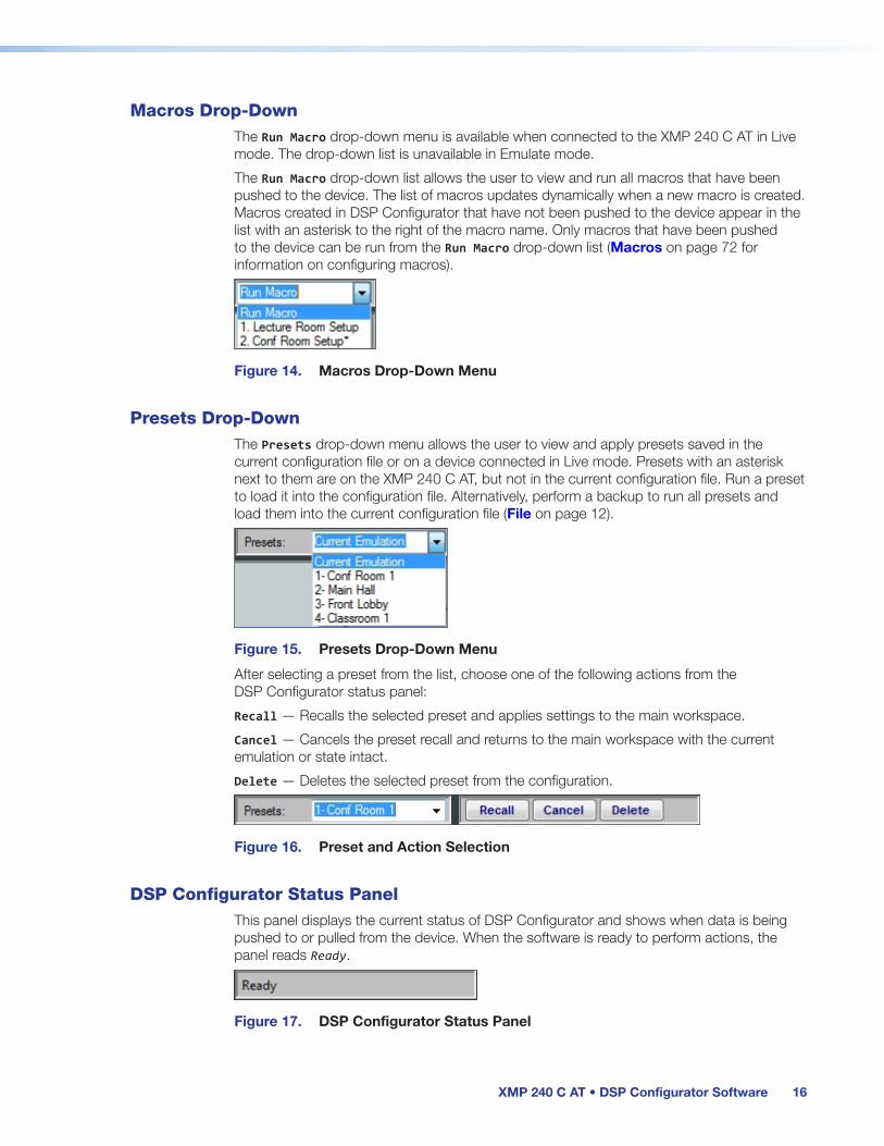
Macros Drop-DownThe Run Macro drop-down menu is available when connected to the XMP 240 C AT in Live mode. The drop-down list is unavailable in Emulate mode.
The Run Macro drop-down list allows the user to view and run all macros that have been pushed to the device. The list of macros updates dynamically when a new macro is created. Macros created in DSP Configurator that have not been pushed to the device appear in the list with an asterisk to the right of the macro name. Only macros that have been pushed to the device can be run from the Run Macro drop-down list (Macros on page 72 for information on configuring macros).
Figure 14. Macros Drop-Down Menu
Presets Drop-DownThe Presets drop-down menu allows the user to view and apply presets saved in the current configuration file or on a device connected in Live mode. Presets with an asterisk next to them are on the XMP 240 C AT, but not in the current configuration file. Run a preset to load it into the configuration file. Alternatively, perform a backup to run all presets and load them into the current configuration file (File on page 12).
Figure 15. Presets Drop-Down Menu
After selecting a preset from the list, choose one of the following actions from the DSP Configurator status panel:
Recall — Recalls the selected preset and applies settings to the main workspace.
Cancel — Cancels the preset recall and returns to the main workspace with the current emulation or state intact.
Delete — Deletes the selected preset from the configuration.
Figure 16. Preset and Action Selection
DSP Configurator Status PanelThis panel displays the current status of DSP Configurator and shows when data is being pushed to or pulled from the device. When the software is ready to perform actions, the panel reads Ready.
Figure 17. DSP Configurator Status Panel
figure 9. Macros Drop-down Menu
figure 10. Presets Drop Down Menu
figure 11. Preset and Action Selection
figure 12. DSP Configurator Status Panel

XMP 240 C AT • DSP Configurator Software 17
Live and Emulate PanelThe Live and Emulate buttons allow users to switch between Live and Emulate mode and displays transmit activity (Tx) and receive activity (Rx) when in Live mode.
Figure 18. Mode Panel
Emulate Mode
While in Emulate mode, DSP Configurator is functioning in an “offline” state. Changes made to the configuration file are not applied to a XMP 240 C AT.
In Emulate mode, the user can create and configure the software as though a device was connected, except for any actions that require direct connection to the device or information that is stored only on the device. Once configuration is complete, the user can switch to Live mode and apply the configuration to the device or save the configuration file to be loaded onto one or multiple devices at a later time.
Creating configuration files in Emulate mode saves time by not requiring a device to be connected or present in order for the bulk of DSP configuration to be completed.
NOTE: Not all menu options or actions are available in Emulate mode.
Live Mode
Enter Live mode to connect to a XMP 240 C AT and push or pull configurations between the device and host PC. In Live mode, changes made in DSP Configurator are directly applied to the XMP 240 C AT. Additionally, presets and macros can be created and stored on the device.
When entering Live mode, the user is prompted with the Connect to device dialog box.
Connect to a XMP 240 C AT in Live Mode
1. Click the Live button in the menu bar of DSP Configurator (see figure 19 , 1). Alternatively, select Tools > Connect to Device or press <F6> on the keyboard. The Connect to device dialog box opens.
Figure 19. Live Button
2. Connect to the XMP 240 C AT.
a. To connect via TCP/IP (recommended):
Click the TCP/IP tab in the dialog box. Enter the IP address of the device in the Hostname or IP Address field. If necessary, enter the device password in the Password field (see figure 20, a on the next page).
b. To connect via USB:
Click the USB tab in the dialog box. Select the device from the USB Devices drop-down menu (b).
c. To connect via RS-232:
Click the RS-232 tab in the dialog box. Select the com port the device is connected to on the host PC from the Com Port drop-down (c).
figure 13. Mode Panel
figure 14. Live Button

XMP 240 C AT • DSP Configurator Software 18
Figure 20. Connect to device... TCP/IP, USB, and RS-232 Dialog Box
3. When a connection with a device is established, the Synchronize with Device dialog box opens.
Figure 21. Synchronize with Device Dialog Box
a. Pull — Pulls the configuration file, presets, macros, and ACP configurations from the device and displays it in the DSP Configurator main workspace.
b. Push — Pushes the configuration file, presets, macros, and ACP configurations open in DSP Configurator to the connected XMP 240. The check boxes indicate what will be pushed when OK is selected. Pushing a selected item will overwrite that item on the device.
NOTE: If only pushing selected presets, the preset selection dialog box opens after clicking OK. This dialog allows you to select which preset to push to the device.
figure 15. Connect to device...

XMP 240 C AT • DSP Configurator Software 19
If only pushing selected presets, select them in the dialog box shown in the figure below.
Figure 22. Preset Selection Dialog Box
4. Once a push or pull is completed, the current state of the connected XMP 240 C AT is displayed in the DSP Configurator status panel and the device is ready for further configuration.
Exit Live Mode and Enter Emulate Mode
1. Click the Emulate button in the DSP Configurator menu bar (see figure 23, 1). Alternatively, select Tools > Disconnect from Device or press <F6> on the keyboard.
Figure 23. Emulate Button
2. Click OK to confirm.
Figure 24. Confirm Disconnect

XMP 240 C AT • DSP Configurator Software 20
DSP Configurator InputsAll available inputs are listed vertically along the left side of the DSP Configurator main workspace. The input groups can be expanded or collapsed by clicking the (expand) or (collapse) buttons next to the input group names.
There are two types of inputs available:
• Inputs • Virtual Returns
InputsThe 48 mic/line input channels on the XMP 240 are shown in DSP Configurator under the Inputs panel.
Figure 25. Inputs
Inputs 1 - 24 offer AEC (Acoustic Echo Cancellation) DSP capability. Inputs 25 - 48 do not have AEC. The 48 channels of Dante inputs and 16 channels of audio via the EXP port are available as digital sources for the XMP 240 inputs.
Renaming an InputNOTE: Renaming an AT input in DSP Configurator affects the receiver name in
Dante Controller. Alternatively, renaming a receiver channel in Dante Controller affects the name displayed in DSP Configurator (see Renaming a Receiver or Transmitter on page 93).

XMP 240 C AT • DSP Configurator Software 21
1. Click the expansion or input name field.
Figure 26. Input Name Field
2. Delete or highlight the text, and type the desired name.
Figure 27. Input Name
3. Press the <Enter> key or navigate away from the field to confirm and apply the new name. Press the <Down Arrow> key to navigate to and highlight the next name field.
Figure 28. Renamed Input
Inputs OverviewWith the Extron Expansion Port (EXP), two EXP enabled devices can be connected for bidirectional communication. When two units are connected, one unit must be set as the Primary Unit and the other must be set as the Secondary Unit (see Expansion Bus on page 88). This synchronizes the sampling clocks of the two units.
AT inputs allow a XMP 240 C AT model to receive signal from the audio network. Network audio routing is done with Dante Controller (see Dante Controller on page 89).
Figure 29. AT Inputs
figure 16. Expansion Input Name Field
figure 17. New Expansion Input Name
figure 18. Renamed Expansion
figure 19. Expansion Inputs Panel
XMP 240 C AT • DSP Configurator Software 22
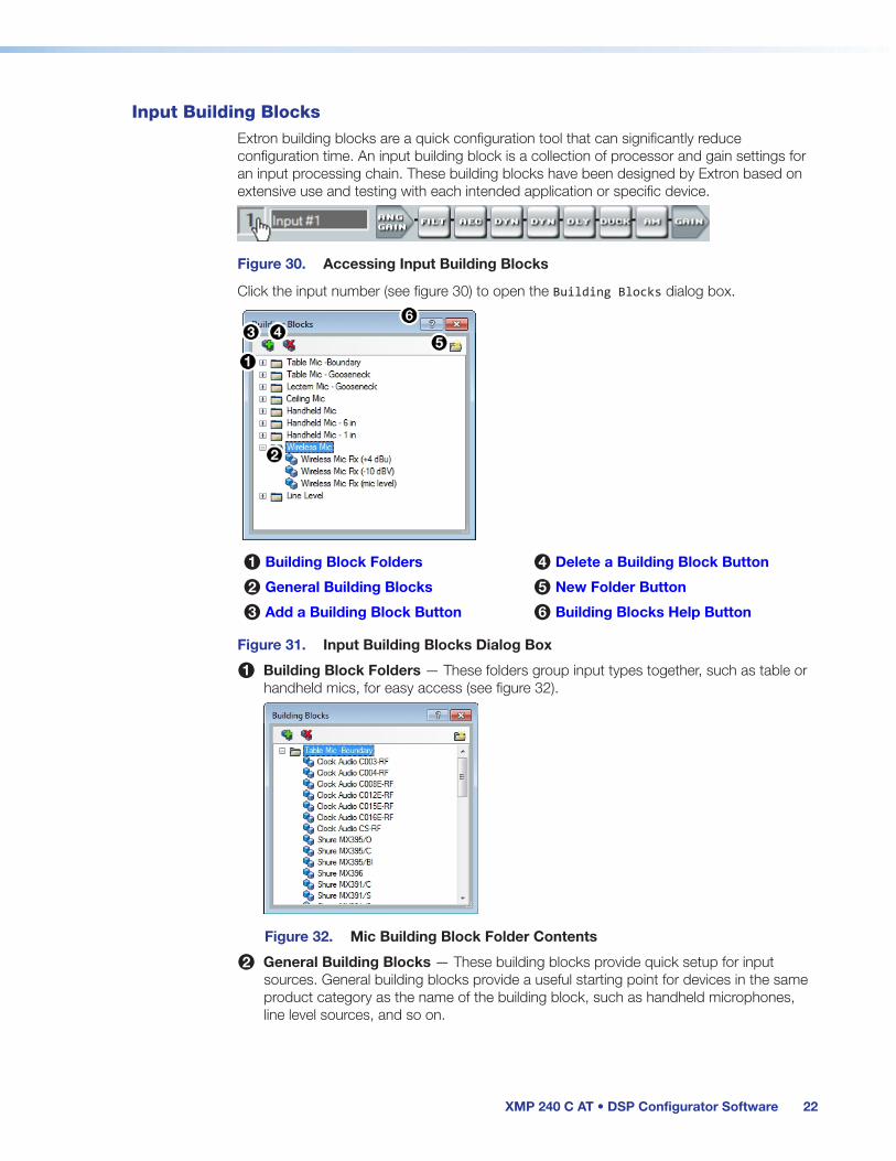
Input Building BlocksExtron building blocks are a quick configuration tool that can significantly reduce configuration time. An input building block is a collection of processor and gain settings for an input processing chain. These building blocks have been designed by Extron based on extensive use and testing with each intended application or specific device.
Figure 30. Accessing Input Building Blocks
Click the input number (see figure 30) to open the Building Blocks dialog box.
1 Building Block Folders 4 Delete a Building Block Button
2 General Building Blocks 5 New Folder Button
3 Add a Building Block Button 6 Building Blocks Help Button
Figure 31. Input Building Blocks Dialog Box
1 Building Block Folders — These folders group input types together, such as table or handheld mics, for easy access (see figure 32).
Figure 32. Mic Building Block Folder Contents
2 General Building Blocks — These building blocks provide quick setup for input sources. General building blocks provide a useful starting point for devices in the same product category as the name of the building block, such as handheld microphones, line level sources, and so on.
figure 20. Accessing Building Blocks on an Input
figure 21. Building Blocks Dialog Box
figure 22. Mic Building Block Folder Contents

XMP 240 C AT • DSP Configurator Software 23
3 Add a Building Block Button — Creates a custom building block from the current gain and processor settings on the selected channel. When this button is clicked, the Add a Building Block dialog box opens. Name the new custom building block and choose a folder to save the block to, or create a new folder (see figure 33).
Figure 33. Add a Building Block Dialog Box
4 Delete a Building Block Button — Deletes the currently selected building block or building block folder. If default building blocks are deleted, they can be restored from the Organize Building Blocks dialog box. Custom building blocks can be saved to a file from the same dialog box (Organize Building Blocks on page 82).
5 New Folder Button —Creates a new folder or sub-folder in the Building Blocks dialog box.
6 Building Blocks Help Button — Opens the Building Blocks topic of the DSP Configurator Help file. This topic contains more information on the different types of building blocks for inputs and outputs.
Input ProcessingThe input processing chain in DSP Configurator is visually represented by a string of blocks (see figure 34). Each block contains a specific processor or type of processor. For example, the Input Gain block contains a fader to boost or attenuate incoming signal, the Filter block contains several types of filters, and so on. Inputs 1 - 24 contain the following processing chain:
1. Input Gain Block
2. Input Filter Block
3. Input AEC Block
4. Input Dynamics Blocks (2)
5. Input Delay Block
6. Input Ducking Block
7. Input Automix Block
8. Input Pre-Mixer Gain Block
Figure 34. Input 1 - 24 Processing Chain
Inputs 25 - 48 contain the following processing chain:
Figure 35. Input 25 - 48 Processing Chain
figure 23. Add a Building Block Dialog Box

XMP 240 C AT • DSP Configurator Software 24
Input Gain BlockDouble-click the DIG GAIN (Input Gain) block to open the Input Gain dialog box.
Figure 36. Input Gain Block
The Input Gain dialog box provides controls to configure the input gain stage of the input processing path.
Figure 37. Input Gain Dialog Box
1 Input Name — This name changes to match the default or user defined input name.
2 Gain Fader — Provides up to 24 dB of gain or 18 dB of attenuation in 0.1 dB steps. Click the fader once and press the <Up Arrow> or <Down Arrow> keys to adjust the fader up or down in 1 dB steps. Press the <Page Up> or <Page Down> keys to adjust the fader up or down in 10 dB steps.
3 dBFS Meter — This meter displays the input signal level in dBFS ranging from -60 dBFS to 0 dBFS. Once the signal reaches or passes -1 dBFS (default) or the clip threshold defined in the Options dialog box (Options on page 87), the clip box located at the top of the meter lights red.
4 dBFS Numeric Readout — This read-only text box displays the numerical value of the input signal level in dBFS.
5 Input Gain Text Field — This text field allows the user to enter a gain or attenuation value in 0.1 dB steps.
6 Polarity Toggle Button — Inverts the signal polarity of the selected input. When the button displays the black + symbol on a gray field ( ), the polarity is normal. When the button displays the black - symbol on a yellow field ( ), the polarity is inverted.
7 Mute Button — Mutes signal at the input stage, preventing it from going any further in the signal processing chain.
8 Source Drop-Down Menu — Selects the input audio source for the channel. Source options are any of the 48 AT Inputs or 16 EXP inputs.
9 OK Button — Confirms changes and closes the Input Gain dialog box.
figure 24. Input Gain Icon
1 Input Name 7 Mute Button
2 Gain Fader 8 Source Drop-Down Menu
3 dBFS Meter 9 OK Button
4 dBFS Numeric Readout ¢ Cancel Button
5 Input Gain Text Field £ Input Gain Help Button
6 Polarity Toggle Button

XMP 240 C AT • DSP Configurator Software 25
¢ Cancel Button — Reverts any changes made to the contained parameters back to their states when the current instance of the Input Gain dialog box was opened and closes the dialog box.
£ Input Gain Help Button — Opens the Mic/Line Input Gain topic in the DSP Configurator Help file for further assistance in configuring input gain.
Input Filter BlockDouble-click the Filter block to open the filter drop-down menu. Select one of the eleven available filters to insert into the block.
Figure 38. Filter Block and Drop-Down Menu
Alternatively, right-click the Filter block and select Insert, then select a filter to insert it into the block.
Figure 39. Insert Filter Drop-Down Menu
Once an initial filter is selected, the Filter block changes to display the type of filter applied. For example, if High Pass Filter is selected, the Filter block would display HIGH PASS instead of FILT. If multiple filters are applied, the Filter block displays FILT over a dark green field.
Figure 40. Filter Block Icons
Once a filter is applied to the Filter block, double-click the block to open the Filter dialog box.

XMP 240 C AT • DSP Configurator Software 26
1 Filter Channel Name 5 OK Button
2 Filter Graph 6 Cancel Button
3 Filter List 7 Filters Help Button
4 Set Defaults Button
Figure 41. Filter Dialog Box
1 Filter Channel Name — This name changes to match the default or user defined input name.
2 Filter Graph — Graphically displays the applied filter curve and provides handles for adjusting filter parameters. Numbers along the top of the graph represent the filter curve of the corresponding slot in the filter list below the graph. The number appears over the center frequency of the filter.
If a filter is active (unbypassed), it appears as a solid red curve. If a filter is bypassed, it appears as a broken orange curve (such as the bass filter in slot 2).
NOTE: All filters are bypassed by default.
3 Filter List — Provides filter drop-down menus for all 5 available filter slots. Frequency, Slope, Boost/Cut, Q, and Bypass controls are also available in this list.
Available filters include:
• High Pass Butterworth • High Pass Linkwitz-Reily
• Low Pass Butterworth • Low Pass Linkwitz-Reily
• Bass • High Pass Bessel
• Treble • Low Pass Bessel
• Parametric • Loudness
• Notch
NOTE: See the DSP Configurator Help file for more information on each of the filters. Click the Filters Help button to open the help file topic discussing filters.

XMP 240 C AT • DSP Configurator Software 27
4 Set Defaults Button — Resets all filter parameters of all filters in the filter list to their default values.
To reset a single filter to default parameters, right-click the filter number on the left side of the Filter dialog box, and select Set to Default (see figure 42).
Figure 42. Set Single Filter Parameters to Default
5 OK Button — Confirms changes made to the contained parameters and closes the Filter dialog box.
6 Cancel Button — Reverts any changes made to the contained parameters back to their states when the current instance of the Filter dialog box was opened and closes the dialog box.
7 Filters Help Button — Opens the About Filters topic in the DSP Configurator Help file. This help file topic discusses each filter type in greater detail.
Input AEC Block
About AEC
Echo occurs when audio from a talker in the far end is received and amplified into the near end listener’s room, with that sound then being picked up by microphones in the near end acoustic space and sent back to the far end. The amount of signal sent back to the far end talker can be substantial, and with the added transmission delay, the result is an echo effect that can seriously compromise communication in a teleconference or videoconference.
The Extron Acoustic Echo Cancellation (AEC) processor removes the potential echo signal at the near end mic channel by comparing it to the received signal from the far end, designated as the “reference,” and then creating an adaptive filter to cancel the potential echo before it is sent back to the far end.
Successful operation of the AEC processing block is mainly a function of proper gain structure and selection of an AEC reference. This section provides an overview of those two elements.
Proper gain structure involves the relationship between the signal at the selected reference and the signal at the mic input, within the context of proper levels for the reference and mic inputs independently. The mic input gain setting will naturally be optimized for the voice level of the talker in that room. Therefore, the amount of signal from the far end picked up by the mic is dependent on how much far end signal is being amplified in the near end room and the distance from the mic to the speakers.

XMP 240 C AT • DSP Configurator Software 28
AEC Operation
Double-click the AEC block to open the AEC drop-down menu. Select AEC to insert the AEC processor.
Figure 43. AEC Block and Drop-Down Menu
NOTE: Insert the AEC processor on the input with the near end microphone connected.
Once the AEC processor is inserted, double-click the AEC block to open the AEC dialog box.
1 Activity Panel 7 Bypass Button
2 ERL Meter 8 OK Button
3 ERLE Meter 9 Cancel Button
4 TER Meter ¢ Show/Hide Advanced Options Button
5 Reference Selection Drop-Down £ AEC Help Button
6 Noise Cancellation Panel
Figure 44. AEC Dialog Box
1 Activity Panel — Far lights when signal activity is detected from the far end. Near lights when activity is detected from the near end. Update lights when AEC is updating, converging, or reconverging.
2 ERL Meter — ERL (echo return loss) is the ratio of the far end signal at the reference input to the far end signal received at the mic input and is expressed in dB. This meter should read between -10 dB and +10 dB for proper AEC operation.
3 ERLE Meter — ERLE (echo return loss enhancement) is the amount of potential echo signal that the AEC algorithm is cancelling (not including NLP processing) and is expressed in dB.
4 TER Meter — TER (total echo reduction) is the sum of ERL and ERLE and represents the total amount of echo reduction and is expressed in dB.
figure 25. AEC Dialog Box

XMP 240 C AT • DSP Configurator Software 29
5 Reference Selection Drop-Down Menu — (See figure 44 on the previous page)Provides all inputs, outputs, and virtual returns for reference selection. When a channel is selected as the reference, the AEC processor compares the reference channel signal to the current input channel.
6 Noise Cancellation Panel — Provides a checkbox to engage the noise canceller (engaged by default) and text field to enter the amount of noise reduction in dB.
7 Bypass Button — Bypasses the AEC processor. When the button is red, bypass is enabled.
8 OK Button — Confirms changes made to the contained parameters and closes the AEC dialog box.
9 Cancel Button — Reverts any changes made to the contained parameters back to their states when the current instance of the AEC dialog box was opened and closes the dialog box.
¢ Show/Hide Advanced Options Button — Shows or hides the advanced configuration options for the AEC processor (AEC Advanced Options below).
£ AEC Help Button — Opens the Acoustic Echo Cancellation topic of the DSP Configurator Help file for further assistance in operating AEC processor.
AEC Advanced Options
The AEC dialog box provides advanced NLP (non-linear processing) options for fine tuning echo cancellation. These options are hidden by default. Click the Show/Hide Advanced Options button to access them (see figure 44, ¢ on the previous page).
Figure 45. AEC Advanced Options
1 Enable NLP Checkbox — Checked by default, NLP (non-linear processing) is required to completely remove echo.
2 NLP Presets — Offers three preset options for NLP parameters.
• Soft — Applies soft preset values to the NLP reduction parameters for light echo cancellation.
• Normal (default) — Applies normal preset values to the NLP reduction parameters for the widest array of echo cancellation needs.
• Aggressive — Applies aggressive preset values to the NLP reduction parameters for aggressive echo cancellation.
3 NLP Reduction Parameters — Provides text boxes for Max NLP Reduction, Attack
1 Enable NLP Checkbox
2 NLP Presets
3 NLP Reduction Parameters
4 Double Talk Echo Reduction
5 Comfort Noise

XMP 240 C AT • DSP Configurator Software 30
Time, and Release Time to customize NLP reduction parameters.
4 Double Talk Echo Reduction — Provides a text box to enter a reduction value (in dB) when double talk occurs. Double talk is when near end talkers and far end talkers are speaking simultaneously while AEC is engaged.
5 Comfort Noise Text Box — Provides an ambient noise signal to prevent states of complete silence that may be perceived as a failed or dropped connection. 0 dB is the default.
Input Dynamics BlocksDouble-click the Dynamics block to open the dynamics drop-down menu.
Figure 46. Dynamics Block and Drop-Down Menu
From the Dynamics drop-down menu, four types of dynamics processors are available. Select a dynamics processor type to insert it into the Dynamics block.
There are two Dynamics blocks available per mic/line input channel. Each block can be configured with any of the processor types.
The four types of dynamics processors available are:
• AGC (Automatic Gain Control) on the next page
• Compressor on page 32
• Limiter on page 33
• Noise Gate on page 34
Once a dynamics processor is inserted, double-click the dynamics block icon to open the corresponding dialog box.
Figure 47. AGC, Compressor, Limiter, and Noise Gate Icons
If a dynamics processor has been inserted and needs to be changed to a different dynamics processor, right-click the dynamics block, hover over Insert, and select a new processor to insert it (see figure 48).
figure 26. Dynamics Block and Drop Down Menu

XMP 240 C AT • DSP Configurator Software 31
Figure 48. Changing Dynamics Processors
AGC (Automatic Gain Control)
Figure 49. AGC Dialog Box
1 Dynamics Channel Name — This name changes to match the default or user defined input name.
2 AGC Graph — Graphically displays AGC parameter settings. Parameters can also be adjusted using this graph. Click and drag the yellow lines to adjust the Window parameter. Click and drag the bottom dot to adjust the Threshold parameter. Click and drag the middle dot to adjust the Maximum Gain parameter. Click and drag the top dot to adjust the Target parameter.
3 AGC Parameters List and Control — Provides text boxes to adjust all AGC parameters. Attack Time, Hold Time, and Release Time also have sliders that adjust their respective parameters. Click a slider once and use the <Left Arrow> and <Right Arrow> keys to adjust the respective parameter in 1 ms steps.
4 Bypass Button — Bypasses the AGC processor. When the button is red, bypass is enabled.
5 Set Defaults Button — Resets all AGC parameters to their default values. To view individual parameter default values, see the DSP Configurator Help file by clicking the Dynamics Help button (8) and opening the About Dynamics topic.
6 OK Button — Confirms changes made to the contained parameters and closes the AGC dialog box.
7 Cancel Button — Reverts any changes made to the contained parameters back to their states when the current instance of the AGC dialog box was opened and closes the dialog box.
8 Dynamics Help Button — Opens the Dynamics Operation topic of the DSP Configurator Help file for further assistance in operating dynamics processors.
1 Dynamics Channel Name
2 AGC Graph
3 AGC Parameters List and Control
4 Bypass Button
5 Set Defaults Button
6 OK Button
7 Cancel Button
8 Dynamics Help Button
figure 27. AGC Dialog Box

XMP 240 C AT • DSP Configurator Software 32
Compressor
Figure 50. Compressor Dialog Box
1 Compressor Channel Name — This name changes to match the default or user defined input name.
2 Compressor Graph — Graphically displays compressor parameter settings. Parameters can also be adjusted using this graph. Click and drag the dot within the green area of the graph to adjust the compressor Threshold. Click and drag the dot outside the green box to adjust the compressor Ratio.
3 Compressor Parameter List and Control — Lists all configurable parameters for the compressor. Text fields are available to adjust Threshold, Ratio, Attack Time, Hold Time, and Release Time. Click and drag sliders to adjust Attack Time, Hold Time, and Release Time. Click a slider once and use the <Left Arrow> and <Right Arrow> keys to adjust the respective parameter in 1 ms steps. Select the Soft Knee checkbox to provide a more natural implementation of compression when the signal reaches the threshold.
4 Bypass Button — Bypasses the compressor. When the button is red, bypass is enabled.
5 Set Defaults Button — Resets all compressor parameters to their default values. To view individual parameter default values, see the DSP Configurator Help file by clicking the Dynamics Help button (8) to open the About Dynamics topic.
6 OK Button — Confirms changes made to the contained parameters and closes the Compressor dialog box.
7 Cancel Button — Reverts any changes made to the contained parameters back to their states when the current instance of the Compressor dialog box was opened and closes the dialog box.
8 Dynamics Help Button — Opens the Dynamics Operation topic of the DSP Configurator Help file for further assistance in operating dynamics processors.
1 Compressor Channel Name
2 Compressor Graph
3 Compressor Parameter List and Control
4 Bypass Button
5 Set Defaults Button
6 OK Button
7 Cancel Button
8 Dynamics Help Button

XMP 240 C AT • DSP Configurator Software 33
Limiter
Figure 51. Limiter Dialog Box
1 Limiter Channel Name — This name changes to match the default or user defined input name.
2 Limiter Graph — Graphically displays limiter parameter settings. Parameters can also be adjusted using this graph. Click and drag the dot on the graph to adjust the limiter Threshold.
3 Limiter Parameter List and Control — Lists all configurable parameters for the limiter. Text fields are available to adjust Threshold, Attack Time, Hold Time, and Release Time. Click and drag sliders to adjust Attack Time, Hold Time, and Release Time. Click a slider once and use the <Left Arrow> and <Right Arrow> keys to adjust the respective parameter in 1 ms steps. Select the Soft Knee checkbox to provide a more gradual implementation of limiting when the signal reaches the threshold.
4 Bypass Button — Bypasses the limiter. When the button is red, bypass is enabled.
5 Set Defaults Button — Resets all limiter parameters to their default values. To view individual parameter default values, see the DSP Configurator Help file by clicking the Dynamics Help button (8) and navigate to the About Dynamics topic.
6 OK Button — Confirms changes made to the contained parameters and closes the Limiter dialog box.
7 Cancel Button — Reverts any changes made to the contained parameters back to their states when the current instance of the Limiter dialog box was opened and closes the dialog box.
8 Dynamics Help Button — Opens the Dynamics Operation topic of the DSP Configurator Help file for further assistance in operating dynamics processors.
1 Limiter Channel Name
2 Limiter Graph
3 Limiter Parameter List and Control
4 Bypass Button
5 Set Defaults Button
6 OK Button
7 Cancel Button
8 Dynamics Help Button
figure 28. Limiter Dialog Box

XMP 240 C AT • DSP Configurator Software 34
Noise Gate
Figure 52. Noise Gate Dialog Box
1 Noise Gate Channel Name — This name changes to match the default or user defined input name.
2 Noise Gate Graph — Graphically displays noise gate parameter settings. Parameters can also be adjusted using this graph. Click and drag the upper dot to adjust Ratio. Click and drag the middle dot to adjust Threshold. Click and drag the bottom dot (out of view at default settings) to adjust Max Attenuation.
3 Noise Gate Parameter List and Control — Lists all configurable parameters for the noise gate. Text fields are available to adjust Threshold, Max Attenuation, Ratio, Attack Time, Hold Time, and Release Time. Click and drag the sliders to adjust Attack Time, Hold Time, and Release Time. Click a slider once and use the <Left Arrow> and <Right Arrow> keys to adjust the respective parameter in 1 ms steps.
4 Bypass Button — Bypasses the noise gate. When the button is red, bypass is enabled.
5 Set Defaults Button — Resets all noise gate parameters to their default values. To view individual parameter default settings, see the DSP Configurator Help file by clicking the Dynamics Help button (8) and navigate to the About Dynamics topic.
6 OK Button — Confirms changes made to the contained parameters and closes the Noise Gate dialog box.
7 Cancel Button — Reverts any changes made to the contained parameters back to their states when the current instance of the Noise Gate dialog box was opened and closes the dialog box.
8 Dynamics Help Button — Opens the Dynamics Operation topic of the DSP Configurator Help file for further assistance in operating dynamics processors.
1 Noise Gate Channel Name
2 Noise Gate Graph
3 Noise Gate Parameter List and Control
4 Bypass Button
5 Set Defaults Button
6 OK Button
7 Cancel Button
8 Dynamics Help Button
figure 29. Noise Gate Dialog Box

XMP 240 C AT • DSP Configurator Software 35
Input Delay BlockDouble-click the Delay block to open the delay drop-down. Click Delay to insert the delay processor into the block.
Figure 53. Delay Block and Drop-Down Menu
Once a delay processor is inserted into the Delay block, double-click the block to open the Delay dialog box.
Figure 54. Delay Dialog Box
1 Delay Channel Name — This name changes to match the default or user defined input name.
2 Units of Measurement — Radio buttons change the unit of measurement used by the delay fader and text box. Samples, Milliseconds, Feet, and Meters are available units of measurement. Values are converted when the unit of measurement is changed. Changing the unit of measurement does not alter the amount of delay applied to the signal.
3 Delay Fader and Text Box — Adjusts the amount of delay applied to the signal. Click and drag the fader up or down to increase or decrease the amount of delay. Click the fader once and use the <Up Arrow> or <Down Arrow> to adjust delay in 1 sample steps (or the 1 sample equivalent in milliseconds, feet, or meters). Use the text box below the fader to input a delay value.
4 Temperature Panel — Becomes available when using delay in feet or meters. Compensates delay for ambient temperature in the acoustic space. Temperature is not available when using samples or milliseconds as the unit of measurement.
5 OK Button — Confirms changes made to the contained parameters and closes the Delay dialog box.
6 Set Defaults Button — Resets the delay to 4800 samples.
7 Cancel Button — Reverts any changes made to the contained parameters back to their states when the current instance of the Delay dialog box was opened and closes the dialog box.
8 Bypass Button — Bypasses the delay. When the button is red, bypass is enabled.
9 Delay Help Button —Opens the Delay Operation topic of the DSP Configurator Help file for further assistance in understanding operating the delay processor.
figure 30. Delay Block and Drop Down Menu
1 Delay Channel Name
2 Units of Measurement
3 Delay Fader and Text Box
4 Temperature Panel
5 OK Button
6 Set Defaults Button
7 Cancel Button
8 Bypass Button
9 Delay Help Button
figure 31. Delay Dialog Box

XMP 240 C AT • DSP Configurator Software 36
Input Ducking BlockThe duck block contains a ducking processor as well as an adaptive gain processor.
• Ducker (see the next page) — Decreases levels on specified channels when signal is present above a set threshold on the duck source (trigger).
• Adaptive Gain (see page 38) — Increases levels on specified channels when signal is present above a set threshold on the adaptive gain source channel (trigger).
Double-click the Duck block to open the drop-down menu where the Ducker and Adaptive Gain processors can be selected.
Figure 55. Duck Block and Drop-Down Menu
Select Ducker to insert a ducking processor into the duck block. Select Adaptive Gain to insert an adaptive gain processor into the duck block. Depending on the processor selected, the duck block displays DUCK for a ducker or AG for adaptive gain.
Figure 56. Ducking Block Icons
If a ducking processor has been inserted and needs to be changed to an adaptive gain processor, or vice versa, right-click the block and hover over Insert to insert a different processor (see figure 57).
Figure 57. Changing Ducking Processor

XMP 240 C AT • DSP Configurator Software 37
Ducker
After inserting a ducker processor, double-click the Duck icon to open the Ducker Configuration dialog box.
Figure 58. Ducker Configuration Dialog Box
1 Duck Source Configuration — The Enable Source Mic/Line checkbox is checked when a ducker is inserted (default). In the Duck column, check the inputs that will be ducked. In the by (dB) column, enter the amount of ducking that will occur on each channel selected in the Duck column. When the threshold is exceeded on the duck source, ducking occurs on the selected channels.
2 Duck Parameter Settings — Contains controls for setting Threshold, Attack Time, Hold Time, and Release. Click the Ducking Operation Help button (4) to open the Ducking Operation topic in the DSP Configurator Help fie.
3 Duck Priority Tree — Displays the ducking priority for all Input and Aux In channels. Select another input to populate the Ducker Configuration dialog with the ducker information for that channel. Channels with an adaptive gain processor are appended with an (AG). Channels with adaptive gain processors cannot be selected from this dialog box.
4 Ducking Operation Help Button —Opens the Ducking Operation topic of the DSP Configurator Help file for further assistance in ducker configuration.
1 Duck Source Configuration
2 Duck Parameter Settings
3 Duck Priority Tree
4 Ducking Operation Help Button

XMP 240 C AT • DSP Configurator Software 38
Adaptive Gain
After inserting an adaptive gain processor, double-click the AG icon to open the Adaptive Gain dialog box.
Figure 59. Adaptive Gain Dialog Box
1 Adaptive Gain Source Configuration — In the Add Gain To column, check the inputs that will have gain added by the adaptive gain processor. In the Max Gain (dB) column, enter the maximum amount of gain that will be applied to each channel selected in the Add Gain To column. When a box is checked, gain is applied to that channel when signal exceeds the threshold on the adaptive gain trigger channel.
NOTE: For every 1 dB of signal beyond the level set in the Threshold field, 1 dB of gain will be added to the channels selected in the Add Gain To column. This occurs until the maximum gain set in the Max Gain (dB) field has been applied.
2 Adaptive Gain Parameter Settings — Contains controls for Threshold, Attack Time, Hold Time, and Release Time.
3 Adaptive Gain Operation Help Button — Opens the Adaptive Gain Operation topic of the DSP Configurator Help file for further assistance in adaptive gain configuration.
1 Adaptive Gain Source Configuration
2 Adaptive Gain Parameter Settings
3 Adaptive Gain Operation Help Button
figure 32. Adaptive Gain Dialog Box

XMP 240 C AT • DSP Configurator Software 39
Input Automix BlockDouble-click the Automix block to open a drop-down menu. Select Auto-mixer to insert the automix processor into the block.
Figure 60. Automix Block and Drop-Down
Once the automix processor is inserted into the Automix block, double-click the block to open the Automix dialog box.
Figure 61. Automix Dialog Box
1 Automix Channel Name — This name changes to match the default or user-defined input name.
2 AM Group Assignment Panel — Provides nine radio buttons to assign the current automix processor to an AM (automix) group. The default is None and leaves the automixer unassigned.
3 Show AM Group Details Button — Opens the Automix Groups dialog box (click the Automix Help button for more information regarding Automix Groups).
4 Automix Parameters — Provides configuration controls for all automix parameters.
5 dBFS Meter — Displays the post-automix signal level.
6 Gate Status Indicator — This LED lights when monitoring is enabled and the gate is open.
7 Monitor Gate Checkbox — Click the Monitor Gate checkbox to enable SIS responses regarding gate status (see Automixer Gate Monitoring on the next page).
8 Set Defaults Button — Resets all automix parameters to their default settings.
9 Bypass Button — Bypasses the automix processor. When the button is red, bypass is enabled.
¢ OK Button — Confirms changes made to the contained parameters and closes the Automix dialog box.
figure 33. Automix Block and Drop Down
1 Automix Channel Name
2 AM Group Assignment Panel
3 Show AM Group Details Button
4 Automix Parameters
5 dBFS Meter
6 Gate Status Indicator
7 Monitor Gate Checkbox
8 Set Defaults Button
9 Bypass Button
¢ OK Button
£ Cancel Button
¤ Automix Help Button
figure 34. Automix Dialog Box

XMP 240 C AT • DSP Configurator Software 40
£ Cancel Button — Reverts any changes made to the contained parameters back to their states when the Automix dialog box was opened and closes the dialog box.
¤ Automix Help Button — Opens the Automix topic of the DSP Configurator Help file for further assistance in configuring the automix processor.
Automixer Gate Monitoring
Automixer gate monitoring allows the user to track when an automixer gate opens or closes. This feature can be enabled by checking the Monitor Gate checkbox in an Automix dialog (figure 61, 7 on the previous page). When automixer gate monitoring is enabled for a channel, an unsolicited message is sent when the gate has opened or closed. The response will include the Automixer OID, gate open or closed status, and the signal level immediately after the status has changed (see Automixer Gate Monitoring on page 125 for SIS response syntax).
Comparing the automixer gate threshold setting to the gate status in the response will indicate whether the automixer gate has opened or closed. When the gate status in the response is 1024 or greater, the gate has opened, and when the gate status in the response is less than 1024, the gate has closed.
Input Pre-Mixer Gain BlockDouble-click the pre-mixer Gain block to open the Pre-mixer Gain dialog box.
Figure 62. Input Pre-mixer Gain Block
The Pre-mixer Gain dialog box provides controls to boost, attenuate, and mute the signal after input processing occurs and before it is sent to the mix matrix.
Figure 63. Input Pre-mixer Gain Dialog Box
1 Input Name — This name changes to match the default or user defined input name.
figure 35. Input Pre-mixer Gain Block
1 Input Name
2 Pre-mixer Gain Fader
3 Pre-mixer Gain Text Box
4 Mute Button
5 OK Button
6 Cancel Button
7 Pre-mixer Gain Help Button
figure 36. Input Pre-Mixer Gain Dialog Box

XMP 240 C AT • DSP Configurator Software 41
2 Pre-mixer Gain Fader — Click and drag the gain fader to provide up to 12 dB of gain or 100 dB of attenuation in 1 dB steps. Click the fader and use the <Up Arrow> or <Down Arrow> keys to adjust the fader up or down in 1 dB steps.
3 Pre-mixer Gain Text Box — Enter a gain or attenuation value in 0.1 dB steps.
4 Mute Button — Mutes signal at the pre-mixer stage, preventing it from reaching the mix matrices.
5 OK Button — Confirms changes made to the contained parameters and closes the Pre-mixer Gain dialog box.
6 Cancel Button — Reverts any changes made to the contained parameters back to their states when the current instance of the Pre-mixer Gain dialog box was opened and closes the dialog box.
7 Pre-mixer Gain Help Button — Opens the Pre-mixer Gain topic of the DSP Configurator Help file for further assistance in understanding operating the Pre-mixer Gain dialog.
Virtual ReturnsVirtual returns receive signal when inputs are routed to the virtual send bus (see Virtual Send Bus on page 55). Sixteen virtual return channels are available and are labeled A through P. These channels can be used in a number of applications. For example, they can act as an AEC reference channel or be used for sub-mix processing.
Figure 64. Virtual Returns Input Panel
figure 37. Virtual Returns Input Panel

XMP 240 C AT • DSP Configurator Software 42
Renaming a Virtual Return1. Click the virtual return name field.
Figure 65. Virtual Return Name Field
2. Delete or highlight the text and type the desired name.
Figure 66. New Virtual Return Name
3. Press the <Enter> key or navigate away from the field to confirm and apply the new name. Press the <Down Arrow> key to navigate to and highlight the next name field.
Figure 67. Renamed Virtual Return
Virtual Return Building BlocksBuilding blocks can be applied to all 16 virtual return channels (see Input Building Blocks on page 22 for more information on configuring virtual return building blocks).
Virtual Return Processing Virtual returns A through H contain the following signal processing chain:
1. Virtual Return Feedback Suppressor Block
2. Virtual Return Filter Block
3. Virtual Return Dynamics Block
4. Virtual Return Delay Block
5. Virtual Return Pre-Mixer Gain Block
Virtual returns I through P contain the following signal processing chain:
1. Virtual Return Filter Block
2. Virtual Return Dynamics Block
3. Virtual Return Delay Block
4. Virtual Return Pre-Mixer Gain Block
NOTE: Only Virtual Return channels A through H contain Feedback Suppression processing blocks.
figure 38. Virtual Return Name Field
figure 39. New Virtual Return Name
figure 40. Renamed Virtual Return

XMP 240 C AT • DSP Configurator Software 43
Virtual Return Feedback Suppressor BlockUse the feedback suppressor when there is an indication of feedback during live operation. Dynamic filters automatically detect feedback on a live mic channel, and engage a set of up to 5 fixed and 15 dynamic filters to counteract feedback at the detected frequencies. The dynamic filters act in a “first in, first out” rotation. If all 15 dynamic filters are employed and an additional feedback frequency is detected, the first feedback frequency detected is overwritten.
To avoid a new feedback frequency overwriting a previously detected frequency, up to 5 dynamic filters can be transferred into fixed filters. Once a dynamic filter is transferred into a fixed filter, it can only be overwritten by manually assigning a new frequency to the filter.
Double-click the feedback suppressor block to show the feedback suppressor drop-down menu. Select Feedback Suppressor to insert a feedback suppressor processor into the signal chain.
Figure 68. Feedback Suppressor Block and Drop-Down Menu
After inserting the feedback suppressor in the signal chain, double-click the FBS block to open the Feedback Suppressor dialog box.
Feedback Suppressor Dialog Box
The Feedback Suppressor dialog box contains three tabs for configuring feedback suppression.
• Settings Tab on the next page
• Dynamic Filters Tab on page 45
• Fixed Filters Tab on page 46
figure 41. Feedback Suppressor Block and Drop Down Menu

XMP 240 C AT • DSP Configurator Software 44
Settings Tab
Figure 69. Feedback Suppressor Dialog Box - Settings Tab
1 Settings Tab — Provides access to the global FBS settings.
2 Composite View Panel — Three radio buttons control which filters are displayed in the filter graph:
• Only Dynamic FBS Filters
• Only Fixed FBS Filters
• Fixed & Dynamic FBS Filters (default)
3 Filter Graph — Displays the dynamic filters, fixed filters, or both, as selected in the Composite View panel.
4 Q Adjustment Panel — Adjust the default Q parameter of the dynamic filters using the text box or the up/down spinner controls.
5 Attack Time Panel — Adjust the default Attack Time for dynamic filters.
6 Hold Time Panel — Provides an Enable checkbox, that enables the Hold Time parameter. Entering a time into the Hold Time text boxes sets how long each dynamic filter will hold before removing the filter.
7 Bypass FBS — Turns off feedback detection when bypass is engaged (button is red when bypass is engaged). Only the dynamic filters are bypassed. Fixed filters remain active.
8 Set Defaults Button — Resets parameters on all tabs to their default values and positions.
9 OK Button — Confirms changes made to the contained parameters and closes the Feedback Suppressor dialog box.
¢ Cancel Button — Reverts any changes made to the contained parameters back to their states when the current instance of the Feedback Suppressor dialog box was opened and closes the dialog box.
1 Settings Tab
2 Composite View Panel
3 Filter Graph
4 Q Adjustment Panel
5 Attack Time Panel
6 Hold Time Panel
7 Bypass FBS Button
8 Set Defaults Button
9 OK Button
¢ Cancel Button
figure 42. Feedback Suppressor Dialog Box - Settings Tab

XMP 240 C AT • DSP Configurator Software 45
Dynamic Filters Tab
Figure 70. Feedback Suppressor Dialog Box - Dynamic Filters Tab
1 Dynamic Filters Tab — Provides access to dynamic filter configuration options.
2 Dynamic Filters List — Displays a list of 15 dynamic feedback suppression filters. As feedback is detected on the virtual return channel, dynamic filters are applied to suppress feedback with the Q parameter defined in the Settings tab.
3 Move to Fixed Button — Transfers the dynamic filter along with its current parameters to the Fixed Filters tab, allowing parameters to be edited. This frees up a filter slot in the Dynamic Filters list.
4 Clear Button — Clears the dynamic filter and contained parameters.
5 Clear All Button — Clears all dynamic filters and resets the feedback detection and suppression process.
6 Lock Button — Locks current dynamic filters and prevents more dynamic filters from being applied.
7 Bypass FBS Button — Bypasses the FBS processor. When the button is red, FBS is bypassed.
8 Set Defaults Button — Resets parameters on all tabs to their default values and positions.
9 OK Button — Confirms changes made to the contained parameters and closes the Feedback Suppressor dialog box.
¢ Cancel Button — Reverts any changes made to the contained parameters back to their states when the current instance of the Feedback Suppressor dialog box was opened and closes the dialog box.
1 Dynamic Filters Tab
2 Dynamic Filters List
3 Move to Fixed Button
4 Clear Button
5 Clear All Button
6 Lock Button
7 Bypass FBS
8 Set Defaults Button
9 OK Button
¢ Cancel Button
figure 43. Feedback Suppressor Dialog Box - Dynamic Filters Tab

XMP 240 C AT • DSP Configurator Software 46
Fixed Filters Tab
Figure 71. Feedback Suppressor Dialog Box - Fixed Filters Tab
1 Fixed Filters Tab — Provides access to fixed filter configuration options.
2 Fixed Filters List — Displays up to 5 fixed feedback suppression filters.
3 Filter Parameters — Configure the Frequency, Boost/Cut, and Q parameters for each fixed filter using the text boxes.
4 Single Filter Bypass Button — Bypasses only the filter associated with that filter slot. When the button is red, the filter is bypassed.
5 Clear All Button — Clears all fixed filters from the list.
6 Bypass FBS Button — Bypasses the FBS processor. When the button is red, FBS is bypassed.
7 Set Defaults Button — Resets parameters on all tabs to their default values and positions.
8 OK Button — Confirms changes made to the contained parameters and closes the Feedback Suppressor dialog box.
9 Cancel Button — Reverts any changes made to the contained parameters back to their states when the current instance of the Feedback Suppressor dialog box was opened and closes the dialog box.
¢ Feedback Suppressor Help Button — Opens the Feedback Suppressor topic of the DSP Configurator Help file for further assistance in understanding and operating the feedback suppression processor.
1 Fixed Filters Tab
2 Fixed Filters List
3 Filter Parameters
4 Single Filter Bypass Button
5 Clear All Button
6 Bypass FBS Button
7 Set Defaults Button
8 OK Button
9 Cancel Button
¢ Feedback Suppressor Help Button
figure 44. Feedback Suppressor Dialog Box - Fixed Filters Tab

XMP 240 C AT • DSP Configurator Software 47
Virtual Return Filter BlockOne filter block is available for each virtual return channel. This filter block functions the same as the mic/line input filter block (see Input Filter Block on page 25 for information on configuring the virtual return filter block).
Virtual Return Dynamics BlockOne dynamics block is available for each virtual return channel. This block functions the same as the mic/line input dynamics block (see Input Dynamics Blocks on page 30 for information on configuring the virtual return dynamics block).
Virtual Return Delay BlockOne delay block is available for each virtual return channel. This block functions the same as the mic/line input delay block (see Input Delay Block on page 35 for information on configuring the virtual return delay block).
Virtual Return Pre-Mixer Gain BlockThe virtual return pre-mixer gain block functions the same as the mic/line input pre-mixer gain block (see Input Pre-Mixer Gain Block on page 40 for information on configuring the virtual return pre-mixer gain block).
Mix-PointsDSP Configurator contains twelve mix matrices that connect all inputs and outputs (see figure 72 on page 48). The mix matrices set post-processing mix levels.
Each input is connected to a mix-point for the signal to be routed to an output. In general, mix levels are set relative to each other, achieving a blend of input signals at an optimal output level, close to, but not exceeding 0 dBFS at the output.
NOTE: In order for mix-points to appear in the workspace, the input group sending signal to the mix-point must be expanded and the input channel must be visible.

XMP 240 C AT • DSP Configurator Software 48
Figure 72. DSP Configurator Mix Matrices Part 1
1 Inputs to AT Outputs
2 Inputs to Virtual Sends

XMP 240 C AT • DSP Configurator Software 49
Figure 73. DSP Configurator Mix Matrices Part 2
Mix-Point Dialog BoxDouble-click a mix-point to open the Mix-point dialog box. Alternatively, highlight a mix-point with a single click and press the <Enter> key to open the Mix-point dialog box.
Figure 74. Mix-point Dialog Box
1 Mix-point Input and Output — Displays which input (top) and output (bottom) the mix-point is connecting.
2 Mix-point Fader — Click and drag the mix-point fader to provide up to 12 dB of gain or 100 dB of attenuation in 1 dB steps. Click the fader and use the <Up Arrow> or <Down Arrow> keys to change the level in 1 dB steps.
3 Level Text Box — Allows specific level values to be entered in 0.1 dB steps.
4 Mute Button — Mutes the mix-point (muted by default). When the button is red, the mix point is muted.
5 Mix Dot Selection — Three radio buttons provide options to choose the type of input processing applied to the mix-point.
NOTE: Mix dot selections are not available on Virtual Returns.
6 OK Button — Confirms changes made to the contained parameters and closes the Mix-point dialog box.
7 Cancel Button — Reverts any changes made to the contained parameters back to their states when the current instance of the Mix-Point dialog box was opened and closes the dialog box.
1 Mix-point Input and Output
2 Mix-point Fader
3 Level Text Box
4 Mute Button
5 Mix Dot Selection
6 OK Button
7 Cancel Button
3 Virtual Returns to Outputs
4 Virtual Returns to Virtual Sends

XMP 240 C AT • DSP Configurator Software 50
Mix-Point Context MenuRight-click a mix-point to open the mix-point context menu. This menu provides quick options to operate mix-points.
Figure 75. Mix-Point Context Menu
1 Mute — Mutes the mix-point.
2 Unmute — Unmutes the mix-point and creates an audio path between an input and output.
3 Bypass Automixer — Bypasses automixer processing at the mix-point and marks the mix-dot blue to signify automixing is bypassed.
4 Include Automixer — Includes automixer processing at the mix-point and marks the mix-dot orange to signify automixing is included.
5 Bypass Processors (*Except filter block) — Bypasses signal processing, except for filters, at the mix-point and marks the mix-dot green to signify signal processing is bypassed.
6 Cut — Cuts the mix-point parameter configuration, preparing it to be pasted to another mix-point. The parameter configuration information is not removed until it is pasted to another mix-point.
7 Copy — Copies the mix-point parameter configuration, leaving the mix-point intact and preparing it to be pasted to another mix-point.
8 Paste — Pastes a previously cut or copied mix-point parameter configuration to the selected mix-point.
9 Delete — Deletes the mix-point parameter configuration and mutes the mix-point.
¢ Mark Row — Marks the entire row containing the selected mix-point, highlighting all of the elements.
£ Unmark Row — Unmarks the entire row containing the selected mix-point.
DSP Configurator OutputsThe outputs run along the top right of the main workspace in DSP Configurator. These outputs receive signal when mix-point connections are made between an input and an output in the mix-matrices.
Each output panel can be expanded or collapsed by clicking the (expand) or (collapse) buttons.
figure 45. Mix-point Drop Down Menu

XMP 240 C AT • DSP Configurator Software 51
OutputsThere are 48 AT and Expansion outputs are available in the Outputs panel. Signals routed to these outputs can also be transmitted onto the Dante network.
Figure 76. Outputs Panel
Naming an Output1. Click the output name field.
Figure 77. Output Name Field
2. Delete the text and type the desired output name.
Figure 78. New Output Name
3. Press the <Enter> key or navigate away from the field to confirm and apply the new output name. Press the <Down Arrow> key to navigate to and highlight the next name field.
Figure 79. Renamed Output
NOTE: Follow the same procedure to edit an Output name.
Output Building BlocksExtron building blocks are a quick configuration tool that can significantly reduce configuration time. A building block is a collection of processor and gain settings for an input or output processing chain. These building blocks have been built by Extron based on extensive use and testing with each intended application or specific device.
Figure 80. Accessing Building Blocks on an Output
figure 46. Output Name Field
figure 47. New Output Name
figure 48. Renamed Output
figure 49. Accessing Building Blocks on an Output

XMP 240 C AT • DSP Configurator Software 52
Click the output number to open the Building Blocks dialog box.
Figure 81. Output Building Blocks Dialog Box
1 Output Building Blocks List — Contains building blocks for output channels.
2 Add a Building Block Button — Allows users to create custom building blocks, saving the currently applied gain and processor settings on the selected channel. Click the icon to open the Add a Building Block dialog box. This allows users to name the new custom building block and choose the folder to save the block to an existing folder, or create a new folder.
Figure 82. Add a Building Block Dialog Box
3 Delete a Building Block Button — Deletes the currently selected building block or building block folder. If default building blocks are deleted, they can be restored from the Organize Building Blocks dialog box.
4 New Folder Button —Creates a new folder or sub-folder.
5 Building Blocks Help Button — Opens the Building Blocks topic of the DSP Configurator Help file. This topic contains more information on the different types of building blocks for inputs and outputs.
figure 50. Output Building Blocks Dialog Box1 Output Building Blocks List
2 Add a Building Block Button
3 Delete a Building Block Button
4 New Folder Button
5 Building Blocks Help Button
figure 51. Add a Building Block Dialog Box

XMP 240 C AT • DSP Configurator Software 53
Output ProcessingThe output processing chain in DSP Configurator is represented by a string of blocks (see figure 83). Each block contains a specific processor or type of processor. Each output contains the following processor chain:
1. Output Trim Block
2. Output Delay Block
3. Output Filter Block
4. Output Dynamics Block
5. Output Attenuation Block
Figure 83. Output Processing Chain
Output Trim BlockDouble-click the output Trim block to open the Post-mixer Trim dialog box.
Figure 84. Output Trim Block
The Post-mixer Trim dialog box provides pre-processing gain and attenuation control for the selected output.
Figure 85. Post-mixer Trim Dialog Box
1 Output Name — This name changes to match the default or user defined output name.
2 Post-mixer Trim Fader — Click and drag the trim fader to provide up to 12 dB of gain or 12 dB of attenuation in 0.1 dB steps. Click the trim fader and use the <Up Arrow> or <Down Arrow> to adjust the fader up or down in 0.1 dB steps.
3 Post-mixer Trim Text Box — Allows the user to enter a gain or attenuation value in 0.1 dB steps.
4 OK Button — Confirms changes made to the contained parameters and closes the Post-mixer Trim dialog box.
5 Cancel Button — Reverts any changes made to the contained parameters back to their states when the current instance of the Post-mixer Trim dialog box was opened and closes the dialog box.
figure 52. Output Processing Chain
figure 53. Output Trim Block
figure 54. Post-mixer Trim Dialog Box
1 Output Name
2 Post-mixer Trim Fader
3 Post-mixer Trim Text Box
4 OK Button
5 Cancel Button

XMP 240 C AT • DSP Configurator Software 54
Output Delay BlockOne delay block is available for each output channel. This block functions the same as the mic/line input delay block (see Input Delay Block on page 35 for information on configuring the output delay block).
Output Filter BlockOne filter block is available for each output channel. This filter block functions the same as the input filter block, except that there are 10 slots for filters instead of 5 (see Input Filter Block on page 25 for information on configuring output filters).
Output Dynamics BlockOne dynamics block is available for each output channel. This block functions the same as the input dynamics block (see Input Dynamics Blocks on page 30 for information on configuring the output dynamics block).
Output Attenuation BlockDouble-click the output Attenuation block to open the Attenuation dialog box.
Figure 86. Output Attenuation Block
The Attenuation dialog box provides attenuation control for the selected output.
Figure 87. Attenuation Dialog Box
1 Output Name — This name changes to match the default or user defined output name.
2 Output Attenuation Fader — Click and drag the trim fader to provide up to 100 dB of attenuation. Click the trim fader and use the <Up Arrow> or <Down Arrow> to adjust the fader up or down in 1 dB steps.
3 Output Attenuation Text Box — Allows the user to enter a gain or attenuation value in 0.1 dB steps.
4 dBFS Meter — Provides post-attenuation and pre-mute a readout of the output signal level.
1 Output Name 6 Polarity Button
2 Output Attenuation Fader 7 Mute Button
3 Output Attenuation Text Box 8 OK Button
4 dBFS Meter 9 Cancel Button
5 dBFS Text Readout

XMP 240 C AT • DSP Configurator Software 55
5 dBFS Text Readout — Displays a numerical readout of the output signal level.
6 Polarity Button — Click this button to invert the signal polarity of the selected output. When the button displays the black + symbol on a gray field ( ), the polarity is normal. When the button displays the black - symbol on a yellow field ( ), the polarity is inverted.
7 Mute Button — Mutes the signal at the output stage.
8 OK Button — Confirms changes made to the contained parameters and closes the Attenuation dialog box.
9 Cancel Button — Reverts any changes made to the contained parameters back to their states when the current instance of the Attenuation dialog box was opened and closes the dialog box.
Virtual Send BusThe virtual send bus consists of mix points that allow inputs to be routed back to the virtual return input panel for additional mixing and processing (see Virtual Returns on page 41).
NOTE: Virtual Send Bus mix-points are highlighted in green.
Figure 88. Virtual Send Bus Mix Points
Virtual Send channels cannot be routed to themselves. For example, Virtual Return A may be routed to Virtual Return B via the virtual send bus, but Virtual Return A cannot be routed to itself via the virtual send bus, and so on (see figure 89).
Figure 89. Virtual Send Bus for Virtual Returns

XMP 240 C AT • Configuration Tools 67
Configuration Tools
This section contains information for configuring certain tools and options that are found under the Tools menu in DSP Configurator and covers the following topics:
• Presets • Firmware Loader
• Groups • Organize Building Blocks
• Macros • Device Settings
• Connect to or Disconnect from Device • Options
• Device Manager • Expansion Bus
PresetsPreset options are available from the Tools menu.
Figure 90. Presets Options
1 Mark All Items — Marks all gain blocks, processor blocks, and mix-points in the main workspace. Performing this function before saving a preset ensures every element in the workspace is saved to the preset.
2 Save Preset — Saves the marked blocks and mix points of the current configuration as a preset. When Save Preset is clicked, the following dialog box opens saying that only the elements marked with a green outline are saved to the preset (see figure 91). This option is only available if items are marked.
Figure 91. Preset Save Message
3 Clear Marked Items — Unmarks all currently marked elements.

XMP 240 C AT • Configuration Tools 68
Methods for Marking ItemsMarked items are highlighted in green (see figure 92). There are four ways to mark items in DSP Configurator:
• Mark All — Press <Ctrl+A> on the keyboard to mark all items in the main workspace.
• Mark Group — Click and drag the cursor to create a box around a group of items to mark them. Click and drag the cursor while holding the <Shift> key to create box around another group of items to mark them while keeping previous group marked.
• Mark Series — Click the first item in the series to mark it, then press <Shift+Click> on the final item in the series. All items between the first and last items are marked.
• Mark Multiple Individual – Click the first item to mark it and press <Ctrl+Click> to mark additional items anywhere in the main workspace.
Figure 92. Marked Items Highlighted in Green
Configuring Presets1. Create a configuration to be saved as a preset (see DSP Configurator Software on
page 10).
2. Mark the items that will be included in the preset.
3. Select Tools > Presets > Save Preset.
4. From the Save a Preset dialog box, enter the preset number (1 through 32) in the Preset Number field (see figure 93, 1). Preset slots that do not already have a preset assigned read [unassigned]. Enter a name into the Preset Name field (2, 12 character maximum).
5. Click OK (3) to save the preset.
Figure 93. Save a Preset Dialog Box
NOTE: When a configuration file is pushed to a XMP 240 C AT, presets contained within that file are available for recall from DSP Configurator or SIS commands.
6. The preset is saved and is available from the Presets drop-down menu at the top of the main workspace.
Figure 94. Presets Drop-Down

XMP 240 C AT • Configuration Tools 69
GroupsGroups allow master control of Gain, Mute, Bass, Treble, Loudness and Meter for groups of channels. Groups are used in macros and other control configurations.
Click Tools > Configure Groups to open the Configure Groups dialog box.
1 Select Group 5 Apply Button
2 Select Control Type 6 Delete Current Group Button
3 Available Group Members 7 Close Button
4 Change Name Button
Figure 95. Group Controls Dialog Box
1 Select Group — Provides a drop-down menu to select the number of the group to be configured. If the group has been configured and named, the group name appears next to the group number. If the group slot is empty, it reads <empty> next to the group number. There are 64 group slots available.
2 Select Control Type — Group controls can manage Gain, Mute, Bass, Treble, Loudness, or Meter for the specified inputs, mix-points, or outputs. From the Select Control Type panel, select the type of control from the Gain, Mute, Bass, Treble, or Treble lists.
NOTE: Bass and Treble are only available if the Bass and Treble filters are inserted on a channel and only allow channels with the filters to be placed in a group.
3 Available Group Members — This section populates according to the selected control type and lists all inputs, mix-points, and outputs available to be added as group members. Check the box next to a member to add it to the group. Group members must be the same control type. The maximum number of group members for a single group is 128.
NOTE: Loudness processors can be selected from input and output gain stages.
4 Change Name Button — Once a group has been created, select it from the Select Group drop-down menu (1), click Change Name to change the name of the selected group.
5 Apply Button — Click Apply after changes to a group have been made. The Confirm Group Details dialog box opens allowing the group name and number to be edited. Click OK to apply group changes.
6 Delete Current Group Button — Select a group from the Select Group drop-down menu and click Delete Current Group to delete the group.
7 Close Button — Click Close to close the dialog box. Any changes that have not been applied will be lost.

XMP 240 C AT • Configuration Tools 70
Configuring GroupsTo create a new group:
1. Select Tools > Configure Groups to open the Configure Groups dialog box.
2. From the Select Group drop-down, select a group slot to configure (see figure 96, 1).
3. From the Select Control Type panel (2), expand a control type.
4. Choose which gain stage the control type affects.
5. From the Available Group Members panel, select the channels to be configured as group members (3).
6. Click Apply (4).
Figure 96. Configure Groups Dialog Box
7. Confirm the group number and name from the Confirm Group Details dialog box (see figure 97, 5).
8. Click OK to confirm all details and create the group (6).
Figure 97. Confirm Group Details Dialog Box
To edit an existing group:
1. Select Tools > Configure Groups to open the Configure Groups dialog box (see figure 98 on the next page).
2. From the Select Group drop-down (1), select an existing group to edit.
3. From the Select Control Type panel (2), expand a control type.
4. Choose which gain stage to edit.
5. From the Available Group Members panel (3), select or deselect channels that will be members of the group.
6. Click Apply (4).
7. From the Confirm Group Details dialog box, the group number and group name can be edited (5).

XMP 240 C AT • Configuration Tools 71
8. Click OK to confirm the group details (figure 98, 6).
9. When the Overwrite Group dialog box opens, click OK to confirm the changes made to the group.
To edit only a group name or group number:
1. Choose the group from the Select Group drop-down (1).
2. Click Change Name (7).
3. From the Change Group Name dialog box, enter the new group number or group name into the respective fields (5).
4. Click OK (6).
Figure 98. Editing a Group

XMP 240 C AT • Configuration Tools 72
MacrosMacros are sets of actions that can affect the local XMP 240 C AT and other Extron products on the same TCP/IP or Dante network. They can be configured in Emulate or Live mode via an Ethernet connection only, and they can be saved to a configuration file or pushed to XMP internal memory. Macros are comprised of up to 32 actions that occur in sequence to quickly configure a system for specific applications.
Figure 99. Configure Macros Dialog Box
1 Select Macro Drop-Down — Select an empty macro slot to configure or select an existing macro to edit from this drop-down menu.
2 Change Name Button — Click this button to enter a new name for a previously configured macro. Press <Enter> to confirm the macro name change.
3 Macro Configuration Form — Up to 32 actions can be configured in this form. When one action is configured, a new line appears to configure the next action in the macro.
4 Delete Current Macro Button — Deletes the macro currently selected from the Select Macro drop-down.
5 Clone Macro Button — Clones the currently selected macro to a new macro slot.
6 Run Macro Button — Runs the macro currently selected from Select Macro drop-down, performing all of the configured actions in sequential order. This is only available when connected to a XMP 240 C AT in Live mode via the LAN port.
7 Edit Remote Destinations Button — Opens the dialog box to edit data for remote devices being configured by the actions in a macro. Remote devices in the network can also be added from this dialog box (see the Configure Macros topic in the DSP Configurator Help file). This is only available when connected in Live mode.
8 Push Macros to Device Button — Pushes all macros to a connected XMP 240. Once the macros are on the device, they can be run by control systems or DSP Configurator. This button is only available when connected Live to a XMP 240 (see Live and Emulate Panel on page 17).
9 Power-on Macro Drop-Down — Select an existing macro to run whenever the XMP 240 C AT is powered on.
¢ Close Button — Closes the Configure Macros dialog box, retaining macros that have been created or edited. Actions that have not been completely configured show a symbol to the left of the Destination field in the macro configuration form. Actions showing the symbol are not saved when the dialog box is closed.

XMP 240 C AT • Configuration Tools 73
Configuring a Macro1. From the Tools menu, click Configure Macros. The Configure Macros dialog box
opens.
2. Select an empty macro slot from the Select Macro drop-down.
3. From the Destination drop-down, select a destination for the macro action. Choose Local for the local XMP 240 C AT, or Add Destination... for a remote destination. If choosing Local, proceed to step 4.
NOTE: Macro commands can only be sent to remote destinations via the LAN 1 port.
a. After selecting Add Destination..., the Edit Remote Destinations dialog box opens.
b. Complete the form in the dialog box, including username and password, if required.
c. Select Apply to add the device to the drop-down in the Destinations column.
d. Click Close to close the Edit Remote Destinations dialog box.
e. Select the newly created remote destination from the Destination drop-down.
4. From the Action drop-down, select an action to be configured.
• Recall Preset — Recall an existing preset.
• Set Group Gain — Set the level of an existing gain group.
• Group Gain Inc/Dec — Set the increment/decrement values of an existing gain group.
• Set Group Mute — Mute or unmute an existing mute group.
• Gain — Set the gain of a specific gain block on a specific channel.
• Mute — Mute or unmute a specific gain block on a specific channel.
• Meters On/Off — Enable or disable level meters at the input gain or output attenuation stages of a specific channel.
• SIS Command — Type in a single SIS command to perform an action not listed above (see Remote Communication and Control on page 103).
NOTE: Use the W key in place of E and the | (pipe) key in place of }.
• Set Input Format — Specify whether mic/line inputs receive analog signal from the inputs or digital signal via the Dante network (see 9 in figure 40 on page 24).
5. Once the action is chosen, up to four additional selections are made available. These additional selections must be completed in order to proceed to the next macro step. For example, if Set Group Gain is the selected action, Selection 1 prompts the selection of a gain group to be affected and Selection 2 determines the gain level of the selected group.
6. When all of the action selections are configured, a new line appears at the bottom of the form so another action can be configured.
7. From the Next Command drop-down, select whether the XMP 240 C AT waits for an SIS response from each action before executing the next action in the macro or executes the next command immediately without waiting for an SIS response. The default is Execute immediately. Responses can be viewed through Extron Dataviewer and follow SIS response syntax (see DSP SIS Commands on page 121).
a. Use the Delay field to enter the amount of delay in seconds. The default is 0.000

XMP 240 C AT • Configuration Tools 74
seconds of delay.
8. Click Change Name at the top of the dialog box and enter a new name for the macro in the Select Macro text field. Default macro names are Macro 1, Macro 2, and so on.
9. Up to 32 actions can be configured per macro. Follow steps 3 through 7 to configure additional actions. Right click the left-most field in an action to cut, copy, or paste actions in a macro.
10. Connect Live to the XMP 240 C AT and click Push Macro to Device to push it to the XMP 240 C AT. Once the macro has been pushed, it can be run via DSP Configurator, a control system, or SIS commands.
NOTES:
• A macro cannot be run until it is pushed to the device. Edits made to an existing macro must also be pushed to the device.
• Macro configuration data is saved on a per-line basis. When an action is completely configured, the data is saved even if the Configure Macros dialog box is closed.
• Macro configurations are saved when the DSP Configurator configuration file is saved.
• If DSP Configurator is closed without saving the configuration file or pushing the macro to a XMP 240 C AT, unsaved macro configuration data is deleted.
To delete a Macro:
1. Click Tools > Configure Macros.
2. From the Select Macro drop-down, choose the macro to be deleted.
3. Once the macro information is displayed, click Delete Current Macro in the bottom left corner of the Configure Macros dialog box.
To clone a Macro:
1. Click Tools>Configure Macros.
2. From the Select Macro drop-down, choose the macro to be cloned.
3. Click Clone Macro at the bottom of the Configure Macros dialog box.
4. Use the drop-down in the Clone Macro dialog to select a destination for the cloned macro. By default, the next empty macro slot is selected as the destination.
NOTE: If a macro already exists in the selected destination, a warning message appears below the drop-down, warning that the existing macro will be overwritten with the cloned macro.
5. Click OK to clone the macro or Cancel to cancel the action.
6. After the macro is cloned, the new macro is displayed in the Configure Macros dialog box. The cloned macro has a default macro name.
To run a Macro:
1. Connect to the XMP 240 C AT in Live mode (see Live and Emulate Panel on page 17).
2. Click Tools > Configure Macros.
3. From the Select Macro drop-down, choose the macro to be run.
4. Once the macro information is displayed, click Run Macro.
-or-
1. Connect to the XMP 240 C AT in Live mode (see Live and Emulate Panel on

XMP 240 C AT • Configuration Tools 75
page 17).
2. Select the macro to be run from the Run Macro drop-down in the tool bar.
Figure 100. Run Macro Drop-Down
To edit remote destinations:
1. Click Edit Remote Destinations from the Configure Macros dialog box.
2. Select an existing device from the Unique Device Name drop-down.
3. Edit the information for the device or click Delete to remove the selected device.
4. Click Apply to save changes made to the remote destination.
5. Click Close to close the Edit Remote Destinations dialog box.
NOTE: See step 3 on page 79 for information regarding adding a destination.
Manipulating Macro Actions
After a macro action has been fully configured, it can be cut, copied, pasted, inserted, or deleted. Right-click the left-most box in the action line item (see figure 99, 3 on page 78) and select an option from the drop-down menu.
Figure 101. Macro Action Manipulation Drop-Down
To cut a macro action:
1. Right click the box furthest to the left in the action list item to be cut.
2. Select Cut. The action is removed from the list and placed in the clipboard.
To copy a macro action:
1. Right click the box furthest to the left in the action list item to be copied.
2. Select Copy. The action is copied to the clipboard.
To paste a macro action:
1. Right click the box furthest to the left in the action list item where the action is to be pasted.
2. Select Paste. The action is copied to the list item. Any existing action data is overwritten.
To insert a macro action:
1. Cut or copy a macro action to be inserted.
2. Right click the box furthest to left in the action list item directly below where the action in the clipboard is to be inserted.
figure 55. Run Macro Dropdown
figure 56. Macro Action Manipulation

XMP 240 C AT • Configuration Tools 76
3. Select Insert. The action is inserted from the clipboard above the action that was right clicked in step 1.
To delete a macro action:
1. Right click the box furthest to the left in the action to be deleted.
2. Click Delete.
Device ManagerDevice Manager is used to configure and switch between multiple devices in Live or Emulate mode within DSP Configurator (see Live and Emulate Panel on page 17). Devices can be placed and ordered in user-created folders for easily tracking systems with devices across multiple rooms. When Device Manager contains multiple devices, all device configurations are saved in a single DSP Configurator file.
Select Tools > Device Manager to open the Device Manager dialog box.
Figure 102. Device Manager Dialog Box
1 Add Device Button — Click the button to open the DSP Configurator splash screen to select another device to be configured. As a device is chosen or connected, it is added to the Device Manager dialog box.
2 Clone Device Button —Click the button to clone the currently selected device. When a device is cloned, information within the device configuration file is also cloned.
NOTE: If Live mode is enabled, a backup may need to be performed before the device can be successfully cloned.
3 Remove Device Button — Click the button to remove the currently selected device from the device manager. Select a folder and click this button to delete the folder and all devices it contains.
4 Expand and Collapse All Buttons — Click the icon to expand all folders and show the devices it contains. Click the to collapse all folders.
5 New Folder Button — Click the button to create a new folder to drag a device into.
1 Add Device Button
2 Clone Device Button
3 Remove Device Button
4 Expand and Collapse All Buttons
5 New Folder Button
6 Device List Panel
figure 57. Device Manager Dialog Box

XMP 240 C AT • Configuration Tools 77
6 Device List Panel — Lists the devices and folders in Live and Emulate mode. From this panel, devices can be clicked and dragged into folders, placed in custom order, and folders can be renamed. If the device is connected via LAN, the device IP is displayed. Double-clicking a device in this list will initiate a pull (see Connect to a XMP 240 C AT in Live Mode on page 17).
The color of the icon next to a device name indicates Live or Emulate status, as well as whether the device is configured as a Primary or Secondary EXP device. Devices with color icons are in Live mode. Devices with grayed icons are in Emulate mode. Devices with blue icons are configured as Secondary units (see Expansion Bus on page 88).
Managing Devices in Device ManagerTo add a device:
1. Click Tools > Device Manager to open the Device Manager dialog box.
2. Click the Add Device button (see figure 103, 1).
Figure 103. Adding a Device
3. From the DSP Configurator splash screen drop-down, select the device to be added to Device Manager (see figure 104, 2). Select Connect... to open the Connect to device... dialog box and directly connect with a device. When connecting directly, DSP Configurator performs a pull of the newly connected device configuration.
4. Click OK (3).
Figure 104. Selecting a Device to be Added
To arrange devices into a folder:
1. From the Device Manager dialog box, click the New Folder button (see figure 105, 1 on the following page).
2. Enter a name for the folder. The text for the folder name is automatically highlighted and ready to be edited (2).
NOTE: Folders can be renamed later by clicking twice on the folder name and editing the text.
figure 58. Adding a Device
figure 59. Selecting a Device to be Added

XMP 240 C AT • Configuration Tools 78
3. Press <Enter>.
4. Click and drag devices over the folder name and release to insert the devices into a folder (3).
Figure 105. Arranging Devices Into a Folder
Connect to or Disconnect from DeviceWhen DSP Configurator is in Emulate mode, this selection in the Tools menu reads Connect to Device and opens the Connect to device... dialog box when selected. When DSP Configurator is in Live mode and connected to a device, this selection reads Disconnect from Device and disconnects DSP Configurator from the current device when selected, and returns to Emulate mode.
For detailed instructions on connecting to a XMP 240 C AT, see Connect to a XMP 240 C AT in Live Mode on page 17. For detailed instructions on disconnecting from an XMP, see Exit Live Mode and Enter Emulate Mode on page 19.
figure 60. Arranging Devices Into a Folder

XMP 240 C AT • Configuration Tools 79
Firmware LoaderSelect Tools > Firmware Loader to open the Extron Firmware Loader software from DSP Configurator. Firmware Loader assists users in updating firmware or uploading new firmware to devices via RS-232, USB, or TCP/IP connection. Refer to the Firmware Loader Help file for more information in using the Firmware Loader software.
NOTES:
• Extron Firmware Loader software must be installed on the host PC in order for it to be opened.
• TCP/IP connection is recommended for updating firmware.
Downloading Firmware Updates1. Go to www.extron.com and click the Download tab at the top of the page (see
figure 106, 1).
2. From the Download page, select the Firmware link (2) near the middle of the page.
Figure 106. Download Page and Firmware Link
3. The Firmware link opens the firmware Download Center page. Click the X from the alphabet list at the top of the page (see figure 107, 3).
4. Select the Download link (4) at the right side of the XMP 240 C AT listing.
Figure 107. Download Center and Firmware Link
figure 61. Download Page and Firmware Link
figure 62. Download Center and Firmware Link

XMP 240 C AT • Configuration Tools 80
5. After clicking the Download link, select Run from the next page to run the firmware installer (see figure 108, 5). Alternatively, select Save (6) to save the firmware installer and install the firmware at a later time.
Figure 108. Firmware Installer Run or Save
6. Once the installer has been run, the Firmware Upgrade dialog box opens, click Next to begin the installation process (see figure 109, 6).
Figure 109. Firmware Upgrade InstallShield
7. The terms of installation must be agreed to. Select the I accept... radio button (see figure 110, 7 on the next page).
8. Click Next (8).
figure 63. Firmware Installer Run or Save
figure 64. Firmware InstallShield

XMP 240 C AT • Configuration Tools 81
Figure 110. Firmware License Agreement
9. An installation status dialog box opens that displays the completion status of firmware download and installation.
10. When the firmware is installed, the Firmware Upgrade dialog box displays that the installation is complete and the install location of the firmware file. By default, firmware is installed in: Program Files > Extron > Firmware > XMP_240> vx.xx
If the View Firmware Release Notes checkbox is checked (see figure 111, 9), a PDF of the firmware release notes opens automatically. The box is checked by default.
Click Finish to close the dialog box (¢).
Figure 111. Firmware Installed Dialog Box
figure 65. Firmware License Agreement
figure 66. Firmware Installed Dialog Box

XMP 240 C AT • Configuration Tools 82
Organize Building BlocksExtron building blocks are a quick configuration tool that can significantly reduce configuration time. A building block is a collection of processor and gain settings for an input or output processing chain. Building blocks have been built by Extron based on extensive use and testing with each intended application or specific device. The Organize Building Blocks dialog box allows users to organize building blocks to their preference, import new building blocks, export existing building blocks, delete building blocks, and restore default building blocks that may have been deleted by the user. Building blocks in the Organize Building Blocks dialog are organized into folders for easily locating building blocks for a multitude of applications.
Select Tools > Organize Building Blocks to open the Organize Building Blocks dialog box.
1 Export Building Blocks File Button 4 Restore Default Building Blocks Button
2 Import Building Blocks File Button 5 New Folder Button
3 Delete Building Block Button 6 Building Blocks Panel
Figure 112. Organize Building Blocks Dialog Box
1 Export Building Blocks File Button — Click the button to export the selected building block file to be saved to a disk.
NOTE: Building block files have an XML extension.
2 Import Building Blocks File Button — Click the button to browse the computer for building block files to import to DSP Configurator.
3 Delete Building Block Button — Click the button to delete the currently selected building block.

XMP 240 C AT • Configuration Tools 83
4 Restore Default Building Blocks Button — (See figure 112 on the previous page) If default building blocks that come installed with DSP Configurator are deleted, click the
button to restore them.
NOTE: Only the default building blocks can be restored with this function. User created building blocks are not restored if deleted.
TIP: To avoid accidentally deleting user created building block files, once they are created, export them to a safe location on the disk. This creates a backup copy of the building block file, should it be deleted by the user by mistake.
5 New Folder Button — Click the button to create a new folder that building blocks can be dragged into. Upon creation, a default folder name is highlighted and a custom name can be entered. Click a folder name twice to edit the folder name.
6 Building Blocks Panel — This panel contains folders and building blocks. Click and drag building blocks to change their order or place them inside folders. Click a building block name twice to edit the building block name. Click a folder name twice to edit the name of the folder.
Device SettingsThe Device Settings dialog box provides access to general settings of the XMP 240 C AT. Select Tools > Device Settings to open the Device Settings dialog box. Device settings are only available when connected live to a device.
Within the Device Settings dialog box, the following tabs are available:
• Unit Info • IP Settings • Passwords
• Serial Settings • Date/Time • Dante Device
Unit InfoThe Unit Info tab displays the unit name, firmware version, device model, device part number, and device MAC address. Click in the Unit Name field to rename the device within the listed naming parameters. Click Apply to save the changes.
Figure 113. Unit Info Tab
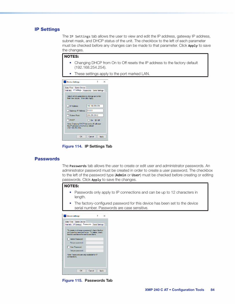
XMP 240 C AT • Configuration Tools 84
IP Settings The IP Settings tab allows the user to view and edit the IP address, gateway IP address, subnet mask, and DHCP status of the unit. The checkbox to the left of each parameter must be checked before any changes can be made to that parameter. Click Apply to save the changes.
NOTES:
• Changing DHCP from On to Off resets the IP address to the factory default (192.168.254.254).
• These settings apply to the port marked LAN.
Figure 114. IP Settings Tab
Passwords The Passwords tab allows the user to create or edit user and administrator passwords. An administrator password must be created in order to create a user password. The checkbox to the left of the password type (Admin or User) must be checked before creating or editing passwords. Click Apply to save the changes.
NOTES:
• Passwords only apply to IP connections and can be up to 12 characters in length.
• The factory-configured password for this device has been set to the device serial number. Passwords are case sensitive.
Figure 115. Passwords Tab

XMP 240 C AT • Configuration Tools 85
Serial Settings The Serial Settings tab allows users to change the baud rate of the rear panel RS-232 port. Click Apply to save the changes.
NOTE: The recommended baud rate for the XMP 240 C AT is 38400.
Figure 116. Serial Settings Tab
Date/Time
Figure 117. Date/Time Tab
To set the date and time:
1. Click the Set Local button to sync the date and time information with the date and time on the connected PC.
2. Set the time zone by using the Zone drop-down.
3. Use the Daylight Savings radio buttons to enter the daylight saving region, or leave off (default).
-or-
1. Click on the Set Date and Time check box.
2. Enter the desired date in the Date field. A drop-down calendar is available for date selection.
3. Enter the desired time in the Time field by clicking on the hours and entering the hour,

XMP 240 C AT • Configuration Tools 86
then clicking on the minutes and entering the number of minutes.4. Set the time zone by using the Zone drop-down.
5. Use the Daylight Savings radio buttons to enter the daylight saving region, or leave off (default).
NOTE: The information displayed in the Date/Time tab is static. In order to update the information to reflect the current time, click Refresh.
Dante Device This tab allows the XMP 240 C AT Dante settings to be configured within DSP configurator without opening Dante Controller.
Figure 118. Dante Device Tab in Device Settings Dialog Box
ATTENTION:
• It is essential that a Dante device be named immediately after it is connected to the Dante network and before audio connections with other devices are established. Existing connections are removed when a device is renamed.
• Il est essentiel d’identifier un appareil Dante immédiatement après sa connexion au réseau Dante et avant tout établissement de connexion audio avec d’autres appareils. Les connexions existantes sont supprimées dès qu’un appareil est renommé.
Dante Device Name
A Dante device can be renamed to identify the device on the audio network.
To assign the Dante device name:
1. Select Tools > Device Settings.
2. Use the arrows to navigate to the Dante Device tab (see figure 118).
3. Click the Device name text box.
4. Enter a device name for the Dante interface.
5. Click Apply. A confirmation dialog box opens.
6. Click Yes, to confirm existing connections will be removed after the name is changed.

XMP 240 C AT • Configuration Tools 87
Dante Device Network Settings
To configure Dante network settings:
1. Select the DHCP or Static IP radio buttons (see figure 118 on the previous page). If using DHCP, the XMP 240 C AT Dante interface will be assigned an IP address by the DHCP server and Dante network configuration is complete. If Static IP is selected, proceed to step 2.
2. Enter a valid network configuration into the respective fields.
3. Click Apply.
To reboot the Dante interface:
1. Click Reboot Dante. Only the Dante interface will reboot, not the entire XMP 240 C AT.
To refresh the device name and network configuration displayed:
1. Click Refresh to have DSP Configurator refresh information from the XMP 240 Dante interface.
Redundant Mode
In redundant mode, the 2-port AT switch becomes separate Primary and Secondary ports (see Redundant Configuration on page 96).
To enable redundant mode:
1. Click the Enable Redundant Mode checkbox.
2. By default, the DHCP radio button is selected to have the DHCP server assign a redundant network configuration. If necessary, select the Static radio button and enter the redundant network configuration in the text boxes that appear below.
NOTE: A valid redundant static network configuration must be entered.
OptionsThe Options dialog box allows the user to edit and reset default options for DSP Configurator color schemes, default processor and gain block behavior, as well as a number of other settings. For a comprehensive overview of the Options dialog box, see the DSP Configurator Help file.
Figure 119. Options Dialog Box
figure 67. Dante Tab in Device Settings Dialog Box
figure 68. Options Dialog Box

XMP 240 C AT • Configuration Tools 88
Expansion BusWith the Extron Expansion (EXP) port, two EXP-enabled devices can be connected for bidirectional streaming of up to 16 channels of audio. EXP inputs and outputs contain DSP (see Inputs Mix-Points on page 47 and Outputs on page 51).
Connecting the EXP PortsWhen connecting an XMP 240 C AT to another EXP-enabled device for EXP communication, the XMP 240 C AT is always set as the primary unit. The primary unit serves as the master clock for all EXP audio communication. The other unit must be set as a secondary unit in order for a connection to be established.
The following procedure describes how to set up a XMP 240 C AT model with another EXP-enabled non-AT device for EXP communication.
NOTE: Two XMP 240 devices cannot be connected via the EXP port because the XMP 240 can only be configured as a primary unit and cannot be set as a secondary unit. Instead, use the rear panel AT switch to connect the two devices over a Dante network (see Dante Controller on page 89).
Connecting an XMP 240 C AT Device and an EXP-enabled non-AT Device
1. Connect Live to the XMP 240 C AT.
2. Double-click on a DIG GAIN block (see Input Gain Block on page 24). The Input Gain dialog box opens.
3. From the Source drop-down list, select the desired source (see Input Gain Block on page 24).
4. Connect Live to the DMP 128 Plus non-AT. If connecting a DTP CrossPoint, proceed to step 6.
5. Select Tools > Expansion Bus and ensure Secondary Unit is selected.
NOTES:
• The XMP 240 C AT cannot be configured as a secondary unit. This means the DMP 128 Plus non-AT must be configured as a secondary unit.
• If both devices are configured as primary, an EXP connection cannot be established.
6. Use a CAT 6 cable (such as the 1 foot cable included with the XMP 240 C AT) to connect the two rear panel EXP ports.
7. When the connection is established, the front panel EXP LED on the primary unit lights steadily and the EXP LED on the secondary unit blinks rapidly.
NOTE: The DTP CrossPoint EXP LED is located on the rear panel next to the EXP port.
8. Open the Tools menu from the XMP 240 C AT main workspace and view the Expansion Bus status software LED (see figure 120, 1). The LED lights green when there is a valid connection.
Figure 120. Expansion Bus Software LED
figure 69. EXP Status LED

XMP 240 C AT • Dante Controller 89
Dante Controller
This section describes the XMP 240 C AT network installation, configuration, and control using Dante Controller for Windows and covers the following topics:
• Overview
• Downloading and Installing Dante Controller
• Configuring the XMP 240 C AT in Dante Controller
• Physical Dante Network Setup
• Dante Controller Operation
• Dante Routing Operation
• Dante Troubleshooting
OverviewXMP 240 C AT devices use Dante technology by Audinate to provide high performance digital audio networking over standard TCP/IP networks. The Dante Controller software application is used to route audio on the network. Dante allows audio channels to be transported across a switched Ethernet data network while meeting the quality requirements of professional audio.
Up to 48 channels can be transmitted from the XMP 240 C AT to the Dante network and up to 48 channels can be received by the XMP 240 C AT from the Dante network.
Audio signals are converted by XMP 240 C AT devices, processed and routed to the AT bus, and transmitted onto the Dante network. Audinate recommends the Dante audio network be kept separate from other networks. However, the audio network can be shared with control traffic or unrelated data traffic. Audio channels can be unicast or multicast to make the best use of available bandwidth.

XMP 240 C AT • Dante Controller 90
Downloading and Installing Dante ControllerDante Controller from Audinate is required to route transmitters and receivers and can be used to configure Dante settings and monitor performance. Install Dante Controller on a PC running Microsoft® Windows® 7 or newer. For full details about computer requirements and to download the software, see the Dante Controller product page at www.extron.com.
To download Dante Controller:
1. From www.extron.com, hover over the Download tab at the top of the page.
2. From the Featured Software list, select Dante Controller.
3. From the Dante Controller product page, click the blue Download button.
4. Select Run to run the Dante Controller installer. Select Save to save the install file to run at a later time.
5. If you choose to run the file, follow all prompts. If you saved the file, click the saved file to begin installation when ready.
The installed Dante Controller program files are saved in: C:\Program Files (x86)\Audinate\Dante Controller\DanteController.exe.
Configuring the XMP 240 C AT in Dante ControllerUse a standard Ethernet cable to connect the XMP 240 C AT to a Dante network via the rear panel AT port (see Rear Panel Features and Cabling, C on page 5) and power the device.
Device NameMultiple devices on the same Dante network can present difficulty in identifying individual devices. To avoid confusion and difficulty, ensure the following steps are taken:
• Connect devices to the Dante network one at a time.
• Rename each device before making audio connections in Dante Controller.
• Rename each device with a unique and meaningful identifier.
• Rename each device before the next device is connected to the Dante network.
ATTENTION:
• It is essential that a Dante device be named before audio subscriptions with other devices are established. Existing subscriptions are removed when a device is renamed.
• Il est essentiel d’identifier un appareil Dante immédiatement après sa connexion au réseau Dante et avant tout établissement de connexion audio avec d’autres appareils. Les connexions existantes sont supprimées dès qu’un appareil est renommé.
In Dante Controller, a device can be renamed to identify the device on the audio network. The default device name of the XMP 240 C AT consists of the model name, followed by the last six characters of the Dante interface MAC address (for example, XMP240-0ee8ee). In addition to renaming the device, individual Transmitter (Tx) and Receiver (Rx) channels can be renamed.
The Dante device name must be set before making any connections to other devices on the Dante network. Renaming a device after making connections removes existing connections to and from that device. Refer to Renaming the XMP 240 C AT in Dante Controller on the next page for renaming procedure.

XMP 240 C AT • Dante Controller 91
Receiver and Transmitter NamesIn addition to renaming a device, individual transmitter and receiver channels can be renamed in Dante Controller. Rename transmitter and receiver channels to reflect the location of the device or the purpose of the transmitter or receiver. Ensure transmitter and receiver channels are renamed before making audio connections between devices. Refer to Renaming a Receiver or Transmitter on page 93 for renaming procedure.
Dante Controller Naming Conventions• Device names follow Domain Name System (DNS) hostname rules. Legal characters are
A-Z, a-z, 0-9, and hyphen (-). Names must begin with a letter and cannot end with a hyphen (-).
• Dante Tx and Rx channel names (also known as labels) can be up to 31 characters in length. Label names are not case-sensitive. For example, “ANALOG OUT-1” and “analog out-1” are recognized as the same name. Unicode and non-roman characters are not supported.
• Tx and Rx channel labels can use any character except equals (=), period (.), or @.
• Tx and Rx channel labels must be unique on a device but do not need to be unique on the network.
Renaming the XMP 240 C AT in Dante ControllerNOTE: Dante device naming can also be done via DSP Configurator (see Dante Device
on page 86).
1. Ensure that the control computer and a single XMP 240 C AT are connected to the same network.
2. From the control computer Start menu select: All Programs > Audinate > Dante Controller > Dante Controller
3. The Dante Controller - Network View screen opens. All Dante devices on the network are discovered and listed.
4. From the Device menu, select Device View or press <Ctrl+D> on the keyboard (see figure 121).
Figure 121. Opening Device View
70 Opening Device View
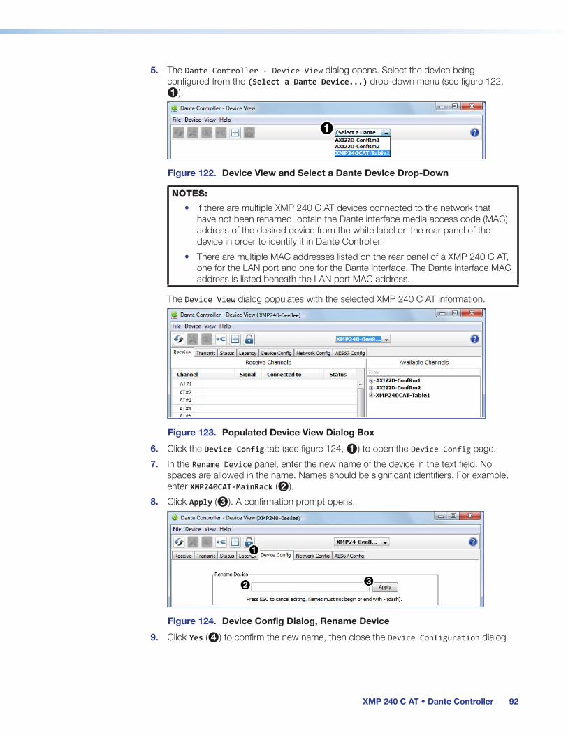
XMP 240 C AT • Dante Controller 92
5. The Dante Controller - Device View dialog opens. Select the device being configured from the (Select a Dante Device...) drop-down menu (see figure 122, 1).
Figure 122. Device View and Select a Dante Device Drop-Down
NOTES:
• If there are multiple XMP 240 C AT devices connected to the network that have not been renamed, obtain the Dante interface media access code (MAC) address of the desired device from the white label on the rear panel of the device in order to identify it in Dante Controller.
• There are multiple MAC addresses listed on the rear panel of a XMP 240 C AT, one for the LAN port and one for the Dante interface. The Dante interface MAC address is listed beneath the LAN port MAC address.
The Device View dialog populates with the selected XMP 240 C AT information.
Figure 123. Populated Device View Dialog Box
6. Click the Device Config tab (see figure 124, 1) to open the Device Config page.
7. In the Rename Device panel, enter the new name of the device in the text field. No spaces are allowed in the name. Names should be significant identifiers. For example, enter XMP240CAT-MainRack (2).
8. Click Apply (3). A confirmation prompt opens.
Figure 124. Device Config Dialog, Rename Device
9. Click Yes (4) to confirm the new name, then close the Device Configuration dialog
71 Device View and Select a Dante Device Drop-Down
72 Populated Device View Dialog Box
73 Device Config, Rename Device

XMP 240 C AT • Dante Controller 93
box. The new name is written to the Dante interface of the XMP 240 C AT. Repeat as necessary for all devices.
NOTE: The device name assigned in Dante Controller only applies to the Dante interface and does not affect the device name recognized in DSP Configurator.
Figure 125. Rename Device Confirmation Dialog Box
Renaming a Receiver or TransmitterIn addition to renaming devices, individual receiver and transmitter channels can be renamed in Dante Controller. To better organize the various receivers and transmitters, it is recommended each receiver and each transmitter be named using a description of the device they belong to, the location of the device, or the purpose of the receiver or transmitter.
To view the receiver or transmitter channels in Dante Controller, click the + sign next to the receiver or transmitter device name to expand it. The + sign becomes a – sign when the device is expanded (see figure 126, 1).
Figure 126. Expanded Device View — Input and Output Names
TIP: To simplify setup and operation of large matrix systems, rename the receiver and transmitter channels to better indicate the source at the transmitters or receivers.
74 Rename Device Confirmation Dialog Box

XMP 240 C AT • Dante Controller 94
Renaming a Receiver
The default names shown in the Dante Receivers column are extracted from the Dante interface of the connected device (see figure 127, 1). The XMP 240 C AT receivers are labelled AT#1 through AT#48. Follow the instructions on the next page to rename a receiver.
To rename a XMP 240 C AT receiver:
1. From the Device menu on the Network View screen, select Device View, or press <Ctrl+D> on the keyboard. The Device View dialog box opens.
2. From the (Select a Dante Device..) drop-down menu, select the name of the desired XMP 240 C AT (see figure 127, 1).
3. On the Device View screen, select the Receive tab (2).
4. Click on the name of the receiver to be renamed. The name becomes a text box with a cursor (3).
5. Enter the new name (up to 31 characters) using any combination of letters, numbers, and special characters except for @, =, and . (period).
6. Press <Enter> on the keyboard to confirm the name, or click another channel text box.
7. Repeat steps 4 through 6 to rename additional receiver channels.
8. When finished renaming receivers, close the Device View dialog box.
Figure 127. Device View Screen — Renaming a Receiver
Renaming a Transmitter
The default names shown in the Dante Transmitters column are extracted from the Dante interface of the connected device (see figure 126, 2 on the previous page). The XMP 240 transmitters are labelled Exp_Out-01 through Exp_Out-48. Follow the instructions on the next page to rename a transmitter.
To rename a XMP 240 C AT transmitter:
1. Select Device View from the Device menu on the Network View screen or press <Ctrl+D> on the keyboard. The Device View dialog box opens.
2. From the (Select a Dante Device...) drop-down menu, select the name of the XMP 240 C AT (see figure 128, 1 on the next page).
3. On the Device View screen, select the Transmit tab (2).
4. Click in the Channel Label column to the right of the name of the transmitter being renamed. A text box and cursor appear (3).
5. Enter a new name (up to 31 characters) using any combination of letters, numbers, and special characters except for @, =, and . (period).
6. Press <Enter> on the keyboard to confirm the name, or click another label text box.
7. Repeat steps 4 through 6 to rename additional transmitter channels.
8. When finished renaming transmitters, close the Device View dialog box.

XMP 240 C AT • Dante Controller 95
Figure 128. Device View Screen — Renaming a Transmitter
Finding a Dante Device IP AddressTo find the IP address of a Dante device, the name of the device is needed (see Renaming the XMP 240 C AT in Dante Controller on page 91).
NOTE: If the XMP 240 C AT has not been renamed, its default name consists of the product name followed by a hyphen, plus the last 6 digits of the device MAC address (for example, XMP240CAT-0ee8ee).
1. Open Dante Controller.
2. On the Dante Controller-Network View screen, click the Device Info tab (see figure 129, 1).
3. On the Device Info page, locate the name of the XMP 240 C AT in the Device Name column (2). The IP address is located in the Primary Address column (3). In the example below, the IP address for the connected XMP 240 C AT is 192.168.11.120.
Figure 129. Device Info Page
75 Device Info Page

XMP 240 C AT • Dante Controller 96
Physical Dante Network SetupA physical network is required to share Dante audio channels between Dante-enabled devices like the XMP 240 C AT. Other Dante-enabled devices must be on the same physical network in order to communicate via Dante. A daisy chain topology can be used to connect multiple devices.
Daisy Chain topology has XMP 240 C AT units connected in succession.D
MP
EX
P
AT
RE
MO
TE
R
LAN1 (PRI) PoE 2 (SEC)
RS-232
Tx Rx G
POWER 12V 1.0A MAX
XMP 240 C ATD
MP
EX
P
AT
RE
MO
TE
R
LAN1 (PRI) PoE 2 (SEC)
RS-232
Tx Rx G
POWER 12V 1.0A MAX
XMP 240 C AT
DM
P E
XP
AT
RE
MO
TE
R
LAN1 (PRI) PoE 2 (SEC)
RS-232
Tx Rx G
POWER 12V 1.0A MAX
XMP 240 C AT
DM
P E
XP
AT
RE
MO
TE
R
LAN1 (PRI) PoE 2 (SEC)
RS-232
Tx Rx G
POWER 12V 1.0A MAX
XMP 240 C AT
Ethernet
Figure 130. Daisy Chain Network Topology
NOTE: The daisy chain topology only functions in switched mode. It is not possible to use it in redundant mode.
Redundant ConfigurationIn redundant mode, the 2-port AT switch becomes two separate primary and secondary ports that duplicate audio traffic. Port 1 is marked (PRI) for primary while port 2 is marked (SEC) for secondary (see figure 131). Primary and secondary switches/ports cannot be connected together anywhere in the audio network. Redundant configuration can be enabled using Dante Controller or DSP Configurator.
POWER12V 2.0 A MAX
1 2 3 41 2 5 6 7 8
1 (PRI) POE C V A T1 2
RS-232 R
Tx Rx G+V +S -S GDM
P E
XP
AT
AC
P
LAN
/Vo
IP
USB AUD
INP
UTS
1 2 3 4
2 (SEC)
I/O
OU
TS
RE
MO
TE
IN G O IN G O
Primary Port Secondary Port
Figure 131. Primary and Secondary AT Ports
76 Physical Dante Network Diagram
77 Primary and Secondary Ports

XMP 240 C AT • Dante Controller 97
To configure the XMP 240 C AT in redundant mode using Dante Controller:
1. Open Dante Controller.
2. Press <Ctrl+D> on the keyboard to access the Device View dialog box.
3. Select the desired XMP 240 C AT from the (Choose a Dante Device...) drop-down menu (see figure 132, 1).
4. Select the Network Config tab (2).
5. From the Dante Redundancy panel, use the drop-down to select Redundant (3).
Figure 132. Redundant Mode Configuration in Dante Controller
To configure the XMP 240 C AT in redundant mode using DSP Configurator:
1. Use DSP Configurator to connect to the XMP 240 C AT in Live mode (see Live and Emulate Panel on page 17).
2. Select Tools > Device Settings.
3. In the Device Settings dialog box, use the right navigation arrow ( ) to navigate to and select the Dante Device tab (see figure 133, 1).
4. Select Enable Redundant Mode (2).
5. Select DHCP or Static IP and enter a valid redundancy network configuration (3).
6. Click Apply (4).
Figure 133. Redundant Mode Configuration in DSP Configurator
78 Redundant config in Dante Cont
79 Redundant Mode DSPC

XMP 240 C AT • Dante Controller 98
Dante Controller Operation
Dante Transmitters and ReceiversA Dante network is comprised of transmitters that output digital audio onto the Dante network and receivers that receive digital audio input from the Dante network.
• Transmitters output digital audio from the device onto the audio network.
• Receivers take in digital audio from the audio network into the device.
XMP 240 C AT Transmitters and Receivers
In the XMP 240 C AT, all output channels are Dante transmitters because their audio output is transmitted onto the Dante network. Routing a signal to any of the first 16 outputs allows the signal to be output on both Dante and EXP simultaneously.
The XMP 240 C AT EXP input channels are Dante receivers because they receive digital audio signal from the Dante network that can then be selected as sources for the XMP 240 C AT inputs.
Dante Routing OperationDante Controller is used for all network signal routing of transmitters and receivers for Dante-enabled devices. The XMP 240 C AT transmitters and receivers are available in Dante Controller for routing to other Dante devices (see Dante Transmitters and Receivers above).
Routing DevicesAfter the XMP 240 C AT is configured, the channels can be routed to the other Dante devices on the audio network. Channels transmitted to the network or received from the network are routed using the Dante Controller Routing tab on the Network View page (see figure 134 on the next page). The transmitters, listed horizontally along the top of the screen, and the receivers, listed vertically down the left side, form a matrix whose intersections are the connection points between the receivers and transmitters.
• To make a receiver-to-transmitter connection, click once on an intersection.
• To remove a connection, click on the icon at the intersection.
One of the following icons appears at each connection intersection, indicating the status of both the transmitter and receiver channels and the connections (subscriptions):
Icon Description
Indicates an active subscription.
Indicates subscription is in progress.
Indicates a pending subscription.
Indicates a broken subscription.
Indicates the transmitting device has been removed from the network or is switched off.
See the Dante Controller User Guide, available at www.audinate.com, for additional information.

XMP 240 C AT • Dante Controller 99
Creating Subscriptions Between Transmitters and Receivers
1. Ensure the control computer and XMP 240 C AT are connected to the same network.
2. From the start menu select: All Programs > Audinate > Dante Controller > Dante Controller
The Dante Controller - Network View screen opens.
Dante Controller auto-discovers Dante devices on the network and advertises itself to allow other Dante-enabled devices to communicate with it. Transmitters connect to receivers using the subscription matrix.
Figure 134. Routing Tab of Network View Screen
3. To show the transmitters of a Dante device, click the + box next to the desired device in the Dante Transmitters panel, such as AXI22D-ConfRm1 (see figure 134, 1). The + changes to a – sign when the device expands.
4. To show the receivers of a Dante device, click the + box next to the desired device in the Dante Receivers panel, such as XMP240CAT-MainRack (2).
5. Click the intersection of the desired subscription between a transmitter and a receiver (3).
Example: The mic/line input transmitters of the AXI22D-ConfRm1 and AXI22D-ConfRm2 are routed to the AT input receivers of the XMP240CAT-MainRack.
A check mark at the intersection indicates the subscription is made. A check mark also appears next to the receiver channel.
NOTE: A receiver can subscribe to only one transmitter. A transmitter can subscribe to multiple receivers.
80 Routing Tab of Network View Screen

XMP 240 C AT • Dante Controller 100
Disconnecting Inputs from OutputsTo undo routing, click the junction again to disconnect the receiver from the transmitter.
NOTE: After making changes to Dante network routing such as subscriptions, device names, or channel labels, wait at least 5 seconds before disconnecting or powering down the devices. This ensures that the new information is properly saved to those devices. Device level configuration such as sample rates, latency, and clock settings are saved instantly.
Sending SIS Commands to Dante Audio Interface Devices through the XMPThe XMP 240 C AT can be set to pass through SIS commands to connected Dante-controlled Extron devices (see Dante Control and Configuration on page 120 for the list of SIS commands).
To send an SIS command to an AXI device connected to a XMP 240 C AT:
1. Connect the XMP 240 and Dante-controlled devices to the same network via their AT ports (see Physical Dante Network Setup on page 96).
2. Connect to the XMP 240 via the DataViewer or HyperTerminal utility (see Remote Communication and Control on page 103).
3. Use the Set verbose mode command to set the XMP 240 to Verbose mode 3 (see Set verbose mode on page 112). Example: Command Response
w3cv| Vrb3
4. Use the Query available remote devices command (see Query available remote devices on page 120) to receive a list of Dante devices that are currently connected to the XMP. Example: Command Response
waexpr| ExprA•AXI-XTP-RoomA] AXI-XTP-RoomB]]
NOTE: This list is similar to the list displayed within Dante Controller.
5. Use the Enable remote connection command to display the remote Dante-controlled device responses based on the list of devices provided in the response in step 4 (see Enable remote connection for listening on page 120). Repeat if necessary for all desired devices. Example: Command Response
wcAXI02-XTP-RoomA*1expr| ExprCAXI-XTP-RoomA*1]
NOTE: AXI devices can be set up for listening even if not currently connected to the XMP unit.
6. To verify that the XMP is listening to the correct remote devices, use the Query remote devices being listened to command to display a list of all remote devices enable with the command in step 5 (see Query remote devices being listened to on page 120). Example: Command Response
wlexpr| ExprL•AXI-XTP-RoomA]

XMP 240 C AT • Dante Controller 101
7. Send the desired command to the AXI and confirm the correct response is received.
• When entering a command, use the “w” character in place of the <Esc> key and the “pipe” character ( | ) in place of a return. Failing to do so may cause the command to fail.
• The closing bracket ( } ) is necessary to successfully end a command before attempting to send a new command. Example: Command Response
{dante@AXI02-XTP-RoomA:wg40000*30AU|}| {dante@AXI-XTP-RoomA}DsG40000*30]
NOTE: The XMP provides the tag showing the Dante-controlled remote device name while the remote device provides the response for the SIS command.
Dante TroubleshootingThe most common Dante troubleshooting issues occur when devices are not discovered by Dante Controller or when routing is not successful. Both issues occur when software is not able to properly discover devices operating on the Dante network.
Before moving into more difficult troubleshooting, shut down Dante Controller and reseat the Ethernet cable connecting the PC to the Dante network and restart Dante Controller. This can be enough for the software to reacquire the Dante network.
If the problem persists, perform the following troubleshooting procedures in the order listed.
Simplifying the Network for TroubleshootingIf further troubleshooting of Dante Controller is necessary, begin by simplifying the network:
1. Bypass network switches by connecting two Dante-compatible units, such as an XMP 240 C AT and a DMP 128 FlexPlus, via their AT ports.
2. Connect the PC to an unused AT port with an Ethernet cable.
3. Use Dante Controller to check if the issue was resolved before moving on to network interface troubleshooting.
4. If the issue is resolved, add connections and hardware one at a time, checking for proper operation after each addition, until the point of failure is discovered (typically a bad cable or invalid redundant configuration).
Troubleshooting the Network InterfaceIf the issue is still present, continue to diagnose the PC network connections as described below. Check Dante Controller after each step to see if the problem is resolved.
1. Click the Choose a Dante Interface icon (see figure 135, 1). The Configure Dante Interfaces dialog box opens.
Figure 135. Choose a Dante Interface Icon
81 Choose a Dante Interface Icon

XMP 240 C AT • Dante Controller 102
Be certain the correct LAN connection is selected (the PC LAN port that is physically connected to the AT network) and note the IP address.
Figure 136. Configure Dante Interfaces Dialog Box
2. If it is on, turn off the PC wireless adapter. Disable all connections except the LAN port connected to the Dante network (verify this is the correct port by checking the IP address shown in the Configure Dante Interfaces dialog).
3. Turn off all anti-virus and firewall software on the computer.
4. Enable DHCP on the remaining network connection. This forces the computer to acquire an IP address from the Dante interface.
NOTE: A DHCP server must be on the network for DHCP to function correctly.
Restarting Dante ControllerIf subscriptions or normal operation cannot be restored, restart Dante Controller software. To access the Dante Controller Help file, do any of the following:
• Click the Help icon in the upper-right corner of the Network View screen (see figure 137, 1).
• Select Help, then Online Help or Offline Help from the menu (2).
• Press the <F1> key on the computer keyboard for online help or <Shift+F1> for offline help.
Figure 137. Accessing the Dante Help File
82 Configure Dante Interfaces Dialog Box
83 Accessing the Dante Help File

XMP 240 C AT • Remote Control and Configuration 103
Remote Communication and Control
This section describes how to control the XMP 240 C AT with SIS programming and covers the following topics:
• Connection Options
• Host-to-Device Communications
• SIS Overview
• Command and Response Table for Basic SIS Commands
• Command and Response Table for DSP SIS Commands
• Object ID (OID) Number Tables
Connection OptionsThe XMP 240 C AT Expansion Matrix Processor can be remotely connected via a host computer or other device (such as a control system) attached to the rear panel RS-232 port or LAN port, or the front panel USB Config port.
The XMP 240 C AT can be set up and controlled using SIS commands or DSP Configurator software (see Installation on page 4 for pin assignments and details on the configuration and control port connections. For information on DSP Configurator, see DSP Configurator Software on page 10).
SIS commands can be executed using the Extron DataViewer application available from www.extron.com. The host computer issuing the commands can be connected via the following connections:
• RS-232 Port on the next page
• LAN Port on the next page
• USB Config Port on page 105

XMP 240 C AT • Remote Control and Configuration 104
RS-232 PortThe XMP 240 C AT has a serial port that can be connected to a host device such as a computer running either the DataViewer or HyperTerminal utilities. The port makes serial control of the XMP 240 C AT possible.
The XMP 240 C AT uses the following RS-232 protocols:
• 38400 baud • No parity • 1 stop bit
• 8 data bits • No flow control
NOTES:
• The rear panel configuration port requires 38400 baud communication. This speed is higher than most other Extron products. The XMP 240 C AT control software automatically sets the connection for the appropriate speed. When using DataViewer or similar application, make sure the host PC or control system is set for 38400 baud.
• See Rear Panel Features and Cabling on page 4 for additional details on connecting to the RS-232 port.
LAN PortThe XMP 240 C AT can be connected to an Ethernet LAN or WAN. Communication between the device and the controlling device is via Telnet (a TCP socket using port 23). The Telnet port can be changed, if necessary, via SIS. This connection makes SIS control of the device possible using a computer connected to the same LAN or WAN. The SIS commands and behavior are identical to the commands and behavior the product exhibits when communicating by serial port or USB.
The XMP 240 C AT LAN 1 port defaults are as follows:
IP Address Subnet Mask Default Gateway DHCP192.168.254.254 255.255.255.0 0.0.0.0 OFF
The Ethernet cable can be terminated as a straight-through cable or a crossover cable and must be properly terminated for your application.
• Crossover cable — Direct connection between the computer and the XMP 240 C AT.
• Straight-through (Patch) cable — Connection of the XMP 240 C AT to an Ethernet LAN.
12345678
RJ-45Connector
Insert TwistedPair Wires
Pins:
A cable that is wired as TIA/EIA T568A at one end and T568B at the other (Tx and Rx pairs reversed) is a "crossover" cable.
A cable wired the same at both ends is called a "straight-through" cable because no pin/pair assignments are swapped.
T568A T568B T568B T568B
Straight-through Cable(for connection to a switch, hub, or router)
End 1 End 2 Pin Wire Color Pin Wire Color
1 white-orange 1 white-orange 2 orange 2 orange 3 white-green 3 white-green 4 blue 4 blue 5 white-blue 5 white-blue 6 green 6 green 7 white-brown 7 white-brown 8 brown 8 brown
Crossover Cable(for direct connection to a PC)
End 1 End 2 Pin Wire Color Pin Wire Color
1 white-orange 1 white-green 2 orange 2 green 3 white-green 3 white-orange 4 blue 4 blue 5 white-blue 5 white-blue 6 green 6 orange 7 white-brown 7 white-brown 8 brown 8 brown
Figure 138. RJ-45 Ethernet Connector Pin Assignments
figure 84. RRJ-45

XMP 240 C AT • Remote Control and Configuration 105
Establishing a Network Connection via LAN
1. Open a TCP socket to port 23 using the XMP 240 C AT IP address.
NOTE: If the local system administrators have not changed the value, the factory specified default, 192.168.254.254, is the correct value for this field.
2. The XMP 240 C AT responds with a copyright message including the date, the name of the product, firmware version, part number, and the current date/time.
3. If the device is password protected, enter the appropriate administrator or user password.
a. If the password is accepted, the device responds with Login User or Login Administrator.
b. If the password is not accepted, the Password prompt reappears.
NOTES:
• The factory configured password for this device has been set to the device serial number. Passwords are case sensitive. Resetting the device sets the password to default (no password).
• The Ethernet link times out after a designated period of time of no communications. By default, the timeout value is set to 5 minutes and can be changed (see Set global IP port timeout on page 110).
• Extron recommends leaving the default timeout at 5 minutes and periodically issuing the Query (Q) command to keep the connection active. If there are long idle periods, disconnect the socket and reopen the connection when another command must be sent.
USB Config PortThe XMP 240 C AT has a front panel USB port that can be connected to a computer as a host device running DataViewer utilities for control of the device. Once a connection is established, SIS programming can begin (see Host-to-Device Communications on the next page).
Verbose ModesThe connection to an XMP 240 C AT can be used to monitor for changes that occur on the device, such as SIS commands from a TCP/IP connection or the RS-232 serial port. To receive change notices from the device, you must enable verbose mode 1 or 3 (see Set verbose mode on page 112). In verbose mode 1 or 3, the connection reports changes in messages that resemble SIS command responses.
Tagged and Untagged Responses
When a query command is sent in verbose mode 0 or 1, only the “untagged” value is returned. When a query command is sent in other verbose modes, the response is “tagged” and resembles the response to a set command.
Example: The gain query command EG40000AU} is sent. The following responses appear depending on the verbose mode:
• Untagged (verbose 0 or 1): 626], just the gain value with no other information.
• Tagged (verbose 2 or 3): DsG40000*626], the type of query sent, the OID queried, and the gain value.
NOTE: All query responses listed in this guide are shown untagged unless marked otherwise.

XMP 240 C AT • Remote Control and Configuration 106
Host-to-Device CommunicationsSIS commands consist of one or more characters per field. No special characters are required to begin or end a command sequence. When the scaler determines that a command is valid, it executes the command and sends a response to the host device. All responses from the device to the host end with a carriage return and a line feed (CR/LF = ]), indicating the end of the response character string (one or more characters).
XMP 240 C AT-initiated MessagesThe XMP 240 C AT initiates messages under specific conditions. No response is required from the host. The XMP 240 C AT-initiated messages are listed below.
Copyright Message
The XMP 240 C AT initiates the following copyright message when it is first powered on or when a connection via IP is established:
(c) Copyright 2020, Extron Electronics, XMP 240 C AT, Vn.nn, 60-nnnn-nn]
Day, DD MMM YYYY HH:MM:SS]• Vn.nn is the firmware version number.
• 60-nnnn-nn is the XMP 240 C AT part number.
The XMP 240 C AT sends the boot and copyright messages under the following circumstances:
• If the XMP 240 C AT is off and RS-232 connection is already set up (the PC is cabled to the XMP 240 C AT and a serial communication program such as DataViewer is open), the connected unit sends these messages via RS-232 when first powered on.
• The XMP 240 C AT sends the boot and copyright messages when a Telnet connection to the XMP 240 C AT is opened via Telnet, but not via RS-232. If using a Telnet connection, the copyright message, date, and time may be followed by a password prompt.
Password Prompt
The ]Password prompt requires an administrator or user password followed by a carriage return. The prompt is repeated if the incorrect password is entered.
If the correct password is entered, the unit responds with ]Login Administrator] or ]Login User] depending on the password entered. If passwords are the same for both administrator and user, the unit will default to administrator privileges.

XMP 240 C AT • Remote Control and Configuration 107
SIS Overview
Using the Command and Response TablesWhen programming, certain characters are more conveniently represented by their hexadecimal rather than ASCII values. The table below shows the hexadecimal equivalent of each ASCII character:
•
Space
l
I
ASCII to HEX Conversion Table
Figure 139. ASCII to Hex Conversion Table
The Command and Response tables list valid ASCII commands, the XMP 240 C AT responses to the host, and descriptions of the command functions with the results of executing the commands.
Symbol Definitions
] = Carriage return (with line feed)
} = Carriage return (no line feed)
• = Space character
| = Pipe (can be used interchangeably with the } character)
E = Escape key
W = Can be used interchangeably with the E character.
NOTES:
• Only instances marked with a • character require a space. Any spaces between characters in the command and response tables are only inserted for ease of reading.
• Unless stated otherwise, SIS commands are not case sensitive.
figure 85. ASCII to Hex

XMP 240 C AT • Remote Control and Configuration 108
Error ResponsesWhen the XMP 240 C AT is unable to execute the command, it returns an error response to the host. The error response codes and their descriptions are as follows:
E10 — Unrecognized command E22 — Busy
E12 — Invalid port number E24 — Privilege violation
E13 — Invalid parameter E25 — Device not present
E14 — Not valid for this configuration E26 — Maximum number of connections exceeded
E17 — Invalid command for signal type E27 — Invalid event number
E18 — System/command timed out E28 — Bad filename or file not found
Simple Control Port CommandsUpper and lower case text can be used interchangeably except where noted. Port 23 is the default port for Telnet. Port 80 is the default port for web browsers. Both can be mapped to different ports.

XMP 240 C AT • Remote Control and Configuration 109
Command and Response Table Sections
Command and Response Table for Basic SIS CommandsCommand ASCII command
(host to device)
Response
(device to host)
Additional description
Firmware Version / Part Number / Information Queries
General Information (Advanced)
X56^ I {Specific Information} ] – see X56^
Verbose mode 2/3: Inf X56^*{Specific Information} ]
Query Firmware Version Q {version x.xx} ] Verbose mode 2/3: Ver01* {version x.xx} ]
Query Firmware Version (w/build)
*Q {version x.xx.xxxx} ]
Verbose mode 2/3: Bld {version x.xx.xxxx} ]
Query Firmware Version (Advanced)
X4% Q {Specific Version Info} ] – see X4% list
Verbose mode 2/3: Ver X56& *{Specific Version Info} ]
Query Part Number N zz-zzzz-zz ] Verbose mode 2/3: Pno zz-zzzz-zz ]
KEY:
X4% = Firmware Query 0 = Detailed version information (includes all 2Q, 3Q, and 4Q)1 = Firmware version2 = Final stage bootloader3 = Factory base code version4 = Updated firmware version
X56^ = General Information Query 1 = Model Name (e.g. XMP 240 C AT) 2 = Model Description (e.g. Dante Audio Matrix Processor with AEC) 3 = System memory Usage (# of Bytes Used out of # of Kbytes)4 = User Memory Usage [ # Bytes Used out of # Kbytes ]

XMP 240 C AT • Remote Control and Configuration 110
Command ASCII command
(host to device)
Response
(device to host)
Additional description
Ethernet Data Port
Set current connected port timeout
E0*X6(TC} Pti0*X6(]
View current connected port timeout
E 0TC} X6(]
Set global IP port timeout
E1*X6(TC} Pti1*X6(]
View global IP port timeout
E1TC} X6(]
KEY:
X6( = The number of seconds before timeout on IP connections: (min = 1, max = 65000 & default = 30 = 300 seconds)
Serial Data Port
Configure parameters E1*X2%,X2^,X2&,X2* CP} Cpn1•CcpX2%,X2^, X2&,X2*]
View parameters E1CP} X2%,X2^,X2&,X2*]
View mode E1CY} X2(]
Configure flow control E1*X3),X3!CF} Cpn1•CflX3),X3!]
View flow control E1CF} X3),X3!]
KEY:
X1& = General Information Query
X2% = Baud rate: 300, 600, 1200, 1800, 2400, 3600, 4800, 7200, 9600, 14400, 19200, 28800, 38400, 57600, 115200 (default = 9600)
X2^ = Parity Odd, Even, None, Mark, Space Only use the first letter (default = N = None)
X2& = Data bits 7, 8 (default = 8)
X2* = Stop bits 1, 2 (default = 1)
X2( = Port type 0 = RS-232, 1 = RS-422, 2 = RS-485 (default = 0 = RS-232)
X3) = Flow control Hardware, Software, None [only use the first letter](default = N = None)
X3! = Data Pacing [specified in milliseconds between bytes]: 0000 – 1000 (default = 0 ms).For host ports, this value is ignored – always returns 0

XMP 240 C AT • Remote Control and Configuration 111
Command ASCII command
(host to device)
Response
(device to host)
Additional description
IP Setup Commands
Set unit name EX1@CN} Ipn•X1@]Set unit name to factory default
E•CN} Ipn•X4(]
View unit name ECN} X1@]Set date/time EX1#CT} Ipt•X1#]View date/time ECT} X1#]View date/time in hex E*CT} X6%]View GMT offset ECZ} X#] Verbose modes 2/3
IpzX#]Set DHCP on E1DH} Idh1]Set DHCP off E0DH} Idh0]View DHCP mode EDH} X1$]
NOTE: The following commands affect the LAN 1 port.
Set IP address EX1$CI} Ipi•X1$]View IP address ECI} X1$]View hardware address (MAC)
ECH} X1*] Verbose modes 2/3 IphX1*]
Set subnet mask EX33#CS} Ips•X33#]View subnet mask ECS} X33#]Set gateway IP address EX1$CG} Ipg•X1$]View gateway IP address
ECG} X1$]
KEY:
X# = Greenwich Mean Time (GMT) offset value (-12:00 to 14:00). This represent hours and minutes (hh:mm) offset from GMT
X1@ = Unit name is a text string up to 63 characters (24 before 2/2013) drawn from the alphabet (A-Z), digits (0-9), minus sign/hyphen (-)
X1# = Set local date and time format (MM/DD/YY-HH:MM:SS)
X1$ = IP address (xxx.xxx.xxx.xxx). Leading zeros in each of 4 fields are optional in setting values
X1* = Hardware (MAC) address (00-05-A6-xx-xx-xx)
X33# = Subnet Mask (xxx.xxx.xxx.xxx). Leading zeros in each of 4 fields are optional in setting values
X4( = Default Name Combination of model-name and last 3 pairs of MAC address (e.g. XMP-240-C-AT-00-02-3D)
X6% = Date/Time returned in 7 Hex bytes month, day, year, hour minutes, seconds, day of the week (1 begins on Sunday)

XMP 240 C AT • Remote Control and Configuration 112
Command ASCII command
(host to device)
Response
(device to host)
Additional description
IP Setup Commands (continued)
Set IP EX57^*X1$CISG} Cisg•X57^*X1$/X57&* X1$]
In all CISG commands, the first X1$ represents the IP address, X57^ represents the subnet mask, and the second X1$ represents the gateway IP address.
Set IP/subnet EX57^*X1$/X57& CISG}
Cisg•X57^*X1$/X57&* X1$]
Set IP/subnet/gateway EX57^*X1$*X33#*X1$ CISG}
Cisg•X57^*X1$/X57&* X1$]
Set IP/subnet/gateway (all)
EX57^*X1$/X57&*X1$ CISG}
Cisg•X57^*X1$/X57&* X1$]
View IP/subnet/gateway EX57^CISG} X1$/X57&* X1$]Set DNS server IP address
EX1$DI} Ipd•X1$]
View DNS server IP address
EDI} X1$]
Set verbose mode EX2@CV} VrbX2@]View Verbose mode ECV} X2@]Get connection listing ECC} {number of connections}] Verbose modes 2/3
Icc{number of connections}]
KEY:
X1$ = IP Address xxx.xxx.xxx.xxx . Leading zeros in each of the 4 fields are optional in setting values and are suppressed in responses.
X2@ = Verbose/Response Mode 0 = clear/none 1 = verbose mode 2 = tagged responses for queries 3 = verbose mode and tagged responses for queries
X57^ NIC (Network Interface Card) number (1)
X57& = Prefix (subnet mask bits) Subnet 255.255.0.0 is represented as a prefix value of /16

XMP 240 C AT • Remote Control and Configuration 113
Command ASCII command
(host to device)
Response
(device to host)
Additional description
Password and Security Settings
Set admin password EX3#CA} Ipa•X4!]Clear admin password E•CA} Ipa•]View admin password ECA} X4!]Set user password EX3#CU} Ipu•X4!]Clear user password E•CU} Ipu•]View user password ECU} X4!]Query session’s security level
ECK} X5@] Verbose modes 2/3 PvlX5@]
KEY:
X3# = Password 0-128 characters. All man-readable characters are permitted except “|”. Password cannot be a single space. Passwords are case-sensitive.
X4! Reading Password Responds with 4 asterisk (****) if password exists and empty if not, instead of actual password
X5@ = Connection’s security level 11 = user, 12 = administrator
NOTE: The factory configured password for this device has been set to the device serial number. Passwords are case sensitive.
Directories
Change/Create directory
Epath/directory/CJ}
Dir•path/directory/]
Back to root directory E/CJ} Dir•/]Up one directory E..CJ} Dir•path/directory/]View current directory ECJ} path/directory/]
File Commands
Erase user-supplied web page/file
EFilename EF} Del1 Filename]
Erase current directory and contained files
E/EF} Ddl]
Erase current directory and subdirectories
E//EF} Ddl]
List files from current directory
EDF} filenamex•date/time •length]
filenamex•date/time •length]
filenamex•date/time •length]...
space_remaining•bytes left]]
Responses for EDF} and ELF} are in the same format.
List files from current directory and below
ELF}

XMP 240 C AT • Remote Control and Configuration 114
Command ASCII command
(host to device)
Response
(device to host)
Additional description
Load file to user flash memory
E+UFfilesize, filename}
Upl]
Retrieve file from user flash memory
EfilenameSF} {responds with 4 bytes of file size and unprocessed data in file}
Backup/Restore Device Configuration
Save device configuration (to filesystem)
E1*{config type} XF}
Cfg1*{config type}]
Restore device configuration
E0*{config type} XF}
Cfg0*{config type}]
NTP (Network Time Protocol)
Enable NTP to set the time
E1NTEN} Nten1]
Disable NTP E0NTEN} Nten0]Sync NTP now E2NTEN} Nten2]View NTP status ENTEN} X3!]Set NTP IP address EX1$NTIP} NtipX1$]Reset NTP IP address E•NTIP} Ntip] Sets address to default
View NTP IP address ENTIP} X1$]Set NTP port map EN{port#}PMAP} PmapN{port#}]Reset NTP port map EN123PMAP} PmapN00123]Disable NTP port EN0PMAP} PmapN00000]View NTP port map ENPMAP} {port#}]
KEY:
X1$ = IP address (xxx.xxx.xxx.xxx). Leading zeros in each of 4 fields are optional in setting values

XMP 240 C AT • Remote Control and Configuration 115
Command ASCII command
(host to device)
Response
(device to host)
Additional description
Port Assignment
Set telnet port map E{port#}MT} Pmt{port#}]Reset telnet port map E23MT} Pmt00023]Disable telnet port E0MT} Pmt00000]View telnet port map EMT} {port#}]Set web port map E{port#}MH} Pmh{port#}]Reset web port map E80MH} Pmh00080]Disable web port map E0MH} Pmh00000]View web port map EMH} {port#}]Set SNMP port map EA{port#}PMAP} PmapA{port#}]Reset SNMP port map EA161PMAP} PmapA00161]Disable SNMP port EA0PMAP} PmapA00000]View SNMP port map EAPMAP} {port#}]Set SSH port map EB{port#}PMAP} PmapB{port#}]Reset SSH port map EB22023PMAP} PmapB22023]Disable SSH port EB0PMAP} PmapB00000]View SSH port map EBPMAP} {port#}]Set SSL port map ES{port#}PMAP} PmapS{port#}]Reset SSL port map ES443PMAP} PmapS00443]Disable SSL port ES0PMAP} PmapS00000]View SSL port map ESPMAP} {port#}]Set FTP port map EF{port#}PMAP} PmapF{port#}]Reset FTP port map EF21PMAP} PmapF00021]Disable FTP port EF0PMAP} PmapF00000]View FTP port map EFPMAP} {port#}]Set TFTP port map ET{port#} PMAP} PmapT{port#}]Reset TFTP port map ET69PMAP} PmapT00069]Disable TFTP port map ET0PMAP} PmapT00000]View TFTP port map ETPMAP} {port#}]

XMP 240 C AT • Remote Control and Configuration 116
Command ASCII command
(host to device)
Response
(device to host)
Additional description
SNMP (Simple Network Management Protocol)
Set unit contact ECX58!SNMP} SnmpC*X58!]Set unit contact to default
EC•SNMP} SnmpC* Not•Specified]
View unit contact ECSNMP} X58!]Set unit location ELX58!SNMP} SnmpL*X58!]Set unit location to default
EL•SNMP} SnmpL* Not•Specified]
View unit location ELSNMP} X58!]Set community public (read-only)
EPX58!SNMP} SnmpP*X58!]
Set community public to default
EP•SNMP} SnmpP*public]
View community public EPSNMP} X58!]Set community private (read/write)
EXX58!SNMP} SnmpX*X58!]
Set community private to default
EXSNMP•X58!} SnmpX*private]
View community private EXSNMP} X58!]Enable SNMP access and traps
EE1SNMP} SnmpE*1]
Disable SNMP access and traps
EE0SNMP} SnmpE*0]
View SNMP access setting
EESNMP} X8#]
KEY:
X8# = 0 = Disable; 1 = Enable
X58! = Text – up to 64 characters
Reboot Commands
Reboot system E1BOOT} Boot1]Reboot network E2BOOT} Boot2]

XMP 240 C AT • Remote Control and Configuration 117
Command ASCII command
(host to device)
Response
(device to host)
Additional description
Serial Host Control Port Mode
Standard host control (SIS)
EX!*1HSTM} HstmX!*1]
Device control (no SIS) EX!*2HSTM} HstmX!*2]Disable port EX!*0HSTM} HstmX!*0]Query port mode EX!HSTM} X8%]
KEY:
X! = Specific port number (01-99)
X8% = Serial Host-control port mode
0 = Device Control (no SIS), 1 = Standard Host control (Default = SIS), 2 = Disable Port
Ping
Execute test E{address/name} PING}
{address}*{bytes}* {ttl}*{time}]
Verbose modese 2/3 {ping}•{name}* {address}*{bytes}* {ttl}*{time}]
Example: E192.168.254.254 PING}
192.168.254.254*64* 64*3.469
If ping fails to get reply from address
{address}*0*0*0] {ping}•{name}* {address}*0*0*0]
Timezone and Daylight Settings
Set time zone E{zone name}* TZON} Tzon•{zone name, description}]
View current time zone ETZON} {zone name, description}]
List all time zones E*TZON} {zone name, description}]
...]
...]]Display Environmental Variables
View EEPROM Parameters
ENVPR} {JSON formatted tag-value pairs of various info}]

XMP 240 C AT • Remote Control and Configuration 118
Command ASCII command
(host to device)
Response
(device to host)
Additional description
Miscellaneous
Get temperature E20STAT} X8^]
KEY:
X8^ = Device temperature, degrees Celsius
Write Names
Write EXP input name EX9(,X@NE} NeiX9(,X@]Write output name EX9*,X@NX} NexX9*,X@]Write preset name EX#,X$NG} NmgX#,X$]
View Names
View EXP input name EX9(NE} X@] Verbose modes 2/3 NeiX9(,X@]
View output name EX9*NX} X@] Verbose modes 2/3 NexX9*,X@]
View preset name EX#NG} X$] Verbose modes 2/3 NmgX#,X$]
KEY:
X@ = Name Invalid characters = ~ , @ = ‘ [ ] { } < > ` “ : ; | \ and ?
X# = Preset number 1 through 64
X$ = Preset name Invalid characters = ~ , @ = ‘ [ ] { } < > ` “ : ; | \ and ?
X9* = Output number 1 through 48
X9( = EXP input number 1 through 16
Recall Presets
Recall Preset X#. RprX#]
KEY:
X# = Preset number 1 through 64

XMP 240 C AT • Remote Control and Configuration 119
Command ASCII command
(host to device)
Response
(device to host)
Additional description
Reset to Factory Defaults
Reset presets and names
EZG} Zpg]
Reset individual preset EX#ZG} Zpg X#]System reset (factory default)
EZXXX} Zpx]
Reset flash file system EZFFF} Zpf]Absolute reset including IP settings
EZQQQ} Zpq]
Reset all device settings and delete files
EZY} Zpy] Reset excludes IP address, subnet mask, gateway IP address, unit name, DHCP, and port mapping in order to preserve communication with the device.
KEY:
X# = Preset number 1 through 64
Macro Commands
NOTE: When referencing a macro using its name, the system will always return the macro number in its response.
Run macro ERX6(MCRO} McroRX6(]Kill macro EKX6(MCRO} McroKX6(]Get macro status ESX6(MCRO} X7)] Verbose modes 2/3
McroSX6(*X7)]Set macro name EAX6(*X7!MCRO} McroAX6(*X7!]Get macro name EAX6(MCRO} X7!] Verbose modes 2/3
McroAX6(*X7!]Set power-on macro EPX6(MCRO} McroPX6(] Using 0 for X6( clears
power-on macro assignment.
Get power-on macro EPMCRO} X6(]
KEY:
X6( = Macro number 1 through 64. Response will be padded with a leading 0.
X7) = Macro status 0 = Macro idle
X7! = Macro name 24 characters maximum (A-Z, a-z, 0-9, and “-”)

XMP 240 C AT • Remote Control and Configuration 120
Command ASCII command
(host to device)
Response
(device to host)
Additional description
Asynchronous Macro Responses
Macro started McroSTARTED X6(]Macro finished McroFINISHED X6(]Macro failed McroFAILED X6(*X7)]Macro killed McroKILLED X6(*X7)]
KEY:
X6( = Macro number 1 through 64. Response will be padded with a leading 0.
X7) = Macro status 0 = Macro idle
Dante Control and Configuration
The following commands configure the XMP 240 C AT to listen for and pass through SIS commands meant for Extron AXI 02 AT, AXI 22 AT, and AXI 44 AT endpoints.
NOTE: The XMP must be set to Verbose mode 2/3 when using the Dante Control and Configuration commands.
Query available remote devices
EA EXPR} X17&]X17&]...]] Verbose 2/3: ExprA•X17&]X7&]...]]
Enable remote connection for listening
ECX17&*X22@EXPR} ExprCX17&*X22@] All listening disabled when XMP Dante module rebooted
Read remote connection listening status
ECX17&EXPR} X22@] Verbose 2/3: ExprCX17&*X22@]
Query remote devices being listened to
EL EXPR} X17&]X17&]...]] Verbose 2/3: ExprL•X17&]X17&]...]]
Send command to remote device
{dante@X17&:X19*}} Verbose 2/3: {dante@X17&}X19(]
example command: {dante@AXI02-XTP-RoomA:wg40000*10AU|}|
example response: {dante@AXI-XTP-RoomA}DsG40000*10]
KEY:
X17& = Dante Device Name Device names are not case sensitive
X19* = SIS command SIS command to be sent to remote dante-controlled device
X19( = SIS command response Response from remote dante-controlled device, tagged by XMP
X22@ = Extron Remote Connection Mode
0 = Disabled1 = Enabled

XMP 240 C AT • Remote Control and Configuration 121
DSP SIS CommandsMany digital signal processor (DSP) functions such as gain, mute, and group masters can be controlled using SIS commands. These commands follow the same general rules as basic SIS commands but the variables can be more complex. Also, an understanding of the audio signal flow is helpful for using audio DSP SIS commands. The following gain blocks are addressable via SIS commands:
• Mic/Line Input (gain and mute) • Virtual Return (gain and mute)
• Aux Input (gain, mute, and source) • Post-mixer (gain only)
• Pre-mixer (gain and mute) • Output (attenuation and mute)
• Mix-points (gain and mute)
Symbol Definitions
] = Carriage return/line feed
} = Carriage return (no line feed)
• = Space character
| = Pipe (can be used interchangeably with the } character)
E = Escape key
W = Can be used interchangeably with the E character
Special CharactersThe HTML language reserves certain characters for specific functions. The device will not accept the following characters as a part of preset names, the device names, passwords, or locally created file names.
The XMP 240 C AT rejects the following characters:
{space (OK for names)} + ~ , @ = ‘ { } [ ] < > ` “ ; : \ ?

XMP 240 C AT • Remote Control and Configuration 122
Command and Response Table for DSP SIS CommandsCommand ASCII command
(host to device)
Response
(device to host)
Additional description
Audio level control
NOTE: The command format is the same regardless of the control point, but the acceptable gain range varies depending on the control point.
• The mic/line input gain range is -18 dB to +24 dB in 0.1 dB increments when the source is set to a digital input (for more on changing the input source, see Input Gain Block on page 24).
• The pre-mixer gain and virtual return gain range is -100 dB to +12 dB in 0.1 dB increments.
• The post-mixer trim gain range is -12 dB to +12 dB in 0.1 dB increments. Post mixer trim cannot be muted.
• The output attenuation gain range is -100 dB to 0 dB in 0.1 dB increments.
• All responses are shown with the XMP 240 C AT in Verbose mode 2 or 3.
Set gain level EGX7@*X7#AU} DsGX7@*X7#] Set gain on OID X7@ to a value of X7# dB.
Example 1 (input 1):
EH40000*120 AU} DsH40000*120] Set the input 1 to a level of +12.0 dB.
Example 2 (pre-mixer gain 1):
EG40100*-8 AU} DsG40100*-8] Set pre-mixer gain 1 to a value of -0.8 dB.
Read gain level EGX7@AU} DsGX7@*X7#] Gain on OID X7@ is set to a value of X7# dB.
Example 1 (input 1) :
EH40000AU} DsH40000*25] Input 1 gain is set to a value of +2.5 dB.
Example 2 (post-mixer gain 1) :
EG60100AU} DsG60100*55] Output 2, post mixer gain is set to a value of +5.5 dB.
NOTE: Use the H parameter instead of the G parameter when setting or reading digital input gain level (for more on changing the input source, see Input Gain Block on page 24).
Audio Mute
Audio mute EMX7@*1AU} DsMX7@*1] Mute audio at X7@.
Audio unmute EMX7@*0AU} DsMX7@*0] Unmute audio at X7@.
Mute status EMX7@AU} DsMX7@*X7$]
KEY:
X7@ = Target OID See Object ID (OID) Number Tables on page 127
X7# = Gain value Levels use a 10x multiplier system with no decimal spaces. For example, a level of +10.4 dB would be entered as 104 and a level of -3.2 dB would be entered as -32.
X7$ = Mute status 0 = disabled1 = enabled

XMP 240 C AT • Remote Control and Configuration 123
Command ASCII command
(host to device)
Response
(device to host)
Additional description
Audio Group Master Commands
NOTES:
• For information on configuring groups, see Groups on page 69.
• A group must have assigned members for these commands to have an effect.
• For X7^, a positive (+) value is assumed unless a negative (-) value is specified.
• If entering an X7^ value outside the valid range for the group or outside the soft limits, the XMP 240 C AT responds with an E13 error (invalid parameter).
• X7^, X7&, and X7* values can be sent without leading zeroes. Responses are always 5 digits in length.
Set a group fader value EDX7%*X7^GRPM} GrpmDX7%*X7^] Set a group fader to a value of X7^.
Example: ED2*-239GRPM} GrpmD2*-293] Set group 2 fader control to -29.3 dB.
Increment a group fader value
EDX7%*X7&+GRPM} GrpmDX7%*X7^] Increase the level of X7% by X7& dB.
Example: ED2*30+GRPM} GrpmD2*-263] Raise the group 2 fader 3 dB from -29.3 dB (set in example above) to -26.3 dB.
Decrement a group fader value
EDX7%*X7&-GRPM} GrpmDX7%*X7^] Decrease the level of the X7% group fader by X7& dB.
View the group fader value
EDX7%GRPM} GrpmDX7%*X7^] In verbose modes 0 and 1, the response is simplified to X7^].
Mute a group EDX7%*1GRPM} GrpmDX7%*1] Mute all blocks in group X7%.
Unmute a group EDX7%*0GRPM} GrpmDX7%*0] Unmute all blocks in group X7%.
View a group mute value
EDX7%GRPM} GrpmDX7%*X7$]
KEY:
X7$ = Mute status 0 = unmuted1 = muted
X7% = Group master group number
1 through 64
X7^ = Group fader level dB value in 0.1 dB steps, using negative numbers and eliminating decimal places using a 10x multiplier. -100.0dB to +80.0 dB is represented by -1000 to 800. The valid range depends on the type of gain or trim block assigned to the group number (X7%).
X7& = Group fader increase/decrease
dB value in 0.1 dB steps to raise or lower a group fader. Gain uses 10x multiplier (+10 dB = 100+). + or - goes after the number.

XMP 240 C AT • Remote Control and Configuration 124
Command ASCII command
(host to device)
Response
(device to host)
Additional description
Audio Group Master Commands (continued)
Set soft limits ELX7%*X7*upper*
X7*lowerGRPM}GrpmLX7%*X7**X7*] Set the groups soft limits to
X7*upper and X7*lower.
Example: EL2*60*-60 GRPM} GrpmL2*60*-60] Set the upper soft limit for the group 2 fader to +6.0 dB and the lower limit to -6.0 dB.
View soft limits ELX7%GRPM} GrpmLX7%*X7**X7*] In verbose modes 0 and 1, the response is simplified to X7**X7*].
View group type EPX7%GRPM} GrpmPX7%*X7(]View group members EOX7%GRPM} GrpmOX7%*X7@1*X7@2
*...*X7@16]X7@ is the control address. In verbose modes 0 and 1, the response is simplified to X7@1 * X7@2 *...* X7@16]
KEY:
X7@ = Target OID See Object ID (OID) Number Tables on page 127
X7% = Group master group number
1 through 64
X7* = Group fader soft limit dB value in 0.1 dB steps. Gain uses 10x multiplier (+10 dB = 100+).
X7( = Group type 6 = gain 12 = mute 21 = gain

XMP 240 C AT • Remote Control and Configuration 125
Command ASCII command
(host to device)
Response
(device to host)
Additional description
Metering
NOTE: Metering is available on all input gain and output attenuation blocks.
Read meter level EVX7@AU} X8**X8(] -150.0 dBFS to 0.0 dBFS
Enable meter updates EVX7@*X8*AU} DsVX7@*X8*]
KEY:
X7@ = Target OID See Object ID (OID) Number Tables on page 127
X8* = Updates status 0 = disabled, 1 = enabled
X8( = Meter level -150.0 dBFS to 0.0 dBFS (1500 to 0000)
Automixer Gate Monitoring
Get current automixer gate monitoring status
EJX7@AU} X9!] Verbose mode 2/3 DsJX7@*X9$]
Unsolicited automixer gate status update
This is enabled by selecting the Automix dialog Monitor Gate checkbox (see Input Automix Block on page 39).
DsVX7@*X9@*X9%*X9^]
KEY:
X7@ = Automixer OID See Object ID (OID) Number Tables on page 127
X9! = Gate monitoring status 0 = gate monitoring disabled, 1024 = gate monitoring enabled
X9@ = Meter status 0 = meter off, 1 = meter on
X9% = Signal level when gate is opened or closed
0000-1023 = gate closed, ≥1024 = gate open (see Automixer Gate Monitoring on page 125)
X9^ = Automixer gate status 0 = gate closed, 1 = gate open
Signal Level Monitoring (SLM)
SLM tracks when the signal at a metered gain OID crosses a set threshold level. When SLM is enabled for an OID, an unsolicited message is sent when the threshold level is crossed. The response includes the OID, meter on/off status, level after the threshold was crossed, and if the level was going up or down when the threshold was crossed.
Set SLM status EJX17@*X9$AU} DsJX17@*X9$]Get current threshold status
EJX17@AU} X9$] Verbose mode 2/3 DsJX17@*X9$]
Unsolicited meter value DsVX17@*X9@*X19% *X19^]
KEY:
X9@ = Meter status 0 = meter off, 1 = meter on
X9$ = Monitoring threshold 0 = disabled, 0001-2000 = signal threshold to monitor (-0.1 to -200.0 dBFS).
X17@ = Metered gain OID See Object ID (OID) Number Tables on page 127
X19% = Meter value 0000-2000 = 0.0 to -200.0 dBFS
X19^ = Meter relative to threshold 0 = above threshold, 1 = equal to or below threshold

XMP 240 C AT • Remote Control and Configuration 126
Command ASCII command
(host to device)
Response
(device to host)
Additional description
Unsolicited Meter Groups
NOTE: See Configuring Groups on page 70 for more information on groups.
Set Global Unsolicited Meter Response Rate
ERX17%GRPU} GrpuRX17%]
View Global Unsolicited Meter Response Rate
ERGRPU} X17%] Verbose modes 2/3 GrpuRX17%]
Set Unsolicited Meter Group
EGX17^GRPU} GrpuGX17^]
View Unsolicited Meter Group
EGGRPU} X17^] Verbose modes 2/3 GrpuGX17^]
View OID Members in Meter Group
EOX7%GRPM} GrpmOX7%*<OID>1 *<OID>2...*<OID>n]
This returns the group number, followed by the list of OIDs.
Enable Meters in Meter Group
EDX7%*1GRPM} GrpmDX7%*1]
Disable Meters in Meter Group
EDX7%*0GRPM} GrpmDX7%*0]
KEY:
X7% = Meter group number 1 through 64
X17% = Unsolicited Meter Rate (responses per second)
1 – 10. Default is 1
X17^ = Unsolicited Meter Group Setting
0 disables unsolicited meter responses, 1 – 64 specifies/enables a meter group for unsolicited meter value responses; 0 at power-on.
Unsolicited Meter Group Response
Unsolicited Meter Group values
GrpmVX27%*<val>1* <val>2*...*<val>8]
Verbose modes 1/3 only
NOTES:
• Values in the response can be 0 to 1500 (0.0 to -150.0 dBFS).
• The order of the values is the numerical order of the OIDs/members in that group.
KEY:
X27% = Group Master Meter Group Number
1 through 64

XMP 240 C AT • Remote Control and Configuration 127
Object ID (OID) Number TablesThe following tables list input and output gain OIDs. For mix-point OID tables, see Mix-point OIDs on page 131.
Input Path OIDsFlex Input Gain Block OID Flex Input Gain Block OID
Flex Input 1 40000 Flex Input 25 40024
Flex Input 2 40001 Flex Input 26 40025
Flex Input 3 40002 Flex Input 27 40026
Flex Input 4 40003 Flex Input 28 40027
Flex Input 5 40004 Flex Input 29 40028
Flex Input 6 40005 Flex Input 30 40029
Flex Input 7 40006 Flex Input 31 40030
Flex Input 8 40007 Flex Input 32 40031
Flex Input 9 40008 Flex Input 33 40032
Flex Input 10 40009 Flex Input 34 40033
Flex Input 11 40010 Flex Input 35 40034
Flex Input 12 40011 Flex Input 36 40035
Flex Input 13 40012 Flex Input 37 40036
Flex Input 14 40013 Flex Input 38 40037
Flex Input 15 40014 Flex Input 39 40038
Flex Input 16 40015 Flex Input 40 40039
Flex Input 17 40016 Flex Input 41 40040
Flex Input 18 40017 Flex Input 42 40041
Flex Input 19 40018 Flex Input 43 40042
Flex Input 20 40019 Flex Input 44 40043
Flex Input 21 40020 Flex Input 45 40044
Flex Input 22 40021 Flex Input 46 40045
Flex Input 23 40022 Flex Input 47 40046
Flex Input 24 40023 Flex Input 48 40047

XMP 240 C AT • Remote Control and Configuration 128
Flex Input Pre-mixer Gain Block
OID Flex Input Pre-mixer Gain Block
OID
Flex Input 1 40100 Flex Input 25 40124
Flex Input 2 40101 Flex Input 26 40125
Flex Input 3 40102 Flex Input 27 40126
Flex Input 4 40103 Flex Input 28 40127
Flex Input 5 40104 Flex Input 29 40128
Flex Input 6 40105 Flex Input 30 40129
Flex Input 7 40106 Flex Input 31 40130
Flex Input 8 40107 Flex Input 32 40131
Flex Input 9 40108 Flex Input 33 40132
Flex Input 10 40109 Flex Input 34 40133
Flex Input 11 40110 Flex Input 35 40134
Flex Input 12 40111 Flex Input 36 40135
Flex Input 13 40112 Flex Input 37 40136
Flex Input 14 40113 Flex Input 38 40137
Flex Input 15 40114 Flex Input 39 40138
Flex Input 16 40115 Flex Input 40 40139
Flex Input 17 40116 Flex Input 41 40140
Flex Input 18 40117 Flex Input 42 40141
Flex Input 19 40118 Flex Input 43 40142
Flex Input 20 40119 Flex Input 44 40143
Flex Input 21 40120 Flex Input 45 40144
Flex Input 22 40121 Flex Input 46 40145
Flex Input 23 40122 Flex Input 47 40146
Flex Input 24 40123 Flex Input 48 40147
Virtual Return Pre-mixer Gain Block
OID Virtual Return Pre-mixer Gain Block
OID
Virtual Return A 53000 Virtual Return I 50108
Virtual Return B 50101 Virtual Return J 50109
Virtual Return C 50102 Virtual Return K 50110
Virtual Return D 50103 Virtual Return L 50111
Virtual Return E 50104 Virtual Return M 50112
Virtual Return F 50105 Virtual Return N 50113
Virtual Return G 50106 Virtual Return O 50114
Virtual Return H 50107 Virtual Return P 50115

XMP 240 C AT • Remote Control and Configuration 129
Output Attenuation Block OIDsOutput Post-mixer Trim
BlockOID Output Post-mixer Trim
BlockOID
AT/EXP Output 1 60000 AT Output 25 60024
AT/EXP Output 2 60001 AT Output 26 60025
AT/EXP Output 3 60002 AT Output 27 60026
AT/EXP Output 4 60003 AT Output 28 60027
AT/EXP Output 5 60004 AT Output 29 60028
AT/EXP Output 6 60005 AT Output 30 60029
AT/EXP Output 7 60006 AT Output 31 60030
AT/EXP Output 8 60007 AT Output 32 60031
AT/EXP Output 9 60008 AT Output 33 60032
AT/EXP Output 10 60009 AT Output 34 60033
AT/EXP Output 11 60010 AT Output 35 60034
AT/EXP Output 12 60011 AT Output 36 60035
AT/EXP Output 13 60012 AT Output 37 60036
AT/EXP Output 14 60013 AT Output 38 60037
AT/EXP Output 15 60014 AT Output 39 60038
AT/EXP Output 16 60015 AT Output 40 60039
AT Output 17 60016 AT Output 41 60040
AT Output 18 60017 AT Output 42 60041
AT Output 19 60018 AT Output 43 60042
AT Output 20 60019 AT Output 44 60043
AT Output 21 60020 AT Output 45 60044
AT Output 22 60021 AT Output 46 60045
AT Output 23 60022 AT Output 47 60046
AT Output 24 60023 AT Output 48 60047

XMP 240 C AT • Remote Control and Configuration 130
Output Path OIDsOutput Post-mixer Trim
BlockOID Output Post-mixer Trim
BlockOID
AT/EXP Output 1 60100 AT Output 25 60124
AT/EXP Output 2 60101 AT Output 26 60125
AT/EXP Output 3 60102 AT Output 27 60126
AT/EXP Output 4 60103 AT Output 28 60127
AT/EXP Output 5 60104 AT Output 29 60128
AT/EXP Output 6 60105 AT Output 30 60129
AT/EXP Output 7 60106 AT Output 31 60130
AT/EXP Output 8 60107 AT Output 32 60131
AT/EXP Output 9 60108 AT Output 33 60132
AT/EXP Output 10 60109 AT Output 34 60133
AT/EXP Output 11 60110 AT Output 35 60134
AT/EXP Output 12 60111 AT Output 36 60135
AT/EXP Output 13 60112 AT Output 37 60136
AT/EXP Output 14 60113 AT Output 38 60137
AT/EXP Output 15 60114 AT Output 39 60138
AT/EXP Output 16 60115 AT Output 40 60139
AT Output 17 60116 AT Output 41 60140
AT Output 18 60117 AT Output 42 60141
AT Output 19 60118 AT Output 43 60142
AT Output 20 60119 AT Output 44 60143
AT Output 21 60120 AT Output 45 60144
AT Output 22 60121 AT Output 46 60145
AT Output 23 60122 AT Output 47 60146
AT Output 24 60123 AT Output 48 60147

XMP 240 C AT • Remote Control and Configuration 131
Mix-point OIDs
NOTE: In the tables on the following pages, inputs are listed vertically along the left side of the table and outputs are listed horizontally across the top of the table.
Flex Input to AT Output Mix Matrix
Flex Inputs 1 - 12AT Out
1AT Out
2AT Out
3AT Out
4AT Out
5AT Out
6AT Out
7AT Out
8AT Out
9AT Out
10AT Out
11AT Out
12
Flex In 1 20016 20017 20018 20019 20020 20021 20022 20023 20024 20025 20026 20027
Flex In 2 20116 20117 20118 20119 20120 20121 20122 20123 20124 20125 20126 20127
Flex In 3 20216 20217 20218 20219 20220 20221 20222 20223 20224 20225 20226 20227
Flex In 4 20316 20317 20318 20319 20320 20321 20322 20323 20324 20325 20326 20327
Flex In 5 20416 20417 20418 20419 20420 20421 20422 20423 20424 20425 20426 20427
Flex In 6 20516 20517 20518 20519 20520 20521 20522 20523 20524 20525 20526 20527
Flex In 7 20616 20617 20618 20619 20620 20621 20622 20623 20624 20625 20626 20627
Flex In 8 20716 20717 20718 20719 20720 20721 20722 20723 20724 20725 20726 20727
Flex In 9 20816 20817 20818 20819 20820 20821 20822 20823 20824 20825 20826 20827
Flex In 10 20916 20917 20918 20919 20920 20921 20922 20923 20924 20925 20926 20927
Flex In 11 21016 21017 21018 21019 21020 21021 21022 21023 21024 21025 21026 21027
Flex In 12 21116 21117 21118 21119 21120 21121 21122 21123 21124 21125 21126 21127
AT Out 13
AT Out 14
AT Out 15
AT Out 16
AT Out 17
AT Out 18
AT Out 19
AT Out 20
AT Out 21
AT Out 22
AT Out 23
AT Out 24
Flex In 1 20028 20029 20030 20031 20032 20033 20034 20035 20036 20037 20038 20039
Flex In 2 20128 20129 20130 20131 20132 20133 20134 20135 20136 20137 20138 20139
Flex In 3 20228 20229 20230 20231 20232 20233 20234 20235 20236 20237 20238 20239
Flex In 4 20328 20329 20330 20331 20332 20333 20334 20335 20336 20337 20338 20339
Flex In 5 20428 20429 20430 20431 20432 20433 20434 20435 20436 20437 20438 20439
Flex In 6 20528 20529 20530 20531 20532 20533 20534 20535 20536 20537 20538 20539
Flex In 7 20628 20629 20630 20631 20632 20633 20634 20635 20636 20637 20638 20639
Flex In 8 20728 20729 20730 20731 20732 20733 20734 20735 20736 20737 20738 20739
Flex In 9 20828 20829 20830 20831 20832 20833 20834 20835 20836 20837 20838 20839
Flex In 10 20928 20929 20930 20931 20932 20933 20934 20935 20936 20937 20938 20939
Flex In 11 21028 21029 21030 21031 21032 21033 21034 21035 21036 21037 21038 21039
Flex In 12 21128 21129 21130 21131 21132 21133 21134 21135 21136 21137 21138 21139
AT Out 25
AT Out 26
AT Out 27
AT Out 28
AT Out 29
AT Out 30
AT Out 31
AT Out 32
AT Out 33
AT Out 34
AT Out 35
AT Out 36
Flex In 1 20040 20041 20042 20043 20044 20045 20046 20047 20048 20049 20050 20051
Flex In 2 20140 20141 20142 20143 20144 20145 20146 20147 20148 20149 20150 20151
Flex In 3 20240 20241 20242 20243 20244 20245 20246 20247 20248 20249 20250 20251
Flex In 4 20340 20341 20342 20343 20344 20345 20346 20347 20348 20349 20350 20351
Flex In 5 20440 20441 20442 20443 20444 20445 20446 20447 20448 20449 20450 20451
Flex In 6 20540 20541 20542 20543 20544 20545 20546 20547 20548 20549 20550 20551
Flex In 7 20640 20641 20642 20643 20644 20645 20646 20647 20648 20649 20650 20651
Flex In 8 20740 20741 20742 20743 20744 20745 20746 20747 20748 20749 20750 20751
Flex In 9 20840 20841 20842 20843 20844 20845 20846 20847 20848 20849 20850 20851
Flex In 10 20940 20941 20942 20943 20944 20945 20946 20947 20948 20949 20950 20951
Flex In 11 21040 21041 21042 21043 21044 21045 21046 21047 21048 21049 21050 21051
Flex In 12 21140 21141 21142 21143 21144 21145 21146 21147 21148 21149 21150 21151

XMP 240 C AT • Remote Control and Configuration 132
AT Out 37
AT Out 38
AT Out 39
AT Out 40
AT Out 41
AT Out 42
AT Out 43
AT Out 44
AT Out 45
AT Out 46
AT Out 47
AT Out 48
Flex In 1 20052 20053 20054 20055 20056 20057 20058 20059 20060 20061 20062 20063
Flex In 2 20152 20153 20154 20155 20156 20157 20158 20159 20160 20161 20162 20163
Flex In 3 20252 20253 20254 20255 20256 20257 20258 20259 20260 20261 20262 20263
Flex In 4 20352 20353 20354 20355 20356 20357 20358 20359 20360 20361 20362 20363
Flex In 5 20452 20453 20454 20455 20456 20457 20458 20459 20460 20461 20462 20463
Flex In 6 20552 20553 20554 20555 20556 20557 20558 20559 20560 20561 20562 20563
Flex In 7 20652 20653 20654 20655 20656 20657 20658 20659 20660 20661 20662 20663
Flex In 8 20752 20753 20754 20755 20756 20757 20758 20759 20760 20761 20762 20763
Flex In 9 20852 20853 20854 20855 20856 20857 20858 20859 20860 20861 20862 20863
Flex In 10 20952 20953 20954 20955 20956 20957 20958 20959 20960 20961 20962 20963
Flex In 11 21052 21053 21054 21055 21056 21057 21058 21059 21060 21061 21062 21063
Flex In 12 21152 21153 21154 21155 21156 21157 21158 21159 21160 21161 21162 21163
Flex Inputs 13 - 24AT Out
1AT Out
2AT Out
3AT Out
4AT Out
5AT Out
6AT Out
7AT Out
8AT Out
9AT Out
10AT Out
11AT Out
12
Flex In 13 21216 21217 21218 21219 21220 21221 21222 21223 21224 21225 21226 21227
Flex In 14 21316 21317 21318 21319 21320 21321 21322 21323 21324 21325 21326 21327
Flex In 15 21416 21417 21418 21419 21420 21421 21422 21423 21424 21425 21426 21427
Flex In 16 21516 21517 21518 21519 21520 21521 21522 21523 21524 21525 21526 21527
Flex In 17 21616 21617 21618 21619 21620 21621 21622 21623 21624 21625 21626 21627
Flex In 18 21716 21717 21718 21719 21720 21721 21722 21723 21724 21725 21726 21727
Flex In 19 21816 21817 21818 21819 21820 21821 21822 21823 21824 21825 21826 21827
Flex In 20 21916 21917 21918 21919 21920 21921 21922 21923 21924 21925 21926 21927
Flex In 21 22016 22017 22018 22019 22020 22021 22022 22023 22024 22025 22026 22027
Flex In 22 22116 22117 22118 22119 22120 22121 22122 22123 22124 22125 22126 22127
Flex In 23 22216 22217 22218 22219 22220 22221 22222 22223 22224 22225 22226 22227
Flex In 24 22316 22317 22318 22319 22320 22321 22322 22323 22324 22325 22326 22327
AT Out 13
AT Out 14
AT Out 15
AT Out 16
AT Out 17
AT Out 18
AT Out 19
AT Out 20
AT Out 21
AT Out 22
AT Out 23
AT Out 24
Flex In 13 20028 20029 20030 20031 20032 20033 20034 20035 20036 20037 20038 20039
Flex In 14 20128 20129 20130 20131 20132 20133 20134 20135 20136 20137 20138 20139
Flex In 15 20228 20229 20230 20231 20232 20233 20234 20235 20236 20237 20238 20239
Flex In 16 20328 20329 20330 20331 20332 20333 20334 20335 20336 20337 20338 20339
Flex In 17 20428 20429 20430 20431 20432 20433 20434 20435 20436 20437 20438 20439
Flex In 18 20528 20529 20530 20531 20532 20533 20534 20535 20536 20537 20538 20539
Flex In 19 20628 20629 20630 20631 20632 20633 20634 20635 20636 20637 20638 20639
Flex In 20 20728 20729 20730 20731 20732 20733 20734 20735 20736 20737 20738 20739
Flex In 21 20828 20829 20830 20831 20832 20833 20834 20835 20836 20837 20838 20839
Flex In 22 20928 20929 20930 20931 20932 20933 20934 20935 20936 20937 20938 20939
Flex In 23 21028 21029 21030 21031 21032 21033 21034 21035 21036 21037 21038 21039
Flex In 24 21128 21129 21130 21131 21132 21133 21134 21135 21136 21137 21138 21139

XMP 240 C AT • Remote Control and Configuration 133
AT Out 25
AT Out 26
AT Out 27
AT Out 28
AT Out 29
AT Out 30
AT Out 31
AT Out 32
AT Out 33
AT Out 34
AT Out 35
AT Out 36
Flex In 13 20040 20041 20042 20043 20044 20045 20046 20047 20048 20049 20050 20051
Flex In 14 20140 20141 20142 20143 20144 20145 20146 20147 20148 20149 20150 20151
Flex In 15 20240 20241 20242 20243 20244 20245 20246 20247 20248 20249 20250 20251
Flex In 16 20340 20341 20342 20343 20344 20345 20346 20347 20348 20349 20350 20351
Flex In 17 20440 20441 20442 20443 20444 20445 20446 20447 20448 20449 20450 20451
Flex In 18 20540 20541 20542 20543 20544 20545 20546 20547 20548 20549 20550 20551
Flex In 19 20640 20641 20642 20643 20644 20645 20646 20647 20648 20649 20650 20651
Flex In 20 20740 20741 20742 20743 20744 20745 20746 20747 20748 20749 20750 20751
Flex In 21 20840 20841 20842 20843 20844 20845 20846 20847 20848 20849 20850 20851
Flex In 22 20940 20941 20942 20943 20944 20945 20946 20947 20948 20949 20950 20951
Flex In 23 21040 21041 21042 21043 21044 21045 21046 21047 21048 21049 21050 21051
Flex In 24 21140 21141 21142 21143 21144 21145 21146 21147 21148 21149 21150 21151
AT Out 37
AT Out 38
AT Out 39
AT Out 40
AT Out 41
AT Out 42
AT Out 43
AT Out 44
AT Out 45
AT Out 46
AT Out 47
AT Out 48
Flex In 13 20052 20053 20054 20055 20056 20057 20058 20059 20060 20061 20062 20063
Flex In 14 20152 20153 20154 20155 20156 20157 20158 20159 20160 20161 20162 20163
Flex In 15 20252 20253 20254 20255 20256 20257 20258 20259 20260 20261 20262 20263
Flex In 16 20352 20353 20354 20355 20356 20357 20358 20359 20360 20361 20362 20363
Flex In 17 20452 20453 20454 20455 20456 20457 20458 20459 20460 20461 20462 20463
Flex In 18 20552 20553 20554 20555 20556 20557 20558 20559 20560 20561 20562 20563
Flex In 19 20652 20653 20654 20655 20656 20657 20658 20659 20660 20661 20662 20663
Flex In 20 20752 20753 20754 20755 20756 20757 20758 20759 20760 20761 20762 20763
Flex In 21 20852 20853 20854 20855 20856 20857 20858 20859 20860 20861 20862 20863
Flex In 22 20952 20953 20954 20955 20956 20957 20958 20959 20960 20961 20962 20963
Flex In 23 21052 21053 21054 21055 21056 21057 21058 21059 21060 21061 21062 21063
Flex In 24 21152 21153 21154 21155 21156 21157 21158 21159 21160 21161 21162 21163
Flex Inputs 25 - 36AT Out
1AT Out
2AT Out
3AT Out
4AT Out
5AT Out
6AT Out
7AT Out
8AT Out
9AT Out
10AT Out
11AT Out
12
Flex In 25 22416 22417 22418 22419 22420 22421 22422 22423 22424 22425 22426 22427
Flex In 26 22516 22517 22518 22519 22520 22521 22522 22523 22524 22525 22526 22527
Flex In 27 22616 22617 22618 22619 22620 22621 22622 22623 22624 22625 22626 22627
Flex In 28 22716 22717 22718 22719 22720 22721 22722 22723 22724 22725 22726 22727
Flex In 29 22816 22817 22818 22819 22820 22821 22822 22823 22824 22825 22826 22827
Flex In 30 22916 22917 22918 22919 22920 22921 22922 22923 22924 22925 22926 22927
Flex In 31 23016 23017 23018 23019 23020 23021 23022 23023 23024 23025 23026 23027
Flex In 32 23116 23117 23118 23119 23120 23121 23122 23123 23124 23125 23126 23127
Flex In 33 23216 23217 23218 23219 23220 23221 23222 23223 23224 23225 23226 23227
Flex In 34 23316 23317 23318 23319 23320 23321 23322 23323 23324 23325 23326 23327
Flex In 35 23416 23417 23418 23419 23420 23421 23422 23423 23424 23425 23426 23427
Flex In 36 23516 23517 23518 23519 23520 23521 23522 23523 23524 23525 23526 23527

XMP 240 C AT • Remote Control and Configuration 134
AT Out 13
AT Out 14
AT Out 15
AT Out 16
AT Out 17
AT Out 18
AT Out 19
AT Out 20
AT Out 21
AT Out 22
AT Out 23
AT Out 24
Flex In 25 22428 22429 22430 22431 22432 22433 22434 22435 22436 22437 22438 22439
Flex In 26 22528 22529 22530 22531 22532 22533 22534 22535 22536 22537 22538 22539
Flex In 27 22628 22629 22630 22631 22632 22633 22634 22635 22636 22637 22638 22639
Flex In 28 22728 22729 22730 22731 22732 22733 22734 22735 22736 22737 22738 22739
Flex In 29 22828 22829 22830 22831 22832 22833 22834 22835 22836 22837 22838 22839
Flex In 30 22928 22929 22930 22931 22932 22933 22934 22935 22936 22937 22938 22939
Flex In 31 23028 23029 23030 23031 23032 23033 23034 23035 23036 23037 23038 23039
Flex In 32 23128 23129 23130 23131 23132 23133 23134 23135 23136 23137 23138 23139
Flex In 33 23228 23229 23230 23231 23232 23233 23234 23235 23236 23237 23238 23239
Flex In 34 23328 23329 23330 23331 23332 23333 23334 23335 23336 23337 23338 23339
Flex In 35 23428 23429 23430 23431 23432 23433 23434 23435 23436 23437 23438 23439
Flex In 36 23528 23529 23530 23531 23532 23533 23534 23535 23536 23537 23538 23539
AT Out 25
AT Out 26
AT Out 27
AT Out 28
AT Out 29
AT Out 30
AT Out 31
AT Out 32
AT Out 33
AT Out 34
AT Out 35
AT Out 36
Flex In 25 22440 22441 22442 22443 22444 22445 22446 22447 22448 22449 22450 22451
Flex In 26 22540 22541 22542 22543 22544 22545 22546 22547 22548 22549 22550 22551
Flex In 27 22640 22641 22642 22643 22644 22645 22646 22647 22648 22649 22650 22651
Flex In 28 22740 22741 22742 22743 22744 22745 22746 22747 22748 22749 22750 22751
Flex In 29 22840 22841 22842 22843 22844 22845 22846 22847 22848 22849 22850 22851
Flex In 30 22940 22941 22942 22943 22944 22945 22946 22947 22948 22949 22950 22951
Flex In 31 23040 23041 23042 23043 23044 23045 23046 23047 23048 23049 23050 23051
Flex In 32 23140 23141 23142 23143 23144 23145 23146 23147 23148 23149 23150 23151
Flex In 33 23240 23241 23242 23243 23244 23245 23246 23247 23248 23249 23250 23251
Flex In 34 23340 23341 23342 23343 23344 23345 23346 23347 23348 23349 23350 23351
Flex In 35 23440 23441 23442 23443 23444 23445 23446 23447 23448 23449 23450 23451
Flex In 36 23540 23541 23542 23543 23544 23545 23546 23547 23548 23549 23550 23551
AT Out 37
AT Out 38
AT Out 39
AT Out 40
AT Out 41
AT Out 42
AT Out 43
AT Out 44
AT Out 45
AT Out 46
AT Out 47
AT Out 48
Flex In 25 22452 22453 22454 22455 22456 22457 22458 22459 22460 22461 22462 22463
Flex In 26 22552 22553 22554 22555 22556 22557 22558 22559 22560 22561 22562 22563
Flex In 27 22652 22653 22654 22655 22656 22657 22658 22659 22660 22661 22662 22663
Flex In 28 22752 22753 22754 22755 22756 22757 22758 22759 22760 22761 22762 22763
Flex In 29 22852 22853 22854 22855 22856 22857 22858 22859 22860 22861 22862 22863
Flex In 30 22952 22953 22954 22955 22956 22957 22958 22959 22960 22961 22962 22963
Flex In 31 23052 23053 23054 23055 23056 23057 23058 23059 23060 23061 23062 23063
Flex In 32 23152 23153 23154 23155 23156 23157 23158 23159 23160 23161 23162 23163
Flex In 33 23252 23253 23254 23255 23256 23257 23258 23259 23260 23261 23262 23263
Flex In 34 23352 23353 23354 23355 23356 23357 23358 23359 23360 23361 23362 23363
Flex In 35 23452 23453 23454 23455 23456 23457 23458 23459 23460 23461 23462 23463
Flex In 36 23552 23553 23554 23555 23556 23557 23558 23559 23560 23561 23562 23563

XMP 240 C AT • Remote Control and Configuration 135
Flex Inputs 37 - 48AT Out
1AT Out
2AT Out
3AT Out
4AT Out
5AT Out
6AT Out
7AT Out
8AT Out
9AT Out
10AT Out
11AT Out
12
Flex In 37 23616 23617 23618 23619 23620 23621 23622 23623 23624 23625 23626 23627
Flex In 38 23716 23717 23718 23719 23720 23721 23722 23723 23724 23725 23726 23727
Flex In 39 23816 23817 23818 23819 23820 23821 23822 23823 23824 23825 23826 23827
Flex In 40 23916 23917 23918 23919 23920 23921 23922 23923 23924 23925 23926 23927
Flex In 41 24016 24017 24018 24019 24020 24021 24022 24023 24024 24025 24026 24027
Flex In 42 24116 24117 24118 24119 24120 24121 24122 24123 24124 24125 24126 24127
Flex In 43 24216 24217 24218 24219 24220 24221 24222 24223 24224 24225 24226 24227
Flex In 44 24316 24317 24318 24319 24320 24321 24322 24323 24324 24325 24326 24327
Flex In 45 24416 24417 24418 24419 24420 24421 24422 24423 24424 24425 24426 24427
Flex In 46 24516 24517 24518 24519 24520 24521 24522 24523 24524 24525 24526 24527
Flex In 47 24616 24617 24618 24619 24620 24621 24622 24623 24624 24625 24626 24627
Flex In 48 24716 24717 24718 24719 24720 24721 24722 24723 24724 24725 24726 24727
AT Out 13
AT Out 14
AT Out 15
AT Out 16
AT Out 17
AT Out 18
AT Out 19
AT Out 20
AT Out 21
AT Out 22
AT Out 23
AT Out 24
Flex In 37 23628 23629 23630 23631 23632 23633 23634 23635 23636 23637 23638 23639
Flex In 38 23728 23729 23730 23731 23732 23733 23734 23735 23736 23737 23738 23739
Flex In 39 23828 23829 23830 23831 23832 23833 23834 23835 23836 23837 23838 23839
Flex In 40 23928 23929 23930 23931 23932 23933 23934 23935 23936 23937 23938 23939
Flex In 41 24028 24029 24030 24031 24032 24033 24034 24035 24036 24037 24038 24039
Flex In 42 24128 24129 24130 24131 24132 24133 24134 24135 24136 24137 24138 24139
Flex In 43 24228 24229 24230 24231 24232 24233 24234 24235 24236 24237 24238 24239
Flex In 44 24328 24329 24330 24331 24332 24333 24334 24335 24336 24337 24338 24339
Flex In 45 24428 24429 24430 24431 24432 24433 24434 24435 24436 24437 24438 24439
Flex In 46 24528 24529 24530 24531 24532 24533 24534 24535 24536 24537 24538 24539
Flex In 47 24628 24629 24630 24631 24632 24633 24634 24635 24636 24637 24638 24639
Flex In 48 24728 24729 24730 24731 24732 24733 24734 24735 24736 24737 24738 24739
AT Out 25
AT Out 26
AT Out 27
AT Out 28
AT Out 29
AT Out 30
AT Out 31
AT Out 32
AT Out 33
AT Out 34
AT Out 35
AT Out 36
Flex In 37 23640 23641 23642 23643 23644 23645 23646 23647 23648 23649 23650 23651
Flex In 38 23740 23741 23742 23743 23744 23745 23746 23747 23748 23749 23750 23751
Flex In 39 23840 23841 23842 23843 23844 23845 23846 23847 23848 23849 23850 23851
Flex In 40 23940 23941 23942 23943 23944 23945 23946 23947 23948 23949 23950 23951
Flex In 41 24040 24041 24042 24043 24044 24045 24046 24047 24048 24049 24050 24051
Flex In 42 24140 24141 24142 24143 24144 24145 24146 24147 24148 24149 24150 24151
Flex In 43 24240 24241 24242 24243 24244 24245 24246 24247 24248 24249 24250 24251
Flex In 44 24340 24341 24342 24343 24344 24345 24346 24347 24348 24349 24350 24351
Flex In 45 24440 24441 24442 24443 24444 24445 24446 24447 24448 24449 24450 24451
Flex In 46 24540 24541 24542 24543 24544 24545 24546 24547 24548 24549 24550 24551
Flex In 47 24640 24641 24642 24643 24644 24645 24646 24647 24648 24649 24650 24651
Flex In 48 24740 24741 24742 24743 24744 24745 24746 24747 24748 24749 24750 24751

XMP 240 C AT • Remote Control and Configuration 136
AT Out 37
AT Out 38
AT Out 39
AT Out 40
AT Out 41
AT Out 42
AT Out 43
AT Out 44
AT Out 45
AT Out 46
AT Out 47
AT Out 48
Flex In 37 23652 23653 23654 23655 23656 23657 23658 23659 23660 23661 23662 23663
Flex In 38 23752 23753 23754 23755 23756 23757 23758 23759 23760 23761 23762 23763
Flex In 39 23852 23853 23854 23855 23856 23857 23858 23859 23860 23861 23862 23863
Flex In 40 23952 23953 23954 23955 23956 23957 23958 23959 23960 23961 23962 23963
Flex In 41 24052 24053 24054 24055 24056 24057 24058 24059 24060 24061 24062 24063
Flex In 42 24152 24153 24154 24155 24156 24157 24158 24159 24160 24161 24162 24163
Flex In 43 24252 24253 24254 24255 24256 24257 24258 24259 24260 24261 24262 24263
Flex In 44 24352 24353 24354 24355 24356 24357 24358 24359 24360 24361 24362 24363
Flex In 45 24452 24453 24454 24455 24456 24457 24458 24459 24460 24461 24462 24463
Flex In 46 24552 24553 24554 24555 24556 24557 24558 24559 24560 24561 24562 24563
Flex In 47 24652 24653 24654 24655 24656 24657 24658 24659 24660 24661 24662 24663
Flex In 48 24752 24753 24754 24755 24756 24757 24758 24759 24760 24761 24762 24763
Virtual Return to AT Output Mix MatrixAT Out
1AT Out
2AT Out
3AT Out
4AT Out
5AT Out
6AT Out
7AT Out
8AT Out
9AT Out
10AT Out
11AT Out
12
Vtl Rtn A 24816 24817 24818 24819 24820 24821 24822 24823 24824 24825 24826 24827
Vtl Rtn B 24916 24917 24918 24919 24920 24921 24922 24923 24924 24925 24926 24927
Vtl Rtn C 25016 25017 25018 25019 25020 25021 25022 25023 25024 25025 25026 25027
Vtl Rtn D 25116 25117 25118 25119 25120 25121 25122 25123 25124 25125 25126 25127
Vtl Rtn E 25216 25217 25218 25219 25220 25221 25222 25223 25224 25225 25226 25227
Vtl Rtn F 25316 25317 25318 25319 25320 25321 25322 25323 25324 25325 25326 25327
Vtl Rtn G 25416 25417 25418 25419 25420 25421 25422 25423 25424 25425 25426 25427
Vtl Rtn H 25516 25517 25518 25519 25520 25521 25522 25523 25524 25525 25526 25527
Vtl Rtn I 25616 25617 25618 25619 25620 25621 25622 25623 25624 25625 25626 25627
Vtl Rtn J 25716 25717 25718 25719 25720 25721 25722 25723 25724 25725 25726 25727
Vtl Rtn K 25816 25817 25818 25819 25820 25821 25822 25823 25824 25825 25826 25827
Vtl Rtn L 25916 25917 25918 25919 25920 25921 25922 25923 25924 25925 25926 25927
Vtl Rtn M 26016 26017 26018 26019 26020 26021 26022 26023 26024 26025 26026 26027
Vtl Rtn N 26116 26117 26118 26119 26120 26121 26122 26123 26124 26125 26126 26127
Vtl Rtn O 26216 26217 26218 26219 26220 26221 26222 26223 26224 26225 26226 26227
Vtl Rtn P 26316 26317 26318 26319 26320 26321 26322 26323 26324 26325 26326 26327
AT Out 13
AT Out 14
AT Out 15
AT Out 16
AT Out 17
AT Out 18
AT Out 19
AT Out 20
AT Out 21
AT Out 22
AT Out 23
AT Out 24
Vtl Rtn A 24828 24829 24830 24831 24832 24833 24834 24835 24836 24837 24838 24839
Vtl Rtn B 24928 24929 24930 24931 24932 24933 24934 24935 24936 24937 24938 24939
Vtl Rtn C 25028 25029 25030 25031 25032 25033 25034 25035 25036 25037 25038 25039
Vtl Rtn D 25128 25129 25130 25131 25132 25133 25134 25135 25136 25137 25138 25139
Vtl Rtn E 25228 25229 25230 25231 25232 25233 25234 25235 25236 25237 25238 25239
Vtl Rtn F 25328 25329 25330 25331 25332 25333 25334 25335 25336 25337 25338 25339
Vtl Rtn G 25428 25429 25430 25431 25432 25433 25434 25435 25436 25437 25438 25439
Vtl Rtn H 25528 25529 25530 25531 25532 25533 25534 25535 25536 25537 25538 25539
Vtl Rtn I 25628 25629 25630 25631 25632 25633 25634 25635 25636 25637 25638 25639
Vtl Rtn J 25728 25729 25730 25731 25732 25733 25734 25735 25736 25737 25738 25739
Vtl Rtn K 25828 25829 25830 25831 25832 25833 25834 25835 25836 25837 25838 25839
Vtl Rtn L 25928 25929 25930 25931 25932 25933 25934 25935 25936 25937 25938 25939
Vtl Rtn M 26028 26029 26030 26031 26032 26033 26034 26035 26036 26037 26038 26039
Vtl Rtn N 26128 26129 26130 26131 26132 26133 26134 26135 26136 26137 26138 26139
Vtl Rtn O 26228 26229 26230 26231 26232 26233 26234 26235 26236 26237 26238 26239
Vtl Rtn P 26328 26329 26330 26331 26332 26333 26334 26335 26336 26337 26338 26339

XMP 240 C AT • Remote Control and Configuration 137
AT Out 25
AT Out 26
AT Out 27
AT Out 28
AT Out 29
AT Out 30
AT Out 31
AT Out 32
AT Out 33
AT Out 34
AT Out 35
AT Out 36
Vtl Rtn A 24840 24841 24842 24843 24844 24845 24846 24847 24848 24849 24850 24851
Vtl Rtn B 24940 24941 24942 24943 24944 24945 24946 24947 24948 24949 24950 24951
Vtl Rtn C 25040 25041 25042 25043 25044 25045 25046 25047 25048 25049 25050 25051
Vtl Rtn D 25140 25141 25142 25143 25144 25145 25146 25147 25148 25149 25150 25151
Vtl Rtn E 25240 25241 25242 25243 25244 25245 25246 25247 25248 25249 25250 25251
Vtl Rtn F 25340 25341 25342 25343 25344 25345 25346 25347 25348 25349 25350 25351
Vtl Rtn G 25440 25441 25442 25443 25444 25445 25446 25447 25448 25449 25450 25451
Vtl Rtn H 25540 25541 25542 25543 25544 25545 25546 25547 25548 25549 25550 25551
Vtl Rtn I 25640 25641 25642 25643 25644 25645 25646 25647 25648 25649 25650 25651
Vtl Rtn J 25740 25741 25742 25743 25744 25745 25746 25747 25748 25749 25750 25751
Vtl Rtn K 25840 25841 25842 25843 25844 25845 25846 25847 25848 25849 25850 25851
Vtl Rtn L 25940 25941 25942 25943 25944 25945 25946 25947 25948 25949 25950 25951
Vtl Rtn M 26040 26041 26042 26043 26044 26045 26046 26047 26048 26049 26050 26051
Vtl Rtn N 26140 26141 26142 26143 26144 26145 26146 26147 26148 26149 26150 26151
Vtl Rtn O 26240 26241 26242 26243 26244 26245 26246 26247 26248 26249 26250 26251
Vtl Rtn P 26340 26341 26342 26343 26344 26345 26346 26347 26348 26349 26350 26351
AT Out 37
AT Out 38
AT Out 39
AT Out 40
AT Out 41
AT Out 42
AT Out 43
AT Out 44
AT Out 45
AT Out 46
AT Out 47
AT Out 48
Vtl Rtn A 24852 24853 24854 24855 24856 24857 24858 24859 24860 24861 24862 24863
Vtl Rtn B 24952 24953 24954 24955 24956 24957 24958 24959 24960 24961 24962 24963
Vtl Rtn C 25052 25053 25054 25055 25056 25057 25058 25059 25060 25061 25062 25063
Vtl Rtn D 25152 25153 25154 25155 25156 25157 25158 25159 25160 25161 25162 25163
Vtl Rtn E 25252 25253 25254 25255 25256 25257 25258 25259 25260 25261 25262 25263
Vtl Rtn F 25352 25353 25354 25355 25356 25357 25358 25359 25360 25361 25362 25363
Vtl Rtn G 25452 25453 25454 25455 25456 25457 25458 25459 25460 25461 25462 25463
Vtl Rtn H 25552 25553 25554 25555 25556 25557 25558 25559 25560 25561 25562 25563
Vtl Rtn I 25652 25653 25654 25655 25656 25657 25658 25659 25660 25661 25662 25663
Vtl Rtn J 25752 25753 25754 25755 25756 25757 25758 25759 25760 25761 25762 25763
Vtl Rtn K 25852 25853 25854 25855 25856 25857 25858 25859 25860 25861 25862 25863
Vtl Rtn L 25952 25953 25954 25955 25956 25957 25958 25959 25960 25961 25962 25963
Vtl Rtn M 26052 26053 26054 26055 26056 26057 26058 26059 26060 26061 26062 26063
Vtl Rtn N 26152 26153 26154 26155 26156 26157 26158 26159 26160 26161 26162 26163
Vtl Rtn O 26252 26253 26254 26255 26256 26257 26258 26259 26260 26261 26262 26263
Vtl Rtn P 26352 26353 26354 26355 26356 26357 26358 26359 26360 26361 26362 26363

XMP 240 C AT • Remote Control and Configuration 138
Flex Input to Virtual Send Mix Matrix
Send A
Send B
Send C
Send D
Send E
Send F
Send G
Send H
Send I
Send J
Send K
Send L
Send M
Send N
Send O
Send P
Flex In 1 20000 20001 20002 20003 20004 20005 20006 20007 20008 20009 20010 20011 20012 20013 20014 20015
Flex In 2 20100 20101 20102 20103 20104 20105 20106 20107 20108 20109 20110 20111 20112 20113 20114 20115
Flex In 3 20200 20201 20202 20203 20204 20205 20206 20207 20208 20209 20210 20211 20212 20213 20214 20215
Flex In 4 20300 20301 20302 20303 20304 20305 20306 20307 20308 20309 20310 20311 20312 20313 20314 20315
Flex In 5 20400 20401 20402 20403 20404 20405 20406 20407 20408 20409 20410 20411 20412 20413 20414 20415
Flex In 6 20500 20501 20502 20503 20504 20505 20506 20507 20508 20509 20510 20511 20512 20513 20514 20515
Flex In 7 20600 20601 20602 20603 20604 20605 20606 20607 20608 20609 20610 20611 20612 20613 20614 20615
Flex In 8 20700 20701 20702 20703 20704 20705 20706 20707 20708 20709 20710 20711 20712 20713 20714 20715
Flex In 9 20800 20801 20802 20803 20804 20805 20806 20807 20808 20809 20810 20811 20812 20813 20814 20815
Flex In 10 20900 20901 20902 20903 20904 20905 20906 20907 20908 20909 20910 20911 20912 20913 20914 20915
Flex In 11 21000 21001 21002 21003 21004 21005 21006 21007 21008 21009 21010 21011 21012 21013 21014 21015
Flex In 12 21100 21101 21102 21103 21104 21105 21106 21107 21108 21109 21110 21111 21112 21113 21114 21115
Flex In 13 21200 21201 21202 21203 21204 21205 21206 21207 21208 21209 21210 21211 21212 21213 21214 21215
Flex In 14 21300 21301 21302 21303 21304 21305 21306 21307 21308 21309 21310 21311 21312 21313 21314 21315
Flex In 15 21400 21401 21402 21403 21404 21405 21406 21407 21408 21409 21410 21411 21412 21413 21414 21415
Flex In 16 21500 21501 21502 21503 21504 21505 21506 21507 21508 21509 21510 21511 21512 21513 21514 21515
Flex In 17 21600 21601 21602 21603 21604 21605 21606 21607 21608 21609 21610 21611 21612 21613 21614 21615
Flex In 18 21700 21701 21702 21703 21704 21705 21706 21707 21708 21709 21710 21711 21712 21713 21714 21715
Flex In 19 21800 21801 21802 21803 21804 21805 21806 21807 21808 21809 21810 21811 21812 21813 21814 21815
Flex In 20 21900 21901 21902 21903 21904 21905 21906 21907 21908 21909 21910 21911 21912 21913 21914 21915
Flex In 21 22000 22001 22002 22003 22004 22005 22006 22007 22008 22009 22010 22011 22012 22013 22014 22015
Flex In 22 22100 22101 22102 22103 22104 22105 22106 22107 22108 22109 22110 22111 22112 22113 22114 22115
Flex In 23 22200 22201 22202 22203 22204 22205 22206 22207 22208 22209 22210 22211 22212 22213 22214 22215
Flex In 24 22300 22301 22302 22303 22304 22305 22306 22307 22308 22309 22310 22311 22312 22313 22314 22315
Flex In 25 22400 22401 22402 22403 22404 22405 22406 22407 22408 22409 22410 22411 22412 22413 22414 22415
Flex In 26 22500 22501 22502 22503 22504 22505 22506 22507 22508 22509 22510 22511 22512 22513 22514 22515
Flex In 27 22600 22601 22602 22603 22604 22605 22606 22607 22608 22609 22610 22611 22612 22613 22614 22615
Flex In 28 22700 22701 22702 22703 22704 22705 22706 22707 22708 22709 22710 22711 22712 22713 22714 22715
Flex In 29 22800 22801 22802 22803 22804 22805 22806 22807 22808 22809 22810 22811 22812 22813 22814 22815
Flex In 30 22900 22901 22902 22903 22904 22905 22906 22907 22908 22909 22910 22911 22912 22913 22914 22915
Flex In 31 23000 23001 23002 23003 23004 23005 23006 23007 23008 23009 23010 23011 23012 23013 23014 23015
Flex In 32 23100 23101 23102 23103 23104 23105 23106 23107 23108 23109 23110 23111 23112 23113 23114 23115
Flex In 33 23200 23201 23202 23203 23204 23205 23206 23207 23208 23209 23210 23211 23212 23213 23214 23215
Flex In 34 23300 23301 23302 23303 23304 23305 23306 23307 23308 23309 23310 23311 23312 23313 23314 23315
Flex In 35 23400 23401 23402 23403 23404 23405 23406 23407 23408 23409 23410 23411 23412 23413 23414 23415
Flex In 36 23500 23501 23502 23503 23504 23505 23506 23507 23508 23509 23510 23511 23512 23513 23514 23515
Flex In 37 23600 23601 23602 23603 23604 23605 23606 23607 23608 23609 23610 23611 23612 23613 23614 23615
Flex In 38 23700 23701 23702 23703 23704 23705 23706 23707 23708 23709 23710 23711 23712 23713 23714 23715
Flex In 39 23800 23801 23802 23803 23804 23805 23806 23807 23808 23809 23810 23811 23812 23813 23814 23815
Flex In 40 23900 23901 23902 23903 23904 23905 23906 23907 23908 23909 23910 23911 23912 23913 23914 23915
Flex In 41 24000 24001 24002 24003 24004 24005 24006 24007 24008 24009 24010 24011 24012 24013 24014 24015
Flex In 42 24100 24101 24102 24103 24104 24105 24106 24107 24108 24109 24110 24111 24112 24113 24114 24115
Flex In 43 24200 24201 24202 24203 24204 24205 24206 24207 24208 24209 24210 24211 24212 24213 24214 24215
Flex In 44 24300 24301 24302 24303 24304 24305 24306 24307 24308 24309 24310 24311 24312 24313 24314 24315
Flex In 45 24400 24401 24402 24403 24404 24405 24406 24407 24408 24409 24410 24411 24412 24413 24414 24415
Flex In 46 24500 24501 24502 24503 24504 24505 24506 24507 24508 24509 24510 24511 24512 24513 24514 24515
Flex In 47 24600 24601 24602 24603 24604 24605 24606 24607 24608 24609 24610 24611 24612 24613 24614 24615
Flex In 48 24700 24701 24702 24703 24704 24705 24706 24707 24708 24709 24710 24711 24712 24713 24714 24715

XMP 240 C AT • Remote Control and Configuration 139
Virtual Return to Virtual Send Mix MatrixSend
ASend
BSend
CSend
DSend
ESend
FSend
GSend
HSend
ISend
JSend
KSend
LSend
MSend
NSend
OSend
P
Vtl Rtn A
24800 24801 24802 24803 24804 24805 24806 24807 24808 24809 24810 24811 24812 24813 24814 24815
Vtl Rtn B
24900 24901 24902 24903 24904 24905 24906 24907 24908 24909 24910 24911 24912 24913 24914 24915
Vtl Rtn C
25000 25001 25002 25003 25004 25005 25006 25007 25008 25009 25010 25011 25012 25013 25014 25015
Vtl Rtn D
25100 25101 25102 25103 25104 25105 25106 25107 25108 25109 25110 25111 25112 25113 25114 25115
Vtl Rtn E
25200 25201 25202 25203 25204 25205 25206 25207 25208 25209 25210 25211 25212 25213 25214 25215
Vtl Rtn F
25300 25301 25302 25303 25304 25305 25306 25307 25308 25309 25310 25311 25312 25313 25314 25315
Vtl Rtn G
25400 25401 25402 25403 25404 25405 25406 25407 25408 25409 25410 25411 25412 25413 25414 25415
Vtl Rtn H
25500 25501 25502 25503 25504 25505 25506 25507 25508 25509 25510 25511 25512 25513 25514 25515
Vtl Rtn I
25600 25601 25602 25603 25604 25605 25606 25607 25608 25609 25610 25611 25612 25613 25614 25615
Vtl Rtn J
25700 25701 25702 25703 25704 25705 25706 25707 25708 25709 25710 25711 25712 25713 25714 25715
Vtl Rtn K
25800 25801 25802 25803 25804 25805 25806 25807 25808 25809 25810 25811 25812 25813 25814 25815
Vtl Rtn L
25900 25901 25902 25903 25904 25905 25906 25907 25908 25909 25910 25911 25912 25913 25914 25915
Vtl Rtn M
26000 26001 26002 26003 26004 26005 26006 26007 26008 26009 26010 26011 26012 26013 26014 26015
Vtl Rtn N
26100 26101 26102 26103 26104 26105 26106 26107 26108 26109 26110 26111 26112 26113 26114 26115
Vtl Rtn O
26200 26201 26202 26203 26204 26205 26206 26207 26208 26209 26210 26211 26212 26213 26214 26215
Vtl Rtn P
26300 26301 26302 26303 26304 26305 26306 26307 26308 26309 26310 26311 26312 26313 26314 26315

XMP 240 C AT • Web Pages 140
Web Pages
This section describes web page operation and control of the XMP 240 C AT.
The XMP 240 C AT can be accessed by a PC or control system using a rear panel Ethernet LAN port and a web browser such as Microsoft© Internet Explorer. These web pages are factory-installed HTML pages and cannot be erased or overwritten.
NOTE: If the Ethernet connection to the device is unstable, try turning off the proxy server in the web browser. In Microsoft Internet Explorer, click Tools > Internet Options > Connections > LAN Settings, uncheck the Use a proxy server... , then click OK.
XMP 240 C AT Web Page
Accessing the Embedded Web Page1. From a web browser, enter the device IP address into the address field.
NOTE: If the local system administrators have not changed the IP address, and the device has not been assigned an IP address via DHCP, the default address is 192.168.254.254.
2. Press <Enter>. The device checks the password protection status, if a password is required, enter the password in the Connect to... dialog box and press <Enter>. No username is required.
3. The device checks several possibilities in the following order and responds accordingly:
a. If the address includes a specific file name, such as 192.168.254.254/file_name.html, the device downloads the web page.
b. If there is a file in the device memory named index.html, the device downloads index.html as the default startup page.
c. If a and b do not apply, the device downloads the factory-installed default startup page, nortxe_index.html, also known as the System Status page.

XMP 240 C AT • Web Pages 141
Using the Web Page
1 Device Info Panel 5 RS-232 Panel
2 Device Status Panel 6 Roles and Permissions Panel
3 Network Settings Panel 7 Dante Device Info Panel
4 Firmware Panel
Figure 140. XMP 240 C AT Web Page
1 Device Info — Displays device name, description, part number, and manufacturer. Click EDIT to open the Device Info dialog box and edit the device name.
Figure 141. Device Info Settings Dialog Box
2 Device Status Panel — Displays date, time, timezone, device uptime, and device temperature. Click EDIT to set the time and date information manually. Click SYNC TO PC to sync the time data to the connected PC.

XMP 240 C AT • Web Pages 142
3 Network Settings Panel — Displays network information. Click EDIT to open the Network Settings dialog box and change the network settings.
Figure 142. Network Settings Dialog Box
From this dialog box DHCP status, IP address, subnet mask, and default gateway can be edited.
NOTE: If DHCP is on, IP address, subnet mask, and default gateway can not be edited.
4 Firmware Panel — Click the SELECT FILE button to open the Firmware Update dialog box.
Figure 143. Firmware Update Dialog Box
Click the Browse button to open the Choose a File to Upload dialog box where a firmware file can be selected to upload. Once a file is selected, click the UPDATE button to begin the firmware update.
NOTE: Only files with a .S19 and .eff extensions are accepted.
Figure 144. File to Upload Dialog Box
figure 86. Firmware Update Dialog Box
figure 87. File to Upload Dialog Box

XMP 240 C AT • Web Pages 143
For information regarding the download and installation of firmware files, see Downloading Firmware Updates on page 79.
5 RS-232 Settings Panel — Provides a read-only display of device RS-232 settings.
6 Roles and Permissions Panel — Click EDIT to change the admin or user passwords.
7 Dante Device Info Panel — Provides a read-only display of the Dante device name and firmware version.

Contact Information
Worldwide Headquarters: Extron USA West, 1025 E. Ball Road, Anaheim, CA 92805, 800.633.9876
Extron Warranty
Extron Electronics warrants this product against defects in materials and workmanship for a period of three years from the date of purchase. In the event of malfunction during the warranty period attributable directly to faulty workmanship and/or materials, Extron Electronics will, at its option, repair or replace said products or components, to whatever extent it shall deem necessary to restore said product to proper operating condition, provided that it is returned within the warranty period, with proof of purchase and description of malfunction to:
USA, Canada, South America, and Central America:Extron Electronics 1230 South Lewis Street Anaheim, CA 92805 U.S.A.
Asia:Extron Asia Pte Ltd 135 Joo Seng Road, #04-01 PM Industrial Bldg. Singapore 368363 Singapore
Japan:Extron Electronics, Japan Kyodo Building, 16 Ichibancho Chiyoda-ku, Tokyo 102-0082 Japan
Europe:Extron Europe Hanzeboulevard 10 3825 PH Amersfoort The Netherlands
China:Extron China 686 Ronghua Road Songjiang District Shanghai 201611 China
Middle East:Extron Middle East Dubai Airport Free Zone F13, PO Box 293666 United Arab Emirates, Dubai
Africa:Extron South Africa 3rd Floor, South Tower 160 Jan Smuts Avenue Rosebank 2196, South Africa
This Limited Warranty does not apply if the fault has been caused by misuse, improper handling care, electrical or mechanical abuse, abnormal operating conditions, or if modifications were made to the product that were not authorized by Extron.
NOTE: If a product is defective, please call Extron and ask for an Application Engineer to receive an RA (Return Authorization) number. This will begin the repair process. USA: 714.491.1500 or 800.633.9876 Asia: 65.6383.4400
Europe: 31.33.453.4040 or 800.3987.6673 Japan: 81.3.3511.7655 Africa: 27.11.447.6162 Middle East: 971.4.299.1800
Units must be returned insured, with shipping charges prepaid. If not insured, you assume the risk of loss or damage during shipment. Returned units must include the serial number and a description of the problem, as well as the name of the person to contact in case there are any questions.
Extron Electronics makes no further warranties either expressed or implied with respect to the product and its quality, performance, merchantability, or fitness for any particular use. In no event will Extron Electronics be liable for direct, indirect, or consequential damages resulting from any defect in this product even if Extron Electronics has been advised of such damage.
Please note that laws vary from state to state and country to country, and that some provisions of this warranty may not apply to you.