SMD202 User Guide - Extron
179
68-2232-01 Rev. A 3 16 H.264 Streaming Media Decoder SMD 202 User Guide Streaming AV Products
-
Upload
khangminh22 -
Category
Documents
-
view
2 -
download
0
Transcript of SMD202 User Guide - Extron

68-2232-01 Rev. A3 16
H.264 Streaming Media DecoderSMD 202
User Guide
Streaming AV ProductsCover

Safety InstructionsImportant Information
Safety Instructions • English
WARNING: This symbol, , when used on the product, is intended to alert the user of the presence of uninsulated dangerous voltage within the product’s enclosure that may present a risk of electric shock.
ATTENTION: This symbol, , when used on the product, is intended to alert the user of important operating and maintenance (servicing) instructions in the literature provided with the equipment.
For information on safety guidelines, regulatory compliances, EMI/EMF compatibility, accessibility, and related topics, see the Extron Safety and Regulatory Compliance Guide, part number 68-290-01, on the Extron website, www.extron.com.
Sicherheitsanweisungen • Deutsch
WARNUNG: Dieses Symbol auf dem Produkt soll den Benutzer darauf aufmerksam machen, dass im Inneren des Gehäuses dieses Produktes gefährliche Spannungen herrschen, die nicht isoliert sind und die einen elektrischen Schlag verursachen können.
VORSICHT: Dieses Symbol auf dem Produkt soll dem Benutzer in der im Lieferumfang enthaltenen Dokumentation besonders wichtige Hinweise zur Bedienung und Wartung (Instandhaltung) geben.
Weitere Informationen über die Sicherheitsrichtlinien, Produkthandhabung, EMI/EMF-Kompatibilität, Zugänglichkeit und verwandte Themen finden Sie in den Extron-Richtlinien für Sicherheit und Handhabung (Artikelnummer 68-290-01) auf der Extron-Website, www.extron.com.
Instrucciones de seguridad • Español
ADVERTENCIA: Este símbolo, , cuando se utiliza en el producto, avisa al usuario de la presencia de voltaje peligroso sin aislar dentro del producto, lo que puede representar un riesgo de descarga eléctrica.
ATENCIÓN: Este símbolo, , cuando se utiliza en el producto, avisa al usuario de la presencia de importantes instrucciones de uso y mantenimiento recogidas en la documentación proporcionada con el equipo.
Para obtener información sobre directrices de seguridad, cumplimiento de normativas, compatibilidad electromagnética, accesibilidad y temas relacionados, consulte la Guía de cumplimiento de normativas y seguridad de Extron, referencia 68-290-01, en el sitio Web de Extron, www.extron.com.
Instructions de sécurité • Français
AVERTISSEMENT : Ce pictogramme, , lorsqu’il est utilisé sur le produit, signale à l’utilisateur la présence à l’intérieur du boîtier du produit d’une tension électrique dangereuse susceptible de provoquer un choc électrique.
ATTENTION : Ce pictogramme, , lorsqu’il est utilisé sur le produit, signale à l’utilisateur des instructions d’utilisation ou de maintenance importantes qui se trouvent dans la documentation fournie avec le matériel.
Pour en savoir plus sur les règles de sécurité, la conformité à la réglementation, la compatibilité EMI/EMF, l’accessibilité, et autres sujets connexes, lisez les informations de sécurité et de conformité Extron, réf. 68-290-01, sur le site Extron, www.extron.com.
Istruzioni di sicurezza • Italiano
AVVISO: Questo simbolo, ,quando viene utilizzato il prodotto, serve ad avvisare l’utente della presenza di tensioni pericolose non isolate all’interno del prodotto, che può presentare un rischio di scosse elettriche.
ATTENTZIONE: Questo simbolo, , quando viene utilizzato il prodotto, serve ad avvisare l’utente di importanti istruzioni di uso e manutenzione (assistenza) nella letteratura fornita con l’apparecchiatura.
Per informazioni sulle linee guida di sicurezza, adempimenti normativi, compatibilità EMI/EMF, accessibilità e argomenti correlati, vedere la sicurezza di Extron e Regulatory Compliance Guide, parte numero 68-290-01, sul sito Web Extron, www.extron.com.
Instrukcje bezpieczeństwa • Polska
OSTRZEŻENIE: Ten symbol, , gdy używany na produkt, ma na celu poinformować użytkownika o obecności izolowanego i niebezpiecznego napięcia wewnątrz obudowy produktu, który może stanowić zagrożenie porażenia prądem elektrycznym.
UWAGI: Ten symbol, , gdy używany na produkt, jest przeznaczony do ostrzegania użytkownika ważne operacyjne oraz instrukcje konserwacji (obsługi) w literaturze, wyposażone w sprzęt.
Informacji na temat wytycznych w sprawie bezpieczeństwa, regulacji wzajemnej zgodności, zgodność EMI/EMF, dostępności i Tematy pokrewne, zobacz Extron bezpieczeństwa i regulacyjnego zgodności przewodnik, część numer 68-290-01, na stronie internetowej Extron, www.extron.com.
Инструкция по технике безопасности • Русский
ПРЕДУПРЕЖДЕНИЕ: Данный символ, , если указан на продукте, предупреждает пользователя о наличии неизолированного опасного напряжения внутри корпуса продукта, которое может привести к поражению электрическим током.
ВНИМАНИЕ: Данный символ, , если указан на продукте, предупреждает пользователя о наличии важных инструкций по эксплуатации и обслуживанию в руководстве, прилагаемом к данному оборудованию.
Для получения информации о правилах техники безопасности, соблюдении нормативных требований, электромагнитной совместимости (ЭМП/ЭДС), возможности доступа и других вопросах см. руководство по безопасности и соблюдению нормативных требований Extron на сайте Extron: , www.extron.com, номер по каталогу - 68-290-01.
安全说明 • 简体中文
警告: 产品上的这个标志意在警告用户该产品机壳内有暴露的危险 电压,有触电危险。
注意: 产品上的这个标志意在 提示用户设备随附的用户手册中有 重要的操作和维护(维修)说明。
关于我们产品的安全指南、遵循的规范、EMI/EMF 的兼容性、无障碍 使用的特性等相关内容,敬请访问 Extron 网站 , www.extron.com,参见 Extron 安全规范指南,产品编号 68-290-01。
安全記事 • 繁體中文
警告: 若產品上使用此符號,是為了提醒使用者,產品機殼內存在著 可能會導致觸電之風險的未絕緣危險電壓。
注意 若產品上使用此符號,是為了提醒使用者,設備隨附的用戶手冊中有重要的操作和維護(維修)説明。
有關安全性指導方針、法規遵守、EMI/EMF 相容性、存取範圍和相關主題的詳細資訊,請瀏覽 Extron 網站:www.extron.com,然後參閱《Extron 安全性與法規遵守手冊》,準則編號 68-290-01。

安全上のご注意 • 日本語
警告: この記号 が製品上に表示されている場合は、筐体内に絶縁されて いない高電圧が流れ、感電の危険があることを示しています。
注意: この記号 が製品上に表示されている場合は、本機の取扱説明書に 記載されている重要な操作と保守(整備)の指示についてユーザーの 注意を喚起するものです。
安全上のご注意、法規厳守、EMI/EMF適合性、その他の関連項目に ついては、エクストロンのウェブサイト www.extron.com より 『Extron Safety and Regulatory Compliance Guide』 (P/N 68-290-01) をご覧ください。
안전 지침 • 한국어
경고: 이 기호 가 제품에 사용될 경우, 제품의 인클로저 내에 있는 접지되지 않은 위험한 전류로 인해 사용자가 감전될 위험이 있음을 경고합니다.
주의: 이 기호 가 제품에 사용될 경우, 장비와 함께 제공된 책자에 나와 있는 주요 운영 및 유지보수(정비) 지침을 경고합니다.
안전 가이드라인, 규제 준수, EMI/EMF 호환성, 접근성, 그리고 관련 항목에 대한 자세한 내용은 Extron 웹 사이트(www.extron.com)의 Extron 안전 및 규제 준수 안내서, 68-290-01 조항을 참조하십시오.
Copyright© 2016 Extron Electronics. All rights reserved.
TrademarksAll trademarks mentioned in this guide are the properties of their respective owners.
The following registered trademarks®, registered service marks(SM), and trademarks(TM) are the property of RGB Systems, Inc. or Extron Electronics:
Registered Trademarks (®)
Extron, AVTrac, Cable Cubby, CrossPoint, DTP, eBUS, EDID Manager, EDID Minder, Flat Field, FlexOS, Global Configurator, GlobalViewer, Hideaway, Inline, IP Intercom, IP Link, Key Minder, LinkLicense, LockIt, MediaLink, MediaPort, NetPA, PlenumVault, PoleVault, PowerCage, PURE3, Quantum, SoundField, SpeedMount, SpeedSwitch, System INTEGRATOR, TeamWork, TouchLink, V-Lock, VersaTools, VN-Matrix, VoiceLift, WallVault, WindoWall, XTP, and XTP Systems
Registered Service Mark(SM) : S3 Service Support Solutions
Trademarks (™)
AAP, AFL (Accu-Rate Frame Lock), ADSP (Advanced Digital Sync Processing), Auto-Image, CableCover, CDRS (Class D Ripple Suppression), DDSP (Digital Display Sync Processing), DMI (Dynamic Motion Interpolation), Driver Configurator, DSP Configurator, DSVP (Digital Sync Validation Processing), eLink, Entwine, EQIP, FastBite, FOX, FOXBOX, IP Intercom HelpDesk, MAAP, MicroDigital, ProDSP, QS-FPC (QuickSwitch Front Panel Controller), Room Agent, Scope-Trigger, ShareLink, SIS, Simple Instruction Set, Skew-Free, SpeedNav, Triple-Action Switching, True4K, Vector™ 4K , WebShare, XTRA, ZipCaddy, ZipClip
Copyrights
Trademarks

FCC Class A NoticeThis equipment has been tested and found to comply with the limits for a Class A digital device, pursuant to part 15 of the FCC rules. The Class A limits provide reasonable protection against harmful interference when the equipment is operated in a commercial environment. This equipment generates, uses, and can radiate radio frequency energy and, if not installed and used in accordance with the instruction manual, may cause harmful interference to radio communications. Operation of this equipment in a residential area is likely to cause interference. This interference must be corrected at the expense of the user.
NOTE: This unit was tested with shielded I/O cables on the peripheral devices. Shielded cables must be used to ensure compliance with FCC emissions limits.
A급 기기(업무용 방송통신기자재)
이 기기는 업무용(A급) 전자파적합기기로서 판매자 또는 사용자는 이 점을 주의하시기를 바라며, 가정외의 지역에서 사용하는 것을 목적으로 합니다.
Battery NoticeThis product contains a battery. Do not open the unit to replace the battery. If the battery needs replacing, return the entire unit to Extron (for the correct address, see the Extron Warranty section on the last page of this guide).
CAUTION: Risk of explosion. Do not replace the battery with an incorrect type. Dispose of used batteries according to the instructions.
ATTENTION : Risque d’explosion. Ne pas remplacer la pile par le mauvais type de pile. Débarrassez-vous des piles usagées selon le mode d’emploi.
NOTE: For information on safety guidelines, regulatory compliances, EMI/EMF compatibility, accessibility, and related topics, see the “Extron Safety and Regulatory Compliance Guide” on the Extron website.

Conventions Used in this GuideNotifications
The following notifications are used in this guide:
WARNING: Potential risk of severe injury or death.
AVERTISSEMENT : Risque potentiel de blessure grave ou de mort.
CAUTION: Risk of minor personal injury.
ATTENTION : Risque de blessure mineure.
ATTENTION:
• Risk of property damage. • Risque de dommages matériels.
NOTE: A note draws attention to important information.
TIP: A tip provides a suggestion to make working with the application easier.
Software CommandsCommands are written in the fonts shown here:
^AR Merge Scene, Op1 scene 1,1 ̂ B 51 ̂ W^C[01] R 0004 00300 00400 00800 00600 [02] 35 [17] [03]
E X! *X1&* X2)* X2#* X2! CE}
NOTE: For commands and examples of computer or device responses mentioned in this guide, the character “0” is used for the number zero and “O” is the capital letter “o.”
Computer responses and directory paths that do not have variables are written in the font shown here:
Reply from 208.132.180.48: bytes=32 times=2ms TTL=32
C:\Program Files\Extron
Variables are written in slanted form as shown here:ping xxx.xxx.xxx.xxx —t
SOH R Data STX Command ETB ETX
Selectable items, such as menu names, menu options, buttons, tabs, and field names are written in the font shown here:
From the File menu, select New.Click the OK button.
Specifications AvailabilityProduct specifications are available on the Extron website, www.extron.com.
Extron Glossary of TermsA glossary of terms is available at http://www.extron.com/technology/glossary.aspx.


Introduction .................................................... 1
About this Guide ................................................. 1About the SMD 202 ............................................ 1
Video Output .................................................. 3Output Resolution and EDID Support Table ... 4Suggested PC Requirements .......................... 5Supported formats: ........................................ 5
Features ............................................................. 6
Panels and Cabling ......................................... 8
Front Panel Features ........................................... 8Rear Panel Features ........................................... 9
SMD 202 Rear Panel Reset .......................... 13SMD 202 Power Up Procedure ........................ 14Hardware Setup Overview ................................ 14
Web-based User Interface ........................... 15
Overview of the Web-based User Interface ....... 15Web Browser Requirements ............................. 15
Turning Off Compatibility Mode ..................... 16Accessing the Embedded Web Pages .............. 16Overview of the SMD 202 Embedded Web Pages ...................................................... 16
Tabs ............................................................. 17Screens Within Pages ................................... 17Panels and Screen Sections ......................... 18Collapsing and Expanding Panes .................. 18
Web Page Idle (Timeout) ................................... 19Logging Out and Logging In ............................. 19Player Page Overview ....................................... 22
Player Controls Features ............................... 23Browser ........................................................ 29Browser Pane - Streams ............................... 29Browser Pane - Files ..................................... 32
Folder Playlists.................................................. 36Folder Playlist Configuration .......................... 37Lists.............................................................. 39Playlist Editor ................................................ 42
Configuration Page ........................................... 48Configuration Page Features ......................... 48Video Configuration ...................................... 49Audio Configuration ...................................... 56On Screen Display ........................................ 58Caption and Subtitle Text .............................. 61Automation ................................................... 62
Advanced Configuration Page .......................... 66Advanced Configuration Page Features ........ 66Connection .................................................. 67SNMP ........................................................... 72Firmware Loader ........................................... 74Exec/Power Mode ........................................ 78Date and Time .............................................. 81Password ..................................................... 82Reset Device ................................................ 85Alarms .......................................................... 86
Device Information Page ................................... 88Troubleshooting ................................................ 90
Status ........................................................... 90Logs Page .................................................... 94Alarm History Page ....................................... 95Diagnostics Page .......................................... 96
Advanced Player Configuration ................... 99
Loading Content to Local Storage Using SFTP ..................................................... 99
Play Video on Demand ................................... 102Play Video from a Network Share ............... 102
SME 100 Stream Discovery ............................ 104Connecting to Streams Without SAP Announcements ............................................ 105
UDP or RTP Connections ........................... 105HTTP Connection to an SME 100 ............... 106
Contents
SMD 202 • Contents vii

IR Remote Control ...................................... 108
On Screen User Interface ........................... 110
Menu Navigation Using Front Panel Controls ..................................................... 111
Menu Overview ........................................... 111Channels Menu .......................................... 116Streams Menu ............................................ 117Files Submenu ............................................ 118OSD Submenu ........................................... 119Video Output Submenu .............................. 120Audio Output Submenu .............................. 121Advanced Submenu ................................... 122Communications Submenu ........................ 123Unmount Media Subpanel .......................... 125Device Info Submenu .................................. 126
Remote Communication and Control ........ 127
Connection Options ........................................ 127RS-232 Port ............................................... 127Front Panel Configuration Port .................... 128
LAN (Ethernet) Port......................................... 129Verbose Mode ............................................ 130
Host and Device Communications .................. 131SMD 202-initiated Messages ...................... 131Copyright Information ................................. 131Password Information ................................. 131Error Responses ......................................... 131Using the Command and Response Tables ....................................... 132
Symbol definitions ...................................... 133Command and Response Tables .................... 136
Basic SIS Commands ................................. 136Player SIS Commands ................................ 142
Reference Information ............................... 151
Parts and Accessories .................................... 151Mounting the SMD 202 .................................. 151
Tabletop Use .............................................. 151Rack Mounting ........................................... 152Furniture Mounting...................................... 152Table or Wall Mounting ................................ 152
SMD 202 Reset Summary .............................. 153Supported File Types ...................................... 155
Network file share protocols ....................... 155SD card slot ............................................... 155
Optimum Network Share Performance ........... 155Network Shares Dialog ............................... 155
Configuring Windows 7 for Network File Sharing .................................................... 156
Firewalls ..................................................... 162Copying Config Files Using Internet Explorer ... 163DataViewer ..................................................... 165
Start the DataViewer program ..................... 165Glossary ......................................................... 166Extron Warranty .............................................. 171Contact Information ........................................ 171
SMD 202 • Contents viii

Introduction
This section gives an overview of the user guide and describes the SMD 202 and its features. Topics that are covered include:
• About this Guide
• About the SMD 202
• Features
About this GuideThis guide contains installation, configuration, and operating information for the SMD 202.
In this guide:
• Codec or H.264 refers to the H.264/MPEG-4 Part 10 AVC codec.
• Stream can refer to audio, video, or both that is received by the SMD 202 and constantly decoded for display.
About the SMD 202The SMD 202 is a compact, high performance H.264 decoder used in applications that require live AV streaming or file playback from files located on shared network storage devices. The SMD 202 can decode and display one SD or HD stream and output a single HDMI signal supporting resolutions up to 1920x1200 (60 fps, progressive). The video output can be scaled and its aspect ratio modified. The Extron SMD 202 is compatible with all SME 100 and SMP 351 protocols and resolutions from other Extron H.264 streaming products.
The SMD 202 can be controlled from the front panel, using IR, and from the RS-232 and Ethernet ports. Ethernet to RS-232 pass-through for display control is possible.
The SMD 202 decodes H.264/MPEG-4 AVC streams or clips and outputs HDMI video with embedded audio for display on any HDMI compatible device (see figure 1 on the next page).
SMD 202 • Introduction 1

ExtronSMD 202StreamingMedia Decoder
12V
--A MAXPOWER USB
INPUT
AUDIO
L
R
L
ROUTPUT
INPUT
AUDIO Tx Rx G
SG
RS-232
IR IN
OUTPUT
SD
HDMI
RESET
LAN
OU
TP
UT
HDMI
INP
UT
SMD 202
ExtronSI 26Surface-mountSpeakers
ExtronXPA 1002Stereo PowerAmplier
ExtronTLP 700TVTouch Panel
USB LocalStorage
Network AttachedStorage
SD LocalStorage
Streaming Encoder
HD Display
HDMI
HDMI
Ethernet
• SD• USB• HDMI• Network
Select:
Extron
ON
OFF
DISPLAY
MUTE
SCREEN
UP
SCREEN
DOWN
VCR
DVD
DOC
CAM
LAPTOP
PC
Internet/Network
Audio
12
LIMITER/PROTECT
SIGNAL
OVER
TEMP
XPA 1002
SME 100
STREAMING MEDIA ENCODER
ADJUST
1
MENUNEXT
2
3
CONFIG
Blu-ray Disc
Figure 1. Typical SMD 202 Application
SMD 202 • Introduction 2

The optional handheld IR remote control allows channel preset recall and channel navigation. The SMD 202 automatically detects transport and stream formats and decodes the content for presentation to the display.
A channel list can be defined that allows simple selection of individual streams. The user can import or export source selection data including URLs and associated data from the channel list. This is an extension of the configuration save or restore capability that can save box and IP configuration settings for the product as a separate file.
The channel list can be accessed with a remote control (not included) for selection and playing streams included in the list.
The SMD 202 decodes all common stream resolutions and frame rates.
NOTES: The SMD 202 does not support decoding of encrypted content.
The SMD 202 can be configured using a host PC or laptop connected to the front panel USB Config port, the RJ-45 LAN connector, or the RS-232 port (see Remote Communication and Control on page 127). A compatible Web browser on a control PC connected to the same network as the SMD 202 can access the embedded HTML pages. A video confidence display allows image monitoring from the user interface while making configuration and control adjustments.
Video OutputVideo output parameters are configured automatically for the connected display based on the display EDID, or can be configured manually using a browser and the video configuration page.
NOTE:
• The SMD 202 does frame rate conversion between the input stream frame rate and the output frame rate, scaling from the source resolution and output resolution, and aspect ratio between fit (zoom), fill, and follow as required.
• Fill and follow background, when necessary, is black.
The SMD 202 by default, automatically outputs video corresponding to EDID data from the connected display within the resolution and rate combinations (see Output Resolution and EDID Support Table on page 4). The output rates available are limited by the display capabilities. EDID data exchange is compatible with E-EDID V2.0 (EDID data structure 1.4) and EIA/CEA-861E.
SMD 202 • Introduction 3
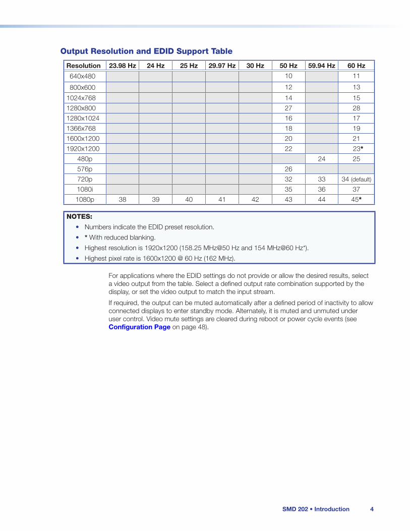
Output Resolution and EDID Support Table
Resolution 23.98 Hz 24 Hz 25 Hz 29.97 Hz 30 Hz 50 Hz 59.94 Hz 60 Hz
640x480 10 11
800x600 12 13
1024x768 14 15
1280x800 27 28
1280x1024 16 17
1366x768 18 19
1600x1200 20 21
1920x1200 22 23*
480p 24 25
576p 26
720p 32 33 34 (default)
1080i 35 36 37
1080p 38 39 40 41 42 43 44 45*
NOTES:
• Numbers indicate the EDID preset resolution.
• * With reduced blanking.
• Highest resolution is 1920x1200 (158.25 MHz@50 Hz and 154 MHz@60 Hz*).
• Highest pixel rate is 1600x1200 @ 60 Hz (162 MHz).
For applications where the EDID settings do not provide or allow the desired results, select a video output from the table. Select a defined output rate combination supported by the display, or set the video output to match the input stream.
If required, the output can be muted automatically after a defined period of inactivity to allow connected displays to enter standby mode. Alternately, it is muted and unmuted under user control. Video mute settings are cleared during reboot or power cycle events (see Configuration Page on page 48).
SMD 202 • Introduction 4

Suggested PC RequirementsThe suggested PC requirements to access the default Web pages of the SMD 202 are listed below.
• Hardware
• 2.0 GHz dual-core processor
• Operating Systems
• Microsoft® Windows® XP or higher
• Mac® OS® X® 10.6 or higher
In order to view the SMD 202 embedded Web pages, use one of the supported Web browsers (and versions) listed below.• Web Browsers
• Google® Chrome™ (version 37 or higher)
• Mozilla® Firefox® (version 35 or higher)
• Internet Explorer® version 11 or higher (for Windows operating systems)
• Apple® Safari® version 8 or higher (for Mac OS X operating systems
NOTE: The SMD 202 embedded Web pages are designed for viewing in a browser at 100% zoom. The appearance of individual pages can differ from those in this guide for other zoom ratios.
Supported formats:• File Formats
• MPEG2 TS MPEG-2 part 1 (or ISO/IEC 13818-1 or ITU-T Rec. H.222.0)
• MP4 (including mp4, m4a, m4v file extensions, not case sensitive).
• TS, m2t, m2ts, 264, and sdp.
• MOV and FLV (supports only files that use H.264 encoding and AAC audio)
• Streaming Container Formats
• MPEG2 Transport stream (including .ts, .m2ts, .m2t file extensions, not case sensitive)
NOTE: Adaptive bit rate streams are not supported.
The SMD 202 can play video on demand from network shares and local storage supporting the following file types:
Video: mp4, ts, m2t, m2ts, mov*, 264, m4v, flv*, sdp.
NOTE: *Supports files that use H.264 encoding and AAC audio only.
Images: bmp, jpg, jpeg, tif, tiff, png, gif.
NOTE: TIFF files using JPEG compression are not supported.
Audio: wav, aac, m4a.
Playlists: jspf, m3u, pls, m3u8, xspf.
NOTE: Some m3u8 playlists generated by third party software are not supported.
SMD 202 • Introduction 5

Features• Supports live IP video stream decoding — Combine with the SME 100 to provide a
complete end-to-end streaming solution.
• Supports streaming resolutions from 480x320 up to 1080p/60 — Supports a wide range of resolutions to meet varying network conditions, topologies, source and display requirements.
• AV media file playback from network shares — Use as a playback device for on-demand playback of network-accessible media files.
• Compatible with MP4 and MPEG-2 Transport Stream container formats — Playback common H.264 media player formats from accessible network drives.
• Stereo or dual mono audio output format: Embedded HDMI digital audio or analog stereo audio — Flexible, cost effective use of display speakers or existing audio systems.
• Integrated scaler offers selectable output resolutions from 640x480 to 1920x1200 — Wide range of output resolutions ensure that consistent, reliable image quality is presented on many different types of displays.
• Decode at native resolution — The output rate and resolution can be configured to automatically follow the native format of the connected display.
• EDID defined scaling — The output rate and resolution can be configured for automatic selection based on EDID communication with the connected display.
• Ethernet to RS-232 pass through control — Integration friendly Ethernet to RS-232 pass through for display control.
• Fill/Follow/Fit (zoom) Aspect Ratio Management — Decoded video can fill a display, maintain aspect ratio, or maintain uniformity, presenting imagery that meets customer expectations.
• Control from IR remote, wired IR, RS-232, Ethernet, or embedded web interface — Select from a range of control options to manage the SMD 202 for stand-alone operation or as part of an AV system.
• Compatible with the full range of SME 100 and SMP 351 streaming transport protocols — Providing the flexibility to apply the most appropriate protocol based on various streaming system requirements and network conditions.
• Compatible with unicast and multicast push, or pull streaming applications — Support for push and pull streaming makes the SMD 202 compatible with different network topologies and streaming system configurations.
• Upload and display image files — Upload PNG, JPG, TIFF (TIFF with JPEG compression not supported), or BMP image files at resolutions up to 1920x1080 to present familiar imagery or organizational branding, either on demand or in times of network or streaming disruption.
• On-screen messaging — On-screen presentation of operating status or channel selection aids in channel selection, system configuration, and troubleshooting.
• HDMI output — Compatible with HDMI and DVI digital displays.
• Automatic negotiation of streaming transport protocols with SME 100 — Makes configuration and operation of Extron H.264 streaming products easy in various streaming and network configurations.
• Easy-to-use embedded web interface — Embedded Web interface makes configuration and deployment a simple activity.
SMD 202 • Introduction 6

• Playback controls including progress bar — On-screen playback controls present a visual indication of Time and Pause status, allowing for efficient control of content.
• Compatible with many third party H.264 encoders — Decode 720p/60 and 1080p/60 streaming video from an Extron SME 100 or other compatible H.264 encoders.
• Compatible with H.264 Baseline, Main, and High profiles up to and including level 4.2 — Offers the flexibility to efficiently decode and present streaming video at various bit rates and coding complexity.
• Decoder status reporting — Simplify configuration and troubleshooting activities with on-screen status reporting to ensure continuous, reliable operation.
• Front-accessible USB configuration port — Front-accessible port provides easy access for system configuration and control from a PC.
• Compact and energy efficient — Efficient, low power use generates very little heat, making it easy to optimize rack space and maintain lower operating costs.
• Seamless transitions — between still image files (cut or fade - global rate adjustable).
• Seamless video clip transitions.
• Caption and subtitle text — support from streams or clips with text streams included or stand alone files.
• User Fonts — User supplied True Type (TTF) and Open Type (OTF) fonts can be installed for caption and subtitle text.
• Multilingual OSD — Selectable a different language for the onscreen menus.
• Random access and seeking — to provide searching for specific points within clips.
• Auto switch — Automatically switches between HDMI input and decoder on loss of signal.
SMD 202 • Introduction 7

Panels and Cabling
This section provides information on:
• Front Panel Features
• Rear Panel Features
• SMD 202 Power Up Procedure
• Hardware Setup Overview
Front Panel FeaturesThe front panel of the SMD 202 is shown in figure 2 below.
SMD 202
INPUT MENUINPUT
ENTERIR
HDMI
DECODER
CONFIG
AABBCC DD FF GG HH IIEE
A Power LED D IR receiver window G Onscreen menu selection
B Playback status indicator E Config port H Menu navigation
C Network status indicator F Input source indicators I Menu entry
Figure 2. SMD 202 Front Panel
A Power LED — Dual color LED lights solid green when the SMD 202 is powered. Lights solid red when in standby (low power) mode.
B Playback status indicator — Dual color LED indicates playback operation:
• Solid Green — The SMD 202 is actively decoding a source (clip, image, or stream).
• Blinking Green — A source (clip, image, or stream) is selected, but playback is paused.
• Off — The selected stream is not being decoded.
• Solid Red — Unable to load (or play) the selected source.
C Network status indicator — Dual-color LED indicates network operation and connection or stream quality:
• Solid Green — Indicates network conditions are favorable for the current source. The LED is also green if the current source is a local file (see Browser Pane - Files on page 32).
• Red/Green — When flashing red and green, indicates encoder or network conditions could compromise image or audio quality, and buffers could be depleted.
• Red — When lit, indicates degraded server or network conditions are compromising video or audio quality and may have depleted the buffers.
• Off — No network connection.
NOTE: In many cases, the error correction features of the SMD 202 allow good image quality even when degraded network conditions are indicated.
SMD 202 • Panels and Cabling 8

D IR Receiver Window— Allows remote operation using an optional compatible IR hand control.
E Config port — Connect a control PC or other USB device to this port using a mini-B USB cable (not supplied). Use this port to send Simple Instruction Set (SIS) commands to the SMD 202 for device configuration and control.
• For information on connecting a control PC or other USB device to this port, see the Front Panel Configuration Port section on page 128.
• For information on SIS commands, see Remote Communication and Control on page 127.
F Input source – Indicates the current playback source.
• HDMI – Indicates the rear panel HDMI input is selected.
• DECODER – Indicates a source on the connected LAN is selected .
G Menu selection button – Press to activate the interactive OSD menu system. A local display must be connected to view the menu. When the OSD menu is selected, the input reverts to the Decoder.
H Input selection and OSD menu navigation buttons – By default the up and down arrow buttons provide manual input selection between the HDMI and decoder inputs. Press UP to select the HDMI input and DOWN to select the Decoder input.
When the OSD menu is active, the directional arrow buttons provide navigation within the OSD menu structure.
I Enter button – Press to make a selection on the interactive OSD menu.
Rear Panel FeaturesThe rear panel of the SMD 202 is shown in figure 3.
12V1.3A MAX
POWER
USBSD
HDMI HDMI
INPUTAUDIO
L R L R
OUTPUTINPUTAUDIO
Tx Rx GS G
RS-232 RESETIR IN
LAN
INPUTS
OU
TP
UT
OUTPUT12V
1.3A MAX
POWER
USBSD
HDMI
INPUTAUDIO
L R L R
OUTPUTINPUTAUDIO
Tx Rx GS G
RS-232 RESETIR IN
LAN
OU
TP
UT
HDMI
INP
UT
OUTPUT SMD 202
AA BB CC DD EE FF GG HH II KKJJ
A 12 VDC power connector G 3.5 mm, 5-pole captive screw connector for analog audio output
B USB type A connector for external storage device connection
H 3.5 mm, 3-pole captive screw connector for wired IR receiver input
C Card slot for attaching optional storage I 3.5 mm, 3-pole captive screw connector for Simple Instruction Set (SIS™) control over RS-232D HDMI input connector
E HDMI output connector J Reset button and LED
F 3.5 mm, 5-pole captive screw connector for analog audio input
K RJ-45 LAN connector
Figure 3. SMD 202 Rear Panel
SMD 202 • Panels and Cabling 9

A 12 VDC power input — Connect the provided 12 VDC power supply to the rear panel captive screw connectors (see figure 3 on page 9). When power is connected, the front panel power indicator lights green (see figure 2, A on page 8).
SMD 202
DC Power Cord Captive ScrewConnectors
DC PowerOutputs
DC PowerInput
AC PowerCord
TieWraps
PS 1220POWER12V 1.3A MAX
12V--A MAX
POWER
USB
SD
HDMI
INPUTAUDIOL
R
L
R
OUTPUT
INPUT
AUDIO
Tx RxG
SG
RS-232RESET
IR IN
LAN
OU
TPU
T
HDMI
INPU
T
OUTPUT
SMD 202
Figure 4. Power Supply Connection
ATTENTION: Risk of property damage:
ATTENTION : Risque de dommages matériels :
• Always use a power supply provided by or specified by Extron.
• Utilisez toujours une source d’alimentation fournie ou recommandée par Extron.
• Use of an unauthorized power supply voids all regulatory compliance certification and may cause damage to the supply and the end product.
• L’utilisation d’une source d’alimentation non autorisée annule toute conformité réglementaire et peut endommager la source d’alimentation ainsi que le produit final.
• Unless otherwise stated, the AC/DC adapters are not suitable for use in air handling spaces or in wall cavities.
• Sauf mention contraire, les adaptateurs AC/DC ne sont pas appropriés pour une utilisation dans les espaces d’aération ou dans les cavités murales.
• The power supply must be located within the same vicinity as the Extron AV processing equipment in an ordinary location, Pollution Degree 2, secured to a podium, a desk, or an equipment rack within a dedicated closet.
• La source d’alimentation doit être située à proximité de l’équipement audiovisuel Extron dans un emplacement habituel, avec un degré de pollution 2, fixée à une estrade, un bureau, ou dans une baie technique à l’intérieur d’un placard dédié.
• The installation must always be in accordance with the applicable provisions of National Electrical Code ANSI/NFPA 70, article 725 and the Canadian Electrical Code part 1, section 16.
• Cette installation doit toujours être en accord avec les mesures qui s’applique au National Electrical Code ANSI/NFPA 70, article 725, et au Canadian Electrical Code, partie 1, section 16.
• The power supply shall not be permanently fixed to building structure or similar structure.
• La source d’alimentation ne devra pas être fixée de façon permanente à une structure de bâtiment ou à une structure similaire.
SMD 202 • Panels and Cabling 10

B USB connector — Connect a USB compatible media device to this port.
C SDI card slot — This card slot supports SD, SD-HC, and SD-SC cards up to 512 GB capacity. UHS 1, Class 10 data rate of 25 MBytes/second is supported. Mounted media appears in the user file system under the media folder. The media folder and contents are accessible from the file browser section of the Web interface (see Overview of the Web-based User Interface on page 15).
D HDMI input — Connect an HDMI (or DVI with suitable adapter) display device to the HDMI output connector. The EDID of a connected display is read and the output automatically configured. For non-standard displays or devices, see the SMD 202 User Guide for additional output resolutions and format settings.
E HDMI output connector — Connect an HDMI (or DVI with suitable adapter) display device to the HDMI output connector. The EDID of a connected display is read and the output automatically configured.
F Analog audio input connector — Connect audio input devices using cables with balanced or unbalanced 3.5 mm, 5-pole captive screw connectors (see figure 5).
Unbalanced Stereo Input
TipSleeve
TipSleeve
Balanced Stereo Input
TipRing
Sleeve (s)Tip
Ring
(high impedance)
(high impedance)
Unbalanced Mono Input
TipSleeve
TipSleeve
Balanced Mono Input
TipRing
Sleeve (s)Tip
Ring
(high impedance)
(high impedance)
LR
LR
LR
LR
Balanced Audio Output Unbalanced Audio Output
Tip
No Ground Here
No Ground Here
TipSleeves
LR
TipRing
TipRing
Sleeves
LR
Do not tin the wires!
Figure 5. Audio Input Captive Screw Connector Wiring
G Analog audio output connector — Connect audio output devices using cables with balanced or unbalanced 3.5 mm, 5-pole captive screw connectors. See figure 6 to wire the connectors.
ATTENTION: For unbalanced audio, connect the sleeves to the ground contact. DO NOT connect the sleeves to the negative (–) contacts.
ATTENTION : Pour l’audio asymétrique, connectez les manchons au contact au sol. Ne PAS connecter les manchons aux contacts négatifs (–).
Unbalanced Stereo Input
TipSleeve
TipSleeve
Balanced Stereo Input
TipRing
Sleeve (s)Tip
Ring
(high impedance)
(high impedance)
Unbalanced Mono Input
TipSleeve
TipSleeve
Balanced Mono Input
TipRing
Sleeve (s)Tip
Ring
(high impedance)
(high impedance)
LR
LR
LR
LR
Balanced Audio Output Unbalanced Audio Output
Tip
No Ground Here
No Ground Here
TipSleeves
LR
TipRing
TipRing
Sleeves
LR
Do not tin the wires!
Figure 6. Audio Output Captive Screw Connector Wiring
H IR IN — Connect a remote IR receiver to this 3-pole 3.5 mm captive screw connector to extend the range of the hand control.
+S
FromIR Receiver
SMD 202IR IN
G
Figure 7. IR In Wiring
SMD 202 • Panels and Cabling 11

I RS-232 connector (optional) — Connect a host computer or control system to the RS-232 connector or to the local device if pass-through mode is used. Use this port for Simple Instruction Set (SIS) command of the SMD 202 for device configuration and control, or IP to serial pass-through for display control. The default protocol for this port is 9600 baud rate, no parity bit, 8 data bits, 1 stop bit, and no flow control (handshaking).
• For information on SIS commands, see Remote Communication and Control on page 127.
• See figure 8 for the RS-232 connector wiring.
Ground
TxRx
ReceiveTransmit
Connected RS-232Device Pins
SMD 202Pins
G
Figure 8. RS-232 Connector Wiring
J Reset button and LED — The reset button is used to return the SMD 202 to partial or complete factory condition. The reset LED provides the status of the reset. The SMD 202 has four reset modes (see SMD 202 Rear Panel Reset on the following page).
K RJ-45 LAN connector — Connect one end of an RJ-45 cable to the LAN (Ethernet) connector on the SMD 202 (see figure 9). Connect the other end of the RJ-45 cable to a router or switch connecting the SMD 202 to a network.
LAN
ACT LINK
Figure 9. RJ-45 Ethernet Connector
The left side (amber) LED indicator on the LAN connector blinks in a pattern to indicate the network link speed.
• Three blinks, pause — 1 Gbps
• Two blinks, pause — 100 Mbps
• One blink, pause — 10 Mbps
NOTE: The SMD 202 LAN connection uses Auto MDI-X allowing direct connection of a control PC using a standard straight through Ethernet cable.
SMD 202 • Panels and Cabling 12

SMD 202 Rear Panel ResetThe Reset button on the rear panel of the SMD 202 (see figure 3 on page 9) returns the SMD 202 to various modes of operation. To select different reset modes, use a pointed stylus or small screwdriver to press and hold the Reset button while the SMD 202 is powered, or press and hold the Reset button while applying power to the SMD 202.
ATTENTION:
• Review the reset modes carefully.
• Étudier de près les différents modes de réinitialisation.
• Some reset modes delete all user loaded content and revert the device to default configuration.
• Certains modes de réinitialisation suppriment la totalité du contenu chargé de l’utilisateur et remettent l’appareil en mode de configuration par défaut.
NOTES:
• The reset modes close all open IP and Telnet connections and all sockets.
• Each reset mode is a separate reset (not a continuation from mode 1 to mode 5).
• Reset mode 2 is not available for the SMD 202.
• The SMD 202 can also be reset using the Web-based user interface (see Reset Device on page 85).
• For information on resetting the SMD 202 using SIS commands, see Resets on page 137 of the Command and Response Tables section.
• Further details comparing the reset modes and affected configuration settings and user content are in the reference section (see SMD 202 Reset Summary on page 153).
RESET RESET
RESET RESET RESET
Release, then immediatelypress and release again. Reset LED flashes, then goes off.
Modes 3
Press and hold the Reset button.
Mode 1
Reset LED flashes once.
Press and hold for3 seconds.
Apply powerto the SMD 202.
Release Reset button.
RESET RESET RESET
Release, then immediatelypress and release again. Reset LED flashes, then goes off.
Modes 4 Reset LED flashes twice.
Press and hold for6 seconds.
RESET RESET RESET
Release, then immediatelypress and release again. Reset LED flashes, then goes off.
Modes 5 Reset LED flashes three times.
Press and hold for9 seconds.
Figure 10. Resetting the SMD 202
SMD 202 • Panels and Cabling 13

SMD 202 Power Up Procedure
NOTE: Before powering on the SMD 202, ensure that all necessary devices are connected properly. Devices do not need to be powered.
Connect the external power supply to a 100 to 240 VAC supply (see Rear Panel Features on page 9). The DC power LED lights and the SMD 202 undergoes a self testing sequence. When connected to a network, the front panel network LED indicator lights green to indicate the SMD 202 is ready to decode.
Hardware Setup Overview
NOTE: If it is difficult to access the device after installation, configure the communications settings of the SMD 202 prior to starting (see Communications Submenu on page 123).
1. If the SMD 202 has been on for configuration, turn it off and disconnect the SMD 202 and all connected devices.
2. Mount the SMD 202 (see Mounting the SMD 202 on page 151).
3. Connect one end of an RJ-45 cable to the rear panel LAN connector on the SMD 202 (see Rear Panel Features on page 9). Connect the other end of the RJ-45 cable to the local network.
4. Connect a compatible output device to the rear panel (see Rear Panel Features on page 9) and power it on.
5. Connect a control device to the SMD 202 by one of the following connections:
a. The front panel config port (see Front Panel Configuration Port on page 128).
b. The rear panel RS-232 port (see RS-232 Port on page 127).
c. The Ethernet connection. Configure the network settings of the control PC so it is compatible with the network the SMD 202 is connected to (see LAN (Ethernet) Port on page 129).
6. Connect the external power supply output connector to the SMD 202 (see Rear Panel Features on page 9), then connect the power supply to a 100 to 240 VAC, 50 Hz or 60 Hz power source. The SMD 202 powers up automatically and undergoes a self testing sequence (see the SMD 202 Power Up Procedure, above).
7. From the control PC, access the user interface of the SMD 202 (see Accessing the Embedded Web Pages on page 16).
8. Select a stream, clip, or image to decode (see Player Page Overview on page 22).
9. If necessary, set the decoder output for the connected display (see Video Output on page 3 and Video Configuration on page 49).
10. Press Play on the software interface (see Player Controls Features on page 23) or on the optional remote control (see IR Remote Control on page 108) to begin decoding the selected source.
SMD 202 • Panels and Cabling 14

Web-based User Interface
This section provides information about:
• Overview of the Web-based User Interface
• Web Browser Requirements
• Accessing the Embedded Web Pages
• Overview of the SMD 202 Embedded Web Pages
• Web Page Idle (Timeout)
• Logging Out and Logging In
• Player Page Overview
• Configuration Page
• Advanced Configuration Page
• Device Information Page
• Troubleshooting
Overview of the Web-based User InterfaceThe SMD 202 embedded Web-based User Interface pages provide the software user interface for operating and configuring the SMD 202 streaming media decoder via a control PC on the same network.
NOTES:
• The user interface screen captures in this user guide were taken using Google Chrome. Pages and panels viewed in other browsers can differ from those in this guide.
• The SMD 202 embedded Web pages are designed for viewing in a browser at 100% zoom. The appearance of individual pages can differ from those in this user guide for other zoom ratios.
Web Browser RequirementsTo access the SMD 202 embedded Web pages, use one of the supported Web browsers (and versions) listed in order of preference.
• Google® Chrome™ (version 37 or higher)
• Mozilla® Firefox® (version 35 or higher)
• Internet Explorer® version 11 or higher (for Windows operating systems)
• Apple® Safari® version 8 or higher (for Mac OS X operating systems)
NOTES:
• Google Chrome is the preferred browser for Windows-based computer platforms.
• Apple Safari is the preferred browser for Apple- and Mac-based computer platforms.
SMD 202 • Web-based User Interface 15

Turning Off Compatibility ModeThe SMD 202 embedded Web pages do not support compatibility mode in Microsoft Internet Explorer.To check compatibility view settings:From the Tools menu of the browser, select Compatibility View settings. The Compatibility View Settings dialog box opens.Be sure that the Display all websites in Compatibility View check box is cleared and that the IP address of the SMD 202 is not in the list of websites in the Websites you've added to Compatibility View list.
Accessing the Embedded Web PagesAfter the SMD 202 and the encoders and codecs that will serve as stream sources are installed, open the Web pages that are embedded within the internal memory.
To open the SMD 202 embedded Web pages:
1. Open a Web browser.
2. Enter the IP address of the SMD 202 (default IP address is 192.168.254.254) into the browser address bar (see figure 11). The embedded Web pages open to the Player page.
Figure 11. Enter the IP Address
3. If necessary, enter the user name and password (see Logging Out and Logging In on page 19).
4. Click Log In or OK.
The SMD 202 embedded Web page opens to the Player page (see Player Page Overview on page 22).
Overview of the SMD 202 Embedded Web PagesThe SMD 202 embedded Web pages provide the software user interface for operating and configuring the SMD 202 streaming media decoder via a control PC on the same network.
All SMD 202 Web pages include the Player Controls tab at the left of the screen (see Player Controls Features on page 23). The Player page serves as the main interface for operating the SMD 202.
The Web pages provide the following features:
• Fully configure the SMD 202 from a remote location
• Remote control and active monitoring of the SMD 202
• A full color embedded video confidence window to view the selected decoded stream
• Update firmware
SMD 202 • Web-based User Interface 16

TabsThe Web pages are organized by functions grouped within five tabs near the top of the screen (see figure 12).
http://192.168.254.254/www/
Figure 12. Web pages, Tab Layout
Player — The pages within this tab contain the basic operating controls for managing media streams such as basic media player controls (to play, pause, stop, loop, and navigate playlists), lists of selectable streaming media sources and source history, files, customizable lists of channels, favorite sources and source history, and a playlist editor. This is the page used regularly to control media selection and playback.
Configuration — The four pages within this tab provide settings for configuring the audio and video output of the SMD 202, setting up on-screen displays for the output video, and setting automated functions such as a screensaver and determining what media to play upon unit boot-up and how the device behaves when a signal stream is lost.
Advanced Configuration — This tab includes seven pages with controls used for initial setup and during system integration. Changes to this page can only be made from the admin account. These pages provide a way to configure ports and Ethernet connection settings, replace firmware, upload a saved configuration file, enable or disable IR control of the unit, set the power saving mode, set up the date and time, configure passwords, reset the unit, and set up and enable or disable SNMP for network management.
Device Information — A single page within this tab displays factory-defined and user-defined information about the unit. This is where you can look up the unit name, part number, firmware version, MAC address, location description, and related information about the SMD.
Troubleshooting — This tab provides access to four pages which collect together information and controls for status, logs, alarms, and diagnostics.
Screens Within PagesThe Configuration, Advanced Configuration, and Troubleshooting tabs each include additional pages. Click the corresponding icon on the global navigation bar located just below the main tabs to access the pages (see figure 13).
Figure 13. Web User Interface, Navigation Bar
SMD 202 • Web-based User Interface 17

Panels and Screen SectionsEach SMD 202 Web page contains at least one panel and a main window with sections that group the controls and information for each page. The panels (see figure 14 1, 2, 3, 4, and 5), include controls and a variety of items that can be adjusted or configured, but can also include display information.
11 22
33 44
55
Figure 14. Video Configuration Panels
All SMD 202 Web pages include the Player Controls at the left of the screen (see Player Controls Features on page 23). The Player page is the main page and serves as the primary interface for operating the SMD 202.
Collapsing and Expanding PanesClick the arrow button (see figure 15, 1 and 2) at the top corner of a pane to either collapse it to a narrow bar (3) to hide its controls and make room for other panes, or to expand it to its full size. If the pane is already expanded, it collapses. If already collapsed, it expands to make the controls and lists accessible again.
11
33
22
Figure 15. Web Pages Collapsed and Expanded
SMD 202 • Web-based User Interface 18

Web Page Idle (Timeout)To conserve the host computer resources (memory, bandwidth), if you leave the browser page idle, after about 60 minutes, the SMD 202 Web interface stops requesting status and video confidence updates. An Idle dialog box opens (see figure 16).
Figure 16. Web Page Idle Dialog
The idle status does not affect the output AV stream, which continues unaffected no matter what state (active or idle) the Web pages are in.
Click Resume to reconnect the Web page to the live feed from the SMD 202. In a moment, the browser refreshes the view, and the status updates and video confidence display resume.
Logging Out and Logging InIf a password is active, you must log in to the appropriate account using the password to access the SMD 202. Additionally, before you can change roles (from administrator to user, or user to administrator) or user accounts, you must log out of the SMD 202 embedded Web pages. The user or administrator status is displayed in the upper right corner of all Web pages (see figure 17):
Figure 17. Logged in Status and Logout Button
If no password is active, anyone connecting to the SMD 202 is automatically logged in as the administrator.
To log out of the SMD 202 Web pages:
1. From any SMD 202 embedded Web page, click Logout above the navigation bar.
A Logout dialog box opens (see figure 18).
Figure 18. Logout Dialog
2. Click OK to log out of the SMD 202 Web pages, or click Cancel to remain logged in using the same account.
The Logout dialog box closes and returns you to the SMD 202 embedded Web pages screen.
3. Click Cancel to remain logged in. The embedded Web pages continue to function as they did before you clicked Logout.
SMD 202 • Web-based User Interface 19

NOTE: If you clicked OK, the SMD 202 controls are replaced by a message confirming that you have logged out and asking you to close the browser. Close the browser completely. If you close only a tab within the browser, the logout process will not be completed.
To log in to an SMD 202 when a password (admin or user) is active:
1. Open the Web browser.
http://192.168.254.254/www/
Figure 19. Web Browser, SMD 202 Default IP Address
2. Enter the IP address of the SMD 202 into the address field (see figure 19).
Depending on the Web browser one of the following dialog boxes opens:
Authentication Required for Chrome (see figure 20) and Firefox (see figure 21).
Authentication Required
The server http://192.168.193.182:80 requires a username and password. The server says: ‘SMD_202’.
User Name:
Password:
Log In Cancel
Figure 20. Chrome
Enter username and password for http:/192.168.193.182
Figure 21. Firefox
Windows Security for Internet Explorer (see figure 22).
The server 192.168.193.182 at ‘SMD_202’ requires a username and password.
Warning: This server is requesting that your username and password be sent in an insecure manner (basic authentication without a secureconnecton).
Figure 22. Internet Explorer
SMD 202 • Web-based User Interface 20

Safari login dialog box (see figure 23).
Figure 23. Apple Safari
NOTE: For Safari browsers, when an Admin or User password (or both) is set, the browser displays multiple login dialog boxes. Enter the credentials in each box or press Cancel to prevent the duplicate fields.
3. Enter the appropriate user or administrator user name and corresponding password into the fields.
4. Click Log In or OK as required. The SMD 202 embedded Web page opens.
SMD 202 • Web-based User Interface 21

Player Page OverviewThe panes on the Player page allow you to monitor and control all the playback features of the SMD 202. They include basic media player controls (to play, pause, stop, loop, seek, or navigate through a list of media streams), lists of selectable streaming media sources and files, customizable lists of channels and favorite sources, and a playlist editor. This is the page that is used regularly to control media selection and playback.
Those logged in at the user level can make changes to all items on the Player page except modifying or deleting existing playlists or channels or creating new folders for files. Users logged in to the SMD 202 with administrator privileges can make changes to all settings.
An interactive embedded help file is always available. Click the help icon (see figure 24, 6) from any page or pane.
22 333
666
555444
192.168.193.170
192.168.193.182
192.168.193.198
192.168.194.28
192.168.209.31
192.168.0.31
192.168.0.32
192.168.20.170
192.168.56.113
192.168.0.33
192.168.0.30
192.168.56.214
192.168.254.254
192.168.0.34
xsap://192.168.56.214:Cameras
xsap://192.168.56.113:Classroom+1
xsap://192.168.0.34:PDLAB-34
xsap://192.168.0.32:PDLAB-32
xsap://192.168.193.170:SME100-uni
xsap://192.168.0.30:PDLAB-30
file:///Clips/top5_2009-02-11.m
xsap://192.168.0.34:PDLAB-4
xsap://192.168.56.113:Classro
xsap://192.168.56.214:Camer
xsap://192.168.0.32:PDLAB-3
xsap://192.168.0.30:PDLAB-3
xsap://192.168.0.33:Previews+
xsap://192.168.193.170:SME1
11
Figure 24. Player Page - All Panes Expanded
Click the Player tab (see figure 24, 1). This tab has four panes, each of which can be expanded or collapsed for easier viewing of the contents of other panes.
The panes on this page include the following:
• Player Controls (2) — This pane makes it possible to easily control play of the current media stream, see a thumbnail view of the output video (confidence), select a different playlist or source, and view the input and output stream formats and network condition.
• Browser (3) — Includes a Streams tab that displays a list of devices on the network with available source streams and a Files tab that lists clips and other files stored within the SMD 202, on network-attached storage (NAS) devices, on removable SD cards, and connected USB devices. Fields at the bottom of the panel allow the lists to be filtered. A user can click on a stream or file in this panel, or double-click it to select and load it for output. Click on and drag the stream or file into the other panels to form channels, set it as a favorite source, or add it to a playlist.
SMD 202 • Web-based User Interface 22

• Lists (see figure 24, 4 on page 22) — Features the following tabs:
• Channels — Where an administrator can save the URI for any source (streams, clips, images, or playlists) as a channel preset for quick access using SIS commands or an optional IR remote control
• Favorites — Where you can bookmark streams or files for quick access
• History — Which lists in chronological order each source file or stream to which the SMD has connected since the last time the history list was cleared.
• Playlist Editor (see figure 24, 5)— Within this panel you can create playlists by selecting sets of files and stream sources from the other Player page panels. These playlists can then be selected for the live output or designated as the source material to play upon boot-up.
Initially, the Player page opens with all four panes expanded (see Panels and Screen Sections on page 18) and with the Stream and Channels tabs open. Changes made to the layout of this page are retained during the current session. For example, a user collapses the Playlist Editor pane and opens the Favorites tab in the Lists panel. If they switch to the Troubleshooting tab, then return to the Player page, the view that was selected before navigating away from the Player page is maintained.
Users logged in with administrator privileges can make changes to all settings on the Player page. Those logged in at the user level can not modify or delete existing playlists or channels and create new folders for files.
Player Controls FeaturesThe Player Controls pane is available on every SMD 202 embedded Web page within all the different tab views. Located along the left side of the pages, this panel makes it possible to easily control playback of the current media stream with basic player controls (play, pause, stop, loop) and navigate through a list of media streams, see a thumbnail view of the output video, select a different playlist or source, and view the input and output stream formats and network condition. The Player page opens with the Player Controls panel expanded.
The Player Controls allow the user to select a source (clip, stream, or playlist), monitor the playback video, and control playback. The panel is available on every embedded Web page within all the different tab views. Located along the left side of the pages, this panel makes it possible to easily control playback of the current media stream, see a thumbnail view of the output video, select a different playlist or source, and view the input and output stream formats and network condition.
The Player page opens with the Player Controls panel expanded (see figure 24, 2 on page 22). Changes made to the layout of the player page are retained during the current session. For instance, if a user switches to the Status page then back to the Player page, the same view is maintained.
SMD 202 • Web-based User Interface 23

The Player Controls panel includes the following features:
Video Confidence Display — The display shows a series of full color snapshots corresponding to the real-time output, updated every 2 seconds. To save bandwidth and make the embedded Web pages faster to refresh or for privacy reasons, this live view can be disabled and a default still image can be displayed here in place of the output stream. The output video stream continues to be sent to the display device when this thumbnail view is disabled. The control to disable the live feed to this page is located in the Executive/Power Mode page with the Advanced Configuration tab and is available only to users with administrative account access.
Figure 25. Player Control - Video Confidence Display
Progress Bar — Shows the position in time of the currently playing clip. The current playback position is on the left (00:00:12 in figure 25), and the total duration of the clip (if known) on the right (00:00:52).
A progress bar below the display is similar to the progress bar on-screen display (see OSD Submenu on page 119). A horizontal bar graph shows how much of the clip has played and how much remains. For streams, the bar dims and no position or duration timing is given.
With mp4 clips, click and hold the progress indicator and move it right or left to seek with the clip and change the playback timeline position.
NOTES:
• The precision of seek requests is limited by the video file structure and includes the interval between I frames and the frame rate. When a seek command is issued, the SMD attempts to seek the nearest I frame to the requested position. For instance, with a 60 frame GOP (one I-frame per 60 frames) and frame rate of 30 fps, the seek point can differ from the expected position by up to 2 seconds.
• Seeking within clips that use the .ts container format is not supported.
SMD 202 • Web-based User Interface 24

Status indicator and Player Controls — Player control buttons function the way DVD player controls do. Text above the controls (figure 26, 1) indicates the current decode state (stopped, paused, or playing).
11
22
33
44
55
66
77
££
88
99
¢¢
Figure 26. Player Control Buttons
The controls are:
2 Seek Backward 10 seconds from the current clip position.
3 Previous. If pressed within five seconds after the clip begins, returns to the previous clip or stream and plays. If pressed after five seconds, returns to the beginning of the current clip and plays.
4 Loop (set the SMD 101 to replay the current selection automatically for continuous play).
5 Play (start playback for any media type) .
6 Pause (pause playback).
7 Stop (stop playback).
8 Seek Forward (move ahead by 10 seconds when playing a clip).
9 Next (select the next stream or file in a playlist).
¢ Closed Caption controls the display of the Closed Captions and Subtitles, when available.
£ Analog audio output volume control.
NOTES:
• Selected or active buttons are blue ( )
• If playback of a source stream fails or if the SMD 202 cannot connect to the source, the Play button is red ( ) instead of blue. When the unit reconnects to the stream or is connected to a new source, the Play button returns to normal.
SMD 202 • Web-based User Interface 25

The player control also provides input source selection, mute, and load play functions.
Figure 27. Input Source, Mute, and Load Play Controls
Input Source Selection — These buttons select the input video and analog audio source for the HDMI display and audio output. Click HDMI to select the HDMI input source and analog audio. A green LED indicates there is an active HDMI signal source. Click Decoder to select a network stream or file from internal or external storage and the corresponding analog audio.
The output switches between the two input sources. Signals from the HDMI input are not routed through the decoder therefore no processing, such as scaling, rate conversion, or OSD of signals from the HDMI input by the decoder is possible.
When HDMI is selected, the HDMI source (input 2) is routed to the HDMI output. Analog audio from input 2 is routed to the analog audio switch.
When the Network Input (Input 1) is selected, the source is decoded and the resulting HDMI signal is routed to the Video Switch. The decoder also outputs an analog audio signal to the Analog Audio Switch.
HDMI
Analog Audio
Input 1
HDMI Output
AnalogAudio Output
Video and
Embedded Audio
VideoSwitch
AnalogAudioSwitch
Decoder
Analog Audio
Input 2 (HDMI)
Input 1 (Decoder)
Input 1(Decoder)
Input 2(Analog Audio)
Input 2
Rear PanelInputs
Rear PanelOutputs
NetworkStream
Figure 28. Input Signal Switching
NOTE: Switching to the HDMI input (input 2) does not interrupt decoding of the source. Stream decoding continues in the background. If the OSD menu is selected (via the front panel button or IR command), the SMD 202 switches to the decoder input to display the menu.
Mute buttons — Clicking the desired button to mute video only (Video Mute), audio only (Audio Mute), or both audio and video (AV Mute). When a mute mode is active, the corresponding button or buttons are shown in red. Mute states are selected by clicking these buttons, by clicking buttons in the Audio Configuration or Video Configuration pages, or by sending SIS commands.
Click the button again to unmute the selection. The button returns to gray.
Load Play button — When this button is enabled, indicated by blue button color (see figure 27 on page 26), any file clip or stream that is loaded for output automatically starts playing. When Load Play is enabled, you do not have to click Play to start playing the
SMD 202 • Web-based User Interface 26

clip, stream, or playlist. This automatic play feature works regardless of whether the material is loaded via one of the other Player panels or dragging a clip or stream into the Source or Playlist field in this pane. To disable the automatic play feature, click Load Play again. The button turns from blue to gray to indicate that automatic play is disabled.
At the bottom of the Player Controls pane are status indicators for the currently selected playlist or file, the input source selection, the source and output format, and the current network conditions (see figure 29).
Figure 29. Playlist, Source, and Network Conditions
Playlist field — When a playlist is loaded, this field displays the path and file name of the playlist. Click the ellipsis button ( ) to the right of the text field to display the path and file name if it is too long for the field to display completely.
To load a playlist:
• Click on and hold a playlist then drag it from the Browser panel to this field.
• Enter or paste a playlist path and file name directly into this field.
• Select a playlist from the Browser panel and click the Load button within that panel.
• Double-click a playlist in the browser window.
NOTE: When a playlist is selected, its contents are displayed in the playlist editor. If the playlist is modified after loading, the playlist name is prefixed with "*". Click the name in the playlist editor to reload the playlist.
Source field — When a source (clip or stream) is loaded, this field displays the path and file name of the clip or stream. If the path and file name is too long for the field to display completely, click on the ellipsis button ( ) to the right of the text field.
To load a source, do one of the following:
• Double-click the source on the Browser pane.
• Click and hold, then drag a source from the browser to this field.
• Use <Ctl+C> to copy, then <Ctl+V> to paste a URI or URL directly into the field. If required, edit the name and press <Enter> or click outside the field to load the source.
• <Right-click> a source in the Browser>Files panel, and select Load.
• Select a source in the Browser>Files panel and click Load in the bottom panel..
NOTES: When the source is loaded, the Player Control pane displays the following information about the source:
• The source format (resolution, frame rate, and audio signal format) of the current file, clip, or stream is displayed below the Source field for reference.
• The output format (resolution, frame rate, and audio signal format) for which the SMD 202 is configured is displayed below the source format.
SMD 202 • Web-based User Interface 27

Output formatDisplays the current format (video resolution, frame rate, and audio format) of the output.
Network ConditionDisplays a simple indication of current network conditions relative to the selected stream (corresponds to the front panel network indicator). The network conditions are defined as:
Good Reduced NonePoor• Good (green) — Network conditions allow full image and sound quality. • Reduced (amber) — Image and sound quality is acceptable. • Poor (red) — Network conditions such as packet loss, jitter, or delay are likely to cause
intermittent and noticeable degradation of image or sound quality. • None (black) — Network conditions are likely to cause frequent and sustained
degradation or loss of audio and video content. Communication with the source could be lost. The server could be disconnected from the network.
NOTE: In many cases, the error correction features of the SMD 202 allow good image quality even when degraded network conditions are indicated.
If the SMD loses its network connection, the connection to its embedded Web pages is also lost. After a delay of a few seconds, the browser displays a message stating the connection has been lost and attempts to reconnect. Once network connectivity is restored, the browser reconnects to the player and refreshes the page.
SMD 202 • Web-based User Interface 28

BrowserBy default, the player page opens with the streams tab selected (see figure 30). Collapse the pane to make more room for the lists or playlist editor panels. Tabs divide available source content into Files and Streams.
Figure 30. Browser Panel, Streams Tab
Browser Pane - StreamsThe Streams tab in the Browser displays a list of streams identified on the local subnet the SMD 202 is connected to.
NOTE: The compatibility of streams listed in the browser is not assured. Although a stream is identified in the browser, stream compatibility is verified by the SMD 202 only as it is loaded for play.
The streams list is generated using information from Session Announcement Protocol (SAP) messages broadcast on the local subnet.
• Extron sources such as SME 100 and SMP 351 units are listed within an "Extron" folder.
• Third party devices are listed within the "Other" folder.
• Streams are grouped in folders within the list according to "x-plgroup:" attribute information within each SAP message. Typically each stream source is listed according to its IP address.
SMD 202 • Web-based User Interface 29

• The stream list is updated dynamically as devices are added to or removed from the network or as streams switch transport protocol types, or you can refresh the list on demand by clicking .
TIP: It is possible that some listed streams are not accessible. For example, unicast streams intended for another decoder or multicast streams in situations where multicast traffic is being blocked by the network.
Controls within the Streams tab allow the user to expand, collapse, or refresh the entire stream source list. In addition, individual folders can be expanded or collapsed by clicking the corresponding folder icon.
• The + and - buttons to the left of each folder control the expansion or collapse of individual folders or groups of folders within the list.
• The double up and down arrows ( ) at the top of the list expand and collapse the entire list.
• Click the refresh button ( ) to update the source streams list.
TIP: The list updates automatically at 5 second intervals.
Streams are grouped into folders according to information within the SAP message. Standard panel controls expand, collapse, or refresh the list. In addition, click the corresponding folder icon to expand or collapse individual folders.
7755
11
2244
33
66
Figure 31. Browser Pane, Streams
The default view showing the top folders expanded and sub-folders collapsed is restored each time the Web page opens. The folders are sorted by IP address.
SMD 202 • Web-based User Interface 30

To load a stream:
1. Click the Player tab in the upper left of the SMD 202 embedded Web page (see figure 31, 1 on page 30).
2. Click the Streams tab (2) in the browser pane.
3. Click the + button adjacent to one or more folders (3) to expand the desired folders, or click the button (4) within the Streams tab to expand all the folders.
4. If desired, click on the filters at the bottom of the pane (5) and select an option from each drop-down list to narrow the list of sources based on the following factors (see Filter on the next page).
5. Click the stream name in the list to select it (see figure 31, 6 on page 30).
You can do the following with a selected stream:
• Load the stream. Click Load at the bottom of the Streams tab (7).
• Right-click on a stream and select one of the options from the pop-up menu to load the stream for playback, add it to a playlist (see Playlist Editor on page 42), get information about the stream, set it as the default boot play source (see Automation on page 62), or set it as the stream to play in case of fail over (see Automation on page 62).
• Click and drag the stream anywhere on the Player Controls pane to load it.
• Click and drag the stream into an available row in the Channels tab in the Lists pane to create a new channel.
• Click and drag the stream into the Favorites tab in the Lists panel to save it to the Favorites list for easy access at a later time.
• Click and drag the stream into an existing playlist in the Playlists panel to add it to a playlist.
Filter
Filters are provided to refine the list of streams viewed in the browser (see figure 31, 5 on page 30). There are three filters with sub-filters to narrow the list of streams. The default choice for each filter is All.
• Source — Limits the browser to streams identified by their source device or location. The drop-down list is populated with SAP source identification data. Limiting choices are Extron or Other.
NOTE: A stream listed under Extron is defined as a member of the Extron group by the SAP/SDP message. If the SAP/SDP message does not indicate Extron group membership, it is listed in Other.
• Protocol — Limits the browser to streams identified by their transport protocol (UDP or RTP). The list is dynamic, populated from SAP transport protocol data as the streams are identified.
• Addressing — Limits the browser list to streams identified as unicast or as multicast.
NOTE: Unicast streams can only be played if the connection (destination) address matches that of the decoder.
Load
Loads the selected stream for playing (see figure 31, 7 on page 30).
SMD 202 • Web-based User Interface 31

Browser Pane - FilesThe Files tab (see figure 32, 1) opens a list of available clips, playlists, and other files located in the internal storage memory (up to 550 MB for user content), local removeable storage (SD card or USB drive), on a network-attached storage (NAS) device, and on shared network folders (when mounted). Each file type (audio, image, video, system, and playlist) has a different icon.
Folders containing multiple files can also be loaded as a Folder Playlist. The files within the folder are played according to the configuration set by the user (see Folder Playlist Configuration on page 37). Files in the folder can be changed and the playlist dynamically updates to include or exclude the files. Individual playlists (see Playlist Editor on page 42) can also be included with other files in a Folder Playlist.
NOTE: To achieve optimum performance, clips for playback from internal storage should be limited to a maximum average bitrate of 20 Mbps. Clips with higher bitrates can be replayed from removable media (SD card or USB device) or network share drives.
TIP: Search for files via direct input in the Search field (see figure 32, 7).
4455
2233
1166
77
Figure 32. Browser Pane, Files
NOTE: The media folder is a placeholder for mounted removable storage devices. You can add and remove folders and files from the mounted devices in the media folder, but you cannot add or delete files in the media folder itself.
Controls within the Files tab allow the user to collapse and expand, or refresh the file list. In addition, click the corresponding folder icon to expand and collapse individual folders.
• The + (2) and - (3) buttons to the left of each folder expand and collapse individual folders or groups of folders within the list. Folders are not refreshed automatically. A manual refresh must be initiated (see refresh button below) if files are added to a shared folder by another device. For improved response when working with large file systems, individual folders can be refreshed using the right-click (context) menu.
• The double up (4) and down (5) arrows expand and collapse the entire list.
• Click the refresh button (6) to update the list.
SMD 202 • Web-based User Interface 32

In a current session, the folder view is retained after the user collapses the browser, changes tabs within the browser, and changes the page (for example, from Player to Configuration). The default view (top folders expanded and all sub-folders collapsed) is restored each time the Web interface is opened or refreshed.
NOTE: Right-click on file browser items for additional actions. When renaming files or folders, the Web interface enforces SIS file name and path requirements. Spaces are not allowed. When creating folders or uploading files using a SFTP client, spaces are allowed and fully supported.
Select and load a source object
Drag the selected clip, folder playlist, or playlist from the browser and drop it inside the Player Controls panel to load for playback.
To select a source object such as a media file, folder playlist, and playlist:
1. Click the Player tab in the upper left of the SMD 202 embedded Web page (see figure 31, 1 on page 30).
2. Click the Files tab (see figure 32, 1 on page 32) within the Browser pane.
3. Click the + button (2) adjacent to one or more folders to expand the selected folders or click the button within the Files tab (5) to expand all the folders.
NOTES:
• If there are large network shares connected to the SMD 202, they can take time to appear in the files list.
• It can take time to refresh the files list. It is preferable to open (expand) individual folders rather than to expand all folders at once.
• Search and filter functions are only applied to local folders and those folders which have been expanded.
4. If desired, select a filter option from the drop-down list at the bottom of the panel to narrow the list of files based on the file type: Click on the Filter: field to open the drop-down list, then click one or more check boxes for the desired file types. Click Clear Filter to clear all the check boxes.
5. Access to shared network files and folders can be obtained by configuring Network Shares (see Network Shares on page 35). Once mounted (connected), the shared folder appears under the Shares folder.
6. In the files list, click the desired file or folder to select it. You can do the following things with the selected file:
• Load the file or folder (click Load at the bottom of the Files tab).
• Right-click on a file and select one of the options from the pop-up menu to load the file for playback, add it to a playlist (see Playlist Editor on page 42), get information about the file, set it as the default boot play file or set it as the file to play in case of fail over (see Automation on page 62).
• Click and drag the file (clip, image, or playlist) anywhere in the Player Controls pane to load it.
• Click and drag the file into an available row in the Channels tab in the Lists panel to create a new channel.
• Click and drag the file into the Favorites tab in the Lists panel to save it to the Favorites list for easy access at a later time.
• Click and drag the file into an existing playlist in the Playlists panel to add it to a playlist.
SMD 202 • Web-based User Interface 33

Create a New Folder
If storage space is available on the SMD 202 (see the Device Information Page on page 88) to find out how to verify available space), you can create a folder in the user memory where you can store files (clips, playlists, audio files, and the like).
To create a folder:
1. Click the Player tab in the upper left of the SMD 202 embedded Web page (see figure 31, 1 on page 30).
2. Click on the Files tab within the Browser pane (see figure 33, 1).
3. Right-click on the folder or subfolder within which you want to create the new folder. A small dialog box opens (see figure 33, 2).
NOTE: Network share permissions and user privileges may limit folder creation.
4. Select New Folder from the dialog box (see figure 34, 3).
11
22
33
Figure 33. New Folder
The Add Directory dialog opens (see figure 35, 1).
5. Enter a folder name in the Name field (2). Do not use spaces or special characters.
11
2233
Figure 34. Add Directory Dialog
6. Click Save (3). The new folder is at the bottom of the file list. The next time the Files tab is refreshed, the new folder automatically moves to fit into alphabetical order within that level of folders.
SMD 202 • Web-based User Interface 34

Filter
The drop-down filter limits the browser files list to any combination of the following file types:
• Clips — compatible video files.
• Playlists — compatible playlist files created by the user.
• Images — compatible image files.
• Audio Only — compatible audio files.
NOTE: The quantity, size, and contents of shared folders on the network are initially unknown. In order to maximize performance, the filter is applied only to one level below the currently expanded folders. When a user expands a folder, it is then indexed and filtered.
Load
Loads the currently selected file (audio, clip, image, or playlist) to the player.
Network Shares
Folders residing on network servers or network-attached storage ("network shares") can be added to the files tab to allow the SMD 202 to access and play files stored on those shared network resources.
The number of items available on a network share is initially unknown and can be large. In order to provide the best performance with available resources, searching and filtering for network shares is limited to the folder level immediately below the level that the user manually expands. If the user fully expands the shared folder, then it is fully indexed, searched, and filtered.
Click Network Shares to open the Network-Shares dialog. This allows connection to a network directory or drive for access to compatible files (see figure 35).
To add a Network Share to the file list:
1. Click the Player tab in the upper left of the SMD 202 embedded Web page.
2. Click on the Files tab within the Browser pane.
3. Click Network Shares near the bottom of the Files tab (see above, right).
A Network - Shares dialog box opens (see figure 36).
Network - Shares
Network Path:
Options:
Local Name:
//MediaServer/folderShare/media
MediaShare
Save Cancel
Password:
User Name:
Reconnect at power up:
This field is required
Figure 35. Network Shares Dialog
For additional information on the Network Path: format, User Name:, Password:, Options:, Local Name:, and allowed characters, click the ? button in the upper right corner of the Network - Shares dialog box or see Play Video on Demand on page 102.
SMD 202 • Web-based User Interface 35

4. Click Save to add the network share to the files list.
The Network - Shares dialog box closes. The link to the new network share is created automatically and listed within the shares folder (see figure 36).
Figure 36. Network Share Added
To view or update the network path or other information related to the share after it has been added, right-click the name of the share and select Share Info from the pop-up dialog box.
To remove a network share, right-click on the name of the share and select Unmount Share from the pop-up dialog box.
Folder PlaylistsFolders containing multiple files are loaded as a Folder Playlist. This feature allows any folder within the user file system (local, removable, and shared folders) to be treated as a dynamic playlist. The files within the folder are played according to the configuration set by the user (see Folder Playlist Configuration on page 37).
The Folder Playlist is dynamic, enabling a user to add and delete files from the folder without the need to change the playlist. Files in the folder can be changed and the playlist dynamically updates to include or exclude the files. Individual playlists (see Playlist Editor on page 42) can also be included with other files in a Folder Playlist.
A Folder Playlist is loaded the same as a single file (see Browser Pane - Files on page 32). The user can load a folder playlist by dragging and dropping the folder on the Player Control Panel in the web interface as they would for any conventional source object (video clips, still images, music files and playlists).
NOTE: The Folder Playlist feature ignores sub-folders. Only those files directly in the playlist folder root are included.
It is also possible to load a single folder as a folder playlist by entering the path directly in the Playlist field or including the path in the appropriate SIS command. For example, enter /folder for local, /media/device/folder for removable, and /shares/name/folder for network share folders.
SMD 202 • Web-based User Interface 36

Folder Playlist ConfigurationThere is a global setting on the Configuration page - Automation tab that defines the sequence in which objects are played from the folder.
Figure 37. Folder Playlist Configuration Panel
To set the global Folder Playlist configuration:
1. Go to the Configuration>Automation page.
2. In the Folder Playlist panel select a Sort By: option.
a. By file name ascending alphanumeric – Plays the folder files in alphanumeric order from 0 to Z, then begins again.
b. By file name descending alphanumeric – Plays the folder files in alphanumeric order from Z to 0, then begins again.
c. By modified date oldest first – Plays the folder files in order of the their modified dates beginning with the oldest.
d. By modified date newest first – Plays the folder files in order of the their modified dates beginning with the newest.
e. Unsorted – Plays the folder files according to their sort order in the folder.
3. In the Limit range to: field, select the number of files within the folder you want to limit the folder playlist to. Leave the number at 0 (default) to include all the files.
4. Click Save. The selections now become the default settings for all Folder Playlists.
The Limit range to: field is used to create a dynamic playlist for unattended streaming. For example, choose By modified date newest first and set the Limit range to: field to 3.
The player now loops through the three most recent files in the folder. When a new file is added to the folder the player adds the new file to the playback sequence and drops the oldest file. Files are not added or removed from the folder, they are only included or excluded from the playback sequence.
NOTES:
• If the folder contains multiple video files created in accordance with the active SMP file length setting, the files are played back seamlessly in sequence.
• You can have a folder with playlists only, or a combination of playlists and audio, video, and image files.
• A folder with a still image file will not advance past the image file. Manual advance must be used to continue playing the files.
SMD 202 • Web-based User Interface 37

Folders are also added to the Folder Playlist by entering the path direclty in the Playlist field or including the path in the appropriate SIS command.
For example, /folder, /media/device/folder, and /shares/name/folder for local, removable, and network share folders, respectively.
TIPS:
• It is not necessary to enter file:/// before a folder path. The SMD recognizes a valid path and adds the prefix automatically.
• A conventional static Playlist encountered within a folder processed as a Folder Playlist is loaded and played in the normal way. As the conventional Playlist completes, the Folder Playlist continues to the next file in line according to the Folder Playlist configuration.
• Only files and folders in the root of the folder are added to the playback sequence. Sub-folders are not included.
• A still image within a Folder Playlist displays indefinitely due to having no display time limit data associated with the image file. This is useful if a user wants to pause playback at a specific point, and wait for user input before proceeding. Press NEXT on the Web interface or the IR remote to continue the playback to the next item in the Folder Playlist.
SMD 202 • Web-based User Interface 38

ListsThe Lists pane features an editable channel list for use with the optional IR remote control (see IR Remote Control on page 108), a drag and drop favorites list for convenient access of frequently played files, and the playback history. By default the player page opens with the Lists panel expanded to the right of the browser.
NOTE: M3U, M3U8, and PLS playlist formats do not support Playlist Title or Playlist Creator metadata. Text entered in those fields is not retained. If that information is required for your application, use .jspf or .xspf playlist format.
The Lists pane has three tabs (see figure 38):
• Channels — Where an administrator can save the URI for any source (streams, clips, images, or playlists) as a channel preset for quick access using SIS commands or the optional IR remote control. For example, pressing <1> on the remote automatically loads a source saved as channel preset 1.
• Favorites — Where you can bookmark streams, files, and playlists for quick access.
• History — Which lists in chronological order each source file and stream the SMD 202 has connected to since the last time the history list was cleared.
11 22 33
Figure 38. Lists Pane: Channels, Favorites, and History Tabs shown
Lists Pane – Channels tab
The Channels tab (see figure 38, 1) displays a list of current populated channels. Up to 99 channels are individually defined by associating a stream, a file, or a playlist with a channel number and (optionally) defining a logical name for the channel.
Fields below the channel list show the currently selected channel number, channel name, and channel Universal Resource Identifier (URI). To assign a stream, file, or playlist to a channel, select and drag an item from the browser Files or Streams panel to the desired channel number. The channel name and URI are edited directly or new information is pasted from the clipboard of the host computer. The ellipses (...) to the right open a dialog box to read or modify longer paths or filenames.
SMD 202 • Web-based User Interface 39

To play a channel:
• Select and drag an item from the Channels panel to the Player Controls panel,
• Select a channel and click Load,
• Select a channel using the optional IR remote control.
To mirror typical IR remote control operation, the channel begins playing immediately regardless of the Load Play setting (see Player Controls Features on page 23).
NOTE: Standard Windows keyboard shortcuts can be used to copy <Ctrl+C> and paste <Ctrl+V> the stream, file, or playlist to a channel number, or to copy a channel to the player. Multiple individual files can be selected simultaneously by holding <Ctrl> and selecting the desired files. A contiguous range of files can be selected selecting the first file in the range, then holding <Shift> and selecting the last file in the range.
The optional handheld IR remote control accesses this channel list to provide wireless program selection (see IR Remote Control on page 108).
To clear an item, select the item, then click Delete>Delete Selected. To clear all items, click Delete>Delete All.
NOTE: Channel, Favorite and History lists are imported or exported using the Configuration panel found on the Firmware Loader page of the Advanced Configuration page.
Lists Pane – Favorites
The Favorites tab displays a list of user defined favorite clips (see figure 38, 2 on page 39). Favorites are clips, streams, or playlists more frequently played by the user. The favorites list is defined by dragging a file or stream to the tab. The file location does not change. The favorites list provides quick and easy access to more commonly used files and clips.
Fields are available below the channel list to show the currently selected folder, favorites name, and favorites URI. The folder name, favorites name, and URI can be edited or new information pasted from the clipboard of the host machine. The ellipses (...) to the right of the editable fields opens a dialog box to allow reading and modifying longer paths or filenames.
To load a favorite:
• Drag the selected item from the Favorites panel to inside the Player Controls panel,
• Select an item and click Load.
To delete a favorite, select the favorite, then click Delete to clear.
NOTE: The deleted clip is only removed from the Favorites list, not deleted.
Clip files in the Favorites tab can be grouped for easier locating. The files are always placed in the Root folder. Within the root folder, any number of new folders and sub-folders can be added.
To add a group folder:
1. Click the folder where you want to add the new group folder.
2. Right-click the selected folder (Physics in figure 39).
3. In the context menu, select New Folder.
SMD 202 • Web-based User Interface 40

Figure 39. Add New Folder Dialog
The new folder is created under the selected folder and is highlighted (see figure 40).
4. Rename the new folder as needed (Audio-Video in figure 40).
Figure 40. Rename Folder
Lists Panel – History
The History tab displays a list of previously played clips, playlists, or streams with details of the data and time the item played and the URI of the item, grouped by time period (see figure 38, 3 on page 39).
Fields below the history list show the date and time of the selected item along with the URI. The URI can be copied or edited to create a new URI, which can be loaded and played (the original entry remains unchanged).
A history item can be played by selecting and dragging the history item from the History tab to the Player Controls panel, or select an item and click Load.
To clear history information, select the item or range of items, and click Delete>Delete Selected. To clear the entire history, click Delete>Delete All. The files are not deleted, only the history entry.
SMD 202 • Web-based User Interface 41

Playlist EditorThis pane allows an administrator to create and edit playlists, one playlist at a time. By default, the Player page opens with the Playlist Editor open (see figure 40, 4).
NOTE: M3U, M3U8, and PLS playlist formats do not support Playlist Title or Playlist Creator metadata. Text entered in those fields is not retained. If that information is required for your application, use .jspf or .xspf playlist format.
11 22 33 44
55
Figure 41. Player Page
Playlists are stored in local media. Select a playlist from the files listed in the Files tab of the Browser pane (see figure 40, 2). The playlist opens in the Playlist Editor pane (4) for viewing or editing. The name of the currently selected playlist is on the title bar at the top of the pane.
The sequence of the clips in the playlist determines the sequence the clips are played. Clips can be reordered within the playlist using drag and drop.
NOTE: Multiple clips can be selected using the standard <shift> or <control> key combination shortcuts.
A user can click on a playlist in this panel to select and load it for output, or click on and drag the playlist into the other panes to form a channel and set it as a favorite source.
The playlist path can be changed at any time, but it is more convenient to make a folder selection first. The playlist name (filename) is required. Title and author are optional.
Playlist Properties
The Playlist Properties panel can create a new playlist, add a new clip, stream, or image (Add Track), remove a track (Remove Track), or shorten the playing time of a selected track in the playlist.
SMD 202 • Web-based User Interface 42

To create a new playlist, from the Player page:
1. Select Browser>Files.
2. Locate and select the folder or network share to store the playlist. In the example (see figure 41 on the previous page), select the Playlists folder in the browser-files list (2).
3. In the Playlist Editor (see figure 41, 4), click New Playlist (5) to create an empty playlist. A New Playlist Configuration dialog opens (see figure 41).
NOTES:
• If you omitted step 3, the Path: field shows file:///. If you selected the desired folder in step 3, the Path: field displays the selected path name.
• Alternatively, right-click on the desired location of the playlist and select New Playlist.
�le:///playlists/
11
22
Figure 42. New Playlist Configuration Dialog
4. In the Name: field (1), enter a file name. Do not use special characters. To maximize compatibility with control systems, avoid using spaces in the file name.
5. Enter a descriptive name or version number in the Title: field (optional).
NOTE: The Title and Creator fields are not available for seamless playlists.
6. If desired, enter a name in the Creator: field (optional).
file:///playlists/playlist_test.jsp
playlist_test.jsp
Test for playlist naming
User 1
Figure 43. Enter Text in Fields
7. The file path is displayed in the Path: field. However, you can change or edit the playlist file path manually, if desired.
NOTE: The path can be changed to another existing folder, but you cannot enter new text in this field to create a new folder.
SMD 202 • Web-based User Interface 43

8. Select the playlist file format from the Format: drop-down menu (see figure 42, 2, on page 43). The preferred, default format is .jspf. The following formats are also supported: .m3u, .m3u8, .pls, or .xspf.
NOTES:
• Select the .m3u8 format if seamless playback of video clips is a requirement.
• (MPEG-2 TS clips must be formatted for "fast start".
9. Click Save. The New Playlist Configuration dialog closes and the name of the playlist file is listed at the top of the Playlist.
10. Select streams, files, and channels from the corresponding tabs in the Browser and Lists panels and drag them into the Playlist Editor panel to add content to the playlist. Each item is assigned a track number and index (playlist order) number based on the order it is added to the list. You can also enter the filepath directly into the URI: field of the Playlist Properties panel. The playlist is automatically saved as you add or edit items.
The playlist title, creator, track title, track duration, and URI of a currently selected clip in the playlist are shown in the Playlist Properties panel. If an attempt is made to add an unsupported clip, an error message (“unsupported file format”) is presented.
NOTE: Playlist level metadata is not supported in m3u, m3u8, and PLS format playlists.
�le:///clips/hd_other.ts
Figure 44. Playlist - Clip Properties
Seamless Playlists
Seamless playlists have no delay between the end of one file and the beginning of the next. This option is only selectable for .m3u8 format playlists.
NOTE: Seamless playlists depend on the tracks being correctly prepared in advance and do not allow individual track durations to be modified with the playlist.
SMD 202 • Web-based User Interface 44

To create a seamless playlist, follow the instructions in the previous section, but in step 8 from the Format drop-down list, be certain to select m3u8 (see figure 44, 1), then click the Seamless check box (2).
file:///playlists/
playlist_test
Seamlessm3u8 1122
Figure 45. Seamless Playlist Configuration
NOTES:
• The baseline attributes, including the track duration, are established by the first track of the playlist.
• The following attributes cannot change between tracks of a seamless playlist:
Audio
• bits_per_sample
• channels
• codec
• number of streams
• sampling frequency
Video
• pixel format
• number of streams
• codec
Edit Playlists
Once files and clips are added to the playlist, the clip properties are in the playlist editor and displayed in the Playlist Properties panel below the editor. The track title and duration can be changed using either.
NOTES:
• Clips in the playlist that are in network shares and local storage have known durations. Streams in the playlist whether in local storage, network shares, or are streamed live, typically have an unknown duration.
• When playlists are assembled offline, it is possible to introduce incompatible, damaged, or missing clips into a playlist without warning. The player always attempts to play the entire playlist. Incompatible, damaged, or missing clips are skipped.
• In seamless playlists, the track durations are dictated by the clips. Any track duration set in the playlist is ignored.
When a playlist is edited, changes are saved immediately. If the playlist is active (currently loaded), the changes are indicated by an asterisk following the playlist name until the playlist is reloaded. Double-click the playlist header to reload it without searching for the original playlist location.
SMD 202 • Web-based User Interface 45

Editing a Playlist
TIP: To select contiguous items, press and hold the <Shift> key while clicking on the beginning and ending tracks in a range. The selected items can then be added and deleted. To select multiple non-continguous items, press and hold the <Ctrl> keyboard key while clicking on several individual tracks that are not listed sequentially.
1. Click the Player tab.
2. Click the Files tab within the Browser pane.
3. Locate and select a playlist file. Playlist files have one of the following file extensions: .jspf, .m3u, .m3u8, .pls, or .xspf. The playlist opens in the Playlist Editor panel (see figure 44 on page 44).
4. Change labels, organization, and settings as follows:
• To change the order of play, select an item and drag it up or down within the list, with the topmost stream, file, or channel playing first. As items are moved, the index number automatically updates to reflect the new order. The track title text remains unchanged.
• To give a track item a name in place of the default track number, type the desired text into the field that appears when you double-click in the Track Title row for the desired stream, file or channel (as shown at right).
• Alternatively, select the stream, file, or channel in the list, then type the desired text into the Track Title: field in the Playlist Properties panel.
• To specify the duration to play a track, double-click in the Duration(sec) column for the desired item and type the number of seconds into the field or use the arrow buttons to select a number. Alternatively, click the stream, file, or channel to select it, then type the number of seconds into the Track Duration: field Playlist Properties panel. If no duration is specified, the track plays until it ends (for a file) or indefinitely (for an ongoing stream).
NOTE: In seamless playlists, the track durations are dictated by the clips. Any track duration set in the playlist is ignored.
• To change a stream, file, or channel, you can double-click in the Track URI field of an item and type or paste in a new path. You can also select the item and type or paste a new path into the URI: field in the Playlist Properties panel. However, it is easier to select an item, delete it, and replace it with another stream, file, or channel.
• To delete an item from the playlist, select and right-click on the item, then click Remove in the pop-up menu and confirm the deletion. Or select one or more items and click Remove Track(s) at the bottom of the Playlist Editor pane.
SMD 202 • Web-based User Interface 46

• To add an item to the playlist, select a stream, file, or channel from the corresponding tabs in the Browser pane and drag it into the Playlist Editor pane. Or click the Add Track button at the bottom of the Playlist Editor.
Figure 46. Add Track Dialog
NOTE: Seamless playlists depend on the tracks being correctly prepared in advance and do not allow individual track durations to be modified with the playlist.
SMD 202 • Web-based User Interface 47

Configuration PageThe Configuration pages provide controls to configure and adjust basic features of the SMD 202. The controls are in four groups; Video, Audio, On Screen Display, and Automation accessed from a ribbon toolbar across the top of the screen (see figure 46).
Administrators can configure automated functions such as the screen saver feature, set how the SMD behaves when an input AV stream fails, and select the stream or other source material that the unit plays on power up. Administrators can make changes to all items within the Configuration tab. Users have access to all items except Automation.
Figure 47. Configuration Tab
Configuration Page FeaturesThe pages within Configuration include the following:
Video — Allows output of one of several video test patterns for use during setup. In this page you can also configure the timing, EDID settings, digital color space and format, and aspect ratio of the HDMI video output, or mute the video or sync output. Enable or disable stream buffering and set the amount to buffer, and configure still image transitions.
Audio — Provides a way to set the analog audio output format and delay, set the output volume, or mute the output.
On Screen Display — Enable or disable the on-screen status display and progress bar on the video output and select where those elements are positioned and set how long to display them on screen. Configure the caption text attributes.
Automation — Provides administrator-level access to set up and enable the screen saver feature, set how the SMD behaves when an input AV stream fails, and select the stream or other source material that the unit plays on power up.
SMD 202 • Web-based User Interface 48

Video ConfigurationSelect Configuration>Video to open the Video Configuration page (see figure 47). The controls within the Video page let you adjust a number of settings for video output. Anyone can adjust these settings, whether logged in as an administrator or a user. The page is divided into five panels:
• General Video Settings – Allow you to output one of several video test patterns for use during setup (see figure 47, 1).
• HDMI Output – Configure the timing, EDID settings, digital color space and format, and aspect ratio of the HDMI video output, or mute the video or sync output (2).
• Player Settings – Enable or disable stream buffering and set the amount to buffer in time (3).
• Still Image Transitions – Configure the transition times between images in a playlist (4).
• Auto Switch – Configures the SMD 202 to automatically switch between the decoder (input 1) and HDMI (input 2) input when the selected source is not available (5).
11 22
55
4433
Figure 48. Configuration - Video Configuration Page
General Video Settings Panel
This panel allows selection and immediate output of one of eight video test patterns that are stored within the SMD 202. The test patterns can be helpful when setting up the video output device.
In addition to the video, each test pattern includes a 1kHz audio tone on the left and right channels. The level is at -20 dBFS per SMPTE RP-155 which equates to +1 dBu (-1.218 dbV, 0.869 Vrms or 2.458 Vp-p) on the balanced outputs with the Level control at 0 dB.
To select and output a test pattern:
1. Click the Configuration tab above the navigation bar.
2. Click the Video icon on the navigation bar. The Video Configuration page opens.
SMD 202 • Web-based User Interface 49

3. Select a pattern from the drop-down menu within the Test Patterns panel. Available test patterns include the following:
Alternating Pixels
Alternating lines
GrayscaleCrosshatch
RampCrosshatch 4x4
White fieldColor bars
Figure 49. Video Configuration Page - Test Patterns
The selected test pattern is immediately output to the display and reflected in the Video Confidence Display in the Player Controls panel on the left of the screen. The test pattern is displayed until another pattern is selected or until a stream or a file is selected and loaded via the Player page controls.
NOTE: When a test pattern is selected, source streaming stops and the test pattern is switched to the output. If the output format is changed after the test pattern is selected, the test pattern is also stopped while the output stream reformats. You must restart the test pattern from the player controls (press Play) or select another test pattern.
4. Click the drop-down list again and select Off to stop playing the test pattern.
HDMI Output panel
The HDMI Output panel of the Video Configuration page configures the timing, EDID settings, digital color space and format, and aspect ratio of the HDMI video output, and can mute the video or sync output.
By default the output timings are set to Auto (see figure 48, 2, on page 49). In this mode, the SMD 202 selects the optimum output rate based on the EDID information from the display. If the display or EDID information changes (for example if the SMD is connected to a matrix switcher which allows EDID management), on each hot plug or power cycle event, the output timings update automatically to the optimum setting for the current display.
If a fixed output rate is preferred (for example, in cases where scaling or frame rate conversion is handled downstream), one can be selected. A manually selected rate remains selected following a hot plug, power cycle, or display change event. If the selected rate is out of range for the display, it can be necessary to use a mode 2 reset to revert to Auto mode.
SMD 202 • Web-based User Interface 50

Select an output resolution and rate from a list of output timings. When the source (stream or file) resolution or rate differs from the selected output, scaling and frame rate conversion are applied. In addition, you can choose to match the output resolution to the timings of the current stream or file (provided those timings are supported by the SMD 202 and the connected display) or to match the output with optimum timings for the current display.
Figure 50. Video Configuration Page - HDMI Output Panel
Output Timings — Click the drop-down list and select the desired format (see Output Resolution and EDID Support Table on page 4).
Match Stream/File — Automatically selects an output format based on the current stream of file.
Match Display EDID — Automatically selects a fixed output resolution based on the best match of the input stream format and available display formats provided by the EDID of the display. When selected in this way, the rate remains fixed even if the display subsequently changes.
Digital Format — Sets the digital output format from these selections (see below for further details):• Auto (default)• DVI RGB 444• HDMI RGB 444 Full• HDMI RGB 444 Limited• HDMI YUV 444 Limited• HDMI YUV 422 Limited
Aspect Ratio — Sets the output aspect ratio.
• Fill — Scales the source to fill the display area. If the aspect ratios differ, the source aspect ratio is not maintained.
• Follow (default) — Does not scale the source. If the aspect ratios differ, the source aspect ratio is maintained using black bars to fill areas where the source video does not fit the display screen.
• Zoom — Maintains the source aspect ratio, but crops excess video to fit the screen.
NOTE: A message is presented to the user that an aspect ratio change is not applied until the stream is restarted.
SMD 202 • Web-based User Interface 51

Video Mute — Mutes only the active video.
Sync Mute — Mutes both video and sync allowing a connected display to go into power save mode (if equipped).
NOTE: When Sync Mute is manually enabled, the OSD menu is not displayed. However, if the syncs are muted automatically as a result of inactivity (see Automation on page 62), the OSD returns within 1 to 2 seconds after a front panel or IR remote MENU button press.
Configure the HDMI Output
To configure the HDMI output:
1. Click the Configuration tab above the navigation bar.
2. Click the Video icon on the navigation bar. The Video Configuration page opens.
3. In the HDMI Output panel (see figure 51) set the output resolution and refresh rate by doing one of the following:
• Select an option from the Output Timings drop-down list.
Figure 51. HDMI Output Dialog
• Click Match Stream/File to set the output video resolution and rate to that of the input stream.
• Click Match Display EDID to set the output to automatically select a fixed output resolution and frame rate based on the display EDID.
NOTES:
• Selecting Auto for the output timing allows the SMD to select the optimum rate supported by the display (sink) based on the E-EDID. The information and selection can change dynamically if the display (sink) E-EDID changes.
• The settings applied when using Match Stream/File and Match Display EDID are applied once and do not cause or allow the SMD to track changes to the stream resolution or the display E-EDID.
SMD 202 • Web-based User Interface 52

4. Select a digital output format combination from the Digital Format drop-down list.
Figure 52. Digital Format Drop-down List
Auto mode (see figure 51) is optimized to provide the best picture quality with most displays when using the default settings of the display. It favors the HDMI RGB 444 Full format if the display E-EDID suggests this format is supported. However, in some cases, if the display (or other HDMI/DVI sink device) strictly follows the HDMI standard and clamps SMPTE/TV rates (such as 720p and 1080p) to limited range quantization (16-235). In this case full range signals are crushed towards black and white, resulting in degraded image quality.
This condition can be detected and corrected as follows:
The way the display handles quantization levels can change when switching between SMPTE/TV rates (such as 720p or 1080p) and PC/IT rates (such as 1280x1024@60 or 1920x1200@60). Be sure to select the output rate correctly (see step 3) before selecting the output format. Select the gray scale test pattern on the SMD 202 (see General Video Settings Panel on page 49) and observe the bars towards the black and white ends of the range on the display (see figure 52). If any of the bars are not clearly visible (having merged with the full black or full white levels, as shown below), there is likely a mismatch between the quantization levels which must be corrected for the best image quality.
Figure 53. Quantization Levels Mismatch
In this case, select one of the limited quantization range options such as HDMI RGB 444 Limited or HDMI YUV 444 Limited (see figure 51).
The display should now show all 32 levels distinctly while also reaching the brightest white and blackest black levels as shown in figure 53 on the next page.
NOTE: Adjustment of the connected display brightness and contrast may be necessary to achieve this result.
SMD 202 • Web-based User Interface 53

Figure 54. Proper Quantization Levels
5. Select an aspect ratio option from the Aspect Ratio drop-down list.
Figure 55. Aspect Ratio Drop-down List
6. If desired, click Video Mute to mute the output video. This is identical to the Video Mute button within the Player Controls pane at the left of the screen.
NOTE: When video mute is enabled, the Video Confidence Display preview in the Player Controls panel is also muted. Video is not output to the display; however, the sync signal is still output, allowing the display to maintain sync timing.
7. If desired, click Sync Mute to mute the output sync, which also mutes the video. When sync mute is on, the Video Confidence Display preview in the Player Controls pane is muted, and video and sync are not output to the display. You must click Sync Mute again to disable sync mute. When sync mute is disabled, video and sync output are restored.
Player Settings panel
Player Settings allows you to enable or disable stream buffering and adjust the video time to buffer. The stream buffer runs the stream into internal memory, delaying output video until the buffer fills. This adds some resilience to network related disturbances.
Figure 56. Player Settings Panel
The following options are available:
Enable Buffering — Place a checkmark in this box to turn buffering on. To turn buffering off, click the checkbox again to clear the checkmark.
Buffer before playback (sec): — Sets the time in seconds the stream is buffered before video output begins. Choose a time from 1 to 30 seconds. Default is 2.0 seconds.
Buffer before restart (sec): — Sets the time in seconds the video output is delayed after a restart. Range is 1 to 30 seconds. Default is 6.0 seconds.
SMD 202 • Web-based User Interface 54

Prefer RTSP Multicast — For RTSP sources, the SMD 202 attempts to connect to a mulitcast stream first. Some encoders may stream in both single and multicast sessions but are using incorrect connection addresses. Check this box to prioritize selection of the multicast stream by the SMD 202 if available. If a multicast stream is unavailable, the SMD 202 reverts to the unicast stream when possible.
Configure the Buffer Settings
Buffer settings are configured to optimize the way stream data is handled for specific applications. Where low latency (minimum delay) is required, reduce the Buffer before playback (sec): time or disable buffering by unchecking Enable Buffering. Where network performance is limited, increase the buffer times to ensure sufficient data is available to prevent freeze or dropouts.
NOTE: When decoding streams from IP cameras, Extron recommends disabling buffering (uncheck Enable Buffering).
From the Video Configuration page, select buffer options as follows:
1. To enable stream buffering, select (check) the Enable Buffering check box. The buffer settings fields are now active.
2. Click the up and down arrows or enter numbers (from 1 to 30) into the Buffer before playback (sec): and Buffer before restart (sec): fields to set the amount (in seconds) to buffer the stream by.
NOTE: Buffering is disabled by unchecking the Enable Buffering check box.
Configure Still Image Settings
Figure 57. Still Image Settings Panel
These settings set the transition types and the duration between images loaded manually and in a playlist.
To configure the transitions:
1. Click the radio button of the desired type of transition:• Cut immediately switches from one image to the next.• Fade gradually crossfades from the current image, to the next image. The time
from the beginning of the transition (when the initial image is at 100%), to the when the next image reaches 100% is specified by the Duration (sec): field.
2. If Fade is selected in step 1, enter the desired time (in seconds) into the Duration (sec): field, or use the buttons to select the duration of the fade transition.
NOTES:
• The still image transition settings are global.• Duration (sec): is not available when the Cut transition is selected.
SMD 202 • Web-based User Interface 55

Auto Switch
Auto Switch configures the SMD 202 to automatically switch between the Decoder (input 1) and HDMI (input 2) input when the selected source is not available. Priority is selectable between the two sources.
Figure 58. Auto Switch Panel
To enable Auto Switch:
• Click the Enable Auto Switch checkbox
• Select Priority to IN1 (Decoder)to automatically switch to the Decoder input (input 1) when it has an active source. If the decoder input source is lost, the input is returned to the HDMI input (input 2).
• Select Priority to IN2 (HDMI)to automatically switch to the HDMI input (input 2) when it has an active source. Only when the HDMI input source is lost will the SMD 202 return to the Decoder (input 1).
NOTE: The user can override Auto Switch from the front panel using the Input buttons (see Front Panel Features on page 8), and using the embedded Web pages (see Player Controls Features on page 23). Auto Switch operation resumes on the next change of state (source loss or restoration). Even when the HDMI input has priority, the SMD 202 still switches back to the decoder input when the front panel or IR remote menu button is pressed (subject to front panel lockout and manual sync mute settings).
Audio ConfigurationThe Audio Configuration page (see figure 58) provides information and control of the analog audio output. The controls do not affect embedded audio on the HDMI output. You can adjust the format, delay, and volume for audio output. Analog audio can be delayed or muted and a master gain control for the selected audio is available. A user can adjust these settings, whether logged in as an administrator or a user. Audio settings are retained during reboot and power cycle events.
Figure 59. Audio Configuration Page
SMD 202 • Web-based User Interface 56

The analog audio output format is displayed in the Audio Output panel. Click Stereo to maintain a 2-channel audio output. Select Dual Mono when there is only a single channel for the source audio. Dual mono provides two channel output from a single channel input or mixes left and right channels and sends the mix to both the left and right outputs.
The audio delay control allows the user to achieve audio-to-video synchronization when timing differences occur between the audio and video streams. By default, the audio and video streams are synchronized (Audio Delay: = 0 mS). Audio delay is adjusted between +255 to -255 milliseconds.
• Positive delay results in audio lagging video by the set value.
• Negative delay results in audio leading video by the set value.
NOTE: The source input must be restarted for an audio delay change to take effect.
Output audio can be toggled on and off using the master Mute button.
A master level control graduated in 1 dB steps from -100 dB (full attenuation) to 0 dB (unity gain) to set or match output levels. Move the slider or enter a value in the field below the slider to adjust volume from 0 (maximum output) to -100 (no output).
Audio mute and level settings are retained through reboot or power cycle events.
Configuring Audio Output Settings
To set up audio output:
1. Click Configuration>Audio.
The Audio Configuration page opens.
2. In the Analog Format section click the appropriate radio button to select either stereo or dual mono analog audio output.
3. If audio delay is needed to synchronize the audio and video, use the up and down arrow buttons or enter a number in the Audio Delay field to specify the number of milliseconds of audio delay. The delay setting takes effect after the current source is restarted.
4. In the Analog Volume section, set the analog output attenuation level in decibels by clicking and dragging the slider control, by clicking the up or down arrow buttons, or by entering a number in the Analog Volume field. Adjustments can be made in 1 dB steps from -100 dB (no sound) to 0 dB (full volume). This button is duplicated on the Player Controls (see Player Controls Features on page 23).
5. If desired, click Mute to mute the audio output. This function is interchangeable with the Audio Mute button in the Player Controls panel at the left of the screen (see Player Controls Features on page 23). Both buttons turn red when audio mute is active, as shown in figure 60. They are silvery gray when audio is unmuted (see figure 59 on page 56).
Figure 60. Configuration Page - Audio Configuration
SMD 202 • Web-based User Interface 57

On Screen DisplayIn addition to the OSD menu and caption text, there are two elements that can be displayed dynamically on the output: Status Information and Progress Bar. The On Screen Display (OSD) page (see figure 60) enables the display of realtime information about the video output and device operation on a connected display. Controls allow you enable or disable one or both types of OSD and to set the position and display duration of each. If enabled, these displays are superimposed on the output video and provide information that can be useful for troubleshooting or for checking the elapsed duration of play and related statistics for the selected file or stream.
This page also contains settings for Closed Caption text and subtitles read from streams, clips, and standalone subtitle files, and displayed over the video. Any user, whether logged in as an administrator or a user, can adjust these settings.
Figure 61. Configuration Page – On Screen Display
Status Information
The Status Information OSD displays the following types of information:
• Information about the SMD 202
• The SMD 202 model name and description
• The IP address of the unit
• The current firmware version
• Some of the information from the Status embedded Web page including the percentage of CPU usage, percent of memory usage, internal temperature of the unit, and the current date and time
• Video stream data including encoding type, the image width and height in pixels, frame rate, and whether or not the signal is interlaced.
• Audio stream data including encoding type, audio format, number of channels, rate, and whether the stream is signed.
• Network and stream status, including network condition and audio and video bit rates.
• The source rate (resolution, refresh rate, and audio format).
• The output rate (resolution, refresh rate).
SMD 202 • Web-based User Interface 58

The Status Information panel controls the timing and position of the on-screen status information that includes stream, network condition, and device information.
Extron ElectronicsSMD 202 Stream Media Decoder
192.168.254.254FW: 2.00
SOURCE RATE704x576 @ 25 AAC-LC
OUTPUT RATE1080p @ 60
VIDEO STREAM 0encoding: h264 videowidth: 704height: 576framerate: 25interlaced: false
AUDIO STREAM 0encoding: mpeg4_aac_audioprofile: Icchannels: 2rate: 44100signed: true
STATUS INFORMATIONNetwork Condition: Very GoodAudio Bitrate: 124 KbpsVideo Bitrate: 3618 Kbps
DEVICE INFORMATIONCPU: 21%Mem: 37% usedTemp: 58.5CDate: 12/01/2013 15:10
Figure 62. Status Information Panel
Enable OSD — Click this checkbox to enable the status information.
NOTE: When enabled, the Status Information panel is displayed only when a source is loaded and for the duration set below.
Duration (Seconds) — Set the time in seconds the status information is on screen after the start of playback using the adjustment arrows or enter the time (in seconds) directly. Default is 5 seconds, maximum is 500 seconds. 501 seconds = always on. The IR remote can toggle it on or off.
Position — Select the screen position from one of nine positions (left-top (default), center-top, right-top, left-center, center-center, right-center, left-bottom, center-bottom, right-bottom) using the drop-down list.
Progress Bar Panel
The progress bar is similar to the information shown underneath the live confidence display in the Player Control panel. The bar shows the clip or filename and current playback location. The current playback position is at the left of the progress bar. The total clip length is on the right when a clip is selected and its length is known. If the playback is a network stream, the total length is not likely known and the total time is blank. If the current selection is part of playlist or channel list, the channel number and name (if any) is at the upper right corner (Ch 2 in figure 63 below).
Ch 1:SME100-Chan-1Ch 2
Figure 63. Progress Bar OSD
The progress bar tracks the current playback position across the bar. Blue indicates the file and gray indicates buffer fill.
Enable Progress Bar — Click this checkbox to enable or disable the progress bar.
NOTE: The progress bar displays when the clip starts and when playback resumes after pausing the clip.
Duration — Use the adjustment arrows or enter the time directly in the duration field to set the time (in seconds) the progress bar is displayed. Default is 5 seconds, maximum is 500 seconds. 501 indicates the progress bar is always on. The IR remote can toggle it on or off.
SMD 202 • Web-based User Interface 59

Position — Using the drop-down list, select the screen position of the OSD from one of nine positions:
• left-top (default) • center-top • right-top
• left-center • center-center • right-center
• left-bottom • center-bottom • right-bottom
Configuring the On-Screen Displays
Figure 64. On-Screen Display Configuration (left), Position Drop-down List (right)
To enable and set up the on-screen displays:
1. Click Configuration>On Screen Display. The On Screen Display page opens (see figure 61, left).
2. In the Status Information panel, click the Enable OSD check box to enable the Status Information OSD. The fields for adjusting the settings become active.
3. Click the up and down arrows or enter a number (0 to 501) in the Duration (Seconds): field to set the length of time to display status information on the output.
4. Select an option from the Position drop-down list (see figure 61, right).
5. Click Save to save the duration and position settings, or click Cancel to discard them.
6. If desired, in the Progress Bar panel, click the Enable OSD check box to enable the Progress Bar OSD. The fields for adjusting the settings become accessible.
7. Click the up and down arrows or enter a number (0 to 501) in the Duration (Seconds): field to set the length of time to display the status information on the video output.
8. Select an option from the Position drop-down list.
9. Click the Hide URL: checkbox to hide the source URL.
10. Click Save to save the duration and position settings, or click Cancel to discard them.
Either on-screen display can be disabled at any time by deselecting (clearing) the Enable OSD check box for the corresponding type of on-screen display.
SMD 202 • Web-based User Interface 60

Caption and Subtitle TextThese settings enable and configure custom captions, which can be embedded into a stream or video file and displayed during stream playback.
Figure 65. Caption and Sub-title Text Panel
Configure Caption and Subtitle Text
1. Click the Enable text check box to display captions and subtitles included in program material.
2. Configure the available settings to display the text in the desired fashion.
3. Click Save to save the settings, or click Cancel to undo any changes made.
TIPS: • Change settings by using the scroll arrows on the right side of the field, the
drop-down lists, or enter values directly. • Custom colors are entered directly into the Text Color:, Text Stroke Color:,
and Background Color: fields using the hex value of the desired colors.
Using Custom Caption Files
Custom caption files can be used in place of embedded captions. Custom caption files must be placed in the same folder as the video file and have an identical name as the video file (with the exception of the file extension). This caption method allows greater flexibility when changes to the text or timing are required as they can be made using a text or subtitle editor without requiring changes to the main clip.
NOTES:
• Basic subrip (.SRT) or webbTT (.VTT) caption files without formatting notations are recommended.
• The caption file loads automatically with the video file.• The SMD 202 contains only a limited subset of Asian fonts (Japanese,
Simplified and Traditional Chinese) for use in the OSD. When these languages are present in subtitles or captions, a corresponding font file must be provided by the user to ensure that all characters are rendered correctly. The font file must be added to a folder named "fonts" in the user file system and must use either .TTF or .OTF format.
• This feature also allows specialized user fonts for styling and design purposes.
SMD 202 • Web-based User Interface 61

Caption and Subtitle Fonts
To allow extensive international language support and design flexibility without increasing system storage requirements, the SMD 202 offers users the ability to install TTF and OTF fonts for rendering closed captions and subtitles. To load a new font:
1. If not present, create a folder named fonts in the root of the user file system (see Create a New Folder on page 34).
2. Copy the font to the fonts folder.
3. After the progress bar indicates the copy is complete, wait a minimum of 10 seconds.
4. Remove power from the device.
5. Power up the SMD 202.
The newly loaded fonts are now available in the list of available caption fonts.
AutomationThe Automation page (see figure 66) provides features and configuration options that are normally set once and continue automatically. The controls within the Automation page let you select and configure one or two types of screen saver, select a source stream or file for the SMD to play as soon as it powers on, or define how the SMD 202 responds when a data stream is interrupted or lost. Once they are set up, these features run automatically.
Any user can view these settings, but only an administrator can change them.
Figure 66. Configuration Page - Automation
Screen Saver panel
The screen saver activates when there is inactivity. Settings include:
Screen Saver: — The length of inactivity time (no stream decode, no commands received, and no user input) before the screen saver starts. Click After to enable the screen saver mode, then enter or select the number of seconds of inactivity before the screen saver activates.
Color: — The color of the screen saver. There are three choices:
• Black presents a black screen.
• Blue with OSD bug displays a blue background with the message: SMD202: No Source Input.
• Custom allows selection of a color using the drop-down palette or by entering the hex value of the desired color directly into the field.
SMD 202 • Web-based User Interface 62

Mute Video and Sync — When the screen saver is active, sync is still sent to the connected display. For the display to enter its own power save mode (if equipped), sync must also stop. Check After and enter the number of seconds of inactivity before sync is discontinued, up to 500.
Screen Saver Configuration
If the screen saver is enabled, when there is no active AV stream, the selected screen saver mode is activated. Optionally, output video and sync can be disabled after a set duration. This allows display devices to go into a low power, standby state.
To enable and set up the screen saver:
1. Click the Configuration tab above the navigation bar.
2. Click the Automation icon on the navigation bar. The Automation page opens.
3. In the Screen Saver panel, click the After___seconds of inactivity check box to enable the screen saver and make the screen saver fields accessible.
4. Use the up and down arrows or enter a number (0 to 500) in the After___seconds of inactivity field to set the length of time in seconds that the SMD 202 waits when there is no activity (no AV stream is active) before turning on the screen saver.
NOTE: Setting this value to 0 specifies that the screen saver starts immediately when no active input signal is detected.
5. Click on the radio button for the desired option (Black, Blue with OSD bug, Custom) to select the color to display on the output device in screen saver mode. By default, the Black radio button is selected.
• Black — Mutes the video output to black.
• Blue with OSD bug — Displays a blue background with a moving OSD bug that indicates "SMD 202: No Input Signal” for a set duration before disabling the output sync.
• Custom — Select a solid color background using the drop-down palette or enter the hex value of the desired color directly into the field.
6. If you selected Custom, select a color from the drop-down palette or specify a different color by entering the hexadecimal value for it in the Custom field.
7. If desired, the unit can mute both video and sync so that the display device can enter a low power, standby state. To set the SMD 202 to mute both video and sync, click the After___seconds of inactivity check box in the Mute Video and Sync section to enable muting and make the settings accessible.
8. Use the up and down arrows or enter a number (0 to 500) in the After___seconds of inactivity field to set the length of time in seconds that the SMD 202 will wait when there is no activity (no AV stream is active) before muting the sync signal.
NOTE: Setting this value to 0 specifies that the output sync is immediately disabled when no active input signal is detected.
Boot play
Boot play is a feature that allows a source to be defined for automatic playback immediately after power to the SMD 202 is restored or cycled. The boot play source can be a clip, file, or playlist. Select a source (a stream URL from the network, or a playlist or filename for locally stored clips) to load on each power up cycle or reboot. Right-click the file and select Set as Boot Play, or cut and paste the file into the boot play field. Alternately, type the folder location or stream URL of the desired file directly into the entry field.
SMD 202 • Web-based User Interface 63

To specify the source signal to play upon boot up:
1. Click the Configuration tab above the navigation bar.
2. Click the Automation icon on the navigation bar. The Automation page opens.
3. In the Boot Play panel, enter the URL of the source stream or the path of the folder location for the desired file in the Source to play on power up: field.
Figure 67. Boot Play Panel
4. Click Save. The source address now plays when the SMD 202 is powered on. Click Cancel to discard the newly entered source address.
Fail over
In this panel you specify the time to wait after a data stream is interrupted before the SMD switches to an alternative source which can be a solid color on the screen or display video from a specified source path. The time to wait after the stream is lost, the solid background color that plays in the event of stream loss, and an alternate source clip, image, playlist, or stream on the local drive can be selected here (see figure 66 on page 62). Settings include:
Display Solid Color — The length of time after a stream loss before a solid color screen is output to the connected display. Click the After checkbox to activate the fail over mode. Select the time after the stream loss is detected before the solid screen is output.
Color — The color of the fail over output. There are three choices:
• Black presents a black screen.
• Blue with OSD bug displays a blue background with the message: SMD202: No Source Input.
• Custom allows selection of a solid color background using the drop-down palette or by entering the hex value of the desired color directly into the field.
Source from Path Below: — Select a clip or image to display upon entering fail over mode. Although not a requirement, the alternative is ideally located on internal or local removeable (such as the SD card) storage, to remove dependence on the network. The SMD 202 does not automatically revert from the fail over source to the primary souce if it becomes available. External control system monitoring can allow this operation if required. Right-click the file and select Set as Failover Play or cut and paste the file into the field. Alternately, click Source from Path Below: and type the folder location of the file into the entry field.
To configure the fail over behavior for the SMD 202:
1. Click the Configuration tab above the navigation bar.
2. Click the Automation icon on the navigation bar. The Automation page opens.
3. In the Failover panel, select (check) the After____seconds from stream failure check box. Fail over mode is now activated, and the other settings within the Fail over panel are accessible.
SMD 202 • Web-based User Interface 64

4. Click the up and down arrows or enter a number (0 to 501) in the After____seconds from stream failure field to set the length of time for the decoder to wait after a stream failure before a solid color background is displayed on the output.
NOTE: Set this value to 0 to start the screen saver immediately when no active input signal is detected.
5. Click the radio button for the desired color option (Black, Blue with OSD bug, Custom) to select the color to display on the output device after source stream failure. By default, the Black radio button is selected.
• Black — Mutes the video output to black.
• Blue with OSD bug — Displays a blue background with a moving OSD bug that indicates "SMD 202: No Input Signal” for a set duration before disabling the output sync.
• Custom — Select a solid color background using the drop-down palette or enter the hex value of the desired color directly into the field.
6. If you selected Custom, select a color from the drop-down palette or specify a different color by entering the hexadecimal value for it in the Custom field.
7. If desired, click the Source from path below check box to enable the decoder to display a video clip or image on the output when the unit enters fail over mode.
8. If Source from path below is enabled, enter the full path of a video clip or image to be displayed.
NOTE: Locate fail over images and clips in local storage (SMD 202 internal memory or an SD card). This provides a more reliable source in the event of network failure or the loss or relocation of the original source.
SMD 202 • Web-based User Interface 65

Advanced Configuration PageThe Advanced Configuration page provides options that are not frequently changed, such as initial setup and administrator level configuration options for items that are normally set only once. Pages within the tab are displayed for all users, but only users logged in to the SMD 202 with administrator privileges can make changes to settings. Options not available to the current user are dimmed according to the user privileges.
Figure 68. Advanced Configuration Ribbon
Advanced Configuration Page FeaturesThe pages within Advanced Configuration include the following:
Connection — Allows you to adjust the settings for the Ethernet connection, remap the network ports, and to adjust settings for the RS-232 port.
Firmware Loader — Provides a way to upload and install firmware onto the SMD 202. It also allows the installer to save and export configuration settings from the connected SMD 202 or to import configuration settings from another SMD 202.
Executive/Power Mode — Allows you to enable or disable IR reception on the product, enable or disable the playback control panel video confidence monitor within the embedded Web pages, and to set the power mode for the device.
Date and Time — Allows you to set the date and time on the SMD 202.
Password — Allows you to set an administrator and user password on the device.
Reset Device — Lets you select and execute one of three options for resetting the device to factory default settings.
Alarms — Provides a way to configure and monitor system alarms.
SMD 202 • Web-based User Interface 66

Connection The Connection Settings page allows configuration of parameters related to the LAN (Ethernet) and serial ports. Adjust the settings for the Ethernet connection for the SMD 202, remap the network ports, adjust settings for the RS-232 port, and set up SNMP.
192.168.193.168
192.168.0.2
SMD-202-0C-8E-B5
Figure 69. Connection Settings Page
Ethernet Settings panelThis panel provides basic Ethernet configuration including:
• Use DHCP — Click the checkbox to enable DHCP. The IP Address, Subnet Mask, Default Gateway, and DNS Server fields dim.
• IP Address: — Under DHCP control, this field displays the assigned IP address. Otherwise, enter a static IP address here. The default IP address is 192.168.254.254
• Subnet Mask: — Under DHCP control, this field displays the assigned Subnet Mask. Otherwise, enter a mask here. The default subnet mask is 255.255.0.0.
• Default Gateway: — Under DHCP control, this field displays the assigned default gateway address. Otherwise, the default gateway is 0.0.0.0.
NOTE: This gateway address must be changed (and set correctly) if access between this device and equipment on other subnets is required.
SMD 202 • Web-based User Interface 67

• DNS Server: — Under DHCP control, this field displays the assigned DNS Server address.
• DNS Suffix: — Allows you to specify a primary DNS suffix for the SMD 202.
• Host Name: — Enter a name for the device here. The name assists identification.
• Link Local: — An IP address automatically negotiated by the SMD 202 when not assigned a static IP address and DHCP is disabled, or when DHCP is enabled but a DHCP server is not found.
• MAC Address: — The MAC address of the connected SMD 202. The address is also available on the rear panel label.
• Reset to Default: — Resets all network configuration to default.
• Save — Saves manual network configuration changes.
• Cancel — Discards manual network configuration changes.
NOTES:
• The DHCP assigned Gateway and DNS address are retained after DHCP is deselected. They are reset using the reset button on the rear panel (see SMD 202 Rear Panel Reset on page 13) or using the Web-based user interface (see Reset Device on page 85).
• The network interface restarts when changes are saved.
• Many of the Ethernet settings can be set using Simple Instruction Set (SIS) commands via a direct RS-232 connection to the rear panel or a USB connection on the front panel of the SMD 202.
To set a static IP address:
1. Click the Advanced Configuration tab above the navigation bar.
2. Click the Connection icon on the navigation bar. The Connection Settings page opens.
3. Enter an IP address for the device in the IP Address field in the Ethernet Settings panel.
4. Enter the subnet mask for the device in the Subnet Mask field.
5. Enter the default gateway in the Default Gateway field.
6. Enter the IP address of the Domain Name System (DNS) server in the DNS Server field.
7. If desired, specify the unit name of this SMD 202 device in the Host Name field. The default name is a combination of the model name and the last six digits of the MAC address. After it is saved, this name also appears in the Device Information page. The name can be changed on either page.
NOTE: By default the host or device name is a combination of the model name (SMD 202) and the last half of the MAC address for that unit. It can be changed to any alphanumeric name of up to 63 characters. Letters, numbers, and hyphens are allowed. Spaces and symbols are not permitted. The name must start with a letter. A hyphen cannot be used for the first or last character.
8. Click Save to save the settings or click Cancel to discard changes.
SMD 202 • Web-based User Interface 68

To use Dynamic Host Control Protocol (DHCP) to obtain an IP address automatically for the device:
1. Click the Advanced Configuration tab above the navigation bar.
2. Click the Connection icon on the navigation bar. The Connection Settings page opens.
3. In the Ethernet Settings panel, select (check) Use DHCP.
SMD-202-0A-B7-5D
192.168.254.254
0.0.0.0
255.255.0.0
Figure 70. Ethernet Settings Panel
With DHCP selected, you cannot enter IP addresses into the fields in this section. The fields are inaccessible, but they can display the IP addresses and subnet mask assigned by the DHCP server.
NOTE: The DHCP assigned gateway and DNS addresses are retained after the DHCP option is deselected. Both can be reset using the reset button on the rear panel of the SMD 202 (see SMD 202 Rear Panel Reset on page 13) or by using the Device Reset embedded Web page (see Reset Device on page 85).
4. In the Host Name field, specify the unit name of this SMD 202 device, if desired. The default name is a combination of the model name (SMD 202) and the last half of the MAC address for that unit. It can be changed to any alphanumeric name up to 63 characters. The first character must be a letter. Letters, numbers, and hyphens are allowed. Spaces, slashes, and symbols are not permitted.
5. Click Save to save the settings or click Cancel to discard changes.
To reset all settings to the factory default values:
1. In the Ethernet Settings panel, click Reset to Default.
2. Click Save to set all IP addresses to the factory defaults, or click Cancel to keep the existing IP settings.
SMD 202 • Web-based User Interface 69

About the Link Local IP Address
The Ethernet Settings panel of the Connection Settings page displays a "Link Local" IP address that is negotiated automatically by the SMD 202. The address cannot be changed. This address provides a way for the decoder to communicate on the network in a peer-to-peer fashion in the event that a DHCP server is unavailable.
How IP Addresses are Assigned in Networks
Three blocks of IPv4 addresses are allocated for private networks:
• 192.168.0.0 to 192.168.255.255
• 172.16.0.0 to 172.31.255.255
• 10.0.0.0 to 10.255.255.255
Addresses on a private network are assigned to a device using any of the following methods:
• Statically by a network administrator using one of the above range of addresses
• Dynamically using a Dynamic Host Configuration Protocol (DHCP) server using one of the above range of addresses
• Automatically by devices within the range reserved for Link Local addresses (169.254.1.0 to 169.254.254.255).
Additional Factors for Link Local Addressing
• Link local IP addresses use a separate range of addresses from those assigned by a DHCP server so they cannot conflict with the server-assigned addresses.
• Signals from devices using link local IP addresses are not routed by routers and gateways. They stay within the local network. That makes it possible for many different LANs to use the same range of link local IP addresses without creating conflicts.
• Each LAN must use Network Address Translation (NAT) to hide private addresses and present only one or few public addresses to other or larger networks
Network Port Mapping panel
This panel provides basic Ethernet configuration that includes:
• SFTP: — Set the port number for SFTP here. Check Enable to use the port.
• SSH (Extron SIS): — SSH provides a method for a SSH client to establish a secure connection to the player at port 22023, which then supports SIS commands.
• Telnet (Extron SIS): — The port used by DataViewer or other telnet programs to access the SMD 202. Check Enable to use the port.
• HTTP: — Set the port number for HTTP here. Check Enable to use the port.
• SNMP: — Set the port number for SNMP here. Check Enable to use the port.
• HTTPS/SSL: — Set the port number for HTTPS here. Check Enable to use the port.
NOTE: Changing or disabling this port while using the default port (80) causes a loss of the connection. Try https://<SMD202 IP> to reconnect to port 443.
• Serial Pass-through: — Set the port number for the serial pass-through feature here. Check Enable to use the port.
• Reset to Default — Click to return all port mappings to default.
Default port numbers are shown on the next page.
SMD 202 • Web-based User Interface 70

Click the checkbox after a port number field to enable the port entry in the associated field. Click Reset to return the port number to default.
192.168.193.168
192.168.0.2
SMD-202-0C-8E-B5
Figure 71. Network Port Mapping Panel
If required, you can remap any of the network virtual ports and assign new numbers.
To change (remap) a network port number:
1. Click Advanced Configuration>Connection. The Connection Settings page opens.
2. In the Network Port Mapping panel (see figure 68), enter a number into the field for the appropriate port type or click the corresponding up or down list arrows to select the desired number.
NOTES:
• The standard (default) port numbers are shown in the above image.
• The Telnet port is used by Extron DataViewer software and for Extron SIS communication and programming.
3. Ensure that the Enable check box for the desired port is selected, indicated by a check mark.
To reset port numbers:
• Click the Reset button to the right of the desired port type to reset the network port map.
• Click the Reset to Default button to reset all of the ports to the standard port numbers.
NOTE: When a port is reset, the port number is reset to the default number. To use the port again, click the Enable check box.
Serial RS-232 Settings panel
This panel (see figure 69 on the next page) provides basic serial port configuration that includes:
• Mode: — Configures the port to receive SIS commands from an external host controller, or to pass communication between the "serial pass-through" network port and the serial port. Select the mode from the drop-down list:
• SIS — To set the serial port to the default configuration for SIS communication.
• Direct Access — To set the serial port to enable serial data passthrough.
• Disable — To prevent all serial port communications.
Click Save to enable the selection.
SMD 202 • Web-based User Interface 71

In addition, the serial port can be configured manually with the following drop-down lists:
• Baud Rate: — Select the baud rate for the RS-232 port.
• Stop Bits: — Select the stop bits for the RS-232 port.
• Data Bits: — Select the data bits for the RS-232 port.
• Parity: — Select the parity for the RS-232 port.
• Reset to Default — Click Reset to Default to return the port mappings to their defaults.
• Save/Cancel: — Click Save to save new RS-232 settings. Click Cancel to discard all changes and return to the previous settings.
To configure the RS-232 settings:
1. Click the Advanced Configuration>Connection. The Connection Settings page opens.
192.168.193.168
192.168.0.2
SMD-202-0C-8E-B5
Figure 72. Serial RS-232 Settings Panel
2. In the Serial RS-232 Settings panel, select the desired options from the drop-down lists.
3. Click Save to save the settings or click Cancel to discard the changes.
SNMPThe Simple Network Management Protocol (SNMP) panel facilitates the exchange of basic network management information to provide monitoring.
Figure 73. SNMP Panel
SMD 202 • Web-based User Interface 72

The SNMP panel provides the following features:
• Enable SNMP — SNMP is disabled by default. Check this box, then click Save to enable SNMP. If SNMP is enabled, a strong password (community strings) is recommended.
• Unit Contact — The name of the person to contact with questions on operation or configuration. To change the contact information, enter the new information in the field, then click Save.
• Unit Location — The location of the device. For easier identification on the network, enter a descriptive name in this field, then click Save.
To set up SNMP on the SMD 202:
1. Click Advanced Configuration>Connection. The Connection Settings page opens.
2. In the SNMP panel (see figure 70 on the previous page), click the Enable SNMP box. If it is checked, the unit allows SNMP communication. If unchecked (clear), the unit will not use SNMP.
3. Click Save at this time to save the SNMP setting, or proceed to configure additional items.
NOTE: Changes to any setting in this page are not applied and saved until you click Save.
4. If desired, in the Unit Contact field, enter the name of the person who can be contacted for assistance with this SMD 202 unit in case someone (such as a network administrator) has questions about the device.
5. If desired, for easier identification by users viewing device information on the network, enter a brief descriptive name for the physical location of the SMD 202 in the Unit Location field. Spaces are permitted in this field.
NOTE: This location name is the same as the device location that can be set from the Device Information page (see Device Information Page on page 88).
6. Click Save.
Password Management panel
Access to the SNMP page can be public or private. Public access provides read-only access to all SNMP features. Private access allows both read and write access.
The two passwords must be different to provide security from unwanted changes. If desired, to set and reset public and private passwords:
1. Click Public to set a password for network management that will be publicly accessible.
2. Enter a password in the Public Password field, then enter the same password in the Confirm Password field. The password can be any alphanumeric name of 4 to 12 characters. Letters, numbers, and hyphens are allowed. Spaces, slashes, and symbols are not permitted.
3. Click Private to set a password for a more limited group.
4. Enter a password in the Private Password field, then enter the same password in the Confirm Password field.
5. Click Save.
SMD 202 • Web-based User Interface 73

Firmware LoaderThe Firmware Loader page provides a way to upload and install new firmware and to export configuration settings from the connected SMD 202, or import saved configuration settings from another SMD 202. Check for firmware updates on the product page at the Extron Website. Download the firmware to a computer connected to the SMD 202.
Figure 74. Firmware Loader Page
NOTE: During a firmware upgrade, the file temporarily resides in the SMD 202 local user memory. There must be sufficient space available to accommodate the firmware file for the update to succeed. For example, a 52 MB firmware upgrade file requires at least 52 MB of unallocated memory. Prior to an update, check the available internal memory (see Status on page 90). If there is not at least enough to store the entire firmware file, delete or remove files from the internal memory until there is.
Firmware panel
• Current Firmware Version: — Displays the active firmware version. Compare the version with the online version on the SMD 202 product page at the Extron Website, to determine if you are running the most current firmware.
• Select a firmware file to upload: — This field displays the location of the update firmware file. Click Browse, then locate and select the firmware file.
• Auto-reboot after upload: — When a check is placed inside the box (default) the SMD automatically reboots after a firmware file is uploaded,
• Click Upload to begin. Cancel stops the update and clears the Browse field.
NOTE: Depending on the browser, the firmware upgrade path displayed in the browse folder field is not the same as the file path. The following list shows how the upgrade path displays for the recommended browsers uploading a firmware file named "49-244-50-n.nn.nnnn.eff-full".
• Chrome: C:\fakepath\49-244-50-n.nn.nnnn-full.eff
• Firefox: 49-244-50-n.nn.nnnn-full.eff
• IE: C:\upgrades\Garnet(SMD)\Build n.nn.nnnn\49-244-50-n.nn.nnnn-full.eff
SMD 202 • Web-based User Interface 74

The currently installed firmware version is displayed in the Firmware panel of the Firmware Loader page. It is also displayed in the Device Information page. The firmware version and firmware build level are displayed within the Factory Defined Information section of the Advanced Configuration page. Compare the installed version with the version that is available on the Extron website to determine if it is current.
To obtain new firmware visit the SMD 202 product page on the Extron website (www.extron.com). Locate the firmware (via the firmware link within the Downloads tab on the product page) and save it to a location on the computer connected to the SMD 202.
Update the firmware as follows:
1. Click the Advanced Configuration tab above the navigation bar.
2. Click the Firmware Loader icon on the navigation bar. The Firmware Loader page opens (see figure 74 on page 74).
3. If you know the path and file name for the firmware, you can copy and paste the path directly into the Select a Firmware File to Upload field in the Firmware panel or enter it by hand, then proceed to step 7. Otherwise, proceed to step 4.
4. In the Firmware panel click Browse. The Choose File to Upload dialog box opens.
5. Browse to and select the firmware file to upload to the device. Valid firmware files have an EFF extension. If necessary, click Cancel to clear the file name and path from the field.
6. Click Open . This closes the dialog box and returns you to the Firmware Loader page, where the file name and path are displayed in the Firmware panel. Click Cancel to stop the file selection.
NOTE: The firmware file path displayed in the Firmware field can appear in a different format from the actual file path. The format of the displayed path is dependent on the browser program.
7. Click Upload to begin the upgrade.
NOTE: Do not click or select any options after clicking Upload. The Upload button starts the full upload and upgrade process, which cannot be interrupted.
An indicator displays the status and completion of the firmware upload. The device reboots after uploading is complete. During rebooting, the connection to the device is lost, so you will need to refresh the browser connection to reconnect to the device.
NOTE: Playback stops, and the connection is lost during the reboot, requiring a refresh of the browser once the reboot is complete.
Configuration panel
A configuration file contains a snapshot (or record) of the relevant settings of the SMD 202. The settings are divided into two files: box.cfg with general settings, and ip.cfg with the network configuration. Multiple SMD 202 devices can be configured identically using the same configuration file, saving setup time. Also, multiple configuration files can be saved and used at different times in order to customize the SMD 202 for specific tasks. Configure one SMD 202, then save the configuration file to a location that is accessible by each SMD 202.
SMD 202 • Web-based User Interface 75

Save a configuration file to a computer as follows:
1. Click the Advanced Configuration tab above the navigation bar.
2. Click the Firmware Loader icon on the navigation bar. The Firmware Loader page opens (see figure 74 on page 74).
3. In the Configuration panel click Save, then select Box Config or IP Config.
Figure 75. Save Config File
• Box Config — Select this option to save all settings from both the Configuration and Advanced Configuration pages.
• IP Config – Select this option to save only the connection settings on the Advanced Configuration page.
The saved configuration files are automatically named box.cfg and ip.cfg and saved to the Downloads folder on the host computer and also saved to the SMD 202 local memory nortxe-backup folder (see figure 75). They can be renamed or moved to another location.
NOTE: Using Chrome, the user is prompted for a download location.
Figure 76. Configuration Files
Upload a configuration file from a computer to an SMD 202 as follows:
1. Click the Advanced Configuration tab above the navigation bar.
2. Click the Firmware Loader icon on the navigation bar. The Firmware Loader page opens (see figure 74 on page 74).
3. In the Configuration panel, click Browse. The Choose File to Upload dialog box opens.
4. Browse to and select the desired configuration file.
SMD 202 • Web-based User Interface 76

5. Click Open. This closes the dialog box and returns you to the Firmware Loader page, where the file name and path are displayed in the Configuration panel.
NOTE: The firmware file path displayed in the firmware field can appear in a different format from the actual file path. The format of the displayed path is dependent on the browser program.
6. Click Upload. An indicator displays the status and completion of the configuration upload. Alternatively, click Cancel to stop the update and clear the file name and path from the configuration file field.
To configure multiple devices with a single config file:
1. Configure the first SMD 202 (see Configuration panel on page 75).
2. Click Save to place the configuration file in a location accessible from each SMD 202. The drop-down list provides two options:
• Box Config — Select this option to save all settings including channel presets but excluding network settings from both the Configuration and Advanced Configuration pages.
• IP Config — Select this option to save all network related settings. The file contains additional reference information such as the device name, date, and time, but only the network settings are restored.
The files are saved to the host computer downloads folder and also saved to the SMD 202 local memory nortxe-backup folder.
NOTES:
• Using Firefox or Chrome, the config files are automatically named box.cfg and ip.cfg and saved to both the SMD 202 local memory (in the nortxe-backup folder( and to the host computer downloads folder (or designated location if changed). From the host computer, they can be renamed or moved to a folder selected by the user with a standard file browser.
• Using MS Internet Explorer, after saving the files to local memory, the browser remains on a page with only the configuration text displayed. Press the back button to return to the Player page.
• Earlier versions of IE do not save the config files to the host computer. You must save the file using cut and paste from the open Web browser page, or extract the locally saved files from the SMD 202 local memory to the host computer (see Copying Config Files Using Internet Explorer on page 163).
To upload a configuration file to the same or another SMD 202:
1. Select a configuration file to upload: — This field displays the location of the configuration file for cloning a SMD 202, or to reload a custom configuration for a specific task. Click Browse to locate and select the file from the host computer or local memory.
2. Upload: — Click Upload to begin the configuration change with the selected file. Cancel stops the update and clears the Browse field.
After a configuration file (box.cfg or ip.cfg) is uploaded, the SMD 202 automatically restarts and applies the changes. The process takes about a minute.
SMD 202 • Web-based User Interface 77

Exec/Power ModeThe Executive and Power Mode page allows configuration of device control and power settings. You can enable or disable IR reception, enable or disable the playback control panel video confidence monitor within the embedded Web pages, and set the power mode for the device.
Figure 77. Exec/Power Mode Page
Setting Control Options for the IR Receiver
The front panel IR receiver or rear panel IR receiver input can be enabled or both can be disabled.
To set the control options for IR reception:
1. Click the Advanced Configuration tab above the navigation bar.
2. Click the Executive/Power Mode icon on the navigation bar. The Executive/Power Mode page opens (see figure 76).
3. In the Control Options panel, select the desired option from the IR receiver drop-down list.
• Disable all IR reception — When selected, ignores all IR commands.
• Enable the front panel IR receiver — When selected ignores IR commands from the rear panel wired IR input.
• Enable the rear panel IR receiver — When selected, ignores IR commands from the front panel IR receiver.
4. Click Save. A notice appears briefly at the top of the screen stating that the Executive/Power Mode settings are now applied.
Disable Video Confidence Display — Check this box to disable the video confidence display on the Player Controls panel. The thumbnail images in the Video Confidence Display within the Player Controls panel is disabled to make more network bandwidth available for the displayed video streams or for security purposes.
To disable the Player Controls panel video confidence monitor within the embedded Web pages:
1. Click the Advanced Configuration tab above the navigation bar.
2. Click the Executive/Power Mode icon on the navigation bar. The Executive/Power Mode page opens (see figure 76).
3. In the Control Options panel, select (check) the Disable Video Confidence Display check box to turn the real-time video display off.
4. Click Save.
SMD 202 • Web-based User Interface 78

A notice appears briefly at the top of the screen stating that the Executive/Power Mode settings have been applied. The Video Confidence Display within the Player Controls panel changes from displaying the current video stream to a default still image. The video output stream from the HDMI port to the display continues uninterrupted.
Setting Control Options for Front Panel Lockout
The front panel controls can be locked out, or partially locked out to prevent unauthorized or accidental tampering.
Figure 78. Executive Power Mode Page, Front Panel Lockout
To set front panel lockout:
1. Click the Advanced Configuration tab above the navigation bar.
2. Click the Executive/Power Mode icon on the navigation bar. The Executive/Power Mode page opens.
3. In the Control Options panel, for the Front Panel Lockout (Exec mode): drop-down list select from the following:
• Unlock front panel (default) — Normal operation. All front panel controls are available.
• Mode 1 : Lock Front Panel — All front panel controls and input selection buttons are locked out.
• Mode 2 : Limit front panel to Input Select — All front panel controls are locked out. Input select buttons are available.
4. Click Save.
SMD 202 • Web-based User Interface 79

The OSD front panel controls can be locked to prevent unauthorized or accidental tampering.
Figure 79. Executive Power Mode Page, OSD Lockout
To set OSD lockout:
1. Click the Advanced Configuration tab above the navigation bar.
2. Click the Executive/Power Mode icon on the navigation bar. The Executive/Power Mode page opens.
3. In the Control Options panel for OSD: select Mode 1: User control — to enable user control of the OSD menus, or Mode 2 : Admin Control (default)— to only allow administrator use of the OSD menus.
4. Click Save
Power Mode Panel
Low power standby stops the stream and places all processing in a low power condition awaiting external commands. The SMD 202 offers two power modes: full power and low power-standby state (to conserve power when the unit is inactive). The inactivity (Auto Standby Delay) period that elapses before the unit enters standby can be set to a specific period of your choice. The default standby delay period is 4 hours (240 minutes).
To set the power mode:
1. Click the Advanced Configuration tab above the navigation bar.
2. Click the Executive/Power Mode icon on the navigation bar. The Executive/Power Mode page opens.
3. In the Power Mode pane, click the radio button for the desired power mode.
• Full Power: — Click to select normal operation (default).
• Low Power-Standby State: — Click to immediately enter standby mode. Normal operation is resumed by clicking Full Power, by pressing a front panel control, by sending a power on/off command from the IR remote (if enabled in control options), or when a SIS command that sets a value is received on the network or serial ports (see Automation on page 62).
• Auto Standby Delay: — Enter a time in minutes or use the list buttons to scroll to the desired time selection the device waits after the inactivity period is met before entering standby mode. Default: off.
NOTE: When the SMD 202 comes out of standby mode, the first clip can fail to load or play automatically. Any "set" command causes the SMD 202 to resume full power state, but command execution could be delayed. For best results, before sending any other commands, always send a 0psav SIS command to bring the SMD 202 out of standby (see Power Save and Standby on page 137).
SMD 202 • Web-based User Interface 80

4. If Low Power - Standby State is selected, you can change the inactivity delay period. To do so, select the Auto Standby Delay button and enter the number of minutes into the field, or use the up and down arrows to select the inactivity period.
NOTE: When a browser is connected to access the embedded Web pages, occasionally when the device exits standby mode, the browser screen is blank or items are dimmed. Refresh the browser to return to normal operation.
5. Click Save. A notice appears briefly at the top of the screen stating that the settings have been applied. If standby was selected, a message can appear on screen to indicate if standby mode is active.
NOTE: OSD options allow the menu to be disabled, limited for certain user applications, or set for full administrative control.
Date and TimeThe Date and Time page allows automatic sync of the date and time from the connected control device, and provides manual setting of the date and time, time zone, and daylight saving mode.
Figure 80. Date and Time Panel
• Sync Date and Time to PC — Click to force the SMD 202 date and time to sync with the connected control PC.
• Date — Press the Calendar icon on the right side of this field to manually select the current date from the calendar dialog box.
• Time — Use the scroll list buttons, or enter the time directly to set the current time.
• Time Zone — Use the drop-down list to select your time zone.
• Save/Cancel — Save the time and date or cancel the entries.
SMD 202 • Web-based User Interface 81

Setting the Date and Time on the Device
1. Click the Advanced Configuration tab above the navigation bar.
2. Click the Date and Time icon on the navigation bar. The Date and Time page opens (see figure 79 on the previous page).
3. Click Sync Date and Time to PC to sync the date and time of the SMD 202 to that of the PC. To manually select a date, click the Date calendar icon to open the Calendar dialog box and select the date. To manually adjust the time use the scroll list arrows next the Time fields.
NOTE: If you click the Sync Date and Time to PC button, the date and time synchronization occurs immediately. The operation cannot be canceled. You do not need to click Save for this option.
4. Select the appropriate time zone from the Time Zone drop-down menu.
5. Click Save to save the new date and time settings, or click Cancel to discard them.
You can also automatically sync the unit with an external server-based source using Network Time Protocol (NTP). When enabled, NTP Time Sync overrides manual date and time settings when sync occurs.
1. Click the NTP Time Sync check box.
2. Enter one or more (maximum three) NTP server addresses in the NTP Server # fields.
3. Click Sync Now!.
PasswordThe password page provides user and administrator (admin) ID password options for security and to limit access. No other login IDs are available. The admin password provides access to all pages and all selections to anyone logging on with Login ID: admin. Prior to an admin password being set, there is no security challenge to access the SMD 202. Any user who accesses the interface has full administrator privilege.
Figure 81. Password Page
NOTE: Administrator and user passwords must be set at the same time. If you intend to set a user password, set it at the same time as the administrator password. If you go back later to add or change a user password, always reconfirm the administrator password at the same time.
SMD 202 • Web-based User Interface 82

When an administrator password and user password are both set, logging in with the user ID and password limits access. Full player control is allowed, but configuration options are limited including:
Player Page:
• Create a new playlist, but cannot delete an existing playlist.
• Full player control
• Use play, stop, pause, loop, go to previous or following buttons
• Select items to play from input streams, files, channels, favorites, history lists, playlists
Configuration Page:
• Video, Audio, and OSD panels — Full Access
• Automation — View Only Access (pages are dimmed)
Advance Configuration Page:
• View only access (all selections are dimmed)
Device Information Page:
• View only access (all selections are dimmed)
Troubleshooting Page:
• Status, logs, alerts, and diagnostics
An attempt by a non-admin user to access a page or selection that requires administrator security opens a dialog box stating the privileges violation.
An administrator password must enabled before a user ID and password can be set.
NOTES:
• Passwords must be between 4 and 12 characters and are case sensitive.
• No spaces are allowed in the password and it must consist of alpha-numeric characters only.
• If no passwords are currently in use, the displayed fields are blank.
• If passwords exist, the password fields are filled with bullet characters (•).
To log in as a different user, click the Logout button at the top of the Web page (the Logout button is displayed only when a password exists). In the dialog box that opens, click OK. A reminder notifies you to close and restart the browser.
To set an administrator password:
1. Click Advanced Configuration>Password. The Password page opens.
2. In the Administrator Password field, enter the desired password.
3. In the Confirm Password field, re-enter the password.
4. If you need to discard the entered passwords and start over, go to step 2. Otherwise, click Save.
NOTE: An administrator password must be entered before you can set a user password.
SMD 202 • Web-based User Interface 83

To change or clear the administrator password, you must be logged on the SMD 202 with admin privileges. In the Login ID: admin panel:
1. Delete the previous password, or type a new password in the Administrator Password: field.
2. Delete the previous password, or duplicate the new password in the Confirm Password: field.
3. Click Save.
The new password is now current and the SMD 202 automatically logs off. Login with the new password to continue.
To clear the administrator password, you must be logged on the SMD 202 with administrator privileges.
1. In the Login ID: admin panel:, delete the password.
2. Click Save.
The user interfaces (DWP, SIS, SFTP) no longer require a password. The user is logged out and automatically logged back in as the administrator.
NOTE: If a user password is active, clearing the administrator password also clears the user password.
To create or change the user password:
1. Click the Advanced Configuration tab above the navigation bar.
2. Click the Password icon on the navigation bar. The Password page opens.
3. In the User Password field, enter the desired password.
4. In the Confirm Password field, re-enter the password.
5. If you need to discard the entered passwords and start over, click Clear, then return to step 3. Otherwise, click Save.
To clear a user password you must be logged on as an admin.
1. Click the Advanced Configuration tab above the navigation bar.
2. Click the Password icon on the navigation bar. The Password page opens.
3. In the User Password field, delete the previous password.
4. Click Save.
SMD 202 • Web-based User Interface 84

Reset DeviceThis panel provides several options to reset and reboot the SMD 202 if hardware or software conditions require.
NOTE: Proceed with caution. Some reset modes intentionally delete all user files, media content, and settings from internal memory.
Figure 82. Device Reset, Reset Options
To reset the device:
1. Click the Advanced Configuration tab above the navigation bar.
2. Click the Reset Device icon on the navigation bar. The Reset Device page opens.
3. Click the radio button of the desired reset option.
• Reset Device settings to default, but retain user files and all IP settings — Resets all hardware and software to default condition, but retains user files and IP settings for communication.
• Reset Device settings and delete internal user files (Retains all IP settings) — Resets all hardware and software to default condition, deletes user files stored in internal memory, and retains communication settings including the IP address, subnet mask, gateway IP address, device name, DHCP setting, and port mapping. This reset is recommended after updating device firmware.
• Reset Device settings, delete internal user files, and reset all IP settings — Resets all hardware and software to default condition including the communications settings.
NOTE: If the control PC is connected via the Ethernet port, communications is broken. Use the default IP address (192.168.254.254), subnet mask (255.255.0.0), and default gateway (0.0.0.0), the front panel config port, or the rear panel RS-232 port to reconnect.
4. Click Apply. The reset process begins.
5. Depending on the reset option chosen, either refresh the browser page to reconnect to the SMD 202 or enter the default IP address into the browser.
Reboot Now
If conditions exist that cause to the SMD to stop responding to other software commands or to front panel button presses, click Reboot Now to force the SMD to reboot.
SMD 202 • Web-based User Interface 85

AlarmsThe Alarms page contains settings to configure the SMD 202 to generate e-mail notifications or display warnings if certain events occur during operation.
Figure 83. Alarms Page
Configuring Alarm Notifier Destinations
To configure the Alarms to be sent via e-mail:
1. Enter an e-mail address into the "From" User ID field. This address is shown as the sender for the alarm notification.
2. Enter an e-mail address into the "To" User ID field. This is the e-mail address to which the alarm notifications will be sent.
3. Enter the address for the e-mail server into the Email Address Server field.
4. From the Use Encryption drop-down list, select whether to use encryption, and which type to use.
5. Enter the TCP port number into the TCP Port field.
6. If desired, enter Username and Password information into those fields.
NOTE: The Options field is reserved for future use.
Configuring the Alarm Message List
From the list, click on the radio button of the desired action in the presence of each type of alarm.
Alarm types include:
• App Unresponsive — This alarm activates when an app fails but is recoverable.
• Auth Failures — This alarm activates if excessive failed login attempts are detected.
• CPU Usage — This alarm activates if the device CPU exceeds 90% utilization for 75% of a 5 minute window.
SMD 202 • Web-based User Interface 86

• Device FS Timeout — This alarm indicates a user connected removable device that cannot be successfully mounted.
• NTP Sync — This alarm activates if the SMD attempts to automatically sync with the configured NTP server and fails the primary and retry attempts.
• Temperature Internal — This alarm activates if the SMD unit temperature exceeds 60°C for 2 minutes.
• Source Loss — This alarm activates when the selected input source is unavailable such as a network stream that is disconnected or a mounted drive removed.
• USB Overcurrent — This alarm activates if a user connects a USB device to the USB port and the current draw exceeds the limit of the SMD specification.
Actions include:
Notify — This option sends an e-mail to the designated recipient each time the corresponding alarm is triggered. The alarm is also displayed and logged.
Display — This option displays a notice of the alarm condition within the SMD embedded web pages and the front panel display when the corresponding alarm condition occurs. No e-mail is sent. The event is logged.
Log — This option tells the SMD to list the corresponding alarm in the events log, accessed by clicking the Troubleshooting tab and then the Logs tab within Troubleshooting. No e-mail is sent.
Disabled — If this option is selected, the SMD will not create a log or notification for the corresponding alarm type.
SMD 202 • Web-based User Interface 87

Device Information PageThe Device Information tab contents are displayed for all users, but only users logged in to the SMD 202 with administrator privileges can change user defined information settings. This page provides two categories of information:
• Factory defined information — Characteristics of the unit that are set at the factory and cannot be changed by the user, with the exception of firmware version (see figure 83, 1).
• User defined information — Descriptions that will be visible on the network and that can be changed by a user who is logged in with administrator privileges. Displays both device (factory) and user defined information (see figure 83, 2).
11 22
Figure 84. Device Information Page
Factory Defined Information panel
With the exception of the firmware version (see Firmware Loader on page 74 to change the installed firmware), the panel displays read-only technical information about the SMD 202 including:
• Model Number — The model number of the device.
• Model Description — The marketing description of the device.
• Part Number — The sales number of the device.
• Firmware Version — The current firmware version.
• Firmware Build — The specific build number of the firmware.
• MAC Address — The Media Access Control (MAC) address of the device.
• Default Web Version — This number indicates the revision of the SMD 202 embedded Web pages.
SMD 202 • Web-based User Interface 88

• License Information — Click this button to open the License Information dialog.
Figure 85. License Information Dialog
The dialog lists all third-party applications used by the SMD 202 with links to the license agreements. Click License Information to open a dialog box with a list that includes the name of the technology or software type ("package") and the name of the corresponding license.
The name of each license includes a hyperlink. Click a blue link to open the agreement page. The selected license opens in a new browser tab.
To exit the License Information dialog, click Close.
User Defined Information Panel
This panel can be viewed by all users. The customized information within it can be changed by administrator-level users.
The panel contains information input by the user including:
• Device Name — A unique name to identify the device on the network.
• Device Location — (optional) The location of the device.
NOTE: The device name and location must begin with an alpha character. Other restrictions are detailed in the help file and tool tips.
The device name shown in this section is identical to the host name set in the Ethernet Settings panel of the Connection Settings page (see Connection on page 67). The name can be changed on either page.
By default the device name is a combination of the model name (SMD 202) and the last half of the MAC address for that unit. It can be changed to any alphanumeric name of up to 63 characters. Letters, numbers, and hyphens are allowed. Spaces and symbols are not permitted. The device name must start with a letter. A hyphen cannot be used for the first or last character.
The device location text is the same as the unit location name in the SNMP settings (see SNMP on page 72). If desired, for easier identification by users viewing device information on the network, enter a brief descriptive name for the physical location of the SMD in the Device Location field. Spaces are permitted in this field. The text is saved automatically when you navigate away from the Device Information page.
SMD 202 • Web-based User Interface 89

TroubleshootingThe Troubleshooting tab displays current information related to the performance of the device, device logs, an alarm history, and device diagnostics.
This tab contains four pages:
• Status
• Logs
• Alarm History
• Diagnostics
StatusThe Status page displays the current operating condition and statistics related to the performance of the device. You can also force an NTP sync. The page information updates every ten seconds.
11 2233
44 55
66
77
Figure 86. Status Page
Contents of this page are read-only and displayed for all users, but only users logged in to the SMD 202 with administrator privileges can reset the totals.
The Status page provides network statistics with information on the performance of the SMD 202. It includes statistics organized into three panels: Network Statistics (see figure 86, 1), Device Status (2), and Local Storage (6).
SMD 202 • Web-based User Interface 90

Network Statistics panel
This section displays information related to the outgoing stream traffic. In addition to indicating the network condition (good, reduced, poor, or none) and the link speed (1000 Mbps, 100 Mbps, 10 Mbps) for the LAN to which the SMD 202 is connected.
The Network Statistics panel is divided into two subpanels: Current Stream (see figure 86, 4 on page 90) and Total (5).
Network Conditions — Monitors and displays information concerning network traffic including (3):
• Network Condition: — Very Good, Good, Poor, or Disconnected.
• Link Speed: — The speed of the connection negotiated with the link partner (1 Gbps, 100 Mbps, 10 Mbps).
The Current Stream panel (4) displays information about the currently playing stream, clip, or file including:
• Peak Stream Bitrate: — Populated for streams only. The combined audio and video bit rate for the current stream.
• Audio Bitrate: — The current stream audio bitrate.
• Video Bitrate: — The current stream video bitrate.
• Received Packets: — Total received packet count for the current source since playback of the stream started.
• Dropped Packets: — Total dropped packets for the current source since playback of the stream started.
• Dropped %: — Total percentage of dropped packets for the current source since playback of the stream started.
• Jitter: — For transport streams, audio and video streams are combined for this value.
• Audio Jitter: — For elementary streams, the audio stream jitter in milliseconds.
• Video Jitter: — For elementary streams, the video stream jitter in milliseconds.
The data in all current stream categories resets automatically when a new stream is selected or when play stops.
The Total panel (5) displays a running total of raw network statistics from the interface for all streams, files, or clips played since the last manual reset (Reset Totals) including:
• Collisions: — Always zero for full duplex links. This provides the number of data collisions on the network.
• Rx_Bytes: — Total number of received bytes.
• Rx_dropped: — Total number of receive packets dropped out of the total number received in bytes.
• Rx_errors: — Number of errors in the received data, in bytes.
• Rx_packets: — Number of packets received.
• Tx_Bytes: — Total number of transmitted bytes.
• Tx_dropped: — Total number of transmitted packets dropped out of the total number transmitted in bytes.
• Tx_errors: — Number of errors in the transmitted data, in bytes.
• Tx_packets: — Number of packets transmitted.
Press Reset Totals to return the values in the Total panel to zero. The information monitoring restarts automatically after each reset.
SMD 202 • Web-based User Interface 91

Device Status panel
Device Status panel (see figure 86, 2 on page 90) — Monitors general operating conditions including:
• Power Mode: — Operating (working at full power) or standby (in low power mode). To select whether the unit operates at full power all the time or uses standby power part time (see Exec/Power Mode on page 78).
• Temperature: — The current operating temperature of the unit in Celsius and Fahrenheit. Readings above 60°C could indicate excessive ambient temperature or insufficient ventilation and should be investigated.
• Processor Usage: — A general indication of the device workload the value represents the percent used of the total available processing capacity.
• Memory Usage: — Provides an indication of internal memory usage. It is typically 15% after a power cycle, and expected to approach 100% after playing large clips from shared network folders.
• Up Time (operating) Hours: — The time in days, hours, and minutes since the SMD 202 was powered up or reset.
Local Storage panel
This section (see figure 84) displays the total internal and removable file storage space the SMD 202 includes, how much of that storage is used, and how much remains available. Additionally, the Unmount Media button is used to remove a USB device or SD card.
Figure 87. Status Page - Local Storage
The Local Storage panel provides additional details about the user accessible storage including:
• Type — Internal or removable.
• Name — For the internal storage the name is User Content and can not be changed. For external storage drives, the name is the logical name of the attached device.
• Total — Total size of the storage drive in megabytes.
• Used — Size of the files currently located on the storage drive (in megabytes).
NOTE: The SMD 202 has a total of 550 MB of internal memory reserved for user content. Of that total, 5 MB is reserved for system use.
• Available — Currently unallocated drive space.
NOTE: Used plus Available may not exactly add up to the Total size due to system requirements.
• Permissions — Read and Write for internal memory. Can be Read only for attached drives.
• Select — Select this box for an attached device, then click Unmount Media to safely disconnect the drive.
• Unmount Media (Admin only) — Click once to select a mounted device (checked), then click Unmount Media to remove the device.
SMD 202 • Web-based User Interface 92

NTP Status
The current status of the time and date set from the Advanced Configuration page (see Date and Time on page 81) is monitored by the NTP Status panel.
If the date and time are not as expected, click Sync (1) to force the SMP to sync its internal clock time and date with the settings from the source specified on the Date and Time page.
11 2233
44 55
66
11
Figure 88. NTP Status and Sync Control
SMD 202 • Web-based User Interface 93

Logs PageThis page displays a list of events that have occurred on the SMD 202 during operation.
Figure 89. Troubleshooting Page – Logs
The alarm list can grow lengthy during normal operation. To isolate the list, use the filters.
Applying Filters
Filters can be applied to the log to search for specific events.
Filter types include:
• Severity: Alert, Error and Notice
• Reported Date
To apply a filter, from either of the two drop-down lists in the Filter panel, select the desired filter to apply, or click the Calendar icon to choose a specific date to filter.
Alternatively, the Search field allows for direct input searches.
To reset the applied filters, click Reset Filters.
Searching for a log entry
To search for a specific log or for logs with specific characteristics:
1. Enter text (for example, "Audio") into the Search field. Log text matching that entry are highlighted in yellow.
2. If desired, click the corresponding check box to select additional search parameters.
• Regular expression — If this is selected,you can use "regular expression" (regex) characters and syntax to create more complex or advanced searches. Regex searches use standard characters and syntax and allow you to include some items and exclude others.
• Case sensitive — If selected, the search results must match the capitalization of the text in the Search field.
3. Click the Find Next Row arrow (>) to the right of the Search field to move down to the next log row containing the search term, or click the Find Previous Row arrow (<) to move back through the list to the previous row containing the term.
4. When you have finished searching, delete all text from the Search field to clear the search.
NOTE: To search multiple pages instead of only the current, visible page, first export the logs to a file (see next page).
SMD 202 • Web-based User Interface 94

Exporting Logs
Logs can be exported in CSV file format.
To export a log, click Export Log to CSV file.
NOTE: Exporting logs is only supported in the following Web browsers:
• Microsoft Internet Explorer version 11 or higher (compatibility mode off)
• Mozilla Firefox (version 35 or higher)
• Google Chrome (version 37 or higher)
Clearing Logs
To clear the logs list, click Clear All Logs.
NOTE: All reset modes will clear the log list.
Alarm History PageThis page displays a history of alarms that have been activated on the SMD 202 during operation.
Figure 90. Troubleshooting Page - Alarm History
Applying Filters
Filters can be applied to the history to search for specific alarms.
Filter types include:
• Status
• Severity
• Reported Date
To apply a filter, from either of the two drop-down lists in the Filter panel, select the desired filter to apply, or click the Reported Date icon to choose a specific date to filter.
To reset the applied filters, click Reset Filters.
SMD 202 • Web-based User Interface 95

Exporting Alarms History
Alarm history can be exported in CSV file format.
To export a history, click Export Log to CSV file.
NOTE: Exporting logs is supported only for the following Web browsers:
• Internet Explorer 10+ (compatibility mode off)
• Mozilla Firefox 6+
• Chrome 9+
Clearing Alarm History
To clear an alarm, click the desired alarm, then click Clear Selected Alarm(s).
NOTE: Multiple alarms can be selected by holding the <Ctrl> key and selecting the desired alarms.
Diagnostics PageThe Diagnostics page within Troubleshooting provides a convenient way to test network connections using a ping utility and a trace route (tracert) function. It also allows you to generate a log file that you can send to Extron support staff to aid in troubleshooting problems with the unit or the system.
Figure 91. Diagnostics Page
Ethernet Diagnostics
The Ethernet Diagnostics panel on the Diagnostics page provides a ping utility for troubleshooting network connection issues.
SMD 202 • Web-based User Interface 96

To test a device for network connection:
1. In the Address to ping: field, enter an IP address for the device to be tested (Example: 192.168.3.51 above and 169.254.7.239 below) or a complete host name (www.extron.com) in this field.
192.168.3.51
192.168.3.51
169.254.7.239
192.168.3.51
169.254.7.239
169.254.7.239
Figure 92. Network Ping Dialog
2. Click Ping. The Network Ping Results dialog box opens, showing the IP address, the bytes of information communicated, the time to live (TTL) and time in milliseconds that the ping transaction took. A successful connection is indicated by a green check mark (top example). A lack of connection or response is indicated by a red "X" (bottom example).
3. To retest the connection, click Ping in the dialog box. To close the dialog box, click Close. The Network Ping Results dialog box closes, and the last-entered IP address remains displayed in the Address to ping field.
Trace Route (Tracert) Test
Trace route follows the path to a destination IP address by sending a few packets of information in successive rounds with increasing time-to-live (TTL) values. It reports the network "hops" required to reach the IP address and how long the test took. Also, if the device at that IP address fails to respond, the trace route test reports the path of the last router that forwarded the test packets. This type of test is useful to determine where in the network the longest transmission delays occur or where the transmission fails.
To perform a trace route test:
1. Enter the IP address for the device you want to check into the Address to Trace field (see figure 91 on page 96).
SMD 202 • Web-based User Interface 97

2. Click Trace. The test can take a full minute to process. Results display in the Network Trace Results dialog box.
traceroute to 192.168.199.1 (192.168.199.1), 30 hops max, 38 byte packets1 192.168.0.170 (192.168.0.170) 2.259 ms 1.487 ms 1.461 ms2 cust-60.grntown.enet.net (192.168.39.45) 1.082 ms 0.775 ms 0.644 ms3 * * *4 * * *5 * * *6 * * *
Trace Close
3. To retest the connection, click Trace. To finish the test and return to the Diagnostics page, click Close.
Create (Troubleshooting) Log
Click Create Log to generate a troubleshooting log that can assist support techicians in diagnosing SMD 202 issues. Select a convenient folder to create the log to that will enable you to easily find it when it is requested.
NOTE: The log is encrypted and only for Extron use as a troubleshooting aid. The log file is created in the root of the user file system and is named similar to: 20160125T153800Z-NNNNNN-engr.enc where NNNNNN is the first six digits of the unit MAC address that created the log.
SMD 202 • Web-based User Interface 98

Advanced Player Configuration
The SMD 202 can play video on demand, video from a network share, and video from its own local memory. The following section includes SMD 202 configuration for playing those videos and how to configure the SME 100 for stream discovery that includes the following topics:
Loading Content to Local Storage Using SFTP
Play Video on Demand
SME 100 Stream Discovery
Connecting to Streams Without SAP Announcements
NOTE: In large systems, streams are easier to locate if the encoders are configured for SAP announcements.
Loading Content to Local Storage Using SFTPThe SMD 202 has internal memory reserved for local content. Local content is viewed from the browser Files tab. A typical folder structure for the internal memory is shown in figure 88. The structure also provides a folder for attached media. Clips and files can be loaded for playback using drag and drop from the Browser-Files pane to the Player Controls pane (see Browser Pane - Files on page 32).
For simple and occasional file transfer, the SMD 202 offers the ability to drag and drop files between the folders listed in the Browser - Files tab. For example, to copy a file, drag it from a network share folder and drop it on internal folders such as the Clips and Images folders. Files can also be dropped in the local, removable storage devices such as the SD-CARD and USB-CLIPS listed in the Media folder in figure 93).
Figure 93. Browser Panel, Files Tab
SMD 202 • Advanced Player Configuration 99

NOTES:
• The nortxe-backup folder only exists after configuration files are saved.
• The fonts folder must be created by the user prior to uploading fonts (see Caption and Subtitle Text on page 61)
• Limit clips intended for playback from internal storage to a maximum average bitrate of 20-24Mbps.
For more advanced or demanding applications an SFTP file transfer program. Content (up to 550MB total) can be transferred directly to the SMD 202 from a computer on the same network using an FTP client such as Filezilla, a free FTP program available here:
https://filezilla-project.org/download.php?type=client
Download and install the FileZilla program.
After installation, run the program.
1. From the toolbar select File>Site Manager. The Site Manager dialog opens with the General tab selected (see figure 94, 1).
General
Host:
Protocol:
Logon Type:
User:
Password:
Account:
Comments:
192.168.193.165 22022
SFTP-SSH File Transfer Protocol
Normal
admin
*****
Port:
Advanced Transfer Settings Charset11
22 3344
5566
88
77
Figure 94. SFTP Site Manager Dialog
2. Enter the SMD 202 IP address in the Host: field (2).
3. Enter 22022 in the Port: field (3).
4. Select SFTP in the Protocol: drop-down list (4).
5. Select Normal from the Logon Type: drop-down list (5).
6. Enter admin in the User: field (6).
7. Enter the SMD 202 admin password if one is set. Otherwise leave the Password: field blank (7).
8. Click Connect (8) to start the connection routine.
Filezilla establishes a connection to the SMD 202 at the IP address in the Host: address and logs in.
SMD 202 • Web-based User Interface 100

Filezilla defaults to the root of the SMD 202 local memory (on the right in figure 95) and shows all files and folders currently in memory. Users can create folders only in the top level (root) of the SMD 202 file system.
In figure 95, a file is uploaded from the PC to the SMD 202 Clips folder.
C:\Users\Videos\MediaShare Remote site:Local site:
PC file uploads to:
PC Folders and Files SMD 202 Folders and Files
Figure 95. Filezilla Folder Browser
NOTES:
• The media folder is reserved for system use. DO NOT upload user content files (clips, audio, or images) to this folder.
• Using SFTP to transfer files to the SMD 202, if the file size exceeds the available space, the file is truncated and is not playable. When working near the capacity limit of the SMD 202, pay close attention to the SFTP client messages for transfer errors.
Right-click on a file for quick access to file and folder functions. See the Filezilla help files for additional information.
Figure 96. Filezilla Right-click Menu
SMD 202 • Web-based User Interface 101

Play Video on DemandThe SMD 202 can play video on demand from network shares and local storage supporting the following file types:
Video: mp4, ts, m2t, m2ts, mov*, 264, m4v, flv*, and sdp.
NOTE: *Supports files that use H.264 encoding and AAC audio only.
Images: bmp, jpg, jpeg, tif, tiff, png, and gif.
NOTE: TIFF files using JPEG compression are not supported.
Audio: wav, aac, and m4a.
Playlists: jspf, m3u, m3u8, pls, and xspf.
Play Video from a Network ShareThe shared folder must be added to the player browser file list.
To add a shared network file folder:
1. From the files browser, click Network Shares. The Network Shares dialog opens.
Figure 97. Network Share Configuration
2. In the Network Path: field, enter the path of the shared folder.
NOTE: A local name for the shared folder (in this example, Share) is optional. If the user does not define a name, it defaults to the server folder name.
Network Path: (required) Server IP address (or server name) and share name format depending on protocol:
CIFS/SMB: \\<server>\<sharedfolder> \\<server>\<sharedFolder>\<optionalSubFolder>
NOTE: Microsoft Windows machines expect the backslash (\) character as the separator. In most cases, the forward slash (/) character can be used as an alternative, but the separator character must be applied consistently throughout.
NFS: <server:>/<sharedFolder> <server:>/<sharedFolder>/<optionalSubFolder>
NOTE: Network shares supports both IP address and host name path options. For example, if the host name in figure 94 is "server" and the IP address of the server is 192.168.127.101. The Network Path: name is then: //192.168.127.101/sharedFolder.
SMD 202 • Web-based User Interface 102

3. Enter a User Name: and Password: — Entries in these fields are optional and are only applicable to CIFS shares.
4. Options: — Entries in this field are used to specify advanced mount options, if required.
NOTES: This field is optional. Extron recommends it only be used in advanced applications. If the field is used there should be:
• no white space characters in the option string
• no leading spaces
• no trailing spaces
• no spaces between options
• no spaces around equal signs (=)
• separate options with a comma.
When connecting to shared folders in a Windows domain, enter the following: domain=YOURDOMAIN.
When connecting to shared folders on a MAC computer, the user must enter the following string: nounix,noserverino,sec=ntlmssp.
To set the port number on which the SMD attempts to contact the server, include the following key value pair (applies to both CIFS or NFS network share servers): port=VALUE.
5. In the Local Name: field, enter a descriptive name (no spaces or special characters allowed) for the shared file to ease identification in the browser.
NOTE: The local name for the shared folder (in this example, Share) is optional. If the user does not define a name, it defaults to the server folder name.
6. Click Reconnect at power up: if you want the connection to persist.
7. Click Save.
The SMD 202 connects to the shared folder and places it under the default Shares folder of the files browser (see figure 95).
Figure 98. Browser Shares Folder
To play a file from a network share, on the browser Files pane, drag and drop the selected file from the MediaShare folder to the player panel (see Player Controls Features on page 23).
NOTE: Reliable playback of content from network shares depends on server and network performance. If playback issues are apparent, verify that the server and network performance are sufficient for the content bitrate, or try a lower bitrate clip.
SMD 202 • Web-based User Interface 103

SME 100 Stream DiscoveryFor SME 100 stream discovery in the SMD 202 stream browser window (see Browser Pane - Streams on page 29), the SME 100 must have both Stream Control and SAP Control enabled. Figure 96 shows the SME 100 settings. From the SME 100 default Web page (see the SME 100 User Guide), select the Encoder Configuration link, then Encoder Settings to open the configuration dialog shown in figure 99.
22
11
Test Pattern 1
33 44
Figure 99. SME 100 Encoder Configuration Panel (Partial View)
To enable the SME 100 stream control:
1. In the Stream Control (1) drop-down list, select Enable.
2. In the SAP Control (2) drop-down list, select Enable.
3. Enter a Destination IP address (3).
4. Enter a Destination Port (4).
NOTE: Choose a Destination IP and Destination Port which avoid conflict with other multicast devices on your network.
With SAP Control enabled, the SME 100 session name (Test Pattern 1) is listed in the SMD 202 stream browser page in the Extron folder. To connect the stream, from the browser, drag and drop the stream anywhere on the Player Controls panel (see Player Controls Features on page 23).
NOTE: Some encoders offer both unicast and multicast RTSP streams at the same URL. In this case the SMD 202 must request the multicast stream (recommended for large systems with networks designed for multicast traffic). This setting allows the decoder to make a specific request for a multicast stream when it is available. If the request fails, the SMD 202 reverts to the unicast stream.
RTSP Multicast (Pull Streaming)
If an SME 100 is configured for RTSP multicast, the SMD 202 must still connect to it using the SME 100 IP address (for example rtsp://192.168.254.100/extron) rather than the typical multicast IP address (for example rtsp://239.10.193.165).
If the SME 100 is set up for push streaming (Stream Control Enable), the RTSP bitrate is limited to 5 Mbps on startup or restart. Although it can be higher, it is not recommended.
If higher bitrates are required, only a single stream method should be active.
SMD 202 • Advanced Player Configuration 104

Push Streaming (Unicast Port Numbers)
In systems with more than one SME 100 encoder using any of the unicast push methods (TS/UDP, TS/RTP, ES/RTP) to a single SMD 202 decoder, each SME 100 must use a unique port number (such as 60000 and 61000)
Multicast
For systems where streams from one or more SME 100s are received and decoded by multiple SMD 202s, multicast addressing is strongly recommended. All network switches must be suitably rated and correctly configured for IGMP snooping and multicast filtering with an active IGMP querier (possibly the network switch) available on the local subnet for optimum performance.
Source Specific Multicast (SSM) IGMP v3
This protocol is an enhancement to conventional Internet Standard Multicast (ISM) which normally requires a client (decoder) to specify the multicast group address and port number.
Using SSM, the client (decoder) also specifies the IP address of the server (or encoder) from which it wants to receive the multicast traffic. The additional address information is used by IGMP v3 capable switches and routers to optimize delivery of the multicast stream from the server (encoder) to the client (decoder).
NOTE: SSM multicast groups are typically assigned in the range 232.0.0.0 to 232.255.255.255. Contact your system administrator for further details of the multicast addressing scheme in use on your network.
SSM streams can be accessed in the conventional way using SAP or RTSP protocols. In this case the information necessary for the connection is supplied via SDP. SSM streams can also be accessed by entering the appropriate extension to the conventional UDP or RTP URL.
For example, for multicast group address 232.199.188.177 and port address 10000:
To access a TS/UDP multicast PUSH stream from source IP 192.168.100.201:
udp://232.199.188.177:10000?include_sources=192.168.100.201
Connecting to Streams Without SAP AnnouncementsFor a source that is not configured for SAP announcements (such as IP cameras), the RTSP (pull) stream URI is entered directly in the Source field of the SMD 202 player controls. The URI prefix (udp in the example below) corresponds to the streaming method.
UDP or RTP ConnectionsTo connect the SMD 202 to a stream using the destination port of the encoder, use the following template:
udp://@:<destination port>
For example, to connect to a SME 100 stream, enter the following URI in the SMD 202 Source field (see Player Controls Features on page 23):
udp://@:60000
The SMD 202 also supports the URI formats:
rtp://[email protected]:60000and rtp://@192.168.254.254:60000
SMD 202 • Advanced Player Configuration 105

HTTP Connection to an SME 100To connect SME 100 unicast or multicast push streams over HTTP, use the following templates.
For unicast streams with no password, the URI format is: http://<sme100_ip>/web/output1.sdp.
For multicast RTP over UDP RTSP (pull) streams with no credentials set, the URI format is: http://<sme100_ip>/web/multicast.sdp.
NOTE: A typical IPv4 address for an SME 100 device on a private network is 192.168.nnn.nnn or 10.nnn.nnn.nnn). A multicast address is in the range 224.nnn.nnn.nnn to 239.nnn.nnn.nnn.
If the encoder has an active admin password, it challenges the connection. An admin or user password is required for connection. To play the stream, the user name and password must be embedded in the URI entered in the Source field.
For unicast or multicast PUSH streams with a password, the URI format is: http://user:password@<sme100_ip_adr>/web/output1.sdp.
In the following example, connect to a unicast RTSP over UDP stream broadcast from the SME 100 in (see figure 99 on page 104), using an admin password “123456”.
1. Locate the HTTP stream in the streams browser (see Player Page Overview on page 22).
2. Drag and drop the stream into the player panel. An error message indicates the stream load failed. The URI of the stream is shown in the Source: field.
3. Click the ellipsis (...) to open the full file path.
http://admin:[email protected]/web/extron.sdp
http:192.168.254.254/web/extron.sdp
4. Add the SME 100 user name and password.
http://admin:[email protected]/web/extron.sdp
http:192.168.254.254/web/extron.sdp
5. Press <Enter> to load the stream.
The stream loads. If Load Play is active, the stream begins playing. If Load Play is not active, press play (see Player Controls Features on page 23) to start playing the stream.
SMD 202 • Advanced Player Configuration 106

Use the templates below to connect the SMD 202 player to SME 100 encoder streams. Substitute the SME 100 IP address for <SME100_IP>.
PULL Streaming: URL
RTSP Unicast RTSP://<SME100_IP>/extron
RTSP Multicast RTSP://<SME100_IP>/extronorHTTP://<SME100_IP>/web/multicast.sdp
RTP/STP Interleaved
RTSPT://<SME100_IP>/extron
PUSH Streaming:
Unicast
TS/UDP UDP://@:<DESTINATION_PORT>
TS/RTP RTP://@:<DESTINATION_PORT>
ES/RTP HTTP://<SME100_IP>/web/output1.sdp
Multicast (<DESTINATION IP> address must be the multicast IP address)
TS/UDP UDP://@<DESTINATION_IP>:<DESTINATION_PORT>
TS/RTP RTP://@<DESTINATION_IP>:<DESTINATION_PORT>
ES/RTP HTTP://<SME100_IP>/web/output1.sdp
NOTES:
• <SME100_IP> is the IP address of the SME 100 encoder.
• UDP and RTP DESTINATION_PORT default is 60000.
• For ES/RTP, SAP is available in "Video only" stream mode.
SMD 202 • Advanced Player Configuration 107

The optional handheld IR remote control allows source selection and playback control. Features include standard transport controls for play, pause, and stop. Up to 99 pre-configured channels are directly accessed using the digit buttons.
The following list details the available functions.
POWER — Toggles the SMD 202 power on and off.
CHANNEL — Steps up or down the channel list from the last selected channel.
HDMI — Select the HDMI input.
DECODER — Select the decoder.
VOLUME — Increase and decrease analog output volume to a display device connected to the SMD 202 (see Rear Panel Features on page 9).
Digits — Provides direct selection of up to 99 pre-defined channels (see Lists Pane – Channels tab on page 39). After channel entry using direct selection the entry is accepted after a short delay. Press ENTER (below) after the channel entry to change to the channel immediately.
PAGE UP — Allows quick navigation UP through long lists through multiple pages on the OSD menu.
PAGE DOWN — Allows quick navigation DOWN through long lists over multiple pages on the OSD menu.
AV MUTE — Mutes both the outgoing audio and video but allows a stream to continue playback.
INFO — Displays the on screen information panel with technical details for the current source (see On Screen Display on page 58).
Navigation Arrows — Replicates the front panel navigation buttons for navigation within the OSD menu.
ENTER — Replicates the front panel ENTER button.
VIDEO MUTE — Mutes and unmutes only the video output.
AUDIO MUTE — Mutes and unmutes only the audio output.
PROGRESS — Displays the on screen progress bar showing progress information for the current source. It includes the total play time of the stream and the current position of playback. The on-screen display duplicates the progress bar shown in the player control section of the default Web page (see Progress Bar Panel on page 59).
MENU — Press to reveal or hide the on screen menu. This function is also available from the front panel.
IR Remote Control
SMD 202 • IR Remote Control 108

TRANSPORT CONTROL — Provides remote access of the player controls panel (see Player Controls Features on page 23) including:
Icon Name Description
CC
PLAY Begins normal playback of the selected stream or file.
CC
PREV When a playlist is loaded, returns to the previous track.
CC
PAUSE Pauses the current playback freezing the last decoded frame.
CC
NEXT When a playlist is loaded, moves to the next track.
CCLOOP Places the currently selected clip or playlist into an endless loop.
CC STOP Stops the playback of the current source.
CC
Seek Reverse Jump backward 10 seconds.
CC
Seek Forward Jump forward 10 seconds.
CC CC Reveal or conceal closed captioning text (subtitles) when available from the source.
SMD 202 • Remote Control Handset 109

On Screen User Interface
The primary user interface for the SMD 202 is the internal Web pages (see Web-based User Interface on page 15). However, the SMD 202 provides an interactive on screen control interface on the display connected to the local output. Navigate the interface using the front panel controls or the optional IR remote control.
The OSD menu presents source selection and configuration options on a local monitor using the front panel controls to make the adjustments and selections. In general, the on screen display provides access to the same functions as the Web UI pages. The descriptions in this section reference the pages of this guide.
The OSD menu can be used for initial setup or for source selection and control. Figure 100 below is the main OSD menu.
2 Lab Safety (stream)
4 Lab Monitor (live)
6 Lobby Monitor (live)
7 Front Desk Monitor (live)
9 Class IV Lecture (file)
12 Appropriate Lecture (audio)
15 Streaming 101 (live)
18 Lecture, Feb 19 (stream)
17 Test (stream)
192.168.193.165FW: 2.00.0003-b005
2233
11
Figure 100. SMD 202 On Screen Interactive Control Interface
In the OSD menu, the IP address of the SMD 202 and the firmware version are displayed in the top border (1). The menu contains ten submenus (2) with various submenu items (3) of adjustable settings or device information.
SMD 202 • On Screen User Interface and Front Panel Controls 110

Menu Navigation Using Front Panel Controls
SMD 202
INPUT MENUINPUT
ENTERIR
HDMI
DECODER
CONFIG
AABBCC DD FF GG HH IIEE
Figure 101. SMD 202 Front Panel Menu, Navigation, and Enter Buttons
Use the front panel MENU, Navigation, and ENTER buttons to access, navigate, and select features or options of the OSD menu.
Menu button — Press MENU (G) to activate or exit the OSD menu, deselect a submenu, or cancel a pending change.
Enter button — Press ENTER (I) to select submenus or submenu items, or accept pending changes.
Navigation buttons — Press the Up (>) button and the Down (<) buttons (H) to navigate the submenus or submenu items. Press the Right (
>
) button to access the currently selected submenu or submenu item. Press the Left ( >) button to exit a currently selected submenu or submenu item. Also use the navigation buttons to adjust settings according to specific directions.
NOTE: The front panel buttons necessary to navigate the OSD User Interface are also available using the corresponding button presses on the IR remote (see IR Remote Control on page 108).
Menu OverviewThe following list details the available functions from the OSD menu.
Channels — Select a channel preset from the list. The channels are set up using the Web UI (see Lists on page 39). When using direct channel selection the entry is accepted after a short delay. Press ENTER after the channel entry to switch to the channel immediately.
Streams — Steps up or down through the streams list. Streams are identified by the SMD 202 and listed in the Web UI browser panel (see Browser Pane - Streams on page 29).
Files — Steps up or down through the file list. Files are loaded and identified by the SMD 202 and listed in the Web UI browser panel (see Browser Pane - Files on page 32).
OSD — The Info Position, Info panel position, Progress bar position, and Progress bar timeout submenu items duplicate the Web UI Status Information page (see On Screen Display on page 58).
The Subtitles submenu item enables and disables the subtitles. To further customize the subtitles, see Caption and Subtitle Text on page 61.
Video Output — Provides resolution, HDMI format, aspect ratio, initial buffer level, rebuffer level, and loop configuration (see Video Configuration on page 49).
Audio Output — Provides output volume adjustment, mute, format, and delay configuration (see Audio Configuration on page 56).
Advanced — The advanced menu provides a test pattern for display setup, the screen saver delay time, and the fail over delay (see Advanced Configuration Page on page 66).
111SMD 202 • On Screen User Interface and Front Panel Controls

Communications — The Communications menu provides a way to set the RS-232 protocol, enable and disable DHCP, set the IP address, Subnet Mask, Gateway, and DNS address.
Unmount Media — The Unmount Media pane lists all connected external drives. Select a drive and click Enter to safely remove the drive.
Device Info — Provides on-screen real-time information of the current playback stream on the connected local display. It includes the total play time of the stream and the current position of playback.
The following table provides a list of menu and submenu configurations and items.
Submenus Submenu ItemsChannels Lists all assigned channels
Streams Lists all active streams
Files Lists all folders and folder items
OSD Info panel position
Info Panel Timeout
Progress bar position
Progress bar timeout
Subtitles Language
Video Output Resolution HDMI format Aspect Ratio Initial buffer level
Rebuffer level
Loop
Audio Output Volume Mute Format Delay
Advanced Test Pattern
Screen Saver Delay
Fail over Delay
Communications RS-232 Baud Rate
RS-232 Data Bits
RS-232 Parity
RS-232 Stop Bits
DHCP mode IP Address Subnet Mask
Gateway DNS
Unmount Media Lists all external devices, folders, and files
Device Info (Read Only)
Unit Name MAC address
IP Address Model name Model Description
Temperature Date Firmware
112SMD 202 • On Screen User Interface and Front Panel Controls

To access the OSD Menu from the front panel, press MENU (see figure 101, G on page 111), or press MENU on the optional IR remote control (see IR Remote Control on page 108).
NOTE: The front panel buttons are duplicated on the optional IR remote control. Either can be used for OSD menu navigation and configuration.
The OSD menu opens (see figure 102).
2 Lab Safety (stream)
4 Lab Monitor (live)
6 Lobby Monitor (live)
7 Front Desk Monitor (live)
9 Class IV Lecture (file)
12 Appropriate Lecture (audio)
15 Streaming 101 (live)
18 Lecture, Feb 19 (stream)
17 Test (stream)
192.168.193.165FW: 2.00.0003-b005
Figure 102. On Screen Display User Interface
To navigate around the menu, use the navigation buttons on the front panel (see figure 101, H on page 111) or remote control (see Navigation Arrows on page 108).
Press the Down arrow to move down the menu list. For example press the Down arrow once to move from Channels to Streams in figure 102.
Language Selection and Recovery
If a language is accidently changed, or the OSD is set to a language unfamiliar to the user, access the OSD, and navigate to the OSD>Language submenu.
Regardless of the current OSD language, the English translation for the Language field title is always available. Select the desired language.
113SMD 202 • On Screen User Interface and Front Panel Controls

To select from a list and preconfigured entries
1. With the Channels menu highlighted, press Enter or the Right arrow to enter the Channels submenu.
2 Lab Safety (stream)
4 Lab Monitor (live)
6 Lobby Monitor (live)
7 Front Desk Monitor (live)
9 Class IV Lecture (file)
12 Appropriate Lecture (audio)
15 Streaming 101 (live)
18 Lecture, Feb 19 (stream)
17 Test (stream)
192.168.193.165FW: 2.00.0003-b005
Figure 103. Channels Submenu, Select a Channel
The submenu is highlighted in figure 103. The selection arrows always start in the center of the highlighted box.
2. Use the Up and Down arrow buttons to move through the list.
2 Lab Safety (stream)
4 Lab Monitor (live)
6 Lobby Monitor (live)
7 Front Desk Monitor (live)
9 Class IV Lecture (file)
12 Appropriate Lecture (audio)
15 Streaming 101 (live)
18 Lecture, Feb 19 (stream)
17 Test (stream)
192.168.193.165FW: 2.00.0003-b005
Figure 104. Channels Submenu, Channel 9 selected.
3. When the desired selection is highlighted (channel 9 in figure 104) , press ENTER to make it the current selection.
4. Press Menu to exit the OSD.
NOTE: If the OSD is idle for more than 60 seconds, the OSD times out, unsaved changes are discarded, and normal operation resumes.
All submenus containing lists or toggle from one state to another are configured in this manner. Submenu items can toggle from one state to another such as enable and disable. They can have limited selection pre-configured lists such as the channels list to choose from.
114SMD 202 • On Screen User Interface and Front Panel Controls

To change a submenu item valueSubmenus can also require specific numbers such as the serial port configuration, the IP address, and other dotted decimal notation entries. To change a number value:1. If it is not open, press Menu to open the OSD menu (see figure 105).
2. Navigate to the Communications submenu (1) using the Up and Down arrows.
192 . 168 . 193 . 165
192 . 168 . 0 . 100
0. 0. 0. 0
192.168.193.165FW: 2.00.0003-b005
11
22
Figure 105. Communications Menu, IP Address Selected
3. Press the Enter or the Right arrow to edit the submenu panel.
4. Press the Up and Down arrows to move up and down the submenu items. Stop on the IP Address (2).
5. Press the Right arrow to move the selection arrows to the desired octet.
0 . 0 . 0 . 0
0 . 0 . 0 . 0
0 . 0 . 0 . 0
6. Press Up and Down to advance the number range to the required address.
192 . 0 . 0 . 0
0 . 0 . 0 . 0
0 . 0 . 0 . 0
NOTE: Press and hold the arrow to auto-repeat at a higher rate.
7. Repeat steps 5 and 6 for the next three octets.
8. Press Enter to accept the new values or press Menu to cancel any pending changes.
To exit the menu:
Press Menu to exit the OSD.
115SMD 202 • On Screen User Interface and Front Panel Controls

Channels MenuThe Channels menu lists all currently assigned channels for selection. Channels are assigned using the Web UI (see Lists on page 39).
2 Lab Safety (stream)
4 Lab Monitor (live)
6 Lobby Monitor (live)
7 Front Desk Monitor (live)
9 Class IV Lecture (file)
12 Appropriate Lecture (audio)
15 Streaming 101 (live)
18 Lecture, Feb 19 (stream)
17 Test (stream)
192.168.193.165FW: 2.00.0003-b005
Figure 106. On Screen User Interface, Channels submenu.
To select a channel, see To select from a list and preconfigured entries on page 114.
116SMD 202 • On Screen User Interface and Front Panel Controls

Streams MenuThe Streams menu duplicates the Streams list from the Web UI (see Browser Pane - Streams on page 29).
192.168.193.165
FW: 2.00.0003-b005
Figure 107. On Screen User Interface, Streams submenu.
To select a stream, see To select from a list and preconfigured entries on page 114.
117SMD 202 • On Screen User Interface and Front Panel Controls

Files SubmenuThe Files submenu duplicates the Files list from the Web UI (see Browser Pane - Files on page 32). The Files submenu allows you to select a file for playback using the OSD. The files list is navigated using standard file folder methods and the navigation buttons.
192.168.193.165
FW: 2.00.0003-b005
Figure 108. On Screen User Interface, Files submenu.
To select a file for playback, see To select from a list and preconfigured entries on page 114.
118SMD 202 • On Screen User Interface and Front Panel Controls

OSD SubmenuThe OSD submenu allows you to position the OSD and its items on the local output display, adjust how long the OSD remains onscreen, select subtitles when available, and choose a language for the OSD menus and submenus. The menu and submenu items are also available from the Web UI.
192.168.193.165
FW: 2.00.0003-b005
Figure 109. On Screen User Interface, OSD submenu.
To configure the OSD, see To select from a list and preconfigured entries on page 114.
Language Selection and Recovery
If a language is accidently changed, or the OSD is set to a language unfamiliar to the user, access the OSD, and navigate to the Language submenu.
Regardless of the current OSD language, the English translation for the Language field title is always available. Select the desired language.
119SMD 202 • On Screen User Interface and Front Panel Controls

Video Output SubmenuThe Video Output submenu (see figure 110) allows you to change the output resolution, select the HDMI format, change the output aspect ratio, set the initial and rebuffer levels, and select to loop the input. The menu and submenu items are also available from the Web UI (see Video Configuration on page 49).
192.168.193.165
FW: 2.00.0003-b005
Figure 110. On Screen User Interface, Video Output submenu.
To configure the video output, see To select from a list and preconfigured entries on page 114 and see To change a submenu item value on page 115.
120SMD 202 • On Screen User Interface and Front Panel Controls

Audio Output SubmenuThe Audio Output submenu (see figure 108) allows you to change the volume, mute and unmute, set the format, and delay of the audio output. The menu and submenu items are also available from the Web UI (see Audio Configuration on page 56).
192.168.193.165
FW: 2.00.0003-b005
Figure 111. On Screen User Interface, Audio Output submenu.
To configure the audio output, see To select from a list and preconfigured entries on page 114 and To change a submenu item value on page 115.
121SMD 202 • On Screen User Interface and Front Panel Controls

Advanced SubmenuThe Advanced submenu (see figure 112) allows you to output a test pattern and set the screen saver and fail over delay time. The menu and submenu items are also available from the Web UI (see Configuration Page on page 48).
192.168.193.165FW: 2.00.0003-b005
Figure 112. On Screen User Interface, Advanced submenu.
To configure the items in the advanced submenu, see To select from a list and preconfigured entries on page 114 and To change a submenu item value on page 115.
122SMD 202 • On Screen User Interface and Front Panel Controls

Communications SubmenuThe Communications submenu (see figure 113) allows you to configure the communications ports. The submenu items are also available from the Web UI (see Connection on page 67).
192 . 168 . 193 . 165
192 . 168 . 0 . 100
0. 0. 0. 0
192.168.193.165FW: 2.00.0003-b005
11
22
Figure 113. On Screen User Interface, Communications submenu.
To configure items in the Communications submenu, see To select from a list and preconfigured entries on page 114 and To change a submenu item value on page 115.
The Communications submenu can be used to change the IP address and other communications settings prior to the SMD 202 installation.
To change the IP Address using the OSD menus:
1. Connect the external power supply to a 100 to 240 VAC, 50 or 60 Hz power source. The SMD 202 powers up and undergoes a self testing sequence.
2. Power up the display device. The SMD 202 reads the EDID of the display and sets the output resolution and format.
3. Press Menu (see figure 101, G on page 111) to open the OSD menu.
4. Navigate to the Communications submenu (see figure 113, 1) using the UP and DOWN arrow buttons (see figure 101, H on page 111).
The Communications submenu opens (see figure 110). Configure the communications ports to connect the SMD 202 to your local network (consult your IT department for the suitable network settings).
1. Press the Enter or Right button to enter the submenu panel (see figure 113, right side).
123SMD 202 • On Screen User Interface and Front Panel Controls

2. Press the front panel (or remote control) Up and Down buttons to scroll through the submenu items. Stop on the IP Address field (see figure 113, 2 on page 123).
3. Press the Right arrow button to move the selection arrow to the first octet of the address.
100 . 168 . 254 . 254
0 . 0 . 0 . 0
255 . 255 . 0 . 0
0 . 0 . 0 . 0
4. Press the Up and Down buttons to change the octet to the required address, or enter the numbers directly using the optional IR remote control number buttons.
NOTE: Press and hold the front panel or IR remote Up and Down buttons to advance rapidly through the range of values. The longer you hold the Up or Down button, the faster it accelerates through the number field.
5. Repeat steps 7 and 8 for the next three octets.
6. Press Enter to accept the new value or press Menu to cancel the changes.
7. In the same manner, repeat the steps to configure all communications settings.
8. When configuration of the communications settings is complete, press Menu on the front panel or the remote to exit the OSD.
The SMD 202 can now be installed.
Alternatively, you can use SIS commands to configure communications (see Communications Commands on page 139). Use DataViewer (see DataViewer on page 165) on a control PC via any of the control system connections to send commands to the SMD 202 and view the results.
124SMD 202 • On Screen User Interface and Front Panel Controls

Unmount Media SubpanelThe Unmount Media submenu (see figure 114) allows you to safely disconnect attached external media drives. This item is also available from the Web UI (see Status on page 90).
192.168.193.165FW: 2.00.0003-b005
Figure 114. On Screen User Interface, Unmount Media submenu.
To configure the Unmount Media submenu:
1. Press Menu or Enter to open the OSD menu.
2. Navigate to the Unmount Media submenu using the Up and Down arrow buttons.
3. Press the Enter or Right button to enter the submenu panel.
4. Press the Up and Down buttons to select the external media. Stop on the desired item.
5. Press Enter or the Right arrow button to unmount the media.
Press the Menu button to cancel any pending changes.
To exit the Unmount Media menu:
Press Menu to exit the OSD. If the OSD is idle for more than 60 seconds, the OSD times out and normal operation resumes.
125SMD 202 • On Screen User Interface and Front Panel Controls

Device Info SubmenuThe Device Info submenu (see figure 115) provides an overview of the SMD 202 including the unit name, MAC address, current IP address, model name and description, firmware version, the current operating temperature, and the date. All items in this submenu are also available from the Web UI (see Status on page 90).
192.168.193.165
192.168.193.165
FW: 2.00.0003-b005
FW: 2.00.0003-b005
Figure 115. On Screen User Interface, Device Info submenu.
To view the Device Info:
1. Press Menu or Enter to open the OSD menu.
2. Navigate to the Device Info submenu using the Up and Down arrow buttons.
3. Press Enter or the Right button to enter the submenu panel.
The Device Info submenu is read-only. There are no adjustments or configurations.
To exit the Device Info submenu:
Press Menu to exit the OSD. If the OSD is idle for more than 60 seconds, the OSD times out and normal operation resumes.
126SMD 202 • On Screen User Interface and Front Panel Controls

Remote Communication and Control
This section describes SIS programming and control of the SMD 202, including:
• Connection Options
• LAN (Ethernet) Port
• Host and Device Communications
• Command and Response Tables
Connection OptionsThe SMD 202 Streaming Media Decoder can be remotely connected via a host computer or other device (such as a control system) attached to the rear panel RS-232 port or LAN port, or the front panel USB Config port.
The SMD 202 can be configured and controlled using SIS commands or embedded Web pages. SIS commands can be executed using the Extron DataViewer program, found on the Extron website.
RS-232 protocol:• 9600 baud • no parity • 1 stop bit
• 8 data bits • no flow control
See RS-232 Port below, for additional details on connecting the RS-232 port.
USB port details:The Extron USB driver must be installed before use (see Front Panel Configuration Port on page 128).
LAN port defaults:SMD 202 IP address: 192.168.254.254
Gateway IP address: 0.0.0.0
Subnet mask: 255.255.0.0
DHCP: off
RS-232 PortThe SMD 202 has a rear panel serial port (see figure 3, I on page 9) that connects to a host device such as a computer running a HyperTerminal utility, or the Extron DataViewer utility. The port makes serial control of the player possible. Use the protocol information listed above to make the connection (see Host and Device Communications on page 131). The port can also be configured as pass-through for direct RS-232 control of a connected display using serial commands via the network.
SMD 202 • Remote Communication and Control 127

Front Panel Configuration PortThe mini type B USB port is located on the front panel (see figure 2, E on page 8) It connects to a host computer for configuration using SIS commands with DataViewer.
To connect the SMD 202 to a host computer:
NOTE: If an Extron USB device has never been connected to the host computer, prior to connecting the SMD 202 config (USB) port for the first time, you must install and activate the USB driver. The simplest way to do this is to install DataViewer (see DataViewer on page 165) or obtain the driver from the SMD 202 product page at www.extron.com.
1. After the USB driver is loaded, connect a USB A to mini B cable between the Config port on the SMD 202 front panel and a USB port of the PC.
2. If this is the first time an Extron product is connected to the PC, the Found New Hardware Wizard dialog opens. The first screen offers to connect to Windows Update to search the internet for the appropriate driver. This is not necessary if the USB driver is already on your PC (see the NOTE above).
Found New Hardware Wizard
Welcome to the Found New Hardware Wizard
Windows will search for current and updated software bylooking on your computer, on the hardware installation CD, or onthe Windows Update Web site [with your permission].
Read our privacy policy
Can Windows connect to Windows Update to search forsoftware?
Yes, this time only
Yes, now and every time I connect a device
No, not this time
Click Next to continue
Next > Cancel33
22
Figure 116. Found New Hardware Wizard
Select No, not this time (see figure 113, 2) if the driver is already on the PC (see the NOTE above).
3. Click Next (see 3).
The following dialog box opens:
Found New Hardware Wizard
Welcome to the Found New Hardware WizardThis Wizard helps you install software for:
If your hardware came with an installation CDor floppy disk, insert it now.
What do you want the wizard to do?
Install the software automatically [Recommended]
Install from a list or specific location [Advanced]
Click Next to continue
Next > Cancel
Extron USB Device
44
55
Figure 117. Install the Software Automatically
128SMD 202 • Remote Communication and Control

4. Select Install the software automatically (Recommended)(see figure 114, 4 on the previous page).
NOTE: You do not need to insert an installation disc.
5. Click Next (5).
The PC locates the driver and installs it.
6. When the Completed dialog opens, click Finish to close the wizard.
NOTE: The wizard opens only on the first occasion you connect the SMD 202 to a USB port. The wizard reopens only if you connect the SMD 202 to a different USB port or if you connect a different piece of equipment, requiring a different driver, to the same USB port.
7. Configure the SMD 202 as required.
NOTE: There are three SIS commands you may find useful at this point:
• E CI ] returns the current IP address.
• E 1DH ] enables DHCP mode.
• E 2BOOT ] must be sent after the above commands to restart the network interface and apply the changes.
Use DataViewer (see DataViewer on page 165) to send the commands and view the results.
LAN (Ethernet) PortThe rear panel LAN connector on the device can be connected to an Ethernet LAN or WAN. Communication between the device and the controlling PC is via Telnet (a TCP socket using port 23). The Telnet port can be changed, if necessary, via SIS or using the SMD 202 user interface. This connection makes SIS control of the device possible using a computer connected to the same LAN or WAN. The SIS commands and behavior of the product are common to the commands and behavior the product exhibits when communicating by serial port or USB.
Ethernet Connection
The Ethernet cable can be terminated as a straight-through cable or a crossover cable and must be properly terminated for your application (see figure 115).
• Crossover cable — Direct connection between the computer and the SMD 202.
• Patch (straight) cable — Connection of the SMD 202 to an Ethernet LAN.
12345678
RJ-45Connector
Insert TwistedPair Wires
Pins:
A cable that is wired as TIA/EIA T568A at one end and T568B at the other (Tx and Rx pairs reversed) is a "crossover" cable.
A cable wired the same at both ends is called a "straight-through" cable because no pin/pair assignments are swapped.
T568A T568B T568B T568B
Straight-through Cable(for connection to a switch, hub, or router)
End 1 End 2 Pin Wire Color Pin Wire Color
1 white-orange 1 white-orange 2 orange 2 orange 3 white-green 3 white-green 4 blue 4 blue 5 white-blue 5 white-blue 6 green 6 green 7 white-brown 7 white-brown 8 brown 8 brown
Crossover Cable(for direct connection to a PC)
End 1 End 2 Pin Wire Color Pin Wire Color
1 white-orange 1 white-green 2 orange 2 green 3 white-green 3 white-orange 4 blue 4 blue 5 white-blue 5 white-blue 6 green 6 orange 7 white-brown 7 white-brown 8 brown 8 brown
Figure 118. RJ-45 Ethernet Connector Pin Assignments
129SMD 202 • Remote Communication and Control

To establish a network connection to the SMD 202:
1. Open a TCP socket to port 23 using the SMD 202 IP address.
NOTE: If the local system administrators have not changed the value, the factory-specified default, 192.168.254.254, is the correct value for this field.
2. The SMD 202 responds with a copyright message including the date, the name of the product, firmware version, part number, and the current date/time.
a. If the SMD 202 is not password-protected, the device is ready to accept SIS commands immediately after it sends the copyright message.
b. If the SMD 202 is password-protected, a password prompt appears below the copyright message. Proceed to step 3.
3. If the device is password protected, enter the appropriate administrator or user password.
a. If the password is accepted, the device responds with Login User or Login Administrator.
b. If the password is not accepted, the Password prompt reappears.
Connection Timeouts
The Ethernet link times out after a designated period of time with no communications. By default, this timeout value is 5 minutes, but the value can be changed.
NOTE: Extron recommends leaving the default timeout at 5 minutes and periodically issuing the Query (Q) command to keep the connection active. If there are long idle periods, disconnect the socket and reopen the connection when another command must be sent.
Verbose ModeTelnet connections are used to monitor for changes that occur, such as SIS commands from other Telnet sockets or serial port changes. For a Telnet session to recieve change notices, the Telnet session must be in verbose mode 1 or 3 (see the Set Verbose Mode command on page 136). In verbose mode 1 or 3, the Telnet socket reports changes in messages that resemble SIS command responses.
130SMD 202 • Remote Communication and Control

Host and Device CommunicationsThe SMD 202 accepts SIS (Simple Instruction Set) commands through the rear panel remote RS-232 port, the front panel Configuration port, and the rear panel Ethernet (LAN) Port. SIS commands consist of one or more characters per command field. They do not require special characters to begin or end the command character sequence. Each response to an SIS command ends with a carriage return and a line feed (CR/LF = ]), which signals the end of the response character string. A string is one or more characters.
SMD 202-initiated MessagesWhen a local event such as a front panel selection or adjustment takes place, the SMD 202 responds by sending a message to the host. No response is required from the host.
Copyright InformationThe copyright message is displayed upon connecting to the SMD 202 via TCP/IP or Telnet or after a power cycle via RS-232.
© Copyright 20nn, Extron Electronics, SMD 202, Vn.nn, 60– nnnn-nn] Day, DD MMM YYYY HH:MM:SS]Vn.nn is the firmware version number.
The SMD 202 sends the boot and copyright messages under the following circumstances:
• If the SMD 202 is off and an RS-232 connection is already set up (the PC is cabled to the SMD 202 and a serial communication program such as HyperTerminal is open), the connected unit sends these messages via RS-232 when first powered on.
• If the SMD 202 is on, it sends the boot and copyright messages when a Telnet connection to the SMD 202 is first opened. The day of the week, date, and time are shown when the SMD 202 is connected via Telnet, but not via RS-232. If using a Telnet connection, the copyright message, date, and time may be followed by a password prompt.
Password InformationThe ]Password: prompt requires a password (administrator level or user level) followed by a carriage return. The prompt is repeated if the correct password is not entered. If the correct password is entered, the unit responds with ] Login Administrator ] or ] Login User ], depending on the password entered. If passwords are the same for both administrator and user, the unit will default to administrator privileges.
Error ResponsesWhen the SMD 202 is unable to execute the command, it returns an error response to the host. The error response codes and their descriptions are as follows:
E10 Unrecognized command E24 Privilege violation
E12 Invalid port number E25 Device is not present
E13 Invalid parameter (number is out of range)
E26 Maximum connections exceeded
E14 Not valid for this configuration E28 Bad filename or file not found
E17 System timed out E30 Hardware failure
E22 Busy E31 Attempt to break port pass-through when not set
131SMD 202 • Remote Communication and Control

Using the Command and Response TablesThe Command and Response Tables begin on page 136. Symbols used in the tables represent variables in the command and response fields. Command and response examples are shown throughout the tables. The SIS commands are not case sensitive. The ASCII to HEX conversion table below is for use with the command and response table.
ASCII to Hex Conversion Table
•
Space
Figure 119. ASCII to Hex Conversion Table
132SMD 202 • Remote Communication and Control

Symbol definitions] = CR/LF (carriage return/line feed)
} or ¦ = Carriage return (no line feed, hex 0D)
• = Space
E or W = Escape
X! = Port number (two digits, zero padding)
X% = DHCP mode (0=off, 1=on)
X1) = Time (in seconds)
X1! = Firmware version number
X1@ = Device name (63 characters, max) Must comply with internet host name standards. See RFC1123.
X1# = Day, date, and time (Day, DDMmmYYYY HH:MM:SS)
X1$ = IP address in dotted decimal notation (xxx.xxx.xxx.xxx) Default: 192.168.254.254 no padding
X1% = Gateway address Default: 0.0.0.0 no padding
X1* = Hardware MAC address (00-05-A6-NN-NN-NN)
X1( = Subnet mask default: 255.255.255.0 no padding)
X2@ = Verbose mode 0=off/none (default for telnet connections 1=verbose mode (default for RS-232 host control) 2=tagged responses for queries 3=verbose mode and tagged responses
X2% = RS-232 baud (300 to 115200 bps, default: 9600)
X2^ = RS-232 parity (Odd, Even, None (default), Mark, Space.
X2& = RS-232 data bits 7, 8 (default)
X2* = RS-232 stop bits 1 (default), 2
X3# = Password: maximum length 12 characters. All alpha-numeric characters permitted except /,\,|,"space", and "*".
X3^ = HDMI output format: 0=Auto (based on EDID), default 1=DVI 2=HDMI 444 RGB (0 to 255, audio, InfoFrames) 3=unused 4=HDMI 444 YUV "Limited" (16 to 235, audio, InfoFrames) 5=unused 6=HDMI 422 YUV "Limited" (16 to 235, audio, InfoFrames)
X5) = RS-232 direct access mode (00=disabled, 01=host control, 02=direct access:pass-through)
X5@ = Security level: 11=network user 12=admin user
X6( = Port timeout in seconds (response is zero padded, example 00030=300 seconds)
X50! = Input number 1 = Internal decoder input 2 = External HDMI input 1 or 2 digit command, 2 digit response (00=all)
X51) = 0=Off/disable, 1=On/enable
X51! = 0=no source detected 1=Source with HDCP detected 2=Source detected but no HDCP
X51@ = Internal temperature (in degrees Celsius; xx.x)
X52! = EDID Slot and Video Rate
02 = User slot10 = 640x480 @ 50 Hz11 = 640x480 @ 60 Hz12 = 800x600 @ 50 Hz13 = 800x600 @ 60 Hz14 = 1024x768 @ 50 Hz15 = 1024x768 @ 60 Hz16 = 1280x1024 @ 50 Hz17 = 1280x1024 @ 60 Hz18 = 1366x768 @ 50 Hz19 = 1366x768 @ 60 Hz20 = 1600x1200 @ 50 Hz21 = 1600x1200 @ 60 Hz22 = 1920x1200 @ 50 Hz23 = 1920x1200 @ 60 Hz24 = 480p @ 59.94 Hz25 = 480p @ 60 Hz26 = 576p @ 50 Hz27 = 1280x800 @ 50 Hz28 = 1280x800 @ 60 Hz32 = 720p @ 50 Hz33 = 720p @ 59.94 Hz34 = 720p @ 60 Hz (default)35 = 1080i @ 50 Hz36 = 1080i @ 59.94 Hz37 = 1080i @ 60 Hz38 = 1080p @ 23.98 Hz39 = 1080p @ 24 Hz40 = 1080p @ 25 Hz
133SMD 202 • Remote Communication and Control

41 = 1080p @ 29.97 Hz42 = 1080p @ 30 Hz43 = 1080p @ 50 Hz44 = 1080p @ 59.94 Hz45 = 1080p @ 60 Hz
X52@ = Test Pattern (two-digit response, 0 padding) 00 = Off (default) 01 = Crop (not currently supported) 02 = Alternating pixels 03 = Alternating lines 04 = Crosshatch (grid) 05 = 4x4 crosshatch (grid) 06 = Color bars 07 = Grayscale 08 = Ramp 09 = White field
X52* = Onscreen display timeout: 0 to 501 seconds. 0=disabled, 5=default, 501=never time out (three digit response, 0 padding).
X53( = Aspect ratio settings
0 = Fit (zoom)1 = Fill (each input rate automatically fills the entire output raster; default)2 = Follow (each input rate is displayed in its native aspect ratio)
X54) = Screen saver mode
0 = Custom color set via DWP1 = Black screen (default)2 = Blue with OSD text
X54@ = Video mute
0 = Unmute all (default)1 = Mute to black2 = Mute video and sync
X55) = Audio volume in dB (0 to -100, 1 dB steps) -30=default, -100=mute 1 dB steps)
X55! = Analog audio format 1=dual mono, 2-stereo (default)
X55@ = Stream mode
0 = Audio and video (default)1 = Video
X55$ = Source video bit rate in kbps
X55% = Current source peak video bitrate in kbps
X55* = Audio input type 0 = None (DVI) 1 = LPCM-2Ch 2 = Multi-Ch
X55( = Static audio delay in milliseconds Positive values are 3-digit padded. Negative values are 2-digit padded 00-99 and 3-digit 100-255.
X56# = Screen saver status
0 = Input active and timer reset1 = Input inactive, timer running, and output active2 = Input inactive, timer expired, and output video and sync muted
02 Alternating Pixels 06 Color bars
03 Alternating lines 07 Grayscale
04 Crosshatch 08 Ramp
05 Crosshatch 4x4 09 White field
134SMD 202 • Remote Communication and Control

X56$ = Source audio bit rate (kbps)
X56% = Source audio sample rate
0 = Reserved1 = Reserved2 = 44.1 kHz3 = 48 kHz
X56( = Total source bit rate (kbps)
X57^ = Network interface ID
X58% = System software upgrade operation (UPGS) status0 = Idle, no upgrade in progress1 = Done, upgrade completed successfully2 = Busy, upgrade has started, writes to flash memory not complete3 = Writing to flash memory4 = Done, requires reboot to complete upgrade5 = Failed, due to insufficient flash memory space6 = Failed, due to corrupted file7 = Failed, due to product ID mismatch8 = Failed, other
X58^ = IP address or URI
X58& = Ping result (IP address*Bytes*TTL*time), returns E13 if URL cannot be resolved or IP*0*0*0*0 if ping times out
X58* = OSD window number 1=info panel 2=progress bar
X58( = OSD window position 1=top left, 2=top center, 3=top right, 4=center left, 5=center center, 6=center right, 7=bottom left, 8=bottom center, 9=bottom right
X59) = OSD window visibility 0=hidden 1=visible 2=toggle
X59! = Playback channel (always 1 for single channel devices)
X59@ = Player state 0=stop, 1=play, 2=pause
X59# = Playback speed (1=normal speed)
X59$ = Timecode value HH:MM:SS.DD format DD is decimal seconds up to nine digits
X59% = Track number
X59^ = File path (file:///folder/filename), network path (http://download.vid.com/share/filename), network port path (udp://@:6000/folder/filename), or RTSP stream URI (rtsp://192.168.193.170/folder/filename).
X59& = Channel preset number (1-99. Returns -1 if current source is not a channel preset.
X59* = Media Uniform Resource Identifier (URI) For clips, "file:///" is optional. Do not enclose the URI in quotes even when it contains spaces.
X59( = Name, preset number, and Media URI Example: {"name":"1280x720p6016x9","preset":1"uri":"rtsp://10.13.193.170/extron"}
X60) = Start value (1-5120)
X60! = Count value (1-5120)
X60@ = IR input (0=disabled, 1=front panel [default], 2=rear panel)
X60# = PSAV state (0=inactive [default], 1=active)
X60$ = Standby timer value (0-500 minutes, 0=off, default)
X60% = SNMP contact name text (up to 64 characters, default="not specified")
X60^ = SNMP location text (up to 64 characters, default="not specified")
X60& = SNMP public password (up to 64 characters, default="public")
X60* = SNMP private password (up to 64 characters, default="private")
X60( = Time zone location (2-6 letters)
X61) = Time zone description Example: (UCT-08:00) Pacific Time
X61@ = History limit
135SMD 202 • Remote Communication and Control

Command and Response TablesBasic SIS Commands
CommandASCII command(host to device)
Response(device to host)
Additional Description
Information requests
NOTE: An asterisk (*) after the version number indicates the currently running version. Question marks (?.??) indicate that only factory firmware is loaded. A caret (^) indicates the firmware version that should be running, but a Mode 1 reset (see SMD 202 Reset Summary on page 153) was executed and the default factory firmware is running. An exclamation point (!) indicates corrupted firmware.
Firmware version Q or 1Q X1!] Firmware version to 2 decimal places (N.nn)
Firmware and build version
*Q/q X1!] Firmware version to 2 decimal places plus build number to 4 decimal places (N.nn.nnnn)
Verbose version info 0Q Sum of 2Q-3Q-4Q] Show bootstrap, factory-installed, and updated firmware version.
Bootstrap version 2Q X1!] The bootstrap firmware is not user replaceable but you may need this information for troubleshooting.
Factory firmware version 3Q X1! plus kernel version, model number, and load date]
Factory installed firmware is not user replaceable. This firmware is the version the SMD 202 reverts to after a mode 1 reset.
Updated firmware version 4Q/4q X1! plus kernel version, model number, and load date]
Use this command to find out which version of firmware has been uploaded into the SMD 202.
Query part number N/n 60-1306-01]Query model number 1I SMD •202]Query model description 2I Streaming•Media•DecoderQuery system memory usage
3I #Bytes used out of #KBytes]
View system processor usage
11I NN Returns a percentage of total.
View system processor idle
12I NN Returns a percentage of total.
View eth0 link status 13I [up/down]* [10/100/1000]*[full/half]
Current link state, speed, and mode.
View telnet connections E CC} N] IccN]
N=number of active IP connections. Verbose mode 3.
Set verbose mode E X2@CV} Vrb X2@]
View verbose mode E CV} X2@]
NOTES: X1! = Version number Firmware version number to second decimal place (N.nn) Version and Build number adds four digits (N.nn.nnnn) to the Version number X2@ = Verbose/Response mode 0=clear/none (default for telnet connections) 1=verbose mode (default for RS-232 host control) 2=tagged responses for queries 3=verbose mode and tagged responses for queries
NOTE: If tagged responses is enabled, all read commands return the data, the same as setting the value does (Example: command: E CV} Response: Vrb3 ]).
136SMD 202 • Remote Communication and Control

Command and Response Table for Basic SIS Commands (continued)
CommandASCII Command(host to unit)
Response(unit to host)
Additional Description
System CommandsConfiguration
Save box configuration
E 1*{config type}XF} Cfg1*{config type}]
Restore box configuration
E 0*{config type}XF} Cfg0*{config type}] Load a configuration file.
IR Control Set IR input E X60@ IREN } Iren X60@ ]
View IR input E IREN } X60@]
Power Save and Standby Set the power save mode
E X60# PSAV } Psav X60# ]
View the power save mode
E PSAV } X60#]
Set standby timer E X60$ PTIM} Ptim X60$ ]
View timer standby E PTIM } X60$ ]
Internal temperature E 20STAT} X51@] Temperature in Celsius.
ResetsReboot system E 1BOOT} Boot1] Complete system reboot.
Restart the network E 2BOOT} Boot2]Reset flash E ZFFF} Zpf] Reset flash memory
(erase user-supplied files).System Reset (factory defaults)
E ZXXX} Zpx]
Reset all device settings and delete files
E ZY} Zpy] Reset to default except IP address, delete all user files.
NOTE: This reset excludes IP settings such as IP address, subnet mask, gateway IP address, unit name, DHCP setting and port mapping (telnet/Web/direct access) in order to preserve communication with the device. This reset is recommended after a firmware update.
Absolute reset E ZQQQ} Zpq] System Reset, plus returns the IP address and subnet mask to defaults.
NOTES: X51@ = Temperature Internal temperature in degrees Celsius. X58% = System software upgrade operation (UPGS) status (see the UPGS table on page 127) X60@ = IR Input 0 = disabled 1 = front (default) 2 = rear panel X60# = PSAV state 0 = inactive (default) 1 = active X60$ = Standby timer 0 to 500 minutes 0 = off (default)
137SMD 202 • Remote Communication and Control

CommandASCII Command(host to unit)
Response(unit to host)
Additional Description
Port Assignment
NOTES:
• Duplicate port# assignments are not permitted. For example, the telnet and Web port assignment cannot be the same and return the E13 error if they are.
• Remapping of port# assignments must be to ports 1024 or higher (unless resetting to the default port number or disabling the port by setting it to 0).
Telnet portSet telnet port map E [port#]MT } Pmt[port#]]
Reset telnet port map
E 23MT } Pmt 00023 ] Reset the telnet port to the default value (23).
Disable telnet port E 0MT } Pmt 00000 ]
View telnet port map E MT } [port#]]
Web port
Set Web port map E [port#]MH } Pmh[port#]]
Reset Web port map E 80MH } Pmh 00080 ] Reset the Web port to the default value (80).
Disable Web port E 0MH } Pmh 00000 ]
View Web port map E MH } [port#]]
SNMP port
Set SNMP port map E A[port#]PMAP } Pmap A[port#]]
Reset SNMP port map
E A 161PMAP } Pmap A 00161 ] Reset the SNMP port to the default value (161).
Disable SNMP port E A 0PMAP } Pmap A 00000 ]
View SNMP port map
E A PMAP } [port#]]
SSH port
Set SSH port map E B[port#]PMAP } Pmap B[port#]]
Reset SSH port map E B 22023PMAP } Pmap B 22023 ] Reset the SSH port to the default value (22023).
Disable SSH port E B 0PMAP } Pmap B 00000 ]
View SSH port map E B PMAP } [port#]]
SSL port
Set SSL port map E S[port#]PMAP } Pmap S[port#]]
Reset SSL port map E S 443PMAP } Pmap S 00443 ] Reset the SSL port to the default value (443).
Disable SSL port E S 0PMAP } Pmap S 00000 ]
View SSL port map E S PMAP } [port#]]
Direct access port Set direct access port map
E [port#]MD } Pmd [port#]]
Reset direct access port map
E 2001MD } Pmd 2001] Reset serial pass-through port.
Disable direct access port
E 0MD } Pmd 00000 ]
View direct access port map
E MD } [port#]]
Command and Response Table for Basic SIS Commands (continued)
138SMD 202 • Remote Communication and Control

Command and Response Table for Basic SIS Commands (continued)
NOTES: X% = DHCP mode 0 = Off, 1 = On X1@ = Unit/Device/Network Host Name 63 characters, maximum. Must comply with internet host name standards. See RFC1123. X1# = Day, date, and time Format: Day, DD Mmm YYYY HH : MM : SS X1$ = IP address (xxx.xxx.xxx.xxx) Default IP address = 192.168.254.254 X1% = Gateway address Default gateway IP address = 0.0.0.0 X1* = Hardware MAC address 00-05-A6-xx-xx-xx X1( = Subnet mask Default subnet mask = 255.255.0.0 X60( = Time zone location 2 to 6 letters (typically 3) X61) = Time zone description Example: (UTC-08:00) Pacific Time
CommandASCII Command(host to unit)
Response(unit to host)
Additional Description
Communications CommandsIP Setup Commands
NOTE: Changes made to the IP address, subnet mask, DHCP, host name, and gateway address do not take effect until the 2BOOT command is issued (see Resets on page 137). Changes made using the CISG command take place immediately.
Set unit name E X1@ CN } Ipn X1@ ]
Set unit name to factory default
E • CN } Ipn X1@ ]
View unit name E CN } X1@ ]
Set date and time E MM/DD/YY-HH:MM:SS CT }
Ipt • X1# ]
View date / time E CT } X1# ]
Set time zoneExample:
E X60( * TZON }E PST * TZON }
Tzon X60( * X61) ]
Tzon • PST*(UTC-08:00) Pacific Time]
View time zoneExample:
E TZON } X60(* X61) ]
PST*(UTC-08:00) Pacific Time]
Verbose mode 2/3 response adds Tzon • to beginning of string
View all time zones E * TZON } X60(* X61) ]... X60(* X61) ]].
Repeats for all time zones Verbose mode 2/3 adds Tzon • to beginning of string
Set DHCP on E 1DH } Idh1 ]
Set DHCP off E 0DH } Idh0 ]
View DHCP mode E DH } X% ]
Set IP address E X1$ CI } Ipi • X1$ ]
View IP address E CI } X1$ ]
View hardware MAC address
E CH } X1* ]
Iph • X1* ]
Verbose mode 2/3 response adds Iph • to beginning of string
Set subnet mask E X1( CS } Ips • X1( ]
View subnet mask E CS } X1( ]
Set gateway IP address
E X1% CG } Ipg • X1% ]
View gateway IP address
E CG } X1% ]
Set DNS server IP address
E X1$ DI } Ipd • X1$ ]
View DNS server IP address
E DI } X1$ ]
139SMD 202 • Remote Communication and Control

CommandASCII Command(host to unit)
Response(unit to host)
Additional Description
Set IP address, subnet mask, gateway
E X57^ * X1$ * X1( * X1% CISG }
Cisg1*IP/subnet bits*gateway]
View IP address, subnet mask, gateway
E X57^ CISG } Example:
IP/subnet bits*gateway ]192.168.254.254/16*0.0.0.0]
Ping a remote IP address
E X58^ PING } X58& ]
Set global IP port timeout
E 1* X6( TC} Pti0 * X6( ]
View global IP port timeout
E 1 TC} X6( ]
RS-232 PortSet RS-232 port mode
E X5) HSTM } Hstm X5) ]
View RS-232 port mode
E HSTM } X5) ]
Configure serial port parameters
E 1* X2%,X2^,X2&,X2*CP} Cpn 01 •Ccp X2%, X2^, X2&, X2*]
Reset serial port E 1*9600,n,8,1CP } Cpn 01 • Ccp X2%, X2^, X2&, X2*]
View serial port settings
E 1CP } X2%, X2^, X2&, X2* ]
Set current port timeout
E 0 * X6( TC } Pti 0 * X6( ]
View current port timeout
E 0 TC } X6( ]
NOTES:
X! = Port number Two digits, zero padding X1$ = IP address (xxx.xxx.xxx.xxx) Default IP address = 192.168.254.254 X1% = Gateway address Default gateway IP address = 0.0.0.0 X1( = Subnet mask Default subnet mask = 255.255.0.0 X2% = RS-232 baud Default: 9600, range: 300 to 115200 bps X2^ = RS-232 parity Odd, Even, None (default), Space, Mark X2& = RS-232 data bits 7, 8 (default) X2* = RS-232 stop bits 1 (default), 2 X5) = RS-232 direct access mode 00=disabled, 01=host control (default), 02=direct access:pass-through X6( = Port timeout in seconds In tens of seconds, response is zero padded (default: 00030 = 300 seconds) X57^ = Network interface ID First NIC=1 X58^ = IP address or URI X58& = Ping result IP address*Bytes*TTL*time (in mS)
Command and Response Table for Basic SIS Commands (continued)
140SMD 202 • Remote Communication and Control

CommandASCII Command(host to unit)
Response(unit to host)
Additional Description
SNMP (Simple Network Management Protocol)SNMP unit contact
Set unit contact E C X60% SNMP} Snmp C* X60%] Sets the unit contact to X60%.
Set unit contact to default
E C • SNMP} Snmp C*Not•Specified]
View unit contact E CSNMP} X60%]
SNMP unit location
Set unit location E L X60^ SNMP} Snmp L* X60^] Sets the unit location to X60^.
Set unit location to default
E L•SNMP} Snmp L*Not•Specified]
View unit location E LSNMP } X60^]
SNMP passwords
Set public password E P X60&SNMP} Snmp P* X60&] Sets public password to X60&.
Set public password to default
E P•SNMP} SnmpP*public]
View public password
E PSNMP} X60&]
Set private password E X X60*SNMP} SnmpX* X60*] Sets private password to X60*.
Set private password to default
E X•SNMP} Snmp X*private ]
View private password
E XSNMP } X60*]
SNMP access enable
Enable SNMP access
E E1SNMP } Snmp E*1]
Disable SNMP access
E E0SNMP } Snmp E*0]
View SNMP state E ESNMP } X51) ] View the SNMP access setting.
NOTES: X51) = 0 = Off or disable 1 = On or enable X60% = SNMP contact name text, up to 64 alphanumeric characters, hyphens, underscores and period. (default="not specified") X60^ = SNMP location, up to 64 alphanumeric characters, hyphens, underscores and period. (default="not specified") X60& = SNMP public password, up to 64 alphanumeric characters, hyphens, underscores and period. (default="public") X60* = SNMP private password, up to 64 alphanumeric characters, hyphens, underscores and period. (default="private")
Command and Response Table for Basic SIS Commands (continued)
141SMD 202 • Remote Communication and Control

Player SIS CommandsCommand ASCII command
(host to device)Response(device to host)
Additional description
Password and Security SettingsSet administrator password
E X3# CA} Ipa• X3#] X3# = Up to 12 alpha-numeric characters.
View administrator password
E CA} ****]
Reset (clear) administrator password
E •CA} Ipa•]
Set user password E X3# CU} Ipu• X3#] X3# = Up to 12 alpha-numeric characters.
View user password E CU} ****]Reset (clear) user password
E •CU} Ipu•]
View session security level
E CK} n] 11=user, 12=administrator.
File CommandsView local storage free space
15I M*N*O] Local storage details: M=Block size (Bytes) N=Free Inodes (returns -1 if unlimited) O=Free blocks
Change or create directory
E path/directory/CJ} Dirl path/directory/]
Return to root directory
E /CJ } Dirl/]
Up one directory E ../CJ } Dirl path/directory/]View current directory E CJ } path/directory/]Erase user-supplied file
E filenameEF } Del•path/filename]
Erase current directory and included files
E /EF } Ddl] Also deletes files inside directory
Erase current directory and sub-directories
E //EF } Ddl] Also deletes files inside directory
List files from current directory
E DF } filename•date/time•length]
space_remaining•Bytes Left]]
List files from current directory and below
E LF } path/filename•date/time•length]
path/filename•date/time•length]
path/filename•date/time•length]
... space_remaining•Bytes Left]]
filename/date/time/bytes remaining
Load file to user flash memory
E +UFfilesize,filename}
(followed by raw file data using binary mode, if necessary)
Upl] If there is insufficient space to store the file, response is Fld?.
Load file to user flash and set specific time and date
E +UFfilesize*<day>•<month>•<day>•<year>•<hour>•<minute>•<second>, filename}
(followed by raw file data using binary mode, if necessary)
Upl] If there is insufficient space to store the file, response is Fld?.
Retrieve file from user flash memory
E filenameSF} Response is 4 bytes of file size plus the raw unprocessed data in the file.
142SMD 202 • Remote Communication and Control

Command and Response Table for Player SIS Commands (continued)
CommandASCII Command(host to unit)
Response(unit to host)
Additional Description
Input SelectionSelect input X50!! In X50! All]
View input ! In X50!]
Input information I/i Vid X50! Aud X50! Blk X54@]
Input EDID (Input 2 only)Assign an EDID to input 2
E A 2* X52! EDID } EdidA 2* X52! ] Set the EDID resolution and refresh rate for the HDMI input.
View the EDID on input 2
E A 2 EDID } X52!* 2 ]
In verbose mode:
EdidA 2 * X52! ]
View the EDID resolution and refresh rate for the HDMI input.
Save the EDID of a connected display to a user slot
E S 1 * 2 EDID } EdidS 1* X52!*2 ] Save output 1 EDID to user slot 2. The SMD202 has only one user slot.
Export EDID file in user slot 2 to specified location
E E2,<filename>EDID } EdidE X52! ] Exports EDID bin file to the root of user file system.
Import an EDID to the user slot
E I2,<filename>EDID } EdidI X52! ] Import an EDID bin file to user slot 2.
Assign the EDID file in custom slot 2 to the input
E A2*2EDID } Edid A 2 *X52! ]
NOTES: X50! = Input number 1=Decoder 2=HDMI (one or two digit command, two digit response) X52! = EDID see below. X53( = Aspect ratio settings 0=Fit (zoom) 1=Fill 2=Follow (default) X54@ = Video mute 0=Unmute all (default) 1=mute to black 2=mute video and sync
X52! Video Resolution and EDID Support Table
Resolution EDID Resolution EDID
User defined slot 02 576p @ 50 Hz 26
640x480 @ 50 Hz 10 1280x800 @ 50 Hz 27
640x480 @ 60 Hz 11 1280x800 @ 60 Hz 28
800x600 @ 50 Hz 12 720p @ 50 Hz 32
800x600 @ 60 Hz 13 720p @ 59.94 Hz 33
1024x768 @ 50 Hz 14 720p @ 60 Hz (default) 34
1024x768 @ 60 Hz 15 1080i @ 50 Hz 35
1280x1024 @ 50 Hz 16 1080i @ 59.94 Hz 36
1280x1024 @ 60 Hz 17 1080i @ 60 Hz 37
1366x768 @ 50 Hz 18 1080p @ 24 Hz 38
1366x768 @ 60 Hz 19 1080p @ 24 Hz 39
1600x1200 @ 50 Hz 20 1080p @ 25 Hz 40
1600x1200 @ 60 Hz 21 1080p @ 29.97 Hz 41
1920x1200 @ 50 Hz 22 1080p @ 30 Hz 42
1920x1200 @ 60 Hz 23 1080p @ 50 Hz 43
480p @ 59.94 Hz 24 1080p @ 59.94 Hz 44
480p @ 60 Hz 25 1080p @ 60 Hz 45
143SMD 202 • Remote Communication and Control

CommandASCII Command(host to unit)
Response(unit to host)
Additional Description
Input ConfigurationInput 1 video aspect ratio (changes take effect after the next playback start)
Set to zoom (fit) E 1*0ASPR} Aspr X50!*00]
Set to fill E 1*1ASPR} Aspr X50!*01]
Set to follow E 1*2ASPR} Aspr X50!*02]
View aspect setting E 1 ASPR} X53(]
AudioSet none E I X50!*0 AFMT} AfmtI X50!*0] Mutes all input X50! audio.
Select LPCM-2Ch E I X50!*1AFMT} AfmtI X50!*1] HDMI input only
Select Multi-Ch E I X50!*2AFMT} AfmtI X50!*2] HDMI input only
Set static audio delay
E S X55( ADLY} AdlyS X55(]
View static audio delay
E SADLY} X55(]
StreamingCurrent source peak video bit rate
E MBITR} X55%] Verbose mode 2/3 response adds BitM to beginning
Current source audio bit rate
E ABITR} X56$] Verbose mode 2/3 response adds BitA to beginning
Current source audio sample rate
E AUSR} X56%] Verbose mode 2/3 response adds Ausr to beginning
Current source video bit rate
E VBITR} X55$] Verbose mode 2/3 response adds BitV to beginning
Current source total bit rate
E SBITR} X56(] Verbose mode 2/3 response adds BitS to beginning
Current source stream mode
E SMOD} X55@]
NOTES: X50! = Input number 1=Decoder 2=HDMI (one or two digit command, two digit response) X53( = Aspect ratio settings 0=Fit (zoom) 1=Fill 2=Follow (default) X54@ = Video mute 0=Unmute all (default) 1=mute to black 2=mute video and sync X55@ = Stream mode 0=Audio and Video (default) 1=Video only X55$ = Source video rate (kbps) X55% = Current source peak video rate (kbps) X55* = Audio input type 0=None (DVI) 1=LPCM-2Ch 2=Multi-Ch X55( = Static audio delay Positive values are 3-digit padded. Negative values are 2-digit padded 00 to 99 and 3-digit 100 to 255. X56$ = Source audio bitrate (kbps) X56% = Source audio sample rate 0=reserved 1=reserved 2=44.1 kHz 3=48 kHz X56( = Total source bitrate (kbps)
144SMD 202 • Remote Communication and Control

CommandASCII Command(host to unit)
Response(unit to host)
Additional Description
PlaybackStart playback E S X59!* X59# PLYR} PlyrS X59! * X59# ] Play channel X59! at
speed X59#.
Pause playback E E X59! PLYR} PlyrE X59! * X59# ]
Stop playback E O X59! PLYR} PlyrO X59!]
View playback state E Y X59! PLYR} PlyrY X59!* X59@]
Set loop play on E R X59!*1PLYR} PlyrR1*1]
Set loop play off E R X59!*0PLYR} PlyrR1*0]
View loop play status E R X59!PLYR} PlyrR1* X51)]
Enable subtitles E E X59!*1SUBT} SubtE1*1]
Disable subtitles E E X59!*0SUBT} SubtE1*0]
View subtitle status E E X59!SUBT} SubtE1* X51)]
Select next track E N X59! PLYR} PlyrN1* X59%] PlyrT1* X59%] PlyrS1* X59#]
Response returns the current
track number (T) and the
current playback speed (S).
Select previous track E P X59! PLYR} PlyrP1* X59%] PlyrT1* X59%] PlyrS1* X59#]
Response returns the current
track number (T) and the
current playback speed (S).
View current timecode
E K X59! PLYR} PlyrK X59!* X59$] X59$=timecode in HH:MM:SS.DD format.
View current clip length
E Z X59! PLYR} X59$]
Seek by offset E J X59!* X1) PLYR} PlyrJ X59!* X1)]
Seek to timecode E K X59!* X59$ PLYR} PlyrK X59!* X59$] Set playback position
Load playlist E L X59!* X59^ PLYR} PlyrL X59!* X59^] Set playlist path and filename.
View current playlist E L X59! PLYR} X59^]
View files in playlist E G X59* PLST} [{"duration":X59(,"location":["X59^"],"title":"X60)"},
Load media item path
E U X59!* X59^ PLYR} PlyrU X59!* X59^]
View current media path
E U X59! PLYR} PlyrU X59!* X59^]
Command and Response Table for Player SIS Commands (continued)
NOTES:
X1) = Time (in seconds)
X51) = 0 = Off or disable 1 = On or enable
X59! = Playback channel Always 1 for single channel devices X59@ = Player State 0=stop 1=play 2=pause X59# = Playback Speed 1=Normal speed X59$ = Timecode HH:MM:SS.DD where DD is decimal seconds up to nine-digits X59% = Track number 1 to maximum tracks currently defined X59^ = File path file:///folder/filename, network path, network port path, or RTSP stream URI. X59* = Media URI Uniform Resource Identifier. The prefix "file:///" is optional. X59( = Duration Seconds times 1000 (default: 5000 or 5 seconds) X60) = Title Title of the track (can be blank)
145SMD 202 • Remote Communication and Control

Command and Response Table for Player SIS Commands (continued)
NOTES: X59! = Player channel Always 1 for single channel devices X59^ = File path file:///folder/filename, network path, network port path, or RTSP stream URI. X59& = Channel number 1 to 99 X59* = Media URI Uniform Resource Identifier. The prefix "file:///" is optional. X59( = Preset number, and Media URI Example: [{“preset”:1,”uri”:file:///clips/clip1.mp4,”name”:”Chan1”}, …] NOTE: If the channel was previously named, the name is also included in the response.
CommandASCII Command(host to unit)
Response(unit to host)
Additional Description
Channel (Preset) Short Form
View current preset T X59&] Get current channel number.
Recall preset by reference
X59&T TvprT X59!* X59&] Load channel X59&.
Next preset +T TvprT X59!* X59&] Channel up.
Previous preset -T TvprT X59!* X59&] Channel down.
Long Form
View current preset E T X59!TVPR} X59&] Get current channel number.
Recall preset by reference
E T X59!* X59&TVPR} TvprT X59!* X59&] Load channel X59&.
Next preset E T X59!+TVPR} TvprT X59!* X59&] Channel up.
Previous preset E T X59!-TVPR} TvprT X59!* X59&] Channel down.
View all presets E GTVPR} [{...},...] Get channel list.
Example: [{"preset":1,"uri":"file:///clips/clip1.mp4","name":"Chan 1"},...]
Save URI to preset E U X59&* X59*TVPR} TvprU X59&* X59(] Save URI to channel X59&.
Save current URI to preset
E S X59!* X59&TVPR} TvprS X59!* X59&] Save current URI to channel X59&.
Import channel preset
E I* X59^TVPR} TvprI * X59^]
NOTE: The channel preset import command overwrites any current channel that has the same preset number, but leaves all others. For a fresh start, the user can issue the "Delete all presets" command (E X*0TVPR}) before importing the new channel preset list.
Export channel preset
E E* X59^TVPR} TvprE * X59^]
Delete preset E X X59&TVPR} TvprX X59&]
Delete all presets E X*0TVPR} TvprX]
146SMD 202 • Remote Communication and Control

Command and Response Table for Player SIS Commands (continued)
NOTES: X59! = Player channel Always 1 for single channel devices X59^ = File path file:///folder/filename, network path, network port path, or RTSP stream URI. X59* = Media URI Uniform Resource Identifier. The prefix "file:///" is optional. X60) = Start value 1-5120 X60! = Count value 1-5120 X61@ = History limit 1-5120 X61# = Favorite item {"id":1, "type":"uri","name":"myFave","uri":"X59*" X61$ = Favorite folder {"id":1, "type":"folder","name":"myFolder","children":[X61#,[X61#,[X61#,..."]} X61% = Favorite ID {"id":1, "type":"folder","name":"myFolder","children":[X61#,[X61#,[X61#,..."]} X61^ = Folder ID {"id":1, "type":"folder","name":"myFolder","children":[X61#,[X61#,[X61#,..."]} X61* = Favorite name {"id":1, "type":"folder","name":"myFolder","children":[X61#,[X61#,[X61#,..."]}
CommandASCII Command(host to unit)
Response(unit to host)
Additional Description
Favorites
Get all favorites E GFAVS} [{"uri":"uri1", "uuid":"uuid1"},...]
Get favorite list (top level).
Get a favorite item E G X61% FAVS} X61#]
Add URI to favorites E A X59* FAVS} FavsA• X59*]
Add a folder for favorite items
E F 0 * X61* FAVS} FavsF• X61$]
Move a favorite to a specific folder
E M X61% * X61^ FAVS} FavsM X61% * X61^ ]
Save specific channel URI as favorite
E S X59! FAVS} FavsS X59!* X61#]
Save current channel URI as favorite (short version)
E SFAVS} FavsS X59!* X59*]
Save current URI to folder
E T X61^ * X61* FAVS} FavsT X61^* X61*]
Name and add specified URI to specified folder
E U X61^*X61**X59* FAVS} FavsU X61^* X61** X59*]
Delete favorite E X X61% FAVS} FavsX•X61%]
Delete all favorites E X*0FAVS} FavsX] Clear favorites list.
HistoryGet history, all E GHIST} [{"id":nnn,"date":"YYYY-MM-DDTHH:MM:SS",
"uri":"filename"},...]] (Repeats for all entries).
Get history, start E G X60)HIST} [{"id":nnn,"date":"YYYY-MM-DDTHH:MM:SS", "uri":"filename"}]]
Get history from start point X60). Does not use or reset event ID. Response repeats for all entries.
Get history, range E G X60)* X60!HIST} [{"id":nnn,"date":"YYYY-MM-DDTHH:MM:SS", "uri":"filename"}]]
Get X60! entries prior to X60). Response repeats for all entries.
Delete history, range E X X60)* X60!HIST} HistX X60)* X60!] Delete X60! entries prior to X60). Does not use, reorder, or reset event IDs.
Export history to file E E X59^HIST} HistE]
Delete history, all E X*0HIST} HistX]
Delete history, start E X X60)HIST} HistX X60)] Delete history prior to X60). Does not use or reset event ID.
Set history limit E L X60!HIST} HistL X60!]
Get history limit E LHIST} X61@]
147SMD 202 • Remote Communication and Control

CommandASCII Command(host to unit)
Response(unit to host)
Additional Description
OSDSet OSD window timeout
E D X58** X52* WNDW} WndwD X58** X52*]
View OSD window timeout
E D X58* WNDW} X52*]
Set OSD window location
E L X58** X58( WNDW} WndwL X58** X58(] Set the OSD position of window X58* to X58(.
View OSD window location
E L X58* WNDW} X58(]
Set OSD window visibility
E V X58** X59) WNDW} WndwV X58** X59)]
View OSD window visibility
E V X58* WNDW} Wndw X59)]
Hide the URL E H 2 *1WNDW} WndwD 1]
Reveal the URL E H 2 *0 WNDW} WndwD 0]
View the URL status E H 2 WNDW} 0 or 1
Screen SaverSet timeout duration E T X52* SSAV} SsavT X52*]
View timeout duration
E TSSAV} X52*]
Set screen saver mode
E M X54) SSAV} SsavM X54)]
View screen saver mode
E MSSAV} X54)]
View status E SSSAV} X56#]
NOTES: X52* = Onscreen display timeout 0 to 501 seconds. 0=disabled, 5=default, 501=never time out. (3-digit response, 0 padding) X54) = Screen saver mode 0=Custom color set via DWP 1=Black screen (default) 2=Blue screen with OSD text X56# = Screen saver status 0=Input active and timer reset 1=Input active, timer running and output active 2=Input active, timer expired and output video and sync muted X58* = OSD window number 1=Info panel 2=Progress bar X58( = OSD window position 1=top left 2=top center 3=top right 4=center left 5=center center 6=center right 7=bottom left 8=bottom center 9=bottom right X59) = OSD window visibility 0=Hidden 1=Visible 2=Toggle
Command and Response Table for Player SIS Commands (continued)
148SMD 202 • Remote Communication and Control

CommandASCII Command(host to unit)
Response(unit to host)
Additional Description
OutputsDecoder (for input 1 HDMI processing)
Set decoder HDMI video format
E X3^ VTPO} Vtpo X3^]
View decoder HDMI format
E VTPO} X3^]
Set decoder rate E X52! RATE} Rate X52!]
View decoder rate E RATE} X52! ]
HDMI Output
Mute to black 1B Vmt1]
Mute sync and video 2B Vmt2]
Unmute output 0B Vmt0]
View mute status B X54@
HDCP Settings
Enable HDCP encryption support
E E X50! *1HDCP} HdcpE X50! *1 ] HDCP support cannot be configured for input 1 (Error response E14).
Disable HDCP encryption support
E E X50! *0HDCP} HdcpE X50! *0 ] HDCP support cannot be configured for input 1 (Error response E14).
View HDCP support for input X50!
E E X50! HDCP} HdcpE X50! * X51) Always 1 for input 1.
View HDCP status for input X50!
E I X50! HDCP} HdcpI X50! * X51! ] Always 2 for input 1.
All HDMI Outputs
Set HDCP notification off
E N0HDCP} HdcpN0 ]
Set HDCP notification on
E N1HDCP} HdcpN1 ]
View HDCP notification status
E NHDCP} HdcpN X51) ]
View output 1 HDCP status
E O1HDCP} HdcpO X51! ]
HDCP authentication and encryption only when required
E S0HDCP} HdcpS0 ]
Force HDCP authentication and encryption
E S1HDCP} HdcpS1 ]
View HDCP status for output
E SHDCP} HdcpS X51) ]
Command and Response Table for Player SIS Commands (continued)
NOTES: X3^ = HDMI output format See the HDMI output table on page 133. X50! = Input selection 1=Internal decoder input 2=External HDMI input 1 or 2 digit command, 2 digit response X51) = Enable or disable 0=Mute off/disabled 1=Mute on/enabled X51! = HDMI source/sink 0=No sink/source detected 1=Sink/source detected with HDCP 2=Sink/source detected but no HDCP X52! = Video output rate See the video output rate table on page 133. X54@ = Video mute 0=Unmute all 1=Mute to black 2=Mute video and sync
<esc>e0hdcp<cr> Disable HDCP encryption support for input 1
<esc>e1hdcp<cr> Enable HDCP encryption support for input 1
<esc>ehdcp<cr> Query HDCP encryption support for input 1
<esc>i1hdcp<cr> Query input 1 HDCP status (0 = no source, 1=HDCP source, 2=nonHDCP source)
For all HDMI outputs
<esc>n0hdcp<cr> set HDCP notification off
<esc>n1hdcp<cr> set HDCP notification on
<esc>nhdcp<cr> query HDCP notification status
<esc>o1hdcp<cr> query output 1 HDCP status (0 = no sink, 1=HDCP sink, 2=nonHDCP sink)
For all HDMI outputs
<esc>s0hdcp<cr> HDCP authentication and encryption only when required
<esc>s1hdcp<cr> Force HDCP authentication and encryption.
<esc>shdcp<cr> Query HDCP encryption status for all HDMI outputs.
149SMD 202 • Remote Communication and Control

CommandASCII Command(host to unit)
Response(unit to host)
Additional Description
Test patternSelect test pattern E X52@ TEST} Test X52@ ]
Stop test pattern E O 1PLYR} PlyrO1 ]
NOTE: Instead of stopping the test pattern output, you can also select an input using the playback controls.
View test pattern output selection
E TEST } X52@ ]
AudioSet dual mono E O1AFMT} Afmto1]
Set stereo E O2AFMT} Afmto2]
View audio format E OAFMT} X55! ]
Set output volume X55) V} Vol X55)]
Increment volume +V} Vol X55)] Increase output volume by 1 dB.
Decrement volume -V} Vol X55)] Decrease output volume by 1 dB.
View output volume V X55) ]
Mute on 1Z Amt1]
Mute off 0Z Amt0]
View mute status Z X51)]
NOTES: X51) = Enable or disable 0=Mute off/disabled 1=Mute on/enabled X52@ = Test pattern See test pattern selection table on page 134. X55) = Audio volume 0 to -100 dB in 1 dB steps -30=default, -100=mute X55! = Analog audio format 1=Dual mono 2=Stereo (default)
150SMD 202 • Remote Communication and Control

Reference Information
This section provides information about:
• Parts and Accessories
• Mounting the SMD 202
• SMD 202 Reset Summary
• Supported File Types
• Optimum Network Share Performance
• Configuring Windows 7 for Network File Sharing
• Copying Config Files Using Internet Explorer
• DataViewer
• Glossary
Parts and AccessoriesSeveral parts and accessories are available for the SMD 202 including:
• IR Remote Control
• Wired IR sensor kit
• Multiple outlet power supply
• False plates to fill out rack space
• Mounting kits to install the SMD 202 in a variety of locations.
See the product page at www.extron.com for part numbers and descriptions.
Mounting the SMD 202The 1-inch high, half rack width, 6-inch deep SMD 202 Streaming Media Decoder can be:
• Set on a table,
• Mounted on a rack shelf,
• Mounted under a desk or tabletop, or
• Mounted on a projector bracket.
See the SMD 202 product page at www.extron.com for compatible mounting kits.
Tabletop UseThe SMD 202 includes rubber feet (not installed). For tabletop use, attach a self-adhesive rubber foot to each corner on the bottom of the unit.
SMD 202 • Reference Information 151

Rack MountingFor optional rack mounting, do not install the rubber feet. Mount the SMD 202 on a 19 inch universal or basic rack shelf. Follow the instructions included with the rack mount kit to install the SMD 202.
UL Rack Mounting Guidelines
The following Underwriters Laboratories (UL) guidelines pertain to the safe installation of the SMD 202 in a rack.
1. Elevated operating ambient temperature — If installed in a closed or multi-unit rack assembly, the operating ambient temperature of the rack environment can be greater than room ambient temperature. Therefore, install the unit in an environment compatible with the maximum ambient temperature (Tma = +122 °F, +50 °C) specified by Extron.
2. Reduced air flow — Install the equipment in a rack so that the amount of air flow required for safe operation of the equipment is not compromised.
3. Mechanical loading — Mount the equipment in the rack so that a hazardous condition is not achieved due to uneven mechanical loading.
4. Circuit overloading — Connect the equipment to the supply circuit and consider the effect that circuit overloading might have on overcurrent protection and supply wiring. Appropriate consideration of equipment nameplate ratings should be used when addressing this concern.
5. Reliable earthing (grounding) — Maintain reliable grounding of rack-mounted equipment. Pay particular attention to supply connections other than direct connections to the branch circuit (e.g. use of power strips).
Furniture MountingFurniture mount the SMD 202 using an optional under-desk or through-desk mounting kit. Follow the instructions included with the mounting kit.
Table or Wall MountingExtron table or wall mounting brackets extend approximately 1/4 inch (6.4 mm) above the top surface of the SMD 202 enclosure. This design allows for an air space between the mounting surface and the enclosure. Follow the instructions included with the mounting kit.
SMD 202 • Reference Information 152

SMD 202 Reset SummaryThe SMD 202 can be reset to default states using the rear panel reset button, the Reset Device page of the user interface, and SIS commands. As shown in the reset mode summary below, each reset affects different configurations and local files, resetting some to factory condition and retaining others.
SMD 202 Reset Mode Summary
Mode Activation Result Purpose and Notes
Fact
ory
Fir
mw
are 1 Hold in the recessed rear panel
Reset button while applying power to the unit.
The SMD 202 reverts to the factory default firmware for a single power cycle.
If incompatibility issues arise with user-loaded firmware, use mode 1 to revert to the factory default firmware for a single power cycle. All user files and settings are maintained.
Res
et F
acto
ry D
efau
lts 3 Hold in the Reset button for
about 3 seconds until the Power LED blinks once, then release and press Reset again within 1 second*.
Mode 3:
• Same as ZXXX SIS command.
• Reset to defaults, but retains the IP address and user files.
Mode 3 is useful for restoring Auto video output rate if the display is unable to support the currently set rate.
Res
et A
ll IP
Set
ting
s
4 Hold in the Reset button for about 6 seconds until the Power LED blinks twice (once at 3 seconds, again at 6 seconds). Then, release and press Reset again within 1 second*.
Mode 4:
• Sets port mapping back to factory default.
• Sets the IP address back to factory default (192.168.254.254).
• Sets the subnet mask address back to the factory default (255.255.0.0).
• Sets the gateway IP address to the factory default (0.0.0.0).
• Turns DHCP off.
• The Reset LED on the rear panel of the unit flashes four times in succession.
Mode 4 is used to set IP address information using ARP and the MAC address.
"Resetting IP Settings" appears on a connected display.
Res
et t
o F
acto
ry D
efau
lts
5 Hold in the Reset button for about 9 seconds until the Power LED blinks three times (once at 3 seconds, again at 6 seconds, again at 9 seconds). Then, release and press Reset again within 1 second*.
Mode 5:
Performs a complete reset to factory defaults (except the firmware).
• Does everything mode 4 does.
• Clears port configurations.
• Resets all IP options.
• Clears all user settings.
• Clears all files from the unit.
• The Reset LED on the rear panel of the unit flashes four times in succession.
Mode 5 is useful when wanting to start over with configuration and uploading, and also to replace events.
"Resetting SMD 202" appears on a connected display.
NOTES:
• * = For modes 3, 4, and 5, nothing happens if the momentary press does not occur within 1 second.
• Although removable devices and network shares are accessible as part of the user file system, those temporarily mounted file systems are not affected by reset operations. A mode 1, 3, 4, and 5 reset does not un-mount removable devices. If required, those devices must be unmounted manually.
SMD 202 • Reference Information 153

The Web-based user interface explains what is retained by each reset. The following table outlines configuration settings and files affected by the SIS command and rear panel resets.In general, configuration settings and files can be:
• Retained (not affected by the reset).
• Reset to factory (the original factory firmware replaces the current).
• Erased (the configuration settings or files are deleted).
Device Reset From:
SIS Command
Rear Panel Web-based User
Interface
Firmware Internal User File System
Only
Network Shares
Device Config
Passwords IP Settings
Factory Firmware (one power cycle)
n/a Mode 1 (see note,
below)
n/a Factory Retained Retained Retained Retained Retained
Flash Reset EZFFF} n/a n/a Retained Erased Retained Retained Retained Retained
System reset (Factory defaults).
User files and settings Retained.
EZXXX} Mode 3 Reset device settings to default, but retain user files and all IP settings
Retained Retained Reset Reset Retained Retained
Network (IP settings) reset
E1ZQQQ } Mode 4 n/a Retained Retained Retained Retained Retained Reset
Reset device settings and delete user files. Retain IP settings.
EZY} n/a Reset device settings
to default, delete user
files, retain IP settings
Retained Erased Reset Reset Reset Retained
Absolute Reset: settings, files, and IP settings.
EZQQQ } Mode 5 Reset device settings, delete
internal user files, and
Reset all IP settings
Retained Erased Reset Reset Reset Reset
NOTES:
• A browser refresh is required to see results of a reset.
• Although removable devices and network shares are accessible as part of the user file system, those temporarily mounted file systems are not affected by reset operations. A mode 1, 3, 4, and 5 reset does not un-mount removable devices. If required, those devices must be unmounted manually.
SMD 202 • Reference Information 154

Supported File TypesThe SMD 202 supports the video and audio file formats listed below.
Video File Types Audio File Types Still Image File Types Playlist Formats
H.264 aac bmp m3u
flv m4a gif m3u8*
m2t wav jpg, jpeg pls
m2ts tif, tiff jspf
mov png xspf
mp4 (including mp4, m4v)
sdp
ts (seamless playback using using m3u8 playlists and MPEG-2 TS or "fast start" MP4 clips)
*NOTE:
• Some m3u8 playlists generated by third party software are not supported
• TIFF files using JPEG compression are not supported
Network file share protocols CIFS/SMB (SMB 2.x), NFS
SD card slot SD, SDHC to speed class 10 / UHS-1 (10-25 MB/sec)
FAT32 file system formatted up to 512 GB
Optimum Network Share PerformanceFor optimum performance, the PC used for network file sharing should be a dedicated server. In smaller systems using a desktop PC, the computer must be configured for the task. You may need to allocate additional resources on the PC by setting the following registry key to 3:HKLM\SYSTEM\CurrentControlSet\Services\LanmanServer\Parameters\Size.
Image quality and playback can be compromised when files are uploaded to the player during active playback.
Network Shares DialogThe SMD 202 network shared folder dialog provides options for flexibility within the SMB/CIFS protocol (see Play Video from a Network Share on page 102). You can add a credentials file, change the port mapping, configure security related features, and add security mode settings. Other options provide the ability to set the read/write mode, filename character remapping, and control over filename case sensitivity. The options field is not normally required. If the network connection fails, or you cannot access a server folder, contact your network administrator to determine if these options are necessary for your network.
SMD 202 • Reference Information 155

Configuring Windows 7 for Network File SharingThe SMD 202 can access shared folders and files of devices on the same network running various operating systems. PCs running Windows 7 must specifically share the folder to make it available to the SMD 202. The following instructions show how to share a folder on the network and make it available to the SMD 202.
To create and share a folder, start with step 1. If the folder already exists on the PC, navigate to the folder and begin with step 2.
1. On the PC you want to share a folder, right-click an empty space on the desktop, then select New to create a folder on the desktop named New Folder (see figure 117, 1). With the folder name highlighted, rename it Media.
11
Figure 120. Create a Folder for Network Sharing
2. Right-click the folder and select Properties.
3. Click the Sharing tab (see figure 118, 1). The Media folder Properties tab opens.
11
22
Figure 121. Media Folder, Advanced Sharing
4. Click Advanced Sharing... (2).
SMD 202 • Reference Information 156

5. The Advanced Sharing dialog opens (see figure 119). Check the Share this Folder box (1) in the upper left, then click Permissions (2)
11
22
Figure 122. Advanced Sharing Dialog
6. The Permissions for Media dialog box opens (figure 120). In the Group or user names: panel, select Everyone (1).
11
22
44 33
Figure 123. Permissions for Media Folder Dialog
7. In the Permissions for Everyone panel, under Allow, check the Read box (2).
NOTE: To reduce the chance of unintentional or unauthorized changes, Extron recommends only Read access to folders and files that are shared on the network.
8. Click Apply (3).
9. Click OK (4) to close the Permissions for Media dialog box, then OK to close the Advanced Sharing dialog.
SMD 202 • Reference Information 157

The Media Properties dialog box reopens (see figure 121).
10. In the Media Properties dialog, select the Security tab (1).
11
22
Figure 124. Media Properties Dialog, Security Tab
11. In the middle of the dialog, click Edit (see figure 121, 2). The Permissions for Media dialog box opens (see figure 122).
11
22
Figure 125. Security Dialog
12. In the Group or user names: panel, select System (see figure 122, 1).
13. Click Add (2).
SMD 202 • Reference Information 158

The Select Users, Computers, Service Accounts, or Groups dialog opens (see figure 123).
11 22
33
Figure 126. Select Users, Computers, Service Accounts, or Groups Dialog
14. In the Enter the object names to select (examples): field (see figure 124, 1), enter Everyone, then click Check Names (2). Everyone is underlined.
15. Click OK (3).
The Security dialog box opens (see figure 124).
22
44 33
11
Figure 127. Security Dialog
16. In the Group or user names: panel, select Everyone (see figure 124, 1).
17. In the Permissions for Everyone panel, under Allow, if they are not already, make certain Read & execute, List folder contents, and Read are checked (2).
18. Click Apply (3)
19. Click OK to exit the Security dialog box (4).
NOTE: To reduce the chance of unintentional or unauthorized changes, Extron recommends only Read access to folders and files that are shared on the network.
This completes the folder sharing permissions. Close all open dialog boxes.
SMD 202 • Reference Information 159

Next, the sharing properties must be configured.
1. In the control panel, click Network and Internet (see figure 125, 1).
11
Figure 128. Network and Internet Settings
2. In the next dialog, click Network and Sharing Center (see figure 126, 2).
22
Figure 129. Network and Sharing Center Dialog
3. Click Change advanced sharing settings on the left side of the dialog (see figure 127, 3).
33
Figure 130. Advanced Sharing Settings Dialog
4. Click the down arrow icon (see figure 128, 4) to expand the Home or Work option.
44
Figure 131. Open the Home or Work Panel
SMD 202 • Reference Information 160

5. On the expanded Home or Work panel make the following selections:
• Network Discovery: On (see figure 129, 1)• File and Printer Sharing: On (2)• Public Folder Sharing: On (3)• File Sharing Connections: Enable File Sharing for Devices that use 40- or 56-bit
encryption (4).• HomeGroup Connections: Allow Windows to manage homegroup connections (5).• Password Protected Sharing: Off (this selection may or may not be visible
depending on security settings).
66
11
22
33
44
55
Figure 132. Home or Work Panel Dialog.
6. Click Save Changes (6), then close the control panel.
File and folder sharing is now available on the PC.
SMD 202 • Reference Information 161

FirewallsWhen using SMB/CIFS, Firewall settings can block access to shared folders. Ensure the following ports are open as required:
Port Description
445 Port 445 is sufficient for services specified as using IP addresses in place of host names. Example: \\192.168.1.100\share_name
137 to 139 Ports 137 to 139 are for NetBIOS/Name resolution. Without these ports, you must access other computers and devices by their IP address rather than the NetBIOS name. Example: \\my_file_server\share_name
SMD 202 • Reference Information 162

Copying Config Files Using Internet ExplorerInternet Explorer does not automatically save the SMD 202 config files to the host computer (see Configuration panel on page 75), but attempts to open them instead. The box.cfg and ip.cfg files must be saved using a text file copy.
To save a configuration file using IE:
1. Open the Web-interface for the SMD 202 (see Accessing the Embedded Web Pages on page 16).
2. Open the Advanced Configuration page (see Advanced Configuration Page on page 66).
3. Save the box configuration file.
4. When the configuration file is saved, a new browser tab automatically opens and displays the contents of the configuration text file (see figure 130, 1).
Figure 133. Configuration Text File
5. Press <CTL+A> (or triple-click anywhere in the text line) to select the entire contents of the file.
6. Click <CTL+C> to copy the full text to the clipboard.
7. Open a text program (such as Notepad) and paste the text line using <CTL+V> or Edit>Paste from the toolbar.
8. Choose a location for the file, then select File>SaveAs from the toolbar.
9. In the Save As dialog, name the file, box.cfg (see figure 131, 1).
11
22
Figure 134. Box Cfg File
10. Click Save (2).
SMD 202 • Reference Information 163

To save the IP configuration file:
1. Repeat steps 1 to 3 in the configuration file instructions, choosing to save the IP Config in step 3.
2. Continue with steps 4 to 8.
3. In the Save As dialog, name the file, ip.cfg (see figure 132, 1).
11
22
Figure 135. IP Cfg File
4. Click Save (2).
The two files (box.cfg and ip.cfg) are now ready.
To return to the SMD 202 Web interface, click the browser Back button.
SMD 202 • Reference Information 164

1122
4433
1122
4433
DataViewerDataViewer is an enhanced terminal emulation program that facilitates analysis of RS-232, USB, and TCP/IP communication with Extron devices. The software allows users to send commands to a device and view the responses in ASCII or hexadecimal format. Command and response logs can be saved in text or HTML format.
DataViewer is available at www.extron.com. Download the installation file and load the program on the PC connected to the SMD 202.
Start the DataViewer programTo connect Dataviewer to the device, from the control PC, click the desktop icon.
The Communications Setup dialog box opens.
To connect Dataviewer to the device, from the control PC, click the desktop icon.
The Communications Setup dialog box opens.
Com port
1. Select the Comm Port (RS-232) tab (1).
2. Configure the port settings (2) (shown with default settings at right)
3. To automatically connect to the SMD 202 each time DataViewer opens, select Auto-connect on startup (3).
4. Click OK (4) to use the program.
You are now ready to begin entering commands.
Use the DataViewer help file for more information on the program.
USB port
1. Select the USB tab (1) to use the front panel config port.
2. Choose Extron USB Device in the drop-down list (2).
3. To automatically connect to the SMD 202 each time DataViewer opens, select Auto-connect on startup (3).
4. Click OK (4) to start using the program.
You are now ready to begin entering commands.
Use the DataViewer help file for more information on the program.
SMD 202 • Reference Information 165

GlossaryAdvanced Audio Coding (AAC) — A standardized compression and encoding scheme for lossy (low quality) digital audio. Higher bit rates provide higher quality. Part of the MPEG-2 and MPEG-4 specifications. The SMD 202 supports AAC-LC (MPEG-2 part 7, MPEG-4 part 3, sub-part 4 and part 14, MP4 audio).
Advanced Video Coding (AVC) — Video compression format, H.264/MPEG-4 part 10. See the H.264 (MPEG-4 AVC) definition.
Address Resolution Protocol (ARP) — A protocol for assigning an IP address to a device based on the device MAC (Media Access Control) address or physical machine address, that maintains a table showing the correlation between the two.
B-frames — Bi-predictive frames (B-frames) reference video frames before and after the current frame. They offer significantly better compression than I or P frames, but are not available in Baseline profile.
Bandwidth — A measure of available (or used) data communication resources. The total range of frequencies or bit rate required to pass a specific signal without significant distortion or loss of data. The maximum bit rate at a specified error rate, expressed in bits per second (bps). The device bandwidth should be wider than the highest possible bandwidth of the signals it could be required to process.
Bit rate — The number of bits that are conveyed or processed per unit of time. Bit rate is quantified using the bits per second (bit / s) unit, often in conjunction with an SI prefix such as kilo- (kbit / s or kbps), mega- (Mbit / s or Mbps), or giga- (Gbit / s or Gbps).
Codec — A hardware device or software program used to encode or decode a digital data stream or signal. Loosely, a combination of coder-decoder or compressor-decompressor.
Compression — Reducing the amount of data required to represent a picture (or a stream of pictures) and sound before sending or storing it.
Constant Bit Rate (CBR) — This scheme adjusts the output bit rate so that it stays very close to the specified target bit rate.
Constrained Variable Bit Rate (CVBR) — This scheme is similar to Variable Bit Rate (VBR), but sets a maximum allowed bit rate that the encoder cannot exceed.
Data bits — The number of bits used to represent one character of data. Data bits can be 7, 8, or 16, but most serial devices use 8 bits for ASCII characters.
DDC — Display Data Channel (DDC) is a bi-directional communications standard developed by VESA ( Video Electronics Standards Association) that defines a universal data transmission standard for the connectivity between display devices and computers.
Decoder — A hardware device or software program used to decompress (decode) or change a signal from one format to another or convert a digital signal into analog. The SMD 202 is a decoder that converts compatible digital AV streams into a video and audio HDMI signal or to HDMI AV plus analog audio.
Dynamic Host Configuration Protocol (DHCP) — A network protocol that enables a server to automatically assign unique network addresses (IP address, subnet mask, gateway) to a device using a defined range of numbers configured for the network.
Domain Name System (DNS) — A database system that translates domain names (such as www.extron.com) into IP addresses.
Dynamic IP address — An IP address that is automatically assigned to a client device in a TCP/IP network, typically by a DHCP server. Network devices that serve multiple user, such as servers and printers, are usually assigned a static (unchanging) IP address.
SMD 202 • Reference Information 166

Elementary Stream — Raw H.264 video or raw AAC audio, not wrapped by additional headers.
Encoder — A hardware device or software program used to compress (encode) or change a signal from one format to another or convert an analog signal into a digital data stream. The SME 100 is an encoder that converts analog audio and video into digital streams.
Extended Display Identification Data (EDID) — A data structure used to communicate video display information, including native resolution and vertical interval refresh rate requirements, to a source device over the Display Device Channel (DDC). The source device outputs the optimal video format for the display based on the provided EDID, ensuring proper video image quality.
Ethernet — A Local Area Network (LAN) standard officially known as IEEE 802.3. Ethernet and LAN technology are used for interconnecting computers, printers, workstations, terminals, services, and similar devices, within the same building or campus. Ethernet operates over twisted pair and over coaxial cable at speeds starting at 10 Mbps. For LAN interconnectivity, Ethernet is a physical link and data link protocol reflecting the two lowest layers of the OSI Reference Model.
File Transfer Protocol (FTP) — A protocol that is used to transfer files from one host to another host over a TCP-based network (such as the Internet). Also see Secure File Transport Protocol (SFTP) for more information.
Gateway — A router or proxy server between networks, or a network node equipped to interface with another network that uses different protocols (an entrance and exit into a communications network).
Group of Pictures (GOP) — A group of successive pictures within a coded video stream. A GOP begins with an I-frame containing the full spatial resolution and data of a video frame. Predictive frames (P-frames) follow I-frames and contain data that has changed from the preceding I-frame. Bi-predictive frames (B-frames) reference frames before and after the current frame.
H.264 (MPEG-4 AVC) — H.264/MPEG-4 Part 10. A block oriented, motion-compression-based codec standard developed by the ITU-T Video Coding Experts Group (VCEG) together with the ISO / IEC Moving Picture Experts Group (MPEG).
HDMI — High-Definition Multimedia Interface (HDMI®): an interface for the digital transmission of high definition video, multi-channel audio, and control signals, over a single cable. (NOTE: The SMD 202 transmits 2-channel digital audio only.)
HDTV — High definition television with a resolution of 1080p (1920x1080p), 720p (1280x720p), or 1080i (1920x1080i).
HDTV 1080p/60 — High definition television displayed at 1920x1080 resolution (1080p; 2,073,600 pixels) with a refresh rate of 60 Hz.
Hop — In a packet-switching network, a hop is the trip a data packet takes from one router (or intermediate point) to another in the network.
Host name — This is a unique name by which a device is known on a network. It identifies a particular host in electronic communication.
Hypertext Transfer Protocol (HTTP) — A network protocol based on TCP/IP that is used to retrieve hypertext objects from remote web pages and allows servers to transfer and display web content to users.
Hypertext Transfer Protocol over Secure Sockets Layer (HTTPS) — A networking protocol that allows web servers to transfer and display web content to users securely. All transferred data is encrypted so that only the recipient is able to access and read the content. It is not a protocol itself, but rather a combination of Hypertext Transfer Protocol (HTTP) on top of the SSL/TLS protocol, which adds the security capabilities of SSL/TLS to standard HTTP communications.
SMD 202 • Reference Information 167

Internet Group Management Protocol (IGMP) — A TCP/IP communications protocol used by hosts and adjacent routers on a network to establish multicast group memberships.
When the SMD 202 is connected to a streaming media server, the IGMP multicast protocol is used to pull RTSP streams. The IGMP multicast protocol conserves network bandwidth because the streaming media server only connects to the SMD 202 when the connection to the streaming media server is made by the user. All network switches and routing equipment must be properly configured to support IGMP snooping and IGMP query to avoid flooding all endpoints with unnecessary streaming traffic.
Internet Protocol (IP) — The primary protocol that establishes the Internet. It defines addressing methods and structures for datagram encapsulation, allowing delivery of packets from a source to a destination across an internetwork based purely on addressing.
Intraframe (I-frame) — In video compression schemes, intraframes (I-frames) are primary frames that contain the full spatial resolution and data of a video frame.
IP address — A numerical label using the Internet Protocol assigned to devices in a network. The IP address for the source and destination are included in an IP datagram. A unique, 32-bit binary number (12-digit dotted decimal notation — xxx.xxx.xxx.xxx) based on version 4 of the Internet Protocol (IPv4) that identifies each sender and each receiver of information connected to a LAN, WAN, or the Internet. IP addresses can be static (see Static IP) or dynamic (see DHCP).
Java™ — A class-based, object oriented programming language developed at Sun Microsystems®, Inc. (merged with Oracle® Corporation). Programs written in Java can run on multiple platforms.
JavaScript® — A scripting programming language adding interactive features to web pages.
LAN — Local Area Network. A computer network that connects devices in a limited area, such as a building or campus, using network equipment that does not include leased communications lines.
Maximum Transmission Unit (MTU) — The maximum packet size allowed in a network data packet.
Media Access Control (MAC) — A unique hardware number given to devices that connect to the Internet. When your computer or networking device (such as a router, hub, or interface) is connected to the Internet, a table (see "ARP") relates the IP address of the device to its corresponding physical (MAC) address on the LAN. This protocol allows for several terminals or network nodes to communicate within a multi-point network, typically a local area network (LAN).
MPEG-2 — The video compression algorithm used for DVD-Video, Digital Broadcast Satellite (DBS), and Digital TV (including HDTV) delivery systems.
MPEG-4 — A patented collection of methods defining compression of audio and visual (AV) digital data. MPEG-4 allows higher amounts of data compression and encoding efficiency than MPEG-2. It also includes support for digital rights management and for interactive multimedia applications.
MPEG-4 uses include compression of AV data for streaming media on the web; CD, HD DVD, or Blu-Ray Disc distribution; voice (telephone, videophone) distribution; and broadcast television applications.
Multicast — A network technology for the delivery of information to a group of destinations simultaneously using the most efficient strategy to deliver the messages over each link of the network only once. A single stream is sent from the source to a group of devices at the same time in one transmission. Delivery is managed by network switches using the most efficient strategy to deliver the messages over each link of the network only once, and creating copies only when the links to the group of destinations split.
SMD 202 • Reference Information 168

Network Address Translation (NAT) — A network protocol that allows multiple devices to have their own, individual, private addresses, but they share one public IP address (IPv4) for connection to the internet or other networks.
Network Time Protocol (NTP) — A protocol used for synchronizing the clocks of computer systems over networks.
Parity (or Parity checking) — An error detection technique that tests the integrity of the digital data being sent. Parity can be set to None, Even, or Odd.
Predictive frame (P-frame) — In video compression schemes, predictive frames (P-frames) follow I-frames and contain data that has changed from the preceding I-frame.
Pull streaming — Streaming method that allows users to search for content. Users specify a content source and initiate a download or view the stream. The content streaming is initiated by the end user (at the decoder rather than at the encoder).
Push streaming — A streaming method where the encoder sends content out to one (unicast) or more (multicast) decoders using one of the transport protocols. Content streaming is initiated at the encoder.
Quality of Service (QoS) — The grade of performance, such as transmission rates and error rates, of a communications channel or system. QoS provides a level of predictability and control beyond the best-effort delivery that the router provides by default (best-effort service provides packet transmission with no assurance of reliability, delay, jitter, or throughput).
Real-time Streaming Protocol (RTSP) — A network control protocol designed for use in audio visual and communications systems to control streaming media.
Real-time Transport Protocol (RTP) — An Internet Engineering Task Force (IETF) standard for streaming real-time multimedia over IP in packets.
Router — A network device that forwards packets from one network to another.
Session Announcement Protocol (SAP) — Used by source devices (encoders or servers) in conjunction with SDP to publicize the availability of a stream to decoders and players. The SAP periodically broadcasts session description information on an industry standard multicast address and port. When received by remote clients, these announcements can be used to facilitate the viewing of streams, eliminating the need for user configuration.
Session Description Protocol (SDP) — Used to describe multimedia sessions for the purposes of session announcement, session invitation, and other forms of multimedia session initiation (as defined in RFC 2327).
Secure Shell (SSH) — A network protocol that creates a secure channel used for secure communication between two computers on a network. SSH is typically used for data communication, remote shell (login) services, or command execution.
Secure Sockets Layer (SSL) — A protocol used by web servers and web browsers that creates a uniquely encrypted channel for private communications over the public Internet.
Simple Instruction Set (SIS) — A set of commands developed by Extron that allows for RS-232, USB, and TCP / IP control of certain Extron products. A command is sent from the control device to the product (using a minimal number of characters) and a response is received from the product and shown on the display of the control device.
Secure File Transfer Protocol (SFTP) — Similar to FTP, this protocol adds encryption and requires credentials for file transfers.
Simple Network Management Protocol (SNMP) — An application-layer protocol that facilitates the exchange of management information between network devices. This protocol collects (and configures) information from network devices (such as servers, hubs, switches, and routers) on an Internet Protocol (IP) network.
SMD 202 • Reference Information 169

Static IP address — An IP address specifically (instead of dynamically [see "DHCP"]) assigned to a device or system in a network configuration. This type of address requires manual configuration of the network device or system and can only be changed manually or by enabling DHCP.
Stop bits — The bit or bits transmitted that signal the end of a character. Typically set to 1.
Streaming Media Player (SMP) web browser plugin — The Extron SMP web browser plugin (V1.0) provides the best streaming features to display streams.
Streaming media (stream) — Multimedia that is constantly received by (and normally presented to) an end-user while being delivered by a streaming provider. Internet television is a commonly streamed medium.
Switch — A network switch enables communication between devices in a network by routing data between ports at the data link layer (layer 2 of the OSI model). A managed switch can be configured to transmit data only to the specific device for which the data was meant.
Telnet port — Most controllers support Telnet and use port 23 as the communication port to receive or issue commands.
Time To Live (TTL) — A value that specifies the number of router hops multicast traffic can make between routed domains when it exits a source.
Transmission Control Protocol (TCP) — A protocol developed for the Internet that provides reliable end-to-end data packet delivery from one network device to another.
Transmission Control Protocol/Internet Protocol (TCP/IP) — The communication protocol of the Internet. Computers and devices with direct access to the Internet are provided with a copy of the TCP/IP program to allow them to send and receive information in an understandable form.
Transport Streams (TS) — A form of media wrapped in MPEG-2 transport stream headers. The MPEG-2 transport headers contain information about the media.
The SMD 202 is compatible with transport streams that contain H.264 encoded video and AAC encoded audio. Transport streams containing MPEG-2 video and AC3 audio are not supported.
• TS/UDP — (Unicast or multicast) An MPEG-2 transport stream containing the elementary streams for the audio and video. It is sent using UDP packets.
• TS/RTP — (Unicast or multicast) Transport stream that is sent using RTP/UDP. RTP provides sequencing information; if the sequencing information is reordered by the network, RTP reorganizes and processes the information in the correct order. UDP would process the sequencing information out of order, making RTP performance better on larger, many hop networks.
TMDS — Transition Minimized Differential Signaling. An all-digital video transmission standard developed by Silicon Image, Inc. TMDS is the core technology used in DVI and HDMI.
Unicast — Sending messages from one device to a single network destination on a network. Having N clients of a unicast stream requires the server to produce N streams of unicast data.
User Datagram Protocol (UDP) — A connectionless, transport layer protocol that sends packets (datagrams) across networks using "best-effort" delivery. It is a relatively simple protocol that does not include handshaking.
Variable Bit Rate (VBR) — A compression scheme that adjusts the output bit rate around a specified target bit rate depending on the audio or image complexity. More bandwidth is used when the video frame is more complex and less bandwidth is used when the video frame is simple.
SMD 202 • Reference Information 170

Extron Headquarters+1.800.633.9876 (Inside USA/Canada Only)
Extron USA - West Extron USA - East +1.714.491.1500 +1.919.850.1000 +1.714.491.1517 FAX +1.919.850.1001 FAX
Extron Europe+800.3987.6673 (Inside Europe Only)
+31.33.453.4040 +31.33.453.4050 FAX
Extron Asia+65.6383.4400+65.6383.4664 FAX
Extron Japan+81.3.3511.7655+81.3.3511.7656 FAX
Extron China+86.21.3760.1568 +86.21.3760.1566 FAX
Extron Middle East+971.4.299.1800+971.4.299.1880 FAX
Extron Korea+82.2.3444.1571+82.2.3444.1575 FAX
Extron India1800.3070.3777 (Inside India Only)
+91.80.3055.3777 +91.80.3055.3737 FAX
© 2016 Extron Electronics All rights reserved. www.extron.com
Extron Warranty
Extron Electronics warrants this product against defects in materials and workmanship for a period of three years from the date of purchase. In the event of malfunction during the warranty period attributable directly to faulty workmanship and/or materials, Extron Electronics will, at its option, repair or replace said products or components, to whatever extent it shall deem necessary to restore said product to proper operating condition, provided that it is returned within the warranty period, with proof of purchase and description of malfunction to:
USA, Canada, South America, and Central America: Extron Electronics 1230 South Lewis Street Anaheim, CA 92805 U.S.A.
Japan: Extron Electronics, Japan Kyodo Building, 16 Ichibancho Chiyoda-ku, Tokyo 102-0082 Japan
Europe and Africa: Extron Europe Hanzeboulevard 10 3825 PH Amersfoort The Netherlands
China: Extron China 686 Ronghua Road Songjiang District Shanghai 201611 China
Asia: Extron Asia Pte Ltd 135 Joo Seng Road, #04-01 PM Industrial Bldg. Singapore 368363 Singapore
Middle East: Extron Middle East Dubai Airport Free Zone F13, PO Box 293666 United Arab Emirates, Dubai
This Limited Warranty does not apply if the fault has been caused by misuse, improper handling care, electrical or mechanical abuse, abnormal operating conditions, or if modifications were made to the product that were not authorized by Extron.
NOTE: If a product is defective, please call Extron and ask for an Application Engineer to receive an RA (Return Authorization) number. This will begin the repair process. USA: 714.491.1500 or 800.633.9876 Europe: 31.33.453.4040 Asia: 65.6383.4400 Japan: 81.3.3511.7655
Units must be returned insured, with shipping charges prepaid. If not insured, you assume the risk of loss or damage during shipment. Returned units must include the serial number and a description of the problem, as well as the name of the person to contact in case there are any questions.
Extron Electronics makes no further warranties either expressed or implied with respect to the product and its quality, performance, merchantability, or fitness for any particular use. In no event will Extron Electronics be liable for direct, indirect, or consequential damages resulting from any defect in this product even if Extron Electronics has been advised of such damage.
Please note that laws vary from state to state and country to country, and that some provisions of this warranty may not apply to you.
Contact Information