DVC RGB-HD A | User Guide | Extron
41
User Guide DVC RGB-HD A Video Converters RGB-HDMI Converter 68-2898-01 Rev. D 04 21
-
Upload
khangminh22 -
Category
Documents
-
view
3 -
download
0
Transcript of DVC RGB-HD A | User Guide | Extron

User Guide
DVC RGB-HD A
Video Converters
RGB-HDMI Converter
68-2898-01 Rev. D04 21


Copyright© 2018-2021 Extron. All rights reserved. www.extron.com
TrademarksAll trademarks mentioned in this guide are the properties of their respective owners.The following registered trademarks (®), registered service marks (SM), and trademarks (TM) are the property of RGB Systems, Inc. or Extron (see the current list of trademarks on the Terms of Use page at www.extron.com):
Registered Trademarks (®)
Extron, Cable Cubby, ControlScript, CrossPoint, DTP, eBUS, EDID Manager, EDID Minder, eLink, Flat Field, FlexOS, Glitch Free, Global Configurator, Global Scripter, GlobalViewer, Hideaway, HyperLane, IP Intercom, IP Link, Key Minder, LinkLicense, LockIt, MediaLink, MediaPort, NAV, NetPA, PlenumVault, PoleVault, PowerCage, PURE3, Quantum, ShareLink, Show Me, SoundField, SpeedMount, SpeedSwitch, StudioStation, System INTEGRATOR, TeamWork, TouchLink, V-Lock, VideoLounge, VN-Matrix, VoiceLift, WallVault, WindoWall, XPA, XTP, XTP Systems, and ZipClip
Registered Service Mark(SM) : S3 Service Support Solutions
Trademarks (™)
AAP, AFL (Accu-RATE Frame Lock), ADSP (Advanced Digital Sync Processing), AVEdge, CableCover, CDRS (Class D Ripple Suppression), Codec Connect, DDSP (Digital Display Sync Processing), DMI (Dynamic Motion Interpolation), Driver Configurator, DSP Configurator, DSVP (Digital Sync Validation Processing), EQIP, Everlast, FastBite, Flex55, FOX, FOXBOX, IP Intercom HelpDesk, MAAP, MicroDigital, Opti-Torque, PendantConnect, ProDSP, QS-FPC (QuickSwitch Front Panel Controller), Room Agent, Scope-Trigger, SIS, Simple Instruction Set, Skew-Free, SpeedNav, Triple-Action Switching, True4K, True8K, Vector™ 4K, WebShare, XTRA, and ZipCaddy

FCC Class A NoticeThis equipment has been tested and found to comply with the limits for a Class A digital device, pursuant to part 15 of the FCC rules. The Class A limits provide reasonable protection against harmful interference when the equipment is operated in a commercial environment. This equipment generates, uses, and can radiate radio frequency energy and, if not installed and used in accordance with the instruction manual, may cause harmful interference to radio communications. Operation of this equipment in a residential area is likely to cause interference. This interference must be corrected at the expense of the user.
ATTENTION:
• The Twisted Pair Extension technology works with unshielded twisted pair (UTP) or shielded twisted pair (STP) cables; but to ensure FCC Class A and CE compliance, STP cables and STP Connectors are required.
• La technologie extension paires torsadées fonctionne avec les câbles paires torsadées blindées (UTP) ou non blindées (STP). Afin de s’assurer de la compatibilité entre FCC Classe A et CE, les câbles STP et les connecteurs STP sont nécessaires.
NOTES:
• (This 1st paragraph is for TP ONLY, delete for all others products) This unit was tested with shielded I/O cables on the peripheral devices. Shielded cables must be used to ensure compliance with FCC emissions limits.
• (if only this paragraph is used, reformat to single NOTE format.) For more information on safety guidelines, regulatory compliances, EMI/EMF compatibility, accessibility, and related topics, see the Extron Safety and Regulatory Compliance Guide on the Extron website.
• Laser products see NOTE on next page
VCCI-A Notice
Battery NoticeThis product contains a battery. Do not open the unit to replace the battery. If the battery needs replacing, return the entire unit to Extron (for the correct address, see the Extron Warranty section on the last page of this guide).
CAUTION: Risk of explosion. Do not replace the battery with an incorrect type. Dispose of used batteries according to the instructions.
ATTENTION : Risque d’explosion. Ne pas remplacer la pile par le mauvais type de pile. Débarrassez-vous des piles usagées selon le mode d’emploi.

Conventions Used in this Guide
NotificationsThe following notifications are used in this guide:
CAUTION: Risk of minor personal injury.
ATTENTION : Risque de blessure mineure.
ATTENTION:
• Risk of property damage.
• Risque de dommages matériels.
NOTE: A note draws attention to important information.
Software CommandsCommands are written in the fonts shown here:
^AR Merge Scene,,0p1 scene 1,1 ̂ B 51 ̂ W^C.0[01] R 0004 00300 00400 00800 00600 [02] 35 [17] [03]E X! *X1&* X2)* X2#* X2! CE}
NOTE: For commands and examples of computer or device responses used in this guide, the character “0” is the number zero and “O” is the capital letter “o.”
Computer responses and directory paths that do not have variables are written in the font shown here:
Reply from 208.132.180.48: bytes=32 times=2ms TTL=32C:\Program Files\Extron
Variables are written in slanted form as shown here:
ping xxx.xxx.xxx.xxx —tSOH R Data STX Command ETB ETX
Selectable items, such as menu names, menu options, buttons, tabs, and field names are written in the font shown here:
From the File menu, select New.Click the OK button.
Specifications AvailabilityProduct specifications are available on the Extron website, www.extron.com.
Extron Glossary of TermsA glossary of terms is available at https://www.extron.com/technology/glossary.aspx.

viDVC RGB-HD A • Contents
Contents
Introduction............................................................ 1
About this Guide ................................................. 1About the DVC RGB-HD A Converter ................. 1Features ............................................................. 1Application Diagram ........................................... 2
Installation .............................................................. 3
Installation Overview ........................................... 3Front and Rear Panel Features ........................... 4
Front Panel ..................................................... 4Rear Panel ...................................................... 5
Wiring the Power Connector ............................... 5Securing the HDMI Connector Using the LockIt Cable Lacing Bracket ............................. 7
Connecting for USB Control ............................... 8EDID Minder ..................................................... 10
Remote Configuration and Control ................ 11
Communication Port ......................................... 11Using SIS Commands ...................................... 11
DVC-initiated Message ................................. 11Error Responses ........................................... 12Using the Command and Response Table .... 12Symbol Definitions ........................................ 13Command and Response Table for SIS Commands ................................................. 15
Product Configuration Software (PCS) .............. 19Downloading the PCS Software from the Website ....................................................... 19
Starting the Configuration Program ............... 21Firmware Loader .............................................. 22
Downloading and Installing Firmware Loader ......................................................... 23
Downloading and Installing the DVC RGB-HD A Firmware ........................... 26
Loading the Firmware to the DVC ................. 27
Mounting ............................................................... 32
Mounting Options ............................................. 32UL Guidelines for Rack Mounting .................. 32Mounting under Furniture .............................. 33

DVC RGB-HD A • Contents vii

DVC RGB-HD A • Introduction 1
Introduction
This section gives an overview of the Extron DVC RGB-HD A Digital Video Converter. Topics include:
• About this Guide
• About the DVC RGB-HD A Converter
• Features
• Application Diagram
About this GuideThis guide provides information for experienced installers on how to install, configure, and operate the DVC RGB-HD A converter.
In this guide, the terms “DVC,” “DVC RGB-HD A,” and “converter” are used interchangeably to refer to the DVC RGB-HD A converter.
About the DVC RGB-HD A ConverterThe Extron DVC RGB-HD A is a one VGA input, one HDMI output converter that digitizes analog RGBHV video to HDMI, with analog stereo audio embedding. A USB port allows for system configuration and firmware updates using Extron Simple Instruction Set (SIS) commands or PCS Product Configuration Software. The DVC RGB-HD A allows the adaptation or integration of legacy VGA products into an all-digital audio-video system.
FeaturesThe DVC RGB-HD A provides the following features:
• Conversion of analog RGBHV to HDMI — Adapts analog computer video for use in digital video systems.
• Analog stereo audio embedding — Converts analog audio signals to digital HDMI audio.
• Input resolutions — Accepts computer video resolutions from 640x480 up to 1080p @ 60 Hz and 1920x1200 @ 60 Hz with reduced blanking.
• EDID Minder — EDID Minder automatically manages EDID communication between connected devices and ensures that all sources power up output content for display properly and reliably.
• Automatic output format selection — By default, outputs the signal as HDMI format when input audio is present, or as DVI when no input audio is detected. (You can change the output selection manually using SIS commands.)
• Status LED — A front panel LED provides power and signal status.
• Configuration port — A rear panel USB port enables system configuration via SIS commands or the PCS Configuration Software.

DVC RGB-HD A • Introduction 2
• Low profile form factor — Has a compact, 1-inch (2.5 cm) high, one-eighth rack wide metal enclosure.
• Extron mounting kit — An Extron MBU 125 Low-Profile Mount Kit is provided with this product.
• LockIt HDMI cable lacing bracket — A LockIt bracket is included to securely attach the HDMI output connector.
• Extron PCS Product Configuration Software — Enables configuration of multiple products using a single software application.
Application DiagramThe following diagram shows an example of a DVC RGB-HD A application.
HDMI with AudioDVC RGB-HD A
INPUT
CONFIG
DTP CROSSPOINT 4K SERIESDIGITAL PRESENTATION SWITCHER
Extron
CONTROL I/O
AUDIOVIDEO
LOGO
SELECT ENTER PRESET VIEW ESC1 2 3 4
1 2 3 4
5 6 7 8MIC VOLUME VOLUME
INPUTS
OUTPUTS
eBUS
COM
1 1 2
1 2 23 3 4
1 2
3 4
IR/S I/O RELAYS
S LIMIT
OVER
RTS
CTS
Tx
Rx
DTP HDMI 330 Rx
OVER DTP
RS-232 IR
Tx Rx Tx RxG
MODEL 80
FLAT PANEL
CAT× Cable up to 330'(100 m)
HDMI with AudioVGA Audio
Laptop
Display
ExtronDVC RGB-HD ARGB to HDMI Converterwith Audio Embedding
ExtronDTP CrossPoint 82 4K IPCP SA 8×2 Seamless 4K Scaling Presentation Matrix Switcher
ExtronDTP HDMI 330 RxReceiver
Figure 1. Connection Diagram for a DVC RGB-HD A

DVC RGB-HD A • Installation 3
Installation
This section gives the steps for installing the DVC RGB-HD A. It also provides a description of the rear panel connectors and instructions for cabling. Topics include:
• Installation Overview
• Front and Rear Panel Features
• Wiring the Power Connector
• Securing the HDMI Connector Using the LockIt Cable Lacing Bracket
• Connecting for USB Control
• EDID Minder
Installation OverviewATTENTION:
• Installation and service must be performed by authorized personnel only.
• L’installation et l’entretien doivent être effectués par le personnel autorisé uniquement.
Follow these steps to install and set up the DVC RGB-HD A :
1. Disconnect power from the converter and ensure that all other devices that will be connected to it are powered off.
2. (Optional) Mount the unit in a rack or to furniture (see Mounting, beginning on page 32).
3. Connect the input. Connect an RGBHV source to the front panel VGA input connector (see figure 2, B, on the next page).
4. (Optional) Connect the audio input. Connect analog audio to the 3.5 mm TRS jack on the front panel (see figure 2, C).
5. Connect the digital output. Connect an HDMI sink to the rear panel HDMI output connector (see figure 3, B, on page 5).
6. Connect a control device. Connect a computer or control system to the rear panel USB Config port (see figure 3, C) to configure and control the converter via SIS commands or the PCS Configuration Software.
7. Connect a 12 VDC power supply to the 2-pole captive screw power connector (see figure 3, A).
NOTE: The 12 VDC power supply is not included, but can be ordered at www.extron.com.
8. Configure the DVC RGB-HD A as needed, using SIS commands (see the Remote Configuration and Control section, beginning on page 11) or the PCS software (see the program help file).

DVC RGB-HD A • Installation 4
Front and Rear Panel FeaturesThe illustrations below show the connectors and indicators on the DVC RGB-HD A front and rear panels.
CAUTION: Remove power from the unit before making any connections.
ATTENTION : Couper l’alimentation de l’unité avant de faire l’installation électrique.
ATTENTION:
• Use electrostatic discharge precautions (be electrically grounded) when making connections. Electrostatic discharge (ESD) can damage equipment, although you may not feel, see, or hear it.
• Prenez des précautions contre les décharges électrostatiques (soyez électriquement relié à la terre) lorsque vous effectuez des connexions. Les décharges électrostatiques (ESD) peuvent endommager l’équipement, même si vous ne pouvez pas le sentir, le voir ou l’entendre.
Front Panel
DVC RGB-HD A
AAA CCC
INPUT
BBB
Figure 2. DVC RGB-HD A Front Panel
A Power and signal status LED — This bicolor LED lights as follows:
• Amber while the unit is powered by a 12 VDC external power supply
• Green when the DVC detects horizontal sync on the input
B VGA input — Connect an RGBHV input, such as a computer, to this 15-pin VGA connector (a male-to-male, 15 pin mini VGA cable is provided for this connection). The DVC digitizes and converts the RGB input signal to DVI or HDMI format.
C Audio input — Connect an analog audio input to this 3.5 mm TRS jack.
The analog audio input can be embedded onto the TMDS output. TMDS output with embedded analog audio (HDMI RGB Full 4:4:4) is the default setting.

DVC RGB-HD A • Installation 5
Rear Panel
OUTPUT
POWER12V0.2A MAX
CONFIG
CCCAAA
BBB
Figure 3. DVC RGB-HD A Rear Panel
A Power connector — Connect a 12 VDC power supply between this 2-pole, 3.5 mm captive screw connector and a 100 to 240 VAC, 50 Hz or 60 Hz power source. See Wiring the Power Connector for the connection procedure.
B HDMI output connector — Connect an HDMI sink to this female HDMI connector.
• No input signal — When there is no input signal present, this connector does not output TMDS data or clock activity. This ensures that any downstream device does not erroneously detect a signal.
• Output 5 V mode — This mode is configurable via SIS commands (see the 5 V Output Hot Plug Mode commands on page 16). Select either of the following:
• Always enabled — The 5 V pin is always active, regardless of the input signal status. This enables the unit to detect hot-plug assertion and read the EDID from a connected sink.
• Auto — 5 V output is active only when a source is connected to the input. If no source is connected the 5 V output is disabled. (This may be necessary for some sinks to enter power save mode.)
Secure the HDMI output cable to the HDMI connector using the LockIt bracket (see Securing the HDMI Connector Using the LockIt Cable Lacing Bracket on page 7).
C Config port — Use a USB A-to-mini B cable to connect this port to a USB port on the computer.
Wiring the Power ConnectorThe DVC RGB-HD A requires a 12 VDC, 1 A power supply to power it.
CAUTION: The wires must be kept separate while the power supply is plugged in. Remove power before wiring.
ATTENTION : Les deux cordons d’alimentation doivent être tenus à l’écart l’un de l’autre quand l’alimentation est branchée. Couper l’alimentation avant de faire l’installation électrique.
ATTENTION:
• Do not connect any external power supplies until you have read the Attention notifications beginning on the next page.
• Ne branchez pas de sources d’alimentation externes avant d’avoir lu les mises en garde sur la page suivante.
NOTE: The 12 VDC power supply is not included, but can be ordered at www.extron.com.

DVC RGB-HD A • Installation 6
Follow these instructions to wire the provided 2-pole captive screw connector to your power supply:
1. Cut the DC output cord to the length needed.
2. Strip the jacket to expose 3/16” (5 mm) of the conductors.
3. Slide the leads into the supplied 2-pole captive screw plug and secure them, using a small screwdriver.
4. To verify the power cord polarity before applying power to the unit, connect the power supply to AC power with no load and check the output with a voltmeter.
5. Use the supplied tie wrap to strap the power cord to the extended tail of the connector.
Captive Screw Connector
Tie Wrap
HeatShrink 1/8"
(3 mm)
7/8"(22 mm)
3/16"(5 mm) Max.
AA
Power SupplyOutput Cord
RidgesSmooth
SECTION A–A
Figure 4. Wiring the Power Connector
ATTENTION:
• Always use a power supply supplied and or specified by Extron. Use of an unauthorized power supply voids all regulatory compliance certification and may cause damage to the supply and the end product.
• Utilisez toujours une source d’alimentation fournie ou recommandée par Extron. L’utilisation d’une source d’alimentation non autorisée annule toute conformité réglementaire et peut endommager la source d’alimentation ainsi que le produit final.
• If not provided with a power supply, this product is intended to be supplied by a UL Listed power source marked “Class 2” or “LPS” and rated output 12 VDC, minimum 0.2 A.
• Si le produit n’est pas fourni avec une source d’alimentation, il doit être alimenté par une source d’alimentation certifiée UL de classe 2 ou LPS, avec une tension nominale 12 Vcc, 0.2 A minimum.
• The installation must always be in accordance with the applicable provisions of National Electrical Code ANSI/NFPA 70, article 725 and the Canadian Electrical Code part 1, section 16. The power supply shall not be permanently fixed to building structure or similar structure.
• Cette installation doit toujours être en accord avec les mesures qui s’applique au National Electrical Code ANSI/NFPA 70, article 725, et au Canadian Electrical Code, partie 1, section 16. La source d’alimentation ne devra pas être fixée de façon permanente à une structure de bâtiment ou à une structure similaire.
• Power supply voltage polarity is critical. Incorrect voltage polarity can damage the power supply and the unit. The ridges on the side of the cord (see figure 4) identify the power cord negative lead.
• La polarité de la source d’alimentation est primordiale. Une polarité incorrecte pourrait endommager la source d’alimentation et l’unité. Les stries sur le côté du cordon permettent de repérer le pôle négatif du cordon d’alimentation.
• To verify the polarity before connection, plug in the power supply with no load and check the output with a voltmeter.
• Pour vérifier la polarité avant la connexion, brancher l’alimentation hors charge et mesurer sa sortie avec un voltmètre.

DVC RGB-HD A • Installation 7
ATTENTION:• The length of the exposed (stripped) copper wires is important.
The ideal length is 3/16 inch (5 mm). Longer bare wires can short together. Shorter wires are not as secure in the connectors and could be pulled out.
• La longueur des câbles exposés est primordiale lorsque l’on entreprend de les dénuder. La longueur idéale est de 5 mm (3/16 inches). S’ils sont un peu plus longs, les câbles exposés pourraient se toucher et provoquer un court circuit. S’ils sont un peu plus courts, ils pourraient sortir, même s’ils sont attachés par les vis captives.
• Unless otherwise stated, the AC/DC adapters are not suitable for use in air handling spaces or in wall cavities.
• Sauf mention contraire, les adaptateurs AC/DC ne sont pas appropriés pour une utilisation dans les espaces d’aération ou dans les cavités murales.
Securing the HDMI Connector Using the LockIt Cable Lacing Bracket After connecting an input or output device to an HDMI connector, secure the connector in place with the provided LockIt bracket as follows:
1. Plug the HDMI cable into the panel connection (1).
2. Loosen the HDMI connection mounting screw from the panel enough to allow the LockIt lacing bracket to be placed over it (2).
3. Place the LockIt lacing bracket onto the screw and slide it up against the HDMI connector. Tighten the screw to secure the bracket (3).
4. Loosely place the included tie wrap around the HDMI connector and LockIt lacing bracket (4).
5. While holding the connector securely against the lacing bracket, tighten the tie wrap, then remove any excess length.
3
333
222
444
111

DVC RGB-HD A • Installation 8
Connecting for USB ControlThe USB mini B Config port is located on the DVC rear panel. It can be used to configure the converter via SIS commands or the PCS configuration software.
1. Connect the DVC rear panel USB Config port to a USB port on the computer.
USB Cable
USB AUSB Mini B USB 1
USBPorts
ComputerDVC RGB-HD Rear Panel
OUTPUTPOWER12V
A MAX
CONFIG
Figure 5. Connecting to the Config Port
2. When the DVC is first connected to a particular USB port on the computer, one of the following windows may open.
NOTE: If you have uploaded the PCS software to your computer, the USB driver is already installed and the screens do not appear.
• Windows XP and earlier: If the following window opens, specify whether Windows Update will search the Web for the driver needed for the computer to communicate with the DVC via the USB port (this is not necessary if the USB driver already exists on the computer).
Figure 6. Found New Hardware Wizard Opening Screen

DVC RGB-HD A • Installation 9
Select one of the following radio buttons:
• Select the Yes, this time only radio button for the computer to connect to Windows Update only this one time.
• Select the Yes, now and every time I connect a device radio button to automatically connect to Windows Update every time the DVC is connected to this USB port.
• Select the No, not this time radio button to not connect to Windows Update at this time (for example, if the driver is already installed).
NOTE: This wizard appears only the first time the DVC is connected to each USB port. It does not reopen until you connect the DVC to a different USB port.
• Windows 7 and later: A pop-up notification appears on the Windows taskbar informing you that Windows Update is searching the Web for the USB driver and installing it. If desired, click the USB icon on the computer desktop to view the progress of the search.
3. Click Next. On the next screen, make sure that the Install the software automatically (Recommended) radio button is selected, then click Next (you do not need to insert a disc).
Figure 7. Selecting the Radio Button to Install the USB Driver Automatically
The Driver Software Installation window appears:
Figure 8. Driver Software Installation Window for USB Software

DVC RGB-HD A • Installation 10
4. (Windows XP and earlier only) Click Next. On the next screen, if asked whether to install the driver automatically or from a specific location, select to install the software automatically
The computer locates the driver needed for it to communicate with the DVC via the USB port.
5. Windows XP or earlier: When the Completed window appears, click Finish to close the wizard.
Windows 7 or later: When the USB software has been located and downloaded, the message Ready to use appears on the Driver Software Installation screen (a pop-up message appears above the Windows taskbar if the screen is closed). Click Close to close the status window.
6. Configure the DVC as desired, using SIS commands (see Remote Configuration and Control, beginning on page 11) or the PCS configuration program (see the program help file).
EDID MinderEDID information consists of the display resolution, refresh rate, data rate type, and video format. EDID Minder maintains EDID communication to the connected source, ensuring that the source continuously sees the EDID of a sink device, regardless of the input that is being selected or is actually connected. You can assign a unique EDID file to an input, emulating a sink device that has the desired characteristics.
The DVC has nine slots to which EDIDs can be assigned:
• VGA EDIDs (slots 1 through 7) — These factory-provided EDID files can be assigned to slots 1 through 7 via SIS commands. Each EDID file contains a unique native resolution. See the EDID Minder SIS commands on page 15 or the PCS Configuration Software help file for more information.
• Output slot (slot 8, default EDID) — This slot contains the EDID of the connected sink. When a sink is detected, this slot also detects the HDMI format EDID of the sink and converts it to VGA format before saving it to the output slot. When the sink is disconnected and power is cycled to the DVC, the EDID is removed from this slot and replaced by the default EDID: 1280 x 720 @ 60 Hz. You can assign a different EDID to this slot only via the PCS software (see the program help file).
• User-assigned EDID (slot 9) — This slot is available to import an EDID. The user slot can be assigned only to the VGA input and initially contains the default VGA EDID. You can assign an EDID to this slot only using the PCS software (see the program help file).
The following table shows the provided EDIDs and slot assignments.
Slot Native Resolution Refresh Rate Rate Type Video Format
1 1280 x 720 60 Hz IT VGA
2 1280 x 800 60 Hz IT VGA
3 1440 x 900 60 Hz IT VGA
4 1600 x 900 60 Hz IT VGA
5 1680 x 1050 60 Hz IT VGA
6 1920 x 1080 60 Hz IT VGA
7 1920 x 1200 60 Hz IT VGA
8* Output (current display EDID)
9 User-assigned
*Default

DVC RGB-HD A • Remote Configuration and Control 11
Remote Configuration and Control
This section describes the connections through which the DVC RGB-HD A can be configured and controlled remotely via SIS commands and the Product Configuration Software (PCS), as well as the available commands and screen selections. Topics include:
• Communication Port
• Using SIS Commands
• Product Configuration Software (PCS)
• Firmware Loader
Communication PortThe DVC RGB-HD A can be remotely controlled via a host computer or other device (such as a control system) that is connected to the rear panel USB Config port. With a USB connection, you can configure and control the DVC using SIS commands or the PCS software.
See Connecting for USB Control on page 8 to connect to the USB port.
Using SIS CommandsSIS commands consist of one or more characters per command field. They do not require any special characters to begin or end the command character sequence. When the DVC determines that a command is valid, it executes the command and sends a response to the host device. Each converter response to an SIS command ends with a carriage return and a line feed (CR/LF = ]), which signals the end of the response character string. A string is one or more characters.
DVC-initiated MessageWhen power is cycled to the DVC (or at initial power-up) while the unit is connected to the computer, the converter responds by sending the following message to the host. No response is required from the host.
©Copyright 20nn, Extron Electronics DVC RGB-HD A, Vn.nn, 60-1614-01 ]
20nn is the year, and Vn.nn is the firmware version number.

DVC RGB-HD A • Remote Configuration and Control 12
Error ResponsesWhen the DVC receives a valid command, it executes the command and sends a response to the host device. If the unit is unable to execute the command because the command contains invalid parameters, it returns an error response to the host. The responses include:
• E01 — Invalid input number
• E10 — Invalid command
• E13 — Invalid parameter
• E14 — Not valid for this configuration
• E17 — Invalid command for signal type
Using the Command and Response TableThe Command and Response Table for SIS Commands, beginning on page 15, lists the commands that the DVC RGB-HD A converter recognizes as valid, the responses that are returned to the host, a description of the command function or the results of executing the command, and command examples.
NOTE: If the unit does not support or recognize a command that is entered, no action is taken and no response is returned.
ASCII to Hex Conversion Table
•
Space
Figure 9. ASCII to Hexadecimal Character Conversion Table
NOTE: Upper- and lowercase text can be used interchangeably.

DVC RGB-HD A • Remote Configuration and Control 13
Symbol Definitions
• = Space
]] = Carriage return with line feed
}} = Carriage return with no line feedE = Escape| = Pipe (vertical bar) character. Has the same function as }}.
W = Has the same function as E.
X!X! = On or off, enable or disable, detected or not detected 0 = Off, not detected, or disable 1 = On, detected, or enable
X@X@ = Unit name — Text string of up to 24 characters: A through Z, 0 through 9, and hyphen or minus sign (-). The default is DVC-RGB-HD-A.
NOTE: No blank or space characters are permitted. The first character must be a letter and the last character cannot be a hyphen.
X#X# = Verbose mode
0 = None 1 = Verbose mode (default) 2 = Tagged response for queries 3 = Verbose mode and tagged response for queries
NOTES:
• In verbose mode, the DVC responds with unsolicited responses for value and setting changes that may result from a signal change, or a setting adjustment made via another interface.
For example, the DVC can send out a notice of a change in some setting without receiving a query via your PC. That change could have been a result of an internal process or a power cycle. This is an example of a verbose (wordy) relationship between the controller and a connected device.
• If tagged responses are enabled, all “view” commands return the command string plus the data, the same as in responses for setting a value. For example, for the View EDID assignment command: Command: E AEDID } Response: EdidA X$ ] (tagged response) or X$ ] (untagged response)
X$X$ = EDID slot number (1 through 9). The following table shows descriptions of the factory provided EDIDs and slot assignments:
X$ Native Resolution Refresh Rate Rate Type Video Format
1 1280 x 720 60 Hz IT VGA
2 1280 x 800 60 Hz IT VGA
3 1440 x 900 60 Hz IT VGA
4 1600 x 900 60 Hz IT VGA
5 1680 x 1050 60 Hz IT VGA
6 1920 x 1080 60 Hz IT VGA
7 1920 x 1200 60 Hz IT VGA
8* Output (current display EDID)
9 User-assigned
*Default
DVC RGB-HD A • Remote Configuration and Control 14
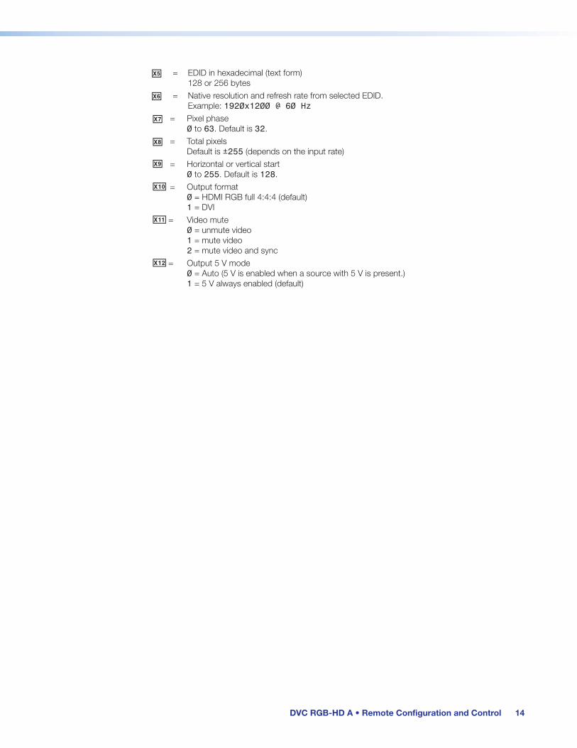
X%X% = EDID in hexadecimal (text form) 128 or 256 bytes
X^X^ = Native resolution and refresh rate from selected EDID. Example: 1920x1200 @ 60 Hz
X&X& = Pixel phase 0 to 63. Default is 32.
X*X* = Total pixels Default is ±255 (depends on the input rate)
X( = Horizontal or vertical start 0 to 255. Default is 128.
X1) = Output format 0 = HDMI RGB full 4:4:4 (default) 1 = DVI
X1! = Video mute 0 = unmute video 1 = mute video 2 = mute video and sync
X1@ = Output 5 V mode 0 = Auto (5 V is enabled when a source with 5 V is present.) 1 = 5 V always enabled (default)

DVC RGB-HD A • Remote Configuration and Control 15
Command and Response Table for SIS Commands
Command ASCII Command (Host to Converter)
Response (Converter to Host) Additional Description
Video Mute
Mute video 1B Vmt1 ] Mute the video output and display a black screen.
Mute video and sync 2B Vmt2 ] Mute (blank) the video output and disconnect the sync.
Unmute video 0B Vmt0 ] Unmute the video and display the output.
View mute status B X1! ]In verbose modes 2 and 3: Vmt X1! ]
Show the video mute status.
Audio Mute (Embedded HDMI Audio Output)
Audio mute X! Z Amt X! ] Mute or unmute the embedded HDMI audio output. For X!: 0 = Unmute audio (default) 1 = Mute audio
View audio mute Z X! ] In verbose modes 2 and 3: Amt X! ]
View the audio mute status.
Signal Presence
Signal presence, input and output
E 0LS } X! * X! ]In verbose modes 2 and 3: Sig X! * X! ]
Show signal presence on input and output. For X!:0 = No signal detected 1 = Signal detected
EDID Minder
Assign EDID slot to input
E A X$ EDID } Edid A X$ ] Assign EDID resolution and refresh rate X$ to the input.
View EDID assignment E A EDID } X$ ] View assigned EDID X$.
View EDID in hexadecimal format
E REDID } X% ] Show the hexadecimal data as text from the EDID assigned to the input.
View EDID native resolution
E NEDID } X^ ] Show the resolution and rate of the currently assigned EDID.
NOTE: X!X! = On (detected) or off (not detected): 0 = off, 1 = on. X$ = EDID number or slot: 1 = 1280 x 720 @ 60 Hz 6 = 1920 x 1080 @ 60 Hz 2 = 1280 x 800 @ 60 Hz 7 = 1920 x 1200 @ 60 Hz 3 = 1440 x 800 @ 60 Hz 8 = Current output EDID (default) 4 = 1600 x 900 @ 60 Hz 9 = User-assigned 5 = 1680 x 1050 @ 60 Hz X% = Currently assigned EDID data in hexadecimal form X^ = Resolution and refresh rate of currently assigned EDID. (Example: 1920x1080 @60.0Hz) X1!X1! = Video mute: 0 = mute off (default), 1 = mute on (mute to black screen), 2 = mute on (mute all output sync and video)

DVC RGB-HD A • Remote Configuration and Control 16
Command ASCII Command (Host to Converter)
Response (Converter to Host) Additional Description
5 V Output Hot Plug Mode
Set output hot plug mode (5 V)
E M X1@ HPLG } HplgM X1@ ] Set output 5 V hot plug mode to X1@.
View output hot plug mode status
E M HPLG } X1@ ]In verbose modes 2 and 3: HplgM X1@ ]
View the 5 V hot plug mode.
Output Format
Set the TMDS output format
E X1) VTPO } Vtpo X1) ] Set the format of the output.
View output format setting
E VTPO } X1) ]In verbose modes 2 and 3: Vtpo X1) ]
View the output format.
Picture Adjustment
Pixel Phase
Set pixel phase value E 1* X& PHAS} Phas 1* X& ] Set the point (X&) at which pixels aresampled for the display.
Increment pixel phase value
E 1 + PHAS } Phas 1* X& ] Increase the pixel phase value by 1.
Decrement pixel phase value
E 1 - PHAS } Phas 1* X& ] Decrease the pixel phase value by 1.
View pixel phase value E 1 PHAS } X& ]In verbose modes 2 and 3: Phas 1* X& ]
View the pixel phase value.
Total Pixels
Set total pixels value E 1* X* TPIX } Tpix 1* X* ] Set the width in pixels of the total videodisplay area (X*).
Increment total pixels value
E 1 + TPIX } Tpix 1* X* ] Increase the total pixels by 1.
Decrement total pixels value
E 1 - TPIX } Tpix 1* X* ] Decrease the total pixels by 1.
View total pixels value E 1 TPIX } X* ]In verbose modes 2 and 3: Tpix 1* X* ]
View the total pixels.
NOTE: X& = Pixel phase: 0-63. Default is 32. X* = Total pixels: Default value ± 255. X1) = TMDS output format: 0 = HDMI RGB full 4:4:4 (default), 1 = DVI. X1@X1@ = Output 5 V mode: 0 = Auto: 5 V is enabled when a source with 5 V is present), 1 = 5 V mode is always enabled (default).

DVC RGB-HD A • Remote Configuration and Control 17
Command ASCII Command (Host to Converter)
Response (Converter to Host) Additional Description
Picture Adjustment (continued)
Horizontal Start
Set horizontal start value
E 1* X( HSRT } Hsrt 1* X( ] Set the distance in pixels from the leftedge of the total video input displayarea to the left edge of its activearea (X().
Increment horizontal start value
E 1 + HSRT } Hsrt 1* X( ] Increase the horizontal start value by 1.
Decrement horizontal start value
E 1 - HSRT } Hsrt 1* X( ] Decrease the horizontal start value by 1.
View horizontal start value
E 1 HSRT } X( ]In verbose modes 2 and 3: Hsrt 1* X( ]
View the horizontal start value.
Vertical Start
Set vertical start value E 1* X( VSRT } Vsrt 1* X( ] Set the distance in lines from the topedge of the total video input displayarea to the top edge of its activearea (X().
Increment vertical start value
E 1 + VSRT } Vsrt 1* X( ] Increase the vertical start value by 1.
Decrement vertical start value
E 1 - VSRT } Vsrt 1* X( ] Decrease the vertical start value by 1.
View vertical start value E 1 VSRT } X( ]In verbose modes 2 and 3: Vsrt 1* X( ]
View the vertical start value.
Verbose ModeSet verbose mode E X# CV } Vrb X# ] Set the verbose mode.
View verbose mode E CV } X# ]In verbose modes 2 and 3: Vrb X# ]
View current verbose mode X#.
Device Name
Set unit name E X@ CN } Ipn • X@ ] Set a new name for the DVC.
Set unit name to factory default
E • CN } Ipn • DVC-RGB-HD-A] Reset the unit name to the factory default name: DVC-RGB-HD-A.
View unit name E CN } X@ ]In verbose modes 2 and 3: Ipn • X@ ]
View the name of the unit.
NOTE: X@ = Unit name: a text string of up to 24 characters, including A-Z, 0-9, and hyphen (-). No blank or space characters are permitted. The first character must be a letter and the last character cannot be a hyphen. X# = Verbose mode: 0 = None, 1 = verbose mode on (default), 2 = verbose mode off, tagged responses enabled for queries, 3 = Verbose mode and tagged responses for queries enabled (see the Verbose mode symbol definitions on page 13). X( = Horizontal or vertical start: 0 to 255. Default is 128.
DVC RGB-HD A • Remote Configuration and Control 18
Command ASCII Command (Host to Converter)
Response (Converter to Host) Additional Description
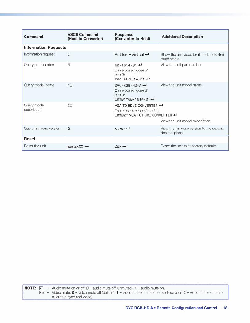
Information Requests
Information request I Vmt X1! • Amt X! ] Show the unit video (X1!) and audio (X1) mute status.
Query part number N 60-1614-01 ]In verbose modes 2 and 3: Pno 60-1614-01 ]
View the unit part number.
Query model name 1I DVC-RGB-HD-A ]In verbose modes 2 and 3: Inf01*60-1614-01]
View the unit model name.
Query model description
2I VGA TO HDMI CONVERTER ]In verbose modes 2 and 3: Inf02* VGA TO HDMI CONVERTER ]
View the unit model description.
Query firmware version Q n.nn ] View the firmware version to the second decimal place.
Reset
Reset the unit E ZXXX } Zpx ] Reset the unit to its factory defaults.
NOTE: X! = Audio mute on or off. 0 = audio mute off (unmuted), 1 = audio mute on. X1! = Video mute: 0 = video mute off (default), 1 = video mute on (mute to black screen), 2 = video mute on (mute all output sync and video)

DVC RGB-HD A • Remote Configuration and Control 19
Product Configuration Software (PCS)The Extron PCS configuration software for DVC RGB-HD A is a Windows-based program that provides a convenient way to configure the input and output, audio, and image settings. It lets you perform many other functions that can be accomplished via SIS commands.
Downloading the PCS Software from the WebsiteTo use PCS, download the latest version of the program from the Extron Web page and install it on the PC that will be connected to the DVC, as described in the following sections. You can also download updates to the PCS software as they become available. To access the software:
1. Go to www.extron.com and select the Download tab (see figure 10, 1).
2. On the Download screen, click the PCS link on the left sidebar menu (2).
Figure 10. PCS Software Link on the Download Page of the Extron Website

DVC RGB-HD A • Remote Configuration and Control 20
3. On the PCS page, click the Download button in the new features table (see figure 11, 1).
Figure 11. Download Button on the PCS Web Page
4. On the Download Center page, fill in the required information, then click the Download PCS_vnxnxnxnn.exe button.
5. On the next screen, log in with your e-mail address and password. (If you do not have an Extron account with a password, follow the instructions on the screen to obtain one, then proceed to step 6).
6. On the Download Center page that is displayed next, fill in the required information, then click the Download pcss_vnxn.exe button.
7. If the File Download - Security Warning window appears, click Run to begin downloading the installer file.
NOTE: If you want to save the installation file to your computer hard drive to run later, click Save. On the Save As window that opens, save the setup file to the desired location. When you are ready to install the software, double-click on the PCS_vnxnxnxnn.exe icon, click Run on the download screen that opens, and restart this procedure at step 6.
If, instead, you see a Download icon at the bottom of the page, wait until the icon displays the name PCS_vnxnxnxnn.exe, then click it.
8. On the next prompt window that opens, click Run to start the installation process.

DVC RGB-HD A • Remote Configuration and Control 21
9. Follow the instructions on the InstallShield Wizard screens to complete the software program installation. By default, the installation creates a folder called “Extron PCS” in one of the following locations on the computer (depending on the Windows version):
c:\Program Files (x86)\Extron\Extron PCS or c:\Program Files\Extron\Extron PCS
If there is not already an Extron folder in your Program Files or Program Files x86 folder, the installation program creates it as well.
Starting the Configuration ProgramIn order to use the PCS software, the DVC must be connected to your computer via the rear panel USB port (see Connecting for USB Control on page 8).
1. To start the PCS configuration program, do either of the following:
• Access the program from the Start menu on your computer as follows:
a. Click Start on your computer screen.
b. Select All Programs from the Start menu.
c. From the All Programs menu, select Extron Electronics/Extron Product Configuration Software/Extron Product Configuration Software. The Extron Product Configuration Software window opens.
• Double-click on the EAF.exe file, located on your computer at c:\Program Files [or Program Files(x86)]\Extron\Extron PCS.
2. The first time you open the PCS software, the Tutorial screen appears, identifying items on the toolbar at the top of the PCS screen. When finished looking at the tutorial, click I Get It to close the screen. The Extron PCS window opens.
3. In the Device Discovery panel of the PCS window, click on DVC RGB-HD A (see figure 12, 1). You may need to scroll to locate it, depending on the number of devices listed. The Connect button in the bottom-right corner becomes available.
Figure 12. Device Discovery Panel

DVC RGB-HD A • Remote Configuration and Control 22
4. Click Connect (see figure 12, 2 on the previous page) or double-click on the product name (see figure 12, 1) to open the DVC RGB-HD A main window (see figure 13, below).
Figure 13. DVC RGB-HD A Main Window
Firmware LoaderExtron periodically updates product firmware in conjunction with the release of new software revisions. Before updating any Extron product to the latest revision level, be sure to read the supplied release notes or contact Extron Technical Support to determine if your product requires a firmware update. You can update firmware using the Firmware Loader software or the PCS configuration software (see the program help file).
You can find out what version of firmware is currently loaded on your DVC by entering the SIS Q command via the USB interface (see the Query Firmware Version command on page 18).

DVC RGB-HD A • Remote Configuration and Control 23
Downloading and Installing Firmware LoaderIf you do not already have Firmware Loader installed on your computer, download it as follows:
1. Go to www.extron.com and click the Download tab.
2. On the Download screen, click the Software link (see figure 14, 1) in the left panel or the Software icon (2) near the center of the screen.
Figure 14. Selecting Software on the Download Screen

DVC RGB-HD A • Remote Configuration and Control 24
3. On the Download Center screen, click the F link (see figure 15, 1), then locate Firmware Loader and click its Download link (2).
Figure 15. Firmware Loader Links on the Download Center Screen

DVC RGB-HD A • Remote Configuration and Control 25
4. On the Please log in for File Downloading, log in with your e-mail address and password. (If you do not have an Extron account with a password, follow the instructions on the screen to obtain one, then proceed to step 5).
Figure 16. Download Login Screen
5. On the Download Center page that appears next, fill in the required information, then click the Download fw_loader_vnxn.exe button (where nxn is the Firmware Loader version number).
6. Follow the instructions on the rest of the download screens to run the executable Firmware Loader installer file.
7. Follow the instructions on the Installation Wizard screens to install Firmware Loader on your computer. Unless you specify otherwise, the installer program places the Firmware Loader files at c:\Program Files [(x86)]\Extron\FWLoader.

DVC RGB-HD A • Remote Configuration and Control 26
Downloading and Installing the DVC RGB-HD A FirmwareTo obtain the latest version of firmware for the DVC RGB-HD A:
1. Go to www.extron.com and click the Download link at the top of the page (see figure 17, 1).
Figure 17. Firmware Links on the Download Center Screen
2. On the Download screen, click the Firmware link (2) in the left panel.
3. On the Download Center screen that appears next, click the D button (3) near the top of the page, then scroll to locate the DVC RGB-HD A firmware.
4. In the DVC RGB-HD A panel of the firmware Download Center screen, click the Download button at the right edge of the page.
5. On the Please log in for File Downloading, log in with your e-mail address and password. (If you do not have an Extron account with a password, follow the instructions on the screen to obtain one, then proceed to step 6).
6. On the Download Center page that appears next, fill in the required information, then click the Download button for the new firmware version.
7. Follow the instructions on the rest of the download screens to run the executable firmware installer file.
8. Follow the instructions on the Installation Wizard screens to install the new firmware on your computer. A Release Notes file, providing information on what has changed in the new firmware version, and a set of instructions for updating the firmware are also loaded.
NOTE: When downloaded from the Extron website, by default the firmware is placed in a folder at: C:\Program Files\Extron\Firmware\DVC RGB-HD A (Windows XP) or C:\Program Files (x86)\Extron\Firmware\DVC RGB-HD A (Windows 7 or higher).

DVC RGB-HD A • Remote Configuration and Control 27
Loading the Firmware to the DVCTo load a new version of firmware to the DVC using Firmware Loader:
1. Connect your computer to the DVC via the rear panel USB port (see Connecting for USB Control on page 8).
2. If you have not already done so, download and install the Firmware Loader executable installer file to your computer (see Downloading and Installing Firmware Loader on page 23).
3. If necessary, download the latest version of DVC RGB-HD A firmware and install it on your computer (see Downloading and Installing the DVC RGB-HD A Firmware on the previous page).
4. Open the Firmware Loader on your computer. The Firmware Loader window opens with the Add Device dialog box in front.
NOTE: You can also open Firmware Loader from within the PCS software. See the PCS help file for DVC RGB-HD A for instructions.
Figure 18. Firmware Loader Window with Add Device Dialog Box
5. On the Add Device window, select DVC RGB-HD A from the Device Name drop-down menu (see figure 18, 1).
Because there is only one connection method for the DVC RGB-HD A, the Connection Method and Available Devices fields are automatically populated with your USB connection information.

DVC RGB-HD A • Remote Configuration and Control 28
6. Click the Connect button (see figure 19, 1). DVC RGB-HD A appears in green in the Connected Device panel, followed by a check mark.
Figure 19. Connection Method Menu on the Add Device Window
7. Click the Browse button in the New Firmware File (Optional) panel (2).
8. In the Open window, navigate to the new firmware file, which has an .S19 extension, and double-click it.
ATTENTION:
• Valid firmware files must have the file extension .S19. A file with any other extension is not a firmware upgrade for this product and could cause the switcher to stop functioning.
• Les fichiers firmware valides doivent contenir l’extension fichier .S19. Un fichier avec n’importe quelle autre extension n’est pas une mise à jour de firmware pour cet appareil et l’appareil pourrait arrêter de fonctionner.
On the Add Device window, the path to the new firmware file is displayed in the Path field.

DVC RGB-HD A • Remote Configuration and Control 29
9. If this is the only device to which you are uploading firmware, click Add in the Add Device dialog box (see figure 19, 3, on the previous page).
The DVC information is added to the Device panel of the Firmware Loader window (see figure 20, 1) and the Add Device window closes.
Figure 20. Firmware Loader Screen with a DVC RGB-HD A Added
If you will be uploading the firmware to multiple devices that are connected to your computer, do the following:
a. Click the Add Next button in the Add Device dialog box. Your first device is added to the Device panel (see figure 20, 2) of the Firmware Loader window, and the Add Device window remains open.
b. For each additional device that you want to add to the Firmware Loader window, repeat steps 5 through 8, then click Add Next.
c. For the last device, click Add (instead of Add Next) to add the device and to close the Add Device window.
10. If you want to remove devices from the Device panel, do the following:
a. Click on the names of the devices to be deleted, to highlight them.
b. Click Edit > Remove Selected Device(s). The selected devices are removed from the Device panel.
To remove all devices, click Edit > Remove All Devices.
To add devices after the Add Device dialog box has closed, click Edit > Add Device(s) to reopen the Add Device window. Repeat step 9 as needed.

DVC RGB-HD A • Remote Configuration and Control 30
11. Click the Begin button (see figure 20, 2, on the previous page). The following indicators show the progress of the update:
• The Transfer Time panel (see figure 21, 1) shows the remaining and elapsed time for the update.
• The Total Progress panel (2) displays the percentage of upload time that has elapsed, a progress bar with Uploading... above it, and the rate of device data transfer in kilobytes per second.
• In the Device panel, the Progress column (3) displays an incrementing percentage. The Status column (4) displays Uploading....
Figure 21. Firmware Upload in Progress

DVC RGB-HD A • Remote Configuration and Control 31
12. The upload is complete when the Remaining Time field (see figure 22, 1) of the Transfer Time panel shows 00.00.00, the Progress column (2) shows 100%, Completed is displayed above the progress bar (3) and in the Status column (4), and the new firmware version is displayed in the Current Firmware Version column (5).
Figure 22. Firmware Upload Complete

DVC RGB-HD A • Mounting 32
Mounting
This section provides mounting information on the DVC RGB-HD A. See www.extron.com for available Extron mounting kits and ordering information.
Mounting OptionsThe DVC RGB-HD A can be mounted to a rack, attached under a desk or podium, or placed on a table top.
• Rack mounting — Attach the DVC to a standard 19-inch, 6-inch, or 3.5-inch rack shelf (see the instructions provided with the mounting kit to rack mount the DVC).
• Under-furniture mounting — Mount the DVC under the surface of a desk, table, or podium. The Extron Under-desk Mounting Kit is provided with the DVC RGB-HD A (see Mounting under Furniture on the next page).
• Free-standing — Attach the four rubber feet to the bottom of the DVC in the four corners and place the unit on furniture as desired.
To mount the DVC using an Extron mounting kit, see the instructions provided with the kit.
UL Guidelines for Rack MountingThe following Underwriters Laboratories (UL) guidelines pertain to the installation of the DVC RGB-HD A in a rack:
• Elevated operating ambient temperature — If the equipment is installed in a closed or multi-unit rack assembly, the operating ambient temperature of the rack environment may be greater than room ambient temperature. Therefore, consider installing the equipment in an environment compatible with the maximum ambient temperature (TMA) specified by the manufacturer.
• Reduced air flow — Install the equipment in the rack so that the amount of air flow required for safe operation of the equipment is not compromised.
• Mechanical loading — Mount the equipment in the rack so that uneven mechanical loading does not create a hazardous condition.
• Circuit overloading — When connecting the equipment to the supply circuit, consider the effect that circuit overloading might have on overcurrent protection and supply wiring. Consider equipment nameplate ratings when addressing this concern.
• Reliable earthing (grounding) — Maintain reliable grounding of rack-mounted equipment. Pay particular attention to supply connections other than direct connections to the branch circuit (such as the use of power strips).
DVC RGB-HD A • Mounting 33
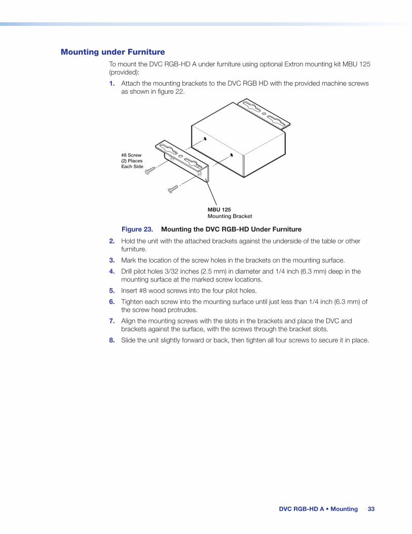
Mounting under FurnitureTo mount the DVC RGB-HD A under furniture using optional Extron mounting kit MBU 125 (provided):
1. Attach the mounting brackets to the DVC RGB HD with the provided machine screws as shown in figure 22.
#8 Screw(2) PlacesEach Side
MBU 125 Mounting Bracket
Figure 23. Mounting the DVC RGB-HD Under Furniture
2. Hold the unit with the attached brackets against the underside of the table or other furniture.
3. Mark the location of the screw holes in the brackets on the mounting surface.
4. Drill pilot holes 3/32 inches (2.5 mm) in diameter and 1/4 inch (6.3 mm) deep in the mounting surface at the marked screw locations.
5. Insert #8 wood screws into the four pilot holes.
6. Tighten each screw into the mounting surface until just less than 1/4 inch (6.3 mm) of the screw head protrudes.
7. Align the mounting screws with the slots in the brackets and place the DVC and brackets against the surface, with the screws through the bracket slots.
8. Slide the unit slightly forward or back, then tighten all four screws to secure it in place.

Contact Information
Worldwide Headquarters: Extron USA West, 1025 E. Ball Road, Anaheim, CA 92805, 800.633.9876
Extron Warranty
Extron warrants this product against defects in materials and workmanship for a period of three years from the date of purchase. In the event of malfunction during the warranty period attributable directly to faulty workmanship and/or materials, Extron will, at its option, repair or replace said products or components, to whatever extent it shall deem necessary to restore said product to proper operating condition, provided that it is returned within the warranty period, with proof of purchase and description of malfunction to:
USA, Canada, South America, and Central America:Extron 1230 South Lewis Street Anaheim, CA 92805 U.S.A.
Asia:Extron Asia Pte Ltd 135 Joo Seng Road, #04-01 PM Industrial Bldg. Singapore 368363 Singapore
Japan:Extron Japan Kyodo Building, 16 Ichibancho Chiyoda-ku, Tokyo 102-0082 Japan
Europe:Extron Europe Hanzeboulevard 10 3825 PH Amersfoort The Netherlands
China:Extron China 686 Ronghua Road Songjiang District Shanghai 201611 China
Middle East:Extron Middle East Dubai Airport Free Zone F13, PO Box 293666 United Arab Emirates, Dubai
Africa:Extron South Africa 3rd Floor, South Tower 160 Jan Smuts Avenue Rosebank 2196, South Africa
This Limited Warranty does not apply if the fault has been caused by misuse, improper handling care, electrical or mechanical abuse, abnormal operating conditions, or if modifications were made to the product that were not authorized by Extron.
NOTE: If a product is defective, please call Extron and ask for an Application Engineer to receive an RA (Return Authorization) number. This will begin the repair process.
USA: 714.491.1500 or 800.633.9876 Asia: 65.6383.4400
Europe: 31.33.453.4040 or 800.3987.6673 Japan: 81.3.3511.7655
Africa: 27.11.447.6162 Middle East: 971.4.299.1800
Units must be returned insured, with shipping charges prepaid. If not insured, you assume the risk of loss or damage during shipment. Returned units must include the serial number and a description of the problem, as well as the name of the person to contact in case there are any questions.
Extron makes no further warranties either expressed or implied with respect to the product and its quality, performance, merchantability, or fitness for any particular use. In no event will Extron be liable for direct, indirect, or consequential damages resulting from any defect in this product even if Extron has been advised of such damage.
Please note that laws vary from state to state and country to country, and that some provisions of this warranty may not apply to you.