Electromechanical cylinders EMC - Bosch Rexroth
44
R320103102/2021-04 Replaces: 2018-03 EN EN Electromechanical cylinders EMC Instructions
-
Upload
khangminh22 -
Category
Documents
-
view
0 -
download
0
Transcript of Electromechanical cylinders EMC - Bosch Rexroth

R320103102/2021-04Replaces: 2018-03EN
EN
Electromechanical cylinders EMC
Instructions

The information provided serves only to describe the product. No statements concerning a certain condition or suitability for a certain purpose can be derived from our information. The information given does not release the user from the obligation of own judgment and verification. It should be noted that our products are subject to a natural process of aging and wear.© This document, as well as the data, specifications, and other information set forth in it, are the exclusive property of Bosch Rexroth AG. It may not be reproduced or given to third parties without our consent.
The title page contains an illustration of a sample configuration. The product as delivered can differ from the illustration.The original instructions are in German.
Any dissemination of the product must include these mounting instructions and the safety instructions and information for linear motion systemsR320103152.
Die vorliegende Anleitung ist in folgenden Sprachen verfügbar.These instructions are available in the following languages.Les présentes instructions sont disponibles dans les langues suivantes.Le presenti istruzioni sono disponibili nelle lingue seguenti.Las presentes instrucciones están disponibles en los siguientes idiomas.As presentes instruções estão disponíveis nas seguintes línguas.本说明书具有下列语言版本。DE Deutsch (Originaldokumentation)EN EnglishFR FrançaisIT ItalianoES EspañolPT PortuguêsZH 中文
2/44 Bosch Rexroth AG Electromechanical cylinders EMC | R320103102/2021-04

EN
EN
FR
IT
ES
PT
R320103102/2021-04 | Electromechanical cylinders EMC Bosch Rexroth AG 3/44
Contents1 About these instructions ������������������������������������������������������������������������� 42 Safety instructions ���������������������������������������������������������������������������������� 63 Scope of delivery ������������������������������������������������������������������������������������ 64 Product description �������������������������������������������������������������������������������� 65 Transport and storage ����������������������������������������������������������������������������� 86 Assembly ������������������������������������������������������������������������������������������������� 97 Start-up ������������������������������������������������������������������������������������������������� 309 Operation ���������������������������������������������������������������������������������������������� 358 Cleaning and care ���������������������������������������������������������������������������������� 3510 Maintenance and repair ������������������������������������������������������������������������ 3611 Removal and replacement ��������������������������������������������������������������������� 4212 Disposal ������������������������������������������������������������������������������������������������� 4313 Technical data ��������������������������������������������������������������������������������������� 4314 Operating conditions ���������������������������������������������������������������������������� 43

4/44 Bosch Rexroth AG Electromechanical cylinders EMC | R320103102/2021-04
1 About these instructions
1.1 Validity of the documentationThis documentation applies to the following products:
• Electromechanical cylinders EMC as described in the catalog "Electromechanical Cylinders EMC".This documentation is intended for assembly personnel, operators and system owners.This documentation contains important information for the proper and safe mounting, operation, maintenance and disassembly of the product and for troubleshooting simple errors oneself.
X Before commencing any work with the product, be sure to read these Instructions and the "Safety Instructions for linear motion systems" carefully and completely.
1.2 Required documentationDocumentation which is indicated by the book symbol must be obtained before handling the product and must be observed:
Table 1: Required documentation
Title Document number
Application Included in delivery
Safety instructions for linear motion systems R320103152 Safety instructions 4
Electromechanical cylinders EMC R999000473 Catalog
Safety data sheet for Dynalub 510 R320103160 Safety instructions
Product data sheet for Dynalub 510 R310 2052 Catalog
Safety data sheet for Dynalub 520 R320103161 Safety instructions
Product data sheet for Dynalub 520 R310 2053 Catalog
The Rexroth documentation is available for download at www.boschrexroth.com/mediadirectory.
1.3 Presentation of informationTo enable users to work rapidly and safely with the product while following these instructions, this documentation uses standardized safety instructions, symbols, terms and definitions, and abbreviations. These are explained in the following sections.
1.3.1 Safety instructions in this documentThis document contains safety instructions preceding any actions that involve a risk of personal injury or damage to property. The safety precautions described must be adhered to.Safety instructions are structured as follows:
EN
EN
FR
IT
ES
PT
R320103102/2021-04 | Electromechanical cylinders EMC Bosch Rexroth AG 5/44
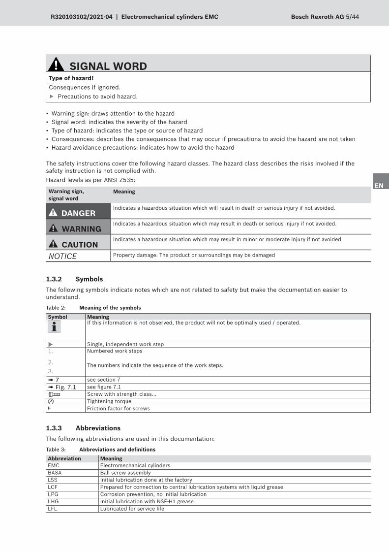
The safety instructions cover the following hazard classes. The hazard class describes the risks involved if the safety instruction is not complied with.Hazard levels as per ANSI Z535:
Warning sign, signal word
Meaning
DANGERIndicates a hazardous situation which will result in death or serious injury if not avoided.
WARNINGIndicates a hazardous situation which may result in death or serious injury if not avoided.
CAUTIONIndicates a hazardous situation which may result in minor or moderate injury if not avoided.
NOTICE Property damage: The product or surroundings may be damaged
SIGNAL WORDType of hazard!Consequences if ignored.
f Precautions to avoid hazard.
• Warning sign: draws attention to the hazard • Signal word: indicates the severity of the hazard • Type of hazard: indicates the type or source of hazard • Consequences: describes the consequences that may occur if precautions to avoid the hazard are not taken • Hazard avoidance precautions: indicates how to avoid the hazard
1.3.2 SymbolsThe following symbols indicate notes which are not related to safety but make the documentation easier to understand.
Table 2: Meaning of the symbols
Symbol MeaningIf this information is not observed, the product will not be optimally used / operated.
X Single, independent work step 1.
2. 3.
Numbered work steps
The numbers indicate the sequence of the work steps.
! 7 see section 7! Fig. 7.1 see figure 7.1
Screw with strength class...u Tightening torquem Friction factor for screws
1.3.3 AbbreviationsThe following abbreviations are used in this documentation:
Table 3: Abbreviations and definitionsAbbreviation MeaningEMC Electromechanical cylindersBASA Ball screw assemblyLSS Initial lubrication done at the factoryLCF Prepared for connection to central lubrication systems with liquid greaseLPG Corrosion prevention, no initial lubricationLHG Initial lubrication with NSF-H1 greaseLFL Lubricated for service life

6/44 Bosch Rexroth AG Electromechanical cylinders EMC | R320103102/2021-04
2 Safety instructionsThe general safety instructions for this product can be found in the documentation "Safety Instructions for linear motion systems", which is also enclosed with the product. You must have read and understood these before handling the product.
3 Scope of deliveryThe following is included within the scope of delivery:
• Electromechanical cylinders EMC plus any motors and accessories • Documents ! Table 1 on page 4 that are indicated
3.1 Condition as delivered • Depends on order
3.2 AccessoriesThe following accessories are available:
• Fastening elements, switches, motor attachment kit (flange and coupling, belt side drive) • Force sensor, screw plugs ! Fig. 1, Straight connectors
Dimensions and material numbers of the accessories as well as additional fastening accessories ! Product catalog.
4 Product description
4.1 Performance descriptionPlease refer to the notes, technical data, dimensions and descriptions in the product catalog.
4.2 Device description
64
3
2
1 5
Fig� 1: Components of the electromechanical cylinder EMC
78
9
1 Piston rod (stainless steel)2 Hex socket head cap screw on the cover (8) with
inner thread for fastening accessories3 Housing4 Hex socket head cap screw on the base (9) with
inner thread for fastening accessories, flange or belt side drive
5 Drive journal
6 Hexagon nut7 Screw plug (accessory) for cover8 Cover9 Bottom

EN
EN
FR
IT
ES
PT
R320103102/2021-04 | Electromechanical cylinders EMC Bosch Rexroth AG 7/44
4.3 Identification of the product
Table 4: Information on nameplateMNR Material number
TYP Short product name
CS Customer information
FD Date of manufacture
7210 Manufacturing location
Bosch Rexroth AGD-97419 SchweinfurtMade in Germany
7210
CNR: R12345678
TYP: EMC-080-NN-2CS: 9876543210 0030 0001 FD: 5129
smax (mm) u (mm/U) vmax (m/s) amax (m/s2) M1max (Nm) d i -- -- -- -- -- -- --
MNR: R123456789
rexroth
Fig� 2: Nameplate
X When ordering wear parts, please always state all data given on the nameplate. For further information on the nameplate, see the chapter "Start-up".
The nameplate of the product contains the following information:

8/44 Bosch Rexroth AG Electromechanical cylinders EMC | R320103102/2021-04
!
!
1 2
3 4 5
Fig� 3: Transporting the EMC
5 Transport and storageTake note of the environmental conditions ! 14 and product catalogs.For special environmental conditions, please consult us.
5.1 Transporting the EMCElectromechanical cylinders are pre-mounted as ready-to-install units.
WARNINGRisk of product falling due to inadequate load handling equipment!Death or severe injury.
f Use only inspected and suitable load handling equipment. f Fasten load handling equipment only to the housing or at the designated points. f Do not stand under suspended loads.
NOTICERisk of damage to motor attachment due to motor vibrations/motor breaking off!Damage to the product.
f When transporting the product with mounted motor, always provide support for the motor, or f Disassemble the motor prior to transport.

EN
EN
FR
IT
ES
PT
R320103102/2021-04 | Electromechanical cylinders EMC Bosch Rexroth AG 9/44
NOTICERisk of damage to the product due to improper transportDamage to the product.
f Retract the piston rod (1). f Lift the EMC only by its housing (2). f Do not lift the EMC by the piston rod (3). The BASA is not self-locking. f Only use eyebolts on the cover of the EMC. Subject these to tensile stress only (4). f Prevent the EMC from swinging during lifting operations (5).
1. Before hoisting the EMC, take note of the weight ! Product catalog, chapter "Technical data".
2. Hoist the EMC using suitable lifting accessories.
5.2 Storing the EMC
NOTICERisk of product corrosion due to incorrect storage!Damage to the product.
f Store the product only in dry, covered areas. f Protect the product from humidity and corrosive agents.
6 AssemblyFor dimensions and material numbers of the individual components ! Product catalog.
WARNINGRisk of product falling if installed vertically or suspended due to lack of protection against falling loads!Death or severe injury.
f Secure the product against falling. f Do not stand under the product in the hazard zone.
X Before hoisting the EMC, take note of the weight ! Product catalog.

10/44 Bosch Rexroth AG Electromechanical cylinders EMC | R320103102/2021-04
6.2 Installation positionThe EMC can be installed in any position.
WARNINGRisk of piston rod crashing down in vertical or slanting installations as the unit is not self-locking or risk of damage to mechanics inside the EMC or breakage of toothed belt in case of motor mounting using a belt side drive!Death or severe injury.
f In vertical or slanting installations, secure the piston rod against falling. f Do not stand in the fall direction of the piston rod
Fig� 5: Dropping of the piston rod
6.1 Installation conditionsTake note of the operating conditions ! 14 and product catalogs.
X For special operating conditions, please contact us.
NOTICERisk of damage due to improper loads!Damage to the product.
f Do not place any protruding loads on the product (for maximum values, see product catalog). f Do not turn the piston rod. f Do not use the housing for attaching other machine elements to absorb forces.
Fig� 4: Non-permissible loads
F F
M

EN
EN
FR
IT
ES
PT
R320103102/2021-04 | Electromechanical cylinders EMC Bosch Rexroth AG 11/44
6.3 Required accessoriesRequired fastening material ! product catalog, chapter "Fastening elements".
6.4 Fastening options1 By the cover2 By the belt side drive3 By the base4 By the piston rod end
1
2
3
4
Fig� 6: Fastening options

12/44 Bosch Rexroth AG Electromechanical cylinders EMC | R320103102/2021-04
6.5 Fastening elements
6.5.1 Overview of fastening elements
Fig� 7: Fastening options

EN
EN
FR
IT
ES
PT
R320103102/2021-04 | Electromechanical cylinders EMC Bosch Rexroth AG 13/44

14/44 Bosch Rexroth AG Electromechanical cylinders EMC | R320103102/2021-04
6.5.2 Permissible forces for fastening elements
CAUTIONSome fastening elements are not approved up to the "Maximum permissible axial force of EMC Fmax EMC".Risk of injury.
f Observe the permissible maximum forces Fmax for fastening elements in the chapter "Fastening elements" in the product catalog.
Fmax EMC can be attained with suitably designed customer-built fastening elements.
6.5.3 Mounting the fastening elements
• The EMC is supplied with the fastening elements ordered. • Fastening elements between EMC and flange/coupling are delivered mounted. All other fastening elements are enclosed loose.
• Fastening elements can also be ordered separately as accessories.
NOTICEDamage to the mechanical system inside the cylinder due to the initiation of torques to the product.Damage to the product.
f Do not transfer any torque to the piston rod. f Counterhold by means of a wrench flat.
Fig� 8: Mounting the spherical rod end bearing
X Prior to mounting fastening elements on the timing belt side drive, the set screws need to be removed from the housing.
X Observe the max. permissible screw-in depth in the housing (see catalog EMC, chapter "Dimension drawing motor attachment with belt side drive")
X Mount the fastening elements as shown in the illustration ! Fig. 9. Tighten the fastening screws evenly, taking care not to exceed the maximum screw-in depth BG or tightening torque MA.
Table 5: Tightening torques MA
EMC 32, 40 50, 63 80, 100 100XC 8.8, µ = 0.125 M6 M8 M10 M12
BG (mm) 16 16 20 26u MA (Nm) 9.5 23.0 46.0 80.0

EN
EN
FR
IT
ES
PT
R320103102/2021-04 | Electromechanical cylinders EMC Bosch Rexroth AG 15/44
Fig� 9: Overview of fastening elements
BG

16/44 Bosch Rexroth AG Electromechanical cylinders EMC | R320103102/2021-04
6.5.4 Mounting the load measuring pinThe load measuring pin replaces the standard pin. Like the standard pin, it is installed between the spherical rod end bearing and the clevis bracket or in connection with the belt side drive between the swivel bearing and the clevis bracket.
3
1
4
2
Table 6: Metrological specifications for load measuring pin
Measurement range/inaccuracy EMC Measurement range (kN) Measurement inaccuracy (kN)
-032 1.3 ± 0.007-040 5.0 ± 0.025-050 8.0 ± 0.04-063 16.0 ± 0.08-080 22.0 ± 0.11-100 45.0 ± 0.23
-100XC 56.0 ± 0.28Material Stainless steelProtection class IP65Hardness (load range) 38 HRCMechanical systemOperating load 150% of MB1)
Breaking load 300% of MBAccuracyNon-linearity ±0.5% of MBRepeatability ±0.25% of MBHysteresis ±0.2% of MBTemperature drift at zero point ±0.05% of MB/K.2)
Temperature drift over measurement range ±0.05% of MB/K.Compensated temperature +10 ... +40 °COperating temperature -20 ... +60 °C
CAUTIONFunctional errors due to incorrect mounting of load measuring pinDamage to the product
f Push the load measuring pin into the bore by hand. f Do not use a hammer or press to fit the load measuring pin.
1. Remove the pin lock (4) on the standard pin.
2. Take out the standard pin.
3. Push the load measuring pin (1) by hand between the spherical rod end bearing (2) and the clevis mount (3).4. Use the included pin lock (4) to secure the load measuring pin (1) axially and against twisting on one side of
the clevis mount (3).5. Align the electrical connection on the load measuring pin according to the application. Polarity of the
connection ! Fig. 11.
Fig� 10: Force measuring bolt
1) MB = Measurement range2) MB/K. = Measurement range per Kelvin

EN
EN
FR
IT
ES
PT
R320103102/2021-04 | Electromechanical cylinders EMC Bosch Rexroth AG 17/44
Connection cable
Table 8: Technical data, connection cableLength 5 mRated voltage 250 VRated current 4 APlug outlet angledConnection type 1 Female connector M12, 4-pinConnection type 2 Flying leadsType of cable PUR black, shieldedSuitable for drag chains yesCable cross-section 4 x 0.34 mm2
Cable diameter D 5.9 ±0.2 mmStatic bending radius >10 x DDynamic bending radius >5 x DBending cycles >2 milAmbient temperature, stationary -25 … +80 °CAmbient temperature, in motion -40 … +80 °CProtection class IP65
Plug on the load measuring pin
F 0 to -10V0 to +10V
Output signal depending on direction of loading
Connection diagram
1 Supply (+)2 Tare3 GND4 Output5 Internal assignment
12
43
5
Fig� 11: Connecting the electrical power supply to the load measuring pin
Table 9: Colors, connection cable
Color Functionbrn Power supply (+)wht Tareblu GNDblk Output– Internal assignment
Table 7: Electrical specification for load measuring pinOutput signal 0kN 0±0.03 VOutput signal MB -10 ... 10 V ±0.2 VPower supply voltage 24 V ±2 VTare (zero setting function) 7.2 ... 24 VCurrent consumption 25 mA (24 V)Bandwidth 2.5 ±0.2 KHzConnection Plug M12x1

18/44 Bosch Rexroth AG Electromechanical cylinders EMC | R320103102/2021-04
Fig� 12: Distortive stress to cover/base and housing
6.6 Mounting the EMC
NOTICEFunction failure of product due to incorrect fastening (distortive stress)!Damage to the product
f Mount the EMC so it is free of distortive stress ! Fig. 12.
F
F
F
1. Bring the EMC into position (piston rod extended/retracted). ! Air compensation hole 6.6.1
2. Tighten the fastening screws evenly. Take care not to exceed the maximum permissible tightening torques MA ! Table 20 on page 43.
6.6.1 Air compensation bore (with housing option IP65 and IP65+R)
1. Mount the EMC so that the air compensation bore (1) is not obstructed.
2. If required by the environment, a hose can be connected for the supply of clean air.3. Alternatively, overpressure (max. 0.2 bar) can be applied as sealing air via the hose (Ø8 mm).
Fig� 13: Air compensation hole
1

EN
EN
FR
IT
ES
PT
R320103102/2021-04 | Electromechanical cylinders EMC Bosch Rexroth AG 19/44
6.7 Mounting the drive
NOTICEExceeding of limit values for torque and rotary speed!Damage to the product.
f Observe the specified limits.
Technical data and maximum values, ! Catalog "Electromechanical Cylinders EMC".The Electromechanical Cylinder EMC has the following drive types:
• Motor (1) with flange and coupling (2) • Motor (1) with belt side drive (3)
1
2
3
1
Fig� 14: Drive types
6.7.1 Motor type / motor identifier
X The motor type is described by two variants:
a) Rexroth motor, for example MS2N04b) Motor code describing the connection geometry of the third-party motor, e.g. 14-30-060-3.0-075-M05-008-072
⌀E
⌀D
CC1
B1
⌀F
A
⌀G
Example
b) motor code
a) MS2N04b) 14-30-060-3.0-075-M05-008-072
Fig� 15: Motor type / motor identifier
/

20/44 Bosch Rexroth AG Electromechanical cylinders EMC | R320103102/2021-04
6.7.2 Mounting the motor with flange and coupling
1. Push the coupling (1) onto the motor’s drive journal (6). Observe the distance dimension (B) ! Fig. 17/table 13. Clamp the coupling onto the motor journal with the clamping screw (3) to MA1.
4
10
8
9
67
5
132
Fig� 16: Mounting the motor with flange and coupling
2. Mount the coupling housing (4) on the base of the cylinder using four screws (5). See MA2 ! Table 12 Pay attention to the alignment of the sealing bore (10).
3. Mount the motor plate (8) using four/six screws (9) on the coupling housing (4). MA2 ! Table 12.4. Slide the motor (6) with coupling (1) into the motor plate (8) and the coupling housing (4). Fasten the motor
with four screws (7) to the motor plate with MA2. Clamp the coupling with screw (2) on the drive journal of the cylinder to MA1 ! Table 11
5. Using the sealing plug, seal the coupling housing.
Table 11: MA1
µ = 0.125 M3 M4 M5 M6 M8 M10u MA1 (Nm) 1.7 3.5 7.0 12.0 25.0 50.0
Table 12: MA2
8.8, µ = 0.125 M3 M4 M5 M6 M8 M10 M12u MA2 (Nm) 1.3 2.7 5.5 9.5 23.0 46.0 80.0
Fig� 17: Adjusting B dimensions
B

EN
EN
FR
IT
ES
PT
R320103102/2021-04 | Electromechanical cylinders EMC Bosch Rexroth AG 21/44
Table 13: Dimension B for flange and couplingEMC Motor type Dimension B (mm)
32MSM019B, MSM031B 3.5 8.01)
MSK030C, MS2N03B, 09-20-040-2.5-063-M05-010-055 4.0 8.01)
40MSM031C 3.5
-
MSK030C, MS2N03B, MS2N03D, MSK040C, MS2N04 4.014-30-060-3.0-075-M06-008-072 3.5
50MSM031C, MSM041B 3.5MSK040C, MS2N04 4.0MSK050C, MS2N05, 19-40-080-3.0-100-M06-010-096 3.5
63MSM041B 15.5MSK040C, MS2N04 17.5MSK050C, MS2N05, MSK060C, MS2N06, 19-40-080-3.0-100-M06-010-096 15.5
80
MSK050C, MS2N05, MSK060C, MS2N06 8.5MSK076C 7.5MS2N07 17.524-50-110-3.5-130-M08-010-126 8.0
100MSK060C, MS2N06 9.5MSK071D, MS2N07, MSK076C 8.532-58-130-3.5-165-M10-013-155 9.0
100-XCMSK071E, MS2N07 19.5MSK101D, MS2N10 21.538-80-180-4.0-215-M12-013-192 19.5
Option 3 Option 5
1) For version MF01 and fastening element "Option 3 and 5"

22/44 Bosch Rexroth AG Electromechanical cylinders EMC | R320103102/2021-04
1 Base plate2 Motor plate3 Belt side drive cover4 Hex socket head cap screw5 Hex socket head cap screw6 Tensioning unit7 Hex socket head cap screw
8 Tensioning unit9 Toothed belt10 System-side belt pulley11 Motor-side belt pulley12 Hex socket head cap screw13 Centering plate (necessary for
some motors)
14 Hex socket head cap screw15 Motor16 Hex socket head cap screw17 Set screw
Fig� 19: Motor with belt side drive
Design of the belt side drive for EMC-032 to EMC-100XC
Design of the belt side drive for EMC-032 to EMC-050
114
16
15
13
12
10
87
1819
22 23
211
9
65
2021
3
4
17
18 Adapter shaft19 Hex socket head cap screw20 Deep-groove ball bearing
6.7.3 Mounting the motor with belt side drive
During the mounting, apply threadlocking adhesive to the threads of all screws/bolts that were not coated with threadlocking adhesive on delivery.
The belt side drive can be attached in the following positions:RV01 RV02 RV03
11 1
Fig� 18: Mounting orientation for the belt side drive1 Lube connection on EMC2 Slot for sensor profile
21 Retaining ring22 Flange for deep-groove ball bearing23 Hex socket head cap screw
2 22

EN
EN
FR
IT
ES
PT
R320103102/2021-04 | Electromechanical cylinders EMC Bosch Rexroth AG 23/44
Table 14: Tightening torques for tensioning unit screws
Type 1 Type 2
m = 0.125 Type M2.5 M3 M4 M5 M6u MA (Nm) 1 – – 2.9 6.0 10.0
2 1.2 2.1 4.9 9.7 16.5
NOTICERisk of insufficient lubrication due to use of improper lubricants!Damage to the product.
f Do not use lubricant with MoS2 additives!
Mounting the base plate and system-side belt pulley
1. Screw-fasten the base plate (1) of the timing belt side drive to the base of the EMC. Observe the specified tightening torques ! Table 20 on page 43.
2. Push the system-side belt pulley (10) with fitted toothed belt (9) onto the journal of the EMC.3. Lightly oil the tensioning elements.
4. Install the tensioning unit (8). The tensioning elements must be completely inserted into the bore of the belt pulley.
Fig� 20: Tensioning units types 1 and 2
Fig� 21: Mounting system-side belt pulley
5. Lightly tighten the screws (7) at the tensioning unit.
6. Set the distance A to the base plate (1) ! Fig. 23, table 157. Evenly tighten the screws (7) cross-wise in several stages to the specified tightening torques ! Table 14Only for EMC-032 to EMC-050:
8. Mount the adapter shaft (18) to the belt pulley (10) with the hex socket head cap screws (18).9. Mount the deep-groove ball bearing (20) to the adapter shaft (18) and fix with the retaining ring (21).10. Push the flange (22) onto the deep-groove ball bearing (20) and fasten to the base plate (1) with hex socket
head cap screw (23).
EMC-032 to EMC-100-XC EMC-032 to EMC-0501
9
10
8
7 1819
202122
23

24/44 Bosch Rexroth AG Electromechanical cylinders EMC | R320103102/2021-04
Fig� 22: Mounting the motor and motor-side belt pulley, i = 1
Mounting the second belt pulley and motor, i = 1
1. To make sure the second belt pulley (11) can be easily inserted, pre-mount the motor as close to the EMC as possible with motor plate, centering plate (if available) and hex socket head cap screws at housing (1).
2. Push the belt pulley (11) and tensioning unit (6) onto the motor journal.
3. Set the distance B to the base plate (1) ! Fig. 24, table 15.4. Tighten the screws (5) at the tensioning unit (6) to the specified tightening torque ! Table 14 on page 235. Insert the belt pulley into the belt.6. Centrally align the toothed belt on the belt pulley
Mounting the second belt pulley and motor, i = 1.5 and 2
1. Attach the belt pulley (11) and tensioning unit type 1 (12) for i = 2 and type 2 (13) for i = 1.5 to the motor journal. Lightly tighten the screws (8). Exception EMC40 with MSM031C: Attach the belt pulley (11) to the motor journal.
2. Set distance C ! Fig. 23, table 153. Tighten the screws at the tensioning unit (8) to the specified tightening torque ! Table 14 on page 23
Exception EMC-040 with motor MSM031C: Tighten the belt pulley (11) with set screw (X) onto the motor journal to a tightening torque of 5.5 Nm
4. To make sure the second belt pulley (11) can be easily inserted, pre-mount the motor as close to the EMC as possible with motor plate (if available), centering plate and hex socket head cap screws at housing (1).
5. Insert the belt pulley into the belt.6. Centrally align the toothed belt on the belt pulley
11X
Fig� 23: Mounting the motor and motor-side belt pulley, i= 1.5 and i = 2
115
11
i = 1.5 i = 2
1
8
138
1211
11

EN
EN
FR
IT
ES
PT
R320103102/2021-04 | Electromechanical cylinders EMC Bosch Rexroth AG 25/44
Table 15: Distance dimensions A / B / C
Fig� 24: Distance dimensions A / B / C
EMC (mm)
A B C032 MSM019 0.5 0.3 –
MSM031B 0.5 0.5 – MS2N03-B 0.5 0.5 – 09-20-040-2.5-063-M05-010-055
0.5 0.5 –
040 MSM031C 0.5 0.5 – 0.5 – 14.0
MS2N03-B 0.5 0.5 – 0.5 – 12.0
MS2N04 1.5 1.5 – 1.5 – 14.0
14-30-060-3.0-075-M06-008-072
1.5 1.5 – 1.5 – 14.0
050 MSM031C 1.5 1.0 – 1.5 – 15.0
MSM041B 1.5 1.0 – 1.5 – 18.0
MS2N04 1.5 1.5 – 1.5 – 14.0
MS2N05 4.5 3.5 – 19-40-080-3.0-100-M06-010-096
4.5 3.5 –
063 MSM041B 7.0 6.0 – 7.0 – 17.5
MS2N04 7.0 6.0 – 7.0 – 8.0
19-40-080-3.0-100-M06-010-096
0.0 -1.5 – 0.0 – 20.5
MS2N05 0.0 -1.5 – 0.0 – 19.5
MS2N06 0.0 -1.5 –
080 MS2N05 0.0 -1.5 – 0.0 – 19.5
MSK060 15.0 12.5 – 15.0 – 23.0
MS2N06 15.0 12.5 – 15.0 – 23.0
24-50-110-3.5-130-M08-010-126
15.0 12.5 – 15.0 – 23.0
MSK076 15.0 12.5 – MS2N07 15.0 13.5
100 MSK060 14.0 12.5 – 14.0 – 23.0
MS2N06 14.0 12.5 – 14.0 – 23.0
24-50-110-3.5-130-M08-010-126
14.0 12.5 – 14.0 – 23.0
MSK076 -4.0 -5.5 – -4.0 – 26.5
32-58-130-3.5-165-M10-013-155
-4.0 -5.5 –
MS2N07 -4.0 -5.5 – -4.0 – 23.5
100-XC MS2N07 -6.5 -6.5 – -6.5 – 29.5
MS2N10 -6.5 -6.5 – -6.5 – 30.5
38-80-180-4.0-215-M12-013-192
-6.5 -6.5 – -6.5 – 30.5

26/44 Bosch Rexroth AG Electromechanical cylinders EMC | R320103102/2021-04
Pre-tensioning the toothed belt
NOTICEExcessive belt pulley pretensioning can cause the toothed belt to break at the product or the motor!Damage to the product.
f Observe permissible limits!
Fig� 25: Pre-tensioning the toothed belt
3
7. Perform a functional check.
Fig� 26: Mounting the cover
1. Screw the adjusting screw (14) through the housing (1) into the motor plate (2).
2. Adjust the belt frequency using a frequency gauge (R913057897) and adjusting screw (14) according to table of the inside of the cover.
3. Tighten the screws (16) for the motor in the motor plate (2) to the specified tightening torque. Table 20 on page 43.
4. Check the belt frequency and adjust again if necessary.5. Screw-fasten the cover (3) of the belt side drive to the base plate (1).6. Screw the set screws flush into the cover (3).
2
1
14
16

EN
EN
FR
IT
ES
PT
R320103102/2021-04 | Electromechanical cylinders EMC Bosch Rexroth AG 27/44
6.8 Mounting the switching system
NOTICERisk of collision due to incorrect assembly of the switching system!Damage to product, adjoining structure and workpieces.
f The entire switching system must be fastened on the designated side of the product.
At the customer, sensor profile (1), retaining clip (2) and switch (10) (magnetic field sensors) need to be mounted. The required magnet (11) is factory-fitted.
6.8.1 Mounting the sensor profile
1. Align the sensor profile (1) with the guide edge (7) in the longitudinal slot (6) in the protective profile. Align the sensor profile between base (8) and cover (9).
2. Arrange the included retaining clips (2) uniformly along the sensor profile.3. Clamp the retaining clips with clamping screws (3/5) (tightening torque 1.9 Nm) to the protective profile.4. Fix the sensor profile against the protective profile using clamping screws (4).5. Check the sensor profile for secure fitting.
6.8.2 Mounting the switchesSwitches can be inserted into either or both of the two T-slots.
1. Insert the switches (magnetic field sensors) in the T-slot of the sensor profile (1) in such a way that the clamping screws (12) point outwards ! Fig. 28.
2. Move the switches into the desired switch activation point Take care to ensure that the active zone of the switch is between L0 1Mag and Lsmax 1Mag. ! Fig. 29 on page 28 and Table 16 on page 28.
1
5
34
2
4
6
7
9
810
11
Fig� 27: Mounting the switching system
12
Fig� 28: Mounting the switches

28/44 Bosch Rexroth AG Electromechanical cylinders EMC | R320103102/2021-04
L0 1Mag
Lsmax 1Mag
L0 2Mag
Lsmax 2Mag
Table 16: Setting the switching points
EMC BASA size Dimensions (mm)At travel range 0 mm At travel range smax mm
d0 x P (mm) L0 1Mag L0 2Mag Lsmax 1Mag Lsmax 2Mag
32 12x5 12.00 55.00 12.0 + smax 55.0 + smax12x10 12.00 55.00 12.0 + smax 55.0 + smax
40 16x5 12.00 61.50 12.0 + smax 61.5 + smax16x10 12.00 61.50 12.0 + smax 61.5 + smax16x16 12.00 61.50 12.0 + smax 61.5 + smax
50 20x5 12.00 76.50 12.0 + smax 76.5 + smax20x10 12.00 76.50 12.0 + smax 76.5 + smax20x20 12.00 76.50 12.0 + smax 76.5 + smax
63 25x5 12.00 76.50 12.0 + smax 76.5 + smax25x10 12.00 76.50 12.0 + smax 76.5 + smax25x25 12.00 76.50 12.0 + smax 76.5 + smax
80 32x5 11.00 94.50 11.0 + smax 94.5 + smax32x10 11.00 94.50 11.0 + smax 94.5 + smax32x20 11.00 94.50 11.0 + smax 94.5 + smax32x32 11.00 94.50 11.0 + smax 94.5 + smax
100 40x5 10.50 99.00 10.5 + smax 99.0 + smax40x10 10.50 99.00 10.5 + smax 99.0 + smax40x20 10.50 99.00 10.5 + smax 99.0 + smax40x40 10.50 99.00 10.5 + smax 99.0 + smax
100XC 50x10 11.50 144.00 11.5 + smax 144.0 + smax50x20 11.50 144.00 11.5 + smax 144.0 + smax
The dimensions in the table indicate the position of the magnet as a function of the maximum travel range smax.
3. Fix by rotating the clamping screw (12) ! Fig. 28 on page 27 Secure. Tighten the screw by hand and check the switch is secure.
Fig� 29: Setting the switching points

EN
EN
FR
IT
ES
PT
R320103102/2021-04 | Electromechanical cylinders EMC Bosch Rexroth AG 29/44
6.8.3 Connecting the switches
1. Connect the switches as illustrated in the drawing.
2. After connection, allow the cylinder to travel slowly while you check the switching points. Adjust if necessary.
1 Connection2 Clamping screw3 LED display4 Position of sensor element: 2.0 mm
NOTICECollision of BASA nut with cover or base!Damage to product, adjoining structure and workpieces.
f Do not exceed the positions specified in Table 16 on page 28
For further technical data relating to the switches ! Product catalog.
NO NC
R913037444
R913037446
R913037443
R913037445
1
4
3
+
- PNP - NO
1
4
3
+
- PNP - NC
1
4
3
+
- NPN - NO
1
4
3
+
- NPN - NC
1
4
3
M8x
137
24
1
5
5,6
2 3
2 3
4
1
4
3
M8x
1
37
24
1
5
5,6
2 3
2 3
4
Fig� 30: Connecting the switches

30/44 Bosch Rexroth AG Electromechanical cylinders EMC | R320103102/2021-04
6.8.4 Connecting the electrical power supply to the EMC
WARNINGRisk of electric shock due to contact with live parts!Death or severe injury.
f Before working on the electrical equipment, switch off the power supply and secure it against being switched on again.
f Follow the safety instructions given in the documentation for the controller used.
1. Switch off the voltage supply to the relevant parts of the system.
2. Connect the electrical components to the EMC as illustrated in the drawing.
Fig� 31: Connecting the electrical power supply to the EMC
X Please note the information on electromagnetic compatibility. X Observe the information in the latest print documentation ! Table 1 on page 4 X Follow the instructions given in the documentation for the controller used ! Table 1 on page 4.
7 Start-up
WARNINGRisk of injury due to moving parts!Crushing.
f Do not reach into moving parts while the system is in operation. f Do not stand in the hazard zone in front of the piston rod. f Make sure that no one is in the hazard zone before start-up.

EN
EN
FR
IT
ES
PT
R320103102/2021-04 | Electromechanical cylinders EMC Bosch Rexroth AG 31/44
NOTICERisk of liquid or humidity penetration due to insufficient impermeability!Motor damage, short circuit.
f Before start-up, make sure all plug-and-socket connections have been correctly plugged in. f Before start-up, make sure all seals and plug-and-socket connections are tight.
X Do not start up the product until it has been verified that the end product (for example a machine or system) into which the Rexroth product has been installed complies with the country-specific requirements, safety regulations and standards for the application.
X Perform start-up at low rotary speeds and torques.
NOTICERisk of collisions due to overshooting end positions!Damage to the product.
f Do not allow the product to collide with a stop. f If required by the application, the BASA nut may be moved to a specific stop in the end position for
referencing. Approaching the rear end position with the following parameters: – Maximum travel speed: 10 mm/s – Maximum force: 5% of Fmax EMC
f Do not exceed the max. travel range smax of the EMC. f In all installation orientations, make sure there is a sufficient safety margin (excess travel se) on two sides
of the stroke.
Lack of lubrication!Failure to perform basic lubrication will lead to damage to the product (LPG version).
f Never start up product without basic lubrication.
Fig� 32: Excess travel se of EMC
Excess travel must be greater than braking distance. The acceleration travel can be adopted as the guideline value for the braking distance.
smaxse seseff

32/44 Bosch Rexroth AG Electromechanical cylinders EMC | R320103102/2021-04
7.1 Nameplate with parameters for easy start-up
The values specified describe the mechanical limit values of the product for installation case I. (See product catalog)Limits values for the included fastening elements and application-related installation cases are not taken into account here.
Fig� 33: EMC nameplate
1 Customer's material number2 Short product name3 Size4 Customer information5 Material number6 Date of manufacture7 Manufacturing location8 smax – max. travel range (mm)9 u – lead constant without motor attachment (mm/rev)
10 vmax – max. speed (m/s)11 amax – max. acceleration (m/s2)12 M1max – max. drive torque at motor journal (Nm)13 d – direction of rotation of the motor for travel in
positive direction14 i – gear ratio15 QR code (for start-up)
Bosch Rexroth AGD-97419 SchweinfurtMade in Germany
7210
CNR: R12345678
TYP: EMC-080-NN-2CS: 9876543210 0030 0001 FD: 5129
smax (mm) u (mm/U) vmax (m/s) amax (m/s2) M1max (Nm) d i -- -- -- -- -- -- --
MNR: R123456789
rexroth
4 1 2 3 5 7
8 9 10 11 12 13 14 15
6

EN
EN
FR
IT
ES
PT
R320103102/2021-04 | Electromechanical cylinders EMC Bosch Rexroth AG 33/44
7.2 Checking the operating conditions X Take note of the permitted ambient temperature, load, rotary speed, linear travel speed and maximum travel
range of the EMC ! 14 and the catalog "Electromechanical Cylinders EMC". X For special operating conditions, please contact us.
7.3 Initial start-up
1. Make sure that the travel area is unobstructed. The piston rod is fully retracted on delivery.
2. To extend the piston rod, turn the drive journal of the EMC counterclockwise. It is best to turn the drive journal by hand. If the piston rod is extended using the motor, use only a low motor speed.
Fig� 34: Extending the piston rod
NOTICE HRisk of collisions due to overshooting end positions!Damage to the product.
f Do not exceed the max. travel range of the EMC. f For all installation positions, comply with the safety distance (excess travel) on two sides. f Before start-up, check the direction of rotation for retracting/extending the piston rod. f Only allow the piston rod to travel very slowly. f Make sure that the travel area is unobstructed.

34/44 Bosch Rexroth AG Electromechanical cylinders EMC | R320103102/2021-04
7.4 Recommissioning after removal X When starting up the unit again, proceed as described in the chapter "Initial start-up".
7.5 Test run, running in
CAUTIONMotor becomes very hot during operation!Risk of burns.
f During running in or operation, do not touch the motor or only when wearing suitable protective equipment (e.g. heat-resistant gloves).
X Only start up the product after running successful tests under simulated production conditions.
X Move at low speed over the entire travel range. While doing so, be sure to check the settings and the function of the limit switches.
X If necessary, optimize the interaction of the mechanical equipment and the electronics.
Fig� 35: Extending and retracting the EMC

EN
EN
FR
IT
ES
PT
R320103102/2021-04 | Electromechanical cylinders EMC Bosch Rexroth AG 35/44
8 Cleaning and care
NOTICERisk of damage due to improper cleaning, e.g. use of solvents and high-pressure jets!Degradation of gaskets and functional failure of the product.
f Do not use high-pressure cleaning equipment. f For cleaning, use only water and, if necessary, a mild detergent.
X Before cleaning, seal all holes with suitable protective caps/devices. X Check that all seals and locks of plug connections are
fitted tightly to ensure that no moisture can penetrate the product during cleaning.
9 Operation
WARNINGRisk of electric shock due to contact with live parts!Death or severe injury.
f Before working on the electrical equipment, switch off the power supply and secure it against being switched on again.
Risk of injury due to moving parts (e.g. piston rod)!Crushing.
f Do not reach into moving parts while the system is in operation. f Do not stand in the hazard zone in front of the piston rod. f Make sure that no one is in the hazard zone before start-up.
CAUTIONMotor becomes very hot during operation!Risk of burns.
f During operation, do not touch the motor or only when wearing suitable protective equipment (e.g. heat-resistant gloves).
NOTICE EISRisk of motor overheating when overloaded!Risk of fire.
f During operation, be sure to comply with technical data such as load capacities, torques, maximum rotary speeds, motor data, etc. ! Product catalog.
Risk of collisions due to overshooting end positions!Damage to the product.
f Do not allow the product to collide with a stop. f Observe the max. travel range smax of the product. f In all installation orientations, make sure there is a sufficient safety margin (excess travel se) on two sides
of the stroke.
Lubricant may escape!Environmental contamination.
f Take suitable precautions to collect any leaking lubricant and dispose of it properly. (Due to the stroke movement of the piston rod, a certain amount of lubricant may be discharged).

36/44 Bosch Rexroth AG Electromechanical cylinders EMC | R320103102/2021-04
10 Maintenance and repairMaintenance is restricted to lubrication of the ball screw assembly using a conventional manual grease gun or for lubrication option LCF with a central lubrication system with semi-fluid grease. Basic lubrication is carried out by the manufacturer. Initial lubrication is only necessary for lubrication option LPG. For lubrication option LFL, relubrication is not required.
Nozzle pipes for the manual grease gun with a suitable mouth piece can be ordered under material number R345503044.
NOTICELack of lubrication!Failure to perform basic lubrication will lead to damage to the product (LPG version).
f Never start up product without basic lubrication.
Risk of property damage due to insufficient lubrication!Loss of performance and corrosion.
f Lubricate the product every two years or when the specified travel range has been covered – whichever limit is reached first.
Performance altered by special operating conditions!Damage to the product.
f Before starting up the product under special operating conditions, please consult Bosch Rexroth AG. This applies especially to environments with glass fiber or wood dust, solvents, extreme temperatures, and for short-stroke applications.
L
R1/8"
Ø6Ø10
Material number Dimensions (mm)L
Mass(g)
R3455 030 44 200 158
Fig� 36: Nozzle pipe
10.1 LubricationThe following options are possible on delivery:LSS: Initial lubrication in the factory with Dynalub 510LCF: Initial lubrication in the factory with Dynalub 520, prepared for connection to central lubrication system with semi-fluid greaseLPG: Preserved, not initially lubricated (initial lubrication with double the relubrication quantity required!)LHG: Initial lubrication in factory with NSF-H1 greaseLFL: Lubricated for service life
X Before using lubricants, read and observe the appropriate safety data sheets.

EN
EN
FR
IT
ES
PT
R320103102/2021-04 | Electromechanical cylinders EMC Bosch Rexroth AG 37/44
NOTICEOverlubrication!Increased coefficients of friction resulting in increased temperature generation in the ball screw assembly.
f Do not significantly overlubricate the product.
Risk of insufficient lubrication due to use of wrong lubricants f Use only the recommended lubricants. f Do not use lubricants containing solid particles (e.g. graphite or MoS2)! f Only use lubricants of one type.
Lubricant may escape!Environmental contamination.
f Take suitable precautions to collect any escaping lubricant and dispose of it in the proper way.
Avoiding pressure peaks due to excessive speed after lubrication!Damage to the product.
f Operate slowly (<0.5 m/s) immediately after lubrication.
X If using a central lubrication system, make sure all lines and elements are filled with lubricant all the way to the connection to the consumer and there are no trapped air bubbles.
X Rexroth recommends the pump tank or supply tank for the lubricant be equipped with an agitator in order to ensure that the lubricant keeps flowing (preventing funnel formation in the tank).
X Rexroth recommends piston distributors by SKF. These should be installed as close as possible to the EMC lube connection. Long lines and small line diameters should be avoided, and the lines should be laid on an upward slant. Install the lines at a gradient.
X The number of pulses results from the relubrication quantity and the piston distributor size.

38/44 Bosch Rexroth AG Electromechanical cylinders EMC | R320103102/2021-04
10.1.1 Lubricating the EMC
NOTICEDamage due to incorrect parameters when approaching the rear end position!Damage to the product.
f Approaching the rear end position with the following parameters. Maximum travel speed: 10 mm/s Maximum force: 5% of Fmax EMC
1. In order to reach lubrication position LLub, move the piston rod to stroke position S2. For this purpose, move S1 from Table 17 on page 39 the rear end position. ! Fig. 37.
2. For lubrication options LSS, LPG and LHG, grease the ball screw assembly via the lube nipple. For lubrication option LCF, replace the funnel-type lube nipple with the enclosed port for the central lubrication system and grease it ! Fig. 37. Apply the full relubrication quantity in one go. For lubrication option LFL, relubrication is not required.
3. Extend and retract the piston rod over its entire travel range for three full cycles.
Fig� 37: Lubrication position / options
S2S1
LLub
1.
2.
3.
LSS / LPG / LHG
Lubrication options
LCF
Lubrication position
LFL

EN
EN
FR
IT
ES
PT
R320103102/2021-04 | Electromechanical cylinders EMC Bosch Rexroth AG 39/44
Table 17: Lubrication positions
EMC Dimensions (mm)P LLub S1 S2
32 5 36.0 + smax/2 21.5 + smax/2 33.0 + smax/210 38.0 + smax/2 18.5 + smax/2 30.0 + smax/2
40 5 35.5 + smax/2 16.1 + smax/2 28.1 + smax/210 40.0 + smax/2 17.5 + smax/2 29.5 + smax/216 48.0 + smax/2 15.0 + smax/2 27.0 + smax/2
50 5 33.0 + smax/2 10.0 + smax/2 24.0 + smax/210 42.5 + smax/2 10.0 + smax/2 24.0 + smax/220 52.0 + smax/2 10.0 + smax/2 24.0 + smax/2
63 5 35.0 + smax/2 10.0 + smax/2 24.0 + smax/210 44.5 + smax/2 10.0 + smax/2 24.0 + smax/225 60.5 + smax/2 10.0 + smax/2 24.0 + smax/2
80 5 37.0 + smax/2 10.0 + smax/2 26.0 + smax/210 49.0 + smax/2 7.5 + smax/2 24.5 + smax/220 53.0 + smax/2 7.5 + smax/2 24.5 + smax/232 70.5 + smax/2 7.5 + smax/2 24.5 + smax/2
100 5 36.0 + smax/2 7.9 + smax/2 23.9 + smax/210 43.0 + smax/2 10.5 + smax/2 27.5 + smax/220 52.0 + smax/2 4.5 + smax/2 21.5 + smax/240 79.5 + smax/2 4.5 + smax/2 21.5 + smax/2
100XC 10 66.5 + smax/2 15.3 + smax/2 43.4 + smax/220 77.5 + smax/2 18.4 + smax/2 46.5 + smax/2
P Lead for BASA (mm)smax Maximum travel range of the EMC (see nameplate ) (mm)
Table 18: Lubricants
Lubrication option
Rexroth lubricant Can also be usedGrease Material number
LSSDynalub 510 R341603700 – Elkalub GLS 135 / N2 (Chemie-Technik)(NLGI 2) – Tribol GR 100-2 PD (Castrol)
LCFDynalub 520 R341604300 – Elkalub GLS 135 / N00 (Chemie-Technik)(NLGI 00) – Tribol GR 100-00 PD (Castrol)
LPG
Dynalub 510(NLGI 2)
R341603700 – Elkalub GLS 135 / N2 (Chemie-Technik)– Castrol Longtime PD 2 (Castrol)
Dynalub 520(NLGI 00)
R341604300 – Elkalub GLS 135 / N00 (Chemie-Technik)– Castrol Longtime PD 00 (Castrol)
Berulub FG-H2SL R341604600 – VP 874, NLGI 2 (Chemie-Technik)(NLGI 2), H1 grease – Cassida Grease EPS2, NGLI 2 (Bremer & Leguil)
LHG Berulub FG-H2SL (NLGI 2), H1 grease R341604600 –
X Only one kind of the lubricants must be used. Mixing different types of grease is prohibited.
10.1.2 Lubrication with H1 greaseBall screw assembly and other components are initially lubricated with NSF-H1 lubricant.Even when using an H1 lubricant, the EMC is only conditionally suitable for use in the foodstuff industry.H1 lubricants or separating agents (anti-corrosion agents) only have H1 approval if they are available with grade purity in an unmixed state. A blend of two H1 approval lubricants or separating agents does not have H1 approval.Owing to the preservation used for the ball screw assembly, the H1 lubricant in the EMC does not have grade purity.

40/44 Bosch Rexroth AG Electromechanical cylinders EMC | R320103102/2021-04
1 Set to lubrication position2 Lubricate according to table 19 Lubricants ! Table 193 Extend and retract the piston rod over its entire travel range for three full cycles.4 Repeat steps 1 to 3.
EMC Lubrication/relubrication quantities V (cm3)Lead P (mm)
5 10 16 20 25 32 4032 0.4 0.4 – – – – –40 0.8 1.1 1.5 – – – –50 1.2 1.9 – 3.0 – – –63 1.9 2.3 – – 4.2 – –80 2.7 3.8 – 4.3 – 6.7 –100 3.7 8.2 – 10.6 – 17.5100-XC – 13.2 – 12.4 – – –
This applies to the following conditions: • No exposure to media • Ambient temperature: T = 10 - 40 °C • Normal operating conditions • No short stroke (travel range < smin)
X With short stroke (travel range < smin): Halve the relubrication interval and relubrication quantity (only valid for distances > 2xP). For distances < 2 x P please contact Bosch Rexroth.
X Use of lubricants with H1 approval (e.g. Berulub FG-H2SL): First relubrication takes place after 20 km. The subsequent relubrication intervals according to schedule
Table 19: Lubrication/relubrication quantities
Fig� 38: Initial lubrication LPG
NOTICELack of lubrication!Failure to perform basic lubrication will lead to damage to the product (LPG version).
f Never start up the electromechanical cylinder without basic lubrication.
10.1.3 Initial lubrication LPG
Initial lubrication

EN
EN
FR
IT
ES
PT
R320103102/2021-04 | Electromechanical cylinders EMC Bosch Rexroth AG 41/44
X If the specified travel range s is completed, or after no more than two years, whichever is reached first. X To ensure the lubricant is evenly distributed, the quantity of grease specified per lubrication interval is to be
applied.1 Set to lubrication position2 Re-lubricate according to table 193 Extend and retract the piston rod over its entire travel range for three full cycles.
smin = minimum permissible travel rangeFm = equivalent dynamic load (N)C = dynamic load capacity BASA (N)Refer to the catalog EMC for the values
10
100
1.000
10.000
0,00 0,05 0,10 0,15 0,20 0,25 0,30
s (km)
Fm/C
8.000
4.0005.0006.400
3.200
2.000
800
400
10
100
1.000
0,00 0,05 0,10 0,15 0,20 0,25 0,30
s (km)
Fm/C
150
75
1.5001.200
940750600
375
190
10
100
1.000
0,00 0,05 0,10 0,15 0,20 0,25 0,30
s (km)
Fm/C
50
250
625
500
400
800
125
P = 40
P = 40
P = 40P = 32
P = 32
P = 32
P = 5
P = 5
P = 5
P = 10
P = 10
P = 10
P = 16
P = 16
P = 16
P = 20
P = 20
P = 20
P = 20
P = 20
P = 20
P = 25
P = 25
P = 25
P = 10
P = 10
P = 10
Berulub FG-H2SL (NLGI 2, H1)
Dynalub 510 (NLGI 2) Dynalub 520 (NLGI 00)
EMC-032 - 100EMC-100-XC
EMC-032 - 100EMC-100-XC
EMC-032 - 100EMC-100-XC
Fig� 39: Relubrication
Fig� 40: Relubrication intervals
10.1.4 Lubrication/relubrication interval

42/44 Bosch Rexroth AG Electromechanical cylinders EMC | R320103102/2021-04
Example:EMC-040-NN-2 with BASA 16x10Fm/C: 0.1Lubrication interval: 375 kmRelubrication quantity: 1.1 cm³Piston distributor size: 0.2 cm³
Number of pulses:Relubrication quantityPiston distributor size
= 1.1 cm3
0.2 cm3= 6
11 Removal and replacementTo ensure the accuracy of the EMC after replacement of assemblies, sub-assemblies may only be dismantled and replaced by Rexroth.The only exceptions to this rule are the work steps described in this chapter .
11.1 Disassembling the drive
WARNINGRisk of electric shock due to contact with live parts!Death or severe injury.
f Before working on the electrical equipment, switch off the power supply and secure it against being switched on again.
Risk of piston rod crashing down in vertical or slanting installations as the unit is not self-locking!Death or severe injury.
f If the product is mounted vertically or on a slant, secure the piston rod against dropping before loosening the fastening screws.
f Do not stand in line with the direction of travel of the piston rod.
11.1.1 Disassembling the motor with flange and couplingDisassembly is carried out in reverse order
11.1.2 Disassembling motor and belt side drive
Disassembly is carried out in reverse order
CAUTIONUncontrolled motion of the pre-tensioned toothed belt when loosening the screws!Risk of injury.
f Take care when unscrewing the fastening screws on the motor.
Relubrication with the LCF option:
The pulse count can be calculated as the quotient (rounded to the next whole figure) of the relubrication quantity and the piston distributor size.

EN
EN
FR
IT
ES
PT
R320103102/2021-04 | Electromechanical cylinders EMC Bosch Rexroth AG 43/44
12 DisposalThe EMC contains a number of different materials: aluminum, steel, plastics, grease and possibly electronic components.
NOTICEEnvironmentally hazardous materials can pollute the environment if not disposed of properly.Environmental pollution.
f Collect any leaking lubricant and dispose of it properly. f The product and its components must be recycled correctly and in compliance with all applicable national
and international guidelines and regulations.
13 Technical dataTechnical data ! Catalog "Electromechanical Cylinders EMC".
13.1 Tightening torquesWe use screws in the 8.8 strength class as standard. Any deviations are marked accordingly.
Table 20: Tightening torques
m = 0.125 M2 M2.5 M3 M4 M5 M6 M8 M10 M12 M14 M168.8
u MA (Nm)0.4 0.7 1.3 2.7 5.5 9.5 23 46 80 127 194
– 0.4 0.8 1.9 3.5 5.5 9.5 23 46 – –
14 Operating conditionsTable 21: Normal operating conditions
Ambient temperature
Cylinder mechanics: -10 °C ... 50 °C
ϑ
Cylinder with Rexroth servo motor: 0 °C ... 40 °C,loss of performance at 40 °C or higher
Travel speed max. 1.6 m/sv
Maximum travel 1500 mm
Min. travel range > smin, see catalog
14.1 Service and support X When ordering spare parts, please specify all the data on the nameplate ! Fig. 2 on page 7. X To order spare parts, please contact your local Bosch Rexroth sales partner. You can find this on the Internet
under www.boschrexroth.com/contact.
In urgent cases, our Bosch Rexroth Customer Service help desk and hotline staff will be happy to assist you in any way they can.Phone: +49 (0) 9352 40 50 60E-mail: [email protected]
Return address:Bosch Rexroth AGSERVICERöntgenstraße 597424 Schweinfurt

Printed in GermanyR320103102/2021-04
Subject to technical modifications
Bosch Rexroth AGErnst-Sachs-Straße 10097424 Schweinfurt, Germanywww.boschrexroth.com
Find your local contact person here:www.boschrexroth.com/contact