Rexroth PNC DIN Programming Instructions - Nuova Elva
367
Rexroth PNC DIN Programming Instructions Mobile Hydraulics Service Automation Pneumatics Linear Motion Assembly Technologies Electric Drives and Controls Industrial Hydraulics Application description V7.3 1070 073 738 Edition 11
-
Upload
khangminh22 -
Category
Documents
-
view
0 -
download
0
Transcript of Rexroth PNC DIN Programming Instructions - Nuova Elva

Rexroth PNCDIN Programming Instructions
MobileHydraulics
ServiceAutomationPneumatics
Linear MotionAssembly Technologies
Electric Drivesand Controls
IndustrialHydraulics
Application description V7.3
1070 073 738 Edition 11

II Electric Drivesand Controls
Bosch Rexroth AG PNC 1070 073 738 / 11
Rexroth PNCDIN Programming Instructions
Application description
DOK-PNC***-DIN*PROG***-AW11-EN-P
The present manual provides information on the operation, syntaxand instruction set of the DIN programming language.
Description ReleaseDate
Notes
DOK-PNC***-DIN*PROG***-AW11-EN-P 06.2003 Valid from V7.3
E Bosch Rexroth AG, 1993 � 2003
Copying this document, giving it to others and the use orcommunication of the contents thereof without express authority, areforbidden. Offenders are liable for the payment of damages. All rightsare reserved in the event of the grant of a patent or the registrationof a utility model or design (DIN 34�1).
The specified data is for product description purposes only andmay not be deemed to be guaranteed unless expressly confirmedin the contract. All rights are reserved with respect to the contentof this documentation and the availability of the product.
Bosch Rexroth AGPostfach 11 62D-64701 ErbachBerliner Straße 25D-64711 ErbachTel.: +49 (0) 60 62/78-0Fax: +49 (0) 60 62/78-4 28Abt.: BRC/ESM11 (WE)
Title
Type of Documentation
Document Typecode
Purpose of Documentation
Record of Revisions
Copyright
Validity
Published by

Contents
Electric Drivesand Controls
IIIBosch Rexroth AGPNC1070 073 738 / 11
ContentsPage
1 Safety Instructions 1�1 . . . . . . . . . . . . . . . . . . . . . . . 1.1 Intended use 1�1 . . . . . . . . . . . . . . . . . . . . . . . . . . . . . . . . . . . . . . . . 1.2 Qualified personnel 1�2 . . . . . . . . . . . . . . . . . . . . . . . . . . . . . . . . . . 1.3 Safety markings on products 1�3 . . . . . . . . . . . . . . . . . . . . . . . . . . 1.4 Safety instructions in this manual 1�4 . . . . . . . . . . . . . . . . . . . . . . 1.5 Safety instructions for the described product 1�5 . . . . . . . . . . . . 1.6 Documentation, software release and trademarks 1�7 . . . . . . .
2 Basics 2�1 . . . . . . . . . . . . . . . . . . . . . . . . . . . . . . . . . . 2.1 Function and structure of an NC program 2�1 . . . . . . . . . . . . . . . 2.1.1 Programming principles 2�1 . . . . . . . . . . . . . . . . . . . . . . . . . . . . 2.1.2 Program design elements 2�6 . . . . . . . . . . . . . . . . . . . . . . . . . . . 2.1.3 Subprograms 2�8 . . . . . . . . . . . . . . . . . . . . . . . . . . . . . . . . . . . . . . 2.1.4 Jump destinations and jump instructions 2�11 . . . . . . . . . . . . . . 2.1.5 End of program 2�14 . . . . . . . . . . . . . . . . . . . . . . . . . . . . . . . . . . . . 2.1.6 Standard programming formats 2�15 . . . . . . . . . . . . . . . . . . . . . .
3 G Instructions 3�1 . . . . . . . . . . . . . . . . . . . . . . . . . . .
See also the table of all G instructions and functions in the Annex.
4 Spindles 4�1 . . . . . . . . . . . . . . . . . . . . . . . . . . . . . . . . . 4.1 Individual spindles, spindle groups and channels 4�1 . . . . . . . . 4.1.1 Assigning individual spindles to spindle groups 4�2 . . . . . . . . 4.1.2 Reserving spindles and spindle groups for specific channels 4�4 4.2 Functions for individual spindles and spindle groups (M functions)
in speed mode 4�7 . . . . . . . . . . . . . . . . . . . . . . . . . . . . . . . . . . . . . . 4.2.1 Spindle functions 4�7 . . . . . . . . . . . . . . . . . . . . . . . . . . . . . . . . . . 4.2.2 Gear functions 4�10 . . . . . . . . . . . . . . . . . . . . . . . . . . . . . . . . . . . . . 4.2.3 Specifying the spindle speed 4�12 . . . . . . . . . . . . . . . . . . . . . . . . 4.2.4 Activating spindles via machine functions 4�13 . . . . . . . . . . . . . 4.2.5 Activating the spindle via the interface 4�14 . . . . . . . . . . . . . . . . 4.3 G functions involving spindle programming 4�15 . . . . . . . . . . . . .

IV Electric Drivesand Controls
Bosch Rexroth AG PNC 1070 073 738 / 11
Contents
4.4 Special spindle functions 4�16 . . . . . . . . . . . . . . . . . . . . . . . . . . . . . 4.4.1 Spindle functions in position mode 4�16 . . . . . . . . . . . . . . . . . . . 4.4.2 Spindle referencing 4�16 . . . . . . . . . . . . . . . . . . . . . . . . . . . . . . . . 4.4.3 Switching to position-controlled spindle operation 4�16 . . . . . . 4.4.4 Main spindle switchover 4�17 . . . . . . . . . . . . . . . . . . . . . . . . . . . . 4.4.5 Spindle operation in positional synchronism 4�18 . . . . . . . . . . . 4.4.6 Configuring slave spindles 4�19 . . . . . . . . . . . . . . . . . . . . . . . . . . 4.4.7 Defining groups of coupled spindles 4�21 . . . . . . . . . . . . . . . . . . 4.4.8 Programming while coupling is active 4�23 . . . . . . . . . . . . . . . . . 4.4.9 Spindle coupling process 4�24 . . . . . . . . . . . . . . . . . . . . . . . . . . . 4.4.10 Test mode with spindle coupling active 4�26 . . . . . . . . . . . . . . . 4.4.11 Effects of spindle-specific interface signals on
spindle couplings 4�26 . . . . . . . . . . . . . . . . . . . . . . . . . . . . . . . . . . 4.4.12 Effects of drive-specific messages on spindle couplings 4�27 .
5 Auxiliary and special functions 5�1 . . . . . . . . . . . 5.1 F address (feedrate) 5�2 . . . . . . . . . . . . . . . . . . . . . . . . . . . . . . . . . 5.2 FA address (feedrate of asynchronous axes) 5�3 . . . . . . . . . . . . 5.3 S address (spindle speed) 5�3 . . . . . . . . . . . . . . . . . . . . . . . . . . . . 5.4 M functions 5�4 . . . . . . . . . . . . . . . . . . . . . . . . . . . . . . . . . . . . . . . . . 5.4.1 Subprogram calls 5�5 . . . . . . . . . . . . . . . . . . . . . . . . . . . . . . . . . . 5.4.2 Stop processing M00, M01, M02/M30 5�6 . . . . . . . . . . . . . . . . 5.4.3 Spindle instructions 5�8 . . . . . . . . . . . . . . . . . . . . . . . . . . . . . . . . 5.4.4 Gear ranges 5�8 . . . . . . . . . . . . . . . . . . . . . . . . . . . . . . . . . . . . . . 5.4.5 Tool changeM6 5�8 . . . . . . . . . . . . . . . . . . . . . . . . . . . . . . . . . . . . 5.5 T address (tool selection) 5�9 . . . . . . . . . . . . . . . . . . . . . . . . . . . . .
A Annex A�1 . . . . . . . . . . . . . . . . . . . . . . . . . . . . . . . . . . . A.1 Abbreviations A�1 . . . . . . . . . . . . . . . . . . . . . . . . . . . . . . . . . . . . . . . A.2 Instructions (Overview) A�2 . . . . . . . . . . . . . . . . . . . . . . . . . . . . . . . A.3 Overview of M functions A�8 . . . . . . . . . . . . . . . . . . . . . . . . . . . . . . A.4 Overview of spindle functions A�9 . . . . . . . . . . . . . . . . . . . . . . . . . A.5 G functions (sorted by groups) A�10 . . . . . . . . . . . . . . . . . . . . . . . . A.6 Index A�15 . . . . . . . . . . . . . . . . . . . . . . . . . . . . . . . . . . . . . . . . . . . . . .

Safety Instructions
Electric Drivesand Controls
1�1Bosch Rexroth AGPNC1070 073 738 / 11
1 Safety Instructions
Please read this manual before programming the PNC or modifying ex-isting programs. Store this documentation in a place to which all usershave access at any time.
1.1 Intended use
This manual contains all information required for the proper use of thecontrol units. For reasons of clarity, however, it cannot contain each andevery detail about each and all combinations of functions. Likewise, it isimpossible to consider each and any aspect of integration or operation.
The PNC controls serve asD activate feed drives, spindles and auxiliary axes of a machine tool via
SERCOS interface for the purpose of guiding a processing tool alonga programmed path to process a workpiece (CNC). Furthermore, I/Ocomponents are required for the integrated PLC which � in communi-cation with the actual CNC � controls the machine processing cyclesholistically and acts as a technical safety monitor.
D program contours and the processing technology (path feedrate,spindle speed, tool change) of a workpiece.
Any other application is deemed improper use!
The products describedD have been developed, manufactured, tested and documented in
compliance with the safety standards. These products pose no dan-ger to persons or property if they are used in accordance with the han-dling stipulations and safety notes prescribed for their configuration,mounting, and proper operation.
D comply with the requirements ofD the EMC Directives (89/336/EEC, 93/68/EEC and 93/44/EEC)D the Low-Voltage Directive (73/23/EEC)D the harmonized standards EN 50081-2 and EN 50082-2
D are designed for operation in industrial environments, i.e.D no direct connection to public low-voltage power supply,D connection to the medium- or high-voltage system via a trans-
former.In residential environments, in trade and commerce as well as smallenterprises class A equipment may only be used if the following warn-ing is attached:
. This is a Class A device. In a residential area, this device may causeradio interference. In such case, the user may be required to intro-duce suitable countermeasures, and to bear the cost of the same.

1�2 Electric Drivesand Controls
Bosch Rexroth AG PNC 1070 073 738 / 11
Safety Instructions
The faultless, safe functioning of the product requires proper transport,storage, erection and installation as well as careful operation.
1.2 Qualified personnel
The requirements as to qualified personnel depend on the qualificationprofiles described by ZVEI (central association of the electrical industry)and VDMA (association of German machine and plant builders) in:Weiterbildung in der Automatisierungstechnikedited by: ZVEI and VDMAMaschinenbauVerlagPostfach 71 08 64D-60498 Frankfurt.
The present manual is designed for NC programming personnel and NCproject engineers. These persons need special knowledge of the operation, syntax and in-struction set of the DIN programming language.
Programming, start and operation as well as the modification of pro-grams or program parameters may only be performed by properlytrained personnel! This personnel must be able to judge potential haz-ards arising from programming, program changes and in general fromthe mechanical, electrical, or electronic equipment.Interventions in the hardware and software of our products, unless de-scribed otherwise in this manual, are reserved to our specialized person-nel.
Tampering with the hardware or software, ignoring warning signs at-tached to the components, or non-compliance with the warning notesgiven in this manual may result in serious bodily injury or material dam-age. Only electrotechnicians as recognized under IEV 826-09-01 (modified)who are familiar with the contents of this manual may install and servicethe products described.
Such personnel areD those who, being well trained and experienced in their field and famil-
iar with the relevant norms, are able to analyze the jobs being carriedout and recognize any hazards which may have arisen.
D those who have acquired the same amount of expert knowledgethrough years of experience that would normally be acquired throughformal technical training.
With regard to the foregoing, please note our comprehensive range oftraining courses. Please visit our website at http://www.boschrexroth.com for the latest information concerning training courses, teachware andtraining systems. Personal information is available from our DidacticCenter Erbach,Telephone: (+49) (0) 60 62 78-600.

Safety Instructions
Electric Drivesand Controls
1�3Bosch Rexroth AGPNC1070 073 738 / 11
1.3 Safety markings on products
Warning of dangerous electrical voltage!
Warning of danger caused by batteries!
Components sensitive to electrostatic discharge!
Warning of hazardous light emissions (optical fiber cableemissions)
Disconnect mains power before opening!
Lug for connecting PE conductor only!
Connection of shield conductor only

1�4 Electric Drivesand Controls
Bosch Rexroth AG PNC 1070 073 738 / 11
Safety Instructions
1.4 Safety instructions in this manual
DANGEROUS ELECTRICAL VOLTAGEThis symbol is used to warn of a dangerous electrical voltage. Thefailure to observe the instructions in this manual in whole or in part mayresult in personal injury.
DANGERThis symbol is used wherever insufficient or lacking compliance with in-structions may result in personal injury.
CAUTIONThis symbol is used wherever insufficient or lacking compliance with in-structions may result in damage to equipment or data files.
. This symbol is used to draw the user�s attention to special circumstan-ces.
L This symbol is used if user activities are required.

Safety Instructions
Electric Drivesand Controls
1�5Bosch Rexroth AGPNC1070 073 738 / 11
1.5 Safety instructions for the described product
DANGERDanger of life through inadequate EMERGENCY-STOP devices!EMERGENCY-STOP devices must be active and within reach in allsystem modes. Releasing an EMERGENCY-STOP device must notresult in an uncontrolled restart of the system! First check the EMERGENCY-STOP circuit, then switch the sys-tem on!
DANGERIncorrect or undesired axis movement!First, new programs should be tested carefully without axis move-ment! For this purpose, the control offers the possibility of inhibi-ting axis movements and/or auxiliary function outputs by appro-priate softkeys in the �Automatic� mode.
DANGERIncorrect or undesired control unit response!Rexroth accepts no liability for damage resulting from the execu-tion of an NC program, an individual NC block or the manual move-ment of axes!
Furthermore, Rexroth accepts no liability for consequential dam-age which could have been avoided by programming the PLCappropriately!
DANGERRetrofits or modifications may adversely affect the safety of theproducts described!The consequences may include severe injury, damage to equip-ment, or environmental hazards. Possible retrofits or modifica-tions to the system using third-party equipment therefore have tobe approved by Rexroth.
DANGEROUS ELECTRICAL VOLTAGEUnless described otherwise, maintenance works must be per-formed on inactive systems! The system must be protectedagainst unauthorized or accidental reclosing.
Measuring or test activities on the live system are reserved toqualified electrical personnel!

1�6 Electric Drivesand Controls
Bosch Rexroth AG PNC 1070 073 738 / 11
Safety Instructions
DANGERTool or axis movements!Feed and spindle motors generate very powerful mechanicalforces and can accelerate very quickly due to their high dynamics.D Always stay outside the danger area of an active machine tool!D Never deactivate safety-relevant functions!D Report any malfunction of the unit to your servicing and repairs
department immediately!
CAUTIONOnly spare parts approved by Rexroth may be used!
CAUTIONDanger to the module!All ESD protection measures must be observed when using themodule! Prevent electrostatic discharges!
The following protective measures must be observed for modules andcomponents sensitive to electrostatic discharge (ESD)!D Personnel responsible for storage, transport, and handling must have
training in ESD protection.D ESD-sensitive components must be stored and transported in the
prescribed protective packaging.D ESD-sensitive components may only be handled at special ESD-
workplaces.D Personnel, working surfaces, as well as all equipment and tools
which may come into contact with ESD-sensitive components musthave the same potential (e.g. by grounding).
D Wear an approved grounding bracelet. The grounding bracelet mustbe connected with the working surface through a cable with an inte-grated 1 MW resistor.
D ESD-sensitive components may by no means come into contact withchargeable objects, including most plastic materials.
D When ESD-sensitive components are installed in or removed fromequipment, the equipment must be de-energized.

Safety Instructions
Electric Drivesand Controls
1�7Bosch Rexroth AGPNC1070 073 738 / 11
1.6 Documentation, software release and trademarks
Documentation
The present manual provides information on the operation, syntax andinstruction set of the DIN programming language.
Overview of available documentation Part no.
German English French
PNC-R � Connectivity Manual for projectengineering and maintenance
1070 073 704 1070 073 736 �
PNC-R � Software installation 1070 073 796 1070 073 797 �
PNC-P � Connectivity Manual 1070 073 880 1070 073 881 �
PNC-P � BF2xxT/BF3xxT Control PanelConnectivity Manual
1070 073 814 1070 073 824 �
PNC-P � Software installation 1070 073 882 1070 073 883 �
Description of functions 1070 073 870 1070 073 871 �
MACODAOperation and configuration of the machine param-eters
1070 073 705 1070 073 742 �
Operating instructions � Standard operator interface 1070 073 726 1070 073 739 1070 073 876
Operating instructions � Diagnostics Tools 1070 073 779 1070 073 780 �
Error Messages 1070 073 798 1070 073 799 �
PLC project planning manual, Software interfaces of the integrated PLC
1070 073 728 1070 073 741 �
iPCL system description and programming manual 1070 073 874 1070 073 875 �
ICL700 system description (PNC-R only), Program structure of the integrated PLC ICL700
1070 073 706 1070 073 737 �
DIN programming manualfor programming to DIN 66025
1070 073 725 1070 073 738 �
CPL programming manual 1070 073 727 1070 073 740 1070 073 877
CPL Debugger Operating Instructions 1070 073 872 � �
Tool Management � Parameterization 1070 073 782 1070 073 793 �
Software PLCDevelopment environment for Windows NT
1070 073 783 1070 073 792 �
Measuring cycles for touch-trigger switching probes
1070 073 788 1070 073 789 �
Universal Milling Cycles � 1070 073 795 �
. In this manual the floppy disk drive always uses drive letter A:, andthe hard disk drive always uses drive letter C:.

1�8 Electric Drivesand Controls
Bosch Rexroth AG PNC 1070 073 738 / 11
Safety Instructions
Special keys or key combinations are shown enclosed in pointed brack-ets:D Named keys: e.g., <Enter>, <PgUp>, <Del>D Key combinations (pressed simultaneously): e.g., <Ctrl> + <PgUp>
Release
. This manual refers to the following version:Software release: V7.3
The current release number of the individual software modules can beviewed by selecting the �Control-Diagnostics� softkey in the �Diagnostics�operating mode.
The software version of Windows may be displayed as follows:1. Click the right mouse button on the My Computer icon on your desk-
top.2. Select Properties.
Trademarks
All trademarks of software installed on Rexroth products upon deliveryare the property of the respective manufacturer.
Upon delivery, all installed software is copyright-protected. The softwaremay only be reproduced with the approval of Rexroth or in accordancewith the license agreement of the respective manufacturer.
MS-DOSr and Windowst are registered trademarks of MicrosoftCorporation.
PROFIBUSr is a registered trademark of the PROFIBUS Nutzerorgani-sation e.V. (user organization).
SERCOS interfacet is a registered trademark of Interessengemein-schaft SERCOS interface e.V.

Basics
Electric Drivesand Controls
2�1Bosch Rexroth AGPNC1070 073 738 / 11
2 Basics
2.1 Function and structure of an NC program
The NC program serves to provide the control unit with all informationrequired for machining on the machine.The structure of an NC program is variable. Only the guidelines are sum-marized in DIN 66025*). In this publication you can find the rules accord-ing to which the programming blocks are to be formed in the NCprogram.
. The contents of DIN 66025, �Program structure for numerically con-trolled machines� (Parts 1 and 2) correspond to the ISO/DIS 6983and ISO/DP 6983 international standards, �Numerical control of ma-chines�.
The PNC offers two different ways of programming:D DIN 66025 programmingD CPL programming
In the present manual, you will find a description of the programmingmethod according to DIN 66025. Machine-dependent cycles (machinemanufacturer cycles) will not be described in this manual.All NC programs (part programs) are maintained in the �File System� ofthe PNC. For the structure as well as for detailed explanations of the FileSystem and the File Protection (access rights), please refer to the �Di-rectories� section of the PNC operating instructions.The operating instructions will also give you information about the newcreation and editing of part programs.
2.1.1 Programming principles
Workpiece contours are divided into straight lines and circular arcs. Thecontrol unit is able to execute the respective movements required foreach of these geometrically �simple� contour elements in one machiningstep � a program block. As a prerequisite, all the machining steps mustbe determined in the correct sequence and with all necessary boundaryconditions within the NC program.The NC program consists of individual program blocks. These containpreparatory functions, positional data, auxiliary and special functions. These blocks are used to enter details about the position, the technologyand the program flow.
. The memory available (e.g. for NC programs) depends on the con-trol memory option.
2�2 Electric Drivesand Controls
Bosch Rexroth AG PNC 1070 073 738 / 11
Basics
Example: Procedure for machiningD Breaking down the machining process into logical (and possibly re-
current) sectionsD Breaking down the contour into �simple� consecutive contour ele-
ments.D Creation of the program (incl. subprograms, if any), program input
into the CNC.D Program start.CNC controls the machining of the workpiece.
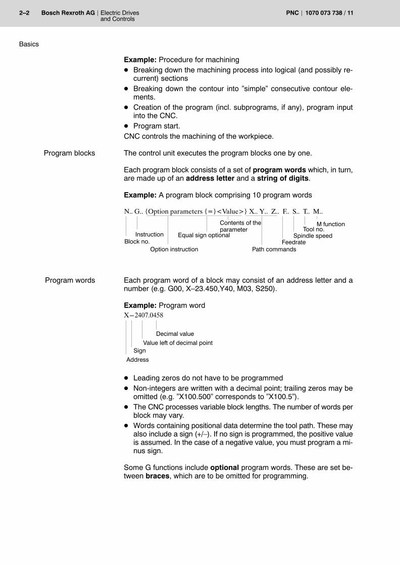
The control unit executes the program blocks one by one.
Each program block consists of a set of program words which, in turn,are made up of an address letter and a string of digits.
Example: A program block comprising 10 program words
N.. G.. {Option parameters {=}<Value>} X.. Y.. Z.. F.. S.. T.. M..
Path commandsBlock no.
M functionTool no.
Spindle speedFeedrate
Instruction
Option instruction
Contents of theparameter
Equal sign optional
Each program word of a block may consist of an address letter and anumber (e.g. G00, X�23.450,Y40, M03, S250).
Example: Program wordX−2407.0458
Decimal valueValue left of decimal point
Sign
Address
D Leading zeros do not have to be programmedD Non-integers are written with a decimal point; trailing zeros may be
omitted (e.g. �X100.500� corresponds to �X100.5�).D The CNC processes variable block lengths. The number of words per
block may vary.D Words containing positional data determine the tool path. These may
also include a sign (+/�). If no sign is programmed, the positive valueis assumed. In the case of a negative value, you must program a mi-nus sign.
Some G functions include optional program words. These are set be-tween braces, which are to be omitted for programming.
Program blocks
Program words

Basics
Electric Drivesand Controls
2�3Bosch Rexroth AGPNC1070 073 738 / 11
Example: Syntax rule: G631 {SYM<s>} {ANG<a>} Programming: G631 SYM2 ANG10
Setting the SYM<s> parameter as shown above between braces {..} isoptional. If this parameter is omitted in the programmed instruction, theSYM parameter is automatically assigned a value(s) preset in MA-CODA.
Example: Syntax rule: G612 <Axis name i><TimeAxis name i>Programming: G612 X10
�Axis name i � denotes the i-th physical axis, e.g.X axis = 1st physical axisY axis = 2nd physical axis
�Timeaxis name i� is 10 ms and refers only to the X axis.
Program words put between square brackets represent various param-eters of one and the same category or are to be assigned specific values.If required, these program words must be set correspondingly when pro-gramming.Example: Parameters for modal subprogramsSyntax rule: G81 [<Parameter 1>,<Parameter 2>,
{<Parameter 3>},{<Parameter 4>}]
Programming: G81 [Z,R1,P,R2]
Most words have a modal effect. This means that their effect remains inforce until you program the same word with a different value, or until youswitch off the word�s function.Example:As soon as you have programmed G1 (linear interpolation at feedrate) ina program block, the control unit will approach all subsequently specifiedpositions at feedrate without the necessity of programming G1 again. G1remains effective until you program a different interpolation type (e.g.�G2�: circular interpolation or �G0�: linear interpolation at rapid feedrate).
Words of this type are only effective within the block in which they wereprogrammed.
Modal effect
Nonmodal effect

2�4 Electric Drivesand Controls
Bosch Rexroth AG PNC 1070 073 738 / 11
Basics
Instructions and special functions
In terms of their effect, program words act either as instructions or spe-cial functions.
For instance, the CNC must be told in which manner and to which posi-tion a tool is supposed to travel. This positional data is communicated tothe CNC via the G address (manner of travelling) and the X, Y, Z, C ad-dresses etc. (where to travel).
Addresses X, Y, Z, C etc.
You use these addresses to determine the axis that is to travel to a spe-cific position or over a specific distance.
. With asynchronous axes (auxiliary axes), the input of positional/path information alone will always initiate a motion. Normally,asynchronous axes are traversed in rapid mode. The speed canonly be influenced by programming an FA address (refer to section5.2).
With various G functions, the value input is not interpreted as positional/path information, but rather a parameter for the function, e.g.:N10 G60 X10 Y10 Z50 Specification of a new program zero point,
does not cause any axis traversing.
The axis address (axis name) is specified by MACODA parameter1003 00001. Axis addresses may also end in a numeral (e.g. �X1�, �X2�,�B1�, �PALLET1� etc.). If this is the case, the �=� sign or a blank must beprogrammed between the axis address and any subsequent positional/path information!G1 X1=90 or G1 X1 90
. If a longer axis designation starts with another shorter one (thereare axes �X� and �X2�), and a decimal point is programmed subse-quently, the longer designation shall always apply (X2.5 ³ axis X2travels to 0.5).
G address
G addresses are used to program the type of traversing movement (e.g.rapid feed, linear or circular interpolation etc.); this is also the reason whyreference to �preparatory functions� is made.All preparatory functions are �sorted� in groups. Preparatory functionsfrom different groups do not interfere with each other. However, as pre-paratory functions contained within one and the same group act modally,not more than one G instruction from any one group may be used perprogram block.From section 3on, you will find a list of all preparatory functions which arerecognized by the CNC. It also describes their respective groups.
Instructions
Basics
Electric Drivesand Controls
2�5Bosch Rexroth AGPNC1070 073 738 / 11
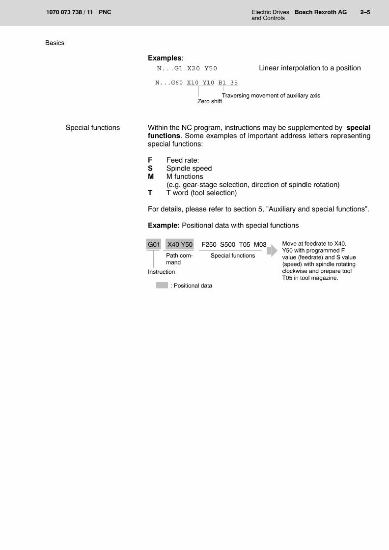
Examples:N...G1 X20 Y50 Linear interpolation to a position
N...G60 X10 Y10 B1 35
Zero shiftTraversing movement of auxiliary axis
Within the NC program, instructions may be supplemented by specialfunctions. Some examples of important address letters representingspecial functions:
F Feed rate: S Spindle speedM M functions
(e.g. gear-stage selection, direction of spindle rotation)T T word (tool selection)
For details, please refer to section 5, �Auxiliary and special functions�.
Example: Positional data with special functions
G01 X40 Y50 F250 S500 T05 M03
Special functions
Move at feedrate to X40,Y50 with programmed Fvalue (feedrate) and S value(speed) with spindle rotatingclockwise and prepare toolT05 in tool magazine.
: Positional data
Path com-mand
Instruction
Special functions
2�6 Electric Drivesand Controls
Bosch Rexroth AG PNC 1070 073 738 / 11
Basics
2.1.2 Program design elements
You may identify each NC block by a block number. This improves theprogram�s readability. DIN block numbers are always on the left at thebeginning of a program line and consist of the �N� address letter and anumber following directly behind (example: �N10 ...�).
You should program the block numbers in ascending order and with anincrement width of 10 (N10 ...; N20 ...; N30 ... etc.). This way, you caninsert additional program lines between two blocks in the case of pro-gram changes without impairing the readability of the program.
If you wish to use branching instructions or jump markers containingblock numbers as parameters, you must identify the target blocks withblock numbers. Likewise, block numbers are required in subprogramsand cycles.
Comments are used to provide program parts with explanations or todocument them. Well-commented programs facilitate and acceleratesubsequent familiarization for other programmers, e.g. if the programneeds to be changed. However, each comment character will increasethe size of the program file by 1 byte.
Comment text is usually put between parentheses, e.g. �( )� or pre-ceded by a semicolon �;� set before the comment text. The PNC will ig-nore text between the parentheses.
Example: Comment textN50 (Pocket machining)orN50 ; Pocket machining
If you program notes, they are used to display text on the CNC screenduring the execution of the program. You can use such notes to informthe operating staff about the current status of the program, or to givethem instructions for action.
There are two kinds of notes:D Channel-specific
notesSyntax variants: (MSG ...), (*MSG ...),(MSG, ...), (*MSG, ...), MSG (...)These notes are displayed in the MSG window ofthe �Automatic� mode for the calling channel. Ad-ditionally, these notes are displayed under �Mes-sages� in the info dialog. They are deleted whenthe program is cancelled or by control reset.
D Channel-indepen-dent notes
Syntax variants: (GMSG ...), (GMSG, ...) These notes are displayed under the channel-in-dependent notes in the info dialog. They are de-leted by system control reset.
A programmed note may have up to 80 characters.
Block numbers
Comments
Notes

Basics
Electric Drivesand Controls
2�7Bosch Rexroth AGPNC1070 073 738 / 11
For an instruction to take action, you would program, e.g., an �M0� in thevery same line or in the following one. This ensures that the execution ofthe program will only be resumed after the note has been acknowledgedby �Cycle start� .
Example: Note textN60 (MSG Measure workpiece!)N70 M0
In the absence of instructions relating to the program flow, the programblocks will be processed one by one. However, you have the followingoptions of influencing the running of the program:D Subprogram calls (please refer to sections 2.1.3 and 5.4.1 )D Repeat instructions (please refer to the CPL manual)D Jump instructions (please refer to the CPL manual)D �Skip block� instruction
You can mark program blocks in such a manner that the control unit willsimply ignore these blocks if the input signal �I3.4 Skip block� is active. Todo so, you program the �/� sign at the beginning of the program line.
Example: /N30
I3.4 is active: N30 block will be ignored
I3.4 is not active: N30 block will be processed.
A program may contain a channel designation.Syntax: $<Channel number>
If a program containing a channel designation is started on anotherchannel, a runtime error will occur.
Example:N10 S2 The following program can be executed on chan-
nel 2 only.N20 G.. X.. Y.. Program instructions on channel 2N30 S1 The following program can be executed on chan-
nel 1 only.N40 G.. X.. Y.. Program instructions on channel 1...
Program run
Skip block
Channel designation

2�8 Electric Drivesand Controls
Bosch Rexroth AG PNC 1070 073 738 / 11
Basics
2.1.3 Subprograms
If you need to repeat a specific processing operation within a program, itis recommended that you write this program part in the form of a subpro-gram and call it whenever it is needed.This will save programming code and memory space. In addition, yourprograms will become clearer and easier to maintain.
Subprogram call with P address
You call subprograms via the P address in the form of �P<SP name> DIN�.
Explanation:<SP name> stands for the subprogram name.
DIN Optional parameter. Prevents the subprogram frombeing linked. You should not use this parameterunless the subprogram consists of DIN blocks onlyand does not call any other subprograms. If this is notthe case (e.g., if CPL blocks are used in thesubprogram), a program runtime error message willbe displayed. For further information, please refer tothe �CALL command� of the �CPL programminginstructions�.
Traversing movements which are programmed in the same line will beexecuted prior to the subprogram call.
(e.g. �N40 PTest1 X10 Y10 Z0�).
The subprogram is executed unconditionally. A subprogram can call further subprograms (nesting).
Example: Subprogram callN...
N40 PBohrbild1 �Bohrbild1� (drilling graph 1) is called and executedonce.
N50... Subsequently, the calling program will be further exe-cuted by the N50 block.
N...
Example: Nesting of subprograms
P1 P5 P2 P7 P8N1
N9N10
N11
N18 M30 N57 M30 N39 M30 N55 M30 N6 M30
N1 N1 N1 N1
P5 N23 P2 N32 P7� N44 P8N45N33N24
...
...
P1: Main programP5, P2, P7, P8: Subprograms

Basics
Electric Drivesand Controls
2�9Bosch Rexroth AGPNC1070 073 738 / 11
. Nesting is possible to a depth of 9 (incl. main program), i.e. withcomplete nesting, the main program can open a maximum of 8 sub-programs.
. Subprograms can also be called viaG addresses (refer to section 2.1.4, page 2�11), and M addresses (refer to section 5.4.1, page 5�5).
Subprogram call without P address
Subprograms can also be called directly without a P address. In thiscase, it is sufficient to state the name of the subprogram.
. Any confusion with normal syntax must be avoided! Always giveyour subprograms unmistakable names to avoid misinterpreta-tions by the control interpreter.
Explanation:
<Sp name> stands for the subprogram name.
In both cases, the syntax is the same:
N40 XSpandN40 PXSp
Subprogram call without P address
Subprogram call with P address
Example: Subprogram callsN...
N40 XSp Subprogram �XSp� is called and executed.
N50... Subsequently, the calling program will be further executedby the N50 block.
N60 X0Sp �>results in a syntax error!X0 is interpreted as the �0� coordinate in the X axis to whichthe X axis is to traverse, i.e. a subprogram called �X0Sp� willnot even be recognized by the interpreter.
N...

2�10 Electric Drivesand Controls
Bosch Rexroth AG PNC 1070 073 738 / 11
Basics
Subprogram call via nonmodal G instructions
Besides using various M functions (refer to page 5�5) or the P address(refer to page 2�8), subprograms can also be called via 16 nonmodalG instructions.
You can use the MACODA to determine both the G instructions and theprograms to be called via these G instructions. The subprogram calledwill be executed once.
. The allocation of the G instruction to the program name is applica-tion-specific and can be defined in MACODA parameters3090 00001 and 3090 00002.Please contact your systems administrator for the G instructionsdefined as subprogram calls for your specific machine.
As a rule, only one SP call may be programmed in a block with P, G or Mfunctions. In the event of several identical address letters in one block(e.g. G or M), the address calling the subprogram must be programmedat the end of the line.
Example: Subprogram call via GxxN... G0 X20 Y30 Z50 Gxx...
. In addition to these 16 - non-modal - G instructions, an additional 16modal G instructions may be defined as subprogram calls in MA-CODA parameters 3090 00005, 3090 00006, and 3090 00007. These subprograms are processed by the PNC in each programblock, until the modal effect is explicitly canceled by an appropriatecommand. This effect may be interesting, e.g., for drilling cycles.For example, you only need to travel to a new drilling position. Aftertraversing to the new position, the hole is then drilled automaticallyby the subprogram.
End of subprogram
The end of a subprogram is reachedD at the file end.
The NC returns to the calling program. All modal statuses are re-tained.
D in a program line containing �M2�, �M02�, or �M30�.For details, refer to section 5.4.2.
Programming

Basics
Electric Drivesand Controls
2�11Bosch Rexroth AGPNC1070 073 738 / 11
2.1.4 Jump destinations and jump instructions
As a rule, main program and subprogram blocks and cycles are exe-cuted in the same order as they were programmed.
The processing sequence can be changed by program jumps.
The following instructions are available:
D Jump destinations(LABELS)
Stating jump destinations with user-de-fined names.
D Jump destination (G23,G24)
Jump destinations dependent on an in-terface signal with a block numberstated.
D Jump instructions(GOTOF and GOTOB)
Allow branching from any point in theprogram to a jump destination. Programexecution continues immediately uponarrival at the jump destination.
Destination labelling (LABEL) within a program:User-defined branches in a program can be programmed by definingjump destinations.
D Label names with a minimum of 2 and a maximum of 32 characters(letters, digits, underline) are assigned.
D The first two characters must be letters or underlines.D The label name must always be followed by a colon.D Labels are always written at the beginning of an NC block, directly af-
ter the block number.D Jump destinations are addressed by means of jump instructions
(GOTOF and GOTOB).
Jump instruction (GOTOF) with a forward jump destination (towards the program end):D must be programmed in a separate block.D is programmed in combination with a LABEL.
Jump instruction (GOTOB) with a backward jump destination(towards the beginning of the program):D must be programmed in a separate block.D is programmed in combination with a LABEL.
Jump destination
Jump instruction
Jump instruction

2�12 Electric Drivesand Controls
Bosch Rexroth AG PNC 1070 073 738 / 11
Basics
Examples: Label, GOTOF, GOTOBN100 GOTOF TO_PART2 Jump forward to jump destination
N110.. �TO PART2�
N120..
N130 TO_PART1: Definition of jump destination �TO PART1�
N140..
N150 GOTOB TO_PART1 Jump backward to jump destination �TOPART1�
N160..
N170 TO_PART2: Definition of the jump destination�TO PART2�
The jump destination (G24) is a block number and is executed uncondi-tionally. The jump destination is defined as an L address with a blocknumber.
. If an �unconditional jump� is programmed incorrectly, an endlessloop may occur.
G24 L<block number>with<block number> = 15 digits, with an optional �.�.
Please note for G24 L...:D Jumps must never be programmed together with any other instruc-
tions in the same block.D The syntax in the statement of the L address must be identical with the
jump destination (N word) (also in the case of preceding zeros).
Example: N020 G1 X200 Y300 F500
...
N500 G24 L20 Wrong!
N500 G24 L020 Correct!
D Only DIN blocks can be jumped to. Blocks written in CPL may not beused as an L address.
Unconditional jump

Basics
Electric Drivesand Controls
2�13Bosch Rexroth AGPNC1070 073 738 / 11
The jump destination (G23) is conditioned by the status of the interfacesignal �CONDITIONAL JUMP�. The interface signal is scanned while theG23 block is being prepared
. Any interface signals between block preparation mode and blockexecution mode will be ignored! Unless this can be ensured, block preparation must be interruptedby programming a WAIT instruction.
The jump destination is defined as an L address with a block number.
G23 L<block number>with<block number> = 15 digits, with an optional �.�.
Please note for G23 L...:D Jumps must never be programmed together with any other instruc-
tions in the same block.D The syntax in the statement of the L address must be identical with the
jump destination (N word) (also in the case of preceding zeros).D Only DIN blocks can be jumped to. Blocks written in CPL may not be
used as an L address.
Example:N68 X–250 Y20...
Jump destination
N100 X100 Y200 Z50
N101 X0 Y0 Z10
102 WAIT Waiting for an IF (IF = interface) signal, blockpreparation interrupted.
N103 G23 L68 Jump to N68 is executed if an IF condition isfulfilled.
N104 X200 Y–300...
. In CPL block 102, the programmed WAIT instruction ensures thatany signal changes are recognized by the NC immediately beforeN103 processing.
Conditional jump

2�14 Electric Drivesand Controls
Bosch Rexroth AG PNC 1070 073 738 / 11
Basics
2.1.5 End of program
The end of a (sub)program is reachedD at the file end, orD in a program line containing �M2�, �M02�, or �M30�.
For details concerning these M functions, refer to section 5.4.2.
If none of these M functions was used in the program, the control unit willinterpret the end of file as the end of program.
At the end of a subprogram, execution returns to the calling program. Allmodal statuses are retained.At the end of a main program, the system returns to the top of the pro-gram and waits for the next �Cycle start�. Again, all modal statuses areretained.

Basics
Electric Drivesand Controls
2�15Bosch Rexroth AGPNC1070 073 738 / 11
2.1.6 Standard programming formats
The standard format applies to metric input in terms of �mm� and a mea-suring-system resolution of 0.0001 mm.
Addresses Preparatoryfunction
Format Meaning Unit
variable, e.g.
X,Y,Z,C
X = AC(50)
X(p1,p2,p3, p4)
e.g.: G1, G2
e.g.: AC(..)
e.g.: G581
real
real
real
Positional data:
cartesian axis position
positional data withassignment
positional data withparameter list
mm or degrees
mm or degrees
mm or degrees
I,J,K
RG2, G3 real Circle parameters
Circle radius
mm
mm
D
F
F
FA
H
S
T
G41/G42
G94
G4
int
real
real
real
int
real
real
Technological information
cutter-radius compensation
feedrate (sync. axis)
dwell time ( � )
feedrate (auxil. axis)
tool length comp.
spindle speed
tool
compens. no.
mm/min
sec
mm/min
compens. no.
rpm
tool no.
N (block no.) int N1, N2, N3 etc. block address
P,K,V str Program, compensation, zero-shift address
G int G function
M int Special machine function
Meaning of the values in the �Format� column:int: Numerical string consisting of 9 digits max., without decimal point
real: Numerical string. consisting of 15 digits max., with decimal point
str: Character string
. Auxiliary functions (e.g. F, FA, S, ...etc.) can be bit- or bcd-coded(refer to Section 5).

2�16 Electric Drivesand Controls
Bosch Rexroth AG PNC 1070 073 738 / 11
Basics
Notes:

G Instructions G00
Electric Drivesand Controls
3�1Bosch Rexroth AGPNC1070 073 738 / 11
3 G Instructions
. For a tabular overview, please refer to the Annex.
3.1 Linear interpolation at rapid travel G00
The programmed position is interpolated and approached at max. pos-sible speed on a straight line.
At least one axis travels at max. speed or acceleration. The speed of theother axes is controlled in such a manner that they reach the target pointat the same time.D The speed can be influenced using the potentiometer.D With active G0, the G0 ACTIVE channel IF (= interface) signal is out-
put.D With active G0, the system decelerates to V=0 after each block.
Use G161/G162 to determine whether G0 is to be active with or without�In-position logic�.If decelerating to V=0 after each block is not desired, you must use theG200 function instead of G0.
G0: Linear interpolation at rapid travel ON
Please note for G0:D Programmable with or without axis addresses.D No feedrate value has to be programmed. The max. axis speed
(1005 00002) is defined in MACODA.D The feedrate of G0 rapid travel can be limited to the value set in MA-
CODA parameter 7030 00110 by means of the channel-related inter-face signal �Limit Rapid Travel� (NC I1.7).
D Acts modally until a new movement type is selected.D G0 deletes G1, G2, G3, G5, G10�G13, G73, G200.
Example: rapid-travel programmingX100 Y100 Starting position
G0 X500 Y300 Programmed target position
+Y
+XW
100
200
300
100 200 300 400 500
Target position
Starting position
G0
Effect
Programming

3�2 Electric Drivesand Controls
Bosch Rexroth AG PNC 1070 073 738 / 11
G Instructions G200
3.2 Linear interpolation at rapid feed without decelerating to V=0 G200
If G0 is programmed, the system will � irrespective of G161/G162 � de-celerate to V=0 at the block end. If this is not desired, use G200 instead.
This means that interpolation can continue without deceleration beyondthe block limits. However, the following preconditions apply:D G61 is not active andD G163 is not active.
If G61 is actually active, the control unit will, despite G200, decelerate toV=0 after each block.
If G163 is active, the behavior depends on the respectively set �In-posi-tion logic mode� (please refer to G164 to G166).
The effect of G200 corresponds to �G1Fmax�.
G200: Linear interpolation at rapid feed without decelerating to V=0ON
Please note for G200:D Programmable with or without axis addresses.D No feedrate value has to be programmed. The max. axis speed
(1005 00002) is defined in MACODA.D The feedrate of G200 rapid travel can be limited to the value set in
MACODA parameter 7030 00110 by means of the channel-related in-terface signal �Limit Rapid Travel� (NC I1.7).
D Acts modally until a new movement type is selected.D G200 deletes the types of movement G0, G1, G2, G3, G5, G10�G13,
G73.
Effect
Programming

G Instructions G01
Electric Drivesand Controls
3�3Bosch Rexroth AGPNC1070 073 738 / 11
3.3 Linear interpolation at feedrate G01
The programmed point is approached on a straight line at the effectivefeedrate (F word).
The movement is coordinated in such a manner that all axes involvedarrive at the programmed end point simultaneously. At the end of the tra-versing movement, the control unit will perform a complete downslopedown to speed V=0, unless a G8 is active.
The programmed feedrate value (F) acts as path feed; this means in thecase of more than one moving axis that the portion of each individual axisis smaller than F.
The feedrate can be limited by MACODA parameters (as regards theaxis or path).
The speed can be influenced using the feedrate potentiometer.
Use G61/G62 to determine whether G1 is to be active with or without �In-position logic�.
G1: Linear interpolation at feedrate ON
Please note for G1:D G1 may be programmed with or without positional data.D G1 has to be programmed with F word if no feedrate is yet active.D The programmed feedrate remains effective until overwritten by a
new one.D G1 deletes G0, G2, G3, G5, G10�G13, G73 and G200.
Example: Linear programmingX100 Y100 Starting position
G0 X500 Y300 F100 Programmed target position
+Y
+XW
100
200
300
100 200 300 400 500
Target position
Starting position
G1
Effect
Programming

3�4 Electric Drivesand Controls
Bosch Rexroth AG PNC 1070 073 738 / 11
G Instructions G03 G02
3.4 Circular interpolation / helical interpolation G02 G03
The programmed end point is approached on a circular path at the activefeedrate (F word).
The determination whether G2/G3 is to be active with or without �In-posi-tion logic� is made using G61/G62.
The movement is coordinated in such a manner that all axes involvedarrive at the programmed end point simultaneously. This applies also ifan axis outside the circular plane is programmed within the block. In thiscase the PNC will interpolate this axis linearly together with the otheraxes. A helical movement will result (helical interpolation).
G2, G3 acts modally and deletes the G functions of the same group or isdeleted by them.
The machine traverses at the programmed feedrate and in a circular mo-tion in the selected plane:D G2 clockwiseD G3 counter-clockwise.
A feedrate value has to be active. By G20, �Plane selection 2 out of 6axes�, it is possible to execute circles with two freely definable synchro-nous axes.
For programming, you can choose betweenD radius programming andD center-point programming.
. Another option is G05 (circular interpolation with tangential entry).
Depending on the type of programming, various parameters must beprogrammed in the G02/G03 block. Please refer to the following sec-tions.
3.4.1 Radius programming
Using the current position as starting point, you define a circular move-ment with the programmed radius leading through the programmedend point.
The end point may be programmed in absolute or incremental terms.The radius will always act as an incremental value.
On the basis of the starting point, end point and radius, the PNC first cal-culates the circle center point. This results in two intersections, locatedto the left and to the right of the starting/end point distance:
Effect

G Instructions G03 G02
Electric Drivesand Controls
3�5Bosch Rexroth AGPNC1070 073 738 / 11
RA.
RE
A.
E
MR
ML
A = Starting pointE = End pointR = Radius
ML = center point leftMR = center point right
The applicable center point of the two is determined by the sign of theradius value:
D Positive radius value: center point leftD Negative radius value: center point right
The direction of rotation of the arc has already been specified by G2 orG3.
A.
E
−RA.
E+R
G3G3
G2G2
As the diagrams show, the radius must be at least half as large as thedistance between the starting and end point, since otherwise no inter-section point can be created.If the radius is exactly half as large as the starting to end point path, thisspecial case results in only one intersection point. This is only possiblewith a semi-circle. The sign of the radius value is then freely definable.
. Radius programming cannot be used to create full circles. Thesmallest possible arc depends on the set MACODA parameters ofthe control unit (approx. 10 increments IN POS range).
Example:N... G17 G3 X... Y... R+−... F... S ... M ...where:G17: Selection of the circular path in the X/Y planeG3: Circle in counter-clockwise senseX,Y: End point of the circleR: Circle radius
Programming

3�6 Electric Drivesand Controls
Bosch Rexroth AG PNC 1070 073 738 / 11
G Instructions G03 G02
3.4.2 Center-point programming
Using the current position as starting point, you define a circular move-ment through the programmed end point using the programmed cen-ter point.
Imprecise entries can lead to two different radii (center point � startingpoint, center point � end point) in the internal calculation. The control unit can compensate this by means of internal center pointcorrection.D Radius differences above the radius accuracy (MACODA parameter
7050 00010) are corrected automatically. Below this threshold, theprogrammed data are exclusively effective.
D The center point correction is effective at most up to the radius toler-ance range (MACODA parameter 7050 00020). Greater differencestrigger a runtime error.
For circular interpolation, the interpolation parameters I, J and K are as-signed to the axes involved in accordance with MACODA parameter7010 00030 (axis classification).They define the incremental distance between the A circle startingpoint and the M circle center point for each axis. Their sign results fromthe vector direction from A to M.
The standard assignment of the interpolation parameters is as follows:
+K
−I
+J
+Z
+X
+Y
+I
−K
−J
I = M (X) � A (X) I, J, K as interpolation parameters
J = M (Y) � A (Y) X, Y, Z axis portion of relevant coordinate
K = M (Z) � A (Z) M for circle center pointA for circle starting point.
Interpolationparameters

G Instructions G03 G02
Electric Drivesand Controls
3�7Bosch Rexroth AGPNC1070 073 738 / 11
Examples:N... G90 G17 G2 X350 Y250 I200 J−50 F... S... M...
+Y
+X
50100
250
100 300 350
A.
E
M
+I
−J
P�/�W
N.... G90 G17 G3 X350 Y200 I−50 J200 F... S... M...
+Y
+X
50
250
150 350
A.
EM
−I
+J200
200P�/�W
Quarter circle as a quadrant
N... G17 G2 X... Y... J−... F... S... M...
Characteristic: One of the interpolation parametersis always zero and need not bewritten in the program. In this ex-ample, I can be omitted.
Y
X
A.
E
MJ
P�/�W
Semicircle made up of two quadrants
N... G17 G3 X... I... F... S... M...
Characteristics: The coordinates of the starting point andthe end point are identical for one axis.The axis portion need not be specifiedas target. The interpolation parameterbelonging to this axis is zero and mayalso be omitted. In this example, Y andJ can be omitted.
Y
X
A. EM
IP�/�W
Programming
Special case
Special case

3�8 Electric Drivesand Controls
Bosch Rexroth AG PNC 1070 073 738 / 11
G Instructions G03 G02
Full circle
N... G17 G2 I... F... S... M...
Characteristics:The coordinates of the starting point andthe end point are identical. None of thetwo axis portions need to be specifiedas target. If the starting and end pointsare located exactly on a quadrant transi-tion, one interpolation parameter is zeroand hence need not be programmed. Inthis example, X, Y and J can be omitted.
Y
X
A. E M
IP�/�W
. If an interpolation parameter is programmed which does not cor-respond to the selected plane, the control unit will report the �Pro-grammed interpolation parameter outside the selected plane�runtime error.
Example: N... G17 G2 X5 I9 K7 K is not valid
. If interpolation parameters and circle radius are programmed wit-hin one and the same block, only the radius will be used.
Special case

G Instructions G203G202
Electric Drivesand Controls
3�9Bosch Rexroth AGPNC1070 073 738 / 11
3.5 Helical-N-Interpolation G202, G203
For a helical-N-movement, the travel to the programmed position is exe-cuted by the axes providing the working plane travel to this position alonga circular arc while all other axes are moved along linearly with the effectthat all axes arrive simultaneously. A maximum of 6 synchronous axescan be moved linearly, with permissible axis movement types being lin-ear, endless, or rotary axis.
The function �Helical-N-Interpolation� is a generalised version of the pre-vious �Helical Interpolation�, which is still available (refer to �Specialcase� below). With helical interpolation, only one linear feed axis can bemoved along and this axis must be configured as a normal axis, i.e. per-pendicularly to the selected working plane (MACODA parameter7010 00030, axis classification as determined in version 108 or higher).
The axes travelling along a circular arc are clearly defined by the se-lected working plane (G17, G18, G19, G20). The maximum circularmovement that can be programmed in one traversing block is a fullcircle.
The function �Helical-N-Interpolation� allows the programming of �helicalmovements coupled with a change in orientation�.
Generally, the programmed feedrate applies to all the axes traversing ina block. Those axes that are moved along linearly, however, are con-trolled by the specific MACODA parameters set for functions G594 andG595, that are contributing to feedrate computing.
Any circular or helical movement can also be programmed as an equiva-lent helical-N-movement.
The Helical-N-Interpolation acts modally, i.e. it remains active until it isdeselected through programming or another modal function that gener-ates a movement.
All standard compensations like zero offset, tool length, workpiece posi-tion, or cutter compensation are also effective for helical-N path seg-ments. Helical-N path segments can be programmed also for working ininclined planes.
G202: circular movement, turning clockwise
G203: circular movement, turning counter-clockwise
Both radius programming (R) and center-point programming (I, J, K) ispossible:D The sign of the radius determines whether the resulting center of the
circle is located left (+) or right (�) of the line between the starting pointand the end point.
Effect
Programming

3�10 Electric Drivesand Controls
Bosch Rexroth AG PNC 1070 073 738 / 11
G Instructions G203G202
D The size of the radius must be at least half the distance between thestarting and the end point. If the radius is smaller than this value and ifthe balance lies within the tolerance window defined in MACODA pa-rameter 7050 00030, the radius will be automatically corrected to halfthe above distance.
D If center-point programming is used, the coordinates of the centerpoint refer to the starting point of the circular movement (center-pointcoordinates are incremental).
D If the starting point and the end point in the circle plane are identical,the control will automatically generate a full circle if center-point pro-gramming is used.
D MACODA parameters 7050 00010 and 7050 00020 allow to config-ure the required programming accuracy.
D If a center-point coordinate is programmed as lying outside the work-ing plane, the control will display a runtime error.
Since the helical-N-interpolation is a modal function causing a move-ment, the active G code is shown on the MMI display of the respectivemodal function activated.
The behavior upon resetting the control or switching on/off is determinedby the init strings configured in MACODA for control start-up or followingcontrol reset.
This function belongs to group 2.
. Since the number of axes per channel is limited to a maximum of 8,coupled linear motion is limited to a maximum of 6 synchronousaxes.
Helical interpolation
If a third axis is programmed in addition to circular interpolation of twoaxes, this third axis will traverse linearly. The result is a helical movement(also refer to the figure below).
The tool-path compensation acts within the circular-path plane whichcan be freely selected via plane selection (G17...). The F feedrate corre-sponds to the real path speed.
Example:Circular interpolation involving axes X and Y,Linear interpolation of axis Z:
Special case

G Instructions G203G202
Electric Drivesand Controls
3�11Bosch Rexroth AGPNC1070 073 738 / 11
N... G91 G17 G3 X... Y... Z... I... J... F... S... M...
Z
X
A.
E
M
Y
J
I
Characteristics:The coordinates of thestarting point and the endpoint are identical for the Xand Y coordinates. Inter-polation parameter K isomitted, because the start-ing point is in the X�Yplane.
P�/�W
Application: e.g. thread cutting

3�12 Electric Drivesand Controls
Bosch Rexroth AG PNC 1070 073 738 / 11
G Instructions G104G4
3.6 Dwell time in seconds G4Dwell time in spindle revolutions G104
The �dwell time� can be programmedD in seconds (G4) orD in spindle revolutions (G104).
The dwell time is started when the G4/G104 dwell time block has beencompletely processed by the CNC and block execution takes place.The program is stopped for the duration of the dwell time. A rotatingspindle or traversing auxiliary axes are not stopped. Synchronous axescan reduce their lag, if necessary.The block programmed subsequently is only executed when the pro-grammed �dwell time� has elapsed.
The function G4/G104 is programmed with an F word for the dwell timeduration in a separate block without positional data. Only auxiliary andspecial functions are permissible in this block.The programmed dwell seconds or the number of spindle rotations, re-spectively, have to be programmed again in every G4/G104 block.
If G4/G104 is programmed with a dwell time F=0, programmingG4/G104 will not cause the axes to decelerate within a G08 or G108movement sequence. In this case, the G4/G104 block is deleted withinthe NC.
Programming G4/G104 without F word leads to a runtime error.
Determination of the spindle revolutions with G104:To determine the spindle revolutions, the current actual revolutions areestablished cyclically from the main spindle, calculating the revolutionsperformed on that basis. In case of highly dynamic spindles, a certaindeviation between the programmed and the actual spindle revolutionswaited may therefore occur in the acceleration or deceleration phases.If the configured main spindle is an analogous spindle (without speedfeedback), the rpm setpoint is used for the calculation instead of the ac-tual rpm.
The programmed spindle revolutions refer to the main spindle config-ured in MACODA parameter 7020 00010 or using the MAINSP function(refer to page 4�17).
G4 F<dwell time>...where:dwell time Dwell time in seconds
G104 F<Number of spindle revolutions>...where:Number of spindle revolutions Dwell time in number of spindle revolu-
tions
Effect
Programming
Programming

G Instructions G05
Electric Drivesand Controls
3�13Bosch Rexroth AGPNC1070 073 738 / 11
3.7 Circular interpolation/helical interpolation with tangential entry G05
The control unit uses G5 to calculate a tangential circle entry. Only a tran-sition involving no reversal of direction is referred to as �tangential�.
The first entry tangent determines all following contour elements with G5if several G5 movements take place consecutively.
The size and position of the arc formed are calculated by the control unitin accordance with the following:
G5 X... Y...
No radius is programmed.
Restrictions:D Programming G5 in manual data input or as 1st block within the pro-
gram is impossible, since no tangent can be calculated there.D A block containing a traversing movement has to be programmed
ahead of G5.D The plane must not be switched over directly ahead of or during an
active G5.
CAUTIONWhen helical interpolation is used, machining marks may occur atthe block transition!The tangential transition refers only to the circle plane! The spatialtangent (with helical interpolation) may jump at the block transi-tion!
Effect
Programming

3�14 Electric Drivesand Controls
Bosch Rexroth AG PNC 1070 073 738 / 11
G Instructions G05
+Y
+X
70
50 110
+Y
+X
70
50 130
+Y
+X
70
50 90
A.
MW10
A.100
W
M
E3M2
A.
40 P1T1
W
+Y
+X
70
50 110
E
A.
W30
+Y
+X
70
50 110
E
A.
W30
+Y
+X
70
50 110
W30M
E
A.
G1 X20 Y70 F200X50X110 Y10G5
G1 X20 Y70 F200X50X130 Y100G5
G1 X–15 Y40 F200X50X90 Y120G5
G2 Y70 R–60
G1 X50 Y70 F200X110
G1 X50 Y70 F200X110
G1 X–15 Y80 F200X50X110 Y30G5
G2 Y70 R–32.882G5 Y30 G5 Y30
E1
T1 T1
E1
−15
T4
M2
M1
−15
T3T2
Influence of the tangent
120
Tn = tangent
Mn = center point
A = beginning of circle segment
E = end of circle segment
Influence of the end point

G Instructions G206G07 G06
Electric Drivesand Controls
3�15Bosch Rexroth AGPNC1070 073 738 / 11
3.8 Acceleration programming G06, G07, G206
The upper limits of the max. axis acceleration defined in MACODA(please refer to MACODA parameter 1010 00001) can be temporarily re-duced within the part program via G6.
DANGERIncorrect axis addressing may cause inadvertent axis movementsthat may pose a hazard to the machine and personnel.
This programming refers directly to a real physical axis. A logicalaxis addressed, for instance, by a coordinate transformation (e.g.inclined plane) with the same axis address will lead to incorrectaxis values. This might result in damage to the workpiece and/orthe machine. There might even be danger to persons.
G06with axis information:
Supersedes the max. MACODA axis accelera-tion values defined in MACODA parameter1010 00001 with the programmed values. De-pending on the currently used measuring units(G71/G70), the control will interpret the pro-grammed values as �1000 inch/s2� or �m/s2�.You should program G6 preferably in a sepa-rate block.
G06without axis information:
refer to G206.
G07 the maximum axis acceleration values speci-fied in MACODA parameter 1010 000001 areapplicable for all axes.G7 may be programmed in connection withtraversing data.
G206 Storing of the currently valid max. accelerationvalues of all axes in an internal memory. Thismemory is pre-initialized with the values fromMACODA parameter 1010 00001 during pro-gram selection.By programming G6 without axis information,all acceleration values stored in this memoryare re-activated.
Example 1: G6 X2 Y2 max. acceleration of axes X and Y is 2m/s2, each.
Effect
Programming

3�16 Electric Drivesand Controls
Bosch Rexroth AG PNC 1070 073 738 / 11
G Instructions G206G07 G06
Example 2: Starting situation: The value of 8.0 m/s2 is preassigned to axes X throughZ in MACODA parameter 1010 00001.
G6 X1.0 Z2.1...
max. acceleration for X axis: 1.0 m/s2
max. acceleration for Y axis: 8.0 m/s2
max. acceleration for Z axis: 2.1 m/s2
G206...
storing all current axis acceleration values
G7...
reactivate values from MACODA parameter 1010 00001.max. acceleration for X axis: 8.0 m/s2
max. acceleration for Y axis: 8.0 m/s2
max. acceleration for Z axis: 8.0 m/s2
G6 Y5...
max. acceleration for X axis: 8.0 m/s2
max. acceleration for Y axis: 5.0 m/s2
max. acceleration for Z axis: 8.0 m/s2
G6...
max. acceleration for X axis: 1.0 m/s2
max. acceleration for Y axis: 8.0 m/s2
max. acceleration for Z axis: 2.1 m/s2

G Instructions G107G106
Electric Drivesand Controls
3�17Bosch Rexroth AGPNC1070 073 738 / 11
3.9 Programmable path acceleration G106, G107
Function G106 allows the upper limits entered in the MACODA parame-ters 7030 00210 and 7030 00220 forD path acceleration andD path decelerationto be reduced in the part program. The two acceleration values can beswitched over separately or together.
Irrespective of the currently effective path acceleration, the axis accel-eration of the axes involved in the motion is always checked additionally,so that a programmed or preset path acceleration may be restricted.
G107 is used to switch back to the MACODA setting.
Restriction:D The programmable acceleration values are restricted by the values
set in MACODA.D If an invalid value is programmed, a runtime error will occur.D The programmed acceleration values are interpreted in dependence
on G71 and G70 in m/s2 or 1000 inch/s2, respectively.
G106 ACC<Value> Setting the path acceleration and deceleration
where:<value > Identical value for path acceleration and decel-
eration in m/s2 or 1000 inch/s2.
G106 {UP<Value1>}{DOWN<Value2>}
Setting the path acceleration and decelerationseparately.
where:UP<Value1> optional:
value for path acceleration in m/s2 or1000 inch/s2.
DOWN<Value1> optional:value for path deceleration in m/s2 or1000 inch/s2.
G107 Resetting of path acceleration and decelerationto MACODA setting.
Effect
Programming
Programming
Programming

3�18 Electric Drivesand Controls
Bosch Rexroth AG PNC 1070 073 738 / 11
G Instructions G107G106
Examples:
G71..
G106 UP 1.5 Path acceleration is set at 1.5 m/s2.
G106 ACC 5 Path acceleration and deceleration are set at 5m/s2.
G107 The acceleration values are reset to the MA-CODA setting.
G106 ACC 3.5 DOWN 2 Path acceleration is set at 3.5 m/s2, path de-celeration is set at 2 m/s2.
Please note for G106, G107:D The G106 and G107 functions act modally and cancel each other
mutually.D The programmable acceleration values have to be programmed to-
gether with G106 in one and the same block.
. For reasons of compatibility with the CC series, the alternative syn-tax for �ACC� is the address letter �E�.

G Instructions G09G08
Electric Drivesand Controls
3�19Bosch Rexroth AGPNC1070 073 738 / 11
3.10 Path slope G08, G09
Using the �path slope� function, the control unit attempts to generate aspeed as constant as possible within the magnitude of the programmedfeedrate during contour machining.Without �path slope�, the control unit performs a complete up and downslope (speed ramp) at the start and end of a traversing block.With �path slope�, this slope will � except for the beginning and end ofmachining � only take place to the extent required for going around a cor-ner. In this process the PNC takes into account the value of the max. axisstep change programmed in MACODA. To limit contour deviations occurring at real corners, the maximum stepchange must not be set at too high a value in MACODA. On the otherhand, if the maximum step change is set too low, this will result in unde-sirable deceleration at minor knees in the contour (quasi-continuoustransitions). A solution is provided by G228 (refer to page 3�21).
P0 X
Y
G0
G1
P1 P2
P3 P4
P5 P6
P7
P8
t
VPath
Contour
withoutpath slope(G9)
t
VPath
Rapid
Feedrate
withpath slope(G8)
Rapid
Feedrate
Please note that the two time axes in the above illustration have differentscalings.
With active G8, the P8 point will be approached within a shorter time thanwith active G9.Decelerating to V=0 is performed after each G0 block!After a G200 block, decelerating to V=0 is only performed ifD G61 orD G163 are active!
G08: Path slope on
G09: Path slope off
The function has a modal effect. Path slope acts only on the machiningaxes.
Effect
Programming
3�20 Electric Drivesand Controls
Bosch Rexroth AG PNC 1070 073 738 / 11
G Instructions G108
Example: G08, path slope ON
N... G8 (Path slope ON)N... G0 X100 Y50 (at rapid to P1)N... G1 X150 F5000 (continued at feedrate)N...
When programming auxiliary functions while the path slope function isactive, please make sure that the travel paths programmed are longenough for the amount of time required for interpolating the NC block isgreater than the time required for executing the auxiliary function, includ-ing acknowledgement. (Basically, the time required for executing an NCblock is defined by the travel path programmed and the feedrate.)
3.11 Limited-jerk velocity control G108
In contrast to function G08, G108 calculates a velocity profile for severalblocks. The number of blocks can be configured in MACODA parame-ters 7060 00110 - 7060 00130. This block look-ahead function accounts for longer deceleration dis-tances, and ensures a smoother velocity profile.
Additional smoothing is provided by the optional Shape function whichshares possible sudden changes in path acceleration out among severalinterpolation cycles, thus ensuring a continuous path acceleration profile(jerk limitation).The number of cycles can be programmed.
Limited-jerk velocity control
G108 {Shape<Shape order>} �Limited-jerk velocity control� on.Without Shape, the order stored in MA-CODA parameter 7050 00320 will be ac-tive.
whereShape<Shape order> optional: Shape filter order (number of
interpolation cycles):0: Default (MP 7050 00320)0 ..100: Programmable number of
interpolation cycles
Please note for G108:D Functions G8, G9, G108, G408, and G608 form a modal group in
each case and, therefore, cancel each other mutually.
Effect
Programming

G Instructions G228
Electric Drivesand Controls
3�21Bosch Rexroth AGPNC1070 073 738 / 11
3.12 Block transition without deceleration G228
The function �Block transition without deceleration� limits the impact ofthe maximum step change on wide transition angles.By proper parame-terisation, the behavior can be defined so as to take major knees in thecontour into account in detail, whereas quasi-continuous contour transi-tions are rounded and thus smoothed due to the higher machiningspeed.
G228 {K<transition angle>} Activate function.Without the K address, the transition anglestored in MACODA parameter 7030 00310will be active.
where:K<transition angle> K address with
transition angle = 0_ to 50_
Please note for G228:D G228 is not modal as such, but it acts modally.D After a control reset, the respective init string setting is activated. If
there is no G228 entered there, the previously activated setting re-mains active.
. When configuring MACODA parameter 7030 00310, the desired tra-versing speed must be taken into account because at a high speedand a wide transition angle it is theoretically possible that a servoerror occurs.
Effect
Programming

3�22 Electric Drivesand Controls
Bosch Rexroth AG PNC 1070 073 738 / 11
G Instructions G408
3.13 Point-to-point movement using SHAPE G408
The shape function is used to share out jumps in the course of path ac-celeration between several interpolation cycles. This enables�sin2-shaped� path-speed behavior patterns, i.e. jerk-free speedchanges, to be made.
X
Y
P1 P2 P3
VPath
Contour
withSHAPE
Feedrate
t
VPath
without SHAPE(corresponds to G9)
Feedrate
t
Path-speed behavior patterns
. Compared to G9 (unchanged acceleration), the interpolation time(�with shape�) per point-by-point movement extends by order*in-terpolation cycle.
Using the LIN and SIN parameters, the characteristics of the accelera-tion transition and thus a jerk-free path speed can be set.
LIN <Number> Number of interpolation cycles(Settings: 2-41 cycles) between which an occurringpath acceleration jump is to be shared out. Theacceleration increase or decrease is linear.
SIN <Number> Activation of fixed acceleration-behavior patternsettings. The acceleration increase or decrease issin2-shaped.
Effect
G Instructions G408
Electric Drivesand Controls
3�23Bosch Rexroth AGPNC1070 073 738 / 11
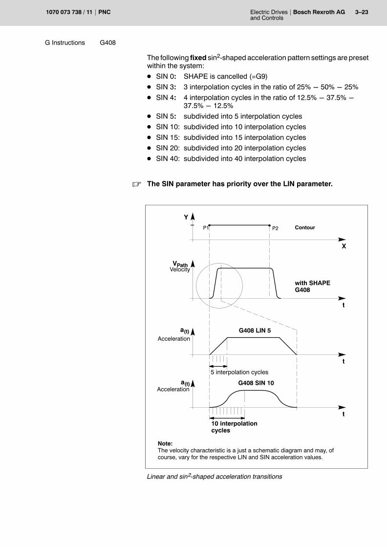
The following fixed sin2�shaped acceleration pattern settings are presetwithin the system:D SIN 0: SHAPE is cancelled (=G9)
D SIN 3: 3 interpolation cycles in the ratio of 25% − 50% − 25%D SIN 4: 4 interpolation cycles in the ratio of 12.5% − 37.5% −
37.5% − 12.5%D SIN 5: subdivided into 5 interpolation cyclesD SIN 10: subdivided into 10 interpolation cyclesD SIN 15: subdivided into 15 interpolation cyclesD SIN 20: subdivided into 20 interpolation cyclesD SIN 40: subdivided into 40 interpolation cycles
. The SIN parameter has priority over the LIN parameter.
X
Y
P1 P2
VPath
Contour
with SHAPEG408
Velocity
t
a(t) G408 LIN 5Acceleration
t
t
G408 SIN 10
Note:The velocity characteristic is a just a schematic diagram and may, ofcourse, vary for the respective LIN and SIN acceleration values.
a(t)Acceleration
10 interpolationcycles
5 interpolation cycles
Linear and sin2-shaped acceleration transitions

3�24 Electric Drivesand Controls
Bosch Rexroth AG PNC 1070 073 738 / 11
G Instructions G408
G408 Default setting corresponds to G408 LIN 2(2 interpolation cycles)
G408 SIN 3 LIN 5 Acceleration jump with SIN 3 only(3 interpolation cycles with fixed accelerationcharacteristic setting)
G408 LIN 5 Acceleration jump with LIN 5(5 interpolation cycles)
G408 LIN 2 corresponds to default setting(2 interpolation cycles)
�Invalid� programming:G408 SIN 5 SIN valid, therefore: G408 SIN 5
G408 LIN 41 LIN invalid (value too high),therefore: G408 LIN 2
G408 SIN 3 LIN 5 SIN valid, therefore: G408 SIN 3
G408 SIN 7 LIN 5 SIN invalid, therefore: G408 LIN 5
G408 SIN 7 LIN 41 SIN and LIN invalid (value toohigh), therefore: G408 LIN 2
The SIN parameter supersedes the LIN parameter.
The default setting will be selected if invalid values were programmed forLIN or SIN.
Please note for G408:D G408 acts modally (belongs to the G8, G9, G108, G608 group)
Programming
G Instructions G608
Electric Drivesand Controls
3�25Bosch Rexroth AGPNC1070 073 738 / 11
3.14 Axis-by axis programmable SHAPE G608
Using the shape function, which can be programmed axis by axis, youcan define a maximum permitted jerk for each synchronous axis thatmust not be exceeded in traversing.
Each axis is programmed to have one special shape order of its own.Internally, the control unit forms a resultant shape order based on allthe axes involved for path interpolation purposes.
The shape order determines the sharing out of the path acceleration ofone individual axis between a programmed number of interpolationsteps (also ref. to G408).
For this purpose, the programmed shape order determines the max.shape order which may be effective for the respective axis.
If more than one axis is involved in the interpolation, the resulting shapeorder acting along the path is computed.
G608 <i axis>< Shape order i> <n axis><Shape order n>
whereaxis i logical i-th axis
shape order i the programmed max. Shape order of thei-th axis (= number of interpolation cycles (21 max.)among which a path acceleration jump of the i-th axisis to be shared out).
i i=1...n (nmax = 8 axes)
Example:N10 G608 X4 Y6 Z10 Shape order (X axis) = 4
Shape order (Y axis) = 6Shape order (Z axis) = 10
Please note for G608:D The G608, G8, G9, G408 functions act modally and cancel each other
mutually.D The shape order must only take on integer values (1<= shape or-
der<=21)D Unprogrammed axes will be preallocated with default values (also
ref. to MACODA parameter 1003 00008).D If G608 is programmed alone, all the axes are preallocated with de-
fault values (also ref. to MACODA parameter 1003 00008).D An active G608 function will always lead to a block-transition speed =
0 and is therefore only suitable for positioning movements.D In power-up condition, G09 is activated.
Effect
Programming

3�26 Electric Drivesand Controls
Bosch Rexroth AG PNC 1070 073 738 / 11
G Instructions G608
Resulting shape order
The resulting path shape order Sb is the maximum of the effective axisshape orders Srms
i of all the axes involved in the interpolation.
SrmsnbS = max { },...,S
rms1
The rms axis shape orders Srmsi are computed from the programmed
shape orders using the formula:
Sa
a
irms
maxi
rmsi
p
iS=
where:
Spi
Axis shape order programmed with G608
armsi rms axis acceleration in the current NC block. With linear interpola-
tion, this depends on the current path segment of the axis. Withother types of interpolation (e.g. circular, helical), it is the axis ac-celeration usually programmed with G06.If the functions �inclined plane� or �axis coupling� are used, the rmsaxis acceleration is generally decreased once again as comparedto the G06 value!
amaxi Maximum axis acceleration (MACODA parameter).
Attention: G06 does not change this value!
Relationship betweenShape order and jerk
With axis shape orders Srmsi , a maximum jerk rmax
i (derivative from accel-eration after time) is defined as a limit not to be exceeded in any move-ment.
This jerk is defined by:
ra i
maxmaxi p
iS
=
ipoT
ipoT is the interpolator cycle time
Example:Axis X has a maximum acceleration (MACODA parameter) of 10 m/s2.The programmed axis shape order is 5, and the interpolation cycle is 4ms. According to the above formula, a maximum jerk of 500 m/s3 is de-fined for axis X.

G Instructions G13 to G10
Electric Drivesand Controls
3�27Bosch Rexroth AGPNC1070 073 738 / 11
3.15 Polar coordinate programming G10 to G13
Within the polar coordinate system, and in contrast to Cartesian coordi-nate systems, you specify points by defining the radius and angle start-ing from a freely selectable pole.The pole corresponds to the point of reference of the polar coordinatesystem and can be defined via G20 within all admissible planes.
Example: G20 X100 Z100 The pole lies on the Z/X plane at the Cartesian
coordinates X = 100 Z = 100.
D If the pole is not programmed, the PNC will always use the coordinateorigin as pole.
D The position of a point is described by the radius axis (one of the twoaxis forming the plane), the radius value and the angle. This angle re-lates to the programmed radius axis (refer to the example below). Thesyntax �A� of this angle may be declared differently in MACODA pa-rameter 8005 0001.
D A positive axis direction of the radius axis always corresponds to theangle value of 0 degrees. All angular information refers to the positiveaxis direction.
Example 1 Example 2 Comment
N150 G20 Z25 X10 N150 G20 Z30 X20 Pole determination
N160 G10 Z20 A70 N160 G10 X20 A70 Determination of the radiusaxis incl. radius value andangle
P
X
Z
Polar plane
10 20 30 40
10
20
30
Pole
A70
P1
Z20
P
X
Z
Polar plane
10 20 30 40
10
20
30
Pole
A70P1
X20
Example 1 Example 2
You select the desired type of interpolation via the corresponding G in-struction.
Explanation:G10 Polar-coordinate programming at rapid travel (corresponds to G0)
G11 Polar-coordinate programming at feedrate (corresponds to G1)
G12 Polar-coordinate programming with circular clockwise interpolation(corresponds to G2, without helical)
Effect
Programming

3�28 Electric Drivesand Controls
Bosch Rexroth AG PNC 1070 073 738 / 11
G Instructions G15 G14
G13 Polar-coordinate programming with circular counterclockwiseinterpolation (corresponds to G3, without helical)
The G0, G1, G2, G3, G5 and G10�G13 functions act modally and canceleach other mutually.
Unless explicitly switched over, the plane programmed via G20 duringpole determination will also remain active after the cancellation of polar-coordinate programming.
3.16 Loop gain programming G14, G15
The function enables the program-controlled change of the KV values(loop gain) of individual axes.
This can be used for short-term increases of the rigidity of axes (e.g. formilling a bore). The KV values for the programmed axes, defined as MA-CODA parameters, are irrelevant during active KV programming.
[ ]mmin
mm
Vwhere: KV = V = Path feedrate
S = LagS [ ]
Decelerating to V=0 is performed ahead of each block containing a KVswitch, since the KV value in the drive should only be switched over atstandstill.KV switching as such is always carried out directly ahead of the nexttraversing movement.
DANGERIncorrect axis addressing may cause inadvertent axis movementsthat may pose a hazard to the machine and personnel.
This programming refers directly to a real physical axis. A logicalaxis addressed, for instance, by a coordinate transformation (e.g.inclined plane) with the same axis address will lead to incorrectaxis values. This might result in damage to the workpiece and/orthe machine. There might even be danger to persons.
G14 KV programming ON
G15 KV programming OFF
Example:G14 X1.20 Y1.20 Z1.20...
for axes X, Y and Z a KV value of �1.2� isspecified
G14 Z1.4...
KV value of �1.4� defaulted for the Z axis
G15 X200 Y300 Z–150...
The KV parameters (S-0-0104) defined inthe SERCOS file apply again.
The max. programmable KV value is �655.35�.G15 may also be programmed without axis information.
Effect
Programming

G Instructions G16
Electric Drivesand Controls
3�29Bosch Rexroth AGPNC1070 073 738 / 11
3.17 No plane G16
Function G16, �No plane�, is to be selceted for the following applications:
D If a main or secondary axis is taken out of a channel by means of�Axis transfer� (refer to page 3�177), the control unit automaticallycancels the selected plane and activates function G16.In this case, circular or helical interpolation cannot be performed onthis channel before a valid plane is selected.
D If no plane function (G17, G18, G19, G20) has been entered for anactive channel after power-up (MACODA parameters 7060 00010and 7060 00020), function G16, �No plane�, will be activated for therespective channel by implication.In this case, no entry will appear on the channel-specific display of ac-tive functions.
D Some applications, types of machines, or processing functions do notrequire the definition of a plane because, e.g., no circular or helicalinterpolation is necessary (e.g., for channels with only one machiningaxis assigned).In this case, the axis classifications (MACODA parameter 701000030) have no function, either. Classification 999 � without process-ing function � can then be entered in MACODA for each axis.
No plane:G16 Deactivate plane selection
Please note for G16:
D Function G16 is modal and forms a group together with G17...G20.These functions mutually cancel each other.
D After M30/control reset, the plane as defined in MACODA for pow-er-up condition is automatically reactivated.
Effect
Programming

3�30 Electric Drivesand Controls
Bosch Rexroth AG PNC 1070 073 738 / 11
G Instructions G19G18G17
3.18 Plane selectionX/Y plane G17Z/X plane G18Y/Z plane G19
Used to define the working plane within the workpiece or program coor-dinate system. The effects of G2, G3, G5 as well as the polar-coordinateprogramming and the tool compensations are linked to this function.
Immediately after the activation of an axis, the PNC places the pole forpolar-coordinate programming into the origin of the plane�s coordinates.If an angle value is still active, it will be set to �0�.
Within a Cartesian coordinate system, the three X, Y and Z axes formthree different basic planes. These planes are characterized in that therespective third axis, as feed axis, is standing perpendicularly on theseplanes.
The following illustration shows the principle:
G2G2
G41 G2
+X
+Y
+Z
+X
+Y
+Z
+X
+Y
+Z
G�17
G41
G41
G�18 G�19
W / P
W / P W / P
As the individual axes of the PNC may be assigned any desired name,machines with axis names other than X, Y, and Z may be configured. Inthis case, the individual planes are assigned the axes that correspond tothe relevant �axis classification� (refer to MACODA parameter 701000030). The following assignment scheme applies here:
Classification of main axis Classification of secondary axis
G17 1 2
G18 3 1
G19 2 3
Effect

G Instructions G19G18G17
Electric Drivesand Controls
3�31Bosch Rexroth AGPNC1070 073 738 / 11
If no axis meeting the above classification is defined for a selected plane,the �Selected plane cannot be configured� runtime error will be dis-played.
The axis classification also determines the addresses of the interpola-tion parameters for circular and helical interpolation in the case of cen-ter-point interpolation:
Axis classification Address of the interpolation parameter
1 I
2 J
3 K
If more than 2 machining axes (= feed axes) are defined within the sys-tem, the infeed axis is determined according to the following assign-ment scheme:
Plane Classification of feed axis
G17 3
G18 2
G19 1
If no axis meeting the stated axis classification has been defined, the firstaxis within the system which does not have the axis classification of themain and secondary axis will always be selected by the system as feedaxis.
Example:
System axis index*) Axis address Axis classification
0 Y 2
1 B 200
2 C 300
3 X 1
*) corresponds to the order specified in the MACODA parameters
In the case of a G17 plane, the B axis would be the feed axis, since it isthe axis with the lowest system axis index (except for the axis having the1 and 2 classification) and since, in addition, an axis with a classificationof 3 does not exist.
From a functional perspective, the definition of a pole via G20 is equiva-lent to the selection of a plane.
Interaction offunctions

3�32 Electric Drivesand Controls
Bosch Rexroth AG PNC 1070 073 738 / 11
G Instructions G20
Impact on tool compensation with standard axis classification beingused:
G instruction Cutter-radiuscompensationCircular interpolation
Cutter-length compens.Feed axis for standard dril-ling cycles
G17G18G19
X/Y planeZ/X planeY/Z plane
Z axisY axisX axis
Example:
N ... G19 ... ( (Selection of the Y/Z plane)
D G16, G17, G18, G19 and G20 are modal and cancel each other mutu-ally (for G16, �No plane�, please refer to section 3.17).
D After M30 the plane defined as power-up condition in the MACODAparameters will automatically become active.
D No plane change must be programmed with active cutter-path com-pensation (G41 or G42).
3.19 Plane selection 2 out of 8 axes G20 Pole programming for polar�coordinate programming
G20 allows the free selection of the circular interpolation and cutter-ra-dius compensation plane. In addition, G20 is used to determine the polefor polar-coordinate programming (please refer to G10�G13).
CAUTIONDanger of confusion through incorrect programming. Possibilityof damaging the machine.Whereas the X, Y and Z axes represent the 3 main axes of thecurrent workpiece coordinate system, all the other axis addresses(e.g. the �A� rotary axes) always designate real physical axes.
In the G20 block you indicate the axes of the desired plane. The controlunit will interpret programmed axis values (e.g. X100 Y40) as pole coor-dinates.
N... G20 X0 Y0 (Selection of the X/Y plane as interpolationplane. The pole for polar-coordinate program-ming is set to X=0 and Y=0)
N... G20 Y100 Z200 (Selection of the Y/Z plane as interpolationplane. The pole for polar-coordinate program-ming is set to Y=100 and Z=200).
Programming
Effect
Programming

G Instructions G20
Electric Drivesand Controls
3�33Bosch Rexroth AGPNC1070 073 738 / 11
D G20 may only be programmed together with two axis addresses. IfG20 is programmed without, with one or with more than two axis ad-dresses, an error message is output and processing is stopped at theend of the previous block.
D G20 is latching. It will delete the G17, G18 and G19 functions. AfterM30 the plane defined as power-up condition in the MACODA param-eters will automatically become active.
D After M30 the plane defined as power-up condition in the MACODAparameters will automatically become active.
D The axes of the selected plane will automatically have the cutter-pathcompensation assigned.
D You must not program G20 during active cutter-path compensa-tion. Therefore, an active cutter-path compensation must be exitedwith G40 before selecting a new plane.
D With active helical interpolation, the programmed axis which does notlie within the circular interpolation plane will be moved along linearly.
. Circular interpolation is only possible in the axis of the selectedplanes. As is described in section 3.4.2, center-point programmingrequires the specification of interpolation parameters. The assign-ment of interpolation parameters and the corresponding axis is de-fined in the �axis classification� MACODA parameter 7010 00030.
I
J
K
100
200
300
10
20
30
1
2
3
I J K
Determination of the interpolation parameters:The table to the right shows the correlationbetween the axis classification and the re-quired interpolation parameter. If both axes ofthe plane are within one and the same col-umn, the parameters at the right margin apply,otherwise those at the bottom margin.

3�34 Electric Drivesand Controls
Bosch Rexroth AG PNC 1070 073 738 / 11
G Instructions G21
3.20 Programming of axis classifications G21
Function G21, �Axis classification� (also refer to G17, G18, G19, planeselection, in section 3.18), defines the functional significance of anaxis on a machining channel.
Axis classifications define the following:D The axes defining the G17, G18 and G19 planes and which of these
axes are the main, the secondary and the feed axes,D which of the two axes programmed in G20 is the main axis and which
one is the secondary axis, andD which of the interpolation parameters I, J, and K is assigned to the re-
spective main axis and the secondary axis for circular and helical in-terpolation.
You can specify the axis classification of all logical axes on each channelby using MACODA parameter 7010 00030.
Transferring an axis may impact the functional relevance of logicalaxes. Therefore, the following applies:D If an axis not included in the power-up condition of a channel is trans-
ferred to this channel, this axis is assigned the �neutral axis classifica-tion� 999 (no functional significance) for the time being.Using G21, the axis classification is then definitely determined in thepart program, so that these axes can co-define a plane in the furthercourse and thus participate in a circular or helical interpolation.When programming G21, please note that no axis classification offunctional significance (1, 2, 3, 10, 20, 30, 100, 200, 300) may be as-signed more than once to any one channel. By contrast, axis classifi-cation �999� (no functional significance) may be assigned any numberof times on any one channel.
D If an axis pertaining to a channel in its power-up condition is first trans-ferred to another channel and then transferred back to its originalchannel, this axis is reassigned its original axis classification in thepower-up condition.
D If an axis is removed from a group of axes on the currently activeplane, i.e. this axis is either the main or secondary axis of the selectedworking plane, this selected plane is not available any more becauseone of its defining elements is missing.The control unit will then implicitly deactivate the selected plane andinstead activate the G16 function, �No plane�.
Example:N100 G17 X0 Y0 Z0...
Default axis classification: X=1, Y=2, Z=3.
N200 G512(Y) Y is removed from the group of axes. Implicitswitch to G16.Circular interpolation is rendered impossible.
N210 G511(YA) Axis YA is included in the group of axes andassigned a neutral classification.
N220 G21 YA2 YA is assigned axis classification 2.
Effect

G Instructions G22
Electric Drivesand Controls
3�35Bosch Rexroth AGPNC1070 073 738 / 11
N230 G17 Switch to X/YA plane.N240 G2 X.. YA.. Circular interpolation is possible again.
Programming of axis classifications:G21 (<LANi><Axis classification>,..,<LANn><Axis classification>)
whereLAN designation of logical axis/axes
Axis classification programmable axis classification value.
Permitted values: 1, 2, 3, 10, 20, 30, 100, 200, 300, 999. Please note that � with the exception of �999� � noaxis classification may be assigned more than onceon each channel!
Example:G21 X1 Y2 X3 B200 The part program uses the axis classification
X=1, Y=2, Z=3, B=200
3.21 Table activation G22
Use G22 to activate:D zero-shift tablesD compensation tablesD tables for the �inclined plane� function
These tables are stored as ASCII files in the file system of the PNC. Thenumber of tables is limited by the storage capacity of this file system.
N... G22 V {<path>}<file name> activation of zero-shift table
N... G22 K {<path>}<file name> activation of a compensation table
N... G22 ID {<path>}<file name> activation of a compensation table�inclined plane�
where:<file name> freely defined file name
<path> optional statement of path (directory) where the file isstored
. There has to be a blank before the �{<path>}<file name>�.
Programming
Effect
Programming

3�36 Electric Drivesand Controls
Bosch Rexroth AG PNC 1070 073 738 / 11
G Instructions G22
Examples:G22 V /mnt/npvtab1.npv Activates the zero-shift table �npvtab1.npv�
in the mounted directory �/mnt�.
G22 K geotab2.geo Activates the geometry compensation table�geotab2.geo�. The file will be searched inthe �/database� directory. If the table yousearch is available there, it will be activated.Otherwise, the search will continue on thesearch path for subprograms and the firsttable with the name geotab2.geo that isfound will be activated.
G22 V npvtab3.npv K geotab3.geo
Tables �npvtab3.npv� and �geotab3.geo� willbe searched in the �/database� directoryand � if not found there � on the searchpath for subprograms and then activated.Several tables can be activated within oneand the same block.
Please note for G22 and zero shift tables:D Table columns are assigned to the axes on a channel via the axis
names entered on the table. These may be names of both logical andphysical axes, with logical axis names taking precedence over physi-cal axis names.You can select the option �Strict assignment� for the table in the tableeditor (or when writing the table in CPL).If the option �Strict assignment� is available for a zero-shift table and ifthis table is activated using G22, the system will check whether thecurrent axis configuration of the respective channel matches the tableentries. If this is not the case, an error message is displayed and pro-gram execution is aborted.If the option �Strict assignment� has not been activated, any discrep-ancies between the current axis configuration and the table columnswill not give rise to an error message. This allows to activate tablescontaining shift values of just some of the axes. Also, this allows touse tables containing additional columns with shift values of axes tobe transferred to the respective channel at a later point in time.
Example 1: G22 V npvtab1.npv (zero shift table on channel 1)Channel 1 contains 3 axesStrict assignment: 3 channel axes < � > 3 table axes
Example 2: G22 V npvtab2.npv (zero shift table on channel 2)Channel 2 contains 4 axesNo strict assignment: 4 channel axes < � > 2 table axes��> No error message as �strict assignment� has not been activated.
Example 3: G22 V npvtab1.npv (zero shift table on channel 2)Channel 2 contains 4 axesStrict assignment is active��> Error message as �strict assignment� has been activated.
. Please refer to the PNC Operating Manual on how to create or edittables!

G Instructions GOTOFGOTOBG23G24
Electric Drivesand Controls
3�37Bosch Rexroth AGPNC1070 073 738 / 11
3.22 Jump destinations:Unconditional jump (block number) G24Conditional jump (interface signal) G23Jump backwards GOTOBJump forwards GOTOF
As a rule, main program and subprogram blocks and cycles are exe-cuted in the same order as they were programmed.
The processing sequence can be changed by program jumps. There arevarious jump destination types available for this purpose.
Refer to the explanation, section 2.1.4, p. 2�11 ff.
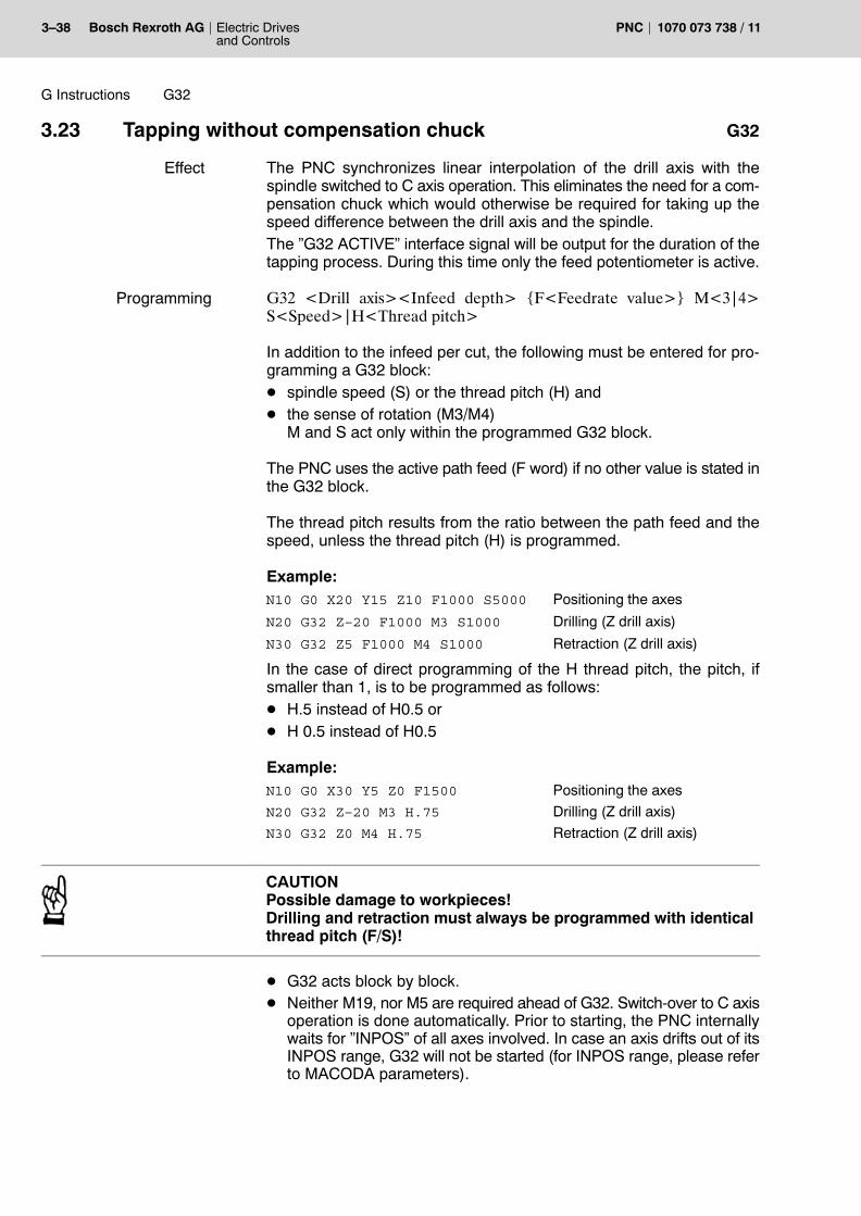
3�38 Electric Drivesand Controls
Bosch Rexroth AG PNC 1070 073 738 / 11
G Instructions G32
3.23 Tapping without compensation chuck G32
The PNC synchronizes linear interpolation of the drill axis with thespindle switched to C axis operation. This eliminates the need for a com-pensation chuck which would otherwise be required for taking up thespeed difference between the drill axis and the spindle.The �G32 ACTIVE� interface signal will be output for the duration of thetapping process. During this time only the feed potentiometer is active.
G32 <Drill axis><Infeed depth> {F<Feedrate value>} M<3|4>S<Speed>|H<Thread pitch>
In addition to the infeed per cut, the following must be entered for pro-gramming a G32 block:D spindle speed (S) or the thread pitch (H) andD the sense of rotation (M3/M4)
M and S act only within the programmed G32 block.
The PNC uses the active path feed (F word) if no other value is stated inthe G32 block.
The thread pitch results from the ratio between the path feed and thespeed, unless the thread pitch (H) is programmed.
Example:N10 G0 X20 Y15 Z10 F1000 S5000 Positioning the axes
N20 G32 Z–20 F1000 M3 S1000 Drilling (Z drill axis)
N30 G32 Z5 F1000 M4 S1000 Retraction (Z drill axis)
In the case of direct programming of the H thread pitch, the pitch, ifsmaller than 1, is to be programmed as follows:D H.5 instead of H0.5 orD H 0.5 instead of H0.5
Example:N10 G0 X30 Y5 Z0 F1500 Positioning the axes
N20 G32 Z–20 M3 H.75 Drilling (Z drill axis)
N30 G32 Z0 M4 H.75 Retraction (Z drill axis)
CAUTIONPossible damage to workpieces!Drilling and retraction must always be programmed with identicalthread pitch (F/S)!
D G32 acts block by block.D Neither M19, nor M5 are required ahead of G32. Switch-over to C axis
operation is done automatically. Prior to starting, the PNC internallywaits for �INPOS� of all axes involved. In case an axis drifts out of itsINPOS range, G32 will not be started (for INPOS range, please referto MACODA parameters).
Effect
Programming

G Instructions G532
Electric Drivesand Controls
3�39Bosch Rexroth AGPNC1070 073 738 / 11
D The drilling and retraction blocks must be programmed directly oneafter another, otherwise the �Retraction block not programmed� run-time error will appear.
D After the retraction block, the spindle will return to spindle operation.
. Please refer to section 3.24 for tapping using several spindles,G532, and to section 3.83 for suppressing axes for calculating thefeedrate, G594.
3.24 Activation of tapping without compensation chuckfor several spindles G532
You can tap threads in parallel without compensation chuck using up to 8spindles. Programming and effect correspond to G32. However, you use G532 to determine the spindles to which G32 is to re-fer. If you do not program any G532, G32 will always refer to the 1st spindle.
G532 CAX<i>..{CAX<n>} tapping (G32) using the i-th spindle(s).
G532 GRP<j> tapping (G32) using (a) spindle(s)from the j-th spindle group
G532 GRP<j>..CAX<i>..{CAX<n>} tapping (G32) using (a) spindle(s)from the j-th spindle group andadditionally the i-th spindle(s)
where:CAX spindle axisi = 1 .. max. 8 (n) number of the spindle
GRP spindle groupj = 1 .. max. 4 number of the spindle group
Example:G532 CAX1 tapping (G32) using the 1st spindle
G532 CAX2 CAX4 CAX7 tapping (G32) using the 2nd, 4th and 7th spindle
G532 GRP2 tapping (G32) using (a) spindle(s) from spindlegroup 2
G532 GRP3 CAX4 tapping (G32) using (a) spindle(s) from spindlegroup 3 and the additional 4th spindle
Please note for G532:D With G532 you cannot activate more than one spindle group.D CAX1 through CAX8 can be combined in any way and in addition to
any spindle group.
. The information will remain active until a new G532 is programmed(i.e. even after CONTROL RESET!). After a control reset, this func-tion can be entered in the MACODA start-up string.
Effect
Programming

3�40 Electric Drivesand Controls
Bosch Rexroth AG PNC 1070 073 738 / 11
G Instructions G9322G9321
3.25 Retraction from tapped hole G9321, G9322
If function �Tapping without compensation chuck� (G32) was cancelled(by �control reset� or due to a voltage drop) while the screw tap was still inoperation, G9321 or G9322 can be used to retract the tap from thetapped hole. Programming can be done by manual input or within a partprogram (cycle).
G9321 Switches the spindle(s) running again in spindle speed modeafter �control reset� (control start-up) to Position mode.
G9322 F Initiates the retraction motion proper (with F value).
. G9321 must be programmed before retracting!
2 situations must be distinguished when applying the function �Retrac-tion from tapped hole�:D Retraction after �control reset� (automatic retraction)
The data saved when starting the tapping process is retained.The spindles are switched over to position mode with G9321. IfG9322 is programmed next, the tap moves out of the thread and on tothe stored starting position. Only the desired feedrate (F value) mustbe programmed together with G9322.
D Retraction after power failure (manual retraction)The data saved when starting the tapping process is lost. In this case,the parameters have to be programmed explicitly together withG9322.G91 G9322 S<Speed> F<Feedrate> M3/M4 <Drill axis> <incremen-tal path>
Preconditions for the use of G9321/G9322:D The C axes involved must be defined as endless rotary axes (MA-
CODA parameter 1001 0000 4 = 2 and SERCOS parameterS-0-0076 = Ob1xxxxxxx).
D In SERCOS secondary operation mode 1 (S-0-0033), bit 8 for drive-controlled change of operation mode must not be set: S-0-0033 =Ob000001011 or S-0-0033 = Ob000001100.
Application of subprograms for retraction from tapping:To make the application of the function �Retraction from tapping� easier,it is recommended that you write one subprogram (cycle), each, for auto-matic and manual retraction. With MACODA parameters 3090 00001and 3090 00002, these subprograms can then be assigned to any G-code available.
Effect
Programming

G Instructions G9322G9321
Electric Drivesand Controls
3�41Bosch Rexroth AGPNC1070 073 738 / 11
Example: Automatic retraction cycleAutoTR[feedrate]
N12 If P1=NUL THENN3 (MSG, ** P1 NO FEEDRATE PROGRAMMED **)N4 M05 GOTO N36 ELSE7 GVORSCH%=SD(1,7,2)8 FVORSCH%=SD(5,1,2)N9 G9321N10 G94 G9322 F(P1)N11 G[GFEED%]12 IF GFEED%=94 THENN13 F[FFEED%]14 ENDIF15 ENDIFM30
Example: Manual retraction cycleManTR[drill axis number, path, master pitch, feedrate]
N12 If P1=NUL THENN3 (MSG, ** P1 AXIS NOT PROGRAMMED **)N4 M05 GOTO N36 ENDIF7 If P2=NUL THENN8 (MSG, ** P2 PATH NOT PROGRAMMED **)N9 M010 GOTO N811 ENDIF12 If P3=NUL THENN13 (MSG, ** P3 THREAD PITCH NOT PROGRAMMED **)N14 M015 GOTO N1316 ENDIF17 If P4=NUL THENN18 (MSG, ** P4 FEEDRATE NOT PROGRAMMED **)N19 M020 GOTO N1821 ENDIF22 BAXIS%=ROUND(P1)23 IF P3>0 THEN24 MCODE1%=425 ELSE26 MCODE1%=327 ENDIF28 PITCH=ABS(P3)29 GABS_INC%=SD(1,4,2)30 GFEED%=SD(1,7,2)

3�42 Electric Drivesand Controls
Bosch Rexroth AG PNC 1070 073 738 / 11
G Instructions G9322G9321
31 FFEED%=SD(5,1,2)N32 G9321N33 G91 G94 G9322 [AXP(BAXIS%,P2)] H[PITCH] F[P4]
M[MCODE1%]N34 G[GABS_INC%] G[GFEED%]35 IF GFEED%=94 THENN36 F[FFEED%]37 ENDIFM30
For the cycles to run, some configurations need to be set in MACODA.
MACODA configuration:
Parameter: 3090 00001
0 9032
1 9132
2 ...
Parameter: 3090 00002
0 AutoTR
1 ManTR
2 ...
Example:G9032[1000] automatic retraction at a feedrate of
F1000mm/min
G9132[3,-100,0.5,500] manual retraction at a pitch of 0.5, a retrac-tion path of �100mm, F500, with the 3rd log-ical axis of the channel as the drill axis

G Instructions G33
Electric Drivesand Controls
3�43Bosch Rexroth AGPNC1070 073 738 / 11
3.26 Tapping G33
Activates tapping ofD Longitudinal threads
(Cutting motion in parallel to the main axis of the active plane),D Transversal threads
(Cutting motion in parallel to the secondary axis of the active plane),D Tapered threads
(the main and the secondary axis of the active plane are involved inthe cutting movement).
G33 can be programmed with a speed-controlled and position-con-trolled spindle. The cutting motion is always linked to the main spindle active on thechannel in question (refer to page 4�17).The feedrate of the cutting motion results from the current spindle speedand the programmed pitch portions (fixed, variable � refer to �Program-ming�).Special features:D single and multiple threads can be producedD constant and variable thread pitches can be programmedD special dynamics adjustment during the cutting processD programmable quick retraction movementD chained threads can be produced.
. The feedrate potentiometer has no effect while G33 is active.
. G33 acts modally and belongs to the same group of NC functionsas G0, G1, G2, G3, etc.
. Like circular interpolation (G2, G3), the tapping function is subjectto the active plane (G17 ... G20).
The behavior of the �Tapping� function is normally defined in MACODAparameters 7050 006xx. In individual cases, or during initial commissioning, it may be advanta-geous to adjust individual sections quickly. This requirement is satisfiedby function G533 (for a description, refer to page 3�49 ff.).G533 provides forD the adjustment of the dynamics and retraction movementD change-over of the spindle mode (speed control, position control)D specification of the channel IF signal NC-O20.4, �Tapping cycle ac-
tive�.
Effect
3�44 Electric Drivesand Controls
Bosch Rexroth AG PNC 1070 073 738 / 11
G Instructions G33
G33 <End point> <fixed thread pitch> {<var. pitch>} {<startingangle>}where<End point> Axis coordinates of the main and secondary axis of the
active plane. The active plane is defined by G17, G18,G19 or G20.Example:The active plane for G18 is usually defined by axes Z(main axis) and X (secondary axis).
<fixed pitch> Defines the path (in mm) traveled in the direction of themain or secondary axis with each spindle revolution.This value is programmed by the interpolation parameter(I, J or K) valid in the respective active plane.In the event of tapered threads, the pitch thread speci-fied always has to relate to the main cutting direction.Example:For G18, parameter K is assigned to the main axis, and Ito the secondary axis. For a longitudinal thread (pitch indirection of main axis), the fixed thread pitch is pro-grammed with the K address.
<var. pitch> Optional parameter with address DF. Defines the pitch increase/decrease per spindle revolu-tion in mm. Programming: �DF<Value>� with <Value> in mm.
<starting angle> Optional parameter. If no <Starting angle> has been programmed, it is as-sumed to be 0 degrees.The starting angle (offset) is needed for multiple threads.The interpolation parameter not assigned to the activeplane is used as address.Example:Addresses I and K have been assigned to the plane forG18. Therefore, the address of the starting angle is J.
. Alternatively, a syntax of the type used for CC220/Typ1 osa may beused. Details on request.
Programming

G Instructions G33
Electric Drivesand Controls
3�45Bosch Rexroth AGPNC1070 073 738 / 11
Programming example: Longitudinal thread
X
Z
12
3
G91 G18 G8 M3 S1000
G0 X–10G33 Z–50 K2
G0 X10
Activate incremental data input.Activate Z/X planeInfeed motion of the cutting tool (1).Tapping (2). End point: incremental by �50 mmin Z direction. Fixed thread pitch: 2 mm/rev. Interpolation pa-rameter: K in this case.Move out cutting tool (3)
Programming example: Transversal thread
X
Z
1
2
3
G91 G18 G8 M3 S1000
G0 Z–10G33 X40 I2
G0 Z10
Activate incremental data input.Activate Z/X planeInfeed motion of the cutting tool (1).Tapping (2). End point: incremental by +40 mmin X direction. Fixed thread pitch: 2 mm/rev. Interpolation pa-rameter: I in this case.Move out cutting tool (3)

3�46 Electric Drivesand Controls
Bosch Rexroth AG PNC 1070 073 738 / 11
G Instructions G33
Programming example: Tapered longitudinal thread
X
Z
12
3
max. 45 degrees!
K
The thread pitch (K in this case) alwaysrefers to the main direction of cut.
G91 G18 G8 M3 S1000
G0 X–20G33 Z–50 X15 K2
G0 X5
Activate incremental data input.Activate Z/X planeInfeed motion of the cutting tool (1).Tapping (2). End point: incremental by �50 mmin Z direction and +15 mm in X direction. Fixedthread pitch: 2 mm/rev. Interpolation parame-ter: K in this case.Move out cutting tool (3)
Chained threadsD can be produced from all types of thread.D are programmed by several consecutive G33 blocks.With each G33 block programmed, the NC checks whether a subse-quent G33 block has been programmed with path information. If this isthe case, the next block is processed without halting the axes.
Multi-start threadsMulti-start threads are produced by a starting angle offset (for startingangle, refer to page 3�44).
Example: A four-start thread is produced by four cuts displaced by90 degrees each (0,90, 180, 270).
X
Z
12
3
1st cutStarting angle 0 degrees
X
Z
12
3
2nd cutStarting angle 90 degrees
X
Z
12
3
3rd cutStarting angle 180 degrees
Z
12
3
4th cutStarting angle 270 degrees

G Instructions G33
Electric Drivesand Controls
3�47Bosch Rexroth AGPNC1070 073 738 / 11
...G18...
...G33...J0...G33...J90...G33...J180...G33...J270...
Activate Z/X plane
First thread. Starting angle: 0 degrees
Second thread: Starting angle: 90 degrees
Third thread. Starting angle: 180 degrees
Fourth thread. Starting angle: 270 degrees
Dynamic behaviorIn the beginning and at the end of a thread-cutting process, the axes in-volved have to be accelerated and stopped, respectively.
L Therefore, you should always provide for a sufficiently long entry path(for accelerating the cutting axes) and discharge path (for stopping).
As a rule, a distinction is made between 2 process options:D �hard� start and �hard� end of the cutting motion
In the beginning of the G33 movement, the axis/axes jump(s) to thecutting speed (spindle speed * fixed pitch) when the starting angle isreached. At the end of the G33 movement the speed returns to 0.
D Start/end of the cutting motion with individual dynamics selection:Since the �hard� solution is not always desirable, or cannot be per-formed due to restrictions existing in the area of axis dynamics, youmay set the dynamic behavior concerning the speed jump, startingand deceleration speed individually. � statically with MACODA (7050 00610, 7050 00615 and7050 00620)� dynamically in the part program using �G533 DYN ...�
(refer to page 3�49)).The control unit uses the programmed starting angle to compute astarting angle offset, taking into account the slope of the accelerationramp. Thus, it can be ensured that the same thread is always cut, re-gardless of the size of the acceleration.
At the end of the thread, the cutting axis/axes are uncoupled from thespindle and initially decelerated to the jump speed, depending on thedeceleration setting, in order to be finally decelerated to stop.
However, if the G33 block is followed by another traversing block withactive G8 or G108, the motion of this block will start at the speed thatwould have resulted if the thread-cutting block had been a G1 block.
3�48 Electric Drivesand Controls
Bosch Rexroth AG PNC 1070 073 738 / 11
G Instructions G33
Fast retractThe �fast retract� function can be used in conjunction with G33. If retract data has beenD configured
(� statically with MACODA (7050 00645, 7050 00650), or � dynamically in the part program using �G533 RD ...�
(refer to page 3�49))and
D has been activated(� statically with MACODA (7050 00640), or � dynamically in the part program using �G533 RON1 ... �
(refer to page 3�49)),a positive edge at the channel IF signal NC-I7.4, �fast retract�, will initiatethe retraction with the following sequence:1. The cutting motion is superimposed by a motion that is oriented verti-
cally to the main cutting direction.2. If more than 70% of the retract path have been traveled, the cutting
axis/axes is/are uncoupled from the spindle and stopped at the con-figured deceleration (MACODA 7050 00620).
. If the retract motion was initiated by NC-I7.4, this condition canonly be canceled by �Control reset� or �Moving away from the con-tour�.
Retract motions are always carried out perpendicularly to the main cut-ting direction of the secondary cutting axis.Retract motions are automatically initiated if either of the events �Chan-nel reset�, �System reset�, or �Spindle reset� is triggered by the NC.
Programming example: Retraction from longitudinal threadG18 G533 RON1 RD(0,5) Activate Z/X plane (G18)
Activate fast retract (RON1).Retract motion (RD ...) by +5 mm in thesecondary cutting direction (X in this case).
G91 G33 Z–20 K1 Incremental programming on (G91).Tapping (G33). End point: incremental by�20 mm in Z direction. Fixed thread pitch: 1 mm/rev. Interpolationparameter: K in this case.

G Instructions G533
Electric Drivesand Controls
3�49Bosch Rexroth AGPNC1070 073 738 / 11
3.27 Additional tapping functions G533
Individual partial areas of G33 can be temporarily adjusted by program-ming G533. In this case, the control unit superimposes the static values stored inMACODA.G533 provides forD the adjustment of the dynamics and retraction movementD change-over of the spindle mode (speed control, position control)D specification of the channel IF signal NC-O20.4, �Tapping cycle ac-
tive�.
Control reset or M30D cancels the settings superimposed by G533D clears an IF signal that had been set by G533D switches the main spindle back to speed-controlled operation, if it had
previously changed over to position-controlled spindle operation by�G533 SPC1�.
. All partial functions described below can be jointly programmed ina single G533 block.
Configuring the retract data:
G533 RD(<MA value>,<SA value>{,−1})where<MA value> Retract path (incremental in mm) towards the main axis
of the currently selected plane (G17, G18, G19, G20). The value always has to be programmed, however, it isonly relevant for longitudinal and tapered threads.
<SA value> Retract path (incremental in mm) towards the secondaryaxis of the currently selected plane.The value always has to be programmed, however, it isonly relevant for transversal and tapered threads.
−1 ��1� is an optional third parameter. In this case, the retract data from MP 7050 00645 andMP 7050 00650 will be active again.
Activating retraction:
G533 RON<Status>where<Status> 0: Deactivate fast retract.
1: Activate fast retract.
Effect
Programming

3�50 Electric Drivesand Controls
Bosch Rexroth AG PNC 1070 073 738 / 11
G Instructions G533
Configuring the dynamics:
G533 DYN({<Jump>},{<Accel>}{,<Decel>})where<Jump> max. permitted jump speed in mm/min
Entering ��1� will activate MP 7050 00610 again.
<Accel> Acceleration in m/s2
Entering ��1� will activate MP 7050 00615 again.
<Decel> Deceleration in m/s2
Entering ��1� will activate MP 7050 00620 again.
Changing over the spindle mode:
G533 SPC<Status>where<Status> 0:
Switching the main spindle into speed-controlled mode.
1:Switching the main spindle into position-controlled mode,depending on the setting of 7050 00600 [3].
For details on main spindles, refer to page 4�17.
Influencing the channel IF signal �Tapping cycle active�:
G533 TCI<Status>where<Status> 0: clears the channel IF signal NC-O20.4
1: sets the channel IF signal NC-O20.4

G Instructions G134G36G35G34
Electric Drivesand Controls
3�51Bosch Rexroth AGPNC1070 073 738 / 11
3.28 Corner rounding G34, G35, G36, G134
The �corner rounding� function inserts tangential transition arcs between2 linear blocks (G34, G134) and between circular and helical blocks(G134 only) in the principal plane. On the one side, this leads to a minormodification of the programmed contour at these corners, but on theother side, continuous speed and acceleration patterns are achievedduring interpolation (refer to �PNC Description of Functions� manual).
G34 Switch on �corner rounding� with max. admissible deviations
G35 Switch off �corner rounding�
Address E The E word is used to program the �maximum permitteddeviation� (in mm) between the modified contour and theprogrammed values. Fractional parts are allowed.Programming �E� is only possible if G34 is active.
G36 Deletes a max. admissible deviation programmed via Eword. The value activated in MACODA parameter7050 00110 becomes active again.
G134 Switch �corner rounding� on with specification of therounding radius.
R address: You use an R word to program the radius of the transitionarc. Fractional parts are allowed. �R� has to be programmedtogether with G134 in one and the same block.
Please note for G34, G134:D the radius is programmed together with G134 in one block,D the radius acts modally,D in the case of helical blocks, only the components of the circular plane
for rounding are taken into account.D G34, G134, G234 (for chamfer programming, refer to Section 3.29)
form a group.D The functions G34, G134, G234 and G35 deselect each other, with
G35 deselecting any type of insertion of transition segments.
With active G34, the control unit will not execute �corner rounding� if:D at least one of the two neighbouring blocks is no linear block.
With active G34, G134, the control unit will not execute �corner round-ing� if:D at least one of the two neighbouring blocks has a path portion outside
the selected principal plane, orD at least one of the two neighbouring blocks has a traversing path
which is smaller than the path set in MACODA parameter 7050 00120(2 to 90 mm, default value: 2 mm), or
D no �quasi-continual� block transition according to MACODA parame-ter 7050 00130 is present, i.e. the angle between the two blocks isgreater than the value in 7050 00130 stated as maximum angle (de-fault = 1).
Effect
Programming

3�52 Electric Drivesand Controls
Bosch Rexroth AG PNC 1070 073 738 / 11
G Instructions G35G234
3.29 Chamfer programming G234, G35
The function �chamfer programming� inserts a transition phase betweentwo consecutive NC blocks of the type straight line or circle, the length ofwhich can be specified as absolute chamfer length or as length of thechamfer segment. The chamfer is generated within the active workingplane.
The following chamfer transitions are possibleD Chamfer between two abutting straight lines:
The chamfer runs at a right angle to the bisector between neighboringpath segments. The length of the chamfer is automatically corrected(reduced) when there is no intersection with the neighboring pro-grammed path segments.
Chamfer length
Bisector of the angle
Straight lineStraightline
Chamfer segment
D Chamfer between two abutting circle segments:In case of contour transitions involving circle segments, the dimen-sions of the chamfers refer to the respective end or starting tangent ofthe path segments involved in the contour transition. The actual re-sulting chamfer length is strongly dependent, among others, on theradii of the circles involved and thus deviates more or less from theprogrammed dimensions.
Chamfer length
Bisector of the angle
Circle segment 2
Tangent line 1
Tangent line 2
Circle segment 1
Chamfer segment
Correction of the chamfer length in case of non-existing intersec-tionsReasons why intersections with the neighboring contour segments donot exist due to the programmed geometry:D Programmed chamfer length too long.
Effect

G Instructions G35G234
Electric Drivesand Controls
3�53Bosch Rexroth AGPNC1070 073 738 / 11
D Path length of the neighboring programmed path segments too short.D Radius of the neighboring path segment is too small in relation to the
chamfer length.
If intersections between the neighboring contour segments do not exist,the specified length of the chamfer is automatically reduced to the pointwhere it can be inserted between the contour segments. The orientationof the chamfer is always perpendicular to the bisector between the twoneighboring path segments.If more than one-half of a programmed path segment would be cut offdue to the reduced chamfer length, the chamfer length needs to beshortened. In this event, the following conditions are applicable:D The transition from the previous path segment to the chamfer takes
place at the earliest after one-half of the path of the previous pathsegment.
D The transition from the chamfer to the following path segment takesplace at the latest after half of the path of the following path segment.
Chamfer segment
programmedchamfer length
Bisector of the angle
Circle segment 2
Tangent line 1
Tangent line 2Circle segment 1
shorter chamfer
G234... CHL<Chamfer length>|CHR<Chamferlength>|CHF<Chamfer segment>
G234... CHL..|CHR..|CHF.. Switch on �chamfer programming�
whereCHL<Chamfer length> Chamfer length (Chamfer Length) in mm
(G71) or inches (G70)
CHR<Chamfer length> alternative to CHL in unit mm (G71) or inches(G70), respectively.
CHF<Chamfer segment> Chamfer segment alternative to CHL in unitmm (G71) or inches (G70), respectively.
G35 Switch off �chamfer programming� or �cornerrounding� (refer to Section 3.28).
Programming
Programming

3�54 Electric Drivesand Controls
Bosch Rexroth AG PNC 1070 073 738 / 11
G Instructions G35G234
Please note for G234, G35:D G234 has a modal effectD G234 forms a group together with the two types of corner rounding
G34 and G134.D The functions G34, G134, G234 and G35 deselect each other, with
G35 deselecting any type of insertion of transition segments.D The chamfer length/chamfer segment parameters CHL, CHR or CHF
have to be programmed together with G234 in one and the sameblock.
D The chamfer exclusively refers to the active working plane (G17,G18, G19, G20). If additional axes are involved in the movement, thechamfers are not influenced by this. As the coordinates of the pro-grammed traversing blocks of the axes within the working plane aremanipulated by the chamfers, but the values for the axes outside theworking plane remain unchanged, the direction of straight lines inspace may change, for example.
D The function is only effective in the �Automatic� operating mode underautomatic, single block and single step. Since the �program block� be-haves like a manual input, chamfer programming is not effective here.
D The switch on/off procedure as well as the behavior upon control re-set is exclusively determined by the two entries for the init strings inMACODA parameters 7060 00010 and 7060 00020.

G Instructions G39G38 G37
Electric Drivesand Controls
3�55Bosch Rexroth AGPNC1070 073 738 / 11
3.30 Mirroring, scaling, rotating G37, G38, G39
Mirroring:The control unit mirrors a programmed contour for machining. You do notneed to change the programmed contour for this purpose.
Scaling:The control unit scales the programmed contour up or down for machin-ing. You need not change the programmed contour for this purpose.
Rotating:The control unit rotates a programmed contour for machining. You neednot change the programmed contour for this purpose.
+Y
+XP
G37 X5 Y2G38 X�1
Mirroring: Scaling+Y
+X
G38 X1.3 Y1.3
+Y
+XP
Rotating
G37 X20 Y10G38 R�60
R
Mirror point
5
2
Point of rotation
20
10
P
The named functions can also be combined.
You can influence the mirroring, scaling and rotating functions jointlyvia the G37, G38 and G39 functions:G37 Determination of the mirror or rotation point
G38 Activate the mirroring, scaling or rotating function
G39 Deactivate the mirroring, scaling or rotating function
CAUTIONThe functions act only in the automatic, single-block and manual-input modes. The traversing direction during jogging will notchange with active G38.
For detailed explanations, please refer to the sections below.
Effect
Programming

3�56 Electric Drivesand Controls
Bosch Rexroth AG PNC 1070 073 738 / 11
G Instructions G39G38 G37
3.30.1 Mirroring G37, G38, G39
The control unit will machine a programmed contour or, for instance, abore-hole pattern in the form of a mirror image.The �scaling� and �rotating� functions can be used simultaneously with�mirroring�.
G37 Pole definition (special case). This is used to determine the position of the �mirror point� forG38. This position has to be input as an absolute pair ofcoordinates referring to the program zero point.
G37 is not required ifD mirroring is supposed to be referring to the program zero pointD rotating is supposed to be referring to the program zero point (please
refer to �Rotating�).
The G37 function:D acts modally The pole values remain effective until G39 or G37 is pro-
grammed (with other pole values)D is only effective in conjunction with G38D does not cause any axis traversingD may be programmed together with other preparatory functions within
the same block; auxiliary functions are allowedD is not influenced by the factors programmed in G38 (in the case of the
�scaling� function) and by the angle of rotation (in the case of the �ro-tating� function).
Example:
N... G37 X100 Y�200
Pole coordinatesCalling the pole definition
G38 Mirroring on.You switch �mirroring� on by programming axis addresses (e.g.X) with the value of ��1� in the same block as G38. By doing soyou instruct the control unit to multiply all subsequentlyprogrammed path commands of the corresponding axis (e.g.X100) internally by the value ��1�.This means that the �mirroring� function is exclusively realizedby the minus sign. If you specify a value other than �1�, you willfurthermore change the size of the mirrored contour (pleaserefer to �Scaling�).Mirroring will become effective together with the next traversinginformation.
Effect
Programming
Programming

G Instructions G39G38 G37
Electric Drivesand Controls
3�57Bosch Rexroth AGPNC1070 073 738 / 11
G38 O(<Sx>,<Sy>,<Sz>) Mirroring of an orientation vectorAn orientation vector is mirrored by com-ponents. Scaling or a pole determinationhave no influence.
where:
<Sx>,<Sy>,<Sz> Mirroring factors Sx, Sy, and Sz:+1: no mirroring�1: mirroring
Please note for the orientation vector:D The polar coordinates ϕ and ϑ proper cannot be mirrored.D Programming �G38 phi�1 theta�1� is not allowed.
The G38 function:D acts modally. It remains active until G39 is programmed.D must always be written into the same block as the axes to be mirroredD may be written with other preparatory functions in the same blockD may be programmed with auxiliary functions.D takes account of interpolation parameters in the case of circular inter-
polationD influences the programmable contour shift G60D does not affect the zero shifts G54�G259, G92 (set actual value) or
cutter-radius and tool-length compensation.
Example:
N... G38 X�1 Y�1
Any subsequently programmedaxis values for the X and Y axiswill be multiplied by the value of��1� within the control unit.
Mirroring on (by nexttraversing motion)
G39 Switch mirroring, scaling, rotating off.Any subsequently programmed axis values will no longer bemultiplied by the value of ��1� within the control unit.Approached axis positions are retained until re-programmed.
The G39 function:D acts modally.D deletes all mirror axes.D deletes G37 and G38 and sets the pole coordinates to the value of �0�.D can be written into a block with preparatory functions, traverse infor-
mation and auxiliary functions.
Programming
Programming

3�58 Electric Drivesand Controls
Bosch Rexroth AG PNC 1070 073 738 / 11
G Instructions G39G38 G37
Mirroring examples:
Y
XP
Effect of: G38 X�1
Y
XP
Effect of: G38 Y�1
Y
XP
Effect of: G38 X�1 Y�1
Y
XP
Effect of: G37 X10 Y13G38 X�1
1
2
10
13
1: definition of the mirror point(X10;Y13)2: Mirroring on

G Instructions G39G38 G37
Electric Drivesand Controls
3�59Bosch Rexroth AGPNC1070 073 738 / 11
3.30.2 Scaling G38, G39
The control unit scales a programmed contour up or down for machining.
This can be used in part programs for programming contours using onefixed size (standard size). Then, prior to calling such a part program (e.g.as a subprogram), you use scaling factors for each axis to determine thescale of the programmed contour.In this way it is, for instance, easy to compensate for the contraction ofthe workpieces in the manufacture of the moulds for cast and forgedparts.
The �scaling� function can be used together with �mirroring� and �rotat-ing�.
D Scaling does not influence feed programming or the active feedrate.D M2/M30 in a subprogram does not switch scaling off.
In principle, different scaling factors can be stated for each axis. How-ever, if you wish to use circular interpolation (or helical interpolation) withactive scaling, the scaling factors must be the same for all axes involved!Otherwise an error message will be generated.
Scaling factors will also change the I, J, K interpolation parameters aswell as the amount of the R address (for radius programming).
D G0, G1, G2, G3, G5, G10,G11, G12, G13, G73, G200
Scaling acts in combination with the pro-grammed axis information.
D G20 Scaling acts in combination with the pro-grammed axis information.
D G37 Pole values will not be scaled.
D G40, G41, G42, G43, G44 Scaling is active; compensation values willnot be scaled.
D G54�G59, G154�G159,G254�G259
Zero-shift values will not be scaled.
D G60 The programmable contour-shift valueswill be scaled.
D G70,G71 Scaling acts independently of the activeunit of measurement.
D G74,G76 Scaling is not active.
D G90,G91 Scaling acts with absolute and incrementaldata input.
D G92 Offset will not be scaled.
Effect
Particularities in thecase of circular
interpolation
Interaction offunctions

3�60 Electric Drivesand Controls
Bosch Rexroth AG PNC 1070 073 738 / 11
G Instructions G39G38 G37
If the starting position of the workpiece contour is not to be influenced bya scale- down or scale-up of the programmed contour, you should selectthe starting point of the workpiece contour to be the program zero point,too.
G38 Scaling on.You switch "scaling" on by programming axis addresses (e.g.X) with a positive factor in the same block as G38. By doing soyou instruct the control unit to multiply all subsequentlyprogrammed path commands of the corresponding axis (e.g.X10) internally by this value.If you specify a value other than "1", you will change the size ofthe contour:Factor> 1 : the contour will be scaled up.Factor< 1 : the contour will be scaled down.If you program the factor with a negative sign, you switch onthe "mirroring" function in addition.
The G38 function:D acts modally. It remains active until G39 is programmed.D always has to be written together with the axes to be scaled within one
block.D does not cause any axis traversing.D may be written with other preparatory functions in the same block.D may be programmed with auxiliary functions.
Example:N... G38 X3 Y0.5
All X coordinates programmedsubsequently are multiplied by �3�,and the Y coordinates by �0.5�.
Scaling on (upon next traversing motion)
+Y
+X
P
10
20
2010 30 40
P2
P1P1 = Position before scalingP2 = Position after scaling
G39: Switch mirroring, scaling, rotating off.Any subsequently programmed axis values will no longer beinfluenced.Approached axis positions are retained until re-programmed.
Programming
Programming

G Instructions G39G38 G37
Electric Drivesand Controls
3�61Bosch Rexroth AGPNC1070 073 738 / 11
The G39 function:D acts modally.D deletes all mirror axes.D deletes G38 and sets the internal scaling factors to the value of �1�.D can be written into a block with preparatory functions, traverse infor-
mation and auxiliary functions.
Scaling examples:
Y
XP
Effect of: G38 X2 Y2(Program zero point = Workpiece zero point)
Y
XP
Effect of: G38 X2 Y2(Program zero point�Workpiece zero point)
Y
XP
Effect of: G38 X2 (Program zero point = Workpiece zero point)
Y
XP
Effect of: G38 X2 (Program zero point�Workpiece zero point)
Y
XP
Effect of: G38 Y2 (Program zero point = Workpiece zero point)
Y
XP
Effect of: G38 Y2 (Program zero point�Workpiece zero point)
Y
XP
Effect of: G38 X0.5 Y0.5(Program zero point = Workpiece zero point)
Y
XP
Effect of: G38 X0.5 Y0.5(Program zero point�Workpiece zero point)
Y
XP
Effect of: G38 X0.5(Program zero point = Workpiece zero point)
Y
XP
Effect of: G38 X0.5(Program zero point�Workpiece zero point)
Y
XP
Effect of: G38 Y0.5(Program zero point = Workpiece zero point)
Y
XP
Effect of: G38 Y0.5(Program zero point�Workpiece zero point)

3�62 Electric Drivesand Controls
Bosch Rexroth AG PNC 1070 073 738 / 11
G Instructions G39G38 G37
3.30.3 Rotating G37, G38, G39
The control unit rotates a programmed contour in the active plane(please refer to G17, G18, G19 or G20).
This means that you must program only once such recurrent program-ming steps as are rotated around a specific angle.In addition you do not have to convert the dimensions of angled work-pieces to the machine coordinates; you simply take them over directlyfrom a production drawing and specify the corresponding angle of rota-tion. The PNC will do the rest.
�Scaling� and �mirroring� can be used in conjunction with the �rotating�function.
G37 Pole definition. This is used to determine the position of the "point ofrotation" for G38. This position has to be input as anabsolute pair of coordinates referring to the program zeropoint.
G37 is not required ifD rotating is supposed to be referring to the program zero pointD mirroring is supposed to be referring to the program zero point
(please refer to "Mirroring").
The G37 function:D acts modally. The pole values remain effective until G39 or G37 (with
other pole values) is programmedD is only effective in conjunction with G38D does not cause any axis traversing.D may be programmed together with other preparatory functions within
the same block; auxiliary functions are allowedD is not influenced by scaling factors programmed in G38 (in the case of
the �scaling� function) or their sign (in the case of the �mirroring� func-tion).
Example:N...G17 G37 X200 Y100
Pole coordinatesCalling the pole definitionPlane selection (may be omitted if rotatingis to be performed in the active plane)
Effect
Programming

G Instructions G39G38 G37
Electric Drivesand Controls
3�63Bosch Rexroth AGPNC1070 073 738 / 11
G38 Rotating on. Program the �R� address with the desired angle of rotation inthe same block as G38.D Positive values: Counter-clockwise rotationD Negative values: Clockwise rotation.
By doing so you instruct the control unit to rotate all subse-quently programmed coordinates of the corresponding planearound the point of rotation (please refer to G37).The rotation becomes active with the next traversing infor-mation. A programmed contour shift (G60) will be included inthe calculation of the coordinate rotation
G38 R<Angle> Rotating an orientation vector
an orientation vector is rotated by the normal of theselected plane. Scaling or a pole determinationhave no influence.
where:
<Angle> Angle of rotation around the normal of the selectedplane.
The G38 function:D acts modally. It remains active until G39 is programmed.D must always be programmed with angle of rotation R in the same
block.D may be written with other preparatory functions in the same block.D may be programmed with auxiliary functions.
Example:N... G38 R+30
Angle of rotationRotating on
+Y
+XP
Angle of rotation :
+R
X
Y
X�Y�
Axis of rotationPoint of rotation
+R: positive mathematical value�R: negative mathematical value
Rotated coordinates
Programming
Programming
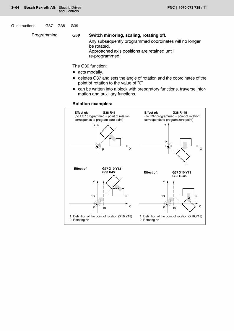
3�64 Electric Drivesand Controls
Bosch Rexroth AG PNC 1070 073 738 / 11
G Instructions G39G38 G37
G39 Switch mirroring, scaling, rotating off.Any subsequently programmed coordinates will no longerbe rotated.Approached axis positions are retained untilre�programmed.
The G39 function:D acts modally.D deletes G37 and sets the angle of rotation and the coordinates of the
point of rotation to the value of �0�D can be written into a block with preparatory functions, traverse infor-
mation and auxiliary functions.
Rotation examples:
Y
XP
Effect of: G38 R45(no G37 programmed = point of rotationcorresponds to program zero point)
Y
XP
Effect of: G37 X10 Y13G38 R45
1
2
10
13
1: Definition of the point of rotation (X10;Y13)2: Rotating on
Y
X
P
Effect of: G38 R�45(no G37 programmed = point of rotationcorresponds to program zero point)
Y
XP
Effect of: G37 X10 Y13G38 R�45
1
10
13
1: Definition of the point of rotation (X10;Y13)2: Rotating on
2
Programming

G Instructions G39G38 G37
Electric Drivesand Controls
3�65Bosch Rexroth AGPNC1070 073 738 / 11
3.30.4 Combining mirroring, scaling and rotating
. If rotating and mirroring or scaling are programmed simulta-neously, rotating will be executed first, followed by mirroring orscaling.
Example: Rotating + Mirroring + Scaling
N... G37 X100 Y–200 determination of point of rotation and mirrorpoint
N... G38 X–3 Y–2 R115...
counter-clockwise rotation by 115 degrees; mirroring produced by the minus sign, andmultiplication of the X and Y coordinates by�3� or �2�)
N... G39 (switch all off)
3.30.5 Relationship between G37/G38 and G60 or G54..G259
Within the program coordinate system, G37/G38 is influenced byG60:
G38
X
Y
10
20
10 20
PG60 P2P1
P3
30 40
Example: G60
N5... P1: current positionN10 G60 P2: G60 shift of P1N20 G38 X2 Y2 Scaling ONN30 G1 X10 Y10 P3: scaled position of P2
As a principle, zero shifts (e.g. G54..G259) will shift the entire programcoordinate system with regard to the machine coordinate system.Therefore they do not cause any change to the operations within the pro-gram coordinate system, triggered, for instance, by G37/G38 or G60:

3�66 Electric Drivesand Controls
Bosch Rexroth AG PNC 1070 073 738 / 11
G Instructions G39G38 G37
+Y
+X
M
R90
X
Y
10
20
10 20
P54
G60
ZSG54
R90
X
Y
10
20
10 20
P55
G60
ZSG55
P1
P3
P1 P2
P3
P2
Example: G54 Example: G55 Comment
N10 G54 N110 G55 Call-up functionN20 G37 X10 Y10 N120 G37 X10 Y10 P1: point of rotation on
X10 Y10N30 G60 X10 N130 G60 X10 P2: G60 shift of P1N40 G38 R90 N140 G38 R90 P3: Coodinate
rotation of P2N50 G1 X10 Y10 N150 G1 X10 Y10

G Instructions G42G41G40
Electric Drivesand Controls
3�67Bosch Rexroth AGPNC1070 073 738 / 11
3.31 Cutter path compensation G40, G41, G42
. The full functionality of the cutter path compensation includes:� G40, G41, G42� G68, G69� G500, G543, G544� G64, G65.
The cutter path compensation function causes the tool to move along anequidistant path parallel to the programmed path during execution of apart-specific program. (Equidistant path = path with right-angled,constant distance from the programmed contour.) The distance betweenthe equidistant and the programmed path depends on the value of cut-ter-path compensation.
The following illustration shows the principle:
G41
G42
G42 G41
= programmed contour
= direction of feed
= equidistant
Cutter path compensationto the right ofthe workpiece
to the left ofthe workpiece
Along a contour element and in the case of tangential contour transi-tions, the equidistant � and thus the cutter path � is uniquely defined bythe programmed contour:
t
t
t tt
t = tangential transition
At unsteady contour transitions the control unit has to calculate a pathindependently in order to combine the equidistants of the contour ele-ments involved.The following functions are available for this purpose for the contourtransition at outer corners (refer to page 3�80):D G68 (contour transition on circular arc) and
Effect

3�68 Electric Drivesand Controls
Bosch Rexroth AG PNC 1070 073 738 / 11
G Instructions G42G41G40
D G69 (contour transition through intersection of the equidistants)
with G68 with G69
At unsteady contour transitions in the case of inner corners the controlunit will use the intersection of the equidistants to determine the requiredpath.
a
u
2
a2
u t = tangential transition u = non-continuous transition t
With some contour patterns (e.g. indentations) this principle may lead tocontour damage.Therefore, for contour transition at inner corners the functionD �Collision monitoring� (G543)is available (refer to page 3�184).
CAUTIONCompensation values may be immediately activated or deactiva-ted without a traversing movement. This may result in damages ofthe workpiece or the tool.Please note the information provided in this section in this con-text!
. With active G2, G3 or G5, functions G40, G41 or G42 may only beprogrammed without any traversing movement.
G40 Cutter-path compensation off (power-up state).If no traversing movement is programmed in the G40 block,the control unit will deactivate the cutter path compensationin position � vertically to the last traversing block!If a traversing movement is programmed in the G40 block,the control unit will deactivate the cutter path compensationlinearly while traveling to the end point of the traversingmovement.
Programming

G Instructions G42G41G40
Electric Drivesand Controls
3�69Bosch Rexroth AGPNC1070 073 738 / 11
G41 Activating the cutter path compensation to the left of theworkpiece (seen in the processing direction, if positivecompensation values are used).In addition to a D address containing the required radiuscompensation value, a linear traversing movement of theaxes of the active plane may be programmed in the sameblock as G41. This will select the compensation whiletraveling to the end of the traversing movement.If no traversing movement is programmed in the G41 block,the control unit will deactivate the cutter path compensationimmediately � vertically to the last traversing block.
G42 Switching cutter-path compensation on to the right of theworkpiece. Apart from that, identical to G41.
. An active tool-length compensation will not be influenced by G40.
CAUTIONPossibility of damaging the workpiece or the machine!The following is not allowed with active G41 or G42:D Plane change-over (G17 to G20)D Inch/metric change-over (G70, G71)D G32, G74, G75, G76, G92
Selection of cutter path compensation
In many cases, it is not possible to approach the contour directly from thetool change point. In most cases, machining is started from an intermedi-ate position (cf. examples).The selection of a suitable starting point helps avoid damage to the con-tour.D The starting point should facilitate a tangential approach to the con-
tourD The starting point should be positioned in such a way that the direc-
tion of an axis does not change (relief cutting) at the first contour point.

3�70 Electric Drivesand Controls
Bosch Rexroth AG PNC 1070 073 738 / 11
G Instructions G42G41G40
Example: Selecting the cutter path compensation with G41 without tra-versing movement:
N1 G0 Z�10 T01M6N2 G1 X�20 Y20F200N3 S500 M3N4 G41N5 X0 Y0N6 X20N7 G2 Y�20 R20N8 G1 X10N9 X0 Y0N10 G40 X�20 Y20N11 Z300 T00 N12 M2
S S: Starting point
Example: Selecting the cutter path compensation with G41 with lineartraversing movement:
N1 G0 Z�10 T01M6N2 G1 X�20 Y20F200N3 G41 X0 Y0 S500 M3N4 X20N5 G2 Y�20 R20N6 G1 X10N7 X0 Y0N8 G40 X�20 Y20N9 Z300 T00 N10 M2
S S: Starting point
Deselection of the cutter path compensation
As a rule, the tool does not directly move from the contour to the toolchange point but rather via an intermediate position (end point).
The selection of a suitable starting point helps avoid damage to the con-tour. Therefore:D The end point should facilitate a tangential contour departure when
the radius compensation function is active.D The end point should be positioned in such a way that relief cutting
does not take place due to a change in direction when the tool movesaway from the contour.

G Instructions G42G41G40
Electric Drivesand Controls
3�71Bosch Rexroth AGPNC1070 073 738 / 11
CAUTIONDamage to the contour possible with inside contours!If the control unit is in a circular mode (G2, G3, G5), no traversingmovement may be programmed in the G40 block.Consequently, the control unit will deselect the cutter path com-pensation in position, vertically to the last traversing block. This may cause damage to the contour.Therefore, before deactivating the cutter path compensation, youshould move out of the inside contour (e.g. in Z direction), or pro-gram a suitable end point.
Inappropriate end point.Contour will be damaged!
EE
E = End point for deselecting the cutter path compensation, programmed by G40.
Suitable end point. Contour will notbe damaged.
The following procedure is recommended (G41 active):D last contour machining procedure (e.g. G2 active)D tangential departure from contour with G1 (e.g. only X and Y pro-
grammed)D relief cutting on Z... with G1 (e.g. program Z only)D program G40 with X/Y movement in the extension of the last move-
mentD Z movement (e.g. program Z only)D End of program

3�72 Electric Drivesand Controls
Bosch Rexroth AG PNC 1070 073 738 / 11
G Instructions G42G41G40
Example 1: Programming an outer contour with cutter path compensa-tion.The cutter path compensation must be activated to the left of the work-piece (G41). The respective geometry compensation table and the radius compensa-tion value are already active.
N1 G1 F200N2 G41 X125 Y60N3 Y50N4 X105 Y40N5 X90N6 G5 X75 Y25N7 G1 Y20N8 X25N9 Y60 N10 X45 Y80N11 X70N12 G3 X100 R15N13 G1 X125 Y60N14 Y50N15 G40 Y20N16 M2
+X
+Y
80
60
70
50
30
40
10
20
10 20 30 40 50 60 70 80 90 100 110 120 130 140 150 160
P12
P0P10
P6
P6
P5
P4
P3 P2
P11
P1
P9P8
programmed path (workpiece contour)compensated path (cutter center-point path)
Example 2: Programming an inner contour with cutter path compensa-tion.The cutter path compensation must be activated to the right of the work-piece (G42). The respective geometry compensation table and the radius compensa-tion value are already active.
N2 G42 F300N3 G1 X115 Y50N4 G5 X130 Y35N5 G1 Y20N6 X55N7 Y30N8 X40N9 G5 X25 Y45N10 G1 Y70N11 X40N12 G3 X70 R15N13 G1 X100 Y80N14 X140N15 Y60N16 X115N17 Y50N18 G40 Y35N19 M2
P12
+X
+Y
80
60
70
50
30
40
10
20
10 20 30 40 50 60 70 80 90 100 110 120 130 140 150 160
P0
P13
P2
P3P4
P6P5
P7
P8
P9 P10
P11
P14
P1
programmed path (workpiece contour)compensated path (cutter center-point path)

G Instructions G254-G154-G54-G53
Electric Drivesand Controls
3�73Bosch Rexroth AGPNC1070 073 738 / 11
3.32 Axis zero shift (ZS) Axis zero shift OFF G53Axis zero shift ON G54-G591st additive axis zero shift OFF G1531st additive axis zero shift ON G154-G1592nd additive axis zero shift OFF G2532nd additive axis zero shift ON G254-G259
Using the axis ZS, it is possible to shift the program zero point to anypoint in reference to the machine coordinate system.
The corresponding distance values are stored in the axis zero-shifttables. Each zero-shift table contains a maximum of 3 groups with 6 axiszero shifts, each (G54..G59; G154..G159; G254..G259).
. For details about editing the axis ZS tables, please refer to the ope-rating instructions.
To activate an axis ZS, you first select the desired axis ZS table (pleaserefer to G22). Subsequently, you simply program the corresponding Ginstruction. Programming the G instruction without additional positionaldata will not result in a traversing movement.
Axis zero shifts from different groups always act additively to eachother (e.g. G54 + G156 + G 259).
Axis zero shifts within the individual groups overwrite each other.
Axis zero shift
N... G22 V1 (activate axis ZS table V1)N... G54 (axis ZS activated; no traversing movement)(or)N... G54 X...Y...Z.. (shift applies already to the position programmed
here)N... N... G154 X...Y...Z.. (1st add. axis ZS activated; with traversing move-
ment)N...N... G254 X...Y...Z.. (2nd add. axis ZS activated; with traversing move-
ment)N...N... G253 (only 2nd add. axis ZS off)N... N... G53 (all still active axis ZS off)
Please note for G53, G54...G59:D G54 to G59 act modally and cancel each other mutually.D They are switched off by G53.D G53 switches the 1st and 2nd additive axis ZS off, too.D G53 will not influence a �programmed contour shift� (G60).
Effect
Programming

3�74 Electric Drivesand Controls
Bosch Rexroth AG PNC 1070 073 738 / 11
G Instructions G254-G154-G54-G53
Please note for G153, G154...G159:D G154 to G159 act modally and cancel each other mutually.D They are switched off by G153 and G53.
Please note for G253, G254...G259:D G254 to G259 act modally and cancel each other mutually.D They are switched off by G253 and G53.
Example:Axis ZS principle (in the example, the program and the workpiece zeropoint are identical)
M
300
200
100
200
+Y
400
500
100 300 400 500 600 700 +X
W W W
W W W
G57 G58 G59
G54 G55 G56
G57 X100 Y450 Z70G58 X300 Y450 Z70G59 X500 Y450 Z70
G54 X100 Y100 Z70G55 X300 Y100 Z70G56 X500 Y100 Z70
. The axis ZS function is not permitted in combination with the �incli-ned plane� function.

G Instructions G67G60
Electric Drivesand Controls
3�75Bosch Rexroth AGPNC1070 073 738 / 11
3.33 Programmed contour shift G60, G67
G60 does not shift the program coordinate system with regard to the ma-chine coordinate system, but only the contour within the program coor-dinate system.
From this program block on, all programmed coordinates will be offsetcorrespondingly. If no coordinate rotation is active (please refer to G38,�rotating�), the programmed shift values act directly in addition to othercompensations.G60 does not cause any traversing movement.
CAUTIONIncorrect programming may cause damage to the workpiece andthe machine!G60 is influenced by G38 (mirroring, scaling, rotating), i.e. thecoordinates of the new zero point which were programmed in theG60 block will also be mirrored, scaled or rotated!
G60 Programmed contour shift on
G67 Programmed contour shift off
Example: Programmed contour shiftN10 G60 X10 Y10 Z50...
new program zero point at X10 Y10 Z50.The axes are not traversed in this block.
N100 G1 X... Y... Z......
traversing of axes with shift values takeninto account
N210 G67 X... Y...Z......
axis traversing without taking the G60 val-ues into account
orN210 G67 reset of G60
When reprogramming G60, any axis not reprogrammed in the processwill retain its previously active contour shift values.
Example: Programmed contour shift (repeated programming of G60)
N10 G60 X10 Y10 Z50...
new program zero point at X10 Y10 Z50.The axes are not traversed in this block.
N100 G1 X... Y... Z......
traversing of axes with shift values takeninto account
N110 G60 X20 Y20...
new program zero point at X20 Y20 Z50 (Zshift is retained as programmed pre-viously in G60!). The axes are not tra-versed in this block.
N120 G1 X... Y... Z......
traversing of axes with shift values takeninto account
N210 G67 reset of G60
Effect
Programming

3�76 Electric Drivesand Controls
Bosch Rexroth AG PNC 1070 073 738 / 11
G Instructions G163G62G61
3.34 In-position logic G61, G62, G163
During the control of a tool movement, a time offset between the set andthe actual values of the individual axes occurs during the movement ow-ing to the dynamics of the machine. This �lag effect� causes a followingdistance error during machining, the size of which depends on the fee-drate speed and the KV factor (axis dynamics). In the case of unsteadycontour transitions (corners) this following distance error becomes no-ticeable in the form of a �slurring� of the corner.
This effect can be avoided using G61. Functions G164 to G166 can beused to set 3 different In-position options.
G61 acts only on movements at feedrate (for In-position logic at rapidtravel, please refer to G161/G162).
The action of G163 is overriding and affects movements both at fee-drate as well as at rapid (G0, G200). G163 supersedes G161/G162.
G61 In�position logic at feedrate on.
G62 In-position logic off.
G163 Switch In-position logic on at feedrate and at rapid travel.
Please note the following for G61, G62 and G163:D G61, G62 and G163 act modally. M2/M30 sets the power-up state.D G61, G62 or G163 must be programmed at the latest within the block
to which the respective function applies.
+Y
+X
G61 G62With In�position logic Without In�position logic
Example: Programming of G61/G62N10 G61 no movement; In-position logic ON
N11 G1 Y200 interpolation with In-position logic
(or)
N10 G62 interpolation without In-position logic
N11 G1 Y200
N50 G61 X200 interpolation with In-position logic already in this block
Effect
Programming

G Instructions G66G63
Electric Drivesand Controls
3�77Bosch Rexroth AGPNC1070 073 738 / 11
3.35 Feedrate 100% G63, G66
You use program control to influence the function of the feedrate poten-tiometer (for feedrate and rapid travel). Both functions are of effect in the�manual data input� and �automatic� operating modes.
. Considering that the G63 function also sets the �G63� output si-gnal, the spindle potentiometer can be influenced as well. To do so,you must link the �G63� output signal to the �spindle override100%� input signal.
G63 feedrate 100% on.Deactivates the feedrate potentiometer. The feedrate is setto 100% of the programmed value irrespective of the positionof the feedrate potentiometer.
G66 feedrate 100% off.Activates the feedrate potentiometer. The feedrate dependson the position of the feedrate potentiometer.
Please note for G63 and G66:D Both functions are modal and cancel each other mutually.D G63 and G66 can also be programmed together with other prepara-
tory functions.D M2/M30 sets the power-up condition.
Example: Programmed �feedrate 100% ON�N... G63 G1 X120.675 Y34.896 Z–34.765 F200 S1000M04
Effect
Programming

3�78 Electric Drivesand Controls
Bosch Rexroth AG PNC 1070 073 738 / 11
G Instructions G65G64
3.36 Feedrate compensation: Cutter contact point G64Cutter center point G65
You define whether the PNC is supposed to keep the programmed fee-drate constantD either at the cutter contact point (cutter cutting path), orD along the cutter center point path
FM
FB
FB
FM
Feed along the center point path Feed along the cutting path
FM
FB
FB
FM
G65 G64
FM = FB =
G64 The control unit keeps constant the feedrate FB along thecutting path. This calculation is only possible when G41/G42are active for arcs G2/03/05.
G65 The control unit keeps constant the feedrate FM along thecutter center point path.
. G64 should be used only for finish milling because the feedratespeed can increase considerably along circular contours.
Please note for G64 and G65:D G64 and G65 act modally and cancel each other mutually.D The power-up state can be set via MACODA parameters.
Effect
Programming

G Instructions G65G64
Electric Drivesand Controls
3�79Bosch Rexroth AGPNC1070 073 738 / 11
The effective feedrate in the case of a compensating circle in combina-tion with cutter-path compensation depends on the point where an Fword is programmed:
Example 1:N10 G64 X100 F100 N20 Y100 F200 The compensating circle is traversed at F100
Example 2:
N10 G64 X100 F100N20 F200N30 Y100 The compensating circle is traversed at F200
Example 3:
N10 G64 X100 F100 N20 Z50N30 Y100 F200 The compensating circle is traversed at F100
FM
FB FB
compensating circle
FM
FM FB
Example:
N.. G64N.. X100 F100N.. Y100N..
Influence oncompensating circles

3�80 Electric Drivesand Controls
Bosch Rexroth AG PNC 1070 073 738 / 11
G Instructions G69G68
3.37 Contour transitions: Circular arc G68Intersection point G69
Function for active cutter-path compensation (G41, G42). In this case,the control unit realizes a transition between two contour elements onouter corners, optionally by an automatically created arc (G68) or by anintersection of the equidistants (G69).
. The full functionality of the cutter path compensation includes:G40, G41, G42G68, G69G500, G543, G544.
G68: Circular arcThe path gap is closed by a tangential arc with the radius r:
programmed pointsgenerated automatically
equidistant traversing path
ar
G69: IntersectionThe control unit tries to close the path gap by determining the intersec-tion of the two equidistants.
1st case: An intersection exists.Depending on the �A� distance between the �KE� contour corner and the�S� intersection, the control unit will proceed as follows:
Effect
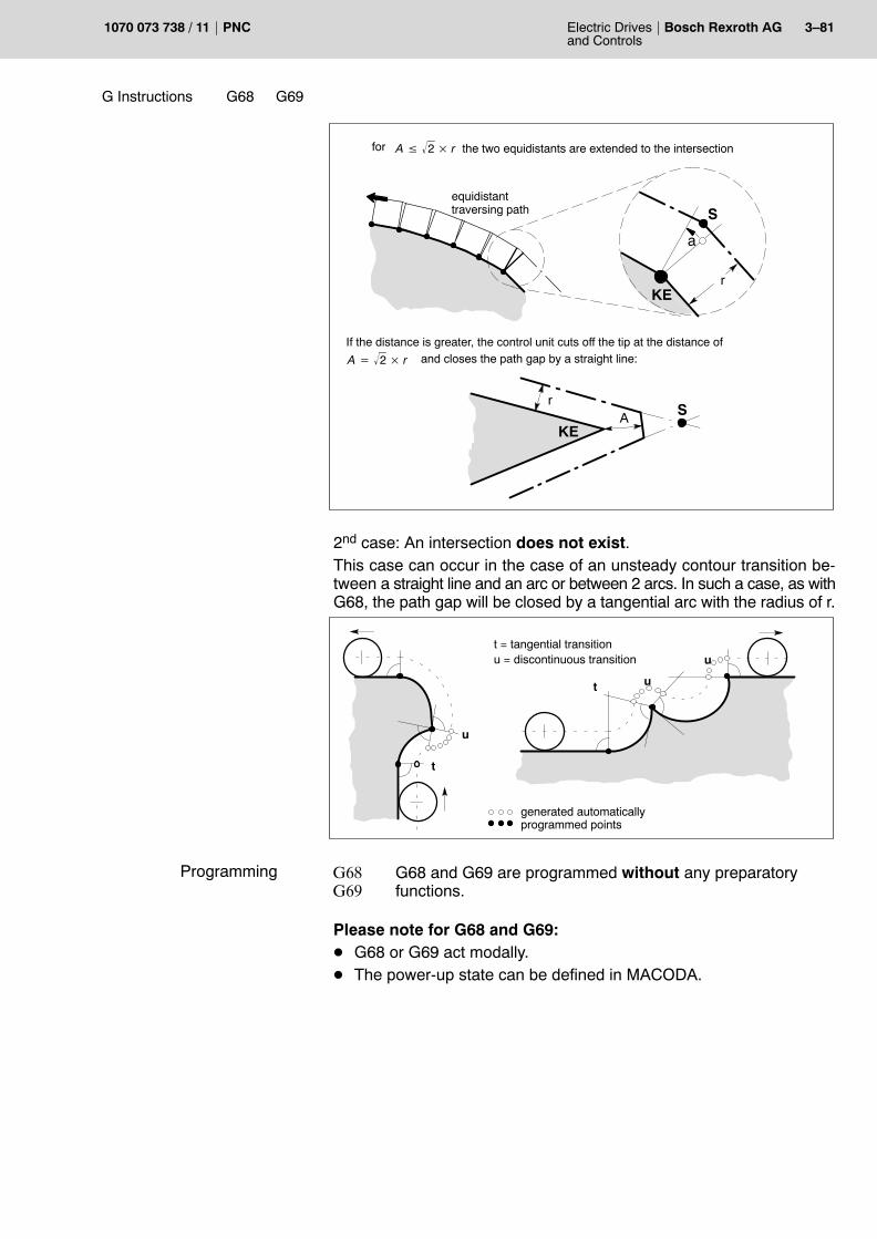
G Instructions G69G68
Electric Drivesand Controls
3�81Bosch Rexroth AGPNC1070 073 738 / 11
equidistanttraversing path
r
S
KE
A � 2� � rfor the two equidistants are extended to the intersection
If the distance is greater, the control unit cuts off the tip at the distance of
A � 2� � r and closes the path gap by a straight line:
KE
rA S
a
2nd case: An intersection does not exist.This case can occur in the case of an unsteady contour transition be-tween a straight line and an arc or between 2 arcs. In such a case, as withG68, the path gap will be closed by a tangential arc with the radius of r.
t = tangential transition u = discontinuous transition
t
t
u
u
u
programmed pointsgenerated automatically
G68G69
G68 and G69 are programmed without any preparatoryfunctions.
Please note for G68 and G69:D G68 or G69 act modally.D The power-up state can be defined in MACODA.
Programming

3�82 Electric Drivesand Controls
Bosch Rexroth AG PNC 1070 073 738 / 11
G Instructions G73G71G70
3.38 Inch programming G70
Positional and feed data after G70 must be entered in inches.All effective metric values and zero shifts are automatically converted toinches. G70 is modal and cancels the G71 function.
Programming of G70
N... G70 from here on all positional and feed information isinterpreted in terms of inch
N... X... Y... Z... all path and feed data to be entered in inch units
3.39 Metric programming G71
Positional and feed data after G71 must be entered in metric measures.All effective inch values and zero shifts are automatically converted tometric values. G71 is modal and cancels the G70 function.
Programming of G71
N... G71 from here on all positional and feed information isinterpreted in terms of metric units
N... X... Y... Z... all path and feed data to be entered in metric units
3.40 Linear interpolation with In-position logic G73
In contrast to G1, a G73 block is always executed with In-positionlogic � irrespective of G61/G62. The In-position logic option is globallydetermined via the G164 to G166 functions.
G73 X... Y... Z... F....
Please note for G73:D G73 may be programmed with or without positional data.D G73 has to be programmed with F word if no feedrate is yet active.D The programmed feedrate remains effective until overwritten by a
new one.D G73 cancels G0, G1, G2, G3, G5, G10�G13 and G200.
Effect
Programming
Effect
Programming
Effect
Programming

G Instructions G74
Electric Drivesand Controls
3�83Bosch Rexroth AGPNC1070 073 738 / 11
3.41 Approach reference point coordinates G74
The axes programmed in the same block as G74 traverse simulta-neously and at rapid to the reference point(s).
With G74 neither reference point cams nor markers are taken into ac-count. G74 is purely a positioning process for the absolute axis positions(i.e. it also applies to axes with distance-coded encoders).
CAUTIONPossibly active compensations will remain unconsidered in thecourse of this positioning process!
D G74 is effective only on a block-by-block basis.D When the reference point is approached with G74 the axis actual val-
ues are not set or reset, i.e. the programmed shift values are not af-fected.
D G74 is canceled when the machine axes programmed with G74 in theblock have reached the reference point.
D Any compensations still active, ZS etc. are not taken account of in theG74 block for the programmed axes.
D G74 does not set the interface signal �RAPID�.
G74 is programmed in a separate block together with the axes to be tra-versed. The axis addresses must be programmed together with a nu-merical value (e.g. �X0�, �Y0�, �Z0�). This numerical value has no effecton the position of the reference point. It is only needed to form a completeword.
Auxiliary and special functions may be programmed within the sameblock.
Example: Programming G74N100 G74 X0 Y0 Z0 The X, Y and Z axes approach the reference
point positions simultaneously linearly.
Effect
Programming

3�84 Electric Drivesand Controls
Bosch Rexroth AG PNC 1070 073 738 / 11
G Instructions G374
3.42 Traverse to reference point G374
The function �Traverse to reference point� allows to initiate axis referenc-ing in the part program.For a detailed description, also refer to �PNC Description of Functions�manual.
Traversing to the reference point is a drive-controlled function, i.e. theinterpolation takes place in the drive.For this purpose, the SERCOS command drive-controlled referenc-ing (S-0-0148) is triggered by the PNC for each of the programmedaxes. As a consequence, the drive generates its own position inputs for refer-encing using SERCOS parameters S-0-0147 (referencing parameter),S-0-0041 (referencing velocity) and S-0-0042 (referencing accelera-tion).
. In order to ensure that the axis potentiometer can work with thesedrive-controlled movements, it must be transferred to the drive bySERCOS parameter S-0-0108 (feedrate override):D by the PLC through the service channel in 500 ms intervals, or D within the cyclic telegram (MDT). For this purpose, S-0-0108
must be entered in the MDT configuration list (S-0-0024).
G374 <Axis address 1> <Integer number>... <Axis address n> <Integer number>
Example:N..
N.. G374 X1 Y1 Z1 referencing of axes X, Y and Z
N..
Please note for G374:D For axes with absolute measuring systems, you can define in refer-
ence point parameter S-0-0147, whether or not these axes shall ref-erence to the set reference point.
D If several axes have been programmed in one G374 block, theseaxes will approach their respective reference points independently ofeach other (no continuous-path operation!).
D With G374, you can program both synchronous and asynchro-nous axes. Block processing is suspended until all axes have tra-versed to their respective reference points (implicit WAIT).
D For matters of compatibility with the Typ1 osa control, a numericalvalue must be entered behind the respective axis address which,however, will not be evaluated. (The approach to the reference pointis configured statically via SERCOS parameter S-0-0147.)
D There is no difference between the axes traversing to their referencepoints initiated this way and the operation mode �Manual�: �Activatetraversing to reference point�.
Effect
Programming

G Instructions G75
Electric Drivesand Controls
3�85Bosch Rexroth AGPNC1070 073 738 / 11
3.43 Probe input G75
The control unit drives the measuring axis at feedrate in the direction ofthe position programmed via G75 and checks in this process whetherthe probe was triggered.The axes for which the measuring probe function G75 is to be activatedare entered in MACODA parameter 1003 00012.
As soon as the edge defined with machine parameters is recognised(probe comes into contact with the measuring surface; the edge evalua-tion can be set via MACODA parameter 1003 00011: all axes involvedmust have identical edge), the control unit performs the following:D the actual position is storedD initiates an axis stop with Down Slope functionD clears the distance to goD deletes G75 (effective block-by-block)
. This function should only be used in combination with a CPL pro-gram (e.g. with measuring cycles).
Programming G75
N100 G75 X400
Please note for G75:D G75 must be programmed together with at least one axis position.
This value represents the maximum search depth to which the probemust have switched at the latest.
D No auxiliary functions may be programmed in the G75 block. G75 canbe programmed with other preparatory functions as far as required.
. You do not have to program WAIT in the part program.
Continuation of program, evaluation of axis information, safety monitor-ing, generation of error messages etc. must be realised in the CPL pro-gram.
Effect
Programming
Evaluation of G75

3�86 Electric Drivesand Controls
Bosch Rexroth AG PNC 1070 073 738 / 11
G Instructions G75
Example: Measuring programN100 G75 Y250 F500 Approach the contour to be
measured (at F500)110 IF SD(9)=0 THEN Query whether probe was dis-
placed120 YPOS=PPOS(2) Store the position in the
�YPOS� variable upon switch-ing of the 2nd axis (Y axis)
N130 (MSG, PROBE DISPLACED)140 GOTO N180150 ENDIFN160 (MSG, PROBE NOT DISPLACED)N170 M0 Program stopN180 ...

G Instructions G275G175
Electric Drivesand Controls
3�87Bosch Rexroth AGPNC1070 073 738 / 11
3.44 On-the-fly measurement G175, G275
With the �On-the-fly measurement� NC functionality it is possible to usethe SERCOS measuring-probe function for measurements without can-celling the programmed movement. Possible collisions are avoided by asuitable measuring probe (contactless or suitable mechanical design).
The function acts as follows:The probe logic of the drive has to be initialized via G175 first (one timeafter each SERCOS phase startup). Subsequently, the initialized drive(= physical axis) is ready to recognize and store measuring (actual) val-ues.
G275 is newly programmed for each measurement.The measuring probe traverses on a programmed path to its end point.Via the probe signal generated by mechanical positioning or a contact-less system, the actual value of the predefined axis is recorded andstored in the drive (probe logic in the drive). In contrast to G75, a suc-cessful measurement will neither cause a cancellation nor a ramp-ing-down (decelerating to standstill) of the movement.
Example:Path movement in X and Ydirection:
actual-value recording of the 1st physical axis =X axis; for further details, please refer to MA-CODA parameter 1003 00001
N... G1 G275 MpiAxis 1 X100 Y100Path movement inX, Y direction
index of the physical axis theactual values of which are to betaken (e.g. index 1 = X axis)
+Y
+X
workpiece
measuringlocation
actual valueof the X axis
Probe
Probe path movement
Initialization: G175 MpiAxis <i>whereG175: Intialization of the probe logic in the SERCOS drive. It is
called once following the SERCOS startup via G175.MpiAxis probe axis parameter
i index of the physical axis the actual values of which are to betaken
Effect
Programming

3�88 Electric Drivesand Controls
Bosch Rexroth AG PNC 1070 073 738 / 11
G Instructions G275G175
Starting the measuring cycle:G275 MpiAxis <i> <axis1> ..<axes n>whereG275: starting the measuring cycle proper
MpiAxis probe axis parameter
i index of the physical axis the actual values of which are to betaken with G175/G275
axis 1 ... n probe positioning axes
Please note for G175 and G275:D G175 and G275 act block by block.D G175 and G275 act in parallel with the active interpolation.D G175 and G275 can be programmed together with all interpolation
types.D If no measurement is made at G275 during interpolation, the system
will wait at the block end until the measurement is completed (to beended by program cancellation).
D The measuring position can be inquired via PPOS (CPL).D PPOS (CPL) will supply the measuring value referred to the respec-
tively valid zero point for linear modulo axes.D The information to know whether a measurement was carried out can
be inquired via SD(9) (CPL).D The block used to further process the probe information should be
preceded by a WAIT (CPL) to avoid that further blocks are edited (50or more blocks in the PNC).
D As an alternative to WAIT, the number of edited blocks can be deter-mined in advance using the PREPNUM function.
For further details about the CPL commands, please refer to the CPLmanual available on this topic.
. Since both functions involve communication via the SERCOS ser-vice channel, you must ensure that the programmed synchronoustraversing paths are sufficiently long so that SERCOS communica-tion can be completed within the course of interpolation (at presentseveral 100 msec). If communication was not complete, or if nomeasurement was performed, the speed will sharply drop at theend of the block and the control unit will wait for the end of SERCOScommunication. WAIT may be omitted if, for instance, �creeping errors� are to becorrected and the main focus is not on the latest measuring results.
Programming

G Instructions G575
Electric Drivesand Controls
3�89Bosch Rexroth AGPNC1070 073 738 / 11
3.45 Switching NC blocks via high-speed signal G575
Function G575 allows early jumping to the next block via the high-speedinputs (HS signal) of the DC/IO.
The traversing blocks in a program are programmed beyond the actualcontour. As a result, the end position of an NC block switched by an HSsignal is never actually reached. Instead, the motion is measured �on-line�, i.e. continuously, and the block end is reported by an HS signal.The NC block currently being executed is cancelled and the next one isexecuted.
This function is linked with NC blocks with linear motion.
A linear motion (G0, G1, G10, G11, G73, G200) can be terminated earlyvia a high-speed input signal by programming function G575, which actsblock by block.
With G575, there are two options for changing blocks early:D on-the-fly change of blocks: early block change without changing the
programmed end points but with changed geometry,D change of blocks with abortion: early block change with cancellation
of the remaining distance to go.
3.45.1 On-the-fly change of blocks G575 HS
Whenever the voltage level y is reached at HS input x, an early change ismade to the next block, which must also contain a linear motion. Blocksare changed without checking the maximum velocity step change.
With the function �On-the-fly change of blocks�, the change from oneblock to the next is made at the current velocity.Please note the exceptions described for operation mode �Automatic�and the special features in operation modes �Program Block� and�Manual Data Input�.
G575 HS<x>=<y>wherex 1..8
Y 0..1
HS1�HS8 designate the HS input at the DC/IO module.
HSx=0 or HSx=1 designate the voltage level required for achange of blocks:HSx=0 (corresponds to 0 V)HSx=1 (corresponds to 24 V)
Effect
Programming

3�90 Electric Drivesand Controls
Bosch Rexroth AG PNC 1070 073 738 / 11
G Instructions G575
Example: On-the-fly change of blocks - G575 HSx=y
Depending on external events, up to 3 different feedrates are to be usedfor traversing on a straight path.
The end points of the programmed blocks must be different because therespective next block (from the point of view of the part program) mustcontain a path to be traversed.
N20 G0 X0 Y0
N30 G575 G1 X70 Y7 F1000 HS1=1 X axis traverses at F1000 untilHS input No. 1 is �High� or X70Y7 is reached.
N40 G575 X90 Y9 F900 HS1=0 X axis traverses at F900 untilHS input No. 1 is �Low� or X90Y9 is reached.
N50 X100 Y10 F800 The remaining distance to goto X100 Y10 is traversed atF800.
X0 Y0
N30
HS1=1 HS1=0
X100 Y10N40
v
tHS1=1 HS1=0
N50
Y
X
F1000F1000
F900
F800
N30 N40 N50
X100
Y10
DANGERThe function �On-the-fly change of blocks� only changes thecontour, not the programmed end point of an NC block.
Refer to the following example:

G Instructions G575
Electric Drivesand Controls
3�91Bosch Rexroth AGPNC1070 073 738 / 11
Example: Changes in contour caused by �On-the-fly change of blocks�
N05 G1 F100 X0 Y5 End point: X0 Y5
N10 G575 HS1=1 G90 X50 End point: X50 Y5
N20 G575 HS1=0 G91 Y10 End point: X50 Y15 (abs. Y5+incr. Y10)
N30 G91 Y5 End point: X50 Y20 (abs. Y15+incr. Y5)
X0 Y5
N10
HS1=1
HS1=0X50 Y15
N30
X50 Y5
N20
X50 Y20
programmedcontour
change in contour
Operation mode �Automatic�
Early changes of blocks are usually made without deceleration to zeroaxis velocity.
Exceptions:D Change of blocks at 0 velocity due to a knee in the contour: The
change from one block to the next is made at zero velocity if there is aknee > 90 degrees in the contour between the block to be cancelledand the next block.
D Change of blocks at 0 velocity due to G function:D The block marked with G575 must end at 0 velocity (G0, G10,
G73).D In-position function is generally activated (e.g. G61, G161, G163).D The next block must begin with 0 velocity due to additional infor-
mation programmed (e.g. G14, G15, G114, G115).D Block-by-block interpolation with path shape is active (G408,
G608).
End point information of axes not programmed in the next block is alwaystaken from the cancelled block.
. The feedrate of the block following G575 HSx=y is limited by its ori-ginal block length.
Operation modes �Single block� and �Single step�
In these operation modes, just one block of a part program is executed ata time. Since this precludes an on-the-fly change of blocks, the velocity isreduced to 0 when the external event for a block change occurs.

3�92 Electric Drivesand Controls
Bosch Rexroth AG PNC 1070 073 738 / 11
G Instructions G575
The end points of axes not programmed in the next block are taken fromthe cancelled blocks. This allows testing the �behavior in the Automaticoperation mode� by approximations also in the operation modes �Singleblock� and �Single step�.
Operation mode �Program block�
In this operation mode, each block of a part program is executed as if itwere a complete part program. As this precludes any next blocks, thevelocity is reduced to 0 when the external event for a block change oc-curs.
DANGERThe remaining distance to go at the end of the block is cancelled.Any next NC block with incremental programming will result in tra-versing to an incorrect end point.
Operation mode �Manual data input�
In this operation mode, the velocity is reduced to 0 when the externalevent for a change of blocks occurs. The same applies when a part pro-gram is executed with manual data input.
DANGERThe remaining distance to go at the end of the block is cancelled.Any next NC block with incremental programming will result in tra-versing to an incorrect end point.

G Instructions G575
Electric Drivesand Controls
3�93Bosch Rexroth AGPNC1070 073 738 / 11
3.45.2 Change of blocks with cancellation
If the level y is reached at the HS input x, the velocity in the current blockis reduced to 0 (HSSTOP=0) or a velocity step change is made(HSSTOP=�1) and the remaining distance to go is cancelled (same be-havior as with G75).
The end point of any NC block and thus also the starting point of the nextNC block are determined by the occurrence of an external event.
G575 HS<x>=<y> HSSTOP=<z>wherex 1..8
Y 0..1
z �1 or 0
HS1�HS8 designate the HS input at the DC/IO module.
HSx=0 or HSx=1 designate the voltage level required for achange of blocks:HSx=0 (corresponds to 0V)HSx=1 (corresponds to 24V)
HSSTOP=�1 designates the cancellation with a velocity stepchange to 0.
HSSTOP=0 designates the cancellation with a velocitydown-slope to 0.
Example: Change of blocks with cancellation
N05 G1 F1000 X0 Y5 End point: X0 Y5
N10 G575 HS1=1 HSSTOP=0 G90 X50 End point: external event atX� 50
N20 G575 HS1=0 HSSTOP1=0 G91 Y10 End point: external event atY� 10
N30 G91 Y5 End point: incremental by Y5from the last occurrence ofexternal event (Y� 10)
X0 Y5
N10
HS1=1
HS1=0
X50 Y15
X50 Y5
N20
X50 Y20
N30
In blocks N20 and N30, the Y axis traverses by increments. The endpoint of the Y axis results from the current position of the Y axis upon can-cellation of the previous block to which the programmed incrementalstep is added.
Programming

3�94 Electric Drivesand Controls
Bosch Rexroth AG PNC 1070 073 738 / 11
G Instructions G575
With the function �Change of blocks with cancellation�, any NC blockends at 0 velocity (even if the programmed event does not occur). Addi-tionally, the remaining distance to go in the aborted block is cancelled.
As the starting point of the next NC block is unknown after a cancellation,this has to be a linear block.
Example: Traversing to a dead stop (e.g. pressure- or torque-driven)N20 G1 F1000 X0 Y0
N30 G575 F10 X10 HS1=1 HSSTOP=–1
X axis traverses until HS input no. 1is �High� or X10 is reached. Upon theoccurrence of HS1=1, the motion iscancelled with a velocity step to 0and the remaining distance to go iscancelled.
N40 G575 F200 Y100 HS2=1 HSSTOP=0
Y axis traverses until HS input no. 2is �High� or Y100 is reached. Uponthe occurrence of HS2=1, the motionis decreased to 0 at the current ac-celeration and the remaining distanceto go is cancelled.
N50 G0 X0 Y0

G Instructions G76
Electric Drivesand Controls
3�95Bosch Rexroth AGPNC1070 073 738 / 11
3.46 Traverse to machine-oriented absolute axis position G76
G76 is used to traverse to a machine-oriented absolute axis position (ab-solute position referring to the machine coordinate system) e.g. tochange tools, check tools for damage, run measuring cycles, changepallets, etc.
G76 acts only block by block. Prior to any traversing movement, the con-trol unit deselects various compensations and cancels some active func-tions block by block:D length compensations (Hxx)D radius compensations (G41, G42)D zero shifts (G54 . . . G259)D inclined plane (G352, G354 . . . G359)D incremental data input (G91)D set actual value (G92)D mirror function (G38)D workpiece position compensation (G138)
Subsequently, the programmed axes travel simultaneously at activespeed (at feedrate or at rapid travel!) to the programmed machine posi-tion.
If deleted by G76, the following functions or compensations will becomeactive again in the next block:D length compensations (Hxx)D zero shiftsD incremental data input (G91)D set actual value (G92)D mirror function (G38)
G76 is programmed together with positional data
Please note for G76:D G76 can be written together with other preparatory functions (e.g.
G93, G94, G95, G0, G1)D G76 can be written together with the F wordD G76 is effective in conjunction with G93, G94, G95 and the F word
Effect
Programming

3�96 Electric Drivesand Controls
Bosch Rexroth AG PNC 1070 073 738 / 11
G Instructions G79G78
3.47 Compensation switchover (drill axis switching) G78Activate presetting for compensation directions G79
Machining on machine tools may be performed using tools of differentsizes, with the tool clamped in different directions, depending on the ma-chine, or oriented in any direction in space in case of the correspondingmachine kinematics.
The function compensation switchover G78 assigns the different lengthcompensations of the individual functions to the geometry compensa-tion of either
D the individual directions of the current workpiece coordinate system(WCS) or
D the directions of the tool coordinate system (TCS).
An assignment with respect to the directions of the workpiece coordinatesystem (WCS) is possible if the tool is aligned perpendicularly to the cur-rent working plane and its orientation with regard to the working planeremains constant during machining.Examples: drilling and turning, milling of plane surfaces.
An assignment of compensations with reference to the directions of thetool coordinate system (TCS) is necessary if the orientation of the toolchanges during machining, e.g. milling of freeform surfaces. This allowsfor a tool length compensation at variable tool orientation. An active axistransformation (e.g. 5 axis or 6 axis transformation) is necessary for thiscompensation. The compensation values are taken into account withinthe axis transformation.
The switchover may be activated either in the manual data input mode orin the part program.
Tool length compensations in the PNC are organized by 2 compensationgroups as follows:
D 1st compensation group refers to axes, on which the following com-pensations have effect:D H and Hext/L(1)3 of the �External tool compensation� (G145�G845)
D 2nd compensation group refers to axes on which the compensa-tionsD L(2)1, L(2)2, L(2)3 of the General Tool Compensation (G147�G847)
take effect.
Effect

G Instructions G79G78
Electric Drivesand Controls
3�97Bosch Rexroth AGPNC1070 073 738 / 11
Z
Y
X
L1
WCS
L2L3
Z
Y
XWCS
Tool compensation inworkpiece coordinatesystem (WCS)
Tool compensation in tool coordinate system (TCS)
Z
Y
X
L1TCS
L2
L3
G78 Coordinate name i <Compensation i>..{Coordinate name n <Com�pensation�n>}
whereG78 ... Activate compensation switchover.
Coordinate name i..n i.. n-th logical axis name (WCS related). Logicalaxis names are synonyms of the coordinate direc-tions of the WCS.The logical axis names are determined channel-specific in MACODA parameter 7010 00010 (e.g.1st logical axis name for X, 2nd for Y, 3rd for Z).
Coordinate name 1..3 XTR, YTR, ZTR (TCS related).The designations XTR, YTR, ZTR are fixed namesfor the axes of the tool coordinate system (TCS).The compensation is only taken into account if acorresponding axis transformation is active.
<Compensa-tion i>
�1 or �13: 1st compensation group (H and Hext/L(1)3of the i-th axis.
�21: 2nd Compensation group, 1st length com-pensation (L(2)1) of the i-th axis
�22: 2nd Compensation group, 2nd length com-pensation (L(2)2) of the i-th axis
�23: 2nd Compensation group, 3rd length com-pensation (L(2)3) of the i-th axis
When double-digit compensation values are entered, the 1st digit standsfor the compensation group and the 2nd digit for the compensation index.
The + or � sign before the compensation defines the direction of thecompensation. This ensures that the proper direction is taken into ac-count in the computation of length compensations. A positive sign in-creases the tool (the tool length) vis-à-vis an assumed zero tool. Anegative sign decreases the tool vis-à-vis an assumed zero tool.
Programming

3�98 Electric Drivesand Controls
Bosch Rexroth AG PNC 1070 073 738 / 11
G Instructions G79G78
Compensations relating to several coordinates can be switched simulta-neously in a single G78 block (max. 4, because 4 compensations exist).Compensations relating to the WCS and compensations relating to theTCS can be switched together in a single block.
The individual length compensation values always have to be assignedto different coordinate directions.
G79 {CG< i>}
whereG79 CG.. Activate presetting for compensation directions
CG<i> optional: i=1,2For the compensation group i specified by CG, the coordi-nate assignment is reset to the presetting entered inMACODA parameter 7050 00420. G79 without option param-eter resets all compensation groups.
Please note for G78 and G79:D G78 and G79 act modally and deselect each other.D The axis addresses programmed under G78 refer to workpiece coor-
dinates or tool coordinates (XTR, YTR, ZTR).D G79 may be programmed with other preparatory functions, travers-
ing information or auxiliary functions.D G78 may be programmed together with other preparatory functions
or auxiliary functions in one block.D The behavior after control start-up is determined by MACODA pa-
rameter 7050 00420 or the init string, respectively.D The individual length compensation values always have to be as-
signed to different coordinate directions.D The external tool compensations have to be applied in MACODA pa-
rameter 7050 00410.
Examples:G78 X21 ZTR13 The L(2)1 compensation is assigned to the X axis of
the workpiece coordinate system (WCS), the L(1)3compensation to the Z axis of the tool coordinate sys-tem (TCS). Both compensations are to be taken intoaccount in the positive direction.
G78 Y–1 The L(1)3 compensation is assigned to the Y axis ofthe workpiece coordinate system (WCS) and takeninto account in the negative direction.
G78 YA21 YB22 The YA and the YB axis of the workpiece coordinatesystem are assigned the L(2)1 and L(2)2 compensa-tion, respectively. Both compensations are taken intoaccount in the positive direction.
G79 CG1 The compensations of the 1st compensation groupare assigned their default axes from MACODA.
G79 All compensations are assigned their default coordi-nates.
Programming

G Instructions G184G80-G86
Electric Drivesand Controls
3�99Bosch Rexroth AGPNC1070 073 738 / 11
3.48 Boring cycles G80-G86, G184
. The boring cycles are programmed in CPL. The assignment bet-ween the individual CPL program names and the G functions to beused as well as the number of the transfer parameters are enteredas a standard in MACODA parameter blocks 3090 00005 to 309000007 and must not be changed.For further details about the parameter blocks, please refer to theMACODA manual.The FEED HOLD interface signal also acts in boring cycles. If requi-red, it has to be blocked by appropriate PLC programming for theduration of a cycle.For more information, refer to the �PLC Configuration� manual.
If you program a boring cycle (G81 to G86 or G184) including the re-quired boring parameters within a program block, the control unit will au-tomatically perform the currently active boring cycle upon reaching theprogrammed position in the same or in all following blocks, if a machiningaxis has been programmed there.
General movement sequence of a boring cycle:
PE
R2
R1
Positioning plane
Reference plane 1
Reference plane 2
Boring depth
: Feedrate: Rapid
Z
1
2
3 5
4
6
Dwell timeP
1. Positioning in the active plane at rapid2. Infeed to the programmed R1 reference plane at rapid3. Infeed to the programmed Z drilling depth at the active feedrate4. Waiting over a programmed P dwell time (the dwell time serves to
compensate for a possibly required deceleration or acceleration tocommand speed of the spindle in the reversing point)
5. Retraction movement at feedrate or rapid to the programmed R1 ref-erence plane
6. Optional approach of the R2 reference plane at rapid
. All boring cycles can be performed in positive (Z > R1) or negative(Z < R1) boring direction.The active boring axis can be switched over using G78 (please referto page 3�96).
Effect
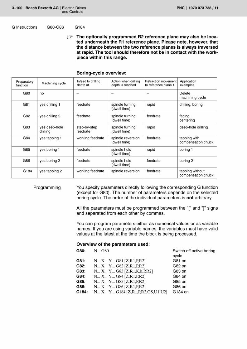
3�100 Electric Drivesand Controls
Bosch Rexroth AG PNC 1070 073 738 / 11
G Instructions G184G80-G86
. The optionally programmed R2 reference plane may also be loca-ted underneath the R1 reference plane. Please note, however, thatthe distance between the two reference planes is always traversedat rapid. The tool should therefore not be in contact with the work-piece within this range.
Boring-cycle overview:
Preparatoryfunction
Machining cycle Infeed to drillingdepth at
Action when drillingdepth is reached
Retraction movementto reference plane 1
Applicationexamples
G80
G81
G82
G83
G84
G85
G86
no
yes drilling 1
yes drilling 2
yes deep-holedrilling
yes tapping 1
yes boring 1
yes boring 2
G184 yes tapping 2
�
feedrate
feedrate
feedrate
feedrate
working feedrate
working feedrate
step-by-stepfeedrate
�
spindle turning(dwell time)
spindle turning(dwell time)
spindle turning(dwell time)
spindle reversion(dwell time)
spindle hold(dwell time)
spindle hold(dwell time)
spindle reversion
�
rapid
rapid
rapid
feedrate
feedrate
feedrate
feedrate
Deletemachining cycle
drilling, boring
facing, centering
deep-hole drilling
tapping withcompensation chuck
boring 1
boring 2
tapping withoutcompensation chuck
You specify parameters directly following the corresponding G function(except for G80). The number of parameters depends on the selectedboring cycle. The order of the individual parameters is not arbitrary.
All the parameters must be programmed between the �[� and �]� signsand separated from each other by commas.
You can program parameters either as numerical values or as variablenames. If you are using variable names, the variables must have validvalues at the latest at the time the block is being processed.
Overview of the parameters used:G80: N... G80 Switch off active boring
cycleG81: N... X... Y... G81 [Z,R1,P,R2] G81 onG82: N... X... Y... G82 [Z,R1,P,R2] G82 onG83: N... X... Y... G83 [Z,R1,K,k,P,R2] G83 onG84: N... X... Y... G84 [Z,R1,P,R2] G84 onG85: N... X... Y... G85 [Z,R1,P,R2] G85 onG86: N... X... Y... G86 [Z,R1,P,R2] G86 onG184: N... X... Y... G184 [Z,R1,P,R2,GS,U1,U2] G184 on
Programming
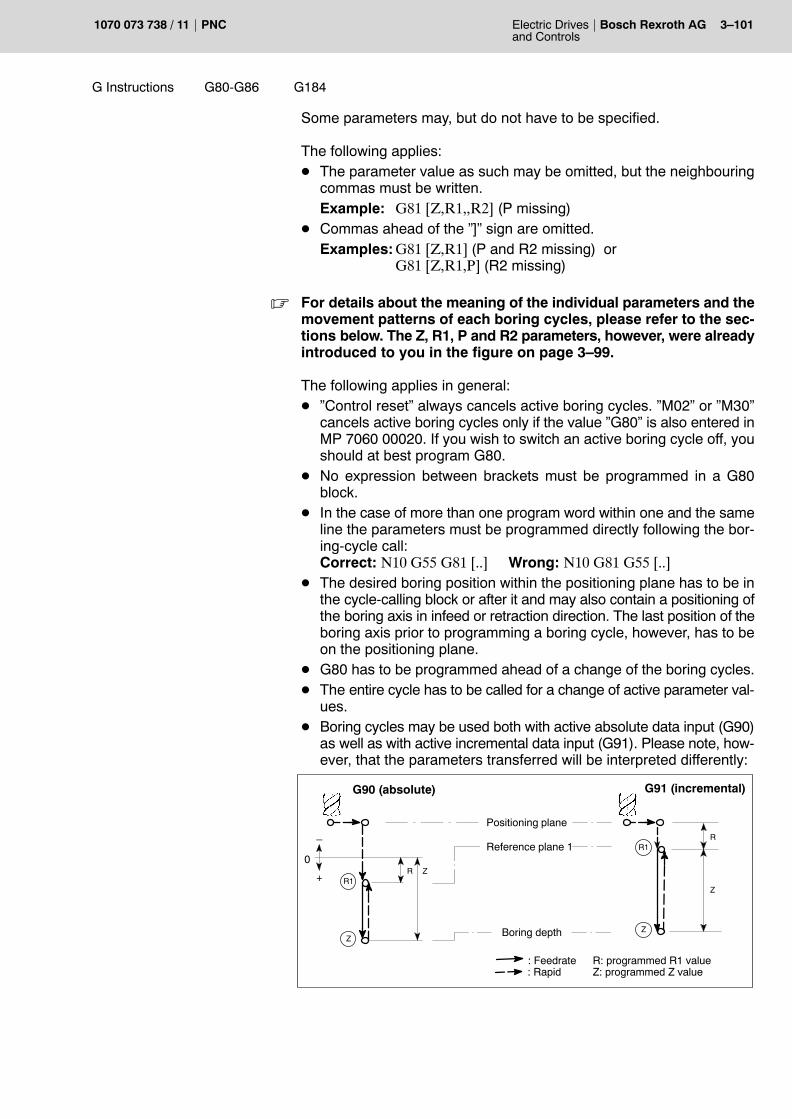
G Instructions G184G80-G86
Electric Drivesand Controls
3�101Bosch Rexroth AGPNC1070 073 738 / 11
Some parameters may, but do not have to be specified.
The following applies:D The parameter value as such may be omitted, but the neighbouring
commas must be written.Example: G81 [Z,R1,,R2] (P missing)
D Commas ahead of the �]� sign are omitted.Examples:G81 [Z,R1] (P and R2 missing) or
G81 [Z,R1,P] (R2 missing)
. For details about the meaning of the individual parameters and themovement patterns of each boring cycles, please refer to the sec-tions below. The Z, R1, P and R2 parameters, however, were alreadyintroduced to you in the figure on page 3�99.
The following applies in general:D �Control reset� always cancels active boring cycles. �M02� or �M30�
cancels active boring cycles only if the value �G80� is also entered inMP 7060 00020. If you wish to switch an active boring cycle off, youshould at best program G80.
D No expression between brackets must be programmed in a G80block.
D In the case of more than one program word within one and the sameline the parameters must be programmed directly following the bor-ing-cycle call:Correct: N10 G55 G81 [..] Wrong: N10 G81 G55 [..]
D The desired boring position within the positioning plane has to be inthe cycle-calling block or after it and may also contain a positioning ofthe boring axis in infeed or retraction direction. The last position of theboring axis prior to programming a boring cycle, however, has to beon the positioning plane.
D G80 has to be programmed ahead of a change of the boring cycles.D The entire cycle has to be called for a change of active parameter val-
ues.D Boring cycles may be used both with active absolute data input (G90)
as well as with active incremental data input (G91). Please note, how-ever, that the parameters transferred will be interpreted differently:
R1
Z
Reference plane 1
Boring depth
: Feedrate: Rapid
R Z0
R: programmed R1 valueZ: programmed Z value
R1
Z
G90 (absolute) G91 (incremental)
Z
R
Positioning plane
+
�

3�102 Electric Drivesand Controls
Bosch Rexroth AG PNC 1070 073 738 / 11
G Instructions G82 G81
3.48.1 Boring cycle G81
Centering and simple drilling operation, facing, boring.
Upon reaching the Z drilling depth a dwell time becomes active, depend-ing on the programming. Subsequently, retraction at rapid will takeplace.
Rx
Z
ZP
Reference plane 1,2
Boring depth
FeedrateRapid
G81 with R1 plane G81 with R2 plane
PE
ZP
PE PE Positioning plane
P Dwell timeR1
R2
R1
N100 X... Y... G81 [Z, R1, P, R2]
Z, R1 must be programmed
P, R2 may be programmed
3.48.2 Boring cycle with retraction movement G82
Like G81. However, retraction to R1 is at feedrate.
Rx
Z
ZP
Reference plane 1,2
Boring depth
FeedrateRapid
G82 with R1 plane G82 with R2 plane
PE
ZP
PE PE Positioning plane
P Dwell timeR1
R2
R1
N100 X... Y... G82 [Z, R1, P, R2]
Z, R1 must be programmed
P, R2 may be programmed
Application
Effect
Programming
Programming

G Instructions G83
Electric Drivesand Controls
3�103Bosch Rexroth AGPNC1070 073 738 / 11
3.48.3 Deep-hole drilling cycle G83
Deep-hole drilling with complete removal of the drilling chips.
After each arrival at the programmed K infeed depth per cut, one retrac-tion movement at rapid to the reference R1 plane will be performed.
Renewed infeed to the programmed k distance (speed-change point)will also be performed at rapid. Subsequently, the PNC will switch backto feedrate.Stepwise infeed with corresponding retraction to the reference plane willbe repeated until the programmed Z total drilling depth is reached.
Rx
K
Z
Reference plane 1,2
Infeed depth
: Feedrate: Rapid
G83 with R1 plane G83 with R2 plane
PE PE Positioning plane
P Dwell time
K
K
K
k
k
R1
P
Z
PE
K
K
K
k
k
R1
P
R2
Z Boring depth
k Distance to speed change-over point
N100 X... Y... G83 [Z, R1, K, k, P, R2]
Z, R1, K, k must be programmed
P, R2 may be programmed
The K infeed depth has to be programmed without sign in incrementaldimensions, irrespective of the drilling direction.If the Z max. drilling depth is exceeded owing to erroneous programmingof the K infeed depth, the control unit will first interrupt the boring cyclevia M0 and display the �K DRILLING DEPTH TOO LARGE� error mes-sage.
After a new start, the boring cycle is cancelled (M30).
Application
Effect
Programming

3�104 Electric Drivesand Controls
Bosch Rexroth AG PNC 1070 073 738 / 11
G Instructions G84
3.48.4 Tapping with compensation chuck G84
Tapping (left and right) with compensation chuck.
Condition: One internal spindle has to be used as drilling axis. Exter-nal spindles are not allowed.
Tool infeed is done at programmed M3 cw rotating spindle or M4 ccw ro-tating spindle (right- or left-handed thread).
As soon as the Z drilling depth (thread depth) has been reached, thesense of rotation is reversed, and the P dwell time (if programmed) startsto run.
Subsequently, the retraction movement to the reference plane is per-formed at feedrate. As soon as it has been reached, the reversal of thesense of rotation is cancelled again.
Rx
Z
ZP
Reference plane 1,2
Thread depth
: Feedrate: Rapid
G84 with R1 plane G84 with R2 plane
PE
ZP
PE
PE Positioning plane
P Dwell timeR1
R2
R1
D
G63
DG66
D
D
D Reversal ofsense of rotation
N100 X... Y... G84 [Z, R1, P, R2]
Z, R1 must be programmed
P, R2 may be programmed
CAUTIONPossible damage to tools or workpieces!
During the cycle, any active single-block processing will not besuppressed! This means that the spindle will keep on runningafter a positioning process within the cycle. This may lead todamage to the tool and the workpiece.You should therefore ensure that the control unit executes thecycle in the AUTOMATIC mode only!
Application
Effect
Programming

G Instructions G184
Electric Drivesand Controls
3�105Bosch Rexroth AGPNC1070 073 738 / 11
3.48.5 Tapping without compensation chuck G184
Tapping (left and right) without compensation chuck.
Condition: controlled spindle; G32 exact tapping without compensationchuck.
Tool infeed is calculated internally on the basis of the product of �speed xthread pitch�. You select the sense of rotation (right- or left-handedthread) via the sign of the GS parameter (thread pitch).
As soon as the Z drilling depth (thread depth) is reached, the sense ofrotation is reversed. Subsequently, the retraction movement to the refer-ence plane is performed at feedrate. The sense of rotation of the spindleremains effective until you program a new boring cycle.
Rx
Z
Z
Reference plane 1,2
Thread depth
: Feedrate: Rapid
G184 with R1 plane G184 with R2 plane
PE
Z
PE
PE Positioning plane
P Dwell timeR1
R2
R1
G63
U1 G66
U1 Speed
U1 U2 U2 Speed uponretraction
U1
U1 U2
G63
GS Thread pitch
GS
PP
N100 X... Y... G184 [Z,R1,P,R2,GS,U1,U2,RP*)] right-handed thread
N100 X... Y... G184 [Z,R1,P,R2,−GS,U1,U2,RP*)] left-handedthread
Z, R1, GS, U1 must be programmed
R2, U2, RP may be programmed
*) Optionally, it is also possible to program the RP parameter. RP deter-mines the orientation position of the spindle.
. For matters of compatibility, P may be assigned a value. However, Pdwell times programmed are not evaluated any more!The syntax entered would read as follows:N100 X... Y... G184 [Z,R1,,R2,−GS,U1,U2,RP*) Example: �left�handed thread")
Application
Effect
Programming

3�106 Electric Drivesand Controls
Bosch Rexroth AG PNC 1070 073 738 / 11
G Instructions G86 G85
3.48.6 Boring G85
Boring
Upon reaching the Z drilling depth, the spindle stops. Depending on pro-gramming, a dwell time will start to run. Subsequently, retraction at rapidwill take place.
Rx
Z
ZP
Reference plane 1,2
Boring depth
FeedrateRapid
G85 with R1 plane G85 with R2 plane
PE
ZP
PE PE Positioning plane
P Dwell timeR1
R2
R1
M05
M03
M05
M03
N100 X... Y... G85 [Z, R1, P, R2]
Z, R1 must be programmed
P, R2 may be programmed
3.48.7 Boring with retraction movement G86
Like G85. However, retraction to R1 is at feedrate.
Rx
Z
ZP
Reference plane 1,2
Boring depth
FeedrateRapid
G86 with R1 plane G86 with R2 plane
PE
ZP
PE PE Positioning plane
P Dwell timeR1
R2
R1
M05
M03 M03
N100 X... Y... G86 [Z, R1, P, R2]
Z, R1 must be programmed
P, R2 may be programmed
Application
Effect
Programming
Programming

G Instructions G86 G85
Electric Drivesand Controls
3�107Bosch Rexroth AGPNC1070 073 738 / 11
3.48.8 Programming examples
Example 1: General programming.N90 G1 M3 S1050 F400N91 G81 [–1000,–800] cycle call without positioningN92 X600 Y800 drilling starts from this blockN95 X500 Y700 G81 [–1000,–800] Cycle call with positioning.
From this position, drilling is al-ready being performed.
N96 X600 Y800N100 X800 Y700 G81 [–1000,–800,,–600]
retraction to R2 plane; no dwelltime
N110 X0 Y0 G81 [–1000,–800] retraction to R1 plane only; nodwell time
N111 X–100 Y–500N150 X–400 Y200 G81 [–1000,–800,1]
retraction to R1 plane only;dwell time 1s
N151 X200 Y300
Example 2: Programming the boring-cycle parameters via CPL vari-ables.N5 X200 Y400 M310 Z=1000 Definition of the CPL variables
20 R1=800
30 P=2
40 R2=900
N50 X... Y... G84 [Z,R1,P,R2]
Example 3: Calling the boring cycle in the main program. The positionsto be approached have been programmed in a subprogram.N05 X100 Y100 Z200N10 G91 G81 [100,10]N20 P1000N30 G80N40 G90N50 X500 Y100 Z200N10 G91 G81 [100,10]N20 P1000N30 G80N40 G90
P1000 Subprogram
N10 G91 X10 Y10N20 X20 Y20N30 X30 Y30M30
Example 4: Drill axis switching; X axis with positive compensationN10 G78 X1N20 G1 M3 S1050 F400 N30 G81 [–100,–800] N40 Y500 Z700N50 G80N60 G79

3�108 Electric Drivesand Controls
Bosch Rexroth AG PNC 1070 073 738 / 11
G Instructions IC(...)AC(...) G189 G91 G90
3.49 Absolute data input 1 G90Incremental programming G91Absolute data input 2 G189Local absolute data input AC(...)Local incremental data input IC(...)
Workpiece drawings may be dimensioned in absolute or relative (incre-mental) dimensions.
The PNC may be set in both formats. The two variants of absolute pro-gramming differ as to the treatment of endless axes (modulo axes) whichhave been configured via MACODA parameter 1003 00005.
G90: The control unit will interpret dimensions as absolute valuesreferring to the active zero point. Endless axes, entered as�can be switched over via G90/G189� in MP 1003 00005, willtraverse with sign logic (also ref. to section 3.64).
G91: The control unit will interpret dimensions as incrementalvalues referring to the position last approached (relative orincremental dimension).
G189: The control unit will interpret dimensions as absolute valuesreferring to the active zero point. Endless axes, entered as�can be switched over via G90/G189� in the MP 1003 00005,will traverse with �shortest-path� logic (also ref. to section3.64).
The following diagram illustrates the difference between G90 and G91:
Y
X
Y
X
Incremental dimension X
G90 G91
Startingpoint
Startingpoint
Abs
olut
e di
men
sion
Y
Incr
emen
tal d
imen
sion
Y
Target point Target point
Absolute dimension X
Please note for G90, G91, and G189:D All functions act modally and cancel each other mutually.D While G90 is active, the length compensation is added to or sub-
tracted from � depending on the sign before the correction value �any new displacement entered for the spindle axis when the H wordis called with the next position data for the spindle axis. While G91is active, the compensation value is taken into account only in thecomputation of the first displacement.
G90, G91N10 G90 all subsequent dimensions will be interpreted as
absolute values referring to the active zero point.N20 X100 Y100 current machine position: X100 Y100
Effect
Programming

G Instructions IC(...)AC(...) G189 G91 G90
Electric Drivesand Controls
3�109Bosch Rexroth AGPNC1070 073 738 / 11
N30 G91 all subsequent dimensions will be interpreted asrelative values referring to the position last ap-proached.
N40 X50 Y10 current machine position: X150 Y110
. For further details on the positioning types of endless axes, alsorefer to G150/G151.
Local absolute / incremental data input
With G90/G189 or G91 active, using the AC and IC address attributes, itis possible to program individual axes block by block in absolute or incre-mental terms.
D AC(...): the programmed axis value is to be treated as absolute.D IC(...): the programmed axis value is to be treated as incremental.
<logical axis address> = <address attribute>(<value>)
X = AC (50) Irrespective of the presetting via G90/G189 or G91, the Xaxis will travel to the absolute position 50 (referred to thecurrent coordinate system).
Within one block it is possible to program different attributes for differentaxes.
Example:G91 X=AC(50) Y50X: X travels to the absolute position X=50
Y: Y travels by increments of 50 mm (to Y=60)
Y
X50
10
50
60
Startingpoint
Incr
emen
tal
dim
ensi
on Y
Target point
Absolute dimension X
. Local incremental data input using the IC address attribute in thecontext of function G76, �Traverse to machine-oriented absoluteaxis position� is not permitted because it would lead to a runtimeerror.
Programming

3�110 Electric Drivesand Controls
Bosch Rexroth AG PNC 1070 073 738 / 11
G Instructions G92
3.50 Set actual value G92
The effect of G92 differs depending on the programmed axis informa-tion:
Programming G92 without axis information:The current actual value of all axes is set to machine coordinates with-out taking into account compensations and zero shifts.
Programming G92 with axis information:The current actual value of an axis is set to the programmed value.
CAUTIONThis option must not be used as long as a ZS is active. If necessary,you must program the G53 instruction ahead of G92.
No axis movement will occur with G92. The new position values will bedisplayed.
N... G92 X0 Y0N...N...
The current actual values of the X and Y axes are setto �0� (point-of-reference shift). The actual values ofthe Z axis remain unchanged.
N... G92 Set all actual values to machine coordinates (cancelpoint-of-reference shift).
Please note for G92:D G92 acts block by block.D Other functions may be programmed jointly with G92 in the same
block provided these functions do not require an axis address.D Whether a G92 shift is to be deleted after a control reset or whether
this shift is to be retained can be entered for each channel in MA-CODA parameter 7050 00510. If the preset option remains un-changed, the shift values will be deleted upon control reset.
Example:
P0+Y
+X
10
20
30
40
50
60
70
80
10 20 30 40 50 60 70 80 90 100 110 120 130 140 150 160
�130 �120 �110 �100 �90 �80 �70 �60 �50 �40 �30 �20 �10 10 20
G90 F200G1 X140 Y70G92 X0G1 Y30G2 X�10 Y20 I�10G1 X�55
X�65 Y30X85 X95 Y20X�100
G2 X�110 Y30 J10G1 Y70
X5X0 Y80
G92M30
P10
P9P8 P7 P6 P5 P4 P3
P2
P1
Effect
Programming

G Instructions G93
Electric Drivesand Controls
3�111Bosch Rexroth AGPNC1070 073 738 / 11
3.51 Time programming (feedrate programming as block duration) G93
The control unit will interpret subsequent F words as machining time fora programmed linear (G1) or circular (G2, G3, G5) distance.
The same applies in the case of polar coordinate programming.
Example:
N10 G93 G1 X300 Z400 A50 B120 F60
The programmed linear interpola-tion will last 60 seconds.
Please note for G93:D acts modallyD remains stored internally in the case of a switch-over to G94 or G95
and becomes active again if G93 is selected againD The power-up condition can be set in MACODA parameters
7060 00010 and 7060 00020.
CAUTIONUpon �power off (7060 00010) and/or �reset� or �control reset�(7060 00020), the machining time as set in the MACODA parame-ters will become active (default value = F0)!
. In addition, please keep taking MACODA parameter 8004 00001into account! The control unit will automatically calculate the required feedrateon the basis of the path length of the block and the programmedmachining time.This feedrate, however, can be restricted according to the pro-grammed path and the max. values of the axes involved!
Effect
Programming

3�112 Electric Drivesand Controls
Bosch Rexroth AG PNC 1070 073 738 / 11
G Instructions G94
3.52 Feedrate programming G94
The programmed feedrate refers to the sum of all programmed axes in-volved in the movement. If a maximum of 3 axes standing perpendicu-larly to each other (Cartesian system, no working range coordinates!)are moved, the programmed feedrate corresponds to the expected pathfeedrate of the tool in space.
If other axes are traversed as well, the path feedrate is reduced becausethe other axes also contribute to the feedrate.The weighting of the ratio �rotary axes to linear axes� is entered in MA-CODA parameter 7040 00110, �scaling of the rotary axis feedrate at G70or G71� in dependence on the active measuring system (inch/metric).
Axes which are not programmed and whose movement is not derivedimplicitly from the programmed axis movement, are generally not in-cluded in the feedrate computing, i.e. the feedrate exclusively refers tothe programmed axes (examples: C axes in case of tapping, tool axis incase of tangential tool guidance, etc.)In MACODA parameter 1003 00020 it is furthermore possible to explic-itly select axes which are removed from feedrate computing when G594(�suppressing axes for feedrate computing and separate programmingof rotary axis feedrate�) is activated. The axes are then synchronouslymoved along with the feedrate contributing axes, monitoring the dy-namic values of all axes involved in the movement and reducing the fee-drate if necessary.
If axes not contributing to the feedrate are involved in the movement ex-clusively, the programmed feedrate refers to their path.
In case of active working range coordinate programming, the activefeedrate refers to (maximally 3) linear working range coordinates. A si-multaneously programmed orientation motion as well as additional pro-grammed synchronous axes (pseudo-coordinates) are guided alongsynchronously.If no linear working range coordinates have been programmed, the ef-fectiveness of the feedrate is transmitted to a programmed orientationmotion. In this case too, programmed pseudo-coordinates are guidedalong synchronously.
If none of the working range coordinates has been programmed, the re-sulting behavior will be analogous to the case of the deselected axistransformation (no working range coordinate programming active).
The programmed feedrate is interpreted as being stated in mm/min(with active G71) or in inch/min (with active G70). In case of rotary axes,the programmed feedrate corresponds to�_/min.
. You can adapt the unit of measure to your specific requirements inMACODA parameter 7040 00010!
Effect

G Instructions G94
Electric Drivesand Controls
3�113Bosch Rexroth AGPNC1070 073 738 / 11
The feedrate can be programmed with the following parameters:D F
F is generally used for feedrate programming.
D Omega2nd Feedrate value:D if working range coordinates are active and no linear working
range coordinates have been programmed but an orientation mo-tion instead.
D for axes suppressed from feedrate computing (G594) and for axesnot contributing to the feedrate if no feedrate contributing axis hasbeen programmed. Alternatively, Omega may be specified insteadof the last active F.
Restrictions:D The limit of F and Omega depends on the maximum speeds of the
axes involved.D In case of some NC functions (e.g. G4, G104), �F� has a different
meaning.
G94... F<value> Feedrate programming with F
whereF<value> Feedrate value for axes contributing to the feedrate and
axes not contributing to the feedrate activated.
value Magnitude of the feedrate. Unit corresponding to thepresetting G70/G71 in case of linear axes. For rotaryaxes, in _/min.
Example: F in mm/minN10 G71 Feedrate in mm/minN10 G1 G94 X200 Z300 F200 programmed feedrate 200 mm/minN11 G4 F40 dwell time 40 secondsN12 X300 Z400 the 200 mm/min feedrate
is active again
Example: F in inch/minN10 G70 Feedrate in inch/minN10 G1 G94 X200 Z300 F200 programmed feedrate 200 inch/minN11 G4 F40 dwell time 40 secondsN12 X300 Z400 the 200 inch/min feedrate
is active again
Programming

3�114 Electric Drivesand Controls
Bosch Rexroth AG PNC 1070 073 738 / 11
G Instructions G94
G94... Omega<value> Feedrate programming with Omega
whereOmega<value> Feedrate value for axes not contributing to the feedrate
activated.
value Magnitude of the feedrate.Unit (linear axes): always in mm/min, irrespective ofG70/G71.Unit (rotary axes): in _/min
Omega 0 active Omega value is deactivated.
Example: X,Y,Z = feedrate contributing axes; B,C, not contributing to thefeedrate
N1 G70 G1 G594 F100 The feedrate is 100 inch/min (suppressingaxes B and C from feedrate computing).
N3 Y200 B200 The Y axis traverses at 100 inch/min to posi-tion 200 inch, the B axis is synchronouslymoved along to position 200_ (B is not feed-rate contributing!).
N4 C200 The C axis traverses at 100 _/min to position200_ (C moves with the last programmed Fvalue because no feedrate contributing axis isprogrammed).
N5 Omega 1000 Omega is 1000_/min (1000 inch/min)
N6 X0 C0 The X axis traverses at 100 inch/min to posi-tion 0 inch. The C axis is carried along to posi-tion 0_ (C is not feedrate contributing!)
N7 B300 The B axis traverses at 1000 _/min to position300_ (Omega acts on not feedrate contributingaxes).
N11 Omega 0 Omega is deactivated
N10 B10 The B axis moves at 100 _/min to position 10_(F is effective again).
Please note for G94:D acts modallyD remains internally stored in the case of a switch-over to G93 or G95
and becomes active again if G94 is selected againD the power-up condition can be determined in MACODA parameters
7060 00020 and 7060 00010.
DANGERChanging the feedrate may pose a risk to the machine and person-nel!
Upon �power off� (7060 00010) and/or �reset� or �control reset�(7060 00020), the feedrate as set in MACODA parameters willbecome active (default value = F0)!
Programming

G Instructions G194
Electric Drivesand Controls
3�115Bosch Rexroth AGPNC1070 073 738 / 11
3.53 Incremental speed programming G194 with acceleration adaptation
Using the G194 function it is possible to increase or decrease the activefeedrate in increments. Within a block in which G194 was programmedthe acceleration will be adapted in such a manner that the resultingspeed will only be reached at the end of the block. This can be used toautomatically achieve a very soft acceleration behavior. The existing ac-celeration and deceleration limits are monitored. (if necessary, the finalspeed is not reached before the next block).
Additionally, you can change the spindle speed by increments for a spe-cific path. Within the block where this function is programmed, thespindle speed is adjusted linearly along the path so that the desiredspindle speed is reached at the end of the block.
Any number of blocks containing G194 may be programmed. The pro-grammed speed change will always refer to the existing speed of thepreceding block.
N.. G194 F100 X.. Y.. Z.. The path speed will increase within theblock by 100 mm/min.
N.. G194 F−50 X.. Y.. Z.. The path speed will decrease within theblock by 50 mm/min.
N.. G194 S1=100 X.. Y.. Z.. The specified speed of the 1st spindle isincreased within the block by 100 rev./min.
N.. G194 F100 S2=150 X.. Y.. Z.. Within the block, the path speed is in-creased by 100 mm/min and the speci-fied speed of the 2nd spindle by 150 rev./min.
Please note for G194:D The function is not modal. However, the resulting feedrate will have a
modal effect on the subsequent blocks.D The calculated acceleration acts only block by block.D The unit of incremental feedrate corresponds to the F value pro-
grammed via G94.
. If the program is cancelled within a G194 block, deceleration at thecalculated acceleration will occur.
Effect
Programming

3�116 Electric Drivesand Controls
Bosch Rexroth AG PNC 1070 073 738 / 11
G Instructions G95
3.54 Feedrate programming in mm/rev G95
The control unit will interpret all subsequent F words as feedrate in mm/rev.
. You can adapt the unit of measure to your specific requirements inMACODA parameter 7040 00020!
The main spindle must be activated before the first traversing movementis to be performed with G95. The main spindle is defined in MACODAparameter 7020 00010 or using the MAINSP function (refer to page4�17). With the main spindle running, the following axis data is interpolated forthe feedrate in mm/rev in accordance with the F word programmed.
The limit of the F word depends on the max. feedrate values set in theparameters of the axes involved.
DANGERChanging the feedrate may pose a risk to the machine and person-nel!
Upon �power off� (7060 00010) and/or �reset� or �control reset�(7060 00020), the feedrate as set in the MACODA parameters willbecome active (default value = F0)!
. Considering that the current feedrate is derived from the spindlespeed, the active feedrate will be influenced by both the spindle aswell as by the feedrate potentiometer!
Feedrate programming in mm/rev with dwell time
N9 S2000 M4 spindle speed 2000 rev/min, ccw runN10 G1 G95 X200 Z300 F0.2 programmed feedrate 0.2 mm/revN11 G104 F4 dwell time 4 spindle revolutionsN12 X300 Z400 the 0.2 mm/rev feedrate is active again
Please note for G95:D acts modallyD remains internally stored in the case of a switch-over to G93 or G94
and becomes active again if G95 is selected againD the power-up condition can be determined in MACODA parameters
7060 00020 and 7060 00010.
Effect
Programming

G Instructions G97G96
Electric Drivesand Controls
3�117Bosch Rexroth AGPNC1070 073 738 / 11
3.55 Constant cutting speed (rotating function) G96Direct speed programming (rotating function) G97
G96: Constant cutting speed
Using G96 and the S word, a constant cutting speed is programmed for aspecific spindle in the unit m/min (G71) or feet/min (G70). For this pur-pose, the control unit automatically changes the speed of the axis en-tered in MACODA parameter 7010 00110, �Reference axis for constantcutting speed�.
If the cutting speed is to be changed in the further course of the program,it is sufficient to program the S word of the respective spindle. In case of achangeover from G96 to G97 and back to G96, it may possible to do with-out programming of the S word. In this case, the last cutting speed pro-grammed under G96 becomes effective again.
Together with G96, it is also possible to switch several spindles to individ-ual constant cutting speed. The spindles not programmed then continueto run in the operating mode �direct speed programming�.
In case of active G96, the spindle override is effective as in G97. A loweror upper speed limit can be set using the speed limiting functions G192or G292.
A possibly desired gear-range change has to be carried out ahead ofG96. If the function automatic gear-range switchover is active, the gearrange remains active until G97 is selected again.
To determine the tool contact point, G96 takes the tool length from thelength compensation of the �general tool compensation� (MACODA pa-rameter 7050 00420[6]) assigned to the reference axis.
The function G196 (compatibility with earlier versions) exists in additionto G96. It differs from G96 as follows:D G196 interprets the programmed S word in unit mm/min (G71) or
inch/min (G70).D To determine the tool contact point, the tool length from the 1st
additive ZS group (G154�G159) is subtracted from the current valueof the 1st axis internally at G196.
G97: Direct speed programming
An S word programmed with G97 causes a constant speed, irrespectiveof the position of the 1st axis.
Effect

3�118 Electric Drivesand Controls
Bosch Rexroth AG PNC 1070 073 738 / 11
G Instructions G97G96
G97.. S<i>=<Speed>.. {S<n>=<Speed>}whereS<i> S word of the i-th spindle in the same block as G97
(i=1..n).Speed Determine the speed of the i-th spindle. If G97
precedes G96/G196 in the beginning section of theprogram, or if a specific speed is supposed to bereached, the S word must be written.The S word may be omitted if a change fromG96/G196 to G97 is made, in this case thecurrently active speed is taken over.
G96.. S<i>=<Cutting speed>.. {S<n>=<Cutting speed>}whereS<i> S word of the i-th spindle (i=1..n).cutting speed Determine cutting speed for the i-th spindle. Using
G96 and the S word, the desired cutting speed isprogrammed for the corresponding spindle in theunit m/min (G71) or feet/min (G70).If the cutting speed is to be changed in the furthercourse of the program, it is sufficient to reprogramthe S word of the respective spindle.In case of a changeover from G96 to G97 andback to G96, the last cutting speed programmedunder G96 will become effective again.
Please note the following for G96, G97 and G196:D G96, G97 and G196 act modally and cancel each other mutually.
Example: Behavior of the function with 2 spindles configured G97 S... �and� G96 S...
G96 S1=.....
Only the 1st spindle runs at constant cutting speed.The 2nd spindle has speed programming.
G96 S1=... S2=....
The 1st and 2nd spindle run at constant cuttingspeed.
G97 S1=... S2=.....
Both spindles run under speed programming (thespeed is calculated internally, unless pro-grammed).
G96 The last setting active under G96 is valid again.
Programming
Programming

G Instructions SplineDefG99
Electric Drivesand Controls
3�119Bosch Rexroth AGPNC1070 073 738 / 11
3.56 Spline programming G99SplineDef
The NC supports programming of 4 splines (for a detailed description,refer to �PNC Description of Functions� manual).
D Spline with coefficient programming (type 0)(polynomial coefficients of CAD/CAM system)
D C1-continuous, cubic splines with interpolation point programming(type 1)(tangential transitions at the interpolation points)
D C2-continuous, cubic splines with interpolation point programming(type 2)(continuous-curvature transitions at the interpolation points)
D B splines with checkpoint programming (type 3)(curve shape near the interpolation points)
D In the program, the spline type first has to be initialised by program-ming �SplineDef�.
D Then the spline is activated by G99.
The following functions can not be programmed with splines:D Tensor orientation this refers to the tensor syntax Ox(..), Oy(..) and
Oz(..) as well as the Eulerian angles phi, theta, psi.D Polar coordinate interpolation (end face)D Path compensation G41/G42.D Cancel distance to go.D Punching and nibbling with path separationD Circle and helix with tangential entry to previous spline elementD Chamfers and curvaturesD Tangential tool guidanceD Precision programmingD Area control
Spline with coefficient programming (type 0)
Initialization
SplineDef(<Id>) Initialize type 0 spline
where<Id> Spline degree: 1,..., 5
Example: SplineDef(5)
Effect
Programming

3�120 Electric Drivesand Controls
Bosch Rexroth AG PNC 1070 073 738 / 11
G Instructions SplineDefG99
Activation
G99 Activating the �Spline� type of path
Modal parameters for G99
D Coordinate/axis programmingEach channel coordinate may be moved if desired
D as a spline by specifying the polynomial coefficients<CoordName>(<c0>,<c1>,...,<cn>) Programming individual
coordinates with polynomialcoefficients
D or linearly by specifying the end positions<CoordName>(<EndPos>) Programming the end posi-
tion of individual coordi-nates/axes
where<CoordName> Name of coordinate or axis<c0>,<c1>,...,<cn> Polynomial coefficient of a coordinate.
n=1,..,5 corresponds to the spline de-gree defined in SplineDef
<EndPos> End position of the coordinate
Example: SplineDef(3)G99 X(0.1,1.25,0.5,0.73) Y30 B(0.0,–1.0,0.1,–0.2)
D Denominator polynomial programming:DN(<g0>,<g1>,...,<gn>) Common denominator polynomial for all
spline coordinates.Exact description of rational Beziersplines, rational B splines (NURBS) andall conics.
where<g0>,<g1>,...,<gn> Polynomial coefficient of the denomina-
tor polynomial.n=1,..,5 corresponds to the spline de-gree defined in SplineDef.
Example: SplineDef(3)G99 X(0.1,1.25,0.5,0.73) B(0.0,–1.0,0.1,–0.2)DN(1,0,1)

G Instructions SplineDefG99
Electric Drivesand Controls
3�121Bosch Rexroth AGPNC1070 073 738 / 11
D Orientation vector programming:Active working range coordinate programming (Coord(..)) is requiredfor this programming method.
O1(<o10>,< o11>,...,< o1n>)O2(<o20>,< o21>,...,< o2n>)O3(<o30>,< o31>,...,< o3n>)
x component of the orientation vector
y component of the orientation vector
z component of the orientation vector
where<o10>,< o11>,...,< o1n>
<o20>,< o21>,...,< o2n>
<o30>,< o31>,...,< o3n>
Spline coefficients of the x component ofthe orientation vector.
Spline coefficients of the y component ofthe orientation vector.
Spline coefficients of the z component ofthe orientation vector.
n=1,..,5 corresponds to the spline de-gree defined in SplineDef.
. The common denominator polynomial (DN) does not apply to vec-tor orientation.
Example: N00 ;Spline-coefficients for vector orientation001 PI=3.14159 : PIH = PI/2 : PIHQ = PIH*PIH : PIHC = PIHQ*PIHN10 G1 F30000 X0 Y0 Z0 B90 C0N20 SplineDef(3)N30 Coord(1) ;5-Axis transformation with vector orientation ONN40 G99 PL[PIH]N50 O1(1,0,–3/PIHQ,2/PIHC) O3(0,1,(3–PI)/PIHQ,(–2+PIH) /PIHC)N60 O1(0,0,3/PIHQ,–2/PIHC) O3(1,0,(–3+PIH)/PIHQ, (2–PIH)/PIHC)N70 O(0,1,0) ;Normal vector orientationN80 G1N90 Coord(0)

3�122 Electric Drivesand Controls
Bosch Rexroth AG PNC 1070 073 738 / 11
G Instructions SplineDefG99
D Spline parameter length programming:The spline parameter length is the length of the interval defined for w,where w is active between 0...we. The value we acts modally and remains valid for all NC blocks untilG99 is deselected. PL must be programmed in the first traversingblock after G99, otherwise, a runtime error will occur.
{PL<we>} optional: Programming the spline parameter length.
where<we> any value > 0
Example: G99 X(0.1,1.25,0.5,0.75) B(0.0,–1.0,0.1,–0.2) PL0.6
(X = 0.1 + 1.25 w + 0.5 w2 + 0.75 w3 and B = 0.0 � 1.0 w + 0.1 w2 � 0.2 w3 wherew active between 0...0.6)
C1- and C2-continuous cubic spline (type 1 and type 2)
Initialization
SplineDef(<Id>,<Members>) Initialize type 1 or type 2 spline
where<Id> four-digit integer, consisting of
<Type> <Parameter settings><Tangent computation><De-grees>
<Type>: 1= continuous C1-spline withtangential transition
2= continuous C2-spline withcontinuous-curvature-transition
<Parameter setting>: 1= equidistant2= chordal3= centripetal
<Tangent computation>: 1= Bessel2= Akima3= chords
<Degrees>: 1,..., 5
Leading zeros may be omitted.

G Instructions SplineDefG99
Electric Drivesand Controls
3�123Bosch Rexroth AGPNC1070 073 738 / 11
<Members> defines the coordinate or axis names involved in the splinemotion.
D If working range coordinate programming(COORD(..)) is active, the orientation motion canalso be programmed as a spline with:
� Orientation �O� or� Polar coordinates �phi� and �theta�
D Coordinates/axes not listed as <Members> can onlybe moved on a straight line.
Examples:SplineDef(2203,�x�,�y�,�z�)SplineDef(2203,�x�,�y�,�z�,�O�)SplineDef(2203,�x�,�y�,�z�,�phi�,�theta�)
Activation
G99 Activating the �Spline� type of path
Modale parameters for G99
D Coordinate/axis programmingThe end points of the channel coordinates are programmed. All mem-bers listed in SplineDef are moved along the spline curve, the remain-ing coordinates move on a straight line.
<CoordName>(<EndPos>) and/or <AxisName>(<EndPos>) and/or<Orientation coordinate>(<EndOrientation>)
Programming of indi-vidual coordinates/axes/orientationcoordinates and theirvalues.
where<EndPos> End position of the coordinate/axis.
<EndOrientation> Orientation in polar angles or Cartesian coordi-nates.
Example: coordinates: x, y, z and orientation coordinate thetaSplineDef(2203,”x”,”y”,”z”,”theta”)G99 x10 y20 theta30
Example: Axes: X,Y, USplineDef(1213,”X”,”Y”)G99 X10 Y10 U20 (X, Y move as Spline, U linearly)

3�124 Electric Drivesand Controls
Bosch Rexroth AG PNC 1070 073 738 / 11
G Instructions SplineDefG99
D Starting conditions:SBC(<Type>[,<Values>]) Boundary conditions for the starting
point of a spline sequenceC1 with 3 starting conditionsC2 with 5 starting conditions
where<type> Default: 2
1 (Valid for C1 and C2)Specification of tangential direction at the starting pointof the spline sequence. A value must be entered in the<Values> list for each spline member.
2 (Valid for C1 and C2)Specification of second derivative at the starting pointof the spline sequence. A value must be entered in the<Values> list for each spline member.
3 (Valid for C2)De Boor�s boundary condition, links the second deriva-tives at the first two interpolation points.<Values> usually 1.
4 (Valid for C2)Periodic boundary condition: the last and the first pointof the spline sequence are matching. SBC(4) necessar-ily requires EBC(4). The entire spline sequence mustbe in the look-ahead range, otherwise, a runtime errorwill be generated.
11 (Valid for C1 and C2)First spline starts tangentially relative to the previouslinear block.
<Values> Default: 0,...,0
All information entered in <Values> taken together indicatesthe direction and size of the starting tangent or the secondderivative at the starting point. A positive or negative valuemay be entered for each spline member.Type 11 does not need any <Values>.
Example:SBC(1,1.0,1.0,0.2), if SplineDef(1213,�X�,�Y�,�B�)

G Instructions SplineDefG99
Electric Drivesand Controls
3�125Bosch Rexroth AGPNC1070 073 738 / 11
D End conditions:EBC(<Type>[,<Values>]) Boundary conditions for the end point of a
spline sequenceC1 with 3 end conditionsC2 with 5 end conditions
where<type> Default: 2
1 (Valid for C1 and C2)Specification of tangential direction at the end point ofthe spline sequence. A value must be entered in the<Values> list for each spline member.
2 (Valid for C1 and C2)Specification of second derivative at the end point ofthe spline sequence. A value must be entered in the<Values> list for each spline member.
3 (Valid for C2)De Boor�s boundary condition, links the second deriva-tives at the last two interpolation points. <Values> usu-ally 1.
4 (Valid for C2)Periodic boundary condition: the last and the first pointof the spline sequence are matching.EBC(4) necessarily requires SBC(4). The entire splinesequence must be in the look-ahead range, otherwise,a runtime error will be generated.
11 (Valid for C1 and C2)The last spline leads tangentially to the subsequentlinear block.
<Values> Default: 0,...,0
All information entered in <Values> taken together indicatesthe direction and size of the end tangent or the second de-rivative at the end point. A positive or negative value maybe entered for each spline member.Type 11 does not need any <Values>.
Example:EBC(1,1.0,1.0,0.2), if SplineDef(1213,�X�,�Y�,�B�)
D Spline parameter length:The spline parameter length is calculated by the NC from the speci-fied interpolation points. The process (parameter setting) defined inthe spline ID is used for this purpose. The spline parameter lengthmay also be programmed, if necessary.
{PL<we>} optional: Programming the spline parameter length ifthe selection of the �parameter setting� inSplineDef(..) is to be overwritten.
where<we> any value > 0

3�126 Electric Drivesand Controls
Bosch Rexroth AG PNC 1070 073 738 / 11
G Instructions SplineDefG99
B-Splines (Type 3, NURBS)
Initialization
SplineDef(<Id>,<Members>) Definition of the spline ID and the splinemembers.
where<Id> four-digit integer, consisting of
<Type> <Parameter settings><Tangent computation><De-grees>
<Type>: 3= B-Spline<Parameter setting>: 1= equidistant
(= uniform B-Spline: isoften used in practice)
2= chordal3= centripetal
<Tangent computation>: 0=irrelevant<Degrees>: 1,..., 5
Leading zeros may be omitted.
<Members> defines the coordinate or axis names involved in the splinemotion.
D If working range coordinate programming(COORD(..)) is active, the orientation motion canalso be programmed as a spline with:
� Orientation �O� or� Polar coordinates �phi� and �theta�
D Coordinates/axes not listed as <Members> can onlybe moved on a straight line.
Examples:SplineDef(3103,�x�,�y�,�z�)SplineDef(3103,�x�,�y�,�z�,�O�)SplineDef(3103,�x�,�y�,�z�,�phi�,�theta�)

G Instructions SplineDefG99
Electric Drivesand Controls
3�127Bosch Rexroth AGPNC1070 073 738 / 11
Activation
G99 Activating the �Spline� type of path
Modal parameters for G99
D Coordinate/axis programmingThe end points of the channel coordinates (checkpoints) are pro-grammed. All members listed in SplineDef are moved along thespline curve, the remaining coordinates not defined in SplineDefmove on a straight line.
<CoordName>(<EndPos>) and/or <AxisName>(<EndPos>) and/or<Orientation coordinate>(<EndOrientation>)
Programming indi-vidual checkpoints (coordinates/axes)and their values.
where<EndPos> End position of a checkpoint (coordinate/axes)
<EndOrientation> Orientation in polar angles or Cartesian coordi-nates.
Example: coordinates: x, y, z and orientation coordinatesSplineDef(3103,�x�,�y�,�z�,�O�)G99 x10 y20 z30 O(0.1,0,1.0)
Example: Axes: X,Y, USplineDef(3102,�X�,�Y�)G99 X10 Y10 U20 (X, Y move as splines, U on a straight line)
. It is not possible to program start or end conditions.
D Spline parameter length:The spline parameter length is automatically calculated by the NCfrom the specified checkpoints. The process (parameter setting: =1)defined in the spline ID is used for this purpose. The spline parameterlength may also be programmed, if necessary.
{PL<we>} optional: Programming the spline parameter length ifthe selection of the �parameter setting� in SplineDef(..) is to be overwritten.
where
<we> any value > 0

3�128 Electric Drivesand Controls
Bosch Rexroth AG PNC 1070 073 738 / 11
G Instructions SplineDefG99
D Spline point weighting for checkpoint of B-splines:{PW<we>} optional: Programming point weightings (the splines
may be modified in the vicinity of a checkpoint).
where
<we> Default: 10�we�1: pressing the spline away from the check-pointwe � 1: pulling the spline towards the checkpoint
Example: coordinates: x, y, z and orientation coordinatesSplineDef(3103,�x�,�y�,�z�,�O�)G99 x10 y20 O(0.1,0,1.0) PW2.3

G Instructions G105
Electric Drivesand Controls
3�129Bosch Rexroth AGPNC1070 073 738 / 11
3.57 Zerosetting of modulo axis (linear endless axis) G105
Using the G105 �modulo axis zerosetting� function, the point of refer-ence (program zero point) of a linear endless axis can be determined.As soon as the modulo value is reached, the actual value of the linearendless axis is automatically set to zero. This modulo calculation pre-vents an overflow of the axis values and enables the axis to travel at�endless�.
G105 determines the program zero point. Using this point the control unitcalculates the distance from the zero point of the command-value sys-tem. The resulting offset is internally added to all subsequent values.
Modulo valueThe modulo value should be as long as possible (e.g. 20 m) in order tohave a large programming range available. The modulo value is takenover by the drive using ID no. S-0-0103 already during SERCOS run-up.A modulo value change can only take effect after rebooting SERCOS.
Traversing rangeThe control unit will not permit any programming of positions greaterthan the modulo value.
A linear endless axis can also travel backwards. Negative input is pos-sible as long as the amount is smaller than the modulo value.
If an endless axis traverses with a negative value (e.g. X�17), the endpoint will automatically be transformed into a positive X=3 end positionas soon as it is reached.
Example: Linear endless axis with modulo value = 20 m
Display of
20�m 20�m
3.000 0.000
G105
0.000
20�m
0�m
G1 X−17
17�m
17.0000.0000.000 0.000 0.000
20�m
G1 X17G1 X17
G105
distance to go0.000
17.000
17�m3�m
20�m
G1 X17
0.00017.000
G1 X17
17�m
G1 X17
G1 X17
17.00034.000
G1 X−17 Programming
G105
0�m
Traversing in negative directionfrom X=17 to X=�17 (afterwardsX=3) without setting G105!
Traversing in positive directionwith modulo setting (G105)
. The on-the-fly measurement (G175/G275) can be used for linearendless axes if the programmed positions have a positive sign.Backward travelling using the probe (programming of negativepositions) will not provide unique values.
Effect

3�130 Electric Drivesand Controls
Bosch Rexroth AG PNC 1070 073 738 / 11
G Instructions G105
G105 G105 sets the program zero point for allinternal linear endless axes configured inMACODA parameter 1003 00004.
G105 X.. Sets the program zero point and programs atraversing movement (e.g. X..) which refersalready to the new zero point. One or moreaxes can be traversed.
G105 LinModAxis<physical axis index>
G105 sets the program zero point only for thelinear endless axis with the physical axis index(1..n) configured in MACODA parameter1003 00004.
G105 LinModAxis<physical axis index>X..
G105 sets the program zero point only for thelinear endless axis with the physical axis index(1..n) configured in MACODA parameter1003 00004 and programs a traversingmovement (e.g. X..) for one or more axes.
Example: Programming the linear endless axis
D N.. G105 Setting the program zero point of all linear end-less axes.
D N.. G105 X200 Setting the program zero point of all linear end-less axes, and traversing the X axis to position200 following zerosetting.
D N.. G105 LinModAxis1 Setting the program zero point of the linearendless axis with the physical axis index of 1.
D N..G105 LinModAxis1 X�200
Setting the program zero point of the linearendless axis with the physical axis index of 1,and traversing the X axis to �200.
Please note for G105:D The workpiece position is always calculated in terms of modulo:
0 <= X < XmodD If the modulo range is exceeded, Xmod on the actual value display
will jump to 0 or from 0 to Xmod. The setpoint value jumps only from 0to Xmod because Xmod cannot be exceeded in the other direction.
D The stored axis offset is deleted upon control reset, i.e. the programzero point coincides with the axis zero point.
D The program value always indicates the position last programmed.
. For linear endless axes, MACODA parameter 1003 00004 must beset to 4.
Programming

G Instructions G113G112
Electric Drivesand Controls
3�131Bosch Rexroth AGPNC1070 073 738 / 11
3.58 Consideration of the existing braking distance with G112, G113 active path slope
The �Consideration of the existing braking distance with activepath slope� function looks ahead at the respective following block andlowers the final speed of the current block of block preparation to such anextent that a speed of V = 0 can be reached at the end of the followingblock.
G112 Deactivate braking�distance consideration.
G113 Activate braking�distance consideration.
Please note for G112 and G113:D Programming G112 requires an active G8. The G112 and G113 func-
tions act modally and cancel each other mutually.
. In the case of short blocks, the restricted lookahead may cause afeedrate reduction although this may not be necessary from a geo-metry perspective.
Effect
Programming

3�132 Electric Drivesand Controls
Bosch Rexroth AG PNC 1070 073 738 / 11
G Instructions G115G114
3.59 Feed forward control G114, G115
Contour errors are primarily caused by system dependent lag. The cur-rent lag depends on the feedrate in the steady state of the axis, and in theacceleration phase on the acceleration as well.
The feed forward control will correct interpolator command values of theCNC in such a manner that the lag is reduced. This enables a more accu-rate contour to be achieved.
. The feed forward control function is integrated in the drive soft-ware according to the manufacturer�s specifications and is only ac-tivated by the PNC via SERCOS interface. For a detaileddescription of the function, please refer to the drive documenta-tion.If the drives being used support feed forward control the functionhas to be released for the corresponding axes via MACODA para-meter 1003 00009.
Upon activation, the drive will switch to �secondary mode 1� (ID no.S-0-0033; bit 3 set = position control excluding following error).
G114: Activate feed forward control.
G114 programmed without axis addresses; all axes will beswitched to secondary mode 1 if MACODA parameter 100300009 is set for these axes.
G114 X.. Y.. G114 programmed with axis addresses; the programmedaxes will be switched to secondary mode 1 if MACODAparameter 1003 00009 is set for these axes.
G115 Deactivate feed forward control.
G115 programmed without axis addresses; all axes will beswitched back to the main operating mode.
G114 X0 Y0 The programmed axes will be switched back to the mainoperating mode.
. The feed forward control parameters (e.g. P-0-0500 or P-0-0501 forServodyn-D drives) can be defined using function G900.
Effect
Programming

G Instructions G115G114
Electric Drivesand Controls
3�133Bosch Rexroth AGPNC1070 073 738 / 11
Example: Programming the feed forward controlN10 G114 activate feed forward control of all axes
N20 F1000 S500N30 G1 X1800 Y800.N160 X1500 Y1500N170 G2 I50
N180 G114 Z0.
deactivate feed forward control for Z
N210 G115 deactivate feed forward control of all axes
M30
DANGERThis programming might result in damage to the workpiece and/orthe machine! There might even be danger to persons!
This programming refers directly to a real physical axis. A logicalaxis addressed, for instance, by a coordinate transformation (e.g.inclined plane) with the same axis address will lead to incorrectaxis values.

3�134 Electric Drivesand Controls
Bosch Rexroth AG PNC 1070 073 738 / 11
G Instructions G130G131
3.60 Tangential tool guidance ON G131Tangential tool guidance OFF G130
Tangential tool guidance allows to approach a path on a selected planewith a tool axis at a specified offset angle with the path. The tool axis isin 0_ position if it is set tangentially (offset angle = 0_) to the main axistraversing in a positive direction.
In the case of a circular path, the offset angle with the tangent to the cir-cular path is calculated in accordance with the interpolator clock pulse.Consequently, the tool axis keeps turning by the respective offset anglecalculated with each interpolator clock pulse.
In the course of the execution of all blocks or block segments, the toolaxis reaches its full tangential angle at the starting point of the path (un-like in the case of the function �Tangential tool orientation�, refer to sec-tion 3.85).
Depending on the adaptation angle parameter, an intermediate(adaptation) block is automatically inserted between two NC blocks:D If the angle at the contour knee is wider than the adaptation angle
programmed, a tool rotation block (adaptation block) is automaticallyinserted, which rotates the tool axis towards the new starting tangent.
D If the angle at the contour knee is smaller than the adaptation angleprogrammed, the tool axis jumps to its new position at the beginningof the block.
X
Y
Axis rotation with tangential tool guidance
cutting edges
offset angle
tool axis (e.g. C axis)
Contour knee� adaptation angle
Contour knee� adaptation angle
offset angle withintermediate blockinserted
new cutting edge
cutting edge
new cutting edge
offset angle
Example:adaptation angle: IA= 90_
Effect

G Instructions G130G131
Electric Drivesand Controls
3�135Bosch Rexroth AGPNC1070 073 738 / 11
G131: Tangential tool guidance ON
G131 {TAX{=}<Axis>} {SYM{=}<s>} {ANG{=}<a>}{IA{=}<Aa>} {PLC{=}<p>}
where:TAX TAX (tool axis) is used for programming the axis which is to ap-
proach the path.
Axis Designation of the axis to which the function �Tangential tool guid-ance� is to apply. You may enter either the logical axis name, orthe physical axis name, or the logical axis number. CPL termsare also permitted.
SYM SYM defines the symmetry value s. Indicates the tool symmetry(number of cutting edges). A tool with the symmetry value s re-turns to its original position after a rotation of 360_/s.
s Symmetry value: any integer except 0.
s=1: The tool is asymmetric having 1 tool edge. The tool edge isrun along the contour with the offset angle taken into account.
s>1: The tool is symmetric having several, equally spaced tooledges. If there is a knee in the contour, the tool is rotated justenough for the nearest tool edge to be positioned at the offsetangle with the contour. �s� is dependent on the kind of tool beingused, i.e. with a rectangular tool, s = 2, with a square tool, s = 4,etc.
s<0: A negative symmetry has the effect that the tool is not rotatedif a reversal of direction of motion (180_ knee) occurs, irrespec-tive of the offset angle. In every other respect tool operation is thesame as in the case of a positive symmetry.
ANG ANG is used for programming the offset angle.
a Offset angle [�180_ .. 180_] The offset angle indicates the angularoffset between the path and the tool.
IA IA is used to program the adaptation (intermediate) angle (Aa)
Aa Adaptation angle [0_ .. 180_]: The adaptation angle specifies fromhow many degrees upwards of a contour knee angle an intermedi-ate block is inserted to rotate the tool axis. If the angle at the con-trour knee is smaller than the limit thus specified, no intermediateblock is inserted to rotate the tool axis. Instead, at the start of thenext block, the tool jumps to its new position.
PLC PLC is used to switch NC-PLC communication on and off while anintermediate block is being executed.
p p=0: NC-PLC communication is switched off while an intermediateblock is being executed. The NC executes the rotation block un-conditionally.p=1: Execution of a rotation block is controlled via NC-PLC com-munication.
Programming
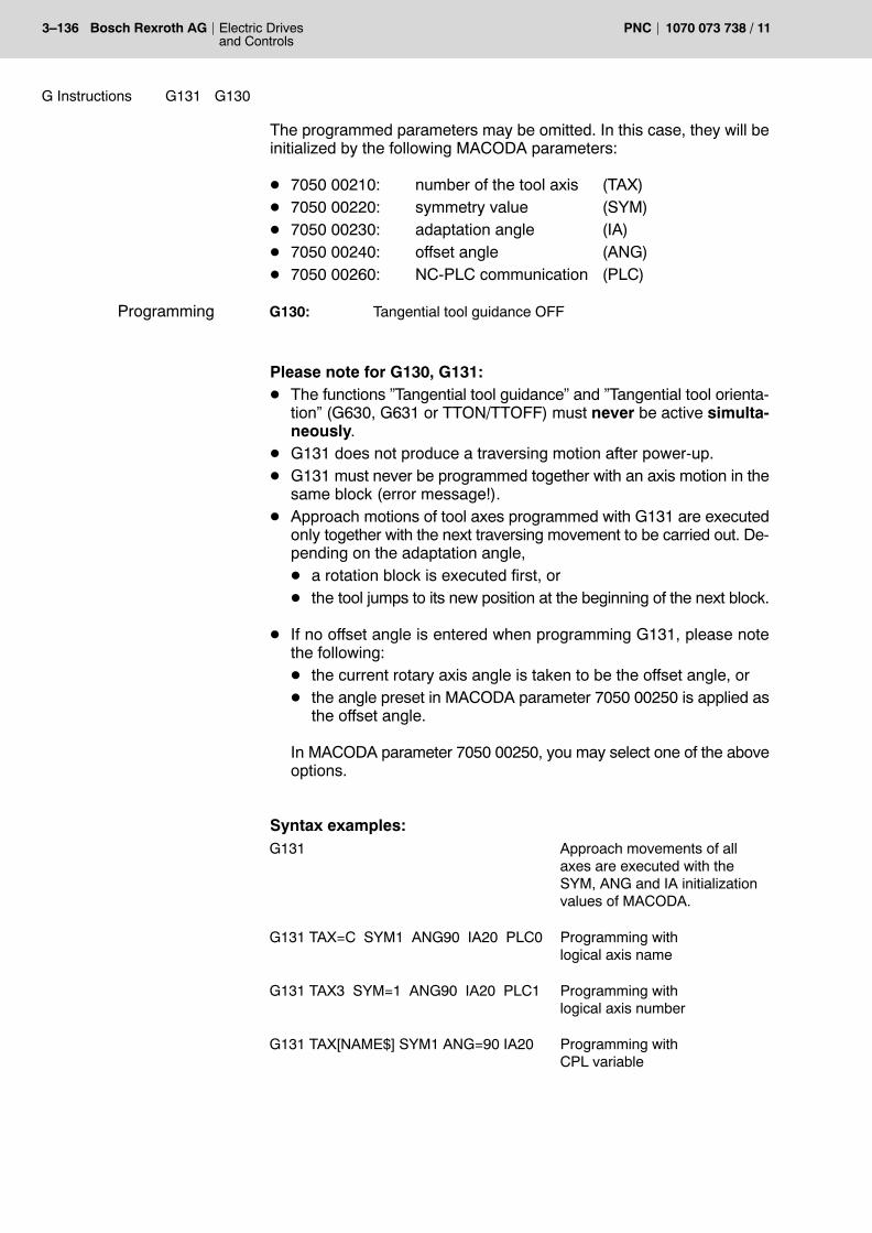
3�136 Electric Drivesand Controls
Bosch Rexroth AG PNC 1070 073 738 / 11
G Instructions G130G131
The programmed parameters may be omitted. In this case, they will beinitialized by the following MACODA parameters:
D 7050 00210: number of the tool axis (TAX)D 7050 00220: symmetry value (SYM)D 7050 00230: adaptation angle (IA)D 7050 00240: offset angle (ANG)D 7050 00260: NC-PLC communication (PLC)
G130: Tangential tool guidance OFF
Please note for G130, G131:D The functions �Tangential tool guidance� and �Tangential tool orienta-
tion� (G630, G631 or TTON/TTOFF) must never be active simulta-neously.
D G131 does not produce a traversing motion after power-up.D G131 must never be programmed together with an axis motion in the
same block (error message!).D Approach motions of tool axes programmed with G131 are executed
only together with the next traversing movement to be carried out. De-pending on the adaptation angle,D a rotation block is executed first, orD the tool jumps to its new position at the beginning of the next block.
D If no offset angle is entered when programming G131, please notethe following:D the current rotary axis angle is taken to be the offset angle, orD the angle preset in MACODA parameter 7050 00250 is applied as
the offset angle.
In MACODA parameter 7050 00250, you may select one of the aboveoptions.
Syntax examples:G131 Approach movements of all
axes are executed with theSYM, ANG and IA initializationvalues of MACODA.
G131 TAX=C SYM1 ANG90 IA20 PLC0 Programming withlogical axis name
G131 TAX3 SYM=1 ANG90 IA20 PLC1 Programming withlogical axis number
G131 TAX[NAME$] SYM1 ANG=90 IA20 Programming withCPL variable
Programming

G Instructions G130G131
Electric Drivesand Controls
3�137Bosch Rexroth AGPNC1070 073 738 / 11
NC-PLC interface signals
The PLC is able to control the execution of the intermediate block if NC-PLC communication is active (PLC=1).
Channel output signal NC�>PLC:
D NC-O18.0, �G131, Tool rotation�A signal is sent to the PLC indicating that the current angle betweentwo blocks is wider than the � adaptation angle� (IA). The NC does notexecute the intermediate block before it receives an acknowledge-ment from the PLC. The signal is not reset before the intermediateblock is executed.
Channel input signal PLC�>NC:
D NC-I3.2, �G131, Tool rotation release�:1The PLC signals the release of the execution of the intermediateblock to the NC. After the execution of the intermediate block, the NCwill not continue to execute any of the following blocks before the sig-nal is reset.
NC-O18.0
NC-I3.2G131, Tool rotation release
start of the next blockG131, Tool rotation

3�138 Electric Drivesand Controls
Bosch Rexroth AG PNC 1070 073 738 / 11
G Instructions G139G138
3.61 Workpiece position compensation G138, G139
The �workpiece position compensation� function unlinks coordinates ofpart programs P from the basis workpiece coordinate system B. Thisfunction acts on the first 3 logical axes on the respective channel.
In contrast to a zero shift function, also the 1st and 2nd coordinates canbe rotated here around the 3rd coordinate. This allows you to adapt thecoordinate system to any workpiece position.
In the course of the execution of a part program, all the programmed tra-versing movements will then be referring to the �new� � offset and rotated� coordinate system.
Workpiece position compensation is only possible in the valid workingarea of the machine and acts additively to active zero shifts!
Y
XB
W+R
+ R : positive mathematical value� R : negative mathematical value
Y�X�
Zero shift with coordinate rotation
D X
D Y
G138 Switch on workpiece position compensation.In the beginning of the part program, the following isprogrammed in the same block as G138:Offset of the workpiece zero point in X, Y and Z directionincluding the corresponding axis address, andAngle of rotation of the 1st and 2nd axis (standard axisaddresses: X and Y) as R address (value range: �360_ <angle of rotation <360_).All programming values must be absolute machinecoordinates.
G139 Switch off workpiece position compensation.
Please note for G138 and G139:D G138/G139 act modally and cancel each other mutually.D If workpiece position compensation is active, G37, G38, G54 � G59,
G154 � G159, G254 � G259, G60, G160 � G360, G168, G268, G145� G845, G147 � G847 as well as tool-length compensation Hx will betaken into account.
D You can program the �Inclined plane� function, G352, G354..G359,together with �Workpiece position compensation�. �Inclined plane�acts additively on the workpiece position compensation.
Effect
Programming

G Instructions G139G138
Electric Drivesand Controls
3�139Bosch Rexroth AGPNC1070 073 738 / 11
D G38, �Scaling�, has no impact on the parameters of the inclined planefunction.
D The axis addresses under G138 refer to (basis) workpiece coordi-nates.
D G138/G139 must never be programmed in combination with a tra-versing motion.
D Programming G138/G139 will interrupt the look-ahead function.Therefore, G138/G139 must never be programmed while the cuttercompensation function, G41/G42, is active. If required, the workpieceposition must be programmed before activating the cutter compensa-tion function.
D The current workpiece position is taken into account in the display ofworkpiece coordinates.
Example: Calling workpiece position compensationN... G90 G17 F1000 S250...N... G138 X50 Y300 Z10 R1.23N...N...N...
Set workpiece zero point to machine coor-dinates X50 Y300 Z10 and rotate X/Yplane counter-clockwise by 1.23 degrees.
N... G139 Switch off workpiece position compensa-tion.

3�140 Electric Drivesand Controls
Bosch Rexroth AG PNC 1070 073 738 / 11
G Instructions G245-G146G145
3.62 External tool compensation G145, G146, G245- G845
Activation of one out of 8 external compensation pairs for radius andlength compensation.For this purpose, the respective compensation values must be importedfrom the PLC (application, e.g., for multiple compensation in the case ofcombination tools).
The effective radius or length compensation value is then equal to thetotal of any active geometry compensation table values plus the acti-vated external tool compensation pair.
If the PLC changes the currently active external compensation values inthe course of the execution of a part program, this change will only be-come active in the block being under preparation as the next block.Under certain circumstances this can mean that even more blocks aredue to execution without this change.
In order to avoid this effect you must program the �WAIT� CPL commanddirectly after the block causing the PLC to hand over the new compensa-tion values. By doing so you hold the block preparation of the PNC untilall program blocks ahead of �WAIT� have been executed.
Subsequently, in the program block following �WAIT�, the new com-pensation values will already be active (please refer to Example 2).
G145..G845 External tool compensation on.
G146 External tool compensation off.
Please note for G145 ... G845 and G146:D G145 ... G845 / G146 act modally and cancel each other mutually.D G145 ... G845 / G146 can be programmed in the same block as
other preparatory functions, axis information and auxiliary function.
D G145 ... G845 / G146 do not cause a traversing movement if theyhave been programmed in a separate block.
Example 1:N... G0 X0 Y0 Z0N... H0 table length compensation OFFN... G146 external tool compensation OFFN... G1N... H1 table length compensation 1 ONN... X10 Y10 Z10 traversing movement with table length compensa-
tion 1N... G145 External tool compensation G145 ONN... X20 Y20 Z20 traversing movement with table length compensa-
tion 1 plus external tool compensation G145N... G345 external tool compensation G145 OFF and G345
ONN... X30 Y30 Z30 traversing movement with table length compensa-
tion 1 plus external tool compensation G345
Effect
Programming

G Instructions G245-G146G145
Electric Drivesand Controls
3�141Bosch Rexroth AGPNC1070 073 738 / 11
N... H0 table length compensation OFFN... X40 Y40 Z40 traversing movement with external tool compensa-
tion G345N... G146 external tool compensation OFFN... X0 Y0 Z0 traversing movement without compensation
Example 2:N... G145 external tool compensation G145 ONN... M... The M function will cause the PLC to perform the
following cycle:1. Transfer new compensation values2. Send acknowledgement to CNC (the CNC will interpret this acknowledgement as�Block or subprogram with �M� has been exe-cuted�).
10 WAIT Block preparation will be suspended until �M� hasbeen executed.
Length compensation will be in the direction of the selected drilling axis(please refer to G78/G79).
The active tool compensation is displayed at the �External tool com-pensation bit 0 ... bit 3� channel interface. (please refer to �PLC ProjectPlanning� manual).

3�142 Electric Drivesand Controls
Bosch Rexroth AG PNC 1070 073 738 / 11
G Instructions G847 G247- G148G147
3.63 General tool compensation G147, G148, G247- G847
General tool compensation is available as the 2nd external tool com-pensation function (2nd compensation group). It may be used with dril-ling, milling, turning and anglehead tools and may be activated inaddition to and independent of the �external tool compensation� function(G145, G146, G245�G845).
The compensation data is stored in a compensation data set that mayinclude the following parameters as a maximum:
D L2(1), L2(2), L2(3): Length compensation or offset
D R: Radius
D TO: Tool orientation (edge position)
D ö (phi), í (theta), y (psi): Eulerian angles, for orientation com-pensation, e.g. for gripping devices
You can program the selection of one compensation data set from a totalof 8.
L1, L2 and L3 length compensation parameters and/or shift param-eters:With a total of 3 shift values, L1, L2 and L3, you can perform bothconstant three-dimensional tool shifts and parallel length compensa-tions of 3 different tools as a maximum.
Example 1: Three-dimensional tool shiftL1, L2 and L3 shift values are assigned to the respective axes via MA-CODA parameter 7050 00420 (also refer to G78, G79 in sect. 3.47). Thecontrol unit will check internally whether or not the assignments are cor-rect.
Shift parameter Assignment to logical axis names
L1 X
L2 Y
L3 Z
Effect

G Instructions G847 G247- G148G147
Electric Drivesand Controls
3�143Bosch Rexroth AGPNC1070 073 738 / 11
+Y
+X
+Z
L(2)2 (∆Y)
L(2)3 (∆Z)
Tool
Three-dimensionaltool shift
L(2)1 (∆X)
+
+
+Shift values: L(2)1, L(2)2, L(2)3
Example 2: Parallel length compensations of up to 3 different tools
Tool T01 T02 T03
+85.251 mm +75.101 mm +78.234 mmL1 = L2 = L3 =
Assignments, which will be internally checked for correctness, are to beentered in MACODA parameter 7050 00420 as follows:
Shift parameter Assignment to logical axis names
L1 Z1 (drill axis 1)
L2 Z2 (drill axis 2)
L3 Z3 (drill axis 3)
. These axes must be different from the drill axis on which the exter-nal tool compensation function (G145 ...) or the length compensa-tion function H act (external tool compensations and lengthcompensations always act additively on one and the same axis).

3�144 Electric Drivesand Controls
Bosch Rexroth AG PNC 1070 073 738 / 11
G Instructions G847 G247- G148G147
Parameter R for radius compensation:If the general tool compensation and the external tool compensation(G145 ... G845) have been activated in the same NC block, the radius setin the general tool compensation function will be applied invariably (referto Example 1 below).
While the cutter compensation function G41/G42 is active, the radiusvalues set in general tool compensation (G147 ff.) and those set in exter-nal tool compensation (G145 ff.) automatically cancel each other, i.e.only the value that was activated last takes effect (refer to Example 2 be-low). The radius value that was activated last always acts additively onany D word (radius compensation) that may have been programmed.
The required compensation values must be specified by the PLC. Anychanges in the currently active compensation values made by the PLC inthe course of the execution of a part program will take effect only in thenext block to be prepared. Therefore, it may happen that a number ofblocks are executed before a change in a compensation value takes ef-fect.
In order to avoid this effect you must program the �WAIT� CPL commanddirectly after the block causing the PLC to hand over the new compensa-tion values. Block preparation by the PNC will be suspended until all pro-gram blocks before the �WAIT� command have been executed. In thefirst NC block after the �WAIT� command, the new compensation valueswill be taken into account.
Example 1:N10 G147 G145 X.. Y.. The radius value set in the general tool
compensation function will take effect!
Example 2:N10 G147 The radius value set in the general tool
compensation function is effective!N20 G145 X.. Y.. The radius value set in the external tool
compensation function will take effect!
TO tool orientation (edge position) parameter:The tool orientation (edge position) parameter (TO) describes the princi-pal orientation of the tool. The tool edge position compensation is de-fined in conjunction with the cutter radius (R). The cutter positioncompensation is needed in connection with path compensation(G41/G42) in order to ensure a faultless contour when processing theworkpiece with milling tools and movements that are not in parallel to themachine axis.For details, please refer to �PNC Description of Functions� manual.

G Instructions G847 G247- G148G147
Electric Drivesand Controls
3�145Bosch Rexroth AGPNC1070 073 738 / 11
Eulerian angles ö (phi), í (theta), y (psi):For special tools (e.g. certain gripper types), orientation compensationmay be required in addition to length compensation. The gripper coordi-nate system can thus be offset and rotated in any way with respect to theflange coordinate system (tool holder).For details, please refer to �PNC Description of Functions� manual.
. Orientation compensation is not possible unless the appropriateaxis transformation is active which takes the rotation internallyinto account.
G147..G847 general tool compensation ON
G148 general tool compensation OFF
Please note for G147... G847and G148:
D G147 .. G847/G148 act modally and cancel each other mutually.
D G147 .. G847/G148 can be programmed in the same block asother preparatory functions, axis informationand auxiliary function.
D G147 .. G847/G148 do not cause a traversing movement if theyhave been programmed in a separate block.
D If the general tool compensation and the external tool compensation(G145 ... G845) have been activated in the same NC block, the radiusset in the general tool compensation function will be applied invari-ably. If the radius of the external tool compensation is to be taken intoaccount, this function must be programmed separately in the next NCblock.
D The general tool compensation is displayed at the channel interface�General tool compensation�, bit 0 ... bit 3 (please refer to the �PLCProject Planning� manual).
Programming

3�146 Electric Drivesand Controls
Bosch Rexroth AG PNC 1070 073 738 / 11
G Instructions ACN(..)ACP(..) DC(..) G151 G150
3.64 Changing the positioning type for endless axes G150, G151Local setting of the positioning type DC(..), ACP(..), ACN(..)for endless axes
The PNC allows the positioning type for endless axes (type: rotary orendless) to be configured in a very flexible manner (please refer toG90/G189, G151/G150 and MACODA parameters 1003 00005, 100300050).
The following table shows various settings and switchover options forthe positioning type of an endless axis:
Presetting inMACODAparameter1003 00005(how does end-less axis trans-late the pro-grammed valueinto a motion)
Presetting inMACODAparameter1003 00050 (changeoverwith G151:1= yes0 = no)
Switchover viaG90/G189
Switchover viaG150/G151 e.g.B axis<..>
0=no special logic1=shortest path2=sign logic
Block-by-blockswitchover viaDC(..),ACP(..),ACN(..)(applies only tolinear interpola-tion G0, G1)
Axistraverses using position-ing type:
0 0 no special logic
1 0 shortest path
2 0 sign logic
3 0 or 1 G90 sign logic
3 0 or 1 G189 shortest path
unequal to 3 1 G150:Switchoveraccording to pre-setting in1003 00005
� no special logicor� shortest pathor� sign logic
unequal to 3 1 G151 B0 no special logic
unequal to 3 1 G151 B1 shortest path
unequal to 3 1 G151 B2 sign logic
0, 1, 2 or 3 0 or 1 DC(..) shortest path
0, 1, 2 or 3 0 or 1 ACP(..) sign logic(in positive direction)
0, 1, 2 or 3 0 or 1 ACN(..) sign logic(in negative direction)
Effect

G Instructions ACN(..)ACP(..) DC(..) G151 G150
Electric Drivesand Controls
3�147Bosch Rexroth AGPNC1070 073 738 / 11
Switching over the positioning type for endless axes
G151 Change positioning type.The axis address of the axis the positioning type of which isto be switched over is specified in the same block.In addition to the axis address the desired positioning type isdefined by the 0, 1 and 2 numerals:0: no logic. The axis will subsequently always traversewithout positioning logic to the respective last programmedposition.
1: shortest path. The axis will always use the shortest pathfor traversing to the respective programmed position(traversing movement is always smaller than 180 degrees).
2: sign logic: The programmed sign determines the senseof rotation of the axis, the numerical value defines itsposition.
G150 The positioning type is switched back to the stateprogrammed in MP 1003 00005.
Example:G151 B0 axis B: no logic.
G151 A1 C2 axis B: logic according to MP 1003 00005axis A: shortest pathaxis C: sign.
G150 axes A, B and C according to MP 1003 00005
Please note for G150 and G151:D G150/G151 act modally and cancel each other mutually.
Local setting of the positioning type for endless axes
With local setting of the positioning type for endless axes you have thepossibility of determining or switching over the positioning type of anendless axis block by block regardless of the MACODA parameter set-ting or active (modal) NC functions.
DC(...): the programmed position is approached on the shortestpath.
ACP(...): the programmed position is approached in mathematicallypositive direction.
ACN(...) the programmed position is approached in mathematicallynegative direction.
Programming
Programming

3�148 Electric Drivesand Controls
Bosch Rexroth AG PNC 1070 073 738 / 11
G Instructions ACN(..)ACP(..) DC(..) G151 G150
Note: mathematically positive direction = counter-clockwise sense ofrotation seen from a coordinate axis in the direction of the coordinatesorigin.
+Z +Y
Coordinateorigin
+X
mathematicallypositive sense of rotation
+
<physical axis address> = <address attribute>(<value>)
B = ACP (258) Irrespective of the presetting by G150/G151, the Baxis will traverse in mathematically positive directionto the position 258 degrees.
Please note for the ACP function:D The address attributes only act block by block.D It is possible to program different attributes for different endless axes
within one block.D The evaluation of the address attributes is only performed for endless
axes. They are ignored for other types of axis movement.D The positioning type of endless axes only applies to G00, G01 linear
interpolations (quasi-positioning mode). For other interpolationtypes, interpolation will include endless axes in analogy to a rotaryaxis.
D Only the amount of the axis value will be evaluated (negative sign willbe ignored).
D The positioning type of endless axes will only be evaluated with abso-lute programming (G90).
DANGERThis programming of the ACP function might result in damage tothe workpiece and/or the machine! There might even be danger topersons!
This programming refers directly to a real physical axis. A logicalaxis addressed, for instance, by a coordinate transformation (e.g.inclined plane) with the same axis address will lead to incorrectaxis values.
Programming

G Instructions G167G360 G160..
Electric Drivesand Controls
3�149Bosch Rexroth AGPNC1070 073 738 / 11
3.65 External axis zero shift G160..G360, G167
You can perform one out of max. 3 external axis zero shifts for each ap-plied machining axis (= synchronous axis).
For this purpose the PLC has to default the corresponding values. Theeffective axis zero shift will then correspond to the total ofD the active axis zero-shift values of the axis ZS tables, if any,D the activated external axis zero shift.
If the PLC changes the currently active external offset values in thecourse of the execution of a part program, this change will only becomeactive in the block under preparation as the next block. Under certaincircumstances this can mean that several blocks are still due to execu-tion without this change.
In order to avoid this effect you must program the �WAIT� CPL commanddirectly after the block causing the PLC to hand over the new shift values.By doing so you suspend block preparation by the PNC until all programblocks ahead of �WAIT� have been executed.Subsequently, in the program block following �WAIT�, the new values willalready be active.
G160 External axis zero shift no. 1 on.G260 External axis zero shift no. 2 on.G360 External axis zero shift no. 3 on.G167 External axis zero shift off.
Please note for G160, G260, G360 and G167:D G160, G260, G360, G167 act modally and cancel each other mutu-
ally.D G160, G260, G360, G167 will not cause any traversing movement if
programmed alone in a block.D The compensation values under G160, G260, G360 refer to machine
or axis coordinate values.D The active �external zero shift� will be displayed at the External axis
zero shift bit 0..bit 1 channel interface (also ref. to �PLC ProjectPlanning� manual).
Effect
Programming

3�150 Electric Drivesand Controls
Bosch Rexroth AG PNC 1070 073 738 / 11
G Instructions G162 G161
3.66 In-position at rapid travel G161, G162
During the control of a tool movement, an offset between the set and theactual values of the individual axes occurs during the movement owingto the dynamics of the machine.
In the case of positioning movements this effect has to be avoided if anaccurate position is to be reached prior to the start of machining.
Using G161 you activate the �In-position logic� especially for movementsat rapid (for movement at feedrate, please refer to G61/62). FunctionsG164 to G166 can be used to set 3 different In-position logic options.
. Please note that G161/G162 are superseded by an active G163!
G161 In�position logic at rapid travel on.G162 In-position logic at rapid travel off (only if G163 is not active).
Please note for G161 and G162:D G161 and G162 act modally. M2/M30 sets the power-up state.D G161 or G162 has to be programmed at the latest in the block to
which the respective function is supposed to apply.
+Y
+X
Starting movementtowards the work-piece
G161
G162
with In-position logic
without In-posi-tion logic
Example: Programming of G161/G162N10 G161 no movement; In-position logic ON
N11 G0 Y200 rapid travel with In-position logic
(or)
N10 G162 rapid travel without In-position logic
N11 G0 Y200
N50 G161 X200 rapid travel with In-position logic already in this block
Effect
Programming

G Instructions G166G165G164
Electric Drivesand Controls
3�151Bosch Rexroth AGPNC1070 073 738 / 11
3.67 In-position logic mode G164, G165, G166
Using G164 to G166 you first determine the behavior of the �In-positionlogic�. Subsequently, you activate �In-position logic� via the G functionsD G61 (for movements at feedrate)D G161 (for movements at rapid travel)D G163 (for movements at feedrate and rapid travel).
G164 At the block end, the PNC reduces the path speed to V=0. Itchecks via the SERCOS interface whether the �positioningwindow fine� (SERCOS ID no.: S-0-0057) has been reachedfor all axes involved. For this purpose, the ID no. S-0-0336 isassigned to the real-time bit 2 S-0-0307.Only when this positioning window has been reached for allaxes involved will the traversing movement of the next blockbe executed.
G165 At the block end, the PNC reduces the path speed to V=0. Itchecks via the SERCOS interface whether the �positioningwindow rough� (SERCOS ID no.: S-0-0261) has beenreached for all axes involved. For this purpose, the ID no.S-0-0341 is assigned to the real-time bit 2 S-0-0307.Only when this positioning window has been reached for allaxes involved will the traversing movement of the next blockbe executed.
G166 At the block end, the PNC reduces the path speed to V=0.Subsequently, the traversing movement of the next block isexecuted without performing a positioning-window check.
Please note the following for G164, G165 and G166:D G164, G165 and G166 act modally. M2/M30 sets the power-up state.D As long as the �positioning window rough� (G165) is selected, this is
indicated at the Inpos range 2 activated channel interface (also ref.to �PLC Project Planning� manual).
. The �positioning window fine� and �positioning window rough�parameters can be determined in the SERCOS files for Phase 3.For further details about the SERCOS files, please refer to the�Configuration parameters and MACODA parameter description�manual under �SERCOS initialization�.
Effect
Programming

3�152 Electric Drivesand Controls
Bosch Rexroth AG PNC 1070 073 738 / 11
G Instructions G166G165G164
The following table shows the In-position logic behavior as a function ofthe different interpolation types:D G1,G2 linear and circular interpolation
D G73 linear interpolation with In-position logic
D G0 rapid travel with In-position logic (with deceleration toV=0)
D G200 rapid travel without In-position logic (without decelerationto V=0)
as a function of the modal functions:
D G61 In-position logic at feedrate
D G62 In-position logic at feedrate off
D G161 In-position logic at rapid travel
D G162 In-position logic at rapid travel off (only if G163 is not active)
D G163 In-position logic at feedrate and rapid travel
D G164 positioning window, fine (V=0)
D G165 positioning window, rough (V=0)
D G166 without positioning window (V=0)
InPosrapid travel InPosInPos window mode
61161164
61161165
61161166
61162164
61162165
61162166
62161164
62161165
62161166
62162164
62162165
62162166
163161164
163161165
163161166
163162164
163162165
163162166
G1,G2G73G0
164
164
165
165
166
166
164
166
165
166
166
166
- - -
164
- - -
165
- - -
166
- - -
166
- - -
166
- - -
166
164
164
165
165
166
166
164
166
165
166
166
166165 166 164 165 166 164 165 166 164 165 166 164 165 166 164 165 166164
G200 166 166 166 166 166 166 - - - - - - - - - - - - - - - - - - 164 165 166 164 165 166
InPos table: Examplecf. below
Examples: Using the table
The following In-position logic defaults are activated:
InPos 62: G62 (deactivate In-position logic function atnormal feedrate) is selected
Rapid travel InPos 162: G162 (deactivate In-position logic functionat rapid travel) is selected
InPos window mode165: G165 (positioning window, rough (V=0)) isselected

G Instructions G166G165G164
Electric Drivesand Controls
3�153Bosch Rexroth AGPNC1070 073 738 / 11
The above InPos settings determine the behavior at block transitionfor the following active G functions:
G1,G2 - - -: No ramping-down (exception: max. axisstep change)
G73 165: reaching the �InPos window rough� is beingwaited for
G0 166: ramping-down to speed V=0
G200 - - -: No ramping-down (exception: max. axisstep change)
Despite G162 being active, ramping-down will be performed with G0.With regard to G0, G162 has the same effect as the combination ofG161, G166.

3�154 Electric Drivesand Controls
Bosch Rexroth AG PNC 1070 073 738 / 11
G Instructions G269G268G169G168
3.68 Program coordinate shift G168, G169Additive program coordinate shift G268, G269
All programmed coordinates of the feed axes (synchronous axes on achannel) of a part program or an MDI block refer to the program coordi-nate system (PCS or P). Therefore, a program zero point can be offsetrelative to a freely defined workpiece zero (WCS or W).
Shifting the program coordinate zero point allows the execution of partprograms without making any changes in any position within the workingrange of the machine.
+ZW
+XW
+YW
+ZP1
P2
+ZP2
�YP2
�XP1
P1
P1 = Program zero point of the 1st program coordinate shiftP2 = Program zero point of the 2nd program coordinate shiftW = Workpiece zero point
W
�XP2
workpiece
�YP1
Additive shifting of the program coordinates allows to describe severalsuccessive coordinate systems and thus to design a part program that isequivalent to the dimensioning of a design drawing.
If one program coordinate shift is already active while a new one is beingprogrammed, any axes for which no new values are entered will retaintheir previous shift values. This is the same behavior as with the �Pro-grammed contour shift� function, G60.
The program coordinate shift function may be used in the context of allNC functions defining coordinate system transformations and in particu-lar together with zero shifts (G54 ... G259) or inclined plane (G352 ...G359).
However, the program coordinate shift function must always be deacti-vated when an inclined plane function is activated or deactivated.
Effect

G Instructions G269G268G169G168
Electric Drivesand Controls
3�155Bosch Rexroth AGPNC1070 073 738 / 11
Difference between this function and �Programmed contour shift,G60/G67�:The functionality of �Program coordinate shift� and �Programmed con-tour shift�, G60, is the same with the exception of their behavior in com-bination with function G38, �Mirroring, scaling, rotating�:Whereas shift values programmed with G60 are impacted by G38 (shiftvalues are also scaled, mirrored and rotated), G38 has no effect on anyshifts made with the program coordinate shift function. Unlike G60, theprogram coordinate shift function has the effect of shifting coordinatesystems.
Example: G168 versus G60, both times in combination with G38 (scaling)
The following shifts result with the scaling factor=2:
Axis Scaling factor Shift using G168and G38
Shift using G60and G38
X 2 DX=1 unit DX=2 units
Y 2 DY=1 unit DY=2 units
+XW
+YW
YP1
W
W = Workpiece zero point
�XP1
P1
Px = x-th program zero point
ϑX (G169)
DX (G60+G38)
+XW
+YW
W
DY (G168+G38)
DX (G168+G38)
DY (G60+G38)
P2 (G168)
P2
YP2
�XP2
P1
Shift using G168 and G60with simultaneous G38 (scaling)
Workpiece contour
Workpiece contour(scaled with G38 andoffset withG60)
YP2
�XP2
Workpiece contour(scaled with G38 andoffset withG168)
Workpiece contour (original)
G168 program coordinate shift ON
G169 all program coordinate shifts OFF
G268 additive program coordinate shift ON
G269 additive program coordinate shift only OFF
The desired shift values must be entered together with the pertinent Gcode (G168 or G268) and the axis addresses in one block that must notinclude any traversing motions.
Functions G168/G169 and G268/G269 form a modal group in each caseand, therefore, cancel each other mutually.
Programming

3�156 Electric Drivesand Controls
Bosch Rexroth AG PNC 1070 073 738 / 11
G Instructions G269G268G169G168
Example: Programmed contour shift
N10 G168 X10 Y10 Z50...
Setting program zero at X10, Y10, Z50 ofthe current workpiece coordinate system.There is no traversing motion included inthis block.
N100 G1 X... Y... Z... Programmed positions refer to the programcoordinate system defined above.
N110 G268 X20 Y10 Now, the program coordinate system is setat X30, Y20, Z50 relative to the workpiececoordinate system. There is no traversingmotion included in this block.
N200 G169 The program coordinate system enteredpreviously is deleted. Now, the programcoordinate system is identical with the work-piece coordinate system.

G Instructions G177
Electric Drivesand Controls
3�157Bosch Rexroth AGPNC1070 073 738 / 11
3.69 Torque reduction G177
The positive edge of the TORQUE REDUCTION axis interface signalcan be used to set the max. torque of an axis to a value defined in MA-CODA parameter 1003 00010. The TORQUE LIMIT output signal indi-cates that the reduced torque has become effective.
G177 offers the possibility of overwriting the value as preset via MA-CODA parameter on an axis-per-axis basis within the value range from 0to 500 (0 to 50% of the standstill torque) using program control. Thevalue of the MACODA parameter itself is not changed.
G177 X5 With the next positive edge of the �torque reduction�signal the max. torque for the X axis in the drive will belimited to 0.5% of the standstill torque.
G177 Y7 With the next positive edge of the �torque reduction�signal the max. torque for the Y axis in the drive will belimited to 0.7% of the standstill torque.
G177 With the respective next positive edge of the �torquereduction� signal the max. torque for the individual axeswill again be limited to the value determined in MACODAparameter 1003 00010.
When entering an invalid value the control unit will limit the input value tothe admissible range (0 to 500) and output a warning.
. In the case of a negative edge of TORQUE REDUCTION the max.torque will be set back to the value which was active in the driveafter the last SERCOS phase startup. If this value is to be changed,it has to be entered in the corresponding SERCOS file under theSERCOS ID no. S-0-0092, and subsequently a phase startup has tobe performed.For further details about the SERCOS files, please refer to the�Configuration parameters and MACODA parameter description�manual under �SERCOS initialization�.
DANGERProgramming function G177 might result in damage to theworkpiece and/or the machine! There might even be danger topersons!
This programming refers directly to a real physical axis. A logicalaxis addressed by a coordinate transformation (e.g. inclinedplane) with the same axis address will lead to incorrect axis va-lues.
Effect
Programming

3�158 Electric Drivesand Controls
Bosch Rexroth AG PNC 1070 073 738 / 11
G Instructions G292G192
3.70 Speed limitation G192, G292
To make sure that the spindle speed does not rise or fall excessively(constant cutting speed G96), the upper or lower limit of the admissiblespeed range can be programmed in the part program. A speed change �even if initiated by the spindle potentiometer � will not be performed un-less it is within the absolute limits specified.
The limit values apply to all speed ranges, however, they are effectiveonly if they are within the speed range limits.
G192 Determine lower limit of admissible speed.The spindle minimum speed is programmed in the sameblock as G192 with the S word.G192 with an S word ≤ 0 cancels the limit value.
G292 Determine upper limit of admissible speed.The spindle maximum speed is programmed in the sameblock as G292 with the S word.G292 with an S word ≤ 0 cancels the limit value.
Please note for G192 and G292:D G192 and G292 can be replaced by programming new limit values.D The speed limits influence the direct speed programmed in G97 and
the constant cutting speed in G96.D The S values programmed with a speed limit do not influence the
speeds in connection with M3/M4 programming. They remain storedand effective until M2/M30, �Control reset�, �Reset� or one of the can-celling functions is activated.
Example:Programming a speed limitN...
N100 X... Y... G192 S1500 minimum speed: 1500 rpm
N101 X... Y... G292 S2500 maximum speed: 2500 rpm
N... X... Y... G292 S–1 cancel maximum speed
N... X... Y... G192 S0 cancel minimum speed
Effect
Programming

G Instructions G350G301
Electric Drivesand Controls
3�159Bosch Rexroth AGPNC1070 073 738 / 11
3.71 Oscillating axis G301, G350
Using the �oscillating axis� function, an oscillating movement can be per-formed with any synchronous axis while linear interpolation is carried outfor the other synchronous axes of the channel (e.g. flat grinding).
Any synchronous axis can be defined as oscillating axis:D linear axisD rotary axisD C axis
The parameters of the oscillating movement (initialization) are set byG350 and saved modally.
This initialization must be programmed prior to the actual oscillatingmovement:D selection of the oscillating axisD starting and end position as reversing points of the oscillating move-
mentD frequency or speed of oscillating movement
The oscillating axis is implemented as modal function G301, �oscillationwith linear movement�. The transition of the oscillating movement be-tween 2 consecutive oscillation blocks is steady (also in terms of speed).
Item
Starting
G301
position
G301
1st block 2nd block
Effect

3�160 Electric Drivesand Controls
Bosch Rexroth AG PNC 1070 073 738 / 11
G Instructions G350G301
Initialization of the oscillating axis function
G350 OscAxis<physical axis index> URP<axis position>LRP<axis position> F<speed>|OF<oscillation frequency>R<reversing range>
where:
OscAxis selection of the oscillating axis (physical axis index)
URP upper reversing point of the oscillating axis (mm)
LRP lower reversing point of the oscillating axis (mm)
F speed of the oscillating axis (mm/min) -alternatively to OF-
OF oscillation frequency (Hz in 1/sec) - alteratively to F -R reversing range (not yet available, will be implemented in
a later option)
Starting the oscillating movement:
G301 X<axis position> Y<axis position> F<speed> Time<duration>
where:
X synchronous axis, interpolating linearly with Y
Y synchronous axis, interpolating linearly with X
F path feed of axes (X, Y)
Time duration (sec) of oscillating movement for blocks withouttraversing movement
Example:G350 OscAxis4 URP200 LRP100 OF5 Oscillating axis is the 4th physi-
cal axis (e.g. U axis)
G301 X100 Y10 F20 Time 200
. If the axis address of the oscillating axis is programmed with a tra-versing path, an error message will be generated. None of the expli-citly programmed axes may be defined as an oscillating axis.
. The programmed time (Time) only refers to the block in which�Time� was programmed. The oscillating movement takes at leastas long as the programmed time. A synchronous traversing move-ment programmed in the same block whose execution takes moretime than the programmed oscillating time, will let the oscillatingmovement take longer. If oscillating is still active in the next block,although no time has been programmed, the execution time of thisblock will be solely determined by the synchronous axis move-ment.
Programming
Programming

G Instructions G350G301
Electric Drivesand Controls
3�161Bosch Rexroth AGPNC1070 073 738 / 11
The display is in workpiece coordinates. If a zero point shift is selectedfor the oscillating axis, the application of the shift will be postponed for aslong as the oscillating axis is active. However, it will be applied to theworkpiece position display.
The last position prior to the beginning of the oscillating movement will bedisplayed as end position. This position also acts as starting position ofthe oscillating movement.
The distance to go is defined as the difference between the end point andthe current machine position setpoint. It oscillates between 0 and the dis-tance between the reversing points.
Please note for G301 and G350:D G301 is a modal function (group G1, G2, ...)D G350 is not modal (therefore not in display)D G350 sets the parameters modally, i.e. the old parameters can only
be overwritten by programming G350 with suitable parameters again.D When oscillating has been activated, the oscillating axis first tra-
verses to the reversing point which can be reached within the shortestdistance starting from its current position.
D Oscillating will remain active until a new modal movement function(e.g. G1, G2, ...) is programmed.
D For as long as oscillating is active, the oscillating movement will besteady and can be differentiated across block limits.
D When oscillating is turned off, the oscillating axis will return to the re-versing point from where it started.
D After Control Reset, the oscillating movement will not be cancelledbefore the next reversing point (speed = 0) has been reached. Themodal function will be cancelled in accordance with the default status.
D Programming of NC functions (loop gain (KV) programming, feed for-ward control, etc.) which act on the physical address of the oscillatingaxis should be avoided within the machining section because suddenspeed losses may be the consequence.
D By programming the address of the oscillating axis in connection witha function internal to the NC (e.g. G60 oscillating axis address value),this function will be activated, however, it will not take effect on the os-cillating axis for as long as oscillating is active. The compensation(e.g. G60) will not be selected before the oscillating movement hasstopped.
D The program value equals zero during the oscillating movement.D If a zero offset is activated while G301 is being programmed, first
make a query of the current data of the oscillating axis using CPLfunction �FXC� because this data must be taken into account whenprogramming the �URP� and the �LRP� (G350).
Example:1 A=FXC(4)N2 G350 OSCAxis4 URP[200+A] LRP [100+A] OF5N3 G301 X100 Y10 F20 Time200

3�162 Electric Drivesand Controls
Bosch Rexroth AG PNC 1070 073 738 / 11
G Instructions G350G301
Restrictions:Function G301, �Oscillating axis�, is not permitted in combination withfunctionsD In-position logic G61 or G163D Switching NC blocks via high-speed signal G575
While G301 is active, the following functions must not be programmed(because otherwise interpolation would be aborted abruptly which mayresult in a servo error):G4, G14/G15, G32, G75, G114/G115, G374, G590/G591, G900
Auxiliary functions may be programmed together with G301 only if thetime required for interpolating the NC block is longer than the time re-quired for the execution of the auxiliary function, including acknowledge-ment. Basically, the time required for executing an NC block isdetermined by the path and the feedrate programmed for this block aswell as by the duration of the oscillating movement, �Time�. Any G301blocks for which no duration of the oscillating movement nor a traversingmotion has been entered are executed within one interpolation cycle.To ensure that the oscillating movement is properly terminated, WAITneeds to be programmed before any M0/M1. If the execution of the pro-gram is continued upon a cycle start command, the oscillating move-ment will also be resumed.
Example:N50 G301 .....N60 WAIT N70 M0N80 ...

G Instructions G316G310
Electric Drivesand Controls
3�163Bosch Rexroth AGPNC1070 073 738 / 11
3.72 Ramp functions G310 - G316
Provides for the definition of own velocity profiles. The following featuresare available for this purpose:D 3 speed interpolators
(for linear, sinusoidal and sin2-shaped velocity rise),D 3 deceleration interpolators
(for linear, sinusoidal and sin2-shaped deceleration),D 1 constant-speed interpolator
Acceleration interpolatorsWith all these options, the control unit will accelerate, starting from veloc-ity V0 in the beginning of the movement, across the entire programmedpath length, to the target velocity V1.The target velocity V1 is reched together with the programmed end point,and results from the programmed feedrate as a function of the currentoverride value. It is limited byD the maximum path acceleration andD the maximum permitted path velocity.Both quantities are calculated by the control unit specifically for eachpath segment and each NC block, and a 1-block look-ahead is per-formed in connection with the maximum permitted velocity. This pre-vents a violation of the maximum axis velocities in the respective nextblock.Behavior in the event of override changes:D for acceleration interpolator with linear velocity increase:
D If the override is reduced to final values below the start velocity V0,the NC will determine a deceleration ramp that lasts until the pro-grammed end point.
D Increasing the override will result in a re-computation of the accel-eration ramp.
D for acceleration interpolator with sinusoidal and sin2-shaped velocityrise:D An override reduction to final values below the start velocity V0 will
be ignored.D Increasing the override will result in a re-computation of the accel-
eration ramp.
Deceleration interpolatorsWith all these options, the control unit will decelerate, starting from ve-locity V0 (in the beginning of the movement), across the entire pathlength programmed in the NC block, always to zero speed (V1=0).
Override changes have no effect, with the following exception:If the override was set to 0% in the previous block and afterwards thecommand velocity of 0 was reached exactly at the block transition to thedeceleration interpolator, the control unit will maintain the decelerationinterpolator until the override is increased to a value > 0!The velocity will be increased by one acceleration step (depending on
Effect

3�164 Electric Drivesand Controls
Bosch Rexroth AG PNC 1070 073 738 / 11
G Instructions G316G310
the permitted path acceleration). The control unit will calculate the necessary deceleration ramp on thebasis of the velocity value resulting from this function. Afterwards, theactual override value will be of no effect until the end of the block.
Constant-speed interpolator The control unit tries to reach the programmed velocity, taking the maxi-mum permitted path velocity and the current override value into account.Behavior in the event of override changes:D Velocity changes are carried out at the respective permitted path ac-
celeration and path deceleration.
G310 Constant-speed interpolator onG311 activate acceleration interpolator with linear velocity riseG312 activate deceleration interpolator with linear velocity decreaseG313 activate acceleration interpolator with sinusoidal velocity riseG314 activate deceleration interpolator with sinusoidal velocity de-
creaseG315 activate acceleration interpolator with sin2-shaped velocity riseG316 activate deceleration interpolator with sin2-shaped velocity de-
crease
L In addition to the G function, the desired end point coordinate has to beindicated for the type of interpolator in the NC block.
. When using deceleration interpolators in connection with extre-mely short traversing paths, excessive acceleration is possible,which may lead to a servo error. Therefore, please note the maximum possible machine dynamicsalready when creating the part program.
. G310 to G316 each act modally, and form a group together with G8,G9, G108, G408 and G608.
D G310 to G316 can only be invoked in operation mode automatic.Other operation modes (manual data input, single block, single step,or program block) will lead to a runtime error.
D No auxiliary functions may be programmed, and no functions such as�In-position logic� may be active in conjunction with G310, G311,G313 and G315 (constant-speed or acceleration interpolators) be-cause otherwise sudden speed drops may be experienced. Prohibited functions: G0, G4, G14, G15, G32, G33, G61, G73, G75,G161, G163, G374, G575, G900.
D No velocity lower than the one active at the beginning of the rampshould be programmed within a movement sequence (comprising ac-celeration, constant-speed and deceleration).
Programming

G Instructions G316G310
Electric Drivesand Controls
3�165Bosch Rexroth AGPNC1070 073 738 / 11
A lower programmed velocity will be simply ignored by the accelera-tion interpolator (same behavior as with override change).
D Auxiliary functions or a dwell time may be programmed at the end ofeach processing sequence.
Application example:Programming an oscillation cycle for the U axis.
V(t)
t
N10 N20 N30 N40 N60 N70N50
0
N5
:N5 G0 U10 U axis is traversed to starting position (U=10mm)
N10 G315 U17 F500 Sin2-shaped acceleration up to position U=17.Feedrate setpoint at the end point:F=500 mm/min
N20 G310 U23 Constant speed until position U=23.
N30 G312 U29 Linear deceleration until position U=29.End speed: 0 mm/min
N40 G4 F0.5 Dwell time in the point of reversal.
N50 G311 U20 Linear acceleration until position U=29.
N60 G310 U17 Constant speed until position U=17.
N70 G314 U10 Sinusoidal deceleration until position U=10. Endspeed: 0 mm/min
:

3�166 Electric Drivesand Controls
Bosch Rexroth AG PNC 1070 073 738 / 11
G Instructions G329G328
3.73 Precision programming G328, G329
The precision programming function automatically reduces the fee-drate for contour transitions or circular contour segments (circles, heli-cal, helicalN) to ensure compliance with accuracy specifications(please refer to the figure below).For this purpose, a feedrate value is calculated based on a control sys-tem model (closed position control loop in steady-state condition, withfeed forward control taken into account). This feedrate value will en-sure that the programmed tolerance does not fall below the required pre-cision at the block transition.
. In contrast to the �in-position� function, the feedrate is not reducedto 0 at a block transition with the �precision programming� func-tion. With the �in-position� function, the actual following errors ofall axes of the respective channel are checked after deceleration to0 speed.
The precision tolerance range is set by selecting one of 2 different pa-rameters:D Deviation from the contour e: Maximum permissible deviation for
contour transitions or maximum permissible deviation from radius forcircular arcs.
D Overtravel d: Maximum overtravel (distance from corners) not to beexceeded at the actual transition point of a contour transition.
G328 Activation of precision programming withthe value of deviation from contour e aspreset in MP 8003 00001.
G328 EPS<contour error> Activation of precision programming
G328 DIST<cornerdistance>
Activation of precision programming
G329 Deactivation of precision programming
where:
EPS Contour transition: A deviation from the contour at ablock transition is the minimum deviation of the actualcontour at the transition from the programmed position.
Circular arc: A deviation from radius is the difference be-tween the programmed radius and the resulting actualradius, which is dependent on path velocity.
Contourerror
Distance (e) to be entered in mm or inch (depending onthe unit set with G70 or G71).
Effect
Programming

G Instructions G329G328
Electric Drivesand Controls
3�167Bosch Rexroth AGPNC1070 073 738 / 11
DIST The overtravel is the distance between the position wherethe actual contour first deviates from the programmedcontour before a contour transition and the block positionprogrammed.When programming circles with DIST, the e value set inMACODA parameter 8003 00001 is taken into account.
Cornerdistance
Distance (d) to be entered in mm or inch (depending onthe unit set with G70 or G71).
. To avoid the need for entering the deviation from contour e expli-citly each time, a default value may be entered in MACODA parame-ter 8003 00001.
Please note for G328 and G329:D Identical dynamics must be set for all axes.
If drives other than Bosch drives are used, active feed forward controlfunctions will be taken into account only in terms of quality (followingerror reduced by 50%). The configuration of operation without any fol-lowing errors in SERCOS varies with the manufacturer.
D A path slope function, G8 or G108, must be active. Otherwise, thespeed is decelerated to 0 at every contour transition.
D In-position (G61, G163) must be deactivated to prevent decelerationto 0 at every contour transition.

3�168 Electric Drivesand Controls
Bosch Rexroth AG PNC 1070 073 738 / 11
G Instructions G329G328
X
X
Y
X
ε (deviation from contour set with G328)
Act2
Prog1
with G328reduced feedrate
Acceleration tonormal feedrate
Act3Act4
Act5
Act6 Prog5
Prog4
= Programmed contour; programmed position
= Actual contour; actual position with G328
= Actual contour�; actual position� without G328
d (setting of overtravel with G328)
Actx�,Progx�= corresponding programmed and actual positionswithoutG328Actx,Progx = corresponding programmed and actual positions withG328
Prog2
Prog3
Act1 Prog6
deviation from contour without G328
without G328reduced feedrate
Acceleration tonormal feedrate
Prog3�
Prog2�
Act3�Act4�
Act5�
Act6�
Prog4�
Prog5�
Act2�
Prog1�
Ract(with G328)
ε
Rprog
Deviation from ra-dius at circular arcat constant pathvelocity
Ract(without G328)
Deviation from contour atblock transition with G328
Deviation from contour atblock transition without G328
actual contour without G328
actual contour with G328
actual contour without G328
actual contour with G328
programmedcontour
actual contour without G328actual contour with G328Programmed contour

G Instructions G354..G353G352
Electric Drivesand Controls
3�169Bosch Rexroth AGPNC1070 073 738 / 11
3.74 Inclined plane G352, G353, G354..G359
The workpiece (WCS) or program (PCS) coordinate system can be off-set and oriented in space at the user�s discretion using the �Inclinedplane� function. The underlying workpiece coordinate system is the ref-erence quantitiy. In addition to a workpiece or program zero point shift,the WCS/PCS can be rotated by several coordinates.
Since there are 3 degrees of freedom for orientation, every orientationcan be represented by 3 consecutive basis rotations.
Machine
+ZB +YB
BCS +XB
+ZW = +ZB
+YB
+XB
+XW
+YW
+X�W
+XW
+Y�W=+YW
+ZW +Z�W
+X�W
+Y�W
+Z��W = +Z�W
+Y��W
+X��W
Rotation of the coordi-nate system by coordi-nate Y�W (=YW) and theangle theta
Basis workpiececoordinate systemand zero point
Orientation (rotation) of the �inclined plane�
Rotation of the coor-dinate system bycoordinate ZB andthe angle phi
Rotation of the coordinatesystem by coordinateZ��W (=Z�W) and the anglepsi
+ZM+YM
BCS +XM
+Z��W
+Y��W
+X��W
DY
DX
DZ
Shifting the zero point of an �in-clined plane� relative to the basisworkpiece coordinate system
Positioning the coordinate system by distance DX,DY, DZ and orientation by angles phi, theta, andpsi, relative to the BCS
BCS= Basis workpiece coordinate systemWCS= Workpiece coordinate system (or program coordinate system)
WCS
WCS WCS WCS�ϕ (phi)
ϑ (theta)
�ψ (psi)
Effect

3�170 Electric Drivesand Controls
Bosch Rexroth AG PNC 1070 073 738 / 11
G Instructions G354..G353G352
Since the inclined plane can be offset and rotated in space relative to theBCS, it is necessary to define the precise location and the orientation ofthe program or workpiece zero point.
The zero point of the workpiece or program coordinate system of the�inclinced plane� relative to the BCS basis workpiece coordinate systemD can be entered directly using G352
G352 X<X�Offset> Y<Y�Offset> Z<Z�Offset> PHI<1st Eul�erian angle> THETA<2nd Eulerian angle> PSI<3rd Eul�erian angle>
where:
X Offset value in X direction relative to BCS zero pointY Offset value in Y direction relative to BCS zero pointZ Offset value in Z direction relative to BCS zero pointPHI Angle of rotation by Z axis relative to BCS (syntax: PHI,
Phi, phi)
THETA Angle of rotation by the new Y coordinate (relative to theposition of the coordinate system after rotation by PHI)(syntax: THETA, Theta, theta, The, the)
PSI Angle of rotation by the new Z coordinate (relative to theposition of the coordinate system after rotation by THETA)(syntax: PSI, Psi, psi)
D or called indirectlyD with G354..G359 (internal call of a table containing all position and
orientation parameters). The table has the format of an ASCII file:ID<filename>. G22 will activate the ID table.
D turn active �inclined plane� off with G353.
Example: G354..G359N... G22 IDTab1 activate Inclined plane table Tab1
N... G354 �inclined plane� active; no traversingmovement
(or)
N... G354 X... Y... Z..N...
offset and angle of rotation already applyto position programmed in this block
N... G353 cancel active inclined plane
Please note for G352, G353, G354..G359:D The �inclined plane� function is retained after Control Reset provided
that no appropriate function is included in the default (power-up) sta-tus.
D Functions G352, G353, G354..G359 act modally and cancel eachother mutually.
D G352...G359 must not be programmed together with a traversing mo-tion.
Programming

G Instructions G354..G353G352
Electric Drivesand Controls
3�171Bosch Rexroth AGPNC1070 073 738 / 11
D G352...G359 must not be programmed while the �cutter path com-pensation� function is active. Consequently, the inclined plane mustbe selected before the �cutter path compensation� function is acti-vated.
D Any workpiece coordinates displayed refer to the �inclined plane�.D The �inclined plane� function acts additively on function G138, �Work-
piece position compensation�.D When the �inclined plane� function is active, functions G37, G38,
G60, G168, G268, G145 � G845, G147 � G847 and Hx are also takeninto account.
D The �inclined plane� function always refers to the first three �coordi-nates� (=directions of the BCS)� of a channel.
D Within an active �inclined plane� function, a plane can be selectedwith G17, G18, G19, G20. Its coordinates refer to the coordinate sys-tem of the �inclined plane�.If the appropriate axis classifications have been set in MACODA, thefollowing coordinates make up the respective plane:D G17: Xprog YprogD G18: Zprog XprogD G19: Yprog Zprog.
D A contour offset programmed with G60 (with active �inclined plane�function) refers to the coordinate system of the �inclined plane�. Pro-grammed axis addresses specify the coordinate directions relative tothe �inclined plane�.
D Axis addresses acting directly on the axes are not affected by the�inclined plane� (e.g. G14 X2: In this case, the loop gain (Kv) valueacts on the X axis of the machine coordinate system).
D The axis display is in machine and/or workpiece coordinates.
. For details concerning the structure of the table ID <...> of the �inc-lined plane�, please refer to the �PNC Description of Functions�manual.

3�172 Electric Drivesand Controls
Bosch Rexroth AG PNC 1070 073 738 / 11
G Instructions G375
3.75 Measuring fixed stop G375
In order to use this function, you have to ensure thatD the drive in question supports the SERCOS command S-0-0149,
�Move to fixed stop�, andD this function has been enabled for the relevant axis by MACODA pra-
meter 1003 00030.
The control unit will traverse all programmed synchronous axes by wayof linear interpolation at the specified feedrate to the programmed endpoint.During this time period, the control unit will output the �Move to fixed stopactive� signal (NC-O17.0) at the corresponding axis interface, and waitfor the feedback of the executed command.The drive monitors the current torque. If a configurable limit value is ex-ceeded during the motion, the drive will generate a message that will trig-ger the following activities by the control unit:D Output of the axis �Fixed stop reached� IF signal (NC-O17.1)D the actual position is storedD Stop motionD the distance to go and G375 (effective block-by-block) are deleted
The NC will generate an error message if no �fixed stop� has beenreached at the end of the path (specified torque threshold is exceeded).
. The G375 function should only be used in combination with a CPLprogram for analysis.
. While G375 is active (G375 is effective block-by-block), the follo-wing functions are not permitted: G75, G175, G177, G475.
G375 <end point> <feedrate> MfsAxis <axis no>� or �G375 <end point> <feedrate> MfsAxis <Var%>� or �G375 <end point> <feedrate> MfsAxis(<axis no.>,<threshold>)
where
<End point> desired end point coordinates of synchronous axes(e.g. �X100 Y100 Z100�). Is traversed to by linear interpolation of all axes in-volved, taking into account the <feedrate> andMP 1010 00030 (maximum acceleration �move tofixed stop�).
<Feedrate> desired path feed.Limited by MP 1005 00030 (maximum feedrate �moveto fixed stop�) and MP 1005 00002 (maximum axisspeed and rapid velocity).
Effect
Programming

G Instructions G475
Electric Drivesand Controls
3�173Bosch Rexroth AGPNC1070 073 738 / 11
<axis no.> index of the axis the torque of which is to be moni-tored.
<Var%> integer variable containing the <axis no.>.
<threshold> Torque limit value. Input as a percentage of the maxi-mum torque. If not programmed, MACODA parameter1003 00031, �torque limit fixed stop� will be effective.
Example: Evaluation by CPL program:
N10 G375 X100 F500 MfsAxis(1,30)
�Measuring fixed stop� for the first axis (in thiscase X) is activated, and end point X=100 istraversed to at a path feed of 500 mm/min.Torque limit value: 30% of the maximumtorque.
10 IF SD(9)=0 THEN Query: fixed stop reached (torque limit ex-ceeded)?
20 XPOS=PPOS(1)N30 (MSG, POSITION MEASURED)
If logic TRUE:Save position of X axis and output message.Else: Jump to ENDIF.
50 ENDIF
:
3.76 Move to fixed stop G475
In order to use this function, you have to ensure thatD the drive in question supports the SERCOS command S-0-0149,
�Move to fixed stop�, andD this function has been enabled for the relevant axis by MACODA pra-
meter 1003 00030.
The control unit will traverse all programmed synchronous and asyn-chronous axes at the specified feedrate to the programmed end pointsand monitor the current torque of a desired drive. During this time, the�move to fixed stop active� interface signal (NC-O17.0) is output at thecorresponding axis interfaces.During the motion, the control unit tries not to exceed the followingtorque values:D Torque limit of fixed stop (MP 1003 00031) orD torque configured in G477 (refer to page 3�176).
The following activities are carried out for this purpose:D Output of the axis �Fixed stop reached� IF signal (NC-O17.1)D Stop motionD Setting the programmed position to the actual position +0.1 mm (or
0.1 degrees)
Effect

3�174 Electric Drivesand Controls
Bosch Rexroth AG PNC 1070 073 738 / 11
G Instructions G475
D Monitoring of the axis position for:Position of fixed stop + MP 1003 00032 (�Monitoring window fixedstop in mm or degrees�)
D Enable block change.
If the specified torque has not been reached until the programmed endpoint, the NC will generate an error message.
. G475 remains active beyond the block and will not be terminatedbefore G476!
. If G475 is active, the following functions are not permitted: G75, G175, G177, G375.
G475 <end point_S> <feedrate_S> <end point_A> <feedrate_A>
where
<end point_S> desired end point coordinates of synchronous axes(e.g. �X100 Y100 Z100�). Is traversed to by linearinterpolation of all axes involved, taking into accountthe <feedrate_S> and MP 1010 00030 (maximumacceleration �move to fixed stop�).
<feedrate_S> desired path feed.Programming by �F� address, limited by MP1005 00030 (maximum feedrate �move to fixedstop�) and MP 1005 00002 (maximum axis andrapid velocity).
<end point_A> Desired end point coordinates of asynchronousaxes. The coordinates are traversed to taking intoaccount the <feedrate_A> and MP 1010 00030(maximum acceleration �move to fixed stop�).
<feedrate_A> Desired feedrate of asynchronous axes.Programming by �FA� address, limited by MP1005 00030 (maximum feedrate �move to fixedstop�) and MP 1005 00002 (maximum axis andrapid velocity).
The following functions are used in conjunction with G475:D G476: deactivates G475D G477: defines the desired torque at the fixed stop
Programming

G Instructions G476
Electric Drivesand Controls
3�175Bosch Rexroth AGPNC1070 073 738 / 11
3.77 Cancel fixed stop G476
Terminates the �Move to fixed stop� function.D If synchronous and/or asynchronous axes have been programmed in
the G476 block, the control unit will traverse all axes at the specifiedfeedrate to the programmed end points. The torque value active in the drive parameter S-0-0092 will be effec-tive for moving away (refer to page 3�176).
D If no axes have been programmed in the G476 block, only the syn-chronous axes will released. In this case, asynchronous axes forwhich �move to fixed stop� is still active can only be released by aninterface signal.
G476 <end point_S> <feedrate_S> <end point_A> <feedrate_A>
where
<end point_S> desired end point coordinates of synchronous axes(e.g. �X100 Y100 Z100�). Is traversed to by linearinterpolation of all axes involved, taking into accountthe <feedrate_S> and MP 1010 00030 (maximumacceleration �move to fixed stop�).
<feedrate_S> desired path feed.Programming by �F� address, limited by MP1005 00030 (maximum feedrate �move to fixedstop�) and MP 1005 00002 (maximum axis andrapid velocity).
<end point_A> Desired end point coordinates of asynchronousaxes. The coordinates are traversed to taking intoaccount the <feedrate_A> and MP 1010 00030(maximum acceleration �move to fixed stop�).
<feedrate_A> Desired feedrate of asynchronous axes.Programming by �FA� address, limited by MP1005 00030 (maximum feedrate �move to fixedstop�) and MP 1005 00002 (maximum axis andrapid velocity).
Effect
Programming

3�176 Electric Drivesand Controls
Bosch Rexroth AG PNC 1070 073 738 / 11
G Instructions G477
3.78 Torque reduction fixed stop G477
G477 overwrites the drive�s internal parameter S-0-0092, �Torque limitvalue� of the programmed axis. In this way, the �clamping torque� of theaxis in question (refer to G476) can be set in the part program.
. ID number S-0-0092, �Torque limit value�, must be available in therelevant drive, and must have been configured for �% weighting�!
. Using the �torque reduction� function via the interface (G177) isnot permitted while functions G375, G475 and G476 are effective!
G477 <axis><torque>
where
<Axis> Axis whose parameter S-0-0092, �Torque limitvalue� is to be influenced.
<Torque> Desired torque limit value as a percentage.
Example:N50 G477 X20 Parameter S-0-0092, �Torque limit value�, is set to
20 in the drive that is assigned to the X axis.
Effect
Programming

G Instructions G518G517 G516G515G513G510..
Electric Drivesand Controls
3�177Bosch Rexroth AGPNC1070 073 738 / 11
3.79 Axis transfer G510..G513, G515 G516 G517 G518
The axis transfer function influences the assignment of an axis to an axisgroup (interpolation group within a channel):D Transferring axes between axis groups, i.e.
a synchronous axis remains a synchronous axisD Removing an axis from an axis group, i.e.
a synchronous axis becomes an asynchronous axisD Taking over an axis to an axis group, i.e.
an asynchronous axis becomes a synchronous axisD Renaming axes within a groupD Changing over the axis classification (functional significance).
. For details, please refer to �PNC Description of Functions� manual.
Overview
The following G functions are available:
G510 (..) Integrate axis.Error message if the axis has not been released from itsprevious axis group.
G511 (..) Integrate axis with WAIT until axis has been released
G512 (..) Remove an axis from an axis group
G513 Accept the axis configuration from MACODA
G515 (..) Assign new logical axis nameThis logical name must have been predefined in MA-CODA parameters 7010 00010, �Logical axis designa-tion�, or 7010 00020, �Optional axis designation�.
G516 (..) Remove logical axis names from the calling axis group.
G517 C axis off
G518 C axis on
G16 Plane selection off.Circular interpolation is rendered impossible. Main or sec-ondary axes can be removed from the axis group. (for adescription, refer to page 3�29).
G21 (..) Change over the axis classification (for a description, re-fer to page 3�34)

3�178 Electric Drivesand Controls
Bosch Rexroth AG PNC 1070 073 738 / 11
G Instructions G518G517 G516G515G513G510..
The following syntax is applicable to G510 to G518:
PAN physical axis namePAI physical axis indexLAN logical axis name
PANi | PAIi | LANioptional:i�th physical axis name, axis index, orlogical axis name
i, n number of axes applied (i=1..n; currently avail-able: nmax.=8)
. The functions G510 to G513 have to be programmed ahead of anaxis in the NC block.Example: Correct: N10 G512(Y) X100
Wrong: N10 X100 G512(Y) will trigger an error message.
Transferring axes between axis groups
D Channel of the� source axis group� is not active.An axis can be transferred to a second axis group at any time (borrow-ing of axes).
D Channel of the �source axis group� is active.The axis first has to be removed from the active channel, and inte-grated into the other channel in a second step.Example:The X axis of channel 1 is transferred to channel 2 (refer to Fig. be-low).On channel 1, preparation has advanced to block N1310 and blockN1220 is active. Thus, the release of the X axis is concluded.At this point in time, block N2110 is active on channel 2. Preparationhas advanced to block N2220 and is going to take over physical axisXP (previously the X axis on channel 1).Axis XP is assigned the name ZA in the process. Since this name isalready known on channel 2, no waiting time will occur in the transferprocess.
N1100 ...N1110 X0 Y0 Z0: machine with axes X, Y, Z....: remove X axis from axis group (channel 1)N1210 G512(X)N1220 Y0 Z0: machine with axes Y, Z...N1310 Y100 Z100...
N2100 ...N2110 XA0 YA0 ZA0: machine with axes XA, YA, ZA..: remove ZA axis from axis group (channel 2)N2210 G512 (ZA): Integrate axis XP named ZAN2220 G510(XP, ZA)N2230 XA0 YA0 ZA0: machine with axes XA, YA, ZAN2310 XA100 YA100 ZA100...
Channel 1 Channel 2
axis transfer
ZA (PAN: ZP):�>asynchronous
synchronous:LAN: ZAPAN: XP
active block
preparation on channel 2active block
preparation on channel 1
Parameters

G Instructions G518G517 G516G515G513G510..
Electric Drivesand Controls
3�179Bosch Rexroth AGPNC1070 073 738 / 11
Removing an axis from an axis group
G512 is used to remove an axis from an axis group. This turns a synchro-nous channel axis into an asynchronous axis.Block preparation is not interrupted by this action.
G512 (<PANi | PAIi |LANi>,..,<PAN n | PAIn | LANn>)
where
PAN | PAI | LAN Defines the axis/axes to be removed.
. An error message is output if an invalid axis name is programmed.However, if the axis no longer exists in the channel, there will be noerror message.
Example:G512 (XP,2,Z) Physical axis XP, the physical axis assigned the index
2, and logical axis Z are removed from this axisgroup.
Taking over an axis to an axis group
Using G510 or G511, an asynchronous axis is integrated into an axisgroup, thus turning it into a synchronous channel axis.D G510 requires a stopped axis, otherwise, an error message will be
output, and block preparation will be stopped.D G511 implicitly waits for the axis to stop.D A new logical axis name can be optionally input with this function
G510 (<PANi | PAIi>,{<LANi>},..,<PAN n | PAIn>,{<LANn>})
where
PAN | PAI Defines the axis/axes to be integrated in the receivingchannel.
LAN Programming is optional and defines the �logicalname� by which the axis to be integrated is to be ad-dressed on the receiving channel. This logical namemust have been predefined in one of channel-specificMACODA parameters 7010 00010, �Logical axis desig-nation�, or 7010 00020, �Optional axis designation�. Ifyou choose not to assign a logical name, enter twocommas.
Example:G510 (YP,,ZP,Z) Physical axes YP and ZP are integrated in the receiv-
ing channel. ZP can be addressed by its logical nameZ. YP only by the name YP. If either one of these axeshas not been released, a runtime error will occur.
Programming
Programming

3�180 Electric Drivesand Controls
Bosch Rexroth AG PNC 1070 073 738 / 11
G Instructions G518G517 G516G515G513G510..
G511 (<PANi | PAIi>,{<LANi>},..,<PANn | PAIn>,{<LANn>})
where
PAN | PAI same as G510
LAN same as G510
Example:G511 (YP,ZP,Z) same as G510. However, block preparation will wait
until YP and ZP have been released.
Accepting the axis configuration from MACODA
If an axis that is to be transferred has not been released yet, this willcause a runtime error. Therefore, G513 should be entered in a suitableposition in the init string.D Behind the #Reset keyword in the init string:
G513 will only be executed with Control reset.D Behind the #SysRes keyword in the init string:
G513 will only be executed with System reset.
G513
Assigning a logical axis name
With function G515, you can assign a new logical axis name on a chan-nel. Again, the same conditions apply as in the case of an axis transfer,i.e. the �new logical axis name� must have been predefined in one of thetwo channel-specific MACODA parameters, either in 7010 00010, �Log-ical axis designation�, or in 7010 00020, �Optional axis designation�.Using G516, the assignment of the name can be reversed.
G515 (<PAN1 | PAI1 |LAN11>,<LAN12>,..,<PANn | PAIn |LANn1>,<LANn2>)where
PAN | PAI | LAN1 Defines the axis/axes that are to be assigned anew �Logical axis name� (LAN2).
LAN2 Specifies the �new� logical axis names.
Axis designations are programmed by pairs. A parameter list may in-clude several such pairs.
Example:G515 (YP,X,3,Y,B,Z) Physical axis YP is assigned the logical axis
name X, the 3rd physical axis is assigned thelogical name Y, and logical axis B is assignedthe logical name Z. Programming B will gener-ate a runtime error.
Programming
Programming
Programming

G Instructions G518G517 G516G515G513G510..
Electric Drivesand Controls
3�181Bosch Rexroth AGPNC1070 073 738 / 11
G516 (<PANi | PAIi |LANi1>,..,<PANn | PAIn |LANn1>)where
PAN | PAI | LAN1 Defines the axis/axes to be removed from thereceiving channel.
Example:G516 (YP,3,Z) The logical names of physical axis YP, the 3rd physi-
cal axis and logical axis Z are removed from the re-ceiving channel.
Switchover from spindles to asynchronous axes and back:
When a spindle is switched to C axis operation, the spindle turns into anasynchronous axis. The display shows an asynchronous axis.Following a switchover, the axis is located on a freely definable positionbetween 0 and 359.9999 degrees.To switch the asynchronous axis back to spindle operation, it has tostand still before the switchover is performed. Furthermore, the axis maynot be active in any axis group.
Switch off �C axis� (switching back to spindle operation):G517 (<PANi | PAIi>,..,<PAN n | PAIn>)where
PAN | PAI Defines the axis/axes to be switched to spindle opera-tion.
Example:G517 (CH) The physical axis CH (i.e. the spindle with the name CH dur-
ing axis operation) is switched back to spindle operation.
Please note for G517:D When switched off, the �C axis� may not be part of any axis group
(group of coupled axes).
C axis on G518 (<PANi | PAIi>,..,<PAN n | PAIn>)where
PAN | PAI Defines the spindle(s) to be switched over to asynchro-nous axis operation.
Example:G518 (CH) The physical axis CH (i.e. the spindle with the name CH dur-
ing axis operation) is switched over to an asynchronous axis.
Please note for G518:D Each spindle entered as spindle/C axis in MACODA parameter
1001 00001 (drive function type) and as SERCOS spindle in MA-CODA parameter 1040 00001 (selection of spindle type), can beswitched to �C axis operation�.
Programming
Effect
Programming
Programming

3�182 Electric Drivesand Controls
Bosch Rexroth AG PNC 1070 073 738 / 11
G Instructions G520..G524
3.80 Drive-controlled interpolation G520..G524
Using the �Drive-controlled interpolation� function, a synchronousaxis can be switched to drive-controlled operation and controlled in par-allel to synchronous operation.
In the case of drive-controlled interpolation, a synchronous axis can begiven position data under its physical axis address through any channelalthough it continues to be permanently assigned to one channel.
At a given moment of time, an axis can only process position data re-ceived from one channel. If another channel wants to access the axis,and if a drive-controlled interpolation is already being performed for thisaxis by another channel, an error message will be output. The positiondata of the requesting channel will not become active for this axis.
If a channel specifies new position data although the last data specifiedby the same channel has not been completely interpolated yet, the olddata will be replaced by the new one.
N.. G522 X1 Z1 X and Z are switched to drive-controlledinterpolation. (Only possible on the channel towhich axes X and Z have been assigned.)
N.. G521 All drive-controlled axes of the channel arereturned to NC operation.
N.. G520 X100 Drive-controlled interpolation of the X axis shallbe performed for position X100 (can beprogrammed from any other channel only if theaxis is not occupied and has been switched overaccordingly).G520 cannot be programmed from the channelto which the axis is assigned.
N.. G523 X1000 The positioning speed of the drive-controlled Xaxis is to be 1000 mm/min (unit specified inMACODA parameter 7040 00010). This can beprogrammed from any channel. The positioningspeed will be entered under SERCOS ID no.S-0-0259.
N.. G524 X3 The acceleration of the drive-controlled X axis isto be 3m/sec. This can be programmed from anychannel. The positioning speed will be enteredunder SERCOS ID no. S-0-0260.
Please note for G521:D During drive-controlled interpolation, the NC�s internal override func-
tion for the axis in question is not active. However, the PLC can di-rectly specify the Feedrate Override (SERCOS ID no. S-0-0108)through the SERCOS service channel in the same way as for refer-encing.
Effect
Programming
G Instructions G520..G524
Electric Drivesand Controls
3�183Bosch Rexroth AGPNC1070 073 738 / 11
D The drive responds to the Drive Hold control signal, i.e. drive-con-trolled interpolation is halted by Feed Hold for the channel to whichthe axis has been assigned in MACODA parameter 1003 00002. Theaxis will continue to run after Cycle start. Control Reset for this chan-nel will cancel drive-controlled interpolation and resume NC-con-trolled position control (corresponding to G522).
D Axis reset will not have any effect on any synchronous axis.D Only the channel to which the axis is assigned can switch over the
drive mode. The �drive-controlled interpolation� drive mode is outputat the axis interface of the axis in question.
D Secondary modes 2 and 3 of the SERCOS drives must be assignedappropriate parameters for �drive-controlled interpolation�:If main operation mode was active previously, the mode is switched tosecondary mode 2.If secondary mode 1 was active previously, the mode is switched tosecondary mode 3. Bit 4 (interpolation in the drive) must be set in the respective SERCOSconfiguration parameters for secondary modes 2 and 3.
D Functions G521 and G522 are active modally and deselect eachother mutually.
D Functions G520, G523 and G524 are active block-by-block.D G520, G523 and G524 have an effect on synchronous and asynchro-
nous axes.
CAUTIONWhen programming functions G523 or G524 of release 4.x.x, in-correct data may sometimes be written to the drive! If this happens, use G900 for entering positioning speed and acce-leration data.

3�184 Electric Drivesand Controls
Bosch Rexroth AG PNC 1070 073 738 / 11
G Instructions G500G544G543
3.81 Collision monitoring ON G543Collision monitoring OFF G544Look-ahead for collision monitoring G500
In connection with G41 and G42, these functions are designed to moni-tor the contour offset by the cutter path compensation for potential colli-sions.
A collision occurs if the look-ahead function of the collision monitoringfunction detects a point of intersection or contact of two path segmentson the offset contour path computed by the cutter path compensationfunction. If an intersection is detected, the offset path will always form aloop. In particular, any point where the contour intersects with itself re-sults in a collision. Only the two coordinates (axes) of the active workingplane are taken into account for detection of any contour loops. Anychanges that may be caused by the infeed per cut are ignored becausethe control has no information of how deep the tool plunges into the work-piece.
The effective look-ahead range for collision monitoring can be adjusted(default=2 blocks).
If the machining tool radius does not permit machining of individual con-tour elements, the control unit will try to modify the related path so as toavoid damages to the contour.
programmedcontour
A B
A B
Path without collision monitoring(contour would be damaged)
Areas of collision
A B
Path with collision monitoring(the contour element A�B is suppressed)
Effect

G Instructions G500G544G543
Electric Drivesand Controls
3�185Bosch Rexroth AGPNC1070 073 738 / 11
Although full circles always constitute a programmed loop in itself of theprogrammed contour, they are excluded from collision monitoring pro-vided they are retained as full circles if a compensation value is takeninto account.
1
2
3no collision
1
2
3
collision
Generally, it is impossible for the control to recognize whether or not adetected collision may have been programmed on purpose. Therefore,the control functions can be adjusted to individual machining segments.
For this purpose, the PNC offers the following options:
G543: Activate collision monitoring. With collision monitoringactivated, you can state whether or not you want collisions tobe indicated by a runtime error or a warning message.
G544: Deactivate collision monitoring.
G500: With G500, you can set the look-ahead range for collisionmonitoring, either generally by changing the default setting,or just locally, for a specific segment.
The PNC performs collision monitoring even if the value of the active Dword of the tool radius compensation is set to �0� (e.g. D1=0).
G543 CollErr 0: Activate collision monitoring; if an anticipated colli-sion is detected, neither runtime errors nor warningmessages are displayed.
G543 CollErr 1: Activate collision monitoring; if a collision is de-tected, a runtime error is displayed and machiningis suspended.
G543 CollErr 2: Activate collision monitoring; if a collision is de-tected, a warning message is displayed but machin-ing continues.
G543 Activate collision monitoring; behavior in terms ofmessages displayed remains unchanged. Unlessthe response in the event of a collision has beenprogrammed previously (or entered in the initstring), G543 = G543 CollErr 0!
G544 Deactivate collision monitoring.
. Optionally, the CollErr variable may also be spelt COLLERR.
Programming

3�186 Electric Drivesand Controls
Bosch Rexroth AG PNC 1070 073 738 / 11
G Instructions G500G544G543
G500 VS 3 The look-ahead range for collision monitoring is setlocally to 3 blocks. When G41 or G42 are pro-grammed the next time, the set default value be-comes effective again.
. In release V4.3.8.1 or later, �G500 VS n� may be programmed in oneblock with G41 or G42. The look-ahead range can be selected bet-ween 1 and 5 blocks.
G500 DVS 1: The DVS variable changes the default setting for thelook-ahead range. The look-ahead range thus pro-grammed becomes effective the next time G41 orG42 is programmed. The preset value can be overrid-den locally with �G500 VS n�. �G500 DVS n� must beprogrammed in a block before G41 or G42. It is rec-ommended that you preset a value between 1 and 5blocks.
G500 The preset value of the look-ahead range is reset tothe default value of 2 blocks. The effect of G500 isthe same as if you program �G500 DVS 2�.
Please note the following for G543, G544 and G500:D You can select the power-up condition (monitoring response follow-
ing control reset) � Monitoring ON/OFF � by setting MACODA param-eters 7060 00020 and 7060 00010 for a specific channel.
D The response in terms of messages displayed in the event of a colli-sion (G543, CollErr) programmed last remains effective until it is re-programmed or a new default is set via the init string at control reset. Ifthe response in terms of messages displayed shall always be thesame, you can program this simply by making the respective entry inthe init string. In the part programs, you may only have to programG543 and G544.
D The DVS default value programmed last remains effective until a newpresetting or just G500 is programmed or activated via the init stringat control reset. If you want to apply the preset look-ahead range (i.e.a range other than 2 blocks) all the time, you just need to program�G500 DVS n� in the init string. With G500 DVS 1, e.g., you can set thelook-ahead range for collision monitoring to 1 block (like with CC220or Typ1 osa).
D If the look-ahead function finds a traversing block for which the colli-sion monitoring function is deactivated (G544), collision monitoring,which was activated by a previous block, is terminated in this travers-ing block. When collision monitoring is activated again (G543), a newlook-ahead process is started for collision monitoring.In order to suspend the collision monitoring function temporarily, it isnot enough just to program G544 in two subsequent blocks and thento program G543 in the next block. In addition, a traversing motionmust be programmed between G544 and G543. This traversing mo-tion may be programmed together with G544 in one and the sameblock.
Programming

G Instructions G500G544G543
Electric Drivesand Controls
3�187Bosch Rexroth AGPNC1070 073 738 / 11
Collision monitoring with reverse compensation directionIn order to move backwards along the contour while the cutter path com-pensation function is active, a reversal in compensation direction (G41becomes G42, or G42 becomes G41) must be programmed. In thiscase, the collision monitoring function will not signal a collision of the for-ward motion with the subsequent backward motion. To this end, the look-ahead function for collision monitoring is canceledin the block in which the compensation direction is reversed. Subse-quently, a new look-ahead is started in the block reversing the com-pensation direction.
Example:N10 G41 G500 DVS10 H1 Traversing forward with cutter path com-
pensation on the left
N20 X10
N30 X20
N40 X30
N50 G42 Reversing motion with cutter path com-pensation on the right. Although the look-ahead function is set to 10 blocks ahead,collision monitoring is canceled and re-started in block N50.
N60 X20
N70 X10
N80 X0
N90 G40
M30

3�188 Electric Drivesand Controls
Bosch Rexroth AG PNC 1070 073 738 / 11
G Instructions G580G581
3.82 Axis coupling G581, G580
The axis coupling function establishes a fixed relationship between thepositions of a master axis and a slave axis.
Group of coupled axes:Master axes and slave axes are linked to form a group of coupled axes.Every group of coupled axes consists of just one master axis and up toseven slave axes. All axes belonging to a group of coupled axes must beon one and the same channel. A channel may be assigned more thanone group of coupled axes.
The following overview shows the structure of parallel axes in terms ofgroups of coupled axes and channel assignment:
Group of coupled axes:multiple groups ofcoupled axesper channel;
Spindle:Spindle must not belongto a group of axes!
Master axis:synchronous axes:� linear axis� rotary axis� no spindle!� no Hirth axis!
Slave axes:synchronous axes:� linear axis� rotary axis� C axes� no spindle!� no Hirth axis!
Slave axis 1Master axis
Slave axis 2
Slave axis 7
Channel 1
Slave axis 1Master axis
Slave axis 2
Slave axis 1Master axisChannel n
Slave axis 2
PNC
Spindle
Channel:multiple channelsper NC
Group of coupled axes:multiple groups ofcoupled axesper channel;
Spindle:Spindle must not belongto a group of axes!
Master axis:synchronous axes:� endless axis� no spindle!
Slave axes:synchronous axes:� endless axes only,
if master axis
also is an endless axis
and is linearly coupled� no spindle!
Spindle
Group ofcoupled axes
.
.
Group ofcoupled axes
Group ofcoupled axes
Spindle
Effect

G Instructions G580G581
Electric Drivesand Controls
3�189Bosch Rexroth AGPNC1070 073 738 / 11
In a group of coupled axes, parallel axes, electronically controlled gearsand other freely definable coupling characteristics are possible simulta-neously.
Coupling characteristics:Linear coupling characteristics are distinguished from freely definedcoupling relationships of the axis positions relative to each other.
Linear coupling:The relationship between the position of the masteraxis, pm, and the position of the slave axis, ps, can be linear:
ps = pm * k + o (formula 1)
Coupling factorOffset
k=1 ��> parallel axes
k1 ��> electronic gearbox
Freely defined coupling: Function f(pm) is stored as a function table(coupling table) in the file system of the PNC.
ps = f (p � p ) * k + o (formula 2)omm
Shift of the master axisCoupling factorOffset
Coupling function (in coupling table format)
A group of coupled axes consists of a master axis and one or more slaveaxes: Each slave axis has its own specific coupling relationship with themaster axis as defined by formula (1) or (2).
The second members of equations (1) and (2) represent reference val-ues in the form of parameters that are dependent on the position of themaster axis and that are used in every interpolation cycle as a positioninput for the slave axes.
Example of coupling characteristics:D parallel axes (layout of machine tables in parallel)D electronically controlled gear box (axes moving at certain ratios)

3�190 Electric Drivesand Controls
Bosch Rexroth AG PNC 1070 073 738 / 11
G Instructions G580G581
3.82.1 Types of axes
The following types of axes may be used both as master and slave axes:D synchronous axesD axes that can be switched from synchronous to asynchronous (if
they belong to a group of axes, they must be switched tosynchronous)
D modulo axes
The following types of axes must not be used as master or slave axes:D asynchronous axesD Hirth axes
Restrictions applying to modulo axes:D Linear coupling characteristics:
If the master axis is a modulo axis (linear or endless: refer to MA-CODA parameter 1003 00004), the slave axis must be a modulo axis,too. The following restriction applies in respect of the modulo value(drive parameter):
mm * k mod ms = 0
modulo value, slave axismodulo value, master axis
D Coupling via coupling table:A modulo master axis can be coupled with a non-modulo slave axisvia the coupling table. The restrictions in respect of the coupling table(refer to sect. 3.82.6, parameter #20) apply to the master axis (mo-dulo axis). The slave axis is not subject to any restrictions.

G Instructions G580G581
Electric Drivesand Controls
3�191Bosch Rexroth AGPNC1070 073 738 / 11
3.82.2 Forming a group of axes
G581: Forming a group of axes with linear coupling
G581<Master name>0 <Slave name 1>({<os1>,<ks1>}) ...{<Slave name n>({<osn>,<ksn>})}
where:
master name logical axis address of the master axisslave name i logical axis address of the i-th slave axisosi shift of the i-th slave axisksi coupling factor of the i-th slave axisi = 1 .. max. 7 (n) max. number of slave axes per channel and
group of coupled axes
Example:G581 Z0 A(4,2) B(2,1) Z= master axis,
A and B = slave axes
G581: Forming a group of axes with any type of coupling
(via coupling table)
G581<Master name>0 <Slave name i>({<osi>,<ksi>,<p0>,<fsi>}) ...{<Slave name n>({<osn>,<ksn>,<p0>,<fsn>})}
where:
master name logical axis address of the master axisslave name i logical axis address of the i-th slave axisosi shift of the i-th slave axisksi coupling factor of the i-th slave axisp0 Shift of the master axisfsi name of the coupling table for the i-th slave axisi = 1 .. max. 7 (n) max. number of slave axes per channel and
group of coupled axes
Example:G581 X0 B(–3,0.5,0,”Ftab_B”) Ftab_B= coupling table for coupling
slave axis B and master axis X
For any parameters not stated inthe syntax, default values are set:
kS = 1; oS = 0; p0 = 0
In a group of coupled axes, it is also possible to define mixed (linear andfreely defined) couplings simultaneously.
Programming
Programming

3�192 Electric Drivesand Controls
Bosch Rexroth AG PNC 1070 073 738 / 11
G Instructions G580G581
Example:G581 X0 A(4,2)B(–3,0.5,0,”Ftab_B”)
� coupling master axis X and A
� coupling master axis X and slave axis B via theFtab_B = Coupling table.
For any parameters not stated inthe syntax, default values are set:kS = 1; oS = 0; p0 = 0
. There is no default available for the coupling table.
Therefore, the following terms are available for the coupling syntax(slave axis B):
B() linear coupling with o = 0, k = 1B(2) linear coupling with o = 2, k = 1B(,�1) linear coupling with o = 0, k = �1B(,,,Tab) coupling via table with o = 0, k = 1, p0 = 0, f=TabB(,,4.5,Tab) coupling via table with o = 0, k = 1, p0 = 4.5, f=TabB(�3.2,,4.5,Tab) coupling via table with o = �3.2, k = 1, p0 = 4.5,
f=Tab
The following actions are carried out with G581 <master name> 0 ...:D Deletion of existing group of coupled axes <master name>D Slave axes 1 through n stated in the syntax are deleted from other
groups of coupled axesD Forming the <master name> group of axes with the slave axes
1 through n.
CAUTIONForming a group of coupled axes with NC block �G581 <mastername>0 ...� will cause a traversing motion of all slave axes pro-grammed in this block.
Each slave axis will traverse to its specific coupling position (refe-rence value) defined by the position of the master axis and thecoupling characteristics.
. The syntax used previously for axis coupling with G functionsD G590 MASTER = formation of a group of coupled axesD G591 deletion of all groups of coupled axes is still supported.

G Instructions G580G581
Electric Drivesand Controls
3�193Bosch Rexroth AGPNC1070 073 738 / 11
3.82.3 Adding more axes to a group
An existing group of axes may be expanded by one or several slaveaxes, or existing axis couplings may be changed:
G581: Expanding an existing group of axes with linear or freelydefined coupling (via the coupling table)
G581<master name>1 <slave name i>({<osi>,<ksi>,<p0>,<fsi>}) ...{<slave name n>({<osn>,<ksn>,<p0>,<fsn>})}
The coupling syntax for slave axes is the same as shown in sect. 3.82.2.
With G581 <master name>1..., you can expand the group of axes de-fined by the master name by slave axes 1 through n. You may also usethis syntax to change the coupling characteristics of an existing slaveaxis in this group.
CAUTIONExpanding a group of coupled axes with NC block �G581 <mastername>1 ...� will cause a traversing motion of all slave axes pro-grammed in this block.
Each slave axis will traverse to its specific coupling position (refe-rence value) defined by the position of the master axis and thecoupling characteristics.
The following actions are carried out with G581 <master name> 1 ...:D Slave axes 1 through n stated in the syntax are deleted from other
groups of coupled axesD Expanding the <master name> group of axes with the slave axes
1 through n.
Programming
3�194 Electric Drivesand Controls
Bosch Rexroth AG PNC 1070 073 738 / 11
G Instructions G580G581
3.82.4 Removing axes from a group
One or several slave axes can be removed from an existing group ofaxes.
G581: Reducing an existing group of axes with linear or freely de-fined coupling
G581<master name>−1<slave name i>()...<slave name n>()
The group of axes defined by <master name> is reduced by slave axes�slave name i� through �slave name n� (where i = 1...n). You do not have to enter the coupling characteristics in the syntax for theslave axes.
Example:G581 Z–1 A() B() Slave axes A and B are removed from the Z group
of coupled axes.
G581 Z–1 If no slave axes are programmed, the wholegroup of coupled axes is disbanded.
3.82.5 Disbanding all groups of axes
G580: With G580, all existing groups of coupled axes are dis-banded.
Apart from G580, disbanding of all groups of axes is possible by repea-ted programming of �G581 <master name>�1�. In the latter case, how-ever, block preparation of axis coupling will remain active. G581 willremain the active G function displayed on the operator interface.
Example:G581 Z0 A(4,2) B(2,1) Z group of axes
G581 Y0 C(3,1)
..
Y group of axes
G580:or:
Disbanding the whole group of coupledaxes.
G581 Z–1 Disband Z group of axes
G581 Y–1 Disband Y group of axes.
Programming
Programming

G Instructions G580G581
Electric Drivesand Controls
3�195Bosch Rexroth AGPNC1070 073 738 / 11
3.82.6 Coupling table
A coupling table contains the coupling characteristics in the form of acoupling function between slave and master axes. The coupling relation-ship is described in the form of a coupling function:
ps = f (p � p ) * k + oomm
Coupling function (in coupling table format)calculated position of the slave axis
Master shift
The user defines the coupling function f(pm) in the form of a table withpairs of interpolation points, (pmi, fi) (i=1,...,n).
Based on these pairs of interpolation points, the NC interpolator com-putes the values of the function between the interpolation points andthus the position of the slave axis.
The following approximations may be selected for the computation of thepositions between the interpolation points:D linear � as a line between two interpolation points, orD cubic spline � as a spline curve between two interpolation points
with the previous and the following interpolations points taken into ac-count (also refer to sect. 3.82.7).
pm1 pm2 pm3 pm4
f4
pm5
linear approximationf(pmlinear)
interpolation points
cubicspline approximationf(pmSpline)
interpolation points
f5f3
f2
f1
f4f5f3
f2
pm1 pm2 pm3 pm4 pm5
f1
pmi (master axis)
fi (slave axis)
pmi (master axis)
fi (slave axis)

3�196 Electric Drivesand Controls
Bosch Rexroth AG PNC 1070 073 738 / 11
G Instructions G580G581
Spline approximation is to be preferred whenever a curved shape is de-sired and no data on the exact shape is available. Cubic spline approxi-mation allows a curve shape with smooth transitions at the interpolationpoints.
Structure of the coupling table
#1 <type of interpolation> 1linear,3cubic spline
#11 <Unit of the pmi values> �3 mm, �2 cm, �1 dm, 0 m,1 inch, 2 degrees, 3 rad
#12 <Unit of the fi values> �3 mm, �2 cm, �1 dm, 0 m,1 inch, 2 degrees, 3 rad
#20 <periodic> 0non-periodic,1periodic
#100 <pm1> <f1> 1st pair of interpolation points
#100 <pm2> <f2> 2nd pair of interpolation points
. . .
. . .
#100 <pmn> <fn> nth pair of interpolation points
Any tables addressed by the NC program will be searched on the sub-program path (compiled table: e.g. /usr/lnk/cam.fct.s).
Coupling table parameters:#1 defines the type of interpolation to be used between the inter-
polation points. The types available are linear interpolation(value = 1) or cubic spline interpolation (value = 3). The defaultvalue is 1, i.e. linear interpolation.
#11 defines the unit of the pm values. If you specify units of length(values �3 through +1) here, the table may be used for linearmaster axes only. Accordingly, if you specify angular units (val-ues 2 and 3), the table may be used for rotary master axesonly. The default value is �3 (mm).
#12 defines the unit of the f values (the same units as with #11). Intables to be used for linear or rotary slave axes, no other val-ues than �3 through +1 or 2 and 3 may be specified. The de-fault value is �3 (mm).

G Instructions G580G581
Electric Drivesand Controls
3�197Bosch Rexroth AGPNC1070 073 738 / 11
#20 defines whether the coupling function is to be periodic or non-periodic. If the coupling function is to be periodic (value = 1),the last pm value defines the period. If the position of the mas-ter axis exceeds the period, function value f(pm) is determinedby means of a modulo calculation for pm to fall within the peri-odic interval. For non-periodic coupling functions, modulo cal-culation is deactivated. The default value is 0, i.e. non-periodic.Please note the following rules:D #20 = 0, Non-periodic:The limit switch range of the master axis is restricted to the pe-riodic interval [pm1, pmn]. No modulo axes (linear modulo axesor endless axes) may be used as master axes.D #20 = 1, Periodic:The pm values must begin with 0, i.e. pm1 = 0. The last pmvalue defines the period. The f values of the first and the lastpairs of interpolation points must be identical, i.e. f(pm1) =f(pmn). If the master axis is a modulo axis, the AxModVal modcycle must be 0, with AxModVal being the axis-specific modulovalue (drive parameter).
#100 defines a pair of interpolation points. You may enter any num-ber of interpolation points in the table. The pm values must beentered in ascending order.
; The comment indicator to be used in the table is the semico-lon.
Example:A camshaft with two cams of identical shape and with 180_ rotational off-set from each other is to move two tappets.
Mechanical design of the camshaft:
Cam 1
Tappet 1
Cam 2
Camshaft (cross-sectional view)
α
Tappet 2l1
l2
r2 (α)
r1 (α)

3�198 Electric Drivesand Controls
Bosch Rexroth AG PNC 1070 073 738 / 11
G Instructions G580G581
Interpolation points of the cam coupling table:
Cam contour calculated by cubicspline approximation
α
r (α)
330_
270_
225_
180_
30_90_
135_
0_ (360_)
Interpolation point
Cam
The shape of the two cams is described by eight pairs of interpolationpoints (refer to coupling table �cam.fct�).
Coupling table:Various angular positions αi of the camshaft are assigned cam radiusvalues ri. This results in a coupling table �cam.fct� with the following con-tents:
#1 3 ; cubic spline approximation#11 2 ; Unit of the pm values is degrees#20 1 ; periodic coupling function#100 0.0 30.0 ; 1st pair of interpolation points (α1, r)#100 30.0 28.0 ; 2nd pair of interpolation points (α2, r)#100 90.0 24.0#100 135.0 22.0#100 180.0 20.0#100 225.0 22.0#100 270.0 24.0#100 330.0 28.0#100 360.0 30.0 ; last pair of interpolation points
. Syntax: A blank or a TAB is to be inserted between the values.
Establishing the coupling relationship:The two tappets with lengths l1 and l2 are represented by two linear axesZ1 and Z2. The camshaft proper is assumed to be an endless axis, calledA. The zero point of the linear axes is assumed to be located in the centerof the shaft.
Note: There is no need to have the camshaft physically represented byan axis. Since the control unit does not support virtual axes, axis A mustbe entered in MACODA. However, it may be suppressed in the SERCOSinterface ring.

G Instructions G580G581
Electric Drivesand Controls
3�199Bosch Rexroth AGPNC1070 073 738 / 11
Thus, the coupling relationships within the group of axes are as follows:The following applies to position ps of axis Z1:
ps = f (p + 90) + l1m
The master shift in this case is �90_ because, with camshaft A in an an-gular position pm = 0, slave axis Z1 is to be in this position (ps = f(90) + l1)(refer to figures).
The following applies to position ps of axis Z2:
ps = f (p � 90) + l2m
The master shift in this case is +90_ because the two cams show a rota-tional offset of 180_from each other.
The axis coupling is generated in the NC program with the following syn-tax:G581 A0 Z1(<l1>,,�90.0,�cam.fct�) Z2(<l2>,,90.0,�cam.fct�)
When this coupling syntax is interpreted during block preparation, thecorresponding spline table /<link directory>/cam.fct.s is created (referto next section).

3�200 Electric Drivesand Controls
Bosch Rexroth AG PNC 1070 073 738 / 11
G Instructions G580G581
3.82.7 Creating a spline table file
The spline table is a separate table. It is created on the basis of the pairsof interpolation points contained in the coupling table.The NC block interpolator accesses an image of the spline table and -onthe basis of this table - calculates the function values between the vari-ous interpolation points and thus the position of the slave axis.
Creating a spline table:- Spline tables are created during block preparation when the couplingsyntax is being interpreted. Spline tables are stored as a file in the linktable directory.In the following cases the spline table is created:D Spline table does not exist in the link directory.D One of the entries #�1, #�2 or #�3 in an already existing spline table
does not correspond with the respective attribute of the active cou-pling table:#�1: Size of the coupling table incorrect.#�2: Time stamp of the coupling table in the existing spline table is
not identical with time stamp of the currently active couplingtable.
#�3: Time stamp of the coupling table in the existing spline table isnot identical with time stamp of the currently active couplingtable.
D When programming G582 STAB(<name>,1), the creation of thespline table is explicitly mandatory.
D When programming G582 STAB(<name>,0), the creation is manda-tory if no spline table exists or if it is older than the coupling table.
. The default link table directory is /usr/lnk. However, it may also befreely defined using MACODA parameter 3080 00004.
Name of the spline table:The extension �.s� is added to the name of the currently active couplingtable.Example: the name of the spline table is derived from the name of thecoupling table curve.fct: curve.fct.s
Effect

G Instructions G580G581
Electric Drivesand Controls
3�201Bosch Rexroth AGPNC1070 073 738 / 11
Structure of the spline table:
#�3 <Size of the coupling table>
#�2 <Path of the coupling table>
#�1 <Time stamp of the couplingtable>
#1 <Type of interpolation of theinterpolation points>
same as coupling table
#10 <Number of splines> Number of splines
#20 <Cycle> Unit increments
#30 <Master axis type> Permitted master axis types
#31 <Slave axis type> Permitted slave axis types
#200 <pm1> 1st master axis position
#201 <c10> <c11> <c12> <c13> Coefficients for 1st spline
#200 <pm2> 2nd master axis position
#201 <c20> <c21> <c22> <c23> Coefficients for 2nd spline
. . . . . . .
. . . . . . .
#200 <pmn> nth master axis position
#201 <cn0> <cn1> <n2> <n3> Coefficients for 2nd spline
Parameters of the spline table:#�3 Entering the size of the coupling table in bytes
#�2 Entering the complete name of the coupling table includingpath.Example:#�2 /mnt/AxCo/cam.fct
#�1 Entering the time stamp (time of last change) of the couplingtable.

3�202 Electric Drivesand Controls
Bosch Rexroth AG PNC 1070 073 738 / 11
G Instructions G580G581
Creating a spline table file while the program is running:
1st step:Creating coupling table(s) �fsi� ... �fsn�:
#1 3 ; cubic spline approximation#11 2 ; Unit of the pm values is degrees
#20 1 ; periodic coupling function
#100 0.0 30.0 ; 1st pair of interpolation points (α1, r1)
#100 30.0 28.0 ; 2nd pair of interpolation points (α2, r2)
#100 90.0 24.0
2nd step:Creating a group of axes with freely defined coupling (via couplingtable):G581<master name>0 <slave name i>({<osi>,<ksi>,<p0>,<fsi>})
...{<slave name n>({<osn>,<ksn>,<p0>,<fsn>})}
3rd step:Program start
4th step (automatic):With the program running and while G581 is interpreted, the NC auto-matically creates one or several spline table files on the basis of thecoupling table(s) �fsi� ... �fsn�.
G582: Creating a spline table with G582
G582 STAB(<"Coupling table name">,{<1|0>})where:
coupling tablename
The coupling table is searched on the subprogramsearch path and the corresponding spline table iscreated in the link table directory.
1|0 optional, default: 0�0�: The spline table is not created, unless it does
not exist or is older than the coupling table.�1�: A new spline table is created.
With G582, you can create a spline table even without an existing groupof axes (e.g. in Manual Data Input mode).
Programming
Programming

G Instructions G580G581
Electric Drivesand Controls
3�203Bosch Rexroth AGPNC1070 073 738 / 11
Example:G582 STAB(”curve.fct”)
equivalent to:
G582 STAB(”curve.fct”,0)
creates the spline table /<link direc-tory>/curve.fct.s, if required
G582 STAB(”curve.fct”,1) creates the /<link directory>/curve.fct.sspline table irrespective of the timestamp and whether or not the splinetable already exists
Please note for G580 and G581:D All axes within a group of coupled axes must be on the same channel
and may be assigned to this group of coupled axes only.D A maximum of 7 slave axes is permissible for each group of coupled
axes.D You may define and program additional groups of coupled axes.
Slave axes are automatically integrated in a new group of axes or de-leted from an existing group of coupled axes.
D No slave axis may be the master axis of any third axis at the sametime (multi-stage coupling is not permitted!).
D Referencing: Deactivate coupling prior to referencing to facilitate ref-erencing of each axis individually.
D Existing axis couplings are retained after the end of a program.D Program value display: The slave axis display depends on the val-
ues of the master axis, taking the coupling relationship into account.The display of the slave axes can be suppressed by MACODA set-tings.
D Limit switches: When a group of axes is coupled, the permitted tra-versing range of the master axis may be reduced if a slave axis has asmaller traversing range than the master axis, or if the shift os or thecoupling factor ks (electronic gearbox) are set accordingly. In thiscase, the traversing range of the master axis will be given new limitswitch values.
D Limit switch suppression: Limit switches can be suppressed bothfor master axes and for slave axes. In this case, the limit switcheshave no effect in the coupled condition.
D Axis dynamics: When coupling is active, the dynamics of the weak-est axis and/or the velocity relationships resulting from the couplingrelationships between master and slave axes (e.g. m=25, Vs=100,with a coupling factor of 1:4) will determine the dynamics of the wholegroup. The maximum admissible speed of the group equals the low-est maximum admissible speed of all axes within the group of coupledaxes. The same applies to the maximum admissible acceleration.

3�204 Electric Drivesand Controls
Bosch Rexroth AG PNC 1070 073 738 / 11
G Instructions G580G581
D Axis inhibit/Test mode: All axes within a group of coupled axes mustbe in the same mode. Axis inhibit of individual axes within a group ofcoupled axes is not permitted. Activating a couple in test mode is onlypermitted if test mode is switched on with active coupling (since theslave axis might not be in coupling position when test mode isswitched off, a setpoint jump may occur which may cause a drive er-ror!). Therefore, the PLC must ensure that the interface signals act onall axes within a group of coupled axes.Axes coupled in test mode must be uncoupled before test mode isswitched off.
D Programming a traversing motion of slave axes is not permitted.

G Instructions G594/G595
Electric Drivesand Controls
3�205Bosch Rexroth AGPNC1070 073 738 / 11
3.83 Explicit suppression of axes for feedrate computing G594/G595
By programming G594, axes can be explicitly removed from feedratecomputing. These axes have to be defined in MACODA parameter 100300020 as axes not contributing to the feedrate.
Axes contributing to feedrate computingD In principle, all programmed axes are taken into account for feedrate
computing. If a maximum of 3 axes standing perpendicular to eachother are programmed (Cartesian system), the programmed feedratecorresponds to the physical path speed. If additional axes have been programmed, the control unit assumes inthe feedrate division, that all axes are standing perpendicularly oneach other.
D For rotary axes, it may be stated in MACODA parameter 7040 00110how these are weighted against linear axes with regard to their fee-drate. The resulting physical path speed then no longer correspondsto the programmed feedrate.
Axes not contributing to feedrate computingD Axis movements created internally by specific NC functions (e.g. C
axes during tapping G32, tangential tool guidance G131) are implic-itly removed from feedrate computing. The programmed feedratethus refers to the programmed axes only.
D Axes defined in MACODA parameter 1003 00020 which are explicitlyremoved from feedrate computing using G594.
D The movement of axes not contributing to feedrate computing is car-ried along synchronously to the movement of the axes contributingto feedrate computing, i.e. all axes start and finish traversing at thesame time. Likewise, all acceleration and deceleration processes arelocked synchronously.
Effect of the programmed feedrate at G594
F value If axes not contributing to feedrate computing are programmed in an NCblock without other feedrate contributing axes, the last programmed Fvalue for the axes not contributing to feedrate computing is used (if noOmega value has been programmed, refer to below).
Example: In machines with parallel, but uncoupled (independent) axisstructures, the parallel axes (except for one) may be suppressed forfeedrate computing. The feedrate then remains constant, irrespective ofwhether the �master axis� alone has been programmed or the parallelaxes have been programmed as well.
Example: In the function �tapping without compensation chuck�, it ismade sure that for calculating the path of the C axes, only the master axisis taken into consideration for feedrate computing and thus the pro-grammed thread pitch is taken into account correctly.
Effect

3�206 Electric Drivesand Controls
Bosch Rexroth AG PNC 1070 073 738 / 11
G Instructions G594/G595
Omega As an option to a programmed F value, the parameter �Omega� can beused with active G94 to program an independent second feedrate value.This value is used whenever exclusively those axes are moved whichhave been removed from feedrate computing. Following deselection ofthe Omega parameter (Omega 0), the last programmed F value is againapplicable to movements of exclusively those axes that do not contributeto feedrate computing.
Example: The speed of the tool axis in case of �tangential tool guidance�can be parametrized in an inserted intermediate block using �Omega�.
Weighting If no feedrate contributing axes have been programmed, the feedrate isalways interpreted in mm/min or in _/min, irrespective of the currently ac-tive measures (G70/G71). This applies both when Omega has been pro-grammed and to the last programmed F value.
Example: All rotary/endless axes of a Cartesian machine tool are sup-pressed for feedrate computing. The programmed F value then corre-sponds to the physical path feedrate. In this case, the movement of therotary axes is carried along synchronously. If only axes not contributingto the feedrate are programmed in a block, their feedrate (either the lastprogrammed F value or Omega) is interpreted in _/min, irrespective ofG70/G71.
. If the specified feedrate of a feedrate contributing or a non-feedratecontributing axis exceeds an axis limit, there will be a block-by-block reduction of the programmed feedrate or the configured ac-celeration.The result is a real reduction of the physical path speed or the pathacceleration.
G594 in case of working range coordinate programming
In case of active working range coordinate programming (Coord(i)), theprogrammed feedrate refers exclusively to the programmed linear posi-tion coordinates. Orientation and further pseudo-coordinates are carriedalong synchronously.If orientation coordinates have been programmed only, the programmedfeedrate refers to the orientation coordinates; however, if pseudo-coor-dinates have been programmed, these will be carried along synchro-nously. With the programming of Omega (G94 active), it is possible to program asecond feedrate value alternatively which refers to the orientation coor-dinates.

G Instructions G594/G595
Electric Drivesand Controls
3�207Bosch Rexroth AGPNC1070 073 738 / 11
If none of the working range coordinates has been programmed, but ex-clusively pseudo-coordinates, the behavior with regard to the feedratewill be identical with the case of inactive working range coordinates. Inthis case the pseudo-coordinates correspond to the axis coordinates.
. Working range coordinates cannot be suppressed for feedratecomputing (MACODA parameter 1030 00020 is an axis parameter).
The following table shows the effect of feedrate computing when pro-gramming feedrate contributing or non-feedrate-contributing axes orworking range coordinates.
Working range coordinate pro-gramming
Position coordi-nates pro-grammed
Orientationcoordinatesprogrammed
Feedrate con-tributing axesprogrammed
Non-feedrate-computing axesprogrammed
Programmed Fvalue refers to
Omega effective(only with G94)
D are carried alongif applicable
are carried alongif applicable
are carried alongif applicable
position coordi-nates
�
D are carried alongif applicable
are carried alongif applicable
orientation coor-dinates
D
D are carried alongif applicable
feedrate contrib-uting axes
�
D non-feedrate-contributing axes
D
G594 All non-feedrate-contributing axes defined in MA-CODA are suppressed for feedrate computing.
G595 If they have been programmed, all axes removedfrom feedrate computing using G594 will be takeninto account in feedrate computing again.(For working range coordinate programming, referto page 3�206)
Example: Axes B and C are set as non-feedrate-contributing axes in MP1003 00020:
Axis des-ignation
Axis movementtype MP 1003 00004
Axis not contributing to feedratecomputing MP 1003 00020
X linear no
Y linear no
Z linear no
B rotary yes
C rotary yes
Programming

3�208 Electric Drivesand Controls
Bosch Rexroth AG PNC 1070 073 738 / 11
G Instructions G594/G595
Programming example with these settings:N1 G70 G1 G94 G594 F100 The feedrate is 100 inch/min (suppressing
axes B and C from feedrate computing).
N2 X100 The X axis traverses at 100 inch/min toposition 100 inch.
N3 Y200 B200 The Y axis traverses at 100 inch/min toposition 200 inch, the B axis is synchro-nously moved along to position 200_(B is not feedrate contributing!).
N4 C200 The C axis traverses at 100 _/min to posi-tion 200_ (C moves with the last pro-grammed F value because no feedratecontributing axis is programmed).
N5 Omega 1000 Omega is 1000_/min (1000 inch/min)
N6 X0 C0 The X axis traverses at 100 inch/min toposition 0 inch. The C axis is carried alongto position 0_ (C is not feedrate contrib-uting!)
N7 B300 The B axis traverses at 1000 _/min toposition 300_ (Omega acts on non-feed-rate-contributing axes).
N8 G595 Deselection of G594
N9 Y0 B0 The Y axis traverses to position 0 inch, theB axis to 0_The feedrate of 100 inch/min acts on bothaxes, the weighting of the rotary axis isdefined in MACODA parameter7040 00110.
N10 B180 The B axis moves at 100 _/min to position180_ (B axis contributes to feedrate com-putation).
Please note for G594 and G595:D Functions G594 and G595 act modally and deselect each other mutu-
ally.D If neither G594 nor G595 is selected, the behavior G595 corresponds
to the current MACODA parameter setting.D G594 and G595 may be programmed together with other preparatory
functions, traversing information and auxiliary functions in one block.

G Instructions G594/G595
Electric Drivesand Controls
3�209Bosch Rexroth AGPNC1070 073 738 / 11
Speed weighting for rotary axes
MACODA parameter 7040 00110 may be used to determine globally foraxes removed from feedrate computing how the speed ratio betweentranslational and rotary axes is weighted. This means, a separate entryis made for G70 (inch programming) and G71 (metric programming)whether 1 degree in feedrate computing is weighted as:D 1 mm orD 1 inch.
This allows for the control unit to be adapted to typically European orAmerican behavior.
European settingThe following must be entered in MACODA parameter 7040 00110:
Definition Parameter Comment
000000 (G70)Inch programming:
1 1 degree = 1 mm = 0.03937 inch (or 25.4 degrees = 1 inch)
000001 (G71)metric programming:
1 1 degree = 1 mm
For metric and for inch programming, internally 1 degree always corre-sponds to 1 mm.
D If the rotary axis alone has been programmed with G71, the feedrateis interpreted as being stated in degrees/min (F100 = 100 mm/min or100 degrees/min).
D If the rotary axis alone has been programmed with G70, the rotaryaxis will traverse too fast by the factor 25.4 (feedrate value is inter-preted as being stated in degrees/min: e.g. F100=100 inches/min=2540 mm/min or 2540 degrees/min)
D If the rotary axis and the linear axis traverse jointly, both are assignedthe same weighting with G71.Example: G71 is preset.
The linear axis and the rotary axis have the same distance to traverseof 100 mm or 100 degrees. Therefore, according to the internal com-putation, both axes traverse at an axis feedrate of 0.7071 x the pro-grammed path feedrate, each, if both distances to be traversed havethe same length.
D If with G70 (inch setting) the linear axes traverse by 100 inches andthe rotary axis by 100 degrees, the linear axis traverses at almost100% of the programmed path feedrate because the traversed dis-tance of the linear axis is longer by the inch-to-metric translation fac-tor of 25.4 than the distance to be traversed by the rotary axis (refer toExample: G594)
3�210 Electric Drivesand Controls
Bosch Rexroth AG PNC 1070 073 738 / 11
G Instructions G594/G595
U.S. settingThe following must be entered in MACODA parameter 7040 00110:
Definition Parameter Comment
000000 (G70)Inch programming:
2 1 degree = 1 inch
000001 (G71)metric programming:
2 1 degree = 1 inch = 25.4 mm(0.03937 degree=1mm)
For metric and for inch programming, internally1 degree always corresponds to 1 inch
D If the rotary axis alone has been programmed with G70, the feedrateis interpreted as being stated in degrees/min (F100 = 100 inches/minor 100 degrees/min).
D If the rotary axis alone has been programmed with G71, the rotaryaxis will traverse too slowly by the factor 25.4 (feedrate value is inter-preted as being stated in degrees/min: e.g. F100=100 mm/min=3.937 inches/min or 3.937 degrees/min)
D If the rotary axis and the linear axis traverse jointly, both are assignedthe same weighting with G70.Example: G70 is preset.
The linear axis and the rotary axis have the same distance to traverseof 100 inches or 100 degrees. Therefore, according to the internalcomputation, both axes traverse at an axis feedrate of 0.7071 x theprogrammed path feedrate, each, if both distances to be traversedhave the same length.
D If with G71 (metric setting) the linear axes traverse by 100 mm and therotary axis by 100 degrees, the rotary axis traverses at almost 100%of the programmed path feedrate because the traversed distance ofthe rotary axis is longer by the inch-to-metric translation factor of 25.4than the distance to be traversed by the linear axes (refer to Example:G594)
General settingFor both US and European programming patterns, the following mustbe entered in MACODA parameter 7040 00110:
Definition Parameter Comment
000000 (G70)Inch programming:
2 1 degree = 1 inch
000001 (G71)metric programming:
1 1 degree = 1 mm
With metric programming, internally 1 degree exactly corresponds to 1mm,with inch programming, internally 1 degree exactly corresponds to 1inch.

G Instructions G594/G595
Electric Drivesand Controls
3�211Bosch Rexroth AGPNC1070 073 738 / 11
D Both with G70 and G71, the feedrate is interpreted as being stated indegrees/min if only the rotary axis has been programmed.
D If the rotary axis and the linear axis traverse jointly, they are assignedthe same weighting, both with G70 and G71.
Example: G70 is preset.Both axes have the same distance to traverse: 100 inches or 100 de-grees. Therefore, according to the internal computation, both axestraverse at an axis feedrate of 0.7071 x the programmed path fee-drate, each, if both distances to be traversed have the same length.
Example: G71 is preset.Both axes have the same distance to traverse: 100 mm or 100 de-grees. Therefore, according to the internal computation, both axestraverse at an axis feedrate of 0.7071 x the programmed path fee-drate, each, if both distances to be traversed have the same length.

3�212 Electric Drivesand Controls
Bosch Rexroth AG PNC 1070 073 738 / 11
G Instructions G612G611G610
3.84 Stroke release time (default values) G610Stroke release time (interpolation end point reached) G611Stroke release time (Inpos window reached) G612
The point in time the stroke is to be released in a punching or nibblingprocess (refer to sect. 3.86) can be influenced with G610 through G612. This is a way to activate the stroke release early (which is the rule), e.g.D to achieve faster machining by releasing the stroke while the position-
ing axes are still moving,
or to release a stroke not before the axes have come to a safe standstill,e.g.:D to achieve increased positioning accuracy for axes with poor dynamic
characteristicsD for punching with holding-down appliances.
The stroke release time required for the above purposes can be pro-grammed as a waiting time which starts to run as soon as the respectiveaxis reaches a specific zero point in time (time reference point).
Two different zero points in time (time reference points) may be used:D zero point in time = time when all axes have reached the inpos win-
dowOnly when all axes involved in the traversing motion have reachedtheir respective inpos windows and the programmed waiting timehas elapsed will the stroke be released.
D zero point in time = time when the interpolation has reached itsend pointThe time when the NC interpolation has reached the end point of thetraversing motion is taken to be the zero point in time. In this case, youcan program both positive times (delayed stroke release) and nega-tive times (early stroke release).
Effect

G Instructions G612G611G610
Electric Drivesand Controls
3�213Bosch Rexroth AGPNC1070 073 738 / 11
Inpos window
t0 (time ref-erence
point)
t1 (release point in time)
Release time
Direction ofstroke
Stroke releasewithout G612
Stroke position
Interpolationcomputationat the end point.
t0 (time reference point)t1 (release point in time)
Release time
Head of stroke Direction ofstroke
Stroke releasewithout G611
Stroke releasewith G611
Direction ofaxis movement
Stroke position
Head of stroke
Stroke releasewith G612
Direction ofaxis movement
Stroke release (Inpos window reached) Stroke release with G611(Interpolation end point reached)
What you need to program is the release point in time and the time ref-erence point for each axis. With every punching block, the �weakest�criterion of all axes involved in terms of release point in time and timereference point determines the stroke release.
G611: Stroke release time (interpolation has reached the end point)
G611 <Axis name i><TimeAxis name i>...<Axis name n><TimeAxis name n>
where:axis name i Name of the i-th logical axis to which a stroke release
time is to apply with �interpolation has reached the endpoint� as the time reference point.
TimeAxis name i Waiting time (in ms) of the ith axis referenced to the in-terpolation reaching the end point where a stroke is tobe released.
i i=1 .. n
G612: Stroke release time (inpos reached)
G612 <Axis name i><TimeAxis name i>...<Axis name n><TimeAxis name n>
where:axis name i Name of the i-th logical axis to which a stroke release
time is to apply with �inpos window reached� as the timereference point.
TimeAxis name i Waiting time (in ms) of the i-th axis referenced to thetime the inpos window is reached, where a stroke is tobe released. Condition: TimeAxis name i�0
i i=1 .. n
Programming
Programming

3�214 Electric Drivesand Controls
Bosch Rexroth AG PNC 1070 073 738 / 11
G Instructions G612G611G610
G610 Setting the MACODA stroke release times (parame-ters 8001 00010, 8001 00020, 8001 00021) for allaxes (default values of times and time referencepoints).
Please note the following for G610, G611 and G612:D The times programmed are not subject to any restrictions. With nega-
tive values in G611, it is possible to achieve an early stroke release.D All time values entered are brought up to match the SERCOS cycle
time slots. For each traversing motion, the stroke release behavior isdetermined by the �weakest� axis. First the maximum reference andthen the maximum time is computed for all axes involved in the mo-tion.Please note for the maximum reference: �Inpos window reached� is greater than �Interpolation has reachedthe end point�.
Example:D Axis configuration: X, Y, CD SERCOS cycle time: 3 ms
Initializing the reference axis:Code Time refer-
ence pointProgrammedrelease time
Release timewith SERCOS
N10 G612 Y10 C2 �inposreached�
X axis: 10 msC axis: 2 ms
Y axis: 12 ms C axis: 3 ms
N20 G611 X–10..
�Ipo end pointreached�
X axis:�10 ms X axis: �9 ms
During machining:Code Stroke release Time reference point
and release time
N30 G1 Y20 C10 Y determines the strokerelease behavior (maxi-mum time!).
Time reference point =�inpos reached�Release time = 12 ms
N40 X20 C20 C determines the strokerelease behavior (maxi-mum reference!).
Time reference point =�inpos reached�Release time = 3 ms
N50 X30 X determines the strokerelease behavior (only X axis is moved!)
Time reference point =�inpos reached�Release time = �9 ms
N60 G610 All axes are assignedMACODA values
All axes are assignedMACODA values
Programming
G Instructions TTOFFTTONG630G631
Electric Drivesand Controls
3�215Bosch Rexroth AGPNC1070 073 738 / 11
3.85 Tangential tool orientation ON G631Tangential tool orientation OFF G630Tangential tool orientation ON TTONTangential tool orientation OFF TTOFF
Function G631, �Tangential tool orientation� is designed to set a punch-ing die tangentially to the path with every stroke (possible only whenG661, punching, or G662, nibbling, is active).
In all blocks or block segments, the orientation axis of the tool reaches itsfull tangential angle normally at the end point of the path (unlike with�Tangential tool guidance�, refer to sect. 3.60). The orientation axismoves synchronously with the linear axes, and both arrive at the endpoint simultaneously.
However, if an additional stroke is released (refer to para 1.2, �Nibbling�)at the beginning of the first path segment, a block inserted specifically forthis purpose turns the orientation axis to the tangential angle of the firstblock segment. This is to ensure correct tool orientation with everypunching stroke.
Together with every orientation motion, the path search logic �shortestpath� is active. If symmetry values greater than 1 occur, the nearestequivalent angle will be approached.
G631: Tangential tool orientation ON
G631 {SYM<s>} {ANG<a>} or
TTON {SYM<s>} {ANG<a>} (Alternative syntax)
where:
SYM SYM defines the symmetry value s. A tool with the symmetryvalue s returns to its original position after a rotation of360_/s.
s Any positive integer may be entered for the symmetry values. It depends on the type of tool used, i.e. a rectangular toolhas the symmetry value s = 2, a square tool the symmetryvalue s = 4, etc.Default: If no entry is made for SYM, the default value fors=1.
ANG ANG is used to enter the offset angle a with the path tan-gent.
a The offset angle may be in between 180_�a�180_.Default: If no entry is made for ANG, the default value fora=0.
Effect
Programming

3�216 Electric Drivesand Controls
Bosch Rexroth AG PNC 1070 073 738 / 11
G Instructions TTOFFTTONG630G631
G630: Tangential tool orientation OFF
G630 or TTOFF (Alternative syntax)
Please note for G630, G631 or TTON/TTOFF:D G631 and TTON/TTOFF can be applied only in combination with
punching, G661, or nibbling, G662 (also refer to sect. 3.86).D Although function G631 may be programmed while G660 is active,
tangential axis setting will be executed only for punching/nibblingblocks.
D The number of the orientation axis is defined by MACODA parameter7050 00210, i.e. it is not programmable.
D For circular blocks with block splitting, the tangent to the circular con-tour is taken as the basis of orientation with each stroke, while the tra-versing motion from one stroke to the next is linear.
D Functions �Tangential tool orientation� and �Tangential tool guid-ance�, G130, G131, must never be active simultaneously.
Example:N10 G660 X0Y0C0
N10 G631 Tang. tool orientation ON, symmetry 1, offsetangle 0
N20 G1 G91 X10Y10
G660 is still active �> no orientation of the C axis
N30 G661 X10 Y10 C end point = 45_
N40 Y–10 C end point = �90_ After modulo calculation, C is positioned at 270_
N50 G660 Punching OFF
N60 G662 LEN=30 Nibbling ON, with 30 mm path segments
N70 G2 X114.6I57.3J0
Semicircle with 180 mm length of arc:
� C rotates from 270_ to 90_; stroke at starting point
� 1st block segment, C from 90_ to 60_
� 2nd block segment, C from 60_ to 30_
� 3rd block segment, C from 30_ to 0_
� 4th block segment, C from 0_ to �30_ (=330_)
� 5th block segment, C from 330_ to 300_
� 6th block segment, C from 300_ to 270_
(also refer to fig. below)
N80 G630 Tangential tool orientation OFF
N90 X200 NUM=2 C remains at 270_
Programming

G Instructions TTOFFTTONG630G631
Electric Drivesand Controls
3�217Bosch Rexroth AGPNC1070 073 738 / 11
X
Y
60_
30_ 0_
�30_=330_
300_
270_
45_
90_
�90_=270_
C axis rotation with tangential tool orientation
Tool
N70 initialization of the C axis (C rotates to +90_) N70 6th block segment
Circular arc tangent angleof the nth block segmentat the stroke position
Example:...N30 G661 X10 Y10N40 Y�10N50 G660N60 G662 LEN=30N70 G2 X114.6 I57.3J0... programmed
circular contour
linear motion fromone stroke to the next

3�218 Electric Drivesand Controls
Bosch Rexroth AG PNC 1070 073 738 / 11
G Instructions G662G661G660
3.86 Punching/Nibbling OFF G660Punching ON G661Nibbling ON G662
When G661 or G662 is active, a punching stroke is released at the end ofevery path segment. The subsequent traversing motion is not startedbefore the stroke is finished.
Basically, punching and nibbling have the same functionality. They differin the following respects:
D Stroke releaseD For punching (G661), strokes are always released at the end of the
path or path segment.D For nibbling (G662), there are two cases where an additional
stroke is released at the beginning of the first path segment:� if no traversing movement was programmed in the previousblock � if G660 is active in the previous block
D Block splittingD Block splitting need not be active for punching. In this case, every
NC block is concluded at its end with a stroke (individual stroke op-eration).
D For nibbling, it is mandatory that you program block splitting � ei-ther by entering a modal LEN value or a local NUM value. Individ-ual stroke operation is not possible for nibbling.Block splitting means that the length of a path on the selectedplane is split in block segments of equal size. Any additional axesprogrammed outside this plane will reach their respective endpoint not before the last block segment (refer to Example 3).
No stroke is released in the following cases:D No axis coordinate on the selected plane has been programmed (e.g.
N..C60). In this case, execution continues without a stroke being re-leased.
D Stroke release is suppressed by the PLC. Execution is suspended atthe point of the stroke until the stroke is released by the PLC.
. The point in time when a stroke is to be released can be influencedvia G611 and G612 (refer to sect. 3.84).
Effect

G Instructions G662G661G660
Electric Drivesand Controls
3�219Bosch Rexroth AGPNC1070 073 738 / 11
G661 Punching ONTogether with G661, path splitting may beprogrammed by entering LEN and NUM values.
G662 Nibbling ONTogether with G662, path splitting must beprogrammed by entering LEN and NUM values.
G660 Punching/Nibbling OFF
LEN=< value> where �value� = length of the path segment of anNC block
NUMN=<value> where �value� = number of path segments of anNC block
Please note the following for G660, G661 and G662:These three NC functions form a modal group, i.e. at any given point intime, no more than one of these three NC functions is active.Punching or nibbling functions can be activated only if the desired func-tion is set in MACODA parameter 8001 00010 and if the path shape(G408 or G608) in the NC program is active.
Please note for LEN:D Defines the lengths of the path segments of each NC block.D May be any positive number. When LEN=0, block splitting is deacti-
vated.D You do not have to enter an integral divisor of the programmed length
of path. Internally, the NC computes an effective LEN value that islower than/equal to the programmed LEN value with the effect thatthe effective path segments are integral divisors of the programmedlength of path.
D The unit for programming is the same as for the axis coordinates.D Applies both to linear and to circular blocks. In the latter case, the LEN
value refers to the length of the arc. However, the traversing motionfrom one stroke to the next is always linear.
D May be overwritten block-by-block by NUM (refer to below).D Can be programmed while G660 is active. However, block splitting
begins only after punching or nibbling have been activated.D Acts modally, i.e. the segmentation of the path applies to all subse-
quent NC blocks as long as G661 or G662 is active.
Please note for NUM:D Defines the number of path segments of an NC block.D May be any positive integer.
NUM=0 is not permitted. NUM=1 does not produce any block split-ting.
D Acts locally, i.e. only in the NC block where it is programmed.D Overwrites block-by-block any path segmentations programmed with
an LEN value.D May be programmed only while either punching or nibbling is active.
Programming

3�220 Electric Drivesand Controls
Bosch Rexroth AG PNC 1070 073 738 / 11
G Instructions G662G661G660
Example: Punching and nibbling
11 22 33 665544 77 88 99 110
10
20
30
90
66
54
42
78
00
X
Ystroke
G661, LEN=12X0 through X110 (10 path segments of 11 mm each)
LEN=12Y42 through Y90 (5 path segmentsof 12 mm each)
NUM=3Y10 through Y30(3 path segmentsof 10mm each)
11 22 33 665544 77 88 99 110
10
20
30
90
66
54
42
78
00
X
Y
additionalstroke at X0
stroke
G662, LEN=12X0 through X110 (10 path segments of 11 mm each)
G661 G662
Punching:N10 C10 G661 Punching is activated. No stroke is released
because X and Y are not programmed.N20 C60 No strokeN30 X0 Stroke because X is programmed (no travers-
ing motion)N40 LEN=12 Path segmentation, 12 mmN50 X110 Block is split in 10 path segments of 11 mm,
ea.Strokes are executed in positions X11, X22, ...,X99, X110
N60 Y30 NUM=3 LEN=12 is overwritten block by block.Strokes at Y10, Y20, Y30
N70 Y90 Modal LEN is active again.Strokes at Y42, Y54, Y66, Y78, Y90
N80 X50Y50 G660 Punching off. No stroke is released.
Nibbling:N01 X0 Y0 C0 G90 G1LEN=12N30 C10 G662 Nibbling is activated.
No stroke because X and Y are not pro-grammed.
N40 X0 Stroke because X is programmed. No travers-ing motion.
N50 X110 Block is split in 10 path segments of 11 mm,ea.Additional stroke at X0 because there is notraversing motion in N40.Further strokes at X11, X22, ..., X99, X110
N60 Y30 NUM=3 LEN=12 is overwritten block by block.Strokes at Y10, Y20, Y30

G Instructions G662G661G660
Electric Drivesand Controls
3�221Bosch Rexroth AGPNC1070 073 738 / 11
N70 Y90 Modal LEN is active again.Strokes at Y42, Y54, Y66, Y78, Y90
N80 X50Y50 G660 Nibbling OFF. No stroke is released.
Example: Block splittingN10 G1 X0 Y0 C0 G660
N20 X100 Y100 LEN=15 Length of path segments: 15 mmNo block splitting because G660 is active.
N30 X200 Y200 C180 G661 Punching is activated. Path length of141.42 mm is split in 10 block segments.Stroke positions at (110,110,18),(120,120,36),...,(200,200,180)
N40 Y290 C210 Path length of 90 mm is split in 6 blocksegments.Stroke positions at (200,215,185),(200,230,190),...,(200,290,210)
N50 G660 Punching off.Subsequently, no more block splitting.
G661, LEN=15X200, Y200, C180 throughX200, Y290 C210, (6 path segments of 15mmeach)
110120
130160
150140
170180
190200
110
120
130
190
170
160
150
180
0
0
Y
140
200
275
245
230
215
260
290
G661, LEN=15X120, Y120, C18 throughX200, Y200 C180 (10 path segments of10mm each)
100
100
X
Tool rotationby 15_ each
Tool rotationby 18_ each

3�222 Electric Drivesand Controls
Bosch Rexroth AG PNC 1070 073 738 / 11
G Instructions G662G661G660
3.86.1 Stroke release
By setting the high-speed output 0 on the DCIO (PNC-R power supplyunit) (HSO = 1), the NC instructs the punching control to release a stroke.The punching control acknowledges the job after releasing the stroke byresetting the high-speed input 0 on the DCIO (HSI = 0). Subsequently,the NC resets the HSO.There is no traversing motion while the stroke is being executed (HSI =0). The NC starts the next traversing block when HSI = 1.
HSO
HSI
stroke ON
stroke running
Beginning of next axis movement(block segment or block change)
3.86.2 Interface signals used in the punching process
It may sometimes be necessary to release individual strokes (if metalsheets get jammed, working position is not properly aligned yet, etc.).The logic required for this can be applied by means of the PLC.
The PLC can release a stroke by sending an instruction to this effect tothe NC via the NC-PLC interface.
Bit signals used between the NC, the punching control and the PLC areas follows:
punching control PLC
stroke planned
stroke inhibit
stroke reserved
stroke ON
stroke not running
punching-HS logic
NC
HSO
HSI
Stroke releaseby the PLC
NC-O5.0
NC-O5.0
NC-I1.0:
NC-I1.1
NC-I1.2
Effect

G Instructions G662G661G660
Electric Drivesand Controls
3�223Bosch Rexroth AGPNC1070 073 738 / 11
All signals are available on the �general interface�.
NC OutputsNC-O5.0 �stroke planned� With this signal, the NC indicates to the
PLC that a stroke is to be released.
NC-O5.1 �stroke not running� The high-speed input HSI-0 is relayedby the punch-HS logic to the PLC.
NC InputsNC-I1.0 �stroke inhibit� This allows the PLC to prevent HSO-0
setting.
NC-I1.1 �stroke reserved� This allows the PLC to reserve the high-speed output HSO-0 for a stroke releasedirectly by the PLC.
NC-I1.2 �stroke ON� The PLC instructs the NC to release astroke.
The following signal conditions must be fulfilled at the input of the Ipo-HSlogic for a stroke to be released (HSO-0 = 1):
Stroke to be released by the NC: Stroke to be released by the PLC:
NC-O5.0: �stroke planned�=1 NC-I1.0: �stroke inhibit�=0
NC-I1.0: �stroke inhibit�=0 NC-I1.1: �stroke reserved�=1
NC-I1.1: �stroke reserved�=0 MC-O1�2: �stroke ON�=1
Programming

3�224 Electric Drivesand Controls
Bosch Rexroth AG PNC 1070 073 738 / 11
G Instructions G900
3.87 Programming SERCOS ID numbers while in a part program G900
In a part program, you can specifyD manufacturer-independent drive parameters (S-0-..) orD manufacturer-specific drive parameters (P-0-..).
The SERCOS parameters in question must be capable of being modi-fied in SERCOS phase 4.
. Read-only access to SERCOS parameters is possible via the CPLcommand SCS.
L Please note:D Drive parameters are not written before the individual axis/spindle
has come to a stop.D All SERCOS parameters modified by G900 will be overwritten when
the drive is started up for the next time.D Please note the drive manufacturer-specific weightings of the individ-
ual parameters! You can display this weighting in the group mode�Diagnostics� on the SERCOS monitor!
G900�0�... X... Y... Z...G900�0�... X... DRIVE("VA",...)
for manufacturer-independentparameters
G900 P�0�... X... Y... Z...G900 P�0�... X... DRIVE(5,...)
for manufacturer-specific pa-rameters
where:DRIVE(<drive_1>,<value_1>,<drive_2>,<value_2>,...,<drive_8>,<value_8>)
Describes the drive parameters of auxil-iary axes or spindles for max. 8 drives
<drivex> Number of the drive or physical axisname
<valuex> Value written to the parameter specified
Example:N.. G900 P-0-0500 X100 Y100 Z99 SERCOS parameter P-0-0500 is as-
signed the following values:in the drive of the X axis: 100in the drive of the Y axis: 100in the drive of the Z axis: 99
DANGERImproper changes in SERCOS parameters may cause damage toworkpieces and/or the machine and pose a hazard to personneldue to unexpected machine reactions.
Improper changes in SERCOS parameters may lead to conditions thatcan only be corrected by a control restart or a drive reset.
Effect
Programming

G Instructions G900
Electric Drivesand Controls
3�225Bosch Rexroth AGPNC1070 073 738 / 11
CAUTIONThe G900 function must not be programmed in machining sec-tions because sudden speed reductions (downslope) may occur.
Incorrect programming of a SERCOS ID number will produce a runtimeerror and may have the following causes:D Invalid SERCOS parameterD SERCOS parameter cannot be programmed in SERCOS phase 4 or
is currently write-protectedD The permitted limit values of the parameter have been exceeded.D An attempt was made to program a non-SERCOS axis.D Several SERCOS parameters were entered for each G900 block.

3�226 Electric Drivesand Controls
Bosch Rexroth AG PNC 1070 073 738 / 11
G Instructions AREA..
3.88 Control area AREA..Area definition AREADEFActivate/deactivate area AREAVALID
The Control area function monitors traversing motions of machine axesas to whether or not their positions are within the specified rectangular,two-dimensional areas with paraxial boundaries. In the event of a viola-tion of a specified area, this function generates a runtime error.
Up to 10 areas can be set in MACODA (NC function parameters/controlareas 8002 00001 � 8002 00033) and may be defined asD Dead ranges: These areas must not be crossed over or touched
upon by a traversing motion. No starting or end points must be lo-cated in a dead range. The area of a dead range extends up to andincludes its boundaries!
D Working range: The boundaries of the working range must not beexceeded by any traversing motion. Starting and end points must bewithin the working range. The area of a working range extends up toand includes its boundaries!
Validity of areas:D Every area used is to be assigned two system axes in MACODA.
These axes define the plane on which the control area is located.Numbering of system axes starts with 1 for the 1st system axis!The designation of these axes is system-specific as opposed tochannel-specific and, therefore, unique within the whole system!
D Every area is unique throughout the system. On every channel, anarea can be monitored only if the system axes of both monitoring di-mensions are located on the very same channel.
D The axes of an area that is activated must be on the channel becauseotherwise a runtime error will occur.
D In the case of an axis transfer it must be ensured that every area con-taining one of the transferred axes is deactivated on the channelfrom which the axes were transferred.
D The transfer of an axis from an active area to another channel willcause a runtime error.
D If the axes of an area are transferred to another channel, this area isassigned the default values of the new channel as preset in MACODAand the area is deactivated! The values set on the original channelare not transferred in the process. (This applies also when the axesare retransferred to their original channel!)
D When you activate the jogging mode, the values last activated applyto every area.
Default status (start-up):D The control area data is input as default values from MACODA. The
control areas are not active.
Effect
Area

G Instructions AREA..
Electric Drivesand Controls
3�227Bosch Rexroth AGPNC1070 073 738 / 11
Control reset:D The data and status of the control areas are retained unless they are
expressly modified by a syntax in the init string.
All data required to monitor an area can be set in MACODA with the ef-fect that all you have to do is activate the respective area in the part pro-gram or the cycle.
The areas are monitored in terms of their absolute machine positions.
. Monitoring is only effective for axes with known reference points.
Monitoring in automatic mode:D In automatic mode, active areas are monitored only if their system
axis dimensions on the channel are located on the selected plane.D Both linear and circular traversing motions are monitored. Blocks not
containing any traversing motion are not monitored.
Monitoring in jog mode:D In jog mode, all active areas are monitored. Monitoring is based on
the physical axes.D Only one of the axes defining a dead range may be jogged at a time. If
both axes are jogged, an error will occur.D If an axis is about to touch upon an area boundary, it stops and a warn-
ing is displayed.D There is no monitoring of handwheel operation.D While the monitoring function is active, use of the �Inclined plane�
function is not permitted if this would involve axes defining the controlarea.
Programming the area:A control area is programmed and takes effect on one channel only.
Every area can be programmed individually with the following parame-ters:D PositionD ExpansionD TypeD Activation of the area programmedD Deactivation of the area programmed
Dimensions must be entered in accordance with the unit of measure-ment valid in each case.
Monitoring
Programming

3�228 Electric Drivesand Controls
Bosch Rexroth AG PNC 1070 073 738 / 11
G Instructions AREA..
Modifying area i and programming �activation� or �deactivation�of monitoring at the same time:N.. AREADEF ( i,k,type, position1,position2,expansion1,expansion2)
where
i i=1.. 10
k 1: modification of the i-th area, including �activa-tion�0: modification of the i-th area, including �deac-tivation� (without activation)
Type 0: not defined1: Dead range2: Working range
Position1 Determination of the center position of the 1st
area dimension relating to the number of the 1st
system axis set in MACODA parameter8002 00001 to define the 1st dimension of the i-tharea.
Position2 Determination of the center position of the 2nd
area dimension relating to the number of the 2nd
system axis set in MACODA parameter8002 00002 to define the 2nd dimension of thei-th area.
Expansion1 Determination of the expansion of the 1st areadimension relating to the number of the 1st sys-tem axis set in MACODA parameter 8002 00001to define the 1st dimension of the i-th area.
Expansion2 Determination of the expansion of the 2nd areadimension relating to the number of the 2nd sys-tem axis set in MACODA parameter 8002 00002to define the 2nd dimension of the i-th area.
Please note for AREADEF:D The syntax can be applied to a specific area only. If you want to modify
more than one area, you must call up the syntax repeatedly.D No entries are required for parameters that are to remain unchanged
(provided that there are further parameters following), or these pa-rameters may be omitted altogether (if at the very end). Also refer tothe example given below.
D If no entries are made for the type, position1, position2, expansion1,or expansion2 parameters, the respective values are retained.
D If the parameter had never been programmed before, the default set-ting specified in MACODA will be used.
Programming

G Instructions AREA..
Electric Drivesand Controls
3�229Bosch Rexroth AGPNC1070 073 738 / 11
Example:N10 AREADEF(4,0,,100,200) Type of range, expansion 1 and expan-
sion 2 remain unchanged (MACODA orprevious settings are applied).
X
Y
100
200
Area type in MACODAparameter 8002 00031:1= dead rangeor2= working range
Range 4
Expansion 2
Expansion 1
Position 1 =100(referred to the X axis)
Position 2 =200(referred tothe Y axis)
M(e.g.:X= 1st system axis)
(e.g.:Y= 2nd system axis)
Center point (100,200)
Activating or deactivating the control area:
The control areas can be activated and deactivated by programming theappropriate syntax. However, the position, expansion and type of areamust be known.
Activating or deactivating the control of the i-th area or of all areason a channel:N.. AREAVALID( i , k)
where
i i=1.. 10: selecting i-th areai= �1: selecting all areas on a channel for
monitoring
k k=1: Activate monitoringk=0: Deactivate monitoring
Programming

3�230 Electric Drivesand Controls
Bosch Rexroth AG PNC 1070 073 738 / 11
G Instructions AREA..
Settings in MACODA:There is a box with 10 entries for each of the following MACODA areacontrol parameters. This allows you to define 10 areas:
8002 00001 System axis number of the 1st axis defining the1st dimension of the area (e.g., 1 for the 1st sys-tem axis ...).
8002 00002 System axis number of the 2nd axis defining the2nd dimension of the area.
8002 00011 1st dimension center point of the area [mm], rela-tive to the axis as defined by MP 8002 00001.
8002 00012 2nd dimension center point of the area [mm], rel-ative to the axis as defined by MP 8002 00002.
8002 00021 1st dimension expansion of the area [mm], rela-tive to the axis as defined by MP 8002 00001.
8002 00022 2nd dimension expansion of the area [mm], rela-tive to the axis as defined by MP 8002 00002.
8002 00031 Type of control area:0: not defined1: dead range2: working range
8002 00032 Area can be modified by reprogramming:0: no1: yes

G Instructions RADDIA
Electric Drivesand Controls
3�231Bosch Rexroth AGPNC1070 073 738 / 11
3.89 Diameter programming (rotating function) DIARAD
Workpieces processed on lathes usually have a rotation symmetricalcross-section. With the functionality �diameter programming�, it is pos-sible to program the coordinates of the plain axis (mostly the X axis) asdiameter value or radius value, optionally.As a result, dimensions may be taken from the technical drawing into thepart program directly and without requiring any conversions.
The following conditions apply to the plain axis with active diameter pro-gramming (operating modes �manual input� and �automatic�):
Programming of the plain axiswith the NC functions
interpreted as
Axis address under G90 (absolute) Diameter value
Axis address under G91 (incremen-tal)
Radius value
Coordinate for circle center point Radius value
X = AC(...) Diameter value
X = IC(...) Radius value
Tool lengths Radius value
Zero shift data Radius value
With active diameter programming, the following conditions apply in theoperating mode �manual� under �jog mode� and �handwheel mode� forthe plain axis:D an incremental path specification may be interpreted optionally as ra-
dius or diameter difference (provided that the axis-specific interfacesignal �incremental step as diameter� has been set).
With active diameter programming, several displays for the respectiveaxis are represented as diameter values and sign �∅�. Other displaysare not affected by this.
Display as diameter values Display as radius values
� Workpiece position� Distance to go� End Position� Program Value
� Machine Position� Axis Position Values� Lag
Effect

3�232 Electric Drivesand Controls
Bosch Rexroth AG PNC 1070 073 738 / 11
G Instructions RADDIA
DIA �Diameter programming" active:The programmed coordinates of the plain axis areinterpreted as diameter values.
RAD Radius programming� active:The programmed coordinates of the plain axis areinterpreted as radius values.
Example:N10... DIA...
Please note for DIA, RAD:D Diameter programming is effective for the plain axis in operating
modes manual and automatic only if it is programmed absolutely:Example:G90 X ..., G91 X=AC(...).
D The switch on behavior as well as the behavior upon Control Resetcan be determined by the corresponding configuration of the initstrings in MACODA parameters 7030 00010 and 7030 00020 (DIAfor diameter programming).
D The diameter programming refers exclusively to the axis of a channelthat is assigned the machining-technological meaning �X axis�(MACODA parameter 7010 00030 axis classification = 1) in the de-fault setting.
D In case of active axis transformation and the connected workingrange coordinate programming, diameter programming is not per-mitted and results in a runtime error.
D The program-flow related behavior is compatible with Typ1 osa T.
Programming

G Instructions PDHSO(..)
Electric Drivesand Controls
3�233Bosch Rexroth AGPNC1070 073 738 / 11
3.90 Programmable position-dependent HS output PDHSO(..)
Using the �Programmable position-dependent HS output� function, youcan set a High-Speed Output in the part program.High-Speed outputs are available for:D PNC-P: on the expansion board �PNC Highspeed I/O�D PNC-R: on modules �osa dc I/O� or �osa dc I/O ana�.(refer to PNC-P Interface conditions and PNC-R Interface conditionsmanuals).
An HS output may be set with reference to the distance between the startand end point of an NC block for a programmable period of time. Only one HS output may be assigned to a channel. The assignment isperformed via presetting in MACODA parameter 4075 00102. The programmed configuration data (release delay, time) have a modaleffect.The setting of the HS output acts block by block.
The HS output is programmed in two steps:
1. �Configuration�:PDHSO(<Set>,{<Release delay>},{<Time>})
2. Set HS output:PDHSO(<Set>)
where:
<Set> 0: configures the function in the program1: activates the function for the active NC block
<Release delay> Optional, default: 0 mm (at the block end)The release delay (value in mm or inch) definesthe distance from the start or to the end of theblock. Upon reaching this value, the signal is set.Release delay>0: Distance from beginning
of blockRelease delay�0: Distance from end of block
<Time> Optional, default: 30 msThe time defines for how long the HS output isset.Value range: 0.5 ms...10000 msThe time value is internally rounded to the nextlarger integer multiple of the NC cycle time.
Effect
Programming

3�234 Electric Drivesand Controls
Bosch Rexroth AG PNC 1070 073 738 / 11
G Instructions PDHSO(..)
Example:
N05 G71
N10 PDHSO(0,–1.2,40)
. . .
Configuration: When calling upPDHSO(1), the HS output is set forapprox. 40 msec at about 1.2 mmprior to reaching the endpoint.
N210 . . .
N220 G1 G91 F1000 X10 Y23 PDHSO(1)N230 . . .
In block N220, the HS signal is setwith the values configured above.
Please note for PDHSO(...):D The programmed configuration data (release delay, time) have a
modal effect.D The setting of the HS output acts block by block.D An HS output which has already been activated is not affected by con-
trol reset. The time that has been set runs.D The specified release delay refers to the axis setpoint position of the
NC.The delays caused by the processing of the setpoint positions (fineinterpolation) and the lag of the axes are not taken into account.
D If the HS output has been set (time starts running) and a new job ar-rives, the still active job is deleted and the new job is executed.
. Since there is no change in the voltage level at the HS output, theexternal hardware is not capable of recognizing the new job.

G Instructions PREPNUM
Electric Drivesand Controls
3�235Bosch Rexroth AGPNC1070 073 738 / 11
3.91 Limitation of the maximum number of prepared blocks PREPNUM
Using the PREPNUM function, the maximum number of blocks preparedby the block preparation function can be limited.
If more blocks have been prepared than specified by the PREPNUMfunction when PREPNUM is programmed, preparation of additionalblocks will be stopped until the number of blocks prepared is identicalwith the number specified by the PREPNUM function.
For example, the PREPNUM function can be used to control furtherprocessing of runtime measuring results in the part program.
PREPNUM 5 Block preparation is limited to 5.
PREPNUM 0 Block preparation will use the maximum number ofblocks prepared available within the NC.
Please note for the PREPNUM function:D If the number of blocks programmed exceeds the maximum number
of prepared blocks available in the NC, block preparation will have thesame effect as if PREPNUM 0 had been programmed. The maximumnumber of prepared blocks available is defined in MACODA parame-ter 7060 00110.
Effect
Programming

3�236 Electric Drivesand Controls
Bosch Rexroth AG PNC 1070 073 738 / 11
G Instructions ASTOPASPVWPVWAITA
3.92 NC synchronization functions: WAITA, WAITOWPV, WPVE
SPV, SPVEASTOPA, BSTOPA, WSTOPA, ASTOPO, BSTOPO, WSTOPO
OFFSTOPA, OFFSTOPO
In the PNC, one program per channel can run. If the individual process-ing segments are divided into the different individual programs and ifthese programs run on different channels, the processing sequence ofall individual programs can be controlled by sequence-related NC syn-chronization functions.
The following NC synchronization functions are available:D �Waiting for interface signals�, at runtimeD �Waiting for the value of a permanent CPL variable�, at runtimeD �Writing of permanent CPL variables�, at runtimeD Channel synchronization by �movement stop�
Waiting for statuses at the digitalinterface
Using the function WAITA / WAITO starts the waiting process, at runtime,until one or out of a maximum of 16 interface signals have reached a spe-cified value.
Conditions for waiting when several interface signals have been speci-fied:D WAITA: �AND logic� of the individual signals.
Waiting for several interface signals until all individual signals havereached the specified value.
D WAITO: �OR logic� of the individual signals.Waiting for several interface signals until one individual signal fromthe list of interface signals specified has reached the specified value.
Example:Program 1 on channel 1 processes the end face of a turned part. Pro-gram 2 in channel 2 has to cut a groove into the end face and has to waitfor program 1 to release the turned part for program 2. The release forprogram 2 is effected by setting certain interface signals. When the in-terface signal(s) has (have) reached the status, channel 1 transmits therelease to channel 2. While program 2 is machining, program 1 is waitingfor program 2 in order to continue its machining task.
Effect
G Instructions ASTOPASPVWPVWAITA
Electric Drivesand Controls
3�237Bosch Rexroth AGPNC1070 073 738 / 11
Waiting for the value of a permanent CPL variable
Using the function WPV / WPVE starts the waiting process, at runtime,until a permanent CPL variable has reached a certain comparison value.
Conditions for the evaluation of the comparison value:D WPV: The comparison value is a CPL term which is compared with
the value of the permanent variable at active time.The evaluation of the CPL term, at runtime, is restricted in that only asimple CPL term is permissible.
D WPVE: The comparison value is a CPL term which, although deter-mined at preparation time, is compared with the value of the perma-nent variable only at runtime.
The comparison operators �equal to�, �not equal to�, �less than�, �lessthan or equal to�, �greater than� and �greater than or equal to� are admis-sible for WPV and WPVE.
Writing of permanent CPL variables
Using the function SPV / SPVE, a value is assigned to a permanent CPLvariable by writing, at runtime.
Conditions, under which a value is assigned to the permanent variable.D SPV: the value to be assigned to the permanent variable is only de-
fined at runtime.The evaluation of the CPL term, at runtime, is restricted in that only asimple CPL term is permissible.
D SPVE: the value to be assigned to the permanent variable is deter-mined at preparation time (CPL interpretation time) but only assignedto the permanent CPL variable at runtime.
Channel synchronization by movement stop
Using this synchronization function, it is possible to synchronize move-ments between channels. Depending on the position of one or severalaxes/coordinates on a channel, the synchronous movement on anotherchannel is stopped and resumed.
Restrictions:D The axes/coordinates used for synchronization have to belong to a
channel other than the channel to be controlled, otherwise a modalinterlock may occur.
D The channel to be controlled has to be in automatic or manual inputmode.

3�238 Electric Drivesand Controls
Bosch Rexroth AG PNC 1070 073 738 / 11
G Instructions ASTOPASPVWPVWAITA
D If AND conditions and OR condition(s) have been specified for thechannel simultaneously, there will be a channel stop when the re-spective condition for at least one of the two functions has been ful-filled.
Conditions for a movement stop:A single or several conditions may be specified which stop the specifiedchannel.D ASTOPA, BSTOPA, WSTOPA: as logical AND link (all conditions
have to be fulfilled) orD ASTOPO, BSTOPO, WSTOPO: as logical OR link (at least one of the
conditions has to be fulfilled)
Triggering a movement stop:Each condition is defined by the designation of an axis/coordinate and acorresponding threshold value (position) where the channel is supposedto stop.
WAITA / WAITO:At runtime, the system will wait until every (WAITA) or one (WAITO) ofthe specified signals has reached the specified value.
Waiting for each of the specified signals:WAITA(IC(<Parameter>) {= <Status>}, IC(<Parameter>) {= <Sta�tus>}, ....,{<Timeout>})
Waiting for one of the specified signals:WAITO(IC(<Parameter>) {= <Status>}, IC(<Parameter>) {= <Sta�tus>}, ....,{<Timeout>})
where:
IC(<Parameter>) IC function for the digital interface between NCand PLC. Queries inputs and outputs of the PNC.optional: 2 to 16 interface signals can bequeried simultaneously.
Parameter Transfer parameter of the IC function: Bit, group,index (refer to CPL programming manual)
Status optional, default: TRUEBoolean term used to compare the result of theIC function. If the condition is fulfilled, the blockprocessing will start again.
Timeout Time in ms.optional, default: 0If �timeout� elapses before the pertaining condi-tion has been fulfilled, a warning is triggered andthe system continues to wait.If timeout has not been programmed or is equalto 0, no warning will be triggered.
Programming

G Instructions ASTOPASPVWPVWAITA
Electric Drivesand Controls
3�239Bosch Rexroth AGPNC1070 073 738 / 11
Example 1:N10 WAITO(IC(10,1,1)=FALSE, IC(11,1,2) )
Waits actively until IC(10,1,1)reaches the value 0 or IC(11,1,2)reaches the value 1.
Example 2:N10 WAITA(IC(10,1,1)=FALSE, IC(11,1,2))
Waits actively until IC(10,1,1)reaches the value 0 and IC(11,1,2)reaches the value 1.
Please note for WAITA, WAITO:D If WAITA and WAITO are programmed in one NC block, block execu-
tion is stopped until both conditions have been fulfilled. The WAITOcondition is evaluated first.
The functions WAITA, WAITO, WVP, WVPE implicitly effect a down-slope at the end of the block. Synchronization points which havebeen set incorrectly can lead to damage of the machine.Test the program sequence for possible synchronization pro-blems prior to the actual processing.
WPV / WPVE: The system waits until a permanent CPL variable has reached a certaincomparison value.
The comparison value is determined at runtime:WPV(<name of the perm. var.> <Comparison operator> <simple CPLterm> {,<Timeout>})
The comparison value can be determined at preparation time already:WPVE(<name of the perm. var.> <Comparison operator> <CPL term>{,<Timeout>})
where:
name of the perm. var. The permanent variable is marked by sign�@� followed by a variable name.
Comparison operator The following comparison operators may beselected:
+ Permanent CPL variable is equal tovalue of CPL term. Only makes sensein case of integer or Boolean values.
tu Permanent CPL variable is not equalto value of CPL term. Only makessense in case of integer or Booleanvalues.
t Permanent CPL variable is less thanvalue of CPL term.
Programming

3�240 Electric Drivesand Controls
Bosch Rexroth AG PNC 1070 073 738 / 11
G Instructions ASTOPASPVWPVWAITA
x Permanent CPL variable is less thanor equal to value of CPL term.
u Permanent CPL variable is greaterthan value of CPL term.
y Permanent CPL variable is greaterthan or equal to value of CPL term.
simple CPL term To avoid impairment of movement generation,the evaluation of CPL terms at runtime is re-stricted, they are designated as simple CPLterms.A simple CPL term is a mathematical term, con-sisting of permanent CPL variables, constantsand the mathematical operations allowed in CPL(refer to CPL programming manual).
CPL term Mathematical term in the programming language�CPL�.
Timeout optional, default: 0, unit in msTimeout limits the time until when the relatedcondition has to be fulfilled. If the time is ex-ceeded, a warning is triggered and the systemcontinues to wait. If timeout has not been programmed or is equalto 0, no warning will be triggered.
Example 1:N10 WPV(@9 = 10) The program waits at the active point
in time until the perm. variable @9reaches the value 10.
Example 2:N10 WPVE(@8 = (5 * #VAR2%)) The term �5 * #VAR2%� is evaluated
at preparation time. The value thusdetermined is compared to permanentvariable @8 at runtime. As long as@8 does not correspond to the valuedetermined, no new NC block will be-come active.
G Instructions ASTOPASPVWPVWAITA
Electric Drivesand Controls
3�241Bosch Rexroth AGPNC1070 073 738 / 11
SPV / SPVE: A value is assigned to the permanent CPL variable at runtime.
The value to be assigned is determined at runtime:SPV(<name of the perm. var.> = <simple CPL term)
The value to be assigned is determined at preparation time:SPVE(<name of the perm. var.> = <CPL term>)
where:name of the perm. var. The permanent variable is marked by sign �@�
followed by a variable name.
simple CPL term refer to function �WPV�.
CPL term Mathematical term in the programming lan-guage �CPL�.
Example 1: SPVN10 SPV(@6 = 1) Value 1 is assigned to the perm. vari-
able �@6� at runtime.
N10 SPV(@5 = (7 * (@PERMVAR1% +5 )))
The value of the term (7*(@PERM-VAR1% + 5)) is determined at runtimeand then assigned @6.
Example 2: SPVEN10 SPVE(@5 = (7 * #VAR1%)) The value of the term (7 * #VAR1%) is
determined at preparation time andassigned @5 at runtime.
Please note for WPV, WPVE, SPV, SPVE:D The permanent CPL variables used in the functions WPV, WPVE,
SPV, SPVE are valid throughout the system. Therefore, the program-mer has to make sure that incorrect use does not lead to unintendedfunction interaction.
D In the framework of the NC functions offered, only the following sim-ple types of permanent CPL variables are permitted:� INT � BOOL � REAL� DOUBLEIn case of arrays, only individual elements may be addressed!
Programming

3�242 Electric Drivesand Controls
Bosch Rexroth AG PNC 1070 073 738 / 11
G Instructions ASTOPASPVWPVWAITA
Channel synchronization with AND condition(s) for channel stop:It is possible to specify several conditions simultaneously for each chan-nel to be controlled in an NC function. As long as all conditions are ful-filled, the synchronous movement of the channel to be controlled will bestopped. If new AND conditions are specified for the channel, the ANDconditions applicable for the channel until then will become ineffective.
ASTOPA(<Channel number >,<Cond.1>{,<Cond.2>{..{,<Cond.8>}}})BSTOPA(<Channel number >,<Cond.1>{,<Cond.2>{..{,<Cond.8>}}})WSTOPA(<Channel number >,<Cond.1>{,<Cond.2>{..{,<Cond.8>}}})
Channel synchronization with OR condition(s) for channel stop:It is possible to specify several conditions simultaneously for each chan-nel to be controlled in an NC function. As long as at least one condition isfulfilled, the synchronous movement of the channel to be controlled willbe stopped.If new OR conditions are specified for the channel, the OR conditions ap-plicable for the channel until then will become ineffective.
ASTOPO(<Channel number >,<Cond.1>{,<Cond.2>{..{,<Cond.8>}}})
BSTOPO(<Channel number >,<Cond.1>{,<Cond.2>{..{,<Cond.8>}}})
WSTOPO(<Channel number >,<Cond.1>{,<Cond.2>{..{,<Cond.8>}}})
where:
ASTOPA, ASTOPO Specification of the conditions with the axis posi-tions related to the machine coordinate system(MCS or ACS).
BSTOPA, BSTOPO Specification of the conditions with the axis posi-tions related to the basis workpiece coordinatesystem (BCS ).
WSTOPA,WSTOPO
Specification of the conditions with the axis posi-tions related to the workpiece coordinate system(WCS ).
Channel number Number of the channel to be controlled (1..n).Integer value or integer variable.
cond.1, cond.2.. cond.8
Specification of at least 1, optionally up to 8 con-ditions with a �greater than/less than compari-son� each of an axis/coordinate with a thresholdvalue.
Each condition has the form:<Axis/coordinate> <Comparison operator> <Comparison value>
Programming
Programming

G Instructions ASTOPASPVWPVWAITA
Electric Drivesand Controls
3�243Bosch Rexroth AGPNC1070 073 738 / 11
where:
Axis/coordinate An axis can be described by its physicalname or the system axis number.A coordinate can be described by its logicalname or the channel coordinate number. Axisand coordinate names have to be pro-grammed as CPL string constant or as CPLstring variable.
Comparison operator permitted operators: < , <= , > , >=
Comparison value Real value or real CPL term. The value is de-termined at preparation time and has a modaleffect.
. From one channel, a maximum of 4 other channels can be stoppedby AND/OR conditions.
Example 1: Use of axis names and numbers10 AXISNO% = 220 AXISNAME$ = ”X”30 STOPCHAN% = 2..
Definition:- axis number, - axis name - channel number
N40 ASTOPO(STOPCHAN%, AXISNO% < 10)..
N90 ASTOPO(STOPCHAN%, ”Z” > 20.3)..
N150 ASTOPO(STOPCHAN%, AXISNAME$<1.5)
Example 2: Activating an AND condition for workpiece coordinatesN10 WSTOPA(3, ”z”<12.0, ”x”>15)
Channel 3 is stopped for as long as the following is ap-plicable to the controlling channel: Position of the workpiece coordinate (WCS) z of thechannel is less than 12 mm and position of the work-piece coordinate (WCS) x is greater than 15 mm.
Canceling all OR stop conditions in the control channel:OFFSTOPO Deletes OR condition(s) for channel stop.
Canceling all AND stop conditions in the control channel:OFFSTOPA Deletes AND condition(s) for channel stop.
Please note for the synchronization functions:D ASTOPO, BSTOPO, WSTOPO, OFFSTOPO act modally and cancel
each other mutually.D ASTOPA, BSTOPA, WSTOPA, OFFSTOPA act modally and cancel
each other mutually.
Programming
Programming

3�244 Electric Drivesand Controls
Bosch Rexroth AG PNC 1070 073 738 / 11
G Instructions ROTAX()O()psithetaphi
3.93 Orientation programming phi, theta, psi, O(), ROTAX()
Using orientation, the main axes of a tool, laser, gripping device andsimilar are aligned in a specified direction in space.
Depending on machine kinematics, the orientation in space is condi-tional on whether one, two or three orientation coordinates are used. Orientation relates to the program coordinate system (PCS) and is de-termined by the angles ϕ (phi), í (theta), ψ (psi) or Cartesian compo-nents (refer to tensor, vector orientation).
Y
Z
X
MCS
TCP
Orientation vector
y
z
xPCS
rSpace vector→
r→
The PNC distinguishes between the following four orientation move-ments.D Linear orientation with axis programming
The orientation of the tool (cutter, laser, gripping tool) is programmedby specifying the angle of the rotation axes acting on the tool. The motion depends on the special axis kinematics. This type of pro-gramming only makes sense for axis kinematics whose rotary axispositions can be mapped one-to-one to the polar coordinate posi-tions.
D Linear orientation with coordinate programmingThe orientation of the tool (cutter, laser, gripping tool) is programmedby specifying angles ϕ and í of the orientation vector. The motion is independent of the special axis kinematics.
D Vector orientationThis function relates to rotation symmetrical tools (e.g. lasers, cut-ters). The motion is described by two orientation coordinates or a Car-tesian orientation vector with the same meaning ò . The motion is independent of the special axis kinematics.
D Tensor orientationThis function relates to non-rotation symmetrical tools (e.g. grippingtools). The motion is determined by the three Eulerian angles ϕ, í andψ, or by a 3x3 orientation tensor.The motion is independent of the special axis kinematics.

G Instructions ROTAX()O()psithetaphi
Electric Drivesand Controls
3�245Bosch Rexroth AGPNC1070 073 738 / 11
3.93.1 Linear orientation with axis programming
The orientation of the tool (cutter, laser, gripping tool) is programmed byspecifying the angle of the rotation axes acting on the tool.The orientation movement is performed as a linear interpolation of therotary axes. Therefore, the motion depends on the special axis kinemat-ics. This type of programming only makes sense for axis kinematicswhose rotary axis positions can be mapped one-to-one to the polar coor-dinate positions.
Condition:D For �Linear orientation with axis programming� it is necessary to acti-
vate an axis transformation with orientation identification 2. This isdone with the aid of function Coord(<i>).
D All names of the programmed coordinates have been defined inMACODA parameter 7080 00010.[1] x[2] y[3] z[4] B[5] C
The orientation movement of the rotary axes and the coordinatescan be programmed as follows:
N.. {NC fct} {x.. y.. z..} B.. C..
where
NC fct Function which expects the working range coordinates aslocal parameters (refer to table on page 3�260)
x, y, z Working range coordinates if a TCP movement is to begenerated in addition to the orientation movement
B.. C.. Orientation with rotary axis names �B� and �C�.Programming only possible absolutely and in degrees.
Example: G1 x10 y50 z30 B90 C90
Please note for linear orientation with axis programming:D The following angle intervals are applicable to the rotary axis posi-
tions:0_�B�360_0_�C�360_A special path logic ensures that no rotation by more than 180_ is exe-cuted.
Programming

3�246 Electric Drivesand Controls
Bosch Rexroth AG PNC 1070 073 738 / 11
G Instructions ROTAX()O()psithetaphi
3.93.2 Linear orientation with coordinate programming
Linear orientation with coordinate programming uses coordinates phi (ϕ)and theta (í) to orientate a tool (cutter, laser, gripping tool) in space. Incontrast to vector orientation, the movement is not carried out as amovement of the coordinate of rotation, but rather as a linear interpola-tion in ϕ and í, i.e. as a straight line on an imaginary ϕ � í� plane.
. For details, please refer to �PNC description of functions� manual,Orientation movement of the tool section.
Condition:D For �Linear orientation with coordinate programming� it is necessary
to activate an axis transformation with orientation identification 2.This is done with the aid of function Coord(<i>). Afterwards, orientation coordinates ϕ and í can be programmed.
D All names of the programmed coordinates have been defined inMACODA parameter 7080 00010.[1] x[2] y[3] z[4] phi[5] theta
The orientation movement of the orientation vector can be pro-grammed using one of the following three alternatives:D N.. {NC fct} {x.. y.. z..} phi<ϕ> theta<ϑ>D N.. {NC fct} {x.. y.. z..} O(<ϕ>,<ϑ>)D N.. {NC fct} {x.. y.. z..} O(<ρx>,<ρy>,<ρz)
where
NC fct Function which expects the working rangecoordinates as local parameters (refer to table onpage 3�260)
x, y, z Working range coordinates if a TCP movement isto be generated in addition to the orientationmovement
phi<ϕ> theta<ϑ>: Orientation using angle names �phi� and �theta�and angles ϕ, ϑ. Programming possible abso-lutely and in degrees.Example: G1 x10 y50 z30 phi90 theta90
Programming

G Instructions ROTAX()O()psithetaphi
Electric Drivesand Controls
3�247Bosch Rexroth AGPNC1070 073 738 / 11
O(<ϕ>,<ϑ>): Orientation with function O(...) and polar anglesϕ, ϑ of the orientation vector. Programming onlypossible absolutely and in degrees.Example: G1 x10 y50 z30 O(90,90)
O(<ρx>,<ρy>,<ρz>): Orientation with function O(...) and the Cartesiancomponents ρx, ρy, ρz of the orientation vector.Components are automatically standardized to 1within the NC. Programming is only possible ab-solutely.Example: G1 x10 y50 z30 O(0,1,0)
. The distinction between angle and vector programming is made bythe number of parameters in function �O(..)�.
Please note for linear orientation with coordinate programming:D The following intervals are applicable to the angles:
0_�ϕ�360_0_�ϑ�180_A special path logic ensures that no rotation by more than 180_ is exe-cuted.

3�248 Electric Drivesand Controls
Bosch Rexroth AG PNC 1070 073 738 / 11
G Instructions ROTAX()O()psithetaphi
3.93.3 Vector orientation
Vector orientation relates to rotation symmetrical tools (e.g. lasers,cutters). The motion is described by two orientation coordinates or aCartesian orientation vector with the same meaning ò . The motion iscarried out as a rotary movement of the orientation vector from the pro-grammed initial orientation to the final orientation. The motion is inde-pendent of the special axis kinematics.
The tool orientation is represented by an orientation vector with a lengthof 1:
ò � �òx
òy
òz
� where �ò � � ò2x � ò2
y � ò2z� � 1
or by the two angles phi (ϕ) and theta (ϑ) (polar coordinates).The following relationship applies to the vector components of ò and thepolar angles:
ò ����cosö sinísinö sinícosí
���
ϕ
í
z
x
y
+
+
Polarcoordinates ϕ, íPolar angles: ϕ, í
0 � í � 1800 � ϕ � 360
r�
Orientation vec-tor
P (ϕ, í)
Pole
z
x
y
Cartesian components ofthe orientation vector
Orientation vector
P (ρx, ρy, ρz)
Pole
ρxρy
ρzPolar coordinate
Polar coordinates: Vector and angle
Polar coordinates: Vector and Cartesian components
Polar coordinates
r�
Effect

G Instructions ROTAX()O()psithetaphi
Electric Drivesand Controls
3�249Bosch Rexroth AGPNC1070 073 738 / 11
The orientation vector is located along the tool symmetry axis and pointsto the tool holder (refer to the figure).
y
z
xPCS
rSpace vector→
Orientation vector r→
Tool Center Point(TCP)
A movement of the orientation vector corresponds to a movement of thetool longitudinal axis around its TCP.
. For details, please refer to �PNC description of functions� manual,Tool orientation section.
Condition: D For vector orientation it is necessary to activate an axis transforma-
tion with orientation identification 2. This is done with the aid of func-tion Coord(<i>).Afterwards, orientation coordinates ϕ and í can be programmed.
D All names of the programmed coordinates have been defined inMACODA parameter 7080 00010.[1] x[2] y[3] z[4] phi[5] theta

3�250 Electric Drivesand Controls
Bosch Rexroth AG PNC 1070 073 738 / 11
G Instructions ROTAX()O()psithetaphi
The vector orientation can be programmed using one of the followingsix alternatives:D N.. {NC fct} {x.. y.. z..} phi<ϕ> theta<ϑ>D N.. {NC fct} {x.. y.. z..} O(<β>)D N.. {NC fct} {x.. y.. z..} O(<ϕ>,<ϑ>)D N.. {NC fct} {x.. y.. z..} O(<ρx>,<ρy>,<ρz)D N.. {NC fct.} {x.. y.. z..} ROTAX(<ϕu>,<ϑu>) O(<β>)D N.. {NC fct} {x.. y.. z..} ROTAX(<ux>,<uy>,<uz>) O(<β>)
where
NC fct Function which expects the working range coordinates aslocal parameters (refer to table on page 3�260)
x, y, z Working range coordinates if a TCP movement isgenerated in addition to the orientation movement
phi<ϕ> theta<ϑ>Programming with coordinate names �phi� and �theta�.Programming possible absolutely and in degrees.Although ϑ has only been defined for the interval [0,180](refer to Fig. on page 3�248), any desired values may beused for programming. Internally, the angles areconverted to the defined interval, e.g. programming �phi0theta�10� will result in the internal angle values = 10 and=180.
Example: G1 x10 y50 z30 phi90 theta90The TCP is moving towards the space position(10,50,30), the orientation vector assumes a positionalong the y direction. In this position, the orientationvector has its final value.
O(<ρx>,<ρy>,<ρz>)
Direct programming of the Cartesian components ρx, ρy,ρz of the orientation vector. Components are automaticallystandardized to 1 within the NC. Programming is onlypossible absolutely.
Example: G1 x10 y50 z30 O(0,1,0)This example is equivalent to the previous one. As aconsequence of the automatic standardization, e.g. thespecifications O(1,2,4), O(2,4,8) and O(0.5,1,2) areidentical.
Programming

G Instructions ROTAX()O()psithetaphi
Electric Drivesand Controls
3�251Bosch Rexroth AGPNC1070 073 738 / 11
O(<ϕ>,<ϑ>)
Programming using polar angles ϕ, ϑ of the orientationvector. Programming possible absolutely and in degrees.The distinction between angle and vector programming ismade by the number of parameters in function O(..).A difference to direct phi-theta programming is only to beobserved for incremental programming
Example: G1 x10 y50 z30 O(90,90)This example is equivalent to the previous one.
With the programming methods described above, the orientation vectorturns by an internal calculated axis of rotation u which is standing per-pendicularly on ò a and ò e. This corresponds to a plane made up of itsinitial state ò a and its final state ò e. The vector furthermore moves alongthe shortest path, i.e. it describes an angle b of less than or equal to 180degrees.
. To be able to calculate an axis of rotation for the orientation inter-nally, the start and end orientation of the orientation vector may notrun parallel or anti-parallel.
The rotation speed of the orientation vector depends on whether a TCPmovement is taking place in addition to the orientation movement. Twosituations are possible:D TCP and orientation movement:
The programmed feedrate refers exclusively to the TCP movement.The orientation movement �follows� synchronously.
D Pure orientation movement:The programmed feedrate is the angle speed of the coordinate ofrotation movement around u . Movements of other axes without TCPcomponent �follow� synchronously.If OMEGA is programmed for feedrate programming in addition to F,the angle speed corresponds to the OMEGA value.

3�252 Electric Drivesand Controls
Bosch Rexroth AG PNC 1070 073 738 / 11
G Instructions ROTAX()O()psithetaphi
The following programming methods using ROTAX(..) may be used togenerate more general movements by programming the axis of rota-tion u .
ROTAX(<ux>,<uy>,<uz>) O(<β>)
D ROTAX(..) defines the orientation of the axis of rotationaround which the orientation vector rotates by theCartesian components ux, uy, uz. Programming is onlypossible absolutely.
D O(..) defines angle β, around which the öa vector ro-tates around the axis of rotation. Programming ispossible incrementally and in degrees.β may assume any desired values, i.e. several rota-tions are also possible. The positive and negativeangle β creates selected rotations with a differentsense of rotation.
Example: N.. G1 x10 y20 z30 O(1,0,0)N.. ROTAX(1,0,1) O(90)N.. O(180)N.. O(–270)
Starting from the start orientation vector ö a = (1,0,0) theorientation vector ò describes a total rotation by 270_around the axis of rotation u � 1� 2� , 0, 1� 2� . In the case ofa reversal, it rotates by 270_ back to its original position.
ROTAX(<ϕu>,<ϑu>) O(<β>)
D ROTAX(..) defines the orientation of the axis of rotationaround which the orientation vector rotates by polarcoordinates ϕu, ϑu. Programming is possible absolutelyand in degrees.
D O(..) defines angle β, around which the öa vector ro-tates around the axis of rotation. Programming ispossible incrementally and in degrees.β may assume any desired values, i.e. several rota-tions are also possible. The positive and negativeangle β creates selected rotations with a differentsense of rotation.
Example: ROTAX(0,45) O(720)
Please note for vector orientation:D The following intervals are applicable to the polar angles:
0_�ϕ�360_0_�ϑ�180_ϑ may be programmed using freely defined values (it is internally con-verted to definition interval [0,180]).

G Instructions ROTAX()O()psithetaphi
Electric Drivesand Controls
3�253Bosch Rexroth AGPNC1070 073 738 / 11
D The movement of the orientation vector is carried out as a rotationaround a programmed axis of rotation, or if ROTAX(..) and O(..)have not been programmed, around an internally calculated axis ofrotation.
D ROTAX(..) has to be programmed prior to or together with O(<β>),otherwise a runtime error will occur.
D With the exception of ROTAX programming, all the different methodsof programming the vector orientation are absolute programmingmethods, i.e. they are independent of the changeover from G90/G91.Coordinate-specific incremental programming with the IC attributewill lead to a runtime error. Example: N10 phi=IC(30).
Syntax variants:
Function Meaning G90/G91 behavior
phi<ϕ> theta<ϑ> Polar coordinates of r→ always absolute
O(<ρx>,<ρy>,<ρz>)Cartesian components of r
→ always absolute
O(<ϕ>,<ϑ>) Polar coordinates of r→ always absolute
O(<β>) Angle of coordinate of rota-tion with programmed axis ofrotation u
→
always incremental
ROTAX(<ux>,<uy>,<uz>) Cartesian components of u→ always absolute
ROTAX(<ϕ>,<ϑ>) Polar coordinates of axis of rotation u
→ always absolute

3�254 Electric Drivesand Controls
Bosch Rexroth AG PNC 1070 073 738 / 11
G Instructions ROTAX()O()psithetaphi
3.93.4 Tensor orientation for non-rotation symmetrical tools
Tensor orientation relates to non-rotation symmetrical tools (e.g. grip-ping tools).A tool coordinate system (TCS) which is permanently connected to atool is oriented in space against a reference coordinate system (PCS,MCS,..).
D With a 3x3 orientation tensor O�
Rotation matrix which aligns the TCS into a different spatial positionaround the tool�s TCP.
D With the Eulerian angles j (phi), J (theta) and y (psi)Three orientation coordinates are sufficient for a general orientationof the TCS. Three consecutive rotations by the Eulerian angles ϕ(phi), ϑ (theta) and ψ (psi) around the main coordinates of the PCSgive the TCS its new orientation.
z
x
y TCP
z
x
y
TCPz
x
y
TCP
z
x
y
PCS
Different orientations and reference positions of the TCS
Gripping tool
TCSTCS TCS
. For details, please refer to �PNC description of functions� manual,Tool orientation section.
Condition:D For tensor orientation it is necessary to activate an axis transforma-
tion with orientation identification 3. This is done with the aid of func-tion Coord(<i>). Afterwards, orientation coordinates ϕ and í can be programmed.
D All names of the programmed coordinates have been defined inMACODA parameter 7080 00010 [1..3] or [4..6]:[1] x[2] y[3] z[4] phi[5] theta[6] psi
Effect

G Instructions ROTAX()O()psithetaphi
Electric Drivesand Controls
3�255Bosch Rexroth AGPNC1070 073 738 / 11
The TCS orientation can be programmed using one of the following fivealternatives:D N..{NC�Fkt} {x.. y.. z..} phi<ϕ> theta<ϑ> psi<ψ>D N..{NC fct} {x.. y.. z..} Ox(<ο11>,<ο21>,<ο31>) Oy(<ο12>,<ο22>,<ο32>)
orN..{NC fct} {x.. y.. z..} Ox(<ο11>,<ο21>,<ο31>) Oz(<ο13>,<ο23>,<ο33>)orN..{NC fct} {x.. y.. z..} Oy(<ο12>,<ο22>,<ο32>) Oz(<ο13>,<ο23>,<ο33>)
D N.. {NC fct} {x.. y.. z..} Ox(<ϕx>,<ϑx>) Oy(<ϕy>,<ϑy>)orN.. {NC fct} {x.. y.. z..} Ox(<ϕx>,<ϑx>) Oz(<ϕz>,<ϑz>)orN.. {NC fct} {x.. y.. z..} Oy(<ϕy>,<ϑy>) Oz(<ϕz>,<ϑz>)
D N.. {NC function} {x.. y.. z..} ROTAX(<ux>,<uy>,<uz>) O(<β>)D N.. {NC function} {x.. y.. z..} ROTAX(<ϕu>,<ϑu>) O(<β>)whereNC fct Function which expects the working range coordinates as local
parameters (refer to table on page 3�260)
x, y, z Working range coordinates if a TCP movement is performed inaddition to the orientation movement
phi<ϕ> theta<ϑ> psi<ψ>Orientation of the TCS using Eulerian angles ϕ, ϑ, ψ.Programming is possible absolutely/incrementally and indegrees. Any values may be used for the Eulerian angles,which are converted by the NC internally to their respectivedefined interval.
Example: G1 x10 y50 z30 phi90 theta90 psi45
Ox(<o11>,<o21>,<o31>)Oy(<o12>,<o22>,<o32>)Oz(<o13>,<o23>,<o33>)
or
Ox(<ϕx>,<ϑx>)Oy(<ϕy>,<ϑy>)Oz(<ϕz>,<ϑz>)
Ox(..) defines the direction of the x coordinate of the TCS in thereference coordinate system.The direction may be specified in Cartesian vector componentsOx(<o11>,<o21>,<o31>) or in polar coordinates Ox(<ϕx>,<íx>).
The definition applies analogously to the column vectors Oy(..)and Oz(..).Programming is only possible absolutely, standardization to 1 isdone internally by the NC. It is only permitted to program 2 ofthe three TCS coordinates. They need not stand perpendicularon each other because one of them is corrected internally to 90degrees:
Programmed combination Corrected column vector
Ox(..) Oy(..) Oy(..)
Ox(..) Oz(..) Ox(..)
Oy(..) Oz(..) Oz(..)
Programming
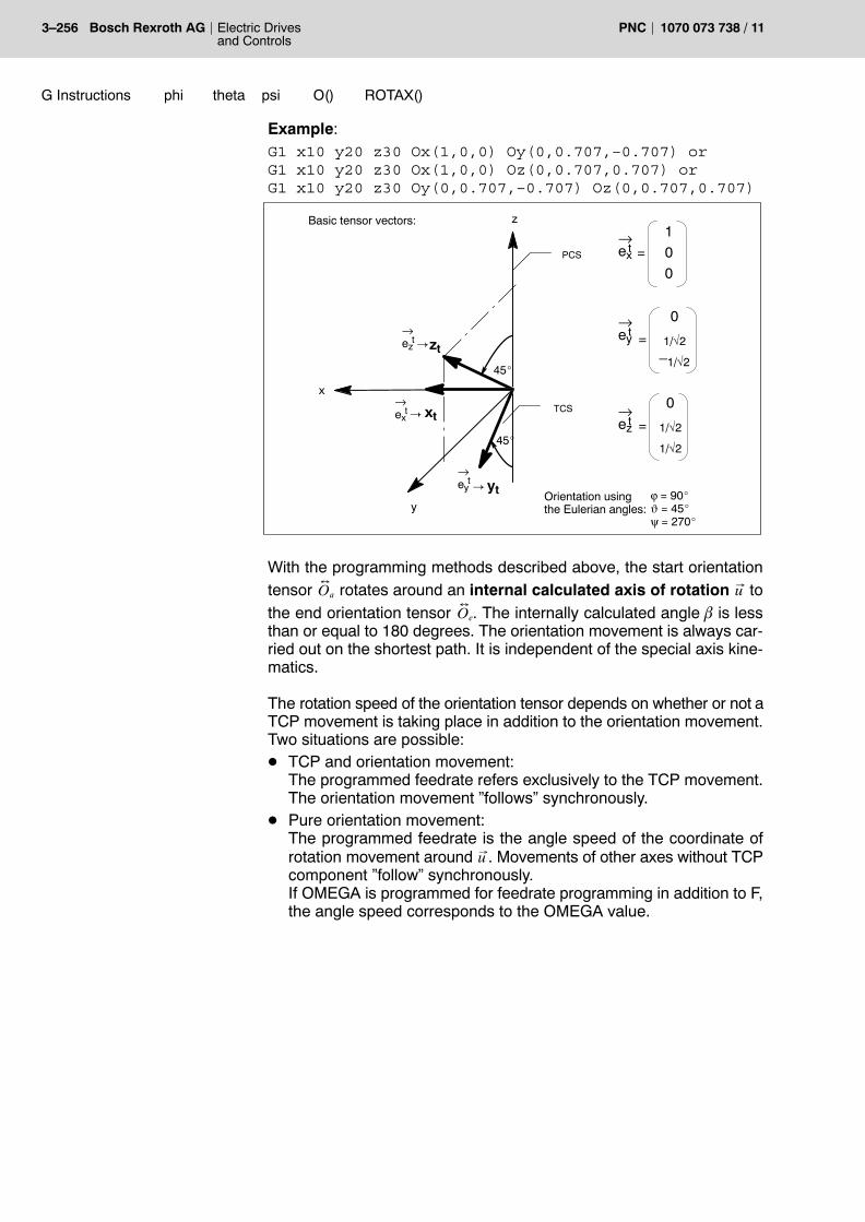
3�256 Electric Drivesand Controls
Bosch Rexroth AG PNC 1070 073 738 / 11
G Instructions ROTAX()O()psithetaphi
Example:G1 x10 y20 z30 Ox(1,0,0) Oy(0,0.707,–0.707) orG1 x10 y20 z30 Ox(1,0,0) Oz(0,0.707,0.707) orG1 x10 y20 z30 Oy(0,0.707,–0.707) Oz(0,0.707,0.707)
x
y
z
ϕ = 90_ϑ = 45_ψ = 270_
PCS
TCS
Basic tensor vectors:
xt
yt
zt
�
�
�
45_
45_
=100
=
0
1/√2
�1/√2
=
0
1/√2
1/√2
Orientation using the Eulerian angles:
ez→
t
ey
→t
ex
→t
ez
→t ey
→t
ex→
t
With the programming methods described above, the start orientationtensor O
�a rotates around an internal calculated axis of rotation u to
the end orientation tensor O�
e. The internally calculated angle b is lessthan or equal to 180 degrees. The orientation movement is always car-ried out on the shortest path. It is independent of the special axis kine-matics.
The rotation speed of the orientation tensor depends on whether or not aTCP movement is taking place in addition to the orientation movement.Two situations are possible:D TCP and orientation movement:
The programmed feedrate refers exclusively to the TCP movement.The orientation movement �follows� synchronously.
D Pure orientation movement:The programmed feedrate is the angle speed of the coordinate ofrotation movement around u . Movements of other axes without TCPcomponent �follow� synchronously.If OMEGA is programmed for feedrate programming in addition to F,the angle speed corresponds to the OMEGA value.

G Instructions ROTAX()O()psithetaphi
Electric Drivesand Controls
3�257Bosch Rexroth AGPNC1070 073 738 / 11
The following programming methods using ROTAX(..) may be used togenerate more general movements by programming the axis of rota-tion u :
ROTAX(<ux>,<uy>,<uz>) O(<β>)
or
ROTAX(<ϕu>,<ϑu>) O(<β>): ROTAX(..)
D ROTAX(..) defines the orientation of the axis of rotationaround which theorientation vector rotates by the Cartesiancomponents ux, uy, uz or the polar coordinates ϕu, ϑu.Programming possible absolutely and in degrees.
D O(..) defines angle β, by which the Oa tensor rotates aroundthe axis of rotation. Programming is possible incrementallyand in degrees.β may assume any desired values, i.e. several rotations arealso possible. The positive and negative angle β createsselected rotations with a different sense of rotation.
Example: ROTAX(0,45) O(720)ROTAX(1,0,1) O(720)
Please note for tensor orientation:D The following intervals are applicable to the Eulerian angles
0_�ϕ�360_0_�ϑ�180_0_�ψ�360_.The orientation tensor can be clearly created with the Eulerianangles, however with the restriction that in case of ϑ = 0_, the sumϕ+ψ and in case of ϑ = 180_ the difference ϕ−ψ is necessary to definean orientation.ϑ may be programmed with freely defined values, even though an in-terval [0,180] has been defined. Internally, the angles are convertedto the definition interval.
D If programming of the tensor columns e tx, e
ty, e
tz results in two column
vectors being parallel or anti-parallel, it is not possible to calculate theorientation tensor. A runtime error is then triggered.
D ROTAX(..) has to be programmed prior to O(<β>), otherwise a run-time error will occur.

3�258 Electric Drivesand Controls
Bosch Rexroth AG PNC 1070 073 738 / 11
G Instructions ROTAX()O()psithetaphi
Syntax variants:
Function Meaning G90/G91 behav-ior
phi<ϕ> theta<ϑ>psi<ψ>
Eulerian angles of the orienta-tion
absolute/incre-mental AC/ICprogr. possible
Ox(<o11>,<o21>,<o31>)
Oy(<o12>,<o22>,<o32>)
Oz(<o13>,<o23>,<o33>)
Vector in the PCS (1st O column)
Vector in the PCS (2nd O column)
Vector in the PCS (3rd O column)
ex
→t
ey
→t
ez
→t
always absolute
Ox(<ϕx>,<ϑx>)
Oy(<ϕy>,<ϑy>)
Oz(<ϕz>,<ϑz>)
in polar coordinates of thePCS
in polar coordinates of thePCS
in polar coordinates of thePCS
ex
→t
ey
→t
ez
→t
always absolute
O(<β>)Angle of coordinate of rotationwith programmed axis of rota-tion u
→always incremen-tal
RO-TAX(<ux>,<uy>,<uz>) Cartesian components of u
→ always absolute
ROTAX(<ϕu>,<ϑu>) Polar coordinates of axis ofrotation u
→ always absolute

G Instructions COORD(..)
Electric Drivesand Controls
3�259Bosch Rexroth AGPNC1070 073 738 / 11
3.94 Working range coordinate programming and axis transformations COORD(..)
In contrast to axis coordinate programming, working range coordinateprogramming is totally independent of the axis configuration of the ma-chine and of the tool compensation of the tools used.
Working range coordinate programming is used to:D program the position of the tool tip (TCP)D program the tool orientationD superimpose the positioning of the tool tip with an orientation move-
ment of the tool.
As a precondition of working range coordinate programming, an �axistransformation� previously defined with COORD(..) has to be activatedwhich determines the axis setpoint values of all necessary physical axesat the machine from the programmed working range coordinates.
Different types of axis transformation are stored in MACODA under sep-arate numbers, by which they can be called up in the program.Furthermore, it is possible to realize customer-specific, freely definedtransformations which require a maximum of six working range coordi-nates.
COORD(<i>) Working range coordinate programming with i-thaxis transformation ON
where
<i> 1..10: refers to one of the ten axis transformationblocks in MACODA
D If the activated axis transformation supports the vector or tensor ori-entation, the corresponding orientation NC function is activated.
D The programming of coordinate names is activated. Depending onthe type of axis transformation, a certain subset of the maximum of sixcoordinates (x,y,z,phi,theta,psi) is then programmable.
D The axis positions are converted to coordinate values, correspondingto the forward transformation equations (the workpiece coordinatedisplay jumps from axis positions to coordinate values).
. Any programming has to be performed in �working range coordi-nates� with activated working range coordinate programming. It isnot permitted to use transformed axes.
Effect
Programming

3�260 Electric Drivesand Controls
Bosch Rexroth AG PNC 1070 073 738 / 11
G Instructions COORD(..)
COORD(0): Working range coordinate programming OFF
D If an orientation NC function is active, it is deactivated.D The programming of coordinate names is deactivated. The axis
names can then be used again without restrictions.D The coordinate values are converted to axis positions, corresponding
to the backward transformation equations (the workpiece coordinatedisplay jumps from coordinate values to axis positions).
. Switching over between different axis transformations is possiblewithout prior deactivation.
NC functions on the basis of working range coordinates
In addition to position programming in the part program, there is a seriesof functions which expect working range coordinates as local parame-ters in the part program.
The list below shows all functions expecting working range coordinatesas parameters or referring to working range coordinates when workingrange coordinate programming (Coord(<i>)) is active.
NC functions Description Effect in the program
G00, G01, G02,G03, G05, G10,G11, G12, G13,G32, G73,G200, G202,G203
NC functions thatgenerate a move-ment
The positions are programmed as working range coordinates.
G17, G18, G19,G20
Plane selection andpole programming
The working range coordinates intended to define the machining planeare selected. In case of G20, the pole coordinates for polar coordinateprogramming are programmed at the same time.
G34, G134,G234
Chamfers and transi-tion arcs
The transition segments are calculated as working range coordinates.
G138, G352,G354, ..., G359
Determination of theworkpiece coordi-nates
Define the position of the WCS in relation to the BCS. The parametersof G352 are coordinates.
G37, G38, G60,G168, G268
Determination of theprogram coordinates
Define the position of the PCS in relation to the WCS. The pro-grammed working range coordinates always refer to the current PCS.
G40, G41 Path compensation Path compensation is performed within the selected machining plane.The machining plane is defined by 2 working range coordinates.
G78, G145, ...,G845, G147, ...,G847, H
Tool compensation Tool compensations are normally accounted for by the PCS. Bychanging over the compensation, it may also be performed in the TCS(axis transformation).
G90, G91,G189, AC, IC
Type of program-ming
States whether the working range coordinates should be interpretedabsolutely or incrementally.
Programming

G Instructions COORD(..)
Electric Drivesand Controls
3�261Bosch Rexroth AGPNC1070 073 738 / 11
NC functions Effect in the programDescription
G92 Program zero point Defines the program coordinate zero point within the current PCS.
G75 Special functions The traversing movement is programmed in working range coordi-nates. Measurement is performed for the axes configured on the chan-nel and released in MACODA. All of the measuring values are axispositions. The conversion from axis measuring values to coordinatevalues in connection with CPL access functions is being prepared.
G175, G275 The traversing movement is programmed in working range coordi-nates. At the same time, a physical axis is specified via its index forwhich a measurement is to be carried out. The measuring value pro-vides an axis position for this physical axis. The conversion from axismeasuring values to coordinate values in connection with CPL accessfunctions is being prepared.
G105 The traversing movement is programmed in working range coordi-nates. The linear modulo axis must not be a member of the axis trans-formation (pseudo coordinate).
G301 The traversing movement is programmed in working range coordi-nates. The oscillating axis must not be a member of the axis trans-formation (pseudo coordinate).

3�262 Electric Drivesand Controls
Bosch Rexroth AG PNC 1070 073 738 / 11
G Instructions COORD(..)
NC functions on the basis of axes
With activated working range coordinate programming, the followingfunctions will continue to be programmed with axis coordinates:
NC functions Description Effect in the program
G06, G14,G608, G114,G177, G594,G595
Functions to influencethe axis dynamics
G21 Axis classification The programmed axis classification has an effect at the earliestwhen the working range coordinate programming has been deacti-vated.
G54�G59,G154�G159,G254�G259,G160, G260,G360
(Axis) zero shifts The existing ZS are axis shift values. Zero shifts at the level ofcoordinates are realized by the respective coordinate functions �e.g. inclined plane. The ZS are taken into account in the interpola-tor behind the axis transformation. When an axis or coordinatetransformation is activated or switched over, it is no longer neces-sary to switch off the ZS.
G374, G520, ...,G524
Functions causing amovement
Drive-controlled movements are generated.
G151, ACP,ACN, DC
Type of programming The positioning type for an endless axis is an axis property.
G510, ..., G513,G515, G516
Axis transfer Axes are transferred, not coordinates.
G581 Axis coupling Two axes are coupled to each other.
G131, G631 Tool guidance The tool axis is a parameter of these functions. Tool guidance withone working range coordinate is not possible.
G900 SERCOS parameter Has a direct effect on the SERCOS drive.
G610, G611,G612
Punching The stroke release times are axis properties.
AREADEF,AREAVALID
Control area At present a function which mixes coordinates and axes. For thisreason, it must not be used together with an axis transformation orcoordinate transformation (e.g. �inclined plane�).The function needs to be extended to machine protection areas(axis function) and PCS protection areas (coordinate function).
G74, G76 Special functions Axis values or axis positions are programmed. The axis position istransformed into working range coordinates internally. The inter-polation is performed in working range coordinates.

G Instructions COORD(..)
Electric Drivesand Controls
3�263Bosch Rexroth AGPNC1070 073 738 / 11
3.94.1 5 axis transformation
The 5 axis transformation realized in the PNC includes:D 3 linear coordinates (e.g. x, y, z)D 2 orientation coordinates í, ϕ (e.g. theta, phi)D 3 linear axes (e.g. X, Y, Z)D 2 rotary axes (e.g. B and C)
There are 3 types of 5 axis transformation:D Linear orientation with axis programming
(Type 3032101)D Linear orientation with coordinate programming
(Type 3232101)D Vector orientation
Special propertiesD Feed rate: having activated the 5 axis transformation, there is a
switchover to working range coordinate programming. The pro-grammed feedrate (F) refers to the programmable position coordi-nates only, i.e. the F word is used to program the path speed of thetool center point (TCP).Additional orientation and pseudo-coordinate movements do notchange this path speed. The orientation and pseudo coordinate movement is guided alongsynchronously, i.e. the end position is reached simultaneously for allcoordinates. The movement of the orientation and pseudo-coordi-nates carried along may, however, lead to an additional limitation ofthe path kinematics (maximum path speed and acceleration) be-cause the limit values of all axes involved in the movement are moni-tored.
D Rotary axes B and C may be endless axes as well as rotary axes.
. For details, please refer to �PNC description of functions� manual.
Effect

3�264 Electric Drivesand Controls
Bosch Rexroth AG PNC 1070 073 738 / 11
G Instructions COORD(..)
5 axis transformation type 3032101
Each 5 axis transformation of the type 3032101 is programmed as fol-lows:1. Switching on the working range coordinate programming using
Coord(<i>) (i-th transformation initialized in MACODA).2. Type 3032101 supports linear orientation with axis programming
(refer to page 3�245).3. Programming the program coordinates in working range coordinates
using the NC functions listed in the table on page 3�260.4. Out of maximally 6 working range coordinates, a maximum of 3 linear
position coordinates (x,y,z) is permitted with this type. Axis coordi-nates as an alternative to coordinate names are no longer permit-ted.In case of this type, orientations are performed as linearinterpolation by the rotary axes names (B,C).
5. Switching off the selected axis transformation using COORD(0) or byselecting a different axis transformation.
All names can be set in MACODA.
. With active axis transformation, the axis positions are converted tocoordinate values. The display of the workpiece coordinates chan-ges from axis coordinate values to working range coordinate va-lues.
Example:N10 G1 X0 Y0 Z0 B0 C0 Programming of the logical or physical
axis names
N20 COORD(1) The configuration of the 5 axis trans-formation type 3032101 is located inthe MACODA parameter block 1:Linear coordinates: x,y,zOrientation coordinates: B,C
N30 x100 y200 z300 B20 C60..
Linear coordinate interpolation withadditional orientation movement
N40 G2 x.. y.. z.. I.. J.. B70 C80..
Helical movement (x,y,z) of the TCPwith additional orientation movement.
N50 G1 B20 C10..
Pure orientation movement. The TCPremains constant.
N60 COORD(0)..
Switching off the 5 axis transforma-tion.
Programming

G Instructions COORD(..)
Electric Drivesand Controls
3�265Bosch Rexroth AGPNC1070 073 738 / 11
5 axis transformation type 3232101
Each 5 axis transformation of the type 3232101 is programmed as fol-lows:1. Switching on the working range coordinate programming using
COORD(<i>) (i<th transformation initialized in MACODA)2. Type 3232101 supports linear orientation with coordinate pro-
gramming (refer to page 3�246).3. Programming the program coordinates in working range coordi-
nates using the NC functions listed in the table on page 3�260. Out of maximally 6 working range coordinates, a maximum of 3 linearposition coordinates (x,y,z) 2 rotary orientation coordinates (ϕ, ϑ) ispermitted for programming with this type. Axis coordinates as an al-ternative to coordinate names are no longer permitted.
4. The syntax ROTAX(..) O(..) is not possible.5. Switching off the selected axis transformation using COORD(0) or by
selecting a different axis transformation.
All names can be set in MACODA.
. For a given axis kinematics it is recommended to configure allthree types of axis transformation (3032101, 3232201, and3232101) in MACODA. Afterwards, you can change over betweenthe different orientation movements in the NC program by pro-gramming COORD(1), COORD(2), and COORD(3).
Example:N10 G1 X0 Y0 Z0 B0 C0 Programming of the logical or physical
axis names
N20 COORD(2) The configuration of the 5 axis trans-formation type 3232101 is located inthe MACODA parameter block 2:Linear coordinates: x,y,zOrientation coordinates: phi, theta
N30 x100 y200 z300 phi5 theta5..
Linear coordinate interpolation in angles ϕ (phi) and ϑ (theta).
N40 G2 x.. y.. z.. I.. J.. phi20 theta60..
Helical movement (x,y,z) of the TCPwith additional linear orientation of theorientation vector.
N50 G1 phi0 theta45 Pure linear orientation movement.The TCP remains constant.
N60 COORD(0)..
Switching off the 5 axis transforma-tion.
Programming

3�266 Electric Drivesand Controls
Bosch Rexroth AG PNC 1070 073 738 / 11
G Instructions COORD(..)
5 axis transformation type 3232201
Each 5 axis transformation of the type 3232201 is programmed as fol-lows:1. Switching on the working range coordinate programming using
Coord(<i>) (i-th transformation initialized in MACODA).2. Type 3232201 supports vector orientation (refer to page 3�248).3. Programming the program coordinates in working range coordinates
using the NC functions listed in the table on page 3�260. Out of maximally 6 working range coordinates, a maximum of 3 linearposition coordinates (x,y,z) 2 rotary orientation coordinates (ϕ, ϑ) ispermitted for programming with this type. Axis coordinates as an al-ternative to coordinate names are no longer permitted.
4. Switching off the selected axis transformation using COORD(0) or byselecting a different axis transformation.
All names can be set in MACODA.
. With active axis transformation, the axis positions are converted tocoordinate values. The display of the workpiece coordinates chan-ges from axis coordinate values to working range coordinate va-lues.
Example:N10 G1 X0 Y0 Z0 B0 C0 Programming of the logical or physical
axis names
N20 COORD(3) The configuration of the 5 axis trans-formation type 3232201 is located inthe MACODA parameter block 3:Linear coordinates: x,y,zOrientation coordinates: phi, theta
N30 x100 y200 z300 phi5 theta5..
Linear coordinate interpolation withadditional coordinate of rotationmovement of the orientation vector.
N40 G2 x.. y.. z.. I.. J.. phi20 theta60..
Helical movement (x,y,z) of the TCPwith additional coordinate of rotationmovement of the orientation vector.
N50 G1 phi0 theta45..
Pure vector orientation movement.The TCP remains constant.
N60 COORD(0)..
Switching off the 5 axis transforma-tion.
Programming

G Instructions COORD(..)
Electric Drivesand Controls
3�267Bosch Rexroth AGPNC1070 073 738 / 11
3.94.2 6 axis transformation
The 6 axis transformation realized in the PNC includes:D 3 linear coordinates (e.g. x, y, z)D 3 orientation coordinates í, ϕ, ψ (e.g. theta, phi, psi),D 3 linear axes (e.g. X, Y and Z)
D 3 rotary axes (e.g. A, B and C)
There are 2 types of 6 axis transformation:D Type 3333301 allows TCP programming via three linear coordinates
and the tool orientation (TCS) by programming the Eulerian angles ϕ(phi), í (theta) and ψ (psi).The orientation movement is performed as TCS rotation around anaxis of rotation fixed in space.
D Type 3033101 supports TCP programming via three linear coordi-nates and tool orientation by programming the three rotary axes. The orientation movement is executed linearly in the rotary axis posi-tions.
. For details, please refer to �PNC description of functions� manual.
6 axis transformation type 3033101
Each 6 axis transformation of the type 3033101 is programmed as fol-lows:1. Switching on the working range coordinate programming using
COORD(<i>) (i<th transformation initialized in MACODA)2. Type 3033101 does not support tensor orientation.3. Programming the program coordinates in working range coordi-
nates using the NC functions listed in the table on page 3�260. Out of maximally 6 working range coordinates, a maximum of 3 linearposition coordinates (x,y,z) is permitted with this type. Axis coordi-nates as an alternative to coordinate names are no longer permitted.In case of this type, tool axis orientations are performed as linear in-terpolation of the rotary axes (A,B,C).
4. Switching off the selected axis transformation using COORD(0) or byselecting a different axis transformation.
All names can be set in MACODA.
. With active axis transformation, the axis positions are converted tocoordinate values. The display of the workpiece coordinates chan-ges from axis coordinate values to working range coordinate va-lues.
Effect
Programming

3�268 Electric Drivesand Controls
Bosch Rexroth AG PNC 1070 073 738 / 11
G Instructions COORD(..)
Example:N10 G1 X0 Y0 Z0 B0 C0 Programming of the logical or physical
axis names
N20 COORD(1) The configuration of the 6 axis trans-formation type 3033101 is located inthe MACODA parameter block 1:Linear coordinates: x,y,zOrientation coordinates: A,B,C
N30 x100 y200 z300 A10 B20 C60..
Linear coordinate interpolation withadditional orientation movement
N40 G2 x.. y.. z.. I.. J.. A30 B70 C80..
Helical movement (x,y,z) of the TCPwith additional orientation movement.
N50 G1 A45 B20 C10..
Pure orientation movement. The TCPremains constant.
N60 COORD(0)..
Switching off the 6 axis transforma-tion.
6 axis transformation type 3333301
Each 6 axis transformation of the type 3333301 is programmed as fol-lows:1. Switching on the working range coordinate programming using
COORD(<i>) (i<th transformation initialized in MACODA)2. Type 3333301 supports tensor orientation (refer to page 3�254).3. Programming the program coordinates in working range coordinates
using the NC functions listed in the table on page 3�260. Out of maximally 6 working range coordinates, a maximum of 3 linearposition coordinates (x,y,z) 3 rotary orientation coordinates (ϕ, ϑ, ψ)is permitted for programming with this type. Axis coordinates as analternative to coordinate names are no longer permitted.
4. Switching off the selected axis transformation using COORD(0) or byselecting a different axis transformation.
Orientation movements are generated by programming the Eulerianangles ϕ, ϑ, ψ or the related alternative syntax options.
All names can be set in MACODA.
. With active axis transformation, the axis positions are converted tocoordinate values. The display of the workpiece coordinates chan-ges from axis coordinate values to working range coordinate va-lues.
Programming
G Instructions COORD(..)
Electric Drivesand Controls
3�269Bosch Rexroth AGPNC1070 073 738 / 11
Example:N10 G1 X0 Y0 Z0 B0 C0 Programming of the logical or physical
axis names
N20 COORD(2) The configuration of the 6 axis trans-formation type 3333301 is stored inMACODA parameter block 2.
N40 G2 x.. y.. z.. I.. J.. phi20 theta60 psi230..
Helical movement (x,y,z) of the TCPwith additional coordinate of rotationmovement of the orientation tensor.
N50 G1 phi0 theta45 psi90..
Pure tensor orientation movement.The TCP remains constant.
N60 COORD(0)..
Switching off the 6 axis transforma-tion.
. For a given axis kinematics it is recommended to configure bothtypes of axis transformation (3033101 and 3333301) in MACODA.Afterwards, you can change over between linear and tensor orien-tation in the NC program by programming COORD(1) andCOORD(2).

3�270 Electric Drivesand Controls
Bosch Rexroth AG PNC 1070 073 738 / 11
G Instructions DistCtrl
3.95 Axis distance control for digitizing DistCtrl
The �Axis distance control for digitizing� function keeps the distance be-tween the surface scanned and the measuring device (e.g. laser)constant during digitizing. This is to ensure that the available workingrange of the measuring device is not exceeded.For a detailed description of the function, please refer to the �PNC de-scription of functions� manual. DistCtrlOn Starts axis distance control. Furthermore, the current dis-
tance between the measuring device and the surface istaken over as reference value. Programming �DistCtrlOn� by itself will activate the configu-ration data for axis distance control defined in MACODA.As an option, various additional instructions may be pro-grammed to override some of the configuration data fromMACODA.
. MACODA configuration data that has been overriden will not be ac-tive again before program deselection, channel or system reset.
DCAXIS(<axis>,<corr>)Overrides MP 7050 00702.
<axis> Name or number of the channel axis for which axisdistance control is to be activated.
<corr> +1 or 1: Account for correction values in positivedirection of movement
�1: Account for correction in negativedirection of movement
DCFILTER(<time>)Overrides MP 7050 00730.
<time> 0: Filter off>0: Filter on, values in ms
DCLIMIT([<speed>],[<accel>])Overrides MP 7050 00740 and 7050 00741.
<speed> Overrides MP 7050 00740. Value input, depending on active unit of measure-ment (G71, G70), in the unit mm/min or inch/min.
<accel> Overrides MP 7050 00741. Value input, depending on active unit of measure-ment (G71, G70), in the unit m/s2 or 1000 inch/s2.
Effect
Programming

G Instructions DistCtrl
Electric Drivesand Controls
3�271Bosch Rexroth AGPNC1070 073 738 / 11
DCMON([<collision>],[<hole>])Overrides MP 7050 00750 and 7050 00752.
<collision> Overrides MP 7050 00740. Value input, depending on active unit of measure-ment (G71, G70), in the unit mm/min or inch/min.
<hole> Overrides MP 7050 00741. Value input, depending on active unit of measure-ment (G71, G70), in the unit m/s2 or 1000 inch/s2.
DistCtrlBreakInterrupts axis distance control. The current correctionvalue remains active.
DistCtrlContinue Resumes axis distance control after an interrup-tion. The NC controls the deviation from the reference valueas fast as possible.
DistCtrlOffDeactivates axis distance control, stores the current correc-tion value, and stops axis movement.If DistCtrlOff is programmed in the same block as a travers-ing movement, the NC will not turn off axis distance controlbefore the movement has been completed.

3�272 Electric Drivesand Controls
Bosch Rexroth AG PNC 1070 073 738 / 11
G Instructions TCSDEF
3.96 TCS definition in program coordinates TCSDEF
Function �TCS definition in program coordinates � generates a tool coor-dinate system TCSp that may be displaced and/or rotated in relation to acurrent TCSc or TCS1.The coordinate values specified in the TCSDEF instruction for TCSp will
be converted to quantities I p
tand T p
t by the NC and stored in the toolcorrection memory. Switching the function off with TCSUNDEF will reactivate the TCSc or � ifno explicit tool compensation is active � the TCS1 (refer to figure below).
zt
xtyt
zt
xt
yt
TCSc
TCSp
z
x
y
zt
xt
yt
BCS
TCS0= TCS1
Type: 1 2 3
z
x
y
zt
xt
yt
BCS
TCS1
MACODA
TCSDEF x.. y.. ϕ..
TC instruction in CPL
z
x
y
PCS
Ttp
→ltp→
ltc→
Ttc
→
Type: 2 1 �3
TCS definition (only for 6 axis transformation)
Defining the position of the tool coordinate system TCSp:
TCSDEF[<Linear coordinates>][<Orientation coordinates>]where
<Linear coordinates> Coordinates that refer to the currentPCS
<Orientation coordinates> Coordinates that refer to the currentPCS or all alternative syntax options oftensor orientation (refer to following ex-amples)
The following programming methods are possible:(coordinate names x, y, z, phi, theta and psi declared in MACODA)
TCSDEF x.. y.. z.. phi.. theta.. psi.. Orientation of TCSp in Euler-ian angles
TCSDEF x.. y.. z.. O(<ϕ >,<ϑ >,<ψ >) Orientation of TCSp in Euler-ian angles
TCSDEF x.. y.. z.. Ox(..) Oy(..) Oz(..) Orientation of TCSp as atensor
TCSDEF x.. y.. z.. ROTAX(...) O(<β>) Rotating the TCS1 to thenew TCSp
Effect
Programming

G Instructions TCSDEF
Electric Drivesand Controls
3�273Bosch Rexroth AGPNC1070 073 738 / 11
Please note for TCSDEF:D TCSDEF may only be used in connection with an active 6 axis trans-
formation.D The values programmed by coordinate names x, y, z, phi, theta and
psi are always interpreted as absolute values by the PCS (are notsubject to G90/G91 changeover).However, individual programming of IC() and AC() is supported.
D The following applies to the alternative syntax options for orientationprogramming:The values programmed by O(<ϕ >,<ϑ >,<ψ >), Ox(..), Oy(..) andOz(..) are absolute values within the PCS.
D Rotary axis programming �ROTAX(...) O(<β>)� is an incremental rota-tion of TCS1 around the angle β.
D Programming TCSDEF without parameters has no effect.
Resetting active tool coordinate system TCSp:
TCSUNDEF Reset to previously active tool coordinate system (e.g.TCSc or if no tool compensation had been active: TCS1)
Please note for TCSUNDEF:D An automatic reset takes place with coordinate changeover
�N.. COORD(<i>)�.
Programming
3�274 Electric Drivesand Controls
Bosch Rexroth AG PNC 1070 073 738 / 11
G Instructions LFPON
3.97 Path velocity-dependent laser power control LFPON LFPOFF
This function controls the power of a laser depending on the actual fee-drate value (Vpath). For this purpose, a suitable voltage value is output toan analog output in the way defined in MP 4075 00104.
The rms path velocity Vpath is calculated from the velocities of the se-lected coordinates:D by selecting the active plane (APL) or the active space (ASP). An ac-
tive axis transformation or coordinate transformation (inclined plane),if any, is also accounted for.
D by a direct selection of coordinates in the part program:D No active axis transformation:
All pseudo-coordinates (axes) of a channel may be selected.D An axis transformation is active:
Working range or pseudo-coordinates may be selected. The se-lected working range coordinates are bound to the transformationactive at that moment.
Restrictions:D The available analog outputs limit the number of channels that may
use this function.D When using the �inclined plane� function, only the �active working
range� can be used for coordinate selection with PL(ASP) in order togenerate the velocity Vpath.
D The function is supported with axes and coordinates if 5 axis trans-formation is active.
D In the event of an error (runtime error, diagnostics class 1 error), when�drive under control� of a drive involved in the path (no enable signal,drive off) is canceled, and in the event of �Feed Hold�, no laser voltagewill be output.
LFPON Starts the path velocity-dependent laser power control. Programming this function by itself will activate the configu-ration data defined in MACODA. Additional parameters maybe programmed as an option.
LFP Sets the parameters for the active laser power control inthe part program.
Parameters for LFPON and LFP:LL([<%voltage>], [<VMin>])
Lower power limit: The voltage value en-tered in this parameter will be output belowthe specified path velocity.
LL([<%voltage>], [<VMax>])Upper power limit: The voltage value en-tered in this parameter will be output abovethe specified path velocity.
Effect
Programming
G Instructions LFPON
Electric Drivesand Controls
3�275Bosch Rexroth AGPNC1070 073 738 / 11
<%voltage> 0% .. 100%: corresponds to 0 .. 10 volts
<VMin> Lower key value of path velocity in mm/min or inch/min
<VMax> Upper key value of path velocity in mm/min orinch/min
PL(<plane name>)Coordinate selection for calculating the pathvelocity through a plane selection
<Plane name> �APL�: Current plane (G17, G18, G20)�ASP�: Current space�MCD�: MACODA values
CD(<Coordinate 1>, [<Coordinate 2>], ... , [<Coordinaten>])Coordinate selection for calculating the pathvelocity directly using the logic name
<Coordinate x> x = 1..nLogic names of the working range coordinatesor pseudo-coordinates (axes) involved
LFPOFF Terminates the path velocity-dependent laser power con-trol.
LPCOFF alternatively to LFPOFF
Please note:D Functions LFPON, LPCOFF (LFPOFF) act modally.D When the control unit is booted, the laser power control is deacti-
vated, and the settings from the MACODA parameters are active.D Data stored in MACODA parameter 7060 00010, �Default state upon
booting�, and MACODA parameter 7060 00020, �Default state upon acontrol reset� will supersede this presetting.
D After control reset and M2/M30, the laser power control is deacti-vated, and the settings from the MACODA parameters are reacti-vated.
Examples:LFPON LL(10,100) Activation of laser power control with the default
value for the lower voltage limit of 10% (=1 V) at100 mm/min
LFP LL(10,100) Programming the lower voltage limit (10% (=1 V) at100 mm/min) in the NC program
LFP UL(90,500) Programming the upper voltage limit (90% (=9 V)at 500 mm/min) in the NC program
The coordinate selection is determined by MP 7050 00820(=2, corresponds to the �active plane�).

3�276 Electric Drivesand Controls
Bosch Rexroth AG PNC 1070 073 738 / 11
G Instructions HWOCON
3.98 Online correction in workpiece coordinates HWOCON HWOCOFF
Programming the �Online correction� will mean that while the part pro-gram is active or inactive, an onlineD correction of the position or orientation is carried out in the work-
piece coordinate system (WCS) using the handwheel.D traversing movement of the position of the longitudinal tool axis in
TCS Z direction of the tool will take place in the tool coordinate system(TCS) (no tool compensation!).
Online correction is controlled:D directly by the PLC via NC block inputD via machine functions, orD by a part program.
Within a part program, the online correction may be controlled for itsown or for another channel.
. For details, please refer to �PNC description of functions� manual.
HWOCON OCONCH<Channel no.> OCCOORD<Coordinate no..>{OCSTEP<Increments>}
Activates the online correction via thePLC or machine functions or from anydesired channel.
HWOCON OCCOORD<Coordinate no..> {OCSTEP<Increments>}Activates the online correction in the own channel.
whereOCONCH<Channel no.> Number of the channel for which online
correction is activated.
OCCOORD<Coordinate no.> 1..8: Number of the coordinate9: TCS Z direction (only with active
5 axis transformation, the correction in TCS Z direction is converted into amovement of the linear working rangecoordinates (x,y,z)).
{OCSTEP<Increments>} Optional: Step size of a handwheel incre-ment (from axis interface).If not specified, the step size will be takenover from the axis interface (I 1.0...1.3,�Manual feed/incremental step�) defined inMP 7050 00926.
Effect
Programming

G Instructions HWOCON
Electric Drivesand Controls
3�277Bosch Rexroth AGPNC1070 073 738 / 11
HWOCOFF OCOFFCH<Channel no.>Deactivates the online correction via thePLC or machine functions or from anydesired channel.
HWOCOFF Deactivates the online correction in the own channel.
where
OCOFFCH<Channel no.> Number of the channel for which onlinecorrection is deactivated.
HWOCDEL Deactivates the online correction anddeletes the correction values
Please note for online correction:D Online correction is not possible in �Manual� operating mode (jogging
mode) or in �Manual approaching the reference point�.D Machine-oriented absolute position:
G76 traverses to a displaced position, i.e. online correction is not cal-culated back.
D CPL functions PPOS and CPROBE do not take the correction valueof the online correction into account.
D Probe:G75 measures the correct position. Use CPL function PROBE to readthe measured value.
D Measuring at the fixed stop:G375 measures the correct position. Use CPL function PROBE toread the measured value.
D Limit switches:A coordinate position generated by online correction is not analyzedby the NC for a possible travel beyond the software limit switches.For this purpose, you should activate �Limit switch control� in theSERCOS drive.
Programming
Programming

3�278 Electric Drivesand Controls
Bosch Rexroth AG PNC 1070 073 738 / 11
G Instructions JogWCSSelect
3.99 Jogging in workpiece coordinates JogWCSSelect
The function can jog coordinates/pseudo-coordinates of a channel inworkpiece coordinates (WCS) and in Z direction of tool coordinates(TCS). The �Set-up, jogging in workpiece coordinates� operating modeis available for this purpose.The following coordinates may be jogged:D all pseudo-coordinates (axes) if axis transformation has been deacti-
vatedD with active 5 axis transformation: all linear and orientation coordi-
nates, the TCS Z direction and the pseudo-coordinates (axes).
The coordinate/pseudo-coordinate to be jogged is selected by the PLCvia the NC block input (program module -B04SATZV) using theJogWCSSelect.. NC function.Alternatively, the coordinate may also be selected in any part program,e.g., a CPL program.
Before jogging, the �Set-up, jogging in workpiece coordinates� operat-ing mode must have been selected:D directly by the PLC (mode 14), if mode selection by the PLC is active.D at the MMI using the �Jog� softkey, if initialized for jogging workpiece
coordinates in MACODA 6001 00030.
Selecting a coordinate:
JogWCSSelect JWSCHAN<Channel no.> JWSCOORD<Coordi�nate no.> {JWSFEED<F value>} {JWSSTEP<Increments>}where
JWSCHAN<Channel no.> Number of the channel for which a coordi-nate is selected.
JWSCOORD<Coordinate no.> 1...8: The number of the coordinate9: TCS Z direction
D the TCS Z direction only existswith active 5 axis transformation.
D a correction in TCS Z direction isconverted into a movement of thelinear working range coordinates(x,y,z).
{JWSFEED<F value>} Optional, default: corresponds to feedrate setting atthe axis interface (refer to MP 7050 01020).Unit: mm/min or degrees/min (G71), or
inch/min or degrees/min (G70)
Effect
Programming

G Instructions JogWCSSelect
Electric Drivesand Controls
3�279Bosch Rexroth AGPNC1070 073 738 / 11
JWSCHAN<Channel no.> Number of the channel for which a coordi-nate is selected.
{JWSSTEP<Increments>} Optional, selects incremental jogging and simulta-neous specification of the step size in incre-ments.
Default: incremental and continuous joggingmode setting at the axis interface (refer to MP 7050 01020).
. JWSSTEP may only be programmed together with JWSFEED.

3�280 Electric Drivesand Controls
Bosch Rexroth AG PNC 1070 073 738 / 11
G Instructions JogWCSSelect
Notes:

Spindles
Electric Drivesand Controls
4�1Bosch Rexroth AGPNC1070 073 738 / 11
4 SpindlesSpindles may be operated:D as individual spindlesD in spindle groups.
For operation, spindles are implicitlyD assigned to channelsD transferred from one channel to another.
A spindle may be operated:D in speed modeD in position mode, orD in synchronism with other spindles.
Spindles can be programmedD in the part programD by manual data input, orD via machine functions,
and can beD set via the interface.
Spindles are programmed usingD M functionsD S functionsD G functionsD special functions for �position mode�.
4.1 Individual spindles, spindle groups and channels
Individual spindles and spindle groups are not assigned to a specificchannel in the PNC until a channel makes an implicit �reservation� for thespindles required.
Each individual spindle or spindle group has the following standardfunctions:D Clockwise rotation, with/without coolantD Counterclockwise rotation, with/without coolantD StopD Positioning (spindle orientation)D Automatic gear selectionD Manual gear selectionD Spindle speed programmingD Tapping without compensation chuck (G32)
4�2 Electric Drivesand Controls
Bosch Rexroth AG PNC 1070 073 738 / 11
Spindles
. The functionality of spindle groups is not to be confounded with agroup of two or more coupled spindles with position control, whichare operated in positional synchronism (refer to sect. 4.4).
The following contains explanations of spindle groups, channel reserva-tion and all functions that may occur in the context of spindle program-ming.
4.1.1 Assigning individual spindles to spindle groups
All 8 spindles can be grouped together to a maximum of 4 spindlegroups. The spindles of a spindle group are programmed together, sothat a less parametric programming is required as opposed to the indi-vidual programming of the spindles. The spindles of a spindle group arealso designated as parallel spindles.
Programming (refer to sect. 4.2, �Spindle functions�) a whole spindlegroup requires less parametric programming than entering the parame-ters of each individual spindle assigned to a group. When programminga spindle group function, the auxiliary functions of both the spindle groupfunction and of the functions of the individual spindles assigned to thisgroup are displayed on the interface, provided that the correspondingbit-coded auxiliary functions have been programmed in MACODA.
Each spindle assigned to a spindle group can be activated both viaspindle group functions and via individual spindle functions. If an NCblock contains concurrent instructions for spindle groups and for individ-ual spindles, the control unit sends a runtime error message.
Modal assignment of spindles to spindle groups:Spindle groups are specified by programming them in the part program /via manual data input for each channel individually, i.e. one and thesame spindle may be assigned to different spindle groups on differentchannels. In order to modify a spindle group, the spindles to be newlyassigned to this spindle group must be specified, e.g.
SPG1(1,2,3) means that from now on spindles 1, 2 and 3 areassigned to spindle group 1 on this channel.(SPG = spindle group)
At the time a spindle group is being programmed, the spindles requiredto form this group may still be included in some other groups. However,every spindle may be assigned to any spindle group at any time. When aspindle function is programmed for a spindle group, prior to its activationthe respective spindles are checked as to whether they are released bythe so-called spindle data management and are thus available for beingassigned. This means that if a spindle was previously activated byanother channel, this spindle must now be switched to speed mode (noC axis mode) and be in STOP state (M5).
Effect
Programming

Spindles
Electric Drivesand Controls
4�3Bosch Rexroth AGPNC1070 073 738 / 11
The spindle assignment entered in MACODA for a spindle group can bereset to its original configuration on a channel by programming as fol-lows:SPGn(0) n = spindle group index 1 ... 4
A spindle group can be disbanded on a channel by entering the value��1�:SPGn(�1) No spindles are assigned to the respective spindle
group any more on this channel.
Examples:
N... SPG1(1,2,3) Spindle group 1 is created of spindles 1, 2 and 3.
N... M19 Spindles 1, 2 and 3 traverse to their respective ref-erence point (M19 = default for SPG1)
N... SPG2(2,4,5) Spindle group 2 is created of spindles 2, 4 and 5,i.e. spindle 2 is removed from SPG1
N... M19 Spindles 1 and 3 traverse to their respective refer-ence point (M19 = default for SPG1)
Restoring spindle group default settings:
SPGALL(0) By programming SPGALL(0), the default settingaccording to MACODA is restored for all spindlegroups of the channel.
The assignment of the individual spindles to a spindle group is preset inMACODA parameter 1040 00002. It may be changed by programming inthe part program and by manual input.

4�4 Electric Drivesand Controls
Bosch Rexroth AG PNC 1070 073 738 / 11
Spindles
4.1.2 Reserving spindles and spindle groups for specific channels
1 2 3 4
Channels
Spindle1
Spindle2
Channel 1: Spindle 5Channel 2:Spindle 6Channel 3: �Channel 4: Spindle group 1Channel 5�n: �
Reservation ofspindle 6 for channel 4
...
1 2 3 4 5 6 7 n
Individual spindles
1 2 3 4 5 6 7 8
Spindle groups
As a rule, no spindle (spindle group) is permanently assigned to any spe-cific channel. Therefore, all spindles (spindle groups) can be activatedfrom any channel.
Whenever you enter a traversing motion for a spindle on a channel viathe part program or manual data input, the spindle concerned is re-served implicitly for that respective channel. This applies irrespective ofwhether the input of the traversing motion is made through an individualspindle function or a spindle group function.
Access to reserved spindles from another channel is blocked, i.e. anyattempt to select them from another channel will result in a runtime error(exception: conditional spindle release, see below, Programming withSADM).
Until a reserved spindle is released, it can be activated only on the chan-nel (authorized channel) where the reservation originated. Therefore, aspindle is not released and thus does not become available to any otherchannel until it is stopped by its authorized channel.
Effect

Spindles
Electric Drivesand Controls
4�5Bosch Rexroth AGPNC1070 073 738 / 11
N......N.. G32 Z�20 F500 M3 ..: Reservation of spindle1...
Channel1 (authorized channel)
Spindle1
N........
N.. G32 Z�5 F1000 M3 ..: Reservation of spindle1 is not possible because it is accessed by channel1!...
Channel 2
NC block preparation on channel 1NC block preparation on channel 2at a later time than that for channel 1
Making a spindle reservation on a channel:The following spindle functions produce an implicit spindle reservationfor the calling channel:D M3, M13D M4, M14D M19D G32 (tapping without compensation chuck)D G96 (constant cutting speed)
Any spindle functions available may be programmed on the channelfrom where the spindle was reserved:D Spindle speed programming S, S1 � S8, SSPG1 � SSPG4D M3, M13, M4, M14, M5, M19D M40, M41�M44, M48D G32D G192, G292D G96
It is forbidden for any other than the authorized channel to activate a re-served spindle. The attempt will produce runtime error 2001: �Spindle isused by another channel!�
The following functions are subject to this restriction:D Spindle speed programming S, S1 � S8, SSPG1 � SSPG4D M3/M13, M4/M14, M19, M5D M40, M41�M44, M48D G32D G192, G292D G96
If called from the init string of an unauthorized channel, the followingfunctions are suppressed and, therefore, no runtime error will occur:D M5D M40, M41�M44, M48D G96, G97
Programming

4�6 Electric Drivesand Controls
Bosch Rexroth AG PNC 1070 073 738 / 11
Spindles
Releasing a spindle reserved for a channel:A reserved spindle can be released on the authorized channel:D by programming M5, orD at the end of G32 if the spindle was reserved using G32.
Termination of a part program with M30 or a control reset on the autho-rized channel has the following effects:D deselection of M40 (if active), current gear range remains selected,D deselection of G96, spindle speed programming is activated, andD functions entered in the init string (MACODA parameter 7060 00020)
are activated:M5 Spindle is stopped if M3/M13, M4/M14 were active or if the
spindle was positioned with M19. Subsequently, the spindleis released.
M40 Selection/Repeat selection of the �Automatic gear selection�function
M41�M48 Automatic gear selection may have already been dese-lected (see above). Manual gear selection in the init stringdoes not produce a gear switch.
Transferring a reserved spindle to another channel:
In exceptional cases, it may be necessary to activate a spindle reservedwith M3, M4 or M19 from an adjacent channel (part program or manualdata input).
In those cases, NC function SADM makes it possible for the authorizedchannel currently �owning� the spindle to transfer the spindle reservationto another channel.
Conditional spindle release:SADM Si=0 ... Sn=0 A channel currently holding a reservation for one or
more spindles, which was made by programming M3,M4 or M19, is caused by this command to grant anyother channel the right to access the spindle:
D With the SADM command, the spindle can nowbe accessed by any other channel.D The spindle can be activated via machine func-tions any time.
Activating a conditionally released spindle from another channel:SADM Si=1 ... Sn=1 This command allows you to activate (a) conditionally
released spindle(s) from another channel via a partprogram or by manual data input.
i Index of the i-th spindle (i=1..n).
n number of available spindles (currently: nmax. .=8)
Programming
Effect
Programming
Programming

Spindles
Electric Drivesand Controls
4�7Bosch Rexroth AGPNC1070 073 738 / 11
4.2 Functions for individual spindles and spindle groups (Mfunctions) in speed mode
4.2.1 Spindle functions
Spindle functions can be programmed in the part program or bymanual data input for individual spindles or for spindles assigned to aspindle group.Each of the 8 spindles may be assigned optionally to one of 4 spindlegroups.Any number of individual spindles and/or spindle groups may be pro-grammed in one NC block.
The syntax for every spindle function of every spindle/spindle group isdetermined in MACODA. Apart from common M functions, the variousfunctions may be assigned freely defined names with up to 8 digits.
. No distinction is made between individual spindles and spindlegroups in the following description of the various spindle func-tions because they show the same behavior. Basically, program-ming a spindle group just means less programming effort.
. The M functions described below are suggestions of MACODA set-tings. For better transparency, the previous (fixed) M codes areused as default parameters.
Declaration applying to the documentation below:Syntax
1
2
3
Assignment
1st Spindle group
1st Spindle
2nd Spindle
Example
M3
M103
M203
Spindle, clockwise rotation:
M3M103M203
The spindle(s) start(s) rotating clockwise (viewed when facing thespindle working range).The spindle speed can be set via the pertinent S address. Thespindle speed may be programmed together with M3 in one andthe same block.
The function remains modally active until it is canceled byanother command for the spindle(s) concerned.This means that after a gear change, e.g., the type of motion isrestored that was active previously.
Effect
Syntax
Programming

4�8 Electric Drivesand Controls
Bosch Rexroth AG PNC 1070 073 738 / 11
Spindles
Spindle, clockwise rotation and coolant ON:
M13M113M213
Same as with M3, M103, M203, plus activation of coolant.
Spindle, counterclockwise rotation:
M4M104M204
The spindle starts rotating counterclockwise (viewed whenfacing the spindle working range). Otherwise the same as�Spindle, clockwise rotation�.
Spindle, counterclockwise rotation and coolant ON:
M14M114M214
Same as with M4, M114, M214, plus activation of coolant.
Spindle stop:
M5M105M205
The spindle is stopped. This command remains active until itis canceled by another spindle command.
Programmable spindle orientation (spindle orientation):
Programming
Programming
Programming
Programming
Programming

Spindles
Electric Drivesand Controls
4�9Bosch Rexroth AGPNC1070 073 738 / 11
M19M119M219
The spindle positions itself at a specific angle.This function may be executed while the spindle is at astandstill or rotating. When at a standstill, the spindle will ori-ent itself along the shortest possible path. When rotating, thespindle will maintain its last direction of rotation.By activating this function, the drive will automatically changeto the internal position control mode if the speed is below thepositioning speed (SERCOS parameter S-0-0222). As soonas another spindle command (M3, M4, M5) is activated,drive operation mode �Position control� is deactivated. Thisfunction may be programmed alone or together with other Mor G instructions. However, there must not be any other func-tion programmed for one and the same spindle that wouldhave to run concurrently (e.g. M3, M4, M5).The spindle orientation function may be programmed in ablock with or without the corresponding S word:D Programming without the S word:
The spindle positions itself relative to its reference point (refer to SERCOS interface).
D Programming with the S word (= positioning angle in de-grees)D The spindle positions itself at the angle specified by the S
word, which is relative (i.e. additive) to its referencepoint. Angles programmed outside the interval [ 0_ ≤positioning angle < 360_ ] will be translated by the controlunit to match the permitted interval. This has the effectthat the spindle will never have to traverse for more thanone rotation.
D If the spindle is already in the correct position, no motionis executed.
Examples: programmable spindle orientation
N... M19 The spindles of the 1st spindle group positionthemselves relative to their respective refer-ence angle.
N... M119 The 1st spindle positions itself to its referenceangle.
N... M219 The 2nd spindle positions itself to its referenceangle.
N... M19 S180 The spindles of the 1st spindle group positionthemselves at 180_.
N... M119 S1= –180 The 1st spindle positions itself at 180_.
N... M219 S2=370 The 2nd spindle positions itself at 10_.
N... PTEST10 M119 The 1st spindle positions itself to its referenceangle. Subsequently, subprogram �TEST10� isexecuted.

4�10 Electric Drivesand Controls
Bosch Rexroth AG PNC 1070 073 738 / 11
Spindles
4.2.2 Gear functions
The total speed range available on a machine is divided by switchedgears into several smaller speed ranges, for which various gear rangesmay be defined.
The number of gear ranges (max. 4), their speed limits (min./max speed)and other specific spindle parameters are defined in group 1040 of MA-CODA.
. Gear selection functions have no impact whatsoever on analogspindles.
Automatic gear selection
M40M140M240
By means of the M function, gear selection is programmedonce at the beginning of the part program.On the basis of the programmed speed, the control unit se-lects the appropriate gear from the maximum of 4 gearranges that may be programmed in MACODA.Please note:D In the event of overlapping speed ranges of the various
gears, the control unit will always select the lower gear(with the higher motor speed).
D Programming �0� for the speed will have the effect that nogear changes are carried out.
In MACODA blocks 7060 00010 and 7060 00020, you can configure theautomatic gear selection function to be the default status.
Examples:N... M40 Automatic gear selection for 1st spindle group
N... M140 Automatic gear selection for 1st spindle
N... M240 Automatic gear selection for 2nd spindle
Effect
Programming
Spindles
Electric Drivesand Controls
4�11Bosch Rexroth AGPNC1070 073 738 / 11
Manual gear selection
If desired, the gear range (1�4) for every spindle/spindle group may beentered manually in the part program. In this case, the control unit dese-lects the automatic gear selection function.
If a speed outside the speed range of a gear is entered in the case ofmanual gear selection, the PNC will display the minimum or maximumspeed for the respective gear.
M41−M44M141−M144M241−M244
Manual gear selection is programmed in the part pro-gram, if required.
Examples:N... M42 Manual selection of 2nd gear for 1st spindle group
N... M141 Manual selection of 1st gear for 1st spindle
N... M244 Manual selection of 4th gear for 2nd spindle
Neutral gear
M48M148M248
Changes the gear of the spindle/spindle group to neu-tral. Afterwards, the gear of the spindle/spindle groupwill be in neutral.
Programming
Programming

4�12 Electric Drivesand Controls
Bosch Rexroth AG PNC 1070 073 738 / 11
Spindles
4.2.3 Specifying the spindle speed
The spindle speed refers to individual spindles, or � in the presence ofseveral spindles � to all spindles of a spindle group.
Spindle speed input:Si=,... Sn=SSPGj=,.., SSPGm=Swhere
Si= Speed specified for the ith spindle(s).
i Index of the ith spindle (i=1..n).
n number of available spindles (nmax.=8)
SSPGj= Speed specified for the jth spindle group.
j Index of the jth spindle group (j=1..m).
m number of available spindle groups (mmax.=4)
S Abridged programming format for theD speed of the whole spindle group containing the 1st
spindle according to default setting.D speed of the 1st spindle only: S � S1, provided that
the 1st spindle is not assigned to any spindle groupaccording to MP 1040 00002.
Please note for spindle speed specifications:D The speed values programmed are interpreted by default as revolu-
tions per minute.D When G96 is active, the programmed speed is interpreted as the cut-
ting speed in m S rpm.D A programmed speed value can be modified with the spindle-specific
override. An override setting of 100% is equivalent to the pro-grammed speed value.
D The control unit will always reduce outputs of the speed setpoint tocomply with the limits entered in MACODA. Please note that theselimits depend on the selected gear.
D You can set an additional speed limit by programming G192 or G292.D The set speed value is applied until it is overwritten by a new �S word�
(acting modally).D In test mode (general inhibit, please refer to the operating manual),
there is no speed output to spindles.D Programmed speed values of auxiliary spindles are ouput only in the
form of auxiliary functions (e.g. 32 bit aux. functions)
Effect
Programming

Spindles
Electric Drivesand Controls
4�13Bosch Rexroth AGPNC1070 073 738 / 11
Examples:N.. G97 Speed programming active.N.. G.. X.. Y.. Z.. F.. SSPG1=1000
The spindles of the 1st spindle groupare to rotate at 1000 rpm.
N.. G.. X.. Y.. Z.. F.. S1=2000
1st spindle speed: 2000 rpm
N.. G.. X.. Y.. Z.. F.. S3=2000
3rd spindle speed: 2000 rpm
N.. G.. X.. Y.. Z.. F.. S1500
The 1st spindle or the spindle group towhich the 1st spindle is assigned by de-fault is to rotate at 1500 rpm.
CAUTIONIncorrect programming may cause machine damage!In combination with the spindle positioning function (M19, ...), thecontrol unit will interpret the S word not as speed but instead asthe positioning angle! The meaning of the S word (spindle speed/cutting speed) is defined by G97/G96!
4.2.4 Activating spindles via machine functions
To activate a spindle via the machine functions, the following conditionsapply:D The spindle was stopped by M5.D The spindle was started by a part program, which has been stopped
by a feed-hold command (spindle is reserved for this channel). In this case, the spindle must not be reserved by G32 (tapping withoutcompensation chuck).
D The spindle was started via a machine function.D The spindle was started in set-up mode (spindle manual or spindle
jog).
Spindle specification via machine functions does not lead to a reserva-tion of the spindle. Therefore, it can be activated at any time by a partprogram, by an external NC block input or by jogging.
The following spindle functions may be selected:D Speed S or SSPGD Spindle functions M3/M13, M4/M14, M5 or M19D gear ranges M41�M44 or M48
. If a spindle in a part program that has been stopped by a feed-holdcommand is switched to constant cutting speed (G96), no S wordmay be specified (error 2575).
Programming

4�14 Electric Drivesand Controls
Bosch Rexroth AG PNC 1070 073 738 / 11
Spindles
4.2.5 Activating the spindle via the interface
To activate a spindle via interface (spindle manual or spindle jog), the fol-lowing conditions apply:D The spindle was stopped by M5.D The spindle was started by a part program, which has been stopped
by a feed-hold command (spindle is reserved for this channel). In this case, the spindle must not be reserved by G32 (tapping withoutcompensation chuck).
D The spindle was started in set-up mode (spindle manual or spindlejog).
Spindle specification via the interface does not lead to a reservation ofthe spindle. Therefore, it can be activated at any time by a part program,by an external NC block input or by jogging.No spindle-specific activities are initiated when exiting set-up mode.
The following spindle functions may be selected:D ManualM3, ManualM4, ManualM5, ManualM19D JogM3, JogM4
. If a spindle in a part program that has been stopped by a feed-holdcommand is switched to constant cutting speed (G96), no S wordmay be specified (error 2575).
Programming

Spindles
Electric Drivesand Controls
4�15Bosch Rexroth AGPNC1070 073 738 / 11
4.3 G functions involving spindle programming
The following G functions involve spindles:
D G32 Tapping without compensation chuckD G33 TappingD G95 Feedrate programming in mm/rev.D G97 Direct speed programmingD G96 Constant cutting speedD G104 Dwell time in spindle revolutionsD G192 Speed limitation, minimum speedD G292 Speed limitation, maximum speedD G517 C axis OFFD G518 C axis OND G533 Additional tapping functions
For detailed descriptions, please refer to section �G instructions�.

4�16 Electric Drivesand Controls
Bosch Rexroth AG PNC 1070 073 738 / 11
Spindles
4.4 Special spindle functions
4.4.1 Spindle functions in position mode
In normal operation, spindles are always operated in spindle speedmode.In special cases (e.g. �Spindle operation in positional synchronism�),spindles must be activated in position mode (position control).
The following functions are available for position mode:D Spindle, clockwise rotation (refer to sect. 4.2.1)D Spindle, counterclockwise rotation (refer to sect. 4.2.1)D Spindle stop (refer to sect. 4.2.1)D Spindle orientation (refer to sect. 4.4.2)D Spindle operation in positional synchronism
(refer to sect. 4.4.5 and 4.4.2)
4.4.2 Spindle referencing
When position mode is active, the spindle reference point must beknown for the following functions:D Spindle orientationD Spindle operation in positional synchronism
The reference point is determined by means of the spindle positioningfunction (M19) while spindle speed mode is active.
Spindle referencing
M<19> Si ...Sn
Spindles are referenced with the spindle positioning function (M19 or ap-plication-specific M function) while spindle speed mode is active.
4.4.3 Switching to position-controlled spindle operation
For spindle operation with spindle position control, the spindle must beswitched from speed mode to position mode.
Manual drive interface switching: SDOMSDOM Si=0|1 ... Sn=0|1orSpDriveOpMode Si=0|1 ... Sn=0|1
Effect
Programming
Effect
Programming

Spindles
Electric Drivesand Controls
4�17Bosch Rexroth AGPNC1070 073 738 / 11
where:
Si Switches the drive interface of the i-th spindle(s) to:Si=0: Speed mode orSi=1: Position mode
n number of available spindles (currently: nmax.=8)
i Index of the i-th spindle (i=1..n)
. Function SDOM should be called only after the spindle was stop-ped with M5 because otherwise a spindle-stop command is trigge-red internally.
. The operating mode of a main spindle (for main spindle, refer topage 4�17) can also be switched over in connection with G533(G533 SPC).
4.4.4 Main spindle switchover
Switches over the main spindle.
Functions G33, G95 and G104 act upon the main spindle within a chan-nel. The desired main spindle can therefore be definedD statically by MACODA parameter 7020 00010, orD dynamically in the part program using the MAINSP(..) function.
MAINSP<Num>orMAINSP(<NumNam>)
where
<Num> number of the spindle: Any number between 1 and8.�1: Reset to MACODA setting.
<NumNam> number of the spindle: Number between 1 and 8-or-name of the spindle in inverted commas (e.g. �S1�)-or-CPL integer variable containing the spindle number-or-CPL string variable containing the spindle name-or-�1: Reset to MACODA setting.
Effect
Programming

4�18 Electric Drivesand Controls
Bosch Rexroth AG PNC 1070 073 738 / 11
Spindles
4.4.5 Spindle operation in positional synchronism
Spindle operation in positional synchronism is required mainly for lathes(e.g. for clamping a workpiece/tool onto 2 spindles facing each other, fortransferring workpieces, etc.).These processes require several spindles running simultaneously andin positional synchronism (spindle coupling).
Definition of spindle coupling
Up to 4 different groups of coupled spindles can be activated simulta-neously by the PNC.D A group of coupled spindles consists of one leadscrew (master) and
up to seven slave spindles.D The slaves can be coupled with the master at any offset angle be-
tween 0_ and 359.9999_ (coupling distance).D When coupling is active, every slave spindle can be turned by up to
�3600_ (absolute) relative to its coupling distance.D Slave spindles can be added or removed while coupling is active.
The following boundary conditions must be fulfilled for spindle cou-pling:D The spindle drives must be configured as endless rotary axes (mo-
dulo axes) (refer to �PNC functional description� manual).D All spindles of a group of coupled spindles must have a common
speed range.D All spindles of a group of coupled spindles must have similar dynam-
ics.D All spindles of a group of coupled spindles must be equipped with an
encoder system which, when M19 (Spindle positioning) is used inspeed mode, determines simultaneously the reference points of� the spindle (spindle speed mode)� the �C axis � (position mode).
Restrictions applying to spindle operation in positional synchro-nism:D The maximum spindle speed of a group of coupled spindles depends
on the NC cycle time (MACODA parameter 9030 00001):Smax[min-1] = 14400 / NC cycle time [msec]
Example: NC cycle time = 4 min-1
Smax = 14400/4= 3600 min-1

Spindles
Electric Drivesand Controls
4�19Bosch Rexroth AGPNC1070 073 738 / 11
4.4.6 Configuring slave spindles
Coupling distance: SCD
The coupling distance defines the positional difference in setpoint val-ues between the master spindle and its slave spindle(s) from the timecoupling takes effect.
Setting the coupling distance for one or several slave spindles:SCD Si=<distance i>... Sn=<distance n>orSpCoupleDistance Si=<distance i>... Sn=<distance n>
where:
Si i-th slave spindle(s)
distance i Positional difference in setpoint values of the i-th slavespindle(s) from the time coupling takes effect
n number of available spindles (currently: nmax. =8)
i Index of the i-th spindle (i=1..n)
range of values (distance): �359.9999_ .. + 359.9999_
Default: 0_
Validity: spindle-specific date
Synchronous mode window: SCSW
At the start of spindle synchronization, the NC waits until the deviation ofthe actual position values from the setpoint values of the respectiveslave spindles lies within the interval defined by the window[�value,+value]. When synchronous spindle mode is active, this windowis monitored.If an error occurs, the IF signal �positional synchronism 1� on the spindle-specific output interface is reset.
Defining the synchronous mode window:SCSW Si=<window i>... Sn=<window n>orSpCoupleSyncWindow Si=<window i>... Sn=<window n>
where:
Si i-th slave spindle(s)
window i specification of the synchronous mode window for thei-th slave spindle(s)
n number of available spindles (currently: nmax.=8)
i index of the i-th spindle (i=1..n)
Effect
Programming
Effect
Programming

4�20 Electric Drivesand Controls
Bosch Rexroth AG PNC 1070 073 738 / 11
Spindles
range of values (window): 0_ .. 20_
Default: 1_
Validity: spindle-specific date
Synchronous mode error window: SCEW
When synchronous spindle mode is active, this window is monitored. Ifan error occurs, the IF signal �positional synchronism 2� on the spindle-specific output interface is reset.
Defining the synchronous mode error window:SCEW Si=<window i>... Sn=<window n>orSpCoupleSyncErrorWindow Si=<window i>... Sn=<window n>
where:
Si i-th slave spindle(s)
Window i specification of the synchronous mode error windowfor the i-th slave spindle(s)
n number of available spindles (currently: nmax.=8)
i Index of the i-th spindle (i=1..n)
Range of values (window): 0_ .. 359.9999_
Default: 10_
Validity: spindle-specific date
Effect
Programming

Spindles
Electric Drivesand Controls
4�21Bosch Rexroth AGPNC1070 073 738 / 11
4.4.7 Defining groups of coupled spindles
Creating, modifying or disbanding groups of coupled spindles:SCC
With the SCC command, you can define, modify (add or remove slavespindles) or delete groups of coupled spindles.
When groups of coupled spindles are defined or new slave spindles areadded to them, they are subsequently switched automatically to positionmode, if required.
Conversely, when slave spindles are removed or a group of coupledspindles is disbanded, the spindles are automatically switched back tospeed mode if this mode was active prior to coupling.
Please note for the following functions:
CP, couple group of coupled spindles
group j ofcoupledspindles
number of the j-th group of coupled spindles: 1 ... 4
MA, master master spindle
S<number i> i-th slave spindle(s)
number physical spindle index of the master spindle: i= 1 ... n
number i ..n physical spindle index of the i-th slave spindle
n number of available spindles (currently: nmax.=8)
i Index of the i-th spindle (i=1..n)
j j = 1...4
Definition of a group of coupled spindles:SCC CP=<group j> MA=<number> S<number i>=1 ... S<number �n>=1>orSpCoupleConfig Couple=<group j> Master=<number> S<number�i>=1 ... S<number n> = 1
Adding slave spindles to or removing slave spindles from a groupof coupled spindles:SCC CP=<group j> S<number i>=0|1 ... S<number n>=0|1orSpCoupleConfig Couple=<group> S<number i>=0|1 ... S<number�n>=0|1
where
S<number i> i-th slave spindle(s):S<number i>=0: remove spindle from group, orS<number i>=1: add spindle
Effect
Programming
Programming

4�22 Electric Drivesand Controls
Bosch Rexroth AG PNC 1070 073 738 / 11
Spindles
When modifying a group of coupled spindles, there is no need to pro-gram the number of the master spindle because the group of coupledspindles is already clearly identified by its number.
Disbanding a group of coupled spindles:SCC CP=<group j> MA=0orSpCoupleConfig Couple=<group j> Master= 0
Waiting for synchronous mode: SCWAIT
The part program waits until the programmed group of coupled spindlesis successfully created, reconfigured or disbanded. The effect of thisfunction is equivalent to that of a conditional WAIT.
Waiting for synchronous mode: SCWAIT CP=<group j>oderSpCoupleWaitSync Couple=<group j>
Programming
Effect
Programming

Spindles
Electric Drivesand Controls
4�23Bosch Rexroth AGPNC1070 073 738 / 11
4.4.8 Programming while coupling is active
Entering an angular offset while coupling is active: SCPO
When coupling is active, the stated angular offset is approached. Thisangle acts additively on the existing coupling offset. Thus, you can twistthe master and slave spindles with reference to each other while cou-pling is active; the absolute offset angle (coupling distance SCD + angu-lar offset SCPO) between master and slave spindles can be redefinedany time.
The torsion may be carried out while spindle rotation is active.
While a torsion is active, the �positional synchronism 1� signal is reset onthe spindle-specific output interface.
Entering an angular offset while coupling is active:SCPO S<number i>=<offset i> ... S<number n>=<offset n> {POSVEL<speed>}orSpCouplePosOffset S<number i>=<offset i> ... S<number n>=<offset n>{POSVEL<speed >}
where
S<number i> i-th slave spindle(s)
offset i ... offset n Torsion angle of the i-th slave spindle(s). The tor-sion angle is entered as an absolute value:�3600_
Speed Speed ratio between master and slave spindle atwhich the stated offset is activated. This parame-ter is optional and acts modally. The defaultvalue is the respective standard spindle speedspecified via SERCOS ident number S-0-0222.
n number of available spindles (currently: nmax.=8)
i Index of the i-th spindle (i=1..n)
Waiting for angular offset: SCPOWAIT
The part program is stopped until the angular offset programmed withSCPO is completed. The effect of this function is equivalent to a condi-tional WAIT.
Waiting for angular offset:SCPOWAIT CP<group j>orSpCouplePosOffsetWait Couple=<group j>
where
group j number of the j-th group of coupled spindles: 1...4
Effect
Programming
Effect
Programming

4�24 Electric Drivesand Controls
Bosch Rexroth AG PNC 1070 073 738 / 11
Spindles
4.4.9 Spindle coupling process
1. Creating a coupling
The following conditions must be fulfilled for creating a spindle coupling:D The coupling parameters (distance, synchronous mode window, ...)
have been configured.D The reference points of the spindles involved have been determined
with M19 in speed mode.D Position mode is activated for all spindles involved:
Failing position mode activation for a spindle involved, the spindleconcerned is stopped, switched to position mode, and restarted.
Following programming of SpCoupleConfig (SCC):D The limits applying to the group of coupled spindles (spindle
speed, acceleration) are determined and relayed to the future masterspindle.
D The �coupling number� is output on the interfaces of all spindles in-volved (master and slave(s)).
D �Spindle is master� is output on the interface of the master spindle.
Varying with the state of motion of the spindles involved, various se-quences of motions may occur in the coupling process:
Creating a coupling Sequence of motions in the cou-pling process
Note
Master and slave spindles are at rest(M5 or M19):
Slave spindle approaches its couplingpoint on the shortest possible path.Upon reaching the synchronous modewindow, �Positional synchronism 1�and �Positional synchronism 2� areoutput on the interface.
The PLC must authorize aslave spindle motion. This au-thorization can be generatedby evaluating the IF signals�Coupling number� + �Spindlecommand�.
Master spindle at rest (M5 or M19),slave spindle rotating (M3 or M4):
Slave spindle approaches its couplingpoint directly. Upon reaching the syn-chronous mode window, �Positionalsynchronism 1� and �Positional syn-chronism 2� are output on the inter-face.
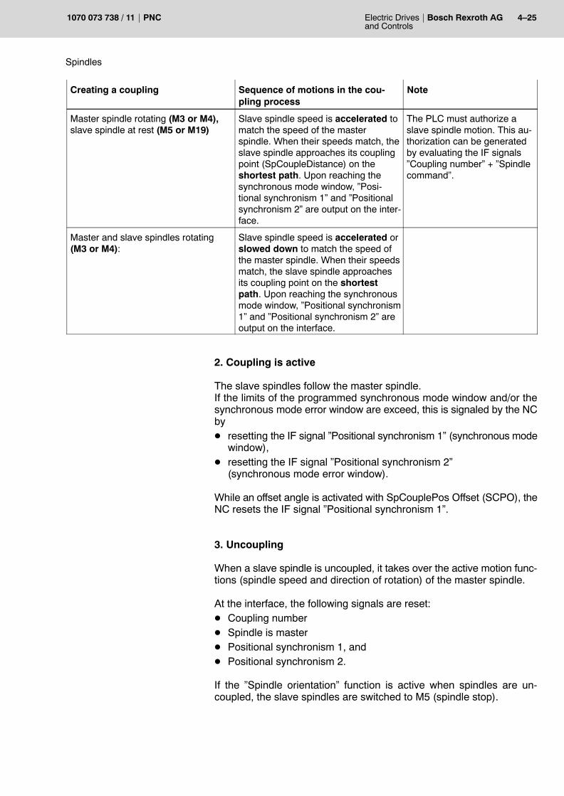
Spindles
Electric Drivesand Controls
4�25Bosch Rexroth AGPNC1070 073 738 / 11
Creating a coupling NoteSequence of motions in the cou-pling process
Master spindle rotating (M3 or M4),slave spindle at rest (M5 or M19)
Slave spindle speed is accelerated tomatch the speed of the masterspindle. When their speeds match, theslave spindle approaches its couplingpoint (SpCoupleDistance) on theshortest path. Upon reaching thesynchronous mode window, �Posi-tional synchronism 1� and �Positionalsynchronism 2� are output on the inter-face.
The PLC must authorize aslave spindle motion. This au-thorization can be generatedby evaluating the IF signals�Coupling number� + �Spindlecommand�.
Master and slave spindles rotating (M3 or M4):
Slave spindle speed is accelerated orslowed down to match the speed ofthe master spindle. When their speedsmatch, the slave spindle approachesits coupling point on the shortestpath. Upon reaching the synchronousmode window, �Positional synchronism1� and �Positional synchronism 2� areoutput on the interface.
2. Coupling is active
The slave spindles follow the master spindle.If the limits of the programmed synchronous mode window and/or thesynchronous mode error window are exceed, this is signaled by the NCbyD resetting the IF signal �Positional synchronism 1� (synchronous mode
window),D resetting the IF signal �Positional synchronism 2�
(synchronous mode error window).
While an offset angle is activated with SpCouplePos Offset (SCPO), theNC resets the IF signal �Positional synchronism 1�.
3. Uncoupling
When a slave spindle is uncoupled, it takes over the active motion func-tions (spindle speed and direction of rotation) of the master spindle.
At the interface, the following signals are reset:D Coupling numberD Spindle is masterD Positional synchronism 1, andD Positional synchronism 2.
If the �Spindle orientation� function is active when spindles are un-coupled, the slave spindles are switched to M5 (spindle stop).

4�26 Electric Drivesand Controls
Bosch Rexroth AG PNC 1070 073 738 / 11
Spindles
4.4.10 Test mode with spindle coupling active
DANGERBy switching to test mode all groups of coupled spindles are stop-ped and uncoupled.
4.4.11 Effects of spindle-specific interface signals on spindle couplings
IF signal �Drive off�
The IF signal �Drive OFF� causes the NC to slow down the group ofcoupled spindles to a stop. The state of motion of the master spindle isset to spindle stop (M5). When the group of coupled spindles has cometo a standstill, the �Drive OFF� signal of the spindle concerned is relayedto the drive.
This will produce the following effects:D The NC blocks any further programming of the group of coupled
spindles.D The IF signals �Positional synchronism 1� and �Positional synchro-
nism 2� of all slave spindles are reset.D The IF signal �Coupling error� is set for the master spindle.D The state of motion of all spindles involved is set to spindle stop (M5).
IF signal �Drive inhibit�
When the IF signal �Drive inhibit� is set, the NC must relay this signal tothe drive. This will immediately open the control loop of the drive!
Therefore, the NC cannot intervene actively, instead, it can only re-spond:D The NC slows down the remaining group of coupled spindles to a
stop.D The NC blocks any further programming of the group of coupled
spindles.D The IF signals �Positional synchronism 1� and �Positional synchro-
nism 2� of all slave spindles are reset.D The IF signal �Coupling error� is set for the master spindle.D The state of motion of all spindles involved is set to spindle stop (M5).
. Fault conditions caused by IF signals �Drive OFF� and �Drive inhi-bit� can be overcome only by a master spindle control reset (IF si-gnal) or an overall (system) control reset (PLC or operator input).

Spindles
Electric Drivesand Controls
4�27Bosch Rexroth AGPNC1070 073 738 / 11
4.4.12 Effects of drive-specific messages on spindle couplings
Resetting �Drive under control�:
The NC responds to this signal byD Slowing down the remaining group of couple spindles to a stop.D The NC blocks any further programming of the group of coupled
spindles.D The IF signals �Positional synchronism 1� and �Positional synchro-
nism 2� of all slave spindles are reset.D The IF signal �Coupling error� is set for the master spindle.D The state of motion of all spindles involved is set to spindle stop (M5).
. This fault condition can be overcome only by a master spindle con-trol reset (IF signal) or an overall (system) control reset (PLC oroperator input).
Diagnostics class 1 error
A �Diagnostics class 1 error� will immediately open the control loop of thedrive. The NC will respond as follows:D Slowing down the remaining group of couple spindles to a stop.D The NC blocks any further programming of the group of coupled
spindles.D The IF signals �Positional synchronism 1� and �Positional synchro-
nism 2� of all slave spindles are reset.D The IF signal �Coupling error� is set for the master spindle.D The state of motion of all spindles involved is set to spindle stop (M5).
. This fault condition (reset of �Drive under control� or diagnosticsclass 1 error) can be overcome only by a master spindle control re-set (IF signal) or an overall (system) control reset (PLC or operatorinput).

4�28 Electric Drivesand Controls
Bosch Rexroth AG PNC 1070 073 738 / 11
Spindles
Notes:

Auxiliary and special functions
Electric Drivesand Controls
5�1Bosch Rexroth AGPNC1070 073 738 / 11
5 Auxiliary and special functions
In addition to path information, auxiliary and special functions are re-quired to provide technological information.
Auxiliary functions are sent to the PLC. The transfer sequence is definedas follows:
D bit-codedauxiliaryfunctions
They are collected in the sequence in which theyhave been programmed and sent in packages of 13auxiliary functions or upon receipt of the last one.An acknowledgement is compulsory only with thelast package.
D bcd-codedauxiliaryfunctions
They are sent individually in the sequence in whichthey have been programmed.An exception are auxiliary functions that act inter-nally (e.g. �S�). They are sent last.
D combinedprogramming
Bit-coded auxiliary functions are sent after each13th auxiliary function or, resp. after the last one.With the exception of auxiliary functions acting inter-nally (�S�), bcd-coded auxiliary functions pro-grammed previously are sent previously. Auxiliaryfunctions acting internally are sent last.
CAUTIONThe functions described below may have different effects on yourmachine!Many auxiliary and special functions may be implementedmanufacturer-specifically. Therefore, the documentationprovided by the respective machine tool manufacturer alwaystakes priority.If you are not sure whether the functions described herein actuallyapply to your machine, contact your system administrator!

5�2 Electric Drivesand Controls
Bosch Rexroth AG PNC 1070 073 738 / 11
Auxiliary and special functions
5.1 F address (feedrate)
F addresses are used to determine the feedrate of the tool during ma-chining.
However, the PNC may interpret F addresses in different ways.
Depending on the G instruction currently active, programmed F wordswill act as:D interpolation time in seconds for G1, G2, G3 and G5
(see G93, page 3�111) orD feedrate in mm/min or inch/min (see G94, page 3�112) orD feedrate in mm/rev (see G95, page 3�116).
DANGERFailure to observe the feedrate preset in the machine parametersmay pose a hazard to the machine and personnel!
�Power off�, �Control reset� or �Reset� will activate the F word setin machine parameters 7060 00020 or 7060 00010 (default value =F0)!
This parameter also contains the information whether G93, G94 orG95 will be active after the events mentioned above (default value= G94)!
Example: Time programming with G93
N10 G93 G1 X300 Z400 A50 B120 F60
The programmed linear interpolation willlast 60 seconds.
Example: Feedrate programming in mm/min with G94
N10 G1 G94 X200 Z300 F200 programmed feedrate200 mm/min
N11 G4 F40 dwell time 40 seconds
N12 X300 Z400 the 200 mm/min feedrate is active again
Example: Feedrate programming in mm/rev with G95
N9 S2000 M4 spindle speed 2000 rev/min, ccw run
N10 G1 G95 X200 Z300 F0.2 programmed feedrate 0.2 mm/rev
N..
N12 X300 Z400 the 0.2 mm/rev feedrate is active again
. You may also program a dwell time using an F word in connectionwith G4 (cf. G4, page 3�12).
Effect
Programming

Auxiliary and special functions
Electric Drivesand Controls
5�3Bosch Rexroth AGPNC1070 073 738 / 11
5.2 FA address (feedrate of asynchronous axes)
Normally, asynchronous axes are traversed in rapid mode. If this beha-viour is not desired under certain circumstances, you may use the FA ad-dress to influence the traversing speed of all asynchronous axesprogrammed in the same block.
CAUTIONIncorrect programming may cause machine damage!
This feedrate will only be active in the block it is programmed, andit will only be effective for the asynchronous axes programmed inthe same block as the FA word!
Programming asynchronous axes without the FA word in asubsequent block will let the axes traverse in rapid mode again.
Example: Programming the feedrate of asynchronous axes in mm/min
N10 G1 G94 X200 Z300 F200 programmed feedrate of synchro-nous axes of 200 mm/min
N11 UA400 VA140 FA250 the asynchronous axes UA and VAare traversed to the programmedpositions at 250 mm/min
N12 UA0 WA10 The asynchronous axes UA andWA traverse to the programmedpositions in rapid mode
5.3 S address (spindle speed)
Refer to section 4.2.3 �Specifying the spindle speed�
Effect
Programming

5�4 Electric Drivesand Controls
Bosch Rexroth AG PNC 1070 073 738 / 11
Auxiliary and special functions
5.4 M functions
M functions (which are sometimes also referred to as M codes) consist ofthe address letter M and a key number. A leading �0� in the key numberneed not be written in the program.
Example: M function M03 (spindle ON � clockwise)
Key codeAddress letter M
Coordinate data Special functionsN ... G01 X200 Y145 Z�67.678 F250 S1000 T16 M03
M functions can be used to form separate program blocks, or can becombined with other words (G, S, F, T) in one block.
. The standard M functions of the PNC are shown in the �Annex� un-der the �Overview of M functions�.
. If 2 mutually exclusive internally effective M functions are program-med in the same block, the last M function programmed will be ac-tive.This refers to M functions within the following groups:D M03�M05, M13�M14, M19, M103�M105, M113�M114, M119D M203�M205, M213�M214, M219D M40, M41�M44, M140, M141�M144, M48, M148D M240, M241�M244, M248

Auxiliary and special functions
Electric Drivesand Controls
5�5Bosch Rexroth AGPNC1070 073 738 / 11
5.4.1 Subprogram calls
In addition to different G addresses and the P address (cf. page 2�8),subprograms can also be called by 8 non-modal M functions.
You may define the actual M functions as well as the programs called bythese M functions in MACODA.
The subprogram called will be executed once.
. The allocation of the M instruction to the program name is machinetool manufacturer�specific and can be defined in MACODA para-meters 3090 00003 and 3090 00004.Please contact your systems administrator for the M functions de-fined as subprogram calls for your specific machine.
As a rule, only one subprogram call by P, G or M may be included in oneblock.
If an address letter (e.g. G or M) occurs repeatedly in a block, the ad-dress calling the subprogram must be programmed at the end of the line.
Example: Calling a subprogram with M6N500 M3 S500 M6 Correct!
N500 M6 M3 S500 Wrong! (will produce runtime error)
If both a traversing motion and a subprogram call are programmed inone block, the subprogram is called after completion of the traversingmotion.
Programming

5�6 Electric Drivesand Controls
Bosch Rexroth AG PNC 1070 073 738 / 11
Auxiliary and special functions
5.4.2 Stop processing M00, M01, M02/M30
Program stop M00The NC program is interrupted and the machine movements arestopped when the block has been executed.
Program execution is restarted by �Cycle start�. Current statuses will notbe changed.
You may program �Program stop� together with other NC functions.When all programmed functions have been executed, �Program stop�will become effective.
Conditional program stop M01The NC program will stop if the �optional stop� interface signal is addi-tionally present.
Program execution is restarted by �Cycle start�. Current statuses will notbe changed.
You may program �Conditional program stop� together with other NCfunctions. When all programmed functions have been executed, �Condi-tional program stop� will become effective.
End of program M2, M02, M30M2, M02 or M30 will end a program.
If the program is a subprogram,D the NC will output the corresponding auxiliary function andD return to the calling program.
. Modal statuses that have been changed in the subprogram will notbe reset!
If the program is a main program,D the NC will reset the interface signal �end of program� and cancel
�program running�,D activate all statuses defined in MACODA parameter 7060 00020,
�Default status�, for an �M30� event,D return to the top of the main program, andD wait for the next �Cycle start�.
Effect
Programming
Effect
Programming
Effect

Auxiliary and special functions
Electric Drivesand Controls
5�7Bosch Rexroth AGPNC1070 073 738 / 11
CAUTIONUndefined default statuses may cause damage to the machine!If certain conditions or functions must be present or performedafter the end of a main program, you have to ensure that the initstring for the �M30� event has been given the proper parametersin MP 7060 00020. It must contain all functions that set the NC tothe required/desired condition after an �M30� event. In this context, you should note that modal functions of a groupfor which no other function has been entered in the init string willremain active even after the end of program!
. For more information on �groups�, please refer to �Instructionsand special functions�, sect. 2.1.1.
. For an overview of the G functions and their assignment to groups,please refer to �Overview of G instructions� in the annex.
. The M functions which mutually influence each other are describedin the annex section �Overview of M functions�.
. For more information on the default statuses, please refer to the�Power�up state� section of the �Description of functions� ma-nual.
You may program M2, M02 or M30 as the only instruction in a programblock.
Programming

5�8 Electric Drivesand Controls
Bosch Rexroth AG PNC 1070 073 738 / 11
Auxiliary and special functions
5.4.3 Spindle instructions
D 1st spindle group: M03, M04, M05, M13, M14, M19D 1st spindle: M103, M104, M113, M114, M105, M119D 2nd spindle: M203, M204, M213, M214, M205, M219
(refer to sect. 4.2.1, �Spindle functions�.
5.4.4 Gear ranges
Selection of the gear rangeD 1st spindle group: M40, M41-M44D 1st spindle: M140, M141-M144D 2nd spindle: M240, M241-M244
Neutral gearD 1st spindle group: M48D 1st spindle: M148D 2nd spindle: M248
(refer to sect. 4.2.2, �Gear functions�.
5.4.5 Tool changeM6
The M6 function initiates a tool change.
It calls a subprogram with the name freely defined in MACODA parame-ters 3090 00003 and 3090 00004.
For tool change, please also refer to section 5.5.

Auxiliary and special functions
Electric Drivesand Controls
5�9Bosch Rexroth AGPNC1070 073 738 / 11
5.5 T address (tool selection)
With this function, you request the tool to be used in the next machiningprocess.
The related tool number identifies the tool. It is also used for storing andcalling the tool dimensions during part program execution.
The PNC can output the tool number in BCD or binary format to an auto-matic tool changer to initiate the magazine search run.
For machine tools with manual tool change, the programmed T word isused as a job instruction for the operating personnel or for checking coin-cidences between the required tool and the tool available in the spindle.
The actual tool change is initiated by M06.
The appropriate signal settings and the maximum word length for pro-gramming the tool number are defined in MACODA.
Please refer to your machine tool builder�s manual for the structure andlength of the tool number.
Depends on tool management system.
Example:Programmed tool selection
N100 T123 M06 Select tool 123. Then initiate tool change withM06.
N110 G0 X100 Y200 Start machining with tool 123.N120 G1 X150 Y230N...N500 T234 M06 Select tool 234. Then initiate tool change with
M06.
Effect
Programming

5�10 Electric Drivesand Controls
Bosch Rexroth AG PNC 1070 073 738 / 11
Auxiliary and special functions
Notes:

Annex
Electric Drivesand Controls
A�1Bosch Rexroth AGPNC1070 073 738 / 11
A Annex
A.1 Abbreviations
Abbreviation Meaning
Aux.fct Auxiliary function
C: Drive name, in this case drive C (harddisk drive)
ESD electrostatic dischargeAbbreviation of all references to elec-trostatic discharge, e.g. ESD protec-tion, ESD hazard
Fx Function key with number x
GUI Graphical user interface
HP Main program
LSEC Lead Screw Error Compensation
MDI �Manual data input� mode
MP MACODA parameter
MSD Machine Status Display
MTB Machine tool builder (manufacturer)
NC, CNC Numerical Control
PE Protective Earth
PLC Programmable Logic Controller
SK Softkey
SP Subprogram, subroutine

A�2 Electric Drivesand Controls
Bosch Rexroth AG PNC 1070 073 738 / 11
Annex
A.2 Instructions (Overview)
For more information on �groups� (�group� column), please refer to �Instructions and specialfunctions�, sect. 2.1.1.
By selecting a new G function, the modal effect of a previously active function with the samegroup number is deselected and replaced by the modal effect of the new G function.
G instructions of group �0� are no �modal� functions. Therefore, they will not deselect eachother mutually!
G function as ofversion
Title Group Page
G00 Linear interpolation at rapid travel (see G200) 2 3�1
G01 Linear interpolation at feedrate (see G73) 2 3�3
G02 Circular interpolation / helical interpolation clockwise 2 3�4
G03 Circular interpolation / helical interpolation counter-clockwise 2 3�4
G04 Dwell time 0 3�12
G05 Circular interpolation / helical interpolation with tangential entry 2 3�13
G06 Acceleration programming ON (see G206) 11 3�15
G07 Acceleration programming OFF (see G206) 11 3�15
G08 Path slope ON 3 3�19
G09 Path slope OFF 3 3�19
G10 Polar-coordinate programming (like G0) 2 3�27
G11 Polar-coordinate programming (like G1) 2 3�27
G12 Polar-coordinate programming (like G2) 2 3�27
G13 Polar-coordinate programming (like G3) 2 3�27
G14 KV programming ON 9 3�28
G15 KV programming OFF 9 3�28
G16 5.1 No plane 5 3�29
G17 X/Y plane selection 5 3�30
G18 Z/X plane selection 5 3�30
G19 Y/Z plane selection 5 3�30
G20 Plane selection 2 out of 6 axes and Pole programming for po-lar-coordinate programming
5 3�32
G21 5.1 Programming of axis classifications 0 3�34
G22 Table activation 0 3�35
G23 Conditional jump 0 2�11
G24 Unconditional jump 0 2�11
G32 Tapping without compensation chuck (see G532) 0 3�38
G33 7.1 Tapping (see G533) 2 3�43
G34 Rounding of corners (with max. admissible deviation) ON (seeG36)
12 3�51
G35 6.2 Chamfer programming or rounding of corners (see G34) OFF(see G36)
3�52
G36 Delete max. admissible deviation programmed for G34 0 3�51
G37 Determination of mirror or rotating point 22 3�55
G38 Mirroring, scaling, rotating ON 22 3�55
G39 Mirroring, scaling, rotating OFF 22 3�55

Annex
Electric Drivesand Controls
A�3Bosch Rexroth AGPNC1070 073 738 / 11
PageGroupTitleas ofversion
G function
G40 Cutter path compensation OFF 41 3�67
G41 Cutter path compensation to the left of the workpiece ON 41 3�67
G42 Cutter path compensation to the right of the workpiece ON 47 3�67
G53 Axis zero shift (ZS) OFF (see G153; G253) 17 3�73
G54..G59 Axis zero shift (ZS) OFF (see G154; G254) 17 3�73
G60 Programmed contour shift ON (see G67) 20 3�75
G61 In-position logic ON (see G163 and G164..166) 13 3�76
G62 In-position logic OFF (see G163) 13 3�76
G63 Feedrate 100% ON (see G66) 7 3�77
G64 Feed compensation: Cutter contact point 42 3�78
G65 Feed compensation: Cutter center point 42 3�78
G66 Feedrate 100% OFF (see G63) 7 3�77
G67 Programmed contour shift OFF (see G60) 20 3�75
G68 Outside angle compensation: Arc 43 3�80
G69 Outside angle compens.: Intersection of the equidistants 43 3�80
G70 Inch programming 8 3�82
G71 Metric programming 8 3�82
G73 Linear interpolation at feedrate with in-position logic (see G1) 2 3�82
G74 Approach reference point coordinates 0 3�83
G75 Probe input 0 3�85
G76 Traverse to machine-oriented absolute axis position 0 3�95
G78 6.2 Compensation switchover (drill-axis switching) ON 36 3�96
G79 6.2 Activate presetting for compensation directions 36 3�96
G80 Deactivate boring cycles G81�G86 and G184 1 3�99
G81 Boring cycle: Drilling; retraction at rapid 1 3�99
G82 Boring cycle: Drilling; retraction at feedrate 1 3�99
G83 Boring cycle: Deep-hole drilling; retraction at rapid 1 3�99
G84 Boring cycle: Tapping with compensation chuck 1 3�99
G85 Boring cycle: Boring; retraction at rapid 1 3�99
G86 Boring cycle: Boring; retraction at feedrate 1 3�99
G90 Absolute data input 1 (see. G189) 4 3�108
G91 Incremental data input: 4 3�108
G92 Set actual value 0 3�110
G93 Time ogramming: 6 3�111
G94 Feedrate programming in mm/min 6 3�112
G95 Feedrate programming in mm/rev 6 3�116
G96 6.2 Constant cutting speed 35 3�117
G97 Direct speed programming (see G196) 35 3�117
G99 7.3 Spline programming 3�119
G104 Dwell time in spindle revolutions 3�12
G105 Zerosetting of modulo axis (linear endless axis) 0 3�129
G106 Programmable path acceleration (setting) 3�17
G107 Programmable path acceleration (resetting) 3�17
G108 Limited-jerk velocity control with path slope 3 3�20

A�4 Electric Drivesand Controls
Bosch Rexroth AG PNC 1070 073 738 / 11
Annex
PageGroupTitleas ofversion
G function
G112 Consideration of the existing braking distance with active pathslope OFF
38 3�131
G113 Consideration of the existing braking distance with active pathslope ON
38 3�131
G114 Feed forward control ON 10 3�132
G115 Feed forward control OFF 10 3�132
G130 5.1 Tangential tool guidance OFF 45 3�134
G131 5.1 Tangential tool guidance ON 45 3�134
G134 Rounding of corners (with specification of rounding radius) ON 12 3�51
G138 Workpiece position compensation ON 23 3�138
G139 Workpiece position compensation OFF 23 3�138
G145..G845 External tool compensation ON (1st to 8th) 25 3�140
G146 External tool compensation OFF 25 3�140
G147..G847 4.4.1(7.1)
General tool compensation ON (1st to 8th)(addition of Eulerian angles and cutter position)
52 3�142
G148 4.4.1 General tool compensation OFF 52 3�142
G150 Changing the positioning type for endless axes (MP) 27 3�146
G151 Changing the positioning type for endless axes ON 27 3�146
G153 1st additive axis ZS OFF 18 3�73
G154..G159 1st additive axis ZS ON 18 3�73
G160 External axis zero shift ON (no.1) (see G167) 24 3�149
G161 In-position logic at rapid travel ON 14 3�150
G162 In position logic at rapid travel OFF 14 3�150
G163 In-position logic ON at feedrate and rapid travel (see G61/62and G161/162)
13 3�76
G164 In-position logic: v=0 and check for �positioning window� 15 3�151
G165 In-position logic: v=0 and check for �positioning window rough� 15 3�151
G166 In-position logic: v=0 without check for �positioning window� 15 3�151
G167 External axis zero shift OFF (see G160) 24 3�149
G168 5.1 program coordinate shift ON 46 3�154
G169 5.1 Program coordinate shift OFF 46 3�154
G175 On-the-fly measurement (initialization) (see G275) 0 3�87
G177 Torque reduction 0 3�157
G184 Boring cycle: Tapping without compensation chuck 1 3�99
G189 Absolute data input 2 (see. G90) 4 3�108
G192 Speed limitation minimum speed (see G292) 29 3�158
G194 Incremental speed programming with acceleration adaptation 0 3�115
G196 Constant cutting speed (see G97) 35 3�117
G200 Linear interpolation at rapid feed without decelerating to v=0(see G0)
2 3�2
G202 circular movement, turning clockwise 2 3�9
G203 circular movement, turning counter-clockwise 2 3�9
G206 Acceleration programming: Storing of currently valid axis acce-leration (see G6)
0 3�15
G228 Block transition without deceleration 0 3�21
G234 6.2 Chamfer programming 3�52

Annex
Electric Drivesand Controls
A�5Bosch Rexroth AGPNC1070 073 738 / 11
PageGroupTitleas ofversion
G function
G253 2nd additive axis ZS OFF 19 3�73
G254..G259 2nd additive axis ZS ON 19 3�73
G260 External axis zero shift ON (no.2) (see G167) 24 3�149
G268 5.1 Additive program coordinate shifts ON 47 3�154
G269 5.1 Additive program coordinate shift OFF 47 3�154
G275 On-the-fly measurement (see G175) 0 3�87
G292 Speed limitation maximum speed (see G192) 30 3�158
G301 Oscillating axis (see G350) 2 3�159
G310 7.3 Ramp functions: Constant-speed interpolator on 3 3�163
G311 7.3 Ramp functions: activate acceleration interpolator with linearvelocity rise
3 3�163
G312 7.3 Ramp functions: activate deceleration interpolator with lineardeceleration
3 3�163
G313 7.3 Ramp functions: activate acceleration interpolator with sine-shaped velocity rise
3 3�163
G314 7.3 Ramp functions: activate deceleration interpolator with sine-shaped deceleration
3 3�163
G315 7.3 Ramp functions: activate acceleration interpolator withsin2-shaped velocity rise
3 3�163
G316 7.3 Ramp functions: activate deceleration interpolator withsin2-shaped deceleration
3 3�163
G328 Precision programming ON 2 3�166
G329 Precision programming OFF 2 3�166
G350 Oscillating axis (initialization) (see G301) 0 3�159
G352 Inclined plane (direct programming) 26 3�169
G353 Inclined plane OFF 26 3�169
G354..G359 Call of an inclined plane table 26 3�169
G360 External axis zero shift ON (no.3) (see G167) 24 3�149
G374 Traverse to reference point 0 3�84
G375 7.1 Measuring fixed stop 0 3�172
G408 Point-to-point movement using SHAPE 3 3�22
G475 7.1 Move to fixed stop 0 3�173
G476 7.1 Cancel fixed stop 0 3�175
G477 7.1 Torque reduction fixed stop 0 3�176
G500 Look-ahead for collision monitoring 0 3�184
G510 5.1 Integrating axes in axis groups with opt. error message 0 3�177
G511 5.1 Integrating axes in axis groups with WAIT 0 3�177
G512 5.1 Removing an axis from an axis group 0 3�177
G513 5.1 Accepting the axis configuration from MACODA 0 3�177
G515 5.1 Assigning �Logical axis name� 0 3�177
G516 5.1 Removing �Logical axis name� 0 3�177
G517 6.2 C axis off 0 3�177
G518 6.2 C axis on 0 3�177
G520 Drive-controlled interpolation 1 0 3�182
G521/G522 Drive-controlled interpolation 2 37 3�182
G523/G524 Drive-controlled interpolation 3 0 3�182
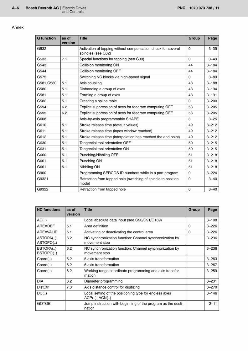
A�6 Electric Drivesand Controls
Bosch Rexroth AG PNC 1070 073 738 / 11
Annex
PageGroupTitleas ofversion
G function
G532 Activation of tapping without compensation chuck for severalspindles (see G32)
0 3�39
G533 7.1 Special functions for tapping (see G33) 0 3�49
G543 Collision monitoring ON 44 3�184
G544 Collision monitoring OFF 44 3�184
G575 Switching NC blocks via high-speed signal 0 3�89
G581,G580 5.1 Axis coupling 48 3�188
G580 5.1 Disbanding a group of axes 48 3�194
G581 5.1 Forming a group of axes 48 3�191
G582 5.1 Creating a spline table 0 3�200
G594 6.2 Explicit suppression of axes for feedrate computing OFF 53 3�205
G595 6.2 Explicit suppression of axes for feedrate computing OFF 53 3�205
G608 Axis-by-axis programmable SHAPE 3 3�25
G610 5.1 Stroke release time (default values) 49 3�212
G611 5.1 Stroke release time (inpos window reached) 49 3�212
G612 5.1 Stroke release time (interpolation has reached the end point) 49 3�212
G630 5.1 Tangential tool orientation OFF 50 3�215
G631 5.1 Tangential tool orientation ON 50 3�215
G660 5.1 Punching/Nibbling OFF 51 3�218
G661 5.1 Punching ON 51 3�218
G661 5.1 Nibbling ON 51 3�218
G900 Programming SERCOS ID numbers while in a part program 0 3�224
G9321 Retraction from tapped hole (switching of spindle to positionmode)
0 3�40
G9322 Retraction from tapped hole 0 3�40
NC functions as ofversion
Title Group Page
AC(..) Local absolute data input (see G90/G91/G189) 3�108
AREADEF 5.1 Area definition 0 3�226
AREAVALID 5.1 Activating or deactivating the control area 0 3�226
ASTOPA(..)ASTOPO(..)
6.2 NC synchronization function: Channel synchronization bymovement stop
3�236
BSTOPA(..)BSTOPO(..)
6.2 NC synchronization function: Channel synchronization bymovement stop
3�236
Coord(..) 6.2 5 axis transformation 3�263
Coord(..) 6.2 6 axis transformation 3�267
Coord(..) 6.2 Working range coordinate programming and axis transfor-mation
3�259
DIA 6.2 Diameter programming 3�231
DistCtrl 7.3 Axis distance control for digitizing 3�270
DC(..) Local setting of the positioning type for endless axesACP(..), ACN(..)
3�146
GOTOB Jump instruction with beginning of the program as the desti-nation
2�11

Annex
Electric Drivesand Controls
A�7Bosch Rexroth AGPNC1070 073 738 / 11
PageGroupTitleas ofversion
NC functions
GOTOL Jump instruction with end of the program as the destination 2�11
HWOCONHWOCOFF
Online correction in workpiece coordinates 3�276
IC(..) Local incremental data input (see G90/G91/G189) 3�108
JogWCSSelect Jogging in workpiece coordinates 3�278
LABEL Destination labelling within a program 2�11
LFPONLFPOFF
Path velocity-dependent laser power control 3�274
MAINSP 7.1 Main spindle switchover 4�17
O(..) 6.2 Orientation programming with angle of rotation 3�244
OFFSTOPAOFFSTOPO
6.2 NC synchronization function: Cancel stop conditions 3�236
PDHSO(..) 6.2 Programmable position-dependent HS output 3�233
phi, thetaO(..)ROTAX(..)
7.1 Orientation programming: Vector orientation 3�248
phi, thetaO(..)
7.1 Orientation programming: Linear orientation 3�246
phi, theta,psiOx(..), Oy(..),Oz(..) O(..)ROTAX(..)
7.1 Orientation programming: Tensor orientation for non-rotationsymmetrical tools
3�254
PREPNUM Limitation of the maximum number of prepared blocks 0 3�235
RAD 6.2 Radius programming 3�231
ROTAX(..) 6.2 Orientation movement with programming the axis of rotation 3�244
SPLINEDEF 7.3 Spline programming 3�119
SPV(..) 6.2 NC synchronization function: Writing of permanent CPL va-riables
3�236
SPVE(..) 6.2 NC synchronization function: Writing of permanent CPL va-riables
3�236
TCSDEF 7.1 TCS definition in program coordinates 3�272
TTOFF Tangential tool orientation OFF none 3�215
TTON Tangential tool orientation ON none 3�215
WAITA(..) 6.2 NC synchronization function: Waiting for several interfacesignals
3�236
WAITO(..) 6.2 NC synchronization function: Waiting for one interface signal 3�236
WPV(..) 6.2 NC synchronization function: Waiting for the value of a per-manent CPL variable
3�236
WPVE(..) 6.2 NC synchronization function: Waiting for the value of a per-manent CPL variable
3�236
WSTOPA(..)WSTOPO(..)
6.2 NC synchronization function: Channel synchronization bymovement stop
3�236
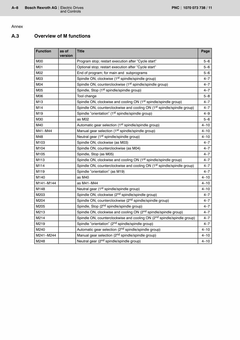
A�8 Electric Drivesand Controls
Bosch Rexroth AG PNC 1070 073 738 / 11
Annex
A.3 Overview of M functions
Function as ofversion
Title Page
M00 Program stop; restart execution after �Cycle start� 5�6
M01 Optional stop; restart execution after �Cycle start� 5�6
M02 End of program; for main and subprograms 5�6
M03 Spindle ON, clockwise (1st spindle/spindle group) 4�7
M04 Spindle ON, counterclockwise (1st spindle/spindle group) 4�7
M05 Spindle, Stop (1st spindle/spindle group) 4�7
M06 Tool change 5�8
M13 Spindle ON, clockwise and cooling ON (1st spindle/spindle group) 4�7
M14 Spindle ON, counterclockwise and cooling ON (1st spindle/spindle group) 4�7
M19 Spindle �orientation� (1st spindle/spindle group) 4�9
M30 as M02 5�6
M40 Automatic gear selection (1st spindle/spindle group) 4�10
M41�M44 Manual gear selection (1st spindle/spindle group) 4�10
M48 Neutral gear (1st spindle/spindle group) 4�10
M103 Spindle ON, clockwise (as M03) 4�7
M104 Spindle ON, counterclockwise (as M04) 4�7
M105 Spindle, Stop (as M05) 4�7
M113 Spindle ON, clockwise and cooling ON (1st spindle/spindle group) 4�7
M114 Spindle ON, counterclockwise and cooling ON (1st spindle/spindle group) 4�7
M119 Spindle �orientation� (as M19) 4�7
M140 as M40 4�10
M141�M144 as M41�M44 4�10
M148 Neutral gear (1st spindle/spindle group) 4�10
M203 Spindle ON, clockwise (2nd spindle/spindle group) 4�7
M204 Spindle ON, counterclockwise (2nd spindle/spindle group) 4�7
M205 Spindle, Stop (2nd spindle/spindle group) 4�7
M213 Spindle ON, clockwise and cooling ON (2nd spindle/spindle group) 4�7
M214 Spindle ON, counterclockwise and cooling ON (2nd spindle/spindle group) 4�7
M219 Spindle �orientation� (2nd spindle/spindle group) 4�7
M240 Automatic gear selection (2nd spindle/spindle group) 4�10
M241�M244 Manual gear selection (2nd spindle/spindle group) 4�10
M248 Neutral gear (2nd spindle/spindle group) 4�10

Annex
Electric Drivesand Controls
A�9Bosch Rexroth AGPNC1070 073 738 / 11
A.4 Overview of spindle functions
Function as ofversion
Title Page
S.. Specifying the spindle speed for individual spindles or for all spindles of aspindle group
4�12
SADM Transferring a spindle to another channel 4�4
SCC Creating, modifying or disbanding groups of coupled spindles 4�21
SCD Setting the coupling distance for one or several slave spindles 4�19
SCSW Defining the synchronous mode window 4�19
SCEW Defining the synchronous mode error window 4�19
SCPO Entering an angular offset while coupling is active 4�23
SCPOWAIT Waiting for angular offset 4�23
SCWAIT Waiting for synchronous mode 4�21
SDOM Switching to position-controlled spindle operation 4�16
SPF,MAINSP
7.1 Main spindle switchover 4�17
SPGALL(0) Restoring spindle group default settings 4�2
SPG Modal assignment of spindles to spindle groups: 4�2
SPL Local override of spindle assignments to spindle groups 4�2
SSPG.. Specifying the spindle speed for a spindle group 4�12

A�10 Electric Drivesand Controls
Bosch Rexroth AG PNC 1070 073 738 / 11
Annex
A.5 G functions (sorted by groups)
G function as ofversion
Title Group Page
G04 Dwell time 0 3�12
G21 5.1 Programming of axis classifications 0 3�34
G22 Table activation 0 3�35
G23 Conditional jump 0 2�11
G24 Unconditional jump 0 2�11
G32 Tapping without compensation chuck (see G532) 0 3�38
G36 Delete max. admissible deviation programmed for G34 0 3�51
G74 Approach reference point coordinates 0 3�83
G75 Probe input 0 3�85
G76 Traverse to machine-oriented absolute axis position 0 3�95
G92 Set actual value 0 3�110
G105 Zerosetting of modulo axis (linear endless axis) 0 3�129
G175 On-the-fly measurement (initialization) (see G275) 0 3�87
G177 Torque reduction 0 3�157
G194 Incremental speed programming with acceleration adaptation 0 3�115
G206 Acceleration programming: Storing of currently valid axis acce-leration (see G6)
0 3�15
G228 Block transition without deceleration 0 3�21
G275 On-the-fly measurement (see G175) 0 3�87
G350 Oscillating axis (initialization) (see G301) 0 3�159
G374 Traverse to reference point 0 3�84
G375 7.1 Measuring fixed stop 0 3�172
G475 7.1 Move to fixed stop 0 3�173
G476 7.1 Cancel fixed stop 0 3�175
G477 7.1 Torque reduction fixed stop 0 3�176
G500 Look-ahead for collision monitoring 0 3�184
G510 5.1 Integrating axes in axis groups with opt. error message 0 3�177
G511 5.1 Integrating axes in axis groups with WAIT 0 3�177
G512 5.1 Removing an axis from an axis group 0 3�177
G513 5.1 Accepting the axis configuration from MACODA 0 3�177
G515 5.1 Assigning �Logical axis name� 0 3�177
G516 5.1 Removing �Logical axis name� 0 3�177
G517 6.2 C axis off 0 3�177
G518 6.2 C axis on 0 3�177
G520 Drive-controlled interpolation 1 0 3�182
G523/G524 Drive-controlled interpolation 3 0 3�182
G532 Activation of tapping without compensation chuck for severalspindles (see G32)
0 3�39
G533 7.1 Special functions for tapping (see G33) 0 3�49
G575 Switching NC blocks via high-speed signal 0 3�89
G582 5.1 Creating a spline table 0 3�200
G900 Programming SERCOS ID numbers while in a part program 0 3�224

Annex
Electric Drivesand Controls
A�11Bosch Rexroth AGPNC1070 073 738 / 11
PageGroupTitleas ofversion
G function
G9321 Retraction from tapped hole (switching of spindle to positionmode)
0 3�40
G9322 Retraction from tapped hole 0 3�40
G80 Deactivate boring cycles G81�G86 and G184 1 3�99
G81 Boring cycle: Drilling; retraction at rapid 1 3�99
G82 Boring cycle: Drilling; retraction at feedrate 1 3�99
G83 Boring cycle: Deep-hole drilling; retraction at rapid 1 3�99
G84 Boring cycle: Tapping with compensation chuck 1 3�99
G85 Boring cycle: Boring; retraction at rapid 1 3�99
G86 Boring cycle: Boring; retraction at feedrate 1 3�99
G184 Boring cycle: Tapping without compensation chuck 1 3�99
G00 Linear interpolation at rapid travel (see G200) 2 3�1
G01 Linear interpolation at feedrate (see G73) 2 3�3
G02 Circular interpolation / helical interpolation clockwise 2 3�4
G03 Circular interpolation / helical interpolation counter-clockwise 2 3�4
G05 Circular interpolation / helical interpolation with tangential entry 2 3�13
G10 Polar-coordinate programming (like G0) 2 3�27
G11 Polar-coordinate programming (like G1) 2 3�27
G12 Polar-coordinate programming (like G2) 2 3�27
G13 Polar-coordinate programming (like G3) 2 3�27
G33 7.1 Tapping (see G533) 2 3�43
G73 Linear interpolation at feedrate with in-position logic (see G1) 2 3�82
G200 Linear interpolation at rapid feed without decelerating to v=0(see G0)
2 3�2
G202 circular movement, turning clockwise 2 3�9
G203 circular movement, turning counter-clockwise 2 3�9
G301 Oscillating axis (see G350) 2 3�159
G328 Precision programming ON 2 3�166
G329 Precision programming OFF 2 3�166
G08 Path slope ON 3 3�19
G09 Path slope OFF 3 3�19
G108 Limited-jerk velocity control with path slope 3 3�20
G310 7.3 Ramp functions: Constant-speed interpolator on 3 3�163
G311 7.3 Ramp functions: activate acceleration interpolator with linearvelocity rise
3 3�163
G312 7.3 Ramp functions: activate deceleration interpolator with lineardeceleration
3 3�163
G313 7.3 Ramp functions: activate acceleration interpolator with sine-shaped velocity rise
3 3�163
G314 7.3 Ramp functions: activate deceleration interpolator with sine-shaped deceleration
3 3�163
G315 7.3 Ramp functions: activate acceleration interpolator withsin2-shaped velocity rise
3 3�163
G316 7.3 Ramp functions: activate deceleration interpolator withsin2-shaped velocity decrease
3 3�163
G408 Point-to-point movement using SHAPE 3 3�22
G608 Axis-by-axis programmable SHAPE 3 3�25

A�12 Electric Drivesand Controls
Bosch Rexroth AG PNC 1070 073 738 / 11
Annex
PageGroupTitleas ofversion
G function
G90 Absolute data input 1 (see. G189) 4 3�108
G91 Incremental data input: 4 3�108
G189 Absolute data input 2 (see. G90) 4 3�108
G16 5.1 No plane 5 3�29
G17 X/Y plane selection 5 3�30
G18 Z/X plane selection 5 3�30
G19 Y/Z plane selection 5 3�30
G20 Plane selection 2 out of 6 axes and Pole programming for po-lar-coordinate programming
5 3�32
G93 Time ogramming: 6 3�111
G94 Feedrate programming in mm/min 6 3�112
G95 Feedrate programming in mm/rev 6 3�116
G63 Feedrate 100% ON (see G66) 7 3�77
G66 Feedrate 100% OFF (see G63) 7 3�77
G70 Inch programming 8 3�82
G71 metric programming 8 3�82
G14 KV programming OFF 9 3�28
G15 KV programming OFF 9 3�28
G114 Feed forward control ON 10 3�132
G115 Feed forward control OFF 10 3�132
G06 Acceleration programming ON (see G206) 11 3�15
G07 Acceleration programming OFF (see G206) 11 3�15
G34 Rounding of corners (with max. admissible deviation) ON (seeG36)
12 3�51
G134 Rounding of corners (with specification of rounding radius) ON 12 3�51
G61 In-position logic ON (see G163 and G164..166) 13 3�76
G62 In-position logic OFF (see G163) 13 3�76
G163 In-position logic ON at feedrate and rapid travel (see G61/62and G161/162)
13 3�76
G161 In-position logic at rapid travel ON 14 3�150
G162 In position logic at rapid travel OFF 14 3�150
G164 In-position logic: v=0 and check for �positioning window� 15 3�151
G165 In-position logic: v=0 and check for �positioning window rough� 15 3�151
G166 In-position logic: v=0 without check for �positioning window� 15 3�151
G53 Axis zero shift (ZS) OFF (see G153; G253) 17 3�73
G54..G59 Axis zero shift (ZS) OFF (see G154; G254) 17 3�73
G153 1st additive axis ZS OFF 18 3�73
G154..G159 1st additive axis ZS ON 18 3�73
G253 2nd additive axis ZS OFF 19 3�73
G254..G259 2nd additive axis ZS ON 19 3�73
G60 Programmed contour shift ON (see G67) 20 3�75
G67 Programmed contour shift OFF (see G60) 20 3�75
G37 Determination of mirror or rotating point 22 3�55
G38 Mirroring, scaling, rotating ON 22 3�55
G39 Mirroring, scaling, rotating OFF 22 3�55

Annex
Electric Drivesand Controls
A�13Bosch Rexroth AGPNC1070 073 738 / 11
PageGroupTitleas ofversion
G function
G138 Workpiece position compensation ON 23 3�138
G139 Workpiece position compensation OFF 23 3�138
G160 External axis zero shift ON (no.1) (see G167) 24 3�149
G167 External axis zero shift OFF (see G160) 24 3�149
G260 External axis zero shift ON (no.2) (see G167) 24 3�149
G360 External axis zero shift ON (no.3) (see G167) 24 3�149
G145..G845 External tool compensation ON (1st to 8th) 25 3�140
G146 External tool compensation OFF 25 3�140
G352 Inclined plane (direct programming) 26 3�169
G353 Inclined plane OFF 26 3�169
G354..G359 Call of an inclined plane table 26 3�169
G150 Changing the positioning type for endless axes (MP) 27 3�146
G151 Changing the positioning type for endless axes ON 27 3�146
G192 Speed limitation minimum speed (see G292) 29 3�158
G292 Speed limitation maximum speed (see G192) 30 3�158
G96 6.2 Constant cutting speed 35 3�117
G97 Direct speed programming (see G196) 35 3�117
G196 Constant cutting speed (see G97) 35 3�117
G78 6.2 Compensation switchover (drill-axis switching) ON 36 3�96
G79 6.2 Activate presetting for compensation directions 36 3�96
G521/G522 Drive-controlled interpolation 2 37 3�182
G112 Consideration of the existing braking distance with active pathslope OFF
38 3�131
G113 Consideration of the existing braking distance with active pathslope ON
38 3�131
G40 Cutter path compensation OFF 41 3�67
G41 Cutter path compensation to the left of the workpiece ON 41 3�67
G64 Feed compensation: Cutter contact point 42 3�78
G65 Feed compensation: Cutter center point 42 3�78
G68 Outside angle compensation: Arc 43 3�80
G69 Outside angle compens.: Intersection of the equidistants 43 3�80
G543 Collision monitoring ON 44 3�184
G544 Collision monitoring OFF 44 3�184
G130 5.1 Tangential tool guidance OFF 45 3�134
G131 5.1 Tangential tool guidance ON 45 3�134
G168 5.1 program coordinate shift ON 46 3�154
G169 5.1 Program coordinate shift OFF 46 3�154
G42 Cutter path compensation to the right of the workpiece ON 47 3�67
G268 5.1 Additive program coordinate shifts ON 47 3�154
G269 5.1 Additive program coordinate shift OFF 47 3�154
G581,G580 5.1 Axis coupling 48 3�188
G580 5.1 Disbanding a group of axes 48 3�194
G581 5.1 Forming a group of axes 48 3�191
G610 5.1 Stroke release time (default values) 49 3�212
G611 5.1 Stroke release time (inpos window reached) 49 3�212

A�14 Electric Drivesand Controls
Bosch Rexroth AG PNC 1070 073 738 / 11
Annex
PageGroupTitleas ofversion
G function
G612 5.1 Stroke release time (interpolation has reached the end point) 49 3�212
G630 5.1 Tangential tool orientation OFF 50 3�215
G631 5.1 Tangential tool orientation ON 50 3�215
G660 5.1 Punching/Nibbling OFF 51 3�218
G661 5.1 Punching ON 51 3�218
G661 5.1 Nibbling ON 51 3�218
G147..G847 4.4.1(7.1)
General tool compensation ON (1st to 8th)(addition of Eulerian angles and cutter position)
52 3�142
G148 4.4.1 General tool compensation OFF 52 3�142
G594 6.2 Explicit suppression of axes for feedrate computing OFF 53 3�205
G595 6.2 Explicit suppression of axes for feedrate computing OFF 53 3�205
G35 6.2 Chamfer programming or rounding of corners (see G34) OFF(see G36)
3�52
G99 7.3 Spline programming 3�119
G104 Dwell time in spindle revolutions 3�12
G106 Programmable path acceleration (setting) 3�17
G107 Programmable path acceleration (resetting) 3�17
G234 6.2 Chamfer programming 3�52

Annex
Electric Drivesand Controls
A�15Bosch Rexroth AGPNC1070 073 738 / 11
A.6 Index
Numbers3x3 orientation tensor, 3�2545 axis transformation, 3�2636 axis transformation, 3�267
Type 3033101, 3�267Type 3333301, 3�267
AAbsolute data input 1 (G90/G189), 3�108Absolute data inputAC(...) , local, 3�108Acceleration interpolators, 3�163Acceleration programming, 3�15Access privileges to files, 2�1Activate tables, 3�35Additional functions, 5�1, 5�4Additive program coordinate shift (G268, G269),
3�154Address, 2�2Administration of part programs, 2�1Traverse to reference point G74, 3�83AREA..., 3�226ASTOPA, BSTOPA, WSTOPA, Channel synchroniz-
ation by movement stop, 3�238ASTOPO, BSTOPO, WSTOPO, Channel synchroniz-
ation by movement stop, 3�238Asynchronous axes, 2�4
Velocity, 5�3Auxiliary and special functions, 5�1Auxiliary axes, Velocity, 5�3Axes, suppression for feedrate computing, 3�205Axis classification, 3�34
Programming, 3�34Axis coupling (G581, G580), 3�188Axis coupling (linear), Forming a group of axes,
3�191, 3�193, 3�194, 3�202Axis distance control for digitizing, 3�270Axis transfer
(G510..G513, G515, G516), 3�177Active area, 3�226Control area, 3�226Integrate axis., 3�179Remove axis, 3�179Transferring axes between axis groups , 3�178
Axis zero shift, 3�73Axis zero shift (G160,260,360/G167), external, 3�149Axis�by�axis programmable SHAPE, (G608), 3�25
BBlock number, N instruction, 2�6Block preparation, Limiting number of blocks, 3�235Boring cycles (G80to G86, G184), 3�99
CCancel fixed stop, 3�175Center�point programming, 3�6Chamfer length, 3�52
CHL, CHR, 3�53Compensation, 3�52
Chamfer programming, 3�52Chamfer segment, 3�52Channel designation, Comments, 2�7Channel synchronization by movement stop, 3�237CHF, Chamfer segment, 3�53CHL, Chamfer length, 3�53CHR, Chamfer length, 3�53Circular interpolation G02/G03 , 3�4Circular interpolation G05, 3�13Coefficient programming, Spline, 3�119Collision monitoring, 3�184
Look�ahead, 3�184Comments, 2�6Compensation directions G79, Activate presetting,
3�96Compensation switchover G78, 3�96Conditional jump G23 , Interface signal, 3�37Conditional program stop M01, 5�6Consideration of breaking distance, Path slope,
3�131Constant cutting speed (G96), 3�117Constant�speed interpolator , 3�164Contour transitions G68/G69, 3�80Control area, 3�226COORD, 3�259Coordinates, Positional values, 2�4Corner rounding, 3�51Coupling (active)
Angular offset, 4�23Programming, 4�23
Coupling characteristics:, 3�189Coupling distance, 4�19
Definition, 4�21Coupling process, Sequence of motions, 4�24Coupling table , 3�195Cutter path compensation, 3�67
Selection / deselection of the compensation, 3�69Cutting speed, constant (G96), 3�117
DDeceleration, none at block transition, 3�21Deceleration interpolators, 3�163Deviation from contour, 3�166DIA, 3�231Diameter programming, 3�231

A�16 Electric Drivesand Controls
Bosch Rexroth AG PNC 1070 073 738 / 11
Annex
Digitizing, Axis distance control, 3�270Direct speed programming (G97), 3�117DistCtrl, 3�270Documentation, 1�7Drill axis switching (G78, G79), 3�96Drive�controlled interpolation, (G520..G524), 3�182Dwell time, in spindle revolutions, 3�12, 3�116Dwell time G4, in seconds, 3�12
EEMC Directive, 1�1EMERGENCY�STOP devices, 1�5End of main program M02/M30, 5�6End of program, 2�14, 5�6End of subprogram, 2�10Endless axes, Change position type, 3�146
local, 3�146ESD
Electrostatic discharge, 1�6grounding, 1�6workplace, 1�6
ESD�sensitive components, 1�6Eulerian angle, Orientation tensor, 3�254European setting, 3�209External axis zero shift (G160,260,360/G167), 3�149External tool compensation (G145 ... G845, G146),
3�140
FF address, 5�2FA address, 5�3Feed forward control, 3�132Feedrate
asynchronous axes, 5�3synchronous axes, 5�2
Feedrate 100% G63, G66, 3�77Feedrate compensation G64/G65, 3�78Feedrate programming, 3�112Feedrate programming as block duration, 3�111Feedrate programming in mm/rev, 3�116File system and file protection, 2�1Fixed stop
cancel, 3�175measuring, 3�172move to, 3�173torque reduction, 3�176
Floppy disk drive, 1�7Following distance error, 3�76, 3�150Freely defined coupling, 3�189
GGear functions, 4�10Gear ranges, 4�10
neutral, 4�11
Gear selectionautomatic, 4�10manual, 4�11
General setting, 3�210General tool compensation (G147... G847, G148),
3�142Grounding bracelet, 1�6Group of coupled axes
adding axes, 3�193disbanding, 3�194forming, 3�191removing axes from, 3�194
Group of coupled spindlesAdding slave spindles, 4�21Removing slave spindles, 4�21Cancel, 4�22
HHandwheel, Online correction, 3�276Hard disk drive, 1�7Helical interpolation G05, 3�4, 3�13Helical�N�Interpolation, G202/G203, 3�9HS output (position�dependent), programmable,
3�233HWOC..., 3�276
IIn�position at rapid travel (G161, G162), 3�150In�position logic always ON (G163), 3�76In�position logic G60/G61, 3�76In�position logic: mode, (G164,G165,G166), 3�151Inch�Metric programming
European setting, 3�209General setting, 3�210U.S. setting, 3�210
Inclined plane (G352, G353, G354..G359), 3�169Incremental data input, 3�108Incremental data input IC(...) , local, 3�108Incremental speed programming with acceleration
adaptation, (G194), 3�115Individual spindles, 4�2
Assignment to spindle groups, 4�2Instructions, 2�4Integrate axis, 3�179Interpolation types, 3�112Interpolator
Acceleration, 3�163constant speed, 3�164deceleration, 3�163
JJogging in workpiece coordinates, 3�278JogWCSSelect, 3�278Jump destinations and jump instructions, 2�11

Annex
Electric Drivesand Controls
A�17Bosch Rexroth AGPNC1070 073 738 / 11
LLaser power control, subject to path velocity, 3�274LFP, 3�274LFPOFF, 3�275LFPON, 3�274Limited�jerk velocity control, 3�20LIN (G408), 3�22Linear coupling, 3�189Linear interpolation
Feedrate (G01), 3�3Linear interpolation with In�position logic (G73),
3�82Rapid travel (G00), 3�1Rapid travel with In�position logic (G161, G162),
3�150Linear orientation movement, 3�245, 3�246Local positioning type change�over for endless axes,
3�146Local setting of the positioning type for endless axes,
3�146Logical axis name, defining, 3�180Loop gain programming, 3�28Low�Voltage Directive, 1�1LPCOFF, 3�275
MM addresses (M instructions), 5�4M0 (Program stop), 5�6M1 (conditional program stop), 5�6M2/M30 (end of main program), 5�6Machine Functions, Spindle, 4�13Machining time, Time programming, 3�111Main spindle switchover, 4�17Measuring fixed stop, 3�172Mirroring of a contour, 3�56Modal, 2�3Modules sensitive to electrostatic discharge. See
ESD�sensitive componentsmodulo axis, Zerosetting, 3�129Move to fixed stop, 3�173
NNC functions
Axis�based, 3�262Working range coordinate�based, 3�260
NC program, 2�1NC synchronization functions, 3�236Nibbling ON (G662), 3�218No plane, 3�29Nonmodal, 2�3
OO(...), 3�247, 3�250
OFFSTOP..., 3�236On�the�fly measurement, (G175,G275), 3�87Online correction in workpiece coordinates, 3�276Orientation, 3�244
linear, 3�246Orientation vector, 3�246Vector orientation, 3�248
Orientation coordinates, Machine kinematics, 3�244Orientation movement, 3�244Orientation programming, 3�244Orientation vector, Speed of rotation, 3�251, 3�256Oscillating axis (G301, G350), 3�159Overtravel, 3�166
PParallel spindles, 4�2Path acceleration, 3�17Path compensation, 3�67Path slope, 3�19Path velocity�dependent laser power control, 3�274PDHSO, 3�233Plane selection G17/G18/G19, 3�30Plane selection G20, 2 out of 6 axes, 3�32Point�to�point movement using SHAPE, (G408),
3�22Polar coordinate programming, 3�27Polar coordinates, 3�248Positioning type change�over for endless axes,
3�146Precision programming (G328, G329), 3�166Preparatory functions, G instructions, G functions,
2�4PREPNUM, 3�235Probe input G75, 3�85Program Block, NC block, 2�2Program coordinate shift (G168/G169), 3�154Program coordinate shift (G268/G269), Additive ,
3�154Program design, 2�6Program run, 2�7Program stopM0, 5�6Program word, 2�2Programmable path acceleration, 3�17Programmed contour shift (G60, G67), 3�75Programming format, Standard format, 2�15Programming notes, Comments, 2�6Programming of endless axes, 3�146Programming of rotary axes, 3�146Punching, Interface signals, 3�222Punching ON (G661), 3�218Punching/Nibbling OFF (G660), 3�218

A�18 Electric Drivesand Controls
Bosch Rexroth AG PNC 1070 073 738 / 11
Annex
QQualified personnel, 1�2
RRAD, 3�231Radius programming, 3�4, 3�232Ramp functions, 3�163Rapid travel without deceleration to V=0, (G200), 3�2Release, 1�8Remove axis, 3�179Reservation, Releasing a spindle, 4�6Retraction from tapped hole, Retraction from, 3�40Rotating of a contour, 3�62Rotation�symmetrical tool, 3�248ROTAX(..), 3�244, 3�252Rounding of corners, 3�51
SS�Address, 4�12SADM, Transferring a spindle to another channel, 4�6Safety instructions, 1�4Safety markings, 1�3Scaling of a contour, 3�59SERCOS parameter, programming while in a part
program, 3�224Set actual value, 3�110Shape (axis�by�axis), (G608), 3�25Shape (interpolation), (G408), 3�22Shape function, 3�20SIN (G408), 3�22Skip block, 2�7Slave spindles, 4�19
Configuration, 4�19Slope, 3�19Spare parts, 1�6Special functions, Auxiliary and special functions, 2�5Speed, 4�12Speed limitation, (G192,G292), 3�158Speed mode, 4�7Spindle coupling, 4�18, 4�26
Effects of drive�specific messages, 4�27Sequence, 4�24
Spindle functions , 4�7Position mode, 4�16
Spindle groups, 4�2Spindle operation in positional synchronism, Restric-
tion:, 4�18Spindle orientation, programmable, 4�8Spindle programming, G functions, 4�15Spindle speed, 4�12
Spindles, 4�1Activation via interface, 4�14Clockwise rotation, with coolant, 4�8Clockwise rotation, 4�7Counterclockwise rotation, 4�8Counterclockwise rotation, with coolant, 4�8Machine Functions, 4�13Orientation, 4�8Position control, 4�16Referencing, 4�16Reservation for channels, 4�4Spindle operation in positional synchronism, 4�18Stop, 4�8Switchover, 4�16
Spline, 3�119B�Splines (NURBS), Programming, 3�126C1 continuous cubic, 3�122C2 continuous cubic, 3�122Coefficient programming, 3�119
Spline table, 3�200creating, 3�200
Spline table file, 3�200SPV, SPVE, Writing of permanent CPL variables,
3�237Standard functions, Spindles, 4�1Standard operation, 1�1Statuses at the digital interface, waiting, 3�236Stop processing, 5�6Stroke release, 3�222Stroke release time
Default\ settings, 3�212Inpos window, 3�212Interpolation end point, 3�212
Subprogram callsvia M functions, 5�5with P address, 2�8
Switch off C axis G517, 3�181Switch on C axis G518, 3�181Switching NC blocks via high�speed signal, G575,
3�89Switching over the positioning type for endless axes,
3�146Switching the drill axis (G78, G79), 3�96Synchronous mode, Waiting for , 4�22Synchronous mode error window, 4�20Synchronous mode window, 4�19
TT�Address, 5�9Tangential tool guidance OFF (G130), 3�134Tangential tool guidance ON (G131), 3�134Tangential tool orientation OFF (G630), 3�215Tangential tool orientation OFF (TTOFF), 3�215Tangential tool orientation ON (G631), 3�215

Annex
Electric Drivesand Controls
A�19Bosch Rexroth AGPNC1070 073 738 / 11
Tangential tool orientation ON (TTON), 3�215Tapping, 3�43
Additional functions, 3�49Retraction from, 3�40
Tapping (G32), 3�38Tapping (G532), 3�39Tapping without compensation chuck (G32), 3�38
automatic retraction, 3�40manual retraction, 3�40Retraction, 3�40
Tapping without compensation chuck (G532), 3�39TCS definition in program coordinates, 3�272TCS orientation, 3�255TCSDEF, 3�272TCSp, 3�272TCSUNDEF, 3�273Tensor orientation, 3�254Test activities, 1�5Thread pitch, 3�38Time programming, 3�111Tool change M06, 5�8Tool compensation (G145 ... G845, G146), external,
3�140Tool compensation (G147 ... G847, G148), general,
3�142Tool selection, 5�9Torque reduction (G177), 3�157Torque reduction fixed stop, 3�176Trademarks, 1�8Transferring a spindle to another channel, SADM, 4�6Transferring axes between axis groups , axis transfer,
3�178Transformation
5�Axis, 3�2636�Axis, 3�267
Traverse to machine�oriented absolute axis position,G76, 3�95
Traverse to reference point (genuine) G374 , in thepart program, 3�84
UU.S. setting, 3�210Unconditional jump G24 , 3�37Unit of measure G70/G71
Inch, 3�82metric, 3�82
VValue of a permanent CPL variable, waiting, 3�237Vector orientation, 3�248, 3�250Velocity profiles, Definition of own, 3�163
WWAITA, WAITO, Statuses at the digital interface,
3�236Working range coordinate programming, 3�259Workpiece position compensation, 3�138WPV, WPVE, Value of a permanent CPL variable,
3�237Writing of permanent CPL variables, 3�237
ZZerosetting of modulo axis, 3�129

A�20 Electric Drivesand Controls
Bosch Rexroth AG PNC 1070 073 738 / 11
Annex
Notes:

Electric Drivesand Controls
A�1Bosch Rexroth AGPNC1070 073 738 / 11
Bosch Rexroth AGElectric Drives and ControlsBgm.-Dr.-Nebel-Str. 297816 Lohr a. Main, [email protected]
Printed in GermanyDOK-PNC***-DIN*PROG***-AW11-EN-P


![19-95------------•PNc•l•][i•id.Uid•i#?fJUJ ·----...... ------------N-2-s ...](https://static.fdokumen.com/doc/165x107/6327fdbd051fac18490e8572/19-95-pncliiduidifjuj-n-2-s.jpg)