Levelflex M FMP43 - Nuova Elva
100
BA00358F/00/EN/13.10 71120306 Valid as of software version: 01.04.zz Operating Instructions Levelflex M FMP43 Guided Level-Radar
-
Upload
khangminh22 -
Category
Documents
-
view
2 -
download
0
Transcript of Levelflex M FMP43 - Nuova Elva

BA00358F/00/EN/13.10
71120306
Valid as of software version:
01.04.zz
Operating Instructions
Levelflex M FMP43Guided Level-Radar

Levelflex M FMP43 PROFIBUS PA
2 Endress+Hauser
Brief Operating Instructions
L00-FMP40xxx-19-00-00-en-012
! Note!
These Operating Instructions explains how to install and commission the level transmitter.
All the functions that are required for a typical measuring task are taken into account here.
In addition, the Levelflex M provides many other functions for optimizing the measuring point and
conventing measured values. These functions are not included in these Operating Instructions.
An overview of all the device functions can be found on → ä 94.
The Operating Instructions BA00245F/00/EN "Description of Instrument Functions" provides an
extensive description of all the device functions which can be found on the enclosed CD-ROM.
The Operating Instructions can also be found on our homepage: www.endress.com
E+-
+
E+-E
E
-
… …
… …
KA189F/00/a2/03.07
52012501
52012501
100%
0%
FE
UB
FMP43
FMP40FMP41CFMP45
LN
D
L
Levelflex M - Brief operating instructions
input E(see sketch)
input F(see sketch) displayed
D and L are confirm
or specifyrange
suggestion
000measured value
Groupselection
00basic setup
01safety settings
09display
04linearisation
05extended calibr.
0Csystemparameters
092language
0Adiagnostics
0A0presenterror
002tankproperties
004processcond.
005emptycalibr.
006fullcalibr.
008dist./meas value
051checkdistance
003mediumproperty
052range ofmapping
053startmapping
008dist./meas value
- envel. curve- substracted signal- mapping
- single curve- cyclic
= 100: unlocked¹ 100: locked
09Aplot settings
09Brecordingcurve
0A1previouserror
0A4unlockparameter
(333 = reset customer parameters)
0A3reset
threadedconnection
1 ½(G 1
:reference point ofmeasurement
¾ or BSP¾ or G ½)
¾ or 1½ NPT
03lengthadjustment
030end ofprobe
031probelength
032probe
033probelength
034determinelength
- unknown- 1.4 … 1.6- 1.6 … 1.9- 1.9 … 2.5
- 4 … 7- 2.5 … 4
- > 7
0Eenvelope curve
Contrast: + or +
- standard- aluminium tank- plastic tank- bypass/pipe- coax-probe- concretewall
- standard- fastchange
- test: no filter
- slowchange
- free- tie downisolated
- tie downgnd.
If shortenedplease enter probe length here.
reference point ofmeasurement
F = measuring span
E = empty distance (= zero)
UB = upper blocking distance
LN = probe lengthL = levelD = distance

Levelflex M FMP43 PROFIBUS PA Table of contents
Endress+Hauser 3
Table of contents
1 Safety instructions . . . . . . . . . . . . . . . . 4
1.1 Designated use . . . . . . . . . . . . . . . . . . . . . . . . . . . . 4
1.2 Installation, commissioning and operation . . . . . . . . 4
1.3 Operational safety and process safety . . . . . . . . . . . . 4
1.4 Notes on safety conventions and icons . . . . . . . . . . . 5
2 Identification . . . . . . . . . . . . . . . . . . . . 6
2.1 Device designation . . . . . . . . . . . . . . . . . . . . . . . . . 6
2.2 Scope of delivery . . . . . . . . . . . . . . . . . . . . . . . . . . . 8
2.3 Certificates and approvals . . . . . . . . . . . . . . . . . . . . 8
2.4 Registered trademarks . . . . . . . . . . . . . . . . . . . . . . . 8
3 Installation . . . . . . . . . . . . . . . . . . . . . . 9
3.1 Incoming acceptance, transport, storage . . . . . . . . . . 9
3.2 Installation conditions . . . . . . . . . . . . . . . . . . . . . . 10
3.3 Installation instructions . . . . . . . . . . . . . . . . . . . . . 15
3.4 Post-installation check . . . . . . . . . . . . . . . . . . . . . . 20
3.5 Cleaning of the probe . . . . . . . . . . . . . . . . . . . . . . 21
4 Wiring . . . . . . . . . . . . . . . . . . . . . . . . 24
4.1 Quick wiring guide . . . . . . . . . . . . . . . . . . . . . . . . 24
4.2 Connecting the measuring unit . . . . . . . . . . . . . . . 27
4.3 Recommended connection . . . . . . . . . . . . . . . . . . 29
4.4 Degree of protection . . . . . . . . . . . . . . . . . . . . . . . 29
4.5 Post-connection check . . . . . . . . . . . . . . . . . . . . . . 29
5 Operation . . . . . . . . . . . . . . . . . . . . . . 30
5.1 Quick operation guide . . . . . . . . . . . . . . . . . . . . . . 30
5.2 Display and operating elements . . . . . . . . . . . . . . . 32
5.3 Local operation . . . . . . . . . . . . . . . . . . . . . . . . . . . 34
5.4 Displaying and acknowledging error messages . . . . 37
5.5 PROFIBUS PA communication . . . . . . . . . . . . . . . . 38
6 Commissioning. . . . . . . . . . . . . . . . . . 53
6.1 Function check . . . . . . . . . . . . . . . . . . . . . . . . . . . 53
6.2 Switching on the measuring device . . . . . . . . . . . . 53
6.3 Basic setup . . . . . . . . . . . . . . . . . . . . . . . . . . . . . . 54
6.4 Basic setup with display VU331 . . . . . . . . . . . . . . . 56
6.5 Blocking distance . . . . . . . . . . . . . . . . . . . . . . . . . 65
6.6 Envelope curve with VU331 . . . . . . . . . . . . . . . . . 67
6.7 Function "envelope curve display" (0E3) . . . . . . . . 68
6.8 Basic setup with the Endress+Hauser
operating program . . . . . . . . . . . . . . . . . . . . . . . . . 71
7 Maintenance. . . . . . . . . . . . . . . . . . . . 77
7.1 Exterior cleaning . . . . . . . . . . . . . . . . . . . . . . . . . . 77
7.2 Repair . . . . . . . . . . . . . . . . . . . . . . . . . . . . . . . . . . 77
7.3 Repairs to Ex-approved devices . . . . . . . . . . . . . . . 77
7.4 Replacement . . . . . . . . . . . . . . . . . . . . . . . . . . . . . 77
8 Accessories . . . . . . . . . . . . . . . . . . . . . 78
8.1 Weather protection cover . . . . . . . . . . . . . . . . . . . . 78
8.2 Weld-in adapter . . . . . . . . . . . . . . . . . . . . . . . . . . . 78
8.3 Remote display and operation FHX40 . . . . . . . . . . . 79
8.4 Commubox FXA291 . . . . . . . . . . . . . . . . . . . . . . . 80
8.5 ToF Adapter FXA291 . . . . . . . . . . . . . . . . . . . . . . . 80
8.6 Proficard . . . . . . . . . . . . . . . . . . . . . . . . . . . . . . . . 80
8.7 Profiboard . . . . . . . . . . . . . . . . . . . . . . . . . . . . . . . 80
8.8 Protective cover . . . . . . . . . . . . . . . . . . . . . . . . . . . 80
8.9 Calibration kit . . . . . . . . . . . . . . . . . . . . . . . . . . . . 80
9 Troubleshooting . . . . . . . . . . . . . . . . . 81
9.1 Troubleshooting instructions . . . . . . . . . . . . . . . . . 81
9.2 System error messages . . . . . . . . . . . . . . . . . . . . . . 82
9.3 Application errors . . . . . . . . . . . . . . . . . . . . . . . . . 84
9.4 Spare Parts . . . . . . . . . . . . . . . . . . . . . . . . . . . . . . 86
9.5 Return . . . . . . . . . . . . . . . . . . . . . . . . . . . . . . . . . . 87
9.6 Disposal . . . . . . . . . . . . . . . . . . . . . . . . . . . . . . . . . 87
9.7 Software history . . . . . . . . . . . . . . . . . . . . . . . . . . . 87
9.8 Contact addresses of Endress+Hauser . . . . . . . . . . . 87
10 Technical data . . . . . . . . . . . . . . . . . . . 88
10.1 Additional technical data . . . . . . . . . . . . . . . . . . . . 88
11 Appendix. . . . . . . . . . . . . . . . . . . . . . . 94
11.1 Operating menu PA (display module) . . . . . . . . . . . 94
11.2 Patents . . . . . . . . . . . . . . . . . . . . . . . . . . . . . . . . . 96
Index . . . . . . . . . . . . . . . . . . . . . . . . . . . . . . 98

Safety instructions Levelflex M FMP43 PROFIBUS PA
4 Endress+Hauser
1 Safety instructions
1.1 Designated use
The Levelflex M is a compact level transmitter for continuous measurement of liquids, measuring
prinziple: Guided Level Radar / TDR: Time Domain Reflectometry.
1.2 Installation, commissioning and operation
The Level M is designed to meet state-of-the-art safety requirements and conforms to applicable
standards and EC regulations. If installed incorrectly or used for applications for which it is not
intended, however, the device can present a source of application-related danger, e.g. product
overflow due to incorrect installation or configuration. For this reason, installation, connection to
the electricity supply, commissioning, operation and maintenance of the measuring system must
only be carried out by trained, qualified specialists authorized to perform such work by the facility's
owner-operator. The specialists must have read and understood these Operating Instructions and
must follow the instructions they contain. Modifications and repairs to the device are permissible
only when they are expressly approved in the Operating Instructions.
1.3 Operational safety and process safety
Alternative monitoring measures must be taken to ensure operational safety and process safety
during configuration, testing and maintenance work on the device.
Hazardous area
Applicable national standards must be observed when using the measuring system in hazardous
areas. The device is accompanied by separate "Ex documentation", which is an integral part of this
documentation. The installation regulations, connection values and safety instructions listed in this
document must be observed.
• Ensure that all personnel are suitably qualified.
• Measuring point requirements with regard to measurement and safety must be observed.

Levelflex M FMP43 PROFIBUS PA Safety instructions
Endress+Hauser 5
1.4 Notes on safety conventions and icons
In order to highlight safety-relevant or alternative operating procedures in the manual, the following
conventions have been used, each indicated by a corresponding symbol in the margin.
Safety instructions
#Warning!
Indicates
an action or procedure which, if not performed correctly, can result in serious personal
injury, a safety hazard or the destruction of the device.
"Caution!
Indicates
an action or procedure which, if not performed correctly, can result in personal injury or the
incorrect operation of the device.
!Note!
Indicates an action or procedure which, if not performed correctly, can have
an indirect effect on operation or trigger an unexpected response on the part of the device.
Explosion protection
0Explosion protected, type-examined equipment
If the device has this symbol embossed on its nameplate, it can be used in a hazardous area or a non-
hazardous area, according to the approval.
-Explosion hazardous area
This symbol is used in the drawings of these Operating Instructions to indicate hazardous areas. devices
in hazardous areas, or cables for such devices, must have appropriate explosion protection.
.Safe area (non-hazardous area)
This symbol is used in the drawings of these Operating Instructions to indicate non-hazardous areas.
devices in the non-hazardous area also have to be certified if connecting cables lead into the hazardous
area.
Electrical symbols
% Direct current
A terminal to which DC voltage is applied or through which direct current flows.
&Alternating current
A terminal to which alternating voltage (sine-wave) is applied or through which alternating current
flows.
)Ground connection
A grounded terminal which, as far as the operator is concerned, is grounded by means of a grounding
system.
* Protective ground connection
A terminal which must be connected to ground prior to making any other connection to the equipment.
+Equipotential connection
A connection that has to be connected to the plant grounding system:
This may be a potential equalization line or a star grounding system depending on national or company
codes of practice.
Temperature resistance of the connecting cables
Indicates that the connecting cables have to withstand a temperature of 85 °C at least.
Safety instruction
For safety instructions refer to the manual for the appropriate device version.
t >85°C

Identification Levelflex M FMP43 PROFIBUS PA
6 Endress+Hauser
2 Identification
2.1 Device designation
2.1.1 Nameplate
The following technical data are given on the device nameplate:
L00-FMP4xxxx-18-00-00-en-001
Information on the nameplate of the Levelflex M FMP43
2.1.2 Ordering structure
This overview does not mark options which are mutually exclusive.
Made in GermanyD-79689 Maulburg
Dat./Insp.:
Order Code:
IP68 / NEMA 6PSer.-No.:
4-wire
ENDRESS+HAUSER
t >85°CTA > 70°C :
D01301-A
if modificationsee sep. labelX = Patents
LEVELFLEX-M
90 … 253 V AC 3,5VA10,5 … 32 V DC 1W16 … 3 V DC 0,8W
Profibus PAFoundation Fieldbus
LN= PN=
4 … 20 mA HART 2-wire
Order No(see Order Information)
Communicationvariant andsupply voltage
Serial number
Reference to additionalsafety-relevant documentation
Designation according to Directive 94/9/ECand designation of protection
10 Approval:
A Non-hazardous area
1 ATEX II 1/2 G Ex ia IIC T6
7 ATEX II 1/2 G Ex d (ia) IIC T6
5 ATEX II 1/2 G Ex ia IIC T6, ATEX II 1/3 D
3 ATEX II 2G Ex emb (ia) IIC T6
2 ATEX II 1/2 D, Alu blind cover
4 ATEX II 1/3 D
M FM DIP Cl. II Div. 1 Gr. E-G N.I.
S FM IS Cl. I, II, III Div. 1 Gr. A-G N.I., zone 0, 1, 2
T FM XP Cl. I, II, III Div. 1 Gr. A-G, zone 1, 2
N CSA General Purpose
P CSA DIP Cl. II Div. 1 Gr. G + coal dust, N. I.
U CSA IS Cl. I, II, III Div. 1 Gr. A-D, G + coal dust, N.I., zone 0, 1, 2
V CSA XP Cl .I, II, III Div. 1 Gr. A-D, G + coal dust, N.I., zone 1, 2
K TIIS Ex ia IIC T4 (in preparation)
I NEPSI Ex ia IIC T6 (in preparation)
Y Special version, TSP-No. to be spec.
20 Probe:
300 mm - 4000 mm/12 in - 157 in
K ..... mm, rod 8 mm, 316L, Ra < 0.76 μm/30 μin
M ..... in, rod 8 mm 316L, Ra < 0.76 μm/30 μin
S ..... mm, rod 8 mm, 316L, electropolished Ra < 0.38 μm/15 μin
T ..... in, rod 8 mm 316L, electropolished Ra < 0.38 μm/15 μin
Y Special version, TSP-No. to be spec.
30 O-ring Material; Temperature:
5 EPDM, FDA, USP Cl. VI; - 20 °C to 130 °C
6 Kalrez, FDA, USP Cl. VI; - 20 °C to 150 °C
9 Special version, TSP-No. to be spec.

Levelflex M FMP43 PROFIBUS PA Identification
Endress+Hauser 7
1) OVP = overvoltage protection
40 Process Connection:
-- Threaded boss --
U1J Thread M24, 316L, install > accessory weld-in adapter
-- Clamp connections --
TCJ Tri-clamp ISO2852 DN25-38 (1 to 1-1/2"), 316L, 3A, EHEDG
TDJ Tri-clamp ISO2852 DN40-51 (2"), 316L, 3A, EHEDG
TFJ Tri-clamp ISO2852 DN70-76.1 (3"), 316L, 3A, EHEDG
-- Hygienic connections --
T7J SMS 1-1/2" PN25, 316L, EHEDG
TXJ SMS 2" PN25, 316L, EHEDG
MAJ DIN11864-1 A DN25 tube DIN11850, 316L, slotted-nut, EHEDG
MQJ DIN11851 DN40 PN40, slotted-nut, 316L, EHEDG
MRJ DIN11851 DN50 PN40, slotted-nut, 316L, EHEDG
S1J NEUMO BioControl DN25 PN16, 316L, EHEDG
-- ANSI flanges --
AEJ 1-1/2" 150 lbs RF, 316L flange ANSI B16.5
AFJ 2" 150 lbs RF, 316L flange ANSI B16.5
YY9 Special version, TSP-No. to be spec.
50 Power Supply; Output:
B 2-wire ; 4-20mA SIL HART
D 2-wire; PROFIBUS PA
F 2-wire; FOUNDATION Fieldbus
G 4-wire 90-250 VAC; 4-20mA SIL HART
H 4-wire 10.5-32 VDC; 4-20mA SIL HART
Y Special version, TSP-No. to be spec.
60 Operation:
1 W/o display, via communication
2 4-line display VU331
3 Prepared for FHX40
9 Special version, TSP-No. to be spec.
70 Type of Probe:
1 Compact, basic version
5 Compact, detachable
6 Remote, cable 3 m, detachable
7 Remote, cable 6 m, detachable
9 Special version, TSP-No. to be spec.
80 Housing:
A F12 Alu, coated IP68 NEMA6P
B F23, 316L, IP68, NEMA6P
C T12 Alu, coated IP68 NEMA6P, separate conn. compartment
D T12 Alu, coated IP68 NEMA6P + OVP1), seperate terminal compartment
Y Special version, TSP-No. to be spec.
90 Cable Entry:
2 Gland M20 (EEx d > thread M20)
3 Thread G 1/2
4 Thread NPT 1/2
5 Plug M12
6 Plug 7/8"
9 Special version, TSP-No. to be spec.
100 Additional Option:
A Basic version
B EN10204-3.1 material (316L wetted parts) inspection certificate
H 5-point linearity protocol, see additional spec.
J 5-point, 3.1, 5-point linearity protocol, see additional spec.,
EN10204-3.1 material (316L wetted parts), inspection certificate
P CoC-ASME BPE, EN10204-3.1 material (316L wetted parts) inspection
certificate
R 5-point, CoC-ASME BPE, 3.1, 5-point linearity protocol, see additional spec.,
EN10204-3.1 material (316L wetted parts), inspection certificate
Y Special version, TSP-No. to be spec.
995 Marking:
1 Tagging (TAG), see additional spec.
2 Bus address, see additional spec.
FMP43- Complete product designation

Identification Levelflex M FMP43 PROFIBUS PA
8 Endress+Hauser
2.2 Scope of delivery
" Caution!
It is essential to follow the instructions concerning the unpacking, transport and storage of
measuring devices given in the chapter "Incoming acceptance, transport, storage", → ä 9!
The scope of delivery consists of:
• Assembled device
• Accessories (→ ä 78)
• Endress+Hauser operating program on the enclosed CD-ROM
• Brief operating instructions KA00189F/00/A2 (basic setup/troubleshooting), housed in the device
• Brief operating instructions KA01048F/00/EN for quick commissioning
• Approval documentation: if this is not included in the operating manual
• CD-ROM with further documentation, e.g.
– Technical Information
– Operating Instructions
– Description of Instrument Functions
2.3 Certificates and approvals
CE mark, declaration of conformity
The device is designed to meet state-of-the-art safety requirements, has been tested and left the
factory in a condition in which it is safe to operate. The device takes into account applicable
standards and regulations which are listed in the EC declaration of conformity and thus meets the
legal requirements of the EC Directives. Endress+Hauser confirms the successful testing of the
device by affixing to it the CE mark.
2.4 Registered trademarks
KALREZ®, VITON®, TEFLON®
Registered trademarks of E.I. Du Pont de Nemours & Co., Wilmington, USA
TRI-CLAMP®
Registered trademark of Ladish & Co., Inc., Kenosha, USA
PulseMaster®
Registered trademark of the company Endress+Hauser GmbH+Co. KG, Maulburg, Germany
PhaseMaster®
Registered trademark of the company Endress+Hauser GmbH+Co. KG, Maulburg, Germany
PROFIBUS®
Registered trademark of the PROFIBUS Trade Organisation, Karlsruhe, Germany

Levelflex M FMP43 PROFIBUS PA Installation
Endress+Hauser 9
3 Installation
3.1 Incoming acceptance, transport, storage
3.1.1 Incoming acceptance
Check the packing and contents for any signs of damage.
Check the shipment, make sure nothing is missing and that the scope of supply matches your order.
3.1.2 Transport
" Caution!
Follow the safety instructions and transport conditions for devices of more than 18 kg.
Do not lift the measuring device by the probe rod in order to transport it.
3.1.3 Storage
Pack the measuring device so that is protect against impact for storage and transport.
The original packing material provides the optimum protection for this.
The permissible storage temperature is -20 °C to +80 °C.

Installation Levelflex M FMP43 PROFIBUS PA
10 Endress+Hauser
3.2 Installation conditions
3.2.1 Dimensions
Housing dimensions
L00-F12xxxx-06-00-00-en-001
L00-T12xxxx-06-00-00-en-001
L00-F23xxxx-06-00-00-en-001
ENDRESS+HAUSER
65 (2.56) 78 (3.07)max. 110 (4.33)
mm (in)
85 (3.35)
150 (
5.9
1)
ø129 (
ø5.0
8)
(Aluminium)F12 housing
ENDRESS+HAUSER
78 (3.07)
85 (3.35)
65 (2.56)
162 (
6.3
8)
max. 100 (4.33) 94 (3.7)
mm (in)
ø129
(ø
5.0
8)
(Aluminium)T12 housing
max. 94 (3.7)
mm (in)
93 (3.66)
ø129 (
ø5.0
8)
150 (
5.9
1)
40 (
1.5
7)
(316L)F23 housing

Levelflex M FMP43 PROFIBUS PA Installation
Endress+Hauser 11
Probes - Dimensions and materials
L00-FMP43xxx-06-00-00-en-001
88
88
10
3
99
17
Ø 54
4 x Ø 8,5
R
50≥
Ø 5
55
69
17
17
F12 / T12 / F23 housing
option “6/7”:remote electronic
option “1”:compact
Pro
be le
ng
th L
N
Pro
be le
ng
th L
N
Pro
be le
ng
th L
N
Pro
be le
ng
th L
N
option “5”:compact, detachable
reference point ofmeasurement
➀ Insulator
Material Approval
Ketron PEEK LSG FDA, 3A,
USP Cl. VI
➁ O-ring (see Feature 30 in "Ordering information"
Material Approval Temperature range Option
EPDM Freudenberg 70 EPDM 291
FDA, 3A,
USP Cl. VI
- 20 °C to +130 °C (functional)
- 20 °C to +121 °C (3A Class. II, USP Cl. VI)5
FFKM DuPont Kalrez 6221 - 20 °C to +150 °C (functional)
- 20 °C to +149 °C (3A Class. I, USP Cl. VI)6
➂ Probe (see Feature 20 in "Ordering information)
Material Version Option
316L (1.4435) 0.76 μm mechanically polished K, M
0.38 μm electropolished S, T
Hastelloy C22 Special version available on request Y
➀➁
➂
processconnection(example)
M24 x 1.5

Installation Levelflex M FMP43 PROFIBUS PA
12 Endress+Hauser
Process connections - Dimensions and materials
Endress+Hauser supplies DIN/EN flanges made of stainless steel according to AISI 316L (DIN/EN
material number 1.4404 or 1.4435). With regard to their temperature stability properties, the
materials 1.4404 and 1.4435 are grouped under 13E0 in EN 1092-1 Tab.18. The chemical
composition of the two materials can be identical.
Process connection Designation Versions Approvals Option
Tri-clamp ISO2852
DN25-38 (1 to 1-½")*
Pmax = 16 bar
Material: 316L (1.4435)
• 0.76 μm
• 0.38 μm
electropolished
• 5 • EHEDG
• ASME-BPE
compliant
TCJ
Tri-clamp ISO2852
DN40-51 (2")*
Pmax = 16 bar
Material: 316L (1.4435)
TDJ
Tri-clamp ISO2852
DN70-76.1 (3")
Pmax = 10 bar
Material: 316L (1.4435)
TFJ
SMS 1-½" PN25
with slotted nut*
Pmax = 16 bar
Material:
A= 1.4307
B= 316L (1.4435)
• 0.76 μm • EHEDG
T7J
SMS 2" PN25
with slotted nut*
Pmax = 16 bar
Material:
A= 1.4307
B= 316L (1.4435)
TXJ
ø50,4
ø43,4
ø63,9
ø56,4
ø90,9
ø83,4
ø74
A
B
25
ø54,85
26
ø84
ø63,9
ø56,4
A
B

Levelflex M FMP43 PROFIBUS PA Installation
Endress+Hauser 13
DIN11851 DN40 PN40
with slotted nut F40*
Pmax = 16 bar
Material:
A= 1.4307
B= 316L (1.4435)
• 0.76 μm
• EHEDG
MQJ
DIN11851 DN50 PN40
with slotted nut F50*
Pmax = 16 bar
Material:
A= 1.4307
B= 316L (1.4435)
MRJ
DIN11864-1 A DN25
Pipe DIN11850
with slotted nut F25*
Pmax = 16 bar
Material:
A= 1.4307
B= 316L (1.4435)
• 0.76 μm
• 0.38 μm
electropolished
MAJ
NEUMO BioControl
DN25 PN16*
Pmax = 16 bar
Material: 316L (1.4435)
S1J
1-1/2" 150lbs RF
Flange ANSI B16.5*
Pmax = 16 bar
Material: 316L
• 0.76 μm
AEJ
2" 150lbs RF
Flange ANSI B16.5*
Pmax = 16 bar
Material: 316L
AFJ
Process connection Designation Versions Approvals Option
21
ø78
ø39
ø56
A
B
22
ø92
ø51
ø68
A
B
21
ø63
ø42,9
A
B
ø30,4
ø64
17
17 2
020
ø127
17,5
ø152,4
19,1

Installation Levelflex M FMP43 PROFIBUS PA
14 Endress+Hauser
Thread M24 x 1.5 U1J
You need the following weld-in adapter:
Weld-in adapter
order number: 71041381
Pmax = 16 bar
Material: 316L (1.4435)
Accessory:
weld-in adapter
• 0.76 μm
Process connection Designation Versions Approvals Option
M24x1.5M24x1.5
ø31ø31
ø65ø65
8.5
8.5
17

Levelflex M FMP43 PROFIBUS PA Installation
Endress+Hauser 15
3.3 Installation instructions
3.3.1 Mounting tools
A 4 mm Allen key is needed to turn the housing.
3.3.2 General instructions
Normally use rod probes. Rope probes are used for measuring ranges > 4 m and with restricted
ceiling clearance which does not allow the installation of rigid probes.
! Note!
You must ensure that the probe does not come into contact with the container wall, container
bottom and tank internals.
Mounting location
• Do not mount the probe in the filling curtain
(2).
• Mount the probe at such a distance away from
the wall (B) that, in the event of buildup on
the wall, there is still a minimum distance of
100 mm between the probe and the buildup.
• Mount the probe as far away as possible from
internals.
• The minimum distance from the probe end to
the tank floor is 10 mm.
• If installing outdoors, it is recommended that
you use a weather protection cover (1).
("Accessories", → ä 78).
L00-FMP43xxx-17-00-00-xx-001
B
1 2
C
Tank internals
• If the distance to the internals is < 300 mm,
"mapping" must be carried out, and the
measurement capability may be restricted.
• During operation, the probe must not touch
any internals within the measuring range.
Optimization options
Interference echo suppression: measurement
can be optimized by electronically suppressing
interference echoes.
L00-FMP43xxx-17-00-00-xx-002

Installation Levelflex M FMP43 PROFIBUS PA
16 Endress+Hauser
3.3.3 Special instructions
When installing in tanks with agitator, observe the lateral loading capacity of rod probes:
• 10 Nm with 316L (1.4435)
• 16 Nm with Hasteloy C22 (on request).
The formula for calculating the bending torque M impacting on the probe:
with
cw : Friction factor
ρ [kg/m3]: Density of the medium
v [m/s]: Velocity of the medium perpendicular to the probe rod
d [m]: Diameter of the probe rod (8 mm)
L [m]: Level
LN [m]: Probe length
L00-FMP43xxx-16-00-00-de-004
Calculation example
L00-FMP43xxx-16-00-00-xx-003
Friction factor [cw] 0.9 (on the assumption of a turbulent
current (high Reynolds number ))
Density [ρ] in kg/m3 1000 (e.g. water)
Probe diameter [d] in m 0.008
L = LN (worst case)
M = c · · v · d · L · (L − 0.5 ·L)W N
2�
2
v
LN
L
d
Bending torque [M] on rod probes
Probe length [ ] in metersLN
v=0.5m/s
v=0.7m/s
v=1.0m/s
max.bendin
gto
rque
0.4 0.8 1.2 1.6 2 2.4 2.8 3.2 3.6 4
0.0
2.0
4.0
6.0
8.0
10.0
12.0
14.0
16.0
18.0
20.0
Bendin
g[N
m]
torq
ue

Levelflex M FMP43 PROFIBUS PA Installation
Endress+Hauser 17
3.3.4 Notes on special installation situations
The probe must be mounted opposite the
agitator.
If possible, check whether a non-contact
process, ultrasonic or level-radar would be
better suited, particularly if the agitator
generates large mechanical loads on the probe.
L00-FMP43xxx-17-00-00-xx-005
Installation at an angle
• For mechanical reasons, the probe should be
installed as vertically as possible.
• With inclined installations the probe length
has to be adjusted in dependence to the
installation angle.
– up to 1 m = 30°
– up to 2 m = 10°
– up to 4 m = 5°.
L00-FMP4xIxx-17-00-00-en-048
rope
pro
be
mounting angle

Installation Levelflex M FMP43 PROFIBUS PA
18 Endress+Hauser
Installation in plastic containers
Please note that the "guided level radar" measuring principle requires a metallic surface at the
process connection! When installing rod or robe probe in plastic silos, whose silo cover is also made
of plastic or silos with wood cover, the probes must either be mounted in a ≥ DN50 (2") metallic
flange, or a metal sheet with diameter of ≥ 200 mm must be mounted under the screw-in piece.
L00-FMP4xxxx-17-00-00-en-018
metal sheet or metal flange
silo roof of plasticor wood
Wall thickness for GFK/PP< 15 mm
metal sheet or metal flange

Levelflex M FMP43 PROFIBUS PA Installation
Endress+Hauser 19
3.3.5 Installation with difficult-to-access process connections
Installation with remote electronics
• Wall and pipe bracket is contained in the scope of delivery and is already mounted.
• Mount the housing on the wall or pipe (vertically or horizontally, as required) as shown in the
diagram.
• The wall retainer can also be used for mounting in display panels.
Please observe the dimensions, → ä 10 for the cutout.
L00-FMP43xxx-17-00-00-en-002
! Note!
The cable cannot be disassembled at these points (1).
The cable should never be bent or buckled.
The ambient temperature for the connecting line (2) between the probe and electronics can be
max. 105 °C. The version with remote electronics consists of the probe, a connecting cable and the
housing. If they are ordered as a set, they are assembled on delivery.
15
0
ENDRESS+HAUSERLevelflex M
65 78Ø
12
9
85
15
0
ENDRESS+HAUSERLevelflex M
65 78
Ø1
29
15
0
ma
x.
80
min
.3
0
96
146
94
88
88
12
3
1
4 x Ø 8,5
1
1
2
85
99
Ø 54
Ø 5
R
50≥
17
pipe
wall
display plate
Pro
be
len
gth
LN

Installation Levelflex M FMP43 PROFIBUS PA
20 Endress+Hauser
3.3.6 Turning the housing
After mounting, the housing can be turned 350° in order to ease access to the display and the
terminal compartment. Proceed as follows to turn the housing to the required position:
• Undo the fixing screw (1)
• Turn the housing (2) in the required direction
• Tighten the fixing screw (1)
L00-FMP41Cxx-17-00-00-en-002
3.4 Post-installation check
After the measuring device has been installed, perform the following checks:
• Is the device damaged (visual inspection)?
• Does the device correspond to specifications at the measuring point, including process
temperature and pressure, ambient temperature, measuring range, etc.?
• Are the measuring point number and labeling correct (visual inspection)?
• Is the device adequately protected against rain and direct sunlight (→ ä 78)?
90°90° 90°90°90°90°
11
2 2
F12/F23 housing T12 housing
allen key4 mm/0.1”

Levelflex M FMP43 PROFIBUS PA Installation
Endress+Hauser 21
3.5 Cleaning of the probe
3.5.1 Cleaning of the probe in the tank
Installation close to tank wall
By installing the probe close to the tank wall, the
cleaning effect is improved in cases where a
spray ball is used. The cleaning jet is deflected
against the tank wall and onto the probe. This
means that those parts of the probe are cleaned
which would normally not be reached by the
spray ball jet. If the probe is positioned in this
way, only one spray ball is needed.
L00-FMP43xxx-17-00-00-xx-003
Installation in the center of the tank
If the probe is mounted in the center of the tank,
it may be necessary to use a second spray ball.
The spray balls should then be mounted to the
left and right of the probe.
L00-FMP43xxx-17-00-00-xx-004

Installation Levelflex M FMP43 PROFIBUS PA
22 Endress+Hauser
3.5.2 Cleaning of the probe outside of the tank
The probe can be disassembled so it can be cleaned better.
The disassembly requires the following tools:
• Note!
vise with fiber braces (surface protection for the polished probe rod)
• hook wrench for sanitary process connections (diary or SMS)
• open-ended wrench AF27 / AF32 with a torque adjustement up to 20 Nm
Before disassembly, it has to be make sure
that the supply voltage for the device is
switched off!
• Note!
Disassembling the housing for calibration
purposes:
When releasing the slotted nut m make sure
to counterhold at the process connection ring
q with an open-ended wrench as the adapter
o could otherwise be released from the
flange. In hazardous or contaminated areas,
seal the adapter with a protective cover s
("Accessories", → ä 78) (20 Nm) and
integrate into the local potential equalization
where necessary.
• Unscrew the grooved nut m with hook
wrench.
• Remove the unscrewed housing n together
with the housing adapter from the adapter o of the process connection. The housing
adapter is still connected with the housing.
At the remote version: remove only the cable
adapter.
• Replace O-ring t where necessary.
Order number, → ä 86
Disassembly of rod probe:
• Unscrew adapter o from the process
connection (as example: flange): unscrew
adapter at the wrench flats with hook wrench
(AF27) and pull it out of the tank together with
the rod probe (length max. 4 m).
• Probe rod p
– without wrench flats (until 2009):
clamp the probe rod in a vise.
– with wrench flats (from 2009 onwards):
clamp the probe rod at the wrench flats or
use a fitting pliers.
Caution:
Protect the surface of the polished probe rod!
Do not damage the surface by scratching or
denting it.
• unscrew adapter o from the probe rod
(approx. 12 rotations counter-clockwise and
remove (plug connection). The probe rod is
screwed in the insulating bush with 4.5 Nm.
• The O-rings r of the probe rod and adapter
are now free accessible respectively
changeable. The probe rod can be cleaned
(autoclaved).
O-ring order numbers, → ä 86.
L00-FMP43xxx-17-00-00-xx-007
ENDRESS+HAUSER
Levelflex M
ENDRESS+HAUSER
Levelflex M
IP65
IP65
Order Code:Ser.-No.:
Order Code:Ser.-No.:
Messbereich
Measuring range
Messbereich
Measuring range
U16...36 V
DC
4...20 mA
U16...36 V
DC
4...20 mA
max. 20 m
max. 20 m
Made
inG
erm
any
Maulb
urg
Made
inG
erm
any
Maulb
urg
T>70°C
:
A
t >85°C
T>70°C
:
A
t >85°C
2
1
5
8
76
6
4
3
F12/F23/T12
AF10(from 2009onwards)

Levelflex M FMP43 PROFIBUS PA Installation
Endress+Hauser 23
Assembly of the probe
The assembly is done in reversed order:
• screw adapter o with 4.5 Nm on the probe rod p• screw the adapter into the container process connection together with the probe rod and tighten
with 20 Nm
• stick housing n with housing adapter on the adapter and bolt it with the grooved nut m - torque
20 Nm

Wiring Levelflex M FMP43 PROFIBUS PA
24 Endress+Hauser
4 Wiring
4.1 Quick wiring guide
Notes on PROFIBUS PA installation can be found in the operating manual BA034S/04/EN.
Wiring in F12/F23 housing
L00-FMP41Cxx-04-00-00-de-003
-
-
"
PA- PA+
3 41 2PAL 1 2 3 4
7
Made in GermanyD-79689 Maulburg
Dat./Insp.:
Order Code:
IP68 / NEMA 6PSer.-No.:
4-wire
ENDRESS+HAUSER
t >85°CTA > 70°C :
D01301-A
if modificationsee sep. labelX = Patents
LEVELFLEX-M
90 … 253 V AC 1VA10,5 … 32 V DC 1W16 … 3 V DC 0,8W
Profibus PAFoundation Fieldbus
LN= PN=
4 … 20 mA HART 2-wire
1
#
4
5
6
2
3
7
8
ENDRESS+HAUSER
ENDRESS+HAUSER
Sealed terminalcompartment
Before connection please note the following:
PROFIBUS devices are marked on the nameplate (1). Thevoltage is determined by the PROFIBUS standard and thedesired safety concept. (see chapter 4.3).
Connect potential matching line to transmitterground terminal before connecting up the device.
Tighten the locking screw :It forms the connection between the antenna and the housingearth potential.
�
�
�
(7)
(8)
When you use the measuring system in hazardous areas, make sure you comply withnational standards and the specifications in the safety instructions (XA’s).Make sure you use the specific cable gland.
On devices supplied with a certificate, the explosion protectionis designed as follows:
Housing F12 - Ex ia:Power supply must be intrinsically safe.
The electronics and the current output are galvanicallyseparated from the probe circuit.
�
�
Connect up the Levelflex M as follows:
Unscrew housing cover (2).
Remove any display (3) if fitted.
Remove cover plate from terminal compartment (4).
Pull out terminal module slightly using pulling loop.
Insert cable (5) through gland (6).Use screened, twisted wire pair.
Only ground screen conductor (7) on sensor side.
Make connection (see pin assignment).
Re-insert terminal module.
Tighten cable gland (6).
Tighten screws on cover plate (4).
Insert display if fitted.
Screw on housing cover (2).(on dust-Ex torque 40 Nm).
�
�
�
�
�
�
�
�
�
�
�
»
Caution!

Levelflex M FMP43 PROFIBUS PA Wiring
Endress+Hauser 25
Wiring in T12 housing
L00-FMP41Cxx-04-00-00-de-004
-
-
1 2 3 4
T-Box
5
3 41 2- +
1
"Ser.-No.:
Order Code:D
00
88
6-A
t >85°C
x =if modificationsee sep. label
Dat./Insp.:
PN max.
TAntenne max. °C
79
68
9M
au
lbu
rgM
ad
ein
Ge
rma
ny
T >70°C :A
LEVELFLEX MENDRESS+HAUSER
Profibus PA
PTB 00 ATEX
II 1/2 G EEx ia IIC T6
IP65
x x x x x x x x
x x x x x x x x
1
3
4
11
8
7
2
4
3
7
8
When you use the measuring system in hazardous areas, make sure you comply withnational standards and the specifications in the safety instructions (XA’s).Make sure you use the specific cable gland.
Connect up the Levelflex M as follows:
Before unscrew housing cover (2) at seperate connection roomturn off the power supply!
Insert cable (3) through gland (5).Use screened, twisted wire pair.
Only ground screening of the line (5) on sensor side.
Make connection (see pin assignment).
Tighten cable gland (4).
Screw on housing cover (2).
Switch on power supply.
�
�
�
�
�
plantground
Before connection please note the following:
PROFIBUS devices are marked on the nameplate (1). Thevoltage is determined by the PROFIBUS standard and thedesired safety concept. (see chapter 4.3).
Connect potential matching line to transmitter earth terminalbefore connecting up the device.
Tighten the locking screw:It forms the connection between the probe and the housingearth potential.
�
�
�
Caution!

Wiring Levelflex M FMP43 PROFIBUS PA
26 Endress+Hauser
Wiring with M12 connector
L00-FMP40xxx-04-00-00-de-004
Cable specification PROFIBUS
Twisted, screened pairs must be used. The following specification must be met for explosion
hazardous application (EN 50020, FISCO model):
• Loop-resistance (DC): 15 to 150 Ω/km
• Specific inductance: 0.4 to 1 mH/km
• Specific capacitance: 80 to 200 nF/km
The following cable types can be used, for example
Non-Ex-area:
• Siemens 6XV1 830-5BH10
• Kerpen CEL-PE/OSCR/PVC/FRLA FB-02YS(ST)YFL
• Belden 3076F
Ex-area:
• Siemens 6XV1 830-5AH10
• Belden 3076F
• Kerpen CEL-PE/OSCR/PVC/FRLA FB-02YS(ST)YFL
Connector
For the versions with a connector, the housing does not have to be opened for connecting the signal
line.
PIN assignment for M12 connector
A0011175
PIN Meaning
1 Signal +
2 Not assigned
3 Signal –
4 Earth
-
"
23
Made in GermanyD-79689 Maulburg
Dat./Insp.:
Order Code:
IP68 / NEMA 6PSer.-No.:
4-wire
ENDRESS+HAUSER
t >85°CTA > 70°C :
D01301-A
if modificationsee sep. labelX = Patents
LEVELFLEX-M
90 … 253 V AC 1VA10,5 … 32 V DC 1W16 … 3 V DC 0,8W
Profibus PAFoundation Fieldbus
LN= PN=
4 … 20 mA HART 2-wire
1
Before connection please note the following:
PROFIBUS devices are marked on the nameplate (1). Thevoltage is determined by the PROFIBUS standard and thedesired safety concept. (see chapter 4.3).
Connect potential matching line to transmitter earth terminalbefore connecting up the device.
Tighten the locking screw:It forms the connection between the probe and the housingearth potential.
●
●
●
When you use the measuring system in hazardous areas, make sure you comply withnational standards and the specifications in the safety instructions (XA’s).Make sure you use the specific cable gland.
On devices supplied with a certificate, the explosion protectionis designed as follows:
Housing F12 - Ex ia:Power supply must be intrinsically safe.
The electronics and the current output are galvanicallyseparated from the antenna circuit.
●
●
Caution!
The Levelflex M is connected as follows:
Insert plug (2) into bushing (3).
Screw firmly
Ground the device according to the desired safety concept.
●
●
●
21
34
+
–
nc

Levelflex M FMP43 PROFIBUS PA Wiring
Endress+Hauser 27
4.2 Connecting the measuring unit
4.2.1 Terminal compartment
Three housings are available:
• Aluminum housing F12 with additionally sealed terminal compartment for:
– standard
– Ex ia
• Aluminum housing T12 with separate terminal compartment for:
– standard
– Ex e
– Ex d
– Ex ia (with overvoltage protection)
• Stainless steel 316L (1.4435) housing F23 for:
– standard
– Ex ia
After mounting, the housing can be turned 350° in order to ease access to the display and the
terminal compartment.
L00-FMR2xxxx-04-00-00-en-019
The device data are given on the nameplate together with important information regarding the
analog output and power supply.
Housing orientation regarding the wiring see "Turning the housing", → ä 20.
4.2.2 Ground connection
It is necessary to make a good ground connection to the ground terminal on the outside of the
housing, in order to achieve EMC security.
4.2.3 Cable gland
4.2.4 Terminals
For wire cross-sections of 0.5 to 2.5 mm2
1 12 23 34 41 2 3 4
sealed terminalcompartment
F12 housing F23 housingT12 housing
Type Clamping area
Standard, Ex ia, IS Plastic M20x1.5 5...10 mm
Ex em, Ex nA Metal M20x1.5 7...10.5 mm

Wiring Levelflex M FMP43 PROFIBUS PA
28 Endress+Hauser
4.2.5 Cable entry
• Cable gland: M20x1.5 (only cable entry for Ex d)
• Cable entry: G½ oder ½NPT
• PROFIBUS PA M12 plug
4.2.6 Supply voltage
The following values are the voltages across the terminals directly at the device:
4.2.7 Current consumption
Approx. 11 mA for the range of voltages given above.
4.2.8 Overvoltage protection
If the measuring device is used for the level measurement in flammable liquids which requires the
use of an overvoltage protection according to EN/IEC 60079-14 or EN/IEC 60060-1
(10 kA, Puls 8/20 μs) it has to be ensured that
• the measuring device with integrated overvoltage protection with gas discharge tubes within the
T12-enclosure is used, refer to "Ordering structure", → ä 6
or
• this protection is achieved by the use of other appropriate measures (external protection devices
e.g. HAW562Z).
4.2.9 Connection with M12 plug
The Levelflex M PROFIBUS PA sensor version with M12 plug is supplied ready wired and need only
be connected to the bus by means of a suitable cord set.
Type Terminal voltage
Standard 9 V to 32 V
Ex ia (FISCO model) 9 V to 17.5 V
Ex ia (Entity concept) 9 V to 24 V
Supply voltage 9 V to 32 V 1)
1) There may be additional restrictions for devices with an explosion protection certificate. Refer to the notes in the
appropriate Safety Instructions (XA).
Lift-off voltage 9 V

Levelflex M FMP43 PROFIBUS PA Wiring
Endress+Hauser 29
4.3 Recommended connection
For maximum EMC protection please observe the following points:
• The external ground terminal on the transmitter must be connected to ground.
• The continuity of the cable screening between tapping points must be ensured.
• If potential equalisation is present between the individual grounding points, ground the screening
at each cable end or connect it to the device housing (as short as possible).
• If there are large differences in potential between grounding points, the grounding should run via
a capacitor that is suitable for high frequency use (e.g. ceramic 10 nF/250 V&).
" Caution!
Applications, which are subject to the explosion prevention, permit only under special conditions
the repeated grounding of the protective screen , see to EN 60079-14.
4.4 Degree of protection
• with closed housing tested according to:
– all housings:
– IP68, NEMA6P (24 h at 1,83 m under water)
– IP66, NEMA4X
– F23 housing: additionally IP69K in connection with M20, G½ and NPT½ cable entries
• with open housing: IP20, NEMA1 also ingress protection of the display)
" Caution!
Degree of protection IP68 NEMA6P applies for M12 PROFIBUS PA plugs only when the PROFIBUS
cable is plugged in.
4.5 Post-connection check
After wiring the measuring device, perform the following checks:
• Is the terminal assignment correct (→ ä 24, 25)?
• Is the cable gland tight?
• Is the M12 connector screwed tight?
• Is the housing cover screwed tight?
• If power is supplied:
Is the device ready for operation and is the LCD display lit?

Operation Levelflex M FMP43 PROFIBUS PA
30 Endress+Hauser
5 Operation
5.1 Quick operation guide
L00-FMP4xxxx-19-00-00-en-001
X XX
X
S
S S
OO O
F F
>3 s
F
...
2x
ENDRESS + HAUSER
E+–
...
Selection and configuration in Operation menu:
Group Selection
Function Groupunction
Note!
Selection menus:function
Typing in numerals and text:numeral / text
function
function
Group selection
Measured value display
1.) Change from Measured Value Display to by pressing
2.) Press or to select the required (e.g.. "basic setup (00)") and confirm by pressing
(e.g. "tank shape (002)") is selected.
The active selection is marked by a in front of the menu text.
3.) Activate Edit mode with or .
a) Select the required in selected (e.g. "tank shape (002)") with or .
b) confirms selection appears in front of the selected parameter
c) confirms the edited value system quits Edit mode
d) / (= ) interrupts selection system quits Edit mode
a) Press or to edit the first character of the (e.g. "empty calibr. (005)")
b) positions the cursor at the next character (a) until you have completed your input
c) if a symbol appears at the cursor, press to accept the value enteredsystem quits Edit mode
d) / (= ) interrupts the input,
4) Press to select the next (e.g. "medium property (003)")
5) Press / (= ) once return to previous (e.g. "tank shape (002)")
Press / (= ) twice return to
6) Press / (= ) to return to
F
S O
O
S O
F
S
X
S
F
S
F
F
O S X
O S
F
O X
F
O S X
O S
O X
➜ ✔
➜
➜
➜
➜
➜
➜
First f
continue with
system quits Edit mode
➜
✔
Parameter
��������
������ ����������������
���������������
�����������
����������� ����
����������
��������
� ������������
� ����������
�������������
��������
����������
��������������
����������������

Levelflex M FMP43 PROFIBUS PA Operation
Endress+Hauser 31
5.1.1 General structure of the operating menu
The operating menu is made up of two levels:
• Function groups (00, 01, 03, …, 0C, 0D):
The individual operating options of the device are split up roughly into different function groups.
The function groups that are available include: "basic setup", "safety settings.", "output",
"display", etc.
• Functions (001, 002, 003, …, 0D8, 0D9):
Each function group consists of one or more functions. The actual operation or configuration of
the device takes place in the functions. Numerical values can be entered here and parameters can
be selected and saved. The available functions of the “basic setup" (00) function group include:
"tank properties" (002), "medium property" (003), "process propert." (004), "empty
calibr." (005), etc.
If, for example, the application of the device is to be changed, carry out the following:
1. Select the “basic setup" (00) function group.
2. Select the "tank properties" (002) function (where the existing tank shape is selected).
5.1.2 Identifying the functions
For simple orientation within the function menus, for each function a position is shown on the
display.
L00-FMRxxxxx-07-00-00-en-005
The first two digits identify the function group:
The third digit numbers the individual functions within the function group:
In the following section, the position is always given in brackets (e.g. "tank properties" (002))
after the function described.
• Basic setup 00
• safety settings 01
• Linearization 04
...
• Basic setup 00 → • Tank properties 002
• Medium property 003
• Process propert. 004
...

Operation Levelflex M FMP43 PROFIBUS PA
32 Endress+Hauser
5.2 Display and operating elements
5.2.1 Liquid crystal display (LCD)
Four lines with 20 characters per line. Display contrast adjustable through key combination.
L00-FMxxxxxx-07-00-00-en-001
The VU331 LCD display can be removed to ease operation by simply pressing the snap-fit (see
graphic above). It is connected to the device by means of a 500 mm cable.
5.2.2 Display
L00-FMRxxxxx-07-00-00-de-007
ENDRESS + HAUSER
E+–
ENDRESS+HAUSER
MICROPILOT II
ENDRESS+HAUSER
MICROPILOT II
IP 65IP 65
Order Code:Ser.-No.:
Order Code:Ser.-No.:
MessbereichMeasuring range
MessbereichMeasuring rangeU 16...36 V DC
4...20 mA
U 16...36 V DC
4...20 mA
max. 20 m
max. 20 m
Made
inG
erm
any
Maulb
urg
Made
inG
erm
any
Maulb
urg
T>70°C :
A
t >85°C
T>70°C :
A
t >85°C
LCD(liquid crystal display)
Symbols
3 keys
snap-fit
XX
X
XS
S
OO FF
F
F
HOME
FG00 F000 F001 F002 F003 F004 ...
FG01FG02FG03FG04FG05FG06FG07
...
ENDRESS + HAUSER
E+–
Headline Position indicator
Main value UnitSymbol
Selection list
Function groups -> Functions
Help text
Envelopecurve
Bargraph

Levelflex M FMP43 PROFIBUS PA Operation
Endress+Hauser 33
5.2.3 Display symbols
The following table describes the symbols that appear on the liquid crystal display:
5.2.4 Key assignment
The operating elements are located inside the housing and are accessible for operation by opening
the lid of the housing.
Function of the keys
Symbol Meaning
ALARM_SYMBOL
This alarm symbol appears when the device is in an alarm condition. If the symbol flashes, this indicates a
warning.
LOCK_SYMBOL
This lock symbol appears when the device is locked, i.e. if no entries are possible.
COM_SYMBOL
This communication symbol appears when data are being transmitted e.g. via HART, PROFIBUS PA or
FOUNDATION Fieldbus.
Key(s) Meaning
O or V Navigate upwards in the selection list.
Edit numeric value within a function.
S or W Navigate downwards in the selection list.
Edit numeric value within a function.
X or Z Navigate to the left within a function group.
F Navigate to the right within a function group, confirmation.
O and For
S and FContrast settings of the LCD.
O and S and FHardware locking/unlocking
After a hardware lock, an operation of the device via display and communication is not
possible! The hardware can only be unlocked via the display. A release code must be
entered for this purpose.

Operation Levelflex M FMP43 PROFIBUS PA
34 Endress+Hauser
5.3 Local operation
5.3.1 Locking the configuration mode
The Levelflex can be protected in two ways against unauthorized changing of device data,
numerical values or factory settings:
Function "unlock parameter" (0A4):
A value <> 2457 (e.g. 2450) must be entered in "unlock parameter" (0A4) in the
"diagnostics" (0A) function group. The lock is indicated on the display by the symbol and can
be released again either via the display or by communication.
Hardware locking:
The device is locked by pressing the O, S and F keys at the same time.
The lock is indicated on the display by the symbol and can only be unlocked again via the display
by pressing the O, S and F keys at the same time again. It is not possible to unlock the hardware
by communication. All parameters can be displayed even if the device is locked.
⇒ Press O, S and F simultaneously
⇓
⇓The LOCK_SYMBOL appears on the LCD
ENDRESS + HAUSER
E+–

Levelflex M FMP43 PROFIBUS PA Operation
Endress+Hauser 35
5.3.2 Unlocking the configuration mode
If an attempt is made to change parameters when the device is locked, the user is automatically
requested to unlock the device:
Function "unlock parameter" (0A4):
By entering the release code (on the display or via communication)
2457 = for PROFIBUS PA devices
the Levelflex is released for operation.
Hardware unlocking:
After pressing the O, S and F keys at the same time, the user is asked to enter the release code
2457 = for PROFIBUS PA devices
" Caution!
Changing certain parameters such as all sensor characteristics, for example, influences numerous
functions of the entire measuring system, particularly measuring accuracy. There is no need to
change these parameters under normal circumstances and consequently, they are protected by a
special code known only to the Endress+Hauser service organization.
Please contact Endress+Hauser if you have any questions.
⇒ Press O, S and F simultaneously
⇓Please enter release code and confirm with F
⇓
ENDRESS + HAUSER
E+–

Operation Levelflex M FMP43 PROFIBUS PA
36 Endress+Hauser
5.3.3 Factory settings (reset)
" Caution!
A reset sets the device back to the factory settings. This can lead to an impairment of the
measurement. Generally, you should perform a basic setup again following a reset.
A reset is only necessary if the device...
• ...no longer works
• ...must be moved from one measuring point to another
• ...is being removed/put into storage/installed
User input ("reset" (0A3)):
• 33 333 = customer parameters
33 333 = reset customer parameters
This reset is recommended whenever a device with an unknown "history" is to be used in an
application:
• The Levelflex is reset to the default values.
• A customer-specific tank map is not deleted.
• The mapping can be deleted in the "cust. tank map" (055) function of the "extended
calibr" (05) function group.
• A linearization is switched to "linear" but the table values are retained. The table can be
reactivated in the "linearization" (04) function group.
List of functions that are affected by a reset:
A complete “basic setup" (00) must be activated.
⇒ENDRESS + HAUSER
E+–
• Tank properties (002)
• Medium property (003)
• Process proper. (004)
• Empty calibr. (005)
• Full calibr. (006)
• Output on alarm (010)
• Outp. echo loss (012)
• Ramp %span/min (013)
• Delay time (014)
• Safety distance (015)
• In safety dist. (016)
• Overfill protection (018)
• End of probe (030)
• Level/ullage (040)
• Linearization (041)
• Customer unit (042)
• Max. scale (046)
• Diameter vessel (047)
• Check distance (051)
• Range of mapping (052)
• Start mapping (053)
• Offset (057)
• Output damping (058)
• Language (092)
• Back to home (093)
• Format display (094)
• No of decimals (095)
• Sep. character (096)
• Unlock parameter (0A4)
• application par (0A8)
• tag no (0C0)
Levelflex M FMP43 PROFIBUS PA Operation
Endress+Hauser 37
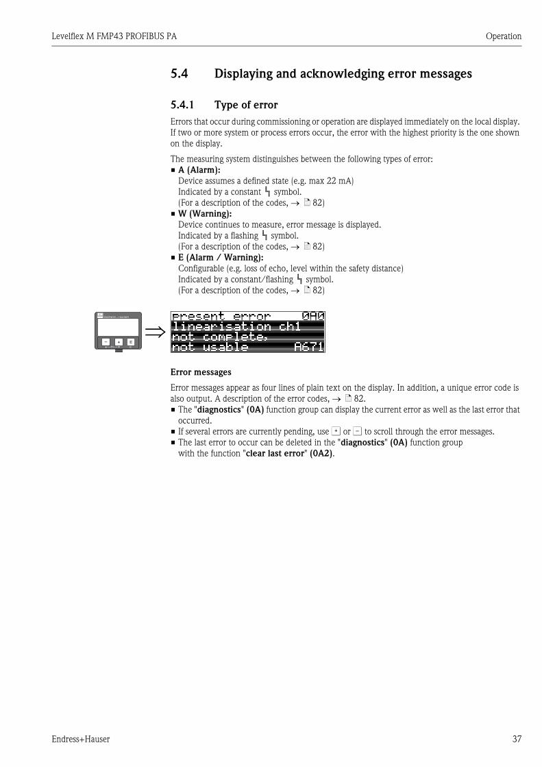
5.4 Displaying and acknowledging error messages
5.4.1 Type of error
Errors that occur during commissioning or operation are displayed immediately on the local display.
If two or more system or process errors occur, the error with the highest priority is the one shown
on the display.
The measuring system distinguishes between the following types of error:
• A (Alarm):
Device assumes a defined state (e.g. max 22 mA)
Indicated by a constant symbol.
(For a description of the codes, → ä 82)
• W (Warning):
Device continues to measure, error message is displayed.
Indicated by a flashing symbol.
(For a description of the codes, → ä 82)
• E (Alarm / Warning):
Configurable (e.g. loss of echo, level within the safety distance)
Indicated by a constant/flashing symbol.
(For a description of the codes, → ä 82)
Error messages
Error messages appear as four lines of plain text on the display. In addition, a unique error code is
also output. A description of the error codes, → ä 82.
• The "diagnostics" (0A) function group can display the current error as well as the last error that
occurred.
• If several errors are currently pending, use O or S to scroll through the error messages.
• The last error to occur can be deleted in the "diagnostics" (0A) function group
with the function "clear last error" (0A2).
⇒ENDRESS + HAUSER
E+–

Operation Levelflex M FMP43 PROFIBUS PA
38 Endress+Hauser
5.5 PROFIBUS PA communication
5.5.1 Synopsis
L00-FMPxxxxx-14-00-06-xx-007
A maximum of 32 transmitters can be connected to the bus (only 10 in explosion hazardous areas
Ex ia IIC according to the FISCO model). The bus power is supplied by the segment coupler.
On-site as well as remote operation are possible. For detailed information on the PROFIBUS PA
standard refer to Operation Instructions BA034S/04/EN and the standards EN 50170/DIN 19245
(PROFIBUS PA) and EN 50020 (FISCO model).
ENDRESS + HAUSER
Micropilot M Prosonic M
Levelflex M
ENDRESS + HAUSER
E+–
%
T
PROFIBUS DP
PROFIBUS PA
• FieldCare• Profiboard/Proficard
SPS / PLC / API
VU331
FieldCare
1
FHX40
Gammapilot M
VU331
Commubox FXA291 withToF Adapter FXA291

Levelflex M FMP43 PROFIBUS PA Operation
Endress+Hauser 39
5.5.2 Device address
Selecting the device address
• Every PROFIBUS PA device must be given an address. If the address is not set correctly, the device
will not be recognised by the process control system.
• A device address may appear only once within a particular PROFIBUS PA network.
• Valid device addresses are in the range 1 and 126. All devices are delivered from the factory with
the software address 126.
• The default address can be used to check the function of the device and connect it to an operating
PROFIBUS PA system. Afterwards the address must be changed to allow other devices to be
connected to the network.
Software addressing
Software addressing comes into operation, when DIP-switch 8 is in the position "ON".
BA034S/04/EN describes, how to set the address in this case.
Hardware addressing
L00-FMU4xxxx-19-00-00-en-014
Hardware addressing comes into operation, when DIP switch 8 is in the position "HW (OFF)". In
this case the address is determinded by the position of DIP-switches 1 to 7 according to the
following table:
The new address becomes valid 10 seconds after switching.
It results a new device restart.
ENDRESS+HAUSER
MICROPILOT II
ENDRESS+HAUSER
MICROPILOT II
IP 65IP 65
Order Code:Ser.-No.:
Order Code:Ser.-No.:
MessbereichMeasuring range
MessbereichMeasuring rangeU 16...36 V DC
4...20 mA
U 16...36 V DC4...20 mA
max. 20 m
max. 20 m
Made in
Germ
any
M
aulb
urg
Made in
Germ
any
M
aulb
urg
T>70°C :
A
t >85°C
T>70°C :
A
t >85°C
onoff
SWHW
41 2 3 5 6 87
1 2 3 4 5 6 7 8
2 + 8 = 10
ONOFF
SWHW
method ofaddressing
address
Switch No. 1 2 3 4 5 6 7
Value in position "OFF" 0 0 0 0 0 0 0
Value in Position "ON" 1 2 4 8 16 32 64

Operation Levelflex M FMP43 PROFIBUS PA
40 Endress+Hauser
5.5.3 Device database and type files (GSD)
A device database file (GSD) contains a description of the properties of the PROFIBUS-PA device,
e.g. the supported transmission rates and the type and format of the digital information output to
the PLC. Additional bitmap files are required in order to represent the device by an icon in the
network design software. Every device is allocated an identity code by the PROFIBUS User
Organisation (PNO). This appears in the device data base file name (.gsd).
The Levelflex M has the ID number 0x152D (hex) = 5421 (dec).
Source of supply
• Internet (ftp-Server): ftp://194.196.152.203/pub/communic/gsd/Levelflex_m.EXE
• CD-ROM with GSD files for all Endress+Hauser devices. Order-Code: 50097200
• GSD library of the PROFIBUS User Organisation (PNO):http: //www.PROFIBUS.com
Directory structure
The files are oranized in the folowing strucutre:
L00-FMP4XXXX-02-00-00-YY-001
• The GSD files in the directory "Extended" are needed for the network design software STEP 7 of
the S7-300/400 PLC family.
• The GSD files in the directory "Standard" are used for PLCs, which do not support an identifier
format but only an identifier byte (e.g. PLC5 of Allen-Bradley)
• For the network design tool COM ET200 with Siemens S5 instead of an GSD file the Type file
"EH_3152Dx.200" and instead of the BMP files the DIB files have to be used.
Universal Database File
As an alternative to the device specific GSD file, the PNO provides an universal database file with
the designation PA139700.gsd for devices with one analogue input block. This file supports the
transmission of the main value. Transmission of a second cyclic value or a display value is not
supported. When the universal database is used, the option "profile" must be selected in the
function "Ident number" (061).
Levelflex_M/PA/Profile3/Revision1.0/
BMP/
Eh152D_d.bmpEh152D_n.bmpEh152D_s.bmp
DIB/
Eh152D_d.dibEh152D_n.dibEh152D_s.dib
GSD/
Extended/Eh3x152D.gsd
Standard/Eh3_152D.gsd
Typdat5x/Eh3152Dx.200
Info/
Liesmich.pdfReadme.pdf

Levelflex M FMP43 PROFIBUS PA Operation
Endress+Hauser 41
5.5.4 Cyclic data exchange
Block model of the Levelflex M
L00-FMR230xx-02-00-00-en-001
The block model shows, which data are exchanged continously (i.e. by cyclic data transfer) between
the Levelflex M and the PLC. The numbers refer to the function groups and functions:
• After linearization and integration in the transducer block the "measured value" (000) is
transmitted to the Analog-Input Block. There, it may be scaled and checked for limit
transgression, and is written out over "OUT value" (063) to the PLC.
• The function "select V0H0" (068) determines whether at the display of the device in the field
for the main measured value the "measured value" (000) or the value from the PLC "display
value" (069) are displayed.
Modules for the cyclic data telegram
For the cyclic data telegram the Levelflex provides the following modules:
1. Main Process Value
This is the main measured value scaled by the Analog Input Block (063).
2. 2nd Cyclic Value
This is the measured distance between the probe and the product surface (0A5) or the
measured temperature (030).
3. Display Value
This is a value which can be transferred from the PLC to the Levelflex M in order to be shown
on the display.
4. FREE PLACE
This module must be applied during configuration (see below), if the 2nd cyclic value or the
display value are not to appear in the data telegram.
Operation Levelflex M FMP43 PROFIBUS PA
42 Endress+Hauser
Configuration of the cyclic data telegram
Use the configuration software of your PLC in order to compose the data telegram from these
modules in one of the following ways:
1. Main value
In order to transmit the main measured value, selct the module "Main Process Value".
2. Main value and second cyclic value
In order to transmit the main value and the second cyclic value (temperature or measured
distance), select the modules in the following order: "Main Process Value", "2nd Cyclic
Value", "FREE PLACE".
3. Main value and display value
In order to transmitt the main value and to receive a display value select the modules in the
following order: "Main Process Value", "FREE PLACE", "Display Value".
4. Main value, second cyclic value and display value
In order to transmit the main value and the second cyclic value and to receive a display value,
select the modules in the following order: "Main Process Value", "2nd Cyclic Value",
"Display Value".
The exact way of performing the configuration depends on the configuration software of the PLC.
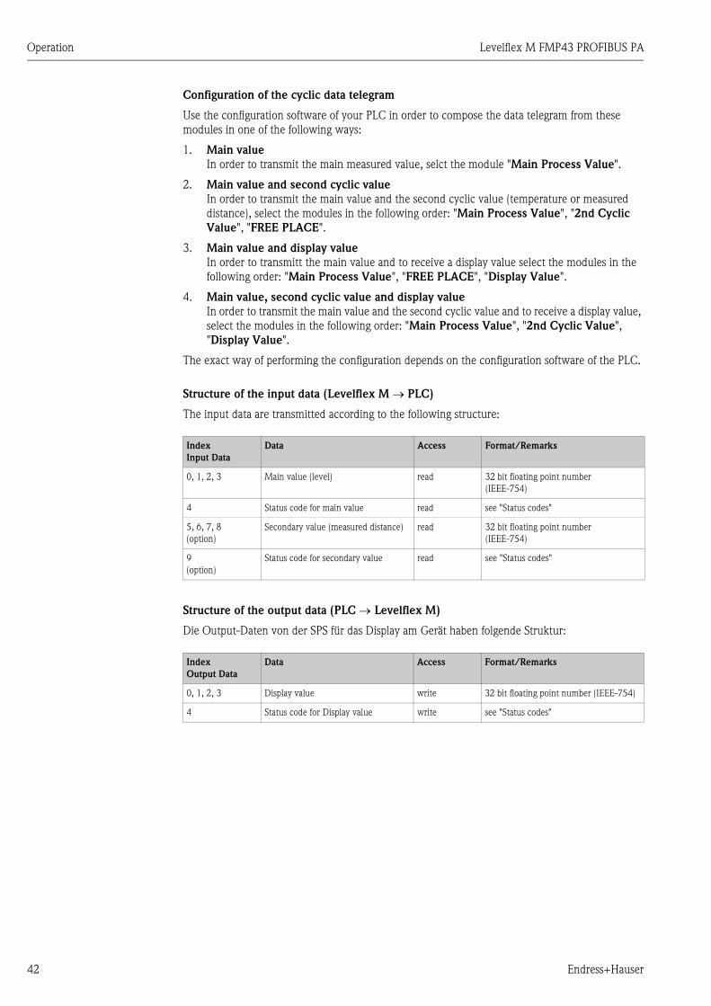
Structure of the input data (Levelflex M → PLC)
The input data are transmitted according to the following structure:
Structure of the output data (PLC → Levelflex M)
Die Output-Daten von der SPS für das Display am Gerät haben folgende Struktur:
Index
Input Data
Data Access Format/Remarks
0, 1, 2, 3 Main value (level) read 32 bit floating point number
(IEEE-754)
4 Status code for main value read see "Status codes"
5, 6, 7, 8
(option)
Secondary value (measured distance) read 32 bit floating point number
(IEEE-754)
9
(option)
Status code for secondary value read see "Status codes"
Index
Output Data
Data Access Format/Remarks
0, 1, 2, 3 Display value write 32 bit floating point number (IEEE-754)
4 Status code for Display value write see "Status codes"

Levelflex M FMP43 PROFIBUS PA Operation
Endress+Hauser 43
IEEE-745 Floating Point Number
The measured value is transmitted as a IEEE 754 floating point number, whereby
Measured value = (-1)VZ x 2(E-127) x (1+F)
Example:
Status codes
The status codes comprise one byte and have got the following meaning:
If a status other than "GOOD" is sent to the device, the display indicates an error.
Byte 1 Byte 2
Bit 7 Bit 6 Bit 5 Bit 4 Bit 3 Bit 2 Bit 1 Bit 0 Bit 7 Bit 6 Bit 5 Bit 4 Bit 3 Bit 2 Bit 1 Bit 0
VZ 27 26 25 24 23 22 21 20 2-1 2-2 2-3 2-4 2-5 2-6 2-7
Exponent (E) Mantisse (F)
Byte 3 Byte 4
Bit 7 Bit 6 Bit 5 Bit 4 Bit 3 Bit 2 Bit 1 Bit 0 Bit 7 Bit 6 Bit 5 Bit 4 Bit 3 Bit 2 Bit 1 Bit 0
2-8 2-9 2-10 2-11 2-12 2-13 2-14 2-15 2-16 2-17 2-18 2-19 2-20 2-21 2-22 2-23
Mantisse (F)
40 F0 00 00 (hex) = 0100 0000 1111 0000 0000 0000 0000 0000 (bin)
= (-1)0 x 2(129-127) x (1 + 2-1 + 2-2 + 2-3)
= 1 x 22 x (1 + 0.5 + 0.25 + 0.125)
= 1 x 4 x 1.875
= 7.5
Status-
Code
Device status Significance Primary value Secondary value
0C Hex BAD instrument error X
0F Hex BAD instrument error X
1F Hex BAD out-of-service (target mode) X
40 Hex UNCERTAIN non-specific (simulation) X
47 Hex UNCERTAIN last usable value
(Fail-safe-Mode aktiv)
X
4B Hex UNCERTAIN Substitute set
(fail-Safe mode active)
X
4F Hex UNCERTAIN initial value
(fail-Safe mode active)
X
5C Hex UNCERTAIN Configuration error
(limits not set correctly)
X
80 Hex GOOD OK X X
84 Hex GOOD Active block alarm
(static revision counter incremented)
X
89 Hex GOOD LOW_LIM (alarm active) X
8A Hex GOOD HI_LIM (alarm active) X
8D Hex GOOD LOW_LOW_LIM (alarm active) X
8E Hex GOOD HI_HI_LIM (alarm active) X

Operation Levelflex M FMP43 PROFIBUS PA
44 Endress+Hauser
5.5.5 Acyclic data exchange
Acyclic data exchange allows device parameters to be changed independently of the communication
between the device and a PLC.
Acyclic data exchange is used
• to transmit device parameters during commissioning and maintenance;
• to display measured values that are not acquired in cyclic traffic.
There are two types of acyclic data exchange:
Acyclic communication with a Class 2 master (MS2AC)
In the case of MS2AC, a Class 2 master opens a communication channel via a so-called service
access point (SAP) in order to access the device. Class 2 masters are for example:
• FieldCare
• PDM
Before data can be exchanged via PROFIBUS, however, the Class 2 master must be made aware of
the parameters contained within the field device. This can be done by:
• a device description (DD)
• a device type manager (DTM)
• a software component within the master, which accesses the parameters via slot and index
addresses.
! Note!
• The DD or DTM is supplied by the device manufacturer.
• The number of Class 2 masters that can simultaneously access a device, is determined by the
number of SAPs that the device can provide.
• The use of a Class 2 master increases the cycle time of the bus system. This must be taken into
consideration when the control system or PLC is programmed.
Acyclic communication with a Class 1 master (MS1AC)
In the case of MS1AC, a Class 1 master that is already communicating cyclically with a device opens
a communication channel via SAP 0x33, a special access point for MS1AC. As is the case for a Class
2 master, the parameter is read or written via the slot and index.
! Note!
• At the time of writing, there are only a few PROFIBUS masters that support this type of
communication.
• Not all PROFIBUS field devices support MS1AC.
" Caution!
Permanent writing of parameters, e.g. with every cycle of the application program, must be avoided,
since this can drastically reduce the life of the device.
Acyclic write parameters are stored electrically in the RAM (EEPROM, Flash...). The RAM modules
are design for a limited number of write operations only. In standard operation without MS1AC, i.e.
during parametrisation of the device, the number of write operations is negligible when compared
to the limit. If the application program is badly designed, however, this limit can be reached quickly,
and the RAM will fail
The Levelflex M supports MS2AC communication with two SAP´s.
The Levelflex M does not support MS1AC communication.

Levelflex M FMP43 PROFIBUS PA Operation
Endress+Hauser 45
5.5.6 Slot/index tables
Device Management
Analog-Input-Block
Parameter Endress+Hauser
Matrix (CW II)
Slot Index Size
[bytes]
Type Read Write Storage
Class
Directory object
header
1 0 12 Array of
UNSIGNED16
X constant
Composite list
directory entries
1 1 24 Array of
UNSIGNED16
X constant
Parameter Endress+Hauser
Matrix (CW II)
Slot Index Size
[bytes]
Type Read Write Storage
Class
Standard parameters
Block Data 1 16 20 DS-32* X constant
Static revision 1 17 2 UNSIGNED16 X non-vol.
Instrument tag 1 18 32 OSTRING X X static
Strategy 1 19 2 UNSIGNED16 X X static
Alert key 1 20 1 UNSIGNED8 X X static
Target Mode 1 21 1 UNSIGNED8 X X static
Mode 1 22 3 DS-37* X dynamic
non-vol.
constant
Alarm summary 1 23 8 DS-42* X dynamic
Batch 1 24 10 DS-67* X X static
Gap 1 25
Block parameters
Out V6H2 (Wert)
V6H3 (Status)
1 26 5 DS-33* X dynamic
PV Scale 1 27 8 Array of FLOAT X X static
Out Scale 1 28 11 DS-36* X X static
Linearisation type 1 29 1 UNSIGNED8 X X static
Channel 1 30 2 UNSIGNED16 X X static
Gap 1 31
PV fail safe time 1 32 4 FLOAT X X non-vol.
Fail safe type 1 33 1 UNSIGNED8 X X static
Fail safe value 1 34 4 FLOAT X X static
Alarm Hysteresis 1 35 4 FLOAT X X static
Gap 1 36
HI HI Limit 1 37 4 FLOAT X X static
Gap 1 38
HI Limit 1 39 4 FLOAT X X static
Gap 1 40
LO Limit 1 41 4 FLOAT X X static
Gap 1 42

Operation Levelflex M FMP43 PROFIBUS PA
46 Endress+Hauser
Physical Block
LO LO Limit 1 43 4 FLOAT X X static
Gap 1 44-45
HI HI Alarm 1 46 16 DS-39* X dynamic
HI Alarm 1 47 16 DS-39* X dynamic
LO Alarm 1 48 16 DS-39* X dynamic
LO LO Alarm 1 49 16 DS-39* X dynamic
Simulate 1 50 6 DS-51* X X non-vol.
Out unit text 1 51 16 OSTRING X X static
Parameter Endress+Hauser
Matrix (CW II)
Slot Index Size
[bytes]
Type Read Write Storage
Class
Standard parameters
Block Data 0 16 20 DS-32* X constant
Static revision 0 17 2 UNSIGNED16 X non-vol.
Instrument tag 0 18 32 OSTRING X X static
Strategy 0 19 2 UNSIGNED16 X X static
Alert key 0 20 1 UNSIGNED8 X X static
Target mode 0 21 1 UNSIGNED8 X X static
Mode 0 22 3 DS-37* X dynamic
non-vol.
constant
Alarm summary 0 23 8 DS-42* X dynamic
Block parameters
Software revision 0 24 16 OSTRING X constant
Hardware revision 0 25 16 OSTRING X constant
Instrument
manufacturer ID
0 26 2 UNSIGNED16 X constant
Instrument ID 0 27 16 OSTRING X constant
Instrument serial
number
0 28 16 OSTRING X constant
Diagnosis 0 29 4 OSTRING X dynamic
Diagnosis extension 0 30 6 OSTRING X dynamic
Diagnosis mask 0 31 4 OSTRING X constant
Diagnosis mask ext. 0 32 6 OSTRING X constant
Instrument certification 0 33 32 OSTRING X X constant
Security locking V9H9 0 34 2 UNSIGNED16 X X non-vol.
Factory reset V9H5 0 35 2 UNSIGNED16 X non-vol.
Descriptor 0 36 32 OSTRING X X static
Instrument message 0 37 32 OSTRING X X static
Instrument instal. date 0 38 8 OSTRING X X static
Gap reserved 0 39
Ident number select V6H0 0 40 1 UNSIGNED8 X X static
HW write protection 0 41 1 UNSIGNED8 X X dynamic
Parameter Endress+Hauser
Matrix (CW II)
Slot Index Size
[bytes]
Type Read Write Storage
Class

Levelflex M FMP43 PROFIBUS PA Operation
Endress+Hauser 47
Endress+Hauser specific level transducer block
Gap reserved 0 42-53
Endress+Hauser-Parameters
error code 0 54 2 UNSIGNED16 X dynamic
last error code 0 55 2 UNSIGNED16 X X dynamic
Up Down features 0 56 1 OSTRING X constant
Up Down control 0 57 1 UNSIGNED8 X dynamic
Up Down param 0 58 20 OSTRING X X dynamic
Bus address 0 59 1 UNSIGNED8 X dynamic
Instrument SW No. 0 60 2 UNSIGNED16 X dynamic
set unit to bus 0 61 1 UNSIGNED8 X X static
input value 0 62 6 FLOAT+U8+U8 X dynamic
Select Main value 0 63 1 UNSIGNED8 X X dynamic
PA profile revision 0 64 16 OSTRING X constant
Parameter Endress+Hauser
Matrix (CW II)
Slot Index Size
[bytes]
Type Read Write Storage
Class
Standard parameter
Block data 1 130 20 DS-32* x constant
Static revision 1 131 2 UNSIGNED16 x non-vol.
Instrument tag 1 132 32 OSTRING x x static
Strategy 1 133 2 UNSIGNED16 x x static
Alert key 1 134 1 UNSIGNED8 x x static
Target mode 1 135 1 UNSIGNED8 x x static
Mode 1 136 3 DS-37* x dynamic
/
non-
vol./
static
Alarm summary 1 137 8 DS-42* x dynamic
Endress+Hauser parameters
Measured value V0H0 1 138 4 FLOAT x dynamic
Gap 139
Tank properties V0H2 1 140 1 UNSIGNED8 x x static
Application parameter V0H3 1 141 1 UNSIGNED8 x x static
Process properties V0H4 1 142 1 UNSIGNED8 x x static
Empty calibration V0H5 1 143 4 FLOAT x x static
Full calibration V0H6 1 144 4 FLOAT x x static
Tube diameter V0H7 1 145 4 FLOAT x x static
Gap 146 - 147
Output on alarm V1H0 1 148 1 UNSIGNED8 x x static
Gap 149
Outp. echo loss V1H2 1 150 1 UNSIGNED8 x x static
Ramp %span/min V1H3 1 151 4 FLOAT x x static
Parameter Endress+Hauser
Matrix (CW II)
Slot Index Size
[bytes]
Type Read Write Storage
Class

Operation Levelflex M FMP43 PROFIBUS PA
48 Endress+Hauser
Delay time V1H4 1 152 2 UNSIGNED16 x x static
Safety distance V1H5 1 153 4 FLOAT x x static
In safety dist. V1H6 1 154 1 UNSIGNED8 x x static
Reset self holding V1H7 1 155 1 UNSIGNED8 x x static
Operating mode V1H8 1 156 1 UNSIGNED8 x x static
Brocken probe det. V1H9 1 157 1 UNSIGNED8 x x static
End of probe V2H0 1 158 1 UNSIGNED8 x x static
Probe shortened V2H1 1 159 1 UNSIGNED8 x x static
Probe free V2H2 1 160 1 UNSIGNED8 x x static
Probe length V2H3 1 161 4 FLOAT x x static
Probe length setup V2H4 1 162 1 UNSIGNED8 x x static
Gap 1 163-167
Level/ullage V3H0 1 168 1 UNSIGNED8 x x static
Linearisation mode V3H1 1 169 1 UNSIGNED8 x x static
Customer unit V3H2 1 170 1 UNSIGNED16 x x static
Table no. V3H3 1 171 1 UNSIGNED8 x x static
Input level V3H4 1 172 4 FLOAT x x static
Input volume V3H5 1 173 4 FLOAT x x static
Max. volume V3H6 1 174 4 FLOAT x x static
Cylinder vessel V3H7 1 175 4 FLOAT x x static
Gap 1 176-177
Selection V4H0 1 178 1 UNSIGNED8 x x static
check distance V4H1 1 179 1 UNSIGNED8 x x static
Range of mapping V4H2 1 180 4 FLOAT x x static
Mapping rec start V4H3 1 181 1 UNSIGNED8 x x static
Pres. map. dist. V4H4 1 182 4 FLOAT x dynamic
Delete mapping V4H5 1 183 1 UNSIGNED8 x x static
Echo quality V4H6 1 184 1 UNSIGNED8 x dynamic
Offset meas dist V4H7 1 185 4 FLOAT x x static
Output damping V4H8 1 186 4 FLOAT x x static
High blocking dist. V4H9 1 187 4 FLOAT x x static
Bus address V5H0 1 188 1 UNSIGNED8 x dynamic
Ident nr sel V5H1 1 189 1 UNSIGNED8 x x static
Set unit to bus V5H2 1 190 1 UNSIGNED8 x x static
AI out value V5H3 1 191 4 FLOAT x dynamic
AI out status V5H4 1 192 1 UNSIGNED8 x dynamic
Simulation type V5H5 1 193 1 UNSIGNED8 x x static
Simulation value V5H6 1 194 4 FLOAT x x static
2nd cyclic value V5H7 1 195 1 UNSIGNED8 x x static
Select Main Value V5H8 1 196 1 UNSIGNED8 x x static
Input value V5H9 1 197 4 FLOAT x dynamic
Gap 1 198
Display contrast V6H1 1 199 1 UNSIGNED8 x x static
Parameter Endress+Hauser
Matrix (CW II)
Slot Index Size
[bytes]
Type Read Write Storage
Class

Levelflex M FMP43 PROFIBUS PA Operation
Endress+Hauser 49
Data strings
In der Slot/Index table some data types, e.g. DS-33 are marked by an asterisk. These are data strings
according to the PROFIBUS-PA specifications part 1, Version 3.0. They contain several elements,
which are addressed by an additional subindex. The following table gives an example.
Language V6H2 1 200 1 UNSIGNED8 x x static
Back to home V6H3 1 201 2 INT16 x x static
Format display V6H4 1 202 1 UNSIGNED8 x x static
No. decimals V6H5 1 203 1 UNSIGNED8 x x static
Sep. character V6H6 1 204 1 UNSIGNED8 x x static
Display test V6H7 1 205 1 UNSIGNED8 x x static
Gap 1 206 - 207
Gap 1 218-227
Actual alarm V9H0 1 228 STRUCT x dynamic
Last alarm V9H1 1 229 STRUCT x dynamic
Clear last alarm V9H2 1 230 1 UNSIGNED8 x x static
Reset V9H3 1 231 2 UNSIGNED16 x x static
Operating code V9H4 1 232 2 UNSIGNED16 x x static
Measured distance V9H5 1 233 4 FLOAT x dynamic
Measured level V9H6 1 234 4 FLOAT x dynamic
Gap 1 235
Application parameter V9H8 1 236 1 UNSIGNED8 x dynamic
Gap 1 237
Tag no. VAH0 1 238 STRING x const
Profile revision VAH1 1 239 STRING x x static
Version string VAH2 1 240 STRING x const
Gap 1 241
Serial no. VAH4 1 242 STRING x x static
Distance unit VAH5 1 243 2 UNSIGNED16 x x static
Gap 1 244 - 245
Download mode VAH8 1 246 1 UNSIGNED8 x x static
Data type Subindex Typ Size [bytes]
DS-331 FLOAT 4
5 UNSIGNED8 1
Parameter Endress+Hauser
Matrix (CW II)
Slot Index Size
[bytes]
Type Read Write Storage
Class

Operation Levelflex M FMP43 PROFIBUS PA
50 Endress+Hauser
5.5.7 Scaling of the output data
The on-site display and the digital output are working independently of each other.
On-site display
The on-site display always displayes the main value V0H0 directly from the Transducer Block.
Digital output
For the digital output this value is rescaled in two steps:
L00-FMUx3xxx-05-00-00-en-001
1. In a first step, the main value is mapped to the interval [0;1]. PV_SCALE_MIN and
PV_SCALE_MAX determine the limits of this mapping.
2. In a second step, the interval [0,1] is mapped to the interval [OUT_SCALE_MIN,
OUT_SCALE_MAX]. The value resulting from this mapping is transfered via V6H2 to the PLC.
! Note!
The scaling of the ouptut value is required by the Profibus profiles. It prevents uncontrolled jumps
of the output value when one changes the unit of the measuring value in the Transducer Block.
If units are changed, PV_SCALE_MIN and PV_SCALE_MAX automatically adapt themselves in
such a way that the output value remains unchanged. Only after confirming the change by the "Set
unit to bus" (062) function,
OUT_SCALE_MIN is set equal to PV_SCALE_MIN and
OUT_SCALE_MAX equal to PV_SCALE_MAX.
Thereby the new unit also becomes effective at the output.
" Caution!
If a linearisation has been carried out, it must be confirmed by the "Set unit to bus" (062) function
in order to become effective at the digital output.
0 10
1PV_SCALE_MAX
PV_SCALE_MINOUT_SCALE
MINOUT_SCALE
MAX
V0H0
AI_OUT(V6H2)
PLC
from Transducerblock

Levelflex M FMP43 PROFIBUS PA Operation
Endress+Hauser 51
5.5.8 Endress+Hauser operating program
The operating program FieldCare is an Endress+Hauser Plant Asset Management Tool based on
FDT technology. You can use FieldCare to configure all your Endress+Hauser devices, as well as
devices from other manufacturers that support the FDT standard. Hardware and software
requirements you can find on the internet:
www.endress.com È select your country È search: FieldCare È FieldCare È Technical Data.
FieldCare supports the following functions:
•Online configuration of transmitters
•Signal analysis via envelope curve
•Tank linearization
•Loading and saving of device data (upload/download)
•Documentation of the measuring point
Connection options:
•PROFIBUS PA via segment coupler and PROFIBUS interface card
•Commubox FXA291 with ToF Adapter FXA291 via service interface
Menu-guided commissioning
L00-FMP4xxxx-20-00-00-en-001

Operation Levelflex M FMP43 PROFIBUS PA
52 Endress+Hauser
Signal analysis via envelope curve
Tank linearization
L00-FMP4xxxx-20-00-00-en-007
L00-fmp-Ixxx-20-00-00-en-041

Levelflex M FMP43 PROFIBUS PA Commissioning
Endress+Hauser 53
6 Commissioning
6.1 Function check
Make sure that all final checks have been completed before you start up your measuring point:
• Checklist "Post-installation check", → ä 20.
• Checklist "Post-connection check", → ä 29.
6.2 Switching on the measuring device
When the device is switched on for the first time, the following messages appear in a sequence of
5 s on the display: software version, communication protocoll and language selection
⇒ Select the language (this message appears the first time
the device is switched on)
⇓Select the basic unit (this message appears the first time
the device is switched on)
⇓The current measured value is displayed
⇓ After pressing F, you are taken to the group selection
This selection enables you to perform the basic setup
ENDRESS + HAUSER
E+–

Commissioning Levelflex M FMP43 PROFIBUS PA
54 Endress+Hauser
6.3 Basic setup
L00-FMP43xxx-19-00-00-en-001
SD
UB
F
L
D
E
LN
lower edge of the process connectionreference point ofmeasurement
����������
��������
��������������
������
��������������
��������
�������
���������������
�����������
����������� ����
���
�������� ����
�� ��� ����
(description
see
BA
00245F
/00/E
N)
ba
sic
se
tup
(sta
nd
ard
)o
ptio
n
E = empty calibr. (= zero) LN = probe length
setting in 005 setting in 033F = full calibr. (= span) UB = upper blocking distance
setting in 006 setting in 059
D = distance (distance flange / product) SD = safety distance
display in 0A5 setting in 015
L = level
display in 0A6

Levelflex M FMP43 PROFIBUS PA Commissioning
Endress+Hauser 55
" Caution!
The basic setup is sufficient for successful commissioning in most applications.
The Levelflex is precalibrated at the factory to the probe length ordered so that in most cases only
the application parameters, which automatically adapt the device to the measuring conditions, need
to be entered. For digital outputs and the display module, the factory adjustment for zero point "E"
and span "F" is 0 % and 100 %.
A linearization function with max. 32 points, which is based on a table input manually or semi-
automatically, can be activated onsite or via remote operation. This function allows the conversion
of the level into units of volume or weight, for example.
! Note!
The Levelflex M also makes it possible to monitor the probe for breakage. On delivery, this function
is switched since any probe shortening would be mistaken for a broken probe. To activate this
function, perform the following:
1. With the probe uncovered, perform a mapping ("range of mapping" (052) and "start
mapping." (053)).
2. Activate the "broken probe det" (019) function in the "safety settings" (01) function
group.
Complex measuring operations necessitate additional functions that the user can use to customize
the Levelflex as necessary to suit his specific requirements. The functions available to do this are
described in detail in BA00245F/00/EN.
Comply with the following instructions when configuring the functions in the "basic setup" (00):
• Select the functions as described, → ä 30.
• Certain functions (e.g. starting interference echo suppression (053)) prompt you to confirm this
function after entering the data. Press O or S to select "YES" and press F to confirm. The
function is now started.
• If you do not press a key during a configurable time period (→ function group "display (09)"),
the system returns automatically to the measured value display position.
! Note!
• The device continues to measure while data entry is in progress, i.e. the current measured values
are output via the signal outputs in the normal way.
• If the envelope curve mode is active on the display, the measured values are updated in a slower
cycle time. Thus, it is advisable to leave the envelope curve mode after the measuring point has
been optimized.
• If the power supply fails, all preset and configured values remain safely stored in the EEPROM.
• All functions are described in detail, as is the overview of the operating menu itself, in
"BA00245F – Description of Instrument Functions" on the enclosed CD-ROM.

Commissioning Levelflex M FMP43 PROFIBUS PA
56 Endress+Hauser
6.4 Basic setup with display VU331
Function "measured value" (000)
This function displays the current measured value in the selected unit (see "customer unit" (042))
function). The number of digits after the decimal point can be selected in the "no.of
decimals" (095) function.
6.4.1 Function group "basic setup" (00)
Function "tank properties" (002)
This function is used to select the tank properties.
Options:
• Standard
• Aluminum tank
• Plastic tank
• Bypass / pipe
• Coax probe
• Concrete wall
Standard
The "standard" option is recommended for normal containers for rod and rope probes.
Aluminum tank
The "aluminium tank" option is designed especially for high aluminium silos that cause an
increased level of noise when empty. This option is only useful for probes longer than > 4 m.
For short probes (< 4 m) select the "standard" option!
! Note!
If "aluminum tank" is selected, the device calibrates of its own accord when first filled, depending
on the medium's properties. Slope errors can, therefore, occur when beginning the first filling
procedure.
Plastic tank
Select the "plastic tank" option when installing probes in wood or plastic containers without
metallic surfaces at the process connection (see installation in plastic containers). When using a
metallic surface at the process connection, the "standard" option is sufficient!
! Note!
In principle, it is preferable to use a metallic surface at the process connection!
⇒ENDRESS + HAUSER
E+–
⇒ENDRESS + HAUSER
E+–
⇒ENDRESS + HAUSER
E+–

Levelflex M FMP43 PROFIBUS PA Commissioning
Endress+Hauser 57
Bypass / pipe
The "bypass / pipe" option is designed especially for the installation of probes in a bypass or a
stilling well. If this option is selected, the upper blocking distance is preset to 100 mm.
Coax probe (not relevant for FMP43)
Select the "coax probe" option when using a coaxial probe. When this setting is made, the
evaluation is adapted to the high sensitivity of the coax probe. This option should, therefore, not be
selected when using rope or rod probes.
Concrete wall
The "concrete wall" option takes into account the signal-damping property of concrete walls when
mounting with < 1 m distance to the wall.
Function "medium property" (003)
This function is used to select the dielectric constant.
Options:
• unknown
• 1.4 to 1.6 (use coax or Rod probe with installation in metallic pipes ≤ DN150)
• 1.6 to 1.9
• 1.9 to 2.5
• 2.5 to 4.0
• 4.0 to 7.0
• > 7.0
⇒ENDRESS + HAUSER
E+–
Media group DC (εr) Typical liquids Typ. measuring range
1 1.4 to 1.6 – Condensed gases, e.g. N2, CO2 —
2 1.6 to 1.9
– Liquefied gas, e.g. propane
– Solvent
– Frigen / Freon
– Palm oil
4 m (354")
3 1.9 to 2.5 – Mineral oils, fuels
4 2.5 to 4
– Benzene, styrene, toluene
– Furan
– Naphthalene
5 4 to 7
– Chlorobenzene, chloroform
– Cellulose spray
– Isocyanate, aniline
6 > 7
– Aqueous solutions
– Alcohols
– Acids, alkalis

Commissioning Levelflex M FMP43 PROFIBUS PA
58 Endress+Hauser
Function "process propert." (004)
Use this function to adapt the device reaction to the filling speed in the tank. The setting impacts
on an intelligent filter.
Options:
• Standard
• Fast change
• Slow change
• Test:no filter
Function "end of probe" (030)
Use this function to select the polarity of the probe end signal. If the probe end is uncovered or in
an insulated attachment, there is a negative probe end signal. The signal from the probe end is
positive if the attachment is grounded and a metallic centering of probe end is used.
Options:
• Free
• Tie down isol.
• Tie down gnd.
⇒ENDRESS + HAUSER
E+–
Selection: Standard Fast change Slow change Test:no filter
Application: For all normal
applications, bulk solids
and liquids at low to
medium filling speed
and sufficiently large
tanks.
Small tanks, primarily
with liquids, at high
filling speeds.
Applications with strong
surface movement, e.g.
caused by agitator,
primarily large tanks
with slow to medium
filling speed.
Shortest reaction time:
• For test purposes
• Measurement in
small tanks at high
filling speeds, if "fast
change" setting is too
slow.
2-wire
electronics:
Dead time: 4 s
Rise time: 18 s
Dead time: 2 s
Rise time: 5 s
Dead time: 6 s
Rise time: 40 s
Dead time: 1 s
Rise time: 0 s
4-wire
electronics:
Dead time: 2 s
Rise time: 11 s
Dead time: 1 s
Rise time: 3 s
Dead time: 3 s
Rise time: 25 s
Dead time: 0.7 s
Rise time: 0 s
⇒ENDRESS + HAUSER
E+–

Levelflex M FMP43 PROFIBUS PA Commissioning
Endress+Hauser 59
Function "probe length" (031)
Use this function to select whether the probe length was changed after factory calibration. Only then
is it necessary to enter or correct the probe length.
Options:
• not modified
• Modified
! Note!
If "modified" was selected in the "probe length" (031) function, the probe length is defined in the
next step.
Function "probe" (032)
Use this function to select whether the probe is uncovered or covered at the time of probe length
adjustment. If the probe is uncovered, the Levelflex can determine the probe length automatically
by the "determine length" (034) function. If the probe is covered, a correct entry is required in
the "probe length" (033) function.
Options:
• Free
• Covered
Function "probe length" (033)
Use this function to enter the probe length manually.
⇒ENDRESS + HAUSER
E+–
⇒ENDRESS + HAUSER
E+–
⇒ENDRESS + HAUSER
E+–

Commissioning Levelflex M FMP43 PROFIBUS PA
60 Endress+Hauser
Function "determine length" (034)
Use this function to determine the probe length automatically.
Depending on the installation conditions, the automatically determined probe length may be larger
than the actual probe length (typically 20 to 30 mm longer). This does not affect the measuring
accuracy. When entering a linearization, please use the "empty calibration" value for the empty
value instead of the automatically determined probe length.
Options:
• Length ok
• Too short
• Too long
After selecting "length too short" or "length too long", the calculation of the new value takes approx.
10 s.
Function "empty calibr." (005)
This function is used to enter the distance from the flange (reference point of the measurement) to
the minimum level (= zero).
L00-FMP4xxxx-14-00-06-en-008
⇒ENDRESS + HAUSER
E+–
⇒ENDRESS + HAUSER
E+–
0%
E
E = empty calibration (= zero)

Levelflex M FMP43 PROFIBUS PA Commissioning
Endress+Hauser 61
Function "full calibr." (006)
This function is used to enter the distance from the minimum level to the maximum level (= span).
L00-FMP4xxxx-14-00-06-en-009
! Note!
The usable measuring range lies between the upper blocking distance and the probe end.
The values for empty distance "E" and span "F" can be set independently of this.
Function "dist./meas.value" (008)
The distance measured from the reference point to the product surface and the meas. value
calculated with the aid of empty calibration are displayed. Check whether the values correspond to
the actual measured value or the actual distance. The following cases can occur:
• Distance correct – meas. value correct È continue with the next function "check distance" (051)
• Distance correct – meas. value incorrect È Check "empty calibr." (005)
• Distance incorrect – meas. value incorrect È continue with the next function
"check distance" (051)
⇒ENDRESS + HAUSER
E+–
100%
0%
F
F = full calibration (= span)
Fmax = E – upper blocking distance
⇒ENDRESS + HAUSER
E+–

Commissioning Levelflex M FMP43 PROFIBUS PA
62 Endress+Hauser
Function "check distance" (051)
This function triggers the mapping of interference echoes. To do so, the measured distance must be
compared with the actual distance to the product surface. The following options are available:
Options:
• Distance = ok
• Dist. too small
• Dist. too big
• Dist. unknown
• Manual
• Probe free
L00-FMP4xxxx-14-00-06-en-010
Distance = ok
Use this function for partially covered probes. Choose "manual" or "probe free" if the probe is free.
• Mapping is carried out up to the currently measured echo
• The range to be suppressed is suggested in the "range of mapping" (052) function
It is wise to carry out a mapping even in this instance.
! Note!
If the probe is free, the mapping should be confirmed with "probe free".
Dist. too small
• At the moment, an interference echo is being evaluated
• Therefore, a mapping is carried out including the echoes currently measured
• The range to be suppressed is suggested in the "range of mapping" (052) function
Dist. too big
• This error cannot be remedied by interference echo suppression
• Check application parameters (002), (003), (004) and "empty calibr." (005)
Dist. unknown
If the actual distance is not known, no mapping can be carried out.
⇒ENDRESS + HAUSER
E+–
+
+
distance toosmall distance=ok

Levelflex M FMP43 PROFIBUS PA Commissioning
Endress+Hauser 63
Manual
Mapping is also possible by manually entering the range to be suppressed. This entry is made in the
"range of mapping" (052) function.
" Caution!
The range of mapping must end 0.3 m (20") before the echo of the actual level.
Probe free
If the probe is uncovered, mapping is carried out along the whole probe length.
" Caution!
Only begin mapping in this function if the probe is definitely uncovered. Otherwise, the device will
not measure correctly!
Function "range of mapping" (052)
This function displays the suggested range of mapping. The reference point is always the reference
point of the measurement (→ ä 54). This value can be edited by the operator.
For manual mapping, the default value is 0.3 m.
Function "start mapping"(053)
This function is used to start the interference echo suppression up to the distance entered in "range
of mapping" (052).
Options:
• off: no mapping is carried out
• on: mapping is started
⇒ENDRESS + HAUSER
E+–
⇒ENDRESS + HAUSER
E+–

Commissioning Levelflex M FMP43 PROFIBUS PA
64 Endress+Hauser
Function "dist./meas.value" (008)
The distance measured from the reference point to the product surface and the measured value
calculated with the aid of the empty calibration are displayed again. Check whether the values
correspond to the actual meas. value or the actual distance. The following cases can occur:
• Distance correct – meas. value correct È basic setup completed
• Distance incorrect – meas. value incorrect È another interference echo suppression must be
carried out "check distance" (051)
• Distance correct – meas. value incorrect È check "empty calibr" (005)
! Note!
After the basic setup, it is recommended to evaluate the measurement with the aid of the envelope
curve ("envelope curve" (0E) function group, → ä 67).
⇒ENDRESS + HAUSER
E+–
⇒⇓ After 3 s, the following message appears
ENDRESS + HAUSER
E+–

Levelflex M FMP43 PROFIBUS PA Commissioning
Endress+Hauser 65
6.5 Blocking distance
Function "upper block. dist" (059)
For rod probes and for rope probes with lengths of up to 8 m, the upper blocking distance is set to
0.2 m at the factory.
The upper blocking distance (= UB) is the minimum distance from the reference point of the
measurement (lower edge of the process connection) to the maximum level. At the lowest part of
the probe an exact measurement is not possible, see "Performance characteristics", → ä 88.
L00-FMP43xxx-17-00-00-en-001
Reference point of measurement, details → ä 54
The blocking distance can be reduced if the probe is mounted flush with the wall or in a nozzle,
max. 50 mm in height.
When using a spray ball the blocking distance may not be smaller than 50 mm.
⇒ENDRESS + HAUSER
E+–
100%
0%
F
UB
D
L
E
reference point ofmeasurement
max. 20 m /67 ft
remote displayFHX40
F = measuring span
E = empty distance (=zero)
UB = upper blocking distance
LN = probe length
probe length LN

Commissioning Levelflex M FMP43 PROFIBUS PA
66 Endress+Hauser
Maximum measured error
Typical values under reference operating conditions:
DIN EN 61298-2, percentage values with reference to the span.
If the reference conditions are not met, the offset/zero point resulting from the installation setup
may be up to ±12 mm. This additional offset/zero point can be compensated for by entering a
correction (function "offset" (057)) during commissioning.
Differing from this, the following measuring error is present in the vicinity of the upper and lower
probe end:
Output: Digital
Sum of non-linearity,
non-repeatability and hysteresis
±3 mm
Offset / zero point ±4 mm
L00-FMP43xxx-05-00-00-en-001
3 mm
0 mm
- 3 mm
100 mm 200 mm 80 mm200 mm 40 mm 20 mm
10 mm
- 10 mm
20 mm
- 20 mm
30 mm
- 30 mm
40 mm
- 40 mm
50 mm
- 50 mm
DK > 7
DK > 7
60 mm
- 60 mm
DK = 2
DK = 2
reference point of measurement
pro
be
end
maxim
um
measure
derr
or
pro
be
end
(water-basedmedium)
(water-basedmedium)
(oils and solvents)
( )oils and solvents

Levelflex M FMP43 PROFIBUS PA Commissioning
Endress+Hauser 67
6.6 Envelope curve with VU331
After the basic setup, it is recommended to evaluate the measurement with the aid of the envelope
curve ("envelope curve" (0E)) function group.
6.6.1 Function "plot settings" (0E1)
Here you can select which information is shown on the display:
• Envelope curve
• Substracted signal
• Mapping
! Note!
The interference echo suppression (map) are explained in BA00245F/00/EN "Description of
Instrument Functions".
6.6.2 Function "recording curve" (0E2)
This function determines whether the envelope curve is read as
• Single curve or
• Cyclic
! Note!
If the envelope curve mode is active on the display, the measured values are updated in a slower
cycle time. Thus, it is advisable to leave the envelope curve mode after the measuring point has been
optimized.
⇒ENDRESS + HAUSER
E+–
⇒ENDRESS + HAUSER
E+–

Commissioning Levelflex M FMP43 PROFIBUS PA
68 Endress+Hauser
6.7 Function "envelope curve display" (0E3)
You can obtain the following information from the envelope curve display in this function:
L00-FMPxxxxx-07-00-00-en-003
6.7.1 Envelope curve
The Levelflex emits individual pulses in quick succession and scans their reflection with a slightly
variable delay. The energy values received are ordered by their time-of-flight. The graphic
representation of this sequence is known as an "envelope curve".
6.7.2 Mapping (empty curve) and difference curve
To suppress interference signals, the envelope curve is not directly evaluated in the Levelflex.
The mapping (empty curve) is first subtracted from the envelope curve.
The system looks for level echoes in the resulting difference curve.
Difference curve = envelope curve - mapping (empty curve)
The mapping (empty curve) should be a good representation of the probe and the empty tank or
silo. Ideally, only the signals from the medium being measured remain in the difference curve.
minimum distanceof the plot
maximum distanceof the plot
distance ofevaluated echo
evaluated echois marked
quality ofevaluated echo empty calibr.
empty calibr.
empty calibr.
envelope curve
substracted signal
mapping
level echo
level echo
full calibr.
full calibr.
probe length
probe length

Levelflex M FMP43 PROFIBUS PA Commissioning
Endress+Hauser 69
6.7.3 Mapping
• Factory mapping
Mapping (empty curve) is already available in the device when the device is delivered.
• Customer mapping
In a partially filled state, the distance up to 10 cm before the actual total level can be mapped
(range of mapping = actual distance from total level - 10 cm), or values > LN can be mapped in
the case of empty tanks.
• Dynamic mapping
It is not static like factory and customer-specific interference echo suppression. Instead, it follows
directly from static mapping and constantly adapts to the changing features of the probe
environment during ongoing operation. Thus, dynamic mapping does not have to be recorded
explicitly.
6.7.4 Echo threshold
Maximum points in the difference curve are only accepted as reflection signals if they are above a
specified threshold. This threshold depends on the location and is automatically calculated from the
ideal echo curve of the probe used. The calculation of the threshold in question depends on the
"Installation" customer parameter in the extended calibration function.
6.7.5 Navigation in the envelope curve display
Using navigation, the envelope curve can be scaled horizontally and vertically and shifted to the left
or the right. The active navigation mode is indicated by a symbol in the top left hand corner of the
display.
L00-FMPxxxxx-07-00-00-en-004
Horizontal zoom mode
Press O or S, to switch to the envelope curve navigation. You are now in the horizontal zoom
mode. Either or is displayed.
You now have the following options:
• O increases the horizontal scale.
• S decreases the horizontal scale.
L00-FMPxxxxx-07-00-00-xx-001
…
Move mode:
- m
-
oved to the left
moved to the right
Horizontal Zoom mode:
- h
-
orizontal zoom in
horizontal zoom out
Vertical Zoom mode:
- vertical zoom (4 steps)
OS

Commissioning Levelflex M FMP43 PROFIBUS PA
70 Endress+Hauser
Move mode
Then press F to switch to the move mode. Either or is displayed.
You now have the following options:
• O shifts the curve to the right.
• S shifts the curve to the left.
L00-FMPxxxxx-07-00-00-xx-002
Vertical zoom mode
Press F once more to switch to the vertical zoom mode. is displayed.
You now have the following options:
• O increases the vertical scale.
• S decreases the vertical scale.
The display icon shows the current zoom factor ( to ).
L00-FMPxxxxx-07-00-00-xx-003
Exiting the navigation
• Press F again to run through the different modes of the envelope curve navigation.
• Press O and S to exit the navigation. The set increases and shifts are retained. Only when you
reactivate the "recording curve"(0E2) function does the Levelflex use the standard display
again.
OS
OS
⇒⇓ After 3 s, the following message appears
ENDRESS + HAUSER
E+–

Levelflex M FMP43 PROFIBUS PA Commissioning
Endress+Hauser 71
6.8 Basic setup with the Endress+Hauser operating
program
To carry out the basic setup with the operating program, proceed as follows:
• Start the operating program and establish a connection.
• Select the "basic setup" function group in the navigation window.
The following display appears on the screen:
Basic setup step 1/6:
• Status image
• The TAG number can be entered.
L00-FMP4xxxx-20-00-00-en-001
! Note!
• Each parameter that is changed must be confirmed with the RETURN key!
• The "Next" button takes you to the next screen:

Commissioning Levelflex M FMP43 PROFIBUS PA
72 Endress+Hauser
Basic setup step 2/6:
• Enter the application parameters (see chapter basic setup with "VU331"):
– Tank properties
– Medium properties
– Process properties
l00-fmp4xxxx-20-00-00-en-002
Basic setup step 3/6:
• Enter the application parameters (see chapter basic setup with "VU331"):
– End of probe
l00-fmp4xxxx-20-00-00-en-003

Levelflex M FMP43 PROFIBUS PA Commissioning
Endress+Hauser 73
Basic setup step 4/6:
• Enter the application parameters (see chapter basic setup with "VU331"):
– Probe length
– Probe
– Probe length
– Determine length
l00-fmp4xxxx-20-00-00-en-004
Basic setup step 5/6:
• Enter the application parameters (see chapter basic setup with "VU331"):
– Empty calibration
– Full calibration
l00-fmp4xxxx-20-00-00-en-005

Commissioning Levelflex M FMP43 PROFIBUS PA
74 Endress+Hauser
Basic setup step 6/6:
• Interference echo suppression takes place in this step
• The measured distance and the current measured value are always displayed in the header
l00-fmp4xxxx-20-00-00-en-006.gif
6.8.1 Signal analysis via envelope curve
After the basic setup, it is recommended to evaluate the measurement with the aid of the envelope
curve.
L00-FMP4xxxx-20-00-00-en-007
! Note!
In the event of severe interference echoes, installing the Levelflex at another point can optimize the
measurement routine.

Levelflex M FMP43 PROFIBUS PA Commissioning
Endress+Hauser 75
Evaluating the measurement with the aid of the envelope curve
Typical curve shapes:
The following examples display typical curve shapes for a rope or rod probe in an empty tank. For
all probe types, a negative probe end signal is shown. For rope probes, the end weight causes an
additional preliminary positive echo (see rope probe diagram).
L00-FMP40xxx-05-00-00-en-024
Level echoes are indicated as positive signals in the envelope curve. Interference echoes can be both
positive (e.g. reflections from internals) and negative (e.g. nozzles). The envelope curve, the map
and the differential curve are used for the evaluation. Level echoes are searched for in the
differential curve.
400.00 400.00
[mV] [mV]
300.00 300.00
200.00 200.00
100.00 100.00
0.00 0.00
-100.00 -100.00
-200.00 -200.00
-300.00 -300.00
-400.00 -400.00
-500.00 -500.00
0.00 0.000.20 0.200.40 0.400.60 0.600.80 0.801.00 1.00 1.20 1.40[m] [m]
LN LNE EF F
(1.00 m, -143.00 mV)(1.08 m, -115.00 mV)
Rod probe Rope probe
Probe end signal
Launch pulse
Probe end signal
Launch pulse

Commissioning Levelflex M FMP43 PROFIBUS PA
76 Endress+Hauser
Evaluating the measurement:
• The map must correspond to the course of the envelope curve (for rod probes up to approx. 5 cm
and for rope probes up to approx. 25 cm before the end of the probe) when the tank is empty.
• Amplitudes in the differential curve should be at a level of 0 mV when the tank is empty and lie
within the span that is specified by the probe-specific blocking distances. In order to not detect
any interference echoes, there must be no signals that exceed the echo threshold when the tank
is empty.
• For partially-filled tanks, the map may only differ from the envelope curve at the position of the
level echo. The level signal is then detected unequivocally as a positive signal in the differential
curve. For detecting the level echo, the amplitude must lie above the echo threshold.
L00-FMP40xxx-05-00-00-en-025
6.8.2 User-specific applications (operation)
For details of setting the parameters of user-specific applications, see separate documentation
BA00245F/00/EN "Description of Instrument Functions" on the enclosed CD-ROM.
400.00
400.00
400.00
[mV]
[mV]
[mV]
300.00
300.00
300.00
200.00
200.00
200.00
100.00
100.00
100.00
0.00
0.00
0.00
-100.00
-100.00
-100.00
-200.00
-200.00
-200.00
-300.00
-300.00
-300.00
-400.00
-400.00
-400.00
-500.00
-500.00
-500.00
0.00
0.00
0.000.20
0.20
0.200.40
0.40
0.400.60
0.60
0.600.80
0.80
0.801.00
1.00
1.00[m]
[m]
[m]
LN
LN
LNE
E
EF
F
F
(1.00 m, -143.00 mV)
(0.98 m, 0.00 mV)
(0.99 m, -137.94 mV)
Launch pulse
Negativeprobe end signal
Envelope curve
Differential curve = Envelope curve Mapping
Mapping

Levelflex M FMP43 PROFIBUS PA Maintenance
Endress+Hauser 77
7 Maintenance
The Levelflex M measuring device requires no special maintenance.
7.1 Exterior cleaning
When cleaning the Levelflex M, always use cleaning agents that do not attack the surface of the
housing and the seals.
7.2 Repair
The Endress+Hauser repair concept assumes that the measuring devices have a modular design and
that customers are able to undertake repairs themselves ("Spare Parts", → ä 86). Please contact
Endress+Hauser Service for further information on service and spare parts.
7.3 Repairs to Ex-approved devices
When carrying out repairs to Ex-approved devices, please note the following:
• Repairs to Ex-approved devices may only be carried out by trained personnel or by
Endress+Hauser Service.
• Comply with the prevailing standards, national Ex-area regulations, safety instructions (XA) and
certificates.
• Only use genuine spare parts from Endress+Hauser.
• When ordering a spare part, please note the device designation on the nameplate. Only replace
parts with identical parts.
• Carry out repairs according to the instructions. On completion of repairs, carry out the specified
individual test on the device.
• Only Endress+Hauser Service may convert a certified device into a different certified version.
• Document all repair work and conversions.
7.4 Replacement
After a complete Levelflex M or electronic module has been replaced, the parameters can be
downloaded into the device again via the communication interface. To do so, the data have to have
been uploaded to the PC beforehand using the FieldCare.Measurement can continue without
having to carry out a new calibration.
• You may have to activate linearization (see BA00245F/00/EN on the enclosed CD-ROM.)
• New interference echo suppression (see Basic setup)
After a probe or the electronics have been replaced, a new calibration must be carried out. This is
described in the repair instructions.

Accessories Levelflex M FMP43 PROFIBUS PA
78 Endress+Hauser
8 Accessories
8.1 Weather protection cover
A weather protection cover made of stainless steel is recommended for outdoor mounting (order
No: 543199-0001). The shipment includes the protective cover and tension clamp.
L00-FMR2xxxx-00-00-06-en-001
8.2 Weld-in adapter
ENDRESS+HAUSER
MICROPILOT II
ENDRESS+HAUSER
MICROPILOT II
IP 65IP 65
Order Code:Ser.-No.:
Order Code:Ser.-No.:
MessbereichMeasuring range
MessbereichMeasuring rangeU 16...36 V DC
4...20 mA
U 16...36 V DC4...20 mA
max. 20 m
max. 20 m
Ma
de
in G
erm
any
Ma
ulb
urg
Ma
de
in G
erm
any
Ma
ulb
urg
T>70°C :
A
t >85°C
T>70°C :
A
t >85°C
70 (
2.7
6)
mm (in)
240 (9.45) 135 (5.31)
95
(3.7
4)
45°
F12 / T12 housing
Welding adapter with M24xof 1.5 - threads for
the front-concise assembly of the sensor.
Material:
corrosion-resistant steel AISI 316L (1.4435)
Weight: 0.22 kg
For details refer to BA00361F/00/A6.
• Standard:
Order No.: 71041381
• With 3.1 inspection certificate:
Order No.: 71041383
L00-FMP43xxx-06-00-00-xx-016
M24x1.5M24x1.5
ø31ø31
ø65ø65
8.5
8.5
17

Levelflex M FMP43 PROFIBUS PA Accessories
Endress+Hauser 79
8.3 Remote display and operation FHX40
L00-FMxxxxxx-00-00-06-de-005
Technical data (cable and housing) and product structure:
For connection of the remote display FHX40 use the cable which fits the communication version of
the respective device.
Max. cable length 20 m (65 ft)
Temperature range -30 °C to +70 °C (-22 °F to +158 °F)
Degree of protection IP65/67(housing); IP68 (cable) acc. to IEC 60529
Materials Housing: AlSi12; cable glands: nickle plated brass
Dimensions [mm (in)] 122x150x80 (4.8x5.9x3.2) / HxWxD
010 Approval:
A Non-hazardous area
2 ATEX II 2G Ex ia IIC T6
3 ATEX II 2D Ex ia IIIC T80°C
G IECEx Zone1 Ex ia IIC T6/T5
S FM IS Cl. I Div.1 Gr. A-D, zone 0
U CSA IS Cl. I Div.1 Gr. A-D, zone 0
N CSA General Purpose
K TIIS Ex ia IIC T6
C NEPSI Ex ia IIC T6/T5
Y Special version, TSP-No. to be spec.
020 Cable:
1 20m / 65ft (> for HART)
5 20m / 65ft (> for PROFIBUS PA/FOUNDATION Fieldbus)
9 Special version, TSP-No. to be spec.
030 Additional option:
A Basic version
B Mounting bracket, pipe 1"/ 2"
Y Special version, TSP-No. to be spec.
FHX40 - Complete product designation
ENDRESS+HAUSER
ENDRESS+HAUSER
IP 65IP 65
Order Code:Ser.-No.:
Order Code:Ser.-No.:
MessbereichMeasuring range
MessbereichMeasuring rangeU 16...36 V DC
4...20 mA
U 16...36 V DC4...20 mA
max. 20 m
max. 20 m
Made in
Germ
any
M
aulb
urg
Made in
Germ
any
M
aulb
urg
T>70°C :
A
t >85°C
T>70°C :
A
t >85°C
82 (3.23)6,3(0.25)
106 (
4.7
1)
122 (
4.8
)
120 (4.72)
mm (in)
max. 80 (3.15)min. 30 (1.18)
96 (3.78)
88
16
0 (
6.3
)
8,5
(0.3
3)
118 (4.65)
18
0 (
7.0
9)
Micropilot MLevelflex MProsonic M
122(4.8)
80(3.51)
150 (5.91)
Separate housingFHX40 (IP 65)
Cable
Wall-mounting(without mounting bracket)
Pipe-mounting(mounting bracket and plate
supplied optionally,s. product structure)
pipe

Accessories Levelflex M FMP43 PROFIBUS PA
80 Endress+Hauser
8.4 Commubox FXA291
The Commubox FXA291 connects Endress+Hauser field devices with CDI interface
(= Endress+Hauser Common Data Interface) to the USB interface of a personal computer or a
notebook. For details refer to TI00405C/07/EN.
! Note!
For the device you need the "ToF Adapter FXA291" as an additional accessory.
8.5 ToF Adapter FXA291
The ToF Adapter FXA291 connects the Commubox FXA291 via the USB interface of a personal
computer or a notebook to the device. For details refer to KA00271F/00/A2.
8.6 Proficard
For the connection of a Laptop to PROFIBUS.
8.7 Profiboard
For the connection of a Personal Computer to PROFIBUS.
8.8 Protective cover
8.9 Calibration kit
The calibration kit is used to regularly test the accuracy and reproducibility of the Levelflex M
FMP43 level measurement device. For details refer to BA00360F/00/EN.
Order No.: 71041382
With the protective cover the probe can be
locked with dismantled electronics.
For details refer to BA00362F/00/A6.
Order No.: 71041379
L00-FMP43xxx-06-00-00-xx-016

Levelflex M FMP43 PROFIBUS PA Troubleshooting
Endress+Hauser 81
9 Troubleshooting
9.1 Troubleshooting instructions
L00-FMP4xxxx-19-00-00-de-100
Proceed accordingto section'Trouble shooting’ in OM
ok.No
ReadyYes
Measurement ok?Repeatbasic setup
Not okCheck basic setupYes
Instrumentmeasuresincorrectly
Contact ServiceEndress+Hauser
ReadyYes
No
Communication ok?Correct configurationNot okCheck configurationof COM port on PC
Communicationvia Service adapterdoes not function
Yes
Contact Endress+Hauser Service
No
ReadyYes
Communication ok?
Check screening(see BA Section'Connection’)
Yes
No
EMC interference?
ok.
No
ReadyYes
Communication ok?Correct cabling +terminator
Not okCheck cabling +terminator
YesCommunicationPA does notfunction
ok No
ReadyDisplay works?Yes
Connect the plugcorrectly
Not okCheck plug contactof the display.
Not okNo
Readyok
Contrast: F O+Yes
Values on displayinvissible
okNo
ReadyYes
Instrument works?Connect plugNot okCheck power connection
to electronic board
oknein
ReadyYes
Instrument works?Correct the polarityNot okCheck the polarity
of the voltage.
ok
ReadyYes
No
Instrument works?Connect thecorrect voltage
Not okCheck voltage andcompare it with thespecifications on thenameplate.
Instrument doesnot respond
Levelflex M -Trouble Shooting

Troubleshooting Levelflex M FMP43 PROFIBUS PA
82 Endress+Hauser
9.2 System error messages
Code Description Possible cause Remedy
A102 checksum error
total reset & new calibr.
required.
device was switched off before data were
stored;
EMC problem;
EEPROM defective
reset
avoid EMC problems;
if alarm prevails after reset,
exchange electronics
W103 initializing - please wait EEPROM storage not yet finished wait a few seconds;
if warning prevails, exchange
electronics
A106 downloading - please wait downloading data wait, message disappears after
downloading operation
A110 checksum error
total reset & new calibr.
required.
device was switched off before data were
stored;
EMC problem;
EEPROM defective
reset
avoid EMC problems;
if alarm prevails after reset,
exchange electronics
A111 electronics defective RAM defective reset
if alarm prevails after reset,
exchange electronics
A113 electronics defective ROM defective reset
if alarm prevails after reset,
exchange electronics
A114 electronics defective EEPROM defective reset
if alarm prevails after reset,
exchange electronics
A115 electronics defective general hardware problem reset
if alarm prevails after reset,
exchange electronics
A116 download error
repeat download
checksum of stored data not correct restart download of data
A121 electronics defective no factory calibration available; EEPROM
cleared
contact service
W153 initializing - please wait initialization of electronics wait a few seconds; if warning
prevails, switch power off and on
again
A160 checksum error
total reset & new calibr.
required.
device was switched off before data were
stored;
EMC problem;
EEPROM defective
reset
avoid EMC problems;
if alarm prevails after reset,
exchange electronics
A164 electronics defective hardware problem reset
if alarm prevails after reset,
exchange electronics
A171 electronics defective hardware problem reset
if alarm prevails after reset,
exchange electronics
A221 probe pulse deviates from
normal values
HF module or cable between HF module
and electronics defective
check contacts on HF module
if fault cannot be eliminated:
replace HF module
A241 Broken probe rod probe broken, rope probe broken/torn
or value entered for probe length is too
long
check the probe length in 033,
check the probe mechanically, if the
probe is broken, change the probe
or change to a non contact system
probe break monitoring enabled without
mapping beforehand
disable probe break monitoring,
perform mapping and then
reactivate probe break monitoring

Levelflex M FMP43 PROFIBUS PA Troubleshooting
Endress+Hauser 83
A251 feedthrough lost contact in the process feedthrough replace process feedthrough
A261 HF cable defective HF cable defective or HF connector loose check HF connector, replace cable if
defective
W275 offset too high temperature at the electronics too high or
HF module defective
check temperature, replace HF
module if defective
W512 recording of mapping -
please wait
recording active wait a few seconds until alarm
disappears
W601 linearization ch1 curve not
monotone
linearization not monotonously increasing correct linearization table
W611 less than 2 linearization
points for channel 1
number of entered linearization points < 2 correct linearization table
W621 simulation ch. 1 on simulation mode is active switch off simulation mode
E641 no usable echo
channel 1
check calibr.
echo lost due to application conditions or
buildup on probe
check basic setup;
clean probe (see Operating
Instructions, Troubleshooting)
W650 signal/noise ratio too low
or no echo
noise amplitude too high eliminate electromagnetic
interference
E651 level in safety distance - risk
of overfill
level in safety distance alarm will disappear as soon as level
leaves safety distance
perform reset where necessary
A671 linearization ch1 not
complete, not usable
linearization table is in edit mode activate linearization table
Code Description Possible cause Remedy

Troubleshooting Levelflex M FMP43 PROFIBUS PA
84 Endress+Hauser
9.3 Application errors
Error Output Possible cause Remedy
A warning or alarm
has occurred
Depending on the configuration See table of
error messages
(→ ä 82)
1. See table of error messages
(→ ä 82)
Measured value
(00) is incorrect
L00-FMP4xxxx-19-00-00-en-019
Measured distance
(008) OK?
yes → 1. Check empty calibr. (005) and
full calibr. (006)
2. Check linearization:
→ Level/ullage (040)
→ Max. scale (046)
→Diameter vessel (047)
→ Check table
no ↓An interference echo
may have been
evaluated.
yes → 1. Carry out tank mapping
→ Basic setup
No change of
measured value on
filling/emptying
L00-FMR2xxxx-19-00-00-en-014
Interference echo from
tank internals, nozzle
or buildup on the
probe
1. Carry out tank mapping
→ Basic setup
2. If necessary, clean probe
3. If necessary, select better
mounting position
E641 (loss of echo)
after switching on
the power supply
If the device is configured to HOLD in the event
of echo loss the output is set to any value/
current.
Noise level during the
initialization phase too
high.
Repeat empty calibr. (005) once
more.
Caution!
Before confirmation change with O
or S to the edit mode.
100%F m/ft
E m/ft0% t →
D m
/ft (
008)
actual
expected
100%
0% t →
actual
expected

Levelflex M FMP43 PROFIBUS PA Troubleshooting
Endress+Hauser 85
Error Output Possible cause Remedy
Device displays a
level when the
tank is empty.
L00-FMP4xxxx-19-00-00-en-020
Incorrect probe length 1. Carry out automatic probe length
detection when the tank is
empty.
2. Carry out mapping over entire
probe when the tank is empty
(probe free!).
Measured value
incorrect (slope
error in the entire
measuring range)
L00-FMP4xxxx-19-00-00-en-021
Tank properties
incorrect.
LN < 4 m and "Aluminum tank" tank
properties selected
→ Calibration not possible.
→ Selection
→ Select standard
→ Thresholds too high
Medium properties
incorrect.
Select lower medium properties.
100%
0% t →
actual
expected
100%
0% t →
2.) actual
1.) actual
expected
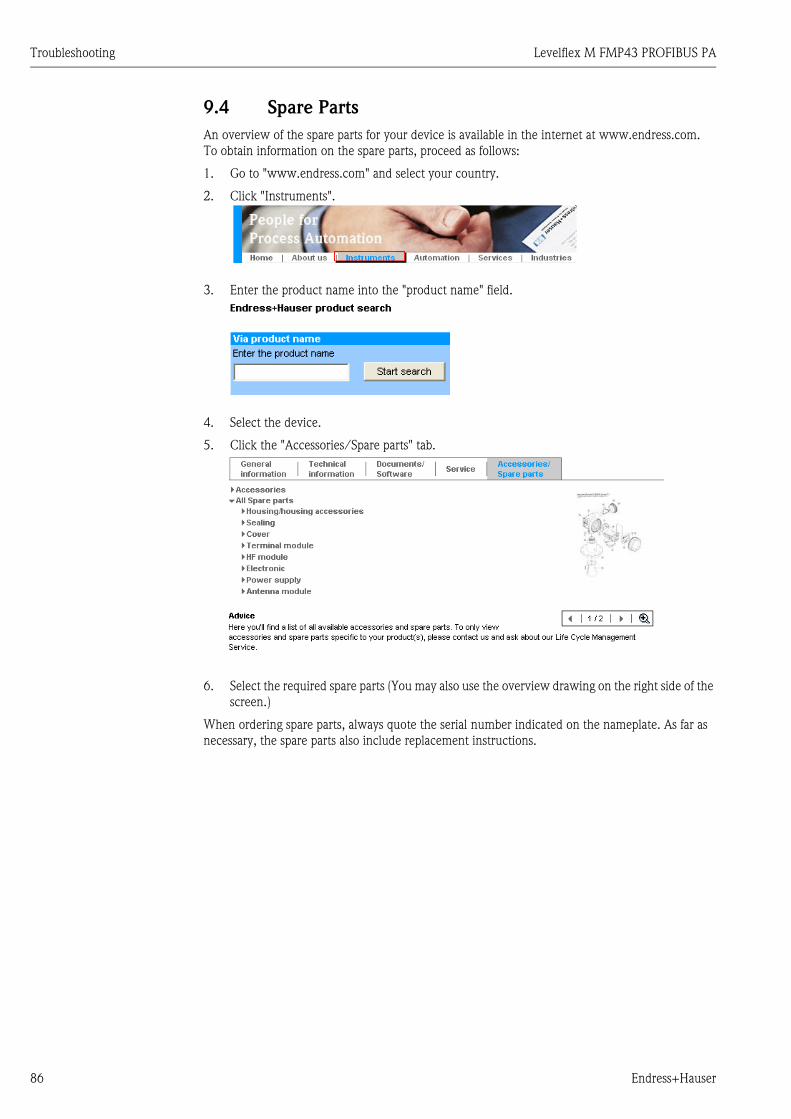
Troubleshooting Levelflex M FMP43 PROFIBUS PA
86 Endress+Hauser
9.4 Spare Parts
An overview of the spare parts for your device is available in the internet at www.endress.com.
To obtain information on the spare parts, proceed as follows:
1. Go to "www.endress.com" and select your country.
2. Click "Instruments".
3. Enter the product name into the "product name" field.
4. Select the device.
5. Click the "Accessories/Spare parts" tab.
6. Select the required spare parts (You may also use the overview drawing on the right side of the
screen.)
When ordering spare parts, always quote the serial number indicated on the nameplate. As far as
necessary, the spare parts also include replacement instructions.

Levelflex M FMP43 PROFIBUS PA Troubleshooting
Endress+Hauser 87
9.5 Return
The following procedures must be carried out before a level transmitter requiring repair or
calibration, for example, is returned to Endress+Hauser:
• Remove all residues. Pay special attention to the grooves for seals and crevices which could
contain fluid residues. This is particularly important if the substance is hazardous to health, e.g.
flammable, toxic, caustic, carcinogenic, etc.
• Always enclose a duly completed "Declaration of contamination" form with the device
(a copy of the "Declaration of contamination" can be found at the end of these Operating
Instructions). Only then can Endress +Hauser transport, examine and repair a returned device.
• Enclose special handling instructions if necessary, for example a safety data sheet as per
EN 91/155/EEC.
Additionally specify:
• The chemical and physical characteristics of the fluid
• A description of the application
• A description of the error that occurred (specify error code if possible)
• Operating time of the device
9.6 Disposal
When disposing, separate and recycle the device components based on the materials.
9.7 Software history
9.8 Contact addresses of Endress+Hauser
Contact addresses can be found on our homepage: www.endress.com/worldwide. If you have any
questions, please do not hesitate to contact your Endress+Hauser representative.
Date Software version Software modifications Documentation Discription of
Instrument Functions
07.2007 01.04.02 Original software. BA358F/00/en/07.07
71041163
BA358F/00/en/03.09
71074937
BA00358F/00/EN/13.10
71120306
BA245F/00/en/07.07
71040940

Technical data Levelflex M FMP43 PROFIBUS PA
88 Endress+Hauser
10 Technical data
10.1 Additional technical data
10.1.1 Input
Measured variable The measured variable is the distance between the reference point (see Fig., → ä 11) and the
product surface. The level is calculated subject to the empty distance entered "E" (see Fig.,
→ ä 54). Alternatively, the level can be converted by means of linearization (32 points) to other
variables (volume, mass).
10.1.2 Output
Output signal • PROFIBUS PA:
– signal coding: Manchester Bus Powered (MBP)
– data transmission rate: 31.25 KBit/s, voltage mode
Signal on alarm Error information can be accessed via the following interfaces:
• Local display:
– Error symbol (→ ä 33)
– Plain text display
• Current output, failsafe mode can be selected (e.g. according to NAMUR recommendation NE43)
• Digital interface
Linearization The linearization function of the Levelflex M allows the conversion of the measured value into any
unit of length or volume and mass or %. Linearization tables for calculating the volume in cylindrical
tanks are preprogrammed. Other tables with up to 32 value pairs can be entered manually or semi-
automatically. The creation of a linearization table with FieldCare is particularly convenient.
10.1.3 Performance characteristics
Reference operating
conditions
• Temperature = +20 °C ± 5 °C
• Pressure = 1013 mbar abs. ±20 mbar
• Relative humidity (air) = 65 % ±20 %
• Metallic tank, no internals, distance to tank wall > 500 mm
• Medium: water (DC > 7), respectively oil (DC = 2)
• Probe length > 500 mm
Maximum measured error Is in Function group "basic setup" (00) starting from → ä 56.
Resolution Digital: 1 mm
Reaction time The reaction time depends on the configuration.
Shortest time:
• 2-wire electronics: 1 s
Influence of ambient
temperature
The measurements are carried out in accordance with EN 61298-3:
• Digital output:
– average TK: 0.6 mm/10 K, max. ±3.5 mm over the entire temperature range -40 °C to +80 °C

Levelflex M FMP43 PROFIBUS PA Technical data
Endress+Hauser 89
10.1.4 Operating conditions: Environment
Ambient temperature range Ambient temperature for electronics: -40 °C to +80 °C. The functionality of the LCD display may
be limited for temperatures Ta < -20 °C and Ta > +60 °C. A weather protection cover should be
used for outdoor operation if the device is exposed to direct sunlight.
Ambient temperature limits If the temperature (T2) at the process connection is above 80 °C, the permitted ambient
temperature (T1) decreases as per the following diagram (temperature derating):
L00-FMP43xxx-05-00-00-en-002
Storage temperature -20 °C to +80 °C
Climate class DIN EN 60068-2-38 (test Z/AD)
Degree of protection • With closed housing tested according to
– All housings
– IP68, NEMA6P (24 h at 1.83 m under water)
– IP66, NEMA4X
– Housing F23: IP69K in combination with cable entries M20, G½ and NPT½
• With open housing: IP20, NEMA1 (also ingress protection of the display)
" Caution!
Degree of protection IP68 NEMA6P applies for M12 PROFIBUS PA connectors only when the
PROFIBUS cable is plugged in.
Vibration resistance DIN EN 60068-2-64 / IEC 68-2-64: 20 to 2000 Hz, 1 (m/s2)2/Hz
Cleaning the probe Depending on the application, contamination or build-up can accumulate on the probe. A thin, even
layer only influences measurements sligthly. Thick layers can dampen the signal and then reduce
the measuring range. Severe, uneven build-up, adhesion e.g. through crystallization, can lead to
incorrect measurement. In this case, we recommend that you use a non-contact measuring
principle, or check the probe regularly for soiling.
T2 [°C]
T1 [°C]
-40 0-40
0
40
60
80 100 150
80
T2
T1
max. process connection temperature
max. ambient temperature80 °C with separate
housing
62 °C compact:F23 housing
70 °CF12 housingT12 housing
compact:

Technical data Levelflex M FMP43 PROFIBUS PA
90 Endress+Hauser
Electromagnetic
compatibility (EMC)
Electromagnetic compatibility to EN 61326 and NAMUR Recommendation EMC (NE21). Details
are provided in the Declaration of Conformity. A standard installation cable is sufficient if only the
analog signal is used.
When installing the probes in metal and concrete tanks and when using a coax probe:
• Interference emission to EN 61326 - x series, electrical equipment Class B.
• Interference Immunity to EN 61326 - x series, requirements for industrial areas and NAMUR
Recommendation NE21 (EMC)
The measured value can be affected by strong electromagnetic fields when installing rod and rope
probes without a shielding / metallic wall, e.g. plastiv, and in wooden silos.
• Interference emission to EN 61326 - x series, electrical equipment Class A.
• Interference Immunity: the measured value can be affected by strong electromagnetic fields.
10.1.5 Operating conditions: Process
Process temperature range The maximum permitted temperature at the process connection (see figure measuring point) is
determined by the O-ring material ordered:
Process pressure limits Pmax = 16 bar.
This range may be reduced by the selection of process connection ( → ä 12).
The pressure rating (PN) specified on the flanges refers to a reference temperatur of 20 °C, for
ASME flanges 100 °F. Observe pressure-temperature dependency.
Please refer to the following standards for the pressure values permitted for higher temperatures:
• EN 1092-1: 2001 Tab.18
With regard to their temperature stability properties, the materials 1.4404 and 1.4435 are
grouped under 13E0 in EN 1092-1 Tab.18. The chemical composition of the two materials can
be identical.
• ASME B 16.5a - 1998 Tab. 2-2.2 F316
• ASME B 16.5a - 1998 Tab. 2.3.8 N10276
• JIS B 2220
Dielectric constant εr ≥ 1.6
O-ring material Min. temperature Max. temperature
FFKM (Kalrez) -20 °C +150 °C
EPDM -20 °C +130 °Cmeasuredhere

Levelflex M FMP43 PROFIBUS PA Technical data
Endress+Hauser 91
10.1.6 Mechanical construction
Material See TI00424F/00/EN, chapter "Material (not in contact with process)" and "Material (in contact
with process)".
Tolerance of probe length
Weight
Process connection See "Ordering structure", → ä 6.
Probe See "Ordering structure", → ä 6.
! Note!
The modular structure of the probe makes a simple possible exchanges of the process seals, the
probe rod and the process coupling ring.
Tolerance Rod length
+ 0 / - 3 mm < 1000 mm
+ 0 / - 5 mm 1000 to < 4000 mm
Part Weight Part Weight
T12 housing approx. 2.7 kg Compact probe, removable approx. 0.8 kg
F12 housing approx. 1.8 kg Separate probe approx. 2.1 kg
F23 housing approx. 5 kg Probe rod approx. 0.4 kg/m
Compact probe approx. 0.7 kg

Technical data Levelflex M FMP43 PROFIBUS PA
92 Endress+Hauser
10.1.7 Certificates and approvals
CE approval The measuring system meets the legal requirements of the applicable EC guidelines. These are listed
in the corresponding EC Declaration of Conformity together with the standards applied.
Endress+Hauser confirms successful testing of the device by affixing to it the CE mark.
Certificates The devices are certified for use in hazardous areas. The safety instructions to be observed are
enclosed and referenced on the nameplate:
• Europe: EC type-examination certificate, safety instructions XA
• USA: FM Approval, Control Drawing
• Canada: CSA Certificate of Compliance, Control Drawing
• China: NEPSI Explosion Protection Certificate of Conformity, Safety Instructions XA
• Japan: TIIS Certificate for Ex-apparatus
Correlation of the certificates (XA, ZD) to the device:
1) Housing F12/F23/T12-OVP: In combination with electronics B, D or F supply intrinsically safe.
* In preparation
XA
41
0F
X
X
X
X
X
XA
41
1F
X
X
X
X
X
X
XA
41
2F
X
X
X
X
X
XA
41
3F
X
X
X
X
X
XA
41
4F
X
X
X
X
X
XA
41
5F
X
X
X
X
X
X
X
X
X
XA
41
6F
X
X
X
X
X
X
XA
37
8F
X
X
XA
37
9F
X
X
X
ZD
08
0F
X
X
X
ZD
08
1F
X
X
X
X
ZD
08
2F
X
X
X
X
X
ZD
08
3F
X
X
X
X
ZD
11
3F
X
X
X
ZD
11
4F
X
X
X
X
ZD
11
6F
X
X
X
ZD
11
7F
X
X
X
X
ZD
07
5F
X
X
X
ZD
07
6F
X
X
X
X
ZD
07
7F
X
X
X
X
X
ZD
07
8F
X
X
X
X
ZD
10
6F
X
X
X
ZD
10
7F
X
X
X
X
ZD
10
9F
X
X
X
ZD
11
0F
X
X
X
X
ZD
02
1F
X
X
X
X
X
X
Va
rian
t
A
I
K
M
N
P
S
T
U
V
1
2
3
4
5
7
B
D
F
G
H
A
B
C
D
Non-hazardous area
*NEPSI Ex ia IIC T6
*TIIS Ex ia IIC T4
FM DIP Cl.II Div.1 Gr. E-G, N.I.
CSA General Purpose
CSA DIP Cl.II Div.1 Gr. G + coal dust
FM IS Cl.I,II,III Div.1 Gr. A-G, N.I., zone 0, 1, 2
FM XP Cl.I,II,III Div.1 Gr. A-G, zone 1, 2
CSA IS Cl.I,II,III Div.1 Gr. A-D, G + coal dust, N.I., zone 0, 1, 2
CSA XP Cl.I,II,III Div.1 Gr. A-D, G + coal dust, N.I., zone 1, 2
ATEX II 1/2G Ex ia IIC T6
ATEX II 1/2D, Alu blind cover 1)
ATEX II 2G Ex e mb (ia) IIC T6
ATEX II 1/3D 1)
ATEX II 1/2G Ex ia IIC T6,ATEX II 1/3D
ATEX II 1/2G Ex d (ia) IIC T6
2-wire 4-20mA SIL HART
2-wire PROFIBUS PA
2-wire FOUNDATION Fieldbus
4-wire 90-250VAC 4-20mA SIL HART
4-wire 10.5-32VDC 4-20mA SIL HART
F12 Alu, coated IP68 NEMA6P
F23 316L IP68 NEMA6P
T12 Alu, coated IP68 NEMA6P
T12 Alu, coated IP68 NEMA6P + OVP
Feature
10
Approval:
50
Power
supply
Output:
80
Housing:

Levelflex M FMP43 PROFIBUS PA Technical data
Endress+Hauser 93
Sanitary compatibility
! Note!
The gap-free connections can be cleaned without residue using the usual cleaning methods.
Many versions of the Levelflex M meet the requirements of 3A-Sanitary Standard No. 74.
Endress+Hauser confirms this by attaching the 3A symbol.
Pharma (CoC) Certificate of Compliance (CoC)
• See "Ordering structure", → ä 6, feature 100 "Additional Option:", option"P".
• Materials in Contact with process made of 316L with Δ ferrite < 3%
• Surface roughness Ra < 0,38 μm/15 μin
• Information on ASME BPE Conformity
Telecommunications Complies with "Part 15" of the FCC rules for an "Unintentional Radiator". All probes meet the
requirements for a "Class A Digital Device".
In addition to this, all probes in metallic tanks meet the requirements for a "Class B Digital Device".
External standards and
guidelines
The European directives and standards applied can be taken from the associated EC Declarations of
Conformity. In addition, the following also applied for Levelflex M:
EN 60529
Protection class of housing (IP-code)
Namur - international user association of automation technology in process industries.
• NE21
Electromagnetic compatibility (EMC) of industrial process and laboratory control equipment.
• NE43
Standardization of the signal level for the failure information of digital transmitters.
10.1.8 Additional documentation
Additional documentation This additional documentation can be found on our product pages on www.endress.com.
• Technical Information (TI00424F/00/EN)
• Operating Instructions "Description of Instrument Functions" (BA00245F/00/EN)
• Guideline for planning and commissioning (BA034S/04/DE)
Overview of permitted process
connections, → ä 12.
74 -74 -

Appendix Levelflex M FMP43 PROFIBUS PA
94 Endress+Hauser
11 Appendix
11.1 Operating menu PA (display module)
L00-FMP4xxxx-19-00-01-en-007
safety settings
basic setup
output on alarm
MIN
holdMAX
standardaluminium tankplastic tankbypass / pipecoax probeconcrete wall
unknownDC: 1.4 … 1.6DC: 1.6 … 1.9DC: 1.9 … 2.5DC: 2.5 … 4DC: 4 … 7DC: > 7
standardfast changeslow changetest: no filter
tank properties
end of probe
freetie down isolatedtie down gnd.
enter value
medium cond.
outp. echo loss
alarmhold
ramp %MB/min
process proper.
ramp %span/min
empty calibr.enter value
Note! The default values of the parameters are typed in boldface.
delay time
in case of echo lossmax. 4000 sec.default: 30 s
length adjustment
01
00
010
002
030
003
012
004
013
005
014
03 probe lengthnot modified
modified
probe
free
probe length
probe length
determine length
length OK
031
032 033
033
034
level/ullage.
level DUullage DU
level CUullage CU
Selectionmapping
common
delete map.
envelope curvesubstracted signalmapping
single curvecyclic
plot settings
present error
tag no.
linearisation
manualsemi-automatictable on
horizontal cyl
linear
clear table
dist./meas.valueD and L is displayed
recording curve
language
previous error
profile version
customer unit
table no.input levelinput volume
customer unit
customer unit
check distancedistance = ok
dist. unknowndist. too big
back to homeenter timeDefault: 900 s
EnglishDeutschFrancaisEspanolItalianoNederlandsKatakana (japanese)
clear last error
protocol + sw-no.
linearisation
range of mapping
pres. Map dist.
input of mappingrange
is displayed
resetfor reset codesee manual
next point
no
yes
start mapping
delete map.
offon
no
yes
no.of decimalsxx.xx.xxx.xxx
unlock parameterfor enter codesee manual
serial no.
linearisation
extended calibr.
envelope curve
display
diagnostics
system parameter
040
050
0E1
0A0
0C0
041
008
0E2
092
0A1
0C1
042
043
043
044045
042
042
051
093
0A2
0C2
052
054
0A3
045
053
055
095
0A4
0C4
04
05
0E
09
0A
0C
format displaydecimal
094
1/16”
manualprobe freedist. too small
covered
see Function group “leghth adjustment 03”end of probe 030 determine length 034
too shorttoo long
instrument_addr. out statusident number
profilemanufacturer
set unit to busconfirm
out valueprofibus param. 060 061 062 063 06406

Levelflex M FMP43 PROFIBUS PA Appendix
Endress+Hauser 95
L00-FMP4xxxx-19-00-02-en-007
safety distancefrom blocking distancedefault: 0.1m
dist./meas.value
D and Lare displayed
in safety dist.alarm
self holdingwarning
check distance
distance = okdist. too small
probe freemanual
dist. unknowndist. too big
ackn. alarm overspill protectionnoyes
standardgerman WHG
range of mapping
input ofmapping range
Retu
rn to
Gro
up S
elec
tion
start mappingfull calibr.enter value
dist./meas.value
brocken probe det
D and Lare displayed
015
008
016
051
017 018
052 053006 008
019
dist./meas.valueD und L is displayed
sep. character
. point, comma
measured dist.
distance unit
max. scale
max. scale
echo qualityis displayed
display test
offon
offon
offon
measured level
download mode
diameter vessel
offsetwill be added to themeasured level
output damping
application par.not modifiedmodified
upper block.dist
008
096
0A5
0C5
046
046
056
097
0A6
0C8
047
057 058
0A8
059
simulation 2nd cyclic value select V0H0measured valuedisplay value
distplay value065 067 068 069
sim. offsim. levelsim. volume
simulation value 066
detection windowoffonreset
0A7

Appendix Levelflex M FMP43 PROFIBUS PA
96 Endress+Hauser
11.2 Patents
This product is protected by at least one of the following patents.
Further patents are pending.
• US 5,661,251 i EP 0 780 664
• US 5,827,985 i EP 0 780 664
• US 5,884,231 i EP 0 780 665
• US 5,973,637 i EP 0 928 9741

Levelflex M FMP43 PROFIBUS PA Appendix
Endress+Hauser 97

Levelflex M FMP43 PROFIBUS PA Index
98 Endress+Hauser
Index
AAlarm. . . . . . . . . . . . . . . . . . . . . . . . . . . . . . . . . . . . . . . . 37
Application errors . . . . . . . . . . . . . . . . . . . . . . . . . . . . . . . 84
BBasic setup . . . . . . . . . . . . . . . . . . . . . . . . . . . . . . . . . 54, 56
Blocking distance . . . . . . . . . . . . . . . . . . . . . . . . . . . . . . . 65
CCE mark . . . . . . . . . . . . . . . . . . . . . . . . . . . . . . . . . . . . . . 8
Commissioning . . . . . . . . . . . . . . . . . . . . . . . . . . . . . . . . 53
Connector . . . . . . . . . . . . . . . . . . . . . . . . . . . . . . . . . . . . 26
DDeclaration of conformity . . . . . . . . . . . . . . . . . . . . . . . . . . 8
Designated use . . . . . . . . . . . . . . . . . . . . . . . . . . . . . . . . . . 4
Determine length . . . . . . . . . . . . . . . . . . . . . . . . . . . . 60, 73
Dimensions . . . . . . . . . . . . . . . . . . . . . . . . . . . . . . . . . . . 10
Display. . . . . . . . . . . . . . . . . . . . . . . . . . . . . . . . . . . . . . . 32
EEmpty calibration . . . . . . . . . . . . . . . . . . . . . . . . . . . . 60, 73
End of probe . . . . . . . . . . . . . . . . . . . . . . . . . . . . . . . . . . 72
Envelope curve . . . . . . . . . . . . . . . . . . . . . . . . . . . . . . . . 67
Error messages . . . . . . . . . . . . . . . . . . . . . . . . . . . . . . 37, 82
Ex approval . . . . . . . . . . . . . . . . . . . . . . . . . . . . . . . . . . . 92
Exterior cleaning . . . . . . . . . . . . . . . . . . . . . . . . . . . . . . . 77
FF12 housing . . . . . . . . . . . . . . . . . . . . . . . . . . . . . . . . . . . 24
F23 housing . . . . . . . . . . . . . . . . . . . . . . . . . . . . . . . . . . . 24
FHX40 . . . . . . . . . . . . . . . . . . . . . . . . . . . . . . . . . . . . . . . 79
FieldCare . . . . . . . . . . . . . . . . . . . . . . . . . . . . . . . . . . . . . 71
Full calibration . . . . . . . . . . . . . . . . . . . . . . . . . . . . . . . . . 61
HHART. . . . . . . . . . . . . . . . . . . . . . . . . . . . . . . . . . . . . . . . 38
IInstallation . . . . . . . . . . . . . . . . . . . . . . . . . . . . . . . . . . . . . 9
Installation instructions. . . . . . . . . . . . . . . . . . . . . . . . . . . 15
Interference echo mapping . . . . . . . . . . . . . . . . . . . . . . . . 74
KKey assignment . . . . . . . . . . . . . . . . . . . . . . . . . . . . . . . . 33
LLocking . . . . . . . . . . . . . . . . . . . . . . . . . . . . . . . . . . . . . . 34
MMaintenance . . . . . . . . . . . . . . . . . . . . . . . . . . . . . . . . . . 77
Medium properties . . . . . . . . . . . . . . . . . . . . . . . . . . . 57, 72
Menu structure . . . . . . . . . . . . . . . . . . . . . . . . . . . . . . . . 94
NNameplate . . . . . . . . . . . . . . . . . . . . . . . . . . . . . . . . . . . . . 6
Notes on safety conventions and icons . . . . . . . . . . . . . . . . 5
OOperating menu . . . . . . . . . . . . . . . . . . . . . . . . . . . . . . . . 31
Operation . . . . . . . . . . . . . . . . . . . . . . . . . . . . . . . . . . 30, 34
Operational safety . . . . . . . . . . . . . . . . . . . . . . . . . . . . . . . . 4
Ordering structure . . . . . . . . . . . . . . . . . . . . . . . . . . . . . . . 6
PProbe . . . . . . . . . . . . . . . . . . . . . . . . . . . . . . . . . . . . . . . . 73
Probe length . . . . . . . . . . . . . . . . . . . . . . . . . . . . . . . . . . . 73
Process propert. . . . . . . . . . . . . . . . . . . . . . . . . . . . . . 58, 72
RRepairs . . . . . . . . . . . . . . . . . . . . . . . . . . . . . . . . . . . . . . . 77
Repairs to Ex-approved devices . . . . . . . . . . . . . . . . . . . . . 77
Replacement. . . . . . . . . . . . . . . . . . . . . . . . . . . . . . . . . . . 77
Reset . . . . . . . . . . . . . . . . . . . . . . . . . . . . . . . . . . . . . . . . 36
Return . . . . . . . . . . . . . . . . . . . . . . . . . . . . . . . . . . . . . . . 87
SService Interface FXA291 . . . . . . . . . . . . . . . . . . . . . . . . . 80
Software history . . . . . . . . . . . . . . . . . . . . . . . . . . . . . . . . 87
Spare Parts . . . . . . . . . . . . . . . . . . . . . . . . . . . . . . . . . . . . 86
System error messages . . . . . . . . . . . . . . . . . . . . . . . . . . . 82
TT12 housing . . . . . . . . . . . . . . . . . . . . . . . . . . . . . . . . 25–26
Tank properties. . . . . . . . . . . . . . . . . . . . . . . . . . . . . . 56, 72
Technical data . . . . . . . . . . . . . . . . . . . . . . . . . . . . . . . . . 88
Terminal compartment . . . . . . . . . . . . . . . . . . . . . . . . . . . 27
Troubleshooting . . . . . . . . . . . . . . . . . . . . . . . . . . . . . . . . 81
Troubleshooting instructions . . . . . . . . . . . . . . . . . . . . . . . 81
Turn housing . . . . . . . . . . . . . . . . . . . . . . . . . . . . . . . . . . 20
UUnlock parameter . . . . . . . . . . . . . . . . . . . . . . . . . . . . . . . 35
VVU331 . . . . . . . . . . . . . . . . . . . . . . . . . . . . . . . . . . . . . . . 67
WWarning . . . . . . . . . . . . . . . . . . . . . . . . . . . . . . . . . . . . . . 37
Weather protection cover . . . . . . . . . . . . . . . . . . . . . . . . . 78
Wiring . . . . . . . . . . . . . . . . . . . . . . . . . . . . . . . . . . . . . . . 24

P/S
F/K
onta
XIV
Because of legal regulations and for the safety of our employees and operating equipment, we need the "Declaration of Hazardous Materialand De-Contamination", with your signature, before your order can be handled. Please make absolutely sure to attach it to the outside of thepackaging.Aufgrund der gesetzlichen Vorschriften und zum Schutz unserer Mitarbeiter und Betriebseinrichtungen, benötigen wir die unterschriebene"Erklärung zur Kontamination und Reinigung", bevor Ihr Auftrag bearbeitet werden kann. Bringen Sie diese unbedingt außen an derVerpackung an.
Serial number
Seriennummer ________________________Type of instrument / sensor
Geräte-/Sensortyp ____________________________________________
Process data/Prozessdaten Temperature _____ [°F] [°C]
Conductivity / ________
_____
Leitfähigkeit
/
[μS/cm]
Temperatur Pressure _____ [psi] [ Pa ]
Viscosity _____ [cp] [mm /s]
_____
_____
/
/
Druck
Viskosität2
corrosiveätzend
harmlessunbedenklich
other *sonstiges*
toxicgiftig
Processmedium
IdentificationCAS No.
flammableentzündlich
harmful/irritant
gesundheits-schädlich/
reizend
Medium /concentrationMedium /Konzentration
Returned partcleaned with
Medium forprocess cleaning
Medium and warnings
Warnhinweise zum Medium
* explosive; oxidising; dangerous for the environment; biological risk; radioactive* explosiv; brandfördernd; umweltgefährlich; biogefährlich; radioaktiv
Please tick should one of the above be applicable, include safety data sheet and, if necessary, special handling instructions.Zutreffendes ankreuzen; trifft einer der Warnhinweise zu, Sicherheitsdatenblatt und ggf. spezielle Handhabungsvorschriften beilegen.
Description of failure / Fehlerbeschreibung __________________________________________________________________________
______________________________________________________________________________________________________________
______________________________________________________________________________________________________________
“We hereby certify that this declaration is filled out truthfully and completely to the best of our knowledge.We further certify that the returnedparts have been carefully cleaned. To the best of our knowledge they are free of any residues in dangerous quantities.”“Wir bestätigenw
bestätigen, die vorliegende Erklärung nach unserem besten Wissen wahrheitsgetreu und vollständig ausgefüllt zu haben. Wireiter, dass die zurückgesandten Teile sorgfältig gereinigt wurden und nach unserem besten Wissen frei von Rückständen in gefahrbringen-
der Menge sind.”
(place, date / Ort, Datum)
Company data /Angaben zum Absender
Company / ________________________________
_________________________________________________
Address /
_________________________________________________
_________________________________________________
Firma ___
Adresse
Phone number of contact person /
____________________________________________
Fax / E-Mail ____________________________________________
Your order No. / ____________________________
Telefon-Nr. Ansprechpartner:
Ihre Auftragsnr.
Medium zurEndreinigung
Medium zurProzessreinigung
Medium imProzess
Used as SIL device in a Safety Instrumented System / Einsatz als SIL Gerät in Schutzeinrichtungen
RA No.
Erklärung zur Kontamination und ReinigungDeclaration of Hazardous Material and De-Contamination
Please reference the Return Authorization Number (RA#), obtained from Endress+Hauser, on all paperwork and mark the RA#clearly on the outside of the box. If this procedure is not followed, it may result in the refusal of the package at our facility.
Bitte geben Sie die von E+H mitgeteilte Rücklieferungsnummer (RA#) auf allen Lieferpapieren an und vermerken Sie dieseauch außen auf der Verpackung. Nichtbeachtung dieser Anweisung führt zur Ablehnung ihrer Lieferung.
Name, dept./Abt. (please print / )bitte Druckschrift Signature / Unterschrift

www.endress.com/worldwide
BA00358F/00/EN/13.10
71120306
CCS/FM+SGML 6.0/ProMoDo 71120306