Inediti di fine Cinquecento alla Chiesa Nuova: Giovanni Balducci e Paul Bril
Upload
khangminh22Category
view
0download
0
TYPE 8226
Inductive Conductivity Transmitter
Instruction Manual
2 8226
EN
GLI
SH
INTRODUCTION
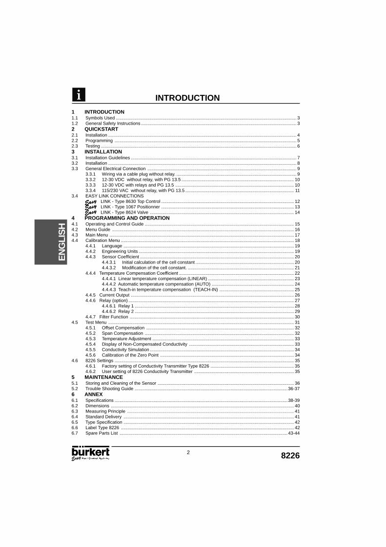
1 INTRODUCTION1.1 Symbols Used ............................................................................................................................................... 31.2 General Safety Instructions ........................................................................................................................... 32 QUICKSTART2.1 Installation ..................................................................................................................................................... 42.2 Programming ................................................................................................................................................ 52.3 Testing ........................................................................................................................................................... 63 INSTALLATION3.1 Installation Guidelines ................................................................................................................................... 73.2 Installation ..................................................................................................................................................... 83.3 General Electrical Connection ...................................................................................................................... 9 3.3.1 Wiring via a cable plug without relay. ............................................................................................... 9 3.3.2 12-30 VDC without relay, with PG 13.5 ......................................................................................... 10 3.3.3 12-30 VDC with relays and PG 13.5 .............................................................................................. 10 3.3.4 115/230 VAC without relay, with PG 13.5 ...................................................................................... 113.4 EASY LINK CONNECTIONS LINK - Type 8630 Top Control ......................................................................................................... 12 LINK - Type 1067 Positionner ......................................................................................................... 13 LINK - Type 8624 Valve .................................................................................................................. 144 PROGRAMMING AND OPERATION4.1 Operating and Control Guide ...................................................................................................................... 154.2 Menu Guide ................................................................................................................................................ 164.3 Main Menu .................................................................................................................................................. 174.4 Calibration Menu ......................................................................................................................................... 18 4.4.1 Language ....................................................................................................................................... 19 4.4.2 Engineering Units ........................................................................................................................... 19 4.4.3 Sensor Coefficient .......................................................................................................................... 20 4.4.3.1 Initial calculation of the cell constant .............................................................................. 20 4.4.3.2 Modification of the cell constant. .................................................................................... 21 4.4.4 Temperature Compensation Coefficient ........................................................................................... 22 4.4.4.1 Linear temperature compensation (LINEAR) .................................................................... 23 4.4.4.2 Automatic temperature compensation (AUTO) ................................................................. 24 4.4.4.3 Teach-in temperature compensation (TEACH-IN) ........................................................... 25 4.4.5 Current Output ................................................................................................................................. 26 4.4.6 Relay (option) ................................................................................................................................... 27 4.4.6.1 Relay 1 .............................................................................................................................. 28 4.4.6.2 Relay 2 .............................................................................................................................. 29 4.4.7 Filter Function .................................................................................................................................. 304.5 Test Menu ................................................................................................................................................... 31 4.5.1 Offset Compensation ..................................................................................................................... 32 4.5.2 Span Compensation ...................................................................................................................... 32 4.5.3 Temperature Adjustment ................................................................................................................ 33 4.5.4 Display of Non-Compensated Conductivity ................................................................................... 33 4.5.5 Conductivity Simulation .................................................................................................................. 34 4.5.6 Calibration of the Zero Point .......................................................................................................... 344.6 8226 Settings .............................................................................................................................................. 35 4.6.1 Factory setting of Conductivity Transmitter Type 8226 .................................................................. 35 4.6.2 User setting of 8226 Conductivity Transmitter ............................................................................... 355 MAINTENANCE5.1 Storing and Cleaning of the Sensor ............................................................................................................ 365.2 Trouble Shooting Guide .........................................................................................................................36-376 ANNEX6.1 Specifications .........................................................................................................................................38-396.2 Dimensions ................................................................................................................................................. 406.3 Measuring Principle .................................................................................................................................... 416.4 Standard Delivery ....................................................................................................................................... 416.5 Type Specification ....................................................................................................................................... 426.6 Label Type 8226 ......................................................................................................................................... 426.7 Spare Parts List .....................................................................................................................................43-44

38226
EN
GLI
SH
INTRODUCTION
1.1 SYMBOLS USED
Indicates information which must be followed. Failure to follow theinformation could endanger the user and effect the function of the device.
Indicates that the page contains general information.
Indicates a quickstart guide for quickly commissioning the transmitter.
Indicates that the page contains information about installation.
Indicates that the page contains information about configuration, programmingand operation.
Indicates important information, tips and recommendations.
Indicates a worked example.
Indicates an action which has to be continued or reference to a relevantsection.
Indicates information about repairs, service, maintenance and spare parts.
1.2 GENERAL SAFETY INSTRUCTIONS
Congratulations on purchasing our 8226 Digital Conductivity Transmitter.
Before installing or using this product, please read this manual and anyother relevant documentation to ensure you fully benefit from all theadvantages the product can offer.
Please verify that the product is complete and free from any damage.(see reference table section 6.6).
It is the customer's responsibility to select an appropriate transmitter for theapplication, ensure the unit is installed correctly and maintain all components.
This product should only be installed or repaired by specialist staff using thecorrect tools.
Please observe the relevant safety regulations throughout the operation,maintenance and repair of the product.
Always ensure that the power supply is switched off before working on thedevice / system.
If these instructions are ignored, no liability will be accepted and the guaranteeon the device and accessories will become invalid.
1.1

4 8226
EN
GLI
SH
QUICK START
Verification of items recievedSee section 6.4
Contact your local Bürkertsubsidiary.
Ensure the powersupply is disconnectedbefore starting work.
Ensure that securityprovisions are consideredwith the power cable andrelay circuit.
Pay attention to themax. permitted load ofthe output currentloop.
If the unit does not work,see section 5.2.
The sensor finger mustnot be immersed influid or within closeproximity of metalelements or magnetic
fields when calibrating.
See section 4.5.6
Unpacking
No VerifySee section 6.6 Ident. No.
O.K
Yes No
Unscrew the plug Unscrew the 4 and open screws and open
Connect power supply cable
See section 3.3
Connect output cable
Re-assemble housing or plug
Turn on the power
Yes No
Install the unit Calibrate unit to the fitting within the air
Program the Transmitter
See the next page.
This section provides a comprehensive installation and operation guide which willassist with the commissioning of the 8226 Conductivity Transmitter.
2.1 INSTALLATION
2.1
Check conductivity <10 µS/cm
Have youa cable plug
version
58226
EN
GLI
SH
QUICK START
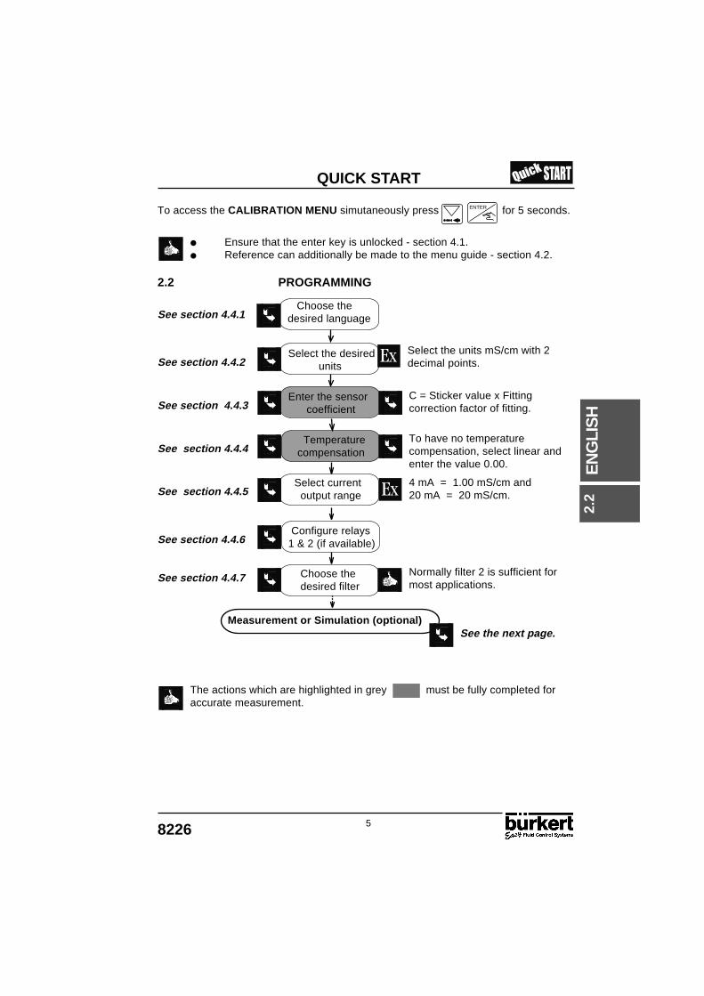
To access the CALIBRATION MENU simutaneously press for 5 seconds.
Ensure that the enter key is unlocked - section 4.1. Reference can additionally be made to the menu guide - section 4.2.
2.2 PROGRAMMING
Measurement or Simulation (optional)
The actions which are highlighted in grey must be fully completed foraccurate measurement.
Select the units mS/cm with 2decimal points.
C = Sticker value x Fittingcorrection factor of fitting.
To have no temperaturecompensation, select linear andenter the value 0.00.
4 mA = 1.00 mS/cm and20 mA = 20 mS/cm.
Normally filter 2 is sufficient formost applications.
ENTER
Choose thedesired language
Select the desired units
Enter the sensor coefficient
Temperature compensation
Select current output range
Configure relays1 & 2 (if available)
Choose the desired filter
See section 4.4.1
See section 4.4.2
See section 4.4.3
See section 4.4.4
See section 4.4.5
See section 4.4.6
See section 4.4.7
See the next page.
2.2
6 8226
EN
GLI
SH
QUICK START
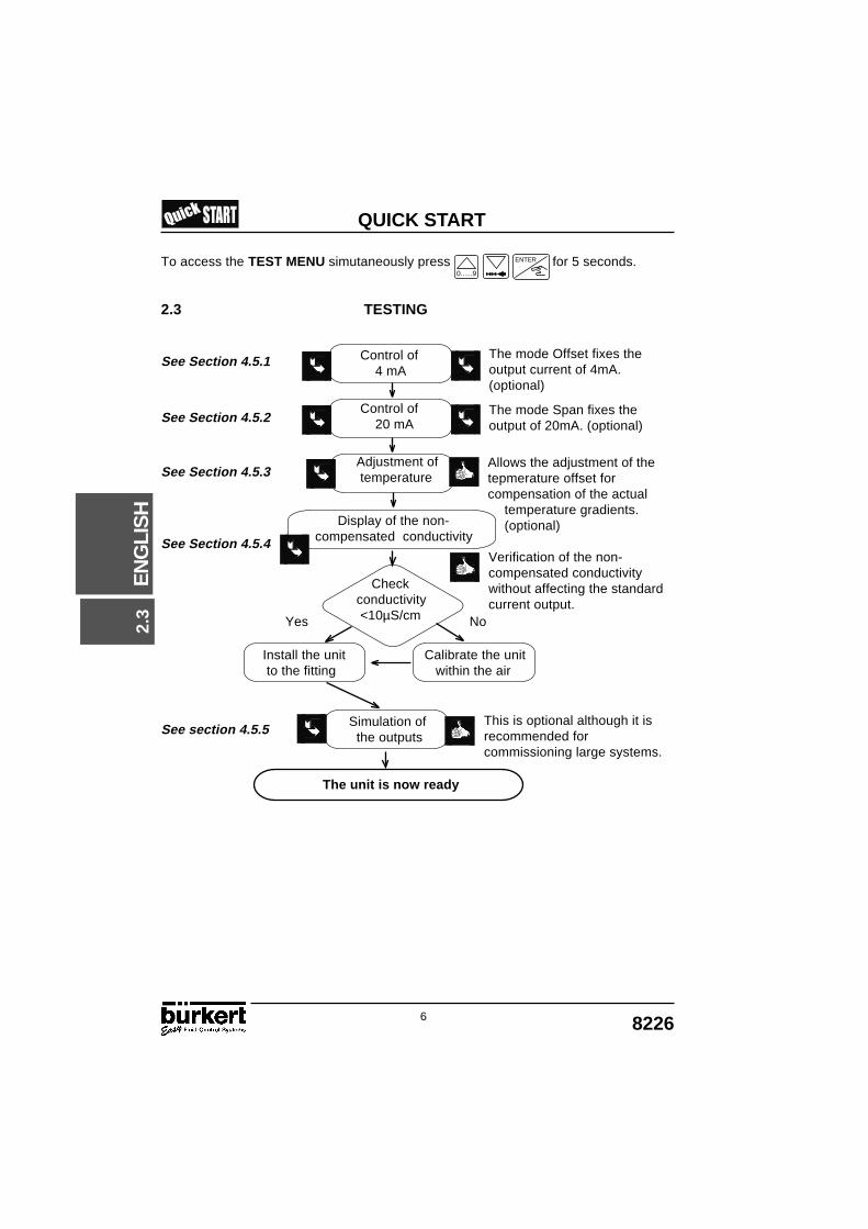
To access the TEST MENU simutaneously press for 5 seconds.
2.3 TESTING
See Section 4.5.1
See Section 4.5.2
See Section 4.5.3
See Section 4.5.4
Yes No
Install the unit Calibrate the unit to the fitting within the air
See section 4.5.5
0......9
ENTER
Control of 4 mA
Control of 20 mA
Adjustment ofthe temperature
Display of the non-compensated conductivity
Checkconductivity <10µS/cm
Simulation of the outputs
The unit is now ready
The mode Offset fixes theoutput current of 4mA.(optional)
The mode Span fixes theoutput of 20mA. (optional)
Allows the adjustment of thetepmerature offset forcompensation of the actual
temperature gradients. (optional)
Verification of the non-compensated conductivitywithout affecting the standardcurrent output.
This is optional although it isrecommended forcommissioning large systems.
2.3
78226
EN
GLI
SH
INSTALLATION
-50 -30 -10 +10 +30 +50 +70 +90 +110 +1300
2
1
3
4
5
6
7
8
9
10bar
T°C
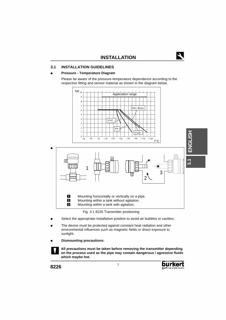
Mounting horizontally or vertically on a pipe. Mounting within a tank without agitation. Mounting within a tank with agitation.
1
23
3.1
Application range
3.1 INSTALLATION GUIDELINES
Pressure - Temperature Diagram
Please be aware of the pressure-temperature dependence according to therespective fitting and sensor material as shown in the diagram below.
SSt / Brass
PVC
PP
PVDF
Fig. 3.1 8226 Transmitter positioning
Select the appropriate installation position to avoid air bubbles or cavities.
The device must be protected against constant heat radiation and otherenvironmental influences such as magnetic fields or direct exposure tosunlight.
Dismounting precautions:
All precautions must be taken before removing the transmitter dependingon the process used as the pipe may contain dangerous / agressive fluidswhich maybe hot.

8 8226
EN
GLI
SH
INSTALLATION
3.2 INSTALLATION
The 8226 conductivity transmitter can be easily installed into pipes using our speciallydesigned fitting system.
Place the plastic nut onto the fitting and snap the plastic ring into theguide -bush .
Ensure that the sensor is fully inserted and sitting correctly, making sure thatthe lug is aligned correctly onto the fitting and that the sensor housing cannot be rotated.
The plastic nut must only be tightened by hand!
Fig. 3.2 8226 Transmitter installation
3.2
98226
EN
GLI
SH
INSTALLATION
3.3 GENERAL ELECTRICAL CONNECTION
Use cables with a temperature limit of 80°C minimum. For normal operating conditions the measuring signal can be transmitted by a
simple cable of 0.75 mm2 cross section. The line must not be installed in combination with carrying lines with a higher
voltage or frequency. If a combined installation cannot be avoided, a minimum space of 30 cm (1 ft)
or shielded cables should be adopted. When using shielded cables observe faultless grounding of the shield.
In case of doubt, always use shielded cables. The power supply must be regulated - section 6.1.
Do not open and wire the transmitter with the power supplyconnected.
It is advisable to put security devices on :Power supply : Fuse (eg/ 250mA) and an interrupterRelay : 3A fuse max. and circuit breaker (depending on application).
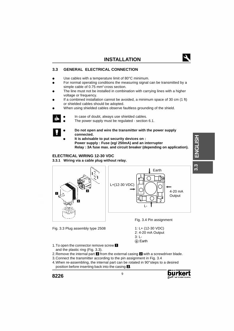
ELECTRICAL WIRING 12-30 VDC3.3.1 Wiring via a cable plug without relay.
Fig. 3.3 Plug assembly type 2508
1.To open the connector remove screw and the plastic ring (Fig. 3.3).
2.Remove the internal part from the external casing with a screwdriver blade.3.Connect the transmitter according to the pin assignment in Fig. 3.44.When re-assembling, the internal part can be rotated in 90°steps to a desired
position before inserting back into the casing .
Fig. 3.4 Pin assignment
1: L+ (12-30 VDC)2: 4-20 mA Output3: L-: Earth
L+(12-30 VDC)
4-20 mAOutput
L-
Earth
3.3
1
23
10 8226
EN
GLI
SH
INSTALLATION
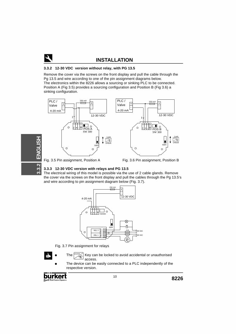
3.3.2 12-30 VDC version without relay, with PG 13.5
Remove the cover via the screws on the front display and pull the cable through thePg 13.5 and wire according to one of the pin assignment diagrams below.The electronics within the 8226 allows a sourcing or sinking PLC to be connected.Position A (Fig 3.5) provides a sourcing configuration and Position B (Fig 3.6) asinking configuration.
Fig. 3.5 Pin assignment, Position A Fig. 3.6 Pin assignment, Position B
3.3.3 12-30 VDC version with relays and PG 13.5The electrical wiring of this model is possible via the use of 2 cable glands. Removethe cover via the screws on the front display and pull the cables through the Pg 13.5‘sand wire according to pin assignment diagram below (Fig. 3.7).
Fig. 3.7 Pin assignment for relays
The Key can be locked to avoid accidental or unauthorised access.
The device can be easily connected to a PLC independently of therespective version.
4-20 mA
+-
12-30 VDC
POS A
+-
-+I
250 mA
I
SW4
SW 300
4-20 mA
+-
12-30 VDC
POS B
+-
-+I
250 mA
SW4
I
SW 300
PLC /Valve
PLC /Valve
4-20 mA12-30 VDC
+-
-+I
250 mA
48 VAC
48 VAC
REL 2
REL 1
R2
R1R2
R1
3 A
3 A
SW300
SW4
m
Unlock
LockENTER
Unlock
LockENTER
3.3.
2
ENTER

118226
EN
GLI
SH
INSTALLATION
3.3.4 115/230 VAC version without relay, with PG 13.5
Remove the cover via the screws on the front display and pull the cable through thePg 13.5 and wire according to one of the pin assignment diagrams below.The electronics within the 8226 allows a sourcing or sinking PLC to be connected.Position A (Fig 3.5) provides a sourcing configuration and Position B (Fig 3.6) asinking configuration.
Do not open and wire the transmitter with the power supplyconnected.
Ensure that the power supply switch is selected for the appropriatevoltage 115VAC or 230 VAC.
The connection for relays 1 and 2 are identical to that of the 12...30VDC on theprevious page - section 3.3.3.
Power Supply Switch
OR
4-20 mA
+-
POS B-+I
I
SW4
115
L1N115/230 VAC
4-20 mA
+-
POS A-+I
I
SW4
115
L1N115/230 VAC
Fig. 3.5 Pin assignment, Position A
Fig. 3.6 Pin assignment, Position B
Power supply switch
Red
Red
Black
Black
3.3.
4
Power supply switch
PLC /Valve
PLC /Valve
230V115V
Not connected
Not connected
12 8226
EN
GLI
SH
INSTALLATION
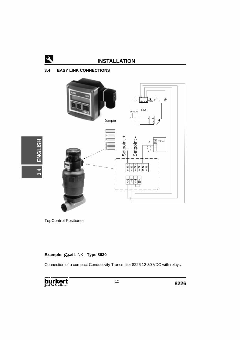
3.4 EASY LINK CONNECTIONS
TopControl Positioner
Example: LINK - Type 8630
Connection of a compact Conductivity Transmitter 8226 12-30 VDC with relays.
3.4
24 V=
+
-
8226SENSOR
Set
poin
t +
Set
poin
t -
Jumper
SW300
9 107 8
653 41 2
+ - + -+ -

138226
EN
GLI
SH
INSTALLATION
+-
24 V=
4-20
mA
8226SW01
Example: LINK - Type 1067
Connection of a compact Conductivity Transmitter 8226 12-30 VDC with relays
3.4
3.4
Positioner Type 1067

14 8226
EN
GLI
SH
INSTALLATION
4-20 mA
+-
24 V=
24
VD
C O
utp
ut
GN
D
4-2
0 m
A I
np
ut
(a)
GN
D S
etp
oin
t
4-2
0 m
A I
np
ut
(b)
8226
V=V
V=V
SW300
Solenoid control valve with PI-controller Type 8624
Example: LINK - Type 8624
Connection of a compact Conductivity Transmitter 8226 12-30 VDC with relays
3.4
(a) Conductivity(b) Setpoint

158226
EN
GLI
SH
OPERATION
4.1 OPERATING AND CONTROL GUIDE
LCD display.
Measured value.
Selection of parametersand increse digits.
Touches Mode Menu Finding a value
Previous Menu Increase from the blinking digit
Next Menu Advance to the next digit
Activate the menu display Validate the displayed value(If “END“ is displayed,save the modifiedparameters and returnto the main menu
5 Seconds
Activating or deactivating theHOLD MENU*
+ Stop the Teach-In option
+ Access to the
5 Seconds
CALIBRATION MENU*
+ + Access to the TEST MENU* 5 Seconds
* Only available within the main menu.
The Key can be locked to avoid accidental or unauthorised access.
For further information see section 3.3.2.
125.6 mS Unit selected.
Selection and confirmation.
Indication of the state ofrelay 1 and 2.( LED on = closed contact )
Selection of parametersand digits.
ENTER
ENTER
0......9
0......9
0......9
ENTER
0......9
ENTER
ENTER
4.1

16 8226
EN
GLI
SH
OPERATION
4.2 MENU GUIDE
The menu guide below will assist in quickly and easily finding a desiredparameter and programming the 8226 conductivity transmitter.
Indicates blinking digits.
ENTER
0......9
ENTER
0......9
0......9
0......9
0......9
0......9
0......9
0......9
0......9
0......9
0......9
0......9
0......9
0......9
0......9
0......9
0......9
0......9
0......9
0......9
0......9
0......9
0......9
ENTER
ENTER
ENTER
ENTER
ENTER
20.6 °C
12.6 mS
10.32 mA
HOLD
20.6 °C
12.6 mS
10.32 mA
HOLD
5 s
5 s
5 s
5 s
Option
+
+ +
ENTER
MAIN MENU
CALIBRATION MENU
TEST MENUHOLD FUNCTION
HOLD NO
OFFSET
SPAN
CONDUCT.
T° ADJUST
END
SIMUL
CALIB .
HOLD YES
UNIT
SENS.COEF.
CURRENT
RELAY 1
FILTER
END
LANGUAGE
T° COEFF
RELAY 2
4.2
178226
EN
GLI
SH
MAIN MENU
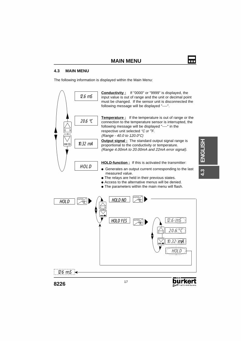
Conductivity : If "0000" or "9999" is displayed, theinput value is out of range and the unit or decimal pointmust be changed. If the sensor unit is disconnected thefollowing message will be displayed "----".
Temperature : If the temperature is out of range or theconnection to the temperature sensor is interrupted, thefollowing message will be displayed "----" in therespective unit selected °C or °F.(Range - 40.0 to 120.0°C)Output signal : The standard output signal range isproportional to the conductivity or temperature.(Range 4.00mA to 20.00mA and 22mA error signal).
HOLD-function : If this is activated the transmitter:
Generates an output current corresponding to the last measured value. The relays are held in their previous states. Access to the alternative menus will be denied. The parameters within the main menu will flash.
4.3 MAIN MENU
The following information is displayed within the Main Menu:
0......9
12.6 mS
20.6 °C
HOLD
10.32 mA
ENTER
0......9
ENTER
HOLD
ENTER
0......9
HOLD
126 mS
20.6 °C
12.6 mS
10.32 mA
HOLD NO
HOLD YES
4.3
18 8226
EN
GLI
SH
CALIBRATION MENU
4.4.1
4.4.2
4.4.3
4.4.4
4.4.5
4.4.6
4.4.6
4.4.7
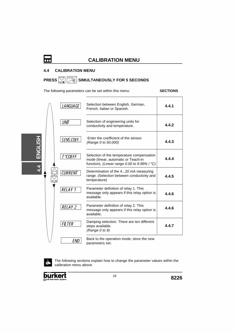
4.4 CALIBRATION MENU
PRESS SIMULTANEOUSLY FOR 5 SECONDS
The following parameters can be set within this menu: SECTIONS
The following sections explain how to change the parameter values within thecalibration menu above.
ENTER
Selection between English, German,French, Italian or Spanish.
Selection of engineering units forconductivity and temperature.
Enter the coefficient of the sensor.(Range 0 to 50.000)
Selection of the temperature compensationmode (linear, automatic or Teach-infunction). (Linear range 0.00 to 9.99% / °C)
Determination of the 4...20 mA measuringrange. (Selection between conductivity andtemperature)
Parameter definition of relay 1. Thismessage only appears if this relay option isavailable.
Parameter definition of relay 2. Thismessage only appears if this relay option isavailable.
Damping selection. There are ten differentsteps available.(Range 0 to 9)
Back to the operation mode; store the newparameters set.
0......9
UNIT
SENS.COEF.
CURRENT
RELAY 1
FILTER
END
LANGUAGE
T°COEFF
RELAY 2
4.4
198226
EN
GLI
SH
CALIBRATION MENU
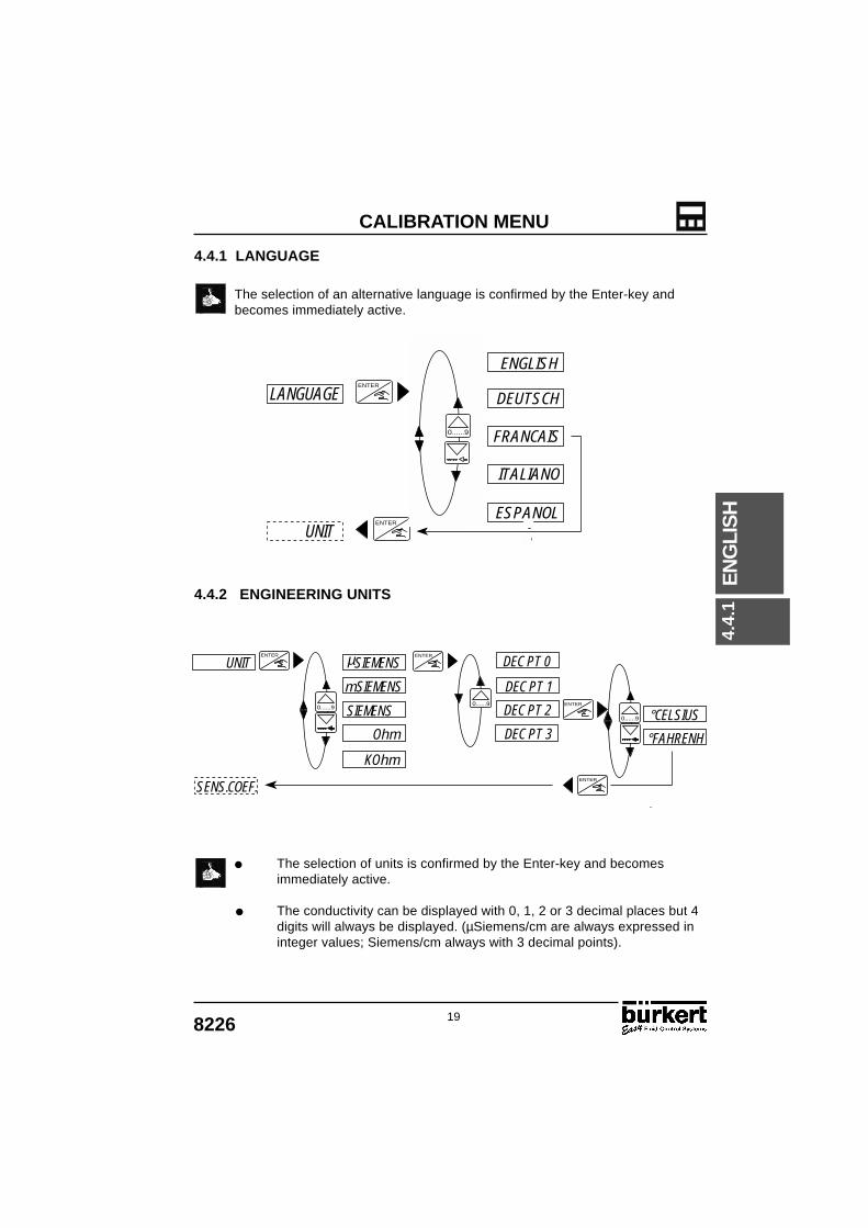
4.4.1 LANGUAGE
The selection of an alternative language is confirmed by the Enter-key andbecomes immediately active.
4.4.2 ENGINEERING UNITS
The selection of units is confirmed by the Enter-key and becomesimmediately active.
The conductivity can be displayed with 0, 1, 2 or 3 decimal places but 4digits will always be displayed. (µSiemens/cm are always expressed ininteger values; Siemens/cm always with 3 decimal points).
ENTER
ENTER
ENGLISH
DEUTSCH
FRANCAIS
ITALIANO
ESPANOL
0......90......9
UNIT
LANGUAGE
ENTER ENTER
ENTER0......9
ENTER
0......9
0......9
µSIEMENS
mSIEMENS
Ohm
UNIT
SENS.COEF.
KOhm
DEC PT 3
DEC PT 2
DEC PT 1
DEC PT 0
SIEMENS °CELSIUS
°FAHRENH4.
4.1
20 8226
EN
GLI
SH
CALIBRATION MENU
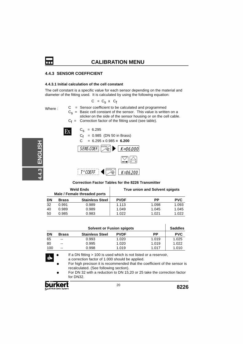
4.4.3 SENSOR COEFFICIENT
4.4.3.1 Initial calculation of the cell constant
The cell constant is a specific value for each sensor depending on the material anddiameter of the fitting used. It is calculated by using the following equation:
C = Cs x Cf
Where : C = Sensor coefficient to be calculated and programmedCs = Basic cell constant of the sensor. This value is written on a
sticker on the side of the sensor housing or on the cell cable.Cf = Correction factor of the fitting used (see table).
Cs = 6.295
Cf = 0.985 (DN 50 in Brass)C = 6.295 x 0.985 = 6.200
Correction Factor Tables for the 8226 Transmitter
If a DN fitting > 100 is used which is not listed or a reservoir,a correction factor of 1.000 should be applied.
For high precison it is recommended that the coefficient of the sensor isrecalculated. (See following section).
For DN 32 with a reduction to DN 15,20 or 25 take the correction factorfor DN32.
0......9
ENTER
ENTER
SENS.COEF.
T° COEFF
K=06.000
K=06.200
Weld Ends True union and Solvent spigots Male / Female threaded ports
DN Brass Stainless Steel PVDF PP PVC32 0.991 0.989 1.113 1.098 1.09340 0.989 0.989 1.049 1.045 1.04550 0.985 0.983 1.022 1.021 1.022
Solvent or Fusion spigots Saddles
DN Brass Stainless Steel PVDF PP PVC65 -- 0.993 1.020 1.019 1.02580 -- 0.995 1.020 1.019 1.022100 -- 0.998 1.019 1.017 1.010
4.4.
3

218226
EN
GLI
SH
CALIBRATION MENU
4.4.3.2 Modification of the cell constant.
The cell constant may drift with time due to deposits on the sensoror the fitting. It is advisable to periodically check this value bymeasuement with a buffer solution or reference device and ensurethat the sensor finger is clean.
A new cell constant can be calculated as follows:
C new
= C old
x Cond ref
Cond 8226
Where : C new
- New value for the known sensor coefficient.
C old
- Old value for the programmed sensor coefficient.
Cond ref
- Value for the measured conductivity.
Cond 8226
- Value for the conductivity indicated by the 8226 transmitter.
Calibration with a solution of 10.00 mS
Electric cell constant programmed = 6.295
Conductivity measured by the 8226 = 10.50
Elec cst new
= 6.295 x 10.00 / 10.50 = 5.995
In cases of the sensor finger replacement, please take into account thenew cell constant value.
4.4.
3

22 8226
EN
GLI
SH
CALIBRATION MENU
4.4.4 TEMPERATURE COMPENSATION COEFFICIENT
1) Linear Compensation (LINEARLINEARLINEARLINEARLINEAR)
Enter a single value for compensation over the entire conductivity and temperatureranges (e.g. 2.1 % / °C ).
For no compensation enter 0.0% / °C within this option.
2) Compensation with memorized curves (AUTOAUTOAUTOAUTOAUTO)
Select one of the 4 pre-programmed compensation curves for commonly usedproducts. The available compensation curves include; NaOH, HNO3, H2SO4, NaCl orspecial (determined by Teach-In).
3) Teach-In function (TEACH-INTEACH-INTEACH-INTEACH-INTEACH-IN)
This function allows the user to practically determine with the transmitter acompensation curve within the desired temperature range. From entering thetemperature limits and starting measurement the conductivity transmitter automaticallycomputes the compensation curve.
The Conductivity Transmitter offers 3 different types of temperature compensation;Linear, Automatic and Teach-In.
Section 4.4.4.1
Section 4.4.4.2
Section 4.4.4.3TEACH IN
T° COEFF
AUTO
LINEARENTER
0......9
4.4.
4

238226
EN
GLI
SH
CALIBRATION MENU
4.4.4.1 LINEAR TEMPERATURE COMPENSATION (LINEARLINEARLINEARLINEARLINEAR)
In some cases linear compensation provides enough precision for process monitoringor control. Linear temperature compensation requires just one input value which is theaverage compensation for both the temperature and conductivity ranges.
The units for this option are %/°C The linear limit range is 0.00...9.99%/°C For calculating the average compensation value α, the following
equation can be used:
The figure below explains the significance of the linear temperature compensationcoefficient.
Figure 4.1 - Linear Compensation
0......9
ENTER ENTER
ENTER
0......9
CURRENT
T° COEFF
TC=02.10
TC=00.00LINEAR
α = χχT
x 1 25
χ
χ25
25 C T C
χ
Τ
Τχ
T
4.4.
4

24 8226
EN
GLI
SH
CALIBRATION MENU
4.4.4.2 AUTOMATIC TEMPERATURE COMPENSATION (AUTOAUTOAUTOAUTOAUTO)
The compensation curves for NaOH, HNO3, H
2SO
4 and NaCl have been determined
over the temperature range of 10...80°C for the following concentrations:
NaCl : 0,2%NaOH : 1,0%HNO3 : 1,0%H2SO4 : 20.0% from 5 to 55°C
The option "special" stores the compensation curve achieved by the customer throughthe Teach-In function (see next section).
The "SPECIAL" option is not available until a Teach-In function has beencompleted, i.e. there is no temperature compensation of theconductivity.
The memorized compensation curve for NaCl applies for concentrationsbetween 60mg/l (≅ 100µS) to 270 g/l (≅ 220mS). In most cases thecompensation within this option will be sufficient for water and dilutedsolutions.
ENTER
0......9
ENTER
0......9
ENTER
NAOH
HNO3
H2SO4
NACL
SPECIAL
CURRENT
AUTOT° COEFF
4.4.
4

258226
EN
GLI
SH
CALIBRATION MENU
This option enables the practical definition of the compensation curve over a specifiedtemperature range.
Steps for sucessful measurement.
Enter the temperature range (T - and T +) of the fluid making surethe difference between T - and T + exceeds 5°C.
During the measurement the temperature of the solution must reach25°C.
Immerse the device into the solution and heat slowly from T - or 25°Cuntil T + or 25°C has been reached.
The compensation coefficients are automatically calculated and storedfor further reference within the "SPECIAL" option within the automaticcompensation option.
If the message "ERROR" appears on display, it means that a problem hasoccured (for example the liquid has been heated too quickly). In thiscase the operation must be repeated.
The increase in temperature must be slow in order to compensate thethermal resistance of the temperature sensor. Please avoid bubblesappearing on the surface of the sensor. The user can quit the Teach-Inoption at any time by pressing for a duration of 5 sec.
0......9
4.4.4.3 TEACH-IN TEMPERATURE COMPENSATION (TEACH-INTEACH-INTEACH-INTEACH-INTEACH-IN)
ENTER0......9
0......9
ENTER
ENTER
ENTER
0......9
ENTER
CURRENT MEAS END
TEACH IN T-= 000
T-= 015
T+=110 MEASURE
T°= 065
T+= 000
T° COEFF4.
4.4

26 8226
EN
GLI
SH
CALIBRATION MENU
4.4.5 CURRENT OUTPUT
Within this option the measuring range for the conductivity or temperature can bedefined corresponding to the output current of 4...20 mA.
The beginning of the measuring range might be larger than the endcreating an inverted signal, eg/ 0....10 mS/cm corresponds to20...4 mA.
The adjustments (engineering unit and decimal point) selected for theconductivity or temperature display will be valid within this option.
Select the measurement required for theoutput current, then enter the beginning ofthe measuring range. (4mA)
Enter the end of the measuring range.(20mA)
2....12 mS/cm corresponds to 4...20 mA. The figure below shows the type of relationship between the 4.....20mA
output and the associated measuring range.
Figure 4.3 - Output Signal
0......9
0......9
ENTER
ENTER
S....m A
° C...m A
4 = 00.00
4 = 02.00
20= 00.00
20= 12.00
ENTERENTER
CURRENT
RELAY 1
4.4.
5
4
20
mA
2 12 mS

278226
EN
GLI
SH
CALIBRATION MENU
4.4.6 RELAY (OPTION)
The parameter definition of the limit contacts is completed within this mode. Two limitvalues are entered for each relay : - 1, + 1 and - 2, + 2. The user also has the option toinvert the relays and to set a delay time between 0 and 180 seconds. This delay shallprevent the relays from being activated too quickly, eg/ when time for homogenization isrequired (eg/ measurements within tanks with agitator). If the conductivity exceeds alimit value, the transmitter will wait for the designated delay time before activating therelay. If the conductivity does not exceed the limit value or drops under the limit valuebefore the delay is completed the relay will not be activated.
The unit and decimal point for conductivity or temperature are activated withinthis option as selected within the "UNIT" menu (see section 4.4.2).
The following conditions must be observed: 1- 1+, 2- 2+.
Relay 1 : Non inverted with thresholds of 2 and 4 mS/cm and no delay. Relay 2 : Inverted with thresholds of 6 and 8mS/cm and delay of 2 Sec.
1- and 2- = the low settings for both relays1+ and 2+ = the high settings for both relays
Delay = 0 s Delay = 2 s
Invert noContact
DEL 2 SDEL 2 S
t s
6
8
10
0
mS
Invert yes
off
on
2
4
off
on
2- (6) 2+ (8)1- (2) 1+ (4) mS/cm mS/cm
Relay 1
Relay 2
4.4.
6
28 8226
EN
GLI
SH
CALIBRATION MENU
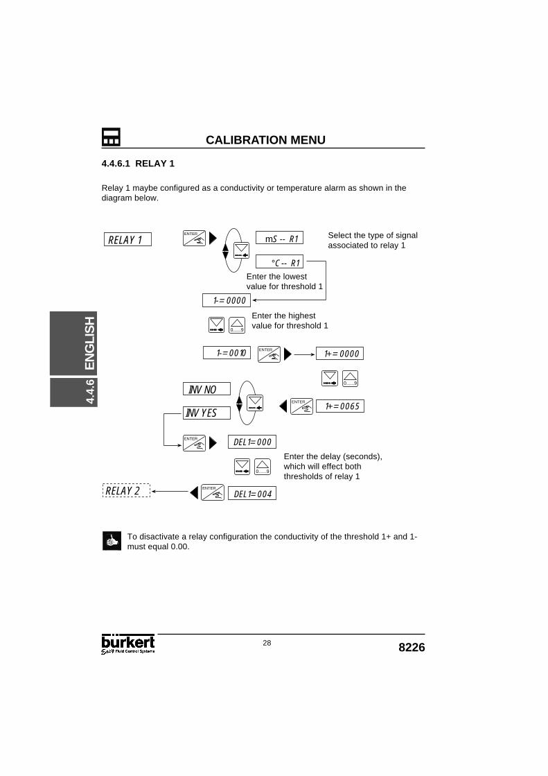
4.4.6.1 RELAY 1
Relay 1 maybe configured as a conductivity or temperature alarm as shown in thediagram below.
To disactivate a relay configuration the conductivity of the threshold 1+ and 1-must equal 0.00.
ENTER
ENTER
ENTER
DEL1= 000
DEL1= 004
0......9
1+= 0000
1+= 0065
0......9
1-= 0000
1-= 0010
0......9
ENTER
ENTER
mS -- R1
°C -- R1
INV NO
INV YES
Enter the highestvalue for threshold 1
Enter the delay (seconds),which will effect boththresholds of relay 1
RELAY 1
RELAY 2
Enter the lowestvalue for threshold 1
Select the type of signalassociated to relay 1
4.4.
6

298226
EN
GLI
SH
CALIBRATION MENU
4.4.6.2 RELAY 2
Relay 2 maybe configured as conductivity, temperature or a general alarm for a connectionfailure.
The alarm is activated in the following situations: Problem with the power supply (display “PWR FAIL“)
- Supply < 12V or it is not regulated Measurement problem
- Sensor finger is disconnected Measurement is out of range
- χ > 2S/cm or - 40°C < T < 120°C
Enter the delay (seconds),which will affect both ofthe thresholds of relay 2.
If the relay 2 is used as an alarm, ensure that the normally open state of the relaycorresponds to a safe position of the process.
ENTER
DEL2= 000
0......9
DEL2= 004ENTER
ENTER
0......9
ENTER
ENTER
ENTER
ENTER
2-= 0000
2-= 0040
0......9
ENTER
2+= 0044
2+= 0000
0......9
ENTER
mS -- R2
°C -- R2
INV YES
INV NO
INV YES
ALARMRELAY 2
Enter the lowest valuefor threshold 2
Enter the highestvalue for threshold 2
Select the type of signalassociated to relay 2
INV NO
FILTER
FILTER
4.4.
6

30 8226
EN
GLI
SH
CALIBRATION MENU
ENTER
ENTER
0......9
FILTER
END
FILTER 9
FILTER 0
4.4.7 FILTER FUNCTION
The filter function provides a damping effect to prevent fluctuation within the outputcurrent and display. There are 10 levels available from 0 to 9 with 0 having nodamping effect.
The filter which will be appropriate for most applications is filter 2.
From the diagram below it is possible to see how the different filters influence theconductivity output and display over time.
Filter 3
Conductivity Filter 6
Filter 9
C (mS/cm)
C (mS/cm)
C (mS/cm)
C (mS/cm)
t (s)
t (s)
t (s)
t (s)

318226
EN
GLI
SH
TEST MENU
4.5.1
4.5.2
4.5.3
4.5.4
4.5.5
4.5.6
4.5 TEST MENU
PRESS SIMULTANEOUSLY FOR 5 SECONDS
The following parameters are selected and set within this menu; SECTIONS
The following sections explain how to change and investigate the parametervalues within the test menu above.
0......9
Zero point compensation (4 mA).
Span compensation (20 mA).
Temperature correction + / - 5°C or 9°F.
Display of non-compensatedconductivity.
Input of the conductivity to be simulated.The current and relay outputs will reactaccording to this value.
Calibration of the zero point. This mustbe completed if the conductivity is> 10 µS/cm before mounting the device.
Return to the main menu and store thenew parameters set for OFFSET andSPAN. If one of the two values isinappropriate, the device willautomatically return to the "OFFSET"parameter and new values must beentered.
0......9
OFFSET
SPAN
CONDUCT.
T° ADJUST
END
SIMUL
CALIB4.
5

32 8226
EN
GLI
SH
TEST MENU
0......9
ENTER
ENTER
4.5.1 OFFSET COMPENSATION
Within this option the user has the possibility of correcting the basic setting of 4 mAgenerated by the transmitter. The transmitter generates a value of 4mA by pressing
when"OFFSET" is displayed within the main test menu.
Measure the generated current with an ammeter. If the displayed value is incorrect itcan be corrected by entering the measured value on the ammeter.
Adjustment range : + / - 0.5mA
4.5.2 SPAN COMPENSATION
Span compensation provides the option of changing the basic setting of 20 mA. Theprocedure is identical to that of the offset compensation above. The transmittergenerates 20mA if the key is pressed when "SPAN " is displayed within the maintest menu.
Measure the generated current with an ammeter. If the displayed value is incorrect itcan be corrected by entering the measured value on the ammeter.
Adjustment range : + / - 0.5mA
Enter the measured value
Enter the measured valueSP= 19.96T° ADJUST
OFFSET
SPAN
OF= 04.00
OF= 04.02
0......9
ENTER
ENTER
SPAN SP= 20.00
ENTER
ENTER
4.5.
1
338226
EN
GLI
SH
TEST MENU
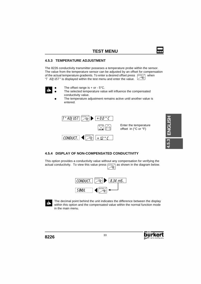
4.5.3 TEMPERATURE ADJUSTMENT
The 8226 conductivity transmitter posseses a temperature probe within the sensor.The value from the temperature sensor can be adjusted by an offset for compensationof the actual temperature gradients. To enter a desired offset press when"T ADJUST " is displayed within the test menu and enter the value.
The offset range is + or - 5°C. The selected temperature value will influence the compensated
conductivity value. The temperature adjustment remains active until another value is
entered.
4.5.4 DISPLAY OF NON-COMPENSATED CONDUCTIVITY
This option provides a conductivity value without any compensation for verifying theactual conductivity. To view this value press as shown in the diagram below.
The decimal point behind the unit indicates the difference between the displaywithin this option and the compensated value within the normal function modein the main menu.
0......9
ENTER
ENTER
Enter the temperatureoffset in (°C or °F)
+ 0.0 ° C
+ 1.2 ° C
T ° ADJUST
CONDUCT.
ENTER
ENTER
ENTER
CONDUCT. 8.34 mS.
SIMUL
ENTER
4.5.
3

34 8226
EN
GLI
SH
TEST MENU
4.5.5 CONDUCTIVITY SIMULATION
A conductivity or temperature value can be simulated within this menu, allowing theuser to test the system without any liquid being present. The simulated valueinfluences all the outputs including the relays.
Quit the sub-menu SIMUL by pressing or .
The simulation will remain active until the user enters another parameter ormenu.
4.5.6 CALIBRATION OF THE ZERO POINT
If the conductivity display within the main menu is greater than 10 µS/cm in the air,perform a new calibration of the transmitter with the sensor in the air.To calibrate the unit, hold the sensor in the air and select "CALIB YES" and the unitwill automatically perform a calibration test.
The measure for calibration continues for a duration of about 1 min.
0......9
ENTER ENTER
0......9
ENTER
ENTER
0......9
ENTER
0......9
Enter the conductivity value
SIMUL 00.00 S
Enter the temperature value
TEMPERA 00.0 ° C
021 ° C
ENTER
ENTER
END
CONDUCT.
CALIB NO
CALIB YES
CALIB
SIMUL
10.00 S SIMUL
4.5.
5

358226
EN
GLI
SH
INFORMATION
4.6 8226 SETTINGS
The 8226 Conductivity Transmitter is calibrated within the factory before delivery to thesettings shown in the table below.
4.6.1 FACTORY SETTING OF CONDUCTIVITY TRANSMITTER TYPE 8226
The table below allows the configuration settings for the 8226 conductivitytransmitter to be written for future reference and quick referral.
4.6.2 USER SETTING OF CONDUCTIVITY TRANSMITTER TYPE 8226
IDENT N°: SERIAL N°:
Relay: 1-: 00.001+: 00.002-: 00.002+: 00.00DEL1: 000DEL2: 000
Filter: Filter 2
Language: EnglishUnit of conductivity: mS/cmUnit of temperature: °CDecimal points: 2Cell constant: ≅ 6.30Temperature compensationcoefficient: 00.00%/°CCurrent: 4 mA: 00.00
20 mA: 00.00
Relay: 1-: ........................1+: ........................2-: ........................2+: ........................DEL1: ........................DEL2: ........................
Filter: ........................
Language: ...........................Unit of conductivity: ...........................Unit of temperature: ...........................Decimal points: ...........................Cell constant: ...........................Temperature compensationcoefficient: ...........................Current: 4 mA: ...........................
20 mA: ...........................
4.6
8226
EN
GLI
SH
MAINTENANCE
36
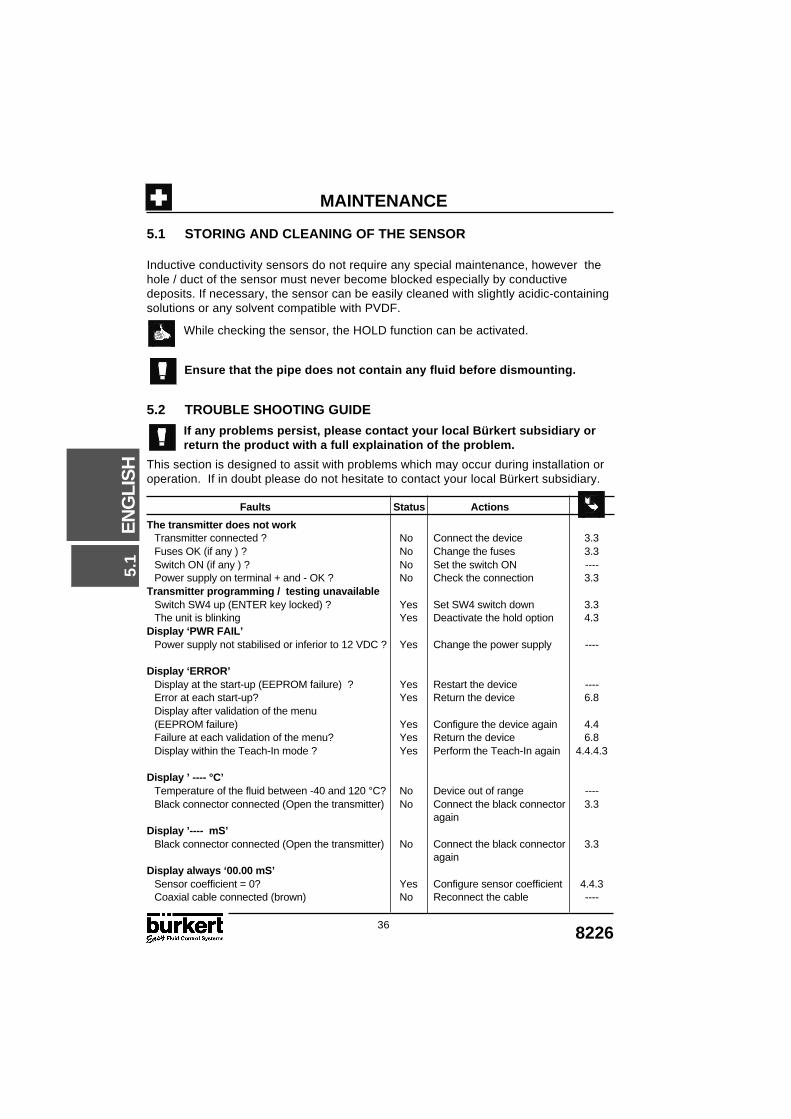
5.1 STORING AND CLEANING OF THE SENSOR
Inductive conductivity sensors do not require any special maintenance, however thehole / duct of the sensor must never become blocked especially by conductivedeposits. If necessary, the sensor can be easily cleaned with slightly acidic-containingsolutions or any solvent compatible with PVDF.
While checking the sensor, the HOLD function can be activated.
Ensure that the pipe does not contain any fluid before dismounting.
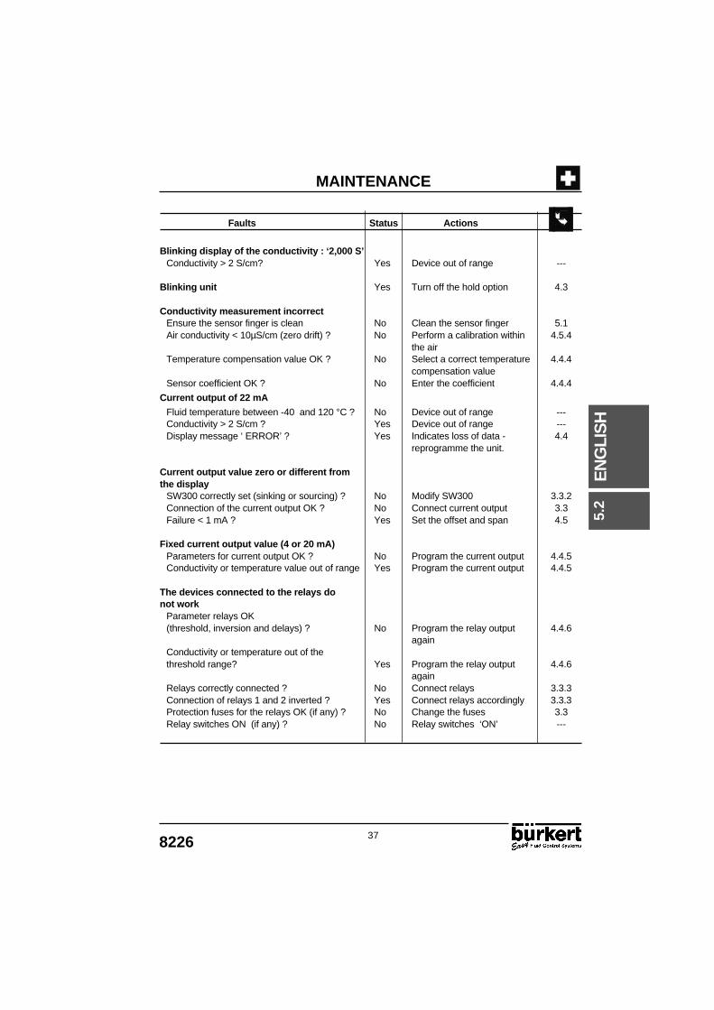
5.2 TROUBLE SHOOTING GUIDE
If any problems persist, please contact your local Bürkert subsidiary orreturn the product with a full explaination of the problem.
This section is designed to assit with problems which may occur during installation oroperation. If in doubt please do not hesitate to contact your local Bürkert subsidiary.
Faults Status Actions
The transmitter does not workTransmitter connected ? No Connect the device 3.3Fuses OK (if any ) ? No Change the fuses 3.3Switch ON (if any ) ? No Set the switch ON ----Power supply on terminal + and - OK ? No Check the connection 3.3
Transmitter programming / testing unavailableSwitch SW4 up (ENTER key locked) ? Yes Set SW4 switch down 3.3The unit is blinking Yes Deactivate the hold option 4.3
Display ‘PWR FAIL’Power supply not stabilised or inferior to 12 VDC ? Yes Change the power supply ----
Display ‘ERROR’Display at the start-up (EEPROM failure) ? Yes Restart the device ----Error at each start-up? Yes Return the device 6.8Display after validation of the menu(EEPROM failure) Yes Configure the device again 4.4Failure at each validation of the menu? Yes Return the device 6.8Display within the Teach-In mode ? Yes Perform the Teach-In again 4.4.4.3
Display ’ ---- °C’Temperature of the fluid between -40 and 120 °C? No Device out of range ----Black connector connected (Open the transmitter) No Connect the black connector 3.3
againDisplay ’---- mS’
Black connector connected (Open the transmitter) No Connect the black connector 3.3again
Display always ‘00.00 mS’Sensor coefficient = 0? Yes Configure sensor coefficient 4.4.3Coaxial cable connected (brown) No Reconnect the cable ----
5.1
378226
EN
GLI
SH
MAINTENANCE
Faults Status Actions
Blinking display of the conductivity : ‘2,000 S’Conductivity > 2 S/cm? Yes Device out of range ---
Blinking unit Yes Turn off the hold option 4.3
Conductivity measurement incorrectEnsure the sensor finger is clean No Clean the sensor finger 5.1Air conductivity < 10µS/cm (zero drift) ? No Perform a calibration within 4.5.4
the airTemperature compensation value OK ? No Select a correct temperature 4.4.4
compensation valueSensor coefficient OK ? No Enter the coefficient 4.4.4
Current output of 22 mA
Fluid temperature between -40 and 120 °C ? No Device out of range ---Conductivity > 2 S/cm ? Yes Device out of range ---Display message ‘ ERROR’ ? Yes Indicates loss of data - 4.4
reprogramme the unit.
Current output value zero or different fromthe display
SW300 correctly set (sinking or sourcing) ? No Modify SW300 3.3.2Connection of the current output OK ? No Connect current output 3.3Failure < 1 mA ? Yes Set the offset and span 4.5
Fixed current output value (4 or 20 mA)Parameters for current output OK ? No Program the current output 4.4.5Conductivity or temperature value out of range Yes Program the current output 4.4.5
The devices connected to the relays donot work
Parameter relays OK(threshold, inversion and delays) ? No Program the relay output 4.4.6
againConductivity or temperature out of thethreshold range? Yes Program the relay output 4.4.6
againRelays correctly connected ? No Connect relays 3.3.3Connection of relays 1 and 2 inverted ? Yes Connect relays accordingly 3.3.3Protection fuses for the relays OK (if any) ? No Change the fuses 3.3Relay switches ON (if any) ? No Relay switches ‘ON’ ---
5.2

38 8226
EN
GLI
SH
SPECIFICATIONS
6.1 SPECIFICATIONS
Specifications in relation to the process
Conductivity measurementMeasurement type Inductive conductivity measurementMeasuring range 0...2 S/cm (minimum)Accuracy + / - 2% of the measured value from 100µS...2S/cmTemperature drift 0.1 % / °C (maximum)Response time < 1 s
Temperature measurementMeasurement type Numeric measurementMeasuring range - 40...120 °CAccuracy + / - 0.5°C from 0...110°C and
+ / - 1°C from - 40°C...0°C and 110°C...120°C
Piping installationPipes Stainless steel, brass or plastic (PVDF, PP and PVC)Connection Solvent/fusion spigots, threaded ports (G, NPT,Rc),
buttwelding ends, flange, Tri-clamp - See instructionmanual SO20 - Ident. No. 429633S
Pressure rating PN 6Fluid temperature 0...120°CMaterial contacting the fluid: Sensor body : PVDF
Seals : EPDM or FPM
Specification in relation to the control outputs
Electrical connectionPower supply 12...30 VDC regulated +/- 5%
115/230 VACConsumption 250mA (maximum)
Proportional outputOutput type Current output from 4...20 mA (error signal 22 mA)Accuracy + / - 1%Wiring Sinking or sourcing modeMaximum load 1000 Ω at 30VDC
800 Ω at 24VDC 450 Ω at 15VDC 330 Ω at 12VDC
Adjustment Selectable software measuring range (4... 20mA)for conductivity or temperature measuremnet22mA if the signal is out of the measuring range(Conductivity > 2S or T < - 40, T > 120°C)
Output calibration Software: offset (4mA) and span (20mA) adjustable
Relay outputOutput type Normally open relaysLoad DC: 75V = ; 3A
AC: 48V ≅ ; 3A -Life expectancy 100 000 cycles (minimum)Thresholds Hysteresis programmable according to the
temperature or conductivity.Switching delay Programmable from 0...180 s
6.1

398226
EN
GLI
SH
SPECIFICATIONSSpecifications in relation to the user
User’s interfaceDisplay 8 digits alphanumeric LCD 9mm highConductivity units µS/cm without decimal point
mS/cm with 4 positions for the decimal pointS/cm with 3 positions for the decimal point
Resistance units Ω and kΩ with 4 positions for the decimalpoint
Temperature units Temperature °C of °F with 1 decimal pointDisplay :
Current output Generated current indication : ‘xx.xx mA’Relay state Red LED’s on when the contact is closed
Programming Menus with 3 programming keysProtection Lockable switch for the ‘Enter’ key
ProcessingAssistance for commissioning Simulation of the conductivity or temperature to
check the correct running of the installationFiltering of the conductivity 10 levels of filtering (Filter 0...9)Temperature adjustment + / - 5°C maximum, programmableTemperature conpensation Reference of 25°CType of compensation : Linear: (from 0.00...9.99% / °C)
Automatic:Sodium chloride (NaCl) from 0.05...270g/ l from 0...80°CNitric acid (HNO3) dosing 1% from 10...80°CSodium hydroxyde (NaOH) dosing 1% form 10...80°CSulfuric acid (H2SO3) dosing 20% from 5...55°C
Teach-In: Teach-In of the variations from the conductivity accordingto T°C splitting the variations curve into 5 linear segments
Maintenance HOLD function to maintain the output signals
Specifications in relation to the environment
Ambient conditionsStoring temperature 0...60°C (32...140°F)Storing humidity Maximum of 80%Operating temperature 0...60°C (32...140°F)Operating humidity Maximum of 80%Enclosure rating IP65
ConstructionDimensions maximum 188 x 88 x 126mmWeight 550 g (maximum)
Materials in contact with the environmentElectronic housing PC 20% glass reinforced fibreFront plate Polyester
Conformity to standardsEmission According to generic norm EN 50081.1Immunity According to generic norm EN 50082.2
Output current accuracy +/- 2% according toTest ENV 50145 (only valid for 115/230 VAC with relay)
Safety According to safety regulations for measuring instrumentsfor regulation and laboratory NF EN 61010-1
6.1
40 8226
EN
GLI
SH
INFORMATION
88 (
3,46
")
88 (3,46")88 (3,46")
126 (4,96")
188
(7,
40")
108
(4,1
7")
88 (
3,46
")
126 (4,96")
188
(7,
40")
108
(4,1
7")
88 (3,46")
126 (4,96")
188
(7,
40")
108
(4,1
7")
88 (
3,46
")
88 (
3,46
")
88 (3,46")
106 (4,06")
188
(7,
40")
108
(4,1
7")
1/2" G
Version:"WORLDWIDE"
1/2" G
Version:"NORTH AMERICA"
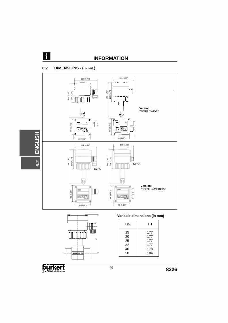
6.2 DIMENSIONS - ( IN MM )
6.2
H1
Variable dimensions (in mm)
DN H1
15 17720 17725 17732 17740 17850 184

418226
EN
GLI
SH
INFORMATION
6.3 MEASURING PRINCIPLE
Conductivity is the ability of a liquid / solution to conduct an electrical current. Tomeasure the conductivity of a solution the 8226 conductivity transmitter uses thefollowing principle:
A voltage is connected to the primary magnetic coil.
The magnetic field induced generates a current in the secondary magnetic coil.
The intensity of the current is a direct function of the conductivity of the solutionbetween the 2 magnetic coils.
6.4 STANDARD DELIVERY
From a standard delivery you should of recieved the following:
1 8226 Inductive Conductivity Transmitter 1 Instruction Manual (3 languages)
(If the transmitter has 1 or 2 Pg13.5 connections you should additionallyrecieve 1 or 2 multiway seals depending on the version).
CONDUCTIVE FLUID
1
1
1
2
2
2 6.3

42 8226
EN
GLI
SH
ANNEX
6.5 TYPE SPECIFICATION
Inductive Type 8226 Conductivity TransmitterWorldwide types4-20 mA output
Power supply Relays Gasket Connection Ident N°12...30 VDC No FPM DIN 43650 431673U12...30 VDC No EPDM DIN 43650 431675W12...30 VDC No FPM 1x PG 13,5 431674V12...30 VDC No EPDM 1x PG 13,5 431676X
12...30 VDC 2 FPM 2 x PG 13,5 431679A12...30 VDC 2 EPDM 2 x PG 13,5 431680Y
115/230 VAC No FPM 2x PG 13,5 431677Y115/230 VAC No EPDM 2x PG 13,5 431678H
115/230 VAC 2 FPM 2x PG 13,5 431681M115/230 VAC 2 EPDM 2x PG 13,5 431682N
Inductive Conductivity Transmitter Type 8226North America types; G 1/2" connection 4-20 mA output
Power supply Relays Gasket Connection Ident N°12...30 VDC No FPM 1 x G1/2" 431683P12...30 VDC No EPDM 1 x G1/2" 431684Q
12...30 VDC 2 FPM 2 x G1/2" 431687K12...30 VDC 2 EPDM 2 x G1/2" 431688U
115/230 VAC No FPM 2 x G1/2" 431685R115/230 VAC No EPDM 2 x G1/2" 431686J
115/230 VAC 2 FPM 2 x G1/2" 431689V115/230 VAC 2 EPDM 2 x G1/2" 431690S
COND :8226-FPM-PVDF N=004712-30 V = 250 mA 4-20 mA REL :48 VAC ; 75 VDC/3A
431679AW4YUP
Mad
e in
Fra
nce
1 Conductivity2 Type3 Seal material4 Sensor material5 Serial number6 Relay caracteristics7 Output current8 Power supply9 Power/current consumption10 (Factory internal N°)11 Protection rating12 CE mark13 Ident. No.
6.6 LABEL TYPE 8226
6.5
438226
EN
GLI
SH
ANNEX
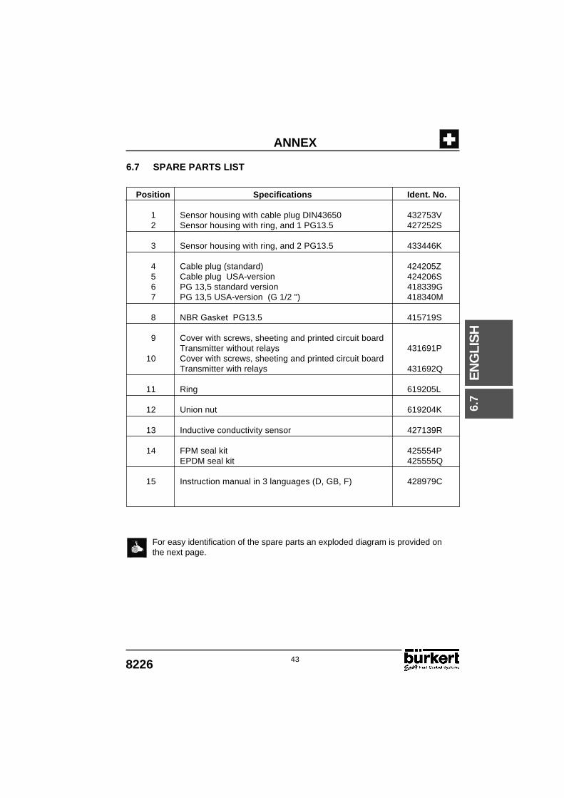
6.7 SPARE PARTS LIST
For easy identification of the spare parts an exploded diagram is provided onthe next page.
Position Specifications Ident. No.
1 Sensor housing with cable plug DIN43650 432753V2 Sensor housing with ring, and 1 PG13.5 427252S
3 Sensor housing with ring, and 2 PG13.5 433446K
4 Cable plug (standard) 424205Z5 Cable plug USA-version 424206S6 PG 13,5 standard version 418339G7 PG 13,5 USA-version (G 1/2 ") 418340M
8 NBR Gasket PG13.5 415719S
9 Cover with screws, sheeting and printed circuit boardTransmitter without relays 431691P
10 Cover with screws, sheeting and printed circuit boardTransmitter with relays 431692Q
11 Ring 619205L
12 Union nut 619204K
13 Inductive conductivity sensor 427139R
14 FPM seal kit 425554PEPDM seal kit 425555Q
15 Instruction manual in 3 languages (D, GB, F) 428979C6.
7

44 8226
EN
GLI
SH
ANNEX
6.7

SERVICE
Bürkert ContromaticChina/HK Ltd.Beijing OfficeRm. 808, Jing Tai BuildingNo. 24, JianguomenWaldajie100022 Beijing P.R.CTel +86 10 6508 33 31Fax +86 10 6592 86 29
Bürkert ContromaticChina/HK Ltd.Cheng Du Representative OfficeRm. 502, Fuji BuildingNo. 26 ShududadaoDongfung StreetChengdu P.R.CTel +86 28 443 1895Fax +86 28 445 1341
DenmarkBürkert-Contromatic A/SHorkær 24DK-2730 HerlevTel +45 44 50 75 00Fax +45 44 50 75 75
FinlandBürkert OyAtomitie 5SF-00370 HelsinkiTel +358 9 549 70 600Fax +358 9 503 12 75
FranceBürkert ContromaticB.P. 21Triembach au ValF-67220 VilléTel +33 (0) 388 58 91 11Fax +33 (0) 388 57 09 61
Germany / DeutschlandBürkert Steuer- und RegeltechnikChristian-Bürkert-Straße 13-17D-74653 IngelfingenTel +49 7940 10-0Fax +49 7940 10 361
Niederlassung NRWHolzener Straβe 70D-58708 MendenTel +49 2373 96 81-0Fax +49 2373 96 81-52
Niederlassung FrankfurtAm Flugplatz 27D-63329 EgelsbachTel +49 6103 94 14-0Fax +49 6103 94 14-66
Niederlassung MünchenPaul-Gerhardt-Allee 24D-81245 MünchenTel +49 89 82 92 28-0Fax +49 89 82 92 28-50
Niederlassung BerlinBruno-Taut-Straβe 4D-12524 BerlinTel +49 30 67 97 17-0Fax +49 30 67 97 17-66
Niederlassung DresdenChristian Bürkert Straße 2D-01900 GroßröhrsdorfTel +49 35952 3 63 00Fax +49 35952 3 65 51
Niederlassung HannoverRendburger Straße 12D-30569 HannoverTel +49 511 9 02 76-0Fax +49 511 9 02 76-66
Niederlassung StuttgartKarl-Benz-Straße 9D-70794 Filderstadt (Bernh.)Tel +49 711 4 51 10-0Fax +49 711 4 51 10-66
GreeceTevex E.E3 Xirogianni StraßeZografos AthenTel +30 1- 7 71 50 97 Fax +30 1- 7 75 12 26
Great BritainBürkert Contromatic Ltd.Brimscombe Port Business ParkBrimscombe, Stroud, Glos.GL5 2QFTel. +44 (0) 1453 73 13 53Fax +44 (0) 1453 73 13 43
Hong KongBurkert Contromatic(China/HK) Ltd.Unit 708, Prosperity Centre77-81 Container Port RoadKwai Chung N.T.Hong KongTel +852 2480 1202Fax +852 2418 1945
IndonesiaP.T. FulkosindoJLKH Hasyim Ashari No. 38-AJakarta 10140Tel +62 21 386 24 85Fax +62 21 386 24 85
AustraliaBurkert Fluid Control SystemsUnit 1 No.2, Welder RoadSeven Hills NSW 2147Tel +61 2 967 461 66Fax +61 2 967 461 67
AustriaBürkert Contromatic GmbHCentral and Eastern EuropeDiefenbachgasse 1-3Postfach 89A-1150 WienTel +43 1894 13 33Fax +43 1 894 13 00
BelgiumBürkert Contromatic N.V/S.RMiddelmolenlaan 100B-2100 DeurneTel +32 3 325 89 00,Fax +32 3 325 61 61
BrasilConterval Ind. E. Com. Ltda.Rua Pinheiros 358Caixa Postal 1116705422 San PauloTel +55 11 852 93 77Fax +55 11 852 95 61
CanadaBürkert Contromatic Inc.760 Pacific Road, Unit 3Oakville, Ontario, L6L 6M5Tel +1 905 847 55 66,Fax +1 905 847 90 06
ChileTermodinamica Ltd.Av. Bulnes 195, Cas. 118Santiago de ChileTel +56 2 635 39 50Fax +56 2 635 39 47
ChinaBürkert Contromatic(Suzhou) Co. Ltd.2/F, 71 Zhu Yuan Road215011 SuzhouTel +86 512 808 19 16Fax +86 512 824 51 06
Bürkert ContromaticChina/HK Ltd.Rm. 1313No. 103, Cao Bao Road200233 Shanghai P.R.CTel +86 21 6484 7007Fax +86 21 6484 7008
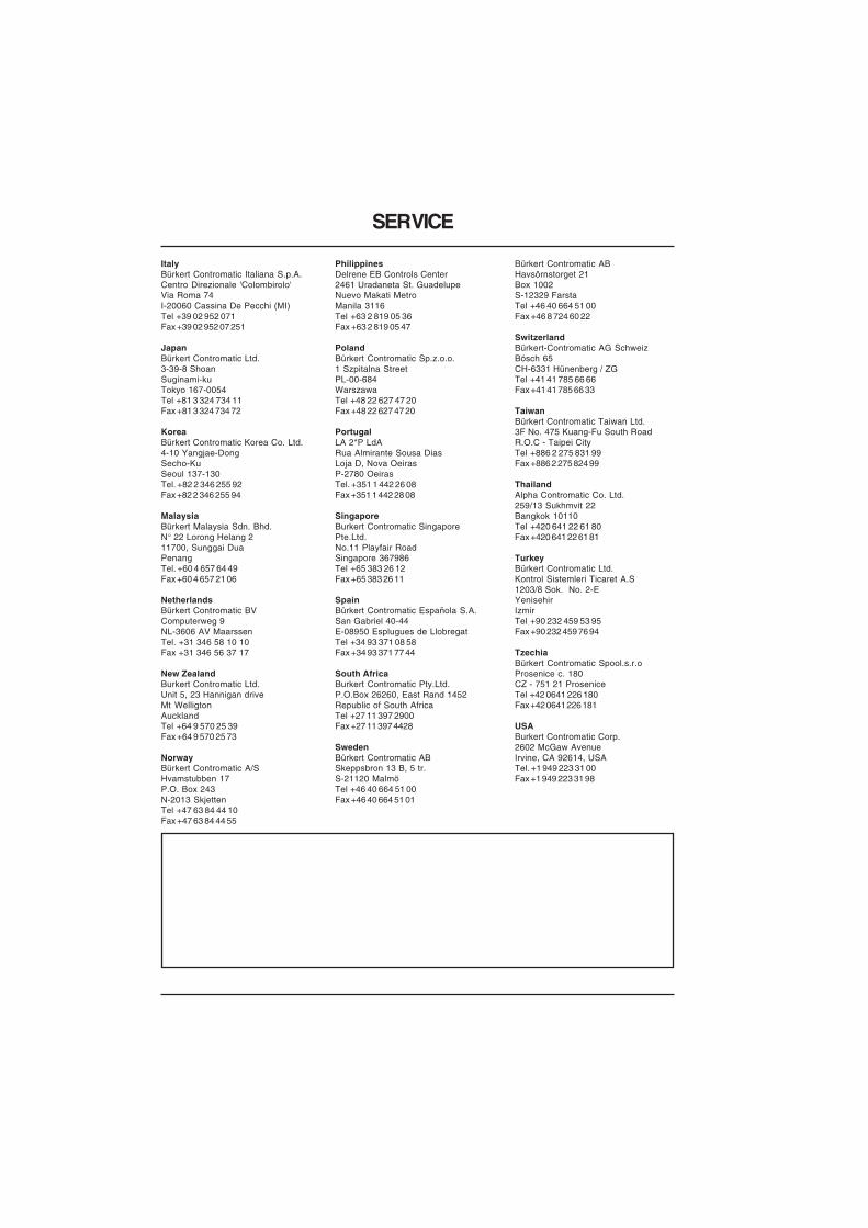
PhilippinesDelrene EB Controls Center2461 Uradaneta St. GuadelupeNuevo Makati MetroManila 3116Tel +63 2 819 05 36Fax +63 2 819 05 47
PolandBürkert Contromatic Sp.z.o.o.1 Szpitalna StreetPL-00-684WarszawaTel +48 22 627 47 20Fax +48 22 627 47 20
PortugalLA 2*P LdARua Almirante Sousa DiasLoja D, Nova OeirasP-2780 OeirasTel. +351 1 442 26 08Fax +351 1 442 28 08
SingaporeBurkert Contromatic SingaporePte.Ltd.No.11 Playfair RoadSingapore 367986Tel +65 383 26 12Fax +65 383 26 11
SpainBürkert Contromatic Española S.A.San Gabriel 40-44E-08950 Esplugues de LlobregatTel +34 93 371 08 58Fax +34 93 371 77 44
South AfricaBurkert Contromatic Pty.Ltd.P.O.Box 26260, East Rand 1452Republic of South AfricaTel +27 11 397 2900Fax +27 11 397 4428
SwedenBürkert Contromatic ABSkeppsbron 13 B, 5 tr.S-21120 MalmöTel +46 40 664 51 00Fax +46 40 664 51 01
SERVICE
Bürkert Contromatic ABHavsörnstorget 21Box 1002S-12329 FarstaTel +46 40 664 51 00Fax +46 8 724 60 22
SwitzerlandBürkert-Contromatic AG SchweizBösch 65CH-6331 Hünenberg / ZGTel +41 41 785 66 66Fax +41 41 785 66 33
TaiwanBürkert Contromatic Taiwan Ltd.3F No. 475 Kuang-Fu South RoadR.O.C - Taipei CityTel +886 2 275 831 99Fax +886 2 275 824 99
ThailandAlpha Contromatic Co. Ltd.259/13 Sukhmvit 22Bangkok 10110Tel +420 641 22 61 80Fax +420 641 22 61 81
TurkeyBürkert Contromatic Ltd.Kontrol Sistemleri Ticaret A.S1203/8 Sok. No. 2-EYenisehirIzmirTel +90 232 459 53 95Fax +90 232 459 76 94
TzechiaBürkert Contromatic Spool.s.r.oProsenice c. 180CZ - 751 21 ProseniceTel +42 0641 226 180Fax +42 0641 226 181
USABurkert Contromatic Corp.2602 McGaw AvenueIrvine, CA 92614, USATel. +1 949 223 31 00Fax +1 949 223 31 98
ItalyBürkert Contromatic Italiana S.p.A.Centro Direzionale 'Colombirolo'Via Roma 74I-20060 Cassina De Pecchi (MI)Tel +39 02 952 071Fax +39 02 952 07 251
JapanBürkert Contromatic Ltd.3-39-8 ShoanSuginami-kuTokyo 167-0054Tel +81 3 324 734 11Fax +81 3 324 734 72
KoreaBürkert Contromatic Korea Co. Ltd.4-10 Yangjae-DongSecho-KuSeoul 137-130Tel. +82 2 346 255 92Fax +82 2 346 255 94
MalaysiaBürkert Malaysia Sdn. Bhd.N° 22 Lorong Helang 211700, Sunggai DuaPenangTel. +60 4 657 64 49Fax +60 4 657 21 06
NetherlandsBürkert Contromatic BVComputerweg 9NL-3606 AV MaarssenTel. +31 346 58 10 10Fax +31 346 56 37 17
New ZealandBurkert Contromatic Ltd.Unit 5, 23 Hannigan driveMt WelligtonAucklandTel +64 9 570 25 39Fax +64 9 570 25 73
NorwayBürkert Contromatic A/SHvamstubben 17P.O. Box 243N-2013 SkjettenTel +47 63 84 44 10Fax +47 63 84 44 55
Copyright © 2022 FDOKUMEN