Rexroth IndraMotion - Bosch Rexroth
150
Electric Drives and Controls Pneumatics Service Linear Motion and Assembly Technologies Hydraulics
-
Upload
khangminh22 -
Category
Documents
-
view
19 -
download
0
Transcript of Rexroth IndraMotion - Bosch Rexroth
Electric Drivesand Controls Pneumatics Service
Linear Motion and Assembly TechnologiesHydraulics

Rexroth IndraMotion10VRSGeneric Application Template
Application Manual
DOK-IM*MLC-TF*GAT**V10-AP02-EN-P
RS-b3e4284e4f74209c0a6846a001ed437c-2-en-US-8
This documentation provides a structured template to the IndraLogic PLC pro‐grammer. This template can be used to add and edit PLC programming code.It includes the template, the template wizard and the example applications.
Edition Release Date Notes
120-2850-B360/EN -01 09.2009 First edition for 10VRS120-2850-B360/EN -02 03.2010 Changes in chapters 5
and 6
Copyright © Bosch Rexroth AG, 2010Copying this document, giving it to others and the use or communication of thecontents thereof without express authority, are forbidden. Offenders are liablefor the payment of damages. All rights are reserved in the event of the grant ofa patent or the registration of a utility model or design (DIN 34-1).
Validity The specified data is for product description purposes only and may not bedeemed to be guaranteed unless expressly confirmed in the contract. All rightsare reserved with respect to the content of this documentation and the availa‐bility of the product.
Published by Bosch Rexroth AGBgm.-Dr.-Nebel-Str. 2 ■ 97816 Lohr a. Main, GermanyPhone +49 (0)93 52/ 40-0 ■ Fax +49 (0)93 52/ 40-48 85http://www.boschrexroth.com/System Development Automation MotionLogic Control, AK (SyMu/MePe)
Note This document has been printed on chlorine-free bleached paper.
Title
Type of Documentation
Document Typecode
Internal File Reference
Purpose of Documentation
Record of Revision
Bosch Rexroth AG DOK-IM*MLC-TF*GAT**V10-AP02-EN-P Rexroth IndraMotion 10VRS Generic Application Template

Table of ContentsPage
1 Introduction.................................................................................................................... 7
2 Important Instructions on Use........................................................................................ 92.1 Intended Use.......................................................................................................................................... 92.1.1 Introduction.......................................................................................................................................... 92.1.2 Scope of Use and Application............................................................................................................. 92.2 Improper Use........................................................................................................................................ 10
3 Safety Instructions for Electric Drives and Controls .................................................... 113.1 Definitions of Terms.............................................................................................................................. 113.2 General Information.............................................................................................................................. 123.2.1 Using the Safety Instructions and Passing Them on to Others......................................................... 123.2.2 Requirements for Safe Use............................................................................................................... 123.2.3 Hazards by Improper Use.................................................................................................................. 133.3 Instructions with Regard to Specific Dangers....................................................................................... 143.3.1 Protection Against Contact with Electrical Parts and Housings......................................................... 143.3.2 Protective Extra-Low Voltage as Protection Against Electric Shock ................................................ 153.3.3 Protection Against Dangerous Movements....................................................................................... 153.3.4 Protection Against Magnetic and Electromagnetic Fields During Operation and Mounting.............. 173.3.5 Protection Against Contact With Hot Parts........................................................................................ 173.3.6 Protection During Handling and Mounting......................................................................................... 173.3.7 Battery Safety.................................................................................................................................... 183.3.8 Protection Against Pressurized Systems........................................................................................... 183.4 Explanation of Signal Words and the Safety Alert Symbol................................................................... 19
4 Automating Applications.............................................................................................. 214.1 General................................................................................................................................................. 214.2 Initialization........................................................................................................................................... 214.3 Operation Modes.................................................................................................................................. 214.3.1 General.............................................................................................................................................. 214.3.2 Automatic........................................................................................................................................... 224.3.3 Manual............................................................................................................................................... 224.4 Cyclical Processing............................................................................................................................... 224.4.1 General.............................................................................................................................................. 224.4.2 Operation Mode Independent Logic.................................................................................................. 224.4.3 Generating and displaying diagnostic messages.............................................................................. 224.5 Task Management................................................................................................................................ 224.5.1 General.............................................................................................................................................. 224.5.2 Principles of Task Management........................................................................................................ 224.5.3 Recommended Task Division when Using IndraWorks/IndraLogic................................................... 23
General........................................................................................................................................... 23Typical tasks for the MotionTask.................................................................................................... 23Typical tasks for the PlcTask.......................................................................................................... 24
DOK-IM*MLC-TF*GAT**V10-AP02-EN-P Rexroth IndraMotion 10VRS Generic Application Template
Bosch Rexroth AG I/147
Table of Contents

Page
Typical tasks for the BackgroundTask............................................................................................ 244.5.4 Measuring Cycle Times..................................................................................................................... 24
Monitoring dialog for task configuration.......................................................................................... 24Cycle time dialog of the control...................................................................................................... 25Task execution viewer of the control.............................................................................................. 26Time measurement in the PLC project........................................................................................... 26
4.5.5 Application-specific Watchdog........................................................................................................... 274.6 Error Management................................................................................................................................ 284.6.1 General.............................................................................................................................................. 284.6.2 Basic Error Management................................................................................................................... 284.6.3 Error Recognition............................................................................................................................... 284.6.4 Error Reaction................................................................................................................................... 294.6.5 Error Diagnostics............................................................................................................................... 294.6.6 Error Acknowledgement / Restart after an Error............................................................................... 304.7 Visualization.......................................................................................................................................... 314.7.1 General.............................................................................................................................................. 314.7.2 Typical Contents of a Visualization.................................................................................................... 31
Machine status display................................................................................................................... 31Controlling the machine states....................................................................................................... 31
4.7.3 Providing Data Using the PLC........................................................................................................... 31General........................................................................................................................................... 31Symbol configuration...................................................................................................................... 31Communication configuration......................................................................................................... 34
5 The GATcompact Example Project.................................................................................. 355.1 Overview of GATcompact......................................................................................................................... 355.2 First Steps - GATcompact......................................................................................................................... 355.2.1 Preparation........................................................................................................................................ 355.2.2 Creating a Simple Motion Application................................................................................................ 36
General........................................................................................................................................... 36Topic............................................................................................................................................... 36Operating sequence....................................................................................................................... 37
5.3 Initialization........................................................................................................................................... 445.4 Operation Modes.................................................................................................................................. 475.5 Cyclical Processing............................................................................................................................... 495.6 Task Management................................................................................................................................ 495.6.1 Task Configuration, GATcompact.......................................................................................................... 495.6.2 Adding a MotionTask......................................................................................................................... 495.6.3 Adding a BackgroundTask................................................................................................................ 515.7 Error Management................................................................................................................................ 525.7.1 Error Recognition and Diagnostics.................................................................................................... 525.7.2 Error Reaction................................................................................................................................... 545.7.3 Deleting an Error............................................................................................................................... 565.8 Visualization.......................................................................................................................................... 565.8.1 Internal visualization for assistance during start up........................................................................... 56
General........................................................................................................................................... 56
Bosch Rexroth AG DOK-IM*MLC-TF*GAT**V10-AP02-EN-P Rexroth IndraMotion 10VRS Generic Application Template
II/147
Table of Contents

Page
System_Overview........................................................................................................................... 565.8.2 External Visualization with Separate HMIs (WinStudio Visualization)............................................... 58
General........................................................................................................................................... 58Dialog structure.............................................................................................................................. 60Extending the visualization............................................................................................................. 61Communication connection............................................................................................................ 63Multiple language capability........................................................................................................... 65
5.9 Interfaces to GAT.................................................................................................................................. 665.9.1 General.............................................................................................................................................. 665.9.2 Data for the State Machine ............................................................................................................... 665.9.3 Data for Error Management .............................................................................................................. 665.9.4 Data for Axes .................................................................................................................................... 675.9.5 Data of the Control ........................................................................................................................... 675.10 How To: Typical User Activities............................................................................................................ 685.10.1 Access to Axis Data .......................................................................................................................... 685.10.2 Adding an Axis................................................................................................................................... 695.10.3 Removing/renaming an Axis ............................................................................................................. 705.10.4 Adding an Operation Mode ............................................................................................................... 725.10.5 Processing in the MotionTask........................................................................................................... 735.10.6 AxisInterface Extensions .................................................................................................................. 735.11 GATcompact Brief Overview..................................................................................................................... 755.11.1 GATcompact structure overview............................................................................................................ 755.11.2 Overview of the Most Important Global Machine Variables............................................................... 755.11.3 Overview of the Most Important Global Axis Variables..................................................................... 765.11.4 Overview of the Machine Methods and Actions................................................................................ 765.11.5 Access to Axes within the Machine................................................................................................... 76
6 Project Development with GAT.................................................................................... 776.1 General................................................................................................................................................. 776.2 Overview............................................................................................................................................... 776.2.1 Basic Idea.......................................................................................................................................... 776.2.2 Requirements for Use........................................................................................................................ 786.3 First Steps - GAT.................................................................................................................................. 796.3.1 Preparation........................................................................................................................................ 796.3.2 Creating a Simple Motion Application................................................................................................ 79
General........................................................................................................................................... 79Topic............................................................................................................................................... 79Operating sequence....................................................................................................................... 80
6.4 Functional Principle.............................................................................................................................. 936.5 Initialization........................................................................................................................................... 936.6 Operation Modes.................................................................................................................................. 946.6.1 General.............................................................................................................................................. 946.6.2 Setting the Target Operation Mode after Initialization....................................................................... 956.6.3 Changing the Operation Mode.......................................................................................................... 956.6.4 User Activities when Exiting an Operation Mode............................................................................... 966.6.5 User Activities when Starting an Operation Mode............................................................................. 96
DOK-IM*MLC-TF*GAT**V10-AP02-EN-P Rexroth IndraMotion 10VRS Generic Application Template
Bosch Rexroth AG III/147
Table of Contents
Page
6.6.6 States of an Operation Mode............................................................................................................. 976.7 Modules................................................................................................................................................ 986.7.1 General.............................................................................................................................................. 986.7.2 Creation Rules................................................................................................................................... 986.7.3 Module Interface................................................................................................................................ 98
General........................................................................................................................................... 98Control and status structure........................................................................................................... 99Module axes................................................................................................................................... 99Module-specific I/O data............................................................................................................... 101Module instances.......................................................................................................................... 102
6.7.4 States in the Module........................................................................................................................ 1026.7.5 Module Coordination....................................................................................................................... 1036.8 Task Management.............................................................................................................................. 1036.8.1 Task Configuration, GAT................................................................................................................. 1036.8.2 GATMotionTask............................................................................................................................... 1036.8.3 GATBackgroundProgTask............................................................................................................... 1046.9 Error Management.............................................................................................................................. 1056.9.1 Error Recognition and Diagnostics.................................................................................................. 1056.9.2 Error Reaction................................................................................................................................. 1066.9.3 Deleting an Error............................................................................................................................. 1086.10 Visualization........................................................................................................................................ 1086.10.1 Internal visualization for assistance during start up......................................................................... 108
General......................................................................................................................................... 108AXIS_GAT.................................................................................................................................... 108
6.10.2 External Visualization with Separate HMIs (WinStudio Visualization)............................................. 109General......................................................................................................................................... 109Dialog structure............................................................................................................................ 112Extending the visualization........................................................................................................... 113Communication connection.......................................................................................................... 115Multiple language capability......................................................................................................... 117
6.11 Interfaces to GAT................................................................................................................................ 1186.11.1 General............................................................................................................................................ 1186.11.2 Machine Data ................................................................................................................................. 1186.11.3 Data for Error Management ............................................................................................................ 1196.11.4 Module Data.................................................................................................................................... 1196.11.5 Data for Axes .................................................................................................................................. 1216.11.6 Data of the Control.......................................................................................................................... 1216.12 How To: Typical User Activities.......................................................................................................... 1216.12.1 Access to Axis Data ........................................................................................................................ 1216.12.2 Adding an axis................................................................................................................................. 1226.12.3 Removing/renaming an axis............................................................................................................ 1236.12.4 Adding an operation mode.............................................................................................................. 1256.12.5 Selecting the Desired Operation Mode after Error Deletion............................................................ 1266.12.6 Adding States and Transitions......................................................................................................... 1276.12.7 Adding a New Module..................................................................................................................... 1286.12.8 Adding another instance of a module.............................................................................................. 129
Bosch Rexroth AG DOK-IM*MLC-TF*GAT**V10-AP02-EN-P Rexroth IndraMotion 10VRS Generic Application Template
IV/147
Table of Contents

Page
6.12.9 Deactivating a Module..................................................................................................................... 1306.12.10 Reusing Modules............................................................................................................................. 1316.12.11 Using Global and Address Variables in Modules............................................................................ 1326.12.12 Processing in the MotionTask......................................................................................................... 1346.12.13 AxisInterface Extensions ................................................................................................................ 1346.12.14 Generating Your Own Program Framework Based on the GAT..................................................... 1356.12.15 PackML V3.0 Program Framework Based on GAT......................................................................... 1366.12.16 Time Sensitive, Application-specific Error Reaction........................................................................ 1386.13 GAT, Brief Overview........................................................................................................................... 1396.13.1 GAT, structure overview ................................................................................................................. 1396.13.2 Overview of the Most Important Global Machine Variables............................................................. 1396.13.3 Overview of the Most Important Global Module Variables.............................................................. 1406.13.4 Overview of the Most Important Global Axis Variables................................................................... 1406.13.5 Overview of the Machine Methods and Actions.............................................................................. 1406.13.6 Overview of the Module Methods and Actions................................................................................ 1416.13.7 Access to Axes within the Module................................................................................................... 1426.13.8 Access to I/O Data within the Module.............................................................................................. 142
7 Service and Support.................................................................................................. 143
Index.......................................................................................................................... 145
DOK-IM*MLC-TF*GAT**V10-AP02-EN-P Rexroth IndraMotion 10VRS Generic Application Template
Bosch Rexroth AG V/147
Table of Contents

Bosch Rexroth AG DOK-IM*MLC-TF*GAT**V10-AP02-EN-P Rexroth IndraMotion 10VRS Generic Application Template
VI/147

1 IntroductionIn addition to the functionalities that an automation solution offers for the auto‐mation of machines and systems, effective engineering is increasingly impor‐tant. The key component is to map an application quickly using efficientprogram code.Knowing which aspects of machine automation must be taken into considera‐tion is the main requirement. In addition, coordinating the movement of the axesplays a significant role for some of the specific features in the automation ofMotion applications.For these reasons, the Bosch Rexroth Generic Application Template (GAT) willhelp you develop clearly arranged Logic applications quickly and easily. In ad‐dition, it takes the specific features of Motion applications into consideration.This documentation describes how the GAT is used.The section Basic Procedures for Automating Applications, page 21, dem‐onstrates the basic procedures for automating applications.Two versions of the GAT are available, depending on the complexity of theapplication.● GATcompact, page 35, example program for simple applications with
few axes● GAT, page 77, program framework for flexible, modular machine con‐
ceptsGAT and GATcompact use simplified form of access, based on PLCopen, for axes(AxisInterface) and the control (IndraMotion Control IMC Interface). For a de‐scription of AxisInterface or ImcInterface1) see "Rexroth IndraMotion 10VRStechnology basic libraries". The following figure shows a schematic of the ar‐chitecture.Both versions of the Generic Application Template are integral components ofthe IndraWorks MLC Engineering framework.
1) IndraMotionControl Interface = IndraLogic library with an interface to the control, e.g.clear errors
DOK-IM*MLC-TF*GAT**V10-AP02-EN-P Rexroth IndraMotion 10VRS Generic Application Template
Bosch Rexroth AG 7/147
Introduction

Fig.1-1: Overview of the GAT versions
Bosch Rexroth AG DOK-IM*MLC-TF*GAT**V10-AP02-EN-P Rexroth IndraMotion 10VRS Generic Application Template
8/147
Introduction

2 Important Instructions on Use2.1 Intended Use2.1.1 Introduction
Rexroth products are developed and manufactured according to the state ofthe art . Before delivery, they are checked for operational safety.
Personal injuries and damage to property dueto incorrect use of the products!
WARNING
The products have been designed for use in an industrial environment and mayonly be used properly. When they are not used as intended, situations mayarise resulting in damage to person or material.
Rexroth, as the manufacturer of the products, shall not assume anywarranty, liability or payment of damages in case of damage re‐sulting from a non-intended use of the products. If the user fails touse the products as intended, the user shall assume sole respon‐sibility for any resulting risks.
Before using Rexroth products, the following prerequisites must be fulfilled toensure their proper use:● Anyone using our products must read and understand the corresponding
safety notes and intended use of the product.● If the products are hardware, they must be kept in their original state, i.e.
no constructional modifications should be made. Software products maynot be decompiled; their source codes may not be modified.
● Damaged or defective products must not be installed or put into operation.● It must be ensured that the products are installed according to the regu‐
lations specified in the documentation.
2.1.2 Scope of Use and ApplicationIndraControl and its function modules are intended for Motion/Logic applica‐tions.To control and monitor IndraControl and its function modules, it may be to con‐nect additional sensors and actuators.
IndraControl and its function modules must only be used with theaccessories and mounting parts listed in this documentation. Do notinstall or connect components not expressly specified in this docu‐mentation. This also applies to cables and lines.The unit may be operated only with the explicitly specified compo‐nent configurations and combinations and only with the softwareand firmware specified in the appropriate functional description.
Before commissioning, every drive controller must be programmed to ensurethat the motor executes the appropriate functions for the application.IndraControl and its function modules have been developed for use in singleand multi-axis drive and control tasks.
DOK-IM*MLC-TF*GAT**V10-AP02-EN-P Rexroth IndraMotion 10VRS Generic Application Template
Bosch Rexroth AG 9/147
Important Instructions on Use

To allow for application-specific requirements in the machine operating andvisualization terminal, our product range comprises device types with variousequipment and interfaces.Typical scopes of use where IndraControl and its function modules can be ap‐plied are:● [Handling and assembly systems]● [Packaging and food machines]● [Printing and paper-processing machines]IndraControl and its function modules must only be operated under the mount‐ing and installation conditions, the position, and the ambient conditions (tem‐perature, type of protection, moisture, EMC, etc.) specified in this documenta‐tion.
2.2 Improper UseThe use of IndraControl and its function modules in applications other thanthose specified or described in the documentation and the technical data isconsidered as "improper".IndraControl and its function modules must not be used if ...● they are subjected to operating conditions not corresponding to the speci‐
fied ambient conditions. They must not be operated under water, underextreme temperature fluctuations, or within extreme maximum tempera‐tures.
● the intended application is not explicitly approved by Rexroth. Please notethe specifications outlined in the general safety instructions!
Bosch Rexroth AG DOK-IM*MLC-TF*GAT**V10-AP02-EN-P Rexroth IndraMotion 10VRS Generic Application Template
10/147
Important Instructions on Use

3 Safety Instructions for Electric Drives and Controls 3.1 Definitions of Terms
Application Documentation Application documentation comprises the entire documentation used to informthe user of the product about the use and safety-relevant features for config‐uring, integrating, installing, mounting, commissioning, operating, maintaining,repairing and decommissioning the product. The following terms are also usedfor this kind of documentation: User Guide, Operation Manual, CommissioningManual, Instruction Manual, Project Planning Manual, Application Manual, etc.
Component A component is a combination of elements with a specified function, which arepart of a piece of equipment, device or system. Components of the electric driveand control system are, for example, supply units, drive controllers, mainschoke, mains filter, motors, cables, etc.
Control System A control system comprises several interconnected control components placedon the market as a single functional unit.
Device A device is a finished product with a defined function, intended for users andplaced on the market as an individual piece of merchandise.
Electrical Equipment Electrical equipment encompasses all devices used to generate, convert, trans‐mit, distribute or apply electrical energy, such as electric motors, transformers,switching devices, cables, lines, power-consuming devices, circuit board as‐semblies, plug-in units, control cabinets, etc.
Electric Drive System An electric drive system comprises all components from mains supply to motorshaft; this includes, for example, electric motor(s), motor encoder(s), supplyunits and drive controllers, as well as auxiliary and additional components, suchas mains filter, mains choke and the corresponding lines and cables.
Installation An installation consists of several devices or systems interconnected for a de‐fined purpose and on a defined site which, however, are not intended to beplaced on the market as a single functional unit.
Machine A machine is the entirety of interconnected parts or units at least one of whichis movable. Thus, a machine consists of the appropriate machine drive ele‐ments, as well as control and power circuits, which have been assembled fora specific application. A machine is, for example, intended for processing,treatment, movement or packaging of a material. The term "machine" also cov‐ers a combination of machines which are arranged and controlled in such a waythat they function as a unified whole.
Manufacturer The manufacturer is an individual or legal entity bearing responsibility for thedesign and manufacture of a product which is placed on the market in the in‐dividual's or legal entity's name. The manufacturer can use finished products,finished parts or finished elements, or contract out work to subcontractors.However, the manufacturer must always have overall control and possess therequired authority to take responsibility for the product.
Product Examples of a product: Device, component, part, system, software, firmware,among other things.
Project Planning Manual A project planning manual is part of the application documentation used tosupport the sizing and planning of systems, machines or installations.
Qualified Persons In terms of this application documentation, qualified persons are those personswho are familiar with the installation, mounting, commissioning and operationof the components of the electric drive and control system, as well as with thehazards this implies, and who possess the qualifications their work requires. Tocomply with these qualifications, it is necessary, among other things,
DOK-IM*MLC-TF*GAT**V10-AP02-EN-P Rexroth IndraMotion 10VRS Generic Application Template
Bosch Rexroth AG 11/147
Safety Instructions for Electric Drives and Controls

1) to be trained, instructed or authorized to switch electric circuits and devicessafely on and off, to ground them and to mark them2) to be trained or instructed to maintain and use adequate safety equipment3) to attend a course of instruction in first aid
User A user is a person installing, commissioning or using a product which has beenplaced on the market.
3.2 General Information3.2.1 Using the Safety Instructions and Passing Them on to Others
Do not attempt to install and operate the components of the electric drive andcontrol system without first reading all documentation provided with the product.Read and understand these safety instructions and all user documentation priorto working with these components. If you do not have the user documentationfor the components, contact your responsible Bosch Rexroth sales partner. Askfor these documents to be sent immediately to the person or persons respon‐sible for the safe operation of the components.If the component is resold, rented and/or passed on to others in any other form,these safety instructions must be delivered with the component in the officiallanguage of the user's country.Improper use of these components, failure to follow the safety instructions inthis document or tampering with the product, including disabling of safety de‐vices, could result in property damage, injury, electric shock or even death.
3.2.2 Requirements for Safe UseRead the following instructions before initial commissioning of the componentsof the electric drive and control system in order to eliminate the risk of injuryand/or property damage. You must follow these safety instructions.● Bosch Rexroth is not liable for damages resulting from failure to observe
the safety instructions.● Read the operating, maintenance and safety instructions in your language
before commissioning. If you find that you cannot completely understandthe application documentation in the available language, please ask yoursupplier to clarify.
● Proper and correct transport, storage, mounting and installation, as wellas care in operation and maintenance, are prerequisites for optimal andsafe operation of the component.
● Only qualified persons may work with components of the electric drive andcontrol system or within its proximity.
● Only use accessories and spare parts approved by Bosch Rexroth.● Follow the safety regulations and requirements of the country in which the
components of the electric drive and control system are operated.● Only use the components of the electric drive and control system in the
manner that is defined as appropriate. See chapter "Appropriate Use".● The ambient and operating conditions given in the available application
documentation must be observed.● Applications for functional safety are only allowed if clearly and explicitly
specified in the application documentation "Integrated Safety Technolo‐gy". If this is not the case, they are excluded. Functional safety is a safety
Bosch Rexroth AG DOK-IM*MLC-TF*GAT**V10-AP02-EN-P Rexroth IndraMotion 10VRS Generic Application Template
12/147
Safety Instructions for Electric Drives and Controls

concept in which measures of risk reduction for personal safety dependon electrical, electronic or programmable control systems.
● The information given in the application documentation with regard to theuse of the delivered components contains only examples of applicationsand suggestions.The machine and installation manufacturers must– make sure that the delivered components are suited for their individ‐
ual application and check the information given in this applicationdocumentation with regard to the use of the components,
– make sure that their individual application complies with the appli‐cable safety regulations and standards and carry out the requiredmeasures, modifications and complements.
● Commissioning of the delivered components is only allowed once it is surethat the machine or installation in which the components are installedcomplies with the national regulations, safety specifications and standardsof the application.
● Operation is only allowed if the national EMC regulations for the applica‐tion are met.
● The instructions for installation in accordance with EMC requirements canbe found in the section on EMC in the respective application documenta‐tion.The machine or installation manufacturer is responsible for compliancewith the limit values as prescribed in the national regulations.
● The technical data, connection and installation conditions of the compo‐nents are specified in the respective application documentations and mustbe followed at all times.
National regulations which the user must take into account● European countries: In accordance with European EN standards● United States of America (USA):
– National Electrical Code (NEC)– National Electrical Manufacturers Association (NEMA), as well as
local engineering regulations– Regulations of the National Fire Protection Association (NFPA)
● Canada: Canadian Standards Association (CSA)● Other countries:
– International Organization for Standardization (ISO)– International Electrotechnical Commission (IEC)
3.2.3 Hazards by Improper Use● High electrical voltage and high working current! Danger to life or serious
injury by electric shock!● High electrical voltage by incorrect connection! Danger to life or injury by
electric shock!● Dangerous movements! Danger to life, serious injury or property damage
by unintended motor movements!● Health hazard for persons with heart pacemakers, metal implants and
hearing aids in proximity to electric drive systems!● Risk of burns by hot housing surfaces!
DOK-IM*MLC-TF*GAT**V10-AP02-EN-P Rexroth IndraMotion 10VRS Generic Application Template
Bosch Rexroth AG 13/147
Safety Instructions for Electric Drives and Controls

● Risk of injury by improper handling! Injury by crushing, shearing, cutting,hitting!
● Risk of injury by improper handling of batteries!● Risk of injury by improper handling of pressurized lines!
3.3 Instructions with Regard to Specific Dangers3.3.1 Protection Against Contact with Electrical Parts and Housings
This section concerns components of the electric drive and controlsystem with voltages of more than 50 volts.
Contact with parts conducting voltages above 50 volts can cause personaldanger and electric shock. When operating components of the electric driveand control system, it is unavoidable that some parts of these componentsconduct dangerous voltage. High electrical voltage! Danger to life, risk of injury by electric shock or seriousinjury!● Only qualified persons are allowed to operate, maintain and/or repair the
components of the electric drive and control system.● Follow the general installation and safety regulations when working on
power installations.● Before switching on, the equipment grounding conductor must have been
permanently connected to all electric components in accordance with theconnection diagram.
● Even for brief measurements or tests, operation is only allowed if theequipment grounding conductor has been permanently connected to thepoints of the components provided for this purpose.
● Before accessing electrical parts with voltage potentials higher than 50 V,you must disconnect electric components from the mains or from the pow‐er supply unit. Secure the electric component from reconnection.
● With electric components, observe the following aspects:Always wait 30 minutes after switching off power to allow live capacitorsto discharge before accessing an electric component. Measure the elec‐trical voltage of live parts before beginning to work to make sure that theequipment is safe to touch.
● Install the covers and guards provided for this purpose before switchingon.
● Never touch electrical connection points of the components while poweris turned on.
● Do not remove or plug in connectors when the component has been pow‐ered.
● Under specific conditions, electric drive systems can be operated at mainsprotected by residual-current-operated circuit-breakers sensitive to uni‐versal current (RCDs/RCMs).
● Secure built-in devices from penetrating foreign objects and water, as wellas from direct contact, by providing an external housing, for example acontrol cabinet.
Bosch Rexroth AG DOK-IM*MLC-TF*GAT**V10-AP02-EN-P Rexroth IndraMotion 10VRS Generic Application Template
14/147
Safety Instructions for Electric Drives and Controls

High housing voltage and high leakage current! Danger to life, risk of injury byelectric shock!● Before switching on and before commissioning, ground or connect the
components of the electric drive and control system to the equipmentgrounding conductor at the grounding points.
● Connect the equipment grounding conductor of the components of theelectric drive and control system permanently to the main power supply atall times. The leakage current is greater than 3.5 mA.
● Establish an equipment grounding connection with a copper wire of across section of at least 10 mm2 (8 AWG) or additionally run a secondequipment grounding conductor of the same cross section as the originalequipment grounding conductor.
3.3.2 Protective Extra-Low Voltage as Protection Against Electric Shock Protective extra-low voltage is used to allow connecting devices with basic in‐sulation to extra-low voltage circuits.On components of an electric drive and control system provided by BoschRexroth, all connections and terminals with voltages between 5 and 50 voltsare PELV ("Protective Extra-Low Voltage") systems. It is allowed to connectdevices equipped with basic insulation (such as programming devices, PCs,notebooks, display units) to these connections. Danger to life, risk of injury by electric shock! High electrical voltage by incorrectconnection!If extra-low voltage circuits of devices containing voltages and circuits of morethan 50 volts (e.g., the mains connection) are connected to Bosch Rexrothproducts, the connected extra-low voltage circuits must comply with the re‐quirements for PELV ("Protective Extra-Low Voltage").
3.3.3 Protection Against Dangerous MovementsDangerous movements can be caused by faulty control of connected motors.Some common examples are:● Improper or wrong wiring or cable connection● Operator errors● Wrong input of parameters before commissioning● Malfunction of sensors and encoders● Defective components● Software or firmware errorsThese errors can occur immediately after equipment is switched on or evenafter an unspecified time of trouble-free operation.The monitoring functions in the components of the electric drive and controlsystem will normally be sufficient to avoid malfunction in the connected drives.Regarding personal safety, especially the danger of injury and/or property dam‐age, this alone cannot be relied upon to ensure complete safety. Until theintegrated monitoring functions become effective, it must be assumed in anycase that faulty drive movements will occur. The extent of faulty drive move‐ments depends upon the type of control and the state of operation.
DOK-IM*MLC-TF*GAT**V10-AP02-EN-P Rexroth IndraMotion 10VRS Generic Application Template
Bosch Rexroth AG 15/147
Safety Instructions for Electric Drives and Controls

Dangerous movements! Danger to life, risk of injury, serious injury or propertydamage!A risk assessment must be prepared for the installation or machine, with itsspecific conditions, in which the components of the electric drive and controlsystem are installed.As a result of the risk assessment, the user must provide for monitoring func‐tions and higher-level measures on the installation side for personal safety. Thesafety regulations applicable to the installation or machine must be taken intoconsideration. Unintended machine movements or other malfunctions are pos‐sible if safety devices are disabled, bypassed or not activated.To avoid accidents, injury and/or property damage:● Keep free and clear of the machine’s range of motion and moving machine
parts. Prevent personnel from accidentally entering the machine’s rangeof motion by using, for example:– Safety fences– Safety guards– Protective coverings– Light barriers
● Make sure the safety fences and protective coverings are strong enoughto resist maximum possible kinetic energy.
● Mount emergency stopping switches in the immediate reach of the oper‐ator. Before commissioning, verify that the emergency stopping equip‐ment works. Do not operate the machine if the emergency stopping switchis not working.
● Prevent unintended start-up. Isolate the drive power connection by meansof OFF switches/OFF buttons or use a safe starting lockout.
● Make sure that the drives are brought to safe standstill before accessingor entering the danger zone.
● Additionally secure vertical axes against falling or dropping after switchingoff the motor power by, for example,– mechanically securing the vertical axes,– adding an external braking/arrester/clamping mechanism or– ensuring sufficient counterbalancing of the vertical axes.
● The standard equipment motor holding brake or an external holding brakecontrolled by the drive controller is not sufficient to guarantee personalsafety!
● Disconnect electrical power to the components of the electric drive andcontrol system using the master switch and secure them from reconnec‐tion ("lock out") for:– Maintenance and repair work– Cleaning of equipment– Long periods of discontinued equipment use
● Prevent the operation of high-frequency, remote control and radio equip‐ment near components of the electric drive and control system and theirsupply leads. If the use of these devices cannot be avoided, check themachine or installation, at initial commissioning of the electric drive andcontrol system, for possible malfunctions when operating such high-fre‐quency, remote control and radio equipment in its possible positions ofnormal use. It might possibly be necessary to perform a special electro‐magnetic compatibility (EMC) test.
Bosch Rexroth AG DOK-IM*MLC-TF*GAT**V10-AP02-EN-P Rexroth IndraMotion 10VRS Generic Application Template
16/147
Safety Instructions for Electric Drives and Controls

3.3.4 Protection Against Magnetic and Electromagnetic Fields During Oper‐ation and Mounting
Magnetic and electromagnetic fields generated by current-carrying conductorsor permanent magnets of electric motors represent a serious danger to personswith heart pacemakers, metal implants and hearing aids.Health hazard for persons with heart pacemakers, metal implants and hearingaids in proximity to electric components!● Persons with heart pacemakers and metal implants are not allowed to
enter the following areas:– Areas in which components of the electric drive and control systems
are mounted, commissioned and operated.– Areas in which parts of motors with permanent magnets are stored,
repaired or mounted.● If it is necessary for somebody with a heart pacemaker to enter such an
area, a doctor must be consulted prior to doing so. The noise immunity ofimplanted heart pacemakers differs so greatly that no general rules canbe given.
● Those with metal implants or metal pieces, as well as with hearing aids,must consult a doctor before they enter the areas described above.
3.3.5 Protection Against Contact With Hot PartsHot surfaces of components of the electric drive and control system. Risk ofburns!● Do not touch hot surfaces of, for example, braking resistors, heat sinks,
supply units and drive controllers, motors, windings and laminated cores!● According to the operating conditions, temperatures of the surfaces can
be higher than 60 °C (140 °F) during or after operation.● Before touching motors after having switched them off, let them cool down
for a sufficient period of time. Cooling down can require up to 140 mi‐nutes! The time required for cooling down is approximately five times thethermal time constant specified in the technical data.
● After switching chokes, supply units and drive controllers off, wait 15 mi‐nutes to allow them to cool down before touching them.
● Wear safety gloves or do not work at hot surfaces.● For certain applications, and in accordance with the respective safety reg‐
ulations, the manufacturer of the machine or installation must take meas‐ures to avoid injuries caused by burns in the final application. Thesemeasures can be, for example: Warnings at the machine or installation,guards (shieldings or barriers) or safety instructions in the applicationdocumentation.
3.3.6 Protection During Handling and MountingRisk of injury by improper handling! Injury by crushing, shearing, cutting, hitting!● Observe the relevant statutory regulations of accident prevention.● Use suitable equipment for mounting and transport.● Avoid jamming and crushing by appropriate measures.
DOK-IM*MLC-TF*GAT**V10-AP02-EN-P Rexroth IndraMotion 10VRS Generic Application Template
Bosch Rexroth AG 17/147
Safety Instructions for Electric Drives and Controls
● Always use suitable tools. Use special tools if specified.● Use lifting equipment and tools in the correct manner.● Use suitable protective equipment (hard hat, safety goggles, safety shoes,
safety gloves, for example).● Do not stand under hanging loads.● Immediately clean up any spilled liquids from the floor due to the risk of
slipping.
3.3.7 Battery SafetyBatteries consist of active chemicals in a solid housing. Therefore, improperhandling can cause injury or property damage.Risk of injury by improper handling!● Do not attempt to reactivate low batteries by heating or other methods (risk
of explosion and cauterization).● Do not attempt to recharge the batteries as this may cause leakage or
explosion.● Do not throw batteries into open flames.● Do not dismantle batteries.● When replacing the battery/batteries, do not damage the electrical parts
installed in the devices.● Only use the battery types specified for the product.
Environmental protection and disposal! The batteries contained inthe product are considered dangerous goods during land, air, andsea transport (risk of explosion) in the sense of the legal regulations.Dispose of used batteries separately from other waste. Observe thenational regulations of your country.
3.3.8 Protection Against Pressurized SystemsAccording to the information given in the Project Planning Manuals, motors andcomponents cooled with liquids and compressed air can be partially suppliedwith externally fed, pressurized media, such as compressed air, hydraulics oil,cooling liquids and cooling lubricants. Improper handling of the connected sup‐ply systems, supply lines or connections can cause injuries or property damage.Risk of injury by improper handling of pressurized lines!● Do not attempt to disconnect, open or cut pressurized lines (risk of explo‐
sion).● Observe the respective manufacturer's operating instructions.● Before dismounting lines, relieve pressure and empty medium.● Use suitable protective equipment (safety goggles, safety shoes, safety
gloves, for example).● Immediately clean up any spilled liquids from the floor due to the risk of
slipping.
Bosch Rexroth AG DOK-IM*MLC-TF*GAT**V10-AP02-EN-P Rexroth IndraMotion 10VRS Generic Application Template
18/147
Safety Instructions for Electric Drives and Controls

Environmental protection and disposal! The agents (e.g., fluids)used to operate the product might not be environmentally friendly.Dispose of agents harmful to the environment separately from otherwaste. Observe the national regulations of your country.
3.4 Explanation of Signal Words and the Safety Alert SymbolThe Safety Instructions in the available application documentation contain spe‐cific signal words (DANGER, WARNING, CAUTION or NOTICE) and, whererequired, a safety alert symbol (in accordance with ANSI Z535.6-2006).The signal word is meant to draw the reader's attention to the safety instructionand identifies the hazard severity.The safety alert symbol (a triangle with an exclamation point), which precedesthe signal words DANGER, WARNING and CAUTION, is used to alert thereader to personal injury hazards.
DANGER
In case of non-compliance with this safety instruction, death or serious injurywill occur.
WARNING
In case of non-compliance with this safety instruction, death or serious injurycould occur.
CAUTION
In case of non-compliance with this safety instruction, minor or moderate injurycould occur.
NOTICEIn case of non-compliance with this safety instruction, property damage couldoccur.
DOK-IM*MLC-TF*GAT**V10-AP02-EN-P Rexroth IndraMotion 10VRS Generic Application Template
Bosch Rexroth AG 19/147
Safety Instructions for Electric Drives and Controls

Bosch Rexroth AG DOK-IM*MLC-TF*GAT**V10-AP02-EN-P Rexroth IndraMotion 10VRS Generic Application Template
20/147

4 Automating Applications4.1 General
Based on experience, the following tasks must be carried out when automatinga machine:● Initialization● Operation mode management● Cyclical Processing● Task handling / computing time allocation● Diagnostics / error management● VisualizationThe following section describes the basic procedures for carrying out thesetasks also with regard to Motion application specifics. The SERCOS bus is ofparticular interest in terms of the communication between the controls and thedrives in this context. The IndraWorks Engineering framework also takes taskand error management as well as visualization into consideration.
4.2 InitializationWhen the machine starts to power up, most of the parameters and variables inthe control and the associated drives specific to the system are set in order toprepare for operation. This procedure is called initialization.There are two different types of initialization: in communication phase 2 (P2,parameterization mode) and communication phase 4 (BB, operating mode).Communication phase 2 means that the control and drives are in parameteri‐zation mode. Many parameters that can be written in this mode can nolonger be written in communication phase 4 (operating mode).In communication phase 2 the following is carried out:● usually, the communication parameters are transferred from the master
to the drive (for fieldbus and SERCOS devices)● if necessary, the "Load drive parameters" and "Save drive parame‐
ters" ("File service") are implementedTypically, the following activities are carried out during the initialization in orderto prepare the machine for operation.● Drive firmware is checked● Existing hardware is scanned● Axes are configured● Control and drive parameters are checked and/or set● PLC variables/FBs are set/reset● System phase switching into operating mode (P4)● At the end of the initialization, the torque is added to the axis
4.3 Operation Modes4.3.1 General
Typical operation modes for each application are Automatic and Manual. Theremay be further operation modes (e.g. Cleaning).
DOK-IM*MLC-TF*GAT**V10-AP02-EN-P Rexroth IndraMotion 10VRS Generic Application Template
Bosch Rexroth AG 21/147
Automating Applications

Normally, all axes are stopped when an operation mode change occurs in Mo‐tion applications.
4.3.2 AutomaticIn the Automatic operation mode in Motion applications, the axes generallymove in coordination with each other. In this way, often one or more slave axesfollow a master axis with synchronous velocity or position. In addition, a slaveaxis can traverse a MotionProfile (cam) specific to the application. The axesmove without operator influence.In order to achieve better management or a better overview in complex appli‐cations, the Automatic operation mode is often subdivided into several states.
4.3.3 ManualThe Manual operation mode is used to set up or adjust the machine. Typically,each axis is moved using a certain velocity profile or incrementally (jogged).The axes can also be moved synchronously. Depending on the degree of com‐plexity, the Manual operation mode can also be subdivided into several states.
4.4 Cyclical Processing4.4.1 General
All automation tasks that are not dependent on the operation mode should beplaced in their own program section. This section can then be processed, e.g.within a cyclical task.The following section describes typical automation tasks for cyclical processing.
4.4.2 Operation Mode Independent LogicNormally, the logic that does not depend on the operation mode is handled ina separate program section. In general, this section is processed cyclically. Alltasks that do not depend on the operation mode should be programmed in thiscyclical task (e.g. do not allow jogging during Automatic operation).
4.4.3 Generating and displaying diagnostic messagesDuring everyday system use, users need current information regarding its sta‐tus (e.g. current operation mode, temperature, hydraulic pressure, ...). Toprovide this necessary information, it must be collected at a central location andadapted into meaningful status messages. These are provided for display onthe HMI, for example. For further information, see chapter 4.7 "Visualization"on page 31.
4.5 Task Management4.5.1 General
One subtask in automation is the practical division of the application into tasks.At the same time, the computing time must be measured in order to evaluatethe load on the system.
4.5.2 Principles of Task Management● As many tasks as necessary, as few as possible
– Multitasking increases system complexity– Task switching requires more computing time
Bosch Rexroth AG DOK-IM*MLC-TF*GAT**V10-AP02-EN-P Rexroth IndraMotion 10VRS Generic Application Template
22/147
Automating Applications

● PLC tasks are always to be performed with a watchdog (exception: freerunning tasks in the background). Otherwise, unexpected system behav‐ior can result.– On: Watchdog time=Task cycle time and sensitivity=1– Normal: Watchdog time=(Task cycle time+50 to 100%) and sensi‐
tivity=2– Optional watchdog in the application program as an early warning:
Time measurement functions can be used to implement a "warningwatchdog" in the application program with 90% of the time of thesystem watchdog, for example. In this way, a warning can be gen‐erated and countermeasures can be taken.
● A system is under optimum load if:– the smallest control variant possible can be used for this task– all tasks of the control are executed on time– no PLC task watchdog (worst case) occurs in any of the operating
states
4.5.3 Recommended Task Division when Using IndraWorks/IndraLogicGeneral
If the process takes longer than the set watchdog time and the watchdog isactivated in IndraWorks/IndraLogic for this task, this task will be interrupted witherror status (exception error). In this case, sensitivity is calculated in as follows:● If the watchdog time is exceeded several times in a row, there are:
– Exception errors in cycle 1 if sensitivity is 1 or 2– Exception errors in cycle 2 if sensitivity is 3– …– Exception errors in cycle (n-1) if sensitivity is n
● If the watchdog time is exceeded once, an exception error occurs if thecurrent cycle time is greater than (watchdog time * sensitivity).For example: Current cycle time = 10 ms, sensitivity = 5 -> exception errorif the task exceeds 50 ms once.
Based on this information, the following task and the associated time-relatedsettings are recommended.
Priority Cycle time Watchdog time Watchdog sensitivi‐ty
MotionTask (optional with GATcompact) 2 =SERCOS cycle time T#2 to 10 ms 1..2
PlcTask ~5 T#10 to 50 ms T#10 to 100 ms 2..3
BackgroundTask (optional with GATcompact) ~6 T#40 to 100 ms - -
Typical tasks for the MotionTaskIn general, the MotionTask is reserved for certain tasks:● Handling gantry axes and axes with special requirements● Handling technology function blocks with special time requirements (wind‐
ers, register control, smart belt, flying shears, ...)● Fast error reactions● Handling Fast I/Os
DOK-IM*MLC-TF*GAT**V10-AP02-EN-P Rexroth IndraMotion 10VRS Generic Application Template
Bosch Rexroth AG 23/147
Automating Applications

Typical tasks for the PlcTaskThe PlcTask is the central location for all standard tasks:● Handling the axes, operation mode switching● Machine sequences● Standard I/Os● Error management● Support for safety technology
Typical tasks for the BackgroundTaskThe optional BackgroundTask is used to reduce the load on the PlcTask. Alltasks that are not time critical can be handled here.● Generating and displaying diagnostic messages● Preparing data for visualization● Complex calculations (e.g. cams) to prepare for the next product change
4.5.4 Measuring Cycle TimesMonitoring dialog for task configuration
Fig.4-1: Cycle times for PLC tasks
Bosch Rexroth AG DOK-IM*MLC-TF*GAT**V10-AP02-EN-P Rexroth IndraMotion 10VRS Generic Application Template
24/147
Automating Applications

Cycle time dialog of the control
Fig.4-2: Distribution of the cycle times for Motion Control and PLC
DOK-IM*MLC-TF*GAT**V10-AP02-EN-P Rexroth IndraMotion 10VRS Generic Application Template
Bosch Rexroth AG 25/147
Automating Applications

Task execution viewer of the control
Fig.4-3: Time sequence for the PLC and selected system tasks
Time measurement in the PLC projectIn order to measure individual code sections, the MotionLogic system provideshigh resolution time measurement functions.Functions: IL_HighResTimeTick and IL_HighResTimeDiff in the RIL_UTILIT‐IES library.
Bosch Rexroth AG DOK-IM*MLC-TF*GAT**V10-AP02-EN-P Rexroth IndraMotion 10VRS Generic Application Template
26/147
Automating Applications

Fig.4-4: Time measurement in the PLC projectTime measurement functions can be used to implement a "warning watch‐dog" in the application program with 90% of the time of the system watchdog,for example. In this way, an error/warning can be implemented that does notlead to a machine stop. In contrast, the system watchdog stops the PLC.
4.5.5 Application-specific WatchdogIf a watchdog is entered in the IndraLogic task configuration, the PLC programis interrupted as soon as this watchdog responds. In this way, no further reac‐tions based on this event can occur in the application within the PLC program.By implementing an application-specific watchdog, i.e. internal cycle timemeasurement, in case the cycle time is exceeded, a reaction can still take placewithin the PLC program. The functions used for this are described in chapter"Time measurement in the PLC project" on page 26.
DOK-IM*MLC-TF*GAT**V10-AP02-EN-P Rexroth IndraMotion 10VRS Generic Application Template
Bosch Rexroth AG 27/147
Automating Applications

4.6 Error Management4.6.1 General
Special requirements are made for industrial automation systems in the areaof error management. It must be ensured that damages are minimized if errorsoccur. Furthermore, downtime is to be reduced to a minimum. This can be ach‐ieved with meaningful diagnostics and defined restart procedures.The following section describes error management more specifically.
4.6.2 Basic Error ManagementError management is subdivided into the following 4 subsections:
1. Error detection, page 28All possible sources of error must be investigated. Examples of error sour‐ces include drives (AxisInterface), control (ControlInterface), functionblock errors, peripheral errors (I/O, fieldbus), user-defined errors (materialjam...), PLC errors...
2. Error reaction, page 29In case of error, damage is to be limited to a minimum. This can normallybe achieved with a defined shut down. A few components (such as drives)have error reactions in this case as well. In addition, a user-defined errorreaction is often necessary as well (e.g. synchronized drive shut down sothat the paper or film does not tear).
3. Error diagnostics, page 29To reduce downtime, the cause for the error must be determined as quick‐ly as possible. For distributed systems, the diagnostics should be providedat a central location. Furthermore, plain text should be used as much aspossible for the messages. In some cases, the error displayed is an aftereffect that can only partially indicate the cause of the error. For this reason,a logbook is often very helpful as an additional diagnostic tool for findingthe actual cause of the error and for a better analysis of the error scenario.
4. Error acknowledgement / Restart after an error, page 30When the cause of the error is repaired, production mode must be rees‐tablished as soon as possible. The error acknowledgement should onlybe made at a central location. Steps often also need to be taken at theapplication site in order to restore trouble-free production mode (e.g. re‐setting user-defined errors, starting the virtual master axis...)
4.6.3 Error RecognitionTypically, when an application program is generated, the following sources oferror are to be investigated and made available to the machine operator at acentral location.
Error source Query / Recognition
Drive ● Without AxisInterface: AxisData [AxisRef.AxisNo].ErrorBit
● With AxisInterface: MB_AXIS_DIAGNOSIS.Error Bit
Control ● MLC control without ImcInterface: ML_CONTROLDA‐TA.C_0_0023.Bit26
● MLD control without ImcInterface: P-0-0115.Bit13● MLC and MLD control with ImcInterface: MB_IMC_DI‐
AGNOSIS.Error
Bosch Rexroth AG DOK-IM*MLC-TF*GAT**V10-AP02-EN-P Rexroth IndraMotion 10VRS Generic Application Template
28/147
Automating Applications

Error source Query / Recognition
Function block ● Error output of the called FB
Peripheral errors ● Specific to fieldbus, e.g. function IL_DPDevInfoGet onlibrary RIL_ProfibusDP_02.lib for MLC 1G ProfibusMaster
Application-specific ● User-defined
ImcInterface IndraMotionControl Interface = IndraLogic library with an interface to thecontrol, e.g. clear errors
4.6.4 Error ReactionAfter an error occurs, an error reaction generally follows in order to preventdamage to the machine and material. Depending on the the source of the error,the basic system will have already initiated an error reaction (see the followingtable). In addition, another user-specific error reaction can be implemented inthe application program (e.g. defined shut down of a virtual master axis).
Error source Reaction
Drive
● Reaction depending on degree of error severity:– F0 to F2: Best possible shut down -> in accord‐
ance with set parameterization– F6 to F7: Velocity command value, set to zero– F8: Torque enable
● Only the axes affected by the error are shut down● The application program continues to run
CautionIf "30s NC Reaction" is set as the best possible shut down inthe drive, the MLC control system delays the real axis affec‐ted by the error by switching to AH.
Control
● MLC: All axes are shut down -> Fail safe shut down withdeceleration ramp A-0-0224 (emergency deceleration)
● MLD: Reaction can be parameterized● Application program does not continue to run in all ca‐
ses:– SERCOS interruption: The application program
continues to run– Cycle exceeded for Motion kernel: The applica‐
tion program does not continue to run
Function block● Various, reaction in accordance with FB documentation● The application program continues to run
Peripheral errors● No reaction● The application program continues to run
Application-specific● Reaction is user-specific● The application program continues to run
4.6.5 Error DiagnosticsTo determine the cause of error, the components of the basic system providecomprehensive diagnostic messages (for diagnostic messages, see the fol‐
DOK-IM*MLC-TF*GAT**V10-AP02-EN-P Rexroth IndraMotion 10VRS Generic Application Template
Bosch Rexroth AG 29/147
Automating Applications

lowing table). For this reason, the error messages for the drives and controlalso contain a degree of severity. In general, errors are to be indicated initiallyat the highest degree of severity. Diagnostic messages are to be summarizedat a central location and made available to the machine operator in order toensure a quick diagnosis.
Error source Error diagnosis
Drive ● Without AxisInterface: A-0-0023 (only for MLC),S-0-0095, S-0-0390
● With AxisInterface: MB_AXIS_DIAGNOSIS.Message
Control ● MLC without ImcInterface– C-0-0650,C-0-0627
● MLD without ImcInterface– P-0-0115; P1351
● MLC & MLD with ImcInterface– MB_IMC_DIAGNOSIS.Number– MB_IMC_DIAGNOSIS.Message
Function block ● ErrorID, ErrorIdent at the FB output
Peripheral errors ● See fieldbus / Inline documentation
Application-specific ● Application-specific
ImcInterface IndraMotionControl Interface = IndraLogic library with an interface to thecontrol, e.g. clear errors
4.6.6 Error Acknowledgement / Restart after an ErrorAfter the cause of the error has been repaired, the error must be acknowledgedat the source of the error. From the user's perspective, a Clear central error isrequired. For this reason, the error acknowledgement must be carried out fromthe central location to the causes of error in the application program. The fol‐lowing table shows how to clear the error at the respective subcomponents.
Error source Error acknowledgement
Drive ● Without AxisInterface: Function block MC_Reset● With AxisInterface: MB_AXIS_ADMINISTRA‐
TION.ClearError
Control ● MLC without ImcInterface– Start command C-0-1030 (using MB_Command)
● MLD without ImcInterface– MC_Reset function block with AxisRef = local axis
● MLC & MLD with ImcInterface– MB_IMC_ADMINISTRATION.ClearError
Function block ● Falling edge at execute / Enable FB input
Peripheral errors ● See fieldbus / Inline documentation
Application-specific ● Application-specific
ImcInterface IndraMotionControl Interface = IndraLogic library with an interface to thecontrol, e.g. clear errors
Bosch Rexroth AG DOK-IM*MLC-TF*GAT**V10-AP02-EN-P Rexroth IndraMotion 10VRS Generic Application Template
30/147
Automating Applications

4.7 Visualization4.7.1 General
A visualization should not just provide the data that are required for machineoperation, but it should also provide support for error diagnostics.
4.7.2 Typical Contents of a VisualizationMachine status display
● Active operation mode● Current diagnostics /diagnostic history (see Error recognition, page 28)● Further information for support during commissioning, e.g. axis states
(position, velocity, status, ...)● Application-specific machine data
Controlling the machine states● Switching the operation mode (Automatic, Manual, ...)● Acknowledging existing errors● Switching the operation screens● Operating application-specific machine functionalities
4.7.3 Providing Data Using the PLCGeneral
The data to be visualized must be entered in the symbol file.
Symbol configurationThe variables can be configured using the following access authorizations:● No access● Read● Write● Read and writeThe symbol configuration can be carried out using a dialog in the "Symbol con‐figuration" window, using "Pragma directives" in the variable declaration areaof the POU or using variable lists.A prerequisite for the symbol configuration is that the PLC object "Symbol con‐figuration" exists below the PLC application in the IndraWorks project tree. Todo this, use drag and drop to move the object from the "PLC objects / Generalobjects" library window and add it below the "Logic / Application" device node.
DOK-IM*MLC-TF*GAT**V10-AP02-EN-P Rexroth IndraMotion 10VRS Generic Application Template
Bosch Rexroth AG 31/147
Automating Applications

Fig.4-5: Symbol configuration in project treeSymbol configuration using a dialogThe dialog for symbol configuration can be opened using the new "Symbolconfiguration" node in the IndraWorks project explorer. The symbol configura‐tion window is divided into two areas:
Available variables List of all of the variables in the PLC program with the respective maximum access au‐thorization level. If no variables are listed here, use the "Refresh" link to update the list.Note that the project must be able to be compiled without errors.
Selected variables List of all of the variables configured for symbolic access with the respective configuredaccess authorization. Select the "Display invalid variables" link to highlight all of the var‐iables that are no longer in the PLC project.
Select or delete the variables by double-clicking on the element or by using the">" and "<" buttons. This either selects or removes the selected element andall subordinate elements.
Bosch Rexroth AG DOK-IM*MLC-TF*GAT**V10-AP02-EN-P Rexroth IndraMotion 10VRS Generic Application Template
32/147
Automating Applications

Fig.4-6: Symbol configuration using a dialogThe access rights for the respective variable can be changed by clicking on thesymbol in the "Access rights" in the "Selected variables" area.Access rights are arranged in the following order:
Read and write access
Write access
Read access
Symbol entries for variables from global variable lists that comefrom a library must be reinserted in the symbol configuration afterthe respective library version has been modified.
Symbol configuration using PragmaSymbol configuration using "Pragma directives" is carried out directly in thevariables' declaration area, e.g. in variable lists or in POUs.The "{attribute 'symbol'}" attribute with the parameters for access authorizationis available for Pragma configuration. The possible configurations are shownin the following figure.
DOK-IM*MLC-TF*GAT**V10-AP02-EN-P Rexroth IndraMotion 10VRS Generic Application Template
Bosch Rexroth AG 33/147
Automating Applications
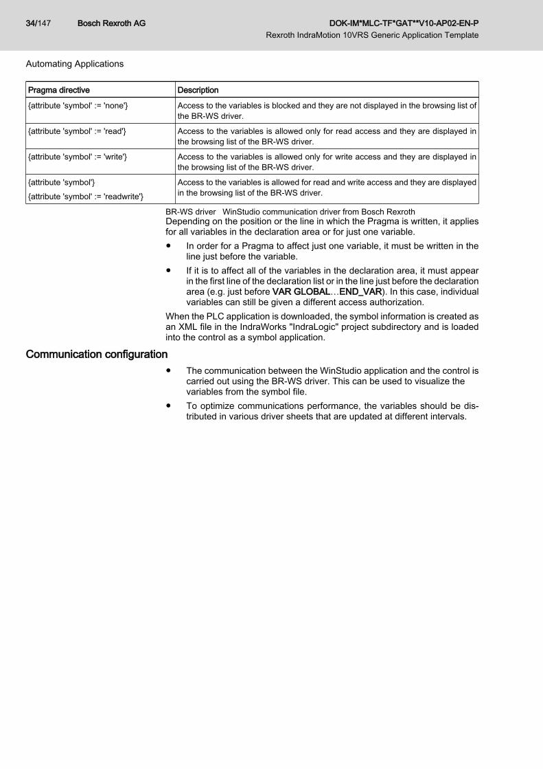
Pragma directive Description
{attribute 'symbol' := 'none'} Access to the variables is blocked and they are not displayed in the browsing list ofthe BR-WS driver.
{attribute 'symbol' := 'read'} Access to the variables is allowed only for read access and they are displayed inthe browsing list of the BR-WS driver.
{attribute 'symbol' := 'write'} Access to the variables is allowed only for write access and they are displayed inthe browsing list of the BR-WS driver.
{attribute 'symbol'}{attribute 'symbol' := 'readwrite'}
Access to the variables is allowed for read and write access and they are displayedin the browsing list of the BR-WS driver.
BR-WS driver WinStudio communication driver from Bosch RexrothDepending on the position or the line in which the Pragma is written, it appliesfor all variables in the declaration area or for just one variable.● In order for a Pragma to affect just one variable, it must be written in the
line just before the variable.● If it is to affect all of the variables in the declaration area, it must appear
in the first line of the declaration list or in the line just before the declarationarea (e.g. just before VAR GLOBAL…END_VAR). In this case, individualvariables can still be given a different access authorization.
When the PLC application is downloaded, the symbol information is created asan XML file in the IndraWorks "IndraLogic" project subdirectory and is loadedinto the control as a symbol application.
Communication configuration● The communication between the WinStudio application and the control is
carried out using the BR-WS driver. This can be used to visualize thevariables from the symbol file.
● To optimize communications performance, the variables should be dis‐tributed in various driver sheets that are updated at different intervals.
Bosch Rexroth AG DOK-IM*MLC-TF*GAT**V10-AP02-EN-P Rexroth IndraMotion 10VRS Generic Application Template
34/147
Automating Applications

5 The GATcompact Example Project5.1 Overview of GATcompact
General The Generic Application Templatecompact is an example project based on IEC61131-3. It is made available by the IndraWorks MLC engineering frameworkand a wizard can be used for loading and start up. It also supports the specificfeatures of Motion applications such as the management of axes.
Basic Idea Using GATcompact is based on the idea that a simple machine must have oper‐ation modes "Auto" and "Manual". In addition, axis management shall bedemonstrated based on examples.The following figure shows a schematic of the GATcompact architecture.
Fig.5-1: Basis for GATcompact
Requirements for Use The user must know which activities are to be performed in Automatic operationand which in Manual operation by the machine to be implemented.
5.2 First Steps - GATcompact
5.2.1 PreparationGATcompact is integrated into the IndraWorks Suite installation package and isautomatically available upon installation.
DOK-IM*MLC-TF*GAT**V10-AP02-EN-P Rexroth IndraMotion 10VRS Generic Application Template
Bosch Rexroth AG 35/147
The GATcompact Example Project

GATcompact is ready to use when a project with an MLC control is created (seealso the "Rexroth IndraMotion MLC 10VRS First Steps") documentation.The GAT wizard, which can be loaded using GATcompact, can be started usingthe context menu for the logic node in the project tree (see the following figure).
Fig.5-2: GAT wizard context menu
5.2.2 Creating a Simple Motion ApplicationGeneral
This section describes how to create an application based on GATcompact.
TopicIn the Automatic operation of a machine, a "master" axis is to move continuouslyat 100 rev./min. A second "slave" axis is to operate phase synchronously to thefirst axis. The following figure shows a schematic topic.
Fig.5-3: Schematic topic
Bosch Rexroth AG DOK-IM*MLC-TF*GAT**V10-AP02-EN-P Rexroth IndraMotion 10VRS Generic Application Template
36/147
The GATcompact Example Project

Operating sequenceAs described earlier, the GAT wizard starts. In the following dialog, select"GATcompact" and confirm with "Finish".
Fig.5-4: GAT wizard start up dialogBy selecting GATcompact, the example project is imported, in which two globalvirtual axes (MyVirtualAxis1, MyVirtualAxis2) have already been configured inaddition to a PLC program template.After the example project has been successfully imported, the guided configu‐ration of the GAT wizard appears (following figure). The guided configurationgives a short overview of the GATcompact functionalities and can be exited at anytime by pressing the "F2" button.
DOK-IM*MLC-TF*GAT**V10-AP02-EN-P Rexroth IndraMotion 10VRS Generic Application Template
Bosch Rexroth AG 37/147
The GATcompact Example Project

Fig.5-5: GAT wizard guided configurationIn GATcompact, as an example, two virtual axes have been declared and imple‐mented. The axes "MyAxis1" (global: MyVirtualAxis1) and "MyAxis2" (global:MyVirtualAxis2) are defined in the "TE_GAT_AXES" structure. The"Axes" var‐iable of this type is declared in the Function_Block "Machine" and the assign‐ment of global MLC axes to GATcompact axes is carried out in the "FB_init"method in the FB "Machine" (see the following figure).When using the GAT wizard, however, the user does not have to carry out thesetasks. When adding, deleting or modifying GATcompact axes, the GAT wizardcarries out all of the code changes that affect the declaration of an axis in theGATcompact axis container.
Bosch Rexroth AG DOK-IM*MLC-TF*GAT**V10-AP02-EN-P Rexroth IndraMotion 10VRS Generic Application Template
38/147
The GATcompact Example Project

Fig.5-6: Declaring the axis dataThe GATcompact axes are implemented in the following actions: "actModeAu‐to_entry" (process that takes place once when the "AUTO" operation mode isactivated) and "actModeAuto_activ" (cyclical processing while the "AUTO" op‐eration mode is active). The implementation of the actions is shown in thefollowing figure.
DOK-IM*MLC-TF*GAT**V10-AP02-EN-P Rexroth IndraMotion 10VRS Generic Application Template
Bosch Rexroth AG 39/147
The GATcompact Example Project

Fig.5-7: Controlling the axesIn an analysis of the code for the "actModeAuto_entry" action, you can see that"MyAxis1" is commanded in the velocity mode and "MyAxis2" should follow thefirst axis phase synchronously. This content corresponds exactly with the topic.According to the topic, however, the names of the GATcompact axes should be"Master" and "Slave". To do this, the GATcompact wizard opens and the first axisbelow the "Axes" node is highlighted. The axis name in parentheses is the nameof the assigned global MLC axis. The name of the GATcompact axis must bechanged to "Master" (see the following figure).
Bosch Rexroth AG DOK-IM*MLC-TF*GAT**V10-AP02-EN-P Rexroth IndraMotion 10VRS Generic Application Template
40/147
The GATcompact Example Project

Fig.5-8: Changing the name of the axis with the GAT wizardThe name of the second GATcompact axis is to be changed from "MyAxis2" to"Slave" in the same way. After the changes, the GATcompact axis container nowcontains "Master" and "Slave" axes, displayed in the GATcompact wizard asshown in the following figure.
DOK-IM*MLC-TF*GAT**V10-AP02-EN-P Rexroth IndraMotion 10VRS Generic Application Template
Bosch Rexroth AG 41/147
The GATcompact Example Project

Fig.5-9: Axis overview after adjustmentsHowever, with the GATcompact wizard, only the code changes with respect to thedeclaration of the GATcompact axes are made. The implementation in the "ac‐tAutoMode_entry" and "actAutoMode_active" actions must be corrected man‐ually. This can be done with "Find and Replace" or the action is supported bythe IndraLogic Intellisense functionality if the axis names are to be immediatelychanged into the actions. To do this, delete the point following the "Axes" iden‐tifier and insert it again. Following this action, all of the elements of the "Axes"structure will be displayed. In this way, when you highlight the "Slave" axis andpress <Enter>, the "MyVirtualAxis2" identifier is replaced by "Slave" (see thefollowing figure).
Fig.5-10: Intellisense functionAs a result, the actions in which the GATcompact axes are implemented are toappear as follows:
Bosch Rexroth AG DOK-IM*MLC-TF*GAT**V10-AP02-EN-P Rexroth IndraMotion 10VRS Generic Application Template
42/147
The GATcompact Example Project

Fig.5-11: Implementation of the axis control for the exampleNote:Changing the visualization is not necessary because the axis visualizationsreference the global MLC axes.The implementation is complete.If all of the changes are carried out correctly, the project can be compiled withoutany errors.After the configuration (1) and the PLC project (2) have been downloaded, thePLC can be started (3) (see the following figure).
Fig.5-12: Download and starting the PLCWhen the pre-defined internal visualization "System_Overview_All_Axis" isused, after the initialization is completed, press the "Auto" button to commandthe application into the "Auto" operation mode.
DOK-IM*MLC-TF*GAT**V10-AP02-EN-P Rexroth IndraMotion 10VRS Generic Application Template
Bosch Rexroth AG 43/147
The GATcompact Example Project
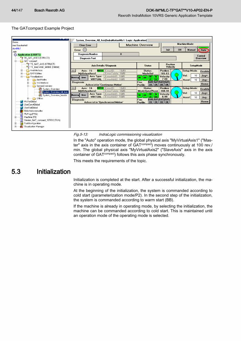
Fig.5-13: IndraLogic commissioning visualizationIn the "Auto" operation mode, the global physical axis "MyVirtualAxis1" ("Mas‐ter" axis in the axis container of GATcompact) moves continuously at 100 rev./min. The global physical axis "MyVirtualAxis2" ("SlaveAxis" axis in the axiscontainer of GATcompact) follows this axis phase synchronously.This meets the requirements of the topic.
5.3 InitializationInitialization is completed at the start. After a successful initialization, the ma‐chine is in operating mode.At the beginning of the initialization, the system is commanded according tocold start (parameterization mode/P2). In the second step of the initialization,the system is commanded according to warm start (BB).If the machine is already in operating mode, by selecting the initialization, themachine can be commanded according to cold start. This is maintained untilan operation mode of the operating mode is selected.
Bosch Rexroth AG DOK-IM*MLC-TF*GAT**V10-AP02-EN-P Rexroth IndraMotion 10VRS Generic Application Template
44/147
The GATcompact Example Project
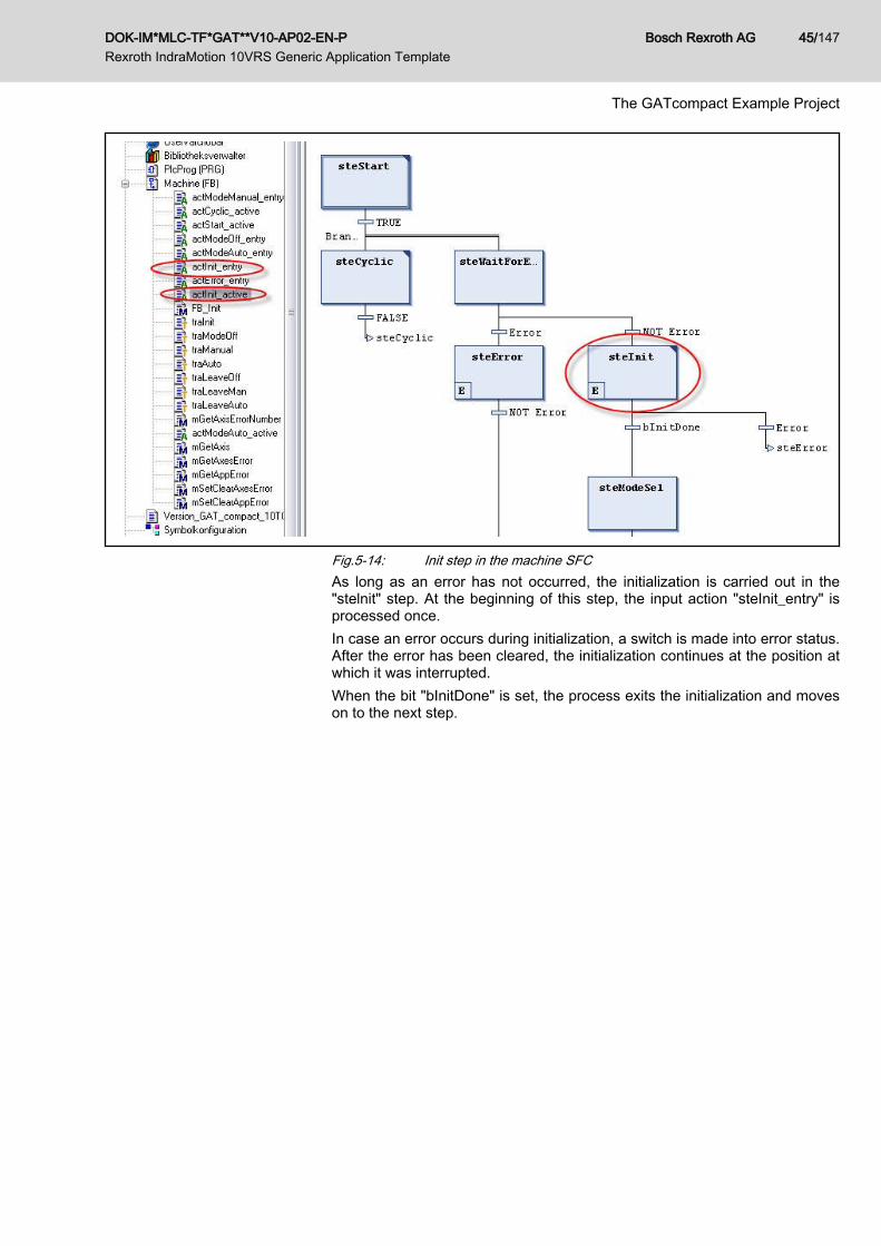
Fig.5-14: Init step in the machine SFCAs long as an error has not occurred, the initialization is carried out in the"stelnit" step. At the beginning of this step, the input action "steInit_entry" isprocessed once.In case an error occurs during initialization, a switch is made into error status.After the error has been cleared, the initialization continues at the position atwhich it was interrupted.When the bit "bInitDone" is set, the process exits the initialization and moveson to the next step.
DOK-IM*MLC-TF*GAT**V10-AP02-EN-P Rexroth IndraMotion 10VRS Generic Application Template
Bosch Rexroth AG 45/147
The GATcompact Example Project

Fig.5-15: Implementation of the initialization in the "actInit_active" actionThe following occurs in the "actInit_active" step:
Bosch Rexroth AG DOK-IM*MLC-TF*GAT**V10-AP02-EN-P Rexroth IndraMotion 10VRS Generic Application Template
46/147
The GATcompact Example Project

1. At the beginning, it is checked if all active axes are ready and free fromtorque (Ab) (lines 7 to 15). Otherwise, the machine cannot be commandedaccording to cold start (P2).
2. Then the machine is commanded into the cold start (P2) state (lines 22 to27).
3. When the machine reaches the cold start state, the state is maintaineduntil an operation mode of the operating mode (e.g. ModeOff, ModeAuto,ModeManual) is commanded. This is the position at which the parametersthat can only be modified in P2 can be written in the control and the drives(lines 33 to 36).
4. Then the machine is commanded into the warm start state (line 37). Thisis the position at which the parameters that can only be modified in P4 canbe written in the control and the drives (lines 46 to 49).
5. When the initialization is finished, the "bInitDone" bit is set to "TRUE" andthe process exits the initialization. Now the machine is ready for operationin the "Manual" or "Auto" operation mode.
Fig.5-16: "SkipColdStartAtStartup" input at the machine FBIf the initialization should not be completed the first time the PLC is started, thiscan be set using the "bSkipColdstartAtStartup" bit. Then the process will jumpinto the warm start state; cold start will not be processed. This eliminates theswitch into P2 and then back to BB. This setting saves time during when pow‐ering up. However, it should be ensured that the actions processed in the coldstart state (e.g. writing parameters) are not required.
5.4 Operation ModesAfter a successful initialization, page 44, the sequence branches into one of the3 operation modes (see the following figure).● ModeOff (all drives free of torque)● ModeManual (machine setup, axes can be jogged)● ModeAuto (cyclical Automatic operation)
DOK-IM*MLC-TF*GAT**V10-AP02-EN-P Rexroth IndraMotion 10VRS Generic Application Template
Bosch Rexroth AG 47/147
The GATcompact Example Project

Fig.5-17: Operation modesIn GATcompact, "ModeManual" is preset as the target operation mode after theinitial machine start (see the following figure).
Fig.5-18: Setting the target operation mode after the initial machine startentry-/active action
When an operation mode is activated, a special "entry" action is carried out justonce. The following table provides an overview of this action, shows how eachoperation mode is activated and what is done in the operation mode.
Condition for activa‐tion
Action (executed once at the beginning) Action executed cyclically
ModeOff(drives free of tor‐que)
Ctrl=MODE_OFFquery is carried out intraModeOff and tra‐LeaveOff
actModeOff_entry● Sets the status to "MODE_OFF"● Sets all active axes to "Mod‐
eAb" (axes are free of torque)
No predefined cyclical action
ModeManual(machine setup, ax‐is jogging)
Ctrl=MODE_MANUALquery is carried out intraManual and traLea‐veManual
actModeManual_entry● Sets the status to "MODE_MAN‐
UAL"● Sets all active axes to "ModeAH"
mode (axis loaded with torque, v=0)
No predefined cyclical actionTypical activities:Machine setup and adjustment, e.g.jogging selected axes
ModeAuto(cyclical Automaticoperation)
Ctrl=MODE_AUTOquery is carried out intraAuto and traLea‐veAuto
actModeAuto_entry● Sets the status to "MODE_AUTO"● Commands "MyVirtualAxis1" in the
example into the axis velocity modeand synchronizes "MyVirtualAxis2"without phase offset
actModeAuto_activee.g. processing of process control‐lers, monitoring the production proc‐ess (material available? synchro‐nous coupling/decoupling)
An ongoing scan for errors is executed simultaneously with processing in anactive operation mode. In case an error occurs, the process branches into errormanagement (see chapter 6.9.1 "Error Recognition and Diagnostics" on page105).To add operation modes, see chapter 6.12.4 "Adding an operation mode" onpage 125.
Bosch Rexroth AG DOK-IM*MLC-TF*GAT**V10-AP02-EN-P Rexroth IndraMotion 10VRS Generic Application Template
48/147
The GATcompact Example Project
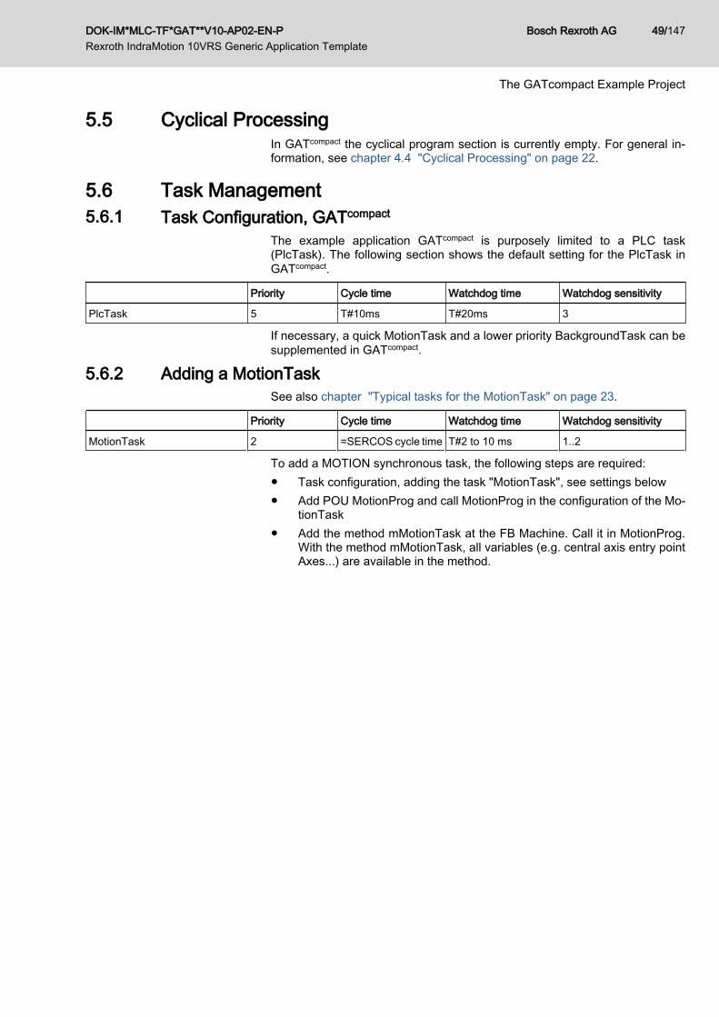
5.5 Cyclical ProcessingIn GATcompact the cyclical program section is currently empty. For general in‐formation, see chapter 4.4 "Cyclical Processing" on page 22.
5.6 Task Management5.6.1 Task Configuration, GATcompact
The example application GATcompact is purposely limited to a PLC task(PlcTask). The following section shows the default setting for the PlcTask inGATcompact.
Priority Cycle time Watchdog time Watchdog sensitivity
PlcTask 5 T#10ms T#20ms 3
If necessary, a quick MotionTask and a lower priority BackgroundTask can besupplemented in GATcompact.
5.6.2 Adding a MotionTaskSee also chapter "Typical tasks for the MotionTask" on page 23.
Priority Cycle time Watchdog time Watchdog sensitivity
MotionTask 2 =SERCOS cycle time T#2 to 10 ms 1..2
To add a MOTION synchronous task, the following steps are required:● Task configuration, adding the task "MotionTask", see settings below● Add POU MotionProg and call MotionProg in the configuration of the Mo‐
tionTask● Add the method mMotionTask at the FB Machine. Call it in MotionProg.
With the method mMotionTask, all variables (e.g. central axis entry pointAxes...) are available in the method.
DOK-IM*MLC-TF*GAT**V10-AP02-EN-P Rexroth IndraMotion 10VRS Generic Application Template
Bosch Rexroth AG 49/147
The GATcompact Example Project

Fig.5-19: Configuration of the MotionTaskIn order to access axes consistently from the MotionTask, the AxisInterfacemust also be called in the MotionTask. Because processing all of the axes inthe MotionTask would cause an unnecessary load on the MotionTask, the fol‐lowing procedure is recommended.The following steps are required:● Extend the structure TE_GAT_AXIS (in the "GATcompact" folder) to include
the element MotionSync (type BOOL)● In the Init section (e.g. actInit_entry), set the new element MotionSync for
the selected axes to TRUE, e.g. ST Axes.MyVirtualAxis1.MotionSync :=TRUE;
● TE_AxisInterfaceType01Prog():– Supplement the program with the flag query MotionSync = FALSE.
Bosch Rexroth AG DOK-IM*MLC-TF*GAT**V10-AP02-EN-P Rexroth IndraMotion 10VRS Generic Application Template
50/147
The GATcompact Example Project

Fig.5-20: Flag query MotionSync = FALSE– Add action actMotionTask. Copy the call loop for the function block
fbAxis() (see above). Create new loop variable uiLoopMotionSync(do not use uiLoop!); change flag query MotionSync to TRUE.Result:
Fig.5-21: "actMotionTask" action– Add a call of the action actMotionTask in MotionProg. (TE_AxisIn‐
terfaceType01Prog.actMotionTask();)
5.6.3 Adding a BackgroundTaskIf the runtime for the PlcTask is too long, the load on the PlcTask can be reducedby moving tasks that are not time critical to a background task. Please note,however, that a greater load is placed on the entire system due to the additionaltask switch PlcTask <> BackgroundTask.See also chapter "Typical tasks for the BackgroundTask" on page 24.
Priority Cycle time Watchdog time Watchdog sensitivity
BackgroundTask ~6 T#40ms - -
To add a background task, the following steps are required:● Task configuration, adding the task "BackgroundTask", see settings below● Add POU BackgroundProg and call BackgroundProg in the configuration
of the BackgroundTask● Add the method mBackground at the FB Machine. Call it in Background‐
Prog. With the method mBackground, all of the variables in the methodare available.
DOK-IM*MLC-TF*GAT**V10-AP02-EN-P Rexroth IndraMotion 10VRS Generic Application Template
Bosch Rexroth AG 51/147
The GATcompact Example Project

Fig.5-22: Configuration of the BackgroundTask
5.7 Error Management5.7.1 Error Recognition and Diagnostics
The program template GATcompact contains predefined functionalities for recog‐nizing, handling and deleting errors at a central location. Errors from varioussources (e.g. control errors, application errors, FB errors, ...) are automaticallygathered together with the cross-machine FB "Machine" in the action "mErro‐rHandling" and are made available using the diagnostic outputs of the FBMachine.If several errors occur simultaneously, the most severe is displayed. If severalerrors with the same degree of severity have occurred simultaneously, the mostrecently recognized error is output.The FB Machine contains the following described outputs for diagnostic pur‐poses:
Bosch Rexroth AG DOK-IM*MLC-TF*GAT**V10-AP02-EN-P Rexroth IndraMotion 10VRS Generic Application Template
52/147
The GATcompact Example Project

Element Type Description
Error BOOL TRUE indicates an error
DiagNo DWORD Number according to the MLC documentation with the following extensions:● 16#F0AE xxxx: Application error (e.g. safety doors are open) (xxxx = can be
defined by the user)● 16#F0FB 0000: FB error (e.g. error at a TechFB) -> for details, see ErrorID /
ErrorIdent● 16#F0AA 0000: GAT internal error -> for details, see ErrorID / ErrorIdent
ErrorID ERROR_CODE Detailed diagnostics in case of FB + GAT errors (DiagNo = 16#F0FB/AA 0000)
ErrorIdent ERROR_STRUCT Detailed diagnostics in case of FB + GAT errors (DiagNo = 16#F0FB/AA 0000)
DiagMessage STRING(60) Contains the diagnostic text for drive and control errors
The DiagNo output is only for use on an HMI. The error texts are assigned thenumerical information in any desired language there.DiagMessage, ErrorID and ErrorIdent provide additional information that is pri‐marily displayed during commissioning by the programmer, e.g. using anIndraLogic visualization.Note regarding application-specific errorsBy calling the method mSetAppError(Number), application errors (e.g. opensafety doors) can be signaled. The "number" transferred at the method inputcorresponds with the application error number.If an application number was signaled, the central diagnostic system in theMachine FB performs cyclical monitoring of the user errors that have been sig‐naled and generates the application error DiagNo = Error 16#F0AE xxxx (xxxx= application error number).In the global variable list "UserConstGlobal", the application errors can be as‐signed to diagnostic texts, which are then displayed in the VI logic visualization.Numbers in the range 1 to uiMAX_APP_ERROR_INDEX are valid for applica‐tion errors in the machine. The constant "uiMAX_APP_ERROR_INDEX" hasthe value 64 by default. If necessary, this constant can be adjusted in the globalvariable list "UserConstGlobal" below the "Application" folder.Code example for signalling application errors:
Fig.5-23: Code example for signalling application errorsNote regarding severe errorsThe control diagnostic system defines 10 degrees of "severity" (see MLC di‐agnostic system). The degree of severity affects the error reaction (see chapter4.6.4 "Error Reaction" on page 29).● DiagNo = 16#F0xx xxxx is the lowest degree of severity (e.g. application
errors, FB errors)● DiagNo = 16#F9xx xxxx is the highest degree of severity (fatal system
errors)The error with the highest degree of severity is displayed if several errors occursimultaneously.
DOK-IM*MLC-TF*GAT**V10-AP02-EN-P Rexroth IndraMotion 10VRS Generic Application Template
Bosch Rexroth AG 53/147
The GATcompact Example Project

Note regarding function block errorsIf errors occur in called function blocks (e.g. technology FBs), calling the method"mSetFBError(ErrorID, ErrorIdent)" recommended along with transferring the"ErrorID" and "ErrorIdent" outputs of the FB that caused the error to the method.This ensures that the error is forwarded to the diagnostic system of the MachineFB and the "ErrorID" and "ErrorIdent" are made available to the diagnostic out‐puts of the Machine FB.Code example for signalling function block errors:
Fig.5-24: Code example for signalling function block errors
5.7.2 Error ReactionDepending on the system, the control system automatically executes an errorreaction only for axis and control errors starting at a severity degree of 2 -> seechapter 4.6.4 "Error Reaction" on page 29. For all other errors and lower de‐grees of severity (e.g. application errors, FB errors...) an automatic errorreaction is not executed.If GATcompact error management is activated (Machine FB input "DisableErro‐rHandling" = FALSE), in case of an error, the selected operation mode is alwaysinterrupted and the error reaction active. Additional application-specific errorreactions can be programmed in the action "actError_entry" of the module.When error management is switched off ("DisableErrorHandling" = TRUE), theselected operation mode remains active even if the error output is set. Theapplication-specific error reaction "actError" is not processed in this case.For standard cases, the deceleration of all axes is programmed with "Mod‐eAH" as an example in the following section (ModeAH = deceleration to full stopand torque remains on).If the GAT error management is switched off (machine input "DisableErrorHan‐dling" = TRUE), the selected operation mode is not interrupted (the application-specific error reaction is not started). The diagnostic outputs, however, are setin this case as well and can be deleted using "ClearError".Standard case for the error reaction in the module action "actError_entry" (De‐celerate all axes):
Bosch Rexroth AG DOK-IM*MLC-TF*GAT**V10-AP02-EN-P Rexroth IndraMotion 10VRS Generic Application Template
54/147
The GATcompact Example Project

Fig.5-25: Standard case for the error reaction in the module action "actError_en‐try"
If "axes are suspended", torque may not be enabled in order to prevent fallingaxes. In these applications, switching all axes into "ModeAH" is recommended.If torque enable is desired when an error occurs, in the example above, "Mod‐eAH" must be replaced by "ModeAb" (ModeAb = Decelerate up to full stop andsubsequent torque enable).Often it is required that axes be decelerated synchronously (to prevent a ma‐terial web from tearing, for example). In these applications, it is recommendedthat all axes remain connected in synchronous movement, and that only themaster is decelerated. This application is shown in the following example:Example for synchronous deceleration of the axes in the module action actEr‐ror_entry (only axes that are not synchronous are decelerated using "Mod‐eAb").
Fig.5-26: Example for the synchronous deceleration of the axes in the moduleaction "actError_entry"
For synchronous deceleration, the module bus reaction for the real axes mustalso be switched off. Furthermore, in the "best possible deceleration" of the realaxes, "30s NC reaction" must be set.
DOK-IM*MLC-TF*GAT**V10-AP02-EN-P Rexroth IndraMotion 10VRS Generic Application Template
Bosch Rexroth AG 55/147
The GATcompact Example Project

In the setting "Best possible deceleration = 30s NC reaction" for areal axis, in the MLC control system, in case of an F2 error, the axisaffected by the error is decelerated with the emergency stop rampA-0-0224. All other trouble-free axes are not affected.
5.7.3 Deleting an ErrorThe central deletion of an error is automatically executed with a positive edgeat the "ClearError" input of the Machine FB. The Machine FB forwards thecommand to all subordinate components (e.g. ImcInterface1) , AxisInterface…) in order to bring the entire system into a trouble-free state. The active, se‐lected operation mode continues processing after the error is deleted theprocess exited the mode due to the error reaction.
5.8 Visualization5.8.1 Internal visualization for assistance during start upGeneral
GATcompact contains predefined IndraLogic visualization objects that offer as‐sistance during commissioning as well as extended diagnostic possibilities.
System_OverviewThe visualization element "System_Overview" can be instantiated for individualaxes.This is implemented as an example in the "System_overview_All_Axis" visual‐ization for the "MyVirtualAxis1" and "MyVirtualAxis2" axes.
Fig.5-27: Internal visualization for assistance during start upThe "Frame" object can be used to create an instance of the visualization objectSystem_Overview in the visualization.
1) IndraMotionControl Interface = IndraLogic library with an interface to the control, e.g.clear errors
Bosch Rexroth AG DOK-IM*MLC-TF*GAT**V10-AP02-EN-P Rexroth IndraMotion 10VRS Generic Application Template
56/147
The GATcompact Example Project

Fig.5-28: Creating an instance of the visualization object "System_Overview"
Fig.5-29: Creating an instance of the visualization object "System_Overview"Now the corresponding axis reference must be entered under Properties - Ref‐erences.
DOK-IM*MLC-TF*GAT**V10-AP02-EN-P Rexroth IndraMotion 10VRS Generic Application Template
Bosch Rexroth AG 57/147
The GATcompact Example Project

Fig.5-30: Creating an instance of the visualization object "System_Overview"
5.8.2 External Visualization with Separate HMIs (WinStudio Visualization)General
A predefined WinStudio visualization is available for GATcompact. A wizard canbe used to add this visualization into the project.
To edit the WinStudio visualization, at least the following develop‐ment environment license (or higher) is required:WinStudio development license, max. 1,500 variables (Mat.No.R911323596)For execution on a VEP, at least the following runtime license isrequired:WinStudio runtime license for devices using Windows CE as anoperating system, max. 1,500 variables (Mat. No. R911323620)
Adding the WinStudio visualization
In order to add the WinStudio visualization to the project, a corre‐sponding visualization device must be present in the project.
Use "drag and drop" to add a VEP from the device library into the project treeand configure it as follows:● Device type: VEPxx (CE)● Application type: WinStudio application
Bosch Rexroth AG DOK-IM*MLC-TF*GAT**V10-AP02-EN-P Rexroth IndraMotion 10VRS Generic Application Template
58/147
The GATcompact Example Project

Fig.5-31: Adding a visualization deviceIf a corresponding visualization device is present, the WinStudio visualizationis added using the following link and the wizard.
Fig.5-32: Adding a WinStudio visualization
DOK-IM*MLC-TF*GAT**V10-AP02-EN-P Rexroth IndraMotion 10VRS Generic Application Template
Bosch Rexroth AG 59/147
The GATcompact Example Project

All of the project's visualization devices that correspond to the given configu‐ration are included in the following wizard dialog.After the corresponding visualization device is selected, click "Apply" to add theWinStudio visualization.
Fig.5-33: Selecting a visualization device and adding a WinStudio visualization
Existing visualization data from the visualization device along withthe symbol configuration of the control are overwritten when theWinStudio visualization is added!
After the visualization is added, its data can be edited.The control address is configured in the BR-WS driver properties dialog.
Fig.5-34: Setting the control's IP address
Now you can use "Start application" in the WinStudio node context menuto start the emulation of the WinStudio visualization.
Dialog structureThe operation screens are divided into 3 subsections:
Bosch Rexroth AG DOK-IM*MLC-TF*GAT**V10-AP02-EN-P Rexroth IndraMotion 10VRS Generic Application Template
60/147
The GATcompact Example Project

● Header with status information● Main screen with menu-related displays and function keys● Footer with keys for switching from one operation screen to another
Fig.5-35: WinStudio visualizationThe header contains:● Operation mode display● Global function keys for deleting errors and opening the "Settings" dialog
(for switching languages, setting the decimal place for numerical displays)● Display of current machine diagnostics● Display of current SERCOS phase (including active phase switching)● Display of communication statusThe main screen contains displays and function keys related to operationscreens (e.g. axis information, operation mode switching, ...)The footer contains the keys for switching from one operation screen to another.
Extending the visualizationAdding an operation screenTo extend the visualization, new operation screens can be created by copyingthe existing "template" screens and inserting them with new names.
DOK-IM*MLC-TF*GAT**V10-AP02-EN-P Rexroth IndraMotion 10VRS Generic Application Template
Bosch Rexroth AG 61/147
The GATcompact Example Project

Fig.5-36: Duplicating an operation screenThe elements for displaying the axis data are grouped individual objects thatcan be duplicated by "copying" and "pasting". To reconfigure the inserted objectfor a different axis you must now use the Replace function for the respectiveobject to adapt the axis array index (see the following figures).
Fig.5-37: Reconfiguring the inserted object
Bosch Rexroth AG DOK-IM*MLC-TF*GAT**V10-AP02-EN-P Rexroth IndraMotion 10VRS Generic Application Template
62/147
The GATcompact Example Project

Fig.5-38: Reconfiguring the inserted objectExtending the footerThe keys used to switch from one operation screen to another are stored asgraphic objects that can be parameterized (linked symbol). They have the fol‐lowing transfer parameters:● Caption -> Key label● Disable -> Input for blocking key functionality (grayed out label)● ScreenName -> Screen name for the operation screens to be opened (or
screen group)● ScreenNumber -> Number to be assigned to the screen (to highlight the
respective key)
Communication connectionThe communication between visualization and control is executed symbolicallyusing the BR-WS driver. To do this, you must generate the symbol entries forthe PLC variables to be visualized (see the chapter "Communication configu‐ration" on page 34).The required symbol configuration for the predefined WinStudio visualizationcontains the following entries:
DOK-IM*MLC-TF*GAT**V10-AP02-EN-P Rexroth IndraMotion 10VRS Generic Application Template
Bosch Rexroth AG 63/147
The GATcompact Example Project

Fig.5-39: Symbol configuration of the predefined WinStudio visualization
Symbol entries for variables from global variable lists that comefrom a library must be reinserted in the symbol configuration afterthe respective library version has been modified.
Setting the control's IP address:The control address is configured in the BR-WS driver properties dialog:
Fig.5-40: Setting the control's IP addressIn order to structure the communication, the variables were distributed in vari‐ous driver sheets:
1. read cyclic fast: The values of these variables are to be read cyclically atshort intervals (e.g. diagnostic numbers, axis positions, ...)
2. read only once: These variables are read once after the visualization isstarted (e.g. axis names)
Bosch Rexroth AG DOK-IM*MLC-TF*GAT**V10-AP02-EN-P Rexroth IndraMotion 10VRS Generic Application Template
64/147
The GATcompact Example Project

3. read after switching phase: These variables are read only once after aphase switch (e.g. if the axis was activated)
4. read - write cyclic: The values of these variables are to be both read andwritten (e.g. machine velocity, axis velocity for setup mode, ...)
5. write only: These variables are only to be written through the visualization(trigger signals for deleting errors, ...)
To extend a driver sheet, the BR-WS browser can search the offline symbol file(*.XML) and the corresponding variable can be selected.
Fig.5-41: Extended the driver sheet
Multiple language capabilityMultiple language capability for the visualization has been realized with thetranslation functionality integrated into WinStudio.The translation file is stored as a *.CSV table, which provides a column for eachlanguage.It is predefined to include multiple languages although only "German" and"English" are completely filled out. For the rest of the languages only the drivediagnostics are included.
DOK-IM*MLC-TF*GAT**V10-AP02-EN-P Rexroth IndraMotion 10VRS Generic Application Template
Bosch Rexroth AG 65/147
The GATcompact Example Project

Fig.5-42: Editing the translation file
5.9 Interfaces to GAT5.9.1 General
Most of the interface data for GATcompact is gathered together in the "UserVar‐Global" variable list. Part of the data is made available in libraries.In the following section, the data from libraries in the "Name of the variables"column is marked as such. All other data is located in the "UserVarGlobal" var‐iable list.
5.9.2 Data for the State MachineI/O type Name Data type Description
I stCtrl_gb TE_MACHINE_MODE_CTRL Command for machine operation mode
I bSkipColdstartAtStartup_gb BOOL When starting the GATcompact program, aswitch is made into parameterizationmode (P2) to carry out the parameteri‐zation required for the application. Thisphase switch can be skipped with TRUEif the application does not require pa‐rameterization in P2.
O stStatus_gb TE_MACHINE_MODE_STATUS Feedback regarding the current machineoperation mode
I Input for writingO Output for reading
5.9.3 Data for Error ManagementI/O type Name Data type Description
I bClearError_gb BOOL TRUE = Global error deletion
I bDisableErrorHandling_gb BOOL TRUE = In case of error, the process does not switchinto the ERROR state The error display continues anderror deletion is still possible.
O bError_gb BOOL TRUE = Global error has occurred
Bosch Rexroth AG DOK-IM*MLC-TF*GAT**V10-AP02-EN-P Rexroth IndraMotion 10VRS Generic Application Template
66/147
The GATcompact Example Project

I/O type Name Data type Description
O dwDiagNo_gb DWORD Diagnostics number in accordance with MLC specifica‐tionDiagNo = 16#F0AE xxxx: application defined error (e.g.open door)DiagNo = 16#F0FB 0000: function block errorDiagNo = 16#F0AA xxxx: GAT internal error
O enErrorID_gb ERROR_CODE Detailed information if DiagNo = 16#F0FB 0000 /16#F0AA xxxx
O stErrorIdent_gb ERROR_STRUCT Detailed information if DiagNo = 16#F0FB 0000 /16#F0AA xxxx
O strDiagMessage_gb STRING(60) Diagnostic text of the control / axis
O arAppError_gb ARRAY OF BOOL Application-specific error (e.g. safety doors open)
I Input for writingO Output for reading
5.9.4 Data for AxesI/O type Name Data type Description
I arAxisCtrl_gb ARRAY OF TE_AXIS_CON‐TROL_TYPE01
Commands for the axes
O arAxisStatus_gb ARRAY OF TE_AXIS_STA‐TUS_TYPE01
Feedback from the axes
I/O AxisData (GVL_Base fromthe ML_Base library)
ARRAY OF ML_AXISDATA_SM Firmware structure with axis inputs and out‐puts
I Input for writingO Output for readingI/O Structure with inputs and outputs
Elements for arAxisCtrl_gb are written in the Machine FB and forthis reason they can no longer be used externally.
5.9.5 Data of the ControlI/O type Name Data type Description
I ImcCtrl (Global_ImcInterface fromthe ML_TechInterface library)
MB_IMC_CONTROL_TYPE01 Commands for the control
O ImcStatus (Global_ImcInterfacefrom the ML_TechInterface library
MB_IMC_STATUS_TYPE01 Feedback from the control
I Input for writingO Output for reading
Elements for ImcCtrl_gb are written in the Machine FB and for thisreason they can no longer be used externally.
DOK-IM*MLC-TF*GAT**V10-AP02-EN-P Rexroth IndraMotion 10VRS Generic Application Template
Bosch Rexroth AG 67/147
The GATcompact Example Project
5.10 How To: Typical User Activities5.10.1 Access to Axis Data
In the FB Machine, the structure Axes is defined as the central access point foraccessing axis data. All relevant data for an axis can be addressed using theAxes structure.The structure is designed such that the axis data is accessed using the nameof the axes. This generates program code that is easily readable.The following data are available below Axes:● Axes.Name.AxisData => Axis data structure: Status data for the firmware
and access to the axis data container● Axes.Name.Ctrl => Control structure for the AxisInterface● Axes.Name.Status => Status structure for the AxisInterface● Axes.Name.DV => Access to direct variables (function variables)● Axes.Name.AxisRef => Axis reference structure for FB calls (e.g.
MB_ReadParameter)Array Axes.arAll[] can also be used to access the data listed above. That canbe advantageous for loop programming (for an example, see actModeOff_en‐try).In both versions, references to the same storage locations are accessed.Example: the accesses● Axes.Name.AxisData.rActualPosition_i● Axes.arAll[Name.AxisNo].AxisData.rActualPosition_iare absolutely equivalent and deliver the same result.
Bosch Rexroth AG DOK-IM*MLC-TF*GAT**V10-AP02-EN-P Rexroth IndraMotion 10VRS Generic Application Template
68/147
The GATcompact Example Project
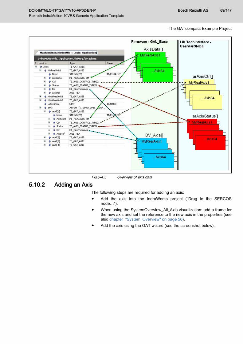
Fig.5-43: Overview of axis data
5.10.2 Adding an AxisThe following steps are required for adding an axis:● Add the axis into the IndraWorks project ("Drag to the SERCOS
node…").● When using the SystemOverview_All_Axis visualization: add a frame for
the new axis and set the reference to the new axis in the properties (seealso chapter "System_Overview" on page 56).
● Add the axis using the GAT wizard (see the screenshot below).
DOK-IM*MLC-TF*GAT**V10-AP02-EN-P Rexroth IndraMotion 10VRS Generic Application Template
Bosch Rexroth AG 69/147
The GATcompact Example Project

Fig.5-44: Adding an axis with the GAT wizard
5.10.3 Removing/renaming an Axis The wizard changes only the name in the axis declaration. If theaxis is already being used in the implementation or internal visual‐ization, the new axis name must be changed at these positionsusing "Find/Replace".
The following steps are required for removing/renaming an axis:● Removing an axis from/renaming an axis in the IndraWorks project● When using the SystemOverview_All_Axis visualization: remove the
frame for the deleted axis and change the reference to the axis in theproperties.
● Remove/rename the axis using the GAT wizard (see the screenshot be‐low).
Bosch Rexroth AG DOK-IM*MLC-TF*GAT**V10-AP02-EN-P Rexroth IndraMotion 10VRS Generic Application Template
70/147
The GATcompact Example Project

Fig.5-45: Editing an existing axis with the GAT wizard
DOK-IM*MLC-TF*GAT**V10-AP02-EN-P Rexroth IndraMotion 10VRS Generic Application Template
Bosch Rexroth AG 71/147
The GATcompact Example Project

Fig.5-46: Editing an existing axis with the GAT wizard
5.10.4 Adding an Operation Mode GATcompact has the following predefined operation modes:● OFF● MANUAL● AUTOAs an example, in the following section, the "CLEANING" operation mode(cleaning the machine) shall also be implemented.To do this, the following steps are required:● TYPE TE_MACHINE_MODE (GATcompact folder): extend with the
MODE_CLEANING element● FB Machine:
2.1 Copy the transition traAuto into traCleaning and in traCleaning, re‐place MODE_AUTO with MODE_CLEANING; result:(Ctrl=MODE_CLEANING);
2.2 Copy the transition traLeaveAuto into traLeaveCleaning and in tra‐LeaveCleaning, replace MODE_AUTO with MODE_CLEANING; re‐sult: NOT(Ctrl=MODE_CLEANING);
2.3 Add a "ModeCleaning" branch parallel to ModeAuto2.4 Use the transitions listed above at ModeCleaning
Bosch Rexroth AG DOK-IM*MLC-TF*GAT**V10-AP02-EN-P Rexroth IndraMotion 10VRS Generic Application Template
72/147
The GATcompact Example Project
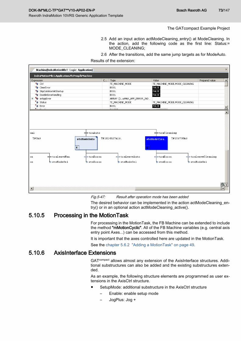
2.5 Add an input action actModeCleaning_entry() at ModeCleaning. Inthe action, add the following code as the first line: Status:=MODE_CLEANING;
2.6 After the transitions, add the same jump targets as for ModeAuto.Results of the extension:
Fig.5-47: Result after operation mode has been addedThe desired behavior can be implemented in the action actModeCleaning_en‐try() or in an optional action actModeCleaning_active().
5.10.5 Processing in the MotionTaskFor processing in the MotionTask, the FB Machine can be extended to includethe method "mMotionCyclic". All of the FB Machine variables (e.g. central axisentry point Axes...) can be accessed from this method.It is important that the axes controlled here are updated in the MotionTask.See the chapter 5.6.2 "Adding a MotionTask" on page 49.
5.10.6 AxisInterface Extensions GATcompact allows almost any extension of the AxisInterface structures. Addi‐tional substructures can also be added and the existing substructures exten‐ded.As an example, the following structure elements are programmed as user ex‐tensions in the AxisCtrl structure.● SetupMode: additional substructure in the AxisCtrl structure
– Enable: enable setup mode– JogPlus: Jog +
DOK-IM*MLC-TF*GAT**V10-AP02-EN-P Rexroth IndraMotion 10VRS Generic Application Template
Bosch Rexroth AG 73/147
The GATcompact Example Project

– JogMinus: Jog –– Vel: Jog / reference travel velocity– Accel: Jog/Reference travel de/acceleration– Homing: activates ModeHoming|SetAbsRef|ModesPosAbs depend‐
ing on axis type/configuration● SyncMode: extension of the existing substructure in the AxisCtrl structure
– AngleOffset: Phase offset start of table -> parameter A-0-2730 is de‐scribed with this value
– PhaseShift: offset relative to the master axis before the gear (Pha‐seOffset: offset relative to the master axis after the gear)
– PhaseShiftVel: velocity for adjusting the PhaseShift– PhaseShiftAcc: acceleration for adjusting the PhaseShift– SyncVelocity: Phase shift velocity -> parameter A-0-2790 is descri‐
bed with this value– SyncAcceleration: Phase shift acceleration -> this value is written on
parameter A-0-2791As an example, the following structure elements are programmed as user ex‐tensions in the AxisStatus structure:● SetupMode: additional substructure in the AxisStatus structure
– EnableAck: Setup mode is active– Homingack: Homing is finished.
● SyncMode: extension of the existing substructure in the AxisStatus struc‐ture– AngleOffsetDone: Transfer of phase offset start of table -> parameter
A-0-2730 was described– PhasingMasterDone: PhaseShift was completed.– SyncVelocityDone: Transfer of phase shift velocity -> parameter
A-0-2790 was transferred.– SyncAccelerationDone: Transfer of phase shift acceleration -> pa‐
rameter A-0-2791 was transferred.The code for these extensions can be found in the action of the TE_AxisInter‐face() block in the GATcompact/AxisInterface folder. The related structures canbe found in the GATcompact/AxisInterface/Type/Control and GATcompact/AxisIn‐terface/Type/Status folders.You can add your own extensions. To do this, see the section titled "AxisInter‐face user extension" in the "Rexroth IndraMotion 10VRS technology basiclibraries" documentation.When new error codes are introduced, a diagnostic message can be assignedfor the VI logic visualization by extending the structure "arAXIS_DIAG_MES‐SAGES" in the GatConstGLobal variable list in the folder \GAT compact\GAT-Utilities.
Bosch Rexroth AG DOK-IM*MLC-TF*GAT**V10-AP02-EN-P Rexroth IndraMotion 10VRS Generic Application Template
74/147
The GATcompact Example Project

5.11 GATcompact Brief Overview5.11.1 GATcompact structure overview
Fig.5-48: GATcompact structure overview
5.11.2 Overview of the Most Important Global Machine VariablesSee the global variable list "UserVarGlobal":
Variable Description Access
stCtrl_gb Machine control (operation mode selection, default operationmode)
RD/WR
stStatus_gb Machine status (current operation mode) RD
bClearError_gb Deleting an Error RD/WR
bDisableErrorHandling_gb In case of error, do not switch into the error state RD/WR
bSkipColdstartAtStartup_gb When starting the program, a "cold start" (switch into P2) is notcarried out.
RD/WR
bError_gb TRUE indicates an error RD
dwDiagNo_gb Diagnostic number in accordance with the MLC documenta‐tion
RD
enErrorID_gb Detailed information if dwDiagNo_gb = 16#F0FB 0000 (func‐tion block error)
RD
stErrorIdent_gb Detailed information if dwDiagNo_gb = 16#F0FB 0000 (func‐tion block error)
RD
DOK-IM*MLC-TF*GAT**V10-AP02-EN-P Rexroth IndraMotion 10VRS Generic Application Template
Bosch Rexroth AG 75/147
The GATcompact Example Project

Variable Description Access
strDiagMessage_gb Control or axis diagnostic text RD
arAppError_gb Array of BOOL with user-specific machine error flags RD
RD ReadWR Write
5.11.3 Overview of the Most Important Global Axis VariablesSee the global variable list "UserVarGlobal":
Variable Description Access
arAxisCtrl_gb Array with the AxisInterface command data RD/WR
arAxisStatus_gb Array with the AxisInterface status data RD
RD ReadWR Write
5.11.4 Overview of the Machine Methods and ActionsAction/method Call Related task Description / example
actCyclic_active In every state PlcTask Comprehensive logic, e.g. safety technol‐ogy
actError_entry For a cycle during the transitioninto the MODE_ERROR state
PlcTask Error reaction, e.g. switching into ModeAH(full stop with power on)
actInit_entry For a cycle during the transitioninto the MODE_INIT state
PlcTask Preparing the MODE_INIT state, e.g.switching off all axes in order to enable thephase switch into P2
actInit_active Only in the MODE_INIT state PlcTask Switching into parameterization mode P2,possible description of parameters in P2.When exiting the MODE_INIT, switch intooperating mode (bb), possible descriptionof parameters when arriving in bb.
actModeOff_entry For a cycle during the transitioninto the MODE_OFF state
PlcTask Preparing the MODE_OFF state, usuallyswitching off all axes (ModeAb).
actModeManual_en‐try
For a cycle during the transitioninto the MODE_MANUAL state
PlcTask Preparing the MODE_MANUAL state, usu‐ally stopping all axes (ModeAH).
actModeAuto_entry For a cycle during the transitioninto the MODE_AUTO state
PlcTask Preparing the MODE_AUTO state, e.g. ac‐tivating a synchronous operation mode(e.g. ModeSyncVel) for all slave axes andenabling a master axis (e.g. ModeVel)
actModeAuto_active Only in the MODE_AUTO state PlcTask e.g. monitoring in Automatic mode, callingprocess controller function blocks.
FB_init Once before starting/resetting aPLC program
No specific task assign‐ment
Internal system use, may not be modified
5.11.5 Access to Axes within the MachineAlways use Axes.<axisname> Example:Program: // Command axis in velocity control mode Axes.MyAxis1.Ctrl.Admin._OpMode.en := ModeVel; // If axis has reached the velocity IF IF (Axes.MyAxis1.Status.PtrAxisData^.Axis_InVelocity = TRUE) THEN;
Bosch Rexroth AG DOK-IM*MLC-TF*GAT**V10-AP02-EN-P Rexroth IndraMotion 10VRS Generic Application Template
76/147
The GATcompact Example Project

6 Project Development with GAT6.1 General
The Generic Application Template is a software tool that is integrated intoIndraWorks. Based on a program framework in accordance with IEC61131-3,together with a dialog-based wizard it can be used to develop applicationsquickly and easily. It also supports the specific features of Motion applicationssuch as the management of axes.
6.2 Overview6.2.1 Basic Idea
Using the GAT is based on the idea that an application runs on a machine thatcoordinates one or more functional units in a various operation modes.The following example is used to explain this idea.An application will be created for a simple packaging machine that consists ofa infeed unit, a sorting unit and a packaging unit (see the following figure).
Fig.6-1: Example: horizontal form fill and seal machineryIn order to apply the GAT, this packaging machine is divided into 3 functionalunits (modules).
DOK-IM*MLC-TF*GAT**V10-AP02-EN-P Rexroth IndraMotion 10VRS Generic Application Template
Bosch Rexroth AG 77/147
Project Development with GAT

Fig.6-2: Functional units of the horizontal form fill and seal machineryThe result is the following software architecture, which can be implementeddirectly in the real machine's corresponding software by using GAT.
Fig.6-3: Software architecture when using the GAT
6.2.2 Requirements for UseAlready presented to some extent in the previous section, the prerequisites forusing the GAT are summarized again here.
Bosch Rexroth AG DOK-IM*MLC-TF*GAT**V10-AP02-EN-P Rexroth IndraMotion 10VRS Generic Application Template
78/147
Project Development with GAT

Before a Motion application is developed with the GAT, the user must clarifythe following questions with respect to the application:● Which operation modes are to be realized? Which states are required in
each respective operation mode?● Which functional units (modules) make up the machine? Which axes and
I/Os are associated with each respective functional unit?Using the information, the wizard can generate the code framework for the ac‐tual Motion application in a very short time.The following section describes the parts of the GAT, how these parts worktogether and where the user has to make additions in order to realize the actualapplication.
6.3 First Steps - GAT6.3.1 Preparation
The GAT is integrated into the IndraWorks Suite installation package and isautomatically installed.The GAT is ready to use when a project with an MLC control is created (seealso the "Rexroth IndraMotion MLC 10VRS First Steps") documentation.The GAT wizard can be started using the context menu for the logic node in theproject tree (see the following figure).
Fig.6-4: Calling the GAT wizard
6.3.2 Creating a Simple Motion ApplicationGeneral
This section describes how to create an application using the GAT wizard.
TopicA machine is to consist of two functional units (modules). Starting from a stopstate, in the first functional unit an axis should move continuously at 100 rev./min. in automatic operation in a producing state. In the other unit, a second axisworks in producing Automatic operation, phase synchronously to the axis in thefirst module. The following figure shows a schematic topic.
DOK-IM*MLC-TF*GAT**V10-AP02-EN-P Rexroth IndraMotion 10VRS Generic Application Template
Bosch Rexroth AG 79/147
Project Development with GAT

Fig.6-5: Schematic topic
Operating sequenceAs described earlier, the GAT wizard starts. In the following dialog, select"GAT" and confirm with "Finish".
Bosch Rexroth AG DOK-IM*MLC-TF*GAT**V10-AP02-EN-P Rexroth IndraMotion 10VRS Generic Application Template
80/147
Project Development with GAT
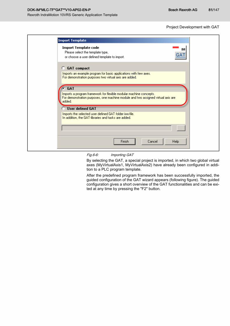
Fig.6-6: Importing GATBy selecting the GAT, a special project is imported, in which two global virtualaxes (MyVirtualAxis1, MyVirtualAxis2) have already been configured in addi‐tion to a PLC program template.After the predefined program framework has been successfully imported, theguided configuration of the GAT wizard appears (following figure). The guidedconfiguration gives a short overview of the GAT functionalities and can be exi‐ted at any time by pressing the "F2" button.
DOK-IM*MLC-TF*GAT**V10-AP02-EN-P Rexroth IndraMotion 10VRS Generic Application Template
Bosch Rexroth AG 81/147
Project Development with GAT

Fig.6-7: GAT wizard dialogs for guided configurationAn AUTO operation mode with the states "Stopped" and "Producing" is prede‐fined in the GAT. Switching from the "Stopped" state to the "Producing" stateoccurs when the global Boolean variable "bStart_gb" is set (see the followingfigure; to define the global variable "bStart_gb" see the global variable list"Global_GAT_Machine" below the "Machine" folder).
Bosch Rexroth AG DOK-IM*MLC-TF*GAT**V10-AP02-EN-P Rexroth IndraMotion 10VRS Generic Application Template
82/147
Project Development with GAT

Fig.6-8: Editing transitionsNothing else is required in order to realize the tasks with respect to defining theoperation mode or states.A module is already applied in the GAT (Module1). Another module is requiredto complete the topic. To do this, highlight the "Module" node in the GAT wizarddirectory tree and select "Add module" (following figure).
DOK-IM*MLC-TF*GAT**V10-AP02-EN-P Rexroth IndraMotion 10VRS Generic Application Template
Bosch Rexroth AG 83/147
Project Development with GAT

Fig.6-9: Adding a moduleIn a subsequent dialog, the name of the new module is specified as "Mod‐ule_Master".
Bosch Rexroth AG DOK-IM*MLC-TF*GAT**V10-AP02-EN-P Rexroth IndraMotion 10VRS Generic Application Template
84/147
Project Development with GAT

Fig.6-10: Specifying a module nameNow the axis is to be created and implemented in the "Module_Master" module.This axis is to move continuously at 100 rev./min. in a producing state.To do this, the wizard is used to create a new axis for the "Module_Master"module (see the next figure).
DOK-IM*MLC-TF*GAT**V10-AP02-EN-P Rexroth IndraMotion 10VRS Generic Application Template
Bosch Rexroth AG 85/147
Project Development with GAT
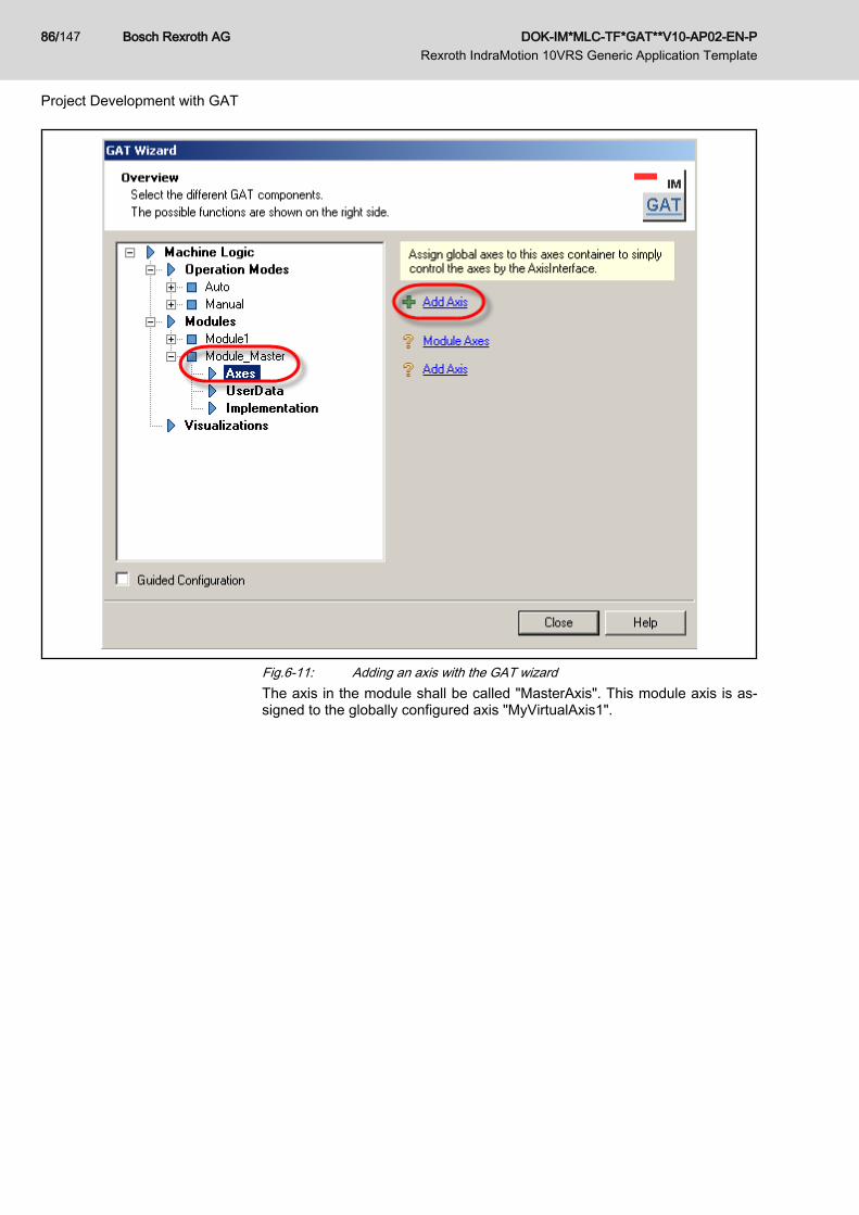
Fig.6-11: Adding an axis with the GAT wizardThe axis in the module shall be called "MasterAxis". This module axis is as‐signed to the globally configured axis "MyVirtualAxis1".
Bosch Rexroth AG DOK-IM*MLC-TF*GAT**V10-AP02-EN-P Rexroth IndraMotion 10VRS Generic Application Template
86/147
Project Development with GAT

Fig.6-12: Assigning the module axis to the globally configured axisIn a subsequent step, the axis must be implemented in the module such that itmoves in the "Producing" state at a constant velocity of 100 rev./min. (unit isspecified by scaling the axis) and stops in the "Stopped" state. The code posi‐tion in the module that corresponds with the state can be highlighted quicklyand easily using the wizard. After the "Implementation" node below the modulein the wizard directory tree is selected, all of the links in the implementation aredisplayed (see the following figure). The lines of code found on the right side ofthe figure must be entered in the result.
DOK-IM*MLC-TF*GAT**V10-AP02-EN-P Rexroth IndraMotion 10VRS Generic Application Template
Bosch Rexroth AG 87/147
Project Development with GAT
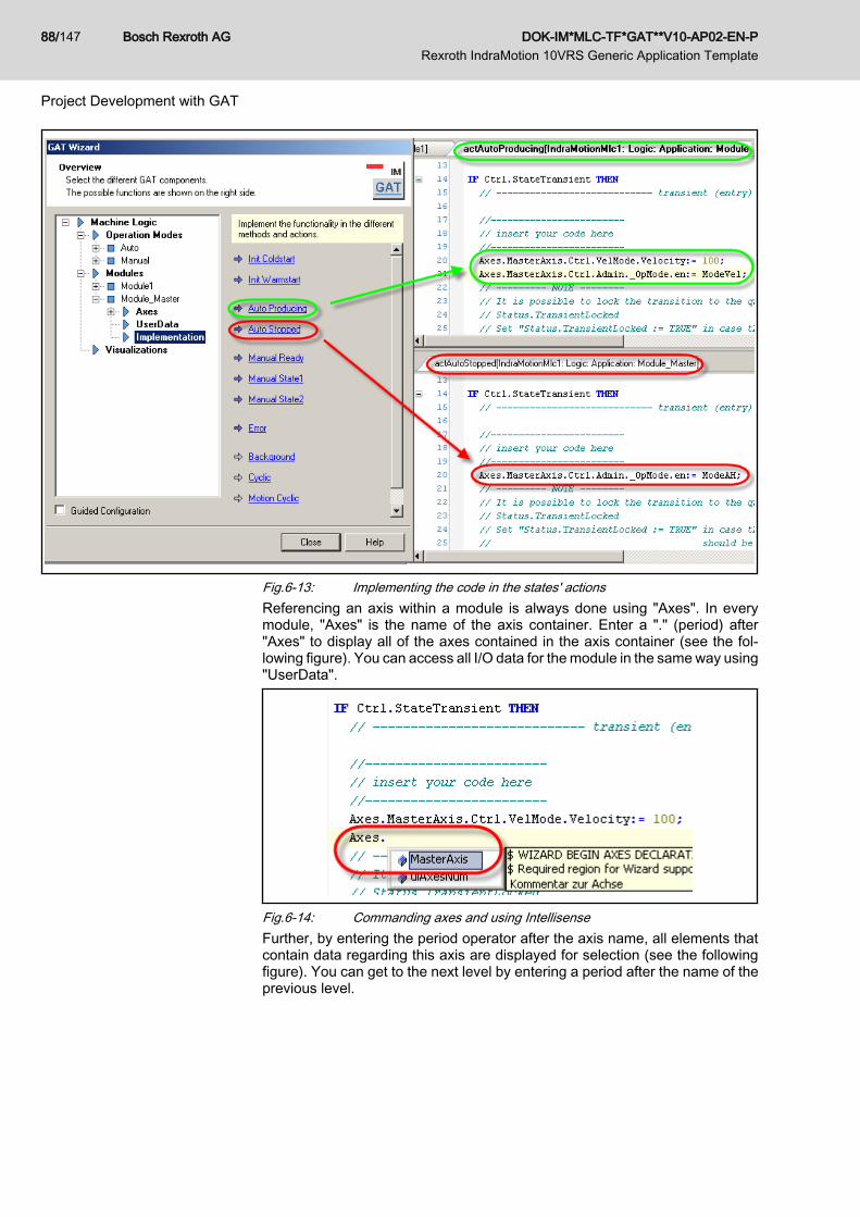
Fig.6-13: Implementing the code in the states' actionsReferencing an axis within a module is always done using "Axes". In everymodule, "Axes" is the name of the axis container. Enter a "." (period) after"Axes" to display all of the axes contained in the axis container (see the fol‐lowing figure). You can access all I/O data for the module in the same way using"UserData".
Fig.6-14: Commanding axes and using IntellisenseFurther, by entering the period operator after the axis name, all elements thatcontain data regarding this axis are displayed for selection (see the followingfigure). You can get to the next level by entering a period after the name of theprevious level.
Bosch Rexroth AG DOK-IM*MLC-TF*GAT**V10-AP02-EN-P Rexroth IndraMotion 10VRS Generic Application Template
88/147
Project Development with GAT
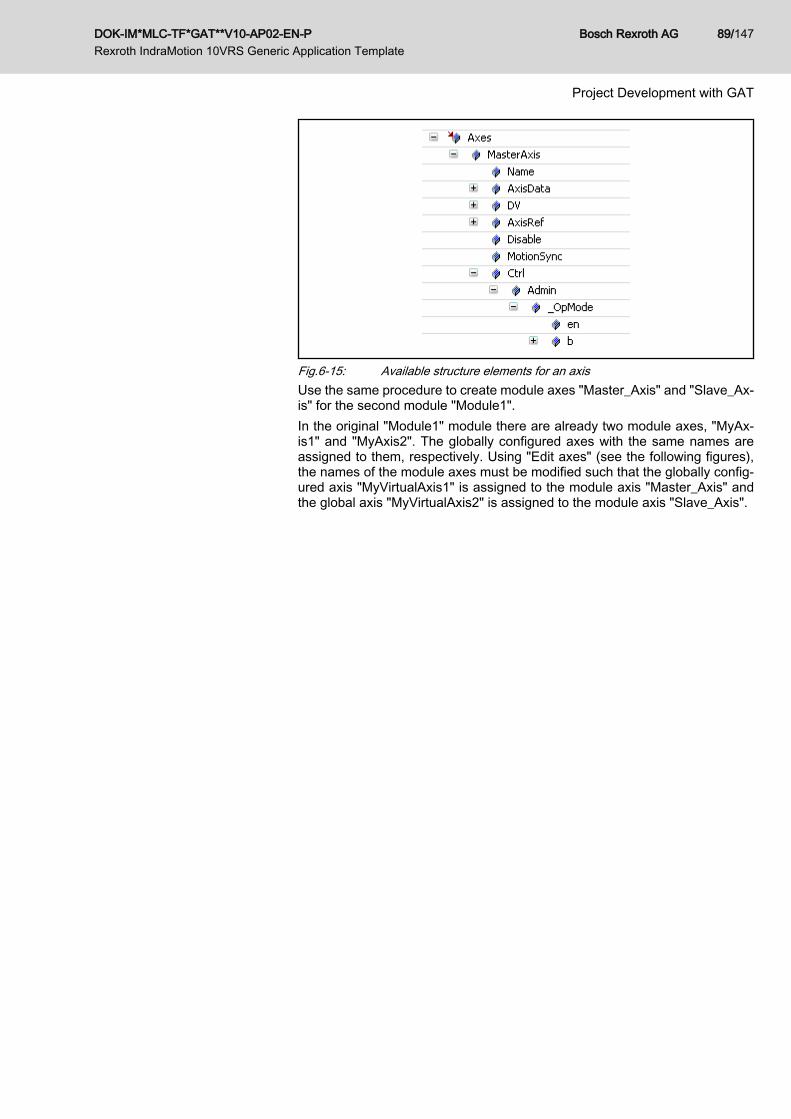
Fig.6-15: Available structure elements for an axisUse the same procedure to create module axes "Master_Axis" and "Slave_Ax‐is" for the second module "Module1".In the original "Module1" module there are already two module axes, "MyAx‐is1" and "MyAxis2". The globally configured axes with the same names areassigned to them, respectively. Using "Edit axes" (see the following figures),the names of the module axes must be modified such that the globally config‐ured axis "MyVirtualAxis1" is assigned to the module axis "Master_Axis" andthe global axis "MyVirtualAxis2" is assigned to the module axis "Slave_Axis".
DOK-IM*MLC-TF*GAT**V10-AP02-EN-P Rexroth IndraMotion 10VRS Generic Application Template
Bosch Rexroth AG 89/147
Project Development with GAT

Fig.6-16: Editing configured axes
Bosch Rexroth AG DOK-IM*MLC-TF*GAT**V10-AP02-EN-P Rexroth IndraMotion 10VRS Generic Application Template
90/147
Project Development with GAT

Fig.6-17: Editing configured axesIn the final step, the axis "Slave_Axis" in the "Producing" state in module "Mod‐ule1" must be synchronized to the axis MasterAxis (following figure). To do this,the lines of code found on the right side of the figure must be entered.In addition, the axis "Slave" must be commanded into the "AH" state by acti‐vating the "Auto Stopped" state. See the following note regarding the reasonfor this.
DOK-IM*MLC-TF*GAT**V10-AP02-EN-P Rexroth IndraMotion 10VRS Generic Application Template
Bosch Rexroth AG 91/147
Project Development with GAT

Depending on the system, switching into the Init operation mode(and therefore parameterization mode) is only permitted when allaxes acknowledge the Ab or AH state. Before switching from a Useroperation mode into the Init operation mode, all axes must be com‐manded into the Ab or AH state. For this reason, a correspondingaxis command is recommended in the transient section of the initialstate "Stopped".
Fig.6-18: Implementing the code in the action of the "Auto_Producing" stateThe implementation is complete.After the configuration (1) and the PLC project (2) have been downloaded, thePLC can be started (3) (see the following figure).
Fig.6-19: Downloading and starting the example projectWhen the pre-defined internal visualization "MAIN_VISU" is used, after the in‐itialization is completed, press the "START" button to command the applicationwill be commanded into the "Stopped" state.
Bosch Rexroth AG DOK-IM*MLC-TF*GAT**V10-AP02-EN-P Rexroth IndraMotion 10VRS Generic Application Template
92/147
Project Development with GAT
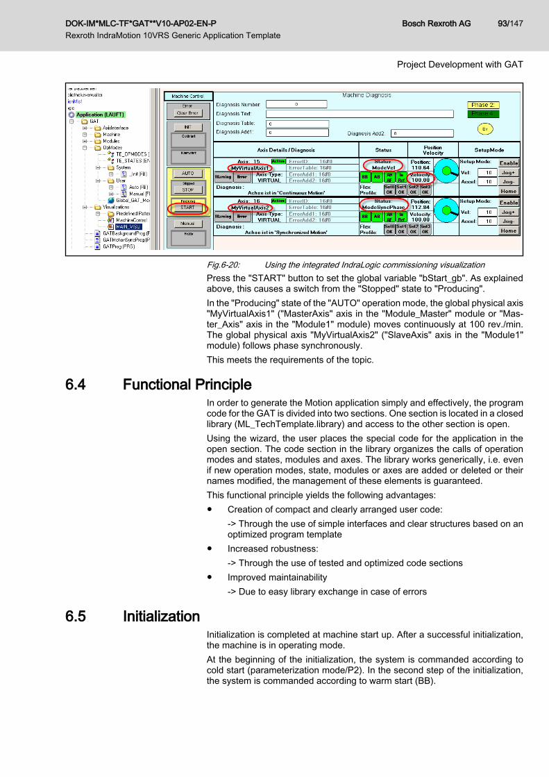
Fig.6-20: Using the integrated IndraLogic commissioning visualizationPress the "START" button to set the global variable "bStart_gb". As explainedabove, this causes a switch from the "Stopped" state to "Producing".In the "Producing" state of the "AUTO" operation mode, the global physical axis"MyVirtualAxis1" ("MasterAxis" axis in the "Module_Master" module or "Mas‐ter_Axis" axis in the "Module1" module) moves continuously at 100 rev./min.The global physical axis "MyVirtualAxis2" ("SlaveAxis" axis in the "Module1"module) follows phase synchronously.This meets the requirements of the topic.
6.4 Functional PrincipleIn order to generate the Motion application simply and effectively, the programcode for the GAT is divided into two sections. One section is located in a closedlibrary (ML_TechTemplate.library) and access to the other section is open.Using the wizard, the user places the special code for the application in theopen section. The code section in the library organizes the calls of operationmodes and states, modules and axes. The library works generically, i.e. evenif new operation modes, state, modules or axes are added or deleted or theirnames modified, the management of these elements is guaranteed.This functional principle yields the following advantages:● Creation of compact and clearly arranged user code:
-> Through the use of simple interfaces and clear structures based on anoptimized program template
● Increased robustness:-> Through the use of tested and optimized code sections
● Improved maintainability-> Due to easy library exchange in case of errors
6.5 InitializationInitialization is completed at machine start up. After a successful initialization,the machine is in operating mode.At the beginning of the initialization, the system is commanded according tocold start (parameterization mode/P2). In the second step of the initialization,the system is commanded according to warm start (BB).
DOK-IM*MLC-TF*GAT**V10-AP02-EN-P Rexroth IndraMotion 10VRS Generic Application Template
Bosch Rexroth AG 93/147
Project Development with GAT

SkipColdstartAtStartup / mOneTi‐meInit
After PLC project download or a PLC reset, the "cold start" state of the Initoperation mode is activated by default. Particularly for initial machine commis‐sioning, this behavior can cause disturbances as switching to "cold start" =parameterization mode is time-consuming. For this reason, the "SkipColdstar‐tAtStartup = TRUE" setting can be used to prevent the switch to "cold start" inthese cases. With this setting, after PLC download or reset, "cold start" is skip‐ped and only "warm start" is processed. However, if the Init machine operationmode is specified using the "OpMode" input, the cold start will be completedeven with the setting "SkipColdStartAtStartup = TRUE".Modifications to the "SkipColdstartAtStartup" setting can be made in the as‐signment of the "mOneTimeInit" method at the Machine FB (see the followingfigure). After the modified PLC project is downloaded, the new settings becomeeffective.
Fig.6-21: Configuration of the initialization using the "SkipColdstartAtStartup"structure element
In the state machine (SFC) for the initialization (see "GAT/OpMo‐des/System/_Init") no states/transitions may be removed!
6.6 Operation Modes6.6.1 General
The GAT already has the predefined operation modes "AUTO" and "MAN‐UAL" - the previous section deals with the initialization.
Fig.6-22: Configured operation modesAmong operation modes, a distinction is generally made between● System operation modes,
Bosch Rexroth AG DOK-IM*MLC-TF*GAT**V10-AP02-EN-P Rexroth IndraMotion 10VRS Generic Application Template
94/147
Project Development with GAT

such as "_Init", which are provided by the system and which users cannotmodify
● User operation modes,such as "AUTO" and "MANUAL", which users can modify.
Depending on the actual application, users can defined up to 8 further useroperation modes (see chapter 6.12.4 "Adding an operation mode" on page125).The operation modes are managed by the machine organization unit in theML_TechTemplate.library.For this reason, users do not have to call an operation mode within the GAT.
6.6.2 Setting the Target Operation Mode after InitializationThe target operation mode is specified after initialization using the variablefbMachine_gb.Ctrl.Init_Successor. The default value is OPMODE_AUTO. TheGAT remains in the this operation mode until fbMachine_gb.Ctrl.OpMode isused to command another operation mode. The following figure shows wherethese elements are located in the GAT. To create further operation modes, seechapter 6.12.4 "Adding an operation mode" on page 125.
Fig.6-23: Setting the target operation mode after initialization
6.6.3 Changing the Operation ModeA change of the operation mode is introduced when fbMachine_gb.Ctrl.Op‐Mode is assigned a value (an operation mode) that differs from the value of thevariable fbMachine_gb.Status.OpMode. But this is only possible when the initialstate (STATE_<OPMODE>_STOPPED) is active in the current operationmode. In this case, there is a transition from the initial state of the current op‐eration mode to the initial state of the new operation mode.
mOpModeChangeAllowed As an option, the operation mode switch can be blocked with the "mOpMode‐ChangeAllowed" method of the Machine FB. This method is automaticallycalled by the GAT when an operation mode switch is introduced. The operationmode switch is blocked as long as the method returns the value FALSE. If themethod returns the value TRUE, the operation mode switch is not blocked (de‐fault).Program:
METHOD mOpModeChangeAllowed : BOOL// Method is called in case of operation mode change// mOpModeChangeAllowed := FALSE blocks the operation mode switching// mOpModeChangeAllowed := TRUE allows the operation mode switching
DOK-IM*MLC-TF*GAT**V10-AP02-EN-P Rexroth IndraMotion 10VRS Generic Application Template
Bosch Rexroth AG 95/147
Project Development with GAT

// DeclarationVAR_INPUT OpMode: TE_OPMODES_PREDEFINED; // Current operation modeEND_VAR// Implementation (*IF (OpMode=OPMODE_AUTO) THEN // Switching from AUTO Mode to another mode is allowed only if the ServiceKey is enabled mOpModeChangeAllowed := bServiceKeyEnabled;END_IF *)// END Implementation
Depending on the system, switching into the Init operation mode(and therefore parameterization mode) is only permitted when allaxes acknowledge the Ab or AH state. Before switching from a Useroperation mode into the Init operation mode, all axes must be com‐manded into the Ab or AH state. For this reason, a correspondingaxis command is recommended in the transient section of the initialstate "Stopped".
6.6.4 User Activities when Exiting an Operation ModemExitOpMode In special application cases, certain activities must be carried out when exiting
an operation mode (e.g. to reset PLC variables). Functionalities have alreadybeen prepared for such application cases and they can be used as follows:The method "mExitOpMode" can be added to each module FB / machine FB.This method is called from GAT when exiting an operation mode for a cycle.The exited operation mode is transferred from GAT using the method's "Op‐Mode" input. For this reason, the following declaration of the method is required:Program:
METHOD mExitOpMode// Method is called for one cycle on operation mode exit// DeclarationVAR_INPUT OpMode: TE_OPMODES_PREDEFINED; // Old operation modeEND_VAR // Implementation (* CASE OpMode OF OPMODE_AUTO: ; // Activities in order to reset all variables of operation mode AUTO OPMODE_MANUAL: ; // Activities in order to reset all variables of operation mode MANUAL ELSE ; END_CASE *) // END Implementation
Within the method, the operation mode can then be queried and the corre‐sponding PLC variables reset.
6.6.5 User Activities when Starting an Operation ModemEntryOpMode In special application cases, certain activities must be carried out when starting
an operation mode (e.g. to set PLC variables). Functionalities have alreadybeen prepared for such application cases and they can be used as follows:The method "mEntryOpMode" can be added to each module FB / machine FB.This method is called from GAT when starting an operation mode for a cycle.The newly started operation mode is transferred from GAT using the method's
Bosch Rexroth AG DOK-IM*MLC-TF*GAT**V10-AP02-EN-P Rexroth IndraMotion 10VRS Generic Application Template
96/147
Project Development with GAT
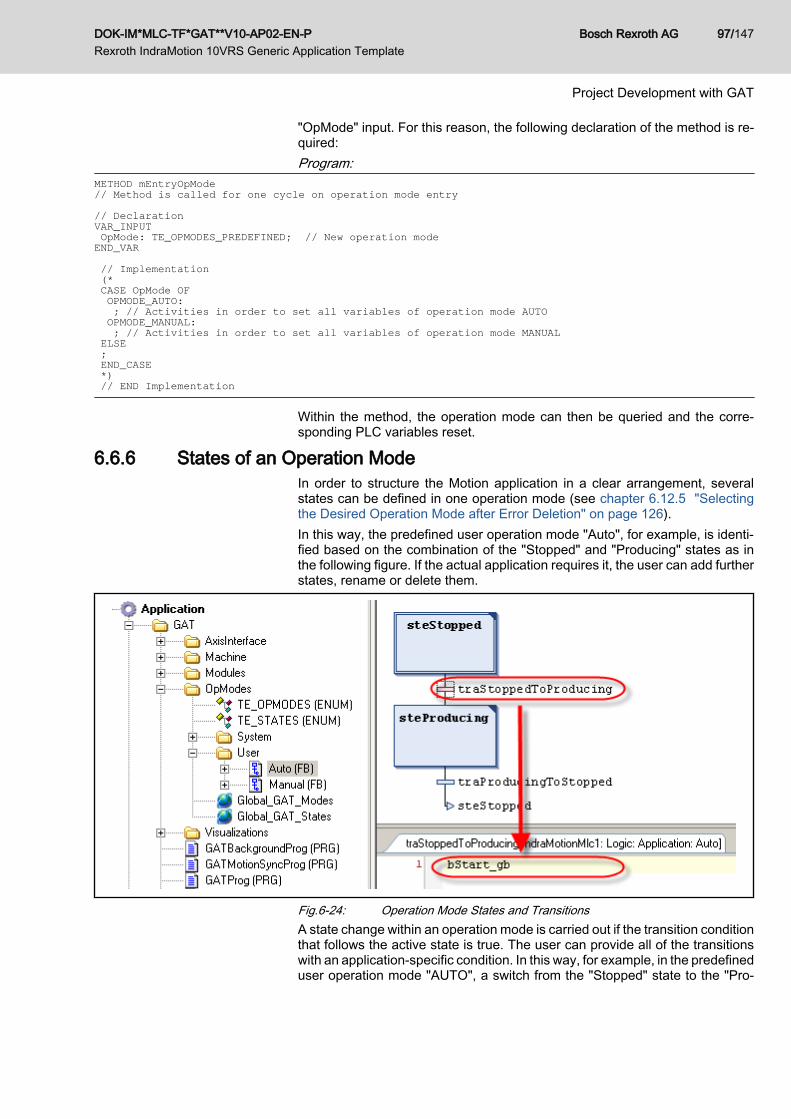
"OpMode" input. For this reason, the following declaration of the method is re‐quired:Program:
METHOD mEntryOpMode// Method is called for one cycle on operation mode entry// DeclarationVAR_INPUT OpMode: TE_OPMODES_PREDEFINED; // New operation modeEND_VAR // Implementation (* CASE OpMode OF OPMODE_AUTO: ; // Activities in order to set all variables of operation mode AUTO OPMODE_MANUAL: ; // Activities in order to set all variables of operation mode MANUAL ELSE ; END_CASE *) // END Implementation
Within the method, the operation mode can then be queried and the corre‐sponding PLC variables reset.
6.6.6 States of an Operation ModeIn order to structure the Motion application in a clear arrangement, severalstates can be defined in one operation mode (see chapter 6.12.5 "Selectingthe Desired Operation Mode after Error Deletion" on page 126).In this way, the predefined user operation mode "Auto", for example, is identi‐fied based on the combination of the "Stopped" and "Producing" states as inthe following figure. If the actual application requires it, the user can add furtherstates, rename or delete them.
Fig.6-24: Operation Mode States and TransitionsA state change within an operation mode is carried out if the transition conditionthat follows the active state is true. The user can provide all of the transitionswith an application-specific condition. In this way, for example, in the predefineduser operation mode "AUTO", a switch from the "Stopped" state to the "Pro‐
DOK-IM*MLC-TF*GAT**V10-AP02-EN-P Rexroth IndraMotion 10VRS Generic Application Template
Bosch Rexroth AG 97/147
Project Development with GAT

ducing" state takes place if the "Stopped" state is active and the global variable"bStart_gb" has the value TRUE (see the previous figure).
6.7 Modules6.7.1 General
A module in the GAT represents a functional unit of the machine.Users do not have to call a module within the GAT. The localized machineorganization unit in the ML_TechTemplate library takes care of this.chapter 6.12.7 "Adding a New Module" on page 128 describes how the wizardcan be used to add and remove modules.The provided GAT already contains the module Module1 (see the followingfigure). This name can be easily changed by using the GAT wizard (see chapter6.12.7 "Adding a New Module" on page 128).
Fig.6-25: Module files in the project directory
6.7.2 Creation RulesIn order that the GAT module be easy to maintain and reuse, it should be de‐signed such that:● Dependencies between the modules are kept to a minimum● No global variables are used within a moduleTo achieve this, each module has the following interface.
6.7.3 Module InterfaceGeneral
The following figure shows the uniform module interface.
Fig.6-26: Module interfaceFor effective, high-performance data management, all of the elements of themodule interface are executed as references, i.e. the data required in the mod‐ule is not copied into the module, but instead transferred in by a reference tothe module.
Bosch Rexroth AG DOK-IM*MLC-TF*GAT**V10-AP02-EN-P Rexroth IndraMotion 10VRS Generic Application Template
98/147
Project Development with GAT

The components of this interface are described in the following section.
Control and status structureEach module has a variable for control (Ctrl) and a variable for reporting status(Status) (see the following figure).
Fig.6-27: Module control and status structureThe names and types of these variables are identical in each module, andchapter 6.11.4 "Module Data" on page 119 provides an overview of whichelements belong to these structures, which can be used by the user and whichare reserved for use in the internal machine organization unit.
Module axesEach module's interface has an axis container (Axes) that contains all of theaxes used in the module. The name of the axis container is the same for eachmodule, but the contents (type) differ because not every module uses the sameaxes.Each axis in the axis container (module axis) is type TE_GAT_AXIS, which isbased on type TE_BASE_MODULE_AXIS (see ML_TechTemplate library). Thefollowing table shows all of the elements that are available in structure typeTE_GAT_AXIS.
Element Type Description
Name STRING(20) Name of the axis as character string(Initialized when the system is initialized; can be modified bythe user)
AxisData REFERENCE TO ML_AXISDATA_SM Reference to the corresponding element in the global arrayAxisData (see ML_Base library)
DV REFERENCE TO ML_DirectVarAxis In case there is a local axis: Reference to the correspondingelement in the global array DV_Axis (see ML_Base library)In case there is a link axis (axis from another control): dummyelement
GV REFERENCE TO ML_GlobalVarAxis Reference to the corresponding element in the global arrayGV_Axis (see ML_Base library)
AxisRef AXIS_REF Axis reference
Disable BOOL TRUE: the corresponding AxisInterface data set will no longerbe updatedFALSE: DefaultA change to the value of this variable will first take effect in INITmode ( (STATE_INIT_COLDSTART or STATE_INIT_WARM‐START)
MotionSync BOOL TRUE: The axis data for this axis are updated in the Motion‐TaskFALSE: The axis data for this axis are updated in the PlcTask
DOK-IM*MLC-TF*GAT**V10-AP02-EN-P Rexroth IndraMotion 10VRS Generic Application Template
Bosch Rexroth AG 99/147
Project Development with GAT

Element Type Description
Ctrl REFERENCE TO TE_AXISINTER‐FACE_CONTROL
Reference to the control structure of the AxisInterface of thecorresponding axis (for the reference to the corresponding en‐try of the global array arAxisCtrl_gb, see the global variable listGlobal_GAT_AxisInterfaces in the AxisInterface folder
Status REFERENCE TO TE_AXISINTER‐FACE_STATUS
Reference to the status structure of the AxisInterface of thecorresponding axis (for the reference to the corresponding en‐try of the global array arAxisStatus_gb, see the global variablelist Global_GAT_AxisInterfaces in the AxisInterface folder
Fig.6-28: All of the available elements of type TE_GAT_AXIS. Within the module,an element can be accessed from Axes.<AxisName>.<Element>
The options for deactivating an axis within the GAT programming environment(Element Disable) or for assigning it to the MotionTask (Element MotionSync),can be selected within the GAT wizard when a module axis is defined or re‐named (see chapter 6.12.3 "Removing/renaming an axis" on page 123).
An axis must be assigned to the MotionTask if an activity is runningin the MotionTask that uses this axis!
All relevant data for an axis can be addressed using the Axes axis container.The container is designed such that the axis data is accessed using the nameof the axes. This generates program code that is easily readable.The following table shows how to access axes in the axis container from withinand outside a module.
Access to a module axis (e.g. axis"vAxis" in the axis container of the"Module1" module)
Assigning the update of the axis data to the Mo‐tionTask
Disable axis
Access from outside the module stAxesModule1_gb.vAxis.MotionSync := TRUE; stAxesModule1_gb.vAxis.Disable :=TRUE;
Access from within the module Axes.vAxis.MotionSync :=TRUE; Axes.vAxis.Disable := TRUE;
In the method "mOneTimeInit" (this method is processed only once during theinitialization of the GAT) of the superordinate machine, the wizard is used toassign a physical axis (real, virtual, ...) to the corresponding axis in the module(see the following figure and see chapter 6.12.2 "Adding an axis" on page122).
Bosch Rexroth AG DOK-IM*MLC-TF*GAT**V10-AP02-EN-P Rexroth IndraMotion 10VRS Generic Application Template
100/147
Project Development with GAT

Fig.6-29: Axis assignment in the "mOneTimeInit" methodAn example from the figure above: the global axis generated in IndraWorks,"MyVirtualAxis1", is assigned the axis "Master_Axis" of the module "Mod‐ule1".
Module-specific I/O dataIf a module is to be reused, global data may not be accessed in that module.All I/Os required in the modules are made available using the I/O containerUserData. The name of the I/O container is the same for each module, but thecontents (type) differ because not every module uses the same I/O data.The variable UserData is a data structure for which the user must define theelements.The following figure shows where the I/O data for the Module1 module con‐tained in the GAT are to be defined:
DOK-IM*MLC-TF*GAT**V10-AP02-EN-P Rexroth IndraMotion 10VRS Generic Application Template
Bosch Rexroth AG 101/147
Project Development with GAT

Fig.6-30: Module-specific I/O data
Module instancesFurther instances can be created from an existing module. These instancesdiffer only in the assigned IndraWorks axes and assigned I/Os. The moduleinstantiation is supported by the GAT wizard and is described in section chapter6.12.8 "Adding another instance of a module" on page 129.
6.7.4 States in the ModuleWhen adding or deleting a state within an operation mode, the wizard ensuresthat an action corresponding to the state is created in each module. This actionis only processed if the corresponding state is active in the related operationmode. In this way, the action "actAutoProducing" is processed in the module"Module1" if the "Producing" state in the "AUTO" operation mode is active.Each action within a module that refers to a state can be divided into a transi‐ent and a stationary section.The transient section of the action that refers to a state is specified by theCtrl.StateTransient condition. Here the user should coordinate the activities thatare required only for a certain period in order to detect a state (e.g. switch ona temperature controller in the AUTO_PRODUCING state). If this is not possiblein a PLC cycle, the user can set Status.TransientLocked:= TRUE so that theprocess remains in this section (e.g. until the nominal temperature of the tem‐perature controller in the AUTO_PRODUCING state is reached).If Ctrl.StateTransient=FALSE, the stationary section of the action that refers toa state is processed. In this case, the user should code all activities that are tobe executed when this state is already detected (e.g. synchronous coupling/decoupling in case of missing products) by setting Status.State‐Locked:=TRUE, a switch into another state in this operation mode can beprevented, even if the corresponding transition condition has been met.
Bosch Rexroth AG DOK-IM*MLC-TF*GAT**V10-AP02-EN-P Rexroth IndraMotion 10VRS Generic Application Template
102/147
Project Development with GAT

6.7.5 Module CoordinationBecause a module does not contain any information about other modules, thecoordination of the modules must be carried out at a superordinate position.The machine organization unit of the ML_TechTemplate.library library calls themachine's "mCyclic" method in each PLC cycle (following figure). In this cycli‐cally called method, I/O information is to be exchanged between the modulesand from the modules to the I/O points of the machine.
Fig.6-31: Method "mCyclic" of the machine organization unitBecause the module configuration or the assignment of global axis to a corre‐sponding module axis does not change during runtime, these activities arecarried out in the machine's "mOneTimeInit" method. This method is calledonce for initializing the GAT using the machine organization unit (previous fig‐ure).The code contained in the "mOneTimeInit" method is managed by the wizard.When adding or removing modules or module axes, the corresponding entriesare added or removed.
6.8 Task Management6.8.1 Task Configuration, GAT
The MotionTask, PlcTask and Background Task are all contained in the stand‐ard GAT.
Priority Cycle time Watchdog time Watchdog sensi‐tivity
Program call
GATMotionTask 2 =SERCOS cy‐cle time
T#2ms 1 GATMotionSyncProg
GATProgTask 5 T#10ms T#20ms 2 GATProg
GATBackgroundProgTask 6 T#40ms - - GATBackgroundProg
6.8.2 GATMotionTaskSee also chapter "Typical tasks for the MotionTask" on page 23.In order to access axes consistently from the MotionTask, the AxisInterfacemust also be called in the MotionTask. Processing all of the axes in the Mo‐tionTask would cause an unnecessary load on the MotionTask. For this reason,you can add an axis using the GAT wizard to assigned the processing of theAxisInterface to the PlcTask or MotionTask.
DOK-IM*MLC-TF*GAT**V10-AP02-EN-P Rexroth IndraMotion 10VRS Generic Application Template
Bosch Rexroth AG 103/147
Project Development with GAT

Fig.6-32: Assigning the processing of the AxisInterface
In principle, the axis data should be updated in the PLCTask.An axis must be assigned to the MotionTask if an activity is runningin the MotionTask that uses this axis! (e.g. A process controller isprocessed in the MotionTask. Then all of the axes assigned to theprocess controller must also be updated in the MotionTask!)
For processing in the MotionTask, each module / machine has "mMotionCy‐clic". All of the module / machine variables (e.g. central axis entry point Axes...)can be accessed from this method.
6.8.3 GATBackgroundProgTaskIf the runtime for the PlcTask is too long, the load on the PlcTask can be reducedby moving tasks that are not time critical to a background task. Please note,however, that a greater load is placed on the entire system due to the additionaltask switch PlcTask <> BackgroundTask.See also chapter "Typical tasks for the BackgroundTask" on page 24.
Bosch Rexroth AG DOK-IM*MLC-TF*GAT**V10-AP02-EN-P Rexroth IndraMotion 10VRS Generic Application Template
104/147
Project Development with GAT

For processing in the BackgroundTask, each module / machine has "mBack‐ground". All of the module methods can be accessed from this method.
6.9 Error Management6.9.1 Error Recognition and Diagnostics
The program template GAT contains predefined functionalities for recognizing,handling and deleting errors at a central location. Errors from various sources(e.g. control errors, application errors, FB errors, ...) are automatically gatheredtogether with the cross-machine FB "Machine" and are made available usingthe status structure of the FB Machine.If several errors occur simultaneously, the most severe is displayed. If severalerrors with the same degree of severity have occurred simultaneously, the mostrecently recognized error is output.The machine status structure contains the following described structure ele‐ments for diagnostic purposes:
Element Type Description
Error BOOL TRUE indicates an error
DiagNo DWORD Number according to the MLC documentation with the following extensions:● 16#F0AE xxxx: Application error (e.g. safety doors are open) (xxxx = can be
defined by the user)● 16#F0FB 0000: FB error (e.g. error at a TechFB) -> for details, see ErrorID /
ErrorIdent● 16#F0AA 0000: GAT internal error -> for details, see ErrorID / ErrorIdent
ErrorID ERROR_CODE Detailed diagnostics in case of FB + GAT errors (DiagNo = 16#F0FB/AA 0000)
ErrorIdent ERROR_STRUCT Detailed diagnostics in case of FB + GAT errors (DiagNo = 16#F0FB/AA 0000)
DiagMessage STRING(60) Contains the diagnostic text for drive and control errors
The DiagNo element is only for use on an HMI. The error texts are assignedthe numerical information in any desired language there.DiagMessage, ErrorID and ErrorIdent provide additional information that is pri‐marily displayed during commissioning by the programmer, e.g. using anIndraLogic visualization.Note regarding application-specific errors
mSetAppError By calling the method mSetAppError(Number), application errors (e.g. opensafety doors) can be signaled. The "number" transferred at the method inputcorresponds with the application error number.If an application error was signaled, the central diagnostic system in the mod‐ule /machine performs cyclic monitoring of the application errors that have beensignaled and generates the application error DiagNo = Error 16#F0AE xxxx(xxxx = application error number).Numbers in the range 1 to uiMAX_MODULE_APP_ERROR_INDEX are validfor application errors in modules. The constant "uiMAX_MOD‐ULE_APP_ERROR_INDEX" has the value 64 by default. If necessary, thisconstant can be adjusted in the global variable list "Global_GAT_Machine" be‐low the "Machine" folder.Numbers in the range 1 to uiMAX_MACHINE_APP_ERROR_INDEX are validfor application errors in the machine. The constant "uiMAX_MA‐CHINE_APP_ERROR_INDEX" has the value 64 by default. If necessary, this
DOK-IM*MLC-TF*GAT**V10-AP02-EN-P Rexroth IndraMotion 10VRS Generic Application Template
Bosch Rexroth AG 105/147
Project Development with GAT

constant can be adjusted in the global variable list "Global_GAT_Machine" be‐low the "Machine" folder.Code example for signalling an application error:
Fig.6-33: Code example for signalling an application errorNote regarding severe errorsThe control diagnostic system defines 10 degrees of "severity" (see MLC di‐agnostic system). The degree of severity affects the error reaction (see chapter4.6.4 "Error Reaction" on page 29).● DiagNo = 16#F0xx xxxx is the lowest degree of severity (e.g. application
errors, FB errors)● DiagNo = 16#F9xx xxxx is the highest degree of severity (fatal system
errors)The error with the highest degree of severity is displayed if several errors occursimultaneously.Note regarding function block errors
mSetFBError If errors occur in called function blocks (e.g. technology FBs), calling the method"mSetFBError(ErrorID, ErrorIdent)" recommended along with transferring the"ErrorID" and "ErrorIdent" outputs of the FB that caused the error to the method.This ensures that the error is forwarded to the diagnostic system of the module /machine and the "ErrorID" and "ErrorIdent" are made available to the diagnosticoutputs of the module / machine.Code example for signalling function block error:
Fig.6-34: Code example for signalling a function block error
6.9.2 Error ReactionDepending on the system, the control system automatically executes an errorreaction only for axis and control errors starting at a severity degree of 2 -> seechapter 4.6.4 "Error Reaction" on page 29. For all other errors and lower de‐grees of severity (e.g. application errors, FB errors...) an automatic errorreaction is not executed.
DisableErrorHandling If GAT error management is activated (Machine control structure element "Dis‐ableErrorHandling" = FALSE), in case of an error, the selected operation modeis always interrupted and the error reaction active.Additional application-specific error reactions can be programmed in this casein the action "actError" of the module. When error management is switched off("DisableErrorHandling" = TRUE), the selected operation mode remains activeeven if the error output is set. The application-specific error reaction "actEr‐ror" is not processed in this case.
Bosch Rexroth AG DOK-IM*MLC-TF*GAT**V10-AP02-EN-P Rexroth IndraMotion 10VRS Generic Application Template
106/147
Project Development with GAT

If the error reaction is already active and if the structure element"DisableErrorHandling = TRUE" is currently set, the system exitsthe error reaction and branches into the following operation mode(see OpMode_ErrorSuccessor setting in the machine control struc‐ture).
Decelerating all axes For standard cases, the deceleration of all axes is programmed with "Mod‐eAH" as an example in the following section (ModeAH = deceleration to fullstop).If the GAT error management is switched off (machine control structure element"DisableErrorHandling" = TRUE), the selected operation mode is not interrup‐ted (the application-specific error reaction "actError" is not started). The diag‐nostic outputs, however, are set in this case as well and can be deleted using"ClearError".
Fig.6-35: Standard case for the error reaction in the module action actError (allaxes decelerate)
Synchronous deceleration Often it is required that axes be decelerated synchronously (to prevent film orpaper from tearing, for example). In these applications, it is recommended thatif at all possible, all axes remain connected in synchronous movement, and thatonly the master is decelerated. This application is shown in the following ex‐ample:
Fig.6-36: Example for synchronous deceleration of the axes in the module actionactError_entry (only axes that are not synchronous are decelerated us‐ing "ModeAb").
For synchronous deceleration, the module bus reaction for the real axes mustalso be switched off (see the "Error reaction" section in the drive documenta‐tion). Furthermore, in the "best possible deceleration" of the real axes, "30s NCreaction" must be set.In addition, bit 0 of A-0-0651 = TRUE must be set so that the control does notexecute an automatic error reaction --> see also the "Error reaction" section inthe MLC function description.
DOK-IM*MLC-TF*GAT**V10-AP02-EN-P Rexroth IndraMotion 10VRS Generic Application Template
Bosch Rexroth AG 107/147
Project Development with GAT

6.9.3 Deleting an ErrorThe central deletion of an error is automatically executed with a positive edgeat the structure element "ClearError" of the machine control structure. The"Machine" FB forwards the command to all subordinate components (e.g. Im‐cInterface1) , module, AxisInterface …) in order to bring the entire system intoa trouble-free state. The structure element "enOpModeCtrl_ErrorSucces‐sor" (see machine control structure) determines which operation mode be‐comes active after error deletion.
6.10 Visualization6.10.1 Internal visualization for assistance during start upGeneral
The GAT contains predefined IndraLogic visualization objects that offer assis‐tance during commissioning as well as extended diagnostic possibilities.
AXIS_GATThe visualization element "AXIS_GAT" can be instantiated for individual axes.This is implemented as an example in the "MAIN_VISU" visualization for the"MyVirtualAxis1" and "MyVirtualAxis2" axes.
Fig.6-37: Internal visualization for assistance during start upThe "Frame" object can be used to create an instance of the visualization objectAXIS_GAT in the visualization.
1) IndraMotionControl Interface = IndraLogic library with an interface to the control, e.g.clear errors
Bosch Rexroth AG DOK-IM*MLC-TF*GAT**V10-AP02-EN-P Rexroth IndraMotion 10VRS Generic Application Template
108/147
Project Development with GAT

Fig.6-38: Creating an instance of the visualization object "AXIS_GAT"Now the corresponding axis reference must be entered under Properties - Ref‐erences.
Fig.6-39: Creating an instance of the visualization object "GAT_AXIS"
6.10.2 External Visualization with Separate HMIs (WinStudio Visualization)General
A predefined WinStudio visualization is available for the GAT. A wizard can beused to add this visualization into the project.
DOK-IM*MLC-TF*GAT**V10-AP02-EN-P Rexroth IndraMotion 10VRS Generic Application Template
Bosch Rexroth AG 109/147
Project Development with GAT

To edit the WinStudio visualization, at least the following develop‐ment environment license (or higher) is required:WinStudio development license, max. 1,500 variables (Mat.No.R911323596)For execution on a VEP, at least the following runtime license isrequired:WinStudio runtime license for devices using Windows CE as anoperating system, max. 1,500 variables (Mat. No. R911323620)
Adding the WinStudio visualization
In order to add the WinStudio visualization to the project, a corre‐sponding visualization device must be present in the project.
Use "drag and drop" to add a VEP from the device library into the project treeand configure it as follows:● Device type: VEPxx (CE)● Application type: WinStudio application
Fig.6-40: Adding a visualization deviceIf a corresponding visualization device is present, the WinStudio visualizationis added using the following link and the wizard.
Bosch Rexroth AG DOK-IM*MLC-TF*GAT**V10-AP02-EN-P Rexroth IndraMotion 10VRS Generic Application Template
110/147
Project Development with GAT

Fig.6-41: Adding a WinStudio visualizationAll of the project's visualization devices that correspond to the given configu‐ration are included in the following wizard dialog.After the corresponding visualization device is selected, click "Apply" to add theWinStudio visualization.
Fig.6-42: Selecting a visualization device and adding a WinStudio visualization
DOK-IM*MLC-TF*GAT**V10-AP02-EN-P Rexroth IndraMotion 10VRS Generic Application Template
Bosch Rexroth AG 111/147
Project Development with GAT

Existing visualization data from the visualization device along withthe symbol configuration of the control are overwritten when theWinStudio visualization is added!
After the visualization is added, its data can be edited.The control address is configured in the BR-WS driver properties dialog:
Fig.6-43: Setting the control's IP address
Now you can use "Start application" in the WinStudio node context menuto start the emulation of the WinStudio visualization.
Dialog structureThe operation screens are divided into 3 subsections:● Header with status information● Main screen with menu-related displays and function keys● Footer with keys for switching from one operation screen to another
Bosch Rexroth AG DOK-IM*MLC-TF*GAT**V10-AP02-EN-P Rexroth IndraMotion 10VRS Generic Application Template
112/147
Project Development with GAT

Fig.6-44: WinStudio visualizationThe header contains:● Operation mode display● Global function keys for "deleting errors" and opening the "Settings" dialog
(for switching languages, setting the decimal place for numerical displays)● Display of current machine diagnostics● Display of current SERCOS phase (including active phase switching)● Display of communication statusThe main screen contains displays and function keys related to operationscreens (e.g. axis information, operation mode switching, ...)The footer contains the keys for switching from one operation screen to another.
Extending the visualizationAdding an operation screenTo extend the visualization, new operation screens can be created by copyingthe existing "template" screens and inserting them with new names.
DOK-IM*MLC-TF*GAT**V10-AP02-EN-P Rexroth IndraMotion 10VRS Generic Application Template
Bosch Rexroth AG 113/147
Project Development with GAT

Fig.6-45: Duplicating an operation screenThe elements for displaying the axis data are grouped individual objects thatcan be duplicated by "copying" and "pasting". To reconfigure the inserted objectfor a different axis you must now use the Replace function for the respectiveobject to adapt the axis array index (see the following figures).
Fig.6-46: Reconfiguring the inserted object
Bosch Rexroth AG DOK-IM*MLC-TF*GAT**V10-AP02-EN-P Rexroth IndraMotion 10VRS Generic Application Template
114/147
Project Development with GAT
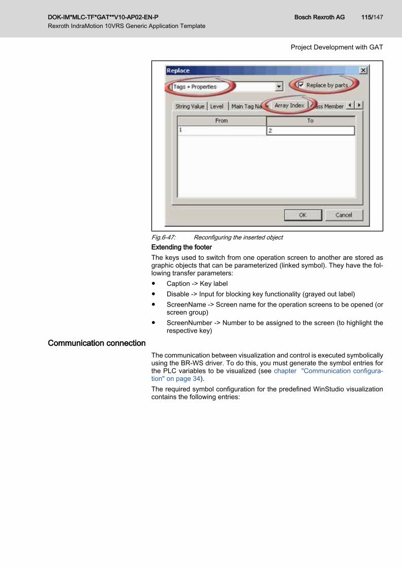
Fig.6-47: Reconfiguring the inserted objectExtending the footerThe keys used to switch from one operation screen to another are stored asgraphic objects that can be parameterized (linked symbol). They have the fol‐lowing transfer parameters:● Caption -> Key label● Disable -> Input for blocking key functionality (grayed out label)● ScreenName -> Screen name for the operation screens to be opened (or
screen group)● ScreenNumber -> Number to be assigned to the screen (to highlight the
respective key)
Communication connectionThe communication between visualization and control is executed symbolicallyusing the BR-WS driver. To do this, you must generate the symbol entries forthe PLC variables to be visualized (see chapter "Communication configura‐tion" on page 34).The required symbol configuration for the predefined WinStudio visualizationcontains the following entries:
DOK-IM*MLC-TF*GAT**V10-AP02-EN-P Rexroth IndraMotion 10VRS Generic Application Template
Bosch Rexroth AG 115/147
Project Development with GAT

Fig.6-48: Symbol configuration of the predefined WinStudio visualization
Symbol entries for variables from global variable lists that comefrom a library must be reinserted in the symbol configuration afterthe respective library version has been modified.
Setting the control's IP address:The control address is configured in the BR-WS driver properties dialog:
Fig.6-49: Setting the control's IP addressIn order to structure the communication, the variables were distributed in vari‐ous driver sheets:
1. read cyclic fast: -> The values of these variables are to be read cyclicallyat short intervals (e.g. diagnostic numbers, axis positions, ...)
Bosch Rexroth AG DOK-IM*MLC-TF*GAT**V10-AP02-EN-P Rexroth IndraMotion 10VRS Generic Application Template
116/147
Project Development with GAT

2. read only once: -> These variables are read once after the visualization isstarted (e.g. axis names)
3. read after switching phase: These variables are read only once after aphase switch (e.g. if the axis was activated)
4. read - write cyclic: -> The values of these variables are to be both readand written (e.g. machine velocity, axis velocity for setup mode, ...)
5. write only: -> These variables are only to be written through the visuali‐zation (trigger signals for deleting errors, ...)
To extend a driver sheet, the BR-WS browser can search the offline symbol file(*.XML).
Fig.6-50: Extended the driver sheet
Multiple language capabilityMultiple language capability for the visualization has been realized with thetranslation functionality integrated into WinStudio.The translation file is stored as a *.CSV table, which provides a column for eachlanguage.It is predefined to include multiple languages although only "German" and"English" are completely filled out. For the rest of the languages only the drivediagnostics are included.
DOK-IM*MLC-TF*GAT**V10-AP02-EN-P Rexroth IndraMotion 10VRS Generic Application Template
Bosch Rexroth AG 117/147
Project Development with GAT

Fig.6-51: Editing the translation file
6.11 Interfaces to GAT6.11.1 General
The GAT interface data are made available in a variety of variable lists. Part ofthe data is made available in libraries.In the following section, the data from libraries in the "Name of the variables"column is marked as such or the variable list is indicated.
6.11.2 Machine DataThe machine input data are summarized in the stMachine1Ctrl_gb (Glob‐al_GAT_MachineControl) structure of type TE_MACHINE_CTRL.The following table describes the elements of the stMachine1Ctrl_gb structure.
I/O type Name Data type Description
I OpMode TE_OPMODES_PREDEFINED Command for machine operationmode
I OpMode_InitSuccessor TE_OPMODES_PREDEFINED Machine operation mode after suc‐cessful initialization
I OpMode_ErrorSuccessor TE_OPMODES_PREDEFINED Machine operation mode after suc‐cessful error deletion
E*) StateCtrl TE_STATES_PREDEFINED Internal use / Machine states
I SkipColdstartAtStartup BOOL When starting the GAT program, aswitch is made into parameterizationmode (P2) to carry out the parameter‐ization required for the application.This phase switch can be skipped withTRUE if the application does not re‐quire parameterization in P2.
Bosch Rexroth AG DOK-IM*MLC-TF*GAT**V10-AP02-EN-P Rexroth IndraMotion 10VRS Generic Application Template
118/147
Project Development with GAT

I/O type Name Data type Description
I DisableErrorHandling BOOL TRUE = In case of error, the processdoes not switch into the ERROR stateThe error display continues and errordeletion is still possible.
I ClearError BOOL Global error deletion with a positiveedge
*) May not be described by the user. Setting this input is reserved for themachine organization unit.
I Input for writingThe machine output data are summarized in the stMachine1Status_gb (Glob‐al_GAT_MachineControl) structure of type TE_MACHINE_STATUS.The following table describes the elements of the stMachine1Status_gb struc‐ture.
I/O type Name Data type Description
O OpMode TE_OPMODES_PREDEFINED Feedback regarding the current machine operationmode
O State TE_STATES_PREDEFINED Internal use / Feedback regarding the current ma‐chine state
O Error BOOL TRUE = Global error has occurred
O ErrorID ERROR_CODE Detailed information if DiagNo = 16#F0FB 0000 /16#F0AA xxxx
O ErrorIdent ERROR_STRUCT Detailed information if DiagNo = 16#F0FB 0000 /16#F0AA xxxx
O DiagNo DWORD Diagnostics number in accordance with MLC specifi‐cationDiagNo = 16#F0AE xxxx: Application error (e.g. safe‐ty doors are open)DiagNo = 16#F0FB 0000: FB errorDiagNo = 16#F0AA xxxx: GAT internal error
O DiagMessage STRING(60) Diagnostic text of the control / axis
O Output for reading
6.11.3 Data for Error ManagementThe inputs and outputs for error management are contained in the machinestructures mentioned above.
6.11.4 Module DataThe modules are controlled by the machine organization unit. The module datacan be accessed from an external position for diagnostic purposes.The input data for all modules are summarized in an array arModuleCtrl of typeTE_CMI_CONTROL within the function block bMachine1_gb (Glob‐al_GAT_MachineControl).The following table describes the elements of the Global_GAT_MachineCon‐trol.fbMachine1_gb.arModuleCtrl structure.
DOK-IM*MLC-TF*GAT**V10-AP02-EN-P Rexroth IndraMotion 10VRS Generic Application Template
Bosch Rexroth AG 119/147
Project Development with GAT

I/O type Name Data type Description
I Enable BOOL TRUE = Module processing starts
I ClearError BOOL TRUE = Module error deletion
E*) State TE_STATES_PREDEFINED Command for module state
E*) StateTransient BOOL TRUE = Module is in transition to the commanded state
E*) DisableTransient BOOL TRUE = Module deactivation was started
I Input for writingO Output for reading*) May not be described by the user. Setting this input is reserved for the
machine organization unit.
Elements for arModuleCtrl are written in the Machine FB and forthis reason, from an external position they can only be read.
The output data for all modules are summarized in an array arModuleStatus oftype TE_CMI_STATUS within the function block bMachine1_gb (Glob‐al_GAT_MachineControl).The following table describes the elements of the Global_GAT_MachineCon‐trol.fbMachine1_gb.arModuleStatus structure.
I/O type Name Data type Description
A*) InOperation BOOL TRUE = the module is processed
A*) State TE_STATES_PREDEFINED Feedback regarding module state
O StateLocked BOOL TRUE = Switching to the following state has beenblocked by the user
O TransientLocked BOOL TRUE = The transition to the stationary section of thecommanded state was blocked by the user.
A*) TransientState TE_STATES_PREDEFINED Display of the state into which the module is currentlyswitching (commanded state not yet reached, relatedactivities are running)
O DisableLocked BOOL TRUE = Activities for module deactivation are still run‐ning
A*) Error BOOL TRUE = Module error has occurred
A*) ErrorID ERROR_CODE Detailed information if DiagNo = 16#F0FB 0000
A*) ErrorIdent ERROR_STRUCT Detailed information if DiagNo = 16#F0FB 0000
A*) DiagNo DWORD Diagnostics number in accordance with MLC specifica‐tionDiagNo = 16#F0AE xxxx: Application error (e.g. safetydoors are open)DiagNo = 16#F0FB 0000: FB errorDiagNo = 16#F0AA xxxx: GAT internal error
A*) DiagMessage STRING(60) Diagnostic text of the control / axis
I Input for writingO Output for reading*) May not be described by the user. Setting this input is reserved for the
machine organization unit.
Bosch Rexroth AG DOK-IM*MLC-TF*GAT**V10-AP02-EN-P Rexroth IndraMotion 10VRS Generic Application Template
120/147
Project Development with GAT

6.11.5 Data for AxesI/O type Name Data type Description
I arAxisCtrl_gb (Global_GAT_Axi‐sInterfaces)
ARRAY OF TE_AXIS_CON‐TROL_TYPE01
Commands for the axes
O arAxisStatus_gb (Glob‐al_GAT_AxisInterfaces)
ARRAY OF TE_AXIS_STA‐TUS_TYPE01
Feedback from the axes
I/O AxisData (GVL_Base from theML_Base library)
ARRAY OF ML_AXISDATA_SM Firmware structure with axis inputs andoutputs
I Input for writingO Output for readingI/O Structure with inputs and outputs
Elements for arAxisCtrl_gb are written in the Machine FB and forthis reason they can no longer be used externally.
6.11.6 Data of the ControlI/O type Name Data type Description
I ImcCtrl (Global_ImcInterface fromthe ML_TechInterface library)
MB_IMC_CONTROL_TYPE01 Commands for the control
O ImcStatus (Global_ImcInterfacefrom the ML_TechInterface library
MB_IMC_STATUS_TYPE01 Feedback from the control
I Input for writingO Output for reading
Elements for ImcCtrl_gb are written in the Machine FB and for thisreason they can no longer be used externally.
6.12 How To: Typical User Activities6.12.1 Access to Axis Data
For access to axis data, in every module the axes structure defined as thecentral access point for all of the axes assigned to the module. All relevant datafor an axis can be addressed using the Axes structure.The structure is designed such that the axis data is accessed using the nameof the axis. This generates program code that is easily readable.The following data are available below Axes:● Axes.<Name>.AxisData => Axis data structure: Status data for the firm‐
ware and access to the axis data container● Axes.<Name>.Ctrl => Control structure for the AxisInterface● Axes.<Name>.Status => Status structure for the AxisInterface● Axes.<Name>.DV => Access to direct variables (function variables)● Axes.<Name>.AxisRef => Axis reference structure for FB calls (e.g.
MB_ReadParameter)
DOK-IM*MLC-TF*GAT**V10-AP02-EN-P Rexroth IndraMotion 10VRS Generic Application Template
Bosch Rexroth AG 121/147
Project Development with GAT

Fig.6-52: Overview / axis data accessTo program loops across all of the axes of a module, each module has themethod mGetAxis() and the element Axes.uiAxesNum.Example: Switching all of a module's axes into ModeAb:Declaration:Program: pCurrentAxis: POINTER TO TE_GAT_AXIS; uiLoopIndex: UINT; // For loop index
Implementation:Program:
// ------------------------ Error reaction example 1 --------------------- // Decelerate all module axes to standstill and turn power off // --> switch all axes off to ModeAb // ----------------------------------------------------------------------- FOR uiLoopIndex := 1 TO Axes.uiAxesNum DO IF mGetAxis(AxisNumber:=uiLoopIndex, PointerToAxis => pCurrentAxis) THEN pCurrentAxis^.Ctrl.Admin._OpMode.en := ModeAb; END_IF END_FOR
6.12.2 Adding an axisThe following steps are required for adding an axis:● Add the axis into the IndraWorks project ("Drag to the SERCOS
node…")
Bosch Rexroth AG DOK-IM*MLC-TF*GAT**V10-AP02-EN-P Rexroth IndraMotion 10VRS Generic Application Template
122/147
Project Development with GAT

● When using the SystemOverview_All_Axis visualization: add a frame forthe new axis and set the reference to the new axis in the properties (seealso chapter "System_Overview" on page 56).
● Add the axis using the GAT wizard (see the screenshots below)
Fig.6-53: Adding an axis
6.12.3 Removing/renaming an axisThe wizard changes only the name in the axis declaration. If theaxis is already being used in the implementation or internal visual‐ization, the new axis name must be changed at these positionsusing "Find/Replace".
The following steps are required for removing/renaming an axis:● Removing an axis from/renaming an axis in the IndraWorks project● When using the SystemOverview_All_Axis visualization: remove the
frame for the deleted axis and change the reference to the axis in theproperties.
● Remove/rename the axis using the GAT wizard (see the screenshot be‐low).
DOK-IM*MLC-TF*GAT**V10-AP02-EN-P Rexroth IndraMotion 10VRS Generic Application Template
Bosch Rexroth AG 123/147
Project Development with GAT

Fig.6-54: Removing/renaming an axis
Bosch Rexroth AG DOK-IM*MLC-TF*GAT**V10-AP02-EN-P Rexroth IndraMotion 10VRS Generic Application Template
124/147
Project Development with GAT

Fig.6-55: Removing/renaming an axis
6.12.4 Adding an operation modeThe GAT wizard makes is easy to add operation modes to the machine. Youcan also use the wizard to delete or rename the operation modes.
DOK-IM*MLC-TF*GAT**V10-AP02-EN-P Rexroth IndraMotion 10VRS Generic Application Template
Bosch Rexroth AG 125/147
Project Development with GAT

Fig.6-56: Adding an operation mode
6.12.5 Selecting the Desired Operation Mode after Error DeletionThe variable fbMachine_gb.Ctrl. OpMode_ErrorSuccessor affects the behaviorof the application after error deletion. The user can change the value of thisvariable at any time. The variable is evaluated by the machine organization unitimmediately after error deletion.By default, the value of this variable is "STATE_UNDEFINED". If an error isreset under this conditions, the application exits the error state and transitionsthrough the STATE_INIT_WARMSTART state into the STOPPED operationmode state that was previously active.For example, the PRODUCING state of the AUTO operation mode was activebefore an error occurred. If the error is deleted, the application switches intothe STATE_INIT_WARMSTART state and then into the STATE_AUTO_STOP‐PED state.If the value of the variables listed above is a specific operation mode, then theapplication is commanded into the STOPPED state of this operation mode afterthe error is deleted.For example, before an error occurred, the PRODUCING state of the AUTOoperation mode was active. In addition, "fbMachine_gb.Ctrl. OpMode_Error‐Successor=OPMODE_MANUAL" applies. After the error is deleted, the appli‐cation switches directly into the STATE_MANUAL_STOPPED state.The initial state of INIT is STATE_INIT_COLDSTART.
Bosch Rexroth AG DOK-IM*MLC-TF*GAT**V10-AP02-EN-P Rexroth IndraMotion 10VRS Generic Application Template
126/147
Project Development with GAT

If an error occurs while the application is in the STATE_INIT_COLDSTART orSTATE_INIT_WARSTART state, the application returns to exactly this stateafter error deletion.
6.12.6 Adding States and TransitionsIf the activities to be executed within an operation mode are very complex, adivision into several states is recommended. In this way, the application isclearly structured and easier to understand.The wizard makes it easy to add states and conditions between states (transi‐tions).
Fig.6-57: Adding statesWhen adding states within an operation mode, it must be decided if a new stateis to be added after a highlighted state or after a highlighted condition (transi‐tion). In addition, branches can be created (see the previous figure).When a new state is generated, actions that correspond to this state are createdin all of the modules that exist at this point.The generation of transitions allows one or more states to be bypassed, de‐pending on a specific condition (see the following figure).
DOK-IM*MLC-TF*GAT**V10-AP02-EN-P Rexroth IndraMotion 10VRS Generic Application Template
Bosch Rexroth AG 127/147
Project Development with GAT

Fig.6-58: Adding transitions
6.12.7 Adding a New ModuleThe GAT wizard makes is easy to add modules to the machine. You can alsouse the wizard to delete or rename the modules.In the new module, actions that correspond to the state are created in all of thestates that exist at this point.
Bosch Rexroth AG DOK-IM*MLC-TF*GAT**V10-AP02-EN-P Rexroth IndraMotion 10VRS Generic Application Template
128/147
Project Development with GAT

Fig.6-59: Adding a module
6.12.8 Adding another instance of a moduleThe GAT wizard makes is easy to add further instances of existing modules tothe machine.The interfaces remain the same, but other global axes (an axes) and I/O data(an UserData) must be assigned.
DOK-IM*MLC-TF*GAT**V10-AP02-EN-P Rexroth IndraMotion 10VRS Generic Application Template
Bosch Rexroth AG 129/147
Project Development with GAT
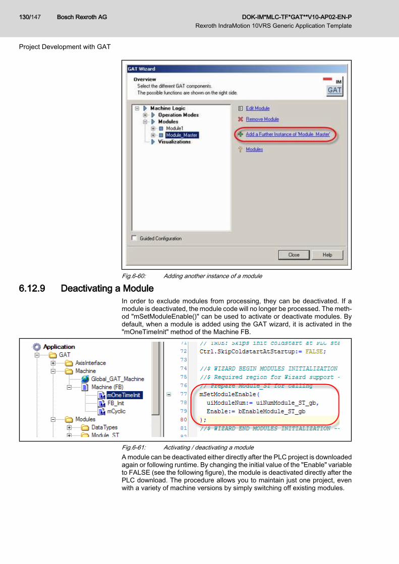
Fig.6-60: Adding another instance of a module
6.12.9 Deactivating a ModuleIn order to exclude modules from processing, they can be deactivated. If amodule is deactivated, the module code will no longer be processed. The meth‐od "mSetModuleEnable()" can be used to activate or deactivate modules. Bydefault, when a module is added using the GAT wizard, it is activated in the"mOneTimeInit" method of the Machine FB.
Fig.6-61: Activating / deactivating a moduleA module can be deactivated either directly after the PLC project is downloadedagain or following runtime. By changing the initial value of the "Enable" variableto FALSE (see the following figure), the module is deactivated directly after thePLC download. The procedure allows you to maintain just one project, evenwith a variety of machine versions by simply switching off existing modules.
Bosch Rexroth AG DOK-IM*MLC-TF*GAT**V10-AP02-EN-P Rexroth IndraMotion 10VRS Generic Application Template
130/147
Project Development with GAT

Fig.6-62: Activating / deactivating a module by changing the initial valueThe module can be deactivated during runtime even if the program is running.To do this, the following procedure must be used:● First, the user must bring the machine (and all of the assigned modules)
into a secure initial state (e.g. the STOPPED state in the Automatic oper‐ation mode). For safety-related reasons, the command for deactivating themodule is not executed if the secure initial machine state is not achieved.
● Then the "mSetModuleEnable(Enable:=FALSE…)" method is used to in‐itiate the function for module deactivation from the application program.
● The GAT sets the "DisableTransient" control element in the control struc‐ture module to TRUE for at least one cycle.
● The action "actDisable" is then processed in the deactivated module. Inthis action, the code necessary for deactivating the module can be imple‐mented. The action "actDisable" is processed for at least one cycle. If themodule deactivation requires several cycles, the processing can be ex‐tended by setting the module status element "DisableLocked := TRUE".The action "actDisable" is processed until "DisableLocked" is reset toFALSE again. Then the module code will no longer be processed.
6.12.10 Reusing ModulesThe GAT is designed such that the functional units (modules) developed canalso be reused in other projects built using the GAT.To do this, you must simply select the folder of the desired module and exportthe related data by using the context menu (following figure).
Fig.6-63: Exporting a moduleSelect all of the elements in the following dialog.Import the file generated during the export into the new project. To do this,highlight the "Module" folder and use the "Import" functionality in the relatedcontext menu (following figure).
DOK-IM*MLC-TF*GAT**V10-AP02-EN-P Rexroth IndraMotion 10VRS Generic Application Template
Bosch Rexroth AG 131/147
Project Development with GAT

Fig.6-64: Importing a moduleWhen using a module in another project (importing), make sure that all statescontained in the module are also defined in the new machine (project) (see thefollowing figure).
Fig.6-65: Declaration of the statesGAT wizard support for exporting/importing modules is in preparation.
6.12.11 Using Global and Address Variables in ModulesBecause a module can be used more than once in an application (instantiation)and because it can be reused in another application, there may be no directaccess to a global or address variable in a module.All global and address variables that are to be used in the module must bedeclared as interface variables in the module data container "UserData". Theassignment of the global or address variable to the corresponding element inthe UserData container is carried out only once in the machine. The elementwithin the module is accessed using UserData.<Element>.The following example demonstrates how access is handled:Two variables are declared in the global variable list MlcVarGlobal: a globalinput and a global output (see the following figure)
Bosch Rexroth AG DOK-IM*MLC-TF*GAT**V10-AP02-EN-P Rexroth IndraMotion 10VRS Generic Application Template
132/147
Project Development with GAT

Fig.6-66: Declaration of one Boolean input and one Boolean output variable in theglobal variable list UserVarGlobal
If necessary, these variables can also be mapped into physical addresses. Inthis specific case, the global input variable is mapped to the first bit of the on‐board inputs and the global output variable to the first bit of the onboard outputsof the control (following figure).
Fig.6-67: Mapping of Boolean global variables on onboard inputs/outputsIn the module in which the global variables are to be used, the reference vari‐ables must be declared in the UserData data structure. The reference variablesmust correspond with the type of the global variables to be used (following fig‐ure).
Fig.6-68: Declaration of reference variables in the module for the global variablesthat are to be used in the module
Finally, the connection between the global variables and the corresponding in‐terface variables (reference variables) for the module must be made. In princi‐
DOK-IM*MLC-TF*GAT**V10-AP02-EN-P Rexroth IndraMotion 10VRS Generic Application Template
Bosch Rexroth AG 133/147
Project Development with GAT

ple, global and address variables are updated with reference to tasks. For thisreason, there are task-related actions in the FB Machine in which the globaland address variables are linked with the corresponding module variables. Forthis reason, the variables to be updated in the● MotionSyncTask in the actAssignIOMotionSync action● PlcTask in the actAssignIO action● BackgroundTask in the actAssignIOBackground actionmust be connected with each other.The following figure shows how the global input and output variables declaredat the input can be linked with the corresponding module variables
Fig.6-69: Connection of the global input and output from the global variable listUserVarGlobal with the corresponding variables in the data container ofthe module Module1
Because this link is carried out in the actAssignIOMotionSync action, thesevariables are updated using the MotionSyncTask.Based on the previous declarations and assignments, access to the global oraddress variable within the module is now carried out using the data containerUserData (see the following figure).
Fig.6-70: Access to global or address variables within the module using the datacontainer UserData, which refers to the module
6.12.12 Processing in the MotionTaskFor processing in the MotionTask, each module / machine has "mMotionCy‐clic". All of the module / machine variables (e.g. central axis entry point Axes...)can be accessed from this method.It is important that the axes controlled here are updated in the MotionTask.See also chapter 4.5 "Task Management" on page 22.
6.12.13 AxisInterface Extensions GAT allows almost any extension of the AxisInterface structures. Additionalsubstructures can also be added and the existing substructures extended.
Bosch Rexroth AG DOK-IM*MLC-TF*GAT**V10-AP02-EN-P Rexroth IndraMotion 10VRS Generic Application Template
134/147
Project Development with GAT
As an example, the following structure elements are programmed as user ex‐tensions in the AxisCtrl structure.● SetupMode: additional substructure in the AxisCtrl structure
– Enable: enable setup mode– JogPlus: Jog +– JogMinus: Jog –– Vel: Jog / reference travel velocity– Accel: Jog/Reference travel de/acceleration– Homing: activates ModeHoming|SetAbsRef|ModesPosAbs depend‐
ing on axis type/configuration● SyncMode: extension of the existing substructure in the AxisCtrl structure
– AngleOffset: Phase offset start of table -> parameter A-0-2730 is de‐scribed with this value
– PhaseShift: offset relative to the master axis before the gear (Pha‐seOffset: offset relative to the master axis after the gear)
– PhaseShiftVel: velocity for adjusting the PhaseShift– PhaseShiftAcc: acceleration for adjusting the PhaseShift– SyncVelocity: Phase shift velocity -> parameter A-0-2790 is descri‐
bed with this value– SyncAcceleration: Phase shift acceleration -> this value is written on
parameter A-0-2791As an example, the following structure elements are programmed as user ex‐tensions in the AxisStatus structure:● SetupMode: additional substructure in the AxisStatus structure
– EnableAck: Setup mode is active– Homingack: Homing is finished.
● SyncMode: extension of the existing substructure in the AxisStatus struc‐ture– AngleOffsetDone: Transfer of phase offset start of table -> parameter
A-0-2730 was described– PhasingMasterDone: PhaseShift was completed.– SyncVelocityDone: Transfer of phase shift velocity -> parameter
A-0-2790 was transferred.– SyncAccelerationDone: Transfer of phase shift acceleration -> pa‐
rameter A-0-2791 was transferred.The code for these extensions can be found in the action of the TE_AxisInter‐face() block in the GAT/AxisInterface folder. The related structures can befound in the GAT/AxisInterface/Type/Control and GAT/AxisInterface/Type/Sta‐tus folders.You can add your own extensions. To do this, see the section titled "AxisInter‐face user extension" in the "Rexroth IndraMotion 10VRS technology basiclibraries" documentation.
6.12.14 Generating Your Own Program Framework Based on the GATAn application developed based on the GAT can in turn be used as a template(program framework) for developing another, more complex application. In thisway, users can provide their own program frameworks for various machinetypes, for example. However, these frameworks differ from the standard GATdue to more advanced developments (e.g. additional operation modes and
DOK-IM*MLC-TF*GAT**V10-AP02-EN-P Rexroth IndraMotion 10VRS Generic Application Template
Bosch Rexroth AG 135/147
Project Development with GAT

modules). The GAT wizard can then be used to work with the more advancedprogram frameworks.To generate your own template based on an application developed with theGAT, use the following procedure:
1. Export the entire GAT folder; leave all check boxes selected (generate an*.iwx file).
Fig.6-71: Exporting the GAT folder2. The *.iwx file generated in step 1 contains the adapted / extended template
and can now be used with the GAT wizard as follows for creating newprojects:
Fig.6-72: Importing a user-defined template
6.12.15 PackML V3.0 Program Framework Based on GATA prefabricated program framework is provided with the installation, whichmaps the modes and state defined in PackML V3.0.The PackML V3.0 program framework can be loaded by selected User-definedGAT after calling the GAT wizard.
Bosch Rexroth AG DOK-IM*MLC-TF*GAT**V10-AP02-EN-P Rexroth IndraMotion 10VRS Generic Application Template
136/147
Project Development with GAT

Fig.6-73: Importing the prefabricated PackML V3.0 program framework using theGAT wizard, User-defined GAT selection
All PackML V3.0 definitions are located below the GAT folder in the PackML_V3folder.
Fig.6-74: Location of the PackML V3.0 definitions in the pre-defined programframework
DOK-IM*MLC-TF*GAT**V10-AP02-EN-P Rexroth IndraMotion 10VRS Generic Application Template
Bosch Rexroth AG 137/147
Project Development with GAT

In addition to the modes and states defined in PackML V3.0, this program tem‐plate also contains the visualizations defined in the standard template.
Fig.6-75: PackML V3.0 visualization for the Producing mode within the prefabri‐cated program framework
Because this program template is based on the GAT, all of the processing rulesand possibilities mentioned in this document regarding the GAT also apply.
To implement transient PackML states (<statename>ing), the rele‐vant code must be placed in the transient section of a GAT actionthat corresponds to the state (see chapter 6.7.4 "States in theModule" on page 102).To implement stationary PackML states, the relevant code must beplaced in the stationary section of a GAT action that correspondsto the state (see chapter 6.7.4 "States in the Module" on page102).
For more information regarding PackML V3.0, see www.isa.org/link/PWG.
6.12.16 Time Sensitive, Application-specific Error ReactionIn the standard version of the GAT, the operation modes and state machinesare processed in the context of the "GATProgTask" (10 ms cyclical task).Therefore, an error is recognized and taken care of within this relatively lengthyperiod of time.For applications that require faster error reaction, it is recommended that theoperation modes and state machines be processed in the context of the "GAT‐MotionTask" (cyclical processing synchronous to the Motion cycle). The timeperiod between error recognition and error reaction is then one Motion cycle.The following steps are required:
1. Deleting "GATProgTask" from the task configuration2. Additional program call "GATProg" in the "GATMotionTask"
Bosch Rexroth AG DOK-IM*MLC-TF*GAT**V10-AP02-EN-P Rexroth IndraMotion 10VRS Generic Application Template
138/147
Project Development with GAT

6.13 GAT, Brief Overview6.13.1 GAT, structure overview
Fig.6-76: GAT, structure overview
6.13.2 Overview of the Most Important Global Machine VariablesSee the global variable list "GAT/Machine/Global_GAT_Machine":
Variable Description Access
stMachine1Ctrl_gb Machine control (e.g. operation mode selection, central "error deletion",subsequent operation mode after initialization / error reset, switching offerror management, initialization settings
RD/WR
stMachine1Status_gb Machine status (e.g. current operation mode and state, error and diagnos‐tic outputs)
RD
arAppErrMachine1_gb Array of BOOL with user-specific machine error flags RD
arMachine1ModuleDiag‐No_gb
Array with the diagnostic numbers of all modules RD
DOK-IM*MLC-TF*GAT**V10-AP02-EN-P Rexroth IndraMotion 10VRS Generic Application Template
Bosch Rexroth AG 139/147
Project Development with GAT

Variable Description Access
bStart_gb Start signal for Auto operation mode / Transition from AUTO_STOPPEDto AUTO_PRODUCING
RD/WR
bStop_gb Stop signal for Auto operation mode / Transition from AUTO_PRODUCINGto AUTO_STOPPED
RD/WR
RD ReadWR Write
6.13.3 Overview of the Most Important Global Module VariablesSee the global variable list "GAT/Module/Global_GAT_<Modulename>":
Variable Description Access
st<Modulename>_gb Module-specific I/Os RD/WR
arAppErr<Modulename>_gb Array of BOOL with user-specific module error flags RD
stAxes<Modulename>_gb Container with module axes RD
RD ReadWR Write
6.13.4 Overview of the Most Important Global Axis VariablesSee the global variable list „"GAT/ AxisInterface/ Global_GAT_AxisInterfa‐ces":
Variable Description Access
arAxisCtrl_gb Array with the AxisInterface command data RD/WR
arAxisStatus_gb Array with the AxisInterface status data RD
RD ReadWR Write
6.13.5 Overview of the Machine Methods and ActionsAction/method
Call Related task Description / example
mMotion‐Cyclic
In every state GATMotionTask Time sensitive, cross module logic
mCyclic In every state GATProgTask Cross module logic
mBack‐ground
In every state GATBackgroundTask Cross module background activities thatare not time sensitive (e.g. HMI data prep‐aration, statistics)
mOneTi‐meInit
For one cycle when the GAT isinitialized. Execution before coldstart
GATProgTask Activating / deactivating modules, initializ‐ing settings for "SkipColdStart", assigningmodule axes to the global IndraWorks axes
mExitOp‐Mode
For one cycle when exiting anoperation mode
GATProgTask Method is optional: activities when exitingan operation mode (e.g. resetting varia‐bles)
mEn‐tryOp‐Mode
For one cycle when activating anoperation mode
GATProgTask Method is optional: activities when activat‐ing an operation mode (e.g. initializing var‐iables)
Bosch Rexroth AG DOK-IM*MLC-TF*GAT**V10-AP02-EN-P Rexroth IndraMotion 10VRS Generic Application Template
140/147
Project Development with GAT

Action/method
Call Related task Description / example
mOpMo‐deChan‐geAllow‐ed
Before switching operationmodes
GATProgTask Method is optional: the method is called byGAT before switching operation modes.The operation mode switch is blocked aslong as the return value = FALSE.
actAs‐signIOMo‐tionSync
Once after starting/resetting aPLC program
GATMotionTask I/O assignment at the "GATMotionTask"
actAssi‐gnIO
Once after starting/resetting aPLC program
GATProgTask I/O assignment at the "GATProgTask"
actAs‐signIO‐Back‐ground
Once after starting/resetting aPLC program
GATBackgroundTask I/O assignment at the "GATBackground‐Task"
FB_init Once before starting/resetting aPLC program
No specific task assignment Internal system use, may not be modified
6.13.6 Overview of the Module Methods and ActionsAction/method
Call Related task Description / example
actInit‐Coldstart
Only in the INIT_COLDSTARTstate
GATProgTask Initializing / writing parameters in parame‐terization mode (P2)
actInit‐Warm‐start
Only in the INIT_WARMSTARTstate
GATProgTask Initializing / writing parameters, power ac‐tivation for axes
actAutoS‐topped
Only in the AUTO_STOPPEDstate
GATProgTask Stop axis movement
actAuto‐Produc‐ing
Only in the AUTO_PRODUCINGstate
GATProgTask Start axis movement
actMa‐nual‐Ready
Only in the MANUAL_READYstate
GATProgTask Monitoring while jogging the axes
actError Only in the ERROR_F0.. stateERROR_F9
GATProgTask Additional user-specific error reaction (e.g.synchronized deceleration of the axes)
mMotion‐Cyclic
In every state GATMotionTask Call of the time sensitive process controllerFBs (e.g. RegisterController)
mCyclic In every state GATProgTask Cross module logic
mBack‐ground
In every state GATBackgroundTask Background activities that are not time sen‐sitive (e.g. HMI data preparation, statistics)
mExitOp‐Mode
For one cycle when exiting anoperation mode
GATProgTask Method is optional: activities when exitingan operation mode (e.g. resetting varia‐bles)
mEn‐tryOp‐Mode
For one cycle when activating anoperation mode
GATProgTask Method is optional: activities when activat‐ing an operation mode (e.g. initializing var‐iables)
DOK-IM*MLC-TF*GAT**V10-AP02-EN-P Rexroth IndraMotion 10VRS Generic Application Template
Bosch Rexroth AG 141/147
Project Development with GAT

Action/method
Call Related task Description / example
actDisa‐ble
In every state while deactivatinga module until the deactivation iscomplete
GATProgTask Resetting variables or module outputs dur‐ing module deactivation
actDisa‐ble
In every state while deactivatinga module until the deactivation iscomplete
GATProgTask Resetting variables or module outputs dur‐ing module deactivation
mGetAxis No automatic call No specific task assignment Internal system use, may not be modified.Delivers the pointer to a module axis
mFB_Ax‐esInit
During axis initialization GATProgTask Internal system use, may not be modified
FB_init Once before starting/resetting aPLC program
No specific task assignment Internal system use, may not be modified
6.13.7 Access to Axes within the ModuleAlways use Axes.<axisname> Example:Program: // Command axis in velocity control mode Axes.MyAxis1.Ctrl.Admin._OpMode.en := ModeVel; / If axis has reached the velocity IF (Axes.MyAxis1.Status.PtrAxisData^.Axis_InVelocity = TRUE) THEN;
6.13.8 Access to I/O Data within the ModuleAlways use UserData. !! No direct access to global variables !! Example:Program:IF (UserData.bInput1=TRUE) THEN // If "bInput1" is set… UserData.bOutput1:=TRUE; // Ausgang „bOutput1“ setzenEND_IF
Bosch Rexroth AG DOK-IM*MLC-TF*GAT**V10-AP02-EN-P Rexroth IndraMotion 10VRS Generic Application Template
142/147
Project Development with GAT

7 Service and SupportOur service helpdesk at our headquarters in Lohr, Germany and our worldwideservice will assist you with all kinds of enquiries. You can reach us around theclock - even on weekend and on holidays.
HelpdeskService HotlineWorldwide
Phone +49 (0) 9352 40 50 60 Outwith Germany please con‐tact our sales/service office inyour area first.For hotline numbers refer tothe sales office addresses onthe Internet.
Fax +49 (0) 9352 40 49 41
E-mail [email protected]
Internethttp://www.boschrexroth.comYou will also find additional notes regarding service, mainte‐nance (e.g. delivery addresses) and training.
Preparing Information For quick and efficient help please have the following information ready:● Detailed description of the fault and the circumstances● Information on the type plate of the affected products, especially type co‐
des and serial numbers● Your phone, fax numbers and e-mail address so we can contact you in
case of questions.
DOK-IM*MLC-TF*GAT**V10-AP02-EN-P Rexroth IndraMotion 10VRS Generic Application Template
Bosch Rexroth AG 143/147
Service and Support

Bosch Rexroth AG DOK-IM*MLC-TF*GAT**V10-AP02-EN-P Rexroth IndraMotion 10VRS Generic Application Template
144/147

IndexAAdding an axis, GATcompact.................................. 69Adding an operation mode, GATcompact............... 72Address variables in a module.......................... 132Automating applications
Cyclical processing ...................................... 22Error management ....................................... 28Initialization .................................................. 21Operation modes .......................................... 21Task management ....................................... 22
Automating ApplicationsBasic procedures ......................................... 21
Axis data access, GATcompact............................... 68AxisInterface extensions, GAT.......................... 134AxisInterface extensions, GATcompact................... 73
CChanging the operation mode, GAT................... 95Cycle time measurement.................................... 24
DDrive system....................................................... 11
EElectric drive system........................................... 11Error management, GAT................................... 105Error management, GATcompact............................ 52Error reaction, GAT........................................... 106Error reaction, GATcompact.................................... 54
FFirst steps, GAT.................................................. 79First steps, GATcompact......................................... 35Functional principle, GAT.................................... 93
GGeneral information regarding cyclical pro‐cessing................................................................ 22General information regarding error manage‐ment.................................................................... 28General information regarding operation modes 21General information regarding task manage‐ment.................................................................... 22General information regarding the Automaticoperation mode................................................... 22General information regarding the Manual op‐eration mode....................................................... 22Global variables in a module............................. 132
IImproper use....................................................... 10Initialization, GAT................................................ 93
IInitialization, GATcompact....................................... 44Intended use......................................................... 9
scopes of application ...................................... 9Interfaces to GAT.............................................. 118Interfaces to GATcompact....................................... 66
MModularization rules............................................ 98Module axes........................................................ 99Module Coordination......................................... 103Module instances.............................................. 102Module interface ................................................ 98Module reuse.................................................... 131Modules.............................................................. 98Module-specific I/O data .................................. 101mOneTimeInit..................................................... 94mSetAppError................................................... 105mSetFBError..................................................... 106
NNon-intended use
consequences, exclusion of liability ............... 9
OOperation modes, GAT....................................... 94Operation modes, GATcompact.............................. 47Operation mode selection after error deletionin the GAT......................................................... 126
PPackML V3.0..................................................... 136PELV................................................................... 15Protective extra-low voltage................................ 15
RRemoving/renaming an axis, GATcompact............. 70
SSafety instructions for electric drives and con‐trols..................................................................... 11State of the art...................................................... 9States in the Module......................................... 102States of an Operation Mode.............................. 97Support
see Service Hotline .................................... 143
TTarget mode after initializing the GAT................ 95Task configuration, GAT................................... 103
DOK-IM*MLC-TF*GAT**V10-AP02-EN-P Rexroth IndraMotion 10VRS Generic Application Template
Bosch Rexroth AG 145/147
Index

TTime sensitive, application-specific error re‐action................................................................ 138
UUse
improper use ................................................ 10
U...Use
intended use ................................................... 9User-defined GAT............................................. 135
VVisualization, GAT............................................ 108Visualization, GATcompact..................................... 56
Bosch Rexroth AG DOK-IM*MLC-TF*GAT**V10-AP02-EN-P Rexroth IndraMotion 10VRS Generic Application Template
146/147
Index
T

Notes
DOK-IM*MLC-TF*GAT**V10-AP02-EN-P Rexroth IndraMotion 10VRS Generic Application Template
Bosch Rexroth AG 147/147

Printed in GermanyDOK-IM*MLC-TF*GAT**V10-AP02-EN-PR911329382
Bosch Rexroth AGElectric Drives and ControlsP.O. Box 13 5797803 Lohr, GermanyBgm.-Dr.-Nebel-Str. 297816 Lohr, GermanyTel. +49 (0)93 52-40-0Fax +49 (0)93 52-48 85www.boschrexroth.com