2-way cartridge valves, pressure relief function - Bosch Rexroth
16
RE 21055, edition: 2021-02, Bosch Rexroth AG Features ▶ Installation bore according to ISO 7368 (main pressure relief valve) ▶ Response pressure 50 … 420 bar ▶ Additional directional valve connection surface (version "DBW"), optional ▶ Two adjustment types, optionally: – Hexagon – Rotary knob ▶ Mounting set (sealable) as accessories ▶ Size 32 … 63 ▶ Component series 7X ▶ Maximum operating pressure 420 bar ▶ Maximum flow 5000 l/min H8061 Contents Features 1 Ordering code 2, 3 Symbols 3 Function, section 4 Technical data 5 Characteristic curves 6 … 9 Dimensions 10, 11 Installation bore and connection dimensions 12 Accessories 13 Safety instructions 14 Further information 14 2-way cartridge valves, pressure relief function Type-examination tested safety valves according to Pressure Equipment Directive 2014/68/EU RE 21055 Edition: 2021-02 Replaces: 2019-01
-
Upload
khangminh22 -
Category
Documents
-
view
4 -
download
0
Transcript of 2-way cartridge valves, pressure relief function - Bosch Rexroth

RE 21055, edition: 2021-02, Bosch Rexroth AG
Features
▶ Installation bore according to ISO 7368 (main pressure relief valve)
▶ Response pressure 50 … 420 bar ▶ Additional directional valve connection surface
(version "DBW"), optional ▶ Two adjustment types, optionally:
– Hexagon – Rotary knob
▶ Mounting set (sealable) as accessories
▶ Size 32 … 63 ▶ Component series 7X ▶ Maximum operating pressure 420 bar ▶ Maximum flow 5000 l/min
H8061
Contents
Features 1Ordering code 2, 3Symbols 3Function, section 4Technical data 5Characteristic curves 6 … 9Dimensions 10, 11Installation bore and connection dimensions 12Accessories 13Safety instructions 14Further information 14
2-way cartridge valves, pressure relief function
Type-examination tested safety valves according to Pressure Equipment Directive 2014/68/EU
RE 21055 Edition: 2021-02Replaces: 2019-01
Inhalt
Features 1Contents 1Ordering code 2Ordering code 3Symbols 3Function, section 4Technical data (For applications outside the stated values, please ask us!) 5Characteristic curves: Admissible flow ranges – size 32 6Characteristic curves: Admissible flow ranges – size 40 7Characteristic curves: Admissible flow ranges – size 50 8Characteristic curves: Admissible flow ranges – size 63 9Dimensions: Version "DB" (dimensions in mm) 10Dimensions: Version "DBW" (dimensions in mm) 11Installation bore and connection dimensions according to ISO 7368 (main pressure relief valve) (dimensions in mm) 12Accessories (separate order) 13Safety instructions 14Further information 14Notes 15Notes 16

2/14 LFA | 2-way cartridge valve - Safety valve
Bosch Rexroth AG, RE 21055, edition: 2021-02
Ordering code
01 Control cover LFA
02 Size 32 32
Size 40 40
Size 50 50
Size 63 63
03 Pressure limiting function (only NG40 … 63) DB
Pressure limiting function with connection surface for directional valve DBW
Adjustment types
04 Rotary knob 1
Hexagon 2
05 Component series 70 … 79 (70 … 79: unchanged installation and mounting dimensions) 7X
Response pressure (50 … 420 bar, in 10 bar steps, maximum flow see table page 3)
06 50 bar 050
60 bar 060
… bar …
400 bar 400
410 bar (only NG32) 410
420 bar (only NG32) 420
Seal material (observe compatibility of seals with hydraulic fluid used, see page 5)
07 NBR seals N
FKM seals F
08 Type-examination tested safety valve according to Pressure Equipment Directive 2014/68/EU E
01 02 03 04 05 06 07 08
LFA – 7X / E

2-way cartridge valve - Safety valve | LFA 3/14
RE 21055, edition: 2021-02, Bosch Rexroth AG
Ordering code
Symbols
Size Component marking Maximum flow qV max in l/min ("Q") Response pressure p in bar
("p")Mineral oils: HL, HLP Other approved hydraulic fluids
(see page 5)
32 TÜV.SV. –1138.31.F.Q.p
550 500 50 … 90
900 800 100 … 190
1200 1100 200 … 290
1500 1350 300 … 420
40 TÜV.SV. –1138.38.F.Q.p
900 800 50 … 90
1500 1350 100 … 190
2000 1800 200 … 290
2400 2150 300 … 400
50 TÜV.SV. –1138.48.F.Q.p
1400 1400 50 … 90
2000 2000 100 … 190
2600 2600 200 … 290
3600 3600 300 … 400
63 TÜV.SV. –1138.61.F.Q.p
1750 1550 50 … 90
2500 2250 100 … 190
3600 3600 200 … 290
5000 5000 300 … 400
Information is entered at the factory
Order example:qV = 2200 l/min, p = 270 bar
→ Type LFA 50 DB.–7X/270.E → TÜV.SV. –1138.48.F.2600.270
Version "DB" Version "DBW"
A
B
X Y
T
T
X D
FX
A
B
X Z1 Z2 Y
T
AA
P
F
P
B T
T
DX

A
B
X
D
P
FX
T
Y
5
4
37
10
6
1
289
4/14 LFA | 2-way cartridge valve - Safety valve
Bosch Rexroth AG, RE 21055, edition: 2021-02
Function, section
Type-examination tested safety valves type LFA . DB (W)...E according to Pressure Equipment Directive 2014/68/EU are pilot-operated 2-way cartridge valves in seat design with set relief pressure setting pmax.The complete valve generally consists of one cartridge valve (1) for installation bores according to ISO 7368 and one respective control cover (2) with integrated sealed pressure limitation unit (4).
As amendment to version "DB", version "DBW" offers a connection possibility closed by a cover plate (8) for a directional valve with porting pattern according to ISO 4401-03-02-0-05. By attaching a suitable directional valve at the position of the cover plate, an additional function like "depressurized start-up" can be realized. The use of this additional function requires a special set-up of the overall circuitry in order to maintain compatibility with the Pressure Equipment Directive 2014/68/EU.
The factory nozzle fitting (9) ("X", "F", "P") as well as the installed compression spring (10) must not be changed. The installation position ("D") is not fitted.The cartridge valve (1) is designed as seat valve without area difference. The relief pressure effective at port A is directed to the spring chamber (6) of the cartridge valve (1) and to the pressure limitation unit (4) via channel X (5). The piston sealing (7) prevents an internal leakage from the spring chamber (6) to port B and thus increases the operational safety by avoiding gap filtration. Under the pressure value set at the pressure limitation unit (4), the spool (3) is pressure-compensated and remains closed in a seat-tight manner due to the spring force of the compression spring (10). The pressure equilibrium at the spool (3) is only changed when the relief pressure at port A is reached, namely by opening the pressure limitation unit (4), so that excessive hydraulic fluid directly flows to channel B via the spool (3) and the pressure in A is limited to the set pressure value.The pressure limitation unit (4) is optionally available with rotary knob. This allows for a manual reduction of the pressure adjustment without changing the relief pressure setting. This simplifies a regular functional test.

2-way cartridge valve - Safety valve | LFA 5/14
RE 21055, edition: 2021-02, Bosch Rexroth AG
Technical data (For applications outside the stated values, please ask us!)
1) With mineral oil2) The cleanliness classes specified for the components must be
adhered to in hydraulic systems. Effective filtration prevents faults and simultaneously increases the life cycle of the components.
For the selection of filters, see www.boschrexroth.com/filter.
hydraulic
Size 32 40 50 63
Maximum operating pressure ▶ Port B bar 15
▶ Port T and Y bar depressurized to the tank
Maximum response pressure ▶ Port A and X bar 420 400
Maximum flow 1) ▶ Port A to B l/min 1500 2400 3600 5000
Maximum pilot flow ▶ Port Y and T l/min 4 15 23
Hydraulic fluid see table below
Hydraulic fluid temperature range (= TS) °C –10 … +60
Viscosity range mm2/s 12 … 230
Maximum admissible degree of contamination of the hydraulic fluid, cleanliness class according to ISO 4406 (c)
Class 20/18/15 2)
general
Ambient temperature range °C –10 … +80
Hydraulic fluid Classification Suitable sealing materials Standards Data sheet
Mineral oils HL, HLP NBR, FKM DIN 51524 90220
Bio-degradable ▶ Insoluble in water HETG FKMISO 15380
90221HEES FKM
▶ Soluble in water HEPG FKM ISO 15380
Flame-resistant ▶ Water-free HFDU (glycol base) FKM
ISO 12922 90222HFDU (ester base) FKM
HFDR FKM
▶ Containing water HFC (Fuchs: Hydrotherm 46M, Fuchs Renosafe 500; Petrofer: Ultra Safe 620; Houghton: Safe 620; Union: Carbide HP5046)
NBR
ISO 12922 90223
Important information on hydraulic fluids: ▶ For further information and data on the use of other hydraulic fluids, please refer to the data sheets above or contact us.
▶ There may be limitations regarding the technical valve data (temperature, pressure range, life cycle, maintenance intervals, etc.).
▶ Bio-degradable and flame-resistant – containing water: If components with galvanic zinc coating (e.g. version "J3" or "J5") or parts containing zinc are used, small amounts of dissolved zinc may get into the hydraulic system and cause accelerated aging of the hydraulic fluid. Zinc soap may form as a chemical reaction product, which may clog filters, nozzles and solenoid valves - particularly in connection with local heat input.
▶ Flame-resistant – containing water: Due to increased cavitation tendency with HFC hydraulic fluids, the life cycle of the component may be reduced by up to 30% as compared to the use with mineral oil HLP.

0 400 800 1200 1500
50
100
150
200
250
300
400420
350
0 400 800 1200 1500
50
100
150
200
250
300
400420
350
6/14 LFA | 2-way cartridge valve - Safety valve
Bosch Rexroth AG, RE 21055, edition: 2021-02
Res
pon
se p
ress
ure
in b
ar →
Res
pon
se p
ress
ure
in b
ar →
Flow in l/min →
Flow in l/min →
Characteristic curves: Admissible flow ranges – size 32
Notes: ▶ The flow values only apply for depressurized pilot oil return. ▶ Operating points in the gray areas of the characteristic curves are not admissible with this valve!
▶ Observe the admissible flows of the overall system.
Mineral oil (measured with HLP46, ϑoil = 40 ±5 °C)
Other approved hydraulic fluids (see page 5) (simulated; kinetic viscosity 40 mm2/s)

0 400 800 1200 1600 2000 2400
50
100
150
200
250
300
400
350
0 400 800 1200 1600 2000 2400
50
100
150
200
250
300
400
350
2-way cartridge valve - Safety valve | LFA 7/14
RE 21055, edition: 2021-02, Bosch Rexroth AG
Res
pon
se p
ress
ure
in b
ar →
Res
pon
se p
ress
ure
in b
ar →
Flow in l/min →
Flow in l/min →
Characteristic curves: Admissible flow ranges – size 40
Notes: ▶ The flow values only apply for depressurized pilot oil return. ▶ Operating points in the gray areas of the characteristic curves are not admissible with this valve!
▶ Observe the admissible flows of the overall system.
Mineral oil (measured with HLP46, ϑoil = 40 ±5 °C)
Other approved hydraulic fluids (see page 5) (simulated; kinetic viscosity 40 mm2/s)

0 400 800 1200 1600 2000 2400 2800 3200 3600
50
100
150
200
250
300
400
350
0 400 800 1200 1600 2000 2400 2800 3200 3600
50
100
150
200
250
300
400
350
8/14 LFA | 2-way cartridge valve - Safety valve
Bosch Rexroth AG, RE 21055, edition: 2021-02
Characteristic curves: Admissible flow ranges – size 50
Res
pon
se p
ress
ure
in b
ar →
Res
pon
se p
ress
ure
in b
ar →
Flow in l/min →
Flow in l/min →
Notes: ▶ The flow values only apply for depressurized pilot oil return. ▶ Operating points in the gray areas of the characteristic curves are not admissible with this valve!
▶ Observe the admissible flows of the overall system.
Mineral oil (measured with HLP46, ϑoil = 40 ±5 °C)
Other approved hydraulic fluids (see page 5) (simulated; kinetic viscosity 40 mm2/s)

0 400 800 1200 1600 2000 2400 2800 3200 3600 4000 4400 4800 5000
50
100
150
200
250
300
400
350
0 400 800 1200 1600 2000 2400 2800 3200 3600 4000 4400 4800 5000
50
100
150
200
250
300
400
350
2-way cartridge valve - Safety valve | LFA 9/14
RE 21055, edition: 2021-02, Bosch Rexroth AG
Res
pon
se p
ress
ure
in b
ar →
Res
pon
se p
ress
ure
in b
ar →
Flow in l/min →
Flow in l/min →
Characteristic curves: Admissible flow ranges – size 63
Notes: ▶ The flow values only apply for depressurized pilot oil return. ▶ Operating points in the gray areas of the characteristic curves are not admissible with this valve!
▶ Observe the admissible flows of the overall system.
Mineral oil (measured with HLP46, ϑoil = 40 ±5 °C)
Other approved hydraulic fluids (see page 5) (simulated; kinetic viscosity 40 mm2/s)

H5H4 H1
H6H2
L5L1
4 L2
L4 L3
80 max
H3
94 max
Ø37
max
Ø60
TX
6
2
5
3 4
1
6
5
D1
D2
10/14 LFA | 2-way cartridge valve - Safety valve
Bosch Rexroth AG, RE 21055, edition: 2021-02
Dimensions: Version "DB" (dimensions in mm)
1 Name plate
2 Locating pin
3 Pilot control valve, adjustment type "2"
4 Pilot control valve, adjustment type "1"
5 Valve mounting set, see page 13
6 External connections
NG 40 50 63
H1 60 60 82
H2 32 34 50
H3 27 31 40
H4 69 67 91
H5 105 122 155
H6 28 23 30
L1 125 140 180
L2 89 105 144
L3 76 84 90
L4 60 70 90
L5 68 79 90
D1 G1/4 G1/2 G1/2
D2 G1/4 G1/4 G1/2
Notice: The dimensions are nominal dimensions which are subject to tolerances.

H5H4
H1H6 H7
H2L4
L1
4
4
L2L6
L3L5
H3
L8 maxL7 max
Ø37
max
ØD2
T
1
XX
YF1F2
F4F3 ABP
T
6
2
57
3 46
5
D1
D1
2-way cartridge valve - Safety valve | LFA 11/14
RE 21055, edition: 2021-02, Bosch Rexroth AG
Dimensions: Version "DBW" (dimensions in mm)
NG 32 40 50 63
H1 50 60 60 82
H2 28 32 34 50
H3 26 27 35 49
H4 75 85 85 107
H5 85 105 122 155
H6 37 40 44 64
H7 26 22 32 30
L1 100 125 140 180
L2 60 68 75 95
L3 57 76 84 104
L4 57 66 82 99
L5 35 47 55 75
L6 72 84 92 112
L7 41 80 80 80
L8 57 94 94 94
D1 G1/4 G1/4 G3/8 G1/2
ØD2 37 60 60 60
1 Name plate
2 Locating pin
3 Pilot control valve, adjustment type "2"
4 Pilot control valve, adjustment type "1"
5 Valve mounting set, see page 13
6 External connections
7 Cover plate
Notice: The dimensions are nominal dimensions which are subject to tolerances.
ØD2
ØD1
ØD3H1
H8
H7H6
H5H2
H3
R u
Ro
15°
15°
ØD4y
xy
z
z
0.1A
U A
1
1
A
B
2
Rz1max 4x =
Rz1max 8y =
0,0025- / Pt max 16z =
L14 x D5; H4
ØD6(X, Y)
L2±0.2
L2±0
.2
L1
L3±0.2 ØD7; 10L4±0.2L4±0.2
L5±0
.2
X Y
3
12/14 LFA | 2-way cartridge valve - Safety valve
Bosch Rexroth AG, RE 21055, edition: 2021-02
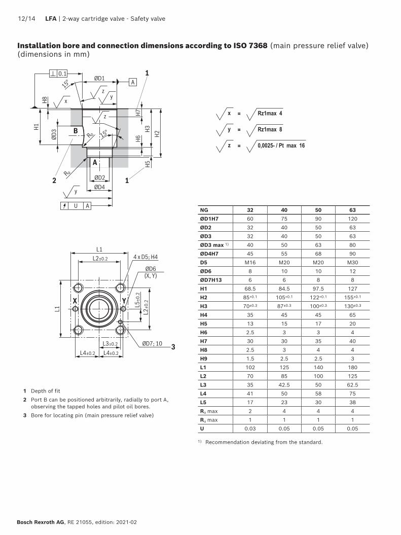
Installation bore and connection dimensions according to ISO 7368 (main pressure relief valve) (dimensions in mm)
1 Depth of fit
2 Port B can be positioned arbitrarily, radially to port A, observing the tapped holes and pilot oil bores.
3 Bore for locating pin (main pressure relief valve)
NG 32 40 50 63
ØD1H7 60 75 90 120
ØD2 32 40 50 63
ØD3 32 40 50 63
ØD3 max 1) 40 50 63 80
ØD4H7 45 55 68 90
D5 M16 M20 M20 M30
ØD6 8 10 10 12
ØD7H13 6 6 8 8
H1 68.5 84.5 97.5 127
H2 85+0.1 105+0.1 122+0.1 155+0.1
H3 70±0.3 87±0.3 100±0.3 130±0.3
H4 35 45 45 65
H5 13 15 17 20
H6 2.5 3 3 4
H7 30 30 35 40
H8 2.5 3 4 4
H9 1.5 2.5 2.5 3
L1 102 125 140 180
L2 70 85 100 125
L3 35 42.5 50 62.5
L4 41 50 58 75
L5 17 23 30 38
Ro max 2 4 4 4
Ru max 1 1 1 1
U 0.03 0.05 0.05 0.05
1) Recommendation deviating from the standard.

2-way cartridge valve - Safety valve | LFA 13/14
RE 21055, edition: 2021-02, Bosch Rexroth AG
Valve mounting set (separate order) Size Quantity Consisting of Material number
32 4 Hexagon socket head cap screws ISO 4762 - M16 x 60 - 10.9-flZn/nc/480h/C(thereof 1 special screw with bore) Tightening torque MA = 240 Nm ±10%
R901476528
1 Sealing material
40, 50 4 Hexagon socket head cap screws ISO 4762 - M20 x 80 - 10.9-flZn/nc/480h/C(thereof 1 special screw with bore) Tightening torque MA = 480 Nm ±10%
R901362574
1 Sealing material
63 4 Hexagon socket head cap screws ISO 4762 - M30 x 110 - 10.9-flZn/nc/480h/C(thereof 1 special screw with bore) Tightening torque MA = 1600 Nm ±10%
R901362575
1 Sealing material
Accessories (separate order)
Notes: ▶ For reasons of stability, exclusively the specified valve mounting screws may be used.
▶ The specified tightening torques were calculated with total friction coefficient µtotal = 0.09 ... 0.14; adjust in case of modified surfaces.
▶ The specified tightening torques stated are guidelines when using screws with the specified friction coefficients and when using a manual torque wrench (tolerance ± 10%).

Bosch Rexroth AG, RE 21055, edition: 2021-02
14/14 LFA | 2-way cartridge valve - Safety valve
Bosch Rexroth AG Industrial HydraulicsZum Eisengießer 197816 Lohr am Main, Germany Phone +49 (0) 93 52 / 40 30 20 [email protected] www.boschrexroth.de
© All rights reserved to Bosch Rexroth AG, also regarding any disposal, exploitation, reproduction, editing, distribution, as well as in the event of applications for industrial property rights.The data specified above only serves to describe the product. No statements concerning a certain condition or suitability for a certain application can be derived from our information. The information given does not release the user from the obligation of own judgment and verification.It must be remembered that our products are subject to a natural process of wear and aging.
Safety instructions
▶ When selecting a type-examination tested safety valve, it must be observed that for the desired response pressure p, the maximum possible flow lies below the admissible flow qVmax. According to the Pressure Equipment Directive 2014/68/EU, the increase in the system pressure due to the discharged flow must not exceed 10% of the set response pressure (see component marking table on page 2).
▶ The maximum admissible flow qVmax stated in the component marking must not be exceeded.
▶ Discharge lines of safety valves must end in a risk-free manner. An accumulation of fluids in the discharge system must not be possible (see data sheet AD2000 A 2).
▶ Safety valves with adjustment type "1" (rotary knob) may only be unloaded in case of maintenance! Operation outside the specified pressure ranges is not admissible.
Further information
▶ Type-examination tested safety valves according to Pressure Equipment Directive 2014/68/EU
Operating instructions 21055-B
▶ Safety equipment against excessive pressure – safety valves Data sheet AD 2000 A 2
▶ Hydraulic fluids on mineral oil basis Data sheet 90220
▶ Hydraulic valves for industrial applications Operating instructions 07600-B
▶ Selection of filters www.boschrexroth.com/filter
It is imperative to observe the application notes:The response pressure with a flow of 12 l/min and a hydraulic fluid viscosity of 46 mm2/s specified in the component marking is set by default. Within the admissible viscosity range, the response pressure may vary by +3% (230 mm2/s) to -3% (12 mm2/s).
▶ The maximum flow stated in the component marking applies for applications without counter pressure in the control line (port Y).
▶ By removing the lead seal at the safety valve, the approval according to the Pressure Equipment Directive becomes void!
▶ The nozzle fittings installed at the factory as well as the main spool compression spring must not be changed.
▶ Basically, the requirements of the Pressure Equipment Directive and of data sheet AD 2000 A 2 have to be observed!
▶ In order to prevent unauthorized assembly, the valve assembly can be additionally secured by means of the valve mounting set (sealing) (separate order, see page 10 and 11).

2-way cartridge valve - Safety valve | LFA 15/14
RE 21055, edition: 2021-02, Bosch Rexroth AG
Bosch Rexroth AG Industrial HydraulicsZum Eisengießer 197816 Lohr am Main, Germany Phone +49 (0) 93 52 / 40 30 20 [email protected] www.boschrexroth.de
© All rights reserved to Bosch Rexroth AG, also regarding any disposal, exploitation, reproduction, editing, distribution, as well as in the event of applications for industrial property rights.The data specified above only serves to describe the product. No statements concerning a certain condition or suitability for a certain application can be derived from our information. The information given does not release the user from the obligation of own judgment and verification.It must be remembered that our products are subject to a natural process of wear and aging.
Notes

Bosch Rexroth AG, RE 21055, edition: 2021-02
16/14 LFA | 2-way cartridge valve - Safety valve
Bosch Rexroth AG Industrial HydraulicsZum Eisengießer 197816 Lohr am Main, Germany Phone +49 (0) 93 52 / 40 30 20 [email protected] www.boschrexroth.de
© All rights reserved to Bosch Rexroth AG, also regarding any disposal, exploitation, reproduction, editing, distribution, as well as in the event of applications for industrial property rights.The data specified above only serves to describe the product. No statements concerning a certain condition or suitability for a certain application can be derived from our information. The information given does not release the user from the obligation of own judgment and verification.It must be remembered that our products are subject to a natural process of wear and aging.
Notes