ctrlX PLC Engineering - Bosch Rexroth
940
ctrlX PLC Engineering PLC programming system Application Manual R911403764, Edition 03
-
Upload
khangminh22 -
Category
Documents
-
view
1 -
download
0
Transcript of ctrlX PLC Engineering - Bosch Rexroth
ctrlX PLC Engineering
PLC programming system
Application Manual
R911403764, Edition 03

Copyright
© Bosch Rexroth AG © Bosch Rexroth AG 2021All rights reserved, also regarding any disposal, exploitation, reproduction, editing, distribution, as well as in theevent of applications for industrial property rights.
Liability
The specified data is intended for product description purposes only and shall not be deemed to be a guaranteedcharacteristic unless expressly stipulated in the contract. All rights are reserved with respect to the content of thisdocumentation and the availability of the product.
DOK-XPLC**-ENGINEERING-AP03-EN-P
cd94cde49b6ce2ddc0a8640e00867156, 10, en_US

3 / 940ctrlX PLC Engineering
Bosch Rexroth AGR911403764, Edition 03
Table of contents1 ctrlX PLC Engineering System 7
1.1 Configuring PLC Engineering. . . . . . . . . . . . . . . . . . . . . . . . . . . . . . . . . . . . . . . 91.1.1 Setting PLC Engineering Options. . . . . . . . . . . . . . . . . . . . . . . . . . . . 91.1.2 Customizing the User Interface. . . . . . . . . . . . . . . . . . . . . . . . . . . . . . 9
1.2 Creating and configuring projects. . . . . . . . . . . . . . . . . . . . . . . . . . . . . . . . . . . 141.2.1 What is a project?. . . . . . . . . . . . . . . . . . . . . . . . . . . . . . . . . . . . . . . . 141.2.2 Creating a new project. . . . . . . . . . . . . . . . . . . . . . . . . . . . . . . . . . . . . 141.2.3 Adding Objects. . . . . . . . . . . . . . . . . . . . . . . . . . . . . . . . . . . . . . . . . . 191.2.4 Changing the compiler version. . . . . . . . . . . . . . . . . . . . . . . . . . . . . . 201.2.5 Opening a V3 Project. . . . . . . . . . . . . . . . . . . . . . . . . . . . . . . . . . . . . . 201.2.6 Configuring a Project. . . . . . . . . . . . . . . . . . . . . . . . . . . . . . . . . . . . . . 221.2.7 Retrieving and Editing Project Information. . . . . . . . . . . . . . . . . . . . . 241.2.8 Making Project Settings. . . . . . . . . . . . . . . . . . . . . . . . . . . . . . . . . . . . 26
1.3 Exporting and Transferring a Project. . . . . . . . . . . . . . . . . . . . . . . . . . . . . . . . . 261.3.1 Exporting and Importing Projects. . . . . . . . . . . . . . . . . . . . . . . . . . . . 261.3.2 Transferring Projects. . . . . . . . . . . . . . . . . . . . . . . . . . . . . . . . . . . . . . 27
1.4 Comparing Projects. . . . . . . . . . . . . . . . . . . . . . . . . . . . . . . . . . . . . . . . . . . . . . 281.4.1 Creating a Comparison View. . . . . . . . . . . . . . . . . . . . . . . . . . . . . . . . 291.4.2 Opening the Detailed Compare View. . . . . . . . . . . . . . . . . . . . . . . . . . 30
1.5 Protecting and Saving a Project. . . . . . . . . . . . . . . . . . . . . . . . . . . . . . . . . . . . . 311.5.1 Setting up Write Protection. . . . . . . . . . . . . . . . . . . . . . . . . . . . . . . . . 341.5.2 Assigning Passwords. . . . . . . . . . . . . . . . . . . . . . . . . . . . . . . . . . . . . . 351.5.3 Protecting Projects Using a Dongle. . . . . . . . . . . . . . . . . . . . . . . . . . . 361.5.4 Setting up a User Management. . . . . . . . . . . . . . . . . . . . . . . . . . . . . . 371.5.5 Protecting Objects in the Project by Access Rights. . . . . . . . . . . . . . . 371.5.6 Logging in via User Account and Password Manager. . . . . . . . . . . . . . 381.5.7 Encrypting Projects with Certificates. . . . . . . . . . . . . . . . . . . . . . . . . 401.5.8 Save project. . . . . . . . . . . . . . . . . . . . . . . . . . . . . . . . . . . . . . . . . . . . . 421.5.9 Saving/Sending the Project Archive. . . . . . . . . . . . . . . . . . . . . . . . . . . 431.5.10 Linking a project to the source control system. . . . . . . . . . . . . . . . . . 44
1.6 Localizing Projects. . . . . . . . . . . . . . . . . . . . . . . . . . . . . . . . . . . . . . . . . . . . . . . 441.7 Configuring I/O Links. . . . . . . . . . . . . . . . . . . . . . . . . . . . . . . . . . . . . . . . . . . . . 46
1.7.1 Device Tree and Device Editor. . . . . . . . . . . . . . . . . . . . . . . . . . . . . . . 471.7.2 Mapping a Hardware Structure in the Device Tree. . . . . . . . . . . . . . . 501.7.3 Configuring Devices and I/O Mapping. . . . . . . . . . . . . . . . . . . . . . . . . 54
1.8 Programming of Applications. . . . . . . . . . . . . . . . . . . . . . . . . . . . . . . . . . . . . . . 621.8.1 Designating Identifiers. . . . . . . . . . . . . . . . . . . . . . . . . . . . . . . . . . . . . 621.8.2 Declaration of Variables . . . . . . . . . . . . . . . . . . . . . . . . . . . . . . . . . . . 621.8.3 Creating Source Code in IEC. . . . . . . . . . . . . . . . . . . . . . . . . . . . . . . . 721.8.4 Configuring the Memory Reserve for an Online Change. . . . . . . . . . . 971.8.5 Function Block — Calling Functions or Methods with External Imple-
mentation. . . . . . . . . . . . . . . . . . . . . . . . . . . . . . . . . . . . . . . . . . . . . . . 981.8.6 Using Input Assistance. . . . . . . . . . . . . . . . . . . . . . . . . . . . . . . . . . . . . 991.8.7 Using Pragmas. . . . . . . . . . . . . . . . . . . . . . . . . . . . . . . . . . . . . . . . . . . 1011.8.8 Using Library POUs. . . . . . . . . . . . . . . . . . . . . . . . . . . . . . . . . . . . . . . 103

4 / 940 ctrlX PLC Engineering
Bosch Rexroth AG R911403764, Edition 03
1.8.9 Managing Text in Text Lists. . . . . . . . . . . . . . . . . . . . . . . . . . . . . . . . . 1041.8.10 Using Image Pools. . . . . . . . . . . . . . . . . . . . . . . . . . . . . . . . . . . . . . . . 1111.8.11 Integrating C Modules. . . . . . . . . . . . . . . . . . . . . . . . . . . . . . . . . . . . . 1131.8.12 Programmatic Access to I/Os. . . . . . . . . . . . . . . . . . . . . . . . . . . . . . . . 1161.8.13 Checking Syntax and Analyzing Code. . . . . . . . . . . . . . . . . . . . . . . . . 1201.8.14 Orientation and Navigation. . . . . . . . . . . . . . . . . . . . . . . . . . . . . . . . . 1231.8.15 Searching and Replacing in the Entire Project. . . . . . . . . . . . . . . . . . . 1261.8.16 Refactoring. . . . . . . . . . . . . . . . . . . . . . . . . . . . . . . . . . . . . . . . . . . . . . 1261.8.17 Task Configuration. . . . . . . . . . . . . . . . . . . . . . . . . . . . . . . . . . . . . . . . 1291.8.18 Encrypting an Application. . . . . . . . . . . . . . . . . . . . . . . . . . . . . . . . . . 1321.8.19 Unit Conversion. . . . . . . . . . . . . . . . . . . . . . . . . . . . . . . . . . . . . . . . . . 1361.8.20 Data Persistence. . . . . . . . . . . . . . . . . . . . . . . . . . . . . . . . . . . . . . . . . 1391.8.21 Alarm Management. . . . . . . . . . . . . . . . . . . . . . . . . . . . . . . . . . . . . . . 1471.8.22 Using POUs for Implicit Checks. . . . . . . . . . . . . . . . . . . . . . . . . . . . . . 1511.8.23 Object-Oriented Programming. . . . . . . . . . . . . . . . . . . . . . . . . . . . . . . 152
1.9 Working with Control Networks. . . . . . . . . . . . . . . . . . . . . . . . . . . . . . . . . . . . . 1591.9.1 Network and Addressing. . . . . . . . . . . . . . . . . . . . . . . . . . . . . . . . . . . 1591.9.2 Symbol Configuration. . . . . . . . . . . . . . . . . . . . . . . . . . . . . . . . . . . . . 1641.9.3 Network Variables. . . . . . . . . . . . . . . . . . . . . . . . . . . . . . . . . . . . . . . . 1661.9.4 Data Source Manager. . . . . . . . . . . . . . . . . . . . . . . . . . . . . . . . . . . . . . 1691.9.5 Subordinate Safety Controller. . . . . . . . . . . . . . . . . . . . . . . . . . . . . . . 183
1.10 Transferring an Application to the PLC. . . . . . . . . . . . . . . . . . . . . . . . . . . . . . . 1841.10.1 Configuring the Connection to the PLC. . . . . . . . . . . . . . . . . . . . . . . . 1841.10.2 Encrypting Communication, Changing Security Settings. . . . . . . . . . 1851.10.3 Handling of Device User Management. . . . . . . . . . . . . . . . . . . . . . . . . 1881.10.4 Generating Application Code. . . . . . . . . . . . . . . . . . . . . . . . . . . . . . . . 1921.10.5 Downloading the Application Code, Logging in, and Starting the PLC 1931.10.6 Generating Boot Applications. . . . . . . . . . . . . . . . . . . . . . . . . . . . . . . 194
1.11 Testing and Debugging. . . . . . . . . . . . . . . . . . . . . . . . . . . . . . . . . . . . . . . . . . . . 1951.11.1 Testing in Simulation Mode. . . . . . . . . . . . . . . . . . . . . . . . . . . . . . . . . 1961.11.2 Using Breakpoints. . . . . . . . . . . . . . . . . . . . . . . . . . . . . . . . . . . . . . . . 1961.11.3 Stepping Through a Program. . . . . . . . . . . . . . . . . . . . . . . . . . . . . . . . 1991.11.4 Forcing and Writing Variables. . . . . . . . . . . . . . . . . . . . . . . . . . . . . . . 2011.11.5 Resetting Applications. . . . . . . . . . . . . . . . . . . . . . . . . . . . . . . . . . . . . 2041.11.6 Flow Control. . . . . . . . . . . . . . . . . . . . . . . . . . . . . . . . . . . . . . . . . . . . 2051.11.7 Determining the Current Processing Position with the Call Stack. . . . 2071.11.8 Checking the Task Deployment. . . . . . . . . . . . . . . . . . . . . . . . . . . . . . 207
1.12 Application at Runtime. . . . . . . . . . . . . . . . . . . . . . . . . . . . . . . . . . . . . . . . . . . . 2081.12.1 Monitoring of Values. . . . . . . . . . . . . . . . . . . . . . . . . . . . . . . . . . . . . . 2081.12.2 Changing Values with Recipes. . . . . . . . . . . . . . . . . . . . . . . . . . . . . . . 2161.12.3 Data Recording with Trace. . . . . . . . . . . . . . . . . . . . . . . . . . . . . . . . . . 2201.12.4 Data Recording with Trend. . . . . . . . . . . . . . . . . . . . . . . . . . . . . . . . . 2261.12.5 Monitoring Tasks. . . . . . . . . . . . . . . . . . . . . . . . . . . . . . . . . . . . . . . . . 2301.12.6 Reading the PLC log. . . . . . . . . . . . . . . . . . . . . . . . . . . . . . . . . . . . . . . 2301.12.7 Analysing Errors with Core Dump. . . . . . . . . . . . . . . . . . . . . . . . . . . . 231
5 / 940ctrlX PLC Engineering
Bosch Rexroth AGR911403764, Edition 03
1.12.8 Using PLC Shell for requesting Information. . . . . . . . . . . . . . . . . . . . . 2321.12.9 Backup and Restore. . . . . . . . . . . . . . . . . . . . . . . . . . . . . . . . . . . . . . . 233
1.13 Updating an Application on the PLC. . . . . . . . . . . . . . . . . . . . . . . . . . . . . . . . . 2341.13.1 Executing the Online Change. . . . . . . . . . . . . . . . . . . . . . . . . . . . . . . . 2351.13.2 Execution of a Download. . . . . . . . . . . . . . . . . . . . . . . . . . . . . . . . . . . 236
1.14 Copying Files to/from PLC. . . . . . . . . . . . . . . . . . . . . . . . . . . . . . . . . . . . . . . . . 2371.15 Using Libraries. . . . . . . . . . . . . . . . . . . . . . . . . . . . . . . . . . . . . . . . . . . . . . . . . . 237
1.15.1 Information for Library Developers. . . . . . . . . . . . . . . . . . . . . . . . . . . 2381.15.2 Adding a library to the application. . . . . . . . . . . . . . . . . . . . . . . . . . . . 2391.15.3 Adding a Library to the Repository. . . . . . . . . . . . . . . . . . . . . . . . . . . 2401.15.4 Exporting Library Files. . . . . . . . . . . . . . . . . . . . . . . . . . . . . . . . . . . . . 240
1.16 Managing Devices. . . . . . . . . . . . . . . . . . . . . . . . . . . . . . . . . . . . . . . . . . . . . . . 2411.16.1 Installing Devices. . . . . . . . . . . . . . . . . . . . . . . . . . . . . . . . . . . . . . . . . 241
1.17 Security. . . . . . . . . . . . . . . . . . . . . . . . . . . . . . . . . . . . . . . . . . . . . . . . . . . . . . . 2411.17.1 General Information. . . . . . . . . . . . . . . . . . . . . . . . . . . . . . . . . . . . . . . 2421.17.2 Security for the Development System. . . . . . . . . . . . . . . . . . . . . . . . . 2441.17.3 Security for the Runtime System / PLC. . . . . . . . . . . . . . . . . . . . . . . . 2441.17.4 FAQ. . . . . . . . . . . . . . . . . . . . . . . . . . . . . . . . . . . . . . . . . . . . . . . . . . . 245
1.18 Reference, Programming. . . . . . . . . . . . . . . . . . . . . . . . . . . . . . . . . . . . . . . . . . 2481.18.1 Programming Languages and Editors. . . . . . . . . . . . . . . . . . . . . . . . . 2541.18.2 Variables. . . . . . . . . . . . . . . . . . . . . . . . . . . . . . . . . . . . . . . . . . . . . . . 3121.18.3 Operators. . . . . . . . . . . . . . . . . . . . . . . . . . . . . . . . . . . . . . . . . . . . . . . 3271.18.4 Operands. . . . . . . . . . . . . . . . . . . . . . . . . . . . . . . . . . . . . . . . . . . . . . . 3751.18.5 Data Types. . . . . . . . . . . . . . . . . . . . . . . . . . . . . . . . . . . . . . . . . . . . . . 3861.18.6 Pragmas. . . . . . . . . . . . . . . . . . . . . . . . . . . . . . . . . . . . . . . . . . . . . . . . 4181.18.7 Identifiers. . . . . . . . . . . . . . . . . . . . . . . . . . . . . . . . . . . . . . . . . . . . . . . 4601.18.8 Shadowing Rules. . . . . . . . . . . . . . . . . . . . . . . . . . . . . . . . . . . . . . . . . 4651.18.9 Keywords. . . . . . . . . . . . . . . . . . . . . . . . . . . . . . . . . . . . . . . . . . . . . . . 4671.18.10 Methods 'FB_Init', 'FB_Reinit', and 'FB_Exit'. . . . . . . . . . . . . . . . . . . . . 4681.18.11 Error Messages. . . . . . . . . . . . . . . . . . . . . . . . . . . . . . . . . . . . . . . . . . 472
1.19 Reference, User Interface. . . . . . . . . . . . . . . . . . . . . . . . . . . . . . . . . . . . . . . . . 5261.19.1 Objects. . . . . . . . . . . . . . . . . . . . . . . . . . . . . . . . . . . . . . . . . . . . . . . . 5281.19.2 Menu Commands. . . . . . . . . . . . . . . . . . . . . . . . . . . . . . . . . . . . . . . . . 6521.19.3 Dialogs. . . . . . . . . . . . . . . . . . . . . . . . . . . . . . . . . . . . . . . . . . . . . . . . . 816
2 ctrlX PLC Engineering – Additions 8732.1 Working with ctrlX PLC Engineering. . . . . . . . . . . . . . . . . . . . . . . . . . . . . . . . . 873
2.1.1 Project synchronization. . . . . . . . . . . . . . . . . . . . . . . . . . . . . . . . . . . . 8732.1.2 Templates for compiler check functions. . . . . . . . . . . . . . . . . . . . . . . 8742.1.3 API PLC Engineering. . . . . . . . . . . . . . . . . . . . . . . . . . . . . . . . . . . . . . 878
2.2 Reference, user interface. . . . . . . . . . . . . . . . . . . . . . . . . . . . . . . . . . . . . . . . . . 8792.2.1 Objects. . . . . . . . . . . . . . . . . . . . . . . . . . . . . . . . . . . . . . . . . . . . . . . . 8792.2.2 Commands. . . . . . . . . . . . . . . . . . . . . . . . . . . . . . . . . . . . . . . . . . . . . . 8802.2.3 Dialogs. . . . . . . . . . . . . . . . . . . . . . . . . . . . . . . . . . . . . . . . . . . . . . . . . 883
3 ctrlX I/O Engineering – Additions 8893.1 Project synchronization - ctrlX I/O Engineering. . . . . . . . . . . . . . . . . . . . . . . . . 8893.2 API ctrlX I/O Engineering. . . . . . . . . . . . . . . . . . . . . . . . . . . . . . . . . . . . . . . . . . 889

6 / 940 ctrlX PLC Engineering
Bosch Rexroth AG R911403764, Edition 03
3.3 Reference, user interface. . . . . . . . . . . . . . . . . . . . . . . . . . . . . . . . . . . . . . . . . . 8903.3.1 Objects. . . . . . . . . . . . . . . . . . . . . . . . . . . . . . . . . . . . . . . . . . . . . . . . 8903.3.2 Tabs – EtherCAT master. . . . . . . . . . . . . . . . . . . . . . . . . . . . . . . . . . . . 8903.3.3 Tabs – EtherCAT slave. . . . . . . . . . . . . . . . . . . . . . . . . . . . . . . . . . . . . 8983.3.4 Commands. . . . . . . . . . . . . . . . . . . . . . . . . . . . . . . . . . . . . . . . . . . . . . 9093.3.5 Dialogs. . . . . . . . . . . . . . . . . . . . . . . . . . . . . . . . . . . . . . . . . . . . . . . . . 909
4 Libraries 9114.1 Guidelines for Creating Libraries. . . . . . . . . . . . . . . . . . . . . . . . . . . . . . . . . . . . 911
5 Index 913
7 / 940ctrlX PLC Engineering
Bosch Rexroth AGR911403764, Edition 03
1 ctrlX PLC Engineering SystemUsing PLC Engineering HelpPLC Engineering Help is intended to assist you in using the PLC EngineeringDevelopment System easily and successfully. You will find quick answers toquestions and solutions to problems.Each help component consists of a concept section and a reference section.In the concept sections, we explain in detail all topics that are relevant for cre-ating PLC Engineering projects. The concepts are supplemented with instruc-tions that lead you step-by-step to the intended result.In the reference sections, we provide complete reference works for the userinterface and programming of PLC Engineering.The following formats of PLC Engineering Help are provided:● PLC Engineering Online Help: Web-based PLC Engineering HelpIn the PLC Engineering options, you determine whether to use PLC EngineeringOffline Help or PLC Engineering Online Help.You can call the context-sensitive help directly from the user interface of thePLC Engineering Development System. In PLC Engineering, when you positionthe cursor over an object, menu command, or programming element, and thenpress the [F1] key, the respective help page opens. As an alternative, you canuse the commands in the “Help” menu. This is a full-text search. The indexsearch is possible in PLC Engineering Offline Help only.Search operators for the offline help● AND
Used automatically, for example the input of the search terms DeviceDiagnosis has the same results as the input of Device AND Diagnosis
● The * placeholder is used automatically. However, the * character must notbe used as a wildcard because in this case the * character will be searchedfor specifically.
Search operators for the online help● AND● OR● NOT
Example: abc NOT abcd: The search result includes all help pages that con-tain abc and excludes the pages with abcd.
● ANDNOTANDNOT is the combination of the search operators AND nd NOT.
● ANDMAYBEExample: The search for abc ANDMAYBE xyz finds the help pages that con-tain abc and xyz, and all pages that contain only the string abc.
● Placeholders– *: Replaces any number of characters– ?: Replaces exactly one character
In the online help, you can use parentheses to group together multiple searchoperators for complex search queries. Example: ((profinet AND cycle) OR(Ethernet/IP AND cycle)) ANDNOT IRTSee also● ⮫ Chapter “Dialog 'Options' - 'Help'” on page 855● ⮫ Chapter “Command 'Contents'” on page 754● ⮫ Chapter “Command 'Index'” on page 754● ⮫ Chapter “Command 'Find'” on page 754
8 / 940 ctrlX PLC Engineering
Bosch Rexroth AG R911403764, Edition 03
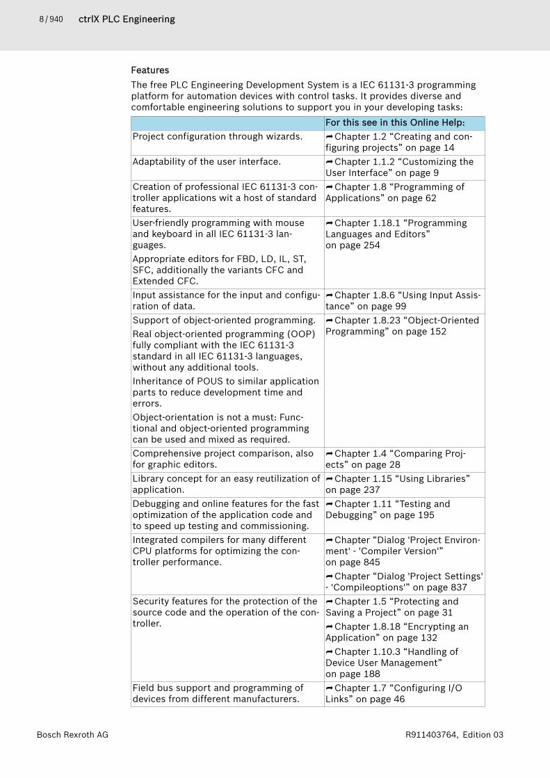
FeaturesThe free PLC Engineering Development System is a IEC 61131-3 programmingplatform for automation devices with control tasks. It provides diverse andcomfortable engineering solutions to support you in your developing tasks:
For this see in this Online Help:Project configuration through wizards. ⮫ Chapter 1.2 “Creating and con-
figuring projects” on page 14Adaptability of the user interface. ⮫ Chapter 1.1.2 “Customizing the
User Interface” on page 9Creation of professional IEC 61131-3 con-troller applications wit a host of standardfeatures.
⮫ Chapter 1.8 “Programming ofApplications” on page 62
User-friendly programming with mouseand keyboard in all IEC 61131-3 lan-guages.Appropriate editors for FBD, LD, IL, ST,SFC, additionally the variants CFC andExtended CFC.
⮫ Chapter 1.18.1 “ProgrammingLanguages and Editors”on page 254
Input assistance for the input and configu-ration of data.
⮫ Chapter 1.8.6 “Using Input Assis-tance” on page 99
Support of object-oriented programming.Real object-oriented programming (OOP)fully compliant with the IEC 61131-3standard in all IEC 61131-3 languages,without any additional tools.Inheritance of POUS to similar applicationparts to reduce development time anderrors.Object-orientation is not a must: Func-tional and object-oriented programmingcan be used and mixed as required.
⮫ Chapter 1.8.23 “Object-OrientedProgramming” on page 152
Comprehensive project comparison, alsofor graphic editors.
⮫ Chapter 1.4 “Comparing Proj-ects” on page 28
Library concept for an easy reutilization ofapplication.
⮫ Chapter 1.15 “Using Libraries”on page 237
Debugging and online features for the fastoptimization of the application code andto speed up testing and commissioning.
⮫ Chapter 1.11 “Testing andDebugging” on page 195
Integrated compilers for many differentCPU platforms for optimizing the con-troller performance.
⮫ Chapter “Dialog 'Project Environ-ment' - 'Compiler Version'”on page 845⮫ Chapter “Dialog 'Project Settings'- 'Compileoptions'” on page 837
Security features for the protection of thesource code and the operation of the con-troller.
⮫ Chapter 1.5 “Protecting andSaving a Project” on page 31⮫ Chapter 1.8.18 “Encrypting anApplication” on page 132⮫ Chapter 1.10.3 “Handling ofDevice User Management”on page 188
Field bus support and programming ofdevices from different manufacturers.
⮫ Chapter 1.7 “Configuring I/OLinks” on page 46

9 / 940ctrlX PLC EngineeringConfiguring PLC Engineering
Bosch Rexroth AGR911403764, Edition 03
Customization of the user interface languageIn the “Option 🠂 International Settings” dialog you can customize the languageof the user interface of the development system. This change will take effectthe next time you start PLC Engineering. You can adjust the help language sepa-rately.If you start PLC Engineering from the command line, you can add a parameterto adjust the user interface language.See also● ⮫ Chapter “Dialog 'Options' – 'International Settings'” on page 857
Copyrights and TrademarksAll rights are reserved by the individual copyright holders. Technical specifica-tions are subject to change. Reproduction or further use of this help resp. ofparts of it require the express prior authorization of Bosch Rexroth AG.
1.1 Configuring PLC EngineeringctrlX PLC Engineering System allows to configure the behavior, the appearance,the content of the menus and the arrangement of the windows individually. Inthe “Tools” menu you find dialogs for customizing the user interface and tosetup the PLC Engineering options.See also● ⮫ Chapter “Dialog 'Customize'” on page 863● ⮫ Chapter “Dialog 'Options'” on page 848
1.1.1 Setting PLC Engineering OptionsYou can configure the behavior and appearance of the ctrlX PLC EngineeringSystem in the different tabs of the “Options” dialog. The dialog opens byclicking “Tools 🠂 Options”. Here you can configure the default settings for dif-ferent editors and functionalities. These settings apply throughout PLC Engi-neering.The settings are stored in your current user profile on your local system. Foruse on other systems, option settings, either user-specific or machine-specific(computer), can be exported to an XML file.In V3.5 SP13 and later, PLC Engineering checks whether an older version isalready installed when the development system is started for the first time. Ifthis is the case, then the “Import Assistant” dialog opens for transferring thePLC Engineering options set with the older version.See also● ⮫ Chapter “Command 'Options'” on page 748● ⮫ Chapter “Command 'Import and Export Options'” on page 749● ⮫ Chapter “Dialog 'Import Assistant'” on page 816● ⮫ Chapter “Customizing Menus” on page 10● ⮫ Chapter “Customizing Keyboard Shortcuts” on page 12● ⮫ Chapter “Customizing Toolbars” on page 11
1.1.2 Customizing the User InterfaceIn PLC Engineering, you can customize the user interface by changing thewindow layout as well as the appearance of menus and commands according toyour requirements.

10 / 940 ctrlX PLC EngineeringConfiguring PLC Engineering
Bosch Rexroth AG R911403764, Edition 03
Customizing MenusYou can customize the menu commands of the PLC Engineering user interface.In a configuration dialog, you can add or remove menus.
Removing menus and commands1. Choose the command “Tools 🠂 Customize”.
🡆 The “Customize” dialog box opens. The “Menu” tab is visible.2. Select a menu in the menu tree or a command in a menu.3. Click “Delete”.
🡆 The menu or command is deleted from the menu tree.4. Click “OK”.
🡆 The dialog box closes and the menu is customized.
Adding menus1. Choose the command “Tools 🠂 Customize”.
🡆 The “Customize” dialog box opens. The “Menu” tab is visible.2. Scroll to the end of the menu tree.3. Select the blank symbol ( ).4. Click “Add Popup Menu”.
🡆 The “Add Popup Menu” dialog box opens.5. Type a name for the new menu in the “Default text” field.
If localization is unnecessary, then skip to step 9.6. Click “Add Language”.
🡆 A drop-down list opens with available languages.7. Choose the required language.
🡆 The language is added to the list of languages.8. Click into the “Text” field and type the language-specific text.9. Click “OK”.
🡆 The new menu is added at the bottom of the menu tree.10. Change the menu order by clicking “Move up” and “Move down”. Click
“OK” to close the “Customize” dialog box.The new menu is displayed only when it contains a command.:
Adding commands1. Choose the command “Tools 🠂 Customize”.
🡆 The “Customize” dialog box opens. The “Menu” tab is visible.2. Expand the branch of the menu where the new command should be
added.3. Select the blank symbol ( ).4. Click “Add Command”.
🡆 The “Add Command” opens dialog box.The dialog box lists all commands grouped by category.
5. Select the command to be added. Click “OK”.🡆 The new command is added to the menu tree.
6. Change the menu order by clicking “Move up” and “Move down”. Click“Add separator” to add a border between commands. Click OK to closethe “Customize” dialog box.🡆 The new command is now available in the menu.

11 / 940ctrlX PLC EngineeringConfiguring PLC Engineering
Bosch Rexroth AGR911403764, Edition 03
See also● ⮫ Chapter “Dialog 'Customize' - 'Menu'” on page 863● ⮫ Chapter “Customizing Toolbars” on page 11
Customizing ToolbarsYou can customize the toolbars of the PLC Engineering user interface. In a con-figuration dialog, you can add or remove toolbars.
Removing toolbars and commands1. Choose the command “Tools 🠂 Customize”.
🡆 The “Customize” dialog box opens.2. Choose the “Toolbars” tab.3. Select a toolbar or a command from a toolbar tree.4. Click “Delete”.
🡆 The toolbar or command is deleted.5. Click “OK”.
🡆 The dialog box closes and the toolbar or command is removed.
Adding toolbars1. Choose the command “Tools 🠂 Customize”.
🡆 The “Customize” dialog box opens.2. Choose the “Toolbars” tab.3. Select the blank toolbar.4. Click “Add Toolbar”.
🡆 The cursor blinks in the new toolbar.5. Type a name.6. Change the toolbar order by clicking “Move up” and “Move down”. Click
“OK” to close the “Customize” dialog box.PLC Engineering displays the new toolbar only when it contains a com-
mand.:
Adding commands1. Choose the command “Tools 🠂 Customize”.
🡆 The “Customize” dialog box opens.2. Choose the “Toolbars” tab.3. Expand the tree of the toolbar where the new command should be added.4. Select the blank symbol ( ).5. Click “Add Command”.
🡆 The “Add Command” dialog box opens.The dialog box lists all commands grouped by category.
6. Select the command to be added. Click “OK”.🡆 The new command is added to the toolbar tree.
7. Change the toolbar order by clicking “Move up” and “Move down”. Click“Add separator” to add a border between commands. Click “OK” to closethe “Customize” dialog box.🡆 The new command is available in the toolbar.
See also● ⮫ Chapter “Dialog 'Customize' - 'Toolbars'” on page 864● ⮫ Chapter “Customizing Menus” on page 10

12 / 940 ctrlX PLC EngineeringConfiguring PLC Engineering
Bosch Rexroth AG R911403764, Edition 03
Customize Command IconPLC Engineering provides the capability of assigning customized icons to com-mands.
1. Select the command “Tools 🠂 Customize”.🡆 The “Customize” dialog box opens.
2. Click the “Command icons” tab.3. Select the category “Help” from the list on the left.
🡆 All commands in this category are listed on the right.4. Select the command “Information”.5. Click “Assign”.
🡆 A dialog box opens for selecting the icon file (*.ico).6. Select an icon file.7. Click the “Open” button.
🡆 The icon is assigned to the selected command.8. Click “OK”.See also● ⮫ Chapter “Dialog 'Customize' - 'Command Icons' ” on page 863
Customizing Keyboard ShortcutsPLC Engineering provides the capability of executing commands directly viakeyboard shortcuts. You can customize or extend predefined keyboard short-cuts.
1. Choose the command “Tools 🠂 Customize”.🡆 The “Customize” dialog box opens.
2. Choose the “Keyboard” tab.3. Select the category “Help” from the list on the left.
🡆 All commands in this category are listed on the right.4. Select the command “Search”.5. Click into the field “Press Shortcut Keys”.6. Press [Ctrl]+[Shift]+[S].
🡆 PLC Engineering adds the key combination to the field.7. Click “Assign”.
🡆 The keyboard shortcut is assigned to the command.8. Click “OK”.
🡆 You can call the “Search” command by pressing [Ctrl]+[Shift]+[S].See also● ⮫ Chapter “Dialog 'Customize' - 'Keyboard' ” on page 864
Changing the Window LayoutIn PLC Engineering, you can easily customize the layout of different views toyour individual needs.1. Drag the view by the caption bar or by the tab.
🡆 Arrows are shown to mark possible destinations. Example: 2. Drag the view to one of the arrows.
🡆 The destination is displayed as a blue-shaded area.3. Release the left mouse button.
🡆 The window is inserted into the selected destination.
13 / 940ctrlX PLC EngineeringConfiguring PLC Engineering
Bosch Rexroth AGR911403764, Edition 03
The window can also be placed outside of the PLC Engineering programminginterface.See also● ⮫ Chapter “Resizing Windows” on page 13● ⮫ Chapter “Auto-Hiding Windows” on page 13● ⮫ Chapter “Switching Between Windows” on page 13
Resizing Windows1. Move the mouse pointer over the border between two windows or views.
🡆 The cursor becomes a left-right arrow.2. Drag the border to another position.You can resize detached views by moving the frame lines.
See also● ⮫ Chapter “Changing the Window Layout” on page 12● ⮫ Chapter “Auto-Hiding Windows” on page 13● ⮫ Chapter “Switching Between Windows” on page 13
Auto-Hiding WindowsHiding windowsWhen you hide a view, it is minimized to a tab in the frame of the user inter-face. When you move the pointer over the tab, the window is shown automati-cally.1. Click into the window to be hidden.2. Click “Window 🠂 Auto Hide”.
Or click the pin symbol ( ) in the upper right corner of the view.🡆 The window is hidden and only visible by a small tab on the edge of the
main window.3. Move the mouse pointer over the tab.
🡆 The window is shown as long as the mouse pointer hovers over the tab.
Showing windows1. Click the tab of the hidden window.2. Clear the check box “Window 🠂 Auto Hide”.
Or click the pin symbol ( ) in the upper right corner of the view.🡆 The window is permanently shown.
See also● ⮫ Chapter “Changing the Window Layout” on page 12● ⮫ Chapter “Resizing Windows” on page 13● ⮫ Chapter “Switching Between Windows” on page 13
Switching Between WindowsIt is possible to switch directly between the currently opened views and theeditor windows.1. Press the keystroke combination [Ctrl]+[Tab]. Continue pressing the [Ctrl]
key.🡆 An overview opens with all active views and editors.
2. Continue pressing the [Ctrl] key and select a window using the arrowkeys.
14 / 940 ctrlX PLC EngineeringCreating and configuring projects
Bosch Rexroth AG R911403764, Edition 03
3. Release the [Ctrl] key.🡆 The selected view or editor is activated.
See also● ⮫ Chapter “Changing the Window Layout” on page 12● ⮫ Chapter “Resizing Windows” on page 13● ⮫ Chapter “Auto-Hiding Windows” on page 13
1.2 Creating and configuring projects
1.2.1 What is a project?A project contains objects and properties that are required a control programor a control configuration.TemplatesTo create projects, templates are provided, containing pre-defined objects,depending on the target device. These templates can be selected when cre-ating a new project.A project is stored as file in the file system. Optionally, the project can be bun-dled together with other project-relevant files and information as file via aproject archive.
Which objects are available?The objects can be classified as follows:● Device and application-specific objects, e.g. device configuration or PLC
objects, e.g. task configuration are managed in the “devices” view via the“Device tree".
● Project-comprehensively available objects, e.g. PLC blocks are managed inthe “POUs”.
Project propertiesTApart from the objects, take the following properties into account:● In den “Project settings” and “Project information”, the basic configuration
and information about the project is contained.● Each project contains information which PLC Engineering version has been
used to create the project. When opening the project with a different ver-sion, PLC Engineeringprovides information about potential or requiredupdates with regard to memory format, library version, etc.
Working with projectsTake the following into account when working with projects:● Projects can be compared, exported, imported and a corresponding docu-
mentation can be generated.● A project can be protected against modifications and against reading out of
data.● Use a user management to specifically access the projects as well as indi-
vidual objects in the project.
1.2.2 Creating a new projectctrlX PLC Engineering provides a wizard to create projects.

15 / 940ctrlX PLC EngineeringCreating and configuring projects
Bosch Rexroth AGR911403764, Edition 03
Start the wizard to create a project:1. Open ctrlX PLC Engineering and start the wizard to create a project via
the menu “File 🠂 New Project...”🡆 The “New Project” dialog opens.
2. In the dialog, select the project properties. The following sections areavailable in the dialog:“Categories” Available Categories:
● “Libraries”:Category to create a library. A library can beused in other projects.
● “Projects”:Category to configure a target device.
“Templates” Select a template for implementation. The tem-plates depend on the category and provide pre-configured elements.
“Name” Project name“Location” Directory in the file system in which the project is
storedSelect the category, the template and the file system directory in whichthe project is stored.Assign a name to the project.Confirm the dialog with “OK”🡆 Depending on the selected template, the dialog for more project set-
tings is opened.
Further detailed documentation● ⮫ Chapter 1.2.3 “Adding Objects” on page 19● ⮫ Chapter 1.8.8 “Using Library POUs” on page 103
Creating a project on the basis of a template for ctrlX CORE Creating devicesctrlX PLC Engineering provides released project templates for ctrlX COREtarget devices.The following example guides through the different steps to create a newproject for the “ctrlX CORE” target system.
Steps to create a project for the target system “ctrlX CORE”:1. Open ctrlX PLC Engineering and start the wizard to create a project via
the menu “File 🠂 New Project...”2. In the “New Project” dialog, select the template “ctrlX CORE” of
(“Categories 🠂 Projects 🠂 Templates”).🡆 The “New Project” dialog is opened, see ⮫ Chapter “Dialog “New
Project”” on page 884

16 / 940 ctrlX PLC EngineeringCreating and configuring projects
Bosch Rexroth AG R911403764, Edition 03
3. In the “New Project” dialog, configure the control to be configured, selectthe project synchronization settings and confirm the dialog with “OK”.🡆 ctrlX PLC Engineering now automatically creates the project with the
control node in the device tree. The control node contains all objectrequired to create a control program, see ⮫ Chapter “Object “device(ctrlX CORE)”” on page 879.
4. Start to create a control program by adding program code to the“PLC_PRG (PRG)” POU, to load it to the control and to execute it.
Further detailed documentation● ⮫ Chapter 1.2.3 “Adding Objects” on page 19
Project on basis ctrlX CORE Virtual Creating an axis/kin interfaceIn connection with the Motion App, ctrlX PLC Engineering provides a releasedproject template based on a ctrlX CORE Virtual control.The project template features mechanisms for complete access to axes and kin-ematics, managed via the Motion App.If the project template should be operated on a real ctrlX CORE control, thetarget system has to be adjusted after the project has been created, see⮫ “Assigning a new target device” on page 17Steps to create a project on the basis of the ctrlX CORE Virtual axis/kin inter-face:1. Open ctrlX PLC Engineering and start the wizard to create a project via
the menu “File 🠂 New Project...”2. In the “Categories 🠂 Projects” dialog, select the “ctrlX CORE Axis-/Kin-
Interface” project template.3. Enter a project name in the dialog as well as the storage dialog in the file
system.
17 / 940ctrlX PLC EngineeringCreating and configuring projects
Bosch Rexroth AGR911403764, Edition 03
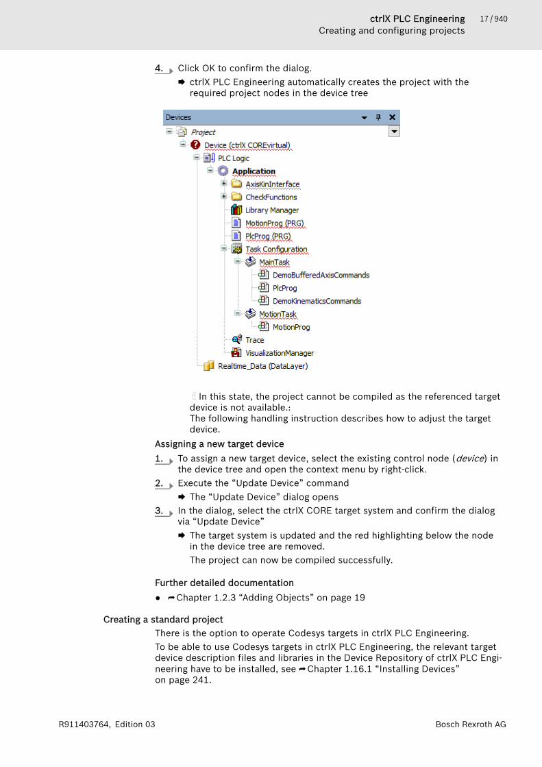
4. Click OK to confirm the dialog.🡆 ctrlX PLC Engineering automatically creates the project with the
required project nodes in the device tree
In this state, the project cannot be compiled as the referenced targetdevice is not available.: The following handling instruction describes how to adjust the targetdevice.
Assigning a new target device1. To assign a new target device, select the existing control node (device) in
the device tree and open the context menu by right-click.2. Execute the “Update Device” command
🡆 The “Update Device” dialog opens3. In the dialog, select the ctrlX CORE target system and confirm the dialog
via “Update Device”🡆 The target system is updated and the red highlighting below the node
in the device tree are removed.The project can now be compiled successfully.
Further detailed documentation● ⮫ Chapter 1.2.3 “Adding Objects” on page 19
Creating a standard projectThere is the option to operate Codesys targets in ctrlX PLC Engineering.To be able to use Codesys targets in ctrlX PLC Engineering, the relevant targetdevice description files and libraries in the Device Repository of ctrlX PLC Engi-neering have to be installed, see ⮫ Chapter 1.16.1 “Installing Devices”on page 241.
18 / 940 ctrlX PLC EngineeringCreating and configuring projects
Bosch Rexroth AG R911403764, Edition 03
To create a project, please use the project template “Standard project”.
Steps to create a standard project:1. Open ctrlX PLC Engineering and start the wizard to create a project via
the menu “File 🠂 New Project...”2. In the “New Project” dialog, select the “Standard project” template.
Enter a project name, e.g. myProject as well as the storage location inthe file system.Confirm the dialog with “OK”.🡆 The “Standard project” dialog opens.
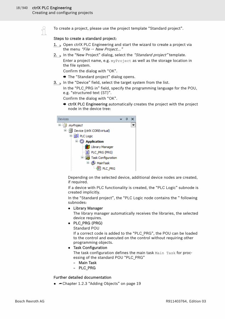
3. In the “Device” field, select the target system from the list.In the “PLC_PRG in” field, specify the programming language for the POU,e.g. “structured text (ST)”.Confirm the dialog with “OK”.🡆 ctrlX PLC Engineering automatically creates the project with the project
node in the device tree:
Depending on the selected device, additional device nodes are created,if required.If a device with PLC functionality is created, the “PLC Logic” subnode iscreated implicitly.In the “Standard project”, the “PLC Logic node contains the ” followingsubnodes:● Library Manager
The library manager automatically receives the libraries, the selecteddevice requires.
● PLC_PRG (PRG)Standard POUIf a correct code is added to the “PLC_PRG”, the POU can be loadedto the control and executed on the control without requiring otherprogramming objects.
● Task ConfigurationThe task configuration defines the main task Main Task for proc-essing of the standard POU “PLC_PRG”– Main Task– PLC_PRG
Further detailed documentation● ⮫ Chapter 1.2.3 “Adding Objects” on page 19
19 / 940ctrlX PLC EngineeringCreating and configuring projects
Bosch Rexroth AGR911403764, Edition 03
Creating an empty projectTo create an empty project, use the “Empty project” project template..
Steps to create an “empty” project:1. Open ctrlX PLC Engineering and start the wizard to create a project via
the menu “File 🠂 New Project...”2. Select the “Empty project” template.
Confirm the dialog with “OK”.🡆 ctrlX PLC Engineering automatically creates an empty project.
Add and configure your elements via the context menu of the project.
Further detailed documentation● ⮫ Chapter 1.7.1 “Device Tree and Device Editor” on page 47● ⮫ Chapter 1.2.3 “Adding Objects” on page 19● ⮫ Chapter 1.8 “Programming of Applications” on page 62● ⮫ Chapter 1.7 “Configuring I/O Links” on page 46● ⮫ Chapter 1.8.8 “Using Library POUs” on page 103● ⮫ Chapter 1.5 “Protecting and Saving a Project” on page 31● ⮫ Chapter “Dialog 'Project Settings' - 'Security'” on page 840
1.2.3 Adding ObjectsRequirement: A project is open. At least the highest node “<project name>” isshown in the “Devices” view (‘Device tree’) and in the “POUs” view.The following instructions indicate a few possibilities when creating objects inthe project.1. Select an entry in the Device tree or in the POUs tree, for example the
“Application” object.2. Select the command “Project 🠂 Add Object”.
🡆 Depending on the selected entry in the tree, PLC Engineering offers thesuitable objects for selection.
3. For example, select the object “POU” and, in the dialog box “Add POU”which then appears, select the type “Program” with implementation lan-guage “Structured Text (ST)” and name "prog".🡆 After clicking on “Add”, PLC Engineering inserts a program object
“prog” in the device tree below “Application”.4. Select an object in the tree and select the command “Properties” in the
context menu.🡆 The dialog box “Properties” appears with the object-relevant catego-
ries. If you use a user management system you can, for example,restrict access to the object here.
5. Select an entry in the tree under which you would like to create a folder inorder to collect certain objects in it. Please note: you cannot structure thearrangement of device nodes and device objects through folders that youhave created yourself.
6. Select the command “Add Folder” in the context menu and, in the dialogbox that appears, define a name for the new folder. Click on “OK”.🡆 The folder appears in the tree.
7. Select an object in the tree and shift it by dragging it with the mousewithin the tree to another position, for example into the folder.
20 / 940 ctrlX PLC EngineeringCreating and configuring projects
Bosch Rexroth AG R911403764, Edition 03
8. Do not select an object in the Device tree; instead, set the focus on anydesired free position in the PLC Engineering interface. Select the com-mand “Project 🠂 Add Object” and then, for example, the object “TextList”.🡆 The object “Text List” is inserted in the “POUs” view!
See also● ⮫ Chapter “Creating a standard project” on page 17● ⮫ Chapter “Command ‘Add Folder’” on page 694● ⮫ Chapter “Command 'Properties'” on page 693
1.2.4 Changing the compiler versionThe version of the compiler with which code is generated in the current projectfor use on the target device is defined in the project settings.The compiler version is independent of the PLC Engineering version. Hence,constant application code is created from the source code when the compilerversion is set the same, even if this takes place from different PLC Engineeringversions.
NOTICE Pay attention to the setting “Do not update” on the“Compiler Version” tab in the “Project Environment”dialog box: if this is activated and you open an olderproject, for which the “Newest” compiler version is stillset, then PLC Engineering will continue to use the com-piler version used last in the old project. This alsoapplies if a different "current" version is defined in thenew environment!
If you open a project in which the newest compiler version is not set, the“Project Environment” dialog box appears with a corresponding note and thepossibility to update directly.Requirement: A project is open.1. Select the command “Project 🠂 Project Settings” and then the “Compile
Options” tab.2. Select the desired “Fix Version” and click on “OK”.
🡆 The change is immediately effective.See also● ⮫ Chapter 1.10.4 “Generating Application Code” on page 192● ⮫ Chapter “Dialog 'Project Settings' - 'Compileoptions'” on page 837● ⮫ Chapter “Dialog 'Project Environment' - 'Compiler Version'” on page 845
1.2.5 Opening a V3 ProjectRequirement: PLC Engineering is started (or a project is already open).1. Click “File 🠂 Open Project”.
21 / 940ctrlX PLC EngineeringCreating and configuring projects
Bosch Rexroth AGR911403764, Edition 03
2. In the “Open project” dialog, click any V3 project or project archive in thefile system. A file filter is located in the lower right corner of the dialog.Note: If necessary, you can open the project as write protected in order toprevent any accidental changes to the existing project file.If no other project is open, then the following cases are possible:● You have selected a project that was saved with a later PLC Engi-
neering version.This kind of project may include data that cannot be loaded. You canstill open the project, but you have to understand that the project canbehave unexpectedly because it cannot be interpreted completely.Objects that PLC Engineering could not load, either partially or com-pletely, are highlighted in red in the device tree with the text"[unknown]" or "[incomplete]". PLC Engineering cannot displayobjects in the editor that are unknown to the current version. PLC Engi-neering displays incomplete objects in the editor with a warning thatthe displayed contents may not correspond to the original. PLC Engi-neering cannot save incomplete projects as their original names. This isdisplayed by a write protection note in the upper right corner. You cansave the file as another name.
● You have selected a project that PLC Engineering did not save properlyafter the last change, but the project option “Auto Save” was activated:The dialog “Auto Save Backup” opens for handling the backup.
● You have selected a project that is write-protected: You can either openthe project in write-protected mode or remove the write protection.
● You have selected a project that is password-protected. You areprompted for the password.
● You have selected a project that is protected by a security key. If thesecurity key is not plugged into the computer, then you are promptedto plug it in. Otherwise PLC Engineering opens the project without anyinformation about the protection.
● You have selected a project that contains a package (add-on) or plug-inspecific POU. In addition, the project was saved with a PLC Engi-neering installation that also had the relevant add-ons and plug-insinstalled. However,the add-ons and plug-ins are not installed in the cur-rent PLC Engineering installation.A dialog opens with information that the project cannot be loaded withall POUs. The missing add-ons and plug-ins are listed with the versioninformation. You can cancel opening the project and then perform aninstallation.
🡆 The “Project Environment” dialog opens.3. Check the updates provided in the “Project Environment” dialog. For proj-
ects that were created with very old V3 versions, information may be dis-played how to replace specific objects in order to continue using theproject. Depending on whether you leave the project as it is or continuedevelopment under up-to-date conditions, you perform updates or you donot. After each update, a login without download or online change is nolonger possible.🡆 The project opens.
See also● ⮫ Chapter “Dialog 'Options' – 'Load and Save'” on page 857● ⮫ Chapter 1.5.1 “Setting up Write Protection” on page 34● ⮫ Chapter 1.5.2 “Assigning Passwords” on page 35● ⮫ Chapter “Command ‘Open Project’” on page 654
22 / 940 ctrlX PLC EngineeringCreating and configuring projects
Bosch Rexroth AG R911403764, Edition 03
1.2.6 Configuring a ProjectYou can configure your PLC Engineering project using the following dialogs:● “Project Settings”: Basic settings on the behavour of editors and of the com-
piler, on user management etc.● “Project Information”: Adding of individual and tagging information to the
project● “Project Environment”: Defining which versions of the external and internal
modules should be used, with the aim of achieving up-to-dateness and com-patibility with each other.
See also● ⮫ Chapter “Dialog 'Project Settings'” on page 835● ⮫ Chapter “Object 'Project Information'” on page 622● ⮫ Chapter “Dialog 'Project Environment'” on page 845
Retrieving and Editing Project InformationYou can use the “Project Information” object to retrieve information about yourproject and the associated file, and edit certain information.The object contains information about● File attributes● Meta-information, such as manufacturer, title, or author● Properties with keys● Statistics● Licensing● Signing: This way of signing translated libraries is deprecated, and for
security reasons should only be used if compatibility with older versions isrequired. If this method is used, then later you can use a public key token toverify that the library was last signed by the library vendor. As a libraryvendor, it is therefore crucial that you make the public key used available tothe customer, for example in the documentation.
PLC Engineering saves the project information as an object within the project.When you transfer a project to another system, the “Project Information” objectis transferred with it. There is no need for a project archive.You can use property keys to access the project information externally via func-tion blocks. For a library project, you can also query information about thelicensing.
Editing meta-information1. Click “Project 🠂 Project Information”.
🡆 The “Project Information” dialog opens.2. Select the “Summary” tab.3. Specify your data in the input fields (example: 0.0.0.1 in the “Version”
input field).🡆 PLC Engineering creates a property with a key for each given value and
manages them on the “Properties” tab. For a library project, PLC Engi-neering still uses the properties and sorts later in the library repository.If you select the option for PLC Engineering to create a functions blockfor these properties, then you can access the properties programmati-cally.
Creating functions for accessing properties1. Click “Project 🠂 Project Information”.
🡆 The “Project Information” dialog opens.
23 / 940ctrlX PLC EngineeringCreating and configuring projects
Bosch Rexroth AGR911403764, Edition 03
2. Select the “Automatically generate 'Project Information' POUs” option.
ExampleRequirement: The following property is defined.
Key = nProp1Type= numberValue= 3331. Select the “Automatically generate 'Project Information' POUs” option.2. Declare a property of the type DINT, for example showprop : DINT;.3. Call the function GetNumberProperty: showprop := GetNumberProp-
erty("nProp1"); 🡆 You are granted access to the value in the application.
Note: The functions that are created with the “Automatically generate 'ProjectInformation' POUs” option can be used only if the runtime system supports theWSTRING data type. If this is not the case, then instead you can apply the “Auto-matically generate 'Library Information' POUs” option. You can use the func-tions created in this way at least in the application to access properties. Thesefunctions are not registered in the runtime system.
Licensing library projectsIf your project is a library project, then you can activate the library licensing inuse here. The PLC Engineering Security Key is a dongle.Requirement: The project is a library project.1. Click “Project 🠂 Project Information”.
🡆 The “Project Information” dialog opens.2. Click the “Licensing” tab.3. Select the “Activate dongle licensing” option.4. Specify the dongle data in “Firm code”, “Product code”, “Activation URL”,
and “Activation mail”.🡆 The library is licensed.
Creating private key files1. Click “Project 🠂 Project Information”.2. Click the “Signing” tab.3. Click the “Create Private Key File” button.
🡆 The “Create Private Key File” dialog opens.4. Select a safe location, e.g. D:\for lib developers only
\mycomp_libkey.libpk and exit the dialog with “Save”.
See also● ⮫ Chapter “Object 'Project Information'” on page 622
Making Project SettingsYou can configure settings that affect the behavior of PLC Engineering and thatof certain editors in the “Project Settings” object. The settings are validthroughout the project and are applied immediately for active editors. You canalso access the dialog boxes of the object with the command “Project🠂 Project Settings”.
24 / 940 ctrlX PLC EngineeringCreating and configuring projects
Bosch Rexroth AG R911403764, Edition 03
PLC Engineering saves the project settings as an object directly in the project.If you then transfer a project to another system, the “Project Settings” object isalso transferred with it, without a project archive being required.See also● ⮫ Chapter 1.2.4 “Changing the compiler version” on page 20● ⮫ Chapter “Analyzing Code Statically” on page 121● ⮫ Chapter “Command 'Project Settings'” on page 699● ⮫ Chapter “Dialog 'Project Settings' - 'SFC'” on page 835● ⮫ Chapter “Dialog 'Project Settings' - 'Users and Groups'” on page 836● ⮫ Chapter “Dialog 'Project Settings' - 'Compileoptions'” on page 837● ⮫ Chapter “Dialog 'Project Settings' - 'Compiler Warnings'” on page 838● ⮫ Chapter “Dialog 'Project Settings' - 'Page Setup'” on page 839● ⮫ Chapter “Dialog 'Project Settings' - 'Security'” on page 840● ⮫ Chapter “Dialog 'Project Settings' - 'Static Analysis Light'” on page 841● ⮫ Chapter “Dialog 'Project settings' - 'Visualization'” on page 843● ⮫ Chapter “Dialog 'Project Settings' - 'Visualization Profile'” on page 844
1.2.7 Retrieving and Editing Project InformationYou can use the “Project Information” object to retrieve information about yourproject and the associated file, and edit certain information.The object contains information about● File attributes● Meta-information, such as manufacturer, title, or author● Properties with keys● Statistics● Licensing● Signing: This way of signing translated libraries is deprecated, and for
security reasons should only be used if compatibility with older versions isrequired. If this method is used, then later you can use a public key token toverify that the library was last signed by the library vendor. As a libraryvendor, it is therefore crucial that you make the public key used available tothe customer, for example in the documentation.
PLC Engineering saves the project information as an object within the project.When you transfer a project to another system, the “Project Information” objectis transferred with it. There is no need for a project archive.You can use property keys to access the project information externally via func-tion blocks. For a library project, you can also query information about thelicensing.
Editing meta-information1. Click “Project 🠂 Project Information”.
🡆 The “Project Information” dialog opens.2. Select the “Summary” tab.3. Specify your data in the input fields (example: 0.0.0.1 in the “Version”
input field).🡆 PLC Engineering creates a property with a key for each given value and
manages them on the “Properties” tab. For a library project, PLC Engi-neering still uses the properties and sorts later in the library repository.If you select the option for PLC Engineering to create a functions blockfor these properties, then you can access the properties programmati-cally.

25 / 940ctrlX PLC EngineeringCreating and configuring projects
Bosch Rexroth AGR911403764, Edition 03
Creating functions for accessing properties1. Click “Project 🠂 Project Information”.
🡆 The “Project Information” dialog opens.2. Select the “Automatically generate 'Project Information' POUs” option.
ExampleRequirement: The following property is defined.
Key = nProp1Type= numberValue= 3331. Select the “Automatically generate 'Project Information' POUs” option.2. Declare a property of the type DINT, for example showprop : DINT;.3. Call the function GetNumberProperty: showprop := GetNumberProp-
erty("nProp1"); 🡆 You are granted access to the value in the application.
Note: The functions that are created with the “Automatically generate 'ProjectInformation' POUs” option can be used only if the runtime system supports theWSTRING data type. If this is not the case, then instead you can apply the “Auto-matically generate 'Library Information' POUs” option. You can use the func-tions created in this way at least in the application to access properties. Thesefunctions are not registered in the runtime system.
Licensing library projectsIf your project is a library project, then you can activate the library licensing inuse here. The PLC Engineering Security Key is a dongle.Requirement: The project is a library project.1. Click “Project 🠂 Project Information”.
🡆 The “Project Information” dialog opens.2. Click the “Licensing” tab.3. Select the “Activate dongle licensing” option.4. Specify the dongle data in “Firm code”, “Product code”, “Activation URL”,
and “Activation mail”.🡆 The library is licensed.
Creating private key files1. Click “Project 🠂 Project Information”.2. Click the “Signing” tab.3. Click the “Create Private Key File” button.
🡆 The “Create Private Key File” dialog opens.4. Select a safe location, e.g. D:\for lib developers only
\mycomp_libkey.libpk and exit the dialog with “Save”.
See also● ⮫ Chapter “Object 'Project Information'” on page 622
26 / 940 ctrlX PLC EngineeringExporting and Transferring a Project
Bosch Rexroth AG R911403764, Edition 03
1.2.8 Making Project SettingsYou can configure settings that affect the behavior of PLC Engineering and thatof certain editors in the “Project Settings” object. The settings are validthroughout the project and are applied immediately for active editors. You canalso access the dialog boxes of the object with the command “Project🠂 Project Settings”.PLC Engineering saves the project settings as an object directly in the project.If you then transfer a project to another system, the “Project Settings” object isalso transferred with it, without a project archive being required.See also● ⮫ Chapter 1.2.4 “Changing the compiler version” on page 20● ⮫ Chapter “Analyzing Code Statically” on page 121● ⮫ Chapter “Command 'Project Settings'” on page 699● ⮫ Chapter “Dialog 'Project Settings' - 'SFC'” on page 835● ⮫ Chapter “Dialog 'Project Settings' - 'Users and Groups'” on page 836● ⮫ Chapter “Dialog 'Project Settings' - 'Compileoptions'” on page 837● ⮫ Chapter “Dialog 'Project Settings' - 'Compiler Warnings'” on page 838● ⮫ Chapter “Dialog 'Project Settings' - 'Page Setup'” on page 839● ⮫ Chapter “Dialog 'Project Settings' - 'Security'” on page 840● ⮫ Chapter “Dialog 'Project Settings' - 'Static Analysis Light'” on page 841● ⮫ Chapter “Dialog 'Project settings' - 'Visualization'” on page 843● ⮫ Chapter “Dialog 'Project Settings' - 'Visualization Profile'” on page 844
1.3 Exporting and Transferring a ProjectExport and import functions are available to you for the exchange of the datafrom PLC Engineering projects with other programs.An exchange of PLC Engineering projects between PLC Engineering develop-ment systems takes place by way of a copy of the project file (*.project) orproject archive (*.projectarchive).See also● ⮫ Chapter 1.3.1 “Exporting and Importing Projects” on page 26● ⮫ Chapter 1.3.2 “Transferring Projects” on page 27
1.3.1 Exporting and Importing ProjectsPLC Engineering offers commands for the export and import of objects to andfrom a file. Two possibilities are available to you here:● Export to or import from a PLC Engineering XML file (*.export)
This format is completely compatible with the PLC Engineering projectformat. The objects are saved in a machine-readable XML format.
● Export to or import from an XML file in the PLCopen format (*.xml)You can use this format to exchange information with other programs (forexample program editors or documentation tools). PLCopen XML defines asubset of the elements known in PLC Engineering. 100% compatibility isthus not guaranteed.
Exporting ProjectsRequirement: A project is open in PLC Engineering.1. Select the command “Project 🠂 Export…” or “Project 🠂 Export
PLCopenXML”2. Select the objects that you wish to export in the dialog box “Export” or
“Export PLCopenXML”.

27 / 940ctrlX PLC EngineeringExporting and Transferring a Project
Bosch Rexroth AGR911403764, Edition 03
3. Click on “OK”.4. Enter the file name and the location and click on “Save”.
Importing ProjectsRequirement: A project is open in PLC Engineering.1. Select the command “Project 🠂 Import…” or “Project 🠂 Import
PLCopenXML”.2. In the dialog box “Import” or “Import PLCopenXML”, select the export file
that you wish to import.🡆 A dialog box opens and displays the objects in a tree structure, which
can be inserted at this point.3. Select the object in the object tree, under which the objects to be
imported are to be inserted.4. Select the objects and click “OK”.
🡆 The objects are added to the existing object tree.
See also● ⮫ Chapter “Dialog 'Options' - 'PLCopenXML'” on page 858● ⮫ Chapter “Command 'Export PLCopenXML'” on page 706● ⮫ Chapter “Command 'Export'” on page 705● ⮫ Chapter “Command 'Import PLCopenXML'” on page 706● ⮫ Chapter “Command 'Import'” on page 705
1.3.2 Transferring ProjectsIf you wish to transfer a project to another computer and connect from there tothe same PLC, without an online change or download being required, observethe following points.● Make sure that the project requires only fixed versions of libraries (excep-
tion: interface libraries), visualization profile and compiler.● Make sure that the boot application is up to date.Then create a project archive, which you unpack on the other computer.
Transferring a project to another systemRequirement: A project is open on computer “PC1” that you transfer to anothercomputer “PC2” and reconnect from there to the same controller.1. Make sure that only libraries with fixed versions are integrated in the
project, with the exception of pure interface libraries. To do this, open the“Library Manager” and check all entries that have a “*” instead of a fixedversion specification.
2. Make sure that a fixed compiler version is set in the project settings. Tocheck, select “Project 🠂 Project Settings” and the “Compiler Options”category.
3. Make sure that a fixed visualization profile is defined in the project set-tings. To check, select “Project 🠂 Project Settings” and the “VisualizationProfile” category.

28 / 940 ctrlX PLC EngineeringComparing Projects
Bosch Rexroth AG R911403764, Edition 03
4. Make sure that the application that is presently open is the same as thatwhich is presently in use on the PLC. This means that the “boot applica-tion” must be identical to the project in the programming system. Tocheck, look at the project name in the title bar of the programming systemwindow: If an asterisk is displayed behind the name, this means that theproject has been modified, but not yet saved. It is then possible that theapplication and boot application do not correspond!In this case, first create a (new) boot application. It depends on the PLCand the application properties, whether this takes place automaticallyduring the download of the application. For explicit creation, select thecommand “Online 🠂 Create boot application”. Then execute a downloadwith the help of the commands “Online 🠂 Login” and “Online 🠂 Load”.After that, start the application on the controller with the command“Debug 🠂 Start”.🡆 Now the desired application is running on the PLC, to which you wish
to reconnect from the same project later on PC2.5. Generate a project archive: Select “File 🠂 Project Archive 🠂 Save/Send
Archive”. In the “Project Archive” dialog box, also select the followinginformation:● “Download information files”● “Library profile”● “Referenced devices”● “Referenced libraries”● “Visualization profile”Save the project archive in a place that is accessible by PC2.
6. Log out from the controller: To do this, select “Online 🠂 Logout”. You canstop and restart the PLC without reservations, before you reconnect fromPC2.
7. Extract the project archive to PC2: Select “File 🠂 Project Archive🠂 Extract Archive” and open the archive saved above. In the “ExtractProject Archive” dialog box, activate the same information as describedabove when generating the archive.
8. Open the project and log in to PLC “xy” again.🡆 PLC Engineering does not demand an online change or download; the
project runs.
See also● ⮫ Chapter “Dialog 'Project Settings' - 'Compileoptions'” on page 837● ⮫ Project Settings - Visualization Profile● ⮫ Chapter “Command 'Create Boot Application'” on page 721● ⮫ Chapter “Command 'Save/Send Archive'” on page 658
1.4 Comparing ProjectsYou can compare the currently open project with another project – a referenceproject. The differences in contents, properties, or access rights are detectedand shown in a comparison view.Clicking “Project 🠂 Compare” opens the “Project Compare” dialog for you toconfigure and run the comparison. Then the result is shown in the comparisonview “Project Compare - Differences” where the objects are aligned in a treestructure. Objects that indicate differences from the respective referenceobject are identified by colors and symbols. This is how you detect whether ornot the contents, properties, or access rights are different.
29 / 940ctrlX PLC EngineeringComparing Projects
Bosch Rexroth AGR911403764, Edition 03
For differences in the contents, you can also open the detailed compare view“Project Compare - <object name> Differences” in order to zoom into theobject. In the detailed compare view, the contents of the object and referenceobject are displayed or their source code aligned. The detected differences aremarked. Previously opened views are not closed. In this way, you can have anynumber of comparison views open and read them, in addition to the projectcompare view.You can accept the detected differences from the reference project into the cur-rent project. This is possible only from the reference project into the openproject. To do this, you activate differences (for example in the code) thatshould be accepted in the current project with the commands , , or inthe active comparison view for accepting. These positions are highlighted inyellow. Make sure that any other open compare views are inactive (write-pro-tected, read-only). therefore, you can activate differences to be accepted inexactly one comparison view only. When exiting the active compare view, if youconfirm that the differences that are activated for acceptance are actuallyaccepted into the current project, then the current project is modified.In order to exit the project comparison completely, close the project compareview.See also● ⮫ Chapter “Command 'Compare'” on page 701
1.4.1 Creating a Comparison ViewRequirement: You have made changes in your current project and wish, forexample, to compare it with the last-saved version. In the meantime, forexample, you have added further POUs, removed a POU, changed single lines ofcode or the object properties in function blocks.1. Select the command “Project 🠂 Compare”.
🡆 The “Project Comparison” dialog box opens.2. Enter the path to the reference project, for example the path to the last-
saved version of your current project.3. Leave the activation of the comparison option “Ignore Spaces” as it is.4. Click on “OK”.
🡆 PLC Engineering opens the comparison view. Title: “ Project Compar-ison – Differences”. The Device trees of the current project and the ref-erence project are displayed alongside each other and the changedobjects are marked in color.
5. Select an object marked in blue in the tree of the reference project(right). The current project no longer contains this object.Click on “Accept Single”🡆 PLC Engineering adds the object to the tree of the current project
(left). The line has a yellow background. appears in the middlecolumn.
6. Select an object marked in green in the tree of the current project (left).The reference project does not contain this object.Click on “Accept Single”🡆 PLC Engineering removes the object again from the tree of the current
project (left). The line has a yellow background. appears in themiddle column.
7. If PLC Engineering detects changes in the content of an object that is con-tained in both the current project and the reference project, this is indi-cated by red lettering. You can then switch to the detailed comparisonview for the object by double-clicking on the object.

30 / 940 ctrlX PLC EngineeringComparing Projects
Bosch Rexroth AG R911403764, Edition 03
8. Close the comparison view and answer the query whether the changesmade are to be saved with “Yes”.🡆 The changes become effective in the project.
See also● ⮫ Chapter 1.4 “Comparing Projects” on page 28● ⮫ Chapter “Command 'Compare'” on page 701● ⮫ Chapter 1.4.2 “Opening the Detailed Compare View” on page 30
1.4.2 Opening the Detailed Compare ViewRequirement: For example, a user modified the code in a POU of the currentproject. You have performed the project comparison by clicking “Project🠂 Compare”. The project compare view shows this POU highlighted in red inthe aligned in the project tree.1. Double-click the line of the aligned POU versions.
🡆 The compare view switches to the detailed compare view of the POU.The modified code lines are highlighted in gray and written in red.
2. Click .🡆 Code lines with changes (red) are extended by two lines: an line with
insert (left, green) and a line with delete (right, blue).3. Click again.
🡆 The code line is marked again as modified.4. Move the mouse pointer to the code line marked as modified and click
“Accept Single”.🡆 The code line from the reference project is activated for acceptance
into the current project.5. Click .
🡆 The project compare view opens for the entire project. It is write-pro-tected (read-only) to prevent you from activating differences for accept-ance. The link highlighted in yellow above the tree view also indicatesthis.
6. Click the link: “Project compare view is read only because there areuncommitted changes in another view. Click here to switch to the modi-fied view.”🡆 The detailed compare view opens again. The unconfirmed changes are
highlighted in yellow.7. Click in the tab of the view and confirm that the changes should be
saved.🡆 The detail project view is closed and the POU is overwritten. Now it
corresponds to the POU of the reference project. The project view isactive again so that you can continue working with project compare.
If you do not click the link, but click instead to close the editor of the projectcompare view, then you will also confirm the acceptance of changes into thecurrent project. The detail changes are accepted and then the project compareis closed completely.See also● ⮫ Chapter 1.4 “Comparing Projects” on page 28● ⮫ Chapter “Command 'Compare'” on page 701● ⮫ Chapter 1.4.1 “Creating a Comparison View” on page 29
31 / 940ctrlX PLC EngineeringProtecting and Saving a Project
Bosch Rexroth AGR911403764, Edition 03
1.5 Protecting and Saving a ProjectGeneral information about write and access protectionYou can protect a project against unintentional changes by means of access andwrite protection. You can also provide it with read protection (knowledge pro-tection).Write protection:The following options are available for providing the entire project with simplewrite protection:● Select the “Open Read-Only” option when opening the project.● You set the “Released” status in the “Project Information”.● You select the "read-only" option in the properties of the project file in the
local file system.In order to protect only certain objects in a project against changes, or to allowaccess only to certain users, you can use a user and access rights management(see below). Some target devices similarly support user and rights manage-ment. The access of PLC Engineering to objects and files of the target devicecan thus be restricted.However, write protection and access protection do not serve as protection ofexpertise of the POUs. Both PLC Engineering itself, automation platform plug-ins and persons with knowledge of the project file format can view or modifyfunction blocks created with PLC Engineering.Knowledge protection:Knowledge protection of a project is done by encrypting the project file. Eitherwith a project password, the PLC Engineering Security Key (dongle), or a certif-icate. We recommend protection by means of the key or the certificate becausein this case no secret needs to be shared between authorized users. Thedesired type of project encryption is enabled in the project settings.You can attain knowledge protection of a library by providing it as a target-system-independent "protected library" (*.compiled-library, *.compiled-library-v3). The library file no longer contains source code in this format, butonly encrypted precompile context. The compiler is still able to interpret thesedata. Whether access by other PLC Engineering components or additional plug-ins is possible depends on their functionality and is to be observed in indi-vidual cases. Signing can increase protection even more.See also● ⮫ “User management and password manager” on page 32● ⮫ Chapter 1.5.3 “Protecting Projects Using a Dongle” on page 36● ⮫ Chapter 1.5.2 “Assigning Passwords” on page 35● ⮫ Chapter 1.5.5 “Protecting Objects in the Project by Access Rights”
on page 37● ⮫ Chapter 1.15.1 “Information for Library Developers” on page 238● ⮫ Chapter 1.8.18 “Encrypting an Application” on page 132
Encryption with certificatesIn PLC Engineering, projects and applications can be encrypted with certifi-cates and signed in order to protect them from unauthorized access.To do this, you can configure specific security settings for each individual userprofile. These settings are always used automatically when the user works withPLC Engineering projects. Therefore, they do not have to be redone for eachproject. The general configuration of the security features for a user profile isdone in the “Security Screen” view of PLC Engineering. See the individualinstructions below.
32 / 940 ctrlX PLC EngineeringProtecting and Saving a Project
Bosch Rexroth AG R911403764, Edition 03
You can also encrypt a project file or an application for download or onlinechange directly with a certificate:● User-independent encryption for the current project is configured in the
“Security” category of the “Project Settings”.● User-independent encryption of the application is configured in the “Proper-
ties” dialog of the application object.
NOTICE When you encrypt a project, an application, or onlinecode with a certificate, you will always require the certif-icate with a private key in order to open the object again.
If the CODESYS Security Agent add-on product is installed, then the “SecurityScreen” view provides an additional tab: “Devices”. This allows for the configu-ration of certificates for the encrypted communication with controllers.Certificates, Windows Certificate StoreAll available certificates are located in the Windows Certificate Store(“certmgr”) on your computer. There are two types of keys:● Certificates with private keys
– for file decryption– for digital signatures
● Certificates with public keys– for file encryption– for verifying digital signatures
The local Windows Certificate Store is usually filled with certificates by the ITadministrator of the computer. Certificates are either created using specialtools or the creation is requested by a trusted certification authority (CA).If you receive a certificate file that you need to install yourself in the WindowsCertificate Store, then double-click the file in the store directory. Depending onthe type (certificate with private or public key only), the appropriate importwizard will appear.See also● ⮫ Chapter 1.17.1 “General Information” on page 242● ⮫ Chapter 1.5.7 “Encrypting Projects with Certificates” on page 40
User management and password managerUser accounts with different rights can be managed in PLC Engineering. Foreach account you can define the actions with which the user can access aproject object.The user management is configured in the “Project settings” in the category“Users and Groups”.Before the creation of users and groups, please note the following:● Rights can only be assigned to user groups. Therefore, you must assign each
user to a group.● There is automatically always a group Everyone and by default every user
and every other group is initially a member of this group. Thus each useraccount is automatically equipped with at least the defined standard rights.You cannot delete the group Everyone, you can only rename it, and youcannot remove members from this group.Caution: by default Everyone does not have the right to change the currentuser, group and rights configuration!
● There is automatically always a group Owner containing a user Owner. FromV3.5 only the Owner initially has the right to change the current user, groupand rights configuration in a new project! Hence, only Owner can assign thisright to another group.

33 / 940ctrlX PLC EngineeringProtecting and Saving a Project
Bosch Rexroth AGR911403764, Edition 03
Initially the Owner can log in with user name Owner and an empty password.You can add further users to the group Owner or remove users from it, but atleast one member must be retained. Like Everyone, you cannot delete thegroup Owner and it always possesses all access rights. This prevents aproject from being rendered unusable by denying all access rights to allgroups.You can rename both the group Owner and the user Owner.
● If the programming system or a project is restarted, no user is initiallylogged in to the project. However, the user can then log in via a certain useraccount with user name and password in order to obtain the access rightsdefined for the account.
● Each project has its own user management! Therefore, in order to obtaincertain access rights to a library integrated into the project, for example, theuser must explicitly log in to the library project.Users and groups defined in different projects are not the same, even if theyhave the same names.
● A user management in a project only makes sense if it is connected with cor-responding rights assignment for the access to project and objects. Theproject rights are generally managed in the dialog box “Rights” of the “UserManagement”. You can also change the access rights to an individual projectobject on the “Access control” tab of the “Properties” of the object.
● There are standard menu commands under “Project 🠂 User Management”for logging into and out of a project as a defined user. A password managerpermits the management of the login data on your computer.
From V3.5 only the Owner initially has the right to change the current user,group and rights configuration in a new project! Hence, only Owner can assignthis right to another group.
NOTICE PLC Engineering stores the user passwords inaccessibly.If you forget a password, the user account becomesunusable. If you forget the Owner password, the entireproject may become unusable!
Password managerThe password manager enables you to save login data records that you enterduring the login procedures for projects. It is accessible via a button in thelogin dialog box and offers fast access to the login data currently required. Thiscan be helpful, for example, if you are working in parallel on several library proj-ects that are protected by different passwords.The password manager itself is protected by an individual master password. Ifyou wish to use the password manager for the first time, PLC Engineeringrequests you to define this password in the password manager configurationdialog box. PLC Engineering notes the master password until you terminate thecurrent PLC Engineering session. You must always input the password whenyou wish to log in to the password manager for the first time during a new ses-sion, or after you have changed it.See also● ⮫ Chapter 1.5.5 “Protecting Objects in the Project by Access Rights”
on page 37● ⮫ Chapter 1.5.6 “Logging in via User Account and Password Manager”
on page 38● ⮫ Chapter 1.10.3 “Handling of Device User Management” on page 188
Rights managementRights management for access to a project and objects in a project is necessaryin order to make a user management meaningful.

34 / 940 ctrlX PLC EngineeringProtecting and Saving a Project
Bosch Rexroth AG R911403764, Edition 03
The rights for a project are generally managed in the “Rights” editor of the“User Management”. You can also change the access rights to an individualproject object on the “Access control” tab of the “Properties” dialog box of theobject.Before assigning rights, please observe the following:● In a new project PLC Engineering always sets all rights for the execution of
actions on objects with the default value 'allowed' (standard right). The onlyexception to this is the right to change the current user, group and rightsconfiguration. Initially only the 'Owner' group has this right.
● If you are member of a group that is permitted to change rights, you can dothis at any time for each right when working further on a project. You changea right by switching between 'allowed' and 'forbidden' or by resetting to thedefault.
See also● ⮫ Chapter 1.5.4 “Setting up a User Management” on page 37● ⮫ Chapter 1.5.5 “Protecting Objects in the Project by Access Rights”
on page 37
Filing, savingProvide the project file with the desired protection before saving it in the filesystem; see above. For a read-only project file you are given various options sothat you can still save the file, depending on the type of write protection.If the project is to be opened later in an older PLC Engineering version, itmakes sense to save the project for precisely this version (file type), since PLCEngineering will also inform you immediately about possible losses of data inthe course of saving it.If you wish to save library projects, please observe the rules for the creation oflibraries. Also consider the possibility of installing a library directly in a libraryrepository.If you wish to continue to use a project on another computer, it makes sensenot only to save the project file, but also to create a project archive from all rel-evant auxiliary files.You can make a setting so that a backup copy of this project is created eachtime the project is saved. In addition you can configure PLC Engineering so thatprojects are generally automatically saved at certain time intervals.If you wish to keep projects in a source control system, observe the corre-sponding add-ons for PLC Engineering. For example, the link to SVN is sup-ported.See also● ⮫ Chapter “Dialog 'Options' – 'Load and Save'” on page 857● ⮫ Chapter 1.3 “Exporting and Transferring a Project” on page 26● ⮫ Chapter 1.5.8 “Save project” on page 42● ⮫ Chapter 1.5.9 “Saving/Sending the Project Archive” on page 43● ⮫ Chapter 1.15.1 “Information for Library Developers” on page 238● ⮫ Chapter 1.5.10 “Linking a project to the source control system”
on page 44
1.5.1 Setting up Write ProtectionA project can be protected against inadvertent changes by means of access andwrite protection. In addition, however, it can also be provided with read protec-tion (know-how protection). You have the following options:

35 / 940ctrlX PLC EngineeringProtecting and Saving a Project
Bosch Rexroth AGR911403764, Edition 03
Open the project with write protectionRequirement: No project is opened.1. Select “File 🠂 Open Project”.
🡆 The dialog box “Open project” appears.2. Select the project.3. Click on the arrow button next to the “Open” button and select “Open
read-only” from the menu.🡆 PLC Engineering opens the project. At the top right in the main window
a line appears “'Project file cannot be saved…'”. You must now selectone of the offered options if you wish to save the project file.
See also● ⮫ Chapter 1.2.5 “Opening a V3 Project” on page 20
Providing projects with the attribute 'Released'Requirement: project is opened.1. Select “Project 🠂 Project Information”, then the “Summary” tab.2. Activate the option “Released”, confirm with “OK”.3. Save the project, for example with [Ctrl]+[S].4. Open the project again with the command “File 🠂 Open Project”.
🡆 PLC Engineering opens the project. At the top right in the main windowa line appears “'Project file cannot be saved…'”. You can now directlyremove the status “Released” again via the offered option if you wish tosave the project file.
See also● ⮫ Chapter “Object 'Project Information'” on page 622
Providing a project in the file system with the property 'Read-only'Provide the project file in its local file system with the property attribute'Read-only'.🡆 If you had already opened the project and you now attempt to save it
under the same name, a dialog box appears informing you about theexistent write protection. This dialog box provides you with the fol-lowing options:You can save the project under another name or another path using thebutton “Save As…”.You can deliberately save the project under the same name and pathand thus overwrite the existing version in the file system using thebutton “Overwrite”.You can abort the saving procedure using the “Cancel” button, forexample to remove the write protection on the disk.If you re-open the project, a line appears at the top right in the mainwindow 'The project cannot not be saved…'. You must nowselect one of the offered options if you wish to save the project file.
See also● ⮫ “General information about write and access protection” on page 31
1.5.2 Assigning PasswordsRequirement: The project is open.

36 / 940 ctrlX PLC EngineeringProtecting and Saving a Project
Bosch Rexroth AG R911403764, Edition 03
1. Click “Project 🠂 Project Settings” and then select the “Security” category.🡆 The dialog “Project Settings / Security” opens.
2. Select the “Encryption” option.🡆 The option fields “Password”, “Dongle”, and “Certificates” are select-
able.3. Select the option “Password”.
🡆 The input fields for the encryption password appear.4. Enter the encryption password in the input field “New password”.5. Enter the encryption password for confirmation in the input field “Confirm
new password”.6. Click “OK”.
🡆 PLC Engineering saves the encryption password for the project. Youmust enter this password in order to be able to open the project again,even if it is to be loaded as a library reference.
CAUTION If you no longer know the encryption password, you canno longer open or restore the project!
See also● ⮫ Chapter “Dialog 'Project Settings' - 'Security'” on page 840● ⮫ Chapter 1.5 “Protecting and Saving a Project” on page 31
1.5.3 Protecting Projects Using a DongleRequirement: The project is opened and you have connected the PLC Engi-neering Security Key (dongle) to your computer.1. Click “Project 🠂 Project Settings” and then select the “Security” category.
🡆 The dialog “Project Settings / Security” opens.2. Select the “Encryption” option.
🡆 The option fields “Password”, “Dongle”, and “Certificates” are select-able.
3. Select the option “Dongle”.🡆 The dialog with the drop-down list “Registered Dongles” and the but-
tons “Add”, “Remove”, “Comment” and “Flash” opens.4. Click “Add”.
🡆 The “Add registered dongle” dialog opens.5. Select the PLC Engineering Security Key (dongle) from the “Dongle” drop-
down list and optionally enter a comment.6. Click “OK”.
🡆 The added dongle is listed in the list “Registered Dongles”.7. Click “OK”.
🡆 The dongle is registered for the project. You must connect the dongleto your computer in order to be able to open the project again, even ifit is to be loaded as a library reference.
NOTICE If the PLC Engineering Security Key registered for theproject is lost, you can no longer open the project orrestore it.
See also● ⮫ Chapter “Dialog 'Project Settings' - 'Security'” on page 840● ⮫ Chapter 1.5 “Protecting and Saving a Project” on page 31
37 / 940ctrlX PLC EngineeringProtecting and Saving a Project
Bosch Rexroth AGR911403764, Edition 03
1.5.4 Setting up a User ManagementThis concerns a user management for a PLC Engineering project file. Visualiza-tions and devices can have their own user management.The following guide describes how you can adapt the user management for thefirst time in a project. It deals with the definition of a user and a group to whichhe belongs.Requirement: the project for which the user management is to be set up isopened. There is no adapted user configuration yet.1. Select “Project Settings 🠂 Users and Groups” and then the “Users” tab.
The user Owner is already created by default.2. Click on “Add”.
🡆 The dialog box “Add User” appears.3. Enter a login name, for example 'Dev1', and a password. Leave the option
“Activated” activated. Click on “OK”.🡆 On creating a group for the first time, PLC Engineering now requests
you to authenticate yourself to perform this action.In this case, enter 'Owner' as the “current user”. Do not enter a “pass-word”, just click on “OK”.The user Dev1 appears in the list and is automatically a member ofthe group 'Everyone'.
4. Change to the tab “Groups”, in order to add the user to a new group.🡆 The groups Everyone and Owner have already been created.
5. Click on “Add” in order to open the dialog box “Add Group”.6. Specify at least one name for the new group, for example 'Developers'.
Activate the checkbox next to the entry “User 'Dev1'” in the field “Mem-bers”. Click on “OK”.🡆 The group “Developers” now appears with has user member 'Dev1'.
7. Switch to the “Users” tab.🡆 The user “Dev1” now appears as a member of the groups 'Everyone'
and 'Developers'.You can take over the user management configuration from another project byusing the “Export/Import” functions in the dialog box “Project Settings”, cate-gory “Users and Groups”.See also● ⮫ Chapter 1.5 “Protecting and Saving a Project” on page 31● ⮫ “User management and password manager” on page 32● ⮫ Chapter “Dialog 'Project Settings' - 'Users and Groups'” on page 836● ⮫ Chapter 1.10.3 “Handling of Device User Management” on page 188
1.5.5 Protecting Objects in the Project by Access RightsProtection of individual objects by setting access rights in the “Rights” editor1. Select “Project 🠂 User Management 🠂 Rights”
🡆 The window of the “Rights” editor opens. On the left you can see theaction categories, on the right the currently existing user groups.
2. Expand the relevant action category and below it the action for which youwish to change a right.
3. Select the goal of the action in the “Actions” window. In the “Rights”window, select the group for which you would like to change the right.Multiple selection is possible.🡆 The buttons in the symbol bar are active.
38 / 940 ctrlX PLC EngineeringProtecting and Saving a Project
Bosch Rexroth AG R911403764, Edition 03
4. Click on the appropriate button in order to change the right of the groupfor the action on the target object.🡆 PLC Engineering updates the symbol in front of the group according to
the new right. The right is immediately effective.See also● ⮫ Chapter “Dialog 'Permissions'” on page 819
Protection of individual objects by setting access rights in the object propertiesHere you can configure whether the members of a group have the right to view,edit or remove the object and to add/remove child objects to/from the object.1. Select the object in the navigator tree.2. In the context menu, select the command “Properties” and in the dialog
box select the category “Access Control”.3. In the table under “Groups, actions and permissions”, double-click on the
symbol of the right that you wish to change.🡆 A selection list of the possible rights appears: “Grant”, “Deny”, “Clear”.
4. Select the desired right and click on “Accept” or “OK”.🡆 The right is immediately effective for the action and group. The symbol
changes accordingly.See also● ⮫ Chapter “Dialog 'Properties' - 'Access Control'” on page 826
1.5.6 Logging in via User Account and Password ManagerLogging in to a project without using the password manager functionsRequirement: A project is open. You wish to log in as a defined user for thisproject or for a library integrated in it in order to edit one or the other with cer-tain rights. You have the required login data for the respective project or thelibrary.1. Select “Project 🠂 User Management 🠂 User Logon”.
🡆 The dialog box “Logon” opens.2. Select the project file from “Project/Library” and enter the required
access data “User name” and “Password”.3. Log in with “OK”.
🡆 If another user is already logged in, this user will automatically belogged out by the new login.
Setting a master password for the password managerRequirement: A project is open. The dialog box “Login” is open for you to log inas a defined user for a project or for a library integrated in the project. Youwish to use the password manager in order to save login data in it.1. Select “Project 🠂 User Management 🠂 User Logon”.2. In the dialog box “Logon”, click on the button .
🡆 If you are working for the first time with the password manager, thedialog box “Password Manager Configuration” opens.
3. Enter a character string as the future master password. Confirm it in thesecond line and click on “OK”.🡆 PLC Engineering notes the master password until you terminate the cur-
rent PLC Engineering session. You must always input this passwordwhen you wish to log in to the password manager for the first timeduring a new session, or after you have changed it.
39 / 940ctrlX PLC EngineeringProtecting and Saving a Project
Bosch Rexroth AGR911403764, Edition 03
NOTICE If you have forgotten your master password, you nolonger have any possibility to access the login dataalready saved! In this case you can only reset the pass-word manager. After that you must start again to savepasswords in the manager!
Saving login data in the password managerRequirement: A project is open. You wish to log in as a defined user for thisproject or for a library integrated in it in order to edit one or the other with cer-tain rights. You have the required login data for the respective project or thelibrary. These login data have not yet been saved in the password manager.1. Select “Project 🠂 User Management 🠂 User Logon”, in order to open the
“Logon” dialog box.2. Select the project file from “Project/Library”.3. Enter the user name and password for the project or the library.4. Click on the button .
🡆 If you are working for the first time with the password manager, youwill be requested to define a master password. Refer to the aboveguide 'Setting a master password for the password manager' for this.When you call the password manager for the first time in this PLC Engi-neering session, you will be requested to enter the master password.
5. Enter the master password when requested to do so.🡆 The password manager menu appears.
6. Select the option “Save the credentials locally on this computer”.🡆 The login takes place. The data are saved in the password manager.
Getting the login data from the password managerRequirement: A project is open. You wish to log in as a defined user for thisproject or for a library integrated in it in order to edit one or the other with cer-tain rights. The login data required for this are already saved in the passwordmanager.1. Select “Project 🠂 User Management 🠂 User Logon” in order to open the
“Logon” dialog box.2. Click on the button .
🡆 If you are working for the first time with the password manager, youwill be requested to define a master password. Refer to the aboveguide 'Setting a master password for the password manager' for this.When you call the password manager for the first time in this PLC Engi-neering session, you will be requested to enter the master password.
3. Enter the master password when requested to do so.🡆 The password manager menu appears.
4. Select the appropriate entry “Use the stored credentials for <username>”.🡆 The login takes place automatically with the data read from the pass-
word manager.
Opening the password manager, changing the master passwordRequirement: A project is open. You wish to open the password manager inorder to view and/or edit the entries or to change the master password. Youhave already logged in once with the master password.1. Select “Project 🠂 User Management 🠂 User Logon”, in order to open the
“Logon” dialog box.

40 / 940 ctrlX PLC EngineeringProtecting and Saving a Project
Bosch Rexroth AG R911403764, Edition 03
2. Click on the button .Select “Open the Password Manager”.🡆 The password manager window opens.
3. Click on “Change master password” and make the change.
Logging out from the projectRequirement: A project is open. A user is logged in, which is recognizable by aname entry in the field “Current User” in the status bar.
Select “Project 🠂 User Management 🠂 User Logoff”. Alternatively, double-click on the field “Current User” in the status bar.🡆 If the user is logged in to only one project, he will now be logged out
without further interaction. “(nobody)” appears again in the field “Cur-rent User” in the status barIf the user is logged in to several projects, the dialog box “Logoff”opens. There, select the specific project or library project from whichthe user is to be logged out.
See also● ⮫ “User management and password manager” on page 32● ⮫ Chapter “Command 'User management' – 'Log in User'” on page 707● ⮫ Chapter 1.5.4 “Setting up a User Management” on page 37
1.5.7 Encrypting Projects with CertificatesConfiguring a certificate for project file encryption in a user profileWhen a project is encrypted with a certificate, this certificate is needed fordecryption to open the project. You can assign this certificate to specific userprofiles. To do this, select the certificate from the Windows Certificate Store onthe “User” tab of the “Security Screen”.1. Double-click in the status bar or click “View 🠂 Security Screen”.
🡆 The “Security Screen” view opens.2. In the “User” tab, select the user profile for which the communication will
be encrypted. By default, the specified user profile is the one you haveused on your computer to sign into Windows. You can also create a newuser profile with .
3. Click the button in the “Project file decryption” area.🡆 The “Certificate Selection” dialog opens.
4. Select a certificate with a private key from the list “Available certificates inthe local Windows Certificate Store”. Certificates with a private key areidentified by the symbol.
5. Click .6. The certificate is added to the upper part of the dialog.7. Click “OK” to confirm your selection.
🡆 The selected certificate is displayed in the “Security Screen” in the“Project file decryption” area.
Encrypting a project with a certificateA project encrypted with a certificate in connection with a user managementallows you to restrict access to the project.1. Click “Project 🠂 Project Settings” and then select the “Security” category.
🡆 The “Project Settings / Security” dialog opens.

41 / 940ctrlX PLC EngineeringProtecting and Saving a Project
Bosch Rexroth AGR911403764, Edition 03
2. Select the “Encryption” option.🡆 The option fields “Password”, “Dongle”, and “Certificates” are avail-
able.3. Select the “Encryption” option.
🡆 The certificates available for project encryption are listed in the lowerpart of the dialog. If no certificate has been specified yet, then click to select a relevant certificate in the “Certificate Selection” dialog.Then return to the “Project Settings” dialog. Now the certificate isspecified for encryption. Now the project can only be edited on com-puters of users who also have the certificate for file decryption.
Deleting a certificate in the user profileYou delete the certificate in the “Security Screen” view, either directly on the“User” tab or in the “Certificate Selection” dialog. The deletion will follow inthe other dialog.● Dialog “Security Screen”, tab “User”, “Digital signature”, or “Project data
decryption”: Select a certificate and click ● Dialog “Certificate Selection”: in the “Security Screen” dialog, click on
the “User” tab. In the upper field of the “Certificate Selection” dialog, selectthe certificate to be deleted and click .
Configuring a certificate for the digital signature in a user profileTo ensure that the project is not only encrypted with a certificate, but also thatits authorship and integrity can be verified, you can add a signature to theproject:1. Double-click in the status bar or click “View 🠂 Security Screen”.
🡆 The “Security Screen” view opens.2. In the “User” tab, select the user profile for which the digital signature
will be created. By default, the specified user profile is the one you haveused on your computer to sign into Windows. You can also create a newuser profile with .
3. Click the button in the “Digital signature” area.🡆 The “Certificate Selection” dialog opens.
4. Select a certificate with a private key from the list “Available certificates inthe local Windows Certificate Store”. Certificates with a private key areidentified by the symbol.
5. Click .🡆 The certificate is added to the upper part of the dialog.
6. Click “OK” to confirm your selection.🡆 The selected certificate is displayed in the “Security Screen” in the
“Digital signature” area.
See also● ⮫ “Encryption with certificates” on page 31● ⮫ Chapter “Command 'Security Screen'” on page 688● ⮫ Chapter “Dialog 'Certificate Selection'” on page 871● ⮫ Chapter “Dialog 'Properties' - 'Encryption'” on page 824● ⮫ Chapter “Dialog 'Project Settings' - 'Security'” on page 840● ⮫ Chapter 1.8.18 “Encrypting an Application” on page 132
42 / 940 ctrlX PLC EngineeringProtecting and Saving a Project
Bosch Rexroth AG R911403764, Edition 03
1.5.8 Save projectSaving a project under the same nameRequirement: The project is open. The project file is not write-protected.
Select “File 🠂 Save”.🡆 PLC Engineering saves the project file with the current project name,
which appears in the title bar of the main window. If the project hasbeen changed since it was last saved, then the project name is pro-vided with an asterisk. If this is set in the PLC Engineering options inthe category “Load and save”, then a backup copy will also be made.
Saving a project under a different name or formatRequirement: The project is open.1. Select “File 🠂 Save Project As”.
🡆 The “Save Project” dialog box opens.2. Select a storage location in the file system and the desired “File Type”
(project file or library file) and the desired storage version. If you want toopen the project later in an older version, then it makes sense to save forprecisely this version, as you will then be informed immediately in themessage window about possible data loss.🡆 If the project file is not write protected, then PLC Engineering saves it
in the selected path. Otherwise you will be informed how to proceed.3. If the current project contains add-ons that are not available in the
selected memory format, then the “Extend Profile” dialog box opens.4. Select the add-ons to extend the memory profile in order for the add-on
data to be saved.5. To save the memory profile permanently, click “Save Profile” and specify a
name in the “Enter profile name” dialog box.6. In the “Extend Profile” dialog box, select the “Use saved profile” option
and click “Yes”.🡆 PLC Engineering saves the project with the saved profile.
Saving a read-only projectRequirement: A read-only project is open.
Select “File 🠂 Save”.If the write protection was assigned in PLC Engineering, then it will be dis-played by a line in the top right corner of the main window. Depending on thecurrent situation you will be offered one or more of the following actions sothat you can still save the project:● “Save project under a different file name on the disk”: Always appears and
continues to the “Save File” dialog box, as for the “Save File As” command● “Exit read-only mode”: Appears if the “Open read-only” option is selected
when opening the project.● “Remove read-only attribute from the project on the disk”: Appears if the
project file was provided with the 'Read-only' property in the local filesystem at the time of opening.
● “Remove identification 'Released' in the project information”: Appears only ifthis attribute is currently set.
If the write protection was assigned outside of PLC Engineering in the proper-ties of the project file in the file system, you will be offered the followingoptions when you attempt to save under the same name and path:

43 / 940ctrlX PLC EngineeringProtecting and Saving a Project
Bosch Rexroth AGR911403764, Edition 03
● “Save As”: You can save under a different name as with the “Save ProjectAs” command.
● “Overwrite”: The write protection is removed from the project file and thefile is saved under its existing name.
1. Click on the line in the top right corner of the main window that indicatesthe write protection.🡆 The current options with which you can still save the project appear in
a selection menu.2. Select one of the options offered and perform any necessary actions.3. Click “File 🠂 Save” or “File 🠂 Save As”.
🡆 The project can be saved.
Saving of the project automatically; creating a backup copyRequirement: The project is open.1. Click “Tools 🠂 Options” (category “Load and Save”.
🡆 The “Load and Save” dialog box opens.2. Activate the “Create backup files” option.3. Activate the “Automatically save every … minute(s)” option and select a
time interval.4. Click “OK” to close the “Options” dialog box.
🡆 Each time the project is saved, PLC Engineering also creates a backupcopy <project name>.backup.PLC Engineering saves the project automatically at the specified timeinterval to a file <project name>.autosave in the project directory. Ifyou open the project again after the development system was closedirregularly, then this file will be offered to you as an alternative to thefile last saved by the user.
See also● ⮫ Chapter 1.5 “Protecting and Saving a Project” on page 31● ⮫ Chapter “Dialog 'Options' – 'Load and Save'” on page 857
1.5.9 Saving/Sending the Project ArchiveYou can configure a project archive and then save it in the file system or send itdirectly in an e-mail.To send, follow the guide below as far as point 9. There, click on the button“Send” instead of “Save” in order to directly open the standard e-mail program,in which a new mail will automatically be created with the project archive fileas an attachment.Requirement: A project is opened.1. Select “File 🠂 Project Archive 🠂 Save/Send Archive”.
🡆 The dialog box “Project Archive” appears.2. Activate the checkbox next to each object that is to be saved in the
archive.In order to guarantee know-how protection,PLC Engineering will not
automatically add unprotected libraries, not available as "compiled-library", to a project archive. If you explicitly select such a library in thelist of additional files, you will get an appropriate warning. :
3. If you want to pack further files in the archive, click on “Additional Files”.🡆 The dialog box “Additional Files” opens.
4. Click on “Add”.
44 / 940 ctrlX PLC EngineeringLocalizing Projects
Bosch Rexroth AG R911403764, Edition 03
5. Select the files and click “Open”.🡆 The files are added to the list of additional files.
6. Click on “OK”.7. Click on “Comment”.
🡆 The dialog box “Comment” opens.8. Enter a comment and click on “OK”.9. Click on the button “Save”.10. Select a storage location and a file name and click on “Save”.
🡆 The project archive is saved in the file directory.See also● ⮫ Chapter “Command 'Save project'” on page 655● ⮫ Chapter “Command 'Save Project as'” on page 655
1.5.10 Linking a project to the source control systemTo link your PLC Engineering projects to a source control system, check the fol-lowing option:The CODESYS SVN add-on provides the capability of directly linking to an SVNdatabase. You can get the package at the CODESYS Store and install it with thehelp of the Package Manager.Refer to the corresponding help when using CODESYS SVN.
1.6 Localizing ProjectsYou can display your project in different languages when you create and linklocalization files. The localization files correspond to those of the GNU gettextsystem. The format of the localization template files is *.pot (Portable ObjectTemplate), from which localization files *.po (Portable Object) are generatedafter translation.The project can be localized in different languages. However, editing is possibleonly in the original version.You configure which categories of text information are localized in the project.Then you export these texts into a translation template. This template is a filein *.pot format (example: project_1.pot). You produce localization files inthe format *.po (example: de.po, en.po, or es.po), either automatically with acorresponding external translation tool or manually with a neutral text editor.You can import the *.po files back into PLC Engineering and use them for local-ization.The commands for using project localization are located in the menu “Project🠂 Project localization”.See also● ⮫ Chapter “Command 'Project Localization' - 'Create Localization Template'”
on page 699
Generating localization templatesRequirement: A project is open.1. Click “Project 🠂 Project Localization 🠂 Create Localization Template”.
🡆 The “Create Localization Template” dialog box opens.2. Activate the categories of text information that should be included in the
localization template.

45 / 940ctrlX PLC EngineeringLocalizing Projects
Bosch Rexroth AGR911403764, Edition 03
3. “Position information” can also be included in the template. For each textto be translated, specify its location in the project. Select the positions tobe displayed in the translation template: only the first position found, allpositions found, or none.
4. Click the “Generate” button.🡆 The dialog box opens for saving a *.pot file to the file system. Save the
localization template. Then you can process the file in a translation tooland generate localization files <language>.po in the required lan-guages.
Format of the localization template: file *.potIn the first line, the text categories are specified that were selected for thetranslation when generating the template:Example: #: Content:Comments|Identifiers|Names|Strings: All four cat-egories were selected.Then each text to be translated is segmented in the form as in the followingexample:
Example#: D:\Projects\p1.project\Project_Settings:1msgid "Project Settings"msgstr ""Line 1: Position information displayed as source code reference. Displayedonly if this has been configured when generating the translation file.Line 2: Untranslated text as entry msgid (example: msgid "Project set-tings").Line 3: Placeholder for the translation: msgstr "". Between the singlestraight quotation marks, the translation in the *.po file must be inserted inthe respective language.
Format of the localization file: *-<language>.poYou can generate a *.po file with a translation tool or create one using a neu-tral text editor based on the *.pot file. For this purpose, you could change thefile extension from *.pot to *.po and edit the according to *.po standardformat.It is imperative to specify the language in the form of the usual culture abbrevi-ation in the metadata of the file (example: "Language: de" for German. Thenyou insert the translations of the individual texts between the straight quota-tion marks for the msgstr "" entries.
Example"Language: de\n"#: Content:Names#: D:\projects\p1.project\Project_Settings:1msgid "Project Settings"msgstr "Projekteinstellungen"
Importing localization files / Localizing projectsRequirement: For your project, localization files (<language>.po) were gener-ated based on the translation template *.pot. The project is open.1. Click “Project 🠂 Project Localization 🠂 Manage Localizations”.

46 / 940 ctrlX PLC EngineeringConfiguring I/O Links
Bosch Rexroth AG R911403764, Edition 03
2. Click on the “Add” button.🡆 The “Open Localization File” dialog box appears for selecting a *.po
file from the file system.3. Select one of the localization files (example: <project name>-de.po).
🡆 The dialog box closes and the affected texts appear in the project inthe respective language. For example, if you specify the translationmsgstr "Main program" for the POU name "PLC_PRG" in the Englishlocalization file, then the object name "Main program" appears in thedevice tree.
4. In the same way, you import the localization files for other language tar-gets.
Switching localization, Adding and removing localization filesRequirement: All required language are stored in the project by importing thecorresponding *.po file. The project is open.1. Click “Project 🠂 Project Localization 🠂 Manage Localization”.
🡆 The “Manage Localization” dialog box opens. All stored localization files*-<language>.po appear in “Files”, as well as the entry “<original ver-sion>”.
2. Select the desired language and click the “Switch Localization” button.🡆 The project appears in the selected language. When you select “<orig-
inal version>”, the project is displayed in the original, unlocalized ver-sion and it cannot be edited.
Optional: Defining a default localization, Toggling localizationsSelect one of the available localizations and activate the “Default Localiza-tion” option.🡆 Click “Project 🠂 Project Localization 🠂 Toggle Localization” to toggle
the localization between the default localization and original version. Bydefault, this command is also available with the button on thetoolbar.
See also● ⮫ Chapter “Command 'Project Localization' - 'Manage Localizations'”
on page 700● ⮫ Chapter “Command 'Project Localization' - 'Toggle Localization'”
on page 700
1.7 Configuring I/O LinksWith the help of device objects, you can map hardware to be controlled in atree structure in your PLC Engineering project. This makes for easy handling ofthe linking of hardware and application.In the configuration editors of the device objects, you can configure the set-tings for the communication between PLC Engineering and the controller, andabove all for I/O mapping. I/O mapping is the linking of the inputs and outputsof the controller with the variables of your application.Depending on the device, access to controller objects at runtime can be regu-lated by means of an editable online user management in the ctrlX PLC Engi-neering System. Moreover, communication with the controller depends on thecurrent security settings.See also● ⮫ Chapter 1.7.1 “Device Tree and Device Editor” on page 47● ⮫ Chapter 1.7.2 “Mapping a Hardware Structure in the Device Tree”
on page 50
47 / 940ctrlX PLC EngineeringConfiguring I/O Links
Bosch Rexroth AGR911403764, Edition 03
● ⮫ Chapter 1.7.3 “Configuring Devices and I/O Mapping” on page 54● ⮫ Chapter 1.10.2 “Encrypting Communication, Changing Security Settings”
on page 185● ⮫ Chapter 1.10.3 “Handling of Device User Management” on page 188
1.7.1 Device Tree and Device EditorDevice treeIn the “Devices” view (also called the device tree), you organize applicationsaccording to target device. In this view, you can see the PLC hardware andfieldbus systems, configure the hardware communication, and assign applica-tions.The root node of the device tree is a symbolic node entry: “<project name>”.You insert device objects below this node for one or more PLCs, also referredto as target systems. Each device object represents a specific hardware compo-nent, for example a controller, fieldbus, bus coupler, drive, I/O module, or mon-itor. When you add objects, an add assistant helps you by offering all possibledevices from your local device repository.If you are already connected to a controller network, then you can scan thehardware for available devices and save them to the device tree in the currentconfiguration.For creating device objects in the device tree (mapping to the controlling hard-ware environment), specific rules apply (see below). The hierarchical layout ofapplication objects and device objects defined the scope of other objects, suchas libraries and GVLs.There are programmable devices and parameterizable devices. The device typedefines the possible insertion point in the device tree and the selection ofobjects that you can insert below the device. Programmable devices automati-cally get an additional “PLC Logic” node below the device object, which ismerely for organizational purposes. Below this node, you insert the objects thatare required for programming the device (this means the application(s) andGVLs or text lists, for example).Each device is defined by a device description and must be installed on thelocal system in order to be inserted into the device tree. The device descriptionfile defines the device properties for configurability, programmability, and pos-sible connections to other devices.The “POUs” view includes objects that can be used throughout the project.Programming objects that are intended for a specific application must beinserted below the application object in the “Devices” view (device tree).Note the option of letting the active application run on a simulated device,which is provided by default within the development system. Currently, thissimulation option is available for the ctrlX CORE target system. In simulationmode, you can also test the online functionality of the application without hard-ware. Click “Online 🠂 Simulation” to activate simulation mode.Note the option of establishing a connection to the device by means of the“Online Config Mode” command for an application, without having to load theapplication beforehand. This is useful for the initial commissioning of an I/Osystem because you can reference and test the I/Os with it in the PLC configu-ration, before you have programmed and downloaded the actual application.Example of a device tree:
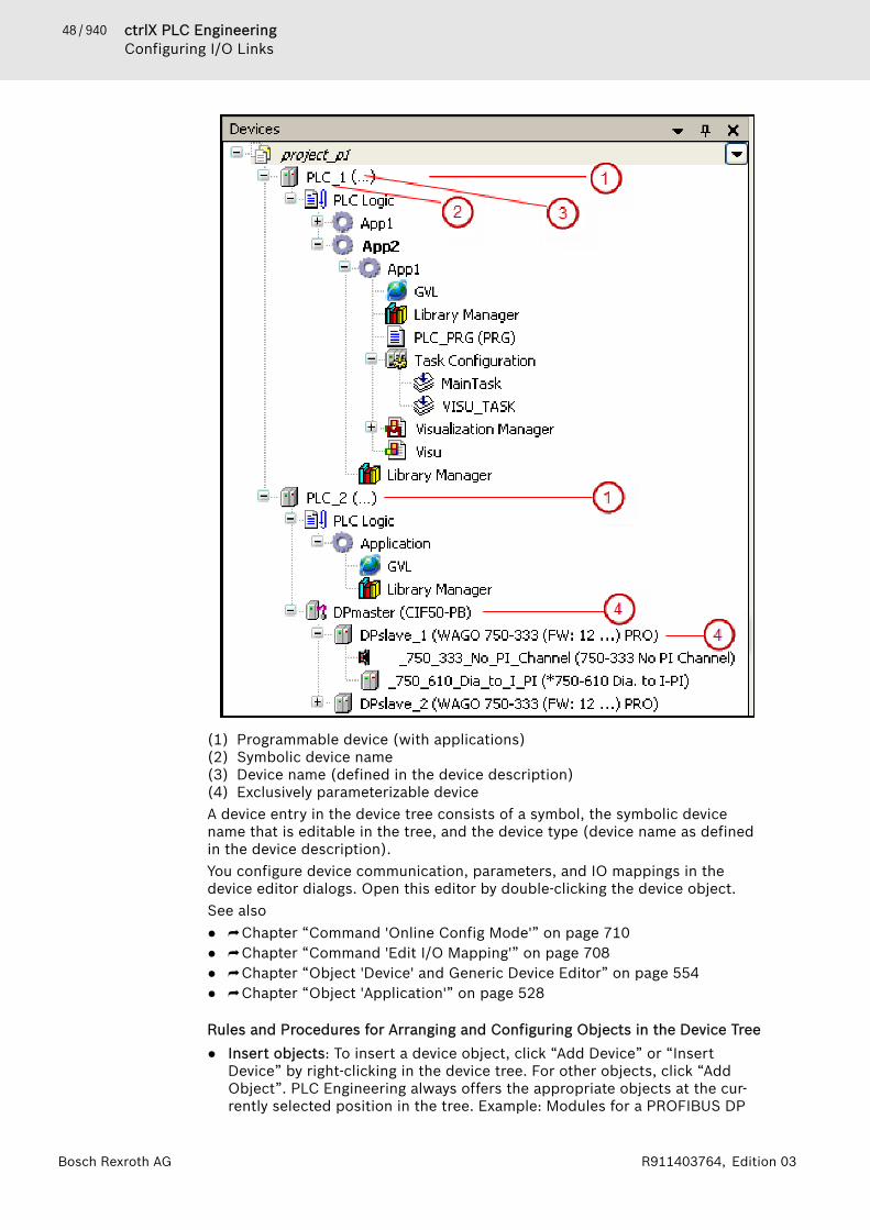
48 / 940 ctrlX PLC EngineeringConfiguring I/O Links
Bosch Rexroth AG R911403764, Edition 03
(1) Programmable device (with applications)(2) Symbolic device name(3) Device name (defined in the device description)(4) Exclusively parameterizable deviceA device entry in the device tree consists of a symbol, the symbolic devicename that is editable in the tree, and the device type (device name as definedin the device description).You configure device communication, parameters, and IO mappings in thedevice editor dialogs. Open this editor by double-clicking the device object.See also● ⮫ Chapter “Command 'Online Config Mode'” on page 710● ⮫ Chapter “Command 'Edit I/O Mapping'” on page 708● ⮫ Chapter “Object 'Device' and Generic Device Editor” on page 554● ⮫ Chapter “Object 'Application'” on page 528
Rules and Procedures for Arranging and Configuring Objects in the Device Tree● Insert objects: To insert a device object, click “Add Device” or “Insert
Device” by right-clicking in the device tree. For other objects, click “AddObject”. PLC Engineering always offers the appropriate objects at the cur-rently selected position in the tree. Example: Modules for a PROFIBUS DP
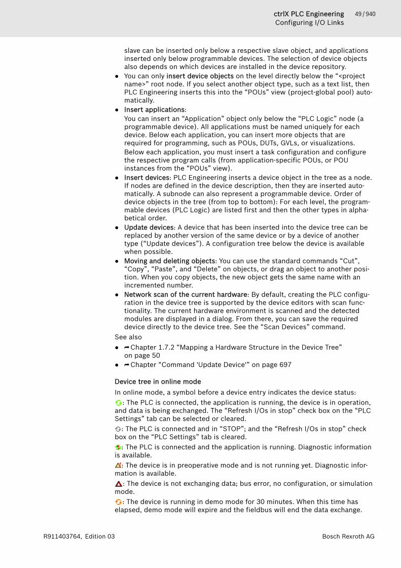
49 / 940ctrlX PLC EngineeringConfiguring I/O Links
Bosch Rexroth AGR911403764, Edition 03
slave can be inserted only below a respective slave object, and applicationsinserted only below programmable devices. The selection of device objectsalso depends on which devices are installed in the device repository.
● You can only insert device objects on the level directly below the “<projectname>” root node. If you select another object type, such as a text list, thenPLC Engineering inserts this into the “POUs” view (project-global pool) auto-matically.
● Insert applications:You can insert an “Application” object only below the “PLC Logic” node (aprogrammable device). All applications must be named uniquely for eachdevice. Below each application, you can insert more objects that arerequired for programming, such as POUs, DUTs, GVLs, or visualizations.Below each application, you must insert a task configuration and configurethe respective program calls (from application-specific POUs, or POUinstances from the “POUs” view).
● Insert devices: PLC Engineering inserts a device object in the tree as a node.If nodes are defined in the device description, then they are inserted auto-matically. A subnode can also represent a programmable device. Order ofdevice objects in the tree (from top to bottom): For each level, the program-mable devices (PLC Logic) are listed first and then the other types in alpha-betical order.
● Update devices: A device that has been inserted into the device tree can bereplaced by another version of the same device or by a device of anothertype (“Update devices”). A configuration tree below the device is availablewhen possible.
● Moving and deleting objects: You can use the standard commands “Cut”,“Copy”, “Paste”, and “Delete” on objects, or drag an object to another posi-tion. When you copy objects, the new object gets the same name with anincremented number.
● Network scan of the current hardware: By default, creating the PLC configu-ration in the device tree is supported by the device editors with scan func-tionality. The current hardware environment is scanned and the detectedmodules are displayed in a dialog. From there, you can save the requireddevice directly to the device tree. See the “Scan Devices” command.
See also● ⮫ Chapter 1.7.2 “Mapping a Hardware Structure in the Device Tree”
on page 50● ⮫ Chapter “Command 'Update Device'” on page 697
Device tree in online modeIn online mode, a symbol before a device entry indicates the device status:
: The PLC is connected, the application is running, the device is in operation,and data is being exchanged. The “Refresh I/Os in stop” check box on the “PLCSettings” tab can be selected or cleared.
: The PLC is connected and in “STOP”; and the “Refresh I/Os in stop” checkbox on the “PLC Settings” tab is cleared.
: The PLC is connected and the application is running. Diagnostic informationis available.
: The device is in preoperative mode and is not running yet. Diagnostic infor-mation is available.
: The device is not exchanging data; bus error, no configuration, or simulationmode.
: The device is running in demo mode for 30 minutes. When this time haselapsed, demo mode will expire and the fieldbus will end the data exchange.
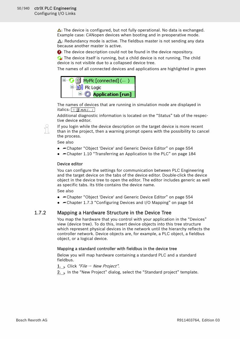
50 / 940 ctrlX PLC EngineeringConfiguring I/O Links
Bosch Rexroth AG R911403764, Edition 03
: The device is configured, but not fully operational. No data is exchanged.Example case: CANopen devices when booting and in preoperative mode.
: Redundancy mode is active. The fieldbus master is not sending any databecause another master is active.
: The device description could not be found in the device repository.: The device itself is running, but a child device is not running. The child
device is not visible due to a collapsed device tree.The names of all connected devices and applications are highlighted in green
The names of devices that are running in simulation mode are displayed initalics: Additional diagnostic information is located on the “Status” tab of the respec-tive device editor.If you login while the device description on the target device is more recentthan in the project, then a warning prompt opens with the possibility to cancelthe process.See also● ⮫ Chapter “Object 'Device' and Generic Device Editor” on page 554● ⮫ Chapter 1.10 “Transferring an Application to the PLC” on page 184
Device editorYou can configure the settings for communication between PLC Engineeringand the target device on the tabs of the device editor. Double-click the deviceobject in the device tree to open the editor. The editor includes generic as wellas specific tabs. Its title contains the device name.See also● ⮫ Chapter “Object 'Device' and Generic Device Editor” on page 554● ⮫ Chapter 1.7.3 “Configuring Devices and I/O Mapping” on page 54
1.7.2 Mapping a Hardware Structure in the Device TreeYou map the hardware that you control with your application in the “Devices”view (device tree). To do this, insert device objects into this tree structurewhich represent physical devices in the network until the hierarchy reflects thecontroller network. Device objects are, for example, a PLC object, a fieldbusobject, or a logical device.
Mapping a standard controller with fieldbus in the device treeBelow you will map hardware containing a standard PLC and a standardfieldbus.1. Click “File 🠂 New Project”.2. In the “New Project” dialog, select the “Standard project” template.

51 / 940ctrlX PLC EngineeringConfiguring I/O Links
Bosch Rexroth AGR911403764, Edition 03
3. In the “Standard Project” dialog, select the “ctrlX CORE” device.
🡆 PLC Engineering inserts the Device “ (ctrlX CORE)” object in thedevice tree under the root node and below it the “PLC Logic” node,which always provides a programmable device object. An “Application”object exists below that, and the “Library Manager”, “PLC_PRG”, and“Task Configuration” objects exist below that.
4. Select the Device entry and click “Add Device” in the context menu.🡆 The “Add Device” dialog provides a selection of the devices installed on
your system. 'Installed on the system' means that PLC Engineering hasreceived a device description for the respective hardware. You can thususe the device object and the associated configuration editor in theproject.
5. Select one of the provided PLCs (example: “CAN-bus”) and click the “AddDevice” button.🡆 The “CAN-Bus” object appears in the device tree indented below
Device “(ctrlX CORE)”. The “Add Device” dialog remains open. If younow select the new “CAN-bus” entry, it automatically offers the objectsthat are insertable under it.
6. For example, select the “CANopen Device” from the “Local Device” cate-gory.🡆 “CANopen_Device” is inserted indented under “CAN-bus” in the device
tree.7. Do you want to add a different device to the one you added before? Select
the device entry and click “Update Device” in the context menu.🡆 The “Update Device” dialog opens. It corresponds to the “Add Device”
dialog used previously. You can select another device, which is theninserted in the tree in place of the previous one.
See also● ⮫ Chapter “Command 'Insert Device'” on page 694● ⮫ Chapter “Command 'Update Device'” on page 697
Scanning the current hardware and applying devices into the projectYou can determine the devices in the network of the hardware environment(scan) and apply the devices found into the device tree of your project. If thescan function is permanently implemented in the PLC, you can perform thescan without further preparations. For this purpose, PLC Engineering estab-lishes a brief connection to the controller. If the scan function is provided in alibrary, the device that includes the library must be inserted in the device treeand a login to the controller executed. Only then can the library be placed onthe controller, making scanning possible.
52 / 940 ctrlX PLC EngineeringConfiguring I/O Links
Bosch Rexroth AG R911403764, Edition 03
Scanning is started by means of the “Scan for Devices” command. It refers tothe controller that is currently selected in the device tree and linked to theproject. For example, you can select an inserted PROFINET IO controller anduse the command to determine the I/O devices and I/O modules assigned to it.Requirement: Your project has a device configuration. The communication set-tings are correct. Gateways and hardware are running.1. Select a PLC object in the device tree.2. Click “Scan for Devices” in the context menu.
🡆 PLC Engineering establishes the connection to the hardware. Thedialog “Scan for Devices” appears. Depending on the type of device itoffers different functions. However, a table always appears, showingthe devices found in the hardware: device name, type of device, stationname, etc. Regarding this, see the help for the respective device editor.
3. So that the list displays only devices found that you do not yet have in thedevice configuration of your project, activate the “Show differences toproject” option.
4. In order to apply a device into the device tree of the project, select theentry in the table and click the button “Copy to project”. All devices foundare applied if you do not select an entry.🡆 The corresponding entries are inserted in the device tree.
See also● ⮫ Chapter “Command 'Scan for Devices'” on page 696
Checking the controller configuration with the help of the 'Online Config Mode'commandWith PLC Engineering you can test the correct wiring of the I/Os and thefieldbus of your target system, without having to develop a real application forthe controller and loading it to the controller beforehand. This is interesting forthe initial commissioning phase. Use the 'Simple online configuration mode' forthis. If there is already an application on the controller, you can optionally alsouse the 'Advanced online configuration mode' if the device supports this. Thisallows you to read device parameters without having to login with the applica-tion concerned from PLC Engineering.Simple online configuration modeYou create an implicit application by means of the “Online Config Mode” com-mand in the context menu of the PLC object in the device tree.PLC Engineeringautomatically loads the application to the PLC and, via the application, auto-matically initializes all I/Os once. The application is called “HiddenOnlineCon-figModeApp”. It is displayed in the device editor of the PLC on the “Applica-tions” tab. You can use it to operate the I/Os with the following functions as innormal online mode:● Read I/Os● Write outputs● Diagnosis (in the tree and on the status page)● Scan (of the current hardware)● Interactive online functions, if supported (for example, writing asynchronous
messages)Writing and forcing in the I/O mappingIn online configuration mode, the writing and forcing of values in the “I/O Map-ping” dialog works differently to the way it works in real online mode.PLC Engi-neering writes the outputs into the I/O mapping table immediately after inser-tion. There is no “Prepared Value” column. Instead, you change the initialvalues directly after you double-click the “Current Value” column.

53 / 940ctrlX PLC EngineeringConfiguring I/O Links
Bosch Rexroth AGR911403764, Edition 03
Testing the I/O access with the help of the simple online configuration mode:Requirement: You have created a standard project with a device configurationin which you have configured an I/O mapping. In a program block you makeread or write accesses to inputs or outputs of the hardware in order to checktheir wiring. The connection to the PLC of the hardware is configured in thecommunication settings. The PLC is running.1. Select the PLC object in the device tree.
🡆 For example, the ctrlX CORE device is selected in the device tree.2. Click “Online Config Mode” in the context menu.
🡆 PLC Engineering connects to the controller and the PLC object in thetree is given a green background.
3. Double-click the PLC object in the device tree in order to open the deviceeditor. Select the tab “Applications”.
4. Click the “Update list” button.🡆 The application HiddenOnlineConfigModeApp appears in the window
“Applications on the controller”.5. Start your program and check the behavior of the inputs and outputs.Advanced online configuration mode (parameter mode)If there is already a 'real' application on the controller and the device supportsthe 'Advanced online configuration mode', you can also optionally select the'Parameter mode' after the command “Online configuration mode”. Then youcan read the parameters of the real application on the controller without havingto perform a standard login and – if compilation information is missing – havingto download this application again. You can see the parameters on the “Config-uration” tab of the device editor. The parameter mode prevents the inadvertentchanging of the data on the controller; the applications remain untouched.Writing of the parameters is possible only if the driver supports it.Setting up parameter mode for reading the device parameters:Requirement: There are already one or more applications on the target device.The target device supports the advanced online configuration mode. You haveopened the project containing these applications. You wish to look at thedevice parameters without having to login to the controller. The connection tothe PLC of the hardware is configured in the communication settings. The PLCis running.1. Select the PLC object in the device tree.2. Click “Online Config Mode” in the context menu.
🡆 PLC Engineering connects to the controller and the PLC object in thetree is given a green background. The dialog “Select configurationmode” appears with a display of the application(s) on the PLC.
3. Select the desired application and click the “Parameter mode” button.🡆 PLC Engineering checks whether the application in the project corre-
sponds to the application on the PLC.4. If PLC Engineering does not signal an error regarding the correspondence
of the applications to each other, open the “Configuration” tab of the PLCdevice editor.🡆 You can read the device parameters.
See also● ⮫ Chapter “Command 'Online Config Mode'” on page 710● ⮫ Chapter “Tab 'Parameters'” on page 560
54 / 940 ctrlX PLC EngineeringConfiguring I/O Links
Bosch Rexroth AG R911403764, Edition 03
1.7.3 Configuring Devices and I/O MappingConfiguring devicesYou can configure the device objects inserted into the device tree in the associ-ated device editor. The possibilities depend on the device description. The 'ge-neric device editor' provides tabs that are supplemented as necessary bydevice-specific tabs.Requirement: You have opened a standard project in whose device tree astandard PLC and below that a fieldbus device object are inserted.1. Double-click the device object of the standard PLC in the device tree of
your project.🡆 The “<device name>” editor opens in the PLC Engineering main
window. The “Communication Settings” tab is in the foreground.Change to the other tabs in order to make configuration settings for thecontroller. See the help pages for the generic device editor.
2. Double-click the fieldbus device object in the device tree of your project.🡆 The “<fieldbus device name>” editor opens in the PLC Engineering
main window. Specific tabs are available depending on the device. Forthe configuration options, see the help pages for the respective deviceeditor. If the “Show generic device configuration views” option isselected in “Tools 🠂 Options”, in the “Device Editor” category, then seealso the tabs contributed by the generic device editor.
See also● ⮫ Chapter “Generic Device Editor” on page 555
Read PLC parameter file to configurationIf the configuration parameters of the PLC have been changed by anotherdevice, for example via a visualization, a configuration file IoConfig.par is cre-ated on the controller. Depending on the device, a button may be in the param-eter dialog of the device editor in online mode for writing the current parame-ters to such a file. In order to update the changed parameters inside yourproject as well, you can read in the parameter file in online mode.Requirement: You have a standard project with a device tree in which the hard-ware environment is mapped with a PLC and a parameterizable device in thedevice tree. On the controller there is a file IoConfig.par, in which the deviceparameters were previously saved with the current values.1. Add the “Read PLC parameter file to configuration” command from the
“Devices” category in the “Tools 🠂 Customize” dialog to an interfacemenu.
2. Select the PLC device object in the device tree and open the contextmenu.
3. Click “Read PLC parameter file to configuration”.🡆 PLC Engineering automatically establishes a connection to the con-
troller and reads in the parameters from the par-file. These are updatedaccordingly on the tab with the device parameters.
See also● ⮫ Chapter “Command 'Read PLC Parameter File to Configuration'”
on page 710● ⮫ Chapter “Dialog 'Customize' - 'Menu'” on page 863

55 / 940ctrlX PLC EngineeringConfiguring I/O Links
Bosch Rexroth AGR911403764, Edition 03
General information about I/O mappingWhether or not you can configure an I/O mapping to project variables or evento the entire function blocks depends on the type of device. Configuring an I/Omap means linking input and output channels of the device with variables ofthe project. We also use the term 'mapping' for this.Pay attention in general to the following for the mapping of inputs and outputsof a device to variables in PLC Engineering:● You do not have write access to variables that are mapped to an input.● You can map an existing variable to one input only.● You can directly generate new global implicit variables in the I/O map and
map them to a device channel.● The memory layout of structures is specified by the device.● You can change addresses and fix values in the I/O map.● For each variable that is assigned to an I/O channel in the “I/O Mapping”
dialog, you can cause 'force variables' to be generated during the compila-tion of the application (see further below). Using these variables you can,for example during the commissioning of a plant, force a value on the inputor output via a visualization/HMI.
● Changes in the I/O map can be transferred to the controller with an onlinechange.
● If a pointer to a device input is used, the access is considered to be a writeaccess, for example pTest := ADR(input);. This leads to a compilerwarning when code is generated : "...invalid assignment target". Ifyou require a construct of this kind, you must first copy the input valueinput to a variable with write access.
● An I/O address can also be linked with a variable via the 'AT declaration' inthe IEC code. Since a device configuration often changes again, however, werecommend that you make the assignments only in the device editor.If you use the AT declaration, note the following:– An AT declaration is permissible only with local or global variables, not
with input or output variables of function blocks.– Implicit 'force variables' for I/Os (see below) cannot be generated for AT
declarations.– If you use an AT declaration with structure variables or function block var-
iables, all instances will access the same memory location. This then cor-responds to the use of 'static variables' in classic programming languagessuch as 'C'.
NOTICE If a pointer to a device input is used, then the access (forexample pTest := ADR(input);) is considered to be awrite access. This leads to a compiler warning whencode is generated : "...invalid assignment target".If you require a construct of this kind, you must firstcopy the input value (input) to a variable with writeaccess.
As an alternative, you can assign a variable to an address in the programmingcode using the AT declaration. In view of possible changes of the device config-uration, however, we recommend that you make the assignments only in thedevice editor.You can export the I/O mapping configuration of a device to a csv file or importit from such a file.

56 / 940 ctrlX PLC EngineeringConfiguring I/O Links
Bosch Rexroth AG R911403764, Edition 03
See also● ⮫ Chapter “Tab '<device name> I/O Mapping'” on page 568● ⮫ Chapter “Command 'Export Mapping to CSV'” on page 709● ⮫ “Generating implicit variables for the forcing of I/Os” on page 60
Linking a device input with an existing project variable ("mapping")Requirement: A device that supports an I/O mapping configuration in PLC Engi-neering is inserted in the device tree of your project. On the “I/O Mapping” tabin the device editor you thus get a tabular display of the input and output chan-nels of the device with specification of the addresses and data types.
NOTICE Mapping 'too large' data typesIf a variable of a data type that is larger than a byte ismapped to a byte address, the value of the variable willbe truncated to byte size there. For monitoring the vari-able value in the “I/O Mapping” dialog, this means thefollowing: In the root element of the address, the value isdisplayed that the variable currently has in the project.The current individual bit values of the byte are displayedin succession in the bit elements below that, but thismay not be sufficient for the entire variable value.
If a UNION is represented by I/O channels in the mapping dialog, it depends onthe device whether mapping to the "root" element is also possible.1. In a POU, declare, for example, a variable xBool4 of the type BOOL with
which you wish to access an input of the target device from the applica-tion.
2. To open the device editor, double-click the device object in the devicetree, and then the “<device name> I/O Mapping” tab.
3. Observe the “Variable” column with the display of the device input chan-nels and device output channels , which can still be sorted by organi-zational nodes , depending on the device. We assume that there is adevice input of the type BYTE. It is displayed with its individual bitaddresses (bit channels) below the BYTE node.
4. Note: When mapping structured variables, the editor prevents you fromentering both the structure variable (example: %QB0) and individual struc-ture elements (example: %QB0.1 and QB0.2). Therefore, if there is a mainentry with a subtree of bit channel entries in the mapping table, then thefollowing applies: Then you can specify a variable either into the line ofthe main entry, or into the lines of the subelements (bit channels), but notinto both.You can now occupy either the entire channel with a variable of a suitabletype OR its individual bit-channel addresses with suitable variables of thetype BOOL or BIT. First of all, double-click a bit input channel in the “Varia-bles” column.🡆 An input field opens.

57 / 940ctrlX PLC EngineeringConfiguring I/O Links
Bosch Rexroth AGR911403764, Edition 03
5. In order to place an existing variable on the channel, you must enter thedesired project variable with the complete path. Press to open theInput Assistant. Select, for example, the variable Applica-tion.PLC_PRG.xBool4 declared in PLC_PRG.🡆 The variable is inserted. The HMI symbol ( ) is displayed in the “ Map-
ping” column. The address is now struck through. That does not meanthat the address is no longer available, because values of existing varia-bles are managed at another memory space. But: in order to avoidambiguities when writing the values, you should nevertheless notoccupy the address with a further variable, especially in the case ofoutputs.Note: For compiler version V3.5 SP11 and later, the initialization valueof the variables is used automatically as the default value when map-ping to an existing variable. You can edit the “Default value” field only ifyou map to a new created variable or if no mapping is specified. Inolder versions, users had to specify explicitly that the default value andinitialization value were identical.
6. Delete the variable assignment again. Click the root of the channel, theBYTE node. Use the Input Assistant again to select the variable Applica-tion.PLC_PRG.byte_gotodevice.🡆 The variable is inserted, all bit addresses of the main channel are
struck through and you should not additionally occupy them.
See also● ⮫ Chapter “Tab '<device name> I/O Mapping'” on page 568
Mapping a device input to a recently created project variableIn the following you will map a device output to a global implicit variable, whichyou recently create for this purpose directly in the “I/O Mapping” dialog.The “I/O Mapping” dialog is thus a further place for declaring a global variable.
Requirement: A device that supports an I/O mapping configuration in PLC Engi-neering is inserted in the device tree of your project. On the “I/O Mapping” tabin the device editor you will thus see a tabular display of the input and outputchannels of the device with specification of the addresses and data types.1. To open the device editor, double-click the device object in the device
tree, and then the “<device name> I/O Mapping” tab.2. Click in the mapping table on a channel entry in the “Variable” column in
order to open an input field.
58 / 940 ctrlX PLC EngineeringConfiguring I/O Links
Bosch Rexroth AG R911403764, Edition 03
3. Enter a simple name (without '.') for a new variable (for example,myBool).🡆 PLC Engineering creates the variable as an implicit global variable in
the project and assigns it directly to the channel address. Therefore inthis case the address does not appear struck through as in the case ofmappings to existing variables .
Linking a device with a function block instanceIf supported by the device, you can map entire function blocks to an input oroutput channel. This allows you to count the frequency of signal changes orscale a channel value for maintenance purposes, for example.Here you will map a device output channel to a function block. In this example,the block scales the channel output value.Requirement: A device with a digital output that supports FB mapping is linkedin the project. There is a function block “Scale_Output_Int” with the followingimplementation. The attributes of the function block itself and before theoutput parameter with which the channel output is processed are important.{attribute 'io_function_block'}FUNCTION_BLOCK Scale_Output_IntVAR_INPUT
iInput : INT;iNumerator : INT;iDenominator : INT :=1;iOffset : INT := 0;
END_VARVAR_OUTPUT {attribute 'io_function_block_mapping'}iOutput : INT;
END_VARVAREND_VARIF iDenominator <> 0 THENiOutput := TO_INT(TO_DINT(iInput) * TO_DINT(iNumerator) /
TO_DINT(iDenominator)) + iOffset;1. Open the “<device name> I/O Mapping” tab of the device editor. Double-
click the output that should be connected to the function block. Click thebutton “Add FB for IO channel”.🡆 The “Select Function Block” dialog opens. On the left side, you see at
least the function block “Scale_Output_int” below the “Application”node. Libraries linked in the project that contain corresponding func-tion blocks are also displayed for selection.
2. Select the POU myScaleOutputInt.🡆 After clicking “OK”, the path of the function block parameter iOutput
in the “Variable” is entered in the mapping dialog. The path comprisesthe application name, the device channel name, and the selected FBoutput (example:App1.Out_4_Int_myScale_Output_Int_1.iOutput).
59 / 940ctrlX PLC EngineeringConfiguring I/O Links
Bosch Rexroth AGR911403764, Edition 03
3. Select the channel and click “Go to Instance”.🡆 The focus switches to the “<device name> IEC Objects” tab and the
created entry for the new IEC objectOut_4_Int_myScale_Output_Int_1. In this view in online mode, yousee the current value of the parameter iOutput for the channelOut_4_Int scaled by the FB. You can also write and force the value asin other monitoring views.
See also● ⮫ Chapter “Dialog 'Select Function Block'” on page 817● ⮫ Chapter “Tab '<device name> I/O Mapping'” on page 568● ⮫ Chapter “Tab '<device name> IEC Objects'” on page 571● ⮫ Chapter “Attribute 'io_function_block', 'io_function_block_mapping'”
on page 435
Changing and fixing an address value in the I/O mapYou can change the address value of an entire channel (but not that of an indi-vidual subelement of the channel!) in the mapping table of the “<device name>I/O Mapping” tab. This allows you to adapt the addressing to a specifiedmachine configuration and to retain the address value even if the layout of themodules changes. By default, a change of the layout leads to an automaticadaptation of the address values.Requirement: Your project has I/O mapping. See the corresponding sections ofthe help page above.1. To open the device editor, double-click the device object in the device
tree, and then the “<device name> I/O Mapping” tab.2. Click in the mapping table on a channel entry in the “Address” column in
order to open an input field. This is only possible for the 'root' address ofa channel, not for a particular one of its subelements.Therefore, change the top address entry of a channel in the table, forexample from QB0 to QB1. Exit the input field.🡆 The address value is changed. The symbol is displayed before the
address. It indicates that the address is fixed. The addresses of thesubelements of the channel are also changed accordingly. If you nowchange the position of the device object inside other device objectswith input/output channels in the device tree, PLC Engineering doesnot adapt these addresses to the new order as would be the casewithout fixing.
3. In order to undo the manual change or fixing, open the input field of theaddress value again, delete the address entry and press the Enter key.🡆 PLC Engineering resets the address and the subsequent addresses con-
cerned to the values they had before the change and removes thesymbol .
See also● ⮫ Chapter “Tab '<device name> I/O Mapping'” on page 568● ⮫ Chapter “Addresses” on page 384
Configuration of the I/O variable updateDepending on the device that you link in the project, PLC Engineering updatesthe variables applied to its inputs and outputs in different ways. You can explic-itly change the settings for this in the “I/O Mapping” dialog.

60 / 940 ctrlX PLC EngineeringConfiguring I/O Links
Bosch Rexroth AG R911403764, Edition 03
See also● ⮫ Chapter “Tab '<device name> I/O Mapping'” on page 568
Monitoring of variables in the I/O map in online modeRequirement: You have compiled an application with a device configurationcontaining I/O maps without error. The associated hardware and the bussystem are running. You have connected to the controller by means of the“Online 🠂 Login” command and have loaded and started the application.1. Open the “I/O Mapping” tab of the PLC in the device editor. To open the
editor, double-click the device object in the device tree.🡆 The mapping table now additionally contains the “Current Value” and
“New Value” columns.If a structure variable is mapped to the 'root' element of an address1,PLC Engineering does not display a value in this line in online mode. If,for example, a DWORD variable is mapped to the address, however, therespective values are monitored both in the 'root' line and in theindented bit-channel lines below it.As a matter of principle, the field in the 'root' line always remains emptyif the value would be composed of several subelements.1 'root' = top element of this address in the Mapping dialog
2. Enter a certain variable value for an entry in the column “New value” andpress [F7] to force or [Ctrl]+[F7] to write the value.🡆 As in the case of monitoring in the declaration editor or in watch lists,
the forced variable value is displayed in the column “Current Value”with a prefixed red F-symbol or the written value.
NOTICE Inputs and outputs that the PLC code does NOT use arenot read by the PLC in online mode, as a result of whichthe displayed value could be incorrect. The “CurrentValue” of the variables concerned is displayed with agray background.
(1) Forcedvalues on thecontroller
(2) Values notused on thecontroller,value shownin gray
Generating implicit variables for the forcing of I/OsDuring the commissioning of a plant or machine it may be necessary to 'force'the values applied at the inputs and outputs. If a device supports this you cancause special 'force variables' to be generated for this purpose and use them,for example, in an HMI visualization.Requirement: The device supports the functionality. You have a project in whichan I/O map is configured for the device and which contains a program objectPLC_PRG.1. Open the device editor, “PLC Settings” tab, by double-clicking the device
object in the device tree.2. Activate the option “Generate force variables for IO mapping”.

61 / 940ctrlX PLC EngineeringConfiguring I/O Links
Bosch Rexroth AGR911403764, Edition 03
3. Press [F11] to compile the application.🡆 Two variables are created for each I/O channel in accordance with the
following syntax, in the process of which spaces in the channel nameare replaced by underscores:<device name>_<channel name>_<IEC address>_Force of typeBOOL for the activation and deactivation of forces.<device name>_<channel name>_<IEC address>_Value of the datatype of the channel for defining the value that you wish to force on thechannel.These variables are available in the Input Assistant in the category “Var-iables” / “IoConfig_Globals_Force_Variables.” You can use them in PLCEngineering in programming objects, in visualizations, in the symbolconfiguration, etc.
4. Open the function block “PLC_PRG”, set the focus in the implementationpart and press F2.🡆 The Input Assistant opens. The variables are available in the category
“Variables” / “IoConfig_Globals_Force_Variables” as described above.A rising edge at the 'Force variable' input activates the forcing of therespective input or output with the value given by the 'Value variable'. Afalling edge deactivates the forcing. Deactivation by resetting the'Force' variable to FALSE is the requirement for being able to force anew value.
Take note of the following restrictions.● Forcing via the implicit force variables is only possible for channels that are
mapped in the “I/O Mapping” of the device to an existing or recently createdvariable.
● Forcing via the implicit force variables is not possible for unused inputs andoutputs or those that are mapped to a variable via an AT declaration in anapplication program.
● I/O channels that you wish to force via the mechanism have to be used byPLC Engineering in at least one task.
● PLC Engineering identifies forced inputs in the monitoring by the red Forcesymbol, but not forced input/outputs! The forced value is used only implic-itly by the I/O driver for writing to the device.
See also● ⮫ Chapter “Tab 'PLC Settings'” on page 565● ⮫ Chapter 1.11.4 “Forcing and Writing Variables” on page 201
I/O mapping in one dialog for multiple devicesThere is a table that displays the I/O map of a device plus the I/O maps of allsubelements inserted below it in the device tree. There you can edit the I/Omaps in exactly the same way as in the individual mapping tables of the respec-tive device editors.Requirement: In the device tree of your project there are several PLCs insertedthat each enable an I/O mapping configuration.1. Select the root node of the device tree and click “Edit I/O Mapping” in the
context menu .🡆 The “Edit I/O Mapping” dialog opens, in which the I/O mapping config-
urations of all devices inserted in the project are displayed in a table.You can edit the entries in the same way as in the “I/O Mapping” dialogof the associated device editor.
62 / 940 ctrlX PLC EngineeringProgramming of Applications
Bosch Rexroth AG R911403764, Edition 03
2. Now select one of the control objects in the device tree and select the“Edit I/O Mapping” command once again in the context menu.🡆 The “Edit I/O Mapping” dialog now shows only the I/O table for the I/O
mapping configurations found in and under the selected object.3. Set a desired “Filter” in the bar above the table or enter a variable name
in the “Search for variable” field in order to see the use of this variable inthe mapping.🡆 The method of working in this window is the same as that described for
the “<device name> I/O Mapping” tab.See also● ⮫ Chapter “Command 'Edit I/O Mapping'” on page 708
1.8 Programming of ApplicationsFor creating an application program which is executable on the PLC, you fillPOUs with declarations and implementation code (source code), you define themapping of the hardware I/Os on application variables, and you configure thetask handling. After having checked and debugged your implementation, thePLC Engineering compiler will generate the application code which can bedownloaded to the PLC.The programming of the application POUs will be supported by the program-ming language editors and further features like for example textlists, imagepools, alarm configuration, pragmas, refactoring and usage of ready modulesprovided by ctrlX PLC Engineering System or by libraries.There are features for syntax checking and code analysis, for achieving datapersistence and for encrypting the application code which gets downloaded tothe PLC.
1.8.1 Designating IdentifiersIdentifiers are names of variables and programming objects (for example pro-grams, function blocks, and methods) and names of other objects of the appli-cation and project. There are rules that you must follow when assigning identi-fiers. Furthermore, there are also recommendations to help you designateuniform and expressive identifiers.You designate variables identifiers in the variables declaration. These identifierscan e changed in the declaration section of the programming object. You desig-nate identifiers for programming objects and other objects in the dialog boxwhen adding the object. You can change the identifier of an existing object ofthe application or of the project in the properties dialog of the object. However,you cannot change the identifiers of objects that can be available only one timeper application or project (for example, the “Library Manager” and “ImagePool”identifiers).See also● ⮫ Chapter 1.18.7 “Identifiers” on page 460
1.8.2 Declaration of VariablesVariable declaration: where and howIn PLC Engineering projects you can declare variables in the following places:● Declaration part of a POU● Dialog box “Auto Declare”, if a POU has the focus● DUT, GVL or NVL editor● I/O mapping configuration of an I/O device object
63 / 940ctrlX PLC EngineeringProgramming of Applications
Bosch Rexroth AGR911403764, Edition 03
The variable declarations in global variable lists (GVL, NVL) and in the declara-tion part of POUs are carried out in the declaration editor. Special editors ordialog boxes are available for all other variants.
NOTICE By adding pragmas you can affect the behavior and theproperties of one or more variables. More precise infor-mation can be found in the chapter "Use of pragmas".
Syntax for the variable declaration in POUs or global variable lists, if textual dis-play is selected for the declaration editor:<identifier> {AT <address>}:<data type> {:=<initialisation>};● <identifier>: Name of the variable. The rules listed in the chapter "Identi-
fiers" must be followed without exception when assigning an identifier. Inaddition, this chapter contains recommendations for standardizing theassignment of names.
● {AT <address>} (optional): You can directly bind a variable to a certainaddress with the help of the keyword AT.
● <data type>● {:=<initialization>} (optional)In function blocks you can also declare variables with incomplete address spec-ifications. In order to be able to use such a variable in a local instance, how-ever, there must be a corresponding entry for this variable in the "variable con-figuration".If you define a variable in the tabular declaration editor, the correct syntax isautomatically produced.See also● ⮫ Chapter “Using the Declaration Editor” on page 64● ⮫ Chapter 1.18.5 “Data Types” on page 386● ⮫ Chapter 1.18.2 “Variables” on page 312● ⮫ Chapter “Command 'Auto Declare'” on page 671● ⮫ Chapter 1.18.7 “Identifiers” on page 460● ⮫ Chapter “Object 'GVL' - Global Variable List” on page 581● ⮫ Chapter 1.8.7 “Using Pragmas” on page 101● ⮫ Chapter “Using the 'Declare variable' Dialog Box” on page 65● ⮫ Chapter 1.7.3 “Configuring Devices and I/O Mapping” on page 54
Variable initializationThe standard initialization value for all declarations is 0. In the declaration partyou can also specify user-defined initialization values for each variable and eachdata type.The user-defined initialization starts with the assignment operator := and con-sists of any valid expression of the programming language ST (structured text).You thus define the initialization value with the help of constants, other varia-bles or functions. If you use a variable, you must also initialize it.
64 / 940 ctrlX PLC EngineeringProgramming of Applications
Bosch Rexroth AG R911403764, Edition 03
Examples
VAR
var1:INT := 12; (* initialization value 12*)
x : INT := 13 + 8; (* initalization value defined by an expression of constants*)
y : INT := x + fun(4); (* initialization value defined by an expression, that contains a function call; notice the order! *)
z : POINTER TO INT := ADR(y); (* not described in the standard IEC61131-3: initialization value defined by an adress function; Notice: the pointer will not be initialized diesem Fall, during an Online Change *) END_VAR
Notes on the order of initializationFrom compiler version 3.5.3.40, variables in a function block are initialized inthe following order: firstly, all constants in accordance with the order of theirdeclarations, then all other variables in accordance with the order of their dec-larations.
NOTICE From compiler version 3.3.2.0, variables from global vari-able lists are always initialized before the local variablesof a POU.
See also● ⮫ Chapter “Data Type 'ARRAY'” on page 397● ⮫ “Initializing structures” on page 412● ⮫ Chapter 1.18.5 “Data Types” on page 386
Using the Declaration EditorThe declaration editor is used for declaring variables in the variable lists andPOUs.The declaration editor offers two possible views: textual and tabular .in the dialog in “Tools 🠂 Options 🠂 Declaration Editor”, you define whetheronly the textual view or only the tabular view is available, or whether you canswitch between both views by means of the buttons on the right side of theeditor view.If the declaration editor is used in conjunction with a programming languageeditor, it appears as the declaration part at the top of the window of a POU.
Declaring in the textual declaration editorThe behavior and the appearance of the textual editor are configured with thesettings in the dialog “Tools 🠂 Options 🠂 Text Editor”. The settings concerncolors, line numbers, tab widths, indentations etc. The usual Windows func-tions are available, plus the IntelliMouse functions if necessary.Requirement: You have opened a programming object (POU, GVL or NVL) of aproject. The textual declaration editor has the focus.
65 / 940ctrlX PLC EngineeringProgramming of Applications
Bosch Rexroth AGR911403764, Edition 03
Enter the variable declarations in correct syntax. With [F2] you can openthe dialog “Input Assistant” for the selection of the data type or a key-word.
Declaring in the tabular declaration editorIn the tabular declaration editor, you add variable declarations to a table withthe following columns: “Scope”, “Name”, “Address”, “Data type”, “Initializa-tion”, “Comment”, and “Attributes” (pragmas).Requirement: A programming object (POU or GVL) of a project is open. Thetabular declaration editor has the focus.1. Click the button in the declaration header or select the command
“Insert” in the context menu.🡆 PLC Engineering inserts a new row for a variable declaration and the
input field for the variable name opens.2. Specify a valid variable identifier.3. Open the other fields of the declaration line as required with a double-
click and select the desired specifications from the drop-down lists orwith the help of the dialogs which appear.
See also● ⮫ “Declaration editor in online mode” on page 255● ⮫ Chapter “Command 'Auto Declare'” on page 671● ⮫ Chapter “Using the 'Declare variable' Dialog Box” on page 65● ⮫ Chapter “Command 'Edit Declaration Header'” on page 792● ⮫ “Dialog 'Input Assistant' - Tab 'Categories'” on page 673
Using the 'Declare variable' Dialog BoxRequirement: A programming object (POU or GVL) of a project is open.1. Select the command “Edit 🠂 Auto Declare”.
🡆 The dialog box “Auto Declare” opens.2. Select the desired scope for the variable from the selection list “Scope”.3. Enter a variable name in the input field “Name”.4. Select the desired data type from the selection list “Type”.5. If the initialization value deviates from the standard initialization value,
enter an initialization value for the variable.6. Complete your entries with a click on “OK”.
🡆 PLC Engineering lists the newly declared variable in the declarationpart of your programming object.
With the help of pragmas in the declaration part you can affect the processingof the declaration by the compiler.See also● ⮫ Chapter “Command 'Auto Declare'” on page 671● ⮫ Chapter 1.18.5 “Data Types” on page 386● ⮫ Chapter 1.8.7 “Using Pragmas” on page 101
Declaring ArraysRequirement: A programming object (POU or GVL) of a project is open.1. Click “Edit 🠂 Declare Variable”.
🡆 The “Declare Variable” dialog opens.2. Select the desired scope for the array from the drop-down list “Scope”.3. Enter an identifier for the array in the “Name” input field.

66 / 940 ctrlX PLC EngineeringProgramming of Applications
Bosch Rexroth AG R911403764, Edition 03
4. Click the arrow button ( ) next to the “Data type” input field and selectthe “Array Assistant” entry from the selection menu.
5. In the input fields “Dimension 1”, type in the lower and upper limit of thefirst dimension of the array (example: 1 and 3).🡆 The field “Result” displays the 1st dimension of the array (example:
ARRAY [1..3] OF ?).6. In the input field “Basic type”, type in the data type of the array or use the
“Input Assistant” ( ) or the “Array Assistant” (example: DINT).🡆 The field “Result” displays the data type of the array now (example:
ARRAY [1..3] OF DINT).7. Define the second and third dimensions of the array according to steps 5
and 6 (example: Dimension 2: 1 and 4, Dimension 3: 1 and 2).🡆 The “Result” field displays the array with the defined dimensions:
ARRAY [1..3, 1..4, 1..2] OF DINT. The array consists of 3 * 4 * 2= 24 elements.
In an array of variable length, declare the dimension limits with anasterisk placeholder (*). Arrays of variable length are permitted to beused only in VAR_IN_OUT declarations of function blocks, methods, orfunctions.: Example of a 2-dimensional array of variable length: aiUnknown-LengthData : ARRAY [*,*] OF INT;
8. Click “OK”.🡆 In the dialog “Declare Variable” the field “Data type” displays the array.
9. To modify the initialization values of the array, click the arrow button ( )next to the “Initialization value” input field.🡆 The “Initialization Value” dialog opens.
10. Select the line of the array element whose initialization value you wish tomodify. Example: Select array component [1, 1, 1].
11. Enter the desired initialization value in the input field below the list andclick button “Use value on selected lines” (example: value 4).🡆 PLC Engineering displays the changed initialization value of the
selected line.12. Click “OK”.
🡆 In the “Initialization value” field of the “Declare Variable” dialog, PLCEngineering displays the initialization values of the array (example:{4,23(0)]).
13. You can optionally enter a “Comment” in the input field.14. Click “OK” in order to conclude the declaration of the array.
🡆 PLC Engineering adds the declaration of the array to the declarationpart of the programming object.
See also● ⮫ Chapter “Command 'Auto Declare'” on page 671● ⮫ Chapter “Data Type 'ARRAY'” on page 397
Declaring Global VariablesDeclaring global variables that are available within the application.Requirement: A project is open.1. In the Device tree of your project, select the application in which the
global variables are to be valid.
67 / 940ctrlX PLC EngineeringProgramming of Applications
Bosch Rexroth AGR911403764, Edition 03
2. Select the context menu command “Add Object 🠂 Global Variable List”.🡆 PLC Engineering inserts the “GVL” in the Device tree under the applica-
tion and opens it in the editor.3. Select the menu command “Edit 🠂 Auto Declare”.
🡆 The dialog box “Auto Declare” opens.4. In the selection list “Scope”, select the entry “VAR_GLOBAL”.5. In the field “Name”, enter a name for the global variable.6. Select a data type from the selection list “Type”.7. If your variable is to have an initialization value other than the standard ini-
tialization value, click on next to the field “Initialization”.🡆 The dialog box “Initialization Value” opens.
8. Double-click on the cell “Init value” of your variable and enter the desiredvalid value.
9. Click on “OK”.🡆 The initialization value is displayed in the dialog box “Auto Declare”.
10. Activate one of the “Flags” if necessary.11. Confirm your entries by clicking on the button “OK”.
🡆 PLC Engineering inserts the declared variable in the GVL.The global variable is available in the total application of your project.
Declaring global variables that are available in the entire project.1. Select the menu command “View 🠂 POUs”.
🡆 The “POUs” view opens.2. In the “POUs” view, select the uppermost node with the project name and
select the context menu command “Add Object 🠂 Global Variable List”.🡆 PLC Engineering inserts the “GVL” in the “POUs” view and opens it in
the editor.3. Select the menu command “Edit 🠂 Auto Declare”.
🡆 The dialog box “Auto Declare” opens.4. In the selection list “Scope”, select the entry “VAR_GLOBAL”.5. In the field “Name”, enter a name for the global variable.6. Select a data type from the selection list “Type”.7. If your variable is to have an initialization value other than the standard ini-
tialization value, enter it in the column “Initialization”.8. Activate one of the “Flags” if necessary.9. Confirm your entries by clicking on the button “OK”.
🡆 PLC Engineering inserts the declared variable in the GVL.The global variable is now available in the entire project.
See also● ⮫ Chapter “Command 'Auto Declare'” on page 671
Using Task-Local Global Variable ListsYou can insert task-local global variable lists in the project in order to syn-chronize variables over multiple tasks. A task-local global variable list is cycle-consistent. The contents of the list are modified by only one task during a taskcycle. Only this task writes to the variables in the list. All other tasks have read-only access to the list.
68 / 940 ctrlX PLC EngineeringProgramming of Applications
Bosch Rexroth AG R911403764, Edition 03
You declare task-local variables in the object “Global Variable List (task-local)” as a list, which syntactically is the same as a global variable list. Thereyou also determine the task that has write access.
Implementing an applicationRequirement: PLC Engineering is open and a new standard project is created.1. Select the “PLC Logic” node in the “Devices” view. Click “Add Object
🠂 Application” in the context menu.🡆 The “Add Application” dialog opens.
2. Specify the name appTasklocal.3. Select the application and click “Add Object 🠂 POU” in the context menu.
🡆 The “Add POU” dialog opens.4. Specify the name ReadDate. Select “Program” as the type. Select “Struc-
tured Text” as the implementation language. Click “Add” to close thedialog.🡆 The program ReadData is created.
5. Select the application again and click “Add Object 🠂 POU” in the contextmenu.
6. Specify the name WriteData. Select the “Program” options as the type.Select “Structured Text” as the implementation language. Click “Add” toclose the dialog.🡆 The program WriteData is created.
7. Select the application and click “Add Object 🠂 Task Configuration” in thecontext menu.🡆 The task configuration is created with the standard task Task.
8. Select the standard task and click “Properties” in the context menu.9. Specify the name Read in the input field.
🡆 The task is renamed. Moreover, the “Configuration” tab is open in theeditor.
10. Click “Add Call” in the editor.🡆 The “Input assistant” dialog opens.
11. Select the “ReadData” program in the configuration tree. Click “OK” toclose the dialog.🡆 The Read task calls the ReadData program at runtime.
12. Select the task configuration and click “Add Object 🠂 Task” in the contextmenu.🡆 The “Add Task” dialog opens.
13. Specify the name Write in the input field. Click “Add” to close the dialog.🡆 The Write task is created. The “Configuration” tab is opened in the
editor.14. Click “Add Call” in the editor.
🡆 The “Input Assistant” dialog opens.15. Select the “WriteData” program in the configuration tree. Click “OK” to
close the dialog.🡆 The Write task calls the WriteData program at runtime.
16. Select the appTasklocal application and click “Add Object 🠂 GlobalVariable List (Task-Local)” in the context menu.🡆 The “Add Global Variable List (Task-Local)” dialog opens.
17. Specify the name Tasklocals.
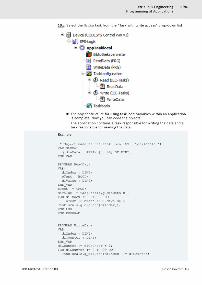
69 / 940ctrlX PLC EngineeringProgramming of Applications
Bosch Rexroth AGR911403764, Edition 03
18. Select the Write task from the “Task with write access” drop-down list.
🡆 The object structure for using task-local variables within an applicationis complete. Now you can code the objects.The application contains a task responsible for writing the data and atask responsible for reading the data.
Example
(* Object name of the task-local GVL: Tasklocals *)VAR_GLOBALg_diaData : ARRAY [0..99] OF DINT;
END_VAR
PROGRAM ReadDataVARdiIndex : DINT;bTest : BOOL;diValue : DINT;
END_VARbTest := TRUE;diValue := TaskLocals.g_diaData[0];FOR diIndex := 0 TO 99 DO bTest := bTest AND (diValue = Tasklocals.g_diaData[diIndex]);END_FOREND_PROGRAM
PROGRAM WriteDataVARdiIndex : DINT;diCounter : DINT;
END_VARdiCounter := diCounter + 1;FOR diCounter := 0 TO 99 DOTasklocals.g_diaData[diIndex] := diCounter;
70 / 940 ctrlX PLC EngineeringProgramming of Applications
Bosch Rexroth AG R911403764, Edition 03
END_FOREND_PROGRAM
The diaData array is populated with values in the WriteData program. TheReadData program tests whether or not the values of the array are asexpected. If so, then the bTest variable yields the result TRUE.The tested data is declared in the variable g_diaData as task-local GVL. Thiscauses data access to be synchronized in the computer. In turn, this guaran-tees that the data is with cycle consistency even if the accessing programs arecalled from different tasks. It is taken into account that tasks can be inter-rupted by other tasks or can run simultaneously. The guarantee also appliesabove all if the application is running on a system with a multicore processor.If the variable g_diaData is declared as a global variable list only and theWirteData and ReadData programs are called from different tasks, then thetest will yield FALSE more often. Because then for example the values in Wir-teData can be changed while the values in ReadData are being read.
When using task-local variables, the compiler synchronizes the data of the vari-ables, which takes a lot of time and memory. The synchronization is a complextask that is suitable above all for multicore operation. Select this data type onlyif sufficient resources are available. Then having this kind of data consistency isa convenient option for you without worrying about data synchronization. Youcan concentrate on the actual task of implementing the functionality.
Restrictions in the declarationIn the global task-local variable list, pay attention to the following:● Do not assign direct addresses.● Do not map direct addresses.● Do not declare pointers.● Do not declare references.● Do not instantiate function blocks.● Do not declare remanent variables as PERSISTENT and RETAIN at the same
time.Example: VAR_GLOBAL RETAIN g_RemanentData END_VAR
When you edit the declaration in the list of task-local variables, you cannotlogin to the application afterwards with an online change.
Data accessCompiler errors:The compiler reports write access in a task without write access as an error.However, not all write-access violations can be detected. The compiler can onlyassign static calls to a task. The call of a function block by means of a pointeror an interface is not assigned to a task, for example. Therefore, no writeaccess is recorded there either. Moreover, pointers can point to task-local varia-bles. Therefore, data can be manipulated in a read task. In this case, a runtimeerror is not issued. However, values that are modified by means of pointeraccess are not copied back in the shared reference of variables.Read access:Task-local variables are located at a different address in the list for each task.As a result, the ADR operator applied for a task-local variable yields anotheraddress in each task.
71 / 940ctrlX PLC EngineeringProgramming of Applications
Bosch Rexroth AGR911403764, Edition 03
Controlling the task executionA scheduler controls the time-based execution of multiple tasks and thereforealso task switching. The strategy, which is tracked by the scheduler in order tocontrol the allocation of the execution time, has the goal of preventing a taskfrom being blocked. The synchronization mechanism is optimized to preventblocking states (lock states) and at no time does a task wait for the action ofanother task.Scheduling strategy:● As long as the writing task saves a copy back to the shared reference, none
of the reading tasks gets a copy.● As long as a reading task gets a copy of the common reference, the writing
task does not write back a copy.Due to the scheduling method, no time can be determined when a reading tasksecurely receives a copy of the writing task. In principle, the copies can runapart from one another. During the runtime of the sample application appTas-klocal, you cannot expect each written copy to be edited once by the reader.For example, the reading task can edit the same array over multiple cycles, orthe contents of the array can skip one or more values between two cycles. Payattention to these effects of task switching.For task-local variables on the other hand, it is guaranteed that task switchingruns with cycle consistency.A task with write access is halted for example between two accesses to theshared reference by a reading task for the duration of one cycle. Therefore, if nreading tasks exist, then the writing task can have n cycles of delay until thenext update of the shared reference.A writing task can also prevent a reading task from getting a reading copy ineach cycle. Consequently, no upper limit can be specified for the number ofcycles after which a reading task will definitely receive a copy. This can lead toproblems especially when the reading task runs very slowly. For example, if atask runs only every hour and cannot access the task-local variables during thistime, then the task works with a very old copy of the list.You can remedy this by adding a time stamp for each task-local variable. In thisway, you can at least determine whether the reading tasks access a current list.For example, add a variable of data type LTIME to the list of task-local variablesand add the following code to the writing task:tasklocal.g_ltimStamp := LTIME();
Technical implementationThe compiler creates a copy for a list of task-local variables for each task. Thiscreates a structure with the same variables as those in the list of task-local vari-ables. Moreover, an array with this structure is created in which a dimension iscreated for each task. As a result, an array element is indexed for each task. If avariable in the list is accessed now in the code, then the task-local copy of thelist is actually accessed. Furthermore, it is determined in which task the blockis currently running and then the access is indexed accordingly.For example, the line of code diValue := TaskLocals.g_diaData[0]; fromthe above example is replaced by: diValue := __TaskLocalVarsArray[__CURRENTTASK.Tas-kIndex].__g_diarr[0];__CURRENTTASK is an operator that is available in PLC Engineering V3.5 SP13and later in order to determine the current task index quickly.At runtime for the writing task at the end, the contents of the task-local list arewritten to the global list. For a reading task at the beginning, the contents ofthe global list are copied to the task-local copy. Therefore, for n tasks, there are

72 / 940 ctrlX PLC EngineeringProgramming of Applications
Bosch Rexroth AG R911403764, Edition 03
n+1 copies of the list: One list serves as a shared reference and every task alsohas its own copy of the list. In addition, copying to or from the shared refer-ence is also synchronized.When deciding whether or not synchronization is the appropriate technique foryour system, consider that the technical implementation requires more effort.
Established methodTask-local variables are designed for the use case "Single writer - multiplereaders". When you implement a code that is called by different tasks, usingtask-local variables is a significant advantage. For example, this is the case forthe sample application appTasklocal when it is extended by multiple readingtasks that all access the same array and use the same functions.Task-local variables are especially useful on multicore systems. On these sys-tems, you cannot synchronize tasks by priority. Then other synchronizationmechanisms become necessary.Do not use task-local variables when a reading task always works on the newestcopy of the variable. Task-local variables are not suitable for this purpose.A similar issue is the "Producer - Consumer" dilemma. This happens when atask produces data and another task processes the data. Choose another typeof synchronization for this configuration. For example, the producer could use aflag to notify that a new date is present. Then the consumer uses a second flagto notify that it has processed its data and is waiting for new input. In this way,both can work on the same data. This removes the overhead for cyclic copyingof data, and the consumer does not lose any data generated by the producer.
MonitoringAt runtime, there may exist multiple different copies of the task-local variablelist in memory. When monitoring a position, not all values can be displayed.Therefore, the values from the shared reference are displayed for inline moni-toring, in the monitoring list, and in the visualization for a task-local variable.If you set a breakpoint, then the data of the task is displayed that ran to thebreakpoint and was halted as a result. Meanwhile, the other tasks continue run-ning. Under certain circumstances, the shared copy can be changed. In the con-text of the halted task, however, the values remain unchanged and are dis-played as they are. You must be aware of this.
See also● ⮫ Chapter “Command 'Auto Declare'” on page 671● ⮫ Chapter “Declaring Global Variables” on page 66● ⮫ Chapter “Object 'GVL' - Global Variable List (task-local)” on page 581
1.8.3 Creating Source Code in IECSource code:"Source code" is a term used for the implementation code, which you insert inthe programming modules by using the appropriate programming language edi-tors. The following programming module types are available for this purpose:POU (Program, Function, Function Block), Action, Method, Property, Interface.Programming Language:When creating a POU, you define, in which programming language the imple-mentation should be inserted. Besides the IEC languages also CFC is available.Programming Language:Editors:
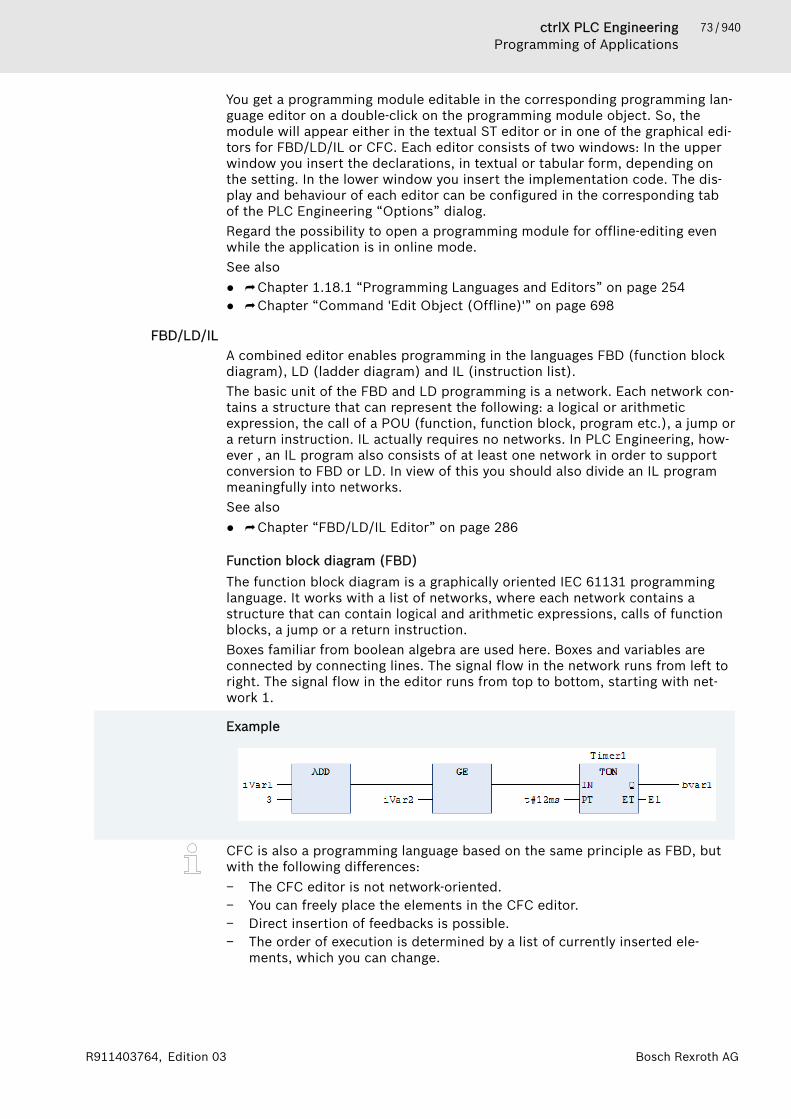
73 / 940ctrlX PLC EngineeringProgramming of Applications
Bosch Rexroth AGR911403764, Edition 03
You get a programming module editable in the corresponding programming lan-guage editor on a double-click on the programming module object. So, themodule will appear either in the textual ST editor or in one of the graphical edi-tors for FBD/LD/IL or CFC. Each editor consists of two windows: In the upperwindow you insert the declarations, in textual or tabular form, depending onthe setting. In the lower window you insert the implementation code. The dis-play and behaviour of each editor can be configured in the corresponding tabof the PLC Engineering “Options” dialog.Regard the possibility to open a programming module for offline-editing evenwhile the application is in online mode.See also● ⮫ Chapter 1.18.1 “Programming Languages and Editors” on page 254● ⮫ Chapter “Command 'Edit Object (Offline)'” on page 698
FBD/LD/ILA combined editor enables programming in the languages FBD (function blockdiagram), LD (ladder diagram) and IL (instruction list).The basic unit of the FBD and LD programming is a network. Each network con-tains a structure that can represent the following: a logical or arithmeticexpression, the call of a POU (function, function block, program etc.), a jump ora return instruction. IL actually requires no networks. In PLC Engineering, how-ever , an IL program also consists of at least one network in order to supportconversion to FBD or LD. In view of this you should also divide an IL programmeaningfully into networks.See also● ⮫ Chapter “FBD/LD/IL Editor” on page 286
Function block diagram (FBD)The function block diagram is a graphically oriented IEC 61131 programminglanguage. It works with a list of networks, where each network contains astructure that can contain logical and arithmetic expressions, calls of functionblocks, a jump or a return instruction.Boxes familiar from boolean algebra are used here. Boxes and variables areconnected by connecting lines. The signal flow in the network runs from left toright. The signal flow in the editor runs from top to bottom, starting with net-work 1.
Example
CFC is also a programming language based on the same principle as FBD, butwith the following differences:− The CFC editor is not network-oriented.− You can freely place the elements in the CFC editor.− Direct insertion of feedbacks is possible.− The order of execution is determined by a list of currently inserted ele-
ments, which you can change.
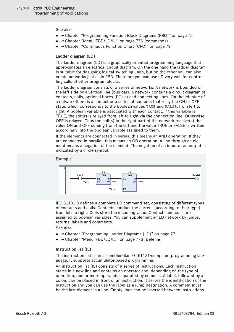
74 / 940 ctrlX PLC EngineeringProgramming of Applications
Bosch Rexroth AG R911403764, Edition 03
See also● ⮫ Chapter “Programming Function Block Diagrams (FBD)” on page 75● ⮫ Chapter “Menu 'FBD/LD/IL'” on page 776 (commands)● ⮫ Chapter “Continuous Function Chart (CFC)” on page 79
Ladder diagram (LD)The ladder diagram (LD) is a graphically oriented programming language thatapproximates an electrical circuit diagram. On the one hand the ladder diagramis suitable for designing logical switching units, but on the other you can alsocreate networks just as in FBD. Therefore you can use LD very well for control-ling calls of other program blocks.The ladder diagram consists of a series of networks. A network is bounded onthe left side by a vertical line (bus bar). A network contains a circuit diagram ofcontacts, coils, optional boxes (POUs) and connecting lines. On the left side ofa network there is a contact or a series of contacts that relay the ON or OFFstate, which corresponds to the boolean values TRUE and FALSE, from left toright. A boolean variable is associated with each contact. If this variable isTRUE, the status is relayed from left to right via the connection line. OtherwiseOFF is relayed. Thus the coil(s) in the right part of the network receive(s) thevalue ON and OFF coming from the left and the value TRUE or FALSE is writtenaccordingly into the boolean variable assigned to them.If the elements are connected in series, this means an AND operation. If theyare connected in parallel, this means an OR operation. A line through an ele-ment means a negation of the element. The negation of an input or an output isindicated by a circle symbol.
Example
IEC 61131-3 defines a complete LD command set, consisting of different typesof contacts and coils. Contacts conduct the current (according to their type)from left to right. Coils store the incoming value. Contacts and coils areassigned to boolean variables. You can supplement an LD network by jumps,returns, labels and comments.See also● ⮫ Chapter “Programming Ladder Diagrams (LD)” on page 77● ⮫ Chapter “Menu 'FBD/LD/IL'” on page 776 (Befehle)
Instruction list (IL)The instruction list is an assembler-like IEC 61131-compliant programming lan-guage. It supports accumulator-based programming.An instruction list (IL) consists of a series of instructions. Each instructionstarts in a new line and contains an operator and, depending on the type ofoperation, one or more operands separated by commas. A label, followed by acolon, can be placed in front of an instruction. It serves the identification of theinstruction and you can use the label as a jump destination. A comment mustbe the last element in a line. Empty lines can be inserted between instructions.

75 / 940ctrlX PLC EngineeringProgramming of Applications
Bosch Rexroth AGR911403764, Edition 03
All IEC 61131-3 operators are supported, as are multiple inputs, multiple out-puts, negations, comments, set/reset of outputs and conditional/unconditionaljumps.Each instruction is based primarily on the loading of values into the accumu-lator (LD instruction). After that the corresponding operation is executed withthe parameter from the accumulator. The result of the operation is writtenagain into the accumulator, from where you should store it purposefully withthe help of an ST instruction.The instruction list supports comparison operators (EQ, GT, LT, GE, LE, NE)and jumps for programming of conditional executions or loops. Jumps can beunconditional (JMP) or conditional (JMPC / JMPCN). In the case of conditionaljumps, a check is performed as to whether the value in the accumulator is TRUEor FALSE.
Example
See also● ⮫ Chapter “Programming in Instruction List (IL)” on page 78● ⮫ Chapter “Modifiers and Operators in IL” on page 291
Programming Function Block Diagrams (FBD)Creating a POU in the function block diagram (FBD) implementation language1. Select an application in the device tree.2. Select the command “Project 🠂 Add Object 🠂 POU”.
🡆 The dialog box “Add POU” opens.3. Enter a name and select the implementation language “Function Block
Diagram (FBD)”.Click on “Add”.🡆 The POU is added to the device tree and opened in the editor. It con-
sists of the declaration editor in the top part and the implementationpart with an empty network in the lower part. The view “ToolsBox” isalso automatically opened , in which the suitable elements, operatorsand function blocks for FBD programming are available.
See also● ⮫ Chapter “Object 'POU'” on page 587● ⮫ Chapter “FBD/LD/IL” on page 73
76 / 940 ctrlX PLC EngineeringProgramming of Applications
Bosch Rexroth AG R911403764, Edition 03
Programming a network1. Click inside the automatically inserted empty network in the implementa-
tion part.🡆 The network is given a yellow background and the area at the left-hand
side with the network number is given a red background.2. Open the context menu with the right mouse button.
🡆 You obtain amongst other things the insert commands for the elementsthat can be inserted at this point.
3. Insert the elements required for your programming using the menu com-mands or by dragging in the elements from the toolbox.
4. For example, select the command “Insert Assignment”.🡆 An assignment line is inserted. In each case three question marks stand
for assignment source and assignment target.5. Select the question marks and replace them with the desired variable.
Input assistance is available for this purpose.6. Move the cursor over the assignment line.
🡆 The possible insertion positions for further elements are displayed asgrey diamonds. A click on a diamond selects that position and the suit-able insert commands are once again available.
7. Alternatively, you can drag an element with the mouse from the toolboxinto the network. For example, click in the tool box on the box element,keep the mouse button pressed and move the cursor over the network.🡆 Each possible insertion position lights up green.
8. Release the mouse button in order to insert the box.🡆 The box is displayed in the network. The type of box on the inside and
the instance name above the box, which is required in the case of afunction block, are still kept free with three question marks.
9. Select the string ??? inside the box and replace it with the name of thebox. Input assistance is available for this purpose.🡆 The inputs and outputs of the selected box are displayed. They are still
kept free with question marks, as is the instance name in the case of afunction block.
See also● ⮫ Chapter “Menu 'FBD/LD/IL'” on page 776● ⮫ Chapter “FBD/LD/IL” on page 73
Programming line branches (subnetworks)1. In the implementation part of your POU, insert a new network using the
command “FBD/LD/IL 🠂 Insert network” or drag it in from the tool box.2. For example, drag an “ADD” operator into the empty network and replace
the characters ??? with two variables of the type INT.3. Drag the element “Branch” from the tool box into your implementation
and release the mouse button at the green insertion position directly atthe output of the operator.🡆 The line branch splits the processing line at the output of the operator
box into 2 subnetworks.4. Further FBD elements and also further line branches can now be added to
each of the two subnetworks.See also● ⮫ Chapter “FBD/LD/IL Element 'Branch'” on page 297● ⮫ Chapter “Command 'Insert Branch'” on page 785
77 / 940ctrlX PLC EngineeringProgramming of Applications
Bosch Rexroth AGR911403764, Edition 03
See also● ⮫ Chapter “FBD/LD/IL Editor” on page 286
Programming Ladder Diagrams (LD)Creating a POU in the ladder diagram (LD) implementation language1. Select the application in the Device tree.2. Select the command “Project 🠂 Add Object 🠂 POU”.
🡆 The dialog box “Add POU” opens.3. Enter a name and select the implementation language “Ladder Diagram
(LD)”.Click on “Add”.🡆 PLC Engineering adds the POU to the Device tree and opens it in the
editor. An empty network is inserted in the implementation part. Theempty network is bounded on the left by a vertical line, which repre-sents a bus bar. The view “ToolBox” is also automatically opened, inwhich the suitable elements, operators and function blocks for LD pro-gramming are available.
Adding a contact and a function block (TON)Requirement: a POU with the implementation language LD is opened in theeditor and an empty network is inserted.1. Click on the category “Ladder Elements” in the view “ToolBox”2. Click on the “Contact” element, drag it into your network and release the
mouse button at the insertion position “Start here”.🡆 The contact is added on the left in the network directly against the ver-
tical line.3. Click on ??? and enter the identifier of a boolean variable. The input assis-
tant is also available to you for this.4. Click on the category “Function Blocks” in the view “ToolBox” and drag
the function block “TON” onto an insertion position on the connecting lineto the right of the inserted contact.🡆 PLC Engineering inserts the box “TON” to the right of the contact. The
contact is connected with the input IN of the TON box.5. Enter a time constant at the input PT, for example T#3s.
🡆 If the variable of your contact goes TRUE, then the input IN of the TONbox also goes TRUE. The TON box forwards the value TRUE to theoutput Q with a switch-on delay of T#3s, for example.
Inserting a closed line branchRequirement: a POU with the implementation language LD is opened in theeditor and an empty network is inserted.1. Click inside the empty network and select the command “FBD/LD/IL
🠂 Insert Contact”.2. Select the connecting line to the left of the contact and select the com-
mand “FBD/LD/IL 🠂 Set Branch Start Point”.🡆 The starting point on the connecting line is marked by a red rectangle.
PLC Engineering marks all possible end points of the branch with ablue rectangle.

78 / 940 ctrlX PLC EngineeringProgramming of Applications
Bosch Rexroth AG R911403764, Edition 03
3. Click on a blue rectangle in order to set the end point of your closed linebranch.🡆 PLC Engineering inserts the line branch between the starting and end
points. The program flow will go through both branches up to the endpoint.If you insert the line branch at a box instead of at a contact, the boxwill only be called if none of the other branches is TRUE.
See also● ⮫ Chapter “FBD/LD/IL Editor” on page 286● ⮫ Chapter “Closed Branch” on page 299● ⮫ Chapter “LD Element 'Contact'” on page 298
Programming in Instruction List (IL)If necessary, IL can be activated in the PLC Engineering options.
Creating POUs in the Instruction List (IL) implementation language1. Select the application in the device tree.2. Click “Project 🠂 Add Object 🠂 POU”.
🡆 The “Add POU” dialog opens.3. Enter a name and select the implementation language “Instruction List
(IL)”.Click “Add”.🡆 PLC Engineering adds the POU to the device tree and opens it in the
editor. A network is already inserted in the implementation part.
Programming networks (example: ADD operation)Requirement: A POU (IL) is opened in the editor and possesses an empty net-work.1. Click the line marked in color in the 1st column and enter the operator LD.2. Press the [Tab] key.
🡆 The cursor jumps to the 2nd column3. Enter the first summand of your ADD operation, for example 6.4. Press [Ctrl]+[Enter] or select the command “FBD/LD/IL 🠂 Insert IL Line
After”.🡆 PLC Engineering inserts a new instruction line. The first column of this
line has the focus.5. Enter ADD and press [Tab].6. Enter the second summand of your ADD operation, for example 12.7. Press [Ctrl]+[Enter]8. Enter the operator ST and press [Tab].9. Specify a variable of the data type INT, for example iVar.
🡆 The result – 16 in the example – is stored in the iVar.
Calling function blocksRequirement: A POU (IL) is opened in the editor and possesses an empty net-work. A variable of the data type <function block> is declared in the declarationpart (example: C1:CTU;).
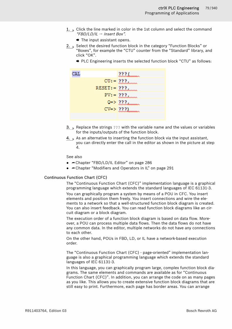
79 / 940ctrlX PLC EngineeringProgramming of Applications
Bosch Rexroth AGR911403764, Edition 03
1. Click the line marked in color in the 1st column and select the command“FBD/LD/IL 🠂 Insert Box”.🡆 The input assistant opens.
2. Select the desired function block in the category “Function Blocks” or“Boxes”, for example the “CTU” counter from the “Standard” library, andclick “OK”.🡆 PLC Engineering inserts the selected function block “CTU” as follows:
3. Replace the strings ??? with the variable name and the values or variablesfor the inputs/outputs of the function block.
4. As an alternative to inserting the function block via the input assistant,you can directly enter the call in the editor as shown in the picture at step4.
See also● ⮫ Chapter “FBD/LD/IL Editor” on page 286● ⮫ Chapter “Modifiers and Operators in IL” on page 291
Continuous Function Chart (CFC)The “Continuous Function Chart (CFC)” implementation language is a graphicalprogramming language which extends the standard languages of IEC 61131-3.You can graphically program a system by means of a POU in CFC. You insertelements and position them freely. You insert connections and wire the ele-ments to a network so that a well-structured function block diagram is created.You can also insert feedback. You can read function block diagrams like an cir-cuit diagram or a block diagram.The execution order of a function block diagram is based on data flow. More-over, a POU can process multiple data flows. Then the data flows do not haveany common data. In the editor, multiple networks do not have any connectionsto each other.On the other hand, POUs in FBD, LD, or IL have a network-based executionorder.
The “Continuous Function Chart (CFC) - page-oriented” implementation lan-guage is also a graphical programming language which extends the standardlanguages of IEC 61131-3.In this language, you can graphically program large, complex function block dia-grams. The same elements and commands are available as for “ContinuousFunction Chart (CFC)”. In addition, you can arrange the code on as many pagesas you like. This allows you to create extensive function block diagrams that arestill easy to print. Furthermore, each page has border areas. You can arrange

80 / 940 ctrlX PLC EngineeringProgramming of Applications
Bosch Rexroth AG R911403764, Edition 03
inputs and sink connection marks on the left, and outputs and source connec-tion marks on the right. This helps you to insert connecting lines and provides abetter overview.Unfortunately, it is not possible to switch a POU between the “ContinuousFunction Chart (CFC) - page-oriented” and “Continuous Function Chart (CFC)”implementation languages.
Siehe auch● ⮫ Chapter “CFC Editor” on page 301● ⮫ Chapter “CFC Editor, Page-Oriented” on page 303● ⮫ Chapter “Menu 'CFC'” on page 763● ⮫ Chapter “Dialog 'Properties' - 'CFC Execution Order'” on page 830
Automatic Execution Order by Data FlowThe execution order in POUs is uniquely determined in text-based and network-based editors. In the CFC editor, however, you can position the elements freely,so the execution order is initially not unique. For this reason, PLC Engineeringdetermines the execution order by data flow and, in the case of multiple net-works, by the topological position of the elements. The elements are sortedfrom top to bottom and left to right. Now the execution order is unique andmakes sure that the POU is processed while optimized by time and by cycle.You can get information about the chronological order of the elements in thechart and temporarily display the execution order. When you program networkswith feedback you can define an element as the starting point in the feedbackloop.You can also explicitly edit the processing order in a CFC object if necessary. Todo this, switch the “Auto Data Flow Mode” property of the CFC object to“Explicit Execution Order Mode”. In this mode, you have the option of editingthe execution order by means of menu commands.Before ctrlX PLC Engineering System V3.5 SP15, you had to define the execu-tion order explicitly for each POU. The was no mode switching.
Data flowIn general, data flow is described as the chronological order in which data isread or written when and how in which programming objects. A POU canprocess any number of data flows, which can also be executed independentlyof each other.
Displaying the execution orderBy default, the execution order of a CFC object is determined automatically.The “Auto Data Flow Mode” property is selected for this. You can temporarilydisplay the automatically determined execution order in the CFC editor.1. Create a new project using the “Standard project” template and specify
the name Minimal for example.

81 / 940ctrlX PLC EngineeringProgramming of Applications
Bosch Rexroth AGR911403764, Edition 03
2. Extend the application with the function block FB_DOIt in the “ST” imple-mentation language with inputs and outputs.🡆
FUNCTION_BLOCK FB_DoItVAR_INPUTiAlfa : INT;iBravo: INT;sCharlie : STRING := 'Charlie';xItem : BOOL;
END_VARVAR_OUTPUT
iResult : INT;sResult : STRING;xResult : BOOL;
END_VARVAREND_VAR
iResult := iAlfa + iBravo;
IF xItem = TRUE THEN xResult := TRUE;
END_IF3. Create the function block ExecuteCFC in the “CFC” implementation lan-
guage.🡆
PROGRAM ExecuteCFCVARfb_DoIt_0: FB_DoIt;fb_DoIt_1: FB_DoIt;iFinal_1: INT;iFinal_0: INT;xFinal: BOOL;
END_VAR
Recently created programming objects in CFC have the Auto Data FlowMode selected. The execution order of the programming object is opti-mally defined internally.

82 / 940 ctrlX PLC EngineeringProgramming of Applications
Bosch Rexroth AG R911403764, Edition 03
4. Click “CFC 🠂 Execution Order 🠂 Display Execution Order”.🡆 The execution order of the object is shown. The boxes and inputs are
numbered accordingly and reflect the chronological processing order.The numbering is hidden as soon as you click again in the CFC editor.
Determining the execution order in feedback networks1. Create a CFC program with feedback.
🡆 The POU PrgPositiveFeedback counts.
PROGRAM PrgPositiveFeedbackVARiResult: INT;
END_VAR
2. Select an element within the feedback.🡆 The selected element is highlighted in red.
3. Click “CFC 🠂 Execution Order 🠂 Set Start of Feedback”.
🡆 At runtime, this POU is processed first. The start POU of the feedbackis defined and decorated with the symbol. The execution order isresorted and the selected element gets the number 0. (This is thelowest number of the feedback.)
4. Select the start POU again.
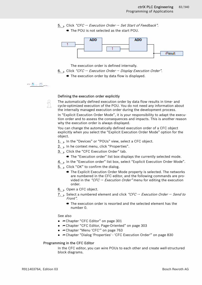
83 / 940ctrlX PLC EngineeringProgramming of Applications
Bosch Rexroth AGR911403764, Edition 03
5. Click “CFC 🠂 Execution Order 🠂 Set Start of Feedback”.🡆 The POU is not selected as the start POU.
The execution order is defined internally.6. Click “CFC 🠂 Execution Order 🠂 Display Execution Order”.
🡆 The execution order by data flow is displayed.
Defining the execution order explicitlyThe automatically defined execution order by data flow results in time- andcycle-optimized execution of the POU. You do not need any information aboutthe internally managed execution order during the development process.In “Explicit Execution Order Mode”, it is your responsibility to adapt the execu-tion order and to assess the consequences and impacts. This is another reasonwhy the execution order is always displayed.You can change the automatically defined execution order of a CFC objectexplicitly when you select the “Explicit Execution Order Mode” option for theobject.1. In the “Devices” or “POUs” view, select a CFC object.2. In he context menu, click “Properties”.3. Click the “CFC Execution Order” tab.
🡆 The “Execution order” list box displays the currently selected mode.4. In the “Execution order” list box, select “Explicit Execution Order Mode”.5. Click “OK” to confirm the dialog.
🡆 The Explicit Execution Order Mode property is selected. The networksare numbered in the CFC editor, and the following commands are pro-vided in the “CFC 🠂 Execution Order” menu for editing the executionorder.
6. Open a CFC object.7. Select a numbered element and click “CFC 🠂 Execution Order 🠂 Send to
Front”.🡆 The execution order is resorted and the selected element has the
number 0.
See also● ⮫ Chapter “CFC Editor” on page 301● ⮫ Chapter “CFC Editor, Page-Oriented” on page 303● ⮫ Chapter “Menu 'CFC'” on page 763● ⮫ Chapter “Dialog 'Properties' - 'CFC Execution Order'” on page 830
Programming in the CFC EditorIn the CFC editor, you can wire POUs to each other and create well-structuredblock diagrams.
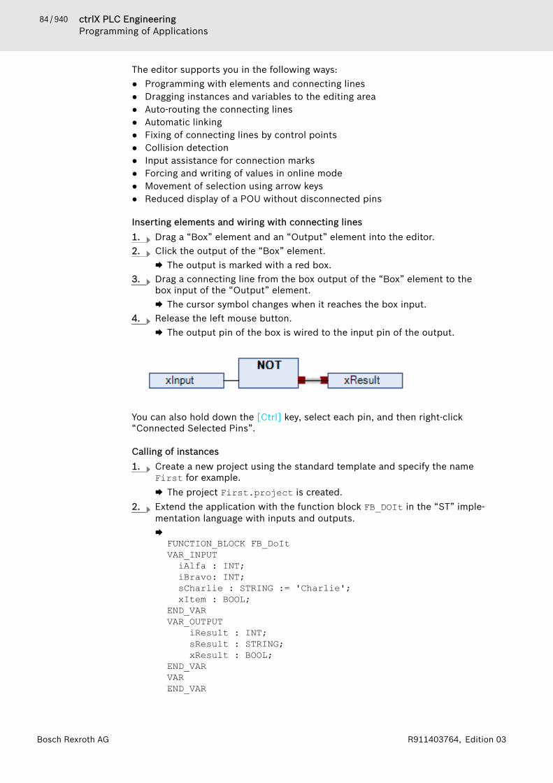
84 / 940 ctrlX PLC EngineeringProgramming of Applications
Bosch Rexroth AG R911403764, Edition 03
The editor supports you in the following ways:● Programming with elements and connecting lines● Dragging instances and variables to the editing area● Auto-routing the connecting lines● Automatic linking● Fixing of connecting lines by control points● Collision detection● Input assistance for connection marks● Forcing and writing of values in online mode● Movement of selection using arrow keys● Reduced display of a POU without disconnected pins
Inserting elements and wiring with connecting lines1. Drag a “Box” element and an “Output” element into the editor.2. Click the output of the “Box” element.
🡆 The output is marked with a red box.3. Drag a connecting line from the box output of the “Box” element to the
box input of the “Output” element.🡆 The cursor symbol changes when it reaches the box input.
4. Release the left mouse button.🡆 The output pin of the box is wired to the input pin of the output.
You can also hold down the [Ctrl] key, select each pin, and then right-click“Connected Selected Pins”.
Calling of instances1. Create a new project using the standard template and specify the name
First for example.🡆 The project First.project is created.
2. Extend the application with the function block FB_DOIt in the “ST” imple-mentation language with inputs and outputs.🡆
FUNCTION_BLOCK FB_DoItVAR_INPUTiAlfa : INT;iBravo: INT;sCharlie : STRING := 'Charlie';xItem : BOOL;
END_VARVAR_OUTPUT
iResult : INT;sResult : STRING;xResult : BOOL;
END_VARVAREND_VAR

85 / 940ctrlX PLC EngineeringProgramming of Applications
Bosch Rexroth AGR911403764, Edition 03
iResult := iAlfa + iBravo;
IF xItem = TRUE THEN xResult := TRUE;
END_IF3. Select the application and click “Add Object 🠂 POU” in the context menu.
Select the “Continuous Function Chart (CFC)” implementation languageand the type Program. Specify the name PrgFirst for example.Click “OK” to confirm the dialog.🡆 The program PrgFirst is created and it opens in the editor. It is still
empty.4. Instantiate function blocks and declare variables.
🡆PROGRAM PrgFirstVARiCounter: INT;
fbDoIt_1 : FB_DoIt;fbDoIt_2 : FB_DoIt; iOut : INT;sOut: STRING;xOut: BOOL;
END_VAR5. Drag a “Box” element from the “ToolBox” view into the editor.6. Click the ??? field and type in ADD.
🡆 The box type is ADD. The box acts as an adder.7. Click line 3 in the declaration editor.
🡆 The declaration line of iCounter is selected.8. Click in the selection and drag the selected variable into the implementa-
tion. Focus there on an input of the ADD box.🡆 An input has been created, declared, and connected to the box.
9. Click again in the selection and drag the variable to the output of the ADDbox.🡆 An output has been created, declared, and connected to the box.
10. Drag an “Input” element from the “ToolBox” view to the implementation.Click its ??? field and type in 1.
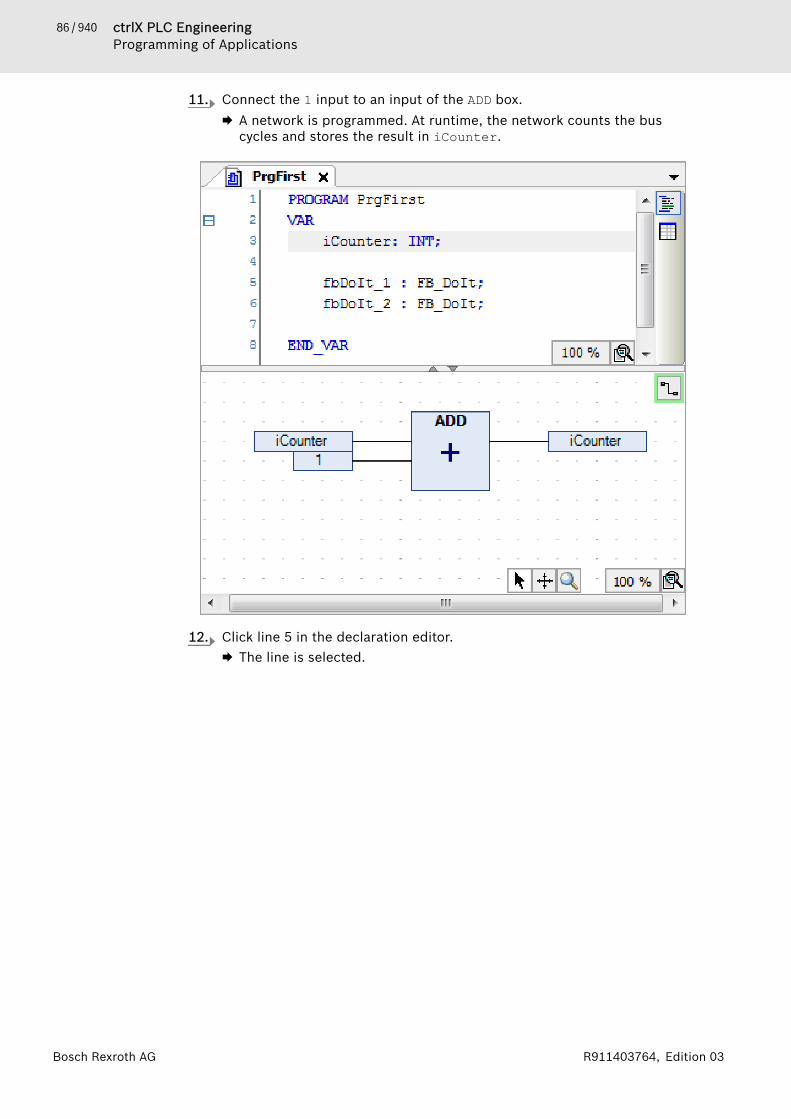
86 / 940 ctrlX PLC EngineeringProgramming of Applications
Bosch Rexroth AG R911403764, Edition 03
11. Connect the 1 input to an input of the ADD box.🡆 A network is programmed. At runtime, the network counts the bus
cycles and stores the result in iCounter.
12. Click line 5 in the declaration editor.🡆 The line is selected.
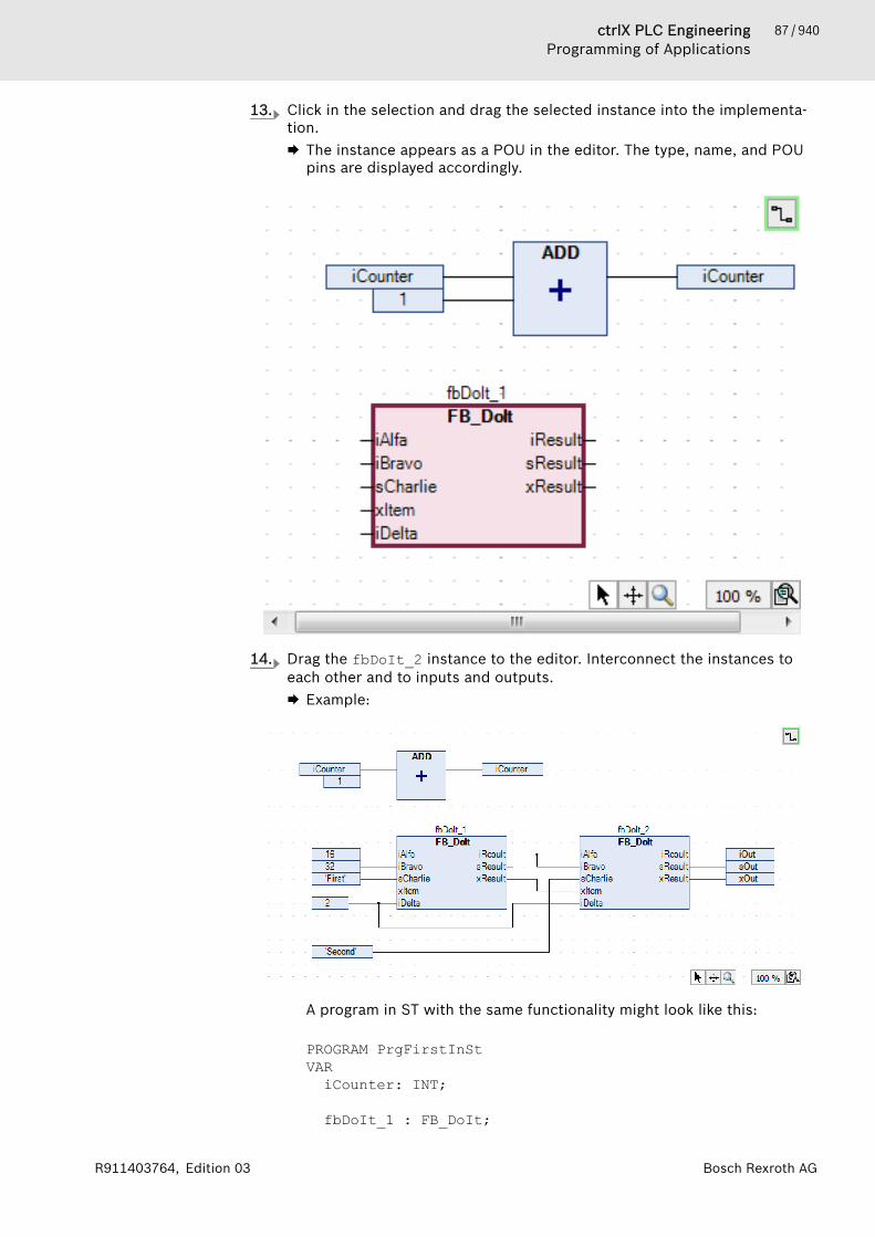
87 / 940ctrlX PLC EngineeringProgramming of Applications
Bosch Rexroth AGR911403764, Edition 03
13. Click in the selection and drag the selected instance into the implementa-tion.🡆 The instance appears as a POU in the editor. The type, name, and POU
pins are displayed accordingly.
14. Drag the fbDoIt_2 instance to the editor. Interconnect the instances toeach other and to inputs and outputs.🡆 Example:
A program in ST with the same functionality might look like this:
PROGRAM PrgFirstInStVARiCounter: INT;
fbDoIt_1 : FB_DoIt;

88 / 940 ctrlX PLC EngineeringProgramming of Applications
Bosch Rexroth AG R911403764, Edition 03
fbDoIt_2 : FB_DoIt; iOut : INT;sOut: STRING;xOut: BOOL;
END_VARiCounter := iCounter + 1;fbDoIt_1(iAlfa := 16, iBravo := 32, sCharlie := 'First', xItem := TRUE, iDelta := 2, iResult => fbDoIt_2.iAlfa, xResult => fbDoIt_2.xItem);fbDoIt_2(iBravo := fbDoIt_1.iResult, sCharlie := 'Second', iDelta := 2, iResult => iOut , sResult=> sOut, xResult => xOut);
Creating connection marksRequirement: A CFC POU has connected elements.1. Select a connecting line between two elements.
🡆 The connecting line is displayed as selected. The ends of the con-necting line are marked with red boxes ( ).
2. Click “CFC 🠂 Connection Mark”.🡆 The connection is separated into a “Connection Mark - Source” and a
“Connection Mark - Sink”. The name of the mark is generated automati-cally.
3. Click in the source connection marks.🡆 You can edit the name.
4. Specify a name SimpleMark for the source connection mark.🡆 The source connection mark and sink connection mark have the same
name.
Resolving collisions and fixing connecting lines by means of control pointsThe following example shows how to use the “Route All Connections” com-mand with control points.

89 / 940ctrlX PLC EngineeringProgramming of Applications
Bosch Rexroth AGR911403764, Edition 03
1. Position the “Input” and “Output” elements. Connect the elements.
2. Position two “Box” elements on the line.🡆 The connecting line and the boxes are marked red because of the colli-
sion.
3. Click “CFC 🠂 Routing 🠂 Route All Connections”.🡆 The collision is resolved.
4. Change the connecting lines gradually.
🡆 The connecting line has been changed manually and is now blocked forauto-routing. This is shown by a lock symbol at the end of the connec-tion.
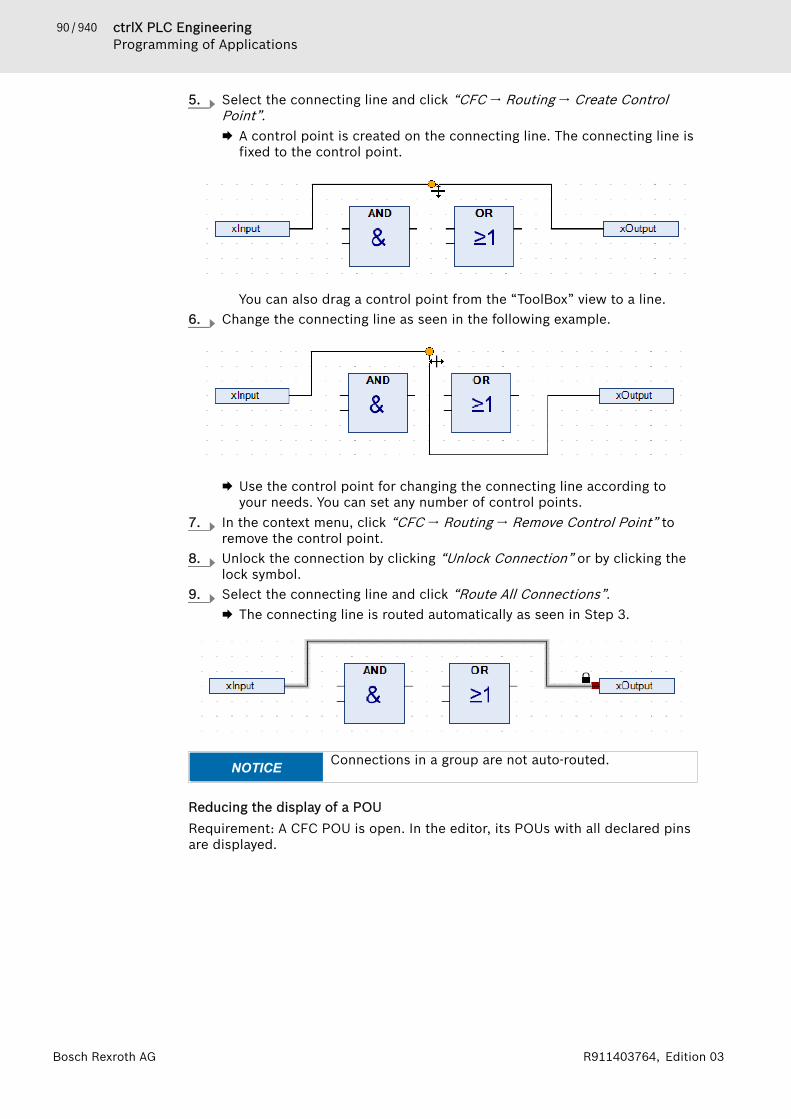
90 / 940 ctrlX PLC EngineeringProgramming of Applications
Bosch Rexroth AG R911403764, Edition 03
5. Select the connecting line and click “CFC 🠂 Routing 🠂 Create ControlPoint”.🡆 A control point is created on the connecting line. The connecting line is
fixed to the control point.
You can also drag a control point from the “ToolBox” view to a line.6. Change the connecting line as seen in the following example.
🡆 Use the control point for changing the connecting line according toyour needs. You can set any number of control points.
7. In the context menu, click “CFC 🠂 Routing 🠂 Remove Control Point” toremove the control point.
8. Unlock the connection by clicking “Unlock Connection” or by clicking thelock symbol.
9. Select the connecting line and click “Route All Connections”.🡆 The connecting line is routed automatically as seen in Step 3.
NOTICE Connections in a group are not auto-routed.
Reducing the display of a POURequirement: A CFC POU is open. In the editor, its POUs with all declared pinsare displayed.
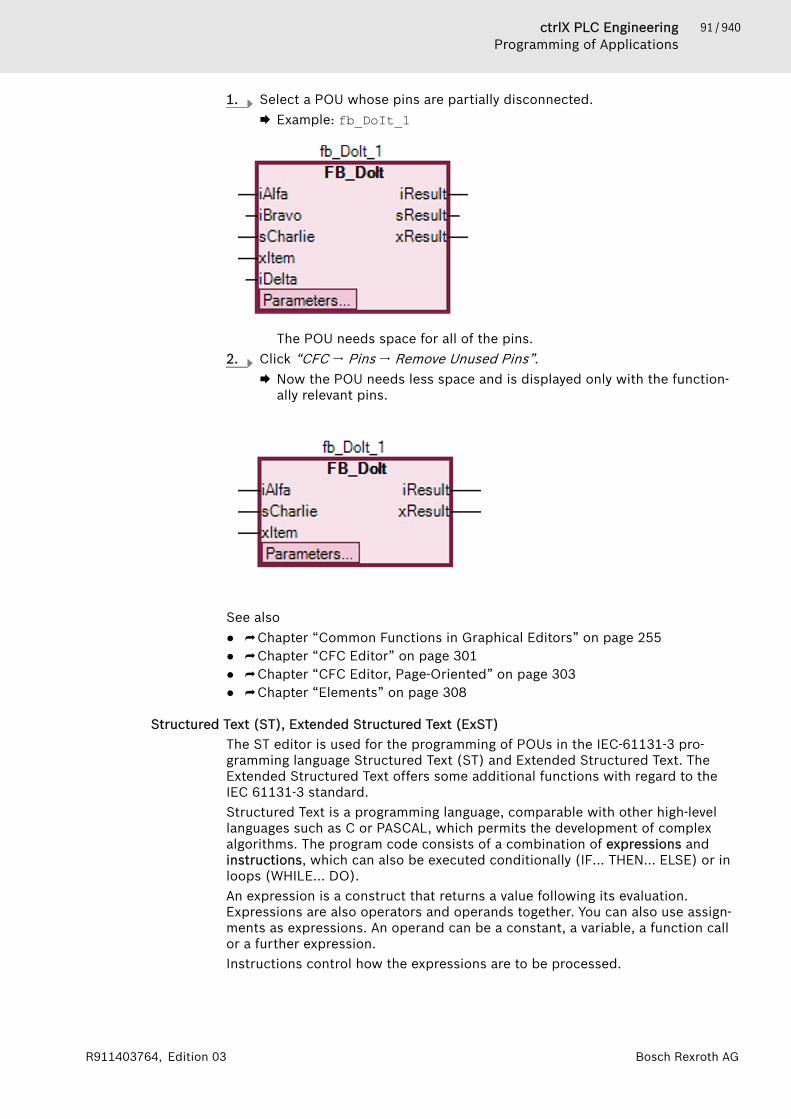
91 / 940ctrlX PLC EngineeringProgramming of Applications
Bosch Rexroth AGR911403764, Edition 03
1. Select a POU whose pins are partially disconnected.🡆 Example: fb_DoIt_1
The POU needs space for all of the pins.2. Click “CFC 🠂 Pins 🠂 Remove Unused Pins”.
🡆 Now the POU needs less space and is displayed only with the function-ally relevant pins.
See also● ⮫ Chapter “Common Functions in Graphical Editors” on page 255● ⮫ Chapter “CFC Editor” on page 301● ⮫ Chapter “CFC Editor, Page-Oriented” on page 303● ⮫ Chapter “Elements” on page 308
Structured Text (ST), Extended Structured Text (ExST)The ST editor is used for the programming of POUs in the IEC-61131-3 pro-gramming language Structured Text (ST) and Extended Structured Text. TheExtended Structured Text offers some additional functions with regard to theIEC 61131-3 standard.Structured Text is a programming language, comparable with other high-levellanguages such as C or PASCAL, which permits the development of complexalgorithms. The program code consists of a combination of expressions andinstructions, which can also be executed conditionally (IF… THEN… ELSE) or inloops (WHILE… DO).An expression is a construct that returns a value following its evaluation.Expressions are also operators and operands together. You can also use assign-ments as expressions. An operand can be a constant, a variable, a function callor a further expression.Instructions control how the expressions are to be processed.
92 / 940 ctrlX PLC EngineeringProgramming of Applications
Bosch Rexroth AG R911403764, Edition 03
For this text editor you can make various settings with regard to behavior,appearance and menus in the dialog boxes “Options” and “Adapt” in the“Tools” menu. The familiar Windows functions (for example IntelliMouse) arealso available for this editor.See also● ⮫ Chapter “Programming Structured Text (ST)” on page 92● ⮫ Chapter “Dialog 'Options' - 'Text Editor'” on page 860● ⮫ Chapter “Dialog 'Customize' - 'Menu'” on page 863
ExST - Extended Structured TextExtended Structured Text (ExST) is a PLC Engineering-specific extension of theIEC 61131-3 standard for Structured Text (ST).See also● ⮫ Chapter “ExST assignment 'R='” on page 260● ⮫ Chapter “ExST assignment 'S='” on page 259● ⮫ Chapter “ExST – Assignment as Expression” on page 261
Programming Structured Text (ST)PrincipleThe programming languages 'Structured Text' and 'Extended Structured Text'are programmed in the ST editor. The program code consists of a combinationof expressions and instructions, which can also be executed conditionally or inloops. You must conclude each instruction with a semicolon ;.The variables are declared in the declaration editor.
Creating a POU in the Structured Text (ST) implementation language1. Select an application in the device tree.2. Select the command “Project 🠂 Add Object 🠂 POU”.
🡆 The dialog box “Add POU” opens.3. Enter a name and select the “Implementation language”“Structured Text
(ST)”. Click on “Add”.🡆 The POU is added to the device tree and opened in the editor.
Now insert the variable declarations in the upper part of the POU andenter the ST program code in the lower part of the POU.
See also● ⮫ Chapter “ST Expressions” on page 257● ⮫ Chapter “Structured Text and Extended Structured Text (ExST)”
on page 256● ⮫ Chapter “ST Function Block Call” on page 267● ⮫ Chapter “ST Comments” on page 268● ⮫ Chapter “Using the Declaration Editor” on page 64
Sequential Function Chart (SFC)Use the SFC editor for programming POUs in the IEC 61131-3 compliant SFCimplementation language. SFC is a graphical programming language fordescribing the chronological sequence of individual actions in a program. Forthis purpose, actions (discrete programming objects) are assigned to step ele-ments. Transition elements control the processing order of steps.See also● ⮫ Chapter “SFC Editor” on page 268

93 / 940ctrlX PLC EngineeringProgramming of Applications
Bosch Rexroth AGR911403764, Edition 03
Programming the Sequential Function Chart (SFC)Creating POUs in the SFC implementation language1. Select an application in the device tree.2. Click “Project 🠂 Add Object 🠂 POU”.
🡆 The dialog box “Add POU” opens.3. Enter a name and select the implementation language “Sequential Func-
tion Chart (SFC)”.Click “Add”.🡆 PLC Engineering adds the POU to the device tree and opens it in the
editor.
Adding step-transitions1. Select the transition after the initial step.
🡆 The transition is marked red.2. Click “SFC 🠂 Insert step-transition after”.
🡆 PLC Engineering inserts the “Step0” step and the “Trans0” transition.3. Select the “Trans0” transition and click “SFC 🠂 Insert Step-Transition”.
🡆 PLC Engineering inserts the “Trans1” transition and the “Step1” stepbefore the “Trans0” transition.
You can also drag the “Step” and “Transition” elements into the diagram fromthe “Toolbox” view.See also● ⮫ Chapter “SFC Elements 'Step' and 'Transition'” on page 277● ⮫ Chapter “Command 'Insert Step-Transition'” on page 757● ⮫ Chapter “Command 'Insert Step-Transition After'” on page 757
Adding entry actions1. Select “Step0”.2. Click “SFC 🠂 Add entry action”.
🡆 By default, you are prompted to select the duplication mode for thestep actions. You decide whether the reference to the existing stepaction objects is copied when the step is copied, or the objects areembedded. Embedding results in new step action objects being createdwhen the step is copied. The duplication mode is defined in the “Dupli-cate when copying” step property. When it is deactivated, the copiedsteps call the same actions as the current step.You can deactivate the prompt completely in the SFC properties.The display of embedded objects in the “Devices” and “POUs” viewscan be deactivated by means of a menu command.
3. For this example, accept the default setting “Copy reference” and confirmby clicking “OK”.🡆 The “Add Entry Action” dialog box opens.
4. Type the name "Step0_entry" and select “Structured Text (ST)" as theimplementation language. Click “Add”.🡆 PLC Engineering inserts the "Step0_entry" action below the POU in the
device tree and opens the action in the editor.In the "Step0_entry" entry action, you program statements to be exe-cuted one time when the “Step0” step becomes active.

94 / 940 ctrlX PLC EngineeringProgramming of Applications
Bosch Rexroth AG R911403764, Edition 03
5. Close the "Step0_entry" editor.🡆 The “Step0” step is now marked with an “E” in the lower left corner.
Double-clicking this marker opens the editor.
The entry action Step0_entry is now available in the properties of thestep in “Entry action”. Other actions can also be selected there asneeded.
6. Select Step0. Press [Ctrl]+[V] to copy the step.🡆 The same entry actions inserted above are available In the inserted
copy of the step. The new step then calls the same exact action.See also● ⮫ Chapter “Command 'Add Entry Action'” on page 758● ⮫ “2. Step actions” on page 280● ⮫ Chapter “ Dialog 'Options' - 'SFC Editor'” on page 848
Adding exit actions1. Select “Step0”.2. Click “SFC 🠂 Add Exit Action”.
🡆 By default, you are prompted to select the duplication mode for thestep actions of the step. See above for adding entry actions. Then the“Add Exit Action” dialog box opens.
3. Specify the name "Step0_exit" and select the implementation language"Structured Text (ST)". Click “Add”.🡆 PLC Engineering inserts the "Step0_exit" action below the POU in the
device tree and opens the action in the editor.In the "Step0_exit" exit action, you program statements to be executedone time before the “Step0” step becomes inactive.
4. Close the "Step0_exit" editor.🡆 The “Step0” step is now marked with an “X” in the lower right corner.
Double-clicking this marker opens the editor.
You can define the exit action in the step properties of “Exit action”, as well asselect other actions as needed.See also● ⮫ Chapter “Command 'Add Exit Action'” on page 758● ⮫ “2. Step actions” on page 280

95 / 940ctrlX PLC EngineeringProgramming of Applications
Bosch Rexroth AGR911403764, Edition 03
Adding actions1. Double-click the “Step0” step.
🡆 By default, you are prompted to select the duplication mode for thestep actions of the step. See above for adding entry actions. The “AddAction” dialog box opens.
2. Type the name "Step0_active" and select the implementation language"Structured Text (ST)". Click “Add”.🡆 PLC Engineering inserts the “Step0_active” action below the POU in the
device tree and opens the action in the editor.In the Step0_active step action, you program statements to be exe-cuted as long as the step is active.
3. Close the "Step0_active" editor.🡆 The “Step0” step is now marked with a black triangle in the upper right
corner.
You can define the action in the step properties of “Step action”, as well asselect other actions as needed.See also● ⮫ “2. Step actions” on page 280
Adding alternative branches1. Select “Step1”.2. Click “SFC 🠂 Insert Branch Right”.
🡆 PLC Engineering inserts the “Step2” step to the right of “Step1”. Thesteps are connected as a parallel branch signified by two pairs ofdouble lines.
3. Select one of the double lines.🡆 The double line is marked red.
4. Click “SFC 🠂 Alternative”🡆 PLC Engineering converts the branch into an alternative branch. The
double lines change into a single line.You can convert an alternative branch into a parallel branch by clicking “SFC🠂 Parallel”.See also● ⮫ Chapter “SFC Element 'Branch'” on page 281● ⮫ Chapter “Command 'Parallel'” on page 758● ⮫ Chapter “Command 'Insert Branch'” on page 759● ⮫ Chapter “Command 'Insert Branch Right'” on page 759
Adding jumps1. Select “Step2”.2. Click “SFC 🠂 Insert Jump After”.
🡆 PLC Engineering inserts the “Step” jump after the “Step2” step.
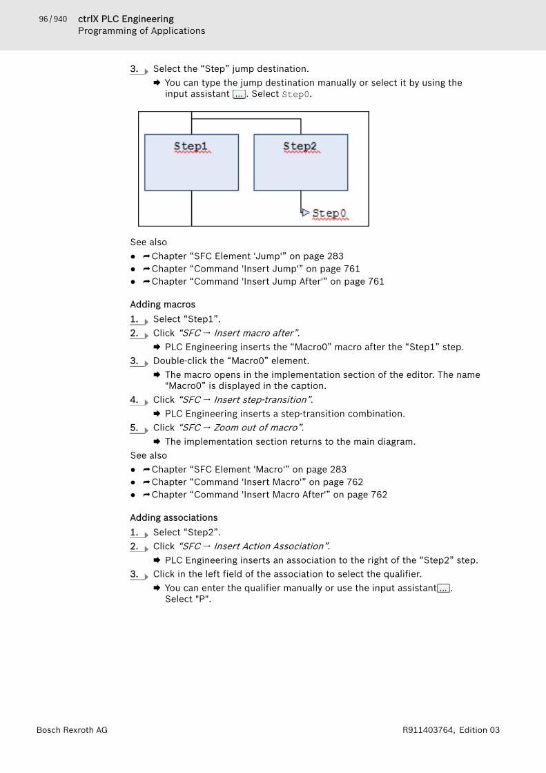
96 / 940 ctrlX PLC EngineeringProgramming of Applications
Bosch Rexroth AG R911403764, Edition 03
3. Select the “Step” jump destination.🡆 You can type the jump destination manually or select it by using the
input assistant . Select Step0.
See also● ⮫ Chapter “SFC Element 'Jump'” on page 283● ⮫ Chapter “Command 'Insert Jump'” on page 761● ⮫ Chapter “Command 'Insert Jump After'” on page 761
Adding macros1. Select “Step1”.2. Click “SFC 🠂 Insert macro after”.
🡆 PLC Engineering inserts the “Macro0” macro after the “Step1” step.3. Double-click the “Macro0” element.
🡆 The macro opens in the implementation section of the editor. The name"Macro0” is displayed in the caption.
4. Click “SFC 🠂 Insert step-transition”.🡆 PLC Engineering inserts a step-transition combination.
5. Click “SFC 🠂 Zoom out of macro”.🡆 The implementation section returns to the main diagram.
See also● ⮫ Chapter “SFC Element 'Macro'” on page 283● ⮫ Chapter “Command 'Insert Macro'” on page 762● ⮫ Chapter “Command 'Insert Macro After'” on page 762
Adding associations1. Select “Step2”.2. Click “SFC 🠂 Insert Action Association”.
🡆 PLC Engineering inserts an association to the right of the “Step2” step.3. Click in the left field of the association to select the qualifier.
🡆 You can enter the qualifier manually or use the input assistant .Select "P".
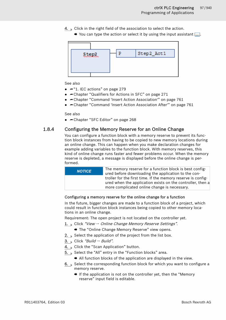
97 / 940ctrlX PLC EngineeringProgramming of Applications
Bosch Rexroth AGR911403764, Edition 03
4. Click in the right field of the association to select the action.🡆 You can type the action or select it by using the input assistant .
See also● ⮫ “1. IEC actions” on page 279● ⮫ Chapter “Qualifiers for Actions in SFC” on page 271● ⮫ Chapter “Command 'Insert Action Association'” on page 761● ⮫ Chapter “Command 'Insert Action Association After'” on page 761
See also● ⮫ Chapter “SFC Editor” on page 268
1.8.4 Configuring the Memory Reserve for an Online ChangeYou can configure a function block with a memory reserve to prevent its func-tion block instances from having to be copied to new memory locations duringan online change. This can happen when you make declaration changes forexample adding variables to the function block. With memory reserves, thiskind of online change runs faster and fewer problems occur. When the memoryreserve is depleted, a message is displayed before the online change is per-formed.
NOTICE The memory reserve for a function block is best config-ured before downloading the application to the con-troller for the first time. If the memory reserve is config-ured when the application exists on the controller, then amore complicated online change is necessary.
Configuring a memory reserve for the online change for a functionIn the future, bigger changes are made to a function block of a project, whichcould result in function block instances being copied to other memory loca-tions in an online change.Requirement: The open project is not located on the controller yet.1. Click “View 🠂 Online Change Memory Reserve Settings”.
🡆 The “Online Change Memory Reserve” view opens.2. Select the application of the project from the list box.3. Click “Build 🠂 Build”.4. Click the “Scan Application” button.5. Select the “All” entry in the “Function blocks” area.
🡆 All function blocks of the application are displayed in the view.6. Select the corresponding function block for which you want to configure a
memory reserve.🡆 If the application is not on the controller yet, then the “Memory
reserve” input field is editable.
98 / 940 ctrlX PLC EngineeringProgramming of Applications
Bosch Rexroth AG R911403764, Edition 03
7. If the application is already on the controller, then click the “Enabled”button in the “Enable Editing” area.Note that if you modify the memory reserve of an application that isalready on the controller, then the instances of all affected function blockshave to be copied to the memory.
8. Specify the size of the memory reserve (in bytes) and click “Apply forSelection”.🡆 The given number of bytes is shown in the “Memory reserve” field in
the table.9. Click “Build 🠂 Build” and then click “Scan Application”.
🡆 The following information is updated in the function block list for theconfigured function block: “Size”, “Instance count”, “Additionalmemory for all instances”, and “Remaining size of the memoryreserve”.
Now when you download the application to the controller, the function blockinstances occupy the required memory and also the memory reserve. In thefuture, bigger changes of the function block can be downloaded to the con-troller with the online change without having to copy all function blockinstances to memory.
See also● ⮫ Chapter “Command 'Settings of Memory Reserve for Online Change' ”
on page 691● ⮫ Chapter “Command 'Online Change'” on page 722
1.8.5 Function Block — Calling Functions or Methods with ExternalImplementationA runtime system can include the implementation of a function block, function,or method (for example, from a library). If you create a POU in your applicationwith the same name by using the “External implementation” without an imple-mentation, then you can execute the existing implementation. Please make surethat you declare local variables only in an external function block. External func-tions and methods must not contain local variables.When the application is downloading, PLC Engineering searches for and linksthe associated implementation in the runtime system for each external POU.Objects with the property “External implementation” are postfixed with (EXT)after the object name in the “Devices” or “POUs” view.See also● ⮫ Chapter “Dialog 'Properties' - 'Build'” on page 825
Creating POUs with external implementation1. Click “Project 🠂 Add Object 🠂 POU”.2. Activate “Function block”, Method, or “Function” and specify the name of
the associated implementation of the runtime system. Close the dialogbox by clicking “Add”.🡆 The runtime system POU is created in the “POUs” view. The name is
postfixed with (EXT).3. Right-click the POU and select “Properties”.
🡆 The dialog box opens.4. Click the “Build” tab.
99 / 940ctrlX PLC EngineeringProgramming of Applications
Bosch Rexroth AGR911403764, Edition 03
5. Select the “External implementation (Late link in the runtime system)”check box.🡆 The POU is declared and you can implement a POU call.
Creating methods with external implementation1. Select a function block in the device tree or in the POUs view.2. Select “Add Object 🠂 Method” and type the name of the associated
implementation of the runtime system. Click “Add” to close the dialogbox.🡆 The method is created.
3. Right-click the method and select “Properties”.🡆 The dialog box opens.
4. Click the “Build” tab.5. Select the “External implementation (Late link in the runtime system)”
check box.🡆 The method is declared and you can implement a method call. The
method name is postfixed with (EXT) in the “Devices” or “POUs” view.
1.8.6 Using Input AssistancePLC Engineering provides tools and features to help you code when creatingprograms.
Input AssistantThe input assistant provides all program elements that you can insert at thecurrent cursor position. Open the “Input Assistant” dialog by clicking “Edit🠂 Input Assistant” or by pressing [F2].See also● ⮫ “Dialog 'Input Assistant' - Tab 'Categories'” on page 673
Dialog 'Auto Declare'This dialog supports the declaration of variables.See also● ⮫ Chapter “Command 'Auto Declare'” on page 671
"List components"The "List components" function is an input tool in textual editors to help youinput valid identifiers. Activate this function by clicking “Tools 🠂 Options” andthen the “SmartCoding” category. Select the “List components after typing adot (.)” check box.● If you type a dot (.) instead of a global variable, then a drop-down list opens
with all available global variables. You insert the selected variable after thedot by double-clicking a variable in the drop-down list or by pressing [Enter].
● If you type a dot (.) instead of a global variable after a function blockinstance variable or a structure variable, then PLC Engineering opens a drop-down list with all global variables, all input and output variables for the func-tion block, or all structure members.You insert the selected variable after the dot by double-clicking a variable inthe drop-down list or by pressing [Enter].Note: When you also want to choose from the local variables of functionblock instances, select the “Show all instance variables in input assistant”option in the PLC Engineering options (SmartCoding category).
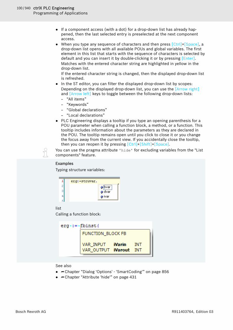
100 / 940 ctrlX PLC EngineeringProgramming of Applications
Bosch Rexroth AG R911403764, Edition 03
● If a component access (with a dot) for a drop-down list has already hap-pened, then the last selected entry is preselected at the next componentaccess.
● When you type any sequence of characters and then press [Ctrl]+[Space], adrop-down list opens with all available POUs and global variables. The firstelement in this list that starts with the sequence of characters is selected bydefault and you can insert it by double-clicking it or by pressing [Enter].Matches with the entered character string are highlighted in yellow in thedrop-down list.If the entered character string is changed, then the displayed drop-down listis refreshed.
● In the ST editor, you can filter the displayed drop-down list by scopes:Depending on the displayed drop-down list, you can use the [Arrow right]and [Arrow left] keys to toggle between the following drop-down lists:– “All items”– “Keywords”– “Global declarations”– “Local declarations”
● PLC Engineering displays a tooltip if you type an opening parenthesis for aPOU parameter when calling a function block, a method, or a function. Thistooltip includes information about the parameters as they are declared inthe POU. The tooltip remains open until you click to close it or you changethe focus away from the current view. If you accidentally close the tooltip,then you can reopen it by pressing [Ctrl]+[Shift]+[Space].
You can use the pragma attribute 'hide' for excluding variables from the "Listcomponents" feature.
ExamplesTyping structure variables:
listCalling a function block:
See also● ⮫ Chapter “Dialog 'Options' - 'SmartCoding'” on page 856● ⮫ Chapter “Attribute 'hide'” on page 431

101 / 940ctrlX PLC EngineeringProgramming of Applications
Bosch Rexroth AGR911403764, Edition 03
Short form featureThe short form feature allows you to type abbreviated forms for variable decla-rations in the declaration editor and in textual editors where variables declara-tions are possible. Use this feature by pressing [Ctrl]+[Enter] to end a declara-tion line.PLC Engineering supports the following short forms:● All identifiers become variable identifiers except the last identifier of a line.● The data type of the declaration is determined by the last identifier of the
line. The following applies:– B or BOOL yields BOOL– I or INT yields INT– R or BOOL yields BOOL– S or STRING yields STRING
● If a data type is not defined using this rule, then the data type is automati-cally BOOL, and the last identifier is not used as the data type (see Example1).
● Depending on the type of declaration, every defined constant becomes aninitialization or string length definition (see Example 2 and 3).
● An address, such as %MD12, is automatically extended with the AT attribute(see Example 4).
● Any text after a semicolon (;) is converted into a comment (see Example 3).● All other characters in the line are ignored (see exclamation mark in Example
5).
ExamplesExample Short Form Resulting declaration1 A A: BOOL2 A B I 2 A, B: INT := 2;3 ST S 2; A string ST:STRING(2); (* A string *)4 X %MD12 R 5 Real Number X AT %MD12: REAL := 5.0;(*
Real Number *)5 B ! B: BOOL
See also● ⮫ Chapter 1.8.2 “Declaration of Variables ” on page 62
Smart tag functionsSmart tags make it easier to write program code by suggest appropriate com-mands directly at the programming element. When you place the cursor over aprogramming element that has a smart tag function, the symbol appears.When you click the symbol, the commands that you can choose from areshown. Available smart tags:● The smart tag function provides the “Declare Variable” command for unde-
clared variables in the implementation part of the ST editor.See also● ⮫ Chapter “Command 'Auto Declare'” on page 671
1.8.7 Using PragmasWhat is a pragma in PLC Engineering?A pragma is a special statement in the source code of an application that influ-ences the properties of variables when precompiling or compiling (code gener-ation).

102 / 940 ctrlX PLC EngineeringProgramming of Applications
Bosch Rexroth AG R911403764, Edition 03
There are different pragmas for different purposes (example: initialization of avariable, monitoring of a variable, adding a variable to the symbol configuration,forcing the display of messages during the compilation process, and behaviorof a variable under certain conditions).
NOTICE Uppercase and lowercase characters must be maintained
How and where to insert a pragma?A pragma statement is specified in braces. Attributes and texts used within thestatement are enclosed in single straight quotation marks. The opening bracemay follow immediately after a variable name. Opening and closing braces mustbe located on the same line.
Examples{warning 'This is not allowed'} {attribute 'obsolete' := 'datatype fb1 not valid!'}
Possible insertion points:● Declaration part of a POU
In the textual declaration editor, you specify pragmas directly as a line. Inthe tabular editor, you specify pragmas that must be located before the firstdeclaration line in the dialog box “Edit Declaration Part” / “Attributes”.
● Global variable list● Implementation part of a POU (on a separate line or on a line with code
text)FBD/LD/IL: Pragmas in networks of the FBD/LD/IL editor are entered as alabel. Click the command “FBD/LD/IL 🠂 Add Label” and replace the defaulttext “Label:” in the text field with the appropriate pragma statement. To usea pragma in addition to a label, you specify the pragma first and then thelabel.
NOTICE Pragmas in PLC Engineering are not one-to-one imple-mentations of C preprocessor directives. You must posi-tion a pragma like an ordinary statement. It must not beused within an expression.
Incorrect and correct positions for a conditional pragma
INCORRECT:{IF defined(abc)}IF x = abc THEN{ELSE}IF x = 12 THEN{END_IF}y := {IF defined(cde)} 12; {ELSE} 13; {END_IF}END_IF CORRECT:{IF defined(abc)}IF x = abc THEN{IF defined(cde)} y := 12;{ELSE} y := 13;{END_IF}END_IF{ELSE}IF x = 12 THEN

103 / 940ctrlX PLC EngineeringProgramming of Applications
Bosch Rexroth AGR911403764, Edition 03
{IF defined(cde)} y := 12;{ELSE} y := 13;{END_IF}END_IF{END_IF}
In the “Properties” dialog box (“Compile” category), you can specify "defines"that can be queried in pragmas.Scope:Depending on the type and contents of a pragma, it may influence the fol-lowing:● subsequent declarations● the next statement only● all subsequent statements until it is canceled by a corresponding pragma● all subsequent statements until the same pragma is executed with other
parameters or the end of the code is reached. In this context, "code" meansthe declaration part, implementation part, global variable list, and type dec-laration. Therefore, a pragma influences the entire object when the pragmais alone on the first line of the declaration part and is not superseded orcanceled by another pragma.
What kinds of pragmas are there?The PLC Engineering pragmas are divided into the following categories:● Attribute pragmas (influence compiling and precompiling)● Message pragmas (print user-defined messages when compiling)● Conditional pragmas (influence code generation)● User-defined pragmas
See also● ⮫ Chapter “Using the 'Declare variable' Dialog Box” on page 65● ⮫ Chapter “Attribute Pragmas” on page 419● ⮫ Chapter “Conditional Pragmas” on page 452● ⮫ Chapter “Message pragmas” on page 418
1.8.8 Using Library POUsLibraries are collections of objects that you can link to your application. Youcan use the objects contained in libraries in exactly the same way as objectsthat you have defined in the project.Libraries can contain:● POUs, such as function blocks or functions● Interfaces and their methods and attributes● Data types, such as enumerations, structures, aliases, and unions● Global variables, constants, parameter lists● Text lists, image collections, visualizations, and visual elements● External files, such as documentation● Cam plate tablesThe library manager is used for managing libraries in a project. You use thelibrary repository dialog box for installing the library in advance onto thesystem.
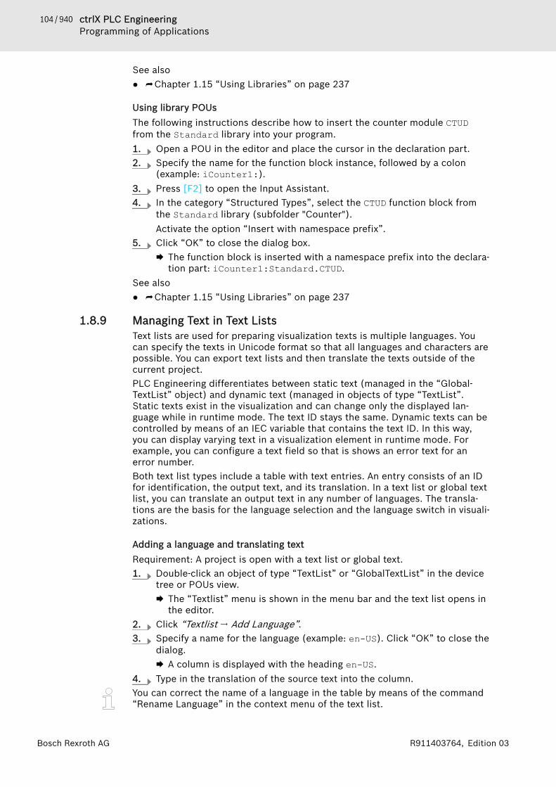
104 / 940 ctrlX PLC EngineeringProgramming of Applications
Bosch Rexroth AG R911403764, Edition 03
See also● ⮫ Chapter 1.15 “Using Libraries” on page 237
Using library POUsThe following instructions describe how to insert the counter module CTUDfrom the Standard library into your program.1. Open a POU in the editor and place the cursor in the declaration part.2. Specify the name for the function block instance, followed by a colon
(example: iCounter1:).3. Press [F2] to open the Input Assistant.4. In the category “Structured Types”, select the CTUD function block from
the Standard library (subfolder "Counter").Activate the option “Insert with namespace prefix”.
5. Click “OK” to close the dialog box.🡆 The function block is inserted with a namespace prefix into the declara-
tion part: iCounter1:Standard.CTUD.See also● ⮫ Chapter 1.15 “Using Libraries” on page 237
1.8.9 Managing Text in Text ListsText lists are used for preparing visualization texts is multiple languages. Youcan specify the texts in Unicode format so that all languages and characters arepossible. You can export text lists and then translate the texts outside of thecurrent project.PLC Engineering differentiates between static text (managed in the “Global-TextList” object) and dynamic text (managed in objects of type “TextList”.Static texts exist in the visualization and can change only the displayed lan-guage while in runtime mode. The text ID stays the same. Dynamic texts can becontrolled by means of an IEC variable that contains the text ID. In this way,you can display varying text in a visualization element in runtime mode. Forexample, you can configure a text field so that is shows an error text for anerror number.Both text list types include a table with text entries. An entry consists of an IDfor identification, the output text, and its translation. In a text list or global textlist, you can translate an output text in any number of languages. The transla-tions are the basis for the language selection and the language switch in visuali-zations.
Adding a language and translating textRequirement: A project is open with a text list or global text.1. Double-click an object of type “TextList” or “GlobalTextList” in the device
tree or POUs view.🡆 The “Textlist” menu is shown in the menu bar and the text list opens in
the editor.2. Click “Textlist 🠂 Add Language”.3. Specify a name for the language (example: en-US). Click “OK” to close the
dialog.🡆 A column is displayed with the heading en-US.
4. Type in the translation of the source text into the column.You can correct the name of a language in the table by means of the command“Rename Language” in the context menu of the text list.
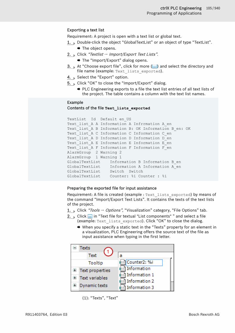
105 / 940ctrlX PLC EngineeringProgramming of Applications
Bosch Rexroth AGR911403764, Edition 03
Exporting a text listRequirement: A project is open with a text list or global text.1. Double-click the object “GlobalTextList” or an object of type “TextList”.
🡆 The object opens.2. Click “Textlist 🠂 Import/Export Text Lists”.
🡆 The “Import/Export” dialog opens.3. At “Choose export file”, click for more ( ) and select the directory and
file name (example: Text_lists_exported).4. Select the “Export” option.5. Click “OK” to close the “Import/Export” dialog.
🡆 PLC Engineering exports to a file the text list entries of all text lists ofthe project. The table contains a column with the text list names.
ExampleContents of the file Text_lists_exported
TextList Id Default en_USText_list_A A Information A Infrrmation A_enText_list_A B Information B: OK Information B_en: OKText_list_A C Information C Information C_enText_list_A D Information D Information D_enText_list_A E Information E Information E_enText_list_A F Information F Information F_enAlarmGroup 2 Warning 2AlarmGroup 1 Warning 1GlobalTextList Information B Information B_enGlobalTextList Information A Information A_enGlobalTextList Switch SwitchGlobalTextList Counter: %i Counter : %i
Preparing the exported file for input assistanceRequirement: A file is created (example : Text_lists_exported) by means ofthe command “Import/Export Text Lists”. It contains the texts of the text listsof the project.1. Click “Tools 🠂 Options”, “Visualization” category, “File Options” tab.2. Click in “Text file for textual "List components" ” and select a file
(example: Text_lists_exported). Click “OK” to close the dialog.🡆 When you specify a static text in the “Texts” property for an element in
a visualization, PLC Engineering offers the source text of the file asinput assistance when typing in the first letter.
(1): “Texts”, “Text”
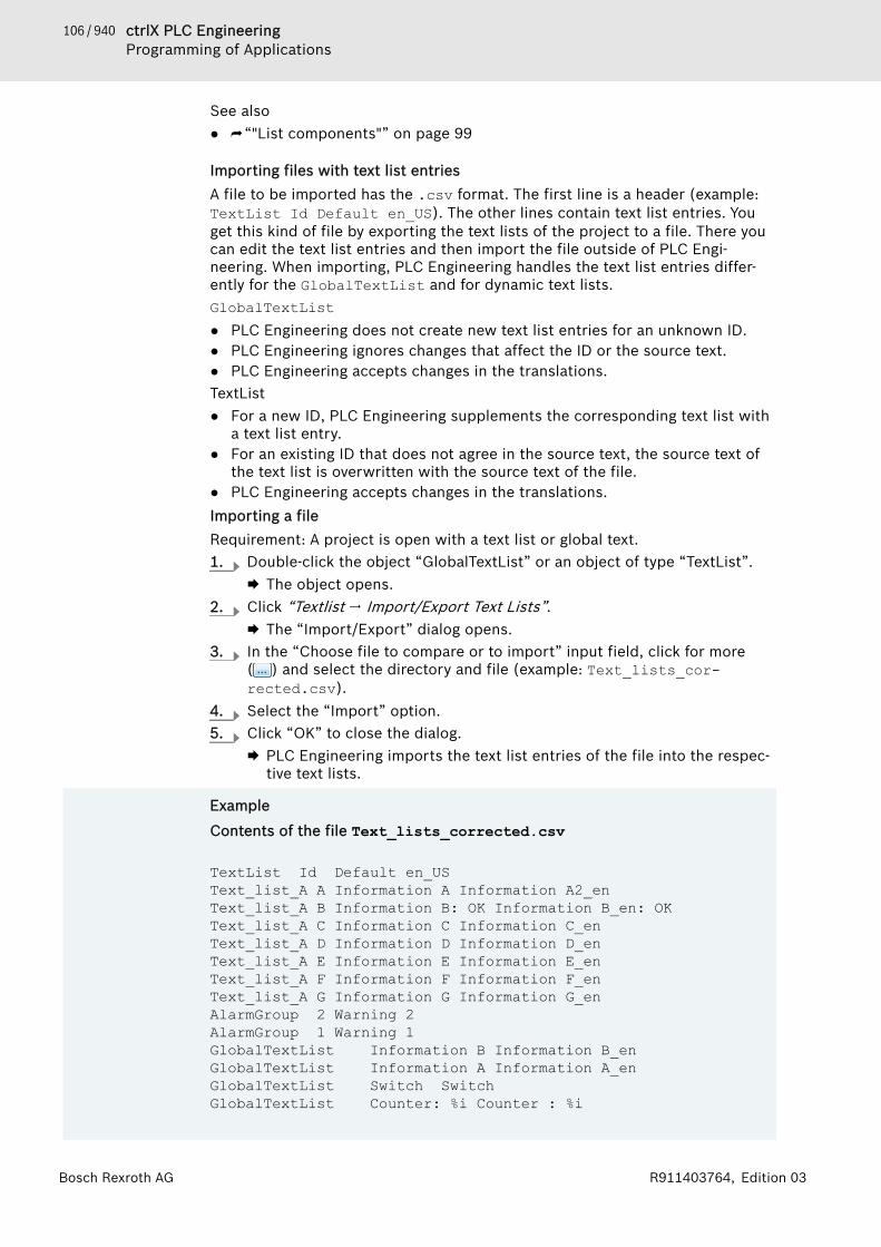
106 / 940 ctrlX PLC EngineeringProgramming of Applications
Bosch Rexroth AG R911403764, Edition 03
See also● ⮫ “"List components"” on page 99
Importing files with text list entriesA file to be imported has the .csv format. The first line is a header (example:TextList Id Default en_US). The other lines contain text list entries. Youget this kind of file by exporting the text lists of the project to a file. There youcan edit the text list entries and then import the file outside of PLC Engi-neering. When importing, PLC Engineering handles the text list entries differ-ently for the GlobalTextList and for dynamic text lists.GlobalTextList● PLC Engineering does not create new text list entries for an unknown ID.● PLC Engineering ignores changes that affect the ID or the source text.● PLC Engineering accepts changes in the translations.TextList● For a new ID, PLC Engineering supplements the corresponding text list with
a text list entry.● For an existing ID that does not agree in the source text, the source text of
the text list is overwritten with the source text of the file.● PLC Engineering accepts changes in the translations.Importing a fileRequirement: A project is open with a text list or global text.1. Double-click the object “GlobalTextList” or an object of type “TextList”.
🡆 The object opens.2. Click “Textlist 🠂 Import/Export Text Lists”.
🡆 The “Import/Export” dialog opens.3. In the “Choose file to compare or to import” input field, click for more
( ) and select the directory and file (example: Text_lists_cor-rected.csv).
4. Select the “Import” option.5. Click “OK” to close the dialog.
🡆 PLC Engineering imports the text list entries of the file into the respec-tive text lists.
Example
Contents of the file Text_lists_corrected.csv
TextList Id Default en_USText_list_A A Information A Information A2_enText_list_A B Information B: OK Information B_en: OKText_list_A C Information C Information C_enText_list_A D Information D Information D_enText_list_A E Information E Information E_enText_list_A F Information F Information F_enText_list_A G Information G Information G_enAlarmGroup 2 Warning 2AlarmGroup 1 Warning 1GlobalTextList Information B Information B_enGlobalTextList Information A Information A_enGlobalTextList Switch SwitchGlobalTextList Counter: %i Counter : %i
107 / 940ctrlX PLC EngineeringProgramming of Applications
Bosch Rexroth AGR911403764, Edition 03
These contents are applied to the text lists with the same name in the project.
See also● ⮫ Chapter “Command 'Import/Export Text Lists'” on page 803
Comparing text lists with a file and exporting differencesRequirement: A project is open with a text list or global text.1. Double-click the object “GlobalTextList” or an object of type “TextList”.
🡆 The object opens.2. Click “Textlist 🠂 Import/Export Text Lists” in the context menu.
🡆 The “Import/Export” dialog opens.3. In the “Choose file to compare or to import” input field, click for more
( ) and select the directory and file name of the comparison file(example: Text_lists_corrected.csv).
4. For “Choose export file”, click and select the directory and file thatcontains the comparison result.
5. Select the “Export only text differences” option.6. Click “OK” to close the dialog.
🡆 PLC Engineering reads the import file and compares the text list entriesthat have the same ID. If they do not agree, then PLC Engineeringwrites the text list entries of the text list to the export file.For the global text list, PLC Engineering compares the translations ofthe same source texts. If they do not agree, then PLC Engineeringwrites the text list entries to the export file.
See also● ⮫ Chapter “Command 'Add Language'” on page 802● ⮫ Chapter “Command 'Import/Export Text Lists'” on page 803● ⮫ Chapter “Command 'Remove Language'” on page 805● ⮫ Chapter “Object 'TextList'” on page 629
Managing Static Text in Global Text ListsThe global text list is the central location for texts that are displayed in the visu-alization.When you configure a text for the first time in visualization element, PLC Engi-neering creates the global text list. PLC Engineering fills in the table as youcreate more texts. Therefore, the table includes all texts automatically that youcreate in the project visualizations. PLC Engineering assigns incremental IDs asintegers, beginning at 0.You can check, update, and compare the global text list with the static texts ofthe visualization. You cannot edit the source text or the ID directly in the table.However, you can replace a source text with another source text by creatingand importing a replacement file. Menu commands are provided for this pur-pose.
Configuring visualization elements with static textA text in a “GlobalTextList” can contain a format definition.Requirement: A project is open with a visualization. The “GlobalTextList” objectcontains the texts that are defined in the project visualizations.1. Double-click the visualization.
🡆 The editor opens.2. Select an element with the “Text” property (example: “Text field”).

108 / 940 ctrlX PLC EngineeringProgramming of Applications
Bosch Rexroth AG R911403764, Edition 03
3. Type in some text in the “Text” property (example: Static InformationA).🡆 PLC Engineering adds the text to the global text list in the POU view.
Checking the global text listRequirement: A project is open with a visualization. The “GlobalTextList” objectcontains the texts that are defined in the project visualizations.1. Double-click the “GlobalTextList” object in the POUs tree.
🡆 The table opens with the static texts.2. Click “Text List 🠂 Check Visualization Text IDs”.
🡆 PLC Engineering reports when a source text of the text list does notmatch the static text that is identified by the ID. The source text in theglobal text list and the text in the visualization with the same ID do notmatch.
Updating IDs of the global text listRequirement: A project is open with a visualization. The “GlobalTextList” objectcontains the texts that are defined in the project visualizations.1. Double-click the “GlobalTextList” object in the POUs tree.
🡆 The list opens with the text list entries.2. Click “Text List 🠂 Update Visualization Text IDs”.
🡆 PLC Engineering adds text to the global text list when a text in the“Static Text” property does not match the source text in the project vis-ualizations.
Removing the global text list and creating current IDs againRequirement: A project is open with a visualization. The “GlobalTextList” objectcontains the texts that are defined in the project visualizations.1. Right-click the “GlobalTextList” object in the POUs tree and select the
“Delete” command.🡆 The object is removed.
2. Open a visualization.3. Click “Visualization 🠂 Create Global Text List”.
🡆 In the POU view, a new “GlobalTextList” object is created. The globaltext list contains the static text from the existing project visualizations.
Removing IDs from the global text listRequirement: A project is open with a visualization. The “GlobalTextList” objectcontains the texts that were defined in the project visualizations.1. Double-click the “GlobalTextList” object in the POUs tree.
🡆 The table opens with the texts.2. Click “Text List 🠂 Remove Unused Text List Entries”.
🡆 PLC Engineering removes the text list entries with IDs not referenced inthe project visualizations.
Updating the global text list with a replacement fileA replacement file has the CSV format. The first row is a header: defaultolddefaultnew REPLACE. The following rows contain the old source texts, thenew source texts, and then the REPLACE command. Tabs, commas, and semico-lons are permitted separators. A combination of separator characters in a file isnot permitted.
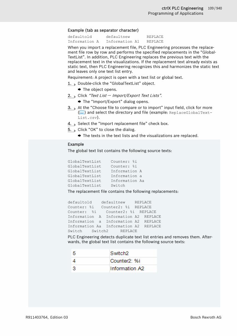
109 / 940ctrlX PLC EngineeringProgramming of Applications
Bosch Rexroth AGR911403764, Edition 03
Example (tab as separator character)defaultold defaultnew REPLACEInformation A Information A1 REPLACEWhen you import a replacement file, PLC Engineering processes the replace-ment file row by row and performs the specified replacements in the “Global-TextList”. In addition, PLC Engineering replaces the previous text with thereplacement text in the visualizations. If the replacement text already exists asstatic text, then PLC Engineering recognizes this and harmonizes the static textand leaves only one text list entry.Requirement: A project is open with a text list or global text.1. Double-click the “GlobalTextList” object.
🡆 The object opens.2. Click “Text List 🠂 Import/Export Text Lists”.
🡆 The “Import/Export” dialog opens.3. At the “Choose file to compare or to import” input field, click for more
( ) and select the directory and file (example: ReplaceGlobalText-List.csv).
4. Select the “Import replacement file” check box.5. Click “OK” to close the dialog.
🡆 The texts in the text lists and the visualizations are replaced.
ExampleThe global text list contains the following source texts:
GlobalTextList Counter: %i GlobalTextList Counter: %i GlobalTextList Information AGlobalTextList Information aGlobalTextList Information AaGlobalTextList SwitchThe replacement file contains the following replacements:
defaultold defaultnew REPLACECounter: %i Counter2: %i REPLACECounter: %i Counter2: %i REPLACEInformation A Information A2 REPLACEInformation a Information A2 REPLACEInformation Aa Information A2 REPLACESwitch Switch2 REPLACEPLC Engineering detects duplicate text list entries and removes them. After-wards, the global text list contains the following source texts:

110 / 940 ctrlX PLC EngineeringProgramming of Applications
Bosch Rexroth AG R911403764, Edition 03
The texts in the visualization have been replaced.
See also● ⮫ Chapter “Command 'Create Global Text List'” on page 802● ⮫ Chapter “Command 'Check Visualization Text IDs'” on page 805● ⮫ Chapter “Command 'Update Visualization Text IDs'” on page 805● ⮫ Chapter “Object 'GlobalTextList'” on page 580
Managing Dynamic Text in Text ListsYou can create and translate texts in a text list for dynamic texts in order toshow them dynamically in a visualization or in the alarm management. Theobject of type “Text list” can be located globally in the POUs view or below anapplication in the device tree. It contains a table with text list entries that youcan edit and extend. A text list entry consists of an ID for identification, theoutput text, and its translation. You can add new text list entries to a text list.Menu commands are provided for this purpose.
Creating text lists for dynamic text outputRequirement: A project is open with a visualization.1. Select an application in the POUs view or device tree and click “Project
🠂 Add Object”.2. Select “Text list”.3. Type a name (example: Textliste_A). Click “Add” to close the dialog.
🡆 An object of type “Text list” is created.4. Click below the “Default” column and open the input field. Type a text
(example: Information).🡆 The source text is created. It is used as a key in the table and as a
source text for translations.5. Type any string in the “ID” column (example: A).
🡆 A text list entry is defined with source text and ID. If you configure the“Dynamic texts” property of an element in a visualization, then you canselect the text list Textliste_A and assign the ID A.
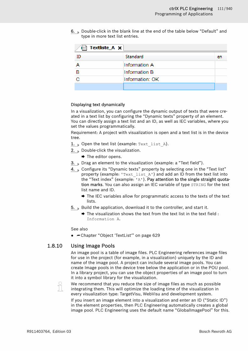
111 / 940ctrlX PLC EngineeringProgramming of Applications
Bosch Rexroth AGR911403764, Edition 03
6. Double-click in the blank line at the end of the table below “Default” andtype in more text list entries.
Displaying text dynamicallyIn a visualization, you can configure the dynamic output of texts that were cre-ated in a text list by configuring the “Dynamic texts” property of an element.You can directly assign a text list and an ID, as well as IEC variables, where youset the values programmatically.Requirement: A project with visualization is open and a text list is in the devicetree.1. Open the text list (example: Text_list_A).2. Double-click the visualization.
🡆 The editor opens.3. Drag an element to the visualization (example: a “Text field”).4. Configure its “Dynamic texts” property by selecting one in the “Text list”
property (example: 'Text_list_A') and add an ID from the text list intothe “Text index” (example: 'A'). Pay attention to the single straight quota-tion marks. You can also assign an IEC variable of type STRING for the textlist name and ID.🡆 The IEC variables allow for programmatic access to the texts of the text
lists.5. Build the application, download it to the controller, and start it.
🡆 The visualization shows the text from the text list in the text field :Information A.
See also● ⮫ Chapter “Object 'TextList'” on page 629
1.8.10 Using Image PoolsAn image pool is a table of image files. PLC Engineering references image filesfor use in the project (for example, in a visualization) uniquely by the ID andname of the image pool. A project can include several image pools. You cancreate Image pools in the device tree below the application or in the POU pool.In a library project, you can use the object properties of an image pool to turnit into a symbol library for the visualization.We recommend that you reduce the size of image files as much as possibleintegrating them. This will optimize the loading time of the visualization inevery visualization type: TargetVisu, WebVisu and development system.If you insert an image element into a visualization and enter an ID (“Static ID”)in the element properties, then PLC Engineering automatically creates a globalimage pool. PLC Engineering uses the default name “GlobalImagePool” for this.
112 / 940 ctrlX PLC EngineeringProgramming of Applications
Bosch Rexroth AG R911403764, Edition 03
Please note the following when the ID of an image file appears in several imagepools.● Search order: If you selected an image managed in “GlobalImagePool”, then
you do not have to enter the name of the image pool. The search order forimage files is as follows:– 1. GlobalImagePool– 2. Image pools assigned to the currently active application– 3. Image pools next to the GlobalImagePool in the POU window– 4. Image pools in libraries
● Unique access: You can reference a selected image directly and uniquely byappending the image ID to the name of the image pool in the followingsyntax "<pool name>.<image ID>.
See also● ⮫ Chapter “Object 'Image Pool'” on page 582● ⮫ Chapter “Dialog 'Properties' - 'Image Pool'” on page 833
Creating image pools1. Select the “Application” object in the device tree.
Click “Project 🠂 Add Object 🠂 Image Pool”.🡆 The “Add Image Pool” dialog box opens.
2. Type a name for the image pool (for example, "Images1") and click “Add”.🡆 The image pool is added to the device tree.
3. Select the image pool object and open by choosing the command “Project🠂 Edit Object”.
4. Double-click the field in the “ID” column and assign an appropriate ID (forexample, "Icon1").You can also add new images to the list by clicking “Imagepool 🠂 AddImage File”.
5. Double-click the field in the “File name” column. Click for more settings( ).🡆 The “Select Image” dialog box opens.
6. Click for more settings ( ) and select the image file.🡆 A thumbnail of the image file is displayed in the field of the column
“Image”. The name of the file is displayed in the field of the column“File name”.
The image file can be references only by the name Images1.Icon1.See also● ⮫ Chapter “Command 'Insert Image'” on page 792
Using image files in the 'Image' visualization elementWhen you insert an image element into a visualization, you can define theimage type.● Static image: Enter the image ID of the image file or the name of the image
pool plus the image ID into the element configuration (property “Static ID”).Please note the comments for the search order and access.
● Dynamic image: Type the variable for defining the image file ID (for example,PLC_PRG.imagevar) in the element configuration (“Bitmap ID variable”property). You can exchange a dynamic element in online mode dependingon a variable.
See also● ⮫ Visualization element 'Image'

113 / 940ctrlX PLC EngineeringProgramming of Applications
Bosch Rexroth AGR911403764, Edition 03
Using image files for the visualization backgroundYou can set an image in the background definition of a visualization. You candefine the image by the name of the image pool plus the filename, as describedabove for a visualization element.See also● ⮫ Command 'Background'
1.8.11 Integrating C ModulesWith the C code integration plugin, externally implemented C code files can beincluded in PLC Engineering projects and C stubs can be generated from IECobjects.In PLC Engineering, the “C Code Module” object type is available for this pur-pose. The C code files and the used IEC objects are located below a “C CodeModule”. A file directory on the hard disk with C code files is assigned to eachC code module.In the project, you can generate IEC objects from a C code file in the format *.hor *.hpp (header file) in order to use them in other POUs.The generation of C-stubs is intended for the following use cases:● A C code file accesses an IEC object: A C code file cannot access an IEC
object directly. It can access only the C stub that was generated from theIEC object.
● Generation of precompiled modules that you can merge into a libraryproject.
After being imported, the imported source code files are part of the PLC Engi-neering project and they are therefore decoupled from the original files on thedisk.During compilation, a dynamic module is generated from a C code module andsaved as part of the project. Information, warnings, and errors are displayed inthe message view in the “C Code Module” category.All dynamic modules of an application are transferred and loaded to the run-time system during the download. The runtime system must support dynamiclinking for this.License for the runtime systemThe runtime system requires a license that permits C modules to be loaded.Without this license, dynamic modules cannot be linked during the download,and therefore the download will be aborted.The dynamic modules are part of the boot application and they are reloadedand activated when the controller is restarted. The “Reset Origin” commandunloads all C code modules in the application. The “Reset Cold” and “ResetWarm” commands do not lead to a repeated initialization of the C code mod-ules.
NOTICE No C code for simulation modeIn simulation mode, C code is not generated and loadedto the runtime system. To simulate the code contained inthe C modules anyway, you can implement it for this pur-pose in the respective IEC objects of the C code module.
PLC Engineering does not support the monitoring of variables in C code files orthe setting of breakpoints in C source code.Precompiled module in a library:C code integration provides the capability of assigning a precompiled runtimemodule (example: *.dll) in the library to a device and then to save it in thelibrary. Then, these modules can be loaded dynamically.

114 / 940 ctrlX PLC EngineeringProgramming of Applications
Bosch Rexroth AG R911403764, Edition 03
See also● ⮫ Chapter “Object 'C Code Module'” on page 551● ⮫ Chapter “Object 'C Code File'” on page 553● ⮫ Chapter “Object 'C Implemented Library'” on page 554● ⮫ Chapter 1.10.3 “Handling of Device User Management” on page 188
Configuring C code modulesRequirement: A project is open that already includes a C code module.1. Click the object “C Code Module” in the device tree.2. Select the command “Properties” in the context menu.3. Open the “Build” tab in the “Properties” dialog.4. Specify the file path of the Visual Studio installation on your computer.
The input assistant ( ) and the search tool (magnifying glass) are alsoavailable.
5. Specify the file path of the MS Windows SDK installation on your com-puter. The input assistant ( ) and the search tool (magnifying glass) arealso available.
6. Specify a file path for PLC Engineering to store the temporary compilefiles.
Importing folders with C source files from the file directoryRequirement: A project is open. The project controller supports the integrationof C code.1. Select “Application” in the device tree and click “Project 🠂 Add Object
🠂 C Code Module”.2. If necessary, specify a new name for your C code module in the “Add C
Code Modules” dialog. If you do not, then your object will be given thestandard name “C Code Module”.
3. Click the symbol ( ) next to the “Source directory” input field.4. The “Find Folder” dialog opens.5. In the “Find Folder” dialog, select the folder containing the C source files
(*.c, *.cpp, *.h, or *.hpp).6. When you select the “Monitor folder for source code changes” option, PLC
Engineering displays a message when changes have been made to the Csource files in the selected folder of the file system.
7. Click “Add”.🡆 PLC Engineering inserts the C code module into the device tree with
the folders “Extensions”, “IEC interface”, and “Source Files”.8. In the device tree, click the plus symbol (“+”) of the “Source Files” folder.
🡆 The imported C source files are listed in the open folder.9. If you double-click one of the C source files ( ), then the C code file
opens in your editor.
Importing individual C code filesRequirement: A project is open that already includes a C code module.1. Click the object “C Code Module” in the device tree.2. Click “Project 🠂 Add Object 🠂 C Code File”.

115 / 940ctrlX PLC EngineeringProgramming of Applications
Bosch Rexroth AGR911403764, Edition 03
3. In the “Add C Code-File” dialog, use the input assistant ( ) to select afile in *.c, *.cpp, *.h, or *.hpp format, and then click “Add”.🡆 PLC Engineering inserts the selected C code file into the device tree
below the “C Code Module”.4. If you double-click the new C code file ( ) in the device tree, then it
opens in the editor for modification.
Generating empty C code filesRequirement: A project is open that already includes a C code module.1. Click the object “C Code Module” in the device tree.2. Click “Project 🠂 Add Object 🠂 C Code File”.3. In the “Add C Code File” dialog, specify the name for the new C code file
with the appropriate file extension and click “Add”.🡆 PLC Engineering inserts the selected C code file into the device tree
below the “C Code Module”.4. If you double-click the new C code file ( ) in the device tree, then it
opens in the editor for modification.
Converting C code files into IEC objects for use as programming objects inapplicationsRequirement: A project is open that includes a C code module and C codefiles. For example, the C code file contains the following C code: intadder(int a, int b);1. Click a C code file with the file extension *.h. In this example, it is
test.h.2. Click “Build 🠂 C-Integration 🠂 Create IEC Interface”.
🡆 The dialog “Create C Interface” opens and lists the file test.h and itsfunction adder (int, int). Both are activated for the import.
3. Click “Import”.4. PLC Engineering generates the “adder (FUN)” function and inserts it as an
object in the “IEC Interface” folder in the device tree.5. When you double-click the “adder (FUN)” object, it opens in the editor.
🡆 It contains the following declaration part:
6. You can now call the adder function in the implementation part of a POU(example: adder (diVar1, diVar2);).
116 / 940 ctrlX PLC EngineeringProgramming of Applications
Bosch Rexroth AG R911403764, Edition 03
Creating C stubsRequirement: A project is open that includes a C code module. A POU isadded to the C code module and this POU has implemented code.
In the device tree, select the POU below the C code module and click “C-Integration 🠂 Create Stub Implementation in C”.🡆 PLC Engineering creates the objects “iec_external.c” and
“iec_external.h” and adds them to the “Extensions” folder in the devicetree.In the message view (“C Code module” category), you will find a mes-sage that an m4 file has been successfully created.
When you click “Create Stub Implementation in C”, the application iscompiled automatically. If errors occur in the process, then these areindicated in the message view. In addition, please monitor the mes-sages in the “C Code Module” category. :
Assigning precompiled runtime modules to devices and saving them in librariesRequirement: A library (*.library) is open in PLC Engineering.1. Click “View 🠂 POUs”.
🡆 The “POUs” view opens and displays the library project and its objects.2. Select the library project and click “Project 🠂 Add Object 🠂 C-
Implemented Library”.3. Click “Add” in the “Add C-Implemented Library” dialog.
🡆 PLC Engineering adds the object “C Implemented Library” to the“POUs” view.
4. Double-click the “C Implemented Library” object.🡆 The object opens in its editor
5. Click “Add” in this editor.🡆 The “Select Device” dialog opens.
6. In the “Object file” input field, specify the name of a dynamically loadablemodule in the format *.dll or *.so.
NOTICE The *.dll file must contain the title of the libraryproject in its name. For example, if the library project is named XYlib, thenthe “Object file” must be called: <Name>_XYlib.dll.
7. In the “Device” window, select a device for assignment of the “Objectfile”.
8. Click “Select Device”.🡆 PLC Engineering displays the created device file assignment in the
editor on the tab “Compiled Components”.9. Save the library project.See also● ⮫ Chapter “Object 'C Implemented Library'” on page 554
1.8.12 Programmatic Access to I/OsPLC Engineering provides the following features for mapping project variablesto input, output and memory addresses:
117 / 940ctrlX PLC EngineeringProgramming of Applications
Bosch Rexroth AGR911403764, Edition 03
● Assignment of project variables to input, output and memory addresses inthe “I/O Mapping” tab of the device editor
● Programmed access to I/Os– Variables configuration– AT declaration
NOTICE We recommend that you define the mapping of projectvariables to input, output and memory addresses in the“I/O Mapping” of the editor of the respective device.
See also● ⮫ Chapter 1.7.3 “Configuring Devices and I/O Mapping” on page 54
Variables Configuration - VAR_CONFIGUse the variables configuration for mapping variables of functions blocks to theprocess map. For declarations in the function block, assign the variables to thedevice inputs/outputs without providing the full address. Later, the exactaddress is provided centrally for all function block instances of the applicationin a global variable list including VAR_CONFIG declarations. This global variableslist with the VAR_CONFIG declarations is termed the "variables configuration".
NOTICE For changes to variables that are assigned to I/Oaddresses, PLC Engineering displays them immediatelyIn the process map. For changes to variables that aremapped by a variables configuration, PLC Engineeringdisplays them not until the end of the responsible task.
Declaration of variables in functions blocksWhen declaring variables in a function block, declare the variables between thekeywords VAR and END_VAR and assign incomplete addresses to the variables.Mark these incomplete addresses with an asterisk (*).Syntax:<identifier> AT %<I|Q>*:<data type>;
ExampleDefine two local I/O variables: the input variable xLocIn and the output vari-able xLocOut.FUNCTION_BLOCK locio VAR xLocIn AT %I*: BOOL := TRUE; xLocOut AT %Q*: BOOL; END_VAR
Final definition of addresses in the variables configuration of the global varia-bles listIn the global variables list that you use as the variables configuration, definethe variable declarations with the absolute addresses between the keywordsVAR_CONFIG and END_VAR.You must declare the VAR_CONFIG variables with the complete instance path,separating the individual POU and instance name by a dot (.). The declarationmust include an address whose class (input/output) agrees with the class ofthe incomplete address (%I*, %Q*) in the function block. The data type mustalso agree.Syntax:<instance variable path> AT %<I|Q><location>: <data type>;
118 / 940 ctrlX PLC EngineeringProgramming of Applications
Bosch Rexroth AG R911403764, Edition 03
If the path instance does not exist, then an error is reported. PLC Engineeringprints an error also if there is not an address configuration available for a vari-able that you declared with an incomplete address.
ExampleThe locio function block in the example above is used in a program as fol-lows:PROGRAM PLC_PRG VAR locioVar1: locio; locioVar2: locio; END_VAR A correct variables configuration in a global variable list could then look likethis:VAR_CONFIG PLC_PRG.locioVar1.xLocIn AT %IX1.0 : BOOL; PLC_PRG.locioVar1.xLocOut AT %QX0.0 : BOOL; PLC_PRG.locioVar2.xLocIn AT %IX1.0 : BOOL; PLC_PRG.locioVar2.xLocOut AT %QX0.3 : BOOL; END_VAR
See also● ⮫ Chapter “Configuration Variables - VAR_CONFIG” on page 320● ⮫ Chapter “AT Declaration” on page 119● ⮫ Chapter “Addresses” on page 384
Creating a variables configurationRequirement: You have a project open that includes a controller configurationwith a field device. The project contains a program (e.g. PLC_PRG) and a func-tion block (e.g. func1). The field device has inputs and outputs. The textualview is selected in the options for the declaration editor.In the function block, assign variables to device I/Os with incomplete addressesand then create a variables configuration.1. Double-click a function block in the device tree (e.g. func1).
🡆 The function block editor opens.2. Type the following between the keywords VAR and END_VAR: xLocIn AT
%I*: BOOL := TRUE; and XLocOut AT %Q*:BOOL; in the next line.🡆 You have declared an input variable xLocIn and assigned it to the
incomplete input address %I* of a field device. You have assigned thedeclared output variables have to the incomplete output address %Q*.
3. Click the PLC_PRG object in the device tree and add the following to thedeclaration section of the program between VAR and END_VAR:locioVar1: func;locioVar2: func;
4. Right-click the “Application” object in the device tree and click “AddObject 🠂 Global Variable List” and then click “Add” in the “Add Global Var-iable List” dialog box.🡆 The global variables list is added to the device tree and opens in the
editor.5. Change the keyword VAR_GLOBAL to VAR_CONFIG.
119 / 940ctrlX PLC EngineeringProgramming of Applications
Bosch Rexroth AGR911403764, Edition 03
6. Click “Declarations 🠂 Add All Instance Paths”.🡆 The following instance paths are added:
PLC_PRG.logioVar1.xLocIn AT %I*;PLC_PRG.logioVar2.xLocIn AT %I*;PLC_PRG.logioVar1.xLocOut AT %Q*;PLC_PRG.logioVar2.xLocOut AT %Q*;
7. Now, replace the incomplete addresses %I* and %Q* with the absolute,complete addresses.
See also● ⮫ Chapter “Command 'Add all instance paths'” on page 795
AT DeclarationIn the variables declaration, the code AT assigns a project variable to a specificinput address, output address, or memory address of the PLC that is config-ured in the device tree. You can also define the assignment of variables to anaddress in the “I/O Mapping” dialog of the device in the PLC configuration.Syntax
<variable name> AT <address> : <data type>;
<address> : %<memory area prefix> ( <size prefix> )? <memory position>The AT declaration allows you to give the address a meaningful name. You canmake any necessary changes for the input or output signals at just one location,for example in the declaration.
ExamplesVAR wInput AT %IW0 : WORD; END_VAR Variable declaration with address information of
an input wordVAR xActuator AT %QW0 : BOOL; END_VAR Boolean variable declaration
Note: For Boolean variables, one byte is allo-cated internally if a single bit address is notspecified. A change in the value of xActuatoraffects the range from QX0.0 to QX0.7.
VAR xSensor AT IX7.5 : BOOL; END_VAR Boolean variable declaration with explicit speci-fication of a single bit address. On access, onlythe input bit 7.5 is read.
VAR xSensor AT IX* : BOOL; END_VAR For the address specification, the placeholder *is given instead of the memory position. Thefinal address specification is done in the varia-bles configuration.Note: This is possible in function blocks.
If you assign a variable to an address, please note the following:● You cannot write to variables that are placed at inputs. This will cause a
compiler error.● You can perform AT declarations only for local and global variables, not for
input/output variables of POUs.● Furthermore, AT declarations cannot be used in persistent variable lists.
120 / 940 ctrlX PLC EngineeringProgramming of Applications
Bosch Rexroth AG R911403764, Edition 03
● If you use AT declarations for structure components or function block varia-bles, then all instances use the same memory. This is just like using staticvariables in classic programming languages, such as C.
● The memory layout of structures also depends on the target system.
NOTICE If you do not specify a single bit address explicitly, thenBoolean variables are allocated byte-by-byte.
Example
PROGRAM PLC_PRGVARxVar AT %QW0 : BOOL;
END_VAR
xVar := TRUE;When the variable xVar is written, the output memory range from QX0.0 toQX0.7 is affected.
See also● ⮫ Chapter “Variables Configuration - VAR_CONFIG” on page 117● ⮫ Chapter “Configuration Variables - VAR_CONFIG” on page 320● ⮫ Chapter “Addresses” on page 384
1.8.13 Checking Syntax and Analyzing CodePLC Engineering provides useful functions for detecting errors and assistingyou while you create programs. The syntax check flags errors and prints themto the message view as early as the programming phase.The static code analysis in PLC Engineering also assists you in complying withdefined coding guidelines and detecting weak constructs.See also● ⮫ Chapter “Checking Syntax” on page 120● ⮫ Chapter “Analyzing Code Statically” on page 121
Checking SyntaxWhen you input code, the precompile in PLC Engineering already runs somebasic checks. Then, wavy underlines appear under buggy code in the editor andan error message is printed to the messages view.After programming, you must check the syntax of the application by clicking“Build 🠂 Build” or by pressing [F11]. In this step, the compiler checks the pro-gram and prints any other errors.PLC Engineering automatically generates the application code from the sourcecode that was written in the development system. This is done automaticallybefore downloading the application to the controller. Before the applicationcode is generated, a test is performed for checking the assignments, the datatypes, and library availability. In addition, the memory addresses are allocatedwhen the application code is generated. You can execute this command explic-itly by clicking “Build 🠂 Generate Code”. This is useful for detecting any errorsin your source code, even when the controller is not connected yet.PLC Engineering prints all errors and warnings to the "Build" category of themessages view. Double-clicking the error message opens the respective POU inthe editor with the buggy code marked. As an alternative, you can also jump tothe buggy code by right-clicking the error message.
121 / 940ctrlX PLC EngineeringProgramming of Applications
Bosch Rexroth AGR911403764, Edition 03
Please note the settings for this in the PLC Engineering options.See also● ⮫ Chapter “Dialog 'Options' - 'SmartCoding'” on page 856
Analyzing Code StaticallyYou can subject your source code also to static analysis (lint) during the codegeneration. This determines whether or not your source code complies with thecoding guidelines that you defined - according to the idea behind the lint anal-ysis tool.● You activate the rules to the checked in the “Project Settings” dialog in the
“Static Analysis Light” category. The check itself is performed automaticallyeach time code is generated, for example when you click “Build 🠂 GenerateCode”. If divergence from the rules is determined, then it is reported as anerror message in the “Build” category of the message view. The reportederrors have the prefix SA<number>.
NOTICE For static code analysis with “Static Analysis Light”, onlythe application code of the project is checked. Librariesare excluded from the check.GVL variables in the “POUs” view are not necessarilychecked: If you have a project with several applications,then only the objects in the active application arechecked. If you have only one application, then theobjects in the common POU pool are also checked.
“Static Analysis Light” includes only a reduced set of rules in the default devel-opment system. A larger set of rules, additional naming conventions, and met-rics are available when you install the CODESYS Static Analysis add-on.
Deactivating lines of code in the implementations with pragmas from the staticanalysisBy means of the pragma {analysis ...}, you can mark code so that thespecified rules are not checked. As a result, the marked lines of code are notsubjected to static analysis. The marked code is ignored during the check.Syntax:{analysis <sign><rule number>|,<other combinations of signs andrules, comma-separated>}-<rule number>: Deactivate the rule SA<rule number>.-<rule number>: Activate the rule SA<rule number>.Excluding implementation codeRequirement: Rules are activated in the “Project Settings” dialog.1. Add the pragma {analysis -<number>} above the line of code that con-
tains code not to be checked first of all. For example, for the rule SA0024🡆 The line of code is the first line of the code snippet that is not checked
with rule 24.2. Add the pragma {analysis -<number>} below the line of code that con-
tains code not to be checked first of all. For example, for the rule SA0024🡆 The line of code above is the last line of the code snippet that is not
checked with rule 24.
122 / 940 ctrlX PLC EngineeringProgramming of Applications
Bosch Rexroth AG R911403764, Edition 03
Example: Ignore untyped literal
{analysis -24}nTest := 99;iVar := INT#2;{analysis +24}The rule “SA0024: Untyped literals only” is deactivated for two lines. An erroris not issued although the code does not correct to: nTest := DINT#99;
Example: Ignore several rules
{analysis -10, -24, -18}...{analysis +10, +24, +18}“SA0010: Arrays with only one component”“SA0018: Unusual bit access”“SA0024: Untyped literals only”
However, you cannot deactivate the rule SA0004: “Multiple Write Access onOutput” with a pragma.
Excluding programming objects with pragmas from the static analysisSyntax:{attribute 'analysis' := '-<rule number>[,<other negative rulenumbers, comma-separated>]'}When you insert the attribute pragma in the declaration part of a programmingobject, the specified rules are excluded for the entire programming object. Ifmultiple rules are excluded, then the rules are each comma-separated with adash and a number. A pragma statement for activation is not required.
Example
{attribute 'analysis' := '-33, -31'}TYPE LocalData :STRUCTiLocal : INT;uiLocal : UINT;udiLocal : UDINT;
END_STRUCTEND_TYPEThe rules SA0033 and SA0031 are ignored for the structure LocalData.
{attribute 'analysis' := '-100'}big: ARRAY[1..10000] OF DWORD;The rule SA0100 is ignored for the array big.
See also● ⮫ Chapter “Dialog 'Project Settings' - 'Static Analysis Light'” on page 841

123 / 940ctrlX PLC EngineeringProgramming of Applications
Bosch Rexroth AGR911403764, Edition 03
1.8.14 Orientation and Navigation
Using the Cross-Reference List to Find OccurrencesThe occurrences of symbols of a variable, a POU (program, function block,function), or a DUT can be displayed in a cross reference list. Then you canjump from the list directly to the corresponding locations in the project.There are two ways to search for occurrence locations of a symbol:● Plain text search: You manually specify a text (symbol name, placeholder) in
the “Cross Reference List” view.● Search for a specific declaration:
– In the “Cross-Reference List” view, you select the declaration from theinput assistant.
– The focus is on a symbol name in the POU editor and you start the cross-reference search from the context menu.
– The focus is on a symbol name in the POU editor, the “Cross-ReferenceList” view is open, and the cross-reference search executes automatically.
– In the “Cross-Reference List” view which already lists occurrence loca-tions for several declarations, you limit these results to a specific declara-tion.
Cross references with text search by symbol nameRequirement: The “Cross-Reference List” view is open.1. Specify a string in the field next to the name, for example the identifier of
the variable for which you want to find the occurrence location in theproject. Example: "iCounter".For the text search, you can use the asterisk "*" (for any number of char-acters) or the question mark "?" (for an exact number of characters) com-bined with a substring of a variable identifier.Use the percent sign "%" to search for IEC addresses. Examples: "%MW8","%M*".
2. Click the button to start a text search in the project.🡆 The view “Cross-Reference List” opens and displays the occurrence
locations for the iCounter variable. The declaration parts are alwaysdisplayed in the project with the occurrence location indented.
3. Double-click an occurrence location in the cross-reference list.🡆 The respective object opens in the editor with the marked occurrence
location.
Cross-references for a specific symbol declarationRequirement: A POU is open in the editor.From the POU editor, with a menu command1. Set the cursor at the identifier of the symbol (variable, POU) in the decla-
ration part or implementation part.2. Click “Browse for Symbol 🠂 Browse Cross-References” in the context
menu or “Edit” menu.🡆 The “Cross-Reference List” view opens and shows the occurrence loca-
tions of the variables or POU.If the “Cross-Reference List” view is already open, then you can also search theoccurrence locations for a specific result as follows:
124 / 940 ctrlX PLC EngineeringProgramming of Applications
Bosch Rexroth AG R911403764, Edition 03
From the POU editor, automaticSelect the “Automatically list selection in cross reference view” check boxin “Tools 🠂 Options” (“SmartCoding” category). Select the name of thesymbol in the POU, or set the cursor in the name.🡆 Depending on the position of the selection or cursor, the cross-refer-
ence list automatically shows the occurrence locations for the respec-tive symbol.
In the cross-reference list view, with input assistanceIn the “Cross-Reference List” view, use the input assistant to specify asymbol name in the field next to “By declaration”.🡆 The cross reference list displays the occurrence locations for the
symbol.In the cross-reference list view, limited to a specific declaration
If multiple declarations for a symbol are listed in the “Cross- ReferenceList” view, for example after a text search, then you can reduce the displayto one result: Select the line with the desired declaration and click the button or click “Limit Results to Current Declaration” in the context menu.🡆 the cross-reference list includes only the occurrence locations for the
selected declaration.See also● ⮫ Chapter “Command 'Cross Reference List'” on page 684● ⮫ Chapter “Command 'Browse Cross-References'” on page 670● ⮫ Chapter “Dialog 'Options' - 'SmartCoding'” on page 856
Finding DeclarationsPLC Engineering provides the capability of searching the entire project for thedefinition location of a variable or function. The block that includes the defini-tion opens in the editor with the marked declaration.
Finding the declaration of a variableRequirement: You have opened a POU in the editor.1. Set the cursor at an identifier in the implementation section.2. Click “Edit 🠂 Browse 🠂 Go to Definition”.
🡆 The POU with the declaration opens in the editor with the variable defi-nition marked. If the definition is located in a compiled library, then therespective block opens in the library manager.
You can execute this command in both online and offline mode.
ExamplesThe following block includes a function block definition (fbinst), a programcall (prog_y()), and a function block call (fbinst.out):VAR fbinst:fb1; ivar:INT; END_VAR prog_y(); ivar:=prog_y.y; res1:=fbinst.out;If the cursor is located at prog_y, then the command opens the programprog_y in the editor.If the cursor is located at fbinst, then this command focuses in the declara-tion section at line fbinst:fb1;If you set the cursor at out, then this command opens the function block fb1in its editor.
125 / 940ctrlX PLC EngineeringProgramming of Applications
Bosch Rexroth AGR911403764, Edition 03
See also● ⮫ Chapter “Command 'Go to Definition'” on page 674
Setting and Using BookmarksBookmarks are used for easy navigation through long programs. You can usebookmarks in all implementation language editors, except SFC (sequentialfunction chart). Commands help to navigate directly to the marked position inthe program.
Setting and deleting bookmarksRequirement: The POU is open in the editor.1. Set the cursor at any program line.2. Click “Edit 🠂 Bookmarks 🠂 Toggle Bookmark”.
🡆 A bookmark is set at this position in the program. This is marked by thebookmark symbol .
3. Set several bookmarks at different places in the program.4. Set the cursor at a bookmarked program line.5. Click “Edit 🠂 Bookmarks 🠂 Toggle Bookmark”.
🡆 The bookmark is removed. The bookmark symbol is deleted.As an alternative to this, you can delete one or more bookmarks in the“Bookmarks” view by clicking the button. For this purpose, the cor-responding bookmarks have to be selected in the “Bookmarks” view.
Click “Edit 🠂 Bookmarks 🠂 Clear All Bookmarks (Active Editor)” toremove all bookmarks from the active POU.:
In order to delete all bookmarks in a project, click “Clear All Book-marks”. However, for this command to be available, you first have toadd it to a menu by means of the command “Tools 🠂 Customize”.:
See also● ⮫ Chapter “Command 'Toggle Bookmark'” on page 669● ⮫ Chapter “Command 'Clear All Bookmarks (Active Editor)'” on page 670● ⮫ Chapter “Command 'Clear All Bookmarks'” on page 670
Jumping to bookmarks within a POURequirement: The POU is open in the editor. Multiple bookmarks are set.1. Click “Edit 🠂 Bookmarks 🠂 Next Bookmark (Active Editor)”.
🡆 Depending on the current cursor position, the cursor jumps to the nextbookmark (see below).
2. Click “Edit 🠂 Bookmarks 🠂 Previous Bookmark (Active Editor)”.🡆 Depending on the current cursor position, the cursor jumps to the pre-
vious bookmark (see above).See also● ⮫ Chapter “Command 'Next Bookmark (Active Editor)'” on page 669● ⮫ Chapter “Command 'Previous Bookmark (Active Editor)'” on page 669
Jumping to bookmarks of different POUs in a projectA project is open with multiple POUs. Multiple bookmarks are set in differentPOUs.1. Click “View 🠂 Bookmarks”.
🡆 The “Bookmarks” view opens.All bookmarks in the project are listed in a table in the view.

126 / 940 ctrlX PLC EngineeringProgramming of Applications
Bosch Rexroth AG R911403764, Edition 03
2. Click the “Next Bookmark” button.🡆 In the “Bookmarks” view, the bookmark in the row below the selected
bookmark is selected.The POU with the recently selected bookmark in the table opens in theeditor and the row with the bookmark is selected in the POU.
3. As in step 2, you can click the “Previous Bookmark” button to jump tothe bookmark in the project that is displayed in the row above it in the“Bookmarks” view.
See also● ⮫ Chapter “Command 'Bookmarks'” on page 682● ⮫ Chapter “Command 'Previous Bookmark'” on page 670● ⮫ Chapter “Command 'Next Bookmark'” on page 669
1.8.15 Searching and Replacing in the Entire ProjectIn PLC Engineering you can search for strings in single objects or project-wide.If required, you can replace the string found.1. Choose the command “Search” in the main menu “Edit 🠂 Search
Replace”.🡆 The dialog “Find” opens.
2. Enter the string to be found in the field “Find what”.3. Activate the search options4. Define the objects to be searched by choosing an entry from the com-
bobox “Search”.5. Click on the button “Find Next”.
🡆 The first hit is displayed.6. Click on the button “Replace” to replace the string found by a different
one.7. Click on the button “Find All” to get a list of all hits.See also● ⮫ Chapter “Command 'Find', 'Find in Project'” on page 663● ⮫ Chapter “Command 'Replace', 'Replace in Project'” on page 664
1.8.16 RefactoringIn general, refactoring is a technique for improving the design of existing soft-ware code without changing the way it functions.In PLC Engineering, refactoring provides functions for renaming objects andvariables and updating referenced pins. You can display all occurrences ofrenamed objects and variables and then rename them all at once or individu-ally. In “Tools 🠂 Options”, you can also configure where PLC Engineering willprompt you for refactoring.
Renaming global variablesRequirement: A project is open that includes at least a function block “FB” anda global variable list. The global variable list “GVL” is open in the editor andcontains a variable declaration (example: iGlobal). “FB” uses iGlobal.Renaming global variables throughout the project1. Select the global variable name iGlobal.2. Right-click the variable and click “Refactoring 🠂 Rename iGlobal”.

127 / 940ctrlX PLC EngineeringProgramming of Applications
Bosch Rexroth AGR911403764, Edition 03
3. In the “Rename” dialog, type a name in the “New name” input field, forexample iGlobalOK, and click “OK”.🡆 The “Refactoring” dialog opens. In the device tree view on the left, the
“GVL” and “FB” objects are highlighted in red and yellow. In the view onthe right, “FB” in is open in its editor and iGlobal has already beenrenamed as iGlobalOK.
4. Click “OK”.🡆 No global variable iGlobal is in your project. Now iGlobalOK is every-
where.Renaming global variables throughout the project (except for a POU)1. Select the global variable name iGlobal.2. Right-click the variable and click “Refactoring 🠂 Rename iGlobal”.3. In the “Rename” dialog, type a name in the “New name” input field, for
example iGlobalTest, and click “OK”.🡆 The “Refactoring” dialog opens. In the device tree view on the left, the
“GVL” and “FB” objects are highlighted in red and yellow. In the windowon the right, the function block “FB ” is open in its editor. iGlo-balTest is listed instead of iGlobal.
4. Right-click in the view on the right.5. Click “Reject this Object” and click “OK”.
🡆 The global variable iGlobal is available in “FB” in your project. The var-iable iGlobalTest is now specified in the objects where the previousvariable occurred.The error message in the message view reports that the iGlobal iden-tifier is not defined.
Adding and removing input variablesIn the declaration part of blocks, you can add and delete input and output vari-ables by using the refactoring commands. PLC Engineering performs updates atthe occurrence locations and calling locations of the blocks. You can accept orreject these updates individually. The “Refactoring” dialog also opens for thispurpose.Requirement: The FCT (function type) POU is open in the editor. The functionalready contains the input variables input1, input2, and inputx. They arecalled in the PLC_PRG and POU programs.1. Set the focus in the declaration part of the FCT function.2. Click “Refactoring 🠂 Add Variable”.
🡆 The default dialog opens for declaring variables.3. Declare the variable input_3 with the scope of VAR_INPUT and data type
INT. Click “OK” to close the dialog.🡆 The “Refactoring” dialog opens (see figure below). The affected loca-
tions are marked in yellow. (1)+(2)4. In the upper right corner, select “Add inputs with placeholder text” from
the drop-down list. (3).5. In the left side of the window, click one of the highlighted objects (for
example, PLC_PRG). Right-click and choose the “Accept Whole Project”command to add the new variable at the new location of use in FCT forthe entire project.🡆 You see the change in the implementation part of PLC_PRG in the view
on the right: The placeholder _REFACTOR_ appears at the locationwhere the new variable was added.

128 / 940 ctrlX PLC EngineeringProgramming of Applications
Bosch Rexroth AG R911403764, Edition 03
6. Click “OK” to close the “Refactoring” dialog.7. Click “Edit 🠂 Find”. Search the project for "_REFACTOR_" to check and
edit the affected locations.8. Note: As an alternative, you can insert the new variable with another initi-
alization value without working with a placeholder first. In this case, inStep 4 you select "Add inputs with the following value" and type the valuein the field on the right side of the drop-down list.
Example of a new variable with placeholder text in a CFC block:
Please note that you can also remove variables with refactoring.
Reordering variables in the declarationIn the declaration part of function blocks, you can change the order of declara-tions by refactoring This is possible for declarations with scope VAR_INPUT,VAR_OUTPUT, or VAR_IN_OUT.Requirement: The declaration part of a POU is open and includes declarations,for example:
VAR_INPUTinvar2 : INT;invar1 : INT;in : DUT;bvar : BOOL;invar3 : INT;
END_VAR1. Right-click in this declaration block to access the context menu.2. Click “Refactoring 🠂 Reorder Variables”.
🡆 The “Reorder” dialog opens with a list of VAR_INPUT variables.3. Drag the “invar1 : INT;” entry to the position before the “invar2.” entry.
🡆 The invar1 declaration is now at the top position.4. Click “OK” to close the dialog.
🡆 The “Refactoring” dialog opens. The affected locations are marked inyellow (see figure above).
5. Click “OK” to accept the new order for the function block.
Changing a variable declaration and applying refactoring automaticallyRefactoring helps you in the declaration when renaming variables (by means of"Auto declare").Requirement: Function block fb_A.1. Click “Tools 🠂 Options”.
🡆 The “Options” dialog opens.2. Select the “Refactoring” category.
129 / 940ctrlX PLC EngineeringProgramming of Applications
Bosch Rexroth AGR911403764, Edition 03
3. In “Auto-Declare”, activate the options “On renaming variables” and “Onadding or removing variables, or for changing the namespace”.
4. Double-click the function block fb_A.5. Select a variable in the declaration of fb_A, for example iA. As an alterna-
tive, you can set the cursor before or in the variable.6. Specify “Edit 🠂 Declare variable” ([Shift]+[F2]).
🡆 The “Declare Variable” dialog opens. The dialog includes the settings ofiA.
7. Change the name of iA to iCounter_A.8. The option “Changes by means of refactoring” appears and is activated.9. Click “OK”.
🡆 The dialog “Refactoring” “Renaming from iA to iCounterA” opens. Alllocations affected by the variable renaming are marked there.
10. Click “OK” to close the dialog.🡆 The changes are applied.
See also● ⮫ Chapter “Command 'Refactoring' - 'Rename <...>'” on page 675● ⮫ Chapter “Command 'Refactoring' - 'Update Referenced Pins'” on page 676● ⮫ Chapter “Command 'Refactoring' - 'Add Variable'” on page 676● ⮫ Chapter “Command 'Refactoring' - 'Remove <variable>'” on page 678
1.8.17 Task ConfigurationIn the task configuration, you define one or more tasks for controlling and exe-cuting the application program in the controller. Each application must includea “Task Configuration” object.A task is a time-based flow unit of an IEC program. You define a task with aname, a priority, and a type, which determines which condition triggers thestart of the task. You can define this condition either by time (cyclic-interval,freewheeling) or by the occurrence of an internal or external event to processthe task. Examples of an event are the rising edge of a global project variable oran interrupt event of the controller.A task calls one or more program blocks (POUs). These programs can be appli-cation-specific (objects below the application in the device tree) or project-spe-cific (objects available in the POU window). In the case of a project-specificprogram, the application instances the project-global program. If PLC Engi-neering processes the task in the current cycle, then the programs are exe-cuted for the duration of a cycle.With the combination of priority and condition, you define the order in whichthe tasks are processed. You can configure a watchdog for each task, and youcan link a start, stop, and reset directly to the execution of the project block.Rules for the processing order of the defined tasks:● If the task condition is satisfied, then PLC Engineering processes the task.● If several tasks satisfy the condition for processing at the same time, then
PLC Engineering processes the tasks with the highest priority first.● If several tasks with the same priority level satisfy the condition for proc-
essing at the same time, then PLC Engineering processes the longestwaiting task first.

130 / 940 ctrlX PLC EngineeringProgramming of Applications
Bosch Rexroth AG R911403764, Edition 03
● The program calls are processed in the order they appear in the configura-tion dialog of the task.
● If a called program has the same name in the device tree of the applicationand in a library or project-global in the POU window, then the applicationprogram is used.
AttentionAll tasks share one process map. The reason is as follows: When each task hasits own individual process map, performance is compromised. However, theprocess map can be consistent only with one task. When you create a project,you must ensure that the application copies the input and output data to a safelocation in case of conflicts. Modules, such as the library SysSem, provide thecapability of solving consistency and synchronization problems.Consistency problems can also occur when accessing other global objects,such as global variables or blocks. Consistency problems always occur if sev-eral tasks read and write to one variable. Modules, such as the library SysSem,are available as a solution.Also see● ⮫ Chapter “Object 'Task Configuration'” on page 640● ⮫ Chapter “Object 'Task'” on page 645
Creating a Task ConfigurationRequirement: The open project includes a program-type POU and a “Task Con-figuration” with a “Task” object has been inserted below “Application” in thedevice tree.1. Double-click the task object below “Task Configuration” in the device tree.
🡆 The “Configuration” tab of the task object opens.2. In the “Type” dropdown list., click “Cyclic”.
🡆 The “Interval (e.g. t#200ms)” input field appears.3. Enter t#300ms in the “Interval (e.g. t#200ms)” input field.4. Click “Add Call”.
🡆 The Input Assistant opens.5. In “Input Assistant 🠂 Categories” -> “Programs”, click the desired POU
and then click “OK”.🡆 PLC Engineering inserts the selected POU into the POU list of the “Con-
figuration” tab and below the task object in the device tree.When the application is executed from the controller, PLC Engineeringexecutes the selected POU in cyclical intervals of 300 ms.
● ⮫ Chapter “Tab 'Configuration'” on page 645
MulticoreObject: “Task Configuration”More and more of today's controllers have processors with multiple CPU cores.In order to take advantage of this for the IEC program and improve perform-ance, PLC Engineering provides options for distributing the IEC tasks overthese CPU cores. In order to benefit from a multicore processor as well, theIEC program has to be distributed into multiple tasks.There are two basic different strategies in PLC Engineering for distributing IECtasks over CPU cores:● Fixed linking of an IEC task to a CPU core:

131 / 940ctrlX PLC EngineeringProgramming of Applications
Bosch Rexroth AGR911403764, Edition 03
The task is always executed on this specific CPU core. In this case, multipletasks can also be bundled to one and the same CPU core if the IEC programis not yet able to be executed on multiple CPU cores at the same time.
● The IEC task is executed on all CPU cores:The operating system takes control of distributing the task on the CPUcores.
NOTICE When the IEC tasks are distributed over CPU cores,some changes result in the behavior in the IEC program,which have to be considered:− The processing of IEC tasks by priority is no longer a
given. They are processed by priority only if the tasksare bundled together to one CPU core.
− The cycle consistency of the data in the IEC task withthe highest priority is no longer a given. Therefore,the data has to be copied locally at the beginning ofthe IEC task cycle if the values should not changeduring the cycle.
− For consistent counters (incrementer, decrementer),the atomic external library function SysCpuAtomi-cAdd() should always be used (for more details, seeSysCpuHandling.library).
NOTICE Data consistency− Bit access (data type BIT) is not processed consis-
tently on marker CPUs in the IEC program. For thiswe recommend that you use the external library func-tion SysCpuTestAndSetBit() (for more details, seeSysCpuHandling.library).
− Simple data types up to a width of 32 bits (BIT,BYTE, WORD/INT, DWORD/DINT, etc.) are processedconsistently in the IEC program on marker CPUs aswell.
− Data types with 64 bits (LINT, LWORD, LREAL) areprocessed consistently in the IEC program on markerCPUs only. You do not have to do anything explicit inthis case.
− To access complex data types (STRINGs, FBs,STRUCTs, ARRAYs), you have to make arrangementsyourself for the synchronization/consistency.
− In the task configuration in the “Variable Usage” tab,you can define whether a date in IEC has read orwrite access.
− On multicore systems, a memory reordering effectcan occur. For more information, see __MemoryBar-rier() IEC-Operator.
See also● ⮫ Chapter “Tab 'PLC Shell'” on page 566● ⮫ Chapter “Tab 'Variable Usage'” on page 644● ⮫ “Multicore operators” on page 331
Distributing tasks over multiple processor coresRequirement: At least two tasks are defined in your application, for example“MainTask (IEC task)” and “LowTask (IEC task)”.1. Open the “Task Configuration” object in the editor.

132 / 940 ctrlX PLC EngineeringProgramming of Applications
Bosch Rexroth AG R911403764, Edition 03
2. Switch to the “Task Groups” tab.🡆 The overview shows a “IEC-Tasks” task group.
3. Add a new task group by clicking the “Add Group” button.🡆 The group “NewGroup” is added.
4. Double-click the group name “NewGroup” and change it to LowGroup.5. Select an assignment in “Core”, for example “1”.6. Open the task “LowTask (IEC task)” in the editor.7. Select the new group “LowGroup” in “Task Group”.
🡆 The task “LowTask” is processed now by processor core 1 due to itsgroup membership in “LowGroup”.
See also● ⮫ Chapter “Tab 'Task Groups'” on page 644● ⮫ Chapter “Tab 'Configuration'” on page 645
Display the Processor Load in the Trace for each Processor Core
1.8.18 Encrypting an ApplicationYou achieve the know-how protection and copy protection of a boot applicationwith the help of PLC -specific license management and its settings in the objectproperties of the application. In this case, the download code and boot applica-tion are encrypted.
Encryption with a dongleRequirements: You have a project with an application that you want to down-load to the controller as an encrypted boot application. A security key forlicense management is connected to your computer.1. Select the application in the device tree.2. Select the “Properties” command in the context menu.
🡆 The “Properties - <application name>” dialog opens.3. Click the “Encryption” tab.4. For “Encryption Technology”, select the “Simple Encryption” option and
type the “Product Code” that you received from the hardware manufac-turer for the controller. Depending on the controller, it is protected eitherby a security key (firmcode is shown automatically) or by an integratedWibu SD card for example.
5. Click “Online 🠂 Login” and download the application.🡆 If the matching security key and/or valid license is available, then you
can download the application to the controller. By default, a boot appli-cation is automatically created at this time in the controller directory.The default setting is defined in the application “Properties”, in the“Boot Application” category.
6. Logout, change the application, and login again.🡆 You are prompted to perform an online change. The dialog provides the
option of updating the boot application on the PLC. If the security keyand license match, then you can log in. If not, then you receive a corre-sponding message.
Encrypting with certificatesRequirements: You have a project with an application that you want to down-load to the controller as an encrypted boot application. In the Windows Certifi-cate Store of your computer, you have a certificate of this controller for
133 / 940ctrlX PLC EngineeringProgramming of Applications
Bosch Rexroth AGR911403764, Edition 03
encrypting the application. Note: In case you want to download the applicationto different controllers, you will need the appropriate certificate for each con-troller.1. Select the application in the device tree.2. Select the “Properties” command in the context menu.
🡆 The “Properties - <application name>” dialog opens.3. Click the “Encryption” tab.4. On “Encryption Technology”, select the “Encryption with certificates”
option.🡆 The “Certificates” group is enabled.
5. If there are not any certificates listed in the table, then click the button.🡆 The “Certificate Selection” dialog opens for selecting a certificate from
the local Windows Certificate Store.6. In the lower area, select a certificate and add it to the upper area by
clicking the button, Click “OK” to confirm.🡆 The certificate is shown in the “Certificates” group of the “Encryption”
dialog.7. Select the certificate and click “Apply” or “OK”.
🡆 The certificate is now used to encrypt the application. It can only betransferred to the controller on computers that have an correspondingkey installed in the Windows Certificate Store.
See also● ⮫ Chapter 1.17.3 “Security for the Runtime System / PLC” on page 244● ⮫ Chapter 1.5 “Protecting and Saving a Project” on page 31● ⮫ Chapter 1.5.7 “Encrypting Projects with Certificates” on page 40● ⮫ Chapter “Dialog 'Properties' - 'Encryption'” on page 824
Signing a boot application1. Click in the status bar of PLC Engineering to open the “Security
Screen” view. Then select a certificate with a private key for a user profilefor the “Digital signature”. The procedure is described in the instructions"Configuring a certificate for the digital signature in a user profile".
2. Double-click the certificate for the “Digital signature” in the “User” tab.🡆 The “Certificate” dialog opens.
3. On the “Details” tab, click “Copy to file”.🡆 The “Certificate Export Wizard” starts.
4. In the “Export Private Key” prompt, select the “No, do not export the pri-vate key” option.
5. For “Export File Format”, select the “DER encoded binary X.509 (.CER)”option.
6. In the next step, select a file name and the location for the certificate.7. After the last step “Finish”, a message appears that the export was suc-
cessful.8. After successful export to PLC Engineering, open the device editor by
double-clicking the controller in the device tree and selecting the “Files”tab for the file transfer.
9. Select the “Path” cert/import in the right side of the “Runtime” dialog.10. On the left side of the dialog for “Host”, select the path in the file system
where you saved the exported certificate and selected the certificate.
134 / 940 ctrlX PLC EngineeringProgramming of Applications
Bosch Rexroth AG R911403764, Edition 03
11. Click .🡆 The certificate is copied to the cert/import folder.
12. Click the “PLC Shell” tab.13. Type the command cert-import trusted <file name of the cer-
tificate.cer> in the input line of the tab and press the [Enter] key.Note that the file name is specified with the extension .cer; otherwisethe certificate is not imported successfully.🡆 The certificate is created on the controller under trusted. With this
certificate, the controller can test the integrity of the boot application.14. Open the “Security Screen” by double-clicking in the status bar.15. If you want that downloads, online changes, and boot applications of your
project are always encrypted, then select the “Enforce signing of down-loads, online changes and boot applications” option in the “Security level”group on the “User” tab. To do this, the “Enforce encryption of down-loads, online changes and boot applications” option also has to beselected.
See also● ⮫ Chapter 1.5.7 “Encrypting Projects with Certificates” on page 40● ⮫ “Encryption, Signature” on page 242● ⮫ Chapter “Command 'Security Screen'” on page 688● ⮫ Chapter “Dialog 'Properties' - 'Encryption'” on page 824
Encrypting the download, online change, and boot applicationRequirement: The CODESYS Security Agent add-on product is installed.The “Security Screen” view provides an additional tab: “Devices”. This allowsfor the configuration of certificates for the encrypted communication with con-trollers. In this case, see the help for CODESYS Security Agent.Alternatives:If you the CODESYS Security Agent is not available to you, then you can pro-ceed as follows by means of the PLC shell of the device editor:In order to use certificates on the controller for the encryption of downloads,online changes, and boot applications, these certificates first have to be gener-ated on the controller and loaded from the controller and installed in the Win-dows Certificate Store.Requirement: You are connected to the controller.1. Open the device editor by double-clicking the controller in the device tree,
and select the “PLC Shell” tab.🡆 The tab appears with a blank display window. Below that is a command
line.2. Type ? in the command line and press the [Enter] key.
🡆 All commands are listed in the display window.3. Type the following command in the command line: cert-getapplist.
🡆 All used certificates are listed with information about components andavailability with certificates.
4. If no certificate is available for the CmpApp component, then type the com-mand cert-genselfsigned <Number of the Component in theapplist>.
5. Click the “Log” tab and then the refresh button ( ).🡆 The display shows whether or not the certificate was generated suc-
cessfully.
135 / 940ctrlX PLC EngineeringProgramming of Applications
Bosch Rexroth AGR911403764, Edition 03
6. Type in cert-getcertlist and press the [Enter] key.🡆 Your own certificates are listed that can be used for encryption. The
information Number and Key usage(s) are useful in the next step.Number: The number is specified as a parameter in the next step.Key usage(s): Data encryption means that this is a certificate ofthe controller for a download, online change, and boot application.
7. Export the required certificate by typing in the command cert-exportown 0 and press the [Enter] key. 0 is the Number of the certificate withKey usage(s):Data encryption.🡆 The display shows that the certificate has been exported to a cert
directory.8. Click the “Files” tab of the device editor.9. Click the refresh button ( ) in the right part of the dialog in “Runtime”.
🡆 The list of files and directories is refreshed.10. Open the “cert” folder in the list and then the “export” subfolder.11. In the left part of the dialog in “Host”, open the directory where the certif-
icate of the controller will be loaded.12. In the right part of the dialog, select the certificate that you have exported
and click .🡆 The certificate is copied to the selected directory.
13. In the file explorer, go to the directory where the certificate was copiedand double-click the certificate.🡆 The “Certificate” dialog opens and shows the information about this
certificate.14. On the “General” tab, click “Install Certificate”.
🡆 The “Certificate Import Wizard” starts.15. In the “Certificate Storage” dialog, for “Certificate Import Wizard”, select
the “Store all certificates in the following store” option and then selectthe “Controller Certificates” folder.🡆 The controller certificate is imported into the Windows Certificate
Store in the “Controller Certificates” folder. Now the certificate is avail-able for the encryption of boot applications, downloads, and onlinechanges.
16. Open the “Security Screen” by double-clicking in the status bar.17. If you want that downloads, online changes, and boot applications of your
project are always encrypted, then select the “Enforce encryption ofdownloads, online changes and boot applications” option in the “Securitylevel” group on the “User” tab.
18. Open the “Project” tab and double-click the application in the “Encryptionof boot application, download and online change” area.🡆 The properties dialog of the application opens.
19. Click the “Encryption” tab, select “Encryption with certificates” in the“Encryption technology” list box, and click .If the “Enforce encryption of downloads, online changes and boot applica-tions” option is selected in the “Security Screen”, then “Encryption withcertificates” is already selected.
20. In the “Certificate Selection” dialog, select the respective certificate fromthe “Controller Certificates” folder and click .
21. Click “OK” to confirm the dialog.🡆 The certificate is displayed in the properties dialog.
136 / 940 ctrlX PLC EngineeringProgramming of Applications
Bosch Rexroth AG R911403764, Edition 03
22. Confirm the properties dialog of the application.🡆 The certificate is shown on the “Project” tab of the “Security Screen”
in the “Encryption of boot application, download and online change”group.The boot application, download, and online change are encrypted.
See also● Help for the CODESYS Security Agent add-on product● ⮫ Chapter “Tab 'PLC Shell'” on page 566● ⮫ Chapter “Command 'Security Screen'” on page 688
Deleting a certificate for the encryption of boot application, download and,online changeRequirement: The CODESYS Security Agent add-on product is installed. A cer-tificate with the information "Encrypted Application" is already installed on yourcomputer.1. In the “Security Screen” view, on the “Project” tab, in the bottom view,
click the entry for the application.🡆 The “Properties” dialog for the application opens with the “Encryption”
tab.2. For “Encryption Technology”, select “Encryption with certificates”. In the
“Certificates” group, click .3. In the “Certificate Selection” dialog, delete the certificate as described
above.4. Click “OK” to close the “Certificate Selection” dialog.
🡆 The certificate is no longer displayed in the “Properties” dialog.See also● Help for the CODESYS Security Agent add-on product● ⮫ Chapter “Command 'Security Screen'” on page 688
1.8.19 Unit ConversionYou define a conversion rule when you want to convert data for another systemof units. This data is executed for a specific order of magnitude and unit ofmeasure.Conversion rules are defined in a “Unit Conversion” object. PLC Engineeringautomatically implements each conversion rule as a function block<name>_Impl and instances it as <name>. Each conversion rule includes Con-vert and Reverse methods for use as function blocks. Locations where youaccess a variable, you can link the variable to a conversion rule. The input assis-tant provides conversion rules in the “Function Blocks” and “Instance Calls”categories. After execution, the result is a converted value according to theconversion rule.In a visualization, an IEC variable that is configured in an element property canalso be linked to a conversion rules.
Defining unit conversions1. Double-click a “Unit conversion” object in the device tree.
🡆 The respective editor opens with a table of the defined conversionrules. You edit a rule in “Type setting” and a respective condition in“Condition setting”.
137 / 940ctrlX PLC EngineeringProgramming of Applications
Bosch Rexroth AGR911403764, Edition 03
2. Double-click the “Add new entry” field and type a name.🡆 PLC Engineering implements the <name>_Impl function block and
instances it as <name>.3. Double-click the “Type” field and click a type from the drop-down list.
🡆 Input fields are displayed below the table for editing the conversionrule. The input fields vary according to selected type.
4. Change the conversion rule in the input fields.🡆 The changes are displayed in the “Setting” category of the table.
5. Double-click the “Condition” field and click a condition type from thedrop-down list.🡆 Input fields are displayed below the “Condition Setting” category of the
table to edit the condition. The input fields vary according to selectedtype.
6. Edit the condition.🡆 The changes are displayed in the “Condition Setting” category of the
table.
Defining switchable unit conversionsYou can define which conversion rule is applied to a specific language or condi-tion.1. Double-click a “Unit Conversion” object in the device tree.
🡆 The respective editor opens with a table of the predefined conversionrules.
2. Click the “Add new entry” field and type a name.🡆 Example: Conv_A_LanguageDependent
3. Double-click the “Type” field and click “Switchable conversion”. Double-click the “Condition” field and click “Language”.🡆 Below the main table, the “Switchable Conversion” table is displayed
with “Condition setting”.4. In the “Switchable Conversion” table, double-click a predefined conver-
sion rule from the drop-down list in the “Switchable conversion name”column, for example Conv_AInInch.In “Condition Setting”, type a value in the “For condition 'Language'” inputfield, for example en.🡆 PLC Engineering executes the Conv_AInInch conversion rule only if the
language set in the visualization manager is “en ”.5. In the “Switchable Conversion” table, double-click a predefined conver-
sion rule from the drop-down list in the “Switchable conversion name”column, for example Conv_AInMM.In “Condition Setting”, type a value in the “For condition 'Language'” inputfield, for example de.🡆 PLC Engineering executes the Conv_AInMM conversion rule only if the
language set in the visualization manager is “de”.6. Apply the Conv_A_LanguageDependent conversion rule in the application
or visualization.🡆 If the set language in the visualization is English, then the application
visualization apply the Conv_AInInch conversion rule. If the set lan-guage in the visualization is German, then the application visualizationapplies the Conv_AInMM conversion rule. The current visualization lan-guage is located in the VisuElems.CurrentLanguage variable.
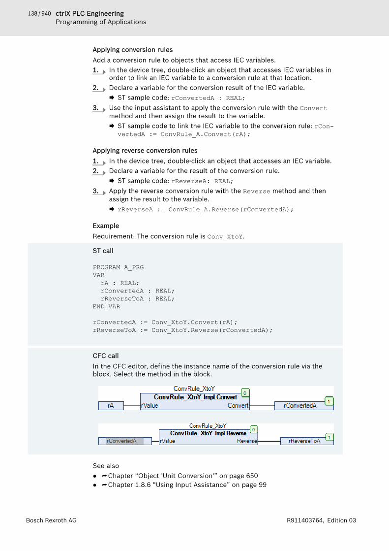
138 / 940 ctrlX PLC EngineeringProgramming of Applications
Bosch Rexroth AG R911403764, Edition 03
Applying conversion rulesAdd a conversion rule to objects that access IEC variables.1. In the device tree, double-click an object that accesses IEC variables in
order to link an IEC variable to a conversion rule at that location.2. Declare a variable for the conversion result of the IEC variable.
🡆 ST sample code: rConvertedA : REAL;3. Use the input assistant to apply the conversion rule with the Convert
method and then assign the result to the variable.🡆 ST sample code to link the IEC variable to the conversion rule: rCon-
vertedA := ConvRule_A.Convert(rA);
Applying reverse conversion rules1. In the device tree, double-click an object that accesses an IEC variable.2. Declare a variable for the result of the conversion rule.
🡆 ST sample code: rReverseA: REAL;3. Apply the reverse conversion rule with the Reverse method and then
assign the result to the variable.🡆 rReverseA := ConvRule_A.Reverse(rConvertedA);
ExampleRequirement: The conversion rule is Conv_XtoY.
ST call
PROGRAM A_PRGVARrA : REAL;rConvertedA : REAL;rReverseToA : REAL;
END_VAR
rConvertedA := Conv_XtoY.Convert(rA);rReverseToA := Conv_XtoY.Reverse(rConvertedA);
CFC callIn the CFC editor, define the instance name of the conversion rule via theblock. Select the method in the block.
See also● ⮫ Chapter “Object 'Unit Conversion'” on page 650● ⮫ Chapter 1.8.6 “Using Input Assistance” on page 99

139 / 940ctrlX PLC EngineeringProgramming of Applications
Bosch Rexroth AGR911403764, Edition 03
1.8.20 Data PersistenceThe lifespan of a variable and its data begins at the time when the variable iscreated and ends at the time when the variable is deleted and its memory isfreed. The time when the variable is created, initialized, or instantiateddepends on the declared scope. The time when the memory is freed usuallydepends on the scope as well. For example, the memory of global variables isfreed by exiting the application.They can retain data longer than usual. The following mechanisms are providedfor this purpose.Mechanisms for data retention● (A): Persistent global variable list with the keyword PERSISTENT RETAIN
Persistent variables retain their values when the application is reloaded.Moreover, the values are restored after a download, warm start, or coldstart.
● (B): Retain variables with the keyword RETAINRetain variables retain their values after a warm start, but not after reloadingthe application, a download, or a cold start.
● (C): Recipe variablesRecipe variables and their values are stored in a recipe file.
See also● ⮫ Chapter “Preserving Data with Retain Variables” on page 144● ⮫ Chapter “Preserving Data with Recipes” on page 145● ⮫ Chapter “Persistent Variable - PERSISTENT” on page 321● ⮫ Chapter “Retain Variable - RETAIN” on page 323● ⮫ Chapter “Object 'Persistent variable list'” on page 582
Mechanisms in ComparisonWhich mechanism is suitable for which application? Some common use casesare considered in the table. The specific examples refer to a building controlsystem.Table 1: Comparison of mechanisms and use cases
Uses case (A) Per-sistentvariables
(B) Retainvariables
(C) Varia-bles ofthe Per-sistenceManager
(D)Recipevariables
1 The application must main-tain device settings.Example: After a powerfailure, the building controlhas to have informationavailable about how long awindow blind needs to beraised.
Suitable1
Preferreduse caseIn thiscase, youcan alsouse retainvariablesinstead ofpersistentvariables.This isadvanta-geous forvariableswhosedeclara-
SuitablePreferred usecaseRetain varia-bles are anadvantagewhen theirdeclarationsare changedoften.
Suitable2
This isadvanta-geous forcontrol-lers thatdo nothave anyhardwaresupport.Specialfunction-alitiesmake thispossible,such as
Possible,but verycompli-cated andthereforenot rec-ommended.
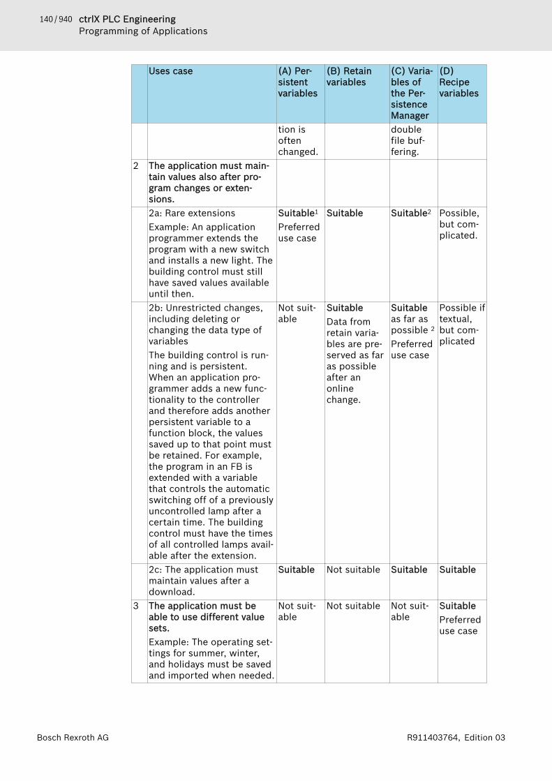
140 / 940 ctrlX PLC EngineeringProgramming of Applications
Bosch Rexroth AG R911403764, Edition 03
Uses case (A) Per-sistentvariables
(B) Retainvariables
(C) Varia-bles ofthe Per-sistenceManager
(D)Recipevariables
tion isoftenchanged.
doublefile buf-fering.
2 The application must main-tain values also after pro-gram changes or exten-sions.2a: Rare extensionsExample: An applicationprogrammer extends theprogram with a new switchand installs a new light. Thebuilding control must stillhave saved values availableuntil then.
Suitable1
Preferreduse case
Suitable Suitable2 Possible,but com-plicated.
2b: Unrestricted changes,including deleting orchanging the data type ofvariablesThe building control is run-ning and is persistent.When an application pro-grammer adds a new func-tionality to the controllerand therefore adds anotherpersistent variable to afunction block, the valuessaved up to that point mustbe retained. For example,the program in an FB isextended with a variablethat controls the automaticswitching off of a previouslyuncontrolled lamp after acertain time. The buildingcontrol must have the timesof all controlled lamps avail-able after the extension.
Not suit-able
SuitableData fromretain varia-bles are pre-served as faras possibleafter anonlinechange.
Suitableas far aspossible 2
Preferreduse case
Possible iftextual,but com-plicated
2c: The application mustmaintain values after adownload.
Suitable Not suitable Suitable Suitable
3 The application must beable to use different valuesets.Example: The operating set-tings for summer, winter,and holidays must be savedand imported when needed.
Not suit-able
Not suitable Not suit-able
SuitablePreferreduse case

141 / 940ctrlX PLC EngineeringProgramming of Applications
Bosch Rexroth AGR911403764, Edition 03
Uses case (A) Per-sistentvariables
(B) Retainvariables
(C) Varia-bles ofthe Per-sistenceManager
(D)Recipevariables
4 The application must beable to use settings fromanother system.It must be possible totransfer settings to anotherplant using similar varia-bles.
Not suit-able
Not suitable Suitable2 Suitable3
5 The application must pro-vide human readable data.The user must be able toread, compare, and edit thedata.
Not suit-able
Not suitable Suitable2 Suitable3
1 Disadvantage: Only possible if the runtime system supports this mechanismand an NVRAM memory or UPS is available. Advantage: Speed; recommendedapplication: 1 and 2a2 Disadvantage: In the case of large variable sets (> 10000), long delays duringinitialization and shutdown are to be expected. Advantage: No special memoryis required; value retention exists even in case of changes, extensions, or dele-tions.3 Advantage: Editable remotely, transferable. Disadvantage: Complicated
Lifespan of variables when calling online commands
User input in the“Online” menu
Variable with usual life-span
Neither RETAIN norPERSISTENT
RETAIN PERSISTENTRETAIN PERSISTENT PERSISTENT RETAIN
Command “OnlineChange”
x x x
Command “Resetwarm”
- x x
Command “Reset cold” - - xCommand “Download” - - x 1
Command “Resetorigin”
- - -
x : Variable retains its value- : Variable is initialized1 Note: For the structure of persistent data, refer to the information in "Mecha-nism for downloading".See also● ⮫ “Mechanism for downloading” on page 143● ⮫ Chapter “Command 'Online Change'” on page 722● ⮫ Chapter “Command 'Reset Origin'” on page 727● ⮫ Chapter “Command 'Reset Cold'” on page 725● ⮫ Chapter “Command 'Load'” on page 722
142 / 940 ctrlX PLC EngineeringProgramming of Applications
Bosch Rexroth AG R911403764, Edition 03
Lifespan of variables when downloading a boot projectThe values of ordinary variables lose their value and are reinitialized.The values of persistent variables are protected when:● The structure of the persistent variable in memory matches the structure in
the persistent data list.The values of retain variables are protected when:● The structure of the persistent variable in memory matches the structure in
the persistent data list.● The persistent variables match the application (GUID has to agree).A "Retain mismatch" occurs when the requirements for restoring the values ofretain variables and persistent variables are not met when the application isbooted. The response to this discrepancy is described in the documentation ofthe hardware manufacturer.Note: For the structure of persistent data, refer to the information in "Mecha-nism for downloading".See also● ⮫ “Mechanism for downloading” on page 143
Preserving Data with Persistent VariablesPersistent variables retain their values after reloading the application, and aftera download, warm start, or cold start.A special non-volatile memory area on the controller, for example as NVRAM orUPS, is required to extend the lifespan. Securing the data in such a memorydoes not require any additional time, which is an advantage over data retentionwith the Persistence Manager. If the controller does not provide hardware sup-port, then the data is usually stored in a file. Then the data will be retained ifyou shut down the controller correctly. In the event of a power failure or apulled plug, however, data will be lost.
BehaviorValue retained for● Uncontrolled exit● Warm start by calling the “Reset Warm” command● Cold start by calling the “Reset Cold” command● Repeated download of the applicationReinitialization for● Call of the “Reset Origin” commandTherefore, persistent variables are reinitialized only if you reset the controller tothe factory settings (for example, when you click “Online 🠂 Reset Origin”).If, on the other hand, you download the application again, the persisted data isretained if possible. That depends on how profound the changes that led to thedownload were. Changing the application name always leads to a full reinitiali-zation. Changes to the implementations never lead to a reinitialization: the datapersistence is completely preserved. Changes to the declarations lead to an ini-tialization of the new variables only if the existing variables are persistent,when you change the declarations so that the persistent variable list remainsconsistent. This is the case when you add a new variable or delete an existingone. Inconsistencies can occur if you edit and change the identifiers or datatypes of previously declared persistent variables.
143 / 940ctrlX PLC EngineeringProgramming of Applications
Bosch Rexroth AGR911403764, Edition 03
Mechanism for downloadingEditing the variable list in the persistence editor causes the variable list to beedited automatically before it is saved, not to be saved as it is shown in theeditor.During post-processing, a variable that you have removed is replaced by a pla-ceholder variable with the same memory requirement. As a result, the subse-quent variables retain their addresses in the process image. Moreover, a vari-able you add is moved to the end of the list. Post-processing can neutralizechanges that would lead to a loss of persistence. But you create gaps that useadditional memory.When downloading, the CRC value of the variable list and the length of the list(number of variables) are stored on the controller. When downloading again,the new test value is compared with the test value currently on the controller.Then the variable list is compared successively up to the specified length. If youhave edited a declaration (for example, the name or data type), then the vari-able is reinitialized. Otherwise its value is retained. When the download isrepeated, PLC Engineering checks whether the variable list declared in the per-sistence editor is still consistent with the variable list already on the controller.The mechanism works well when the variables themselves are not modified sig-nificantly. Too extensive changes of the identifiers and the data types continueto lead to a reinitialization and the loss of persistence. If you anticipate fre-quent changes due to your application requirements, then this kind of a list isnot recommended. Moreover, in an online change after a data type change, apersistent variable is less robust than a variable with a normal lifespan.It is good practice to clear any gaps in the variable list after a while (command“Reorder List and Clear Gaps”). After cleaning, however, the list no longermatches the list on the controller and you have triggered an initialization of allpersistent variables. The persistence of all variables is lost.For versions before V3.5 SP1, changes in the persistence editor always lead toreinitialization.
Recovering data with the recipe managerTo clean up the global persistent variable list without losing persistence, youcan save the data in a recipe using the Recipe Manager. This creates a list forall variables of the persistent variable list in the recipe manager, and at thesame time its current values are stored by the controller as a recipe. Then exe-cute the command “Reorder List and Clear Gaps” and perform a downloadagain. Now when you execute the command “Restore Values from Recipe”, thevalues saved in the recipe are restored.
Changing an existing declaration in the persistent variable listif you change the name or data type of a variable, this is interpreted as a newdeclaration and causes a re-initialization of the variables at the next onlinechange or download. For complex data types, a change occurs when a newcomponent is added, or when you change the type of a variable from INT toUINT in the depth of a used structure used, for example.Basically, complex user-defined data types are not suitable for administration ina persistent variable list, because even small changes cause the variable to beinitialized with all components.

144 / 940 ctrlX PLC EngineeringProgramming of Applications
Bosch Rexroth AG R911403764, Edition 03
Double allocation of memory in the case of instance pathsYou can persist global variables or variables declared locally in a function blockor program. To do this, add the keyword PERSISTENT to the declaration. Inaddition, you insert the instance path to this variable in the persistent globalvariable list. To do this, execute the “Add All Instance Paths” command in thepersistence editor.Persistence is guaranteed by the following mechanism:● The cyclic tasks in which the variable is accessed are determined.● At the end of the first cyclic task (in each cycle), the variable is copied to the
persistent global variable list.● After restarting the controller, the value of the persistent variable is copied
to the ordinary variable.The disadvantage of this mechanism is that memory is allocated both at theplace of declaration and at the place of the instance path. This persistent vari-able has a double memory allocation. Moreover, the data is copied to bothplaces in each cycle. This can be time consuming, especially when large struc-tured values are involved.
Memory location in the case of persistent function block instancesA function block instance is always stored completely in memory. This is neces-sary so that the same code can work on different instances. If only one variablein a function block is marked with PERSISTENT, then the function blockinstance is stored completely with all variables in remanent memory, althoughonly the one variable is treated as persistent. However, non-volatile memory isnot available to the same extent as main memory.A function block with a pointer to an instance in SRAM as a variable is notstored in the protected memory.
See also● ⮫ Chapter “Persistent Variable - PERSISTENT” on page 321● ⮫ Chapter “Command 'Add all instance paths'” on page 795
Preserving Data with Retain VariablesRetain variables preserve their values after a warm start. However, the degreeof value retention for persistent variables is higher.A special non-volatile memory area on the controller, for example as NVRAM orUPS, is required to extend the lifespan. Securing the retain variables in such amemory does not require any additional time, which is an advantage over dataretention with the Persistence Manager. If the controller does not provide hard-ware support, then the data is usually stored in a file. Then the data will beretained if you shut down the controller correctly. In the event of a powerfailure or a pulled plug, however, data will be lost.
DeclarationTo declare a retain variable, add the RETAIN keyword to a variable declaration.
BehaviorValue retained for● Uncontrolled exit● Call of the “Reset Warm” command

145 / 940ctrlX PLC EngineeringProgramming of Applications
Bosch Rexroth AGR911403764, Edition 03
Reinitialization for● Repeated download of the application● Call of the “Reset Cold” command (in contrast to persistent variables)● Call of the “Reset Origin” commandWhen you restart an application, its variables are usually initialized with anexplicitly preset initial value or with a default value. Variables marked with theRETAIN keyword are managed in a separate memory area depending on thetarget system and retain their value. Then the variables are protected frompower failure, for example. This means that you can apply retain variables to aparts counter in a production line so that you can continue counting even aftera power failure.
Memory location of persistent function block instancesFunction block instances are stored as one block in memory. This is necessaryso that the same code can work on different instances. If a variable is markedwith RETAIN in a function block, then each instance of the function block isprotected with all variables. This is also true for the variables of the functionblock that are not marked this way. However, non-volatile memory is not avail-able to the same extent as main memory.A function block with a pointer to an instance in SRAM as a variable is notstored in the protected memory.
See also● ⮫ Chapter “Retain Variable - RETAIN” on page 323
Preserving Data with RecipesVariables are managed persistently in the Recipe Manager. The Recipe Managerdoes not need any special memory on the controller in order to preserve valuesand data.
DeclarationA recipe definition consists of a set of variables with values and is created andedited in the “Recipe Manager” object and saved to a file.
Functionality● You can include a variable in multiple recipes, each with different values.● In online mode, you can read in the actual values of the variables from the
controller and save them as recipe values (specified value).● You can use the Recipe Management library to programmatically implement
the creation and editing of a recipe.● You can save and backup a recipe as a recipe file.
See also● ⮫ Chapter 1.12.2 “Changing Values with Recipes” on page 216● ⮫ Chapter “Command 'Save Current Values to Recipe'” on page 794● ⮫ Chapter “Command 'Reorder List and Clean Gaps'” on page 793● ⮫ Chapter “Command 'Restore Values from Recipe'” on page 794● ⮫ Chapter “Object 'Recipe Manager'” on page 626● ⮫ Chapter “Object 'Recipe Definition'” on page 629
Declaring VAR PERSISTENT VariablesBelow you will declare persistent variables in a persistent variable list and in aPOU.
146 / 940 ctrlX PLC EngineeringProgramming of Applications
Bosch Rexroth AG R911403764, Edition 03
Requirement: A project is opened and contains a program POU. You have ena-bled the option for the textual view in the “Declaration Editor” category of theoptions (menu command “Tools 🠂 Options”).1. Add the “Persistent Variables” object to the application object with the
menu command “Project 🠂 Add Object”.🡆 PLC Engineering adds the persistent variable list “PersistentVars”
below the application object in the device tree and the editor opens.2. In the editor, enter a variable declaration, for example ivarpersist1 :
INT; between VAR_GLOBAL PERSISTENT RETAIN and END_VAR.3. Double-click the POU in the device tree.
🡆 The editor of the POU opens.4. Specify the following declaration in the declaration part:
VAR PERSISTENTivarpersist2 : INT;END_VAR
5. Click “Build 🠂 Build”.🡆 The message view opens. If PLC Engineering has compiled the applica-
tion without errors, then close the message window and continue withthe next step. Otherwise, correct the error(s) and select the menucommand “Build 🠂 Build” again.
6. Click the tab “PersistentVars” to select the persistent variable list as theactive editor and select the menu command “Declarations 🠂 Add AllInstance Paths”.🡆 PLC Engineering adds the persistent variable from the persistent vari-
able list “PersistentVars” to the POU:// instance path of the persistent variables createdPOU.IVARPERSIST2: INT
See also● ⮫ Chapter “Persistent Variable - PERSISTENT” on page 321● ⮫ Chapter “Retain Variable - RETAIN” on page 323● ⮫ Chapter “Object 'Persistent variable list'” on page 582● ⮫ Chapter “Command 'Add all instance paths'” on page 795
Saving the Values of a Persistent Variable List in a RecipeRequirement: a project is opened and a persistent variable list with declara-tions of persistent variables exists under an application object.1. Double-click on the controller in the device tree and select the tab “Com-
munication Settings”.2. Select your gateway and click on the button “Scan Network”.
🡆 Your device is shown in bold in the tree view of the gateway.3. Select your device and click on the button “Set Active Path”.4. Select your application object in the device tree and select the context
menu command “Set Active Application”.🡆 The application object is displayed in bold.
5. Select the menu command “Online 🠂 Login”🡆 Your application is logged in to the controller and the controller and the
application object in the device tree have a green background.
147 / 940ctrlX PLC EngineeringProgramming of Applications
Bosch Rexroth AGR911403764, Edition 03
6. Double-click on the persistent variable list and select the command“Declarations 🠂 Save Current Values to Recipe”.🡆 PLC Engineering creates the objects “Recipe Manager” and “Persistent-
Variables” under the application object.7. Select the menu command “Online 🠂 Logout”.
🡆 The application is logged out from the controller.See also● ⮫ Chapter “Command 'Save Current Values to Recipe'” on page 794● ⮫ Chapter 1.8.20 “Data Persistence” on page 139
1.8.21 Alarm ManagementYou can use the alarm management as part of an application in order to deter-mine and record critical process states and to display them with the help of vis-ualization elements. You can take notice of alarms via the application or userinputs in the visualization and react accordingly with acknowledgment and sub-sequent actions. PLC Engineering provides special visualization elements and alibrary for this.An alarm management consists of the following elements● Alarm class: an alarm class serves the typifying of alarms, i.e. it defines a
basic parameter set for an alarm. You must specify the class when creatingan alarm. For example, it defines how an alarm must be confirmed, whetherit is to be recorded and displayed, or whether it is to be written to a file.
● Alarm group: an alarm group is for the concrete configuration of one or morealarms. In the alarm group you define the conditions for the individualalarms and assign the alarms to the alarm classes. Furthermore you definethere whether the alarms of this group are archived.
● Alarm storage: an alarm storage is for defining the parameters for thearchiving of the alarms that occur.
The visualization of PLC Engineering offers the elements “Alarm Table” and“Alarm Banner” for displaying the alarm messages.So that you have access to the alarms from the application, the library Alarm-Manager.library offers certain functions and interfaces.See also● ⮫ Chapter “Object 'Alarm Class'” on page 530● ⮫ Chapter “Object 'Alarm Group'” on page 533● ⮫ Chapter “Object 'Alarm Storage'” on page 537● ⮫ Chapter “Configuring the Alarm Management” on page 148● ⮫ Visualization Element 'Alarm table'● ⮫ Visualization Element 'Alarm banner
Defining AlarmsFor alarm management in PLC Engineering the following definitions apply to analarm. An alarm definition consists in principle of● a general description (ID, message text, etc.)● a description of the cause of the alarm (expression to be monitored, limits,
min. pending time, etc.)● a description of the effects of the alarm (actions, display properties, confir-
mation method etc.).
Acknowledgement of alarms: the main reason for the use of alarms is to informthe user about an alarm situation. In order to ensure that the user has takennotice of the information, PLC Engineering provides you with various actions

148 / 940 ctrlX PLC EngineeringProgramming of Applications
Bosch Rexroth AG R911403764, Edition 03
3.
that you define in the alarm class. The user must acknowledge the alarm inorder to delete it from the alarm list. The special types of alarm acknowledg-ment are described in the status diagrams as status transitions.Alarm event: an alarm event is linked to an alarm condition. While an alarm con-dition can exist over a lengthy period, the alarm event describes the momen-tary occurrence of a change, for example the change from the normal state tothe alarm state. In the PLC Engineering alarm configuration the same names(Active, ACK, Inactive) are used for the three types of events and the associatedalarm status.The following features are supported in PLC Engineering:● Deactivation of the alarm generation for simple alarms as well as for alarm
groups● Selection of the alarms that are to be displayed, by definition of alarm
groups and priorities● Display of all alarm events in an alarm table● Visualization elements “Alarm Table” and “Alarm Banner” in the PLC Engi-
neering visualization
Configuring the Alarm ManagementCreating alarm configurations1. Select an application in the device tree.2. Click “Project 🠂 Add Object 🠂 Alarm configuration”.
🡆 The “Add Alarm Configuration” dialog box opens.3. Click “Add”.
🡆 PLC Engineering adds the “Alarm Configuration” to the device treebelow the application.In addition, PLC Engineering inserts the predefined alarm classes(“Error”, “Info”, and “Warning”) and the alarm storage “AlarmStorage”below the alarm configuration. The predefined objects are available toyou if you need them.
Configuring alarm classes1. Select the “Alarm Configuration” object in the device tree.2. Click “Project 🠂 Add Object 🠂 Alarm Class”.
Type in a name (example: "PartsDeficit") and click “Add”🡆 The “PartsDeficit” alarm class is added to the device tree. The object
opens in the editor.Set the following parameters for the class. These apply to all alarms thatbelong to this class group:● “Priority”: 10● “Archiving”● “Acknowledgment method”: REP_ACK● “acknowledge separately”:
4. In the following, you define that the bPartsDeficit variable has thevalue TRUE when alarm messages occur: Double-click the “Action” columnin the “Notification actions” group.Select the “Variable” action.Press the [Enter] key.🡆 The action is added and all options are activated.
5. Select the “Activate” check box, and clear the “Deactivate” and “Confirm”check boxes.

149 / 940ctrlX PLC EngineeringProgramming of Applications
Bosch Rexroth AGR911403764, Edition 03
3.
5.
6. Click inside the input field “Variable” and enter bPartsDeficit or selectthe variable with the help of the input assistantEnter the value TRUE into the right field.🡆 The ...bPartsDeficit := TRUE statement is displayed in the
“Details” column.7. Select the “Background color” "Red" in the “Active” row of the “Display
Options” group.Select the “Background color” "Yellow" in the “Wait for confirmation” rowin the “Presentation Options” group.
All messages in the “PartsDeficit” class set the variable bPartsDeficit toTRUE. Active messages are highlighted in red in the "Alarm table" visualizationelement. Deactivated messages that are not acknowledged are highlighted inyellow.See also● ⮫ Chapter “Object 'Alarm Class'” on page 530● ⮫ Visualization Element Alarm table● ⮫ Visualization Element Alarm banner
Configuring alarm groupsIn the following, you define an alarm group with an alarm for monitoring Parts-Deficit. You have already created the applicable alarm class above.1. Select the “Alarm Configuration” object in the device tree.2. Click “Project 🠂 Add Object 🠂 Alarm Group”.
Type in the name "PartsDeficit" and click “Add”🡆 The “PartsDeficit” alarm group is added to the device tree. The object
opens in the editor.PLC Engineering creates the text list “PartsDeficit”.
Set the following parameters:● “Archiving”: (none)
4. Double-click in the “Observation type” field.Select the “Digital” monitoring type.Configure the alarm as follows:● “Class”: PartsDeficit● “Message”: PartsDeficit at Station 1 - level: <LATCH1>
("<LATCH1>" is a placeholder for latch variable 1.)● “Min. pend. time”: t#5s● “Latch var 1”: ...iFuellstand
6. In the “Digital” group, click the “Expression” field and type inbPart1Empty or select the variable by using the input assistant.Type in the value TRUE in the right field.🡆 The ...bTeil1Leer = TRUE statement is displayed in the “Details”
column.If the bTeil1Leer variable switches to TRUE, then PLC Engineering triggers amessage. The value of the iFuellstand variable is printed with the message.The acknowledgment response and the display are executed according to the“PartsDeficit” alarm class. The alarm is not archived.See also● ⮫ Chapter “Object 'Alarm Group'” on page 533

150 / 940 ctrlX PLC EngineeringProgramming of Applications
Bosch Rexroth AG R911403764, Edition 03
Configuring alarm storage1. Select the “Alarm Storage” object in the device tree.2. To change the name, select the “Properties” command in the context
menu.Change the name from "AlarmStorage" (example: "DatabaseFileAlarm-Storage") and click “OK”.
3. Double-click the “DatabaseFileAlarmStorage” object in the device tree toopen the editor.
4. Configure as follows:● “Subdirectory”: Leave this field blank. Specifying a directory is optional
only on the PLC where the alarm storage file will be saved.● “Limit” group: Select the “No limit” check box.🡆 The alarm storage is configured. In this case, PLC Engineering saves the
alarms internally in an unlimited buffer.See also● ⮫ Chapter “Object 'Alarm Storage'” on page 537
Calling event alarms in the programYou define the alarms in the object Alarm Group. The monitoring type “Event”is thereby available. Contrary to the other monitoring types, which trigger thealarm depending on a condition, you can trigger the alarm with the type“Event” via a function block call.
Defining the event alarm in the alarm group1. Create an alarm group.2. Define an alarm of the monitoring type “Event” in the alarm group.3. In the column “Class”, select an alarm class with the acknowledgement
method “ACK” or create a new alarm class.See also● ⮫ “Configuring alarm classes” on page 148
Program call for triggering the event alarm1. Set the cursor at the program position at which the function-block call is
to take place.2. Use the RaiseEvent function from the AlarmManager library:
Enter 'AlarmManager', followed by a period.🡆 A window opens containing a list of all insertable elements (function
'List components').
3. Select AlarmGlobals and enter a period.
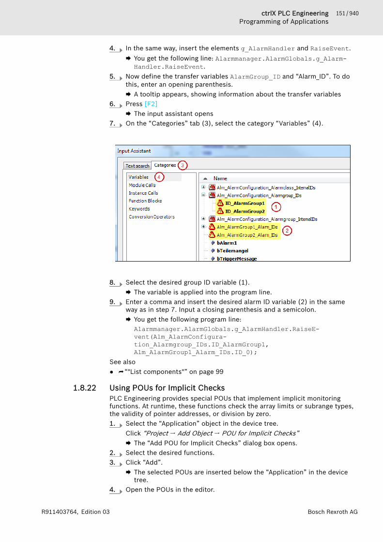
151 / 940ctrlX PLC EngineeringProgramming of Applications
Bosch Rexroth AGR911403764, Edition 03
4. In the same way, insert the elements g_AlarmHandler and RaiseEvent.🡆 You get the following line: Alarmmanager.AlarmGlobals.g_Alarm-
Handler.RaiseEvent.5. Now define the transfer variables AlarmGroup_ID and “Alarm_ID”. To do
this, enter an opening parenthesis.🡆 A tooltip appears, showing information about the transfer variables
6. Press [F2]🡆 The input assistant opens
7. On the “Categories” tab (3), select the category “Variables” (4).
8. Select the desired group ID variable (1).🡆 The variable is applied into the program line.
9. Enter a comma and insert the desired alarm ID variable (2) in the sameway as in step 7. Input a closing parenthesis and a semicolon.🡆 You get the following program line:
Alarmmanager.AlarmGlobals.g_AlarmHandler.RaiseE-vent(Alm_AlarmConfigura-tion_Alarmgroup_IDs.ID_AlarmGroup1,Alm_AlarmGroup1_Alarm_IDs.ID_0);
See also● ⮫ “"List components"” on page 99
1.8.22 Using POUs for Implicit ChecksPLC Engineering provides special POUs that implement implicit monitoringfunctions. At runtime, these functions check the array limits or subrange types,the validity of pointer addresses, or division by zero.1. Select the “Application” object in the device tree.
Click “Project 🠂 Add Object 🠂 POU for Implicit Checks”🡆 The “Add POU for Implicit Checks” dialog box opens.
2. Select the desired functions.3. Click “Add”.
🡆 The selected POUs are inserted below the “Application” in the devicetree.
4. Open the POUs in the editor.

152 / 940 ctrlX PLC EngineeringProgramming of Applications
Bosch Rexroth AG R911403764, Edition 03
5. Adapt the implementation suggestion to your requirements.
CAUTION To obtain the feature for monitoring functions, donot edit the declaration section. However, you are permitted to add localvariables.
See also● ⮫ Chapter “Object 'POU'” on page 587● ⮫ Chapter “Object 'POUs for Implicit Checks'” on page 608
1.8.23 Object-Oriented ProgrammingPLC Engineering supports object oriented programming with function blocksand for this purpose provides the following features and objects:● Methods● Interfaces● Properties● Inheritance● Method call, virtual function call● Definition of function blocks as extensions of other function blocksSee also● ⮫ Chapter “Object 'Method'” on page 596● ⮫ Chapter “Object 'Interface'” on page 594
Extension of Function BlocksThe extension of a function block is based on the concept of inheritance inobject-oriented programming. A derived function block thereby extends a basicfunction block and in doing so is given the properties of the basic functionblock in addition to its own properties.The extension of a function block means:● The inherited function block contains all data and methods that are defined
by the basic function block. You can use an instance of the basic functionblock in every context in which PLC Engineering expects a function block ofthe type of the basic function block.
● The derived function block can overwrite the methods that you have definedin the base function block. This means that the inherited function block candefine a method with the same name, the same inputs and the same outputas is defined by the basic function block.Tip: You have the following support when overwriting methods, actions,attributes, and transitions that are inherited by the base block: When youinsert a method, action, etc. below an inherited block, the “Add Object”dialog includes a combo box with a list of methods, actions, etc. used in thebase block. You can accept these and adapt them accordingly.
● The derived function block may not contain function block variables with thesame names as used by the basic function block. The compiler reports thisas an error.The only exception: If you have declared a variable in the basic functionblock as VAR_TEMP, then the inherited function block may define a variablewith the same name. In this case, the inherited function block can no longeraccess the variable of the basic function block.
● You can directly address the variables and methods of the basic functionblock within the scope of the inherited function block by using the SUPERpointer.

153 / 940ctrlX PLC EngineeringProgramming of Applications
Bosch Rexroth AGR911403764, Edition 03
NOTICE Multiple inheritance is not permitted.Exception: A function block can implement multiple inter-faces, and an interface can extend other interfaces.
Extension of a basic function block by a new function blockRequirement: the currently opened project possesses a basic function block,for example “POU_1(FB)”, which is to be extended by a new function block.1. Right-click the “Application” object in the device tree and select “Project
🠂 Add Object 🠂 POU”.🡆 The “Add POU” dialog opens.
2. Type the name for the new POU in the “Name” input field, for example“POU_Ex”.
3. Select “Function block”.4. Click “Advanced” and then the more button ( ).5. In the category “Function blocks” under “Application” in the input assis-
tant, select the POU(FB) that is to serve as the basic function block, forexample POU_1, and click “OK”.
6. As an option, you can select an “Access modifier” for the new functionblock from the drop-down list.
7. Select from the “Implementation language” combo box (example: “Struc-tured text (ST)”.
8. Click “Add”.🡆 PLC Engineering adds the POU_Ex function block to the device tree and
opens the editor. The first line contains the text:FUNCTION_BLOCK POU_Ex EXTENDS POU_1The function block POU_Ex extends the basic function block POU_1.
Extension of a basic function block by an existing function blockRequirement: The open project possesses a base function block (example:POU_1(FB)) and another function block (example: POU_Ex(FB)). The functionblock POU_Ex(FB) is also to be given the properties of the basic functionblock. This means that POU_Ex(FB) should extend POU_1(FB).1. Double-click the function block POU_Ex(FB) in the device tree.
🡆 The function block editor opens.2. Extend the existing entry in the top line FUNCTION_BLOCK POU_Ex with
EXTENDS POU_1.🡆 The function block POU_Ex extends the basic function block POU_1.
See also● ⮫ Chapter “Implementing Interfaces” on page 154● ⮫ Chapter “Extending Interfaces” on page 155● ⮫ Chapter “SUPER” on page 323● ⮫ Chapter “THIS” on page 325● ⮫ Chapter “Object 'Function Block'” on page 590● ⮫ Chapter “Object 'Method'” on page 596● ⮫ Chapter “Object 'Property'” on page 603● ⮫ Chapter “Object 'Action'” on page 606● ⮫ Chapter “Object 'Transition'” on page 607
154 / 940 ctrlX PLC EngineeringProgramming of Applications
Bosch Rexroth AG R911403764, Edition 03
Implementing InterfacesImplementing interfaces is based on the concept of object-oriented program-ming. With common interfaces, you can use different but similar functionblocks the same way.A function block that implements an interface has to include all methods andattributes that are defined in that interface (interface methods and interfaceattributes). This means that the name and the inputs and outputs of themethods or attributes must be exactly the same. When you create a new func-tion block that implements an interface, PLC Engineering adds all methods andattributes of the interface automatically to the tree below the new functionblock.
NOTICE If you add more interface methods afterwards, then PLCEngineering does not add these methods automaticallyto the affected function block. To perform this update,you must execute the “Implement Interfaces” commandexplicitly.For inherited function blocks, you have to make sure thatany methods or attributes that were derived through theinheritance of an interface also receive the appropriateimplementation. Otherwise they should be deleted incase the implementation that was provided in the basisshould be used. Respective compile error messages orwarnings are displayed, prompted automatically byadded pragma attributes. For more information, refer tothe help page for the “Implementing Interfaces” com-mand.
NOTICE − You must assign the interface of a function block to avariable of the interface type before a method can becalled via the variable.
− A variable of the interface type is always a referenceof the assigned function block instance.
A variable of the interface type is a reference to instances of function blocks.This kind of variable can refer to every function block that implements the inter-face. If there is no assignment to a variable, then the variable in online modecontains the value 0.
ExamplesThe I1 interface contains the GetName method.METHOD GetName : STRING The functions blocks A and B implements the interface I1:FUNCTION_BLOCK A IMPLEMENTS I1FUNCTION_BLOCK B IMPLEMENTS I1For this reason, both function blocks must include a method named GetNameand the return type STRING. Otherwise the compiler reports an error.A function includes the declaration of a variable of interface I1 type.FUNCTION DeliverName : STRINGVAR_INPUT l_i : I1;END_VAR Function blocks that implement the I1 interface can be assigned to theseinput variables.Examples of function calls:

155 / 940ctrlX PLC EngineeringProgramming of Applications
Bosch Rexroth AGR911403764, Edition 03
DeliverName(l_i := A_instance); // call with instance of type ADeliverName(l_i := B_instance); // call with instance of type BCalling of interface methods:In this case, it depends on the actual type of l_i whether the application callsA.GetName or B.GetName.DeliverName := l_i.GetName();
● ⮫ Chapter “Command 'Implement Interfaces'” on page 815
Implementing an interface in a new function blockRequirement: The open project has at least one interface object.1. Right-click “Application” in the device tree and select “Project 🠂 Add
Object 🠂 POU”.🡆 The “Add POU” dialog box opens.
2. Type the name for the new POU in the “Name” input field, for example“POU_Im”.
3. Select “Function block”.4. Click “Implemented” and then the more button ( ).5. In the input assistant, select the interface from the category “Interfaces”,
for example ITF1, and click on “OK”.6. To insert more interfaces, click and select a another interface.7. As an option, you can select an “Access modifier” for the new function
block from the selection list.8. Select from the “Implementation language” combo box (example: “Struc-
tured text (ST)”.9. Click “Add”.
🡆 PLC Engineering adds the “POU_Ex” function block to the device treeand opens the editor. The first line contains the text:FUNCTION_BLOCK POU_Im IMPLEMENTS ITF1The interface and its methods and properties are now inserted belowthe function block in the device tree. Now you can type program codeinto the implementation part of the interface and its methods.
Implementing an interface in an existing function blockRequirement: The currently open project has a function block (example:“POU_Im”) and at least one interface object (example: “ITF1”).1. Double-click the “POU_Ex(FB)” POU in the device tree.
🡆 The POU editor opens.2. Extend the existing entry in the uppermost line FUNCTION_BLOCK POU_Im
with IMPLEMENTS ITF1🡆 The “POU_Im” function block implements the “ITF1” interface.
See also● ⮫ Chapter “Object 'Function Block'” on page 590
Extending InterfacesYou can extend interfaces just like function blocks. The interface is then alsogiven the interface methods and interface properties of the basic interface inaddition to its own.

156 / 940 ctrlX PLC EngineeringProgramming of Applications
Bosch Rexroth AG R911403764, Edition 03
Creation of an interface that extends another interface.1. Select the object “Application” in the device tree.2. Select the command “Project 🠂 Add Object 🠂 Interface”.
🡆 The dialog box “Add Interface” opens.3. Enter a name for the new interface.4. Activate the option “Extended” and click on the button .5. The input assistant opens.6. From the category “Interfaces”, select the interface that is to be extended
by the new interface.● ⮫ Chapter “Object 'Interface'” on page 594
Calling MethodsTo implement a method call, the actual parameters (arguments) are passed tothe interface variables. As an alternative, the parameter names can be omitted.Depending on the declared access modifier, a method can be called only withinits own namespace (INTERNAL), only within its own programming module andits derivatives (PROTECTED), or only within its own programming module (PRI-VATE). For PUBLIC, the method can be called from anywhere.Within the implementation, a method can call itself recursively, either directlyby means of the THIS pointer, or by means of a local variable for the assignedfunction block.
Method call as a virtual function callVirtual function calls can occur due to inheritance.Virtual function calls enable one and the same call to call various methods in aprogram source code during the runtime.In the following cases the method call is dynamically bound:● You call a method via a pointer to a function block (for example
pfub^.method).In this situation the pointer can point to instances of the type of the functionblock and to instances of all derived function blocks.
● You call the method of an interface variable (for example inter-face1.method).The interface can refer to all instances of function blocks that implementthis interface.
● A method calls another method of the same function block. In this case themethod can also call the method of a derived function block with the samename.
● The call of a method takes place by means of a reference to a function block.In this situation the reference can point to instances of the type of the func-tion block and to instances of all derived function blocks.
● You assign VAR_IN_OUT variables of a basic function block type to aninstance of a derived FB type.In this situation the variable can point to instances of the type of the func-tion block and to instances of all derived function blocks.

157 / 940ctrlX PLC EngineeringProgramming of Applications
Bosch Rexroth AGR911403764, Edition 03
Example
Overloading methodsThe function blocks fub1 and fub2 extend the function block fubbase andimplement the interface interface1. The methods method1 and method2exist.PROGRAM PLC_PRGVAR_INPUT b : BOOL;END_VAR
VAR pInst : POINTER TO fubbase; instBase : fubbase; inst1 : fub1; inst2 : fub2; instRef : REFERENCE to fubbase;END_VAR
IF b THEN instRef REF= inst1; (* reference to fub1 *) pInst := ADR(instBase);ELSE instRef REF= inst2; (* reference to fub2 *) pInst := ADR(inst1);END_IFpInst^.method1(); (* If b is TRUE, fubbase.method1 will be called, otherwise fub1.method1 is called *) instRef.method1(); (* If b ist TRUE, fub1.method1 will be called, otherwise fub2.method1 is called*)
On the assumption that fubbase in the above example contains two methodsmethod1 and method2, it overwrites fub1 method2, but not method1. Thecall of method1 takes place as follows:pInst^.method1();If b is TRUE, then PLC Engineering calls fubbase.method1. If not, thenfub1.method1 is called.
Additional outputsIn accordance with the IEC 61131-3 standard, methods can have additional out-puts declared, like normal functions. With the method call, you assign variablesto the additional outputs.Detailed information about this can be found in the topic “Function”.Syntax for the call:
<function block name>.<method name>(<first input name> := <value> (, <further input assignments>)+ , <first output name> => <first output variable name> (,<further output assignments>)+ );

158 / 940 ctrlX PLC EngineeringProgramming of Applications
Bosch Rexroth AG R911403764, Edition 03
Example
Declaration
METHOD PUBLIC DoIt : BOOLVAR_INPUT
iInput_1 : DWORD;iInput_2 : DWORD;
END_VARVAR_OUTPUTiOutput_1 : INT;sOutput_2 : STRING;
ENDVARCall
fbInstance.DoIt(iInput_1 := 1, iInput_2 := 2, iOutput_1 => iLocal_1, sOUtput_2 => sLocal_2);When the method is called, the values of the method outputs are written tothe locally declared output variables.
Calling a method even if the application is in the STOP stateIn the device description it is possible to define that a certain function blockinstance (of a library function block) always calls a certain method in each taskcycle. If the method contains the input parameters of the following example,PLC Engineering processes the method even if the active application is pres-ently in the STOP state:
Example
VAR_INPUTpTaskInfo : POINTER TO DWORD;pApplicationInfo: POINTER TO _IMPLICIT_APPLICATION_INFO;
END_VAR
(*Now the status of the application can be queried via pApplicationInfo and the instructions can be implemented: *)IF pApplicationInfo^.state = RUNNING THEN <instructions> END_IF;
Calling methods recursivelyUse recursions mainly for processing recursive data types such as linked lists.Generally, we recommend that you be careful when using recursion. An unex-pectedly deep recursion can lead to stack overflow and therefore to machinedowntime.Within their implementation, a method can call itself:● Directly by means of the THIS pointer● Indirectly by means of a local function block instance of the basic function
blockUsually, a compiler warning is issued for such a recursive call. If the method isprovided with the pragma {attribute 'estimated-stack-usage' :='<sstimated_stack_size_in_bytes>'}, then the compiler warning is sup-pressed. For an implementation example, refer to the section "Attribute 'esti-mated-stack-usage'".
159 / 940ctrlX PLC EngineeringWorking with Control Networks
Bosch Rexroth AGR911403764, Edition 03
See also● ⮫ Chapter “Attribute 'estimated-stack-usage'” on page 426● ⮫ Chapter “THIS” on page 325● ⮫ Chapter “SUPER” on page 323● ⮫ Chapter “Object 'Method'” on page 596● ⮫ Chapter “Object 'Property'” on page 603
1.9 Working with Control NetworksWith the following functionalities, PLC Engineering supports communicationbetween controllers (PLC) and the insertion of a safety device below a PLC:● Symbol configuration: PLC Engineering creates symbols with certain access
rights for the variables in an application. With these symbols, you can accessthe variables from outside, for example from an OPC server.
● Data source manager: Manages the connection settings and the data trans-mission to remote devices (data sources). The transmitted data is mappedin data source variables that are accessed in the visualization or local appli-cation. An example of this is a control panel that controls remote devicesand visualizes the state of the device as an HMI application.
● Network variables: Network variables are variables whose values are acces-sible to different controllers in the network. The variables must be definedin rigid, identical lists in both the transmitter device and the receiver device.These lists are assigned to applications, but can be located in different proj-ects.
● A safety device can be inserted below a PLC in the device tree. The commu-nications links of the safety devices to the field devices, controller networks,and development system are routed via this controller.
See also● ⮫ Chapter 1.9.2 “Symbol Configuration” on page 164● ⮫ Chapter 1.9.4 “Data Source Manager” on page 169● ⮫ Chapter 1.9.3 “Network Variables” on page 166● ⮫ Chapter “Network Topology” on page 159● ⮫ Chapter “Addressing and Routing” on page 160● ⮫ Chapter “Address Structures” on page 161● ⮫ Chapter 1.9.5 “Subordinate Safety Controller” on page 183
1.9.1 Network and AddressingConstructing a control network hierarchically, so that extensive self-configura-tion is possible.In PLC Engineering the network topology is mapped to clear addresses and therouting algorithm is kept simple by structured addresses. There is direct andrelative addressing and automatic address determination during the bootup ofthe system.See also● ⮫ Chapter “Network Topology” on page 159● ⮫ Chapter “Addressing and Routing” on page 160● ⮫ Chapter “Address Structures” on page 161
Network TopologyInformation and recommendations for the topology of a control networkIt is recommended to set up a network system so that the following are pos-sible:
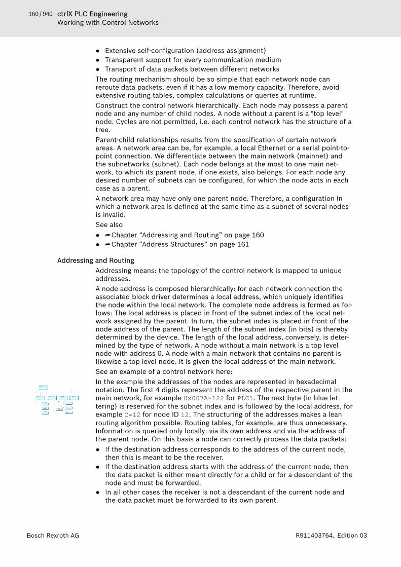
160 / 940 ctrlX PLC EngineeringWorking with Control Networks
Bosch Rexroth AG R911403764, Edition 03
● Extensive self-configuration (address assignment)● Transparent support for every communication medium● Transport of data packets between different networksThe routing mechanism should be so simple that each network node canreroute data packets, even if it has a low memory capacity. Therefore, avoidextensive routing tables, complex calculations or queries at runtime.Construct the control network hierarchically. Each node may possess a parentnode and any number of child nodes. A node without a parent is a "top level"node. Cycles are not permitted, i.e. each control network has the structure of atree.Parent-child relationships results from the specification of certain networkareas. A network area can be, for example, a local Ethernet or a serial point-to-point connection. We differentiate between the main network (mainnet) andthe subnetworks (subnet). Each node belongs at the most to one main net-work, to which its parent node, if one exists, also belongs. For each node anydesired number of subnets can be configured, for which the node acts in eachcase as a parent.A network area may have only one parent node. Therefore, a configuration inwhich a network area is defined at the same time as a subnet of several nodesis invalid.See also● ⮫ Chapter “Addressing and Routing” on page 160● ⮫ Chapter “Address Structures” on page 161
Addressing and RoutingAddressing means: the topology of the control network is mapped to uniqueaddresses.A node address is composed hierarchically: for each network connection theassociated block driver determines a local address, which uniquely identifiesthe node within the local network. The complete node address is formed as fol-lows: The local address is placed in front of the subnet index of the local net-work assigned by the parent. In turn, the subnet index is placed in front of thenode address of the parent. The length of the subnet index (in bits) is therebydetermined by the device. The length of the local address, conversely, is deter-mined by the type of network. A node without a main network is a top levelnode with address 0. A node with a main network that contains no parent islikewise a top level node. It is given the local address of the main network.See an example of a control network here:In the example the addresses of the nodes are represented in hexadecimalnotation. The first 4 digits represent the address of the respective parent in themain network, for example 0x007A=122 for PLC1. The next byte (in blue let-tering) is reserved for the subnet index and is followed by the local address, forexample C=12 for node ID 12. The structuring of the addresses makes a leanrouting algorithm possible. Routing tables, for example, are thus unnecessary.Information is queried only locally: via its own address and via the address ofthe parent node. On this basis a node can correctly process the data packets:● If the destination address corresponds to the address of the current node,
then this is meant to be the receiver.● If the destination address starts with the address of the current node, then
the data packet is either meant directly for a child or for a descendant of thenode and must be forwarded.
● In all other cases the receiver is not a descendant of the current node andthe data packet must be forwarded to its own parent.
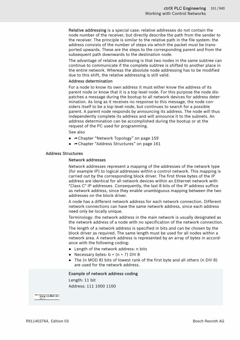
161 / 940ctrlX PLC EngineeringWorking with Control Networks
Bosch Rexroth AGR911403764, Edition 03
Relative addressing is a special case: relative addresses do not contain thenode number of the receiver, but directly describe the path from the sender tothe receiver. The principle is similar to the relative path in the file system: theaddress consists of the number of steps via which the packet must be trans-ported upwards. These are the steps to the corresponding parent and from thesubsequent path downwards to the destination node.The advantage of relative addressing is that two nodes in the same subtree cancontinue to communicate if the complete subtree is shifted to another place inthe entire network. Whereas the absolute node addressing has to be modifieddue to this shift, the relative addressing is still valid.Address determinationFor a node to know its own address it must either know the address of itsparent node or know that it is a top level node. For this purpose the node dis-patches a message during the bootup to all network devices for address deter-mination. As long as it receives no response to this message, the node con-siders itself to be a top level node, but continues to search for a possibleparent. A parent node responds by announcing its address. The node will thusindependently complete its address and will announce it to the subnets. Anaddress determination can be accomplished during the bootup or at therequest of the PC used for programming.See also● ⮫ Chapter “Network Topology” on page 159● ⮫ Chapter “Address Structures” on page 161
Address StructuresNetwork addressesNetwork addresses represent a mapping of the addresses of the network type(for example IP) to logical addresses within a control network. This mapping iscarried out by the corresponding block driver. The first three bytes of the IPaddress are identical for all network devices within an Ethernet network with"Class C" IP addresses. Consequently, the last 8 bits of the IP address sufficeas network address, since they enable unambiguous mapping between the twoaddresses on the block driver.A node has a different network address for each network connection. Differentnetwork connections can have the same network address, since each addressneed only be locally unique.Terminology: the network address in the main network is usually designated asthe network address of a node with no specification of the network connection.The length of a network address is specified in bits and can be chosen by theblock driver as required. The same length must be used for all nodes within anetwork area. A network address is represented by an array of bytes in accord-ance with the following coding:● Length of the network address: n bits● Necessary bytes: b = (n + 7) DIV 8● The (n MOD 8) bits of lowest rank of the first byte and all others (n DIV 8)
are used for the network address.
Example of network address codingLength: 11 bitAddress: 111 1000 1100

162 / 940 ctrlX PLC EngineeringWorking with Control Networks
Bosch Rexroth AG R911403764, Edition 03
Node addressesThe node address indicates the absolute address of a node within a controlnetwork and is therefore unique within the whole "network tree". The addressis composed of up to 15 address components, each of which occupies 2 bytes.The lower a node is located within the network hierarchy, the longer itsaddress.The complete node address consists of the partial addresses of all precedingnodes and the partial address of the node itself. Each partial address consistsof one or more address components. The length is therefore always a multipleof 2 bytes. The partial address of a node is formed from the network address ofthe node in its main network and the subnet index of the main network in thecase of the parent node. The bits required for the subindex are determined bythe router of the parent node. Filler bits can be inserted between the subnetindex and the network address in order to ensure that the length of the partialaddress is a multiple of 2 bytes.Special cases:● A node without a main network: this means that there is neither a subnet
index nor a network address in the main network. In this case the address isset to 0x0000.
● A node in the main network without a parent: In this case a subnet indexwith the length 0 is assumed. The partial address corresponds to the net-work address, if necessary extended by filler bits.
Example of node addresses
The node address is always specified in hexadecimal. The individual addresscomponents (two bytes in each case) are separated by a colon ":". Since thisrepresents an array of bytes and not a 16-bit value, the components are not dis-played in the Intel format. For manually input addresses, missing parts in anaddress component are supplemented by leading zeros: "274" = "0274". Inorder to improve the legibility, the display should also always contain theleading zeros.Absolute and relative addressesCommunication between two nodes can be based on relative or absoluteaddresses. Absolute addresses are identical to node addresses. Relativeaddresses specify a path from the sender to the receiver. They consist of anaddress offset and the descending path to the receiver.The (negative) address offset describes the number of address components bywhich a packet must be passed upwards in the tree before it can be passedback down by the common parent node. Since nodes can use partial addressesthat consist of more than one component, the number of parent components tobe passed is always equal to the address offset. This means that the demarca-tion between the parent nodes is no longer clear. For that reason the commonstart of the address of the communication partners is used as the parentaddress. Each address component is counted as an upward step, independentof the current parent node. Each error resulting from this assumption can bedetected by the corresponding parent node and must be handled by it accord-ingly.
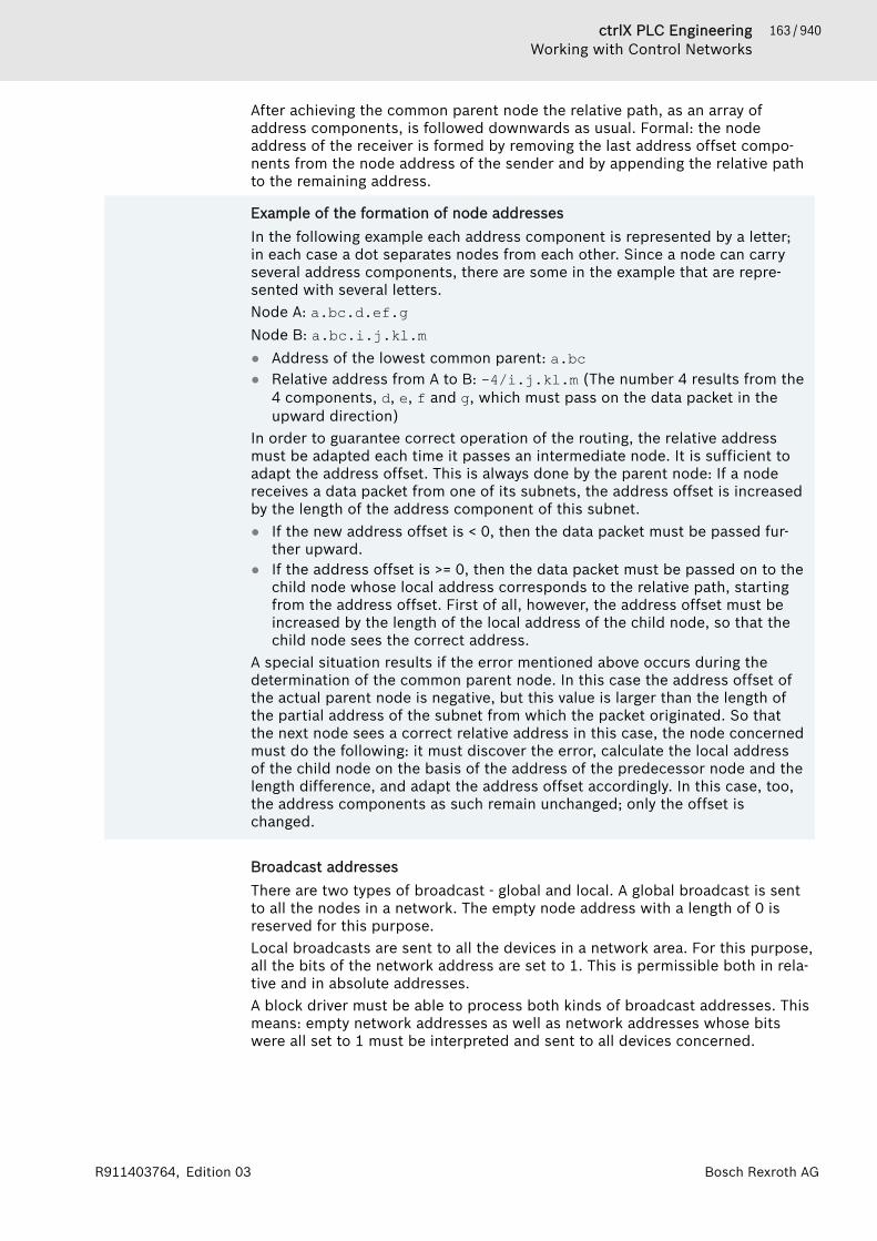
163 / 940ctrlX PLC EngineeringWorking with Control Networks
Bosch Rexroth AGR911403764, Edition 03
After achieving the common parent node the relative path, as an array ofaddress components, is followed downwards as usual. Formal: the nodeaddress of the receiver is formed by removing the last address offset compo-nents from the node address of the sender and by appending the relative pathto the remaining address.
Example of the formation of node addressesIn the following example each address component is represented by a letter;in each case a dot separates nodes from each other. Since a node can carryseveral address components, there are some in the example that are repre-sented with several letters.Node A: a.bc.d.ef.gNode B: a.bc.i.j.kl.m● Address of the lowest common parent: a.bc● Relative address from A to B: -4/i.j.kl.m (The number 4 results from the
4 components, d, e, f and g, which must pass on the data packet in theupward direction)
In order to guarantee correct operation of the routing, the relative addressmust be adapted each time it passes an intermediate node. It is sufficient toadapt the address offset. This is always done by the parent node: If a nodereceives a data packet from one of its subnets, the address offset is increasedby the length of the address component of this subnet.● If the new address offset is < 0, then the data packet must be passed fur-
ther upward.● If the address offset is >= 0, then the data packet must be passed on to the
child node whose local address corresponds to the relative path, startingfrom the address offset. First of all, however, the address offset must beincreased by the length of the local address of the child node, so that thechild node sees the correct address.
A special situation results if the error mentioned above occurs during thedetermination of the common parent node. In this case the address offset ofthe actual parent node is negative, but this value is larger than the length ofthe partial address of the subnet from which the packet originated. So thatthe next node sees a correct relative address in this case, the node concernedmust do the following: it must discover the error, calculate the local addressof the child node on the basis of the address of the predecessor node and thelength difference, and adapt the address offset accordingly. In this case, too,the address components as such remain unchanged; only the offset ischanged.
Broadcast addressesThere are two types of broadcast - global and local. A global broadcast is sentto all the nodes in a network. The empty node address with a length of 0 isreserved for this purpose.Local broadcasts are sent to all the devices in a network area. For this purpose,all the bits of the network address are set to 1. This is permissible both in rela-tive and in absolute addresses.A block driver must be able to process both kinds of broadcast addresses. Thismeans: empty network addresses as well as network addresses whose bitswere all set to 1 must be interpreted and sent to all devices concerned.
164 / 940 ctrlX PLC EngineeringWorking with Control Networks
Bosch Rexroth AG R911403764, Edition 03
1.9.2 Symbol ConfigurationUse the symbol configuration for preparing symbols with specific access rightsfor project variables. With these symbols, you can access the variables fromoutside, for example from an OPC server. When generating code, PLC Engi-neering also generates a symbol file (*.xml) that includes the description of thesymbols.The symbol file is stored in the project directory. The name of the symbol file iscomposed as follows: <project name>.<device name>.<applicationname>.xml
Exampleproj_xy.PLC1.application.xml
You can also generate the symbol file with the “Generate Code” command. Thisis very useful when downloading to the PLC is not possible.The variables that you export as symbols can be bundled in the symbol configu-ration editor or defined in the variables declaration using the {attribute'symbol'} pragma. Another option is using the element in the SFC editor,where you can define the implicitly generated element variables that should beexported to the symbol configuration.The name of the symbol is generated in the symbol configuration in the fol-lowing syntax: <application name>.<POU name>.<variable name>. Whenaccessing the variable, you must always provide the complete symbol name inthis syntax.
ExampleMyApplication.PLC_PRG.a or MyApplication.SymFB.a
As a rule, read-only access applies to symbols for input addresses and for varia-bles that are mapped to input channels. Write access is possible for testing pur-poses in simulation mode only.The symbol file is loaded with the application to the PLC. Depending on thedevice description, this file can be generated as an additional (child) applica-tion. This application is then listed in the “Application” tab of the device editor.Syntax: <application name>._symbols. The symbol application is regardedas a "normal" application with respect to the maximum number of applicationson the PLC.If your controller has a user management, then you can assign different accessrights to a symbol to the individual user groups (clients). To do this, place thesame symbol in different symbol sets and allow the individual user groups (cli-ents) either to access a symbol set or not. An on-site operator or an operatingdata record, for example, receives more information and access to the samesymbols as telemaintenance.See also● ⮫ Chapter “Object 'Symbol Configuration'” on page 630● ⮫ Chapter “Attribute 'symbol'” on page 450● ⮫ Chapter “SFC Element Properties” on page 284● ⮫ Chapter “Tab 'Applications'” on page 560● ⮫ Chapter “Command 'Simulation” on page 731
Creating a symbol configurationRequirement: The project can be compiled without any errors.1. Select the “Application” object in the device tree.

165 / 940ctrlX PLC EngineeringWorking with Control Networks
Bosch Rexroth AGR911403764, Edition 03
2. Click “Project 🠂 Add Object 🠂 Symbol Configuration”.🡆 The “Symbol Configuration” object is added to the device tree and the
objects editor opens.3. Open the “View” menu of the editor and activate the categories of varia-
bles that should be provided in the configuration editor. Click “Build” inthe symbol configuration editor.🡆 All variables (according to the currently defined filter in the “View”
menu) are displayed in a tree structure.4. Select the check boxes of individual variables.
Note: Pay attention to the current settings (see the “Settings” button inthe menu bar of the editor).🡆 In the field below the menu bar of the editor, information is provided
about the current situation with accompanying instructions, as well ascontrols for corrective actions.
5. Follow the prompt in the field below the menu bar. In the following case,this should be only the information that the modified symbol configura-tion is transferred with the next download or online change.Click “Build 🠂 Generate Code” in the PLC Engineering main menu.🡆 The <project name>.<device name>.<application name>.xml file
is generated in the project directory.PLC Engineering transmits the symbol configuration to the PLC for an applica-tion download or online change.See also● ⮫ Chapter “Object 'Symbol Configuration'” on page 630
Creating symbol sets with different access rights for different control clientsA symbol set is a defined set of symbols. If supported by the target device, youcan combine different symbol sets from the symbols of the application in thesymbol configuration editor. The information about the symbol sets is down-loaded to the controller. Then you can define the user group that has access toeach symbol set. Rights are assigned in the “Symbol Rights” tab of the deviceeditor.As a result, symbol sets allow different client-specific access rights to a symbolin the controller.You can download changes to a symbol set definition to the controller in anonline change. When the application is deleted on the controller, the symbolsets are also deleted. When building the application, you can create and save asymbol file in XML format for each symbol set.In the following section, you will see an example of steps for creating symbolsets and the assignment of rights on the controller:Requirements: The application has a defined symbol configuration in theproject. The “Enable symbol sets” option is enabled in the settings of thesymbol configuration. The controller has a user management. For the examplehere, there should be a user group that has the necessary rights for the serv-icing of the plant. By default, this type of user group, named "Service", isalready created.1. Define the connection to the controller in the “Communication Settings”
of the device editor.2. Click the button in the editor of the “Symbol Configuration” in order to
create a new symbol set. Specify a name of the group ("startup") in thedialog “Add a New Symbol Set”.
166 / 940 ctrlX PLC EngineeringWorking with Control Networks
Bosch Rexroth AG R911403764, Edition 03
3. Click the button (“Build”) in the toolbar of the dialog in order to displayall symbols available in the project. Select the users who should belong tothe group. Save the project.
4. Click the button “Configure Symbol Rights”.🡆 The “Symbol Rights” tab of the device editor opens.
5. Click the button (“Synchronization”) to synchronize the display of thesymbol sets with the device.🡆 If you have not enabled user management on the controller yet, then
you will see a dialog box in the “Users and Groups” tab prompting youto do it.
6. Click “OK” in the dialog box and click the “Users and groups” tab.Click the button (“Synchronization”). Click “Yes” to confirm that usermanagement should be enabled.🡆 The “Device User Login” dialog opens.
7. Sign in. If this is the first login, use "Administrator" as the user name andpassword, and then set a new password in the following dialog.🡆 After closing the dialog, the configurations of the device user manage-
ment are displayed in the “Users and Groups” and “Access Rights”tabs.
8. Login to the controller by clicking “Online 🠂 Login”. Click “Yes” to theprompt of whether or not the application should be downloaded to thedevice.
9. After successful login, click the “Symbol Rights” tab. Click the “Synchroni-zation” button.🡆 In “Symbol sets”, you see all sets that have currently been downloaded
for the application (for this example, at least "startup"). In “Rights”, atable shows the user groups that are created in the user managementof the controller. In the example, we assume that the default groups“Administrator” and “Service” have been created. When a symbol set isselected on the left, you see on the right the access rights of the indi-vidual user groups to this symbol set ( : access granted; : access notgranted). The possible type of access is already defined for eachsymbol in the symbol configuration (read, write, execute).
10. On the left, select the “Startup” symbol set and double-click the presetminus sign for "Administrator" as well as for "Service".🡆 The symbol changes into a plus sign. The "Administrator" and "Service"
now have access to the symbols in the “Startup” symbol set.See also● ⮫ Chapter 1.10.3 “Handling of Device User Management” on page 188
1.9.3 Network VariablesThe values of network variables can be exchanged between different PLCs in anetwork. The variables must be defined in strict, identical lists on both thesender device and receiver device, and only one device application defines thenetwork variables. The lists can be in one or more projects.The network variable list in the sender is a global variable list where specificlog and transfer parameters are defined in their object properties. By addingthese properties, you create a "network variable list (sender)" from an ordinary“GVL”. You can also insert a “Network Variable List (Sender)” object directlyinto the device tree when this object already has these parameters set.

167 / 940ctrlX PLC EngineeringWorking with Control Networks
Bosch Rexroth AGR911403764, Edition 03
The network variable list in the receiver is of type “Network Variable List(Receiver)”. When creating one, select the respective network variable list ofthe server. As an alternative, you can read this variable list from an export filethat was generated from the sender list. An export file is required anyway fordefining the sender list in another project.The network variables are transmitted as broadcasting in one direction only:sender to receiver. However, it is also possible for a device to contain bothsender and receiver lists. For the NetVarUdp library version 3.5.7.0 and later, a receiver channel is nolonger assigned when confirmed transfer is not selected. In this way, networkvariable exchange is also possible between two controllers on one hardwaredevice .
NOTICE − If the exchanging devices should be senders andreceivers, then the variable list identifiers must beunique in order to prevent abnormal operation. Thevariable list identifiers are defined in the “Properties”dialog of an object GVL.
− Data exchange via network variables is not possiblewhen:− The device (target system) does not support it.− A firewall blocks the communication.− Another client or application is using the UDP
port that is set in the properties of the networkvariable list.
− More than one application per sender device andreceiver device use network variable lists.
− Only arrays that have limits defined with a literal orconstant are transmitted to the receiver application.Constant expressions are not permitted for this pur-pose.Example: "arrVar : ARRAY[0..g_iArraySize-1]OF INT ;" is not transmitted, but "arrVar :ARRAY[0..10] OF INT ;" is transmitted.
− The maximum size of a network variable is 255 bytes.The possible number of network variables is unlim-ited.
− If the size of the GVL exceeds the maximum length ofthe network telegram, then the data is split into mul-tiple telegrams. Depending on the configuration, thiscan result in data inconsistencies.
Communication by means of network variables is also possible when the PLCsoperated with applications from different versions of the development system(V2.3, V3). However, in this case, you cannot use the export/import mechanismfor matching the variable lists exactly in the sender and receiver projects. Thereason is that an variable export file (*.exp) that is generated from V2.3 doesnot include the required amount of information necessary for creating areceiving NVL in V3. There is no respective network parameter configuration asa GVL file, which you exported from the sender previously. To get this file, youmust recreate the V2.3 NVL in V3 first. Then you can generate an export file andcreate a receiving NVL in V3 based on this.An alternate to data exchange between PLCs is the use of data sources. Asopposed to the broadcasting method for exchanging network variables, definedpoint-to-point connections are created between one application and a remotedata source.

168 / 940 ctrlX PLC EngineeringWorking with Control Networks
Bosch Rexroth AG R911403764, Edition 03
See also● ⮫ Chapter “Dialog 'Properties' - 'Network Variables'” on page 828● ⮫ Chapter “Object 'GVL' - Global Variable List” on page 581
Configuring a Network Variable ExchangeThe following steps are necessary for exchanging network variables betweenthe sender device and receiver device.
1. Creating a network variable list in the sender device and generating anexport fileRequirements: An application is inserted in the device tree of the PLC that hasbeen employed as the sender device.1. Select the application and insert a “Network Variable List (Sender)”
object. Make the following settings in the “Add Network Variable List(Sender)” dialog: network type: UDP, example: "NVL_Sender".
2. Double-click the NVL object to open the respective editor and type thedeclarations of the network variables. Example:VAR_GLOBALiglobvar:INT;bglobvar:BOOL;strglobvar:STRING;END_VAR
3. Right-click the NVL object in the device tree to open the “Properties”.Open the “Network Variables” tab in the “Properties” dialog. This showsthe following settings: Network type: UDP; List identifier: 1; Pack varia-bles; Cyclic transmission: every 50 ms.
4. Note: You can also convert an existing GVL into a network variable list byconfiguring its network variable properties.
5. Click the “Link To File” tab.in the “Properties” dialog of the “NVL_Sender”.Define a file name <export>.gvl and a location in the file system for theexport file of the GVL. Select the “Export before compile” check box.
6. Click “Build 🠂 Build” to compile the application.The export file for the network variable list is now located in the defined folder.See also● ⮫ Chapter “Dialog 'Properties' - 'Network Variables'” on page 828
2. Creating an associated network variable list in the receiver deviceRequirements: A sender device and a receiver device exist in the device tree. Anapplication with a task configuration is inserted below the device. An NVL or aGVL is created below the sender device as network variable list to be sent.1. Select the application of the receiver in the device tree and click “Add
Object 🠂 Network Variable List (Receiver)”.🡆 The “Add Network Variable List (Receiver)” dialog opens.
2. In the dialog, select the previously created NVL of the sender device andtype a name (for example, "NVL_Receiver").PLC Engineering populatesthis recipient list automatically with the variable declarations from thesender list.Note: As an alternative, you can select the “Import from file” option andload the export file that was generated previously from the sender list.

169 / 940ctrlX PLC EngineeringWorking with Control Networks
Bosch Rexroth AGR911403764, Edition 03
3. Testing the network variable exchangeRequirements: A network variable list (sender) exists in the sender device, anetwork variable list (receiver) exists in the receiver device, and both lists haveidentical variable declarations.1. Below the application in the sender device, create a program that incre-
ments a network variable. Example: iglobvar:=iglobvar+1;.2. Configure the application task so that this program calls it.3. Below the application in the receiver device, create a program that writes
the value of this network variable to a local variable. Example: ilo-calvar:=iglobvar;.
4. Configure the application task so that this program calls it.5. Download both applications to the controllers and start them. (Set the
application as active, login, download, and start.)6. In the online views of the editors of both programs, check whether the
values of iglobvar match in the receiver and the sender.
Configuration of network variable communication between V2.3 and V3 PLCsRequirements: A global variable list exists in a V2.3 project with network varia-bles that you want to read into your V3 project. In the V3 project in the devicetree below the PLC, there is an application with a program that uses the varia-bles.1. Open the “Properties” dialog of the GVL in the V2.3 project (sender).2. Insert another PLC into the project as a dummy with an application and a
task. Then create the V2.3 GVL below it as follows:3. Insert a “Network Variable List (Sender)” object named "dummy23" below
the dummy application.4. Right-click “dummy23” to open the “Properties” dialog. Click the “Net-
work Variables” tab. Type the same network properties as the GVL in theV2.3 project.
5. Fill “dummy23” with the same variable declarations as in the V2.3 GVL.6. Define a location for an export file "dummy23.gvl" in the “Link To File” tab
of the “Properties” for “dummy23”.7. Set the application of the dummy PLC as active and press [F11] to com-
pile.PLC Engineering creates the export file.8. Set the application of the physical PLC as active and right-click to open
the “Add Object” dialog.9. Select “Network Variable List (Receiver)” and type a name (for example,
"NVL_from_23").10. Select the “Import from file” check box and select dummy23.gvl, which
was generated previously.11. Check “NVL_from_23”, which has just been created. You must receive the
same variable declarations as those in the sender GVL in the V2.3 project.
See also● ⮫ Chapter “Object 'Network Variable List (Sender)'” on page 586● ⮫ Chapter “Object 'Network Variable List (Receiver)'” on page 586
1.9.4 Data Source ManagerIn order to have read/write access to remote devices and their running applica-tions, you can add a data source manager to your application with one or moredata sources.

170 / 940 ctrlX PLC EngineeringWorking with Control Networks
Bosch Rexroth AG R911403764, Edition 03
The functionality of the data source manager allows for establishing connec-tions and communication to remote devices, and it makes its data availablethrough data source variables. At this time, the partners communicate bymeans of a point-to-point connection. Depending on the network where thecontrollers are located, a connection is established via different data sourcetypes and different connection types.During the development phase, you can create a variable list offline by meansof local symbol configuration files. In this way, you can develop a local applica-tion offline based on the symbol information without a connection to a datasource.See also● ⮫ Chapter “Object 'Data Source Manager'” on page 539
Data source typeThe communication between remote and local devices communicate by meansof data source types. PLC Engineering provides the following two types.CODESYS Symbolic:Data is accessed by means of symbolic monitoring. A symbol file on the remotedevice is read and the stored variable information is used for the data sourcevariables and the data transfer. The advantage is that the application does nothave to be updated in the local device when someone edits modifies theremote application without updating its symbol configuration. If the symbol fileis also located on your development system (either a file or a symbol configura-tion object as part of your project), then the local symbol file can also be read.Then, you can work offline during the development phase.You will usually use CODESYS Symbolic. Do not use CODESYS Symbolic only ifno resources are available for a symbol configuration in the remote PLC.CODESYS ApplicationV3:Data is accessed by means of address monitoring. This requires that theaddress information between the remote PLC and the local device match. Dis-advantage: For changes to the remote application, the local application (forexample the HMI application) is updated. The advantage is that a symbol con-figuration is not required in the remote application.Use this communication for embedded or mini PLCs when there are no avail-able resources for the symbol configuration.See also● ⮫ “Dialog 'Add data source'” on page 539
Connection typesThe functionality of the data source manager allows for establishing a point-to-point connection from a local device to one or more remote devices (eventhrough networks). Select the appropriate connection type.When the communication is based on the data source type PLC EngineeringSymbolic, the following connection types are possible:● “PLC Engineering V2”:
The devices are located in the same network. The V2 runtime system on theremote PLC provides a communication interface.
● “PLC Engineering V2 (via gateway)”The devices are not located in the same network. They are connected via aV2 gateway.Note: For this connection, a “CoDeSys V2.3 Gateway Server” (V2 gateway)must be installed on the development computer where PLC Engineering V3is running.
171 / 940ctrlX PLC EngineeringWorking with Control Networks
Bosch Rexroth AGR911403764, Edition 03
● “PLC Engineering V3”The devices are located in the same network. The V3 runtime system on theremote PLC provides a communication interface.
● “PLC Engineering V3 (via gateway)”The devices are not located in the same network. They are connected via aV3 gateway.
When the communication is based on the data source type PLC EngineeringApplication V3, the runtime system of the local application needs valid commu-nication parameters in order to establish the connection. The network scanfunction can support you when configuring the data source.See also● ⮫ Chapter “Object 'Data Source' - Tab 'Communication'” on page 543
Data transmissionWhen the local application is in runtime mode, the data source variables thatappear in the data source editor of the “Variables” tab are updated in configu-rable time intervals. The remote application is also executed at this time. Varia-bles that are configured in the visualization, in the trend, as alarms, or for rec-ipes are transferred and stored automatically. When a variable is accessed inIEC code only, the variable is not updated automatically. In this case, you mustactivate the “Update always” option in the data source editor of the “Variables”tab.The communication types support the (read or write) data access to variablesof the source PLC for the following data types:● Scalar value at highest level
Example: PLC_PRG.hugo● Property to a program or GVL by means of a call when it is marked with
{attribute monitoring := ‚call‘}.Example: PLC_PRG.PropertyCall
● Variable that is mapped to bit addresses.Example in PLC_PRG: x AT %MX0.5 : BOOL;
● Variable (type BIT) in a function blockExample: Declaration in DUT: x, y : BIT, access: PLC_PRG.dutInst.y
● Structured obtainable variableExample: PLC_PRG.outerInst.innerInst.dwVar
● Property to POU instance when it is marked with {attribute moni-toring := ‚call‘}.Example: PLC_PRG.instance.PropertyCall
● Property at highest level and to an instance when it is marked with{attribute monitoring := ‚variable‘}.Note: This cannot be written by monitoring or by the data sources.
● Array access with literal indexExample: PLC_PRG.arrOfInts[3], PLC_PRG.inst.arrOfBool[1]
● Nested access (for example, array of structures or structure of arrays)
CAUTION Bit access used in visualizations that are transferred via adata source connection function only if they contain lit-eral offset specifications. A visualization cannot processan offset specification by defined constants.
See also● ⮫ “Tab 'Variables'” on page 541
172 / 940 ctrlX PLC EngineeringWorking with Control Networks
Bosch Rexroth AG R911403764, Edition 03
Adding Initial Data SourcesFor data exchange between your local device and a remote device, add a “DataSource Manager” object and then a “Data Source” below your application inthe device tree. An assistant guides you through the configuration of the datasource. Then you can modify the settings in the editor of the object at any time.However, it is not possible to modify the data source type later.Use the data source type “CODESYS Symbolic”, even if there are not anyresources available in the remote PLC for a symbol configuration. As long as thesymbol configuration is not affected after an application change in the remotedevice, you have the advantage that the application does not have to beupdated in the local device.When adding a data source, select a data source type. Then specify the connec-tion settings of the point-to-point connection to the remote device. Ideally, theremote device is being executed in the meantime and PLC Engineering canestablish the connection immediately. Then all available data source variablesare displayed from the remote PLC. Select the variables that should be trans-ferred. You can also select all variables. Then the data source is initialized auto-matically, the data source variables are created below the “Data-Sources_Objects” folder, and an additional data source is added below the datasource manager.When the data is transferred by means of symbolic monitoring and the symbolfile is stored on your development system, then you can read the variable infor-mation from the symbol file and work offline. The symbol file is stored as eithera file on your development system or a symbol configuration object as part ofyour project (in PLC Engineering).The initial settings can be modified at any time in the editor of the data source.See also● ⮫ Chapter “Object 'Data Source Manager'” on page 539
Initial connection of devices symbolically with 'CODESYS V3'A “ctrlX CORE” is running on the remote device. In addition, an application isrunning with a symbol configuration.1. Insert a “Data Source Manager” object below your application in the
device tree.2. Select the “Data Source Manager” object and click “Add Object 🠂 Data
Source”.🡆 The “Add Data Source” dialog opens.
3. Specify the data source name in “Name”.🡆 Example: ds_Remote_Device
4. Select the “CODESYS Symbolic” data source type.🡆 Data The data is transmitted via symbolic monitoring. The “Initialize
Data Source Wizard - Provider Settings” dialog opens.5. Select the connection type “CODESYS V3”.6. Select the “Node name” option for “Type of name or address”.7. In “Name or address of device”, specify the connection parameters for
configuring the remote device. Example: “[03A7)”🡆 The connection to the remote device is established and the application
is read. In addition, the “Initialize Data Source Wizard - Browse DataItems” dialog opens. Below the “Variables” item, the read remote con-trol variables are displayed in a tree view. The top node is the applica-tion that is displayed with its remote application name.
173 / 940ctrlX PLC EngineeringWorking with Control Networks
Bosch Rexroth AGR911403764, Edition 03
8. In the tree view, select the control variables to be transmitted, and click“Exit”.🡆 The data source is configured initially. The object ds_Remote_Device
is added below the node “Data Source Manager”. The object is openand the data source variables that were created are listed in the treeview on the “Variables” tab. The GVL ds_Remote_Device, where thedata source variables are declared, is displayed below the folder “Data-Source_Objects”.
See also● ⮫ Table 33 “Connection settings for PLC Engineering V3” on page 545
Initial connection of devices symbolically with 'CODESYS V3 (via gateway)'A “ctrlX CORE” is running on the remote device. In addition, an application isrunning with a symbol configuration. The remote device is located in anothernetwork so that the communication must be routed via a gateway.1. Insert a “Data Source Manager” object below your application in the
device tree.2. Select the “Data Source Manager” object and click “Add Object 🠂 Data
Source”.🡆 The “Add Data Source” dialog opens.
3. Specify the data source name in “Name”.🡆 Example: ds_Remote_Device
4. Select the “CODESYS Symbolic” data source type.🡆 Data The data is transmitted via symbolic monitoring. The “Initialize
Data Source Wizard - Provider Settings” dialog opens.5. Select the connection type “CODESYS V3 (via gateway)”.
🡆 You can also specify the communication parameters for the gateway.6. Select the “Node name” option for “Type of name or address”.7. In “Name or address of device”, specify the connection parameters for
configuring the remote device. Example: “[03A7)”🡆 The connection to the remote device is established and the application
is read. In addition, the “Initialize Data Source Wizard - Browse DataItems” dialog opens. Below the “Variables” item, the read remote con-trol variables are displayed in the tree view. The top node is the appli-cation that is displayed with its remote application name.
8. In the tree view, select the control variables to be transmitted, and click“Exit”.🡆 The data source is configured initially. The object ds_Remote_Device
is added below the node “Data Source Manager”. The object is openand the data source variables that were created are listed in the treeview on the “Variables” tab. The GVL ds_Remote_Device, where thedata source variables are declared, is displayed below the folder “Data-Source_Objects”.
See also● ⮫ Table 34 “Connection settings for PLC Engineering V3 (via gateway)”
on page 545
Initial connection of devices symbolically with 'CODESYS V2'A “CoDeSys V2.3 SP PLCWinNT V2.4” is running on the remote device. In addi-tion, an application is running with a symbol configuration.1. Insert a “Data Source Manager” object below your application in the
device tree.
174 / 940 ctrlX PLC EngineeringWorking with Control Networks
Bosch Rexroth AG R911403764, Edition 03
2. Select the “Data Source Manager” object and click “Add Object 🠂 DataSource”.🡆 The “Add Data Source” dialog opens.
3. Specify the data source name in “Name”.🡆 Example: ds_Remote_Device
4. Select the “CODESYS Symbolic” data source type.🡆 Data The data is transmitted via symbolic monitoring. The “Initialize
Data Source Wizard - Provider Settings” dialog opens.5. Select the connection type “CODESYS V2”.6. In “Connection Settings”, specify the connection parameters for config-
uring the remote device.Example: Driver type TCP/IP (Level 2 Route), address localhost,port 1200🡆 The connection to the remote device is established and the application
is read. In addition, the “Initialize Data Source Wizard - Browse DataItems” dialog opens. Below the “Variables” item, the read remote con-trol variables are displayed in a tree view.
7. In the tree view, select the control variables to be transmitted, and click“Exit”.🡆 The data source is configured initially. The object ds_Remote_Device
is added below the node “Data Source Manager”. The object is openand the data source variables that were created are listed in the treeview on the “Variables” tab. The GVL ds_Remote_Device, where thedata source variables are declared, is displayed below the folder “Data-Source_Objects”.
See also● ⮫ Table 31 “Connection settings for PLC Engineering V2” on page 544
Initial connection of devices symbolically with 'CODESYS V2 (via gateway)'A “CoDeSys V2.3 SP PLCWinNT V2.4” is running on the remote device. In addi-tion, an application is running with a symbol configuration. The remote deviceis located in another network so that the communication must be routed via agateway.1. Insert a “Data Source Manager” object below your application in the
device tree.2. Select the “Data Source Manager” object and click “Add Object 🠂 Data
Source”.🡆 The “Add Data Source” dialog opens.
3. Specify the data source name in “Name”.🡆 Example: ds_Remote_Device
4. Select the “CODESYS Symbolic” data source type.🡆 Data The data is transmitted via symbolic monitoring. The “Initialize
Data Source Wizard - Provider Settings” dialog opens.5. Select the connection type “CODESYS V2 (via gateway)”.
🡆 You can also specify the communication parameters for the gateway.

175 / 940ctrlX PLC EngineeringWorking with Control Networks
Bosch Rexroth AGR911403764, Edition 03
6. In “Connection Settings”, specify the connection parameters for both thegateway and the device configuring the remote device.Example: Driver type TCP/IP (Level 2 Route), address localhost,port 1200🡆 The connection to the remote device is established and the application
is read. The “Initialize Data Source Wizard - Browse Data Items” dialogopens. Below the “Variables” item, the remote control variables are dis-played in the tree view.
7. In “Name or address of device”, specify the connection parameters forconfiguring the remote device. Example: “[03A7)”🡆 The connection to the remote device is established and the application
is read. The “Initialize Data Source wizard - Browse data items” dialogopens. Below the “Variables” item, the read remote control variablesare displayed in a tree view. The top node is the application that is dis-played with its remote application name.
8. In the tree view, select the control variables to be transmitted, and click“Exit”.🡆 The data source is configured initially. The object ds_Remote_Device
is added below the node “Data Source Manager”. The object is openand the data source variables that were created are listed in the treeview on the “Variables” tab. The GVL ds_Remote_Device, where thedata source variables are declared, is displayed below the folder “Data-Source_Objects”.
See also● ⮫ Table 32 “Connection settings for PLC Engineering V2 (via gateway)”
on page 544
Initial addition of data source variables from a symbol fileIdeally, the same symbol file on the remote device is saved on your develop-ment system.1. Insert a “Data Source Manager” object below your application in the
device tree.2. Select the “Data Source Manager” object and click “Add Object 🠂 Data
Source” in the context menu.🡆 The “Add Data Source” dialog opens.
3. Specify the data source name in “Name”.🡆 Example: ds_Symbols
4. Select the “CODESYS Symbolic” data source type.🡆 Data The data is transmitted via symbolic monitoring. The “Initialize
Data Source Wizard - Provider Settings” dialog opens.5. Click the item “From symbol file” in “Variable information”.6. In “Select symbol file”, specify the storage location and the file name of
the symbol file. When code is generated, an XML symbol file is created inthe project directory by default.🡆 Example: D:\Projects\V3.5 SP11\Project_A.Device.Applica-
tion.xmlTip: When a symbol file is specified, no additional connection settingshave to be configured. A connection is not established. You work off-line. You have to configure the connection settings only when you needcurrent data from the controller that is transferred online. Activate theoption “From connection settings” in the “Variable information” set-tings.
176 / 940 ctrlX PLC EngineeringWorking with Control Networks
Bosch Rexroth AG R911403764, Edition 03
7. Click “Next”.🡆 The “Initialize Data Source Wizard - Search Data Source Variables”
dialog opens. Below the “Variables” item, the read symbols are dis-played in the tree view.
8. Select the symbols to be transferred in the tree view. Then select “Exit”.🡆 The data source is configured initially. The object ds_Symbols is added
below the node “Data Source Manager”. The object is open and thedata source variables that were created based on the symbol file arelisted in the tree view on the “Variables” tab. The GVL ds_Symbols,where the data source variables are declared, is displayed below thefolder “DataSource_Objects”.
See also● ⮫ Table 32 “Connection settings for PLC Engineering V2 (via gateway)”
on page 544
Initial addition of data source variables from a symbol configurationYour active project contains the control application for the remove device. Thecontrol application includes a symbol configuration with symbols that areadded to your local application as data source variables.1. Insert the “Data Source Manager” object below your local application in
the device tree.2. Select the “Data Source Manager” object and click “Add Object 🠂 Data
Source”.🡆 The “Add Data Source” dialog opens.
3. Specify the data source name in “Name”.🡆 Example: ds_Symbols
4. Select the “CODESYS Symbolic” data source type.🡆 Data The data is transmitted via symbolic monitoring. The “Initialize
Data Source Wizard - Provider Settings” dialog opens.5. Select the item “<remote device>.<application>.symbol configuration” in
“Variable information”.🡆 Example: Device.Application.Symbol Configuration
Tip: When a symbol file is specified, no additional connection settingshave to be configured. A connection is not established. You work off-line.
6. Click “Next”.🡆 The “Initialize Data Source Wizard - Search Data Source Variables”
dialog opens. Below the “Variables” item, the read symbols are dis-played in the tree view.
7. Select the symbols to be transferred in the tree view. Click “Finish”.🡆 The data source is configured initially. The object ds_Symbols is added
below the node “Data Source Manager”. The object is open and thedata source variables that were created based on the symbol configura-tion are listed in the tree view on the “Variables” tab. The GVL ds_Sym-bols, where the data source variables are declared, is displayed belowthe folder “DataSource_Objects”.
See also● ⮫ Table 32 “Connection settings for PLC Engineering V2 (via gateway)”
on page 544

177 / 940ctrlX PLC EngineeringWorking with Control Networks
Bosch Rexroth AGR911403764, Edition 03
Initial connection of devices with address monitoringA “ctrlX CORE” is running on the remote device. The project of the remotedevice is located on your development computer. The developed applicationthere does not contain a symbol configuration.Use this communication connection only if no resources are available for asymbol configuration in the remote PLC.1. Insert a “Data Source Manager” object below your application in the
device tree.2. Select the “Data Source Manager” object and click “Add Object 🠂 Data
Source”.🡆 The “Add Data Source” dialog opens.
3. Specify the data source name in “Name”.🡆 Example: ds_Remote_Device
4. Select the “CODESYS ApplicationV3” data source type.🡆 Data The data is transmitted via address monitoring. The “Initialize
Data Source wizard - Provider settings” dialog opens.5. Select the “Other project” option for “Select project type”.6. For “Choose file”, specify the file and storage location of the project on
the remote device. Example: C:\Data\Projects\PLC_A.project.🡆 The remote device is displayed in the tree view of the window below,
and as a result the connection was established.7. Select the link “From device”.
🡆 The connection parameters to the remote device are read and displayedin the dialog. The connection is configured.
8. Click “Next>”.🡆 The “Initialize Data Source Wizard - Browse Data Items” dialog opens.
Below the “Variables” item, the remote control variables are displayedin the tree view.
9. In the tree view, select the control variables to be transmitted, and click“Exit”.🡆 The data source is configured. A connection is established. The settings
are stored in the object and can be modified in the editor of the object.The data source is configured initially. The object ds_Remote_Deviceis added below the node “Data Source Manager”. The object is openand the data source variables that were created are listed in the treeview on the “Variables” tab. The GVL ds_Remote_Device, where thedata source variables are declared, is displayed below the folder “Data-Source_Objects”.
See also● ⮫ “Tab 'Communication' for PLC Engineering ApplicationV3” on page 547
Editing Data Source VariablesIn runtime mode, the remote data is saved to the data source variables. Thedata source variables and their mapping to the remote variables are displayedin the data source editor below of the “Variables” tab. If the local and remotevariables have the same names and the same data types, then the data ismapped 1:1. The variables and the data types are created automatically. That isthe regular procedure.You can also map to existing variables. This is necessary, for example, if a visu-alization includes a data type in an interface. Then the same data must bepassed to this visualization. In this case, the declared local variable and the
178 / 940 ctrlX PLC EngineeringWorking with Control Networks
Bosch Rexroth AG R911403764, Edition 03
remote variable have the same data type, for example from one library. More-over, you can map a local variable with a conforming data type to a remote vari-able. The data type can be created in the “Type Mappings” tab.The specifically created variables and data types are declared in the “Data-Sources_Objects” folder. For each data source, a global variable list of thesame name as the data source is declared there. Moreover, the data source var-iables usually have the identical or conforming data type as the remote controlvariable and they are declared as user-defined data types (DUT objects). Con-sidering all data sources, multiple declaration of the same data types isavoided.Do not edit the data interface in the “DataSources_Objects” folder manually. Itis created initially when adding a data source. Changes can be made later inthe editor of the data source.See also● ⮫ Chapter 1.9 “Working with Control Networks” on page 159● ⮫ Chapter “ Updating Data Interfaces” on page 181● ⮫ Chapter “Object 'Data Source' - Tab 'Variables'” on page 540
Selecting variables for data transferYou can edit the selection of the data source variables.Requirement: The remote device and its application are running. A data sourcemanager is already inserted below the local application with a data source.1. Open the editor of the data source.2. Select the “Variables” tab.3. Click “Update Variables”.
🡆 The “Browse Variables” dialog opens.4. Activate the variables that should be transferred and click “OK” to close
the dialog.🡆 The data source variables are modified according to the selection. The
declaration of variables and data types is also modified.The “Variables” tab shows the modified selection. Moreover, themapped remote variable is listed in the “Remote variable” column.
See also● ⮫ Chapter 1.9 “Working with Control Networks” on page 159● ⮫ Chapter “ Updating Data Interfaces” on page 181● ⮫ Chapter “Object 'Data Source' - Tab 'Variables'” on page 540
Mapping remote variables to a new variables
You need to map a remote variable to a global implicit variable that is creatednew. That is the regular procedure for transposing data source to 1:1.Requirement: A project is open. A data source manager and a data sourcebelow it are located in the device tree of the local application.1. Open the editor of the data source.2. Select the “Variables” tab.
🡆 The data source variables are listed.3. Select a variable and click the symbol in the “Create or map” column.4. Specify a name in “Local variable”.
🡆 A variable is declared automatically and it contains the same value asthe mapped remote variable.
179 / 940ctrlX PLC EngineeringWorking with Control Networks
Bosch Rexroth AGR911403764, Edition 03
Mapping remote variables to a existing variables
You need to map a remote variable to an existing variable.Requirement: A data source manager and a data source below it are located inthe device tree of the local application. The remote data that should be trans-ferred is displayed in the editor of the data source in the “Variable” tab1. Open the editor of the data source.2. Select the “Variables” tab.3. Select a variable and click the symbol in the “Create or map” column.
🡆 A variable contains the same value as the mapped remote variable.
Mapping remote variables to local variables with a conforming data type
First, create a conforming data type and then use it for a variable.Requirement: A data source manager and a data source below it are located inthe device tree of the local application. The remote data that should be trans-ferred is displayed in the editor of the data source in the “Variable” tab1. Open the editor of the data source.2. Select the “Type Mappings” tab.3. Select the data type in the list that you want to edit.
🡆 The elements of the data type are listed in the window below the datatype list
4. Specify a name for the data type. Example: DataType_A. Select the namefor the remote data types to which the local type should conform.Example: Library1.DataType_A.
5. Modify it in the window below the data type list and remove the elementsthat are not necessary for the data transfer.
6. Select the symbol for this data type in the “Create or map” column.🡆 The data type DataType_A is declared in the “DataSources_Objects”
folder.7. Select the “Variables” tab.8. Specify a name in the “Local variable” column. Example: Var_A9. Select the symbol in the “Create or map” column.10. Specify the data type DataType_A in the “Mapping type” column.11. Select the remote variable with the data that should be transferred.
Example: appPLC_A.Data_A. Use the input assistance for this.🡆 A variable Var_A is declared automatically with the user-defined data
type DataType_A. During data transfer, it receives the data of themapped remote variables.
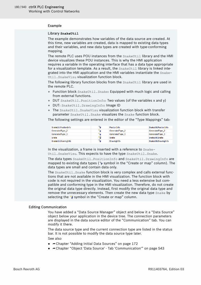
180 / 940 ctrlX PLC EngineeringWorking with Control Networks
Bosch Rexroth AG R911403764, Edition 03
Example
Library SnakeUtilThe example demonstrates how variables of the data source are created. Atthis time, new variables are created, data is mapped to existing data typesand their variables, and new data types are created with type-conformingmapping.The remote PLC uses POU instances from the SnakeUtil library and the HMIdevice visualizes these POU instances. This is why the HMI applicationrequires a variable in the operating interface that has a data type appropriatefor a visualization template. As a result, the SnakeUtil library is linked inte-grated into the HMI application and the HMI variables instantiate the Snake-Util.SnakeVisu visualization function block.The following library function blocks from the SnakeUtil library are used inthe remote PLC.● Function block SnakeUtil.Snake: Equipped with much logic and calling
from external functions.● DUT SnakeUtil.PositionInfo: Two values (of the variables x and y)● DUT: SnakeUtil.DrawingInfo: Image ID● The SnakeUtil.SnakeVisu visualization function block with transfer
parameter SnakeUtil.Snake visualizes the Snake function block.The following settings are entered in the editor of the “Type Mappings” tab:
In the visualization, a frame is inserted with a reference to Snake-Util.SnakeVisu. This expects to have the type SnakeUtil.Snake.The data types SnakeUtil.PositionInfo and SnakeUtil.DrawingInfo aremapped to existing data types ( symbol in the “Create or map” column). Thedata types are small and contain data only.The SnakeUtil.Snake function block is very complex and calls external func-tions that are not available in the HMI visualization. The function block withcode is not required in the visualization. You need a less extensive but com-patible and conforming type in the HMI visualization. Therefore, do not createthe original data type directly. Instead, first modify the original data type andremove the unnecessary elements. Then create the new data type Snake byselecting the symbol in the “Create or map” column.
Editing CommunicationYou have added a “Data Source Manager” object and below it a “Data Source”object below your application in the device tree. The connection parametersare displayed in the data source editor of the “Communication” tab. You canmodify it there.The data source type and the current connection type are listed in the statusbar. It is not possible to modify the data source type later.See also● ⮫ Chapter “Adding Initial Data Sources” on page 172● ⮫ Chapter “Object 'Data Source' - Tab 'Communication'” on page 543
181 / 940ctrlX PLC EngineeringWorking with Control Networks
Bosch Rexroth AGR911403764, Edition 03
Updating Data InterfacesThe data source variables are updated cyclically in runtime mode. Only the datais updated that either is used in the current visualization or has the property“Update always”.You can define the time interval. Moreover, you can define variables whose datais transferred in each update interval, and therefore they are always update. Toupdate variables that are not used in the application code, you can implementan update programmatically with the help of interface functions from the datasource manager.
NOTICE If data traffic between the remote and local device is toohigh, then the update rate is reduced automatically. Thiscan lead to an incomplete transfer.
See also● ⮫ Chapter “Object 'Data Source' - Tab 'Variables'” on page 540
Setting the update rate1. Open the editor of the data source.2. Click the “General and Diagnosis” tab.3. Specify a value in the “Update rate” field.
Example: 100🡆 The data from the remote device to the local device is transferred every
100 ms.See also● ⮫ Chapter “Object 'Data Source' - Tab 'General and Diagnosis'” on page 549
Selecting the variable for 'Update always'
NOTICE Avoid updating too many variables always. Each updateproduces additional data traffic at the connectionbetween the remote and local devices. When data trafficis too high, the update rate is reduced automatically. Thiscan lead to an incomplete transfer.
1. Open the editor of the data source.2. Activate the option “Update always” for a variable.
🡆 The data of the variables is transferred at each update cycle, even whenthe data has not changed.
See also● ⮫ “Tab 'Variables'” on page 541
Updating data programmaticallyThe data source manager provides interface functions in the Datasourceslibrary. If a data source manager is integrated in the application code, then theglobal variable g_Datasources is instantiated automatically. This providesaccess to the interface functions.Then you can update individual variables that are not called in the active visuali-zation.
182 / 940 ctrlX PLC EngineeringWorking with Control Networks
Bosch Rexroth AG R911403764, Edition 03
ExampleThe variable ivar is activated and deactivated by means of methods from theDatasources library so that its value is transferred. Furthermore, you canconfigure that the variable is updated only over a defined duration in order tosave transfer capacity.
//Synchronize with DatasourcesTask and block until access is possible //Regard the feedback in ERR_OK or in ERR_DE_MULTITASKING_LOCKEDg_Datasources.BeginDataConfiguration(TRUE); // Activate variableg_DataServer.UseData(ADR('RemoteDevice.Application.PLC_PRG.iVar'));// Deactivate variable//g_DataServer.ReleaseData(ADR('RemoteDevice.Application.PLC_PRG.iVar')); g_DataServer.EndDataConfiguration(); The data configuration is started with BeginDataConfiguration(TRUE),thus initializing the synchronization of the task DatasourceTask with theapplication task. The value TRUE blocks the processing until the access to thevariable is possible; FALSE repeats access attempts without blocking. Thereturn values ERR_OK and ERR_DS_MULTITASKING_LOCKED provide feedbackabout the access attempts.When synchronization is successful, the variable is activated by means of theUseData method. Then the data configuration is completed with the EndDa-taConfiguration method and the synchronization triggered again with thetask DatasourceTask.The ReleaseData method is used in the same way for deactivating the vari-able again at the desired processing time.
Using Remote DataThe variables that are listed in the data source editor of the “Variables” tab(and declared in the “DataSources_Objects” folder) can be used in your appli-cation like IEC variables. For example, you can visualize the variables.If multiple data sources are available and therefore conflicts occur regardingunique variable names, then you must specify the data source name as theprefix. If no conflicts occur, then this is not necessary and you can map the var-iables without a data source prefix.<data source name>.<function block name>.<variable name>
Displaying variable values from the remote deviceYou need to show the variable value iTemp of a remote device in a visualizationelement of a visualization in the local application (with the data source man-ager).Initial situation: A data source dsRemotePLC is below the local data sourcemanager where the connection to the remote device is configured. In addition,the variable iTemp is selected in the data source editor of the “Variables” tab.1. Select the visualization element in the editor view. Select the properties
“Text variables” - “Text variable” in the “Properties” view.
183 / 940ctrlX PLC EngineeringWorking with Control Networks
Bosch Rexroth AGR911403764, Edition 03
2. Select the iTemp variable.🡆 The variable mapping is qualified. Example: dsRemo-
tePLC.PLC_PRG.iTemp.3. Select the “Text” property of the visualization element and type in the fol-
lowing: Temperature: %s🡆 The value of the iTemp variable from the remote device RemoteDevice
is displayed.4. Download and start the remote application.5. Download and start the local application.
🡆 The visualization starts and displays the actual value of iTemp.
NOTICE The visualization integrated in PLC Engineering does notdisplay actual values of variables that are transferred bymeans of a data source connection. The integrated visu-alization displays only the initialization values or the lastotherwise delivered values because they do not establisha connection to the data sources.
NOTICE If variables are used that are not called in the visualiza-tion code, then the variables must be updated in theapplication code by means of functions from the datasource interface.
1.9.5 Subordinate Safety ControllerIf a safety controller is below the standard controller, then the communicationwith the development system and the data exchange run via the standard con-troller. The communication links of the safety controller can interrupted theexecution of commands that affect the standard controller. You find a noticeabout this for each these command.Possible interruptions● Temporary interruption: During the execution of the command (for example:
download), the connections with the safety controller are interrupted firstand then are automatically available again afterwards. If the interruptiontime is too long, then safety-oriented reactions can occur in the outputdevices and connected network variable receiver safety controllers. Then inthe safety controller, the corresponding communication errors must beacknowledged (if not done automatically) in order to end the safety-orientedreactions. This affects the connection to their field devices and network vari-able receiver connections to other sender safety controllers. In the case of aconnected safety controller with network variable senders, the communica-tion errors must be acknowledged in the other safety controllers.
● Permanent interruption: The execution of commands (for example: delete)leads to an interruption that is ended again by another action (for example:download). As a result of the interruption, safety-oriented reactions canoccur in the output devices and connected network variable receiver safetycontrollers. After ending the interruption, the corresponding communicationerrors must be acknowledged in the safety controller (if not done automati-cally) in order to end the safety-oriented reactions.
For a subordinate safety controller, the routing runs via “<Name of Safe-tyApp>_Mapping”. In some cases, it can happen that the user can see thisapplication in the device tree.
CAUTION No commands may be executed in the application“<Name of SafetyApp>_Mapping”.
● ⮫ Chapter 1.9 “Working with Control Networks” on page 159
184 / 940 ctrlX PLC EngineeringTransferring an Application to the PLC
Bosch Rexroth AG R911403764, Edition 03
1.10 Transferring an Application to the PLC1.10.1 Configuring the Connection to the PLC. . . . . . . 1841.10.2 Encrypting Communication, Changing Security
Settings. . . . . . . . . . . . . . . . . . . . . . . . . . . . . . . . 1851.10.3 Handling of Device User Management. . . . . . . . 1881.10.4 Generating Application Code. . . . . . . . . . . . . . . 1921.10.5 Downloading the Application Code, Logging in,
and Starting the PLC. . . . . . . . . . . . . . . . . . . . . . 1931.10.6 Generating Boot Applications. . . . . . . . . . . . . . . 194
In order to transfer your application to the PLC, the program must compiledwithout any errors and the connection settings for the PLC must be set.If the communication with the controller is encrypted and/or restricted to spe-cific users, then you need the respective certificates and permissions. Seehere:− ⮫ Chapter 1.10.3 “Handling of Device User Management” on page 188− ⮫ Chapter 1.8.18 “Encrypting an Application” on page 132You can edit the basic security policy for communication with the device in adialog on the “Communication Settings” tab of the device editor. See here:− ⮫ Chapter 1.10.2 “Encrypting Communication, Changing Security Settings”
on page 185If these requirements are fulfilled, then the application is downloaded to thePLC at login.
1.10.1 Configuring the Connection to the PLCThe connection to the controller is established via a gateway. This gateway canbe your development computer or another network computer connected to thecontroller. The “Communication Settings” dialog is available for configuring theconnection path. This dialog opens automatically when you attempt to log in,but the communication settings have not been configured yet.If the communication with the controller is encrypted and secured by means ofuser management, then you need a corresponding certificate and credentials toestablish the connection to the controller. In this case, see the relevant instruc-tions on the "Encrypting communication and Changing Security Settings" helppage.Requirement: The project can be compiled without any errors. A programmablelogic controller (PLC) is inserted in the device tree.1. In the device tree, select the PLC and click “Project 🠂 Edit Object”.
🡆 The PLC opens in the editor.2. Select the “Communication Settings” tab.3. Click “Scan Network” in the menu bar.
🡆 The “Select Device” dialog opens. All available devices in the networkare shown on the left side.
4. Select the required device and click “OK”.🡆 The connection path for the PLC is set.
You can reset the communication settings view to the original view in the PLCEngineering options of the device editor.
185 / 940ctrlX PLC EngineeringTransferring an Application to the PLC
Bosch Rexroth AGR911403764, Edition 03
See also● ⮫ Chapter 1.10.2 “Encrypting Communication, Changing Security Settings”
on page 185● ⮫ Chapter “Tab 'Communication Settings'” on page 556● ⮫ Chapter “Dialog 'Options' - 'Device Editor'” on page 855
1.10.2 Encrypting Communication, Changing Security Settings
NOTICE Recommendations for data securityIn order to minimize the risk of data security violations,we recommend the following organizational and tech-nical actions for the system where your applications arerunning. As far as possible, avoid exposing the PLC andcontrol networks to open networks and the Internet. Useadditional data link layers for protection, such as a VPNfor teleaccess. Install firewall mechanisms. Restrictaccess to authorized people. Change any default pass-words regularly before and after commissioning.Use the security features supported by PLC Engineeringand the respective controller, such as encryption of com-munication with the controller and intentionallyrestricted user access.
Communication with the device can be protected by means of encryption anduser management on the device. You can change the current security preset onthe “Communication Settings” tab of the device editor.
Establishing a connection to the controller, logging in, installing a trustedcertificate for encrypted communicationRequirement: Encrypted communication with the controller and user manage-ment are enforced on the controller. However, there is no individual passwordyet, no certificate installed on your computer, and the connection to the con-troller is not configured yet.1. In the device tree, double-click the controller.
🡆 The device editor opens.2. Click the “Communication Settings” tab.3. Click “Scan Network”.
186 / 940 ctrlX PLC EngineeringTransferring an Application to the PLC
Bosch Rexroth AG R911403764, Edition 03
4. Select a controller.🡆 A dialog opens, informing you that the certificate of the device does not
have a trusted signature for communication. You are prompted whetheror not to install this certificate as trusted in the local "Controller Certif-icates" store on your computer.
NOTICE A controller certificate installed in this way is validfor only 30 days. This gives you time for the following long-term solu-tions:− Creation of an additional self-signed certificate with a longer term
(for example, 365 days). You can do this on the security screen ifyou have installed the CODESYS Security Agent, even if a certificatealready exists. Using the PLC shell of the device editor is not a con-venient workaround.See below: "Configuring encrypted communication with a controllercertificate with a more long-term validity period"
− Importing a CA-signed certificate. This is currently only possible viathe PLC shell commands of the runtime system. Therefore we rec-ommend to use self-signed certificates first.
5. Click “OK” to confirm the dialog prompt.🡆 The certificate is listed as trusted.
After accepting the self-signed certificate for the first time, you canestablish an encrypted connection with the controller again and againwithout further prompts.
6. If user management is currently enforced, then you are prompted to login.When you login for the first time, enter "Administrator" as your user nameand password. Then the “Password expired, please enter a new one!”dialog opens to define an individual password.🡆 You can now login to the controller as usual.
7. All saved controller certificates (from step 5) are kept in the local Win-dows Certificate Store on your computer. You can access this by means of“Execute”, certmgr.msc command.🡆 All registered certificates for encrypted communication with controllers
are listed here in “Controller Certificates”.
Configuring a controller certificate with a more long-term validity period forencrypted communication by means of CODESYS Security Agent(recommended)Requirement: The CODESYS Security Agent add-on product is installed. Youwant to replace the temporary certificate (as described above) acquired thefirst time you connected to the protected controller with a certificate with alonger validity period.In this case, the “Security Screen” view provides an additional tab: “Devices”.This allows for the simple configuration of certificates for the encrypted com-munication with controllers. For operation, see the help for CODESYS SecurityAgent: "Encrypted Communication with Devices via Controller Certificates".
Installing a controller certificate for encrypted communication via the PLC shellof the device editorChoose this less convenient method when the CODESYS Security Agent isunavailable to you. In this case, you can set up a certificate with a more long-term validity period for communication encryption on the “PLC Shell” tab ofthe device editor.
187 / 940ctrlX PLC EngineeringTransferring an Application to the PLC
Bosch Rexroth AGR911403764, Edition 03
Requirement: You are connected to the controller.1. At first, you check if a qualified certificate is already on the controller. If
no certificate is available, then you create a new certificate.Open the device editor by double-clicking the controller in the device tree,and select the “PLC Shell” tab.🡆 The tab appears with a blank display window. Below that is a command
line.2. Type the following command in the command line: cert-getapplist.
🡆 All used certificates are listed. The list includes information about theruntime component and whether or not the certificate is available.
3. If a certificate still does not exist for the component CmpSecureChannel,then type the following command in the input line:cert-genselfsigned <number of the component in the applist>
4. Click the “Log” tab and then the refresh button ( ).🡆 The display shows whether or not the certificate was generated suc-
cessfully.5. Change back again to the “PLC Shell” tab and type the command cert-
getapplist.🡆 The new certificate for the component CmpSecureChannel is dis-
played.6. In the next two steps, activate encrypted communication in the security
screen of PLC Engineering.7. Open the “Security Screen” by double-clicking in the status bar.8. On the “User” tab, select the “Enforce encrypted communication” option
in the “Security Level” group.🡆 The communication to all controllers is encrypted. If there is not a cer-
tificate on a controller, then you cannot login to it.The connecting line between the development system, the gateway, andthe controller is displayed in yellow on the “Communication Settings”tab of the device editor of the controller.
9. As an alternative to the “Enforce encrypted communication” option whichapplies to all controllers, you can also define encrypted communicationfor specific controllers only. To do this, select the “Communication Set-tings” tab in the editor of the respective controller. Then click “EncryptedCommunication” in the “Device” list box.🡆 The communication to this controller is encrypted. If there is not a cer-
tificate on the controller, then you cannot login to it.The connecting line between the development system, the gateway, andthe controller is displayed in yellow on the “Communication Settings”tab of the device editor of the controller.
10. When you login to the controller for the first time, a dialog opens withinformation that the certificate of the controller is not signed by a trust-worthy authority. In addition, the dialog displays information about thecertificate and prompts for you to install it as a trustworthy certificate inthe local store in the “Controller Certificates” folder.When you confirm the dialog, the certificate is installed in the local storeand you are logged in to the controller.In the future, communication with the controller will be encrypted auto-matically with this control certificate.
Changing the communication policy (encryption, user management)Requirement: The connection to the device is established.

188 / 940 ctrlX PLC EngineeringTransferring an Application to the PLC
Bosch Rexroth AG R911403764, Edition 03
1. In the device tree, double-click the controller.🡆 The device editor opens.
2. Click the “Communication Settings” tab.3. Open the “Device” menu in the header of the editor. Click “Change Com-
munication Policy”.🡆 The “Change Communication Policy” dialog opens.
4. In the upper part of the dialog, you can toggle between the “Optionalencryption”, “Enforced encryption”, and “No encryption” settings.
5. In the lower part of the dialog, you can toggle between the “Optional usermanagement” and “Enforced user management” settings.
Enabling and disabling enforced encrypted communicationRequirement: The device supports encrypted communication.1. In the device tree, double-click the controller.
🡆 The device editor opens.2. Click the “Communication Settings” tab.3. Open the "Device" menu in the header of the editor. Click “Encrypted
Communication”. The status toggles between enabled and disabled.🡆 If the “Encrypted communication” option is selected, then the connec-
tion line between the development system, the gateway, and the deviceis highlighted in the editor in bold and in color in the graphical repre-sentation.
See also● ⮫ Chapter 1.10.3 “Handling of Device User Management” on page 188● ⮫ Chapter 1.8.18 “Encrypting an Application” on page 132● ⮫ “Encryption with certificates” on page 31
1.10.3 Handling of Device User Management
NOTICE Recommendations for data securityIn order to minimize the risk of data security violations,we recommend the following organizational and tech-nical actions for the system where your applications arerunning. As far as possible, avoid exposing the PLC andcontrol networks to open networks and the Internet. Useadditional data link layers for protection, such as a VPNfor teleaccess. Install firewall mechanisms. Restrictaccess to authorized people. Change any default pass-words regularly before and after commissioning.Use the security features supported by PLC Engineeringand the respective controller, such as encryption of com-munication with the controller and intentionallyrestricted user access.
For devices that support a device user management, the device editor includesthe “Users and Groups” tab and the “Access Rights”. When offered by thedevice, you can view and also edit the user management for the device. Here,the defined user groups can be granted or denied specific rights on the con-troller.The device user management can already be set up in the device description.Note the commands in the “Online 🠂 Security” menu. You can easily add, edit,or remove a user account on the controller where you are currently logged in.
189 / 940ctrlX PLC EngineeringTransferring an Application to the PLC
Bosch Rexroth AGR911403764, Edition 03
In order for the “Access Rights” tab to be available in the device editor, the cor-responding PLC Engineering option must be selected in the device editor andunlocked in the device description. If the device editor is not available, thencontact the manufacturer of the controller.In order to grant access rights to user groups, users and user groups first haveto be configured on the “Users and Groups” tab of the device editor. User man-agement first has to be set up on the controller before access rights can beconfigured on it.
General information about device user managementNote that access rights can only be granted to groups, not to individual users.Therefore every user has to be a member of a group.Access rights can be granted for the following actions which are performed onthe individual objects of the controller:● View● Modify● Add/Remove● ExecuteEach object on the controller is usually assigned to just one component. And allof the above access rights can be used by the object. However, in most casesonly the following two rights are required for an object:● “View”● “Modify”The objects are organized in a tree structure. There exist two root objects forboth of the separate types of objects: “Runtime objects 🠂 Device” and “Filesystem objects 🠂 /”.In the file system objects, the rights can be granted to folders of the currentexecution directory of the controller.In the runtime objects, all objects are managed that have online access in thecontroller and therefore have to control the access rights.In general, the access rights are inherited from the root object (also “Device” or“/”) to the subobjects. This means that if you deny or explicit grant a right to auser group on a parent object, then this first affects all child objects.For the rights, a distinction also has to be made as to whether a right is explic-itly granted, denied, or neutral. Neutral means that it is neither explicitlygranted nor denied. In this case, the right of the parent object applies. How-ever, if no right has been explicitly granted or denied in the entire hierarchy ofthe object, then it is by definition initially denied. This means that all rights aredenied at first.The only exception is the access right for the “View” action. This is explicitlygranted initially for every user group both on the “Device” runtime object aswell as on the "“/”" file system object. This allows read access to all objects atfirst, unless it is explicitly denied in child objects.The "Everyone" user group has a special position here: This right only applies atthe very end of the rights check if no other user group on a level has explicitlygranted or denied access.For an overview table for the objects, see the "Tab 'Access Rights'" chapter.See the following instructions for handling the editor for the device user man-agement:
First-time login on the controller in order to edit or view its user managementRequirement: the controller has a device user management.
190 / 940 ctrlX PLC EngineeringTransferring an Application to the PLC
Bosch Rexroth AG R911403764, Edition 03
1. Double-click the controller device object in the device tree.🡆 The device editor opens.
2. Click the “Users and Groups” tab.3. Click .
🡆 A dialog opens prompting whether the device user management shouldbe activated.
4. Click “Yes” to confirm the prompt.🡆 The “Device User Logon” dialog opens.
5. Specify "Administrator" as the “User Name” and “Password”.🡆 The “Password expired, please enter a new one!” dialog opens.
6. Specify a new “Password”. The password strength is displayed.🡆 After you click “OK” to confirm, the device user management is shown
in the editor view.
Setting up a new user in the user management of the controllerRequirement: the controller has a device user management. You have the corre-sponding access data.1. Double-click the controller device object in the device tree.
🡆 The device editor opens.2. Click the “Users and Groups” tab.3. Click (Synchronization) to load the user management configuration
from the controller to the editor. If you are not logged in to the device yet,then the “Device User Logon” dialog opens for entering the user name andpassword.🡆 The user management configuration of the device is shown in the
editor.4. In the “Users” view, click “Add”.
🡆 The “Add User” dialog opens.5. Specify the name of the new user and assign the user to a group. This
counts as the user's minimum required default group. The user can beassigned to other groups later. Define and confirm a “Password” for theuser. Define whether the user can change the password and whether theuser has to change the password at the first login. Click “OK” to confirm.🡆 The new user appears in the “Users” view as a new node and in the
“Groups” view as a new subentry of the selected default group.
Changing of access rights to controller objects in the user management of thecontrollerRequirement: the controller has a device user management. You have the corre-sponding access data.1. Double-click the controller device object in the device tree.
🡆 The device editor opens.2. Click the “Access Rights” tab.
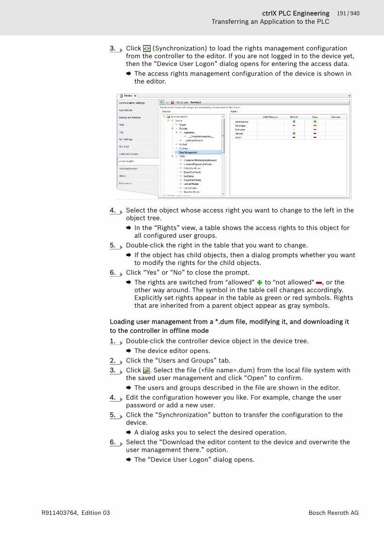
191 / 940ctrlX PLC EngineeringTransferring an Application to the PLC
Bosch Rexroth AGR911403764, Edition 03
3. Click (Synchronization) to load the rights management configurationfrom the controller to the editor. If you are not logged in to the device yet,then the “Device User Logon” dialog opens for entering the access data.🡆 The access rights management configuration of the device is shown in
the editor.
4. Select the object whose access right you want to change to the left in theobject tree.🡆 In the “Rights” view, a table shows the access rights to this object for
all configured user groups.5. Double-click the right in the table that you want to change.
🡆 If the object has child objects, then a dialog prompts whether you wantto modify the rights for the child objects.
6. Click “Yes” or “No” to close the prompt.🡆 The rights are switched from "allowed" to "not allowed" , or the
other way around. The symbol in the table cell changes accordingly.Explicitly set rights appear in the table as green or red symbols. Rightsthat are inherited from a parent object appear as gray symbols.
Loading user management from a *.dum file, modifying it, and downloading itto the controller in offline mode1. Double-click the controller device object in the device tree.
🡆 The device editor opens.2. Click the “Users and Groups” tab.3. Click . Select the file (<file name>.dum) from the local file system with
the saved user management and click “Open” to confirm.🡆 The users and groups described in the file are shown in the editor.
4. Edit the configuration however you like. For example, change the userpassword or add a new user.
5. Click the “Synchronization” button to transfer the configuration to thedevice.🡆 A dialog asks you to select the desired operation.
6. Select the “Download the editor content to the device and overwrite theuser management there.” option.🡆 The “Device User Logon” dialog opens.

192 / 940 ctrlX PLC EngineeringTransferring an Application to the PLC
Bosch Rexroth AG R911403764, Edition 03
7. Provide valid credentials in order to login to the controller.🡆 After you login successfully, the changes are transferred from the editor
to the device. As long as the synchronization is not switched off,PLC Engineering automatically transfers more changes to the controllerthat are made in the editor.
See also● ⮫ Chapter “Tab 'Access Rights'” on page 574● ⮫ Chapter “Dialog 'Options' - 'Device Editor'” on page 855● ⮫ Chapter “Tab 'Users and Groups'” on page 572● ⮫ Chapter 1.7.3 “Configuring Devices and I/O Mapping” on page 54● ⮫ Chapter 1.10.2 “Encrypting Communication, Changing Security Settings”
on page 185
1.10.4 Generating Application CodeThe application code is the machine code that a PLC executes when you startan application.PLC Engineering automatically generates the application code from the sourcecode that was written in the development system. This is done automaticallybefore downloading the application to the PLC. Before the application code isgenerated, a test is performed for checking the assignments, the data types,and library availability. In addition, the memory addresses are allocated whenthe application code is generated.You can execute this command explicitly by clicking “Build 🠂 Generate Code”.This is useful for detecting any errors in your source code, even when the PLCis not connected yet. The errors are printed to the message view ("Build" cate-gory).
NOTICE If you have encrypted the application, then consider thefollowing information: If a (new) boot application gener-ated on request after an online change, then the bootapplication is formed in the RAM with the current codethat is NOT encrypted.
Explicit generation of application codeRequirement: The application can be compiled without any errors.
Click “Build 🠂 Generate code”.🡆 The application code is generated. Detailed information about memory
allocation is printed in the message view.See also● ⮫ Chapter 1.10.6 “Generating Boot Applications” on page 194● ⮫ Chapter “Command 'Generate Code'” on page 712
Messages when generating application codeWhen you generate application code, PLC Engineering prints information aboutmemory allocation in the message view. Gaps arise in the memory becausereallocation is only for new and changed blocks and variables due to the incre-mental memory compile. Online changes have the same effect. This fragmenta-tion reduces the amount of available memory. However, you can completelyreallocate the memory by clicking “Clean” and therefore increase the amount offree memory.More information about messages at code generation: Syntax errors and errorsthat PLC Engineering detects during code generation and memory allocationappear in the message view in the “Build” category. At each code generation,
193 / 940ctrlX PLC EngineeringTransferring an Application to the PLC
Bosch Rexroth AGR911403764, Edition 03
information is also provided about the code size, the data size (in bytes), thecontents of the allocated memory, and the highest address used (byte). Itdepends on the PLC which data and code is stored in which memory areas. Forexample, code and data is located in the same area on the ctrlX CORE. For theaddresses %I, %M, and %Q, memory is always reserved, even when a variable isnot assigned to an address. After cleaning the application, the memory is reas-signed completely. In this case, small gaps may result from the predefinedalignment (normally 8). Larger gaps result from changing a date withoutcleaning, for example increasing an array range. In this case, only the affectedPOUs are rebuilt. Online changes have the same effect. Resulting gaps arereused when possible for other changes. As small gaps can no longer be usedat all in some cases, the size of the "largest correlating memory gap" of theaffected memory area (in bytes) is issued as meaningful information for the cur-rent code generation, as well as its percentage of the total memory.Please note the options for generating applications.See also● ⮫ Chapter “Dialog 'Properties' - 'Application Build Options'” on page 828
Encrypting the application codeSee also● ⮫ Chapter 1.8.18 “Encrypting an Application” on page 132
1.10.5 Downloading the Application Code, Logging in, and Starting thePLCIn order to download the source code of your application to the PLC, you mustlog in to the PLC with application. If there are several applications in theproject, then you must switch explicitly to the correct application first.When you download an application to the PLC, PLC Engineering performs thefollowing checks:The list of applications on the PLC is compared with the applications availablein the project. If they do not match, then you are prompted to download theapplication that is not on the PLC yet or delete existing applications.For "externally implemented" blocks in the application to be downloaded, PLCEngineering checks whether these are available on the PLC. If they are notavailable, then the message "unresolved reference(s)" is printed to a dialogprompt and to the message view. Then PLC Engineering compares the parame-ters (variables) of the blocks in the application to be downloaded and theparameters of the same-named blocks in the application that exists on the PLC(signature check). If there are any discrepancies, then the message "invalid sig-nature(s)" is printed to a dialog prompt and to the message view.If the "Download Application Info" check box is selected in the applicationproperties, then additional information about the application contents aredownloaded to the PLC.if multiple applications exist for the same device, then notice that the “I/OMapping” dialog contains the definition for which of the applications is usedfor for the I/O mapping of the device.See also● ⮫ Chapter “Object 'Application'” on page 528
Transferring an application and starting the programRequirement: The application contains no errors and the communication set-tings of the PLC are correct. The application does not exist yet on the PLC: Theapplication and the communication with the controller are not encrypted.
194 / 940 ctrlX PLC EngineeringTransferring an Application to the PLC
Bosch Rexroth AG R911403764, Edition 03
1. Select the required application in the device tree. Skip to Step 3 if youhave only one application.
2. Click “Set Active Application”.🡆 The application name appears in bold typeface.
3. Click “Online 🠂 Login”.🡆 A dialog prompts you whether the application should be created on the
PLC.4. Click “Yes” to confirm.
🡆 The application is downloaded to the PLC.5. Click “Debug 🠂 Start” or press the [F5] key.
🡆 The application is running on the controller.
1.10.6 Generating Boot ApplicationsA boot application is the application that is started automatically when the con-troller is switched on or started. For this to happen, the application on the con-troller must exist as a file <application name>.app.For each application that is running on the controller, a boot application canalso be saved there.By default, PLC Engineering generates the boot application automatically whenan application is downloaded and transfers them to the PLC. The defaults forgenerating automatically are located in the “Boot application” category of theapplication “Properties”. When logging in with a changed application, you arestill prompted whether or not to generate a new boot application.In addition, you can create a (new) boot application at any time in online modeby clicking “Online 🠂 Create boot application”.You can create and save a local copy of a boot application in offline mode aswell. Then, you can copy this application to the controller with external tools. Inthis way, you transfer an application to the controller, even when there is noconnection to PLC Engineering.
Generating boot applications on the controller automatically and explicitlyRequirement: Offline mode; the application is compiled without errors. Theconnection to the controller is configured and the controller is running. Theapplication is active. The following steps demonstrate the options:1. Click “Online 🠂 Login”.
🡆 The boot application file <application name>.app is created on thecontroller with the checksum of the boot application <applicationname>.crc.
2. Click “Online 🠂 Create Boot Application” explicitly.🡆 The files on the controller are replaced by new files.
3. Log out.4. Change the application. Log back in to the controller.
🡆 You are prompted whether an online change should be performed. Yousee the “Update boot application” check box in the same dialog box.This is cleared by default, but this can be changed in the “Boot Applica-tion” category of the application “Properties”.
5. Keep the check box cleared and continue login.🡆 A new boot application file is not created.
6. Log out. Close the project. Stop the controller. Restart the controller.🡆 The boot application that was created above is running on the con-
troller.

195 / 940ctrlX PLC EngineeringTesting and Debugging
Bosch Rexroth AGR911403764, Edition 03
You can save the encrypted boot application on the controller. These settingsare defined in the “Application Build Options” category of the application“Properties”.See also● ⮫ Chapter “Dialog 'Properties' - 'Application Build Options'” on page 828● ⮫ Chapter “Dialog 'Properties' - 'Boot Application'” on page 823● ⮫ Chapter 1.13.1 “Executing the Online Change” on page 235● ⮫ Chapter “Command 'Create Boot Application'” on page 721
Creating boot applications in offline modeRequirement: Offline mode; the application is compiled without errors. Youwant to generate a boot application for an application and save it in the filedirectory for copying it later to the controller by using external tools (withoutPLC Engineering).1. Click “Online 🠂 Create Boot Application”.
🡆 A dialog box opens for specifying a save location in the local filesystem.
2. Click a save path and then click “Save”.3. If the application has changed since the last boot application was gener-
ated, then you are prompted to use a new code for the boot application.In this case, click “Yes”.🡆 The “Save as” dialog box opens.
4. Select a directory and click “Save”.🡆 The boot application file <application name>.app is created in the given
path.You are prompted whether or not the build information for the bootapplication is saved.
5. Click “Yes”.🡆 The build information is saved to the project directory as a file named
<application name>.compileinfo. It is a requirement for a possibleonline change the next time the application is updated. Please note:Clicking “Build 🠂 Clean” deletes this file.
See also● ⮫ Chapter “Command 'Create Boot Application'” on page 721
1.11 Testing and DebuggingPLC Engineering provides various options for testing your application anddetecting errors. You can start your application in simulation mode, evenwithout connecting any hardware. Using breakpoints and stepping commands,you can examine specific parts of a program. By writing values to variables, youcan influence the running program.Commands are provided that reset your application in various different ways,from resetting only non-persistent variables to completely resetting the con-troller to factory settings.See also● ⮫ Chapter 1.11.1 “Testing in Simulation Mode” on page 196● ⮫ Chapter 1.11.2 “Using Breakpoints” on page 196● ⮫ Chapter 1.11.3 “Stepping Through a Program” on page 199● ⮫ Chapter 1.11.5 “Resetting Applications” on page 204
196 / 940 ctrlX PLC EngineeringTesting and Debugging
Bosch Rexroth AG R911403764, Edition 03
1.
1.11.1 Testing in Simulation ModeUse simulation mode for testing and debugging your program when you do nothave a physical target device. In this mode, the application is started on a simu-lated device.The command is available only when you are logged out.Requirement: You program contains no errors (compiler error messages orcompile errors) and you are not logged in.
Activate simulation mode as follows:● Click “Online 🠂 Simulation”, or● Right-click the controller in the device tree and click “Simulation”.🡆 The name of the controller in the device tree is displayed in italics. In
the status line, "Simulation" appears highlighted in red. The “Simula-tion” command is selected in the main menu.
2. Click “Online 🠂 Login”.3. When logging in for the first time with the active application, you will be
prompted whether the application "Sim.<device name>.<applicationname>" should be created and loaded. Click “Yes” to confirm.🡆 The application is logged onto the controller. This is marked in the
device tree by a warning symbol ( ) in front of the controller.4. Now you can check and correct the program flow with the commands pro-
vided in the main menu in “Debug”.5. Log out from the controller and end the simulation mode.See also● ⮫ Chapter “Command 'Simulation” on page 731
1.11.2 Using BreakpointsBreakpoints are commonly used for debugging programs. PLC Engineering sup-ports breakpoints in all IEC editors.You can set breakpoints at specific positions in the program to force an execu-tion stop and to monitor variable values. You can set special data breakpointsto halt program execution when the value of a specific variable changes.The halt at a breakpoint or data breakpoint can be linked to additional condi-tions. You can also redefine breakpoints and data breakpoints as executionpoints where specific code is executed instead of stopping the program.The “Breakpoints” view provides an overview of all defined breakpoints. It alsoincludes additional commands for processing batch changes to multiple break-points.In the editor, the following symbols identify the status of a breakpoint or execu-tion point:● Breakpoint enabled● Breakpoint disabled● Breakpoint is set in another instance of the POU open in the editor.● Halted at breakpoint● Conditional breakpoint enabled● Conditional breakpoint disabled● Execution point enabled● Execution point disabled● Conditional execution point enabled● Conditional execution point disabled● Data breakpoint enabled● Data breakpoint disabled

197 / 940ctrlX PLC EngineeringTesting and Debugging
Bosch Rexroth AGR911403764, Edition 03
● Halted at data breakpoint● Data execution point enabled● Data execution point disabled● Halted at data execution point● Conditional data execution point enabled● Conditional data breakpoint enabledSee also● ⮫ Chapter “Command 'Breakpoints'” on page 682
Data breakpointsWhether or not data breakpoints can be set and how many depends on thetarget system.Program execution stops at a data breakpoint when the value of a particularvariable or memory address changes. As with ordinary breakpoints, the halt canbe linked to an additional condition, or specific code can be processed insteadof the halt (converted to a data execution point).You set a data breakpoint either by means of the “New Data Breakpoint” com-mand in the “Debug” menu or by means of the “New” button in the “Break-points” view. You specify a qualified variable name or a memory addressdirectly which is to be monitored for changes in its value.
ExampleIn the following sample code, the memory of the variable iNumber is over-written unintentionally. However, a data breakpoint at the variable iNumberwill detect when its value changes. The processing then stops with a corre-sponding message at the array access, which overwrites the variable value:Idx = 7. See also below: "Setting a data breakpoint".PROGRAM PLC_PRGVAR Idx : INT; Ary : ARRAY[0..3] OF BYTE; iNumber : INT := 55;END_VARFOR idx := 0 TO 6 DO Ary[idx] := 0;END_FOR
Breakpoints in applications with multiple tasksBasically, debugging is not possible for multiple tasks at the same time. Whileyou are working on a task with breakpoints or stepping, breakpoints areignored in other tasks.If a block containing a breakpoint is used by multiple tasks, then only thedebug task is halted because it arrives at the breakpoint first. All other taskscontinue. The “Call Stack” dialog shows which task is currently halted.If you need a breakpoint to affect only one specific task, then you can definethis in the breakpoint properties.Breakpoints operate separately for each application so that a "HALT ON BP"does not affect any other applications. This applies also to parent/child applica-tions, even if the breakpoint is set in a block that is used by several applica-tions and whose code is located only once on the PLC.
NOTICE The I/Os that are called by the debug task are notupdated at a halt in the breakpoint, even if you select the“Refresh I/Os in Stop” check box in the PLC settings.
198 / 940 ctrlX PLC EngineeringTesting and Debugging
Bosch Rexroth AG R911403764, Edition 03
If the application stops at a breakpoint on the PLC, then an online change ordownload causes all tasks to halt which means the PLC will stop. In this case,PLC Engineering prompts you whether or not to continue with the login.See also● ⮫ Chapter “Command 'Call Stack'” on page 686
Setting a single breakpoint (example in ST editor)Requirement: The application is in online mode and running. The operatingmode is “Debug”.1. In the editor, open a POU programmed in structured text (ST).2. Place the cursor in the line where a breakpoint will be set.3. Click “Debug 🠂 Toggle Breakpoint” or press [F9].
🡆 The line is marked in red and identified by the "breakpoint enabled"symbol ( ). If the program is halted at the breakpoint, then the line ismarked by the "stop at breakpoint" symbol ( ). Program processing isstopped and identified in the status line by the red-highlighted HALTON BP status.
4. Click “Debug 🠂 Start” or press [F5].🡆 The program continues.
5. Set more breakpoints and check the variable values at the break position.6. Place the cursor in the line where a breakpoint should be removed.7. Click “Debug 🠂 Toggle Breakpoint” or press [F9].
🡆 The marking disappears. The breakpoint is deleted.See also● ⮫ Chapter “Command 'Toggle Breakpoint'” on page 734
Defining a breakpoint condition (example in ST editor)1. In the editor, open a POU programmed in structured text (ST).2. Place the cursor in the line where a breakpoint will be set.3. Click “Debug 🠂 New Breakpoint”.
🡆 The “Breakpoint Properties” dialog opens.4. Click the “Condition” tab.5. Click “Break when the hit count is a multiple of” in the “Hit Count” list
box.Type the value "5" in the field to the right.
6. In addition, you can define a Boolean condition for when the breakpointshould be active. Select the “Break, if true” check box. Type a Boolean var-iable in the text field to the right.
7. Select the “Enable breakpoint immediately” check box.8. Close the dialog.
🡆 The line is marked red and identified by the "conditional breakpointenabled" symbol ( )
Monitor the running program. As long as the Boolean variable for the conditionis FALSE, the breakpoint condition is not fulfilled and the program continues torun. If you set the variable to TRUE, then the condition is fulfilled and the pro-gram halts at the breakpoint every 5th pass.See also● ⮫ Chapter “Dialog 'Breakpoint Properties'” on page 818
199 / 940ctrlX PLC EngineeringTesting and Debugging
Bosch Rexroth AGR911403764, Edition 03
Defining an execution point (example in ST editor)1. In the editor, open a POU programmed in structured text (ST).2. Place the cursor at the position for an execution point.3. Click “Debug 🠂 New Breakpoint”.
🡆 The “Breakpoint Properties” dialog opens.4. Click the “Execution Point Settings” tab.5. Select the “Execution point” check box.
In the “Execute the following code” field, type the following statement:iCounter := iCounter + 1;In the “Print a message in the device log” field, type the following text:Execution point reached {iCounter}
6. Close the dialog.When the program reaches the execution point, it does not halt, but executesthe code defined above. In addition. a message is issued to the device log.See also● ⮫ Chapter “Dialog 'Breakpoint Properties'” on page 818
Setting a data breakpointRequirement: The application is in online mode and running.1. Click “View 🠂 Breakpoints”.2. Click “Debug 🠂 New Data Breakpoint”.3. Click the button in the “New breakpoint” dialog (“Data” tab.4. In the “Input assistant” dialog (“Watch Variables” tab), select the varia-
bles for which the program should halt when changed.As an alternative, specify the qualified name of the variable on the “Data”tab directly in the input line. Example: PLC_PRG.iNumber. The exactnumber of bytes to be monitored is specified as the “Size”. A value thatcorresponds to the data type is set here automatically by default. You canalso specify fewer bytes to be monitored.
5. In the “Breakpoints” view, select the line with the data breakpoint andclick the button.🡆 The line is marked and identified by the "Data breakpoint enabled"
symbol ( ). When the program reaches the data breakpoint (meaningwhen the value of the selected variables changes), the program proc-essing halts. In the implementation part of the POU, the next line isidentified by an arrow . This is identified in the status line by theHALT ON BP status highlighted in red.
6. Click “Debug 🠂 Start” or press [F5].🡆 The program continues running and halts again when the value of the
variables changes again.See also● ⮫ Chapter “Dialog 'Breakpoint Properties'” on page 818
1.11.3 Stepping Through a ProgramYou can step through an application and navigate the code. This is useful tocheck the status of your code at runtime. You can examine the call process,track variable values, or locate errors.
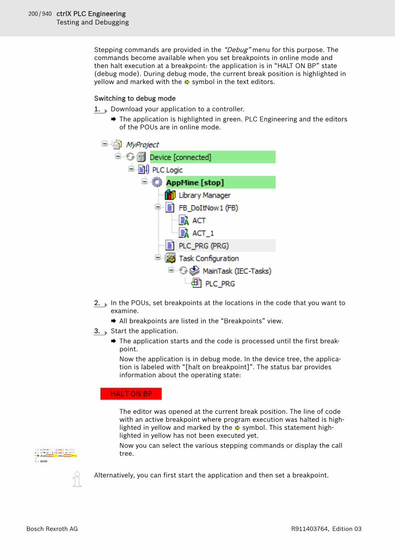
200 / 940 ctrlX PLC EngineeringTesting and Debugging
Bosch Rexroth AG R911403764, Edition 03
Stepping commands are provided in the “Debug” menu for this purpose. Thecommands become available when you set breakpoints in online mode andthen halt execution at a breakpoint: the application is in “HALT ON BP” state(debug mode). During debug mode, the current break position is highlighted inyellow and marked with the symbol in the text editors.
Switching to debug mode1. Download your application to a controller.
🡆 The application is highlighted in green. PLC Engineering and the editorsof the POUs are in online mode.
2. In the POUs, set breakpoints at the locations in the code that you want toexamine.🡆 All breakpoints are listed in the “Breakpoints” view.
3. Start the application.🡆 The application starts and the code is processed until the first break-
point.Now the application is in debug mode. In the device tree, the applica-tion is labeled with “[halt on breakpoint]”. The status bar providesinformation about the operating state:
The editor was opened at the current break position. The line of codewith an active breakpoint where program execution was halted is high-lighted in yellow and marked by the symbol. This statement high-lighted in yellow has not been executed yet.Now you can select the various stepping commands or display the calltree.
Alternatively, you can first start the application and then set a breakpoint.

201 / 940ctrlX PLC EngineeringTesting and Debugging
Bosch Rexroth AGR911403764, Edition 03
Behavior of the stepping command in the 'Debug' menu● Command “Step Over”
The statement at the breakpoint position is executed. Program executionhalts before the next statement in the POU.If the statement contains a call (from a program, function block instance,function, method, or action), then the subordinate POU is processed com-pletely in one step.
● Command “Step Into”The statement at the breakpoint position is executed. Program executionhalts before the next statement.If the statement contains a call (from a program, function block instance,function, method, or action), then the program execution jumps to this sub-ordinate POU. The first statement there is executed and the program execu-tion halts before the next statement. The new current breakpoint position isthen in the called POU.
● Command “Step Out”The command executes the POU from the current breakpoint position to theend of the POU and then jumps back to the calling POU. Program executionhalts at the calling position (in the line with the call).If the current breakpoint position is in the main program, then the POU isrun through to the end. Then the program execution jumps back to thebeginning (to the program start at the first line of code in the POU) andhalts there.
● Command “Run to Cursor”First set the cursor at any line of code and then execute the command. Theprogram is executed from the current breakpoint position and halts at thecurrent cursor position without executing the code of this line.
● Command “Set Next Statement”First set the cursor at any line of code (also before the current breakpointposition) and then execute the command. The statement marked with thecursor is executed next. All statements in between are ignored and skipped.
● Command “Show Next Statement”If you do not see the current breakpoint position, then execute the com-mand. Then the window with the current breakpoint position comes intofocus and the breakpoint position is visible.
Click “View 🠂 Call Stack” to completely show the previous call tree for thebreakpoint position currently reached in the program processing.The “Call Stack” view shows the location of the block in the call structure ofthe program at all times, even before compiling the application.
See also● ⮫ Chapter “Command 'Step Into'” on page 734● ⮫ Chapter “Command 'Step Over'” on page 734● ⮫ Chapter “Command 'Step Out'” on page 735● ⮫ Chapter “Command 'Run to Cursor'” on page 735● ⮫ Chapter “Command 'Set Next Statement'” on page 735● ⮫ Chapter “Command 'Show Next Statement'” on page 736● ⮫ Chapter “Command 'Call tree'” on page 687
1.11.4 Forcing and Writing VariablesIn PLC Engineering, variable values in the PLC can be changed in online mode.Here we make a distinction between forcing and writing.
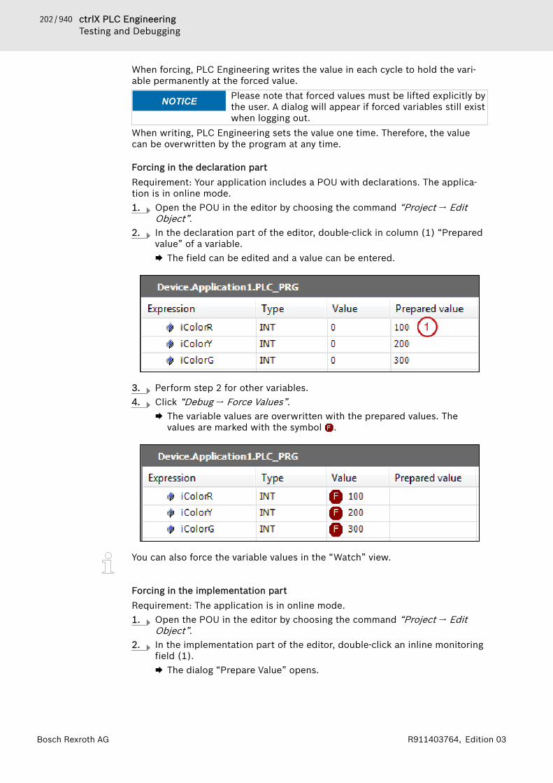
202 / 940 ctrlX PLC EngineeringTesting and Debugging
Bosch Rexroth AG R911403764, Edition 03
When forcing, PLC Engineering writes the value in each cycle to hold the vari-able permanently at the forced value.
NOTICE Please note that forced values must be lifted explicitly bythe user. A dialog will appear if forced variables still existwhen logging out.
When writing, PLC Engineering sets the value one time. Therefore, the valuecan be overwritten by the program at any time.
Forcing in the declaration partRequirement: Your application includes a POU with declarations. The applica-tion is in online mode.1. Open the POU in the editor by choosing the command “Project 🠂 Edit
Object”.2. In the declaration part of the editor, double-click in column (1) “Prepared
value” of a variable.🡆 The field can be edited and a value can be entered.
3. Perform step 2 for other variables.4. Click “Debug 🠂 Force Values”.
🡆 The variable values are overwritten with the prepared values. Thevalues are marked with the symbol .
You can also force the variable values in the “Watch” view.
Forcing in the implementation partRequirement: The application is in online mode.1. Open the POU in the editor by choosing the command “Project 🠂 Edit
Object”.2. In the implementation part of the editor, double-click an inline monitoring
field (1).🡆 The dialog “Prepare Value” opens.

203 / 940ctrlX PLC EngineeringTesting and Debugging
Bosch Rexroth AGR911403764, Edition 03
3. Enter the new value in the field “Prepare a new value for the next write orforce operation”.🡆 The prepared value appears in the inline monitoring field.
4. Click “Debug 🠂 Force Values”.🡆 The value of the variables is overwritten with the prepared values. The
values are marked with the symbol .
View and edit all forced variables 1 listRequirement: The application is in online mode. Several variables are forced.1. Click “View 🠂 Watch 🠂 Watch All Forces”.
🡆 The “Watch all forces” view opens. It contains all currently forced varia-bles of the application in the form of a watch list.
2. Select all lines in the list and click “Unforce 🠂 Unforce and Keep AllSelected Values” in the drop-down list in the upper left part of the view.🡆 The variables are unforced and they get the values that they had before
forcing.
Forcing a function block input in CFCRequirement: An application has a CFC POU that contains a function block, andthe application is in offline mode.
NOTICE This kind of forcing uses a data breakpoint internally andis therefore different from forcing with the “ForceValues” command or [F7].Values that were forced by the command “Force FBInput” do not respond to the commands “Show AllForces” or “Unforce Values”.
1. Open the editor of the CFC POU by double-clicking the object in the tree.2. Activate the forceability for the desired function block. Select the POU ele-
ment in CFC and click “CFC 🠂 Prepare POU Element for Forcing”.3. Login to the application on the target device. In CFC, select the input of
the POU and click “Force FB Input” in the context menu.🡆 The “Force Value” dialog opens.
4. Set a new value for the input. Example in the case of a TON POU: FALSEfor the Boolean input IN, or t#4s for the PT input (TIME). Click “OK” toconfirm.🡆 The set value is forced immediately. A green circle is displayed at the
upper left of the POU element and the name of the input in the elementis highlighted in green. For a Boolean value, a small monitoring viewwith the value also opens at the input. In the monitoring views, theforced value is displayed, for example in the “Value” column, as in thedeclaration part.

204 / 940 ctrlX PLC EngineeringTesting and Debugging
Bosch Rexroth AG R911403764, Edition 03
5. To remove the forced value, click “Force FB Input” again. In the “ForceValue” dialog, select the “Remove value” option.🡆 Forcing is canceled. The input gets the current value from the con-
troller.
See also● ⮫ Chapter “Command 'Prepare Function Block Element for Forcing'”
on page 775● ⮫ Chapter “Command 'Force FB Input'” on page 775● ⮫ Chapter “Dialog 'Prepare Value'” on page 820● ⮫ Chapter “Command 'Force Values'” on page 736● ⮫ Chapter “Command 'Unforce Values'” on page 737● ⮫ Chapter “Command 'Write Values'” on page 737● ⮫ Chapter “Using watch lists” on page 215
1.11.5 Resetting ApplicationsResetting the application stops the program and resets the variables to theirinitialization values. Depending on the type of reset, retain variables and persis-tent variables are also reset.● Reset warm: All variables are reset, except RETAIN and PERSISTENT varia-
bles.● Reset cold: All variables are reset, except PERSISTENT variables.● Reset origin: All variables are reset.● Reset origin device: All variables are reset and all applications are deleted.The following sample program and statements clarify the functionality of thevarious resets.See also● ⮫ “Lifespan of variables when calling online commands” on page 141
Sample program
Declaration
VARiVar: INT := 0;
END_VARVAR RETAIN iVarRetain: INT :=0;
END_VAR VAR PERSISTENT iVarPersistent : INT:= 0;
END_VAR Implementation
iVar := 100;iVarRetain := 200;iVarPersistent :=300; 1. Insert the “Persistent Variables” object below the application and open it
in the editor.2. Click “Build 🠂 Build”.3. Click “Declare 🠂 Add All Instance Paths”.
🡆 The instance path of the persistent variables is inserted.
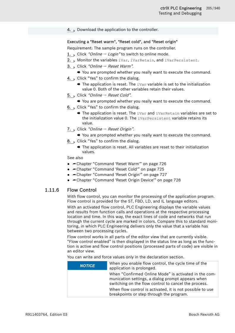
205 / 940ctrlX PLC EngineeringTesting and Debugging
Bosch Rexroth AGR911403764, Edition 03
4. Download the application to the controller.
Executing a "Reset warm", "Reset cold", and "Reset origin"Requirement: The sample program runs on the controller.1. Click “Online 🠂 Login” to switch to online mode.2. Monitor the variables iVar, iVarRetain, and iVarPersistent.3. Click “Online 🠂 Reset Warm”.
🡆 You are prompted whether you really want to execute the command.4. Click “Yes” to confirm the dialog.
🡆 The application is reset. The iVar variable is set to the initializationvalue 0. Both of the other variables retain their values.
5. Click “Online 🠂 Reset Cold”.🡆 You are prompted whether you really want to execute the command.
6. Click “Yes” to confirm the dialog.🡆 The application is reset. The iVar and iVarRetain variables are set to
the initialization value 0. The iVarPersistent variable retains itsvalue.
7. Click “Online 🠂 Reset Origin”.🡆 You are prompted whether you really want to execute the command.
8. Click “Yes” to confirm the dialog.🡆 The application is reset. All variables are reset to their initialization
values.See also● ⮫ Chapter “Command 'Reset Warm'” on page 726● ⮫ Chapter “Command 'Reset Cold'” on page 725● ⮫ Chapter “Command 'Reset Origin'” on page 727● ⮫ Chapter “Command 'Reset Origin Device'” on page 728
1.11.6 Flow ControlWith flow control, you can monitor the processing of the application program.Flow control is provided for the ST, FBD, LD, and IL language editors.With an activated flow control, PLC Engineering displays the variable valuesand results from function calls and operations at the respective processinglocation and time. In this way, the exact lines of code and networks that runthrough the current cycle are marked in colors. Compare this to standard moni-toring, in which PLC Engineering delivers only the value that a variable hasbetween two processing cycles.Flow control works in all parts of the editor view that are currently visible.“Flow control enabled” is then displayed in the status line as long as the func-tion is active and flow control positions (processed parts of code) are visible inan editor view.You can write and force values only in the declaration section.
NOTICE When you enable flow control, the cycle time of theapplication is prolonged.When “Confirmed Online Mode” is activated in the com-munication settings, a dialog prompt appears whenswitching on the flow control to cancel the process.When flow control is activated, it is not possible to usebreakpoints or step through the program.
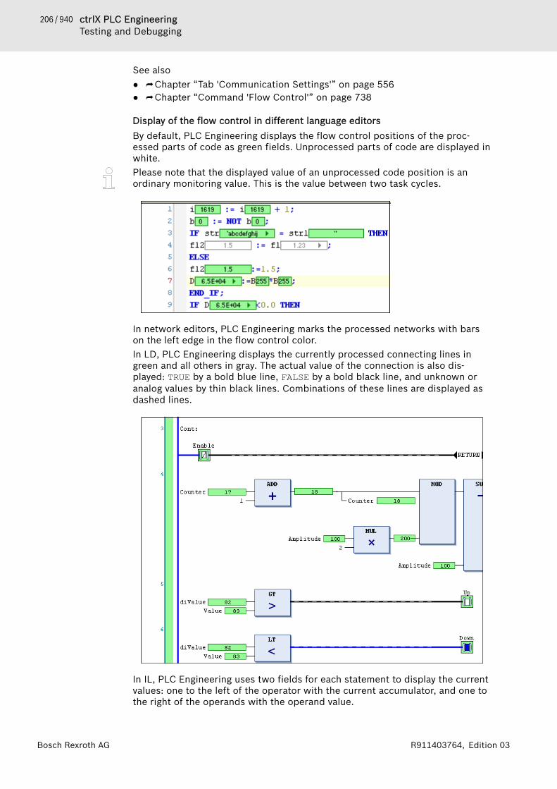
206 / 940 ctrlX PLC EngineeringTesting and Debugging
Bosch Rexroth AG R911403764, Edition 03
See also● ⮫ Chapter “Tab 'Communication Settings'” on page 556● ⮫ Chapter “Command 'Flow Control'” on page 738
Display of the flow control in different language editorsBy default, PLC Engineering displays the flow control positions of the proc-essed parts of code as green fields. Unprocessed parts of code are displayed inwhite.Please note that the displayed value of an unprocessed code position is anordinary monitoring value. This is the value between two task cycles.
In network editors, PLC Engineering marks the processed networks with barson the left edge in the flow control color.In LD, PLC Engineering displays the currently processed connecting lines ingreen and all others in gray. The actual value of the connection is also dis-played: TRUE by a bold blue line, FALSE by a bold black line, and unknown oranalog values by thin black lines. Combinations of these lines are displayed asdashed lines.
In IL, PLC Engineering uses two fields for each statement to display the currentvalues: one to the left of the operator with the current accumulator, and one tothe right of the operands with the operand value.

207 / 940ctrlX PLC EngineeringTesting and Debugging
Bosch Rexroth AGR911403764, Edition 03
1.11.7 Determining the Current Processing Position with the Call StackYou can use the call stack for determining the current position of the programflow. This function is very useful when stepping into programs.Requirement: The application is in online mode. The program is halted at abreakpoint or you are stepping into it.
Open the call stack by clicking “View 🠂 Call Stack”.🡆 The call stack opens. The list shows the current location with the com-
plete call path.The call stack is also available in offline mode and normal online mode (withoutusing debugging functions). In this case, it receives the last displayed locationduring a stepped execution, but it is displayed in gray.See also● ⮫ Chapter “Command 'Call Stack'” on page 686● ⮫ Chapter 1.11.3 “Stepping Through a Program” on page 199
1.11.8 Checking the Task DeploymentThe Tab “Task deployment” of the device editor indicates in an overview thetasks that process the individual inputs and outputs of the I/O mapping of yourapplication and the priority with which they do so. You can check here whetheran unintentional overwriting of values is caused, which can lead to undefinedvalues.1. Generate code for the application: to do this select, for example, the com-
mand “Build 🠂 Generate Code”.
208 / 940 ctrlX PLC EngineeringApplication at Runtime
Bosch Rexroth AG R911403764, Edition 03
2. Open the device editor by double-clicking on the device object in thedevice tree. Select the “Task Deployment” tab.🡆 You obtain a display of the inputs and outputs of your application and
the assignment of the tasks and their priorities. See the description ofthe “Task deployment” tab for details.
See also● ⮫ Chapter “Tab 'Task deployment'” on page 579● ⮫ Chapter 1.7.1 “Device Tree and Device Editor” on page 47● ⮫ “General information about I/O mapping” on page 55
1.12 Application at Runtime1.12.1 Monitoring of Values. . . . . . . . . . . . . . . . . . . . . . 208
Calling of Monitoring in Program-ming Objects . . . . . . . . . . . . . . . . . . 209Using watch lists. . . . . . . . . . . . . . . 215
1.12.2 Changing Values with Recipes. . . . . . . . . . . . . . 2161.12.3 Data Recording with Trace. . . . . . . . . . . . . . . . . 220
Getting Started. . . . . . . . . . . . . . . . 221Creating Trace Configuration. . . . . . 222Operating the Data Recording. . . . . 225Navigating into Trace Data. . . . . . . . 225Managing Trace. . . . . . . . . . . . . . . . 226Showing Statistics. . . . . . . . . . . . . . 226
1.12.4 Data Recording with Trend. . . . . . . . . . . . . . . . . 226Getting Started with TrendRecording. . . . . . . . . . . . . . . . . . . . . 227Configuring Trend Recording. . . . . . 228
1.12.5 Monitoring Tasks. . . . . . . . . . . . . . . . . . . . . . . . . 2301.12.6 Reading the PLC log. . . . . . . . . . . . . . . . . . . . . . 2301.12.7 Analysing Errors with Core Dump. . . . . . . . . . . . 2311.12.8 Using PLC Shell for requesting Information. . . . 2321.12.9 Backup and Restore. . . . . . . . . . . . . . . . . . . . . . 233
When the application is running on the PLC, in the ctrlX PLC EngineeringSystem there are some features for monitoring and changing the values of thevariables as well as for recording and storing the value charts.Furthermore, you can poll some information from the PLC, you can have a lookinto the PLC-log, display a core dump and monitor the time behaviour of thetasks.Regard also the possibility to restrict the access on the running application incritical states of the machine via online commands provided by ctrlX PLC Engi-neering System. For this purpose some system variables are available in amodule of the ComponentManager library.
1.12.1 Monitoring of ValuesIn runtime mode, you can monitor the current variable values of a programmingobject at different places in a project. The following is what we refer to as mon-itoring:
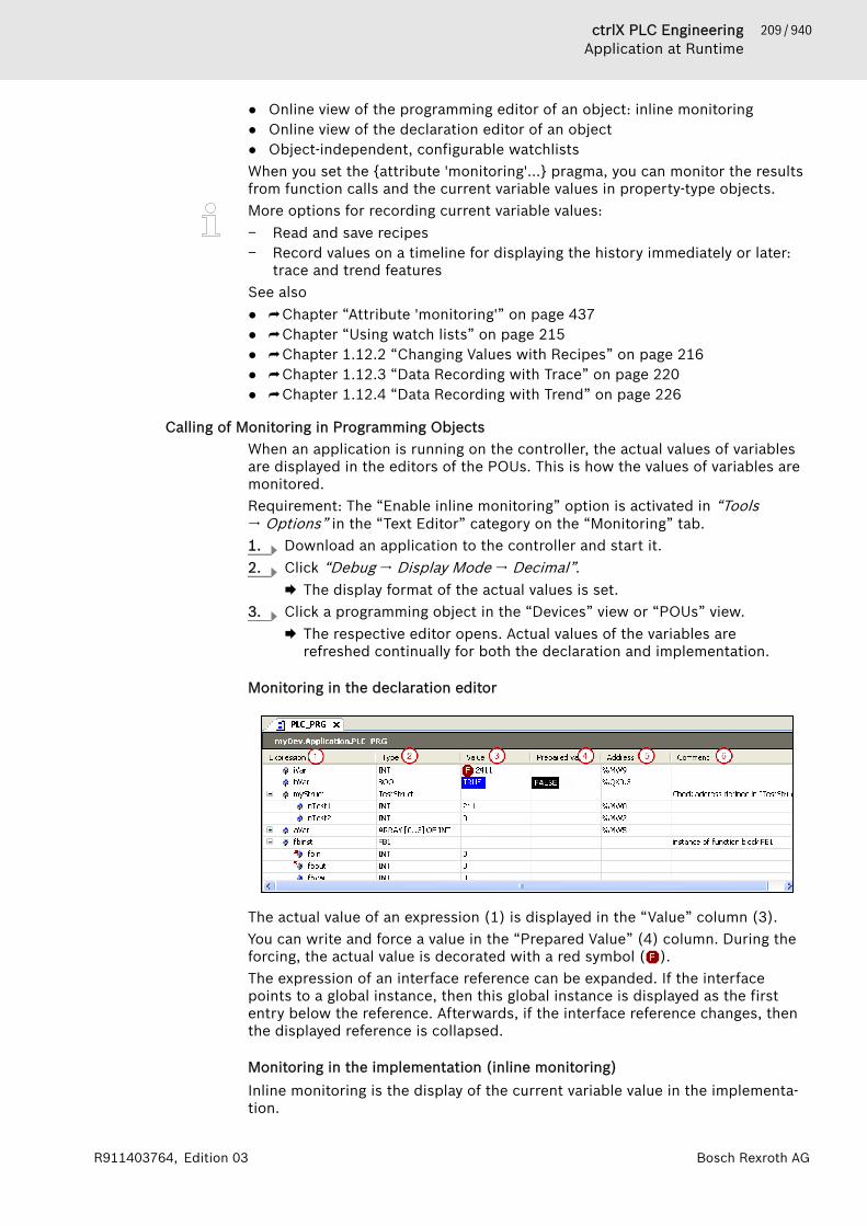
209 / 940ctrlX PLC EngineeringApplication at Runtime
Bosch Rexroth AGR911403764, Edition 03
● Online view of the programming editor of an object: inline monitoring● Online view of the declaration editor of an object● Object-independent, configurable watchlistsWhen you set the {attribute 'monitoring'...} pragma, you can monitor the resultsfrom function calls and the current variable values in property-type objects.More options for recording current variable values:− Read and save recipes− Record values on a timeline for displaying the history immediately or later:
trace and trend featuresSee also● ⮫ Chapter “Attribute 'monitoring'” on page 437● ⮫ Chapter “Using watch lists” on page 215● ⮫ Chapter 1.12.2 “Changing Values with Recipes” on page 216● ⮫ Chapter 1.12.3 “Data Recording with Trace” on page 220● ⮫ Chapter 1.12.4 “Data Recording with Trend” on page 226
Calling of Monitoring in Programming ObjectsWhen an application is running on the controller, the actual values of variablesare displayed in the editors of the POUs. This is how the values of variables aremonitored.Requirement: The “Enable inline monitoring” option is activated in “Tools🠂 Options” in the “Text Editor” category on the “Monitoring” tab.1. Download an application to the controller and start it.2. Click “Debug 🠂 Display Mode 🠂 Decimal”.
🡆 The display format of the actual values is set.3. Click a programming object in the “Devices” view or “POUs” view.
🡆 The respective editor opens. Actual values of the variables arerefreshed continually for both the declaration and implementation.
Monitoring in the declaration editor
The actual value of an expression (1) is displayed in the “Value” column (3).You can write and force a value in the “Prepared Value” (4) column. During theforcing, the actual value is decorated with a red symbol ( ).The expression of an interface reference can be expanded. If the interfacepoints to a global instance, then this global instance is displayed as the firstentry below the reference. Afterwards, if the interface reference changes, thenthe displayed reference is collapsed.
Monitoring in the implementation (inline monitoring)Inline monitoring is the display of the current variable value in the implementa-tion.

210 / 940 ctrlX PLC EngineeringApplication at Runtime
Bosch Rexroth AG R911403764, Edition 03
Depending on the implementation language, the following displays are possiblein the implementation part:● Variables have a window with the current value displayed after their name:
If you have prepared values for variables for forcing or writing, then they aredisplayed in angle brackets in the inline monitoring view after the currentvalue.After forcing, the respective values are identified by the symbol.
● Network editors and the CFC editor:Connecting lines are displayed in color according to their actual Booleanvalue (blue means TRUE, black means FALSE).
● LD editor:The contact and coil elements are also marked.For contacts and coils, a prepared value (TRUE or FALSE) is shown in a smallview next to the element.
● SFC editor:Transitions with the value TRUE are displayed in color according to theiractual Boolean value (blue means TRUE, black means FALSE).Active steps are displayed in blue.Forced transition values are displayed in red in the implementation.
● IL tabular editor:Current values are displayed in a separate column.
Monitoring in the ST editor
Monitoring in the LD editor
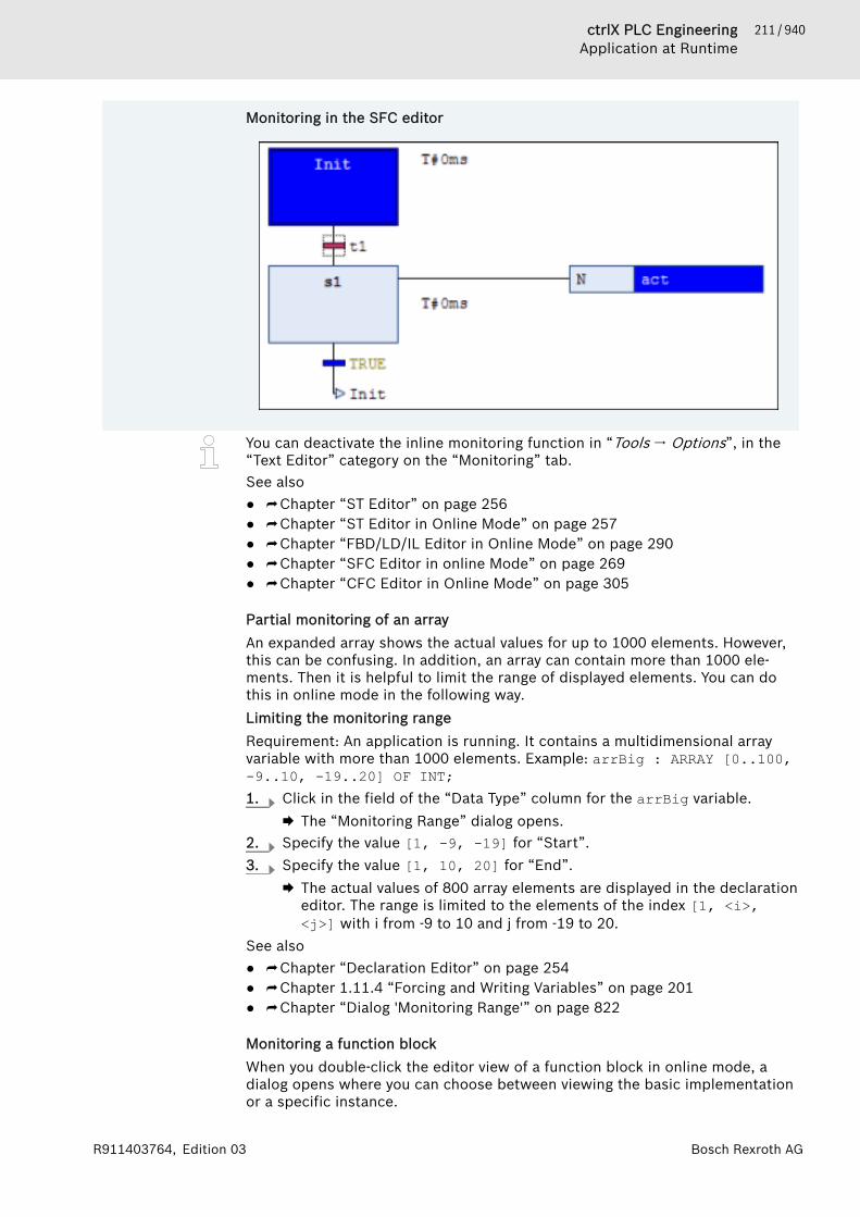
211 / 940ctrlX PLC EngineeringApplication at Runtime
Bosch Rexroth AGR911403764, Edition 03
Monitoring in the SFC editor
You can deactivate the inline monitoring function in “Tools 🠂 Options”, in the“Text Editor” category on the “Monitoring” tab.See also● ⮫ Chapter “ST Editor” on page 256● ⮫ Chapter “ST Editor in Online Mode” on page 257● ⮫ Chapter “FBD/LD/IL Editor in Online Mode” on page 290● ⮫ Chapter “SFC Editor in online Mode” on page 269● ⮫ Chapter “CFC Editor in Online Mode” on page 305
Partial monitoring of an arrayAn expanded array shows the actual values for up to 1000 elements. However,this can be confusing. In addition, an array can contain more than 1000 ele-ments. Then it is helpful to limit the range of displayed elements. You can dothis in online mode in the following way.Limiting the monitoring rangeRequirement: An application is running. It contains a multidimensional arrayvariable with more than 1000 elements. Example: arrBig : ARRAY [0..100,-9..10, -19..20] OF INT;1. Click in the field of the “Data Type” column for the arrBig variable.
🡆 The “Monitoring Range” dialog opens.2. Specify the value [1, -9, -19] for “Start”.3. Specify the value [1, 10, 20] for “End”.
🡆 The actual values of 800 array elements are displayed in the declarationeditor. The range is limited to the elements of the index [1, <i>,<j>] with i from -9 to 10 and j from -19 to 20.
See also● ⮫ Chapter “Declaration Editor” on page 254● ⮫ Chapter 1.11.4 “Forcing and Writing Variables” on page 201● ⮫ Chapter “Dialog 'Monitoring Range'” on page 822
Monitoring a function blockWhen you double-click the editor view of a function block in online mode, adialog opens where you can choose between viewing the basic implementationor a specific instance.
212 / 940 ctrlX PLC EngineeringApplication at Runtime
Bosch Rexroth AG R911403764, Edition 03
If you select the basic implementation, then the code is displayed in the editorwithout current values. Now set a breakpoint in the basic implementation. Ifthe execution halts there, then the current values of the instance that is proc-essed first in the program flow are displayed. Now you can step successivelythrough all instances.If you select one of the instances, then the editor opens with the code of thefunction block instance. The current values are displayed in the declarationand, if applicable, in the implementation, and are updated continuously.See also● ⮫ Chapter “Object 'Function Block'” on page 590● ⮫ Chapter 1.11.2 “Using Breakpoints” on page 196
Monitoring a propertyYou can monitor variables in a property object by setting a breakpoint in thefunction during online mode. When halted there, the current values are dis-played.In addition to your own values, the values of the variables of the superordinateinstance are displayed automatically. In the declaration part of the property,the THIS pointer, which points to the superordinate instance, appears in thefirst line with the current data type information and values.
Example
Code
FUNCTION_BLOCK FB_BaseAlfaVARiBaseLocal : INT;sBaseLocal : STRING;
END_VARiBaseLocal := iBaseLocal + 1;sBaseLocal := 'Testing Text';
FB_BaseAlfa.PorpBeta.GetiBaseLocal := iBaseLocal + 1;IF iBaseLocal > 0 THENPropBeta := TRUE;
END_IF
FB_BaseAlfa.PorpBeta.SetIF PropBeta = TRUE THENiBaseLocal := 0;sBaseLocal := 'Tested IF';
END_IF
PROGRAM PLC_PRGVARfb_BaseAlfa : FB_BaseAlfa;
END_VAR
fb_BaseAlfa();
IF fb_BaseAlfa.PropBeta = TRUE THENxResult := TRUE;
END_IFIF xReset THEN
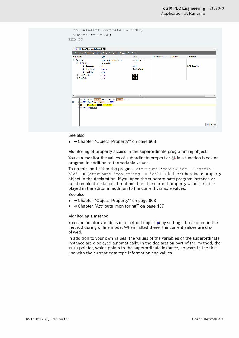
213 / 940ctrlX PLC EngineeringApplication at Runtime
Bosch Rexroth AGR911403764, Edition 03
fb_BaseAlfa.PropBeta := TRUE;xReset := FALSE;
END_IF
See also● ⮫ Chapter “Object 'Property'” on page 603
Monitoring of property access in the superordinate programming objectYou can monitor the values of subordinate properties in a function block orprogram in addition to the variable values.To do this, add either the pragma {attribute 'monitoring' = 'varia-ble'} or {attribute 'monitoring' = 'call'} to the subordinate propertyobject in the declaration. If you open the superordinate program instance orfunction block instance at runtime, then the current property values are dis-played in the editor in addition to the current variable values.See also● ⮫ Chapter “Object 'Property'” on page 603● ⮫ Chapter “Attribute 'monitoring'” on page 437
Monitoring a methodYou can monitor variables in a method object by setting a breakpoint in themethod during online mode. When halted there, the current values are dis-played.In addition to your own values, the values of the variables of the superordinateinstance are displayed automatically. In the declaration part of the method, theTHIS pointer, which points to the superordinate instance, appears in the firstline with the current data type information and values.

214 / 940 ctrlX PLC EngineeringApplication at Runtime
Bosch Rexroth AG R911403764, Edition 03
Example
Code
FUNCTION_BLOCK FB_BaseAlfaVARiBaseLocal : INT;sBaseLocal : STRING;
END_VARiBaseLocal := iBaseLocal + 1;sBaseLocal := 'Testing Text';
METHOD MethBaseAlfa : BOOL // Method of FB_BaseAlfaVAR_INPUTEND_VARVARiMethLocal : INT;
END_VARiMethLocal := iMethLocal + 1;
PROGRAM PLC_PRGVARfb_BaseAlfa : FB_BaseAlfa;
END_VARfb_BaseAlfa();fb_BaseAlfa.MethBaseAlfa();
See also● ⮫ Chapter “Object 'Property'” on page 603● ⮫ Chapter “Object 'Method'” on page 596
Monitoring a functionYou can monitor variables in a function object by setting a breakpoint in thefunction during online mode. When halted there, the current values are dis-played.
Monitoring the return value of a function callIn the ST editor of a POU, the current return value is displayed as inline moni-toring at the position of the POU where a function is called.

215 / 940ctrlX PLC EngineeringApplication at Runtime
Bosch Rexroth AGR911403764, Edition 03
The following conditions must be fulfilled:● The value can be interpreted as a 4-byte numeric value. Example: INT, SINT,
or LINT.● The pragma {attribute 'monitoring' := 'call'} is inserted into the
function.See also● ⮫ Chapter “Object 'Function'” on page 592● ⮫ Chapter “Attribute 'monitoring'” on page 437
Using watch listsWhat is a watch list?A watch list is a user-defined list of project variables that are collected in oneview for the purpose of monitoring their values. In online mode, you can writeand force variable values in a watch list. Monitoring, writing, and forcing arehandled the same way as the declaration editor in online mode. You can cus-tomize the format of the representation of floating-point values in the optionsfor monitoring.There are four, ready-to-use watch lists (Watch <n>) available in a project.Click “View 🠂 Watch”.If the expression is an interface reference, then it can be expanded. If the inter-face points to a global instance, then this global instance is displayed as thefirst entry below the reference. If the interface reference changes, then the dis-played reference is collapsed.See also● ⮫ “Declaration editor in online mode” on page 255● ⮫ Chapter “Dialog 'Options' - 'Monitoring'” on page 857
Creating and editing a watch list (offline or online mode)Requirement: The project is in either online or offline mode. It includes anapplication with declared variables that you want added to one of the four pos-sible watch lists.1. Click “View 🠂 Watch 🠂 Watch <n>”.
🡆 The Watch <n> view opens. It contains a blank table row.2. Double-click the field in the “Expression” column and type a variable to
monitor, either manually or with the input assistant.Syntax: <device name>.<application name>.<object name>.<variablename>Example: "Dev1.App1.PLC_PRG.ivar"If you type the name of a structured variable, then the individual compo-nents are displayed automatically in other lines in online mode.
3. Define all successive variables that will be monitored with this list. Youcan change the order by using drag and drop operations.🡆 The “Execution point”, “Type”, “Address”, “Comment” fields are filled
in automatically according to the variables declaration. The symbolbefore the expression indicates the type of variable: input variable ( ),output variable ( ), or ordinary variable ( ).
In online mode, you can also create or edit watch lists by right-clicking andchoosing the “Add Watch” command.See also● ⮫ Chapter “Command 'Watch' - 'Watch <n>'” on page 681
216 / 940 ctrlX PLC EngineeringApplication at Runtime
Bosch Rexroth AG R911403764, Edition 03
Adding variables by choosing the 'Add Watch' command (online mode)Requirement: A project is open and running. It includes an application withdeclared variables that you want added to a possible watch list.1. Click “View 🠂 Watch <n>” to open the watch list.2. Place the cursor on a variable in the declaration or implementation part of
a POU and right-click to choose the “Add Watch” command.🡆 This adds an entry to the list for the selected variable.
3. You can add other variables in this way or by typing directly into the list inthe “Expression” field as described above.🡆 The watch lists are updated immediately.
If a watch list is not open when you click “Add Watch” for a variable, then it isadded automatically to the “Watch 1” list.Writing and forcing variable values is also possible in the watch lists. In onlinemode, the “Prepared value” column is also available.
See also● ⮫ Chapter “Command 'Add Watch'” on page 815● ⮫ Chapter “Calling of Monitoring in Programming Objects ” on page 209● ⮫ Chapter 1.11.4 “Forcing and Writing Variables” on page 201
1.12.2 Changing Values with RecipesUse recipes to change or read recipes values for a specific set of variables(recipe definition) on the controller at the same time.You define the basic settings for recipes, such as location and format, in theobject “Recipe Manager”. Insert one or more recipe definitions below thisobject. A recipe definition comprises one or more recipes for the contained var-iable. The recipe consists of specific variable values.You can save a recipe to a file or write directly from files to the PLC.Recipes can be loaded via the PLC Engineering development interface, the visu-alization element, or the application program.Using recipes on remote devicesThe variable values from recipes are transferred automatically to and fromanother controller when they are data source variables and a data sourceexchange is configured. Reading and writing occurs synchronously. Therefore,PLC Engineering updates all variables in a recipe at the same time. Afterreading or writing, you can use the call g_RecipeManager.LastError to checkwhether or not the transfer was successful (g_RecipeManager.LastError =0).See also● ⮫ Chapter “Object 'Recipe Manager'” on page 626● ⮫ Chapter “Object 'Recipe Definition'” on page 629● ⮫ Chapter 1.9.4 “Data Source Manager” on page 169
Using recipes in the PLC Engineering user interfaceThe PLC Engineering development interface provides commands for generatingrecipes as well as read/write in online mode.See also● ⮫ Chapter “Menu 'Recipes'” on page 797
217 / 940ctrlX PLC EngineeringApplication at Runtime
Bosch Rexroth AGR911403764, Edition 03
Using recipes in applicationsWhen the application is in runtime mode, you can use recipes in the user pro-gram and visualization elements.In the user program, you use the methods for the function block RecipeMan-Commands from the library RecipeManagement. In the visualization, you userecipes via the input configuration (internal command of visualization elements.During the initialization process, the recipe management reads the values ofthe variables that are defined in the recipe definition. This operation takesplace at the end of the initialization phase of the application. At this point, allinitial values of the application variables are set. This is performed to initializemissing values from recipe files correctly.See also● ⮫ RecipeManCommands● ⮫ Input configuration
Creating recipes1. Select the “Application” object in the device tree.2. Click “Project 🠂 Add Object 🠂 Recipe Manager”.
🡆 PLC Engineering adds the Recipe Manager to the device tree.3. Select the “Recipe Manager” object in the device tree.4. Click “Project 🠂 Add Object 🠂 Recipe Definition”.
🡆 PLC Engineering adds the recipe definition below the Recipe Manager.5. Open the editor of the recipe definition by double-clicking the object.6. Double-click the blank field below “Variable”. Specify the name of a vari-
able that you will define a recipe. The input assistant can be used for this: button.
7. Click “Recipes 🠂 Add a New Recipe” and enter a name for the new recipe.🡆 A column with the new recipe name appears in the editor.
8. Enter the variable value for this recipe in this field.9. Insert additional fields as needed.10. Select a variable value for the recipe and click “Recipes 🠂 Save Recipe”.
Select a location and file name.🡆 PLC Engineering saves the recipe in the format as defined in the Recipe
Manager.See also● ⮫ Chapter “Object 'Recipe Manager'” on page 626● ⮫ Chapter “Object 'Recipe Definition'” on page 629● ⮫ Chapter “Menu 'Recipes'” on page 797
Loading recipes from a fileRequirement: A Recipe Manager is available in the application. In a recipe defi-nition, there is a “myRec” recipe with variable values. A myRec.txt recipe fileis located on the file system and contains the entries for this recipe.Example of the recipe file:PLC_PRG.bVar:=0PLC_PRG.iVar:=2PLC_PRG.dwVar:=35232PLC_PRG.stVar:='first'PLC_PRG.wstVar:='123443245'
218 / 940 ctrlX PLC EngineeringApplication at Runtime
Bosch Rexroth AG R911403764, Edition 03
1. Double-click the “Recipe Definition” object in the device tree to open thetabular editor for the definition of the individual recipes.🡆 You see the myRec column with the current values for this recipe.
2. Edit the myRec.txt file in an external text editor and replace the variablevalues with other values that you want to load into the recipe definition inPLC Engineering. Save the file.
3. Click the “myRec” column in the recipe definition and right-click for the“Load Recipe” command.🡆 A dialog prompt notifies you about the possibly needing to perform an
online change when logging in again. An online change is necessarywhen you change the current values of the recipe variables by loadingthe recipe.
4. Click “Yes” to close the dialog and continue. Select the myRec.txt filefrom the file explorer for loading.🡆 The recipe values in the recipe definition are updated according to the
values read in the file.If you want to overwrite only individual recipe variables with new values, thenremove the values for the other variables before loading to the recipe file.Entries without value definitions are not read, and therefore updating leavesthese variables unchanged on the PLC and in the project.For values of the data type REAL/LREAL, the hexadecimal value is also writtento the recipe file in some cases. This is necessary so that the exact identicalvalue is restored when converting back. In this case, change the decimal valueand delete the hexadecimal value.See also● ⮫ Chapter “Command ‘Load Recipe'” on page 798● ⮫ Chapter “Command 'Load and Write Recipe'” on page 800
Recipe management on the controller; memory usageWhen you clear the “Recipe management in the PLC” option, the Recipe Man-ager and recipe definitions will not use any memory on the PLC.If you select this check box, then code is generated for the Recipe Manager andall recipe definitions, and this code is stored on the PLC. The size of the usedmemory primarily depends on the number pf recipes and their variables, aswell as the data type of the variables. Whether or not the fields of the recipedefinition are filled also has an effect. The memory usage of recipes cannot becalculated. It has to be determined by experimentation at the time it is needed.The following table merely provides some guiding principles.Table 2: Memory Usage for PLC Engineering V3 SP6 with ctrlX CORE Controller
Code Size (bytes) Data Size (bytes) Total (bytes)Recipe definitionwith 100 INT varia-bles
194406 79400 267352
Recipe definitionwith 200 INT varia-bles
238318 121284 459344
Recipe definitionwith 300 INT varia-bles
282230 163084 543856
Recipe definitionwith 100 BOOLvariables
192742 69884 343168

219 / 940ctrlX PLC EngineeringApplication at Runtime
Bosch Rexroth AGR911403764, Edition 03
Code Size (bytes) Data Size (bytes) Total (bytes)Recipe definitionwith 200 BOOLvariables
235446 101568 436872
Recipe definitionwith 300 BOOLvariables
278146 133284 510072
Recipe definitionwith 100 string var-iables
203278 870084 1154000
Recipe definitionwith 200 string var-iables
255570 1709784 2973296
Recipe definitionwith 300 string var-iables
307886 2549484 2964112
Loading recipe values from the controllerYou can apply recipe values on the controller to recipe definitions in theproject, even if these definitions have been modified in the project.Requirement: The “Recipe management in the PLC” is option is selected in theRecipe Manager.1. Create a recipe definition RecDef1 in the project, containing the variables
PLC_PRG.ivar and PLC_PRG.bvar. Insert a recipe “R1”: value forPLC_PRG.ivar: 33; value for PLC_PRG.bvar: TRUE.
2. Login to the controller and download the application.🡆 The recipe file R1.RecDef1.txtrecipe is saved to the default direc-
tory of the controller ($PlcLogic$).3. Logout and add another variable PLC_PRG.dwvar to the recipe definition
in the project.4. Edit the recipe definition file R1.RecDef1.txtrecipe on the device by
changing the value for PLC_PRG.ivar from 33 to 34.Moreover, add another recipe “R2” on the device. To do this, copy theR1.RecDef1.txtrecipe and rename it to R2.RecDef1.txtrecipe. Thenedit this file and change the recipe values: PLC_PRG.ivar: 1,PLC_PRG.bvar: FALSE.🡆 Now two recipes “R1” and “R2” are available on the device. In the
project, there is only “R1”, and it also contains other values than “R1”on the device.
5. Login again to the controller with online change.6. Click “Upload Recipes from Device” from the context menu.
🡆 A dialog prompt notifies you that executing the command at the nextlogin may trigger an online change, and that the recipes on the runtimesystem will overwrite the recipes of the current recipe definition.
7. Confirm that you wish to continue.🡆 A dialog prompt notifies you that the recipe for PLC_PRG.dwvar loaded
on the device cannot yield a value from the controller.

220 / 940 ctrlX PLC EngineeringApplication at Runtime
Bosch Rexroth AG R911403764, Edition 03
8. Confirm that you wish to continue.🡆 The value of PLC_PRG.ivar in recipe “R1” of the recipe definition in
the project changes to 34. The recipe “R2” with the values 1 and FALSEis also listed in the recipe definition now. PLC_PRG.dwvar remains inthe recipe definition.
1.12.3 Data Recording with TraceYou can use a “Trace” to follow the value history of variables on the controllerin a similar way as a digital sampling oscilloscope. When the application is inruntime mode with trace, all statements are executed first within the taskcycle. Then, data recording starts with value storage including time stamps.These time stamps are relative and refer to the start time of the data recording.The data yields a discrete time signal and PLC Engineering displays its coursein the trace editor.A sample (data record) is composed of the value and the time stamp. The run-time system writes the samples to a buffer with a definable size. PLC Engi-neering requests the data, saves it in the trace editor buffer, and displays it inthe trace diagram as a function of time. You can monitor the value history ofthe configured variables continually because PLC Engineering displays thelatest data.You can trigger the data recording. When this happens, the application savesthe data from the time of the trigger and PLC Engineering displays the data atthe time of the trigger.The configuration and the display of a trace are possible in the PLC Engineeringproject by means of trace objects in the trace editor. There are the followingobject types:● “Trace”: Inserted below the IEC application in the device tree. This kind of
object always contains a purely application-specific trace configuration. Youcan download this trace configuration to the controller and run it with theapplication.
Access to the trace manager from IEC code is possible by means of the func-tions from the library CmpTraceMgr.library. For more information, refer tothe library documentation.
NOTICE A running data recording with trace can lead to a signifi-cant increase in the cycle time of the IEC task.
NOTICE Data recording with trace also continues running afterlogging out of the device.
Data recording after triggeringTo monitor data that depends on an event or a condition, you can free the datarecording that depends on a trigger. At runtime, the application checks whetherthe event has occurred or the the condition is fulfilled, and then it buffers thedata accordingly.The trace configuration enables triggering by:● a trigger variable that maps the event● a condition as expression● a combination of trigger variable and condition
Saving samples to a fileYou can save samples from the development system to a file. The file can alsoinclude the trace configuration.
221 / 940ctrlX PLC EngineeringApplication at Runtime
Bosch Rexroth AGR911403764, Edition 03
Table 3: Possible file formatsFile Extension File type Description*.trace: “Trace file” Contains the samples and the trace
configuration in XML format. Youcan execute the “Load Trace” com-mand to load the file to the traceeditor when offline and analyze thesamples without a controller.
*.txt “Text File” Contains the samples in ASCIIformat. You can edit the file with anexternal tool.
*.trace.csv “Trace dump” File in CSV format includes thetrace configuration and optionalsamples.You can create the file by clicking“Export Symbolic Trace Config”.You can transfer the file to the con-troller and load it to the applica-tion. Then you can execute the“Load Trace” command in PLCEngineering to display this in thetrace editor.You can also click “Trace 🠂 SaveTrace” and select the *.trace.csvfile format. You can transfer the fileto the controller and load it with anHMI for analysis.
*.traceconfig “Symbolic trace configuration” Contains the trace configurationCSV format. You can create the fileby clicking “Export Symbolic TraceConfig”. The CmpTraceMgr runtimesystem component can read thefile.
See also● ⮫ Chapter “Command 'Save Trace'” on page 813● ⮫ Chapter “Command 'Load Trace'” on page 811● ⮫ Chapter “Command 'Export Symbolic Trace Config'” on page 809● ⮫ Chapter “Object 'Symbol Configuration'” on page 630
Getting StartedProgram PLC_PRG
PROGRAM PLC_PRGVARiVar : INT;rSin : REAL;rVar : REAL;
END_VAR
iVar := iVar + 1;iVar := iVar MOD 33;
rVar := rVar + 0.1;rSin := 30 * SIN(rVar);
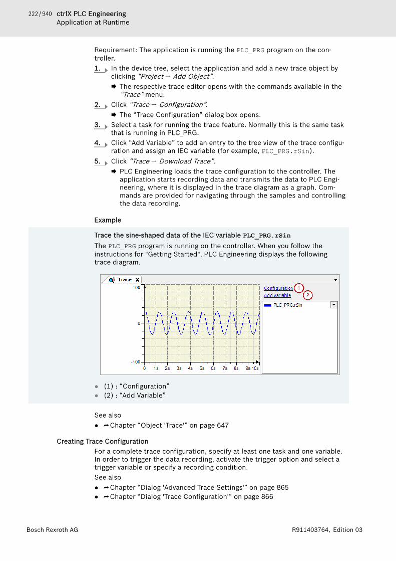
222 / 940 ctrlX PLC EngineeringApplication at Runtime
Bosch Rexroth AG R911403764, Edition 03
Requirement: The application is running the PLC_PRG program on the con-troller.1. In the device tree, select the application and add a new trace object by
clicking “Project 🠂 Add Object”.🡆 The respective trace editor opens with the commands available in the
“Trace” menu.2. Click “Trace 🠂 Configuration”.
🡆 The “Trace Configuration” dialog box opens.3. Select a task for running the trace feature. Normally this is the same task
that is running in PLC_PRG.4. Click “Add Variable” to add an entry to the tree view of the trace configu-
ration and assign an IEC variable (for example, PLC_PRG.rSin).5. Click “Trace 🠂 Download Trace”.
🡆 PLC Engineering loads the trace configuration to the controller. Theapplication starts recording data and transmits the data to PLC Engi-neering, where it is displayed in the trace diagram as a graph. Com-mands are provided for navigating through the samples and controllingthe data recording.
Example
Trace the sine-shaped data of the IEC variable PLC_PRG.rSinThe PLC_PRG program is running on the controller. When you follow theinstructions for "Getting Started", PLC Engineering displays the followingtrace diagram.
● (1) : “Configuration”● (2) : “Add Variable”
See also● ⮫ Chapter “Object 'Trace'” on page 647
Creating Trace ConfigurationFor a complete trace configuration, specify at least one task and one variable.In order to trigger the data recording, activate the trigger option and select atrigger variable or specify a recording condition.See also● ⮫ Chapter “Dialog 'Advanced Trace Settings'” on page 865● ⮫ Chapter “Dialog 'Trace Configuration'” on page 866

223 / 940ctrlX PLC EngineeringApplication at Runtime
Bosch Rexroth AGR911403764, Edition 03
● ⮫ Chapter “Dialog 'Advanced Trend Settings'” on page 871● ⮫ Chapter “Configuring Trend Recording” on page 228
Assigning a taskIn this task, the data recording is executed in runtime mode. Usually the sametask is selected where the variables are written.1. Double-click the trace object.
🡆 The trace editor opens with the commands available in the “Trace”menu.
2. Click “Trace 🠂 Configuration”.🡆 The “Trace Configuration” dialog opens. In the tree view “Trace
Record”, the top item is selected and the subdialog “Record Settings”is shown on the right.
3. Click the "arrow down" symbol ( ) in the “Task” drop-down list.🡆 The drop-down list opens with all tasks that are available throughout
the application.4. Select a task for the trace.See also● ⮫ Chapter “Dialog 'Trace Configuration'” on page 866
Configuring a trace variable1. Double-click the trace object.
🡆 The trace editor opens. The commands of the “Trace” menu are avail-able.
2. Click “Add Variable”.🡆 The “Trace Configuration” dialog opens. The subdialog “Variable Set-
tings” is displayed on the right.3. Click in the input field of the “Variable” setting and select a trace vari-
able in the “Input Assistant” dialog.🡆 The variable is configured for data recording. The trace record tree and
the display tree were extended by the variable.4. Click the “Add Variable” link.
🡆 The trace record tree and the display tree receive a new variable. Thesettings of the variables are available on the right.
5. Select a trace variable.6. Click “OK” to close the dialog.
🡆 The variables are trace variables and are displayed in the trace variablelist.
Deleting a trace variable1. Double-click the trace object.2. Click a variable in the trace record tree.3. Click the “Delete Variable” command or press [Del].4. Click “OK” to close the dialog.
🡆 The variable is removed from the trace variable list.
Tracing a parameter1. Double-click the trace object.
224 / 940 ctrlX PLC EngineeringApplication at Runtime
Bosch Rexroth AG R911403764, Edition 03
2. Click “Add Variable”.🡆 The “Trace Configuration” dialog opens. The subdialog “Variable Set-
tings” is displayed on the right.3. Click (right of the “Variable” setting, left of the input field).4. Select the “Parameter” option in the drop-down list.5. Click and select a parameter from the “Input Assistant” dialog.6. Configure how the parameter is displayed.7. Click “OK” to close the dialog.
🡆 The parameter will be traced and displayed in the trace variable list.
Configuring a trigger1. Double-click the trace object.
🡆 The trace editor opens with the commands available in the “Trace”menu.
2. Click “Trace 🠂 Configuration”.🡆 The “Trace Configuration” dialog opens. The subdialog “Record Set-
tings” is displayed on the right.3. Select the “Enable trigger” check box.4. Select the task in which the trend record is to be executed.5. Select a variable from the “Trigger Variable” field.6. Click “OK” to close the dialog.
🡆 The data recording will be triggered.The trigger time is displayed as a black line in the diagram in runtime mode.1. Download the application and start it.2. Click “Trace 🠂 Download Trace”.
🡆 The trace configuration is loaded. After triggering, the runtime systemsaves the value graph of the trace variables. The data is displayed in thetrace editor. The trigger time is displayed as a black line in the diagram.
Configuring the display of the time axis1. Double-click a trace object.2. Click the “Configuration” link above the configuration tree.
🡆 The “Trace Configuration” dialog opens.3. Select “Time axis” in the display tree (below “Presentation (Diagrams)”).
🡆 The display settings of the time axis are shown on the right.4. Edit the presets and click the “Preview” link.
🡆 The changes are seen in the coordinate system preview.5. Click “Y-axis” in the display tree. The “Y-axis” item is below every config-
ured diagram. Therefore, the display of the value axis is set for each dia-gram.🡆 The subdialog “Display Settings” of the selected axis is displayed on
the right.6. Change the preset value.
🡆 The changes are applied in the coordinate system preview.7. Click OK to close the “Trace Configuration” dialog.
🡆 The display changes are visible in the affected diagrams.
Configuring the display of the trace variable1. Double-click a trace object.

225 / 940ctrlX PLC EngineeringApplication at Runtime
Bosch Rexroth AGR911403764, Edition 03
2. Click the “Configuration” link.🡆 The “Trace Configuration” dialog opens.
3. Select a variable below “Trace Record”.🡆 The subdialog “Variable Settings” of the selected variable is displayed
on the right.4. Change a setting, for example the “Line type”.5. Click “OK” to close the dialog.
🡆 The display changes are visible in the affected diagrams.
Configuring the buffer for data on the runtime system1. Double-click a trace object.2. Click “Trace 🠂 Configuration”.
🡆 The “Trace Configuration” dialog opens. The subdialog “Record Set-tings” is displayed on the right.
3. Click “Advanced”.🡆 The “Advanced Trace Settings” dialog opens.
4. Change the setting “Measure in every n-th cycle” or “Recommended run-time buffer size (samples)”.
5. Click “OK” to close the dialog.🡆 The buffer settings are reconfigured. It is applied after the trace config-
uration is loaded to the RTS the next time.
Editing the trace configuration in runtime modeRequirement: The application is running on the controller and a trace configu-ration is loaded.1. Double-click a variable in the trace record tree.
🡆 The “Trace Configuration” dialog opens.2. Change the color, for example.
🡆 The variable is displayed in the new color in the affected diagramswithout interrupting the execution of the application.
If you change essential settings, for example a trace variable, then you mustdownload the trace configuration to the controller again.
Operating the Data RecordingUse menu commands for controlling how data is recorded.Requirement: The application is loaded on the runtime system and a trace isconfigured.Menu Commands● “Trace 🠂 Download Trace”● “Trace 🠂 Start Trace”● “Trace 🠂 Stop Trace”● “Trace 🠂 Reset Trigger”See also● ⮫ Chapter “Command 'Download Trace'” on page 809● ⮫ Chapter “Command 'Start Trace'” on page 813● ⮫ Chapter “Command 'Stop Trace'” on page 813● ⮫ Chapter “Command 'Reset Trigger'” on page 812
Navigating into Trace DataUse menu commands to navigate the data in the trace diagram.

226 / 940 ctrlX PLC EngineeringApplication at Runtime
Bosch Rexroth AG R911403764, Edition 03
Requirement: The application is in online mode.Menu Commands● “Trace 🠂 Cursor”● “Trace 🠂 Mouse Zooming”● “Trace 🠂 Reset View”● “Trace 🠂 AutoFit”● “Trace 🠂 Compress”● “Trace 🠂 Stretch”● “Trace 🠂 Convert to Single-Channel”● “Trace 🠂 Convert to Multi-Channel”See also● ⮫ Chapter “Command 'Cursor'” on page 808● ⮫ Chapter “Command 'Mouse Zooming'” on page 811● ⮫ Chapter “Command 'Reset View'” on page 813● ⮫ Chapter “Command 'AutoFit'” on page 807● ⮫ Chapter “Command 'Compress'” on page 807● ⮫ Chapter “Command 'Stretch'” on page 814● ⮫ Chapter “Command 'Convert to Multi-Channel'” on page 811● ⮫ Chapter “Command 'Convert to Single-Channel'” on page 812
Managing TraceUse menu commands to load and save traces in various formats.Menu Commands● “Trace 🠂 Save Trace”● “Trace 🠂 Load Trace”● “Trace 🠂 Export Symbolic Trace Config”See also● ⮫ Chapter “Command 'Save Trace'” on page 813● ⮫ Chapter “Command 'Load Trace'” on page 811● ⮫ Chapter “Command 'Export Symbolic Trace Config'” on page 809
Showing StatisticsPLC Engineering evaluates and displays the recorded data with an option ofsaving the data to the clipboard. Click “Trace 🠂 Statistics”.See also● ⮫ Chapter “Command 'Statistics'” on page 814
1.12.4 Data Recording with TrendWhen you want to monitor the development of data over a long period of timefor the purpose of reading a trend, you can save the data with “TrendRecording”. You can configure any number of variables or parameters to savetheir values in a persistent database. This database is located on the PLC and ispopulated continually at runtime.

227 / 940ctrlX PLC EngineeringApplication at Runtime
Bosch Rexroth AGR911403764, Edition 03
Trend recording comprises the following objects:● (1):“Trend recording task” of type “Task”● (2): Object of type “Trend Recording Manager”● (3): Object of type “Trend Recording”
NOTICE Timeout for trend recordingDuring a trend recording, it can happen that the applica-tion task triggers a timeout that is caught with an excep-tion when transitioning from “Running” to “Stop”.Causes can be that file operations with the SQLite data-base are taking too long or that too many variables arebeing recorded. This usually happens on a target devicewith weak performance.You can avoid the occurrence of an exception:− Configure the trend recording with less memory
demand so that the amount of data that is stored isadapted to the target system.
− Reduce the number of variables.To display the collected data, you design a visualization with a “Trend” element.This kind of visualization accesses the database for visualizing the data.
Getting Started with Trend RecordingTo execute trend recording on a runtime system, you need an application with a“Trend Recording Manager” object that contains at least one “Trend Recording”object. Then you can configure a database on the runtime system and the databuffering.1. Add a “Trend Recording Manager” object below your application.2. Select the “Trend Recording Manager” object and click “Add Object
🠂 Trend Recording”. Type a name in the “Add Trend Recording” dialogbox.🡆 PLC Engineering creates the object. The editor opens.
3. Type a task in “Record Settings”.4. Click “Add Variable”.
🡆 PLC Engineering adds another variables. The blank settings open in the“Variable Settings” to the right of the tree view.
228 / 940 ctrlX PLC EngineeringApplication at Runtime
Bosch Rexroth AG R911403764, Edition 03
5. Select a valid IEC variable from the “Variable” field.🡆 The IEC variable is configured for trend recording.
6. Build the application.7. Download the application to the controller and click “Start”.
🡆 The application records data in runtime mode and saves it to a data-base.
Configuring Trend RecordingYou can configure a database on the runtime system and the data buffering.
NOTICE Timeout for trend recordingDuring a trend recording, it can happen that the applica-tion task triggers a timeout that is caught with an excep-tion when transitioning from “Running” to “Stop”.Causes can be that file operations with the SQLite data-base are taking too long or that too many variables arebeing recorded. This usually happens on a target devicewith weak performance.You can avoid the occurrence of an exception:− Configure the trend recording with less memory
demand so that the amount of data that is stored isadapted to the target system.
− Reduce the number of variables.
Assigning tasksIn this task, the runtime system records the trend.In general, trend recording runs in the same task as the main program (forexample, PLC_PRG).1. Double-click a “Trend Recording” object in the device tree.
🡆 The respective editor opens. In the tree view of the trend configuration,the top entry is selected, and on the right you see the current configu-ration in “Record Settings”.
2. Click the "arrow down" symbol ( ) in the “Task” drop-down list.🡆 The drop-down list opens with all tasks that are available throughout
the application.3. Select a task for trend recording.
Adding IEC variables
NOTICE The number of variables is limited for trend recording.You can change this number in the “Trend storage”dialog.
1. Double-click a “Trend Recording” object in the device tree.🡆 The respective editor opens. In the tree view of the trend configuration,
the top entry is selected, and on the right you see the current configu-ration in “Record Settings”.
2. Right-click an entry in the tree view.3. Click “Add Variable”.
🡆 PLC Engineering adds another variables. The blank settings open in the“Variable Settings” to the right of the tree view.
4. Select a valid IEC variable from the “Variable” field.🡆 The IEC variable is configured for trend recording.
5. Configure how the variable is displayed in the trend diagram.
229 / 940ctrlX PLC EngineeringApplication at Runtime
Bosch Rexroth AGR911403764, Edition 03
6. Configure how the alert color is displayed in the trend diagram.See also● ⮫ Chapter “Dialog 'Trend Storage'” on page 870
Removing variables from the configuration1. Double-click a “Trend Recording” object in the device tree.2. Click a variable in the tree view of the configuration.3. Click “Delete Variable” or press [Del].
Starting conditional trend recordingYou can configure conditional trend recording for execution. Configuration isnot possible when depending on triggering. For that you need a “Trace” object.1. Double-click a “Trend Recording” object in the device tree.2. Click the top node in the tree view of the trend configuration.
🡆 The name of the trend configuration is selected and on the right yousee the current configuration in “Record Settings”.
3. Assign a Boolean variable, an access to a bit, or a property to the “Recordcondition” field.🡆 When the application is in runtime mode, data is recorded only if the
value is TRUE.See also● ⮫ Chapter 1.12.3 “Data Recording with Trace” on page 220
Adding parameter1. Double-click a “Trend Recording” object in the device tree.
🡆 The respective editor opens. In the tree view of the trend configuration,the top entry is selected, and on the right you see the current configu-ration in “Record Settings”.
2. Right-click an entry in the tree view.3. Click “Add Variable”.
🡆 PLC Engineering inserts a new variable. The blank settings open in the“Variable Settings” to the right of the tree view.
4. Click the "down" symbol ( ) to the right of the “Variable” label.5. Select “Parameter” from the drop-down list.6. Click and select a parameter from the “Input Assistant” dialog.7. Configure how the parameter is displayed in the trend diagram.8. Configure how the alert color is displayed in the trend diagram.
Configuring data buffering on the RTS1. Double-click a “Trend Recording” object in the device tree.
🡆 The respective editor opens. In the tree view of the trend configuration,the top entry is selected, and on the right you see the current configu-ration in “Record Settings”.
2. Click “Trend Storage”.🡆 The “Trend Storage” dialog opens.
3. Now you can change the settings.See also● ⮫ Chapter “Dialog 'Trend Storage'” on page 870

230 / 940 ctrlX PLC EngineeringApplication at Runtime
Bosch Rexroth AG R911403764, Edition 03
Configuring additional buffering1. Double-click a “Trend Recording” object in the device tree.
🡆 The respective editor opens. In the tree view of the trend configuration,the top entry is selected, and on the right you see the current configu-ration in “Record Settings”.
2. Click “Advanced”.🡆 The “Advanced Trace Settings” dialog opens.
3. Now you can change the settings.See also● ⮫ Chapter “Dialog 'Advanced Trend Settings'” on page 871
See also● ⮫ Chapter “Creating Trace Configuration” on page 222
1.12.5 Monitoring TasksIn online mode, you can display some statistical values of the tasks in the run-time system. This information is very useful for testing clock cycles or solvingproblems in the runtime performance.1. Switch to online mode.2. Select the “Task Configuration” object in the device tree.
Click “Project 🠂 Edit Object”.🡆 The task configuration opens in the editor.
3. Click the “Monitor” tab.
See also● ⮫ Chapter “Tab 'Monitor'” on page 643
1.12.6 Reading the PLC logPLC Engineering provides the capability to display the events and error mes-sages logged in the controller.See also● ⮫ Chapter “Tab 'Log'” on page 563
Reading the logRequirement: The controller is running.1. Select the controller in the device tree.2. Choose the command “Project 🠂 Edit Object”.
🡆 The device editor opens.3. Choose the tab “Log”.4. Click on to update the view.
🡆 A connection to the controller is established. The controller in thedevice tree is highlighted in green.All controller log information are displayed.
5. Click on to delete the current list.6. Filter the view by clicking on the desired category (for example "Informa-
tion").7. Save the log entries. Click on and choose a file name.See also● ⮫ Chapter “Tab 'Log'” on page 563
231 / 940ctrlX PLC EngineeringApplication at Runtime
Bosch Rexroth AGR911403764, Edition 03
1.12.7 Analysing Errors with Core DumpA core dump is a memory snapshot of the application data. In case of an excep-tion error, runtime systems that support this feature automatically store a coredump file (<application name>.core) in the application directory and on thecontroller.In online mode, you can also generate a core dump explicitly if the applicationis currently stopped at breakpoint or if an exception has occurred. In this case,PLC Engineering stores the core dump file in the project directory and not onthe controller.In offline mode, you can load the core dump from the controller to the project.An online view of the application is then displayed with the data and values atthe time of the exception.In addition, you can call a project view of the controller log file at the time ofgenerating the core dump.
NOTICE The runtime system must completely support the func-tionality to assure a correct display of variable values inthe core dump view.In the online view of the application that PLC Engi-neering created when loading the core dump into theproject, menu commands are displayed as available butdo not have any effect in this status. When selecting oneof these commands, a message is displayed.
CAUTION Restriction (CDS-37572): Exception handling in the run-time system may overwrite parts of the variable values inthe call stack. Therefore, the original values are lost andimportant information may no longer be displayed forvariables in functions and methods at the time of moni-toring.
When creating project archives: If you created a core dump explicitly by clicking“Create Core Dump”, then this option is available automatically in the archiveconfiguration. On the other hand, if you copied the core dump from the PLC,then you can add it to a project archive only by selecting “Additional files”.Important: A project archive with a core dump must necessarily include thedownload information. If it does not, then PLC Engineering cannot use the coredump.
Loading the core dump and device log into the project for analysisRequirement: You have a project open with an application that has produced anexception on the controller. The runtime system is able to create core dumps.The application in the project is in offline mode.1. Load the required core dump from the controller by clicking “Debug
🠂 Load Core Dump”.🡆 PLC Engineering shows an online view of the application. You see the
variable values and call stack from the time of error (see below). Thisincludes also the values of the I/O variables in the mapping dialog boxof the device configurator and the task configuration. "Core dumploaded" appears in the status line. PLC Engineering copies the coredump file as <project name>.<device name>.<application name>.<appli-cation Guid>.core to the local project directory.
2. Click “Debug 🠂 Load Device Log from Core Dump” to load the device logfrom the time of error into the project.🡆 The log view opens (as in online mode of the device editor) with the
events at the time of the core dump.
232 / 940 ctrlX PLC EngineeringApplication at Runtime
Bosch Rexroth AG R911403764, Edition 03
3. After completing the core dump analysis, click “Debug 🠂 Close CoreDump”.🡆 PLC Engineering closes the core dump view of the application. The
project returns to the normal offline mode with its views.
Creating the core dump of the running application manuallyRequirement: A PLC Engineering application is in online mode. The runtimesystem supports core dump functionality.
Click “Debug 🠂 Create Core Dump”.🡆 PLC Engineering starts generating a new core dump. A progress bar
appears in the status line and a button to cancel the process.PLC Engineering saves a core dump file to the local project directory as<project name>.<device name>.<application name>.<applica-tion Guid>.core.
See also● ⮫ Chapter “Command 'Create Core Dump'” on page 739● ⮫ Chapter “Command 'Load Core Dump'” on page 738● ⮫ Chapter “Command 'Close Core Dump'” on page 739● ⮫ Chapter “Command 'Load Device Log from Core Dump'” on page 739
1.12.8 Using PLC Shell for requesting InformationThe "PLC shell" in PLC Engineering is a text-based control monitor (terminal)on a tab of the device editor. There you can enter commands for the request ofspecific information from the controller, as well as execute actions like starting,stopping or downloading applications. Also a description on the meaning andsyntax of the possible commands you can get directly via the PLC shell.The list of available commands depends on the PLC manufacturer. It can beextended via the so-called SPS Shell Command Handler interface, either in aC-component of the runtime system, or as a function block in an IEC library orproject.The response from the PLC will be shown as a string in an output data windowwithin the tab.
Requesting information about the application on the controllerRequirement: Your project is connected with a controller; Example: ctrlX CORE,on which an application App1 is running.1. Open the device editor double-clicking on the object ctrlX CORE in the
device tree, and activate tab “PLC Shell”.🡆 The tab shows an empty output data window. Below there is an entry
field for a command.2. Click button .
🡆 The “Insert Standard Command” dialog appears with a list of com-mands.
3. Choose command “?” and click button “Execute”.🡆 The dialog closes and in the output data window you see a list of the
supported commands and their possible parameters. Each the syntaxfor how to enter the command is displayed.
233 / 940ctrlX PLC EngineeringApplication at Runtime
Bosch Rexroth AGR911403764, Edition 03
4. Click again and choose command “pid”. In the input assistant supple-ment the command as follows: pid App1. Press the Enter key.🡆 In the output data window the following gets displayed (the GUIDs are
just exmples):pid App1Project IdentificationApplication: App1Code GUID:0x08a893c0Data GUID:0x762d0e90
5. Click button in the command line.🡆 Command pid App1 is added to the history of already entered com-
mands.See also● ⮫ Chapter “Tab 'PLC Shell'” on page 566
1.12.9 Backup and RestorePLC Engineering and the PLC Engineering standard runtime systems (with ver-sion 3.5.8.0 and later) support backing up application-specific files on the PLC.You can execute the required actions in the “Backup and Restore” tab of thegeneric device editor.A backup consists of creating and saving a file in zip archive that contains theapplication-related files and an information file meta.info. This backup file hasthe extension TBF (="Target Backup File") and can be saved in the local filesystem or on the PLC.The following applies when restoring the software status from the backup file:● A dialog opens with a list of affected files on the PLC, and you can deacti-
vate optional components.● If you have to set the application to STOP mode for backup or restore, a
dialog prompt will open to warn you about this- Warnings also open whenincompatibilities are detected.
● The user interface is blocked when restoring to the PLC.● Existing files are overwritten without warning.● Existing boot applications are deactivated as soon as at least one new boot
application is part of the restore.See also● ⮫ Chapter “Tab 'Backup and Restore'” on page 561
Creating backup filesRequirement: A project is open with an application that is running on therequired device. In addition, for this example an external file myExternal-File.txt is inserted as an object below the application. This file is down-loaded to the PLC implicitly when downloading the application.1. Open the device editor by double-clicking the device entry in the device
tree. Click the “Backup and Restore” tab.🡆 The tab opens with a menu bar including the “Backup” and “Restore”
menus.
234 / 940 ctrlX PLC EngineeringUpdating an Application on the PLC
Bosch Rexroth AG R911403764, Edition 03
2. In the “Backup” menu, select the “Read Backup Information from Device”item.🡆 If the PLC is not connected at the moment, then PLC Engineering
opens a temporary connection to the device and reads the relevant filesfrom the $PlcLogic$ directory of the PLC into a table in the lower partof the tabbed page. In this example, at least the following files will belisted: $PlcLogic$/Application/Application.app, $PlcLogic$/Application/Application.crc, and $PlcLogic$/Application/myExternalFile.txt. In addition, other external, project-dependentfiles are listed, which have been inserted below the application in thedevice tree. Furthermore, the source code archive file $PlcLogic$/Archive.prj is listed if you have set the project setting for this(“Implicitly at program download and online change”) as the loadingtime.
3. In the table, clear the check box for the $PlcLogic$/Application//myExternalFile.txt file in the “Active” column.
4. Select “Save Backup File to Device” in the “Backup” menu.🡆 The “Save as” dialog opens. The file type is predefine as “Backup files
(*.tbf)”.5. Select a location for the backup file and click “Save”.See also● ⮫ Chapter “Dialog 'Project Settings' – 'Source Download'” on page 838
Restoring from backup filesRequirement: A project is open with an application that is running on therequired device. A backup file is saved to the local file system as describedabove.1. Open the device editor by double-clicking the device entry in the device
tree. Click the “Backup and Restore” tab.Click “Restore 🠂 Load Backup File from Disc”.🡆 The default prompt opens for selecting a backup file tbf in the local
file system.2. Select the backup file and click “Open”.
🡆 The files are read from the backup file and shown in the table of thedialog below. The file $PlcLogic$/Application/myExternal-File.txt that was excluded in the backup is missing.
3. Click “Restore 🠂 Restore Backup to Device”.🡆 A dialog prompt opens with information about the actions when
restoring.4. Click “OK” to start restoring the files to the PLC file system.
🡆 When restore is complete, you are prompted to restart the PLC in orderto activate the loaded application.
1.13 Updating an Application on the PLCPLC Engineering offers in principle two possibilities to transfer a modifiedapplication to the controller: download and online change.A download leads to a recompilation of the application. In the process, a syntaxcheck is performed and application code is also created and loaded to the con-troller. This leads to the running program being stopped. A download is the rec-ommended method of data transfer, since a defined starting state is always cre-ated due to the program stop and the re-initialization.
235 / 940ctrlX PLC EngineeringUpdating an Application on the PLC
Bosch Rexroth AGR911403764, Edition 03
In the case of an online change, only the modified parts are reloaded to thecontroller. A running program is not stopped for this. You should only carry outan online change in the case of minor changes to the application. In the case ofextensive changes the behavior of a program cannot be safely predicted. Pleaseread the notes in the description of the “Online Change” command regardingthis.See also● ⮫ Chapter 1.13.1 “Executing the Online Change” on page 235● ⮫ Chapter 1.13.2 “Execution of a Download” on page 236● ⮫ Chapter “Command 'Load'” on page 722● ⮫ Chapter “Command 'Online Change'” on page 722
1.13.1 Executing the Online ChangePLC Engineering automatically offers you an online change if you log in with anapplication that is already present on the controller, but has been changedsince the last download in the programming system. With this procedure onlythe modified parts are reloaded to the controller. A running program on thecontroller is not stopped during the online change.In the view “Memory reserve for online change”, you can configure memoryreserves for the online change for function blocks of a project. In this way,instance variables do not have to be moved to the memory after changes aremade to a function block for an online change.
NOTICE When carrying out the online change, pay attention tothe notes in the description of the “Online Change” com-mand.
See also● ⮫ Chapter “Command 'Online Change'” on page 722● ⮫ Chapter “Command 'Login'” on page 718● ⮫ Chapter 1.10.4 “Generating Application Code” on page 192● ⮫ Chapter 1.8.4 “Configuring the Memory Reserve for an Online Change”
on page 97
Executing the online change when logging inRequirement: The connection settings of the controller are correctly set. Theapplications in the project and on the controller are identical. The project onthe controller is running. The application is logged out.1. Change your application.2. Click “Online 🠂 Login”.
🡆 A dialog appears with the information that the application has beenchanged since the last download.
3. Click the “Details…” button4. Check the details in the “Application information” tab.
If you have not generated any code since the last change, the command“Application is not up to date. Generate code now?” appears at thebottom edge of the dialog. In this case click this command.🡆 You are shown a comparison view of the objects (objects marked red
are different).5. Close the dialog.6. Select the option “Login with Online Change” and click “OK”.
🡆 The change is loaded to the controller. The running program on thecontroller is not stopped while doing this. The application is logged in.
236 / 940 ctrlX PLC EngineeringUpdating an Application on the PLC
Bosch Rexroth AG R911403764, Edition 03
See also● ⮫ “View 'Project Comparison' - 'Differences'” on page 702
Execute online change in the logged-in state (online operation)Requirement: The connection settings of the controller are correctly set. Theapplications in the project and on the controller are identical. The project onthe controller is running. The application is logged in.1. Select an object in the device tree. It is best to select a POU or a GVL
here.2. Click “Project 🠂 Edit Object (Offline)”.
🡆 The object opens in the editor.3. Change the object. For example, you can declare a new variable or change
a value assignment here.4. Click “Online 🠂 Online Change”.
🡆 A query will appear, asking whether you really want to execute theonline change.
5. Click “Yes” to confirm the dialog.🡆 The change is loaded to the controller.
1.13.2 Execution of a DownloadA download of the application causes a compilation of the active application. Inthe process, a syntax check is performed and application code is also createdand loaded to the controller. A program running on the controller is stoppedduring the download.
NOTICE During the download, pay attention to the notes in thedescription of the “Download” command.
See also● ⮫ Chapter “Command 'Load'” on page 722● ⮫ Chapter “Command 'Login'” on page 718● ⮫ Chapter 1.10.4 “Generating Application Code” on page 192
Downloading when logging inRequirement: the connection settings of the controller are correctly set. Theapplications in the project and on the controller are identical. The project onthe controller is running. The application is logged out.1. Change your application.2. Select the command “Online 🠂 Login”
🡆 A dialog box appears with the information that the application has beenchanged since the last download.
3. Select the option “Login with download” and click on “OK”.🡆 The running program on the controller is stopped and the change is
loaded to the controller. The application is logged in.
Downloading in the logged-in state (online mode)Requirement: the connection settings of the controller are correctly set. Theapplications in the project and on the controller are identical. The project onthe controller is running. The application is logged in.1. Select an object in the device tree. It is best to select a POU or a GVL
here.
237 / 940ctrlX PLC EngineeringUsing Libraries
Bosch Rexroth AGR911403764, Edition 03
2. Select the command “Project 🠂 Edit Object (Offline)”🡆 The object opens in the editor.
3. Change the object. For example, you can declare a new variable or changea value assignment here.
4. Select the command “Online 🠂 Download”.🡆 A query will appear, asking whether you really want to execute the
download.5. Confirm the dialog box with “Yes”.
🡆 The running program on the controller is stopped and the change isloaded to the controller.
1.14 Copying Files to/from PLCIn the generic “Files” tab of the device editor, you can copy files to and fromthe local file system and the controller.Requirement: The vendor has unlocked the tab. In the device tree, the connec-tion to the controller is configured. The device is running.1. Double-click the PLC device object in the device tree to open the device
editor.2. Click the “Files” tab.3. In “Host” | “Location” on the left part of the view, set the path in the local
file system where files will be copied to and from. Example: D:\File-TransferWithPLC. If necessary, create a new directory by clicking thefolder symbol ( ).🡆 The files and directories are shown like in a file manager. Click the
refresh symbol ( ) to update the display.4. In “Runtime” on the right side of the view, set the required directory for
the data transfer in the same way.🡆 PLC Engineering shows the files on the controller.
5. Select the required files from the file system tree for the file transfer (mul-tiple selection is possible). You can also select a directory for transferringall files in a folder.
6. Click the left and right arrow symbols ( , ) between the two partsof the view.🡆 PLC Engineering copies the selected files to the other file system imme-
diately. If a file is not already available in the target directory, then it iscreated. If it is already available and not write-protected, then it is over-written. Otherwise a message is shown.
See also● ⮫ Chapter “Tab 'Files'” on page 563
1.15 Using Libraries1.15.1 Information for Library Developers. . . . . . . . . . . 2381.15.2 Adding a library to the application. . . . . . . . . . . 2391.15.3 Adding a Library to the Repository. . . . . . . . . . . 2401.15.4 Exporting Library Files. . . . . . . . . . . . . . . . . . . . 240
Library repositoryThe library repository is the storage location on the development system forlibraries and associated metadata. You can link any installed the libraries intoyour project by means of a library manager. Moreover, the libraries are installedwith version management for easy library updates.
238 / 940 ctrlX PLC EngineeringUsing Libraries
Bosch Rexroth AG R911403764, Edition 03
You can create and edit more repositories in addition to the preinstalledSystem repository.See also● ⮫ Chapter “Command 'Library Repository'” on page 742
Library managerThe library manager manages the libraries that are linked into your project. Itdisplays the libraries by the respective library types and properties. You canlink more libraries from the library repository, remove them, or edit their prop-erties.The library manager can be inserted into the “POUs” view or the “Devices”view. In this way, a project can have one library manager per application andalso one cross-application library manager in the “POUs” view. The library mod-ules of the linked libraries in the “POUs” view can be called regardless of theapplication. The library modules of the linked libraries in the “Devices” viewcan be called in the respective application code only. Furthermore, placeholderlibraries behave differently when downloading depending on their positions.Libraries that are linked to a specific version in the project also have a place-holder for that version (placeholder library). You can define special placeholderresolutions. You can also use the placeholder resolution that is defined for adevice in the device description or that is stored in the library repository for alibrary. The library manager notifies about the actual placeholder resolutionand shows the version that is used when downloading an application (effectiveversion).If a library manager is linked cross-application in the “POUs” view, then youhave global access to its contents. If placeholder libraries are linked, then onlythe placeholder resolutions in the device description or library repository arechecked.Normally, a library manager is linked in the “Devices” view. Then, only the appli-cation code below it calls the library modules. Moreover, the special place-holder resolutions are checked first for placeholder libraries. Only after that arethe placeholder resolutions checked that are in the device description or thatoriginate from the library repository.See also● ⮫ Chapter “Object 'Library Manager'” on page 583
1.15.1 Information for Library DevelopersIn order to avoid consistency problems and to adequately support the user, besure to adhere to certain rules for the creation, referencing, encryption, protec-tion, and documentation of libraries.The following description provides only an overview of the library developmentpossibilities. For a more detailed description of these topics, see the "LibDev-Summary" guidelines for library development.
General● You can define categories for libraries. The libraries are then displayed in the
library repository below these categories.● You can define a namespace for a library in order to enable unambiguous
access to the integrated objects. The access becomes unambiguous byadding the namespace in front of the module name:<namespace>.<variable name>Example: AC.Module
● You can open the POUs of unencrypted libraries (*.library) by double-clicking the respective entry in the Library Manager.

239 / 940ctrlX PLC EngineeringUsing Libraries
Bosch Rexroth AGR911403764, Edition 03
● You can create the following library types:– *.library: Implementation library (source code of the library)– *.compiled-library, *.compiled-library-v3: Protected library;
source code no longer accessible.– *_Itfs.library: Interface library– *_Cnt.library: Container library
● You can integrate external libraries into the application. External libraries areprogrammed outside of PLC Engineering in a different programming lan-guage, for example C.
Protection of libraries● Source code protection:
When a library is prepared in "compiled-library" format, the source code ofthe library modules is no longer visible after the library is integrated into aproject.
● Signing:In PLC Engineering V3 SP15 and later, a certificate is always used for thesigning of library projects (*.compiled-library-v3). The signing can beenforced by means of a setting in the security screen. Then for generating acompiled library, you need a certificate suitable for code signing in your userprofile.For library projects that have to be compatible with PLC Engineering < V3SP15 (*.compiled-library), only the less safe signing is possible with aprivate key and a corresponding token. These deprecated methods shouldonly be used for reasons of compatibility. Settings are configured in the“Project Information” on the “Signing” tab.
● Licensing:You can protect libraries by means of a license (dongle or soft container).License-protected libraries can be installed in the library repository. How-ever, for use in the project, the valid license has to exist on the computer.Licenses are managed in the License Manager.
Library versions● You can have several versions of a library installed on the system at the same
time.● You can have several versions of a library integrated into your project at the
same time. However, we do not recommend doing this. In this case, each ofthe libraries must be assigned a unique namespace and access to the sym-bols must be qualified. Examples: V1.SendBlob, V2.SendBlob
Referenced libraries● You can integrate a library into other libraries (referenced libraries). The
nesting can be of any depth.● You can define whether referenced libraries should be visible in the Library
Manager.● You can integrate referenced libraries via library placeholders. This way you
avoid the problems that could occur due to version dependencies or thenecessity to use vendor-specific libraries.
See also● ⮫ Chapter “Retrieving and Editing Project Information” on page 22
1.15.2 Adding a library to the applicationThe following instructions describe how to integrate the Util library into yourapplication.
240 / 940 ctrlX PLC EngineeringUsing Libraries
Bosch Rexroth AG R911403764, Edition 03
1. Select the library manager and open it in the editor with the command“Project 🠂 Edit Object”.🡆 The library manager opens in the editor.
2. Execute the command “Library 🠂 Add Library”.🡆 The “Add Library” dialog box opens.
3. Browse for the library by entering the string 'util' in the input field above.🡆 The Util library appears in the library view.
4. Select the Util library and close the dialog box with “OK”.🡆 The Util library is added in the library manager.
See also● ⮫ Chapter “Command 'Add Library'” on page 787● ⮫ Chapter 1.15.3 “Adding a Library to the Repository” on page 240
1.15.3 Adding a Library to the RepositoryThe following instructions describe how to install a library in the library reposi-tory.1. Select the command “Tools 🠂 Library Repository”.
🡆 The dialog box “Library Repository” opens.2. Click on the “Install” button.3. Select the library that you wish to install. You can set a file filter here.
Click on “Open”.🡆 The library is added to the repository. The library can now be added in
the Library Manager.See also● ⮫ Chapter 1.15.2 “Adding a library to the application” on page 239
1.15.4 Exporting Library FilesYou can export a library from the library manager of a project or from thelibrary repository and then save it as a file to the hard disk.Export from the library manager1. Open a library manager of an application in a project.2. Select a library in the library manager.3. Click the export command in the context menu.
🡆 The “Export Library” dialog box opens.4. If the selected library is linked in the project not only as a compiled
library, but also in source format, then both file types are in the drop-down list for “File type”. Otherwise, the filter automatically shows theavailable type: "*.library or *.compiled-library.
5. Select the file type and storage location and click “Save”.Export from the library manager1. Open the PLC Engineering library repository (“Tools” menu).2. Select a library version in the window of the installed libraries.3. Click the “Export” button.
🡆 The “Export Library” dialog box opens.4. As step 4 and 5 for "Export from the library manager".
241 / 940ctrlX PLC EngineeringSecurity
Bosch Rexroth AGR911403764, Edition 03
See also● ⮫ Chapter “Object 'Library Manager'” on page 583● ⮫ Chapter “Command 'Library Repository'” on page 742
1.16 Managing DevicesPLC Engineering manages the installed devices in the device repository. Adevice repository is a defined location in the file system. In the default PLCEngineering installation, it is defined with an absolute path as the system repo-sitory. You install or uninstall devices in the “Device Repository” dialog. Thesystem installs a device by reading the device description file. The properties ofa device are defined in these files regarding configurability, programmability,and possible connections to other devices.You can use the devices provided in the device repository by adding them tothe device tree of your project.See also● ⮫ Chapter “Command 'Device Repository'” on page 747● ⮫ Chapter 1.16.1 “Installing Devices” on page 241
1.16.1 Installing DevicesInstall a device in the device repository in order to include it in your project.1. Click “Tools 🠂 Device Repository”.
🡆 The “Device Repository” dialog box opens.2. Select the install location. “System Repository” is set by default.3. Click “Install”.
🡆 The “Install Device Description” dialog box opens.4. Select the file path of the device description.5. Select the file type filter of the required device description.
🡆 All device descriptions of the selected file type are listed.6. Select the required device description and click “Open”.
🡆 PLC Engineering adds the device description to the matching categoryof your device repository.If errors occur during installation (for example, missing files that arereferenced by the device description), then PLC Engineering displaysthem in the lower part of the device repository dialog box.
See also● ⮫ Chapter “Command 'Device Repository'” on page 747
1.17 Security1.17.1 General Information. . . . . . . . . . . . . . . . . . . . . . 2421.17.2 Security for the Development System. . . . . . . . . 2441.17.3 Security for the Runtime System / PLC. . . . . . . 2441.17.4 FAQ. . . . . . . . . . . . . . . . . . . . . . . . . . . . . . . . . . . 245
Certificate Expired. . . . . . . . . . . . . . 245New Certificate (while the currentone is still valid). . . . . . . . . . . . . . . . 245Client Does Not Support SecurityFeature. . . . . . . . . . . . . . . . . . . . . . . 245CA-Signed Certificates Preferred(PLC Shell). . . . . . . . . . . . . . . . . . . . 246Problems at Login. . . . . . . . . . . . . . 247

242 / 940 ctrlX PLC EngineeringSecurity
Bosch Rexroth AG R911403764, Edition 03
Disabling User Management. . . . . . 247Permitting Encrypted Communica-tion Again. . . . . . . . . . . . . . . . . . . . . 247
Due to the increased networking of controllers and plants, potential threats arealso quickly rising. Therefore, you should carefully consider all possible safetymeasures.Security measures are absolutely necessary to protect data and communicationchannels from unauthorized access.On the following help pages, you can learn more about the safety functions ofPLC Engineering and the controller.
1.17.1 General InformationBelow is some general information about security measures. This informationapplies regardless of the use in PLC Engineering or on in a controller con-nected to PLC Engineering.
Access protection with user managementAs a means of protecting against unauthorized access to data, it is necessary toconfigure user accounts with specific access rights. Only a user with the cre-dentials has access to the data or functions.The following types of user management are roughly distinguished:● Simple user management:
To access data, only a password or the valid combination of user name andpassword has to be entered. This means that access can be only granted ordenied. Graduated rights cannot be configured.
● Group-based user management:The access rights are assigned to user groups. Users who belong to a groupcan access the data or functions after entering the credentials with preciselythese assigned and different rights.
Encryption, SignatureEncryption:Encryption of data means the following: Data is converted into an unreadableform and can only be made readable again with a matching key. In the simplestcase, the key is a password or a key pair.There are two types of encryption methods:● Symmetrical method: (the only type of encryption until the mid-1970s)
Characteristic: Use of a secret keyAdvantages: Fast, easy encodingDisadvantages: The key must be shared secretly.
● Asymmetric method:Characteristic: Use of a key pair (private/secret key and public key)Advantages: The public key can be made accessible to anyone, and authenti-cation possible with it.Disadvantages: Slow (approx. 1,000 to 10,000 times slower than symmetricmethods); complex encoding; long key lengths
Key exchange is usually performed by asymmetric methods; encryption anddecryption by symmetric methods.Signature:In order for the irrefutable ownership and integrity of a message to be verifi-able, it should be provided with a signature. The following steps are common:
243 / 940ctrlX PLC EngineeringSecurity
Bosch Rexroth AGR911403764, Edition 03
● Sender: Determines a unique hash value over the data (H)● Sender: Encrypts the hash value with private key (He)● Recipient: Also calculates the hash value and decrypts the He with the
public key and compares the two values. This allows the sender to be identi-fied uniquely and verifies that the sender owns the private key.
In the case of asymmetric encryption, a public key contained in a certificate isfirst exchanged between the sender and the recipient. In addition, each partici-pant needs a private key with which they can decrypt the data if they have thecertificate. So if you want to access a certificate, you need a certificate AND aprivate key.Hash methods are necessary for this:● Hash method:
Characteristic: Unique fingerprint of the data (for example, checksum of thedata)As low a collision as possible (it is very difficult to find / construct two dif-ferent data for a single hash value)
CertificatesIn order to assign the public key to an identity, it is usually embedded in a cer-tificate.In certificate-based systems, each user receives a digital certificate. The certifi-cate is used for digital identification. It contains information about the identityand the public key of the user. Each certificate is authenticated by an issuingauthority, which in turn may be authenticated by higher authorities. The trustsystem of this PKI (Public Key Infrastructure) is strictly hierarchical. Thecommon trust anchor is a root certificate.Contents of a certificate:● Version● Serial number● Algorithm ID● Issuer (authority or company)● Validity from (not before) to (not after)● Certificate owner (subject)● Certificate owner key information (subject public key)
– Public key algorithm– Public key of the certificate owner
● Unique ID of the issuer (optional)● Unique ID of the owner (optional). The owner owns the private key that
matches the public key.● Extensions
– Purpose (extended key usage)– ...
The certificate consists of 2 parts / files:● Public X.509 certificate (can be issued to anyone)● Private key that matches the certificate or its public key only (must be kept
secret).For information on how to manage the certificates in your local "Windows Cer-tificate Store" you can also see in the current Help:● ⮫ Chapter 1.5 “Protecting and Saving a Project” on page 31
244 / 940 ctrlX PLC EngineeringSecurity
Bosch Rexroth AG R911403764, Edition 03
1.17.2 Security for the Development SystemIn PLC Engineering, you can apply access protection to projects, libraries, aswell as individual applications. In addition to a simple write protection for aproject, a user management (credentials, access rights) and encryption usingcertificates should be used.See current help:● ⮫ Chapter 1.5 “Protecting and Saving a Project” on page 31● ⮫ Chapter 1.8.18 “Encrypting an Application” on page 132
1.17.3 Security for the Runtime System / PLCCommunication with the controller connected in the PLC Engineering projectshould be protected against unauthorized access in the following ways:● Enabling user management: simple or group-based● Certificate-based encryption of communication with the controller
NOTICE With PLC Engineering V3.5 SP14, encrypted communica-tion and user management are not enforced yet bydefault for SL runtime systems. However, you can explic-itly set the communication to safe mode.
Enabling security featuresFirst switch the communication to encryption so that you do not reveal any cre-dentials to other users in the network when transferring the user management.Enforcing encrypted communication● On the controller:
– Runtime version >= 3.5 SP14: Encryption can be enabled for “Communi-cation Policy” and enforced for all clients.
– Runtime version < 3.5 SP14: The controller can communicate with orwithout encryption. Encryption is not enforced.See the current help regarding this:⮫ Chapter 1.10.2 “Encrypting Communication, Changing Security Set-tings” on page 185
● In PLC Engineering:– Encrypted communication can be selected as an option in the device
editor on the “Communication Settings” tab (command or “Change Com-munication Policy” dialog) or in the “Security Screen” view.See the current help regarding this:⮫ Chapter 1.10.2 “Encrypting Communication, Changing Security Set-tings” on page 185If the CODESYS Security Agent is installed, then see the help for COD-ESYS Security Agent.
Enforcing a user management● On the controller:
– Runtime version >= 3.5 SP14: User management can be enabled for“Communication Policy” and enforced.
– Runtime version < 3.5 SP14: Simple user management or one for users/groups with respective rights can be enabled.
● In PLC Engineering:– See the current help regarding this:
⮫ Chapter 1.10.2 “Encrypting Communication, Changing Security Set-tings” on page 185⮫ Chapter 1.10.3 “Handling of Device User Management” on page 188
245 / 940ctrlX PLC EngineeringSecurity
Bosch Rexroth AGR911403764, Edition 03
1.17.4 FAQCertificate Expired. . . . . . . . . . . . . . 245New Certificate (while the currentone is still valid). . . . . . . . . . . . . . . . 245Client Does Not Support SecurityFeature. . . . . . . . . . . . . . . . . . . . . . . 245CA-Signed Certificates Preferred(PLC Shell). . . . . . . . . . . . . . . . . . . . 246Problems at Login. . . . . . . . . . . . . . 247Disabling User Management. . . . . . 247Permitting Encrypted Communica-tion Again. . . . . . . . . . . . . . . . . . . . . 247
Certificate ExpiredIf the certificate from the controller for encrypted communication has expired( valid from "not before" until "not after"), you get a prompt with a corre-sponding message in PLC Engineering when you attempt to access the con-troller. For example, to renew the expired certificate, you can accept theexpired certificate and connect to the controller.You will see this message again every time you try to login until a valid certifi-cate is installed on the controller.If you have created or imported a new certificate on the controller, then thisnew certificate will be available for you to accept the next time you login.See also● ⮫ Chapter 1.10.2 “Encrypting Communication, Changing Security Settings”
on page 185Other clients that communicate encrypted with the controller (for example,PLCHandler) will typically not accept an expired certificate. This means that noconnection can be established here.
New Certificate (while the current one is still valid)A new certificate can be issued before the existing certificate expires. Thismakes it possible for the encrypted communication to continue seamlessly. Assoon as a new certificate is available on the controller parallel to the one cur-rently used, the new certificate will be offered by the controller at the nextlogin attempt. All you have to do is accept it.See also● ⮫ “Installing a controller certificate for encrypted communication via the
PLC shell of the device editor” on page 186
Client Does Not Support Security FeatureUser managementThe following PLC Engineering clients do not support user management yet:● WebServer < V3.5.14.0In order for these clients to be able to establish a connection to the controller,the user management must not be enabled.
Encrypted communicationThe following PLC Engineering clients do not support encrypted communica-tion yet:● Data servers with compiler version =< V3.5.9.0● WebVisu < V3.5.14.0 or in the case of enabled file transfer

246 / 940 ctrlX PLC EngineeringSecurity
Bosch Rexroth AG R911403764, Edition 03
● WebServer < V3.5.14.0● Remote TargetVisu● Data source ApplicationV3● OPC Server V3● PLCHandler < V3.5.14.0In order for these clients to be able to establish a connection to the controller,the encrypted communication can be set as optional. Therefore clients canestablish either an encrypted or an unencrypted connection.Do not use the same user or password for encrypted and unencrypted commu-nication.
See also● ⮫ Chapter 1.10.2 “Encrypting Communication, Changing Security Settings”
on page 185
CA-Signed Certificates Preferred (PLC Shell)Using CA-signed certificates is not conveniently supported yet in PLC Engi-neering. However, you can still request and use these types of certificates. Inthe device editor, on the “PLC Shell” tab, you export the required CSR files tothe file system and import from there the CER files sent from the certificationauthority.
Requesting and providing a CA-signed certificateYou are connected to the controller.1. First you generate certificate signing requests (CSR) of all server certifi-
cates.For this purpose, click the “PLC Shell” tab of the controller and type thecommand cert-createcsr in the input line.
2. Click the “Log” tab and then the refresh button ( ).🡆 In the log entries, you can see that the CSR files were generated.
3. Click the “Files” tab and open the file path cert/export in the right sideof the “Runtime” dialog.🡆 The export folder contains the generated CSR files, for example
0_CmpsecureChannl.csr, 1_CmpApp.csr, 2_CmpWebServer.csr.4. Select a file path where you wish to insert the CSR files in the left side of
the “Host” dialog, mark the CSR files in the right side of the dialog, andclick .🡆 The CSR files are copied to the required folder.
5. These requests can be signed for certification signing by a certificateauthority (CA), and then you receive a signed certificate from the certifica-tion authority.
6. In the steps that follow, you import these signed server certificates toyour controller.
NOTICE Caution: Self-signed certificates of the server mustbe deleted before importing the CA-signed certificates.
7. Select the “Path” cert/import in the right side of the “Runtime” dialog.8. In the left side of the “Host” dialog, select the path in the file system
where you saved the signed certificates and selected the certificates.9. Click .
🡆 The certificates are copied to the cert/import folder.10. Click the “PLC Shell” tab.
247 / 940ctrlX PLC EngineeringSecurity
Bosch Rexroth AGR911403764, Edition 03
11. Type the command cert-import own <file name of the certifi-cate.cer> in the input line of the tab and press the [Enter] key.🡆 The signed certificates are available to the runtime system servers.
See also● ⮫ Chapter “Tab 'PLC Shell'” on page 566● ⮫ Chapter “Tab 'Log'” on page 563● ⮫ Chapter “Tab 'Files'” on page 563
Problems at LoginIf you have entered an incorrect password when logging in to the user manage-ment of the controller, then the login dialog reappears immediately afterwards.After three incorrect attempts, the controller is locked for a defined period oftime. However, stricter policies on the controller can lead to the user beinglocked out and only authorized again by an administrator.See also● ⮫ Chapter “Command 'Login'” on page 718
Disabling User Management
NOTICE After disabling the user management, your controller isaccessible again for everyone in the network of the con-troller. Therefore, you should only do this in justifiedexceptional cases or if the clients used do not supportany user management.
To delete the user management of the controller after any unintentional activa-tion, proceed as follows:1. If the security policy for device user management is set to "Enforced", first
set it back to "Optional".2. Execute the “Reset Origin Device” command. This deletes the user man-
agement and you can then reconnect to the controller without having toenter user credentials.
See also● ⮫ “Changing the communication policy (encryption, user management)”
on page 187⮫ Chapter “Command 'Reset Origin Device'” on page 728
● ⮫ Chapter 1.10.3 “Handling of Device User Management” on page 188● ⮫ Chapter 1.5 “Protecting and Saving a Project” on page 31
Permitting Encrypted Communication AgainRemember that not every controller supports the deactivation of encryptedcommunication.
NOTICE We strongly advise against disabling encrypted communi-cation. Especially in connection with an enabled usermanagement, encrypted communication should be ena-bled so that credentials do not fall into the wrong hands.
To disable encrypted communication with the controller again, proceed as fol-lows:1. If the communication policy for encrypted communication is set to
"Enforced", first set it back to "Optional".

248 / 940 ctrlX PLC EngineeringReference, Programming
Bosch Rexroth AG R911403764, Edition 03
2. In the device editor, on the “Communication Settings” tab in the “Device”menu, disable “Encrypted communication”. If you have installed the COD-ESYS Security Agent, then you can also change the setting in the “SecurityScreen”.🡆 PLC Engineering establishes unencrypted communication again with
the controller. Other clients can also communicate again withoutencryption.
See also● ⮫ Chapter 1.10.2 “Encrypting Communication, Changing Security Settings”
on page 185● ⮫ Chapter “Command 'Security Screen'” on page 688
1.18 Reference, Programming1.18.1 Programming Languages and Editors. . . . . . . . . 254
Declaration Editor. . . . . . . . . . . . . . 254Common Functions in Graphical Edi-tors. . . . . . . . . . . . . . . . . . . . . . . . . . 255Structured Text and Extended Struc-tured Text (ExST). . . . . . . . . . . . . . . 256Sequential Function Chart (SFC). . . 268Function Block Diagram / LadderDiagram / Instruction List(FBD/LD/IL). . . . . . . . . . . . . . . . . . . 286Continuous Function Chart (CFC)and Page-Oriented CFC. . . . . . . . . . 300
1.18.2 Variables. . . . . . . . . . . . . . . . . . . . . . . . . . . . . . . 312Local Variables - VAR. . . . . . . . . . . . 312Input Variables - VAR_INPUT. . . . . . . 312Output Variables - VAR_OUTPUT. . . 313Input/Output Variable (VAR_IN_OUT)313Global Variables - VAR_GLOBAL. . . . 318Temporary Variable - VAR_TEMP. . . 318Static Variables - VAR_STAT. . . . . . . 318External Variables - VAR_EXTERNAL. 319Instance Variables - VAR_INST. . . . . 319Configuration Variables -VAR_CONFIG. . . . . . . . . . . . . . . . . . 320Constant Variables - VAR CONSTANT 320Persistent Variable - PERSISTENT. . 321Retain Variable - RETAIN. . . . . . . . . . 323SUPER. . . . . . . . . . . . . . . . . . . . . . . 323THIS. . . . . . . . . . . . . . . . . . . . . . . . . 325
1.18.3 Operators. . . . . . . . . . . . . . . . . . . . . . . . . . . . . . 327Operator 'ADD'. . . . . . . . . . . . . . . . . 331Operator 'MUL'. . . . . . . . . . . . . . . . . 332Operator 'SUB'. . . . . . . . . . . . . . . . . 332Operator 'DIV'. . . . . . . . . . . . . . . . . . 333Operator 'MOD'. . . . . . . . . . . . . . . . 333Operator 'MOVE'. . . . . . . . . . . . . . . 334

249 / 940ctrlX PLC EngineeringReference, Programming
Bosch Rexroth AGR911403764, Edition 03
Operator 'INDEXOF'. . . . . . . . . . . . . 334Operator 'SIZEOF'. . . . . . . . . . . . . . 334Operator 'NOT'. . . . . . . . . . . . . . . . . 335Operator 'AND'. . . . . . . . . . . . . . . . . 335Operator 'OR' . . . . . . . . . . . . . . . . . 335Operator 'XOR'. . . . . . . . . . . . . . . . . 336Operator 'AND_THEN'. . . . . . . . . . . . 336Operator 'OR_ELSE'. . . . . . . . . . . . . 337Operator 'SHL'. . . . . . . . . . . . . . . . . 337Operator 'SHR'. . . . . . . . . . . . . . . . . 338Operator 'ROL'. . . . . . . . . . . . . . . . . 339Operator 'ROR'. . . . . . . . . . . . . . . . . 340Operator 'SEL'. . . . . . . . . . . . . . . . . 340Operator 'MAX'. . . . . . . . . . . . . . . . . 341Operator 'MIN'. . . . . . . . . . . . . . . . . 342Operator 'LIMIT'. . . . . . . . . . . . . . . . 342Operator 'MUX'. . . . . . . . . . . . . . . . . 342Operator 'GT'. . . . . . . . . . . . . . . . . . 343Operator 'LT'. . . . . . . . . . . . . . . . . . . 343Operator 'LE'. . . . . . . . . . . . . . . . . . 343Operator 'GE'. . . . . . . . . . . . . . . . . . 344Operator 'EQ'. . . . . . . . . . . . . . . . . . 344Operator 'NE'. . . . . . . . . . . . . . . . . . 344Operator 'ADR'. . . . . . . . . . . . . . . . . 345Operator 'Content Operator'. . . . . . 345Operator 'BITADR'. . . . . . . . . . . . . . 346Operator 'CAL'. . . . . . . . . . . . . . . . . 346Operator 'BOOL_TO' . . . . . . . . . . . . 346Operator 'TO_BOOL' . . . . . . . . . . . . 347Operator 'TO_<xxx>' . . . . . . . . . . . . 348Operator '<INT Type>_TO_<INTType>'. . . . . . . . . . . . . . . . . . . . . . . . 348Operator 'REAL_TO-/ LREAL_TO' . . . 349Operator 'TIME_TO/TIME_OF_DAY_TO' . . . . . . . . . . . . . . 350Operator 'DATE_TO/DT_TO'. . . . . . . 351Operator 'STRING_TO' . . . . . . . . . . . 352Operator 'TRUNC' . . . . . . . . . . . . . . 352Operator 'TRUNC_INT' . . . . . . . . . . . 353Operator 'ABS'. . . . . . . . . . . . . . . . . 353Operator 'SQRT'. . . . . . . . . . . . . . . . 354Operator 'LN'. . . . . . . . . . . . . . . . . . 354Operator 'LOG'. . . . . . . . . . . . . . . . . 354Operator 'EXP'. . . . . . . . . . . . . . . . . 355Operator 'EXPT'. . . . . . . . . . . . . . . . 355Operator 'SIN'. . . . . . . . . . . . . . . . . 356Operator 'COS'. . . . . . . . . . . . . . . . . 356
250 / 940 ctrlX PLC EngineeringReference, Programming
Bosch Rexroth AG R911403764, Edition 03
Operator 'TAN'. . . . . . . . . . . . . . . . . 356Operator 'ASIN'. . . . . . . . . . . . . . . . 357Operator 'ACOS'. . . . . . . . . . . . . . . . 357Operator 'ATAN'. . . . . . . . . . . . . . . . 357Operator '__DELETE'. . . . . . . . . . . . 358Operator '__ISVALIDREF'. . . . . . . . . 359Operator '__NEW'. . . . . . . . . . . . . . . 360Operator '__QUERYINTERFACE'. . . . 363Operator '__QUERYPOINTER'. . . . . . 364Operators '__TRY', '__CATCH','__FINALLY', '__ENDTRY'. . . . . . . . . . 364Operator '__VARINFO'. . . . . . . . . . . . 366Operator '__CURRENTTASK'. . . . . . . 369Operator '__COMPARE_AND_SWAP. 370Operator '__XADD'. . . . . . . . . . . . . . 371Operator 'TEST_AND_SET'. . . . . . . . 371Operator - Global Namespace. . . . . 372Operator - Namespace for GlobalVariables Lists. . . . . . . . . . . . . . . . . 372Operator - Library Namespace. . . . . 373Operator - Enumeration Namespace 373Operator 'INI'. . . . . . . . . . . . . . . . . . 374
1.18.4 Operands. . . . . . . . . . . . . . . . . . . . . . . . . . . . . . 375BOOL Constants. . . . . . . . . . . . . . . 375TIME/LTIME Constant. . . . . . . . . . . . 375DATE Constant. . . . . . . . . . . . . . . . . 377DATE_AND_TIME Constant. . . . . . . . 378TIME_OF_DAY Constant. . . . . . . . . . 378Numeric Constants. . . . . . . . . . . . . 379REAL/LREAL Constants. . . . . . . . . . 379String Constants. . . . . . . . . . . . . . . 380Typed Literals. . . . . . . . . . . . . . . . . . 381Access to Variables in Arrays, Struc-tures, and Blocks. . . . . . . . . . . . . . . 382Bit Access to Variables. . . . . . . . . . . 382Addresses. . . . . . . . . . . . . . . . . . . . 384Functions. . . . . . . . . . . . . . . . . . . . . 386
1.18.5 Data Types. . . . . . . . . . . . . . . . . . . . . . . . . . . . . 386Data Type 'BOOL'. . . . . . . . . . . . . . . 387Integer Data Types. . . . . . . . . . . . . . 387Data Type 'REAL' / 'LREAL'. . . . . . . . 387Data Type 'STRING'. . . . . . . . . . . . . 388Time Data Types. . . . . . . . . . . . . . . . 389Data Type 'UNION'. . . . . . . . . . . . . . 389Data Type 'ANY' and 'ANY_<type>'. . 389Data Type 'LTIME'. . . . . . . . . . . . . . . 393Data Type 'WSTRING'. . . . . . . . . . . . 393

251 / 940ctrlX PLC EngineeringReference, Programming
Bosch Rexroth AGR911403764, Edition 03
Data Type 'BIT'. . . . . . . . . . . . . . . . . 393Special Data Types '__UXINT' and'__XWORD'. . . . . . . . . . . . . . . . . . . . 394Pointers. . . . . . . . . . . . . . . . . . . . . . 394Reference. . . . . . . . . . . . . . . . . . . . . 395Data Type 'ARRAY'. . . . . . . . . . . . . . 397Data Type '__VECTOR'. . . . . . . . . . . . 403Structure. . . . . . . . . . . . . . . . . . . . . 411Enumerations. . . . . . . . . . . . . . . . . . 413Subrange Types. . . . . . . . . . . . . . . . 417
1.18.6 Pragmas. . . . . . . . . . . . . . . . . . . . . . . . . . . . . . . 418Message pragmas. . . . . . . . . . . . . . . 418Attribute Pragmas. . . . . . . . . . . . . . 419Conditional Pragmas. . . . . . . . . . . . 452Region Pragma. . . . . . . . . . . . . . . . . 459
1.18.7 Identifiers. . . . . . . . . . . . . . . . . . . . . . . . . . . . . . 4601.18.8 Shadowing Rules. . . . . . . . . . . . . . . . . . . . . . . . 4651.18.9 Keywords. . . . . . . . . . . . . . . . . . . . . . . . . . . . . . 4671.18.10 Methods 'FB_Init', 'FB_Reinit', and 'FB_Exit'. . . . 4681.18.11 Error Messages. . . . . . . . . . . . . . . . . . . . . . . . . . 472
Compiler error C0001. . . . . . . . . . . 475Compiler error C0002. . . . . . . . . . . 475Compiler error C0003. . . . . . . . . . . 475Compiler Error C0004. . . . . . . . . . . 476Compiler error C0005. . . . . . . . . . . 476Compiler error C0006. . . . . . . . . . . 476Compiler error C0007. . . . . . . . . . . 477Compiler error C0008. . . . . . . . . . . 477Compiler error C0009. . . . . . . . . . . 477Compiler error C0010. . . . . . . . . . . 478Compiler error C0011. . . . . . . . . . . 478Compiler error C0013. . . . . . . . . . . 478Compiler error C0016. . . . . . . . . . . 479Compiler error C0018. . . . . . . . . . . 479Compiler Error C0020. . . . . . . . . . . 480Compiler Error C0022. . . . . . . . . . . 480Compiler Error C0023. . . . . . . . . . . 480Compiler Error C0026. . . . . . . . . . . 481Compiler Error C0027. . . . . . . . . . . 481Compiler Error C0030. . . . . . . . . . . 481Compiler Error C0031. . . . . . . . . . . 482Compiler error C0032. . . . . . . . . . . 482Compiler Error C0035. . . . . . . . . . . 482Compiler Error C0037. . . . . . . . . . . 483Compiler Error C0038. . . . . . . . . . . 483Compiler Error C0039. . . . . . . . . . . 484Compiler Error C0040. . . . . . . . . . . 484

252 / 940 ctrlX PLC EngineeringReference, Programming
Bosch Rexroth AG R911403764, Edition 03
Compiler Error C0041. . . . . . . . . . . 485Compiler Error C0043. . . . . . . . . . . 485Compiler Error C0044. . . . . . . . . . . 486Compiler error C0045. . . . . . . . . . . 486Compiler Error C0046. . . . . . . . . . . 487Compiler Error C0047. . . . . . . . . . . 487Compiler Error C0048. . . . . . . . . . . 488Compiler Error C0049. . . . . . . . . . . 488Compiler Error C0050. . . . . . . . . . . 488Compiler Error C0061. . . . . . . . . . . 489Compiler Error C0062. . . . . . . . . . . 489Compiler Error C0064. . . . . . . . . . . 490Compiler Error C0066. . . . . . . . . . . 490Compiler Error C0068. . . . . . . . . . . 491Compiler Error C0069. . . . . . . . . . . 491Compiler Error C0070. . . . . . . . . . . 491Compiler Error C0072. . . . . . . . . . . 492Compiler Error C0074. . . . . . . . . . . 492Compiler Error C0075. . . . . . . . . . . 493Compiler Error C0076. . . . . . . . . . . 493Compiler Error C0077. . . . . . . . . . . 493Compiler Error C0080. . . . . . . . . . . 494Compiler Error C0081. . . . . . . . . . . 494Compiler Error C0082. . . . . . . . . . . 495Compiler Error C0084. . . . . . . . . . . 495Compiler Error C0086. . . . . . . . . . . 495Compiler Error C0087. . . . . . . . . . . 496Compiler Error C0089. . . . . . . . . . . 496Compiler Error C0090. . . . . . . . . . . 497Compiler Error C0091. . . . . . . . . . . 497Compiler Error C0094. . . . . . . . . . . 498Compiler Error C0096. . . . . . . . . . . 498Compiler Error C0097. . . . . . . . . . . 499Compiler Error C0098. . . . . . . . . . . 499Compiler Error C0101. . . . . . . . . . . 499Compiler Error C0102. . . . . . . . . . . 500Compiler Error C0104. . . . . . . . . . . 500Compiler Error C0114. . . . . . . . . . . 500Compiler Error C0116. . . . . . . . . . . 500Compiler Error C0117. . . . . . . . . . . 501Compiler Error C0118. . . . . . . . . . . 501Compiler Error C0119. . . . . . . . . . . 501Compiler Error C0120. . . . . . . . . . . 502Compiler Error C0122. . . . . . . . . . . 502Compiler Error C0124. . . . . . . . . . . 503Compiler Error C0125. . . . . . . . . . . 503
253 / 940ctrlX PLC EngineeringReference, Programming
Bosch Rexroth AGR911403764, Edition 03
Compiler Error C0126. . . . . . . . . . . 503Compiler Error C0130. . . . . . . . . . . 504Compiler Error C0131. . . . . . . . . . . 504Compiler Error C0132. . . . . . . . . . . 505Compiler Error C0136. . . . . . . . . . . 505Compiler Error C0139. . . . . . . . . . . 505Compiler Error C0140. . . . . . . . . . . 506Compiler Error C0141. . . . . . . . . . . 506Compiler Error C0142. . . . . . . . . . . 506Compiler Error C0143. . . . . . . . . . . 507Compiler Error C0144. . . . . . . . . . . 507Compiler Error C0145. . . . . . . . . . . 508Compiler Error C0149. . . . . . . . . . . 508Compiler Error C0161. . . . . . . . . . . 508Compiler Error C0162. . . . . . . . . . . 509Compiler Error C0168. . . . . . . . . . . 509Compiler Error C0169. . . . . . . . . . . 509Compiler Error C0174. . . . . . . . . . . 510Compiler Error C0175. . . . . . . . . . . 510Compiler Error C0177. . . . . . . . . . . 510Compiler Error C0178. . . . . . . . . . . 511Compiler Error C0182. . . . . . . . . . . 511Compiler Error C0185. . . . . . . . . . . 511Compiler Error C0189. . . . . . . . . . . 512Compiler Error C0190. . . . . . . . . . . 512Compiler Error C0191. . . . . . . . . . . 512Compiler Error C0195. . . . . . . . . . . 513Compiler Error C0196. . . . . . . . . . . 513Compiler Error C0197. . . . . . . . . . . 513Compiler Error C0198. . . . . . . . . . . 514Compiler Error C0199. . . . . . . . . . . 514Compiler Error C0201. . . . . . . . . . . 514Compiler Error C0203. . . . . . . . . . . 515Compiler Error C0204. . . . . . . . . . . 515Compiler Error C0205. . . . . . . . . . . 515Compiler Error C0206. . . . . . . . . . . 516Compiler Error C0208. . . . . . . . . . . 516Compiler Error C0211. . . . . . . . . . . 516Compiler Error C0212. . . . . . . . . . . 517Compiler Error C0216. . . . . . . . . . . 517Compiler Error C0217. . . . . . . . . . . 517Compiler Error C0218. . . . . . . . . . . 518Compiler Error C0219. . . . . . . . . . . 518Compiler Error C0221. . . . . . . . . . . 518Compiler Error C0222. . . . . . . . . . . 519Compiler Error C0224. . . . . . . . . . . 519
254 / 940 ctrlX PLC EngineeringReference, Programming
Bosch Rexroth AG R911403764, Edition 03
Compiler Error C0227. . . . . . . . . . . 519Compiler Error C0228. . . . . . . . . . . 520Compiler Error C0234. . . . . . . . . . . 520Compiler Error C0235. . . . . . . . . . . 521Compiler Error C0236. . . . . . . . . . . 521Compiler Error C0237. . . . . . . . . . . 521Compiler Error C0238. . . . . . . . . . . 522Compiler Error C0239. . . . . . . . . . . 522Compiler Error C0240. . . . . . . . . . . 523Compiler Error C0241. . . . . . . . . . . 523Compiler Error C0242. . . . . . . . . . . 523Compiler Error C0243. . . . . . . . . . . 524Compiler error C0380. . . . . . . . . . . 524Compiler Error C0509. . . . . . . . . . . 525Compiler Error C0511. . . . . . . . . . . 526
1.18.1 Programming Languages and EditorsDeclaration Editor. . . . . . . . . . . . . . 254Common Functions in Graphical Edi-tors. . . . . . . . . . . . . . . . . . . . . . . . . . 255Structured Text and Extended Struc-tured Text (ExST). . . . . . . . . . . . . . . 256Sequential Function Chart (SFC). . . 268Function Block Diagram / LadderDiagram / Instruction List(FBD/LD/IL). . . . . . . . . . . . . . . . . . . 286Continuous Function Chart (CFC)and Page-Oriented CFC. . . . . . . . . . 300
You program a POU in each case in the editor for the implementation languagethat you selected when creating the POU. PLC Engineering offers a text editorfor ST and graphic editors for SFC, FBD/LD/IL and CFC.The editor opens with a double-click on the POU in the device tree or in the“POUs” view.Each of the programming language editors consists of two sub-windows:● In the upper part you make declarations in the “declaration editor”, in text or
tabular form depending on the setting.● In the lower part you insert the implementation code in the respective lan-
guage.You can configure the display and the behavior of each editor project-wide onthe associated tab of the PLC Engineering options.
Declaration EditorThe declaration editor is used for declaring variables in the variable lists andPOUs.If the declaration editor is used with an implementation language editor, then isopens in a view above the implementation language editor.

255 / 940ctrlX PLC EngineeringReference, Programming
Bosch Rexroth AGR911403764, Edition 03
The declaration editor offers two possible views: textual and tabular . Inthe dialog in “Tools 🠂 Options 🠂 Declaration Editor”, you define whether onlythe textual view or only the tabular view is available, or whether you can switchbetween both views by means of the buttons on the right side of the editorview.A rectangle selection is possible in the textual view of the declaration editor.You can find the key combination for the rectangle selection in the help pagefor the ST editor.See also● ⮫ Chapter “Using the Declaration Editor” on page 64● ⮫ Chapter 1.8.2 “Declaration of Variables ” on page 62● ⮫ Chapter 1.18.1 “Programming Languages and Editors” on page 254● ⮫ Chapter “Dialog 'Options' – 'Declaration Editor'” on page 852● ⮫ Chapter “ST Editor” on page 256
Declaration editor in online modeIn online mode, you see the tabular view of the editor. The header always con-tains the current object path:<device name>.<application name>.<objectname>. In contrast to offline mode, the table also contains the columns “Value”and “Prepared Value”.The “Value” column shows the actual value on the PLC, offering monitoringfunctionality. If the expression is an array, then you can define the range of thearray indices to monitor. You do this, double-click the “Data Type” column toopen the “Monitoring Area” dialog and type in the “Start Index” and the “EndIndex” of the required range. You can use a scrollbar to define a series of 1000elements easily.The “Prepared value” column contains the value that you prepared for forcingor writing.If you double-click a “Prepared Value” field, then you can specify a value explic-itly for writing or forcing. In the case of enumerations, a combo box opens fromwhich you can select a value. In the case of a Boolean variable you can togglethe prepared value with the help of the [Enter] key or the [Space] bar. If anexpression (variable) is of a structured data type, for example the instance of afunction block or an array variable, then a plus or a minus sign is placed infront.You can customize the format of the representation of floating-point values inthe options for monitoring.See also● ⮫ Chapter “Using the Declaration Editor” on page 64● ⮫ Chapter “Dialog 'Prepare Value'” on page 820● ⮫ “Forcing in the declaration part” on page 202● ⮫ Chapter “Dialog 'Options' - 'Monitoring'” on page 857
Common Functions in Graphical EditorsThe implementation part of the graphical editors for FBD, LD, CFC, and SFCcontains a toolbar in the lower right corner.
Return to normal editing mode: The mouse pointer changes back tothe shape of the default arrow. You can select and edit elements inthe editor view.Panning tool: The mouse pointer changes to the shape of twocrossed arrows. You can click and drag anywhere in the editor viewto move the visible area of the FBD/LD/IL editor or also pivot a CFCchart.
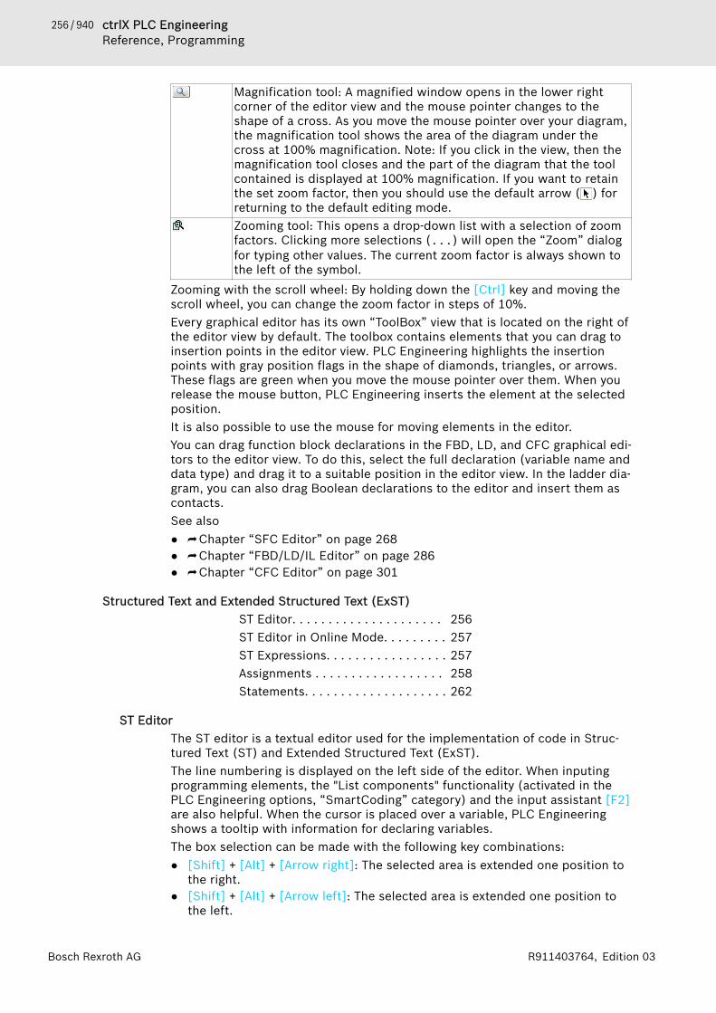
256 / 940 ctrlX PLC EngineeringReference, Programming
Bosch Rexroth AG R911403764, Edition 03
Magnification tool: A magnified window opens in the lower rightcorner of the editor view and the mouse pointer changes to theshape of a cross. As you move the mouse pointer over your diagram,the magnification tool shows the area of the diagram under thecross at 100% magnification. Note: If you click in the view, then themagnification tool closes and the part of the diagram that the toolcontained is displayed at 100% magnification. If you want to retainthe set zoom factor, then you should use the default arrow ( ) forreturning to the default editing mode.Zooming tool: This opens a drop-down list with a selection of zoomfactors. Clicking more selections (...) will open the “Zoom” dialogfor typing other values. The current zoom factor is always shown tothe left of the symbol.
Zooming with the scroll wheel: By holding down the [Ctrl] key and moving thescroll wheel, you can change the zoom factor in steps of 10%.Every graphical editor has its own “ToolBox” view that is located on the right ofthe editor view by default. The toolbox contains elements that you can drag toinsertion points in the editor view. PLC Engineering highlights the insertionpoints with gray position flags in the shape of diamonds, triangles, or arrows.These flags are green when you move the mouse pointer over them. When yourelease the mouse button, PLC Engineering inserts the element at the selectedposition.It is also possible to use the mouse for moving elements in the editor.You can drag function block declarations in the FBD, LD, and CFC graphical edi-tors to the editor view. To do this, select the full declaration (variable name anddata type) and drag it to a suitable position in the editor view. In the ladder dia-gram, you can also drag Boolean declarations to the editor and insert them ascontacts.See also● ⮫ Chapter “SFC Editor” on page 268● ⮫ Chapter “FBD/LD/IL Editor” on page 286● ⮫ Chapter “CFC Editor” on page 301
Structured Text and Extended Structured Text (ExST)ST Editor. . . . . . . . . . . . . . . . . . . . . 256ST Editor in Online Mode. . . . . . . . . 257ST Expressions. . . . . . . . . . . . . . . . . 257Assignments . . . . . . . . . . . . . . . . . . 258Statements. . . . . . . . . . . . . . . . . . . . 262
ST EditorThe ST editor is a textual editor used for the implementation of code in Struc-tured Text (ST) and Extended Structured Text (ExST).The line numbering is displayed on the left side of the editor. When inputingprogramming elements, the "List components" functionality (activated in thePLC Engineering options, “SmartCoding” category) and the input assistant [F2]are also helpful. When the cursor is placed over a variable, PLC Engineeringshows a tooltip with information for declaring variables.The box selection can be made with the following key combinations:● [Shift] + [Alt] + [Arrow right]: The selected area is extended one position to
the right.● [Shift] + [Alt] + [Arrow left]: The selected area is extended one position to
the left.

257 / 940ctrlX PLC EngineeringReference, Programming
Bosch Rexroth AGR911403764, Edition 03
● [Shift] + [Alt] + [Arrow up]: The selected area is extended one position up.● [Shift] + [Alt] + [Arrow down]: The selected area is extended one position
down.The behavior (for example parentheses, mouse actions, tabs) and appearanceof the editor are configured in the “Text Editor” category of the PLC Engi-neering options.For an incremental search for strings in the editor, open an input field at thebottom edge of the editor by means of the key combination [Ctrl] + [Shift] +[i]. As soon as you start typing in characters, the corresponding search loca-tions are highlighted in color in the editor. The number of found matches isshown to the right of the input field. You can set the cursor at the search loca-tion by using the arrow keys or the key combinations [Alt] + [Page up] or [Alt] +[Page down].When you place the cursor on a symbol name, all occurrence locations of thesymbol within the editor are highlighted in color. The search locations corre-spond to the hits in the cross-reference list. For very large projects, this cancause input delays. In this case, you can disable the function in the options ofthe text editor.PLC Engineering identifies syntax errors already when inputing in the editorand shows the corresponding messages in the message view (“Precompile” cat-egory). If the corresponding option is selected in the PLC Engineering options(“SmartCoding” category), then the error locations in the text are also under-lined with a wavy red line.See also● ⮫ Chapter “Programming Structured Text (ST)” on page 92● ⮫ Chapter “ST Expressions” on page 257● ⮫ Chapter “ST Comments” on page 268● ⮫ Chapter “Structured Text and Extended Structured Text (ExST)”
on page 256● ⮫ Chapter “Dialog 'Options' - 'Text Editor'” on page 860● ⮫ Chapter “Command 'Messages'” on page 680
ST Editor in Online ModeIn online mode PLC Engineering displays the variables and expressions in theST editor. The writing and forcing of the variables and expressions as well asdebugging functions (breakpoints, single step execution) are also possible.If you use assignments as expressions in ST programming, no further break-point positions are created within a line.See also● ⮫ Chapter “Calling of Monitoring in Programming Objects ” on page 209● ⮫ Chapter 1.11.4 “Forcing and Writing Variables” on page 201● ⮫ Chapter “Using watch lists” on page 215● ⮫ Chapter 1.11.2 “Using Breakpoints” on page 196● ⮫ Chapter 1.11 “Testing and Debugging” on page 195● ⮫ Chapter 1.11 “Testing and Debugging” on page 195● ⮫ Chapter 1.11.3 “Stepping Through a Program” on page 199● ⮫ Chapter 1.11.6 “Flow Control” on page 205● ⮫ Chapter 1.11.7 “Determining the Current Processing Position with the Call
Stack” on page 207
ST ExpressionsAn expression is a construct that returns a value following its evaluation.

258 / 940 ctrlX PLC EngineeringReference, Programming
Bosch Rexroth AG R911403764, Edition 03
Expressions are composed of operators and operands. In Extended StructuredText (ExST) you can also use assignments as expressions. An operand can be aconstant, a variable, a function call or a further expression.
Examples2014 (* Constant *)ivar (* Variable *)fct(a,b) (* Function call *)(x*y)/z (* Expression *)real_var2 := int.var; (* in ExST: Assignment *) *)
See also● ⮫ “ExST - Extended Structured Text” on page 92
Evaluation of expressionsThe evaluation of an expression takes place by processing the operatorsaccording to certain rules of binding. PLC Engineering processes the operatorwith the strongest binding first. Operators with the same binding strength areprocessed from left to right.
Operation Symbol Binding strength
Parenthesize (Expression) Strongest bindingFunction Call Function name (parameter list)
all operators with syntax: <oper-ator> ()
Exponentiate EXPTNegateComplementation
-NOT
MultiplicationDivisionModulo
*/MOD
AdditionSubtraction
+-
Comparison <,>,<=,>=EqualityInequality
= <>
Bool AND ANDAND_THEN
Bool XOR XORBool OR
OROR_ELSE
Weakest binding
See also● ⮫ Chapter 1.18.3 “Operators” on page 327
AssignmentsST Assignment Operator. . . . . . . . . 259ST Assignment Operator for Outputs259ExST assignment 'S='. . . . . . . . . . . . 259ExST assignment 'R='. . . . . . . . . . . . 260

259 / 940ctrlX PLC EngineeringReference, Programming
Bosch Rexroth AGR911403764, Edition 03
ExST – Assignment as Expression. . 261Assignment operator 'REF'. . . . . . . . 261
ST Assignment OperatorSyntax:<operand> := <expression>This assignment operator executes the same function as the MOVE operator.See also● ⮫ Chapter “Operator 'MOVE'” on page 334
ST Assignment Operator for OutputsThe assignment operator => assigns the output of a function, a function block,or a method to a variable. The position on the right side of the operator canalso be blank.Syntax<output> => <variable>
ExampleFBcomp_Output1 => bVar1;FBcomp_Output2 => ;FBcom_Output1 and FB_Output2 are outputs of a function block. The value ofFBcom_Output1 is assigned to the variable bVar1.
ExST assignment 'S='When the operand of the Set assignment switches to TRUE, then TRUE isassigned to the variable to the left of the operator. The variable is set.<variable name> S= <operand name> ;The variables and the operand have the data type BOOL.
Example
PROGRAM PLC_PRGVARxOperand: BOOL := FALSE;xSetVariable: BOOL := FALSE;
END_VAR
xSetVariable S= xOperand;When the operand xOperand switches from FALSE to TRUE, then TRUE is alsoassigned to the variable xSetVariable. But then the variable keeps this state,even if the operand continues to change its state.
Multiple assignments
NOTICE In the case of multiple assignments within a code line,the individual assignments are not processed from rightto left, but all assignments refer to the operands at theend of the code line.
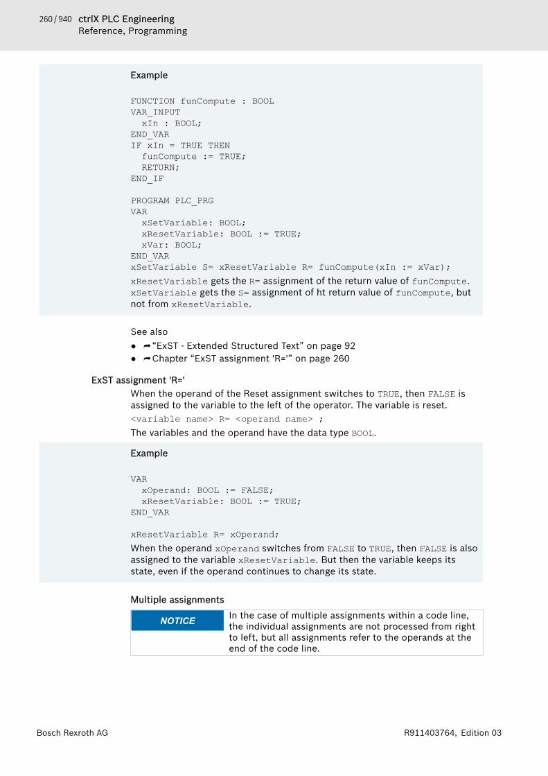
260 / 940 ctrlX PLC EngineeringReference, Programming
Bosch Rexroth AG R911403764, Edition 03
Example
FUNCTION funCompute : BOOLVAR_INPUTxIn : BOOL;
END_VARIF xIn = TRUE THENfunCompute := TRUE;RETURN;
END_IF
PROGRAM PLC_PRGVARxSetVariable: BOOL;xResetVariable: BOOL := TRUE;xVar: BOOL;
END_VARxSetVariable S= xResetVariable R= funCompute(xIn := xVar);xResetVariable gets the R= assignment of the return value of funCompute.xSetVariable gets the S= assignment of ht return value of funCompute, butnot from xResetVariable.
See also● ⮫ “ExST - Extended Structured Text” on page 92● ⮫ Chapter “ExST assignment 'R='” on page 260
ExST assignment 'R='When the operand of the Reset assignment switches to TRUE, then FALSE isassigned to the variable to the left of the operator. The variable is reset.<variable name> R= <operand name> ;The variables and the operand have the data type BOOL.
Example
VARxOperand: BOOL := FALSE;xResetVariable: BOOL := TRUE;
END_VAR
xResetVariable R= xOperand;When the operand xOperand switches from FALSE to TRUE, then FALSE is alsoassigned to the variable xResetVariable. But then the variable keeps itsstate, even if the operand continues to change its state.
Multiple assignments
NOTICE In the case of multiple assignments within a code line,the individual assignments are not processed from rightto left, but all assignments refer to the operands at theend of the code line.

261 / 940ctrlX PLC EngineeringReference, Programming
Bosch Rexroth AGR911403764, Edition 03
Example
FUNCTION funCompute : BOOLVAR_INPUTxIn : BOOL;
END_VARIF xIn = TRUE THENfunCompute := TRUE;RETURN;
END_IF
PROGRAM PLC_PRGVARxSetVariable: BOOL;xResetVariable: BOOL := TRUE;xVar: BOOL;
END_VARxSetVariable S= xResetVariable R= funCompute(xIn := xVar);xResetVariable gets the R= assignment of the return value of funCompute.xSetVariable gets the S= assignment of ht return value of funCompute, butnot from xResetVariable.
See also● ⮫ “ExST - Extended Structured Text” on page 92● ⮫ Chapter “ExST assignment 'S='” on page 259
ExST – Assignment as ExpressionIn ExST, as an extension to the IEC 61131-3 standard, PLC Engineering permitsthe use of assignments as expressions.
Examplesint_var1 := int_var2 := int_var3 + 9; (* int_var1 and int_var2 receive the value of
int_var3 + 9 *)real_var1 := real_var2 := int_var; (* real_var1 and real_var2 receive the value
of int_var *)int_var := real_var1 := int_var; (* incorrect assignment, the data types do not
correspond! *)IF b := (i = 1) THEN i := i + 1;END_IF
See also● ⮫ “ExST - Extended Structured Text” on page 92
Assignment operator 'REF'This operator generates a reference (pointer) to a value.Syntax:REF= <variable>
262 / 940 ctrlX PLC EngineeringReference, Programming
Bosch Rexroth AG R911403764, Edition 03
Example
A : REFERENCE TO DUT;B : DUT;C : DUT;
A REF= B; // corresponds to A := ADR(B);A := C; // corresponds to A^ := C;
See also● ⮫ Chapter “Reference” on page 395
StatementsST Statement 'IF'. . . . . . . . . . . . . . . 262ST Instruction 'FOR'. . . . . . . . . . . . . 263ST Instruction 'CASE'. . . . . . . . . . . . 264ST Instruction 'WHILE'. . . . . . . . . . . 265ST Instruction 'REPEAT'. . . . . . . . . . 265ST Statement 'RETURN'. . . . . . . . . . 266ST Instruction 'JMP'. . . . . . . . . . . . . 266ST Instruction 'EXIT'. . . . . . . . . . . . . 267EXST Instruction 'CONTINUE'. . . . . . 267ST Function Block Call. . . . . . . . . . . 267ST Comments. . . . . . . . . . . . . . . . . . 268
ST Statement 'IF'The IF statement is used for checking a condition and, depending on this con-dition, for executing the subsequent statements.A condition is coded as an expression that returns a Boolean value. If theexpression returns TRUE, then the condition is fulfilled and the correspondingstatements after THEN are executed. If the expression returns FALSE, then thefollowing conditions, which are identified with ELSIF, are evaluated. If anELSIF condition returns TRUE, then the statements are executed after the cor-responding THEN. If all conditions return FALSE, then the statements after ELSEare executed.Therefore, at most one branch of the IF statement is executed. ELSIFbranches and the ELSE branch are optional.Syntax
IF <condition> THEN<statements>
( ELSIF <condition> THEN<statements> )*
( ELSE<statements> )?
END_IF;// ( ... )* None, once or several times// ( ... )? Optional
263 / 940ctrlX PLC EngineeringReference, Programming
Bosch Rexroth AGR911403764, Edition 03
Example
PROGRAM PLC_PRGVARiTemp: INT;xHeatingOn: BOOL;xOpenWindow: BOOL;
END_VAR
IF iTemp < 17 THEN xHeatingOn := TRUE;
ELSIF iTemp > 25 THEN xOpenWindow := TRUE;
ELSE xHeatingOn := FALSE;END_IF;The program is run as follows at runtime:For the evaluation of the expression iTemp < 17 = TRUE, the subsequentstatement is executed and the heating is switched on. For the evaluation ofthe expression iTemp < 17 = FALSE, the subsequent ELSIF condition iTemp> 25 is evaluated. If this is true, then the statements in ELSIF are executedand the view is opened. If all conditions are FALSE, then the statement inELSE is executed and the heating is switched off.
See also● ⮫ Chapter “ST Expressions” on page 257
ST Instruction 'FOR'The FOR loop is used to execute instructions with a certain number of repeti-tions.Syntax:FOR <counter> := <start value> TO <end value> {BY <increment> } DO<instructions>END_FOR;The section inside the curly parentheses {} is optional.PLC Engineering executes the <instructions> as long as the <counter> isnot greater, or - in case of negative increment - is not smaller than the <endvalue>. This is checked before the execution of the <instructions>.Every time the instructions <instructions> have been executed, the counter<counter> is automatically increased by the increment <increment>. Theincrement <increment> can have any integral value. If you do not specify anincrement, the standard increment is 1.
ExampleFOR iCounter := 1 TO 5 BY 1 DOiVar1 := iVar1*2;END_FOR;Erg := iVar1;If you have pre-configured iVar1 with 1, iVar1 has the value 32 after the FORloop.
264 / 940 ctrlX PLC EngineeringReference, Programming
Bosch Rexroth AG R911403764, Edition 03
CAUTION The end value <end value> may not attain the same valueas the upper limit of the data type of the counter.If the end value of the counter is equal to the upper limitof the data type of the counter, an endless loop results.For example, an endless loop results in the aboveexample if iCounter is of the data type SINT and the<end value> equals 127, since the data type SINT hasthe upper limit 127.
As an extension to the IEC 61131-3 standard you can use the CONTINUE instruc-tion within the FOR loop.See also● ⮫ Chapter “Integer Data Types” on page 387● ⮫ Chapter “EXST Instruction 'CONTINUE'” on page 267
ST Instruction 'CASE'Use this dialog box for pooling several conditional instructions containing thesame condition variable into a construct.Syntax:CASE <Var1> OF<value1>:<instruction1><value2>:<instruction2><value3, value4, value5>:<instruction3><value6 ... value10>:<instruction4>...<value n>:<instruction n>
{ELSE <ELSE-instruction>}
END_CASE;The section within the curly brackets {} is optional.Processing scheme of a CASE instruction.● If the value of the variable <Var1> is <value i>, then the instruction
<instruction i> is executed.● If the variable <Var1> has non of the given values, then the <ELSE-
instruction> is executed.● If the same instruction is executed for several values of the variable, then
you can write the values in sequence, seperated by commas.
ExampleCASE iVar OF 1, 5: bVar1 := TRUE; bVar3 := FALSE;
2: bVar2 := FALSE; bVar3 := TRUE;
10..20: bVar1 := TRUE; bVar3= TRUE; ELSE bVar1 := NOT bVar1; bVar2 := bVar1 OR bVar2; END_CASE;
265 / 940ctrlX PLC EngineeringReference, Programming
Bosch Rexroth AGR911403764, Edition 03
ST Instruction 'WHILE'The WHILE loop is used like the FOR loop in order to execute instructions sev-eral times until the abort condition occurs. The abort condition of a WHILE loopis a boolean expression.Syntax:WHILE <boolean expression> DO <instructions> END_WHILE;PLC Engineering repeatedly executes the <instructions> for as long as the<boolean expression> returns TRUE. If the boolean expression is alreadyFALSE at the first evaluation, then PLC Engineering never executes the instruc-tions. If the boolean expression never adopts the value FALSE, then the instruc-tions are repeated endlessly, as a result of which a runtime error results.
ExampleWHILE iCounter <> 0 DOVar1 := Var1*2iCounter := iCounter-1;END_WHILE;
NOTICE You must ensure by programming means that no endlessloops are caused.
In a certain sense the WHILE and REPEAT loops are more powerful than theFOR loop, since you don't need to already know the number of executions ofthe loop before its execution. In some cases it is thus only possible to workwith these two kinds of loop. If the number of executions of the loop is clear,however, then a FOR loop is preferable in order to avoid endless loops.As an extension to the IEC 61131-3 standard you can use the CONTINUEinstruction within the WHILE loop.See also● ⮫ Chapter “ST Instruction 'FOR'” on page 263● ⮫ Chapter “EXST Instruction 'CONTINUE'” on page 267
ST Instruction 'REPEAT'The REPEAT loop is used like the WHILE loop, but with the difference that PLCEngineering only checks the abort condition after the execution of the loop.The consequence of this behavior is that the REPEAT loop is executed at leastonce, regardless of the abort condition.Syntax:REPAEAT <instructions> UNTIL <boolean expression> END_REPEAT; PLC Engineering executes the <instructions> until the <boolean expres-sion> returns TRUE.If the boolean expression already returns TRUE at the first evaluation, PLC Engi-neering executes the instructions precisely once. If the boolean expressionnever adopts the value TRUE, then the instructions are repeated endlessly, as aresult of which a runtime error results.
266 / 940 ctrlX PLC EngineeringReference, Programming
Bosch Rexroth AG R911403764, Edition 03
ExampleREPEATVar1 := Var1*2;iCounter := iCounter-1;UNTILiCounter = 0END_REPEAT;
In a certain sense the WHILE and REPEAT loops are more powerful than the FORloop, since the number of executions of the loop doesn't already need to beknown before its execution. In some cases you can only work with these twokinds of loop. If the number of executions of the loop is clear, however, then aFOR loop is preferable in order to avoid endless loops.As an extension to the IEC 61131-3 standard you can use the CONTINUEinstruction within the WHILE loop.See also● ⮫ Chapter “ST Instruction 'WHILE'” on page 265● ⮫ Chapter “ST Instruction 'FOR'” on page 263● ⮫ Chapter “EXST Instruction 'CONTINUE'” on page 267
ST Statement 'RETURN'Use the RETURN statement in order to exit from a function block. You can makethis dependent on a condition, for example.
Example
IF xIsDone = TRUE THEN RETURN;
END_IF;
iCounter := iCounter + 1; If the value of xIsDone is equal to TRUE, then the function block is exitedimmediately and the statement iCounter := iCounter + 1; is not exe-cuted.
See also● ⮫ Chapter “ST Statement 'IF'” on page 262
ST Instruction 'JMP'The JMP instruction is used to execute an unconditional jump to a program linethat is marked by a jump label.Syntax:<label>: <instructions>JMP <label>;The jump label <label> is any unique identifier that you place at the beginningof a program line. On reaching the JMP instruction, a return to the program linewith the <label> takes place.

267 / 940ctrlX PLC EngineeringReference, Programming
Bosch Rexroth AGR911403764, Edition 03
ExampleiVar1 := 0;_label1: iVar1 := iVar1+1;(*instructions*)
IF (iVar1 < 10) THENJMP _label1;END_IF;
NOTICE You must ensure by programming means that no endlessloops are caused. For example, you can make the jumpconditional.
ST Instruction 'EXIT'The EXIT instruction is used in a FOR, WHILE or REPEAT loop in order to endthe loop regardless of other abort conditions.See also● ⮫ Chapter “ST Instruction 'FOR'” on page 263● ⮫ Chapter “ST Instruction 'WHILE'” on page 265● ⮫ Chapter “ST Instruction 'REPEAT'” on page 265
EXST Instruction 'CONTINUE'CONTINUE is an instruction of the Extended Structured Text (ExST).The instruction is used inside FOR, WHILE and REPEAT loops in order to jump tothe beginning of the next execution of the loop.
ExampleFOR Counter:=1 TO 5 BY 1 DOINT1:=INT1/2; IF INT1=0 THEN CONTINUE; (* to provide a division by zero *) END_IFVar1:=Var1/INT1; (* executed, if INT1 is not 0 *)END_FOR;
Erg:=Var1;
See also● ⮫ Chapter “ST Instruction 'FOR'” on page 263● ⮫ Chapter “ST Instruction 'WHILE'” on page 265● ⮫ Chapter “ST Instruction 'REPEAT'” on page 265
ST Function Block CallSyntax <FB-instance>(<FB input variable>:=<value or address>|, <otherFB input variables>);

268 / 940 ctrlX PLC EngineeringReference, Programming
Bosch Rexroth AG R911403764, Edition 03
Example
TMR:TON;
TMR (IN:=%OX5, PT:=T#300ms); varA:=TMR.Q; The timer function block TON is instanced in TMR:TON and called with assign-ments for the parameters IN and PT.The output Q is addressed with TMR.Q and assigned to the variable varA.
See also● ⮫ Chapter “Object 'Function Block'” on page 590
ST CommentsComment Description ExampleSingle-line Starts with // and ends at the end of
the line.// This is a comment
Multi-line Starts with (* and ends with *). (* This is a multi-line comment*)
Nested Starts with (* and ends with *). Theremay be further (*....*) commentsinside this comment.
( * a:=inst.out; (* 1st comment*) b:=b+1; (* 2nd comment *) *)
Sequential Function Chart (SFC)SFC Editor. . . . . . . . . . . . . . . . . . . . 268SFC Editor in online Mode. . . . . . . . 269Processing Order in SFC. . . . . . . . . 270Qualifiers for Actions in SFC. . . . . . 271Implicit Variables. . . . . . . . . . . . . . . 272SFC Flags. . . . . . . . . . . . . . . . . . . . . 273Elements. . . . . . . . . . . . . . . . . . . . . 277
SFC EditorThe SFC editor is graphical editor. A new SFC POU includes an Init step and asubsequent transition.In the SFC editor, you can insert individual elements into the diagram by meansof commands in the “SFC” menu, the context menu, or the “ToolBox” view.When inserting by means of a menu command, the elements that can beinserted at the currently selected position are available.Before inserting branches parallel to multiple actions and transitions, you musthighlight these actions and transitions in a multiple selection.You can also drag SFC elements from the “ToolBox” view to the diagram. Whenyou drag an element over the editor, PLC Engineering marks all possible inser-tion points with gray boxes. If you move the mouse over a gray box, then thecolor of the box changes to green. When you release the mouse button, theobject is inserted at that location.If you drag a branch into the diagram, then you must set the beginning and theend of the branch using the mouse pointer. You set the beginning of the branchby releasing the mouse button at an insertion point. The color of the box then

269 / 940ctrlX PLC EngineeringReference, Programming
Bosch Rexroth AGR911403764, Edition 03
changes to red. You set the end of the branch by clicking the second insertionpoint. Then PLC Engineering inserts a branch around the objects between thebeginning and end markers.For copying step and transition elements that call action objects or transitionobjects, two different duplication modes can be set. Either the references arecopied at the same time, or the referenced objects are embedded and dupli-cated when copying.You define the look and feel of the editor in the PLC Engineering options (“SFCEditor”).See also● ⮫ Chapter “Common Functions in Graphical Editors” on page 255● ⮫ Chapter “Sequential Function Chart (SFC)” on page 268● ⮫ Chapter “Programming the Sequential Function Chart (SFC)” on page 93● ⮫ Chapter “ Dialog 'Options' - 'SFC Editor'” on page 848
SFC Editor in online ModeIn the SFC editor, you can display the variables and expressions in use on thecontroller in online mode. You can also write and force variables and expres-sions. Debugging functions, such as breakpoints and step-by-step execution,are not yet available.You can set the online display of the SFC elements and attributes in the PLCEngineering options (“SFC Editor”).If you have declared SFC flags explicitly, then they are displayed in the declara-tion section in online mode. They are not displayed in offline mode.Please note the processing order of elements in an SFC diagram.
In online mode, PLC Engineering displays active steps in blue.
See also● ⮫ Chapter “Implicit Variables” on page 272● ⮫ Chapter “Using the Declaration Editor” on page 64● ⮫ Chapter “Processing Order in SFC” on page 270● ⮫ Chapter “ Dialog 'Options' - 'SFC Editor'” on page 848
270 / 940 ctrlX PLC EngineeringReference, Programming
Bosch Rexroth AG R911403764, Edition 03
Processing Order in SFCBasic element behavior● Active step: An active step includes actions currently being executed. In
online mode, PLC Engineering displays active steps in blue.● Initial step: In the first cycle after calling a POU in SFC, the initial step is
activated automatically and the step action is executed.● PLC Engineering executes IEC actions at least two times: the first time is
when the step is activated, and the second time when the step is deacti-vated (but not until the next cycle).
● Alternative branches: If the step before the branch is active, then PLC Engi-neering passes the first transition of each alternative branch line from left toright. PLC Engineering activates the subsequent step in the first branch linewith a transition yielding TRUE.
● Parallel branches: If the step before the branch (horizontal double line) isactive and the transition before the branch yields TRUE, then PLC Engi-neering activates the first steps in every branch line. The branch lines arethen processed at the same time. The step after the end of the branch isactivated when every last step in each branch line is active and the transi-tion after the double line yields TRUE.
Processing order1. Reset IEC actions
PLC Engineering resets the internal action control flags of the action quali-fiers (N, R, S, L, D, P, SD, DS, SL). These flags control IEC actions. How-ever, flags are not reset when they are called within actions.
2. Execute exit actionsPLC Engineering verifies whether all steps fulfill the condition for exe-cuting the exit action for each step. The order of verification follows thelayout in the SFC diagram, from top to bottom and from left to right.PLC Engineering executes an exit action when the step is deactivated(after any entry and step actions have been executed in the precedingcycle and the condition for the subsequent step yields TRUE).
3. Execute entry actionsPLC Engineering verifies whether all steps fulfill the condition for exe-cuting the entry action for each step. The order of verification follows thelayout in the SFC diagram, from top to bottom and from left to right. If theconditions are fulfilled, then PLC Engineering executes the entry actions.PLC Engineering executes an entry action as soon as the transition of thepreceding step has been processed and yields TRUE, thus indicating thatthe step has been activated.
4. Time check / Execute step actionsPLC Engineering performs the following check for each step in the orderof the SFC layout:● PLC Engineering copies the elapsed time of the active step to the
respective implicit step variable <step name>.t. (not yet imple-mented)
● If a timeout occurs, then PLC Engineering sets the respective errorflags. (not yet implemented)
● For non-IEC steps: PLC Engineering executes the step action.

271 / 940ctrlX PLC EngineeringReference, Programming
Bosch Rexroth AGR911403764, Edition 03
5. Execute IEC actionsPLC Engineering executes the IEC actions in alphabetical order, passingthrough the list of actions two times. In the first pass, PLC Engineeringexecutes the IEC actions for each step that was deactivated in the pre-ceding cycle. In the second pass, the IEC actions are executed for eachactive step.
6. Transition check / Activate next stepsThe transitions are passed as follows: If a step is active in the currentcycle and the subsequent transition yields TRUE and any defined minimumtime of the step has elapsed, then the subsequent step is activated.
NOTICE Please note when executing actions:An action can be executed multiple times within thesame cycle if you use it in multiple SFC diagrams. Forexample, if a sequential function chart includes two IECactions A and B, both of which are programmed in SFCand call an IEC action C, then the IEC action C is calledtwo times.If you use the same IEC action at the same time in dif-ferent levels of an SFC diagram, then this can lead tounpredictable results when processing. For this reason,PLC Engineering issues a corresponding error message.This error message can appear for projects that havebeen created in an earlier version of the developmentsystem.
Please note: It is possible to use implicit variables to monitor the processingstatus of steps and actions and to control processing.See also● ⮫ Chapter “Implicit Variables” on page 272● ⮫ Chapter “Qualifiers for Actions in SFC” on page 271
Qualifiers for Actions in SFCYou assign qualifiers to IEC steps. Qualifiers describe how a step action is proc-essed.Qualifiers are processed by the SFCActionControl function block in thelibrary IecSfc.library. The library is automatically integrated into the projectby the SFC plug-in.
Table 4: Available qualifiersN Non-stored The action is active as long as the step is active.R0 overriding
ResetThe action is deactivated.
S0 Set (Stored) PLC Engineering executes this action as soon as the step is active.The action is executed until it receives a reset, even if the stephas already been deactivated.
L time Limited PLC Engineering executes this action as soon as the step is active.The action is executed until the step is deactivated or the giventime interval has elapsed.
D time Delayed PLC Engineering begins executing the action only after the givendelay time has elapsed following step activation and the step isstill active. The action is executed until the step is deactivated.
P Pulse PLC Engineering executes the action exactly two times: one timewhen the step is activated and one time when the step is deacti-vated.

272 / 940 ctrlX PLC EngineeringReference, Programming
Bosch Rexroth AG R911403764, Edition 03
SD Stored and timeDelayed
PLC Engineering begins executing the action only after the givendelay time has elapsed following step activation. The action isexecuted until it receives a reset.
DS Delayed andStored
PLC Engineering begins executing the action only after the givendelay time has elapsed following step activation and the step isstill active. The action is executed until it receives a reset.
SL Stored and timeLimited
PLC Engineering executes this action as soon as the step is active.The action is executed until the given time has elapsed or itreceives a reset.
You must enter the times for the L, D, SD, DS, and SL qualifiers in the format ofa TIME constant.When an IEC action is deactivated, it is executed one more time. This meansthat PLC Engineering executes this kind of action at least two times. This alsoapplies to actions with the P qualifier.See also● ⮫ Chapter “Programming the Sequential Function Chart (SFC)” on page 93
Implicit VariablesEvery SFC object supplies implicit variables for you to monitor the status ofsteps and IEC actions at runtime. These implicit variables are declared auto-matically by PLC Engineering for each step and each IEC action.The implicit variables are structure instances of the type SFCStepType forsteps and type SFCActionType for actions. The variables have the same namesas their elements, for example "step1" variable name for "step1" step name. Thestructure members describe the status of a step or action or the currentlyelapsed time in an active step.In the element properties, you can define whether PLC Engineering shouldexport a symbol definition for this flag to the symbol configuration.See also● ⮫ Chapter “SFC Element Properties” on page 284
Step and action statusSyntax for the implicit variable declaration:<step name>:SFCStepType; _<action name>:SFCActionType;
Table 5: The following implicit variables are available for step or IEC action status:Step<step name>.x Shows the activation status in the current cycle.
When <step name>.x = TRUE, PLC Engineering processes thestep in the current cycle.
<step name>._x Shows the activation status for the next cycle.When <step name>._x = TRUE and <step name>.x = FALSE,PLC Engineering processes the step in the next cycle. This meansthat <step name>._x is copied to <step name>.x at the begin-ning of a cycle.
<step name>.t The flag t yields the current elapsed time since the step was acti-vated. This applies only to steps, regardless of whether a min-imum time has been defined or not in the step properties.Also see SFC flag SFCError.
<step name>._t For internal use onlyIEC action
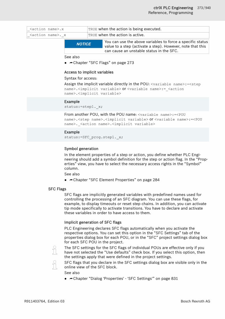
273 / 940ctrlX PLC EngineeringReference, Programming
Bosch Rexroth AGR911403764, Edition 03
_<action name>.x TRUE when the action is being executed._<action name>._x TRUE when the action is active.
NOTICE You can use the above variables to force a specific statusvalue to a step (activate a step). However, note that thiscan cause an unstable status in the SFC.
See also● ⮫ Chapter “SFC Flags” on page 273
Access to implicit variablesSyntax for access:Assign the implicit variable directly in the POU: <variable name>:=<stepname>.<implicit variable> or <variable name>:=_<actionname>.<implicit variable>
Examplestatus:=step1._x;
From another POU, with the POU name: <variable name>:=<POUname>.<step name>.<implicit variable> or <variable name>:=<POUname>._<action name>.<implicit variable>
Examplestatus:=SFC_prog.step1._x;
Symbol generationIn the element properties of a step or action, you define whether PLC Engi-neering should add a symbol definition for the step or action flag. In the “Prop-erties” view, you have to select the necessary access rights in the “Symbol”column.See also● ⮫ Chapter “SFC Element Properties” on page 284
SFC FlagsSFC flags are implicitly generated variables with predefined names used forcontrolling the processing of an SFC diagram. You can use these flags, forexample, to display timeouts or reset step chains. In addition, you can activatetip mode specifically to activate transitions. You have to declare and activatethese variables in order to have access to them.
Implicit generation of SFC flagsPLC Engineering declares SFC flags automatically when you activate therespective options. You can set this option in the “SFC Settings” tab of theproperties dialog box for each POU, or in the “SFC” project settings dialog boxfor each SFC POU in the project.The SFC settings for the SFC flags of individual POUs are effective only if youhave not selected the “Use defaults” check box. If you select this option, thenthe settings apply that were defined in the project settings.SFC flags that you declare in the SFC settings dialog box are visible only in theonline view of the SFC block.See also● ⮫ Chapter “Dialog 'Properties' - 'SFC Settings'” on page 831
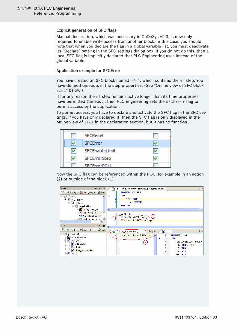
274 / 940 ctrlX PLC EngineeringReference, Programming
Bosch Rexroth AG R911403764, Edition 03
Explicit generation of SFC flagsManual declaration, which was necessary in CoDeSys V2.3, is now onlyrequired to enable write access from another block. In this case, you shouldnote that when you declare the flag in a global variable list, you must deactivateits “Declare” setting in the SFC settings dialog box. If you do not do this, then alocal SFC flag is implicitly declared that PLC Engineering uses instead of theglobal variable.
Application example for SFCError
You have created an SFC block named sfc1, which contains the s1 step. Youhave defined timeouts in the step properties. (See "Online view of SFC blocksfc1" below.)If for any reason the s1 step remains active longer than its time propertieshave permitted (timeout), then PLC Engineering sets the SFCError flag topermit access by the application.To permit access, you have to declare and activate the SFC flag in the SFC set-tings. If you have only declared it, then the SFC flag is only displayed in theonline view of sfc1 in the declaration section, but it has no function.
Now the SFC flag can be referenced within the POU, for example in an action(2) or outside of the block (1).
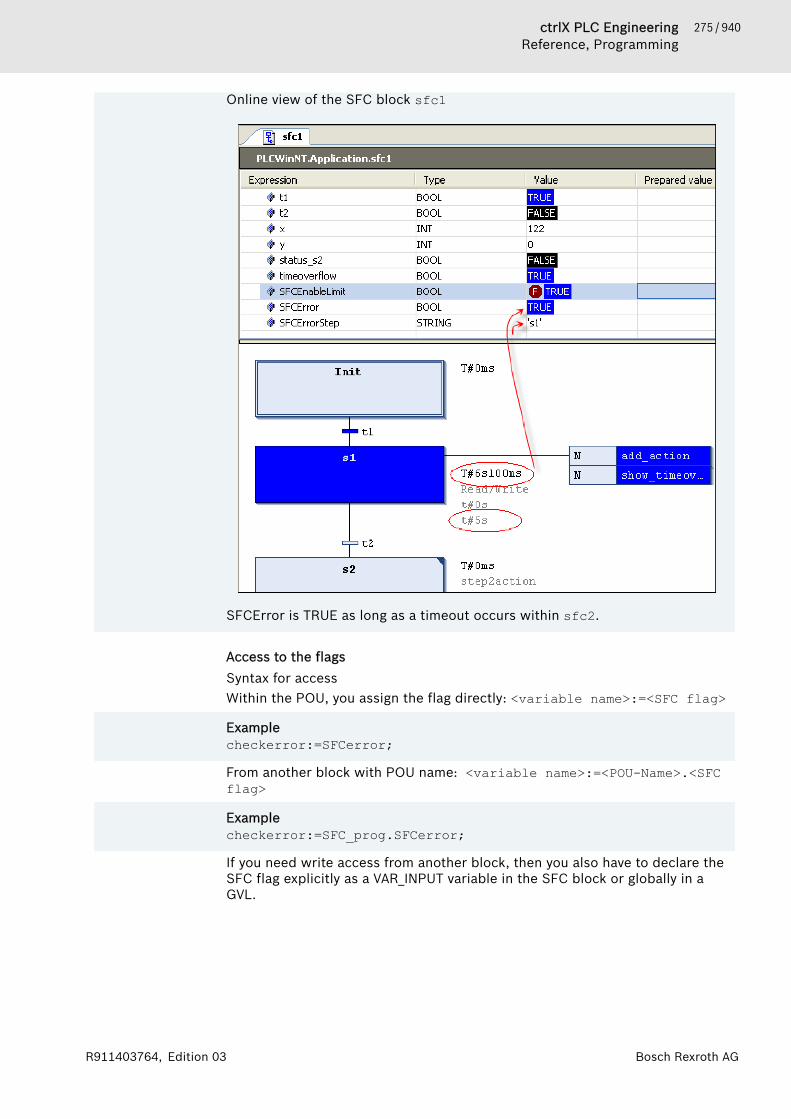
275 / 940ctrlX PLC EngineeringReference, Programming
Bosch Rexroth AGR911403764, Edition 03
Online view of the SFC block sfc1
SFCError is TRUE as long as a timeout occurs within sfc2.
Access to the flagsSyntax for accessWithin the POU, you assign the flag directly: <variable name>:=<SFC flag>
Examplecheckerror:=SFCerror;
From another block with POU name: <variable name>:=<POU-Name>.<SFCflag>
Examplecheckerror:=SFC_prog.SFCerror;
If you need write access from another block, then you also have to declare theSFC flag explicitly as a VAR_INPUT variable in the SFC block or globally in aGVL.
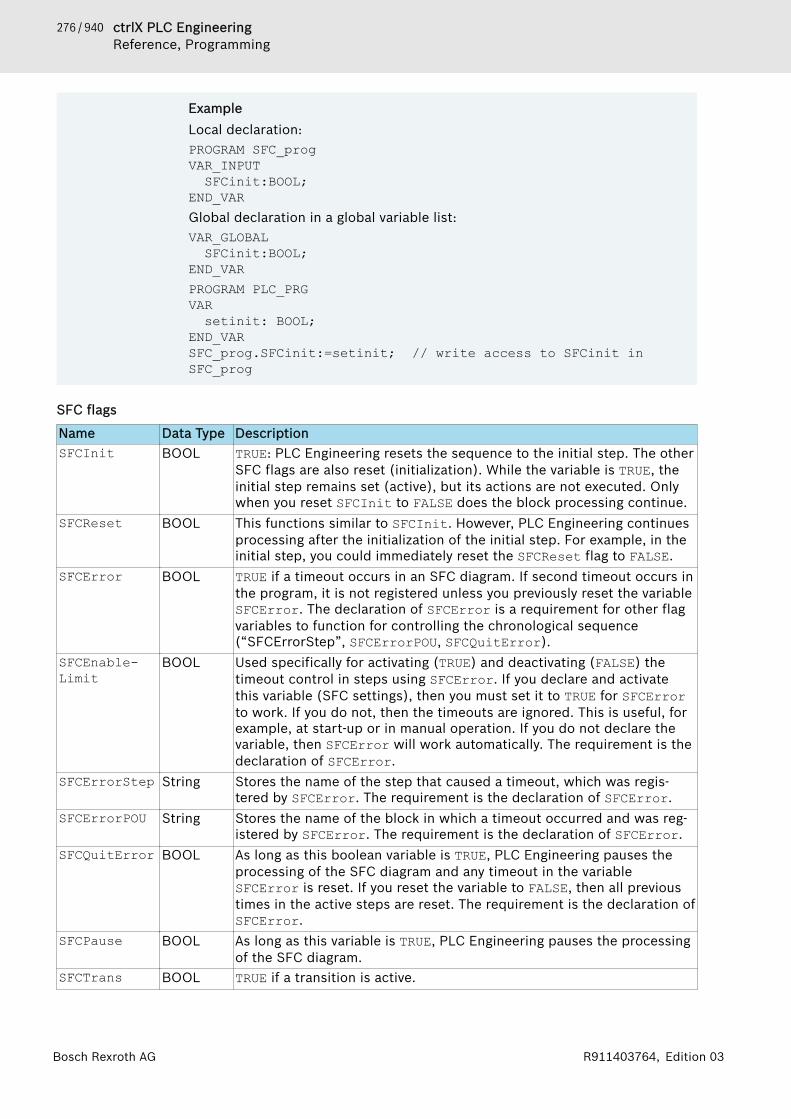
276 / 940 ctrlX PLC EngineeringReference, Programming
Bosch Rexroth AG R911403764, Edition 03
ExampleLocal declaration:PROGRAM SFC_progVAR_INPUT SFCinit:BOOL;END_VARGlobal declaration in a global variable list:VAR_GLOBAL SFCinit:BOOL;END_VARPROGRAM PLC_PRGVAR setinit: BOOL;END_VARSFC_prog.SFCinit:=setinit; // write access to SFCinit in SFC_prog
SFC flags
Name Data Type DescriptionSFCInit BOOL TRUE: PLC Engineering resets the sequence to the initial step. The other
SFC flags are also reset (initialization). While the variable is TRUE, theinitial step remains set (active), but its actions are not executed. Onlywhen you reset SFCInit to FALSE does the block processing continue.
SFCReset BOOL This functions similar to SFCInit. However, PLC Engineering continuesprocessing after the initialization of the initial step. For example, in theinitial step, you could immediately reset the SFCReset flag to FALSE.
SFCError BOOL TRUE if a timeout occurs in an SFC diagram. If second timeout occurs inthe program, it is not registered unless you previously reset the variableSFCError. The declaration of SFCError is a requirement for other flagvariables to function for controlling the chronological sequence(“SFCErrorStep”, SFCErrorPOU, SFCQuitError).
SFCEnable-Limit
BOOL Used specifically for activating (TRUE) and deactivating (FALSE) thetimeout control in steps using SFCError. If you declare and activatethis variable (SFC settings), then you must set it to TRUE for SFCErrorto work. If you do not, then the timeouts are ignored. This is useful, forexample, at start-up or in manual operation. If you do not declare thevariable, then SFCError will work automatically. The requirement is thedeclaration of SFCError.
SFCErrorStep String Stores the name of the step that caused a timeout, which was regis-tered by SFCError. The requirement is the declaration of SFCError.
SFCErrorPOU String Stores the name of the block in which a timeout occurred and was reg-istered by SFCError. The requirement is the declaration of SFCError.
SFCQuitError BOOL As long as this boolean variable is TRUE, PLC Engineering pauses theprocessing of the SFC diagram and any timeout in the variableSFCError is reset. If you reset the variable to FALSE, then all previoustimes in the active steps are reset. The requirement is the declaration ofSFCError.
SFCPause BOOL As long as this variable is TRUE, PLC Engineering pauses the processingof the SFC diagram.
SFCTrans BOOL TRUE if a transition is active.

277 / 940ctrlX PLC EngineeringReference, Programming
Bosch Rexroth AGR911403764, Edition 03
Name Data Type DescriptionSFCCurrent-Step
String Shows the name of the active step, regardless of the time monitoring.In parallel branches, the name of the step of the rightmost branch lineis always stored.
SFCTip,SFCTipMode
BOOL Controls the tip mode of the SFC block.If you enable this flag with SFCTipMode=TRUE, then you can activate thenext step only by setting SFCTip to TRUE. While SFCTipMode is set toFALSE, transitions can also be used to continue activation.
ElementsSFC Elements 'Step' and 'Transition' 277SFC Element 'Action'. . . . . . . . . . . . 279SFC Element 'Branch'. . . . . . . . . . . . 281SFC Element 'Jump'. . . . . . . . . . . . . 283SFC Element 'Macro'. . . . . . . . . . . . 283SFC Element Properties. . . . . . . . . . 284
SFC Elements 'Step' and 'Transition'Step symbol ; Transition symbol As a rule, PLC Engineering inserts steps and transitions as combinations.Inserting a step without a transition or a transition without a step causes anerror when compiling. You can modify this by double-clicking the name.
NOTICE Step names must be unique within the scope of theparent block. Consider this especially when usingactions that were also programmed in SFC.
Please note that you can convert a step into an initial step by clicking “Initstep” or by setting the respective property in the SFC properties.All steps are defined by the step properties, which you can display and edit inthe “Properties” view, depending on the set options.You have to add those actions to the step which are to be executed when thestep is active. A distinction is made between IEC actions and step actions.Details for this are found in the chapter about the SFC element "Action".A transition must include the condition for the subsequent step to be active assoon as the value of the condition yields TRUE. Therefore, a transition conditionmust yield TRUE or FALSE. It can be defined in one of two ways:● (1) Inline condition (direct): You replace the default transition name with
either the name of a Boolean variable, a Boolean address, a Boolean con-stant, or a statement with a Boolean result, for example (i<100) AND b.You cannot specify programs, function blocks, or assignments here.
● (2) Multi-use condition (separate transition or property object): You replacethe default transition name with the name of a transition or property object( , ). You create these objects by clicking “Project 🠂 Add Object”. Thisallows multiple use of transitions, for example "condition_xy" in the figuresbelow. Like an inline condition, the object can contain a Boolean variable,Boolean address, Boolean constant, or an statement with a Boolean result.In addition, it can also contain multiple statements with any code.
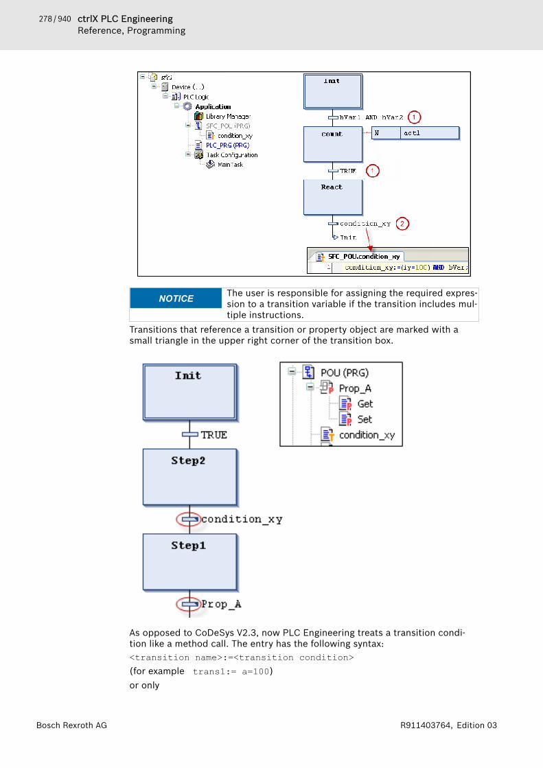
278 / 940 ctrlX PLC EngineeringReference, Programming
Bosch Rexroth AG R911403764, Edition 03
NOTICE The user is responsible for assigning the required expres-sion to a transition variable if the transition includes mul-tiple instructions.
Transitions that reference a transition or property object are marked with asmall triangle in the upper right corner of the transition box.
As opposed to CoDeSys V2.3, now PLC Engineering treats a transition condi-tion like a method call. The entry has the following syntax:<transition name>:=<transition condition>(for example trans1:= a=100)or only

279 / 940ctrlX PLC EngineeringReference, Programming
Bosch Rexroth AGR911403764, Edition 03
<transition condition>(for example a=100)You will find an example (condition_xy) in the figure above.See also● ⮫ Chapter “Programming the Sequential Function Chart (SFC)” on page 93● ⮫ Chapter “Command 'Insert Step-Transition'” on page 757● ⮫ Chapter “SFC Element 'Action'” on page 279● ⮫ Chapter “Command 'Init Step'” on page 756● ⮫ Chapter “SFC Element Properties” on page 284● ⮫ Chapter “Calling Methods” on page 156
SFC Element 'Action'Symbol: An action includes one or more statements in one of the valid implementationlanguages. You can assign an action to a step.Actions that you use in SFC steps must be created as POUs in the project.
Exception: In the case of IEC actions, which you add to a step as action associ-ation, you can also specify a Boolean variable instead of an action object. Thevalue of these variables is switched between FALSE and TRUE each time the"action" is executed.
NOTICE You must define unique step names within the scope ofthe parent block. An action written in SFC cannot con-tain a step with a name identical to the step to which theaction is assigned.
A distinction is made between IEC actions and step actions:
1. IEC actionsIEC actions comply with the IEC1131-3 standard. They are executed accordingto their qualifiers.IEC actions are executed two times: first when the step is activated and secondwhen the step is deactivated. If you assign multiple actions to one step, thenthe action list is processed from top to bottom.Each action box includes the qualifier in the first column and the action namein the second column, both of which can be edited directly.
NOTICE If the same global Boolean variable is associated as anIEC action in different SFC blocks, then this can result inundesired overwriting effects.
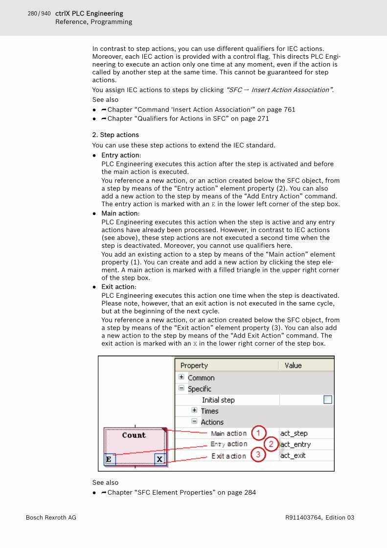
280 / 940 ctrlX PLC EngineeringReference, Programming
Bosch Rexroth AG R911403764, Edition 03
In contrast to step actions, you can use different qualifiers for IEC actions.Moreover, each IEC action is provided with a control flag. This directs PLC Engi-neering to execute an action only one time at any moment, even if the action iscalled by another step at the same time. This cannot be guaranteed for stepactions.You assign IEC actions to steps by clicking “SFC 🠂 Insert Action Association”.See also● ⮫ Chapter “Command 'Insert Action Association'” on page 761● ⮫ Chapter “Qualifiers for Actions in SFC” on page 271
2. Step actionsYou can use these step actions to extend the IEC standard.● Entry action:
PLC Engineering executes this action after the step is activated and beforethe main action is executed.You reference a new action, or an action created below the SFC object, froma step by means of the “Entry action” element property (2). You can alsoadd a new action to the step by means of the “Add Entry Action” command.The entry action is marked with an E in the lower left corner of the step box.
● Main action:PLC Engineering executes this action when the step is active and any entryactions have already been processed. However, in contrast to IEC actions(see above), these step actions are not executed a second time when thestep is deactivated. Moreover, you cannot use qualifiers here.You add an existing action to a step by means of the “Main action” elementproperty (1). You can create and add a new action by clicking the step ele-ment. A main action is marked with a filled triangle in the upper right cornerof the step box.
● Exit action:PLC Engineering executes this action one time when the step is deactivated.Please note, however, that an exit action is not executed in the same cycle,but at the beginning of the next cycle.You reference a new action, or an action created below the SFC object, froma step by means of the “Exit action” element property (3). You can also adda new action to the step by means of the “Add Exit Action” command. Theexit action is marked with an X in the lower right corner of the step box.
See also● ⮫ Chapter “SFC Element Properties” on page 284

281 / 940ctrlX PLC EngineeringReference, Programming
Bosch Rexroth AGR911403764, Edition 03
Difference between IEC actions and step actionsThe main difference between step actions and IEC actions with a qualifier N isthat an IEC action is always executed two times: when the step is activated andwhen the step is deactivated. See the following example:
Example
You have attached the Action_AS1 action to the AS1 step as a step action(left) and as an IEC action with qualifier N (right). Because two transitions areactivated in each case, the time to reach the initial step again is two PLCcycles. This is true as long as the iCounter counter variable was initialized at0 and then incremented in the Action_AS1 action. After the Init step isreactivated, iCounter returns a value of 1 in the example on the left. In theexample on the right, a value of 2 is returned because the IEC action is exe-cuted a second time due to the deactivation of AS1.
Another difference is that step actions can be pseudo-embedded. In this case,they can be called only from the related step. If you copy this step, PLC Engi-neering creates new action objects automatically and copies the respectiveimplementation code. You define whether or not a step action is embedded,either when the first action is inserted into the step, or later in the “Duplicatewhen copying” element property. In general, this behavior can also be preset inthe SFC options.Finally, for IEC actions a Boolean variable can be specified instead of an actionobject. This is not possible for step actions.
SFC Element 'Branch'Symbol Use branches to program parallel or alternative sequences in the sequentialfunction chart.For alternative branches, PLC Engineering processes just one of the branchlines at a time, depending on the preceding transition condition. Parallelbranches are processed at the same time.See also● ⮫ Chapter “Processing Order in SFC” on page 270● ⮫ Chapter “Programming the Sequential Function Chart (SFC)” on page 93● ⮫ Chapter “Command 'Insert Branch Right'” on page 759

282 / 940 ctrlX PLC EngineeringReference, Programming
Bosch Rexroth AG R911403764, Edition 03
Parallel branchFor parallel branches, the branch lines must begin and end with steps. Parallelbranch lines can contain additional branches.The horizontal lines before and after the branch are double lines.
Processing in online mode: If the preceding transition (t2 in the example) yieldsTRUE, then the first steps in all parallel branch lines are active (Step11 andStep21). PLC Engineering processes the individual branch lines at the sametime and the subsequent transition is passed afterwards (t3).The "Branch<n>" jump marker is added automatically to the horizontal line thatindicates the beginning of a branch. You can define this marker as the jumpdestination.Please note that you can convert a parallel branch into an alternative branch byclicking “Alternative”.See also● ⮫ Chapter “Command 'Alternative'” on page 759
Alternative branchThe horizontal line before and after the branch is a single line.In an alternative branch, the branch lines must begin and end with transitions.The branch lines can contain additional branches.
If the step before the branch is active, then PLC Engineering passes the firsttransition of each alternative branch line from left to right. For the first transi-tion that yields TRUE, the associated branch line opens, thus activating the stepfollowing the transition.
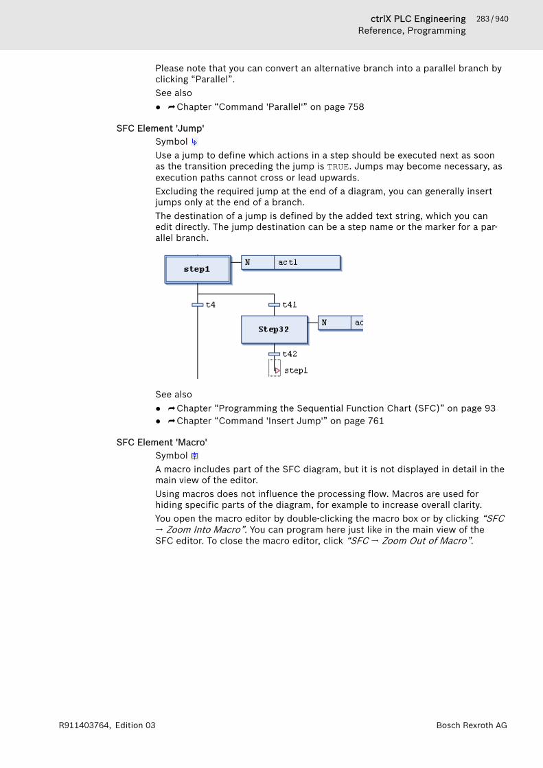
283 / 940ctrlX PLC EngineeringReference, Programming
Bosch Rexroth AGR911403764, Edition 03
Please note that you can convert an alternative branch into a parallel branch byclicking “Parallel”.See also● ⮫ Chapter “Command 'Parallel'” on page 758
SFC Element 'Jump'Symbol Use a jump to define which actions in a step should be executed next as soonas the transition preceding the jump is TRUE. Jumps may become necessary, asexecution paths cannot cross or lead upwards.Excluding the required jump at the end of a diagram, you can generally insertjumps only at the end of a branch.The destination of a jump is defined by the added text string, which you canedit directly. The jump destination can be a step name or the marker for a par-allel branch.
See also● ⮫ Chapter “Programming the Sequential Function Chart (SFC)” on page 93● ⮫ Chapter “Command 'Insert Jump'” on page 761
SFC Element 'Macro'Symbol A macro includes part of the SFC diagram, but it is not displayed in detail in themain view of the editor.Using macros does not influence the processing flow. Macros are used forhiding specific parts of the diagram, for example to increase overall clarity.You open the macro editor by double-clicking the macro box or by clicking “SFC🠂 Zoom Into Macro”. You can program here just like in the main view of theSFC editor. To close the macro editor, click “SFC 🠂 Zoom Out of Macro”.

284 / 940 ctrlX PLC EngineeringReference, Programming
Bosch Rexroth AG R911403764, Edition 03
① Main view in the SFC editor② Macro editor view for Macro1 Macros can also include other macros. The caption of the macro editor alwaysshows the path of the open macro within the diagram, for example:
See also● ⮫ Chapter “Programming the Sequential Function Chart (SFC)” on page 93● ⮫ Chapter “Command 'Zoom Into Macro'” on page 762● ⮫ Chapter “Command 'Zoom Out of Macro'” on page 762
SFC Element PropertiesYou edit the properties of an SFC element in the “Properties” view. Click “View🠂 Element Properties” to open this view. The properties to be displayeddepend on the currently selected element.The properties that are displayed in the SFC diagram next to the elementdepend on the settings in the “View” tab of the SFC editor options.
General
Property Value description“Name” Element name, by default "<element><consecutive number>", for
example step name "Step0", "Step1", branch name "Branch0”, etc.“Comment” Element comment in text, for example “counter reset”. You can insert
line breaks by pressing [Ctrl]+[Enter].

285 / 940ctrlX PLC EngineeringReference, Programming
Bosch Rexroth AGR911403764, Edition 03
Property Value description“Symbol” For each SFC element, PLC Engineering declares an implicit variable
with the same name as the element.The configuration determines whether this flag variable should beexported to the symbol configuration and which access rights for thesymbol should be applied in the PLC.● “No access”: The symbol is exported to the symbol configuration
but cannot be accessed from the PLC.● “Read”: The symbol is exported to the symbol configuration and
can be read from the PLC.● “Write”: The symbol is exported to the symbol configuration and
can be written from the PLC.● “Read/Write”: Combination of read and write.● Empty: A symbol is not exported to the symbol configuration.
Specific
Property Value description“Init step” : This option is activated only for the defined initial step. By default,
this is the first step in an SFC diagram.Note: If you activate this property for another step, then it must bedeactivated in the previous step to prevent compilation errors.
“Duplicate when copying” This option is available for steps that contain a step action (entryaction, main action, or exit action), and for transitions that are linkedto a transition object.
: When copying the step or transition, a new object is created foreach called action or transition. It contains a copy of the implementa-tion code of the copied object.
: When copying a step or transition, the link to the called object isretained for the respective action or transition. No new objects aregenerated. The source and the copies of the step or transition call thesame action or transition.
“Times”● “Minimum active”● “Maximum active”
Minimum time that the step is active, even when the subsequent tran-sition is TRUE.Maximum time that the step can be active. If this time is exceeded,then PLC Engineering sets the SFCError implicit variable to TRUE.Times according to IEC syntax (for example t#8s) or the TIME variable;default: t#0s.
“Actions”● “Entry action”● “Step action”● “Exit action”
● “Entry action”: PLC Engineering executes these actions after acti-vating the step.
● “Step action”: PLC Engineering executes this action when the stepis active and any entry actions have already been processed.
● “Exit action”: PLC Engineering executes this action in the subse-quent cycle when the step is deactivated.
Please note the processing sequence.When using the respective implicit SFC variables and flags, you receive informa-tion about the status of a step or an action or about timeouts.See also● ⮫ Chapter “ Dialog 'Options' - 'SFC Editor'” on page 848● ⮫ Chapter “Implicit Variables” on page 272● ⮫ Chapter “SFC Element 'Action'” on page 279

286 / 940 ctrlX PLC EngineeringReference, Programming
Bosch Rexroth AG R911403764, Edition 03
Function Block Diagram / Ladder Diagram / Instruction List (FBD/LD/IL)FBD/LD/IL Editor. . . . . . . . . . . . . . . 286FBD/LD/IL Editor in Online Mode. . 290Modifiers and Operators in IL. . . . . 291Elements. . . . . . . . . . . . . . . . . . . . . 295
FBD/LD/IL EditorThe FBD/LD/IL editor is a combined editor of the programming languages FBD,LD and IL.
If necessary, IL can be activated in the PLC Engineering options.
There is a common set of commands and elements and PLC Engineering auto-matically converts the 3 programming languages into one another internally.The code in the implementation part is structured in all three languages withthe aid of networks.The “FBD/LD/IL” menu provides the commands for working in the editor.In offline and online modes, you can switch editors at any time by using themenu command in “View”.The behavior of the FBD/LD/IL editor is defined by the settings in “Tools🠂 Options” (category “FBD, LD and IL”).
NOTICE There are some special elements that PLC Engineeringcannot convert and thus it displays only in the applicablelanguage. There are also constructs that are not clearlyconvertible between IL and FBD and are therefore 'nor-malized', i.e. nullified, when converted back to FBD. Thisconcerns: negation of expressions and explicit/implicitassignment of function block inputs and outputs.An error-free conversion between the languages requiressyntactically correct code. Otherwise parts of the imple-mentation can be lost.
See also● ⮫ Chapter “FBD/LD/IL” on page 73 (programming)● ⮫ Chapter “Menu 'FBD/LD/IL'” on page 776 (commands)● ⮫ Chapter “Dialog 'Options' - 'FBD, LD, and IL'” on page 853● ⮫ Chapter “Common Functions in Graphical Editors” on page 255
FBD and LD editorInserting and arranging elementsYou can drag elements with the mouse from the view “Tools” (toolbox) into theimplementation part of the editor. Alternatively you can use the commands ofthe context menu or the “FBD/LD/IL” menu.Settings for the display and interface are defined in the PLC Engineeringoptions, category “FBD/LD/IL”.If you drag an element with the mouse over a network in the editor, all possibleinsertion positions are displayed with gray diamond-shaped, triangular orarrow-shaped position marks. As soon as the mouse pointer is located over oneof these marks, the mark turns green. If the mouse button is now released, PLCEngineering inserts the element at this position.
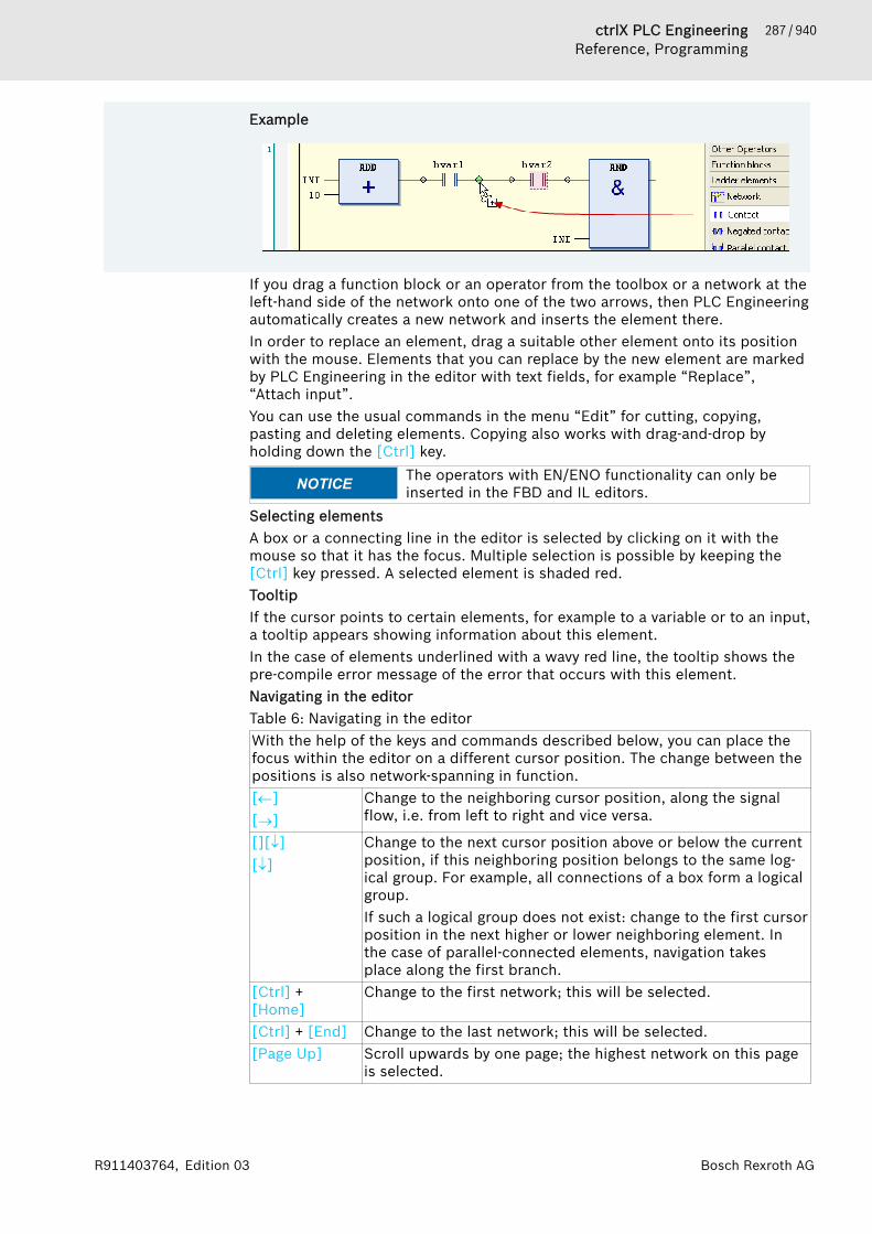
287 / 940ctrlX PLC EngineeringReference, Programming
Bosch Rexroth AGR911403764, Edition 03
Example
If you drag a function block or an operator from the toolbox or a network at theleft-hand side of the network onto one of the two arrows, then PLC Engineeringautomatically creates a new network and inserts the element there.In order to replace an element, drag a suitable other element onto its positionwith the mouse. Elements that you can replace by the new element are markedby PLC Engineering in the editor with text fields, for example “Replace”,“Attach input”.You can use the usual commands in the menu “Edit” for cutting, copying,pasting and deleting elements. Copying also works with drag-and-drop byholding down the [Ctrl] key.
NOTICE The operators with EN/ENO functionality can only beinserted in the FBD and IL editors.
Selecting elementsA box or a connecting line in the editor is selected by clicking on it with themouse so that it has the focus. Multiple selection is possible by keeping the[Ctrl] key pressed. A selected element is shaded red.TooltipIf the cursor points to certain elements, for example to a variable or to an input,a tooltip appears showing information about this element.In the case of elements underlined with a wavy red line, the tooltip shows thepre-compile error message of the error that occurs with this element.Navigating in the editorTable 6: Navigating in the editorWith the help of the keys and commands described below, you can place thefocus within the editor on a different cursor position. The change between thepositions is also network-spanning in function.[¬][®]
Change to the neighboring cursor position, along the signalflow, i.e. from left to right and vice versa.
[][¯][¯]
Change to the next cursor position above or below the currentposition, if this neighboring position belongs to the same log-ical group. For example, all connections of a box form a logicalgroup.If such a logical group does not exist: change to the first cursorposition in the next higher or lower neighboring element. Inthe case of parallel-connected elements, navigation takesplace along the first branch.
[Ctrl] +[Home]
Change to the first network; this will be selected.
[Ctrl] + [End] Change to the last network; this will be selected.[Page Up] Scroll upwards by one page; the highest network on this page
is selected.
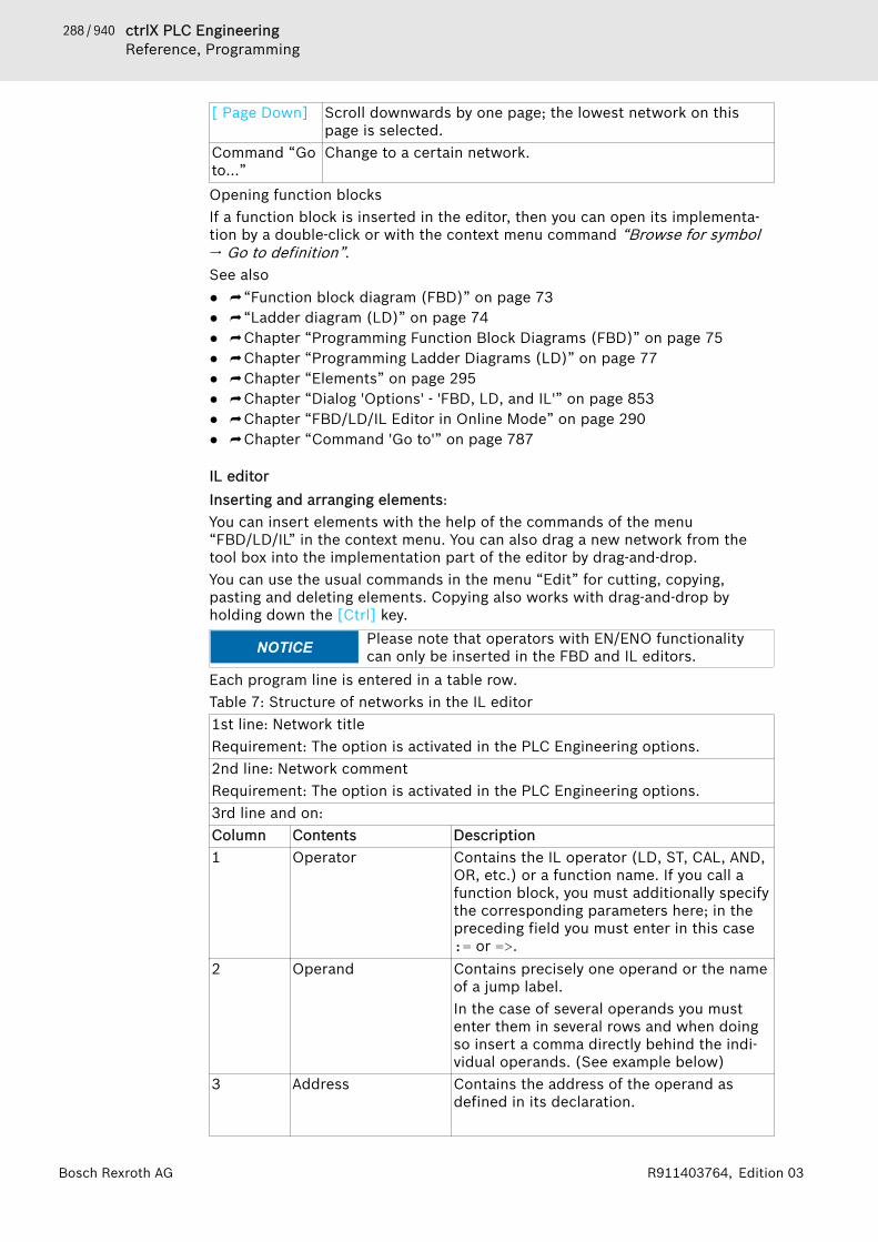
288 / 940 ctrlX PLC EngineeringReference, Programming
Bosch Rexroth AG R911403764, Edition 03
[ Page Down] Scroll downwards by one page; the lowest network on thispage is selected.
Command “Goto…”
Change to a certain network.
Opening function blocksIf a function block is inserted in the editor, then you can open its implementa-tion by a double-click or with the context menu command “Browse for symbol🠂 Go to definition”.See also● ⮫ “Function block diagram (FBD)” on page 73● ⮫ “Ladder diagram (LD)” on page 74● ⮫ Chapter “Programming Function Block Diagrams (FBD)” on page 75● ⮫ Chapter “Programming Ladder Diagrams (LD)” on page 77● ⮫ Chapter “Elements” on page 295● ⮫ Chapter “Dialog 'Options' - 'FBD, LD, and IL'” on page 853● ⮫ Chapter “FBD/LD/IL Editor in Online Mode” on page 290● ⮫ Chapter “Command 'Go to'” on page 787
IL editorInserting and arranging elements:You can insert elements with the help of the commands of the menu“FBD/LD/IL” in the context menu. You can also drag a new network from thetool box into the implementation part of the editor by drag-and-drop.You can use the usual commands in the menu “Edit” for cutting, copying,pasting and deleting elements. Copying also works with drag-and-drop byholding down the [Ctrl] key.
NOTICE Please note that operators with EN/ENO functionalitycan only be inserted in the FBD and IL editors.
Each program line is entered in a table row.Table 7: Structure of networks in the IL editor1st line: Network titleRequirement: The option is activated in the PLC Engineering options.2nd line: Network commentRequirement: The option is activated in the PLC Engineering options.3rd line and on:Column Contents Description1 Operator Contains the IL operator (LD, ST, CAL, AND,
OR, etc.) or a function name. If you call afunction block, you must additionally specifythe corresponding parameters here; in thepreceding field you must enter in this case:= or =>.
2 Operand Contains precisely one operand or the nameof a jump label.In the case of several operands you mustenter them in several rows and when doingso insert a comma directly behind the indi-vidual operands. (See example below)
3 Address Contains the address of the operand asdefined in its declaration.
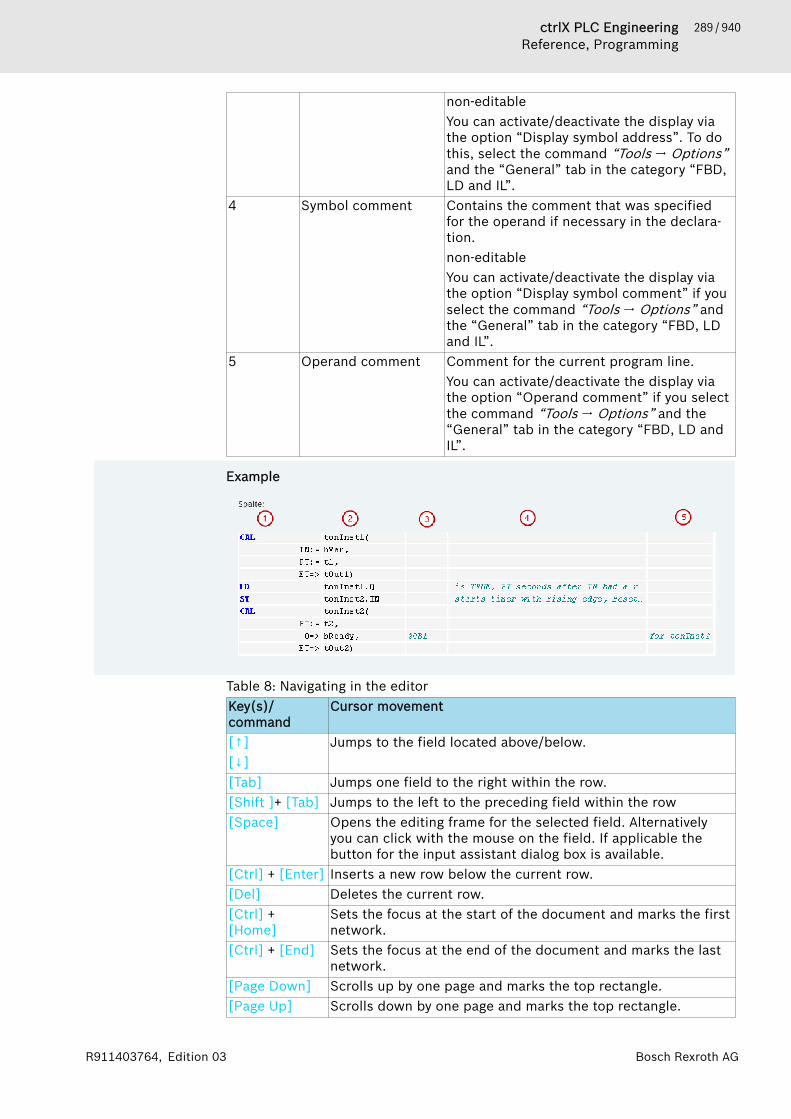
289 / 940ctrlX PLC EngineeringReference, Programming
Bosch Rexroth AGR911403764, Edition 03
non-editableYou can activate/deactivate the display viathe option “Display symbol address”. To dothis, select the command “Tools 🠂 Options”and the “General” tab in the category “FBD,LD and IL”.
4 Symbol comment Contains the comment that was specifiedfor the operand if necessary in the declara-tion.non-editableYou can activate/deactivate the display viathe option “Display symbol comment” if youselect the command “Tools 🠂 Options” andthe “General” tab in the category “FBD, LDand IL”.
5 Operand comment Comment for the current program line.You can activate/deactivate the display viathe option “Operand comment” if you selectthe command “Tools 🠂 Options” and the“General” tab in the category “FBD, LD andIL”.
Example
Table 8: Navigating in the editorKey(s)/command
Cursor movement
[↑][↓]
Jumps to the field located above/below.
[Tab] Jumps one field to the right within the row.[Shift ]+ [Tab] Jumps to the left to the preceding field within the row[Space] Opens the editing frame for the selected field. Alternatively
you can click with the mouse on the field. If applicable thebutton for the input assistant dialog box is available.
[Ctrl] + [Enter] Inserts a new row below the current row.[Del] Deletes the current row.[Ctrl] +[Home]
Sets the focus at the start of the document and marks the firstnetwork.
[Ctrl] + [End] Sets the focus at the end of the document and marks the lastnetwork.
[Page Down] Scrolls up by one page and marks the top rectangle.[Page Up] Scrolls down by one page and marks the top rectangle.
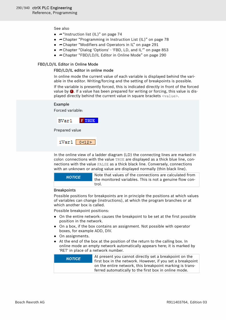
290 / 940 ctrlX PLC EngineeringReference, Programming
Bosch Rexroth AG R911403764, Edition 03
See also● ⮫ “Instruction list (IL)” on page 74● ⮫ Chapter “Programming in Instruction List (IL)” on page 78● ⮫ Chapter “Modifiers and Operators in IL” on page 291● ⮫ Chapter “Dialog 'Options' - 'FBD, LD, and IL'” on page 853● ⮫ Chapter “FBD/LD/IL Editor in Online Mode” on page 290
FBD/LD/IL Editor in Online ModeFBD/LD/IL editor in online modeIn online mode the current value of each variable is displayed behind the vari-able in the editor. Writing/forcing and the setting of breakpoints is possible.If the variable is presently forced, this is indicated directly in front of the forcedvalue by . If a value has been prepared for writing or forcing, this value is dis-played directly behind the current value in square brackets <value>.
ExampleForced variable:
Prepared value
In the online view of a ladder diagram (LD) the connecting lines are marked incolor: connections with the value TRUE are displayed as a thick blue line, con-nections with the value FALSE as a thick black line. Conversely, connectionswith an unknown or analog value are displayed normally (thin black line).
NOTICE Note that values of the connections are calculated fromthe monitored variables. This is not a genuine flow con-trol.
BreakpointsPossible positions for breakpoints are in principle the positions at which valuesof variables can change (instructions), at which the program branches or atwhich another box is called.Possible breakpoint positions:● On the entire network: causes the breakpoint to be set at the first possible
position in the network.● On a box, if the box contains an assignment. Not possible with operator
boxes, for example ADD, DIV.● On assignments.● At the end of the box at the position of the return to the calling box. In
online mode an empty network automatically appears here; it is marked by'RET' in place of a network number.
NOTICE At present you cannot directly set a breakpoint on thefirst box in the network. However, if you set a breakpointon the entire network, this breakpoint marking is trans-ferred automatically to the first box in online mode.
291 / 940ctrlX PLC EngineeringReference, Programming
Bosch Rexroth AGR911403764, Edition 03
NOTICE Breakpoints in methods: PLC Engineering automaticallysets a breakpoint in all methods that can be called.Therefore, if a method managed by an interface is called,breakpoints are set in all methods that occur in functionblocks that implement this interface as well as in allderived function blocks that use the method. If a methodis called by a pointer to a function block, PLC Engi-neering sets the breakpoints in the method of the func-tion block and in all derived function blocks that use themethod.
See also● ⮫ Chapter 1.11.4 “Forcing and Writing Variables” on page 201● ⮫ Chapter 1.11.2 “Using Breakpoints” on page 196
Modifiers and Operators in ILTable 9: ModifiersModifier Combined with
operatorDescription
C JMP, CAL, RET The command is only executed if theresult of the preceding expression isTRUE.
N JMPC, CALC, RETC The command is only executed if theresult of the preceding expression isFALSE.
N otherwise negation of the operand (not of theaccumulator).
Table 10: Operators with the possible modifiersOperator N Meaning ExampleLD N Loads the (negated) the value of the
operand into the accumulator.LD ivar
ST N Stores the (negated) content of theaccumulator in the operand.
ST iErg
S Sets the operand (type BOOL) to TRUEif the content of the accumulator isTRUE.
S bVar1
R Sets the operand (type BOOL) to FALSEif the content of the accumulator isTRUE.
R bVar1
AND N,( Bitwise AND of the accumulator valueand (negated) operand
AND bVar2
OR N,( Bitwise OR of the accumulator valueand (negated) operand
OR xVar
XOR N,( Bitwise exclusive OR of the accumu-lator value and (negated) operand
XOR N,(bVar1,bVar2)
NOT Bitwise negation of the accumulatorvalue
ADD ( Addition of the accumulator value andthe operand; result is written into theaccumulator.
ADD ivar1
292 / 940 ctrlX PLC EngineeringReference, Programming
Bosch Rexroth AG R911403764, Edition 03
Operator N Meaning ExampleSUB ( Subtraction of the operand from the
accumulator value; result is writteninto the accumulator.
SUB iVar2
MUL ( Multiplication of accumulator valueand operand; result is written into theaccumulator.
MUL ivar2
DIV ( Division of the accumulator value bythe operand; result is written into theaccumulator.
DIV 44
GT ( Checks whether the accumulator valueis greater than the operand value;result (BOOL) is written into the accu-mulator; >
GT 23
GE ( Checks whether the accumulator valueis greater than or equal to the operandvalue; result (BOOL) is written into theaccumulator.
GE iVar2
EQ ( Checks whether the accumulator valueis equal to the operand value; result(BOOL) is written into the accumulator.
EQ iVar2
NE ( Checks whether the accumulator valueis not equal to the operand value;result (BOOL) is written into the accu-mulator;
NE iVar1
LE ( Checks whether the accumulator valueis smaller than or equal to the operandvalue; result (BOOL) is written into theaccumulator.
LE 5
LT ( Checks whether the accumulator valueis smaller than the operand value;result (BOOL) is written into the accu-mulator.
LT cVar1
JMP CN Unconditional (conditional) jump tothe specified jump label
JMPN next
CAL CN (Conditional) call of a program or afunction block (if the accumulatorvalue is TRUE)
CAL prog1
RET Exit the box and return to the callingbox.
RET
RET C If the accumulator value is TRUE: exitthe box and return to the calling box.
RETC
RET CN If the accumulator value is FALSE: exitthe box and return to the calling box.
RETCN
) Evaluation of the reset operation

293 / 940ctrlX PLC EngineeringReference, Programming
Bosch Rexroth AGR911403764, Edition 03
Example
Application Description ExamplesSeveral operands for 1operator
Options● You enter the oper-
ands into consecutiverows, separated bycommas in the 2ndcolumn.
● You repeat the oper-ator in consecutiverows.
Variant 1 :
Variant 2 :
Complex operands For a complex operand,you enter the openingparenthesis ( in the firstcolumn. You enter theclosing parenthesis in thefirst column in a separaterow following theoperand entries of thefollowing rows.
A string is rotated by acharacter each cycle:
Function block call, pro-gram call
Column 1: Operator CALor CALCColumn 2: Name of thefunction block instanceor the program andopening parenthesis (. Ifno parameters follow, theclosing parenthesis ) isentered here.rows following that:Column 1: parametername followed by := forinput parameter or => foroutput parameterColumn 2: parametervalue followed by acomma , if furtherparameters follow. The
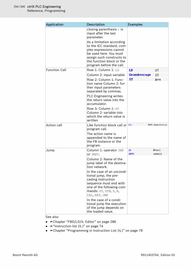
294 / 940 ctrlX PLC EngineeringReference, Programming
Bosch Rexroth AG R911403764, Edition 03
Application Description Examplesclosing parenthesis ) isinput after the lastparameter.As a limitation accordingto the IEC standard, com-plex expressions cannotbe used here. You mustassign such constructs tothe function block or theprogram before the call.
Function Call Row 1: Column 1: LDColumn 2: input variableRow 2: Column 1: Func-tion name Column 2: fur-ther input parametersseparated by commas.PLC Engineering writesthe return value into theaccumulator.Row 3: Column 1: STColumn 2: variable intowhich the return value iswritten
Action call Like function block call orprogram call.The action name isappended to the name ofthe FB instance or theprogram.
Jump Column 1: operator JMPor JMPC.Column 2: Name of thejump label of the destina-tion network.In the case of an uncondi-tional jump, the pre-ceding instructionsequence must end withone of the following com-mands: ST, STN, S, R,CAL, RET, JMPIn the case of a condi-tional jump the executionof the jump depends onthe loaded value.
See also● ⮫ Chapter “FBD/LD/IL Editor” on page 286● ⮫ “Instruction list (IL)” on page 74● ⮫ Chapter “Programming in Instruction List (IL)” on page 78

295 / 940ctrlX PLC EngineeringReference, Programming
Bosch Rexroth AGR911403764, Edition 03
ElementsFBD/LD/IL Element 'Network'. . . . . 295FBD/LD/IL Element 'Box'. . . . . . . . . 295FBD/LD/IL Element 'Assignment'. . . 296FBD/LD/IL Element 'Box with EN/ENO'. . . . . . . . . . . . . . . . . . . . . . . . . 296FBD/LD/IL Element 'Input'. . . . . . . . 296FBD/LD/IL Element 'Label'. . . . . . . . 296FBD/LD/IL Element 'Jump'. . . . . . . . 296FBD/LD/IL Element 'Return'. . . . . . . 297FBD/LD/IL Element 'Branch'. . . . . . 297FBD/LD/IL Element 'Execute'. . . . . . 298LD Element 'Contact'. . . . . . . . . . . . 298LD Element 'Coil'. . . . . . . . . . . . . . . 298LD Element 'Branch Start/End'. . . . 299Closed Branch. . . . . . . . . . . . . . . . . 299
FBD/LD/IL Element 'Network'Symbol A network is the base unit of an FBD or LD program. In the FBD/LD/IL editor,the networks are arranged in a list. Each network is provided with a sequentialnetwork number on the left side and can include: logical and arithmetic expres-sions, program/function/function block calls, jumps, or return statements.An IL program consists of at least one network. This network can include all ILstatements of the program.You can provide each network with a title, comment, or label. In the PLC Engi-neering options (category “FBD, LD, and IL”, you can define whether networktitle, comment, and separator between individual networks are displayed in theeditor.Click the first line of the network to enter a network title. Click the second lineof the network to enter a network comment.See also● ⮫ Chapter “Dialog 'Options' - 'FBD, LD, and IL'” on page 853● ⮫ Chapter “Command 'Insert Network'” on page 778
FBD/LD/IL Element 'Box'Symbol: A box and its call can represent additional functions, for example IEC functionblocks, IEC functions, library function blocks, operators.A box can have any number of inputs and outputs.If the box also provides an image file, the box icon is displayed inside the box.The requirement is that the option “Show box symbol” is activated in the PLCEngineering options, category “FBD, LD and IL”.If you have changed the box interfaces, you can update the box parameterswith the command “FBD/LD/IL 🠂 Update Parameters” without having to re-insert the box.See also● ⮫ Chapter “Command 'Insert Box'” on page 778● ⮫ Chapter “Dialog 'Options' - 'FBD, LD, and IL'” on page 853● ⮫ Chapter “Command 'Update Parameters'” on page 786
296 / 940 ctrlX PLC EngineeringReference, Programming
Bosch Rexroth AG R911403764, Edition 03
FBD/LD/IL Element 'Assignment'Symbol: The FBD editor shows a newly inserted assignment as a line with 3 questionmarks after it. The LD editor shows a newly inserted assignment as a coil with3 question marks located above it.After insertion you can replace the placeholder ??? by the name of the variableto which the signal coming from the left is to be assigned. The input assistantis available to you for this.In IL an assignment is programmed via the operators LD and ST.
● ⮫ Chapter “FBD/LD/IL Editor” on page 286● ⮫ Chapter “Command 'Insert Assignment'” on page 778
FBD/LD/IL Element 'Box with EN/ENO'Symbol: The element is available only in the FBD and LD editors.The box generally corresponds to the FBD/LD/IL element “Box”; however, thisbox additionally contains an EN input and an ENO output. EN and ENO have thedata type BOOL.Function of the EN input and ENO output: if the input EN has the value FALSE atthe time of the calling the box, the operations defined in the box are not exe-cuted. Otherwise, i.e. if EN has the value TRUE, these operations are executed.The ENO output has the same value as the EN input.See also● ⮫ Chapter “Command 'Insert Box with EN/ENO'” on page 779● ⮫ Chapter “FBD/LD/IL Element 'Box'” on page 295
FBD/LD/IL Element 'Input'Symbol: The maximum number of inputs depends on the type of box.A newly added input is first marked with ???. You can replace the string ??? bya variable or a constant.See also● ⮫ Chapter “Command 'Insert Input'” on page 780● ⮫ Chapter “FBD/LD/IL Editor” on page 286
FBD/LD/IL Element 'Label'The label is an optional identifier for a network in FBD and LD, which you canspecify as a destination for a jump.If you insert a jump label in a network, it will be added as an editable field“Label:” in the network.See also● ⮫ Chapter “FBD/LD/IL Editor” on page 286● ⮫ Chapter “Command 'Insert Label'” on page 780
FBD/LD/IL Element 'Jump'Symbol In FBD or LD a jump is inserted either directly before an input, directly after anoutput or at the end of the network, depending on the current cursor position.You enter a jump label as the jump destination directly behind the jump ele-ment.

297 / 940ctrlX PLC EngineeringReference, Programming
Bosch Rexroth AGR911403764, Edition 03
In IL you program a jump with the instruction JMP.See also● ⮫ Chapter “FBD/LD/IL Editor” on page 286● ⮫ Chapter “Command 'Insert Jump'” on page 780● ⮫ Chapter “FBD/LD/IL Element 'Label'” on page 296
FBD/LD/IL Element 'Return'This element immediately interrupts the execution of the box if the input of theRETURN element goes TRUE.In an FBD or LD network you can place the Return instruction parallel to orafter the preceding elements.In IL the RET instruction is available to you for this purpose.See also● ⮫ Chapter “Command 'Insert Return'” on page 780● ⮫ Chapter “Modifiers and Operators in IL” on page 291
FBD/LD/IL Element 'Branch'Symbol: The element is available in the LD and FBD editor and represents an open linebranch. A line branch splits the processing line from the current cursor positiononwards into 2 subnetworks, which are executed in succession from top tobottom. You can branch each subnetwork further, as a result of which multiplebranches are created within a network.Each subnetwork is given a marker symbol (rectangle) at the branch point,which you can select in order to execute further commands.The commands “Copy”, “Cut” and “Paste” are not available for subnetworks.
In order to delete a subnetwork, you must first delete all elements of the net-work and then the marker symbol of the subnetwork.See also● ⮫ Chapter “Command 'Insert Branch'” on page 785● ⮫ Chapter “Command 'Insert Branch Above'” on page 785● ⮫ Chapter “Command 'Insert Branch Below'” on page 785

298 / 940 ctrlX PLC EngineeringReference, Programming
Bosch Rexroth AG R911403764, Edition 03
FBD/LD/IL Element 'Execute'Symbol: The element is a box that enables you to directly enter ST code in the FBD andLD editors.You can drag the “Execute” element with the mouse from the “Tools” view intothe implementation part of your POU. If you click on “Enter ST code here...”, aninput field opens where you can input multiple-line ST code.● ⮫ Chapter “FBD/LD/IL Editor” on page 286
LD Element 'Contact'Symbol: , in the editor The element is available only in the LD editor.A contact passes on the signal TRUE (ON) or FALSE (OFF) from left to rightuntil the signal finally reaches a coil in the right-hand part of the network. Forthis purpose a boolean variable containing the signal is assigned to the contact.To do this, replace the placeholder ??? above the contact with the name of aboolean variable.You can arrange several contacts both in series and in parallel. In the case oftwo parallel contacts, only one needs to obtain the value TRUE in order for ONto be passed on to the right. If contacts are connected in series, all of themmust obtain the value TRUE in order for ON to be passed on to the right by thelast contact in the series. Hence, you can program electrical parallel and seriesconnections with LD.A negated contact forwards the signal TRUE if the variable value is FALSE.You can negate an inserted contact with the help of the command “FBD/LD/IL🠂 Negation” or insert a negated contact from the “Tools” view.If you place the mouse pointer on a contact with the left mouse button pressedand with a network selected, the button “Convert to coil” appears in the net-work. If you now move the mouse pointer onto this button, still with the mousebutton pressed, and then release the mouse button over this button, PLC Engi-neering converts the contact into a coil.See also● ⮫ Chapter “Command 'Insert Contact'” on page 781● ⮫ Chapter “Command 'Insert Negated Contact'” on page 782● ⮫ Chapter “Command 'Insert Contact (Right)'” on page 781● ⮫ Chapter “Command 'Insert Contact in Parallel (Above)'” on page 782● ⮫ Chapter “Command 'Insert Contact in Parallel (Below)'” on page 781● ⮫ Chapter “FBD/LD/IL Editor” on page 286
LD Element 'Coil'Symbol: , in the editor The element is available only in the LD editor.A coil adopts the value supplied from the left and saves it in the boolean vari-able assigned to the coil. Its input can have the value TRUE (ON) or FALSE(OFF).Several coils in a network can only be arranged in parallel.In a negated coil the negated value of the incoming signal is stored in theboolean variable that is assigned to the coil.Set coil, Reset coilSymbol: , , in the editor: ,

299 / 940ctrlX PLC EngineeringReference, Programming
Bosch Rexroth AGR911403764, Edition 03
Set coil: If the value TRUE arrives at a set coil, the coil retains the value TRUE.As long as the application is running, the value can no longer be overwrittenhere.Reset coil: If the value TRUE arrives at a reset coil, the coil retains the valueFALSE. As long as the application is running, the value can no longer be over-written here.You can define an inserted coil as a set or reset coil with the help of the com-mand “FBD/LD/IL 🠂 Set/Reset” or insert it as an element “Set Coil” and “ResetCoil” from the “Tools” view.See also● ⮫ Chapter “Command 'Insert Coil'” on page 780● ⮫ Chapter “Command 'Insert Reset Coil'” on page 781● ⮫ Chapter “Command 'Negation'” on page 784● ⮫ Chapter “Command 'Set/Reset'” on page 784
LD Element 'Branch Start/End'Symbol: The element serves the closed line branch.See also● ⮫ Chapter “Closed Branch” on page 299● ⮫ Chapter “FBD/LD/IL Editor” on page 286● ⮫ Chapter “Command 'Set Branch Start Point'” on page 785● ⮫ Chapter “Command 'Set Branch End Point'” on page 785
Closed BranchA closed branch is available in LD only, and it contains a starting point and anend point. It is used for implementing parallel analyses of logical elements.Inserting a closed branch● Command “FBD/LD/IL 🠂 Insert Contact Parallel (Below) ”● Command “FBD/LD/IL 🠂 Insert Contact Parallel (Above) ”● Command “FBD/LD/IL 🠂 Set Branch Start/End Point”
Closed branch at a contactWhen you select one or more contacts and then execute the command “InsertContact in Parallel”, a parallel branch is added with a single vertical line. Forthis kind of branching, the signal flow passes through both branches. This is anOR construct of both branches.
Closed branch at a block, OR evaluation, or short-circuit evaluationNew: When you select a box and execute the command “Insert Contact in Par-allel”, a parallel branch is inserted with a double vertical line. This indicatesthat a short-circuit evaluation (SCE) is implemented. SCE allows for the execu-tion of a function block with a Boolean output to be bypassed if a specific con-dition is TRUE. The condition can be displayed in the LD editor as a branch con-nected parallel to the function block branch. The short circuit condition isdefined by one or more contacts in this branch that are interconnected parallelor sequentially.Functional principle:The branches that do not include the function block are processed first. If PLCEngineering detects the value TRUE for one of these branches, then the func-tion block is not called in the parallel branch. In this case, the value at the inputof the function block is sent directly to the output. If PLC Engineering deter-

300 / 940 ctrlX PLC EngineeringReference, Programming
Bosch Rexroth AG R911403764, Edition 03
mines FALSE for the SCE condition, then the box will be called and the Booleanresult of its processing is passed on. If all branches contain function blocks,they are analyzed from top to bottom and their outputs are logically ORed. Ifthere are no branches with function blocks, normal OR operations are per-formed.
ExampleThe function block instance x1 (TON) has a Boolean input and a Booleanoutput. The execution of x1 is skipped if TRUE is determined for the conditionin the parallel line branch. The condition value results from the OR and ANDoperations that connect contacts cond1, cond2 and cond3.x1 is executed if the condition value from the connection of the contactscond1, cond2 and cond3 is FALSE.
(1) Indicates from the double vertical connections that it is a construct sub-ject to an SCE.(2) Indicates from the single vertical connections that it is an OR construct.The given LD example is shown below as ST code. P_IN and P_OUT are theBoolean values at the input (split point) and output (reunification point) ofthe parallel line branch.P_IN := b1 AND b2;
IF ((P_IN AND cond1) AND (cond2 OR cond3)) THEN P_OUT := P_IN;ELSE x1(IN := P_IN, PT := {p 10}t#2s); tElapsed := x1.ET; P_OUT := x1.Q;END_IFbRes := P_OUT AND b3;
See also● ⮫ Chapter “FBD/LD/IL Editor” on page 286● ⮫ Chapter “Command 'Set Branch Start Point'” on page 785● ⮫ Chapter “Command 'Set Branch End Point'” on page 785● ⮫ Chapter “Command 'Insert Contact in Parallel (Above)'” on page 782● ⮫ Chapter “Command 'Insert Contact in Parallel (Below)'” on page 781● ⮫ Chapter “Command 'Toggle Parallel Mode'” on page 782
Continuous Function Chart (CFC) and Page-Oriented CFCCFC Editor. . . . . . . . . . . . . . . . . . . . 301CFC Editor, Page-Oriented. . . . . . . . 303
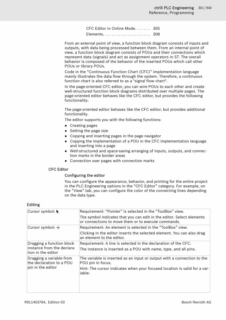
301 / 940ctrlX PLC EngineeringReference, Programming
Bosch Rexroth AGR911403764, Edition 03
CFC Editor in Online Mode. . . . . . . 305Elements. . . . . . . . . . . . . . . . . . . . . 308
From an external point of view, a function block diagram consists of inputs andoutputs, with data being processed between them. From an internal point ofview, a function block diagram consists of POUs and their connections whichrepresent data (signals) and act as assignment operators in ST. The overallbehavior is composed of the behavior of the inserted POUs which call otherPOUs or library POUs.Code in the “Continuous Function Chart (CFC)” implementation languagemainly illustrates the data flow through the system. Therefore, a continuousfunction chart is also referred to as a "signal flow chart".In the page-oriented CFC editor, you can wire POUs to each other and createwell-structured function block diagrams distributed over multiple pages. Thepage-oriented editor behaves like the CFC editor, but provides the followingfunctionality:
The page-oriented editor behaves like the CFC editor, but provides additionalfunctionality.The editor supports you with the following functions:● Creating pages● Setting the page size● Copying and inserting pages in the page navigator● Copying the implementation of a POU in the CFC implementation language
and inserting into a page● Well-structured and space-saving arranging of inputs, outputs, and connec-
tion marks in the border areas● Connection over pages with connection marks
CFC EditorConfiguring the editorYou can configure the appearance, behavior, and printing for the entire projectin the PLC Engineering options in the “CFC Editor” category. For example, onthe “View” tab, you can configure the color of the connecting lines dependingon the data type.
Editing
Cursor symbol: Requirement: “Pointer” is selected in the “ToolBox” view.The symbol indicates that you can edit in the editor. Select elementsor connections to move them or to execute commands.
Cursor symbol: Requirement: An element is selected in the “ToolBox” view.Clicking in the editor inserts the selected element. You can also dragan element to the editor.
Dragging a function blockinstance from the declara-tion in the editor
Requirement: A line is selected in the declaration of the CFC.The instance is inserted as a POU with name, type, and all pins.
Dragging a variable fromthe declaration to a POUpin in the editor
The variable is inserted as an input or output with a connection to thePOU pin in focus.Hint: The cursor indicates when your focused location is valid for a var-iable:
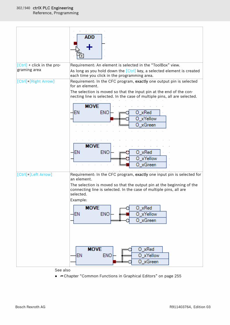
302 / 940 ctrlX PLC EngineeringReference, Programming
Bosch Rexroth AG R911403764, Edition 03
[Ctrl] + click in the pro-graming area
Requirement: An element is selected in the “ToolBox” view.As long as you hold down the [Ctrl] key, a selected element is createdeach time you click in the programming area.
[Ctrl]+[Right Arrow] Requirement: In the CFC program, exactly one output pin is selectedfor an element.The selection is moved so that the input pin at the end of the con-necting line is selected. In the case of multiple pins, all are selected.
[Ctrl]+[Left Arrow] Requirement: In the CFC program, exactly one input pin is selected foran element.The selection is moved so that the output pin at the beginning of theconnecting line is selected. In the case of multiple pins, all areselected.Example:
See also● ⮫ Chapter “Common Functions in Graphical Editors” on page 255

303 / 940ctrlX PLC EngineeringReference, Programming
Bosch Rexroth AGR911403764, Edition 03
ConnectingYou can insert connecting lines between element connections. Connecting linesare inserted by means of auto-routing so that connecting lines are automaticallyoptimal and as short as possible. The connecting lines are checked for colli-sions.
Dragging a pin to another A connecting line is inserted between the two element pins.Command “ConnectSelected Pins”
Requirement: Multiple pins are selected. The pins are marked in red.
Move an inserted elementso that it touches the pin ofanother element.
Requirement: The “Enable AutoConnect” option is selected.The touching pins are connected automatically.
The connection icon is located in the upper right corner of the editor.A green icon indicates collision-free connections. A red icon indicatescollisions. Clicking the icon opens a menu with commands for collisionprocessing, for example the “Show Next Collision” command.Requirement: A connection is selected and the “Connection Mark”command is executed.Instead of a long connecting line, a connection is represented by con-nection marks.
See also● ⮫ Chapter “Command 'Show Next Collision'” on page 772
Commands when editingSee also● ⮫ Chapter “Menu 'CFC'” on page 763
See also● ⮫ Chapter “Common Functions in Graphical Editors” on page 255● ⮫ Chapter “ Programming in the CFC Editor” on page 83● ⮫ Chapter “Automatic Execution Order by Data Flow” on page 80● ⮫ Chapter “Menu 'CFC'” on page 763● ⮫ Chapter “Dialog 'Properties' - 'CFC Execution Order'” on page 830
CFC Editor, Page-OrientedPOUs generated in the “Continuous Function Chart (CFC) - page-oriented”cannot be converted into “Continuous Function Chart (CFC)” POUs or back.
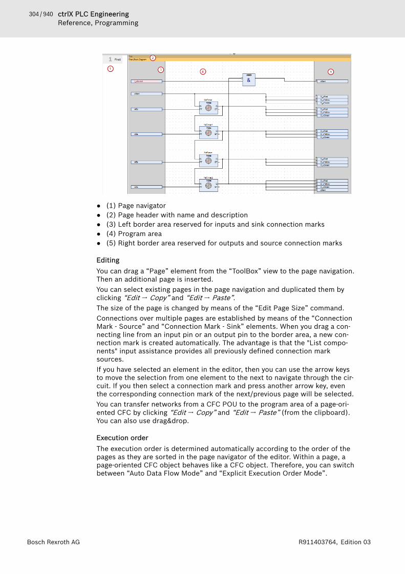
304 / 940 ctrlX PLC EngineeringReference, Programming
Bosch Rexroth AG R911403764, Edition 03
● (1) Page navigator● (2) Page header with name and description● (3) Left border area reserved for inputs and sink connection marks● (4) Program area● (5) Right border area reserved for outputs and source connection marks
EditingYou can drag a “Page” element from the “ToolBox” view to the page navigation.Then an additional page is inserted.You can select existing pages in the page navigation and duplicated them byclicking “Edit 🠂 Copy” and “Edit 🠂 Paste”.The size of the page is changed by means of the “Edit Page Size” command.Connections over multiple pages are established by means of the “ConnectionMark - Source” and “Connection Mark - Sink” elements. When you drag a con-necting line from an input pin or an output pin to the border area, a new con-nection mark is created automatically. The advantage is that the "List compo-nents" input assistance provides all previously defined connection marksources.If you have selected an element in the editor, then you can use the arrow keysto move the selection from one element to the next to navigate through the cir-cuit. If you then select a connection mark and press another arrow key, eventhe corresponding connection mark of the next/previous page will be selected.You can transfer networks from a CFC POU to the program area of a page-ori-ented CFC by clicking “Edit 🠂 Copy” and “Edit 🠂 Paste” (from the clipboard).You can also use drag&drop.
Execution orderThe execution order is determined automatically according to the order of thepages as they are sorted in the page navigator of the editor. Within a page, apage-oriented CFC object behaves like a CFC object. Therefore, you can switchbetween “Auto Data Flow Mode” and “Explicit Execution Order Mode”.
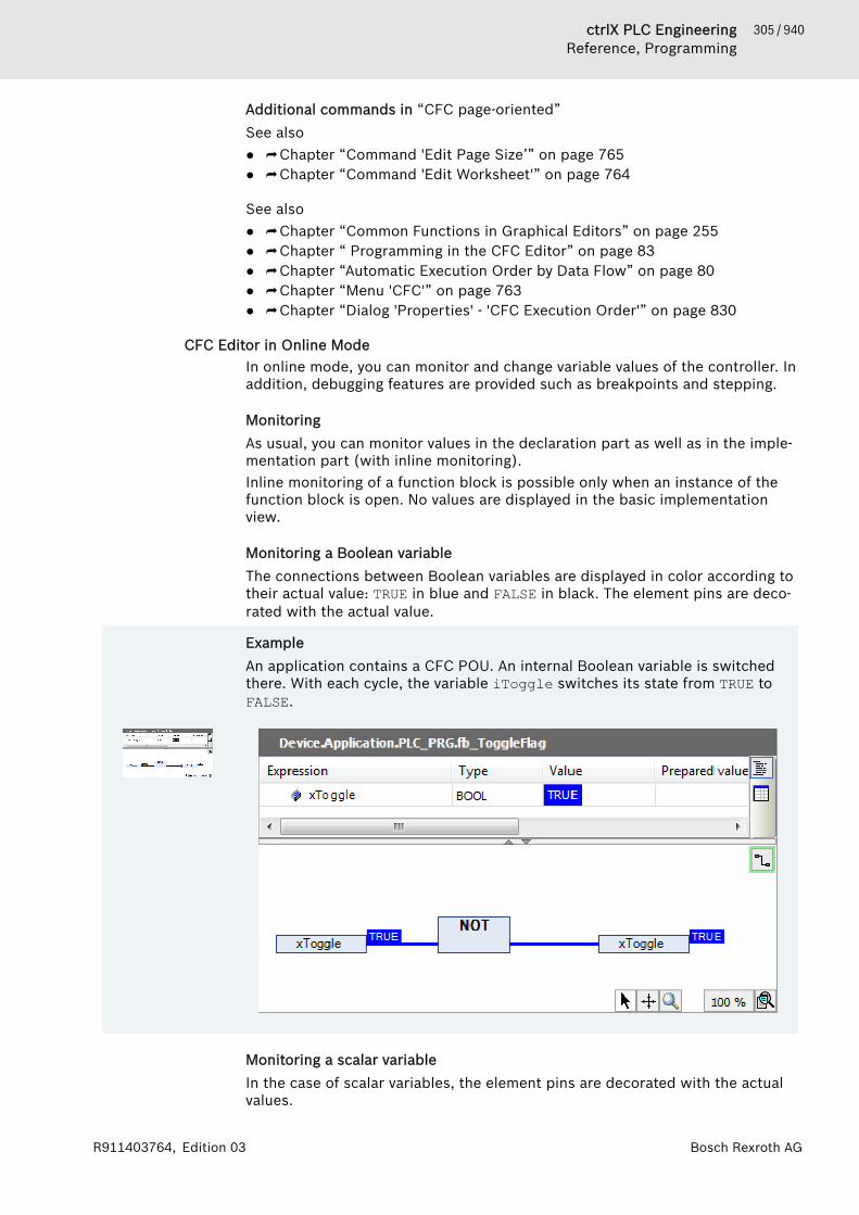
305 / 940ctrlX PLC EngineeringReference, Programming
Bosch Rexroth AGR911403764, Edition 03
Additional commands in “CFC page-oriented”See also● ⮫ Chapter “Command 'Edit Page Size’” on page 765● ⮫ Chapter “Command 'Edit Worksheet'” on page 764
See also● ⮫ Chapter “Common Functions in Graphical Editors” on page 255● ⮫ Chapter “ Programming in the CFC Editor” on page 83● ⮫ Chapter “Automatic Execution Order by Data Flow” on page 80● ⮫ Chapter “Menu 'CFC'” on page 763● ⮫ Chapter “Dialog 'Properties' - 'CFC Execution Order'” on page 830
CFC Editor in Online ModeIn online mode, you can monitor and change variable values of the controller. Inaddition, debugging features are provided such as breakpoints and stepping.
MonitoringAs usual, you can monitor values in the declaration part as well as in the imple-mentation part (with inline monitoring).Inline monitoring of a function block is possible only when an instance of thefunction block is open. No values are displayed in the basic implementationview.
Monitoring a Boolean variableThe connections between Boolean variables are displayed in color according totheir actual value: TRUE in blue and FALSE in black. The element pins are deco-rated with the actual value.
ExampleAn application contains a CFC POU. An internal Boolean variable is switchedthere. With each cycle, the variable iToggle switches its state from TRUE toFALSE.
Monitoring a scalar variableIn the case of scalar variables, the element pins are decorated with the actualvalues.
306 / 940 ctrlX PLC EngineeringReference, Programming
Bosch Rexroth AG R911403764, Edition 03
Example
Forcing and writing of variablesIn online mode in the declaration editor, you can prepare a value for forcing orwriting a monitored variable.When you select the “Prepare values in implementation part” check box in the“CFC Editor” category of the PLC Engineering options, you can also preparevalues in the implementation part.To do this, open the “Prepare Value” dialog by double-clicking an element orthe monitoring box next to an element. No dialog appears for Boolean varia-bles. However, with each mouse click on the value displayed next to the vari-able, the values TRUE and FALSE are toggled.Prepared values are displayed in angle brackets. After executing a write or aforce, a red "F" is shown in the monitoring box.
Changing of constant input parameters of function block instancesYou can write input parameters of function block instances of type VAR_INPUTCONSTANT in online mode and modify the parameters in this way. After loggingout, you save these parameters by clicking “Save Prepared Parameters toProject”.Requirement: A CFC editor is active. An instantiated function block hasVAR_INPUT CONSTANT variables in its declaration.1. In the editor, open the POU by calling the function block instance.
🡆 The declaration of FB_DOIt has been supplemented by the constantMAXIMUM.
FUNCTION_BLOCK FB_DoItVAR_INPUTiAlfa : INT;iBravo: INT;sCharlie : STRING := 'Charlie';xItem : BOOL;iDelta : INT;
END_VARVAR_INPUT CONSTANTMAXIMUM : INT := 12;
END_VAR VAR_OUTPUT
iResult : INT;sResult : STRING;xResult : BOOL;
The graphical representation of the function block instances containsthe “Parameters” button.
2. Login to the controller.3. Click the “Parameters” button of the function block instance.
🡆 The “Edit Parameters” dialog opens.4. Click the “Value” column in an inline monitoring field of a parameter.
🡆 The “Prepare Value” dialog opens.
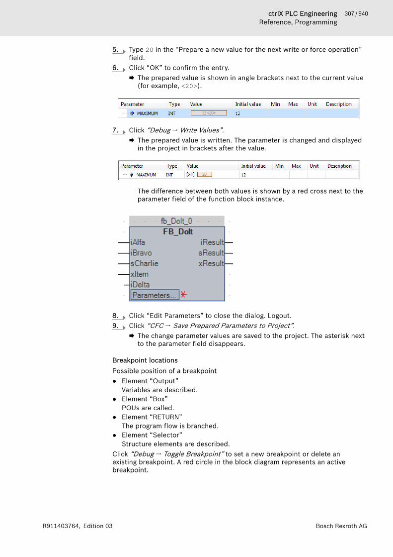
307 / 940ctrlX PLC EngineeringReference, Programming
Bosch Rexroth AGR911403764, Edition 03
5. Type 20 in the “Prepare a new value for the next write or force operation”field.
6. Click “OK” to confirm the entry.🡆 The prepared value is shown in angle brackets next to the current value
(for example, <20>).
7. Click “Debug 🠂 Write Values”.🡆 The prepared value is written. The parameter is changed and displayed
in the project in brackets after the value.
The difference between both values is shown by a red cross next to theparameter field of the function block instance.
8. Click “Edit Parameters” to close the dialog. Logout.9. Click “CFC 🠂 Save Prepared Parameters to Project”.
🡆 The change parameter values are saved to the project. The asterisk nextto the parameter field disappears.
Breakpoint locationsPossible position of a breakpoint● Element “Output”
Variables are described.● Element “Box”
POUs are called.● Element “RETURN”
The program flow is branched.● Element “Selector”
Structure elements are described.Click “Debug 🠂 Toggle Breakpoint” to set a new breakpoint or delete anexisting breakpoint. A red circle in the block diagram represents an activebreakpoint.
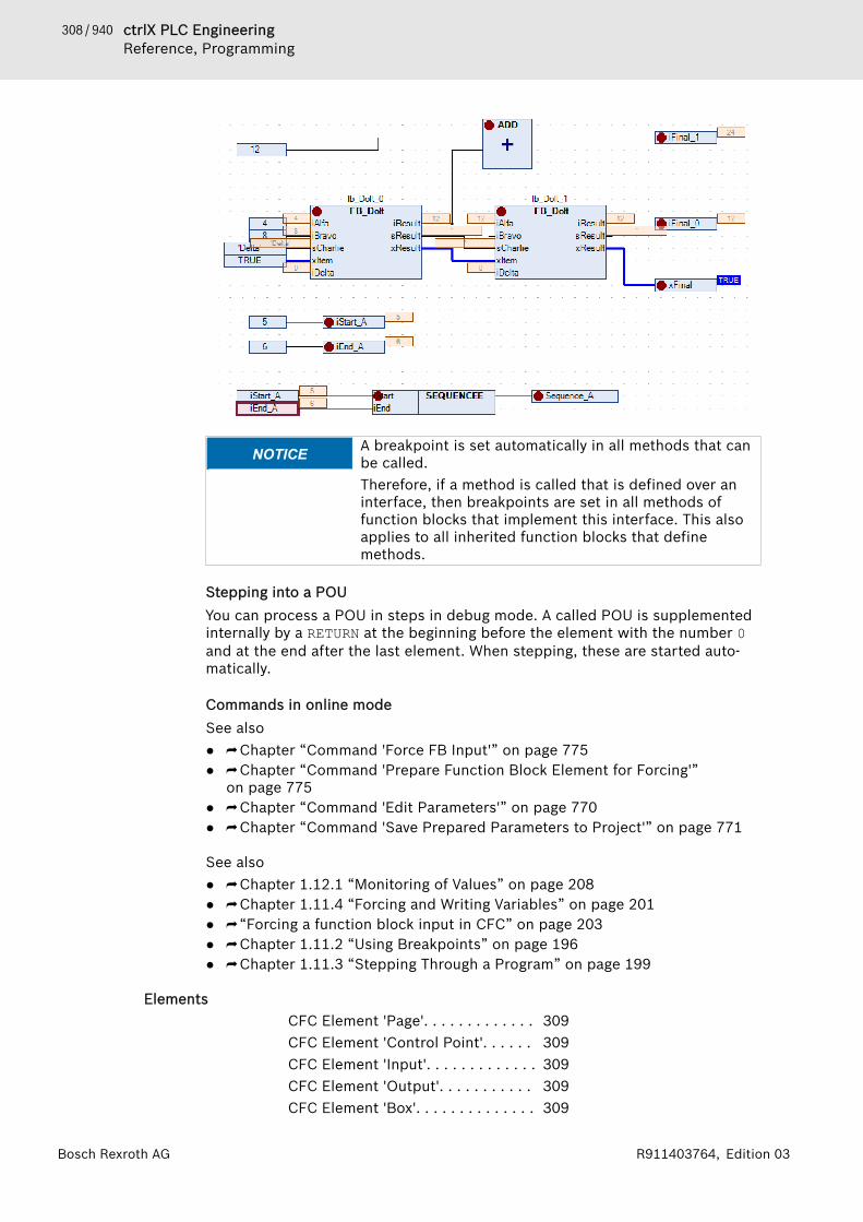
308 / 940 ctrlX PLC EngineeringReference, Programming
Bosch Rexroth AG R911403764, Edition 03
NOTICE A breakpoint is set automatically in all methods that canbe called.Therefore, if a method is called that is defined over aninterface, then breakpoints are set in all methods offunction blocks that implement this interface. This alsoapplies to all inherited function blocks that definemethods.
Stepping into a POUYou can process a POU in steps in debug mode. A called POU is supplementedinternally by a RETURN at the beginning before the element with the number 0and at the end after the last element. When stepping, these are started auto-matically.
Commands in online modeSee also● ⮫ Chapter “Command 'Force FB Input'” on page 775● ⮫ Chapter “Command 'Prepare Function Block Element for Forcing'”
on page 775● ⮫ Chapter “Command 'Edit Parameters'” on page 770● ⮫ Chapter “Command 'Save Prepared Parameters to Project'” on page 771
See also● ⮫ Chapter 1.12.1 “Monitoring of Values” on page 208● ⮫ Chapter 1.11.4 “Forcing and Writing Variables” on page 201● ⮫ “Forcing a function block input in CFC” on page 203● ⮫ Chapter 1.11.2 “Using Breakpoints” on page 196● ⮫ Chapter 1.11.3 “Stepping Through a Program” on page 199
ElementsCFC Element 'Page'. . . . . . . . . . . . . 309CFC Element 'Control Point'. . . . . . 309CFC Element 'Input'. . . . . . . . . . . . . 309CFC Element 'Output'. . . . . . . . . . . 309CFC Element 'Box'. . . . . . . . . . . . . . 309
309 / 940ctrlX PLC EngineeringReference, Programming
Bosch Rexroth AGR911403764, Edition 03
CFC Element 'Jump'. . . . . . . . . . . . . 310CFC Element 'Label'. . . . . . . . . . . . . 310CFC Element 'Return'. . . . . . . . . . . . 310CFC Element 'Composer'. . . . . . . . . 310CFC Element 'Selector'. . . . . . . . . . 311CFC Element 'Comment'. . . . . . . . . 311CFC Element 'Connection Mark -Source/Sink'. . . . . . . . . . . . . . . . . . . 311CFC Element 'Input Pin'. . . . . . . . . . 311CFC Element 'Output Pin'. . . . . . . . 312
CFC Element 'Page'Symbol: The element inserts a new page into the editor. It is available only in the page-oriented CFC editor. The number of the page is automatically assigned inaccordance with its position. You can enter the name and the description of thepage into the orange header. The page size is adapted with the “Edit Page Size”command.See also● ⮫ Chapter “Command 'Edit Page Size’” on page 765
CFC Element 'Control Point'Symbol: Use a control point in order to fix points of a connection before you adapt theline routing. To do this, drag the element to the desired position on a con-necting line. Connecting lines with control points are no longer routed automat-ically.See also● ⮫ Chapter “ Programming in the CFC Editor” on page 83● ⮫ Chapter “Command 'Create Control Point'” on page 774● ⮫ Chapter “Command 'Remove Control Point'” on page 773
CFC Element 'Input'Symbol: PLC Engineering inserts an input element by default with the text “???”. Youcan directly edit this field by clicking on it and entering a constant value or avariable name. Alternatively you can open the input assistant in order to selecta variable by clicking on .
CFC Element 'Output'Symbol: PLC Engineering inserts an output element by default with the text “???”. Youcan directly edit this field by clicking on it and entering a constant value or avariable name. Alternatively you can open the input assistant in order to selecta variable by clicking on .
CFC Element 'Box'Symbol:
310 / 940 ctrlX PLC EngineeringReference, Programming
Bosch Rexroth AG R911403764, Edition 03
You use the element in order to insert an operator, a function, a function blockor a program. By default PLC Engineering inserts the element with the name“???”. You can directly edit this field by clicking on it and entering a functionblock name. Alternatively you can open the input assistant and select a functionblock by clicking on .In the case of a function block, PLC Engineering additionally displays an inputfield (“???”) above the function block symbol. You must replace this name bythe name of the function block instance. If you instance a function block withconstant input parameters, the function block element displays the ‘Param-eter...’ field in the bottom left corner. You edit the parameters by clicking onthis field.In order to replace an existing box, you replace only the currently inserted iden-tifier with the desired new name. When doing this, please note that PLC Engi-neering adapts the number of input and output pins in accordance with thedefinition of the POU and that existing assignments may therefore be deleted.See also● ⮫ Chapter “Command 'Edit Parameters'” on page 770
CFC Element 'Jump'Symbol: You use the element in order to define a position at which program execution isto continue. You must define this target position by a label. To do this, enterthe name of the mark in the input field “???”. If you have already inserted thecorresponding label, you can also select it via the input assistant ( ).See also● ⮫ Chapter “CFC Element 'Label'” on page 310
CFC Element 'Label'Symbol: A label defines a position to which program execution jumps with the help of ajump element.In online mode PLC Engineering automatically inserts a RETURN flag at the endof a CFC function block.See also● ⮫ Chapter “CFC Element 'Jump'” on page 310
CFC Element 'Return'Symbol: Use the element in order to exit the function block.Please note that in online mode in the CFC editor a return element is automati-cally inserted before the first line and after the last element. In single-step exe-cution PLC Engineering automatically jumps to the return element at the endbefore exiting the function block.
CFC Element 'Composer'Symbol: The composer element is for handling structural components. The individualcomponents of a structure are made available to you as an input. For this pur-pose you must name the composer element like the structure concerned(replace the “???”).The composer element is the counterpart to the selector element.See also● ⮫ Chapter “CFC Element 'Selector'” on page 311
311 / 940ctrlX PLC EngineeringReference, Programming
Bosch Rexroth AGR911403764, Edition 03
CFC Element 'Selector'Symbol: The selector element is for handling structural components. The individualcomponents of a structure are made available to you as an output. For this pur-pose you must name the selector element like the structure concerned (replacethe “???”)The selector element is the counterpart to the composer element.See also● ⮫ Chapter “CFC Element 'Composer'” on page 310
CFC Element 'Comment'Symbol: With this element you input a comment in the CFC editor. Replace the place-holder text in the element by the comment text. A line break can be insertedwith the aid of the shortcut [Ctrl] + [Enter].
CFC Element 'Connection Mark - Source/Sink'Symbol: , You can use connection marks instead of a connecting line between elements.That helps you to display complex diagrams more clearly.For a valid connection you must connect an element “Connection Mark -Source” with the output of an element and an element “Connection Mark -Sink” with the input of another element. Both marks must bear the same name.The names are not case-sensitive.Notes on naming● The standard name for connection marks is C-<nr>. <nr> is a sequential
number starting with 1.● You can rename the standard name. In doing so, you must make sure that
the connection mark - source and connection mark - sink have the samename.
● If you change the name of the connection mark - source, the destinationname is automatically renamed.
● If you change the name of the connection mark - sink, the source name isretained.
Observe the command “Connection Mark” for the automatic transformation ofan existing connection.See also● ⮫ Chapter “Command 'Connection Mark'” on page 774● ⮫ Chapter “CFC Editor” on page 301
CFC Element 'Input Pin'Symbol: Depending on the type of function block you can add further inputs to aninserted function block element. To do this you must select the function blockelement and drag the function block input element onto the body of the func-tion block.Please note: You can drag an input or output connection to another position onthe function block with the [Ctrl] key pressed.See also● ⮫ Chapter “CFC Element 'Output Pin'” on page 312
312 / 940 ctrlX PLC EngineeringReference, Programming
Bosch Rexroth AG R911403764, Edition 03
CFC Element 'Output Pin'Symbol: Depending on the type of function block you can add further outputs to aninserted function block element. To do this you must select the function blockelement and drag the function block output element onto the body of the func-tion block.Please note: You can drag an input or output connection to another position onthe function block with the [Ctrl] key pressed.See also● ⮫ Chapter “CFC Element 'Input Pin'” on page 311
1.18.2 VariablesLocal Variables - VAR. . . . . . . . . . . . 312Input Variables - VAR_INPUT. . . . . . . 312Output Variables - VAR_OUTPUT. . . 313Input/Output Variable (VAR_IN_OUT)313Global Variables - VAR_GLOBAL. . . . 318Temporary Variable - VAR_TEMP. . . 318Static Variables - VAR_STAT. . . . . . . 318External Variables - VAR_EXTERNAL. 319Instance Variables - VAR_INST. . . . . 319Configuration Variables -VAR_CONFIG. . . . . . . . . . . . . . . . . . 320Constant Variables - VAR CONSTANT 320Persistent Variable - PERSISTENT. . 321Retain Variable - RETAIN. . . . . . . . . . 323SUPER. . . . . . . . . . . . . . . . . . . . . . . 323THIS. . . . . . . . . . . . . . . . . . . . . . . . . 325
The scope of a variable defines how and where you can use a variable. Youdefine the scope in the variable declaration.
Local Variables - VARLocal variables are declared between the keywords VAR and END_VAR in thedeclaration part of programming objects.You have read-only access to local variables by using the instance path.You can extend local variables with an attribute keyword.
Example
VARiVar1 : INT;
END_VAR
See also● ⮫ Chapter 1.8.20 “Data Persistence” on page 139
Input Variables - VAR_INPUTInput variables are used at the inputs of function blocks.VAR_INPUT variables are declared between the keywords VAR_INPUT andEND_VAR in the declaration part of programming objects.

313 / 940ctrlX PLC EngineeringReference, Programming
Bosch Rexroth AGR911403764, Edition 03
You can extend input variables with an attribute keyword.
ExampleVAR_INPUTiIn1 : INT; (* 1st input variable *)
END_VAR
See also● ⮫ Chapter 1.8.20 “Data Persistence” on page 139
Output Variables - VAR_OUTPUTOutput variables are used at the outputs of function blocks.VAR_OUTPUT variables are declared between the keywords VAR_OUTPUT andEND_VAR in the declaration part of programming objects. PLC Engineeringreturns the values of this variable to the calling POU. There you can retrieve thevalues and continue using them.You can extend output variables with an attribute keyword.
Example
VAR_OUPUTiOut1 : INT; (*1st output variable *)
END_VAR
See also● ⮫ Chapter 1.8.20 “Data Persistence” on page 139
Output variables in functions and methodsAccording to the IEC 61131-3 standard, functions and methods have additionaloutputs. You have to assign these additional outputs when calling the function,as shown below.
Examplefun(iIn1 := 1, iIn2 := 2, iOut1 => iLoc1, iOut2 => iLoc2);
Input/Output Variable (VAR_IN_OUT)A VAR_IN_OUT variable is an input/output variable, which is part of a POU inter-face and serves as a formal pass-by-reference parameter.Syntax declaration
<keyword> <POU name> VAR_IN_OUT<variable name> : <data type> ( := <initialization
value> )? ;END_VAR<keyword> : FUNCTION | FUNCTION_BLOCK | METHOD | PRG You can declare an input/output variable in the VAR_IN_OUT declaration sectionin the POUs PRG, FUNCTION_BLOCK, METHOD, or FUNCTION. As an option, a con-stant of the declared data type can be assigned as an initialization value. TheVAR_IN_OUT variable can be read and written.Usage● Call: When a POU is called, the formal VAR_IN_OUT variable receives the
actual variable (pass-by-reference variable) as the argument. In runtimemode, no copies are generated when parameters are passed. Instead, theformal variable receives a reference to the actual variable passed remotely.

314 / 940 ctrlX PLC EngineeringReference, Programming
Bosch Rexroth AG R911403764, Edition 03
The referential variables contain a memory address internally as a value tothe actual value (pass as pointer, call-by reference). It is not possible tospecify a constant (literal) or a bit variable directly as an argument.
● Read/write access within the POU: If the variable is written to within thePOU, then this affects the passed variable. When the POU is exited, the per-formed changes are retained. This means that a POU uses its VAR_IN_OUTvariables just like the calling POU uses its variables. Read access is alwayspermitted.
● Read/write access remotely: VAR_IN_OUT variables cannot be directly reador written remotely via <function block instance name>.<variablename>. This works only for VAR_INPUT and VAR_OUTPUT variables.
● Passing string variables: If a string variable is passed as an argument, then itis recommended when the actual variable and the formal variable have thesame length. Otherwise, the passed string can be manipulated accidentally.This problem does not occur in the case of VAR_OUTPUT CONSTANT parame-ters.
● Passing bit variables: A bit variable cannot be passed directly to aVAR_IN_OUT variable because it needs an intermediate variable.
When a string is passed as a variable or a constant to a formal VAR_IN_OUTCONSTANT variable, the string is automatically passed completely. You do nothave to check the string length.See also● Chapter ⮫ “Transfer variable VAR_IN_OUT CONSTANT” on page 316
Example
Passing arrays
TYPE DUT_A :STRUCTxA: BOOL;iB: INT;
END_STRUCTEND_TYPE
FUNCTION_BLOCK FB_SetArrayVAR_IN_OUTaData_A : ARRAY[0..1] OF DUT_A; // Formal variable
END_VAR aData_A[0].xA := TRUE;aData_A[0].iB := 100;
PROGRAM PLC_PRGVARfbSetA : FB_SetArray;aSpecialData : ARRAY[0..1] OF DUT_A; // Actual variable
END_VARfbSetA(aData_A := aSpecialData);
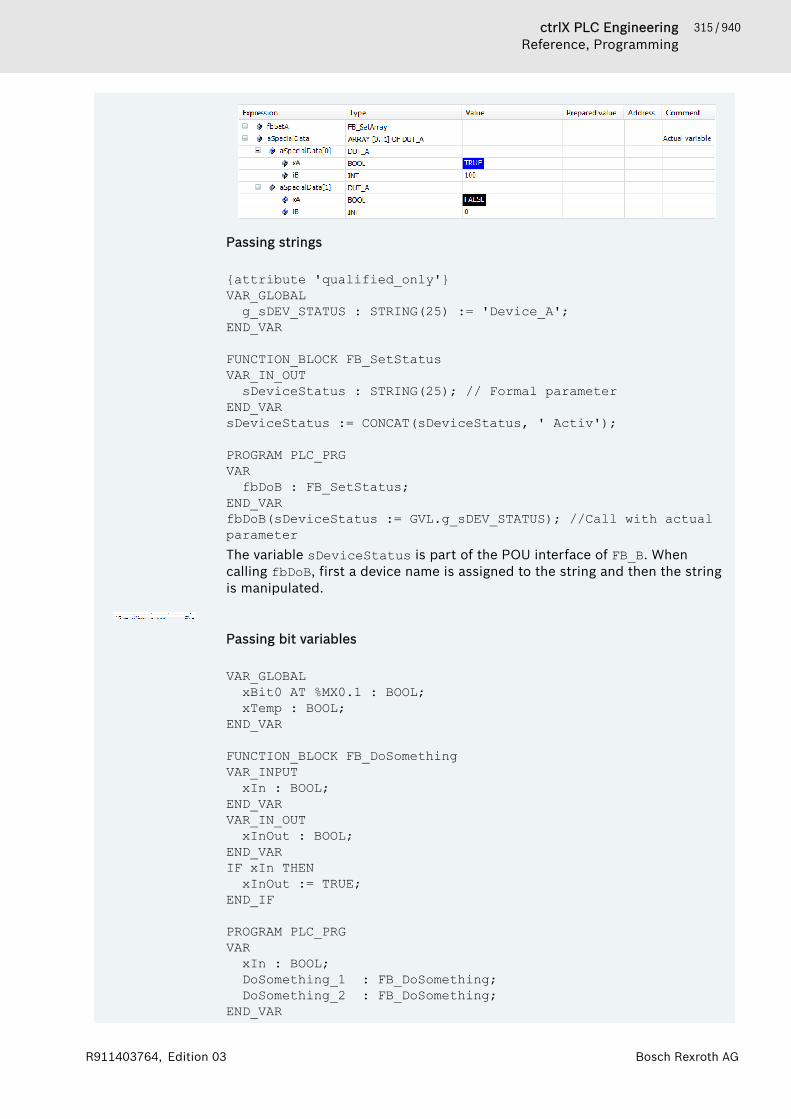
315 / 940ctrlX PLC EngineeringReference, Programming
Bosch Rexroth AGR911403764, Edition 03
Passing strings
{attribute 'qualified_only'}VAR_GLOBALg_sDEV_STATUS : STRING(25) := 'Device_A';
END_VAR
FUNCTION_BLOCK FB_SetStatusVAR_IN_OUTsDeviceStatus : STRING(25); // Formal parameter
END_VARsDeviceStatus := CONCAT(sDeviceStatus, ' Activ');
PROGRAM PLC_PRGVARfbDoB : FB_SetStatus;
END_VARfbDoB(sDeviceStatus := GVL.g_sDEV_STATUS); //Call with actual parameterThe variable sDeviceStatus is part of the POU interface of FB_B. Whencalling fbDoB, first a device name is assigned to the string and then the stringis manipulated.
Passing bit variables
VAR_GLOBALxBit0 AT %MX0.1 : BOOL;xTemp : BOOL;
END_VAR
FUNCTION_BLOCK FB_DoSomethingVAR_INPUTxIn : BOOL;
END_VARVAR_IN_OUT xInOut : BOOL;
END_VARIF xIn THENxInOut := TRUE;
END_IF
PROGRAM PLC_PRGVARxIn : BOOL;DoSomething_1 : FB_DoSomething;DoSomething_2 : FB_DoSomething;
END_VAR
316 / 940 ctrlX PLC EngineeringReference, Programming
Bosch Rexroth AG R911403764, Edition 03
// The following line of code causes a compiler error:// C0201: Typ 'BIT' is not equal to type 'BOOL' of VAR_IN_OUT 'xInOut'DoSomething_1(xIn := xIn, xInOut := xBit0);
// WorkaroundxTemp := xBit0;DoSomething_2(xIn := xIn, xInOut := xTemp);xBit0 := xTemp;
The program calls the function block instances DoSomething_1 and DoS-omething_2. As a result of the direct assignment of the bit variable xBit0 tothe VAR_IN_OUT input, a compiler error is generated when the DoS-omething_1 instance is called. In contrast, calling the DoSomething_2instance with the assignment of an intermediate variable is correct code.
Transfer variable VAR_IN_OUT CONSTANTA VAR_IN_OUT CONSTANT variable serves as a constant pass-by-referenceparameter, to which a variable and a constant can be passed. The parametercan be read, but not written.Syntax declaration
<keyword> <POU name> VAR_IN_OUT CONSTANT<variable name> : <data type>; // formal parameter
END_VAR<keyword> : FUNCTION | FUNCTION_BLOCK | METHOD | PRG VAR_IN_OUT CONSTANT variables are declared without assigning an initializa-tion value.Usage:● When calling the POU, a constant variable or a literal is passed. All data
types are permitted for this. Consequently, write access is not permitted.● Passing parameters of a string constant: The string length of the constants
can be any size, and the string length does not depend on the string lengthof the VAR_IN_OUT CONSTANT variables.
If the “Replace constants” option is selected in “Project 🠂 Project Settings”(category “Compile Options”), then the passing of the parameter of a constantor constant variable with a base data type causes a compiler error to be gener-ated.This variable is supported in compiler version >= 3.5.2.0.
317 / 940ctrlX PLC EngineeringReference, Programming
Bosch Rexroth AGR911403764, Edition 03
Example
Passing parameters of string constants and string variables
FUNCTION funManipulate : BOOLVAR_IN_OUTsReadWrite : STRING(16); (* Can be read or written here in
POU *)dwVarReadWrite : DWORD; (* Can be read or written here in
POU *)END_VAR VAR_IN_OUT CONSTANTc_sReadOnly : STRING(16); (* Constant string variable can
only be read here in POU *)END_VAR
sReadWrite := 'String_from_POU'; dwVarReadWrite := STRING_TO_DWORD(c_sReadOnly);
PROGRAM PRG_AVARsVarFits : STRING(16);sValFits : STRING(16) := '1234567890123456';dwVar: DWORD;
END_VAR
// The following line of code causes the compiler error C0417:// C0417: VAR_IN_OUT parameter 'sReadWrite' needs a variable with write access as input.funManipulate(sReadWrite:='1234567890123456', c_sReadOnly:='1234567890123456', dwVarReadWrite := dwVar);
// Correct codefunManipulate(sReadWrite := sValFits, c_sReadOnly := '23', dwVarReadWrite := dwVar);funManipulate(sReadWrite := sVarFits, c_sReadOnly := sValFits, dwVarReadWrite := dwVar);
In the code, strings are passed to the funManipulate function via differentVAR_IN_OUT variables. When passing a literal, a compiler error is output to aVAR_IN_OUT variable. When passing a constant variable to a VAR_IN_OUTCONSTANT variable, correct code is generated even for passing string varia-bles.
See also● ⮫ Chapter 1.8.2 “Declaration of Variables ” on page 62● ⮫ Chapter “Dialog 'Project Settings' - 'Compileoptions'” on page 837● ⮫ Chapter “Object 'Function'” on page 592● ⮫ Chapter “Object 'Function Block'” on page 590● ⮫ Chapter “Object 'Method'” on page 596● ⮫ Chapter “Object 'Interface'” on page 594● ⮫ Chapter “Object 'Interface Method'” on page 600● ⮫ Chapter “Constant Variables - VAR CONSTANT” on page 320

318 / 940 ctrlX PLC EngineeringReference, Programming
Bosch Rexroth AG R911403764, Edition 03
Global Variables - VAR_GLOBALGlobal variables are ordinary variables, constants, external or remanent varia-bles that are recognized within the entire project.You declare global variables in global variable lists or in the declaration sectionof programming objects between the keywords VAR_GLOBAL and END_VAR.The system recognizes a global variable when you prepend the variable namewith a dot (for example, .iGlobVar1).
NOTICE If a local variable that is declared in a block has the samename as a global variable, then it has precedence withinthe block.
NOTICE For compiler version 3.2.0.0 and later, PLC Engineeringalways initializes global variables before the local POUvariables.
ExampleVAR_GLOBALiVarGlob1 : INT;
END_VAR
See also● ⮫ Chapter “Object 'GVL' - Global Variable List” on page 581● ⮫ Chapter “Operator - Global Namespace” on page 372
Temporary Variable - VAR_TEMPThis function is an extension of the IEC 61131-3 standard.You declare temporary variables locally between the keywords VAR_TEMP andEND_VAR.VAR_TEMP declarations are possible only in program blocks and functionblocks.PLC Engineering initializes temporary variables each time the block is called.The application can access the temporary variables only in the implementationsection of a program block or a function block.
ExampleVAR_TEMP
iVarTmp1 : INT; (*1st temporary variable *)END_VAR
Static Variables - VAR_STATThis function is an extension of the IEC 61131-3 standard.You declare static variables locally between the keywords VAR_STAT andEND_VAR. PLC Engineering initializes static variables the first time each block iscalled.You can access static variables only from within the namespace where the vari-ables are declared (like static variables in C). But static variables retain theirvalues when the application leaves the block. For example, you can use staticvariables as counters for function calls.You can extend static variables with an attribute keyword.
ExampleVAR_STATiVarStat1 : INT;
END_VAR
319 / 940ctrlX PLC EngineeringReference, Programming
Bosch Rexroth AGR911403764, Edition 03
See also● ⮫ Chapter 1.8.20 “Data Persistence” on page 139
External Variables - VAR_EXTERNALExternal variables are global variables that are imported into a block.You declare these variables between the keywords VAR_EXTERNAL andEND_VAR. If the global variable does not exist, then an error message is printed.
NOTICE PLC Engineering does not require you to declare a globalvariable as external in order to use it in a POU. The key-word exists only for maintaining compliance with IEC61131-3.
Syntax
<POU keyword> <POU name> VAR_EXTERNAL<variable name> : <data type>;
END_VARInitialization is not permitted.
Example
FUNCTION_BLOCK FB_DoSomething VAR_EXTERNALiVarExt1 : INT; (* 1st external variable *)
END_VAR
See also● ⮫ Chapter “Object 'GVL' - Global Variable List” on page 581
Instance Variables - VAR_INSTPLC Engineering does not save a VAR_INST method variable in a method stack,but in the stack of the function block instance. This means that the VAR_INSTvariable functions like other Variables of the function block instance, and it isnot reinitialized each time the method is called.VAR_INST variables are permitted in methods only and you can access thesevariables only within the method. The variable values of instance variables aremonitored in the declaration section of the method.You can extend instance variable with an attribute keyword.
ExampleMETHOD meth_last : INTVAR_INPUT iVar : INT;END_VARVAR_INST iLast : INT := 0;END_VARmeth_last := iLast;iLast := iVar;
See also● ⮫ Chapter “Object 'Method'” on page 596

320 / 940 ctrlX PLC EngineeringReference, Programming
Bosch Rexroth AG R911403764, Edition 03
Configuration Variables - VAR_CONFIGUse configuration variables for assigning complete addresses to variables thatare declared in function blocks with incomplete addresses and will be mappedon device I/Os.Declare the variables in a global variables list between VAR_CONFIG andEND_VAR. The global variables list is termed "variables configuration", whereyou type the configuration variables with a complete instance path and the cor-rect address.
ExampleDeclaration of the variable xLocIn with incomplete address %I* in a functionblock:FUNCTION_BLOCK locio
VAR xLocIn AT %I* : BOOL := TRUE;
END_VAR
The locio function block is used in the PLC_PRG program:PROGRAM PLC_PRG
VAR locioVar1 : locio;
END_VAR
The correct variables configuration in the global variable list is as follows:VAR_CONFIG
PLC_PRG.locioVar1.xLocIn AT %IX1.0 : BOOL;
END_VAR
See also● ⮫ Chapter “Variables Configuration - VAR_CONFIG” on page 117
Constant Variables - VAR CONSTANTConstant variables are declared in global variable lists or in the declaration partof programming objects. In implementations, constant variables can beaccessed as read-only via the instance path.Syntax
<scope> CONSTANT<identifier> : <data type> := <initialization> ;
END_VAR
<scope> : VAR | VAR_INPUT | VAR_STAT | VAR_GLOBALAlways assign an initialization value when declaring a constant variable. Thenthe constant cannot be written any more.

321 / 940ctrlX PLC EngineeringReference, Programming
Bosch Rexroth AGR911403764, Edition 03
Example
Declaration
VAR CONSTANTc_rTAXFACTOR : REAL := 1.19;
END_VARCall
rPrice := rValue * c_rTAXFACTOR;In implementations, you can access constant variables exclusively as read-only. Constant variables are located to the right of the assignment operator.
See also● ⮫ Chapter “Input/Output Variable (VAR_IN_OUT)” on page 313
Persistent Variable - PERSISTENTPersistent variables are declared in the declaration section VAR_GLOBALRETAIN PERSISTENT in the persistent global variable list. For variables that aremarked with the PERSISTENT keyword outside of the persistence editor,instance paths are added there.As of PLC Engineering version 3.3.0.1, a variable declaration with PERSISTENTRETAIN has the same effect as with RETAIN PERSISTENT or PERSISTENT.Syntax of the declaration in the global persistent variable list PersistentVars:
VAR_GLOBAL PERSISTENT RETAIN<identifier>: <data type> (:= <initialization>)?;
<instance path to POU variable>END_VARSyntax of the declaration in POUs
<scope> PERSISTENT RETAIN<identifier>: <data type> ( := <initialization> )?; //
( ... )? : OptionalEND_VAR<scope> : VAR | VAR_INPUT | VAR_OUTPUT | VAR_IN_OUT | VAR_STAT | VAR_GLOBAL
An assignment of inputs, outputs, or memory addresses with the AT keyword isnot permitted.Never use the POINTER TO data type in persistent variable lists. If the applica-tion is downloaded again, their addresses could change. The correspondingcompiler warnings are shown in the message window.If you frequently change the names or data types of remanent variables, then itis better to declare them as retain variables with the RETAIN keyword only.
NOTICE Declare variables directly in the list of persistent varia-bles and avoid inserting instance paths. As a result, thistakes up twice as much memory and also increases thecycle time.
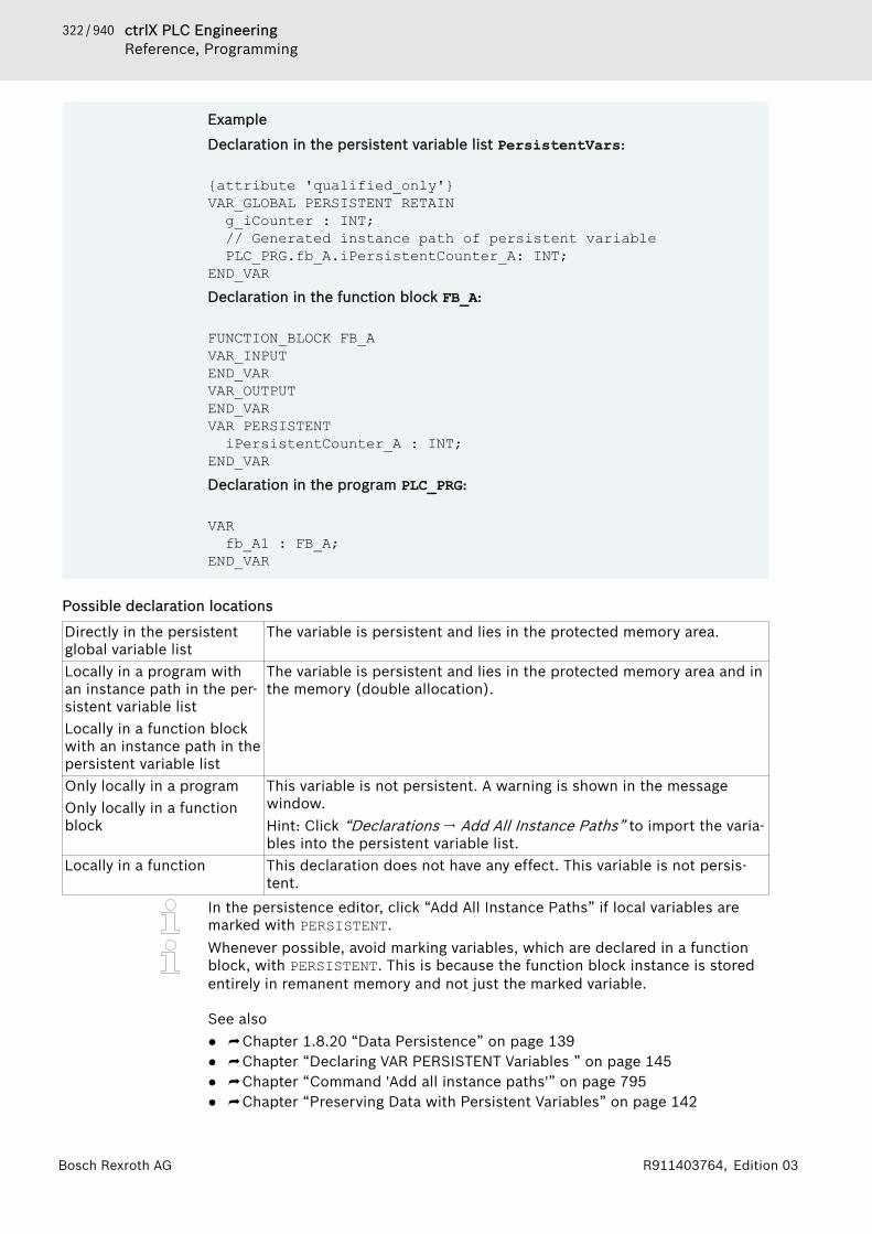
322 / 940 ctrlX PLC EngineeringReference, Programming
Bosch Rexroth AG R911403764, Edition 03
Example
Declaration in the persistent variable list PersistentVars:
{attribute 'qualified_only'}VAR_GLOBAL PERSISTENT RETAINg_iCounter : INT;// Generated instance path of persistent variablePLC_PRG.fb_A.iPersistentCounter_A: INT;
END_VARDeclaration in the function block FB_A:
FUNCTION_BLOCK FB_AVAR_INPUTEND_VARVAR_OUTPUTEND_VARVAR PERSISTENTiPersistentCounter_A : INT;
END_VARDeclaration in the program PLC_PRG:
VARfb_A1 : FB_A;
END_VAR
Possible declaration locations
Directly in the persistentglobal variable list
The variable is persistent and lies in the protected memory area.
Locally in a program withan instance path in the per-sistent variable listLocally in a function blockwith an instance path in thepersistent variable list
The variable is persistent and lies in the protected memory area and inthe memory (double allocation).
Only locally in a programOnly locally in a functionblock
This variable is not persistent. A warning is shown in the messagewindow.Hint: Click “Declarations 🠂 Add All Instance Paths” to import the varia-bles into the persistent variable list.
Locally in a function This declaration does not have any effect. This variable is not persis-tent.
In the persistence editor, click “Add All Instance Paths” if local variables aremarked with PERSISTENT.Whenever possible, avoid marking variables, which are declared in a functionblock, with PERSISTENT. This is because the function block instance is storedentirely in remanent memory and not just the marked variable.
See also● ⮫ Chapter 1.8.20 “Data Persistence” on page 139● ⮫ Chapter “Declaring VAR PERSISTENT Variables ” on page 145● ⮫ Chapter “Command 'Add all instance paths'” on page 795● ⮫ Chapter “Preserving Data with Persistent Variables” on page 142

323 / 940ctrlX PLC EngineeringReference, Programming
Bosch Rexroth AGR911403764, Edition 03
Retain Variable - RETAINRetain variables are declared by the keyword RETAIN is added in programmingobjects in the scope VAR, VAR_INPUT, VAR_OUTPUT, VAR_IN_OUT, VAR_STAT, orVAR_GLOBAL.Syntax in the declaration
<scope> RETAIN<identifier>: <data type> ( := <initialization> )? //
( ... )? : OptionalEND_VAR<scope> : VAR | VAR_INPUT | VAR_OUTPUT | VAR_IN_OUT | VAR_STAT | VAR_GLOBALAn assignment of inputs, outputs, or memory addresses with the AT keyword isnot permitted.
Example
In a POU:
VAR RETAINiVarRetain: INT;
END_VARIn a GVL:
VAR_GLOBAL RETAINg_iVarRetain: INT;
END_VAR
Possible declaration locations
Locally in a program Only the variable lies within the retain memory area.Globally in a global variablelist
Only the variable lies within the retain memory area.
Locally in a function block The entire instance of the function block with all of its data lies withinthe retain memory area. Only the declared retain variable is protected.
Locally in a function Even the variable does not lie within the retain memory area. This dec-laration does not have any effect.
Locally and persistently in afunction
Even the variable does not lie within the retain memory area. This dec-laration does not have any effect.
Whenever possible, avoid marking variables of a function block with RETAIN.
See also● ⮫ Chapter 1.8.20 “Data Persistence” on page 139● ⮫ Chapter “Declaring VAR PERSISTENT Variables ” on page 145● ⮫ Chapter “Command 'Add all instance paths'” on page 795● ⮫ Chapter “Preserving Data with Retain Variables” on page 144
SUPERSUPER is a special variable and is used for object-oriented programming.
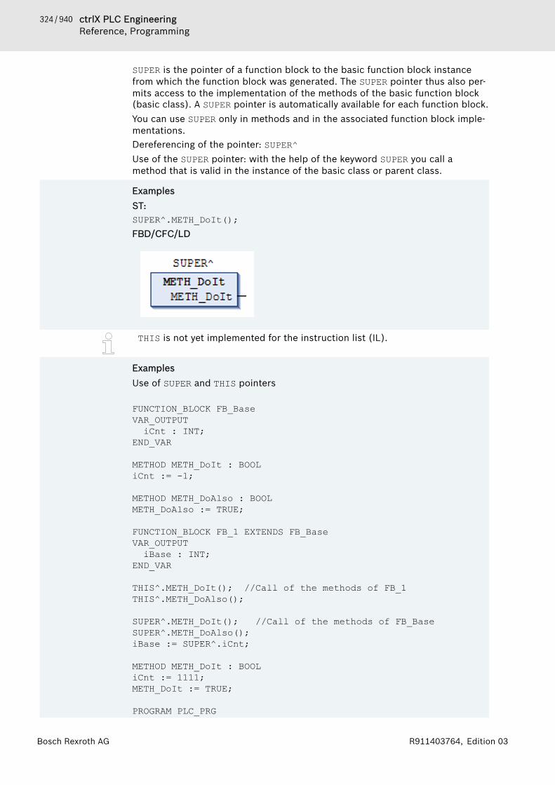
324 / 940 ctrlX PLC EngineeringReference, Programming
Bosch Rexroth AG R911403764, Edition 03
SUPER is the pointer of a function block to the basic function block instancefrom which the function block was generated. The SUPER pointer thus also per-mits access to the implementation of the methods of the basic function block(basic class). A SUPER pointer is automatically available for each function block.You can use SUPER only in methods and in the associated function block imple-mentations.Dereferencing of the pointer: SUPER^Use of the SUPER pointer: with the help of the keyword SUPER you call amethod that is valid in the instance of the basic class or parent class.
ExamplesST:SUPER^.METH_DoIt();FBD/CFC/LD
THIS is not yet implemented for the instruction list (IL).
ExamplesUse of SUPER and THIS pointers
FUNCTION_BLOCK FB_BaseVAR_OUTPUTiCnt : INT;
END_VAR
METHOD METH_DoIt : BOOLiCnt := -1;
METHOD METH_DoAlso : BOOLMETH_DoAlso := TRUE;
FUNCTION_BLOCK FB_1 EXTENDS FB_BaseVAR_OUTPUTiBase : INT;
END_VAR
THIS^.METH_DoIt(); //Call of the methods of FB_1THIS^.METH_DoAlso();
SUPER^.METH_DoIt(); //Call of the methods of FB_BaseSUPER^.METH_DoAlso();iBase := SUPER^.iCnt;
METHOD METH_DoIt : BOOLiCnt := 1111; METH_DoIt := TRUE;
PROGRAM PLC_PRG

325 / 940ctrlX PLC EngineeringReference, Programming
Bosch Rexroth AGR911403764, Edition 03
VAR myBase : FB_Base; myFB_1 : FB_1; iTHIS : INT; iBase : INT;END_VARmyBase();iBase := myBase.iCnt;myFB_1();iTHIS := myFB_1.iCnt;
FUNCTION_BLOCK FB_BaseVAR_OUTPUTiCnt : INT;
END_VAR
METHOD METH_DoIt : BOOLiCnt := -1;
METHOD METH_DoAlso : BOOLMETH_DoAlso := TRUE;
FUNCTION_BLOCK FB_1 EXTENDS FB_BaseVAR_OUTPUTiBase : INT;
END_VAR
THIS^.METH_DoIt(); //Call of the methods of FB_1THIS^.METH_DoAlso();
SUPER^.METH_DoIt(); //Call of the methods of FB_BaseSUPER^.METH_DoAlso();iBase := SUPER^.iCnt;
METHOD METH_DoIt : BOOL iCnt := 1111; METH_DoIt := TRUE;
PROGRAM PLC_PRGVAR myBase : FB_Base; myFB_1 : FB_1; iTHIS : INT; iBase : INT;END_VAR
myBase();iBase := myBase.iCnt;myFB_1();iTHIS := myFB_1.iCnt;
See also● ⮫ Chapter 1.18.5 “Data Types” on page 386● ⮫ Chapter “THIS” on page 325
THISTHIS is a special variable and is used for object-oriented programming.
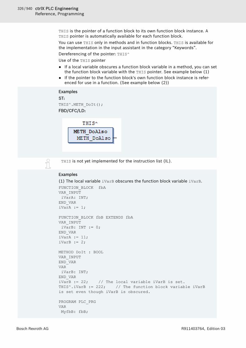
326 / 940 ctrlX PLC EngineeringReference, Programming
Bosch Rexroth AG R911403764, Edition 03
THIS is the pointer of a function block to its own function block instance. ATHIS pointer is automatically available for each function block.You can use THIS only in methods and in function blocks. THIS is available forthe implementation in the input assistant in the category “Keywords”.Dereferencing of the pointer: THIS^Use of the THIS pointer● If a local variable obscures a function block variable in a method, you can set
the function block variable with the THIS pointer. See example below (1)● If the pointer to the function block's own function block instance is refer-
enced for use in a function. (See example below (2))
ExamplesST:THIS^.METH_DoIt();FBD/CFC/LD:
THIS is not yet implemented for the instruction list (IL).
Examples(1) The local variable iVarB obscures the function block variable iVarB.FUNCTION_BLOCK fbAVAR_INPUT iVarA: INT;END_VARiVarA := 1;
FUNCTION_BLOCK fbB EXTENDS fbAVAR_INPUT iVarB: INT := 0;END_VARiVarA := 11;iVarB := 2;
METHOD DoIt : BOOLVAR_INPUTEND_VARVAR iVarB: INT;END_VARiVarB := 22; // The local variable iVarB is set.THIS^.iVarB := 222; // The function block variable iVarB is set even though iVarB is obscured.
PROGRAM PLC_PRGVAR MyfbB: fbB;

327 / 940ctrlX PLC EngineeringReference, Programming
Bosch Rexroth AGR911403764, Edition 03
END_VAR
MyfbB(iVarA:=0, iVarB:= 0);MyfbB.DoIt();(2) A function call requires the reference to its own instance.FUNCTION funAVAR_INPUT pFB: fbA;END_VAR...;
FUNCTION_BLOCK fbAVAR_INPUT iVarA: INT;END_VAR...;
FUNCTION_BLOCK fbB EXTENDS fbAVAR_INPUT iVarB: INT := 0;END_VARiVarA := 11;iVarB := 2;
METHOD DoIt : BOOLVAR_INPUTEND_VARVAR iVarB: INT;END_VARiVarB := 22; //The local variable iVarB is set.funA(pFB := THIS^); //funA is called via THIS^.PROGRAM PLC_PRGVAR MyfbB: fbB;END_VARMyfbB(iVarA:=0 , iVarB:= 0);MyfbB.DoIt();
See also● ⮫ Chapter “Pointers” on page 394● ⮫ Chapter “SUPER” on page 323
1.18.3 OperatorsPLC Engineering V3 supports all IEC-61131-3 operators. These operators arerecognized implicitly throughout the project. In addition to these IEC operators,PLC Engineering also supports some non-IEC 61131-3 operators.Operators are used in blocks, such as functions.For information about the processing order (binding strength) of the ST opera-tors, please refer to the section on ST expressions.
CAUTION For operations with floating-point data types, the compu-tational result depends on the applied target systemhardware.
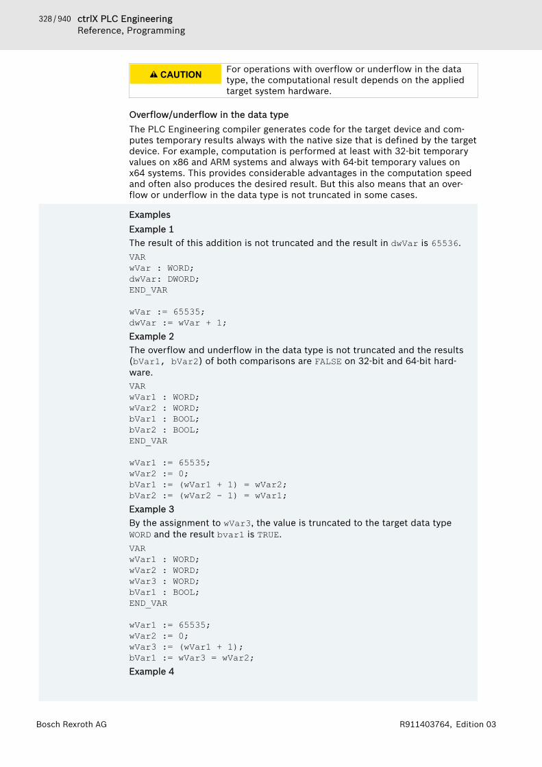
328 / 940 ctrlX PLC EngineeringReference, Programming
Bosch Rexroth AG R911403764, Edition 03
CAUTION For operations with overflow or underflow in the datatype, the computational result depends on the appliedtarget system hardware.
Overflow/underflow in the data typeThe PLC Engineering compiler generates code for the target device and com-putes temporary results always with the native size that is defined by the targetdevice. For example, computation is performed at least with 32-bit temporaryvalues on x86 and ARM systems and always with 64-bit temporary values onx64 systems. This provides considerable advantages in the computation speedand often also produces the desired result. But this also means that an over-flow or underflow in the data type is not truncated in some cases.
ExamplesExample 1The result of this addition is not truncated and the result in dwVar is 65536.VARwVar : WORD;dwVar: DWORD;END_VAR
wVar := 65535;dwVar := wVar + 1;Example 2The overflow and underflow in the data type is not truncated and the results(bVar1, bVar2) of both comparisons are FALSE on 32-bit and 64-bit hard-ware.VARwVar1 : WORD;wVar2 : WORD;bVar1 : BOOL;bVar2 : BOOL;END_VAR
wVar1 := 65535;wVar2 := 0;bVar1 := (wVar1 + 1) = wVar2;bVar2 := (wVar2 - 1) = wVar1;Example 3By the assignment to wVar3, the value is truncated to the target data typeWORD and the result bvar1 is TRUE.VARwVar1 : WORD;wVar2 : WORD;wVar3 : WORD;bVar1 : BOOL;END_VAR
wVar1 := 65535;wVar2 := 0; wVar3 := (wVar1 + 1);bVar1 := wVar3 = wVar2;Example 4

329 / 940ctrlX PLC EngineeringReference, Programming
Bosch Rexroth AGR911403764, Edition 03
In order to force the compiler to truncate the temporary results, a conversioncan be inserted.The type conversion makes sure that both comparisons are 16-bit only and theresults (bVar1, bVar2) of both comparisons are each TRUE.VARwVar1 : WORD;wVar2 : WORD;bVar1 : BOOL;bVar2 : BOOL;END_VAR
wVar1 := 65535;wVar2 := 0;bVar1 := TO_WORD(wVar1 + 1) = wVar2;bVar2 := TO_WORD(wVar2 - 1) = wVar1;
Arithmetic operators⮫ Chapter “Operator 'ADD'” on page 331⮫ Chapter “Operator 'SUB'” on page 332⮫ Chapter “Operator 'MUL'” on page 332⮫ Chapter “Operator 'DIV'” on page 333⮫ Chapter “Operator 'MOD'” on page 333⮫ Chapter “Operator 'MOVE'” on page 334⮫ Chapter “Operator 'INDEXOF'” on page 334⮫ Chapter “Operator 'SIZEOF'” on page 334
Bitstring operators⮫ Chapter “Operator 'AND'” on page 335⮫ Chapter “Operator 'OR' ” on page 335⮫ Chapter “Operator 'XOR'” on page 336⮫ Chapter “Operator 'NOT'” on page 335⮫ Chapter “Operator 'AND_THEN'” on page 336⮫ Chapter “Operator 'OR_ELSE'” on page 337
Bitshift operators⮫ Chapter “Operator 'SHL'” on page 337⮫ Chapter “Operator 'SHR'” on page 338⮫ Chapter “Operator 'ROL'” on page 339⮫ Chapter “Operator 'ROR'” on page 340
Selection operators⮫ Chapter “Operator 'SEL'” on page 340⮫ Chapter “Operator 'MAX'” on page 341⮫ Chapter “Operator 'MIN'” on page 342⮫ Chapter “Operator 'LIMIT'” on page 342⮫ Chapter “Operator 'MUX'” on page 342
Comparison operatorsA comparison operator is a Boolean that compares two inputs (first and secondoperand).

330 / 940 ctrlX PLC EngineeringReference, Programming
Bosch Rexroth AG R911403764, Edition 03
⮫ Chapter “Operator 'GT'” on page 343⮫ Chapter “Operator 'LT'” on page 343⮫ Chapter “Operator 'LE'” on page 343⮫ Chapter “Operator 'GE'” on page 344⮫ Chapter “Operator 'EQ'” on page 344⮫ Chapter “Operator 'NE'” on page 344
Address operators⮫ Chapter “Operator 'ADR'” on page 345⮫ Chapter “Operator 'Content Operator'” on page 345⮫ Chapter “Operator 'BITADR'” on page 346
Call operators⮫ Chapter “Operator 'CAL'” on page 346
Type conversion operatorsImplicit conversion from a larger type to a smaller type is not possible (forexample, from INT to BYTE or from DINT to WORD). You must use a special typeconversion to convert from a larger type to a smaller type. As a rule, you canconvert any elementary type into any other elementary type.Typed conversion: <elementary type1>_TO_<elementary type2>Overflow conversion: TO_<elementary type2>
NOTICE In the case of ...TO_STRING conversions, PLC Engi-neering generates the string left-aligned. If the stringlength is defined too short, then it will be truncated onthe right.
NOTICE If the input value of a type conversion operator is outsidethe value range of the output data type, then the resultof the operation is undefined and dependent on the plat-form. This is the case, for example, if the input value forthe conversion from LREAL to DINT is negative.
See also● ⮫ Chapter “Operator 'BOOL_TO' ” on page 346● ⮫ Chapter “Operator 'TO_BOOL' ” on page 347● ⮫ Chapter “Operator '<INT Type>_TO_<INT Type>'” on page 348● ⮫ Chapter “Operator 'REAL_TO-/ LREAL_TO' ” on page 349● ⮫ Chapter “Operator 'TIME_TO/TIME_OF_DAY_TO' ” on page 350● ⮫ Chapter “Operator 'DATE_TO/DT_TO'” on page 351● ⮫ Chapter “Operator 'STRING_TO' ” on page 352● ⮫ Chapter “Operator 'TRUNC' ” on page 352● ⮫ Chapter “Operator 'TRUNC_INT' ” on page 353● ⮫ Chapter “Operator 'TO_<xxx>' ” on page 348
Numeric Operators⮫ Chapter “Operator 'ABS'” on page 353⮫ Chapter “Operator 'SQRT'” on page 354⮫ Chapter “Operator 'LN'” on page 354⮫ Chapter “Operator 'LOG'” on page 354⮫ Chapter “Operator 'EXP'” on page 355⮫ Chapter “Operator 'EXPT'” on page 355
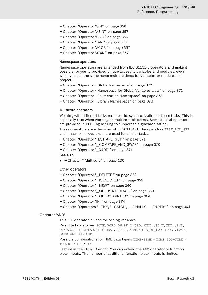
331 / 940ctrlX PLC EngineeringReference, Programming
Bosch Rexroth AGR911403764, Edition 03
⮫ Chapter “Operator 'SIN'” on page 356⮫ Chapter “Operator 'ASIN'” on page 357⮫ Chapter “Operator 'COS'” on page 356⮫ Chapter “Operator 'TAN'” on page 356⮫ Chapter “Operator 'ACOS'” on page 357⮫ Chapter “Operator 'ATAN'” on page 357
Namespace operatorsNamespace operators are extended from IEC 61131-3 operators and make itpossible for you to provided unique access to variables and modules, evenwhen you use the same name multiple times for variables or modules in aproject.⮫ Chapter “Operator - Global Namespace” on page 372⮫ Chapter “Operator - Namespace for Global Variables Lists” on page 372⮫ Chapter “Operator - Enumeration Namespace” on page 373⮫ Chapter “Operator - Library Namespace” on page 373
Multicore operatorsWorking with different tasks requires the synchronization of these tasks. This isespecially true when working on multicore platforms. Some special operatorsare provided in PLC Engineering to support this synchronization.These operators are extensions of IEC-61131-3. The operators TEST_AND_SETand __COMPARE_AND_SWAP are used for similar tasks.⮫ Chapter “Operator 'TEST_AND_SET'” on page 371⮫ Chapter “Operator '__COMPARE_AND_SWAP” on page 370⮫ Chapter “Operator '__XADD'” on page 371See also● ⮫ Chapter “ Multicore” on page 130
Other operators⮫ Chapter “Operator '__DELETE'” on page 358⮫ Chapter “Operator '__ISVALIDREF'” on page 359⮫ Chapter “Operator '__NEW'” on page 360⮫ Chapter “Operator '__QUERYINTERFACE'” on page 363⮫ Chapter “Operator '__QUERYPOINTER'” on page 364⮫ Chapter “Operator 'INI'” on page 374⮫ Chapter “Operators '__TRY', '__CATCH', '__FINALLY', '__ENDTRY'” on page 364
Operator 'ADD'This IEC operator is used for adding variables.Permitted data types: BYTE, WORD, DWORD, LWORD, SINT, USINT, INT, UINT,DINT, UDINT, LINT, ULINT, REAL, LREAL, TIME, TIME_OF_DAY (TOD), DATE,DATE_AND_TIME(DT)Possible combinations for TIME data types: TIME+TIME = TIME, TOD+TIME =TOD, DT+TIME = DTFeature in the FBD/LD editor: You can extend the ADD operator to functionblock inputs. The number of additional function block inputs is limited.
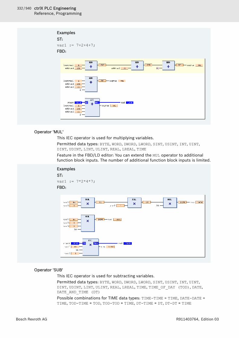
332 / 940 ctrlX PLC EngineeringReference, Programming
Bosch Rexroth AG R911403764, Edition 03
ExamplesST:var1 := 7+2+4+7;FBD:
Operator 'MUL'This IEC operator is used for multiplying variables.Permitted data types: BYTE, WORD, DWORD, LWORD, SINT, USINT, INT, UINT,DINT, UDINT, LINT, ULINT, REAL, LREAL, TIMEFeature in the FBD/LD editor: You can extend the MUL operator to additionalfunction block inputs. The number of additional function block inputs is limited.
ExamplesST:var1 := 7*2*4*7;FBD:
Operator 'SUB'This IEC operator is used for subtracting variables.Permitted data types: BYTE, WORD, DWORD, LWORD, SINT, USINT, INT, UINT,DINT, UDINT, LINT, ULINT, REAL, LREAL, TIME, TIME_OF_DAY (TOD), DATE,DATE_AND_TIME (DT)Possible combinations for TIME data types: TIME-TIME = TIME, DATE-DATE =TIME, TOD-TIME = TOD, TOD-TOD = TIME, DT-TIME = DT, DT-DT = TIME

333 / 940ctrlX PLC EngineeringReference, Programming
Bosch Rexroth AGR911403764, Edition 03
Negative TIME values are undefined.
ExamplesST:var1 := 7-2; FBD:
Operator 'DIV'This IEC operator is used for dividing variables.Permitted data types: BYTE, WORD, DWORD, LWORD, SINT, USINT, INT, UINT,DINT, UDINT, LINT, ULINT, REAL, LREAL, TIME
NOTICE Division by zero may have different results depending onthe target system.
ExamplesST:var1 := 8/2;FBD:1. Series of DIV blocks, 2. Single DIV block, 3. DIV blocks with EN/ENO param-eters
Please note that it is possible to monitor division by zero at runtime by usingthe implicit monitoring functions CheckDivInt, CheckDivLint, CheckDiv-Real, and CheckDivLReal.See also● ⮫ Chapter “POU 'CheckDivInt'” on page 612● ⮫ Chapter “POU 'CheckDivLInt'” on page 613● ⮫ Chapter “POU 'CheckDivReal'” on page 614● ⮫ Chapter “POU 'CheckDivLReal'” on page 614
Operator 'MOD'This IEC operator is used for modulo division.The result of the function is the integer remainder of division.

334 / 940 ctrlX PLC EngineeringReference, Programming
Bosch Rexroth AG R911403764, Edition 03
Permitted data types: BYTE, WORD, DWORD, LWORD, SINT, USINT, INT, UINT,DINT, UDINT, LINT, ULINT
NOTICE Division by zero may have different results depending onthe target system.
ExamplesResult in Var1: 1ST:var1 := 9 MOD 2;FBD:
Operator 'MOVE'This IEC operator is used for assigning a variable to another variable of a corre-sponding type.Because the MOVE block is available in the CFC, FBD, and LD editors, you canalso use the EN/ENO functionality for variable assignment.
CFC with EN/ENO function:PLC Engineering assigns the value of var1 to var2 only if "en_i" yields TRUE.
ST:ivar2 := MOVE(ivar1);This corresponds to:ivar2 := ivar1;
Operator 'INDEXOF'This operator is an extension of the IEC 61131-3 standard.Instead of the INDEXOF operator, the ADR operator is provided in PLC Engi-neering V3 for obtaining a pointer at the index of a block.See also● ⮫ Chapter “Operator 'ADR'” on page 345
Operator 'SIZEOF'This operator is an extension of the IEC 61131-3 standard.This operator is used for defining the number of bytes that are required by thevariable x. The SIZEOF operator always yields an unsigned value. The type ofreturn variable adapts to the detected size of the variable x.
Return Value of SIZEOF(x) Data type of the constant (PLC Engi-neering uses this implicitly fordetected size)
0 <= size of x < 256 USINT
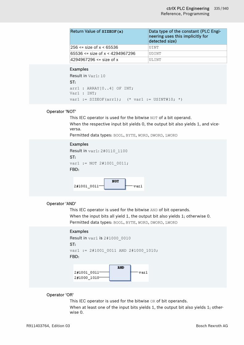
335 / 940ctrlX PLC EngineeringReference, Programming
Bosch Rexroth AGR911403764, Edition 03
Return Value of SIZEOF(x) Data type of the constant (PLC Engi-neering uses this implicitly fordetected size)
256 <= size of x < 65536 UINT65536 <= size of x < 4294967296 UDINT4294967296 <= size of x ULINT
ExamplesResult in Var1: 10ST:arr1 : ARRAY[0..4] OF INT; Var1 : INT; var1 := SIZEOF(arr1); (* var1 := USINT#10; *)
Operator 'NOT'This IEC operator is used for the bitwise NOT of a bit operand.When the respective input bit yields 0, the output bit also yields 1, and vice-versa.Permitted data types: BOOL, BYTE, WORD, DWORD, LWORD
ExamplesResult in var1: 2#0110_1100ST:var1 := NOT 2#1001_0011; FBD:
Operator 'AND'This IEC operator is used for the bitwise AND of bit operands.When the input bits all yield 1, the output bit also yields 1; otherwise 0.Permitted data types: BOOL, BYTE, WORD, DWORD, LWORD
ExamplesResult in var1 is 2#1000_0010ST:var1 := 2#1001_0011 AND 2#1000_1010;FBD:
Operator 'OR'This IEC operator is used for the bitwise OR of bit operands.When at least one of the input bits yields 1, the output bit also yields 1; other-wise 0.
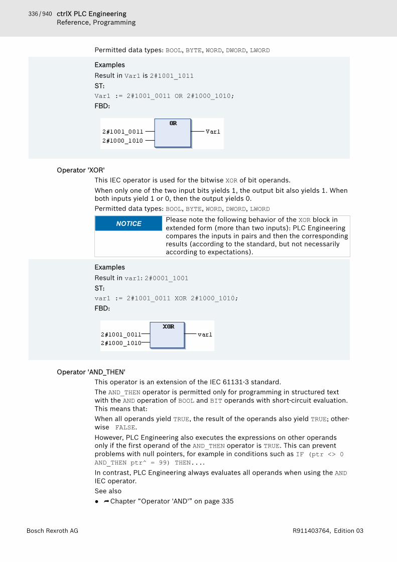
336 / 940 ctrlX PLC EngineeringReference, Programming
Bosch Rexroth AG R911403764, Edition 03
Permitted data types: BOOL, BYTE, WORD, DWORD, LWORD
ExamplesResult in Var1 is 2#1001_1011ST:Var1 := 2#1001_0011 OR 2#1000_1010;FBD:
Operator 'XOR'This IEC operator is used for the bitwise XOR of bit operands.When only one of the two input bits yields 1, the output bit also yields 1. Whenboth inputs yield 1 or 0, then the output yields 0.Permitted data types: BOOL, BYTE, WORD, DWORD, LWORD
NOTICE Please note the following behavior of the XOR block inextended form (more than two inputs): PLC Engineeringcompares the inputs in pairs and then the correspondingresults (according to the standard, but not necessarilyaccording to expectations).
ExamplesResult in var1: 2#0001_1001ST:var1 := 2#1001_0011 XOR 2#1000_1010; FBD:
Operator 'AND_THEN'This operator is an extension of the IEC 61131-3 standard.The AND_THEN operator is permitted only for programming in structured textwith the AND operation of BOOL and BIT operands with short-circuit evaluation.This means that:When all operands yield TRUE, the result of the operands also yield TRUE; other-wise FALSE.However, PLC Engineering also executes the expressions on other operandsonly if the first operand of the AND_THEN operator is TRUE. This can preventproblems with null pointers, for example in conditions such as IF (ptr <> 0AND_THEN ptr^ = 99) THEN....In contrast, PLC Engineering always evaluates all operands when using the ANDIEC operator.See also● ⮫ Chapter “Operator 'AND'” on page 335
337 / 940ctrlX PLC EngineeringReference, Programming
Bosch Rexroth AGR911403764, Edition 03
Operator 'OR_ELSE'This operator is an extension of the IEC 61131-3 standard.The OR_ELSE operator is permitted only for programming in structured text: ORoperation of BOOL and BIT operands; with short-circuit evaluation. This means:When at least one of the operands yields TRUE, the result of the operation alsoyields TRUE; otherwise FALSE.In contrast to using the OR IEC operator, for OR_ELSE the expressions on allother operators are not evaluated as soon as one of the operands is evaluatedas TRUE.
ExampleVARbEver: BOOL;bX: BOOL;dw: DWORD := 16#000000FF;
END_VARbEver := FALSE;bX := dw.8 OR_ELSE dw.1 OR_ELSE dw.1 OR_ELSE (bEver := TRUE);dw.8 is FALSE and dw.1 is TRUE; therefore bX is the result of the operationTRUE. However, the expression at the third input is not executed, and bEverremains FALSE. On the other hand, if the standard OR operation was used,bEver would be set to TRUE.
See also● ⮫ Chapter “Operator 'OR' ” on page 335
Operator 'SHL'This IEC operator is used for bitwise shift of an operand to the left.erg := SHL (in, n)in: Operand that is shifted to the leftn: Number of bits to shift in to the left
NOTICE If n overwrites the data type width, then it depends onthe target system how the BYTE, WORD, DWORD, and LWORDoperands are padded. The target systems cause paddingwith zeros or n MOD <tab width>.
NOTICE Please note the number of bits that PLC Engineeringuses for this operation as defined by the data type of theinput variable in.

338 / 940 ctrlX PLC EngineeringReference, Programming
Bosch Rexroth AG R911403764, Edition 03
ExamplesThe results for erg_byte and erg_word are different, although the values ofthe in_byte and in_word input variables are the same and the data types ofthe input variables are different.ST:PROGRAM shl_stVAR in_byte : BYTE := 16#45; (* 2#01000101 ) in_word : WORD := 16#0045; (* 2#0000000001000101 ) erg_byte : BYTE; erg_word : WORD; n: BYTE := 2; END_VAR erg_byte := SHL(in_byte,n); (* Result is 16#14, 2#00010100 *)erg_word := SHL(in_word,n); (* Result is 16#0114, 2#0000000100010100 *)
FBD:
Operator 'SHR'This IEC operator is used for bitwise shift of an operand to the right.erg := SHR (in, n)in: Operand that is shifted to the rightn: Number of bits for shifting in to the right
NOTICE If n overwrites the data type width, then it depends onthe target system how the BYTE, WORD, DWORD, and LWORDoperands are padded. The target systems cause paddingwith zeros or n MOD <tab width>.
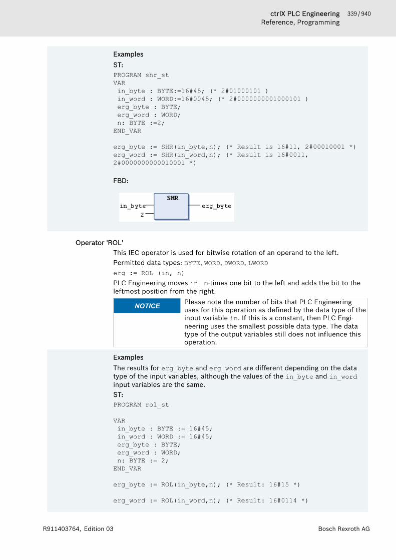
339 / 940ctrlX PLC EngineeringReference, Programming
Bosch Rexroth AGR911403764, Edition 03
ExamplesST:PROGRAM shr_stVAR in_byte : BYTE:=16#45; (* 2#01000101 ) in_word : WORD:=16#0045; (* 2#0000000001000101 ) erg_byte : BYTE; erg_word : WORD; n: BYTE :=2; END_VAR
erg_byte := SHR(in_byte,n); (* Result is 16#11, 2#00010001 *)erg_word := SHR(in_word,n); (* Result is 16#0011, 2#0000000000010001 *) FBD:
Operator 'ROL'This IEC operator is used for bitwise rotation of an operand to the left.Permitted data types: BYTE, WORD, DWORD, LWORDerg := ROL (in, n)PLC Engineering moves in n-times one bit to the left and adds the bit to theleftmost position from the right.
NOTICE Please note the number of bits that PLC Engineeringuses for this operation as defined by the data type of theinput variable in. If this is a constant, then PLC Engi-neering uses the smallest possible data type. The datatype of the output variables still does not influence thisoperation.
ExamplesThe results for erg_byte and erg_word are different depending on the datatype of the input variables, although the values of the in_byte and in_wordinput variables are the same.ST:PROGRAM rol_st
VAR in_byte : BYTE := 16#45; in_word : WORD := 16#45; erg_byte : BYTE; erg_word : WORD; n: BYTE := 2; END_VAR
erg_byte := ROL(in_byte,n); (* Result: 16#15 *)
erg_word := ROL(in_word,n); (* Result: 16#0114 *)
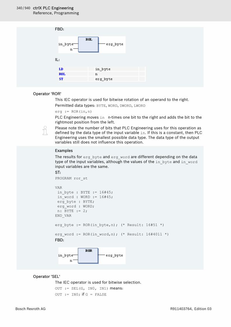
340 / 940 ctrlX PLC EngineeringReference, Programming
Bosch Rexroth AG R911403764, Edition 03
FBD:
IL:
Operator 'ROR'This IEC operator is used for bitwise rotation of an operand to the right.Permitted data types: BYTE, WORD, DWORD, LWORDerg := ROR(in,n)PLC Engineering moves in n-times one bit to the right and adds the bit to therightmost position from the left.Please note the number of bits that PLC Engineering uses for this operation asdefined by the data type of the input variable in. If this is a constant, then PLCEngineering uses the smallest possible data type. The data type of the outputvariables still does not influence this operation.
ExamplesThe results for erg_byte and erg_word are different depending on the datatype of the input variables, although the values of the in_byte and in_wordinput variables are the same.ST:PROGRAM ror_st
VAR in_byte : BYTE := 16#45; in_word : WORD := 16#45; erg_byte : BYTE; erg_word : WORD; n: BYTE := 2; END_VAR
erg_byte := ROR(in_byte,n); (* Result: 16#51 *)
erg_word := ROR(in_word,n); (* Result: 16#4011 *) FBD:
Operator 'SEL'The IEC operator is used for bitwise selection.OUT := SEL(G, IN0, IN1) means:OUT := IN0; if G = FALSE
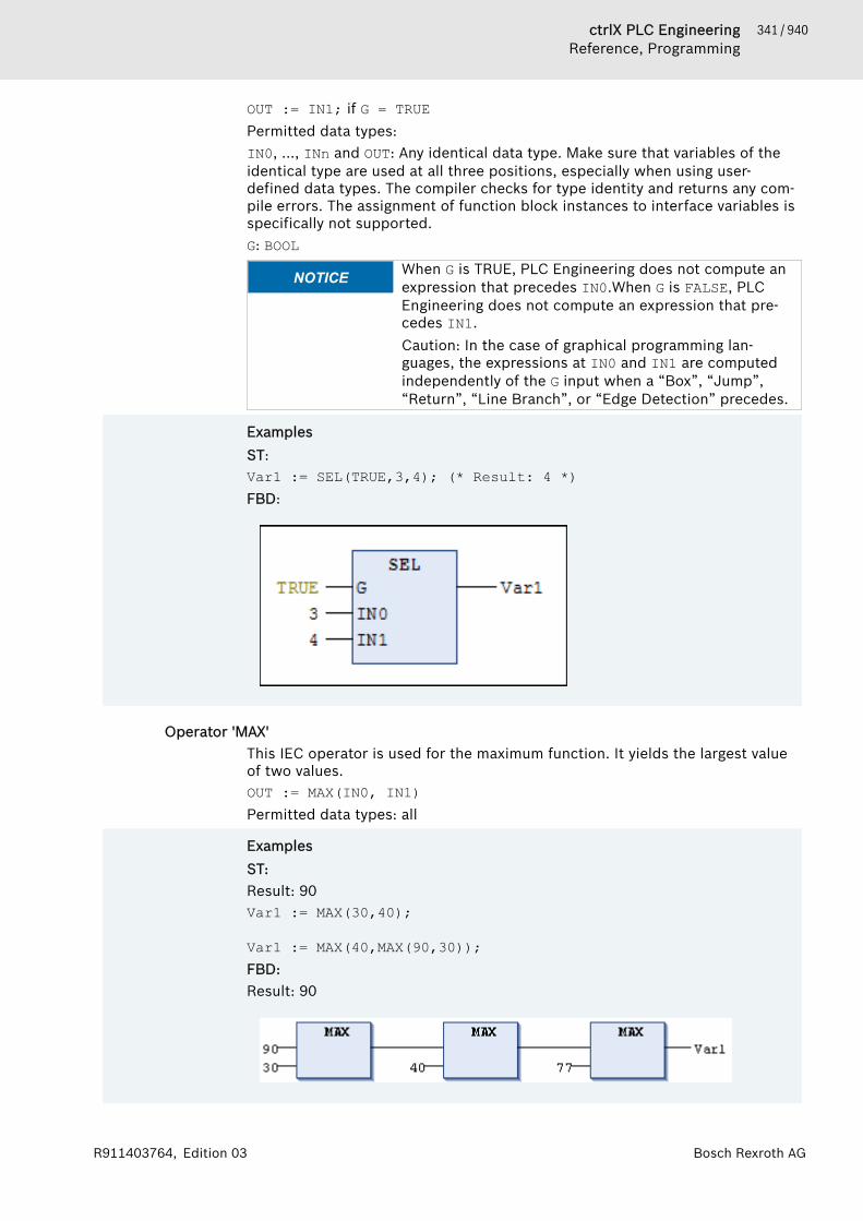
341 / 940ctrlX PLC EngineeringReference, Programming
Bosch Rexroth AGR911403764, Edition 03
OUT := IN1; if G = TRUEPermitted data types:IN0, ..., INn and OUT: Any identical data type. Make sure that variables of theidentical type are used at all three positions, especially when using user-defined data types. The compiler checks for type identity and returns any com-pile errors. The assignment of function block instances to interface variables isspecifically not supported.G: BOOL
NOTICE When G is TRUE, PLC Engineering does not compute anexpression that precedes IN0.When G is FALSE, PLCEngineering does not compute an expression that pre-cedes IN1.Caution: In the case of graphical programming lan-guages, the expressions at IN0 and IN1 are computedindependently of the G input when a “Box”, “Jump”,“Return”, “Line Branch”, or “Edge Detection” precedes.
ExamplesST:Var1 := SEL(TRUE,3,4); (* Result: 4 *) FBD:
Operator 'MAX'This IEC operator is used for the maximum function. It yields the largest valueof two values.OUT := MAX(IN0, IN1)Permitted data types: all
ExamplesST:Result: 90Var1 := MAX(30,40);
Var1 := MAX(40,MAX(90,30)); FBD:Result: 90

342 / 940 ctrlX PLC EngineeringReference, Programming
Bosch Rexroth AG R911403764, Edition 03
Operator 'MIN'This IEC operator is used for the minimum function. It yields the smallest valueof two values.OUT := MIN(IN0,IN1)Permitted data types: all
ExamplesResult: 30ST:Var1:=MIN(90,30);
Var1 := MIN(MIN(90,30),40); FBD:
Operator 'LIMIT'This IEC selection operator is used for limiting.OUT := LIMIT(Min, IN, Max)Means: OUT := MIN (MAX (IN, Min), Max)Max is the upper limit and Min is the lower limit for the result. If the IN value isabove the Max upper limit, then LIMIT yields Max. If the value of IN is below theMin lower limit, then the result is Min.Permitted data types for IN and OUT: all
ExamplesResult in Var1 is 80ST:Var1 := LIMIT(30,90,80);
Operator 'MUX'This IEC operator is used as a multiplexer.OUT := MUX(K, IN0,...,INn)Means: OUT = IN_KPermitted data type for K: BYTE, WORD, DWORD, LWORD, SINT, USINT, INT, UINT,DINT, LINT, ULINT, oUDINT.IN0, ..., INn, and OUT: Any identical data type. Make sure that variables of theidentical type are used at all three positions, especially when using user-defined data types. The compiler checks for type identity and returns any com-pile errors. The assignment of function block instances to interface variables isspecifically not supported.MUX selects the K-th value from a set of values. The first value is K=0. If K isgreater than the number of other inputs (n), then PLC Engineering passes onthe last value (INn).
NOTICE For runtime optimization, PLC Engineering computesonly the expression that precedes IN_K. However, PLCEngineering computes all branches in simulation mode.
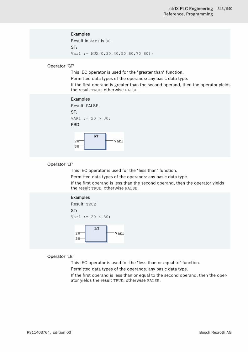
343 / 940ctrlX PLC EngineeringReference, Programming
Bosch Rexroth AGR911403764, Edition 03
ExamplesResult in Var1 is 30.ST:Var1 := MUX(0,30,40,50,60,70,80);
Operator 'GT'This IEC operator is used for the "greater than" function.Permitted data types of the operands: any basic data type.If the first operand is greater than the second operand, then the operator yieldsthe result TRUE; otherwise FALSE.
ExamplesResult: FALSEST:VAR1 := 20 > 30; FBD:
Operator 'LT'This IEC operator is used for the "less than" function.Permitted data types of the operands: any basic data type.If the first operand is less than the second operand, then the operator yieldsthe result TRUE; otherwise FALSE.
ExamplesResult: TRUEST:Var1 := 20 < 30;
Operator 'LE'This IEC operator is used for the "less than or equal to" function.Permitted data types of the operands: any basic data type.If the first operand is less than or equal to the second operand, then the oper-ator yields the result TRUE; otherwise FALSE.

344 / 940 ctrlX PLC EngineeringReference, Programming
Bosch Rexroth AG R911403764, Edition 03
ExamplesResult in Var1: TRUEST:Var1 := 20 <= 30;
Operator 'GE'This IEC operator is used for the "greater than or equal to" function.Permitted data types of the operands: any basic data type.If the first operand is greater than or equal to the second operand, then theoperator yields the result TRUE; otherwise FALSE.
ExamplesResult: TRUEST:VAR1 := 60 >= 40; FBD:
Operator 'EQ'This IEC operator is used for the "equals" function.Permitted data types of the operands: any basic data type, depending on targetsystem and compiler version: structure data type.If the operands are equal, then then the operator yields the result TRUE, other-wise FALSE.
ExamplesResult: TRUEST:VAR1 := 40 = 40; FBD:
Operator 'NE'This IEC operator is used for the "does not equal" function.Permitted data types of the operands: any basic data type, depending on targetsystem and compiler version: structure data type.
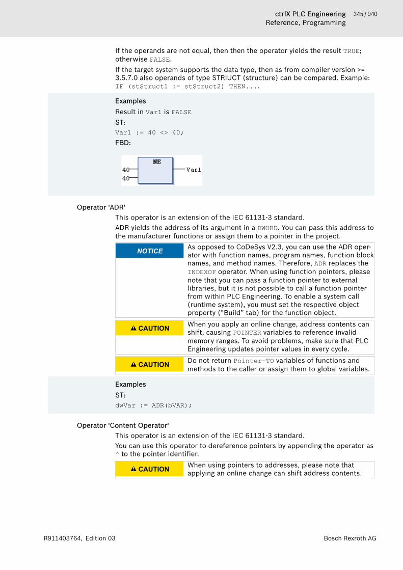
345 / 940ctrlX PLC EngineeringReference, Programming
Bosch Rexroth AGR911403764, Edition 03
If the operands are not equal, then then the operator yields the result TRUE;otherwise FALSE.If the target system supports the data type, then as from compiler version >=3.5.7.0 also operands of type STRIUCT (structure) can be compared. Example:IF (stStruct1 := stStruct2) THEN....
ExamplesResult in Var1 is FALSEST:Var1 := 40 <> 40;FBD:
Operator 'ADR'This operator is an extension of the IEC 61131-3 standard.ADR yields the address of its argument in a DWORD. You can pass this address tothe manufacturer functions or assign them to a pointer in the project.
NOTICE As opposed to CoDeSys V2.3, you can use the ADR oper-ator with function names, program names, function blocknames, and method names. Therefore, ADR replaces theINDEXOF operator. When using function pointers, pleasenote that you can pass a function pointer to externallibraries, but it is not possible to call a function pointerfrom within PLC Engineering. To enable a system call(runtime system), you must set the respective objectproperty (“Build” tab) for the function object.
CAUTION When you apply an online change, address contents canshift, causing POINTER variables to reference invalidmemory ranges. To avoid problems, make sure that PLCEngineering updates pointer values in every cycle.
CAUTION Do not return Pointer-TO variables of functions andmethods to the caller or assign them to global variables.
ExamplesST:dwVar := ADR(bVAR);
Operator 'Content Operator'This operator is an extension of the IEC 61131-3 standard.You can use this operator to dereference pointers by appending the operator as^ to the pointer identifier.
CAUTION When using pointers to addresses, please note thatapplying an online change can shift address contents.

346 / 940 ctrlX PLC EngineeringReference, Programming
Bosch Rexroth AG R911403764, Edition 03
ExampleST:pt : POINTER TO INT;var_int1 : INT;var_int2 : INT;pt := ADR(var_int1);var_int2 := pt^;
Operator 'BITADR'This operator is an extension of the IEC 61131-3 standard.BITADR yields the bit offset within a segment in a DWORD.
NOTICE The offset depends on whether the byte addressingcheck box is selected or cleared in the target system set-tings.
The highest value nibble (4 bits) in this DWORD defines the memory range:Flag: 16x40000000Input: 16x80000000Output: 16xC0000000
CAUTION When using pointers to addresses, please note thatapplying an online change can shift address contents.
ExamplesST:VAR Var1 AT %IX2.3 : BOOL; bitoffset: DWORD;END_VAR
bitoffset := BITADR(var1); (* Result if byte addressing = TRUE: 16x80000013, if byte addressing = FALSE: 16x80000023 *)
Operator 'CAL'This IEC operator is used for calling function blocks. In IL, CAL calls the instance of a function block.CAL <function block> (<input variable1> := <value>, <input variableN> := <value>)
ExampleCall of the Inst instance of a function block with assignment of the input vari-ables Par1 and Par2 with 0 or TRUE.CAL Inst(Par1 := 0, Par2 := TRUE);
Operator 'BOOL_TO'The IEC operator is used for converting the BOOL data type to another datatype.BOOL_TO_<data type>
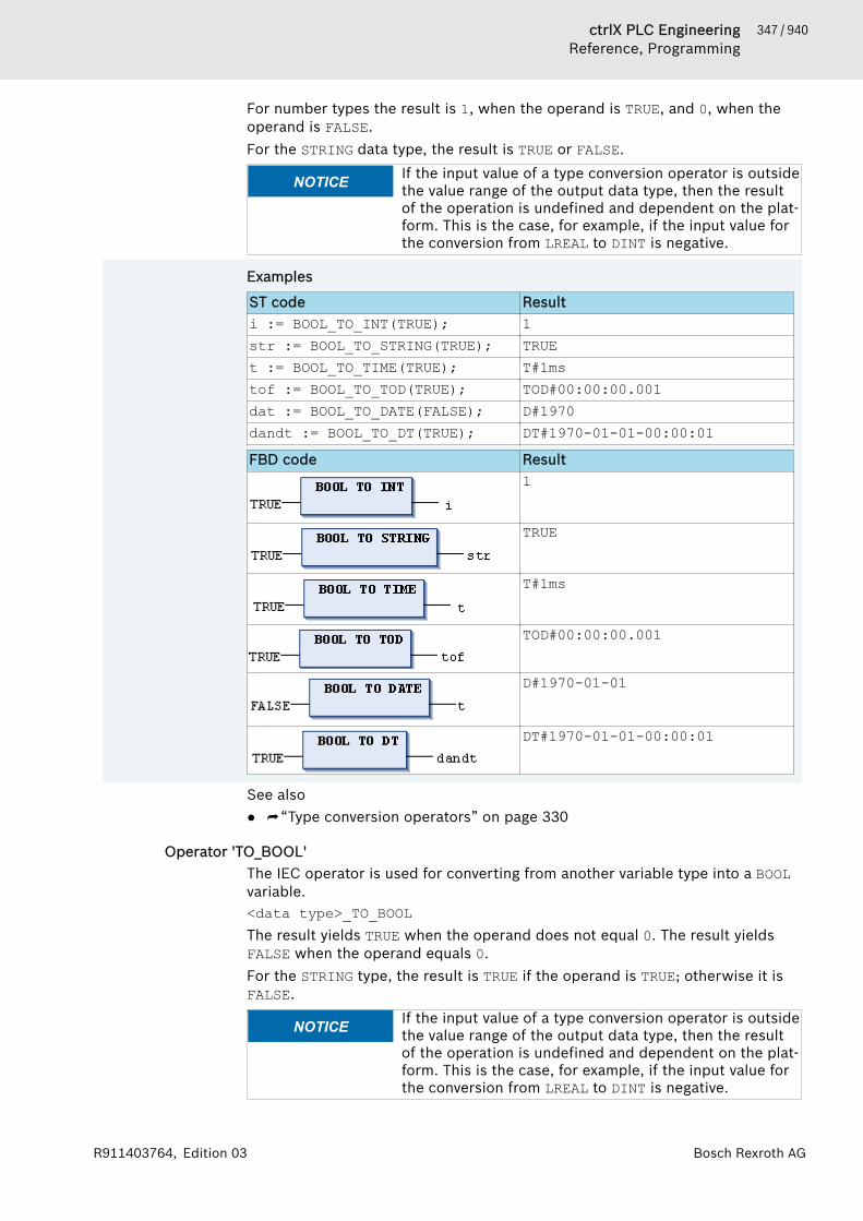
347 / 940ctrlX PLC EngineeringReference, Programming
Bosch Rexroth AGR911403764, Edition 03
For number types the result is 1, when the operand is TRUE, and 0, when theoperand is FALSE.For the STRING data type, the result is TRUE or FALSE.
NOTICE If the input value of a type conversion operator is outsidethe value range of the output data type, then the resultof the operation is undefined and dependent on the plat-form. This is the case, for example, if the input value forthe conversion from LREAL to DINT is negative.
Examples
ST code Resulti := BOOL_TO_INT(TRUE); 1str := BOOL_TO_STRING(TRUE); TRUEt := BOOL_TO_TIME(TRUE); T#1mstof := BOOL_TO_TOD(TRUE); TOD#00:00:00.001dat := BOOL_TO_DATE(FALSE); D#1970dandt := BOOL_TO_DT(TRUE); DT#1970-01-01-00:00:01FBD code Result
1
TRUE
T#1ms
TOD#00:00:00.001
D#1970-01-01
DT#1970-01-01-00:00:01
See also● ⮫ “Type conversion operators” on page 330
Operator 'TO_BOOL'The IEC operator is used for converting from another variable type into a BOOLvariable.<data type>_TO_BOOLThe result yields TRUE when the operand does not equal 0. The result yieldsFALSE when the operand equals 0.For the STRING type, the result is TRUE if the operand is TRUE; otherwise it isFALSE.
NOTICE If the input value of a type conversion operator is outsidethe value range of the output data type, then the resultof the operation is undefined and dependent on the plat-form. This is the case, for example, if the input value forthe conversion from LREAL to DINT is negative.

348 / 940 ctrlX PLC EngineeringReference, Programming
Bosch Rexroth AG R911403764, Edition 03
Examples
ST code Resultb := BYTE_TO_BOOL(2#11010101); TRUEb := INT_TO_BOOL(0); FALSEb := TIME_TO_BOOL(T#5ms); TRUEb := STRING_TO_BOOL('TRUE'); TRUEFBD code Result
TRUE
FALSE
TRUE
TRUE
See also● ⮫ “Type conversion operators” on page 330
Operator 'TO_<xxx>'The IEC operator is used for converting variables of one data type into anotherdata type, where the input type is not explicitly given (overflow conversion).TO_<data type>The function depends on what is described for each typed conversion.
NOTICE If the input value of a type conversion operator is outsidethe value range of the output data type, then the resultof the operation is undefined and dependent on the plat-form. This is the case, for example, if the input value forthe conversion from LREAL to DINT is negative.
ExamplesST implementation language:
VAR iVar : INT; bVar : BOOL; sVar : STRING; rVar : REAL;END_VAR
iVar := TO_INT(4.22); (* Result: 4 *)bVar := TO_BOOL(1); (* Result: TRUE *)sVar := TO_STRING(342); (* Result: '342' *)rVar := TO_WORD('123'); (* Result: 123 *)
See also● ⮫ “Type conversion operators” on page 330
Operator '<INT Type>_TO_<INT Type>'Conversion of one integer data type into another integer data type.
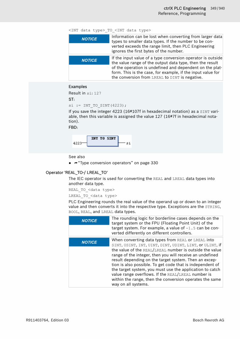
349 / 940ctrlX PLC EngineeringReference, Programming
Bosch Rexroth AGR911403764, Edition 03
<INT data type>_TO_<INT data type>
NOTICE Information can be lost when converting from larger datatypes to smaller data types. If the number to be con-verted exceeds the range limit, then PLC Engineeringignores the first bytes of the number.
NOTICE If the input value of a type conversion operator is outsidethe value range of the output data type, then the resultof the operation is undefined and dependent on the plat-form. This is the case, for example, if the input value forthe conversion from LREAL to DINT is negative.
ExamplesResult in si: 127ST:si := INT_TO_SINT(4223);If you save the integer 4223 (16#107f in hexadecimal notation) as a SINT vari-able, then this variable is assigned the value 127 (16#7f in hexadecimal nota-tion).FBD:
See also● ⮫ “Type conversion operators” on page 330
Operator 'REAL_TO-/ LREAL_TO'The IEC operator is used for converting the REAL and LREAL data types intoanother data type.REAL_TO_<data type>LREAL_TO_<data type>PLC Engineering rounds the real value of the operand up or down to an integervalue and then converts it into the respective type. Exceptions are the STRING,BOOL, REAL, and LREAL data types.
NOTICE The rounding logic for borderline cases depends on thetarget system or the FPU (Floating Point Unit) of thetarget system. For example, a value of -1.5 can be con-verted differently on different controllers.
NOTICE When converting data types from REAL or LREAL intoSINT, USINT, INT, UINT, DINT, UDINT, LINT, or ULINT, ifthe value of the REAL/LREAL number is outside the valuerange of the integer, then you will receive an undefinedresult depending on the target system. Then an excep-tion is also possible. To get code that is independent ofthe target system, you must use the application to catchvalue range overflows. If the REAL/LREAL number iswithin the range, then the conversion operates the sameway on all systems.
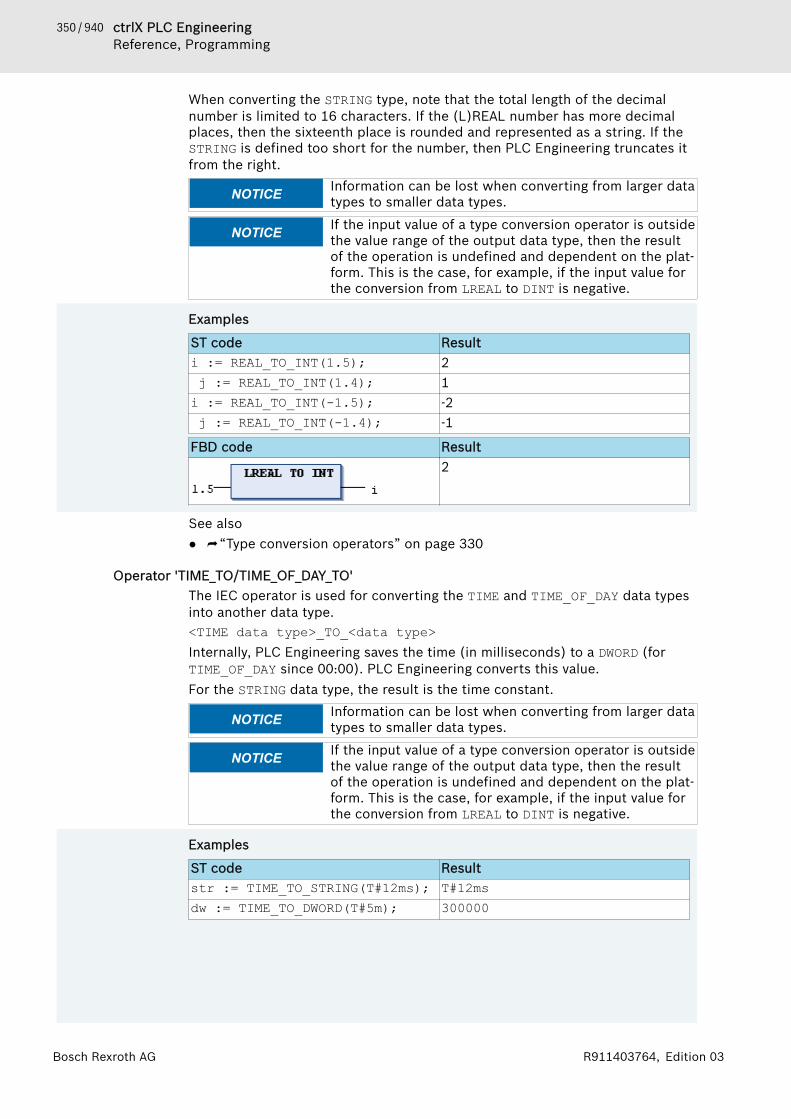
350 / 940 ctrlX PLC EngineeringReference, Programming
Bosch Rexroth AG R911403764, Edition 03
When converting the STRING type, note that the total length of the decimalnumber is limited to 16 characters. If the (L)REAL number has more decimalplaces, then the sixteenth place is rounded and represented as a string. If theSTRING is defined too short for the number, then PLC Engineering truncates itfrom the right.
NOTICE Information can be lost when converting from larger datatypes to smaller data types.
NOTICE If the input value of a type conversion operator is outsidethe value range of the output data type, then the resultof the operation is undefined and dependent on the plat-form. This is the case, for example, if the input value forthe conversion from LREAL to DINT is negative.
Examples
ST code Resulti := REAL_TO_INT(1.5); 2 j := REAL_TO_INT(1.4); 1i := REAL_TO_INT(-1.5); -2 j := REAL_TO_INT(-1.4); -1
FBD code Result2
See also● ⮫ “Type conversion operators” on page 330
Operator 'TIME_TO/TIME_OF_DAY_TO'The IEC operator is used for converting the TIME and TIME_OF_DAY data typesinto another data type.<TIME data type>_TO_<data type>Internally, PLC Engineering saves the time (in milliseconds) to a DWORD (forTIME_OF_DAY since 00:00). PLC Engineering converts this value.For the STRING data type, the result is the time constant.
NOTICE Information can be lost when converting from larger datatypes to smaller data types.
NOTICE If the input value of a type conversion operator is outsidethe value range of the output data type, then the resultof the operation is undefined and dependent on the plat-form. This is the case, for example, if the input value forthe conversion from LREAL to DINT is negative.
Examples
ST code Resultstr := TIME_TO_STRING(T#12ms); T#12msdw := TIME_TO_DWORD(T#5m); 300000
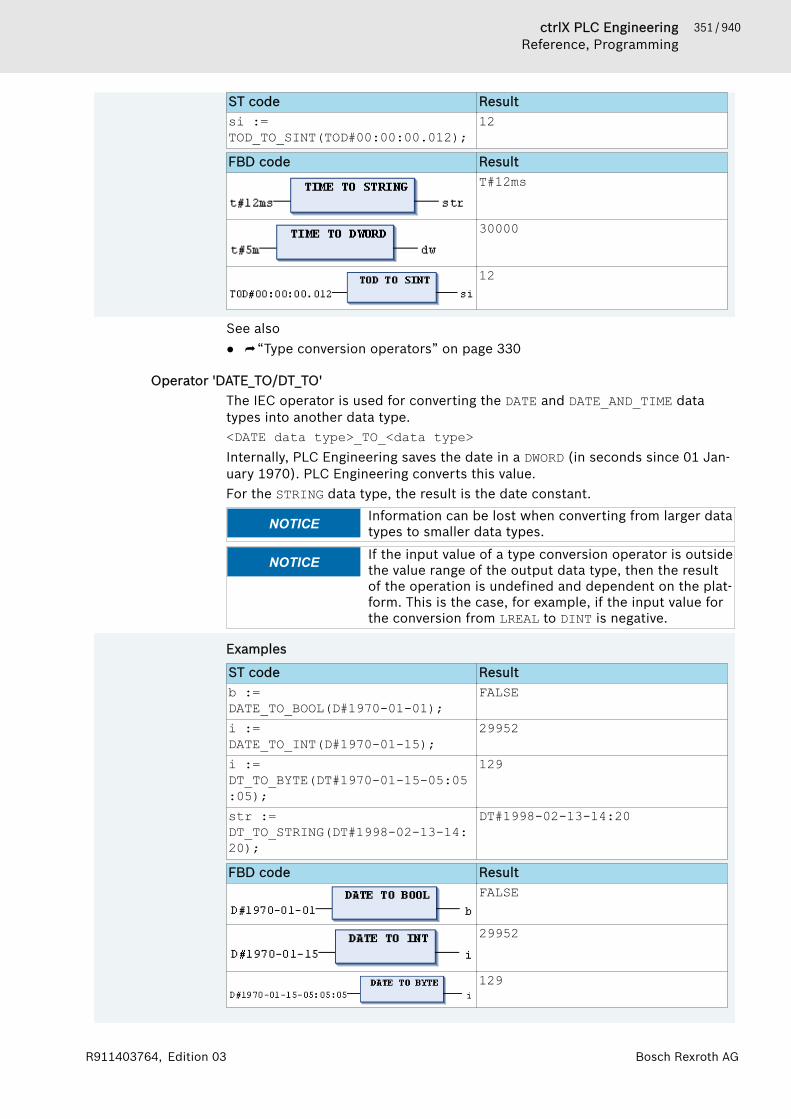
351 / 940ctrlX PLC EngineeringReference, Programming
Bosch Rexroth AGR911403764, Edition 03
ST code Resultsi :=TOD_TO_SINT(TOD#00:00:00.012);
12
FBD code ResultT#12ms
30000
12
See also● ⮫ “Type conversion operators” on page 330
Operator 'DATE_TO/DT_TO'The IEC operator is used for converting the DATE and DATE_AND_TIME datatypes into another data type.<DATE data type>_TO_<data type>Internally, PLC Engineering saves the date in a DWORD (in seconds since 01 Jan-uary 1970). PLC Engineering converts this value.For the STRING data type, the result is the date constant.
NOTICE Information can be lost when converting from larger datatypes to smaller data types.
NOTICE If the input value of a type conversion operator is outsidethe value range of the output data type, then the resultof the operation is undefined and dependent on the plat-form. This is the case, for example, if the input value forthe conversion from LREAL to DINT is negative.
Examples
ST code Resultb :=DATE_TO_BOOL(D#1970-01-01);
FALSE
i :=DATE_TO_INT(D#1970-01-15);
29952
i :=DT_TO_BYTE(DT#1970-01-15-05:05:05);
129
str :=DT_TO_STRING(DT#1998-02-13-14:20);
DT#1998-02-13-14:20
FBD code ResultFALSE
29952
129

352 / 940 ctrlX PLC EngineeringReference, Programming
Bosch Rexroth AG R911403764, Edition 03
FBD code ResultDT#1998-02-13-14:20
See also● ⮫ “Type conversion operators” on page 330
Operator 'STRING_TO'The IEC operator is used for converting the STRING data type into another datatype.STRING_TO_<data type>You must define the STRING operand according to the IEC 61131-3 standard.The value has to be a valid constant (literal) of the target type. This affects anygiven exponential values, infinite values, prefixes, grouping characters (_), andcommas. Additional characters after the digits of a number are permitted (forexample, 23xy). Additional characters before a number are not permitted.The operand must be a valid value of the target data type.
NOTICE If the data type of the operand does not match the targetdata type or if the value is outside the range of the targetdata type, then the result output depends on the pro-cessor type and is therefore undefined. Information canbe lost when converting from larger data types to smallerdata types.
NOTICE If the input value of a type conversion operator is outsidethe value range of the output data type, then the resultof the operation is undefined and dependent on the plat-form. This is the case, for example, if the input value forthe conversion from LREAL to DINT is negative.
Examples
ST code Resultb := STRING_TO_BOOL('TRUE'); TRUEw := STRING_TO_WORD('abc34'); 0w := STRING_TO_WORD('34abc'); 34t :=STRING_TO_TIME('T#127ms');
T#127ms
r := STRING_TO_REAL('1.234'); 1,234bv := STRING_TO_BYTE('500'); 244FBD code Result
TRUE
See also● ⮫ “Type conversion operators” on page 330
Operator 'TRUNC'The IEC operator is used for converting the REAL data type into the DINT datatype. PLC Engineering takes only the integer part of the number.In CoDeSys V2.3, the TRUNC operator converts REAL into INT. If you import aV2.3 project, then PLC Engineering automatically replaces TRUNC withTRUNC_INT.
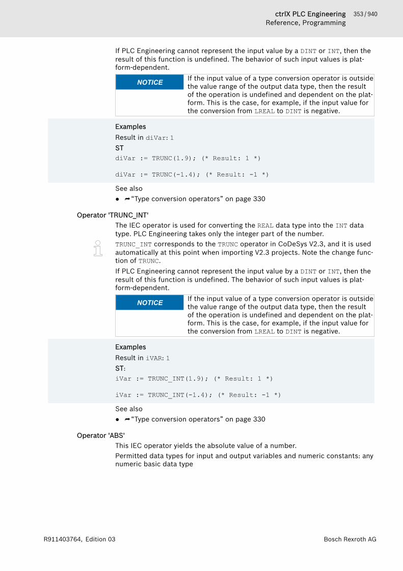
353 / 940ctrlX PLC EngineeringReference, Programming
Bosch Rexroth AGR911403764, Edition 03
If PLC Engineering cannot represent the input value by a DINT or INT, then theresult of this function is undefined. The behavior of such input values is plat-form-dependent.
NOTICE If the input value of a type conversion operator is outsidethe value range of the output data type, then the resultof the operation is undefined and dependent on the plat-form. This is the case, for example, if the input value forthe conversion from LREAL to DINT is negative.
ExamplesResult in diVar: 1STdiVar := TRUNC(1.9); (* Result: 1 *)
diVar := TRUNC(-1.4); (* Result: -1 *)
See also● ⮫ “Type conversion operators” on page 330
Operator 'TRUNC_INT'The IEC operator is used for converting the REAL data type into the INT datatype. PLC Engineering takes only the integer part of the number.TRUNC_INT corresponds to the TRUNC operator in CoDeSys V2.3, and it is usedautomatically at this point when importing V2.3 projects. Note the change func-tion of TRUNC.If PLC Engineering cannot represent the input value by a DINT or INT, then theresult of this function is undefined. The behavior of such input values is plat-form-dependent.
NOTICE If the input value of a type conversion operator is outsidethe value range of the output data type, then the resultof the operation is undefined and dependent on the plat-form. This is the case, for example, if the input value forthe conversion from LREAL to DINT is negative.
ExamplesResult in iVAR: 1ST:iVar := TRUNC_INT(1.9); (* Result: 1 *)
iVar := TRUNC_INT(-1.4); (* Result: -1 *)
See also● ⮫ “Type conversion operators” on page 330
Operator 'ABS'This IEC operator yields the absolute value of a number.Permitted data types for input and output variables and numeric constants: anynumeric basic data type
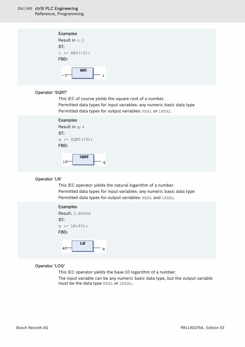
354 / 940 ctrlX PLC EngineeringReference, Programming
Bosch Rexroth AG R911403764, Edition 03
ExamplesResult in i: 2ST:i := ABS(-2);FBD:
Operator 'SQRT'This IEC of course yields the square root of a number.Permitted data types for input variables: any numeric basic data typePermitted data types for output variables: REAL or LREAL
ExamplesResult in q: 4ST:q := SQRT(16); FBD:
Operator 'LN'This IEC operator yields the natural logarithm of a number.Permitted data types for input variables: any numeric basic data typePermitted data types for output variables: REAL and LREAL
ExamplesResult: 3.80666ST:q := LN(45); FBD:
Operator 'LOG'This IEC operator yields the base-10 logarithm of a number.The input variable can be any numeric basic data type, but the output variablemust be the data type REAL or LREAL.
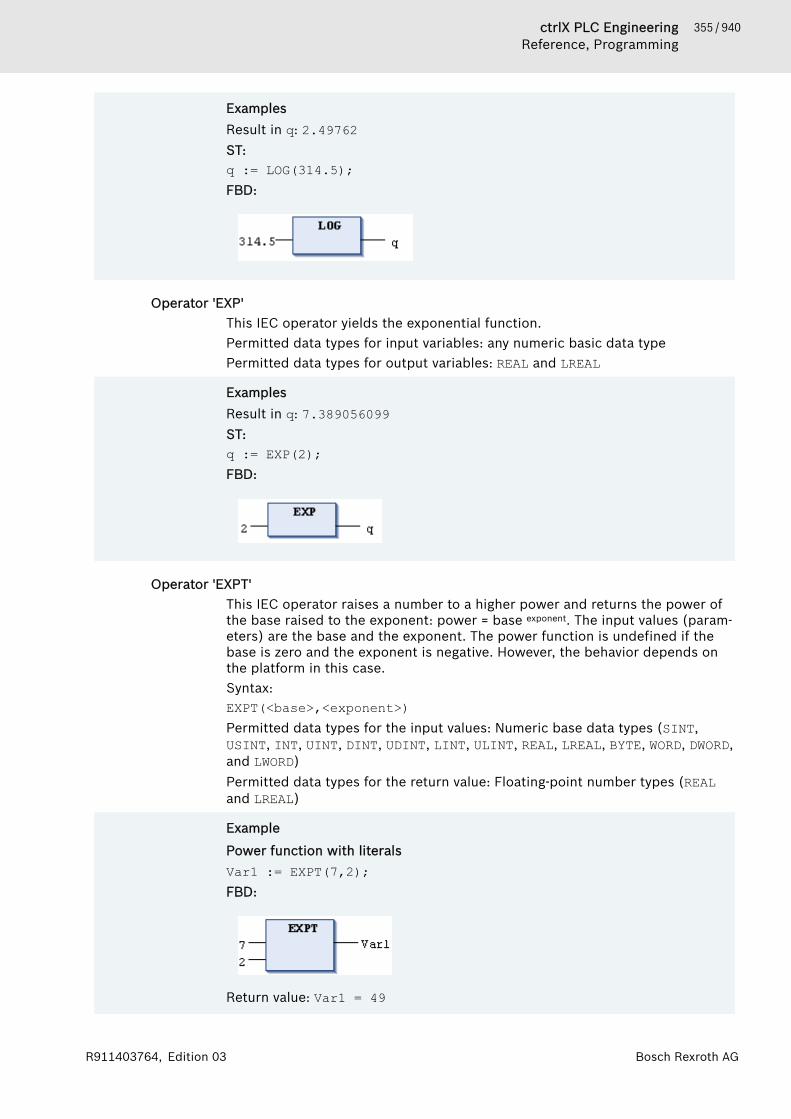
355 / 940ctrlX PLC EngineeringReference, Programming
Bosch Rexroth AGR911403764, Edition 03
ExamplesResult in q: 2.49762ST:q := LOG(314.5);FBD:
Operator 'EXP'This IEC operator yields the exponential function.Permitted data types for input variables: any numeric basic data typePermitted data types for output variables: REAL and LREAL
ExamplesResult in q: 7.389056099ST:q := EXP(2); FBD:
Operator 'EXPT'This IEC operator raises a number to a higher power and returns the power ofthe base raised to the exponent: power = base exponent. The input values (param-eters) are the base and the exponent. The power function is undefined if thebase is zero and the exponent is negative. However, the behavior depends onthe platform in this case.Syntax:EXPT(<base>,<exponent>)Permitted data types for the input values: Numeric base data types (SINT,USINT, INT, UINT, DINT, UDINT, LINT, ULINT, REAL, LREAL, BYTE, WORD, DWORD,and LWORD)Permitted data types for the return value: Floating-point number types (REALand LREAL)
Example
Power function with literalsVar1 := EXPT(7,2);FBD:
Return value: Var1 = 49

356 / 940 ctrlX PLC EngineeringReference, Programming
Bosch Rexroth AG R911403764, Edition 03
Example
Power function with variables
PROGRAM PLC_PRGVARlrPow : LREAL;iBase : INT := 2;iExponent : INT := 7;
END_VAR
lrPow := EXPT(iBase, iExponent);Return value: lrPow = 128
Operator 'SIN'This IEC operator yields the sine value of a number.Permitted data types for input variables that measure the angle in radians: anynumeric basic data typePermitted data types for output variables: REAL and LREAL
ExamplesResult in q: 0.479426ST:q := SIN(0.5); FBD:
Operator 'COS'This IEC operator yields the cosine value of a number.Permitted data types for input variables that measure the angle in radians: anynumeric basic data typePermitted data types for output variables: REAL and LREAL
ExamplesResult in q: 0.877583 ST:q := COS(0.5); FBD:
Operator 'TAN'This IEC operator yields the tangent value of a number.Permitted data types for input variables that measure the angle in radians: anynumeric basic data typePermitted data types for output variables: REAL and LREAL

357 / 940ctrlX PLC EngineeringReference, Programming
Bosch Rexroth AGR911403764, Edition 03
ExamplesResult in q: 0.546302ST:q := TAN(0.5); FBD:
Operator 'ASIN'This IEC operator yields the arcsine value of a number.Permitted data types for input variables: any numeric basic data typePermitted data types for output variables: REAL and LREAL
ExamplesResult in q: 0.523599ST:q := ASIN(0,5);
FBD:
Operator 'ACOS'This IEC operator yields the arccosine value of a number. The value is com-puted in radians.Permitted data types for input variables that measure the angle in radians: anynumeric basic data typePermitted data types for output variables: REAL and LREAL
ExamplesResult in q: 1.0472ST:q := ACOS(0.5); FBD:
Operator 'ATAN'This IEC operator yields the arctangent value of a number. The value is com-puted in radians.Permitted data types for input variables that measure the angle in radians: anynumeric basic data typePermitted data types for output variables: REAL and LREAL
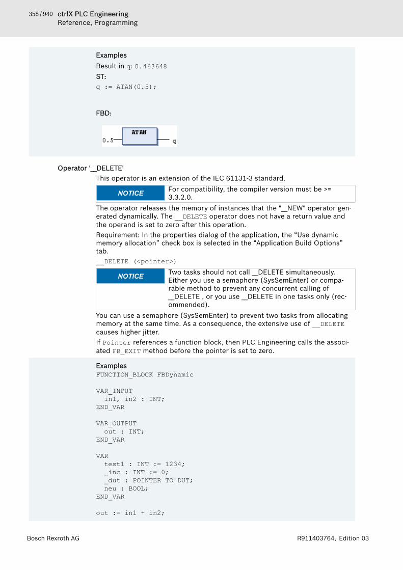
358 / 940 ctrlX PLC EngineeringReference, Programming
Bosch Rexroth AG R911403764, Edition 03
ExamplesResult in q: 0.463648ST:q := ATAN(0.5);
FBD:
Operator '__DELETE'This operator is an extension of the IEC 61131-3 standard.
NOTICE For compatibility, the compiler version must be >=3.3.2.0.
The operator releases the memory of instances that the "__NEW" operator gen-erated dynamically. The __DELETE operator does not have a return value andthe operand is set to zero after this operation.Requirement: In the properties dialog of the application, the “Use dynamicmemory allocation” check box is selected in the “Application Build Options”tab.__DELETE (<pointer>)
NOTICE Two tasks should not call __DELETE simultaneously.Either you use a semaphore (SysSemEnter) or compa-rable method to prevent any concurrent calling of__DELETE , or you use __DELETE in one tasks only (rec-ommended).
You can use a semaphore (SysSemEnter) to prevent two tasks from allocatingmemory at the same time. As a consequence, the extensive use of __DELETEcauses higher jitter.If Pointer references a function block, then PLC Engineering calls the associ-ated FB_EXIT method before the pointer is set to zero.
ExamplesFUNCTION_BLOCK FBDynamic
VAR_INPUT in1, in2 : INT; END_VAR
VAR_OUTPUT out : INT; END_VAR
VAR test1 : INT := 1234; _inc : INT := 0; _dut : POINTER TO DUT; neu : BOOL; END_VAR
out := in1 + in2;

359 / 940ctrlX PLC EngineeringReference, Programming
Bosch Rexroth AGR911403764, Edition 03
METHOD FB_Exit : BOOL
VAR_INPUT bInCopyCode : BOOL; END_VAR
__Delete(_dut);
METHOD FB_Init : BOOL
VAR_INPUT bInitRetains : BOOL; bInCopyCode : BOOL;
END_VAR
_dut := __NEW(DUT);
METHOD INC : INT
VAR_INPUT END_VAR
_inc := _inc + 1; INC := _inc;
PLC_PRG(PRG)
VAR pFB : POINTER TO FBDynamic; bInit: BOOL := TRUE; bDelete: BOOL; loc : INT;
END_VAR
IF (bInit) THEN pFB := __NEW(FBDynamic);bInit := FALSE;
END_IF
IF (pFB <> 0) THENpFB^(in1 := 1, in2 := loc, out => loc); pFB^.INC();
END_IF
IF (bDelete) THEN __DELETE(pFB);
END_IF
Operator '__ISVALIDREF'This operator is an extension of the IEC 61131-3 standard.
360 / 940 ctrlX PLC EngineeringReference, Programming
Bosch Rexroth AG R911403764, Edition 03
The operator is used for checking whether a reference refers to a valid value.For a description of use and an example, refer to the description for the REF-ERENCE data type.See also● ⮫ Chapter “Reference” on page 395
Operator '__NEW'The operator is an extension of the IEC 61131-3 standard.The __NEW operator reserves dynamic memory to instantiate function blocks,user-defined data types, or arrays of standard types. The operator returns amatching typed pointer.Requirement: In the properties dialog of the parent application, on the “Appli-cation Build Options” tab, the “Use dynamic memory allocation” option isselected.Syntax
<pointer name> := __NEW( <type> ( , <size> )? );__DELETE( <pointer name> );
<type> : <function block> | <data unit type> | <standard data type>The operator generates an instance of the type <type> and returns a pointer tothis instance. Then the initialization of the instance is called. If <type> is ascalar standard data type, then the optional operand <size> is also evaluated.Then the operator generates an array of type <standard data type> and size<size>. If the attempt to allocate memory fails, then __NEW returns the value 0.Use the operator within the assignment ":=". Otherwise an error message isdisplayed.A function block or a user-defined data type whose instance is created dynami-cally with __NEW uses a fixed memory area. Here it is required that you markthe objects with the pragma {attribute 'enable_dynamic_creation'}. Itis not required for function blocks that are part of a library.If you change the data layout of the function block in online mode, then youcannot execute a login with an online change afterwards. This is because thememory area of the function block instance has been invalidated. You changethe data layout when you add new variables to the function block, deleteexisting variables, or change the data types of variables.

361 / 940ctrlX PLC EngineeringReference, Programming
Bosch Rexroth AGR911403764, Edition 03
Example
Array (DWORD):
PROGRAM PLC_PRGVARpdwScalar : POINTER TO DWORD; //Typed pointer xInit : BOOL := TRUE;xDelete : BOOL;
END_VAR
IF (xInit) THENpdwScalar := __NEW(DWORD, 16); // Allocates memory (16
dwords) and assigns them to pointer pdwScalarEND_IFIF (xDelete) THEN
__DELETE(pdwScalar); // Frees memory of pointerEND_IFFunction block:
{attribute 'enable_dynamic_creation'}FUNCTION_BLOCK FBComputeGammaVAR_INPUTiAlpha : INT;iBeta : INT;
END_VARVAR_OUTPUTiGamma : INT;
END_VARVAREND_VAR
iGamma := iAlpha + iBeta;
PROGRAM PLC_PRGVARpComputeGamma : POINTER TO FBComputeGamma; // Typed pointerxInit : BOOL := TRUE;xDelete : BOOL;iResult : INT;
END_VAR
IF (xInit) THENpComputeGamma := __NEW(FBComputeGamma); // Allocates memory xInit := FALSE;
END_IFpComputeGamma^.iAlpha := (pComputeGamma^.iAlpha + 1)MOD 100; // Sets first input of pComputeGammapComputeGamma^.iBeta := 10; // Sets second input of pComputeGammapComputeGamma^(); // Calls the FB pComputeGamma is pointing toiResult := pComputeGamma^.iGamma; // Reads output of pComputeGammaIF (xDelete) THEN __DELETE(pComputeGamma); // Frees memoryEND_IF
362 / 940 ctrlX PLC EngineeringReference, Programming
Bosch Rexroth AG R911403764, Edition 03
User-defined data type (DUT):
{attribute 'enable_dynamic_creation'}TYPE ABCDATA :STRUCT
iA, iB, iC, iD : INT;END_STRUCTEND_TYPE
PROGRAM PLC_PRGVARpABCData : POINTER TO ABCDATA; // Typed pointerxInit : BOOL := TRUE;xDelete : BOOL;
END_VAR
IF (xInit) THEN pABCData := __NEW(ABCDATA); // Allocates memory xInit := FALSE;END_IFIF (xDelete) THEN __DELETE(pABCData); // Frees memoryEND_IFArray (BYTE):
PROGRAM PLC_PRGVARpbDataAlpha : POINTER TO BYTE; pbDataBeta : POINTER TO BYTE;xInit : BOOL := TRUE;xDelete : BOOL;usiCnt : USINT;bTestC: BYTE;
END_VAR
IF (xInit) THENpbDataAlpha := __NEW(BYTE, 16); // Allocates 16 bytes for
pbDataAlphapbDataBeta := __NEW(BYTE); // Allocates memory for
pbDataBetaxInit := FALSE;
FOR usiCnt := 0 TO 15 DO pbDataAlpha[usiCnt] := usiCnt; // Writes to new array
END_FORpbDataBeta^:= 16#FF; // Writes to new data
END_IF
bTestC := pbDataAlpha[12]; // Reads new array by index access
IF (xDelete) THEN // Frees memory__DELETE(pbDataAlpha);__DELETE(pbDataBeta);
END_IF
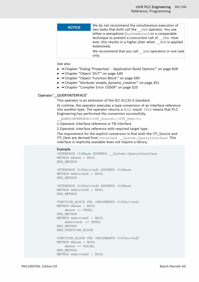
363 / 940ctrlX PLC EngineeringReference, Programming
Bosch Rexroth AGR911403764, Edition 03
NOTICE We do not recommend the simultaneous execution oftwo tasks that both call the __NEW operator. You useeither a semaphore (SysSemEnter) or a comparabletechnique to prevent a concurrent call of __NEW. How-ever, this results in a higher jitter when __NEW is appliedextensively.We recommend that you call __NEW operators in one taskonly.
See also● ⮫ Chapter “Dialog 'Properties' - 'Application Build Options'” on page 828● ⮫ Chapter “Object 'DUT'” on page 549● ⮫ Chapter “Object 'Function Block'” on page 590● ⮫ Chapter “Attribute 'enable_dynamic_creation'” on page 451● ⮫ Chapter “Compiler Error C0509” on page 525
Operator '__QUERYINTERFACE'This operator is an extension of the IEC 61131-3 standard.At runtime, the operator executes a type conversion of an interface referenceinto another type. The operator returns a BOOL result. TRUE means that PLCEngineering has performed the conversion successfully.__QUERYINTERFACE(<ITF_Source>,<ITF_Dest>);1.Operand: Interface reference or FB interface2.Operand: Interface reference with required target typeThe requirement for the explicit conversion is that both the ITF_Source andITF_Dest are derived from Interface __System.IQueryInterface. Thisinterface is implicitly available does not require a library.
ExampleINTERFACE ItfBase EXTENDS __System.IQueryInterface METHOD mbase : BOOL END_METHOD INTERFACE ItfDerived1 EXTENDS ItfBase METHOD mderived1 : BOOL END_METHOD
INTERFACE ItfDerived2 EXTENDS ItfBase METHOD mderived2 : BOOL END_METHOD
FUNCTION_BLOCK FB1 IMPLEMENTS ItfDerived1METHOD mbase : BOOL mbase := TRUE;END_METHOD METHOD mderived1 : BOOL mderived1 := TRUE;END_METHOD END_FUNCTION_BLOCK
FUNCTION_BLOCK FB2 IMPLEMENTS ItfDerived2METHOD mbase : BOOL mbase := FALSE;END_METHOD METHOD mderived2 : BOOL

364 / 940 ctrlX PLC EngineeringReference, Programming
Bosch Rexroth AG R911403764, Edition 03
mderived2 := TRUE;END_METHOD END_FUNCTION_BLOCK PROGRAMM POU VAR inst1 : FB1; inst2 : FB2; itfbase1 : ItfBase := inst1; itfbase2 : ItfBase := inst2; itfderived1 : ItfDerived1 := 0; itfderived2 : ItfDerived2 := 0; xResult1, xResult2, xResult3, xResult4: BOOL; END_VAR
xResult1 := __QUERYINTERFACE(itfbase1, itfderived1); // xResult = TRUE, itfderivedi1 <>0 // references the instance inst1xResult2 := __QUERYINTERFACE(itfbase1, itfderived2); // xResult = FALSE, itfderived2 = 0xResult3 := __QUERYINTERFACE(itfbase2, itfderived1); // xResult = FALSE, itfderived1 = 0xResult4 := __QUERYINTERFACE(itfbase2, itfderived2); // xResult = TRUE, itfderived2 <> 0 // references the instance inst2
Operator '__QUERYPOINTER'This operator is an extension of the IEC 61131-3 standard.At runtime, the operator makes it possible to convert the type of an interfacereference of a function block to a pointer. The operator returns a BOOL result.TRUE means that PLC Engineering has performed the conversion successfully.
NOTICE For compatibility, the definition of the pointer to be con-verted must be an extension of the base interface"__SYSTEM.IQueryInterface".
__QUERYPOINTER (<ITF_Source>, <Pointer_Dest>)The operator receives an interface reference or a FB instance with the requiredtarget types as the first operand and a pointer as the second operand. Afterprocessing __QUERYPOINTER, Pointer_Dest receives the pointer to the refer-ence or instance of a function block that the ITF_Source interface referencecurrently refers to. Pointer_Dest is not typed and can be cast to any type. Youhave to make sure of the type. For example, the interface could offer a methodthat returns a type code.
Operators '__TRY', '__CATCH', '__FINALLY', '__ENDTRY'These operators are extended from the IEC 61131-3 standard and they are usedfor specific exception handling in IEC code.Syntax
__TRY<statements_try>
__CATCH(exec)

365 / 940ctrlX PLC EngineeringReference, Programming
Bosch Rexroth AGR911403764, Edition 03
<statements_catch>__FINALLY<statements_finally>
__ENDTRY <statements_next>
When a statement in the __Try operator throws an exception, the applicationdoes not stop. Instead, the application executes the statements in __Catch,starts the exception handling, and then executes the statements in __FINALLY.The exception handling ends with __ENDTRY, and the application executes thesubsequent statements.An IEC variable for an exception has the data type __System.ExceptionCode.
ExampleIf the statement in __TRY throws an exception, then program execution is notstopped. Instead, the statement in __CATCH is executed. Therefore, in thisexample, the application executes the exc function, then the statement in__FINALLY, and finally the statement in __ENDTRY.
FUNCTION Tester : UDINTVAR_INPUTcount : UDINT;
END_VARVAR_OUTPUTstrExceptionText : STRING;
END_VARVARexc : __SYSTEM.ExceptionCode;
END_VAR
__TRYTester := tryFun(count := count, testcase := g_testcase); // This statement is tested. If it throws an exception, then the statement in __CATCH is executed first, and then the statement in __FINALLY.__CATCH(exc)HandleException(exc, strExceptionText => strExceptionText);__FINALLYGVL.g_count := GVL.g_count + 2;__ENDTRY
See also● ⮫ Chapter “Command 'Stop Execution on Handled Exceptions'” on page 730
Data Type '__System.ExceptionCode'TYPE ExceptionCode :(RTSEXCPT_UNKNOWN := 16#FFFFFFFF,RTSEXCPT_NOEXCEPTION := 16#00000000,RTSEXCPT_WATCHDOG := 16#00000010,RTSEXCPT_HARDWAREWATCHDOG := 16#00000011,RTSEXCPT_IO_CONFIG_ERROR := 16#00000012,RTSEXCPT_PROGRAMCHECKSUM := 16#00000013,RTSEXCPT_FIELDBUS_ERROR := 16#00000014,RTSEXCPT_IOUPDATE_ERROR := 16#00000015,RTSEXCPT_CYCLE_TIME_EXCEED := 16#00000016,RTSEXCPT_ONLCHANGE_PROGRAM_EXCEEDED := 16#00000017,
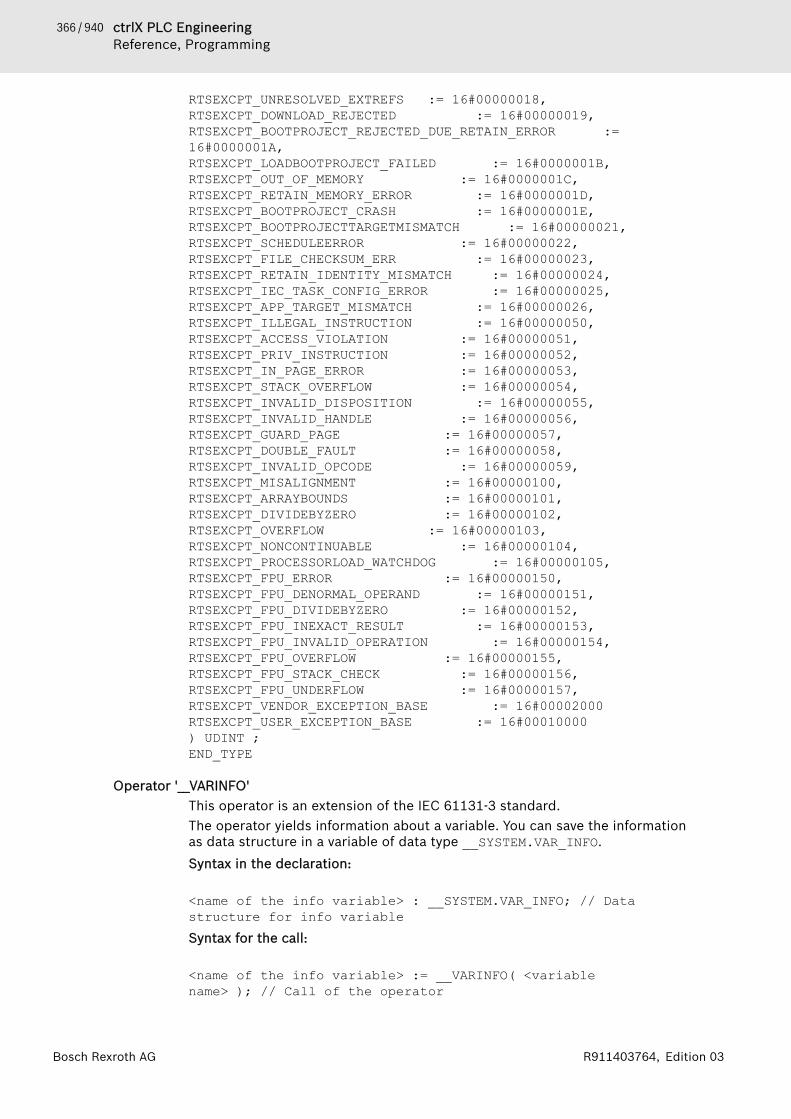
366 / 940 ctrlX PLC EngineeringReference, Programming
Bosch Rexroth AG R911403764, Edition 03
RTSEXCPT_UNRESOLVED_EXTREFS := 16#00000018,RTSEXCPT_DOWNLOAD_REJECTED := 16#00000019,RTSEXCPT_BOOTPROJECT_REJECTED_DUE_RETAIN_ERROR := 16#0000001A,RTSEXCPT_LOADBOOTPROJECT_FAILED := 16#0000001B,RTSEXCPT_OUT_OF_MEMORY := 16#0000001C,RTSEXCPT_RETAIN_MEMORY_ERROR := 16#0000001D,RTSEXCPT_BOOTPROJECT_CRASH := 16#0000001E,RTSEXCPT_BOOTPROJECTTARGETMISMATCH := 16#00000021,RTSEXCPT_SCHEDULEERROR := 16#00000022,RTSEXCPT_FILE_CHECKSUM_ERR := 16#00000023,RTSEXCPT_RETAIN_IDENTITY_MISMATCH := 16#00000024,RTSEXCPT_IEC_TASK_CONFIG_ERROR := 16#00000025,RTSEXCPT_APP_TARGET_MISMATCH := 16#00000026,RTSEXCPT_ILLEGAL_INSTRUCTION := 16#00000050,RTSEXCPT_ACCESS_VIOLATION := 16#00000051,RTSEXCPT_PRIV_INSTRUCTION := 16#00000052,RTSEXCPT_IN_PAGE_ERROR := 16#00000053,RTSEXCPT_STACK_OVERFLOW := 16#00000054,RTSEXCPT_INVALID_DISPOSITION := 16#00000055,RTSEXCPT_INVALID_HANDLE := 16#00000056,RTSEXCPT_GUARD_PAGE := 16#00000057,RTSEXCPT_DOUBLE_FAULT := 16#00000058,RTSEXCPT_INVALID_OPCODE := 16#00000059,RTSEXCPT_MISALIGNMENT := 16#00000100,RTSEXCPT_ARRAYBOUNDS := 16#00000101,RTSEXCPT_DIVIDEBYZERO := 16#00000102,RTSEXCPT_OVERFLOW := 16#00000103,RTSEXCPT_NONCONTINUABLE := 16#00000104,RTSEXCPT_PROCESSORLOAD_WATCHDOG := 16#00000105,RTSEXCPT_FPU_ERROR := 16#00000150,RTSEXCPT_FPU_DENORMAL_OPERAND := 16#00000151,RTSEXCPT_FPU_DIVIDEBYZERO := 16#00000152,RTSEXCPT_FPU_INEXACT_RESULT := 16#00000153,RTSEXCPT_FPU_INVALID_OPERATION := 16#00000154,RTSEXCPT_FPU_OVERFLOW := 16#00000155,RTSEXCPT_FPU_STACK_CHECK := 16#00000156,RTSEXCPT_FPU_UNDERFLOW := 16#00000157,RTSEXCPT_VENDOR_EXCEPTION_BASE := 16#00002000RTSEXCPT_USER_EXCEPTION_BASE := 16#00010000) UDINT ;END_TYPE
Operator '__VARINFO'This operator is an extension of the IEC 61131-3 standard.The operator yields information about a variable. You can save the informationas data structure in a variable of data type __SYSTEM.VAR_INFO.Syntax in the declaration:
<name of the info variable> : __SYSTEM.VAR_INFO; // Data structure for info variableSyntax for the call:
<name of the info variable> := __VARINFO( <variable name> ); // Call of the operator
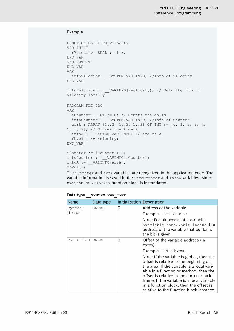
367 / 940ctrlX PLC EngineeringReference, Programming
Bosch Rexroth AGR911403764, Edition 03
Example
FUNCTION_BLOCK FB_VelocityVAR_INPUTrVelocity: REAL := 1.2;
END_VARVAR_OUTPUTEND_VARVARinfoVelocity: __SYSTEM.VAR_INFO; //Info of Velocity
END_VAR
infoVelocity := __VARINFO(rVelocity); // Gets the info of Velocity locally
PROGRAM PLC_PRGVARiCounter : INT := 0; // Counts the callsinfoCounter : __SYSTEM.VAR_INFO; //Info of CounterarrA : ARRAY [1..2, 1..2, 1..2] OF INT := [0, 1, 2, 3, 4,
5, 6, 7]; // Stores the A datainfoA : __SYSTEM.VAR_INFO; //Info of AfbVel : FB_Velocity;
END_VAR
iCounter := iCounter + 1;infoCounter := __VARINFO(iCounter);infoA := __VARINFO(arrA);fbVel();The iCounter and arrA variables are recognized in the application code. Thevariable information is saved in the infoCounter and infoA variables. More-over, the FB_Velocity function block is instantiated.
Data type __SYSTEM.VAR_INFOName Data type Initialization DescriptionByteAd-dress
DWORD 0 Address of the variableExample: 16#072E35ECNote: For bit access of a variable<variable name>.<bit index>, theaddress of the variable that containsthe bit is given.
ByteOffset DWORD 0 Offset of the variable address (inbytes).Example: 13936 bytes.Note: If the variable is global, then theoffset is relative to the beginning ofthe area. If the variable is a local vari-able in a function or method, then theoffset is relative to the current stackframe. If the variable is a local variablein a function block, then the offset isrelative to the function block instance.

368 / 940 ctrlX PLC EngineeringReference, Programming
Bosch Rexroth AG R911403764, Edition 03
Name Data type Initialization DescriptionArea DINT 0 Memory area number Area in the run-
time system.Example: -1: Means that the variable isnot global in the memory, but relativeto an instance or on the stack.Note: The memory areas are device-dependent.
BitNr INT 0 Number of bits (in bytes)Example: 16#00FF bytesNote: If the variable is not an integerdata type, then: BitNr = -1 =16#FFFF.
BitSize INT 0 Memory size of the variable (in bits)Example: 16 bits
BitAddress UDINT 0 Bit address of the variableRequirement: The variable is located inthe input memory area I, outputmemory area Q, or marker memoryarea M. Otherwise the value is unde-fined.
TypeClass TYPE_CLASS TYPE_BOOL Data type class of the variableExample: TYPE_INT, TYPE_ARRAYNote: For user-defined data types orfunction block instances,TYPE_USERDEF is output as the datatype class.
TypeName STRING(79) '' Date type name of the variable asSTRING(79)Note: For user-defined data types, thefunction block name or the DUT nameis output.Example: 'INT', 'ARRAY'
NumEle-ments
UDINT 0 Number of array elementsRequirement: The variable has the datatype ARRAY.Example: 8
BaseType-Class
TYPE_CLASS TYPE_BOOL Elementary basic data type of the arrayelements.Requirement: The variable has the datatype ARRAY.Example: TYPE_INT for arrA : ARRAY[1..2,1..2,1..2] OF INT;
ElemBit-Size
UDINT 0 Memory size of the array element (inbits)Requirement: The variable has the datatype ARRAY.Example: 16 bits for arrA : ARRAY[1..2,1..2,1..2] OF INT;

369 / 940ctrlX PLC EngineeringReference, Programming
Bosch Rexroth AGR911403764, Edition 03
Name Data type Initialization DescriptionMemoryArea MEMORY_ARE
AMEM_MEMORY Information about the memory area
● MEM_GLOBAL: Global memory areaFor example in Area 0
● MEM_LOCAL: Local memory areain Area -1
● MEM_MEMORY: Marker memory area %MFor example in 16#10 in Area 1
● MEM_INPUT: Input memory area %IFor example in 16#04 in Area 2
● MEM_OUTPUT: Output memory area %QFor example in 16#08 in Area 3
● MEM_RETAIN: Retain memory areaFor example in 16#20 in Area 0
Example: MEM_GLOBALNote: The memory area configurationis device-dependent.
Symbol STRING(39) '' Variable name as STRING(39)Example: 'iCounter', 'arrA'
Comment STRING(79) '' Comment of the variable declarationExample: 'Counts the calls' or'Stores the A data'
Operator '__CURRENTTASK'This operator is an extension of the IEC 61131-3 standard.In runtime mode, the operator provides information about the IEC task that iscurrently running.The operator is supported only on target systems in which the target systemsetting memory-layout\max-stack-size is set to a value > 0.The operator allows for access to a structure with two variables:● TaskIndex: Zero-based index that identifies the task● pTaskInfo: Detailed information about the currently running task. It can be
assigned to a POINTER TO Task_Info2 from the library CmpIecTask.The operator cannot be used in the declaration of a POU. This would result inan error message. If the current task cannot be determined, then the Tas-kIndex -1 and the pTaskInfo are zero.
Example//DeclarationVARidx : INT;pInfo : POINTER TO Task_Info2;
END_VAR
//Program code
idx := __CURRENTTASK.TaskIndex;pInfo := __CURRENTTASK.pTaskInfo;
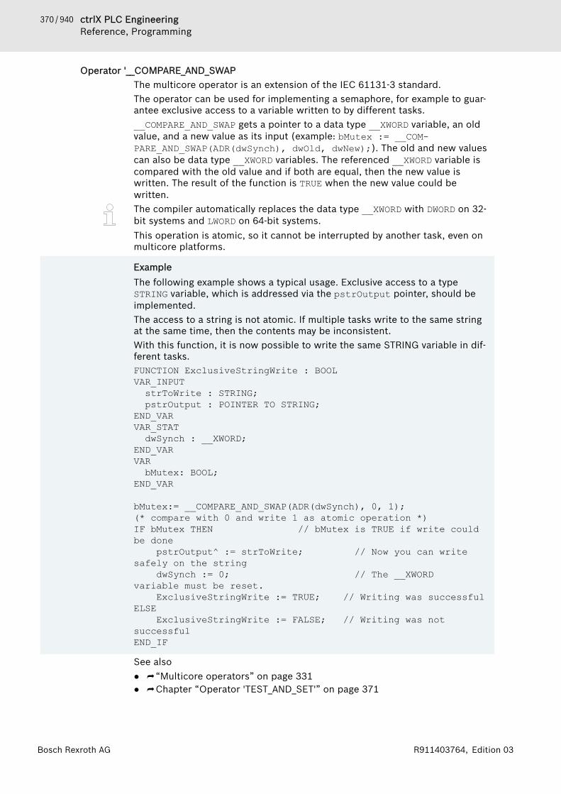
370 / 940 ctrlX PLC EngineeringReference, Programming
Bosch Rexroth AG R911403764, Edition 03
Operator '__COMPARE_AND_SWAPThe multicore operator is an extension of the IEC 61131-3 standard.The operator can be used for implementing a semaphore, for example to guar-antee exclusive access to a variable written to by different tasks.__COMPARE_AND_SWAP gets a pointer to a data type __XWORD variable, an oldvalue, and a new value as its input (example: bMutex := __COM-PARE_AND_SWAP(ADR(dwSynch), dwOld, dwNew);). The old and new valuescan also be data type __XWORD variables. The referenced __XWORD variable iscompared with the old value and if both are equal, then the new value iswritten. The result of the function is TRUE when the new value could bewritten.The compiler automatically replaces the data type __XWORD with DWORD on 32-bit systems and LWORD on 64-bit systems.This operation is atomic, so it cannot be interrupted by another task, even onmulticore platforms.
ExampleThe following example shows a typical usage. Exclusive access to a typeSTRING variable, which is addressed via the pstrOutput pointer, should beimplemented.The access to a string is not atomic. If multiple tasks write to the same stringat the same time, then the contents may be inconsistent.With this function, it is now possible to write the same STRING variable in dif-ferent tasks.FUNCTION ExclusiveStringWrite : BOOLVAR_INPUTstrToWrite : STRING;pstrOutput : POINTER TO STRING;
END_VARVAR_STAT dwSynch : __XWORD;END_VARVARbMutex: BOOL;
END_VAR
bMutex:= __COMPARE_AND_SWAP(ADR(dwSynch), 0, 1); (* compare with 0 and write 1 as atomic operation *)IF bMutex THEN // bMutex is TRUE if write could be done pstrOutput^ := strToWrite; // Now you can write safely on the string dwSynch := 0; // The __XWORD variable must be reset. ExclusiveStringWrite := TRUE; // Writing was successfulELSE ExclusiveStringWrite := FALSE; // Writing was not successfulEND_IF
See also● ⮫ “Multicore operators” on page 331● ⮫ Chapter “Operator 'TEST_AND_SET'” on page 371
371 / 940ctrlX PLC EngineeringReference, Programming
Bosch Rexroth AGR911403764, Edition 03
Operator '__XADD'The multicore operator is an extension of the IEC 61131-3 standard.The operator can be used for implementing an atomic counter. If an integer var-iable is incremented by means of ordinary addition, for example iTest :=iTest + 1;, then this operation is not executed atomically. Another access tothe variable could take place between reading and writing the variable.If the counter is incremented in multiple tasks, then the counter result can beless than the number of counting cycles. So if two tasks execute the abovecode one time and the variable previously had the value 0, then the variable canthen have the value 1. This is especially problematic if arrays are being proc-essed in multiple tasks and a unique index is required for the array in eachprocessing cycle.When the __XADD operator is called, it gets a pointer to a type DINT variable asthe first summand and a type DINT value as the second summand. __XADDreturns the old value of the first summand and in the same step adds thesecond summand to the first summand.For example, the function call can look like this: diOld :=__XADD(ADR(diVar), deAdd);
ExampleThe following example shows a typical usage. An array should be populatedfrom two tasks. In the process, all positions in the array should be used andno position should be overwritten.With this function, multiple tasks can populate a Boolean array.FUNCTION WriteToNextArrayPosition : BOOLVAR_EXTERNALg_diIndex : DINT; // Index and array are globally defined
and used by multiple tasksg_boolArray : ARRAY [0..1000] OF BOOL;
END_VARVAR_INPUTbToWrite : BOOL;
END_VARVARdiIndex : DWORD;
END_VAR
diIndex := __XADD(ADR(g_diIndex), 1); // Returns a unique indexWriteToNextArrayPosition := FALSE;IF (diIndex >= 0 AND diIndex <= 1000) THEN g_boolArray[diIndex] := bToWrite; //Writes to
unique indexWriteToNextArrayPosition := TRUE; // TRUE: Array
was not full yetEND_IF
See also● ⮫ “Multicore operators” on page 331
Operator 'TEST_AND_SET'The multicore operator is an extension of the IEC 61131-3 standard.The operator can be used for implementing a semaphore, for example to guar-antee exclusive access to a variable written to by different tasks.
372 / 940 ctrlX PLC EngineeringReference, Programming
Bosch Rexroth AG R911403764, Edition 03
TEST_AND_SET gets a type DWORD variable as its input. Write access to this vari-able must be possible. The variable is set to 1 and the previous value isreturned as the result.The operation is atomic, which means that it cannot be interrupted by anothertask. This also applies to multicore platforms.For example, the call in the program is dwOldValue := TEST_AND_SET(dw);,in which the variables dwOldValue and dw must be of data type DWORD.
ExampleThe following example shows a typical usage. Exclusive access to a typeSTRING variable, which is addressed via the pstrOutput pointer, should beimplemented. The access to a string is not atomic. If multiple tasks write tothe same string at the same time, then the contents may be inconsistent. Withthe TEST_AND_SET function, it is now possible to write the same STRING vari-able in different tasks.FUNCTION ExclusiveStringWrite : BOOLVAR_INPUT
strToWrite : STRING;pstrOutput : POINTER TO STRING;
END_VARVAR_STATdwSynch : DWORD;
END_VARVARdwOldValue: DWORD;
END_VAR
dwOldValue := TEST_AND_SET(dwSynch); // Write the 1 and read the old value at the same timeIF dwOldValue = 0 THEN // 0 means: no other task is currently writing pstrOutput^ := strToWrite; // Now you can write safely on the string dwSynch := 0; // The DWORD must be reset ExclusiveStringWrite := TRUE; // Writing was successfulELSE ExclusiveStringWrite := FALSE; // Writing was not successful
See also● ⮫ Chapter “Operator '__COMPARE_AND_SWAP” on page 370● ⮫ “Multicore operators” on page 331
Operator - Global NamespaceThis operator is an extension of the IEC 61131-3 standard.An instance path that begins with a dot (.) always opens a global namespace.If there is a local variable that has the same name <varname> as a global vari-able, then you refer to the global variable as .<varname>.
Operator - Namespace for Global Variables ListsThis operator is an extension of the IEC 61131-3 standard.
373 / 940ctrlX PLC EngineeringReference, Programming
Bosch Rexroth AGR911403764, Edition 03
You can use the name of a global variables list (GVL) as a namespace identifierfor the variables that are defined in the list. This makes is possible to use varia-bles with the same name in different global variables lists and still access spe-cific variables uniquely. You use a dot (.) to prepend the name of the globalvariables list to the variable name.<global variable list name>.<variable>
Examplegloblist1.varx := globlist2.varx;The globlist1 and globlist2 global variables lists each contain a varx vari-able. PLC Engineering copies the varx global variable from the globlist2 listto varx in the globlist1 list.
If you reference a variable that is declared in several global variables listswithout referencing the prepended list name, then an error message is printed.
Operator - Library NamespaceThis operator is an extension of the IEC 61131-3 standard.Syntax: <library namespace>.<library identifier>Example: LIB_A.FB_AA library module identifier is appended with the library namespace (as a prefixseparated by a dot) for unique and qualified access to the library module. Thenamespace usually coincides with the library name.
ExampleA library is included in a project and contains the module FB_A. However, thefunction block with the same name is already available locally in the project.Identify the library module as LIB_A.FB_A in order to access the librarymodule, not the local function block.
var1 := FB_A(in := 12); // Call of the project function FB_A var2 := LIB_A.FB_A(in := 22); // Call of the library function FB_A
You can define another identifier for the namespace. To do this, specify a name-space in the project information (library developers: when creating a libraryproject). As an alternative, you can specify a specific namespace for a library inthe library manager in the “Properties” dialog box (application developers:when creating an application).See also● ⮫ Chapter 1.15 “Using Libraries” on page 237● ⮫ Chapter “Command 'Placeholders'” on page 791● ⮫ Chapter “Object 'Library Manager'” on page 583
Operator - Enumeration NamespaceThis operator is an extension of the IEC 61131-3 standard.You can use the TYPE name of an enumeration for unique access to an enumer-ation constant. In this way, you can use the same constant names in differentenumerations.The enumeration name is prepended to the constant name with a dot (.).<enumeration name>.<constant name>
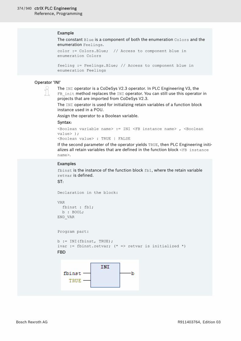
374 / 940 ctrlX PLC EngineeringReference, Programming
Bosch Rexroth AG R911403764, Edition 03
ExampleThe constant Blue is a component of both the enumeration Colors and theenumeration Feelings.color := Colors.Blue; // Access to component blue in enumeration Colors
feeling := Feelings.Blue; // Access to component blue in enumeration Feelings
Operator 'INI'The INI operator is a CoDeSys V2.3 operator. In PLC Engineering V3, theFB_init method replaces the INI operator. You can still use this operator inprojects that are imported from CoDeSys V2.3.The INI operator is used for initializing retain variables of a function blockinstance used in a POU.Assign the operator to a Boolean variable.Syntax:<Boolean variable name> := INI <FB instance name> , <Boolean value> );<Boolean value> : TRUE | FALSEIf the second parameter of the operator yields TRUE, then PLC Engineering initi-alizes all retain variables that are defined in the function block <FB instancename>.
Examplesfbinst is the instance of the function block fb1, where the retain variableretvar is defined.ST:
Declaration in the block:
VARfbinst : fb1; b : BOOL;
END_VAR
Program part:
b := INI(fbinst, TRUE); ivar := fbinst.retvar; (* => retvar is initialized *) FBD

375 / 940ctrlX PLC EngineeringReference, Programming
Bosch Rexroth AGR911403764, Edition 03
See also● ⮫ Chapter 1.18.10 “Methods 'FB_Init', 'FB_Reinit', and 'FB_Exit'” on page 468● ⮫ Chapter 1.8.20 “Data Persistence” on page 139
1.18.4 OperandsConstantsYou declare constants with the keyword CONSTANT. Constants can be eitherlocal or global.Syntax:VAR CONSTANT <identifier>:<Type> := <initialization>; END_VAR● ⮫ Chapter “BOOL Constants” on page 375● ⮫ Chapter “TIME/LTIME Constant” on page 375● ⮫ Chapter “DATE Constant” on page 377● ⮫ Chapter “DATE_AND_TIME Constant” on page 378● ⮫ Chapter “TIME_OF_DAY Constant” on page 378● ⮫ Chapter “Numeric Constants” on page 379● ⮫ Chapter “REAL/LREAL Constants” on page 379● ⮫ Chapter “String Constants” on page 380● ⮫ Chapter “Typed Literals” on page 381See also● ⮫ Chapter 1.8.6 “Using Input Assistance” on page 99
VariablesYou declare variables as local or global in the declaration section of a POU or ina global variable list.The position where you can use a variable depends on its data type.See also● ⮫ Chapter “Access to Variables in Arrays, Structures, and Blocks”
on page 382● ⮫ Chapter “Bit Access to Variables” on page 382● ⮫ Chapter 1.8.6 “Using Input Assistance” on page 99● ⮫ Chapter 1.8.2 “Declaration of Variables ” on page 62
Other● ⮫ Chapter “Addresses” on page 384● ⮫ Chapter “Functions” on page 386
BOOL ConstantsBOOL constants are the truth values TRUE (1) and FALSE (0).See also● ⮫ Chapter “Data Type 'BOOL'” on page 387
TIME/LTIME ConstantYou can use TIME constants to operate the standard timer modules. The con-stant has a size of 32 bits and therefore a resolution in milliseconds.In addition, the time constant LTIME is available as a time basis for high-resolu-tion timers. The LTIME constant has a dimension of 64 bits and therefore a res-olution in nanoseconds.
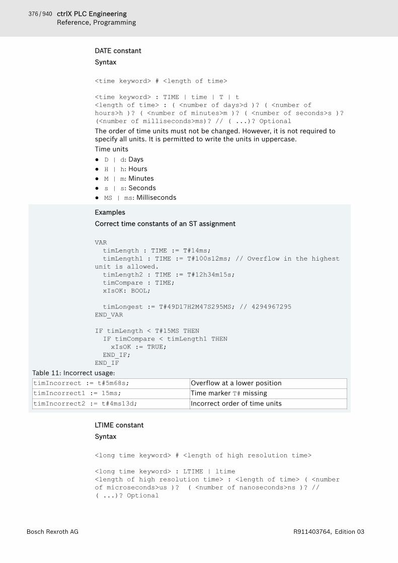
376 / 940 ctrlX PLC EngineeringReference, Programming
Bosch Rexroth AG R911403764, Edition 03
DATE constant
Syntax
<time keyword> # <length of time>
<time keyword> : TIME | time | T | t<length of time> : ( <number of days>d )? ( <number of hours>h )? ( <number of minutes>m )? ( <number of seconds>s )? (<number of milliseconds>ms)? // ( ...)? OptionalThe order of time units must not be changed. However, it is not required tospecify all units. It is permitted to write the units in uppercase.Time units● D | d: Days● H | h: Hours● M | m: Minutes● s | s: Seconds● MS | ms: Milliseconds
Examples
Correct time constants of an ST assignment
VARtimLength : TIME := T#14ms;timLength1 : TIME := T#100s12ms; // Overflow in the highest
unit is allowed.timLength2 : TIME := T#12h34m15s;timCompare : TIME;xIsOK: BOOL;
timLongest := T#49D17H2M47S295MS; // 4294967295END_VAR
IF timLength < T#15MS THENIF timCompare < timLength1 THEN xIsOK := TRUE;
END_IF;END_IF
Table 11: Incorrect usage:timIncorrect := t#5m68s; Overflow at a lower positiontimIncorrect1 := 15ms; Time marker T# missingtimIncorrect2 := t#4ms13d; Incorrect order of time units
LTIME constant
Syntax
<long time keyword> # <length of high resolution time>
<long time keyword> : LTIME | ltime<length of high resolution time> : <length of time> ( <number of microseconds>us )? ( <number of nanoseconds>ns )? // ( ...)? Optional
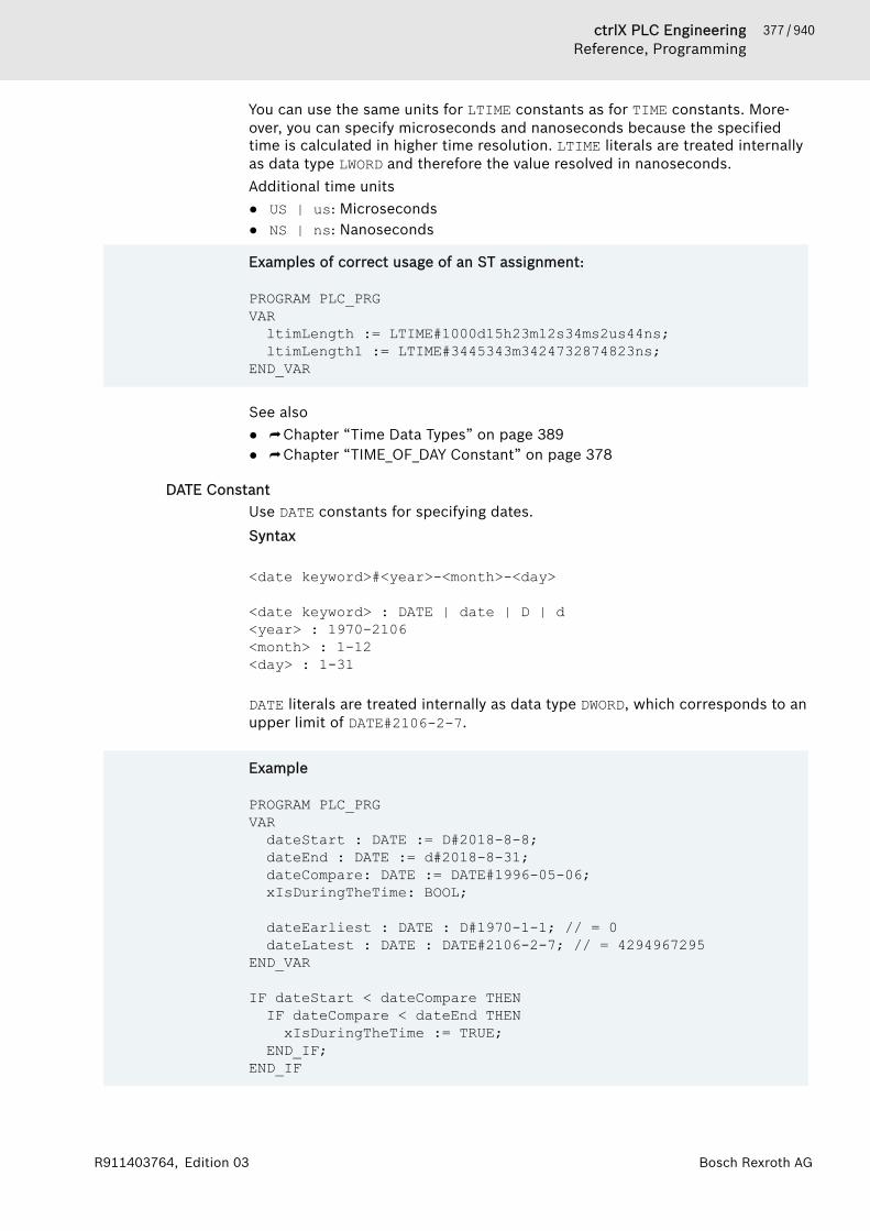
377 / 940ctrlX PLC EngineeringReference, Programming
Bosch Rexroth AGR911403764, Edition 03
You can use the same units for LTIME constants as for TIME constants. More-over, you can specify microseconds and nanoseconds because the specifiedtime is calculated in higher time resolution. LTIME literals are treated internallyas data type LWORD and therefore the value resolved in nanoseconds.Additional time units● US | us: Microseconds● NS | ns: Nanoseconds
Examples of correct usage of an ST assignment:
PROGRAM PLC_PRGVARltimLength := LTIME#1000d15h23m12s34ms2us44ns;ltimLength1 := LTIME#3445343m3424732874823ns;
END_VAR
See also● ⮫ Chapter “Time Data Types” on page 389● ⮫ Chapter “TIME_OF_DAY Constant” on page 378
DATE ConstantUse DATE constants for specifying dates.Syntax
<date keyword>#<year>-<month>-<day>
<date keyword> : DATE | date | D | d<year> : 1970-2106<month> : 1-12<day> : 1-31 DATE literals are treated internally as data type DWORD, which corresponds to anupper limit of DATE#2106-2-7.
Example
PROGRAM PLC_PRGVARdateStart : DATE := D#2018-8-8;dateEnd : DATE := d#2018-8-31;dateCompare: DATE := DATE#1996-05-06;xIsDuringTheTime: BOOL;
dateEarliest : DATE : D#1970-1-1; // = 0dateLatest : DATE : DATE#2106-2-7; // = 4294967295
END_VAR
IF dateStart < dateCompare THENIF dateCompare < dateEnd THEN
xIsDuringTheTime := TRUE;END_IF;
END_IF
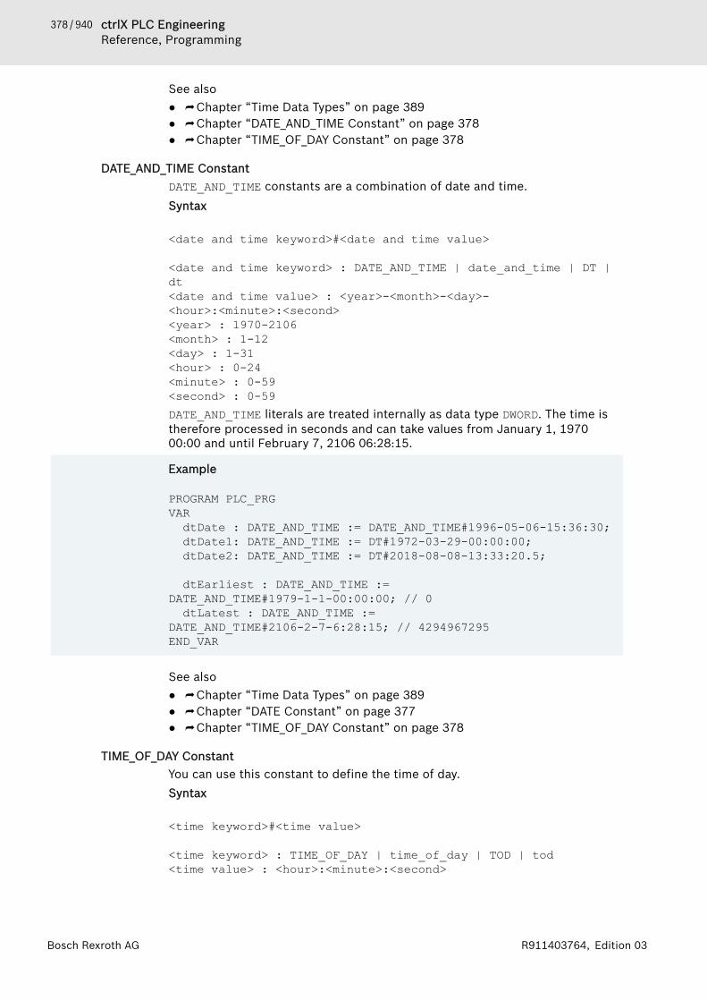
378 / 940 ctrlX PLC EngineeringReference, Programming
Bosch Rexroth AG R911403764, Edition 03
See also● ⮫ Chapter “Time Data Types” on page 389● ⮫ Chapter “DATE_AND_TIME Constant” on page 378● ⮫ Chapter “TIME_OF_DAY Constant” on page 378
DATE_AND_TIME ConstantDATE_AND_TIME constants are a combination of date and time.Syntax
<date and time keyword>#<date and time value>
<date and time keyword> : DATE_AND_TIME | date_and_time | DT | dt<date and time value> : <year>-<month>-<day>-<hour>:<minute>:<second><year> : 1970-2106<month> : 1-12<day> : 1-31<hour> : 0-24<minute> : 0-59<second> : 0-59DATE_AND_TIME literals are treated internally as data type DWORD. The time istherefore processed in seconds and can take values from January 1, 197000:00 and until February 7, 2106 06:28:15.
Example
PROGRAM PLC_PRGVARdtDate : DATE_AND_TIME := DATE_AND_TIME#1996-05-06-15:36:30;dtDate1: DATE_AND_TIME := DT#1972-03-29-00:00:00;dtDate2: DATE_AND_TIME := DT#2018-08-08-13:33:20.5;
dtEarliest : DATE_AND_TIME := DATE_AND_TIME#1979-1-1-00:00:00; // 0dtLatest : DATE_AND_TIME :=
DATE_AND_TIME#2106-2-7-6:28:15; // 4294967295END_VAR
See also● ⮫ Chapter “Time Data Types” on page 389● ⮫ Chapter “DATE Constant” on page 377● ⮫ Chapter “TIME_OF_DAY Constant” on page 378
TIME_OF_DAY ConstantYou can use this constant to define the time of day.Syntax
<time keyword>#<time value>
<time keyword> : TIME_OF_DAY | time_of_day | TOD | tod<time value> : <hour>:<minute>:<second>

379 / 940ctrlX PLC EngineeringReference, Programming
Bosch Rexroth AGR911403764, Edition 03
<hour> : 0-23<minute> : 0-59<second> : 0.000-59.999You can also specify fractions of a second. TIME_OF_DAY literals are neverthe-less treated internally as DWORD and the value is resolved in milliseconds.
Examples
PROGRAM POUVARtodClockTime : TIME_OF_DAY := TIME_OF_DAY#15:36:30.123;todEarliest : TIME_OF_DAY := TIME_OF_DAY#0:0:0.000;todLatest : TOD := TOD#23:59:59.999;
END_VAR
See also● ⮫ Chapter “Time Data Types” on page 389● ⮫ Chapter “DATE Constant” on page 377● ⮫ Chapter “DATE_AND_TIME Constant” on page 378
Numeric ConstantsNumeric values can be binary, octal, decimal, and hexadecimal numbers. If aninteger value is not a decimal number, then you must write its base followed bythe number sign (#) before the integer constant. You enter the hexadecimaldigit values for the numbers 10 to 15 as usual with the letters A-F.You can use an underscore within a numeric value.
Examples:14 decimal number2#1001_0011 binary number8#67 octal number16#A hexadecimal numberDINT#16#A1 typed data type DINT# and base 16# combined
This type of numeric value can be BYTE, WORD, DWORD, SINT, USINT, INT, UINT,DINT, UDINT, REAL, or LREAL.Implicit conversions from "larger" to "smaller" types are not permitted. Youcannot simply use a DINT variable as an INT variable. For this, you have to use atype conversion function.See also● ⮫ Chapter 1.18.3 “Operators” on page 327● ⮫ Chapter “Typed Literals” on page 381
As number constants basically are treated as integers, in divisions you mustenter a constant in the format of a floating-point number in order not to loosethe remainder. For example: Division 1/10 results in 0, division 1.0/10 resultsin 0.1.
REAL/LREAL ConstantsYou can specify floating-point numbers as REAL and LREAL constants either indecimal notation or exponential notation with mantissa and exponent The dec-imal point serves as the decimal separator according to the InternationalSystem of Units (English).
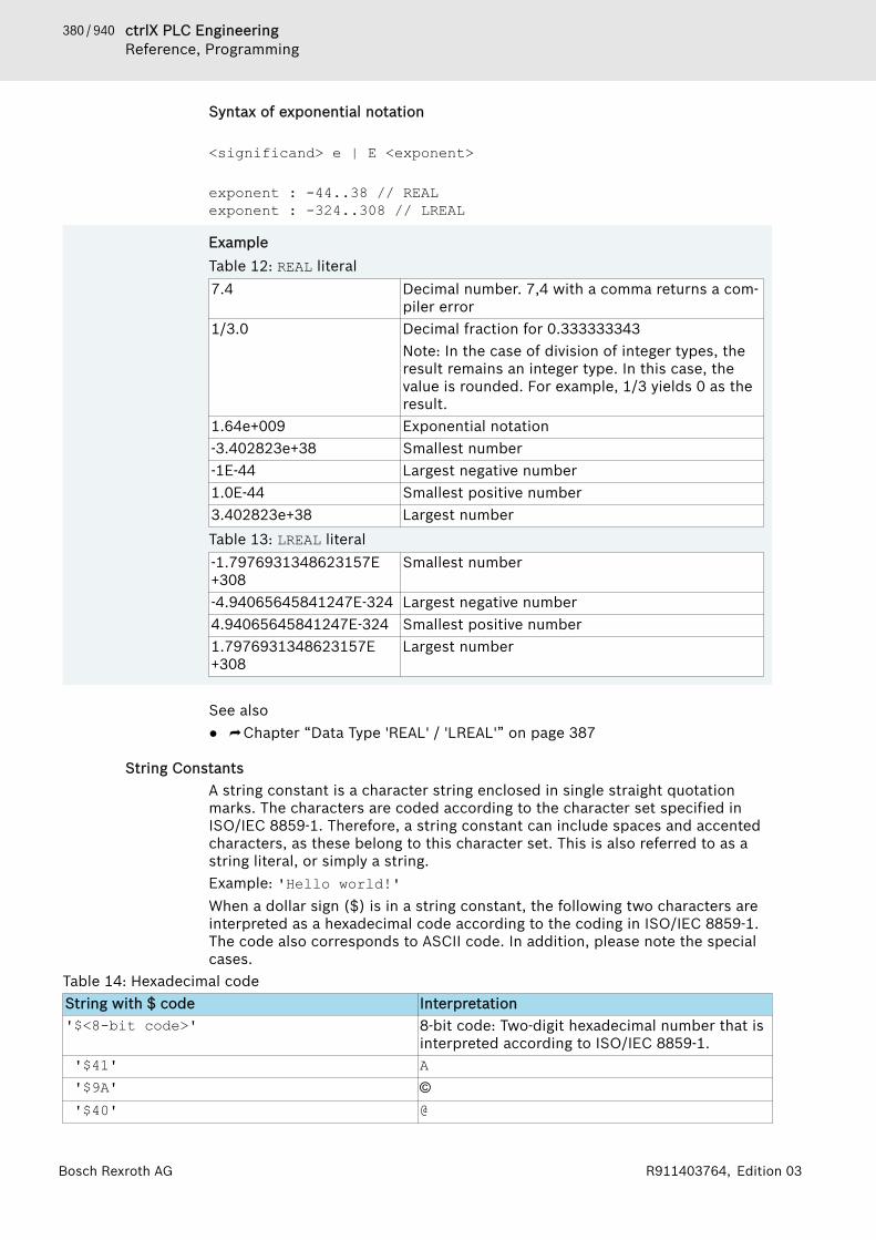
380 / 940 ctrlX PLC EngineeringReference, Programming
Bosch Rexroth AG R911403764, Edition 03
Syntax of exponential notation
<significand> e | E <exponent>
exponent : -44..38 // REALexponent : -324..308 // LREAL
ExampleTable 12: REAL literal7.4 Decimal number. 7,4 with a comma returns a com-
piler error1/3.0 Decimal fraction for 0.333333343
Note: In the case of division of integer types, theresult remains an integer type. In this case, thevalue is rounded. For example, 1/3 yields 0 as theresult.
1.64e+009 Exponential notation-3.402823e+38 Smallest number-1E-44 Largest negative number1.0E-44 Smallest positive number3.402823e+38 Largest numberTable 13: LREAL literal-1.7976931348623157E+308
Smallest number
-4.94065645841247E-324 Largest negative number4.94065645841247E-324 Smallest positive number1.7976931348623157E+308
Largest number
See also● ⮫ Chapter “Data Type 'REAL' / 'LREAL'” on page 387
String ConstantsA string constant is a character string enclosed in single straight quotationmarks. The characters are coded according to the character set specified inISO/IEC 8859-1. Therefore, a string constant can include spaces and accentedcharacters, as these belong to this character set. This is also referred to as astring literal, or simply a string.Example: 'Hello world!'When a dollar sign ($) is in a string constant, the following two characters areinterpreted as a hexadecimal code according to the coding in ISO/IEC 8859-1.The code also corresponds to ASCII code. In addition, please note the specialcases.
Table 14: Hexadecimal codeString with $ code Interpretation'$<8-bit code>' 8-bit code: Two-digit hexadecimal number that is
interpreted according to ISO/IEC 8859-1. '$41' A '$9A' © '$40' @

381 / 940ctrlX PLC EngineeringReference, Programming
Bosch Rexroth AGR911403764, Edition 03
String with $ code Interpretation '$0D' Control character: Line break (corresponds to
'$R') '$0A' Control character: New line (corresponds to '$L'
and '$N')Table 15: Special casesString with $ code Interpretation'$L', ' $l' Control character: Line feed (corresponds to
'$0A')'$N', '$n' Control character: New line (corresponds to
'$0A')'$P', '$p' Control character: Form feed'$R', '$r' Control character: Line break (corresponds to
'$0D')'$T', '$t' Control character: Tab'$$' Dollar sign: §'$'' Single straight quotation mark: '
ExampleConstant declaration
VAR CONSTANT constA : STRING := 'Hello world';constB : STRING := 'Hello world $21'; // Hello world!
END_VAR
Typed LiteralsWith the exception of REAL/LREAL constants (LREAL is always used here), PLCEngineering uses the smallest possible data type when calculating with IECconstants. If you want to use another data type, then you can use typed literalswithout having to declare the constants explicitly. When doing this, provide theconstants with a prefix that indicates the type.Syntax:<type>#<literal><type> defines the desired data type; possible values: BOOL, SINT, USINT,BYTE, INT, UINT, WORD, DINT, UDINT, DWORD, REAL, LREAL. You must capitalizethe entire type name.<literal> defines the constants. The entry must match the data type definedin <Type>.
Example:var1 := DINT#34;
If PLC Engineering cannot convert the constant into the target type withoutdata loss, then an error message is issued.You can use typed constants wherever you can use normal constants.

382 / 940 ctrlX PLC EngineeringReference, Programming
Bosch Rexroth AG R911403764, Edition 03
Access to Variables in Arrays, Structures, and BlocksSyntax for access to● Two-dimensional array components: <array name>[index1, index2]● Structural variables: <structure name>.<variable name>● Function block and program variables: <function block name>.<vari-
able name>See also● ⮫ Chapter “Data Type 'ARRAY'” on page 397● ⮫ Chapter “Structure” on page 411● ⮫ Chapter “Object 'Function Block'” on page 590● ⮫ Chapter “Object 'Program'” on page 589
Bit Access to Variables
NOTICE Implement concurrent bit access by two tasks only if theprocessor can execute bit access directly on thememory. All x86 and x64 systems have commands for bitaccess in memory. Systems such as ARM and PPCcannot access bits directly in the memory.
If two tasks execute bit access simultaneously, even though the processorcannot perform bit access directly in the memory, then proceed as follows. Usea semaphore (SysSemEnter) or a similar technique to prevent competing bitaccess. However, it is best to execute the bit access within a task.Syntax for declarations:<variable name> : <data type> ( := <initialization> )? ;
<data type> = BYTE | WORD | DWORD | LWORD | SINT | USINT | INT | DINT | UDINT | LINT | ULINTSyntax for calls:<variable name>.<index>With a bit access, a single bit is accessed with read or write permissions withinan integer variable. To do this, add a period and an index to the variable identi-fier that addresses the bit within the variable. Indexing is 0-based. The index isa positive integer starting at 0. You can also specify the index as a constant var-iable.
Example
PROGRAM PLC_PRGVARwA : WORD := 16#FF;xB : BOOL := 0;
END_VARwA.2 := xB;In the program, the third bit of the variable wA is set to the value of variablexB.wA = 2#1111_1111_1111_1011 = 16#FFFB
Bit access to a variable with a global constant variableYou can use a global constant as an index to access a bit within an integer vari-able.

383 / 940ctrlX PLC EngineeringReference, Programming
Bosch Rexroth AGR911403764, Edition 03
Example: Bit access to an integer variable.
Declaration in a global variable list:
VAR_GLOBAL CONSTANTc_usiENABLE : USINT := 2;
END_VARThe constant c_usiENABLE addresses the bit in the integer variable.Declaration of a POU:
VARiX : INT;
END_VARCall with bit access:
iX.c_usiENABLE := TRUE; // The third bit in the variable iX is set TRUE
Bit access with BIT data typesWith the BIT data type, you can combine single bits into a structure and thenaccess them individually. The bit is then addressed with the component name.
Example: Access to BIT data types
Declaration of the structure:
TYPE ControllerData :STRUCTStatus_OperationEnabled : BIT;Status_SwitchOnActive : BIT;Status_EnableOperation : BIT;Status_Error : BIT;Status_VoltageEnabled : BIT;Status_QuickStop : BIT;Status_SwitchOnLocked : BIT;Status_Warning : BIT;
END_STRUCTEND_TYPE Declaration of the POU:
VARControllerDrive_1 : ControllerData;
END_VARBit access:
ControllerDrive1.OperationEnabled := TRUE;
See also● ⮫ Chapter “Integer Data Types” on page 387● ⮫ “Bit access in structures” on page 412● ⮫ Chapter “Data Type 'BIT'” on page 393
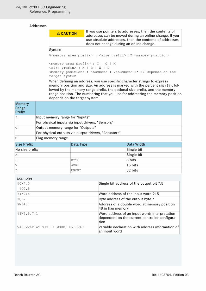
384 / 940 ctrlX PLC EngineeringReference, Programming
Bosch Rexroth AG R911403764, Edition 03
Addresses
CAUTION If you use pointers to addresses, then the contents ofaddresses can be moved during an online change. If youuse absolute addresses, then the contents of addressesdoes not change during an online change.
Syntax:%<memory area prefix> ( <size prefix> )? <memory position>
<memory area prefix> : I | Q | M<size prefix> : X | B | W | D<memory position> : <number> ( .<number> )* // Depends on the target systemWhen defining an address, you use specific character strings to expressmemory position and size. An address is marked with the percent sign (%), fol-lowed by the memory range prefix, the optional size prefix, and the memoryrange position. The numbering that you use for addressing the memory positiondepends on the target system.
MemoryRangePrefixI Input memory range for "Inputs"
For physical inputs via input drivers, "Sensors"Q Output memory range for "Outputs"
For physical outputs via output drivers, "Actuators"M Flag memory range
Size Prefix Data Type Data WidthNo size prefix Single bitX Single bitB BYTE 8 bitsW WORD 16 bitsD DWORD 32 bits
Examples%QX7.5 %Q7.5
Single bit address of the output bit 7.5
%IW215 Word address of the input word 215%QB7 Byte address of the output byte 7%MD48 Address of a double word at memory position
48 in flag memory%IW2.5.7.1 Word address of an input word; interpretation
dependent on the current controller configura-tion
VAR wVar AT %IW0 : WORD; END_VAR Variable declaration with address information ofan input word
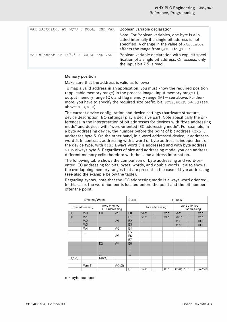
385 / 940ctrlX PLC EngineeringReference, Programming
Bosch Rexroth AGR911403764, Edition 03
VAR xActuator AT %QW0 : BOOL; END_VAR Boolean variable declarationNote: For Boolean variables, one byte is allo-cated internally if a single bit address is notspecified. A change in the value of xActuatoraffects the range from QX0.0 to QX0.7.
VAR xSensor AT IX7.5 : BOOL; END_VAR Boolean variable declaration with explicit speci-fication of a single bit address. On access, onlythe input bit 7.5 is read.
Memory positionMake sure that the address is valid as follows:To map a valid address in an application, you must know the required position(applicable memory range) in the process image: input memory range (I),output memory range (Q), and flag memory range (M) — see above. Further-more, you have to specify the required size prefix: bit, BYTE, WORD, DWord (seeabove: X, B, W, D)The current device configuration and device settings (hardware structure,device description, I/O settings) play a decisive part. Note specifically the dif-ferences in the interpretation of bit addresses for devices with "byte addressingmode" and devices with "word-oriented IEC addressing mode". For example, ina byte addressing device, the number before the point of bit address %IX5.5addresses byte 5. On the other hand, in a word-addressed device, it addressesword 5. In contrast, addressing with a word or byte address is independent ofthe device type: with %IW5 always word 5 is addressed and with byte address %IB5 always byte 5. Regardless of size and addressing mode, you can addressdifferent memory cells therefore with the same address information.The following table shows the comparison of byte addressing and word-ori-ented IEC addressing for bits, bytes, words, and double words. It also showsthe overlapping memory ranges that are present in the case of byte addressing(see also the example below the table).Regarding syntax, note that the IEC addressing mode is always word-oriented.In this case, the word number is located before the point and the bit numberofter the point.
n = byte number
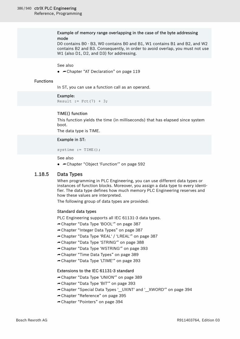
386 / 940 ctrlX PLC EngineeringReference, Programming
Bosch Rexroth AG R911403764, Edition 03
Example of memory range overlapping in the case of the byte addressingmodeD0 contains B0 - B3, W0 contains B0 and B1, W1 contains B1 and B2, and W2contains B2 and B3. Consequently, in order to avoid overlap, you must not useW1 (also D1, D2, and D3) for addressing.
See also● ⮫ Chapter “AT Declaration” on page 119
FunctionsIn ST, you can use a function call as an operand.
Example: Result := Fct(7) + 3;
TIME() functionThis function yields the time (in milliseconds) that has elapsed since systemboot.The data type is TIME.
Example in ST:
systime := TIME();
See also● ⮫ Chapter “Object 'Function'” on page 592
1.18.5 Data TypesWhen programming in PLC Engineering, you can use different data types orinstances of function blocks. Moreover, you assign a data type to every identi-fier. The data type defines how much memory PLC Engineering reserves andhow these values are interpreted.The following group of data types are provided:
Standard data typesPLC Engineering supports all IEC 61131-3 data types.⮫ Chapter “Data Type 'BOOL'” on page 387⮫ Chapter “Integer Data Types” on page 387⮫ Chapter “Data Type 'REAL' / 'LREAL'” on page 387⮫ Chapter “Data Type 'STRING'” on page 388⮫ Chapter “Data Type 'WSTRING'” on page 393⮫ Chapter “Time Data Types” on page 389⮫ Chapter “Data Type 'LTIME'” on page 393
Extensions to the IEC 61131-3 standard⮫ Chapter “Data Type 'UNION'” on page 389⮫ Chapter “Data Type 'BIT'” on page 393⮫ Chapter “Special Data Types '__UXINT' and '__XWORD'” on page 394⮫ Chapter “Reference” on page 395⮫ Chapter “Pointers” on page 394

387 / 940ctrlX PLC EngineeringReference, Programming
Bosch Rexroth AGR911403764, Edition 03
User-defined data typesYou can create user-defined data types in two ways:● DUT object in the POU window● data type in a block in the declaration
NOTICE Please note the recommendations for naming and object.
⮫ Chapter “Data Type 'ARRAY'” on page 397⮫ Chapter “Structure” on page 411⮫ Chapter “Enumerations” on page 413⮫ Chapter “Reference” on page 395⮫ Chapter “Pointers” on page 394⮫ Chapter “Subrange Types” on page 417⮫ Chapter 1.18.7 “Identifiers” on page 460
Data Type 'BOOL'Data Type Values MemoryBOOL TRUE (1), FALSE (0) 8 bit
See also● ⮫ Chapter “BOOL Constants” on page 375
Integer Data TypesPLC Engineering provides the following integer data types.
Data Type Lower Limit Upper Limit MemoryBYTE 0 255 8 bitWORD 0 65535 16 bitDWORD 0 4294967295 32 bitLWORD 0 264-1 64 bitSINT -128 127 8 bitUSINT 0 255 8 bitINT -32768 32767 16 bitUINT 0 65535 16 bitDINT -2147483648 2147483647 32 bitUDINT 0 4294967295 32 bitLINT -263 263-1 64 bitULINT 0 264-1 64 bit
NOTICE Information can be lost when converting from larger tosmaller types.
See also● ⮫ Chapter “Numeric Constants” on page 379
Data Type 'REAL' / 'LREAL'The data types REAL and LREAL are floating-point types according to IEEE 754.They are necessary when using decimal numbers and floating-point numbers indecimal notation or exponential notation.
Table 16: Target system: ctrlX COREData type Smallest value
numberLargest value number Storage space
REAL 1.0E-44 3.402823E+38 32 bit
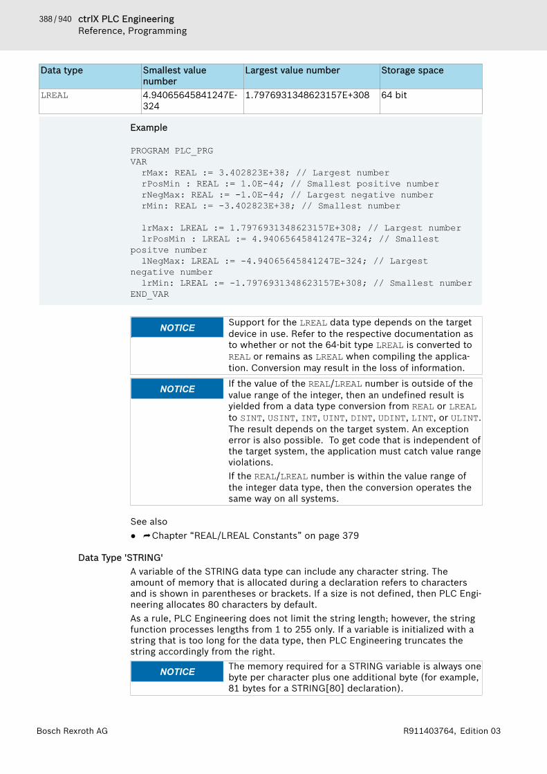
388 / 940 ctrlX PLC EngineeringReference, Programming
Bosch Rexroth AG R911403764, Edition 03
Data type Smallest valuenumber
Largest value number Storage space
LREAL 4.94065645841247E-324
1.7976931348623157E+308 64 bit
Example
PROGRAM PLC_PRGVARrMax: REAL := 3.402823E+38; // Largest numberrPosMin : REAL := 1.0E-44; // Smallest positive numberrNegMax: REAL := -1.0E-44; // Largest negative numberrMin: REAL := -3.402823E+38; // Smallest number
lrMax: LREAL := 1.7976931348623157E+308; // Largest numberlrPosMin : LREAL := 4.94065645841247E-324; // Smallest
positve numberlNegMax: LREAL := -4.94065645841247E-324; // Largest
negative numberlrMin: LREAL := -1.7976931348623157E+308; // Smallest number
END_VAR
NOTICE Support for the LREAL data type depends on the targetdevice in use. Refer to the respective documentation asto whether or not the 64-bit type LREAL is converted toREAL or remains as LREAL when compiling the applica-tion. Conversion may result in the loss of information.
NOTICE If the value of the REAL/LREAL number is outside of thevalue range of the integer, then an undefined result isyielded from a data type conversion from REAL or LREALto SINT, USINT, INT, UINT, DINT, UDINT, LINT, or ULINT.The result depends on the target system. An exceptionerror is also possible. To get code that is independent ofthe target system, the application must catch value rangeviolations.If the REAL/LREAL number is within the value range ofthe integer data type, then the conversion operates thesame way on all systems.
See also● ⮫ Chapter “REAL/LREAL Constants” on page 379
Data Type 'STRING'A variable of the STRING data type can include any character string. Theamount of memory that is allocated during a declaration refers to charactersand is shown in parentheses or brackets. If a size is not defined, then PLC Engi-neering allocates 80 characters by default.As a rule, PLC Engineering does not limit the string length; however, the stringfunction processes lengths from 1 to 255 only. If a variable is initialized with astring that is too long for the data type, then PLC Engineering truncates thestring accordingly from the right.
NOTICE The memory required for a STRING variable is always onebyte per character plus one additional byte (for example,81 bytes for a STRING[80] declaration).
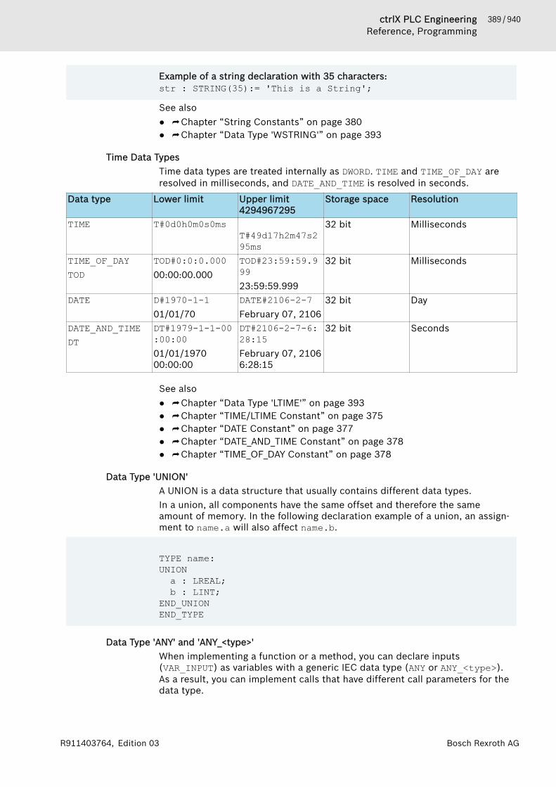
389 / 940ctrlX PLC EngineeringReference, Programming
Bosch Rexroth AGR911403764, Edition 03
Example of a string declaration with 35 characters:str : STRING(35):= 'This is a String';
See also● ⮫ Chapter “String Constants” on page 380● ⮫ Chapter “Data Type 'WSTRING'” on page 393
Time Data TypesTime data types are treated internally as DWORD. TIME and TIME_OF_DAY areresolved in milliseconds, and DATE_AND_TIME is resolved in seconds.
Data type Lower limit Upper limit4294967295
Storage space Resolution
TIME T#0d0h0m0s0msT#49d17h2m47s295ms
32 bit Milliseconds
TIME_OF_DAYTOD
TOD#0:0:0.00000:00:00.000
TOD#23:59:59.999 23:59:59.999
32 bit Milliseconds
DATE D#1970-1-101/01/70
DATE#2106-2-7February 07, 2106
32 bit Day
DATE_AND_TIMEDT
DT#1979-1-1-00:00:0001/01/197000:00:00
DT#2106-2-7-6:28:15February 07, 21066:28:15
32 bit Seconds
See also● ⮫ Chapter “Data Type 'LTIME'” on page 393● ⮫ Chapter “TIME/LTIME Constant” on page 375● ⮫ Chapter “DATE Constant” on page 377● ⮫ Chapter “DATE_AND_TIME Constant” on page 378● ⮫ Chapter “TIME_OF_DAY Constant” on page 378
Data Type 'UNION'A UNION is a data structure that usually contains different data types.In a union, all components have the same offset and therefore the sameamount of memory. In the following declaration example of a union, an assign-ment to name.a will also affect name.b.
TYPE name:UNIONa : LREAL;b : LINT;
END_UNIONEND_TYPE
Data Type 'ANY' and 'ANY_<type>'When implementing a function or a method, you can declare inputs(VAR_INPUT) as variables with a generic IEC data type (ANY or ANY_<type>).As a result, you can implement calls that have different call parameters for thedata type.
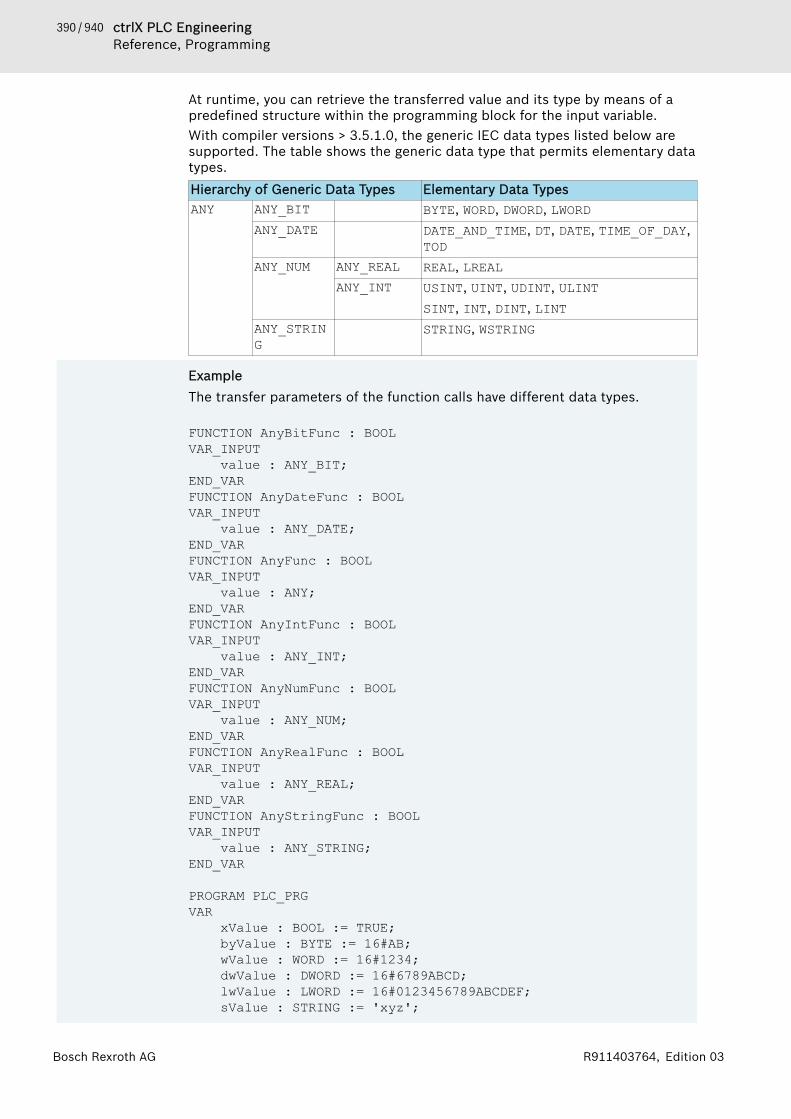
390 / 940 ctrlX PLC EngineeringReference, Programming
Bosch Rexroth AG R911403764, Edition 03
At runtime, you can retrieve the transferred value and its type by means of apredefined structure within the programming block for the input variable.With compiler versions > 3.5.1.0, the generic IEC data types listed below aresupported. The table shows the generic data type that permits elementary datatypes.Hierarchy of Generic Data Types Elementary Data TypesANY ANY_BIT BYTE, WORD, DWORD, LWORD
ANY_DATE DATE_AND_TIME, DT, DATE, TIME_OF_DAY,TOD
ANY_NUM ANY_REAL REAL, LREALANY_INT USINT, UINT, UDINT, ULINT
SINT, INT, DINT, LINTANY_STRING
STRING, WSTRING
ExampleThe transfer parameters of the function calls have different data types.
FUNCTION AnyBitFunc : BOOLVAR_INPUT value : ANY_BIT;END_VARFUNCTION AnyDateFunc : BOOLVAR_INPUT value : ANY_DATE;END_VARFUNCTION AnyFunc : BOOLVAR_INPUT value : ANY;END_VARFUNCTION AnyIntFunc : BOOLVAR_INPUT value : ANY_INT;END_VARFUNCTION AnyNumFunc : BOOLVAR_INPUT value : ANY_NUM;END_VARFUNCTION AnyRealFunc : BOOLVAR_INPUT value : ANY_REAL;END_VARFUNCTION AnyStringFunc : BOOLVAR_INPUT value : ANY_STRING;END_VAR
PROGRAM PLC_PRGVAR xValue : BOOL := TRUE; byValue : BYTE := 16#AB; wValue : WORD := 16#1234; dwValue : DWORD := 16#6789ABCD; lwValue : LWORD := 16#0123456789ABCDEF; sValue : STRING := 'xyz';
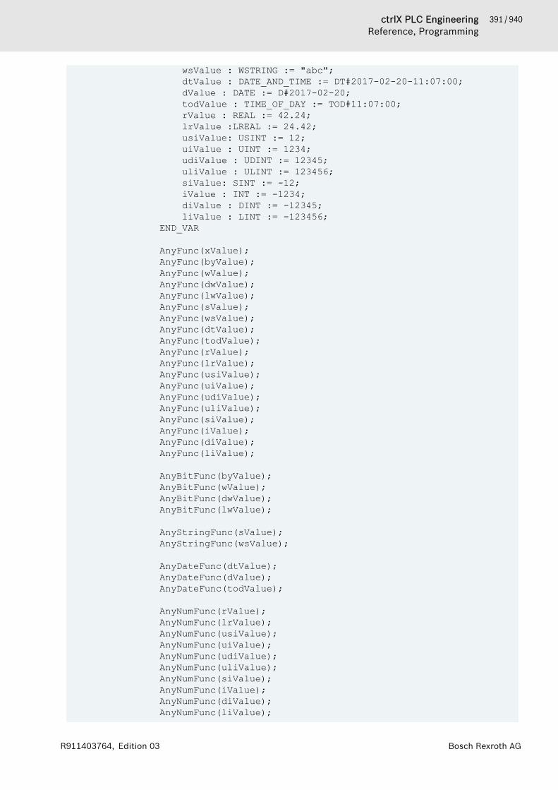
391 / 940ctrlX PLC EngineeringReference, Programming
Bosch Rexroth AGR911403764, Edition 03
wsValue : WSTRING := "abc"; dtValue : DATE_AND_TIME := DT#2017-02-20-11:07:00; dValue : DATE := D#2017-02-20; todValue : TIME_OF_DAY := TOD#11:07:00; rValue : REAL := 42.24; lrValue :LREAL := 24.42; usiValue: USINT := 12; uiValue : UINT := 1234; udiValue : UDINT := 12345; uliValue : ULINT := 123456; siValue: SINT := -12; iValue : INT := -1234; diValue : DINT := -12345; liValue : LINT := -123456; END_VAR
AnyFunc(xValue);AnyFunc(byValue);AnyFunc(wValue);AnyFunc(dwValue);AnyFunc(lwValue);AnyFunc(sValue);AnyFunc(wsValue);AnyFunc(dtValue);AnyFunc(todValue);AnyFunc(rValue);AnyFunc(lrValue);AnyFunc(usiValue);AnyFunc(uiValue);AnyFunc(udiValue);AnyFunc(uliValue);AnyFunc(siValue);AnyFunc(iValue);AnyFunc(diValue);AnyFunc(liValue);
AnyBitFunc(byValue);AnyBitFunc(wValue);AnyBitFunc(dwValue);AnyBitFunc(lwValue);
AnyStringFunc(sValue);AnyStringFunc(wsValue);
AnyDateFunc(dtValue);AnyDateFunc(dValue);AnyDateFunc(todValue);
AnyNumFunc(rValue);AnyNumFunc(lrValue);AnyNumFunc(usiValue);AnyNumFunc(uiValue);AnyNumFunc(udiValue);AnyNumFunc(uliValue);AnyNumFunc(siValue);AnyNumFunc(iValue);AnyNumFunc(diValue);AnyNumFunc(liValue);

392 / 940 ctrlX PLC EngineeringReference, Programming
Bosch Rexroth AG R911403764, Edition 03
AnyRealFunc(rValue);AnyRealFunc(lrValue);
AnyIntFunc(usiValue);AnyIntFunc(uiValue);AnyIntFunc(udiValue);AnyIntFunc(uliValue);AnyIntFunc(siValue);AnyIntFunc(iValue);AnyIntFunc(diValue);AnyIntFunc(liValue);
Predefined structureWhen compiling the code, an ANY data type is replaced internally with the fol-lowing structure:
TYPE AnyType :STRUCT // the type of the actual parametertypeclass : __SYSTEM.TYPE_CLASS ;
// the pointer to the actual parameterpvalue : POINTER TO BYTE;
// the size of the data, to which the pointer pointsdiSize : DINT;
END_STRUCTEND_TYPEThe actual call parameter will assign the structure elements at runtime.
ExampleThis compares whether or not the two passed variables have the same typeand the same value.
FUNCTION Generic_Compare : BOOLVAR_INPUTany1 : ANY;any2 : ANY;
END_VARVARpTest : POINTER TO ARRAY [0..100] OF POINTER TO DWORD;icount: DINT;
END_VAR
pTest := ADR(any1);Generic_Compare := FALSE;IF any1.typeclass <> any2.typeclass THENRETURN;
END_IFIF any1.diSize <> any2.diSize THENRETURN;
END_IF// Byte comparisonFOR icount := 0 TO any1.diSize-1 DOIF any1.pvalue[iCount] <> any2.pvalue[iCount] THEN
RETURN;END_IF

393 / 940ctrlX PLC EngineeringReference, Programming
Bosch Rexroth AGR911403764, Edition 03
END_FORGeneric_Compare := TRUE;RETURN;// END_FUNCTION
Data Type 'LTIME'You can use the data type LTIME as a time base for high-resolution timer. Ahigh-resolution timer has a resolution in nanoseconds.
Data type Lower limit Upper limit Storage spaceLTIME 0 213503d23h34m33s709
ms551us615ns64 bit
Syntax:LTIME#<time declaration>The time declaration can include units of time that apply for the TIME constantas well as:● "us": microseconds● "ns": nanoseconds
Example:LTIME1 := LTIME#1000d15h23m12s34ms2us44ns
See also● ⮫ Chapter “Time Data Types” on page 389
Data Type 'WSTRING'The data type WSTRING is interpreted in Unicode format as opposed to thedata type STRING (ASCII). As a result of this coding, the number of displayedcharacters for WSTRING depends on the characters. A length of 10 forWSTRING means that the length of the WSTRING can take a maximum of 10WORDs. However, for some characters in Unicode, multiple WORDS arerequired for coding a character so that the number of characters do not have tocorrespond to the length of the WSTRING (10 in this case). The data typerequires 1 WORD of memory per character plus 1 WORD of extra memory. EachSTRING requires only 1 byte. The data type WSTRING is terminated with a 0.
Example:wstr : WSTRING := "This is a WString";
See also● ⮫ Chapter “Data Type 'STRING'” on page 388● ⮫ Chapter “String Constants” on page 380
Data Type 'BIT'You can use the BIT data type only for single variables in structures or in afunction block. The possible values are TRUE (1) and FALSE (0).A BIT element requires 1 bit of memory. Therefore, you can reference singlebits of a structure by name. BIT elements that are declared in succession arebundled in bytes. In this way, you can optimize memory use as opposed toBOOL types, which reserve 8 bits each. On the other hand, bit access is signifi-cantly more time-consuming. Therefore, you should use the BIT data type onlywhen you need to define data in a predefined format.See also● ⮫ Chapter “Structure” on page 411
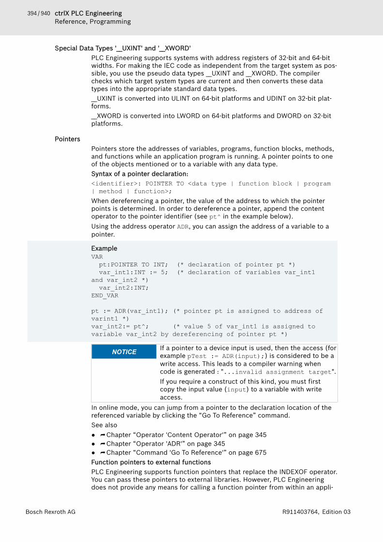
394 / 940 ctrlX PLC EngineeringReference, Programming
Bosch Rexroth AG R911403764, Edition 03
Special Data Types '__UXINT' and '__XWORD'PLC Engineering supports systems with address registers of 32-bit and 64-bitwidths. For making the IEC code as independent from the target system as pos-sible, you use the pseudo data types __UXINT and __XWORD. The compilerchecks which target system types are current and then converts these datatypes into the appropriate standard data types.__UXINT is converted into ULINT on 64-bit platforms and UDINT on 32-bit plat-forms.__XWORD is converted into LWORD on 64-bit platforms and DWORD on 32-bitplatforms.
PointersPointers store the addresses of variables, programs, function blocks, methods,and functions while an application program is running. A pointer points to oneof the objects mentioned or to a variable with any data type.Syntax of a pointer declaration:<identifier>: POINTER TO <data type | function block | program| method | function>;When dereferencing a pointer, the value of the address to which the pointerpoints is determined. In order to dereference a pointer, append the contentoperator to the pointer identifier (see pt^ in the example below).Using the address operator ADR, you can assign the address of a variable to apointer.
ExampleVARpt:POINTER TO INT; (* declaration of pointer pt *)var_int1:INT := 5; (* declaration of variables var_int1
and var_int2 *)var_int2:INT;
END_VAR
pt := ADR(var_int1); (* pointer pt is assigned to address of varint1 *)var_int2:= pt^; (* value 5 of var_int1 is assigned to variable var_int2 by dereferencing of pointer pt *)
NOTICE If a pointer to a device input is used, then the access (forexample pTest := ADR(input);) is considered to be awrite access. This leads to a compiler warning whencode is generated : "...invalid assignment target".If you require a construct of this kind, you must firstcopy the input value (input) to a variable with writeaccess.
In online mode, you can jump from a pointer to the declaration location of thereferenced variable by clicking the “Go To Reference” command.See also● ⮫ Chapter “Operator 'Content Operator'” on page 345● ⮫ Chapter “Operator 'ADR'” on page 345● ⮫ Chapter “Command 'Go To Reference'” on page 675Function pointers to external functionsPLC Engineering supports function pointers that replace the INDEXOF operator.You can pass these pointers to external libraries. However, PLC Engineeringdoes not provide any means for calling a function pointer from within an appli-

395 / 940ctrlX PLC EngineeringReference, Programming
Bosch Rexroth AGR911403764, Edition 03
cation in the development system. The function of the runtime system for theregistration of callback functions (system library function) expects the functionpointer. Depending on which callback was registered, the runtime systemimplicitly calls the function concerned (in the case of STOP for example). Sothat such a system call is possible (runtime system), you must set the corre-sponding object property in the “Build” tab.You can use the ADR operator for functions, programs, function blocks, andmethods. PLC Engineering outputs the address of a pointer to the function, notthe address of the function, because the values of functions can change afteran online change. This address is valid as long as the function exists on thetarget system.See also● ⮫ Chapter “Dialog 'Properties' - 'Build'” on page 825● ⮫ Chapter “Operator 'ADR'” on page 345Index access to pointersIn PLC Engineering, index access "[]" to type POINTER, STRING, and WSTRINGvariables is permitted.● pint[i] returns the basic data type● Index access to pointers is done arithmetically: If you use index access for a
POINTER TO variable, then PLC Engineering computes the offset by pint[i]= (pint + i * SIZEOF(base type))^. The index access also causes animplicit dereferencing of the pointer. The resulting data type is the basicdata type of the pointer. Note that pint[7] != (pint + 7)^.
● When you use the index access with a variable of the type STRING, you getthe character at the offset of the index expression. The result is a BYTE type.str[i] returns the i-th character of the string as SINT (ASCII).
● When you use the index access with a variable of the type WSTRING, you getthe character at the offset of the index expression. The result is a WORD type.wstr[i] returns the i-th character of the string as INT (Unicode).
The result of the difference between two pointers is of type DWORD, even on 64-bit platforms, when the pointers are 64-bit pointers.Note that it is possible to use references which control a value directly, in con-trast to pointers.Note that it is possible to monitor the memory access of pointers at runtime bythe implicit monitoring function CheckPointerSee also● ⮫ Chapter “POU 'CheckPointer'” on page 620
ReferenceA REFERENCE is also a pointer, but it has some advantages over a POINTER:● Ease of use: The reference does not have to be dereferenced explicitly (with
^) in order to access the contents of the referenced object.● Nicer syntax for passing of values: If an input is a REFERENCE TO, then you
do not have to write ADR(value) explicitly for a(refInput := value).● Type safety: Unlike the pointer, for references the compiler checks that the
base type is the same when assigning two referencesYou declare a reference in accordance with the following syntax:Syntax<identifier> : REFERENCE TO <data type>

396 / 940 ctrlX PLC EngineeringReference, Programming
Bosch Rexroth AG R911403764, Edition 03
Example
A : REFERENCE TO DUT;B : DUT;C : DUT;
A REF= B; // corresponds to A := ADR(B);A := C; // corresponds to A^ := C;
You cannot declare references in the following ways:− REFERENCE TO REFERENCE− or ARRAY OF REFERENCE− or POINTER TO REFERENCE.Furthermore, you cannot declare a reference to a bit variable.
NOTICE PLC Engineering initializes references (at 0) with com-piler version >= V3.3.0.0.
NOTICE When a reference is used for a device entry, write accessis enabled (for example, ref REF= input;) . This leadsto a compiler warning when code is generated :"...invalid assignment target".If you require this kind of construct, then first you mustcopy the input value (input) to a variable with writeaccess.
Checking for valid referencesYou can use the operator __ISVALIDREF in order to check whether a referencepoints to a valid value, i.e. to a value not equal to 0.Syntax:<Boolean variable> := __ISVALIDREF(<with REFERENCE TO <datatype> declared identifier);<Boolean variable> is TRUE when the reference points to a valid value; other-wise FALSE.
ExampleDeclaration:ivar : INT;ref_int : REFERENCE TO INT;ref_int0 : REFERENCE TO INT;testref : BOOL := FALSE;Implementation:ivar := ivar + 1;ref_int REF= ivar;ref_int0 REF= 0;testref := __ISVALIDREF(ref_int); (* becomes TRUE, because ref_int points to ivar, which is non-zero *) testref := __ISVALIDREF(ref_int0); (* becomes FALSE, because ref_int0 is set to 0 *)
In compiler version 3.5.7.40 and later, the implicit monitoring function “Check-Pointer” also affects REFERENCE variables the same as pointer variables.See also● ⮫ Chapter “Assignment operator 'REF'” on page 261● ⮫ Chapter “POU 'CheckPointer'” on page 620
397 / 940ctrlX PLC EngineeringReference, Programming
Bosch Rexroth AGR911403764, Edition 03
Data Type 'ARRAY'An array is a collection of data elements of the same data type. PLC Engi-neering supports one- and multi-dimensional arrays of fixed or variable length.
Array of fixed lengthYou can define arrays in the declaration part of a POU or in global variable lists.Syntax of the declaration of a one-dimensional array
<variable name> : ARRAY[ <dimension> ] OF <data type> ( := <initialization> )? ;
<dimension> : <lower index bound>..<upper index bound><data type> : elementary data types | user defined data types | function block types // (...)? : OptionalSyntax of the declaration of a multi-dimensional array
<variable name> : ARRAY[ <1st dimension> ( , <next dimension> )+ ] OF <data type> ( := <initialization> )? ;
<1st dimension> : <1st lower index bound>..<1st upper index bound><next dimension> : <next lower index bound>..<next upper index bound><data type> : elementary data types | user defined data types | function block types // (...)+ : One or more further dimensions// (...)? : OptionalThe index limits are integers; maximum of the data type DINT.Syntax for data access
<variable name>[ <index of 1st dimension> ( , <index of next dimension> )* ]// (...)* : 0, one or more further dimensionsNote the capability of using the implicit monitoring function CheckBounds() tomonitor the index limits at runtime.
Example
One-dimensional array of 10 integer elements
VARaiCounter : ARRAY[0..9] OF INT;
END_VARLower index limit: 0Upper index limit: 9Initialization
aiCounter : ARRAY[0..9] OF INT := [0, 10, 20, 30, 40, 50, 60, 70, 80, 90];Data access
iLocalVariable := aiCounter[2];
398 / 940 ctrlX PLC EngineeringReference, Programming
Bosch Rexroth AG R911403764, Edition 03
The value 20 is assigned to the local variable.
Example
2-dimensional array
VARaiCardGame : ARRAY[1..2, 3..4] OF INT;
END_VAR1st dimension: 1 to 22nd dimension: 3 to 4Initialization
aiCardGame : ARRAY[1..2, 3..4] OF INT := [2(10),2(20)]; // Short notation for [10, 10, 20, 20]Data access
iLocal_1 := aiCardGame[1, 3]; // Assignment of 10iLocal_2 := aiCardGame[2, 4]; // Assignment of 20
Example
3-dimensional array
VARaiCardGame : ARRAY[1..2, 3..4, 5..6] OF INT;
END_VAR1st dimension: 1 to 22nd dimension: 3 to 43rd dimension: 5 to 62 * 2 * 2 = 8 array elementsInitialization
aiCardGame : ARRAY[1..2, 3..4, 5..6] OF INT := [10, 20, 30, 40, 50, 60, 70, 80];Data access
iLocal_1 := aiCardGame[1, 3, 5]; // Assignment of 10iLocal_2 := aiCardGame[2, 3, 5]; // Assignment of 20iLocal_3 := aiCardGame[1, 4, 5]; // Assignment of 30iLocal_4 := aiCardGame[2, 4, 5]; // Assignment of 40iLocal_5 := aiCardGame[1, 3, 6]; // Assignment of 50iLocal_6 := aiCardGame[2, 3, 6]; // Assignment of 60iLocal_7 := aiCardGame[1, 4, 6]; // Assignment of 70iLocal_8 := aiCardGame[2, 4, 6]; // Assignment of 80Initialization
aiCardGame : ARRAY[1..2, 3..4, 5..6] OF INT := [2(10), 2(20), 2(30), 2(40)]; // Short notation for [10, 10, 20, 20, 30, 30, 40, 40]

399 / 940ctrlX PLC EngineeringReference, Programming
Bosch Rexroth AGR911403764, Edition 03
Data access
iLocal_1 := aiCardGame[1, 3, 5]; // Assignment of 10iLocal_2 := aiCardGame[2, 3, 5]; // Assignment of 10iLocal_3 := aiCardGame[1, 4, 5]; // Assignment of 20iLocal_4 := aiCardGame[2, 4, 5]; // Assignment of 20iLocal_5 := aiCardGame[1, 3, 6]; // Assignment of 30iLocal_6 := aiCardGame[2, 3, 6]; // Assignment of 30iLocal_7 := aiCardGame[1, 4, 6]; // Assignment of 40iLocal_8 := aiCardGame[2, 4, 6]; // Assignment of 40
Example
3-dimensional arrays of a user-defined structure
TYPE DATA_ASTRUCT iA_1 : INT; iA_2 : INT; dwA_3 : DWORD;END_STRUCTEND_TYPE
PROGRAM PLC_PRGVARaData_A : ARRAY[1..3, 1..3, 1..10] OF DATA_A;
END_VARThe array aData_A consists of a total of 3 * 3 * 10 = 90 array elements of datatype DATA_A.Initialize partially
aData_A : ARRAY[1..3, 1..3, 1..10] OF DATA_A := [(iA_1 := 1, iA_2 := 10, dwA_3 := 16#00FF),(iA_1 := 2, iA_2 := 20, dwA_3 := 16#FF00),(iA_1 := 3, iA_2 := 30, dwA_3 := 16#FFFF)];In the example, only the first 3 elements are initialized explicitly. Elements towhich no initialization value is assigned explicitly are initialized internally withthe default value of the basic data type. This initializes the structure compo-nents at 0 starting with the element aData_A[2, 1, 1].Data access
iLocal_1 := aData_A[1,1,1].iA_1; // Assignment of 1dwLocal_2 := aData_A[3,1,1].dwA_3; // Assignment of 16#FFFF
400 / 940 ctrlX PLC EngineeringReference, Programming
Bosch Rexroth AG R911403764, Edition 03
Example
Array of a function block
FUNCTION BLOCK FBObject_AVARiCounter : INT;
END_VAR...
PROGRAM PLC_PRGVARaObject_A : ARRAY[1..4] OF FBObject_A;
END_VARThe array aObject_A consists of 4 elements. Each element instantiates aFBObject_A function block.Function Call
aObject_A[2]();
Example
Implementation of FB_Something with method FB_Init
FUNCTION_BLOCK FB_SomethingVAR_nId : INT;_lrIn : LREAL;
END_VAR...
METHOD FB_Init : BOOLVAR_INPUTbInitRetains : BOOL;bInCopyCode : BOOL;nId : INT;lrIn : LREAL;
END_VAR
_nId := nId;_lrIn := lrIN;The function block FB_Something has a method FB_Init that requires 2parameters.Instantiation of the array with initialization
PROGRAM PLC_PRGVARfb_Something_1 : FB_Something(nId := 11, lrIn := 33.44);a_Something : ARRAY[0..1, 0..1] OF FB_Something[(nId := 12,
lrIn := 11.22), (nId := 13, lrIn := 22.33), (nId := 14, lrIn := 33.55),(nId := 15, lrIn := 11.22)];END_VAR
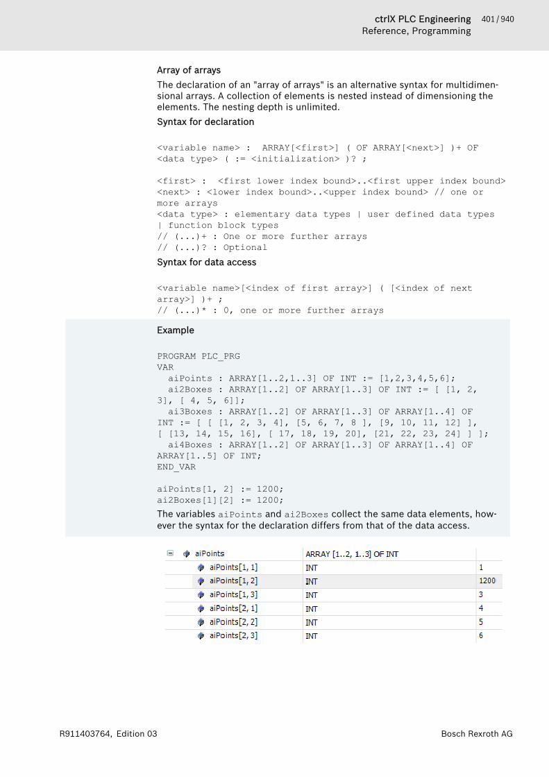
401 / 940ctrlX PLC EngineeringReference, Programming
Bosch Rexroth AGR911403764, Edition 03
Array of arraysThe declaration of an "array of arrays" is an alternative syntax for multidimen-sional arrays. A collection of elements is nested instead of dimensioning theelements. The nesting depth is unlimited.Syntax for declaration
<variable name> : ARRAY[<first>] ( OF ARRAY[<next>] )+ OF <data type> ( := <initialization> )? ;
<first> : <first lower index bound>..<first upper index bound><next> : <lower index bound>..<upper index bound> // one or more arrays<data type> : elementary data types | user defined data types | function block types // (...)+ : One or more further arrays// (...)? : OptionalSyntax for data access
<variable name>[<index of first array>] ( [<index of next array>] )+ ;// (...)* : 0, one or more further arrays
Example
PROGRAM PLC_PRGVARaiPoints : ARRAY[1..2,1..3] OF INT := [1,2,3,4,5,6];ai2Boxes : ARRAY[1..2] OF ARRAY[1..3] OF INT := [ [1, 2,
3], [ 4, 5, 6]];ai3Boxes : ARRAY[1..2] OF ARRAY[1..3] OF ARRAY[1..4] OF
INT := [ [ [1, 2, 3, 4], [5, 6, 7, 8 ], [9, 10, 11, 12] ], [ [13, 14, 15, 16], [ 17, 18, 19, 20], [21, 22, 23, 24] ] ];ai4Boxes : ARRAY[1..2] OF ARRAY[1..3] OF ARRAY[1..4] OF
ARRAY[1..5] OF INT;END_VAR
aiPoints[1, 2] := 1200;ai2Boxes[1][2] := 1200;The variables aiPoints and ai2Boxes collect the same data elements, how-ever the syntax for the declaration differs from that of the data access.

402 / 940 ctrlX PLC EngineeringReference, Programming
Bosch Rexroth AG R911403764, Edition 03
Array of variable lengthIn function blocks, functions, or methods, you can declare arrays of variablelength in the VAR_IN_OUT declaration section. The LOWER_BOUND andUPPER_BOUND operators are provided for determining the index limits of theactual used array at runtime.Syntax of the declaration of a one-dimensional array of variable length
<variable name> : ARRAY[*] OF <data type> ( := <initialization> )? ;
<data type> : elementary data types | user defined data types | function block types // (...)? : OptionalSyntax of the declaration of a multi-dimensional array of variable length
<variable name> : ARRAY[* ( , * )+ ] OF <data type> ( := <initialization> )? ;
<data type> : elementary data types | user defined data types | function block types // (...)+ : One or more further dimensions// (...)? : OptionalSyntax of the operators for calculating the limit index
LOWER_BOUND( <variable name> , <dimension number> )UPPER_BOUND( <variable name> , <dimension number> )
403 / 940ctrlX PLC EngineeringReference, Programming
Bosch Rexroth AGR911403764, Edition 03
ExampleThe SUM function adds the integer values of the array elements and returns thecalculated sum as a result. The sum is calculated across all array elementsavailable at runtime. As the actual number of array elements will only beknown at runtime, the local variable is declared as a one-dimensional array ofvariable length.
FUNCTION SUM: INT;VAR_IN_OUTaiData : ARRAY[*] OF INT;
END_VARVAR diCounter, diResult : DINT; END_VAR
diResult := 0;FOR diCounter := LOWER_BOUND(aiData, 1) TO UPPER_BOUND(aiData, 1) DO // Calculates the length of the current array diResult := diResult + A[i];END_FOR;SUM := diResult;
See also● ⮫ Chapter “Declaring Arrays” on page 65● ⮫ Chapter “POU 'CheckBounds'” on page 609
Data Type '__VECTOR'Vector operations are supported natively only on 64-bit processors and offer aperformance advantage only on these processors. The data sheet of the con-troller provides information about the processor used on the controller.Currently, vector operations on the x86/64-bit platforms with SSE2 and ARM64with NEON are supported natively. On all other platforms, vector operations aretranslated into individual statements. For example, vector addition is then exe-cuted with multiple single addition operations.The command set extensions of the processors are SIMD extensions. SIMD(Single Instruction, Multiple Data) describes a computer architecture in whichmultiple data sets of the same type are processed simultaneously in paralleland therefore faster with one command call. In vector operations, for example,4 pairs of numbers can then be added at the same time.
Syntax
<variable name> : __VECTOR[ <vector size> ] OF <element type> ( := <initialization> )? ;
<vector size> : 1 |2 | 3 | 4 | 5| 6 | 7| 8<element type> : REAL | LREAL// (...)? : OptionalA vector data type is an array of floating-point numbers with a maximum of 8elements. The operators __vc<operator name> are available for this datatype. You can use these to implement vector operations without additionalfunction calls.
404 / 940 ctrlX PLC EngineeringReference, Programming
Bosch Rexroth AG R911403764, Edition 03
Syntax for index access
<variable name>[ <index> ]<index> : 0 | 1 | 2| 3 | 4 | 5| 6 | 7When indexing a vector variable, you can access a single element of the vector.The index starts at 0 and goes until <vector size> - 1.
Example
PROGRAM PLC_PRGVARvcA : __VECTOR[3] OF REAL;
END_VAR
vcA[0] := 1.1;vcA[1] := 2.2;vcA[2] := 3.3;
Determining the optimal vector sizeUse the optimal vector size depending on your target system as the vector sizein order to program the most efficient code possible.For target systems whose computer architecture is generally suitable for vectorprocessing, we do not recommend using vectors of arbitrary size. There is anoptimal vector size depending on the type of data processing of the processor.Vectors that are declared with this array size are processed as quickly as pos-sible. Vectors that are declared as a larger array do not have an advantage inspeed. Vectors that are declared as smaller arrays do not take full advantage ofthe processor's capabilities.You can query the optimal size at runtime. You can find the information in theconstants Constants.vcOptimalREAL (for vectors with REAL elements) andConstants.vcOptimalLREAL (for vectors with LREAL elements). The con-stants have the LREAL data type. If a constant returns the value 1 as theoptimal value, then this means that accelerated vector processing is not avail-able for the target system.
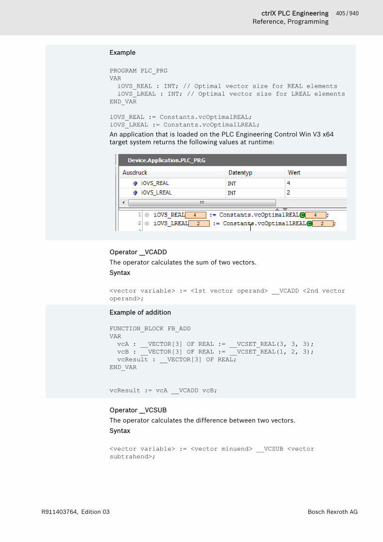
405 / 940ctrlX PLC EngineeringReference, Programming
Bosch Rexroth AGR911403764, Edition 03
Example
PROGRAM PLC_PRGVARiOVS_REAL : INT; // Optimal vector size for REAL elementsiOVS_LREAL : INT; // Optimal vector size for LREAL elements
END_VAR
iOVS_REAL := Constants.vcOptimalREAL;iOVS_LREAL := Constants.vcOptimalLREAL;An application that is loaded on the PLC Engineering Control Win V3 x64target system returns the following values at runtime:
Operator __VCADDThe operator calculates the sum of two vectors.Syntax
<vector variable> := <1st vector operand> __VCADD <2nd vector operand>;
Example of addition
FUNCTION_BLOCK FB_ADDVARvcA : __VECTOR[3] OF REAL := __VCSET_REAL(3, 3, 3);vcB : __VECTOR[3] OF REAL := __VCSET_REAL(1, 2, 3);vcResult : __VECTOR[3] OF REAL;
END_VAR
vcResult := vcA __VCADD vcB;
Operator __VCSUBThe operator calculates the difference between two vectors.Syntax
<vector variable> := <vector minuend> __VCSUB <vector subtrahend>;

406 / 940 ctrlX PLC EngineeringReference, Programming
Bosch Rexroth AG R911403764, Edition 03
Example of subtraction
FUNCTION_BLOCK FB_SUBVARvcA : __VECTOR[3] OF REAL := __VCSET_REAL(3, 3, 3);vcB : __VECTOR[3] OF REAL := __VCSET_REAL(1, 2, 3);vcResult0 : __VECTOR[3] OF REAL;vcResult1 : __VECTOR[3] OF REAL;
END_VAR
vcResult0 := vcA __VCSUB vcB;vcResult1 := vcB __VCSUB vcA;
Operator __VCMULThe operator calculates the product of two vectors or a scalar (floating-pointnumber) and a vector.Syntax
<vector variable> := <1st vector operand> __VCMUL <2nd vector operand> | <scalar operand> __VCMUL <vector operand> | <vector operand> __VCMUL <scalar operand> ;
Example of multiplication
FUNCTION_BLOCK FB_MULVARrScalar : REAL := 1.1;vcA : __VECTOR[3] OF REAL;vcB : __VECTOR[3] OF REAL;vcResult0 : __VECTOR[3] OF REAL;vcResult1 : __VECTOR[3] OF REAL;vcResult2 : __VECTOR[3] OF REAL;
END_VAR
vcResult0 := vcA __VCMUL vcB;vcResult1 := rScalar __VCMUL vcB;vcResult2 := vcA __VCMUL 3.3;
Operator __VCDIVThe operator calculates the quotient of two vectors or a vector and a scalar.Syntax
<vector variable> := <vector dividend> __VCDIV <vector divisor> | < vector dividend> __VCMUL <scalar divisor> ;
407 / 940ctrlX PLC EngineeringReference, Programming
Bosch Rexroth AGR911403764, Edition 03
Example of division
FUNCTION_BLOCK FB_DIVVARiScalar : INT := 3;rScalar : REAL := 1.5;vcA : __VECTOR[3] OF REAL := __VCSET_REAL(3, 3, 3);vcB : __VECTOR[3] OF REAL := __VCSET_REAL(1, 2, 3);vcResult0 : __VECTOR[3] OF REAL;vcResult1 : __VECTOR[3] OF REAL;vcResult2 : __VECTOR[3] OF REAL;
END_VAR
vcResult0 := vcA __VCDIV vcB;// ERROR CODE vcResult1 := rScalar __VCDIV vcB;// ERROR CODE vcResult1 := iScalar __VCDIV vcB;// ERROR CODE vcResult1 := 3.3 __VCDIV vcB;vcResult2 := vcA __VCDIV 1.5;vcResult2 := vcA __VCDIV iScalar;vcResult2 := vcA __VCDIV rScalar;
Operator __VCDOTThe operator calculates the dot product (scalar product) of two vectors.Syntax
<scalar variable> := <1st vector operand> __VCDOT <2nd vector operand> ;
Example of a dot product
FUNCTION_BLOCK FB_DOTVARrResult : REAL;vcA : __VECTOR[3] OF REAL := __VCSET_REAL(3, 3, 3);vcB : __VECTOR[3] OF REAL := __VCSET_REAL(1, 2, 3);
END_VAR
rResult := vcA __VCDOT vcB; // = 18
Operator __VCSQRTThe operator calculates the square root of each element in the vector.Syntax
<vector variable> := __VCSQRT( <vector operand> );
Example of a square root
FUNCTION_BLOCK FB_SQRTVARvcA : __VECTOR[3] OF REAL := __VCSET_REAL(4, 9, 16);vcResult0 : __VECTOR[3] OF REAL;
END_VAR
vcResult0 := __VCSQRT(vcA);
408 / 940 ctrlX PLC EngineeringReference, Programming
Bosch Rexroth AG R911403764, Edition 03
Operator __VCMAXThe operator calculates the maximum vector of two vectors. The maximum isdetermined element by element.Syntax
<vector variable> := __VCMAX( <1st vector operand>, <2nd vector operand>);
Example of a maximum vector
FUNCTION_BLOCK FB_MAXVARvcA : __VECTOR[3] OF REAL := __VCSET_REAL(3, 3, 3);vcB : __VECTOR[3] OF REAL := __VCSET_REAL(1, 2, 6);vcResult0 : __VECTOR[3] OF REAL;
END_VAR
vcResult0 := __VCMAX(vcA, vcB);
Operator __VCMINThe operator calculates the minimum vector of two vectors. The minimum isdetermined element by element.Syntax
<vector variable> := __VCMIN( <1st vector operand>, <2nd vector operand>);
Example of a minimum vector
FUNCTION_BLOCK FB_MINVARvcA : __VECTOR[3] OF REAL := __VCSET_REAL(3, 3, 3);vcB : __VECTOR[3] OF REAL := __VCSET_REAL(1, 2, 6);vcResult0 : __VECTOR[3] OF REAL;
END_VAR
vcResult0 := __VCMIN(vcA, vcB);
Operator __VCSET_REALThe operator sets all elements of a vector in a statement. The elements havethe REAL data type.Syntax
<vector variable> := __VCSET_REAL( <first literal>, ( < next literal> )+ ) ;( ... )+ // number of elements have to match
409 / 940ctrlX PLC EngineeringReference, Programming
Bosch Rexroth AGR911403764, Edition 03
Example
FUNCTION_BLOCK FB_SETVARvcA : __VECTOR[3] OF REAL := __VCSET_REAL(3, 3, 3);vcB : __VECTOR[3] OF REAL := __VCSET_REAL(1, 2, 3);
END_VAR
vcA := __VCSET_REAL(4, 4, 4);vcB := __VCSET_REAL(1.1, 2.2, 3.3);
Operator __VCSET_LREALThe operator sets all elements of a vector at once in a statement. The elementshave the LREAL data type.They can be used wherever variables are valid, such as in assignments in imple-mentations or as parameters in function calls.Syntax
<vector variable> := __VCSET_LREAL( <first literal>, ( < next literal> )+ ) ;( ... )+ // number of elements have to match
Example
FUNCTION_BLOCK FB_SETVARvclA : __VECTOR[3] OF LREAL := __VCSET_LREAL(3, 3, 3);vclB : __VECTOR[3] OF LREAL := __VCSET_LREAL(1, 2, 3);
END_VAR
vclA := __VCSET_LREAL(-1.7976931348623158E+308, 0.0, 1.7976931348623158E+308);vclB := __VCSET_LREAL(-1.7976931348623158E+308, 0.0, 1.7976931348623158E+308);
Operator __VCLOAD_REALThe operator interprets any arbitrary memory area as a vector. This is helpfulfor connecting vector variables to existing code. The operator requires 2 param-eters. The first parameter indicates the number of vector elements. The secondparameter is a pointer to the REAL data.Syntax
<vector variable> := __VCLOAD_REAL( <vector size>, <pointer to data of type REAL> ) ;<vector size> : 2 | 3 | 4 | 5| 6 | 7| 8

410 / 940 ctrlX PLC EngineeringReference, Programming
Bosch Rexroth AG R911403764, Edition 03
Example of vectorization
FUNCTION_BLOCK FB_LOADVAR_INPUTEND_VARVAR_OUTPUTEND_VARVARrData0 : REAL := 1.234;rData1: REAL := 5.678;rData2 : REAL := 9.123;pData: POINTER TO REAL := ADR(rData0);
vcA : __VECTOR[3] OF REAL := __VCSET_REAL(3, 3, 3);END_VAR
vcA := __VCLOAD_REAL(3, pData);
Operator __VCLOAD_LREALThe operator interprets any arbitrary memory area as a vector. This is helpfulfor connecting vector variables to existing code. The operator requires 2 param-eters. The first parameter indicates the number of vector elements. The secondparameter is a pointer to the LREAL data.Syntax
<vector variable> := __VCLOAD_REAL( <vector size>, <pointer to data of type LREAL> );<number of vector elements> : 1 | 2 | 3 | 4 | 5| 6 | 7| 8
Example of vectorization
FUNCTION_BLOCK FB_LOADVAR_INPUTEND_VARVAR_OUTPUTEND_VARVARlrData0 : LREAL := -1.7976931348623158E+308;lrData1: LREAL := 1.6E+308;lrData2 : LREAL := 1.7E+308;lrData3 : LREAL := -1.6E+308;plData: POINTER TO LREAL := ADR(lrData0);
vclA : __VECTOR[4] OF LREAL := __VCSET_LREAL(4, 4, 4, 4);END_VARvclA := __VCLOAD_LREAL(4, plData);
Operator __VCSTOREThe operator saves/copies the contents of the vector to the specified memoryaddress. The number and the types of elements are automatically applied fromthe vector variables.Syntax
__VCSTORE( <pointer to data>, <vector variable> );

411 / 940ctrlX PLC EngineeringReference, Programming
Bosch Rexroth AGR911403764, Edition 03
Example of storage
FUNCTION_BLOCK FB_STOREVAR_INPUTEND_VARVAR_OUTPUTEND_VARVARrData0 : REAL := 3;rData1: REAL := 3;rData2 : REAL := 3;pData: POINTER TO REAL := ADR(rData0);
lrData0 : LREAL := 4;lrData1: LREAL := 4;lrData2 : LREAL := 4;lrData3 : LREAL := 4;plData: POINTER TO LREAL := ADR(lrData0);
vcA : __VECTOR[3] OF REAL := __VCSET_REAL( 1.234, 5.678, 9.123);vclA : __VECTOR[4] OF LREAL :=
__VCSET_LREAL(-1.7976931348623158E+308, 1.6E+308, 1.7E+308, -1.6E+308);END_VAR
__VCSTORE(pData, vcA);__VCSTORE(plData, vclA);
See also● ⮫ Chapter “Declaring Arrays” on page 65● ⮫ Chapter “POU 'CheckBounds'” on page 609
StructureYou create a structure in a project with a “DUT” object by clicking “AddObject”.The structure declaration begins with the keywords TYPE and STRUCT, andends with the keywords END_STRUCT and END_TYPE.Syntax for the structure declaration:
TYPE <structure name>:STRUCT<variable declaration 1>...<variable declaration n>
END_STRUCTEND_TYPE<structure name> is a type that PLC Engineering recognizes through the entireproject and you can use as a standard data type.You can also use nested structures. The only restriction is that you are not per-mitted to assign addresses to variables (because the AT declaration is not per-mitted).
412 / 940 ctrlX PLC EngineeringReference, Programming
Bosch Rexroth AG R911403764, Edition 03
Example of a structure definition named Polygonline
TYPE polygonline:STRUCT
start:ARRAY [1..2] OF INT;point1:ARRAY [1..2] OF INT;point2:ARRAY [1..2] OF INT;point3:ARRAY [1..2] OF INT;point4:ARRAY [1..2] OF INT;end:ARRAY [1..2] OF INT;
END_STRUCTEND_TYPE
See also● ⮫ Chapter “Object 'DUT'” on page 549● ⮫ Chapter “Operator 'EQ'” on page 344
Initializing structures
Example:pPoly_1 : polygonline := ( start:=[3,3], point1:=[5,2],point2 := [7,3], point3 := [8,5], point4 := [5,7], end :=[3,5]);
You are not permitted to use initializations with variables. For an example of ini-tializing an array of a structure, please see the help page for the ARRAY datatype.See also● ⮫ Chapter “Data Type 'ARRAY'” on page 397
Accessing structure membersYou access structure members with the following syntax:<structure name>.<component name>Therefore, you can use poly_1.start to access the start component of thepolygonline structure in the above example.See also● ⮫ Chapter “Data Type 'ARRAY'” on page 397
Bit access in structuresBit is a special data type that you define in structures only. It reserves one bitof memory and permits single bits of a structure to be addressed by a name.
TYPE <structure name>:STRUCT<bit name bit1> : BIT;<bit name bit2> : BIT;<bit name bit3> : BIT;...<bit name bitn> : BIT;
END_STRUCTEND_TYPEYou can access the BIT structure member with the following syntax:<structure name>.<bit name>
413 / 940ctrlX PLC EngineeringReference, Programming
Bosch Rexroth AGR911403764, Edition 03
You cannot use any references or pointers to BIT variables. Furthermore, youare not permitted to use BIT variables in arrays.See also● ⮫ Chapter “Data Type 'BIT'” on page 393
EnumerationsAn enumeration is a user-defined data type composed of a series of comma-separated components (enumeration values) for declaring user-defined varia-bles. Moreover, you can use the enumeration components like constants whoseidentifier <enumeration name>.<component name> is recognized globally inthe project.You declare an enumeration in a DUT object, which you have already created inthe project by clicking “Add Object”.
Declaration
Syntax
( {attribute 'strict'} )? // Pragma optional but recommendedTYPE <enumeration name> :(<first component declaration>,( <component declaration> ,)+<last component declaration>
)( <basic data type> )? ( := <default variable initialization> )? ; END_TYPE
( ... )? : Optional<component declaration> : <component name> ( := <component initialization> )?<basic data type> : INT | UINT | SINT | USINT | DINT | UDINT | LINT | ULINT | BYTE | WORD | DWORD | LWORD<variable initialization> : <one of the component names> In an enumeration declaration, at least 2 components are usually declared.However, you can declare as many as you want. Every single component can beassigned its own initialization. Enumerations automatically have the basic datatype INT, but you can specify another basic data type. Moreover, you canspecify a component in the declaration with which an enumeration variable isthen initialized.The pragma {attribute 'strict'} causes a strict type test to be performedas described below.

414 / 940 ctrlX PLC EngineeringReference, Programming
Bosch Rexroth AG R911403764, Edition 03
Example
{attribute 'qualified_only'}{attribute 'strict'}TYPE COLOR_BASIC :(yellow,green,blue,black
) ; // Basic data type is INT, default initialization for all COLOR_BASIC variables is yellowEND_TYPE
Enumeration with explicit basic data typeExtensions to the IEC 61131-3 standardThe basic data type for an enumeration declaration is INT by default. However,you can also declare enumerations that are based explicitly on another integerdata type.<basic data type> : INT | UINT | SINT | USINT | DINT | UDINT |LINT | ULINT | BYTE | WORD | DWORD | LWORD
ExampleEnumeration with basic data type DWORD
TYPE COLOR : (white := 16#FFFFFF00,yellow := 16#FFFFFF00,green := 16#FF00FF00,blue := 16#FF0000FF,black := 16#88000000
) DWORD := black; // Basic data type is DWORD, default initialization for all COLOR variables is blackEND_TYPE
Strict programming rules
NOTICE In PLC Engineering V3.5 SP7 and later, the pragma{attribute 'strict'} is added automatically in thefirst line when declaring an enumeration.
The strict programming rules are activated when adding the pragma{attribute 'strict'}.The following code is considered a compiler error:● Arithmetic operations with enumeration components
For example, an enumeration variable cannot be used as a counter variablein a FOR loop.
● Assignment of a constant value, which does not correspond to an enumera-tion value, to an enumeration component
● Assignment of a non-constant variable, which has another data type as theenumeration, to an enumeration component
415 / 940ctrlX PLC EngineeringReference, Programming
Bosch Rexroth AGR911403764, Edition 03
Arithmetic operations can lead to undeclared values being assigned to enumer-ation components. A better programming style is to use SWITCH/CASE state-ments for processing component values.
Declaration and initialization of enumeration variables
Syntax
<variable name> : <enumeration name> ( := <initialization> )? ;For a declaration of an enumeration variable with user-defined data type <enu-meration name>, this can be initialized with an enumeration component.
Example
PROGRAM PLC_PRGVARcolorCar: COLOR;colorTaxi : COLOR := COLOR.yellow;
END_VARThe variable colorCar is initialized with COLOR.black. That is the default ini-tialization for all enumeration variables of type COLOR and defined this way inthe type declaration. The variable colorTaxi has its own initialization.
If no initializations are specified, then the initialization value is 0.
Example
PROGRAM PLC_PRGVARcbFlower : COLOR_BASIC;cbTree: COLOR_BASIC := COLOR_BASIC.green;
END_VARThe variable cbFlower is initialized with COLOR_BASIC.yellow. That is thedefault initialization for all enumeration variables of type COLOR_BASIC.Because the enumeration declaration does not specify a component for initial-ization, the system automatically initializes with the component that has thevalue 0. This is usually the first of the enumeration components. However, itcan also be another component that is not in the first position but explicitlyinitialized with 0.The variable cbTree has an explicit initialization.
If no value is specified for both the type and the variable, then the followingrule applies: If an enumeration contains a value for 0, then this value is thedefault initialization, and if not, then the first component in the list.

416 / 940 ctrlX PLC EngineeringReference, Programming
Bosch Rexroth AG R911403764, Edition 03
Example
Initialization with the 0 component
TYPE ENUM :(e1 := 2,e2 := 0,e3
);END_TYPE
PROGRAM PLC_PRGVARe : ENUM;
END_VARThe variable e is initialized with ENUM.e2.Initialization with the first component
TYPE ENUM2 :(e1 := 3,e2 := 1,e3
);END_TYPE
PROGRAM PLC_PRGVARe2 : ENUM2;
END_VAR
The variable e2 is initialized with ENUM.e1.
Unique access to enumeration componentsExtensions to the IEC 61131-3 standardThe enumeration components can also be used as constant variables with theidentifier <enumeration name>.<component name>. Enumeration compo-nents are recognized globally in the project and access to them is unique.Therefore, a component name can be used in different enumerations.
417 / 940ctrlX PLC EngineeringReference, Programming
Bosch Rexroth AGR911403764, Edition 03
ExampleComponent blue
PROGRAM PLC_PRGVARcbFlower : COLOR_BASIC;colorCar : COLOR;
END_VAR
(* unambiguous identifiers although the component names are identical *)cbFlower := COLOR_BASIC.blue; colorCar := COLOR.blue;
(* invalid code *)cbFlower := blue;colorCar := blue;
See also● ⮫ Chapter “Operator - Enumeration Namespace” on page 373
Subrange TypesA subrange type is a data type whose value range is a subset of a base type.Syntax for the declaration:
<name> : <int type> (<lower limit>..<upper limit>);<name> valid IEC identifier<inttype>
data type of the subrange(SINT, USINT, INT, UINT, DINT, UDINT, BYTE, WORD, DWORD, LINT,ULINT, LWORD).
<lowerlimit>
Lower limit of the range: constants that have to be compatible withthe basic data type. The lower limit is also included in this range.
<upperlimit>
Upper limit of the range: constants that have to be compatible withthe base data type. The upper limit is also included in this range.
Examples:
VAR i : INT (-4095..4095); ui : UINT (0..10000);END_VAR
If you assign a value to a subrange type in the declaration or implementationsection that is not within this range (example: i:=5000), then PLC Engineeringissues an error message.Please note: In runtime mode, it is possible to monitor the range limits of asubrange type by using the implicit monitoring functions CheckRangeSignedand CheckRangeUnsigned.See also● ⮫ Chapter “POU 'CheckRangeSigned'” on page 615● ⮫ Chapter “POU 'CheckRangeUnsigned'” on page 618
418 / 940 ctrlX PLC EngineeringReference, Programming
Bosch Rexroth AG R911403764, Edition 03
1.18.6 PragmasMessage pragmas. . . . . . . . . . . . . . . 418Attribute Pragmas. . . . . . . . . . . . . . 419Conditional Pragmas. . . . . . . . . . . . 452Region Pragma. . . . . . . . . . . . . . . . . 459
Pragma instructions affect the properties of one or more variables with regardto the compilation or pre-compilation process. Various categories of pragmasare available to you for this.
Message pragmasMessage pragmas serve to force the display of messages in the Messagewindow during the compilation process.Insertion position: separate or already existing line in the text editor of a POU.Table 17: 4 types of message pragmasPragma Message type{text<'text-string'>}
“Text”: display of <textstring>.
{info<'text-string'>}
“Information ”: display of <textstring>.
{warning<'text-string'>}
“Warning”: display of <textstring>.Unlike the attribute pragma 'obsolete', you define thewarning locally for the current position.
{error<'text-string'>}
“Error ”: display of <textstring>.
In the PLC Engineering Message window you can jump with the help of thecommands “Next Message” and “Previous Message” from a message of the cat-egory “Information”, “Warning” and “Error” to the source position of the mes-sage. This means you jump to the position where the pragma is added in thesource code.
ExampleVARvar : INT; {info 'TODO: should get another name'}
bvar : BOOL; arrTest : ARRAY [0..10] OF INT; i:INT;
END_VARarrTest[i] := arrTest[i]+1;
ivar:=ivar+1;
{warning 'This is a warning'} {text 'Part xy has been compiled completely'}Display in the Message window:

419 / 940ctrlX PLC EngineeringReference, Programming
Bosch Rexroth AGR911403764, Edition 03
See also● ⮫ Chapter “Conditional Pragmas” on page 452
Attribute PragmasUser-defined attributes. . . . . . . . . . 420Attribute 'call_after_global_init_slot'. 421Attribute 'call_after_init'. . . . . . . . . . 421Attribute'call_after_online_change_slot'. . . . . 422Attribute'call_before_global_exit_slot'. . . . . . 423Attribute 'call_on_type_change'. . . . 423Attribute 'const_replaced', attribute'const_no_replaced'. . . . . . . . . . . . . 424Attribute 'dataflow'. . . . . . . . . . . . . 424Attribute 'displaymode'. . . . . . . . . . 425Attribute 'estimated-stack-usage'. . . 426Attribute 'ExpandFully'. . . . . . . . . . . 430Attribute 'global_init_slot'. . . . . . . . . 430Attribute 'hide'. . . . . . . . . . . . . . . . . 431Attribute 'hide_all_locals'. . . . . . . . . 432Attribute 'initialize_on_call'. . . . . . . . 433Attribute 'init_namespace'. . . . . . . . 433Attribute 'init_on_onlchange'. . . . . . 434Attribute 'instance-path'. . . . . . . . . . 434Attribute 'io_function_block','io_function_block_mapping'. . . . . . 435Attribute 'linkalways'. . . . . . . . . . . . 436Attribute 'monitoring'. . . . . . . . . . . . 437Attribute 'no_assign', Attribute'no_assign_warning'. . . . . . . . . . . . . 439Attribute 'no_check'. . . . . . . . . . . . . 439Attribute 'no_copy'. . . . . . . . . . . . . . 440Attribute 'no-exit'. . . . . . . . . . . . . . . 440Attribute 'noinit'. . . . . . . . . . . . . . . . 440Attribute 'no_instance_in_retain'. . . 441Attribute 'no_virtual_actions'. . . . . . 441Attribute 'pingroup'. . . . . . . . . . . . . 442Attribute 'pin_presenta-tion_order_inputs/outputs'. . . . . . . . 443Attribute 'obsolete'. . . . . . . . . . . . . . 444Attribute 'pack_mode'. . . . . . . . . . . 445Attribute 'qualified_only'. . . . . . . . . 449Attribute 'reflection'. . . . . . . . . . . . . 449Attribute 'to_string'. . . . . . . . . . . . . 449Attribute 'subsequent'. . . . . . . . . . . 450Attribute 'symbol'. . . . . . . . . . . . . . . 450

420 / 940 ctrlX PLC EngineeringReference, Programming
Bosch Rexroth AG R911403764, Edition 03
Attribute 'warning disable', attribute'warning restore'. . . . . . . . . . . . . . . 451Attribute 'enable_dynamic_creation' 451Attribute 'ProcessValue'. . . . . . . . . . 452
Attribute pragmas affect the compilation and the pre-compilation.PLC Engineering supports a series of pre-defined attribute pragmas. In additionyou can use user-defined pragmas, which you can query with the help of condi-tional pragmas before the compilation of the project.Attributes are defined within the declaration part. Exception: For the objectsAction and Transition, which have no own declaration part, you can define theattributes at the beginning of the implementation partWhen you define own attributes, please make them unambiguous. Uniquenesscan be reached for example by adding a prefix to the attribute name. OEMs canuse the vendor prefix for this purpose.
User-defined attributesUser-defined attributes are any application-defined or user-defined attributesthat you can apply to POUs, actions, data type definitions and variables. Youcan query a user-defined attribute with the help of conditional pragmas beforethe compilation of the application.You can query user-defined attributes with conditional pragmas with the oper-ator hasattribute.More detailed information and examples can be found in the chapter 'Condi-tional pragmas'.Syntax:{attribute 'attribute'}
Example for POUs and actions
Attribute 'vision' for function “fun1”{attribute 'vision'}FUNCTION fun1 : INTVAR_INPUT i : INT;END_VAR
Example for variables
Attribute 'DoCount' for variable ivar :PROGRAM PLC_PRGVAR {attribute 'DoCount'}; ivar:INT; bvar:BOOL;END_VAR
421 / 940ctrlX PLC EngineeringReference, Programming
Bosch Rexroth AGR911403764, Edition 03
Example for data types
Attribute 'aType' for data type DUT_1:{attribute 'aType'}TYPE DUT_1 :STRUCT a:INT; b:BOOL;END_STRUCTEND_TYPE
See also● ⮫ Chapter “Conditional Pragmas” on page 452
Attribute 'call_after_global_init_slot'
NOTICE VAR_INPUT declarations in functions or methods thatuse the attribute lead to compile errors. Reason: Inputvariables are unknown in this case at the time of the call,which occurs implicitly during the online change.
The effect of this pragma is that all functions and programs containing thisattribute are called after the global initialization. You define the order of callingby means of the attribute value.Syntax:{attribute 'call_after_global_init_slot' := '<slot>'}<slot>: Integer value that defines the ranking in the order of the calls; thelower the value, the earlier the call takes place. If several function blocks havethe same ranking for the attribute, then the order of their calls remains indefi-nite.Insert location: First line above the declaration part of functions and programsIf a method possesses the attribute, PLC Engineering determines all instancesof the corresponding function block and calls all instances in the specified slot.In this case you have no influence on the order of the instances among them-selves.See also● ⮫ Chapter 1.18.10 “Methods 'FB_Init', 'FB_Reinit', and 'FB_Exit'” on page 468
Attribute 'call_after_init'
NOTICE VAR_INPUT declarations in functions or methods thatuse the attribute lead to compile errors. Reason: Inputvariables are unknown in this case at the time of the call,which occurs implicitly during the online change.
The effect of this pragma is that a method is called implicitly after the initializa-tion of a function block instance. For reasons of performance you must add theattribute both to the function block and to the method in its own first lineabove the declaration part.Syntax:{attribute 'call_after_init'}Call: First line above the declaration part of the method and the function block.PLC Engineering calls the method after the method FB_init and after the vari-able values of an initialization expression in the instance declaration havebecome valid.This functionality is supported from compiler version 3.4.1.0.
422 / 940 ctrlX PLC EngineeringReference, Programming
Bosch Rexroth AG R911403764, Edition 03
ExampleDefinition:{attribute 'call_after_init'}FUNCTION_BLOCK FB... <function block definition>
{attribute 'call_after_init'}METHOD FB_AfterInit... <method definition>
The definition implements, for example, the following declaration in the sub-sequent code processing:inst : FB := (in1 := 99);Code processing:inst.FB_Init();inst.in1 := 99;inst.FB_AfterInit();This allows a reaction to the user-defined initialization in FB_AfterInit.
See also● ⮫ Chapter 1.18.10 “Methods 'FB_Init', 'FB_Reinit', and 'FB_Exit'” on page 468
Attribute 'call_after_online_change_slot'
NOTICE VAR_INPUT declarations in functions or methods thatuse the attribute lead to compile errors. Reason: Inputvariables are unknown in this case at the time of the call,which occurs implicitly during the online change.
The effect of this pragma is that all functions and programs containing thisattribute are called after an online change. You define the order of calling bymeans of the attribute <slot>.Syntax:{attribute 'call_after_online_change_slot' := '<slot>'}<slot>: Integer value that defines the ranking in the order of the calls; thelower the value, the earlier the call takes place. If several function blocks havethe same ranking for the attribute, then the order of their calls remains indefi-nite.Call: First line above the declaration part of functions and programs.If a method possesses the attribute, then PLC Engineering determines allinstances of the function block concerned. PLC Engineering calls all instancesin the specified slot. In this case you have no influence on the order of theinstances among themselves.
NOTICE Since the application cannot run during the onlinechange, each code executed in this situation can lead toa jitter. Therefore, keep the extent of the executive codeas small as possible.
See also● ⮫ Chapter “Command 'Online Change'” on page 722
423 / 940ctrlX PLC EngineeringReference, Programming
Bosch Rexroth AGR911403764, Edition 03
Attribute 'call_before_global_exit_slot'
NOTICE VAR_INPUT declarations in functions or methods thatuse the attribute lead to compile errors. Reason: Inputvariables are unknown in this case at the time of the call,which occurs implicitly during the online change.
The effect of this pragma is that all functions and programs containing thisattribute in a dedicated first line of their declaration are called before the Glob-alExit. The GlobalExit takes place before a new download or a reset. Functionblocks provided with an FB_Exit method are affected. The order of calling isdefined by means of the attribute value.Syntax:{attribute 'call_before_global_exit_slot' := '<slot>'}Insert location: First line above the declaration part of functions and programs.<slot>: Integer value that defines the ranking in the order of the calls; thelower the value, the earlier the call takes place. If several function blocks havethe same ranking for the attribute, then the order of their calls remains indefi-nite.If a method possesses the attribute, then the method is called for all instancesof the function block concerned. PLC Engineering calls all instances in thespecified slot. In this case you have no influence on the order of the instancesamong themselves.See also● ⮫ Chapter 1.18.10 “Methods 'FB_Init', 'FB_Reinit', and 'FB_Exit'” on page 468
Attribute 'call_on_type_change'With this pragma, you can mark a method of a function block A that should becalled when the data type changes for one or more function blocks B, C, etc.that are referenced by A. The referencing can be defined by a pointer variableor a REFERENCE variable.Syntax:{attribute 'call_on_type_change':= '<name of the first refer-enced function block>|<name of the second referenced functionblock>|<name of the ... referenced function block>'}Insert location: Line above the first line in the method declaration.
Example
Function blocks with referencesFUNCTION_BLOCK FB_A...VARvar_pt: POINTER TO FB_B;var_ref: REFERENCE TO FB_C;
END_VAR...Method for reaction to a type change in the references FB_B and FB_C {attribute 'call_on_type_change' := 'FB_B, FB_C'}METHOD METH_react_on_type_change : INTVAR_INPUT...

424 / 940 ctrlX PLC EngineeringReference, Programming
Bosch Rexroth AG R911403764, Edition 03
Attribute 'const_replaced', attribute 'const_no_replaced'The effect of the pragma {attribute 'const_replaced'} is that the com-piler option “Replace constants” is explicitly activated for all global constantscontaining this attribute in the constant declaration.Accordingly, you insert the pragma {attribute 'const_non_replaced'} inorder to explicitly deactivate the compiler option “Replace constants”. This canbe desirable, for example, so that a constant is available in the symbol configu-ration.The option “Replace constants” in the dialog box “Project Settings”, category“Compile Options” is preset for the entire project.Syntax:{attribute 'const_replaced'} {attribute 'const_non_replaced'}Insertion position: line above the declaration line of the global variables.
ExampleThe constants iTestCon and bTestCon are available in the symbol configura-tion, because the option “Replace constants” is deactivated.VAR_GLOBAL CONSTANT{attribute 'const_non_replaced'} iTestCon : INT := 12; {attribute 'const_non_replaced'} bTestCon : BOOL := TRUE; rTestCon : REAL := 1.5;END_VAR
VAR_GLOBAL iTestVar : INT := 12; bTestVar : BOOL := TRUE;END_VAR
See also● ⮫ Chapter “Dialog 'Project Settings' - 'Compileoptions'” on page 837● ⮫ Chapter 1.9.2 “Symbol Configuration” on page 164
Attribute 'dataflow'With this pragma you control the data flow in the processing of function blocksin the FBD/LD/IL editor. The attribute defines the input or output of a functionblock to which the continuing connection to the next or previous function blockis connected.You may provide only 1 input and 1 output with the attribute in the declarationof a function block.Syntax:{attribute 'dataflow'}Insertion position: line above the line with the declaration of the correspondingvariables.In the case of function blocks without the attribute 'dataflow', PLC Engi-neering determines the data flow as follows: first of all the connection is placedbetween an output and an input of same data type. The highest input or outputvariable of the function blocks is always taken. If there are no variables of a cor-responding data type, PLC Engineering connects the highest output with thehighest input of the neighboring function blocks.
425 / 940ctrlX PLC EngineeringReference, Programming
Bosch Rexroth AGR911403764, Edition 03
ExampleThe connection between FB and the preceding function block is establishedvia the input variable i1. The connection between FB and the following func-tion block is established via the output variable outRes1.FUNCTION_BLOCK FBVAR_INPUT r1 : REAL; {attribute 'dataflow'} i1 : INT; i2 : INT; r2 : REAL;END_VAR
VAR_OUTPUT{attribute 'dataflow'} outRes1 : REAL; out1 : INT; g1 : INT; g2 : REAL;END_VAR
See also● ⮫ Chapter “Programming Function Block Diagrams (FBD)” on page 75
Attribute 'displaymode'With this pragma you define the display mode of an individual variable. Thisdefinition overwrites the global setting for the display of the monitoring vari-able, which takes place via the commands in the menu “Debug 🠂 DisplayMode”.Syntax:{attribute 'displaymode':=<displaymode>} The following definitions are possible● Binary format
– {attribute 'displaymode':='bin'} – {attribute 'displaymode':='binary'}
● Decimal format– attribute 'displaymode':='dec'} – {attribute 'displaymode':='decimal'}
● Hexadecimal format– {attribute 'displaymode':='hex'} – attribute 'displaymode':='hexadecimal'}
Insertion position: line above the line with the declaration of the correspondingvariables.
ExampleVAR {attribute 'displaymode':='hex'} dwVar1: DWORD;END_VAR
See also● ⮫ Chapter “Command 'Display Mode' - 'Binary', 'Decimal', 'Hexadecimal'”
on page 740
426 / 940 ctrlX PLC EngineeringReference, Programming
Bosch Rexroth AG R911403764, Edition 03
Attribute 'estimated-stack-usage'The pragma provides an estimated value for the stack size requirement.Methods with recursive calls cannot pass a stack check because stack usagecannot be determined. As a result, a warning is issued. To prevent this warning,you can give the method an estimated value (in bytes) for the stack sizerequirement. Then the method passes the stack check successfully.Syntax
{attribute 'estimated-stack-usage' := '<estimated stack size in bytes>'}
Example
{attribute 'estimated-stack-usage' := '127'} // 127 bytesMETHOD PUBLIC DoIt : BOOLVAR_INPUTEND_VAR
Insert location: First line above the declaration part of the method.The section "Method call" includes an example that uses this pragma.
Recursive method callWithin its implementation, a method can call itself, either directly by means ofthe THIS pointer, or by means of a local variable for the assigned functionblock.Use recursions mainly for processing recursive data types such as linked lists.In general, we recommend to be careful when using recursion, as unexpectedlydeep recursions can cause stack overflow and machine downtime.
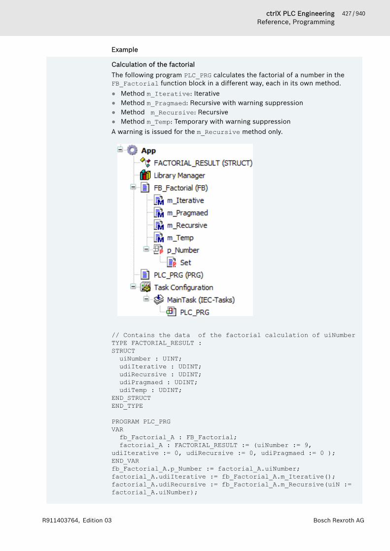
427 / 940ctrlX PLC EngineeringReference, Programming
Bosch Rexroth AGR911403764, Edition 03
Example
Calculation of the factorialThe following program PLC_PRG calculates the factorial of a number in theFB_Factorial function block in a different way, each in its own method.● Method m_Iterative: Iterative● Method m_Pragmaed: Recursive with warning suppression● Method m_Recursive: Recursive● Method m_Temp: Temporary with warning suppressionA warning is issued for the m_Recursive method only.
// Contains the data of the factorial calculation of uiNumberTYPE FACTORIAL_RESULT : STRUCT
uiNumber : UINT;udiIterative : UDINT;udiRecursive : UDINT;udiPragmaed : UDINT;udiTemp : UDINT;
END_STRUCTEND_TYPE
PROGRAM PLC_PRGVARfb_Factorial_A : FB_Factorial;factorial_A : FACTORIAL_RESULT := (uiNumber := 9,
udiIterative := 0, udiRecursive := 0, udiPragmaed := 0 );END_VARfb_Factorial_A.p_Number := factorial_A.uiNumber;factorial_A.udiIterative := fb_Factorial_A.m_Iterative();factorial_A.udiRecursive := fb_Factorial_A.m_Recursive(uiN := factorial_A.uiNumber);

428 / 940 ctrlX PLC EngineeringReference, Programming
Bosch Rexroth AG R911403764, Edition 03
factorial_A.udiPragmaed := fb_Factorial_A.m_Pragmaed(uiN := factorial_A.uiNumber);factorial_A.udiTemp := fb_Factorial_A.m_Temp(uiN := factorial_A.uiNumber);
//Factorial calculation in different waysFUNCTION_BLOCK FB_FactorialVAR_INPUTEND_VARVAR_OUTPUTEND_VARVARuiN : UINT;udiIterative : UDINT;udiPragmaed : UDINT;udiRecursive : UDINT;
END_VAR
// Iterative calculationMETHOD PUBLIC m_Iterative : UDINTVARuiCnt : UINT;
END_VARm_Iterative := 1;IF uiN > 1 THENFOR uiCnt := 1 TO uiN DOm_Iterative := m_Iterative * uiCnt;
END_FOR;RETURN;
ELSERETURN;
END_IF;
//Recursive calculation with suppressed warning{attribute 'estimated-stack-usage' := '99'}METHOD PUBLIC m_Pragmaed : UDINTVAR_INPUTuiN : UINT;
END_VARVAREND_VARm_Pragmaed := 1;IF uiN > 1 THENm_Pragmaed := uiN * THIS^.m_Pragmaed(uiN := (uiN - 1));RETURN;
ELSE RETURN;
END_IF;
//Recursive calculationMETHOD PUBLIC m_Recursive : UDINTVAR_INPUTuiN : UINT;
END_VARVAREND_VARm_Recursive := 1;

429 / 940ctrlX PLC EngineeringReference, Programming
Bosch Rexroth AGR911403764, Edition 03
IF uiN > 1 THENm_Recursive := uiN * THIS^.m_Recursive(uiN := (uiN - 1) );RETURN;
ELSE RETURN;
END_IF;
// Called by temporary FB instance{attribute 'estimated-stack-usage' := '99'}METHOD PUBLIC m_Temp : UDINTVAR_INPUTuiN : UINT;
END_VARVARfb_Temp : FB_Factorial;
END_VARm_Temp := 1;IF uiN > 1 THENm_Temp := uiN * fb_Temp.m_Temp(uiN := (uiN - 1));RETURN;
ELSE RETURN;
END_IF;
PROPERTY p_Number : UINT uiN := p_Number; //Setter methodOnly the m_Recursive issues a warning when the program is executed.
See also● ⮫ Chapter “Calling Methods” on page 156● ⮫ Chapter 1.8.23 “Object-Oriented Programming” on page 152● ⮫ Chapter “Object 'Method'” on page 596● ⮫ Chapter “Object 'Property'” on page 603

430 / 940 ctrlX PLC EngineeringReference, Programming
Bosch Rexroth AG R911403764, Edition 03
Attribute 'ExpandFully'The effect of this pragma is that the components of an array used as an inputvariable for referenced visualizations are made visible in the Properties dialogbox of the visualization.Syntax:{attribute 'ExpandFully'}Insertion position: the line above the line with the declaration of the array.
ExampleThe visualization “visu” is to be inserted into a frame inside the visualization“visu_main”. arr is defined as an input variable in the interface editor of“visu” and will thus be available later for assignments in the Properties dialogbox of the frames in “visu_main”. In order to also make the individual compo-nents of arr available in this Properties dialog box, you must insert theattribute 'ExpandFully' directly before arr in the interface editor of visu.Declaration in the interface editor of “visu”:VAR_INPUT {attribute 'ExpandFully'} arr : ARRAY[0..5] OF INT;END_VAR
Attribute 'global_init_slot'This pragma defines the initialization order of function blocks or global variablelists.Variables in a list (GVL or POU) are initialized from top to bottom.If there are several global variable lists, then the initialization order is notdefined.The initialization does not apply for the initialization of literal values, forexample 1, 'hello', 3.6, or constants of base data types. However, you mustdefine the initialization order yourself if there are dependencies between thelists. You can assign a defined initialization slot to a GVL or POU with the'global_init_slot' attribute.Syntax:{attribute 'global_init_slot' := '<slot>'}<slot>: Integer value that defines the position in the call order. The defaultvalue for a POU (program, function block) is 50000. The default value for a GVLis 49990. A lower value means an earlier initialization. Caution: If several blocksor GVLs receive the same value for the 'global_init_slot' attribute, thenthe initialization order remains undefined.Insert location: The pragma always affects the entire GVL or POU and thereforeit must be located above the VAR_GLOBAL or POU declaration.
431 / 940ctrlX PLC EngineeringReference, Programming
Bosch Rexroth AGR911403764, Edition 03
ExampleThe program includes two global variable lists “GVL_1” and “GVL_2”, as wellas a “PLC_PRG” program that uses variables from both lists. “GVL_1” uses thevariable B for initializing a variable A, which is initialized in “GVL_2” with avalue of 1000.GVL_1:VAR_GLOBAL //49990 A : INT := GVL_2.B*100;END_VARGVL_2:VAR_GLOBAL //49990B : INT := 1000;
C : INT := 10;END_VARPLC_PRGPROGRAM PLC_PRG //50000VARivar: INT := GVL_1.A;ivar2: INT;
END_VAR
ivar:=ivar+1;ivar2:=GVL_2.C;In this case, the compiler prints an error because GVL_2.B is used for initial-izing GVL_1.A before “GVL_2” has been initialized. You can prevent this byusing the global_init_slot attribute to position “GVL_2” before “GVL_1” inthe initialization sequence.In this example, “GVL_1” must have at least a slot value of 49989 in order toachieve the earliest initialization within the program. Every lower value has thesame effect:GVL_2{attribute 'global_init_slot' := '100'}VAR_GLOBAL B : INT := 1000;END_VARNote: Using GVL_2.C in the implementation part of “PLC_PRG” is also not crit-ical even without using a pragma because both GVLs are initialized before theprogram in either case.
Attribute 'hide'The pragma prevents variables or POUs from being shown in the PLC Engi-neering user interface. In this way, you can intentionally hide variables or POUsfrom the user. As a result, the variables or POUs are neither visible in theLibrary Manager nor are they suggested in the input assistant or in the "Listcomponents" function. In online mode, they are not visible in the declarationpart and debug functionalities cannot be applied to them.If the instance path to a variable is known, then it can be addressed in the codeeven when it has the hide attribute.Syntax:{attribute 'hide'} Insert location: For variables, above the line with the declaration of the varia-bles. For POUs, in the first line.
432 / 940 ctrlX PLC EngineeringReference, Programming
Bosch Rexroth AG R911403764, Edition 03
ExampleThe function block “myPOU” uses the attribute {attribute 'hide'}:FUNCTION_BLOCK myPOU
VAR_INPUT a:INT;
{attribute 'hide'} a_invisible: BOOL;
a_visible: BOOL; END_VAR
VAR_OUTPUT b:INT; END_VAR Two instances of the function block “myPOU” are defined in the main pro-gram.PROGRAM PLC_PRG
VAR POU1, POU2: myPOU; END_VAR When the input value for POU1 is implemented, the "List components" func-tion, which opens when you type POU1. (in the implementation part of“PLC_PRG”), displays the variables a, a_visible, and b, but not the hiddenvariable a_invisible.
With the pragma hide_all_locals you can hide all local variables of a decla-ration.See also● ⮫ Chapter “Attribute 'hide_all_locals'” on page 432
Attribute 'hide_all_locals'This pragma prevents all local variables of a signature from being visible in thedisplay of the 'List components' function, in the input assistant or in the decla-ration part in online mode.Syntax:{attribute 'hide_all_locals'}Insertion position: first line above the declaration part of the POU.
433 / 940ctrlX PLC EngineeringReference, Programming
Bosch Rexroth AGR911403764, Edition 03
ExampleThe function block “myPOU” uses the attribute :{attribute 'hide_all_locals'}FUNCTION_BLOCK myPOUVAR_INPUT a:INT;END_VAR
VAR_OUTPUT b:BOOL;END_VAR
VAR c,d:INT;END_VARTwo instances of the function block “myPOU” are defined in the main pro-gram.PROGRAM PLC_PRGVAR POU1, POU2: myPOU;END_VARWhile an input value for “POU1” is now implemented, the 'List components'function, which opens when typing POU1. in the implementation part ofPLC_PRG, displays the variables a and b, but not the hidden local variables cor d.
See also● ⮫ Chapter “Attribute 'hide'” on page 431
Attribute 'initialize_on_call'This pragma can be applied to input variables. It causes the input variables of afunction block to be initialized on each call of the function block. If an inputexpects a pointer and this pointer has been removed in the course of an onlinechange, this input will be set to zero.Syntax:{attribute 'initialize_on_call'} Insertion position: line above the line with the declaration of the correspondinginput variables.
Attribute 'init_namespace'The effect of this pragma is that a variable of the type STRING or WSTRING,which is declared in a library function block with this pragma, is initializedwhen used in the project with the current namespace of the library.Syntax{attribute 'init_namespace'} Insertion position: the line above the line with the declaration of the variablesin a library function block.

434 / 940 ctrlX PLC EngineeringReference, Programming
Bosch Rexroth AG R911403764, Edition 03
ExampleThe function block “POU” is provided with the necessary attributes:FUNCTION_BLOCK POUVAR_OUTPUT {attribute 'init_namespace'} myStr: STRING;END_VARAn instance fb of the function block POU is defined within the main programPLC_PRG:PROGRAM PLC_PRGVAR fb:POU; newString: STRING;END_VAR newString := fb.myStr;The variable myStr is initialized with the current namespace, for exampleMyLib. This value is assigned to newString in the main program.
See also● ⮫ Chapter “Object 'Library Manager'” on page 583
Attribute 'init_on_onlchange'The effect of this pragma is that the variable to which the pragma is applied isinitialized with each online change.
NOTICE For compiler version 3.5.0.0 and later, a fast onlinechange is performed for minor changes. In this case, onlythe modified blocks are compiled and downloaded. Inparticular, no initialization code is generated. This meansthat also no code is generated when variables with theinit_on_onlchange attribute are initialized. As a rule,this has no effect because the attribute is used primarilyfor initializing variables with addresses. However, itcannot happen that a variable changes its address duringan online change.To secure the effect of the init_on_onlchangeattribute in the entire application code, you must deacti-vate the fast online change in general for the applicationby using the compiler definitionno_fast_online_change. To do this, insert the defini-tion in the application “Properties” (“Build” tab).
Syntax:{attribute 'init_on_onlchange' } Insert location: The line above the line with the declaration of the variables.See also● ⮫ Chapter “Dialog 'Properties' - 'Build'” on page 825
Attribute 'instance-path'This pragma can be applied to a local STRING variable and causes this localSTRING variable to be initialized in sequence with the device tree path of thePOU to which it belongs. This can be useful for error messages. The applicationof the pragma requires the application of the attribute 'reflection' to theassociated POU, as well as the application of the additional attribute 'noinit'to the STRING variable.

435 / 940ctrlX PLC EngineeringReference, Programming
Bosch Rexroth AGR911403764, Edition 03
Syntax:{attribute 'instance-path'} Insertion position: the line above the line with the declaration of the STRINGvariable.
ExampleThe following function block contains the attributes 'reflection', 'in-stance-path' and 'noinit'.{attribute 'reflection'}FUNCTION_BLOCK POUVAR {attribute 'instance-path'} {attribute 'noinit'} str: STRING;END_VARAn instance “myPOU” of the function block “POU” is defined within the mainprogram “PLC_PRG”:PROGRAM PLC_PRGVAR myPOU:POU; myString: STRING;END_VARmyPOU();myString:=myPOU.str;Following the initialization of the instance myPOU, the path of the instancemyPOU is assigned to the string variable str, in the examplePLCWinNT.Application.PLC_PRG.myPOU. This path is assigned in the mainprogram to the variable myString.
NOTICE You can define the length of a string to be whatever youlike (even >255), but you must consider that the stringwill be truncated at the end if it is assigned to a variablewhose data type is too small for it.
See also● ⮫ Chapter “Attribute 'reflection'” on page 449● ⮫ Chapter “Attribute 'noinit'” on page 440
Attribute 'io_function_block', 'io_function_block_mapping'With the 'io_function_block' attribute, you mark a function block in orderto prepare it for the assignment to a channel in the I/O mapping of the deviceconfiguration. Then it is shown in the “Select function block” dialog.With the 'io_function_block_mapping' attribute, you mark a parameterthat should be used when mapping the FB to a device channel in this kind offunction block. You can provide the attribute to multiple parameters of thefunction block. For I/O mapping, the first one is used automatically whose typematches the channel (input, output, data type).Syntax:{attribute 'io_function_block'}{attribute 'io_function_block_mapping'}Insert location: The line above the first line in the declaration of the functionblock, or the line above the parameter declaration.
436 / 940 ctrlX PLC EngineeringReference, Programming
Bosch Rexroth AG R911403764, Edition 03
Example{attribute 'io_function_block'}FUNCTION_BLOCK Scale_Output_IntVAR_INPUTiInput : INT;iNumerator : INT;iDenominator : INT :=1;iOffset : INT := 0;
END_VARVAR_OUTPUT {attribute 'io_function_block_mapping'}
iOutput : INT;END_VARVAR
See also● ⮫ Chapter “Dialog 'Select Function Block'” on page 817● ⮫ “Linking a device with a function block instance” on page 58
Attribute 'linkalways'The effect of this pragma is that the associated object is marked with the com-piler and is thus always contained in the compiler information. This means thatthe object is always compiled and loaded to the PLC. The pragma works forPOUs and GVLs that are located below an application or in libraries below anapplication or are contained in the “POUs” view. The “Always link ”option in the“Compile” category of the object properties has the same effect.Syntax:{attribute 'linkalways'}Insertion position: the line above the line with the keyword VAR_GLOBAL in thedeclaration part of POUs and GVLs.If you use the symbol configuration editor, PLC Engineering uses the markedPOU as the basis for the selectable variables of the symbol configuration used.
ExampleThe implementation of the global variable list “GVLMoreSymbols” uses theattribute 'linkalways':{attribute 'linkalways'}VAR_GLOBALS g_iVar1: INT; g_iVar2: INT;END_VARThrough this code the variables of “GVLMoreSymbols” are made available asselectable symbols.
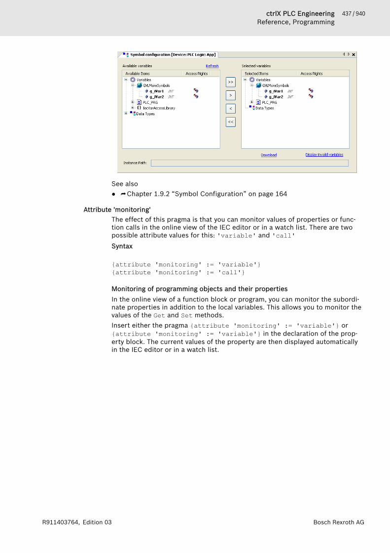
437 / 940ctrlX PLC EngineeringReference, Programming
Bosch Rexroth AGR911403764, Edition 03
See also● ⮫ Chapter 1.9.2 “Symbol Configuration” on page 164
Attribute 'monitoring'The effect of this pragma is that you can monitor values of properties or func-tion calls in the online view of the IEC editor or in a watch list. There are twopossible attribute values for this: 'variable' and 'call'Syntax
{attribute 'monitoring' := 'variable'}{attribute 'monitoring' := 'call'}
Monitoring of programming objects and their propertiesIn the online view of a function block or program, you can monitor the subordi-nate properties in addition to the local variables. This allows you to monitor thevalues of the Get and Set methods.Insert either the pragma {attribute 'monitoring' := 'variable'} or{attribute 'monitoring' := 'variable'} in the declaration of the prop-erty block. The current values of the property are then displayed automaticallyin the IEC editor or in a watch list.

438 / 940 ctrlX PLC EngineeringReference, Programming
Bosch Rexroth AG R911403764, Edition 03
ExampleIn online mode, the PLC_PRG object shows the value of the Minutes propertyat the call location inline in the ST editor. This is because the pragma{attribute 'monitoring' := 'variable'} is located in the declarationof the Minutes property.
Check carefully for each application which attribute pragma is suitable for dis-playing the desired value. This depends on whether further operations with thevariables are implemented within the property.1. Pragma {attribute 'monitoring':='variable'}:An implicit variable is created for the property, which is then always given thecurrent property value when the application calls the Set or Get method. Thevalue stored last in this variable is displayed in the monitoring.2. Pragma {attribute 'monitoring':='call'}:You can use this attribute only for properties that return simple data types orpointers, but not for structured types. The value to be monitored is read orwritten by calling the property directly. This means that the monitoring serviceof the runtime executes the Get or Set method of the property.
NOTICE When you insert the pragma {attribute 'monitor-ing':='call'} for monitoring, you have to pay atten-tion to possible side effects. These kinds of side effectscan occur if additional operations are implemented inthe property.
NOTICE The pragma {attribute 'monitoring'} is also evalu-ated for the symbol configuration. Only read access ispossible for the value 'variable'.
With the context menu command “Add Watch”, a variable on which the cursoris currently positioned is applied directly into the monitoring list in onlinemode.The forcing or writing of functions is not supported. However, you can implicitlyimplement forcing by adding an additional input parameter for the respectivefunction, which serves as an internal force flag.Function monitoring is not possible in the compact runtime system.
See also● ⮫ Chapter “Object 'Property'” on page 603
439 / 940ctrlX PLC EngineeringReference, Programming
Bosch Rexroth AGR911403764, Edition 03
Attribute 'no_assign', Attribute 'no_assign_warning'The pragma 'no_assign' results in compiler errors being displayed if aninstance of the function block is assigned to another instance of the same func-tion block. Such assignments are often to be avoided if the function block con-tains pointers and pointers lead to problems, because they are copied as wellduring the value assignment.The pragma 'no_assign_warning' results in the same as for the pragma'no_assign' with compiler warnings instead of compiler errors.Syntax:{attribute 'no_assign'}Insert location: First line in the declaration part of a function block.
ExampleAssignment of function block instances containing pointers.In this example the value assignment of the function block instances will leadto problems during the execution of fb_exit:VAR_GLOBALinst1 : TestFB; awsBufferLogFile : ARRAY [0..9] OF WSTRING(66);(* Area: 0, Offset: 0x1304 (4868)*) LogFile : SEDL.LogRecord := (sFileName := 'LogFile.log', pBuffer := ADR(awsBufferLogFile), udiMaxEntriesFile := UDINT#10000, udiMaxBuffered := UDINT#10, uiLineSize := UINT#64, wsSep := " ", xCircular := TRUE, siDateFormat := SINT#0, siTimeFormat := SINT#0);END_VAR
PROGRAM PLC_PRGVAR inst2 : TestFB := inst1; LogFileNewEND_VARIn this case LogRecord manages a list of pointers, for which various actionsare executed in the case of fb_exit. Problems result due to the assignment,because fb_exit will be executed twice. You should prevent this by addingthe attribute 'no_assign' in the declaration of the function block “TestFB”:{attribute 'no_assign'}FUNCTION_BLOCK TestFBVAR_INPUT...The following compiler errors are then displayed:C0328: Assignment not allowed for type TestFBC0328: Assignment not allowed for type LogRecordIf the pragma no_assign_warning is used instead of the pragma no_assignfor the function block “TestFB ”, then the C0328 message is issued as com-piler warning, not as a compiler error.
Attribute 'no_check'This pragma prevents the check function being called for the POU (POUs forimplicit checks). Since the check functions can affect the processing speed ofthe program, it can be useful to apply the attribute to function blocks that havealready been checked or are frequently called.You add the pragma to the declaration of a POU.
440 / 940 ctrlX PLC EngineeringReference, Programming
Bosch Rexroth AG R911403764, Edition 03
Syntax:{attribute 'no_check'}Insertion position: first line in the declaration part of the POU.
NOTICE The attribute also automatically affects the child objectsof a POU!Example: If the attribute is entered in a program, checkfunctions will also not be carried out for actions that areassigned to this program.
See also● ⮫ Chapter “Object 'POUs for Implicit Checks'” on page 608
Attribute 'no_copy'In general an online change requires a re-allocation of instances, for example ofa POU. In the process, the value of the variable contained in the instance iscopied.The pragma prevents the value of the variable contained in the instance frombeing copied in the course of an online change; instead, the variable is re-ini-tialized in the course of an online change. This can be useful for a local pointervariable that points to a variable that has just been shifted by the online changeand thus has a changed address.You insert the attribute in the declaration part above the line of the declarationof the variables concerned.Syntax:{attribute 'no_copy'}
Attribute 'no-exit'This attribute suppresses the call of the FB_exit method of a function block fora certain one of its instances. To do this you insert the attribute in the linebefore the declaration of the function block instance.Syntax:{attribute 'no-exit'}
ExampleThe method “FB_exit” is added to the function block “POU_ex”. Two instancesof the function block “POU_ex” are created in the main program “PLC_PRG”.PROGRAM PLC_PRGVAR POU1 : POU_ex; {attribute 'no-exit'} POU2 : POU_ex;END_VARPOU1 is called, POU2 is not called.
See also● ⮫ Chapter 1.18.10 “Methods 'FB_Init', 'FB_Reinit', and 'FB_Exit'” on page 468
Attribute 'noinit'This pragma is applied to variables that should not be implicitly initialized.Syntax:{attribute 'no_init'}{attribute 'no-init'}{attribute 'noinit'}

441 / 940ctrlX PLC EngineeringReference, Programming
Bosch Rexroth AGR911403764, Edition 03
Insertion position: line above the declaration line of the variables concerned inthe declaration part.
ExamplePROGRAM PLC_PRGVAR A : INT;
{attribute 'no_init'} B : INT;END_VARWhen the associated application is reset, the integer variable A is implicitly re-initialized with 0, whereas the variable B retains its current value.
Attribute 'no_instance_in_retain'With this attribute you can prevent the instance of a certain function blockfrom being stored in the retain area.Syntax:{attribute 'no_instance_in_retain'} Insertion position:Line above the FUNCTION_BLOCK declaration in the declaration part of the func-tion block. An error message is then displayed if an instance of the functionblock is declared as a RETAIN variable.See also● ⮫ Chapter 1.8.20 “Data Persistence” on page 139
Attribute 'no_virtual_actions'This pragma is used for function blocks that are derived from a function blockimplemented in SFC and use the fundamental SFC sequence of this base class.The actions called from it exhibit the same virtual behavior as methods. Thismeans that the implementations of the actions in the base class can bereplaced by the derived class with its own specific implementations.If you apply the pragma to the base class, then its actions are protected againstoverloading.Syntax:{attribute 'no_virtual_actions'} Insertion position: top line in the declaration part of the function block
442 / 940 ctrlX PLC EngineeringReference, Programming
Bosch Rexroth AG R911403764, Edition 03
ExampleThe function block “POU_SFC” is the base class for the derived function block“POU_child”.The derived class “POU_child” calls the sequence of the base class written inSFC with the special variable SUPER.The exemplary implementation of this sequence is limited to the initial step,followed by a single step with a linked step action ActiveAction. This stepwith a linked step action takes care of the configuration of the output varia-bles.
an_int:=an_int+1; // Counting the action callstest_act:='father_action';METH(); // Call of the method METH in order to set the string variable test_methIn the case of the derived class POU_child the step action is replaced by aspecial implementation of ActiveAction. Active Action differs from theoriginal only by the assignment of the string 'child_action' in place of'father_action' at the variable test_act.Likewise, the method “METH”, which assigns the string 'father_method' inthe base class of the variable test_meth, is overwritten so that “test_meth” isnow given the value 'child_method'. The main program “PLC_PRG” calls aninstance of the function block POU_child named 'Child'. As expected the valueof the string reflects the call of action and method of the derived class:Now, however, you place the pragma {attribute 'no_virtual_actions'} in front of the base class:
{attribute 'no_virtual_actions'}FUNCTION_BLOCK POU_SFC...As a result the behavior changes: while the implementation of the derivedclass is still used for method METH, the call of the step action now results in acall of the action ActiveAction of the base class. Therefore test_act is nowgiven the value 'father_action':
Attribute 'pingroup'The effect of this pragma is that the input pins or output pins (parameters) aregrouped in the declaration of a function block. In the FBD/LD editor a pingroup defined in this way can be displayed as an enlarged or reduced unit onthe inserted function block. Several groups are possible and are distinguishedby their names. PLC Engineering saves the respective state (reduced) per func-tion block box with the project options.Syntax:{attribute 'pingroup' := '<group name>'}Insertion position: line above the declaration of the input or output variablesconcerned in the declaration part of a function block.

443 / 940ctrlX PLC EngineeringReference, Programming
Bosch Rexroth AGR911403764, Edition 03
ExampleTwo groups are defined: general (i1, out1) and group1 (i2, g1). r1,r2, outRes1 and g2 are always displayedFUNCTION_BLOCK FBVAR_INPUT r1 : REAL; {attribute 'pingroup' := 'general'} i1 : INT; {attribute 'pingroup' := 'group1'} i2 : INT; r2 : REAL;END_VAR
VAR_OUTPUT outRes1 : REAL; {attribute 'pingroup' := 'general'} out1 : INT;{attribute 'pingroup' := 'group1'}
g1 : INT; g2 : REAL;END_VAR
Attribute 'pin_presentation_order_inputs/outputs'The pragmas are evaluated in the CFC, FBD, and LD graphical editors, causingthe order of inputs/outputs of the affected function block to be displayed asspecified. You program the order by assigning the names of the inputs/outputsto the attribute in the desired order.Syntax
{attribute 'pin_presentation_order_inputs' := '<First_Input_Name>, (<Next_Input_Name>, )* ( *, )? (<Next_Input_Name>,)* <Last_Input_Name>'}{attribute 'pin_presentation_order_outputs' := '<First_Output_Name>, (<Next_Output_Name>,)* ( *, )? (<Next_Output_Name>,)* <Last_Output_Name>'}● *
The terminal character serves as a wildcard for all inputs/outputs that arenot specified in the display order. If the terminal character is missing, thenthe missing inputs/outputs are appended at the end.
● ( ... )?The contents of the parentheses are optional.
● ( ... )*The contents of the parentheses are optional again and can therefore occurnot at all, one time, or several times.
● Insert location: First line in the declaration part of a function block.
NOTICE This pragma is not evaluated when pragma {attribute'pingroup' := '<Group_Name>'} is used.

444 / 940 ctrlX PLC EngineeringReference, Programming
Bosch Rexroth AG R911403764, Edition 03
Example
{attribute 'pin_presentation_order_inputs' := 'input_2,*,input_1'}{attribute 'pin_presentation_order_outputs' := 'output_2, output_1'}FUNCTION_BLOCK POU_BASEVAR_INPUTinput_1 : BOOL;input_2 : INT;input_3 : INT;input_4 : INT;
END_VAR
VAR_OUTPUToutput_1 : BOOL;output_2 : INT;output_3 : INT;output_4 : BOOL;
END_VAR
FUNCTION_BLOCK PLC_PRGVAR_INPUTEND_VARVAR_OUTPUTEND_VARVARpouBase_A: POU_BASE;
END_VARIn the representation of function module instance pouBase_A, the pragmasresult in the following arrangement of input and output pins:
See also● ⮫ Chapter “Attribute 'pingroup'” on page 442
Attribute 'obsolete'The effect of this pragma is that a defined warning is displayed for a data typedefinition during compilation if the data type (structure, function block, etc.) isused in the project. This enables you, for example, to draw attention to the factthat a data type is no longer valid because, for example, an interface haschanged and this should also be implemented in the project.In contrast to a message pragma this warning is defined centrally for allinstances of a data type.Syntax:
445 / 940ctrlX PLC EngineeringReference, Programming
Bosch Rexroth AGR911403764, Edition 03
{attribute 'obsolete' := 'user defined text'} Insertion position: line of the data type definition or in a line above it.
ExampleThe pragma is inserted in the definition function block fb1:{attribute 'obsolete' := 'datatype fb1 not valid!'}FUNCTION_BLOCK fb1VAR_INPUT i:INT;END_VARIf you use fb1 as a data type, for example in fbinst:fb1, the followingwarning will be displayed when compiling the project: "datatype fb1 notvalid".
See also● ⮫ Chapter “Message pragmas” on page 418
Attribute 'pack_mode'This pragma defines how a data structure is packed during the allocation. Theattribute must be inserted above the data structure and affects the packing ofthe entire structure.Syntax:{attribute 'pack_mode' := '<Value>'}Insert location: above the declaration of the data structureTable 18: Possible values for <Value>:pack_mod
eAssoci-atedpackingmethod
Description
0 aligned, All variables are allocated to byte addresses. There areno memory gaps.1 1-byte-
aligned2 2-byte-
alignedThere are● 1-byte variables at byte addresses● 2 byte variables at addresses divisible by 2. A max-
imum gap of 1 byte results.● 4 byte variables at addresses divisible by 2. A max-
imum gap of 1 byte results.● 8 byte variables at addresses divisible by 2. A max-
imum gap of 1 byte results.● Strings are always at byte addresses. No gaps result.
4 4-byte-aligned
There are● 1-byte variables at byte addresses● 2 byte variables at even addresses. A maximum gap
of 1 byte results.● 4 byte variables at addresses divisible by 4. A max-
imum gap of 3 byte results.● 8 byte variables at addresses divisible by 4. A max-
imum gap of 3 byte results.● Strings are always at byte addresses. No gaps result.
446 / 940 ctrlX PLC EngineeringReference, Programming
Bosch Rexroth AG R911403764, Edition 03
pack_mode
Associ-atedpackingmethod
Description
8 8-byte-aligned
There are● 1-byte variables at byte addresses● 2 byte variables at addresses divisible by 2. A max-
imum gap of 1 byte results.● 4 byte variables at addresses divisible by 4. A max-
imum gap of 3 byte results.● 8 byte variables at addresses divisible by 8. A max-
imum gap of 7 byte results.● Strings are always at byte addresses. No gaps result.
Depending on the structure, there may be no difference in the memory map-ping of the individual modes. Therefore, the memory allocation of a structurewith pack_mode =4 can correspond to that of pack_mode = 8.Arrays of structures: If the structures are combined in arrays, then bytes areadded at the end of the structure so that the next structure is aligned.
Example 1
Example{attribute 'pack_mode' := '1'}
TYPE myStruct: STRUCT Enable: BOOL; Counter: INT; MaxSize: BOOL; MaxSizeReached: BOOL; END_STRUCTEND_TYPE
The memory range for a variable of the data type myStruct is allocated'aligned': If the storage address of its component Enable is 0x0100, forexample, then the component Counter follows at the address 0x0101, Max-Size at address 0x0103 and MaxSizeReached at address 0x0104. In the caseof 'pack_mode':=2, Counter would be at 0x0102, MaxSize at 0x0104 andMaxSizeReached at 0x0106.
447 / 940ctrlX PLC EngineeringReference, Programming
Bosch Rexroth AGR911403764, Edition 03
Example 2
STRUCT Var1 : BOOL := 16#01; Var2 : BYTE := 16#11; Var3 : WORD := 16#22; Var4 : BYTE := 16#44; Var5 : DWORD := 16#88776655; Var6 : BYTE := 16#99; Var7 : BYTE := 16#AA; Var8 : DWORD := 16#AA;END_TYPE
pack_mode =0
pack_mode =1
pack_mode =2
pack_mode =4
pack_mode =8
Vari-able
Value Vari-able
Value Vari-able
Value Vari-able
Value Vari-able
Value
0 Var1 01 Var1 01 Var1 01 Var1 01 Var1 011 Var2 11 Var2 11 Var2 11 Var2 11 Var2 112 Var3 22 Var3 22 Var3 22 Var3 22 Var3 223 ... 00 ... 00 ... 00 ... 00 ... 004 Var4 44 Var4 44 Var4 44 Var4 44 Var4 445 Var5 55 Var5 556 ... 66 ... 66 Var5 557 ... 77 ... 77 ... 668 ... 88 ... 88 ... 77 Var5 55 Var5 559 Var6 99 Var6 99 ... 88 ... 66 ... 66
10 Var7 AA Var7 AA Var6 99 ... 77 ... 7711 Var8 AA Var8 AA Var7 AA ... 88 ... 8812 ... 00 ... 00 Var8 AA Var6 99 Var6 9913 ... 00 ... 00 ... 00 Var7 AA Var7 AA14 ... 00 ... 00 ... 0015 ... 0016 Var8 AA Var8 AA17 ... 00 ... 0018 ... 00 ... 0019 ... 00 ... 002021222324252627282930

448 / 940 ctrlX PLC EngineeringReference, Programming
Bosch Rexroth AG R911403764, Edition 03
pack_mode =0
pack_mode =1
pack_mode =2
pack_mode =4
pack_mode =8
Vari-able
Value Vari-able
Value Vari-able
Value Vari-able
Value Vari-able
Value
31
Example 3
STRUCT Var1 : BYTE := 16#01; Var2 : LWORD := 16#11; Var3 : BYTE := 16#22; Var4 : BYTE := 16#44; Var5 : DWORD := 16#88776655; Var6 : BYTE := 16#99; Var7 : BYTE := 16#AA; Var8 : WORD := 16#AA;END_TYPE
pack_mode =0
pack_mode =1
pack_mode =2
pack_mode =4
pack_mode =8
Vari-able
Value Vari-able
Value Vari-able
Value Vari-able
Value Vari-able
Value
0 Var1 01 Var1 01 Var1 01 Var1 01 Var1 011 Var2 11 Var2 112 ... 00 ... 00 Var2 113 ... 00 ... 00 ... 004 ... 00 ... 00 ... 00 Var2 115 ... 00 ... 00 ... 00 ... 006 ... 00 ... 00 ... 00 ... 007 ... 00 ... 00 ... 00 ... 008 ... 00 ... 00 ... 00 ... 00 Var2 119 Var3 22 Var3 22 ... 00 ... 00 ... 00
10 Var4 44 Var4 44 Var3 22 ... 00 ... 0011 Var5 55 Var5 55 Var4 44 ... 00 ... 0012 ... 66 ... 66 Var5 55 Var3 22 ... 0013 ... 77 ... 77 ... 66 Var4 44 ... 0014 ... 88 ... 88 ... 77 ... 0015 Var6 99 Var6 99 ... 88 ... 0016 Var7 AA Var7 AA Var6 99 Var5 55 Var3 2217 Var8 AA Var8 AA Var7 AA ... 66 Var4 4418 ... 00 ... 00 Var8 AA ... 7719 ... 00 ... 8820 Var6 99 Var5 5521 Var7 AA ... 6622 Var8 AA ... 7723 ... 00 ... 8824 Var6 9925 Var7 AA
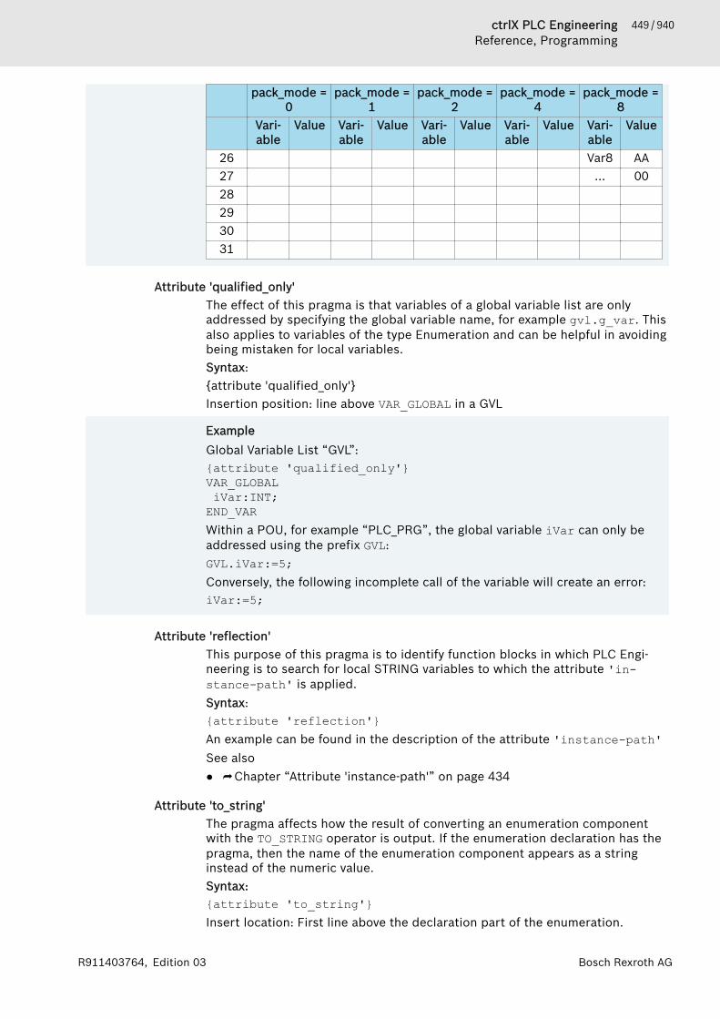
449 / 940ctrlX PLC EngineeringReference, Programming
Bosch Rexroth AGR911403764, Edition 03
pack_mode =0
pack_mode =1
pack_mode =2
pack_mode =4
pack_mode =8
Vari-able
Value Vari-able
Value Vari-able
Value Vari-able
Value Vari-able
Value
26 Var8 AA27 ... 0028293031
Attribute 'qualified_only'The effect of this pragma is that variables of a global variable list are onlyaddressed by specifying the global variable name, for example gvl.g_var. Thisalso applies to variables of the type Enumeration and can be helpful in avoidingbeing mistaken for local variables.Syntax:{attribute 'qualified_only'}Insertion position: line above VAR_GLOBAL in a GVL
ExampleGlobal Variable List “GVL”:{attribute 'qualified_only'}VAR_GLOBAL iVar:INT;END_VARWithin a POU, for example “PLC_PRG”, the global variable iVar can only beaddressed using the prefix GVL:GVL.iVar:=5;Conversely, the following incomplete call of the variable will create an error:iVar:=5;
Attribute 'reflection'This purpose of this pragma is to identify function blocks in which PLC Engi-neering is to search for local STRING variables to which the attribute 'in-stance-path' is applied.Syntax:{attribute 'reflection'}An example can be found in the description of the attribute 'instance-path'See also● ⮫ Chapter “Attribute 'instance-path'” on page 434
Attribute 'to_string'The pragma affects how the result of converting an enumeration componentwith the TO_STRING operator is output. If the enumeration declaration has thepragma, then the name of the enumeration component appears as a stringinstead of the numeric value.Syntax:{attribute 'to_string'}Insert location: First line above the declaration part of the enumeration.

450 / 940 ctrlX PLC EngineeringReference, Programming
Bosch Rexroth AG R911403764, Edition 03
ExampleDeclaration of the enumeration color:{attribute 'to_string'}TYPE color :(red := 0,blue := 1,green := 2
);END_TYPEConversion with TO_STRING:PROGRAM PLC_PRGVARi_color: Color;s_show_color: STRING;
END_VARi_color := 1;s_show_color := TO_STRING(i_color);In this case, str_show_color gets the value 'blue' instead of '1' as theconversion result.
See also● ⮫ Chapter “Enumerations” on page 413
Attribute 'subsequent'This pragma is used to allocate variables to a memory space directly behindone another. If the list changes, the entire variable list is allocated to a newmemory space. This pragma is used in programs and global variable lists.Syntax:{attribute 'subsequent'}
NOTICE VAR_TEMP in a program with the attribute 'subsequent'leads to a compiler error.
If a variable appears in the list 'RETAIN', the total list is saved as 'RETAIN'.
Attribute 'symbol'The pragma {attribute 'symbol'} defines which variables of a program or aglobal variable list are to be adopted into the symbol configuration. This meansthat the variables are exported as symbols to a symbol list. This symbol list isthen available for external access both as an XML file in the project directoryand as a file that is invisible to the user on the target system. For example, thesymbol list is then available for access by an OPC server. The variables thusequipped with a symbol are loaded by PLC Engineering to the controller, even ifthey are not explicitly configured or visible in the editor of the symbol configu-ration.In any case, however, an object “Symbol configuration” must be created belowthe application concerned in the device tree.Syntax:{attribute 'symbol' := '<access possibilities>'}<access possibilities>: none, read, write, readwrite. The default valuereadwrite applies if no parameter is specified.
451 / 940ctrlX PLC EngineeringReference, Programming
Bosch Rexroth AGR911403764, Edition 03
Insertion position:● in order to affect only an individual variable, you must place the pragma in
the line before the variable declaration.● In order to be effective for all variables in the declaration part of a program,
you must place the pragma in the first line of the declaration editor. In thiscase, too, you can still set instructions for individual variables explicitly inthe respective line.
ExampleWith the following configuration the variables A and B are exported with readand write permission. Variable D is exported with read permission.{attribute 'symbol' := 'readwrite'}PROGRAM PLC_PRGVAR A : INT; B : INT;{attribute 'symbol' := 'none'} C : INT;{attribute 'symbol' := 'read'} D : INT;END_VAR
See also● ⮫ Chapter 1.8.7 “Using Pragmas” on page 101● ⮫ Chapter 1.9.2 “Symbol Configuration” on page 164
Attribute 'warning disable', attribute 'warning restore'This pragma causes certain warnings to be suppressed. The warning restorepragma causes a suppressed message to be reactivated.Syntax:{warning disable <compiler ID>}{warning restore <compiler ID>}<compiler ID>: ID located at the beginning of an error or a warning message.
ExampleCompiler message:typify code ...C0196: Implicit conversion from unsigned Type 'UINT' to signed Type 'INT' : possible change of signCompile complete -- 0 errorsApplying the pragma to a variable declaration:VAR {warning disable C0195} test1 : UINT := -1; {warning restore C0195} test2 : UINT := -1;END_VARtest1 does not generate an error message, test2 generates an error mes-sage.
Attribute 'enable_dynamic_creation'The pragma enable_dynamic_creation is needed for using the __NEW oper-ator for function blocks.

452 / 940 ctrlX PLC EngineeringReference, Programming
Bosch Rexroth AG R911403764, Edition 03
Syntax:{attribute 'enable_dynamic_creation'}Insert location: First line in the declaration of the function block.See also● ⮫ Chapter “Operator '__NEW'” on page 360
Attribute 'ProcessValue'With the 'ProcessValue' attribute, you mark a component of a structure. Inthe CFC editor, you can then use the command “Use attributed member asinput” in order to connect this structure to an input of scalar type.Syntax:{attribute 'ProcessValue'}Insert location: Line above the affected structure variable.
Example
TYPE QINT :STRUCTStatus : STRING;{attribute 'ProcessValue'}Value1 : INT;Value2 : INT;
END_STRUCTEND_TYPE
See also● ⮫ Chapter “Command 'Use Attributed Member as Input'” on page 776
Conditional PragmasThe purpose of conditional pragmas is to influence the generation of code inthe pre-compilation process or the compilation process. The ST implementa-tion language supports these pragmas.
NOTICE They use conditional pragmas in the implementations ofPOUs. PLC Engineering does not evaluate these condi-tional pragmas if you use them in the declaration part.
With conditional pragmas you affect whether implementation code is taken intoaccount for the compilation. For example, you can make this dependent onwhether a certain variable is declared, whether a certain function block exists,etc.Pragma Description
{define <identifier> <string>}The value can be queried and compared later with has-value.
{undefine <identifier>}The {define} statement of the identifier <identifier> iscanceled, and the identifier is 'undefined' again from nowon. The pragma is ignored if the specified identifier is notdefined at all.
{IF <expr>}...{ELSIF<expr>}...{ELSE}... END_IF}
These are pragmas for the conditional compilation.The specified expressions <expr> must be constant at thetime of compilation; they are evaluated in the order inwhich they appear here until one of the expressions indi-cates a non-zero value. The text linked to the instruction iscompiled; the other lines are ignored. The order of the sec-tions is fixed. The ELSIF and ELSE sections are optional.

453 / 940ctrlX PLC EngineeringReference, Programming
Bosch Rexroth AGR911403764, Edition 03
Pragma DescriptionThe ELSIF-segments may occur any number of times. Youcan use several conditional compilation operators withinthe constants <expr>.
<expr> You can use one or more operators within the constantexpression <expr> within the conditional compilationpragma {IF} or {ELSIF} .
You can enter expressions and define definitions as “compiler definitions” inthe “Compile” tab in the Properties dialog of POUs. If you enter define defini-tions in the properties dialog, you must omit the term {define}, contrary tothe definition in the implementation code. In addition, you can specify severaldefine definitions in the properties dialog, separated by commas.See also● ⮫ Chapter “Structured Text (ST), Extended Structured Text (ExST)”
on page 91
Operator defined (<identifier>)This operator causes the expression to be given the value TRUE. The require-ment is that the identifier <identifier> was defined with the help of a{define} instruction and not undefined again afterwards with an {undefine}instruction; otherwise FALSE is returned.
ExampleRequirement: The applications App1 and App2 exist. The variable pdef1 isdefined by a {define} statement in App1, but not in App2.
{IF defined (pdef1)}(* This code is processed in App1 *){info 'pdef1 defined'}hugo := hugo + SINT#1;
{ELSE}(* the following code is only processed in App2 *){info 'pdef1 not defined'}hugo := hugo - SINT#1;
{END_IF}This also contains an example of a message pragma: Only the message pdef1defined is displayed in the message view when the application is compiled,because pdef1 is actually defined. The message pdef1 not defined is dis-played if pdef1 is not defined.
Operator defined (variable: <variable>)This operator causes the expression to be given the value TRUE if the variable<variable> is declared within the current scope; otherwise FALSE is returned.
ExampleRequirement: The two applications App1 and App2 exist. The variable g_bTestis declared in App1, but not in App2.
{IF defined (variable: g_bTest)}(* the following code is only processed in App2*)g_bTest := x > 300;
{END_IF}
454 / 940 ctrlX PLC EngineeringReference, Programming
Bosch Rexroth AG R911403764, Edition 03
Operator defined (type: <identifier>)The operator causes the expression to be given the value TRUE if a data type isdeclared with the identifier <identifier>; otherwise FALSE is returned.
ExampleRequirement: The two applications App1 and App2 exist. The data type DUT isdeclared in App1, but not in App2.
{IF defined (type: DUT)}(* the following code is only processed in App1*)
bDutDefined := TRUE;{END_IF}
Operator defined (pou: <pou name>)The operator causes the expression to be given the value TRUE if a functionblock or an action with name <pou-name> exists; otherwise FALSE is returned.
ExampleRequirement: The two applications App1 and App2 exist. The function blockCheckBounds exists in App1, but not in App2.
{IF defined (pou: CheckBounds)}(* the following code is only processed in App1 *)
arrTest[CheckBounds(0,i,10)] := arrTest[CheckBounds(0,i,10)] + 1;{ELSE}(* the following code is only processed in App2 *)
arrTest[i] := arrTest[i]+1;{END_IF}
Operator defined (task: <identifier>)Not yet implemented!The operator causes the expression to be given the value TRUE if a task isdefined with the name <identifier>; otherwise FALSE is returned.
ExampleRequirement: The two applications App1 and App2 exist. The taskPLC_PRG_Task is defined in App1, but not in App2.
IF defined (task: PLC_PRG_Task)}(* the following code is only processed in App1 *)erg := plc_prg.x;
{ELSE}(* the following code is only processed in App2 *)erg := prog.x;
{END_IF}
Operator defined (resource: <identifier>)Not yet implemented!The operator causes the expression to be given the value TRUE if a resourceobject with the name <identifier> exists for the application; otherwiseFALSE is returned.
455 / 940ctrlX PLC EngineeringReference, Programming
Bosch Rexroth AGR911403764, Edition 03
ExampleRequirement: The two applications App1 and App2 exist. A resource objectglob_var1 of the global variable list exists for App1, but not for App2.
{IF defined (resource:glob_var1)}(* the following code is only processed in App1 *)gvar_x := gvar_x + ivar;
{ELSE}(* the following code is only processed in App2 *)x := x + ivar;
{END_IF}
Operator defined (IsSimulationMode)The operator causes the expression to be given the value TRUE if the applica-tion runs on a simulated device, i.e. in simulation mode.See also● ⮫ Chapter 1.11.1 “Testing in Simulation Mode” on page 196
Operator defined (IsLittleEndian)The operator causes the expression to be given the value FALSE, if the CPUmemory is organized in Big Endian (Motorola byte order).
Operator defined (IsFPUSupported)If the expression returns the value TRUE, then the code generator produces anFPU code (for the floating-point unit processor) when calculating with REALvalues. Otherwise PLC Engineering emulates FPU operations, which is muchslower.
Operator hasvalue (RegisterSize, '<register size>')<register size>: Size of a CPU register in bitsThis operator causes the expression to return the value TRUE if the size of aCPU register is equal to <register size>.Possible values for <register size>● 16 for 186 and C16x,● 64 for X86-64 bit● 32 for X86-32 Bit
Operator hasvalue (PackMode, '<pack mode value>')The checked pack mode depends on the device description, not on the pragmathat can be specified for individual DUTs.
Operator hasattribute (pou: <pou name>, '<attribute>')This operator causes the expression to be given the value TRUE if the attribute<attribute> is specified in the first line of the declaration part of the functionblock <pou name>; otherwise FALSE is returned.
456 / 940 ctrlX PLC EngineeringReference, Programming
Bosch Rexroth AG R911403764, Edition 03
ExampleRequirement: The two applications App1 and App2 exist. The function fun1 isdeclared in App1 and App2. However, in App1 it is also provided with thepragma {attribute 'vision'}.In App1:
{attribute 'vision'}FUNCTION fun1 : INTVAR_INPUTi : INT;
END_VARVAREND_VARIn App2:
FUNCTION fun1 : INTVAR_INPUTi : INT;
END_VARVAREND_VAR Pragma instruction:
{IF hasattribute (pou: fun1, 'vision')}(* the following code is only processed in App1 *)ergvar := fun1(ivar);
{END_IF}
See also● ⮫ Chapter “User-defined attributes” on page 420
Operator hasattribute (variable: <variable>, '<attribute>')This operator causes the expression to be given the value TRUE if the pragma{attribute '<attribute>'} is assigned to the variable in the line before thevariable declaration; otherwise FALSE is returned.
457 / 940ctrlX PLC EngineeringReference, Programming
Bosch Rexroth AGR911403764, Edition 03
ExampleRequirement: The two applications App1 and App2 exist. The variable g_glob-alInt is used in App1 and App2, but in App1 the attribute 'DoCount' isassigned to it in addition.Declaration of g_GlobalInt in App1
VAR_GLOBAL{attribute 'DoCount'}g_globalInt : INT;g_multiType : STRING;
END_VAR Declaration g_GlobalInt in App2:
VAR_GLOBALg_globalInt : INT;g_multiType : STRING;
END_VARPragma instruction:
{IF hasattribute (variable: g_globalInt, 'DoCount')}(* the following code is only processed in App1 *)g_globalInt := g_globalInt + 1;
{END_IF}
See also● ⮫ Chapter “User-defined attributes” on page 420
Operator hastype (variable: <variable>, <type-spec>)This operator causes the expression to be given the value TRUE if the variable<variable> is of the data type <type-spec>; otherwise FALSE is returned.Possible data types for <type-spec>:● LREAL● REAL● LINT● DINT● INT● SINT● ULINT● UDINT● UINT● USINT● TIME● LWORD● DWORD● WORD● BYTE● BOOL● STRING● WSTRING

458 / 940 ctrlX PLC EngineeringReference, Programming
Bosch Rexroth AG R911403764, Edition 03
● DATE_AND_TIME● DATE● TIME_OF_DAY
ExampleRequirement: The two applications App1 and App2 exist. The variable g_mul-titype is declared in App1 with data type LREAL, in App2 with data typeSTRING.
{IF (hastype (variable: g_multitype, LREAL))}(* the following code is only processed in App1 *)g_multitype := (0.9 + g_multitype) * 1.1;
{ELSIF (hastype (variable: g_multitype, STRING))}(* the following code is only processed in App2 *)g_multitype := 'this is a multitalent';
{END_IF}
Operator hasvalue (<define-ident>, '<char-string>')This operator causes the expression to be given the value TRUE if a variable isdefined with the identifier <define-ident> and has the value <char-string>; otherwise FALSE is returned.
ExampleRequirement: The two applications App1 and App2 exist. The variable test isused in the applications App1 and App2; in App1 it is given the value 1, inApp2 the value 2.
{IF hasvalue(test,'1')}(* the following code is only processed in App1 *)x := x + 1;{ELSIF hasvalue(test,'2')}(* the following code is only processed in App2 *)x := x + 2;
{END_IF}
Operator hasconstantvalue(<variable>, <literal expression>)You can use this operator to query the declared value of a constant.
ExampleRequirement:
{IF hasconstantvalue(test,'1')}(* the following code is only processed in App1 *)
x := x + 1;{ELSIF hasconstantvalue(test,'2')}(* the following code is only processed in App2 *)
x := x + 2;{END_IF}
Operator NOT <operator>The expression is given the value TRUE if the reverse value of <operator>returns the value TRUE. <operator> can be one of the operators described inthis chapter.
459 / 940ctrlX PLC EngineeringReference, Programming
Bosch Rexroth AGR911403764, Edition 03
ExampleRequirement: The two applications App1 and App2 exist.PLC_PRG1 exists inApp1 and App2, and the POU CheckBounds exists only in App1.
{IF defined (pou: PLC_PRG1) AND NOT (defined (pou: CheckBounds))}(* the following code is only processed in App2 *)bANDNotTest := TRUE;
{END_IF}
Operator <operator> AND <operator>The expression is given the value TRUE if the two specified operators returnTRUE. <operator> can be one of the operators described in this chapter.
ExampleRequirement: The applications App1 and App2 exist.PLC_PRG1 exists in App1and App2, the POU CheckBounds only in App1.
{IF defined (pou: PLC_PRG1) AND (defined (pou: CheckBounds))}(* the following code is only processed in App1 *)bANDTest := TRUE;
{END_IF}
Operator <operator> OR <operator>The expression returns TRUE if one of the two specified operators returns TRUE.<operator> can be one of the operators described in this chapter.
ExampleRequirement: The two applications App1 and App2 exist. The POU PLC_PRG1exists in App1 and App2, and the POU CheckBounds exists only in App1.
{IF defined (pou: PLC_PRG1) OR (defined (pou: CheckBounds))}(* the following code is only processed in App1 and in App2 *)bORTest := TRUE;
{END_IF}
Operator (<operator>)() parenthesizes the operators.
See also● ⮫ Chapter 1.8.7 “Using Pragmas” on page 101● ⮫ Chapter “User-defined attributes” on page 420
Region PragmaThis pragma is used for grouping several lines into one block in a text editor.The block can be named. Region pragmas can also be nested.Code with region pragma: Expanded and collapsed views
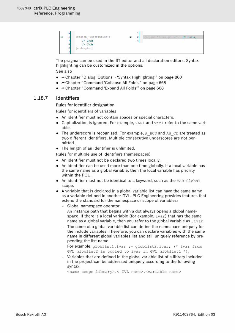
460 / 940 ctrlX PLC EngineeringReference, Programming
Bosch Rexroth AG R911403764, Edition 03
The pragma can be used in the ST editor and all declaration editors. Syntaxhighlighting can be customized in the options.See also● ⮫ Chapter “Dialog 'Options' - 'Syntax Highlighting'” on page 860● ⮫ Chapter “Command 'Collapse All Folds'” on page 668● ⮫ Chapter “Command 'Expand All Folds'” on page 668
1.18.7 IdentifiersRules for identifier designationRules for identifiers of variables● An identifier must not contain spaces or special characters.● Capitalization is ignored. For example, VAR1 and var1 refer to the same vari-
able.● The underscore is recognized. For example, A_BCD and AB_CD are treated as
two different identifiers. Multiple consecutive underscores are not per-mitted.
● The length of an identifier is unlimited.Rules for multiple use of identifiers (namespaces)● An identifier must not be declared two times locally.● An identifier can be used more than one time globally. If a local variable has
the same name as a global variable, then the local variable has prioritywithin the POU.
● An identifier must not be identical to a keyword, such as the VAR_Globalscope.
● A variable that is declared in a global variable list can have the same nameas a variable defined in another GVL. PLC Engineering provides features thatextend the standard for the namespace or scope of variables:– Global namespace operator:
An instance path that begins with a dot always opens a global name-space. If there is a local variable (for example, ivar) that has the samename as a global variable, then you refer to the global variable as .ivar.
– The name of a global variable list can define the namespace uniquely forthe include variables. Therefore, you can declare variables with the samename in different global variables list and still uniquely reference by pre-pending the list name.For example, globlist1.ivar := globlist2.ivar; (* ivar fromGVL globlist2 is copied to ivar in GVL globlist1 *).
– Variables that are defined in the global variable list of a library includedin the project can be addressed uniquely according to the followingsyntax:<name scope library>.< GVL name>.<variable name>

461 / 940ctrlX PLC EngineeringReference, Programming
Bosch Rexroth AGR911403764, Edition 03
For example, globlist1.ivar := lib1.globlist1.ivar (* ivarfrom GVL globlist1 in library lib1 is copied to ivar in GVLgloblist1 *).
● When inserting a library, you also use the library manager to define a name-space. In this way, you can make unique references to library blocks andlibrary via <namespace library>.<block name|variable name>. Pleasenote that when libraries are nested, you must reference the namespaces ofall libraries are in successionExample: If Lib1 is referenced by Lib0, then the block func in Lib1 isaddressed via Lib0.Lib1.fun: ivar := Lib0.Lib1.fun(4, 5); (*return value from func is copied to variable ivar in theproject *)
We recommend that you apply the following rules in addition to the items thatyou have to consider specifically for variables declaration. By doing this, youwill achieve the best possible harmonization when assigning names.
Recommendations for variable namesWhenever possible, you should name variables in Hungarian notation in applica-tions and libraries. Find a meaningful, short, English name for each variable asa base name, which can consist of several words. Write the first letter of eachword in uppercase, the remaining letters in lowercase. In front of the basename, append a prefix in lowercase to indicate the data type of the variable.Example: iFileSize : INT;.
Data type Prefix CommentBOOL x We intentionally recommend x
as the prefix for Boolean varia-bles in order to distinguish themfrom identifiers of the data typeBYTE. The prefix indicates theview of an IEC programmer.
b ReservedBYTE by Bit string; not for arithmetic
operationsWORD w Bit string; not for arithmetic
operationsDWORD dw Bit string; not for arithmetic
operationsLWORD lw Bit string; not for arithmetic
operations
SINT siUSINT usiINT iUINT uiDINT diUDINT udiLINT liULINT uli
REAL rLREAL lr
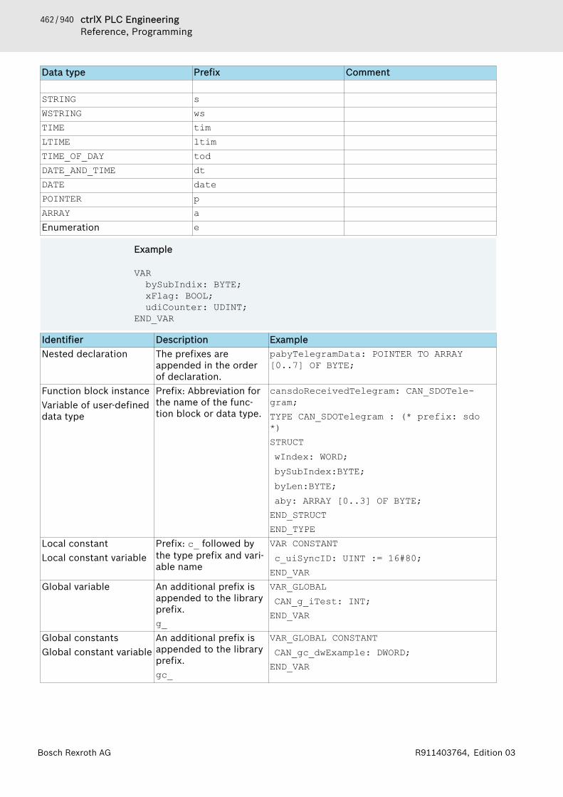
462 / 940 ctrlX PLC EngineeringReference, Programming
Bosch Rexroth AG R911403764, Edition 03
Data type Prefix Comment
STRING sWSTRING wsTIME timLTIME ltimTIME_OF_DAY todDATE_AND_TIME dtDATE datePOINTER pARRAY aEnumeration e
Example
VARbySubIndix: BYTE;xFlag: BOOL;udiCounter: UDINT;
END_VAR
Identifier Description ExampleNested declaration The prefixes are
appended in the orderof declaration.
pabyTelegramData: POINTER TO ARRAY[0..7] OF BYTE;
Function block instanceVariable of user-defineddata type
Prefix: Abbreviation forthe name of the func-tion block or data type.
cansdoReceivedTelegram: CAN_SDOTele-gram;TYPE CAN_SDOTelegram : (* prefix: sdo*)STRUCTᅠwIndex: WORD;ᅠbySubIndex:BYTE;ᅠbyLen:BYTE;ᅠaby: ARRAY [0..3] OF BYTE;END_STRUCTEND_TYPE
Local constantLocal constant variable
Prefix: c_ followed bythe type prefix and vari-able name
VAR CONSTANTᅠc_uiSyncID: UINT := 16#80;END_VAR
Global variable An additional prefix isappended to the libraryprefix.g_
VAR_GLOBALᅠCAN_g_iTest: INT;END_VAR
Global constantsGlobal constant variable
An additional prefix isappended to the libraryprefix.gc_
VAR_GLOBAL CONSTANTᅠCAN_gc_dwExample: DWORD;END_VAR
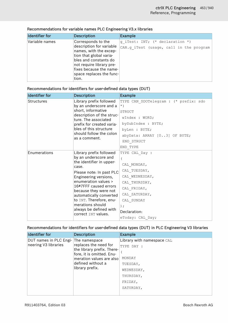
463 / 940ctrlX PLC EngineeringReference, Programming
Bosch Rexroth AGR911403764, Edition 03
Recommendations for variable names PLC Engineering V3.x libraries
Identifier for Description ExampleVariable names Corresponds to the
description for variablenames, with the excep-tion that global varia-bles and constants donot require library pre-fixes because the name-space replaces the func-tion.
g_iTest: INT; (* declaration *)CAN.g_iTest (usage, call in the program
Recommendations for identifiers for user-defined data types (DUT)
Identifier for Description ExampleStructures Library prefix followed
by an underscore and ashort, informativedescription of the struc-ture. The associatedprefix for created varia-bles of this structureshould follow the colonas a comment.
TYPE CAN_SDOTelegram : (* prefix: sdo*) STRUCTᅠwIndex : WORD;ᅠbySubIndex : BYTE;ᅠbyLen : BYTE;ᅠabyData: ARRAY [0..3] OF BYTE; END_STRUCTEND_TYPE
Enumerations Library prefix followedby an underscore andthe identifier in upper-case.Please note: In past PLCEngineering versions,enumeration values >16#7FFF caused errorsbecause they were notautomatically convertedto INT. Therefore, enu-merations shouldalways be defined withcorrect INT values.
TYPE CAL_Day :(ᅠCAL_MONDAY,ᅠCAL_TUESDAY,ᅠCAL_WEDNESDAY,ᅠCAL_THURSDAY,ᅠCAL_FRIDAY,ᅠCAL_SATURDAY,ᅠCAL_SUNDAY);Declaration:eToday: CAL_Day;
Recommendations for identifiers for user-defined data types (DUT) in PLC Engineering V3 libraries
Identifier for Description ExampleDUT names in PLC Engi-neering V3 libraries
The namespacereplaces the need forthe library prefix. There-fore, it is omitted. Enu-meration values are alsodefined without alibrary prefix.
Library with namespace CALTYPE DAY :(ᅠMONDAYᅠTUESDAY,ᅠWEDNESDAY,ᅠTHURSDAY,ᅠFRIDAY,ᅠSATURDAY,

464 / 940 ctrlX PLC EngineeringReference, Programming
Bosch Rexroth AG R911403764, Edition 03
Identifier for Description ExampleᅠSUNDAY);Declaration:eToday: CAL.Day;Use in the applicationIF eToday = CAL.Day.MONDAY THEN
Recommendations for identifiers for POUs, functions, function blocks, programs
Identifier for Description ExamplePOUs: Functions, func-tion blocks, programs
Library prefix followedby an underscore and ashort, informative POUname. Like for variables,the first letter of eachword is uppercase andall other letters are low-ercase. We recommendthat you compose thePOU name from a verband a noun.For function blocks, theassociated prefix forcreated instancesshould follow the nameas a comment.
FUNCTION_BLOCK CAN_SendTelegram (*prefix: canst *)
Actions Only actions that theblock itself calls, begin-ning with prv_. Other-wise, actions do notcontain prefixes.
Recommendations for identifiers for POUs in PLC Engineering V3 libraries
Identifier for Description ExamplePOU The namespace
replaces the need forthe library prefix. There-fore, it is omitted.
FUNCTION_BLOCK SendTelegram (* prefix:canst *)
Method Only methods that theblock itself calls, begin-ning with prv_. Other-wise, methods do notcontain prefixes.
InterfaceInterface
I ICANDevice
Recommendations for identifiers for visualizations
NOTICE Please note that a visualization is not named the same asanother block in the project because this may causeproblems when changing visualizations.

465 / 940ctrlX PLC EngineeringReference, Programming
Bosch Rexroth AGR911403764, Edition 03
See also● ⮫ Chapter 1.8.2 “Declaration of Variables ” on page 62● ⮫ Chapter 1.18.5 “Data Types” on page 386● ⮫ Chapter 1.18.2 “Variables” on page 312
1.18.8 Shadowing RulesIn PLC Engineering, you are generally allowed to use the same identifier for dif-ferent elements. For example, a POU and a variable can be named the same.However, you should avoid this practice in order to prevent confusion.Negative example: In the following code snippet, a local function block instancehas the same name as a function:
ExampleFUNCTION YYY : INT;END_FUNCTION
FUNCTION_BLOCK XXX;END_FUNCTION_BLOCK
PROGRAM PLC_PRGVARYYY : XXX;
END_VARYYY();END_PROGRAMIn such a case as this, it is unclear whether the instance or the function iscalled in the program.
To make sure that names are always unique, you should follow naming conven-tions, such as certain prefixes for variables. Rules for assigning identifiers canbe found in the "Identifiers" section of the help.Naming conventions can be checked automatically using the static code anal-ysis of PLC Engineering. Static code analysis could also detect the duplicateuse of the name YYY and report it as an error.The consistent use of the attribute qualified_only for enumerations andglobal variable lists and the use of qualified libraries can also prevent ambig-uous situations.Shadowing: The compiler does not report any errors or warnings if the sameidentifier is used for different elements. Instead, the compiler searches thecode in a specific order for the declaration of the identifier. If a declaration isfound, then the compiler does not search for any other declarations elsewhere.If other declarations do exist, then they are "shadowed" for the compiler. Thefollowing section describes the shadowing rules (that is, the search order thatthe compiler uses when searching for the declaration for identifiers). The sec-tion "Ambiguous access and qualified access" provides ways to prevent ambig-uous access and bypass shadowing rules.
Search order in the applicationWhen the compiler encounters a single identifier in the code of an application,it searches for the corresponding declaration in the following order:1. Local variables of a method2. Local variables in the function block, program, or function, and in any basefunction blocks
466 / 940 ctrlX PLC EngineeringReference, Programming
Bosch Rexroth AG R911403764, Edition 03
3. Local methods of the POU4. Global variables in the application, if the qualified_only attribute is notset in the variable list where the global variables are declared5. Global variables in referred libraries when neither the library nor the variablelist requires qualified access6. POU or type names from the application (that is, names of global variablelists, function blocks, and so on)7. POU or type names from a library8. Namespaces of locally referred libraries and libraries that are published bylibraries9. Global variables in the “POUs” view, unless the qualified_only attribute isset in the variable list where they are declared10. POU or type names from the “POUs” view (that is, names of global variablelists, function blocks, and so on)Libraries that are inserted in the Library Manager of the “POUs” view are mir-rored in the Library Manager in all applications in the project with the appro-priate placeholder resolution. These libraries then form a common namespacewith the libraries in the application. Therefore, there is no shadowing of libra-ries in the pool by libraries in the application.
Search order in the libraryWhen the compiler encounters a single identifier in the code of a library, itsearches for the corresponding declaration in the following order:1. Local variables of a method2. Local variables in the function block, program, or function, and in any basefunction blocks3. Local methods of the POU4. Global variables in the local library, if the qualified_only attribute is notset in the variable list where the global variables are declared5. Global variables in referred libraries when neither the library nor the variablelist requires qualified access6. POU or type names from the local library (that is, names of global variablelists, function blocks, and so on)7. POU or type names from a referred library8. Namespaces of locally referred libraries and libraries that are published bylocally refereed libraries
Ambiguous access and qualified accessDespite these search orders, ambiguous access can still occur. For example,this is the case when a variable with the same name exists in two global vari-able lists that do not require qualified access. Such a case is reported by thecompiler as an error (for example: ambiguous use of the name XXX).This kind of ambiguous use can be made unique by means of qualified access,for example by accessing via the name of the global variable list (example:GVL.XXX).Qualified access can also always be used to avoid shadowing rules.● The name of the global variable list can be used to uniquely access a vari-
able in the list.● The name of a library can be used to uniquely access elements in the library.● The THIS pointer be used to uniquely access variables in a function block,
even if a local variable with the same name exists in a method of the func-tion block.
467 / 940ctrlX PLC EngineeringReference, Programming
Bosch Rexroth AGR911403764, Edition 03
To find the declaration location of an identifier at any time, use the command“Edit 🠂 Browse 🠂 Go to Definition”. This can be especially helpful if the com-piler produces an apparently obscure error message.
Searching in instance pathsThe search orders described above do not apply to identifiers that exist ascomponents in an instance path or to identifiers that are used as inputs incalls.For access of the following type yy.component, it depends on the entitydescribed by yy where the declaration of component is searched for.If yy denotes a variable with a structured data type (that is, type STRUCT orUNION), then component is searched for in the following order:● Local variables of the function block● Local variables of the basic function block● Methods of the function block● Methods of the basic function blockIf yy denotes a global variable list or a program, then component is searchedfor in this list only.If yy denotes a namespace of a library, then component is searched for in thislibrary exactly as described in the section above "Search order in the library".Only in the second instance does the compiler decide whether access to thefound element is granted (that is, whether the variable is only locally acces-sible, or whether a method is private). If access is not allowed, an error isissued.
See also● ⮫ Chapter 1.18.7 “Identifiers” on page 460● ⮫ Chapter “Attribute 'qualified_only'” on page 449● ⮫ Chapter “THIS” on page 325
1.18.9 KeywordsIn all editors, you must capitalize keywords that for example denote scopes,data types, or operators.Keywords cannot be used as variable names.
Examples
VAREND_VARBOOL_TO_INTIFTHENELSELTIMEMULXORPERSISTENTPROGRAM
PLC Engineering checks the correct use of keywords automatically and high-lights errors immediately during input with a wavy underline.
468 / 940 ctrlX PLC EngineeringReference, Programming
Bosch Rexroth AG R911403764, Edition 03
When PLC Engineering creates implicit code, variables and functions are gener-ally given a name that is prepended with two underscores (__). The use ofdouble underscores in the implementation code is prevented automatically.This eliminates conflicts between internal system identifiers and identifiersassigned by the programmer.The following keywords are used in the PLC Engineering export format. There-fore, you may not use them as identifiers:● ACTION● END_ACTION● END_FUNCTION● END_FUNCTION_BLOCK● END_PROGRAMOther valid keywords:● VAR_ACCESS● READ_ONLY● READ_WRITE● PARAMS
1.18.10 Methods 'FB_Init', 'FB_Reinit', and 'FB_Exit'You can declare the methods explicitly in order to influence the initialization offunction block variables, as well as the behavior when exiting function blocks.The type of the return value for the implicit methods is BOOL. The value is notevaluated by the system, but the type should not be changed.FB_Init is always available implicitly and it is used primarily for initialization.For a specific influence, you can also declare the methods explicitly and pro-vide additional code there with the standard initialization code.FB_Reinit must be implemented explicitly. If this method exists, then it iscalled after the instance of the affected function block is copied. That happensduring an online change after changes to the function block declaration (signa-ture change) in order to reinitialize the new instance module. To reinitialize thebasic implementation of the function block, you must call FB_Reinit explicitly.FB_Exit must be implemented explicitly. If there is an implementation, thenthe method is called before the controller removes the code of the functionblock instance (implicit call).The following shows some use cases of these methods for different operatingconditions.
Operating condition "First download"When downloading an application to a PLC with factory settings, the memoryof all variables must be offset to the required initial state. In this way, the dataareas of function block instances are assigned the required values. By theexplicit implementation of FB_Init for function blocks, you can react specifi-cally to this situation in the application code. By evaluating the method parame-ters bInCopyCode (FALSE) and bInitRetains (TRUE), you can detect thisoperating condition clearly. (See "Operating condition "Online Change"" and"Operating condition "Re-download"".)
Operating condition "Online Change"Within the scope of the online change, you can influence the initialization offunction block instances by means of the methods FB_Exit, FB_Init, andFB_Reinit. During the online change, the changes to the application that weremade in offline mode are applied in the running PLC. This is the reason that theold instances of the function blocks are replaced by new instances as much as

469 / 940ctrlX PLC EngineeringReference, Programming
Bosch Rexroth AGR911403764, Edition 03
possible without incident. If no changes were made to the declaration part of afunction block in the application before login, but in the implementation only,then the data areas are not replaced. Only code blocks are replaced. Then themethods FB_Exit , FB_Init, and FB_Reinit are not called.If you have made changes to the declaration of a function block that lead to thecopying operation described above, then you receive a message during theonline change about possible unintended effects. In the “Details” of the mes-sage view, you see a list of all instances to be copied.In the code of the FB_Init method, the parameter bInCopyCode (TRUE) canbe evaluated to detect whether or not an online change is being executed.The following calls occur in succession during an online change:1. FB_Exit
old_inst.FB_Exit(bInCopyCode := TRUE);You can call FB_Exit when exiting the old instance in order to trigger spe-cific cleanup tasks before the copy operation. In this way, you can preparethe data for the following copy operation and influence the state of thenew instance. You can notify other parts of the application about thepending change in location in the memory. Pay special attention to thevariables of type POINTER and REFERENCE. These may no longer refer tothe required memory locations after the online change. Interface variables(INTERFACE) are handled separately by the compiler and they are adaptedaccordingly during the online change. External resources such as sockets,files, or other handles can be applied by the new instance, in some caseunchanged. Often they do not have to be treated specially during anonline change. (See "Operating condition "Re-download"")
2. FB_Initnew_inst.FB_Init(bInitRetains := FALSE, bInCopyCode :=TRUE);FB_Init is called before the copy operation and can be used in order toexecute specific operations for the online change. For example, you caninitialize variables accordingly at the new location in the memory, or notifyother parts of the application about the new location of specific variablesin the memory.
3. Copy operation: copycopy(&old_inst, &new_inst);Existing values remain unchanged. For this purpose, they are copied fromthe old instance into the new instance.
4. FB_Reinitnew_inst.FB_Reinit();This method is called after the copy operation and should set definedvalues for the variables of the instance. For example, you can initialize var-iables accordingly at the new location in the memory, or notify other partsof the application about the new location of specific variables in thememory. Design the implementation independent of the online change.The method can also be called from the application at any time in order toreset a function block instance to its original state.
With the {attribute 'no_copy'} attribute, you can prevent that this iscopied during the online change for a single variable of the function block. Italways retains the initial value.See also● ⮫ Chapter “Command 'Settings of Memory Reserve for Online Change' ”
on page 691
470 / 940 ctrlX PLC EngineeringReference, Programming
Bosch Rexroth AG R911403764, Edition 03
Operating condition "New download"When downloading an application, an existing application may be replaced onthe PLC. Therefore, the provision of memory for the present function blocksmust be regulated. You can use the FB_Exit method for implementing therequired steps for this. For example, you can offset external resources (withsocket and file handles) in a defined state.You can detect this operating condition by checking whether or not the param-eter bInCopyCode = FALSE for the FB_Exit method.
Operating condition "Start of application"The initial assignments are processed before the first cycle of the applicationtasks.
ExampleT1 : TON := (PT:=t#500ms);
These kinds of assignments are executed only after calling FB_Init. In order tocontrol the effects of these assignments, you can provide a function block or amethod of a function block with the {attribute ‘call_after_init‘}attribute. You must add the attribute above the declaration part of the functionblock body and above the declaration part of the corresponding method. APOU that extends another POU which uses the {attribute'call_after_init'} attribute must also have the attribute. For the benefit ofclarity, we recommend that the corresponding methods are overwritten withthe same name, the same signature, and the same attribute. This requirescalling SUPER^.MyInit. The name of the method can be chosen withoutrestriction. (Exceptions: FB_Init, FB_Reinit, and FB_Exit). The method iscalled after processing the initial assignments and before starting the applica-tion tasks. Therefore, the method can react to user input.When using FB_Init or {attribute 'call_after_init'}, remember thatdetecting errors in the FB_Init method or in methods decorated with the{attribute 'call_after_init'} attribute is tedious, because the setting ofbreakpoints may not have the expected effect.
NOTICE If the explicitly defined initialization code is reachedduring execution, then the function block instance isalready completely initialized via the implicit initializationcode. Therefore, there must not be a SUPER^.FB_Initcall.
NOTICE FB_Init replaces the INI operator used in CoDeSysV2.3. The methods cannot be compared to the design ofa constructor, such as in C#, C++, or Java. This has con-sequences for function blocks that extend other functionblocks. (See below: "Derived function blocks")
Interface of method FB_InitMETHOD FB_Init : BOOLVAR_INPUT bInitRetains : BOOL; // TRUE: the retain variables are initialized (reset warm / reset cold) bInCopyCode : BOOL; // TRUE: the instance will be copied to the copy code afterward (online change)END_VARYou can declare additional function block inputs in an FB_init method. Thenyou have to set these inputs in the declaration of the function block instance.
471 / 940ctrlX PLC EngineeringReference, Programming
Bosch Rexroth AGR911403764, Edition 03
ExampleMethod FB_Init for the serialdevice function block
METHOD PUBLIC FB_Init : BOOLVAR_INPUT bInitRetains : BOOL; // initializing of retain variable bInCopyCode : BOOL; // instance is copied to copy code iCOMnum : INT; // additional input: number of the COM interface, that is to be observedEND_VAR Instantiation of the serialdevice function block: com1: serialdevice(iCOMnum:=1);com0: serialdevice(iCOMnum:=0);
Interface of method FB_Reinit
METHOD FB_Reinit : BOOL
Interface of method FB_ExitThere is the mandatory parameter bInCopyCode.
METHOD FB_Exit : BOOL VAR_INPUT bInCopyCode : BOOL; // TRUE: the exit method is called in order to leave the instance which will be copied afterwards (online change). END_VAR
Behavior for derived function blocksIf a function block is derived from another function block, then the FB_Initmethod of the derived function block must define the same parameters as theFB_Init method of the basic function block. However, you can add furtherparameters in order to set up a special initialization for the instance.
ExampleThe function blocks MainFB, SubFB, and SubSubFB are derived from eachother. Therefore, SubFB EXTENDS MainFB and SubSubFB EXTENDS SubFBapply.Calling order of methods FB_Exit and FB_Init:1. fbSubSubFb.FB_Exit(...);2. fbSubFb.FB_Exit(...);3. fbMainFb.FB_Exit(...);4. fbMainFb.FB_Init(...);5. fbSubFb.FB_Init(...);6. fbSubSubFb.FB_Init(...);
472 / 940 ctrlX PLC EngineeringReference, Programming
Bosch Rexroth AG R911403764, Edition 03
See also● ⮫ Chapter “Object 'Method'” on page 596● ⮫ Chapter “Attribute 'call_after_init'” on page 421● ⮫ Chapter “Attribute 'no_copy'” on page 440● ⮫ Chapter “SUPER” on page 323
1.18.11 Error MessagesCompiler error C0001. . . . . . . . . . . 475Compiler error C0002. . . . . . . . . . . 475Compiler error C0003. . . . . . . . . . . 475Compiler Error C0004. . . . . . . . . . . 476Compiler error C0005. . . . . . . . . . . 476Compiler error C0006. . . . . . . . . . . 476Compiler error C0007. . . . . . . . . . . 477Compiler error C0008. . . . . . . . . . . 477Compiler error C0009. . . . . . . . . . . 477Compiler error C0010. . . . . . . . . . . 478Compiler error C0011. . . . . . . . . . . 478Compiler error C0013. . . . . . . . . . . 478Compiler error C0016. . . . . . . . . . . 479Compiler error C0018. . . . . . . . . . . 479Compiler Error C0020. . . . . . . . . . . 480Compiler Error C0022. . . . . . . . . . . 480Compiler Error C0023. . . . . . . . . . . 480Compiler Error C0026. . . . . . . . . . . 481Compiler Error C0027. . . . . . . . . . . 481Compiler Error C0030. . . . . . . . . . . 481Compiler Error C0031. . . . . . . . . . . 482Compiler error C0032. . . . . . . . . . . 482Compiler Error C0035. . . . . . . . . . . 482Compiler Error C0037. . . . . . . . . . . 483Compiler Error C0038. . . . . . . . . . . 483Compiler Error C0039. . . . . . . . . . . 484Compiler Error C0040. . . . . . . . . . . 484Compiler Error C0041. . . . . . . . . . . 485Compiler Error C0043. . . . . . . . . . . 485Compiler Error C0044. . . . . . . . . . . 486Compiler error C0045. . . . . . . . . . . 486Compiler Error C0046. . . . . . . . . . . 487Compiler Error C0047. . . . . . . . . . . 487Compiler Error C0048. . . . . . . . . . . 488Compiler Error C0049. . . . . . . . . . . 488Compiler Error C0050. . . . . . . . . . . 488Compiler Error C0061. . . . . . . . . . . 489Compiler Error C0062. . . . . . . . . . . 489Compiler Error C0064. . . . . . . . . . . 490Compiler Error C0066. . . . . . . . . . . 490
473 / 940ctrlX PLC EngineeringReference, Programming
Bosch Rexroth AGR911403764, Edition 03
Compiler Error C0068. . . . . . . . . . . 491Compiler Error C0069. . . . . . . . . . . 491Compiler Error C0070. . . . . . . . . . . 491Compiler Error C0072. . . . . . . . . . . 492Compiler Error C0074. . . . . . . . . . . 492Compiler Error C0075. . . . . . . . . . . 493Compiler Error C0076. . . . . . . . . . . 493Compiler Error C0077. . . . . . . . . . . 493Compiler Error C0080. . . . . . . . . . . 494Compiler Error C0081. . . . . . . . . . . 494Compiler Error C0082. . . . . . . . . . . 495Compiler Error C0084. . . . . . . . . . . 495Compiler Error C0086. . . . . . . . . . . 495Compiler Error C0087. . . . . . . . . . . 496Compiler Error C0089. . . . . . . . . . . 496Compiler Error C0090. . . . . . . . . . . 497Compiler Error C0091. . . . . . . . . . . 497Compiler Error C0094. . . . . . . . . . . 498Compiler Error C0096. . . . . . . . . . . 498Compiler Error C0097. . . . . . . . . . . 499Compiler Error C0098. . . . . . . . . . . 499Compiler Error C0101. . . . . . . . . . . 499Compiler Error C0102. . . . . . . . . . . 500Compiler Error C0104. . . . . . . . . . . 500Compiler Error C0114. . . . . . . . . . . 500Compiler Error C0116. . . . . . . . . . . 500Compiler Error C0117. . . . . . . . . . . 501Compiler Error C0118. . . . . . . . . . . 501Compiler Error C0119. . . . . . . . . . . 501Compiler Error C0120. . . . . . . . . . . 502Compiler Error C0122. . . . . . . . . . . 502Compiler Error C0124. . . . . . . . . . . 503Compiler Error C0125. . . . . . . . . . . 503Compiler Error C0126. . . . . . . . . . . 503Compiler Error C0130. . . . . . . . . . . 504Compiler Error C0131. . . . . . . . . . . 504Compiler Error C0132. . . . . . . . . . . 505Compiler Error C0136. . . . . . . . . . . 505Compiler Error C0139. . . . . . . . . . . 505Compiler Error C0140. . . . . . . . . . . 506Compiler Error C0141. . . . . . . . . . . 506Compiler Error C0142. . . . . . . . . . . 506Compiler Error C0143. . . . . . . . . . . 507Compiler Error C0144. . . . . . . . . . . 507Compiler Error C0145. . . . . . . . . . . 508Compiler Error C0149. . . . . . . . . . . 508

474 / 940 ctrlX PLC EngineeringReference, Programming
Bosch Rexroth AG R911403764, Edition 03
Compiler Error C0161. . . . . . . . . . . 508Compiler Error C0162. . . . . . . . . . . 509Compiler Error C0168. . . . . . . . . . . 509Compiler Error C0169. . . . . . . . . . . 509Compiler Error C0174. . . . . . . . . . . 510Compiler Error C0175. . . . . . . . . . . 510Compiler Error C0177. . . . . . . . . . . 510Compiler Error C0178. . . . . . . . . . . 511Compiler Error C0182. . . . . . . . . . . 511Compiler Error C0185. . . . . . . . . . . 511Compiler Error C0189. . . . . . . . . . . 512Compiler Error C0190. . . . . . . . . . . 512Compiler Error C0191. . . . . . . . . . . 512Compiler Error C0195. . . . . . . . . . . 513Compiler Error C0196. . . . . . . . . . . 513Compiler Error C0197. . . . . . . . . . . 513Compiler Error C0198. . . . . . . . . . . 514Compiler Error C0199. . . . . . . . . . . 514Compiler Error C0201. . . . . . . . . . . 514Compiler Error C0203. . . . . . . . . . . 515Compiler Error C0204. . . . . . . . . . . 515Compiler Error C0205. . . . . . . . . . . 515Compiler Error C0206. . . . . . . . . . . 516Compiler Error C0208. . . . . . . . . . . 516Compiler Error C0211. . . . . . . . . . . 516Compiler Error C0212. . . . . . . . . . . 517Compiler Error C0216. . . . . . . . . . . 517Compiler Error C0217. . . . . . . . . . . 517Compiler Error C0218. . . . . . . . . . . 518Compiler Error C0219. . . . . . . . . . . 518Compiler Error C0221. . . . . . . . . . . 518Compiler Error C0222. . . . . . . . . . . 519Compiler Error C0224. . . . . . . . . . . 519Compiler Error C0227. . . . . . . . . . . 519Compiler Error C0228. . . . . . . . . . . 520Compiler Error C0234. . . . . . . . . . . 520Compiler Error C0235. . . . . . . . . . . 521Compiler Error C0236. . . . . . . . . . . 521Compiler Error C0237. . . . . . . . . . . 521Compiler Error C0238. . . . . . . . . . . 522Compiler Error C0239. . . . . . . . . . . 522Compiler Error C0240. . . . . . . . . . . 523Compiler Error C0241. . . . . . . . . . . 523Compiler Error C0242. . . . . . . . . . . 523Compiler Error C0243. . . . . . . . . . . 524Compiler error C0380. . . . . . . . . . . 524
475 / 940ctrlX PLC EngineeringReference, Programming
Bosch Rexroth AGR911403764, Edition 03
Compiler Error C0509. . . . . . . . . . . 525Compiler Error C0511. . . . . . . . . . . 526
Compiler error C0001Message: Constant '<constant value>' too large for type '<data type>'Possible error cause: A typed constant is too large for the given data type or aconstant is too large for each possible data type.Error correction: Use smaller constants or an appropriate data type for a typedconstant.
Example of the error:PROGRAM PLC_PRGVARtest1: INT;test2: INT;test3: LREAL;
END_VAR
test1 := 12345678912345566991923939292939911;test2 := INT#123456;test3 := 10E500;
--> C0001: Constant '12345678912345566991923939292939911' too large for type 'ANY_INT'--> C0001: Constant 'INT#123456' too large for type 'INT'--> C0001: Constant '10E500' too large for type 'ANY_REAL'
Compiler error C0002Message: '<operator 1>' or '<operator 2>' expected instead of '<tag>'Possible error cause: Syntax errorError correction: Use the correct syntax.
Example of the error:PROGRAM PLC_PRGFun(1;
--> C0002: ',' or ')' expected instead of ';'
Compiler error C0003Message: '<value>' is not a valid bit number for '<variable>'Possible error cause: Attempted access to a bit that is outside of the range fora data type.Error correction: Use a bit value for the bit access that is lower than thenumber of bits in the data type of the variable.
Example of the error:PROGRAM PLC_PRGVARtest1: WORD;test2: BOOL;
END_VAR
476 / 940 ctrlX PLC EngineeringReference, Programming
Bosch Rexroth AG R911403764, Edition 03
test1 := test2.17;
--> C0003: '17' is not a valid bit number for 'w'
Compiler Error C0004Message: '<variable>' is not a component of '<structure>'Possible error cause: Component access with "." to a variable that is not astructured value or does not exist as a component of the structure.Error correction: Access a defined component, or change the definition of thecomponent in the data type. The input assistance "List components" providesall valid access to this position.
Example of the error:TYPE DUT:STRUCTx, y : INT;
END_STRUCTEND_TYPE
PROGRAM PLC_PRGVARtest1 : DUT;test2 : INT;
END_VAR
test2 := test1.z;
--> C0032: Type 'Unknown type: 'test1.z'' cannot be converted to type 'INT'--> C0004: 'z' is to a component of 'DUT'
Compiler error C0005Message: Constant overflow in address '<address>'Possible error cause: At least one component in the address does not fit into a32-bit integer value.Error correction: Use a valid address expression.
Example of the error:PROGRAM PLC_PRGVARX: BYTE;
END_VAR
X := %QB5555555555;
--> C0005: Constant overflow in address '%??'
Compiler error C0006Message: '<operator>' expected instead of '<token>'Possible error cause: Syntax errorError correction: Use the correct syntax.

477 / 940ctrlX PLC EngineeringReference, Programming
Bosch Rexroth AGR911403764, Edition 03
Example of the error:PROGRAM PLC_PRGVARx: INT;bTest : BOOL;
END_VAR
IF bTest x := 9;
END_IF
--> C0006: 'THEN' expected instead of 'x'
Compiler error C0007Message: Expression expected instead of '<token>'Possible error cause: Syntax errorError correction: Use the correct syntax.
Example of the error:PROGRAM PLC_PRGVARx: INT;bTest : BOOL;
END_VAR
IF THENx := 9;
END_IF
--> C0007: Expression expected instead of 'THEN'
Compiler error C0008Message: Unexpected end-of-file found: '<operator 1>', '<operator 2>', or '<oper-ator 3>' expectedPossible error cause: Syntax errorError correction: Use the correct syntax.
Example of the error:PROGRAM PLC_PRGVARx: INT;bTest : BOOL;
END_VAR
IF bTest THENx := 9;
--> C0008: Unexpected end-of-file found: 'ELSIF', 'ELSE' or 'END_IF' expected
Compiler error C0009Message: Unexpected token '<token>' foundPossible error cause: Syntax errorError correction: Use the correct syntax.
478 / 940 ctrlX PLC EngineeringReference, Programming
Bosch Rexroth AG R911403764, Edition 03
Example of the error:PROGRAM PLC_PRGVAREND_VAR
END_FOR;
--> C0009: Unexpected token 'END_FOR' found
Compiler error C0010Message: Unexpected end-of-file found: '<token>' expectedPossible error cause: Syntax errorError correction: Use the correct syntax.
Example of the error:PROGRAM PLC_PRGVARi: INT;
END_VAR
FOR i := 0 TO 2 DO;
--> C0010: Unexpected end-of-file 'END_FOR' found
Compiler error C0011Message: No 'CASE' label foundPossible error cause: Syntax error in a CASE statement. A statement in a CASEstatement is not assigned to a CASE label.Error correction: Add a CASE label.
Example of the error:PROGRAM PLC_PRGVARi: INT;x: INT;
END_VAR
CASE i OFx := 9;
END_CASE
--> C0011: No 'CASE' label foundError correction:CASE i OF0:x := 9;
END_CASE
Compiler error C0013Message: At least one statement is expected.Possible error cause: At least one statement is expected at some positions inthe code. For example, in the THEN and ELSE part of an IF statement, or in thebody of a FOR loop.
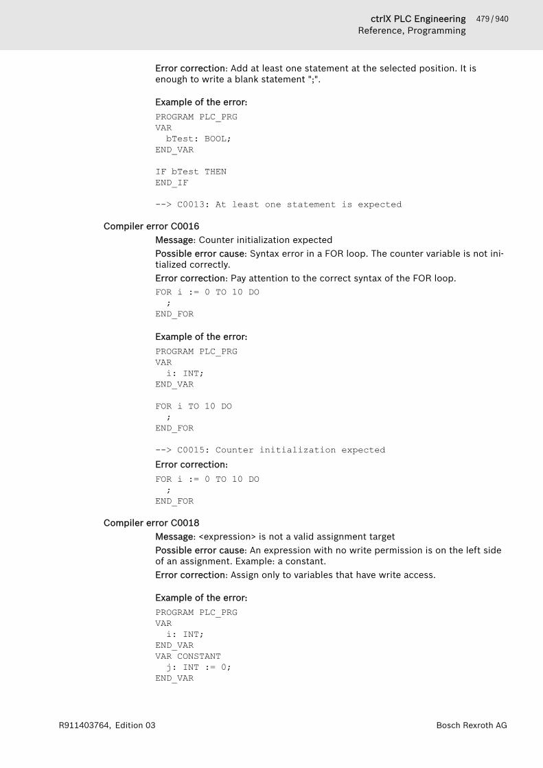
479 / 940ctrlX PLC EngineeringReference, Programming
Bosch Rexroth AGR911403764, Edition 03
Error correction: Add at least one statement at the selected position. It isenough to write a blank statement ";".
Example of the error:PROGRAM PLC_PRGVARbTest: BOOL;
END_VAR
IF bTest THENEND_IF
--> C0013: At least one statement is expected
Compiler error C0016Message: Counter initialization expectedPossible error cause: Syntax error in a FOR loop. The counter variable is not ini-tialized correctly.Error correction: Pay attention to the correct syntax of the FOR loop.FOR i := 0 TO 10 DO;
END_FOR
Example of the error:PROGRAM PLC_PRGVARi: INT;
END_VAR
FOR i TO 10 DO;
END_FOR
--> C0015: Counter initialization expectedError correction:FOR i := 0 TO 10 DO;
END_FOR
Compiler error C0018Message: <expression> is not a valid assignment targetPossible error cause: An expression with no write permission is on the left sideof an assignment. Example: a constant.Error correction: Assign only to variables that have write access.
Example of the error:PROGRAM PLC_PRGVARi: INT;
END_VARVAR CONSTANTj: INT := 0;
END_VAR

480 / 940 ctrlX PLC EngineeringReference, Programming
Bosch Rexroth AG R911403764, Edition 03
j := i;
--> C0018: 'j' is not a valid assignment target
Compiler Error C0020Message: '<statement>' is no valid statementPossible error cause: Syntax error (for example, too few or too many charac-ters)Error correction: Make sure that the syntax is correct.
Example of the error:PROGRAM PLC_PRGVARx : INT;
END_VAR x = 2;
--> C0020: '(x = 2); ' is no valid statementError correction:Example:x := 2;
Compiler Error C0022Message: '<operator>' needs exactly '<number of operands>' operandsPossible error cause: Too many or too few operands are assigned to an oper-ator.Error correction: Assign the required number of operands to the operator.
Example of the error:PROGRAM PLC_PRGVARi : INT;pt: POINTER TO INT;
END_VAR
pt := ADR(i,1);
--> C0022: 'ADR' needs exactly '1' operandsError correction:Example:pt := ADR(i);
Compiler Error C0023Message: '<operator>' needs at least '<number of operands>' operandsPossible error cause: Too few operands are assigned to an operator.Error correction: Assign the required number of operands to the operator.
Example of the error:PROGRAM PLC_PRGVARi : INT;
END_VAR

481 / 940ctrlX PLC EngineeringReference, Programming
Bosch Rexroth AGR911403764, Edition 03
i := MUX(30,40);
--> C0023: 'MUX' needs at least '3' operandsError correction:Example:i := MUX(30,40,50);
Compiler Error C0026Message: Identifier expected instead of '<invalid identifier>'Possible error cause: An invalid identifier is passed to a method.Error correction: Use valid identifiers.
Example of the error:METHOD 123VAR_INPUTEND_VAR
--> C0243: The name used in the signature is not identical to the object name--> C0026: Identifier expected instead of '123'Error correction:Example:METHOD METH123
Compiler Error C0027Message: size of string expected after '('Possible error cause: The length of the string is not specified.Error correction: Specify a string length between the parentheses.
Example of the error:PROGRAM PLC_PRGVAR str : STRING();
END_VAR
--> C0027: size of string expected after '('--> C0006: ';, :=, REF=, ( or [' expected instead of ')'Error correction:Example:str : STRING(100);
Compiler Error C0030Message: Direct Address expected after 'AT' instead of '<identifier>'Possible error cause: Either an invalid address or no address is assigned after'AT'.Error correction: Specify a valid address.
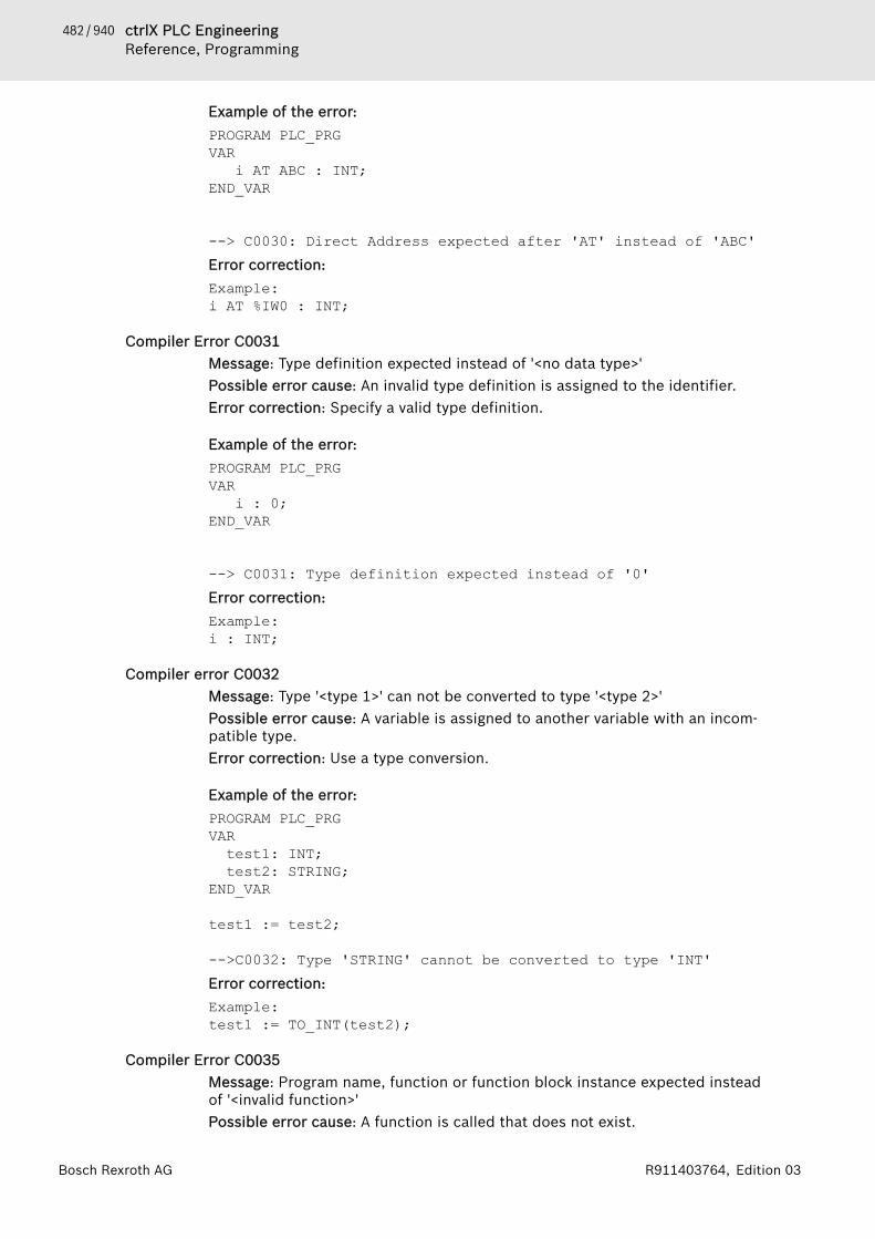
482 / 940 ctrlX PLC EngineeringReference, Programming
Bosch Rexroth AG R911403764, Edition 03
Example of the error:PROGRAM PLC_PRGVAR i AT ABC : INT;
END_VAR
--> C0030: Direct Address expected after 'AT' instead of 'ABC'Error correction:Example:i AT %IW0 : INT;
Compiler Error C0031Message: Type definition expected instead of '<no data type>'Possible error cause: An invalid type definition is assigned to the identifier.Error correction: Specify a valid type definition.
Example of the error:PROGRAM PLC_PRGVAR i : 0;
END_VAR
--> C0031: Type definition expected instead of '0'Error correction:Example:i : INT;
Compiler error C0032Message: Type '<type 1>' can not be converted to type '<type 2>'Possible error cause: A variable is assigned to another variable with an incom-patible type.Error correction: Use a type conversion.
Example of the error:PROGRAM PLC_PRGVARtest1: INT;test2: STRING;
END_VAR
test1 := test2;
-->C0032: Type 'STRING' cannot be converted to type 'INT'Error correction:Example:test1 := TO_INT(test2);
Compiler Error C0035Message: Program name, function or function block instance expected insteadof '<invalid function>'Possible error cause: A function is called that does not exist.

483 / 940ctrlX PLC EngineeringReference, Programming
Bosch Rexroth AGR911403764, Edition 03
Error correction: Make sure that only program names, functions, and functionBlock Instances that exist are called.
Example of the error:PROGRAM PLC_PRGVAREND_VAR
PLC_PRG.METH1();
METHOD METHVAR_INPUTEND_VAR
--> C0004: 'METH1' is no component of 'PLC_PRG'--> C0035: Program name, function or function block instance expected instead of 'PLC_PRG.METH1'Error correction:Example:PLC_PRG.METH();
Compiler Error C0037Message: '<invalid input>' is no input of '<function name>'Possible error cause: A local variable is defined in a function call.Error correction: Declare the variable as an input parameter.
Example of the error:PROGRAM PLC_PRGVAR i : INT;
END_VARi := TEST(iVar := 1);
FUNCTION TEST : INTVARiVar : INT;
END_VAR
--> C0037: 'iVar' is no input of 'TEST'Error correction:Example:VAR_INPUTiVar : INT;
END_VAR
Compiler Error C0038Message: '<invalid output>' is no output of '<function name>'Possible error cause: A local variable is handled as an output in a function call.Error correction: Declare the variable as an output parameter.
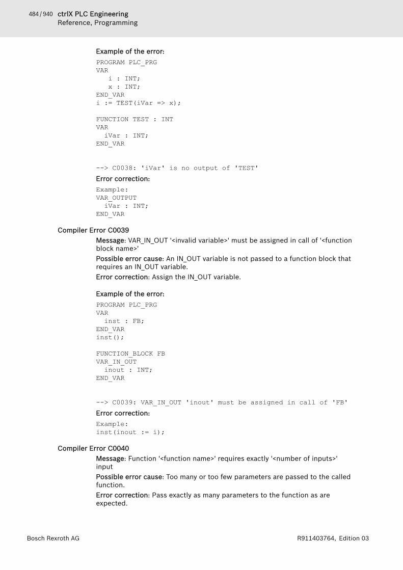
484 / 940 ctrlX PLC EngineeringReference, Programming
Bosch Rexroth AG R911403764, Edition 03
Example of the error:PROGRAM PLC_PRGVAR i : INT; x : INT;
END_VARi := TEST(iVar => x);
FUNCTION TEST : INTVARiVar : INT;
END_VAR
--> C0038: 'iVar' is no output of 'TEST'Error correction:Example:VAR_OUTPUTiVar : INT;
END_VAR
Compiler Error C0039Message: VAR_IN_OUT '<invalid variable>' must be assigned in call of '<functionblock name>'Possible error cause: An IN_OUT variable is not passed to a function block thatrequires an IN_OUT variable.Error correction: Assign the IN_OUT variable.
Example of the error:PROGRAM PLC_PRGVARinst : FB;
END_VAR inst();
FUNCTION_BLOCK FBVAR_IN_OUTinout : INT;
END_VAR
--> C0039: VAR_IN_OUT 'inout' must be assigned in call of 'FB'Error correction:Example:inst(inout := i);
Compiler Error C0040Message: Function '<function name>' requires exactly '<number of inputs>'inputPossible error cause: Too many or too few parameters are passed to the calledfunction.Error correction: Pass exactly as many parameters to the function as areexpected.
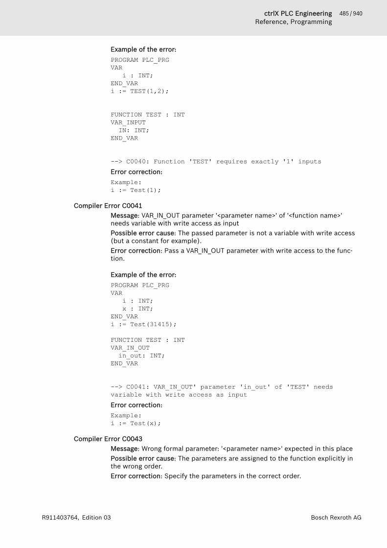
485 / 940ctrlX PLC EngineeringReference, Programming
Bosch Rexroth AGR911403764, Edition 03
Example of the error:PROGRAM PLC_PRGVAR i : INT;
END_VARi := TEST(1,2);
FUNCTION TEST : INTVAR_INPUTIN: INT;
END_VAR
--> C0040: Function 'TEST' requires exactly '1' inputsError correction:Example:i := Test(1);
Compiler Error C0041Message: VAR_IN_OUT parameter '<parameter name>' of '<function name>'needs variable with write access as inputPossible error cause: The passed parameter is not a variable with write access(but a constant for example).Error correction: Pass a VAR_IN_OUT parameter with write access to the func-tion.
Example of the error:PROGRAM PLC_PRGVAR i : INT; x : INT;
END_VARi := Test(31415);
FUNCTION TEST : INTVAR_IN_OUTin_out: INT;
END_VAR
--> C0041: VAR_IN_OUT' parameter 'in_out' of 'TEST' needs variable with write access as inputError correction:Example:i := Test(x);
Compiler Error C0043Message: Wrong formal parameter: '<parameter name>' expected in this placePossible error cause: The parameters are assigned to the function explicitly inthe wrong order.Error correction: Specify the parameters in the correct order.
486 / 940 ctrlX PLC EngineeringReference, Programming
Bosch Rexroth AG R911403764, Edition 03
Example of the error:PROGRAM PLC_PRGVAR i : INT;
END_VARi := Test(iPar2 := 2, 5);
FUNCTION Test : INTVAR_INPUTiPar1 : INT;iPar2 : INT;
END_VAR
--> C0043: Wrong formal parameter: 'iPar1' expected in this place--> C0412: Multiple input assignments for parameter ''Error correction:Example:i := Test(5, iPar2 := 2);
Compiler Error C0044Message: Assignment to input missing for parameter '<input variable name>' incall of '<function block name>'Possible error cause: A parameter is passed although an input variable is notdeclared.Error correction: Declare an input variable.
Example of the error:PROGRAM PLC_PRGVARinst : FB;
END_VAR inst(1);
FUNCTION_BLOCK FBVAR_INPUT
END_VAR
--> C0044: Assignment to input missing for parameter '1' in call of 'FB'Error correction:Example:VAR_INPUTin : INT;
END_VAR
Compiler error C0045Message: Use of 'THIS' is not allowed in this context
487 / 940ctrlX PLC EngineeringReference, Programming
Bosch Rexroth AGR911403764, Edition 03
Possible error cause: In order to be assigned to the current instance, THIS canbe used only in a method, action, transition, or in the body of a function block.This error message appears for all other positions.Error correction: Use THIS in an allowed context only.
Example of the error:PROGRAM PLC_PRGVARtest1: INT;
END_VAR
THIS^.test1 := 19;
--> C0018: 'THIS^.test1' is not a valid assignment target--> C0062: 'THIS^' is not a structure variable--> C0045: Use of 'THIS' is not allowed in this context
Compiler Error C0046Message: Identifier '<identifier name>' not definedPossible error cause: An identifier is used that is not declared.Error correction: Declare the variables that you want to use.
Example of the error:PROGRAM PLC_PRGVAR
END_VAR
i := 1;
--> C0018: 'i' is no valid assignment target--> C0046: Identifier 'i' not definedError correction:Example:VARi : INT;
END_VAR
Compiler Error C0047Message: Cannot apply indexing with '[]' to an expression of type '<data type>'Possible error cause: A data type that is not an array is indexed with '[]'.Error correction: Index data types with '[]' only if they are declared as arrays.
Example of the error:PROGRAM PLC_PRGVARi : INT;
END_VARi[1];
--> C0047: Cannot apply indexing with '[]' to an expression of type 'INT'
488 / 940 ctrlX PLC EngineeringReference, Programming
Bosch Rexroth AG R911403764, Edition 03
Compiler Error C0048Message: Array requires exactly '<number>' indexesPossible error cause: Too many or too few indexes are specified when using anarray.Error correction: Specify as many indexes as there are dimensions assigned tothe array.
Example of the error:PROGRAM PLC_PRGVARarr1 : ARRAY[1..2,1..3] OF INT;
END_VARarr1[1] := 5;
--> C0048: Array requires exactly 2 indexesError correction:Example:arr1[1,2] := 5;
Compiler Error C0049Message: The constant index '<index value>' is not within the range from '<startindex>' to '<end index>'Possible error cause: An index is specified that is outside the size of the array.Error correction: Use only indexes that are within the size of he array.
Example of the error:PROGRAM PLC_PRGVARarr1 : ARRAY[1..2] OF INT;
END_VARarr1[3] := 1;
--> C0049: The constant index '3' is not within the range from '1' to '2'Error correction:Example:arr1[2] := 1;
Compiler Error C0050Message: Bitaccess requires literal or symbolic integer constantPossible error cause: No literal or an integer constant is specified in a bitaccess.Error correction: Use a literal or an integer constant.
Example of the error:PROGRAM PLC_PRGVARi : INT;x : INT;
END_VAR
489 / 940ctrlX PLC EngineeringReference, Programming
Bosch Rexroth AGR911403764, Edition 03
i.x := FALSE;
--> C0018: 'i.x' is no valid assignment target--> C0050: Bitaccess requires literal or symbolic integer constantError correction:Example:i := Test(x);
Compiler Error C0061Message: Bitaccess on function call is not allowedPossible error cause: Bit access is performed on a function.Error correction: Use bit access only for supported data types.
Example of the error:PROGRAM PLC_PRGVAREND_VAR
Test().2;
FUNCTION Test : INTVAR_INPUT
END_VAR
--> C0061: Bitaccess on function call is not allowed
Compiler Error C0062Message: '<variable name>' is no structured variablePossible error cause: A variable that is not a structure variable is treated like astructure variable.Error correction: Make sure that the variable is a structure variable.
Example of the error:PROGRAM PLC_PRGVARpt : PUNKT;i : INT;
END_VAR
i.x := 1024;
TYPE Punkt :STRUCTx : REAL;y : REAL;
END_STRUCTEND_TYPE
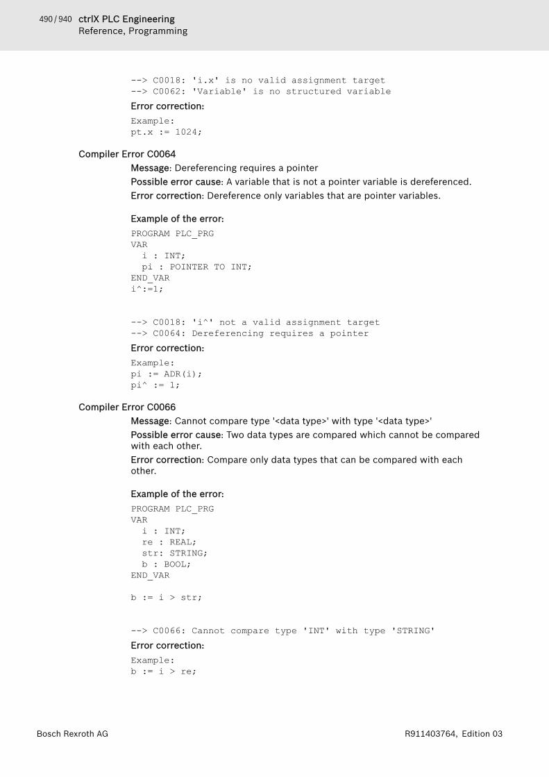
490 / 940 ctrlX PLC EngineeringReference, Programming
Bosch Rexroth AG R911403764, Edition 03
--> C0018: 'i.x' is no valid assignment target--> C0062: 'Variable' is no structured variableError correction:Example:pt.x := 1024;
Compiler Error C0064Message: Dereferencing requires a pointerPossible error cause: A variable that is not a pointer variable is dereferenced.Error correction: Dereference only variables that are pointer variables.
Example of the error:PROGRAM PLC_PRGVARi : INT;pi : POINTER TO INT;
END_VARi^:=1;
--> C0018: 'i^' not a valid assignment target--> C0064: Dereferencing requires a pointerError correction:Example:pi := ADR(i); pi^ := 1;
Compiler Error C0066Message: Cannot compare type '<data type>' with type '<data type>'Possible error cause: Two data types are compared which cannot be comparedwith each other.Error correction: Compare only data types that can be compared with eachother.
Example of the error:PROGRAM PLC_PRGVARi : INT;re : REAL;str: STRING;b : BOOL;
END_VAR
b := i > str;
--> C0066: Cannot compare type 'INT' with type 'STRING'Error correction:Example:b := i > re;
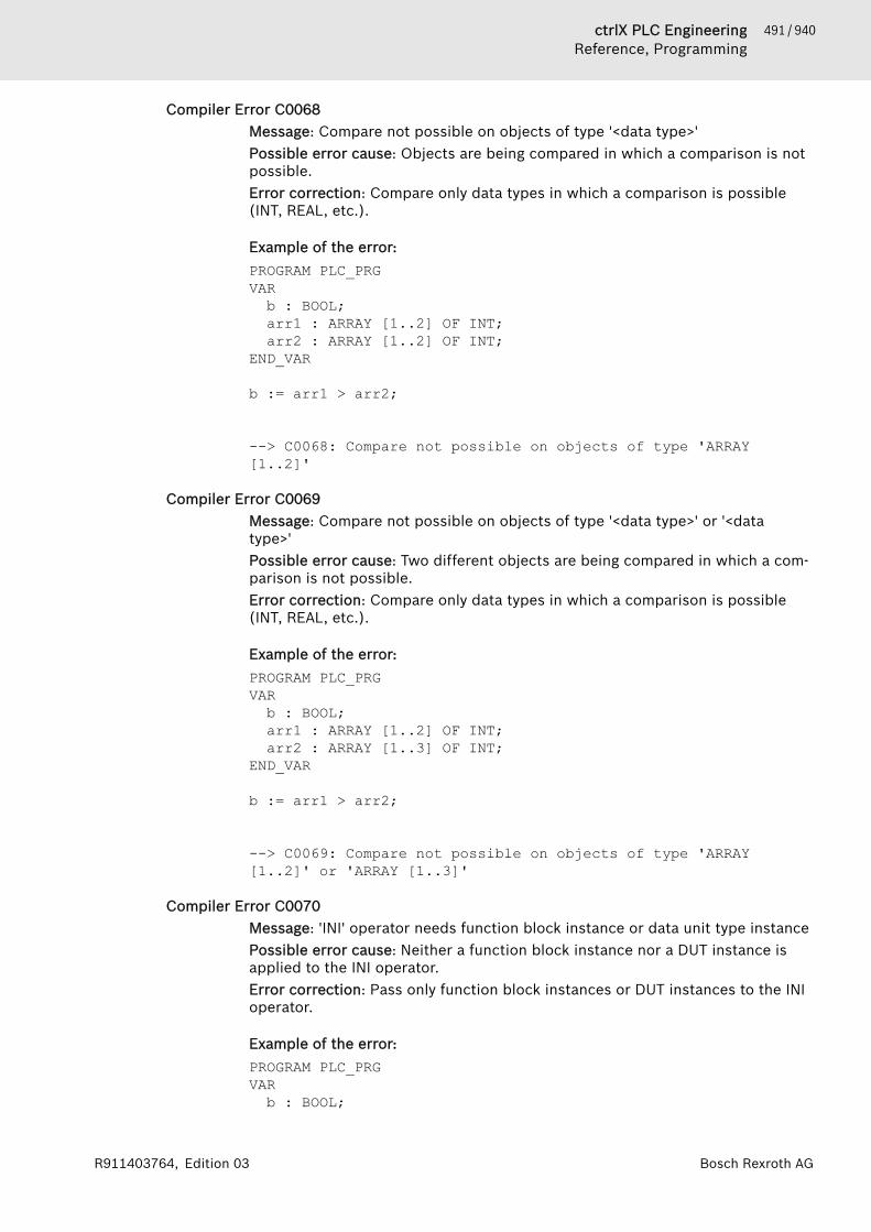
491 / 940ctrlX PLC EngineeringReference, Programming
Bosch Rexroth AGR911403764, Edition 03
Compiler Error C0068Message: Compare not possible on objects of type '<data type>'Possible error cause: Objects are being compared in which a comparison is notpossible.Error correction: Compare only data types in which a comparison is possible(INT, REAL, etc.).
Example of the error:PROGRAM PLC_PRGVARb : BOOL;arr1 : ARRAY [1..2] OF INT;arr2 : ARRAY [1..2] OF INT;
END_VAR
b := arr1 > arr2;
--> C0068: Compare not possible on objects of type 'ARRAY [1..2]'
Compiler Error C0069Message: Compare not possible on objects of type '<data type>' or '<datatype>'Possible error cause: Two different objects are being compared in which a com-parison is not possible.Error correction: Compare only data types in which a comparison is possible(INT, REAL, etc.).
Example of the error:PROGRAM PLC_PRGVARb : BOOL;arr1 : ARRAY [1..2] OF INT;arr2 : ARRAY [1..3] OF INT;
END_VAR
b := arr1 > arr2;
--> C0069: Compare not possible on objects of type 'ARRAY [1..2]' or 'ARRAY [1..3]'
Compiler Error C0070Message: 'INI' operator needs function block instance or data unit type instancePossible error cause: Neither a function block instance nor a DUT instance isapplied to the INI operator.Error correction: Pass only function block instances or DUT instances to the INIoperator.
Example of the error:PROGRAM PLC_PRGVARb : BOOL;

492 / 940 ctrlX PLC EngineeringReference, Programming
Bosch Rexroth AG R911403764, Edition 03
inst : FB;END_VAR
b := INI(b, TRUE);
FUNCTION_BLOCK FBVAREND_VAR
--> C0070: 'INI' operator needs function block instance or data unit type instanceError correction:Example:b := INI(inst, TRUE);
Compiler Error C0072Message: Operator <operator name>' is not possible on type '<data type>'Possible error cause: An operator is applied to an incompatible type.Error correction: Apply operators only on compatible types.
Example of the error:PROGRAM PLC_PRGVARi : INT;str : STRING;
END_VAR
str := ABS(str);
--> C0072: Operator 'Abs' is not possible on type 'STRING'Error correction:Example:i := ABS(i);
Compiler Error C0074Message: Unexpected array initialisationPossible error cause: Syntax error in the array initializationError correction: Correct the syntax
Example of the error:PROGRAM PLC_PRGVARarr1 : INT := [1,2,3,4,5,6];
END_VAR
--> C0074: Unexpected array initialisation--> C0032: Cannot convert type 'Unknown type: [1,2,3,4,5,6]' to type 'INT'Error correction:Example:arr1 : ARRAY [1..6] OF INT := [1,2,3,4,5,6];
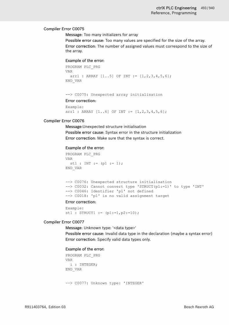
493 / 940ctrlX PLC EngineeringReference, Programming
Bosch Rexroth AGR911403764, Edition 03
Compiler Error C0075Message: Too many initializers for arrayPossible error cause: Too many values are specified for the size of the array.Error correction: The number of assigned values must correspond to the size ofthe array.
Example of the error:PROGRAM PLC_PRGVARarr1 : ARRAY [1..5] OF INT := [1,2,3,4,5,6];
END_VAR
--> C0075: Unexpected array initialisationError correction:Example:arr1 : ARRAY [1..6] OF INT := [1,2,3,4,5,6];
Compiler Error C0076Message:Unexpected structure initialisationPossible error cause: Syntax error in the structure initializationError correction: Make sure that the syntax is correct.
Example of the error:PROGRAM PLC_PRGVARst1 : INT := (p1 := 1);
END_VAR
--> C0076: Unexpected structure initialisation--> C0032: Cannot convert type 'STRUCT(p1:=1)' to type 'INT'--> C0046: Identifier 'p1' not defined--> C0018: 'p1' is no valid assignment targetError correction:Example:st1 : STRUCT1 := (p1:=1,p2:=10);
Compiler Error C0077Message: Unknown type: '<data type>'Possible error cause: Invalid data type in the declaration (maybe a syntax error)Error correction: Specify valid data types only.
Example of the error:PROGRAM PLC_PRGVARi : INTEGER;
END_VAR
--> C0077: Unknown type: 'INTEGER'

494 / 940 ctrlX PLC EngineeringReference, Programming
Bosch Rexroth AG R911403764, Edition 03
Error correction:Example:arr1 : ARRAY[1..2] OF STRUCT1 := (p1:=1,p2:=10);
Compiler Error C0080Message: Functionblock '<function block name>' must be instantiated to beaccessedPossible error cause: Missing function Block InstantiationError correction: Instantiate the function block.
Example of the error:PROGRAM PLC_PRGVAREND_VAR
FB();
FUNCTION_BLOCK FBVAREND_VAR
--> C0080: Functionblock 'FB' must be instantiated to be accessedError correction:Example:VARinst : FB;
END_VARinst();
Compiler Error C0081Message: Unexpected Pragma: '<pragma name>' found without matching 'if'Possible error cause: The IF condition is missing when using the pragma.Error correction: Complete the IF condition of the pragma.
Example of the error:PROGRAM PLC_PRGVARi : INT;
END_VAR
i := 5;{END_IF}
--> C0081: Unexpected Pragma: 'END_IF' found without matching 'if'Error correction:Example:{IF <expression>}i := 5;{END_IF}
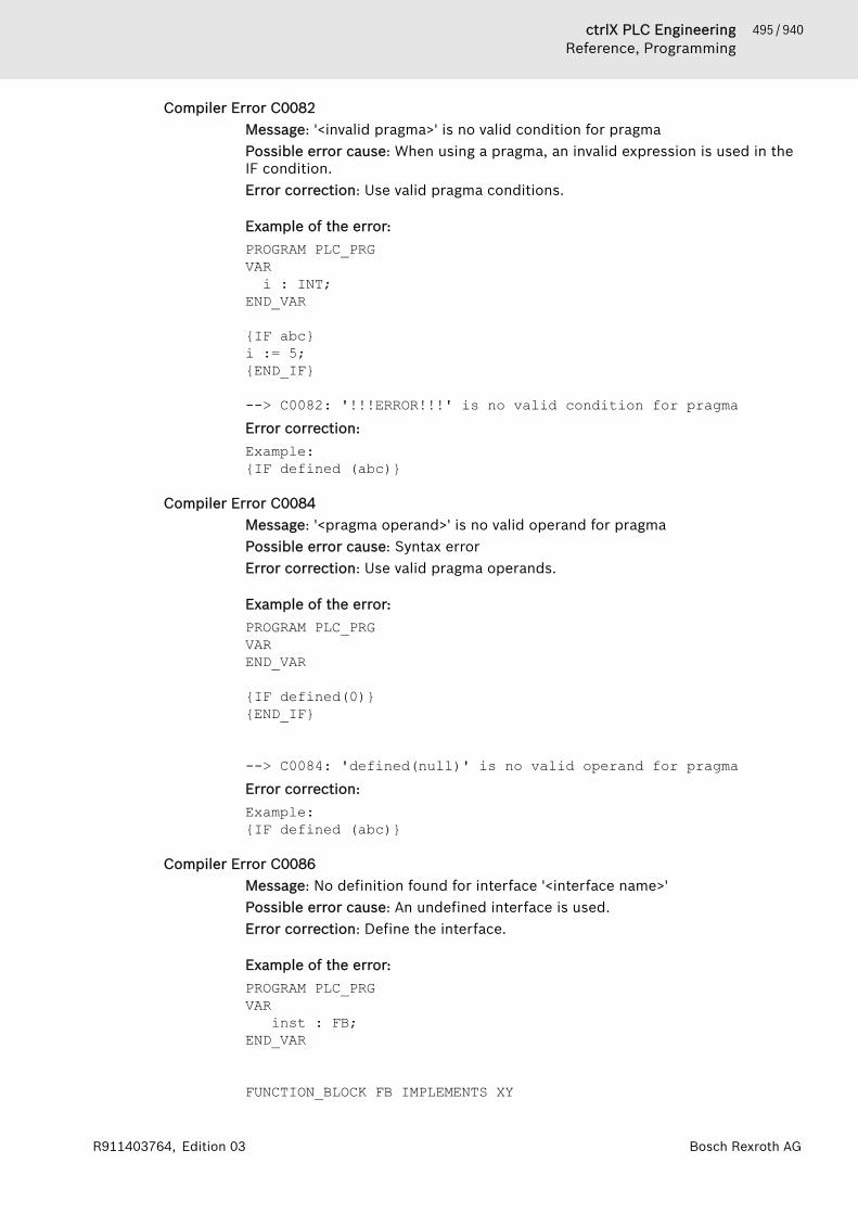
495 / 940ctrlX PLC EngineeringReference, Programming
Bosch Rexroth AGR911403764, Edition 03
Compiler Error C0082Message: '<invalid pragma>' is no valid condition for pragmaPossible error cause: When using a pragma, an invalid expression is used in theIF condition.Error correction: Use valid pragma conditions.
Example of the error:PROGRAM PLC_PRGVARi : INT;
END_VAR
{IF abc}i := 5;{END_IF}
--> C0082: '!!!ERROR!!!' is no valid condition for pragmaError correction:Example:{IF defined (abc)}
Compiler Error C0084Message: '<pragma operand>' is no valid operand for pragmaPossible error cause: Syntax errorError correction: Use valid pragma operands.
Example of the error:PROGRAM PLC_PRGVAREND_VAR
{IF defined(0)}{END_IF}
--> C0084: 'defined(null)' is no valid operand for pragmaError correction:Example:{IF defined (abc)}
Compiler Error C0086Message: No definition found for interface '<interface name>'Possible error cause: An undefined interface is used.Error correction: Define the interface.
Example of the error:PROGRAM PLC_PRG VAR inst : FB;
END_VAR
FUNCTION_BLOCK FB IMPLEMENTS XY

496 / 940 ctrlX PLC EngineeringReference, Programming
Bosch Rexroth AG R911403764, Edition 03
VAR END_VAR
--> C0086: No definition found for interface 'XY'Error correction:Example:INTERFACE XY
Compiler Error C0087Message: There is no implementation for method '<method name>' defined ininterface '<interface name>'.Possible error cause: One of the methods specified by the interface has not beprovided by the implemented function block.Error correction: Implement all methods that are specified by the interface.
Example of the error:PROGRAM PLC_PRG VAR inst : FB;
END_VAR
INTERFACE XYMETHOD METH1VAR_INPUTEND_VAR
FUNCTION_BLOCK FB IMPLEMENTS XYVAR END_VARMETHOD METH2VAR_INPUTEND_VAR
--> C0087: There is no implementation for method 'METH1' defined in interface 'XY'
Compiler Error C0089Message: Interface of overridden method '{0}' of interface '{1}' does not matchdeclarationPossible error cause: The signature of the implemented method does not matchthe signature of the method in the interface.Error correction: Make sure that the same return types and parameters aredeclared.
Example of the error:PROGRAM PLC_PRG VAR inst : FB;
END_VAR
INTERFACE XYMETHOD METH1 VAR_INPUT

497 / 940ctrlX PLC EngineeringReference, Programming
Bosch Rexroth AGR911403764, Edition 03
iPar : INT;END_VAR
FUNCTION_BLOCK FB IMPLEMENTS XYVAREND_VARMETHOD METH1 VAR_INPUTEND_VAR
--> C0089: Interface of overridden method 'METH1' of interface 'XY' does not match declaration
Compiler Error C0090Message: No definition found for base class '<function name>'Possible error cause: The function block specified as the base does not exist oris not a function block.Error correction: Use a function block as the base.
Example of the error:PROGRAM PLC_PRGVAR inst : FB;
END_VAR
FUNCTION_BLOCK FB EXTENDS POUVAREND_VAR
FUNCTION POU VAREND_VAR
--> C00090: No definition found for base class 'POU'
Compiler Error C0091Message: Recursion in base function block list: <function name>Possible error cause: A base function block is extended by itself.Error correction: Recursion in base function block lists is not possible.
Example of the error:PROGRAM PLC_PRGVAR inst : FB;
END_VAR
FUNCTION_BLOCK FB EXTENDS FBVAREND_VAR
--> C00091: Recursion in base function block list: FB -> FB

498 / 940 ctrlX PLC EngineeringReference, Programming
Bosch Rexroth AG R911403764, Edition 03
Compiler Error C0094Message: Interface of overridden method '<method name>' of interface '<func-tion block name>' doesn't match declarationPossible error cause: The signature of the method of the first interface doesnot match the signature of the method in the second interface, which isextended by the first.Error correction: Align the signatures.
Example of the error:PROGRAM PLC_PRG VAR xyz : XY2;
END_VAR
FUNCTION_BLOCK XYMETHOD METH1VAR_INPUTEND_VAR
FUNCTION_BLOCK XY2 EXTENDS XYMETHOD METH1VAR_INPUTiPar : BOOL;
END_VAR
--> C00094: Interface of the overridden method METH1 of interface XY doesn't match declaration
Compiler Error C0096Message: Only one base function block may be defined in EXTENDS-list.Possible error cause: Two or more base function blocks are defined in theEXTENDS list.Error correction: Define only one base function block in the EXTENDS list.
Example of the error:PROGRAM PLC_PRG VARfb : FB;
END_VAR
FUNCTION_BLOCK FB EXTENDS FB2, FB3VAREND_VAR
FUNCTION_BLOCK FB2VAREND_VAR
FUNCTION_BLOCK FB3VAREND_VAR
--> C00096: Only one base function block may be defined in EXTENDS-list
499 / 940ctrlX PLC EngineeringReference, Programming
Bosch Rexroth AGR911403764, Edition 03
Compiler Error C0097Message: Duplicate definition of variable '<variable name>' in function block'<function block name>' and in base '<base function block name>'Possible error cause: A variable is declared with the same name in a functionblock and its base.Error correction: Use different variable names.
Example of the error:PROGRAM PLC_PRG VARfb : FB;
END_VAR
FUNCTION_BLOCK FB EXTENDS FB2VARi : INT;
END_VAR
FUNCTION_BLOCK FB2VARi : INT;
END_VAR
--> C00097: Duplicate definition of variable 'i' in function block 'FB' and in base 'FB2'
Compiler Error C0098Message: The keyword "FUNCTIONBLOCK" is no longer supported. Use "FUNC-TION_BLOCK" instead.Possible cause of error: Syntax errorError correction: Use the keyword "FUNCTION_BLOCK".
Example of the error:PROGRAM PLC_PRGVAR inst : FB;
END_VAR
FUNCTIONBLOCK FBVAREND_VAR
--> C00098: The keyword "FUNCTIONBLOCK" is no longer supported. Use "FUNCTION_BLOCK" instead. Use "FUNCTION_BLOCK" instead.
Compiler Error C0101Message: Data Recursion: '<recursion>'Possible error cause: Recursive data initialization over two function blocksError correction: Avoid recursions for data initialization.

500 / 940 ctrlX PLC EngineeringReference, Programming
Bosch Rexroth AG R911403764, Edition 03
Example of the error:PROGRAM PLC_PRGVARinst0 : FB1;
END_VAR
FUNCTION_BLOCK FB1VARinst1 : FB2;
END_VAR
FUNCTION_BLOCK FB2VAR inst2 : FB1;
END_VAR
--> C0101: Data Recursion: FB1->FB2->FB1
Compiler Error C0102Message: Out of retain memory: Variable '<variable name>', <byte size> bytes.Possible error cause: More retain memory is used than is available on the PLC.It is also possible that the retain memory is too fragmented due to incrementalbuilds.Error correction: Use the “Clean” for fragmenting the memory. This will forcethe reallocation of all data at the next build.
Compiler Error C0104Message: 'Out of global data memory: Variable '<variable name>', <byte size>bytes.Possible error cause: More memory for data is used than is available on thePLC. It is also possible that the memory is too fragmented due to incrementalbuilds.Error correction: Use the “Clean” for fragmenting the memory. This will forcethe reallocation of all data at the next build.
Compiler Error C0114Message: Invalid destination <jump label> for 'JMP'Possible error cause: Syntax error or typographical error in the JMP destinationError correction: Correct the typographical or syntax error.
Example of the error:PROGRAM PLC_PRGVAREND_VARJMP 0;
--> C0114: Invalid destination 0 for 'JMP'
Compiler Error C0116Message: The label '<jump label>' is a duplicatePossible error cause: A label is defined multiple times.Error correction: Define each label one time only.
501 / 940ctrlX PLC EngineeringReference, Programming
Bosch Rexroth AGR911403764, Edition 03
Example of the error:PROGRAM PLC_PRGVAREND_VAR JMP label;label:
label:
--> C0116: The label 'LABEL' is a duplicate
Compiler Error C0117Message: No such label '<jump label>' within the scope of the 'JMP' statementPossible error cause: A jump is made to a label that does not exist.Error correction: Define the label that you specify as the destination.
Example of the error:PROGRAM PLC_PRGVAREND_VAR JMP A;
--> C0117: No such label 'A' within the scope of the 'JMP' statement
Compiler Error C0118Message: The label '<jump label>' has not been referenced.Possible error cause: A jump label is defined that is not referenced.Error correction: Remove the unused jump labels.
Example of the error:PROGRAM PLC_PRGVAREND_VAR LABEL:
--> C0118: The label ' LABEL' has not been referenced
Compiler Error C0119Message: An 'FB_init'-Method of a functionblock or struct needs two inputs 'bI-nitRetains' and 'bInCopyCode' of type BOOLPossible error cause: One or both of the inputs 'bInitRetains' and 'bInCopy-Code' of type BOOL is missing.Error correction: Define the missing inputs.
Example of the error:PROGRAM PLC_PRGVAR inst : FB;END_VAR
502 / 940 ctrlX PLC EngineeringReference, Programming
Bosch Rexroth AG R911403764, Edition 03
FUNCTION_BLOCK FBMETHOD FB_init VAR_INPUTEND_VAR
--> C0119: An 'FB_init'-Method of a functionblock or struct needs two inputs 'bInitRetains' and 'bInCopyCode' of type BOOLError correction:Example:METHOD FB_init VAR_INPUT bInitRetains : BOOL; bInCopyCode : BOOL;END_VAR
Compiler Error C0120Message: An 'FB_Exit'-Method of a functionblock or struct needs an input 'bIn-CopyCode' of type BOOL.Possible error cause: The input 'bInCopyCode' of type BOOL is missing.Error correction: Define the input.
Example of the error:PROGRAM PLC_PRGVAR inst : FB;END_VAR
FUNCTION_BLOCK FBMETHOD FB_exitVAR_INPUTEND_VAR
--> C0120: An 'FB_Exit'-Method of a functionblock or struct needs an input 'bInCopyCode' of type BOOL.Error correction:Example:METHOD FB_exit VAR_INPUT bInCopyCode : BOOL;END_VAR
Compiler Error C0122Message: Expression 'SUPER' is not allowed in this contextPossible error cause: "SUPER^" is used outside of derived function blocks.Error correction: Use "SUPER^" in function blocks only.
Example of the error:PROGRAM PLC_PRGVAREND_VAR

503 / 940ctrlX PLC EngineeringReference, Programming
Bosch Rexroth AGR911403764, Edition 03
SUPER^.METH(TRUE, TRUE);
--> C0122: Expression 'SUPER' is not allowed in this context
Compiler Error C0124Message: 'Initialization' is no valid initialization for an enumerationPossible error cause: A data type that is not ANY_INT is used for the enum initi-alization.Error correction: Use only ANY_INT for enum initializations.
Example of the error:PROGRAM PLC_PRGVAR inst : DUT;END_VAR
TYPE DUT :( enum_member := 1.5) DWORD;END_TYPE
--> C0032: Cannot convert type 'LREAL' to type 'DUT'--> C0124: 'Initialization' is no valid initialization for an enumeration
Compiler Error C0125Message: The constant <constant value> is assigned to more than one enumera-tion.Possible error cause: The same value is assigned to two or more enumerations.Error correction: Assign different values to the enumerations.
Example of the error:PROGRAM PLC_PRGVARinst : DUT;
END_VAR
TYPE DUT :(enum_member := 0,enum_member2 := 0
);END_TYPE
--> C0125: The constant 0 is assigned to more than one enumeration
Compiler Error C0126Message: Variable of type '<data type>' requires exactly 1 IndexPossible error cause: Multiple indexes are assigned to a variable with oneindex.

504 / 940 ctrlX PLC EngineeringReference, Programming
Bosch Rexroth AG R911403764, Edition 03
Error correction: Assign only one index.
Example of the error:PROGRAM PLC_PRGVARpi : POINTER TO INT;
END_VARpi[0,1] := 0;
--> C0126: Variable of type 'POINTER TO INT' requires exactly 1 IndexError correction:Example:pi[0] := 0;
Compiler Error C0130Message: <object> '<object name>' referenced without parentheses '()'Possible error cause: A method is referenced without parentheses.Error correction: Always reference methods by means of parentheses.
Example of the error:PROGRAM PLC_PRGVARinst : FB;
END_VAR inst.METH1
--> C0130: METHOD 'METH1' referenced without parentheses '()'Error correction:Example:inst.METH1();
Compiler Error C0131Message: '<value>' is not allowed as operand for 'ADR'Possible error cause: A constant is passed as an operand to the operator ADR.Error correction: Use only valid operands for ADR.
Example of the error:PROGRAM PLC_PRGVARi : INT;pt : POINTER TO INT;
END_VAR
pt := ADR(1);
--> C0131: '1' is not allowed as operand for 'ADR'Error correction:Example:pt := ADR(i);

505 / 940ctrlX PLC EngineeringReference, Programming
Bosch Rexroth AGR911403764, Edition 03
Compiler Error C0132Message: No enclosing loop of which to EXITPossible error cause: EXIT is used outside of a loop.Error correction: Use EXIT inside of a loop only.
Example of the error:PROGRAM PLC_PRGVAREND_VAR
EXIT;
--> C0132: No enclosing loop of which to EXIT
Compiler Error C0136Message: ambiguous use of name '<variable name>'Possible error cause: A variable is declared in multiple GVLs.Error correction: Qualify the variable with the desired GVL.
Example of the error:PROGRAM PLC_PRGVARj : INT := g_i;
END_VAR
GVL1:VAR_GLOBALg_i : INT;
END_VAR
GVL2:VAR_GLOBALg_i : INT;
END_VAR
--> C0136: ambiguous use of name 'g_i'Error correction:Example:j : INT := GVL1.g_i;
Compiler Error C0139Message: The code <code> has no effect. Is this the intent?Possible error cause: The written code is syntactically correct but does not doanything.Error correction: Write code that has a purpose.
Example of the error:PROGRAM PLC_PRGVARi : INT;
END_VAR

506 / 940 ctrlX PLC EngineeringReference, Programming
Bosch Rexroth AG R911403764, Edition 03
i;
--> C0139: The code 'i;' has no effect. Is this the intent?
Compiler Error C0140Message: Reference assign is only allowed to variables of Reference typePossible error cause: An attempt is made to assign a reference value to a vari-able not defined as a reference type.Error correction: Define the variable as a reference type.
Example of the error:PROGRAM PLC_PRGVARi : INT;I_r : INT;
END_VAR
I_r REF= i;
--> C0140: Reference assign is only allowed to variables of Reference typeError correction:Example:I_r : REFERENCE TO INT;
Compiler Error C0141Message: Reference assign needs variable with write accessPossible error cause: A constant is assigned to the reference assignment.Error correction: Assign a writable variable.
Example of the error:PROGRAM PLC_PRGVARi : INT;I_r : REFERENCE TO INT;
END_VAR
I_r REF= 314;
--> C0141: Reference assign needs variable with write accessError correction:Example:I_r REF= i;
Compiler Error C0142Message: A local variable named '<variable name>' is already defined in '<pouname>'Possible error cause: The same variable name is used two times.Error correction: Use different variable names.
507 / 940ctrlX PLC EngineeringReference, Programming
Bosch Rexroth AGR911403764, Edition 03
Example of the error:PROGRAM PLC_PRGVARi : INT;i : INT;
END_VAR
--> C0142: A local variable named 'i' is already defined in 'PLC_PRG'
Compiler Error C0143Message: The property '<property name>' cannot be used in this contextbecause it lacks the get accessorPossible error cause: The property does not have Get access.Error correction: Make sure that the property has a Get access definition.
Example of the error:PROGRAM PLC_PRG VARi : INT;inst: FB;
END_VAR
i := inst.Prop;
FUNCTION_BLOCK FBVAREND_VAR
PROPERTY Prop : INTSet;
--> C0143: The property 'Prop' cannot be used in this context because it lacks the get accessor
Compiler Error C0144Message: Inheritance only allowed in Functionblocks, Interfaces and StructuresPossible error cause: An attempt is made to use inheritance in an object thatdoes not permit inheritance.Error correction: Use EXTENDS in function blocks, interfaces, and structuresonly.
Example of the error:PROGRAM PLC_PRGVARinst : DUT_1;
END_VAR
TYPE DUT:(enum_member := 0
);END_TYPE
TYPE DUT_1 EXTENDS DUT:

508 / 940 ctrlX PLC EngineeringReference, Programming
Bosch Rexroth AG R911403764, Edition 03
(enum_memberX := 0
);END_TYPE
--> C0144: Inheritance only allowed in Functionblocks, Interfaces and Structures
Compiler Error C0145Message: Interfaces can only be implemented by FunctionblocksPossible error cause: An attempt is made to implement an interface outside ofa function block.Error correction: Implement interfaces only in function blocks.
Example of the error:PROGRAM PLC_PRG VAREND_VAR
POU();
FUNCTION POU IMPLEMENTS ITFVAREND_VAR
--> C0145: Interfaces can only be implemented by Functionblocks
Compiler Error C0149Message: Variable declarations are not allowed in interfacesPossible error cause: An attempt is made to define a variable in an interface.Error correction: Do not define variables in interfaces.
Example of the error:PROGRAM PLC_PRG VARinst : ITF;
END_VAR
INTERFACE ITFVAR_INPUTi : INT;
END_VAR
--> C0149: Variable declarations are not allowed in interfaces
Compiler Error C0161Message: Border <array bound> of array is no constant valuePossible error cause: A variable is specified as an array bound.Error correction: Use constants for the array bounds.
Example of the error:PROGRAM PLC_PRGVARi : INT := 3;

509 / 940ctrlX PLC EngineeringReference, Programming
Bosch Rexroth AGR911403764, Edition 03
arr1 : ARRAY[1..i] OF INT;END_VAR
--> C0161: Border 'i' of array is no constant valueError correction:Example:arr1 : ARRAY[1..3] OF INT;
Compiler Error C0162Message: Number <number of array values> of array initialisations is no con-stant valuePossible error cause: The initialization [Wert1,AnzahlWert2(Wert2)] worksonly with a constant for AnzahlWert2.Error correction: Use constants only.
Example of the error:PROGRAM PLC_PRGVARi : INT := 3;arr1 : ARRAY[1..4] OF INT := [1,i(7)];
END_VAR
--> C0162: Number 'i' of array initialisations is no constant valueError correction:Example:arr1 : ARRAY[1..4] OF INT := [1,3(7)];
Compiler Error C0168Message: 'VAR_CONFIG' declaration only allowed in VAR_CONFIG - listPossible error cause: 'VAR_CONFIG' is used outside of a VAR_CONFIG list.Error correction: Use 'VAR_CONFIG' only in VAR_CONFIG lists.
Example of the error:PROGRAM PLC_PRGVAR_CONFIGi : INT;
END_VAR
--> C0168: 'VAR_CONFIG' declaration only allowed in VAR_CONFIG - list
Compiler Error C0169Message: 'VAR_GLOBAL' declaration only allowed in Global variable listPossible error cause: 'VAR_GLOBAL' is used outside of global variable lists.Error correction: Use 'VAR_GLOBAL' in global variable lists only.
Example of the error:PROGRAM PLC_PRGVAR_GLOBALi : INT;
END_VAR
510 / 940 ctrlX PLC EngineeringReference, Programming
Bosch Rexroth AG R911403764, Edition 03
--> C0169: 'VAR_GLOBAL' declaration only allowed in Global variable list
Compiler Error C0174Message: 'VAR_TEMP' declaration not allowed in this placePossible error cause: 'VAR_TEMP' is used outside of a program or functionblock.Error correction: Use 'VAR_TEMP' inside of programs and function blocks only.
Example of the error:PROGRAM PLC_PRGVAREND_VAR
FUN();
FUNCTION FUN VAR_TEMPEND_VAR
--> C0174: 'VAR_TEMP' declaration not allowed in this place
Compiler Error C0175Message: 'RETAIN' or 'PERSISTENT' not allowed in this placePossible error cause: 'RETAIN' or 'PERSISTENT' is used in a function.Error correction: Use 'RETAIN' or 'PERSISTENT' at the intended locations.
Example of the error:PROGRAM PLC_PRGVAREND_VAR
POU_1();
FUNCTION POU_1 VAR RETAINEND_VAR
--> C0175: 'RETAIN' or 'PERSISTENT' not allowed in this placeSee also● ⮫ Chapter “Retain Variable - RETAIN” on page 323● ⮫ Chapter “Retain Variable - RETAIN” on page 323
Compiler Error C0177Message: '<object>' is of type 'type' and cannot be instantiatedPossible error cause: An attempt is made to instantiate a function.Error correction: Instantiate only objects that can be instantiated.
Example of the error:PROGRAM PLC_PRGVAR inst : POU;
END_VAR
511 / 940ctrlX PLC EngineeringReference, Programming
Bosch Rexroth AGR911403764, Edition 03
FUNCTION POU VAREND_VAR
--> C0177: 'POU' is of type 'FUNCTION' and cannot be instantiated
Compiler Error C0178Message: No external access to 'VAR_IN_OUT' parameter '<parameter name>' of'<object name>'Possible error cause: An attempt is made to remotely access a 'VAR_IN_OUT'parameter.Error correction: Do not remotely access 'VAR_IN_OUT' parameters.
Example of the error:PROGRAM PLC_PRGVARinst : FB;i : INT;
END_VARi := inst.in_out;
FUNCTION_BLOCK FBVAR_IN_OUTin_out : INT;
END_VAR
--> C0178: No external access to 'VAR_IN_OUT' parameter 'in_out' of 'FB'
Compiler Error C0182Message: Return type is only possible for POUs of Type FUNCTION andMETHODPossible error cause: An attempt is made to define a return value in a program.Error correction: Define a return value only in methods and functions.
Example of the error:PROGRAM PLC_PRG : BOOLVAREND_VAR
--> C0182: Return type is only possible for POUs of Type FUNCTION and METHOD
Compiler Error C0185Message: It is not possible to perform component access '.', index access '[]' orcall '()' on result of function call. Assign result to help variable first.Possible error cause: Component or index access to the result of a function callis performed.Error correction: Assign the result to a variable in order to access.

512 / 940 ctrlX PLC EngineeringReference, Programming
Bosch Rexroth AG R911403764, Edition 03
Example of the error:PROGRAM PLC_PRGVARit : ITF;
END_VAR
POU_1()[0].METH1();
FUNCTION POU_1 : ARRAY[0..0] OF ITF
INTERFACE ITF
METHOD METH1
--> C0185: It is not possible to perform component access '.', index access '[]' or call '()' on result of function call. Assign result to help variable first.
Compiler Error C0189Message: ';' expected instead of '<token>'Possible error cause: Syntax errorError correction: Make sure that the syntax is correct.
Example of the error:PROGRAM PLC_PRGVARINT
END_VAR
--> C0009: Unexpected Token '<Token>' found--> C0189: ';' expected instead of 'INT'
Compiler Error C0190Message: ';' expected instead of end of POUPossible error cause: Syntax error in the POUError correction: Make sure that the syntax is correct.
Example of the error:PROGRAM PLC_PRG VARi : INT;
END_VARi := 5
--> C0190: ';' expected instead of end of POU
Compiler Error C0191Message: The operator 'INDEXOF' is no longer supported. Use ADR instead.ADR on a POU-Name returns a Pointer to a Pointer to the function code.Possible error cause: The outdated operator 'INDEXOF' is used.Error correction: Use the operator 'ADR'.

513 / 940ctrlX PLC EngineeringReference, Programming
Bosch Rexroth AGR911403764, Edition 03
Compiler Error C0195Message: Implicit conversion from signed Type '<data type 1>' to unsigned Type'<data type 2>' : possible change of signPossible error cause: A sign conflict may have been missed in the implicit con-version.Error correction: Convert only data types with the same sign implicitly.
Example of the error:PROGRAM PLC_PRGVARi : INT;b : UINT;
END_VAR
b := i;
--> C0195: Implicit conversion from signed Type 'INT' to unsigned Type 'UINT' : possible change of sign
Compiler Error C0196Message: Implicit conversion from unsigned Type '<data type 1>' to signed type'<data type 2>' : possible change of signPossible error cause: A sign conflict may have been missed in the implicit con-version.Error correction: Use explicit conversions.
Example of the error:PROGRAM PLC_PRGVARi : INT;b : UINT;
END_VAR
i := b;
--> C0196: Implicit conversion from unsigned Type 'UINT' to signed type 'INT' : possible change of sign
Compiler Error C0197Message: Implicit conversion from '<data type 1>' to '<data type 2>': possibleloss of informationPossible error cause: An attempt is made to convert a variable from data typeDINT or LINT to data type REAL.Error correction: For DINT, use the data type LREAL, and when converting fromLINT to LREAL make sure that the value of LINT does not exceed the capacity ofLREAL.
Example of the error:PROGRAM PLC_PRGVARi : DINT;b : REAL;
END_VARb := i;

514 / 940 ctrlX PLC EngineeringReference, Programming
Bosch Rexroth AG R911403764, Edition 03
--> C0197: Implicit conversion from 'DINT' to 'REAL': possible loss of information
Compiler Error C0198Message: String constant '<string value>' too long for destination type '<datatype>'Possible error cause: The string constant has too many characters.Error correction: Use shorter string constants or declare larger strings.
Example of the error:PROGRAM PLC_PRGVARstr : STRING(4) := '12345';
END_VAR
--> C0198: String constant '12345' too long for destination type 'STRING(4)'
Compiler Error C0199Message: Interface '<interface name>' must be instantiated to be accessedPossible error cause: An attempt is made to access an interface methodwithout the interface being instantiated.Error correction: Instantiate the interface.
Example of the error:PROGRAM PLC_PRGVAREND_VAR
ITF.METH();
INTERFACE ITF
METHOD METHVAR_INPUTEND_VAR
--> C0199: Interface 'ITF' must be instantiated to be accessedError correction:Example:itest: ITF;
Compiler Error C0201Message: Type '<data type 1>' is not equal to type '<data type 2>' ofVAR_IN_OUT 'Variable'Possible error cause: The data type that is passed to the function as aVAR_IN_OUT parameter does not match the data type defined in it.Error correction: Pass a variable with the correct data type.
Example of the error:PROGRAM PLC_PRGVARInst: POU;
515 / 940ctrlX PLC EngineeringReference, Programming
Bosch Rexroth AGR911403764, Edition 03
b : BOOL;END_VAR
inst(in_out := b);
FUNCTION_BLOCK POUVAR_IN_OUTin_out : INT;
END_VAR
--> C0201: Type 'BOOL' is not equal to type 'INT' of VAR_IN_OUT 'Variable'
Compiler Error C0203Message: Only Structures and Function Blocks can contain variables of typeBIT.Possible error cause: An attempt is made to declare a variable of type BIT out-side of structures and function blocks.Error correction: Declare variables of type BIT only in structures and functionblocks.
Example of the error:PROGRAM PLC_PRGVARb : BIT;
END_VAR
--> C0203: Only Structures and Function Blocks can contain variables of type BIT.
Compiler Error C0204Message: Variables of type BIT must be declared within a VAR_INPUT-,VAR_OUTPUT or VAR-blockPossible error cause: An attempt is made to define a variable of type BIT or as aVAR_IN_OUT parameter.Error correction: Define variables of type BIT only within a VAR_INPUT,VAR_OUTPUT or VAR block.
Example of the error:PROGRAM PLC_PRGVARinst : FB;
END_VAR
FUNCTION_BLOCK FBVAR_IN_OUTb : BIT;
END_VAR
--> C0204: Variables of type BIT must be declared within a VAR_INPUT-, VAR_OUTPUT or VAR-block
Compiler Error C0205Message: POINTER TO BIT is not allowed
516 / 940 ctrlX PLC EngineeringReference, Programming
Bosch Rexroth AG R911403764, Edition 03
Possible error cause: An attempt is made to declare a POINTER TO BIT.Error correction: Do not declare POINTER TO BIT.
Example of the error:PROGRAM PLC_PRGVARpt : POINTER TO BIT;
END_VAR
--> C0205: POINTER TO BIT is not allowed
Compiler Error C0206Message: BIT is not allowed as base type of an arrayPossible error cause: An attempt is made to declare a BIT array.Error correction: Do not declare BIT arrays.
Example of the error:PROGRAM PLC_PRGVARarr : ARRAY[1..2] OF BIT;
END_VAR
--> C0206: BIT is not allowed as base type of an array
Compiler Error C0208Message: 'MOD' is not defined for 'REAL'Possible error cause: An attempt is made to perform a modulo operation with avariable of type REAL.Error correction: Modulo operations are only possible with variables of typeANY_INT.
Example of the error:PROGRAM PLC_PRGVARr1 : REAL;
END_VARr1 := r1 MOD 2;
--> C0208: 'MOD' is not defined for 'REAL'
Compiler Error C0211Message: Variable declaration expected instead of <expression>Possible error cause: Syntax errorError correction: Make sure that the syntax is correct.
Example of the error:PROGRAM PLC_PRGVAR VAR
END_VAREND_VAR
--> C0211: Variable declaration expected instead of VAR END_VAR

517 / 940ctrlX PLC EngineeringReference, Programming
Bosch Rexroth AGR911403764, Edition 03
Compiler Error C0212Message: VAR, VAR_INPUT, VAR_OUTPUT or VAR_INOUT expected instead of<expression>Possible error cause: Syntax errorError correction: Make sure that the syntax is correct.
Example of the error:PROGRAM PLC_PRG i : INT;
--> C0212: VAR, VAR_INPUT, VAR_OUTPUT or VAR_INOUT expected instead of i : INT;
Compiler Error C0216Message: Case label duplicatePossible error cause: A CASE label is used multiple times.Error correction: Use each CASE label only one time.
Example of the error:PROGRAM PLC_PRG VARi : INT;
END_VAR
CASE i OF 1: i := i+1; 1: i := i+2;ELSE i := i+10;END_CASE;
--> C0216: Case label duplicate
Compiler Error C0217Message: Case label <case label> also contained in range <case range begin> ..<case range end>Possible error cause: A CASE label is part of the range of another CASE label.Error correction: Make sure that there is no intersecting.
Example of the error:PROGRAM PLC_PRG VARi : INT;
END_VARCASE i OF 3..5: i := i+2; 4: i := i+2;ELSE i := i+10;END_CASE;
--> C0217: Case label 4 also contained in range 3 .. 5

518 / 940 ctrlX PLC EngineeringReference, Programming
Bosch Rexroth AG R911403764, Edition 03
Compiler Error C0218Message: Case label requires literal or symbolic integer constantPossible error cause: An attempt is made to use a variable as a CASE label.Error correction: Use only literals and symbolic integer constants.
Example of the error:PROGRAM PLC_PRG VARi : INT;a : INT := 2;
END_VAR
CASE i OF 1: i := i+1; a: i := i+2;ELSE i := i+10;END_CASE;
--> C0218: Case label requires literal or symbolic integer constant
Compiler Error C0219Message: Case contains overlapping range <case range 1 begin> .. <case range1 end> and <case range 2 begin> .. <case range 2 end>Possible error cause: Two branches of CASE markers have the same elementsor subsets.Error correction: Make sure that there is no intersecting.
Example of the error:PROGRAM PLC_PRG VARi : INT;
END_VARCASE i OF 3..5: i := i+2; 1..4: i := i+2;ELSE i := i+10;END_CASE;
--> C0219: Case contains overlapping range 1 .. 4 and 3 .. 5
Compiler Error C0221Message: Direct Address '<address>' malformedPossible error cause: An address is not displayed completely.Error correction: Make sure that the address is displayed correctly.
Example of the error:PROGRAM PLC_PRG VARxVar : BOOL;
END_VAR;

519 / 940ctrlX PLC EngineeringReference, Programming
Bosch Rexroth AGR911403764, Edition 03
xVar := %IX0;
--> C0221: Direct Address '%IXO' malformedError correction:Example:xVar := %IX0.2;
Compiler Error C0222Message: Outputs can't be of type 'REFERENCE TO'Possible error cause: An attempt is made to define REFERNCE TO as an outputparameter.Error correction: Do not use REFERENCE TO as an output parameter.
Example of the error:PROGRAM PLC_PRG VARinst : FB;
END_VAR
FUNCTION_BLOCK FBVAR_OUTPUTre : REFERENCE TO INT;
END_VAR
--> C0222: Outputs can't be of type 'REFERENCE TO'
Compiler Error C0224Message: Call Recursion: <recursion>Possible error cause: A function calls itself.Error correction: Make sure that functions are not recursive.
Example of the error:PROGRAM PLC_PRGVAREND_VAR
POU();
FUNCTION POU VAREND_VAR
POU();
--> C0224: Call Recursion: POU -> POU
Compiler Error C0227Message: Initialisation of constant variable <constant name> not constantPossible error cause: A constant is initialized with a variable.Error correction: Initialize constants only with constant values.
520 / 940 ctrlX PLC EngineeringReference, Programming
Bosch Rexroth AG R911403764, Edition 03
Example of the error:PROGRAM PLC_PRGVARi : INT;
END_VARVAR CONSTANTk : INT := i;
END_VAR
--> C0227: Initialisation of constant variable 'k' not constant
Compiler Error C0228Message: No initial value for constant variable '<constant name>'Possible error cause: A constant is not initialized.Error correction: Initialize the constants.
Example of the error:PROGRAM PLC_PRGVAREND_VARVAR CONSTANTk : INT;
END_VAR
--> C0228: No initial value for constant variable 'k'Error correction:Example:k : INT := 1;
Compiler Error C0234Message: First Operand of __QueryInterface must be an interface reference orthe instance of a function blockPossible error cause: Incorrect operands are passed to the operator __Quer-yInterface.Error correction: Pass an interface reference or the instance of a functionblock.
Example of the error:PROGRAM PLC_PRGVARa : INT;ITFref, ITFref2 : ITF; ITFref2 : ITF2;
END_VAR
__QueryInterface(a ,ITFref);
INTERFACE ITF EXTENDS __SYSTEM.IQueryInterfaceINTERFACE ITF2 EXTENDS ITF
--> C0234: First Operand of __QueryInterface must be an interface reference or the instance of a function block

521 / 940ctrlX PLC EngineeringReference, Programming
Bosch Rexroth AGR911403764, Edition 03
Error correction:Example:__QueryInterface(ITFref2, ITFref);
Compiler Error C0235Message: Second Operand of __QueryInterface must be an interface referencePossible error cause: Incorrect operands are passed to the operator __Quer-yInterface.Error correction: Pass an interface reference.
Example of the error:PROGRAM PLC_PRGVARa : INT;ITFref, ITFref2 : ITF; ITFref2 : ITF2;
END_VAR
__QueryInterface(ITFref2, a);
INTERFACE ITF EXTENDS __SYSTEM.IQueryInterfaceINTERFACE ITF2 EXTENDS ITF
--> C0235: Second Operand of __QueryInterface must be an interface referenceError correction:Example:__QueryInterface(ITFref2, ITFref);
Compiler Error C0236Message: Wrong type definition for VAR_EXTERNAL <variable name>Possible error cause: The variable is declared in VAR_GLOBAL / VAR_EXTERNALas different types.Error correction: Use the same type definition in VAR_GLOBAL andVAR_EXTERNAL.
Example of the error:PROGRAM PLC_PRGVAR_EXTERNALig : STRING;
END_VAR
VAR_GLOBALig : INT;
END_VAR
--> C0236: Wrong type definition for VAR_EXTERNAL ig
Compiler Error C0237Message: No global definition found for VAR_EXTERNAL '<variable name>'Possible error cause: An attempt is made to declare a variable inVAR_EXTERNAL which does not exist in VAR_GLOBAL.Error correction: Make sure that the identifiers match.

522 / 940 ctrlX PLC EngineeringReference, Programming
Bosch Rexroth AG R911403764, Edition 03
Example of the error:PROGRAM PLC_PRGVAR_EXTERNALi : INT;
END_VAR
VAR_GLOBALig : INT;
END_VAR
--> C0237: No global definition found for VAR_EXTERNAL 'i'
Compiler Error C0238Message: No initial value allowed for VAR_EXTERNAL <variable name>Possible error cause: An attempt is made to initialize a variable inVAR_EXTERNAL.Error correction: Do not initialize variables in VAR_EXTERNAL.
Example of the error:PROGRAM PLC_PRGVAR_EXTERNALig : INT := 2;
END_VAR
VAR_GLOBALig : INT;
END_VAR
--> C0238: No initial value allowed for VAR_EXTERNAL ig
Compiler Error C0239Message: Interface <interface name 1> does not extend <interface name 2>Possible error cause: The used interface does not extend another interface.Error correction: Extend the interface.
Example of the error:PROGRAM PLC_PRGVARITFref : ITF;ITFref2 : ITF2;
END_VAR
__QueryInterface(ITFref2,ITFref);
INTERFACE ITFINTERFACE ITF2 EXTENDS ITF
--> C0239: Interface ITF__Union does not extend __System.IQueryInterfaceError correction:Example:INTERFACE ITF EXTENDS __System.IQueryInterface
523 / 940ctrlX PLC EngineeringReference, Programming
Bosch Rexroth AGR911403764, Edition 03
Compiler Error C0240Message: First Operand of __QueryPointer must be an interface reference orthe instance of a function blockPossible error cause: Incorrect operands are passed to the operator __Query-Pointer.Error correction: Pass an interface reference or the instance of a functionblock.
Example of the error:PROGRAM PLC_PRGVARa : INT;ITFref : ITF;pt : POINTER TO FB;
END_VAR
__QueryPointer(a,pt);
--> C0240: First Operand of __QueryPointer must be an interface reference or the instance of a function blockError correction:Example:__QueryPointer (ITFref, pt);
Compiler Error C0241Message: Second Operand of __QueryPointer must be pointerPossible error cause: Incorrect operands are passed to the operator __Query-Pointer.Error correction: Pass a pointer.
Example of the error:PROGRAM PLC_PRGVARb : INT;ITFref : ITF;pt : POINTER TO FB;
END_VAR
__QueryPointer(ITFref,b);
INTERFACE ITF EXTENDS __System.IQueryInterface
--> C0241: Second Operand of __QueryPointer must be pointerError correction:Example:__QueryPointer (ITFref, pt);
Compiler Error C0242Message: Operand of __DELETE must be pointerPossible error cause: An incorrect operand is passed to the operator __DELETE.Error correction: Pass a pointer.
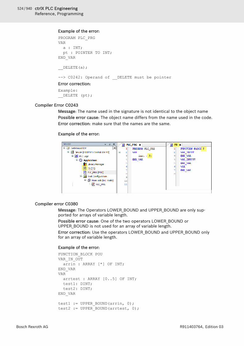
524 / 940 ctrlX PLC EngineeringReference, Programming
Bosch Rexroth AG R911403764, Edition 03
Example of the error:PROGRAM PLC_PRGVARa : INT;pt : POINTER TO INT;
END_VAR
__DELETE(a);
--> C0242: Operand of __DELETE must be pointerError correction:Example:__DELETE (pt);
Compiler Error C0243Message: The name used in the signature is not identical to the object namePossible error cause: The object name differs from the name used in the code.Error correction: make sure that the names are the same.
Example of the error:
Compiler error C0380Message: The Operators LOWER_BOUND and UPPER_BOUND are only sup-ported for arrays of variable length.Possible error cause: One of the two operators LOWER_BOUND orUPPER_BOUND is not used for an array of variable length.Error correction: Use the operators LOWER_BOUND and UPPER_BOUND onlyfor an array of variable length.
Example of the error:FUNCTION_BLOCK POUVAR_IN_OUTarrin : ARRAY [*] OF INT;
END_VARVARarrtest : ARRAY [0..5] OF INT;test1: DINT;test2: DINT;
END_VAR
test1 := UPPER_BOUND(arrin, 0);test2 := UPPER_BOUND(arrtest, 0);

525 / 940ctrlX PLC EngineeringReference, Programming
Bosch Rexroth AGR911403764, Edition 03
--> C0380: The operators LOWER_BOUND and UPPER_BOUND are supported only for arrays with variable lenth.
Compiler Error C0509Message: Multiple assignments for operator '__New' not allowedPossible error cause: In one line of code, the assignment operator ":=" is calleda multiple number of times with the __New operator.Error correction: Program the memory allocation with the __New operator in aseparate line of code for each pointer that points to dynamically allocatedmemory.
Example of the error:PROGRAM PLC_PRGVARpbAlpha : POINTER TO BYTE; // Typed pointer to AlphapbBeta: POINTER TO BYTE; // Typed pointer to BetaxInit : BOOL := TRUE;xDelete : BOOL;
END_VAR
IF (xInit) THENpbBeta := pbAlpha := __NEW(BYTE); // Incorrect code for
memory allocation END_IF
pbBeta := pbAlpha := 16#01;
IF (xDelete) THEN __DELETE(pbAlpha); // Frees memory of pointer
END_IF
--> C0509: Multiple assignments for operator '__New' not allowedError correction:
PROGRAM PLC_PRGVARpbAlpha : POINTER TO BYTE; // Pointer to AlphapbBeta: POINTER TO BYTE; // Pointer to BetaxInit : BOOL := TRUE;xDelete : BOOL;
END_VAR
IF (xInit) THENpbAlpha := __NEW(BYTE); // Allocates memory for Alpha pbBeta := __NEW(BYTE); // Allocates memory for Beta
END_IF
pbBeta := pbAlpha := 16#01; // Multiple assignment
IF (xDelete) THEN __DELETE(pbAlpha); // Frees memory of pointer
END_IF
526 / 940 ctrlX PLC EngineeringReference, User Interface
Bosch Rexroth AG R911403764, Edition 03
See also● ⮫ Chapter “Operator '__NEW'” on page 360● ⮫ Chapter “Attribute 'enable_dynamic_creation'” on page 451
Compiler Error C0511Message: The function block '<function block name>' is ABSTRACT and cannotbe used as a target for an assignment.Possible error cause: A value was assigned to an abstract function block. Theconcrete function blocks may have different types and therefore cannot becopied.Error correction: In order to copy the data of the function block, concrete func-tion blocks have to be used.
Example of the error:PROGRAM PLC_PRGVARrefAbstract1 : REFERENCE TO AbstractPOU;refAbstract2 : REFERENCE TO AbstractPOU;END_VAR
refAbstract1 := refAbstract2;--> C0511: The function block 'refAbstract1' is ABSTRACT and cannot be used as a target for an assignment.Error correction:Use the reference assignment REF= to assign the reference refAbstract1 tothe same function block as refAbstract2.
1.19 Reference, User Interface1.19.1 Objects. . . . . . . . . . . . . . . . . . . . . . . . . . . . . . . . 528
Object 'Application'. . . . . . . . . . . . . 528Object 'POU Locations'. . . . . . . . . . 529Object 'Alarm Configuration'. . . . . . 530Object 'Alarm Class'. . . . . . . . . . . . . 530Object 'Alarm Group'. . . . . . . . . . . . 533Object 'Alarm Storage'. . . . . . . . . . . 537Object 'Data Source Manager'. . . . . 539Object 'Data Source' - Tab 'Variables'540Object 'Data Source' - Tab 'TypeMappings'. . . . . . . . . . . . . . . . . . . . . 542Object 'Data Source' - Tab 'Commu-nication'. . . . . . . . . . . . . . . . . . . . . . 543Object 'Data Source' - Tab 'Generaland Diagnosis'. . . . . . . . . . . . . . . . . 549Object 'DUT'. . . . . . . . . . . . . . . . . . . 549Object 'External File'. . . . . . . . . . . . 551Object 'C Code Module'. . . . . . . . . . 551Object 'C Code File'. . . . . . . . . . . . . 553Object 'C Implemented Library'. . . . 554Object 'Device' and Generic DeviceEditor. . . . . . . . . . . . . . . . . . . . . . . . 554Object 'GlobalTextList'. . . . . . . . . . . 580

527 / 940ctrlX PLC EngineeringReference, User Interface
Bosch Rexroth AGR911403764, Edition 03
Object 'GVL' - Global Variable List. . 581Object 'GVL' - Global Variable List(task-local). . . . . . . . . . . . . . . . . . . . 581Object 'Persistent variable list'. . . . 582Object 'Image Pool'. . . . . . . . . . . . . 582Object 'Library Manager'. . . . . . . . . 583Object 'Network Variable List(Sender)'. . . . . . . . . . . . . . . . . . . . . 586Object 'Network Variable List(Receiver)'. . . . . . . . . . . . . . . . . . . . 586Object 'POU'. . . . . . . . . . . . . . . . . . 587Object 'POUs for Implicit Checks'. . 608Object 'Project Settings'. . . . . . . . . 621Object 'Project Information'. . . . . . . 622Object 'Recipe Manager'. . . . . . . . . 626Object 'Recipe Definition'. . . . . . . . 629Object 'TextList'. . . . . . . . . . . . . . . . 629Object 'Symbol Configuration'. . . . . 630Object 'Task Configuration'. . . . . . . 640Object 'Task'. . . . . . . . . . . . . . . . . . . 645Object 'Trace'. . . . . . . . . . . . . . . . . . 647Object 'Unit Conversion'. . . . . . . . . 650
1.19.2 Menu Commands. . . . . . . . . . . . . . . . . . . . . . . . 652Menu 'File'. . . . . . . . . . . . . . . . . . . . 653Menu 'Edit'. . . . . . . . . . . . . . . . . . . . 661Menu 'View'. . . . . . . . . . . . . . . . . . . 679Menu 'Project'. . . . . . . . . . . . . . . . . 693Menu 'Build'. . . . . . . . . . . . . . . . . . . 711Menu 'Online'. . . . . . . . . . . . . . . . . . 716Menu 'Debug'. . . . . . . . . . . . . . . . . . 732Menu 'Tools'. . . . . . . . . . . . . . . . . . . 740Menu 'Window'. . . . . . . . . . . . . . . . . 749Menu 'Help'. . . . . . . . . . . . . . . . . . . 754Menu 'SFC'. . . . . . . . . . . . . . . . . . . . 755Menu 'CFC'. . . . . . . . . . . . . . . . . . . . 763Menu 'FBD/LD/IL'. . . . . . . . . . . . . . . 776Menu 'Library'. . . . . . . . . . . . . . . . . 787Menu 'Image Pool'. . . . . . . . . . . . . . 792Menu 'Declarations'. . . . . . . . . . . . . 792Menu 'Declarations' (Persistence). . 793Menu 'Device Communication',Gateway. . . . . . . . . . . . . . . . . . . . . . 795Menu 'Recipes'. . . . . . . . . . . . . . . . . 797Menu 'Text List'. . . . . . . . . . . . . . . . 802Menu 'Trace'. . . . . . . . . . . . . . . . . . . 806Other. . . . . . . . . . . . . . . . . . . . . . . . 815

528 / 940 ctrlX PLC EngineeringReference, User Interface
Bosch Rexroth AG R911403764, Edition 03
1.19.3 Dialogs. . . . . . . . . . . . . . . . . . . . . . . . . . . . . . . . 816Dialog 'Import Assistant'. . . . . . . . . 816Dialog 'Library Reference Conver-sion'. . . . . . . . . . . . . . . . . . . . . . . . . 817Dialog 'Select Function Block'. . . . . 817Dialog 'Device Conversion' . . . . . . . 818Dialog 'Breakpoint Properties'. . . . . 818Dialog 'Permissions'. . . . . . . . . . . . . 819Dialog 'Prepare Value'. . . . . . . . . . . 820Dialog 'New Breakpoint'. . . . . . . . . . 820Dialog 'Monitoring Range'. . . . . . . . 822Dialog 'Properties'. . . . . . . . . . . . . . 822Dialog 'Project Settings'. . . . . . . . . . 835Dialog 'Project Environment'. . . . . . 845Dialog 'Options'. . . . . . . . . . . . . . . . 848Dialog 'Customize'. . . . . . . . . . . . . . 863Dialog 'Trace Configuration'. . . . . . . 865Dialog 'Trend Storage'. . . . . . . . . . . 870Dialog 'Advanced Trend Settings'. . . 871Dialog 'Certificate Selection'. . . . . . 871
1.19.1 ObjectsObjects in PLC Engineering provide special functionalities to create applica-tions. Examples: Application, program, function, Library Manager, devices,image pool. Objects are managed in tree structures in the views “Devices”,“POUs” and “Modules”.You can add an object to the belonging "tree" by use of the command “Project🠂 Add Object”. The possible insert positions depends on the position withinthe tree.Each object provides properties, which can be viewed and accessed with thecommand from the context menu of the object.See also● ⮫ Chapter 1.2.3 “Adding Objects” on page 19● ⮫ Chapter “Command 'Properties'” on page 693
Object 'Application'Symbol: The object "Application" is presented as a node in the device tree. It comprisesobjects required for an executable control program.You can insert an application object below a “PLC Logic” node, that is below aprogrammable device.Below each application there must be a “Task Configuration”, where you definewhich program of the application will be called by which task, using which set-tings.Additionally, below an application you insert the modules of your control pro-gram, for example POUs, global variables lists, library manager.Additionally the application may use instances of project-global modules.Project-global modules are managed in the “POUs” view. Using instances ofsuch modules follows the thinking of object-oriented programming.
529 / 940ctrlX PLC EngineeringReference, User Interface
Bosch Rexroth AGR911403764, Edition 03
You can set special properties for an application in the “Application BuildOptions” tab of the “Properties” dialog. For example: Activation of dynamicmemory allocation.When downloading the application to the PLC, you can add information on theapplication content. Again this is to be activated in the “Application BuildOptions” tab. Then you will be able later to compare the application on the PLCwith the application currently active in PLC Engineering.If you want to add application-specific information on author, version and anapplication-specific short description, then modify the common Project Infor-mation entries, using the “Information” tab of the application “Properties”dialog.When you are going to log in to the target system (PLC or simulation) with anapplication, PLC Engineering first will check, which applications are currentlyon the PLC and whether the application parameters on the target match thoseof the project configuration. Appropriate messages will tell you about mis-matches and possible proceedings. During this step you also may remove appli-cations from the PLC.In the “Applications” tab of the device editor you can see, which applicationsare currently available on the device. In this tab you can remove applicationsfrom the target system. Possibly the list also shows applications, which are notrepresented by a separate object in the device tree, like for example <Appli-cation>_symbols.app. This application contains a symbol list created for theapplication (see on "Symbol Configuration").See also● ⮫ Chapter 1.7.1 “Device Tree and Device Editor” on page 47● ⮫ Chapter “Object 'Task Configuration'” on page 640● ⮫ Chapter “Dialog 'Properties' - 'Application Build Options'” on page 828● ⮫ Chapter 1.10 “Transferring an Application to the PLC” on page 184● ⮫ Chapter “Tab 'PLC Settings'” on page 565● ⮫ Chapter 1.9.2 “Symbol Configuration” on page 164● ⮫ Chapter 1.13.1 “Executing the Online Change” on page 235● ⮫ Chapter “Command 'Project information'” on page 698
Object 'POU Locations'This object is available only for specific controllers. It is displayed automaticallyin the device tree. The object cannot be added or removed manually. Theobject can be used for mapping the executable code of an application in dif-ferent code areas on the controller. Specifically small controllers often havelimited internal code areas (flash memory). If one or more additional codeareas (for example, external flash memory) are available on the controller, thenthe location of the code POUs of an application can be changed specifically. Inthe case of a safety controller (SIL2), this can also be used for moving non-safety-relevant code POUs or entire libraries into this external memory.If there are no specific requirements, then the code POUs are stored sequen-tially in the code areas (“default”). This means that the next code POUs arestored in the next areas only when the first code area is filled. In the “POULocations” editor, you will see the current location of the POUs in the memoryareas and you can change them specifically. Especially in the case of a safetyapplication, this may be necessary for getting all safe POUs into the safeinternal memory area.
530 / 940 ctrlX PLC EngineeringReference, User Interface
Bosch Rexroth AG R911403764, Edition 03
Editor 'POU Locations'Double-clicking the “POU Locations” object in the device tree of the controlleropens the editor. Then it receives the entry “<application>”. After a code gener-ation, all program blocks of the application are displayed with the respectiveobject type, current location in the memory, and code size.In the “Configured Location” column, you can set one of the memory areasother than the “Current Location” for each POU or library.In order to move the POUs to the recently configured memory locations, youfirst have to “Clean” and then “Generate Code” again.Make sure to pay attention to the messages in the category “POU Locations”.This also shows when a code POU cannot be moved as expected.
“Clean” Deletion of the compile information for the application. Correspondsto the menu command “Build 🠂 Clean”. Requirement for moving thePOUs to the configured memory locations.
“Generate code” Starting of the code generation for the application. Corresponds to themenu command “Build 🠂 Generate Code”. Requirement for moving thePOUs to the configured memory locations.
“Objects” Objects of the application, including the objects from the referencedlibraries
“Type” Object type; examples: “Function block”, “Method”, “Library”“Current location” Current memory location of the POU: area_<n>.“Configured location” Configured memory location where the POU is moved at the next code
generation. Possible values:● “default”: Automatically assigned area.● “area_<n>”: Explicitly assigned memory area (n=number)
“Code size” Code size of the POU (in bytes)
● ⮫ Chapter “Command 'Clean'” on page 713● ⮫ Chapter “Command 'Generate Code'” on page 712
Object 'Alarm Configuration'The object “Alarm Configuration” is for the management of alarms. It consistsof alarm classes, alarm groups and optionally an alarm storage. The alarm con-figuration does not have a configuration.If you insert the object, PLC Engineering also automatically inserts the fol-lowing predefined objects:● Alarm class “Error”● Alarm class “Info”● Alarm class “Warning”● Alarm storage “AlarmStorage”You can use these objects, but you don't have to. You can delete them andreplace them by objects that you add yourself.See also● ⮫ Chapter “Object 'Alarm Class'” on page 530● ⮫ Chapter “Object 'Alarm Group'” on page 533● ⮫ Chapter “Object 'Alarm Storage'” on page 537
Object 'Alarm Class'An alarm class describes the general properties of an alarm. These include thetype of acknowledgement of the alarm and the actions that are to take placeautomatically if a certain alarm status is attained. In the definition of the alarmclass you can also define the font of the message in the visualization elements.
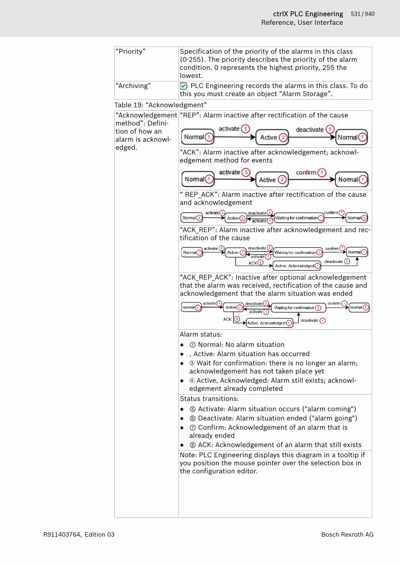
531 / 940ctrlX PLC EngineeringReference, User Interface
Bosch Rexroth AGR911403764, Edition 03
“Priority” Specification of the priority of the alarms in this class(0-255). The priority describes the priority of the alarmcondition. 0 represents the highest priority, 255 thelowest.
“Archiving” : PLC Engineering records the alarms in this class. To dothis you must create an object “Alarm Storage”.
Table 19: “Acknowledgment”“Acknowledgementmethod”: Defini-tion of how analarm is acknowl-edged.
“REP”: Alarm inactive after rectification of the cause
“ACK”: Alarm inactive after acknowledgement; acknowl-edgement method for events
“ REP_ACK”: Alarm inactive after rectification of the causeand acknowledgement
“ACK_REP”: Alarm inactive after acknowledgement and rec-tification of the cause
“ACK_REP_ACK”: Inactive after optional acknowledgementthat the alarm was received, rectification of the cause andacknowledgement that the alarm situation was ended
Alarm status:● ① Normal: No alarm situation● ‚ Active: Alarm situation has occurred● ➂ Wait for confirmation: there is no longer an alarm;
acknowledgement has not taken place yet● ➃ Active, Acknowledged: Alarm still exists; acknowl-
edgement already completedStatus transitions:● ⑤ Activate: Alarm situation occurs ("alarm coming")● ⑥ Deactivate: Alarm situation ended ("alarm going")● ⑦ Confirm: Acknowledgement of an alarm that is
already ended● ⑧ ACK: Acknowledgement of an alarm that still existsNote: PLC Engineering displays this diagram in a tooltip ifyou position the mouse pointer over the selection box inthe configuration editor.
532 / 940 ctrlX PLC EngineeringReference, User Interface
Bosch Rexroth AG R911403764, Edition 03
You frequently have to ensure that the user notices thealarm during operation. Various actions are available in thealarm class for this. The user must confirm (acknowledge)the alarm in order for the alarm to be removed from thealarm list.
“Acknowledge sep-arately”
: During operation the user cannot acknowledge thealarm together with other alarms, but must acknowledge itseparately. This prevents the user from inadvertentlyacknowledging an alarm together with other alarms.
Table 20: “Notification Actions”You can assign a list of actions to each alarm class that are to be executed assoon as the alarm is subject to a status transition.“Action” Select one of the following actions by double-clicking the
action column:● “Variable”: Value assignment of a variable● “Execute”: Execution of a program● “Call”: Call a function block instance
“Activate”“Deactivate”“Confirm”“ACK”
The available status transitions depend on the selected“acknowledgement method”.
: The action is executed with the status transition.
“Details” Displays a summary of the action. You define the actionbelow the table or edit the action directly in this row.
“Deactivation”: Variable via which an application can deactivate the action.Table 21: “Variable/Execute/Call”You define the parameters of the action in the field below the table. Theparameters depend on the selected action:
● Variable:“Variable”: Variable to which you assign a value or anexpression.In the field on the right: Assigned variable or expres-sion. You can select the variables via the input assistant( ).In the case of boolean variables you can use the place-holder ALARM, in the case of integer variables the place-holder STATE. In the case of string variables you canenter any IEC literal (e.g. 'too high!').– ALARM: Status (TRUE or FALSE) of the alarm of this
alarm class that was last activated/deactivated– STATE: Status of the alarm of this alarm class that
last changed its status. (0: Normal, 2: Active, 3: Wai-tingForConfirmation, 4: ActiveAcknowledged)
● Execute:“Executable file”: Path and file name of the executablefile on the controller.“Parameter”: One or more parameters that you add tothe call. You separate several parameters by a space.
● Call:
533 / 940ctrlX PLC EngineeringReference, User Interface
Bosch Rexroth AGR911403764, Edition 03
“Function block instance”: Function block that is called.The function block must implement the interfaceIAlarmNotifiable (AlarmManager.library). Thedesired action on a change of state is implemented inthe method Execute.“Additional parameter structure”: If the function blockrequires an additional parameter structure, the struc-ture members are listed in this table and can be filledhere. An additional parameter structure is defined inthe function block with the attribute AlarmManagerAd-ditionalData.Example: The function block has the attribute{attribute 'AlarmManagerAdditionalData' :='StructEmailParams'}.The structure employed must consist of scalar compo-nents or components of the type POINTER TO. PLCEngineering does not support the ARRAY data type oruser-defined data types.Note: Using the attribute {attribute 'AlarmMana-gerMandatoryParameter'} you can identify structuremembers as mandatory parameters.
Table 22: “Presentation Options for Alarm Table/Alarm Banner”Defines how PLC Engineering displays the individual statuses of an alarm inthe alarm visualization element (alarm table, alarm banner).“Status” Alarm status. The available statuses depend on the selected
“acknowledgement method”.“Font” The standard dialog for the selection of a font or color is
opened with the button.“Backgroundcolor”
Background color for the alarm message
“Bitmap” You can add a bitmap by entering the bitmap ID. If noimage file is assigned to this ID yet, the standard file searchdialog opens. After having selected a file, the bitmap defini-tion of the image pool “GlobalImagePool” is added.
“Transparent” Activate this option if the bitmap has a transparent color.“Transparentcolor”
Color that is to be displayed transparently. Relevant only ifthe “Transparent” option has been activated.
See also● ⮫ Chapter “Configuring the Alarm Management” on page 148● ⮫ Chapter “Object 'Alarm Group'” on page 533● ⮫ Chapter “Object 'Alarm Storage'” on page 537
Object 'Alarm Group'Use alarm groups for organizing individual alarms in the alarm management ofan application. Each alarm is assigned to one alarm group only. To configure analarm group, insert an “Alarm Group” object below an “Alarm Configuration”object in the device tree.A common deactivation variable can be assigned to all alarms that are assignedto a group. You can create a hierarchical structure of alarm groups in the devicetree with the help of folder elements.
534 / 940 ctrlX PLC EngineeringReference, User Interface
Bosch Rexroth AG R911403764, Edition 03
The dialog of the alarm group editor includes a table listing all alarms of thegroup. The dialog displays the basic settings for the entire group, such as deac-tivation, archiving, and associated text list, as well as the properties of the indi-vidual alarms. You can edit the values in the list. Note the option of exportingand importing alarms to and from a CSV file (see below).
Dialog 'Alarm Group'
“Text list” Name of the text list where the alarm message text issaved (see below: “Message”). PLC Engineering generatesthe list automatically when you create an alarm group. Youcan also select an existing text list here.
“Archiving” Selection of the alarm storage object for the alarm group.When you specify an alarm storage object, PLC Engi-neering activates the alarm storage.
“Deactivation” Boolean variable that deactivates all alarms in this group.PLC Engineering does not trigger these alarms any longer,even if the alarm condition is fulfilled. Alarms that arealready active are not affected by this.
Table 23: Table of alarmsYou enter the properties of the individual alarms in the corresponding tablecolumns. Depending on the selected observation type, PLC Engineering setsadditional parameters in input fields below the table.“ID” This unique ID corresponds to the ID of the associated text
list. You can change the ID in the “ID” field of the table.The ID must always be unique within the alarm group. Achange of the ID in the alarm table also directly causes achange in the text list, and the other way around.
“Observationtype”
Drop-down list of observation types. Depending on thetype, different editing fields are available below the tablethat define the condition for the alarm. The fields define anexpression that triggers the alarm. See the following table.
“Details” This field shows the configuration settings (defined in thefields below the table) for the selected alarm type.You can also enter the condition directly into the field. Ifyou input an expression that does not match the currentlyselected observation type, the type is automaticallyadapted.
“Deactivation” Variable for deactivating the alarm (optional).“Class” Assigned alarm class.“Message” Required entry of a message text (message) that PLC Engi-
neering will display in the “Alarm Table” visualization ele-ment when the alarm occurs. The text entered here istransferred automatically by PLC Engineering to the textlist for the alarm group. You can insert line breaks bypressing [Ctrl]+[Enter].PLC Engineering supports the fol-lowing placeholders, which are replaced by the actualvalue at runtime:<DATE> Date of the change to the present
status.<TIME> Time of the last status change.<EXPRESSION> Expression (defined within the alarm)
that triggered the alarm.

535 / 940ctrlX PLC EngineeringReference, User Interface
Bosch Rexroth AGR911403764, Edition 03
<PRIORITY> Priority of the alarm (defined in thealarm class).
<TRIGGERVALUE>*
Value that caused the alarm conditionto become true.
<ALARMID> Alarm ID as displayed in the firstcolumn of the alarm table.
<CLASS> Name of the alarm class (defined in thealarm).
<ALLDEFAULT> Complete information about the alarmis output.
<CURRENTVALUE>*
Actual value of the monitored variable.
<LATCH1> * Value of the first latch variable at thetime when the alarm was triggered.
<LATCH2> * Value of the second latch variable at thetime when the alarm was triggered.
<ALARM> TRUE in the case of the alarm status 'Ac-tive', FALSE with every other alarmstatus.
<STATE> Alarm status: 0 = 'normal', 1 = 'active', 2= 'waiting for ACK', 3 = 'active, acknowl-edged' (still active and already acknowl-edged)
* For <TRIGGERVALUE>, <CURRENTVALUE>, and <LATCHn>,you can also use formatting specifications, such as thosethat are valid for the C function "printf" (example: "Thevalue is <CURRENTVALUE %d>".By default, only one column is available for message text.You can add more columns from the context menu whichwill be available in the “Data type” property for columnconfiguration of the “Alarm table” and “Alarm banner” visu-alization elements.
“Min. pendingtime”:
Defines the minimum duration for fulfilling the alarm con-dition so that PLC Engineering triggers the alarm. In thisway, PLC Engineering can inhibit alarm conditions thatoccur only for a short time.IEC 61131 compliant format (example: t#2ms).
“Latch var 1”,“Latch var 2”
The latch variables are used to record additional valueswhen the alarm becomes active. A latch variable has to bea scalar type (8-byte) or a STRING or WSTRING type.PLCEngineering records a latch variable or a latch expressionwhen the alarm becomes active. In this way, it allows addi-tional information about the alarm to be provided.Note: With the respective configuration of the “Alarmtable” element or “Alarm banner” element, you can filterthe occurring alarms in the visualization by the contents ofthe latch variable.Example: When monitoring a motor speed, the temperatureand the current are additionally recorded.
536 / 940 ctrlX PLC EngineeringReference, User Interface
Bosch Rexroth AG R911403764, Edition 03
By default, columns are available for two latch variables.You can add more columns from the context menu whichwill be available in the “Data type” property for columnconfiguration of the “Alarm table” and “Alarm banner” visu-alization elements.
“Higher prio.alarm”
When the alarm is triggered, it can be acknowledged bytriggering another alarm.Example: A temperature monitor should issue a warning at> 60 °C and an error at > 90 °C. If the temperature rises,then the warning is displayed starting at 60 °C. At 90 °Cand higher, the alarm for the error is triggered (this auto-matically acknowledges the 60 °C warning).
Table 24: Monitoring types“Digital”: “Expression”: Expression to be monitored. On the right
side of the expression for the comparison. In the center,you select the desired comparison operator (“=” or <>).
“Upper limit”1): “Expression”: As described for “Digital”, but with the com-pare options “>” or >= and optionally a “Hysteresis in %”.
“Lower limit”1): “Expression”: As described for “Digital”, but with the com-pare options “<” or <= and optionally a “Hysteresis in %”.
“Inside range”1): “Expression”: Expression to be monitored.“Range”: PLC Engineering triggers the alarm when themonitored expression is within the range defined here. Theleft field defines an expression for the lower limit of thisrange. The right field defines an expression for the upperlimit. The expression to be monitored is displayed in thefield in-between. You have to set the comparison operatorsaccordingly. You can define a “Hysteresis in %” optionally.
“Outside range”1): “Expression”: Expression to be monitored.“Range”: PLC Engineering triggers the alarm when themonitored expression is outside the range defined here.The left field defines an expression for the lower limit ofthis range. The right field defines an expression for theupper limit. The expression to be monitored is displayed inthe field in-between. You have to set the comparison oper-ators accordingly. You can define a “Hysteresis in %”optionally.
“Change”: “Expression”: Expression to be monitored.PLC Engineeringtriggers the alarm when its value changes.
“Event”: In this case, the application triggers the alarm (eventalarm) by using functions from the library AlarmMan-ager.library.
1) For this observation type, you can monitor the specified expression as abso-lute or relative. Absolute means that the limit value is defined by a fixed valueor a variable that returns a fixed value. Relative means that the limit valuedepends on an expression; for example: upper limit: “Variable x >= 0.9 * y”.“Hysteresis in %”: When you specify a hysteresis, the alarm condition is ful-filled until a certain deviation from the specified limit value is reached. Thesize of the deviation is specified as a percentage [%] of the limit value.Example: Upper limit: i_temp >= 30 Hysteresis: 10%. The alarm is activewhen the variable i_temp reaches or exceeds the value 30. The alarm is nolonger active if the value falls below 27.
537 / 940ctrlX PLC EngineeringReference, User Interface
Bosch Rexroth AGR911403764, Edition 03
The context menu includes the following commands for adding and removingadditional columns for messages and latch variables:● “Add message column”● “Remove message column”● “Add latch var column”● “Remove latch var column”See also● ⮫ Alarm Table in the Visualization● ⮫ Chapter “Configuring the Alarm Management” on page 148● ⮫ Chapter “Calling event alarms in the program ” on page 150● ⮫ Chapter “Object 'Alarm Class'” on page 530● ⮫ Chapter “Object 'Alarm Storage'” on page 537
Exporting and importing of alarmsIn the context menu of the alarm table you will find commands for the exportand import of alarms to and from a CSV file:● “Export Alarms”: The command opens the default dialog for saving a file
in the file system. The default file type is Alarm Group Export File(*.csv). This way you can export the current alarm list to a CSV file.
● “Import Alarms”: The command opens the default dialog for searching fora file in the file system. The default file type is Alarm Group Export File(*.csv) for describing alarm definitions.
Object 'Alarm Storage'
NOTICE In case of a reset (origin), PLC Engineering clears thealarm storage file.
In “Alarm Storage”, you define the settings for the database file where PLCEngineering saves the alarms that occur. You can insert the object only oncebelow an alarm configuration.There is exactly one memory file located in a database. As an option, PLC Engi-neering saves this file in a file directory on the controller. You cannot changethe name it is derived from the application name according to the followingconvention: <application name>.alarmstorage.sqlite. The alarm classes andalarm groups define whether or not the memory file should be used.
“Subdirectory:” Name of a subdirectory on the PLC where PLC Engineering saves thememory file (optional).
“No limit” No limit for the file size for the alarm storage.“Maximum number ofrecords”
Number of recorded entries that PLC Engineering saves. When thisnumber is reached and a new entry is queued in the ring buffer, PLCEngineering deletes the oldest entry.
“Maximum storage size” Maximum size of the memory file with specification of the unit. PLCEngineering converts this size implicitly into an approximate maximumnumber of entries that can be saved in the file (ring buffer).
“Circular buffer” For display purposes only (not editable).: Memory in a circular buffer: Memory in an unlimited buffer
The records that PLC Engineering saves in the database can be displayed in the“Alarm Table” visualization element.See also● ⮫ Chapter “Configuring the Alarm Management” on page 148● ⮫ Chapter “Object 'Alarm Class'” on page 530
538 / 940 ctrlX PLC EngineeringReference, User Interface
Bosch Rexroth AG R911403764, Edition 03
● ⮫ Chapter “Object 'Alarm Group'” on page 533●
Command 'CSV Export of Alarm Storage'Function: This command opens the “Alarm Storage Export Configuration”dialog box.Call: Context menu of the “Alarm Storage” object.Requirements: The application is in online mode with an alarm configuration.An alarm storage is configured.This command opens the “Alarm Storage Export Configuration” dialog box.
Dialog box 'Alarm Storage Export Configuration' - 'Basic Settings'“Export file”: Path to the generated CSV file in the file system
Table 25: “Alarms to Export”“Export all” All listed alarms are exported.“Export alarms in time-stamp range (timestampactivated)”
Defined time range for the export of the listed alarms. This refers tothe time stamp when the alarm was activated. The min./max. timestamps that are available in the alarm storage or were the last ones tobe used in an export are shown by means of "From" and Until".When selecting the time range, the smallest unit is one second.
Table 26: “Language”“Language” The drop-down list includes all languages that are available in text lists
for alarm texts, as well as the default language (<Standard>).
Dialog box 'Alarm Storage Export Configuration' - 'Advanced Settings'Table 27: “Sort by Time Stamp Activated”“Ascending”“Descending”
Sort order by the time stamp when the alarm was activated
Table 28: “File Format”“Formatted values andtimestamps”
The time stamps are formatted with the date and time format asdefined below. REAL and LREAL values are formatted in numberformat.
“Raw data from alarmstorage file”
The time stamps and values are written unformatted to the CSV file, asthey appear in the alarm storage. Alarms, alarm groups, and alarmclasses are written in non-readable form to the CSV file as internal IDs.
Table 29: “Formatting Options”Defines the formatting of the entries in the CSV file. Possible only if the “Formatted values andtimestamps” data format is selected.“REAL format (printfsyntax)”
Setting: “%.1f”
“Date format” The settings are applied from the system control.“Time format” The settings are applied from the system control.Table 30: “Separator”“Semicolon” The entries in the CSV file are separated by a semicolon.“Comma” The entries in the CSV file are separated by a comma.“Tab” The entries in the CSV file are separated by a tab.
“Local time” Available only if the “Formatted values and timestamps” data format isselected.
: The time stamps are written to the CSV file in local time.
539 / 940ctrlX PLC EngineeringReference, User Interface
Bosch Rexroth AGR911403764, Edition 03
: The time stamps are written to the CSV file in universal time coor-dinated (UTC).
Object 'Data Source Manager'Symbol: This object is used as a node for managing the data sources below it. At leastone data source must be available. An application with the data source man-ager communicates with remote devices.See also● ⮫ Chapter 1.9.4 “Data Source Manager” on page 169
Command 'Add object' > 'Data source'Function: This command opens the “Add data source” dialog.Call● “Project” menu● Context menu in the “Devices” view of the CODESYS perspective● Context menu in the “Data sources” view of the “HMI” perspectiveRequirement: The “Data source manager” object is selected that should havean additional data source.
Dialog 'Add data source'
“Name” Example: Data_Source_A“Select data source type” Data source type that fits the controller configurations to establish
communication.● “CODESYS Symbolic”:
The data is transferred by means of symbolic monitoring. Thisrequires that symbols are configured in the symbol configuration ofthe remote control application.Note: As long as the symbol configuration is not affected after anapplication change, you have the advantage that the applicationdoes not have to be updated in the local device.Tip: Use this communication connection unless there are noresources are available for a symbol configuration in the remotePLC.
● “CODESYS ApplicationV3”:Data is transferred by means of the PLC Engineering address pro-tocol. This requires that the address information between theremote PLC and the local device match. Otherwise a connectioncannot be established.Advantage: A symbol configuration is not required in the remoteapplication.Note: For changes to the remote application, the local applicationmust be updated (for example, the HMI application).Tip: Use this communication for embedded or mini PLCs whenthere are no available resources for the symbol configuration.
“Add” Opens the dialog “Initialize data source - Provider settings”. The con-tents of the dialog depend on the selected data source type.
NOTICE The remote controller should be running and the remotecontroller application loaded and started.
540 / 940 ctrlX PLC EngineeringReference, User Interface
Bosch Rexroth AG R911403764, Edition 03
See also● ⮫ Chapter “Object 'Data Source Manager'” on page 539● ⮫ Chapter “Object 'Data Source' - Tab 'Variables'” on page 540
Dialog 'Initialize data source wizard - Provider settings' (for 'CODESYSSymbolic')The settings of this dialog are described in the following section: Object 'Datasource' - Tab 'Communication".This dialog is used for the initial configuration of the connection when youselect “CODESYS Symbolic” as the data source type. The communication takesplace by means of symbolic monitoring. The configuration can be modified laterin the editor of the data source in the “Communication” tab.See also● ⮫ “Tab 'Communication' for PLC Engineering Symbolic” on page 543
Dialog 'Initialize data source wizard - Provider settings' (for 'CODESYSApplicationV3')The settings of this dialog are described in the following section: Object 'Datasource' - Tab 'Communication".This dialog is used for the initial configuration of the connection when youselect “CODESYS ApplicationV3” as the data source type. The communicationtakes place by means of address monitoring.See also● ⮫ “Tab 'Communication' for PLC Engineering ApplicationV3” on page 547
Dialog 'Initialize data source wizard - Browse data source variables'The settings of this dialog are described in the section "Object 'Data source'",heading "Dialog 'Choose variables'".Function: You can select the variables for the data transfer from the variables ofthe remote PLC. By clicking “Exit”, the data source is initialized and the datatypes and variables (data interface) are declared below the folder “Data-Sources_Objects”. You can modify the settings in the editor of the data sourceobject.Call: AutomaticSee also● ⮫ “Dialog 'Choose Variables'” on page 541
Object 'Data Source' - Tab 'Variables'Symbol: The object (type “Data source”) manages the access to the data of a remotedevice in the tabs “Variables”, “Type mappings”, “Communication”, and “Gen-eral and diagnosis”. The status bar which is always visible notifies you aboutthe data source type and the most important communication settings.See also● ⮫ Chapter 1.9 “Working with Control Networks” on page 159● ⮫ Chapter “Object 'Data Source' - Tab 'Type Mappings'” on page 542● ⮫ Chapter “Object 'Data Source' - Tab 'Communication'” on page 543● ⮫ Chapter “Object 'Data Source' - Tab 'General and Diagnosis'” on page 549

541 / 940ctrlX PLC EngineeringReference, User Interface
Bosch Rexroth AGR911403764, Edition 03
Tab 'Variables'The variables for the data originating from the remote source are declared inthe global variable list <name of data source>. The GVL acts as a data inter-face for remote control and it is located below the application and folder “Data-Sources_Objects”.In this way, you can develop a local application offline based on the symbolinformation without a connection to a data source.
“Update variables” Establishes a connection to the remote device and opens the dialog“Choose variables”.
“Local variable” Variable in the local application. Contains the remote data.“Access rights” Access permission of the variables. The respective remote variable has
the same access permission.● : Write permission. Every time the values changes, the variable is
updated on the controller.● : Read access. Every time the values changes on the controller,
the variable is updated in the application.● : Read and write access
“Update always” : The controller data is updated automatically (by means of the datasource). A variable is updated automatically if it is used in the visuali-zation, trend, recipe, or as an alarm.Note: That is the recommended setting type.
: The variable is updated in each cycle.Note: Activate the option only if the variable is used in IEC code exclu-sively. If a variable is used in the visualization code, then it is updatedautomatically.Note: When an instance of a function block or a data type is updated inthis way, the instance is always transferred completely.
“Create or map” Mapping type how the remote variable is mapped to the local variable.● : Mapping to a specific created variable with the data type of the
remote variable. The control data is mapped 1:1. That is the recom-mended mapping type. The variable is declared in the GVL <nameof data source>.
● : Mapping to an existing variable. This requires that the existingvariable has the same data type.
● : Mapping to a specific created variable with type-conformingdata type to the remote data type: remote and local data types arenot the same, but compatible. For example, a type-conforming datatype can be available in a library. The variable is declared in the GVL<name of data source>.
“Type mappings” Data type of the remote variable. If the variable does not have a scalartype, the type is listed in the “Type mappings” tab.
“Remote variable” Variable in the remote PLC
Dialog 'Choose Variables'Symbol: Function: This dialog lists the remote variables that are accessed by means ofthe configured connection.Call: Click “Update variables” in the “Variables” tab.Requirement: The remote PLC is running. The control application is down-loaded.
542 / 940 ctrlX PLC EngineeringReference, User Interface
Bosch Rexroth AG R911403764, Edition 03
“Variables” The remote variables are listed in the tree view. The top node is identi-fied by the remote application name. Its variables are listed belowthat. Structured data is listed with all of its subordinate elements.Example: appControl_A
: The variable is selected for transferring to the local device. Whenthe variable is structured, it is accepted with all subelements. If thevariables themselves are subelements, then only this subelement isaccepted without accepting the structure completely.Red font: When a variable is displayed in a red font, the variable is notavailable (anymore) in the remote PLC.Note: You can remove the variable from the list by clicking “Uncheckunavailable variables”.
: The variable is not selected for the transfer.The variable has expandable elements. By clicking the symbol, the vari-able is extended by their elements.
“Insert elements struc-tured”
: The selected variables are transferred with this structure if they arestructured.
: The variable is transferred unstructured with a scalar data type.“Uncheck unavailable varia-bles”
Requirement: The link is visible when previously are no longer availablein the variable available on the remote PLC. These variables aremarked in red in the window above. The symbol configuration or theapplication presumably changed in the remote PLC.By clicking the command, the red variables are removed from the drop-down list.
Status bar Information about the data source type and the most important com-munication settingsIf the communication is established by means of the data source typeCODESYS Symbolic, then the name of the data source type, the con-nection type, and the network name of the remote device are dis-played.If the communication is established by means of data source typeCODESYS ApplicationV3, then the name of the data source type, thestorage location of the remote project, and the instance name of theremote application.Example: CODESYS ApplicationV3 (D:\Projects\Project_A):Project_A.App_A
Object 'Data Source' - Tab 'Type Mappings'The tab lists the non-scalar data types as they are currently available in the“DataSources_Objects” folder. You can edit or delete the data type declarationby selecting a data type and then the declared elements in the lower window.Moreover, you can modify the name, reset access rights, map another type, orselect another remote variable.See also● ⮫ Chapter “Editing Data Source Variables” on page 177
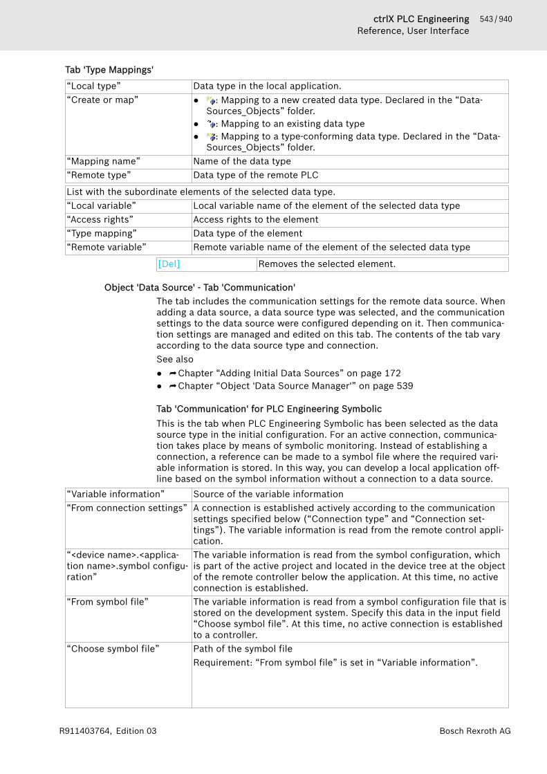
543 / 940ctrlX PLC EngineeringReference, User Interface
Bosch Rexroth AGR911403764, Edition 03
Tab 'Type Mappings'
“Local type” Data type in the local application.“Create or map” ● : Mapping to a new created data type. Declared in the “Data-
Sources_Objects” folder.● : Mapping to an existing data type● : Mapping to a type-conforming data type. Declared in the “Data-
Sources_Objects” folder.“Mapping name” Name of the data type“Remote type” Data type of the remote PLC
List with the subordinate elements of the selected data type.“Local variable” Local variable name of the element of the selected data type“Access rights” Access rights to the element“Type mapping” Data type of the element“Remote variable” Remote variable name of the element of the selected data type
[Del] Removes the selected element.
Object 'Data Source' - Tab 'Communication'The tab includes the communication settings for the remote data source. Whenadding a data source, a data source type was selected, and the communicationsettings to the data source were configured depending on it. Then communica-tion settings are managed and edited on this tab. The contents of the tab varyaccording to the data source type and connection.See also● ⮫ Chapter “Adding Initial Data Sources” on page 172● ⮫ Chapter “Object 'Data Source Manager'” on page 539
Tab 'Communication' for PLC Engineering SymbolicThis is the tab when PLC Engineering Symbolic has been selected as the datasource type in the initial configuration. For an active connection, communica-tion takes place by means of symbolic monitoring. Instead of establishing aconnection, a reference can be made to a symbol file where the required vari-able information is stored. In this way, you can develop a local application off-line based on the symbol information without a connection to a data source.
“Variable information” Source of the variable information“From connection settings” A connection is established actively according to the communication
settings specified below (“Connection type” and “Connection set-tings”). The variable information is read from the remote control appli-cation.
“<device name>.<applica-tion name>.symbol configu-ration”
The variable information is read from the symbol configuration, whichis part of the active project and located in the device tree at the objectof the remote controller below the application. At this time, no activeconnection is established.
“From symbol file” The variable information is read from a symbol configuration file that isstored on the development system. Specify this data in the input field“Choose symbol file”. At this time, no active connection is establishedto a controller.
“Choose symbol file” Path of the symbol fileRequirement: “From symbol file” is set in “Variable information”.

544 / 940 ctrlX PLC EngineeringReference, User Interface
Bosch Rexroth AG R911403764, Edition 03
The symbol file is stored on the development system and contains therequired variable information. By default, a symbol file path is createdin the project directory in the following structure: <project folder>\<project name>.<device name>.<application name>.xml.Example: D:\Projects\Project_A\Visualize-WithHMI.Device.Application.xmlNote: If the “Alarm table” element or “Trend” element is used in thevisualization, then the symbol file required for symbolic access and therespective project must both be saved in the same folder. The projectcontains the configuration for the alarm table element or the trendrecording for the trend element. This is the default case for automati-cally generated symbol files.Example: D:\Projects\Project_A\VisualizeWithHMI.project
“Connection type” Connection type between the remote PLC and the local device.Depending on the selected connection type, the following settingsbelow change.Note: If possible, avoid a direct connection without a gateway.
“PLC Engineering V2” The devices are located in the same network. The V2 runtime systemon the remote PLC provides a communication interface.
“PLC Engineering V2 (viaGateway)”
The devices are not located in the same network. They are connectedvia a V2 gateway.
“PLC Engineering V3” The devices are located in the same network. The V3 runtime systemon the remote PLC provides a communication interface.Default
“PLC Engineering V3 (viaGateway)”
The devices are not located in the same network. They are connectedvia a V3 gateway.
Table 31: Connection settings for PLC Engineering V2“PLC”“Driver type” ● “Tcp/Ip (Level 2 Route)”
● “Tcp/Ip (Level 2)”● “Tcp/Ip”
“Address” Example: localhost for the currently used system“Port” Example: 1200“Blocksize” Example: 128
Requirement: The driver type is “Tcp/Ip (Level 2)”.“TargetId” Example: 0
Requirement: The driver type is “Tcp/Ip (Level 2 Route)”.“Motorola byteorder” : Byte order on the PLC in big endian (Motorola format)
: Byte order in little endian (Intel format)Table 32: Connection settings for PLC Engineering V2 (via gateway)Note: For this connection, a “CoDeSys V2.3 Gateway Server” (V2 Gateway) must be also installedon the development computer where PLC Engineering V3 is running.“Gateway”“IP address” Example: localhost“Port” Example: 1217“PLC”“Name or address ofdevice”
Example of device name: PLC_A

545 / 940ctrlX PLC EngineeringReference, User Interface
Bosch Rexroth AGR911403764, Edition 03
Example of device address: [ABCD)“Type of name or address” ● “Node name (automatically derived)”
● “Node address (automatically derived)”● “IP address (automatically derived)”● “Node name”● “Node address”● “IP address”
Table 33: Connection settings for PLC Engineering V3“PLC”“Name or address ofdevice”
The input depends on the selected “Type of name or address”.Example of device name: PLC_AExample of device address: [ABCD]
: Opens the input for selecting the program variables for dynamicconfiguration. Requirement: “Dynamic from variable” is selected in“Type of name or address”.Example IEC variable of the application: POU.dssCommVar. This vari-able must have the data type DatasourceSym.ConnectionSetup.
“Type of name or address” ● “Node name (automatically derived)”● “Node address (automatically derived)”● “IP address (automatically derived)”● “Node name”● “Node address”● “IP address”● “Dynamic from variable”
The device name or address is configured dynamically at runtime bymeans of an IEC variable of data type DatasourceSym.Connec-tionSetup. The data type DatasourceSym.ConnectionSetup(struct) is defined in the Datasource Symbolic Access library.For the configuration, the structure member xDataValid first hasto be set to FALSE. If the address data has been specified, thenxDataValid has to be set back to TRUE.Use case: The device name or address is not available when aproject is being created.The dynamic configuration can also be used to change the settingsat runtime without restarting the HMI application.Note: For this connection type, the connection also does not takeplace dynamically via gateway.
Table 34: Connection settings for PLC Engineering V3 (via gateway)“Gateway”“IP address” Example: localhost“Port” Example: 1217“PLC”“Name or address ofdevice”
The input depends on the selected “Type of name or address”.Example of device name: PLC_AExample of device address: [ABCD]
: Opens the input for selecting the program variables for dynamicconfiguration. Requirement: “Dynamic from variable” is selected in“Type of name or address”.
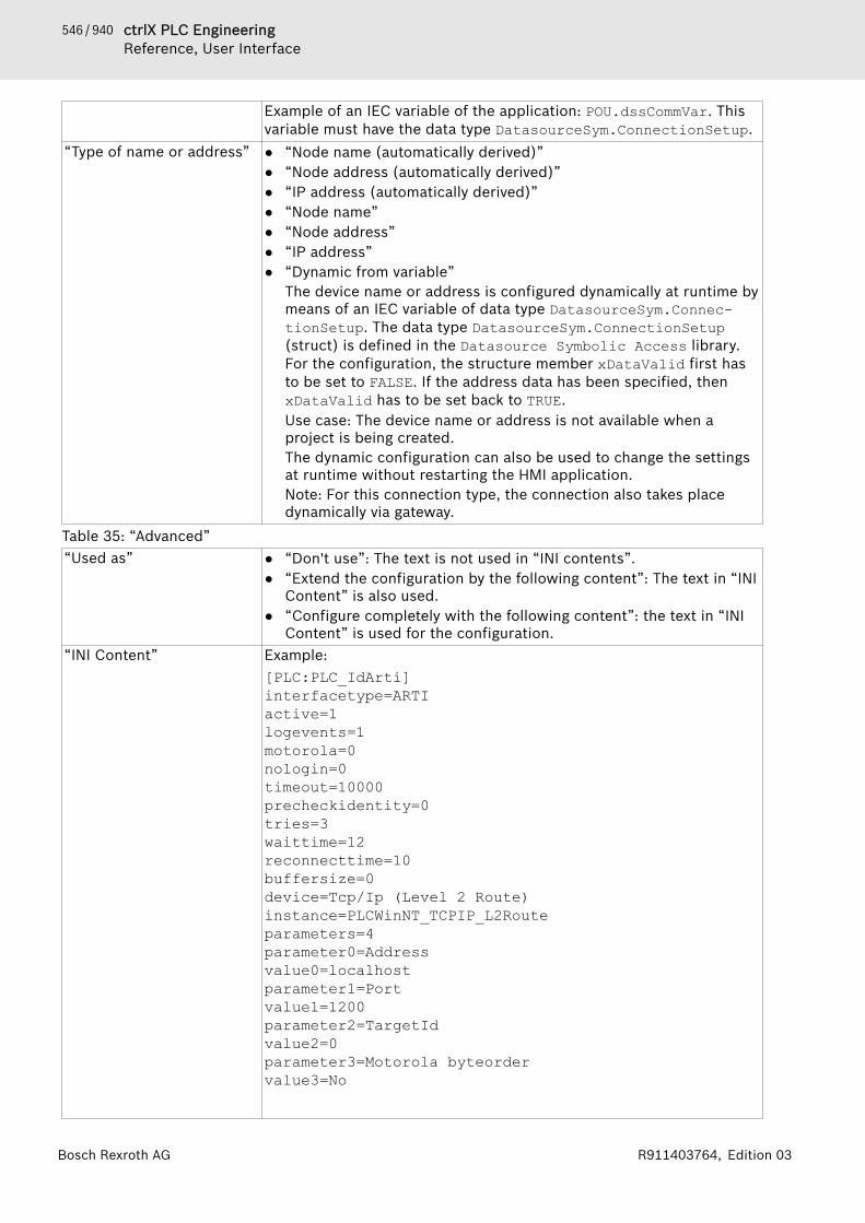
546 / 940 ctrlX PLC EngineeringReference, User Interface
Bosch Rexroth AG R911403764, Edition 03
Example of an IEC variable of the application: POU.dssCommVar. Thisvariable must have the data type DatasourceSym.ConnectionSetup.
“Type of name or address” ● “Node name (automatically derived)”● “Node address (automatically derived)”● “IP address (automatically derived)”● “Node name”● “Node address”● “IP address”● “Dynamic from variable”
The device name or address is configured dynamically at runtime bymeans of an IEC variable of data type DatasourceSym.Connec-tionSetup. The data type DatasourceSym.ConnectionSetup(struct) is defined in the Datasource Symbolic Access library.For the configuration, the structure member xDataValid first hasto be set to FALSE. If the address data has been specified, thenxDataValid has to be set back to TRUE.Use case: The device name or address is not available when aproject is being created.The dynamic configuration can also be used to change the settingsat runtime without restarting the HMI application.Note: For this connection type, the connection also takes placedynamically via gateway.
Table 35: “Advanced”“Used as” ● “Don't use”: The text is not used in “INI contents”.
● “Extend the configuration by the following content”: The text in “INIContent” is also used.
● “Configure completely with the following content”: the text in “INIContent” is used for the configuration.
“INI Content” Example:[PLC:PLC_IdArti]interfacetype=ARTIactive=1logevents=1motorola=0nologin=0timeout=10000precheckidentity=0tries=3waittime=12reconnecttime=10buffersize=0device=Tcp/Ip (Level 2 Route)instance=PLCWinNT_TCPIP_L2Routeparameters=4parameter0=Addressvalue0=localhostparameter1=Portvalue1=1200parameter2=TargetIdvalue2=0parameter3=Motorola byteordervalue3=No
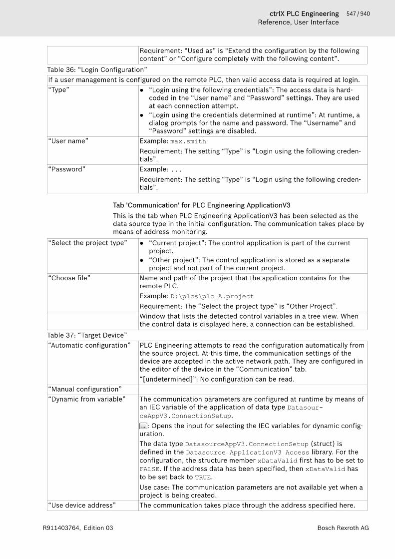
547 / 940ctrlX PLC EngineeringReference, User Interface
Bosch Rexroth AGR911403764, Edition 03
Requirement: “Used as” is “Extend the configuration by the followingcontent” or “Configure completely with the following content”.
Table 36: “Login Configuration”If a user management is configured on the remote PLC, then valid access data is required at login.“Type” ● “Login using the following credentials”: The access data is hard-
coded in the “User name” and “Password” settings. They are usedat each connection attempt.
● “Login using the credentials determined at runtime”: At runtime, adialog prompts for the name and password. The “Username” and“Password” settings are disabled.
“User name” Example: max.smithRequirement: The setting “Type” is “Login using the following creden-tials”.
“Password” Example: ...Requirement: The setting “Type” is “Login using the following creden-tials”.
Tab 'Communication' for PLC Engineering ApplicationV3This is the tab when PLC Engineering ApplicationV3 has been selected as thedata source type in the initial configuration. The communication takes place bymeans of address monitoring.
“Select the project type” ● “Current project”: The control application is part of the currentproject.
● “Other project”: The control application is stored as a separateproject and not part of the current project.
“Choose file” Name and path of the project that the application contains for theremote PLC.Example: D:\plcs\plc_A.projectRequirement: The “Select the project type” is “Other Project”.Window that lists the detected control variables in a tree view. Whenthe control data is displayed here, a connection can be established.
Table 37: “Target Device”“Automatic configuration” PLC Engineering attempts to read the configuration automatically from
the source project. At this time, the communication settings of thedevice are accepted in the active network path. They are configured inthe editor of the device in the “Communication” tab.“[undetermined]”: No configuration can be read.
“Manual configuration”“Dynamic from variable” The communication parameters are configured at runtime by means of
an IEC variable of the application of data type Datasour-ceAppV3.ConnectionSetup.
: Opens the input for selecting the IEC variables for dynamic config-uration.The data type DatasourceAppV3.ConnectionSetup (struct) isdefined in the Datasource ApplicationV3 Access library. For theconfiguration, the structure member xDataValid first has to be set toFALSE. If the address data has been specified, then xDataValid hasto be set back to TRUE.Use case: The communication parameters are not available yet when aproject is being created.
“Use device address” The communication takes place through the address specified here.
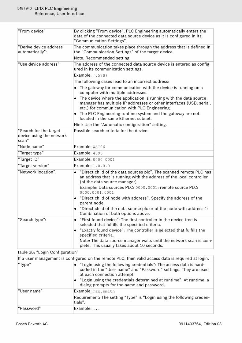
548 / 940 ctrlX PLC EngineeringReference, User Interface
Bosch Rexroth AG R911403764, Edition 03
“From device” By clicking “From device”, PLC Engineering automatically enters thedata of the connected data source device as it is configured in its“Communication Settings”.
“Derive device addressautomatically”:
The communication takes place through the address that is defined inthe “Communication Settings” of the target device.Note: Recommended setting
“Use device address” The address of the connected data source device is entered as config-ured in its communication settings.Example: [057B}The following cases lead to an incorrect address:● The gateway for communication with the device is running on a
computer with multiple addresses.● The device where the application is running with the data source
manager has multiple IP addresses or other interfaces (USB, serial,etc.) for communication with PLC Engineering.
● The PLC Engineering runtime system and the gateway are notlocated in the same Ethernet subnet.
Hint: Use the “Automatic configuration” setting.“Search for the targetdevice using the networkscan”
Possible search criteria for the device:
“Node name” Example: WST06“Target type” Example: 4096“Target ID” Example: 0000 0001“Target version” Example: 1.0.0.0“Network location”: ● “Direct child of the data sources plc”: The scanned remote PLC has
an address that is running with the address of the local controller(of the data source manager).Example: Data sources PLC: 0000.0001; remote source PLC:0000.0001.0001
● “Direct child of node with address”: Specify the address of theparent node
● “Direct child of the data source plc or of the node with address:”:Combination of both options above.
“Search type”: ● “First found device”: The first controller in the device tree isselected that fulfills the specified criteria.
● “Exactly found device”: The controller is selected that fulfills thespecified criteria.Note: The data source manager waits until the network scan is com-plete. This usually takes about 10 seconds.
Table 38: “Login Configuration”If a user management is configured on the remote PLC, then valid access data is required at login.“Type” ● “Login using the following credentials”: The access data is hard-
coded in the “User name” and “Password” settings. They are usedat each connection attempt.
● “Login using the credentials determined at runtime”: At runtime, adialog prompts for the name and password.
“User name” Example: max.smithRequirement: The setting “Type” is “Login using the following creden-tials”.
“Password” Example: ...
549 / 940ctrlX PLC EngineeringReference, User Interface
Bosch Rexroth AGR911403764, Edition 03
Requirement: The setting “Type” is “Login using the following creden-tials”.
“Advanced” : The following settings are visible.Requirement: “Automatic configuration” is activated.
“Default communicationbuffer”
Example: 50000
Object 'Data Source' - Tab 'General and Diagnosis'The “General and Diagnosis” tab provides information about the status of thedata source communication.See also● ⮫ Chapter “ Updating Data Interfaces” on page 181
Tab 'General and Diagnosis'Table 39: “Update Configuration”“Update rate (ms)” Example: 200Table 40: “Connection Information”“Connection status” Example: online“Error information” Example: OK
Object 'DUT'Symbol: for DUT without text list support; for DUT (type: enumeration)with text list supportA DUT (data unit type) describes a user-specific data type. You can add a “DUT”object below the application or in the “POUs” view.When adding the object, you can specify definition (see below: Dialog “AddDUT”).Syntax
TYPE <identifier> : <DUT component declaration>END_TYPEThe component declaration depends on the selected type, structure, or enu-meration.
Example:The following two DUTs define the structures struct1 and struct2, in whichstruct2 extends struct1. This mean that struct2.a can be used to accessthe a variable.TYPE struct1 :STRUCTa:INT;b:BOOL;
END_STRUCTEND_TYPE
TYPE struct2 EXTENDS struct1 :STRUCTc:DWORD;d:STRING;
END_STRUCTEND_TYPE
550 / 940 ctrlX PLC EngineeringReference, User Interface
Bosch Rexroth AG R911403764, Edition 03
See also● ⮫ Chapter “Structure” on page 411● ⮫ Chapter “Enumerations” on page 413● ⮫ Chapter “Data Type 'UNION'” on page 389
Dialog 'Add DUT'Function: You use this dialog log for configuring a new DUT. The DUT (Data UnitType) describes a user-specific data type.Call: Menu bar “Project 🠂 Add Object 🠂 DUT”; context menu of the applicationobject.
“Name” DUT nameTable 41: “Type”“Structure” The DUT consists of a structure of various data types.
“Extends”: : The structure extends an existing structure. In this way,the definitions of the extended DUT are automatically valid in the newDUT.
“Enumeration” The DUT consists of a series of integer constants. For declarationsyntax, please refer to the help page for "Enumerations".“Add text list support”: : The text list support allows the localizationof enumeration components. In addition, both the symbolic andnumeric enumeration values are shown in the text display of a visuali-zation element. When an enumeration variable with text list support isspecified in the “Text variable” property of a visualization element, theenumeration variable obtains the additional <enumeration name>.By clicking the buttons on the right edge of the editor, you can switchbetween “Textual view” and “Localized view” (text list). The DUTobject is found as the symbol in the device tree and in the “POUs”view.Example: You use the PLC_PRG.enVar variable (type myEnum). myEnumis a DUT with text list support. Then the entry in the property editorlooks like PLC_PRG.enVar <myEnum>. If the enumeration type is modi-fied in the application, then you are prompted to allow PLC Engi-neering to update the affected visualizations accordingly.Note: Text list support can be added or removed at any time for anexisting enumeration object. For this purpose, the commands “AddText List Support” and “Remove Text List Support” are provided in thecontext menu of the object.
: An enumeration is created without text list support. The DUTobject is found as the symbol in the device tree and in the “POUs”view.
“Alias” Definition of an alias for a “Base type”.You can type in the base type directly or select it using the input assis-tant or array assistant.
“Union” All components reserve the same storage space for this data type. Thememory requirement of a union is determined by the memory require-ment of its "largest" component.
See also● ⮫ Chapter “Structure” on page 411● ⮫ Chapter “Enumerations” on page 413● ⮫ Chapter “Data Type 'UNION'” on page 389● ⮫ Chapter “Command 'Add Text List Support'” on page 806

551 / 940ctrlX PLC EngineeringReference, User Interface
Bosch Rexroth AGR911403764, Edition 03
● ⮫ Chapter “Command 'Remove Text List Support'” on page 806● ⮫ Help for CODESYS Visualization: Using texts
Object 'External File'An “External File” is any file that you add to the project in the “POUs” view or“Devices” view. Click “Project 🠂 Add Object” to open the “Add External File”dialog and define how the file belongs to the project.An external file which was inserted in the “POUs” view is never downloaded tothe controller.An external file which was added in the “Devices” view is always downloaded tothe controller when an online change or a download is performed due to an IECcode change.When an external file is downloaded to the controller, it is not updated in theproject.
Dialog 'Add External File'
“File path” The button opens a dialog for selecting a file in the local filesystem.
“Name” Object name for the file in PLC Engineering. If you do not type any-thing, the file will have its previous name.
Table 42: “File Handling”“Remember the link” The file is available in the project only as long as it exists in the
defined file path.“Remember the link andembed into project”
PLC Engineering saves an internal copy of the file in the project, aswell as the link to the defined file path. The update option selectedbelow applies as long as the external file exists there. Otherwise PLCEngineering uses the version saved in the project.
“Embed into project” PLC Engineering saves only one copy of the file in the project. There isno longer a link to the external file.
Table 43: “Change Tracking”“Reload the file automati-cally”
If the external file changes, then PLC Engineering updates the file inthe project.
“Prompt whether to reloadthe file”
If the external file changes, then a dialog prompt opens whether PLCEngineering should also update the file in the project.
“ Do nothing” The file remains unchanged in the project, even if the external filechanges.
“Display File Properties” Clicking this button opens the default “Properties of <file name>”dialog, which you can also open in the Windows file system by right-clicking the file.
“Open” The file object is inserted into the device tree (“Devices” or “POUs”view) and opened in the editor for the matching file format.
See also● ⮫ Chapter 1.2.3 “Adding Objects” on page 19● ⮫ Chapter “Command ‘Add Object’” on page 694● ⮫ Chapter “Dialog 'Properties' - 'External file'” on page 827
Object 'C Code Module'Symbol: This object is for integrating C-code modules into a PLC Engineering project.You define the necessary configuration parameters on the tabs of the object.
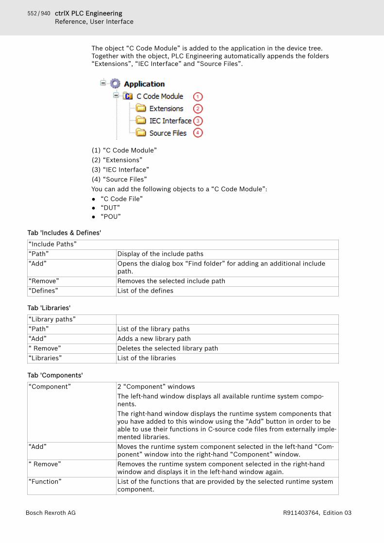
552 / 940 ctrlX PLC EngineeringReference, User Interface
Bosch Rexroth AG R911403764, Edition 03
The object “C Code Module” is added to the application in the device tree.Together with the object, PLC Engineering automatically appends the folders“Extensions”, “IEC Interface” and “Source Files”.
(1) “C Code Module”(2) “Extensions”(3) “IEC Interface”(4) “Source Files”You can add the following objects to a “C Code Module”:● “C Code File”● “DUT”● “POU”
Tab 'Includes & Defines'
“Include Paths”“Path” Display of the include paths“Add” Opens the dialog box “Find folder” for adding an additional include
path.“Remove” Removes the selected include path“Defines” List of the defines
Tab 'Libraries'
“Library paths”“Path” List of the library paths“Add” Adds a new library path“ Remove” Deletes the selected library path“Libraries” List of the libraries
Tab 'Components'
“Component” 2 “Component” windowsThe left-hand window displays all available runtime system compo-nents.The right-hand window displays the runtime system components thatyou have added to this window using the “Add” button in order to beable to use their functions in C-source code files from externally imple-mented libraries.
“Add” Moves the runtime system component selected in the left-hand “Com-ponent” window into the right-hand “Component” window.
“ Remove” Removes the runtime system component selected in the right-handwindow and displays it in the left-hand window again.
“Function” List of the functions that are provided by the selected runtime systemcomponent.

553 / 940ctrlX PLC EngineeringReference, User Interface
Bosch Rexroth AGR911403764, Edition 03
Dialog box 'Add C Code Module'Table: “Name”“Source folder” Input field for folders containing the C-source code files
: opens the dialog box “Search Folder”“Monitor folder for sourcechanges”
: PLC Engineering monitors whether the original directory of theproject on the hard disk changes and, in such a case, it opens a dialogbox in which you can consent to the updating of the files in PLC Engi-neering.
See also● ⮫ Chapter 1.8.11 “Integrating C Modules” on page 113● ⮫ Chapter “Dialog 'Properties' – 'Build' (C-integration)” on page 826● ⮫ Chapter “Object 'C Code File'” on page 553
Object 'C Code File'Symbol: This object contains the C-code for the C-integration in its editor.The C-code files can be created in the following ways:● You add an object “C Code Module” to the application and, in the dialog box
“Add C Code Module”, you specify a source directory containing C-codefiles; you import this directory into PLC Engineering.
● You add an object “C Code File” to a “C Code Module” and in doing so youspecify a C-file in the dialog box “Add C Code File” that you import into PLCEngineering.
● You add an object “C Code File” to a “C Code Module” and in doing so youspecify the name for a new C-file in the dialog box “Add C Code File”. Asopposed to the two other methods you create an empty file by doing this.
Possible file formats of a C-code file:● *.c● *.ccp● *.h● *.hppYou can make simple changes to the C-code in the text editor.
Objects for C-stubs: 'iec_external.c' and 'iec_external.h'If you create C-stubs with the command “Create Stub Implementation in C”,these are stored in the objects “iec_external.c” and “iec_external.h” of the“Extensions” folder. The object “iec_external.c” contains the C-stubs,“iec_external.h” contains the associated declarations.
NOTICE The object “iec_external_c” contains a marked range forheader includes (range between /** INCLUDE SECTIONBEGIN **/ and /** INCLUDE SECTION END **/). Youmay not change this range!
See also● ⮫ Chapter “Command 'C Integration – Create Stub Implementation in C'”
on page 716● ⮫ Chapter 1.8.11 “Integrating C Modules” on page 113● ⮫ Chapter “Object 'C Code File'” on page 553
554 / 940 ctrlX PLC EngineeringReference, User Interface
Bosch Rexroth AG R911403764, Edition 03
Object 'C Implemented Library'Symbol: You add the object to a library project in the “POUs” view. A “C ImplementedLibrary” can contain several precompiled modules, each of which is assigned toa certain device. The inserted modules are not visible in the library manager.If you double-click on the object in the “POUs” view, it opens in its editor.
Table 44: Compiled Components“Object files for devices”List of the devices with the assigned module with the following information:“Device”, “Version”, “File name”, “File size”“Add” Opens the dialog box “Select Device”, where you can assign a precom-
piled module to a device and add it to the C-implemented library.Any number of modules can be added to such an object. When down-loading a concrete project with this library to a device, only the respec-tively matching file is loaded to the device.
“Remove” Removes the selected entry in “Object files for devices”.Table 45: “Choose Device ”“Object File” Input of a file that matches the “Device” and can be loaded by the
operating system as a dynamic object, for example for Windows: *.dll,for Linux: *.soPlease note: The file *.dll must contain the title of the library project inits name. Example: if the library project has name XYlib, then the“Object File” must be called: <name>_XYlib.dll
“Device” ● “Vendor”:● List of the devices● Options
– “Group by category”:: the available devices (newest version) are sorted by category.
The category is defined in the device description file.: the available devices appear flat and alphabetically sorted.
– “Display all versions (for experts only)”: in addition, all other available versions of the devices can also
be selected.: only the newest version of each device is available for selec-
tion.– “Display outdated versions”
: in addition, outdated versions of the devices can also beselected. Outdated versions result, for example, from the updateof plug-ins.
: outdated device versions are not displayed.● Information about the device.
“Chose device” The runtime module precompiled in the “object file” is assigned to theselected “device”.
See also● ⮫ Chapter 1.8.11 “Integrating C Modules” on page 113
Object 'Device' and Generic Device EditorSymbol:

555 / 940ctrlX PLC EngineeringReference, User Interface
Bosch Rexroth AGR911403764, Edition 03
A device object represents a type of hardware; examples: control device,fieldbus node, bus node, drive, I/O module, monitor. The arrangement of thedevice objects in the device tree, that is the view “Devices” in PLC Engineering,maps the hardware structure. In the device object configuration editors interalia you connect the controller I/Os with project variables.Use command “Add Device” or “Insert Device” to insert a device object in thedevice tree. Depending on the insert position PLC Engineering always offersthe currently matching devices.A double-click on a device object in the device tree opens the associated deviceeditor. The editor provides generic and device-specific tabs for the device con-figuration.See also● ⮫ Chapter 1.7.1 “Device Tree and Device Editor” on page 47● ⮫ Chapter “Generic Device Editor” on page 555● ⮫ Chapter 1.7.2 “Mapping a Hardware Structure in the Device Tree”
on page 50
Generic Device EditorThe generic device editor contains tabs for the configuration of a PLC device inPLC Engineering. Additionally there are device-specific tabs, so that the config-uration editor consists of many different dialogs, depending on the device.The editor opens after a double-click the device object in the device tree(“Devices” view).You can make general settings for a device editor in the PLC Engineering“Options” in the “Device Editor” category. For example, you can show and hidethe tabs of the generic device editor.A device editor is given the name of the device. The following tabs of thegeneric device editor can be included:● “Communication”: Configuration of the connection between the develop-
ment system and a programmable device (PLC). Not available in the case ofpure I/O devices.
● “Applications”: List of the applications on the controller.● “<device> Parameters”: Display and configuration of device parameters.● “Files”: Configuration of the file transfers between a host file system and the
device.● “Log”: Display of the PLC log file.● “PLC Settings”: Configuration of the handling of the I/Os: which application,
behavior in the stop state, updating, bus cycle options, etc.● “PLC Shell”: Text-based control monitor for interrogating certain information
from the controller.● “Users and Groups”: User management with regard to the device at runtime.● “Access Rights”: Rights for access to objects and files on the device.● “Symbol Rights”: Access rights of individual user groups to symbols (symbol
sets) on the device.● “Task List”: Overview of all inputs and outputs, which are assigned to tasks
– useful for troubleshooting.● “Status”: Device-specific status and diagnostic messages.● “Information”: General information about the device (name, vendor, version
etc.)See also● ⮫ Chapter 1.7.1 “Device Tree and Device Editor” on page 47● ⮫ Chapter 1.7 “Configuring I/O Links” on page 46

556 / 940 ctrlX PLC EngineeringReference, User Interface
Bosch Rexroth AG R911403764, Edition 03
Tab 'Communication Settings'In this tab of the generic device editor, you define the connection between PLCEngineering and the device where your application should run.If you prefer the classic mode of display for the dialog, then select it in the PLCEngineering “Options” (“Device Editor” category).You select a gateway and a target device from the list boxes. The possibleselections depend on the entries in the “Manage gateways” and “Managefavorite devices” dialogs (see the “Gateway” menu).You can also type in select the target device directly with the IP address(example: "192.168.101.109"), device address (example: "[056D]"), or devicename (example: "MyDevice"). After the device is entered successfully, PLC Engi-neering searches for the device in the network of the gateway.The option of searching by device name requires unique device names in thenetwork.The filled circle on the lower right corner of the gateway symbol provides infor-mation about the connection status:● Red: PLC Engineering cannot establish the connection.● Green: The connection is established.● Black: The connection status is unknown.Some communication protocols allow regular checking of the gateway so thatthe status cannot be displayed.Clicking the filled circle of the target device starts a network scan for thedevice. This works only if the network is not already being scanned.
“Scan network” This button opens the “Select Device” dialog. It lists all configuredgateways with the associated devices. You can select one target devicefrom this list. Refer to the description of the classic view below fordetails about this dialog.
“Gateway ” This menu includes the following commands:● “Add New Gateway”: Opens the “Gateway” dialog for defining a new
gateway channel.● “Manage Gateways”: Opens the “Manage Gateways” dialog with an
overview of all gateways. You can add or delete entries here orchange their order.
● “Configure the Local Gateway”: Opens the “Gateway Configuration”dialog. You can configure the block drivers for the local gateway.
“ Device” This menu includes the following commands:● “Add Current Device to Favorites”: Adds the currently set device to
the list of favorite devices.● “Manage Favorite Devices”: Opens the favorites dialog with a list of
all preferred devices. In this dialog, you can add or delete entries orchange their order. The top device is the default.
● “Rename Active Device”: Opens the “Change Device Name” dialog.● “Wink Current Device”: Devices that support this function illumi-
nate a flashing signal.● “Send Echo Service”: PLC Engineering sends five echo services to
the PLC. These are used to test the network connection, similar tothe ping function. The services are sent first without data packetsand then with data packets. The scope of the data packets dependson the communication buffer of the PLC. A message box opens withinformation about the average echo service delay and the scope ofthe sent data packets.
● “Store Communication Settings in Project”:
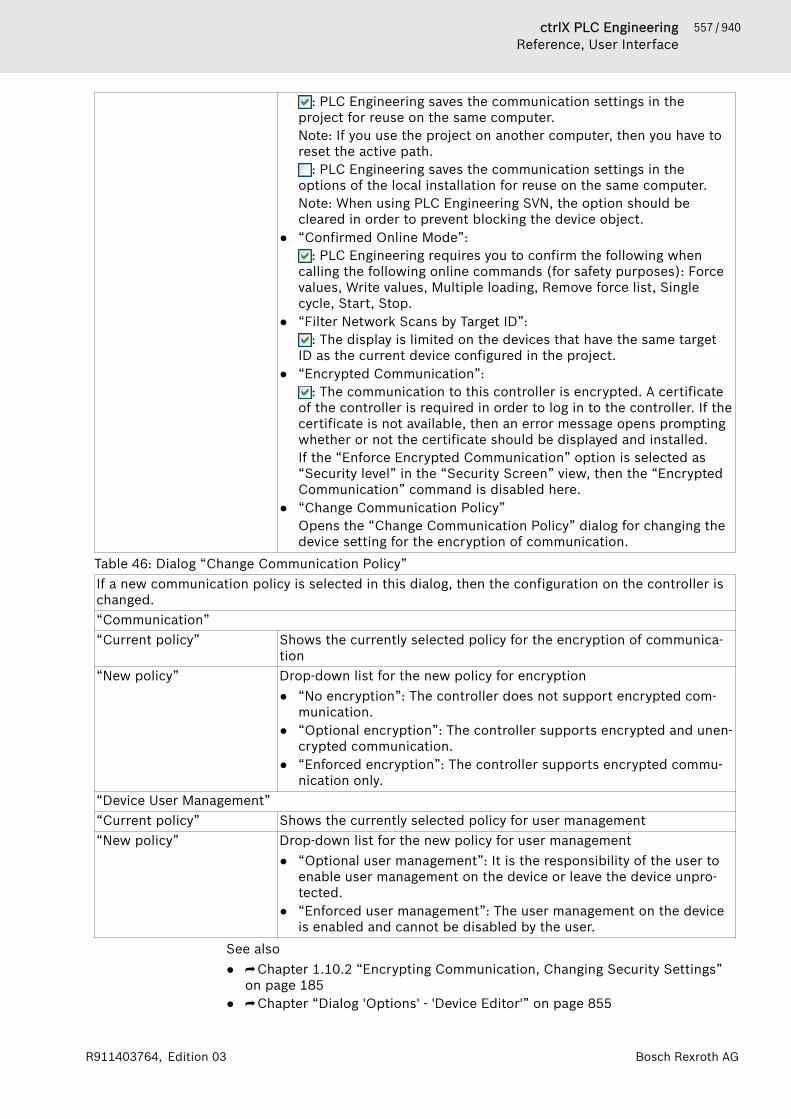
557 / 940ctrlX PLC EngineeringReference, User Interface
Bosch Rexroth AGR911403764, Edition 03
: PLC Engineering saves the communication settings in theproject for reuse on the same computer.Note: If you use the project on another computer, then you have toreset the active path.
: PLC Engineering saves the communication settings in theoptions of the local installation for reuse on the same computer.Note: When using PLC Engineering SVN, the option should becleared in order to prevent blocking the device object.
● “Confirmed Online Mode”:: PLC Engineering requires you to confirm the following when
calling the following online commands (for safety purposes): Forcevalues, Write values, Multiple loading, Remove force list, Singlecycle, Start, Stop.
● “Filter Network Scans by Target ID”:: The display is limited on the devices that have the same target
ID as the current device configured in the project.● “Encrypted Communication”:
: The communication to this controller is encrypted. A certificateof the controller is required in order to log in to the controller. If thecertificate is not available, then an error message opens promptingwhether or not the certificate should be displayed and installed.If the “Enforce Encrypted Communication” option is selected as“Security level” in the “Security Screen” view, then the “EncryptedCommunication” command is disabled here.
● “Change Communication Policy”Opens the “Change Communication Policy” dialog for changing thedevice setting for the encryption of communication.
Table 46: Dialog “Change Communication Policy”If a new communication policy is selected in this dialog, then the configuration on the controller ischanged.“Communication”“Current policy” Shows the currently selected policy for the encryption of communica-
tion“New policy” Drop-down list for the new policy for encryption
● “No encryption”: The controller does not support encrypted com-munication.
● “Optional encryption”: The controller supports encrypted and unen-crypted communication.
● “Enforced encryption”: The controller supports encrypted commu-nication only.
“Device User Management”“Current policy” Shows the currently selected policy for user management“New policy” Drop-down list for the new policy for user management
● “Optional user management”: It is the responsibility of the user toenable user management on the device or leave the device unpro-tected.
● “Enforced user management”: The user management on the deviceis enabled and cannot be disabled by the user.
See also● ⮫ Chapter 1.10.2 “Encrypting Communication, Changing Security Settings”
on page 185● ⮫ Chapter “Dialog 'Options' - 'Device Editor'” on page 855

558 / 940 ctrlX PLC EngineeringReference, User Interface
Bosch Rexroth AG R911403764, Edition 03
● ⮫ Chapter “Command 'Scan for Devices'” on page 696● ⮫ Chapter “Command 'Add gateway'” on page 795● ⮫ Chapter “Command 'Insert Device'” on page 694● ⮫ Chapter “Command 'Configure the local gateway'” on page 795
Communication Settings - Classic ModeIn the PLC Engineering options, you can activate the classic mode of the dialog(“Tools 🠂 Options”, category "Device editor").
Table: “Select the network path tothe controller”
Gateway channel for the connection.Select the channel from the lower part of the view.
Table 47: “View displaying configured gateway channels and network devices”Left side of view Tree structure of the configured gateway channels with the connected
devices in the local network:
Note: PLC Engineering saves these entries on the local system, not inthe project.The device entries are preceded by a device symbol ( ). Entries with atarget ID that are different from those currently configured in theproject are displayed in gray.Clicking “Scan Network” refreshes the list.Note: If you created the first project on the local system, then the localgateway is listed as an entry in the tree by default. PLC Engineeringstarts this gateway automatically on system boot.The filled circle on the lower right corner of the gateway symbol pro-vides information about the connection status:● Red: ctrlX PLC Engineering System cannot establish the connection.● Green: The connection is established: ● Black: The connection status is unknown.
Note: Some communication protocols allow regular checking of thegateway so that the status cannot be displayed.
Each of the device entries in the tree consist of a symbol followed bythe “Device Name”> [“Device Address”]. On the right side of the view,you also see the “Target ID”, “Target Name”, “Target Type, TargetVendor”, and “Target Version”.
Right side of view Information about the gateway channel of device selected on the leftside of the view.When a gateway channel is selected in the left view, the following infor-mation is displayed: “Device Name”, “IP-Address”, “Port”, “Driver”When a device is selected in the left view, the following information isdisplayed (depending of the device): “Device name”, “Device address”,“Number of channels”, “Block driver”, “Serial number”, “Encryptedcommunication”, “Target vendor”, “Target ID”, “Target name”, “Targettype”,“ Target version”.

559 / 940ctrlX PLC EngineeringReference, User Interface
Bosch Rexroth AGR911403764, Edition 03
Table 48: “Filter and sorting functions on the right side of the dialog”“Filter” You can reduce the displayed list of devices that have the same “Target
ID” as the current device configured in the project.“Sorting order” You can sort the list by “Name” or “Device Address” in alphabetical or
ascending order.Table 49: Command buttons on the right side of the dialog“Set Active Path” The command sets the selected communications channel as active.
Double-clicking the entry in the channel tree achieves the same result.“Add Gateway” This command opens the “Gateway” dialog where you can define a
gateway that PLC Engineering should add to the current configuration.“Add Device” This command opens the “Add Device” dialog. Here you can manually
define a device that is to be inserted under the gateway entry currentlyselected in the tree. Please note the functionality of “Scan Network”as well.
“Scan Network” The command starts a search for available devices in the local net-work. The configuration tree of the gateway is refreshed accordingly.
Table 50: “Commands in the context menu of the gateway tree and device tree in the dialog”“Scan for Device byAddress”
The command searches the network for devices with a unique addressas given in the configuration tree. PLC Engineering displays thedetected devices with the given address below the gateway. Thesearch always applies to the devices below the selected gateway orbelow the selected entry.
“Scan for Device by Name” The command searches the network for devices with the same nameas given in the configuration tree. Capitalization is ignored here. PLCEngineering displays the detected devices below the gateway with thegiven name together with its unique device address. The search alwaysapplies to the devices below the selected gateway or below theselected entry.
“Scan for Device by IPAddress”
The command searches the network for devices with a unique IPaddress as given in the configuration tree. PLC Engineering displaysthe detected devices with the given address below the gatewaytogether with its name. The search always applies to the devices belowthe selected gateway or below the selected entry.
“Send Echo Service” PLC Engineering sends five echo services to the PLC. These are usedto test the network connection, similar to the ping function. The serv-ices are sent first without data packets and then with data packets.The scope of the data packets depends on the communication bufferof the PLC. A message box opens with information about the averageecho service delay and the scope of the sent data packets.
“Delete Selected Device” This command deletes the selected device from the channel tree.“Edit Gateway” This command opens the “Gateway” dialog for editing the settings for
the selected gateway.“Configure the LocalGateway”
This command opens a dialog for configuring a local gateway. This pro-vides an alternative to manually editing the Gateway.cfg file.
Table 51: Options in the lower part of the dialog“Don't store com-munication set-tings in project”
: The current connection settings are saved to the local PLC Engineeringoptions on your computer, not in the project. This means that you have to resetthem if you use the project on another system.
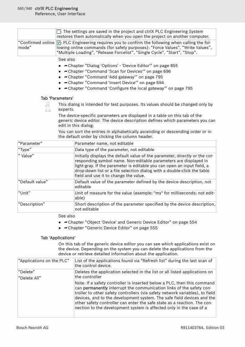
560 / 940 ctrlX PLC EngineeringReference, User Interface
Bosch Rexroth AG R911403764, Edition 03
: The settings are saved in the project and ctrlX PLC Engineering Systemrestores them automatically when you open the project on another computer.
“Confirmed onlinemode”
: PLC Engineering requires you to confirm the following when calling the fol-lowing online commands (for safety purposes): “Force Values”, “Write Values”,“Multiple Loading”, “Release Forcelist”, “Single Cycle”, “Start”, “Stop”.See also● ⮫ Chapter “Dialog 'Options' - 'Device Editor'” on page 855● ⮫ Chapter “Command 'Scan for Devices'” on page 696● ⮫ Chapter “Command 'Add gateway'” on page 795● ⮫ Chapter “Command 'Insert Device'” on page 694● ⮫ Chapter “Command 'Configure the local gateway'” on page 795
Tab 'Parameters'This dialog is intended for test purposes. Its values should be changed only byexperts.The device-specific parameters are displayed in a table on this tab of thegeneric device editor. The device description defines which parameters you canedit in this dialog.You can sort the entries in alphabetically ascending or descending order or inthe default order by clicking the column header.
“Parameter” Parameter name, not editable“Type” Data type of the parameter, not editable“ Value” Initially displays the default value of the parameter, directly or the cor-
responding symbol name. Non-editable parameters are displayed inlight-gray. If the parameter is editable you can open an input field, adrop-down list or a file selection dialog with a double-click the tablefield and use it to change the value.
“Default value” Default value of the parameter defined by the device description, noteditable
“Unit” Unit of measure for the value (example: "ms" for milliseconds; not edit-able)
“Description” Short description of the parameter specified by the device description,not editable
See also● ⮫ Chapter “Object 'Device' and Generic Device Editor” on page 554● ⮫ Chapter “Generic Device Editor” on page 555
Tab 'Applications'On this tab of the generic device editor you can see which applications exist onthe device. Depending on the system you can delete the applications from thedevice or retrieve detailed information about the application.
“Applications on the PLC” List of the applications found via “Refresh list” during the last scan ofthe control device.
“Delete”“Delete All”
Deletes the application selected in the list or all listed applications onthe controllerNote: If a safety controller is inserted below a PLC, then this commandcan permanently interrupt the communication links of the safety con-troller to other safety controllers (via safety network variables), to fielddevices, and to the development system. The safe field devices and theother safety controller can enter the safe state as a reaction. The con-nection to the development system is affected only in the case of a
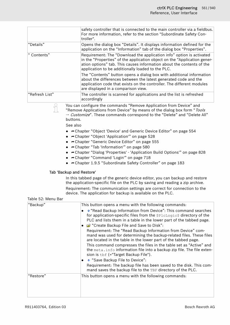
561 / 940ctrlX PLC EngineeringReference, User Interface
Bosch Rexroth AGR911403764, Edition 03
safety controller that is connected to the main controller via a fieldbus.For more information, refer to the section "Subordinate Safety Con-troller".
“Details” Opens the dialog box “Details”. It displays information defined for theapplication on the “Information” tab of the dialog box “Properties”.
“ Contents” Requirement: The “Download the application info” option is activatedin the “Properties” of the application object on the “Application gener-ation options” tab. This causes information about the contents of theapplication to be additionally loaded to the PLC.The “Contents” button opens a dialog box with additional informationabout the differences between the latest generated code and theapplication code that exists on the controller. The different modulesare displayed in a comparison view.
“Refresh List” The controller is scanned for applications and the list is refreshedaccordingly
You can configure the commands “Remove Application from Device” and“Remove Applications from Device” by means of the dialog box form “Tools🠂 Customize”. These commands correspond to the “Delete” and “Delete All”buttons.See also● ⮫ Chapter “Object 'Device' and Generic Device Editor” on page 554● ⮫ Chapter “Object 'Application'” on page 528● ⮫ Chapter “Generic Device Editor” on page 555● ⮫ Chapter “Tab 'Information'” on page 580● ⮫ Chapter “Dialog 'Properties' - 'Application Build Options'” on page 828● ⮫ Chapter “Command 'Login'” on page 718● ⮫ Chapter 1.9.5 “Subordinate Safety Controller” on page 183
Tab 'Backup and Restore'In this tabbed page of the generic device editor, you can backup and restorethe application-specific file on the PLC by saving and reading a zip archive.Requirement: The communication settings are correct for connection to thedevice. The application for backup is available on the PLC.
Table 52: Menu Bar“Backup” This button opens a menu with the following commands:
● “Read Backup Information from Device”: This command searchesfor application-specific files from the $PlcLogic$ directory of thePLC and lists them in a table in the lower part of the tabbed page.
● “Create Backup File and Save to Disk”:Requirement: The “Read Backup Information from Device” com-mand was used for determining the backup-related files. These filesare located in the table in the lower part of the tabbed page.This command compresses the files in the table set as “Active” andthe meta.info information file into a backup zip file. The file exten-sion is tbf (="Target Backup File").
● “Save Backup File to Device”:Requirement: The backup file has been saved to the disk. This com-mand saves the backup file to the TBF directory of the PLC.
“Restore” This button opens a menu with the following commands:

562 / 940 ctrlX PLC EngineeringReference, User Interface
Bosch Rexroth AG R911403764, Edition 03
● “Load Backup File from Disk”: This command opens the “Open”dialog box for navigating the file system for a saved backup file. Theincluded files are listed in a table in the lower part of the tabbedpage.
● “Load Backup File from Device”: This command generates a list ofall backup files found on the PLC. Select one of these files to viewits contents in a table on the tabbed page. For the restore opera-tion, you can deactivate optional components and edit the com-ments.
● “Restore on Device”: This command is available if at least onecomponent of the backup file that is currently loaded in the tabbedpage is set to active. It prompts for restoring the application statuson the device. The user interface is blocked during restore. You cancancel the operation.
Table 53: “Target Information”“ID” ID of the PLC (example: 0000 0001)“Type” Device type (example: 4096)“Version” Device version (example: 3.5.8.0)
Table 54: “Backup Information”“File name” Storage path of the backup file. Clicking the symbol ( ) opens the file
system dialog box. Example: PlcLogic$/Application/Applica-tion.crc
“Size of active files” (in kilobytes) Total size of the files set as active in the table (example:206 KB (210965 bytes)).
“Mode” Defines the scope of the backup: “Application”. The application-relatedfiles are added to the archive.
“Comment” Optional entry for comments to be saved in the meta.info file of thebackup and reading when the files are restored.
Table 55: Table of files for backup“Active” : Optional files can be deactivated here for exclusion in the backup
file.Required components are shown here with a green check mark (nocheck box).
“Component” Affected components (example: file system)“File” Name of the component file to back up (example: $PlcLogic$/
Application/Application.app)“Size” File size in bytes (example: 43280)“Requires STOP” : For components, the application must be stopped before backup
and restore. A dialog prompt will open to warn you of any backup orrestore conflicts.
See also● ⮫ Chapter 1.12.9 “Backup and Restore” on page 233
Tab 'Synchronized Files'This tab of the generic device editor lists the files that are downloaded to thePLC when the application is downloaded. For example, these are external filesthat were added to an application.Implicit files, such as the source code archive file, are displayed here only iftheir time of download is configured for this and the “Show implicit files forapplication download on the editor of a PLC” option is activated in the PLCEngineering options (category “Device Editor”).
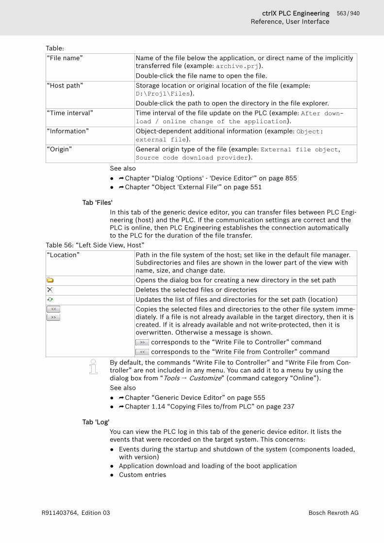
563 / 940ctrlX PLC EngineeringReference, User Interface
Bosch Rexroth AGR911403764, Edition 03
Table: “File name” Name of the file below the application, or direct name of the implicitly
transferred file (example: archive.prj).Double-click the file name to open the file.
“Host path” Storage location or original location of the file (example:D:\Proj1\Files).Double-click the path to open the directory in the file explorer.
“Time interval” Time interval of the file update on the PLC (example: After down-load / online change of the application).
“Information” Object-dependent additional information (example: Object:external file).
“Origin” General origin type of the file (example: External file object,Source code download provider).
See also● ⮫ Chapter “Dialog 'Options' - 'Device Editor'” on page 855● ⮫ Chapter “Object 'External File'” on page 551
Tab 'Files'In this tab of the generic device editor, you can transfer files between PLC Engi-neering (host) and the PLC. If the communication settings are correct and thePLC is online, then PLC Engineering establishes the connection automaticallyto the PLC for the duration of the file transfer.
Table 56: “Left Side View, Host”“Location” Path in the file system of the host; set like in the default file manager.
Subdirectories and files are shown in the lower part of the view withname, size, and change date.Opens the dialog box for creating a new directory in the set pathDeletes the selected files or directoriesUpdates the list of files and directories for the set path (location)Copies the selected files and directories to the other file system imme-diately. If a file is not already available in the target directory, then it iscreated. If it is already available and not write-protected, then it isoverwritten. Otherwise a message is shown.
corresponds to the “Write File to Controller” command corresponds to the “Write File from Controller” command
By default, the commands “Write File to Controller” and “Write File from Con-troller” are not included in any menu. You can add it to a menu by using thedialog box from “Tools 🠂 Customize” (command category “Online”).See also● ⮫ Chapter “Generic Device Editor” on page 555● ⮫ Chapter 1.14 “Copying Files to/from PLC” on page 237
Tab 'Log'You can view the PLC log in this tab of the generic device editor. It lists theevents that were recorded on the target system. This concerns:● Events during the startup and shutdown of the system (components loaded,
with version)● Application download and loading of the boot application● Custom entries
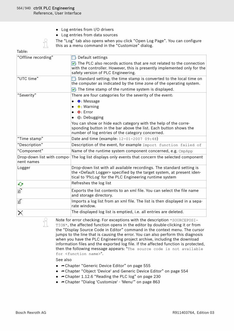
564 / 940 ctrlX PLC EngineeringReference, User Interface
Bosch Rexroth AG R911403764, Edition 03
● Log entries from I/O drivers● Log entries from data sourcesThe “Log” tab also opens when you click “Open Log Page”. You can configurethis as a menu command in the “Customize” dialog.
Table: “Offline recording” : Default settings
: The PLC also records actions that are not related to the connectionwith the controller. However, this is presently implemented only for thesafety version of PLC Engineering.
“UTC time” : Standard setting; the time stamp is converted to the local time onthe computer as indicated by the time zone of the operating system.
: The time stamp of the runtime system is displayed.“Severity” There are four categories for the severity of the event:
● : Message● : Warning● : Error● : DebuggingYou can show or hide each category with the help of the corre-sponding button in the bar above the list. Each button shows thenumber of log entries of the category concerned.
“Time stamp” Date and time (example: 12-01-2007 09:48)“Description” Description of the event, for example Import function failed of“Component” Name of the runtime system component concerned, e.g. CmpAppDrop-down list with compo-nent names
The log list displays only events that concern the selected component
Logger Drop-down list with all available recordings. The standard setting isthe <Default Logger> specified by the target system, at present iden-tical to 'PlcLog' for the PLC Engineering runtime systemRefreshes the log list
Exports the list contents to an xml file. You can select the file nameand storage directory.Imports a log list from an xml file. The list is then displayed in a sepa-rate window.The displayed log list is emptied, i.e. all entries are deleted.
Note for error checking: For exceptions with the description *SOURCEPOSI-TION*, the affected function opens in the editor by double-clicking it or fromthe “Display Source Code in Editor” command in the context menu. The cursorjumps to the line that is causing the error. You can also perform this diagnosiswhen you have the PLC Engineering project archive, including the downloadinformation files and the exported log file. If the affected function is protected,then the following message appears: "The source code is not availablefor <function name>".See also● ⮫ Chapter “Generic Device Editor” on page 555● ⮫ Chapter “Object 'Device' and Generic Device Editor” on page 554● ⮫ Chapter 1.12.6 “Reading the PLC log” on page 230● ⮫ Chapter “Dialog 'Customize' - 'Menu'” on page 863

565 / 940ctrlX PLC EngineeringReference, User Interface
Bosch Rexroth AGR911403764, Edition 03
Tab 'PLC Settings'On this tab of the generic device editor you make the basic settings for the con-figuration of the PLC, for example the handling of inputs and outputs and thebus cycle task.
“Application for I/O han-dling”
Application that is responsible for the I/O handling.
Table 57: “PLC Settings”“Refresh I/Os in stop” : PLC Engineering refreshes the values of the input and output chan-
nels even if the PLC is in the stop state. If the watchdog detects a mal-function, the outputs are set to the predefined default values.
: PLC Engineering does not refresh the values of the input andoutput channels when the PLC is in the stop state.
“Behavior of the outputs atstop”
Handling of the output channels when the controller enters the stopstate:● “Retain values”: The current values are retained.● “All outputs to default value”: The default values resulting from the
I/O mapping are assigned.● “Execute program”: You can control the handling of the output
values via a program contained in the project, which PLC Engi-neering executes at "STOP". Enter the name of the program in thefield on the right.
“Always update variables” Global setting that defines whether or not PLC Engineering updatesthe I/O variables in the bus cycle task. This setting is effective for I/Ovariables of the slaves and modules only if 'deactivated' is defined intheir update settings.● “Deactivated (update only if used in a task)”: PLC Engineering
updates the I/O variables only if they are used in a task.● “Activates 1 (use bus cycle task if not used in another task)”: PLC
Engineering updates the I/O variables in the bus cycle task if theyare not used in any other task.
● “Activate 2 (always in bus cycle task)”: PLC Engineering updates allvariables in each cycle of the bus cycle task, regardless of whetherthey are used and whether they are mapped to an input or outputchannel.
Table 58: “Bus Cycle Options”“Bus cycle task” Task that controls the bus cycle. By default the task defined by the
device description is entered.By default the bus cycle setting of the superordinate bus device (usecycle settings of the superordinate bus) applies, i.e. the device tree isscanned upwards for the next valid bus cycle task definition.Pay strict attention to the following notes!
NOTICE Before you select the “<unspecified>” setting for the buscycle task, you should be aware that "<unspecified>"means that the default setting given in the devicedescription goes into effects. You should therefore checkthis description. Use of the task with the shortest cycletime may be defined as the default there, but use of thetask with the longest cycle time could equally well bedefined!
NOTICE For fieldbuses, a fixed cycle matrix is necessary toassure a determined behavior. Therefore, do not use thetype 'free-running' for a bus cycle task.

566 / 940 ctrlX PLC EngineeringReference, User Interface
Bosch Rexroth AG R911403764, Edition 03
Table 59: “Additional Settings”“Force variables for the I/Omapping ”
This setting is available only if it is supported by the device.: When compiling the application PLC Engineering creates two global
variables for each I/O channel that is mapped to a variable in thedialog “I/O Mapping”. You can use these variables for the forcing of theinput or output value on this channel, for example via an HMI visualiza-tion.
“Activate diagnostics fordevices”
: PLC Engineering automatically integrates the library CAA DeviceDiagnosis in the project and creates an implicit function block foreach device. If there is already a function block for the device, theneither an extended FB is used (for example with EtherCAT) or a furtherFB instance is added. This then contains a general implementation ofthe device diagnostics.By means of the FB instances you can determine the status of alldevices in the application and evaluate errors. In addition, the librarycontains functions for the programmatic editing of the device tree.Example: Scanning of all children of a bus system, jumping to theparent element.
“ Display I/O warnings aserrors ”
Warnings concerning the I/O configuration are displayed as errors.
See also● ⮫ Chapter “Generic Device Editor” on page 555● ⮫ Chapter “Tab '<device name> I/O Mapping'” on page 568● ⮫ Chapter “Command 'Build'” on page 711● PDF document 'CAA Device Diagnosis', which is a component of the library.
Tab 'PLC Shell'This tab of the generic device editor includes a text-based control monitor forquerying specific information from the controller. You can specify device-dependent commands for this and receive the response from the controller in aresult window.
Table 60: Bosch Rexroth AG standard commandsCommand with possible parameters Description? List of available PLC shell commands with possible param-
eters and short description.getcmdlist List of names of available PLC shell commands.mem <memory address> [<size>] Shows a hex dump of the defined memory range. The size
parameter is optional and describes the number of bytesthat should be output. Default value: 16.Example: mem 16x0422139C 8
reflect Repeats the given command (for testing the connection)applist Shows a list of all loaded applications that defines the
order in the list, beginning with 0 (application index).pid [<application name>|<appli-cation index>] *
Shows the GUID (application index) of one or all loadedapplications.
pinf [<application name>|<application index>] *
Shows the contents of the following fields from the projectinformation: title, version, author, and description. Require-ment: The option “Create POU for properties access auto-matically” in the “Project Information” dialog is activated.
startprg [<application name>|<application index>] *
Starts the given application, or all loaded applications if noapplication is given.
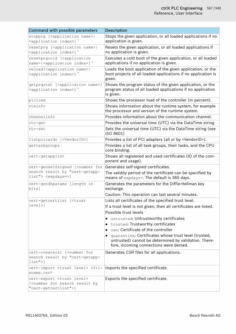
567 / 940ctrlX PLC EngineeringReference, User Interface
Bosch Rexroth AGR911403764, Edition 03
Command with possible parameters Descriptionstopprg [<application name>|<application index>] *
Stops the given application, or all loaded applications if noapplication is given.
resetprg [<application name>|<application index>] *
Resets the given application, or all loaded applications ifno application is given.
resetprgcold [<applicationname>|<application index>] *
Executes a cold boot of the given application, or all loadedapplications if no application is given.
reload[<application name>|<application index>] *
Loads the boot application of the given application, or theboot projects of all loaded applications if no application isgiven.
getprgstat [<application name>|<application index>] *
Shows the program status of the given application, or theprogram status of all loaded applications if no applicationis given.
plcload Shows the processor load of the controller (in percent).rtsinfo Shows information about the runtime system, for example
the processor and version of the runtime system.channelinfo Provides information about the communication channel.rtc-get Provides the universal time (UTC) via the DataTime stringrtc-set Sets the universal time (UTC) via the DataTime string (see
ISO 8601)listpcicards [<VendorID>] Provides a list of PCI adapters (all or by <VendorID>).gettaskgroups Provides a list of all task groups, their tasks, and the CPU
core binding.cert-getapplist Shows all registered and used certificates (ID of the com-
ponent and usage).cert-genselfsigned [<number forsearch result by "cert-getapp-list"> <expdays=>]
Generates self-signed certificates.The validity period of the certificate can be specified bymeans of expdays=. The default is 365 days.
cert-gendhparams [length inbits]
Generates the parameters for the Diffie-Hellman keyexchange.Caution: This operation can last several minutes.
cert-getcertlist [<trustlevel>]
Lists all certificates of the specified trust level.If a trust level is not given, then all certificates are listed.Possible trust levels● untrusted: Untrustworthy certificates● trusted: Trustworthy certificates● own: Certificate of the controller● quarantine: Certificates whose trust level (trusted,
untrusted) cannot be determined by validation. There-fore, incoming connections were denied.
cert-createcsr [<number forsearch result by "cert-getapp-list">]
Generates CSR files for all applications.
cert-import <trust level> <fil-ename.cer>
Imports the specified certificate.
cert-export <trust level>[<number for search result by"cert-getcertlist">]
Exports the specified certificate.

568 / 940 ctrlX PLC EngineeringReference, User Interface
Bosch Rexroth AG R911403764, Edition 03
Command with possible parameters Descriptioncert-remove <trust level><number for search result by"cert-getcertlist" or "all">
Removes the specified certificate
cpuload Shows the processor load of the CPU (for multicore, eachprocessor core)
gettaskgroups Shows a list of defined task groups. The assigned tasks areshown for each task group.
getmulticoreinfo Shows whether or not multicore is supported and thenumber of available processor cores.
*: Application name: Name of the application in the device tree; applicationindex: Results from the list of all applications on the controller that you can callwith the “applist” command. Index 0 for the application in the list, and 1 for thesecond, and so on.See also● ⮫ Chapter 1.12.8 “Using PLC Shell for requesting Information” on page 232● ⮫ Chapter “Generic Device Editor” on page 555● ⮫ Chapter “Command 'Project information'” on page 698
Tab '<device name> I/O Mapping'Devices with I/O channelsThis tab is displayed in device editors for devices with I/O channels. It showsthe available channels and allows for the mapping of input, output, andmemory addresses of the controller to variables or entire function blocks of theapplication. In this way you create the so-called 'I/O mapping'.The application that is to take care of the I/O handling is defined on the “PLCSettings” tab.You can use the 'online configuration mode' if the device supports it. In thismode you can access the I/Os of the hardware without having to load a realapplication to the device beforehand.You can also create the I/O mapping in the dialog “Edit IO Mapping”. Here youget a mapping list with search and filter functions for an entire device tree.
NOTICE Mapping 'too large' data typesIf a variable of a data type that is larger than a byte ismapped to a byte address, the value of the variable willbe truncated to byte size there! For monitoring the vari-able value in the “I/O Mapping” dialog, this means thefollowing: In the root element of the address, the value isdisplayed that the variable currently has in the project.The current individual bit values of the byte are displayedin succession in the bit elements below that, but thismay not be sufficient for the entire variable value.
Example of the tab “<device name> I/O Mapping” for a CAN bus slave:The tab contains a table for the editing of the I/O mapping. The information dis-played for the inputs and outputs originates from the device description.
“Find” (1) Input field for a search string for the mapping table. The search resultsare marked in yellow.
“Filter” (2) Drop-down list for filtering I/O mapping displayed listed in the map-ping table:
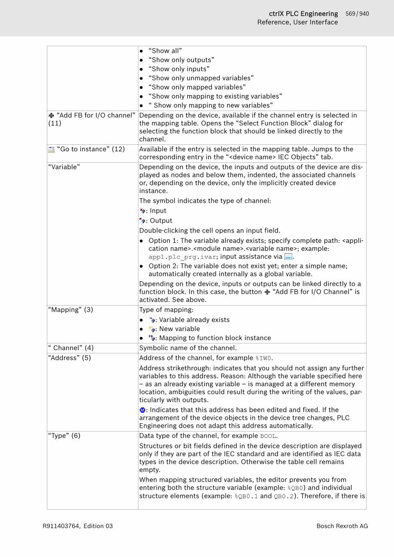
569 / 940ctrlX PLC EngineeringReference, User Interface
Bosch Rexroth AGR911403764, Edition 03
● “Show all”● “Show only outputs”● “Show only inputs”● “Show only unmapped variables”● “Show only mapped variables”● “Show only mapping to existing variables”● “ Show only mapping to new variables”
“Add FB for I/O channel”(11)
Depending on the device, available if the channel entry is selected inthe mapping table. Opens the “Select Function Block” dialog forselecting the function block that should be linked directly to thechannel.
“Go to instance” (12) Available if the entry is selected in the mapping table. Jumps to thecorresponding entry in the “<device name> IEC Objects” tab.
“Variable” Depending on the device, the inputs and outputs of the device are dis-played as nodes and below them, indented, the associated channelsor, depending on the device, only the implicitly created deviceinstance.The symbol indicates the type of channel:
: Input: Output
Double-clicking the cell opens an input field.● Option 1: The variable already exists; specify complete path: <appli-
cation name>.<module name>.<variable name>; example:app1.plc_prg.ivar; input assistance via .
● Option 2: The variable does not exist yet; enter a simple name;automatically created internally as a global variable.
Depending on the device, inputs or outputs can be linked directly to afunction block. In this case, the button “Add FB for I/O Channel” isactivated. See above.
“Mapping” (3) Type of mapping:● : Variable already exists● : New variable● : Mapping to function block instance
“ Channel” (4) Symbolic name of the channel.“Address” (5) Address of the channel, for example %IW0.
Address strikethrough: indicates that you should not assign any furthervariables to this address. Reason: Although the variable specified here– as an already existing variable – is managed at a different memorylocation, ambiguities could result during the writing of the values, par-ticularly with outputs.
: Indicates that this address has been edited and fixed. If thearrangement of the device objects in the device tree changes, PLCEngineering does not adapt this address automatically.
“Type” (6) Data type of the channel, for example BOOL.Structures or bit fields defined in the device description are displayedonly if they are part of the IEC standard and are identified as IEC datatypes in the device description. Otherwise the table cell remainsempty.When mapping structured variables, the editor prevents you fromentering both the structure variable (example: %QB0) and individualstructure elements (example: %QB0.1 and QB0.2). Therefore, if there is
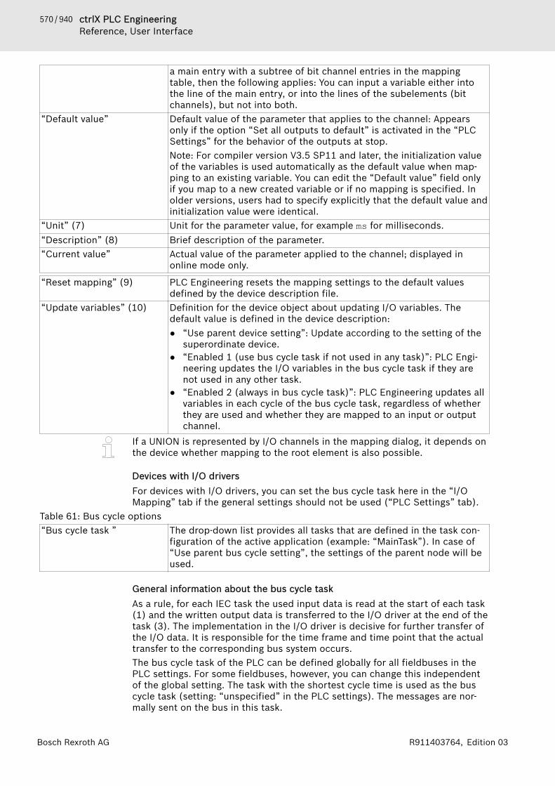
570 / 940 ctrlX PLC EngineeringReference, User Interface
Bosch Rexroth AG R911403764, Edition 03
a main entry with a subtree of bit channel entries in the mappingtable, then the following applies: You can input a variable either intothe line of the main entry, or into the lines of the subelements (bitchannels), but not into both.
“Default value” Default value of the parameter that applies to the channel: Appearsonly if the option “Set all outputs to default” is activated in the “PLCSettings” for the behavior of the outputs at stop.Note: For compiler version V3.5 SP11 and later, the initialization valueof the variables is used automatically as the default value when map-ping to an existing variable. You can edit the “Default value” field onlyif you map to a new created variable or if no mapping is specified. Inolder versions, users had to specify explicitly that the default value andinitialization value were identical.
“Unit” (7) Unit for the parameter value, for example ms for milliseconds.“Description” (8) Brief description of the parameter.“Current value” Actual value of the parameter applied to the channel; displayed in
online mode only.
“Reset mapping” (9) PLC Engineering resets the mapping settings to the default valuesdefined by the device description file.
“Update variables” (10) Definition for the device object about updating I/O variables. Thedefault value is defined in the device description:● “Use parent device setting”: Update according to the setting of the
superordinate device.● “Enabled 1 (use bus cycle task if not used in any task)”: PLC Engi-
neering updates the I/O variables in the bus cycle task if they arenot used in any other task.
● “Enabled 2 (always in bus cycle task)”: PLC Engineering updates allvariables in each cycle of the bus cycle task, regardless of whetherthey are used and whether they are mapped to an input or outputchannel.
If a UNION is represented by I/O channels in the mapping dialog, it depends onthe device whether mapping to the root element is also possible.
Devices with I/O driversFor devices with I/O drivers, you can set the bus cycle task here in the “I/OMapping” tab if the general settings should not be used (“PLC Settings” tab).
Table 61: Bus cycle options“Bus cycle task ” The drop-down list provides all tasks that are defined in the task con-
figuration of the active application (example: “MainTask”). In case of“Use parent bus cycle setting”, the settings of the parent node will beused.
General information about the bus cycle taskAs a rule, for each IEC task the used input data is read at the start of each task(1) and the written output data is transferred to the I/O driver at the end of thetask (3). The implementation in the I/O driver is decisive for further transfer ofthe I/O data. It is responsible for the time frame and time point that the actualtransfer to the corresponding bus system occurs.The bus cycle task of the PLC can be defined globally for all fieldbuses in thePLC settings. For some fieldbuses, however, you can change this independentof the global setting. The task with the shortest cycle time is used as the buscycle task (setting: “unspecified” in the PLC settings). The messages are nor-mally sent on the bus in this task.
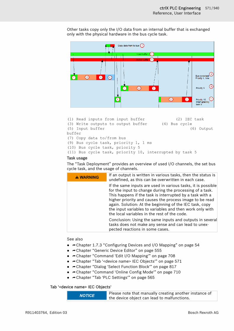
571 / 940ctrlX PLC EngineeringReference, User Interface
Bosch Rexroth AGR911403764, Edition 03
Other tasks copy only the I/O data from an internal buffer that is exchangedonly with the physical hardware in the bus cycle task.
(1) Read inputs from input buffer (2) IEC task(3) Write outputs to output buffer (4) Bus cycle(5) Input buffer (6) Output buffer(7) Copy data to/from bus(9) Bus cycle task, priority 1, 1 ms(10) Bus cycle task, priority 5(11) Bus cycle task, priority 10, interrupted by task 5Task usageThe “Task Deployment” provides an overview of used I/O channels, the set buscycle task, and the usage of channels.
WARNING If an output is written in various tasks, then the status isundefined, as this can be overwritten in each case.If the same inputs are used in various tasks, it is possiblefor the input to change during the processing of a task.This happens if the task is interrupted by a task with ahigher priority and causes the process image to be readagain. Solution: At the beginning of the IEC task, copythe input variables to variables and then work only withthe local variables in the rest of the code.Conclusion: Using the same inputs and outputs in severaltasks does not make any sense and can lead to unex-pected reactions in some cases.
See also● ⮫ Chapter 1.7.3 “Configuring Devices and I/O Mapping” on page 54● ⮫ Chapter “Generic Device Editor” on page 555● ⮫ Chapter “Command 'Edit I/O Mapping'” on page 708● ⮫ Chapter “Tab '<device name> IEC Objects'” on page 571● ⮫ Chapter “Dialog 'Select Function Block'” on page 817● ⮫ Chapter “Command 'Online Config Mode'” on page 710● ⮫ Chapter “Tab 'PLC Settings'” on page 565
Tab '<device name> IEC Objects'
NOTICE Please note that manually creating another instance ofthe device object can lead to malfunctions.
572 / 940 ctrlX PLC EngineeringReference, User Interface
Bosch Rexroth AG R911403764, Edition 03
In this tab of the generic device editor, "objects" are listed that allow for accessto the device from the IEC application. In online mode, this is used as the moni-toring view.For devices for which a function block instance is created implicitly, at leastthis instance is listed as an object here in the table. This instance can be used,for example, in order to restart a bus or to query information from the applica-tion. The device type determines whether this kind of device instance is avail-able and which access options it has. Please refer to the help for the specialdevice configuration.Instances of function blocks that are linked with inputs or outputs of the deviceare also displayed here. The mapping of a function block to a channel is definedin the “<device name> I/O Mapping” tab. The “Go to Instance” commandtakes you directly to the affected object from there.In addition, you can create more objects in the table here that are not yetlinked with a device channel.In online mode, you can use the table of IEC objects as a monitoring view. Italso shows the current value, the address, and the comment for the functionblock variable at the channel. Finally, it provides the capability of writing andforcing values.
“Add” “Edit”
Opens the “Select Function Block” dialog for creating a new instanceor for editing the instance selected in the table.
“Delete” Deletes the selected entry. “Go to Variable” Jumps from the selected entry directly to the corresponding mapping
in the “<device name> I/O Mapping” tab.“Variable” The object name comprises the device name and the function block
name. Example: EL2004_Relay. Changing the device name has animmediate effect. The part of the name after the device name is edit-able here.
“Mapping” Mapping type, as in the “<device name> I/O Mapping” tab“Type” Data type: Here it is the name of the function block.“Value”“Prepared value”“Address ”“ Comment”
In online mode only:Display of the current value, the address, and the comment for the var-iable at the channel. Moreover, the option of specifying a value forwriting or forcing the variable.
See also● ⮫ Chapter “Tab '<device name> I/O Mapping'” on page 568
Tab 'Users and Groups'
NOTICE Recommendations for Data SecurityIn order to minimize the risk of data security violations,we recommend the following organizational and tech-nical actions for the system where your applications arerunning. As far as possible, avoid exposing the PLC andcontrol networks to open networks and the internet. Useadditional data link layers for protection, such as a VPNfor teleaccess and install firewall mechanisms. Limitaccess to authorized persons, change any existingstandard passwords during the initial commissioning andcontinue to change them regularly.
On this tab of the generic device editor you edit the device user managementof the controller.
573 / 940ctrlX PLC EngineeringReference, User Interface
Bosch Rexroth AGR911403764, Edition 03
Depending on how it is supported by the device, you can define user accountsand user groups. In combination with the configuration on the “Access Rights”tab, you thus control access to control objects and files at runtime.Requirements: The controller has a user management and allows it to beedited. You have login data in order to be able to log in to the controller.It is possible to apply user account definitions from the project user manage-ment into the device user management (see below: “Import” button).
Table 62: Toolbar of the tab Synchronization Switches on and off the synchronization between the editor and the
user management on the device.If the button is not pressed, then the editor is blank or it contains aconfiguration that you loaded from the hard disk.If the button is pressed, then PLC Engineering synchronizes the dis-play in the editor continuously with the current user management onthe connected device.If you activate the synchronization while the editor contains a userconfiguration that is not synchronized with the device yet, then you areprompted what should happen to the editor contents. Options:● “Upload from the device and overwrite the editor content”: The
configuration on the device is loaded into the editor, overwritingthe current contents.
● “Download the editor content to the device and overwrite the usermanagement there”: The configuration in the editor is transferred tothe device and applied there.
Import from disk Opens the default dialog for selecting and importing a user manage-ment configuration from the hard disk.When you click the button in the “Users and Groups” tab, the file typeis “Device user management files (*.dum)”.When you click the button in the “Access Rights” tab, the file type is“Device rights management files (*.dum)”.
Export to disk Opens the default dialog for saving a file to the hard disk. This savesthe user management configuration as an XML file. The data type is“Device rights management files (*.drm)”.
“Device user” User name of the user currently logged in on the device
Table 63: “Users”All currently defined users, and below them their memberships of user groups, are listed in a treestructure.
“Add” Opens the “Add User” dialog for creating a new user account. “Import” Opens the dialog “Import User”. It displays all the user accounts
defined in the project user management.Select the desired entries and click “OK” in order to import them intothe device user management. CAUTION: The passwords are NOTapplied.
“Edit” Opens the dialog “Edit User <user name>”. It corresponds to the “AddUser” dialog and you can change the settings of the user account.
“Delete” Deletes the account of the currently selected user.Table 64: “Groups”All currently defined groups, and below them the users assigned to them, are listed in a tree struc-ture.
“Add” Opens the dialog “Add Group”.
574 / 940 ctrlX PLC EngineeringReference, User Interface
Bosch Rexroth AG R911403764, Edition 03
Define a new group name. From the list of defined users, select thosethat are to belong to the group. Confirm the selection with “OK”. Thegroup appears in the tree.
“Import” Opens the dialog “Import User”. It displays all the user groups definedin the project user management.Select the desired entries and click “OK” in order to import them intothe device user management.
“Edit” Opens the dialog “Edit Group <group name>”. It corresponds to the“Add Group” dialog and you can change the group definition.
“Delete” Deletes the currently selected group.Table 65: “Add Dialog 'Add user'”“Name” Name of the new user“Default group” Drop-down list with all configured user groups. Every user must belong
to at least one group. You define this here as a default group.“ Password”“Confirm password”“Password strength” Password security in stages from “Very weak” to “Very good”.“Hide password” : The password is shown only with asterisks "*" when it is typed in.“Password can be changedby the user”“Password must bechanged at first login”
See also● ⮫ Chapter “Object 'Device' and Generic Device Editor” on page 554● ⮫ Chapter “Generic Device Editor” on page 555● ⮫ Chapter 1.10.3 “Handling of Device User Management” on page 188● ⮫ Chapter “Tab 'Access Rights'” on page 574● ⮫ Chapter “Command 'Add Device User'” on page 728
Tab 'Access Rights'
NOTICE Recommendations for data securityIn order to minimize the risk of data security violations,we recommend the following organizational and tech-nical actions for the system where your applications arerunning. Whenever possible, avoid exposing the PLC andcontrol networks to open networks and the Internet. Useadditional data link layers for protection, such as a VPNfor teleaccess, and install firewall mechanisms. Restrictaccess for authorized persons only, and change anyexisting standard passwords during the initial commis-sioning. In addition, change them regularly.

575 / 940ctrlX PLC EngineeringReference, User Interface
Bosch Rexroth AGR911403764, Edition 03
NOTICE Detailed information on the concept and use of deviceuser management is provided in "Handling of Device UserManagement".There you will also find the following instructions on howto use the editor:− Initial login to the controller for editing and viewing
its user management− Setting up a new user in the user management of the
controller− Changing access rights to controller objects in the
user management of the controller− Loading user management from a *.dum file, modi-
fying it, and downloading it to the controller in offlinemode
On this tab of the device editor, you define the device access rights of deviceusers to objects on the controller. As in the project user management, usersmust be members of at least one user group and only user groups can begranted certain access rights.Requirements for the “Access Rights” tab to be displayed:● In the PLC Engineering options, in the “Device editor” category, the “Show
access rights page” option must be selected.Note that this PLC Engineering option can be overwritten by the devicedescription.
Requirements for the access rights to be granted to user groups● A component for the user management has to be available on the controller.
That is the primary requirement.● Users and user groups have to be configured on the “Users and Groups” tab.
Table 66: Toolbar of the tab Synchronization Switches on and off the synchronization between the editor and the
user management on the device.If the button is not pressed, then the editor is blank or it contains aconfiguration that you loaded from the hard disk.If the button is pressed, then PLC Engineering synchronizes the dis-play in the editor continuously with the current user management onthe connected device.If you activate the synchronization while the editor contains a userconfiguration that is not synchronized with the device yet, then you areprompted what should happen to the editor contents. Options:● “Upload from the device and overwrite the editor content”: The
configuration on the device is loaded into the editor, overwritingthe current contents.
● “Download the editor content to the device and overwrite the usermanagement there”: The configuration in the editor is transferred tothe device and applied there.
Import from disk Opens the default dialog for selecting and importing a user manage-ment configuration from the hard disk.When you click the button in the “Users and Groups” tab, the file typeis “Device user management files (*.dum)”.When you click the button in the “Access Rights” tab, the file type is“Device rights management files (*.dum)”.
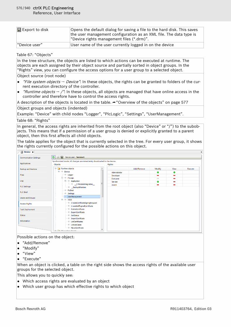
576 / 940 ctrlX PLC EngineeringReference, User Interface
Bosch Rexroth AG R911403764, Edition 03
Export to disk Opens the default dialog for saving a file to the hard disk. This savesthe user management configuration as an XML file. The data type is“Device rights management files (*.drm)”.
“Device user” User name of the user currently logged in on the device
Table 67: “Objects”In the tree structure, the objects are listed to which actions can be executed at runtime. Theobjects are each assigned by their object source and partially sorted in object groups. In the“Rights” view, you can configure the access options for a user group to a selected object.Object source (root node)● “File system objects 🠂 Device”: In these objects, the rights can be granted to folders of the cur-
rent execution directory of the controller.● “Runtime objects 🠂 /”: In these objects, all objects are managed that have online access in the
controller and therefore have to control the access rights.A description of the objects is located in the table. ⮫ “Overview of the objects” on page 577Object groups and objects (indented)Example: “Device” with child nodes “Logger”, “PlcLogic”, “Settings”, “UserManagement”.Table 68: “Rights”In general, the access rights are inherited from the root object (also “Device” or “/”) to the subob-jects. This means that if a permission of a user group is denied or explicitly granted to a parentobject, then this first affects all child objects.The table applies for the object that is currently selected in the tree. For every user group, it showsthe rights currently configured for the possible actions on this object.
Possible actions on the object:● “Add/Remove”● “Modify”● “View”● “Execute”When an object is clicked, a table on the right side shows the access rights of the available usergroups for the selected object.This allows you to quickly see:● Which access rights are evaluated by an object● Which user group has which effective rights to which object

577 / 940ctrlX PLC EngineeringReference, User Interface
Bosch Rexroth AGR911403764, Edition 03
Meanings of the symbols● : Access right granted explicitly● : Access right denied explicitly● : Access right granted through inheritance● : Access right denied through inheritance● : The access right was not granted or denied explicitly and also not inherited by the parent
object. Access is not possible.● No symbol: Multiple objects are selected that have different access rights.Change the permission by clicking the symbol.
ExampleThe “Logger” object on the “Access Rights” tab was created by the "Logger"component and controls its access rights. It is located directly below the“Device” runtime object.The possible access rights for this object can be granted only for the “View”action.
Initially, each object has a read access. This means that every user can readthe "Logger" of a controller. If this access right should be denied for a singleuser group (“Service” in the example), then the read access to the loggerobject has to be denied explicitly.
Overview of the objects
“Runtime objects 🠂 Device”“Logger” Online access to the logger is read only. Therefore, only the “View” access right
can be granted or denied here.“PlcLogic” All IEC applications are inserted here automatically as child objects during down-
load. When an application is deleted, it is removed automatically. This allows spe-cific control of online access to the application. Access rights can be assignedcentrally over all applications in the “PlcLogic” The “Administrator” and “Devel-oper” user groups have full access to the IEC applications. The “Service” and“Watch” user groups only have read access (for example for read-only monitoringof values).The following table shows which action is affected in particular when a specificaccess right is granted for an IEC application.x: The right has to be set explicitly.-: The right is not relevant.“Application” Operation Access rights
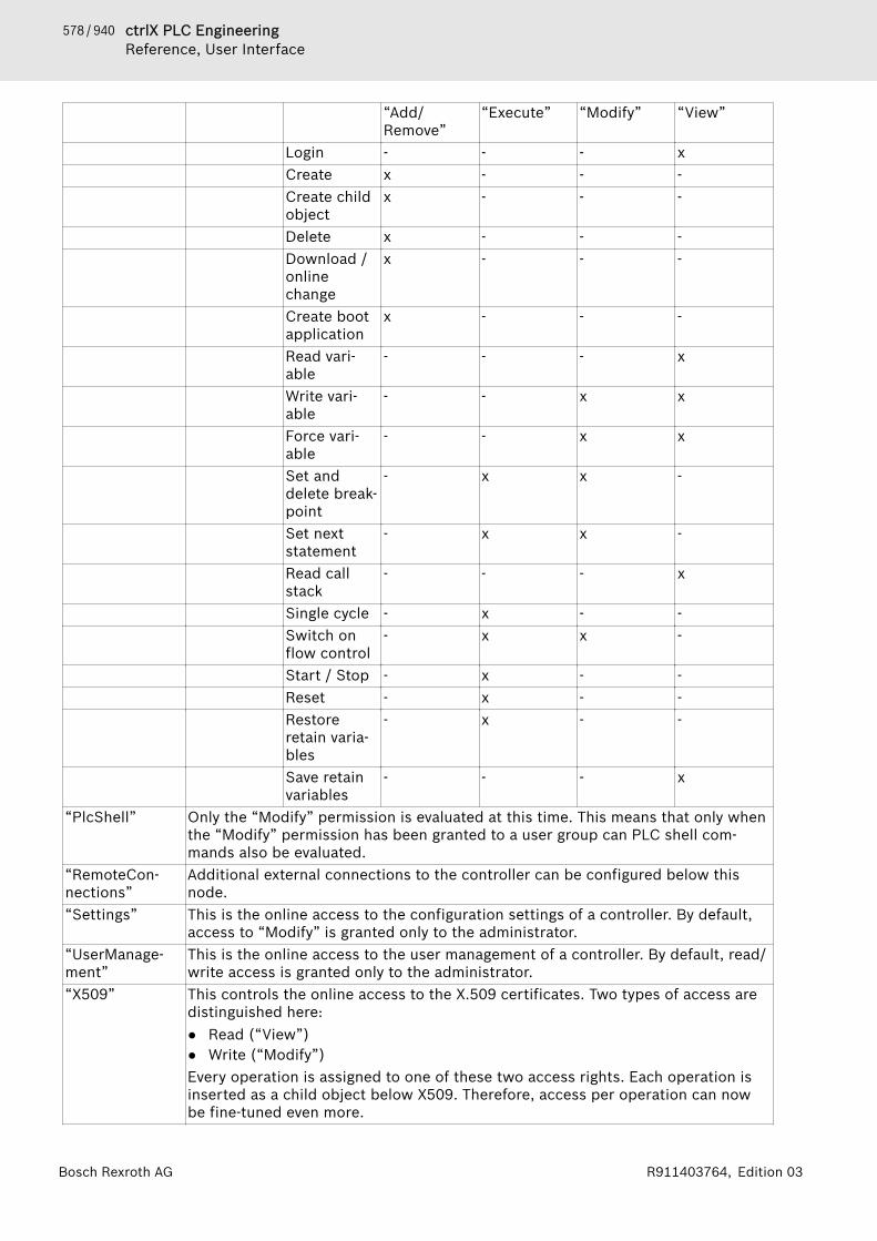
578 / 940 ctrlX PLC EngineeringReference, User Interface
Bosch Rexroth AG R911403764, Edition 03
“Add/Remove”
“Execute” “Modify” “View”
Login - - - xCreate x - - -Create childobject
x - - -
Delete x - - -Download /onlinechange
x - - -
Create bootapplication
x - - -
Read vari-able
- - - x
Write vari-able
- - x x
Force vari-able
- - x x
Set anddelete break-point
- x x -
Set nextstatement
- x x -
Read callstack
- - - x
Single cycle - x - -Switch onflow control
- x x -
Start / Stop - x - -Reset - x - -Restoreretain varia-bles
- x - -
Save retainvariables
- - - x
“PlcShell” Only the “Modify” permission is evaluated at this time. This means that only whenthe “Modify” permission has been granted to a user group can PLC shell com-mands also be evaluated.
“RemoteCon-nections”
Additional external connections to the controller can be configured below thisnode.
“Settings” This is the online access to the configuration settings of a controller. By default,access to “Modify” is granted only to the administrator.
“UserManage-ment”
This is the online access to the user management of a controller. By default, read/write access is granted only to the administrator.
“X509” This controls the online access to the X.509 certificates. Two types of access aredistinguished here:● Read (“View”)● Write (“Modify”)Every operation is assigned to one of these two access rights. Each operation isinserted as a child object below X509. Therefore, access per operation can nowbe fine-tuned even more.
579 / 940ctrlX PLC EngineeringReference, User Interface
Bosch Rexroth AGR911403764, Edition 03
“File system objects 🠂 /”All folders from the execution path of the controller are inserted below the "“/”"file system object. This allows you to grant specific rights to each folder of the filesystem.
See also● ⮫ Chapter 1.10.3 “Handling of Device User Management” on page 188● ⮫ Chapter “Generic Device Editor” on page 555● ⮫ Chapter “Tab 'Users and Groups'” on page 572
Tab 'Symbol Rights'In this tab of the generic device editor, you define the access rights of differentuser groups (clients) to the individual symbol sets available on the controller.Requirement: User management must be set up on the PLC. An application wasdownloaded to the controller for which symbol sets were defined in the PLCEngineering project. They have access data for logging in to the controller.In the “Symbol Sets” view, all symbol sets are listed below the “Application”node whose definition was downloaded with the application to the controller.In the “Rights” view, the user groups defined in the user management of thecontroller are listed in a table. When a symbol set is selected, you see theaccess rights of the corresponding user group to the symbols of this set. :Access granted; : Access not granted. You can change the access rights bydouble-clicking the symbol.Click the button to save the current access configuration to an XML file Thefile type is “Device symbol management files (*.dsm)”. Click the button toread a file like this from the hard drive.See also● ⮫ “Creating symbol sets with different access rights for different control cli-
ents” on page 165● ⮫ Chapter “Generic Device Editor” on page 555● ⮫ Chapter “Tab 'Access Rights'” on page 574● ⮫ Chapter “Tab 'Users and Groups'” on page 572
Tab 'Task deployment'This sub-dialog box of the device editor displays a table of inputs and outputsas well as their assignment to the defined tasks.The information only becomes visible after code has been generated for theapplication. It is used for troubleshooting, because it shows where inputs oroutputs are used in several tasks with different priorities. Multiple use can leadto undefined values through overwriting.
Table 69: “I/O deployment for tasks” (1)“I/O Channels” (2) All inputs and outputs of the linked devices. The display corresponds
to that in the dialog box “I/O Mapping” of the device editor.By double-clicking on an input or output you can open the associatedI/O mapping editor.
“<task name>” (3) A column appears for every task defined in the task configuration. Thetitle contains the task name and priority.
580 / 940 ctrlX PLC EngineeringReference, User Interface
Bosch Rexroth AG R911403764, Edition 03
The priority of the tasks decreases from first to the last column. A redcross appears in the box for inputs and outputs that are written orread by a task: . In addition, the task defined as a “Bus cycle task” inthe “PLC Settings” of the device editor is marked at these points witha blue double arrow symbol .Following a mouse-click on the title cell, only the I/Os assigned to thistask are displayed.Following a mouse-click on the “I/O channels” cell, all channels areshown again.
See also● ⮫ Chapter “Generic Device Editor” on page 555● ⮫ Chapter “Tab '<device name> I/O Mapping'” on page 568● ⮫ Chapter “Tab 'PLC Settings'” on page 565● ⮫ Chapter “Creating a Task Configuration” on page 130
Tab 'Status'This tab of the generic device editor displays status information, for example'Running' or 'Stopped', and specific diagnostic messages from the respectivedevice, also information about the card used and the internal bus system.See also● ⮫ Chapter “Generic Device Editor” on page 555
Tab 'Information'This tab of the generic device editor displays general information that origi-nates from the device description file: name, vendor, categories, version, ordernumber, description, if necessary an illustration.See also● ⮫ Chapter “Generic Device Editor” on page 555
Object 'GlobalTextList'Symbol: This object is for the management and translation of texts that are written asstatic text in visualizations in the project. It contains a table with these texts. Ifyou write a text in a visualization in an element under the property “Texts”, PLCEngineering automatically adds a line in the table. You cannot write any newtext here, you can only edit an existing text.In addition PLC Engineering makes the following commands available, in orderto consolidate the “GlobalTextList”:● “Check Visualization Text IDs”● “Update Visualization Text IDs”● “Remove Unused Text List Entries”The object is located in the POUs view and exists once at the most
“ID” Unambiguous identifier of the text“Default” Source text as a character string with one formatting specification at
the most, for example Information A: %i possibilities. If notranslation is written under a language column , PLC Engineering usesthis text.Double-click in the field in order to edit the text.
581 / 940ctrlX PLC EngineeringReference, User Interface
Bosch Rexroth AGR911403764, Edition 03
The table contains as many language columns as you have added. A language column is named witha language code that you entered when creating the column with the command “Insert Language”.“<Language code>” Name of the language as a language code, for example en-US. This
column contains the translation of the text that is written under“Standard”.If the language code is selected as a language in the visualization man-ager, a visualization displays the translation during operation. A run-ning visualization can switch over during operation to another lan-guage at the request of a user.Double-click in the field in order to edit the text.
See also● ⮫ Chapter “Command 'Add Language'” on page 802● ⮫ Chapter “Command 'Create Global Text List'” on page 802● ⮫ Chapter “Command 'Import/Export Text Lists'” on page 803● ⮫ Chapter “Command 'Remove Language'” on page 805● ⮫ Chapter “Command 'Remove Unused Text List Entries'” on page 805● ⮫ Chapter “Command 'Check Visualization Text IDs'” on page 805● ⮫ Chapter “Command 'Update Visualization Text IDs'” on page 805● ⮫ Chapter “Object 'TextList'” on page 629● ⮫ Chapter 1.8.9 “Managing Text in Text Lists” on page 104
Object 'GVL' - Global Variable ListSymbol: A global variable list is used for the declaration, editing and display of globalvariables.A GVL is added to the application or the project with the command “Project🠂 Add Object 🠂 Global Variable List”.If you insert a GVL under an application in the Device tree, the variables arevalid within this application. If you add a GVL in the POUs view, the variablesare valid for the entire project.You can apply settings for the editor of the object in the dialog “Tools🠂 Options” in the categories “Declaration Editor” and “Text Editor”.If the target system supports network functionality, you can convert the varia-bles of a GVL into network variables and thus use them for data exchange withother devices in the network. To do this you must define corresponding proper-ties for the GVL in the “Network Variables” tab of the “Properties” dialog.See also● ⮫ Chapter 1.8 “Programming of Applications” on page 62● ⮫ Chapter “Dialog 'Properties' - 'Network Variables'” on page 828● ⮫ Chapter “Dialog 'Options'” on page 848
Object 'GVL' - Global Variable List (task-local)Symbol: A global variable list (task-local) is used for the declaration, editing and displayof global variables. For this special global variable list, the declared variables inthe list can be written by one task only. All other tasks have only read-onlyaccess. This makes sure that the values of these variables are always consis-tent, even for multicore projects.The object is available for compiler version 3.5.13.0 with the correspondingdevice description.
“Task with write access” Task that has exclusive write access to the variables.

582 / 940 ctrlX PLC EngineeringReference, User Interface
Bosch Rexroth AG R911403764, Edition 03
See also● ⮫ Chapter “Using Task-Local Global Variable Lists” on page 67● ⮫ Chapter “Declaring Global Variables” on page 66● ⮫ Chapter “ Multicore” on page 130● ⮫ Chapter “Object 'GVL' - Global Variable List” on page 581● ⮫ Chapter “Tab 'Task Groups'” on page 644
Object 'Persistent variable list'Symbol: The object contains the declaration of global persistent variables in the decla-ration section VAR_GLOBAL PERSISTENT RETAIN .. END_VAR. The variablesare stored in special non-volatile memory.The persistence editor shows the variables as a list in the usual way. The dis-played list does not influence the persistence behavior of the variables, butonly the list stored internally in the process image. The list there contains allvariables ever declared in chronological order. Variables that you have removedare marked with a placeholder and continue to exist as a gap.The declaration section can also contain instance paths, which refer to locallydeclared persistent variables and were created with the command“Declarations 🠂 Add All Instance Paths”.
NOTICE Before you decide how to set up persistence for an appli-cation, it would be helpful for you to be familiar with theuse cases described in the “Data Persistence” section.Moreover, it is helpful if you can differentiate betweenthe mechanisms of persistent variables, retain variables,variables of the Persistence Manager, and recipe varia-bles.
CommandsThe following commands are provided in the persistence editor:● Command “Declarations 🠂 Add All Instance Paths”● Command “Declarations 🠂 Reorder List and Clear Gaps”
See also● TODO● ⮫ Chapter “Command 'Reorder List and Clean Gaps'” on page 793● ⮫ Chapter “Preserving Data with Persistent Variables” on page 142● ⮫ Chapter “Preserving Data with Retain Variables” on page 144● ⮫ Chapter “Command 'Add all instance paths'” on page 795
Object 'Image Pool'The “Image Pool” object contains a table with image ID assignments.
“ID” ID of the image; you reference this ID, for example in the visualizationof the image.
“File name” File path of the image; if you click for more settings ( ), the “SelectImage” dialog box opens.
“Image” Show a thumbnail of the image.“Link type” Opens the “Select Image” dialog box, where you define the link type.

583 / 940ctrlX PLC EngineeringReference, User Interface
Bosch Rexroth AGR911403764, Edition 03
Dialog box 'Select Image'
“Image file” Name and directory of the image file (example: "C:\Programme\images\logo.bmp") PLC Engineering supports the following image formats:BMP, EMF, GIF, ICO, JPG, PNG, SVG, and TIFF. Please note that a con-troller may not support all formats.Whether or not you can use images formatted as scalable vectorgraphics (*.svg) depends on the operating system. Any necessary infor-mation is located in the device description of the hardware vendor.
Table 70: “File Handling”“Remember the link” PLC Engineering saves only the link. PLC Engineering automatically
updates any changes to an image file in the image pool. You mustensure that the path of the image file does not change.When saving the project as an archive, PLC Engineering embeds theimage file in the project archive.
“Remember the link andembed into project”
PLC Engineering copies the image to the image pool and the link infor-mation is retained. In this way, PLC Engineering recognizes anychanges to the image file and then update the image pool can asneeded. This behavior is controlled with the options in the next table.Embedded image files increase the memory requirement of theproject.
“Embed into project” PLC Engineering copies the image to the image pool. If the image fileis changed again afterwards, then it is not updated in the project. Forlibraries, you must embed the image in the project.Embedded image files increase the memory requirement of theproject.
Table 71: “Change Tracking”These options are available only if you have selected the “Remember the link and embed intoproject” check box as described above.“Reload the file automati-cally”
PLC Engineering automatically updates the image file in the projectwithout prompting.
“Prompt whether to reloadthe file”
If the image file has changed, you may be prompted whether or not theimage file should be updated.
“Do nothing” PLC Engineering does not update the image file in the image pool.See also● ⮫ Chapter 1.8.10 “Using Image Pools” on page 111
Object 'Library Manager'Symbol: The Library Manager lists all libraries that were integrated in the project forcreating applications. It provides information about the type of library, its prop-erties, and its contents.You can expand or collapse the list of integrated libraries, as well as edit libraryproperties for non-dependent libraries.The Library Manager consists of three views:● Upper view: List of integrated libraries● Lower left view: Tree structure with all modules of the library selected in the
upper view● Lower right view: Documentation for the module selected in the treeSee also● ⮫ Chapter 1.15 “Using Libraries” on page 237

584 / 940 ctrlX PLC EngineeringReference, User Interface
Bosch Rexroth AG R911403764, Edition 03
List of integrated librariesList of all libraries integrated in the project. If a library depends on other libra-ries, then these referenced libraries are automatically integrated.
Displayed in gray fonts The library was added to the project automatically by means of a plug-in.
Displayed in black fonts The library was added to the project automatically by means of the“Add Library” command.
“Name” Display of the integrated library in the following syntax:“<placeholder name> = <library name>, <version> (<company>)”:“<placeholder name>”: If it is a placeholder library for a library, thenthe placeholder name is before a “ = ”.“<library name>”: Name of the library that is used for management inthe library repository.“<version>”: Version that was referenced at the first time it was inte-grated.“ (<company>)”: Vendor (optional)
“Namespace” Namespace for unique access to the contents of the library.It is prepended to a module identifier for this purpose:<namespace>.<library module identifier>The namespace usually coincides with the library name.Note: If the library has the property LanguageModelAttribute"qualified-access-only", then you must access the library modulein the application code by means of the namespace. Qualified (unique)access is enforced.You can modify the standard namespace for local use (within theproject) in the “Properties” dialog.
“ Effective version” Version of the library after the resolution. This version is used in theproject.Requirement: The Library Manager exists in the “Devices” view and aplaceholder library is selected.Example: 3.5.10.0A placeholder library that is integrated below an application isresolved by assigning a special resolution to the placeholder library inthe “Placeholders” dialog. Then the selected library is loaded. Otherresolutions are ignored. If no special resolution is given, then a checkis performed as to whether or not a resolution is specified in thedevice description and library profile of the application. The firstsearch hit is applied.Symbol with tooltip to notify about the current device-dependent reso-lution of the selected library.Example when the Library Manager is in the “Devices” view: “This pla-ceholder is explicitly redirected to this version (see the Placeholdersdialog)”Example when the Library Manager is in the “POUs” view: “In the 'De-vice_1' device, the placeholder is resolved to 'VisuElemsAlarms, 1.0.0.0(System)”A placeholder library that is integrated in the “POUs” view is resolvedby checking depending on the application whether or not a resolutionis specified in the device description. Afterwards, the library profile ischecked. The first detected resolution is used. If you have assigned a

585 / 940ctrlX PLC EngineeringReference, User Interface
Bosch Rexroth AGR911403764, Edition 03
special resolution to the placeholder library in the “Placeholders”dialog, then this will always be ignored. The result is shown in thetooltip of the symbol.Library that is signed with a trusted certificate (compatible with PLCEngineering >= V3 SP15)Library that is signed with a trusted certificate, but references at leastone unsigned libraryLibrary that is signed with a private key and token (compatible withPLC Engineering < V3 SP15)Library that is not signed, or signed with an untrusted or expired cer-tificate. In the case of an untrusted certificate, the “Trust Certificate”command is provided in the context menu.Library that is defined as optional and not currently availableLibrary whose status is being determinedLicensed library for which no valid license is currently availableLibrary symbol for a library that cannot be loaded because its signa-ture (encryption) could not be verified
Table 72: Commands in the Library Manager “Add Library” Opens the dialog for selecting a library. All libraries installed in the
library repository are offered. “Delete Library” Removes the presently selected library from the project “Properties” Opens the dialog for the display and editing of the properties of the
presently selected library “Details” Opens a dialog with details for the presently selected library (general
information, contents, properties, license information) “Try to Reload Library” If you select a library marked as not found, you can attempt to load it
into the project again using this command. “Download Missing
Libraries”PLC Engineering scans for the missing libraries in the downloadservers specified in the project options.After that you can download and install the library.
“Placeholders” The “Placeholders” dialog opens. The current resolution is displayedand you can edit them here.
“Library Repository” Opens the “Library Repository” dialog for installing and uninstallinglibraries and for defining library locations
“Icon legend” Opens the “Information” dialog with a legend of the icons that displaythe current status of a library in the list of integrated libraries (seeabove)
“Trust Certificate” Only in the context menu of a library selected in the Library Manager,in which the library has been signed with an untrusted certificate. Thecommand turns the untrusted certificate into a trusted certificate andthe prepended icon changes from to .
“Export Library” Only in the context menu of a library selected in the Library Manager:Opens the default dialog for saving the library file in the file system
See also● ⮫ Chapter “Command 'Add Library'” on page 787● ⮫ Chapter “Command 'Export Library'” on page 791● ⮫ Chapter “Command 'Properties'” on page 789● ⮫ Chapter “Command 'Library Repository'” on page 742● ⮫ Chapter “Command 'Placeholders'” on page 791
586 / 940 ctrlX PLC EngineeringReference, User Interface
Bosch Rexroth AG R911403764, Edition 03
● ⮫ Chapter “Dialog 'Options' – 'Library Download'” on page 850● ⮫ Chapter “Object 'Project Information'” on page 622
Tree structure of all modules of a selected libraryAll library modules that were integrated with the library are listed in the treestructure.Requirement: A library is selected in the upper view.The usual sorting and search functions are available in the menu bar.
Documentation for the library module selected in the lower left view
Tab “Inputs/Outputs” Interface (inputs/outputs) of the library moduleTab “Graphical” Graphical display of the moduleTab “Documentation” Documentation for the library module.
Note: As a library developer, you must follow the rules for documenta-tion inclusion in 'Guidelines for library development'.
Tab “Parameter List” Requirement: The library project contains a parameter list.You can change the values of these parameters in the column “Value(editable)”.
See also● ⮫ Chapter 1.15.1 “Information for Library Developers” on page 238
Object 'Network Variable List (Sender)'Symbol: A network variable list (sender) is used for declaring and listing global variablesthat should be sent to network variable lists (receiver) of other devices or net-work projects.You add the object to the device tree by clicking “Add Object 🠂 NetworkVariable List (Sender)” of an application.You can configure the protocol and transfer parameters in the “Add NetworkVariable List (Sender)” dialog box or “Properties” dialog box of the object inthe “Network Variables” tab.
Dialog Box 'Add Network Variable List (Sender)'Function: This dialog box defines the network properties for the sender NVL.When you close the dialog box, PLC Engineering adds the sender NVL of theapplication to the device tree.Call: Main menu “Project 🠂 Add Object 🠂 Network Variable List (Sender)”while the application is selected in the device tree.This dialog box corresponds to the “Network Variables” tab in the “Properties”of the network variable list object.See also● ⮫ Chapter 1.9.3 “Network Variables” on page 166● ⮫ Chapter “Dialog 'Properties' - 'Network Variables'” on page 828● ⮫ Chapter “Object 'Network Variable List (Receiver)'” on page 586● ⮫ Chapter “Configuring a Network Variable Exchange” on page 168
Object 'Network Variable List (Receiver)'Symbol: The object is used for listing the received network variables and displaying theinformation: network and transmit information and sender.
587 / 940ctrlX PLC EngineeringReference, User Interface
Bosch Rexroth AGR911403764, Edition 03
You add the object to an application by clicking “Add Object 🠂 NetworkVariable List (Receiver)”.The network variable list (receiver) shows the received network variables,which were declared in network variable list (sender) of another device orproject. You cannot change the network variables in the object editor.The object editor consists of two parts:● Information about the sender and transfer log of the list● List of declarations of network variables
Dialog Box 'Add Network Variable List (Receiver)'Function: This dialog box defines the receiver NVL to a sender NVL and addsthe receiver NVL to the application object in the device tree.Call: Main menu “Project 🠂 Add Object 🠂 Network Variable List (Receiver)”(when the application object is selected).
“Task” Task of the current application that controls the variables tobe received.
“Sender” Drop-down list● Available sender NVLs of another device in the project● “Import from file”: Required if the necessary sender NVL
is defined in another project. For this, the necessarysender NVL must have been generated in another projectas “GVL export file *.gvl” in the properties dialog of theNVL in the “Link To File” tab.
“Import from file” File name in “GVL export file *.gvl” format if you haveselected “Import from file” for “Sender ”.
See also● ⮫ Chapter 1.9.3 “Network Variables” on page 166● ⮫ Chapter “Configuring a Network Variable Exchange” on page 168● ⮫ Chapter “Object 'Network Variable List (Sender)'” on page 586
Object 'POU'Symbol: An object of the type “POU” is a Program Organization Unit in a PLC Engi-neering project. You write source code for your controller program in POUs.There are the following types of POUs:● Program● Function● Function blockA “POU” object is inserted by using the command “Project 🠂 Add Object” inthe Device tree or in the “POUs” view. When adding a POU you define the POUtype and the implementation language.You can also add other programming objects (method, action, etc.) to theseobjects.Calling POUsCertain POUs can call other POUs. Recursions are not permitted.When calling POUs via the namespace, PLC Engineering browses the project forthe POU to be called in accordance with the following order:1. Current application2. “Library Manager” of the current application3. “POUs” view
588 / 940 ctrlX PLC EngineeringReference, User Interface
Bosch Rexroth AG R911403764, Edition 03
4. “Library Manager” in the “POUs” viewIf you want to call a POU that exists with the same name in a library used in theapplication and as an object in the “POUs” view, note the following: There is nosyntax that allows you to call the POU in the “POUs” view only by its name. Inthis case you must shift the library from the application's library manager tothe project's library manager (in the “POUs” view). After that you can call thePOU object in the “POUs” view purely by its name. If you add the namespace tothe library, you can call the POU of the library.The term “POU” is also used in PLC Engineering for the “POUs” view in whichPLC Engineering manages the global objects in the project.See also● ⮫ Chapter “Object 'POU'” on page 587● ⮫ Chapter “Dialog 'Properties'” on page 822
Dialog 'Add POU'Function: The dialog is used to configure a new POU according to the IEC61131-3 standard. This means that a POU can be a program, a function, or afunction block.Call: Menu bar: “Project 🠂 Add Object”; context menu in the “Devices” viewwhen an application is selected; context menu in the “POUs” view
“Name” Name of POUTable 73: “Type”“Program”“Function Block” ● “Extends”: Specification or selection of a base function module
in the sense of object-oriented programming. Specified with theEXTENDS keyword in the function block declaration.
● “Implements”: Specification or selection of an interface in thesense of object-oriented programming. Specified with the IMPLE-MENTS keyword in the function block declaration.
● “Final”: Derived access is not permitted. This means that youcannot extend the function block with another function block. Thisallows for optimized code generation.
● “Abstract”: Identifies that the function block has a missing orincomplete implementation and cannot be instantiated. AbstractFBs are used exclusively as base function blocks and the implemen-tation typically occurs in a derived FB.
● “Access specifier”– “PUBLIC”: Corresponds to the specification of no access modi-
fier– “INTERNAL”: Access to the function block is restricted to the
namespace (library).● “Method implementation language”: When you select the “Imple-
ments” option, you can select an implementation language here forall method objects that PLC Engineering generates by means of theimplementation of the interface.The “Method implementation language” does not depend on theimplementation language of the function block.
“Function” Note: Not available when “Sequential Function Chart (SFC)” isselected as the “Implementation language”.“Return type:”: Data type of the return value
“Implementation language” Implementation language of the POU
589 / 940ctrlX PLC EngineeringReference, User Interface
Bosch Rexroth AGR911403764, Edition 03
See also● ⮫ Chapter “Object 'Function Block'” on page 590● ⮫ Chapter “Object 'Program'” on page 589● ⮫ Chapter “Object 'Function'” on page 592● ⮫ Chapter “Extension of Function Blocks” on page 152● ⮫ Chapter “Implementing Interfaces” on page 154
Object 'Program'A program is a POU that supplies one or more values during execution. Afterexecution of the program, all values are retained until the next execution. Theorder of calling the programs within an application is defined in task objects.A program is added to the application or the project using the command“Project 🠂 Add Object 🠂 POU”. In the Device tree and in the “POUs” view theprogram POUs have the suffix “(PRG)”.The editor of a program consists of the declaration part and the implementa-tion part.The uppermost line of the declaration part contains the following declaration:PROGRAM <program>
Calling a programPrograms and function blocks can call a program. A program call is not per-mitted in a function. There are no instances of programs.If a POU calls a program and values of the program change as a result, thesechanges are retained until the next program call. The values of the program arealso retained even if the repeat call takes place by another POU. This differsfrom the call of a function block. When calling a function block only the valuesof the respective instance of the function block change. The changes only needto be observed if a POU calls the same instance again.You can also set the input or output parameters for a program directly whencalling.Syntax: <program>(<input variable> := <value>, <output value> =><value>):If you insert a program call via the input assistant and the “Insert with argu-ments” option in the input assistant is activated at the same time, PLC Engi-neering adds input and/or output parameters to the program call in accordancewith the syntax.

590 / 940 ctrlX PLC EngineeringReference, User Interface
Bosch Rexroth AG R911403764, Edition 03
ExamplesCalls:IL:
With assignment of the parameters:
ST:
PLC_PRG() erg := PLC_PRG.out2; With assignment of the parameters:PLC_PRG(in1:=2, out1=>erg);
See also● ⮫ Chapter “Object 'POU'” on page 587● ⮫ Chapter 1.8.17 “Task Configuration” on page 129
Object 'Function Block'A function block is a POU that supplies one or more values during execution.The object is added to the application or the project using the command“Project 🠂 Add Object 🠂 POU”. In the Device tree or in the “POUs” view thefunction block POUs have the suffix “(FB)”.You always call a function block via an instance that is a copy of the functionblock.The editor of a function block consists of the declaration part and the imple-mentation part.After execution the values of the output variables and the internal variables areretained until the next execution. This means that the function block does notnecessarily supply the same output values with the same input variables whencalled repeatedly.In addition to the functionality described in IEC 61131-3, you can also use func-tion blocks in PLC Engineering for the following functionalities of object-ori-ented programming:
591 / 940ctrlX PLC EngineeringReference, User Interface
Bosch Rexroth AGR911403764, Edition 03
● Extension of a function block● Implementation of interfaces● Methods● PropertiesThe uppermost line of the declaration part contains the following declaration: FUNCTION_BLOCK <access specifier> <function block> | EXTENDS<function block> | IMPLEMENTS <comma-separated list of inter-faces>
Calling a function blockThe call always takes place via an instance of the function block. When calling afunction block only the values of the respective instance change.Declaration of the instance:<instance> : <function block>;You access a variable of the function block in the implementation part as fol-lows:<instance>.<variable>
NOTICE Please note the following:− From outside of the function block instance you can
access only the input and output variables of a func-tion block, not the internal variables.
− Access to a function block instance is limited to thePOU in which the instance is declared, unless youhave declared the instance as global.
− You can assign the desired values to the functionblock variables when calling the instance.
ExampleAccess to function block variables:The function block “FB1” has the input variable iVar1 of the type INT and theoutput variable out1. In the following the variable iVar1 is called from theprogram “Prog”.
PROGRAM Prog VAR inst1:FB1; END_VAR
inst1.iVar1 := 33; (* FB1 is called and the value 33 is assigned to the variable iVar1 *)
inst1(); (* FB1 is called, that's necessary for the following access to the output variable *)
ires := inst1.out1 (* the output variable out1 of the FB1 is read *)

592 / 940 ctrlX PLC EngineeringReference, User Interface
Bosch Rexroth AG R911403764, Edition 03
In FBD:
Assigning variable values during the call:In the text languages IL and ST you can directly assign values to the inputand/or output variables when calling the function block.The assignment of a value to an input variable takes place with :=The assignment of a value to an output variable takes place with =>
ExampleThe instance CMD_TMR of the timer function block is called with assignmentsfor the input variables IN and PT. Subsequently, the output variable Q of thetimer is assigned to the variable A
CMD_TMR (IN := %IX5, PT := 100=);
A:= CMD_TMR.Q;
If you insert a function block instance via the “input assistant” and the option“Insert with arguments” is activated in the “Input Assistant” dialog box, PLCEngineering inserts the call with all input and output variables. You then onlyneed to insert the desired value assignment. In the above example PLC Engi-neering inserts the call as follows: CMD_TMR (IN:= ,PT:= , Q=> ).
See also● ⮫ Chapter “Object 'POU'” on page 587● ⮫ Chapter “Extension of Function Blocks” on page 152● ⮫ Chapter “Implementing Interfaces” on page 154● ⮫ Chapter “Object 'Method'” on page 596● ⮫ Chapter “Object 'Property'” on page 603
Object 'Function'A function is a POU that supplies precisely one data element when executedand whose call in textual languages can occur as an operator in expressions.The data element can also be an array or a structure.The object is added to the application or the project by clicking “Project 🠂 AddObject 🠂 POU”. In the device tree or in the “POUs” view, function POUs havethe “(FUN)” suffix.
NOTICE Functions have no internal status information, whichmeans that functions do not save the values of their vari-ables until the next call. Calls of a function with thesame input variable values always supply the sameoutput value. Therefore, functions must not use globalvariables and addresses!
The editor of a function consists of the declaration part and the implementa-tion part.The top line of the declaration part contains the following declaration:
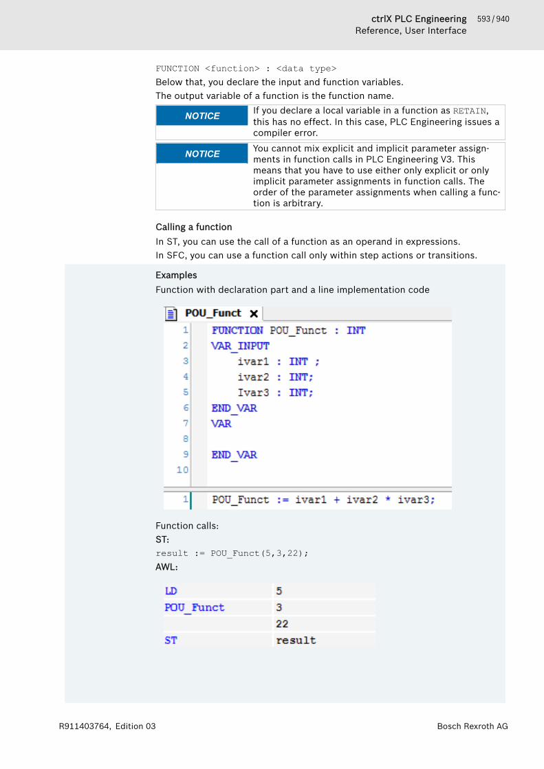
593 / 940ctrlX PLC EngineeringReference, User Interface
Bosch Rexroth AGR911403764, Edition 03
FUNCTION <function> : <data type>Below that, you declare the input and function variables.The output variable of a function is the function name.
NOTICE If you declare a local variable in a function as RETAIN,this has no effect. In this case, PLC Engineering issues acompiler error.
NOTICE You cannot mix explicit and implicit parameter assign-ments in function calls in PLC Engineering V3. Thismeans that you have to use either only explicit or onlyimplicit parameter assignments in function calls. Theorder of the parameter assignments when calling a func-tion is arbitrary.
Calling a functionIn ST, you can use the call of a function as an operand in expressions.In SFC, you can use a function call only within step actions or transitions.
ExamplesFunction with declaration part and a line implementation code
Function calls:ST:result := POU_Funct(5,3,22);AWL:
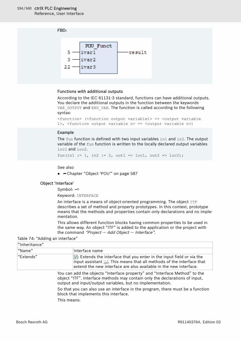
594 / 940 ctrlX PLC EngineeringReference, User Interface
Bosch Rexroth AG R911403764, Edition 03
FBD:
Functions with additional outputsAccording to the IEC 61131-3 standard, functions can have additional outputs.You declare the additional outputs in the function between the keywordsVAR_OUTPUT and END_VAR. The function is called according to the followingsyntax:<function> (<function output variable1> => <output variable 1>, <function output variable n> => <output variable n>)
ExampleThe fun function is defined with two input variables in1 and in2. The outputvariable of the fun function is written to the locally declared output variablesloc1 and loc2.fun(in1 := 1, in2 := 2, out1 => loc1, out2 => loc2);
See also● ⮫ Chapter “Object 'POU'” on page 587
Object 'Interface'Symbol: Keyword: INTERFACEAn interface is a means of object-oriented programming. The object ITFdescribes a set of method and property prototypes. In this context, prototypemeans that the methods and properties contain only declarations and no imple-mentation.This allows different function blocks having common properties to be used inthe same way. An object “ITF” is added to the application or the project withthe command “Project 🠂 Add Object 🠂 Interface”.
Table 74: “Adding an interface”“Inheritance”“Name” Interface name“Extends” : Extends the interface that you enter in the input field or via the
input assistant . This means that all methods of the interface thatextend the new interface are also available in the new interface.
You can add the objects “Interface property” and “Interface Method” to theobject “ITF”. Interface methods may contain only the declarations of input,output and input/output variables, but no implementation.So that you can also use an interface in the program, there must be a functionblock that implements this interface.This means:
595 / 940ctrlX PLC EngineeringReference, User Interface
Bosch Rexroth AGR911403764, Edition 03
● the function block contains the interface in its IMPLEMENTS list in its decla-ration part
● the function block contains an implementation for all methods and propertyprototypes of the interface
A function block can implement one or more interfaces. You can use the samemethod with identical parameters, but different implementation code in dif-ferent function blocks.Please note the following:● You may not define variables within an interface. An interface has no imple-
mentation part and no actions. Only a collection of methods is defined, inwhich you may define only input, output and input/output variables.
● PLC Engineering always treats variables declared with the type of an inter-face as references.
● A function block that implements an interface must contain implementationcode for the methods of the interface. You have named the methods exactlyas in the interface and the methods contain the same input, output andinput/output variables as in the interface.
NOTICE Interface references and online changeThe following can happen with a compiler version <3.4.1.0: if a function block changes its data because vari-ables are added or deleted, or because the type of varia-bles changes, then PLC Engineering copies all instancesof the function block to a new memory location. In thiscase, however, an interface reference refers not to thenew memory location, but still to the old one.In case of compiler versions >= 3.4.1.0, PLC Engineeringautomatically re-addresses the interface references sothat PLC Engineering also references the correct inter-face in case of an online change. PLC Engineeringrequires additional code and more time for this, so thatjitter problems can occur depending on the number ofobjects concerned. Therefore, PLC Engineering displaysthe number of variables and interface references con-cerned before the execution of the online change andyou can then decide whether the online change shouldbe executed or aborted.
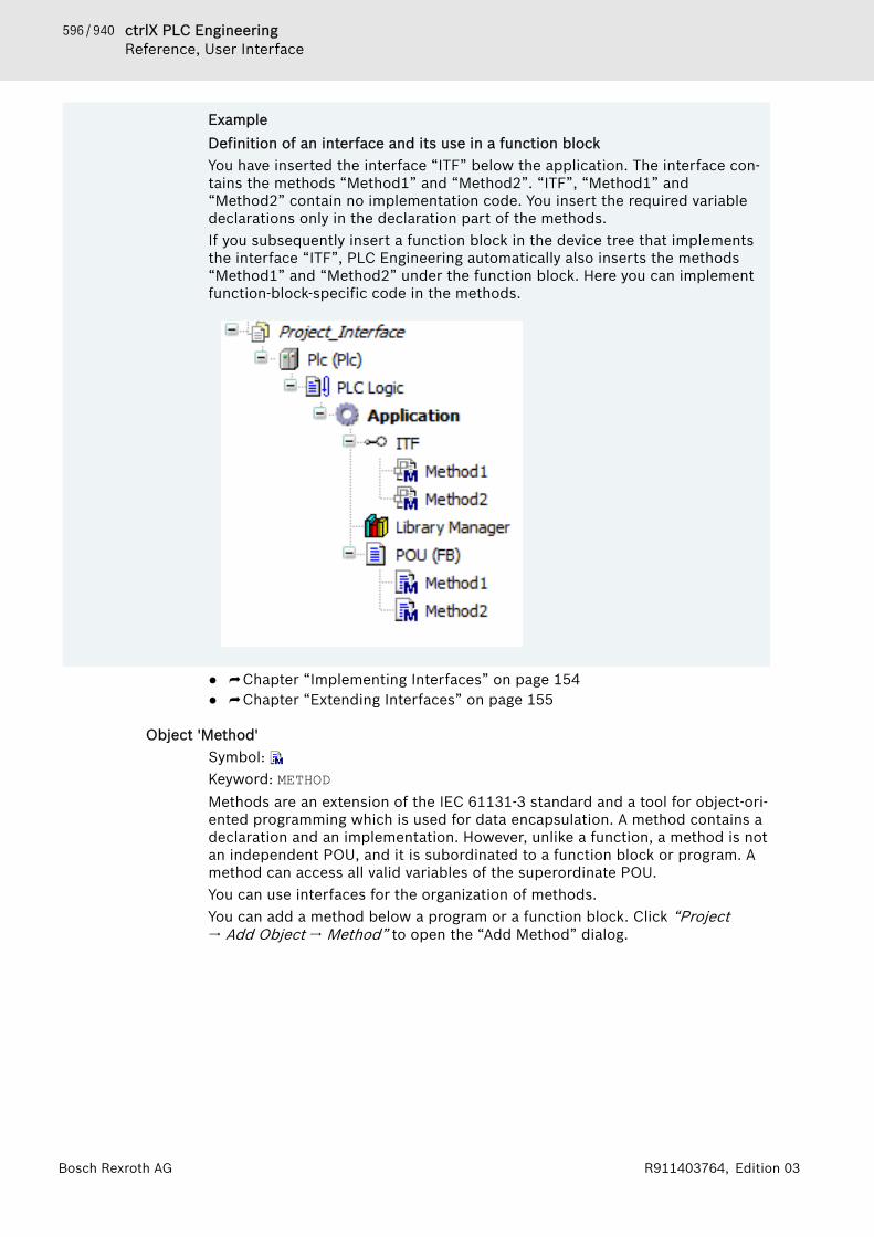
596 / 940 ctrlX PLC EngineeringReference, User Interface
Bosch Rexroth AG R911403764, Edition 03
ExampleDefinition of an interface and its use in a function blockYou have inserted the interface “ITF” below the application. The interface con-tains the methods “Method1” and “Method2”. “ITF”, “Method1” and“Method2” contain no implementation code. You insert the required variabledeclarations only in the declaration part of the methods.If you subsequently insert a function block in the device tree that implementsthe interface “ITF”, PLC Engineering automatically also inserts the methods“Method1” and “Method2” under the function block. Here you can implementfunction-block-specific code in the methods.
● ⮫ Chapter “Implementing Interfaces” on page 154● ⮫ Chapter “Extending Interfaces” on page 155
Object 'Method'Symbol: Keyword: METHODMethods are an extension of the IEC 61131-3 standard and a tool for object-ori-ented programming which is used for data encapsulation. A method contains adeclaration and an implementation. However, unlike a function, a method is notan independent POU, and it is subordinated to a function block or program. Amethod can access all valid variables of the superordinate POU.You can use interfaces for the organization of methods.You can add a method below a program or a function block. Click “Project🠂 Add Object 🠂 Method” to open the “Add Method” dialog.
597 / 940ctrlX PLC EngineeringReference, User Interface
Bosch Rexroth AGR911403764, Edition 03
Declaration● The variables of a method contain temporary data that are valid only during
the execution of the method (stack variables). All variables that are declaredand implemented in a method are reinitialized each time the method iscalled.
● Like functions, methods can have additional outputs. You must assign theseadditional outputs in the method call.
● Depending on the declared access specifier, a method can be called onlywithin its own namespace (INTERNAL), only within its own POU and itsderivatives (PROTECTED), or only within its own POU (PRIVATE). For PUBLIC,the method can be called from anywhere.
Interface methods can have declared input, output, and VAR_IN_OUT variables,but do not contain an implementation.See also● ⮫ Chapter “Object 'Interface Method'” on page 600
Implementation● Access to function block instances or program variables is permitted in the
implementation of the method.● The THIS pointer allows for access to its own function block instance. There-
fore, the pointer is permitted only in methods that are assigned to a functionblock.
● A method cannot access VAR_TEMP variables of the function block.● A method can call itself recursively.
NOTICE When you copy a method below a POU and add it belowan interface, or move the method there, the containedimplementation is removed automatically.
Calling a method
Syntax for calls:
<return value variable> := <POU name> . <method name> ( <method input name> := <variable name> (, <further method input name> := <variable name> )* );For the method call, you assign transfer parameters to the input variables ofthe method. Respect the declaration when doing this. It is enough to specifythe names of the input variables without paying attention to their order in thedeclaration.
598 / 940 ctrlX PLC EngineeringReference, User Interface
Bosch Rexroth AG R911403764, Edition 03
Example
Declaration
METHOD PUBLIC DoIt : BOOLVAR_INPUTiInput_1 : DWORD;iInput_2 : DWORD;sInput_3 : STRING(12);
END_VARCall
bFinishedMethod := fbInstance.DoIt(sInput_3 := 'Hello World ', iInput_2 := 16#FFFF, iInput_1 := 16);When the method is called, the return value of the method is assigned, forexample, to variables declared locally. When you omit the names of the inputvariables, you have to pay attention to the declaration order.
Example
Declaration
METHOD PUBLIC DoIt : BOOLVAR_INPUTiInput_1 : DWORD;iInput_2 : DWORD;sInput_3 : STRING(12);
END_VARCall
bFinishedMethod := fbInstance.DoIt( 16, 16#FFFF,'Hello World ');
Recursive method callWithin the implementation, a method can call itself, either directly by means ofthe THIS pointer, or by means of a local variable for the assigned functionblock.● THIS^. <method name> ( <parameter transfer of all input and
output variables> )Direct call of the relevant function block instance with the THIS pointer
● VAR fb_Temp : <function block name>; END_VARCall by means of a local variable of the method that temporarily instantiatesthe relevant function block
A compiler warning is issued for a recursive call. If the method is provided withthe pragma {attribute 'estimated-stack-usage' := '<ssti-mated_stack_size_in_bytes>'}, then the compiler warning is suppressed.For an implementation example, see the "Attribute 'estimated-stack-usage'"chapter.To call methods recursively, it is not enough to specify only the method name. Ifonly the method name is specified, then a compiler error is issued: “Programname, function or function block instance expected instead of”

599 / 940ctrlX PLC EngineeringReference, User Interface
Bosch Rexroth AGR911403764, Edition 03
See also● ⮫ Chapter “Calling Methods” on page 156● ⮫ Chapter “Attribute 'estimated-stack-usage'” on page 426● ⮫ Chapter “THIS” on page 325
Special methods of a function block
FB_Init Declarations automatically implicit, but explicit declaration also pos-sibleContains initialization code for the function block, as is defined in thedeclaration part of the function block
FB_Reinit Explicit declaration is necessary.Call after the instance of the function block was copied (as during anonline change). It reinitializes the new instance module.
FB_Exit Explicit declaration is necessary.Call for each instance of the function block before a new download ora reset or during an online change for all shifted or deleted instances.
Properties Provides Set and/or Get accessor methods.
See also● ⮫ Chapter 1.18.10 “Methods 'FB_Init', 'FB_Reinit', and 'FB_Exit'” on page 468● ⮫ Chapter “Object 'Property'” on page 603● ⮫ Chapter “Object 'Interface Property'” on page 600
Dialog 'Add Method'Function: Defines a method below the selected POU when the dialog is closed.Call: Menu bar: “Project 🠂 Add Object 🠂 Method”; context menuRequirement: A program (PRG) or a function block (FUNCTION_BLOCK) isselected in the “POUs” view or the “Devices” view.The interface of a method inserted below a basic function block is copied whena method with the same name is inserted below a derived function block.
“Name” Example: meth_DoIt.The standard methods FB_Init and FB_Exit are offered in a list boxif they are not already inserted below the POU. If it is a derived func-tion block, then the list box also offers all of the methods of the basicfunction block.
“Return type” Default data type or structured data type of return valueExample: BOOL
“Implementation language” Example: “Structured Text (ST)”“Access specifier” Controls access to data.
● “PUBLIC” or not specified: Access is not restricted.● “PRIVATE”: Access is restricted to the program, function block, or
GVL.The object is marked as (private) in the POU or device view. Thedeclaration contains the keyword PRIVATE.
● “PROTECTED”: Access is restricted to the program, function block,or GVL with its derivations. The declaration contains the keywordPROTECTED.The object is marked as (protected) in the POU or device view.
● “INTERNAL”: Access to the method is restricted to the namespace(library).
600 / 940 ctrlX PLC EngineeringReference, User Interface
Bosch Rexroth AG R911403764, Edition 03
The object is marked as (internal) in the POU or device view. Thedeclaration contains the keyword INTERNAL.
“Abstract” : Identifies that the method does not have an implementation andthe implementation is provided by the derived FB
“Add” Adds a new method below the selected object.
Input assistance when creating inheriting blocksWhen you do object-oriented programming and want to use inheritance forblocks, you have the following support: When you insert a method, action, etc.below an inherited block, the “Add Object” dialog box includes a combo boxwith a list of methods, actions, etc. used in the base block. In this way, you caneasily accept a method definition of the base and adapt it accordingly for theinherited method of the block. Methods and attributes with the PRIVATEaccess modifier are not available in this selection because they should not beinherited. When accepted into the inherited block, methods and attributes withthe PUBLIC access modifier automatically have a blank access modifier field.(Functionally, this means the same thing.)See also● ⮫ Chapter “Extension of Function Blocks” on page 152● ⮫ Chapter 1.8.23 “Object-Oriented Programming” on page 152
See also● ⮫ Chapter “Implementing Interfaces” on page 154● ⮫ Chapter “ST Editor in Online Mode” on page 257● ⮫ Chapter “Using watch lists” on page 215● ⮫ Chapter “Instance Variables - VAR_INST” on page 319
Object 'Interface Method'Symbol: This object is used for object-oriented programming.The object “Interface Method” is added to an interface via the command“Project 🠂 Add Object”.If a method is inserted underneath an interface, you can add and instance onlyvariable declarations (input, output and input/output variables) in this method.You can only add program code to the method if a function block 'implements'the interface to which the method belongs. PLC Engineering then inserts themethod underneath the function block.See also● ⮫ Chapter “Object 'Interface'” on page 594● ⮫ Chapter “Object 'Method'” on page 596● ⮫ Chapter “Implementing Interfaces” on page 154
Object 'Interface Property'Symbol: Interface properties are an extension of the IEC 61131-3 standard and a toolfor object-oriented programming. An interface property declares the accessormethods Get and Set (no implementation code). Therefore, a function blockthat implements an interface also inherits their interface properties.
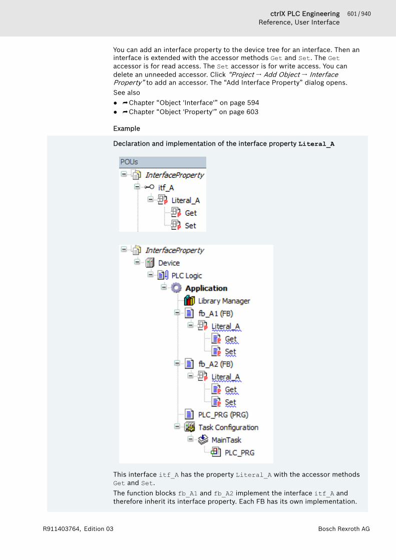
601 / 940ctrlX PLC EngineeringReference, User Interface
Bosch Rexroth AGR911403764, Edition 03
You can add an interface property to the device tree for an interface. Then aninterface is extended with the accessor methods Get and Set. The Getaccessor is for read access. The Set accessor is for write access. You candelete an unneeded accessor. Click “Project 🠂 Add Object 🠂 InterfaceProperty” to add an accessor. The “Add Interface Property” dialog opens.See also● ⮫ Chapter “Object 'Interface'” on page 594● ⮫ Chapter “Object 'Property'” on page 603
Example
Declaration and implementation of the interface property Literal_A
This interface itf_A has the property Literal_A with the accessor methodsGet and Set.The function blocks fb_A1 and fb_A2 implement the interface itf_A andtherefore inherit its interface property. Each FB has its own implementation.
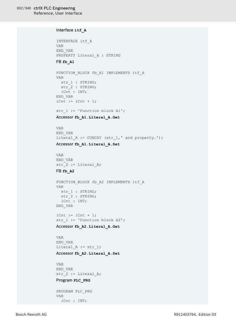
602 / 940 ctrlX PLC EngineeringReference, User Interface
Bosch Rexroth AG R911403764, Edition 03
Interface itf_A
INTERFACE itf_AVAREND_VARPROPERTY Literal_A : STRINGFB fb_A1
FUNCTION_BLOCK fb_A1 IMPLEMENTS itf_AVARstr_1 : STRING;str_2 : STRING;iCnt : INT;
END_VARiCnt := iCnt + 1;
str_1 := 'Function block A1';Accessor fb_A1.Literal_A.Get
VAREND_VARLiteral_A := CONCAT (str_1,' and property.');Accessor fb_A1.Literal_A.Set
VAREND_VARstr_2 := Literal_A;FB fb_A2
FUNCTION_BLOCK fb_A2 IMPLEMENTS itf_AVARstr_1 : STRING;str_2 : STRING;iCnt : INT;
END_VAR
iCnt := iCnt + 1;str_1 := 'Function block A2';Accessor fb_A2.Literal_A.Get
VAREND_VARLiteral_A := str_1;Accessor fb_A2.Literal_A.Set
VAREND_VARstr_2 := Literal_A;Program PLC_PRG
PROGRAM PLC_PRGVARiCnt : INT;
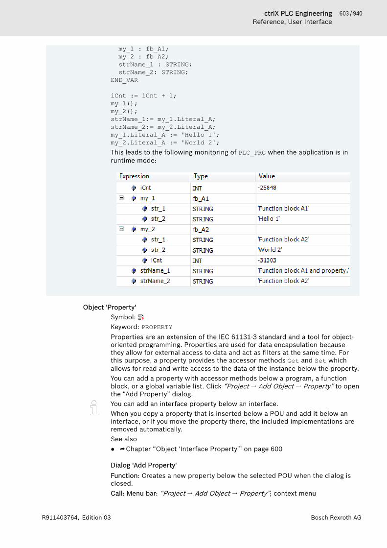
603 / 940ctrlX PLC EngineeringReference, User Interface
Bosch Rexroth AGR911403764, Edition 03
my_1 : fb_A1;my_2 : fb_A2;strName_1 : STRING;strName_2: STRING;
END_VAR
iCnt := iCnt + 1;my_1();my_2();strName_1:= my_1.Literal_A;strName_2:= my_2.Literal_A;my_1.Literal_A := 'Hello 1';my_2.Literal_A := 'World 2';This leads to the following monitoring of PLC_PRG when the application is inruntime mode:
Object 'Property'Symbol: Keyword: PROPERTYProperties are an extension of the IEC 61131-3 standard and a tool for object-oriented programming. Properties are used for data encapsulation becausethey allow for external access to data and act as filters at the same time. Forthis purpose, a property provides the accessor methods Get and Set whichallows for read and write access to the data of the instance below the property.You can add a property with accessor methods below a program, a functionblock, or a global variable list. Click “Project 🠂 Add Object 🠂 Property” to openthe “Add Property” dialog.You can add an interface property below an interface.When you copy a property that is inserted below a POU and add it below aninterface, or if you move the property there, the included implementations areremoved automatically.See also● ⮫ Chapter “Object 'Interface Property'” on page 600
Dialog 'Add Property'Function: Creates a new property below the selected POU when the dialog isclosed.Call: Menu bar: “Project 🠂 Add Object 🠂 Property”; context menu

604 / 940 ctrlX PLC EngineeringReference, User Interface
Bosch Rexroth AG R911403764, Edition 03
Requirement: A program (PRG), a function block (FUNCTION_BLOCK), or a globalvariable list (GVL) is selected in the “POUs” view or the “Devices” view.
“Name” Name (identifier) of the property“Return type” Default type or structured type of return value
Example: BOOL“Implementation language” Example: “Structured Text (ST)”
“Access specifier” Controls access to data“PUBLIC” or unspecified Access is not restricted.“PRIVATE” Access is restricted to the program, function block, or GVL.
The object is marked as (private) in the POU or device view. Thedeclaration contains the keyword PRIVATE.
“PROTECTED” Access is restricted to the program, function block, or GVL with itsderivations.The object is marked as (protected) in the POU or device view. Thedeclaration contains the keyword PROTECTED.
“INTERNAL” Access is restricted to the namespace (library).The object is marked as (internal) in the POU or device view. Thedeclaration contains the keyword INTERNAL.
“Abstract” : Identifies that the property does not have an implementation andthe implementation is provided by the derived FB
“Add” Adds a new property be low the selected object and below that theaccessor methods Get and SetNote: When you select a property, you can also add a previouslyremoved accessor explicitly by clicking “Add Object”.
Editor 'Property'You can program the data access in the editor. The code can contain additionallocal variables. However, it must not contain any additional input variables or(as opposed to a function or method) output variables.
Example
Function block
FUNCTION_BLOCK fb_AVAR_INPUTEND_VARVAR_OUTPUTEND_VARVARiA : INT;iB : INT;
605 / 940ctrlX PLC EngineeringReference, User Interface
Bosch Rexroth AGR911403764, Edition 03
END_VAR
iA := iA + 1;Property Value_A
PROPERTY PUBLIC Value_A : INTAccessor method fb_A.Value_A.Get
VAREND_VARValue_A := iA;Accessor method fb_A.Value_A.Set
VAREND_VAR iB := Value_A;
Get and Set accessorsWhen the Set accessor is called, the property is written. It is then used in thesame way as an input parameter. When the Get accessor is called, the propertyis read. It is then used in the same way as an output parameter. Access isrestricted by means of access specifiers, and the objects are marked accord-ingly.When a property is accessed as read only or write only, you can delete theunneeded accessors.You can add accessors explicitly by selecting a property and clicking “AddObject”. A dialog opens, either “Add Get Accessor” or “Add Set Accessor”.There you can set the implementation language and the access.
Table 75: Dialog “Add Get (Set) Accessor”“Implementation language” Example: “Structured Text (ST)”
“Access specifier”PUBLIC or unspecified Access is not restricted.PRIVATE Access is restricted to the program, function block, or GVL.
The object is marked as (private) in the POU or device view. Thedeclaration contains the keyword.
PROTECTED Access to the property is restricted to the program, function block, orGVL and its derivations. The declaration contains the keyword.The object is marked as (protected) in the POU or device view.
INTERNAL Access to the method is restricted to the namespace (the library).The object is marked as (internal) in the POU or device view. Thedeclaration contains the keyword.
“Add” Adds the accessor methods Get or Set below the selected property.
Monitoring of properties in online modeThe following pragmas are provided for the monitoring of properties in onlinemode. You insert them at the top position of the property definition:● {attribute 'monitoring' := 'variable'}
606 / 940 ctrlX PLC EngineeringReference, User Interface
Bosch Rexroth AG R911403764, Edition 03
Each time the property is accessed, PLC Engineering saves the actual valueto a variable and displays the value of this variable. This value can becomeoutdated if no more access to the property takes place in the code.
● {attribute 'monitoring' := 'call'}Each time the value is displayed, PLC Engineering calls the code of the Getaccessor. If this code contains a side effect, then the monitoring executesthe side effect.
You can monitor a property with the help of the following functions.● Inline monitoring
Requirement: The “Enable inline monitoring” option is selected in the “TextEditor” category of the “Options” dialog.
● Watch listSee also● ⮫ Chapter “Calling Methods” on page 156● ⮫ Chapter “Attribute 'monitoring'” on page 437
Input assistance when creating inheriting blocksWhen you do object-oriented programming and want to use inheritance forblocks, you have the following support: When you insert a method, action, etc.below an inherited block, the “Add Object” dialog box includes a combo boxwith a list of methods, actions, etc. used in the base block. In this way, you caneasily accept a method definition of the base and adapt it accordingly for theinherited method of the block. Methods and attributes with the PRIVATEaccess modifier are not available in this selection because they should not beinherited. When accepted into the inherited block, methods and attributes withthe PUBLIC access modifier automatically have a blank access modifier field.(Functionally, this means the same thing.)See also● ⮫ Chapter “Extension of Function Blocks” on page 152● ⮫ Chapter 1.8.23 “Object-Oriented Programming” on page 152
Object 'Action'Symbol: In an action, you implement additional program code, which you can furtherimplement as in another language as the base implementation. This base imple-mentation is a function block or a program where you inserted the action.An action does not have its own declaration and it works with the data from thebase implementation. This means that the action uses the input and output var-iables and the local variables from its base implementation.Add an “Action” to a function block or program by clicking “Project 🠂 AddObject 🠂 Action”.
Table 76: “Add Action”“Name” Name of the action“Implementation language” Drop-down list of implementation language
Input assistance when creating inheriting blocksWhen you do object-oriented programming and want to use inheritance forblocks, you have the following support: When you insert a method, action, etc.below an inherited block, the “Add Object” dialog box includes a combo boxwith a list of methods, actions, etc. used in the base block. In this way, you caneasily accept a method definition of the base and adapt it accordingly for theinherited method of the block. Methods and attributes with the PRIVATE
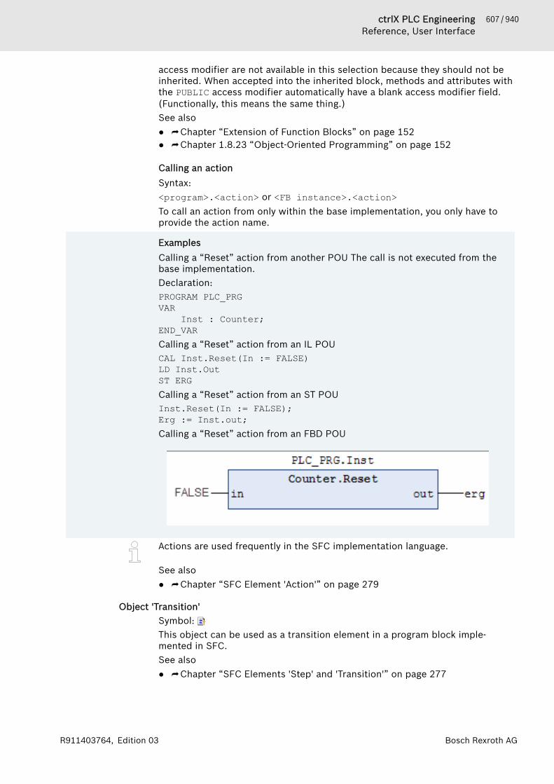
607 / 940ctrlX PLC EngineeringReference, User Interface
Bosch Rexroth AGR911403764, Edition 03
access modifier are not available in this selection because they should not beinherited. When accepted into the inherited block, methods and attributes withthe PUBLIC access modifier automatically have a blank access modifier field.(Functionally, this means the same thing.)See also● ⮫ Chapter “Extension of Function Blocks” on page 152● ⮫ Chapter 1.8.23 “Object-Oriented Programming” on page 152
Calling an actionSyntax:<program>.<action> or <FB instance>.<action>To call an action from only within the base implementation, you only have toprovide the action name.
ExamplesCalling a “Reset” action from another POU The call is not executed from thebase implementation.Declaration:PROGRAM PLC_PRGVAR Inst : Counter;END_VARCalling a “Reset” action from an IL POUCAL Inst.Reset(In := FALSE) LD Inst.OutST ERGCalling a “Reset” action from an ST POUInst.Reset(In := FALSE);Erg := Inst.out;Calling a “Reset” action from an FBD POU
Actions are used frequently in the SFC implementation language.
See also● ⮫ Chapter “SFC Element 'Action'” on page 279
Object 'Transition'Symbol: This object can be used as a transition element in a program block imple-mented in SFC.See also● ⮫ Chapter “SFC Elements 'Step' and 'Transition'” on page 277

608 / 940 ctrlX PLC EngineeringReference, User Interface
Bosch Rexroth AG R911403764, Edition 03
Input assistance when creating inheriting blocksWhen you do object-oriented programming and want to use inheritance forblocks, you have the following support: When you insert a method, action, etc.below an inherited block, the “Add Object” dialog box includes a combo boxwith a list of methods, actions, etc. used in the base block. In this way, you caneasily accept a method definition of the base and adapt it accordingly for theinherited method of the block. Methods and attributes with the PRIVATEaccess modifier are not available in this selection because they should not beinherited. When accepted into the inherited block, methods and attributes withthe PUBLIC access modifier automatically have a blank access modifier field.(Functionally, this means the same thing.)See also● ⮫ Chapter “Extension of Function Blocks” on page 152● ⮫ Chapter 1.8.23 “Object-Oriented Programming” on page 152
Object 'POUs for Implicit Checks'You can add these special POUs to an application to equip them with implicitmonitoring functions. At runtime, these functions check the limits of arrays orsubrange types, the validity of pointer addresses, and division by zero. Pleasenote: This option can be disabled for devices that are already equipped withthese kinds of monitoring blocks by a special implicit library.The command “Add Object 🠂 POU for Implicit Checks” is used for adding tothe application. The command opens the “Add POU for Implicit Checks” dialogwhere you can select a monitoring function type (see table below). Dependingon the monitoring function, you have to adapt the implementation code orcreate it yourself from scratch.To prevent multiple inclusions, monitoring functions that have already beeninserted are disabled in the “Add POU for Implicit Checks” dialog.
NOTICE To get the feature for monitoring functions, do not edittheir declaration part. However, you are permitted to addlocal variables.After removing an implicit monitoring function (example:Check Bounds) from the project, only a download ispossible, not an online change. A corresponding mes-sage is issued.
By default, PLC Engineering does not run implicit checks for function blocksfrom libraries used in the application. However, you can extend the check to thelibraries by opening the “Properties” dialog of the application and specifyingthe compiler definition checks_in_libs in the “Compiler-Defines” field in the“Build” tab. This definition affects implementation libraries (*.library) only,not protected libraries (*.compiled-library).You can use the "no_check" attribute to deactivate the check for special POUsin the project.
Table 77: “Available Functions”Monitoring function Type“Check Bounds” “Bound Checks”
Appropriate handling of bound violations; such handling includes set-ting flags or changing field indices.
“CheckDivDInt” “Division checks”:Monitors the divisor value to avoid division by zero.“CheckDivLInt”
“CheckDivReal”“CheckDivLReal”
609 / 940ctrlX PLC EngineeringReference, User Interface
Bosch Rexroth AGR911403764, Edition 03
Monitoring function Type“CheckRangeSigned” “Range checks”:
Monitors the range limit of a subrange type in runtime mode. Valid fordata types DINT/UDINT.
“CheckRangeUnsigned”
“CheckLRangeSigned” “L-range checks”:Monitors the range limit of a subrange type in runtime mode. Valid fordata types LINT/ULINT.
“CheckLRangeUnsigned”
“CheckPointer” “Pointer checks”You are responsible for filling in this function completely with imple-mentation code. Refer to the help page for "POU 'CheckPointer'". Thefunction should monitor whether the passed pointer reference a validmemory address, and whether the orientation of the referencedmemory area matches the variable type to which the pointer refers. Ifboth conditions are fulfilled, then the pointer is returned. If not, thenCheckPointer should complete an appropriate error handling. Check-Pointer monitors the same way as variables of type REFERENCE TO.
See also● ⮫ Chapter 1.8.22 “Using POUs for Implicit Checks” on page 151● ⮫ Chapter “POU 'CheckBounds'” on page 609● ⮫ Chapter “POU 'CheckDivInt'” on page 612● ⮫ Chapter “POU 'CheckDivLInt'” on page 613● ⮫ Chapter “POU 'CheckDivLReal'” on page 614● ⮫ Chapter “POU 'CheckDivReal'” on page 614● ⮫ Chapter “POU 'CheckPointer'” on page 620● ⮫ Chapter “POU 'CheckRangeSigned'” on page 615● ⮫ Chapter “POU 'CheckRangeUnsigned'” on page 618● ⮫ Chapter “POU 'CheckLRangeSigned'” on page 617● ⮫ Chapter “POU 'CheckLRangeUnsigned'” on page 619● ⮫ Chapter “Dialog 'Properties' - 'Build'” on page 825● ⮫ Chapter “Attribute 'no_check'” on page 439
POU 'CheckBounds'Functions for Bound Checks: CheckBoundsThe task of this monitoring function is to handle bound violations appropriately.Examples of reactions to violations include setting error flags and changing thevalue of the array index. The check is performed only for one variable arrayindex. An incorrect constant array index causes a compiler error. PLC Engi-neering calls the function implicitly when values are assigned to an ARRAY vari-able.After inserting the function, you receive automatically generated code in thedeclaration and implementation parts. See below.
CAUTION To obtain the feature for monitoring functions, do notedit the declaration part. However, you are permitted toadd local variables.
Declaration part// Automatically generated code: DO NOT EDITFUNCTION CheckBounds : DINTVAR_INPUT index, lower, upper: DINT;
END_VAR
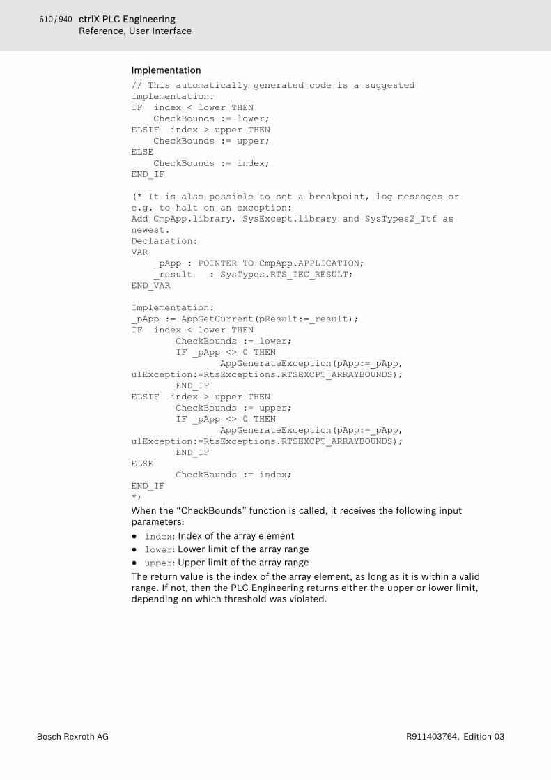
610 / 940 ctrlX PLC EngineeringReference, User Interface
Bosch Rexroth AG R911403764, Edition 03
Implementation// This automatically generated code is a suggested implementation.IF index < lower THEN CheckBounds := lower;
ELSIF index > upper THEN CheckBounds := upper;
ELSE CheckBounds := index;
END_IF
(* It is also possible to set a breakpoint, log messages or e.g. to halt on an exception:Add CmpApp.library, SysExcept.library and SysTypes2_Itf as newest.Declaration:VAR _pApp : POINTER TO CmpApp.APPLICATION; _result : SysTypes.RTS_IEC_RESULT;END_VAR
Implementation:_pApp := AppGetCurrent(pResult:=_result);IF index < lower THEN CheckBounds := lower; IF _pApp <> 0 THEN AppGenerateException(pApp:=_pApp, ulException:=RtsExceptions.RTSEXCPT_ARRAYBOUNDS); END_IFELSIF index > upper THEN CheckBounds := upper; IF _pApp <> 0 THEN AppGenerateException(pApp:=_pApp, ulException:=RtsExceptions.RTSEXCPT_ARRAYBOUNDS); END_IFELSE CheckBounds := index;END_IF*)When the “CheckBounds” function is called, it receives the following inputparameters:● index: Index of the array element● lower: Lower limit of the array range● upper: Upper limit of the array rangeThe return value is the index of the array element, as long as it is within a validrange. If not, then the PLC Engineering returns either the upper or lower limit,depending on which threshold was violated.

611 / 940ctrlX PLC EngineeringReference, User Interface
Bosch Rexroth AGR911403764, Edition 03
Example: Correction of the access to an array outside the defined arrayboundsIn the sample program below, the index falls short of the defined lower limitof the a array.PROGRAM PLC_PRGVAR a: ARRAY[0..7] OF BOOL;b: INT:=10;
END_VAR
a[b]:=TRUE;In this example, the CheckBounds function causes a to change the upper limitof the array range index to 10. The value TRUE is assigned then to the elementa[7]. In this way, the function corrects array access outside of the valid arrayrange.
Example: Output of an exception when array limits are violated.Add the following libraries in the library manager of the application:● CmpApp.library and SysExcept.library as placeholder libraries● SysTypes2_Itfs.library with “Newest version always”Add a “CheckBounds” object below the application and modify the specifiedcode as shown below.Declaration partFUNCTION CheckBounds : DINTVAR_INPUT index, lower, upper: DINT;END_VARVAR _pApp : POINTER TO CmpApp.APPLICATION; _Result : ISystypes2.RTS_IEC_RESULT;END_VARImplementation part// This automatically generated code is a suggested implementation._pApp := AppGetCurrent(pResult := _Result);IF index < lower THEN CheckBounds := lower; IF _pApp <> 0 THEN AppGenerateException(pApp := _pApp, ulException := RtsExceptions.RTSEXCPT_ARRAYBOUNDS); END_IFELSIF index > upper THEN CheckBounds := upper; IF _pApp <> 0 THEN AppGenerateException(pApp:=_pApp, ulException:=RtsExceptions.RTSEXCPT_ARRAYBOUNDS); END_IFELSE CheckBounds := index;END_IFProgram a “MAIN_PRG” object below the application with the contents shownbelow.
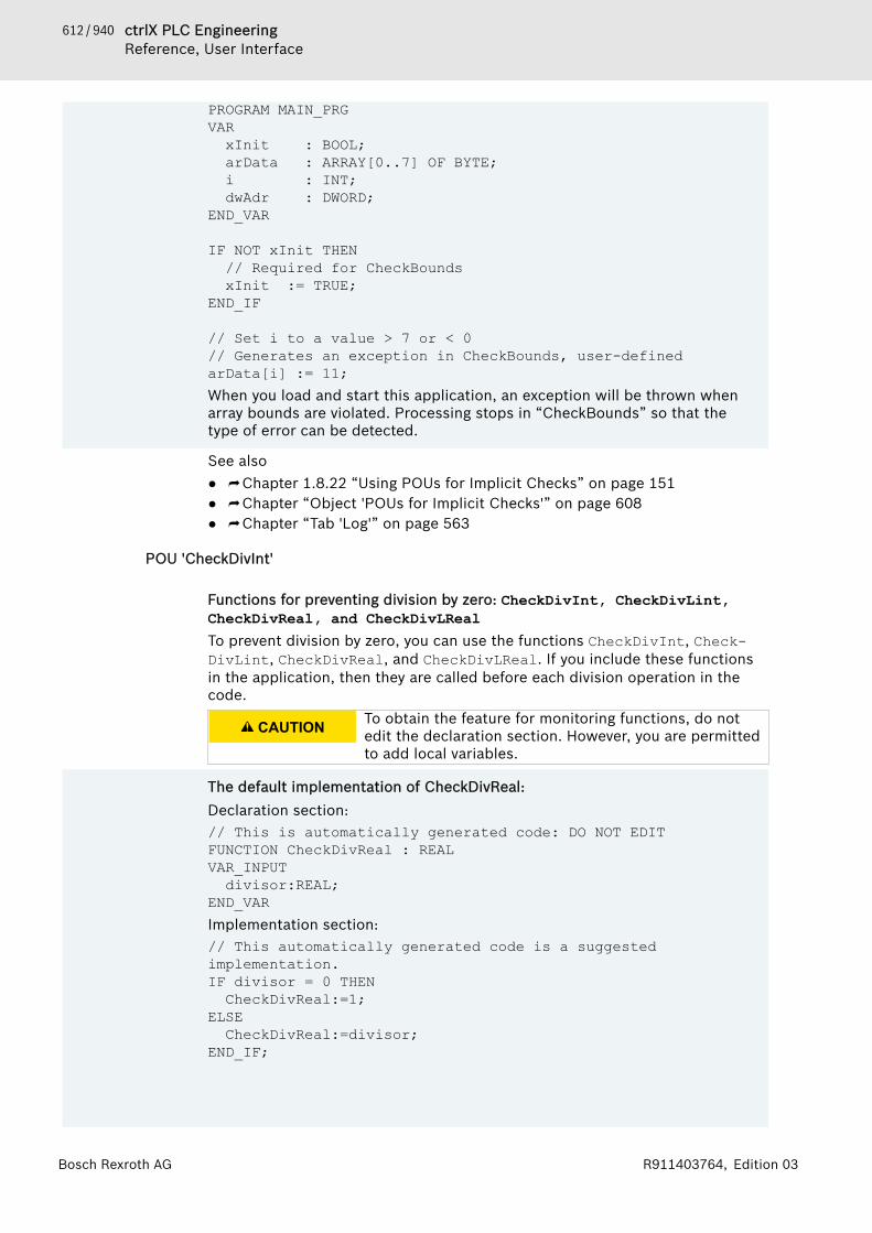
612 / 940 ctrlX PLC EngineeringReference, User Interface
Bosch Rexroth AG R911403764, Edition 03
PROGRAM MAIN_PRGVARxInit : BOOL;arData : ARRAY[0..7] OF BYTE;i : INT;dwAdr : DWORD;
END_VAR
IF NOT xInit THEN// Required for CheckBoundsxInit := TRUE;
END_IF
// Set i to a value > 7 or < 0// Generates an exception in CheckBounds, user-definedarData[i] := 11;When you load and start this application, an exception will be thrown whenarray bounds are violated. Processing stops in “CheckBounds” so that thetype of error can be detected.
See also● ⮫ Chapter 1.8.22 “Using POUs for Implicit Checks” on page 151● ⮫ Chapter “Object 'POUs for Implicit Checks'” on page 608● ⮫ Chapter “Tab 'Log'” on page 563
POU 'CheckDivInt'
Functions for preventing division by zero: CheckDivInt, CheckDivLint,CheckDivReal, and CheckDivLReal To prevent division by zero, you can use the functions CheckDivInt, Check-DivLint, CheckDivReal, and CheckDivLReal. If you include these functionsin the application, then they are called before each division operation in thecode.
CAUTION To obtain the feature for monitoring functions, do notedit the declaration section. However, you are permittedto add local variables.
The default implementation of CheckDivReal:Declaration section:// This is automatically generated code: DO NOT EDITFUNCTION CheckDivReal : REALVAR_INPUT
divisor:REAL;END_VARImplementation section:// This automatically generated code is a suggested implementation.IF divisor = 0 THENCheckDivReal:=1;
ELSECheckDivReal:=divisor;
END_IF;

613 / 940ctrlX PLC EngineeringReference, User Interface
Bosch Rexroth AGR911403764, Edition 03
The DIV operator uses the output of the CheckDivReal function as a divisor.In the sample program below, CheckDivReal prevents division by 0 bychanging the implicit value of the divisor d from "0" to 1 before the divisionoperation is executed. Therefore, the division result is 799.PROGRAM PLC_PRGVAR erg:REAL; v1:REAL:=799; d:REAL:=0;END_VARerg:= v1 / d;
See also● ⮫ Chapter 1.8.22 “Using POUs for Implicit Checks” on page 151● ⮫ Chapter “Object 'POUs for Implicit Checks'” on page 608
POU 'CheckDivLInt'
Functions for preventing division by zero: CheckDivInt, CheckDivLint,CheckDivReal, and CheckDivLReal To prevent division by zero, you can use the functions CheckDivInt, Check-DivLint, CheckDivReal, and CheckDivLReal. If you include these functionsin the application, then they are called before each division operation in thecode.
CAUTION To obtain the feature for monitoring functions, do notedit the declaration section. However, you are permittedto add local variables.
The default implementation of CheckDivReal:Declaration section:// This is automatically generated code: DO NOT EDITFUNCTION CheckDivReal : REALVAR_INPUTdivisor:REAL;
END_VARImplementation section:// This automatically generated code is a suggested implementation.IF divisor = 0 THENCheckDivReal:=1;
ELSECheckDivReal:=divisor;
END_IF; The DIV operator uses the output of the CheckDivReal function as a divisor.In the sample program below, CheckDivReal prevents division by 0 bychanging the implicit value of the divisor d from "0" to 1 before the divisionoperation is executed. Therefore, the division result is 799.PROGRAM PLC_PRGVAR erg:REAL; v1:REAL:=799;

614 / 940 ctrlX PLC EngineeringReference, User Interface
Bosch Rexroth AG R911403764, Edition 03
d:REAL:=0;END_VARerg:= v1 / d;
See also● ⮫ Chapter 1.8.22 “Using POUs for Implicit Checks” on page 151● ⮫ Chapter “Object 'POUs for Implicit Checks'” on page 608
POU 'CheckDivReal'
Functions for preventing division by zero: CheckDivInt, CheckDivLint,CheckDivReal, and CheckDivLReal To prevent division by zero, you can use the functions CheckDivInt, Check-DivLint, CheckDivReal, and CheckDivLReal. If you include these functionsin the application, then they are called before each division operation in thecode.
CAUTION To obtain the feature for monitoring functions, do notedit the declaration section. However, you are permittedto add local variables.
The default implementation of CheckDivReal:Declaration section:// This is automatically generated code: DO NOT EDITFUNCTION CheckDivReal : REALVAR_INPUTdivisor:REAL;
END_VARImplementation section:// This automatically generated code is a suggested implementation.IF divisor = 0 THENCheckDivReal:=1;
ELSECheckDivReal:=divisor;
END_IF; The DIV operator uses the output of the CheckDivReal function as a divisor.In the sample program below, CheckDivReal prevents division by 0 bychanging the implicit value of the divisor d from "0" to 1 before the divisionoperation is executed. Therefore, the division result is 799.PROGRAM PLC_PRGVAR erg:REAL; v1:REAL:=799; d:REAL:=0;END_VARerg:= v1 / d;
See also● ⮫ Chapter 1.8.22 “Using POUs for Implicit Checks” on page 151● ⮫ Chapter “Object 'POUs for Implicit Checks'” on page 608
POU 'CheckDivLReal'

615 / 940ctrlX PLC EngineeringReference, User Interface
Bosch Rexroth AGR911403764, Edition 03
Functions for preventing division by zero: CheckDivInt, CheckDivLint,CheckDivReal, and CheckDivLReal To prevent division by zero, you can use the functions CheckDivInt, Check-DivLint, CheckDivReal, and CheckDivLReal. If you include these functionsin the application, then they are called before each division operation in thecode.
CAUTION To obtain the feature for monitoring functions, do notedit the declaration section. However, you are permittedto add local variables.
The default implementation of CheckDivReal:Declaration section:// This is automatically generated code: DO NOT EDITFUNCTION CheckDivReal : REALVAR_INPUTdivisor:REAL;
END_VARImplementation section:// This automatically generated code is a suggested implementation.IF divisor = 0 THENCheckDivReal:=1;
ELSECheckDivReal:=divisor;
END_IF; The DIV operator uses the output of the CheckDivReal function as a divisor.In the sample program below, CheckDivReal prevents division by 0 bychanging the implicit value of the divisor d from "0" to 1 before the divisionoperation is executed. Therefore, the division result is 799.PROGRAM PLC_PRGVAR erg:REAL; v1:REAL:=799; d:REAL:=0;END_VARerg:= v1 / d;
See also● ⮫ Chapter 1.8.22 “Using POUs for Implicit Checks” on page 151● ⮫ Chapter “Object 'POUs for Implicit Checks'” on page 608
POU 'CheckRangeSigned'Function for monitoring the range limits of a subrange type of type DINT.
This monitoring function is responsible for the appropriate handling violationsto range limits. Examples of reactions to violations include setting error flagsand changing values. The functions are called implicitly when a value isassigned to a subrange type variable.
CAUTION To obtain the feature for monitoring functions, do notedit the declaration section. However, you are permittedto add local variables.
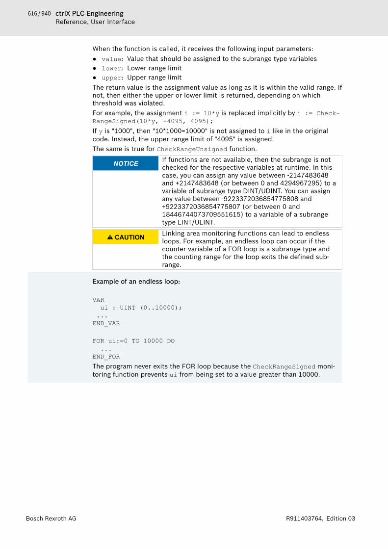
616 / 940 ctrlX PLC EngineeringReference, User Interface
Bosch Rexroth AG R911403764, Edition 03
When the function is called, it receives the following input parameters:● value: Value that should be assigned to the subrange type variables● lower: Lower range limit● upper: Upper range limitThe return value is the assignment value as long as it is within the valid range. Ifnot, then either the upper or lower limit is returned, depending on whichthreshold was violated.For example, the assignment i := 10*y is replaced implicitly by i := Check-RangeSigned(10*y, -4095, 4095);If y is "1000", then "10*1000=10000" is not assigned to i like in the originalcode. Instead, the upper range limit of "4095" is assigned.The same is true for CheckRangeUnsigned function.
NOTICE If functions are not available, then the subrange is notchecked for the respective variables at runtime. In thiscase, you can assign any value between -2147483648and +2147483648 (or between 0 and 4294967295) to avariable of subrange type DINT/UDINT. You can assignany value between -9223372036854775808 and+9223372036854775807 (or between 0 and18446744073709551615) to a variable of a subrangetype LINT/ULINT.
CAUTION Linking area monitoring functions can lead to endlessloops. For example, an endless loop can occur if thecounter variable of a FOR loop is a subrange type andthe counting range for the loop exits the defined sub-range.
Example of an endless loop:
VARui : UINT (0..10000);
...END_VAR
FOR ui:=0 TO 10000 DO...
END_FORThe program never exits the FOR loop because the CheckRangeSigned moni-toring function prevents ui from being set to a value greater than 10000.
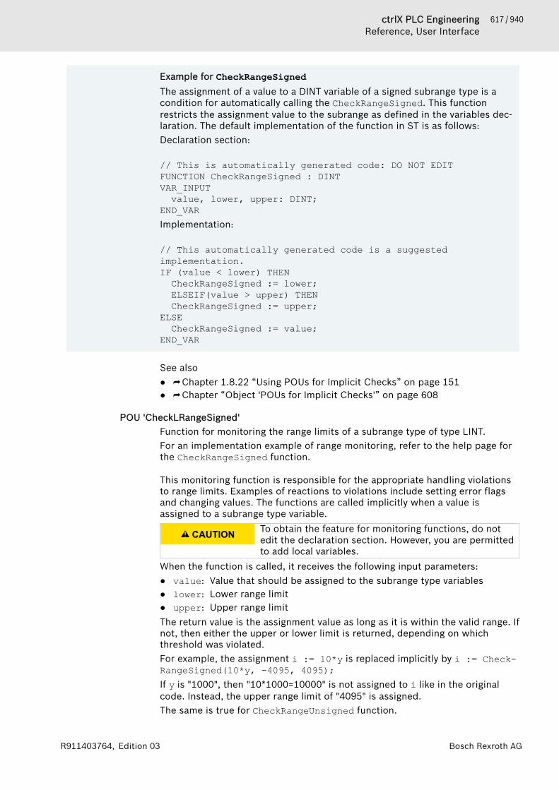
617 / 940ctrlX PLC EngineeringReference, User Interface
Bosch Rexroth AGR911403764, Edition 03
Example for CheckRangeSignedThe assignment of a value to a DINT variable of a signed subrange type is acondition for automatically calling the CheckRangeSigned. This functionrestricts the assignment value to the subrange as defined in the variables dec-laration. The default implementation of the function in ST is as follows:Declaration section:
// This is automatically generated code: DO NOT EDITFUNCTION CheckRangeSigned : DINTVAR_INPUTvalue, lower, upper: DINT;
END_VARImplementation:
// This automatically generated code is a suggested implementation.IF (value < lower) THENCheckRangeSigned := lower;ELSEIF(value > upper) THENCheckRangeSigned := upper;
ELSECheckRangeSigned := value;
END_VAR
See also● ⮫ Chapter 1.8.22 “Using POUs for Implicit Checks” on page 151● ⮫ Chapter “Object 'POUs for Implicit Checks'” on page 608
POU 'CheckLRangeSigned'Function for monitoring the range limits of a subrange type of type LINT.For an implementation example of range monitoring, refer to the help page forthe CheckRangeSigned function.
This monitoring function is responsible for the appropriate handling violationsto range limits. Examples of reactions to violations include setting error flagsand changing values. The functions are called implicitly when a value isassigned to a subrange type variable.
CAUTION To obtain the feature for monitoring functions, do notedit the declaration section. However, you are permittedto add local variables.
When the function is called, it receives the following input parameters:● value: Value that should be assigned to the subrange type variables● lower: Lower range limit● upper: Upper range limitThe return value is the assignment value as long as it is within the valid range. Ifnot, then either the upper or lower limit is returned, depending on whichthreshold was violated.For example, the assignment i := 10*y is replaced implicitly by i := Check-RangeSigned(10*y, -4095, 4095);If y is "1000", then "10*1000=10000" is not assigned to i like in the originalcode. Instead, the upper range limit of "4095" is assigned.The same is true for CheckRangeUnsigned function.
618 / 940 ctrlX PLC EngineeringReference, User Interface
Bosch Rexroth AG R911403764, Edition 03
NOTICE If functions are not available, then the subrange is notchecked for the respective variables at runtime. In thiscase, you can assign any value between -2147483648and +2147483648 (or between 0 and 4294967295) to avariable of subrange type DINT/UDINT. You can assignany value between -9223372036854775808 and+9223372036854775807 (or between 0 and18446744073709551615) to a variable of a subrangetype LINT/ULINT.
CAUTION Linking area monitoring functions can lead to endlessloops. For example, an endless loop can occur if thecounter variable of a FOR loop is a subrange type andthe counting range for the loop exits the defined sub-range.
Example of an endless loop:
VARui : UINT (0..10000);
...END_VAR
FOR ui:=0 TO 10000 DO...
END_FORThe program never exits the FOR loop because the CheckRangeSigned moni-toring function prevents ui from being set to a value greater than 10000.
See also● ⮫ Chapter 1.8.22 “Using POUs for Implicit Checks” on page 151● ⮫ Chapter “POU 'CheckRangeSigned'” on page 615● ⮫ Chapter “Object 'POUs for Implicit Checks'” on page 608
POU 'CheckRangeUnsigned'Function for monitoring the range limits of a subrange type of type UDINT.For an implementation example of range monitoring, refer to the help page forthe CheckRangeSigned function.
This monitoring function is responsible for the appropriate handling violationsto range limits. Examples of reactions to violations include setting error flagsand changing values. The functions are called implicitly when a value isassigned to a subrange type variable.
CAUTION To obtain the feature for monitoring functions, do notedit the declaration section. However, you are permittedto add local variables.
When the function is called, it receives the following input parameters:● value: Value that should be assigned to the subrange type variables● lower: Lower range limit● upper: Upper range limitThe return value is the assignment value as long as it is within the valid range. Ifnot, then either the upper or lower limit is returned, depending on whichthreshold was violated.

619 / 940ctrlX PLC EngineeringReference, User Interface
Bosch Rexroth AGR911403764, Edition 03
For example, the assignment i := 10*y is replaced implicitly by i := Check-RangeSigned(10*y, -4095, 4095);If y is "1000", then "10*1000=10000" is not assigned to i like in the originalcode. Instead, the upper range limit of "4095" is assigned.The same is true for CheckRangeUnsigned function.
NOTICE If functions are not available, then the subrange is notchecked for the respective variables at runtime. In thiscase, you can assign any value between -2147483648and +2147483648 (or between 0 and 4294967295) to avariable of subrange type DINT/UDINT. You can assignany value between -9223372036854775808 and+9223372036854775807 (or between 0 and18446744073709551615) to a variable of a subrangetype LINT/ULINT.
CAUTION Linking area monitoring functions can lead to endlessloops. For example, an endless loop can occur if thecounter variable of a FOR loop is a subrange type andthe counting range for the loop exits the defined sub-range.
Example of an endless loop:
VARui : UINT (0..10000);
...END_VAR
FOR ui:=0 TO 10000 DO...
END_FORThe program never exits the FOR loop because the CheckRangeSigned moni-toring function prevents ui from being set to a value greater than 10000.
See also● ⮫ Chapter 1.8.22 “Using POUs for Implicit Checks” on page 151● ⮫ Chapter “POU 'CheckRangeSigned'” on page 615● ⮫ Chapter “Object 'POUs for Implicit Checks'” on page 608
POU 'CheckLRangeUnsigned'Function for monitoring the range limits of a subrange type of type ULINT.For an implementation example of range monitoring, refer to the help page forthe CheckRangeSigned function.
This monitoring function is responsible for the appropriate handling violationsto range limits. Examples of reactions to violations include setting error flagsand changing values. The functions are called implicitly when a value isassigned to a subrange type variable.
CAUTION To obtain the feature for monitoring functions, do notedit the declaration section. However, you are permittedto add local variables.

620 / 940 ctrlX PLC EngineeringReference, User Interface
Bosch Rexroth AG R911403764, Edition 03
When the function is called, it receives the following input parameters:● value: Value that should be assigned to the subrange type variables● lower: Lower range limit● upper: Upper range limitThe return value is the assignment value as long as it is within the valid range. Ifnot, then either the upper or lower limit is returned, depending on whichthreshold was violated.For example, the assignment i := 10*y is replaced implicitly by i := Check-RangeSigned(10*y, -4095, 4095);If y is "1000", then "10*1000=10000" is not assigned to i like in the originalcode. Instead, the upper range limit of "4095" is assigned.The same is true for CheckRangeUnsigned function.
NOTICE If functions are not available, then the subrange is notchecked for the respective variables at runtime. In thiscase, you can assign any value between -2147483648and +2147483648 (or between 0 and 4294967295) to avariable of subrange type DINT/UDINT. You can assignany value between -9223372036854775808 and+9223372036854775807 (or between 0 and18446744073709551615) to a variable of a subrangetype LINT/ULINT.
CAUTION Linking area monitoring functions can lead to endlessloops. For example, an endless loop can occur if thecounter variable of a FOR loop is a subrange type andthe counting range for the loop exits the defined sub-range.
Example of an endless loop:
VARui : UINT (0..10000);
...END_VAR
FOR ui:=0 TO 10000 DO...
END_FORThe program never exits the FOR loop because the CheckRangeSigned moni-toring function prevents ui from being set to a value greater than 10000.
See also● ⮫ Chapter 1.8.22 “Using POUs for Implicit Checks” on page 151● ⮫ Chapter “POU 'CheckRangeSigned'” on page 615● ⮫ Chapter “Object 'POUs for Implicit Checks'” on page 608
POU 'CheckPointer'Monitoring function for pointers (Checkpointer)Use this function to monitor the memory access of pointers in runtime mode. As opposed to other monitoring functions, a standard suggestion does notexist for the implementation of CheckPointer. You must define an implemen-tation according to your own requirements.

621 / 940ctrlX PLC EngineeringReference, User Interface
Bosch Rexroth AGR911403764, Edition 03
The CheckPointer function should check whether the returned pointer refer-ences a valid memory address; monitors whether the orientation of the refer-enced memory range matches the variable type that the pointer refers to. Ifboth conditions are fulfilled, then the pointer is returned. If not, then the func-tion should complete an appropriate error handling.
CAUTION To obtain the feature for monitoring functions, do notedit the declaration section. However, you are permittedto add local variables.
NOTICE An implicit monitoring function call does not occur forTHIS pointer and SUPER pointer.
NOTICE For complier version 3.5.7.40 and later, the implicitcheck function “Checkpointer” also acts on REFERENCEvariables in the same way as on pointer variables.
Model
Declaration:
// Automatically generated code: DO NOT EDITFUNCTION CheckPointer : POINTER TO BYTE VAR_INPUTptToTest : POINTER TO BYTE;iSize : DINT;iGran : DINT;bWrite: BOOL;
END_VARImplementation: (incomplete)
// Not a standard implementation. Please add your own code here.CheckPointer := ptToTest;When the function is called, PLC Engineering provides the following inputparameters:● ptToTest: Target address of the pointer● iSize: Size of the referenced variable; the data type of iSize must be
compatible with INT and cover the dimensional scope of the variables.● iGran: Granularity of the referenced size; this is the largest non-struc-
tured data type contained in the referenced variables; the data type ofiGran must be compatible with INT
● bWrite: Access type (TRUE = write access, FALSE = read access); the datatype of bWrite must be BOOL
When the result of the check is positive, the unchanged pointer is returned(ptToTest).
See also● ⮫ Chapter 1.8.22 “Using POUs for Implicit Checks” on page 151● ⮫ Chapter “Object 'POUs for Implicit Checks'” on page 608
Object 'Project Settings'Symbol: Function: This object contains the configuration of the project.

622 / 940 ctrlX PLC EngineeringReference, User Interface
Bosch Rexroth AG R911403764, Edition 03
Call:● “Project 🠂 Project Settings”● Double-click on the object in the device treePLC Engineering saves the project settings directly in the project. If, forexample, you transfer a project to another system, the “Project Settings” objectis also transferred with it without a project archive being required.The project settings are valid project-wide and offer setting possibilities for var-ious categories such as “AS” or “Users and Groups”. The available categoriesvary, depending on which software packages you have installed via the packagemanager.See also● ⮫ Chapter “Command ‘Package Manager’ ” on page 740● ⮫ Chapter “Dialog 'Project Settings' - 'SFC'” on page 835● ⮫ Chapter “Dialog 'Project Settings' - 'Users and Groups'” on page 836● ⮫ Chapter “Dialog 'Project Settings' - 'Compileoptions'” on page 837● ⮫ Chapter “Dialog 'Project Settings' - 'Compiler Warnings'” on page 838● ⮫ Chapter “Dialog 'Project Settings' – 'Source Download'” on page 838● ⮫ Chapter “Dialog 'Project Settings' - 'Page Setup'” on page 839● ⮫ Chapter “Dialog 'Project Settings' - 'Security'” on page 840● ⮫ Chapter “Dialog 'Project Settings' - 'Static Analysis Light'” on page 841● ⮫ Chapter “Dialog 'Project settings' - 'Visualization'” on page 843● ⮫ Chapter “Dialog 'Project Settings' - 'Visualization Profile'” on page 844
Object 'Project Information'Symbol: Function: The object contains the properties, meta-information, and projectinformation. With this, you can check the authorship and integrity of theproject.Call● Double-click the object in the device tree● Menu bar: “Project 🠂 Project Information”Requirement: PLC Engineering creates the object when you click “Project🠂 Project Information”, and the dialog opens.PLC Engineering saves the project information directly in the project. Forexample, if you transfer a project to another system, then the “Project Informa-tion” object is also transferred. You do not need a project archive.
Tab 'File'The tab displays the properties of the project file and their attributes. Youcannot edit these attributes. They correspond to the file properties of WindowsExplorer.
Tab 'Summary'The tab contains general information and meta-information of the project file.PLC Engineering uses this information to create keys on the “Properties” tab.For example, if the name Company_A is specified in “Company”, then the Com-pany key with the value Company_A is provided on the “Properties” tab.
NOTICE If you save your project as a library project, then youshould pay attention to the guidelines for library devel-opers (Library Development Summary).
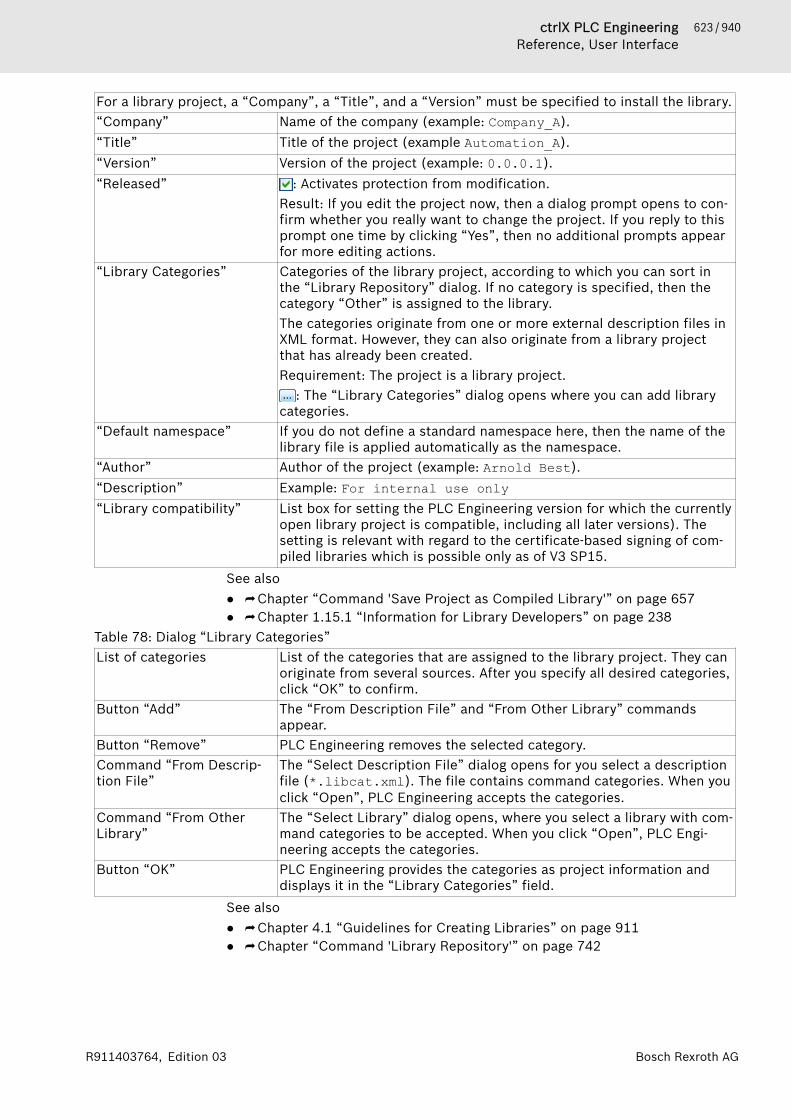
623 / 940ctrlX PLC EngineeringReference, User Interface
Bosch Rexroth AGR911403764, Edition 03
For a library project, a “Company”, a “Title”, and a “Version” must be specified to install the library.“Company” Name of the company (example: Company_A).“Title” Title of the project (example Automation_A).“Version” Version of the project (example: 0.0.0.1).“Released” : Activates protection from modification.
Result: If you edit the project now, then a dialog prompt opens to con-firm whether you really want to change the project. If you reply to thisprompt one time by clicking “Yes”, then no additional prompts appearfor more editing actions.
“Library Categories” Categories of the library project, according to which you can sort inthe “Library Repository” dialog. If no category is specified, then thecategory “Other” is assigned to the library.The categories originate from one or more external description files inXML format. However, they can also originate from a library projectthat has already been created.Requirement: The project is a library project.
: The “Library Categories” dialog opens where you can add librarycategories.
“Default namespace” If you do not define a standard namespace here, then the name of thelibrary file is applied automatically as the namespace.
“Author” Author of the project (example: Arnold Best).“Description” Example: For internal use only“Library compatibility” List box for setting the PLC Engineering version for which the currently
open library project is compatible, including all later versions). Thesetting is relevant with regard to the certificate-based signing of com-piled libraries which is possible only as of V3 SP15.
See also● ⮫ Chapter “Command 'Save Project as Compiled Library'” on page 657● ⮫ Chapter 1.15.1 “Information for Library Developers” on page 238
Table 78: Dialog “Library Categories”List of categories List of the categories that are assigned to the library project. They can
originate from several sources. After you specify all desired categories,click “OK” to confirm.
Button “Add” The “From Description File” and “From Other Library” commandsappear.
Button “Remove” PLC Engineering removes the selected category.Command “From Descrip-tion File”
The “Select Description File” dialog opens for you select a descriptionfile (*.libcat.xml). The file contains command categories. When youclick “Open”, PLC Engineering accepts the categories.
Command “From OtherLibrary”
The “Select Library” dialog opens, where you select a library with com-mand categories to be accepted. When you click “Open”, PLC Engi-neering accepts the categories.
Button “OK” PLC Engineering provides the categories as project information anddisplays it in the “Library Categories” field.
See also● ⮫ Chapter 4.1 “Guidelines for Creating Libraries” on page 911● ⮫ Chapter “Command 'Library Repository'” on page 742
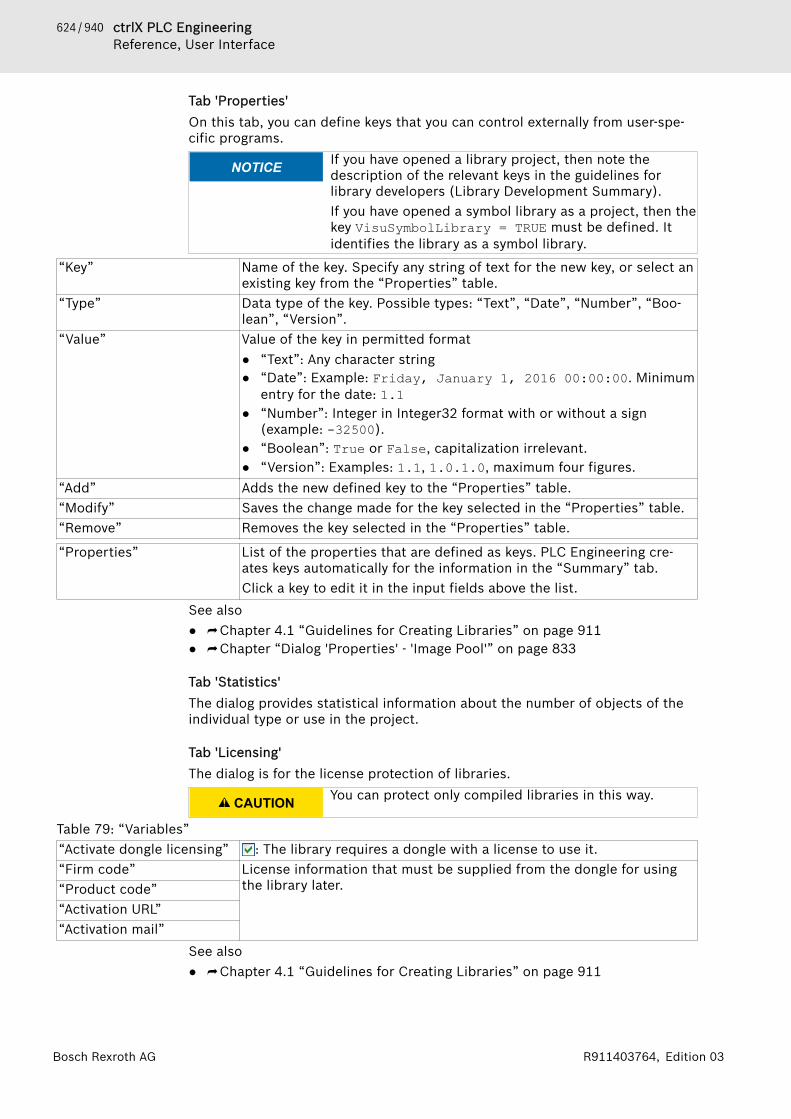
624 / 940 ctrlX PLC EngineeringReference, User Interface
Bosch Rexroth AG R911403764, Edition 03
Tab 'Properties'On this tab, you can define keys that you can control externally from user-spe-cific programs.
NOTICE If you have opened a library project, then note thedescription of the relevant keys in the guidelines forlibrary developers (Library Development Summary).If you have opened a symbol library as a project, then thekey VisuSymbolLibrary = TRUE must be defined. Itidentifies the library as a symbol library.
“Key” Name of the key. Specify any string of text for the new key, or select anexisting key from the “Properties” table.
“Type” Data type of the key. Possible types: “Text”, “Date”, “Number”, “Boo-lean”, “Version”.
“Value” Value of the key in permitted format● “Text”: Any character string● “Date”: Example: Friday, January 1, 2016 00:00:00. Minimum
entry for the date: 1.1● “Number”: Integer in Integer32 format with or without a sign
(example: -32500).● “Boolean”: True or False, capitalization irrelevant.● “Version”: Examples: 1.1, 1.0.1.0, maximum four figures.
“Add” Adds the new defined key to the “Properties” table.“Modify” Saves the change made for the key selected in the “Properties” table.“Remove” Removes the key selected in the “Properties” table.
“Properties” List of the properties that are defined as keys. PLC Engineering cre-ates keys automatically for the information in the “Summary” tab.Click a key to edit it in the input fields above the list.
See also● ⮫ Chapter 4.1 “Guidelines for Creating Libraries” on page 911● ⮫ Chapter “Dialog 'Properties' - 'Image Pool'” on page 833
Tab 'Statistics'The dialog provides statistical information about the number of objects of theindividual type or use in the project.
Tab 'Licensing'The dialog is for the license protection of libraries.
CAUTION You can protect only compiled libraries in this way.
Table 79: “Variables”“Activate dongle licensing” : The library requires a dongle with a license to use it.“Firm code” License information that must be supplied from the dongle for using
the library later.“Product code”“Activation URL”“Activation mail”
See also● ⮫ Chapter 4.1 “Guidelines for Creating Libraries” on page 911

625 / 940ctrlX PLC EngineeringReference, User Interface
Bosch Rexroth AGR911403764, Edition 03
Tab 'Signing'When a certificate-signed library is created (possible as of PLC Engineering V3SP15) and library compatibility with PLC Engineering < V3 SP15 is not set, thesettings on this tab are disabled. In this case, the signing is done by means of acertificate that has to be assigned to the user profile in the security screen.One method, which is not recommended but may be necessary in some casefor compatibility with versions < V3 SP15, is the less secure signing of a libraryby means of a vendor-specific, one-time key in this dialog. Requirement: Thiskey is available as a private key file (*.libpk) with an associated token. Theuser of the library also has to obtain this key in order to be able to checkwhether the last signing was actually performed by the library vendor.
“Activate signing” : PLC Engineering signs the library project with a single-use, manu-facturer-specific key.
“Private key file” Location of the private key file *.libpk (example: D:\for libdevelopers only\mycomp_libkey.libpk).
“Public key token” Example: 427A5701DA3CF3CFRequirement: A private key file is specified, and PLC Engineering hasread and entered the token.
“Create Private Key File” PLC Engineering creates a new private key file.See also● ⮫ Chapter “Command 'Security Screen'” on page 688
Options for creating blocks for accessing project information
“Automatically generate'Project Information' POUs”
Note: The functions that are created with this option can be used onlyif the runtime system supports the WSTRING data type. If this is not thecase, then you can use the functions that were created automaticallyfor the with the individual items of the project information, at least inthe application for accessing properties. These functions are not regis-tered in the runtime system.
: PLC Engineering creates POUs of the FUNCTION type in the “POUs”view, allowing programmatic access to the project properties in theapplication. The function blocks GetCompany, GetTitle and GetVer-sion are created for the properties “Company”, “Title” and “Version”.The following function blocks are available for user-defined properties:● GetBooleanProperty: BOOL (TRUE/FALSE)● GetNumberProperty: DINT (numeric value)● GetTextProperty: WSTRING (character string)● GetTextProperty2: POINTER TO WSTRING (unlimited length)● GetVersionProperty: VERSION (version number as character
string)Note: Do not activate this option for standard libraries, because thiscan cause problems on smaller systems due to the additional memoryrequirements.
“Automatically generate 'Li-brary Information' POUs”
: PLC Engineering creates POUs of the FUNCTION type in the “POUs”view, allowing programmatic access to the project properties in theapplication.For the “Version” and “Released” properties, the following functionsare created: GetLibVersion (version number as character string),GetLibVersionNumber (version number as numeric value), and IsLi-bReleased (TRUE/FALSE).
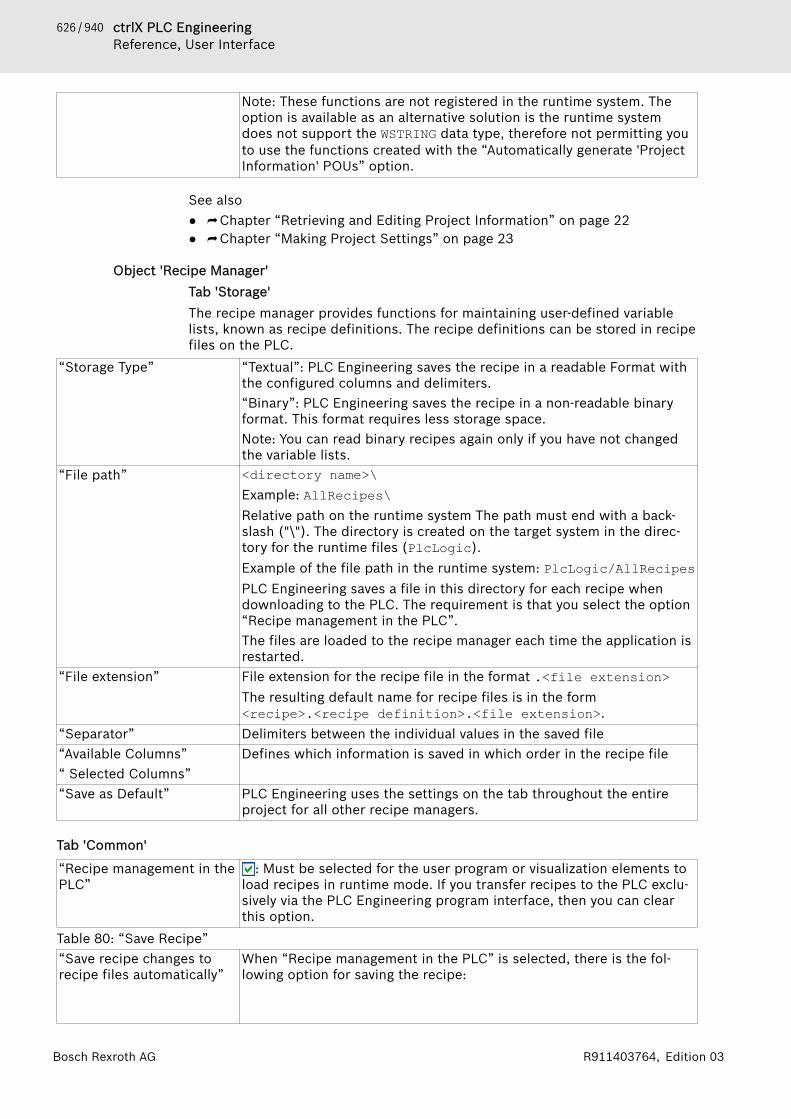
626 / 940 ctrlX PLC EngineeringReference, User Interface
Bosch Rexroth AG R911403764, Edition 03
Note: These functions are not registered in the runtime system. Theoption is available as an alternative solution is the runtime systemdoes not support the WSTRING data type, therefore not permitting youto use the functions created with the “Automatically generate 'ProjectInformation' POUs” option.
See also● ⮫ Chapter “Retrieving and Editing Project Information” on page 22● ⮫ Chapter “Making Project Settings” on page 23
Object 'Recipe Manager'Tab 'Storage'The recipe manager provides functions for maintaining user-defined variablelists, known as recipe definitions. The recipe definitions can be stored in recipefiles on the PLC.
“Storage Type” “Textual”: PLC Engineering saves the recipe in a readable Format withthe configured columns and delimiters.“Binary”: PLC Engineering saves the recipe in a non-readable binaryformat. This format requires less storage space.Note: You can read binary recipes again only if you have not changedthe variable lists.
“File path” <directory name>\Example: AllRecipes\Relative path on the runtime system The path must end with a back-slash ("\"). The directory is created on the target system in the direc-tory for the runtime files (PlcLogic).Example of the file path in the runtime system: PlcLogic/AllRecipesPLC Engineering saves a file in this directory for each recipe whendownloading to the PLC. The requirement is that you select the option“Recipe management in the PLC”.The files are loaded to the recipe manager each time the application isrestarted.
“File extension” File extension for the recipe file in the format .<file extension>The resulting default name for recipe files is in the form<recipe>.<recipe definition>.<file extension>.
“Separator” Delimiters between the individual values in the saved file“Available Columns”“ Selected Columns”
Defines which information is saved in which order in the recipe file
“Save as Default” PLC Engineering uses the settings on the tab throughout the entireproject for all other recipe managers.
Tab 'Common'
“Recipe management in thePLC”
: Must be selected for the user program or visualization elements toload recipes in runtime mode. If you transfer recipes to the PLC exclu-sively via the PLC Engineering program interface, then you can clearthis option.
Table 80: “Save Recipe”“Save recipe changes torecipe files automatically”
When “Recipe management in the PLC” is selected, there is the fol-lowing option for saving the recipe:
627 / 940ctrlX PLC EngineeringReference, User Interface
Bosch Rexroth AGR911403764, Edition 03
: We recommend this option because it helps the recipe manageroperate "normally". The recipe files on the PLC are updated automati-cally in runtime mode whenever a recipe is changed.
Table 81: “Load Recipe”When “Recipe Management in the PLC” is selected, there are the following two options for down-loading from the PLC:“Download only for exactmatch of the variable list”
: The recipe is only downloaded if the file on the PLC contains allvariables from the variable list of the recipe definition of the applica-tion and these are sorted in the same order. Additional entries at theend are ignored. If the required match does not exist, then the errorstatus ERR_RECIPE_MISMATCH is set (RecipeManCommands.GetLas-tError).
“Download variables withmatching names”
: The recipe values are downloaded only for those variables that havethe same name in the recipe definition of the application as in therecipe file on the PLC. If the variable lists differ in composition andsorting, then no error status is set.In this way, recipe files can also be downloaded if variables in the fileor in the recipe definition have been deleted.
Table 82: “Write Recipe”The following options are available for writing recipe values to the variables on the PLC:“Limit the variable tomin/max when recipe valueis out of the range”
: If the recipe contains a value that is outside of the value rangespecified in the definition, then the defined minimum or maximumvalue is written to the PLC variable instead of this value.
“Do not write to a variablewhen the recipe value isout of the min/max range”
: If the recipe contains a value that is outside of the value rangespecified in the definition, then no value is written to the PLC variable.It retains its current value.
Table 83: “Read Recipe”The following option is available for reading recipe values from the PLC into the recipe in theproject:“Check recipe for changes” Always use the function block RecipeManCommands from RecipeMa-
nagement.library to read recipes. Never call the method cyclically.This is because each call can be written to the file system, which istime-intensive and burdens the controller. For example, the number ofwrite cycles is limited for a Raspberry Pi.
: With each method call, the current PLC variable values are firstread into the recipe. Then the system checks whether the values havechanged. Only if the values have changed is the recipe saved. Thismeans that the recipe file is overwritten with the current recipes.This option can be used in order to update the recipe file in the localfile system only if recipe values have changed on the PLC. However, itaffects performance because it generates additional code for checking.
: With each method call, the current PLC variable values are firstread into the recipe. Then the recipe is written to the recipe file in thelocal file system.Note: As the file system is written to each call, the controller can bevery burdened.
628 / 940 ctrlX PLC EngineeringReference, User Interface
Bosch Rexroth AG R911403764, Edition 03
Recipes during online modeTable 84: Option “Save recipe changes to recipe files automatically” isactivated.Menu Commands Behavior of the recipes
defined in the projectBehavior of the definedrecipes at runtime
“Online 🠂 Reset Warm”“Online 🠂 Reset Cold”“Online 🠂 Download”
The recipes of all recipedefinitions are down-loaded with the valuesfrom the current projects.
Dynamically generatedrecipes remainunchanged.
“Online 🠂 Reset Origin” The application is removed from the PLC. If a down-load is done again afterwards, then the recipes arerestored as for an online reset warm.
Shutdown and restart thePLC
After a restart, the recipes are downloaded againfrom the automatically created files. This will restorethe same state as before shutdown.
“Online 🠂 Onlinechange”
The recipe values remain unchanged. In runtimemode, a recipe can be changed only via the functionblock command RecipeManCommands.
“Debug 🠂 Stop”“Debug 🠂 Start”
The recipes remain unchanged when the PLC isstopped or started.
Table 85: Option “Save recipe changes to recipe files automatically” isdeactivated.Actions Recipes defined in the
projectRecipes defined in run-time mode
“Online 🠂 Reset Warm”“Online 🠂 Reset Cold”“Online 🠂 Download”
The recipes of all recipedefinitions are down-loaded with the valuesfrom the current projects.However, these are set inthe memory only. To saverecipes to a file, you mustexecute the command“Save Recipe” explicitly.
Dynamically generatedrecipes are lost.
“Online 🠂 Reset Origin” The application isremoved from the PLC.When a download is per-formed afterwards, therecipes are restored.
Dynamically generatedrecipes are lost.
Shutdown and restart thePLC
After the restart, the recipes are downloaded againfrom the automatically created files. This will restorethe same state as before shutdown.
“Online 🠂 OnlineChange”
The recipe values remain unchanged. In runtimemode, a recipe can be changed only via the functionblock command RecipeManCommands.
“Debug 🠂 Stop”“Debug 🠂 Start”
The recipes remain unchanged when the PLC isstopped or started.
See also● ⮫ Chapter 1.12.2 “Changing Values with Recipes” on page 216● ⮫ Chapter “Command 'Read and Save Recipe'” on page 800● ⮫ Chapter “Object 'Recipe Definition'” on page 629● ⮫ Method Calls of the 'Recipe Management' Library
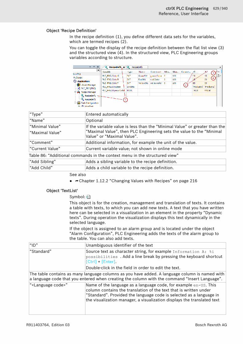
629 / 940ctrlX PLC EngineeringReference, User Interface
Bosch Rexroth AGR911403764, Edition 03
Object 'Recipe Definition'In the recipe definition (1), you define different data sets for the variables,which are termed recipes (2).You can toggle the display of the recipe definition between the flat list view (3)and the structured view (4). In the structured view, PLC Engineering groupsvariables according to structure.
“Type” Entered automatically“Name” Optional“Minimal Value”“Maximal Value”
If the variable value is less than the “Minimal Value” or greater than the“Maximal Value”, then PLC Engineering sets the value to the “MinimalValue” or “Maximal Value”.
“Comment” Additional information, for example the unit of the value.“Current Value” Current variable value; not shown in online modeTable 86: “Additional commands in the context menu in the structured view”“Add Sibling” Adds a sibling variable to the recipe definition.“Add Child” Adds a child variable to the recipe definition.
See also● ⮫ Chapter 1.12.2 “Changing Values with Recipes” on page 216
Object 'TextList'Symbol: This object is for the creation, management and translation of texts. It containsa table with texts, to which you can add new texts. A text that you have writtenhere can be selected in a visualization in an element in the property “Dynamictexts”. During operation the visualization displays this text dynamically in theselected language.If the object is assigned to an alarm group and is located under the object“Alarm Configuration”, PLC Engineering adds the texts of the alarm group tothe table. You can also add texts.
“ID” Unambiguous identifier of the text“Standard” Source text as character string, for example Information A: %i
possibilities . Add a line break by pressing the keyboard shortcut[Ctrl] + [Enter].Double-click in the field in order to edit the text.
The table contains as many language columns as you have added. A language column is named witha language code that you entered when creating the column with the command “Insert Language”.“<Language code>” Name of the language as a language code, for example en-US. This
column contains the translation of the text that is written under“Standard”. Provided the language code is selected as a language inthe visualization manager, a visualization displays the translated text
630 / 940 ctrlX PLC EngineeringReference, User Interface
Bosch Rexroth AG R911403764, Edition 03
during operation. If no translation is written, PLC Engineering uses thetext under “Standard”. During operation a visualization can alsochange the language if requested by a user.
Blank line Edit the line in order to add your own text.See also● ⮫ Chapter 1.8.9 “Managing Text in Text Lists” on page 104● ⮫ Chapter “Object 'GlobalTextList'” on page 580● ⮫ Chapter “Object 'Alarm Group'” on page 533
Object 'Symbol Configuration'You can use the symbol configuration for creating symbol descriptions forproject variables. Click “Project 🠂 Add Object” to add a symbol configurationobject to the device tree. Then define specific presets. See dialog below: “AddSymbol Configuration”.Double-click the “Symbol Configuration” object to open the symbol configura-tion editor.
Dialog 'Add Symbol Configuration'Function: This dialog is used to define the defaults for a “Symbol Configura-tion” object.Call: “Project 🠂 Add Object 🠂 Symbol Configuration” menu; context menu ofthe application object.
“Include comments in XML” Exports the symbol file with the comments assigned to the variables.“Support OPC UA features” Note: Availability and editability of this option depend on the device.
: When downloading the symbol configuration, additional informa-tion is also downloaded to the controller. The information below isnecessary for operating the OPC UA server.● Base types of inherited function blocks● Contents of attributes that were assigned via compiler pragmas● Scopes (example: VAR_INPUT, VAR_OUTPUT, VAR_IN_OUT)
Table 87: “Client Side Data Layout”For detailed information and examples of layout options, see the next section "Symbol configura-tion editor".“Compatibility layout” This setting is used for the compatibility of old projects. The data
layout created for the client is matched as much as possible to thelayout created internally by the compiler.
“Optimized layout” Recommended for new projects. Calculates the output layout in opti-mized form detached from the internal compiler layout. Does not gen-erate any gaps for unpublished elements and strictly fulfills therequirements for memory alignment of the data types. Requires com-piler version 3.5.7.0 or later.
Symbol configuration editorThe editor includes a table with selected variables and a menu bar for editing.
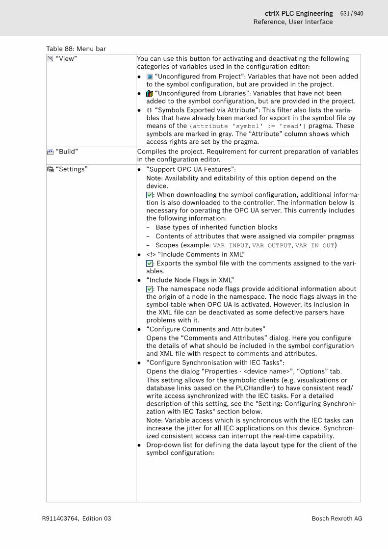
631 / 940ctrlX PLC EngineeringReference, User Interface
Bosch Rexroth AGR911403764, Edition 03
Table 88: Menu bar “View” You can use this button for activating and deactivating the following
categories of variables used in the configuration editor:● “Unconfigured from Project”: Variables that have not been added
to the symbol configuration, but are provided in the project.● “Unconfigured from Libraries”: Variables that have not been
added to the symbol configuration, but are provided in the project.● “Symbols Exported via Attribute”: This filter also lists the varia-
bles that have already been marked for export in the symbol file bymeans of the {attribute 'symbol' := 'read'} pragma. Thesesymbols are marked in gray. The “Attribute” column shows whichaccess rights are set by the pragma.
“Build” Compiles the project. Requirement for current preparation of variablesin the configuration editor.
“Settings” ● “Support OPC UA Features”:Note: Availability and editability of this option depend on thedevice.
: When downloading the symbol configuration, additional informa-tion is also downloaded to the controller. The information below isnecessary for operating the OPC UA server. This currently includesthe following information:– Base types of inherited function blocks– Contents of attributes that were assigned via compiler pragmas– Scopes (example: VAR_INPUT, VAR_OUTPUT, VAR_IN_OUT)
● <!> “Include Comments in XML”: Exports the symbol file with the comments assigned to the vari-
ables.● “Include Node Flags in XML”
: The namespace node flags provide additional information aboutthe origin of a node in the namespace. The node flags always in thesymbol table when OPC UA is activated. However, its inclusion inthe XML file can be deactivated as some defective parsers haveproblems with it.
● “Configure Comments and Attributes”Opens the “Comments and Attributes” dialog. Here you configurethe details of what should be included in the symbol configurationand XML file with respect to comments and attributes.
● “Configure Synchronisation with IEC Tasks”:Opens the dialog “Properties - <device name>”, “Options” tab.This setting allows for the symbolic clients (e.g. visualizations ordatabase links based on the PLCHandler) to have consistent read/write access synchronized with the IEC tasks. For a detaileddescription of this setting, see the "Setting: Configuring Synchroni-zation with IEC Tasks" section below.Note: Variable access which is synchronous with the IEC tasks canincrease the jitter for all IEC applications on this device. Synchron-ized consistent access can interrupt the real-time capability.
● Drop-down list for defining the data layout type for the client of thesymbol configuration:

632 / 940 ctrlX PLC EngineeringReference, User Interface
Bosch Rexroth AG R911403764, Edition 03
Note: See the "Example of data layout types" section at the end ofthis help page.– “Optimized Layout”: Recommend for new projects. Calculates
the output layout in optimized form detached from the internalcompiler layout. Does not generate any gaps for unpublished ele-ments and strictly fulfills the requirements for memory alignmentof the data types. Requires compiler version 3.5.7.0 or later.
– “Compatibility Layout”: This setting is used for the compatibilityof old projects. The data layout created for the client is matchedas much as possible to the layout created internally by the com-piler.Due to the configuration possibilities of the symbol configurationwhich have grown over time, problematic offsets can still result.Causes of offsetsMemory gaps due to internal pointers or references in functionblocks and structure components that are not released forsymbol configuration.Memory gaps that occur differently in 32-bit and 64-bit systemsdepending on the data type, such as __XINT / __XWORD .Fields that are at uneven addresses. Some clients are not set upfor this.Unintentional memory misalignment, which occurs when usingthe attributes 'pack_mode' or 'relative_offset'.
● “Use Empty Namespaces by Default (V2 Compatibility)”: Requiredwhen using a PLC Engineering V2-compatible OPC server configura-tion.
: Behavior same as in PLC Engineering V2.3.– Program variables are exported without an application name
(Application.PLC_PRG.MyVar --> PLC_PRG.MyVar– Global variables are exported additionally without the GVL name
(Application.GVL.MyGlobVar --> .MyGlobVar● “Enable Direct I/O Access”: This feature is potentially dangerous
and not intended for operation in production. Activate only for errorchecking and tests, or when commissioning the machinery (forexample, for checking cables connections).
: In the symbol configuration, you can also use access to directI/O addresses that correspond to IEC syntax (for example,"%IX0.0"). Access to input addresses (I) is read-only*. Access tooutput addresses (Q) and memory addresses (M) can be read-write.*Information: In simulation mode, write access to symbols is alsopossible for input addresses.Because external clients for protocols such as OPC or OPC UA donot always support IEC syntax for direct addresses, access is alsoprovided using an array syntax in the namespace __MIO of theimplicit code. For example, you can also access __MIO.MIO_IX[2].x3instead of %IX2.3.However, the symbols for array access are hidden in browsersbecause some clients cannot handle the large number of nodes(several thousand depending on the size of the I/O ranges).
● “Support Calls of Functions, FBs, Methods and Programs”:Note: Availability and editability of this option depend on thedevice.

633 / 940ctrlX PLC EngineeringReference, User Interface
Bosch Rexroth AGR911403764, Edition 03
: The access rights “execute” can be set in the symbol table forsymbols of POUs of type function, function block, method, or pro-gram. The “Support OPC UA Features” option also has to beselected in the “Settings”.
● “Include Call Information in XML”:: The information about called functions, function blocks,
methods, or programs is also listed in the XML file of the symbolconfiguration. The option is enabled only if the option “SupportCalls of Functions, FBs, Methods and Programs” is supported bythe device.
● “Enable Symbol Sets”:: A toolbar with buttons and a drop-down list is displayed above
the symbol table. You can use this to configure symbol sets forclient-specific assignment of access rights to the controller. See"Toolbar for symbol set configuration" below.
“Download” If you use a device that supports its own application file for the symbolconfiguration, then this button is also available in the toolbar. If youchange the symbol configuration in online mode, then you can load thenew <application name>._symbols file immediately to the PLC.
“Tools” “Save the XSD Scheme File”: This command opens the standard dialogfor saving a file in the file system. With this command, you can preparethe XSD format of the symbol file, for example for use in external pro-grams.
Table 89: Symbol table“Access Rights” You can change the access rights for a symbol by clicking the symbol in
the “Access Rights” column.Icons for access rights (in ascending order)● : Read only● : Write only● : Read and write● : Execute
This permission allow for execute access to functions, functionblocks, methods, and programs.Requirements for the assignment: The device provides the options“Support calls of Functions, FBs, Methods and Programs” and“Support OPC UA Features”. Both options are activated in the “Set-tings”.
Note: In case the controller has a user management, you can usesymbol sets to define client-specific access rights to the same sym-bols.
“Maximal” Maximum access rights for this symbol“Attribute” If the access right was assigned by attribute, then a corresponding
icon is displayed here.“Type” Alias data types are also displayed In PLC Engineering V3.5 SP6 and
later. Example: MY_INT : INT for a variable declared with the datatype MY_INT (type INT).
“Members” You can add variables of a structured data type also by selecting acheck box for symbol configuration in the “Symbols” column. Thiscauses PLC Engineering to export all member variable symbols. How-ever, in the “Members” column, you can click the ellipsis button ( )to select only specific structural components. Note: This selectionapplies to all instances of this data type for which symbols are

634 / 940 ctrlX PLC EngineeringReference, User Interface
Bosch Rexroth AG R911403764, Edition 03
exported. If a member of a structured type cannot be selected, then anasterisk ( ) is displayed in the check boxes of the members to indi-cate that all exportable members of that type are exported.
Table 90: Toolbar for symbol set configuration“List box” Already defined symbol sets
“Add a new symbol set” Opens the “Add a New Symbol Set” dialog for specifying a name forthis set
“Add a duplicate fromselected symbol set”
Opens the “Add a Duplicate from Selected Symbol Set” dialog. A copyis created for the set selected in the drop-down list. You can changethe default name (<group name>_duplicate).
“Rename the selectedSymbol Set”
Opens the “Rename the Selected Symbol Set” dialog for specifyinganother name for the set selected in drop-down list.
“Delete selected SymbolSet”
Opens a dialog prompting whether or not the symbol set selected inthe drop-down list should be deleted.
“Configure Symbol Rights” Opens the “Symbol Rights” tab of the device editor. When logged inthere, you can assign different access rights for each user group(client) to the symbol set selected in the drop-down list.
See also● ⮫ Chapter “Tab 'Symbol Rights'” on page 579
Dialog 'Comments and Attributes'Table 91: “Symbol Table Contents”“Enable extended OPC UAinformation”
Note: Availability and editability of this option depend on the device.: Additional information that can be evaluated by OPC UA servers is
included in the symbol table. This includes inheritance information ofuser-defined data types and the namespace node flags. Additionalinformation, such as comments and attributes, can also be included ifthe OPC UA setting is active.When the OPC UA setting is enabled, attributes are included in thesymbol table according to the following rule:● In compiler versions V3.5.5.0 to V3.5.7.X, all attributes are included
according to the setting “Select simple names”.● In compiler version V3.5.8.X, all attributes are included according to
the setting “Include all attributes”.● In compiler version V3.5.9.0 and later, you can customize the attrib-
utes that are included.“Include comments” Requirement: “Enable extended OPC UA information” is activated.
: Comments and attributes are also saved in the symbol table.“Include attributes”“Also include commentsand attributes for typenodes”
Requirement: “Include comments” is activated.: The information for type nodes is also included (user-defined types,
such as STRUCT and ENUM elements).: Only directly exported variables have comments and attributes.
Table 92: “XML Symbol File Contents”“Include namespace nodeflags”
: The namespace node flags provide additional information about theorigin of a node in the namespace. The node flags always in thesymbol table when OPC UA is activated. However, its inclusion in theXML file can be deactivated as some defective parsers have problemswith it.
“Include comments” : Comments can also be saved in the XML file.In compiler versions V3.5.5.x to V3.5.8.0, this includes the setting“Prefer docu comments”.
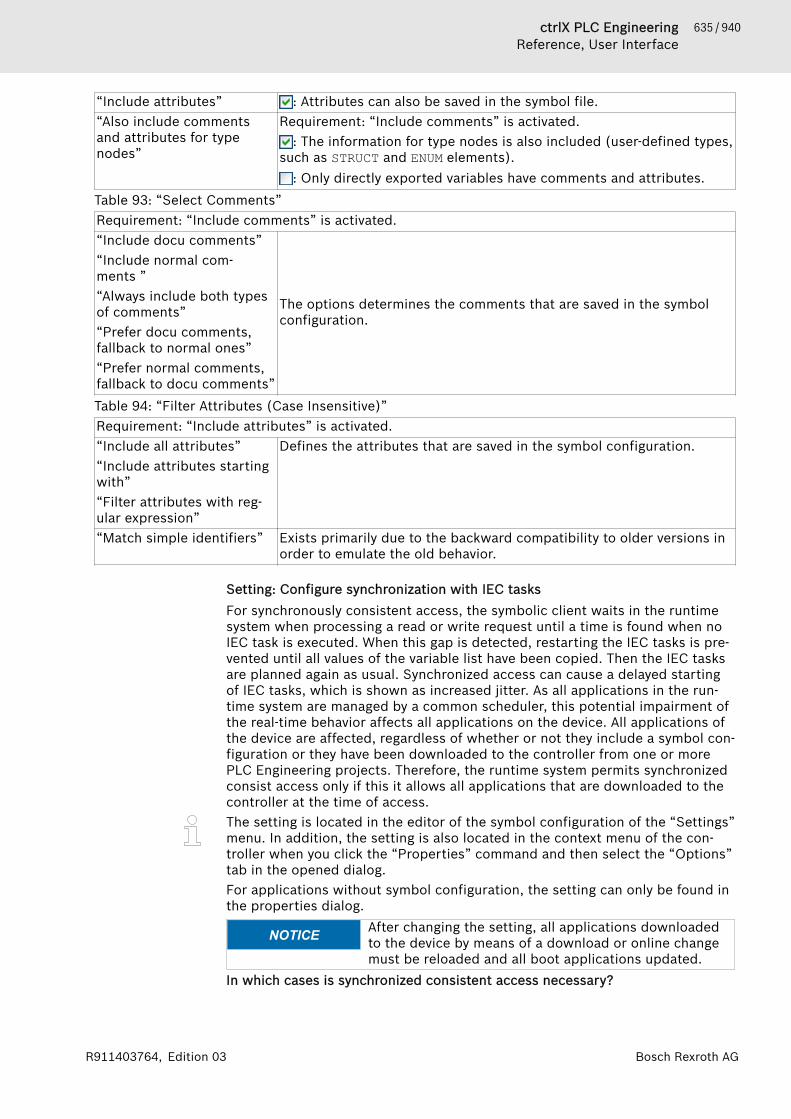
635 / 940ctrlX PLC EngineeringReference, User Interface
Bosch Rexroth AGR911403764, Edition 03
“Include attributes” : Attributes can also be saved in the symbol file.“Also include commentsand attributes for typenodes”
Requirement: “Include comments” is activated.: The information for type nodes is also included (user-defined types,
such as STRUCT and ENUM elements).: Only directly exported variables have comments and attributes.
Table 93: “Select Comments”Requirement: “Include comments” is activated.“Include docu comments”“Include normal com-ments ”“Always include both typesof comments”“Prefer docu comments,fallback to normal ones”“Prefer normal comments,fallback to docu comments”
The options determines the comments that are saved in the symbolconfiguration.
Table 94: “Filter Attributes (Case Insensitive)”Requirement: “Include attributes” is activated.“Include all attributes”“Include attributes startingwith”“Filter attributes with reg-ular expression”
Defines the attributes that are saved in the symbol configuration.
“Match simple identifiers” Exists primarily due to the backward compatibility to older versions inorder to emulate the old behavior.
Setting: Configure synchronization with IEC tasksFor synchronously consistent access, the symbolic client waits in the runtimesystem when processing a read or write request until a time is found when noIEC task is executed. When this gap is detected, restarting the IEC tasks is pre-vented until all values of the variable list have been copied. Then the IEC tasksare planned again as usual. Synchronized access can cause a delayed startingof IEC tasks, which is shown as increased jitter. As all applications in the run-time system are managed by a common scheduler, this potential impairment ofthe real-time behavior affects all applications on the device. All applications ofthe device are affected, regardless of whether or not they include a symbol con-figuration or they have been downloaded to the controller from one or morePLC Engineering projects. Therefore, the runtime system permits synchronizedconsist access only if this it allows all applications that are downloaded to thecontroller at the time of access.The setting is located in the editor of the symbol configuration of the “Settings”menu. In addition, the setting is also located in the context menu of the con-troller when you click the “Properties” command and then select the “Options”tab in the opened dialog.For applications without symbol configuration, the setting can only be found inthe properties dialog.
NOTICE After changing the setting, all applications downloadedto the device by means of a download or online changemust be reloaded and all boot applications updated.
In which cases is synchronized consistent access necessary?
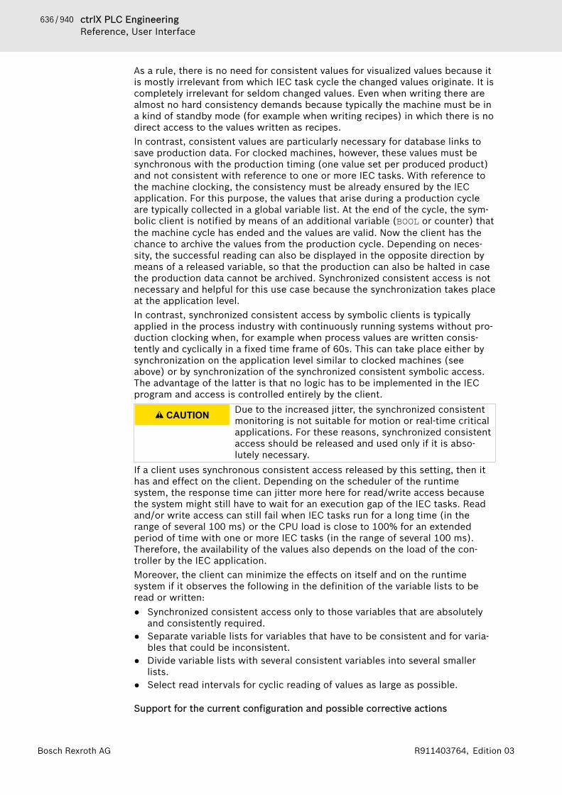
636 / 940 ctrlX PLC EngineeringReference, User Interface
Bosch Rexroth AG R911403764, Edition 03
As a rule, there is no need for consistent values for visualized values because itis mostly irrelevant from which IEC task cycle the changed values originate. It iscompletely irrelevant for seldom changed values. Even when writing there arealmost no hard consistency demands because typically the machine must be ina kind of standby mode (for example when writing recipes) in which there is nodirect access to the values written as recipes.In contrast, consistent values are particularly necessary for database links tosave production data. For clocked machines, however, these values must besynchronous with the production timing (one value set per produced product)and not consistent with reference to one or more IEC tasks. With reference tothe machine clocking, the consistency must be already ensured by the IECapplication. For this purpose, the values that arise during a production cycleare typically collected in a global variable list. At the end of the cycle, the sym-bolic client is notified by means of an additional variable (BOOL or counter) thatthe machine cycle has ended and the values are valid. Now the client has thechance to archive the values from the production cycle. Depending on neces-sity, the successful reading can also be displayed in the opposite direction bymeans of a released variable, so that the production can also be halted in casethe production data cannot be archived. Synchronized consistent access is notnecessary and helpful for this use case because the synchronization takes placeat the application level.In contrast, synchronized consistent access by symbolic clients is typicallyapplied in the process industry with continuously running systems without pro-duction clocking when, for example when process values are written consis-tently and cyclically in a fixed time frame of 60s. This can take place either bysynchronization on the application level similar to clocked machines (seeabove) or by synchronization of the synchronized consistent symbolic access.The advantage of the latter is that no logic has to be implemented in the IECprogram and access is controlled entirely by the client.
CAUTION Due to the increased jitter, the synchronized consistentmonitoring is not suitable for motion or real-time criticalapplications. For these reasons, synchronized consistentaccess should be released and used only if it is abso-lutely necessary.
If a client uses synchronous consistent access released by this setting, then ithas and effect on the client. Depending on the scheduler of the runtimesystem, the response time can jitter more here for read/write access becausethe system might still have to wait for an execution gap of the IEC tasks. Readand/or write access can still fail when IEC tasks run for a long time (in therange of several 100 ms) or the CPU load is close to 100% for an extendedperiod of time with one or more IEC tasks (in the range of several 100 ms).Therefore, the availability of the values also depends on the load of the con-troller by the IEC application.Moreover, the client can minimize the effects on itself and on the runtimesystem if it observes the following in the definition of the variable lists to beread or written:● Synchronized consistent access only to those variables that are absolutely
and consistently required.● Separate variable lists for variables that have to be consistent and for varia-
bles that could be inconsistent.● Divide variable lists with several consistent variables into several smaller
lists.● Select read intervals for cyclic reading of values as large as possible.
Support for the current configuration and possible corrective actions

637 / 940ctrlX PLC EngineeringReference, User Interface
Bosch Rexroth AGR911403764, Edition 03
Entries marked in red in the symbol table show variables that they are config-ured for export to the symbol file but are currently invalid in the application.The cause for this can be that the declaration has been removed from theblock.In version 3.5.8.0 and later, a warning appears in the editor if variables thathave configured symbols are not used in the IEC code or are not mapped in thecase of I/O variables. In addition, the compiler indicates variables that are refer-enced from outdated library versions n the symbol configuration.
NOTICE Object variables that are not used in the program coderemain uncompiled by default and are therefore not avail-able in the symbol configuration.However, PLC Engineering provides variables fromuncompiled objects in the symbol configuration whenone of the following conditions is met:− The “Link always” POU property is selected.− The {attribute 'linkalways'} pragma is used.
See also● ⮫ Chapter 1.9 “Working with Control Networks” on page 159● ⮫ Chapter “Dialog 'Properties' - 'Options'” on page 834● ⮫ Chapter “Dialog 'Properties' - 'Build'” on page 825● ⮫ Chapter “Attribute 'linkalways'” on page 436
Example of data layout types
Example of layout typesThe following examples from an IEC application will show how gaps can resultin the client-side memory layout caused by unpublished symbols, internal"invisible" pointers, or a "pack mode" definition in the device description. Withthe “Optimized Layout” setting, the gaps are avoided. The symbol file containsdifferent information about the size and offset of memory locations,depending on the selected layout setting.Example: Large structure// Example of a big structure, where not all members get published :STRUCT{attribute 'symbol':='readwrite'}PublicNumber : INT;
{attribute 'symbol':='none'}InternalData : ARRAY[0..100] OF BYTE;
{attribute 'symbol':='readwrite'}SecondNumber : INT;
{attribute 'symbol':='none'}MoreData : ARRAY[0..100] OF BYTE;
END_STRUCTEND_TYPEResulting entries in the symbol file; pay attention to size and byteoffset:Symbol file, large structure, compatibility layout option<TypeUserDef name="T_LargeStructure" size="208" nativesize="208" typeclass="Userdef" pouclass="STRUCTURE" iecname="LargeStructure">
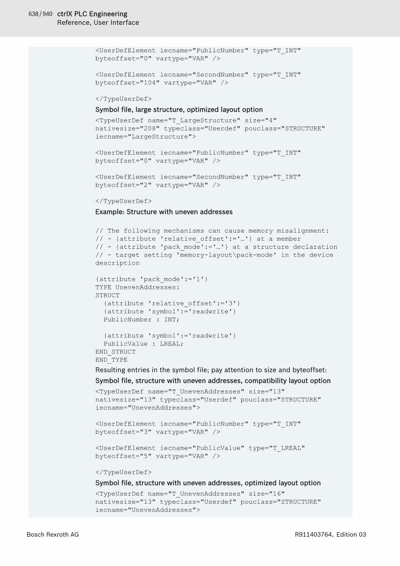
638 / 940 ctrlX PLC EngineeringReference, User Interface
Bosch Rexroth AG R911403764, Edition 03
<UserDefElement iecname="PublicNumber" type="T_INT" byteoffset="0" vartype="VAR" />
<UserDefElement iecname="SecondNumber" type="T_INT" byteoffset="104" vartype="VAR" />
</TypeUserDef>Symbol file, large structure, optimized layout option<TypeUserDef name="T_LargeStructure" size="4" nativesize="208" typeclass="Userdef" pouclass="STRUCTURE" iecname="LargeStructure">
<UserDefElement iecname="PublicNumber" type="T_INT" byteoffset="0" vartype="VAR" />
<UserDefElement iecname="SecondNumber" type="T_INT" byteoffset="2" vartype="VAR" />
</TypeUserDef>Example: Structure with uneven addresses
// The following mechanisms can cause memory misalignment:// - {attribute 'relative_offset':='…'} at a member// - {attribute 'pack_mode':='…'} at a structure declaration// - target setting 'memory-layout\pack-mode' in the device description
{attribute 'pack_mode':='1'} TYPE UnevenAddresses:STRUCT{attribute 'relative_offset':='3'}{attribute 'symbol':='readwrite'}PublicNumber : INT;
{attribute 'symbol':='readwrite'}PublicValue : LREAL;
END_STRUCTEND_TYPEResulting entries in the symbol file; pay attention to size and byteoffset:Symbol file, structure with uneven addresses, compatibility layout option<TypeUserDef name="T_UnevenAddresses" size="13" nativesize="13" typeclass="Userdef" pouclass="STRUCTURE" iecname="UnevenAddresses">
<UserDefElement iecname="PublicNumber" type="T_INT" byteoffset="3" vartype="VAR" />
<UserDefElement iecname="PublicValue" type="T_LREAL" byteoffset="5" vartype="VAR" />
</TypeUserDef>Symbol file, structure with uneven addresses, optimized layout option<TypeUserDef name="T_UnevenAddresses" size="16" nativesize="13" typeclass="Userdef" pouclass="STRUCTURE" iecname="UnevenAddresses">

639 / 940ctrlX PLC EngineeringReference, User Interface
Bosch Rexroth AGR911403764, Edition 03
<UserDefElement iecname="PublicNumber" type="T_INT" byteoffset="0" vartype="VAR" />
<UserDefElement iecname="PublicValue" type="T_LREAL" byteoffset="8" vartype="VAR" />
</TypeUserDef>Example: Function block// Each POU contains some implicit variables, which do not get published. Depending on the data type these might cause memory gaps of different sizes.FUNCTION_BLOCK POU IMPLEMENTS SomeInterfaceVAR_INPUTin : INT;
END_VARVAR_OUTPUTout : INT;
END_VARVAREND_VAREach POU contains some implicit variables, which do not get published. If it isa data type such as __XWORD, then different sizes of memory gaps result in theclient-side data layout, depending on whether the system is 64-bit or 32-bit.Resulting entries in the symbol file for 64-bit and 32-bit; pay attention to sizeand byteoffset:Symbol file, function block, compatibility layout option, 64-bit<TypeUserDef name="T_POU" size="24" nativesize="24" typeclass="Userdef" pouclass="FUNCTION_BLOCK" iecname="POU">
<UserDefElement iecname="in" type="T_INT" byteoffset="16" vartype="VAR_INPUT" />
<UserDefElement iecname="out" type="T_INT" byteoffset="18" vartype="VAR_OUTPUT" />
</TypeUserDef>Symbol file, function block, optimized layout option, 64-bit<TypeUserDef name="T_POU" size="4" nativesize="24" typeclass="Userdef" pouclass="FUNCTION_BLOCK" iecname="POU">
<UserDefElement iecname="in" type="T_INT" byteoffset="0" vartype="VAR_INPUT" />
<UserDefElement iecname="out" type="T_INT" byteoffset="2" vartype="VAR_OUTPUT" />
</TypeUserDef>Symbol file, function block, compatibility layout option, 32-bit<TypeUserDef name="T_POU" size="12" nativesize="12" typeclass="Userdef" pouclass="FUNCTION_BLOCK" iecname="POU">
<UserDefElement iecname="in" type="T_INT" byteoffset="8" vartype="VAR_INPUT" />
640 / 940 ctrlX PLC EngineeringReference, User Interface
Bosch Rexroth AG R911403764, Edition 03
<UserDefElement iecname="out" type="T_INT" byteoffset="10" vartype="VAR_OUTPUT" />
</TypeUserDef>Symbol file, function block, optimized layout option, 32-bit<TypeUserDef name="T_POU" size="4" nativesize="12" typeclass="Userdef" pouclass="FUNCTION_BLOCK" iecname="POU">
<UserDefElement iecname="in" type="T_INT" byteoffset="0" vartype="VAR_INPUT" />
<UserDefElement iecname="out" type="T_INT" byteoffset="2" vartype="VAR_OUTPUT" />
</TypeUserDef>
See also● ⮫ Chapter 1.9.2 “Symbol Configuration” on page 164
Object 'Task Configuration'Symbol: The object is used to define and display the basic settings for the task configu-ration.The “Task Configuration” object must be included exactly one time in eachapplication.“Task Configuration” tabs and functions● “Properties”: Display of the basic settings● “System Events”: Linking of POU calls with system events● “Monitor”: Display of the status and current statistics for the cycles times in
online mode● “Variable Usage”: Overview of the tasks that access the variables and how
they do it● “Task Groups”: Definitions of the tasks groups and their assignment to CPUs● “CPU Load”: Graphical representation of the CPU load in online modeSee also● ⮫ Chapter “Creating a Task Configuration” on page 130● ⮫ Chapter “Tab 'Properties'” on page 640● ⮫ Chapter “Tab 'System Events'” on page 640● ⮫ Chapter “Tab 'Monitor'” on page 643● ⮫ Chapter “Tab 'Variable Usage'” on page 644● ⮫ Chapter “Tab 'Task Groups'” on page 644● ⮫ Chapter “Tab 'CPU Load'” on page 644● ⮫ Chapter “Object 'Task'” on page 645
Tab 'Properties'Object: “Task Configuration”In this tab, you define the basic settings of the task configuration as predefinedby the target system, such as the maximum values for tasks and watchdogparameters.
Tab 'System Events'Object: “Task Configuration”
641 / 940ctrlX PLC EngineeringReference, User Interface
Bosch Rexroth AGR911403764, Edition 03
In the “System Events” tab, you define which events call which functions andwhether or not the configuration is currently activated. You use this tab when asystem event (instead of a task) should call a project function.
“Add Event Handler” Opens the “Add Event Handler” dialog box“Remove Event Handler” Deletes the selected list assignment“Event Info” Shows information from the corresponding event library“Open Event Function” Opens the editor of the new function for the selected assignment You
have selected the implementation language of the new function in the“Add Event Handler” dialog box.
Assignment of functions to call for events with: “Name”,“Description”, “Function to call”, and“Active” (activate/deactivate configuration).Table 95: “Add Event Handler”Adds a new assignment "Event – Function to call" to the list“Event” The list of choices depends on the target device. PLC Engineering
marks unavailable events with a red symbol in front of the name.A list of all possible system events is located at the end of this section.
“Function to call” Function name (“POU”, type “FUNCTION”)You must enter the name of the new function. PLC Engineering insertsthe function to the device tree after you confirm the dialog box.
“Scope” ● “Application”: Function is available for the application● “POUs”: Function is available for the entire project
“Implementation language” Implementation language for the new function“Description” Short description of the selected event
Features in “Online Mode”The list of assignments from called functions to events also includes the fol-lowing information: “Event Status”, “Call Count”, and the “Online Reset”button.
“Event Status” 0: No error has occurred.Does not equal 0: error. You must consult the respective runtimesystem documentation.
“Call Count” Displays how often the event has occurred or the associated functionhas been called.
“Online Reset” PLC Engineering reinitializes the event lists and resets the counter forthe events/function calls. Incorrectly initialized events are displayedwith a red status cell.
Possible system events
Event Description Task DebuggingPrepareStart Call before starting
the applicationCommunication Task no
StartDone Call after startingthe application
Communication Task no
PrepareStop Call before stop-ping the application
Communication Task no
StopDone Call after stoppingthe application
Communication Task no
PrepareReset Call before reset-ting the application
Communication Task no
642 / 940 ctrlX PLC EngineeringReference, User Interface
Bosch Rexroth AG R911403764, Edition 03
Event Description Task DebuggingResetDone Call after resetting
the applicationCommunication Task no
PrepareOnline-Change
Call before onlinechange of the appli-cation
Communication Task no
OnlineChange-Done
Call after onlinechange of the appli-cation
Communication Task no
PrepareDown-load
Call before down-loading the applica-tion
Communication Task no
DownloadDone Call after down-loading the applica-tion
Communication Task no
PrepareDelete Call before deletingthe application
Communication Task no
DeleteDone Call after deletingthe application
Communication Task no
PrepareExit Call before exitingthe application
Communication Task no
ExitDone Call after exitingthe application
Communication Task no
CodeInitDone Event is sent afterCode Init. Calledwithin the safe sec-tion task and onlyfor online change(for example, thecopy code is exe-cuted here foronline change).
Communication Task no
Exception The event is sent ifan exception hasoccurred in thecontext of an appli-cation.
Exception HandlingTask (of runtimesystem) or task itself(if the runtime systemdoes not supportexception handling)
Depends on thetask
Login Logs in a client tothis application
Communication Task no
Logout Logs out a clientfrom this applica-tion
Communication Task no
BeforeReadin-gInputs
Call before readingthe inputs
IEC Task yes
AfterReadingIn-puts
Call after readingthe inputs
IEC Task yes
BeforeWritin-gOutputs
Call before writingthe inputs
IEC Task yes
AfterWritingOut-puts
Call after writingthe inputs
IEC Task yes
643 / 940ctrlX PLC EngineeringReference, User Interface
Bosch Rexroth AGR911403764, Edition 03
Event Description Task DebuggingDebugLoop Event is sent in
cycles to the debugloop if the IEC taskstops at a break-point.
Communication Task no
PrepareShut-down
Event is sent imme-diately before theruntime system isdownloaded.
Runtime System MainLoop
no
PrepareExit-Comm
Event is sent duringdownload beforeexiting the commu-nication server.
Runtime System MainLoop
no
PrepareExitTasks Event is sent duringdownload beforeexiting all tasks.
Runtime System MainLoop
no
Tab 'Monitor'Object: “Task Configuration”This tab shows the following information in online mode: status for tasks in thetask configuration and some current measurements of the cycles and cycletimes. PLC Engineering updates the values in the same time interval as for themonitoring of values from the PLC.Reset the displayed values 0 by right-clicking the task and then clicking the“Reset” command in the context menu.
“Task” Task name (as defined in the task configuration)“Status” ● “Not created”: The task has not been started since the last update
(especially for event tasks).● “Generated”: The task is recognized in the runtime system, but not yet
in operation.● “Valid”: The task is operating normally.● “Exception”: The task has produced an exception status.
“IEC Cycle Count” Number of cycles executed since starting the application where the IECcode was executed (0 if the target system does not support the counterfunction)
“Cycle Count” Number of executed cycles since logging in to the PLC.It depends on the target system whether cycles are also counted wherethe application is not running. In these cases, the “Cycle Count” may begreater than the “IEC Cycle Count”.
“Last Cycle Time (µs)” Last measured cycle time [µs]“Average Cycle Time(µs)”
Average cycle time over all cycles [µs]
“Max. Cycle Time (µs)” Maximum measured cycle time over all cycles [µs]“Min. Cycle Time (µs)” Minimum measured cycle time over all cycles [µs]“Jitter (µs)” Last measured jitter [µs]
Jitter is the difference between the time when the task should be startedand the time when the task is actually started. For example, if the taskshould be started every 1000 µs and it actually starts after 1100 µs, thenthe jitter is 100 µs.
“Min. Jitter (µs)” Minimum measured jitter [µs]

644 / 940 ctrlX PLC EngineeringReference, User Interface
Bosch Rexroth AG R911403764, Edition 03
“Max. Jitter (µs)” Maximum measured jitter [µs]“Core” Number of processor cores on which the task is currently running.
Example: 2Note: The controller has a multi-core CPU.
Tab 'Variable Usage'Object: “Task Configuration”The “Variable Usage” tab provides an overview of all variables and their usage.There you can see the tasks where variables are accessed.When using multicore, write access (w) to a variable should take place only in atask because otherwise it can cause inconsistencies.In the context menu, you can hide individual tasks and show the cross-refer-ence list to variables.
“Variables” Name of the variable“Type” Data type“Number” Number of tasks that access these variables.“<task name>” Access to the variable (r: read, w: write, rw: read/write)
See also● ⮫ Chapter “ Multicore” on page 130● ⮫ Chapter 1.8.17 “Task Configuration” on page 129
Tab 'Task Groups'Object: “Task configuration”You define task groups in the “Task Groups” tab. Task groups can be distrib-uted over the individual processor cores in multicore systems. Tasks in a taskgroup always run on the same processor core.
“Add Group” The button adds a new task group named NewGroup_<no>.“Remove Group” Deletes the selected task group.“Group Name” The name can be changed by double-clicking in the field.“Core” Determines the processor core for process the tasks of this group.
● “Free floating”: All tasks are bound dynamically to different pro-cessor cores. The user does not have any influence over this. Theoperating system is responsible for the distribution.
● “Sequentially pinned”: All tasks are bound and fixed to differentprocessor cores. The user does not have any influence over this.
● “Fixed pinned”: All tasks are bound to one processor core. Bydefault, the runtime system determines the processor core.
● “<core number>”: Fixed defined processor core. If the processorcore is not available, then an error message is issued.
See also● ⮫ Chapter “ Multicore” on page 130● ⮫ Chapter 1.8.17 “Task Configuration” on page 129
Tab 'CPU Load'Object: “Task Configuration”The “CPU Load” tab is available in online mode for multicore devices only. Theload of the individual CPUs is presented in the trace editor.You open the trace configuration by double-clicking the legend in the windowon the right side. Adding more variables is not possible here.

645 / 940ctrlX PLC EngineeringReference, User Interface
Bosch Rexroth AGR911403764, Edition 03
See also● ⮫ Chapter “ Multicore” on page 130
Object 'Task'Symbol: In this object, you define the conditions for starting and calling the task.You insert the object below “Task Configuration” in the device tree.Also see● ⮫ Chapter “Tab 'Configuration'” on page 645● ⮫ Chapter “Object 'Task Configuration'” on page 640
Tab 'Configuration'Object: “Task”
“Priority” Possible values: 0..31, where 0 is the highest priority“Task group” Assigned task group. This assignment is shown in parentheses in the
device tree. Task groups can be assigned to specific processor cores inmulticore.The task group is shown in parentheses after the task in the devicetree.
Table 96: “Type”“Cyclic” PLC Engineering processes the task in cycles. The cycle time of the
task is defined in the input field “Interval”.“Event” PLC Engineering starts processing the task as soon as the global vari-
able defined in the input field “Event” contains a rising edge.“Freewheeling” PLC Engineering starts processing the task again automatically in a
continuous loop at program start and at the end of a complete pass.Cycle time is not defined.
“Status” PLC Engineering starts task processing as soon as the variable definedin the “Event” input field yields the Boolean value TRUE.
“External” PLC Engineering starts processing the task as soon as the eventdefined in the “Event” input field occurs. The target system determineswhich events are supported and offered in the dropdown list. (Not tobe confused with system events).
“Interval” Task-cycle timeRequired for the types “Cyclic” or “External Event” when the eventrequires a given time. Time interval after which the task should berestarted. If you enter a number here, then you can select the desiredunit in the dropdown list after the input field.If you select “ms”, then an entry is automatically displayed in TIMEformat, for example t#200ms, as soon as the window is in focus again.You can also enter the task cycle time directly in TIME format. Entriesin [µs] format are always displayed as a pure number.
NOTICE For fieldbuses, a fixed cycle matrix is necessary toassure a determined behavior. Therefore, you should notuse “Type” “Freewheeling” for a bus cycle task.
646 / 940 ctrlX PLC EngineeringReference, User Interface
Bosch Rexroth AG R911403764, Edition 03
NOTICE Please note the following difference between the proc-essing types “Status ” and “Event”. If the given eventyields TRUE, then the start condition of a task of type“Status” is fulfilled. In contrast, the start of a task oftype “Event” requires a switch of the event from FALSEto TRUE. If the scanning rate of the task scheduler is toolow, then the rising edge of the event can remain unno-ticed.
NOTICE Please note: When setting the task cycle time, identifywhich bus system is currently being used. For example,the task cycle time in a CAN bus system must match thecurrently set baud rate and the number of frames used inthe bus. In addition, the times set for heartbeat, nodeguarding, and sync should always be a multiple of thetask cycle time. If not, then CAN frames can be lost.
Table 97: “Watchdog”Defines the time monitoring for a task. If the target system supports an advanced watchdog config-uration, then the following settings may be predefined in the device description.● Upper and lower limit● Default watchdog time● Time percentageThe default watchdog settings depend on the device.“Enable” The watchdog is active.
If the task exceeds the currently set “Time” of the watchdog, then thetask is halted with an error status (exception). Then the currentlydefined “Sensitivity” is also taken into account. If you activate theoption “Update I/Os” in the “PLC Settings” of the PLC, then PLC Engi-neering resets the outputs to the defined default values.Possible cases:● Several consecutive timeouts:
Sensitivity: 0, 1 - exception in cycle 1Sensitivity: 2 - exception in cycle 2Sensitivity: n - exception in cycle n
● Single timeout: Exception if the cycle time of the current cycle islonger than (time * sensitivity). Example: Time=t#10ms, Sensi-tivity=5 (i.e., exception as soon as the one-time task runs longerthan 50 ms)
“Time (e.g. t#200ms)” Watchdog timeDefines the watchdog for a task (with “Sensitivity”); description as for“Enable”.Depending on the target system, the monitoring interval is given as apercentage of the task interval if possible. In this case, the drop-downlist for the unit is disabled and displays “%”.
“Sensitivity” NumberDefines the watchdog for a task (with the watchdog time); descriptionas for “Enable”.
Using the functions from the library CmpIecTask.library, you can deactivatea watchdog for specific PLC cycles. This is useful for cycles that demand moretime due to initialization.
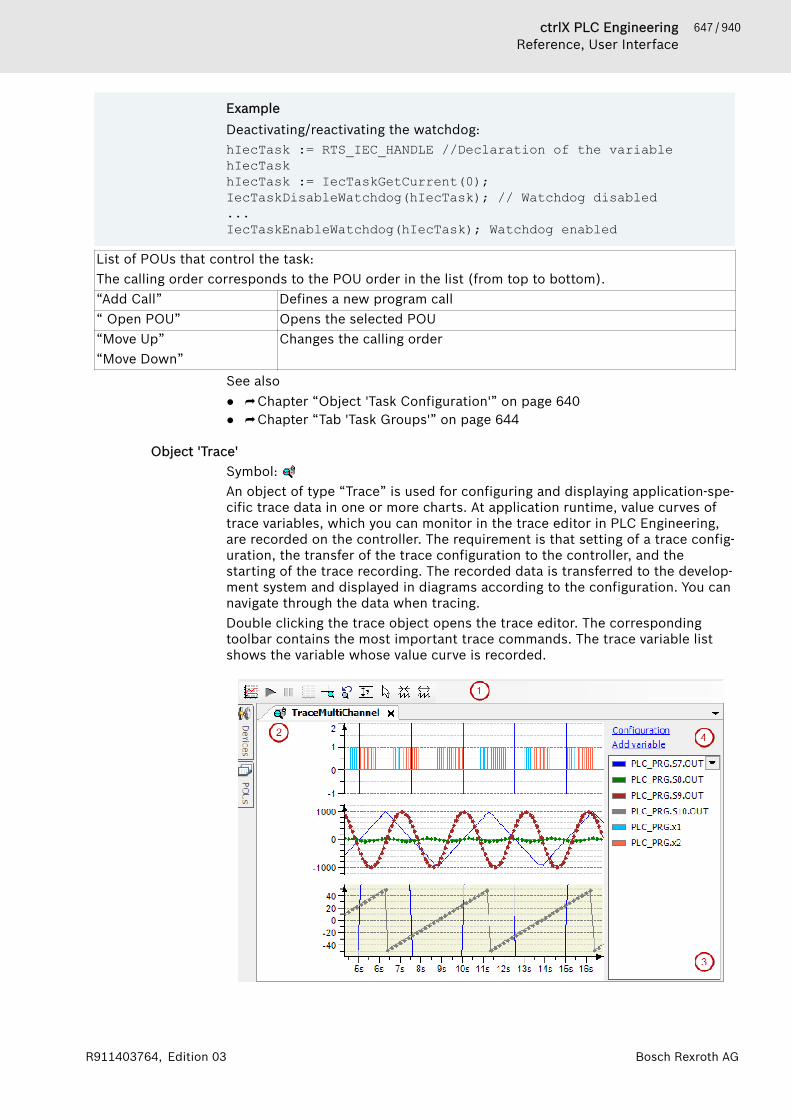
647 / 940ctrlX PLC EngineeringReference, User Interface
Bosch Rexroth AGR911403764, Edition 03
ExampleDeactivating/reactivating the watchdog:hIecTask := RTS_IEC_HANDLE //Declaration of the variable hIecTaskhIecTask := IecTaskGetCurrent(0);IecTaskDisableWatchdog(hIecTask); // Watchdog disabled...IecTaskEnableWatchdog(hIecTask); Watchdog enabled
List of POUs that control the task:The calling order corresponds to the POU order in the list (from top to bottom).“Add Call” Defines a new program call“ Open POU” Opens the selected POU“Move Up”“Move Down”
Changes the calling order
See also● ⮫ Chapter “Object 'Task Configuration'” on page 640● ⮫ Chapter “Tab 'Task Groups'” on page 644
Object 'Trace'Symbol: An object of type “Trace” is used for configuring and displaying application-spe-cific trace data in one or more charts. At application runtime, value curves oftrace variables, which you can monitor in the trace editor in PLC Engineering,are recorded on the controller. The requirement is that setting of a trace config-uration, the transfer of the trace configuration to the controller, and thestarting of the trace recording. The recorded data is transferred to the develop-ment system and displayed in diagrams according to the configuration. You cannavigate through the data when tracing.Double clicking the trace object opens the trace editor. The correspondingtoolbar contains the most important trace commands. The trace variable listshows the variable whose value curve is recorded.
648 / 940 ctrlX PLC EngineeringReference, User Interface
Bosch Rexroth AG R911403764, Edition 03
● (1): Toolbar of the trace editor● (2): Trace editor● (3): Trace variable list● (4): Links for trace configuration
“Configuration”“Add Variable”
See also● ⮫ Chapter 1.12.3 “Data Recording with Trace” on page 220
Toolbar of the trace editorSee also● : ⮫ Chapter “Command 'Download Trace'” on page 809● : ⮫ Chapter “Command 'Start Trace'” on page 813● : ⮫ Chapter “Command 'Stop Trace'” on page 813● : ⮫ Chapter “Command 'Reset Trigger'” on page 812● : ⮫ Chapter “Command 'Mouse Zooming'” on page 811● : ⮫ Chapter “Command 'AutoFit'” on page 807● : ⮫ Chapter “Command 'Cursor'” on page 808● : ⮫ Chapter “Command 'Compress'” on page 807● : ⮫ Chapter “Command 'Compress'” on page 807● : ⮫ Chapter “Command 'Stretch'” on page 814
Trace editorAt application runtime, the runtime system buffer of the trace component isfilled with the recorded samples. The data is transferred to the developmentsystem and stored in its trace editor buffer. The trace editor accesses this dataand visualizes it in diagrams as a graph over time. If you close the trace editor,the trace editor buffer will be freed up.Use menu commands for controlling the trace. In addition, you can use menucommands, keyboard shortcuts, and mouse input for navigating through thedata.See also● ⮫ Chapter “Operating the Data Recording” on page 225● ⮫ Chapter “Navigating into Trace Data” on page 225
Trace variable listThe trace variable list provides an overview of the current trace configuration.When you double-click a trace variable, the dialog “Trace configuration” alsoopens with its variable settings.
Drop-down list opens with the “Hide Instance Paths” command.“Hide Instance Paths” Display of the variable name in the list
● : Variable name with complete instance pathExample: PLC_PRG.iCounter
649 / 940ctrlX PLC EngineeringReference, User Interface
Bosch Rexroth AGR911403764, Edition 03
Table 98: Context menu in the trace variable list“Add Variable” Adds a new trace variable and opens the “Trace Configuration” dialog
with its variable settings. Select a variable in the input field of the“Variable” setting to trace its value curve.
“Visible” Toggles the visibility of the graph (value curve or trace variable) in thecorresponding diagrams:● : Visible.● : Hidden.
“Display Settings” Opens the “Trace Configuration” dialog. Select a configuration item inthe tree view “Trace record” or “Presentation (Diagrams)”.
“Configuration” Opens the “Trace Configuration” dialog. The “Variable Settings” aredisplayed on the right.
See also● ⮫ Chapter “Dialog 'Trace Configuration'” on page 866
Navigating in the diagramTable 99: Via mouse inputUser input via mouse Symbol mouse
cursor during userinput
Effect
Drag the graph along the x-axis. Scrolls trace graphs of all diagrams atthe same time along the time axis (x-axis).
Hold down the [Ctrl] key and drag thegraphs along the y-axis.
Scrolls the trace graphs of the selecteddiagrams along the y-axis.
Move the mouse wheel backwards. Compressed time axis (like the symbol).
Move the mouse wheel forwards. Stretches time axis (like the symbol).
Hold down the [Ctrl] key and move themouse wheel backwards.
Compresses the y-axis.
Hold down the [Ctrl] key and move themouse wheel forwards.
Stretches the y-axis.
Requirement: One or two trace cursorsare activated.Drag the triangle of a trace cursor toanother position along the time axis.
Refreshes the y-values in the trace vari-able list at the same time● First value: y-value at the position of
the left cursor.● Second value: y-value at the posi-
tion of the right cursor.● Third value: Difference between
both values.Requirement: “Mouse zooming” is acti-vated ( ).Stretch a box.
Zooms the trace graphs of all diagramsto the box.
Table 100: With keyboard shortcutsKeyboard shortcuts EffectRequirement: No trace cursor is activated.[Left arrow][Right arrow]
Scrolls trace graphs of all diagrams at the sametime along the time axis.
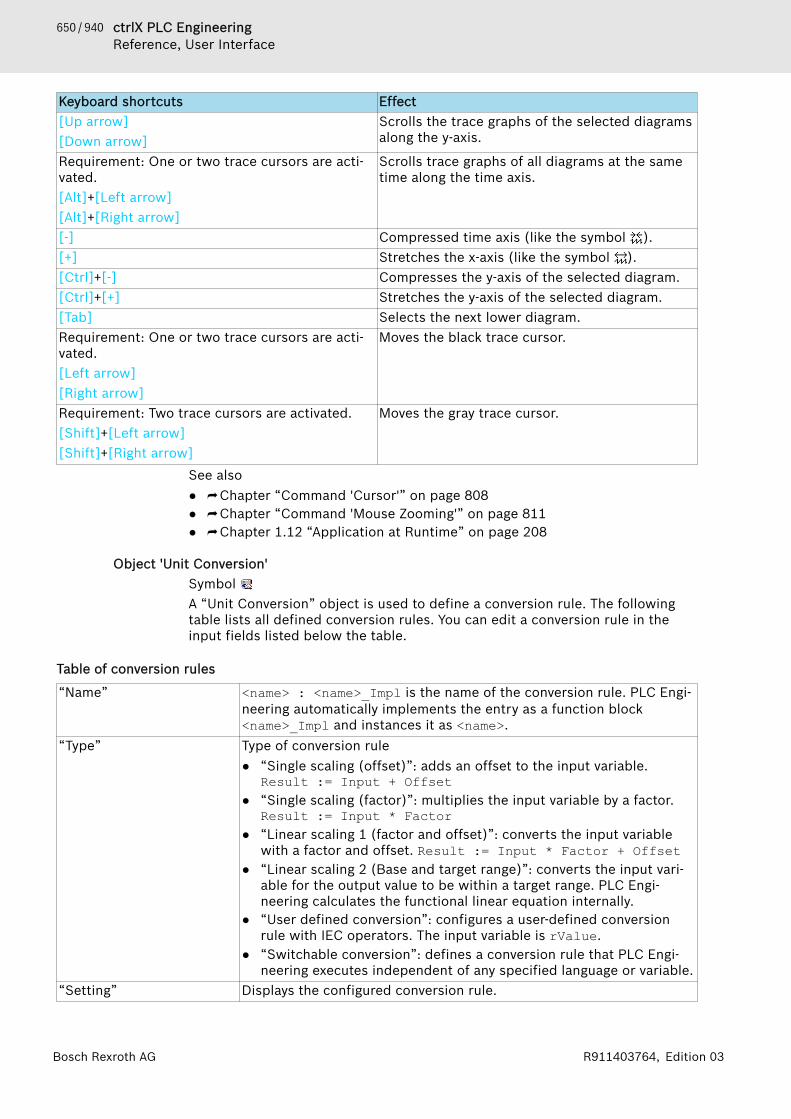
650 / 940 ctrlX PLC EngineeringReference, User Interface
Bosch Rexroth AG R911403764, Edition 03
Keyboard shortcuts Effect[Up arrow][Down arrow]
Scrolls the trace graphs of the selected diagramsalong the y-axis.
Requirement: One or two trace cursors are acti-vated.[Alt]+[Left arrow][Alt]+[Right arrow]
Scrolls trace graphs of all diagrams at the sametime along the time axis.
[-] Compressed time axis (like the symbol ).[+] Stretches the x-axis (like the symbol ).[Ctrl]+[-] Compresses the y-axis of the selected diagram.[Ctrl]+[+] Stretches the y-axis of the selected diagram.[Tab] Selects the next lower diagram.Requirement: One or two trace cursors are acti-vated.[Left arrow][Right arrow]
Moves the black trace cursor.
Requirement: Two trace cursors are activated.[Shift]+[Left arrow][Shift]+[Right arrow]
Moves the gray trace cursor.
See also● ⮫ Chapter “Command 'Cursor'” on page 808● ⮫ Chapter “Command 'Mouse Zooming'” on page 811● ⮫ Chapter 1.12 “Application at Runtime” on page 208
Object 'Unit Conversion'Symbol A “Unit Conversion” object is used to define a conversion rule. The followingtable lists all defined conversion rules. You can edit a conversion rule in theinput fields listed below the table.
Table of conversion rules
“Name” <name> : <name>_Impl is the name of the conversion rule. PLC Engi-neering automatically implements the entry as a function block<name>_Impl and instances it as <name>.
“Type” Type of conversion rule● “Single scaling (offset)”: adds an offset to the input variable.
Result := Input + Offset● “Single scaling (factor)”: multiplies the input variable by a factor.
Result := Input * Factor● “Linear scaling 1 (factor and offset)”: converts the input variable
with a factor and offset. Result := Input * Factor + Offset● “Linear scaling 2 (Base and target range)”: converts the input vari-
able for the output value to be within a target range. PLC Engi-neering calculates the functional linear equation internally.
● “User defined conversion”: configures a user-defined conversionrule with IEC operators. The input variable is rValue.
● “Switchable conversion”: defines a conversion rule that PLC Engi-neering executes independent of any specified language or variable.
“Setting” Displays the configured conversion rule.

651 / 940ctrlX PLC EngineeringReference, User Interface
Bosch Rexroth AGR911403764, Edition 03
“Condition” ● “TRUE”: PLC Engineering always executes the conversion.● “Language” If the language in the visualization is the language
defined here, then PLC Engineering executes the conversion. Thecurrent visualization language is located in the VisuElems.Cur-rentLanguage variable.
● “Variable”: If the comparison is TRUE, then PLC Engineering exe-cutes the conversion rule. PLC Engineering can pass the compar-ison for a constant, variable, or IEC expression.You can edit the comparison below the table in the “Condition Set-ting”.
“Condition Setting” If you select “TRUE” as the “Condition”, then the field is hidden.If you configure “Language” as the “Condition”, then the field showsthe current configuration, for example en,de.If you select “Variable” as the “Condition”, then the field shows thecurrent configuration, for example PLC_PRG.bActual=PLC_PRG.bSet.You can edit the current condition setting below the table in the inputfields for “Condition Setting”.
Input field 'Single scaling (offset)'The input variable is added with an offset.
“Offset” ● as a number, including REAL● as an IEC variable
Input field 'Single scaling (factor)'The input variable is multiplied by the factor.“Factor” ● as a number, including REAL
● as an IEC variable
Input field 'Linear scaling 1 (factor and offset)'The input variable is converted with the linear equation defined below.
“Factor” ● as a number, including REAL● as an IEC variable
“Offset” ● as a number, including REAL● as an IEC variable
Input field 'Linear scaling 2 (Base and target range)'The input variable is converted to be within a target range. PLC Engineeringinternally creates a linear equation from the following input values.
“Base start value” Lowest possible value for the input variable.● as a number, including REAL● as an IEC variable
“Base end value” Highest possible value for the input variable.● as a number, including REAL● as an IEC variable
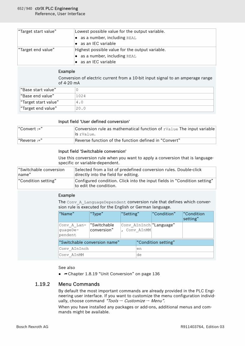
652 / 940 ctrlX PLC EngineeringReference, User Interface
Bosch Rexroth AG R911403764, Edition 03
“Target start value” Lowest possible value for the output variable.● as a number, including REAL● as an IEC variable
“Target end value” Highest possible value for the output variable.● as a number, including REAL● as an IEC variable
ExampleConversion of electric current from a 10-bit input signal to an amperage rangeof 4-20 mA
“Base start value” 0“Base end value” 1024“Target start value” 4.0“Target end value” 20.0
Input field 'User defined conversion'
“Convert :=” Conversion rule as mathematical function of rValue The input variableis rValue.
“Reverse :=” Reverse function of the function defined in “Convert”
Input field 'Switchable conversion'Use this conversion rule when you want to apply a conversion that is language-specific or variable-dependent.
“Switchable conversionname”
Selected from a list of predefined conversion rules. Double-clickdirectly into the field for editing.
“Condition setting” Configured condition. Click into the input fields in “Condition setting”to edit the condition.
ExampleThe Conv_A_LanguageDependent conversion rule that defines which conver-sion rule is executed for the English or German language.“Name” “Type” “Setting” “Condition” “Condition
setting”Conv_A_Lan-guageDe-pendent
“Switchableconversion”
Conv_AInInch, Conv_AInMM
“Language”
“Switchable conversion name” “Condition setting”Conv_AInInch enConv_AInMM de
See also● ⮫ Chapter 1.8.19 “Unit Conversion” on page 136
1.19.2 Menu CommandsBy default the most important commands are already provided in the PLC Engi-neering user interface. If you want to customize the menu configuration individ-ually, choose command “Tools 🠂 Customize 🠂 Menu”.When you have installed any packages or add-ons, additional menus and com-mands might be available.
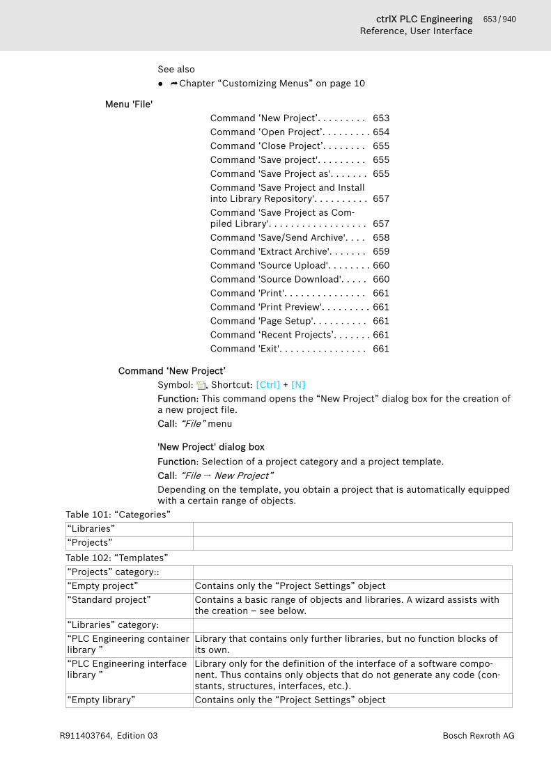
653 / 940ctrlX PLC EngineeringReference, User Interface
Bosch Rexroth AGR911403764, Edition 03
See also● ⮫ Chapter “Customizing Menus” on page 10
Menu 'File'Command ‘New Project’. . . . . . . . . 653Command ‘Open Project’. . . . . . . . . 654Command ‘Close Project’. . . . . . . . 655Command 'Save project'. . . . . . . . . 655Command 'Save Project as'. . . . . . . 655Command 'Save Project and Installinto Library Repository'. . . . . . . . . . 657Command 'Save Project as Com-piled Library'. . . . . . . . . . . . . . . . . . 657Command 'Save/Send Archive'. . . . 658Command 'Extract Archive'. . . . . . . 659Command 'Source Upload'. . . . . . . . 660Command 'Source Download'. . . . . 660Command 'Print'. . . . . . . . . . . . . . . 661Command 'Print Preview'. . . . . . . . . 661Command 'Page Setup'. . . . . . . . . . 661Command ‘Recent Projects’. . . . . . . 661Command 'Exit'. . . . . . . . . . . . . . . . 661
Command ‘New Project’Symbol: , Shortcut: [Ctrl] + [N]Function: This command opens the “New Project” dialog box for the creation ofa new project file.Call: “File” menu
'New Project' dialog boxFunction: Selection of a project category and a project template.Call: “File 🠂 New Project”Depending on the template, you obtain a project that is automatically equippedwith a certain range of objects.
Table 101: “Categories”“Libraries”“Projects”Table 102: “Templates”“Projects” category::“Empty project” Contains only the “Project Settings” object“Standard project” Contains a basic range of objects and libraries. A wizard assists with
the creation – see below.“Libraries” category:“PLC Engineering containerlibrary ”
Library that contains only further libraries, but no function blocks ofits own.
“PLC Engineering interfacelibrary ”
Library only for the definition of the interface of a software compo-nent. Thus contains only objects that do not generate any code (con-stants, structures, interfaces, etc.).
“Empty library” Contains only the “Project Settings” object
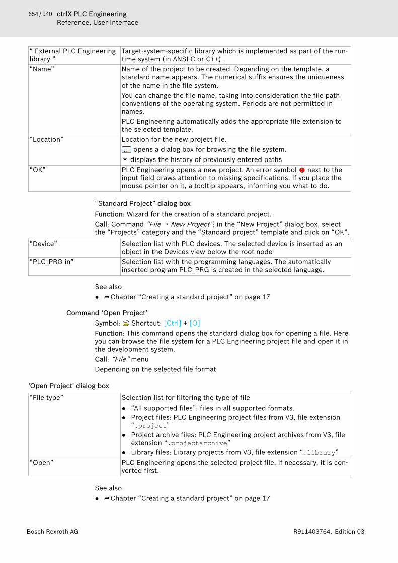
654 / 940 ctrlX PLC EngineeringReference, User Interface
Bosch Rexroth AG R911403764, Edition 03
“ External PLC Engineeringlibrary ”
Target-system-specific library which is implemented as part of the run-time system (in ANSI C or C++).
“Name” Name of the project to be created. Depending on the template, astandard name appears. The numerical suffix ensures the uniquenessof the name in the file system.You can change the file name, taking into consideration the file pathconventions of the operating system. Periods are not permitted innames.PLC Engineering automatically adds the appropriate file extension tothe selected template.
“Location” Location for the new project file. opens a dialog box for browsing the file system.
displays the history of previously entered paths“OK” PLC Engineering opens a new project. An error symbol next to the
input field draws attention to missing specifications. If you place themouse pointer on it, a tooltip appears, informing you what to do.
“Standard Project” dialog boxFunction: Wizard for the creation of a standard project.Call: Command “File 🠂 New Project”; in the “New Project” dialog box, selectthe “Projects” category and the “Standard project” template and click on “OK”.
“Device” Selection list with PLC devices. The selected device is inserted as anobject in the Devices view below the root node
“PLC_PRG in” Selection list with the programming languages. The automaticallyinserted program PLC_PRG is created in the selected language.
See also● ⮫ Chapter “Creating a standard project” on page 17
Command ‘Open Project’Symbol: Shortcut: [Ctrl] + [O]Function: This command opens the standard dialog box for opening a file. Hereyou can browse the file system for a PLC Engineering project file and open it inthe development system.Call: “File” menuDepending on the selected file format
'Open Project' dialog box
“File type” Selection list for filtering the type of file● “All supported files”: files in all supported formats.● Project files: PLC Engineering project files from V3, file extension
“.project”● Project archive files: PLC Engineering project archives from V3, file
extension “.projectarchive”● Library files: Library projects from V3, file extension “.library”
“Open” PLC Engineering opens the selected project file. If necessary, it is con-verted first.
See also● ⮫ Chapter “Creating a standard project” on page 17

655 / 940ctrlX PLC EngineeringReference, User Interface
Bosch Rexroth AGR911403764, Edition 03
Command ‘Close Project’Function: This command closes the currently opened project. PLC Engineeringremains opened.Call: “File” menu. In addition implicitly when opening a new/other project,while another project is still open.If the project contains unsaved changes, a query appears, asking whether theproject should be saved.If you have not yet explicitly saved the project, a query appears asking whetheryou wish to delete the project files.See also● ⮫ Chapter 1.2 “Creating and configuring projects” on page 14
Command 'Save project'Symbol: , shortcut [Ctrl] + [S]Function: this command saves the project file.Call: “File” menuThis command saves the project file with the current project name, whichappears in the title bar of the main window. If the project has been changedsince it was last saved, the project name is given an asterisk.The command is not available if the project is read-only.Write protection exists if● the project is identified in the project information (summary) as 'Released'● the option “Open read-only” was selected in the dialog box “Open Project”
when opening the projectWrite protection is indicated by a line in the top right corner of the mainwindow. A mouse-click on this line brings up a menu with commands for thepossible actions:● “Save project under a different file name on the disk”: a mouse-click on this
option leads to 'Save file as…'● “Exit read-only mode”: appears only if the option “Open read-only” was
selected when opening the project.● “Remove read-only attribute from the project on the disk”: appears only if
the project file had been provided with the property 'Read-only' on the diskat the time of opening.
● “Remove identification 'Released' in the project information”: appears only ifthis attribute is currently set.
Backup copyOptionally a backup copy of the project file can be created. If the option“Create backup copy” is activated in the option dialog box 'Load and Save', theproject is additionally copied to a file <projectname.backup> each time theproject is saved.See also● ⮫ Chapter “Command 'Save Project as'” on page 655● ⮫ Chapter 1.5.8 “Save project” on page 42● ⮫ Chapter “Dialog 'Options' – 'Load and Save'” on page 857
Command 'Save Project as'This command opens the standard Windows dialog box for saving a file. Theproject can be stored with the desired location and file type.
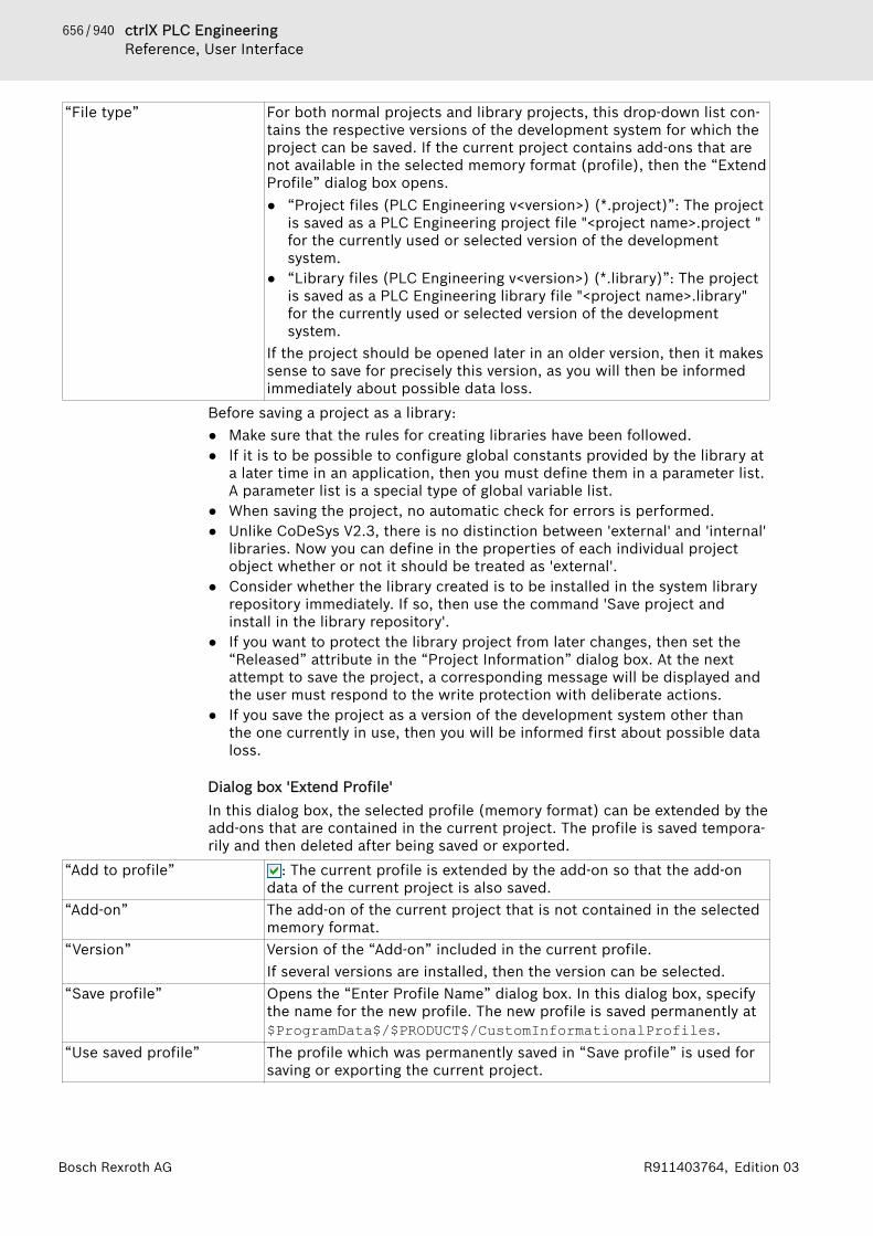
656 / 940 ctrlX PLC EngineeringReference, User Interface
Bosch Rexroth AG R911403764, Edition 03
“File type” For both normal projects and library projects, this drop-down list con-tains the respective versions of the development system for which theproject can be saved. If the current project contains add-ons that arenot available in the selected memory format (profile), then the “ExtendProfile” dialog box opens.● “Project files (PLC Engineering v<version>) (*.project)”: The project
is saved as a PLC Engineering project file "<project name>.project "for the currently used or selected version of the developmentsystem.
● “Library files (PLC Engineering v<version>) (*.library)”: The projectis saved as a PLC Engineering library file "<project name>.library"for the currently used or selected version of the developmentsystem.
If the project should be opened later in an older version, then it makessense to save for precisely this version, as you will then be informedimmediately about possible data loss.
Before saving a project as a library:● Make sure that the rules for creating libraries have been followed.● If it is to be possible to configure global constants provided by the library at
a later time in an application, then you must define them in a parameter list.A parameter list is a special type of global variable list.
● When saving the project, no automatic check for errors is performed.● Unlike CoDeSys V2.3, there is no distinction between 'external' and 'internal'
libraries. Now you can define in the properties of each individual projectobject whether or not it should be treated as 'external'.
● Consider whether the library created is to be installed in the system libraryrepository immediately. If so, then use the command 'Save project andinstall in the library repository'.
● If you want to protect the library project from later changes, then set the“Released” attribute in the “Project Information” dialog box. At the nextattempt to save the project, a corresponding message will be displayed andthe user must respond to the write protection with deliberate actions.
● If you save the project as a version of the development system other thanthe one currently in use, then you will be informed first about possible dataloss.
Dialog box 'Extend Profile'In this dialog box, the selected profile (memory format) can be extended by theadd-ons that are contained in the current project. The profile is saved tempora-rily and then deleted after being saved or exported.
“Add to profile” : The current profile is extended by the add-on so that the add-ondata of the current project is also saved.
“Add-on” The add-on of the current project that is not contained in the selectedmemory format.
“Version” Version of the “Add-on” included in the current profile.If several versions are installed, then the version can be selected.
“Save profile” Opens the “Enter Profile Name” dialog box. In this dialog box, specifythe name for the new profile. The new profile is saved permanently at $ProgramData$/$PRODUCT$/CustomInformationalProfiles.
“Use saved profile” The profile which was permanently saved in “Save profile” is used forsaving or exporting the current project.

657 / 940ctrlX PLC EngineeringReference, User Interface
Bosch Rexroth AGR911403764, Edition 03
See also● ⮫ Chapter “Command 'Save project'” on page 655● ⮫ Chapter 1.5.8 “Save project” on page 42● ⮫ Chapter “Dialog 'Options' – 'Load and Save'” on page 857● ⮫ Chapter 1.15.1 “Information for Library Developers” on page 238● ⮫ Chapter “Command 'Save Project and Install into Library Repository'”
on page 657
Command 'Save Project and Install into Library Repository'Function: this command saves the project as a library in the 'system' libraryrepository.Call: Main menu “File”.With this command PLC Engineering saves the project as a library in the 'sys-tem' library repository. This is an extension to the saving of a project as alibrary file using the “Save Project as” command. The library is installed on thelocal system and is immediately available for insertion into a project.See also● ⮫ Chapter “Command 'Save Project as'” on page 655
Command 'Save Project as Compiled Library'Function: This command saves a library project in encrypted form.Call: Menu bar: “File”The command opens the standard dialog for saving a file in the file system. The“Compiled PLC Engineering Libraries” file type is already preset. The file exten-sion is .compiled-library-v3 or .compiled-library (PLC Engineering <SP15). In this format, then source code of the library POU is not visible whenthe library is used in a project.If the “Enforce signing of compiled libraries” option is selected in the “SecurityScreen” view, then a library project has to be provided with a digital certificate-based signature when being saved. In the “Project Information”, on the “Sum-mary” tab, a “Library compatibility” with a PLC Engineering version >= V3 SP15is set by default. In this case, the project file is stored with the file extension.compiled-library-v3 when being saved as a compiled and signed library. Ifyou still have not specified a suitable valid certificate for your user profile in the“Security Screen”, then a dialog prompt opens next for you to do this. After-wards, you can execute the save command again.In all other respects, compiled library files behave just like *.library files,and therefore they can be installed and referenced with the same steps.We recommend the use of compiled libraries signed with certificates. Besidesthe protection of the source code and the unauthorized use of a library, lessmemory is also used which results in shorter loading times.

658 / 940 ctrlX PLC EngineeringReference, User Interface
Bosch Rexroth AG R911403764, Edition 03
If you have the corresponding help files with translations, then as of PLC Engi-neering V3 SP15 you can extend the library documentation with the translationinto other languages. This is done as follows:Place the files created for the new languages __lmd__<language>.aux in adirectory <library name>.lmd parallel to the library project <libraryname>.compiled-library-v3. If the files are correct, then they are includedin the compiled library file when saving the library project by means of the“Save Project as Compiled Library” command.Example: The directory standard.lmd is exists parallel to the library filestandard.compiled-library-v3 and contains the file __lmd__fr.aux withthe French translation of the library documentation. After the compiled libraryis saved, the French version of the documentation is also available in theLibrary Manager.See also● ⮫ “Tab 'Summary'” on page 622● ⮫ Chapter “Command 'Security Screen'” on page 688● ⮫ Chapter 1.15.1 “Information for Library Developers” on page 238● ⮫ Chapter “Command 'Save Project and Install into Library Repository'”
on page 657
Command 'Save/Send Archive'Function: This command opens the dialog “Project Archive” for the configura-tion of project archives.Call: Menu bar: “File 🠂 Project Archive”An archive file (*.projectarchive) contains all files contained and referenced inthe currently opened project. It can either be saved or dispatched as an e-mailattachment. The dispatch by email is very helpful for providing an employeewith all project-relevant files. The file can be simply unpacked again with thecommand “Extract Archive”.
NOTICE The archiving function is not intended for the storage ofa project, but rather for the simple summarizing of allproject-relevant files.
See also● ⮫ Chapter 1.5.9 “Saving/Sending the Project Archive” on page 43● ⮫ Chapter “Command 'Extract Archive'” on page 659
Dialog 'Project Archive'The dialog displays all the categories that can be added to the project archive.In this dialog, complete categories or individual objects from the categories canbe added to the project archive by setting a check mark ( ).Entries that are display as red in the list require your attention. Move themouse pointer over this library for more information.
“Additional files” Opens the dialog “Additional Files”. Here, further files can be added tothe archive with the “Add” button.
“Comment” Opens the "Comment" dialog. Here, comments can be added to thearchive.
“Save” Creates the archive file and saves it. The storage location and thearchive name are specified in the subsequent dialog
“Send” Creates a temporary archive file that is attached to an empty e-mail. Acorrect installation of the MAPI (Messaging Application ProgrammingInterface) is required for the successful execution of this operation.
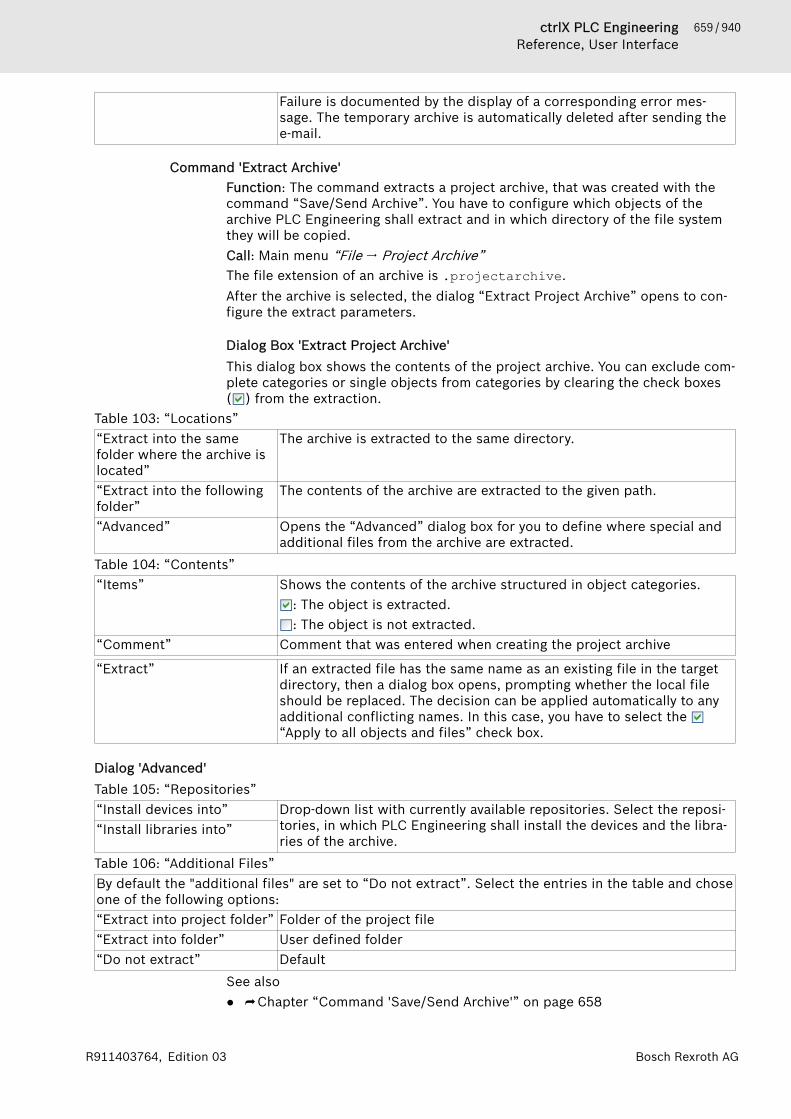
659 / 940ctrlX PLC EngineeringReference, User Interface
Bosch Rexroth AGR911403764, Edition 03
Failure is documented by the display of a corresponding error mes-sage. The temporary archive is automatically deleted after sending thee-mail.
Command 'Extract Archive'Function: The command extracts a project archive, that was created with thecommand “Save/Send Archive”. You have to configure which objects of thearchive PLC Engineering shall extract and in which directory of the file systemthey will be copied.Call: Main menu “File 🠂 Project Archive”The file extension of an archive is .projectarchive.After the archive is selected, the dialog “Extract Project Archive” opens to con-figure the extract parameters.
Dialog Box 'Extract Project Archive'This dialog box shows the contents of the project archive. You can exclude com-plete categories or single objects from categories by clearing the check boxes( ) from the extraction.
Table 103: “Locations”“Extract into the samefolder where the archive islocated”
The archive is extracted to the same directory.
“Extract into the followingfolder”
The contents of the archive are extracted to the given path.
“Advanced” Opens the “Advanced” dialog box for you to define where special andadditional files from the archive are extracted.
Table 104: “Contents”“Items” Shows the contents of the archive structured in object categories.
: The object is extracted.: The object is not extracted.
“Comment” Comment that was entered when creating the project archive
“Extract” If an extracted file has the same name as an existing file in the targetdirectory, then a dialog box opens, prompting whether the local fileshould be replaced. The decision can be applied automatically to anyadditional conflicting names. In this case, you have to select the “Apply to all objects and files” check box.
Dialog 'Advanced'Table 105: “Repositories”“Install devices into” Drop-down list with currently available repositories. Select the reposi-
tories, in which PLC Engineering shall install the devices and the libra-ries of the archive.
“Install libraries into”
Table 106: “Additional Files”By default the "additional files" are set to “Do not extract”. Select the entries in the table and choseone of the following options:“Extract into project folder” Folder of the project file“Extract into folder” User defined folder“Do not extract” Default
See also● ⮫ Chapter “Command 'Save/Send Archive'” on page 658

660 / 940 ctrlX PLC EngineeringReference, User Interface
Bosch Rexroth AG R911403764, Edition 03
Command 'Source Upload'Function: This command loads the project source code (as project archive)from the controller.Call: Main menu “File”.Requirement: The network path for the controller must be configured.After you execute the command, an overview opens with all devices in the net-work. Select a controller from this overview. The dialog box “Extract ProjectArchive” then opens with export settings.See also● ⮫ Chapter “Command 'Source Download'” on page 660
Dialog Box 'Extract Project Archive'This dialog box shows the contents of the project archive. You can exclude com-plete categories or single objects from categories by clearing the check boxes( ) from the extraction.
Table 107: “Locations”“Extract into the samefolder where the archive islocated”
The archive is extracted to the same directory.
“Extract into the followingfolder”
The contents of the archive are extracted to the given path.
“Advanced” Opens the “Advanced” dialog box for you to define where special andadditional files from the archive are extracted.
Table 108: “Contents”“Items” Shows the contents of the archive structured in object categories.
: The object is extracted.: The object is not extracted.
“Comment” Comment that was entered when creating the project archive
“Extract” If an extracted file has the same name as an existing file in the targetdirectory, then a dialog box opens, prompting whether the local fileshould be replaced. The decision can be applied automatically to anyadditional conflicting names. In this case, you have to select the “Apply to all objects and files” check box.
Command 'Source Download'Function: This command loads the project source code (as project archive) tothe controller.Call: Main menu “File”.Requirement: The network path for the controller must be configured.After you execute the command, an overview opens with all devices in the net-work. Select a controller from this overview. Then the Archiv.prj projectarchive is downloaded to this controller. You can click “Source Upload” toupload the complete source code to the PLC Engineering development systemat a later time.If you are already connected to a controller (in online mode), then the “SourceDownload to Connected Device” command is also available for this process.See also● ⮫ Chapter “Command 'Source Upload'” on page 660● ⮫ Chapter “Command 'Source Download to Connected Device'” on page 723

661 / 940ctrlX PLC EngineeringReference, User Interface
Bosch Rexroth AGR911403764, Edition 03
Command 'Print'Symbol: Function: This command opens the default Windows dialog box for printingdocuments.Call: Main menu “File”See also● ⮫ Chapter “Dialog 'Project Settings' - 'Page Setup'” on page 839
Command 'Print Preview'Function: This command opens a print preview for the currently open element.Call: Main menu “File”Requirement: An object is open in the editor.See also● ⮫ Chapter “Dialog 'Project Settings' - 'Page Setup'” on page 839● ⮫ Chapter “Command 'Print'” on page 661
Command 'Page Setup'Symbol: Function: This command opens the “Page Setup” dialog box for configuring thelayout of the printed version of the project contents.Call: Main menu “File 🠂 Page Setup”See also● ⮫ Chapter “Dialog 'Project Settings' - 'Page Setup'” on page 839● ⮫ Chapter “Command 'Print'” on page 661
Command ‘Recent Projects’Function: Opens the list of the projects used recently, from which you canselect a project to open.Call: “File” menuSee also● ⮫ Chapter 1.2 “Creating and configuring projects” on page 14
Command 'Exit'Shortcut: [<Alt>]+[<F4>]Function: this command exits from the programming system. If a project is cur-rently opened that has been changed since it was last saved, a dialog boxopens asking whether the project should be saved.Call: “File” menu
Menu 'Edit'Standard Commands. . . . . . . . . . . . 663Command 'Find', 'Find in Project'. . 663Command 'Replace', 'Replace inProject'. . . . . . . . . . . . . . . . . . . . . . . 664Command 'Find Next'. . . . . . . . . . . . 665Command 'Find Next (Selection)'. . 665Command 'Find Previous'. . . . . . . . . 665Command 'Find Previous (Selec-tion)'. . . . . . . . . . . . . . . . . . . . . . . . . 665Command 'Insert File as Text'. . . . . 666
662 / 940 ctrlX PLC EngineeringReference, User Interface
Bosch Rexroth AG R911403764, Edition 03
Command 'Overwrite Mode'. . . . . . 666Command 'View Whitespace'. . . . . . 666Command 'View Indentation Guides' 666Command 'Go to Line'. . . . . . . . . . . 667Command 'Make Uppercase'. . . . . . 667Command 'Make Lowercase'. . . . . . 667Command 'Go to Matching Bracket'. 667Command 'Select to MatchingBracket'. . . . . . . . . . . . . . . . . . . . . . 667Command 'Expand All Folds'. . . . . . 668Command 'Collapse All Folds'. . . . . 668Command 'Comment Out SelectedLines'. . . . . . . . . . . . . . . . . . . . . . . . 668Command 'Uncomment SelectedLines'. . . . . . . . . . . . . . . . . . . . . . . . 668Command 'Enable Inline Monitoring' 669Command 'Toggle Bookmark'. . . . . . 669Command 'Next Bookmark (ActiveEditor)'. . . . . . . . . . . . . . . . . . . . . . . 669Command 'Next Bookmark'. . . . . . . 669Command 'Previous Bookmark(Active Editor)'. . . . . . . . . . . . . . . . . 669Command 'Previous Bookmark'. . . . 670Command 'Clear All Bookmarks(Active Editor)'. . . . . . . . . . . . . . . . . 670Command 'Clear All Bookmarks'. . . 670Command 'Browse Cross-Referen-ces'. . . . . . . . . . . . . . . . . . . . . . . . . . 670Command 'Browse Call Tree'. . . . . . 671Command 'Auto Declare'. . . . . . . . . 671Command 'Input Assistant'. . . . . . . 673Command 'Go to Source Position'. . 674Command 'Next Message'. . . . . . . . 674Command 'Previous Message'. . . . . 674Command 'Go to Definition'. . . . . . . 674Command 'Go To Reference'. . . . . . 675Command 'Go to Instance'. . . . . . . . 675Command 'Refactoring' - 'Rename<...>'. . . . . . . . . . . . . . . . . . . . . . . . . 675Command 'Refactoring' - 'UpdateReferenced Pins'. . . . . . . . . . . . . . . 676Command 'Refactoring' - 'Add Varia-ble'. . . . . . . . . . . . . . . . . . . . . . . . . . 676Command 'Refactoring' - 'Remove<variable>'. . . . . . . . . . . . . . . . . . . . 678Command 'Refactoring' - 'ReorderVariables'. . . . . . . . . . . . . . . . . . . . . 678

663 / 940ctrlX PLC EngineeringReference, User Interface
Bosch Rexroth AGR911403764, Edition 03
Standard CommandsPLC Engineering provides the following standard commands:● Undo: , shortcut: [Ctrl] + [Z]● Redo: , shortcut: [Ctrl] + [Y]● Cut: , shortcut: [Ctrl] + [X]● Copy: , shortcut: [Ctrl] + [C]● Paste: , shortcut: [Ctrl] + [V]● Delete: , shortcut: [Ctrl]● Select all: shortcut: [Ctrl] + [Ctrl]Not all editors support the “Insert” command. In some editors it can be usedwith limitations. Graphical editors only support the command if the pasted ele-ments will create a valid construct.In object trees like POUs or device view the command refers to the currentlyselected object. Multi selection is possible.
Command 'Find', 'Find in Project'Symbol ; keyboard shortcut: [Ctrl]+[F]Symbol , keyboard shortcut [Ctrl]+[Shift]+[F]Function: These commands scan the project or parts of it for a specified char-acter string.Call: Menu bar: “Edit 🠂 Find Replace”This command opens the “Find” dialog where the searched character string isspecified and the search options are defined.
Dialog 'Find'
“Search for” Character string to be searched.“Match case”: : The search considers uppercase and lowercase.“Match whole word”: : Only character strings are found that exact matches.“Search up”: : The specified search range runs upwards.
: The specified search range runs downwards.“Use regular expressions”: Use the button to receive support when specifying regular expres-
sions.“Search in” : Drop-down list with the areas of the project to be searched:
● “Active editor”● “All open editors”● “Selected objects & Subobjects”● “Entire project”● “Entire project & Uncompiled libraries”● “Selection only”
: Opens a dialog where you set the areas of the project to besearched (see below)
“Find next” Start the search“Find all” All search results are listed in the message view with their object path,
project name, object name, and object position. Possible additionalinformation for position: “(Decl)” = Declaration part of the object;“(Impl)” = Implementation part of the objectDouble-clicking the entry in the list opens the match position in therespective object editor.
“Replace” Switches to the “Replace” dialog

664 / 940 ctrlX PLC EngineeringReference, User Interface
Bosch Rexroth AG R911403764, Edition 03
The color of the search result markings can be customized in the options of thetext editor. This is done by means of the parameter “Selection color” - “Inac-tive” in the “Text Area” tab.See also● ⮫ “Tab 'Text Area'” on page 861
Dialog for setting the objects to be searched
“Entire project” All editable positions in all objects of the project are searched.“Entire project and alluncompiled libraries”
All editable positions in all objects of the project, including integrateduncompiled libraries, are searched.
“Within the followingobjects”
Only the editable positions within the objects defined here aresearched:● “Scheme”: The “Save” command saves the current search configu-
ration by the specified name. All saved schemes are available in thedrop-down list ( ).
● “Object types”: : The object is searched.● “Name filter”: Name filter for the searched objects. The placeholder
"*" can be used.Example: Filter "*CAN*": All objects are searched that have "CAN" inthe name.
“All open editors” All editors are searched that are currently open in a window.“Active editor” Only the editor is searched where the cursor currently is.“Selection only” Only the text is searched that is currently selected in an object.
See also● ⮫ Chapter “Command 'Replace', 'Replace in Project'” on page 664● ⮫ Chapter 1.8.15 “Searching and Replacing in the Entire Project”
on page 126
Command 'Replace', 'Replace in Project'Symbol ; keyboard shortcut: [Ctrl]+[H]Symbol , keyboard shortcut [Ctrl]+[Shift]+[H]Function: These commands scan the project or parts of it for a specified char-acter string and replaces it.Call: Menu bar: “Edit 🠂 Find Replace”Requirement: The application is in online mode.This command opens the “Replace” dialog where the search and replace char-acter strings are specified and the search options are defined.
Table 109: In addition to the options of the “Search” dialog, the following settings are still possible:“Replace with” Input field for the new character string.“Replace” Each next found string is highlighted in the editor and replaced (step-
by-step replace).“Replace all” All found strings are replaced at one time without them being dis-
played in the editors.“Leave changed objectsopen after "Replace all"”
The editors of the found objects remain open.
Replacement in referenced libraries is not possible.
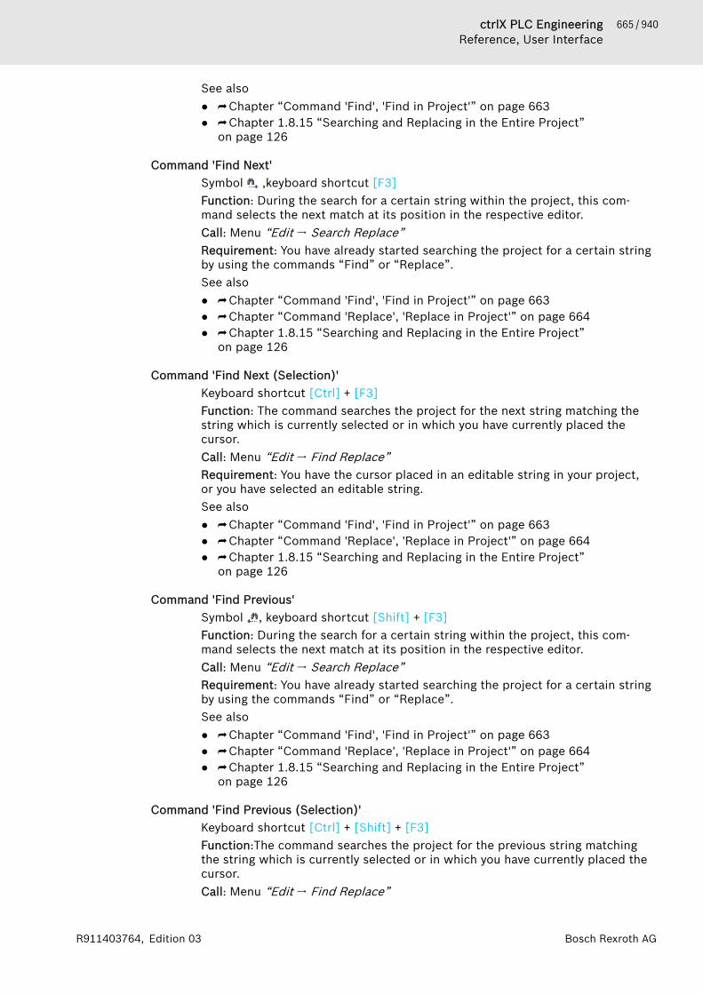
665 / 940ctrlX PLC EngineeringReference, User Interface
Bosch Rexroth AGR911403764, Edition 03
See also● ⮫ Chapter “Command 'Find', 'Find in Project'” on page 663● ⮫ Chapter 1.8.15 “Searching and Replacing in the Entire Project”
on page 126
Command 'Find Next'Symbol ,keyboard shortcut [F3]Function: During the search for a certain string within the project, this com-mand selects the next match at its position in the respective editor.Call: Menu “Edit 🠂 Search Replace”Requirement: You have already started searching the project for a certain stringby using the commands “Find” or “Replace”.See also● ⮫ Chapter “Command 'Find', 'Find in Project'” on page 663● ⮫ Chapter “Command 'Replace', 'Replace in Project'” on page 664● ⮫ Chapter 1.8.15 “Searching and Replacing in the Entire Project”
on page 126
Command 'Find Next (Selection)'Keyboard shortcut [Ctrl] + [F3]Function: The command searches the project for the next string matching thestring which is currently selected or in which you have currently placed thecursor.Call: Menu “Edit 🠂 Find Replace”Requirement: You have the cursor placed in an editable string in your project,or you have selected an editable string.See also● ⮫ Chapter “Command 'Find', 'Find in Project'” on page 663● ⮫ Chapter “Command 'Replace', 'Replace in Project'” on page 664● ⮫ Chapter 1.8.15 “Searching and Replacing in the Entire Project”
on page 126
Command 'Find Previous'Symbol , keyboard shortcut [Shift] + [F3]Function: During the search for a certain string within the project, this com-mand selects the next match at its position in the respective editor.Call: Menu “Edit 🠂 Search Replace”Requirement: You have already started searching the project for a certain stringby using the commands “Find” or “Replace”.See also● ⮫ Chapter “Command 'Find', 'Find in Project'” on page 663● ⮫ Chapter “Command 'Replace', 'Replace in Project'” on page 664● ⮫ Chapter 1.8.15 “Searching and Replacing in the Entire Project”
on page 126
Command 'Find Previous (Selection)'Keyboard shortcut [Ctrl] + [Shift] + [F3]Function:The command searches the project for the previous string matchingthe string which is currently selected or in which you have currently placed thecursor.Call: Menu “Edit 🠂 Find Replace”
666 / 940 ctrlX PLC EngineeringReference, User Interface
Bosch Rexroth AG R911403764, Edition 03
Requirement: You have the cursor placed in an editable string in your project,or you have selected an editable string.See also● ⮫ Chapter “Command 'Find', 'Find in Project'” on page 663● ⮫ Chapter “Command 'Replace', 'Replace in Project'” on page 664● ⮫ Chapter 1.8.15 “Searching and Replacing in the Entire Project”
on page 126
Command 'Insert File as Text'Function: This command copies the contents of a text file to the active editor asthe current cursor position.Call: The command is not in any menu by default. You can add it to a menu byusing the dialog box from “Tools 🠂 Customize” (command category “TextEditor”).Requirement: The file must have the extension .txt. The command is availablein a text editor only.Many development environments and text processing applications provide theoption of exporting code and text as a plain text file. This command can copythe contents of this file to the editor.See also● ⮫ Chapter “Dialog 'Options' - 'Text Editor'” on page 860
Command 'Overwrite Mode'Shortcut: [Insert]Function: This command activates the overwrite mode.Call: Menu “Edit 🠂 Advanced”Requirement: A text editor is opened.If the overwrite mode is activated, characters in front of the cursor are over-written when entering new characters. If the overwrite mode is deactivated,characters are inserted and existing characters in front of the cursor areretained.See also● ⮫ Chapter “Dialog 'Options' - 'Text Editor'” on page 860
Command 'View Whitespace'Symbol: Function: This command causes control characters for spaces and tabs to beshown.Call: Menu “Edit 🠂 Advanced”Requirement: A text editor is opened.PLC Engineering visualizes spaces by a period and tabs by an arrow.See also● ⮫ Chapter “Dialog 'Options' - 'Text Editor'” on page 860
Command 'View Indentation Guides'Function: This command activates the indentation help lines.Call: Menu “Edit 🠂 Extended”Requirement: A text editor is opened.If the indentation help lines are activated, a broken line is inserted for eachmanual indentation in the code. This facilitates the overview of the differentlevels in the code. You can insert manual indentations with the [Tab] key.
667 / 940ctrlX PLC EngineeringReference, User Interface
Bosch Rexroth AGR911403764, Edition 03
See also● ⮫ Chapter “Dialog 'Options' - 'Text Editor'” on page 860
Command 'Go to Line'Function: With this command the cursor jumps to a defined line in the code.Call: Menu “Edit 🠂 Extended”Requirement: A text editor is opened.This command opens a dialog box with an input field “Line number”.See also● ⮫ Chapter “Dialog 'Options' - 'Text Editor'” on page 860
Command 'Make Uppercase'Shortcut: [Ctrl]+[Shift]+[U]Function: This command converts all lowercase letters in the selected code intouppercase letters.Call: Menu “Edit 🠂 Advanced”Requirement: A text editor is opened and code is selected, or the declarationeditor is opened and variable declarations are selected.See also● ⮫ Chapter “Dialog 'Options' - 'Text Editor'” on page 860
Command 'Make Lowercase'Shortcut: [Ctrl]+[U]Function: This command converts all uppercase letters in the selected codeinto lowercase letters.Call: Menu “Edit 🠂 Advanced”Requirement: a text editor is opened and code is selected, or the declarationeditor is opened and variable declarations are selected.See also● ⮫ Chapter “Dialog 'Options' - 'Text Editor'” on page 860
Command 'Go to Matching Bracket'Function: This command makes the cursor jump to the other part of theselected code parenthesis.Call: Menu “Edit 🠂 Advanced”Requirement: A text editor is opened and the cursor is positioned at an openingor closing code parenthesis. If you position the cursor at a code parenthesis,PLC Engineering displays the corresponding parenthesis in color, provided youhave activated the option “Associated parentheses” in the PLC Engineeringoptions in the “Text Editor” category, “Text Area” tab.See also● ⮫ “Tab 'Text Area'” on page 861
Command 'Select to Matching Bracket'Function: This command selects the entire code section within the currentlyselected code parentheses.Call: Menu “Edit 🠂 Extended”
668 / 940 ctrlX PLC EngineeringReference, User Interface
Bosch Rexroth AG R911403764, Edition 03
Requirement: A text editor is opened and the cursor is positioned at an openingor closing code parenthesis. If you position the cursor at a code parenthesis,PLC Engineering displays the corresponding parenthesis in color, provided youhave activated the option “Associated parentheses” in the project options inthe “Text Editor” category, “Text Area” tab.See also● ⮫ Chapter “Dialog 'Options' - 'Text Editor'” on page 860
Command 'Expand All Folds'Function: This command expands all collapsed code segments in the textualeditor or result locations in the cross-reference list so that the code and allsearch locations are displayed in full again.Requirement: A textual editor is active and indentation is activated in the“Options” (“Text Editor” category); or the cross-reference list is active.Call: Textual editors: main menu“Edit 🠂 Advanced”, or right-click. In the cross-reference list: right-click.See also● ⮫ Chapter “Dialog 'Options' - 'Text Editor'” on page 860● ⮫ Chapter “Command 'Collapse All Folds'” on page 668● ⮫ “Right-click commands in the cross-reference list” on page 686
Command 'Collapse All Folds'Function: This command collapses all expanded code segments in the textualeditor or result locations in the cross-reference list. In this way, only the upper-most level of code and only the root node of the result locations displayed.Requirement: A textual editor is active and indentation is activated in the“Options” (“Text Editor” category); or the cross-reference list is active.Call: In textual editors: main menu “Edit 🠂 Advanced”, or right-click. In thecross-reference list: right-click.See also● ⮫ Chapter “Dialog 'Options' - 'Text Editor'” on page 860● ⮫ Chapter “Command 'Expand All Folds'” on page 668● ⮫ “Right-click commands in the cross-reference list” on page 686
Command 'Comment Out Selected Lines'Symbol ; keyboard shortcut: [Ctrl]+[O]Function: The command inserts comment marks ('//') at the beginning of theselected lines.Call: Menu bar: “Edit 🠂 Advanced”; context menuRequirement: In the ST editor, either the cursor is located in a line of the imple-mentation or multiple lines are selected.See also● ⮫ Chapter “Command 'Uncomment Selected Lines'” on page 668
Command 'Uncomment Selected Lines'Symbol ; keyboard shortcut: [Ctrl]+[I]Function: The command removes any comment marks ('//') at the beginning ofthe selected lines.Call: Menu bar: “Edit 🠂 Advanced”; context menuRequirement: In the ST editor, either the cursor is located in a line of the imple-mentation or multiple lines are selected.
669 / 940ctrlX PLC EngineeringReference, User Interface
Bosch Rexroth AGR911403764, Edition 03
See also● ⮫ Chapter “Command 'Comment Out Selected Lines'” on page 668
Command 'Enable Inline Monitoring'Function: This command enables or disables the inline monitoring function.This works the same way as the check box with the same name in the PLC Engi-neering options (“Text Editor” category).Requirement: A text editor is active.Call: Context menu of the text editor in the “Advanced” submenu.See also● ⮫ “Tab 'Monitoring'” on page 862● ⮫ Chapter 1.12.1 “Monitoring of Values” on page 208
Command 'Toggle Bookmark'Symbol , keyboard shortcut [Ctrl]+[F12]Function: The command sets or removes a bookmark at the current position.Call: Menu bar: “Edit 🠂 Bookmarks”Requirement: A POU is open in the editor and the cursor is at a program line.See also● ⮫ Chapter “Setting and Using Bookmarks” on page 125
Command 'Next Bookmark (Active Editor)'Symbol: ; keyboard shortcut: [F12]Function: The command jumps to the next bookmark in the active editor.Call: Menu bar: “Edit 🠂 Bookmarks”Requirement: A POU is open in the editor and the cursor is positioned in thePOU.See also● ⮫ Chapter “Command 'Next Bookmark'” on page 669● ⮫ Chapter “Setting and Using Bookmarks” on page 125
Command 'Next Bookmark'Symbol: Function: The command jumps to the next bookmark in the “Bookmarks” viewand in the project, and opens the respective POU. The order of jumping tobookmarks corresponds to the order of bookmarks in the table of the “Book-marks” view.Call:● “Next Bookmark” button in the “Bookmarks” view● The command is not in any menu by default. You can add it to a menu by
using the dialog from “Tools 🠂 Customize” (command category “Book-marks”).
Requirement:● A project is open.● The “Bookmarks” view is open.See also● ⮫ Chapter “Command 'Next Bookmark (Active Editor)'” on page 669
Command 'Previous Bookmark (Active Editor)'Symbol: ; keyboard shortcut: [Shift]+[F12]

670 / 940 ctrlX PLC EngineeringReference, User Interface
Bosch Rexroth AG R911403764, Edition 03
Function: The command jumps to the previous bookmark in the active editor.Call: Menu bar: “Edit 🠂 Bookmarks”A POU is open in the editor and the cursor is positioned in the POU.See also● ⮫ Chapter “Command 'Previous Bookmark'” on page 670● ⮫ Chapter “Setting and Using Bookmarks” on page 125
Command 'Previous Bookmark'Symbol: Function: The command jumps to the previous bookmark in the “Bookmarks”view and in the project, and opens the respective POU. The order of jumping tobookmarks corresponds to the order of bookmarks in the table of the “Book-marks” view.Call:● “Next Bookmark” button in the “Bookmarks” view● The command is not in any menu by default. You can add it to a menu by
using the dialog from “Tools 🠂 Customize” (command category “Book-marks”).
Requirement:● A project is open.● The “Bookmarks” view is open.See also● ⮫ Chapter “Command 'Previous Bookmark (Active Editor)'” on page 669● ⮫ Chapter “Setting and Using Bookmarks” on page 125
Command 'Clear All Bookmarks (Active Editor)'Symbol: Function: The command deletes all bookmarks in the active editor.Call: Menu bar: “Bookmarks”Requirement: A POU is open in the editor and the cursor is positioned in thePOU.See also● ⮫ Chapter “Command 'Clear All Bookmarks'” on page 670● ⮫ Chapter “Setting and Using Bookmarks” on page 125
Command 'Clear All Bookmarks'Symbol: Function: The command deletes all bookmarks in the open project.Call: The command is not in any menu by default. You can add it to a menu byusing the dialog from “Tools 🠂 Customize” (command category “Bookmarks”).Requirement: A POU is open in the editor and the cursor is positioned in thePOU.See also● ⮫ Chapter “Command 'Clear All Bookmarks (Active Editor)'” on page 670● ⮫ Chapter “Setting and Using Bookmarks” on page 125
Command 'Browse Cross-References'Symbol: Function: This command shows all occurrences of a variable in the view “Cross-Reference List”.
671 / 940ctrlX PLC EngineeringReference, User Interface
Bosch Rexroth AGR911403764, Edition 03
Call: Main menu “Edit 🠂 Browse”; cross-reference list: toolbar.Requirement: A POU is open in the editor and the cursor is at a variable, or theview “Cross-Reference List” is open and a variable is in the “Name” input field.See also● ⮫ Chapter “Using the Cross-Reference List to Find Occurrences”
on page 123
Command 'Browse Call Tree'Symbol: Function: The command opens the view “Call Tree”, which displays the calls ofa module and also its callers.Call:● Menu “Edit 🠂 Browse”● Context menu, see below: RequirementRequirement: A module is opened in the editor and the cursor is placed in avariable, or a module is selected in the “Devices” view or in the “POUs” view.See also● ⮫ Chapter “Command 'Call tree'” on page 687
Command 'Auto Declare'Keyboard shortcut: [Shift]+[F2]Function: The command opens the “Auto Declare” dialog, which supports thedeclaration of a variable.Call: Menu bar: “Edit”Requirement: An object or a device of the project is opened in the editor.Due to the auto-declaration function, the “Auto Declare” dialog also appearswhen the cursor is located in the implementation part of a POU in a line con-taining the name of an undeclared variable. The requirement for this is that youmust have selected the command “Tools 🠂 Options” and activated the option“Declare unknown variables automatically (AutoDeclare)” in the category“SmartCoding”.Thanks to the smart tag function, the “Declare variable” command also appearswhen you place the cursor over an undeclared variable in the implementationpart of the ST editor and then click .
Dialog 'Auto Declare'
“Scope” Scope of the variable that is not declared yet.Example: VAR (default setting for local variables)
“Name” Variable name that is not declared yetExample: bIsValid
“Type” Example: BOOL● : Lists the standard data types.●
– “Input Assistant”: Opens the “Input Assistant” dialog– “Array Assistant”: Opens the “Array” dialog
“Object” Object where the new variable is declared. By default, the object thatyou are editing now.Example: fbA
: Lists that objects where the variable can be declared.
672 / 940 ctrlX PLC EngineeringReference, User Interface
Bosch Rexroth AG R911403764, Edition 03
If no objects are available for the selected “Scope”, the entry “<createobject>” appears. If you select the entry “<create object>”, the dialog“Add Object” appears for the generation of a suitable object.
“Initialization” Example: FALSEIf you do not specify an initialization value, then the variable is initial-ized automatically.
: Opens the “Initialization Value” dialog. This procedure is helpful forthe initialization of structured variables.
“Address” Memory address of the application for the variable that is not declaredyet.Example: %IX1.0Note:Possible only for the following scopes:● Local variable (VAR)● Global variable (VAR_GLOBAL)● Or for a persistent variable (PERSISTENT).
“Flags” Attribute keywords● CONSTANT: Keyword for a constant.● RETAIN: Keyword for a remanent variable.● PERSISTENT: Keyword for a persistent variable (stricter than
RETAIN).The selected attribute keyword is added to the variable declaration.
“Comment” Example: New input In1In the tabular declaration editor the comment entered is displayed inthe column “Comment”, while in the textual declaration editor it is dis-played above the variable declaration.
“Apply changes using refac-toring”
: If you exit the dialog, then the variable is not declared yet, but thenit opens the “Refactoring” dialog. You can continue editing yourchanges here.The option appears for the following scopes:● Input variable (VAR_INPUT)● Output variable (VAR_OUTPUT)● VAR_IN_OUT variables (input variable and output variable)
“OK” The variable is declared and appears in the declaration.Example:
VAR RETAIN// New input In1xIn1 AT %IX1.0: BOOL := FALSE;
END_VAR
Dialog 'Array'
“Ranks and base type spec-ification”
Definition of the field sizes (“Dimension”) by entering the lower andupper limits and the “Base type” of the array. You can enter the basictype directly or with the help of the dialogs “Input Assistant” or“Array” if you click the button.
“Result” Display of the defined array.
NOTICE PLC Engineering only re-initializes variables if you havemodified the initialization values of the variables.

673 / 940ctrlX PLC EngineeringReference, User Interface
Bosch Rexroth AGR911403764, Edition 03
Dialog 'Initialization Value'
List of the variables with name (“Expression”), “Initialization Value” and “Data Type”.Modified initialization values are displayed in bold lettering.Input field below the list Input of an initialization value for the selected variable(s).“Apply value to selectedlines”
Change of the initialization value of the selected line(s) according tothe value of the input field.
“Reset selected lines todefault values”
Establishment of the standard initialization values.
“OK” PLC Engineering applies the initialization values in the “Auto Declare”dialog.
See also● ⮫ Chapter “Using the 'Declare variable' Dialog Box” on page 65● ⮫ “Smart tag functions” on page 101● ⮫ Chapter “AT Declaration” on page 119● ⮫ Chapter 1.8.16 “Refactoring” on page 126● ⮫ Chapter 1.8.20 “Data Persistence” on page 139● ⮫ “Dialog box 'Refactoring'” on page 677● ⮫ Chapter “Addresses” on page 384● ⮫ Chapter “Dialog 'Options' - 'Refactoring'” on page 859● ⮫ Chapter “ST Editor” on page 256
Command 'Input Assistant'Symbol: ; keyboard shortcut: [F2]Function: This command opens the “Input Assistant” dialog which helps you toselect one of the possible programming elements at the current cursor posi-tion.Call: Menu bar: “Edit”; context menu.Requirement: A POU is open in the editor and the cursor is at a program line.
Dialog 'Input Assistant' - Tab 'Categories'The input assistant provides all program elements that you can insert at thecurrent cursor position in the editor.The elements are sorted by “Categories”. In the category “Variables”, you canalso set a “Filter” for the scope, for example “Local variables”, “Global varia-bles”, or “Constants”.
“Structured view” : The elements are displayed in a structure tree. You can show/hidethe columns “Type”, “Address”, and “Origin” by right-clicking thecolumn title and selecting/clearing the column name in the dropdownlist.
: The elements are displayed in a flat structure.“Show documentation” : The dialog is extended with the “Documentation” field.“Insert with arguments” : Elements that include arguments (for example, functions) also
insert with these arguments at the cursor position.Example: If you insert the function block fb1, which contains an inputvariable fb1_in and an output variable fb1_out, "with arguments",then this appears in the editor as follows: fb1(fb1_in:= ,fb1_out=> ).
“Insert with namespaceprefix”
: Inserts the selected element with the appended namespace. In thecase of library modules, the check box remains disabled if the require-ment for a namespace has been defined in the library properties.
674 / 940 ctrlX PLC EngineeringReference, User Interface
Bosch Rexroth AG R911403764, Edition 03
If you create objects with the same name in the same category, whether glob-ally (“POUs” view) or assigned to an application (“Devices” view), then onlyone entry appears in the input assistant. The usage conforms to the usual callpriority (application assigned before global).
Dialog 'Input Assistant' - Tab 'Text Search'This tab allows you to search for specific objects. When you begin typing asearch string into the search field, the names of all objects are listed whosenames include the search string. Double-click an object to insert it at the cur-rent cursor position in the editor.
“Filters” Limits the search to a specific variable category
See also● ⮫ Chapter 1.8.6 “Using Input Assistance” on page 99● ⮫ “Dialog box 'Properties'” on page 789● ⮫ Chapter “Command 'Input Assistant'” on page 673
Command 'Go to Source Position'Function: The command sets the cursor to the position in the source code thatcauses the message.Call: Main menu “Edit”, context menu of the message in the message view.Requirements: A message is selected in the message view.Use the command “Next Message” or “Previous Message” to display the sourcecode position of the next or previous message.See also● ⮫ Chapter “Command 'Next Message'” on page 674● ⮫ Chapter “Command 'Previous Message'” on page 674● ⮫ Chapter “Command 'Messages'” on page 680
Command 'Next Message'Keyboard shortcut: [F4]Function: This command selects the next message in the messages view.Call: Main menu “Edit”.If the last message in the list has been reached, then the marking jumps to thebeginning.See also● ⮫ Chapter “Command 'Previous Message'” on page 674
Command 'Previous Message'Keyboard shortcut: [Shift]+[F4]Function: This command selects the previous message in the messages view.Call: Main menu “Edit”If the first message in the list has been reached, then the marking jumps to theend.See also● ⮫ Chapter “Command 'Next Message'” on page 674
Command 'Go to Definition'Symbol: Function: This command shows the definition locations of a variable or func-tion.
675 / 940ctrlX PLC EngineeringReference, User Interface
Bosch Rexroth AGR911403764, Edition 03
Call: Main menu “Edit 🠂 Browse”Requirement: A POU is open in the editor and the cursor is at a variable orfunction.See also● ⮫ Chapter “Finding Declarations” on page 124
Command 'Go To Reference'Symbol: Function: The command opens the declaration location of the variable that isreferenced by the pointer currently in focus in online mode.Call:● Context menu in the declaration part or implementation code● Menu bar: “Edit 🠂 Browse”Requirement: Online mode. A POU is open in the editor and the cursor is at apointer. The referenced variable is stored in static memory.If the pointer does not point exactly to the beginning of the variable, then a cor-responding message is displayed when you switch to the variable declaration.See also● ⮫ Chapter “Pointers” on page 394
Command 'Go to Instance'Symbol: Function: This command opens the instance of a function block in a newwindow.Call: Menu bar: “Edit 🠂 Browse for Symbol”Requirement: The application is in online mode. A POU is open in the editorand the cursor is at an instance of a function block.The command is not available for temporary instances or instances from com-piled libraries.See also● ⮫ Chapter “Finding Declarations” on page 124
Command 'Refactoring' - 'Rename <...>'Function: This command opens a dialog box for renaming an object or variableacross the project.Call: Main menu “Edit 🠂 Refactoring” or right-click.Requirement: An object is selected in the device tree or in the “POUs” view, orthe cursor is placed before or on a variable identifier in the declaration sectionof a programming object.You can rename the following:● Variables● POUs● GVLs● Methods● Properties● Devices● Variables and unit conversions in the unit conversion edit

676 / 940 ctrlX PLC EngineeringReference, User Interface
Bosch Rexroth AG R911403764, Edition 03
Dialog box 'Rename'
“Current name” Name of the object or variable“New name” Input field for a new name.
If the name already exists, then PLC Engineering reports this directlybelow this input field.
“OK” Can be activated if you have typed a valid name in “New name”.Opens the “Refactoring” dialog box.The affected objects and occurrences are highlighted in both views.You can determine how to handle the occurrences in each view byright-clicking the occurrences and clicking the available commands.
Dialog box 'Refactoring'Table: This dialog box displays all occurrences in the project.The affected objects and occurrences are highlighted in both views.Right view Displays the occurrence within an object where “Current name”
occurs.Left view Device tree of the project with the object.You can determine how to handle the occurrences in each view by right-clicking the occurrencesand clicking the available commands.“Reject this change” Reject the single change in view on the right.“Accept this object” Accept all changes in the affected object.“Reject this object” Reject all changes in the affected object.“Accept whole project” Accept all changes in the project.“Reject whole project” Reject all changes in the project.PLC Engineering highlights the accepted changes in yellow and the rejected changes in gray.
See also● ⮫ Chapter 1.8.16 “Refactoring” on page 126
Command 'Refactoring' - 'Update Referenced Pins'
NOTICE Currently, this command applies only to the CFC, FBD,LD, and IL editors. It is a combination of the “Reset Pins”and “Update Parameters” commands.
Function: This command modifies the pins according to the latest block decla-ration in all affected occurrences of the block.Call: Main menu “Edit 🠂 Refactoring” or right-click.Requirement: The cursor is placed in the name of the block in the first line ofthe block declaration or in the device tree.See also● ⮫ Chapter 1.8.16 “Refactoring” on page 126● ⮫ Chapter “Command 'Reset Pins'” on page 772● ⮫ Chapter “Command 'Update Parameters'” on page 786
Command 'Refactoring' - 'Add Variable'Symbol: Function: This command enables the declaration of variables in a POU, as wellas the automatic update to the occurrence of the POU.Call: Main menu “Edit 🠂 Refactoring”, or right-click.Requirements: The declaration part is in focus.
677 / 940ctrlX PLC EngineeringReference, User Interface
Bosch Rexroth AGR911403764, Edition 03
The command opens the default dialog box for declaring variables.See also● ⮫ “Dialog 'Auto Declare'” on page 671
Dialog box 'Refactoring'After clicking “OK” to close the declaration dialog, the “Refactoring” dialog boxopens with two frames.
“Right dialog frame ” Declaration part and implementation of the POU where the variable isadded.Colored highlighting of changed locations: New added declarationshave a blue font and are highlighted in yellow (1).
“Left dialog frame ” Device tree or POUs tree of the project.Colored highlighting of blocks where the POU is used: red font andyellow highlight (2).After you double-click the POU object, the detail view opens.
Before you decide which changes to accept at which locations, select therequired option from the drop-down list (3) at the upper right part of thewindow:
“Add inputs with place-holder text”
Default placeholder text: _REFACTOR_; editableThe placeholder text defined here is used at the occurrence locationsof the new added variables in the implementation code. This is usedfor searching for the affected locations.
“Add inputs with the fol-lowing value”
Initialization value for the new variable.
You can accept or reject changes by right-clicking the changed locations or byexecuting commands in the left or right area of the dialog box. Refer to thedescription of the “Refactoring 🠂 Rename” command.
Examples1. By refactoring, the fun block receives a new input variable input3 with theinitialization value 1. The change has the following effect:Before:fun(a + b, 3, TRUE);fun(input1:= a + b , input2 :=3 , inputx := TRUE);After:fun(a + b, 3, 1, TRUE);fun(input1:= a + b , input2 :=3 , _REFACTOR_, inputx := TRUE);2. By refactoring, the "fun" block receives a new input variable input3 withthe placeholder text "_REFACTOR_":Before:inst(input1 := a + b, input2 := 3, inputx := TRUE);fun(a + b, 3, TRUE);After:
678 / 940 ctrlX PLC EngineeringReference, User Interface
Bosch Rexroth AG R911403764, Edition 03
inst(input1 := a + b, input2 := 3, input3 := _REFACTOR_, inputx:= TRUE);fun(a + b, 3, _REFACTOR_, TRUE);
See also● ⮫ Chapter 1.8.16 “Refactoring” on page 126● ⮫ Chapter “Command 'Refactoring' - 'Rename <...>'” on page 675
Command 'Refactoring' - 'Remove <variable>'Symbol: Function: This command removes an input or output variable from the POU andall occurrences of the POU.Call: Main menu “Edit 🠂 Refactoring”, or right-click.Requirements: In the declaration part of the POU, the cursor is located in theidentifier of the variable to be removed.Then, the command opens a dialog box with information about the removal.After you confirm this, the “Refactoring” dialog box opens. For a description ofthe “Refactoring” dialog box, refer to the “Edit 🠂 Refactoring 🠂 Rename” helppage.When you accept the changes in the “Refactoring” dialog box, the respectiveinput and output parameters are deleted at the occurrence locations of theaffected POU.In CFC, only the connection is removed between the removed input or outputto the block. The input or output itself remains in the chart.
Example in STIn a POU, refactoring removes the input4 input variable. The occurrences areupdated automatically:Before removal:inst(input1 := a + b, input2 := 3, input4 := 1, input5 := TRUE);fun(a + b, 3, 1, TRUE);After removal:inst(input1 := a + b, input2 := 3, input5 := TRUE);fun(a + b, 3, TRUE);
See also● ⮫ Chapter 1.8.16 “Refactoring” on page 126● ⮫ Chapter “Command 'Refactoring' - 'Rename <...>'” on page 675
Command 'Refactoring' - 'Reorder Variables'Symbol: Function: This command allows changing the order of variables in the declara-tion editor for the selected scope: VAR_INPUT, VAR_OUTPUT, or VAR_IN_OUT.Call: “Edit 🠂 Refactoring”; context menu of the focused scope in the declara-tion editor.Requirement: One of the above scopes is selected in the declaration, and morethan one variable is declared in it.The command opens the “Reorder” dialog box with a list of all declarations ofthe selected scope. You can drag a selected declaration up or down to anotherposition.

679 / 940ctrlX PLC EngineeringReference, User Interface
Bosch Rexroth AGR911403764, Edition 03
See also● ⮫ “Reordering variables in the declaration” on page 128
Menu 'View'Standard Menu in View 'Devices','POUs', 'Modules'. . . . . . . . . . . . . . . 679Command 'Devices'. . . . . . . . . . . . . 679Command ‘POUs’. . . . . . . . . . . . . . . 680Command 'Messages'. . . . . . . . . . . . 680Command 'Element properties'. . . . 680Command 'ToolBox'. . . . . . . . . . . . . 681Command 'Watch' - 'Watch <n>'. . . . 681Command 'Watch' - 'Watch AllForces'. . . . . . . . . . . . . . . . . . . . . . . 681Command 'Add All Forces to Watch-list'. . . . . . . . . . . . . . . . . . . . . . . . . . 681Command 'Bookmarks'. . . . . . . . . . 682Command 'Breakpoints'. . . . . . . . . . 682Command 'Cross Reference List'. . . 684Command 'Browse Cross Refer-ences in Classic View'. . . . . . . . . . . 686Command 'Call Stack'. . . . . . . . . . . 686Command 'Call tree'. . . . . . . . . . . . . 687Command 'Memory'. . . . . . . . . . . . . 688Command 'Security Screen'. . . . . . . 688Command 'Settings of MemoryReserve for Online Change' . . . . . . . 691Command 'Start Page'. . . . . . . . . . . 692Command 'Full Screen'. . . . . . . . . . 692Command 'Properties'. . . . . . . . . . . 693
Standard Menu in View 'Devices', 'POUs', 'Modules'The views “Devices”, “POUs” and “Modules” provide the button in the topright corner to open a menu with the following commands:● “Open in editor”: Opens the selected object in the corresponding editor.● “Find object”: Opens the dialog “Find Object” for the object tree. Starting
to enter a search string all matching objects will be displayed with theirpath. Use the button “Open” to open the selected search result in the editor.
● “Sort by type”: Sorts the objects in the view alphabetic by type.● “Sort by name”: Sorts the objects in the view alphabetic by name.● “Sort ascending”: Displays the chosen sorting in ascending order.● “Sort descending”: Displays the chosen sorting in descending order.● “Track active editor”: PLC Engineering selects the object, that is opened in
the active editor, in the device tree of the view.See also● ⮫ Chapter “Command 'Devices'” on page 679● ⮫ Chapter “Command ‘POUs’” on page 680
Command 'Devices'Symbol: , view: [Alt] + [0]
680 / 940 ctrlX PLC EngineeringReference, User Interface
Bosch Rexroth AG R911403764, Edition 03
Function: The command opens the view “Devices” in the PLC Engineering mainwindow. The view contains the project's "device tree", where you configureyour applicationsButton opens the standard menu for navigating in the tree view.Call: Menu “View”See also● ⮫ Chapter 1.7.1 “Device Tree and Device Editor” on page 47● ⮫ Chapter “Command ‘POUs’” on page 680● ⮫ Chapter “Standard Menu in View 'Devices', 'POUs', 'Modules'” on page 679
Command ‘POUs’Symbol: , Shortcut: [Alt] + [1]Function: This command opens the “POUs” view in the PLC Engineering mainwindow. POUs located here are available in the entire project.Call: Menu “View”See also● ⮫ Chapter “Standard Menu in View 'Devices', 'POUs', 'Modules'” on page 679● ⮫ Chapter 1.2.3 “Adding Objects” on page 19
Command 'Messages'Symbol: Function: This command opens the “Messages” view.Call: Menu bar: “View”.
View 'Messages'
Message category The messages are categorized by component or functionality for selec-tion from a drop-down list. Filter the message display by selecting acategory.
Message type Click the symbol of the message type to show or hide messages. PLCEngineering displays the number of messages next to each symbol.● : Error● : Warning● : MessageDeletes all messages in the selected message category.Deletes all messages in all message categories.
“Description”Message text with the reported object and the location in the object.Double-click a message in the table to jump to the source text location.
“Project”“Object”“Position”Table 110: “Commands in the context menu”“Next Message” The source text position of the next message is displayed.“Previous Message” The source text position of the previous message is displayed.“Go to Source Position” The source position of the selected message is displayed.
Command 'Element properties'Symbol: Function: This command opens the “Element Properties” view.Call: Main menu “View”
681 / 940ctrlX PLC EngineeringReference, User Interface
Bosch Rexroth AGR911403764, Edition 03
This command opens the properties view for the open object. This view is avail-able only for a few objects, for example visualization and POU (SFC).The properties are displayed in a structured table. You change the propertyvalues by clicking into the value fields. You can filter or sort the propertiesview.
Command 'ToolBox'Symbol: Function: This command opens the “ToolBox” view.Call: Main menu “View”This command opens the toolbox view for the open object. By default, this viewis available for graphical editors and visualizations. It includes the graphicalprogramming elements that you can drag into the editor.
Command 'Watch' - 'Watch <n>'Symbol: Function: This command opens the "Watch <n>" view. You can populate awatchlist with variables from your project in order to monitor, force, or writethese variable values in an individual view in online mode. The value "n" can be1, 2, 3, or 4 for a total of up to four watchlists.Call: Main menu “View”See also● ⮫ Chapter “Using watch lists” on page 215
Command 'Watch' - 'Watch All Forces'Symbol: Function: The command opens the view “Watch All Forces”, which is a specialform of a watch list.Call: Menu “View 🠂 Watch 🠂 Watch all Forces”Requirement: A project is in offline mode or in online mode.The view contains all variables currently prepared for forcing, and all forced var-iables of the application in 1 list. The list allows the same actions as otherwatch lists. Additionally in the selection menu “Unforce...” the following com-mands are available:● “Unforce and Keep All Selected Values”: For all selected list entries the varia-
bles will be set to the forced value and the forcing will be released.● “Unforce and Restore All Selected Values”: For all selected list entries the
variables will be reset to the values they had before they got forced, and theforcing will be released.
See also● ⮫ Chapter 1.11.4 “Forcing and Writing Variables” on page 201● ⮫ Chapter “Using watch lists” on page 215
Command 'Add All Forces to Watchlist'Function: The command adds all variables of the active application, which arecurrently prepared for forcing, or which are already forced, to the watchlist.Please regard, that this works only for docked watch list views.Call: Context menu of view “Watch”Requirement: Online mode, a watch list view is active.There is a special watch list: “Watch All Forces”. This view shows automaticallyall variables currently prepared for forcing or already being forced. It providesadditional commands for releasing any forces.

682 / 940 ctrlX PLC EngineeringReference, User Interface
Bosch Rexroth AG R911403764, Edition 03
See also● ⮫ Chapter “Using watch lists” on page 215● ⮫ Chapter “Command 'Watch' - 'Watch <n>'” on page 681● ⮫ Chapter “Command 'Watch' - 'Watch All Forces'” on page 681● ⮫ Chapter 1.11.4 “Forcing and Writing Variables” on page 201
Command 'Bookmarks'Symbol: Function: This command opens the “Bookmarks” view.Call: Menu bar: “View”.
Table: “Previous Bookmark” Jumps to the bookmark that above the selected bookmark in the table
and opens the respective POU in the editor.“Next Bookmark” Jumps to the bookmark that below the selected bookmark in the table
and opens the respective POU in the editor.Deletes the selected bookmark from the table and in the respectivePOU.
List of bookmarks in the project with the following information: “Bookmark”, “Object”, and “Posi-tion”.You can edit the bookmark order per drag&drop.When you double-click a row, PLC Engineering opens the respective “Object” in the editor andjumps to this bookmark.“Bookmark” Name of the bookmark as assigned by PLC Engineering in ascending
numerical order: “Bookmark_0”, “Bookmark_2” etc.If the bookmark is selected and you click in the field, then it is editableand you can modify the bookmark name.
“Object” Name and project path of the POU where the bookmark is setExample: POU_Add [PLC_1: SPS-Logic: Application]
“Position” Position of the bookmark in the POUExample: Row 3, Column 1 (Impl)(Impl): in the implementation part of the POU(Decl): in the declaration part of the POU
See also● ⮫ Chapter “Setting and Using Bookmarks” on page 125● ⮫ Chapter “Command 'Next Bookmark'” on page 669● ⮫ Chapter “Command 'Previous Bookmark'” on page 670
Command 'Breakpoints'Symbol: Function: This command opens the “Breakpoints” view.Call: Menu bar: “View”.This view shows an overview of all defined breakpoints for an application. Youhave access to all breakpoint commands within this view.
Table 111: Table of current breakpoints“Application” Select the required application from the list.“POU” Name of the function block that will receive the breakpoint“Location” Location of the breakpoint in the POU
● Text editor: Line number and column number● Graphical editor: Network number or element number

683 / 940ctrlX PLC EngineeringReference, User Interface
Bosch Rexroth AGR911403764, Edition 03
For function blocks, "(Impl)" indicates that the breakpoint is located inthe implementation of the function block, not in an instance.
“Instance Path” Complete object path of the breakpoint location.“Tasks” Names of tasks that will be effective when the breakpoint is executed.
If there are no restrictions, then "(all)" is displayed here.“Condition” ● “Break always”: No additional enable condition defined; the break-
point is always enabled.● Boolean expression. The expression must yield TRUE for the break-
point to be enabled.“Hit Count Condition” When the breakpoint should be in effect (depending on the hit count)“Current Hit Count” How often the breakpoint has already been reached up to now during
the executionTable 112: Toolbar
“New Break-point”
This command opens the “Breakpoint Properties” dialog.
“New DataBreakpoint”
This command opens the “New Breakpoint” dialog.
“Clear Break-point”
Removes the breakpoint (not the same as disable)
“Enable/DisableBreakpoint”
Toggles the status of the breakpoint or execution point between "ena-bled" and "disabled"● Breakpoint enabled● Breakpoint disabled● Execution point enabled● Execution point disabled● Data breakpoint enabled● Data breakpoint disabled● Data execution point enabled● Data execution point disabledAs opposed to "Clear breakpoint", a disabled breakpoint remains in thelist and can be enabled again.
“Properties” The “Breakpoint Properties” dialog opens for editing the breakpointparameters. This dialog is the same as “New Breakpoint”. In onlinemode, you can change the breakpoint into an execution point.
“Go to SourcePosition”
Opens the online view of the affected block. The cursor is set at thebreakpoint location.
“Clear All Break-points”
Deletes all breakpoints and execution points in the application. The listis cleared. Not to be confused with "deactivate".
“Enable All Break-points”
Enables all currently disabled breakpoints and execution points.
“Disable AllBreakpoints”
Disables all currently enabled breakpoints and execution points. Thepoints remain in the list and can be enabled again.
See also● ⮫ Chapter “Dialog 'Breakpoint Properties'” on page 818● ⮫ Chapter “Command 'New Breakpoint'” on page 733● ⮫ Chapter “Command 'New Data Breakpoint'” on page 733● ⮫ Chapter “Command 'Enable Breakpoint'” on page 734● ⮫ Chapter “Command 'Disable Breakpoint'” on page 734● ⮫ Chapter “Command 'Toggle Breakpoint'” on page 734
684 / 940 ctrlX PLC EngineeringReference, User Interface
Bosch Rexroth AG R911403764, Edition 03
Command 'Cross Reference List'Symbol: Function: This command opens the “Cross Reference List” view.Call: Menu bar: “View”, or “Edit 🠂 Browse 🠂 Browse Cross References”.This view shows a list of cross-references for a symbol in the project. Thesymbol can be a variable, a POU (program, function block, function), or a user-specific data type (DUT). The cross-reference list offer two basic types ofsearches:● Text search: By specifying a symbol name, the cross-references of all sym-
bols in the project are displayed with their names. If multiple symbols withthe same are found, then the display can be limited to individual declara-tions by means of the context menu.
● Declaration search: The symbol can be selected by means of the input assis-tant or by specifying a qualified path (for example, Device.Applica-tion.PLC_PRG.i or __POOL.POU.a). Then only the occurrence locations ofthis symbol are displayed, even if there exist other symbols with the samename.
Input field Symbol name (variable name, POU name, DUT name). Inputoptions:● Selection of a declared symbol by means of the input assistant
( button).● Manual input of the symbol name. Triggering of the search by
pressing the button or the [Enter] key.For the text search, you can use the placeholders "*" (anynumber of characters) or "?" (exactly any one character) incombination with a partial string of a variable identifier.Use the percent sign "%" to search for IEC addresses. Exam-ples: "%MW8", "%M*".
More options outside of cross-reference list view:● Use the command “Browse for Symbol 🠂 Browse Cross
References” if the name of a declared symbol is selected in aneditor, or if the cursor is in the name field. A search is alsopossible if the object is selected in the device tree or POUpool.
● Automatic if the name of a declared symbol is selected in aneditor, or if the cursor is in the name field. A automatic searchis also possible if the object is selected in the device tree orPOU pool.Requirement: PLC Engineering option “Automatically list selec-tion in cross reference view” is activated (category “Smart-Coding”.
The following input is valid:● Variable name, simple or qualified. Examples: "iVar",
"PLC_PRG.iVar".● POU name: Examples: "PLC_PRG", "myFB".● DUT name: Example: "mySTRUCT".● Strings combined with placeholders: asterisk (*) for any char-
acter or question mark (?) for exactly one characters).Example: "iVar*" applies to iVar1, iVar_glob2, iVar45, etc.

685 / 940ctrlX PLC EngineeringReference, User Interface
Bosch Rexroth AGR911403764, Edition 03
"iVar?" refers to iVar1, iVar2, iVarX, and so on, but notiVar_glob2, iVar45 and so on...
● "%<IEC address>": PLC Engineering searches for variablesthat are assigned to this address and direct memory access.Example: "%QB0", %Q0 := 2.
Open input assistant for selecting a symbolPerform a searchDefine columns to search for the string.
Input field String that is searched for in the selected columns. The resultlocations are marked in yellow. Cross references without thisstring are hidden.Show source position of previous cross-reference, [Shift]+[F4]Show source position of next cross-reference, [F4]Limit results to current declaration: Available if multiple declara-tions are found for a symbol. Limits the display to the declarationthat you have selected in the list.Show source position of selected cross-reference: The focusjumps to the occurrence location of the symbol.Print cross-reference list: The default dialog opens for setting upa print job.
The cross references are displayed with the following information:“Symbol” The result locations for the symbols (variables, POUs, or DUTs)
are grouped by declaration. The declaration occurrence com-prises the root node and the occurrence locations in the projectare indented below. The precise expression is displayed that hasthe symbol at the occurrence location.Example: If there is a global variable i in the project and a localdeclared variable i in a POU, then two root node entries will belisted after a text search for cross-references with the occur-rences of the variable i below each.
“POU” Block name; also a task name if a block call in the task configura-tion.
“Variable” Only the variable name (for example, iVar)“Access” Type of access to the variable at the occurrence location: “Decla-
ration” / “Read” / “Write” / “Call”.Special case for pointers: An assignment type p := ADR(var1)is displayed as write | address when searching for var1. Thereason for this: Any write access to p is not displayed whensearching for var1. Write access is also possible by means ofpointer variables.
“Type” Data type of the variable“Address” IEC address if variables are assigned Example: "AT %QB0".“Position” Location of the occurrence in the POU editor, for example line
number, network number, declaration part, or implementationpart. Example: "line 1, column 1 (Impl)".
“Object” POU name plus complete path of the occurrence location inbrackets (if this is found in the “Devices” view). Example:"PLC_PRG [Device:Plc Logic:Application]"
“Comment” Comments if available in the declaration of the variableThe search yields all result locations in the project and in included, uncompiledlibraries.
686 / 940 ctrlX PLC EngineeringReference, User Interface
Bosch Rexroth AG R911403764, Edition 03
Right-click commands in the cross-reference list“Show source position”: Opens the respective POU and marks the occurrence:for root entries, the declaration, and for subordinate entries, the respectiveoccurrence location. As an alternative, you can double-click a line.“Limit Results to Selected Declaration”: Limits the display of results to theselected symbol declaration if multiple declarations are found.“Expand All”: In the list, every single result location is shown.“Collapse All”: In the list, only the root nodes of the result locations are shown.
See also● ⮫ Chapter “Command 'Browse Cross-References'” on page 670● ⮫ Chapter “Using the Cross-Reference List to Find Occurrences”
on page 123● ⮫ Chapter “Command 'Limit Results to Current Declaration'” on page 815● ⮫ Chapter “Command 'Collapse All Folds'” on page 668● ⮫ Chapter “Command 'Expand All Folds'” on page 668
Command 'Browse Cross References in Classic View'Symbol Function: This command opens the “Classic Cross Reference List” view.Call: The command is not in any menu by default. You can add it to a menu byusing the dialog box from “Tools 🠂 Customize” (command category “BrowseProject”).The view corresponds to the “Cross Reference List” view before PLC Engi-neering V3.5 SP6.
Command 'Call Stack'Symbol: Function: This command opens the “Call Stack” view.Call: Main menu “Debug”.This view is very useful when you want to step into programs. It shows the cur-rent location with the complete call path.“Applica-tion”
Name of the active application that controls the current POU
“Task” Name of the task that controls the current POU
“POU” Name of the POU where program execution has haltedThe first line in the list describes the current execution location(marked with a yellow arrow). If this location is in a block that iscalled by another block, then the call location is described in thesecond line. In turn, if the caller is called by yet another block,then that call location is described in the third line, and so on.
“Location” Position within the POU where program execution has halted● Line and column numbers for textual editors● Network or element numbers for graphical editors
“Instancepath”
Instance where program execution has halted
The call stack is also available in offline mode and normal online mode whenyou are not currently using any debugging functions). In this case, it receivesthe last displayed location during a stepped execution, but it is displayed ingray.
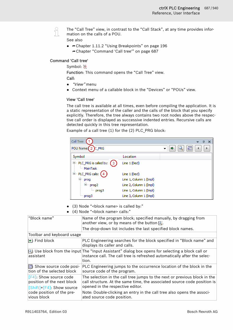
687 / 940ctrlX PLC EngineeringReference, User Interface
Bosch Rexroth AGR911403764, Edition 03
The “Call Tree” view, in contrast to the “Call Stack”, at any time provides infor-mation on the calls of a POU.See also● ⮫ Chapter 1.11.2 “Using Breakpoints” on page 196
⮫ Chapter “Command 'Call tree'” on page 687
Command 'Call tree'Symbol: Function: This command opens the “Call Tree” view.Call:● “View” menu● Context menu of a callable block in the “Devices” or “POUs” view.
View 'Call tree'The call tree is available at all times, even before compiling the application. It isa static representation of the caller and the calls of the block that you specifyexplicitly. Therefore, the tree always contains two root nodes above the respec-tive call order is displayed as successive indented entries. Recursive calls aredetected quickly in this tree representation.Example of a call tree (1) for the (2) PLC_PRG block:
● (3) Node “<block name> is called by:”● (4) Node “<block name> calls:”
“Block name” Name of the program block; specified manually, by dragging fromanother view, or by means of the button .The drop-down list includes the last specified block names.
Toolbar and keyboard usage: Find block PLC Engineering searches for the block specified in “Block name” and
displays its caller and calls.: Use block from the input
assistantThe “Input Assistant” dialog box opens for selecting a block call orinstance call. The call tree is refreshed automatically after the selec-tion.
: Show source code posi-tion of the selected block
PLC Engineering jumps to the occurrence location of the block in thesource code of the program.
[F4]: Show source codeposition of the next block[Shift]+[F4]: Show sourcecode position of the pre-vious block
The selection in the call tree jumps to the next or previous block in thecall structure. At the same time, the associated source code position isopened in the respective editor.Note: Double-clicking an entry in the call tree also opens the associ-ated source code position.
688 / 940 ctrlX PLC EngineeringReference, User Interface
Bosch Rexroth AG R911403764, Edition 03
Display of the call tree:“Symbol” “<block name> is called by”: The call order is displayed for below this
node. The bottom entry in this tree structure shows the start of thecalls.“<block name> calls”: The calls from this block are displayed belowthis node. The bottom entry in this tree structure shows the end of thecall chain.
“Position” For the root node in the call tree: Line numbers of the declaration(“Decl”) of the block.For the caller or calls below the root node: Line number, columnnumber, and network number of the position, depending on the imple-mentation language.
Context menu for the entry selected in the tree:“Collapse All” The expanded entries in the call tree are collapsed, except for the two
root nodes.“Show Source Position” PLC Engineering jumps to the occurrence location of the block in the
source code of the program.“Set as New Root Node” The entry selected in the call tree is displayed in “Block name”. The
tree is refreshed automatically for the new root nodes.The “Call list” view is provided for immediate information when steppingthrough a program, as opposed to the static call tree that provides call informa-tion about a block. The call list always shows the full call path of the currentposition that is reached.See also● ⮫ Chapter 1.11.3 “Stepping Through a Program” on page 199● ⮫ Chapter “Command 'Call Stack'” on page 686● ⮫ Chapter “Command 'Browse Call Tree'” on page 671
Command 'Memory'Symbol: Function: In PLC Engineering V3.5 version earlier than SP11, the commandopens the “Memory” view.Call: Menu bar: “View 🠂 Memory”.As of SP11, the command provides the notice that you must install the COD-ESYS Memory Tools package (available in the PLC Engineering Store) in orderto use the memory view. After installation, you can open the “Memory” view byclicking “View 🠂 Show Memory View”.
Command 'Security Screen'Symbol: Function: The command opens the “Security Screen” view.Call:● “View” menu● icon or in the status bar
The icon is displayed in blue when a valid certificate is specified for the dig-ital signature. When only one client certificate is specified for the encryptedcommunication, the icon remains gray, resulting in the client certificate pro-viding no increased security for the user.
The following security features of PLC Engineering are configured and dis-played in the view:● Personal user certificate● Encrypted communication
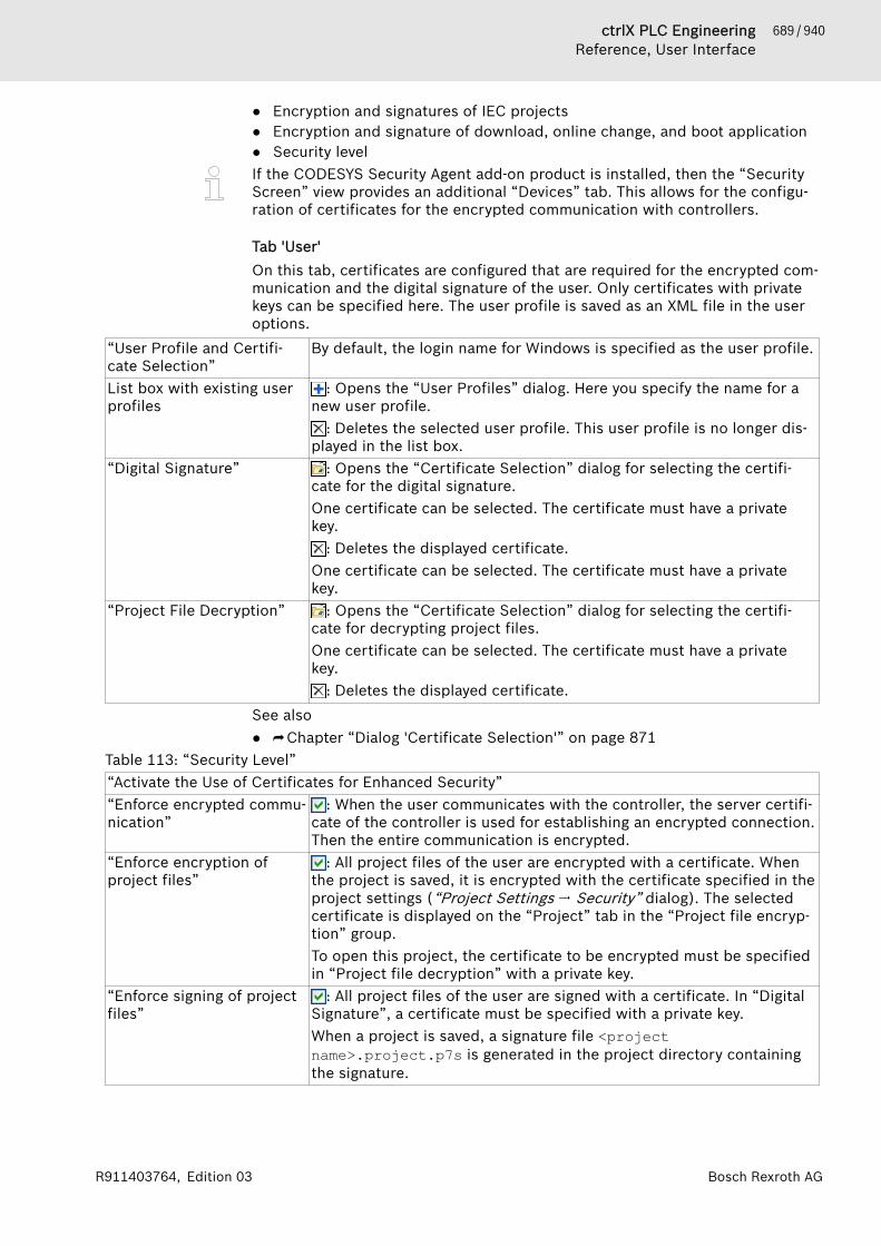
689 / 940ctrlX PLC EngineeringReference, User Interface
Bosch Rexroth AGR911403764, Edition 03
● Encryption and signatures of IEC projects● Encryption and signature of download, online change, and boot application● Security levelIf the CODESYS Security Agent add-on product is installed, then the “SecurityScreen” view provides an additional “Devices” tab. This allows for the configu-ration of certificates for the encrypted communication with controllers.
Tab 'User'On this tab, certificates are configured that are required for the encrypted com-munication and the digital signature of the user. Only certificates with privatekeys can be specified here. The user profile is saved as an XML file in the useroptions.
“User Profile and Certifi-cate Selection”
By default, the login name for Windows is specified as the user profile.
List box with existing userprofiles
: Opens the “User Profiles” dialog. Here you specify the name for anew user profile.
: Deletes the selected user profile. This user profile is no longer dis-played in the list box.
“Digital Signature” : Opens the “Certificate Selection” dialog for selecting the certifi-cate for the digital signature.One certificate can be selected. The certificate must have a privatekey.
: Deletes the displayed certificate.One certificate can be selected. The certificate must have a privatekey.
“Project File Decryption” : Opens the “Certificate Selection” dialog for selecting the certifi-cate for decrypting project files.One certificate can be selected. The certificate must have a privatekey.
: Deletes the displayed certificate.See also● ⮫ Chapter “Dialog 'Certificate Selection'” on page 871
Table 113: “Security Level”“Activate the Use of Certificates for Enhanced Security”“Enforce encrypted commu-nication”
: When the user communicates with the controller, the server certifi-cate of the controller is used for establishing an encrypted connection.Then the entire communication is encrypted.
“Enforce encryption ofproject files”
: All project files of the user are encrypted with a certificate. Whenthe project is saved, it is encrypted with the certificate specified in theproject settings (“Project Settings 🠂 Security” dialog). The selectedcertificate is displayed on the “Project” tab in the “Project file encryp-tion” group.To open this project, the certificate to be encrypted must be specifiedin “Project file decryption” with a private key.
“Enforce signing of projectfiles”
: All project files of the user are signed with a certificate. In “DigitalSignature”, a certificate must be specified with a private key.When a project is saved, a signature file <projectname>.project.p7s is generated in the project directory containingthe signature.
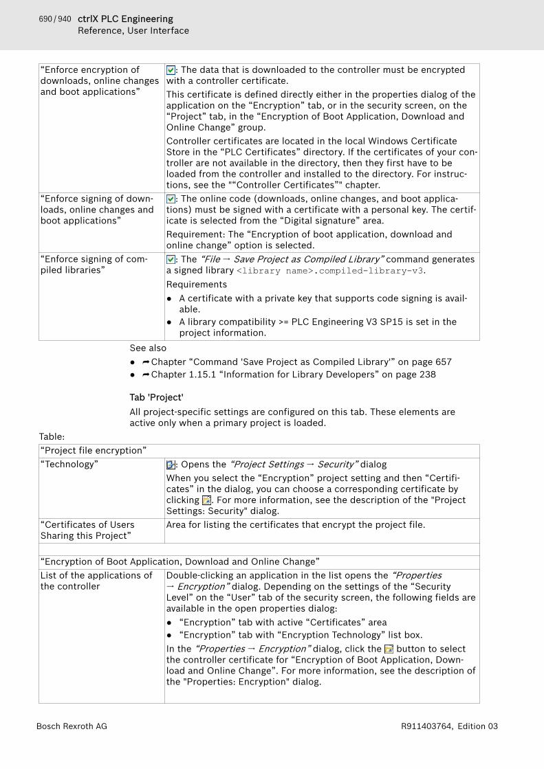
690 / 940 ctrlX PLC EngineeringReference, User Interface
Bosch Rexroth AG R911403764, Edition 03
“Enforce encryption ofdownloads, online changesand boot applications”
: The data that is downloaded to the controller must be encryptedwith a controller certificate.This certificate is defined directly either in the properties dialog of theapplication on the “Encryption” tab, or in the security screen, on the“Project” tab, in the “Encryption of Boot Application, Download andOnline Change” group.Controller certificates are located in the local Windows CertificateStore in the “PLC Certificates” directory. If the certificates of your con-troller are not available in the directory, then they first have to beloaded from the controller and installed to the directory. For instruc-tions, see the "“Controller Certificates”" chapter.
“Enforce signing of down-loads, online changes andboot applications”
: The online code (downloads, online changes, and boot applica-tions) must be signed with a certificate with a personal key. The certif-icate is selected from the “Digital signature” area.Requirement: The “Encryption of boot application, download andonline change” option is selected.
“Enforce signing of com-piled libraries”
: The “File 🠂 Save Project as Compiled Library” command generatesa signed library <library name>.compiled-library-v3.Requirements● A certificate with a private key that supports code signing is avail-
able.● A library compatibility >= PLC Engineering V3 SP15 is set in the
project information.See also● ⮫ Chapter “Command 'Save Project as Compiled Library'” on page 657● ⮫ Chapter 1.15.1 “Information for Library Developers” on page 238
Tab 'Project'All project-specific settings are configured on this tab. These elements areactive only when a primary project is loaded.
Table: “Project file encryption”“Technology” : Opens the “Project Settings 🠂 Security” dialog
When you select the “Encryption” project setting and then “Certifi-cates” in the dialog, you can choose a corresponding certificate byclicking . For more information, see the description of the "ProjectSettings: Security" dialog.
“Certificates of UsersSharing this Project”
Area for listing the certificates that encrypt the project file.
“Encryption of Boot Application, Download and Online Change”List of the applications ofthe controller
Double-clicking an application in the list opens the “Properties🠂 Encryption” dialog. Depending on the settings of the “SecurityLevel” on the “User” tab of the security screen, the following fields areavailable in the open properties dialog:● “Encryption” tab with active “Certificates” area● “Encryption” tab with “Encryption Technology” list box.In the “Properties 🠂 Encryption” dialog, click the button to selectthe controller certificate for “Encryption of Boot Application, Down-load and Online Change”. For more information, see the description ofthe "Properties: Encryption" dialog.

691 / 940ctrlX PLC EngineeringReference, User Interface
Bosch Rexroth AGR911403764, Edition 03
Controller certificates are located in the local Windows CertificateStore in the “PLC Certificates” directory. If the certificates of your con-troller are not available in the directory, then they first have to beloaded from the controller and installed to the directory. For instruc-tions, see the "Protecting and Saving a Project" - " Encryption with Cer-tificates" chapter.
See also● ⮫ Chapter “Dialog 'Project Settings' - 'Security'” on page 840● ⮫ Chapter “Dialog 'Properties' - 'Encryption'” on page 824● ⮫ Chapter 1.5.7 “Encrypting Projects with Certificates” on page 40
Tab 'Devices'This tab is available only after you have installed the CODESYS Security Agentadd-on. For a description of this tab, see the help for the CODESYS SecurityAgent.
Command 'Settings of Memory Reserve for Online Change'Function: This command opens the “ Online Change Memory Reserve” view.Call: Menu bar: “View”.In the view, memory reserves are configured for the function blocks during theonline change.
“Scan Application” ● Searches the selected application for function blocks and displaysthem in the “Function blocks” area
● Updates the “Function blocks” area after the application is builtagain.
● Updates the “Function blocks” area after an online change.Drop-down list with theapplications of the openproject
Selection of the application whose function blocks should be dis-played and/or edited in this view.
Table 114: “Function Blocks”“All” All function blocks of the selected application are displayed.“Pool” All function blocks of the “POUs” view that are displayed which are ref-
erenced in the application.“No memory-reserve” All function blocks with a memory reserve of 0 bytes are displayed.“<memory reserve> bytes” Display of all function blocks with the number of bytes is displayed
that is defined in “Memory reserve”.Information about the function blocksMultiple selection is also possible when selecting a POU for the configuration of the memoryreserve.“Function block” Name of the function block“Size” Size of the function block
Size of an instance of a function blockSpecified in bytes
“Number of instances ” Number of instances of a function block in the project“Memory reserve” Display of the memory reserve for each instance of the function block“Additional memory for allinstances”
Product of “Number of instances” and “Memory reserve”
“Remaining memoryreserve”
Number of bytes that are available as reserve.
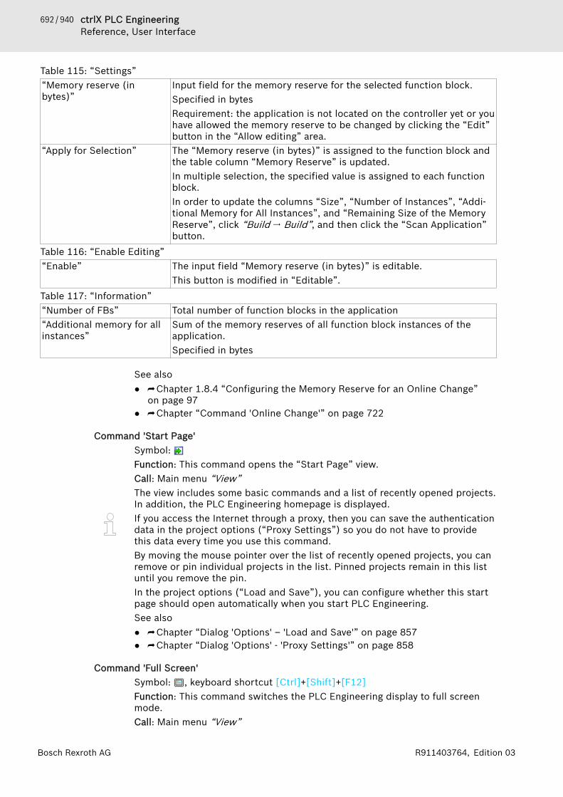
692 / 940 ctrlX PLC EngineeringReference, User Interface
Bosch Rexroth AG R911403764, Edition 03
Table 115: “Settings”“Memory reserve (inbytes)”
Input field for the memory reserve for the selected function block.Specified in bytesRequirement: the application is not located on the controller yet or youhave allowed the memory reserve to be changed by clicking the “Edit”button in the “Allow editing” area.
“Apply for Selection” The “Memory reserve (in bytes)” is assigned to the function block andthe table column “Memory Reserve” is updated.In multiple selection, the specified value is assigned to each functionblock.In order to update the columns “Size”, “Number of Instances”, “Addi-tional Memory for All Instances”, and “Remaining Size of the MemoryReserve”, click “Build 🠂 Build”, and then click the “Scan Application”button.
Table 116: “Enable Editing”“Enable” The input field “Memory reserve (in bytes)” is editable.
This button is modified in “Editable”.Table 117: “Information”“Number of FBs” Total number of function blocks in the application“Additional memory for allinstances”
Sum of the memory reserves of all function block instances of theapplication.Specified in bytes
See also● ⮫ Chapter 1.8.4 “Configuring the Memory Reserve for an Online Change”
on page 97● ⮫ Chapter “Command 'Online Change'” on page 722
Command 'Start Page'Symbol: Function: This command opens the “Start Page” view.Call: Main menu “View”The view includes some basic commands and a list of recently opened projects.In addition, the PLC Engineering homepage is displayed.If you access the Internet through a proxy, then you can save the authenticationdata in the project options (“Proxy Settings”) so you do not have to providethis data every time you use this command.By moving the mouse pointer over the list of recently opened projects, you canremove or pin individual projects in the list. Pinned projects remain in this listuntil you remove the pin.In the project options (“Load and Save”), you can configure whether this startpage should open automatically when you start PLC Engineering.See also● ⮫ Chapter “Dialog 'Options' – 'Load and Save'” on page 857● ⮫ Chapter “Dialog 'Options' - 'Proxy Settings'” on page 858
Command 'Full Screen'Symbol: , keyboard shortcut [Ctrl]+[Shift]+[F12]Function: This command switches the PLC Engineering display to full screenmode.Call: Main menu “View”
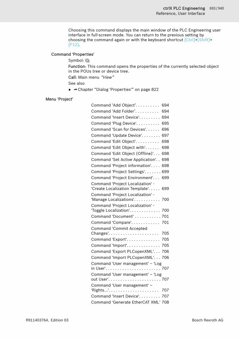
693 / 940ctrlX PLC EngineeringReference, User Interface
Bosch Rexroth AGR911403764, Edition 03
Choosing this command displays the main window of the PLC Engineering userinterface in full-screen mode. You can return to the previous setting bychoosing the command again or with the keyboard shortcut [Ctrl]+[Shift]+[F12].
Command 'Properties'Symbol: Function: This command opens the properties of the currently selected objectin the POUs tree or device tree.Call: Main menu “View”See also● ⮫ Chapter “Dialog 'Properties'” on page 822
Menu 'Project'Command ‘Add Object’. . . . . . . . . . 694Command ‘Add Folder’. . . . . . . . . . 694Command 'Insert Device'. . . . . . . . . 694Command 'Plug Device'. . . . . . . . . . 695Command 'Scan for Devices'. . . . . . 696Command 'Update Device'. . . . . . . . 697Command 'Edit Object'. . . . . . . . . . 698Command 'Edit Object with'. . . . . . 698Command 'Edit Object (Offline)'. . . 698Command 'Set Active Application'. . 698Command 'Project information'. . . . 698Command 'Project Settings'. . . . . . . 699Command 'Project Environment'. . . 699Command 'Project Localization' -'Create Localization Template'. . . . . 699Command 'Project Localization' -'Manage Localizations'. . . . . . . . . . . 700Command 'Project Localization' -'Toggle Localization'. . . . . . . . . . . . . 700Command 'Document' . . . . . . . . . . . 701Command 'Compare'. . . . . . . . . . . . 701Command 'Commit AcceptedChanges'. . . . . . . . . . . . . . . . . . . . . 705Command 'Export'. . . . . . . . . . . . . . 705Command 'Import'. . . . . . . . . . . . . . 705Command 'Export PLCopenXML'. . . 706Command 'Import PLCopenXML'. . . 706Command 'User management' – 'Login User'. . . . . . . . . . . . . . . . . . . . . . . 707Command 'User management' – 'Logout User'. . . . . . . . . . . . . . . . . . . . . . 707Command 'User management' –'Rights…'. . . . . . . . . . . . . . . . . . . . . 707Command 'Insert Device'. . . . . . . . . 707Command 'Generate EtherCAT XML' 708
694 / 940 ctrlX PLC EngineeringReference, User Interface
Bosch Rexroth AG R911403764, Edition 03
Command 'Generate Sercos SCIXML'. . . . . . . . . . . . . . . . . . . . . . . . . 708Command 'Disable Device' – 'EnableDevice'. . . . . . . . . . . . . . . . . . . . . . . 708Command 'Edit I/O Mapping'. . . . . . 708Command 'Import Mappings fromCSV'. . . . . . . . . . . . . . . . . . . . . . . . . 709Command 'Export Mapping to CSV'. 709Command 'Read PLC Parameter Fileto Configuration'. . . . . . . . . . . . . . . 710Command 'Online Config Mode'. . . 710
Command ‘Add Object’Symbol: Function: This command opens a submenu with objects that contain all objectsthat can be inserted, depending on the current position in the “Devices” or“POUs” view.Call: “Project” menu, context menu in the “Devices” or “POUs” view.Requirement: If PLC Engineering is to insert the object in the device tree,select an already existing object under which the new one is can be insertedindented. If PLC Engineering is to insert the object in the POUs tree, set thefocus in any free place in the PLC Engineering window.See also● ⮫ Chapter 1.2 “Creating and configuring projects” on page 14
Command ‘Add Folder’Symbol: Function: This command opens a dialog box for defining a new folder in theDevices or POUs view.Call: “Project” menu, context menu in the Devices or POUs viewYou cannot structure the arrangement of device nodes and device objectsthrough folders that you have created yourself.This command inserts the folder below the object that has just been selectedin the tree. If no object is selected, PLC Engineering inserts the folder right atthe top in the tree directly under the root node.See also● ⮫ Chapter 1.2.3 “Adding Objects” on page 19
Command 'Insert Device'Function: this command opens the dialog box “Add Device” for the selection ofa device object that is to be inserted in the device tree below the currentlyselected object.Call: Context menu of a device object in the device tree.Requirement: An object is selected in the device tree below which a deviceobject can be inserted.See also● ⮫ Chapter 1.7 “Configuring I/O Links” on page 46● ⮫ Chapter 1.7.1 “Device Tree and Device Editor” on page 47

695 / 940ctrlX PLC EngineeringReference, User Interface
Bosch Rexroth AGR911403764, Edition 03
Dialog box 'Add device'Function: Depending on the currently selected position in the device tree, thedialog box offers a selection of the devices that can be inserted at this point. Inaddition, it contains the commands also available in the context menu: “InsertDevice”, “Add Device”, “Plug Device”, “Update Device”.Requirement: The devices are installed in the device repository on the localsystem.If you have opened the dialog box, it always displays the selection to suit theobject currently selected in the device tree until you click “Close”.
“Name” Name with which the device is to appear in the device tree. Must be avalid IEC identifier.
Table 118: “action”“Add device” PLC Engineering inserts the selected device indented below the
selected object in the device tree.“Insert device” PLC Engineering inserts the selected device at the same level as the
selected object below it in the device tree.“Plug device” PLC Engineering inserts the selected device in the selected slot. If the
slot is already occupied, the existing module is replaced by the newone.
“Update device” PLC Engineering replaces the device selected in the device tree by theone selected.Please note: Depending on the device, this may cause the configura-tion already done in the device editor to be overwritten with thedefault values!
“String for the full textsearch”
This field is editable after clicking in it. For any character stringentered, only those devices that include the character string are dis-played in the lower view. The matched string is highlighted in yellowfor these devices.
“Vendor:” Drop-down list with manufacturers whose available devices are dis-played.
“Group by category” : The available devices (newest version) are sorted by category. Thecategory is defined in the device description file.
: The available devices appear flat and alphabetically sorted.“Display all versions (forexperts only)”
: In addition, all other available versions of the devices can also beselected.
: Only the newest version of each device is available for selection“Display outdated versions” : In addition, outdated versions of the devices can also be selected.
Outdated versions result, for example, from the update of plug-ins.: Outdated device versions are not displayed.
The information provided by the device description file is displayed:device name, vendor, categories, version, order number and a short description, device-specificbitmap.
See also● ⮫ Chapter “Command 'Insert Device'” on page 707● ⮫ Chapter “Command 'Plug Device'” on page 695● ⮫ Chapter “Command 'Update Device'” on page 697
Command 'Plug Device'Function: Like the command “Add Device”, this command opens the dialog box“Add Device” for the selection of a device object that is to be inserted in thedevice tree in the currently selected slot.
696 / 940 ctrlX PLC EngineeringReference, User Interface
Bosch Rexroth AG R911403764, Edition 03
Call: Context menu of the slot of a device object in the device tree.Requirement: The slot of a device object is selected in the device tree.An empty slot is identified by the symbol and the entry "<empty>(<empty>)". An occupied slot is given the symbol and the name of thedevice.In the case of an occupied slot, this command replaces the existing modulewith the new one.See also● ⮫ Chapter “Command 'Insert Device'” on page 694● ⮫ Chapter 1.7 “Configuring I/O Links” on page 46● ⮫ Chapter 1.7.1 “Device Tree and Device Editor” on page 47
Command 'Scan for Devices'Function: This command establishes a brief connection to the hardware anddetermines the devices in the network. You can then adopt the devices foundinto the device tree of your project.Call: Main menu “Project”, context menu of a device object in the device tree.Requirement: The settings for communication with the control device are cor-rect. The gateway and the PLC are running. The device supports the scan func-tion.The following devices provide the scan function: EtherCAT, EtherNet/IP (IEC),Sercos, CANopen, PROFINET, PROFIBUS DP.You can perform the scan immediately if the scan function is permanentlyimplemented in the PLC. If scan function is located in a library, you must log inonce in order to load the library to the controller.The command refers to the master controller selected in the device tree. Forexample, an already inserted PROFINET IO controller can be selected and thecommand used to determine the I/O devices and I/O modules assigned to it.After scanning, the dialog box “Scan for Devices” appears with the results.
Dialog 'Scan Devices'Table 119: “Scanned Devices”“Device name, Device type,Address, Station name,etc.”
Data about the scanned device depending on network type.When you change a value in the list of scanned devices, the value isshown in italics. This indicates that the new value has been changed inthe editor in PLC Engineering, but not in the device. When you down-load the value to the device, it is shown normally.Value that indicate differences between the project and the scanneddevice are shown in orange.If several device descriptions are available for the scanned device,then the name is displayed in bold. The selection of the matchingdevice description is resolved differently for different fieldbuses.Details can be found in the corresponding fieldbus sections.If a device description cannot be found, then the following message isshown: "Attention! The device was not found in the repository."Depending on the bus system, additional information is displayed,such as manufacturer number and product number. The device cannotbe inserted into the project without the installed device description.
“Show differences toproject”
: The table in the dialog also shows additional configured devices (inthe device tree of the project).
: The table shows all scanned devices. The configured devices arenot shown.
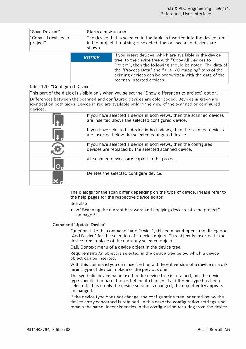
697 / 940ctrlX PLC EngineeringReference, User Interface
Bosch Rexroth AGR911403764, Edition 03
“Scan Devices” Starts a new search.“Copy all devices toproject”
The device that is selected in the table is inserted into the device treein the project. If nothing is selected, then all scanned devices areshown.
NOTICE If you insert devices, which are available in the devicetree, to the device tree with “Copy All Devices toProject”, then the following should be noted. The data ofthe “Process Data” and “<...> I/O Mapping” tabs of theexisting devices can be overwritten with the data of therecently inserted devices.
Table 120: “Configured Devices”This part of the dialog is visible only when you select the “Show differences to project” option.Differences between the scanned and configured devices are color-coded. Devices in green areidentical on both sides. Device in red are available only in the view of the scanned or configureddevices.
If you have selected a device in both views, then the scanned devicesare inserted above the selected configured device.
If you have selected a device in both views, then the scanned devicesare inserted below the selected configured device.
If you have selected a device in both views, then the configureddevices are replaced by the selected scanned device.
All scanned devices are copied to the project.
Deletes the selected configure device.
The dialogs for the scan differ depending on the type of device. Please refer tothe help pages for the respective device editor.See also● ⮫ “Scanning the current hardware and applying devices into the project”
on page 51
Command 'Update Device'Function: Like the command “Add Device”, this command opens the dialog box“Add Device” for the selection of a device object. This object is inserted in thedevice tree in place of the currently selected object.Call: Context menu of a device object in the device tree.Requirement: An object is selected in the device tree below which a deviceobject can be inserted.With this command you can insert either a different version of a device or a dif-ferent type of device in place of the previous one.The symbolic device name used in the device tree is retained, but the devicetype specified in parentheses behind it changes if a different type has beenselected. Thus if only the device version is changed, the object entry appearsunchanged.If the device type does not change, the configuration tree indented below thedevice entry concerned is retained. In this case the configuration settings alsoremain the same. Inconsistencies in the configuration resulting from the device
698 / 940 ctrlX PLC EngineeringReference, User Interface
Bosch Rexroth AG R911403764, Edition 03
update are reported by PLC Engineering at the next compilation of the applica-tion. This also concerns implicitly inserted libraries, which PLC Engineeringdoes not remove accordingly during a device update.See also● ⮫ Chapter 1.7 “Configuring I/O Links” on page 46● ⮫ Chapter “Command 'Insert Device'” on page 694
Command 'Edit Object'Function: This command opens the object in its editor.Call: Main menu “Project”, context menu.Requirement: An object is selected in the device tree or in the “POUs” view.
Command 'Edit Object with'Function: When multiple objects are available for an object, this commandopens a dialog box for selecting an editor.If only one editor is available for an object, then this command opens theobject in that editor.Call: Main menu “Project” or shortcut menu (right-click)Requirement: An object is selected in the device tree or in the “POUs” view.In the standard installation of PLC Engineering, there is no object that has mul-tiple available editors.
Command 'Edit Object (Offline)'Function: The command opens the object offline in the editor.Call: Main menu “Project”, Context menuRequirement: The application is in online mode. An object is selected in thedevice tree or in the “POUs” view.The command allows you to edit objects in online mode. After editing youtransfer the changes to the controller by use of the command “Online 🠂 OnlineChange” or “Online 🠂 Load”.See also● ⮫ Chapter “Command 'Online Change'” on page 722● ⮫ Chapter “Command 'Load'” on page 722
Command 'Set Active Application'Function: This command sets the selected application as the active application.Call: Main menu “Project”, or right-click the “Application” object.Requirement: The project has at least two applications. The selected applica-tion is not active.Online actions apply only to the active application. The name of an active appli-cation is displayed in bold typeface in the device tree.
Command 'Project information'Symbol: Function: This command opens the dialog box “Project Information”.Call: Main menu“Project”When you execute the command in the project for the first time, PLC Engi-neering creates the “Project Information” object.
699 / 940ctrlX PLC EngineeringReference, User Interface
Bosch Rexroth AGR911403764, Edition 03
See also● ⮫ Chapter “Retrieving and Editing Project Information” on page 22● ⮫ Chapter “Making Project Settings” on page 23● ⮫ Chapter “Object 'Project Information'” on page 622
Command 'Project Settings'Symbol: Function: This command opens the “Project Settings” dialog box.Call: “Project” menu or double-click on the object “Project Settings” in the“POUs” viewRequirement: A project is open.See also● ⮫ Chapter “Making Project Settings” on page 23● ⮫ Chapter “Dialog 'Project Settings'” on page 835● ⮫ Chapter “Object 'Project Settings'” on page 621
Command 'Project Environment'Function: This command opens the “Project Environment” dialog box.Call: “Project” menuRequirement: A project is open.this command is for checking the currentness of software and files integratedin the project and enables them to be updated.See also● ⮫ Chapter “Dialog 'Project Environment' – 'Library Versions'” on page 845● ⮫ Chapter “Dialog 'Project Environment' – 'C Code Modules'” on page 847● ⮫ Chapter “Dialog 'Project Environment' - 'Compiler Version'” on page 845● ⮫ Chapter “Dialog 'Project Environment' - 'Device Versions'” on page 846● ⮫ Chapter “Dialog 'Project Environment' – 'Visualization Profile'”
on page 846● ⮫ Chapter “Dialog 'Project Environment' – 'Visualization Styles'” on page 846● ⮫ Chapter “Dialog 'Project Environment' – 'Visualization Symbols'”
on page 847
Command 'Project Localization' - 'Create Localization Template'Function: This command opens the “Create Localization Template” dialog.Define here which information should be exported from the project to a transla-tion template (*.pot file).Call: Menu bar: “Project 🠂 Project Localization”.Requirement: A project is open.
Dialog 'Create Localization Template'This dialog is used for selecting the textual information that should be used inthe localization template.
Table 121: “Include the Following Information”“Names” Texts, such as dialog captions and object names in the device tree“Identifier” Variable identifier (example: Counter)“ Strings” Example: 'count' in the following declaration: strVar: STRING :=
'count';“Comments” Comment texts in the POUs
700 / 940 ctrlX PLC EngineeringReference, User Interface
Bosch Rexroth AG R911403764, Edition 03
“Position information” Selection of which positions of the selected text categories in theproject should be included in the translation file. The position informa-tion is located in the first line(s) of a segment for a translation.Example:#: D:\Proj1.project\Project_Settings:1msgid "Project settings" msgstr ""● “All”: All detected positions of the text are listed.● “First appearance”: In the translation file, the position is included in
the project where the text to be translated appears for the firsttime.
● “None”“Generate” This button opens the dialog for saving a file. The translation template
is created in a text file of type *.pot (portable object template). Eachfurther generation creates a completely new template file.
See also● Help about CODESYS Visualization: Multi-language capability
Command 'Project Localization' - 'Manage Localizations'Function: This command opens the “Manage localizations” dialog. Select thedesired localization language in the dialog or the original version of the project.You can still accept the localization files *.<language>.po into the project orremove them.Call: Menu bar: “Project 🠂 Project localization”.Requirement: A project is open.
Dialog 'Manage localizations'
“Available Localizations” List of the localization files available in the project. Example:proj1-de.poproj1-en.po<original version>The original version is always available. The project can be edited onlyin the original version.
“Add” This button opens the dialog for selecting an additional po file fromthe file system.
“Remove” This button removes the po file, which is selected on the left side,from the project.
“Default localization” : The selected localization is for the default localization. The entry isdisplay in bold.
“Switch Localization” Use this button to switch to the selected localization.“OK” The project is displayed in the language that is provided by the file
selected below the files. If you select “<original version>”, then theproject appears in the editable non-localized version.
See also● ⮫ Help about CODESYS Visualization: Multi-language capability
Command 'Project Localization' - 'Toggle Localization'Symbol: Function: This command switches between the currently set project localiza-tion and the <original version>.
701 / 940ctrlX PLC EngineeringReference, User Interface
Bosch Rexroth AGR911403764, Edition 03
Call: Menu bar: “Project 🠂 Project Localization”; button in the “Manage Locali-zations” dialog; button on the toolbar.Requirement: A project is open. A default localization for the project is definedin the “Manage Localizations” dialog.See also● Help about CODESYS Visualization: Multi-language capability● ⮫ Chapter “Command 'Project Localization' - 'Manage Localizations'”
on page 700
Command 'Document'Symbol: Function: This command opens the “Document Project” dialog box, where youcan define the project documentation. This includes the selection of objects inthe open project that you want to print.Call: Main menu “Project”
Table 122: “Document Project” dialog box“Please select the objectswhich are to be printed”
Project tree viewIn this view, you can select or clear objects for printing.All objects are selected by default.
“Title page” PLC Engineering creates a title page named "Project Documentation"with the following information:● File: project file name● Date: Creation date of the project documentation● Profile: PLC Engineering profile of the project
“Table of contents” PLC Engineering creates a table of contents for the project documen-tation.
“Preview” PLC Engineering creates and opens a print preview of the project doc-umentation.
“Select” PLC Engineering opens a drop-down list of all or single object typesfor the project documentation.
“Deselect” PLC Engineering opens a drop-down list of all or single object typesthat should be excluded from the project documentation.
“OK” The “Print” dialog box opens.See also● ⮫ Chapter “Dialog 'Project Settings' - 'Page Setup'” on page 839● ⮫ Chapter “Command 'Print'” on page 661
Command 'Compare'Symbol: Function: This command opens the “Project Comparison” dialog. In this dialog,you define the reference project to compare with the current project. You con-figure the comparison process by means of options. When the dialog is exited,the comparison starts and the result is shown in the view “Project Compare -Differences”.Call: Menu bar: “Project 🠂 Compare”.Requirement: A project is open.See also● ⮫ Chapter 1.4 “Comparing Projects” on page 28● ⮫ Chapter “Command 'Commit Accepted Changes'” on page 705
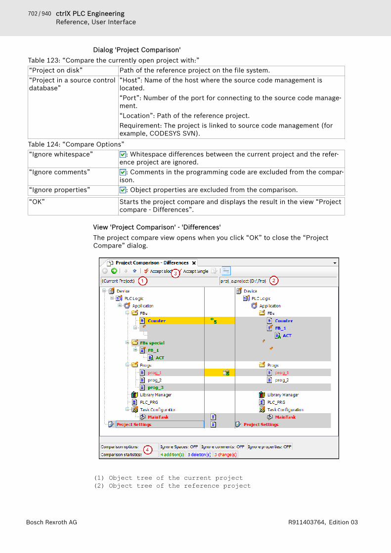
702 / 940 ctrlX PLC EngineeringReference, User Interface
Bosch Rexroth AG R911403764, Edition 03
Dialog 'Project Comparison'Table 123: “Compare the currently open project with:”“Project on disk” Path of the reference project on the file system.“Project in a source controldatabase”
“Host”: Name of the host where the source code management islocated.“Port”: Number of the port for connecting to the source code manage-ment.“Location”: Path of the reference project.Requirement: The project is linked to source code management (forexample, CODESYS SVN).
Table 124: “Compare Options”“Ignore whitespace” : Whitespace differences between the current project and the refer-
ence project are ignored.“Ignore comments” : Comments in the programming code are excluded from the compar-
ison.“Ignore properties” : Object properties are excluded from the comparison.
“OK” Starts the project compare and displays the result in the view “Projectcompare - Differences”.
View 'Project Comparison' - 'Differences'The project compare view opens when you click “OK” to close the “ProjectCompare” dialog.
(1) Object tree of the current project(2) Object tree of the reference project
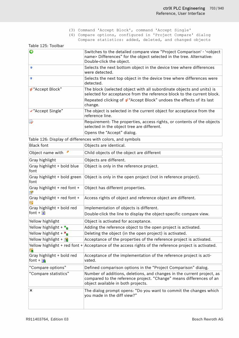
703 / 940ctrlX PLC EngineeringReference, User Interface
Bosch Rexroth AGR911403764, Edition 03
(3) Command 'Accept Block', command 'Accept Single'(4) Compare options, configured in 'Project Compare' dialog Compare statistics: added, deleted, and changed objects
Table 125: ToolbarSwitches to the detailed compare view “Project Comparison' - '<objectname> Differences” for the object selected in the tree. Alternative:Double-click the object.Selects the next bottom object in the device tree where differenceswere detected.Selects the next top object in the device tree where differences weredetected.
“Accept Block” The block (selected object with all subordinate objects and units) isselected for acceptance from the reference block to the current block.Repeated clicking of “Accept Block” undoes the effects of its lastchange.
“Accept Single” The object is selected in the current object for acceptance from thereference line.Requirement: The properties, access rights, or contents of the objectsselected in the object tree are different.Opens the “Accept” dialog.
Table 126: Display of differences with colors, and symbolsBlack font Objects are identical.
Object name with Child objects of the object are different
Gray highlight Objects are different.Gray highlight + bold bluefont
Object is only in the reference project.
Gray highlight + bold greenfont
Object is only in the open project (not in reference project).
Gray highlight + red font + Object has different properties.
Gray highlight + red font + Access rights of object and reference object are different.
Gray highlight + bold redfont +
Implementation of objects is different.Double-click the line to display the object-specific compare view.
Yellow highlight Object is activated for acceptance.Yellow highlight + Adding the reference object to the open project is activated.Yellow highlight + Deleting the object (in the open project) is activated.Yellow highlight + Acceptance of the properties of the reference project is activated.Yellow highlight + red font + Acceptance of the access rights of the reference project is activated.
Gray highlight + bold redfont +
Acceptance of the implementation of the reference project is acti-vated.
“Compare options” Defined comparison options in the “Project Comparison” dialog.“Compare statistics” Number of additions, deletions, and changes in the current project, as
compared to the reference project. “Change” means differences of anobject available in both projects.
The dialog prompt opens: “Do you want to commit the changes whichyou made in the diff view?”
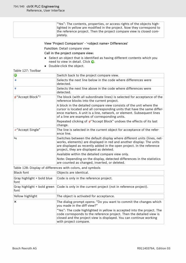
704 / 940 ctrlX PLC EngineeringReference, User Interface
Bosch Rexroth AG R911403764, Edition 03
“Yes”: The contents, properties, or access rights of the objects high-lighted in yellow are modified in the project. Now they correspond tothe reference project. Then the project compare view is closed com-pletely.
View 'Project Comparison' - '<object name> Differences'Function: Detail compare viewCall in the project compare view:● Select an object that is identified as having different contents which you
need to view in detail. Click .● Double-click the object.
Table 127: ToolbarSwitch back to the project compare view.Selects the next line below in the code where differences weredetected.Selects the next line above in the code where differences weredetected.
“Accept Block”2 The block (with all subordinate lines) is selected for acceptance of thereference blocks into the current project.A block in the detailed compare view consists of the unit where thecursor is located and all corresponding units that have the same differ-ence markers. A unit is a line, network, or element. Subsequent linesof a line are examples of corresponding units.Repeated clicking of “Accept Block” undoes the effects of its lastchange.
“Accept Single” The line is selected in the current object for acceptance of the refer-ence line.Switches between the default display where different units (lines, net-works, elements) are displayed in red and another display: The unitsare displayed as recently added in the open project. In the referenceproject, they are displayed as deleted.Available within the detailed compare view only.Note: Depending on the display, detected differences in the statisticsare counted as changed, inserted, or deleted.
Table 128: Display of differences with colors, and symbolsBlack font Objects are identical.
Gray highlight + bold bluefont
Code is only in the reference project.
Gray highlight + bold greenfont
Code is only in the current project (not in reference project).
Yellow highlight The object is activated for acceptance.
The dialog prompt opens: “Do you want to commit the changes whichyou made in the diff view?”“Yes”: The code highlighted in yellow is accepted into the project. Thecode corresponds to the reference project. Then the detailed view isclosed and the project view is displayed. You can continue workingwith project compare.
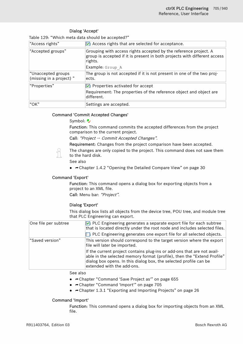
705 / 940ctrlX PLC EngineeringReference, User Interface
Bosch Rexroth AGR911403764, Edition 03
Dialog 'Accept'Table 129: “Which meta data should be accepted?”“Access rights” : Access rights that are selected for acceptance.
“Accepted groups” Grouping with access rights accepted by the reference project. Agroup is accepted if it is present in both projects with different accessrights.Example: Group_A
“Unaccepted groups(missing in a project) ”
The group is not accepted if it is not present in one of the two proj-ects.
“Properties” : Properties activated for acceptRequirement: The properties of the reference object and object aredifferent.
“OK” Settings are accepted.
Command 'Commit Accepted Changes'Symbol: Function: This command commits the accepted differences from the projectcomparison to the current project.Call: “Project 🠂 Commit Accepted Changes”.Requirement: Changes from the project comparison have been accepted.The changes are only copied to the project. This command does not save themto the hard disk.See also● ⮫ Chapter 1.4.2 “Opening the Detailed Compare View” on page 30
Command 'Export'Function: This command opens a dialog box for exporting objects from aproject to an XML file.Call: Menu bar: “Project”.
Dialog 'Export'This dialog box lists all objects from the device tree, POU tree, and module treethat PLC Engineering can export.
One file per subtree : PLC Engineering generates a separate export file for each subtreethat is located directly under the root node and includes selected files.
: PLC Engineering generates one export file for all selected objects.“Saved version” This version should correspond to the target version where the export
file will later be imported.If the current project contains plug-ins or add-ons that are not avail-able in the selected memory format (profile), then the “Extend Profile”dialog box opens. In this dialog box, the selected profile can beextended with the add-ons.
See also● ⮫ Chapter “Command 'Save Project as'” on page 655● ⮫ Chapter “Command 'Import'” on page 705● ⮫ Chapter 1.3.1 “Exporting and Importing Projects” on page 26
Command 'Import'Function: This command opens a dialog box for importing objects from an XMLfile.

706 / 940 ctrlX PLC EngineeringReference, User Interface
Bosch Rexroth AG R911403764, Edition 03
Call: Menu “Project”Requirement: A project is open.
Dialog box 'Import'The dialog box lists all objects from the export file that PLC Engineering canimport at this point.
“Currently selected targetobjects”
Object that is selected in the Device tree
“Insertable items” Displays all objects of the export file that PLC Engineering can insertbelow the selected object.
“Show contents” Displays the contents of the export file in a tree structureSee also● ⮫ Chapter “Command 'Export'” on page 705● ⮫ Chapter 1.3.1 “Exporting and Importing Projects” on page 26
Command 'Export PLCopenXML'Function: This command opens a dialog box for exporting objects from aproject into an XML file in the PLCopen format.Call: Menu “Project”
Dialog box 'Export PLCopenXML'The dialog box lists all objects from the Device tree that PLC Engineering canexport into an XML file in accordance with the PLCopen format.The PLCopenXML scheme does not permit VAR_GLOBAL and VAR_GLOBALCONSTANT POUs to be in the same variable list. Therefore, if you wish toexport both, you must first divide the variables into two separate variable lists.See also● ⮫ Chapter “Command 'Import PLCopenXML'” on page 706● ⮫ Chapter 1.3.1 “Exporting and Importing Projects” on page 26
Command 'Import PLCopenXML'Function: This command opens a dialog box for importing objects from an XMLfile in PLCopen format.Call: Menu “Project”Requirement: A project is open.
Dialog box 'Import PLCopenXML'The dialog box lists all objects from the PLCopen export file that PLC Engi-neering can import at this point.
“Currently selected targetobject”
Object that is selected in the Device tree
“Insertable items” Displays all objects of the export file that PLC Engineering can insertbelow the selected object.
The PLCopenXML scheme does not permit VAR_GLOBAL and VAR_GLOBALCONSTANT POUs to be in the same variable list. Therefore, if you wish toexport both, the variables must first be divided into two separate variable lists.See also● ⮫ Chapter “Command 'Export PLCopenXML'” on page 706● ⮫ Chapter 1.3.1 “Exporting and Importing Projects” on page 26
707 / 940ctrlX PLC EngineeringReference, User Interface
Bosch Rexroth AGR911403764, Edition 03
Command 'User management' – 'Log in User'Symbol: This command opens the dialog box “Login”. Here you specify the project thatyou wish to edit and enter the login data for a user account with the corre-sponding rights. In addition, you can open the password manager from thisdialog box.The command is available in the menu “Project 🠂 User Management”.See also● ⮫ Chapter 1.5.6 “Logging in via User Account and Password Manager”
on page 38
Command 'User management' – 'Log out User'Symbol: The user currently logged in to the project is logged out again with this com-mand. This takes place without a dialog box or message, unless no user is cur-rently logged in.The command is available in the menu “Project 🠂 User Management”.If the user is currently logged in to several projects or to libraries integrated inthem (it does not have to be the same user account), then the dialog box“Logout” opens, in which the specific project or library project can be selectedfrom which the current user is to be logged out.The status bar always displays the user who is currently logged into the project.
A double-click on the field “Current user” in the status bar enables quickaccess to the “Login” or “Logout” dialog box.See also● ⮫ Chapter 1.5.6 “Logging in via User Account and Password Manager”
on page 38● ⮫ Chapter “Command 'User management' – 'Log in User'” on page 707
Command 'User management' – 'Rights…'This command opens the dialog box “Rights”, in which you define the actionsthat may be carried out, the user groups that may carry them out and theproject objects on which they may be carried out.The command is available in the menu “Project 🠂 User Management”.See also● ⮫ Chapter 1.5.5 “Protecting Objects in the Project by Access Rights”
on page 37
Command 'Insert Device'Function: Like the command “Add Device”, this command opens a dialog box“Insert Device” for the selection of a device object. This object is inserted inthe device tree at the same level as the currently selected object.Call: Context menu of a device object in the device tree.Requirement: An object is selected in the device tree below which a deviceobject can be inserted at the same level.See also● ⮫ Chapter 1.7 “Configuring I/O Links” on page 46● ⮫ Chapter “Command 'Insert Device'” on page 694● ⮫ Chapter 1.7.1 “Device Tree and Device Editor” on page 47

708 / 940 ctrlX PLC EngineeringReference, User Interface
Bosch Rexroth AG R911403764, Edition 03
Command 'Generate EtherCAT XML'The command is not integrated in the standard main menu. You can add it viathe dialog box “Tools 🠂 Customize” from the category “Devices”.Function: This command opens the standard dialog box for saving a file in thelocal file system. You can define a name and a storage location for an xml file,in which PLC Engineering is to store the EtherCAT configuration of theEtherCAT master currently selected in the device tree. This may be necessary inorder to operate an external EtherCAT stack.Call: Context menu of an EtherCAT master device object in the device tree.See also● ⮫ Chapter 1.7 “Configuring I/O Links” on page 46● ⮫ Chapter “Customizing Menus” on page 10
Command 'Generate Sercos SCI XML'The command is not integrated in the standard menu. You can add it via thedialog box “Tools 🠂 Customize” from the category “Devices”.Function: This command opens the standard dialog box for saving a file in thelocal file system. You can define a name and a location for an xml file in whichPLC Engineering then stores the configuration data of the sercos master cur-rently selected in the device tree. This may be necessary in order to operate anexternal sercos stack.Call: Context menu of a sercos master device object in the device tree.See also● ⮫ Chapter 1.7 “Configuring I/O Links” on page 46● ⮫ Chapter “Customizing Menus” on page 10
Command 'Disable Device' – 'Enable Device'Function: This command switches back and forth between the enabled (acti-vated) and disabled (deactivated) states of a device in the bus system.Call: Context menu of a device object in the device tree.Requirement: The project is in offline mode. The bus driver must support thefunction.A disabled device is not taken into account and is not addressed. Note thatwith some bus systems the deactivation of a node can lead to the master stop-ping.The entry of a disabled device in the tree appears in light-gray lettering. Whenlogging in, disabled devices are additionally marked with a red triangle .See also● ⮫ Chapter 1.7 “Configuring I/O Links” on page 46
Command 'Edit I/O Mapping'Function: This command opens the “Edit I/O Mapping” dialog box. This displaysall I/O mappings of the currently selected device object, including I/O map-pings of all additional device objects that are inserted in the device tree belowthis object.Call: Context menu of a device object in the device tree.
Dialog box 'Edit I/O mapping'You can edit the I/O mapping in this dialog box in exactly the same way as inthe dialog box “I/O mapping” of the individual device editors. The respectiveother dialog boxes are directly updated accordingly.
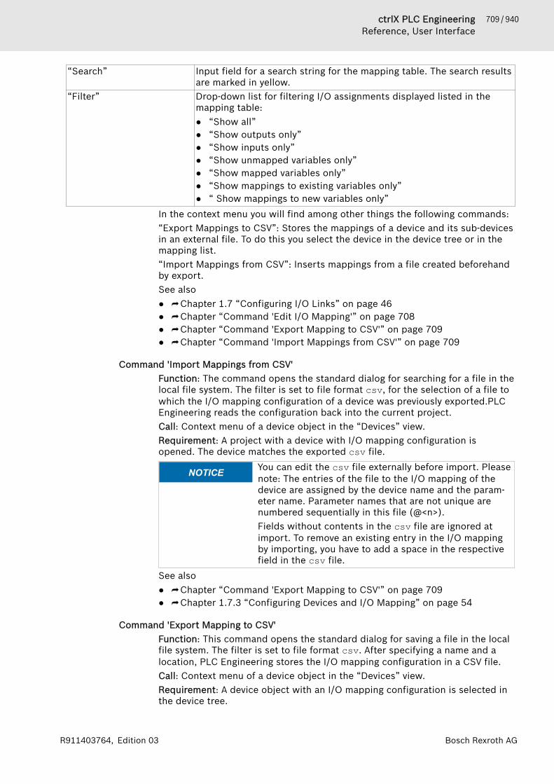
709 / 940ctrlX PLC EngineeringReference, User Interface
Bosch Rexroth AGR911403764, Edition 03
“Search” Input field for a search string for the mapping table. The search resultsare marked in yellow.
“Filter” Drop-down list for filtering I/O assignments displayed listed in themapping table:● “Show all”● “Show outputs only”● “Show inputs only”● “Show unmapped variables only”● “Show mapped variables only”● “Show mappings to existing variables only”● “ Show mappings to new variables only”
In the context menu you will find among other things the following commands:“Export Mappings to CSV”: Stores the mappings of a device and its sub-devicesin an external file. To do this you select the device in the device tree or in themapping list.“Import Mappings from CSV”: Inserts mappings from a file created beforehandby export.See also● ⮫ Chapter 1.7 “Configuring I/O Links” on page 46● ⮫ Chapter “Command 'Edit I/O Mapping'” on page 708● ⮫ Chapter “Command 'Export Mapping to CSV'” on page 709● ⮫ Chapter “Command 'Import Mappings from CSV'” on page 709
Command 'Import Mappings from CSV'Function: The command opens the standard dialog for searching for a file in thelocal file system. The filter is set to file format csv, for the selection of a file towhich the I/O mapping configuration of a device was previously exported.PLCEngineering reads the configuration back into the current project.Call: Context menu of a device object in the “Devices” view.Requirement: A project with a device with I/O mapping configuration isopened. The device matches the exported csv file.
NOTICE You can edit the csv file externally before import. Pleasenote: The entries of the file to the I/O mapping of thedevice are assigned by the device name and the param-eter name. Parameter names that are not unique arenumbered sequentially in this file (@<n>).Fields without contents in the csv file are ignored atimport. To remove an existing entry in the I/O mappingby importing, you have to add a space in the respectivefield in the csv file.
See also● ⮫ Chapter “Command 'Export Mapping to CSV'” on page 709● ⮫ Chapter 1.7.3 “Configuring Devices and I/O Mapping” on page 54
Command 'Export Mapping to CSV'Function: This command opens the standard dialog for saving a file in the localfile system. The filter is set to file format csv. After specifying a name and alocation, PLC Engineering stores the I/O mapping configuration in a CSV file.Call: Context menu of a device object in the “Devices” view.Requirement: A device object with an I/O mapping configuration is selected inthe device tree.
710 / 940 ctrlX PLC EngineeringReference, User Interface
Bosch Rexroth AG R911403764, Edition 03
Parameter names that are note unique are numbered sequentially in this file(@<n>).See also● ⮫ Chapter “Command 'Import Mappings from CSV'” on page 709● ⮫ Chapter 1.7.3 “Configuring Devices and I/O Mapping” on page 54
Command 'Read PLC Parameter File to Configuration'Function: This command reads the configuration file IoConfig.par of the PLCand stores the values in the project. Such a file is created if the parameters ofthe PLC have been changed by another device, for example via a visualization.Then these parameters are changed only in the memory of the PLC, but not inthe configuration of the project.Call: Context menu of the PLC device objectRequirement: You have made the command available using the dialog in “Tools🠂 Customize”.See also● ⮫ “Read PLC parameter file to configuration” on page 54
Command 'Online Config Mode'Function: This command is for switching the online configuration mode on andoff. At switch-on it establishes a connection to the PLC and loads an implicitlycreated application “HiddenOnlineConfigModeApp” to the PLC. Depending onthe device, PLC Engineering goes into simple online configuration mode or adialog box appears for selecting between simple and advanced online configu-ration mode.Call: Context menu of the PLC object in the device treeRequirement: The communication settings for the PLC device are correctly set.
Simple online configuration mode:This command creates the implicit application HiddenOnlineConfigModeAppand loads it to the controller. The application automatically initializes all inputsand outputs of the controller once. After that you can access the I/Os as fol-lows:● Read I/Os● Write outputs● Diagnosis (in the device tree and on the “Status” tab of the device editor)● Scan (of the current hardware)● Interactive online functions, if supported (for example, writing asynchronous
messages)Advanced online configuration mode (parameter mode):If there are already applications on the PLC and the controller supports it, thecommand first opens the dialog box “Devices”, which displays the applicationsexisting on the controller. From this dialog you can connect via the button“Parameter mode” to the PLC and then access the values of the device parame-ters without having to log in with a real application.Writing and forcing in the I/O mappingIn online configuration mode the writing and forcing of values on the “I/O Map-ping” tab works differently to the way it works in real online mode. The outputsare written immediately after insertion into the table. There is no “PreparedValue” column; instead, the initial values can be changed directly after adouble-click on the column “Current Value”.
711 / 940ctrlX PLC EngineeringReference, User Interface
Bosch Rexroth AGR911403764, Edition 03
Dialog box 'Config application mode'This dialog box appears after the command “Online Config Mode” if the devicesupports the advanced online configuration mode and there are already realapplications on the controller.
“Parameter mode” The controller configuration in the project is compared with that onthe device. If they correspond, PLC Engineering establishes a connec-tion to the PLC. Unlike the simple online configuration mode it permitsthe reading and – if supported by the driver – the writing of parame-ters in the generic device editor. The applications already loaded to thedevice remain unchanged in this case!
“Config application mode” PLC Engineering switches to the 'simple online configuration mode'.See also● ⮫ “Checking the controller configuration with the help of the 'Online Config
Mode' command” on page 52
Menu 'Build'Command 'Build'. . . . . . . . . . . . . . . 711Command 'Rebuild'. . . . . . . . . . . . . 712Command 'Generate Code'. . . . . . . 712Command 'Generate RuntimeSystem Files'. . . . . . . . . . . . . . . . . . 712Command 'Clean'. . . . . . . . . . . . . . . 713Command 'Clean All'. . . . . . . . . . . . 714Command 'Check All Pool Objects'. 714Command 'Check All ApplicationObjects'. . . . . . . . . . . . . . . . . . . . . . 714Command 'Check Library Compati-bility'. . . . . . . . . . . . . . . . . . . . . . . . 714Command 'C Integration' - 'Update CSources'. . . . . . . . . . . . . . . . . . . . . . 715Command 'C Integration – Open inIDE'. . . . . . . . . . . . . . . . . . . . . . . . . . 715Command 'C Integration' - 'Export CsSurces'. . . . . . . . . . . . . . . . . . . . . . 715Command 'C Integration – CreateStub Implementation in C'. . . . . . . . 716Command 'Create IEC Interface'. . . 716Command 'Generate DisassemblyFile'. . . . . . . . . . . . . . . . . . . . . . . . . 716
Command 'Build'Symbol: , keyboard shortcut: [F11].Function: This command starts the build process for the active application.Call: Main menu “Build”.During the compile process, PLC Engineering performs a syntactic validation ofall objects in the application. However, code is not generated like at login to thetarget system or download of the application. The compile process is alwaysperformed automatically when you login with a changed program.When the check is complete, PLC Engineering displays any error messages orwarnings in the messages view (“Build” category).

712 / 940 ctrlX PLC EngineeringReference, User Interface
Bosch Rexroth AG R911403764, Edition 03
If the program has not been changed since it was compiled without errors thelast time, then it is not recompiled. The message "The application is current"appears. If the syntactic validation is repeated, then you must execute the“Rebuild” command.See also● ⮫ Chapter “Command 'Rebuild'” on page 712
Command 'Rebuild'Function: This command starts the build process for the active application,even if the last build contained errors.Call: Main menu “Debug”.See also● ⮫ Chapter “Command 'Build'” on page 711
Command 'Generate Code'Function: This command starts the code generation for the active application.Call: Menu bar: “Build”When generating code with this command, code is generated as when down-loading the application to the PLC, but the code is not transferred to the PLC.Other source code tests are performed as well for checking the code for bugsthat were not detected by the compiler and for fixing any bugs before the codeis used in online mode.See also● ⮫ Chapter 1.10.4 “Generating Application Code” on page 192
Command 'Generate Runtime System Files'Function: This command generates a C stub file and an M4 interface file fromthe current library project. These files are used as the basis for creating anexternal library file.Call: Main menu “Build”.This command opens the “Generate Files for Runtime System” dialog box.
“Output directory” Directory where PLC Engineering creates the runtime system files.Click the "more" button ( ) to open the default dialog box forbrowsing the file system.
Table 130: “Which files do you want to create?”“M4 interface file” : Interface file <project name>Itf.m4 with definitions. Example of m4
file:
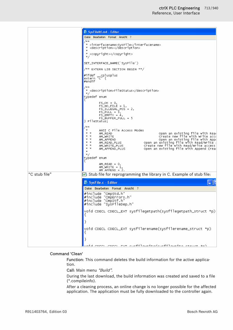
713 / 940ctrlX PLC EngineeringReference, User Interface
Bosch Rexroth AGR911403764, Edition 03
“C stub file” : Stub file for reprogramming the library in C. Example of stub file:
Command 'Clean'Function: This command deletes the build information for the active applica-tion.Call: Main menu “Build”.During the last download, the build information was created and saved to a file(*.compileinfo).After a cleaning process, an online change is no longer possible for the affectedapplication. The application must be fully downloaded to the controller again.

714 / 940 ctrlX PLC EngineeringReference, User Interface
Bosch Rexroth AG R911403764, Edition 03
See also● ⮫ Chapter “Command 'Clean All'” on page 714
Command 'Clean All'Function: This command deletes the build information for all applications in theproject.Call: Main menu “Build”.During the last download, the build information was created in the local filesystem and saved to a file (*.compileinfo).This command requires a download before another login An online change is nolonger possible. As compared to the “Clean” command (only the active applica-tion), PLC Engineering regenerates the language model for all objects, which isvery time-consuming.
NOTICE Reconsider carefully whether or not executing this com-mand is really necessary. If you only want to rebuild anddownload the active application, then execute the“Clean” command.
See also● ⮫ Chapter “Command 'Clean'” on page 713
Command 'Check All Pool Objects'Function: The command causes a build run, that is a syntax check, for all poolobjects, which are managed in the POUs view and thus are available in theentire project .Especially this is useful when creating libraries.Call: By default the command is not available in any menu. You can add it to amenu using the dialog “Tools 🠂 Customize”, command category “Build”.
NOTICE The command does not trigger code generation. Also nocompile information file will be stored in the projectdirectory.
See also● ⮫ Chapter “Dialog 'Customize' - 'Menu'” on page 863● ⮫ Chapter 1.15.1 “Information for Library Developers” on page 238
Command 'Check All Application Objects'Function: This command starts a build operation for all objects of the activeapplication, even for the POUs that are not used by the application. After thebuild operation, the errors that were found in the unused objects are also dis-played in the message window.Call: The command is not in any menu by default. You can add it to a menu byusing the dialog from “Tools 🠂 Customize” (command category “Build”).Requirement: An application of the open project is active.
NOTICE The command does not result in code generation. Inaddition, no file is created in the project directory withinformation about the build operation.
See also● ⮫ Chapter “Dialog 'Customize' - 'Menu'” on page 863
Command 'Check Library Compatibility'Function: The command triggers a check whether the currently opened libraryproject is compatible with the last installed version of this library (next lowerversion number) .

715 / 940ctrlX PLC EngineeringReference, User Interface
Bosch Rexroth AGR911403764, Edition 03
Call: By default the command is not available in any menu. You can add it to amenu by using the “Tools 🠂 Customize” dialog, command category “Build”.Requirement: A library project is opened.The check regards differences in the implemented interfaces of a method. So,after the check you will get displayed error messages in the messages windowin the following cases:● Adding or removing inputs or outputs of function blocks, functions or
methods● Changing the data type of inputs or outputs● Modifying the implemented interfaces of a methodSee also● ⮫ Chapter “Dialog 'Customize' - 'Menu'” on page 863● ⮫ Chapter 1.15.1 “Information for Library Developers” on page 238
Command 'C Integration' - 'Update C Sources'Function: this command opens the dialog “Update C Sources” for updating theobjects in the project that have changed in the source directory on the disk.Call: Menu bar: “Build”; context menu.Requirement: An object “C Code Module” or “C Implemented Library” isselected. When adding the C-code module in the dialog “Add C Code Module”,you have activated the option “Check folder for source code changes”.
“File” File that has changed on the disk.“Action” Action that is executed in PLC Engineering if you click “Update”.“Update options” ● “Remove IEC interfaces due to changed header files”
● “Export source files to the monitored project folder”“Refresh” PLC Engineering updates the listed files.
See also● ⮫ Chapter “Object 'C Code Module'” on page 551● ⮫ Chapter “Command 'C Integration – Open in IDE'” on page 715● ⮫ Chapter 1.8.11 “Integrating C Modules” on page 113
Command 'C Integration – Open in IDE'Function: The command opens the “C Code Module” in the associated IDE(Integrated Development Environment).Call: Main menu “Create”, context menuRequirement: You have opened an object “C Code Module” and the associatedIDE is not opened.If the IDE is closed, PLC Engineering checks whether the files have beenchanged and, in such a case, a dialog box appears for confirming the update ofthe C-code module in PLC Engineering.See also● ⮫ Chapter “Dialog 'Properties' – 'Build' (C-integration)” on page 826● ⮫ Chapter “Command 'C Integration' - 'Update C Sources'” on page 715● ⮫ Chapter 1.8.11 “Integrating C Modules” on page 113
Command 'C Integration' - 'Export C sSurces'Function: The command exports all C-code files of a C-code module and savesthem in the folder that you select in the dialog “Find Folder”.Call: Menu bar: “Build”; context menu.Requirement: A C code module is selected in the device tree.
716 / 940 ctrlX PLC EngineeringReference, User Interface
Bosch Rexroth AG R911403764, Edition 03
See also● ⮫ Chapter 1.8.11 “Integrating C Modules” on page 113
Command 'C Integration – Create Stub Implementation in C'Function: This command creates C-stubs for the selected POU and stores themin the “Extensions” folder in the objects “iec_external.c” and
“iec_external.h”.Call: Main menu “Build”, context menuRequirement: A POU that is inserted under the object of the type “C CodeModule” is selected in the device tree. The application has been compiledwithout errors.See also● ⮫ Chapter “Object 'C Code File'” on page 553● ⮫ Chapter 1.8.11 “Integrating C Modules” on page 113
Command 'Create IEC Interface'Function: The command creates corresponding IEC objects from the selectedfile with the format *.h or *.hhp and stores these IEC objects in the folder“IEC interface”.Call: Main menu “Build”, context menuRequirement: You have selected an imported C-code file of the format *.h or*.hpp in the device tree below the object “C Code Module”.If you select the command and the header file is free of errors, the dialog box“C Functions” opens with a list of the functions of the file that is to beexported.
Dialog box 'Create IEC interface'
“Function” List of the functionsYou select the functions for which a corresponding IEC object is to becreated.
“Import” PLC Engineering generates corresponding IEC objects for the selectedC-functions and stores them in the folder “IEC interface” below theobject “C Code Module”.
See also● ⮫ Chapter 1.8.11 “Integrating C Modules” on page 113
Command 'Generate Disassembly File'Function: This command generates a disassembly file <project name>.asmfrom the current project and saves it in the file directory in the project folder.Call: The command is not in any menu by default. You can add it to a menu byusing the dialog box from “Tools 🠂 Customize” (command category “Build”).See also● ⮫ Chapter “Dialog 'Customize' - 'Menu'” on page 863
Menu 'Online'Command 'Choose active applica-tion'. . . . . . . . . . . . . . . . . . . . . . . . . 717Command 'Login'. . . . . . . . . . . . . . . 718Command 'Logout'. . . . . . . . . . . . . . 721Command 'Create Boot Application' 721Command 'Load'. . . . . . . . . . . . . . . 722
717 / 940ctrlX PLC EngineeringReference, User Interface
Bosch Rexroth AGR911403764, Edition 03
Command 'Online Change'. . . . . . . . 722Command 'Source Download toConnected Device'. . . . . . . . . . . . . . 723Command 'Multiple Download'. . . . 724Command 'Reset Cold'. . . . . . . . . . . 725Command 'Reset Warm'. . . . . . . . . . 726Command 'Reset Origin'. . . . . . . . . 727Command 'Reset Origin Device'. . . . 728Command 'Logoff Current DeviceUser'. . . . . . . . . . . . . . . . . . . . . . . . . 728Command 'Add Device User'. . . . . . 728Command 'Remove Device User'. . . 729Command 'Change Password DeviceUser'. . . . . . . . . . . . . . . . . . . . . . . . . 729Command 'Stop Execution on Han-dled Exceptions'. . . . . . . . . . . . . . . . 730Command 'Connect to Device'. . . . . 730Command 'Disconnect from Device' 730Command 'Wink'. . . . . . . . . . . . . . . 731Command 'Simulation. . . . . . . . . . . 731Command 'Operating Mode'. . . . . . 731
Command 'Choose active application'Symbol: The command is implemented as a list box from which you can set an applica-tion active. By default, the list box is located on the toolbar.Function: The list box displays the currently active application with its devicepath.Call: The list box contains all applications that are organized in the “Devices”view. By clicking an entry in the list box, you activate the selected application.Requirement: The project has multiple applications.

718 / 940 ctrlX PLC EngineeringReference, User Interface
Bosch Rexroth AG R911403764, Edition 03
Example
When you call commands in the “Build” oder “Online” menus, these commandsare applied to the active application. This is displayed in the list box, and alsodisplayed in bold in the device tree. In particular, this applies to the “Build🠂 Build” and “Online 🠂 Login” commands.You can also access these commands using the command icons on the toolbarwhere the list box is located. When the command icons are called, they are alsoapplied to the active application.However, if you call a command from the context menu of a device object in thedevice tree, then the command is applied to the corresponding object. Forexample, by calling , you can establish a connection to an application on thedevice which is not active.
See also● ⮫ Chapter “Command 'Set Active Application'” on page 698● ⮫ Chapter “Command 'Build'” on page 711● ⮫ Chapter “Command 'Login'” on page 718
Command 'Login'Symbol: , shortcut: [Alt]+[F8]Function: The command connects the application to the target system (PLC tosimulated device) and starts the online mode.Call: Menu bar: “Online”; context menu of an “Application” object
719 / 940ctrlX PLC EngineeringReference, User Interface
Bosch Rexroth AGR911403764, Edition 03
Requirement: The application contains no errors and the communication set-tings are configured.A dialog prompt opens if the communication settings are incorrect. You canthen switch directly to the “Communication Settings” of the PLC.If you click “Login” from the online menu, then the currently active applicationis connected to the target system. If you choose this command from the con-text menu (right-click) while an application is selected in the device tree, thenthat application is logged in, even if it is not set as the active application.If an online user management is configured on the target device, then you areprompted for user data when you login. The “Device User Login” dialog opensfor this.
CAUTION Check controller accessibilityFor security reasons, controllers should not be acces-sible from the Internet or untrusted Networks under anycircumstances! In particular, the TCP/IP programmingports (usually UDP-Ports 1740..1743 and TCP-Ports 1217+ 11740 or the controller specific ports) should not beaccessible from the internet without protection. In caseInternet access to the controller is needed, using a a safemechanism is absolutely mandatory, such as VPN andpassword protection of the controller.see also: ⮫ Chapter 1.10.3 “Handling of Device User Man-agement” on page 188
NOTICE If a safety controller is inserted below a controller, thenthis command can interrupt the communication connec-tions temporarily.Connections of the safety controller to other safety con-trollers (via safety network variables), to field devices,and to the development system are affected. The safefield devices or other safety controller can enter the safestate as a reaction. The connection to the developmentsystem is affected only when a safety controller that isconnected to the main controller via a fieldbus.For more information, see the "Subordinate Safety Con-trollers" chapter.
Possible situations when logging in:● A later version of the device description (than in the project) is on the PLC.
A warning prompt is displayed with the option to cancel the process.● The application does not exist on the PLC: You are prompted to confirm the
download.● The application is already on the PLC and has not been changed since the
last download. The login continues without any more prompts.● The application exists on the PLC, but it has been changed since the last
download.You are prompted to select one of the following options:– Login with online change (Note the information about online changes in
the help page "Command 'Online Change' ".)– Login with download– Login without any changeThe position also provides the option of updating the boot application onthe PLC.
● An unknown version of the application exists on the PLC. PLC Engineeringprompts you to replace it.
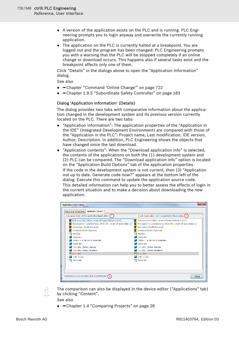
720 / 940 ctrlX PLC EngineeringReference, User Interface
Bosch Rexroth AG R911403764, Edition 03
● A version of the application exists on the PLC and is running. PLC Engi-neering prompts you to login anyway and overwrite the currently runningapplication.
● The application on the PLC is currently halted at a breakpoint. You arelogged out and the program has been changed: PLC Engineering promptsyou with a warning that the PLC will be stopped completely if an onlinechange or download occurs. This happens also if several tasks exist and thebreakpoint affects only one of them.
Click “Details” in the dialogs above to open the “Application Information”dialog.See also● ⮫ Chapter “Command 'Online Change'” on page 722● ⮫ Chapter 1.9.5 “Subordinate Safety Controller” on page 183
Dialog 'Application Information' (Details)The dialog provides two tabs with comparative information about the applica-tion changed in the development system and its previous version currentlylocated on the PLC. There are two tabs:● “Application information”: The application properties of the “Application in
the IDE” (Integrated Development Environment) are compared with those ofthe “Application in the PLC”: Project name, Last modification, IDE version,Author, Description. In addition, PLC Engineering shows the objects thathave changed since the last download.
● “Application contents”: When the “Download application info” is selected,the contents of the applications on both the (1) development system and(2) PLC can be compared. The “Download application info” option is locatedon the “Application Build Options” tab of the application properties.If the code in the development system is not current, then (3) “Applicationnot up to date. Generate code now?” appears at the bottom left of thedialog. Execute this command to update the application source code.This detailed information can help you to better assess the effects of login inthe current situation and to make a decision about downloading the newapplication.
The comparison can also be displayed in the device editor (“Applications” tab)by clicking “Content”.See also● ⮫ Chapter 1.4 “Comparing Projects” on page 28

721 / 940ctrlX PLC EngineeringReference, User Interface
Bosch Rexroth AGR911403764, Edition 03
Compiling the project before loginIf an application program has not been compiled since the last change, thenPLC Engineering compiles the project before login. This operation is the sameas the “Build” command when logged out.If compile errors occur, then a dialog prompt opens. The errors are printed tothe message view (“Build” category). You can then decide whether or not youlogin without downloading the program to the PLC.See also● ⮫ Chapter “Command 'Build'” on page 711
Error at loginIf an error occurs when logging in to the PLC, then PLC Engineering cancels theloading operation with an error message. The error dialog gives you the optionsof showing the error details. If an exception was thrown and the text *SOURCE-POSITION* is included in the log, then you can display the affected function inthe editor by clicking “Show in Editor”. The cursor jumps to the line containingthe error.
Messages during the download operationIf PLC Engineering downloads the project to the PLC at login, then the fol-lowing information is printed to the message view:● Generated code size● Size of the global data● Resulting memory requirement on the PLC● List of the affected blocks (for online change)
In online mode, you cannot change the settings of the devices or modules. Youhave to logout of the application for changing device parameters. Depending onthe bus system, there may be some special parameters that you can alsochange in online mode.PLC Engineering saves the view configuration separately in online and offlinemode. In addition, views are closed that cannot be used in any operating mode.For this reason, the view can change automatically at login.
Command 'Logout'Symbol: , keyboard shortcut: [Ctrl]+[F8].Function: This command disconnects the application from the target system(controller or simulated device) and returns to offline mode.Call: Main menu “Online”, or context menu of the “Application” object.
Command 'Create Boot Application'Function: This command generates a boot application.Call: Main menu “Online”.A boot application is the application that is started automatically when the con-troller is switched on or started.In offline mode, you can save the boot application in any directory. In onlinemode, PLC Engineering save the boot application to the target device. The filename is <application name>.app.See also● ⮫ Chapter 1.10.6 “Generating Boot Applications” on page 194● ⮫ Chapter “Object 'Application'” on page 528
722 / 940 ctrlX PLC EngineeringReference, User Interface
Bosch Rexroth AG R911403764, Edition 03
Command 'Load'Function: This command causes a compilation of the active application withsubsequent download to the controller.Call: Menu bar: “Online”.Requirement: The application is in online mode.When you execute this command, PLC Engineering performs a syntax checkand generates the application code. This code is downloaded to the PLC. Fur-thermore, PLC Engineering generates the build log <project name>.<devicename>.<application ID>.compile info in the project directory.
NOTICE During loading all variables are re-initialized with theexception of persistent variables.
NOTICE If a safety controller is inserted below a controller, thenthis command can interrupt the communication connec-tions temporarily.Connections of the safety controller to other safety con-trollers (via safety network variables), to field devices,and to the development system are affected. The safefield devices or other safety controller can enter the safestate as a reaction. The connection to the developmentsystem is affected only when a safety controller that isconnected to the main controller via a fieldbus.For more information, see the "Subordinate Safety Con-trollers" chapter.
The description of the “Login” command describes the possible situationswhen logging in and loading.If you attempt to download an application when the same version of the appli-cation is already on the PLC, then you get the message: "Program is unchanged.Application was not downloaded". PLC Engineering downloads the applicationto the PLC.During loading a record of the actions being executed (generation of code, exe-cution of initialization, etc.) appears in the Message window in the messagecategory “Compile”. Furthermore, information is displayed regarding thememory ranges, the size of the code, the global data and the allocatedmemory. For the purpose of clarity, as opposed to the online change, the modi-fied function blocks are no longer listed.See also● ⮫ Chapter “Command 'Login'” on page 718● ⮫ Chapter 1.9.5 “Subordinate Safety Controller” on page 183
Command 'Online Change'Function: This command is used for initiating an online change on the currentapplication. When this is done, PLC Engineering re-downloads only the changedparts of an application that is already running on the PLC.Call: Menu bar: “Online”; context menu of object: “Application”Requirement: The application is in online mode.The command is available in the context menu if an application is selected inthe device tree. In this way, you can perform an online change just for oneapplication, even if that application is not currently active.An online change is not possible after the “Clean All” and “Clean” commands.The cleaning process deletes the compile information (build log) that was gen-erated automatically at code generation. This log is the basis for an onlinechange.

723 / 940ctrlX PLC EngineeringReference, User Interface
Bosch Rexroth AGR911403764, Edition 03
CAUTION An online change changes the running application pro-gram and requires a restart.Make sure that the new application code still has therequired effect on the controlled system.Depending on the controlled plant, the plant and work-pieces may be damaged or the health and life of personscould be endangered.
NOTICE If an online change is performed, then the application-specific initializations (example: homing) are not exe-cuted because the machine retains its status. For thisreason, the new program code may not have theintended effect.2. Pointer variables retain their value from the last cycle.If a pointer refers to a variable whose value was changedin an online change, then the variable no longer yieldsthe correct value. Make sure that pointer variables are re-assigned in each cycle.
NOTICE For compiler version 3.5.0.0 and later, a fast onlinechange is performed for minor changes. In this case, onlythe modified blocks are compiled and downloaded. Inparticular, no initialization code is generated. This meansthat also no code is generated when variables with theinit_on_onlchange attribute are initialized. As a rule,this has no effect because the attribute is used primarilyfor initializing variables with addresses. However, itcannot happen that a variable changes its address duringan online change.To secure the effect of the init_on_onlchangeattribute in the entire application code, you must deacti-vate the fast online change in general for the applicationby using the compiler definitionno_fast_online_change. To do this, insert the defini-tion in the application “Properties” (“Build” tab).
At the time of download, PLC Engineering also lists the changed interfaces,affected variables, and all blocks with new generated code in the “Build” cate-gory of the message view. If memory locations change, a dialog will inform youof possible problems in conjunction with pointers.In the view “Memory Reserve for Online Change”, memory reserves can be con-figured for the online change so that instance variables do not have to bemoved in the memory when changing a function block in an online change.See also● ⮫ Chapter 1.10.4 “Generating Application Code” on page 192● ⮫ Chapter 1.13.1 “Executing the Online Change” on page 235● ⮫ Chapter “Attribute 'init_on_onlchange'” on page 434● ⮫ Chapter 1.8.4 “Configuring the Memory Reserve for an Online Change”
on page 97
Command 'Source Download to Connected Device'Function: This command loads the project source code (as project archive) tothe controller currently connected.Call: Main menu “Online”.Requirement: The application is in online mode.
724 / 940 ctrlX PLC EngineeringReference, User Interface
Bosch Rexroth AG R911403764, Edition 03
See also● ⮫ Chapter “Command 'Source Upload'” on page 660● ⮫ Chapter “Command 'Source Download'” on page 660
Command 'Multiple Download'Function: The command causes the code generation of the applications con-tained in the project as well as the loading of the applications to the corre-sponding controllers.Call: Menu bar: “Online”The command opens a dialog with a list of the applications. In this dialog,select the applications that are to be loaded. Then, PLC Engineering performsthe syntax check of these applications and generates the respective code. Thecode is then downloaded to the respective PLC. For each selected application,PLC Engineering generates a build log with the name <projectname>.<device name>.<application ID>.compileinfo in the projectdirectory.
NOTICE If a safety controller is inserted below a controller, thenthis command can interrupt the communication connec-tions temporarily.Connections of the safety controller to other safety con-trollers (via safety network variables), to field devices,and to the development system are affected. The safefield devices or other safety controller can enter the safestate as a reaction. The connection to the developmentsystem is affected only when a safety controller that isconnected to the main controller via a fieldbus.For more information, see the "Subordinate Safety Con-trollers" chapter.
Dialog 'Multiple Download'
“Please select the items tobe downloaded”
: Selection of the applications. The applications are thereby alsoloaded to different controllers.
“Move Up”, “Move Down” Change of the order of download of the applications.The applications are downloaded to the PLCs in the order of this list.By default, this list is alphabetically sorted. Parent-child relationshipsof applications are thereby taken into account.
“OK” Checks the syntax of all selected applications. Afterwards, the commu-nication with the associated controller is verified for each applicationbefore the download takes place.
Table 131: “Online Change Options”If an earlier version already exists on the PLC and is different from the current version, then thefollowing options are provided:“Try to perform an onlinechange. If this is not pos-sible, perform a full down-load.”
Activated by default. If an online change cannot be executed for oneof the applications, then a download is performed.
“ Force an online change. Ifthis is not possible, cancelthe operation.”
If an online change cannot be performed for (at least) one of the appli-cations, then no download is performed and the online change is ter-minated (for example, if you have executed the command “Clean All”beforehand).
“Always perform a fulldownload.”
Downloads all parts of the applications to the PLC, regardless of anyexisting versions.

725 / 940ctrlX PLC EngineeringReference, User Interface
Bosch Rexroth AGR911403764, Edition 03
For selected applications that do not exist on the PLC yet, PLC Engineering per-forms a download automatically to the PLC.
Table 132: “Other Options”“Delete all applications onthe PLC which are not partof the project. ”
: Corresponding applications are deleted
“Start all applications afterdownload or online change”
: The applications are started after the download or online change.
“Do not release forced vari-ables”
: If an application with forced variables exists on the controller, andif the implementation of this application has been changed, then nodownload is performed for this application.The message “Error: Skipped because one or more variables have beenforced” appears for this application in the window “Multiple Download- Result”.
Note that variables with the key attribute PERSISTENT RETAIN are not gener-ally initialized. If you change the data layout, however, the persistent variablesare automatically re-initialized.After completion of the download a listing of all selected applications appearsin the download order that you configured. In addition, you are shown informa-tion on the success of the download for each application.
See also● ⮫ Chapter 1.9.5 “Subordinate Safety Controller” on page 183● ⮫ Chapter 1.8.20 “Data Persistence” on page 139● ⮫ Chapter 1.10.4 “Generating Application Code” on page 192● ⮫ Chapter 1.8.20 “Data Persistence” on page 139● ⮫ Chapter “Command 'Load'” on page 722
Command 'Reset Cold'Function: The command results in a cold start of the active application on thecontroller.Call: Menu bar: “Online”Requirement: The application is in online mode.
NOTICE If a safety controller is inserted below a controller, thenthis command can interrupt the communication connec-tions temporarily.Connections of the safety controller to other safety con-trollers (via safety network variables), to field devices,and to the development system are affected. The safefield devices or other safety controller can enter the safestate as a reaction. The connection to the developmentsystem is affected only when a safety controller that isconnected to the main controller via a fieldbus.For more information, see the "Subordinate Safety Con-trollers" chapter.
After restarting with “Reset Cold”, the following happens:● Application code is retained on the controller.● Variables are initialized (with the initialization value or the default initializa-
tion value 0), and the previous values are lost.● Retain variables are initialized, and the previous values are lost.● Persistent variables are retained with values.
726 / 940 ctrlX PLC EngineeringReference, User Interface
Bosch Rexroth AG R911403764, Edition 03
● Breakpoints that were set in the code are retained with their status (forexample, activated or deactivated).
● The application goes into the “STOP” state.You can also select the command while debugging the application when it haltsat a breakpoint in the “HALT ON BP” state. Then either the warm start is exe-cuted immediately, or the remaining statements of the current cycle are proc-essed. Therefore, a message window opens for you to select the next action.However, the message window opens only if the runtime system is capable ofrestarting the cycle without terminating it first.After the reset, you can run the application as usual and, for example, start theexecution by clicking “Debug 🠂 Start”.
See also● ⮫ Chapter 1.11.5 “Resetting Applications” on page 204● ⮫ Chapter “Preserving Data with Persistent Variables” on page 142● ⮫ Chapter 1.11.2 “Using Breakpoints” on page 196● ⮫ Chapter “Persistent Variable - PERSISTENT” on page 321● ⮫ Chapter 1.9.5 “Subordinate Safety Controller” on page 183● ⮫ Chapter “Command 'Reset Warm'” on page 726● ⮫ Chapter “Command 'Reset Origin'” on page 727
Command 'Reset Warm'Function: The command results in a warm start of the active application on thecontroller.Call: Menu bar: “Online”Requirement: The application is in online mode.
NOTICE If a safety controller is inserted below a controller, thenthis command can interrupt the communication connec-tions temporarily.Connections of the safety controller to other safety con-trollers (via safety network variables), to field devices,and to the development system are affected. The safefield devices or other safety controller can enter the safestate as a reaction. The connection to the developmentsystem is affected only when a safety controller that isconnected to the main controller via a fieldbus.For more information, see the "Subordinate Safety Con-trollers" chapter.
After restarting with “Reset Warm”, the following happens:● Application code remains loaded on the controller.● Variables are initialized (with the initialization value or the default initializa-
tion value 0).● Retain variables are retained with values.● Persistent variables are retained with values.● Breakpoints that were set in the code are retained with their status (for
example, activated or deactivated).● The application goes into the “STOP” state.You can also select the command while debugging the application when it haltsat a breakpoint in the “HALT ON BP” state. Then either the warm start is exe-cuted immediately, or the remaining statements of the current cycle are proc-

727 / 940ctrlX PLC EngineeringReference, User Interface
Bosch Rexroth AGR911403764, Edition 03
essed. Therefore, a message window opens for you to select the next action.However, the message window opens only if the runtime system is capable ofrestarting the cycle without terminating it first.After the reset, you can run the application as usual and, for example, start theexecution by clicking “Debug 🠂 Start”.
See also● ⮫ Chapter 1.11.5 “Resetting Applications” on page 204● ⮫ Chapter “Preserving Data with Persistent Variables” on page 142● ⮫ Chapter 1.11.2 “Using Breakpoints” on page 196● ⮫ Chapter “Persistent Variable - PERSISTENT” on page 321● ⮫ Chapter 1.9.5 “Subordinate Safety Controller” on page 183● ⮫ Chapter “Command 'Reset Cold'” on page 725● ⮫ Chapter “Command 'Reset Origin'” on page 727
Command 'Reset Origin'Function: The command results in a reset origin of the active application on thecontroller.Call: Menu bar: “Online”Requirement: The application is in online mode.
NOTICE If a safety controller is inserted below a controller, thenthis command can interrupt the communication connec-tions permanently.Connections of the safety controller to other safety con-trollers (via safety network variables), to field devices,and to the development system are affected. The safefield devices or other safety controller can enter the safestate as a reaction. The connection to the developmentsystem is affected only when a safety controller that isconnected to the main controller via a fieldbus.For more information, see the "Subordinate Safety Con-trollers" chapter.
After restarting with “Reset Origin”, the following happens:● The application code is deleted, and as a result the application has no state.● Variables are deleted, and the values are lost.● Retain variables are deleted, and the values are lost.● Persistent variables are deleted, and the values are lost.● Breakpoints that were set in the code are lost.
See also● ⮫ Chapter 1.11.5 “Resetting Applications” on page 204● ⮫ Chapter “Preserving Data with Persistent Variables” on page 142● ⮫ Chapter 1.11.2 “Using Breakpoints” on page 196● ⮫ Chapter “Persistent Variable - PERSISTENT” on page 321● ⮫ Chapter 1.9.5 “Subordinate Safety Controller” on page 183● ⮫ Chapter “Command 'Reset Warm'” on page 726● ⮫ Chapter “Command 'Reset Cold'” on page 725
728 / 940 ctrlX PLC EngineeringReference, User Interface
Bosch Rexroth AG R911403764, Edition 03
Command 'Reset Origin Device'Function: The command resets the device to its factory settings. All applica-tions, boot applications, and remanent variables will be deleted from thedevice.Call: Right-click a programmable device in the device tree.Requirement: The application is in online mode.
NOTICE If a safety controller is inserted below a controller, thenthis command can interrupt the communication connec-tions permanently.Connections of the safety controller to other safety con-trollers (via safety network variables), to field devices,and to the development system are affected. The safefield devices or other safety controller can enter the safestate as a reaction. The connection to the developmentsystem is affected only when a safety controller that isconnected to the main controller via a fieldbus.For more information, see the "Subordinate Safety Con-trollers" chapter.
See also● ⮫ Chapter “Command 'Reset Origin'” on page 727● ⮫ Chapter “Command 'Reset Warm'” on page 726● ⮫ Chapter “Command 'Reset Cold'” on page 725● ⮫ Chapter 1.9.5 “Subordinate Safety Controller” on page 183
Command 'Logoff Current Device User'Symbol: Function: This command logs out the user currently logged in to the controller(device). If PLC Engineering still has a connection to the controller, then it willbe disconnected.Call: Main menu “Online”.Requirement: The application is in online mode.
You can manage the device user management in the “Users and Groups” taband “Access control” of the device editor. The commands in the “Online🠂 Security” menu provide another simple option for protecting access to thetarget device.See also● ⮫ Chapter “Tab 'Users and Groups'” on page 572● ⮫ Chapter 1.10.3 “Handling of Device User Management” on page 188
Command 'Add Device User'Symbol: Function: This command configures a new device user and adds this user to theadministrator group.Call: Menu bar: “Online 🠂 Security”Requirement: The device supports a device user management. You are loggedin to the device as a user.
You can manage the device user management in the “Users and Groups” taband “Access control” of the device editor. The commands in the “Online🠂 Security” menu provide another simple option for protecting access to thetarget device.
729 / 940ctrlX PLC EngineeringReference, User Interface
Bosch Rexroth AGR911403764, Edition 03
See also● ⮫ Chapter “Tab 'Users and Groups'” on page 572● ⮫ Chapter 1.10.3 “Handling of Device User Management” on page 188
This command opens the “Add Device User” dialog. Here you define the accessdata of the new user.The dialog corresponds to the dialog in the “Users and Groups” tab of thedevice editor for adding a new user.Please use a strong password as follows:● Password length >= 8 characters (best >= 12)● Use uppercase and lowercase● Include numbers● Use special characters● Do not use existing names or sequence of characters that are easy to guess
(for example, “123”, “abc”, “qwerty”)
CAUTION After performing this action, you can no longer use ablank user name and password to log in. You mustremember your password.
See also● ⮫ Chapter “Command 'Remove Device User'” on page 729● ⮫ Chapter “Command 'Change Password Device User'” on page 729
Command 'Remove Device User'Symbol: Function: This command removes a user from the user management on thetarget system (device).Call: Menu bar: “Online 🠂 Security”Requirement: You are logged in to the device as a user.
You can manage the device user management in the “Users and Groups” taband “Access control” of the device editor. The commands in the “Online🠂 Security” menu provide another simple option for protecting access to thetarget device.See also● ⮫ Chapter “Tab 'Users and Groups'” on page 572● ⮫ Chapter 1.10.3 “Handling of Device User Management” on page 188
This command opens the “Remove Device User” dialog. Specify the user nameand password of the user to be removed and click “OK” to confirm.
CAUTION After performing this action, you can no longer use thisremoved user account to log in. If this user is the onlyone on the target system, then a dialog prompt notifiesyou that this user cannot be removed.
See also● ⮫ Chapter “Command 'Add Device User'” on page 728● ⮫ Chapter “Command 'Change Password Device User'” on page 729
Command 'Change Password Device User'Symbol: Function: This command changes the password for the user who is currentlylogged on the PLC.
730 / 940 ctrlX PLC EngineeringReference, User Interface
Bosch Rexroth AG R911403764, Edition 03
Call: Menu bar: “Online 🠂 Security”Requirement: You are logged in to the device as a user.The command opens the “Change Password for Device User” dialog fordefining a new password.
NOTICE After performing this action, you can no longer use theprevious password to log in.
Please use a strong password as follows:● Password length >= 8 characters (best >= 12)● Use uppercase and lowercase● Include numbers● Use special characters● Do not use existing names or sequence of characters that are easy to guess
(for example, “123”, “abc”, “qwerty”)See also● ⮫ Chapter “Command 'Add Device User'” on page 728● ⮫ Chapter “Command 'Remove Device User'” on page 729● ⮫ Chapter 1.10.3 “Handling of Device User Management” on page 188
Command 'Stop Execution on Handled Exceptions'Function: This command halts the application where the error is locateddespite a programmed exception handling.Call: This command is not available by default, but it can be configured fromthe “Tools 🠂 Customize”, “Add Command” dialog box (“Online” category).Requirement: The application is in online mode and contains a programmedexception handling with the __TRY and __CATCH operators.If you have configured this command from the “Online” menu and you call itfrom there, then the currently active application is affected. Furthermore, thiscommand can help you to detect errors.See also● ⮫ Chapter “Operators '__TRY', '__CATCH', '__FINALLY', '__ENDTRY'”
on page 364● ⮫ “Adding commands” on page 10● ⮫ Chapter “Command 'Customize'” on page 748
Command 'Connect to Device'Function: The command establishes a connection to the device currentlyselected in the device tree.Call: Context menu of the device.Requirements: A device is selected in the device tree. The communication set-tings are configured correctly.See also● ⮫ Chapter “Command 'Disconnect from Device'” on page 730
Command 'Disconnect from Device'Function: The command disconnects the connection from a device.Call: Context menu of the device.Requirements: A device is selected in the device tree.See also● ⮫ Chapter “Command 'Connect to Device'” on page 730
731 / 940ctrlX PLC EngineeringReference, User Interface
Bosch Rexroth AGR911403764, Edition 03
Command 'Wink'Symbol Function: The command causes a short blinking of an LED of the connectedcontroller. Thus the hardware can be identified clearly.Call: By default the command is not available in any menu. You can add it to amenu by using the “Tools 🠂 Customize” dialog, command category “Build”.Requirements: The controller supports this function and the communicationsettings are configured correctly.
Command 'SimulationFunction: This command switches the development system to simulation mode.Call: Menu bar: “Online”In simulation mode, you can start and debug the active application an on asimulated target device. A physical target device is not necessary for testing theonline behavior of an application. When logging in for the first time, you areprompted whether the application should be created or loaded. For a simulateddevice, you do not have to configure the communication settings. In PLC Engi-neering simulation mode, the controller entry in the device tree is shown initalics.
NOTICE No C code for simulation modeIn simulation mode, C code is not generated and loadedto the runtime system. To simulate the code contained inthe C modules anyway, you can implement it for this pur-pose in the respective IEC objects of the C code module.
After successful login, the red triangle symbol ( ) in the device tree indicatessimulation mode. You can use the corresponding online commands for testingthe application.To switch off simulation mode, log out of the controller and execute the“Simulation” command again.This command affects the active application only.See also● ⮫ Chapter 1.11.1 “Testing in Simulation Mode” on page 196● ⮫ Chapter “Object 'C Code Module'” on page 551
Command 'Operating Mode'Function: These commands set the controller in a state that prevents accidentalchange to the project.Call: Menu bar: “Online 🠂 Operating Mode”You can use these commands, for example, to lock the state of a controller inorder to prevent the controller from switching to another state while you pro-gram another controller.When programming is complete, the controller should then be switched to adefined and externally visible state that is set exactly the same way afterreboot.If it supports the controller, then you can switch the controller to the followingoperating modes:● “Debug”: No restrictions● “Locked”: The current state of debugging is locked on the application. No
more breakpoints can be set and no variables can be forced. Writing varia-bles is still possible.
732 / 940 ctrlX PLC EngineeringReference, User Interface
Bosch Rexroth AG R911403764, Edition 03
Only the "RUN" state of an application is preserved in the “Locked” oper-ating mode even if the controller is restarted. Otherwise the applicationremains in "STOP" state.
● “Operational”: Nothing can be changed. Breakpoints cannot be set.Writing variables is still possible.
The symbols , , and in the status bar indicate the current operatingmode. Double-clicking one of these symbols opens a help window.Conditions for activating the “Operational” mode● A boot application for each application must be present on the controller.● There must not be any active breakpoints set.● All applications must be running.● There must not be any forced values present.● Moreover, the device can define more of its own restrictions.You cannot switch the operating mode between “Locked” and “Operational”.
Menu 'Debug'Command 'Start'. . . . . . . . . . . . . . . 732Command 'Stop'. . . . . . . . . . . . . . . . 733Command 'Single Cycle'. . . . . . . . . . 733Command 'New Breakpoint'. . . . . . . 733Command 'New Data Breakpoint'. . 733Command 'Edit Breakpoint'. . . . . . . 733Command 'Enable Breakpoint'. . . . . 734Command 'Disable Breakpoint'. . . . 734Command 'Toggle Breakpoint'. . . . . 734Command 'Step Over'. . . . . . . . . . . 734Command 'Step Into'. . . . . . . . . . . . 734Command 'Step Out'. . . . . . . . . . . . 735Command 'Run to Cursor'. . . . . . . . 735Command 'Set Next Statement'. . . . 735Command 'Show Next Statement'. . 736Command 'Force Values'. . . . . . . . . 736Command 'Write Values'. . . . . . . . . 737Command 'Unforce Values'. . . . . . . 737Command 'Flow Control'. . . . . . . . . 738Menu 'Core Dump'. . . . . . . . . . . . . . 738Command 'Display Mode' - 'Binary','Decimal', 'Hexadecimal'. . . . . . . . . . 740
Command 'Start'Symbol: ; keyboard shortcut: [F5]Function: This command starts the application (status: “RUN”).Call: Menu bar: “Debug”; context menu of object: “Application”Requirement: The application is in online mode and its status is “STOP”.Executing this command from the “Debug” menu will affect the application thatis currently in focus.

733 / 940ctrlX PLC EngineeringReference, User Interface
Bosch Rexroth AGR911403764, Edition 03
See also● ⮫ Chapter 1.10.5 “Downloading the Application Code, Logging in, and
Starting the PLC” on page 193
Command 'Stop'Symbol: ; keyboard shortcut: [Shift]+[F8]Function: This command stops the application (status: “STOP”).Call: Menu bar: “Debug”; context menu of object: “Application”Requirement: The application is in offline mode and its status is “RUN”.Executing this command from the “Debug” menu will affect the application thatis currently in focus.
Command 'Single Cycle'Keyboard shortcut [Ctrl]+[F5]Function: This command executes the active application for one cycle.Call: Main menu “Debug”.Requirement: The application is in online mode and the program is halted at aprogram step.
Command 'New Breakpoint'Symbol: , keyboard shortcut [Alt]+[F7].Function: This command opens the “Breakpoint Properties” dialog box.Call: Main menu “Debug”.Requirement: The application must be in online mode.With the “Toggle Breakpoint” command, you can set a new breakpoint directlyat the current cursor position in online mode.See also● ⮫ Chapter “Dialog 'Breakpoint Properties'” on page 818● ⮫ Chapter 1.11.2 “Using Breakpoints” on page 196
Command 'New Data Breakpoint'Symbol: Function: This command opens the “New Breakpoint” dialog.Call: Menu bar: “Debug”.Requirement:● The application is in online mode.● The device description file of the target device contains the entries for the
"data breakpoints" functionality.See also● ⮫ Chapter “Dialog 'New Breakpoint'” on page 820● ⮫ Chapter 1.11.2 “Using Breakpoints” on page 196
Command 'Edit Breakpoint'Symbol: Function: This command opens the “Breakpoint Properties” dialog box.Call: Main menu “Debug”.Requirement: The application is in online mode and the cursor is halted at abreakpoint.

734 / 940 ctrlX PLC EngineeringReference, User Interface
Bosch Rexroth AG R911403764, Edition 03
See also● ⮫ Chapter 1.11.2 “Using Breakpoints” on page 196● ⮫ Chapter “Dialog 'Breakpoint Properties'” on page 818
Command 'Enable Breakpoint'Function: This command enables a disabled breakpoint.Call: Main menu “Debug”.Requirement: The application is in online mode and the cursor is halted at adisabled breakpoint.See also● ⮫ Chapter 1.11.2 “Using Breakpoints” on page 196
Command 'Disable Breakpoint'Function: This command disables an enabled breakpoint.Call: Main menu “Debug”.Requirement: The application is in online mode and the cursor is halted at anenabled breakpoint.See also● ⮫ Chapter 1.11.2 “Using Breakpoints” on page 196
Command 'Toggle Breakpoint'Keyboard shortcut [F9]Function: This command sets a breakpoint or clears an existing breakpoint.Call: Main menu “Debug”.Requirement: The application is in online mode. The cursor is positioned at abreakpoint.See also● ⮫ Chapter 1.11.2 “Using Breakpoints” on page 196
Command 'Step Over'Symbol , shortcut [F10]Function: The command executes the statement where the program is currentlylocated and halts before the next statement in the POU.Call: Menu bar: “Debug”Requirement: The application is in online mode and the program is halted atthe current break position (debug mode).If the executed statement contains a call (from a program, function blockinstance, function, method, or action), then the subordinate POU is processedcompletely in one step and returned to the call. Then it halts before the nextstatement (in the next line of code).Click “Step Into” to jump to a subordinate POU and process it in single steps.
See also● ⮫ Chapter 1.11.3 “Stepping Through a Program” on page 199● ⮫ Chapter “Command 'Step Into'” on page 734
Command 'Step Into'Symbol , shortcut [F11]Function: The command executes the statement where the program is currentlylocated and halts before the next statement.
735 / 940ctrlX PLC EngineeringReference, User Interface
Bosch Rexroth AGR911403764, Edition 03
Call: Menu bar: “Debug”Requirement: The application is in online mode and the program is halted atthe current break position (debug mode).If the executed statement contains a call (from a program, function blockinstance, function, method, or action), then the program execution jumps tothis subordinate POU. Its code opens in a separate editor. The first statementthere is executed and the program execution halts before the next statement.The new current breakpoint position is then in the called POU.Click “Step Over” to remain in the currently active POU and execute the call inone step.
See also● ⮫ Chapter 1.11.3 “Stepping Through a Program” on page 199● ⮫ Chapter “Command 'Step Over'” on page 734
Command 'Step Out'Symbol , shortcut [Ctrl]+[F11]Function: The command executes the program until the next return and haltsafterwards.Call: Menu bar: “Debug”Requirement: The application is in online mode and the program is halted atthe current break position (debug mode).If the current breakpoint position is in a subordinate POU, then this is runthrough to the end. Then the program execution jumps back to the calling pointin the calling POU and halts there (in the line with the call).If the current breakpoint position is in the main program, then the POU is runthrough to the end. Then the program execution jumps back to the beginning(to the program start at the first line of code in the POU) and halts there.
See also● ⮫ Chapter 1.11.3 “Stepping Through a Program” on page 199
Command 'Run to Cursor'Symbol: Function: The command executes a program until a specified position asmarked by the cursor.Call: Menu bar: “Debug”Requirement: The application is in online mode and the program is halted atthe current break position (debug mode). Moreover, you have marked any lineof code in any POU with the cursor.The statements between the current breakpoint position and the cursor posi-tion are executed in one step. Then the execution halts at the cursor position,which then becomes the next breakpoint position. Remember that the line ofcode where you placed the cursor is reached but not executed.
See also● ⮫ Chapter 1.11.3 “Stepping Through a Program” on page 199
Command 'Set Next Statement'Symbol: Function: The command determines which statement is executed next.Call: Menu bar: “Debug”
736 / 940 ctrlX PLC EngineeringReference, User Interface
Bosch Rexroth AG R911403764, Edition 03
Requirement: The application is in online mode and the program is halted atthe current break position (debug mode). Moreover, you have marked any lineof code in any POU with the cursor.The line of code marked with the cursor becomes the current breakpoint posi-tion without executing the statements in between or the statement that jumpedto it.
See also● ⮫ Chapter 1.11.3 “Stepping Through a Program” on page 199
Command 'Show Next Statement'Symbol: Function: The command displays the program statement that is processed inthe next step.Call: Menu bar: “Debug”Requirement: The application is in online mode and the program is halted atthe current break position (debug mode). The break position is in a line of codethat you cannot see.The command makes the window with the current breakpoint position active(in the code highlighted in yellow and marked with the symbol) and makesthe breakpoint position to become visible. This is useful if you have multipleeditors open and the breakpoint position is hidden in an inactive editor.
See also● ⮫ Chapter 1.11.3 “Stepping Through a Program” on page 199
Command 'Force Values'Keyboard shortcut [F7]Function: This command sets a permanent predefined value to a variable on thecontroller.Call: Main menu “Debug”.Requirement: The application is in online mode.
CAUTION Unusual changes to variable values in an application cur-rently running on the controller can lead to undesiredbehavior of the controlled machinery.Evaluate possible dangers before forcing variable values.Take the respective safety precautions. Depending on thecontrolled machinery, the result may lead to damage tomachinery and equipment or injury to health and life ofpersonnel.
With this command, PLC Engineering permanently sets one or more variablesof the active application to defined values on the controller. This is done at thebeginning and end of a processing cycle. Processing sequence: 1) read inputs,2) force values, 3) process code, 4) force values, 5) write outputs.You can prepare values as follows:● Click in the “Prepared value” field in the declaration section and type in the
value. For Boolean variables, you change the value by clicking the field.● Click in the inline monitoring field in the implementation section of the
FBD/LD/IL editor● Click in the “Prepared value” field in the monitoring view and type in the
value.A forced value is marked with the forced symbol ( ).
737 / 940ctrlX PLC EngineeringReference, User Interface
Bosch Rexroth AGR911403764, Edition 03
PLC Engineering forces the value until you explicitly lift it by● Clicking “Unforce Values”● Lifting the force in the “Prepare Value” dialog box● Logging out of the applicationThe command “Force Values [All Applications]” affects all application in theproject and is not included in a menu by default.See also● ⮫ Chapter “Dialog 'Prepare Value'” on page 820● ⮫ Chapter “Command 'Unforce Values'” on page 737● ⮫ Chapter 1.11.4 “Forcing and Writing Variables” on page 201
Command 'Write Values'Keyboard shortcut [Ctrl]-[F7]Function: This command sets a predefined value to a variable on the controllerone time.Call: Main menu “Debug”.Requirement: The application is in online mode.
CAUTION Unusual changes to variable values in an application cur-rently running on the controller can lead to undesiredbehavior of the controlled machinery.Evaluate possible dangers before forcing variable values.Take the respective safety precautions. Depending on thecontrolled machinery, the result may lead to damage tomachinery and equipment or injury to health and life ofpersonnel.
With this command, one or more variables of the active application are set todefined values on the controller one time. Writing is done one time at thebeginning of the next cycle.Values are prepared by● Clicking in the field “Prepared value” in the declaration section● Clicking in the inline monitoring field in the implementation section● Clicking in the field “Prepared value” in the watch windowThe command “Write Values [All Applications]” affects all application in theproject and is not included in a menu by default.See also● ⮫ Chapter “Command 'Force Values'” on page 736● ⮫ Chapter 1.11.4 “Forcing and Writing Variables” on page 201
Command 'Unforce Values'Keyboard shortcut [Alt]+[F7]Function: This command resets the forcing of all variables. The variables receivetheir current values from the PLC.Call: “Debug”.Requirement: The application is in online mode.The “Remove Force List” command has the same functionality as this commandwith one difference. If the “Remove Force List” command cannot be executedfor all forced values, then no message is displayed.

738 / 940 ctrlX PLC EngineeringReference, User Interface
Bosch Rexroth AG R911403764, Edition 03
CAUTION Unusual changes to variable values in an application cur-rently running on the PLC can lead to undesired behaviorof the controlled machinery.Evaluate possible dangers before forcing variable values.Take the respective safety precautions. Depending on thecontrolled system, the result may lead to damage tomachinery and equipment or injury to health and life ofpersonnel.
The command “Force Values [All Applications]” affects all application in theproject and is not included in a menu by default.See also● ⮫ Chapter “Command 'Force Values'” on page 736● ⮫ Chapter 1.11.4 “Forcing and Writing Variables” on page 201
Command 'Flow Control'Function: This command activates and deactivates the flow control.Call: Menu“Debug”Requirement: The application is in online mode.
NOTICE An active flow control extends application runtime.When “Confirmed Online Mode” is activated in the com-munication settings, a dialog prompt appears whenswitching on the flow control to cancel the process.When flow control is activated, it is not possible to usebreakpoints or step through the program.
See also● ⮫ Chapter 1.11.6 “Flow Control” on page 205
Menu 'Core Dump'Command 'Load Core Dump'. . . . . . 738Command 'Create Core Dump'. . . . 739Command 'Close Core Dump'. . . . . 739Command 'Load Device Log fromCore Dump'. . . . . . . . . . . . . . . . . . . 739
Command 'Load Core Dump'Function: PLC Engineering scans the project directory for core dump files.When a new core dump is forced with the “Create Core Dump” command, thedump file is automatically loaded from the controller to the project directory. Ifmultiple core dump files are available, then PLC Engineering prompts you tochoose whether the latest file should be opened in the project. You can alsoselect one of the other files.When a file is loaded into the project, an online view of the application appearswith state of the application at the time when the core dump was generated.You can then view the variable values afterwards. Finally, the call tree is alsoavailable.Call: Main menu “Debug 🠂 Core Dump”.Requirement: The application is in offline mode.
NOTICE You can close the core dump view only by clicking “CloseCore Dump”. The “Logout” command has no effect inthis view.

739 / 940ctrlX PLC EngineeringReference, User Interface
Bosch Rexroth AGR911403764, Edition 03
See also● ⮫ Chapter 1.12.7 “Analysing Errors with Core Dump” on page 231● ⮫ Chapter “Command 'Create Core Dump'” on page 739● ⮫ Chapter “Command 'Close Core Dump'” on page 739
Command 'Create Core Dump'Function: This command causes PLC Engineering to check whether a coredump file is already available on the controller.If a core dump file is available, then PLC Engineering prompts you to load thisfile to the project directory.With the following requirements, PLC Engineering generates a new dump filewith the current application data:● A core dump file is still not available or PLC Engineering has rejected a core
dump file from being loaded.● The application is currently stopped at breakpoint or an exception has
occurred.The generated core dump file is saved directly to the project directory:<project name>.<device name>.<application name>.<applicationGuid>.core. You can cancel the file generation by clicking the button in thestatus bar.The amount of detail in the dump depends on the support from the runtimesystem. Runtime systems that are appropriate for this purpose generate justone dump in the case of an exception error. The core dump output fromclicking “Load Core Dump” can therefore be used for error analysis.Call: Main menu “Debug 🠂 Core Dump”.Requirement: The application is in online mode.See also● ⮫ Chapter 1.12.7 “Analysing Errors with Core Dump” on page 231● ⮫ Chapter “Command 'Load Core Dump'” on page 738
Command 'Close Core Dump'Function: This command closes the core dump view of the application that isopen in the project.Call: Main menu “Debug 🠂 Core Dump”.Requirement: The application is in offline mode and you have loaded a coredump file to the project from the controller.See also● ⮫ Chapter 1.12.7 “Analysing Errors with Core Dump” on page 231
Command 'Load Device Log from Core Dump'Function: This command imports the controller log list that was saved with thelast generated core dump. The log list is displayed in the same view as in onlinemode in the “Log” tab of the device editor.Call: Main menu “Debug 🠂 Core Dump”.Requirement: The application is in offline mode and a core dump is open in theproject.See also● ⮫ Chapter 1.12.7 “Analysing Errors with Core Dump” on page 231● ⮫ Chapter “Tab 'Log'” on page 563
740 / 940 ctrlX PLC EngineeringReference, User Interface
Bosch Rexroth AG R911403764, Edition 03
Command 'Display Mode' - 'Binary', 'Decimal', 'Hexadecimal'Function: These commands in the “Display Mode” submenu are used for settingthe format of values in the display mode when monitoring in online mode.Call: Main menu “Debug”.Requirement: The project is in either online or offline mode.The "Binary" and "Hexadecimal" display modes are unsigned, and "Decimal" issigned.See also● ⮫ Chapter “Calling of Monitoring in Programming Objects ” on page 209
Menu 'Tools'Command ‘Package Manager’ . . . . . 740Command 'Library Repository'. . . . . 742Command 'License Manager'. . . . . . 743Command ‘License Repository’. . . . 746Command 'Device Repository'. . . . . 747Command 'Customize'. . . . . . . . . . . 748Command 'Options'. . . . . . . . . . . . . 748Command 'Import and ExportOptions'. . . . . . . . . . . . . . . . . . . . . . 749
Command ‘Package Manager’Symbol: Function: The command opens the dialog box “Package Manager”, where youcan install, uninstall and manage packages.Call: Main menu “Tools”You can also call the package manager as a stand-alone application with thecommand line.
Table 133: “Currently Installed Packages”List of the already installed packages with “Name”, “Version”, “Installation Date”, “Update Info”,“License Information”If a package originates from the CODESYS Store, PLC Engineering marks it with the red packagesymbol instead of the yellow symbol .If an update is available, PLC Engineering indicates this with an entry in the column “Update info”and with the symbol .“Refresh” Updates the list“Install” Opens the standard dialog box for browsing for a package in the file
system. The standard file type is *.package.You can also install two versions of a package.Following the selection of the package the setup wizard appears withthe dialog box:● “Installation - License Agreement”
PLC Engineering also displays the “Checksum” of the package inthis dialog box.Appears only if the package contains a license agreement.
● “Choose Setup Type”
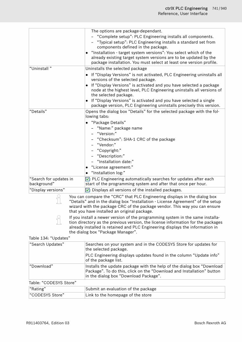
741 / 940ctrlX PLC EngineeringReference, User Interface
Bosch Rexroth AGR911403764, Edition 03
The options are package-dependant.– “Complete setup”: PLC Engineering installs all components.– “Typical setup”: PLC Engineering installs a standard set from
components defined in the package.● “Installation - target system versions”: You select which of the
already existing target system versions are to be updated by thepackage installation. You must select at least one version profile.
“Uninstall ” Uninstalls the selected package● If “Display Versions” is not activated, PLC Engineering uninstalls all
versions of the selected package.● If “Display Versions” is activated and you have selected a package
node at the highest level, PLC Engineering uninstalls all versions ofthe selected package.
● If “Display Versions” is activated and you have selected a singlepackage version, PLC Engineering uninstalls precisely this version.
“Details” Opens the dialog box “Details” for the selected package with the fol-lowing tabs:● “Package Details”
– “Name:” package name– “Version:”– “Checksum”: SHA-1 CRC of the package– “Vendor:”– “Copyright:”– “Description:”– “Installation date:”
● “License agreement:”● “Installation log:”
“Search for updates inbackground”
: PLC Engineering automatically searches for updates after eachstart of the programming system and after that once per hour.
“Display versions” : Displays all versions of the installed packages.You can compare the “CRC” that PLC Engineering displays in the dialog box“Details” and in the dialog box “Installation - License Agreement” of the setupwizard with the package CRC of the package vendor. This way you can ensurethat you have installed an original package.If you install a newer version of the programming system in the same installa-tion directory as the previous version, the license information for the packagesalready installed is retained and PLC Engineering displays the information inthe dialog box “Package Manager”.
Table 134: “Updates”“Search Updates” Searches on your system and in the CODESYS Store for updates for
the selected package.PLC Engineering displays updates found in the column “Update info”of the package list.
“Download” Installs the update package with the help of the dialog box “DownloadPackage”. To do this, click on the “Download and Installation” buttonin the dialog box “Download Package”.
Table: “CODESYS Store”“Rating” Submit an evaluation of the package“CODESYS Store” Link to the homepage of the store

742 / 940 ctrlX PLC EngineeringReference, User Interface
Bosch Rexroth AG R911403764, Edition 03
Command 'Library Repository'Symbol: Function: The command opens the “Library Repository” dialog. In this dialogyou define which libraries are installed on the local system and are thus avail-able for your application.Call: Menu bar: “Tools”
Dialog 'Library Repository'Table 135: “Location”Display of the directory on the local system in which the library files are located. The libraries inthis “Location” are listed in the “Installed libraries” area.“Edit Locations” Opens the “Edit Repository Locations” dialog.
1. You can only use empty directories for new repositories.2. You can also use existing repositories as locations.3. The "System" repository is not editable; PLC Engineering indicates this bythe italic lettering of the entry.
Table 136: Dialog “Edit Repository Locations”List of the repositories with “Location” and “Name”“Add” Creates a new repository.
Opens the “Repository Location” dialog. The selected directory(“Location” input field) has to be either empty or an existing validrepository. “Name” is the input field for a symbolic repository name.
“Edit” Opens the “Repository Location” dialog (see “Add”)“Remove ” A dialog box open, asking whether only the entry should be removed
from the list of repositories, or whether the directory with the libraryfiles should be deleted from the file system. If you want to delete thedirectory, you have to confirm this.
Table 137: “Installed libraries”List of the libraries in a tree structure. Display of each library with category, name, company andversion. The icon to the left of the name indicates whether the library is digitally signed or unsigned.“Company ” List box for filtering the displayed libraries.“Install” Opens the “Select Library” dialog. Possible filters:
● “Compiled PLC Engineering library files (* .compiled-library)”.● “Compiled PLC Engineering library files (* .compiled-library-v3)” ab
V3 SP15● “Library files (*.library)” for still uncompiled library projects● “All files (*.*)”
“Uninstall” Uninstalls the selected library.“Export” Opens the default dialog for saving the library project to the local file
system. The file type is Library files (*.library), Compiledlibrary files (*.compiled-library), or Compiled libraryfiles (*.compiled-library-v3).
“Find” Searches for libraries and function blocks.Opens the “Find Library” dialog. When you enter a string in the inputfield, PLC Engineering displays the libraries that it finds with a corre-sponding string.
“Details” Opens the “Details” dialog with details from the project information ofthe library for the selected version of a library. You find the followinginformation by clicking “More” in the “Details” dialog:
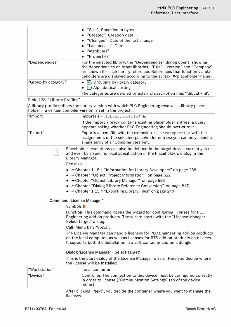
743 / 940ctrlX PLC EngineeringReference, User Interface
Bosch Rexroth AGR911403764, Edition 03
● “Size”: Specified in bytes● “Created”: Creation date● “Changed”: Date of the last change● “Last access”: Date● “Attributes”● “Properties”
“Dependencies” For the selected library, the “Dependencies” dialog opens, showingthe dependencies on other libraries. “Title”, “Version” and “Company”are shown for each library reference. References that function via pla-ceholders are displayed according to the syntax: #<placeholder name>.
“Group by category” ● : Grouping by library category● : Alphabetical sortingThe categories are defined by external description files '*.libcat.xml'.
Table 138: “Library Profiles”A library profile defines the library version with which PLC Engineering resolves a library place-holder if a certain compiler version is set in the project.“Import” Imports a *.libraryprofile file.
If the import already contains existing placeholder entries, a queryappears asking whether PLC Engineering should overwrite it.
“Export” Exports an xml file with the extension *.libraryprofile with theassignments of the selected placeholder entries; you can only select asingle entry of a “Compiler version”.
Placeholder resolutions can also be defined in the target device currently in useand even by a specific local specification in the Placeholders dialog in theLibrary Manager.See also● ⮫ Chapter 1.15.1 “Information for Library Developers” on page 238● ⮫ Chapter “Object 'Project Information'” on page 622● ⮫ Chapter “Object 'Library Manager'” on page 583● ⮫ Chapter “Dialog 'Library Reference Conversion'” on page 817● ⮫ Chapter 1.15.4 “Exporting Library Files” on page 240
Command 'License Manager'Symbol: Function: This command opens the wizard for configuring licenses for PLCEngineering add-on products. The wizard starts with the “License Manager -Select target” dialog.Call: Menu bar: “Tools”.The License Manager can handle licenses for PLC Engineering add-on productson the local computer, as well as licenses for RTS add-on products on devices.It supports both the installation in a soft container and on a dongle.
Dialog 'License Manager - Select Target'This is the start dialog of the License Manager wizard. Here you decide wherethe license will be installed.
“Workstation” Local computer“Device” Controller. The connection to this device must be configured correctly
in order to license (“Communication Settings” tab of the deviceeditor).
After clicking “Next”, you decide the container where you want to manage thelicenses.
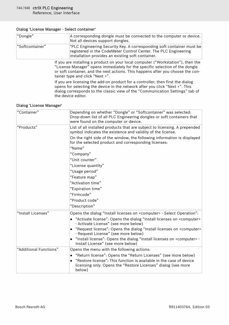
744 / 940 ctrlX PLC EngineeringReference, User Interface
Bosch Rexroth AG R911403764, Edition 03
Dialog 'License Manager - Select container'
“Dongle” A corresponding dongle must be connected to the computer or device.Not all devices support dongles.
“Softcontainer” "PLC Engineering Security Key. A corresponding soft container must beregistered in the CodeMeter Control Center. The PLC Engineeringinstallation provides an existing soft container.
If you are installing a product on your local computer (“Workstation”), then the“License Manager” opens immediately for the specific selection of the dongleor soft container, and the next actions. This happens after you choose the con-tainer type and click “Next >”.If you are licensing the add-on product for a controller, then first the dialogopens for selecting the device in the network after you click “Next >”. Thisdialog corresponds to the classic view of the “Communication Settings” tab ofthe device editor.
Dialog 'License Manager'
“Container” Depending on whether “Dongle” or “Softcontainer” was selected:Drop-down list of all PLC Engineering dongles or soft containers thatwere found on the computer or device.
“Products” List of all installed products that are subject to licensing. A prependedsymbol indicates the existence and validity of the license.On the right side of the window, the following information is displayedfor the selected product and corresponding licenses:“Name”“Company”“Unit counter”“License quantity”“Usage period”“Feature map”“Activation time”“Expiration time”“Firmcode”“Product code”“Description”
“Install Licenses” Opens the dialog “Install licenses on <computer> - Select Operation”:● “Activate license”: Opens the dialog “Install licenses on <computer>
- Activate License” (see more below)● “Request license”: Opens the dialog “Install licenses on <computer>
- Request License” (see more below)● “Install license”: Opens the dialog “Install licenses on <computer> -
Install License” (see more below)“Additional Functions” Opens the menu with the following actions:
● “Return license”: Opens the “Return Licenses” (see more below)● “Restore license”: This function is available in the case of device
licensing only. Opens the “Restore Licenses” dialog (see morebelow)
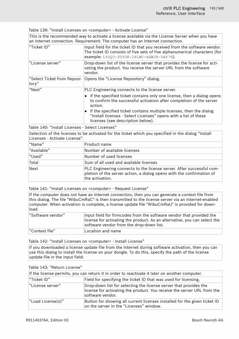
745 / 940ctrlX PLC EngineeringReference, User Interface
Bosch Rexroth AGR911403764, Edition 03
Table 139: “Install Licenses on <computer> - Activate License”This is the recommended way to activate a license available via the License Server when you havean Internet connection. Requirement: The computer has an Internet connection.“Ticket ID” Input field for the ticket ID that you received from the software vendor.
The ticket ID consists of five sets of five alphanumerical characters (forexample: LYSQ3-ZU93K-24LWC-XGWJ8-5AY7H).
“License server” Drop-down list of the license server that provides the license for acti-vating the product. You receive the server URL from the softwarevendor.
“Select Ticket from Reposi-tory”
Opens the “License Repository” dialog.
“Next” PLC Engineering connects to the license server.● If the specified ticket contains only one license, then a dialog opens
to confirm the successful activation after completion of the serveraction.
● If the specified ticket contains multiple licenses, then the dialog“Install licenses - Select Licenses” opens with a list of theselicenses (see description below).
Table 140: “Install Licenses - Select Licenses”Selection of the licenses to be activated for the ticket which you specified in the dialog “InstallLicenses - Activate License”.“Name” Product name“Available” Number of available licenses“Used” Number of used licensesTotal Sum of all used and available licensesNext PLC Engineering connects to the license server. After successful com-
pletion of the server action, a dialog opens with the confirmation ofthe activation.
Table 141: “Install Licenses on <computer> - Request License”If the computer does not have an Internet connection, then you can generate a context file fromthis dialog. The file "WibuCmRaC" is then transmitted to the license server via an Internet-enabledcomputer. When activation is complete, a license update file "WibuCmRaU" is provided for down-load.“Software vendor” Input field for firmcodes from the software vendor that provided the
license for activating the product. As an alternative, you can select thesoftware vendor from the drop-down list.
“Context file” Location and name
Table 142: “Install Licenses on <computer> - Install License”If you downloaded a license update file from the Internet during software activation, then you canuse this dialog to install the license on your dongle. To do this, specify the path of the licenseupdate file in the input field.
Table 143: “Return License”If the license permits, you can return it in order to reactivate it later on another computer.“Ticket ID” Field for specifying the ticket ID that was used for licensing.“License server” Drop-down list for selecting the license server that provides the
license for activating the product. You receive the server URL from thesoftware vendor.
“Load License(s)” Button for showing all current licenses installed for the given ticket IDon the server in the “Licenses” window.
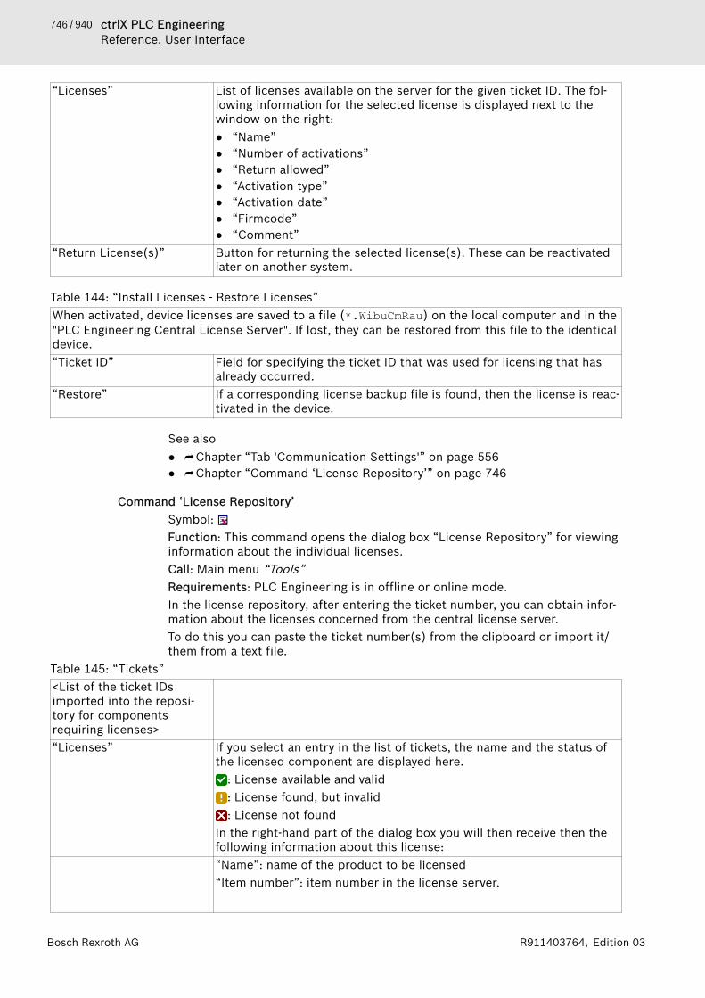
746 / 940 ctrlX PLC EngineeringReference, User Interface
Bosch Rexroth AG R911403764, Edition 03
“Licenses” List of licenses available on the server for the given ticket ID. The fol-lowing information for the selected license is displayed next to thewindow on the right:● “Name”● “Number of activations”● “Return allowed”● “Activation type”● “Activation date”● “Firmcode”● “Comment”
“Return License(s)” Button for returning the selected license(s). These can be reactivatedlater on another system.
Table 144: “Install Licenses - Restore Licenses”When activated, device licenses are saved to a file (*.WibuCmRau) on the local computer and in the"PLC Engineering Central License Server". If lost, they can be restored from this file to the identicaldevice.“Ticket ID” Field for specifying the ticket ID that was used for licensing that has
already occurred.“Restore” If a corresponding license backup file is found, then the license is reac-
tivated in the device.
See also● ⮫ Chapter “Tab 'Communication Settings'” on page 556● ⮫ Chapter “Command ‘License Repository’” on page 746
Command ‘License Repository’Symbol: Function: This command opens the dialog box “License Repository” for viewinginformation about the individual licenses.Call: Main menu “Tools”Requirements: PLC Engineering is in offline or online mode.In the license repository, after entering the ticket number, you can obtain infor-mation about the licenses concerned from the central license server.To do this you can paste the ticket number(s) from the clipboard or import it/them from a text file.
Table 145: “Tickets”<List of the ticket IDsimported into the reposi-tory for componentsrequiring licenses>“Licenses” If you select an entry in the list of tickets, the name and the status of
the licensed component are displayed here.: License available and valid: License found, but invalid: License not found
In the right-hand part of the dialog box you will then receive then thefollowing information about this license:“Name”: name of the product to be licensed“Item number”: item number in the license server.

747 / 940ctrlX PLC EngineeringReference, User Interface
Bosch Rexroth AGR911403764, Edition 03
“Return allowed”: It is possible to have this license deactivated so thatit can be re-activated on another system.“Can be activated”: you can have the license activated via the licensemanager.“Activation quantitiy”: number of activations that have taken place sofar.“Activation date”: date of the current activation“Container serial ”“Firm codes”“Comment”
“Import Tickets” The standard dialog box for browsing the local file system appears. Ifyou open a text file containing one or more “tickets”, i.e. license num-bers, these are imported into the repository. Alternatively you can alsoinsert the numbers from the clipboard into the list.
Command 'Device Repository'Symbol: Function: This command opens the “Device Repository” dialog. This dialog isused for managing the devices that are installed on the local system and can beintegrated into PLC Engineering projects.Call: Menu bar: “Tools”.
Dialog 'Device Repository'
CAUTION Do not change the internal device repository manually.Do not copy any files to or from the repository. Alwaysuse the device repository dialog to install or uninstalldevices.
Table:
“Location” Shows the device repository directory on the local system. The list boxshows the currently set save locations. By default, PLC Engineeringcreates the system repository during installation. The devices of theselected location are listed in the “Installed device descriptions” field.
“Edit Locations” Opens the “Edit Repository Locations” dialog.Table 146: Dialog 'Edit Repository Locations'List of the repositories with “Location” and “Name”.“Add” Creates a new repository.
Opens the “Repository Location” dialog. The selected directory(“Location” input field) must be empty or it must be a valid repository.
“Edit” Opens the “Repository Location” dialog (see “Add”).“Remove ” A dialog prompt opens for you to decide whether the respective direc-
tory should also be deleted from the hard disk.Table 147: “Installed device descriptions”List of device descriptions in multilevel tree structure. Shows all device descriptions with “Name”,“Vendor”, and “Version”. The top nodes represent device categories, for example PLCs, fieldbuses,and logical devices.“String for full-text searchin all devices”
This field is editable after clicking in it. For any character stringentered, only those devices that include the character string are dis-played in the lower view. The matched string is highlighted in yellowfor these devices.
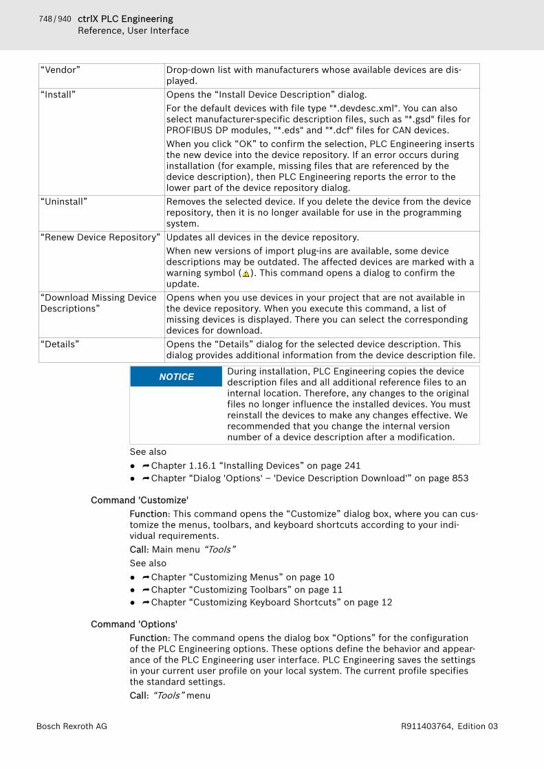
748 / 940 ctrlX PLC EngineeringReference, User Interface
Bosch Rexroth AG R911403764, Edition 03
“Vendor” Drop-down list with manufacturers whose available devices are dis-played.
“Install” Opens the “Install Device Description” dialog.For the default devices with file type "*.devdesc.xml". You can alsoselect manufacturer-specific description files, such as "*.gsd" files forPROFIBUS DP modules, "*.eds" and "*.dcf" files for CAN devices.When you click “OK” to confirm the selection, PLC Engineering insertsthe new device into the device repository. If an error occurs duringinstallation (for example, missing files that are referenced by thedevice description), then PLC Engineering reports the error to thelower part of the device repository dialog.
“Uninstall” Removes the selected device. If you delete the device from the devicerepository, then it is no longer available for use in the programmingsystem.
“Renew Device Repository” Updates all devices in the device repository.When new versions of import plug-ins are available, some devicedescriptions may be outdated. The affected devices are marked with awarning symbol ( ). This command opens a dialog to confirm theupdate.
“Download Missing DeviceDescriptions”
Opens when you use devices in your project that are not available inthe device repository. When you execute this command, a list ofmissing devices is displayed. There you can select the correspondingdevices for download.
“Details” Opens the “Details” dialog for the selected device description. Thisdialog provides additional information from the device description file.
NOTICE During installation, PLC Engineering copies the devicedescription files and all additional reference files to aninternal location. Therefore, any changes to the originalfiles no longer influence the installed devices. You mustreinstall the devices to make any changes effective. Werecommended that you change the internal versionnumber of a device description after a modification.
See also● ⮫ Chapter 1.16.1 “Installing Devices” on page 241● ⮫ Chapter “Dialog 'Options' – 'Device Description Download'” on page 853
Command 'Customize'Function: This command opens the “Customize” dialog box, where you can cus-tomize the menus, toolbars, and keyboard shortcuts according to your indi-vidual requirements.Call: Main menu “Tools”See also● ⮫ Chapter “Customizing Menus” on page 10● ⮫ Chapter “Customizing Toolbars” on page 11● ⮫ Chapter “Customizing Keyboard Shortcuts” on page 12
Command 'Options'Function: The command opens the dialog box “Options” for the configurationof the PLC Engineering options. These options define the behavior and appear-ance of the PLC Engineering user interface. PLC Engineering saves the settingsin your current user profile on your local system. The current profile specifiesthe standard settings.Call: “Tools” menu
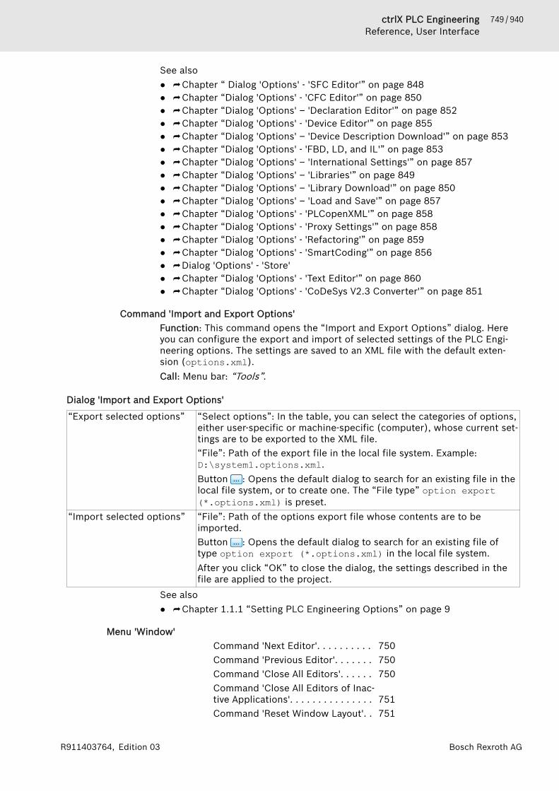
749 / 940ctrlX PLC EngineeringReference, User Interface
Bosch Rexroth AGR911403764, Edition 03
See also● ⮫ Chapter “ Dialog 'Options' - 'SFC Editor'” on page 848● ⮫ Chapter “Dialog 'Options' - 'CFC Editor'” on page 850● ⮫ Chapter “Dialog 'Options' – 'Declaration Editor'” on page 852● ⮫ Chapter “Dialog 'Options' - 'Device Editor'” on page 855● ⮫ Chapter “Dialog 'Options' – 'Device Description Download'” on page 853● ⮫ Chapter “Dialog 'Options' - 'FBD, LD, and IL'” on page 853● ⮫ Chapter “Dialog 'Options' – 'International Settings'” on page 857● ⮫ Chapter “Dialog 'Options' – 'Libraries'” on page 849● ⮫ Chapter “Dialog 'Options' – 'Library Download'” on page 850● ⮫ Chapter “Dialog 'Options' – 'Load and Save'” on page 857● ⮫ Chapter “Dialog 'Options' - 'PLCopenXML'” on page 858● ⮫ Chapter “Dialog 'Options' - 'Proxy Settings'” on page 858● ⮫ Chapter “Dialog 'Options' - 'Refactoring'” on page 859● ⮫ Chapter “Dialog 'Options' - 'SmartCoding'” on page 856● ⮫ Dialog 'Options' - 'Store'● ⮫ Chapter “Dialog 'Options' - 'Text Editor'” on page 860● ⮫ Chapter “Dialog 'Options' - 'CoDeSys V2.3 Converter'” on page 851
Command 'Import and Export Options'Function: This command opens the “Import and Export Options” dialog. Hereyou can configure the export and import of selected settings of the PLC Engi-neering options. The settings are saved to an XML file with the default exten-sion (options.xml).Call: Menu bar: “Tools”.
Dialog 'Import and Export Options'
“Export selected options” “Select options”: In the table, you can select the categories of options,either user-specific or machine-specific (computer), whose current set-tings are to be exported to the XML file.“File”: Path of the export file in the local file system. Example:D:\system1.options.xml.Button : Opens the default dialog to search for an existing file in thelocal file system, or to create one. The “File type” option export(*.options.xml) is preset.
“Import selected options” “File”: Path of the options export file whose contents are to beimported.Button : Opens the default dialog to search for an existing file oftype option export (*.options.xml) in the local file system.After you click “OK” to close the dialog, the settings described in thefile are applied to the project.
See also● ⮫ Chapter 1.1.1 “Setting PLC Engineering Options” on page 9
Menu 'Window'Command 'Next Editor'. . . . . . . . . . 750Command 'Previous Editor'. . . . . . . 750Command 'Close All Editors'. . . . . . 750Command 'Close All Editors of Inac-tive Applications'. . . . . . . . . . . . . . . 751Command 'Reset Window Layout'. . 751

750 / 940 ctrlX PLC EngineeringReference, User Interface
Bosch Rexroth AG R911403764, Edition 03
Command 'New Horizontal TabGroup'. . . . . . . . . . . . . . . . . . . . . . . 751Command 'New Vertical Tab Group'. 751Command 'Float'. . . . . . . . . . . . . . . 751Command 'Dock'. . . . . . . . . . . . . . . 751Command 'Auto Hide'. . . . . . . . . . . 752Command 'Next Pane'. . . . . . . . . . . 752Command 'Previous Pane'. . . . . . . . 752Command 'Toggle First Pane'. . . . . . 752Command 'Toggle Second Pane'. . . 753Command 'Windows'. . . . . . . . . . . . 753Command 'Close All Editors ButThis'. . . . . . . . . . . . . . . . . . . . . . . . . 753Command 'Select Object in Naviga-tor'. . . . . . . . . . . . . . . . . . . . . . . . . . 753Command 'Select Parent Object inNavigator'. . . . . . . . . . . . . . . . . . . . . 753Commands of the Submenu 'Win-dow' . . . . . . . . . . . . . . . . . . . . . . . . 754
Command 'Next Editor'Keyboard shortcut: [Ctrl]+[F6]Function: This command switches focus from the currently active view to thenext view. The next view is identified by the tab to the right of the currentlyactive tab.Call: Main menu “Window”Requirement: At least one object is open.See also● ⮫ Chapter “Command 'Previous Editor'” on page 750
Command 'Previous Editor'Keyboard shortcut: [Shift]+[Ctrl]+[F6]Function: This command switches focus from the currently active view to theprevious view. The previous view is identified by the tab to the left of the cur-rently active tab.Call: Main menu “Window”Requirement: At least one object is open.See also● ⮫ Chapter “Command 'Next Editor'” on page 750
Command 'Close All Editors'Symbol: Function: This command closes all currently open editor views.Call: Main menu “Window”Requirement: At least one editor is open.See also● ⮫ Chapter “Command 'Close All Editors of Inactive Applications'”
on page 751● ⮫ Chapter “Command 'Close All Editors But This'” on page 753
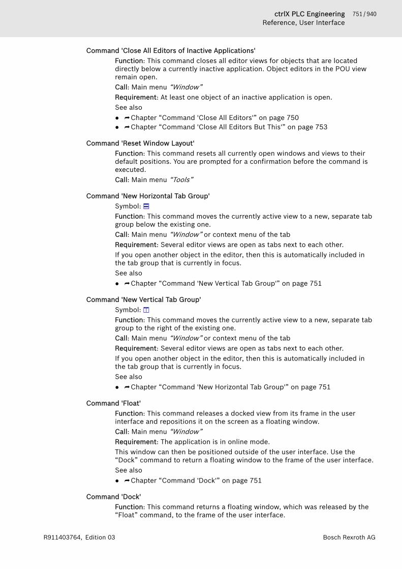
751 / 940ctrlX PLC EngineeringReference, User Interface
Bosch Rexroth AGR911403764, Edition 03
Command 'Close All Editors of Inactive Applications'Function: This command closes all editor views for objects that are locateddirectly below a currently inactive application. Object editors in the POU viewremain open.Call: Main menu “Window”Requirement: At least one object of an inactive application is open.See also● ⮫ Chapter “Command 'Close All Editors'” on page 750● ⮫ Chapter “Command 'Close All Editors But This'” on page 753
Command 'Reset Window Layout'Function: This command resets all currently open windows and views to theirdefault positions. You are prompted for a confirmation before the command isexecuted.Call: Main menu “Tools”
Command 'New Horizontal Tab Group'Symbol: Function: This command moves the currently active view to a new, separate tabgroup below the existing one.Call: Main menu “Window” or context menu of the tabRequirement: Several editor views are open as tabs next to each other.If you open another object in the editor, then this is automatically included inthe tab group that is currently in focus.See also● ⮫ Chapter “Command 'New Vertical Tab Group'” on page 751
Command 'New Vertical Tab Group'Symbol: Function: This command moves the currently active view to a new, separate tabgroup to the right of the existing one.Call: Main menu “Window” or context menu of the tabRequirement: Several editor views are open as tabs next to each other.If you open another object in the editor, then this is automatically included inthe tab group that is currently in focus.See also● ⮫ Chapter “Command 'New Horizontal Tab Group'” on page 751
Command 'Float'Function: This command releases a docked view from its frame in the userinterface and repositions it on the screen as a floating window.Call: Main menu “Window”Requirement: The application is in online mode.This window can then be positioned outside of the user interface. Use the“Dock” command to return a floating window to the frame of the user interface.See also● ⮫ Chapter “Command 'Dock'” on page 751
Command 'Dock'Function: This command returns a floating window, which was released by the“Float” command, to the frame of the user interface.
752 / 940 ctrlX PLC EngineeringReference, User Interface
Bosch Rexroth AG R911403764, Edition 03
Call: Main menu “Window”See also● ⮫ Chapter “Command 'Float'” on page 751
Command 'Auto Hide'Keyboard shortcut: [F7]Function: This command shows or hides a view.Call: Main menu “Window”Hide simply means that PLC Engineering minimizes the view to a tab at thebottom of the user interface which is visible only when you move the mouseover the tab. The command functions like a check box. When a window ishidden, the check box is selected in the menu. When you click the commandagain, the checkbox is cleared and the window is shown.See also● ⮫ Chapter “Auto-Hiding Windows” on page 13
Command 'Next Pane'Keyboard shortcut: [F6]Function: This command sets the focus on the next pane.Call: Main menu “Window”Requirement: An object is open that contains two or more panes.Example: If an object is open in the ST editor and the cursor is currently in thedeclaration section, then command sets the focus to implementation section.See also● ⮫ Chapter “Command 'Previous Pane'” on page 752
Command 'Previous Pane'Keyboard shortcut: [Shift]+[F6]Function: This command sets the focus on the previous pane.Call: Main menu “Window”Requirement: An object is open that contains two or more panes.Example: If an object is open in the ST editor and the cursor is currently in thedeclaration section, then command sets the focus to implementation section.See also● ⮫ Chapter “Command 'Next Pane'” on page 752
Command 'Toggle First Pane'Keyboard shortcut [Alt]+[F6]Function: This command shows and hides the declaration view.Call: “Window”.Requirement: The cursor is positioned in the editor of one of the followingobjects:● POU● Transition● Method● Get accessor method of a property● Set accessor method of a property● VisualizationYou can also toggle the subviews by means of the buttons.
753 / 940ctrlX PLC EngineeringReference, User Interface
Bosch Rexroth AGR911403764, Edition 03
See also● ⮫ Chapter “Command 'Toggle Second Pane'” on page 753
Command 'Toggle Second Pane'Function: This command shows and hides the implementation view.Call: “Window”.Requirement: The cursor is positioned in the editor of one of the followingobjects:● POU● Transition● Method● Get accessor method of a property● Set accessor method of a property● visualizationYou can also toggle the subviews by means of the buttons.
See also● ⮫ Chapter “Command 'Toggle First Pane'” on page 752
Command 'Windows'Function: This command opens the “Windows” dialog box, which lists all openobjects. You can then activate or close any of the listed views.Call: Main menu “Window”
Command 'Close All Editors But This'Function: This command closes all editor views except the currently open one.Call: Right-click the tabRequirement: At least two objects are open.See also● ⮫ Chapter “Command 'Close All Editors'” on page 750● ⮫ Chapter “Command 'Close All Editors of Inactive Applications'”
on page 751
Command 'Select Object in Navigator'Function: This command selects the object of the active editor in the devicetree.Call: Right-click the tabRequirement: At least one object is open.This command is executed automatically when you select the “Track activeeditor” option for the device tree.See also● ⮫ Chapter “Command 'Select Parent Object in Navigator'” on page 753
Command 'Select Parent Object in Navigator'Function: This command selects the parent object in the device tree.Call: Right-click the tabRequirement: At least one object is open.See also● ⮫ Chapter “Command 'Select Object in Navigator'” on page 753

754 / 940 ctrlX PLC EngineeringReference, User Interface
Bosch Rexroth AG R911403764, Edition 03
Commands of the Submenu 'Window'Function: The command activates the selected window.Call: Main menu “Window”For each opened editor window the menu “Window” contains a command“<n><object name>”. Choosing this command activates the correspondingwindow. In offline mode PLC Engineering adds the extension “(Offline)”. To dif-ferentiate between the implementation or the instances of a function block theextension “(Impl)” or “<instance path>” is added.
Menu 'Help'Command 'Contents'. . . . . . . . . . . . 754Command 'Index'. . . . . . . . . . . . . . . 754Command 'Find'. . . . . . . . . . . . . . . . 754Command '3S Homepage'. . . . . . . . 755Command 'About'. . . . . . . . . . . . . . . 755
Command 'Contents'Symbol: ; keyboard shortcut: [Ctrl]+[Shift]+[F1]Function: This command opens the PLC Engineering help.Call: Menu bar: “Help”.
Command 'Index'Symbol: ; keyboard shortcut: [Ctrl]+[Shift]+[F2]Function: This command opens the PLC Engineering help.Call: Menu bar: “Help”.An index search is not possible in the online help. The “Index” tab opens in theoffline help.All index entries of the help are listed alphabetically in the index view.
“ Look for ” As you type letters into the input field, PLC Engineering searches auto-matically for matches in the index list.
“Display” Opens the help page for the highlighted index entry in the list and dis-plays the title of the help page and location of the help file (*.chm) inthe “Index results for <index entry>” view. When several pages arefound and then displayed in this view, then you view a specific helppage by clicking its entry in the list.Clicking an entry in the index list achieves the same result.
Command 'Find'Symbol: Function: This command opens the PLC Engineering help.Call: Menu bar: “Help”.In the online help, you can run a full-text search from the input field on the topright of the help page. The “Find” tab opens in the offline help.
Table 148: Tab 'Search'“Search for” Combo box for defining the search term or for selecting the 25 most
recent search terms.“ Search in titles only” The search is performed only in the titles of the help pages.“Display partial matches” Displays terms also as search results that include the search term.“Limit to .... matches ” Limits the number of search results.

755 / 940ctrlX PLC EngineeringReference, User Interface
Bosch Rexroth AGR911403764, Edition 03
Maximum value: 1000“Find” Starts the full-text search.
Command '3S Homepage'Function: This command opens the Bosch Rexroth AG home page.Call: Main menu “Help”
Command 'About'Function: This command opens a splash screen with information about the PLCEngineering version and copyright. In addition, buttons are available fordetailed information about the version, license, and acknowledgments.Call: Main menu “Help”.
“Version Info” Opens the “Detailed Version Information” dialog box with a list of PLCEngineering components and information about the operating system.“Export”: Exports the detailed version information as a *.txt file or inany other format.
“License Info” Opens the “License Information” dialog box.● “Plug-in”: Drop-down list for the plug-in to display the license infor-
mation● “Software License”: License information about selected “Plug-in”
“Acknowledgments”
Menu 'SFC'Command 'Init Step'. . . . . . . . . . . . . 756Command 'Insert Step'. . . . . . . . . . 756Command 'Insert Step After'. . . . . . 756Command 'Insert Transition After'. . 757Command 'Insert Transition'. . . . . . 757Command 'Insert Step-Transition'. . 757Command 'Insert Step-TransitionAfter'. . . . . . . . . . . . . . . . . . . . . . . . 757Command 'Add Entry Action'. . . . . . 758Command 'Add Exit Action'. . . . . . . 758Command 'Parallel'. . . . . . . . . . . . . 758Command 'Alternative'. . . . . . . . . . . 759Command 'Insert Branch'. . . . . . . . . 759Command 'Insert Branch Right'. . . . 759Command 'Insert Action Associa-tion'. . . . . . . . . . . . . . . . . . . . . . . . . 761Command 'Insert Action AssociationAfter'. . . . . . . . . . . . . . . . . . . . . . . . 761Command 'Insert Jump'. . . . . . . . . . 761Command 'Insert Jump After'. . . . . 761Command 'Insert Macro'. . . . . . . . . 762Command 'Insert Macro After'. . . . . 762Command 'Zoom Into Macro'. . . . . . 762Command 'Zoom Out of Macro'. . . . 762Command 'Paste After'. . . . . . . . . . . 763
756 / 940 ctrlX PLC EngineeringReference, User Interface
Bosch Rexroth AG R911403764, Edition 03
Command 'Change Duplication' -'Set'. . . . . . . . . . . . . . . . . . . . . . . . . 763Command 'Change Duplication' -'Remove'. . . . . . . . . . . . . . . . . . . . . . 763Command 'Do Not DisplayEmbedded Objects'. . . . . . . . . . . . . 763
Command 'Init Step'Symbol: Function: This command converts the selected step into an initial step.Call: Main menu “SFC”After you choose this command, the borders of the step element change to adouble line. The previous initial step is automatically displayed as a normal stepwith a single-line border.You can also activate and deactivate the property “Init step” in the propertiesdialog of a step. However, PLC Engineering does not automatically adjust thesettings of other steps.This command is useful if you want to convert a diagram. When you create anew SFC object, it automatically includes an initial step followed by a transition(TRUE) and a jump back to the initial step.Please note: In online mode, it is possible to reset the diagram to the initialstep using the SFCInit and SFCReset flags.See also● ⮫ Chapter “SFC Flags” on page 273● ⮫ Chapter “SFC Element Properties” on page 284
Command 'Insert Step'Symbol: Function: This command inserts a step before the selected point.Call: Menu bar “SFC”; context menu in SFC editorThe new step is named Step<n> by default, where n is an incremental numberstarting at 0 for the first step that is inserted in addition to the initial step. Thename can be edited by clicking on it.See also● ⮫ Chapter “Command 'Insert Step-Transition After'” on page 757● ⮫ Chapter “Command 'Init Step'” on page 756● ⮫ Chapter “SFC Elements 'Step' and 'Transition'” on page 277
Command 'Insert Step After'Symbol: Function: This command inserts a step after the selected point.Call: Menu bar “SFC”; context menu in SFC editorThe new step is named Step<n> by default, where n is an incremental numberstarting at 0 for the first step that is inserted in addition to the initial step. Thename can be edited by clicking on it.See also● ⮫ Chapter “Command 'Insert Step-Transition After'” on page 757● ⮫ Chapter “Command 'Init Step'” on page 756● ⮫ Chapter “SFC Elements 'Step' and 'Transition'” on page 277

757 / 940ctrlX PLC EngineeringReference, User Interface
Bosch Rexroth AGR911403764, Edition 03
Command 'Insert Transition After'Symbol: Function: This command inserts a transition after the selected point.Call: Menu bar “SFC”; context menu in SFC editorThe new transition is named Trans<n> by default, where n is an incrementalnumber beginning at 0 for the first transition. The name can be edited byclicking on it.See also● ⮫ Chapter “Command 'Insert Step-Transition After'” on page 757● ⮫ Chapter “SFC Elements 'Step' and 'Transition'” on page 277
Command 'Insert Transition'Symbol: Function: This command inserts a transition before the selected point.Call: Menu bar “SFC”; context menu in SFC editorThe new transition is named Trans<n> by default, where n is an incrementalnumber beginning at 0 for the first transition. The name can be edited byclicking on it.See also● ⮫ Chapter “Command 'Insert Step-Transition After'” on page 757● ⮫ Chapter “SFC Elements 'Step' and 'Transition'” on page 277
Command 'Insert Step-Transition'Symbol: Function: This command inserts a step and a transition before the selectedpoint.Call: Main menu “SFC”If you have selected a step, then PLC Engineering inserts a new step-transitioncombination. If you have selected a transition, then a new transition-step com-bination is inserted.The new step is named Step<n> by default, where n is an incremental numberbeginning at 0 for the first step that was inserted in addition to the initial step.The new transition is named Trans<n> by default. You can edit the defaultnames directly by clicking the names.See also● ⮫ Chapter “Command 'Insert Step-Transition After'” on page 757● ⮫ Chapter “Command 'Init Step'” on page 756● ⮫ Chapter “SFC Elements 'Step' and 'Transition'” on page 277
Command 'Insert Step-Transition After'Symbol: Function: This command inserts a step and a transition after the selected point.Call: Main menu “SFC”If you have selected a step, then PLC Engineering inserts a new transition-stepcombination. If you have selected a transition, then a new step-transition com-bination is inserted.The new step is named Step<n> by default, where n is an incremental numberbeginning at 0 for the first step that was inserted in addition to the initial step.The new transition is named Trans<n> by default. You can edit the defaultnames directly by clicking the names.
758 / 940 ctrlX PLC EngineeringReference, User Interface
Bosch Rexroth AG R911403764, Edition 03
See also● ⮫ Chapter “Command 'Insert Step-Transition'” on page 757
Command 'Add Entry Action'Symbol: Function: This command opens the “Add Entry Action” dialog box where youdefine a new entry action. Depending on the SFC options, a dialog prompt mayopen for selecting the duplication mode for the new step action.Call: Menu bar: “SFC”; context menu of the selected step element.Requirement: A step element in SFC is selected.The entry action is opened automatically in the ST editor. The step elementcontains an E in the lower left corner.
Confirmation prompt for selecting the duplication modeOptions:● “Copy reference: A new step will call the same actions”: If the step is copied
in SFC, the link to the step action(s) is also copied. The steps copied byeach other will therefore call the same actions.
● “Copy implementation: New action objects are created for a new step.”: Thismeans that the step actions for a copied step are embedded. By default, thegenerated action objects appear below an SFC box in the device tree or“POUs” view. These objects contains a copy of the original implementationcode of the respective action.The display of the embedded objects can be activated and deactivated inthe tree by means of the “Show Embedded Objects” and “Hide EmbeddedObjects” commands in the context menu of an SFC object.
See also● ⮫ Chapter “ Dialog 'Options' - 'SFC Editor'” on page 848● ⮫ Chapter “Programming the Sequential Function Chart (SFC)” on page 93● ⮫ Chapter “SFC Element 'Action'” on page 279● ⮫ Chapter “Command 'Do Not Display Embedded Objects'” on page 763
Command 'Add Exit Action'Symbol: Function: This command opens the “Add Exit Action” dialog box where youdefine a new exit action. Depending on the SFC options, a dialog prompt mayopen for selecting the duplication mode for the new step action. For moreinformation, refer to the help page for the “Add Exit Action” command.Call: Menu bar: “SFC”; context menu of the selected step element.Requirement: A step element in SFC is selected.See also● ⮫ Chapter “Command 'Add Entry Action'” on page 758● ⮫ Chapter “ Dialog 'Options' - 'SFC Editor'” on page 848● ⮫ Chapter “Programming the Sequential Function Chart (SFC)” on page 93● ⮫ Chapter “SFC Element 'Action'” on page 279● ⮫ Chapter “Command 'Do Not Display Embedded Objects'” on page 763
Command 'Parallel'Symbol: Function: This command converts the selected alternative branch into a parallelbranch.Call: Main menu “SFC”

759 / 940ctrlX PLC EngineeringReference, User Interface
Bosch Rexroth AGR911403764, Edition 03
Requirement: The horizontal connecting line of a branch is selected.Please note that after you convert a branch, you must check and modify thelayout of the steps and transitions before and after the branch.See also● ⮫ Chapter “Command 'Alternative'” on page 759
Command 'Alternative'Symbol: Function: This command converts the selected parallel branch into an alterna-tive branch.Call: Main menu “SFC”Requirement: The horizontal connecting line of a branch is selected.Please note that after you convert a branch, you must check and modify thelayout of the steps and transitions before and after the branch.See also● ⮫ Chapter “Command 'Parallel'” on page 758
Command 'Insert Branch'Symbol: Function: This command inserts a branch to the left of the selected point.Call: Main menu “SFC”This command functions similar to the “Insert Branch Right” command.See also● ⮫ Chapter “SFC Element 'Branch'” on page 281● ⮫ Chapter “Command 'Insert Branch Right'” on page 759
Command 'Insert Branch Right'Symbol: Function: This command inserts a branch to the right of the selected point.Call: Main menu “SFC”The type of inserted branch depends on the selected element.● If the uppermost element of the selected elements is a transition or an alter-
native branch, then PLC Engineering inserts an alternative branch.● If the uppermost element of the selected elements is a step, a macro, a
jump, or a parallel branch, then PLC Engineering inserts a parallel branchwith the Branch<x> jump marker, where x is an incremental number. Youcan edit the default name of the jump marker or define the jump marker as ajump destination.
● If a common element of an existing branch (horizontal line) is selected, thenPLC Engineering inserts the new branch line as a branch line on the farright. If an entire branch line of an existing branch is selected, then PLCEngineering inserts the new branch line directly to the right as a new branchline.
Please note: You can convert a branch into another type with the “Alternative”and “Parallel” commands.
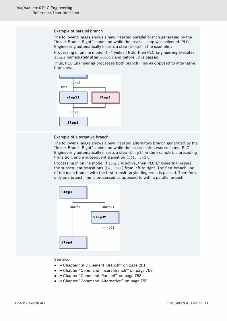
760 / 940 ctrlX PLC EngineeringReference, User Interface
Bosch Rexroth AG R911403764, Edition 03
Example of parallel branchThe following image shows a new inserted parallel branch generated by the“Insert Branch Right” command while the Step11 step was selected. PLCEngineering automatically inserts a step (Step2 in the example).Processing in online mode: If t2 yields TRUE, then PLC Engineering executesStep2 immediately after step11 and before t3 is passed.Thus, PLC Engineering processes both branch lines as opposed to alternativebranches.
Example of alternative branchThe following image shows a new inserted alternative branch generated by the“Insert Branch Right” command while the t4 transition was selected. PLCEngineering automatically inserts a step (Step32 in the example), a precedingtransition, and a subsequent transition (t41, t42).Processing in online mode: If Step3 is active, then PLC Engineering passesthe subsequent transitions (t4, t41) from left to right. The first branch lineof the main branch with the first transition yielding TRUE is passed. Therefore,only one branch line is processed as opposed to with a parallel branch.
See also● ⮫ Chapter “SFC Element 'Branch'” on page 281● ⮫ Chapter “Command 'Insert Branch'” on page 759● ⮫ Chapter “Command 'Parallel'” on page 758● ⮫ Chapter “Command 'Alternative'” on page 759
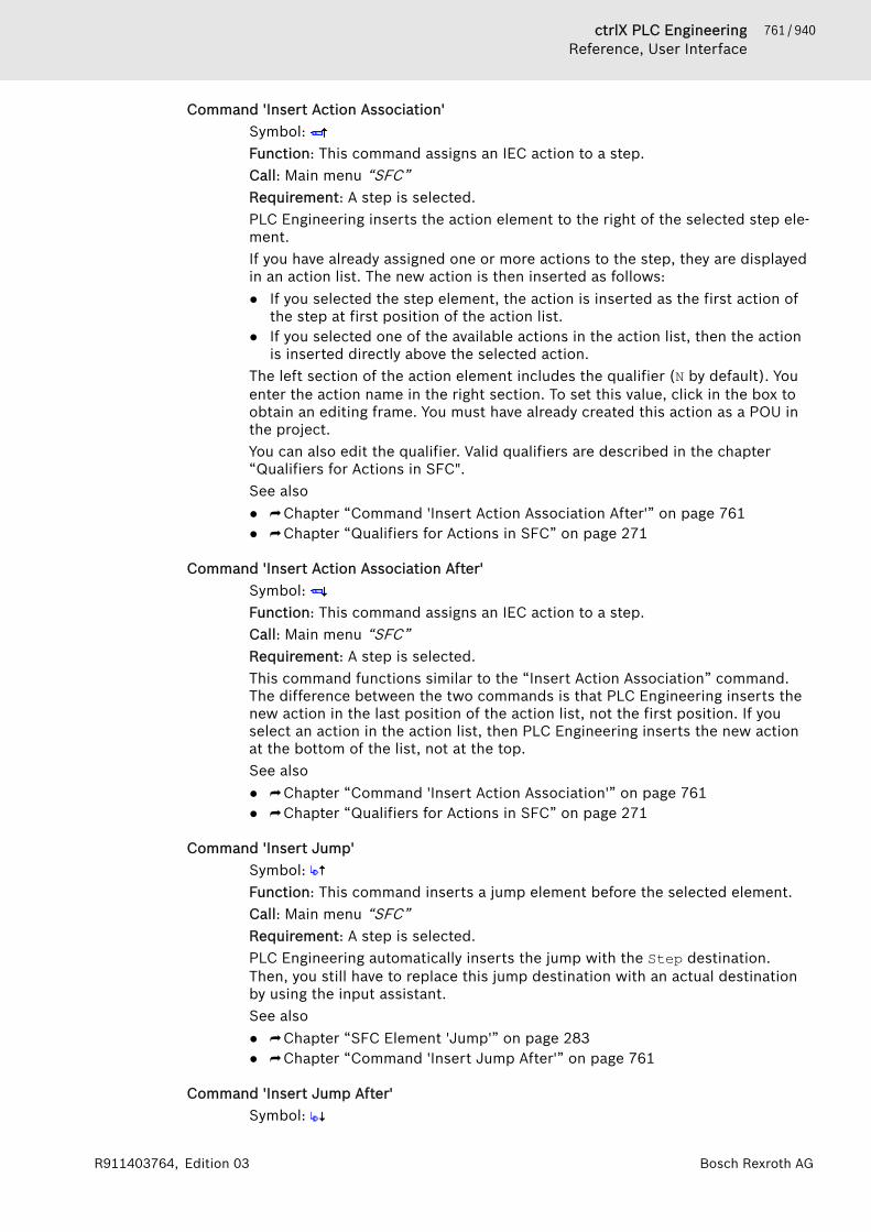
761 / 940ctrlX PLC EngineeringReference, User Interface
Bosch Rexroth AGR911403764, Edition 03
Command 'Insert Action Association'Symbol: Function: This command assigns an IEC action to a step.Call: Main menu “SFC”Requirement: A step is selected.PLC Engineering inserts the action element to the right of the selected step ele-ment.If you have already assigned one or more actions to the step, they are displayedin an action list. The new action is then inserted as follows:● If you selected the step element, the action is inserted as the first action of
the step at first position of the action list.● If you selected one of the available actions in the action list, then the action
is inserted directly above the selected action.The left section of the action element includes the qualifier (N by default). Youenter the action name in the right section. To set this value, click in the box toobtain an editing frame. You must have already created this action as a POU inthe project.You can also edit the qualifier. Valid qualifiers are described in the chapter“Qualifiers for Actions in SFC".See also● ⮫ Chapter “Command 'Insert Action Association After'” on page 761● ⮫ Chapter “Qualifiers for Actions in SFC” on page 271
Command 'Insert Action Association After'Symbol: Function: This command assigns an IEC action to a step.Call: Main menu “SFC”Requirement: A step is selected.This command functions similar to the “Insert Action Association” command.The difference between the two commands is that PLC Engineering inserts thenew action in the last position of the action list, not the first position. If youselect an action in the action list, then PLC Engineering inserts the new actionat the bottom of the list, not at the top.See also● ⮫ Chapter “Command 'Insert Action Association'” on page 761● ⮫ Chapter “Qualifiers for Actions in SFC” on page 271
Command 'Insert Jump'Symbol: Function: This command inserts a jump element before the selected element.Call: Main menu “SFC”Requirement: A step is selected.PLC Engineering automatically inserts the jump with the Step destination.Then, you still have to replace this jump destination with an actual destinationby using the input assistant.See also● ⮫ Chapter “SFC Element 'Jump'” on page 283● ⮫ Chapter “Command 'Insert Jump After'” on page 761
Command 'Insert Jump After'Symbol:

762 / 940 ctrlX PLC EngineeringReference, User Interface
Bosch Rexroth AG R911403764, Edition 03
Function: This command inserts a jump element after the selected element.Call: Main menu “SFC”PLC Engineering automatically inserts the jump with the Step destination.Then, you still have to replace this jump destination with an actual destinationby using the input assistant.See also● ⮫ Chapter “SFC Element 'Jump'” on page 283● ⮫ Chapter “Command 'Insert Jump'” on page 761
Command 'Insert Macro'Symbol: Function: This command inserts a macro element before the selected element.Call: Main menu “SFC”The new macro is named Macro<x> by default, where x is an incrementalnumber beginning at 0 for the first macro. You can edit the default namedirectly by clicking the name.To edit the macro, click “Zoom Into Macro” in the macro editor.See also● ⮫ Chapter “Command 'Zoom Into Macro'” on page 762● ⮫ Chapter “Command 'Insert Macro After'” on page 762
Command 'Insert Macro After'Symbol: Function: This command inserts a macro element after the selected element.Call: Main menu “SFC”This command functions similar to the “Insert Macro” command.See also● ⮫ Chapter “Command 'Zoom Into Macro'” on page 762● ⮫ Chapter “Command 'Insert Macro'” on page 762
Command 'Zoom Into Macro'Symbol: Function: This command opens a macro for editing in the macro editor.Call: Main menu “SFC”Requirement: A macro is selected.By choosing this command, PLC Engineering closes the main view of the SFCeditor and opens the macro editor. This is also an SFC editor for editing thesection of the SFC diagram that is displayed as a macro box in the main view.Click “Zoom Out of Macro” to return to the main view.See also● ⮫ Chapter “Command 'Zoom Out of Macro'” on page 762
Command 'Zoom Out of Macro'Symbol: Function: This command closes the macro editor and returns to the main viewof the SFC editor.Call: Main menu “SFC”Requirement: A macro is open in the macro editor.

763 / 940ctrlX PLC EngineeringReference, User Interface
Bosch Rexroth AGR911403764, Edition 03
See also● ⮫ Chapter “Command 'Zoom Into Macro'” on page 762
Command 'Paste After'Symbol: Function: This command pastes the elements from the clipboard after theselected position.Call: Main menu “SFC”.
Command 'Change Duplication' - 'Set'Function: This command embeds every step action or transition, which is calledby a step or transition in the SFC box, with the caller. In this way, the action ortransition object can be called only from exactly this caller (pseudo-embed-ding). The result is that copying step and transition elements that call cationsor transitions automatically creates new action or transition objects. the imple-mentation code is also copied.Call: Menu bar: “SFC”.For more details about duplication mode, refer to the help page for the SFCelement properties and the instructions for adding step actions.Pseudo-embedded objects can be hidden in the “Devices” or “POUs” view bymeans of a command.See also● ⮫ Chapter “SFC Element Properties” on page 284● ⮫ Chapter “Programming the Sequential Function Chart (SFC)” on page 93
Command 'Change Duplication' - 'Remove'Function: This command removes the embedding of action, transition, andproperty objects by a step or transition that calls it for the entire SFC box. Inthis way, the pseudo-embedding of the action, transition, or property objects isremoved. If step or transition elements are copied, which call actions, transi-tions, or properties, then the copying calls the same actions and transitions asthe source.Call: Menu bar: “SFC”.For more details about duplication mode, refer to the help page for the SFCelement properties and the instructions for adding step actions.Pseudo-embedded objects can be hidden in the “Devices” or “POUs” view bymeans of a command.See also● ⮫ Chapter “SFC Element Properties” on page 284● ⮫ Chapter “Programming the Sequential Function Chart (SFC)” on page 93● ⮫ Chapter “Command 'Do Not Display Embedded Objects'” on page 763
Command 'Do Not Display Embedded Objects'Function: This command causes action and transition objects, which areembedded in an SFC box by a step or transition, do not appear in the tree.Call: Context menu of an SFC box in the “Devices” or “POUs” view.See also● ⮫ Chapter “Programming the Sequential Function Chart (SFC)” on page 93
Menu 'CFC'Command 'Edit Worksheet'. . . . . . . 764Command 'Edit Page Size’. . . . . . . . 765

764 / 940 ctrlX PLC EngineeringReference, User Interface
Bosch Rexroth AG R911403764, Edition 03
Command 'Negate'. . . . . . . . . . . . . . 765Command 'EN/ENO'. . . . . . . . . . . . . 765Command 'None'. . . . . . . . . . . . . . . 765Command 'R-Reset'. . . . . . . . . . . . . 766Command 'S-SET'. . . . . . . . . . . . . . . 766Command 'REF= (Reference Assign-ment)'. . . . . . . . . . . . . . . . . . . . . . . . 766Command 'Display Execution Order' 767Command 'Set Start of Feedback'. . 767Command 'Send to Front'. . . . . . . . 767Command 'Send to Back'. . . . . . . . . 768Command 'Move Up'. . . . . . . . . . . . 768Command 'Move Down'. . . . . . . . . . 769Command 'Set Execution Order'. . . 769Command 'Order by Data Flow'. . . . 769Command 'Order by Topology'. . . . . 770Command 'Edit Parameters'. . . . . . . 770Command 'Save Prepared Parame-ters to Project'. . . . . . . . . . . . . . . . . 771Command 'Connect Selected Pins'. 771Command 'Unlock Connection'. . . . 772Command 'Show Next Collision'. . . 772Command 'Select Connected Pins'. 772Command 'Reset Pins'. . . . . . . . . . . 772Command 'Remove Unused Pins'. . . 773Command 'Add Input Pin'. . . . . . . . 773Command 'Add Output Pin'. . . . . . . 773Command 'Route All Connections'. . 773Command 'Remove Control Point'. . 773Command 'Create Control Point'. . . 774Command 'Connection Mark'. . . . . . 774Command 'Create group'. . . . . . . . . 774Command 'Ungroup'. . . . . . . . . . . . 774Command 'Prepare Function BlockElement for Forcing'. . . . . . . . . . . . . 775Command 'Force FB Input'. . . . . . . . 775Command 'Use Attributed Memberas Input'. . . . . . . . . . . . . . . . . . . . . . 776
Command 'Edit Worksheet'Function: This command opens the “Edit Worksheet” dialog box in which youset the size of the worksheet.Call: Main menu “CFC”Requirements: A CFC editor is active.

765 / 940ctrlX PLC EngineeringReference, User Interface
Bosch Rexroth AGR911403764, Edition 03
Dialog box 'Edit worksheet'
“Use following dimensions” Here is where you set the size of the worksheet. Your change is onlyaccepted if the size is sufficient for the existing program.
“Adapt the dimensionsautomatically”
Automatically adapts the size of the worksheet to the size of your pro-gram.
“Move the working sheetorigin relatively”
Shifts the worksheet along the x or y axis. The input of negative num-bers is permitted.
Command 'Edit Page Size’Function: This command opens the “Edit Page Size” dialog box, in which youchange the size of the page-oriented CFC editor.Call: Main menu “CFC”Requirements: A page-oriented CFC editor is active.
Dialog box 'Edit page size' dialog box
“Width” Width of the page (minimum 24, maximum 1024). Elements outside ofthe working area are marked red.
“Height” Height of the page (minimum 24, maximum 1024). Elements outside ofthe working area are marked red.
“Margin width” Width of the margin (minimum 6, maximum 25% or page width).“Set as standard for newCFC objects”
: The current settings are selected as standard for new CFC objects.
See also● ⮫ Chapter “CFC Element 'Page'” on page 309
Command 'Negate'Symbol: Function: This command negates the selected function block input or functionblock output.Call: Main menu “CFC”, context menuRequirements: A CFC editor is active. A function block input or function blockoutput is selected.
Command 'EN/ENO'Symbol: Function: This command adds a boolean input “EN” (Enable) and a booleanoutput “ENO” (Enable Out) to the selected function block.Call: Main menu “CFC”, context menuRequirements: A CFC editor is active. A function block is selected.The added input “EN” activates the function block. The function block is exe-cuted only if the input is TRUE. The value of this signal is output at the “ENO”output.
Command 'None'Symbol: Function: This command removes a Reset (R) or a Set (S) from the input of the“Output” element.Call: Main menu “CFC 🠂 Set/Reset”, context menu “Set/Reset”Requirements: A CFC editor is active. The input of an “Output” element isselected.

766 / 940 ctrlX PLC EngineeringReference, User Interface
Bosch Rexroth AG R911403764, Edition 03
Command 'R-Reset'Symbol: Function: This command adds a reset to the input of a boolean element“Output”.Call: Main menu “CFC 🠂 Set/Reset”, context menu “Set/Reset”Requirements: A CFC editor is active. The input of an “Output” element isselected.If an element “Output” has a reset input, the boolean output value is set to“FALSE” as soon as the value of the input is “TRUE”. The value “FALSE” remainsat the output, even if the input value changes again.See also● ⮫ Chapter “Command 'S-SET'” on page 766
Command 'S-SET'Symbol: Function: This command adds a set (S) to the input of a boolean element“Output”.Call: Main menu “CFC 🠂 Set/Reset”, context menu “Set/Reset”Requirements: A CFC editor is active. The input of an “Output” element isselected.If an element “Output” has a set input, the boolean output value is set to“TRUE” as soon as the value of the input is “TRUE”. The value “TRUE” remainsat the output, even if the input value changes again.See also● ⮫ Chapter “Command 'R-Reset'” on page 766
Command 'REF= (Reference Assignment)'Symbol: Function: This command assigns a reference to an element “Output”.Call: Main menu “CFC 🠂 Set/Reset”, context menu “Set/Reset”Requirements: A CFC editor is active. The input of an “Output” element isselected.
Example:Declaration:
ref_int : REFERENCE TO INT; a : INT; CFC:
This corresponds to the ST-code ref_int REF= a;
Further information can be found in the description of the data type REFER-ENCE TO.See also● ⮫ Chapter “ Programming in the CFC Editor” on page 83● ⮫ Chapter “Reference” on page 395
767 / 940ctrlX PLC EngineeringReference, User Interface
Bosch Rexroth AGR911403764, Edition 03
Command 'Display Execution Order'Function: The command temporarily shows a numbered tag for all CFC ele-ments of the programming object.Call● Menu bar: “CFC 🠂 Execution Order”● Context menu in the CFC editorRequirement: A CFC editor is active and the “Auto Data Flow Mode” property isselected.The numbers represent the automatically determined execution order. The exe-cution order is determined by data flow. In the case of multiple networks, it isdetermined by their topological position in the editor.The tags are hidden as soon as you click in the CFC editor.
See also● ⮫ Chapter “Automatic Execution Order by Data Flow” on page 80● ⮫ Chapter “Command 'Set Start of Feedback'” on page 767● ⮫ Chapter “Dialog 'Properties' - 'CFC Execution Order'” on page 830
Command 'Set Start of Feedback'Symbol: Function: The command defines the selected element as the starting pointwithin a feedback.Call:● Menu bar: “CFC 🠂 Execution Order”● Context menu: “Execution Order”Requirement: A CFC editor is active and the “Auto Data Flow Mode” property isselected. Moreover, a network of the CFC POU contains a feedback, and an ele-ment within the feedback is selected.
In the CFC editor, the starting point within the feedbacks is decorated with the symbol. Then the element has the lowest number in the execution order
within the feedbacks. At runtime, the processing of the feedback begins withthis element.
See also● ⮫ Chapter “Automatic Execution Order by Data Flow” on page 80● ⮫ Chapter “Command 'Display Execution Order'” on page 767● ⮫ Chapter “Dialog 'Properties' - 'CFC Execution Order'” on page 830
Command 'Send to Front'Symbol: Function: The command numbers the elements so that the selected elementsare located at the front of the execution order.Call: Menu bar: “CFC 🠂 Execution Order”; context menu: “Execution Order”Requirements: A CFC editor is active and the “Explicit Execution Order Mode”property is selected. At least one element is selected.
The selected elements get the lowest numbers beginning at 0 while keeping theprevious order. The remaining elements are numbered so that their executionorder remains the same. The topological positions of the elements are retainedanyway.
768 / 940 ctrlX PLC EngineeringReference, User Interface
Bosch Rexroth AG R911403764, Edition 03
See also● ⮫ Chapter “Automatic Execution Order by Data Flow” on page 80● ⮫ Chapter “Dialog 'Properties' - 'CFC Execution Order'” on page 830● ⮫ Chapter “Command 'Send to Back'” on page 768● ⮫ Chapter “Command 'Move Up'” on page 768● ⮫ Chapter “Command 'Move Down'” on page 769● ⮫ Chapter “Command 'Order by Data Flow'” on page 769● ⮫ Chapter “Command 'Order by Topology'” on page 770
Command 'Send to Back'Symbol: Function: The command numbers the elements so that the selected elementsare located at the end of the execution order.Call: Menu bar: “CFC 🠂 Execution Order”; context menu: “Execution Order”Requirements: A CFC editor is active and the “Explicit Execution Order Mode”property is selected. At least one element is selected.
The selected elements get the highest numbers while keeping the previousorder. The remaining elements are numbered so that their execution orderremains the same. The topological positions of the elements are retainedanyway.
See also● ⮫ Chapter “Automatic Execution Order by Data Flow” on page 80● ⮫ Chapter “Dialog 'Properties' - 'CFC Execution Order'” on page 830● ⮫ Chapter “Command 'Send to Front'” on page 767● ⮫ Chapter “Command 'Move Up'” on page 768● ⮫ Chapter “Command 'Move Down'” on page 769● ⮫ Chapter “Command 'Order by Data Flow'” on page 769● ⮫ Chapter “Command 'Order by Topology'” on page 770
Command 'Move Up'Symbol: Function: The command numbers the elements so that the selected elementsare located one position forward.Call: Menu bar: “CFC 🠂 Execution Order”; context menu: “Execution Order”Requirements: A CFC editor is active and at least one element is selected. The“Explicit Execution Order Mode” property is selected.
The selected elements get a numbering decreased by one while keeping theprevious order. The selected elements are processed one position earlier. Theremaining elements are numbered so that their execution order remains thesame. The topological positions of the elements are retained anyway.
See also● ⮫ Chapter “Automatic Execution Order by Data Flow” on page 80● ⮫ Chapter “Dialog 'Properties' - 'CFC Execution Order'” on page 830● ⮫ Chapter “Command 'Send to Front'” on page 767● ⮫ Chapter “Command 'Send to Back'” on page 768● ⮫ Chapter “Command 'Move Down'” on page 769● ⮫ Chapter “Command 'Order by Data Flow'” on page 769● ⮫ Chapter “Command 'Order by Topology'” on page 770

769 / 940ctrlX PLC EngineeringReference, User Interface
Bosch Rexroth AGR911403764, Edition 03
Command 'Move Down'Symbol: Function: The command numbers the elements so that the selected elementsare located one position backward.Call: Menu bar: “CFC 🠂 Execution Order”; context menu: “Execution Order”Requirements: A CFC editor is active and at least one element is selected. The“Explicit Execution Order Mode” property is selected.
The selected elements get a numbering increased by one while keeping the pre-vious order. The elements are processed one position later. The remaining ele-ments are numbered so that their execution order remains the same. The topo-logical positions of the elements are retained anyway.
See also● ⮫ Chapter “Automatic Execution Order by Data Flow” on page 80● ⮫ Chapter “Dialog 'Properties' - 'CFC Execution Order'” on page 830● ⮫ Chapter “Command 'Send to Front'” on page 767● ⮫ Chapter “Command 'Send to Back'” on page 768● ⮫ Chapter “Command 'Move Up'” on page 768● ⮫ Chapter “Command 'Order by Data Flow'” on page 769● ⮫ Chapter “Command 'Order by Topology'” on page 770
Command 'Set Execution Order'Function: The command opens a dialog for setting the number of the selectedelement to any value.Call: Menu bar: “CFC 🠂 Execution Order”; context menu: “Execution Order”Requirements: A CFC editor is active and the “Explicit Execution Order Mode”property is selected. Exactly one element is selected.
The selected element gets the number specified in the dialog. The remainingelements are numbered so that their execution order remains the same. Thetopological positions of the elements are retained anyway.
See also● ⮫ Chapter “Automatic Execution Order by Data Flow” on page 80● ⮫ Chapter “Dialog 'Properties' - 'CFC Execution Order'” on page 830● ⮫ Chapter “Command 'Send to Front'” on page 767● ⮫ Chapter “Command 'Send to Back'” on page 768● ⮫ Chapter “Command 'Move Up'” on page 768● ⮫ Chapter “Command 'Move Down'” on page 769● ⮫ Chapter “Command 'Order by Data Flow'” on page 769● ⮫ Chapter “Command 'Order by Topology'” on page 770
Command 'Order by Data Flow'Function: The command numbers the elements in the program by data flow, orin the case of multiple networks by their topological position in the editor.Call: Menu bar: “CFC 🠂 Execution Order”; context menu: “Execution Order”Requirements: A CFC editor is active and the “Explicit Execution Order Mode”property is selected.The command is also available when no element is selected.
770 / 940 ctrlX PLC EngineeringReference, User Interface
Bosch Rexroth AG R911403764, Edition 03
The execution order is determined by data flow. In the case of multiple net-works, it is determined by their topological position of the networks. All num-bered elements of the POU are set accordingly. Afterwards, the execution orderis identical to that in auto data flow mode. The topological positions of the ele-ments are retained anyway.
See also● ⮫ Chapter “Automatic Execution Order by Data Flow” on page 80● ⮫ Chapter “Dialog 'Properties' - 'CFC Execution Order'” on page 830● ⮫ Chapter “Command 'Send to Front'” on page 767● ⮫ Chapter “Command 'Send to Back'” on page 768● ⮫ Chapter “Command 'Move Up'” on page 768● ⮫ Chapter “Command 'Move Down'” on page 769● ⮫ Chapter “Command 'Order by Topology'” on page 770
Command 'Order by Topology'Function: The command orders the execution order of the elements by theirtopological position from right to left and from top to bottom.Call: Menu bar: “CFC 🠂 Execution Order”; context menu: “Execution Order”Requirements: A CFC editor is active and the “Explicit Execution Order Mode”property is selected. At least one element is selected.
The command applies to all elements in the program, even if not all elementsare selected when the command is executed. The topological positions of theelements are retained anyway.
See also● ⮫ Chapter “Automatic Execution Order by Data Flow” on page 80● ⮫ Chapter “Dialog 'Properties' - 'CFC Execution Order'” on page 830● ⮫ Chapter “Command 'Send to Front'” on page 767● ⮫ Chapter “Command 'Send to Back'” on page 768● ⮫ Chapter “Command 'Move Up'” on page 768● ⮫ Chapter “Command 'Move Down'” on page 769● ⮫ Chapter “Command 'Order by Data Flow'” on page 769
Command 'Edit Parameters'Function: This command opens the “Edit Parameters” dialog box, where youchange the constant input parameters of a function block.Call: Main menu “CFC 🠂 Edit Parameters”, or “Right-Click 🠂 Edit Parameters”,click the “Parameter” function block.Requirements: A CFC editor is active. An instantiated function block hasVAR_INPUT CONSTANT variables in its declaration.This functionality applies only to blocks that are inserted in a CFC with PLCEngineering >= V3.5 SP4.PLC Engineering displays blocks with VAR_INPUT CONSTANT variables by theword “Parameter” in the lower left corner of the block.
Dialog Box 'Edit Parameters'Table: “Parameters” Name of the variable“Type” Data type of the variables“Value” Click into the field to type a value.

771 / 940ctrlX PLC EngineeringReference, User Interface
Bosch Rexroth AGR911403764, Edition 03
“Initial Value” Initialization Value“Category” Additional information about the parameters; these values are defined
by attributes and cannot be changed in this dialog box.● parameterCategory● parameterUnit● parameterMinValue● parameterMaxValue
“Unit”“Min”“Max”
“Delete Prepared Parame-ters”
This command is active when you write a prepared value (“Debug🠂 Write Value”).
When you exit the field and the dialog box by clicking “OK”, the value changesare applied to the project.
Example of a block with constant inputsFUNCTION_BLOCK FB1VAR_INPUT CONSTANT{attribute 'parameterCategory':='General'}{attribute 'parameterUnit':= 'm/s'}{attribute 'parameterMinValue':= '0'}{attribute 'parameterMaxValue':= '100'}fbin1:INT;fbin2:DWORD:=24354333;fbin3:STRING:='abc';
END_VAR
This functionality and the declaration of variables with keyword VAR_INPUTCONSTANT applies only to the CFC editor. In the FBD editor, PLC Engineeringalways shows all input parameters on the block, regardless of whether or notthey are declared as VAR_INPUT or VAR_INPUT CONSTANT. PLC Engineeringalso does not make a distinction about this in text editors.See also● ⮫ Chapter “CFC Editor in Online Mode” on page 305● ⮫ Chapter “Command 'Save Prepared Parameters to Project'” on page 771
Command 'Save Prepared Parameters to Project'Function: This command saves the prepared parameter values to the project.Call: Main menu “CFC”.Requirements: A CFC editor is active. Parameter values of function blockinstances are changed in online mode. You are in offline mode.If the values of constants on the controller are different from the values in theapplication, then this is indicated by a red asterisk next to the parameter field.Clicking “Incur Prepared Parameters” saves the controller values to the applica-tion.See also● ⮫ “Changing of constant input parameters of function block instances”
on page 306● ⮫ Chapter “Command 'Edit Parameters'” on page 770
Command 'Connect Selected Pins'Symbol: Function: The command establishes a connection between the selected pins.Call: Main menu “CFC”, context menuRequirements: A CFC editor is active. Precisely one output and several inputsare selected.

772 / 940 ctrlX PLC EngineeringReference, User Interface
Bosch Rexroth AG R911403764, Edition 03
In order to select the pins you must keep the [CTRL] key pressed while clickingon the pins. Then you execute the command.See also● ⮫ Chapter “Command 'Select Connected Pins'” on page 772
Command 'Unlock Connection'Symbol: Function: This command unlocks a disabled connection.Call: Main menu “CFC 🠂 Routing”, context menu “Routing”Requirements: A CFC editor is active. A connection or a connection mark isselected.You obtain a disabled connection if you change the connections of the auto-matic routing. If you wish to carry out automatic routing again, you must firstunlock a disabled connection.With a mouse-click on the icon of a disabled connection you can similarlyunlock this connection.See also● ⮫ Chapter “ Programming in the CFC Editor” on page 83● ⮫ Chapter “CFC Element 'Connection Mark - Source/Sink'” on page 311
Command 'Show Next Collision'Function: This command displays the next collision in the editor and marks theplace concerned.Call: Menu menu “CFC 🠂 Routing”, context menu “Routing”Requirements: A CFC editor is active and at least one connection with a colli-sion is present.This function is very useful if you operate with large networks and see only onesub-area. A collision is additionally indicated to you by the red bordered symbolin the top right corner of the editor.
Command 'Select Connected Pins'Symbol: ; shortcut: [Ctrl]+[Left Arrow], or [Ctrl]+[Right Arrow]Function: The command selects all pins that are connected to the currentlyselected line, or connected to the currently selected connection mark in page-oriented CFC.Call: “CFC” menu; context menuRequirements: A CFC editor or a page-oriented CFC editor is active. One lineand therefore exactly one connection or exactly one connection mark isselected.
See also● ⮫ Chapter “CFC Editor” on page 301● ⮫ Chapter “CFC Editor, Page-Oriented” on page 303● ⮫ Chapter “CFC Element 'Connection Mark - Source/Sink'” on page 311
Command 'Reset Pins'Symbol: Function: The command restores deleted pins of a function block.Call: Main menu “CFC 🠂 Pins”, context menu “Pins”Requirements: A CFC editor is active and a function block is selected.
773 / 940ctrlX PLC EngineeringReference, User Interface
Bosch Rexroth AGR911403764, Edition 03
The command restores all inputs and outputs of the function block just as theyare defined in its implementation.See also● ⮫ Chapter “Command 'Remove Unused Pins'” on page 773
Command 'Remove Unused Pins'Symbol: Function: The command removes all unused pins of the selected element.Call: Menu “CFC 🠂 Pins”, context menu “Pins”Requirements: A CFC editor is active. An element is selected.See also● ⮫ Chapter “Command 'Reset Pins'” on page 772
Command 'Add Input Pin'Symbol: Function: The command adds a further input to the selected function block.Call: Main menu “CFC 🠂 Pins”, context menu “Pins”Requirements: A CFC editor is active. A function block is selected.See also● ⮫ Chapter “Command 'Add Output Pin'” on page 773
Command 'Add Output Pin'Symbol: Function: The command adds a further output to the selected function block.Call: Main menu “CFC 🠂 Pins”, context menu “Pins”Requirements: A CFC editor is active. A suitable function block is selected.See also● ⮫ Chapter “Command 'Add Input Pin'” on page 773
Command 'Route All Connections'Symbol: Function: This command cancels all manual changes to the connections in theprogram and re-establishes the original state.Call: Main menu “CFC 🠂 Routing”, context menu “Routing”Requirements: A CFC editor is active.PLC Engineering cannot automatically route connections that are fixed by con-trol points. You must remove the control points before executing the command.Use the “Remove Control Point” command to do this. Furthermore you mustdisconnect connections that have been changed manually and are marked bythe icon. Use the “Disconnect Connection” command to do this.See also● ⮫ Chapter “Command 'Remove Control Point'” on page 773● ⮫ Chapter “Command 'Unlock Connection'” on page 772
Command 'Remove Control Point'Function: This command removes a control point.Call: Context menu “Routing”Requirements: A CFC editor is active. You have selected a connecting line.

774 / 940 ctrlX PLC EngineeringReference, User Interface
Bosch Rexroth AG R911403764, Edition 03
If you move the mouse pointer over a selected connecting line, the existing con-trol points are displayed with yellow circle symbols. Set the cursor on the con-trol point to be deleted and execute the command from the context menu.See also● ⮫ Chapter “CFC Element 'Control Point'” on page 309● ⮫ Chapter “Command 'Create Control Point'” on page 774
Command 'Create Control Point'Symbol: Function: The command creates a control point on a connecting line.Call: Context menu “Routing”Requirements: A CFC editor is active. The cursor is over a connection.The control point is created in the position on the connection at which thecursor is located when calling the command. The command corresponds to the“Control Point” element in the “Tools” window.See also● ⮫ Chapter “CFC Element 'Control Point'” on page 309● ⮫ Chapter “Command 'Remove Control Point'” on page 773
Command 'Connection Mark'Symbol: Function: This command switches the display of the connection between twoelements back and forth between a connecting line and the use of connectionmarks.Call: Main menu “CFC”, context menuRequirements: A CFC editor is active. A connection or a connection mark isselected.If you have selected a connecting line, the command removes this line and addsa “Connection Mark - Source” at the output of one element and a “ConnectionMark - Sink” at the input of the other. Both are given the same name by default,“C-<n>”, where n is a sequential number.If you select a pair of connection marks, the command converts these marksinto a connecting line.See also● ⮫ Chapter “CFC Element 'Connection Mark - Source/Sink'” on page 311
Command 'Create group'Symbol:Function: This command groups the selected elements.Call: Main menu “CFC 🠂 Group”, context menu “Group”Requirements: A CFC editor is active. Several elements are selected.
Grouped elements can only be moved together. The position of the elements isnot affected by the grouping.See also● ⮫ Chapter “Command 'Ungroup'” on page 774
Command 'Ungroup'Symbol: Function: The command undoes a previous grouping.Call: Main menu “CFC 🠂 Group”, context menu “Group”

775 / 940ctrlX PLC EngineeringReference, User Interface
Bosch Rexroth AGR911403764, Edition 03
Requirements: A CFC editor is active. A grouping is selected.See also● ⮫ Chapter “Command 'Create group'” on page 774
Command 'Prepare Function Block Element for Forcing'Function: This command activates and deactivates the forceability of the inputsfor a function block element.Call:● CFC● Context menuRequirements: The CFC editor is in offline mode and a function block elementis selected.After executing the command, the command “Force FB Input” is available inonline mode to open a dialog for forcing the POU input values.See also● ⮫ Chapter “Command 'Force FB Input'” on page 775● ⮫ Chapter “CFC Editor” on page 301● ⮫ Chapter 1.11.4 “Forcing and Writing Variables” on page 201
Command 'Force FB Input'
NOTICE This kind of forcing uses a data breakpoint internally andis therefore different from forcing with the “ForceValues” command or [F7].Values that were forced by the command “Force FBInput” do not respond to the commands “Show AllForces” or “Unforce Values”.
Function: This command opens the “Force Value” dialog to force the selectedinput of a function block. Forcing can be canceled with the same command anddialog.Call:● CFC● Context menuRequirements: The "forcability" of the function block is activated (by the com-mand “Prepare Box for Forcing”). The CFC editor is in online mode and theinput of the function block is selected in the CFC editor.In the “Force Value” dialog, you can either specify a value that the input of thefunction block should be forced, or remove the currently forced value.After forcing, the input is highlighted in green again. Boolean inputs get a smallmonitoring view with the forced value. The forced value is displayed in the“Value” column of monitoring views (in the declaration part of the POU or in awatch list).
Dialog 'Force Value'Table: “Expression” Name of the function block input. Example: TON_1.IN.“Type” Data type of the inputTable 149: “What do you want to do?”“Set a new value to force” : You can specify a new value in the input field. The format must cor-
respond to the data type.“Remove value” : Forcing at the input is canceled.
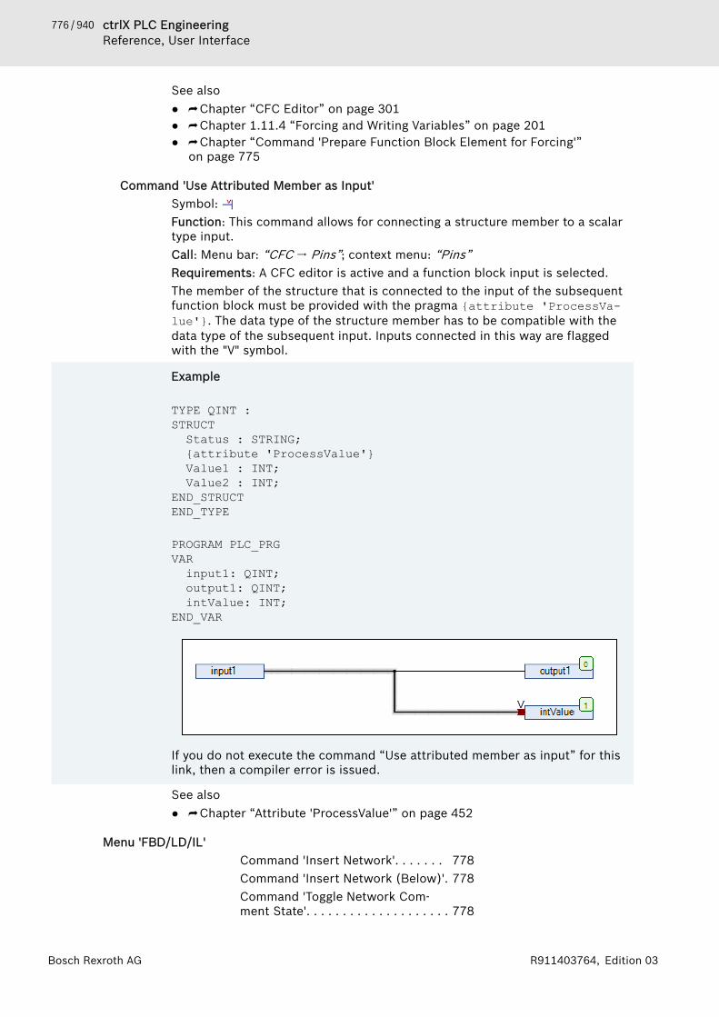
776 / 940 ctrlX PLC EngineeringReference, User Interface
Bosch Rexroth AG R911403764, Edition 03
See also● ⮫ Chapter “CFC Editor” on page 301● ⮫ Chapter 1.11.4 “Forcing and Writing Variables” on page 201● ⮫ Chapter “Command 'Prepare Function Block Element for Forcing'”
on page 775
Command 'Use Attributed Member as Input'Symbol: Function: This command allows for connecting a structure member to a scalartype input.Call: Menu bar: “CFC 🠂 Pins”; context menu: “Pins”Requirements: A CFC editor is active and a function block input is selected.The member of the structure that is connected to the input of the subsequentfunction block must be provided with the pragma {attribute 'ProcessVa-lue'}. The data type of the structure member has to be compatible with thedata type of the subsequent input. Inputs connected in this way are flaggedwith the "V" symbol.
Example
TYPE QINT :STRUCTStatus : STRING;{attribute 'ProcessValue'}Value1 : INT;Value2 : INT;
END_STRUCTEND_TYPE
PROGRAM PLC_PRGVARinput1: QINT;output1: QINT;intValue: INT;
END_VAR
If you do not execute the command “Use attributed member as input” for thislink, then a compiler error is issued.
See also● ⮫ Chapter “Attribute 'ProcessValue'” on page 452
Menu 'FBD/LD/IL'Command 'Insert Network'. . . . . . . 778Command 'Insert Network (Below)'. 778Command 'Toggle Network Com-ment State'. . . . . . . . . . . . . . . . . . . . 778

777 / 940ctrlX PLC EngineeringReference, User Interface
Bosch Rexroth AGR911403764, Edition 03
Command 'Insert Assignment'. . . . . 778Command 'Insert Box'. . . . . . . . . . . 778Command 'Insert Box with EN/ENO' 779Command 'Insert Empty Box'. . . . . . 779Command 'Insert Empty Box withEN/ENO'. . . . . . . . . . . . . . . . . . . . . . 779Command 'Insert Box Parallel(Below)'. . . . . . . . . . . . . . . . . . . . . . 779Command 'Insert Jump'. . . . . . . . . . 780Command 'Insert Label'. . . . . . . . . . 780Command 'Insert Return'. . . . . . . . . 780Command 'Insert Input'. . . . . . . . . . 780Command 'Insert Coil'. . . . . . . . . . . 780Command 'Insert Set Coil'. . . . . . . . 781Command 'Insert Reset Coil'. . . . . . 781Command 'Insert Contact'. . . . . . . . 781Command 'Insert Contact (Right)'. . 781Command 'Insert Contact in Parallel(Below)'. . . . . . . . . . . . . . . . . . . . . . 781Command 'Insert Contact in Parallel(Above)'. . . . . . . . . . . . . . . . . . . . . . 782Command 'Toggle Parallel Mode'. . . 782Command 'Insert Negated Contact'. 782Command 'Insert Negated ContactParallel (Below)'. . . . . . . . . . . . . . . . 783Command 'Paste Contacts: PasteBelow'. . . . . . . . . . . . . . . . . . . . . . . 783Command 'Paste Contacts: PasteAbove'. . . . . . . . . . . . . . . . . . . . . . . 783Command 'Paste Contacts: PasteRight (After)'. . . . . . . . . . . . . . . . . . 783Command 'Insert IL Line Below'. . . 783Command 'Delete IL Line'. . . . . . . . 784Command 'Negation'. . . . . . . . . . . . 784Command 'Edge Detection'. . . . . . . 784Command 'Set/Reset'. . . . . . . . . . . 784Command 'Set Output Connection'. 784Command 'Insert Branch'. . . . . . . . . 785Command 'Insert Branch Above'. . . 785Command 'Insert Branch Below'. . . 785Command 'Set Branch Start Point'. 785Command 'Set Branch End Point'. . 785Command 'Update Parameters'. . . . 786Command 'Remove Unused FB CallParameters'. . . . . . . . . . . . . . . . . . . 786Command 'Repair POU'. . . . . . . . . . 786Command 'View as Function BlockDiagram'. . . . . . . . . . . . . . . . . . . . . . 786
778 / 940 ctrlX PLC EngineeringReference, User Interface
Bosch Rexroth AG R911403764, Edition 03
Command 'View as Ladder Logic'. . 787Command 'View as Instruction List'. 787Command 'Go to'. . . . . . . . . . . . . . . 787
Command 'Insert Network'Symbol: , shortcut: [Ctrl] + [I]Function: This command inserts a further network in the FBD/LD/IL editor.Call: Main menu “FBD, LD, IL”, context menuRequirements: The FBD, LD or IL editor is active. No box is selected.See also● ⮫ Chapter “FBD/LD/IL Element 'Network'” on page 295● ⮫ Chapter “FBD/LD/IL Editor” on page 286● ⮫ Chapter “Command 'Insert Network (Below)'” on page 778
Command 'Insert Network (Below)'Symbol: , shortcut: [Ctrl]+ [T]Function: This command inserts a further network in the FBD/LD/IL editorbelow the selected network.Call: Main menu “FBD, LD, IL”, context menuRequirements: The FBD, LD or IL editor is active. A network is selected. No boxis selected.See also● ⮫ Chapter “FBD/LD/IL Editor” on page 286
Command 'Toggle Network Comment State'Symbol: , shortcut: [Ctrl] + [O]Function: The command comments the selected network in or out.Call: Main menu “FBD, LD, IL”, context menuRequirements: The FBD, LD or IL editor is active. A network is selected, but nobox is selected.See also● ⮫ Chapter “FBD/LD/IL Editor” on page 286
Command 'Insert Assignment'Symbol , shortcut: [Ctrl] + [A]Function: This command inserts an assignment in the FBD or LD editor.Call: Main menu “FBD/LD/IL”, context menuRequirements: The FBD, LD or IL editor is active. A network is selected, but nobox is selected.In IL an assignment is programmed via the operators LD and ST.
See also● ⮫ Chapter “FBD/LD/IL Editor” on page 286
Command 'Insert Box'Symbol: , shortcut: [Ctrl] + [B]Function: This command inserts a box that is available in the project at the endof the selected network.Call: Main menu “FBD, LD, IL”, context menu
779 / 940ctrlX PLC EngineeringReference, User Interface
Bosch Rexroth AGR911403764, Edition 03
Requirements: The FBD, LD or IL editor is active. A network is selected, but nobox is selected.If you select this command the input assistant opens, where you can select thedesired box.See also● ⮫ Chapter “FBD/LD/IL Element 'Box'” on page 295● ⮫ Chapter “FBD/LD/IL Editor” on page 286● ⮫ Chapter 1.8.6 “Using Input Assistance” on page 99
Command 'Insert Box with EN/ENO'Symbol: , shortcut: [Ctrl] + [Shift ]+ [E]Function: This command inserts a box with a boolean input “Enable” and a boo-lean output “Enable Out” at the end of the selected network.Call: Main menu “FBD, LD, IL”, context menuRequirements: the FBD, LD or IL editor is active. A network is selected, but nobox is selected.See also● ⮫ Chapter “FBD/LD/IL Editor” on page 286● ⮫ Chapter 1.8.6 “Using Input Assistance” on page 99
Command 'Insert Empty Box'Symbol: , shortcut: [Ctrl] + [Shift] + [B]Function: This command inserts an empty function block at the end of the cur-rently selected network.Call: Main menu “FBD/LD/IL”, context menuRequirements: The FBD, LD or IL editor is active. A network is selected, but nobox is selected.See also● ⮫ Chapter “FBD/LD/IL Editor” on page 286
Command 'Insert Empty Box with EN/ENO'Symbol: Function: The command inserts an empty box with a Boolean input “Enable”and a Boolean output “Enable Out” at the end of the selected network.Call: Main menu “FBD/LD/IL”, context menuRequirements: The FBD editor, the IL editor or the LD editor is active. A net-work must be selected. No other box may be selected.If “Enable” has the value FALSE at the time of the function block call, then theoperations defined in the fb are not executed. Otherwise, if “Enable” has thevalue TRUE, these operations are executed. The ENO output acts as a repeaterof the EN input.See also● ⮫ Chapter “FBD/LD/IL Editor” on page 286
Command 'Insert Box Parallel (Below)'Function: This command inserts an empty box parallel below the selected func-tion block.Call: Menu bar: “FBD/LD/IL”; context menu.Requirements: A box is selected in the LD editor.
780 / 940 ctrlX PLC EngineeringReference, User Interface
Bosch Rexroth AG R911403764, Edition 03
See also● ⮫ Chapter “FBD/LD/IL Editor” on page 286
Command 'Insert Jump'Symbol , shortcut: [Ctrl]+[L]Function: This command inserts a jump element before the selected element.Call: Main menu “FBD/LD/IL”, context menuRequirements: The FBD, LD or IL editor is active. A connecting line is selected.See also● ⮫ Chapter “FBD/LD/IL Editor” on page 286● ⮫ Chapter “FBD/LD/IL Element 'Jump'” on page 296
Command 'Insert Label'Symbol:Function: This command inserts a jump label into the currently selected net-work.Call: Main menu “FBD, LD, IL”, context menuRequirements: The FBD, LD or IL editor is active. A network is selected. Nojump label is selected.See also● ⮫ Chapter “FBD/LD/IL Editor” on page 286● ⮫ Chapter “FBD/LD/IL Element 'Label'” on page 296
Command 'Insert Return'Symbol: Function: This command inserts an element “Return” in the selected place.Call: Main menu “FBD/LD/IL”, context menuRequirements: The FBD, LD or IL editor is active. A box output is selected.See also● ⮫ Chapter “FBD/LD/IL Editor” on page 286● ⮫ Chapter “FBD/LD/IL Element 'Return'” on page 297
Command 'Insert Input'Symbol: , shortcut: [Ctrl]+[Q]Function: This command adds a further input to an extendable box (ADD, OR,ADD, MUL, SEL) above the selected input.Call: “FBD/LD/IL” menuRequirements: The FBD or LD editor is active. An input of a box is selected.If a box is selected, the command “Append Input” is available in the contextmenu. The input is inserted at the lower end of the box.See also● ⮫ Chapter “FBD/LD/IL Editor” on page 286
Command 'Insert Coil'Symbol: , shortcut: [Ctrl] + [A]Function: This command inserts a coil into the network.Call: Main menu “FBD, LD, IL”, context menuRequirements: The LD editor is active. A network, a coil or a connecting line isselected, but no box is selected.
781 / 940ctrlX PLC EngineeringReference, User Interface
Bosch Rexroth AGR911403764, Edition 03
See also● ⮫ Chapter “FBD/LD/IL Editor” on page 286● ⮫ Chapter “LD Element 'Coil'” on page 298
Command 'Insert Set Coil'Symbol: Function: This command inserts a set coil into the network.Call: Main menu “FBD, LD, IL”, context menuRequirements: The LD editor is active. A network, a coil or a line is selected,but no box is selected.See also● ⮫ Chapter “FBD/LD/IL Editor” on page 286
Command 'Insert Reset Coil'Symbol: Function: This command inserts a reset coil into the network.Call: Main menu “FBD, LD, IL”, context menuRequirements: The LD editor is active. A network, a coil or a line is selected,but no box is selected.See also● ⮫ Chapter “FBD/LD/IL Editor” on page 286● ⮫ Chapter “LD Element 'Coil'” on page 298● ⮫ “Ladder diagram (LD)” on page 74
Command 'Insert Contact'Symbol , shortcut: [Ctrl] + [K]Function: This command inserts a contact to the left of the selected element.Call: Main menu “FBD/LD/IL”, context menuRequirements: The LD editor is active. A line or a contact is selected.See also● ⮫ Chapter “FBD/LD/IL Editor” on page 286● ⮫ Chapter “LD Element 'Contact'” on page 298
Command 'Insert Contact (Right)'Symbol: , shortcut: [Ctrl] + [D]Function: This command inserts a contact to the right of the selected element.Call: Main menu “FBD/LD/IL”, context menuRequirements: The LD editor is active. A line, a contact or a box is selected.See also● ⮫ Chapter “FBD/LD/IL Editor” on page 286● ⮫ Chapter “LD Element 'Contact'” on page 298
Command 'Insert Contact in Parallel (Below)'Symbol: ; keyboard shortcut: [Ctrl]+[R]Function: This command inserts a contact with lines in parallel with and belowthe selected element.Call: Menu bar: “FBD/LD/IL”; context menu.Requirements: The LD editor is active. A line or a contact or a box is selected.
782 / 940 ctrlX PLC EngineeringReference, User Interface
Bosch Rexroth AG R911403764, Edition 03
You can program closed parallel branches in a LD network as short circuit eval-uation (SCE) or OR constructs. SCE branches are displayed with double ver-tical lines, and OR branches with single lines. Refer to the help page for"Closed branches".
See also● ⮫ Chapter “FBD/LD/IL Editor” on page 286● ⮫ Chapter “Command 'Insert Contact in Parallel (Above)'” on page 782● ⮫ Chapter “Closed Branch” on page 299
Command 'Insert Contact in Parallel (Above)'Symbol: ; keyboard shortcut: [Ctrl]+[P]Function: This command inserts a contact with lines in parallel with and abovethe selected element.Call: Menu bar: “FBD/LD/IL”; context menu.Requirements: The LD editor is active. A line, a contact or a box is selected.
You can program closed parallel branches in a LD network as short circuit eval-uation (SCE) or OR constructs. SCE branches are displayed with double ver-tical lines, and OR branches with single lines. Refer to the help page for"Closed branches".
See also● ⮫ Chapter “LD Element 'Contact'” on page 298● ⮫ Chapter “FBD/LD/IL Editor” on page 286● ⮫ Chapter “Closed Branch” on page 299
Command 'Toggle Parallel Mode'Function: This command toggles a parallel branch between an OR constructand the Short Circuit Evaluation (SCE) .Call: Menu bar: “FBD/LD/IL”; context menu.Requirements: The LD editor is active. A vertical line of a parallel branch isselected.
You can program closed parallel branches in a LD network as short circuit eval-uation (SCE) or OR constructs. SCE branches are displayed with double ver-tical lines, and OR branches with single lines. Refer to the help page for"Closed branches".
See also● ⮫ Chapter “FBD/LD/IL Editor” on page 286● ⮫ Chapter “Closed Branch” on page 299
Command 'Insert Negated Contact'Symbol: , shortcut: [Ctrl] + [K]Function: This command inserts a negated contact to the left of the selectedelement.Call: Main menu “FBD/LD/IL”, context menuRequirements: The LD editor is active. A line or a contact is selected.See also● ⮫ Chapter “FBD/LD/IL Editor” on page 286● ⮫ Chapter “LD Element 'Contact'” on page 298

783 / 940ctrlX PLC EngineeringReference, User Interface
Bosch Rexroth AGR911403764, Edition 03
Command 'Insert Negated Contact Parallel (Below)'Symbol: Function: The command inserts a negated contact with lines in parallel withand below the selected element.Call: Main menu “FBD/LD/IL”, context menuRequirements: The LD editor is active. A line, a contact or a box is selected.See also● ⮫ “FBD and LD editor” on page 286● ⮫ Chapter “Programming Ladder Diagrams (LD)” on page 77
Command 'Paste Contacts: Paste Below'Shortcut: [Ctrl] + [F]Function: This command inserts a previously copied contact with lines belowthe selected element.Call: Main menu “FBD/LD/IL 🠂 Paste”, context menuRequirements: the LD editor is active.See also● ⮫ Chapter “FBD/LD/IL Editor” on page 286● ⮫ Chapter “LD Element 'Contact'” on page 298
Command 'Paste Contacts: Paste Above'Shortcut: [Ctrl] + [F]Function: This command inserts a previously copied contact with lines abovethe selected element.Call: Main menu “FBD/LD/IL 🠂 Paste Contacts”, context menuRequirements: the LD editor is active. A line or a contact is selected.See also● ⮫ Chapter “FBD/LD/IL Editor” on page 286● ⮫ Chapter “LD Element 'Contact'” on page 298
Command 'Paste Contacts: Paste Right (After)'Shortcut: [Ctrl] + [G]Function: this command inserts a previously copied contact to the right of theselected element.Call: Main menu “FBD/LD/IL 🠂 Paste Contacts”, context menuRequirements: The LD editor is active. A line or a contact is selected.See also● ⮫ Chapter “FBD/LD/IL Editor” on page 286● ⮫ Chapter “LD Element 'Contact'” on page 298
Command 'Insert IL Line Below'Symbol: Function: The command inserts an instruction line below the selected line.Call: Main menu “FBD/LD/IL”, context menuRequirements: The IL editor is active. A line is selected.See also● ⮫ Chapter “FBD/LD/IL Editor” on page 286

784 / 940 ctrlX PLC EngineeringReference, User Interface
Bosch Rexroth AG R911403764, Edition 03
Command 'Delete IL Line'Symbol: , shortcut: [Ctrl]+[Del]Function: This command deletes the selected instruction line.Call: Main menu “FBD/LD/IL”, context menuRequirements: The IL editor is active. A line is selected.See also● ⮫ Chapter “FBD/LD/IL Editor” on page 286
Command 'Negation'Symbol: , shortcut: [Ctrl] + [N]Function: This command negates the following elements:● Input/output of a box● Jump● Return● CoilCall: Main menu “FBD/LD/IL”, context menuRequirements: the FBD or LD editor is active. The corresponding element isselected.See also● ⮫ Chapter “FBD/LD/IL Editor” on page 286
Command 'Edge Detection'Symbol FBD: , symbol LD: , shortcut: [Ctrl] + [N]Function: This command inserts an edge detector before the selected box inputor box output.Call: Main menu “FBD/LD/IL”, context menuRequirements: The FBD or LD editor is active. A box input or box output isselected.See also● ⮫ Chapter “FBD/LD/IL Editor” on page 286
Command 'Set/Reset'Symbol: , shortcut [Ctrl] + [M]Function: In the case of an element with a boolean output, this commandswitches between reset, set and no mark.Call: Main menu “FBD/LD/IL”, context menuRequirements: The FBD or LD editor is active. An element with a booleanoutput is selected.See also● ⮫ Chapter “FBD/LD/IL Editor” on page 286
Command 'Set Output Connection'Symbol: , shortcut [Ctrl]+ [W]Function: This command turns the selected box output into the forwarding boxoutput.Call: Main menu “FBD/LD/IL”, context menuRequirements: The FBD or LD editor is active. One of several box outputs isselected.See also● ⮫ Chapter “FBD/LD/IL Editor” on page 286

785 / 940ctrlX PLC EngineeringReference, User Interface
Bosch Rexroth AGR911403764, Edition 03
Command 'Insert Branch'Symbol: , shortcut [Ctrl] + [Shift] + [V]Function: This command creates an open line branch on the selected line.Call: Main menu “FBD/LD/IL”, context menuRequirements: The FBD or LD editor is active. An input or an output of a box isselected.See also● ⮫ Chapter “FBD/LD/IL Element 'Branch'” on page 297● ⮫ Chapter “FBD/LD/IL Editor” on page 286
Command 'Insert Branch Above'Symbol:Function: This command inserts a line branch above the selected open linebranch.Call: Main menu “FBD/LD/IL”, context menuRequirements: The FBD or LD editor is active. An open line branch is selected.See also● ⮫ Chapter “FBD/LD/IL Editor” on page 286● ⮫ Chapter “FBD/LD/IL Element 'Branch'” on page 297
Command 'Insert Branch Below'Symbol: Function: This command inserts a line branch below the selected open linebranch.Call: Main menu “FBD/LD/IL”, context menuRequirements: The FBD or LD editor is active. An open line branch is selected.See also● ⮫ Chapter “FBD/LD/IL Editor” on page 286● ⮫ Chapter “FBD/LD/IL Element 'Branch'” on page 297
Command 'Set Branch Start Point'Symbol Function: This command sets the starting point of a line branch on the selectedline.Call: Main menu “FBD/LD/IL”, context menuRequirements: The LD editor is active. A line is selected.See also● ⮫ Chapter “Closed Branch” on page 299● ⮫ Chapter “FBD/LD/IL Editor” on page 286
Command 'Set Branch End Point'Symbol Function: This command sets the end point of a line branch on the selectedline.Call: Main menu “FBD/LD/IL”, context menuRequirements: The LD editor is active. A line is selected. A starting point of theline branch has been set.See also● ⮫ Chapter “FBD/LD/IL Editor” on page 286● ⮫ Chapter “Closed Branch” on page 299

786 / 940 ctrlX PLC EngineeringReference, User Interface
Bosch Rexroth AG R911403764, Edition 03
Command 'Update Parameters'Function: This command enters changes to the declaration of the selected ele-ment in the diagram.Call: Main menu “FBD/LD/IL”, context menuRequirements: The FBD, LD or CFC editor is active. A box is selected. Anextending change has been made to the declaration.The command checks whether a box and its declaration in the declarationeditor correspond. The change is accepted for the box only if the declarationwas extended. Deletions and overwrites are not updated.See also● ⮫ Chapter “FBD/LD/IL Editor” on page 286
Command 'Remove Unused FB Call Parameters'Symbol: Function: This command deletes inputs and outputs of the selected box towhich no variable and no value were assigned. However, the default inputs andoutputs are always retained.Call: Main menu “FBD/LD/IL”, context menuRequirements: The FBD or LD editor is active. A box is selected. The box hasinterfaces to which no value is assigned.See also● ⮫ Chapter “FBD/LD/IL Editor” on page 286
Command 'Repair POU'Symbol:Function: This command repairs internal inconsistencies in the selected box.Call: Main menu “FBD/LD/IL”, context menuRequirements: The FBD or LD editor is active. The defective box is selected.The editor has found internal inconsistencies in the programming module thatcan possibly be resolved automatically. PLC Engineering reports the inconsis-tencies in the Message window.This situation is conceivable when editing a project that was created with anolder programming system version that did not yet handle the inconsistencyconcerned as an error.See also● ⮫ Chapter “FBD/LD/IL Editor” on page 286
Command 'View as Function Block Diagram'
CAUTION Loss of data! An error-free conversion requires syntacti-cally correct code. Otherwise parts of the implementa-tion can be lost.
Shortcut: [Ctrl] + [1]Function: This command converts the active instruction list or the active ladderdiagram into the function block diagram.Call: Menu “FBD/LD/IL 🠂 View”Requirements: The LD or IL editor is active.See also● ⮫ Chapter “FBD/LD/IL Editor” on page 286
787 / 940ctrlX PLC EngineeringReference, User Interface
Bosch Rexroth AGR911403764, Edition 03
Command 'View as Ladder Logic'
CAUTION Loss of data! An error-free conversion requires syntacti-cally correct code. Otherwise parts of the implementa-tion can be lost.
Shortcut: [Ctrl] + [2]Function: This command converts the current function block code or the activeinstruction list into a ladder diagram.Call: Menu “FBD/LD/IL 🠂 View”Requirements: The FBD or IL editor is active.See also● ⮫ Chapter “FBD/LD/IL Editor” on page 286
Command 'View as Instruction List'If necessary, IL can be activated in the PLC Engineering options.
CAUTION Loss of data! An error-free conversion requires syntacti-cally correct code. Otherwise parts of the implementa-tion can be lost.
Shortcut: [Ctrl] + [3]Function: This command converts the active function block code or the activeladder diagram into an instruction list.Call: Menu “FBD/LD/IL 🠂 View”Requirements: The LD or FBD editor is active.See also● ⮫ Chapter “FBD/LD/IL Editor” on page 286
Command 'Go to'Symbol:Function: This command allows you to jump to any network.Call: Main menu “FBD/LD/IL”Requirements: The LD, FBD or IL editor is active. A network is selected.This command opens a dialog box with an input field. Enter the number of thedesired network in the input field.See also● ⮫ Chapter “FBD/LD/IL Editor” on page 286
Menu 'Library'Command 'Add Library'. . . . . . . . . . 787Command 'Try to Reload Library'. . . 789Command 'Properties'. . . . . . . . . . . 789Command 'Placeholders'. . . . . . . . . 791Command 'Export Library'. . . . . . . . 791
Command 'Add Library'Function: The command opens the “Add Library” dialog. In this dialog, you canadd libraries to the Library Manager and then integrate them in your applica-tion.Call: Menu bar: “Libraries”Requirement: The Library Manager is open in the editor.

788 / 940 ctrlX PLC EngineeringReference, User Interface
Bosch Rexroth AG R911403764, Edition 03
Dialog 'Add Library'
In the line above the library list, you can search for library names or library modules by typing anappropriate string.“Library” Suitable libraries that are installed in the library repository. For
example, the selection of libraries is defined in the device descriptionor by the OEM.By default, the displayed libraries are grouped into categories.
“Company” Creator of the library“Advanced” Opens the advanced “Add Library” dialog
The displayed libraries are grouped into categories.The displayed libraries are listed in alphabetical order.All available libraries are displayed.
Specific libraries can be blacklisted in a device description. These librariescannot be added below this device in the Library Manager.See also● ⮫ Chapter “Command 'Library Repository'” on page 742
Dialog 'Add Library' – 'Advanced'You should use this dialog only if you have expert knowledge of library refer-encing. Using this dialog, you can link special versions or change placeholderdefinitions.We recommend seriously that you follow the guidelines for the creation of libra-ries when developing and referencing libraries.
Table 150: Tab 'Library'“Company” Filtering the list according to vendor“Group by category” : Display of the libraries in a tree structure grouped in categories.
: Display of the libraries in alphabetical order in a flat structure.“Display all versions” : Display of all versions of the libraries. Version specification '*'
means the latest version available in the repository.: Display of the latest versions of the libraries only. A multiple selec-
tion of libraries is possible in this display. To do this, hold down the[Shift] key and select the entries.
“Details” Opens a detailed view with the library modules.“Library Repository” Opens the “Library Repository” dialog. There you can install more
libraries to your local system.Table 151: Tab 'Placeholder'“Placeholder name” The input field provides a combo box for entering the valid placeholder
names that are read from the currently accessible device descriptions.You can also enter a new placeholder name in order to define a freeplaceholder, which is not resolved by the device or by the library pro-file.
“Default library” PLC Engineering uses this library when for any reason no device isavailable that the resolution defines. In this way it is possible to com-pile the current project without errors.
Note about placeholder resolutionFor compiler version V3.5.8.0 and later, the following statement applies in thecase of library placeholders with a resolution in the device description that arelocated in the Library Manager of the POU pool. This placeholder is alwaysresolved automatically according to the description of the device that compilesthe application.
789 / 940ctrlX PLC EngineeringReference, User Interface
Bosch Rexroth AGR911403764, Edition 03
See also● ⮫ Chapter 1.15.1 “Information for Library Developers” on page 238● ⮫ Chapter “Command 'Placeholders'” on page 791
Command 'Try to Reload Library'Function: This command tries to reload the selected library.Call: Main menu “Library”.Requirement: A library is selected that failed to load.If for any reason a library is not available in the defined repository locationwhen a project is opened, PLC Engineering displays a corresponding error mes-sage. Once you have rectified the error, i.e. when the library is properly avail-able again, you can reload the library with this command without having toleave the project.See also● ⮫ Chapter “Command 'Library Repository'” on page 742
Command 'Properties'Function: This command opens the “Properties” dialog box for the libraryselected in the library manager.Call● “Library” menu● Context menu of the selected library● symbol in the toolbar of the library managerRequirement: A library is selected.
NOTICE This dialog is intended for library developers. Please usethis only if you have profound knowledge of library refer-encing. In addition, please follow the guidelines forlibrary developers.
See also● ⮫ Chapter “Command 'Placeholders'” on page 791
Dialog box 'Properties'Table 152: “General”“Namespace” Namespace of the selected library. By default, this is identical to the
library name, unless it was defined explicitly in the project informationwhen the library was created. You can change the namespace for theopen project.Example: LA
“Standard” Library that triggers the placeholder when no other trigger is definedor is possible.Requirement: The selected library is a library placeholder, and there-fore the setting is available.Note: Regarding compiler version 3.5.8.0 and later: In the case oflibrary placeholders that have a trigger in the device description andthat located in the library manager of the “POUs” view, the place-holder is always triggered automatically according to the description ofthe device for which the application is compiled.
If the selected library is developed in compliance with the "Guidelines forDeveloping Libraries", then we do not recommend that you change the fol-lowing settings.
790 / 940 ctrlX PLC EngineeringReference, User Interface
Bosch Rexroth AG R911403764, Edition 03
Table 153: “Version”Selection of version constraintRequirement: The settings are available only if the selected library is not a library placeholder.Note: Container and interface libraries are created automatically with library references with ver-sion constraint. As far as possible, do not create libraries that include library references with ver-sion constraint. Otherwise, you reference the libraries by placeholders. Edit a placeholder resolu-tion in the “Placeholders” dialog box.“Specific version” : (selected from drop-down list) Version is integrated into the
project.Note: This option is strongly recommended for container libraries, andit is usually preset for this library type.
“Newest version always” : The library repository is scanned and the latest detected version isintegrated.Note: If a newer library version is available, then the library modulesthat are actually used can change. This option is strongly recom-mended for interface libraries, and it is usually preset for this librarytype.
Table 154: “Visibility”“Only allow qualifiedaccess to all identifiers.”
: Library modules (and variables) are called in the project only withprepended namespace paths.
“If the current project isreferenced as a library byanother project. ”
Note: Changing the following settings makes sense only if you createda library with your project and therefore opened a library project. Inthis way, the selected library is referenced in the new library.
“Publish all IEC symbols tothat project as if this refer-ence would have beenincluded there directly.”
: As a container library, the selected library makes the content of thereferenced library visible at the top level (later in a project).Requirement: A container project is created with a library project. Acontainer library does not implement its own modules, but referencesother libraries exclusively. It bundles libraries. A container library canbe employed sensibly to bundle multiple libraries (in a reference) in aproject. This option must be activated for each library reference.Symbolic access to library modules: <namespace of containerlibrary>.<module name>
: The contents of the referenced library is accessed uniquely bymeans of the namespace. The path name consists of the library nameand the unique name (library reference), and it is prepended to themodule name.Requirement: No container project is created with a library project.Unique symbolic access to the library module: <namespace oflibrary>.<namespace of sublibrary>.<module name>.
“Do not show this referencein the dependency tree.”
: The selected library is not displayed in the library manager as alibrary reference (later in a project). The library is a hidden reference.Warning: If there are compile errors resulting from hidden libraryerrors, then detecting the errors may be difficult.
: The selected library is displayed as a library reference (later in aproject).
“Optional (if the library ismissing, no error will bereported).”
: The selected library is treated as optional. When downloading theproject that references the library, no error is reported, even if thelibrary is not available in the library repository.
See also● ⮫ Chapter “Command 'Placeholders'” on page 791

791 / 940ctrlX PLC EngineeringReference, User Interface
Bosch Rexroth AGR911403764, Edition 03
Command 'Placeholders'Function: This command opens the “Placeholders” dialog box. The dialogshows information on the currently selected placeholder library and allows toassign a project-specific resolution.Call:● Menu “Libraries”● Symbol in the symbol bar in the upper part of the Library Manager
window.Requirement: A placeholder library is selected in the Library Manager.A placeholder library, which is included in the “Devices” view, will be resolvedas follows:● If you have assigned a specific resolution to the placeholder library via the
dialog “Placeholder”, this will be applied.● If no specific resolution is defined, it will be checked, whether there is one
specified in the device description of the application..● Afterwards the library profile will be checked for a resolution definition.● The result is displayed in the Library Manager below the “Effective Version”.A placeholder library, which is included in the “POUs” view, gets resolved asfollows:● A specific resolution defined in the dialog “Placeholder” will be ignored.● For the application it will be checked whether there is a resolution defined
in the device description.● Afterwards the library profile will be checked.● The result is displayed in the tooltip of the symbol .See also● ⮫ Chapter 1.15 “Using Libraries” on page 237● ⮫ Chapter “Object 'Library Manager'” on page 583● ⮫ Chapter 1.15.1 “Information for Library Developers” on page 238
Dialog box 'Placeholders'
“Name” Name of the placeholder.“Library” Current resolution, valid for the project
Double-click on the entry in order to edit the placeholder resolution. Aselection list with the available library versions appears. Additionallythe command “Other Library” is available.
Command “Other Library” The command opens the dialog box “Bibliothek durchsuchen” forsearching and installing libraries. Choose this command, if you do notwant to redirect to another version, but on a specific libray.
“Info” Type of placeholder resolution:● Resolved by device description● Resolved by library profile● Resolved by <specific library>
Command 'Export Library'Function: This command is used for saving the library file to the hard disk.Call: Context menu of the Library ManagerRequirement: A library is selected in the Library Manager.The command opens the standard dialog for saving a file in the local filesystem. The library file can have the file type Library files (*.library),Compiled library files (*.compiled-library), or Compiled libraryfiles (*.compiled-library-v3).
792 / 940 ctrlX PLC EngineeringReference, User Interface
Bosch Rexroth AG R911403764, Edition 03
See also● ⮫ Chapter “Object 'Library Manager'” on page 583● ⮫ Chapter 1.15.4 “Exporting Library Files” on page 240
Menu 'Image Pool'Command 'Insert Image'. . . . . . . . . 792
Command 'Insert Image'Symbol: Function: This command inserts a new line into an image pool.Call: Main menu “Imagepool”, or right-click.Requirements: An image pool is active and a line is selected in the image pool.See also● ⮫ Chapter “Object 'Image Pool'” on page 582
Menu 'Declarations'Command 'Insert'. . . . . . . . . . . . . . . 792Command 'Edit Declaration Header' 792Command 'Move Down'. . . . . . . . . . 793Command 'Move Up'. . . . . . . . . . . . 793
Command 'Insert'Symbol Function: This command inserts a new line for a variable declaration in the dec-laration editor and the input field for the variable name opens.Call: Context menu in the tabular declaration editor; button in the declarationheading.To edit the other fields of the declaration lines, double-click the fields andselect the data from the drop-down lists or by means of the respective dialogs.See also● ⮫ Chapter “Using the Declaration Editor” on page 64
Command 'Edit Declaration Header'Function: The command opens the dialog “Edit Declaration Header”, whichserves in the declaration editor for the configuration of a POU header.Call: Context menu of the tabular declaration editorRequirements: The tabular declaration editor is the active editor.See also● ⮫ “Declaring in the tabular declaration editor” on page 65
Dialog 'Edit Declaration Header'Function: The dialog is for configuring the declaration part of a POU.Call: Click on the header bar of the tabular declaration editor, or context menuin the tabular declaration editor.
“Declaration” Selection list for changing the POU type● “PROGRAM”● “FUNCTION_BLOCK”
– “EXTENDS”:Input field for a basic function block
– “IMPLEMENTS”: Input field for an interface

793 / 940ctrlX PLC EngineeringReference, User Interface
Bosch Rexroth AGR911403764, Edition 03
● “FUNCTION”– “Return type”
Input field with current POU name: you can change the name of thePOU
“Automatically adapt all ref-erences on rename”
: Dialog box “Refactoring” opens.: Renaming is only effective in the declaration header of the POU.
“Attributes” The dialog box “Attribute ” opens for the input of attributes andpragmas.
See also● ⮫ Chapter “Using the Declaration Editor” on page 64● ⮫ Chapter 1.18.6 “Pragmas” on page 418● ⮫ Chapter 1.8.16 “Refactoring” on page 126
Command 'Move Down'Symbol: Function: This command shifts a variable declaration downwards by one row.Call: Context menuRequirement: A row with a variable declaration is selected in the tabular decla-ration editor.See also● ⮫ Chapter “Using the Declaration Editor” on page 64
Command 'Move Up'Symbol: Function: This command shifts a variable declaration upwards by one row.Call: Context menuRequirement: A row with a variable declaration is selected in the tabular decla-ration editor.See also● ⮫ Chapter “Using the Declaration Editor” on page 64
Menu 'Declarations' (Persistence)Command 'Reorder List and CleanGaps'. . . . . . . . . . . . . . . . . . . . . . . . 793Command 'Save Current Values toRecipe'. . . . . . . . . . . . . . . . . . . . . . . 794Command 'Restore Values from Rec-ipe'. . . . . . . . . . . . . . . . . . . . . . . . . . 794Command 'Add all instance paths'. . 795
Command 'Reorder List and Clean Gaps'Function: This command cleans the gaps that can result when you makechanges to the declaration of persistent variables. The memory requirement isreduced by this cleaning. When the command is executed, PLC Engineering dis-plays a warning informing the user about the possible loss of data.Call: Main menu “Declarations”, context menuRequirement: The persistence editor (persistent variable list) is active.Before cleaning you should consider saving the current values of the persistentvariables to a recipe (command “Save Current Values to Recipe”). Then you canload the values to the controller again after the next download.

794 / 940 ctrlX PLC EngineeringReference, User Interface
Bosch Rexroth AG R911403764, Edition 03
See also● ⮫ Chapter 1.8.20 “Data Persistence” on page 139● ⮫ Chapter “Command 'Restore Values from Recipe'” on page 794● ⮫ Chapter “Command 'Save Current Values to Recipe'” on page 794
Command 'Save Current Values to Recipe'Function: This command creates a new recipe definition in the recipe managerand stores the current values of the persistent variables in it. You should exe-cute this command before the command “Reorder List and Clear Gaps” inorder to avoid a possible loss of data. You can subsequently restore the datawith the command “Restore Values from Recipe”.Call: Main menu “Deklarationen”Requirement: The application is in online mode and the persistence editor (per-sistent variable list) is active.If a list already exists in the recipe manager with the corresponding nameswhen saving a persistent variable list, then the current persistent variables aresorted into the list:− New persistent variables are added to the list− Variables, that are not in the list, will be deletedTherefore, it is possible to add more recipes to the list in the recipe managerand these will be retained . However, if new variables are added to the list, thenthese are deleted the next time the command “Save Current Values to Recipe”is executed.See also● ⮫ Chapter 1.8.20 “Data Persistence” on page 139● ⮫ Chapter “Command 'Reorder List and Clean Gaps'” on page 793● ⮫ Chapter “Command 'Restore Values from Recipe'” on page 794● ⮫ Chapter “Object 'Persistent variable list'” on page 582
Command 'Restore Values from Recipe'Function: This command restores the values of the persistent variables that youhave stored in a recipe using the command “Save Current Values to Recipe”.You would normally select this command after executing the command“Reorder List and Clear Gaps”.Call: Main menu “Declarations”Requirement: The persistence editor (persistent variable list) is active, theapplication is in online modeSee also● ⮫ Chapter 1.8.20 “Data Persistence” on page 139● ⮫ Chapter “Command 'Save Current Values to Recipe'” on page 794● ⮫ Chapter “Command 'Reorder List and Clean Gaps'” on page 793● ⮫ Chapter “Object 'Persistent variable list'” on page 582● ⮫ Chapter “Command 'Save Current Values to Recipe'” on page 794

795 / 940ctrlX PLC EngineeringReference, User Interface
Bosch Rexroth AGR911403764, Edition 03
Command 'Add all instance paths'Function:● When you execute the command in the persistence editor, the application is
searched for declarations of persistent variables with the PERSISTENT key-word which are outside of the persistence editor. For each declarationfound, an instance path of this variable is added in the persistence editor.
● When you execute the command in a variable configuration, an instance pathis added for each variable with an incomplete address. All function blocks ofthe application are considered in this case.
Call: Menu bar: “Declarations”, right-click.Requirement● the persistence editor (global persistent variable list) is active or a variable
configuration (global variable list with VAR_CONFIG declarations) is opened.● The application was compiled successfully.
See also● ⮫ Chapter “Persistent Variable - PERSISTENT” on page 321● ⮫ Chapter “Retain Variable - RETAIN” on page 323
Menu 'Device Communication', GatewayCommand 'Add gateway'. . . . . . . . . 795Command 'Configure the local gate-way'. . . . . . . . . . . . . . . . . . . . . . . . . 795
Command 'Add gateway'Function: This command opens the “Gateway” dialog where you can define agateway channel and add it to the current device configuration.Call: Menu bar: “Gateway” in the “Communication” dialog of the device editor.
Dialog 'Gateway'
“Name” Name of the gateway.“Drivers” Driver type from a drop-down list.Driver-specific settings, forexample:IP address, port
Editable after double-clicking the predefined value. A short descriptionfor each parameter is displayed in the lower part of the dialog.Note: You can also specify the address of a DNS domain. This has tobegin with dns: (example: dns:MyDynDNSAdress).
The dialog is also used for later editing of the gateway entries of your project.See also● ⮫ Chapter “Tab 'Communication Settings'” on page 556
Command 'Configure the local gateway'Function: The command opens the dialog “Gateway Configuration”, where youcan set up the block driver configuration for the local gateway. This is an alter-native to manually editing of the configuration file Gateway.cfg.Call: Context menu of a gateway entry in the “Communication Settings” dialog.
NOTICE A correct gateway configuration requires detailed knowl-edge. In case of any doubts do not change the standardconfiguration settings!
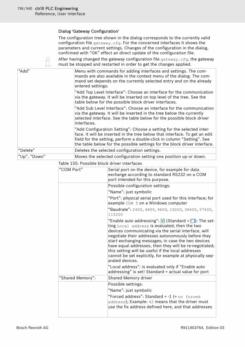
796 / 940 ctrlX PLC EngineeringReference, User Interface
Bosch Rexroth AG R911403764, Edition 03
Dialog 'Gateway Configuration'The configuration tree shown in the dialog corresponds to the currently validconfiguration file gateway.cfg. For the concerned interfaces it shows theparameters and current settings. Changes of the configuration in the dialog,confirmed with “OK” effect an direct update of the configuration file.After having changed the gateway configuration file gateway.cfg, the gatewaymust be stopped and restarted in order to get the changes applied.
“Add” Menu with commands for adding interfaces and settings. The com-mands are also available in the context menu of the dialog. The com-mand set depends on the currently selected entry and on the alreadyentered settings:“Add Top Level Interface”: Choose an interface for the communicationvia the gateway. It will be inserted on top level of the tree. See thetable below for the possible block driver interfaces.“Add Sub Level Interface”: Choose an interface for the communicationvia the gateway. It will be inserted in the tree below the currentlyselected interface. See the table below for the possible block driverinterfaces.“Add Configuration Setting”: Choose a setting for the selected inter-face. It will be inserted in the tree below that interface. To get an editfield for the setting, perform a double-click in column “Setting”. Seethe table below for the possible settings for the block driver interface.
“Delete” Deletes the selected configuration settings.“Up”, “Down” Moves the selected configuration setting one position up or down.
Table 155: Possible block driver interfaces“COM Port” Serial port on the device, for example for data
exchange according to standard RS232 on a COMport intended for this purpose.Possible configuration settings:“Name”: just symbolic“Port”: physical serial port used for this interface; forexample COM 5 on a Windows computer“Baudrate”: 2400, 4800, 9600, 19200, 38400, 57600,115200“Enable auto addressing”: (Standard = ): The set-ting Local address is evaluated; then the twodevices communicating via the serial interface, willnegotiate their addresses autonomously before theystart exchanging messages; in case the two deviceshave equal addresses, then they will be re-negotiated;this setting will be useful if the local addressescannot be set explicitly, for example at physically sep-arated devices.“Local address”: is evaluated only if “Enable autoaddressing” is set! Standard = actual value for port
“Shared Memory”: Shared Memory driverPossible settings:“Name”: just symbolic“Forced address”: Standard = -1 (= no forcedaddress); Example: 42 means that the driver mustuse the fix address defined here, and that addresses
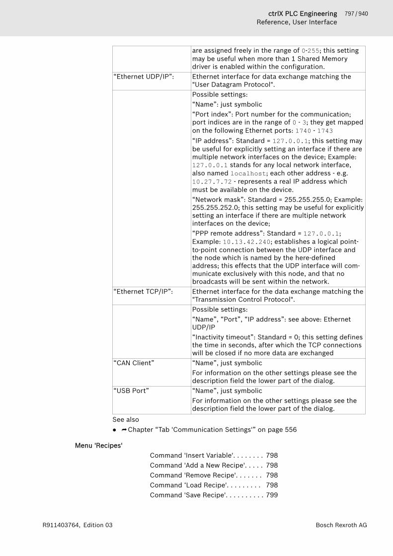
797 / 940ctrlX PLC EngineeringReference, User Interface
Bosch Rexroth AGR911403764, Edition 03
are assigned freely in the range of 0-255; this settingmay be useful when more than 1 Shared Memorydriver is enabled within the configuration.
“Ethernet UDP/IP”: Ethernet interface for data exchange matching the"User Datagram Protocol".Possible settings:“Name”: just symbolic“Port index”: Port number for the communication;port indices are in the range of 0 - 3; they get mappedon the following Ethernet ports: 1740 - 1743“IP address”: Standard = 127.0.0.1; this setting maybe useful for explicitly setting an interface if there aremultiple network interfaces on the device; Example:127.0.0.1 stands for any local network interface,also named localhost; each other address - e.g.10.27.7.72 - represents a real IP address whichmust be available on the device.“Network mask”: Standard = 255.255.255.0; Example:255.255.252.0; this setting may be useful for explicitlysetting an interface if there are multiple networkinterfaces on the device;“PPP remote address”: Standard = 127.0.0.1;Example: 10.13.42.240; establishes a logical point-to-point connection between the UDP interface andthe node which is named by the here-definedaddress; this effects that the UDP interface will com-municate exclusively with this node, and that nobroadcasts will be sent within the network.
“Ethernet TCP/IP”: Ethernet interface for the data exchange matching the"Transmission Control Protocol".Possible settings:“Name”, “Port”, “IP address”: see above: EthernetUDP/IP“Inactivity timeout”: Standard = 0; this setting definesthe time in seconds, after which the TCP connectionswill be closed if no more data are exchanged
“CAN Client” “Name”, just symbolicFor information on the other settings please see thedescription field the lower part of the dialog.
“USB Port” “Name”, just symbolicFor information on the other settings please see thedescription field the lower part of the dialog.
See also● ⮫ Chapter “Tab 'Communication Settings'” on page 556
Menu 'Recipes'Command 'Insert Variable'. . . . . . . . 798Command 'Add a New Recipe'. . . . . 798Command 'Remove Recipe'. . . . . . . 798Command ‘Load Recipe'. . . . . . . . . 798Command 'Save Recipe'. . . . . . . . . . 799
798 / 940 ctrlX PLC EngineeringReference, User Interface
Bosch Rexroth AG R911403764, Edition 03
Command 'Read Recipe'. . . . . . . . . 799Command 'Write Recipe'. . . . . . . . . 800Command 'Load and Write Recipe'. 800Command 'Read and Save Recipe'. . 800Command 'Remove Variables'. . . . . 801Command 'Load Recipes fromDevice'. . . . . . . . . . . . . . . . . . . . . . . 801Command 'Update Structured Varia-bles'. . . . . . . . . . . . . . . . . . . . . . . . . 801
Command 'Insert Variable'Symbol: Function: This command inserts a variable into the currently opened recipe def-inition before the selected position.Call: Main menu “Recipes”.Requirement: You have opened a recipe definition in the editor and selectedthe normal view.PLC Engineering inserts the default text "NewVariable" in the column “Vari-able”. You must replace this name with the respective variable name. To dothis, open the input assistant by clicking or enter the variable name directlyinto the table element.See also● ⮫ Chapter 1.12.2 “Changing Values with Recipes” on page 216● ⮫ Chapter “Menu 'Recipes'” on page 797
Command 'Add a New Recipe'Symbol: Function: This command opens a dialog box for adding a new recipe (newcolumn) to the recipe definition.Call: Main menu “Recipes”.Requirement: You have opened a recipe definition in the editor.After choosing the command, a dialog box opens for you to define the name ofthe new recipe. The dialog box also provides the capability of copying existingrecipes into the new recipe.See also● ⮫ Chapter 1.12.2 “Changing Values with Recipes” on page 216● ⮫ Chapter “Menu 'Recipes'” on page 797
Command 'Remove Recipe'Symbol: Function: This command removes a recipe from the currently opened recipedefinition.Call: Main menu “Recipes”.Requirement: You have selected a field in the recipe column of a recipe defini-tion.See also● ⮫ Chapter 1.12.2 “Changing Values with Recipes” on page 216● ⮫ Chapter “Menu 'Recipes'” on page 797
Command ‘Load Recipe'Symbol:
799 / 940ctrlX PLC EngineeringReference, User Interface
Bosch Rexroth AGR911403764, Edition 03
Function: The command loads a recipe from a file.Call: Menu bar: “Recipes”.Requirement: You have selected a field in the recipe column of a recipe defini-tion.This command overwrites the values of the selected recipe of the recipe defini-tion.If you have selected the option “Recipe Management in the PLC”, please notethe following.If you change recipes in the project by choosing the command “Load Recipe” or“Read Recipe”, then an online change is required when logging in again.If you want to overwrite only individual recipe variables with new values, thenremove the values for the other variables before loading to the recipe file.Entries without value definitions are not read, and therefore updating leavesthese variables unchanged on the PLC and in the project.For values of the data type REAL/LREAL, the hexadecimal value is also writtento the recipe file in some cases. This is necessary so that the exact identicalvalue is restored when converting back. In this case, change the decimal valueand delete the hexadecimal value.See also● ⮫ Chapter 1.12.2 “Changing Values with Recipes” on page 216● ⮫ Chapter “Menu 'Recipes'” on page 797
Command 'Save Recipe'Symbol: Function: This command saves the variable values of a recipe to a file.Call: Main menu “Recipes”.Requirement: You have selected the value of a recipe in the recipe definition.When you choose this command, PLC Engineering saves the values of theselected recipe to a file. You can define the format in the settings for the recipemanager in the tab “Storage”.See also● ⮫ Chapter 1.12.2 “Changing Values with Recipes” on page 216● ⮫ Chapter “Menu 'Recipes'” on page 797
Command 'Read Recipe'Symbol: Function: This command reads the variable values of a recipe from the con-troller.Call: Main menu “Recipes”.Requirement: The application is in online mode and you have selected the valueof a recipe in the recipe definition.When you choose this command, PLC Engineering overwrites the values of theselected recipe with the read values from the controller.If you have selected the option “Recipe Management in the PLC”, please notethe following.If you change recipes in the project by choosing the command “Load Recipe” or“Read Recipe”, then an online change is required when logging in again.See also● ⮫ Chapter 1.12.2 “Changing Values with Recipes” on page 216● ⮫ Chapter 1.19.2 “Menu Commands” on page 652
800 / 940 ctrlX PLC EngineeringReference, User Interface
Bosch Rexroth AG R911403764, Edition 03
Command 'Write Recipe'Symbol: Function: This command writes the values of a recipe to the variables in thecontroller.Call: Main menu “Recipes”.Requirement: The application is in online mode and you have selected the valueof a recipe in the recipe definition.When you choose this command, PLC Engineering overwrites the values in thecontroller with the values of the selected recipe.See also● ⮫ Chapter 1.12.2 “Changing Values with Recipes” on page 216● ⮫ Chapter “Menu 'Recipes'” on page 797
Command 'Load and Write Recipe'Symbol: Function: This command loads a recipe from a file and writes the values to thevariables in the PLC.Call: Menu bar: “Recipes”.Requirement: The application is in online mode. You have selected the value ofa recipe in the recipe definition.After choosing the command, you are prompted either to write the variablevalues also to the recipe in the project or only to write them to the PLC.Updating the values in the recipe could require an online change when loggingin again.When you choose this command, PLC Engineering overwrites the values of theselected recipe of the recipe definition. In addition, these recipe values over-write the variable values in the PLC.If you want to overwrite only individual recipe variables with new values, thenremove the values for the other variables before loading to the recipe file.Entries without value definitions are not read, and therefore updating leavesthese variables unchanged on the PLC and in the project.For values of the data type REAL/LREAL, the hexadecimal value is also writtento the recipe file in some cases. This is necessary so that the exact identicalvalue is restored when converting back. In this case, change the decimal valueand delete the hexadecimal value.See also● ⮫ Chapter 1.12.2 “Changing Values with Recipes” on page 216● ⮫ Chapter “Menu 'Recipes'” on page 797
Command 'Read and Save Recipe'Symbol: Function: This command reads the variable values of a recipe from the con-troller and saves them to a file.Call: Main menu “Recipes”.Requirement: The application is in online mode and you have selected the valueof a recipe in the recipe definition.After choosing the command, you are prompted either to read the variablevalues to the recipe or only to save them. Updating the values in the recipecould require an online change when logging in again.The values are saved with the default name for recipe files according to the set-tings for the recipe manager (tab “Storage”).
801 / 940ctrlX PLC EngineeringReference, User Interface
Bosch Rexroth AGR911403764, Edition 03
See also● ⮫ Chapter 1.12.2 “Changing Values with Recipes” on page 216● ⮫ Chapter “Menu 'Recipes'” on page 797
Command 'Remove Variables'Symbol Function: This command removes the selected variables from a “Recipe Defini-tion”.Call: The command is not in any menu by default. You can add it to a menu byusing the dialog box from “Tools 🠂 Customize” (command category “Recipe”).See also● ⮫ Chapter 1.12.2 “Changing Values with Recipes” on page 216● ⮫ Chapter “Menu 'Recipes'” on page 797
Command 'Load Recipes from Device'Symbol: Function: This command initiates the synchronization of the recipes from theopen recipe definition in the project and the recipes located on the device inthe form of recipe files.Call: Menu bar: “Recipes”.Requirement: The application is in online mode and a recipe definition is openin the editor.In detail, the synchronization is described as follows:● The current values for the recipe variables located in the project are over-
written by the values from the recipes on the controller. As a result, there islikely an online change at the next login.
● If recipe variables are defined in the recipe files on the controller, and therecipe variables are missing in the recipe definition of the project, thenthese variables are ignored when at the time of download. Before that, amessage appears for each recipe file regarding the variables in question.
● If recipe variables are missing in the recipe files on the controller, and theserecipe variables are included in the recipe definition of the project, then amessage appears for each recipe file with the variables in question.
● If more recipes for these variables have been created on the controller, thenthey are added to the recipe definition in the project.
Command 'Update Structured Variables'Symbol: Function: This command opens the “Update Structured Variables” dialog box.Call: Main menu “Recipes”.In this dialog box, you can update recipe definitions if the declaration of astructured variable or a block has changed. For example, if the dimension of anarray is changed, then you can automatically add or remove the entries in therecipe definition.
Table 156: Dialog Box 'Update Structured Variables'“Remove not existing varia-bles”
: Variables are removed from the recipe definition when they nolonger exist in the project due to a change to a structured element.
“Update instances of struc-tures and function blocks”
: If the declaration of a structure or function block is extended andavailable in the recipe definition with an instance, then the respectivevariables are added to the recipe definition.

802 / 940 ctrlX PLC EngineeringReference, User Interface
Bosch Rexroth AG R911403764, Edition 03
“Update array dimensionsof array instances”
: If the dimension of an array is extended and available in the recipedefinition with an instance, then the respective variables are added tothe recipe definition.
“Update contained globalvariable lists”
: If the declaration of a global variable list is extended and availablein the recipe definition with an instance, then the respective variablesare added to the recipe definition.
“Update contained pro-grams”
: If the declaration of a program is extended and instanced in therecipe definition, then the respective variables are added to the recipedefinition.
See also● ⮫ Chapter 1.12.2 “Changing Values with Recipes” on page 216● ⮫ Chapter “Menu 'Recipes'” on page 797
Menu 'Text List'Command 'Add Language'. . . . . . . . 802Command 'Create Global Text List'. 802Command 'Export Everything asText'. . . . . . . . . . . . . . . . . . . . . . . . . 803Command 'Export All Unicode .txtText List Files'. . . . . . . . . . . . . . . . . 803Command 'Insert Text'. . . . . . . . . . . 803Command 'Import/Export Text Lists' 803Command 'Remove Language'. . . . . 805Command 'Rename Language'. . . . . 805Command 'Remove Unused Text ListEntries'. . . . . . . . . . . . . . . . . . . . . . . 805Command 'Check Visualization TextIDs'. . . . . . . . . . . . . . . . . . . . . . . . . . 805Command 'Update Visualization TextIDs'. . . . . . . . . . . . . . . . . . . . . . . . . . 805Command 'Add Text List Support'. . 806Command 'Remove Text List Sup-port'. . . . . . . . . . . . . . . . . . . . . . . . . 806
Command 'Add Language'Symbol: Function: This command adds a further language column to the text list.Call: Main menu “Textlist”, context menuRequirement: A text list or a global text list is open and active.In the dialog box “Enter Language”, enter a code for the new language, forexample “en-US”. PLC Engineering inserts the code as column header.
Command 'Create Global Text List'Symbol: Function: This command creates the global text list in the “POUs” view.Call: “Visualization”, context menu.Requirements: A visualization is open.See also● ⮫ Chapter “Object 'GlobalTextList'” on page 580● ⮫ “Removing the global text list and creating current IDs again” on page 108

803 / 940ctrlX PLC EngineeringReference, User Interface
Bosch Rexroth AGR911403764, Edition 03
Command 'Export Everything as Text'Symbol: Function: This command exports all the text lists of the project.Call: Main menu “Textlist”, context menuRequirement● A text list or a global text list is open and active.● The visualization does not code the characters of the texts in Unicode.PLC Engineering creates a file as plain text in the format .txt for each text list.The name of the text list becomes the name of the file. The directory into whichthe files are exported is set in “Project 🠂 Project Settings 🠂 Visualization”, cat-egory “General” in “Text list files”.A controller can read and use this format. For example, you can copy the file toa controller and, by means of a configuration in the visualization manager, pre-vent the text lists from being transmitted again when loading the application.
Command 'Export All Unicode .txt Text List Files'Symbol: Function: This command exports all the text lists of the project.Call: Main menu “Textlist”, context menuRequirement● A text list or a global text list is open and active.● The visualization codes the characters of the texts in Unicode.
– The option “Use Unicode strings” in the visualization manager is acti-vated.
– The compiler instruction VISU_USEWSTRING in the application is set.Check this by selecting the command “Properties” in the context menu ofthe application. Then select the “Compile” tab. VISU_USEWSTRING mustbe entered in the input field for “Compiler defines”.
PLC Engineering creates a file as plain text in the format .txt for each text list.The name of the text list becomes the name of the file. The directory into whichthe files are exported is set in “Project 🠂 Project Settings 🠂 Visualization”, cat-egory “General” in “Text list files”.A controller can read and use this format. For example, you can copy the file toa controller and, by means of a configuration in the visualization manager, pre-vent the text lists from being transmitted again when loading the application.See also● ⮫ Chapter 1.8.9 “Managing Text in Text Lists” on page 104
Command 'Insert Text'Symbol: Function: This command inserts a new line into the text list above the selectedline. An input field under “Standard” opens, in which you input the source text.Call: Main menu “Textlist 🠂 Insert Text”, context menuRequirement: A text list, not a “GlobalTextList”, is open and active. A field inthe table is selected.See also● ⮫ Chapter 1.8.9 “Managing Text in Text Lists” on page 104
Command 'Import/Export Text Lists'Symbol:
804 / 940 ctrlX PLC EngineeringReference, User Interface
Bosch Rexroth AG R911403764, Edition 03
Function: This command exports an active text list, imports a file, or matches atext list with a file. The file has the CSV format. The “Import/Export” dialog pro-vides options for this.Call: Menu bar: “Text List 🠂 Import/Export Text Lists”; context menuRequirement: A text list or global text list is active.
Dialog 'Import/Export'
“Select File for Import” File that PLC Engineering reads. opens the dialog “Select Text List File” for you to select a file.
“Select export file” File that PLC Engineering writes to. opens the dialog “Select Text List File” for you to select a file and
directory.Table 157: “Import/Export Type”“Import” Requirement: A file is selected in “Select file for compare or import”.
The file can contain text list entries for both the global text list andtext lists.Global text list● PLC Engineering reads the file, compares the text list entries for
the same source text, and accepts differences in the translations.PLC Engineering overwrites any translations in the project.
Text lists● PLC Engineering reads the file, compares the text list entries for
the same ID, and accepts differences in the source text and transla-tions into the project. PLC Engineering overwrites any text listentries in the project.
● If the file contains a new ID, then the text list entry is imported intothe text list of the project and the text list is added.
“Import replacement file” Requirement: A replacement file is selected in “Select file for compareor import”.The replacement file contains replacements for the global text list.PLC Engineering processes the replacement file row by row and per-forms the specified replacements in the global text list.The structure of the replacement file is described in the section "Man-aging static text in a global text list".
“Export” Requirement: The file that PLC Engineering writes to is selected in“Select export file”.PLC Engineering exports all texts from all text lists of the currentproject. All languages available in the project are inserted as columnsin the export file. The file can be used for the external translation ofthe language-dependent texts.
“Export text differencesonly”
Requirement: An import file is selected for the comparison in “Selectfile for compare or export”, and an export file that PLC Engineeringwrites to is selected in “Select export file”.PLC Engineering reads the import file and then uses that informationto compare the rows of the active text list. PLC Engineering ignoresthe rows that match. If rows differ, then PLC Engineering writes therow to the export file and, if necessary, copies translations from thetext list. PLC Engineering accepts the translations from the import fileand overwrites them if necessary.
805 / 940ctrlX PLC EngineeringReference, User Interface
Bosch Rexroth AGR911403764, Edition 03
See also● ⮫ Chapter 1.8.9 “Managing Text in Text Lists” on page 104● ⮫ “Updating the global text list with a replacement file” on page 108
Command 'Remove Language'Symbol: Function: Removes the selected language column from the text list.Call: Main menu “Textlist”, context menuRequirement: A text list or a global text list is open and active. A field isselected in the column of the language that you wish to remove.See also● ⮫ Chapter 1.8.9 “Managing Text in Text Lists” on page 104
Command 'Rename Language'Symbol: Function: Opens a dialog for specifying a new name for a language that is dis-played in the text list as a column heading.Call: Menu bar: “Text List”; context menu.Requirement: A text list or global text list is active. A field in the languagecolumn to be renamed is selected.See also● ⮫ Chapter 1.8.9 “Managing Text in Text Lists” on page 104
Command 'Remove Unused Text List Entries'Symbol: Function: This command checks whether a text list entry in the project is usedas static text. If not, PLC Engineering removes it from the text list.Call: Main menu “Textlist”, context menuRequirement: The “GlobalTextList” is open and active. A field in the table isselected.See also● ⮫ Chapter 1.8.9 “Managing Text in Text Lists” on page 104
Command 'Check Visualization Text IDs'Symbol: Function: This command checks whether the ID of a text list entry in theproject is correct and reports the result.Call: Main menu “Textlist”, context menuRequirement: The “GlobalTextList” is open and active. A field in the table isselected.If PLC Engineering finds during checking that the global text list and the statictexts of the visualizations do not correspond, this could be because the globaltext list is or was write protected. The requirement for this is that you have setup a user management system in the project.See also● ⮫ Chapter 1.8.9 “Managing Text in Text Lists” on page 104● ⮫ Chapter 1.5.5 “Protecting Objects in the Project by Access Rights”
on page 37
Command 'Update Visualization Text IDs'Symbol
806 / 940 ctrlX PLC EngineeringReference, User Interface
Bosch Rexroth AG R911403764, Edition 03
Function: This command updates all inconsistent IDs in a static text list.Call: Main menu “Textlist 🠂 Paste Text”, context menuRequirement: The “GlobalTextList” is open and active. A field in the table isselected. The object is write protected.If PLC Engineering finds during checking that the global text list and the statictexts of the visualizations do not correspond, this could be because the globaltext list is or was write protected. The requirement for this is that you have setup a user management system in the project.See also● ⮫ Chapter 1.8.9 “Managing Text in Text Lists” on page 104● ⮫ Chapter 1.5.5 “Protecting Objects in the Project by Access Rights”
on page 37
Command 'Add Text List Support'Symbol: Function: This command adds text list support to the selected DUT object(type: enumeration).Call: Context menu of a standard DUT object (type: enumeration ).Text list support allows the localization of the enumeration component identi-fier and the display of the symbolic component value in a text output of a visu-alization.See also● ⮫ Chapter “Object 'DUT'” on page 549● ⮫ Chapter “Command 'Remove Text List Support'” on page 806
Command 'Remove Text List Support'Symbol: Function: This command removes text list support from the selected enumera-tion object.Call: Context menu of an object of an enumeration with text list support ( ).Text list support allows the localization of the enumeration component identi-fier and the display of the symbolic component value in a text output of a visu-alization.47293See also● ⮫ Chapter “Object 'DUT'” on page 549● ⮫ Chapter “Command 'Add Text List Support'” on page 806
Menu 'Trace'Command 'Add Variable'. . . . . . . . . 807Command 'AutoFit'. . . . . . . . . . . . . . 807Command 'Compress'. . . . . . . . . . . 807Command 'Configuration'. . . . . . . . 808Command 'Cursor'. . . . . . . . . . . . . . 808Command 'Download Trace'. . . . . . 809Command 'Export Symbolic TraceConfig'. . . . . . . . . . . . . . . . . . . . . . . 809Command 'Load Trace'. . . . . . . . . . . 811Command 'Mouse Zooming'. . . . . . . 811

807 / 940ctrlX PLC EngineeringReference, User Interface
Bosch Rexroth AGR911403764, Edition 03
Command 'Convert to Multi-Chan-nel'. . . . . . . . . . . . . . . . . . . . . . . . . . 811Command 'Convert to Single-Chan-nel'. . . . . . . . . . . . . . . . . . . . . . . . . . 812Command 'Reset Trigger'. . . . . . . . . 812Command 'Reset View'. . . . . . . . . . . 813Command 'Save Trace'. . . . . . . . . . . 813Command 'Start Trace'. . . . . . . . . . . 813Command 'Stop Trace'. . . . . . . . . . . 813Command 'Stretch'. . . . . . . . . . . . . 814Command 'Statistics'. . . . . . . . . . . . 814
Command 'Add Variable'Function: This command adds a trace variable to the configuration.Call: Main menu “Trace”.A new variable is displayed in the tree view of the trace configuration. The asso-ciated variables configuration appears to the right in “Variable Settings”.See also● ⮫ “Subdialog 'Variable Settings'” on page 868● ⮫ Chapter “Creating Trace Configuration” on page 222
Command 'AutoFit'Symbol: Function: This command scales the y-axis of the trace diagram for optimum dis-play of all graphs, making sure that the y-values fit in the visible region of thediagrams. The command works with both single-channel and multi-channel dis-plays.Call: Menu bar: “Trace”; context menu.
Trace in a single-channel displayWhen all trace variables are displayed in one diagram, the trace is in single-channel display.
Trace in a multi-channel displayWhen the trace variables are displayed in multiple diagrams, the trace is inmulti-channel display.
See also● ⮫ “Subdialog 'Display mode'” on page 869● ⮫ Chapter “Navigating into Trace Data” on page 225
Command 'Compress'Symbol: Function: This command compresses the trace graph by zooming into the dis-played time range by a fixed percentage.Call: Main menu “Trace”, or context menu.See also● ⮫ Chapter “Command 'Stretch'” on page 814● ⮫ Chapter “Navigating into Trace Data” on page 225

808 / 940 ctrlX PLC EngineeringReference, User Interface
Bosch Rexroth AG R911403764, Edition 03
Command 'Configuration'Function: This command opens the “Trace Configuration” dialog box for ena-bling the configuration of the data recording.Call: Main menu “Trace”, or context menu.See also● ⮫ Chapter “Dialog 'Trace Configuration'” on page 866
Command 'Cursor'Symbol: Function: This function● inserts a trace cursor into the trace diagram when no trace cursor is avail-
able● inserts a second trace cursor into the trace diagram when 1 trace cursor is
available● removes the trace cursors when 2 trace cursors are availableCall: Menu bar: “Trace”; context menu.A trace cursor is a small black triangle with a vertical black line running parallelto the y-axis.
Trace diagram without trace cursorsIn this mode, you can process the trace diagram with the mouse pointer. The x-value that focuses on with the cursor is displayed in the status bar with normalstyle. Example: “Time: 1m23s456ms; Value: 1 ”
Trace diagram with one trace cursorIn the status bar and y-value, PLC Engineering prints the time that was markedby the trace cursor. Example: “Time: 1m23s456ms ”
Trace diagram with two trace cursorsIn the status bar, PLC Engineering prints the two times and the time intervalthat are marked by the two trace cursors. Example: “Time: 1m23s456ms - Time:1m24s456ms (∆ 1s) ”.
User input in the trace diagramIf one or two trace cursors are available, then you can move them along the x-axis.
Mouse Input Symbol EffectDrag the triangle of a tracecursor to another position.
While the mouse button ispressed, the cursor can bemoved without restriction. Thecurrent y-value is always dis-played in the status bar. Whenthe mouse button is released,the cursor jumps to the nearestmeasuring point
Keyboard Shortcuts Effect[Left arrow][Right arrow]
PLC Engineering moves the black trace cursor tothe next measuring point.
[Shift]+[Left Arrow][Shift]+[Right Arrow]
PLC Engineering moves the gray trace cursor tothe next measuring point.

809 / 940ctrlX PLC EngineeringReference, User Interface
Bosch Rexroth AGR911403764, Edition 03
See also● ⮫ Chapter “Navigating into Trace Data” on page 225
Command 'Download Trace'Symbol: Function: This command transfers the trace configuration on the controller tothe associated application, and starts the data recording. The recorded data istransferred back to the development system. The trace diagram shows the cur-rent samples and continues.Call: Menu bar: “Trace”; context menu.Requirement: The command is available when the assigned application is inonline mode.See also● ⮫ Chapter “Operating the Data Recording” on page 225
Command 'Export Symbolic Trace Config'Function: This command exports a trace configuration to a traceconfig file.Call: Main menu “Trace”, or context menu.Requirement: The origin application includes a symbol configuration thatdefines the configured trace variables as symbols. Access to the IEC variableswhere data was recorded is therefore symbolic. Then you can use the traceconfiguration for various similar applications.
Using the configuration fileYou can transfer this file to any runtime system. At runtime, its CmpTraceMgrruntime system component can access and perform data recording. The config-uration file also includes information about the application context in additionto the configuration data.The configuration file defines the following context:● Application name● Trace name● Task nameThe application that is executed at runtime must fulfill the following conditions:● The application has the same name as the origin application.● The trace that is configured in the application has the same as the trace that
is configured in the origin application● The task that is running in the data recording has the same name as the task
that is configured in the origin application.
NOTICE The configuration is not loaded automatically. You mustexecute the command explicitly.You can proceed as follows:− Access the trace manager programmatically via IEC
code by using library interfaces.− Register the configuration file with the trace man-
ager. Then the trace manager loads the configurationfile when the application is started.
For more information about the functionality of the trace manager, refer to"Trace Manager Runtime System Component Description".
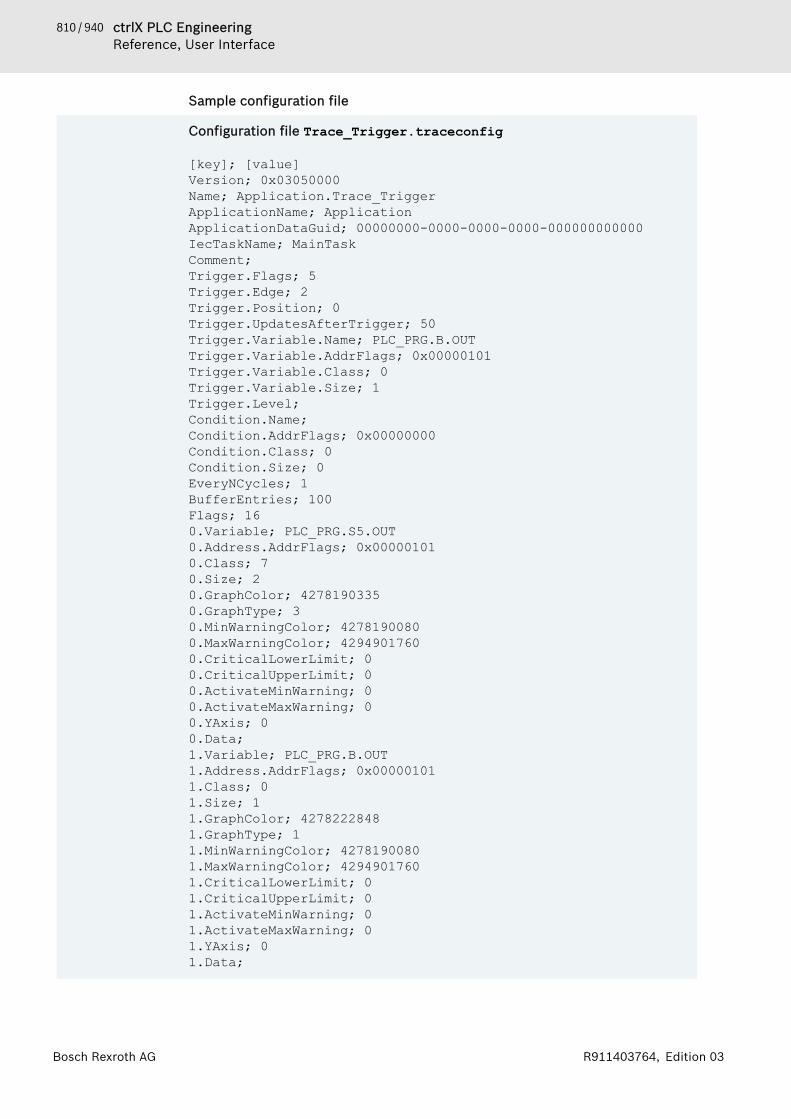
810 / 940 ctrlX PLC EngineeringReference, User Interface
Bosch Rexroth AG R911403764, Edition 03
Sample configuration file
Configuration file Trace_Trigger.traceconfig
[key]; [value]Version; 0x03050000Name; Application.Trace_TriggerApplicationName; ApplicationApplicationDataGuid; 00000000-0000-0000-0000-000000000000IecTaskName; MainTaskComment; Trigger.Flags; 5Trigger.Edge; 2Trigger.Position; 0Trigger.UpdatesAfterTrigger; 50Trigger.Variable.Name; PLC_PRG.B.OUTTrigger.Variable.AddrFlags; 0x00000101Trigger.Variable.Class; 0Trigger.Variable.Size; 1Trigger.Level; Condition.Name; Condition.AddrFlags; 0x00000000Condition.Class; 0Condition.Size; 0EveryNCycles; 1BufferEntries; 100Flags; 160.Variable; PLC_PRG.S5.OUT0.Address.AddrFlags; 0x000001010.Class; 70.Size; 20.GraphColor; 42781903350.GraphType; 30.MinWarningColor; 42781900800.MaxWarningColor; 42949017600.CriticalLowerLimit; 00.CriticalUpperLimit; 00.ActivateMinWarning; 00.ActivateMaxWarning; 00.YAxis; 00.Data; 1.Variable; PLC_PRG.B.OUT1.Address.AddrFlags; 0x000001011.Class; 01.Size; 11.GraphColor; 42782228481.GraphType; 11.MinWarningColor; 42781900801.MaxWarningColor; 42949017601.CriticalLowerLimit; 01.CriticalUpperLimit; 01.ActivateMinWarning; 01.ActivateMaxWarning; 01.YAxis; 01.Data;

811 / 940ctrlX PLC EngineeringReference, User Interface
Bosch Rexroth AGR911403764, Edition 03
See also● ⮫ Chapter “Managing Trace” on page 226
Command 'Load Trace'Function: This command makes it possible to load a file, which contains theconfiguration and data, and was saved to the file system of the developmentsystem. The “Load Trace” dialog box opens.Call: Main menu “Trace”, or context menu.
Dialog box “Load Trace”
“File name” Name of the file that is loaded“File type” File format
● *.trace: “Trace file” that includes the trace configuration● *.csv: Text file in CSV format that includes a trace configuration
See also● ⮫ Chapter “Command 'Save Trace'” on page 813● ⮫ Chapter “Managing Trace” on page 226
Command 'Mouse Zooming'Symbol: (command disabled), (command enabled)Function: This command enables and disables mouse zooming in the trace dia-gram.Call: Menu bar: “Trace”; context menu.
User input in the trace diagramIf the command is enabled, then you can stretch a box with the mouse. Whenyou release the mouse button, the display zooms in on the box and the data isenlarged.
See also● ⮫ Chapter “Navigating into Trace Data” on page 225
Command 'Convert to Multi-Channel'Function: This command switches the display in the trace editor from single-channel to multi-channel.Call: Menu bar: “Trace”; context menu.
Multi-channel displayMulti-channel display means that the trace variables are displayed in multiplediagrams.
See also● ⮫ Chapter “Dialog 'Trace Configuration'” on page 866● ⮫ Chapter “Navigating into Trace Data” on page 225
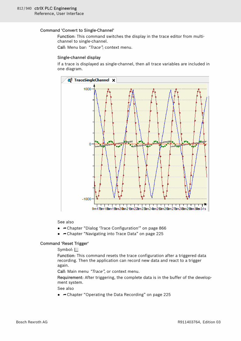
812 / 940 ctrlX PLC EngineeringReference, User Interface
Bosch Rexroth AG R911403764, Edition 03
Command 'Convert to Single-Channel'Function: This command switches the display in the trace editor from multi-channel to single-channel.Call: Menu bar: “Trace”; context menu.
Single-channel displayIf a trace is displayed as single-channel, then all trace variables are included inone diagram.
See also● ⮫ Chapter “Dialog 'Trace Configuration'” on page 866● ⮫ Chapter “Navigating into Trace Data” on page 225
Command 'Reset Trigger'Symbol: Function: This command resets the trace configuration after a triggered datarecording. Then the application can record new data and react to a triggeragain.Call: Main menu “Trace”, or context menu.Requirement: After triggering, the complete data is in the buffer of the develop-ment system.See also● ⮫ Chapter “Operating the Data Recording” on page 225
813 / 940ctrlX PLC EngineeringReference, User Interface
Bosch Rexroth AGR911403764, Edition 03
Command 'Reset View'Symbol: Function: This command resets the trace diagram to the default view.Call: Main menu “Trace”, or context menu.Requirement: The display in the trace diagram has been changed by zooming,scrolling, or “AutoFit”.See also● ⮫ Chapter “Command 'AutoFit'” on page 807● ⮫ Chapter “Navigating into Trace Data” on page 225
Command 'Save Trace'Function: This command saves the data to a file on the development system.Depending on the file format, the configuration may also be saved. The “SaveTrace” dialog box opens.Call: Main menu “Trace”, or right-click.
Dialog Box 'Save Trace'
“File name” Name and location of the trace file“File type” File format
● *.trace:“Trace file” contains the data and configuration.You can run the “Load Trace” command to load the file to the traceeditor when offline.
● *.txt:“Text file” contains the recorded data. You can load this file typeand edit it with tools that support CSV format.It cannot be loaded to the trace editor when offline because thetrace editor cannot read this format.
● *.trace.csv“Trace CSV file (data only)” contains the recorded data. Addressinformation is provided for each trace variable. The created file canbe read in the runtime system. The data is imported but the tracecannot be started because the variable addresses are not saved.
See also● ⮫ Chapter “Command 'Load Trace'” on page 811● ⮫ Chapter “Managing Trace” on page 226
Command 'Start Trace'Symbol: Function: This command starts the data recording on the controller when it isstopped.Call: Main menu “Trace”, or context menu.Requirement: The assigned application on the runtime system is running and atrace configuration is loaded.See also● ⮫ Chapter “Operating the Data Recording” on page 225
Command 'Stop Trace'Symbol: Function: This command stops the data recording of a trace.
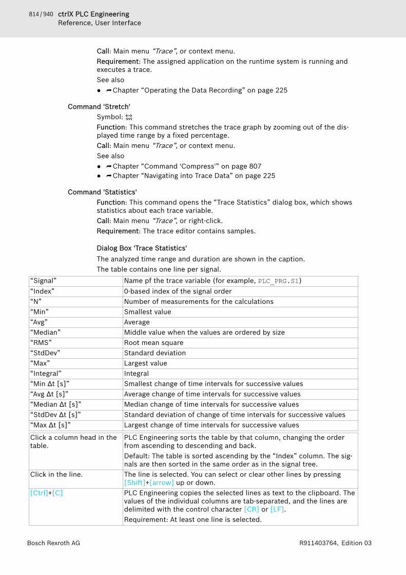
814 / 940 ctrlX PLC EngineeringReference, User Interface
Bosch Rexroth AG R911403764, Edition 03
Call: Main menu “Trace”, or context menu.Requirement: The assigned application on the runtime system is running andexecutes a trace.See also● ⮫ Chapter “Operating the Data Recording” on page 225
Command 'Stretch'Symbol: Function: This command stretches the trace graph by zooming out of the dis-played time range by a fixed percentage.Call: Main menu “Trace”, or context menu.See also● ⮫ Chapter “Command 'Compress'” on page 807● ⮫ Chapter “Navigating into Trace Data” on page 225
Command 'Statistics'Function: This command opens the “Trace Statistics” dialog box, which showsstatistics about each trace variable.Call: Main menu “Trace”, or right-click.Requirement: The trace editor contains samples.
Dialog Box 'Trace Statistics'The analyzed time range and duration are shown in the caption.The table contains one line per signal.
“Signal” Name pf the trace variable (for example, PLC_PRG.S1)“Index” 0-based index of the signal order“N” Number of measurements for the calculations“Min” Smallest value“Avg” Average“Median” Middle value when the values are ordered by size“RMS” Root mean square“StdDev” Standard deviation“Max” Largest value“Integral” Integral“Min Δt [s]” Smallest change of time intervals for successive values“Avg Δt [s]” Average change of time intervals for successive values“Median Δt [s]” Median change of time intervals for successive values“StdDev Δt [s]” Standard deviation of change of time intervals for successive values“Max Δt [s]” Largest change of time intervals for successive values
Click a column head in thetable.
PLC Engineering sorts the table by that column, changing the orderfrom ascending to descending and back.Default: The table is sorted ascending by the “Index” column. The sig-nals are then sorted in the same order as in the signal tree.
Click in the line. The line is selected. You can select or clear other lines by pressing[Shift]+[arrow] up or down.
[Ctrl]+[C] PLC Engineering copies the selected lines as text to the clipboard. Thevalues of the individual columns are tab-separated, and the lines aredelimited with the control character [CR] or [LF].Requirement: At least one line is selected.

815 / 940ctrlX PLC EngineeringReference, User Interface
Bosch Rexroth AGR911403764, Edition 03
See also● ⮫ Chapter 1.12.3 “Data Recording with Trace” on page 220
OtherCommand 'Add Watch'. . . . . . . . . . . 815Command 'Implement Interfaces'. . 815Command 'Limit Results to CurrentDeclaration'. . . . . . . . . . . . . . . . . . . 815
Command 'Add Watch'Symbol: Function: This command adds the variable of the current location of the cursorto a watchlist for the purpose of online monitoring.Call: Right-click a variable in an editor when the application is in online mode.This command adds the variable to the currently opened watchlist. If a watch-list is not open, then the variable is added to the “Watch 1” list and that viewopens.See also● ⮫ Chapter “Using watch lists” on page 215● ⮫ Chapter 1.12.1 “Monitoring of Values” on page 208
Command 'Implement Interfaces'Function: This command updates the implemented interfaces for a functionblock.Call: Context menu of the selected function block (FB) in the device tree.Requirement: The function block implements an interface that you have modi-fied. For example, an additional method was added to the interface.In object-oriented programming, if you derive a function block (FB) from a basefunction block, which implements one or more interfaces, for the purpose ofinheritance, then the following applies:When you execute the “Implement Interfaces” command for the derived FB, allinterface methods and interface attributes of the base FB are accepted into thederived FB in the form of stubs (without implementation). Then you are respon-sible for making sure that an "empty" method/attribute in the derived FB doesnot conflict with an implemented one in the base FB. The following actions aretaken to support you in this case: If there es a base implementation for amethod/attribute, then PLC Engineering adds a pragma attribute {error..} in thefirst line of the affected derived interface method or interface attribute that willgenerate the error message. If there is no base implementation for the method/attribute, then there is a pragma attribute entry for a warning. After editing theblock, you must remove the error pragma attribute entry explicitly.See also● ⮫ Chapter “Object 'Interface'” on page 594● ⮫ Chapter “Implementing Interfaces” on page 154
Command 'Limit Results to Current Declaration'Function: When multiple declarations have been found, this command collapsesthe display in the cross-reference list. It shows only the results for the declara-tion that you selected explicitly in the list.Call: Right-click.Requirement: The cross-reference list is active. Multiple declarations for thesearched symbol are listed as cross-references.

816 / 940 ctrlX PLC EngineeringReference, User Interface
Bosch Rexroth AG R911403764, Edition 03
See also● ⮫ Chapter “Using the Cross-Reference List to Find Occurrences”
on page 123
1.19.3 DialogsDialog 'Import Assistant'. . . . . . . . . 816Dialog 'Library Reference Conver-sion'. . . . . . . . . . . . . . . . . . . . . . . . . 817Dialog 'Select Function Block'. . . . . 817Dialog 'Device Conversion' . . . . . . . 818Dialog 'Breakpoint Properties'. . . . . 818Dialog 'Permissions'. . . . . . . . . . . . . 819Dialog 'Prepare Value'. . . . . . . . . . . 820Dialog 'New Breakpoint'. . . . . . . . . . 820Dialog 'Monitoring Range'. . . . . . . . 822Dialog 'Properties'. . . . . . . . . . . . . . 822Dialog 'Project Settings'. . . . . . . . . . 835Dialog 'Project Environment'. . . . . . 845Dialog 'Options'. . . . . . . . . . . . . . . . 848Dialog 'Customize'. . . . . . . . . . . . . . 863Dialog 'Trace Configuration'. . . . . . . 865Dialog 'Trend Storage'. . . . . . . . . . . 870Dialog 'Advanced Trend Settings'. . . 871Dialog 'Certificate Selection'. . . . . . 871
The dialogs of the PLC Engineering user interface bascally are described on thehelp pages for the PLC Engineering menu commands or PLC Engineeringobjects. The help book “Dialogs” contains only descriptions of dialogs, which● appear only after multi-step calls after a certain menu command call or
within an object editor,● or which are not placed on a help page for a command or for an object
because of their complexity (multiple subdialogs).
Dialog 'Import Assistant'Function: The dialog allows for the transfer of PLC Engineering options andpackage installations from an older PLC Engineering installation that was foundin the local computer.Call: The dialog opens when a recently installed PLC Engineering version isstarted for the first time and an older version is installed on the computer.
“Program settings” : The user-specific PLC Engineering options are transferred from theolder installation to the new installation.
“Packages” : The packages installed with the older PLC Engineering version aretransferred to the Package Manager of the new version. See the list ofdiscovered package installations with the “Name”, “Version”, and“Installation date”.
“Import” The program settings and/or options are transferred to the currentPLC Engineering version.
“Skip” The program settings and/or options are not transferred to the currentPLC Engineering version.

817 / 940ctrlX PLC EngineeringReference, User Interface
Bosch Rexroth AGR911403764, Edition 03
See also● ⮫ Chapter 1.1.1 “Setting PLC Engineering Options” on page 9
Dialog 'Library Reference Conversion'Function: The dialog defines how references to libraries that are no longer avail-able are to be handled. Note: The undefined library references can be found inthe Global Library Manager located in the “POUs” view.Call: When opening a CoDeSys V2.3 project in V3, the dialog opens when theconverter detects a library which cannot be used anymore in the current PLCEngineering version.A CoDeSys V2.3 project can be converted into a PLC Engineering V3 projectonly if the CODESYS V2.3 Converter package is installed in PLC Engineering V3.The package is available in the CODESYS Store.
Table 158: “What do you want to do?”“Convert and install thelibrary as well.”
The converter also converts the library file into the new format. Itremains referenced in the project. It is installed automatically in thelibrary repository in the "Other" category. If the library does not pro-vide the necessary project information for an installation, then the“Enter Project Information” dialog opens for the information to beadded.
“Use the following librarythat has already beeninstalled”
The previously used library is replaced by another library. The“Browse” button opens a dialog for selecting from the local libraryrepository.
“Ignore the library. The ref-erence will not appear inthe converted project”
The library reference is removed from the project.
“Remember this mappingfor all future occurrences ofthat library reference”
The settings made here in the dialog are also used for future projectconversions.
See also● ⮫ Chapter “Command 'Library Repository'” on page 742
Dialog 'Select Function Block'Function: The dialog is used for selecting a function block for I/O mapping. Thefunction block should be mapped to the I/O channel selected in the “<devicename> I/O Mapping” tab or to the object selected in the “<device name> IECObjects” tab.Call:● Tab “<device name> I/O Mapping”, command button “Add FB for I/O
channel”● Tab “<device name> IEC Objects”, command button “Add”The dialog provides all function blocks from the active application and the libra-ries included in the project which fulfill the following:● The function block has the {attribute 'io_function_block'} attribute.● The function block contains input or output parameters that match the
channel type (input, output, data type) and has the {attribute 'io_func-tion_block_mapping'} attribute.
When a function block is selected that provides multiple matching parameters,only the first one is mapped automatically to the channel. The others can onlybe assigned manually in the “<device name> I/O Mapping” tab.

818 / 940 ctrlX PLC EngineeringReference, User Interface
Bosch Rexroth AG R911403764, Edition 03
After the function block is assigned, the parameter of the function blockinstance is entered in the “Variable” column of the mapping table. Then thepath is composed as follows:<application name>.<device channel name>_<FB name>_<continuousFB instance number>. <FB parameter name>Example: App1.Out_4_Int_myScale_Output_Int_1.iOutput for the param-eter iOutput of the first inserted instance of the function blockmyScale_Output.
“Find” Input field for searching for function block names“Type” Function blocks in the tree structure that match the channel type.
Nodes: application, library name(s)“Documentation” Shows the available documentation for the library selected in the tree
or the library block.See also● ⮫ Chapter “Tab '<device name> I/O Mapping'” on page 568● ⮫ Chapter “Attribute 'io_function_block', 'io_function_block_mapping'”
on page 435
Dialog 'Device Conversion'Function: The dialog defines how references to devices that are no longer avail-able are to be handled.Call: When opening a CoDeSys V2.3 project in V3, the dialog opens when theconverter detects a device reference which cannot be used anymore.A CoDeSys V2.3 project can be converted into a PLC Engineering V3 projectonly if the CODESYS V2.3 Converter package is installed in PLC Engineering V3.The package is available in the CODESYS Store.
Table 159: “What do you want to do?”“Use the following devicethat has already beeninstalled”
PLC Engineering replaces the previously used device in the device treewith another device. The “Browse” button opens a dialog for selectingfrom the local device repository.
“Ignore the device. Alldevice specific objects willnot be available in the newproject”
The device entry with all objects inserted below it is removed from thedevice tree.
“Remember this mappingfor all future occurrences ofthat device”
The settings made here in the dialog are saved in the PLC EngineeringOptions, in the “PLC Engineering V2.3 Converter” category. As a result,they are also valid for future project conversions.
See also● ⮫ Chapter “Command 'Device Repository'” on page 747
Dialog 'Breakpoint Properties'Function: The dialog is used to display or change the properties of the selectedbreakpoint in the “Breakpoints” view.Call:● “Breakpoints” view, “Properties” button● “Breakpoints” view, “New” button, “New Breakpoint” command or “New
Data Breakpoint” commandRequirement: An entry is selected in the list of breakpoints.The dialog is identical to the “New Breakpoint” dialog which is opened in the“Debug” menu by means of the respective commands. Therefore, see thedescription in the help for the “New Breakpoint” dialog.
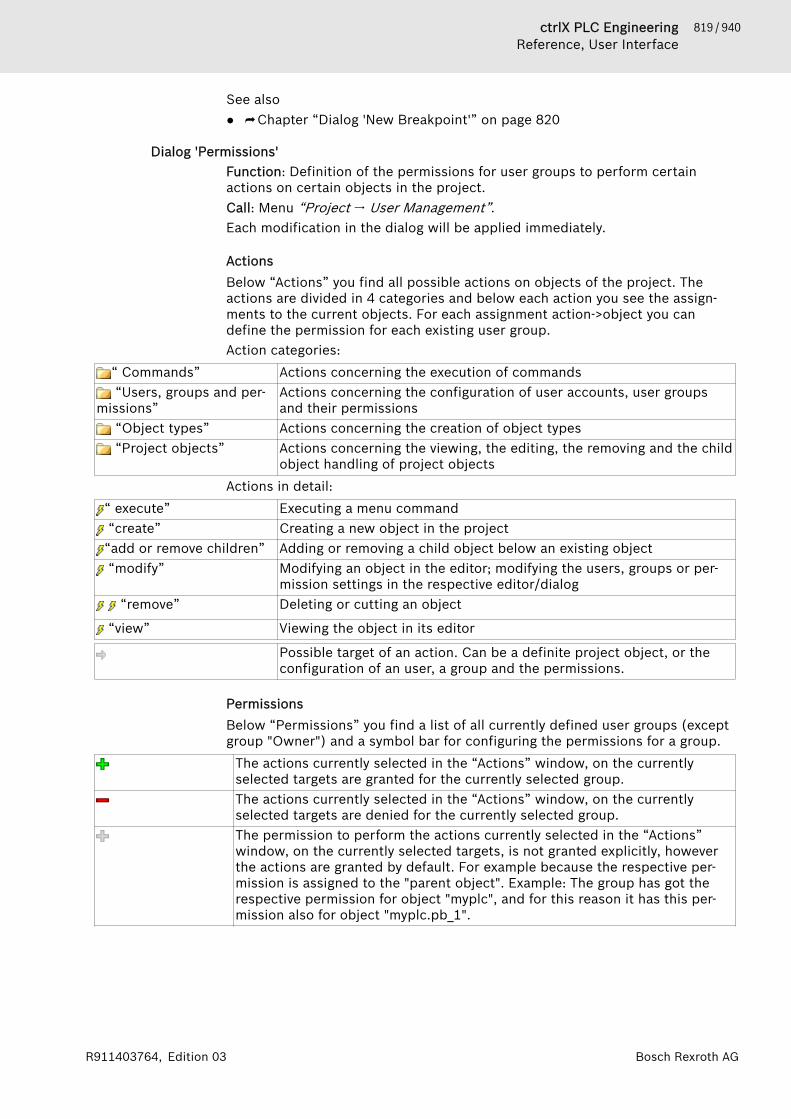
819 / 940ctrlX PLC EngineeringReference, User Interface
Bosch Rexroth AGR911403764, Edition 03
See also● ⮫ Chapter “Dialog 'New Breakpoint'” on page 820
Dialog 'Permissions'Function: Definition of the permissions for user groups to perform certainactions on certain objects in the project.Call: Menu “Project 🠂 User Management”.Each modification in the dialog will be applied immediately.
ActionsBelow “Actions” you find all possible actions on objects of the project. Theactions are divided in 4 categories and below each action you see the assign-ments to the current objects. For each assignment action->object you candefine the permission for each existing user group.Action categories:
“ Commands” Actions concerning the execution of commands “Users, groups and per-
missions”Actions concerning the configuration of user accounts, user groupsand their permissions
“Object types” Actions concerning the creation of object types “Project objects” Actions concerning the viewing, the editing, the removing and the child
object handling of project objectsActions in detail:
“ execute” Executing a menu command “create” Creating a new object in the project“add or remove children” Adding or removing a child object below an existing object “modify” Modifying an object in the editor; modifying the users, groups or per-
mission settings in the respective editor/dialog “remove” Deleting or cutting an object
“view” Viewing the object in its editor
Possible target of an action. Can be a definite project object, or theconfiguration of an user, a group and the permissions.
PermissionsBelow “Permissions” you find a list of all currently defined user groups (exceptgroup "Owner") and a symbol bar for configuring the permissions for a group.
The actions currently selected in the “Actions” window, on the currentlyselected targets are granted for the currently selected group.The actions currently selected in the “Actions” window, on the currentlyselected targets are denied for the currently selected group.The permission to perform the actions currently selected in the “Actions”window, on the currently selected targets, is not granted explicitly, howeverthe actions are granted by default. For example because the respective per-mission is assigned to the "parent object". Example: The group has got therespective permission for object "myplc", and for this reason it has this per-mission also for object "myplc.pb_1".
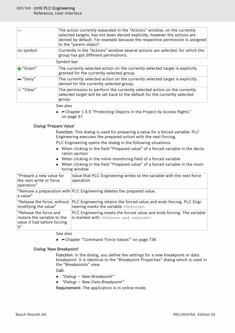
820 / 940 ctrlX PLC EngineeringReference, User Interface
Bosch Rexroth AG R911403764, Edition 03
The action currently expanded in the “Actions” window, on the currentlyselected targets, has not been denied explicitly, however the actions aredenied by default. For example because the respective permission is assignedto the "parent object".
no symbol Currently in the “Actions” window several actions are selected, for which thegroup has got different permissions.
Symbol bar: “Grant” The currently selected action on the currently selected target is explicitly
granted for the currently selected group. “Deny” The currently selected action on the currently selected target is explicitly
denied for the currently selected group. “Clear” The permission to perform the currently selected action on the currently
selected target will be set back to the default for the currently selectedgroup.
See also● ⮫ Chapter 1.5.5 “Protecting Objects in the Project by Access Rights”
on page 37
Dialog 'Prepare Value'Function: This dialog is used for preparing a value for a forced variable. PLCEngineering executes the prepared action with the next forcing.PLC Engineering opens the dialog in the following situations:● When clicking in the field “Prepared value” of a forced variable in the decla-
ration section● When clicking in the inline monitoring field of a forced variable● When clicking in the field “Prepared value” of a forced variable in the moni-
toring window“Prepare a new value forthe next write or forceoperation”
Value that PLC Engineering writes to the variable with the next forceoperation
“Remove a preparation witha value”
PLC Engineering deletes the prepared value.
“Release the force, withoutmodifying the value”
PLC Engineering retains the forced value and ends forcing. PLC Engi-neering marks the variable <Unforce>.
“Release the force andrestore the variable to thevalue it had before forcingit”
PLC Engineering resets the forced value and ends forcing. The variableis marked with <Unforce and restore>.
See also● ⮫ Chapter “Command 'Force Values'” on page 736
Dialog 'New Breakpoint'Function: In the dialog, you define the settings for a new breakpoint or databreakpoint. It is identical to the “Breakpoint Properties” dialog which is used inthe “Breakpoints” view.Call:● “Debug 🠂 New Breakpoint”● “Debug 🠂 New Data Breakpoint”Requirement: The application is in online mode.

821 / 940ctrlX PLC EngineeringReference, User Interface
Bosch Rexroth AGR911403764, Edition 03
Tab 'Condition'The dialog defines the requirements for which program processing should haltat a breakpoint.
NOTICE Using conditional breakpoints slows down code execu-tion, even when the condition does not yield TRUE.
Conditional breakpoints required a PLC Engineering runtime >= V3.5.4.0.
Table 160: “Tasks”“Only break if the break-point is hit in one of the fol-lowing tasks”
: PLC Engineering evaluates the breakpoint only if it is reached byspecific tasks. The required tasks must be activated.For example, you can define a single debug task and also prevent othertasks that use the same block from being affected when debugging.
Table 161: “Hit Count”“Hit Count” “Break always”: The program always halts at this breakpoint.
Alternative: The program halts at the breakpoint when the breakpointhas been hit as often as defined in the following (type in the requiredhit count or select it from the number list):● “Break when the hit count is equal to”● “Break when the hit count is a multiple of ”● “Break when the hit count is greater than or equal to”
Table 162: “Condition”“Break, if true” : PLC Engineering evaluates the specified condition and halts the
program at the breakpoint only when the result yields TRUE. You candefine a condition as a valid Boolean expression. Examples: x>100,x[y]=z, a AND b, boolVar.
Tab 'Data'Requirement: This is used for the properties of a data breakpoint.
On the tab, the variable or memory address is specified for which the data breakpoint is set or willbe set.“Break execution when thevalue of the variable oraddress changes ”
● Input of a qualified variable name● : Selection of a variable in the “Input Assistant” dialog, in the
“Watch Variables” categoryExamples: Variable: PLC_PRG.fb_DoSth.dwVariable, address:16#12A, 0x12A, 129
“Size” Number of bytes of the specified variable or memory address abovewhich should be monitored for changes. When a new variable ormemory address is specified, a value that matches the data type ormemory is set automatically at first.Example: 4 for data type DWORD
Tab 'Execution Point Settings'Here. an existing breakpoint or data breakpoint can be converted into an execu-tion point.
“Execution point (Executiondoes not stop at break-point)”
: The breakpoint becomes an execution point. Processing does nothalt at this point and the given code is executed.● Execution point of a breakpoint: activated: ; deactivated: ● Execution point of a data breakpoint: activated: ; deactivated:
“Execute the followingcode”
Code that is executed when the execution point is reached.

822 / 940 ctrlX PLC EngineeringReference, User Interface
Bosch Rexroth AG R911403764, Edition 03
Looping structures (For, While) and IF or CASE expressions are notpossible.
“Print a message in thedevice log”
This option is available only when you select the “Enable logging inbreakpoints” option in “Project Settings 🠂 Compile Options”.PLC Engineering can print variables with the placeholder {variablename} in the message text.
Tab 'Location'Requirement: The command “New breakpoint” was selected.
“POU” POU of the active application where the breakpoint is placed.“Position” Position of the breakpoint in the POU. Entry as row and column num-
bers (text editor) or as network or element numbers.“Instances” In the case of function blocks, you must define whether the breakpoint
should be set in the implementation or in an instance. PLC Engineering sets the breakpoint in the instance. For this option,
select “Instance Path”. PLC Engineering sets the breakpoint in the implementation.
“Enable breakpoint immedi-ately”
: The breakpoint is activated.: The breakpoint is not activated. To activate later, click the
button in the “Breakpoints” view.
See also● ⮫ Chapter “Dialog 'Breakpoint Properties'” on page 818● ⮫ Chapter 1.11.2 “Using Breakpoints” on page 196
Dialog 'Monitoring Range'Function: This dialog restricts the range of array elements whose values are dis-played during monitoring.Call: Click in the column field “Data Type” that belongs to the array variable.Requirement: A POU is in online mode and is being monitored. In addition, avariable of the POU has the data type “ARRAY”.
“Valid range” The validity range of the array elements that are monitored.Example of a three-dimensional array: [1..10][-3..3][-10..10]
“Maximum number of arrayelements”
Number of elements of the array variablesExample: 1470
When you edit one of the settings “Start”, “End”, or “Scroll range of 1000 elements”, both of theother settings are adapted automatically.“Start” Index of the first array element whose value is displayed.“End” Index of the last array element whose value is displayed.“Scroll range of 1000 ele-ments”
Scrollbar for selecting a range from the set of array elements.
See also● ⮫ Chapter “Calling of Monitoring in Programming Objects ” on page 209
Dialog 'Properties'Dialog 'Properties' - 'Common'. . . . . 823Dialog 'Properties' - 'Boot Applica-tion'. . . . . . . . . . . . . . . . . . . . . . . . . 823
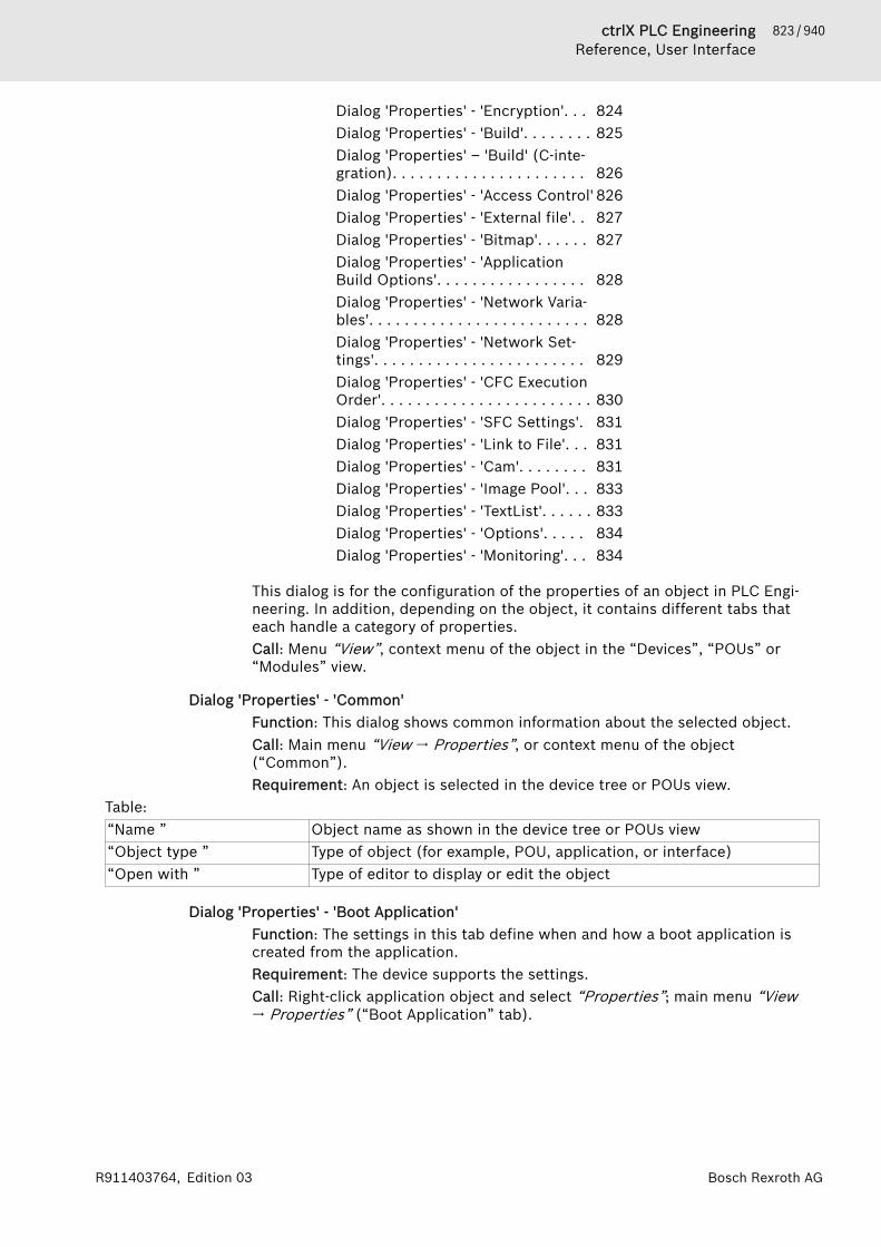
823 / 940ctrlX PLC EngineeringReference, User Interface
Bosch Rexroth AGR911403764, Edition 03
Dialog 'Properties' - 'Encryption'. . . 824Dialog 'Properties' - 'Build'. . . . . . . . 825Dialog 'Properties' – 'Build' (C-inte-gration). . . . . . . . . . . . . . . . . . . . . . 826Dialog 'Properties' - 'Access Control' 826Dialog 'Properties' - 'External file'. . 827Dialog 'Properties' - 'Bitmap'. . . . . . 827Dialog 'Properties' - 'ApplicationBuild Options'. . . . . . . . . . . . . . . . . 828Dialog 'Properties' - 'Network Varia-bles'. . . . . . . . . . . . . . . . . . . . . . . . . 828Dialog 'Properties' - 'Network Set-tings'. . . . . . . . . . . . . . . . . . . . . . . . 829Dialog 'Properties' - 'CFC ExecutionOrder'. . . . . . . . . . . . . . . . . . . . . . . . 830Dialog 'Properties' - 'SFC Settings'. 831Dialog 'Properties' - 'Link to File'. . . 831Dialog 'Properties' - 'Cam'. . . . . . . . 831Dialog 'Properties' - 'Image Pool'. . . 833Dialog 'Properties' - 'TextList'. . . . . . 833Dialog 'Properties' - 'Options'. . . . . 834Dialog 'Properties' - 'Monitoring'. . . 834
This dialog is for the configuration of the properties of an object in PLC Engi-neering. In addition, depending on the object, it contains different tabs thateach handle a category of properties.Call: Menu “View”, context menu of the object in the “Devices”, “POUs” or“Modules” view.
Dialog 'Properties' - 'Common'Function: This dialog shows common information about the selected object.Call: Main menu “View 🠂 Properties”, or context menu of the object(“Common”).Requirement: An object is selected in the device tree or POUs view.
Table: “Name ” Object name as shown in the device tree or POUs view“Object type ” Type of object (for example, POU, application, or interface)“Open with ” Type of editor to display or edit the object
Dialog 'Properties' - 'Boot Application'Function: The settings in this tab define when and how a boot application iscreated from the application.Requirement: The device supports the settings.Call: Right-click application object and select “Properties”; main menu “View🠂 Properties” (“Boot Application” tab).
824 / 940 ctrlX PLC EngineeringReference, User Interface
Bosch Rexroth AG R911403764, Edition 03
Table 163: “<group name>”“Create implicit boot appli-cation on download”
A boot application is created automatically when downloading theapplication.
“Create implicit boot appli-cation on Online Change”
A boot application is created automatically when for an online change.
“Remind boot applicationon project close”
Before closing the project, PLC Engineering prompts to create theboot application.
Regardless of the presets defined here, you are always able to create a bootapplication explicitly when you log in.See also● ⮫ Chapter 1.10.6 “Generating Boot Applications” on page 194● ⮫ Chapter “Command 'Online Change'” on page 722
Dialog 'Properties' - 'Encryption'Function: The dialog contains the properties of the application for encryption.If the CODESYS Security Agent is installed, then you can start a wizard for theencryption of downloads, online changes, and boot applications.Call:● Menu bar: “View 🠂 Properties”● Context menu of an application object
Table 164: “Encryption Technology”If the “Enforce encryption of downloads, online changes and boot applications” option is selectedin the “Security Screen” view in the “Security level” group, then the encryption technology is set to“Encryption with certificates” and cannot be changed in this dialog.“No Encryption”“Simple Encryption” You can download the boot application to the controller only when the
defined dongle (license key) is connected to the computer.The dongle is provided by Bosch Rexroth AG or by the respective hard-ware manufacturer. The firmcode is displayed. Type in the deliveredproduct code.
“Encryption with licensemanagement”
You can download the boot application to the controller only after youhave specified the product code and firmcode, and the respectivedongle is connected to both the development computer and the con-troller. You receive the codes from the vendor that manages thelicenses.
“Encryption with certifi-cates”
You can download the boot application to the controller only when avalid certificate exists for it. The “Certificates” group is enabled. Seethe description below.The option is already selected if the “Enforce signing of downloads,online changes and boot applications” option is selected on the “User”tab of the “Security Screen” view.
Table 165: “Certificates”Note: If the “Enforce encryption of downloads, online changes and boot applications” option isselected in the “Security Screen” view in the “Security level” group, then the encryption technologyis set to “Encryption with certificates” and cannot be changed in the “Properties” dialog.
: The “Certificate Selection” dialog opens. Here you can select previ-ously installed certificates of devices for which the encryption ofdownload, online change, and boot application is enabled. The list cancontain several entries if several devices are authorized to run thisapplication.
825 / 940ctrlX PLC EngineeringReference, User Interface
Bosch Rexroth AGR911403764, Edition 03
“Digitally sign applicationcode”
The application is signed with a digital signature. The certificate forthe digital signature is specified in the “Security Screen” view on the“User” tab.
Area for the display of theselected certificates withcorresponding information
Information per certificate:● “Issued for”● “Issued by”● “Valid from”● “Valid until”● “Thumbprint”
“Encryption Wizard” This button is available only if the CODESYS Security Agent isinstalled. It starts the wizard with the same name. See the help forCODESYS Security Agent in this case.
See also● ⮫ Chapter 1.8.18 “Encrypting an Application” on page 132● ⮫ Chapter “Command 'Security Screen'” on page 688● Help about CODESYS Security Agent
Dialog 'Properties' - 'Build'Symbol: Function: This dialog includes options for compiling the object.Call: Menu bar: “View 🠂 Properties”; context menu of the object in the devicetree.
Name Description“Exclude from build” : This object and inherently its child objects are not considered for
the next compile process.The object entry is displayed in green fonts in the “Devices” or “POUs”view.
“External implementation”“(Late link in the runtimesystem) ”
: PLC Engineering does not generate any code for this object whencompiling the project. The object is linked as soon as the project isrunning on the target system, provided it is available there (forexample, in a library).The object name is postfixed with (EXT) in “Devices” or “POUs” view.
“Enable system call” : A system call (runtime system) for functions is possible.Background: As opposed to CoDeSys V2.3, the ADR operator in V3 canbe used with function names, program names, function block names,and method names. It replaces the INSTANCE_OF operator.BUT: It is not possible to call function pointers from within PLC Engi-neering.
“Link Always” : The object is marked by the compiler and therefore always includedin the compile information. This means that it is always compiled anddownloaded to the PLC.
“Compiler defines” Here you can specify defines or conditions for compiling the object(conditional compile). You can also type in the expression expr, whichis used in these kinds of pragmas. Multiple entries are possible as acomma-separated list (see {define} statements).Example: hello, test:='1'
“Additional compiler definitions from the device description”“Defined in device” List of compiler definitions that originate from the device description.
These compiler definitions are used in the build if they are not listed inthe “Ignored definitions” field.

826 / 940 ctrlX PLC EngineeringReference, User Interface
Bosch Rexroth AG R911403764, Edition 03
Name Description“Ignored definitions” List of compiler definitions from the device description that are not
used in the build.Copies the selected compiler definition from the “Defined in device”field to the “Ignored definitions” field.Moves the selected compiler definition from the “Ignored definitions”field to the “Defined in device” field. The compiler definition is used inthe build.
See also● ⮫ Chapter “Conditional Pragmas” on page 452
Dialog 'Properties' – 'Build' (C-integration)Function: In this dialog, you configure the build environment and the necessarydata for the integration of the C development environment.Call: Main menu “View”, context menu of the object “C Code Module”Requirement: The object “C Code Module” is selected in the device tree.
NOTICE The dialog in this form is valid only for ctrlX CORE andVisual Studio. For other environments, the dialog canlook different or may not even be available at all.
Table: “Visual Studio location” Installation path of Visual Studio on the hard disk
You can also select the path with the input assistant or search for itwith the magnifying glass.
“Windows SDK location” Installation path of Windows SDK on the hard diskYou can also select the path with the input assistant or search for itwith the magnifying glass.
“Temporary build folderLocation”
Path on the hard disk for the temporary build files
See also● ⮫ Chapter “Object 'C Code Module'” on page 551● ⮫ Chapter 1.8.11 “Integrating C Modules” on page 113
Dialog 'Properties' - 'Access Control'Function: The dialog defines the access rights of user groups for objects.Call: Main menu “View 🠂 Properties”, context menu of an object in the view“Device” or “POUs”.Requirement: An object is selected in the view “Device” or in the view “POUs”.
“Groups, actions and permissions” A table which displays the following user groups accessrights on objects:● “View”● “Modify”● “Remove”● “Add/remove children”Perform a double click on the access right symbol to openthe drop down list with the available rights.
See also● ⮫ Chapter 1.5.5 “Protecting Objects in the Project by Access Rights”
on page 37● ⮫ Chapter “Dialog 'Permissions'” on page 819

827 / 940ctrlX PLC EngineeringReference, User Interface
Bosch Rexroth AGR911403764, Edition 03
Dialog 'Properties' - 'External file'Function: The dialog is used to view and edit the properties of the external file.The properties were defined when the object was created. Changed propertiesare saved by pressing the “OK” button.Call: “View 🠂 Properties”; context menu of the objectRequirement: The object of the external file is selected in the “Devices” view or“POUs” view.
Table: “What do you want to do with the external file?”“Remember the link” The file is available in the project only as long as it exists in the
defined file path.“Remember the link andembed into project”
PLC Engineering saves an internal copy of the file in the project, aswell as the link to the defined file path. The update option selectedbelow applies as long as the external file exists there. Otherwise PLCEngineering uses the version saved in the project.
“Embed into project” PLC Engineering saves only one copy of the file in the project. There isno longer a link to the external file.
Table 166: “When the external file changes, then”“reload the file automati-cally”
If the external file changes, then PLC Engineering updates the file inthe project.
“prompt whether to reloadthe file”
If the external file changes, then a dialog prompt opens whether PLCEngineering should also update the file in the project.
“do nothing” The file remains unchanged in the project, even if the external filechanges.
Table 167: “Linked file”Requirement: Either the “Remember the link” option or “Remember the link and embed intoproject” option is selected.The following information about the linked file is shown: “Name”, “Location”, “Size”, “Changed”.“Display file properties” Clicking this button opens the default “Properties of <file name>”
dialog, which you can also open in the Windows file system by right-clicking the file.
Table 168: “Embedded file”Shows the “Size” and “Changed” properties of the embedded file.
See also● ⮫ Chapter “Object 'External File'” on page 551
Dialog 'Properties' - 'Bitmap'Function: The dialog is for assigning a bitmap file to the object. The image willbe used in the graphic view of the Library Manager and in the ToolBox view ofthe FBD/LD/IL editor.Call: Main menu “View 🠂 Properties”, context menu of the objectRequirement: The object is selected in the view “Devices” or in the view“POUs”
“Render pixels of this colortransparently: ”
The selected color will be displayed transparently.
See also● ⮫ Chapter 1.2.3 “Adding Objects” on page 19
828 / 940 ctrlX PLC EngineeringReference, User Interface
Bosch Rexroth AG R911403764, Edition 03
Dialog 'Properties' - 'Application Build Options'Function: This dialog includes settings that PLC Engineering uses for creating aboot application for the controller.Call: Menu bar: “View 🠂 Properties”; context menu of an application object.
“Download Application Info” This feature requires compiler version >=3.5.0.0, runtimesystem version >= 3.5.0.0.The information about the application contents is alsodownloaded to the PLC. We recommend that you keep thisoption activated because it enables a difference checkbetween the current application and the application on thePLC. This compares the number of blocks, data, andmemory locations.To receive information about the differences, click “Details”in the “Applications” tab of the device editor. This is also inthe message view that opens when you are downloading anapplication to the PLC when it is different from the onealready on the PLC.
“Dynamic memory settings” Memory is allocated dynamically for the application, forexample when using the __NEW operator. In this case, definethe “Maximum size of memory (bytes)”.Caution: The entire memory is not available for creatingobjects dynamically. Instead, the system always uses part ofit for management information.
See also● ⮫ Chapter 1.10.4 “Generating Application Code” on page 192● ⮫ Chapter 1.10.6 “Generating Boot Applications” on page 194● ⮫ Chapter “Object 'Application'” on page 528
Dialog 'Properties' - 'Network Variables'Symbol: Function: In this dialog, you define network properties for the variable list thatis selected in the device tree. Furthermore, any variables in it that are declaredas network variables are also available.Call: “Context menu of variable list in device tree 🠂 Properties”, “Network Vari-ables” tab
“Network type” UDP“Task” Task of the current application that controls the variables to
be sent. PLC Engineering always sends the variables at theend of a task cycle.
“List identifier” Used to identify the network variable list. Must be unique“Pack variables” The size of the packages (telegrams) that are transmitted
depends on the network type. In the case of “UDP”, apackage is 256 bytes.
: PLC Engineering bundles the variables for sending inpackages in order to reduce as much as possible thenumber of packages to send. In the case of variables of typearray or structured data types, this can lead to the splittingof the variables into multiple telegrams. As a result, datainconsistencies are possible within these variables, even ifthe variable size is smaller than the package size.
: PLC Engineering generates one package per variable.

829 / 940ctrlX PLC EngineeringReference, User Interface
Bosch Rexroth AGR911403764, Edition 03
“Transmit checksum” : A checksum is provided for each variable package. Thereceiver checks the checksum to make sure that the variabledefinitions match from the sender and receiver. A packagewith non-matching checksums is not accepted.
“Acknowledgement” : PLC Engineering sends an acknowledgement messagefor each received data package. If the sender does notreceive a confirmation before it sends again, then an error iswritten to the diagnostic structure.Note: For the NetVarUdp library version 3.5.7.0 and later, areceiver channel is no longer assigned when confirmedtransfer is not selected. In this way, network variableexchange is also possible between two controllers on onehardware device .
“Cyclic transmission”, “Interval” PLC Engineering sends the variables within the definedinterval. Example for time definition: "T#70ms".
“Transmit on change”, “Minimum gap” : PLC Engineering sends the variables only if their valueshave changed. You can use "minimum gap" to define theleast amount of time between two transmissions.
“Transmit on event”, “Variable” : PLC Engineering sends the variables as soon as thedefined variable yields TRUE.
“Settings” Protocol-specific settings; possible entries depend on thenetwork library.“Port”: Number of the port that PLC Engineering uses fordata exchange with other network units. The “Default value”is "1202". You can change the current value in the “Value”field at any time. Select the field, press the [Space Bar], andtype the value.Caution: The other nodes in the network must define thesame port. If more than one UDP connection is defined inthe project, then the port numbers in all configurations areadapted to this value.“Broadcast Adr.”: The “Default value” is 255.255.255.255,which means that data exchange will take place with all net-work units. You can change the current value in the “Value”:select the field, press the [space bar], and type the addressor address range of a subnetwork (for example,197.200.100.255 when communication should be with allnodes that have an IP address in the range 197.200.100.x.
See also● ⮫ Chapter 1.9.3 “Network Variables” on page 166● ⮫ Chapter “Configuring a Network Variable Exchange” on page 168● ⮫ Chapter “Object 'Network Variable List (Receiver)'” on page 586● ⮫ Chapter “Object 'Network Variable List (Sender)'” on page 586
Dialog 'Properties' - 'Network Settings'If the device supports the network functionality, then the current network set-tings for a GNVL (global network variable list) can be displayed and changed inthe “Properties” dialog of the object. These are the settings that were usedwhen adding the GNVL in the “Add Network Variable List (Receiver)” dialog.See also● ⮫ “Dialog Box 'Add Network Variable List (Receiver)'” on page 587● ⮫ Chapter “Configuring a Network Variable Exchange” on page 168

830 / 940 ctrlX PLC EngineeringReference, User Interface
Bosch Rexroth AG R911403764, Edition 03
Dialog 'Properties' - 'CFC Execution Order'Function: The tab switches the mode of the execution order for CFC objects.Call: Context menu: “Properties” of a CFC object in the “Devices” view or“POUs” view
Tab 'CFC Execution Order'
“Execution order” In the CFC editor, you position the elements and therefore also thenetworks freely. Two modes are available to prevent the executionorder in the CFC POU from being undefined.
“Auto Data Flow Mode” In this mode, the execution order is determined automatically by dataflow, or in case of ambiguity, by network topology. The POUs and theoutputs are numbered internally. The networks are executed from topto bottom and left to right.Advantage: The automatically defined execution order is optimized bytime and by cycle. You do not need any information about the inter-nally managed execution order during the development process.The following commands are provided afterwards in the “CFC🠂 Execution Order” menu:● “Display Execution Order”● “Set Start of Feedback”The elements in the CFC editor are displayed without markers andwithout numbering. It is not possible to change the execution ordermanually. For networks with feedback, you can also set a startingpoint.
“Explicit Execution OrderMode”
In this mode, you can define the execution order explicitly. To do this,the elements are displayed in the CFC editor with markers and num-bering, and menu commands are provided for defining the order.The following commands are provided in the “CFC 🠂 Execution Order”menu:● “Send to Front”● “Send to Back”● “Move Up”● “Move Down”● “Set Execution Order”● “Order by Data Flow”● “Order by Topology”Note: Up to PLC Engineering V3.5 SP1, this was the usual behavior ofCFC POUs. Pay attention that it is your responsibility to adapt the exe-cution order and assess the consequences and impacts. This isanother reason why the execution order is always displayed.
“Apply to All CFCs” Changes the mode for all other CFC objects in the project to the modeselected in the list
See also● ⮫ Chapter “Automatic Execution Order by Data Flow” on page 80● ⮫ Chapter “Command 'Set Start of Feedback'” on page 767● ⮫ Chapter “Command 'Send to Front'” on page 767● ⮫ Chapter “Command 'Send to Back'” on page 768● ⮫ Chapter “Command 'Move Up'” on page 768● ⮫ Chapter “Command 'Move Down'” on page 769● ⮫ Chapter “Command 'Order by Data Flow'” on page 769● ⮫ Chapter “Command 'Order by Topology'” on page 770
831 / 940ctrlX PLC EngineeringReference, User Interface
Bosch Rexroth AGR911403764, Edition 03
Dialog 'Properties' - 'SFC Settings'Function: The dialog defines the default settings for all POUs used in theproject, which are programmed in SFC.Call: Main menu “View 🠂 Properties”, context menu of a SFC POU in the view“Device” or “POUs”.
Flag
List of all possible SFCflags
“Use” : The SFC flag is activated and will be considered in the pro-gram execution.“Declare” : The SFC flag is declared automatically.If “Declare” is activated, but “Use” is not activated, the variable will bedeclared but the flag has no effect in the program execution.Hint: If you have manually declared a SFC variable you have to disablethe declaration of this flag in the “SFC Settings”. Otherwise the auto-matically generated flag will overwrite the manually declared flag.Hint: A automatically declared flag variable is only visible in the onlinemode in the declaration part of the SFC editor.
“Use defaults” : The settings of this dialog overwrites the “SFC settings” of thesingle POUs.
See also● ⮫ Chapter “SFC Flags” on page 273
BuildTable 169: “Code generation”“Calculate active transitionsonly”
: PLC Engineering generates code for the currently active transitiononly.
Dialog 'Properties' - 'Link to File'Function: The dialog defines the link of an external file with the content of theglobal variable list (GVL). You can either export the GVL to an external file orimport it from an external file.Call: Main menu “View 🠂 Properties”, context menu of a GVL.
“Import before compile” : With each compile of the project (for example with F11) PLC Engi-neering saves a file with extension gvl in the directory defined in “Filename”.
“Export before compile” : An existing export file is read automatically with each project com-pile. Thus you can import a GVL exported from a different project, forexample to setup a communication via network variables.
See also● ⮫ Chapter “Object 'GVL' - Global Variable List” on page 581● ⮫ Chapter “Configuring a Network Variable Exchange” on page 168
Dialog 'Properties' - 'Cam'Function: Use this dialog to define the global variables of the cam.
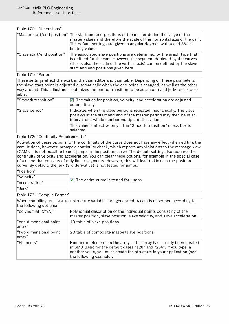
832 / 940 ctrlX PLC EngineeringReference, User Interface
Bosch Rexroth AG R911403764, Edition 03
Table 170: “Dimensions”“Master start/end position” The start and end positions of the master define the range of the
master values and therefore the scale of the horizontal axis of the cam.The default settings are given in angular degrees with 0 and 360 aslimiting values.
“Slave start/end position” The associated slave positions are determined by the graph type thatis defined for the cam. However, the segment depicted by the curves(this is also the scale of the vertical axis) can be defined by the slavestart and end positions given here.
Table 171: “Period”These settings affect the work in the cam editor and cam table. Depending on these parameters,the slave start point is adjusted automatically when the end point is changed, as well as the otherway around. This adjustment optimizes the period transition to be as smooth and jerk-free as pos-sible.“Smooth transition” : The values for position, velocity, and acceleration are adjusted
automatically.“Slave period” Indicates when the slave period is repeated mechanically. The slave
position at the start and end of the master period may then be in aninterval of a whole number multiple of this value.This value is effective only if the “Smooth transition” check box isselected.
Table 172: “Continuity Requirements”Activation of these options for the continuity of the curve does not have any effect when editing thecam. It does, however, prompt a continuity check, which reports any violations to the message view(CAM). It is not possible to edit jumps in the position curve. The default setting also requires thecontinuity of velocity and acceleration. You can clear these options, for example in the special caseof a curve that consists of only linear segments. However, this will lead to kinks in the positioncurve. By default, the jerk (3rd derivative) is not tested for jumps.“Position”
: The entire curve is tested for jumps.“Velocity”“Acceleration”“Jerk”Table 173: “Compile Format”When compiling, MC_CAM_REF structure variables are generated. A cam is described according tothe following options:“polynomial (XYVA)” Polynomial description of the individual points consisting of the
master position, slave position, slave velocity, and slave acceleration.“one dimensional pointarray”
1D table of slave positions
“two dimensional pointarray”
2D table of composite master/slave positions
“Elements” Number of elements in the arrays. This array has already been createdin SM3_Basic for the default cases “128” and “256”. If you type inanother value, you must create the structure in your application (seethe following example).

833 / 940ctrlX PLC EngineeringReference, User Interface
Bosch Rexroth AGR911403764, Edition 03
Example of an array with 720 elements
TYPE SMC_CAMTable_LREAL_720_2 :STRUCTTable: ARRAY[0..719] OF ARRAY[0..1] OF LREAL;fEditorMasterMin, fEditorMasterMax: REAL;fEditorSlaveMin, fEditorSlaveMax: REAL;fTableMasterMin, fTableMasterMax: REAL;fTableSlaveMin, fTableSlaveMax: REAL;
END_STRUCTEND_TYPE
Dialog 'Properties' - 'Image Pool'Function: The dialog allows for setting the basic properties of the selectedimage pool.Call: “View 🠂 Properties” of an “Image Pool” object type; context menu of an“Image Pool” object type.
“Download only usedimages”
: Instead of loading all images from the image pool, PLC Engineeringloads only the images that are actually used in the application on thePLC.
“Download by visualization” : The image pool is downloaded with the visualization to the con-troller.
“Internal” : PLC Engineering does not provide the image pool in the “ToolBox”view. You cannot drag these images to the visualization.
Table 174: “Symbol library settings”“Mark library as symbollibrary”
Marks the image pool as a symbol library for use in a visualization. Thesymbol library receives the key VisuSymbolLibrary = TRUE as fileproperty in the project information. The VisuElements library isinserted automatically as a placeholder library in the “POUs” pool ofthe Library Manager.Requirement: A library project is open.PLC Engineering displays symbol libraries that are installed in therepository in the “Project Settings” (“Visualization” category, “SymbolLibraries” tab).
“Textlist for symbol transla-tion”
Select the text list from the drop-down list that contains the translatedtexts for the image pool.
See also● ⮫ Chapter “Object 'Image Pool'” on page 582● ⮫ Displaying and Marking Visualization Elements● ⮫ Chapter 1.8.10 “Using Image Pools” on page 111● ⮫ Using Text Lists● ⮫ Project Settings - Visualization
Dialog 'Properties' - 'TextList'Function: The dialog allows for setting the basic properties of the selected textlist.Call: “View 🠂 Properties” of an “Text List” object type; context menu of an“Image List” object type.
“Download by visualization” : The text list is downloaded with the visualization to the controller.“Internal” : The text list can be used only in a library. It is not available in an
ordinary PLC Engineering project.
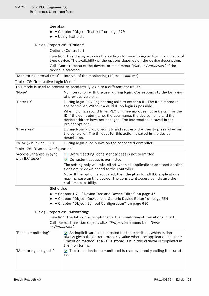
834 / 940 ctrlX PLC EngineeringReference, User Interface
Bosch Rexroth AG R911403764, Edition 03
See also● ⮫ Chapter “Object 'TextList'” on page 629● ⮫ Using Text Lists
Dialog 'Properties' - 'Options'Options (Controller)Function: This dialog provides the settings for monitoring an login for objects oftype device. The availability of the options depends on the device description.Call: Context menu of the device, or main menu “View 🠂 Properties”, if thedevice is selected.
“Monitoring interval (ms)” Interval of the monitoring (10 ms - 1000 ms)Table 175: “Interactive Login Mode”This mode is used to prevent an accidentally login to a different controller.“None” No interaction with the user during login. Corresponds to the behavior
of previous versions.“Enter ID” During login PLC Engineering asks to enter an ID. The ID is stored in
the controller. Without a valid ID no login is possible.When login a second time, PLC Engineering does not ask again for theID if the computer name, the user name, the device name and thedevice address have not changed. The information is saved in theproject options.
“Press key” During login a dialog prompts and requests the user to press a key onthe controller. The timeout for this action is saved in the devicedescription.
“Wink (= blink an LED)” During login a led blinks on the connected controller.Table 176: “Symbol Configuration”“Access variables in syncwith IEC tasks”
: Default setting, consistent access is not permitted: Consistent access is permitted
The setting only will take effect when all applications and boot applica-tions are re-downloaded to the controller.Note: If the option is activated, then the jitter for all IEC applicationsmay increase on this device! The consistent access can disturb thereal-time capability.
Siehe also● ⮫ Chapter 1.7.1 “Device Tree and Device Editor” on page 47● ⮫ Chapter “Object 'Device' and Generic Device Editor” on page 554● ⮫ Chapter “Object 'Symbol Configuration'” on page 630
Dialog 'Properties' - 'Monitoring'Function: The tab contains options for the monitoring of transitions in SFC.Call: Select transition object, click “Properties”; menu bar: “View🠂 Properties”.
“Enable monitoring” : An implicit variable is created for the transition, which is thenalways given the current property value when the application calls theTransition method. The value stored last in this variable is displayed inthe monitoring.
“Monitoring using call” : The transition to be monitored is read by directly calling the transi-tion.
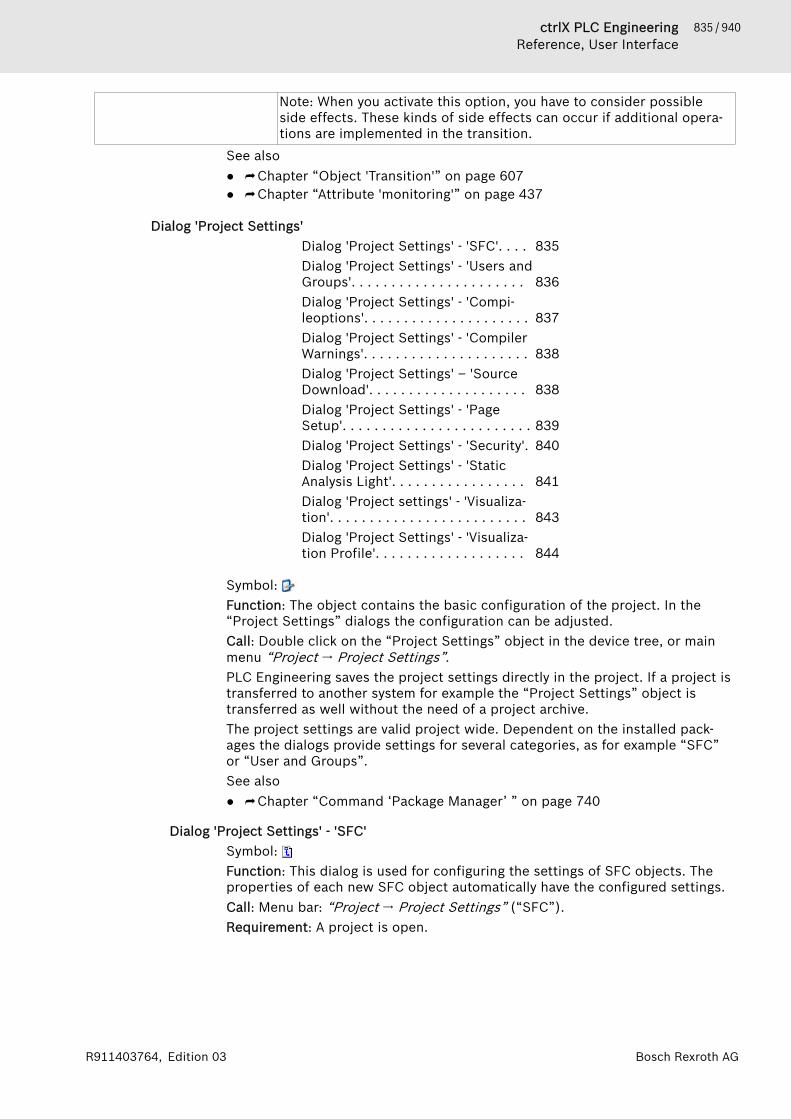
835 / 940ctrlX PLC EngineeringReference, User Interface
Bosch Rexroth AGR911403764, Edition 03
Note: When you activate this option, you have to consider possibleside effects. These kinds of side effects can occur if additional opera-tions are implemented in the transition.
See also● ⮫ Chapter “Object 'Transition'” on page 607● ⮫ Chapter “Attribute 'monitoring'” on page 437
Dialog 'Project Settings'Dialog 'Project Settings' - 'SFC'. . . . 835Dialog 'Project Settings' - 'Users andGroups'. . . . . . . . . . . . . . . . . . . . . . 836Dialog 'Project Settings' - 'Compi-leoptions'. . . . . . . . . . . . . . . . . . . . . 837Dialog 'Project Settings' - 'CompilerWarnings'. . . . . . . . . . . . . . . . . . . . . 838Dialog 'Project Settings' – 'SourceDownload'. . . . . . . . . . . . . . . . . . . . 838Dialog 'Project Settings' - 'PageSetup'. . . . . . . . . . . . . . . . . . . . . . . . 839Dialog 'Project Settings' - 'Security'. 840Dialog 'Project Settings' - 'StaticAnalysis Light'. . . . . . . . . . . . . . . . . 841Dialog 'Project settings' - 'Visualiza-tion'. . . . . . . . . . . . . . . . . . . . . . . . . 843Dialog 'Project Settings' - 'Visualiza-tion Profile'. . . . . . . . . . . . . . . . . . . 844
Symbol: Function: The object contains the basic configuration of the project. In the“Project Settings” dialogs the configuration can be adjusted.Call: Double click on the “Project Settings” object in the device tree, or mainmenu “Project 🠂 Project Settings”.PLC Engineering saves the project settings directly in the project. If a project istransferred to another system for example the “Project Settings” object istransferred as well without the need of a project archive.The project settings are valid project wide. Dependent on the installed pack-ages the dialogs provide settings for several categories, as for example “SFC”or “User and Groups”.See also● ⮫ Chapter “Command ‘Package Manager’ ” on page 740
Dialog 'Project Settings' - 'SFC'Symbol: Function: This dialog is used for configuring the settings of SFC objects. Theproperties of each new SFC object automatically have the configured settings.Call: Menu bar: “Project 🠂 Project Settings” (“SFC”).Requirement: A project is open.
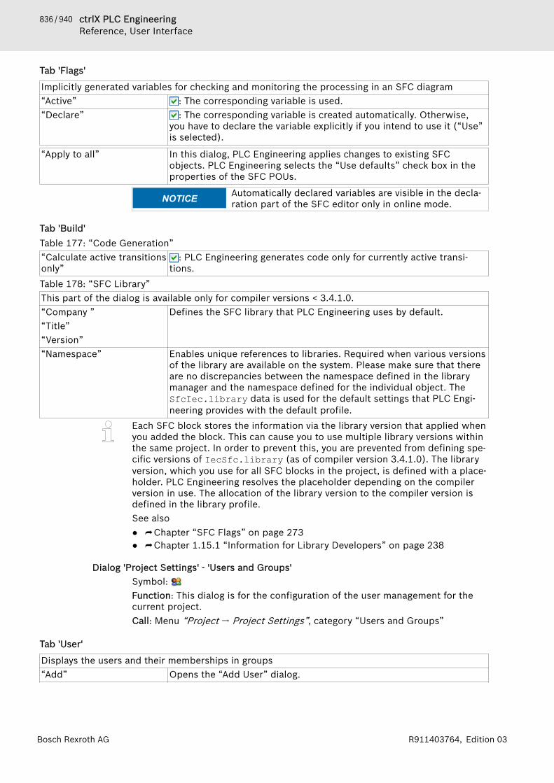
836 / 940 ctrlX PLC EngineeringReference, User Interface
Bosch Rexroth AG R911403764, Edition 03
Tab 'Flags'
Implicitly generated variables for checking and monitoring the processing in an SFC diagram“Active” : The corresponding variable is used.“Declare” : The corresponding variable is created automatically. Otherwise,
you have to declare the variable explicitly if you intend to use it (“Use”is selected).
“Apply to all” In this dialog, PLC Engineering applies changes to existing SFCobjects. PLC Engineering selects the “Use defaults” check box in theproperties of the SFC POUs.
NOTICE Automatically declared variables are visible in the decla-ration part of the SFC editor only in online mode.
Tab 'Build'Table 177: “Code Generation”“Calculate active transitionsonly”
: PLC Engineering generates code only for currently active transi-tions.
Table 178: “SFC Library”This part of the dialog is available only for compiler versions < 3.4.1.0.“Company ”“Title”“Version”
Defines the SFC library that PLC Engineering uses by default.
“Namespace” Enables unique references to libraries. Required when various versionsof the library are available on the system. Please make sure that thereare no discrepancies between the namespace defined in the librarymanager and the namespace defined for the individual object. TheSfcIec.library data is used for the default settings that PLC Engi-neering provides with the default profile.
Each SFC block stores the information via the library version that applied whenyou added the block. This can cause you to use multiple library versions withinthe same project. In order to prevent this, you are prevented from defining spe-cific versions of IecSfc.library (as of compiler version 3.4.1.0). The libraryversion, which you use for all SFC blocks in the project, is defined with a place-holder. PLC Engineering resolves the placeholder depending on the compilerversion in use. The allocation of the library version to the compiler version isdefined in the library profile.See also● ⮫ Chapter “SFC Flags” on page 273● ⮫ Chapter 1.15.1 “Information for Library Developers” on page 238
Dialog 'Project Settings' - 'Users and Groups'Symbol: Function: This dialog is for the configuration of the user management for thecurrent project.Call: Menu “Project 🠂 Project Settings”, category “Users and Groups”
Tab 'User'
Displays the users and their memberships in groups“Add” Opens the “Add User” dialog.

837 / 940ctrlX PLC EngineeringReference, User Interface
Bosch Rexroth AGR911403764, Edition 03
“Edit” Opens the “Edit User” dialog.“Delete” An error message appears if you attempt to delete the last user of a
group, since a group must have at least one member.Table 179: “Add User / Edit User”Input fields for setting up a new user account or changing an existing one“Active” : You may use the user account, default
: The user cannot log in. If he attempts to login again with incorrectlogin data, this can result in automatic deactivation of the account; seebelow: Settings.
“Memberships” List of all user groups that you have defined in addition to the group“Everyone” (to which each new user automatically belongs).
<group name> : the new user belongs to the group.Table 180: “Export/Import”“Export users and groups” The command opens the standard dialog for saving a file in the local
file system. You can store the users and groups definitions of theproject in a file *.users in xml format.
“Import users and groups” Export users and groups opens the standard dialog for browsing thelocal file system for a file. Search for a file with extension *.users inorder to import the users and groups definiitions, stored in this file,into the project.
Tab 'Groups'
Display of the groups and their members. A group can also be a member of a group.“Add” Opens the “Add Group” dialog.“Edit” Opens the “Edit Group” dialog.“Delete” If you delete a group, the user accounts of the members remain
unchanged.You cannot delete the groups “Everyone” and “Owner”.
On button “Export/Import” please see above the “User” paragraph.
Tab 'Settings'
Display of the groups and their members in a tree structure. A group can also be a member of agroup.“Maximum number ofauthentication trials”
(standard) : If the user has attempted to login with an incorrectpassword the number of times specified here, the user account isdeactivated.
: The number of the unsuccessful attempts is unlimited“Automatic logoff after timeof inactivity”
: The user is automatically logged out if PLC Engineering does notregister any user actions by mouse or keyboard during the time period(minutes) specified here.
See also● ⮫ Chapter 1.5 “Protecting and Saving a Project” on page 31● ⮫ Chapter “Command 'User management' – 'Log in User'” on page 707
Dialog 'Project Settings' - 'Compileoptions'Symbol: Function: This dialog is for configuring the compiler options.Call: Main menu “Project 🠂 Project Settings” (“Compileoptions” category).Requirement: A project is open.

838 / 940 ctrlX PLC EngineeringReference, User Interface
Bosch Rexroth AG R911403764, Edition 03
Table 181: “Compilerversion”“Fix Version” Defines the compiler version that PLC Engineering uses when
compiling and downloading for compile (for example, “3.5.6.0” for ver-sion 3.5 SP6).
Table 182: “Settings”“Allow unicode charactersfor identifiers”
Cleared by default because using Unicode characters in identifiernames is not permitted in the IEC standard. May be required for someforeign languages (for example, Asian languages).
“Replace constants” (default): PLC Engineering loads the value directly for every scalarconstant (not for strings, arrays, and structures). In online mode, PLCEngineering marks the constants with a symbol that is prepended tothe value in the declaration editor or monitoring view. In this case,access is not possible, for example by means of an ADR operator,forcing, and writing.
: Access to constants is possible, but it prolongs the computationtime.
“Enable logging in break-points”
For breakpoints that are defined as execution points, you can create amessage text in the “Execution point settings” dialog. PLC Engineeringprints this text to the device log when the application halts at the exe-cution point.
Table 183: “Compiler Warnings”“Maximum number of warn-ings”
Refers to the warnings that PLC Engineering prints to the messagesview.You define the selection of displayed compiler warnings in the “ProjectSettings” dialog in the “Compiler Warnings” category.
See also● ⮫ Chapter “Dialog 'Project Settings' - 'Compiler Warnings'” on page 838● ⮫ Chapter “Tab 'Log'” on page 563● ⮫ Chapter “Dialog 'Breakpoint Properties'” on page 818
Dialog 'Project Settings' - 'Compiler Warnings'Symbol: Function: This dialog is used for selecting the compiler warnings that PLC Engi-neering displays in the messages view during a compile process.Call: Call: Main menu “Project 🠂 Project Settings” (“Compiler Warnings” cate-gory).Requirement: A project is open.You define the maximum number of listed warnings in the “Compileoptions”dialog.
See also● ⮫ Chapter “Dialog 'Project Settings' - 'Compileoptions'” on page 837● ⮫ Chapter “Command 'Build'” on page 711
Dialog 'Project Settings' – 'Source Download'Symbol: Function: This dialog defines the compilation and the storage of the sourcecode as a source-code download archive on one or more controllers.Call: “Project 🠂 Project settings” menu, “Download source code” category
A source-code download archive is a project archive with the nameArchiv.prj.
839 / 940ctrlX PLC EngineeringReference, User Interface
Bosch Rexroth AGR911403764, Edition 03
The settings affect the command “Online 🠂 Load source code to connectedcontroller”. These settings do not affect the command “File 🠂 Load sourcecode to controller”.
Table 184: “Destination device”Defines the location of the project archive.“<name of controller>” Selected controller. PLC Engineering loads the project archive to this
controller. Requirement: the project contains several controllers.“<all devices in project>” PLC Engineering loads the project archive to all controllers in the
project.Table 185: “Content”Defines the contents of the project archive.“Use compact download” : The project archive contains only that device in the project that
contains the active application.: The project archive contains all the devices in the project
“Additional Files” Opens the “Additional files” dialog where you can select additionalfiles for downloading.
Table 186: “Timing”Defines the time at which PLC Engineering creates a project archive.“Implicitly at programdownload and onlinechange”
Each time an application is loaded or an online change is made, PLCEngineering additionally loads the project archive to the targetdevice(s) with no further prompt.
“Implicitly at creating bootproject”
Each time a boot application is created, PLC Engineering additionallyloads the project archive to the target device(s) with no furtherprompt.
“Implicitly at creating bootproject, download andonline change”
Each time a boot application is created, an application is loaded or anonline change is made, PLC Engineering additionally loads the projectarchive to the target device(s) with no further prompt.
“Prompt at program down-load and online change”
Each time an application is loaded or an online change is made, PLCEngineering opens a prompt, where you can select whether PLC Engi-neering should load the project archive to the controller.
“Only on demand” A prompt opens only if the command “Online 🠂 Load source code toconnected controller” is called. There you can select whether PLCEngineering should load the project archive to the controller.
See also● ⮫ Chapter “Command 'Source Download to Connected Device'” on page 723● ⮫ Chapter “Command 'Source Download'” on page 660
Dialog 'Project Settings' - 'Page Setup'Symbol: Function: This dialog defines the layout for the print version of the project con-tents. This layout is used for the printout of the project information by clicking“File 🠂 Print” and the printout of the project documentation by clicking“Project 🠂 Document”.Call: Main menu “Project 🠂 Project Settings” (“Page Setup”)You can change settings the following:● “Paper”● “Margins”● “Header and Footer”● “Document”● “Title Page”
840 / 940 ctrlX PLC EngineeringReference, User Interface
Bosch Rexroth AG R911403764, Edition 03
Table 187: “Edit Header, Edit Footer”The headers and footers are structured in table style. You can configure rows and columns, and addtext and images to the resulting cells.“Row spanning” Number of rows that PLC Engineering should merge into a single
column.“Column spanning” Number of columns that PLC Engineering should merge into a single
row.Opens the list of available placeholders for the “Text” field. Whenprinting the page, PLC Engineering provides the placeholders with thecurrent values.
See also● ⮫ Chapter “Command 'Page Setup'” on page 661● ⮫ Chapter “Command 'Document' ” on page 701● ⮫ Chapter “Command 'Print'” on page 661
Dialog 'Project Settings' - 'Security'Symbol: Function: this dialog is for the configuration of the project protection by a pass-word, a dongle, or a certificate.Call: Menu bar: “Project 🠂 Project Settings” (category “Security”).
NOTICE If the encryption password is lost you can no longeropen the project. You can also no longer restore it.
“No protection” : The project file is not protected from unauthorized access and datamanipulation.Note: We strongly recommend that you use security functionality.
: The “Password”, “Dongle”, and “Certificates” options cannot beselected.
“Integrity check” When you create a new project, this option is enabled by default.: The project file is stored in a proprietary format and its integrity is
checked each time the project is loaded. The file may be incompatiblewith older versions of the development system.Please note that the project file is not encrypted. To better protectyour data, activate one of the encryption functions.
“Encryption” : The “Password”, “Dongle”, and “Certificates” encryption functionscan be selected.
“Password” Entering, changing and confirming the encryption password.If you save the project with these settings you must enter the pass-word later in order to open the project again, even if it is to be loadedas a library reference.
“Dongle” Requirement: you have connected the PLC Engineering security key(dongle) to the computer.“Add”: The dialog “Add Registered Dongle” opens.
“Registered dongles” Drop-down list of the registered dongles.“Certificates” Certificates are used for the encryption of contents of the open
project file.Requirement: The certificates for all users who share the project mustbe installed in the local memory.
: The “Certificate selection” dialog opens.
841 / 940ctrlX PLC EngineeringReference, User Interface
Bosch Rexroth AGR911403764, Edition 03
Table 188: Adding a registered dongle“Dongle” Drop-down list of all connected dongles.“Update” PLC Engineering refreshes the drop-down list.“Flash” The LEDs of the currently selected dongle flash for two seconds (if it
supports this function).The dongle must be connected to the computer when PLC Engineering loadsthe project, even if it is loaded as a library reference.See also● ⮫ Chapter 1.5 “Protecting and Saving a Project” on page 31● ⮫ Chapter 1.5.2 “Assigning Passwords” on page 35● ⮫ Chapter 1.5.3 “Protecting Projects Using a Dongle” on page 36● ⮫ Chapter 1.5.7 “Encrypting Projects with Certificates” on page 40● ⮫ Chapter “Dialog 'Certificate Selection'” on page 871
Dialog 'Project Settings' - 'Static Analysis Light'Symbol: Function: This dialog activates the tests that the light version of PLC Engi-neering Static Analysis performs each time code is generated.Call: Menu bar: “Project 🠂 Project Settings” (“Static Analysis Light” category).You can exclude lines of code from the static code analysis by marking the codewith the pragma {analysis ...} or the pragma {attribute 'analy-sis' := '...'}.
Additional compile tests
“SA0033: Unused variables” Finds variables that are declared, but not used within the compiledprogram code.For GVL variables: If there are multiple applications in one project,then only the objects under the currently active application areaffected. If there is only one application, then the objects in the POUsview are also affected.
“SA0028: Overlappingmemory areas”
Detects the locations where two or more variables reserve the samestorage space. For example, this occurs for the following declarations:var1 AT %QB21: INT and var2 AT %QD5: DWORD. In this case, bothvariables use byte 21, which means that the memory range of the vari-ables overlap.
“SA0006: Write access frommultiple tasks”
Detects variables that are written by more than one task.
SA0004 “Multiple writeaccess on output”
Detects outputs that are written to more than one location.Note: No error is reported when an output variable (VAR_IN_OUT) iswritten in different branches of IF and CASE statements.Note: A pragma cannot deactivate this rule.
“SA0027: Multiple use ofidentifiers”
Detects multiple uses of a name/identifier for a variable or an object(POU) within the scope of a project.The following cases are detected:● The name of an enumeration constant is the same as in another
enumeration in the application or used in an included library.● The name of a variable is the same as an object in the application or
an included library.● The name of a variable is the same as for an enumeration constant
in and enumeration in the application or an included library.
842 / 940 ctrlX PLC EngineeringReference, User Interface
Bosch Rexroth AG R911403764, Edition 03
● The name of an object is the same as another object in the applica-tion.
● The name of a variable is the same as the name of a method.● The name of an object is the same as the name of a superordinate
object ("parent object").“SA0167: Temporary func-tion block instances”
The test detects function block instances that are declared as tempo-rary variables. This concerns instances that are declared in a methodor in a function or as VAR_TEMP, and therefore are reinitialized in eachprocessing cycle and for each POU call.
ExamplesSA0003: Empty statements
;(* Comment *);iVar;SA0006: Concurrent accessFUNCTION_BLOCK ADD_FBg_iTemp1 := g_iTemp1 + INT#1;PROGRAM PLC_PRG //controlled by MainTaskg_iTemp1 := g_iTemp1 + INT#2;g_xTemp2 := g_iTemp1 > INT#10;PROGRAM PLC_PRG_1 //controlled by SubTaskg_iTemp1 := g_iTemp1 - INT#3;g_xTemp2 := g_iTemp1 < INT#-10;SA0004 Multiple write access on outputVAR_GLOBAL g_xVar AT %QX0.0 : BOOL ; g_iTest AT %QW0 : INT ;END_VARPROGRAM PLC_PRGIF iCondition < INT#0 THEN g_xVar := TRUE; g_iTest := INT#12;END_IFCASE iCondition OF INT#1: g_xVar := FALSE; INT#2: g_iTest := INT#11; ELSE g_xVar := TRUE; g_iTest := INT#9;END_CASE SA0006: Write access from multiple tasks
FUNCTION_BLOCK ADD_FBg_iTemp1 := g_iTemp1 + INT#1;
PROGRAM PLC_PRG // Controlled by MainTaskg_iTemp1 := g_iTemp1 + INT#2;g_xTemp2 := g_iTemp1 > INT#10;

843 / 940ctrlX PLC EngineeringReference, User Interface
Bosch Rexroth AGR911403764, Edition 03
PROGRAM PLC_PRG_1 //Controlled by SubTaskg_iTemp1 := g_iTemp1 - INT#3;g_xTemp2 := g_iTemp1 < INT#-10;SA0027: Multiple use of namePROGRAM PLC_PRGVARton : INT; // error SA0027END_VARSA0029: Different notation in implementation and declarationThe PLC_PRG POU and a fnc function POU are in the device tree.
PROGRAM PLC_PRGVARiVar:INT;_123test_var_: INT;
END_VARivar := iVar + 1; // notation different to that in the
declaration part -> SA0029_123TEST_var_ := _123test_var_INT; // notation different
to that in the declaration part -> SA0029 Fnc(); // notation different to that in the devices tree -> SA0029END_VARSA0167: Temporary function block instancesPROGRAM PLC_PRGVAREND_VARVAR_TEMP yafb: AFB; END_VAR
FUNCTION Fun : INTVAR_INPUTEND_VARVAR funafb: AFB;END_VAR
METHOD METH: INTVAR_INPUTEND_VARVAR methafb: AFB;END_VAR
See also● ⮫ Chapter “Analyzing Code Statically” on page 121
Dialog 'Project settings' - 'Visualization'Symbol: Function: This dialog is for the configuration of the project-wide settings forobjects of the type “Visualization”.Call: Main menu “Project 🠂 Project Settings”, category “Visualization”Requirement: A project is open.
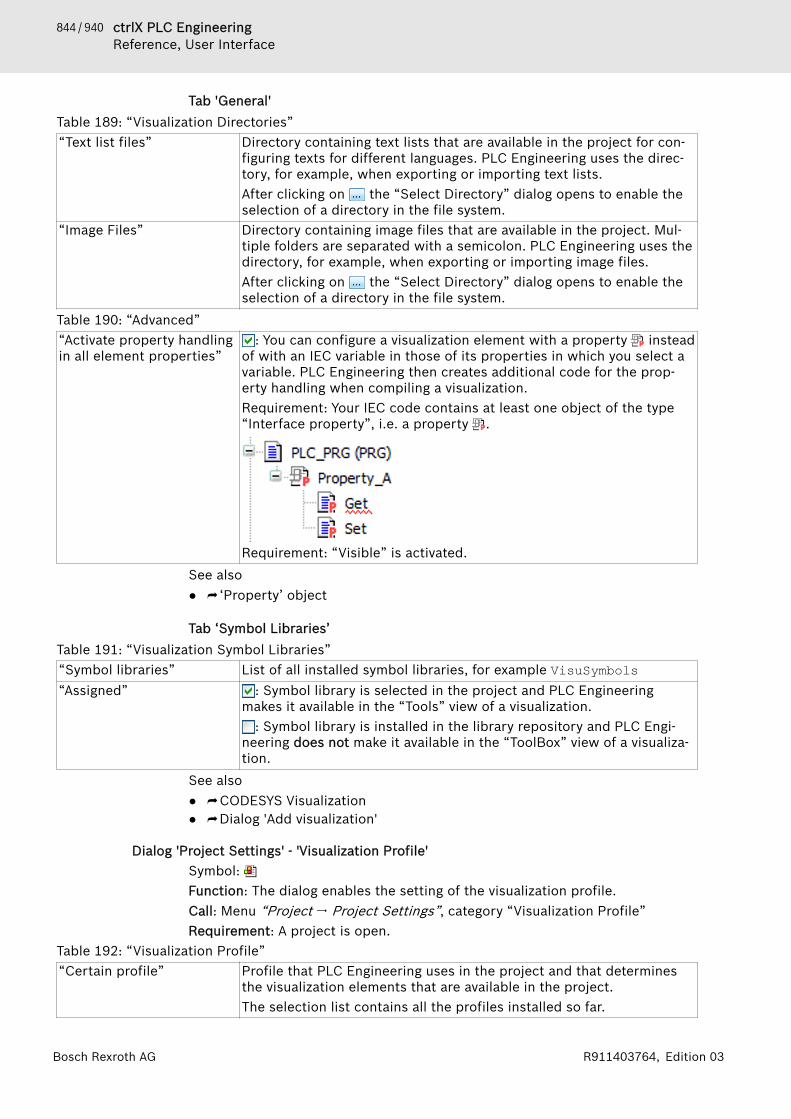
844 / 940 ctrlX PLC EngineeringReference, User Interface
Bosch Rexroth AG R911403764, Edition 03
Tab 'General'Table 189: “Visualization Directories”“Text list files” Directory containing text lists that are available in the project for con-
figuring texts for different languages. PLC Engineering uses the direc-tory, for example, when exporting or importing text lists.After clicking on the “Select Directory” dialog opens to enable theselection of a directory in the file system.
“Image Files” Directory containing image files that are available in the project. Mul-tiple folders are separated with a semicolon. PLC Engineering uses thedirectory, for example, when exporting or importing image files.After clicking on the “Select Directory” dialog opens to enable theselection of a directory in the file system.
Table 190: “Advanced”“Activate property handlingin all element properties”
: You can configure a visualization element with a property insteadof with an IEC variable in those of its properties in which you select avariable. PLC Engineering then creates additional code for the prop-erty handling when compiling a visualization.Requirement: Your IEC code contains at least one object of the type“Interface property”, i.e. a property .
Requirement: “Visible” is activated.See also● ⮫ ‘Property’ object
Tab ‘Symbol Libraries’Table 191: “Visualization Symbol Libraries”“Symbol libraries” List of all installed symbol libraries, for example VisuSymbols“Assigned” : Symbol library is selected in the project and PLC Engineering
makes it available in the “Tools” view of a visualization.: Symbol library is installed in the library repository and PLC Engi-
neering does not make it available in the “ToolBox” view of a visualiza-tion.
See also● ⮫ CODESYS Visualization● ⮫ Dialog 'Add visualization'
Dialog 'Project Settings' - 'Visualization Profile'Symbol: Function: The dialog enables the setting of the visualization profile.Call: Menu “Project 🠂 Project Settings”, category “Visualization Profile”Requirement: A project is open.
Table 192: “Visualization Profile”“Certain profile” Profile that PLC Engineering uses in the project and that determines
the visualization elements that are available in the project.The selection list contains all the profiles installed so far.
845 / 940ctrlX PLC EngineeringReference, User Interface
Bosch Rexroth AGR911403764, Edition 03
Dialog 'Project Environment'Dialog 'Project Environment' – 'Li-brary Versions'. . . . . . . . . . . . . . . . . 845Dialog 'Project Environment' - 'Com-piler Version'. . . . . . . . . . . . . . . . . . 845Dialog 'Project Environment' - 'De-vice Versions'. . . . . . . . . . . . . . . . . . 846Dialog 'Project Environment' – 'Visu-alization Profile'. . . . . . . . . . . . . . . . 846Dialog 'Project Environment' – 'Visu-alization Styles'. . . . . . . . . . . . . . . . 846Dialog 'Project Environment' – 'CCode Modules'. . . . . . . . . . . . . . . . . 847Dialog 'Project Environment' – 'Visu-alization Symbols'. . . . . . . . . . . . . . 847
Function: You use this dialog for checking the actuality of the software and ofthe files, which are included in the project. PLC Engineering checks for examplethe selected compiler and finds out if there is a newer version. In such a caseyou can update the affected components.Call: Main menu“Project”
Dialog 'Project Environment' – 'Library Versions'Function: This dialog displays the libraries of the opened project for whichnewer versions are available.Call: Main menu “Project 🠂 Project Environment”, tab “Library Version ”This dialog opens automatically when you open a project containing outdatedlibraries.
Table: The list shows the name of the outdated library with version, the currently available version and theplanned action.“Action” Double-click inside the field to select the desired actions.“Check for updates whenloading this project”
: Checking takes place each time the project is opened.: Checking takes place once only.
“Set all to newest” PLC Engineering uses the newest available version of the library.“OK” PLC Engineering performs the selected action(s).
Dialog 'Project Environment' - 'Compiler Version'Function: This dialog shows the current compiler version of the project and pro-vides the capability of updating.Call: Main menu “Project 🠂 Project Environment” (“Compiler Version” tab).
Table: “Current compiler versionin project”
Shows the set compiler version for the open project.
“Recommended, newestversion”
Shows the latest version.
“Action” ● “Do not update”: The compiler version of the project remains thesame.
● “Update to x.x.x.x”: The selected compiler version is set for theproject.

846 / 940 ctrlX PLC EngineeringReference, User Interface
Bosch Rexroth AG R911403764, Edition 03
“Check for updates whenloading this project”
: PLC Engineering checks for new versions each time the project isopened. If there is a new version, then the respective update dialogopens automatically.
: The compiler version is not checked. The update dialogs do notopen automatically.
“Set all to newest” The compiler version is set to the latest version.
Dialog 'Project Environment' - 'Device Versions'Function: This dialog shows the devices of the open project in which there arenew versions available.Call: Main menu “Project 🠂 Project Environment” (“Device Versions” tab)This dialog opens automatically when you open a project that contains an out-dated device.
Table: Names of the outdated devices and their versions, as well as the current version and the plannedaction.“Action” Double-click in the field to select the required actions.“Check for updates whenloading this project”
: The check is performed when the project is opened.: The check is performed one time only.
“Set all to newest” PLC Engineering uses the latest library version.“OK” PLC Engineering executes the selected actions.
Dialog 'Project Environment' – 'Visualization Profile'Function: This dialog shows the current visualization profile of the project. Theprofile can be updated here.Call: Menu bar: “Project 🠂 Project Environment” (“Visualization Profile” tab).
“Current visualization pro-file in the project”
The set visualization profile of the open project.
“Recommended, newestprofile”
The newest version.
“Action” ● “Do not update”: The visualization profile of the project remainsunchanged.
● “Update to x.x.x.x”: PLC Engineering updates the project to theselected visualization profile.
“Check for updates whenloading this project”
: PLC Engineering checks for new profiles each time the project isopened. If there is a new version, then the respective update dialogopens automatically.
: Not test of the profile when opening the project. The update dia-logs do not open automatically.
“Set all to newest” PLC Engineering updates the .See also● Help about visualization
Dialog 'Project Environment' – 'Visualization Styles'Function: This dialog shows the current visualization style of the project andprovides the capability of updating it.Call: Menu bar: “Project 🠂 Project Environment” (“Visualization Styles” tab).
Table 193: “Newer versions are available for the following visualization styles currently in use”“Visualization style” Version of the set visualization style in the open project“Current” Current version of the visualization style (example: 3.5.6.0)
847 / 940ctrlX PLC EngineeringReference, User Interface
Bosch Rexroth AGR911403764, Edition 03
“Recommended” Recommended version of the visualization style (example: 3.5.7.0)“Action” ● “Do not update”: The visualization style of the project remains
unchanged.● “Update to x.x.x.x”: PLC Engineering updates the project to the ver-
sion of the selected visualization style.“Check for updates whenloading this project”
: PLC Engineering checks for new versions each time the project isopened. If there is a new version, then the respective update dialogopens automatically.
: The version is not checked. The update dialogs do not open auto-matically.
“Set all to newest” PLC Engineering updates the version.See also● Help for visualization, section "Visualization style"
Dialog 'Project Environment' – 'C Code Modules'Function: This dialog lists all C-code modules and their C-code files that havechanged in the source directory on the disk. You can update individual C-codemodules here.Call: Menu “Project 🠂 Project Environment”, tab “C Code modules”
Table 194: “The sources of the following projects changed”“Project” Display of the C-code module with its changed C-code files in the
project.“Action” Selection option for the C-code module of the “Project” field
A double-click on the field displays all selection options:● “Update”● “Do not update”For each C-code file this indicates what action is executed if you selectthe action “Update” for the corresponding C-code module (“Project”).
“Delete IEC interfaces” Deletes the created IEC interface if the headers in the project havechanged. In this case you must create the IEC interface again.
“Check for updates whenloading this project”
: checking takes place each time the project is opened.
“Set all to 'newest'” PLC Engineering refreshes all C-code modules.“OK” PLC Engineering executes the selected actions in the project.
See also● ⮫ Chapter “Object 'C Code Module'” on page 551● ⮫ Chapter “Command 'Create IEC Interface'” on page 716● ⮫ Chapter 1.8.11 “Integrating C Modules” on page 113
Dialog 'Project Environment' – 'Visualization Symbols'Function: This dialog lists installed symbol libraries and allows for you to assignsymbol libraries to a project.Call: Menu bar: “Project 🠂 Project Environment” (“Visualization Symbols” tab).Requirement: The open project contains a visualization and has been savedwith a compiler version < 3.5.7.0. PLC Engineering recognizes symbol libra-ries in compiler version 3.5.7.0 and later.
“Symbol library” List of all installed symbol libraries“Active” : Symbol library is selected for the project. PLC Engineering provide
its symbols in the “Tools” view.
848 / 940 ctrlX PLC EngineeringReference, User Interface
Bosch Rexroth AG R911403764, Edition 03
: Symbol library has been previously installed only in the libraryrepository.
See also● Help for visualization, section "Using the symbol library in the visualization"
Dialog 'Options'Dialog 'Options' - 'SFC Editor'. . . . . 848Dialog 'Options' – 'Libraries'. . . . . . 849Dialog 'Options' – 'Library Down-load'. . . . . . . . . . . . . . . . . . . . . . . . . 850Dialog 'Options' - 'CFC Editor'. . . . . 850Dialog 'Options' - 'CoDeSys V2.3Converter'. . . . . . . . . . . . . . . . . . . . 851Dialog 'Options' – 'Declaration Edi-tor'. . . . . . . . . . . . . . . . . . . . . . . . . . 852Dialog 'Options' – 'Device Descrip-tion Download'. . . . . . . . . . . . . . . . . 853Dialog 'Options' - 'FBD, LD, and IL'. 853Dialog 'Options' - 'Device Editor'. . . 855Dialog 'Options' - 'Help'. . . . . . . . . . 855Dialog 'Options' - 'SmartCoding'. . . 856Dialog 'Options' – 'International Set-tings'. . . . . . . . . . . . . . . . . . . . . . . . 857Dialog 'Options' – 'Load and Save'. . 857Dialog 'Options' - 'Monitoring'. . . . . 857Dialog 'Options' - 'PLCopenXML'. . . 858Dialog 'Options' - 'Proxy Settings'. . 858Dialog 'Options' - 'Refactoring'. . . . . 859Dialog 'Options' - 'Sequence Editor'. 859Dialog 'Options' - 'Syntax Highlight-ing'. . . . . . . . . . . . . . . . . . . . . . . . . . 860Dialog 'Options' - 'Text Editor'. . . . . 860
Function: You use the dialog for selecting the PLC Engineering options. Withthese options you configure the appearance and the behavior of the user inter-face. PLC Engineering saves the current configuration as standard settings inthe local system.Call: Main menu “Tools 🠂 Options”
Dialog 'Options' - 'SFC Editor'Symbol: Function: This dialog is used for configuring the settings for the SFC editor.Call: Menu bar: “Tools 🠂 Options” (“SFC Editor” category).See also● ⮫ Chapter “Programming the Sequential Function Chart (SFC)” on page 93● ⮫ Chapter “Menu 'SFC'” on page 755● ⮫ Chapter “SFC Editor” on page 268

849 / 940ctrlX PLC EngineeringReference, User Interface
Bosch Rexroth AGR911403764, Edition 03
Tab 'Layout'Table 195: “Elements”This defines the dimensions of the SFC elements: step, action, qualifier, property. The values aregiven in matrix units, where one matrix unit equals the font size that you set in the text editoroptions (text area / font). The settings are always active immediately in all open SFC editor views.“Step height” Possible values: 1-100“Step width” Possible values: 2-100“Action width” Possible values: 2-100“Qualifier width” Possible values: 2-100“Property width” Possible values: 2-100Table 196: “Font”The example text shows the current font. Click it to change the font.Table 197: “Step Actions”“Default insertion method” ● “Copy reference”: The reference to the action objects that call the
step are also copied when the step is copied. The copied step andnew step call the same action.
● “Duplicate implementation”: The reference to the action objectsthat call the step are linked to this step. When copying the step ele-ment, new action objects are created for the new step, and theimplementation is duplicated.
● “Always ask”: When inserting a step action, you are alwaysprompted whether the actions of a step element should be dupli-cated when it is copied, or whether the reference to the existingaction should be applied.Note: If a step already contains an embedded action, then newinserted actions of this step are also embedded. Likewise, newinserted actions are not embedded when the step already containsa non-embedded action. In these cases, you are no longer promptedfor a duplication mode.
Table 198: “Embedded Objects”“Show action and transitionobjects in the navigator”
: Action and transition objects that are embedded in the SFC box bya step are displayed in the “Devices” or “POUs” tree view.
Tab 'View'Table 199: “Property Visibility”List of element properties for the categories “Common” and “Specific” with definitions of the dis-play options.“Property” Defines the element properties displayed next to the element in the
SFC diagram.“Value” : Display of the property value.“With Name” : Display of the property value including name.Table 200: “Online”“Show step time” : In online mode, PLC Engineering displays the step time to the right
of the steps.
Dialog 'Options' – 'Libraries'Symbol: Function: This dialog helps you to manage the mappings of library referencesthat PLC Engineering uses during the conversion of an old project. If you havenot yet stored any mapping for a certain library, you must redefine the mappingeach time when opening an old project in which this library is integrated.
850 / 940 ctrlX PLC EngineeringReference, User Interface
Bosch Rexroth AG R911403764, Edition 03
Call: Menu bar: “Tools 🠂 Options”; category: “Libraries”.A mapping defines what a library reference looks like following the conversionof the project to the current format. There are three possibilities:● You retain the reference. This means that PLC Engineering similarly converts
the library into the current format (*.library) and installs it in the locallibrary repository.
● You replace a reference with another reference. This means that one of theinstalled libraries replaces the library that was integrated until now.
● You delete the reference. This means that the converted project no longerintegrates the library.
PLC Engineering applies all the listed mappings to the library references of an old project the nexttime it is converted. Hence, you must repeat the mapping definition if the same library is integratedagain in a project that is to be converted. You can enter a new mapping in the last line.“Source Library” Path of the library that is integrated in the project before the conver-
sion.A double-click an entry makes the field editable and the button for theinput assistance appears.
“Target Library” Name and location of the library that is to be integrated in the projectafter the conversion.A double-click an entry opens the dialog “Set target system library”.
Table 201: “Set target system library”“Scan” The “Select Library” dialog opens. You can select a library from the
library repository here. The dialog corresponds to the dialog in thelibrary repository.
“Ignore” When PLC Engineering converts the project, PLC Engineering alwaysremoves the existing source library from the project.
Dialog 'Options' – 'Library Download'Symbol Function: This dialog is for the setting of download servers.Call: menu “Tools 🠂 Options”, “Library Download” category
If you click on the button “Download Missing Libraries” in the library manager, PLC Engineeringbrowses these download servers for libraries marked as missing in the library manager and usesthe set login details for the proxy server.“Download servers” URL of a server containing library filesDouble-click on “(Enter newdownload server here)”
An input field opens in which you can enter the URL address of aserver.
See also● ⮫ Chapter “Object 'Library Manager'” on page 583● ⮫ Chapter “Dialog 'Options' - 'Proxy Settings'” on page 858
Dialog 'Options' - 'CFC Editor'Symbol: Function: This dialog is for the configuration of the settings for editing andprinting in the CFC editor.Call: menu “Tools 🠂 Options”, category “CFC Editor”
851 / 940ctrlX PLC EngineeringReference, User Interface
Bosch Rexroth AGR911403764, Edition 03
Tab 'General'
“Enable AutoConnect” : If you drag a CFC element onto the work area of the editor andinsert it, PLC Engineering automatically connects together uncon-nected pins that 'touch' one another. Make sure that you do not createunwanted connections when shifting elements!
“Prepare values in imple-mentation part”
: In online mode you can also prepare variable values for writing andforcing in the implementation part of the CFC module. In addition, PLCEngineering displays the values you have just prepared in the inlinemonitoring box of the variable in angle brackets.
Tab 'View'
“Display grid points” : Grid points at which you can position the elements are visible inthe editor.
“Show box icon” : Existing function blocks that are linked with a bitmap are displayedby PLC Engineering in the CFC editor as symbols.Requirement: You have either created the link for a function block or afunction in the object properties or loaded it via a library.
“Edit Line Colors” Opens the “Edit Line Colors” dialog for the definition of the colors ofthe connecting lines, depending on the data type applied. The linesappear in offline and online mode in these colors, unless PLC Engi-neering paints over them with the thick black and blue lines used todisplay the boolean data flow.● “Add Type:” Adds a data type to the list.● “Delete Type”
“Font” Display of the font and button for changing the font.See also● ⮫ Chapter “Dialog 'Properties' - 'Bitmap'” on page 827
Tab 'Print'
Setting the “Layout Options”“Fit method” “Page” or “Poster”“Scale” Possible values: 20 % - 200 %
See also● ⮫ Chapter “ Programming in the CFC Editor” on page 83● ⮫ Chapter 1.18.1 “Programming Languages and Editors” on page 254
Dialog 'Options' - 'CoDeSys V2.3 Converter'Symbol: Function: The dialog is used to define the mapping when converting a CoDeSysV2.3 project.Call: Menu bar: “Tools 🠂 Options”, “CoDeSys V2.3 Converter” categoryA CoDeSys V2.3 project can be converted into a PLC Engineering V3 projectonly if the CODESYS V2.3 Converter package is installed in PLC Engineering V3.The package is available in the CODESYS Store.
Table 202: “Devices”List and definition of the device mappings for a conversion.
852 / 940 ctrlX PLC EngineeringReference, User Interface
Bosch Rexroth AG R911403764, Edition 03
All device mappings of this list are also in effect the next time a CoDeSys V2.3 project is converted.This eliminates the need to recreate the image definition when the same device is used in multipleprojects.“Source Device” Double-clicking an entry or an empty field opens the “Select Source
Device” dialog. PLC Engineering lists all devices that converter canprocess.
“Target Device” Double-clicking an entry or an empty field opens the “Select TargetDevice” dialog.● “Select a target device from the list of installed devices below”:
Confirm the selection by clicking “OK”.● “None”: The source device will not be available in the new project.
This also means that application-specific objects, such as the taskconfiguration, are not imported.
Table 203: “Visualizations”Defines the handling of the CODESYS TargetVisu and CODESYS WebVisu display variants when aCoDeSys V2.3 project is opened.“Import of Targetvisualiza-tions”“Import of Webvisualiza-tions”
List box● “Try to imitate old behaviour”: The option is available if the cur-
rently used device supports the option. The effect of this option isthat the new target or web visualization settings correspond asaccurately as possible to the settings in the old project.
● “Ask the user once”: PLC Engineering asks the user to define thesettings only when an "old" visualization project is imported for thefirst time. After that, PLC Engineering applies the automatically set-tings in all other visualization imports.
● “Ask the user”: PLC Engineering asks the user to define the settingsevery time an "old" visualization project is opened.
● “Setting from Device Description”: PLC Engineering sets the set-tings according to the entries in the device description of theinstalled target device.
● “Try to imitate old behaviour”: The option is available only if the cur-rently used device supports the option. The effect of this option isthat the new display variant settings for the target or web visualiza-tion correspond as accurately as possible to the settings in the oldproject.
NOTICE CODESYS TargetVisu does not support the access toVAR_IN_OUT variables, because the compiler does notsupport this. This behavior corresponds to the behaviorof CoDeSys V2.3 target visualizations.
See also● ⮫ Chapter 1.2.5 “Opening a V3 Project” on page 20● ⮫ Chapter “Command ‘Package Manager’ ” on page 740
Dialog 'Options' – 'Declaration Editor'Symbol: Function: This dialog is for the configuration of the display settings for the dec-laration editor.Call: Main menu “Tools 🠂 Options”, category “Declaration Editor”
“Textual only” Textual view of the declaration editor“Tabular only” Tabular view of the declaration editor“Switchable between tex-tual and tabular”
The declaration editor offers two buttons for switching between thetextual and tabular views:

853 / 940ctrlX PLC EngineeringReference, User Interface
Bosch Rexroth AGR911403764, Edition 03
: textual view: tabular view
The following option defines the view that appears by default whenopening a programming object:● “Always textual”● “Always tabular”● “Remember recent setting (per object)”● “'Remember recent setting (global)”
See also● ⮫ Chapter “Using the Declaration Editor” on page 64
Dialog 'Options' – 'Device Description Download'Symbol: Function: This dialog is for the configuration of addresses of download serversfor device descriptions.Call: Menu “Tools 🠂 Options”, category “Download the device descriptions”.See also● ⮫ Chapter 1.16 “Managing Devices” on page 241
Table 204: “Download server”List of download servers containing device descriptions. By default 'https://store.codesys.com/CODESYSDevs' is entered as the download server.If you select the button “Download Missing Device Descriptions” in the “Device Repository” dialog,PLC Engineering uses the servers entered here and uses the set login data for the proxy server.Double-click on “(Enter newdownload server here...)”
An input field opens in which you can enter the URL address of aserver.
[Del] Deletes the selected download server.See also● ⮫ Chapter “Command 'Device Repository'” on page 747● ⮫ Chapter “Dialog 'Options' - 'Proxy Settings'” on page 858
Dialog 'Options' - 'FBD, LD, and IL'Symbol: Function: This dialog is used for configuring the display options for theFBD/LD/IL editor.Call: “Tools 🠂 Options” (category “FBD, LD, and IL”.
Tab 'General'Table 205: “View”“Show network title” The network title is displayed in the upper left corner of the network.“Show network comment” The network comment is displayed in the upper left corner of the net-
work. When the network title is also shown in PLC Engineering, thecomment is shown in the line below.
“Show box icon” The block symbol is displayed in the block element in the FBD and LDeditor. The standard operators also have symbols.
“Show operand comment” PLC Engineering shows the comment that you indicated for a variablein the implementation part. The operand comment refers to the localoccurrence of the variable only, as opposed to the symbol comment.This comment is truncated automatically depending on availablespace.
854 / 940 ctrlX PLC EngineeringReference, User Interface
Bosch Rexroth AG R911403764, Edition 03
You can limit the comment to a defined width by activating the option“Fixed size for operand fields”.
“Show symbol comment” The comment that you indicated for a variable or symbol in the decla-ration is displayed in PLC Engineering above the variable name. Youcan also assign a local operand comment in addition to or instead ofthe symbol comment.
“Show symbol address” If an address is assigned to a symbol (variable), then this address isdisplayed above the variable name.
“Show network separators” A separator is displayed between the individual networks.Table 206: “Behavior”“Placeholder for new oper-ands”
The operand field of pins for the new function block is left blank(instead of "???").
“Empty operands for func-tion block pins”
Adds blank operands instead of ???.
Table 207: “Font”Click the input field to open the “Font” dialog.
“Fixed size for operandfields”
: “Edit operand sizes” can be enabled.
“Edit operand sizes” The “Operand Sizes” dialog opens for setting the number of charactersand lines.
Tab 'FBD'Table 208: “View”“Networks with line breaks” : Display of the network with line breaks so that so that PLC Engi-
neering can show as many blocks as possible in the current width ofthe window.
“Connect boxes withstraight line”
: The length of the lines between the elements are fixed and short.
Table 209: “Behavior”“Default network content” Drop-down list: Contents of a new network“After insertion select” Drop-down list: Element that PLC Engineering selects after inserting a
new network
Tab 'LD'Table 210: “View”“Networks with line breaks” : Display of the network with line breaks so that so that PLC Engi-
neering can show as many blocks as possible in the current width ofthe window.
Table 211: “Behavior”“Default network content” Drop-down list: Contents of a new network“After insertion select” Drop-down list: Element that PLC Engineering selects after inserting a
new network
Tab 'IL'Table 212: “View”“Enable IL” The IL implementation language is available in the development
system.
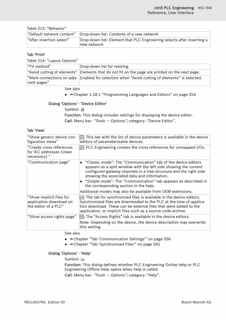
855 / 940ctrlX PLC EngineeringReference, User Interface
Bosch Rexroth AGR911403764, Edition 03
Table 213: “Behavior”“Default network content” Drop-down list: Contents of a new network“After insertion select” Drop-down list: Element that PLC Engineering selects after inserting a
new network
Tab 'Print'Table 214: “Layout Options”“Fit method” Drop-down list for resizing.“Avoid cutting of elements” Elements that do not fit on the page are printed on the next page.“Mark connections on adja-cent pages”
Enabled for selection when “Avoid cutting of elements” is selected.
See also● ⮫ Chapter 1.18.1 “Programming Languages and Editors” on page 254
Dialog 'Options' - 'Device Editor'Symbol: Function: This dialog includes settings for displaying the device editor.Call: Menu bar: “Tools 🠂 Options”; category: “Device Editor”.
Tab 'View'
“Show generic device con-figuration views”
: This tab with the list of device parameters is available in the deviceeditors of parameterizable devices.
“Create cross referencesfor IEC addresses (cleannecessary) ”
: PLC Engineering creates the cross-references for unmapped I/Os.
“Communication page” ● “Classic mode”: The “Communication” tab of the device editorsappears as a split window with the left side showing the currentconfigured gateway channels in a tree structure and the right sideshowing the associated data and information.
● “Simple mode”: The “Communication” tab appears as described inthe corresponding section in the help.
Additional modes may also be available from OEM extensions.“Show implicit files forapplication download onthe editor of a PLC”
: The tab for synchronized files is available in the device editors.Synchronized files are downloaded to the PLC at the time of applica-tion download. These can be external files that were added to theapplication, or implicit files such as a source code archive.
“Show access rights page” : The “Access Rights” tab is available in the device editors.Note: Depending on the device, the device description may overwritethis setting.
See also● ⮫ Chapter “Tab 'Communication Settings'” on page 556● ⮫ Chapter “Tab 'Synchronized Files'” on page 562
Dialog 'Options' - 'Help'Symbol: Function: This dialog defines whether PLC Engineering Online Help or PLCEngineering Offline Help opens when help is called.Call: Menu bar: “Tools 🠂 Options”; category: “Help”.

856 / 940 ctrlX PLC EngineeringReference, User Interface
Bosch Rexroth AG R911403764, Edition 03
“Use PLC EngineeringOnline Help, if available”
● PLC Engineering Online Help opens when PLC Engineering Helpis called. This is the default setting.
● PLC Engineering Offline Help opens when PLC Engineering Helpis called.
See also● ⮫ “Using PLC Engineering Help” on page 7
Dialog 'Options' - 'SmartCoding'Symbol: Function: This dialog is for configuring the settings for easier coding.Call: Menu bar: “Tools 🠂 Options”, “SmartCoding” category
“Declare unknown variablesautomatically (AutoDe-clare)”
: The “Declare Variable” dialog opens when you type an undeclaredidentifier into an implementation language editor and then click awayfrom the input line.In order for the AutoDeclare function to be available in the ST editor aswell, the “Enable for ST editor” option also has to be selected.
“Enable for ST editor” Requirement: The “Declare unknown variables automatically (AutoDe-clare)” option is selected.
: The AutoDeclare function is also available in the ST editor.: The AutoDeclare function is not available in the ST editor.
“Show all instance varia-bles in Input Assistant”
: The "List components" function also lets you select the local varia-bles of a function block instance.
: The "List components" function lets select only the input variablesand output variables of a function block instance.
“Show symbols fromsystem libraries in InputAssistant”
System libraries are inserted in the library manager automatically anddisplayed in light gray.
: Symbols, such as global variables, data types, and function blocks,are offered in the Input Assistant.
: The symbols of the system libraries are not available in the InputAssistant.
“List components aftertyping a dot (.)”
: Activates the "List components" function. When you type a dot (.)at a location where PLC Engineering expects an identifier, a list boxappears with possible code.
“List components immedi-ately when typing”
Requirement: The “List components after typing a dot (.)” check box isselected.
: While you type code, a list box appears with possible identifiersand operators.
“Insert with namespace” : PLC Engineering adds the namespace before the identifier.“Convert keywords touppercase automatically(AutoFormat)”
: PLC Engineering displays all keywords in uppercase.
“Automatically list selectionin cross-reference view”
: The cross-reference list automatically shows the references of varia-bles, POUs, and DUTs that are currently selected or where the cursoris waiting.
“Underline errors in theeditor”
: Incorrect or unknown program code is underlined.
“Highlight symbols” : All occurrences of a symbol where the cursor is positioned arehighlighted in color within the editor. In this way, cross-referenceswithin the editor are quickly detected.
“Max. degree of paral-lelism”
List box for the number of parallel threads that can be used for theprecompile processing.

857 / 940ctrlX PLC EngineeringReference, User Interface
Bosch Rexroth AGR911403764, Edition 03
PLC Engineering detects the displayed number of threads from thenumber of CPU cores. This default number should be changed only inexceptional cases.
See also● ⮫ Chapter 1.18.1 “Programming Languages and Editors” on page 254● ⮫ “Smart tag functions” on page 101● ⮫ Chapter “Using the Cross-Reference List to Find Occurrences”
on page 123● ⮫ Chapter “ST Editor” on page 256
Dialog 'Options' – 'International Settings'Symbol: Function: This dialog is for the setting of the language in the user interface andin the help.Call: Menu bar: “Tools 🠂 Options”, category “International Settings”.
Dialog 'Options' – 'Load and Save'Symbol: Function: This dialog contains settings for the behavior of PLC Engineeringwhen loading and saving a project.Call: Menu “Tools 🠂 Options”, category “Load and Save ”
“Create backup copy” : Each time the project is saved, PLC Engineering also saves theproject as the file <projectname>.backup in addition to the file<projectname>.project. You can rename the backup file and open itin the programming system.
“Automatically save every …minutes”
: PLC Engineering automatically saves the project at the specifiedtime intervals in a file <projectname>.autosave, which you canreload following non-regular closing of the programming system.In case of regular closing or saving of the project, PLC Engineeringdeletes the .autosave file. In the case of a non-regular abort, PLCEngineering keeps the .autosave file. If you open a project for whichthere is an associated autosave file, the “Auto Save Backup” dialogopens. In this dialog, you select whether the .autosave file or the ver-sion of the project last saved by the user should be opened.
“Save before build” PLC Engineering saves the project automatically before any build run.“Advanced Settings” The “Advanced Settings” dialog opens.
“Loading Behavior” : The loading of libraries and compilation infor-mation takes place in the background while you are already editing theproject.
See also● ⮫ Chapter 1.5 “Protecting and Saving a Project” on page 31
Dialog 'Options' - 'Monitoring'Symbol: Function: This dialog includes settings for displaying the variable values in mon-itoring.Call: Menu bar: “Tools 🠂 Options”; category: “Monitoring”.
Table 215: “Display Mode for Integer Variables”“Binary” The value of the variable is displayed in the corresponding format in
online mode.“Decimal”“Hexadecimal”

858 / 940 ctrlX PLC EngineeringReference, User Interface
Bosch Rexroth AG R911403764, Edition 03
This option corresponds to the setting of the command “Debug🠂 Display Mode”.
Table 216: “Floating Point Variables”“Number of displayeddigits”
Decimal places that are represented in online mode when REAL valuesare displayed.Note: The settings apply to the watch list, the monitoring of the decla-ration editor and the trace editor. The configuration for inline moni-toring of the editor is set in the text editor options.
See also● ⮫ “Tab 'Monitoring'” on page 862
Dialog 'Options' - 'PLCopenXML'Symbol: Function:This dialog contains settings for the behavior of PLC Engineeringwhen exporting or importing PLCopenXM.Call: Main menu “Tools 🠂 Options”, category “PLCopenXML”
Table 217: “PLCopenXML Export Settings”“Additionally export decla-rations as plain text”
By default, PLC Engineering splits the declaration parts in accordancewith the PLCopenXML scheme into individual variables and thus losesthe formatting and some comment information.
: Formatting and comments are retained. PLC Engineering addition-ally writes the plain text of the exported declaration part into thePLCopenXML file and thus extends the PLCopenXML scheme.
“Export Folder Structure” : PLC Engineering also exports the folders if they contain one of theselected objects. That is a PLC Engineering-specific extension to thePLCopenXML scheme.
Table 218: “PLCopenXML Import Settings”“Import folder structure” : If the import file contains information about the folder structure of
the objects, PLC Engineering also imports this structure.: PLC Engineering imports objects without structure.
See also● ⮫ Chapter 1.3.1 “Exporting and Importing Projects” on page 26● ⮫ Chapter “Command 'Export PLCopenXML'” on page 706● ⮫ Chapter “Command 'Import PLCopenXML'” on page 706
Dialog 'Options' - 'Proxy Settings'Symbol: Function: You use this dialog for storing the authentication data for the proxyserver which is currently used for accessing the internet from PLC Engineering.Call: Main menu “Tools 🠂 Options”, category “Proxy Settings”Requirement: Internet access of the network via proxy server
“Enter proxy credentials” A double click opens the input request for the user name and the pass-word for the proxy server.PLC Engineering uses the access data for the establishment of theconnection to the download server for libraries and the device descrip-tion, for the establishment of the connection to the CODESYS Storeand for the command “View 🠂 Start Page”.Requirement: If the internet access of your computer or of the networktakes place via a proxy server, then the button is available.

859 / 940ctrlX PLC EngineeringReference, User Interface
Bosch Rexroth AGR911403764, Edition 03
● ⮫ Chapter “Object 'Library Manager'” on page 583● ⮫ Chapter “Command 'Start Page'” on page 692● ⮫ Store
Dialog 'Options' - 'Refactoring'Symbol: Function: This dialog is used for defining the operations in the project for whichthe automatic refactoring is suggested. The refactoring functionality helps youin your improvement endeavors.Call: Menu bar: “Tools 🠂 Options” (“Refactoring”).
'Suggest Refactoring for the Following Operations'
“Auto declare” When you change the name of a variable in a declaration by callingauto-declare ([Shift]+[F2]), the activated option “Apply changes bymeans of refactoring” appears. Then the “Refactoring” dialog opensand you can change the variable throughout the project.
: “On renaming variables” : You specify the names in the auto-declare (dialog “Declare Vari-able”) and click “OK” to close the dialog. Then the “Refactoring” dialogopens for renaming the variable throughout the project.See the section: "Refactoring", "Changing a variable declaration andapplying refactoring automatically".
: “On adding or removingvariables, or for changingthe namespace”
: You delete the names in the auto-declare (dialog “Declare Vari-able”) and click “OK” to close the dialog. Then the “Refactoring” dialogopens for removing the variable throughout the project.
“Unit conversion editor” : When you change the name of a conversion in the unit conversioneditor, you are prompted whether PLC Engineering should perform"Automatic Refactoring" when renaming.
“Mapping editor” : When you change a variable name in the device editor (“I/O Map-ping” tab), you are prompted whether PLC Engineering should perform"Automatic Refactoring" when renaming.
“Navigator” : When you change the name of an object in the device tree or in thePOUs view, you are prompted whether PLC Engineering should per-form "Automatic Refactoring" when renaming.
“Tabular declaration editor” : When you change the name of a variable in the tabular declarationeditor, you are prompted whether PLC Engineering should perform"Automatic Refactoring" when renaming.
See also● ⮫ Chapter 1.8.16 “Refactoring” on page 126● ⮫ Chapter 1.8 “Programming of Applications” on page 62● ⮫ Chapter “Command 'Refactoring' - 'Rename <...>'” on page 675● ⮫ Chapter “Command 'Auto Declare'” on page 671● ⮫ Chapter “Object 'Unit Conversion'” on page 650
Dialog 'Options' - 'Sequence Editor'Symbol: Function: This dialog contains the settings for the sequence editor.Call: Main menu “Tools 🠂 Options”, category “Sequence Editor”
Table 219: “General”Selection of the elements which are displayed in the sequence step of the sequence editor
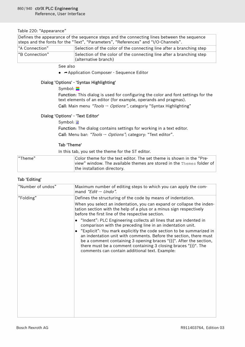
860 / 940 ctrlX PLC EngineeringReference, User Interface
Bosch Rexroth AG R911403764, Edition 03
Table 220: “Appearance”Defines the appearance of the sequence steps and the connecting lines between the sequencesteps and the fonts for the “Text”, “Parameters”, “References” and “I/O-Channels”.“A Connection” Selection of the color of the connecting line after a branching step“B Connection” Selection of the color of the connecting line after a branching step
(alternative branch)See also● ⮫ Application Composer - Sequence Editor
Dialog 'Options' - 'Syntax Highlighting'Symbol: Function: This dialog is used for configuring the color and font settings for thetext elements of an editor (for example, operands and pragmas).Call: Main menu “Tools 🠂 Options”, categoriy “Syntax Highlighting”
Dialog 'Options' - 'Text Editor'Symbol: Function: The dialog contains settings for working in a text editor.Call: Menu bar: “Tools 🠂 Options”; category: “Text editor”.
Tab 'Theme'In this tab, you set the theme for the ST editor.
“Theme” Color theme for the text editor. The set theme is shown in the “Pre-view” window. The available themes are stored in the Themes folder ofthe installation directory.
Tab 'Editing'
“Number of undos” Maximum number of editing steps to which you can apply the com-mand “Edit 🠂 Undo”.
“Folding” Defines the structuring of the code by means of indentation.When you select an indentation, you can expand or collapse the inden-tation section with the help of a plus or a minus sign respectivelybefore the first line of the respective section.● “Indent”: PLC Engineering collects all lines that are indented in
comparison with the preceding line in an indentation unit.● “Explicit”: You mark explicitly the code section to be summarized in
an indentation unit with comments. Before the section, there mustbe a comment containing 3 opening braces "{{{". After the section,there must be a comment containing 3 closing braces "}}}". Thecomments can contain additional text. Example:
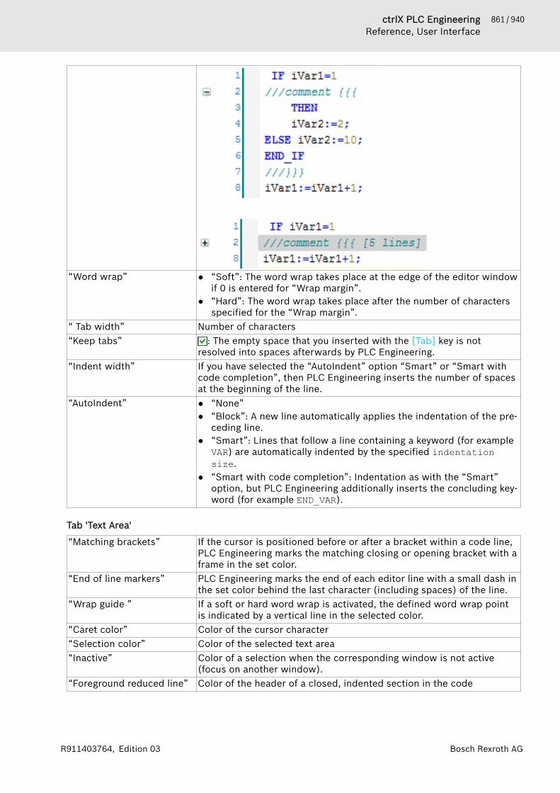
861 / 940ctrlX PLC EngineeringReference, User Interface
Bosch Rexroth AGR911403764, Edition 03
“Word wrap” ● “Soft”: The word wrap takes place at the edge of the editor windowif 0 is entered for “Wrap margin”.
● “Hard”: The word wrap takes place after the number of charactersspecified for the “Wrap margin”.
“ Tab width” Number of characters“Keep tabs” : The empty space that you inserted with the [Tab] key is not
resolved into spaces afterwards by PLC Engineering.“Indent width” If you have selected the “AutoIndent” option “Smart” or “Smart with
code completion”, then PLC Engineering inserts the number of spacesat the beginning of the line.
“AutoIndent” ● “None”● “Block”: A new line automatically applies the indentation of the pre-
ceding line.● “Smart”: Lines that follow a line containing a keyword (for example
VAR) are automatically indented by the specified indentationsize.
● “Smart with code completion”: Indentation as with the “Smart”option, but PLC Engineering additionally inserts the concluding key-word (for example END_VAR).
Tab 'Text Area'
“Matching brackets” If the cursor is positioned before or after a bracket within a code line,PLC Engineering marks the matching closing or opening bracket with aframe in the set color.
“End of line markers” PLC Engineering marks the end of each editor line with a small dash inthe set color behind the last character (including spaces) of the line.
“Wrap guide ” If a soft or hard word wrap is activated, the defined word wrap pointis indicated by a vertical line in the selected color.
“Caret color” Color of the cursor character“Selection color” Color of the selected text area“Inactive” Color of a selection when the corresponding window is not active
(focus on another window).“Foreground reduced line” Color of the header of a closed, indented section in the code

862 / 940 ctrlX PLC EngineeringReference, User Interface
Bosch Rexroth AG R911403764, Edition 03
“Background reduced line” The header of a closed, indented section in the code is given a coloredbackground.
“Font” Clicking the field opens the common dialog for the configuration of thefont.
Tab 'Margin'
Settings for the left margin of the text editor window, which is separated from the input area by avertical line:“Line numbering” Display of the line numbers in the declaration and implementation
part, in each case starting with 1“Foreground color” Color of the line numbers“Background color ” Color of the margin“Bracketing” Bracketing encompasses the lines between the keywords that open
and close a construct, for example IF and END_IF.If this option is enabled and the cursor is located before, after or inone of the keywords of a construct, the bracketed area is indicated bya square bracket in the border. You can select the color of the bracketfrom the drop-down list of this option.
“Active border color” Color of the dividing line between the border and input area“Inactive border color” Color of the dividing line between the border and input area of the
part of the window that is currently inactive“Mouse actions” You can assign one of the following actions to each of the specified
mouse actions or mouse button combinations. PLC Engineering exe-cutes the actions when you execute the mouse action on the plus orminus sign before the header of a parenthesized area:● “Select fold”: PLC Engineering selects all lines of the bracketed
area.● “Toggle fold”: PLC Engineering opens or closes the bracketed area
or, if there are nested brackets, the first level of the bracketed area.● “Toggle fold fully”: PLC Engineering opens or closes all levels of a
nested bracketed area.
Tab 'Monitoring'
Settings for the display of the monitoring fields“Enable inline monitoring” Display of the monitoring fields behind the variables in online mode“Monitoring foregroundcolor”
Display of the value in the monitoring field
“Monitoring backgroundcolor”
Display of the background in the monitoring field
“Flow control foregroundcolor”
Display of the value in the monitoring fields at the flow control posi-tions
“Flow control backgroundcolor”
Display of the background in the monitoring fields at the flow controlpositions
“Number of displayeddigits”
Number of decimal places in the monitoring field
“String length” Maximum length of string variable values in the monitoring fieldSee also● ⮫ Chapter “Programming Structured Text (ST)” on page 92
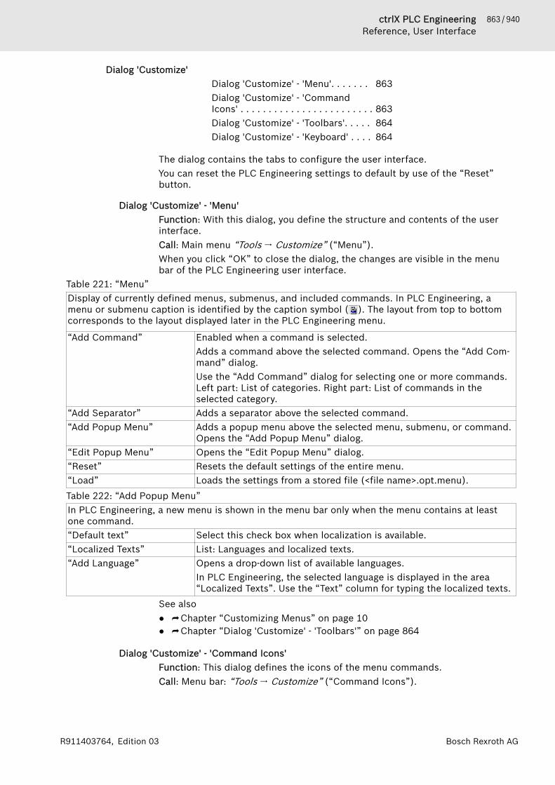
863 / 940ctrlX PLC EngineeringReference, User Interface
Bosch Rexroth AGR911403764, Edition 03
Dialog 'Customize'Dialog 'Customize' - 'Menu'. . . . . . . 863Dialog 'Customize' - 'CommandIcons' . . . . . . . . . . . . . . . . . . . . . . . . 863Dialog 'Customize' - 'Toolbars'. . . . . 864Dialog 'Customize' - 'Keyboard' . . . . 864
The dialog contains the tabs to configure the user interface.You can reset the PLC Engineering settings to default by use of the “Reset”button.
Dialog 'Customize' - 'Menu'Function: With this dialog, you define the structure and contents of the userinterface.Call: Main menu “Tools 🠂 Customize” (“Menu”).When you click “OK” to close the dialog, the changes are visible in the menubar of the PLC Engineering user interface.
Table 221: “Menu”Display of currently defined menus, submenus, and included commands. In PLC Engineering, amenu or submenu caption is identified by the caption symbol ( ). The layout from top to bottomcorresponds to the layout displayed later in the PLC Engineering menu.
“Add Command” Enabled when a command is selected.Adds a command above the selected command. Opens the “Add Com-mand” dialog.Use the “Add Command” dialog for selecting one or more commands.Left part: List of categories. Right part: List of commands in theselected category.
“Add Separator” Adds a separator above the selected command.“Add Popup Menu” Adds a popup menu above the selected menu, submenu, or command.
Opens the “Add Popup Menu” dialog.“Edit Popup Menu” Opens the “Edit Popup Menu” dialog.“Reset” Resets the default settings of the entire menu.“Load” Loads the settings from a stored file (<file name>.opt.menu).Table 222: “Add Popup Menu”In PLC Engineering, a new menu is shown in the menu bar only when the menu contains at leastone command.“Default text” Select this check box when localization is available.“Localized Texts” List: Languages and localized texts.“Add Language” Opens a drop-down list of available languages.
In PLC Engineering, the selected language is displayed in the area“Localized Texts”. Use the “Text” column for typing the localized texts.
See also● ⮫ Chapter “Customizing Menus” on page 10● ⮫ Chapter “Dialog 'Customize' - 'Toolbars'” on page 864
Dialog 'Customize' - 'Command Icons'Function: This dialog defines the icons of the menu commands.Call: Menu bar: “Tools 🠂 Customize” (“Command Icons”).

864 / 940 ctrlX PLC EngineeringReference, User Interface
Bosch Rexroth AG R911403764, Edition 03
Table 223: “Command icon”“Assign” Opens a dialog for selecting the new icon (*.ico).“Remove” Removes the user-defined icon. The default icon is active again.“Reset” Resets all default settings of the command icons.“Load” Loads the settings from a stored file (<file name>.opt.keyb).“Save” Saves the current settings to a file (<file name>.opt.keyb).
See also● ⮫ Chapter “Customize Command Icon” on page 12
Dialog 'Customize' - 'Toolbars'Function: Use this dialog for generating new toolbars or customizing existingtoolbars.Call: Main menu “Tools 🠂 Customize” (“Toolbars”).When you click “OK” to close the dialog, the changes are visible in the menubar of the PLC Engineering user interface.
Table 224: “Toolbars”Display of currently defined toolbars. In PLC Engineering, the associated commands are listedbelow each toolbar in the order they will appear in the toolbar.Double-clicking a toolbar in the list switches to editing mode.“Add Toolbar” Enabled when a toolbar is selected.
In PLC Engineering, this adds a toolbar above the selected toolbar andplaces the cursor in the name field of the new toolbar.
“Add Command” Enabled when you select a command or blank command entry below atoolbar.Adds a command above the selected command. Opens the “Add Com-mand” dialog.Use the “Add Command” dialog to select one or more commands. Leftpart: List of categories. Right part: List of commands in the selectedcategory.
“Add Separator” Adds a separator above the selected command.“Hide” Hide the selected toolbar from the user interface.“Show” Shows the selected hidden toolbar in the PLC Engineering user inter-
face.“Reset” Resets the default settings of the toolbars.“Load” Loads the settings from a stored file (<file name>.opt.tbar).
See also● ⮫ Chapter “Customizing Toolbars” on page 11● ⮫ Chapter “Dialog 'Customize' - 'Menu'” on page 863
Dialog 'Customize' - 'Keyboard'Function: This dialog is used for defining keyboard shortcuts (quick access keysor keyboard combinations) for commands.Call: Main menu “Tools 🠂 Customize” (“Keyboard”).
Table 225: “Keyboard”“Shortcuts for selectedcommand”
Keyboard shortcuts for the selected command The drop-down list caninclude more than one keyboard shortcut for the command.
“Press shortcut keys” Input field for the keyboard shortcut of the selected field. Permittedcombinations include [Ctrl], [Alt], [Shift], and other keys. You clicking“Assign” to assign a recorded keyboard shortcut to a selected com-mand.

865 / 940ctrlX PLC EngineeringReference, User Interface
Bosch Rexroth AGR911403764, Edition 03
“Shortcut keys currentlyused by”
Command assigned to the currently defined keyboard shortcut
“Reset” Resets the default settings of the keyboard shortcuts.“Load” Loads the settings from a stored file (<file name>.opt.keyb).
See also● ⮫ Chapter “Customizing Keyboard Shortcuts” on page 12
Dialog 'Trace Configuration'Dialog 'Advanced Trace Settings'. . . 865Dialog 'Trace Configuration'. . . . . . . 866
Dialog 'Advanced Trace Settings'Function: This dialog provides extended settings for recording data.Call: “Advanced” button in “Trace Configuration ” dialog, “Record Settings”subdialogRequirement: The trace editor is open and active. The dialog “Trace configura-tion” is open and the top node of the trace record tree is selected so that thesubdialog “Record settings” is available.For the calculation of the values, you have to select a task in the “Trace Config-uration” dialog.
The buffer size is defined as "number of samples". PLC Engineering calculates the time intervalsthat corresponds to this number and displays the result in normal fonts on the right outside thetable (for example, “1h1m1s1ms”). The calculation is possible only with the help of the task config-uration settings and when the task cycle time is known.“Measurement in everynth cycle”
Data recording in every n task cyclePreset: 1; then the application performs the datarecording in each task cycle.
Scanning interval of thedata recordingExample: 100ms
“Recommended runtimebuffer size (samples)”
Requirement: “Override runtime buffer size” isdeactivated.The maximum number of samples that PLC Engi-neering calculates and recommends, which theapplication stores at runtime per trace variable.PLC Engineering calculates the number in thetask cycle time from the value in “Measure inevery n-th cycle” and the value in Measure inevery n-th cycle.
Maximum length of thetime interval duringwhich the applicationcollects data on the run-time system.Example: 2s
“Override runtimebuffer size”
Maximum number of samples per trace variablethat saves the application per trace variable inruntime mode.Example: 100Value range: starting at 10
: The application uses this value, not the valuecalculated by PLC Engineering from “Recom-mended runtime buffer size (samples)”.
Maximum length of thetime interval duringwhich the applicationcollects data on the run-time system.Example: 6s
“Trace editor buffer sizeper variable (samples)”
Number of values that can be stored per variablein the trace editor.Example: 10000
The maximum timeperiod for the display inthe trace editor resultsfrom the maximumnumber and the scan-ning interval of the datarecording. You can
866 / 940 ctrlX PLC EngineeringReference, User Interface
Bosch Rexroth AG R911403764, Edition 03
scroll back a maximumof this time in the traceeditor.
See also● ⮫ Chapter “Object 'Trace'” on page 647● ⮫ Chapter “Creating Trace Configuration” on page 222
Dialog 'Trace Configuration'Symbol: Function: This dialog includes the trace configuration for the data recording.Call● Menu bar: “Trace 🠂 Configuration”; context menu.● Link “Configuration” in the trace editor● Link “Add Variable” in the trace editorRequirement: The editor of a trace object is open and active.See also● ⮫ Chapter “Creating Trace Configuration” on page 222● ⮫ Chapter 1.12.3 “Data Recording with Trace” on page 220● ⮫ Chapter “Attribute 'monitoring'” on page 437
Tree view 'Trace record'The tree view lists the variables that are traced and allows for access to the var-iable settings.
Selected trace name The subdialog “Record Settings” is displayed on the right.Selected trace variable The subdialog “Variable Settings” is displayed on the right.Table 226: Context menu commands
“Add Variable” Adds a new trace variable. The subdialog “Variable Settings” opens onthe right and it is partially configured. Select a variable in the inputfield of the “Variable” setting to trace its value graph.
“Assign to Diagram” Lists the diagrams (in the submenu on the right) where the selectedvariable is not currently displayed. Select a diagram to display the vari-able there.The command is available when a variable is selected in the tree view.Tip: When the command is deactivated, the variable is already dis-played in all diagrams.
“Activated” Activated by defaultDeactivated variables are displayed as disabled. They are neither dis-played nor recorded.
Tree view 'Presentation (Diagrams)'The tree view lists the diagrams that are displayed in the trace editor andallows for access to their display mode.
Selected node “Time axis” The subdialog “Display Mode” for the time axis is displayed on theright. You can specify the time axis display. See below.
Selected diagram name The settings for the coordinate system of the diagram and a previeware displayed on the right. See below.
Selected node “Y-axis” The subdialog “Display Mode” is displayed on the right. You canspecify the axis display. See below.
867 / 940ctrlX PLC EngineeringReference, User Interface
Bosch Rexroth AGR911403764, Edition 03
“Show variables”Selected trace variable The subdialog “Variable Settings” is displayed on the right. You can
configure the trace variable. See below.Note: These are the same settings that can be accessed in the treeview “Trace Record”.
Table 227: Context menu commands “Add Diagram” Adds a new diagram below and displays it in the tree view “Presenta-
tion (Diagrams)”. “Add New Variable” Adds a new trace variable. The subdialog “Variable Settings” opens on
the right and it is partially configured. Select a variable in the inputfield of the “Variable” setting to trace its value graph. Specify its dis-play. In addition, the variable is assigned to the selected diagram.
“Add Existing Variable” Lists all trace variables (in the submenu on the right) where theselected diagram is not currently displayed. Select a variable in orderto display it in the selected diagram.Tip: When the command is deactivated, all trace variables are alreadydisplayed in the selected diagram.
Subdialog 'Record Settings'Requirement: The top node is selected in the “Trace record” tree view.
“Enable trigger” : Triggering is activated. The trace data is buffered in runtime modeonly when a trigger signal has been sent. You determine how thetrigger signal is sent in the settings “Trigger variable”, “Trigger param-eter”, “Trigger edge”, “Post trigger (Samples)”, and “Trigger level”.
: Continuous display of current records“Trigger variable” Signal that is used as a trigger. A complete instance path is required.
A valid trigger signal is an IEC variable, a property, a reference, apointer, an array element of the application, or an expression. Per-mitted types are all IEC-based types except STRING, WSTRING, andARRAY. Enumerations are permitted when the base type is not STRING,WSTRING, or ARRAY The contents of a pointer are not a valid signal.When the runtime system uses the CmpTraceMgr component, a prop-erty that is linked to the 'monitoring' attribute can then be recordedas a variable.
“Trigger parameter” System parameter that is used as a triggerThe “Input Assistant” dialog lists all valid system parameters in the“Parameters” category of the “Categories” tab.Selects the “Trigger variable” or “Trigger parameter”
“Trigger edge” Defined the edge detection for triggering:● “positive”
– For Boolean trigger variables, triggering occurs when the valueschanges from FALSE to TRUE.
– For analog trigger variables, triggering occurs when the value asdefined in “Trigger level” is reached from below.
● “negative”– For Boolean trigger variables, triggering occurs when the values
changes from TRUE to FALSE.– For analog trigger variables, triggering occurs when the value as
defined in “Trigger level” is reached from above.
868 / 940 ctrlX PLC EngineeringReference, User Interface
Bosch Rexroth AG R911403764, Edition 03
● “both”– For Boolean trigger variables, triggering occurs when the values
changes.– For analog trigger variables, triggering occurs when the value as
defined in “Trigger level” is reached.“Post trigger (samples)” Number of records per trace variable that are buffered after triggering.
Preset: 50. Value range: 0 to (232 - 1)“Trigger level” Value that is reached for triggering“Task” Task where data was recorded“Recording condition” In runtime mode, the application checks the recording condition. If it
is fulfilled, then the trace data is buffered.Record condition for data recording with CmpTraceMgr runtimesystem component:● As an expression that includes only permitted operators and oper-
ands.Permitted operators that can also be nested: (logical) AND, NOT,OR,comparison operators <, <=, >, >=, =, <>.Permitted operands: Variables that are valid for trace.
● As a variable.Permitted type: BOOL, bit access, property. The condition is fulfilledfor TRUE or 1. The contents of a pointer are not permitted.
Recording condition for a data recording with IEC code.● As an expression that returns a Boolean value.
“Comment” Comment (for example, from the recording condition)“Resolution” Measure for the time stamp that is recorded per data set
● “ms”: Time stamp (in milliseconds).● “µs”: Time stamp (in microseconds) for a task cycle time of 1 ms or
less“Automatic restart” : Persistently saves the trace configuration and the last contents of
the RTS buffer to the target device. After the device is restarted, thetrace is started automatically if the trigger has not occurred yet.
“Advanced” Opens the “Advanced Trace Settings” dialog.See also● ⮫ Chapter “Dialog 'Advanced Trace Settings'” on page 865
Subdialog 'Variable Settings'Requirement: A trace variable is selected in the tree view of “Trace Record” or“Display (Diagrams)”.
“Variable” Valid variable Variable; value recorded with full instance path.Valid:● IEC variable● Property● Reference● Contents of the pointer● Array elementPermitted data type● IEC-based type except STRING, WSTRING, or ARRAY● Enumeration when the base type is not STRING, WSTRING, or ARRAY
869 / 940ctrlX PLC EngineeringReference, User Interface
Bosch Rexroth AGR911403764, Edition 03
When the runtime system uses the CmpTraceMgr component, a prop-erty that is linked to the 'monitoring' attribute can then be recordedas a variable.
“Parameter” Parameter whose data is recorded.Requirement: Runtime system with CmpTraceMgr componentThe “Input Assistant” dialog lists all valid system parameters in the“Parameters” category of the “Categories” tab.Enables toggling between “Variable” and “Parameter”
“Color” Color of the variable in the trace diagram“Line type” Display as line chart
● “Line”: Values are linked to form a line.● “Step”: Values are linked in the form of steps● “None”: Values are not linked
“Point type” Display as scatter chart● “Dot”: Value is displayed as a dot● “Cross”: Value is displayed as a cross.● “None”: value is not displayed
“Activate minimumwarning”
: Warning when less than the lower limit
“Critical lower limit” If the value of the trace variable falls below the limit, the variable isdisplayed in the warning color.
“Color” Warning color on falling below the limit“Activate maximumwarning”
: Warning when exceeding the upper limit
“Critical upper Limit” If the value of the trace variable exceeds the upper limit, the variable isdisplayed in the warning color.
“Color” Warning color on exceeding the limit
Subdialog 'Display mode'Requirement: An axis is selected in the tree view “Presentation (Diagrams)”
“Display mode” Scaling● “Auto”:
Automatically scaled time axis● “Fixed length”:
Time axis segment with a constant “Length”● “Fixed”:
Time axis segment from “Minimum” to “Maximum”“Minimum” Start value of the time axis segment. Requirement: The “Display Mode”
is “Fixed”.“Maximum” End value of the time axis segment. Requirement: The “Display Mode”
is “Fixed”.“Length” Constant segment length; the initial value is adapted automatically.“Grid” : Diagram with grid line in the x-direction. Select the grid line color
from the dropdown list of colors.Table 228: “Tick Marks”“Fixed spacing” : Display of tick marks with “Distance” and “Subdivisions”.“Distance” Distance between tick marks“Subdivisions” Number of subdivisions between two tick marks
“Font” Font for the time axis.

870 / 940 ctrlX PLC EngineeringReference, User Interface
Bosch Rexroth AG R911403764, Edition 03
Link “Preview” Displays the preview of the diagram.
Diagram previewRequirement: A diagram is selected in the tree view “Presentation (Diagrams)”
“Background color” Background color of the diagram. opens the dropdown list ofcolors.
“Background color onselection”
Background color of the selected diagram.
Link “Add Variable” Adds a new trace variable (in the tree view “Trace record”).Link “Delete Variable” Deletes the selected trace variable (in the tree view “Trace record”).Link “Add diagram” Adds a new diagram (in the tree view “Display”).Link “Delete Diagram” Deletes the selected diagram (in the tree view “Display”).Link “Reset Display Set-tings”
Resets the display settings of either the selected diagram or y-axis tothe default values.
“OK” Accepts the configuration changes and saves the trace configuration.
Dialog 'Trend Storage'Function: This dialog includes the configuration for buffering the trend data ofa trend recording.Call: “Trend Storage” button in the editor of a trend recording.
“Maximum number of varia-bles”
Maximum number of trend variables that can be managed in the data-base. If you increase this value afterwards, then will PLC Engineeringperform a download and reconfigure the database.
“Store every N millisec-onds”
Time interval (in ms) when the CmpTraceMgr runtime system compo-nent buffers the recorded data before storing it persistently in thedatabase. The application calculates internally the number of taskcycles from the time interval. The duration of a task cycle is defined inthe task configuration.A high value results in better runtime performance. The disadvantageis the increased risk of losing data if the controller crashes or shutsdown. A low value reduces this risk. The disadvantage is the slowercontrol over a trend visualization with large amounts of data.
“Limit” : Limit the recording

871 / 940ctrlX PLC EngineeringReference, User Interface
Bosch Rexroth AGR911403764, Edition 03
● “No Limit”: Unlimited number of data records (not recommended)● “Maximum number of records”: Maximum number of data records
that are stored in the database. A data record consists of timestamp and the values of the trend variables at this time.
● “Maximum storage size”: Maximum size of the trend storage. Theapplication calculates internally the number of data records.Clicking the "down" symbol ( ) of the drop-down list will set theunits to kilobytes (KB), megabytes (MB), or gigabytes (GB).
See also● ⮫ Chapter “Getting Started with Trend Recording” on page 227
Dialog 'Advanced Trend Settings'Function: This dialog provides more settings for configuring trend recording.Call: Click “Advanced” in the editor of a “TrendRecording” object.
“Measure in every n-thcycle”
Frequency that the runtime system records data, depending on thenumber of processed task cycles. Select a value from the drop-downlist or type a value into the input field.Using the settings from the task configuration, PLC Engineering calcu-lates the time interval according to the frequency. Therefore, the calcu-lation is possible only if at least the task cycle time is set. The result isshown on the right of the input field in normal syntax (for example,“1h1m1s1ms”).Default: 1 means that data is recorded in each task cycle.
“Additional Runtime Bufferfor”
Length of the time interval when the runtime system can record moredata (for example, 1000 ms).If a delay occurs when writing data in the runtime system component,then there is a risk of data loss due to overwriting. In this case, theruntime system uses the addition buffer.
See also● ⮫ Chapter 1.12.4 “Data Recording with Trend” on page 226● ⮫ Chapter “Configuring Trend Recording” on page 228
Dialog 'Certificate Selection'Symbol:Function: This dialog is used for selecting the certificates for encryption,decryption, and digital signatures.Call:● “Security Screen” view, “User” tab● Main menu: “View 🠂 Properties”, “Encryption” tab when the “Application” is
selected in the device tree.● Main menu: “Project 🠂 Project Settings”, category “Security”
Dialog 'Certificate selection'
The purpose of the certificate that is selected in the dialog depends on the call location:● Call location: “Security screen” view, “User” tab
– Certificate for digital signatures– Certificate for the decryption of project files– Certificate for encrypted communication
● Call: “View 🠂 Properties” of the application

872 / 940 ctrlX PLC EngineeringReference, User Interface
Bosch Rexroth AG R911403764, Edition 03
– “Certificates of devices that share the encrypted download and the boot application”● Call location: “Project 🠂 Project settings”, category “Security”
– “Certificate for project encryption”Listing of the selected cer-tificates in a table
The following properties are displayed for each selected X.509 certifi-cate:● “Created for”● “Created by ”● “Valid as of”● “Valid until”● “Thumbprint”: SHA1 fingerprintDouble-clicking an entry opens the “Certificate” dialog with the “Gen-eral” tab, “Details” tab, and “Certification Path” tab. In that tab, youwill find a reference to Windows help with more information about thedialog.Adds the selected available certificate to the list of selected certifi-cates.Deletes the certificate selected in the list.
“Available certificates in thelocal Windows CertificateStore”
Double-clicking an entry opens the “Certificate” dialog with the “Gen-eral” tab, “Details” tab, and “Certification Path” tab. In that tab, youwill find a reference to Windows help with more information about thedialog.
Certificate icons ●● : Certificate with private key● : Untrusted certificate
See also● ⮫ Chapter “Command 'Security Screen'” on page 688
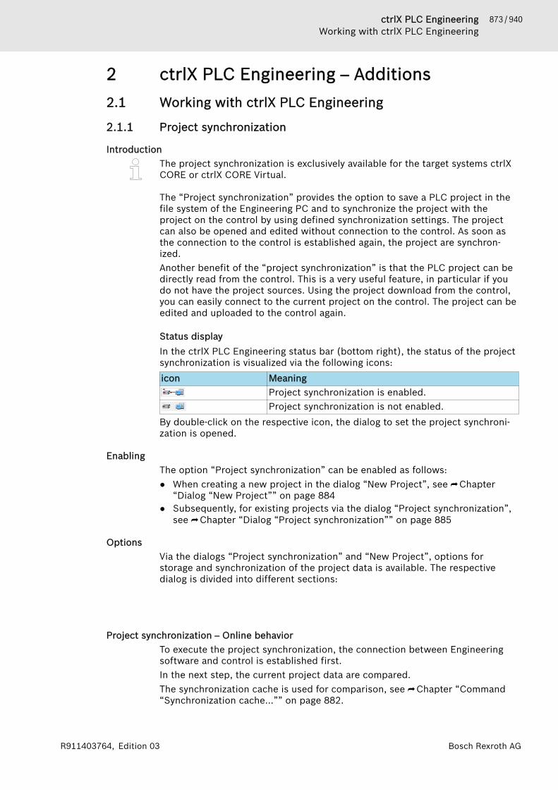
873 / 940ctrlX PLC EngineeringWorking with ctrlX PLC Engineering
Bosch Rexroth AGR911403764, Edition 03
2 ctrlX PLC Engineering – Additions2.1 Working with ctrlX PLC Engineering
2.1.1 Project synchronization
IntroductionThe project synchronization is exclusively available for the target systems ctrlXCORE or ctrlX CORE Virtual.
The “Project synchronization” provides the option to save a PLC project in thefile system of the Engineering PC and to synchronize the project with theproject on the control by using defined synchronization settings. The projectcan also be opened and edited without connection to the control. As soon asthe connection to the control is established again, the project are synchron-ized.Another benefit of the “project synchronization” is that the PLC project can bedirectly read from the control. This is a very useful feature, in particular if youdo not have the project sources. Using the project download from the control,you can easily connect to the current project on the control. The project can beedited and uploaded to the control again.
Status displayIn the ctrlX PLC Engineering status bar (bottom right), the status of the projectsynchronization is visualized via the following icons:icon Meaning
Project synchronization is enabled.Project synchronization is not enabled.
By double-click on the respective icon, the dialog to set the project synchroni-zation is opened.
EnablingThe option “Project synchronization” can be enabled as follows:● When creating a new project in the dialog “New Project”, see ⮫ Chapter
“Dialog “New Project”” on page 884● Subsequently, for existing projects via the dialog “Project synchronization”,
see ⮫ Chapter “Dialog “Project synchronization”” on page 885
OptionsVia the dialogs “Project synchronization” and “New Project”, options forstorage and synchronization of the project data is available. The respectivedialog is divided into different sections:
Project synchronization – Online behaviorTo execute the project synchronization, the connection between Engineeringsoftware and control is established first.In the next step, the current project data are compared.The synchronization cache is used for comparison, see ⮫ Chapter “Command“Synchronization cache...”” on page 882.

874 / 940 ctrlX PLC EngineeringWorking with ctrlX PLC Engineering
Bosch Rexroth AG R911403764, Edition 03
If differences between project storages are determined, the data transmissionis canceled and the dialog “conflict: Project synchronization...” is opened. Inthe dialog, the following project synchronization options can be selected:Button Action“Use project from ctrlX” The project currently opened in the Engi-
neering is closed.The project data available on the control areapplied to a new project in Engineering.
“Use Project from PC” The project data available in Engineering areapplied to the current configuration on thecontrol.
“Open project comparison” By using the project comparison, see ⮫ “View'Project Comparison' - 'Differences'”on page 702, the project data content can becompared and synchronized.
“Cancel synchronization” The synchronization process is canceled.No project data synchronization takes placebetween Engineering and control.The existing data is retained.
2.1.2 Templates for compiler check functionsctrlX PLC Engineering provides the option to create application-specific tem-plates and to integrate these templates into the PLC project.Template for POUs, variable lists, visualizations etc. are provided via a template.These templates can be referenced for a user-friendly PLC project creation. Areoccurring program sequence can be provided as template via a POU with vis-ualization. The contents to be used can be specified using the parameteriza-tion.Using these templates has the following benefits:● Faster program creation● Standardization● Recoverability● Less errors in programming
Inserting templates in the PLC project1. Open the ctrlX PLC Engineering project2. In the device tree, open the context menu of the “Application” node3. Execute the “Inserting templates...” command
🡆 The “Inserting templates” dialog is opened.The dialog contains the tabs “CheckFunctions” and “Motion interface”.
4. Select the template and confirm the dialog with OK“Insert”.🡆 The template is inserted below the application node in the “CheckFunc-
tions” folder.
Template – CheckFunctionsThe provided functions are used to increase machine safety and check foraccess violations in the PLC program during runtime. The implementedstandard error reaction can be adjusted to the machine application require-ments after insertion.The functions are implemented type-specifically and are thus summarized inthe following functional groups:
875 / 940ctrlX PLC EngineeringWorking with ctrlX PLC Engineering
Bosch Rexroth AGR911403764, Edition 03
● Array limitsDetecting inadmissible accesses outside array boundaries
● Divisions by zeroDetecting divisions by zero
● Pointer accessDetecting inadmissible accesses via POINTER and REFERENCE variables.
● BoundariesDetecting inadmissible accesses outside boundaries
The individual functional groups can be selected separately in the relevantdialog. The functions are created below the application in the “CheckFunc-tions” folder in the project tree. Functional groups already inserted in theproject tree are grayed out in the template dialog.When creating a new ctrlX CORE project, all functional groups are inserted inthe project by default.
NOTICE Adding check functions results in a download of theentire application. An online change is not possible any-more.
Removing of check functionsInserted functions can only be removed in the project tree:● Complete removal: delete the “CheckFunctions” folder● Individual removal: delete the relevant functionThe declaration part of the relevant test function contains more information.
Template – Motion interfaceThe Motion interface template provides user-friendly access options to axesand kinematics which are managed via the Motion app. Before the functionalitycan be used, initialize Motion interface first, see ⮫ web documentation.
Integrating customized templates in ctrlX PLC EngineeringApart from the check functions and MotionInterface templates, it is possible toprovide individual templates in the “Inserting templates” dialog.The PLCopenXML and CODESYS.export format are supported as template.
Save the customized templates in the following folder on the Engineering PC tobe able to select them in a dialog.“PLC Engineering Installation directory 🠂 LinkToCommonAppData 🠂 \Studio\Templates”A tab page is created for each folder in this repository. Define the templates asgroups.Specifications:● A *.conf.xml file with the same name is available for each group● Each group can be subdivided into up to four categories● Each category corresponds to a check box in the group● Each category can contain an unlimited number of templates● Each template file (Codesys.export or PlcOpen.xml) has a *.conf.xml
description file with the same nameThe corresponding descriptions and texts in the dialog are defined by the “Vor-lagenGruppenName“.conf.xml (TemplateGroupName) in the same directory.The description file contains five property entries to be filled in by the user.Property entries:

876 / 940 ctrlX PLC EngineeringWorking with ctrlX PLC Engineering
Bosch Rexroth AG R911403764, Edition 03
Creating a customized templateCurrently, only German and English texts are supported.English is the default language and has to be available.
Fig. 1: Dialog - Inserting templates① Name_EN② Description_EN③ GroupBoxHeader_EN④ Note_EN⑤ IsWarning
Beispiel einer *.conf.xml Datei für die Gruppeninformation (Deutsch / Englisch):
<?xml version="1.0" encoding="utf-8"?><GroupInformation> <property name="Name_DE" type="string">Titel der Registerkarte</property> <property name="Name_EN" type="string">Title of the tab page</property>
<property name="Description_DE" type="string">Beschreibung der Vorlagengruppe</property> <property name="Description_EN" type="string">Description of this template group</property>
<property name="GroupBoxHeader_DE" type="string"></property> <property name="GroupBoxHeader_EN" type="string"></property>
<property name="Note_DE" type="string">Hinweis oder Warnung für diese Gruppe</property> <property name="Note_EN" type="string">Note or warning for this group</property>
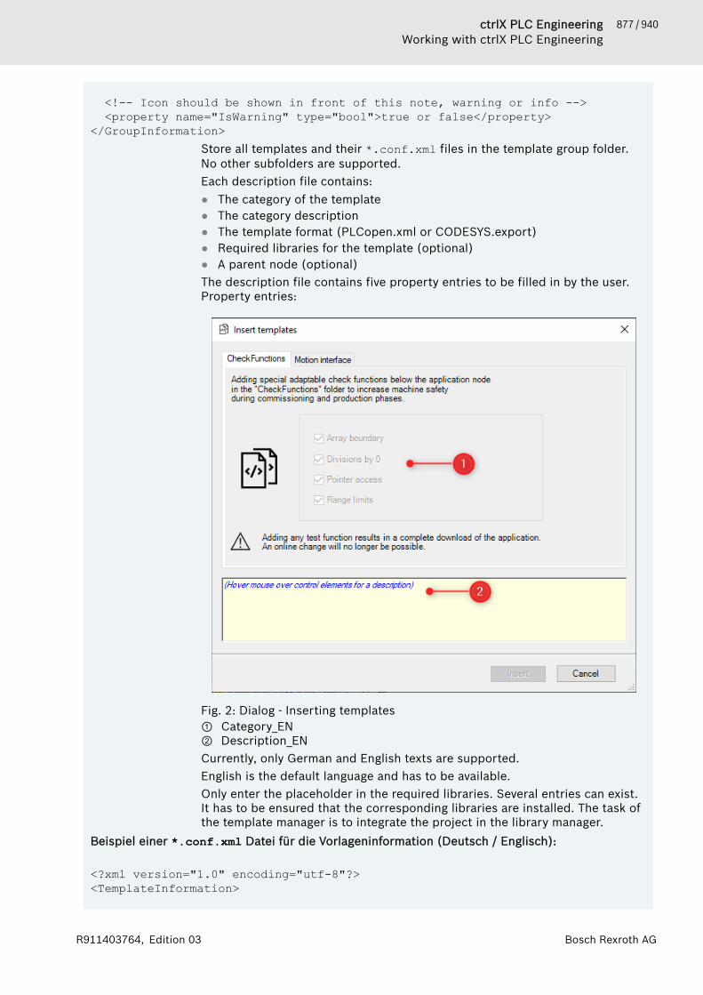
877 / 940ctrlX PLC EngineeringWorking with ctrlX PLC Engineering
Bosch Rexroth AGR911403764, Edition 03
<!-- Icon should be shown in front of this note, warning or info --> <property name="IsWarning" type="bool">true or false</property></GroupInformation>
Store all templates and their *.conf.xml files in the template group folder.No other subfolders are supported.Each description file contains:● The category of the template● The category description● The template format (PLCopen.xml or CODESYS.export)● Required libraries for the template (optional)● A parent node (optional)The description file contains five property entries to be filled in by the user.Property entries:
Fig. 2: Dialog - Inserting templates① Category_EN② Description_ENCurrently, only German and English texts are supported.English is the default language and has to be available.Only enter the placeholder in the required libraries. Several entries can exist.It has to be ensured that the corresponding libraries are installed. The task ofthe template manager is to integrate the project in the library manager.
Beispiel einer *.conf.xml Datei für die Vorlageninformation (Deutsch / Englisch):
<?xml version="1.0" encoding="utf-8"?><TemplateInformation>

878 / 940 ctrlX PLC EngineeringWorking with ctrlX PLC Engineering
Bosch Rexroth AG R911403764, Edition 03
<property name="Category_DE" type="string">Arraygrenzen</property> <property name="Category_EN" type="string">Array boundarys</property> <property name="Description_DE" type="string"></property> <property name="Description_EN" type="string"></property>
<!-- Placeholder only without version. If there more required libraries use this tag again --> <property name="LibraryPlaceholder" type="string">CmpLog</property> <property name="LibraryPlaceholder" type="string">Standard</property>
<property name="ParentNode" type="string">Folder or POU</property>
<!-- Which export format is used? Codesys or PLCopenXML?--> <!-- Possible values "true" or "false" if no tag default is PlcOpenXML--> <property name="CodesysImportFormat" type= "bool">true</property></TemplateInformation>
2.1.3 API PLC EngineeringGeneral informationThe API for PLC Engineering is a REST interface.The interface facilitates editing of projects in PLC Engineering by using “RESTcommands”.
Start parameter for use of interfaceTo be able to use the interface, start the software tool PLC Engineering with anadditional parameter.Parameter name: --webserverport=<Port number>Please note that a blank space is entered between the storage location pathand the parameter.
The parameter call for PLC Engineering can be executed as follows:● Via the Windows input panel
<Storage location>ctrlX-PLC-Engineering.exe --webserverport="9002"● Via a link
<Storage location>\ctrlX-PLC-Engineering.exe --webserverport="9002"
The port number is required to start a web server.The port number should thus not be assigned with another application.
879 / 940ctrlX PLC EngineeringReference, user interface
Bosch Rexroth AGR911403764, Edition 03
Documentation of REST commandsThe interactive documentation of the REST commands can be opened via themenu entry “Open Api...” in the software tool PLC Engineering. However, themenu entry is not contained in the PLC Engineering default menu settings andhas to configured once.Configuring the menu entry1. In the PLC Engineering menu bar, click on “Tools 🠂 Customize...”
🡆 The dialog “Customize...” opens2. In tab “Menu”, open the node “Help”
🡆 An element selection is displayed3. Select the free element below “About...” and right-click on “Add Com-
mand”🡆 The “Add Command” dialog opens
4. In the “Categories” column, select the entry “Help”🡆 In the “Commands” column, all command of the “Help” category are
displayed5. Select “Open Api...” and confirm the dialog with “OK”
🡆 The “Add Command” dialog is closed and the recently added command“Open Api...” is displayed in the “Help” node.
6. Confirm the “Customize...” dialog with “OK”🡆 The recently added command is now available in the PLC Engineering
menu “Help”
Opening interactive documentationsRequirement: configure a menu entry “Open Api...”, as previously described.
In the PLC Engineering menu, click on “Help 🠂 Open Api...”🡆 A browser containing interactive documentation opens.
This documentation describes the REST APIPLC Engineering com-mands:● The interactive browser page communicates with the opened PLC
Engineering● The default parameter port number is contained in the address line.
Example: „http://localhost:9002/index.html“
2.2 Reference, user interface
2.2.1 Objects● ⮫ Chapter “Object “device (ctrlX CORE)”” on page 879● ⮫ Chapter “Object “Realtime_Data (DataLayer)”” on page 880● ⮫ Chapter “Object “ethercat_master_instances_ethercatmaster””
on page 880
Object “device (ctrlX CORE)”Symbol
CallIn the ctrlX PLC Engineering device tree below the project node, see⮫ Chapter 1.7.1 “Device Tree and Device Editor” on page 47

880 / 940 ctrlX PLC EngineeringReference, user interface
Bosch Rexroth AG R911403764, Edition 03
FunctionThe object node “device (ctrlX CORE)” symbolizes the control in your PLCproject and provides all elements and tools required for PLC project configura-tion.In the initial state, the control object node contains the following subnodes:Subnodes Function
PLC Logic The PLC Logic subnode is part of the controlobject node and contains the following objectsto create a PLC control program
Application The “Application” node contains the objectsrequired for an executable control program,see ⮫ Chapter “Object 'Application'”on page 528
Library Manager The Library Manager lists all libraries that wereintegrated in the project for creating applica-tions, see ⮫ Chapter “Object 'Library Man-ager'” on page 583
PLC_PRG (PRG) POU (structured text)The POU “PLC_PRG (PRG)” is automaticallycreated when creating a ctrX project templateand does not contain a program code yet.
Task Configuration The “Task Configuration” object is used todefine and display the basic settings for thetask configuration, see ⮫ Chapter “Object 'TaskConfiguration'” on page 640
Main Task In the “Main Task” object, define the condi-tions for task start and calls within the task,see ⮫ Chapter “Object 'Task'” on page 645
PLC_PRG POU “PLC_PRG (PRG)” with call in Main Task Realtime_Data (DataLayer) The “Realtime_Data (DataLayer)” node allows
the configuration and connection of realtimedata to the PLC which is managed via the ctrlXCORE Data Layer, see ⮫ Chapter “Object “Real-time_Data (DataLayer)”” on page 880
Further documentation● ⮫ Chapter 1.2.2 “Creating a new project” on page 14● ⮫ Chapter “Creating a project on the basis of a template for ctrlX CORE Cre-
ating devices” on page 15
Object “Realtime_Data (DataLayer)”Being prepared
Object “ethercat_master_instances_ethercatmaster”Being prepared
2.2.2 Commands
Command “Determining DataLayerUser from ctrlX...”Symbol:
881 / 940ctrlX PLC EngineeringReference, user interface
Bosch Rexroth AGR911403764, Edition 03
Call:Call the command via the context menu of the “Realtime_Data (DataLayer)”object in the device tree.
Function:The command opens the “Add Realtime Data User” dialog.Via the dialog, add an instance of an EtherCAT master in the device tree, see⮫ Chapter “Dialog “Add Realtime Data User”” on page 883.
Add Command “Determining DataLayerNode from ctrlX...”Prerequisite:The “ethercat_master_instances_ethercatmaster” object has to be available inthe device tree, see ⮫ Chapter “Object “ethercat_master_instances_ethercat-master”” on page 880.
Symbol:
Call:Call the command via the context menu of the“ethercat_master_instances_ethercatmaster” object in the device tree.
Function:The command opens the “Add Realtime Data Node” dialog.Via the dialog, add devices of a Ethercat configuration in the device tree, see⮫ Chapter “Add Dialog “Add Realtime Data Node”” on page 883.
Command “Open project from ctrlX...”Prerequisite:The project data source can be found on the control, see ⮫ Chapter 2.1.1“Project synchronization” on page 873
Symbol:
Call:In the ctrlX PLC Engineering menu “File 🠂 Open project from ctrlX...”
General information:The project data source can be either saved on the control or the EngineeringPC.If the project data source is saved on the control, use the “Open project fromctrlX...” command to read out PLC project data from the control and to edit andopen the data in ctrlX PLC Engineering.By using the function for project synchronization, synchronize the PLC projectdata between PC and control, see ⮫ Chapter “Command “Project synchronisa-tion...”” on page 882.
Function:The command opens the “Open project from ctrlX” dialog, see ⮫ Chapter“Dialog “Open project from ctrlX”” on page 887.

882 / 940 ctrlX PLC EngineeringReference, user interface
Bosch Rexroth AG R911403764, Edition 03
In the dialog, select the control from which the PLC project data can be loadedto the Engineering PC. After the PLC project data can be read out, you can editthe PLC project in ctrlX PLC Engineering and subsequently synchronize it withthe control. Additionally, the PLC project data can be saved on the PC.
Command “Project synchronisation...”Prerequisite:The “Project synchronisation...” command is exclusively supported by the ctrlXCORE, ctrlX CORE Virtual and ctrlX CORE I/O devices.
Symbol:
Call:The command has two access options:● In the ctrlX PLC Engineering menu “Project 🠂 Project synchronisation...”● In the context menu of the “device (ctrlX CORE)” object in the device tree
Function:The command opens the “Project synchronization” dialog by setting the basicsettings to synchronize the project data between the control and the Engi-neering PC, see ⮫ Chapter “Dialog “Project synchronization”” on page 885.The project synchronization functionality allows to transmit a project from thecontrol to the Engineering PC and to save the project in the local file system.Furthermore, define for which actions the project is transmitted or synchron-ized from the PC to the control again.If you do not have the project sources, open the project directly on the controlby means of the project synchronization, to connect to the running project, toedit them if required and to upload it to the control again, see ⮫ Chapter 2.1.1“Project synchronization” on page 873.
Command “Synchronization cache...”Prerequisite:The “Synchronization cache...” command is exclusively supported by the ctrlXCORE, ctrlX CORE Virtual and ctrlX CORE I/O devices.
Symbol:
Call:The command has two access options:● In the ctrlX PLC Engineering menu “Project 🠂 Synchronization cache...”● In the context menu of the “device (ctrlX CORE)” object in the device tree
Function:The “Synchronization cache...” command opens the “Project synchronization”dialog to manage the project cache on the Engineering PC, see⮫ Chapter “Dialog “Project synchronization” (Synchronization cache...)” on page 886.The synchronization cache is used as temporary file storage for project data.The data is exchanged between the control and the ctrlX PLC Engineering orctrlX I/O Engineering.
883 / 940ctrlX PLC EngineeringReference, user interface
Bosch Rexroth AGR911403764, Edition 03
More information● ⮫ Chapter 2.1.1 “Project synchronization” on page 873
2.2.3 Dialogs
Dialog “Add Realtime Data User”Call:The dialog can be opened via the “Determining DataLayerUser from ctrlX...”command, see ⮫ Chapter “Command “Determining DataLayerUser fromctrlX...”” on page 880.
Function:Via the dialog, add an EtherCAT master as a Data Layer instance in the devicetree.
Add EtherCAT master instance1. Open the dialog via the “Determining DataLayerUser from ctrlX...” com-
mand.🡆 The dialog “Add Realtime Data User” opens.
2. In the dialog, select the list item “ethercat_master_instances_ethercat-master” and confirm the dialog via the button“Add”.🡆 The object“ethercat_master_instances_ethercatmaster” is added below
the “Realtime_Data (DataLayer)” object in the device tree.Exit the dialog via the button“Close” without changing the configuration.
More information● ⮫ Chapter “Add Command “Determining DataLayerNode from ctrlX...””
on page 881● ⮫ Chapter “Add Dialog “Add Realtime Data Node”” on page 883
Add Dialog “Add Realtime Data Node”Prerequisite:The “ethercat_master_instances_ethercatmaster” object has to be available inthe device tree, see ⮫ Chapter “Object “ethercat_master_instances_ethercat-master”” on page 880.
Call:The dialog can be opened via the “Determining DataLayerNode from ctrlX...”command, see ⮫ Chapter “Add Command “Determining DataLayerNode fromctrlX...”” on page 881.
Function:Via the dialog, add the Ethercat devices as a Data Layer instance in the devicetree.
Add Ethercat device instance1. Open the dialog via the “Determining DataLayerNode from ctrlX...” com-
mand.🡆 The dialog “Add Realtime Data Node” opens.
884 / 940 ctrlX PLC EngineeringReference, user interface
Bosch Rexroth AG R911403764, Edition 03
2. In the dialog, select the Ethercat devices to be added and confirm thedialog via the button “Add”.🡆 The selected devices are added below the
“ethercat_master_instances_ethercatmaster” object in the device tree.Exit the dialog via the button“Close” without changing the configuration.
More information● ⮫ Chapter “Command “Determining DataLayerUser from ctrlX...””
on page 880● ⮫ Chapter “Dialog “Add Realtime Data User”” on page 883
Dialog “Project data comparison”Call:Automatically (no manual access option).
Function:Upon the ctrlX PLC Engineering start, the system compares the project configu-ration on the control to the project configuration in ctrlX PLC Engineering. Ifthe comparison reported differences, the dialog “ctrlX PLC Engineering - TheRexroth PLC programming system” is opened. In the dialog, select whether theproject data comparison is to be displayed or not. Additionally, extendedproject information can be displayed via button “Details...”.
Further information:● ⮫ Chapter “Command “Project synchronisation...”” on page 882● ⮫ Chapter “Command 'Compare'” on page 701
Dialog “New Project”Call:The dialog is called automatically when creating a new project.A new project can be created using the following menu command:“File 🠂 New Project...”
Function:When creating new ctrlX CORE control projects, basic settings have to beselected.The “New Project” dialog is used to configure the following settings:● Selecting the control to be configured in the network● Sychronization settings between control and Engineering PC
Dialog elements:
Element Description“Project storage onPC”
Display of:● Project name● Filing of the project data in the file system of the
Engineering PCThe displayed settings cannot be changed in thisdialog!To change the settings, the dialog has to be canceledusing the “Cancel” interface.
885 / 940ctrlX PLC EngineeringReference, user interface
Bosch Rexroth AGR911403764, Edition 03
Element DescriptionSubsequently, execute the steps to create a newproject and specify the settings, see ⮫ Chapter 1.2.2“Creating a new project” on page 14.
ctrlX CORE Configuration of the following settings:● “Control”:
Selecting the control to be configured in the net-work
● “Configuration”:Selecting the active configuration on the control onwhich the selected control is to be operated
Synchronisation PCand ctrlX CORE
There is the option to additionally store all relevantproject data at certain points in time on the ctrlXCORE control or to open a project on the control.Setting options:● " Synchronization of project storages between PC
and ctrlX CORE if:"Enabing/disabling the synchronization.In case of an enabled synchronization, the followingconditions have to be configured:– " The project is opened"
In this setting, the project is synchronized uponopening of the project
– " the project is saved on the PC"In this setting, the project is synchronized uponsaving of the project
– " an application is downloaded on the ctrlXCORE"In this setting, the project is synchronized upondownload of the project to ctrlX CORE
– " the project is closed"In this setting, the project is synchronized uponclosing of the project
● " Synchronize device description files and libra-ries"By using this setting, the device description filesand libraries which are not part of the ctrlX WORKSinstallation are additionally stored on the control.This option facilitates the direct project login.
For more information about the project synchroniza-tion, see ⮫ Chapter 2.1.1 “Project synchronization”on page 873
More information● ⮫ Chapter “Creating a project on the basis of a template for ctrlX CORE Cre-
ating devices” on page 15
Dialog “Project synchronization”Prerequisite:The “Project synchronization” dialog is exclusively supported by the , ctrlXCORE and ctrlX CORE Virtual devices.

886 / 940 ctrlX PLC EngineeringReference, user interface
Bosch Rexroth AG R911403764, Edition 03
Symbol:
Call:The dialog can be opened as follows:● Via the “Project synchronisation...” command, see ⮫ Chapter “Command
“Project synchronisation...”” on page 882● In the lower status bar of ctrlX PLC Engineering, double-click on the symbol:
Function:The “Project synchronization” dialog is used to configure the project synchroni-zation between the ctrlX CORE control and ctrlX PLC Engineering on the Engi-neering PC.
Dialog elements:
Further documentation● ⮫ Chapter “Command “Project synchronisation...”” on page 882● ⮫ Chapter 2.1.1 “Project synchronization” on page 873
Dialog “Project synchronization” (Synchronization cache...)
Prerequisite:The “Project synchronization” dialog is exclusively supported by thectrlX CORE,ctrlX CORE Virtual and ctrlX CORE I/O devices.
Symbol:
Call:In the ctrlX PLC Engineering menu via the “Project 🠂 Synchronization cache...”command
Function:The dialog is used to manage the cache of all projects on the Engineering PC
Dialog elements:
Element DescriptionDisplay “Size” Size of the assigned memory for the synchronization
cacheDisplay “Location:” Storage location of the cache in the file system.
The information provides a link. Via the link, the cur-rent directory can be directly opened in the Windowsfile Explorer.
Button “Clear cache” Interface to delete the cache and the content of thefile storage
Button “Close” Interface to close the dialog
Further documentation● ⮫ Chapter “Command “Synchronization cache...”” on page 882● ⮫ Chapter 2.1.1 “Project synchronization” on page 873

887 / 940ctrlX PLC EngineeringReference, user interface
Bosch Rexroth AGR911403764, Edition 03
Dialog “Conflict when opening the project”Currently, there is no help available
Dialog “Project synchronization”Currently, there is no help available
Dialog “Project synchronization”Currently, there is no help available
Dialog “Open project from ctrlX”Prerequisite:ctrlX CORE controls have to respond in the network to which PLC Engineeringcan connect to.
Symbol:
Call:Via the “Open project from ctrlX...” command, see ⮫ Chapter “Command “Openproject from ctrlX...”” on page 881
Function:Via the “Open project from ctrlX” dialog, configure from which the control is tobe loaded to and where the project storage is to be on the Engineering PC.
Dialog elements:
Dialog “Conflict: Project synchronization at open”Symbol:
Call:The dialog is automatically called, e.g. when there are differences between theproject storage on the PC and the project storage on the control when openingPLC Engineering.
Function:The dialog provides different options such as how to handle project differencesbetween control and PLC Engineering, see ⮫ Chapter “ Project synchronization– Online behavior” on page 873.

888 / 940 ctrlX PLC EngineeringReference, user interface
Bosch Rexroth AG R911403764, Edition 03
889 / 940ctrlX PLC EngineeringAPI ctrlX I/O Engineering
Bosch Rexroth AGR911403764, Edition 03
3 ctrlX I/O Engineering – Additions3.1 Project synchronization - ctrlX I/O Engineering
ctrlX I/O Engineering supports the same mechanisms, commands and dialogsrequired for project synchronization which are supported in ctrlX I/O Engi-neering see ⮫ Chapter 2.1.1 “Project synchronization” on page 873.
3.2 API ctrlX I/O EngineeringGeneral informationThe API for ctrlX I/O Engineering is a REST interface.The interface facilitates editing of projects in ctrlX I/O Engineering by usingREST commands.
Start parameter for use of interfaceTo be able to use the interface, start the software tool ctrlX I/O Engineeringwith an additional parameter.Parameter name: --webserverport=<Port number>Please note that a blank space is entered between the storage location pathand the parameter.
The parameter call for ctrlX I/O Engineering can be executed as follows:● Via the Windows input panel
<Storage location>ctrlX-IO-Engineering.exe --webserverport="9003"● Via a link
<Storage location>\ctrlX-IO-Engineering.exe --webserverport="9003"
The port number is required to start a web server.The port number should thus not be assigned with another application.

890 / 940 ctrlX PLC EngineeringReference, user interface
Bosch Rexroth AG R911403764, Edition 03
Documentation of REST commandsThe interactive documentation of the REST commands can be opened via themenu entry “Open Api...” in the software tool ctrlX I/O Engineering. However,the menu entry is not contained in the ctrlX I/O Engineering default menu set-tings and has to configured once.Configuring the menu entry1. In the ctrlX I/O Engineering menu bar, click on “Tools 🠂 Customize...”
🡆 The dialog “Customize...” opens2. In tab “Menu”, open the node “Help”
🡆 An element selection is displayed3. Select the free element below “About...” and right-click on “Add Com-
mand”🡆 The “Add Command” dialog opens
4. In the “Categories” column, select the entry “Help”🡆 In the “Commands” column, all command of the “Help” category are
displayed5. Select “Open Api...” and confirm the dialog with “OK”
🡆 The “Add Command” dialog is closed and the recently added command“Open Api...” is displayed in the “Help” node.
6. Confirm the “Customize...” dialog with “OK”🡆 The recently added command is now available in the ctrlX I/O Engi-
neering menu “Help”
Opening interactive documentationsRequirement: configure a menu entry “Open Api...”, as previously described.
In the ctrlX I/O Engineering menu, click on “Help 🠂 Open Api...”🡆 A browser containing interactive documentation opens.
This documentation describes the REST APIctrlX I/O Engineering com-mands:● The interactive browser page communicates with the opened ctrlX
I/O Engineering● The default parameter port number is contained in the address line.
Example: „http://localhost:9003/index.html“
3.3 Reference, user interface
3.3.1 Objects>> Being prepared <<
3.3.2 Tabs – EtherCAT master
Configure Tab – “General”CallIn the generic device editor of the EtherCAT master.To open the device editor, double-click on the EtherCAT master object in ctrlXI/O Engineering device tree, see ⮫ Chapter 1.7.1 “Device Tree and DeviceEditor” on page 47.

891 / 940ctrlX PLC EngineeringReference, user interface
Bosch Rexroth AGR911403764, Edition 03
FunctionIn the tab “General”, the general settings of the EtherCAT master can be config-ured.
Elements of the tab
“General”“Cycle time” Bus cycle time of the EtherCAT communication.
“State machine”“Master state afterdownload”
Master target state after configuration download.
“Master state afterrestart”
Target master state after control startup.
“Slaves have to reachthe master state”
If this option is enabled, all states have to reach themaster state.If this option is disabled, the master can execute a busstartup (e.g. target state OP) if not all slaves havereached the target state or if some slave are missing atthe EtherCAT bus.
“Options”“Use LRW instead ofLWR/LDR”
If the option is enabled instead of separate read (LRD)and write (LWR) commands, combined read/writecommands (LRW) are used.Caution!● Not all slaves support LRW● LRW cannot be used in case of cable redundancy
Configure Tab – “Sync Unit Assignment”CallIn the generic device editor of the EtherCAT master in ctrlX I/O Engineeringdevice tree, see ⮫ Chapter 1.7.1 “Device Tree and Device Editor” on page 47.
FunctionIn the tab “Sync Unit Assignment”, SyncUnits can be created manually andassigned to slaves.The preset SyncUnit “default” is not always available and cannot be deleted. Allslaves are assigned to the SyncUnit “default”. Further SyncUnits can then becreated and assigned to slaves.
Elements of the tab
“Device name” Name of the slave of the device tree“Sync Unit” Slave assignment to a SyncUnit.
Double-click on the SyncUnit field of a slave (on theright of the device name) to select one of the config-ured SyncUnits.Use this command to add a new SyncUnit. Enter aname in the text field.The command deletes the selected SyncUnit.The preset SyncUnit “Standard” cannot be deleted.
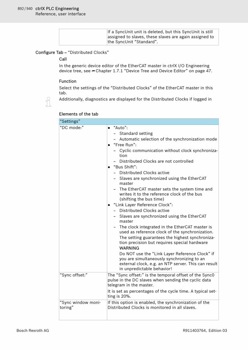
892 / 940 ctrlX PLC EngineeringReference, user interface
Bosch Rexroth AG R911403764, Edition 03
If a SyncUnit unit is deleted, but this SyncUnit is stillassigned to slaves, these slaves are again assigned tothe SyncUnit “Standard”.
Configure Tab – “Distributed Clocks”CallIn the generic device editor of the EtherCAT master in ctrlX I/O Engineeringdevice tree, see ⮫ Chapter 1.7.1 “Device Tree and Device Editor” on page 47.
FunctionSelect the settings of the “Distributed Clocks” of the EtherCAT master in thistab.Additionally, diagnostics are displayed for the Distributed Clocks if logged in
Elements of the tab
“Settings”“DC mode:” ● “Auto”:
– Standard setting– Automatic selection of the synchronization mode
● “Free Run”:– Cyclic communication without clock synchroniza-
tion– Distributed Clocks are not controlled
● “Bus Shift”:– Distributed Clocks active– Slaves are synchronized using the EtherCAT
master– The EtherCAT master sets the system time and
writes it to the reference clock of the bus(shifting the bus time)
● “Link Layer Reference Clock”:– Distributed Clocks active– Slaves are synchronized using the EtherCAT
master– The clock integrated in the EtherCAT master is
used as reference clock of the synchronization.The setting guarantees the highest synchroniza-tion precision but requires special hardwareWARNINGDo NOT use the “Link Layer Reference Clock” ifyou are simultaneously synchronizing to anexternal clock, e.g. an NTP server. This can resultin unpredictable behavior!
“Sync offset:” The “Sync offset:” is the temporal offset of the Sync0pulse in the DC slaves when sending the cyclic datatelegram in the master.It is set as percentages of the cycle time. A typical set-ting is 20%.
“Sync window moni-toring”
If this option is enabled, the synchronization of theDistributed Clocks is monitored in all slaves.
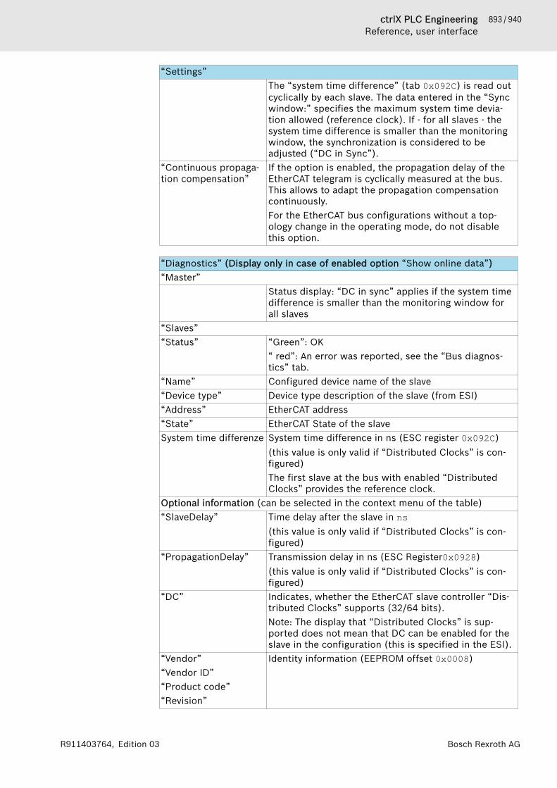
893 / 940ctrlX PLC EngineeringReference, user interface
Bosch Rexroth AGR911403764, Edition 03
“Settings”The “system time difference” (tab 0x092C) is read outcyclically by each slave. The data entered in the “Syncwindow:” specifies the maximum system time devia-tion allowed (reference clock). If - for all slaves - thesystem time difference is smaller than the monitoringwindow, the synchronization is considered to beadjusted (“DC in Sync”).
“Continuous propaga-tion compensation”
If the option is enabled, the propagation delay of theEtherCAT telegram is cyclically measured at the bus.This allows to adapt the propagation compensationcontinuously.For the EtherCAT bus configurations without a top-ology change in the operating mode, do not disablethis option.
“Diagnostics” (Display only in case of enabled option “Show online data”)“Master”
Status display: “DC in sync” applies if the system timedifference is smaller than the monitoring window forall slaves
“Slaves”“Status” “Green”: OK
“ red”: An error was reported, see the “Bus diagnos-tics” tab.
“Name” Configured device name of the slave“Device type” Device type description of the slave (from ESI)“Address” EtherCAT address“State” EtherCAT State of the slaveSystem time differenze System time difference in ns (ESC register 0x092C)
(this value is only valid if “Distributed Clocks” is con-figured)The first slave at the bus with enabled “DistributedClocks” provides the reference clock.
Optional information (can be selected in the context menu of the table)“SlaveDelay” Time delay after the slave in ns
(this value is only valid if “Distributed Clocks” is con-figured)
“PropagationDelay” Transmission delay in ns (ESC Register0x0928)(this value is only valid if “Distributed Clocks” is con-figured)
“DC” Indicates, whether the EtherCAT slave controller “Dis-tributed Clocks” supports (32/64 bits).Note: The display that “Distributed Clocks” is sup-ported does not mean that DC can be enabled for theslave in the configuration (this is specified in the ESI).
“Vendor”“Vendor ID”“Product code”“Revision”
Identity information (EEPROM offset 0x0008)
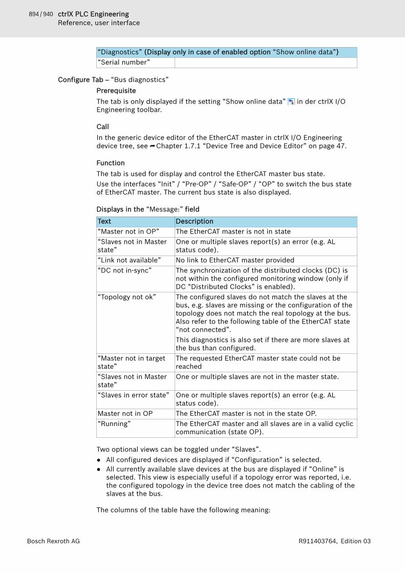
894 / 940 ctrlX PLC EngineeringReference, user interface
Bosch Rexroth AG R911403764, Edition 03
“Diagnostics” (Display only in case of enabled option “Show online data”)“Serial number”
Configure Tab – “Bus diagnostics”PrerequisiteThe tab is only displayed if the setting “Show online data” in der ctrlX I/OEngineering toolbar.
CallIn the generic device editor of the EtherCAT master in ctrlX I/O Engineeringdevice tree, see ⮫ Chapter 1.7.1 “Device Tree and Device Editor” on page 47.
FunctionThe tab is used for display and control the EtherCAT master bus state.Use the interfaces “Init” / “Pre-OP” / “Safe-OP” / “OP” to switch the bus stateof EtherCAT master. The current bus state is also displayed.
Displays in the “Message:” field
Text Description“Master not in OP” The EtherCAT master is not in state“Slaves not in Masterstate”
One or multiple slaves report(s) an error (e.g. ALstatus code).
“Link not available” No link to EtherCAT master provided“DC not in-sync” The synchronization of the distributed clocks (DC) is
not within the configured monitoring window (only ifDC “Distributed Clocks” is enabled).
“Topology not ok” The configured slaves do not match the slaves at thebus, e.g. slaves are missing or the configuration of thetopology does not match the real topology at the bus.Also refer to the following table of the EtherCAT state“not connected”.This diagnostics is also set if there are more slaves atthe bus than configured.
“Master not in targetstate”
The requested EtherCAT master state could not bereached
“Slaves not in Masterstate”
One or multiple slaves are not in the master state.
“Slaves in error state” One or multiple slaves report(s) an error (e.g. ALstatus code).
Master not in OP The EtherCAT master is not in the state OP.“Running” The EtherCAT master and all slaves are in a valid cyclic
communication (state OP).
Two optional views can be toggled under “Slaves”.● All configured devices are displayed if “Configuration” is selected.● All currently available slave devices at the bus are displayed if “Online” is
selected. This view is especially useful if a topology error was reported, i.e.the configured topology in the device tree does not match the cabling of theslaves at the bus.
The columns of the table have the following meaning:

895 / 940ctrlX PLC EngineeringReference, user interface
Bosch Rexroth AGR911403764, Edition 03
Status “Green”: OK,“Red”: An error was reported. The slave is not con-nected or refer to the column " Diagnostics " "¥
Name Configured device name of the slave.An unconfigured slave is shown with the name“Slave_x” in the online view.
Device type Device type description of the slave (from ESI).A slave, whose ESI is not installed in the IndraWorksdevice database, is shown as “Unknown device” in theonline view.
Address EtherCAT addressState EtherCAT State of the slave
Note: The state “not connected” means that the con-figured slave could not be assigned to any device atthe bus, i.e. the device is either physically not con-nected to the bus or the topology position of thedevice at the bus does not match the configuration.Procedure in case of a topology error:● Compare the configuration of the topology in the
device tree with to “online” view of the slavesDiagnostics Diagnostics, e.g. EtherCAT state error.
Switch slave state individuallyThe slave state can be switched individually via the context menu.Select the corresponding slave in the list. Open the context menu via right-clickand select the desired state: “Changing state 🠂 ([Init], [Pre-OP], [Safe-OP],[OP])”
Configure Tab – “EoE”CallIn the generic device editor of the EtherCAT master in ctrlX I/O Engineeringdevice tree, see ⮫ Chapter 1.7.1 “Device Tree and Device Editor” on page 47.
FunctionIn this tab, a virtual Ethernet port can be enabled in the EtherCAT master.By setting the IP address for the EtherCAT master, IP routing to the Engineeringport of the control is enabled.
Virtual network adapterThe EoE communication uses a virtual network adapter on the ctrlX CORE con-trol. The system adds the network adapter automatically to the control if theEoE communication is enabled in the EtherCAT configuration.The network adapter is displayed in the ctrlX CORE web interface in thewindow“Connectivity” with the name “eoe0”.The settings of the network adapter “eoe0” must not be changed in the window“Connectivity” (read-only).
Elements of the tab
GUI element Description“Virtual Ethernet port” : The virtual Ethernet port is disabled by default.
: The virtual Ethernet port is enabled on the control.
896 / 940 ctrlX PLC EngineeringReference, user interface
Bosch Rexroth AG R911403764, Edition 03
GUI element Description“IP address” Input field of the IP address of the virtual Ethernet
port“Subnet mask” Input field of the subnet mask of the virtual Ethernet
port
Configure Tab – “CoE”CallIn the generic device editor of the EtherCAT master in ctrlX I/O Engineeringdevice tree, see ⮫ Chapter 1.7.1 “Device Tree and Device Editor” on page 47.
FunctionIn this tab tab, the CoE objects of the EtherCAT master for diagnostic purposesare now displayed.
Elements of the tabIn the right upper drop-down list, select the following settings:● “Description from ESI”
The slave description is read out from the device description (ESI)● “Description from master (online)”
The slave description is read out of the device (online)Select the objects to be displayed in the left upper drop-down list:● “All Objects”
(RxPDO) objects that can be configured as process data (output data)The specifications are output in the following table:Column Description“Index” Via an index, the object is identified.
If an object contains subelements, they are written bythe subindex
“Name” Object name“Value” Depending on the type, the value can be a text or a
number.The number of subindices is displayed for objects withsubelements
“Access” Describes which access to the object is possible:● “RO”: Read-only● “RW”: Read and write● “WO”: Write only
“Type” The data type of the object
Configure Tab – “Diagnostics”PrerequisiteThe tab is only displayed if the setting “Show online data” in der ctrlX I/OEngineering toolbar.
CallIn the generic device editor of the EtherCAT master in ctrlX I/O Engineeringdevice tree, see ⮫ Chapter 1.7.1 “Device Tree and Device Editor” on page 47.

897 / 940ctrlX PLC EngineeringReference, user interface
Bosch Rexroth AGR911403764, Edition 03
FunctionThe tab is used to display messages provided from the CoE object “DiagnosisHistory” (0x10F3) of the EtherCAT master.
Elements of the tab
Acknowledging/deleting messagesThe diagnostic log is operated as ring buffer and can save up to 250 messages(device-specifically it might be less).Messages can be acknowledged and deleted via the following buttons in theupper area of the tab:● “Acknowledge messages”● “Delete messages”
SettingsThere are different optional settings that can be set in the slave. If a specificoption is not supported by the slave, a writing error is reported while disabling/enabling (parameter value beyond the valid range).● “Activate info”
Setting whether or not information is to be entered in the logbook● “Activate warning”
Setting whether or not warnings are to be entered in the logbook● “Activate error”
Setting whether or not error messages are to be entered in the logbook● “Activate emergency”
Setting whether or not the slave sends new diagnostics as CoE emergencymessages to the master.
● “Activate AcknowledgeMode”Setting options between “OverwriteMode” and “AcknowledgeMode”.In the “OverwriteMode”, if the message buffer is full, a new message over-writes the oldest message in the buffer irrespective of whether the mes-sages were acknowledged.Unacknowledged messages are not overwritten in the “AcknowledgeMode”,i.e. if the message buffer is full, the latest messages are not saved and thuslost.
Table list of messages
Column Description“Category” Message category: Info / Warning / Error
There is no default setting on how incoming and out-going errors are reported. Refer to product descriptionof the device.Acknowledged messages are shown by a greyed outicon.
“Time” Time stamp reported for the device message“Code” Diagnostic code“Text” The diagnostic texts are taken from the device descrip-
tion (ESI) of the device.
898 / 940 ctrlX PLC EngineeringReference, user interface
Bosch Rexroth AG R911403764, Edition 03
Configure Tab – “Information”CallIn the generic device editor of the EtherCAT master in ctrlX I/O Engineeringdevice tree, see ⮫ Chapter 1.7.1 “Device Tree and Device Editor” on page 47.
FunctionThe tab shows general information of the device description file:● Device name● Vendor● Category● Version● Description
3.3.3 Tabs – EtherCAT slave
Tab – “General”CallIn the generic device editor of the EtherCAT slave.To open the device editor, double-click on the EtherCAT slave object in ctrlX I/OEngineering device tree, see ⮫ Chapter 1.7.1 “Device Tree and Device Editor”on page 47.
FunctionIn the tab “General”, the general settings of the EtherCAT slave can be config-ured.
Elements of the tab
“Address”“AutoInc address” Auto increment address: Topological address of the
slave as negative auto increment (16 bits), forexample: 0, -1 (0xFFFF), -2 (0xFFFE) and -3 (0xFFFD)etc.The AutoInc address is automatically specified by theconfigurator in the sequence in which the slaves werecreated in the device tree (from top to bottom).
“EtherCAT address” EtherCAT address of the slave, also called “Fixed Phys-ical Address“.The address is not saved in the slave, but the masterassigns this address to the slave upon bus startup.Note: The EtherCAT address can currently not bechanged. The configurator specifies it automatically.
“Additional”“Enable expert set-tings”
: If the option is enabled, additional configurationsettings can be selected such as startup checks, time-outs, watchdog and identification.The “Expert process data” tab is enabled.
“Distributed Clock”“Select DC” Dropdown list with predefined settings for Distributed
Clocks from the device description file (ESI) of theslave (ESI)

899 / 940ctrlX PLC EngineeringReference, user interface
Bosch Rexroth AGR911403764, Edition 03
“Distributed Clock”“Enable” If the option “Enable expert settings” is selected, a
user-defined DC setting can be configured“Enable Sync0” : Use Sync0 event in EtherCAT slave“Enable Sync1” : Use Sync1 event in EtherCAT slave“Sync unit cycle” The dropdown list can be used to set a factor for multi-
plying the EtherCAT communication cycle time.The set cycle time is displayed in “Cycle time”.
“User-defined” : In case this option is enabled, the cycle time (µs)can be manually set in “Shift time”
“Startup Checking” (only in case of enabled option: “Enable expert settings”)“Check vendor ID” : Upon bus startup, it is checked whether the vendor
ID of the configured slave matches the physical device“Check product ID” : Upon bus startup, it is checked whether the
product ID of the configured slave matches the phys-ical device
“Check revisionnumber”
: Upon bus startup, the revision number of the con-figured is checked with regard to the value of the phys-ical device according to the selection of the drop-downlist.Partially different checks can be selected for low word(LW / bits 0-15) and high word (HW / bits 16-31) of therevision number.
“Download expectedslot configuration”
: For a slave with “modular device profile” (e.g.Rexroth S20-EC-BK), expected or configured slot/module configuration is loaded to the device to beable to compare them to the actual module configura-tion in the device.
“Timeouts” (only in case of enabled option: “Enable expert settings”)“SDO access” Timeout for SDO accesses upon bus startup“I->P” Timeout for state transition from Init to Pre-OP“P->S/S->O” Timeout for state transition from Pre-OP to Safe-OP
and from Safe-OP to OP
“Watchdog” (only in case of enabled option: “Enable expert settings”)“Set multiplier” The multiplier (register 16#400) divides the local cycle
to specify the trigger for the watchdogs:(1 / 25 MHz) * (multiplier + 2)With the multiplier standard setting 2498, the interval100 µs results (computation: (1 / 25 MHz) * (multiplier+ 2) = 40 ns * 2500 = 100 µs)Example of PDI watchdog:With the factor 1,000 results a watchdog timeout of100 ms.A manual adaptation of the multiplier is for examplerequired for very slow EtherCAT communication cycletimes.
“Set PDI watchdog” The “PDI watchdog (register 16#410)” monitors theprocess data communication from the ESC to theapplication (e.g. local micro controller) of the slave

900 / 940 ctrlX PLC EngineeringReference, user interface
Bosch Rexroth AG R911403764, Edition 03
“Watchdog” (only in case of enabled option: “Enable expert settings”)“Set SM watchdog” The “SM watchdog (register (16#420)” monitors the
cyclic EtherCAT communication. The watchdog is resetafter each successful EtherCAT process data communi-cation. If the watchdog is enabled and longer than themonitoring time set, no EtherCAT process data com-munication takes place and the outputs are set to thesafe state.
“Identification” (only in case of enabled option: “Enable expert settings”)“Disabled” : There is no identification“Configured stationalias”
: Identification via “Configured station alias”Normally, the value of the station alias is written to theslave EEPROM via the remote assignment. The slavethen loads this value to its register ADO 0x0012 whenbooting (ADO = Address Offset).
“Explict device identifi-cation”
: Identification via “Explict device identification”Upon request, the slave informs the master on its iden-tification value in the AL status code register (ADO0x0134).
“Data Word” : Identification via “Data Word” (also called “InputWord”)The identification value is expected at a specific reg-ister address offset (ADO) specified from the devicedescription file (ESI) of the slave and arbitrarily set ifrequired in the “ADO” field (refer to the productdescription of the slave device).
“Value” Command value specified for the selected method.This value has to match the value set in the slavedevice.
Tab – “Expert Process Data”PrerequisiteThe tab is only displayed if the setting “Enable expert settings” is enabled inthe tab “General” tab, see ⮫ Chapter “Tab – “General” ” on page 898.
CallIn the generic device editor of the EtherCAT slave.To open the device editor, double-click on the EtherCAT slave object in ctrlX I/OEngineering device tree, see ⮫ Chapter 1.7.1 “Device Tree and Device Editor”on page 47.
FunctionThe tab “Expert Process Data” tab provides a detailed view and an expert con-figuration of the process data, which are also displayed in the “Process data”dialog. Additionally, the download of the PDO assignment and the PDO configu-ration can be enabled in this tab.
Elements of the tab
“Sync Manager”“SM” Sync Manager list“Size” Sync Manager data size

901 / 940ctrlX PLC EngineeringReference, user interface
Bosch Rexroth AGR911403764, Edition 03
“Sync Manager”“Type” PDO type (PDO: Process data object)
“PDO List”“Index” PDO index (or IDN for SoE)“Size” PDO size“Name” PDO name“Flags” ● “F” Fixed content:
The contents of the PDO are fixed and cannot bemodified. It is not possible to add entries to thePDO content.
● “M” Mandatory:The PDO is necessary and cannot be deactivated inthe PDO assignment.
● “V” Virtual PDO:Reserved for future use
“SM” ID of the Sync Manager to which the PDO is to beassigned to
Add new entries or edit or delete existing entries by executing the commandsin the command bar (Add, Delete, Edit). The dialog “Edit PDO List” opens inAdd and Edit, see ⮫ Chapter “Configure dialog – Edit PDO List” on page 909.
“PDO Assignment”List of the PDOs assigned to the selected Sync Manager (in the “Sync Man-ager” field).In case the checkbox is enabled , PDOs are enabled and the I/O channelsare generated (comparable to the object selection in the “Process data”dialog)
“PDO Content”Shows the PDO content selected in the “PDO List” field.Add new entries or edit or delete existing entries by executing the commandsin the command bar (Add, Delete, Edit). Requirement: the PDO flag “Fixedcontent” in the “PDO List” must not be active.You can change the PDO order using the “Move Up” and “Move Down” com-mands.
“Download”“PDO Assignment” CoE commands for initializing the Sync Manager
objects (0x1Cxx) are generated and written to theslave.
“PDO configuration” CoE commands for PDO mapping (0x16xx or0x1Axx) are generated and loaded to the slave. As arule, the default values originate from the ESI file andthe device must support this functionality. Forexample, if a device has a fixed configuration, thenthese commands are seen as flawed.
“Load PDO Info from the device”Note: The function is not supported by the Rexroth EtherCat master.The current PDO configuration is read from the slave and entered into the con-figuration. The lists in the upper and lower right are then deleted and filledwith the read data. This is recommended if the ESI file is incomplete or if theconfiguration is only available in the slave.

902 / 940 ctrlX PLC EngineeringReference, user interface
Bosch Rexroth AG R911403764, Edition 03
Tab – “Process Data”CallIn the generic device editor of the EtherCAT slave.To open the device editor, double-click on the EtherCAT slave object in ctrlX I/OEngineering device tree, see ⮫ Chapter 1.7.1 “Device Tree and Device Editor”on page 47.
FunctionThe tab displays the process data for the inputs and outputs of the slave. Thedevice data is part of the device description file (ESI) of the slave.
Elements of the tab
“Select the Outputs”The table shows the outputs of the slave defined by Name, Type and Index.
In case of enabled slave outputs, they can be used in the tab“I/O image”.Output objects can be excluded by other (enabled) output objects (thedependencies are specified in the device description file of the slave).
“Select the Inputs”The table shows the inputs of the slave defined by Name, Type and Index.
In case of enabled slave inputs, they can be used in the tab“I/O image”.Input objects can be excluded by other (enabled) input objects (the dependen-cies are specified in the device description file of the slave).
Tab – “Startup Parameters”PrerequisiteThe slave device has to support CoE (CAN application layer over EtherCAT) orSoE (Servo drive profile over EtherCAT) in order to be able to enter SDOs(Service Data Object) or IDNs (Identifikations-Nummern).
CallIn the generic device editor of the EtherCAT slave.To open the device editor, double-click on the EtherCAT slave object in ctrlX I/OEngineering device tree, see ⮫ Chapter 1.7.1 “Device Tree and Device Editor”on page 47.
FunctionIn the tab “Startup Parameters”, parameters are defined that are written to theslave device during bus startup (during the transition from Pre-OP to Safe-OP).
Some modules that are inserted below a slave have their own start parameters.These parameters are then also shown in this list but cannot be edited here.The parameters can be modified in the editor of the corresponding module.
Elements of the tab
Table column Description“Line” Line number“Index:Subindex” Index and subindex of the object (CoE)“Name” Name of the parameter“Value” Value of the parameterBit Length Bit length of the parameter
903 / 940ctrlX PLC EngineeringReference, user interface
Bosch Rexroth AGR911403764, Edition 03
Table column DescriptionComment Comment/input field
Command bar“Add” Opens an input dialog to add parameters of the start
parameter table (SDO or IDN)“Edit” Opens a dialog to edit the selected parameter (SDO or
IDN)“Delete” Removes the selected parameter“Move Up” Moves the selected line upwards by one line“Move Down” Moves the selected line downwards by one line
Adding/editing IDN (SoE)An entry can be selected from the object directory (requirement: the parame-ters are described in the device description file (ESI) of the slave device) or aparameter can be defined manually by the input fields.Table column/inputfield
Description
“Idn” ID number“Base Value” Basic value of the IDN, can be edited (open with
double-click)“IDN” Parameter type: S or P-parameters“PSet” Parameter block“Offset” Data block number“Bit Length” Bit Length“Value” Value“Is List” The parameter is a list parameter
Adding/editing SDO (CoE)An entry can be selected from the object directory (requirement: the objectsare described in the device description file (ESI) of the slave device) or aparameter can be defined manually by the input fields.Table column/inputfield
Description
“Flags” Display of the access flag:● “RW” (read write) = read and write● “RO” (read only) = read-only● “WO” (write only) = write only
“Base Value” Basic value of the object, can be edited (open withdouble-click)
“Name” Name of object“Index” Object index (16#)“SubIndex” Subindex of the object (16#)“Bit Length” Bit Length“Value” Value“Byte Array” The object is a list

904 / 940 ctrlX PLC EngineeringReference, user interface
Bosch Rexroth AG R911403764, Edition 03
Configure Tab – “SyncManager”PrerequisiteThe tab is only displayed if the setting “Enable expert settings” is enabled inthe tab “General” tab, see ⮫ Chapter “Tab – “General” ” on page 898.
CallIn the generic device editor of the EtherCAT slave in ctrlX I/O Engineeringdevice tree, see ⮫ Chapter 1.7.1 “Device Tree and Device Editor” on page 47.
FunctionIn this tab, the SyncManager configuration for the selected EtherCAT slave canbe displayed and modified manually.Note that these are expert settings which are not usually required for standardapplications!To change the configuration, select a table entry and click on “Edit”.
Elements of the tab
Display of SyncManager configuration in a tableTable entries Description“Start address” SyncManager Start address“Length (bytes)” SyncManager Length in BYTE:
Default 512 BYTE (min 0 <> max 3999999999)“Flags” Display of the combination of the enabled flags
Description of the abbreviation:● 1 or 3 = Number of buffers● W = Write● R = Read● E = SyncManager enabled● P = Interrupt to PDI enabled● F = Interrupt to EtherCAT enabled
“Type” SyncManager Type:● Inputs● Outputs● Mailbox In● Mailbox Out
Command “Edit”The command is available once a table column is selected.The command opens the Edit SyncManager dialog to configure the SyncMan-ager settings.
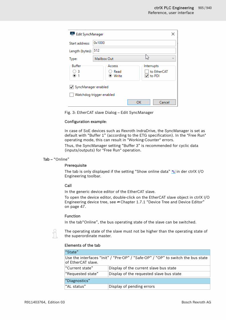
905 / 940ctrlX PLC EngineeringReference, user interface
Bosch Rexroth AGR911403764, Edition 03
Fig. 3: EtherCAT slave Dialog – Edit SyncManager
Configuration example:
In case of SoE devices such as Rexroth IndraDrive, the SyncManager is set asdefault with “Buffer 1” (according to the ETG specification). In the "Free Run"operating mode, this can result in "Working-Counter" errors.Thus, the SyncManager setting “Buffer 3” is recommended for cyclic data(inputs/outputs) for "Free Run" operation.
Tab – “Online”PrerequisiteThe tab is only displayed if the setting “Show online data” in der ctrlX I/OEngineering toolbar.
CallIn the generic device editor of the EtherCAT slave.To open the device editor, double-click on the EtherCAT slave object in ctrlX I/OEngineering device tree, see ⮫ Chapter 1.7.1 “Device Tree and Device Editor”on page 47.
FunctionIn the tab“Online”, the bus operating state of the slave can be switched.
The operating state of the slave must not be higher than the operating state ofthe superordinate master.
Elements of the tab
“State”Use the interfaces “Init” / “Pre-OP” / “Safe-OP” / “OP” to switch the bus stateof EtherCAT slave.“Current state” Display of the current slave bus state“Requested state” Display of the requested slave bus state
“Diagnostics”“AL status” Display of pending errors

906 / 940 ctrlX PLC EngineeringReference, user interface
Bosch Rexroth AG R911403764, Edition 03
“EEPROM”EEPROM Backup slave data in local file
Tab – “ESC register”PrerequisiteThe tab is only displayed if the setting “Enable expert settings” is enabled inthe tab “General” tab, see ⮫ Chapter “Tab – “General” ” on page 898.Additionally muss die settings “Show online data” In the ctrlX I/O Engi-neering Toolbar aktiviert sein.
CallIn the generic device editor of the EtherCAT slave.To open the device editor, double-click on the EtherCAT slave object in ctrlX I/OEngineering device tree, see ⮫ Chapter 1.7.1 “Device Tree and Device Editor”on page 47.
FunctionThe tab values of the EtherCAT slave controller (ESC) are displayed in the tab“ESC register” tab.The values are retrieved when opening the tab as well as when clicking on thebutton“Update”. A tab to write can be selected when clicking on an addresswithin the table.
CAUTION By reading and writing the registers, messages from theslave to the master can be acknowledged which are thennot visible anymore for the master stack.Thus, only experts should read/write registers.
Elements of the tab
GUI element Description“Offset” Offset value of slave controller tab“Length” Length value of slave controller tab“Conpact” Compact representation of list values“Update” Click on the button interface to refresh the displayed
values by reading them again.
Table column Description“Offset” Offset value of the tab“Name” Tab name“Value (hex)” Tab value (hexadecimal)“Value (dec)” Tab value (decimal)“Type” Tab type in bytes
“Write register”“Offset” Current offset of the tab“Length” Current tab length“Value” Current tab value“Write” Click on the button“Write” interface to write the values
to the selected tab.

907 / 940ctrlX PLC EngineeringReference, user interface
Bosch Rexroth AGR911403764, Edition 03
Configure Tab – “CoE”CallIn the generic device editor of the EtherCAT slave in ctrlX I/O Engineeringdevice tree, see ⮫ Chapter 1.7.1 “Device Tree and Device Editor” on page 47.
FunctionThis tab contains information on the CoE objects of an EtherCAT slave with CoEprofile.
Elements of the tabIn the right upper drop-down list, select the following settings:● “Description from ESI”
The slave description is read out from the device description (ESI)Select the objects to be displayed in the left upper drop-down list:● “All Objects”
(RxPDO) objects that can be configured as process data (output data)● “Mappable Objects (TxPdo)”
(RxPDO): Objects that can be configured as process data (output data)● “Settings Objects”
Objects that can be configured as start parameters upon startupThe specifications are output in the following table:Column Description“Index” Via an index, the object is identified.
If an object contains subelements, they are written bythe subindex
“Name” Object name“Value” Depending on the type, the value can be a text or a
number.The number of subindices is displayed for objects withsubelements
“Access” Describes which access to the object is possible:● “RO”: Read-only● “RW”: Read and write● “WO”: Write only
“Type” The data type of the object
Configure Tab – “Diagnostics”PrerequisiteThe tab is only displayed if the setting “Show online data” in der ctrlX I/OEngineering toolbar.
CallIn the generic device editor of the EtherCAT slave in ctrlX I/O Engineeringdevice tree, see ⮫ Chapter 1.7.1 “Device Tree and Device Editor” on page 47.
FunctionThe tab is used to display messages provided from the CoE object “Diagnostichistory” (0x10F3) of the EtherCAT slave.
Elements of the tab
908 / 940 ctrlX PLC EngineeringReference, user interface
Bosch Rexroth AG R911403764, Edition 03
Acknowledging/deleting messagesThe diagnostic log is operated as ring buffer and can save up to 250 messages(device-specifically it might be less).Messages can be acknowledged and deleted via the following buttons in theupper area of the tab:● “Acknowledge messages”● “Delete messages”
SettingsThere are different optional settings that can be set in the slave. If a specificoption is not supported by the slave, a writing error is reported while disabling/enabling (parameter value beyond the valid range).● “Activate info”
Setting whether or not information is to be entered in the logbook● “Activate warning”
Setting whether or not warnings are to be entered in the logbook● “Activate error”
Setting whether or not error messages are to be entered in the logbook● “Activate emergency”
Setting whether or not the slave sends new diagnostics as CoE emergencymessages to the master.
● “Activate AcknowledgeMode”Setting options between “OverwriteMode” and “AcknowledgeMode”.In the “OverwriteMode”, if the message buffer is full, a new message over-writes the oldest message in the buffer irrespective of whether the mes-sages were acknowledged.Unacknowledged messages are not overwritten in the “AcknowledgeMode”,i.e. if the message buffer is full, the latest messages are not saved and thuslost.
Table list of messages
Column Description“Category” Message category: Info / Warning / Error
There is no default setting on how incoming and out-going errors are reported. Refer to product descriptionof the device.Acknowledged messages are shown by a greyed outicon.
“Time” Time stamp reported for the device message“Code” Diagnostic code“Text” The diagnostic texts are taken from the device descrip-
tion (ESI) of the device.
Configure Tab – “Status”CallIn the generic device editor of the EtherCAT slave in ctrlX I/O Engineeringdevice tree, see ⮫ Chapter 1.7.1 “Device Tree and Device Editor” on page 47.
FunctionIn the tab “Status”, the status information about the device is displayed, forexample the operating state “"Running"” or “"Stopped"”.

909 / 940ctrlX PLC EngineeringReference, user interface
Bosch Rexroth AGR911403764, Edition 03
Specific diagnostic messages from the respective device is displayed and thecard used and the internal bus system.
Configure Tab – “Information”CallIn the generic device editor of the EtherCAT slave in ctrlX I/O Engineeringdevice tree, see ⮫ Chapter 1.7.1 “Device Tree and Device Editor” on page 47.
FunctionThe tab shows general information of the device description file:● Device name● Vendor● Category● Version● Description
3.3.4 Commands>> Being prepared <<
3.3.5 Dialogs
Configure dialog – Edit PDO ListCallIn the tab “Expert Process Data” of a EtherCAT slave device, see ⮫ Tab – ExpertProcess Data.
FunctionThis dialog facilitates adding or editing of entries in the PDO list.
Elements of the dialog
Function Description“Name” PDO name“Index” PDO index (or IDN for SoE)“Direction” ● “TxPDO”: PDO is transferred from slave to master
● “RxPDO”: PDO is transferred from master to slave“Flags” ● “F” Fixed content:
The contents of the PDO are fixed and cannot bemodified. It is not possible to add entries to thePDO content.
● “M” Mandatory:The PDO is necessary and cannot be deactivated inthe PDO assignment.
● “V” Virtual PDO:Reserved for future use
“Exclude PDOs” It is possible to specify an exclusion list.If a PDO is enabled in the PDO assignment, the othersare inactive and cannot be enabled.
“Sync unit” ID of the SyncUnit in the slave (Sync manager) toassign the PDO to

910 / 940 ctrlX PLC EngineeringReference, user interface
Bosch Rexroth AG R911403764, Edition 03
911 / 940ctrlX PLC EngineeringGuidelines for Creating Libraries
Bosch Rexroth AGR911403764, Edition 03
4 LibrariesLibraries are used for preparing POUs and functions for use in PLC Engineeringapplications. In addition to the descriptions presented here in the help, alwayssee the documentation included in the library as well.For using libraries in your PLC Engineering project, see the "Managing Libra-ries" chapter.To create your own PLC Engineering libraries, follow the guidelines for librarydevelopers.
See also● ⮫ Chapter 1.15 “Using Libraries” on page 237
4.1 Guidelines for Creating LibrariesLibraries must be created according to specific rules to avoid compatibilityissues.The main items include the following:● Select a meaningful library name (required)● Use templates to ensure consistency (optional)● Use a familiar and uniform project structure, when possible (optional)● Register a unique library namespace (required)● Enter all project information (required)● Apply the correct method for referencing other libraries correctly (required)● Design smart external and internal interfaces (required)● Implement a user-friendly error handling (required)● Apply the correct method (protection) for deployment (required)● Apply a consistent naming convention to get clean code (optional)● When revising an existing library, consider the interface compatibility with
previous versions.Please follow these guidelines when developing libraries in PLC Engineering:"Library Development Summary". You will find this document as a CHM file(LibDevSummary.chm) in the installation directory of PLC Engineering, or inthe online help.See also● ⮫ Chapter 1.15 “Using Libraries” on page 237

912 / 940 ctrlX PLC EngineeringGuidelines for Creating Libraries
Bosch Rexroth AG R911403764, Edition 03
913 / 940ctrlX PLC Engineering
Bosch Rexroth AGR911403764, Edition 03
5 Index1, 2, 3 ...__AdrInst. . . . . . . . . . . . . . . . . . . . . . . . . . . . 467__BitOffset. . . . . . . . . . . . . . . . . . . . . . . . . . . 467__Cast. . . . . . . . . . . . . . . . . . . . . . . . . . . . . . 467__CATCH. . . . . . . . . . . . . . . . . . . . . . . . . . . . 364__COMPARE_AND_SWAP. . . . . . . . . . . . . . . . 370__Copy. . . . . . . . . . . . . . . . . . . . . . . . . . . . . . 467__CRC. . . . . . . . . . . . . . . . . . . . . . . . . . . . . . 467__CURRENTTASK. . . . . . . . . . . . . . . . . . . . . . 369__DELETE. . . . . . . . . . . . . . . . . . . . . . . . . . . . 358__ENDTRY'. . . . . . . . . . . . . . . . . . . . . . . . . . . 364__FCall. . . . . . . . . . . . . . . . . . . . . . . . . . . . . . 467__FINALLY. . . . . . . . . . . . . . . . . . . . . . . . . . . . 364__Init. . . . . . . . . . . . . . . . . . . . . . . . . . . . . . . 467__ISVALIDREF. . . . . . . . . . . . . . . . . . . . 359, 395__Lazy. . . . . . . . . . . . . . . . . . . . . . . . . . . . . . 467__Localoffset. . . . . . . . . . . . . . . . . . . . . . . . . 467__MaxOffset. . . . . . . . . . . . . . . . . . . . . . . . . . 467__NEW. . . . . . . . . . . . . . . . . . . . . . . . . . . . . . 360__PropertyInfo. . . . . . . . . . . . . . . . . . . . . . . . 467__QUERYINTERFACE. . . . . . . . . . . . . . . . . . . 363__QUERYPOINTER. . . . . . . . . . . . . . . . . . . . . 364__RefAdr. . . . . . . . . . . . . . . . . . . . . . . . . . . . . 467__RELOC. . . . . . . . . . . . . . . . . . . . . . . . . . . . 467__System.ExceptionCode, data type. . . . . . . 364__SystemScope. . . . . . . . . . . . . . . . . . . . . . . 467__TEST_AND_SET. . . . . . . . . . . . . . . . . . . . . . 371__TRY. . . . . . . . . . . . . . . . . . . . . . . . . . . . . . . 364__TypeOf. . . . . . . . . . . . . . . . . . . . . . . . . . . . 467__uxint. . . . . . . . . . . . . . . . . . . . . . . . . . . . . . 394__VarInfo. . . . . . . . . . . . . . . . . . . . . . . . . . . . 467__VCADD. . . . . . . . . . . . . . . . . . . . . . . . . . . . 405
vector operator. . . . . . . . . . . . . . . . . . . . . 405__VCDIV. . . . . . . . . . . . . . . . . . . . . . . . . . . . . 406
vector operator. . . . . . . . . . . . . . . . . . . . . 406__VCDOT. . . . . . . . . . . . . . . . . . . . . . . . . . . . 407
vector operator. . . . . . . . . . . . . . . . . . . . . 407__VCLOAD_LREAL. . . . . . . . . . . . . . . . . . . . . 410
vector operator. . . . . . . . . . . . . . . . . . . . . 410__VCLOAD_REAL. . . . . . . . . . . . . . . . . . . . . . 409
vector operator. . . . . . . . . . . . . . . . . . . . . 409__VCMAX. . . . . . . . . . . . . . . . . . . . . . . . . . . . 408
vector operator. . . . . . . . . . . . . . . . . . . . . 408__VCMIN. . . . . . . . . . . . . . . . . . . . . . . . . . . . . 408
vector operator. . . . . . . . . . . . . . . . . . . . . 408__VCMUL. . . . . . . . . . . . . . . . . . . . . . . . . . . . 406
vector operator. . . . . . . . . . . . . . . . . . . . . 406__VCSET_LREAL. . . . . . . . . . . . . . . . . . . . . . . 409
vector operator. . . . . . . . . . . . . . . . . . . . . 409__VCSET_REAL. . . . . . . . . . . . . . . . . . . . . . . . 408
vector operator. . . . . . . . . . . . . . . . . . . . . 408__VCSQRT. . . . . . . . . . . . . . . . . . . . . . . . . . . 407
vector operator. . . . . . . . . . . . . . . . . . . . . 407__VCSTORE. . . . . . . . . . . . . . . . . . . . . . . . . . 410
vector operator. . . . . . . . . . . . . . . . . . . . . 410
__VCSUB. . . . . . . . . . . . . . . . . . . . . . . . . . . . 405vector operator. . . . . . . . . . . . . . . . . . . . . 405
__VECTOR. . . . . . . . . . . . . . . . . . . . . . . . . . . 403__Wait. . . . . . . . . . . . . . . . . . . . . . . . . . . . . . 467__XADD. . . . . . . . . . . . . . . . . . . . . . . . . . . . . 371__xword. . . . . . . . . . . . . . . . . . . . . . . . . . . . . 394_cnt.library. . . . . . . . . . . . . . . . . . . . . . . . . . 238_Itfs.library. . . . . . . . . . . . . . . . . . . . . . . . . . 238AABS. . . . . . . . . . . . . . . . . . . . . . . . . . . . . . . . 353access
symbol set. . . . . . . . . . . . . . . . . . . . . . . . 164access control
properties. . . . . . . . . . . . . . . . . . . . . . . . . 826access protection
development system. . . . . . . . . . . . . . . . . 244general information. . . . . . . . . . . . . . . . . 242runtime system / PLC. . . . . . . . . . . . . . . . 244user management. . . . . . . . . . . . . . . . . . . 242
access rightdevice editor. . . . . . . . . . . . . . . . . . . . . . . 574object. . . . . . . . . . . . . . . . . . . . . . . . . . . . . 33
accessor. . . . . . . . . . . . . . . . . . . . . . . . . . . . 603access method. . . . . . . . . . . . . . . . . . . . . 603access method, interface. . . . . . . . . . . . . 600
acknowledgealarm. . . . . . . . . . . . . . . . . . . . . . . . . . . . . 530
ACOS. . . . . . . . . . . . . . . . . . . . . . . . . . . . . . . 357action. . . . . . . . . . . . . . . . . . . . . . . . . . . . . . 279
SFC, do not display embedded objects. . 763SFC, duplication mode. . . . . . . . . . . . . . . 758SFC, remove duplication. . . . . . . . . . . . . 763SFC, set duplication. . . . . . . . . . . . . . . . . 763
Action. . . . . . . . . . . . . . . . . . . . . . . . . . . . . . 606ACTION. . . . . . . . . . . . . . . . . . . . . . . . . . . . . 467action association
insert, command. . . . . . . . . . . . . . . . . . . . 761add
EN/ENO. . . . . . . . . . . . . . . . . . . . . . . . . . . 765file as text. . . . . . . . . . . . . . . . . . . . . . . . . 666input pin. . . . . . . . . . . . . . . . . . . . . . . . . . 773language in a text list. . . . . . . . . . . . . . . . 802output pin. . . . . . . . . . . . . . . . . . . . . . . . . 773
ADD. . . . . . . . . . . . . . . . . . . . . . . . . . . . . . . . 331add all instance paths. . . . . . . . . . . . . . . . . . 795add file as text. . . . . . . . . . . . . . . . . . . . . . . . 666add folder. . . . . . . . . . . . . . . . . . . . . . . . . . . 694add POU
dialog. . . . . . . . . . . . . . . . . . . . . . . . . . . . 588add user
device user management. . . . . . . . . . . . . 572address. . . . . . . . . . . . . . . . . . . . . . . . . . . . . 384
absolute. . . . . . . . . . . . . . . . . . . . . . . . . . 162assign variable. . . . . . . . . . . . . . . . . . . . . 119broadcast. . . . . . . . . . . . . . . . . . . . . . . . . 163

914 / 940 ctrlX PLC Engineering
Bosch Rexroth AG R911403764, Edition 03
I/O. . . . . . . . . . . . . . . . . . . . . . . . . . . . . . . 59network. . . . . . . . . . . . . . . . . . . . . . . . . . . 161node. . . . . . . . . . . . . . . . . . . . . . . . . . . . . 162relative. . . . . . . . . . . . . . . . . . . . . . . . . . . 162specification. . . . . . . . . . . . . . . . . . . . . . . 384
addressing. . . . . . . . . . . . . . . . . . . . . . . . . . . 160relative. . . . . . . . . . . . . . . . . . . . . . . . . . . 160
ADR. . . . . . . . . . . . . . . . . . . . . . . . . . . . 345, 394alarm. . . . . . . . . . . . . . . . . . . . . . . . . . . . . . . 147
acknowledgement. . . . . . . . . . . . . . . . . . . 530activation. . . . . . . . . . . . . . . . . . . . . . . . . 533archiving. . . . . . . . . . . . . . . . . . . . . . . . . . 533confirmation. . . . . . . . . . . . . . . . . . . . . . . 530create objects for alarm management. . . 148definition. . . . . . . . . . . . . . . . . . . . . . . . . 147event. . . . . . . . . . . . . . . . . . . . . . . . . . . . . 147export. . . . . . . . . . . . . . . . . . . . . . . . . . . . 537import. . . . . . . . . . . . . . . . . . . . . . . . . . . . 537message. . . . . . . . . . . . . . . . . . . . . . . . . . 533notification action. . . . . . . . . . . . . . . . . . . 530status. . . . . . . . . . . . . . . . . . . . . . . . . . . . 147text. . . . . . . . . . . . . . . . . . . . . . . . . . . . . . 533
alarm class. . . . . . . . . . . . . . . . . . . . . . . . . . 530alarm configuration. . . . . . . . . . . . . . . . . . . . 530
create objects. . . . . . . . . . . . . . . . . . . . . . 148alarm group. . . . . . . . . . . . . . . . . . . . . . . . . . 533alarm management. . . . . . . . . . . . . . . . . . . . 147alarm storage. . . . . . . . . . . . . . . . . . . . . . . . . 537
configuration of CSV export. . . . . . . . . . . 538CSV export. . . . . . . . . . . . . . . . . . . . . . . . 538
alias. . . . . . . . . . . . . . . . . . . . . . . . . . . . . . . . 550ALIAS. . . . . . . . . . . . . . . . . . . . . . . . . . . . . . . 395alternative. . . . . . . . . . . . . . . . . . . . . . . . . . . 759AND. . . . . . . . . . . . . . . . . . . . . . . . . . . . . . . . 335AND_THEN. . . . . . . . . . . . . . . . . . . . . . . . . . . 336AND, pragma. . . . . . . . . . . . . . . . . . . . . . . . . 459ANDN. . . . . . . . . . . . . . . . . . . . . . . . . . . . . . . 291ANY. . . . . . . . . . . . . . . . . . . . . . . . . . . . . . . . 389
data type. . . . . . . . . . . . . . . . . . . . . . . . . . 389ANY_BIT. . . . . . . . . . . . . . . . . . . . . . . . . . . . . 389ANY_DATE. . . . . . . . . . . . . . . . . . . . . . . . . . . 389ANY_INT. . . . . . . . . . . . . . . . . . . . . . . . . . . . . 389ANY_NUM. . . . . . . . . . . . . . . . . . . . . . . . . . . . 389ANY_REAL. . . . . . . . . . . . . . . . . . . . . . . . . . . 389ANY_STRING. . . . . . . . . . . . . . . . . . . . . . . . . 389API PLC Engineering. . . . . . . . . . . . . . . 878, 889application. . . . . . . . . . . . . . . . . . . . . . . . . . . 528
activate on toolbar. . . . . . . . . . . . . . . . . . 717backup application files. . . . . . . . . . . . . . 561build. . . . . . . . . . . . . . . . . . . . . . . . . 711, 721clean. . . . . . . . . . . . . . . . . . . . . . . . . . . . . 713cold start. . . . . . . . . . . . . . . . . . . . . . . . . 725compare. . . . . . . . . . . . . . . . . . . . . . . . . . 720compile. . . . . . . . . . . . . . . . . . . . . . . . . . . 721contents. . . . . . . . . . . . . . . . . . . . . . . . . . 720create, options. . . . . . . . . . . . . . . . . . . . . 828delete. . . . . . . . . . . . . . . . . . . . . . . . . . . . 728download. . . . . . . . . . . . . . . . . . . . . 236, 722
download with file. . . . . . . . . . . . . . . . . . 562encrypt. . . . . . . . . . . . . . . . . . . . . . . . 31, 132encryption. . . . . . . . . . . . . . . . . . . . . . . . 824encryption, instructions. . . . . . . . . . . . . . . 41information. . . . . . . . . . . . . . . . . . . . . . . . 720memory mapping. . . . . . . . . . . . . . . . . . . 529online change. . . . . . . . . . . . . . . . . . . . . . 722rebuild. . . . . . . . . . . . . . . . . . . . . . . . . . . 712reset. . . . . . . . . . . . . . . . . . . . . . . . . . . . . 204reset (cold). . . . . . . . . . . . . . . . . . . . . . . . 725reset (origin). . . . . . . . . . . . . . . . . . . . . . . 727reset (warm). . . . . . . . . . . . . . . . . . . . . . . 726reset origin. . . . . . . . . . . . . . . . . . . . . . . . 727set active. . . . . . . . . . . . . . . . . . . . . . . . . 698warm start. . . . . . . . . . . . . . . . . . . . . . . . 726
application codegenerate code. . . . . . . . . . . . . . . . . . . . . . 192messages for generate code. . . . . . . . . . . 192
applications, device editor. . . . . . . . . . . . . . 560arccosine. . . . . . . . . . . . . . . . . . . . . . . . . . . . 357archive
alarm. . . . . . . . . . . . . . . . . . . . . . . . . . . . . 533save. . . . . . . . . . . . . . . . . . . . . . . . . . . . . . 658send. . . . . . . . . . . . . . . . . . . . . . . . . . . . . 658
arcsine. . . . . . . . . . . . . . . . . . . . . . . . . . . . . . 357arctangent. . . . . . . . . . . . . . . . . . . . . . . . . . . 357array. . . . . . . . . . . . . . . . . . . . . . . . . . . . . . . 397
access. . . . . . . . . . . . . . . . . . . . . . . . . . . . 382declaration. . . . . . . . . . . . . . . . . . . . . . . . 397declare. . . . . . . . . . . . . . . . . . . . . . . . . . . . 65initialization. . . . . . . . . . . . . . . . . . . . . . . 397monitor. . . . . . . . . . . . . . . . . . . . . . . . . . . 211of arrays. . . . . . . . . . . . . . . . . . . . . . . . . . 401of function blocks. . . . . . . . . . . . . . . . . . . 397of variable length. . . . . . . . . . . . . . . . . . . 402structure. . . . . . . . . . . . . . . . . . . . . . . . . . 397
ARRAY. . . . . . . . . . . . . . . . . . . . . . . . . . . . . . 397OF. . . . . . . . . . . . . . . . . . . . . . . . . . . . . . . 397
ASIN. . . . . . . . . . . . . . . . . . . . . . . . . . . . . . . . 357assignment. . . . . . . . . . . . . . . . . . . . . . . . . . 261
FBD/LD/IL. . . . . . . . . . . . . . . . . . . . . . . . . 296output ST. . . . . . . . . . . . . . . . . . . . . . . . . 259ST operator. . . . . . . . . . . . . . . . . . . . . . . . 259
associationinsert for SFC action, command. . . . . . . . 761
AT. . . . . . . . . . . . . . . . . . . . . . . . . . . . . . . . . 119declaration. . . . . . . . . . . . . . . . . . . . . . . . 119
ATAN. . . . . . . . . . . . . . . . . . . . . . . . . . . . . . . 357attribute
for pragma. . . . . . . . . . . . . . . . . . . . . . . . 420BB. . . . . . . . . . . . . . . . . . . . . . . . . . . . . . . . . . 384
size prefix. . . . . . . . . . . . . . . . . . . . . . . . . 384backup. . . . . . . . . . . . . . . . . . . . . . . . . . 233, 561
create backup file. . . . . . . . . . . . . . . . . . . 561backup and restore. . . . . . . . . . . . . . . . 233, 561

915 / 940ctrlX PLC Engineering
Bosch Rexroth AGR911403764, Edition 03
backup file. . . . . . . . . . . . . . . . . . . . . . . . . . . 561create, save. . . . . . . . . . . . . . . . . . . . . . . . 561
binarydisplay mode when monitoring. . . . . . . . 740number. . . . . . . . . . . . . . . . . . . . . . . . . . . 379
BIT. . . . . . . . . . . . . . . . . . . . . . . . . . . . . 393, 411bit access. . . . . . . . . . . . . . . . . . . . . . . . . . . 411
to integer variables. . . . . . . . . . . . . . . . . . 382BITADR. . . . . . . . . . . . . . . . . . . . . . . . . . . . . 346bitmap, properties. . . . . . . . . . . . . . . . . . . . 827bookmarks
clear all. . . . . . . . . . . . . . . . . . . . . . . . . . . 670clear all in active editor. . . . . . . . . . . . . . 670next. . . . . . . . . . . . . . . . . . . . . . . . . . . . . . 669next in active editor. . . . . . . . . . . . . . . . . 669previous. . . . . . . . . . . . . . . . . . . . . . . . . . 670previous in active editor. . . . . . . . . . . . . . 669set. . . . . . . . . . . . . . . . . . . . . . . . . . . . . . . 125toggle. . . . . . . . . . . . . . . . . . . . . . . . . . . . 669view. . . . . . . . . . . . . . . . . . . . . . . . . . . . . 682
BOOL. . . . . . . . . . . . . . . . . . . . . . . . . . . . . . . 387constant. . . . . . . . . . . . . . . . . . . . . . . . . . 375data type. . . . . . . . . . . . . . . . . . . . . . . . . . 387
BOOL_TO. . . . . . . . . . . . . . . . . . . . . . . . . . . . 346boot application
delete. . . . . . . . . . . . . . . . . . . . . . . . . . . . 728encrypt. . . . . . . . . . . . . . . . . . . . . . . . . . . . 31encryption. . . . . . . . . . . . . . . . . . . . . . . . 132generate. . . . . . . . . . . . . . . . . . . . . . 194, 721options. . . . . . . . . . . . . . . . . . . . . . . . . . . 828properties. . . . . . . . . . . . . . . . . . . . . . . . . 823signing. . . . . . . . . . . . . . . . . . . . . . . 132, 133
boxCFC. . . . . . . . . . . . . . . . . . . . . . . . . . . . . . 309clean, FBD/LD. . . . . . . . . . . . . . . . . . . . . . 786FBD/LD/IL. . . . . . . . . . . . . . . . . . . . . . . . . 295FBD/LD/IL, empty box with en/eno. . . . . 779insert parallel LD. . . . . . . . . . . . . . . . . . . 779insert, FBD/LD/IL. . . . . . . . . . . . . . . . . . . 778repair. . . . . . . . . . . . . . . . . . . . . . . . . . . . 786with EN/ENO, FBD/LD/IL. . . . . . . . . . . . . 779
box inputinsert, FBD/LD/IL. . . . . . . . . . . . . . . . . . . 780
bracket, code. . . . . . . . . . . . . . . . . . . . . . . . . 667branch. . . . . . . . . . . . . . . . . . . . . . . . . . . . . . 281
add. . . . . . . . . . . . . . . . . . . . . . . . . . . . . . 759closed. . . . . . . . . . . . . . . . . . . . . . . . . . . . 299insert right. . . . . . . . . . . . . . . . . . . . . . . . 759set end point. . . . . . . . . . . . . . . . . . . . . . 785start/end. . . . . . . . . . . . . . . . . . . . . . . . . . 299
breakpoint. . . . . . . . . . . . . . . . . . . . . . . . . . . 196concept. . . . . . . . . . . . . . . . . . . . . . . . . . . 196condition. . . . . . . . . . . . . . . . . . . . . . . . . 821define condition. . . . . . . . . . . . . . . . . . . . 198define execution point. . . . . . . . . . . . . . . 199disable. . . . . . . . . . . . . . . . . . . . . . . . . . . 734edit. . . . . . . . . . . . . . . . . . . . . . . . . . . . . . 733enable. . . . . . . . . . . . . . . . . . . . . . . . . . . . 734
execution point. . . . . . . . . . . . . . . . . . . . . 821new. . . . . . . . . . . . . . . . . . . . . . . . . . . . . . 733position. . . . . . . . . . . . . . . . . . . . . . . . . . . 822set. . . . . . . . . . . . . . . . . . . . . . . . . . . . . . . 198toggle. . . . . . . . . . . . . . . . . . . . . . . . . . . . 734view. . . . . . . . . . . . . . . . . . . . . . . . . . . . . 682
broadcast address. . . . . . . . . . . . . . . . . . . . . 163browse. . . . . . . . . . . . . . . . . . . . . . . . . . . . . . 124build
application. . . . . . . . . . . . . . . . . . . . 711, 712exclude. . . . . . . . . . . . . . . . . . . . . . . . . . . 825messages for generate code. . . . . . . . . . . 192properties. . . . . . . . . . . . . . . . . . . . . . . . . 825
build information. . . . . . . . . . . . . . . . . . 713, 714bus cycle task
device editor. . . . . . . . . . . . . . . . . . . . . . . 570BY. . . . . . . . . . . . . . . . . . . . . . . . . . . . . . . . . 263byte
addressing mode. . . . . . . . . . . . . . . . . . . 384BYTE. . . . . . . . . . . . . . . . . . . . . . . . . . . . . . . 387byte order. . . . . . . . . . . . . . . . . . . . . . . . . . . 455CC code file. . . . . . . . . . . . . . . . . . . . . . . . . . . 553C code integration. . . . . . . . . . . . . . . . . . . . . 113C code module. . . . . . . . . . . . . . . . . . . . . . . 551
project environment. . . . . . . . . . . . . . . . . 847C implemented library. . . . . . . . . . . . . . . . . . 554C integration. . . . . . . . . . . . . . . . . . . . . . . . . 113
C code file. . . . . . . . . . . . . . . . . . . . . . . . 553C code module. . . . . . . . . . . . . . . . . . . . . 551configuration. . . . . . . . . . . . . . . . . . . . . . 113create stub in C. . . . . . . . . . . . . . . . . . . . 716export C sources. . . . . . . . . . . . . . . . . . . 715exporting a C-function. . . . . . . . . . . . . . . 716IDE, path. . . . . . . . . . . . . . . . . . . . . . . . . . 826import C code module. . . . . . . . . . . . . . . 113library. . . . . . . . . . . . . . . . . . . . . . . . . . . . 113open in IDE. . . . . . . . . . . . . . . . . . . . . . . . 715properties. . . . . . . . . . . . . . . . . . . . . . . . . 826update sources. . . . . . . . . . . . . . . . . . . . . 715
C sourcesexport. . . . . . . . . . . . . . . . . . . . . . . . . . . . 715update. . . . . . . . . . . . . . . . . . . . . . . . . . . 715
C stub file for external library. . . . . . . . . . . . 712C0001. . . . . . . . . . . . . . . . . . . . . . . . . . . . . . 475C0002. . . . . . . . . . . . . . . . . . . . . . . . . . . . . . 475C0004. . . . . . . . . . . . . . . . . . . . . . . . . . . . . . 476C0005. . . . . . . . . . . . . . . . . . . . . . . . . . . . . . 476C0006. . . . . . . . . . . . . . . . . . . . . . . . . . . . . . 476C0007. . . . . . . . . . . . . . . . . . . . . . . . . . . . . . 477C0008. . . . . . . . . . . . . . . . . . . . . . . . . . . . . . 477C0009. . . . . . . . . . . . . . . . . . . . . . . . . . . . . . 477C0010. . . . . . . . . . . . . . . . . . . . . . . . . . . . . . 478C0011. . . . . . . . . . . . . . . . . . . . . . . . . . . . . . 478C0013. . . . . . . . . . . . . . . . . . . . . . . . . . . . . . 478C0015. . . . . . . . . . . . . . . . . . . . . . . . . . . . . . 479C0018. . . . . . . . . . . . . . . . . . . . . . . . . . . . . . 479

916 / 940 ctrlX PLC Engineering
Bosch Rexroth AG R911403764, Edition 03
C0020. . . . . . . . . . . . . . . . . . . . . . . . . . . . . . 480C0022. . . . . . . . . . . . . . . . . . . . . . . . . . . . . . 480C0023. . . . . . . . . . . . . . . . . . . . . . . . . . . . . . 480C0026. . . . . . . . . . . . . . . . . . . . . . . . . . . . . . 481C0027. . . . . . . . . . . . . . . . . . . . . . . . . . . . . . 481C0030. . . . . . . . . . . . . . . . . . . . . . . . . . . . . . 481C0031. . . . . . . . . . . . . . . . . . . . . . . . . . . . . . 482C0032. . . . . . . . . . . . . . . . . . . . . . . . . . . . . . 482C0035. . . . . . . . . . . . . . . . . . . . . . . . . . . . . . 482C0037. . . . . . . . . . . . . . . . . . . . . . . . . . . . . . 483C0038. . . . . . . . . . . . . . . . . . . . . . . . . . . . . . 483C0039. . . . . . . . . . . . . . . . . . . . . . . . . . . . . . 484C0040. . . . . . . . . . . . . . . . . . . . . . . . . . . . . . 484C0041. . . . . . . . . . . . . . . . . . . . . . . . . . . . . . 485C0043. . . . . . . . . . . . . . . . . . . . . . . . . . . . . . 485C0044. . . . . . . . . . . . . . . . . . . . . . . . . . . . . . 486C0045. . . . . . . . . . . . . . . . . . . . . . . . . . . . . . 486C0046. . . . . . . . . . . . . . . . . . . . . . . . . . . . . . 487C0047. . . . . . . . . . . . . . . . . . . . . . . . . . . . . . 487C0048. . . . . . . . . . . . . . . . . . . . . . . . . . . . . . 488C0049. . . . . . . . . . . . . . . . . . . . . . . . . . . . . . 488C0050. . . . . . . . . . . . . . . . . . . . . . . . . . . . . . 488C0061. . . . . . . . . . . . . . . . . . . . . . . . . . . . . . 489C0062. . . . . . . . . . . . . . . . . . . . . . . . . . . . . . 489C0064. . . . . . . . . . . . . . . . . . . . . . . . . . . . . . 490C0066. . . . . . . . . . . . . . . . . . . . . . . . . . . . . . 490C0068. . . . . . . . . . . . . . . . . . . . . . . . . . . . . . 491C0069. . . . . . . . . . . . . . . . . . . . . . . . . . . . . . 491C0070. . . . . . . . . . . . . . . . . . . . . . . . . . . . . . 491C0072. . . . . . . . . . . . . . . . . . . . . . . . . . . . . . 492C0074. . . . . . . . . . . . . . . . . . . . . . . . . . . . . . 492C0075. . . . . . . . . . . . . . . . . . . . . . . . . . . . . . 493C0076. . . . . . . . . . . . . . . . . . . . . . . . . . . . . . 493C0077. . . . . . . . . . . . . . . . . . . . . . . . . . . . . . 493C0080. . . . . . . . . . . . . . . . . . . . . . . . . . . . . . 494C0081. . . . . . . . . . . . . . . . . . . . . . . . . . . . . . 494C0082. . . . . . . . . . . . . . . . . . . . . . . . . . . . . . 495C0084. . . . . . . . . . . . . . . . . . . . . . . . . . . . . . 495C0086. . . . . . . . . . . . . . . . . . . . . . . . . . . . . . 495C0087. . . . . . . . . . . . . . . . . . . . . . . . . . . . . . 496C0089. . . . . . . . . . . . . . . . . . . . . . . . . . . . . . 496C0090. . . . . . . . . . . . . . . . . . . . . . . . . . . . . . 497C0091. . . . . . . . . . . . . . . . . . . . . . . . . . . . . . 497C0094. . . . . . . . . . . . . . . . . . . . . . . . . . . . . . 498C0096. . . . . . . . . . . . . . . . . . . . . . . . . . . . . . 498C0097. . . . . . . . . . . . . . . . . . . . . . . . . . . . . . 499C0098. . . . . . . . . . . . . . . . . . . . . . . . . . . . . . 499C0101. . . . . . . . . . . . . . . . . . . . . . . . . . . . . . 499C0102. . . . . . . . . . . . . . . . . . . . . . . . . . . . . . 500C0104. . . . . . . . . . . . . . . . . . . . . . . . . . . . . . 500C0114. . . . . . . . . . . . . . . . . . . . . . . . . . . . . . 500C0116. . . . . . . . . . . . . . . . . . . . . . . . . . . . . . 500C0117. . . . . . . . . . . . . . . . . . . . . . . . . . . . . . 501C0118. . . . . . . . . . . . . . . . . . . . . . . . . . . . . . 501C0119. . . . . . . . . . . . . . . . . . . . . . . . . . . . . . 501C0120. . . . . . . . . . . . . . . . . . . . . . . . . . . . . . 502C0122. . . . . . . . . . . . . . . . . . . . . . . . . . . . . . 502C0124. . . . . . . . . . . . . . . . . . . . . . . . . . . . . . 503
C0125. . . . . . . . . . . . . . . . . . . . . . . . . . . . . . 503C0126. . . . . . . . . . . . . . . . . . . . . . . . . . . . . . 503C0130. . . . . . . . . . . . . . . . . . . . . . . . . . . . . . 504C0131. . . . . . . . . . . . . . . . . . . . . . . . . . . . . . 504C0132. . . . . . . . . . . . . . . . . . . . . . . . . . . . . . 505C0136. . . . . . . . . . . . . . . . . . . . . . . . . . . . . . 505C0139. . . . . . . . . . . . . . . . . . . . . . . . . . . . . . 505C0140. . . . . . . . . . . . . . . . . . . . . . . . . . . . . . 506C0141. . . . . . . . . . . . . . . . . . . . . . . . . . . . . . 506C0142. . . . . . . . . . . . . . . . . . . . . . . . . . . . . . 506C0143. . . . . . . . . . . . . . . . . . . . . . . . . . . . . . 507C0144. . . . . . . . . . . . . . . . . . . . . . . . . . . . . . 507C0145. . . . . . . . . . . . . . . . . . . . . . . . . . . . . . 508C0149. . . . . . . . . . . . . . . . . . . . . . . . . . . . . . 508C0161. . . . . . . . . . . . . . . . . . . . . . . . . . . . . . 508C0162. . . . . . . . . . . . . . . . . . . . . . . . . . . . . . 509C0168. . . . . . . . . . . . . . . . . . . . . . . . . . . . . . 509C0169. . . . . . . . . . . . . . . . . . . . . . . . . . . . . . 509C0174. . . . . . . . . . . . . . . . . . . . . . . . . . . . . . 510C0175. . . . . . . . . . . . . . . . . . . . . . . . . . . . . . 510C0177. . . . . . . . . . . . . . . . . . . . . . . . . . . . . . 510C0178. . . . . . . . . . . . . . . . . . . . . . . . . . . . . . 511C0182. . . . . . . . . . . . . . . . . . . . . . . . . . . . . . 511C0185. . . . . . . . . . . . . . . . . . . . . . . . . . . . . . 511C0189. . . . . . . . . . . . . . . . . . . . . . . . . . . . . . 512C0190. . . . . . . . . . . . . . . . . . . . . . . . . . . . . . 512C0191. . . . . . . . . . . . . . . . . . . . . . . . . . . . . . 512C0195. . . . . . . . . . . . . . . . . . . . . . . . . . . . . . 513C0196. . . . . . . . . . . . . . . . . . . . . . . . . . . . . . 513C0197. . . . . . . . . . . . . . . . . . . . . . . . . . . . . . 513C0198. . . . . . . . . . . . . . . . . . . . . . . . . . . . . . 514C0199. . . . . . . . . . . . . . . . . . . . . . . . . . . . . . 514C0201. . . . . . . . . . . . . . . . . . . . . . . . . . . . . . 514C0203. . . . . . . . . . . . . . . . . . . . . . . . . . . . . . 515C0204. . . . . . . . . . . . . . . . . . . . . . . . . . . . . . 515C0205. . . . . . . . . . . . . . . . . . . . . . . . . . . . . . 515C0206. . . . . . . . . . . . . . . . . . . . . . . . . . . . . . 516C0208. . . . . . . . . . . . . . . . . . . . . . . . . . . . . . 516C0211. . . . . . . . . . . . . . . . . . . . . . . . . . . . . . 516C0212. . . . . . . . . . . . . . . . . . . . . . . . . . . . . . 517C0216. . . . . . . . . . . . . . . . . . . . . . . . . . . . . . 517C0217. . . . . . . . . . . . . . . . . . . . . . . . . . . . . . 517C0218. . . . . . . . . . . . . . . . . . . . . . . . . . . . . . 518C0219. . . . . . . . . . . . . . . . . . . . . . . . . . . . . . 518C0221. . . . . . . . . . . . . . . . . . . . . . . . . . . . . . 518C0222. . . . . . . . . . . . . . . . . . . . . . . . . . . . . . 519C0224. . . . . . . . . . . . . . . . . . . . . . . . . . . . . . 519C0227. . . . . . . . . . . . . . . . . . . . . . . . . . . . . . 519C0228. . . . . . . . . . . . . . . . . . . . . . . . . . . . . . 520C0234. . . . . . . . . . . . . . . . . . . . . . . . . . . . . . 520C0235. . . . . . . . . . . . . . . . . . . . . . . . . . . . . . 521C0236. . . . . . . . . . . . . . . . . . . . . . . . . . . . . . 521C0237. . . . . . . . . . . . . . . . . . . . . . . . . . . . . . 521C0238. . . . . . . . . . . . . . . . . . . . . . . . . . . . . . 522C0239. . . . . . . . . . . . . . . . . . . . . . . . . . . . . . 522C0240. . . . . . . . . . . . . . . . . . . . . . . . . . . . . . 523C0241. . . . . . . . . . . . . . . . . . . . . . . . . . 523, 526C0242. . . . . . . . . . . . . . . . . . . . . . . . . . . . . . 523

917 / 940ctrlX PLC Engineering
Bosch Rexroth AGR911403764, Edition 03
C0243. . . . . . . . . . . . . . . . . . . . . . . . . . . . . . 524C0380. . . . . . . . . . . . . . . . . . . . . . . . . . . . . . 524C0509. . . . . . . . . . . . . . . . . . . . . . . . . . . . . . 525CA-signed
certificate. . . . . . . . . . . . . . . . . . . . . . . . . 246CA-signed certificate. . . . . . . . . . . . . . . . . . . . 41CAL. . . . . . . . . . . . . . . . . . . . . . . . . . . . . . . . 346CALC. . . . . . . . . . . . . . . . . . . . . . . . . . . . . . . 291CALCN. . . . . . . . . . . . . . . . . . . . . . . . . . . . . . 291call
function. . . . . . . . . . . . . . . . . . . . . . . . . . 592function block, ST. . . . . . . . . . . . . . . . . . . 267program. . . . . . . . . . . . . . . . . . . . . . . . . . 589
Callfunction block. . . . . . . . . . . . . . . . . . . . . . 590
call event alarm. . . . . . . . . . . . . . . . . . . . . . . 150call stack. . . . . . . . . . . . . . . . . . . . . . . . . . . . 207
view. . . . . . . . . . . . . . . . . . . . . . . . . . . . . 686call tree
show. . . . . . . . . . . . . . . . . . . . . . . . . . . . . 671view. . . . . . . . . . . . . . . . . . . . . . . . . . . . . 687
call_after_global_init_slot. . . . . . . . . . . . . . . . 421pragma attribute. . . . . . . . . . . . . . . . . . . . 421
call_after_init. . . . . . . . . . . . . . . . . . . . . . . . . 421pragma attribute. . . . . . . . . . . . . . . . . . . . 421
call_after_online_change_slot. . . . . . . . . . . . 422pragma attribute. . . . . . . . . . . . . . . . . . . . 422
call_before_global_exit_slotpragma attribute. . . . . . . . . . . . . . . . . . . . 423
call_on_type_change. . . . . . . . . . . . . . . . . . . 423pragma attribute. . . . . . . . . . . . . . . . . . . . 423
camobject properties. . . . . . . . . . . . . . . . . . . 831
CANbusparameters. . . . . . . . . . . . . . . . . . . . . . . . 560
CASE. . . . . . . . . . . . . . . . . . . . . . . . . . . . . . . 264CATCH. . . . . . . . . . . . . . . . . . . . . . . . . . . . . . 364certificate. . . . . . . . . . . . . . . . . . . . . . . . . . . . 31
application. . . . . . . . . . . . . . . . . . . . . . . . 132CA-signed. . . . . . . . . . . . . . . . . . . 31, 41, 246delete. . . . . . . . . . . . . . . . . . . . . . . . . . . . . 41encrypted communication. . . . . . . . 132, 185encryption. . . . . . . . . . . . . . . . . . . . . . . . . 31encryption, instructions. . . . . . . . . . . . . . . 41expiration date. . . . . . . . . . . . . . . . . . . . . 185expired. . . . . . . . . . . . . . . . . . . . . . . . . . . 245general information. . . . . . . . . . . . . . . . . 243issue more. . . . . . . . . . . . . . . . . . . . . . . . 245project settings. . . . . . . . . . . . . . . . . . . . . 840request from PLC. . . . . . . . . . . . . . . . . . . . 41sign boot application. . . . . . . . . . . . . . . . 133signing. . . . . . . . . . . . . . . . . . . . . . . . . . . . 31via PLC shell. . . . . . . . . . . . . . . . . . . . . . . 246Windows Certificate Store. . . . . . . . . . . . . 31
CFC. . . . . . . . . . . . . . . . . . . . . . . . . . . . . . . . . 79add input. . . . . . . . . . . . . . . . . . . . . . . . . 773add output. . . . . . . . . . . . . . . . . . . . . . . . 773connect structure. . . . . . . . . . . . . . . . . . . 776
connection mark. . . . . . . . . . . . . . . . . . . . 774create control point. . . . . . . . . . . . . . . . . 774edit page size. . . . . . . . . . . . . . . . . . . . . . 765edit parameters. . . . . . . . . . . . . . . . . . . . 770edit worksheet. . . . . . . . . . . . . . . . . . . . . 764editor. . . . . . . . . . . . . . . . . . . . . . . . . . . . 301end with selected elements. . . . . . . . . . . 768force FB. . . . . . . . . . . . . . . . . . . . . . . . . . 775force FB force. . . . . . . . . . . . . . . . . . . . . . 775group. . . . . . . . . . . . . . . . . . . . . . . . . . . . 774move down. . . . . . . . . . . . . . . . . . . . . . . . 769move up. . . . . . . . . . . . . . . . . . . . . . . . . . 768order by data flow. . . . . . . . . . . . . . . . . . 769order by topology. . . . . . . . . . . . . . . . . . . 770page-oriented. . . . . . . . . . . . . . . . . . . 79, 301parameter values. . . . . . . . . . . . . . . . . . . 771programming in CFC editor. . . . . . . . . . . . 83properties. . . . . . . . . . . . . . . . . . . . . . . . . 830reference. . . . . . . . . . . . . . . . . . . . . . . . . 766remove control point. . . . . . . . . . . . . . . . 773remove unused pins. . . . . . . . . . . . . . . . . 773reset. . . . . . . . . . . . . . . . . . . . . . . . . . . . . 766reset connecting line. . . . . . . . . . . . . . . . 773reset pin. . . . . . . . . . . . . . . . . . . . . . . . . . 772route connections. . . . . . . . . . . . . . . . . . . 773select connected pins. . . . . . . . . . . . . . . . 772send to front. . . . . . . . . . . . . . . . . . . . . . . 767set. . . . . . . . . . . . . . . . . . . . . . . . . . . . . . . 766set element number within execution order . . . . . . . . . . . . . . . . . . . . . . . . . . . . . . . . . 769show next collision. . . . . . . . . . . . . . . . . . 772starting point in feedback network. . . . . . 82ungroup. . . . . . . . . . . . . . . . . . . . . . . . . . 774unlock connection. . . . . . . . . . . . . . . . . . 772
CFC editor. . . . . . . . . . . . . . . . . . . . . . . . . . . 301breakpoint. . . . . . . . . . . . . . . . . . . . . . . . 305debugging. . . . . . . . . . . . . . . . . . . . . . . . . 305monitoring. . . . . . . . . . . . . . . . . . . . . . . . 305online mode. . . . . . . . . . . . . . . . . . . . . . . 305option. . . . . . . . . . . . . . . . . . . . . . . . . . . . 850page-oriented. . . . . . . . . . . . . . . . . . . . . . 303setting. . . . . . . . . . . . . . . . . . . . . . . . . . . . 850toolbar. . . . . . . . . . . . . . . . . . . . . . . . . . . 255
character string literal. . . . . . . . . . . . . . . . . . 380check
avoid implicit checks. . . . . . . . . . . . . . . . 439CheckBounds. . . . . . . . . . . . . . . . . . . . . . . . 609
array. . . . . . . . . . . . . . . . . . . . . . . . . . . . . 397CheckDivInt. . . . . . . . . . . . . . . . . . . . . . . . . . 612CheckDivLInt'. . . . . . . . . . . . . . . . . . . . . . . . 613CheckDivLReal'. . . . . . . . . . . . . . . . . . . . . . . 614CheckDivReal. . . . . . . . . . . . . . . . . . . . . . . . 614CheckLRangeSigned. . . . . . . . . . . . . . . . . . . 617CheckLRangeUnsigned. . . . . . . . . . . . . . . . . 619CheckPointer. . . . . . . . . . . . . . . . . . . . . . . . . 620CheckRangeSigned. . . . . . . . . . . . . . . . 417, 615CheckRangeUnsigned. . . . . . . . . . . . . . 417, 618checks_in_libs. . . . . . . . . . . . . . . . . . . . . . . . 608

918 / 940 ctrlX PLC Engineering
Bosch Rexroth AG R911403764, Edition 03
clean all. . . . . . . . . . . . . . . . . . . . . . . . . . . . . 714clean gaps. . . . . . . . . . . . . . . . . . . . . . . . . . . 793closed branch, LD. . . . . . . . . . . . . . . . . . . . . 299CmpTraceMgr.library. . . . . . . . . . . . . . . . . . . 220code
analyze. . . . . . . . . . . . . . . . . . . . . . . . . . . 121collapse all. . . . . . . . . . . . . . . . . . . . . . . . 668create. . . . . . . . . . . . . . . . . . . . . . . . . . . . 712encrypt. . . . . . . . . . . . . . . . . . . . . . . . . . . . 31encryption. . . . . . . . . . . . . . . . . . . . . . . . 193exclude from the static analysis. . . . . . . . 121expand all. . . . . . . . . . . . . . . . . . . . . . . . . 668go to matching bracket. . . . . . . . . . . . . . . 667
code generation. . . . . . . . . . . . . . . . . . . . . . 712CoDeSys V2.3 Converter
option. . . . . . . . . . . . . . . . . . . . . . . . . . . . 851coding guidelines. . . . . . . . . . . . . . . . . . . . . 121coil. . . . . . . . . . . . . . . . . . . . . . . . . . . . . . . . . 298
insert. . . . . . . . . . . . . . . . . . . . . . . . . . . . 780reset. . . . . . . . . . . . . . . . . . . . . . . . . . . . . 781set. . . . . . . . . . . . . . . . . . . . . . . . . . . . . . . 781
cold start. . . . . . . . . . . . . . . . . . . . . . . . . . . . 725collapse all. . . . . . . . . . . . . . . . . . . . . . . . . . 668Command
Determining DataLayerNode from ctrlX.... 881Determining DataLayerUser from ctrlX.... 880Open project from ctrlX.... . . . . . . . . . . . . 881Project synchronisation.... . . . . . . . . . . . . 882Synchronization cache.... . . . . . . . . . . . . . 882
command 'Go to instance'. . . . . . . . . . . . . . . 675command icon. . . . . . . . . . . . . . . . . . . . . . . . 863
customize. . . . . . . . . . . . . . . . . . . . . . . . . . 12comment
CFC. . . . . . . . . . . . . . . . . . . . . . . . . . . . . . 311ST. . . . . . . . . . . . . . . . . . . . . . . . . . . . . . . 268
comment out . . . . . . . . . . . . . . . . . . . . . . . . 668commit accepted changes. . . . . . . . . . . . . . . 705communication
device editor. . . . . . . . . . . . . . . . . . . . . . . 556edit. . . . . . . . . . . . . . . . . . . . . . . . . . . . . . 180enable unencrypted. . . . . . . . . . . . . . . . . 247encrypt. . . . . . . . . . . . . . . . . . . . . . . . . . . . 31encrypted. . . . . . . . . . . . . . . . . . . . . . . . . 185setting, classic display. . . . . . . . . . . . . . . 855
communication policy. . . . . . . . . . . . . . . . . . 556compare
projects. . . . . . . . . . . . . . . . . . . . . . . . 28, 701compare view. . . . . . . . . . . . . . . . . . . . . . . . . 28
detail. . . . . . . . . . . . . . . . . . . . . . . . . . . . . . 28open detailed. . . . . . . . . . . . . . . . . . . . . . . 30project. . . . . . . . . . . . . . . . . . . . . . . . . . . . 28
COMPARE_AND_SWAP. . . . . . . . . . . . . . . . . 370compatibility
library. . . . . . . . . . . . . . . . . . . . . . . . . . . . 714compiled library
save. . . . . . . . . . . . . . . . . . . . . . . . . . . . . . 657compiled library, see compiled library. . . . . 625compiled-library. . . . . . . . . . . . . . . . . . . . . . 238
compiled-library-v3. . . . . . . . . . . . . . . . . . . . 238compiler
options. . . . . . . . . . . . . . . . . . . . . . . . . . . 837version. . . . . . . . . . . . . . . . . . . . . . . . . . . 845warnings. . . . . . . . . . . . . . . . . . . . . . . . . . 838
compiler versionchange. . . . . . . . . . . . . . . . . . . . . . . . . . . . 20project environment. . . . . . . . . . . . . . . . . 845
Complier check functionsInsert templates in the PLC project. . . . . 874
composerCFC. . . . . . . . . . . . . . . . . . . . . . . . . . . . . . 310
conditionbreakpoint. . . . . . . . . . . . . . . . . . . . . . . . 821
conditional compilation. . . . . . . . . . . . . . . . . 452configuration
device. . . . . . . . . . . . . . . . . . . . . . . . . . . . . 54programming system. . . . . . . . . . . . . . . . 816trace. . . . . . . . . . . . . . . . . . . . . . . . . . . . . 866
configuration variable. . . . . . . . . . . . . . . . . . 320connect
to device. . . . . . . . . . . . . . . . . . . . . . 730, 731connection
CFC, connect pins. . . . . . . . . . . . . . . . . . 771CFC, route. . . . . . . . . . . . . . . . . . . . . . . . 773connection mark. . . . . . . . . . . . . . . . . . . . 774
connection markCFC. . . . . . . . . . . . . . . . . . . . . . . . . . . . . . 311
const_no_replaced, pragma attribute. . . . . . 424const_replaced, pragma attribute. . . . . . . . . 424constant
BOOL. . . . . . . . . . . . . . . . . . . . . . . . . . . . 375date. . . . . . . . . . . . . . . . . . . . . . . . . . . . . . 377date and time. . . . . . . . . . . . . . . . . . . . . . 378input/output variable. . . . . . . . . . . . . . . . 316LTIME. . . . . . . . . . . . . . . . . . . . . . . . . . . . 376REAL and LREAL. . . . . . . . . . . . . . . . . . . . 379string. . . . . . . . . . . . . . . . . . . . . . . . . . . . 380time. . . . . . . . . . . . . . . . . . . . . . . . . . . . . 375TIME. . . . . . . . . . . . . . . . . . . . . . . . . . . . . 376time of day. . . . . . . . . . . . . . . . . . . . . . . . 378variable. . . . . . . . . . . . . . . . . . . . . . . . . . . 320
CONSTANT. . . . . . . . . . . . . . . . . . . . . . . 320, 375constants
numeric. . . . . . . . . . . . . . . . . . . . . . . . . . . 379contact. . . . . . . . . . . . . . . . . . . . . . . . . . . . . 298
insert. . . . . . . . . . . . . . . . . . . . . . . . . . . . 783ld. . . . . . . . . . . . . . . . . . . . . . . . . . . . . . . . 781negated . . . . . . . . . . . . . . . . . . . . . . . . . . 782negated, parallel. . . . . . . . . . . . . . . . . . . . 783paste right after. . . . . . . . . . . . . . . . . . . . 783right. . . . . . . . . . . . . . . . . . . . . . . . . . . . . 781
content operator. . . . . . . . . . . . . . . . . . . . . . 345CONTINUE. . . . . . . . . . . . . . . . . . . . . . . . . . . 267Continuous Function Chart. . . . . . . . . . . . . . . 79
page-oriented. . . . . . . . . . . . . . . . . . . 79, 301Continuous Function Chart (CFC). . . . . . . . . . 79

919 / 940ctrlX PLC Engineering
Bosch Rexroth AGR911403764, Edition 03
Continuous Function Chart (CFC) - page-oriented. . . . . . . . . . . . . . . . . . . . . . . . . . 79, 301control point
CFC. . . . . . . . . . . . . . . . . . . . . . . . . . . . . . 309create. . . . . . . . . . . . . . . . . . . . . . . . . . . . 774remove. . . . . . . . . . . . . . . . . . . . . . . . . . . 773
controllercommunication, certificate-encrypted. . . . 31security. . . . . . . . . . . . . . . . . . . . . . . . . . . 244symbol access. . . . . . . . . . . . . . . . . . . . . 579unencrypted communication. . . . . . . . . . 247
conversion rule, see unit conversion. . . . . . . 136convert
BOOL_TO. . . . . . . . . . . . . . . . . . . . . . . . . 346DATE_TO. . . . . . . . . . . . . . . . . . . . . . . . . . 351device. . . . . . . . . . . . . . . . . . . . . . . . . . . . 818integer data type. . . . . . . . . . . . . . . . . . . 348library reference. . . . . . . . . . . . . . . . . . . . 817LREAL_TO. . . . . . . . . . . . . . . . . . . . . . . . . 349REAL_TO. . . . . . . . . . . . . . . . . . . . . . . . . . 349STRING_TO. . . . . . . . . . . . . . . . . . . . . . . . 352TIME_OF_DAY_TO. . . . . . . . . . . . . . . . . . . 350TIME_TO. . . . . . . . . . . . . . . . . . . . . . . . . . 350to FBD. . . . . . . . . . . . . . . . . . . . . . . . . . . . 786to IL. . . . . . . . . . . . . . . . . . . . . . . . . . . . . 787to LD. . . . . . . . . . . . . . . . . . . . . . . . . . . . . 787TO_<xxx>. . . . . . . . . . . . . . . . . . . . . . . . . . 348TO_BOOL. . . . . . . . . . . . . . . . . . . . . . . . . 347TRUNC. . . . . . . . . . . . . . . . . . . . . . . . . . . 352TRUNC_INT. . . . . . . . . . . . . . . . . . . . . . . . 353
core dump. . . . . . . . . . . . . . . . . . . . . . . . . . . 231close. . . . . . . . . . . . . . . . . . . . . . . . . . . . . 739create. . . . . . . . . . . . . . . . . . . . . . . . . . . . 739load. . . . . . . . . . . . . . . . . . . . . . . . . . . . . . 738load device log. . . . . . . . . . . . . . . . . . . . . 739open memory view. . . . . . . . . . . . . . . . . . 688
COS. . . . . . . . . . . . . . . . . . . . . . . . . . . . . . . . 356CPU load. . . . . . . . . . . . . . . . . . . . . . . . . . . . 644cpuload
multicore. . . . . . . . . . . . . . . . . . . . . . . . . 132create localization template. . . . . . . . . . . . . 699create stub implementation in C. . . . . . . . . . 716cross-reference. . . . . . . . . . . . . . . . . . . . . . . 686
auto-update. . . . . . . . . . . . . . . . . . . . . . . 856browse for. . . . . . . . . . . . . . . . . . . . . . . . 670IEC address. . . . . . . . . . . . . . . . . . . . . . . 855
cross-reference list. . . . . . . . . . . . . . . . . . . . 684classic view. . . . . . . . . . . . . . . . . . . . . . . . 686collapse all. . . . . . . . . . . . . . . . . . . . . . . . 668limit. . . . . . . . . . . . . . . . . . . . . . . . . . . . . 815occurrence location. . . . . . . . . . . . . . . . . 123view. . . . . . . . . . . . . . . . . . . . . . . . . . . . . 684
CSV export of alarm storagecommand. . . . . . . . . . . . . . . . . . . . . . . . . 538configuration. . . . . . . . . . . . . . . . . . . . . . 538
ctrlX I/O EngineeringAdditions. . . . . . . . . . . . . . . . . . . . . . . . . 889Commands. . . . . . . . . . . . . . . . . . . . . . . . 909
dialog Edit PDO List. . . . . . . . . . . . . . . . . 909Dialogs. . . . . . . . . . . . . . . . . . . . . . . . . . . 909Tabs EtherCAT master. . . . . . . . . . . . . . . . 890Tabs EtherCAT slave. . . . . . . . . . . . . . . . . 898
ctrlX PLC EngineeringAdditions. . . . . . . . . . . . . . . . . . . . . . . . . 873Assigning a new target device. . . . . . . . . . 17Commands. . . . . . . . . . . . . . . . 880, 881, 882Create a standard project. . . . . . . . . . . . . . 17Create an empty project. . . . . . . . . . . . . . . 19Creating a project for the ctrlX CORE targetsystem. . . . . . . . . . . . . . . . . . . . . . . . . . . . 15Creating projects. . . . . . . . . . . . . . . . . . . . 14ctrlX CORE Creating an axis/kin interface. 16Dialogs. . . . . . . . . . . . . . . 883, 885, 886, 887Objects. . . . . . . . . . . . . . . . . . . 879, 880, 890Project for the target system ctrlX COREVirtual Axis/kin interface. . . . . . . . . . . . . . 16Project template for ctrlX CORE devices. . 15
customize. . . . . . . . . . . . . . . . . . . . . . . . . . . 863DD. . . . . . . . . . . . . . . . . . . . . . . . . . . . . . 384, 389
constant. . . . . . . . . . . . . . . . . . . . . . . . . . 377keyword. . . . . . . . . . . . . . . . . . . . . . . . . . 389literal. . . . . . . . . . . . . . . . . . . . . . . . . . . . 377size prefix. . . . . . . . . . . . . . . . . . . . . . . . . 384
dar file. . . . . . . . . . . . . . . . . . . . . . . . . . . . . . 574data
exchange. . . . . . . . . . . . . . . . . . . . . . . . . . 159record and trace. . . . . . . . . . . . . . . . . . . . 220
data breakpoint. . . . . . . . . . . . . . . . . . . . . . . 196condition. . . . . . . . . . . . . . . . . . . . . . . . . 821execution point. . . . . . . . . . . . . . . . . . . . . 821
data persistence. . . . . . . . . . . . . . . . . . . . . . 139data record (see sample). . . . . . . . . . . . . . . 220data security. . . . . . . . . . . . . . . . . . . . . . . . . 188data source. . . . . . . . . . . . . . . . . . . . . . 169, 540
add. . . . . . . . . . . . . . . . . . . . . . . . . . . . . . 539add initial. . . . . . . . . . . . . . . . . . . . . . . . . 172choose variables. . . . . . . . . . . . . . . . . . . . 541communication. . . . . . . . . . . . . . . . . . . . . 543communication type. . . . . . . . . . . . . . . . . 170connection types. . . . . . . . . . . . . . . . . . . 170object. . . . . . . . . . . . . . . . . . . . . . . . . . . . 540Refresh rate. . . . . . . . . . . . . . . . . . . . . . . 549symbolic access. . . . . . . . . . . . . . . . . . . . 543type. . . . . . . . . . . . . . . . . . . . . . . . . . . . . . 170
data source managergeneral. . . . . . . . . . . . . . . . . . . . . . . . . . . 169object. . . . . . . . . . . . . . . . . . . . . . . . . . . . 539
data type. . . . . . . . . . . . . . . . . . . . . . . . . . . . 386__System.ExceptionCode. . . . . . . . . . . . . 365ANY. . . . . . . . . . . . . . . . . . . . . . . . . . . . . . 389BIT. . . . . . . . . . . . . . . . . . . . . . . . . . . . . . 393enumeration. . . . . . . . . . . . . . . . . . . . . . . 413integer. . . . . . . . . . . . . . . . . . . . . . . . . . . 387LTIME. . . . . . . . . . . . . . . . . . . . . . . . . . . . 393
920 / 940 ctrlX PLC Engineering
Bosch Rexroth AG R911403764, Edition 03
message. . . . . . . . . . . . . . . . . . . . . . . . . . 444overflow underflow. . . . . . . . . . . . . . . . . 328reference. . . . . . . . . . . . . . . . . . . . . . . . . 395structure. . . . . . . . . . . . . . . . . . . . . . . . . . 411UNION. . . . . . . . . . . . . . . . . . . . . . . . . . . . 389user defined. . . . . . . . . . . . . . . . . . . . . . . 413WSTRING. . . . . . . . . . . . . . . . . . . . . . . . . 393
data unit type. . . . . . . . . . . . . . . . . . . . . . . . 549dataflow, pragma attribute. . . . . . . . . . . . . . 424date. . . . . . . . . . . . . . . . . . . . . . . . . . . . . . . . 377
constant. . . . . . . . . . . . . . . . . . . . . . . . . . 377literal. . . . . . . . . . . . . . . . . . . . . . . . . . . . 377
DATE. . . . . . . . . . . . . . . . . . . . . . . . . . . . . . . 389constant. . . . . . . . . . . . . . . . . . . . . . . . . . 377keyword. . . . . . . . . . . . . . . . . . . . . . . . . . 389literal. . . . . . . . . . . . . . . . . . . . . . . . . . . . 377
date and time. . . . . . . . . . . . . . . . . . . . . . . . 378constant. . . . . . . . . . . . . . . . . . . . . . . . . . 378literal. . . . . . . . . . . . . . . . . . . . . . . . . . . . 378
date constant. . . . . . . . . . . . . . . . . . . . . . . . 377DATE_AND_TIME. . . . . . . . . . . . . . . . . . . . . . 389
constant. . . . . . . . . . . . . . . . . . . . . . . . . . 378keyword. . . . . . . . . . . . . . . . . . . . . . . . . . 389literal. . . . . . . . . . . . . . . . . . . . . . . . . . . . 378
DATE_TO. . . . . . . . . . . . . . . . . . . . . . . . . . . . 351DCF file. . . . . . . . . . . . . . . . . . . . . . . . . . . . . 747debug. . . . . . . . . . . . . . . . . . . . . . . . . . . . . . 199
CFC editor. . . . . . . . . . . . . . . . . . . . . . . . 305flow control. . . . . . . . . . . . . . . . . . . . . . . 205operating mode. . . . . . . . . . . . . . . . . . . . 731run to cursor. . . . . . . . . . . . . . . . . . . . . . . 735set next statement. . . . . . . . . . . . . . . . . . 735show next statement. . . . . . . . . . . . . . . . 736step out. . . . . . . . . . . . . . . . . . . . . . . . . . 735using step into. . . . . . . . . . . . . . . . . . . . . 734using step over. . . . . . . . . . . . . . . . . . . . . 734
debug mode. . . . . . . . . . . . . . . . . . . . . . . . . 199debugging
core dump. . . . . . . . . . . . . . . . . . . . . . . . 231decimal
display mode when monitoring. . . . . . . . 740number. . . . . . . . . . . . . . . . . . . . . . . . . . . 379
declarationAuto Declare. . . . . . . . . . . . . . . . . . . . . . . . 99change order. . . . . . . . . . . . . . . . . . . . . . . 128global variable. . . . . . . . . . . . . . . . . . . . . . 66go to. . . . . . . . . . . . . . . . . . . . . . . . . . . . . 124refactoring. . . . . . . . . . . . . . . . . . . . . . . . 128variable. . . . . . . . . . . . . . . . . . . . . . . . . . . . 62
declaration editor. . . . . . . . . . . . . . . . . . 64, 254edit declaration header. . . . . . . . . . . . . . 792option. . . . . . . . . . . . . . . . . . . . . . . . . . . . 852show/hide. . . . . . . . . . . . . . . . . . . . . . . . . 752tabular/textual. . . . . . . . . . . . . . . . . . . . . . 64
declarearray. . . . . . . . . . . . . . . . . . . . . . . . . . . . . . 65automatic. . . . . . . . . . . . . . . . . . . . . . . . . 856short form feature. . . . . . . . . . . . . . . . . . 101
task-local global variable list. . . . . . . . . . . . 67variable, command. . . . . . . . . . . . . . . . . . 671
define, pragma. . . . . . . . . . . . . . . . . . . . . . . 452DELETE. . . . . . . . . . . . . . . . . . . . . . . . . . . . . 358delete IL line. . . . . . . . . . . . . . . . . . . . . . . . . 784dereferencing. . . . . . . . . . . . . . . . . . . . . . . . 394design attribute. . . . . . . . . . . . . . . . . . . . . . . 443devdesc.xml . . . . . . . . . . . . . . . . . . . . . . . . . 747development system
appearance and behavior. . . . . . . . . . . . . . . 9customize user interface. . . . . . . . . . . . . . . 9
Development SystemFeatures. . . . . . . . . . . . . . . . . . . . . . . . . . . . 8
device. . . . . . . . . . . . . . . . . . . . . . . . . . . . . . 554add. . . . . . . . . . . . . . . . . . . . . . . . . . . . . . 694application. . . . . . . . . . . . . . . . . . . . . . . . 560configuration. . . . . . . . . . . . . . . . . . . 49, 555configuration mode. . . . . . . . . . . . . . . . . 710configure. . . . . . . . . . . . . . . . . . . . . . . . . . . 54connect. . . . . . . . . . . . . . . . . . . . . . . . . . . 556connection. . . . . . . . . . . . . . . . . . . . . . . . 730conversion. . . . . . . . . . . . . . . . . . . . . . . . 818database. . . . . . . . . . . . . . . . . . . . . . . . . . 747device editor. . . . . . . . . . . . . . . . . . . . . . . . 49device tree. . . . . . . . . . . . . . . . . . . . . . . . . 47devices view. . . . . . . . . . . . . . . . . . . . 50, 679disable. . . . . . . . . . . . . . . . . . . . . . . . . . . 708encrypted communication. . . . . . . . 185, 556favorite. . . . . . . . . . . . . . . . . . . . . . . . . . . 556files. . . . . . . . . . . . . . . . . . . . . . . . . . . . . . 563function block instance. . . . . . . . . . . . . . 571I/O mapping. . . . . . . . . . . . . . . . . . . . . . . 568IEC objects. . . . . . . . . . . . . . . . . . . . . . . . 571insert. . . . . . . . . . . . . . . . . . . . . . . . . . . . 707install. . . . . . . . . . . . . . . . . . . . . . . . 241, 747interactive login. . . . . . . . . . . . . . . . . . . . 834log. . . . . . . . . . . . . . . . . . . . . . . . . . . . . . . 563map I/Os. . . . . . . . . . . . . . . . . . . . . . . . . . . 56online config mode. . . . . . . . . . . . . . . . . . 710options. . . . . . . . . . . . . . . . . . . . . . . . . . . 834PLC settings. . . . . . . . . . . . . . . . . . . . . . . 565PLC shell. . . . . . . . . . . . . . . . . . . . . . . . . . 232plug. . . . . . . . . . . . . . . . . . . . . . . . . . . . . . 695properties. . . . . . . . . . . . . . . . . . . . . . . . . 834scan. . . . . . . . . . . . . . . . . . . . . . . . . . 51, 556scan of the hardware. . . . . . . . . . . . . . . . 696security. . . . . . . . . . . . . . . . . . . . . . . . . . . 185send echo service. . . . . . . . . . . . . . . . . . . 556simulation mode. . . . . . . . . . . . . . . . 196, 731status. . . . . . . . . . . . . . . . . . . . . . . . . . . . . 49symbol access. . . . . . . . . . . . . . . . . . . . . 579uninstall. . . . . . . . . . . . . . . . . . . . . . . . . . 747update. . . . . . . . . . . . . . . . . . . . . . . . . . . 697user management. . . . . . . . . . . 188, 572, 574wink. . . . . . . . . . . . . . . . . . . . . . . . . . . . . 556

921 / 940ctrlX PLC Engineering
Bosch Rexroth AGR911403764, Edition 03
device descriptiondownload. . . . . . . . . . . . . . . . . . . . . . . . . 747download, option. . . . . . . . . . . . . . . . . . . 853install. . . . . . . . . . . . . . . . . . . . . . . . . . . . 747
device editor. . . . . . . . . . . . . . . . . . . . . . . . . 570access rights. . . . . . . . . . . . . . . . . . . . . . . 574add user. . . . . . . . . . . . . . . . . . . . . . . . . . 573applications. . . . . . . . . . . . . . . . . . . . . . . 560backup and restore. . . . . . . . . . . . . . . . . . 561communication. . . . . . . . . . . . . . . . . . . . . 556communication settings. . . . . . . . . . . . . . 556encrypted communication. . . . . . . . . . . . 556files. . . . . . . . . . . . . . . . . . . . . . . . . . 237, 563generic. . . . . . . . . . . . . . . . . . . . . . . . . . . 555I/O mapping. . . . . . . . . . . . . . . . . . . . . . . 568IEC objects. . . . . . . . . . . . . . . . . . . . . . . . 571information. . . . . . . . . . . . . . . . . . . . . . . . 580log. . . . . . . . . . . . . . . . . . . . . . . . . . . . . . . 563options. . . . . . . . . . . . . . . . . . . . . . . . . . . 855parameters. . . . . . . . . . . . . . . . . . . . . . . . 560PLC settings. . . . . . . . . . . . . . . . . . . . . . . 565PLC shell. . . . . . . . . . . . . . . . . . . . . . . . . . 566status. . . . . . . . . . . . . . . . . . . . . . . . . . . . 580symbol rights. . . . . . . . . . . . . . . . . . . . . . 579synchronized files. . . . . . . . . . . . . . . . . . . 562task deployment. . . . . . . . . . . . . . . . . . . . 579users and groups. . . . . . . . . . . . . . . . . . . 572
device repository. . . . . . . . . . . . . . . . . . . . . . 747renew. . . . . . . . . . . . . . . . . . . . . . . . . . . . 747
device tree. . . . . . . . . . . . . . . . . . . . . . . . . . . . 47device user
add. . . . . . . . . . . . . . . . . . . . . . . . . . . . . . 728change password. . . . . . . . . . . . . . . . . . . 729logout current user. . . . . . . . . . . . . . . . . . 728remove. . . . . . . . . . . . . . . . . . . . . . . . . . . 729
device user management. . . . . . . . . . . . . . . . 188device version. . . . . . . . . . . . . . . . . . . . . . . . 846devices
view. . . . . . . . . . . . . . . . . . . . . . . . . . . . . . 47devices view. . . . . . . . . . . . . . . . . . . . . . . . . 679diagnosis
core dump. . . . . . . . . . . . . . . . . . . . . . . . 231PLC shell. . . . . . . . . . . . . . . . . . . . . . . . . . 232
diagram. . . . . . . . . . . . . . . . . . . . . . . . . . . . . 866autofit Y-trace axis. . . . . . . . . . . . . . . . . . 807in trace editor. . . . . . . . . . . . . . . . . . . . . . 866mouse zooming. . . . . . . . . . . . . . . . . . . . . 811
DialogAdd Realtime Data Node. . . . . . . . . . . . . . 883Add Realtime Data User. . . . . . . . . . . . . . 883Conflict when opening the project. . . . . . 887Conflict: Project synchronization at open 887Dialogs. . . . . . . . . . . . . . . . . . . . . . . . . . . 884New Project. . . . . . . . . . . . . . . . . . . . . . . 884Open project from ctrlX. . . . . . . . . . . . . . 887Project synchronization. . . . . . . . . . 885, 887Project synchronization (Synchronizationcache...). . . . . . . . . . . . . . . . . . . . . . . . . . 886
DINT. . . . . . . . . . . . . . . . . . . . . . . . . . . . . . . 387disable breakpoint. . . . . . . . . . . . . . . . . . . . . 734disassembly file. . . . . . . . . . . . . . . . . . . . . . . 716disconnect
device. . . . . . . . . . . . . . . . . . . . . . . . . . . . 730displaymode, pragma. . . . . . . . . . . . . . . . . . 425DIV. . . . . . . . . . . . . . . . . . . . . . . . . . . . . . . . . 333division by zero. . . . . . . . . . . 612, 613, 614, 615DO. . . . . . . . . . . . . . . . . . . . . . . . . . . . . . . . . 263document. . . . . . . . . . . . . . . . . . . . . . . . . . . 701dongle. . . . . . . . . . . . . . . . . . . . . . . . . . . 36, 743
encryption. . . . . . . . . . . . . . . . . . . . . . . . 132project settings . . . . . . . . . . . . . . . . . . . . 840
dot product. . . . . . . . . . . . . . . . . . . . . . . . . . 407download
device description from the server. . . . . . 853encrypt code. . . . . . . . . . . . . . . . . . . . . . . 132library from server. . . . . . . . . . . . . . . . . . 850multiple. . . . . . . . . . . . . . . . . . . . . . . . . . . 724source code, project setting. . . . . . . . . . . 838trace. . . . . . . . . . . . . . . . . . . . . . . . . . . . . 809
download to controllermultiple. . . . . . . . . . . . . . . . . . . . . . . . . . . 724
DT. . . . . . . . . . . . . . . . . . . . . . . . . . . . . . . . . 389constant. . . . . . . . . . . . . . . . . . . . . . . . . . 378keyword. . . . . . . . . . . . . . . . . . . . . . . . . . 389literal. . . . . . . . . . . . . . . . . . . . . . . . . . . . 378
dum file. . . . . . . . . . . . . . . . . . . . . . . . . . . . . 572duplication. . . . . . . . . . . . . . . . . . . . . . . . . . 758
remove. . . . . . . . . . . . . . . . . . . . . . . . . . . 763SFC. . . . . . . . . . . . . . . . . . . . . . . . . . . . . . 758SFC, set. . . . . . . . . . . . . . . . . . . . . . . . . . 763
duplication mode. . . . . . . . . . . . . . . . . . . . . 758DUT . . . . . . . . . . . . . . . . . . . . . . . . . . . . . . . . 549
add. . . . . . . . . . . . . . . . . . . . . . . . . . . . . . 550DWORD. . . . . . . . . . . . . . . . . . . . . . . . . . . . . 387dynamic memory allocation . . . . . . . . . . . . . 360Eecho service. . . . . . . . . . . . . . . . . . . . . . . . . 556editing mode
graphical editor. . . . . . . . . . . . . . . . . . . . 255editor
close all. . . . . . . . . . . . . . . . . . . . . . . . . . . 750close all (inactive applications). . . . . . . . 751close all other. . . . . . . . . . . . . . . . . . . . . . 753next. . . . . . . . . . . . . . . . . . . . . . . . . . . . . . 750previous. . . . . . . . . . . . . . . . . . . . . . . . . . 750
element properties. . . . . . . . . . . . . . . . . . . . 680SFC. . . . . . . . . . . . . . . . . . . . . . . . . . . . . . 284
ELSE. . . . . . . . . . . . . . . . . . . . . . . . . . . . . . . 262ELSIF. . . . . . . . . . . . . . . . . . . . . . . . . . . . . . . 262empty box
insert. . . . . . . . . . . . . . . . . . . . . . . . . . . . 779empty box with eno . . . . . . . . . . . . . . . . . . . 779EN/ENO
add. . . . . . . . . . . . . . . . . . . . . . . . . . . . . . 765FBD/LD/IL. . . . . . . . . . . . . . . . . . . . . . . . . 296
922 / 940 ctrlX PLC Engineering
Bosch Rexroth AG R911403764, Edition 03
enablebreakpoint. . . . . . . . . . . . . . . . . . . . . . . . 734
enable_dynamic_creation, pragma. . . . . . . . 451encrypted communication
device editor. . . . . . . . . . . . . . . . . . . . . . . 556encryption. . . . . . . . . . . . . . . . . . . . . . . . . . . 242
application. . . . . . . . . . . . . . . . . . . . . . . . 132certificate. . . . . . . . . . . . . . . . . . . . . . . . . . 31communication with PLC. . . . . . . . . . . . . 185dialog, security screen. . . . . . . . . . . . . . . 688dongle. . . . . . . . . . . . . . . . . . . . . . . . . . . . 132download code. . . . . . . . . . . . . . . . . . . . . 132method. . . . . . . . . . . . . . . . . . . . . . . . . . . 242project. . . . . . . . . . . . . . . . . . . . . . . . . . . . 36properties, application. . . . . . . . . . . . . . . 824signature. . . . . . . . . . . . . . . . . . . . . . . . . . 242with certificate, instructions. . . . . . . . . . . 41
END_ACTION. . . . . . . . . . . . . . . . . . . . . . . . . 467END_CASE. . . . . . . . . . . . . . . . . . . . . . . . . . . 264END_FOR. . . . . . . . . . . . . . . . . . . . . . . . . . . . 263END_FUNCTION. . . . . . . . . . . . . . . . . . . . . . . 467END_FUNCTION_BLOCK. . . . . . . . . . . . . . . . 467END_IF. . . . . . . . . . . . . . . . . . . . . . . . . . . . . . 262END_PROGRAM. . . . . . . . . . . . . . . . . . . . . . . 467END_REPEAT. . . . . . . . . . . . . . . . . . . . . . . . . 265END_STRUCT. . . . . . . . . . . . . . . . . . . . . . . . . 411END_TYPE. . . . . . . . . . . . . . . . . . . . . . . . . . . 413END_UNION. . . . . . . . . . . . . . . . . . . . . . . . . . 389END_VAR. . . . . . . . . . . . . . . . . . . . . . . . . . . . 312END_WHILE. . . . . . . . . . . . . . . . . . . . . . . . . . 265endianess. . . . . . . . . . . . . . . . . . . . . . . . . . . 455ENDTRY'. . . . . . . . . . . . . . . . . . . . . . . . . . . . . 364enlarging/reducing a pin group. . . . . . . . . . . 442entry action. . . . . . . . . . . . . . . . . . . . . . . . . . 280
SFC, add. . . . . . . . . . . . . . . . . . . . . . . . . . 758enumeration. . . . . . . . . . . . . . . . . . . . . . . . . 413
conversion TO_STRING. . . . . . . . . . . . . . . 449data type. . . . . . . . . . . . . . . . . . . . . . . . . . 413default value. . . . . . . . . . . . . . . . . . . . . . . 413initialization. . . . . . . . . . . . . . . . . . . . . . . 413namespace. . . . . . . . . . . . . . . . . . . . . . . . 373pragma strict. . . . . . . . . . . . . . . . . . . . . . 414
EQ. . . . . . . . . . . . . . . . . . . . . . . . . . . . . . . . . 344error analysis. . . . . . . . . . . . . . . . . . . . . . . . . 231estimated-stack-usage, pragma. . . . . . . . . . . 426Ethercat
Add Realtime Data Node in device tree. . 883EtherCAT
generate xml file. . . . . . . . . . . . . . . . . . . . 708Ethercat devices to the device tree . . . . . . . 881EtherCAT master
Add instance to device tree . . . . . . . . . . . 883Information – . . . . . . . . . . . . . . . . . . . . . . 898Tab – Bus diagnostics. . . . . . . . . . . . . . . . 894Tab – CoE. . . . . . . . . . . . . . . . . . . . . . . . . 896Tab – Diagnostics. . . . . . . . . . . . . . . . . . . 896Tab – Distributed Clocks. . . . . . . . . . . . . . 892Tab – EoE. . . . . . . . . . . . . . . . . . . . . . . . . 895
Tab – General. . . . . . . . . . . . . . . . . . . . . . 890Tab – Sync Unit Assignment. . . . . . . . . . . 891
EtherCAT master, configuring the slavesDialog start parameter/SDO. . . . . . . . . . . 903
EtherCAT Master, configuring the slavesDialog start parameter/IDN. . . . . . . . . . . 903
EtherCAT slavedialog – Edit PDO List. . . . . . . . . . . . . . . . 909Information – . . . . . . . . . . . . . . . . . . . . . . 909Status – . . . . . . . . . . . . . . . . . . . . . . . . . . 908Tab – CoE. . . . . . . . . . . . . . . . . . . . . . . . . 907Tab – Diagnostics. . . . . . . . . . . . . . . . . . . 907Tab – SyncManager. . . . . . . . . . . . . . . . . . 904
EtherCAT slave configureTab – ESC register. . . . . . . . . . . . . . . . . . . 906Tab – Expert Process Data. . . . . . . . . . . . 900Tab – General. . . . . . . . . . . . . . . . . . . . . . 898Tab – Online. . . . . . . . . . . . . . . . . . . . . . . 905Tab – Process Data. . . . . . . . . . . . . . . . . . 902Tab – Startup Parameters. . . . . . . . . . . . . 902
exceptionstop execution. . . . . . . . . . . . . . . . . . . . . 730
Exceptioncatch in IEC code. . . . . . . . . . . . . . . . . . . 364
exception error, see exception. . . . . . . . . . . 364exception handling. . . . . . . . . . . . . . . . . . . . 364exchange localization files
project. . . . . . . . . . . . . . . . . . . . . . . . . . . . 44execute. . . . . . . . . . . . . . . . . . . . . . . . . . . . . 298
ST code in FBD/LD/IL. . . . . . . . . . . . . . . . 298execution order. . . . . . . . . . . . . . . . . . . . . . . . 80
by data flow. . . . . . . . . . . . . . . . . . . . . . . . 80CFC. . . . . . . . . . . . . . . . . . . . . . . . . . . . . . . 80end with selected elements. . . . . . . . . . . 768move down. . . . . . . . . . . . . . . . . . . . . . . . 769move up. . . . . . . . . . . . . . . . . . . . . . . . . . 768order by data flow. . . . . . . . . . . . . . . . . . 769selected elements to front. . . . . . . . . . . . 767set number of element . . . . . . . . . . . . . . 769set start of feedback in CFC POU. . . . . . . 767show tags. . . . . . . . . . . . . . . . . . . . . . . . . 767
execution point. . . . . . . . . . . . . . . . . . . . . . . 821EXIT. . . . . . . . . . . . . . . . . . . . . . . . . . . . . . . . 267exit action. . . . . . . . . . . . . . . . . . . . . . . . . . . 280
add, SFC. . . . . . . . . . . . . . . . . . . . . . . . . . 758EXP. . . . . . . . . . . . . . . . . . . . . . . . . . . . . . . . 355expand all. . . . . . . . . . . . . . . . . . . . . . . . . . . 668expandfully, pragma. . . . . . . . . . . . . . . . . . . 430export
library. . . . . . . . . . . . . . . . . . . . . . . . . . . . 240library from Library Manager. . . . . . . . . . 791library from repository. . . . . . . . . . . . . . . 742
export/importalarms. . . . . . . . . . . . . . . . . . . . . . . . . . . . 537I/O mapping. . . . . . . . . . . . . . . . . . . . . . . 709PLCopen XML. . . . . . . . . . . . . . . . . . . . . . . 26PLCopenXML. . . . . . . . . . . . . . . . . . . . . . 706
923 / 940ctrlX PLC Engineering
Bosch Rexroth AGR911403764, Edition 03
text list. . . . . . . . . . . . . . . . . . . . . . . . . . . 803XML. . . . . . . . . . . . . . . . . . . . . . . . . . . . . . . 26
Exportieren. . . . . . . . . . . . . . . . . . . . . . . . . . 705exporting C-functions. . . . . . . . . . . . . . . . . . 716expression. . . . . . . . . . . . . . . . . . . . . . . . . . . 257
ST. . . . . . . . . . . . . . . . . . . . . . . . . . . . . . . 257EXPT. . . . . . . . . . . . . . . . . . . . . . . . . . . . . . . 355
operator. . . . . . . . . . . . . . . . . . . . . . . . . . 355ExST. . . . . . . . . . . . . . . . . . . . . . . . . . . . . . . . 92
reset. . . . . . . . . . . . . . . . . . . . . . . . . . . . . 260Set. . . . . . . . . . . . . . . . . . . . . . . . . . . . . . 259
EXT. . . . . . . . . . . . . . . . . . . . . . . . . . . . . 98, 825extend memory profile. . . . . . . . . . . . . . . . . 655extend profile. . . . . . . . . . . . . . . . . . . . . . . . 655Extended Structured Text. . . . . . . . . . . . . . . . 92EXTENDS. . . . . . . . . . . . . . . . . . . . . . . . . . . . 153external file. . . . . . . . . . . . . . . . . . . . . . . . . . 551
properties. . . . . . . . . . . . . . . . . . . . . . . . . 827external implementation. . . . . . . . . . . . . . . . . 98
configuration. . . . . . . . . . . . . . . . . . . . . . 825external variable. . . . . . . . . . . . . . . . . . . . . . 319extract archive. . . . . . . . . . . . . . . . . . . . . . . . 659FFALSE. . . . . . . . . . . . . . . . . . . . . . . . . . . . . . 375FB_Exit. . . . . . . . . . . . . . . . . . . . . . . . . . . . . . 468
method. . . . . . . . . . . . . . . . . . . . . . . . . . . 468FB_Init. . . . . . . . . . . . . . . . . . . . . . . . . . . . . . 468
method. . . . . . . . . . . . . . . . . . . . . . . . . . . 468FB_Reinit. . . . . . . . . . . . . . . . . . . . . . . . . . . . 468
method. . . . . . . . . . . . . . . . . . . . . . . . . . . 468FBD. . . . . . . . . . . . . . . . . . . . . . . . . . . . . . . . . 73
option. . . . . . . . . . . . . . . . . . . . . . . . . . . . 853programming in. . . . . . . . . . . . . . . . . . . . . 75
FBD/LD/ILinsert assignment, . . . . . . . . . . . . . . . . . . 778insert box. . . . . . . . . . . . . . . . . . . . . . . . . 778insert empty box with en/eno. . . . . . . . . 779insert input. . . . . . . . . . . . . . . . . . . . . . . . 780insert jump. . . . . . . . . . . . . . . . . . . . . . . . 780insert jump label. . . . . . . . . . . . . . . . . . . . 780insert network. . . . . . . . . . . . . . . . . . . . . 778insert network below. . . . . . . . . . . . . . . . 778insert return. . . . . . . . . . . . . . . . . . . . . . . 780online operation. . . . . . . . . . . . . . . . . . . . 290view as function block diagram. . . . . . . . 786view as instruction list. . . . . . . . . . . . . . . 787view as ladder logic. . . . . . . . . . . . . . . . . 787
FBD/LD/IL editor. . . . . . . . . . . . . . . . . . . . . . 286line branch. . . . . . . . . . . . . . . . . . . . . . . . 785toolbar. . . . . . . . . . . . . . . . . . . . . . . . . . . 255
FeaturesDevelopment System. . . . . . . . . . . . . . . . . . 8
fileadd. . . . . . . . . . . . . . . . . . . . . . . . . . . . . . 551load by application download. . . . . . . . . . 562save. . . . . . . . . . . . . . . . . . . . . . . . . . . . . . . 42
save as. . . . . . . . . . . . . . . . . . . . . . . . . . . . 42to and from PLC. . . . . . . . . . . . . . . . . . . . 237
filesdevice editor. . . . . . . . . . . . . . . . . . . . . . . 563
filingproject. . . . . . . . . . . . . . . . . . . . . . . . . . . . 34
FINAL. . . . . . . . . . . . . . . . . . . . . . . . . . . . . . . 588FINALLY. . . . . . . . . . . . . . . . . . . . . . . . . . . . . 364find. . . . . . . . . . . . . . . . . . . . . . . . . . . . . . . . 663
find next (selection). . . . . . . . . . . . . . . . . 665find previous (selection). . . . . . . . . . . . . . 665in help. . . . . . . . . . . . . . . . . . . . . . . . . . . . 754next. . . . . . . . . . . . . . . . . . . . . . . . . . . . . . 665previous. . . . . . . . . . . . . . . . . . . . . . . . . . 665ST editor. . . . . . . . . . . . . . . . . . . . . . . . . . 256
flag memory. . . . . . . . . . . . . . . . . . . . . . . . . 384flash. . . . . . . . . . . . . . . . . . . . . . . . . . . . . . . . 529
external memory. . . . . . . . . . . . . . . . . . . . 529floating-point number. . . . . . . . . . . . . . . . . . 387
constant. . . . . . . . . . . . . . . . . . . . . . . . . . 379flow control. . . . . . . . . . . . . . . . . . . . . . 205, 738FOR. . . . . . . . . . . . . . . . . . . . . . . . . . . . . . . . 263force. . . . . . . . . . . . . . . . . . . . . . . . . . . . . . . 201
in CFC. . . . . . . . . . . . . . . . . . . . . . . . . . . . 775watch all forces. . . . . . . . . . . . . . . . . . . . 203
forcingadd all forces to watchlist. . . . . . . . . . . . 681force values. . . . . . . . . . . . . . . . . . . . . . . . 736handling in watch list. . . . . . . . . . . . . . . . 681prepare value. . . . . . . . . . . . . . . . . . . . . . 820
full screen mode. . . . . . . . . . . . . . . . . . . . . . 692function. . . . . . . . . . . . . . . . . . . . . . . . . . . . . 592
call. . . . . . . . . . . . . . . . . . . . . . . . . . . . . . 592call via event. . . . . . . . . . . . . . . . . . . . . . . 640call with external implementation. . . . . . . 98monitor. . . . . . . . . . . . . . . . . . . . . . . . . . . 214reaction to type change. . . . . . . . . . . . . . 423
FUNCTION. . . . . . . . . . . . . . . . . . . . . . . . . . . 592function as operand. . . . . . . . . . . . . . . . . . . 386function block
add input, CFC. . . . . . . . . . . . . . . . . . . . . 311add output, CFC. . . . . . . . . . . . . . . . . . . . 312call with external implementation. . . . . . . 98call, ST. . . . . . . . . . . . . . . . . . . . . . . . . . . 267extend. . . . . . . . . . . . . . . . . . . . . . . . . . . . 153I/O channel. . . . . . . . . . . . . . . . . . . . . . . . . 58I/O channel, mapping. . . . . . . . . . . . . . . . 571I/O mapping. . . . . . . . . . . . . . . . 58, 435, 568implement interface. . . . . . . . . . . . . . . . . 155map I/O channel. . . . . . . . . . . . . . . . . . . . 568monitor. . . . . . . . . . . . . . . . . . . . . . . . . . . 211monitor with properties. . . . . . . . . . . . . . 213property. . . . . . . . . . . . . . . . . . . . . . . . . . 603select for I/O mapping. . . . . . . . . . . . . . . 817
Function block. . . . . . . . . . . . . . . . . . . . . . . . 590call. . . . . . . . . . . . . . . . . . . . . . . . . . . . . . 590
function block diagram. . . . . . . . . . . . . . . . . . 73
924 / 940 ctrlX PLC Engineering
Bosch Rexroth AG R911403764, Edition 03
function pointers. . . . . . . . . . . . . . . . . . . . . . 394FUNCTION_BLOCK. . . . . . . . . . . . . . . . . . . . 590Ggateway
add. . . . . . . . . . . . . . . . . . . . . . . . . . . . . . 556block driver. . . . . . . . . . . . . . . . . . . . . . . . 796configuration. . . . . . . . . . . . . . . . . . . . . . 795configuration file. . . . . . . . . . . . . . . . . . . 796manage. . . . . . . . . . . . . . . . . . . . . . . . . . . 556
gateway.cfg. . . . . . . . . . . . . . . . . . . . . . . . . . 796GE. . . . . . . . . . . . . . . . . . . . . . . . . . . . . . . . . 344generate code
application code. . . . . . . . . . . . . . . . . . . . 192messages. . . . . . . . . . . . . . . . . . . . . . . . . 192
getaccess method, interface. . . . . . . . . . . . . 600
Getaccessor method. . . . . . . . . . . . . . . . . . . 603
global namespace operator. . . . . . . . . . . . . . 372global network variable list. . . . . . . . . . . . . . 166global text list
add language and translate text. . . . . . . . 104check. . . . . . . . . . . . . . . . . . . . . . . . . . . . 108compare and export differences. . . . . . . . 107create. . . . . . . . . . . . . . . . . . . . . . . . . . . . 802create again with current IDs. . . . . . . . . . 108enter text in visualization element. . . . . . 107export. . . . . . . . . . . . . . . . . . . . . . . . . . . . 105for static application. . . . . . . . . . . . . . . . . 107import file. . . . . . . . . . . . . . . . . . . . . . . . . 106object. . . . . . . . . . . . . . . . . . . . . . . . . . . . 580remove text list entries. . . . . . . . . . . . . . . 108update ID. . . . . . . . . . . . . . . . . . . . . . . . . 108update with replacement file. . . . . . . . . . 108
global variable. . . . . . . . . . . . . . . . . . . . . . . . 318declare. . . . . . . . . . . . . . . . . . . . . . . . . . . . 66
global variable list. . . . . . . . . . . . . . . . . . . . . 581declare task-local. . . . . . . . . . . . . . . . . . . . 67task-local. . . . . . . . . . . . . . . . . . . . . . . . . . 581
global variables listnamespace. . . . . . . . . . . . . . . . . . . . . . . . 372
global_init_slot, pragma. . . . . . . . . . . . . . . . . 430GlobalImagePool. . . . . . . . . . . . . . . . . . . . . . 111go to
definition, how to. . . . . . . . . . . . . . . . . . . 124line. . . . . . . . . . . . . . . . . . . . . . . . . . . . . . 667matching bracket. . . . . . . . . . . . . . . . . . . 667network. . . . . . . . . . . . . . . . . . . . . . . . . . . 787
go to definitioncommand. . . . . . . . . . . . . . . . . . . . . . . . . 674
go to source position. . . . . . . . . . . . . . . . . . . 680graphical editor toolbar. . . . . . . . . . . . . . . . . 255group . . . . . . . . . . . . . . . . . . . . . . . . . . . . . . 572
CFC, create. . . . . . . . . . . . . . . . . . . . . . . . 774CFC, remove. . . . . . . . . . . . . . . . . . . . . . . 774user management. . . . . . . . . . . . . . . . . . . . 32
GSD file. . . . . . . . . . . . . . . . . . . . . . . . . . . . . 747
GT. . . . . . . . . . . . . . . . . . . . . . . . . . . . . . . . . 343GVL. . . . . . . . . . . . . . . . . . . . . . . . . . . . . . . . 581
declare task-local. . . . . . . . . . . . . . . . . . . . 67namespace. . . . . . . . . . . . . . . . . . . . . . . . 372property. . . . . . . . . . . . . . . . . . . . . . . . . . 603task-local. . . . . . . . . . . . . . . . . . . . . . . . . . 581
Hhardware
map in device tree. . . . . . . . . . . . . . . . . . . 50scan. . . . . . . . . . . . . . . . . . . . . . . . . . . . . . 51
hasattribute, pragma. . . . . . . . . . . . . . . . . . . 452hasconstantvalue, pragma. . . . . . . . . . . . . . . 452hastype, pragma. . . . . . . . . . . . . . . . . . . . . . 452help
language. . . . . . . . . . . . . . . . . . . . . . . . . . 857offline help. . . . . . . . . . . . . . . . . . . . . . . . 855online help. . . . . . . . . . . . . . . . . . . . . . . . 855
hexadecimaldisplay mode when monitoring. . . . . . . . 740number. . . . . . . . . . . . . . . . . . . . . . . . . . . 379
hide windows. . . . . . . . . . . . . . . . . . . . . . . . . 13hide_all_locals, pragma. . . . . . . . . . . . . . . . . 432hide, pragma. . . . . . . . . . . . . . . . . . . . . . . . . 431homepage. . . . . . . . . . . . . . . . . . . . . . . . . . . 755II. . . . . . . . . . . . . . . . . . . . . . . . . . . . . . . . . . . 384
memory range prefix. . . . . . . . . . . . . . . . 384I/O channel
function block. . . . . . . . . . . . . . . . . . . . . . . 58IEC objects. . . . . . . . . . . . . . . . . . . . . . . . 571map to function blocks. . . . . . . . . . . . . . . 568map to variables. . . . . . . . . . . . . . . . . . . . 568select function block. . . . . . . . . . . . . . . . 817
I/O mapping. . . . . . . . . . . . . . . . . . . . . . . . . . 55all devices. . . . . . . . . . . . . . . . . . . . . . . . . . 61change address. . . . . . . . . . . . . . . . . . . . . . 59device editor. . . . . . . . . . . . . . . . . . . . . . . 568edit. . . . . . . . . . . . . . . . . . . . . . . . . . . . . . 708export to CSV. . . . . . . . . . . . . . . . . . . . . . 709force. . . . . . . . . . . . . . . . . . . . . . . . . . . . . . 60function block. . . . . . . . . . . . . . . . . . . . . . . 58import from CSV. . . . . . . . . . . . . . . . . . . . 709monitoring. . . . . . . . . . . . . . . . . . . . . . . . . 60procedure. . . . . . . . . . . . . . . . . . . . . . . . . . 56select function block. . . . . . . . . . . . . . . . 817task deployment. . . . . . . . . . . . . . . . . . . . 207test. . . . . . . . . . . . . . . . . . . . . . . . . . . . . . . 52update. . . . . . . . . . . . . . . . . . . . . . . . . . . . 59
identifierrules. . . . . . . . . . . . . . . . . . . . . . . . . . . . . 460
Identifierssearch order. . . . . . . . . . . . . . . . . . . . . . . 465
IEC actionSFC. . . . . . . . . . . . . . . . . . . . . . . . . . . . . . 279
IEC objectsdevice editor. . . . . . . . . . . . . . . . . . . . . . . 571

925 / 940ctrlX PLC Engineering
Bosch Rexroth AGR911403764, Edition 03
IF. . . . . . . . . . . . . . . . . . . . . . . . . . . . . . . . . . 262statement. . . . . . . . . . . . . . . . . . . . . . . . . 262
if, pragma. . . . . . . . . . . . . . . . . . . . . . . . . . . 452IL. . . . . . . . . . . . . . . . . . . . . . . . . . . . . . . . . . . 74
online operation. . . . . . . . . . . . . . . . . . . . 290option. . . . . . . . . . . . . . . . . . . . . . . . . . . . 853
image fileinsert. . . . . . . . . . . . . . . . . . . . . . . . . . . . 792
image pool. . . . . . . . . . . . . . . . . . . . . . . 111, 582create. . . . . . . . . . . . . . . . . . . . . . . . . . . . 112download. . . . . . . . . . . . . . . . . . . . . . . . . 833global. . . . . . . . . . . . . . . . . . . . . . . . . . . . 111object. . . . . . . . . . . . . . . . . . . . . . . . . . . . 582properties. . . . . . . . . . . . . . . . . . . . . . . . . 833
image selection. . . . . . . . . . . . . . . . . . . . . . . 583implement interfaces. . . . . . . . . . . . . . . . . . 815IMPLEMENTS. . . . . . . . . . . . . . . . . . . . . . . . . 155import
I/O mapping. . . . . . . . . . . . . . . . . . . . . . . 709PLCopenXML. . . . . . . . . . . . . . . . . . . . . . 706
Import. . . . . . . . . . . . . . . . . . . . . . . . . . . . . . 705import assistant
configuration programming system. . . . . 816import users
device user management. . . . . . . . . . . . . 572index. . . . . . . . . . . . . . . . . . . . . . . . . . . . . . . 754INDEXOF. . . . . . . . . . . . . . . . . . . . . . . . . . . . 334information. . . . . . . . . . . . . . . . . . . . . . . . . . 755
device editor. . . . . . . . . . . . . . . . . . . . . . . 580INI. . . . . . . . . . . . . . . . . . . . . . . . . . . . . . . . . 374init step, SFC. . . . . . . . . . . . . . . . . . . . . . . . . 756init_namespace, pragma attribute. . . . . . . . . 433init_on_onlchange, pragma. . . . . . . . . . . . . . 434initialization. . . . . . . . . . . . . . . . . . . . . . . . . . . 63
array. . . . . . . . . . . . . . . . . . . . . . . . . . . . . 397avoid, pragma. . . . . . . . . . . . . . . . . . . . . . 440input variable, pragma. . . . . . . . . . . . . . . 433namespace, pragma. . . . . . . . . . . . . . . . . 433online change, download. . . . . . . . . . . . . 434sequence, pragma. . . . . . . . . . . . . . . . . . 430vector. . . . . . . . . . . . . . . . . . . . . . . . . . . . 403with FB_Init, FB_Reinit. . . . . . . . . . . . . . . 468
initialize_on_call, pragma attribute. . . . . . . . 433inline monitoring. . . . . . . . . . . . . . . . . . . . . . 209
enable. . . . . . . . . . . . . . . . . . . . . . . . . . . . 669example. . . . . . . . . . . . . . . . . . . . . . . . . . 209
inputCFC. . . . . . . . . . . . . . . . . . . . . . . . . . . . . . 309device. . . . . . . . . . . . . . . . . . . . . . . . . . . . . 56
input assistance. . . . . . . . . . . . . . . . . . . . . . . 99Auto Declare. . . . . . . . . . . . . . . . . . . . . . . . 99input assistant. . . . . . . . . . . . . . . . . . . . . . 99List components. . . . . . . . . . . . . . . . . . . . . 99short form feature. . . . . . . . . . . . . . . . . . 101
input assistant. . . . . . . . . . . . . . . . . . . . . . . . 673categories. . . . . . . . . . . . . . . . . . . . . . . . . 673dialog. . . . . . . . . . . . . . . . . . . . . . . . . . . . 673text search. . . . . . . . . . . . . . . . . . . . . . . . 674
Input Assistantoptions. . . . . . . . . . . . . . . . . . . . . . . . . . . 856
input memory. . . . . . . . . . . . . . . . . . . . . . . . 384input pin order. . . . . . . . . . . . . . . . . . . . . . . 443input variable. . . . . . . . . . . . . . . . . . . . . . . . . 312
refactoring. . . . . . . . . . . . . . . . . . . . . . . . 127input/output variable. . . . . . . . . . . . . . . . . . 313
constant. . . . . . . . . . . . . . . . . . . . . . . . . . 316VAR_IN_OUT. . . . . . . . . . . . . . . . . . . . . . . 313
insert. . . . . . . . . . . . . . . . . . . . . . . . . . . . . . . 792box parallel LD. . . . . . . . . . . . . . . . . . . . . 779branch above. . . . . . . . . . . . . . . . . . . . . . 785branch below. . . . . . . . . . . . . . . . . . . . . . 785branch, ld. . . . . . . . . . . . . . . . . . . . . . . . . 785coil. . . . . . . . . . . . . . . . . . . . . . . . . . . . . . 780contact. . . . . . . . . . . . . . . . . . . . . . . . . . . 783contact parallel above. . . . . . . . . . . . . . . 782contact parallel below. . . . . . . . . . . . . . . 781contact right. . . . . . . . . . . . . . . . . . . . . . . 781contact, ld. . . . . . . . . . . . . . . . . . . . . . . . . 781contact, negated parallel. . . . . . . . . . . . . 783empty box. . . . . . . . . . . . . . . . . . . . . . . . . 779image file. . . . . . . . . . . . . . . . . . . . . . . . . 792instruction line. . . . . . . . . . . . . . . . . . . . . 783line branch prallel. . . . . . . . . . . . . . . . . . . 785negated contact. . . . . . . . . . . . . . . . . . . . 782set coil. . . . . . . . . . . . . . . . . . . . . . . . . . . 781text in a text list. . . . . . . . . . . . . . . . . . . . 803variable declaration in the tabular editor. 792
insert action associationinsert, command. . . . . . . . . . . . . . . . . . . . 761
insert assignment, FBD/LD/IL. . . . . . . . . . . . 778insert contact
parallel above. . . . . . . . . . . . . . . . . . . . . . 782parallel below. . . . . . . . . . . . . . . . . . . . . . 781
insert inputbox, FBD/LD/IL. . . . . . . . . . . . . . . . . . . . . 780
insert jump. . . . . . . . . . . . . . . . . . . . . . . . . . 780insert jump label. . . . . . . . . . . . . . . . . . . . . . 780insert network. . . . . . . . . . . . . . . . . . . . . . . . 778insert network below. . . . . . . . . . . . . . . . . . 778install
device. . . . . . . . . . . . . . . . . . . . . . . . 241, 747library. . . . . . . . . . . . . . . . . . . . . . . . . . . . 742
instance path. . . . . . . . . . . . . . . . . . . . . . . . . 795add in global persistent variable list. . . . . 795add in variables configuration. . . . . . . . . 795
instance variables. . . . . . . . . . . . . . . . . . . . . 319instance-path, pragma. . . . . . . . . . . . . . . . . . 434instruction list. . . . . . . . . . . . . . . . . . . . . . . . . 74INT. . . . . . . . . . . . . . . . . . . . . . . . . . . . . . . . . 387integer data type. . . . . . . . . . . . . . . . . . . . . . 387
convert. . . . . . . . . . . . . . . . . . . . . . . . . . . 348interface. . . . . . . . . . . . . . . . . . . . . . . . . . . . 594
extend. . . . . . . . . . . . . . . . . . . . . . . . . . . . 155implement. . . . . . . . . . . . . . . . . . . . . . . . . 155property. . . . . . . . . . . . . . . . . . . . . . . . . . 600update data source programmatically. . . 181

926 / 940 ctrlX PLC Engineering
Bosch Rexroth AG R911403764, Edition 03
INTERFACE. . . . . . . . . . . . . . . . . . . . . . . . . . 594interface method. . . . . . . . . . . . . . . . . . . . . . 600INTERNAL. . . . . . . . . . . . . . . . . . . . . . . . . . . 596
method. . . . . . . . . . . . . . . . . . . . . . . . . . . 596property. . . . . . . . . . . . . . . . . . . . . . . . . . 603
io_function_blockpragma attribute. . . . . . . . . . . . . . . . . . . . 817
io_function_block_mapping. . . . . . . . . . . . . . 435pragma attribute. . . . . . . . . . . . . . . . 435, 817
IoConfig.par. . . . . . . . . . . . . . . . . . . . . . . . . . . 54JJMP. . . . . . . . . . . . . . . . . . . . . . . . . . . . 266, 291JMPC. . . . . . . . . . . . . . . . . . . . . . . . . . . . . . . 291JMPCN. . . . . . . . . . . . . . . . . . . . . . . . . . . . . . 291jump. . . . . . . . . . . . . . . . . . . . . . . . . . . . . . . 283
add. . . . . . . . . . . . . . . . . . . . . . . . . . . . . . 761CFC. . . . . . . . . . . . . . . . . . . . . . . . . . . . . . 310insert after. . . . . . . . . . . . . . . . . . . . . . . . 761insert, FBD/LD/IL. . . . . . . . . . . . . . . . . . . 780
jump labelFBD/LD/IL. . . . . . . . . . . . . . . . . . . . . . . . . 296insert, FBD/LD/IL. . . . . . . . . . . . . . . . . . . 780ST. . . . . . . . . . . . . . . . . . . . . . . . . . . . . . . 266
Kkey
certificate. . . . . . . . . . . . . . . . . . . . . . . . . 243key combination. . . . . . . . . . . . . . . . . . . . . . . 12key file. . . . . . . . . . . . . . . . . . . . . . . . . . . . 23, 25keyboard shortcut. . . . . . . . . . . . . . . . . . . . . 864
customize. . . . . . . . . . . . . . . . . . . . . . . . . . 12keyboard shortcuts. . . . . . . . . . . . . . . . . . . . . 12keyword. . . . . . . . . . . . . . . . . . . . . . . . . . . . . 467
uppercase. . . . . . . . . . . . . . . . . . . . . . . . . 856Llabel. . . . . . . . . . . . . . . . . . . . . . . . . . . . . . . . 310
CFC. . . . . . . . . . . . . . . . . . . . . . . . . . . . . . 310ladder diagram. . . . . . . . . . . . . . . . . . . . . . . . 74language
help. . . . . . . . . . . . . . . . . . . . . . . . . . . . . . 857project localization. . . . . . . . . . . . . . . . . . . 44user interface, options. . . . . . . . . . . . . . . 857
latch variable. . . . . . . . . . . . . . . . . . . . . . . . . 533LD. . . . . . . . . . . . . . . . . . . . . . . . . . . . . . 74, 291
closed branch. . . . . . . . . . . . . . . . . . . . . . 299online operation. . . . . . . . . . . . . . . . . . . . 290option. . . . . . . . . . . . . . . . . . . . . . . . . . . . 853programming in. . . . . . . . . . . . . . . . . . . . . 77
LDN. . . . . . . . . . . . . . . . . . . . . . . . . . . . . . . . 291LE. . . . . . . . . . . . . . . . . . . . . . . . . . . . . . . . . 343library
add. . . . . . . . . . . . . . . . . . . . . . . . . . . . . . 787adding to the project. . . . . . . . . . . . . . . . 239check compatibility. . . . . . . . . . . . . . . . . . 714checks_in_libs. . . . . . . . . . . . . . . . . . . . . . 608convert library reference. . . . . . . . . . . . . 817create. . . . . . . . . . . . . . . . . . . . . . . . . . . . 911
download. . . . . . . . . . . . . . . . . . . . . . . . . 583download, option. . . . . . . . . . . . . . . . . . . 850export. . . . . . . . . . . . . . . . . . . . 240, 742, 791install. . . . . . . . . . . . . . . . . . . . . . . . . . . . 742integrate. . . . . . . . . . . . . . . . . . . . . . . . . . 583integrate in project. . . . . . . . . . . . . . . . . . 584Library Manager. . . . . . . . . . . . . . . . . . . . 583library types. . . . . . . . . . . . . . . . . . . . . . . 238location. . . . . . . . . . . . . . . . . . . . . . . . . . . 742mapping definition. . . . . . . . . . . . . . . . . . 849namespace. . . . . . . . . . . . . . . . 373, 583, 584options. . . . . . . . . . . . . . . . . . . . . . . . . . . 849outdated versions. . . . . . . . . . . . . . . . . . . 845placeholder. . . . . . . . . . . . . . . . . . . . . . . . 791profile. . . . . . . . . . . . . . . . . . . . . . . . . . . . 742properties. . . . . . . . . . . . . . . . . . . . . 583, 789protected, signed. . . . . . . . . . . . . . . . . . . 238reload. . . . . . . . . . . . . . . . . . . . . . . . . . . . 789save as compiled library. . . . . . . . . . . . . . 657signing. . . . . . . . . . . . . . . . . . . . . . . . . . . 657uninstall. . . . . . . . . . . . . . . . . . . . . . . . . . 742use POUs. . . . . . . . . . . . . . . . . . . . . . . . . 103
library developmentinformation. . . . . . . . . . . . . . . . . . . . . . . . 238
Library Development Summary. . . . . . . . . . . 911library manager
general. . . . . . . . . . . . . . . . . . . . . . . . . . . 238Library Manager. . . . . . . . . . . . . . . . . . . . . . 583library project
category. . . . . . . . . . . . . . . . . . . . . . . . . . 622compiled library. . . . . . . . . . . . . . . . . . . . 625license. . . . . . . . . . . . . . . . . . . . . . . . . 23, 25licensing. . . . . . . . . . . . . . . . . . . . . . . . . . 624sign. . . . . . . . . . . . . . . . . . . . . . . . . . . . . . 625
library referenceconversion. . . . . . . . . . . . . . . . . . . . . . . . 817
library repository. . . . . . . . . . . . . . . . . . . . . . 742adding a library. . . . . . . . . . . . . . . . . . . . . 240general. . . . . . . . . . . . . . . . . . . . . . . . . . . 237
licenseactivate. . . . . . . . . . . . . . . . . . . . . . . . . . . 743information. . . . . . . . . . . . . . . . . . . . . . . . 755manage. . . . . . . . . . . . . . . . . . . . . . . . . . . 743plug-in. . . . . . . . . . . . . . . . . . . . . . . . . . . . 755request. . . . . . . . . . . . . . . . . . . . . . . . . . . 743restore. . . . . . . . . . . . . . . . . . . . . . . . . . . 743return. . . . . . . . . . . . . . . . . . . . . . . . . . . . 743
License Manager. . . . . . . . . . . . . . . . . . . . . . 743license repository. . . . . . . . . . . . . . . . . . . . . 746LIMIT. . . . . . . . . . . . . . . . . . . . . . . . . . . . . . . 342line branch. . . . . . . . . . . . . . . . . . . . . . . . . . 785
IL. . . . . . . . . . . . . . . . . . . . . . . . . . . . . . . . 297open. . . . . . . . . . . . . . . . . . . . . . . . . . . . . 297start point. . . . . . . . . . . . . . . . . . . . . . . . . 785start/end. . . . . . . . . . . . . . . . . . . . . . . . . . 299
linkalways, pragma attribute. . . . . . . . . . . . . 436Lint. . . . . . . . . . . . . . . . . . . . . . . . . . . . . . . . 121
programming tool for code analysis. . . . . 121

927 / 940ctrlX PLC Engineering
Bosch Rexroth AGR911403764, Edition 03
LINT. . . . . . . . . . . . . . . . . . . . . . . . . . . . . . . . 387data type. . . . . . . . . . . . . . . . . . . . . . . . . . 387
List components. . . . . . . . . . . . . . . . . . . . . . . 99literal
character. . . . . . . . . . . . . . . . . . . . . . . . . . 380typed. . . . . . . . . . . . . . . . . . . . . . . . . . . . . 381
LN. . . . . . . . . . . . . . . . . . . . . . . . . . . . . . . . . 354load
project, option. . . . . . . . . . . . . . . . . . . . . 857loading to the controller. . . . . . . . . . . . . . . . 236local variable. . . . . . . . . . . . . . . . . . . . . . . . . 312localization
project. . . . . . . . . . . . . . . . . . . . . . . . . . . . 44localization template
project localization. . . . . . . . . . . . . . . . . . . 44locked, operating mode. . . . . . . . . . . . . . . . . 731log
device. . . . . . . . . . . . . . . . . . . . . . . . . . . . 739open. . . . . . . . . . . . . . . . . . . . . . . . . . . . . 563PLC. . . . . . . . . . . . . . . . . . . . . . . . . . . . . . 230
LOG. . . . . . . . . . . . . . . . . . . . . . . . . . . . . . . . 354log of the PLC
device editor. . . . . . . . . . . . . . . . . . . . . . . 563login. . . . . . . . . . . . . . . . . . . . . . . . . . . . . . . . 718
as user. . . . . . . . . . . . . . . . . . . . . . . . . . . . 39via user account. . . . . . . . . . . . . . . . . . . . . 38with certificate only. . . . . . . . . . . . . . . . . . 31wrong password. . . . . . . . . . . . . . . . . . . . 247
logout. . . . . . . . . . . . . . . . . . . . . . . . . . 721, 728LOWER_BOUND. . . . . . . . . . . . . . . . . . . . . . . 402
array. . . . . . . . . . . . . . . . . . . . . . . . . . . . . 402lowercase. . . . . . . . . . . . . . . . . . . . . . . . . . . 667LREAL. . . . . . . . . . . . . . . . . . . . . . . . . . . . . . 387
constant. . . . . . . . . . . . . . . . . . . . . . . . . . 379literal. . . . . . . . . . . . . . . . . . . . . . . . . . . . 379
LREAL_TO. . . . . . . . . . . . . . . . . . . . . . . . . . . 349LT. . . . . . . . . . . . . . . . . . . . . . . . . . . . . . . . . . 343LTIME. . . . . . . . . . . . . . . . . . . . . . . . . . . . . . . 393
constant. . . . . . . . . . . . . . . . . . . . . . . . . . 376literal. . . . . . . . . . . . . . . . . . . . . . . . . . . . 376
LWORD. . . . . . . . . . . . . . . . . . . . . . . . . . . . . 387MM. . . . . . . . . . . . . . . . . . . . . . . . . . . . . . . . . . 384
memory range prefix. . . . . . . . . . . . . . . . 384M4 interface file for external library. . . . . . . 712macro. . . . . . . . . . . . . . . . . . . . . . . . . . . . . . 283
add. . . . . . . . . . . . . . . . . . . . . . . . . . . . . . 762insert after. . . . . . . . . . . . . . . . . . . . . . . . 762SFC. . . . . . . . . . . . . . . . . . . . . . . . . . . . . . 283zoom into. . . . . . . . . . . . . . . . . . . . . . . . . 762zoom out of. . . . . . . . . . . . . . . . . . . . . . . . 762
magnification tool. . . . . . . . . . . . . . . . . . . . . 255main action. . . . . . . . . . . . . . . . . . . . . . . . . . 280manage localizations. . . . . . . . . . . . . . . . . . . 700mapping. . . . . . . . . . . . . . . . . . . . . . . . . . . . . 55
I/O mapping. . . . . . . . . . . . . . . . . . . . . . . . 55mapping (see I/O mapping). . . . . . . . . . . . . . 56
MAX. . . . . . . . . . . . . . . . . . . . . . . . . . . . . . . . 341memory
display memory snapshot. . . . . . . . . . . . . 688dynamic allocation. . . . . . . . . . . . . . . . . . 360reserve for online change. . . . . . . . . . . . . . 97
memory range. . . . . . . . . . . . . . . . . . . . . . . . 384memory reserve
configure. . . . . . . . . . . . . . . . . . . . . . . . . . . 97function block. . . . . . . . . . . . . . . . . . . . . . 691online change. . . . . . . . . . . . . . . . . . . . . . 691
memory view. . . . . . . . . . . . . . . . . . . . . . . . . 688menu. . . . . . . . . . . . . . . . . . . . . . . . . . . . . . . 863
customize. . . . . . . . . . . . . . . . . . . . . . . . . . 10message
go to source position. . . . . . . . . . . . . . . . 674next. . . . . . . . . . . . . . . . . . . . . . . . . . . . . . 674previous. . . . . . . . . . . . . . . . . . . . . . . . . . 674
message pragma. . . . . . . . . . . . . . . . . . . . . . 418message view. . . . . . . . . . . . . . . . . . . . . . . . 680meta-information. . . . . . . . . . . . . . . . . . . . 22, 24
add to project. . . . . . . . . . . . . . . . . . . . 22, 24method. . . . . . . . . . . . . . . . . . . . . . . . . . . . . 596
call. . . . . . . . . . . . . . . . . . . . . . . . . . 156, 597call recursively. . . . . . . . . . . . . . . . . . . . . 158call with external implementation. . . . . . . 98example of recursive call. . . . . . . . . . . . . 427factorial calculation. . . . . . . . . . . . . . . . . 427FB_Init, FB_Reinit, FB_Exit. . . . . . . . . . . . 468interface. . . . . . . . . . . . . . . . . . . . . . . . . . 600monitor. . . . . . . . . . . . . . . . . . . . . . . . . . . 213object-oriented programming. . . . . . . . . . 596reaction to type change. . . . . . . . . . . . . . 423recursive call. . . . . . . . . . . . . . . . . . . . . . . 598virtual call. . . . . . . . . . . . . . . . . . . . . . . . . 156
METHOD. . . . . . . . . . . . . . . . . . . . . . . . . . . . 596Methode. . . . . . . . . . . . . . . . . . . . . . . . . . . . 319MIN. . . . . . . . . . . . . . . . . . . . . . . . . . . . . . . . 342MOD. . . . . . . . . . . . . . . . . . . . . . . . . . . . . . . 333Modbus
parameters. . . . . . . . . . . . . . . . . . . . . . . . 560modifier. IL. . . . . . . . . . . . . . . . . . . . . . . . . . 291module
call tree. . . . . . . . . . . . . . . . . . . . . . . . . . . 671monitoring. . . . . . . . . . . . . . . . . . . . . . . . . . . 209
area for arrays. . . . . . . . . . . . . . . . . . 255, 822CFC editor. . . . . . . . . . . . . . . . . . . . . . . . 305display mode. . . . . . . . . . . . . . . . . . . . . . 740enable inline monitoring. . . . . . . . . . . . . . 669function call. . . . . . . . . . . . . . . . . . . . . . . 437inline. . . . . . . . . . . . . . . . . . . . . . . . . . . . . 209interval. . . . . . . . . . . . . . . . . . . . . . . . . . . 834options. . . . . . . . . . . . . . . . . . . . . . . . . . . 857pragma. . . . . . . . . . . . . . . . . . . . . . . . . . . 437properties. . . . . . . . . . . . . . . . . . . . . . . . . 834property. . . . . . . . . . . . . . . . . . . . . . . . . . 437using pous for implicit checks. . . . . . . . . 151
MonitoringSFC. . . . . . . . . . . . . . . . . . . . . . . . . . . . . . 269
928 / 940 ctrlX PLC Engineering
Bosch Rexroth AG R911403764, Edition 03
monitoring functionimplicit. . . . . . . . . . . . . . . . . . . . . . . . . . . 608
MOVE. . . . . . . . . . . . . . . . . . . . . . . . . . . . . . . 334move down. . . . . . . . . . . . . . . . . . . . . . . . . . 793move up. . . . . . . . . . . . . . . . . . . . . . . . . . . . . 793MUL. . . . . . . . . . . . . . . . . . . . . . . . . . . . . . . . 332multicore. . . . . . . . . . . . . . . . . . . . . . . . 130, 644
trace. . . . . . . . . . . . . . . . . . . . . . . . . . . . . 132using a task-local global variable list. . . . . 67
multicore operator__COMPARE_AND_SWAP. . . . . . . . . . . . . . 370__XADD. . . . . . . . . . . . . . . . . . . . . . . . . . . 371TEST_AND_SET. . . . . . . . . . . . . . . . . . . . . 371
MUX. . . . . . . . . . . . . . . . . . . . . . . . . . . . . . . . 342Nnamespace. . . . . . . . . . . . . . . . . . . . . . . . . . 460
automatic. . . . . . . . . . . . . . . . . . . . . . . . . 856enumeration. . . . . . . . . . . . . . . . . . . . . . . 373GVL. . . . . . . . . . . . . . . . . . . . . . . . . . . . . . 372library. . . . . . . . . . . . . . . . . . . . . . . . . . . . 373of variables. . . . . . . . . . . . . . . . . . . . . . . . 460
naming convention. . . . . . . . . . . . . . . . . . . . 460NE. . . . . . . . . . . . . . . . . . . . . . . . . . . . . . . . . 344Negate. . . . . . . . . . . . . . . . . . . . . . . . . . . . . . 765negated coil. . . . . . . . . . . . . . . . . . . . . . . . . . 298negated contact. . . . . . . . . . . . . . . . . . . . . . 298negation, fbd/ld/il. . . . . . . . . . . . . . . . . . . . . 784network. . . . . . . . . . . . . . . . . . . . . . . . . . . . . 159
address. . . . . . . . . . . . . . . . . . . . . . . . . . . 161addressing. . . . . . . . . . . . . . . . . . . . . . . . 160comment out. . . . . . . . . . . . . . . . . . . . . . 778FBD/LD/IL. . . . . . . . . . . . . . . . . . . . . . . . . 295FBD/LD/IL, insert. . . . . . . . . . . . . . . . . . . 778FBD/LD/IL, insert below. . . . . . . . . . . . . . 778jump. . . . . . . . . . . . . . . . . . . . . . . . . . . . . 787scan. . . . . . . . . . . . . . . . . . . . . . . . . . . . . 556settings. . . . . . . . . . . . . . . . . . . . . . . . . . . 829topology. . . . . . . . . . . . . . . . . . . . . . . . . . 159
network variable list (receiver). . . . . . . . . . . 586add. . . . . . . . . . . . . . . . . . . . . . . . . . . . . . 586
network variable list (sender). . . . . . . . . . . . 586add. . . . . . . . . . . . . . . . . . . . . . . . . . . . . . 586
network variables. . . . . . . . . . . . . . . . . . . . . 166properties. . . . . . . . . . . . . . . . . . . . . . . . . 828
NEW. . . . . . . . . . . . . . . . . . . . . . . . . . . . . . . . 360next message. . . . . . . . . . . . . . . . . . . . . . . . . 680no_assign_warning, pragma. . . . . . . . . . . . . . 439no_assign, pragma. . . . . . . . . . . . . . . . . . . . . 439no_check, pragma. . . . . . . . . . . . . . . . . . . . . 439no_copy, pragma attribute. . . . . . . . . . . . . . . 440no_fast_online_change. . . . . . . . . . . . . . . . . . 434no_instance_in_retain, Pragma. . . . . . . . . . . 441no_virtual_actions, pragma. . . . . . . . . . . . . . 441no-exit, pragma. . . . . . . . . . . . . . . . . . . . . . . 440node address. . . . . . . . . . . . . . . . . . . . . . . . . 162noinit, pragma. . . . . . . . . . . . . . . . . . . . . . . . 440NOT. . . . . . . . . . . . . . . . . . . . . . . . . . . . . . . . 335
NOT, operator in pragma. . . . . . . . . . . . . . . . 458numeric constants. . . . . . . . . . . . . . . . . . . . . 379NVL (receiver). . . . . . . . . . . . . . . . . . . . . . . . 586NVL (sender). . . . . . . . . . . . . . . . . . . . . . . . . 586Oobject
access right. . . . . . . . . . . . . . . . . . . . . . . . 33add to project. . . . . . . . . . . . . . . . . . . . . . . 19edit. . . . . . . . . . . . . . . . . . . . . . . . . . . . . . 698edit (offline). . . . . . . . . . . . . . . . . . . . . . . 698edit with. . . . . . . . . . . . . . . . . . . . . . . . . . 698find. . . . . . . . . . . . . . . . . . . . . . . . . . . . . . 679link to file. . . . . . . . . . . . . . . . . . . . . . . . . 831open detailed compare view. . . . . . . . . . . . 30select in device tree. . . . . . . . . . . . . . . . . 753select parent object in device tree. . . . . . 753
Objectadd, command. . . . . . . . . . . . . . . . . . . . . 694device (ctrlX CORE). . . . . . . . . . . . . . . . . 879ethercat_master_instances_ethercatmaster. . . . . . . . . . . . . . . . . . . . . . . . . . . . . . . . . . . 880Properties. . . . . . . . . . . . . . . . . . . . . . . . . 823Realtime_Data (DataLayer). . . . . . . . . . . . 880
obsolete, pragma. . . . . . . . . . . . . . . . . . . . . . 444occurrence location
variable. . . . . . . . . . . . . . . . . . . . . . . . . . . 123octal
number. . . . . . . . . . . . . . . . . . . . . . . . . . . 379OF. . . . . . . . . . . . . . . . . . . . . . . . . . . . . . . . . 397
array. . . . . . . . . . . . . . . . . . . . . . . . . . . . . 397offline help
option. . . . . . . . . . . . . . . . . . . . . . . . . . . . 855online
login to application. . . . . . . . . . . . . . . . . . 718logout from application. . . . . . . . . . . . . . 721multiple download. . . . . . . . . . . . . . . . . . 724pointer reference. . . . . . . . . . . . . . . . . . . 675
online change. . . . . . . . . . . . . . . . . . . . . . . . 722active application. . . . . . . . . . . . . . . . . . . 722attribute. . . . . . . . . . . . . . . . . . . . . . . . . . 434compiler definition. . . . . . . . . . . . . . . . . . 434memory reserve. . . . . . . . . . . . . . . . . . . . . 97selected application. . . . . . . . . . . . . . . . . 722
online config mode. . . . . . . . . . . . . . . . . 52, 710online help
option. . . . . . . . . . . . . . . . . . . . . . . . . . . . 855online mode
status of devices. . . . . . . . . . . . . . . . . . . . . 49task monitoring. . . . . . . . . . . . . . . . . . . . . 643
open in the IDE. . . . . . . . . . . . . . . . . . . . . . . 715open project
option. . . . . . . . . . . . . . . . . . . . . . . . . . . . 857Operand. . . . . . . . . . . . . . . . . . . . . . . . . . . . 387operating mode
debug. . . . . . . . . . . . . . . . . . . . . . . . . . . . 731locked. . . . . . . . . . . . . . . . . . . . . . . . . . . . 731operational. . . . . . . . . . . . . . . . . . . . . . . . 731

929 / 940ctrlX PLC Engineering
Bosch Rexroth AGR911403764, Edition 03
operational, operating mode. . . . . . . . . . . . . 731operator. . . . . . . . . . . . . . . . . . . . . . . . . . . . . 327
binding strength. . . . . . . . . . . . . . . . . . . . 257IL. . . . . . . . . . . . . . . . . . . . . . . . . . . . . . . . 291precedence. . . . . . . . . . . . . . . . . . . . . . . . 257
options. . . . . . . . . . . . . . . . . . . . . . . . . 748, 749development status. . . . . . . . . . . . . . . . . . . 9device editor. . . . . . . . . . . . . . . . . . . . . . . 855import assistant. . . . . . . . . . . . . . . . . . . . 816monitoring. . . . . . . . . . . . . . . . . . . . . . . . 857
OR. . . . . . . . . . . . . . . . . . . . . . . . . . . . . . . . . 335OR_ELSE. . . . . . . . . . . . . . . . . . . . . . . . . . . . 337OR, pragma. . . . . . . . . . . . . . . . . . . . . . . . . . 459order
pin. . . . . . . . . . . . . . . . . . . . . . . . . . . . . . . 443ORN. . . . . . . . . . . . . . . . . . . . . . . . . . . . . . . . 291output
assign ST. . . . . . . . . . . . . . . . . . . . . . . . . 259CFC. . . . . . . . . . . . . . . . . . . . . . . . . . . . . . 309device. . . . . . . . . . . . . . . . . . . . . . . . . . . . . 56reverse. . . . . . . . . . . . . . . . . . . . . . . . . . . 766
output memory. . . . . . . . . . . . . . . . . . . . . . . 384output pin order. . . . . . . . . . . . . . . . . . . . . . 443output variable. . . . . . . . . . . . . . . . . . . . . . . 313overflow data type. . . . . . . . . . . . . . . . . . . . . 328Ppack_mode, pragma. . . . . . . . . . . . . . . . . . . 445package
manage. . . . . . . . . . . . . . . . . . . . . . . . . . . 740uninstall. . . . . . . . . . . . . . . . . . . . . . . . . . 740
package manager. . . . . . . . . . . . . . . . . . . . . . 740packages
import assistant. . . . . . . . . . . . . . . . . . . . 816page
CFC. . . . . . . . . . . . . . . . . . . . . . . . . . . . . . 309page oriented
CFC object. . . . . . . . . . . . . . . . . . . . . . . . 303page size
edit. . . . . . . . . . . . . . . . . . . . . . . . . . . . . . 765page-oriented. . . . . . . . . . . . . . . . . . . . . . . . 303pane
next. . . . . . . . . . . . . . . . . . . . . . . . . . . . . . 752previous. . . . . . . . . . . . . . . . . . . . . . . . . . 752
panning tool. . . . . . . . . . . . . . . . . . . . . . . . . 255parallel. . . . . . . . . . . . . . . . . . . . . . . . . . . . . 758parameter
update, fbd/ld/il cfc. . . . . . . . . . . . . . . . . 786parameter mode. . . . . . . . . . . . . . . . . . . 52, 710parameters
CANbus. . . . . . . . . . . . . . . . . . . . . . . . . . . 560device editor. . . . . . . . . . . . . . . . . . . . . . . 560edit. . . . . . . . . . . . . . . . . . . . . . . . . . . . . . 770Modbus. . . . . . . . . . . . . . . . . . . . . . . . . . . 560PROFIBUS DP. . . . . . . . . . . . . . . . . . . . . . 560PROFINET IO. . . . . . . . . . . . . . . . . . . . . . 560
PARAMS. . . . . . . . . . . . . . . . . . . . . . . . . . . . . 467pass-by-reference parameter. . . . . . . . . . . . . 313
passwordindicate at login. . . . . . . . . . . . . . . . . . . . . 38project. . . . . . . . . . . . . . . . . . . . . . . . . . . . 35project settings. . . . . . . . . . . . . . . . . . . . . 840wrong. . . . . . . . . . . . . . . . . . . . . . . . . . . . 247
password manager. . . . . . . . . . . . . . . . . . . . . 32paste after. . . . . . . . . . . . . . . . . . . . . . . . . . . 763persistence. . . . . . . . . . . . . . . . . . . . . . . . . . 139
clean gaps. . . . . . . . . . . . . . . . . . . . . . . . . 793rearrange list. . . . . . . . . . . . . . . . . . . . . . 793save values. . . . . . . . . . . . . . . . . . . . . . . . 794
persistence editor. . . . . . . . . . . . . . . . . . . . . 582PERSISTENT. . . . . . . . . . . . . . . . . . . . . . . . . 321
variable. . . . . . . . . . . . . . . . . . . . . . . 142, 321persistent variable. . . . . . . . . . . . . . . . . . . . . 139
declare. . . . . . . . . . . . . . . . . . . . . . . . . . . 145saving in a recipe. . . . . . . . . . . . . . . . . . . 146
persistent variable list. . . . . . . . . . . . . . . . . . 582pin
reset. . . . . . . . . . . . . . . . . . . . . . . . . . . . . 772select. . . . . . . . . . . . . . . . . . . . . . . . . . . . 772
pin_presentation_order_inputs, pragma attribute. . . . . . . . . . . . . . . . . . . . . . . . . . . . . . . . . . . 443pin_presentation_order_outputs, pragmaattribute. . . . . . . . . . . . . . . . . . . . . . . . . . . . 443pingroup, pragma. . . . . . . . . . . . . . . . . . . . . 442pins
remove. . . . . . . . . . . . . . . . . . . . . . . . . . . 773placeholder. . . . . . . . . . . . . . . . . . . . . . . . . . 791PLC
read parameter file to configuration. . . . . 710security. . . . . . . . . . . . . . . . . . . . . . . . . . . 244
PLC log. . . . . . . . . . . . . . . . . . . . . . . . . . . . . 230PLC parameter file. . . . . . . . . . . . . . . . . . . . . . 54PLC settings
device editor. . . . . . . . . . . . . . . . . . . . . . . 565PLC shell. . . . . . . . . . . . . . . . . . . . . . . . . . . . 232
device editor. . . . . . . . . . . . . . . . . . . . . . . 566PLC templates
Compiler check functions. . . . . . . . . . . . . 874Integrate customized templates in PLCEngineering. . . . . . . . . . . . . . . . . . . . . . . . 875Template for CheckFunctions. . . . . . . . . . 874Template for Motion interface. . . . . . . . . 875
plcloadDeviceTrace. . . . . . . . . . . . . . . . . . . . . . . 132
PLCopenXMLexport/import. . . . . . . . . . . . . . . . . . . . . . 706import. . . . . . . . . . . . . . . . . . . . . . . . . . . . 706option. . . . . . . . . . . . . . . . . . . . . . . . . . . . 858
po file. . . . . . . . . . . . . . . . . . . . . . . . . . . . . . . 44pointer
SUPER. . . . . . . . . . . . . . . . . . . . . . . . . . . . 323THIS. . . . . . . . . . . . . . . . . . . . . . . . . . . . . 325
Pointercheck function CheckPointer. . . . . . . . . . 620
POINTER TO. . . . . . . . . . . . . . . . . . . . . . . . . 394

930 / 940 ctrlX PLC Engineering
Bosch Rexroth AG R911403764, Edition 03
pointers. . . . . . . . . . . . . . . . . . . . . . . . . . . . . 394Go To Reference. . . . . . . . . . . . . . . . . . . . 675
positionbreakpoint. . . . . . . . . . . . . . . . . . . . . . . . 822
pot file. . . . . . . . . . . . . . . . . . . . . . . . . . . . . . . 44POU. . . . . . . . . . . . . . . . . . . . . . . . . . . . . . . . 587
add. . . . . . . . . . . . . . . . . . . . . . . . . . . . . . 588change type. . . . . . . . . . . . . . . . . . . . . . . 792implicit checks. . . . . . . . . . . . . . . . . . . . . 608monitor function call. . . . . . . . . . . . . . . . 214POUs view. . . . . . . . . . . . . . . . . . . . . . . . 680
POU locations. . . . . . . . . . . . . . . . . . . . . . . . 529POUs for implicit checks. . . . . . . . . . . . . . . . 151POUs view. . . . . . . . . . . . . . . . . . . . . . . . . . . 680
check all pool objects. . . . . . . . . . . . . . . . 714power function. . . . . . . . . . . . . . . . . . . . . . . 355
operator. . . . . . . . . . . . . . . . . . . . . . . . . . 355pragma. . . . . . . . . . . . . . . . . . . . . . . . . . . . . 452
attribute. . . . . . . . . . . . . . . . . . . . . . . . . . 420conditional. . . . . . . . . . . . . . . . . . . . . . . . 452const_no_replaced. . . . . . . . . . . . . . . . . . 424const_replaced. . . . . . . . . . . . . . . . . . . . . 424dataflow. . . . . . . . . . . . . . . . . . . . . . . . . . 424define. . . . . . . . . . . . . . . . . . . . . . . . . . . . 452enable_dynamic_creation. . . . . . . . . . . . . 451hasattribute. . . . . . . . . . . . . . . . . . . . . . . 452hasconstantvalue. . . . . . . . . . . . . . . . . . . 452hastype. . . . . . . . . . . . . . . . . . . . . . . . . . . 452if. . . . . . . . . . . . . . . . . . . . . . . . . . . . . . . . 452message. . . . . . . . . . . . . . . . . . . . . . . . . . 418no_copy. . . . . . . . . . . . . . . . . . . . . . . . . . . 440ProcessValue. . . . . . . . . . . . . . . . . . 452, 776reflection. . . . . . . . . . . . . . . . . . . . . . . . . 449region. . . . . . . . . . . . . . . . . . . . . . . . . . . . 459undefine. . . . . . . . . . . . . . . . . . . . . . . . . . 452use. . . . . . . . . . . . . . . . . . . . . . . . . . . . . . 101
precedence, ST. . . . . . . . . . . . . . . . . . . . . . . 257prepare value. . . . . . . . . . . . . . . . . . . . . . . . . 820previous message. . . . . . . . . . . . . . . . . . . . . 680print
page setup. . . . . . . . . . . . . . . . . . . . . . . . 839PRIVATE. . . . . . . . . . . . . . . . . . . . . . . . . . . . . 596
method. . . . . . . . . . . . . . . . . . . . . . . . . . . 596property. . . . . . . . . . . . . . . . . . . . . . . . . . 603
private key. . . . . . . . . . . . . . . . . . . . . . . . . . . 243processing order in SFC. . . . . . . . . . . . . . . . 270processing order, ST. . . . . . . . . . . . . . . . . . . 257processor load. . . . . . . . . . . . . . . . . . . . . . . . 132
trace. . . . . . . . . . . . . . . . . . . . . . . . . . . . . 132ProcessValue. . . . . . . . . . . . . . . . . . . . . . . . . 452PROFIBUS DP
parameters. . . . . . . . . . . . . . . . . . . . . . . . 560PROFINET IO
parameters. . . . . . . . . . . . . . . . . . . . . . . . 560program. . . . . . . . . . . . . . . . . . . . . . . . . . . . . 589
property. . . . . . . . . . . . . . . . . . . . . . . . . . 603PROGRAM. . . . . . . . . . . . . . . . . . . . . . . . . . . 589
projectaccess protection. . . . . . . . . . . . . . . . . . . . 31add folder. . . . . . . . . . . . . . . . . . . . . . . . . 694commit accepted changes. . . . . . . . . . . . 705compare. . . . . . . . . . . . . . . . . . . . . . . 28, 701create property with key. . . . . . . . . . . . 22, 24document. . . . . . . . . . . . . . . . . . . . . . . . . 701dongle. . . . . . . . . . . . . . . . . . . . . . . . . . . . . 36encryption. . . . . . . . . . . . . . . . . . . . . . 31, 36encryption, instructions. . . . . . . . . . . . . . . 41export. . . . . . . . . . . . . . . . . . . . . . . . . . . . . 26export/import. . . . . . . . . . . . . . . . . . . . . . . 26file information. . . . . . . . . . . . . . . . . . . . . 622filing. . . . . . . . . . . . . . . . . . . . . . . . . . . . . . 34functions for accessing properties. . . . 22, 25include with source code management. . . 44information. . . . . . . . . . . . . . . . . . . . . . . . 622install in the library repository. . . . . . . . . 657key for meta-information. . . . . . . . . . . . . . 624last used. . . . . . . . . . . . . . . . . . . . . . . . . . 661localization. . . . . . . . . . . . . . . . . . . . . . . . 699login data. . . . . . . . . . . . . . . . . . . . . . . . . . 38manage localizations. . . . . . . . . . . . . . . . 700meta-information. . . . . . . . . . . . . . . . . . . 622new. . . . . . . . . . . . . . . . . . . . . . . . . . . . . . 653object statistics. . . . . . . . . . . . . . . . . . . . 624open. . . . . . . . . . . . . . . . . . . . . . . . . . . . . 654open comparison view. . . . . . . . . . . . . . . . 29password. . . . . . . . . . . . . . . . . . . . . . . . . . 35password protection. . . . . . . . . . . . . . . . . . 31POUs for keys. . . . . . . . . . . . . . . . . . . . . . 624project settings. . . . . . . . . . . . . . . . . . . 23, 26protection. . . . . . . . . . . . . . . . . . . . . . . . . . 31query information. . . . . . . . . . . . . . . . . 22, 24released. . . . . . . . . . . . . . . . . . . . . . . . . . . 35rights management. . . . . . . . . . . . . . . . . . . 33save. . . . . . . . . . . . . . . . . . . . . . . . . . . . . . . 42save as. . . . . . . . . . . . . . . . . . . . . . . . . . . . 42save as compiled library. . . . . . . . . . . . . . 657save as, command. . . . . . . . . . . . . . . . . . 655saving in project archive. . . . . . . . . . . . . . . 43security. . . . . . . . . . . . . . . . . . . . . . . . . . . . 31template. . . . . . . . . . . . . . . . . . . . . . . . . . 653toggle localization. . . . . . . . . . . . . . . . . . . 700transfer. . . . . . . . . . . . . . . . . . . . . . . . . 26, 27user management. . . . . . . . . . . . . . . . . . . . 37VisuSymbolLibrary key. . . . . . . . . . . . . . . 624write protection. . . . . . . . . . . . . . . . . . 31, 35
ProjectBasics. . . . . . . . . . . . . . . . . . . . . . . . . . . . . 14close. . . . . . . . . . . . . . . . . . . . . . . . . . . . . 655Create and configure. . . . . . . . . . . . . . . . . 14Properties. . . . . . . . . . . . . . . . . . . . . . . . . . 14
project archive. . . . . . . . . . . . . . . . . . . . . . . . . 43project compare
configuration. . . . . . . . . . . . . . . . . . . . . . 702detail. . . . . . . . . . . . . . . . . . . . . . . . . . . . . 704differences. . . . . . . . . . . . . . . . . . . . . . . . 702
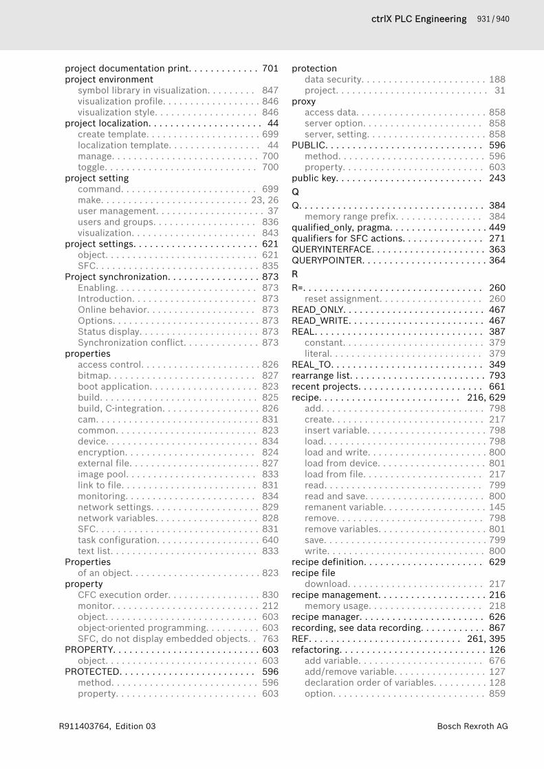
931 / 940ctrlX PLC Engineering
Bosch Rexroth AGR911403764, Edition 03
project documentation print. . . . . . . . . . . . . 701project environment
symbol library in visualization. . . . . . . . . 847visualization profile. . . . . . . . . . . . . . . . . . 846visualization style. . . . . . . . . . . . . . . . . . . 846
project localization. . . . . . . . . . . . . . . . . . . . . 44create template. . . . . . . . . . . . . . . . . . . . . 699localization template. . . . . . . . . . . . . . . . . 44manage. . . . . . . . . . . . . . . . . . . . . . . . . . . 700toggle. . . . . . . . . . . . . . . . . . . . . . . . . . . . 700
project settingcommand. . . . . . . . . . . . . . . . . . . . . . . . . 699make. . . . . . . . . . . . . . . . . . . . . . . . . . . 23, 26user management. . . . . . . . . . . . . . . . . . . . 37users and groups. . . . . . . . . . . . . . . . . . . 836visualization. . . . . . . . . . . . . . . . . . . . . . . 843
project settings. . . . . . . . . . . . . . . . . . . . . . . 621object. . . . . . . . . . . . . . . . . . . . . . . . . . . . 621SFC. . . . . . . . . . . . . . . . . . . . . . . . . . . . . . 835
Project synchronization. . . . . . . . . . . . . . . . . 873Enabling. . . . . . . . . . . . . . . . . . . . . . . . . . 873Introduction. . . . . . . . . . . . . . . . . . . . . . . 873Online behavior. . . . . . . . . . . . . . . . . . . . 873Options. . . . . . . . . . . . . . . . . . . . . . . . . . . 873Status display. . . . . . . . . . . . . . . . . . . . . . 873Synchronization conflict. . . . . . . . . . . . . . 873
propertiesaccess control. . . . . . . . . . . . . . . . . . . . . . 826bitmap. . . . . . . . . . . . . . . . . . . . . . . . . . . 827boot application. . . . . . . . . . . . . . . . . . . . 823build. . . . . . . . . . . . . . . . . . . . . . . . . . . . . 825build, C-integration. . . . . . . . . . . . . . . . . . 826cam. . . . . . . . . . . . . . . . . . . . . . . . . . . . . . 831common. . . . . . . . . . . . . . . . . . . . . . . . . . 823device. . . . . . . . . . . . . . . . . . . . . . . . . . . . 834encryption. . . . . . . . . . . . . . . . . . . . . . . . 824external file. . . . . . . . . . . . . . . . . . . . . . . . 827image pool. . . . . . . . . . . . . . . . . . . . . . . . 833link to file. . . . . . . . . . . . . . . . . . . . . . . . . 831monitoring. . . . . . . . . . . . . . . . . . . . . . . . 834network settings. . . . . . . . . . . . . . . . . . . . 829network variables. . . . . . . . . . . . . . . . . . . 828SFC. . . . . . . . . . . . . . . . . . . . . . . . . . . . . . 831task configuration. . . . . . . . . . . . . . . . . . . 640text list. . . . . . . . . . . . . . . . . . . . . . . . . . . 833
Propertiesof an object. . . . . . . . . . . . . . . . . . . . . . . . 823
propertyCFC execution order. . . . . . . . . . . . . . . . . 830monitor. . . . . . . . . . . . . . . . . . . . . . . . . . . 212object. . . . . . . . . . . . . . . . . . . . . . . . . . . . 603object-oriented programming. . . . . . . . . . 603SFC, do not display embedded objects. . 763
PROPERTY. . . . . . . . . . . . . . . . . . . . . . . . . . . 603object. . . . . . . . . . . . . . . . . . . . . . . . . . . . 603
PROTECTED. . . . . . . . . . . . . . . . . . . . . . . . . 596method. . . . . . . . . . . . . . . . . . . . . . . . . . . 596property. . . . . . . . . . . . . . . . . . . . . . . . . . 603
protectiondata security. . . . . . . . . . . . . . . . . . . . . . . 188project. . . . . . . . . . . . . . . . . . . . . . . . . . . . 31
proxyaccess data. . . . . . . . . . . . . . . . . . . . . . . . 858server option. . . . . . . . . . . . . . . . . . . . . . 858server, setting. . . . . . . . . . . . . . . . . . . . . . 858
PUBLIC. . . . . . . . . . . . . . . . . . . . . . . . . . . . . 596method. . . . . . . . . . . . . . . . . . . . . . . . . . . 596property. . . . . . . . . . . . . . . . . . . . . . . . . . 603
public key. . . . . . . . . . . . . . . . . . . . . . . . . . . 243QQ. . . . . . . . . . . . . . . . . . . . . . . . . . . . . . . . . . 384
memory range prefix. . . . . . . . . . . . . . . . 384qualified_only, pragma. . . . . . . . . . . . . . . . . . 449qualifiers for SFC actions. . . . . . . . . . . . . . . 271QUERYINTERFACE. . . . . . . . . . . . . . . . . . . . . 363QUERYPOINTER. . . . . . . . . . . . . . . . . . . . . . . 364RR=. . . . . . . . . . . . . . . . . . . . . . . . . . . . . . . . . 260
reset assignment. . . . . . . . . . . . . . . . . . . 260READ_ONLY. . . . . . . . . . . . . . . . . . . . . . . . . . 467READ_WRITE. . . . . . . . . . . . . . . . . . . . . . . . . 467REAL. . . . . . . . . . . . . . . . . . . . . . . . . . . . . . . 387
constant. . . . . . . . . . . . . . . . . . . . . . . . . . 379literal. . . . . . . . . . . . . . . . . . . . . . . . . . . . 379
REAL_TO. . . . . . . . . . . . . . . . . . . . . . . . . . . . 349rearrange list. . . . . . . . . . . . . . . . . . . . . . . . . 793recent projects. . . . . . . . . . . . . . . . . . . . . . . 661recipe. . . . . . . . . . . . . . . . . . . . . . . . . . 216, 629
add. . . . . . . . . . . . . . . . . . . . . . . . . . . . . . 798create. . . . . . . . . . . . . . . . . . . . . . . . . . . . 217insert variable. . . . . . . . . . . . . . . . . . . . . . 798load. . . . . . . . . . . . . . . . . . . . . . . . . . . . . . 798load and write. . . . . . . . . . . . . . . . . . . . . . 800load from device. . . . . . . . . . . . . . . . . . . . 801load from file. . . . . . . . . . . . . . . . . . . . . . 217read. . . . . . . . . . . . . . . . . . . . . . . . . . . . . 799read and save. . . . . . . . . . . . . . . . . . . . . . 800remanent variable. . . . . . . . . . . . . . . . . . . 145remove. . . . . . . . . . . . . . . . . . . . . . . . . . . 798remove variables. . . . . . . . . . . . . . . . . . . . 801save. . . . . . . . . . . . . . . . . . . . . . . . . . . . . . 799write. . . . . . . . . . . . . . . . . . . . . . . . . . . . . 800
recipe definition. . . . . . . . . . . . . . . . . . . . . . 629recipe file
download. . . . . . . . . . . . . . . . . . . . . . . . . 217recipe management. . . . . . . . . . . . . . . . . . . . 216
memory usage. . . . . . . . . . . . . . . . . . . . . 218recipe manager. . . . . . . . . . . . . . . . . . . . . . . 626recording, see data recording. . . . . . . . . . . . 867REF. . . . . . . . . . . . . . . . . . . . . . . . . . . . 261, 395refactoring. . . . . . . . . . . . . . . . . . . . . . . . . . . 126
add variable. . . . . . . . . . . . . . . . . . . . . . . 676add/remove variable. . . . . . . . . . . . . . . . . 127declaration order of variables. . . . . . . . . . 128option. . . . . . . . . . . . . . . . . . . . . . . . . . . . 859

932 / 940 ctrlX PLC Engineering
Bosch Rexroth AG R911403764, Edition 03
remove variable. . . . . . . . . . . . . . . . . . . . 678rename. . . . . . . . . . . . . . . . . . . . . . . . . . . 675rename variable. . . . . . . . . . . . . . . . . . . . 126reorder variables. . . . . . . . . . . . . . . . . . . . 678update referenced pins. . . . . . . . . . . . . . . 676
reference. . . . . . . . . . . . . . . . . . . . . . . . . . . . 395__ISVALIDREF. . . . . . . . . . . . . . . . . . . . . . 395data type. . . . . . . . . . . . . . . . . . . . . . . . . . 395test operator. . . . . . . . . . . . . . . . . . . . . . . 395
REFERENCE. . . . . . . . . . . . . . . . . . . . . . . . . . 395REFERENCE TO. . . . . . . . . . . . . . . . . . . . . . . 395reflection, pragma attribute. . . . . . . . . . . . . 449refresh
structured variables . . . . . . . . . . . . . . . . . 801released. . . . . . . . . . . . . . . . . . . . . . . . . . . . . . 35remanent. . . . . . . . . . . . . . . . . . . . . . . . . . . . 321
recipe. . . . . . . . . . . . . . . . . . . . . . . . . . . . 145variable. . . . . . . . . . . . . . . . . . . . . . . . . . . 321
remote datavisualize. . . . . . . . . . . . . . . . . . . . . . . . . . 182
removeIL line. . . . . . . . . . . . . . . . . . . . . . . . . . . . 784reset. . . . . . . . . . . . . . . . . . . . . . . . . . . . . 765set. . . . . . . . . . . . . . . . . . . . . . . . . . . . . . . 765unused parameters, FBD/LD. . . . . . . . . . 786
remove force list. . . . . . . . . . . . . . . . . . . . . . 737remove unused FB call parameters. . . . . . . . 786rename
refactoring. . . . . . . . . . . . . . . . . . . . . . . . 675repair
box. . . . . . . . . . . . . . . . . . . . . . . . . . . . . . 786REPEAT. . . . . . . . . . . . . . . . . . . . . . . . . . . . . 265replace. . . . . . . . . . . . . . . . . . . . . . . . . . . . . . 126
command. . . . . . . . . . . . . . . . . . . . . . . . . 664repository. . . . . . . . . . . . . . . . . . . . . . . . . . . 742
library. . . . . . . . . . . . . . . . . . . . . . . . . . . . 742reserve memory
online change. . . . . . . . . . . . . . . . . . . . . . 691reset
application. . . . . . . . . . . . . . . . . . . . . . . . 204application (reset cold). . . . . . . . . . . . . . 725application (reset origin). . . . . . . . . . . . . 727application (reset warm). . . . . . . . . . . . . 726assignment ST. . . . . . . . . . . . . . . . . . . . . 260cold. . . . . . . . . . . . . . . . . . . . . . . . . . . . . . 725device to origin. . . . . . . . . . . . . . . . . . . . . 728origin. . . . . . . . . . . . . . . . . . . . . . . . . . . . 727origin device. . . . . . . . . . . . . . . . . . . . . . . 728output. . . . . . . . . . . . . . . . . . . . . . . . . . . . 766remove. . . . . . . . . . . . . . . . . . . . . . . . . . . 765warm. . . . . . . . . . . . . . . . . . . . . . . . . . . . . 726
reset coil. . . . . . . . . . . . . . . . . . . . . . . . . . . . 298insert. . . . . . . . . . . . . . . . . . . . . . . . . . . . 781
reset origin. . . . . . . . . . . . . . . . . . . . . . . . . . 727application. . . . . . . . . . . . . . . . . . . . . . . . 727
restore. . . . . . . . . . . . . . . . . . . . . . . . . . . . . . 233restore values from recipe. . . . . . . . . . . . . . . 794RET. . . . . . . . . . . . . . . . . . . . . . . . . . . . . . . . 291
RETAIN. . . . . . . . . . . . . . . . . . . . . . . . . . . . . . 323remanent variable. . . . . . . . . . . . . . . . . . . 144variable. . . . . . . . . . . . . . . . . . . . . . . . . . . 323
RETC. . . . . . . . . . . . . . . . . . . . . . . . . . . . . . . 291RETCN. . . . . . . . . . . . . . . . . . . . . . . . . . . . . . 291return
CFC. . . . . . . . . . . . . . . . . . . . . . . . . . . . . . 310FBD/LD/IL. . . . . . . . . . . . . . . . . . . . . . . . . 297insert, FBD/LD/IL. . . . . . . . . . . . . . . . . . . 780
RETURN. . . . . . . . . . . . . . . . . . . . . . . . . . . . . 266rights management. . . . . . . . . . . . . . . . . . . . . 32
project. . . . . . . . . . . . . . . . . . . . . . . . . . . . 33rising edge detection. . . . . . . . . . . . . . . . . . . 784ROL. . . . . . . . . . . . . . . . . . . . . . . . . . . . . . . . 339ROR. . . . . . . . . . . . . . . . . . . . . . . . . . . . . . . . 340routing. . . . . . . . . . . . . . . . . . . . . . . . . . . . . . 160run
stepping. . . . . . . . . . . . . . . . . . . . . . . . . . 199to cursor. . . . . . . . . . . . . . . . . . . . . . . . . . 735using step out. . . . . . . . . . . . . . . . . . . . . . 735
runtime systemsecurity. . . . . . . . . . . . . . . . . . . . . . . . . . . 244
runtime system filesgenerate . . . . . . . . . . . . . . . . . . . . . . . . . . 712
SS=. . . . . . . . . . . . . . . . . . . . . . . . . . . . . . . . . 259
set assignment. . . . . . . . . . . . . . . . . . . . . 259sample
show in the trace editor. . . . . . . . . . . . . . 220samples
save in trace file. . . . . . . . . . . . . . . . . . . . 220save
project archive. . . . . . . . . . . . . . . . . . . . . . 43Save
project. . . . . . . . . . . . . . . . . . . . . . . . . . . . 42save current values to recipe. . . . . . . . . . . . . 794save the project. . . . . . . . . . . . . . . . . . . . . . . 655save values to recipe. . . . . . . . . . . . . . . . . . . 794save, project
option. . . . . . . . . . . . . . . . . . . . . . . . . . . . 857saving
project. . . . . . . . . . . . . . . . . . . . . . . . . . . . 34scalar product. . . . . . . . . . . . . . . . . . . . . . . . 407scan
devices. . . . . . . . . . . . . . . . . . . . . . . . . . . . 51for devices. . . . . . . . . . . . . . . . . . . . . . . . 696
SCE in LD. . . . . . . . . . . . . . . . . . . . . . . . . . . 299scope. . . . . . . . . . . . . . . . . . . . . . . . . . . . . . . 312search. . . . . . . . . . . . . . . . . . . . . . . . . . 126, 665
object. . . . . . . . . . . . . . . . . . . . . . . . . . . . 679search order
Identifiers. . . . . . . . . . . . . . . . . . . . . . . . . 465variable name. . . . . . . . . . . . . . . . . . . . . . 465
security. . . . . . . . . . . . . . . . . . . . . . . . . . . . . 242add device user. . . . . . . . . . . . . . . . . . . . 728certificate. . . . . . . . . . . . . . . . . . . . . . . . . 243certificate via PLC shell. . . . . . . . . . . . . . 246
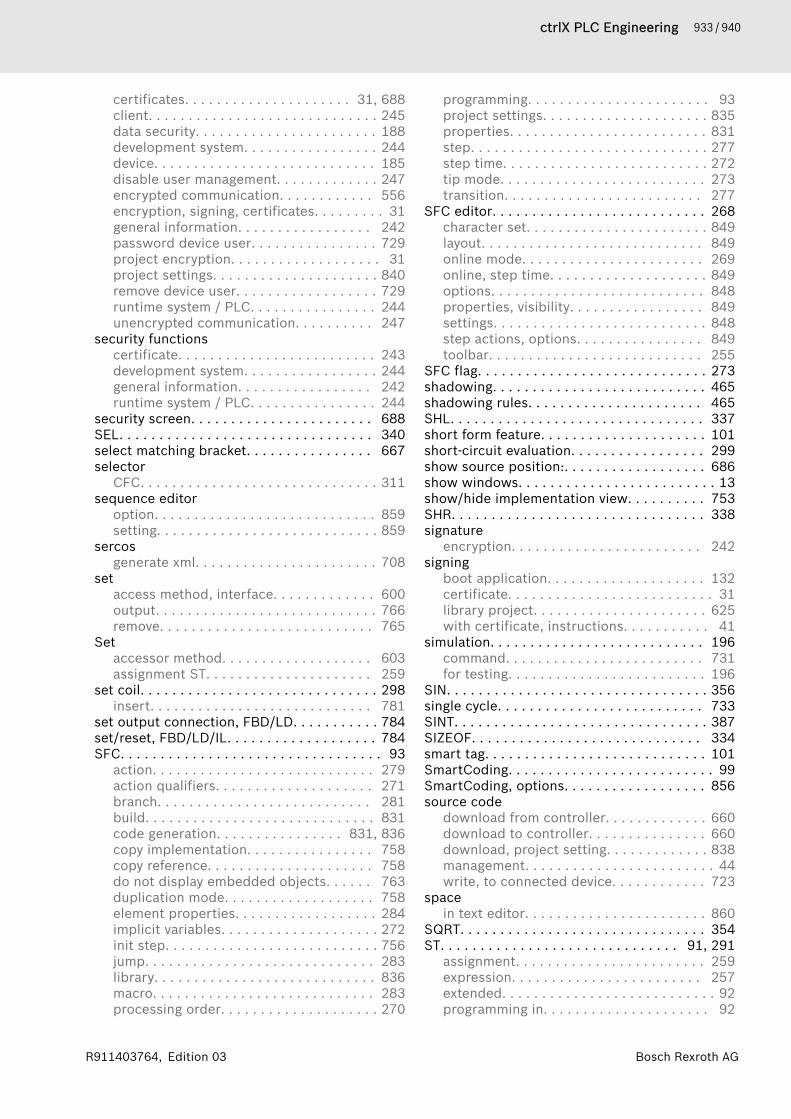
933 / 940ctrlX PLC Engineering
Bosch Rexroth AGR911403764, Edition 03
certificates. . . . . . . . . . . . . . . . . . . . . 31, 688client. . . . . . . . . . . . . . . . . . . . . . . . . . . . . 245data security. . . . . . . . . . . . . . . . . . . . . . . 188development system. . . . . . . . . . . . . . . . . 244device. . . . . . . . . . . . . . . . . . . . . . . . . . . . 185disable user management. . . . . . . . . . . . . 247encrypted communication. . . . . . . . . . . . 556encryption, signing, certificates. . . . . . . . . 31general information. . . . . . . . . . . . . . . . . 242password device user. . . . . . . . . . . . . . . . 729project encryption. . . . . . . . . . . . . . . . . . . 31project settings. . . . . . . . . . . . . . . . . . . . . 840remove device user. . . . . . . . . . . . . . . . . . 729runtime system / PLC. . . . . . . . . . . . . . . . 244unencrypted communication. . . . . . . . . . 247
security functionscertificate. . . . . . . . . . . . . . . . . . . . . . . . . 243development system. . . . . . . . . . . . . . . . . 244general information. . . . . . . . . . . . . . . . . 242runtime system / PLC. . . . . . . . . . . . . . . . 244
security screen. . . . . . . . . . . . . . . . . . . . . . . 688SEL. . . . . . . . . . . . . . . . . . . . . . . . . . . . . . . . 340select matching bracket. . . . . . . . . . . . . . . . 667selector
CFC. . . . . . . . . . . . . . . . . . . . . . . . . . . . . . 311sequence editor
option. . . . . . . . . . . . . . . . . . . . . . . . . . . . 859setting. . . . . . . . . . . . . . . . . . . . . . . . . . . . 859
sercosgenerate xml. . . . . . . . . . . . . . . . . . . . . . . 708
setaccess method, interface. . . . . . . . . . . . . 600output. . . . . . . . . . . . . . . . . . . . . . . . . . . . 766remove. . . . . . . . . . . . . . . . . . . . . . . . . . . 765
Setaccessor method. . . . . . . . . . . . . . . . . . . 603assignment ST. . . . . . . . . . . . . . . . . . . . . 259
set coil. . . . . . . . . . . . . . . . . . . . . . . . . . . . . . 298insert. . . . . . . . . . . . . . . . . . . . . . . . . . . . 781
set output connection, FBD/LD. . . . . . . . . . . 784set/reset, FBD/LD/IL. . . . . . . . . . . . . . . . . . . 784SFC. . . . . . . . . . . . . . . . . . . . . . . . . . . . . . . . . 93
action. . . . . . . . . . . . . . . . . . . . . . . . . . . . 279action qualifiers. . . . . . . . . . . . . . . . . . . . 271branch. . . . . . . . . . . . . . . . . . . . . . . . . . . 281build. . . . . . . . . . . . . . . . . . . . . . . . . . . . . 831code generation. . . . . . . . . . . . . . . . 831, 836copy implementation. . . . . . . . . . . . . . . . 758copy reference. . . . . . . . . . . . . . . . . . . . . 758do not display embedded objects. . . . . . 763duplication mode. . . . . . . . . . . . . . . . . . . 758element properties. . . . . . . . . . . . . . . . . . 284implicit variables. . . . . . . . . . . . . . . . . . . . 272init step. . . . . . . . . . . . . . . . . . . . . . . . . . . 756jump. . . . . . . . . . . . . . . . . . . . . . . . . . . . . 283library. . . . . . . . . . . . . . . . . . . . . . . . . . . . 836macro. . . . . . . . . . . . . . . . . . . . . . . . . . . . 283processing order. . . . . . . . . . . . . . . . . . . . 270
programming. . . . . . . . . . . . . . . . . . . . . . . 93project settings. . . . . . . . . . . . . . . . . . . . . 835properties. . . . . . . . . . . . . . . . . . . . . . . . . 831step. . . . . . . . . . . . . . . . . . . . . . . . . . . . . . 277step time. . . . . . . . . . . . . . . . . . . . . . . . . . 272tip mode. . . . . . . . . . . . . . . . . . . . . . . . . . 273transition. . . . . . . . . . . . . . . . . . . . . . . . . 277
SFC editor. . . . . . . . . . . . . . . . . . . . . . . . . . . 268character set. . . . . . . . . . . . . . . . . . . . . . . 849layout. . . . . . . . . . . . . . . . . . . . . . . . . . . . 849online mode. . . . . . . . . . . . . . . . . . . . . . . 269online, step time. . . . . . . . . . . . . . . . . . . . 849options. . . . . . . . . . . . . . . . . . . . . . . . . . . 848properties, visibility. . . . . . . . . . . . . . . . . 849settings. . . . . . . . . . . . . . . . . . . . . . . . . . . 848step actions, options. . . . . . . . . . . . . . . . 849toolbar. . . . . . . . . . . . . . . . . . . . . . . . . . . 255
SFC flag. . . . . . . . . . . . . . . . . . . . . . . . . . . . . 273shadowing. . . . . . . . . . . . . . . . . . . . . . . . . . . 465shadowing rules. . . . . . . . . . . . . . . . . . . . . . 465SHL. . . . . . . . . . . . . . . . . . . . . . . . . . . . . . . . 337short form feature. . . . . . . . . . . . . . . . . . . . . 101short-circuit evaluation. . . . . . . . . . . . . . . . . 299show source position:. . . . . . . . . . . . . . . . . . 686show windows. . . . . . . . . . . . . . . . . . . . . . . . . 13show/hide implementation view. . . . . . . . . . 753SHR. . . . . . . . . . . . . . . . . . . . . . . . . . . . . . . . 338signature
encryption. . . . . . . . . . . . . . . . . . . . . . . . 242signing
boot application. . . . . . . . . . . . . . . . . . . . 132certificate. . . . . . . . . . . . . . . . . . . . . . . . . . 31library project. . . . . . . . . . . . . . . . . . . . . . 625with certificate, instructions. . . . . . . . . . . 41
simulation. . . . . . . . . . . . . . . . . . . . . . . . . . . 196command. . . . . . . . . . . . . . . . . . . . . . . . . 731for testing. . . . . . . . . . . . . . . . . . . . . . . . . 196
SIN. . . . . . . . . . . . . . . . . . . . . . . . . . . . . . . . . 356single cycle. . . . . . . . . . . . . . . . . . . . . . . . . . 733SINT. . . . . . . . . . . . . . . . . . . . . . . . . . . . . . . . 387SIZEOF. . . . . . . . . . . . . . . . . . . . . . . . . . . . . 334smart tag. . . . . . . . . . . . . . . . . . . . . . . . . . . . 101SmartCoding. . . . . . . . . . . . . . . . . . . . . . . . . . 99SmartCoding, options. . . . . . . . . . . . . . . . . . 856source code
download from controller. . . . . . . . . . . . . 660download to controller. . . . . . . . . . . . . . . 660download, project setting. . . . . . . . . . . . . 838management. . . . . . . . . . . . . . . . . . . . . . . . 44write, to connected device. . . . . . . . . . . . 723
spacein text editor. . . . . . . . . . . . . . . . . . . . . . . 860
SQRT. . . . . . . . . . . . . . . . . . . . . . . . . . . . . . . 354ST. . . . . . . . . . . . . . . . . . . . . . . . . . . . . . 91, 291
assignment. . . . . . . . . . . . . . . . . . . . . . . . 259expression. . . . . . . . . . . . . . . . . . . . . . . . 257extended. . . . . . . . . . . . . . . . . . . . . . . . . . . 92programming in. . . . . . . . . . . . . . . . . . . . . 92
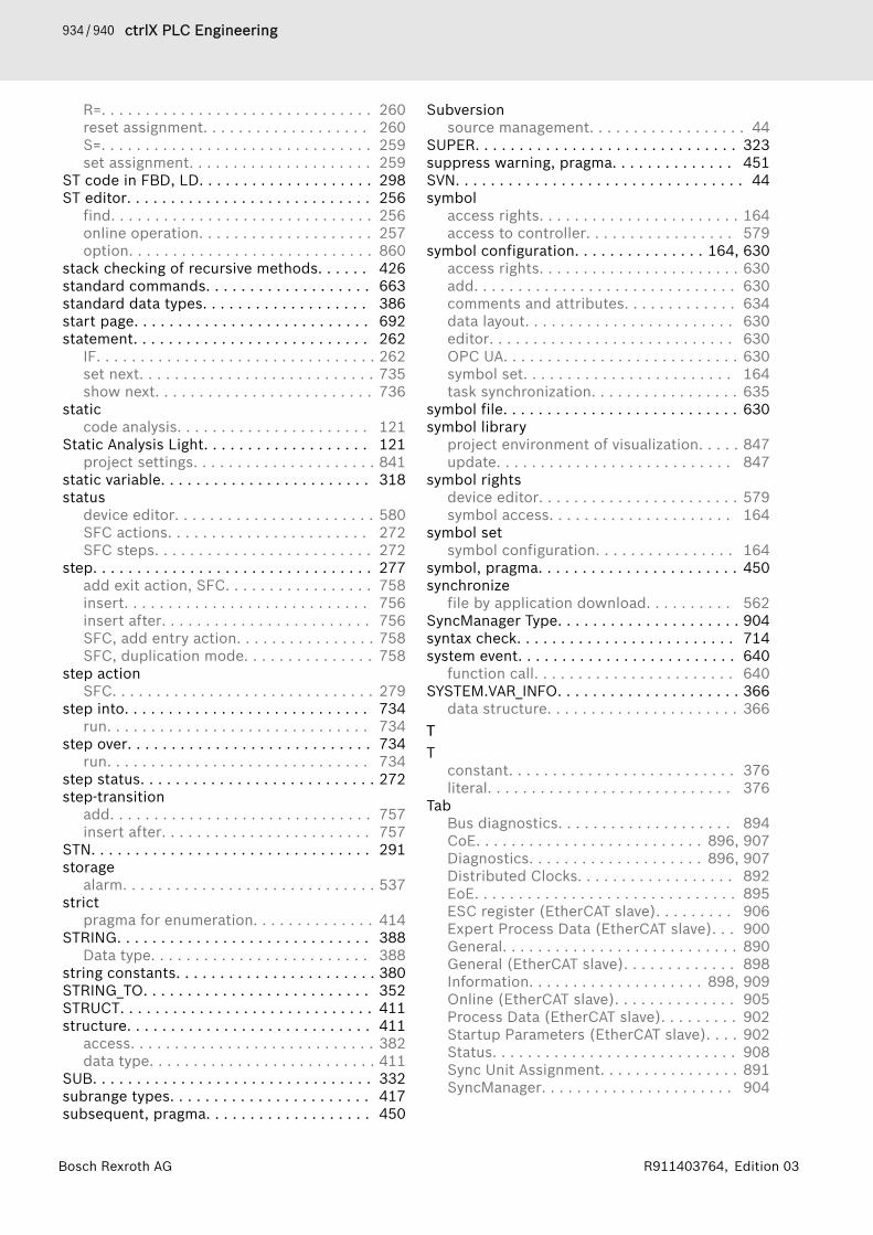
934 / 940 ctrlX PLC Engineering
Bosch Rexroth AG R911403764, Edition 03
R=. . . . . . . . . . . . . . . . . . . . . . . . . . . . . . . 260reset assignment. . . . . . . . . . . . . . . . . . . 260S=. . . . . . . . . . . . . . . . . . . . . . . . . . . . . . . 259set assignment. . . . . . . . . . . . . . . . . . . . . 259
ST code in FBD, LD. . . . . . . . . . . . . . . . . . . . 298ST editor. . . . . . . . . . . . . . . . . . . . . . . . . . . . 256
find. . . . . . . . . . . . . . . . . . . . . . . . . . . . . . 256online operation. . . . . . . . . . . . . . . . . . . . 257option. . . . . . . . . . . . . . . . . . . . . . . . . . . . 860
stack checking of recursive methods. . . . . . 426standard commands. . . . . . . . . . . . . . . . . . . 663standard data types. . . . . . . . . . . . . . . . . . . 386start page. . . . . . . . . . . . . . . . . . . . . . . . . . . 692statement. . . . . . . . . . . . . . . . . . . . . . . . . . . 262
IF. . . . . . . . . . . . . . . . . . . . . . . . . . . . . . . . 262set next. . . . . . . . . . . . . . . . . . . . . . . . . . . 735show next. . . . . . . . . . . . . . . . . . . . . . . . . 736
staticcode analysis. . . . . . . . . . . . . . . . . . . . . . 121
Static Analysis Light. . . . . . . . . . . . . . . . . . . 121project settings. . . . . . . . . . . . . . . . . . . . . 841
static variable. . . . . . . . . . . . . . . . . . . . . . . . 318status
device editor. . . . . . . . . . . . . . . . . . . . . . . 580SFC actions. . . . . . . . . . . . . . . . . . . . . . . 272SFC steps. . . . . . . . . . . . . . . . . . . . . . . . . 272
step. . . . . . . . . . . . . . . . . . . . . . . . . . . . . . . . 277add exit action, SFC. . . . . . . . . . . . . . . . . 758insert. . . . . . . . . . . . . . . . . . . . . . . . . . . . 756insert after. . . . . . . . . . . . . . . . . . . . . . . . 756SFC, add entry action. . . . . . . . . . . . . . . . 758SFC, duplication mode. . . . . . . . . . . . . . . 758
step actionSFC. . . . . . . . . . . . . . . . . . . . . . . . . . . . . . 279
step into. . . . . . . . . . . . . . . . . . . . . . . . . . . . 734run. . . . . . . . . . . . . . . . . . . . . . . . . . . . . . 734
step over. . . . . . . . . . . . . . . . . . . . . . . . . . . . 734run. . . . . . . . . . . . . . . . . . . . . . . . . . . . . . 734
step status. . . . . . . . . . . . . . . . . . . . . . . . . . . 272step-transition
add. . . . . . . . . . . . . . . . . . . . . . . . . . . . . . 757insert after. . . . . . . . . . . . . . . . . . . . . . . . 757
STN. . . . . . . . . . . . . . . . . . . . . . . . . . . . . . . . 291storage
alarm. . . . . . . . . . . . . . . . . . . . . . . . . . . . . 537strict
pragma for enumeration. . . . . . . . . . . . . . 414STRING. . . . . . . . . . . . . . . . . . . . . . . . . . . . . 388
Data type. . . . . . . . . . . . . . . . . . . . . . . . . 388string constants. . . . . . . . . . . . . . . . . . . . . . . 380STRING_TO. . . . . . . . . . . . . . . . . . . . . . . . . . 352STRUCT. . . . . . . . . . . . . . . . . . . . . . . . . . . . . 411structure. . . . . . . . . . . . . . . . . . . . . . . . . . . . 411
access. . . . . . . . . . . . . . . . . . . . . . . . . . . . 382data type. . . . . . . . . . . . . . . . . . . . . . . . . . 411
SUB. . . . . . . . . . . . . . . . . . . . . . . . . . . . . . . . 332subrange types. . . . . . . . . . . . . . . . . . . . . . . 417subsequent, pragma. . . . . . . . . . . . . . . . . . . 450
Subversionsource management. . . . . . . . . . . . . . . . . . 44
SUPER. . . . . . . . . . . . . . . . . . . . . . . . . . . . . . 323suppress warning, pragma. . . . . . . . . . . . . . 451SVN. . . . . . . . . . . . . . . . . . . . . . . . . . . . . . . . . 44symbol
access rights. . . . . . . . . . . . . . . . . . . . . . . 164access to controller. . . . . . . . . . . . . . . . . 579
symbol configuration. . . . . . . . . . . . . . . 164, 630access rights. . . . . . . . . . . . . . . . . . . . . . . 630add. . . . . . . . . . . . . . . . . . . . . . . . . . . . . . 630comments and attributes. . . . . . . . . . . . . 634data layout. . . . . . . . . . . . . . . . . . . . . . . . 630editor. . . . . . . . . . . . . . . . . . . . . . . . . . . . 630OPC UA. . . . . . . . . . . . . . . . . . . . . . . . . . . 630symbol set. . . . . . . . . . . . . . . . . . . . . . . . 164task synchronization. . . . . . . . . . . . . . . . . 635
symbol file. . . . . . . . . . . . . . . . . . . . . . . . . . . 630symbol library
project environment of visualization. . . . . 847update. . . . . . . . . . . . . . . . . . . . . . . . . . . 847
symbol rightsdevice editor. . . . . . . . . . . . . . . . . . . . . . . 579symbol access. . . . . . . . . . . . . . . . . . . . . 164
symbol setsymbol configuration. . . . . . . . . . . . . . . . 164
symbol, pragma. . . . . . . . . . . . . . . . . . . . . . . 450synchronize
file by application download. . . . . . . . . . 562SyncManager Type. . . . . . . . . . . . . . . . . . . . . 904syntax check. . . . . . . . . . . . . . . . . . . . . . . . . 714system event. . . . . . . . . . . . . . . . . . . . . . . . . 640
function call. . . . . . . . . . . . . . . . . . . . . . . 640SYSTEM.VAR_INFO. . . . . . . . . . . . . . . . . . . . . 366
data structure. . . . . . . . . . . . . . . . . . . . . . 366TT
constant. . . . . . . . . . . . . . . . . . . . . . . . . . 376literal. . . . . . . . . . . . . . . . . . . . . . . . . . . . 376
TabBus diagnostics. . . . . . . . . . . . . . . . . . . . 894CoE. . . . . . . . . . . . . . . . . . . . . . . . . . 896, 907Diagnostics. . . . . . . . . . . . . . . . . . . . 896, 907Distributed Clocks. . . . . . . . . . . . . . . . . . 892EoE. . . . . . . . . . . . . . . . . . . . . . . . . . . . . . 895ESC register (EtherCAT slave). . . . . . . . . 906Expert Process Data (EtherCAT slave). . . 900General. . . . . . . . . . . . . . . . . . . . . . . . . . . 890General (EtherCAT slave). . . . . . . . . . . . . 898Information. . . . . . . . . . . . . . . . . . . . 898, 909Online (EtherCAT slave). . . . . . . . . . . . . . 905Process Data (EtherCAT slave). . . . . . . . . 902Startup Parameters (EtherCAT slave). . . . 902Status. . . . . . . . . . . . . . . . . . . . . . . . . . . . 908Sync Unit Assignment. . . . . . . . . . . . . . . . 891SyncManager. . . . . . . . . . . . . . . . . . . . . . 904
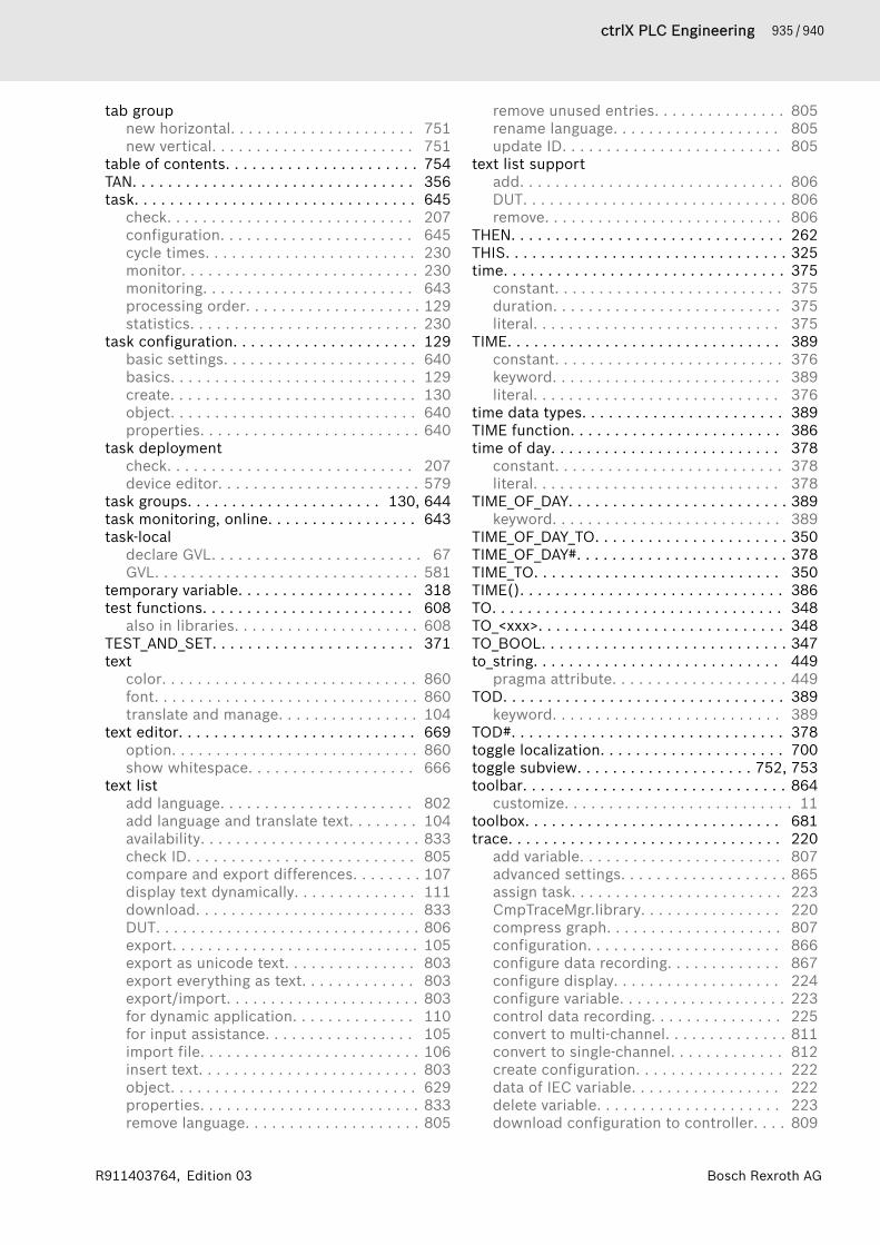
935 / 940ctrlX PLC Engineering
Bosch Rexroth AGR911403764, Edition 03
tab groupnew horizontal. . . . . . . . . . . . . . . . . . . . . 751new vertical. . . . . . . . . . . . . . . . . . . . . . . 751
table of contents. . . . . . . . . . . . . . . . . . . . . . 754TAN. . . . . . . . . . . . . . . . . . . . . . . . . . . . . . . . 356task. . . . . . . . . . . . . . . . . . . . . . . . . . . . . . . . 645
check. . . . . . . . . . . . . . . . . . . . . . . . . . . . 207configuration. . . . . . . . . . . . . . . . . . . . . . 645cycle times. . . . . . . . . . . . . . . . . . . . . . . . 230monitor. . . . . . . . . . . . . . . . . . . . . . . . . . . 230monitoring. . . . . . . . . . . . . . . . . . . . . . . . 643processing order. . . . . . . . . . . . . . . . . . . . 129statistics. . . . . . . . . . . . . . . . . . . . . . . . . . 230
task configuration. . . . . . . . . . . . . . . . . . . . . 129basic settings. . . . . . . . . . . . . . . . . . . . . . 640basics. . . . . . . . . . . . . . . . . . . . . . . . . . . . 129create. . . . . . . . . . . . . . . . . . . . . . . . . . . . 130object. . . . . . . . . . . . . . . . . . . . . . . . . . . . 640properties. . . . . . . . . . . . . . . . . . . . . . . . . 640
task deploymentcheck. . . . . . . . . . . . . . . . . . . . . . . . . . . . 207device editor. . . . . . . . . . . . . . . . . . . . . . . 579
task groups. . . . . . . . . . . . . . . . . . . . . . 130, 644task monitoring, online. . . . . . . . . . . . . . . . . 643task-local
declare GVL. . . . . . . . . . . . . . . . . . . . . . . . 67GVL. . . . . . . . . . . . . . . . . . . . . . . . . . . . . . 581
temporary variable. . . . . . . . . . . . . . . . . . . . 318test functions. . . . . . . . . . . . . . . . . . . . . . . . 608
also in libraries. . . . . . . . . . . . . . . . . . . . . 608TEST_AND_SET. . . . . . . . . . . . . . . . . . . . . . . 371text
color. . . . . . . . . . . . . . . . . . . . . . . . . . . . . 860font. . . . . . . . . . . . . . . . . . . . . . . . . . . . . . 860translate and manage. . . . . . . . . . . . . . . . 104
text editor. . . . . . . . . . . . . . . . . . . . . . . . . . . 669option. . . . . . . . . . . . . . . . . . . . . . . . . . . . 860show whitespace. . . . . . . . . . . . . . . . . . . 666
text listadd language. . . . . . . . . . . . . . . . . . . . . . 802add language and translate text. . . . . . . . 104availability. . . . . . . . . . . . . . . . . . . . . . . . . 833check ID. . . . . . . . . . . . . . . . . . . . . . . . . . 805compare and export differences. . . . . . . . 107display text dynamically. . . . . . . . . . . . . . 111download. . . . . . . . . . . . . . . . . . . . . . . . . 833DUT. . . . . . . . . . . . . . . . . . . . . . . . . . . . . . 806export. . . . . . . . . . . . . . . . . . . . . . . . . . . . 105export as unicode text. . . . . . . . . . . . . . . 803export everything as text. . . . . . . . . . . . . 803export/import. . . . . . . . . . . . . . . . . . . . . . 803for dynamic application. . . . . . . . . . . . . . 110for input assistance. . . . . . . . . . . . . . . . . 105import file. . . . . . . . . . . . . . . . . . . . . . . . . 106insert text. . . . . . . . . . . . . . . . . . . . . . . . . 803object. . . . . . . . . . . . . . . . . . . . . . . . . . . . 629properties. . . . . . . . . . . . . . . . . . . . . . . . . 833remove language. . . . . . . . . . . . . . . . . . . . 805
remove unused entries. . . . . . . . . . . . . . . 805rename language. . . . . . . . . . . . . . . . . . . 805update ID. . . . . . . . . . . . . . . . . . . . . . . . . 805
text list supportadd. . . . . . . . . . . . . . . . . . . . . . . . . . . . . . 806DUT. . . . . . . . . . . . . . . . . . . . . . . . . . . . . . 806remove. . . . . . . . . . . . . . . . . . . . . . . . . . . 806
THEN. . . . . . . . . . . . . . . . . . . . . . . . . . . . . . . 262THIS. . . . . . . . . . . . . . . . . . . . . . . . . . . . . . . . 325time. . . . . . . . . . . . . . . . . . . . . . . . . . . . . . . . 375
constant. . . . . . . . . . . . . . . . . . . . . . . . . . 375duration. . . . . . . . . . . . . . . . . . . . . . . . . . 375literal. . . . . . . . . . . . . . . . . . . . . . . . . . . . 375
TIME. . . . . . . . . . . . . . . . . . . . . . . . . . . . . . . 389constant. . . . . . . . . . . . . . . . . . . . . . . . . . 376keyword. . . . . . . . . . . . . . . . . . . . . . . . . . 389literal. . . . . . . . . . . . . . . . . . . . . . . . . . . . 376
time data types. . . . . . . . . . . . . . . . . . . . . . . 389TIME function. . . . . . . . . . . . . . . . . . . . . . . . 386time of day. . . . . . . . . . . . . . . . . . . . . . . . . . 378
constant. . . . . . . . . . . . . . . . . . . . . . . . . . 378literal. . . . . . . . . . . . . . . . . . . . . . . . . . . . 378
TIME_OF_DAY. . . . . . . . . . . . . . . . . . . . . . . . . 389keyword. . . . . . . . . . . . . . . . . . . . . . . . . . 389
TIME_OF_DAY_TO. . . . . . . . . . . . . . . . . . . . . . 350TIME_OF_DAY#. . . . . . . . . . . . . . . . . . . . . . . . 378TIME_TO. . . . . . . . . . . . . . . . . . . . . . . . . . . . 350TIME(). . . . . . . . . . . . . . . . . . . . . . . . . . . . . . 386TO. . . . . . . . . . . . . . . . . . . . . . . . . . . . . . . . . 348TO_<xxx>. . . . . . . . . . . . . . . . . . . . . . . . . . . . 348TO_BOOL. . . . . . . . . . . . . . . . . . . . . . . . . . . . 347to_string. . . . . . . . . . . . . . . . . . . . . . . . . . . . 449
pragma attribute. . . . . . . . . . . . . . . . . . . . 449TOD. . . . . . . . . . . . . . . . . . . . . . . . . . . . . . . . 389
keyword. . . . . . . . . . . . . . . . . . . . . . . . . . 389TOD#. . . . . . . . . . . . . . . . . . . . . . . . . . . . . . . 378toggle localization. . . . . . . . . . . . . . . . . . . . . 700toggle subview. . . . . . . . . . . . . . . . . . . . 752, 753toolbar. . . . . . . . . . . . . . . . . . . . . . . . . . . . . . 864
customize. . . . . . . . . . . . . . . . . . . . . . . . . . 11toolbox. . . . . . . . . . . . . . . . . . . . . . . . . . . . . 681trace. . . . . . . . . . . . . . . . . . . . . . . . . . . . . . . 220
add variable. . . . . . . . . . . . . . . . . . . . . . . 807advanced settings. . . . . . . . . . . . . . . . . . . 865assign task. . . . . . . . . . . . . . . . . . . . . . . . 223CmpTraceMgr.library. . . . . . . . . . . . . . . . 220compress graph. . . . . . . . . . . . . . . . . . . . 807configuration. . . . . . . . . . . . . . . . . . . . . . 866configure data recording. . . . . . . . . . . . . 867configure display. . . . . . . . . . . . . . . . . . . 224configure variable. . . . . . . . . . . . . . . . . . . 223control data recording. . . . . . . . . . . . . . . 225convert to multi-channel. . . . . . . . . . . . . . 811convert to single-channel. . . . . . . . . . . . . 812create configuration. . . . . . . . . . . . . . . . . 222data of IEC variable. . . . . . . . . . . . . . . . . 222delete variable. . . . . . . . . . . . . . . . . . . . . 223download configuration to controller. . . . 809
936 / 940 ctrlX PLC Engineering
Bosch Rexroth AG R911403764, Edition 03
editor. . . . . . . . . . . . . . . . . . . . . . . . . . . . 648file formats. . . . . . . . . . . . . . . . . . . . . . . . 220getting started. . . . . . . . . . . . . . . . . . . . . 221load file . . . . . . . . . . . . . . . . . . . . . . . . . . 811manage as file. . . . . . . . . . . . . . . . . . . . . . 226multicore. . . . . . . . . . . . . . . . . . . . . . . . . 132navigate in data in diagrams. . . . . . . . . . . 225navigate in diagram. . . . . . . . . . . . . . . . . . 649object. . . . . . . . . . . . . . . . . . . . . . . . . . . . 647open statistics. . . . . . . . . . . . . . . . . . . . . 814read y-value. . . . . . . . . . . . . . . . . . . . . . . . 808reset diagram to default view. . . . . . . . . . 813runtime buffer . . . . . . . . . . . . . . . . . . . . . 865save samples to file. . . . . . . . . . . . . . . . . 220save to file. . . . . . . . . . . . . . . . . . . . . . . . 813show statistics. . . . . . . . . . . . . . . . . . . . . 226start. . . . . . . . . . . . . . . . . . . . . . . . . . . . . 813stop. . . . . . . . . . . . . . . . . . . . . . . . . . . . . . 813stretch graph. . . . . . . . . . . . . . . . . . . . . . 814trace cursor. . . . . . . . . . . . . . . . . . . . . . . 808trigger. . . . . . . . . . . . . . . . . . . . . . . . . . . . 220
trace configurationexport symbolic. . . . . . . . . . . . . . . . . . . . 809
transition. . . . . . . . . . . . . . . . . . . . . . . . 277, 607insert. . . . . . . . . . . . . . . . . . . . . . . . . . . . 757insert after. . . . . . . . . . . . . . . . . . . . . . . . 757SFC, do not display embedded objects. . 763
trend configurationadd parameters. . . . . . . . . . . . . . . . . . . . 229add variable. . . . . . . . . . . . . . . . . . . . . . . 228assign tasks. . . . . . . . . . . . . . . . . . . . . . . 228configure additional buffering. . . . . . . . . 230configure data buffering on RTS. . . . . . . . 229delete variable. . . . . . . . . . . . . . . . . . . . . 229start conditional. . . . . . . . . . . . . . . . . . . . 229
trend recording. . . . . . . . . . . . . . . . . . . . . . . 226configure. . . . . . . . . . . . . . . . . . . . . . . . . . 228getting started. . . . . . . . . . . . . . . . . . . . . 227set additional buffer. . . . . . . . . . . . . . . . . 871storage configuration. . . . . . . . . . . . . . . . 870
triggeractivate in trace configuration. . . . . . . . . 224reset trace configuration. . . . . . . . . . . . . 812
TRUE. . . . . . . . . . . . . . . . . . . . . . . . . . . . . . . 375TRUNC. . . . . . . . . . . . . . . . . . . . . . . . . . . . . . 352TRUNC_INT. . . . . . . . . . . . . . . . . . . . . . . . . . 353TRY. . . . . . . . . . . . . . . . . . . . . . . . . . . . . . . . 364TYPE. . . . . . . . . . . . . . . . . . . . . . . . . . . . . . . 413typed literals. . . . . . . . . . . . . . . . . . . . . . . . . 381UUDINT. . . . . . . . . . . . . . . . . . . . . . . . . . . . . . 387UINT. . . . . . . . . . . . . . . . . . . . . . . . . . . . . . . . 387ULINT. . . . . . . . . . . . . . . . . . . . . . . . . . . . . . . 387uncomment . . . . . . . . . . . . . . . . . . . . . . . . . 668undefine, pragma. . . . . . . . . . . . . . . . . . . . . 452underflow data type. . . . . . . . . . . . . . . . . . . 328unforce. . . . . . . . . . . . . . . . . . . . . . . . . . . . . 737
unforce values. . . . . . . . . . . . . . . . . . . . . . . . 737unicode
text list. . . . . . . . . . . . . . . . . . . . . . . . . . . 803uninstall
device. . . . . . . . . . . . . . . . . . . . . . . . . . . . 747library. . . . . . . . . . . . . . . . . . . . . . . . . . . . 742
UNION. . . . . . . . . . . . . . . . . . . . . . . . . . . . . . 389unit conversion. . . . . . . . . . . . . . . . . . . . . . . 136
apply. . . . . . . . . . . . . . . . . . . . . . . . . . . . . 138apply reverse. . . . . . . . . . . . . . . . . . . . . . 138define. . . . . . . . . . . . . . . . . . . . . . . . . . . . 136define as switchable. . . . . . . . . . . . . . . . . 137example. . . . . . . . . . . . . . . . . . . . . . . . . . 138object. . . . . . . . . . . . . . . . . . . . . . . . . . . . 650
unlock connection. . . . . . . . . . . . . . . . . . . . . 772UNTIL. . . . . . . . . . . . . . . . . . . . . . . . . . . . . . . 265update
IDs in text list. . . . . . . . . . . . . . . . . . . . . . 805parameters, fbd/ld/il cfc. . . . . . . . . . . . . . 786
update referenced pinsrefactoring. . . . . . . . . . . . . . . . . . . . . . . . 676
update structured variables. . . . . . . . . . . . . 801UPPER_BOUND. . . . . . . . . . . . . . . . . . . . . . . 402
array. . . . . . . . . . . . . . . . . . . . . . . . . . . . . 402uppercase. . . . . . . . . . . . . . . . . . . . . . . . . . . 667
keyword. . . . . . . . . . . . . . . . . . . . . . . . . . 856user
login as this. . . . . . . . . . . . . . . . . . . . . . . . 39user group. . . . . . . . . . . . . . . . . . . . . . . . . . . . 32user interface
customize. . . . . . . . . . . . . . . . . . . . . . . . . . . 9language. . . . . . . . . . . . . . . . . . . . . . . . . . 857
user management. . . . . . . . . . . . . . . . . . . . . . 32controller, device. . . . . . . . . . . . . . . . . . . 188deactivate. . . . . . . . . . . . . . . . . . . . . . . . . 247device, enforce. . . . . . . . . . . . . . . . . . . . . 185general information. . . . . . . . . . . . . . . . . 242project. . . . . . . . . . . . . . . . . . . . . . . . . . . . 37project settings. . . . . . . . . . . . . . . . . . . . . 836
user-defined attributes. . . . . . . . . . . . . . . . . 420users and groups
device editor. . . . . . . . . . . . . . . . . . . . . . . 572project settings. . . . . . . . . . . . . . . . . . . . . 836
USINT. . . . . . . . . . . . . . . . . . . . . . . . . . . . . . 387VVAR. . . . . . . . . . . . . . . . . . . . . . . . . . . . . . . . 312VAR_ACCESS. . . . . . . . . . . . . . . . . . . . . . . . . 467VAR_CONFIG. . . . . . . . . . . . . . . . . . . . . . . . . 320VAR_EXTERNAL. . . . . . . . . . . . . . . . . . . . . . . 319VAR_GLOBAL. . . . . . . . . . . . . . . . . . . . . . . . . 318VAR_IN_OUT. . . . . . . . . . . . . . . . . . . . . . . . . . 313
CONSTANT. . . . . . . . . . . . . . . . . . . . . . . . 316input/output variable. . . . . . . . . . . . . . . . 313
VAR_INFO. . . . . . . . . . . . . . . . . . . . . . . . . . . . 366data structure, SYSTEM. . . . . . . . . . . . . . 366
VAR_INPUT. . . . . . . . . . . . . . . . . . . . . . . . . . . 312VAR_INST. . . . . . . . . . . . . . . . . . . . . . . . . . . . 319

937 / 940ctrlX PLC Engineering
Bosch Rexroth AGR911403764, Edition 03
VAR_OUTPUT. . . . . . . . . . . . . . . . . . . . . . . . . 313VAR_STAT. . . . . . . . . . . . . . . . . . . . . . . . . . . . 318VAR_TEMP. . . . . . . . . . . . . . . . . . . . . . . . . . . 318variable. . . . . . . . . . . . . . . . . . . . . . . . . . . . . 375
access . . . . . . . . . . . . . . . . . . . . . . . . . . . 382add by refactoring. . . . . . . . . . . . . . . . . . 676allocating memory space. . . . . . . . . . . . . 450assign address. . . . . . . . . . . . . . . . . . . . . 119bit access. . . . . . . . . . . . . . . . . . . . . . . . . 382constant. . . . . . . . . . . . . . . . . . . . . . . . . . 320declare. . . . . . . . . . . . . . . . . . . . . . . . . 62, 65declare, command. . . . . . . . . . . . . . . . . . 671declare, tabular. . . . . . . . . . . . . . . . . . . . . . 65declare, textual. . . . . . . . . . . . . . . . . . . . . . 64display format, pragma. . . . . . . . . . . . . . . 425external. . . . . . . . . . . . . . . . . . . . . . . . . . . 319global. . . . . . . . . . . . . . . . . . . . . . . . . . . . 318hide, pragma. . . . . . . . . . . . . . . . . . . . . . . 431initialize. . . . . . . . . . . . . . . . . . . . . . . . . . . 63input. . . . . . . . . . . . . . . . . . . . . . . . . . . . . 312insert, tabular. . . . . . . . . . . . . . . . . . . . . . 792local. . . . . . . . . . . . . . . . . . . . . . . . . . . . . 312monitor. . . . . . . . . . . . . . . . . . . . . . . . . . . 209occurrence location. . . . . . . . . . . . . . . . . 123operator for information. . . . . . . . . . . . . . 366output. . . . . . . . . . . . . . . . . . . . . . . . . . . . 313persistent. . . . . . . . . . . . . . . . . . . . . . . . . 142PERSISTENT. . . . . . . . . . . . . . . . . . . . . . . 321remanent. . . . . . . . . . . . . . . . . . . . . . . . . 323remove by refactoring. . . . . . . . . . . . . . . . 678rename. . . . . . . . . . . . . . . . . . . . . . . . . . . 126RETAIN. . . . . . . . . . . . . . . . . . . . . . . 144, 323rules for names. . . . . . . . . . . . . . . . . . . . . 460short form feature. . . . . . . . . . . . . . . . . . 101static. . . . . . . . . . . . . . . . . . . . . . . . . . . . . 318temporary. . . . . . . . . . . . . . . . . . . . . . . . . 318value in online mode. . . . . . . . . . . . . . . . . 209
variable declaration. . . . . . . . . . . . . . . . . . . . . 62move down. . . . . . . . . . . . . . . . . . . . . . . . 793move up. . . . . . . . . . . . . . . . . . . . . . . . . . 793
variable list. . . . . . . . . . . . . . . . . . . . . . . . . . 582global, persistent. . . . . . . . . . . . . . . . . . . 582
variable usage. . . . . . . . . . . . . . . . . . . . . . . . 644variables configuration. . . . . . . . . . . . . . . . . 117VARINFO. . . . . . . . . . . . . . . . . . . . . . . . . . . . 366
operator. . . . . . . . . . . . . . . . . . . . . . . . . . 366vector. . . . . . . . . . . . . . . . . . . . . . . . . . . . . . 403
declaration. . . . . . . . . . . . . . . . . . . . . . . . 403initialization. . . . . . . . . . . . . . . . . . . . . . . 403
versiondevelopment System. . . . . . . . . . . . . . . . 755information. . . . . . . . . . . . . . . . . . . . . . . . 755operating system. . . . . . . . . . . . . . . . . . . 755
viewbookmarks. . . . . . . . . . . . . . . . . . . . . . . . 682breakpoints. . . . . . . . . . . . . . . . . . . . . . . . 682call stack. . . . . . . . . . . . . . . . . . . . . . . . . . 686call tree. . . . . . . . . . . . . . . . . . . . . . . . . . . 687
cross-reference list. . . . . . . . . . . . . . . . . . 684devices. . . . . . . . . . . . . . . . . . . . . . . . . . . 679memory view. . . . . . . . . . . . . . . . . . . . . . 688POUs. . . . . . . . . . . . . . . . . . . . . . . . . . . . . 680standard menu bar. . . . . . . . . . . . . . . . . . 679
view indentation guides. . . . . . . . . . . . . . . . 666visualization
folder containing image pools. . . . . . . . . 844folder containing text lists . . . . . . . . . . . . 844project setting. . . . . . . . . . . . . . . . . . . . . 843
visualization elementconfiguration with interface property. . . 844configuration with interface propertyactivated. . . . . . . . . . . . . . . . . . . . . . . . . . 844enter static text. . . . . . . . . . . . . . . . . . . . 107
visualization profileproject setting. . . . . . . . . . . . . . . . . . . . . 844version. . . . . . . . . . . . . . . . . . . . . . . . . . . 846
visualization styleversion. . . . . . . . . . . . . . . . . . . . . . . . . . . 846
WW. . . . . . . . . . . . . . . . . . . . . . . . . . . . . . . . . . 384
size prefix. . . . . . . . . . . . . . . . . . . . . . . . . 384warm start. . . . . . . . . . . . . . . . . . . . . . . . . . . 726warning disable, pragma. . . . . . . . . . . . . . . . 451warning restore, pragma. . . . . . . . . . . . . . . . 451watch
add all forces to watchlist. . . . . . . . . . . . 681open view. . . . . . . . . . . . . . . . . . . . . . . . . 681watch all forces. . . . . . . . . . . . . . . . 203, 681
watch list. . . . . . . . . . . . . . . . . . . . . . . . . . . . 215watchlist. . . . . . . . . . . . . . . . . . . . . . . . . . . . 681
add variable. . . . . . . . . . . . . . . . . . . . . . . 815WHILE. . . . . . . . . . . . . . . . . . . . . . . . . . . . . . 265whitespace. . . . . . . . . . . . . . . . . . . . . . . . . . 666
show in text editor. . . . . . . . . . . . . . . . . . 666window
auto hide. . . . . . . . . . . . . . . . . . . . . . . . . . 752dock. . . . . . . . . . . . . . . . . . . . . . . . . . . . . 751float. . . . . . . . . . . . . . . . . . . . . . . . . . . . . 751reset layout. . . . . . . . . . . . . . . . . . . . . . . . 751
window <n>. . . . . . . . . . . . . . . . . . . . . . . . . . 754windows. . . . . . . . . . . . . . . . . . . . . . . . . . . . 753
hide. . . . . . . . . . . . . . . . . . . . . . . . . . . . . . . 13layout. . . . . . . . . . . . . . . . . . . . . . . . . . . . . 12move. . . . . . . . . . . . . . . . . . . . . . . . . . . . . . 12resize. . . . . . . . . . . . . . . . . . . . . . . . . . . . . 13show. . . . . . . . . . . . . . . . . . . . . . . . . . . . . . 13toggle. . . . . . . . . . . . . . . . . . . . . . . . . . . . . 13
Windows Certificate Store. . . . . . . . . . . . . . . 31Wink. . . . . . . . . . . . . . . . . . . . . . . . . . . . . . . 731word
addressing mode. . . . . . . . . . . . . . . . . . . 384WORD. . . . . . . . . . . . . . . . . . . . . . . . . . . . . . 387Working with ctrlX PLC Engineering. . . . . . . 873worksheet. . . . . . . . . . . . . . . . . . . . . . . . . . . 764write. . . . . . . . . . . . . . . . . . . . . . . . . . . . . . . 201
938 / 940 ctrlX PLC Engineering
Bosch Rexroth AG R911403764, Edition 03
write protection. . . . . . . . . . . . . . . . . . . . . . . . 35project. . . . . . . . . . . . . . . . . . . . . . . . . . . . 35
writing valuescommand. . . . . . . . . . . . . . . . . . . . . . . . . 737prepare value. . . . . . . . . . . . . . . . . . . . . . 820
WSTRING. . . . . . . . . . . . . . . . . . . . . . . . . . . . 393XX. . . . . . . . . . . . . . . . . . . . . . . . . . . . . . . . . . 384
size prefix. . . . . . . . . . . . . . . . . . . . . . . . . 384XADD. . . . . . . . . . . . . . . . . . . . . . . . . . . . . . . 371XOR. . . . . . . . . . . . . . . . . . . . . . . . . . . . . . . . 336XORN. . . . . . . . . . . . . . . . . . . . . . . . . . . . . . . 291Zzoom
factor. . . . . . . . . . . . . . . . . . . . . . . . . . . . 255graphical editor. . . . . . . . . . . . . . . . . . . . 255
zoom in/outgraphical editor. . . . . . . . . . . . . . . . . . . . 255

939 / 940ctrlX PLC Engineering
Bosch Rexroth AGR911403764, Edition 03

Bosch Rexroth AGP.O. Box 13 5797803 Lohr a.Main, GermanyBgm.-Dr.-Nebel-Str. 297816 Lohr a.Main, GermanyTel. +49 9352 18 0Fax +49 9352 18 8400www.boschrexroth.com/electrics
R911403764R911403764