
2-way cartridge valves, pressure relief function - Bosch Rexroth
Upload
khangminh22Category
view
0download
0
RE 18303-01/02.2016, Bosch Rexroth AG
4/3 - 4/2 Directional valvesL5010… (LC04Z)
RE 18303-01Edition: 02.2016Replaces: 07.12
4/3 - 4/2 Directional valvessolenoid operated
RE 18303-01Edition: 02.2016Replaces: 07.2012
Size 4 Series 00 Maximum operating pressure 310 bar (4500 psi) Maximum fl ow 25 l/min (6.6 gpm)
NEW spool position sensor available for this valve.See RE18300-30
ContentsOrdering details 2Functional description 4Technical data 5Characteristic curves 7External dimensions and fi ttings 8Electric connection 9
L5010… (LC04Z)
General specifi cations Direct solenoid operated spool valve, standard version. Spool switching is by on off solenoids with a central
tube and removable coil. Spring centered control spool. For mounting on industry standard surface
port pattern to CETOP RP121 H-4.2-P02. Wet pin DC solenoids with removable coil and manual
override. Manual override as option (push or screw-in type). Coil can be rotated through 360°. Available electrical connections: EN 175301-803 (Ex.
DIN 43650); AMP JUNIOR; DT04-2P (Deutsch); Free leads.

Bosch Rexroth AG, RE 18303-01/02.2016
2 L5010… (LC04Z) | 4/3 - 4/2 Directional valvesOrdering details
Ordering details
01 02 03 04 05 06 07 08
L 5 0 10
Family01 Directional Valves L
Type02 CETOP Valves 5
Size 03 NG 4 (P02) 0
Operation04 Solenoid operated C36 coil 10
Spool variants05 4/3 operated A and B side _ 2 _ _
4/2 operated A and B side _ 2 _ _4/2 operated A side _ 3 _ _4/2 operated B side _ 4 _ _4/2 operated A and B side with detent _ 5 _ _
Voltage supply 31 07 03 01 0006 Without coil – – – – ● 00
12V DC ● ● ● ● – OB
13V DC – ● – ● – AD
24V DC ● ● ● ● – OC
27V DC – ● – ● – AC
48V DC – – – ● – OD
110V DC – – – ● – OE
24V AC (21.5 DC) – – – ● – OV
110V AC (98 DC) – – – ● – OW
230V AC (207 DC) – – – ● – OZ
Electric connections07 Without coils 00
With coils, without mating connector DIN EN 175301-803 01 1)
With coils, with bi-directional diode, without mating connector vertical Amp-Junior
03
With coils, with bi-directional diode, without mating connector DT04-2P
07
With coils and bipolar sheathed lead 350mm (13,8 in) long
31
Options08 Standard 00
External push button manual override EPScrew-in type manual override EF
● = Available – = Not available
1) For connectors ordering code see data sheet RE 18325-90.

RE 18303-01/02.2016, Bosch Rexroth AG
4/3 - 4/2 Directional valves | L5010… (LC04Z) Ordering details
3
Spool variants
=A201
=C201
=E201
A B_ 2 _ _
P Ta 0 ba b
A B_ 2 _ _
P Ta ba b
A B_ 3 _ _
P Ta 0a
A B_ 4 _ _
P T0 b
b
A B_ 5 _ _
P Ta ba b
=G209
=K209
=L201
=N201
=L501
=N501
=A301
=B301
=C301
=D301
=E301
=K301
=T301
=Y301
=A401
=B401
=C401
=D401
=E401
=K401
=T409
=Y401
=B201
=D201
=G201
=K201
=M201
=M501
=A361
=B361
=C361
=D361
=E361
=N301
=X301
=A471
=B471
=C471
=D471
=E471
=N401
=X401

Bosch Rexroth AG, RE 18303-01/02.2016
4 L5010… (LC04Z) | 4/3 - 4/2 Directional valvesFunctional description
Functional description
67 5 4 1 3 2 3 4 5 6 7A P B(T)(T)
Type L5010The solenoid operated valves type L 5010 provide 3-way or 4-way fl ow control, usually from port P to either port A or B, and the consequent fl ow return to T from B or A respectively.The valves are composed by a central cast iron body (1) which mounts on industry standard surfaces where the fl ow ports and the installation holes are located; the central body houses the precisely machined directional control spool (2) which is held in the neutral or initial position by the return springs (4). One or two solenoids, composed by a central tube and a surrounding coil (5), are fi tted to the body at the spool’s ends: when the coils are energized, their magnetic fi eld develops a force on the oil immersed mobile plunger incorporated in the tube which pushes the control spool from the initial position into a shifted position where oil fl ow is allowed from P to either A or B.With coils (5) de-energized, the control spool (2) returns to the central or initial position pushed by the washers (3) supported by the return springs (4).
The coils (5) are locked on the tube by threaded plastic nuts (6); the tube incorporates an externally reachable push rod (7) which can pushed for emergency spool shifting in case of electric failure.
Type L5010L201_, L5010M201_, L5010N201_These valves do not have return springs (4) for the directional control spool (2): the spool can shift between two positions, driven only by the magnetic force developed by the two solenoids (5), and, when the solenoids are not energized, the neutral position of the spool is not defi ned. The directional control spool holds a specifi c position only when one of the solenoids is maintained energized.
Type L5010L501_, L5010M501_, L5010N501_In these valves the directional control spool has two switched positions, each one with a mechanical detent. Shifting of the spool’s position is achieved by energizing one of the solenoids, but it is unnecessary to maintain the coil energized in order to keep the spool shifted.
RE 18303-01/02.2016, Bosch Rexroth AG
4/3 - 4/2 Directional valves | L5010… (LC04Z) Technical data
5
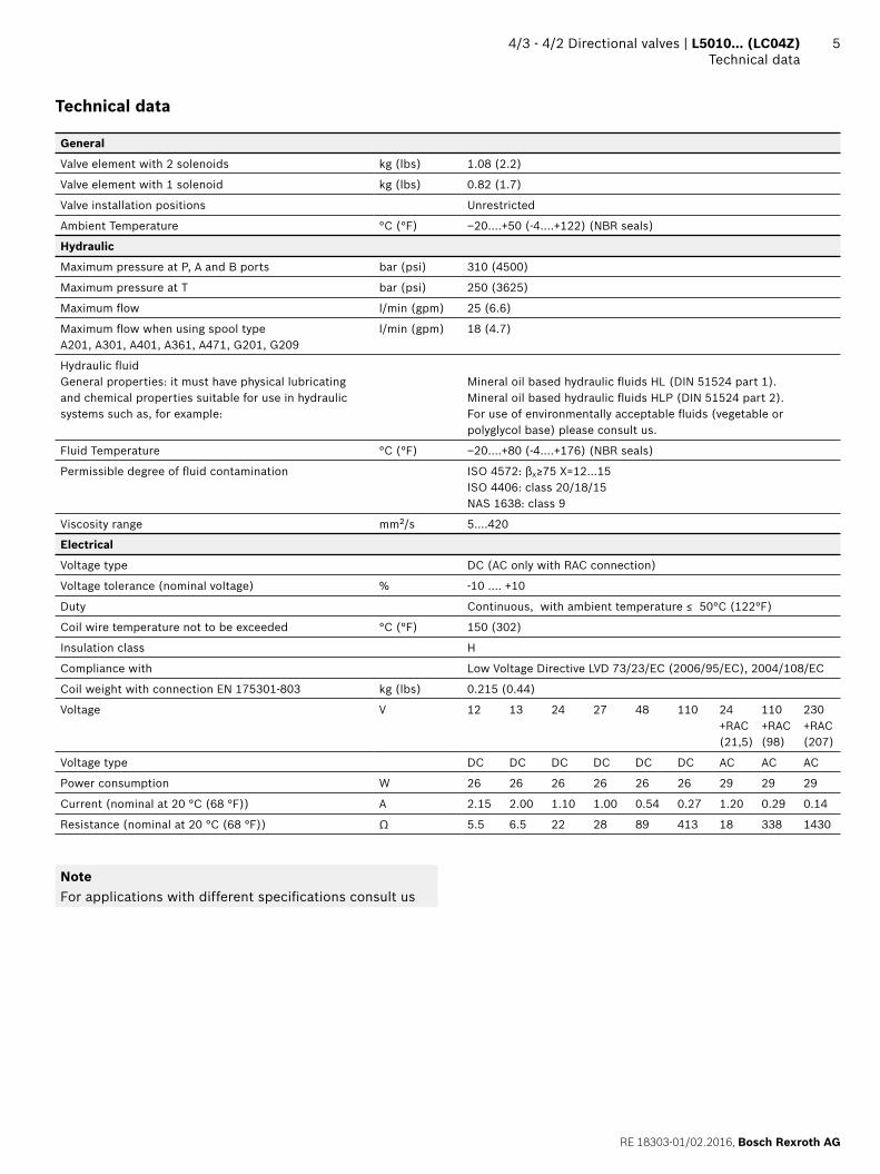
Technical data
General
Valve element with 2 solenoids kg (lbs) 1.08 (2.2)
Valve element with 1 solenoid kg (lbs) 0.82 (1.7)
Valve installation positions Unrestricted
Ambient Temperature °C (°F) –20....+50 (-4....+122) (NBR seals)
Hydraulic
Maximum pressure at P, A and B ports bar (psi) 310 (4500)
Maximum pressure at T bar (psi) 250 (3625)
Maximum fl ow l/min (gpm) 25 (6.6)
Maximum fl ow when using spool typeA201, A301, A401, A361, A471, G201, G209
l/min (gpm) 18 (4.7)
Hydraulic fl uidGeneral properties: it must have physical lubricating and chemical properties suitable for use in hydraulic systems such as, for example:
Mineral oil based hydraulic fl uids HL (DIN 51524 part 1). Mineral oil based hydraulic fl uids HLP (DIN 51524 part 2). For use of environmentally acceptable fl uids (vegetable or polyglycol base) please consult us.
Fluid Temperature °C (°F) –20....+80 (-4....+176) (NBR seals)
Permissible degree of fl uid contamination ISO 4572: βx≥75 X=12...15ISO 4406: class 20/18/15NAS 1638: class 9
Viscosity range mm2/s 5....420
Electrical
Voltage type DC (AC only with RAC connection)
Voltage tolerance (nominal voltage) % -10 .... +10
Duty Continuous, with ambient temperature ≤ 50°C (122°F)
Coil wire temperature not to be exceeded °C (°F) 150 (302)
Insulation class H
Compliance with Low Voltage Directive LVD 73/23/EC (2006/95/EC), 2004/108/EC
Coil weight with connection EN 175301-803 kg (lbs) 0.215 (0.44)
Voltage V 12 13 24 27 48 110 24+RAC(21,5)
110+RAC(98)
230+RAC(207)
Voltage type DC DC DC DC DC DC AC AC AC
Power consumption W 26 26 26 26 26 26 29 29 29
Current (nominal at 20 °C (68 °F)) A 2.15 2.00 1.10 1.00 0.54 0.27 1.20 0.29 0.14
Resistance (nominal at 20 °C (68 °F)) Ω 5.5 6.5 22 28 89 413 18 338 1430
NoteFor applications with different specifi cations consult us

Bosch Rexroth AG, RE 18303-01/02.2016
6 L5010… (LC04Z) | 4/3 - 4/2 Directional valvesTechnical data
Code Voltage [V] Connector type Coil description Marking Coil Mat no.
=OB 01 12 DC EN 175301-803 (Ex. DIN 43650)
C3601 12DC 12 DC R933000044
=OB 03 12 DC AMP JUNIOR C3603 12DC 12 DC R933000047
=OB 07 12 DC DEUTSCH DT 04-2P C3607 12DC 12 DC R933000048
=OB 31 12 DC Cable 350 mm long C3631 12DC 12 DC R933000045
=AD 01 13 DC EN 175301-803 (Ex. DIN 43650)
C3601 13DC 13 DC R933000051
=AD 07 13 DC DEUTSCH DT 04-2P C3607 13DC 13 DC R933000049
=OC 01 24 DC EN 175301-803 (Ex. DIN 43650)
C3601 24DC 24 DC R933000053
=OC 03 24 DC AMP JUNIOR C3603 24DC 24 DC R933000057
=OC 07 24 DC DEUTSCH DT 04-2P C3607 24DC 24 DC R933000058
=OC 31 24 DC Cable 350 mm long C3637 24DC 24 DC R933000055
=AC 01 27 DC EN 175301-803 (Ex. DIN 43650)
C3601 27DC 27 DC R933000056
=AC 07 27 DC DEUTSCH DT 04-2P C3607 27DC 27 DC R933000050
=OD 01 48 DC EN 175301-803 (Ex. DIN 43650)
C3601 48DC 48 DC R933000059
=OE 01 110 DC EN 175301-803 (Ex. DIN 43650)
C3601 110DC 110 DC R933000061
=OV 01 24 RAC EN 175301-803 (Ex. DIN 43650)
C3601 21.5DC 21.5 DC R933000054
=OW 01 110 RAC EN 175301-803 (Ex. DIN 43650)
C3601 98DC 98 DC R933000060
=OZ 01 230 RAC EN 175301-803 (Ex. DIN 43650)
C3601 207DC 207 DC R933000062

RE 18303-01/02.2016, Bosch Rexroth AG
4/3 - 4/2 Directional valves | L5010… (LC04Z) Characteristic curves
7
Characteristic curves
Measured with hydraulic fl uid ISO-VG32 at 45° ±5 °C(113° ±9 °F); ambient temperature 20 °C (68 °F).
Performance limits5 1 4 3 2bar
350
300
250
200
150
100
50
0 5 10 15 20 25 l/min
0 1 2 3 4 5 6 6.6 gpm
psi5000
4000
3000
2000
1000
0
Pre
ssur
e p
Flow Q
Spool Variant Curve no.
A201; A301; A401; A361; A471; G201; G209 1
B201; B301; B401; B361; B471; C201; C301; C401; C361; C471; L201; L501; M201; M501
2
E201, E301, E401; E361; E471; D201, D301, D401; D361; D471; K201, K209; K301; K401; T301; T409
3
X301; X401; Y301; Y401 4
N201; N301; N401; N501 5
The performance curves here shown are applicable when oil fl ow is travelling in both directions, example P>A and B>T. In special circuit schemes the performance limits can be lower.
Spool Variant Curve no.
P>T P>A P>B A>T B>T
A201, A301, A401, A361, A471, G201, G209
4 1 1 2 2
B201, B301, B401 5 5 7 7
B361, B471 5 5 8 8
C201, C301, C401, C361, C471, D201, D301, D401; D361, D471
6 6 6 8 8
E201, E301, E401, E361, E471, K201, K209, K301, K401
5 5 8 8
L201 5 5 8 7
L501 3 5 7 7
M201 3 3 7 6
M501 2 3 6 5
N201 3 3
N301 2 5
N401 5 2
N501 2 3
T301, T409 5 5
X301, Y301 3 5 8 6
X401, Y401 5 3 6 8
Pre
ssur
e Δp
1 2 3 4 5 6 7 8
0 5 10 15 20 25 l/min
bar
20
16
12
8
4
0
0 1 2 3 4 5 6 6.6 gpm
psi
290
250
200
150
100
50
0
Flow Q

Bosch Rexroth AG, RE 18303-01/02.2016
8 L5010… (LC04Z) | 4/3 - 4/2 Directional valvesExternal dimensions and fi ttings
Dimensions [mm (inches)]
External dimensions and fi ttings
( ) ( )
( ) ( ) ( ) ( )
( )( )
( )( ) ( ) ( )
( )( )
( ) ( ) ( )( )
( ) ( )
( )( )
( )
( ) ( )
( )
()
()
()
()
()
()
()
()
()
()
()
()
()
()
()
()
()
()
()
()
()
()
()
Required surface finish of mating piece.
1 Tube Ø 14 mm (0.55).2 Blinding plug for 2 positions version.3 Ring nut (Ø 20.4 mm) for coil locking.
Torque 5 ÷ 6 Nm (3.7÷4.4 ft-lbs).4 Drilling specifi cations of standard mounting surface according to
CETOP RP 121 H-4.2 4-P02.5 Locking screws 3 pieces: UNI 5931 (ISO 4762) hexagon socket
head cap screw M 5x25, recommended specifi c strength 8.8 class. Torque 5 ÷ 6 Nm (3.7÷4.4 ft-lbs).
6 Gap needed for connector removal.7 EP type optional override push-knob: it is pressure fi tted, with
adhesive, on the coil locking ring nut. Code: R9330000428 EF type optional override threaded knob, fi tted on the solenoid
tube, and replacing the locking ring nut. Torque 6 ÷ 7 Nm (4.4÷5.2 ft-lbs). Code: R933000021
9 Identifi cation label.

RE 18303-01/02.2016, Bosch Rexroth AG
4/3 - 4/2 Directional valves | L5010… (LC04Z) Electric connection
9Dimensions [mm (inches)]
Electric connection
00 01
( ) ( )
() (
)(
)
()
03 Protection class: IP 65 with female connector properly fi tted (see drawing).
07 Protection class: IP 69 K with female connector properly fi tted (see drawing).
( ) ( )
()
() (
)(
)
()
( )
( ) ( )(
)
()
()
()
()
31
( ) ( )
( )
()
()
()
()
()

10
Bosch Rexroth AG, RE 18303-01/02.2016
Bosch Rexroth Oil Control S.p.A.Oleodinamica LC DivisionVia Artigianale Sedrio, 1242030 Vezzano sul CrostoloReggio Emilia - ItalyTel. +39 0522 601 801Fax +39 0522 606 226 / 601 [email protected]/compacthydraulics
© This document, as well as the data, specifi cations and other information set forth in it, are the exclusive property of Bosch Rexroth Oil Control S.p.a.. It may not be reproduced or given to third parties without its consent.The data specifi ed above only serve to describe the product. No statements concerning a certain condition or suitability for a certain application can be derived from our information. The information given does not release the user from the obligation of own judgment and verifi cation. It must be remembered that our products are subject to a natural process of wear and aging.Subject to change.
L5010… (LC04Z) | 4/3 - 4/2 Directional valvesElectric connection
Copyright © 2022 FDOKUMEN