Rexroth IndraWorks Engineering
162
Rexroth IndraWorks Engineering R911313099 Edition 01 Electric Drives and Controls Pneumatics Service Linear Motion and Assembly Technologies Hydraulics
-
Upload
khangminh22 -
Category
Documents
-
view
0 -
download
0
Transcript of Rexroth IndraWorks Engineering

Rexroth IndraWorksEngineering
R911313099Edition 01
Operating and Programming Guide
Electric Drivesand Controls Pneumatics Service
Linear Motion and Assembly TechnologiesHydraulics

About this Documentation IndraWorks Engineering
DOK-IWORKS-ENGINEE*V04-AW01-EN-P
Rexroth IndraWorks
Engineering
Operating and Programming Guide
DOK-IWORKS-ENGINEE*V04-AW01-EN-P
Document Number, 120-2700-B303-01/EN
This documentation describes the carrier system IndraWorks forintegration of the Bosch Rexroth engineering tools.
Description ReleaseDate
Notes
120-2700-B303-01/EN 04/06 First Edition
2006 Bosch Rexroth AG
Copying this document, giving it to others and the use or communicationof the contents thereof without express authority, are forbidden. Offendersare liable for the payment of damages. All rights are reserved in the eventof the grant of a patent or the registration of a utility model or design(DIN 34-1).
The specified data is for product description purposes only and may notbe deemed to be guaranteed unless expressly confirmed in the contract.All rights are reserved with respect to the content of this documentationand the availability of the product.
Bosch Rexroth AGBgm.-Dr.-Nebel-Str. 2 • D-97816 Lohr a. Main
Telephone +49 (0)93 52/40-0 • Tx 68 94 21 • Fax +49 (0)93 52/40-48 85
http://www.boschrexroth.com/
Dept. BRC/ESS (MM)
Dept. BRC/EPY (NH)
This document has been printed on chlorine-free bleached paper.
Title
Type of Documentation
Document Typecode
Internal File Reference
Purpose of Documentation
Record of Revisions
Copyright
Validity
Published by
Note

IndraWorks Engineering Contents I
DOK-IWORKS-ENGINEE*V04-AW01-EN-P
Contents
1 IndraWorks 1-1
1.1 About this Manual ......................................................................................................................... 1-1
Elements of the IndraWorks User Interface ............................................................................ 1-2
Title, Menu and Status Bar ...................................................................................................... 1-2
Toolbars................................................................................................................................... 1-3
Workspace............................................................................................................................... 1-3
Project Explorer ....................................................................................................................... 1-5
Library Explorer ....................................................................................................................... 1-5
1.2 Getting Started.............................................................................................................................. 1-6
Starting IndraWorks................................................................................................................. 1-6
Creating a New Project............................................................................................................ 1-6
Opening a Project .................................................................................................................... 1-7
Adding a New Device to a Project ........................................................................................... 1-7
Exiting IndraWorks .................................................................................................................. 1-7
2 Working with IndraWorks 2-1
2.1 General Information ...................................................................................................................... 2-1
2.2 Working with Projects and Devices .............................................................................................. 2-1
Projects and Project Data........................................................................................................ 2-1
Startup Picture ......................................................................................................................... 2-7
Devices .................................................................................................................................... 2-9
Using the Library.................................................................................................................... 2-16
Filing and Restoring Projects................................................................................................. 2-17
Activating a Project for the Operation Desktop ..................................................................... 2-29
Scan for Devices.................................................................................................................... 2-29
Offline and Online Modes ...................................................................................................... 2-35
Switching Back and Forth Between Offline and Online......................................................... 2-36
2.3 Adding Files to an IndraWorks Project ....................................................................................... 2-39
Introduction ............................................................................................................................ 2-39
Adding a File.......................................................................................................................... 2-39
Editing a File .......................................................................................................................... 2-40
Removing a File from the Project .......................................................................................... 2-42
2.4 Working with the Workspace ...................................................................................................... 2-43
Introduction ............................................................................................................................ 2-43
Workspace Structure ............................................................................................................. 2-43
Workspace............................................................................................................................. 2-44
Projects in the Workspace..................................................................................................... 2-46
Properties .............................................................................................................................. 2-47

II Contents IndraWorks Engineering
DOK-IWORKS-ENGINEE*V04-AW01-EN-P
Devices in Projects ................................................................................................................ 2-47
2.5 Persistence ................................................................................................................................. 2-47
2.6 Multilingual Projects.................................................................................................................... 2-48
Defining the Master Language of a Project ........................................................................... 2-48
Managing Project Languages................................................................................................ 2-49
External Project Translation .................................................................................................. 2-51
2.7 Print............................................................................................................................................. 2-57
General Information............................................................................................................... 2-57
2.8 User Management ...................................................................................................................... 2-58
General Information............................................................................................................... 2-58
Working with the User Management ..................................................................................... 2-59
Using Authorizations.............................................................................................................. 2-61
2.9 Firmware Management............................................................................................................... 2-62
2.10 License Management ................................................................................................................. 2-63
Licensing of IndraWorks Components .................................................................................. 2-63
Licensing Firmware Functions............................................................................................... 2-65
2.11 Remote Service .......................................................................................................................... 2-68
I-Remote Client Software ...................................................................................................... 2-69
2.12 External Applications .................................................................................................................. 2-70
Adding an Application............................................................................................................ 2-71
Changing the Properties of an Application ............................................................................ 2-72
Deleting an Application.......................................................................................................... 2-72
2.13 Options Dialog Box ..................................................................................................................... 2-73
Function Areas....................................................................................................................... 2-73
Operation ............................................................................................................................... 2-73
General Options..................................................................................................................... 2-73
2.14 Customizing Dialog Box.............................................................................................................. 2-80
2.15 Info .............................................................................................................................................. 2-81
2.16 Message Box .............................................................................................................................. 2-82
2.17 Help............................................................................................................................................. 2-83
2.18 Controlling the Oscilloscope Function ........................................................................................ 2-85
General Information............................................................................................................... 2-85
Starting the Oscilloscope Function........................................................................................ 2-85
Online and Offline Modes ...................................................................................................... 2-86
Recording a New Measurement ............................................................................................ 2-88
Starting the Measurement ..................................................................................................... 2-96
Graphical Display................................................................................................................... 2-97
Logic Analyzer ..................................................................................................................... 2-102
Computation ........................................................................................................................ 2-105
Loading and Saving a Measurement................................................................................... 2-111
Document Window in Clipboard .......................................................................................... 2-112
Exporting a Measurement as Text File................................................................................ 2-112
References .......................................................................................................................... 2-112
2.19 I/O Configuration....................................................................................................................... 2-113
General Information............................................................................................................. 2-113
Screen Layout...................................................................................................................... 2-114

IndraWorks Engineering Contents III
DOK-IWORKS-ENGINEE*V04-AW01-EN-P
Creating Project and Control ............................................................................................... 2-114
Inserting Slaves or Modules ................................................................................................ 2-115
Slave Settings (Profibus DP) ............................................................................................... 2-118
Module Settings for Slave Modules..................................................................................... 2-121
Module Settings for Inline Modules ..................................................................................... 2-122
Onboard Settings................................................................................................................. 2-123
Master Settings.................................................................................................................... 2-125
Setting the Bus Address ...................................................................................................... 2-128
Wrong Profibus Baud Rate.................................................................................................. 2-129
Profibus DP Diagnosis......................................................................................................... 2-130
3 List of Figures 3-1
4 Service & Support 4-1
1.1 Helpdesk....................................................................................................................................... 4-1
1.2 Service-Hotline ............................................................................................................................. 4-1
1.3 Internet.......................................................................................................................................... 4-1
1.4 Vor der Kontaktaufnahme... - Before contacting us... .................................................................. 4-1
1.5 Kundenbetreuungsstellen - Sales & Service Facilities ................................................................. 4-2

IV Contents IndraWorks Engineering
DOK-IWORKS-ENGINEE*V04-AW01-EN-P

IndraWorks Engineering IndraWorks 1-1
DOK-IWORKS-ENGINEE*V04-AW01-EN-P
1 IndraWorksIndraWorks is the carrier system for integration of the Bosch Rexrothengineering tools.
Cross-sectional functions, such as project navigation and projectadministration as well as the generation of project and configuration data,are executed in a centralized manner.
Basically, there are two types of integration:
• When full integration is used, all operator actions are performed in themain window of IndraWorks.
Examples include parameterization of units in an IndraWorks projector configuration of HMI control elements for visualization panels.
• The connection to IndraWorks allows comfortable integration of 3rd
party tools. 3rd party tools can be called directly from the IndraWorksproject management in their own display format.
This type of integration is, for example, used for PLC programmingand HMI image configuration.
1.1 About this Manual
This manual contains information about:
Elements of the IndraWorks User Interface
This section provides an overview of the visual components ofIndraWorks and explains their functions.
Getting Started
This section provides instructions and templates for facilitating the use ofIndraWorks.
Working with IndraWorks
This chapter contains a detailed description of the most important parts ofIndraWorks.

1-2 IndraWorks IndraWorks Engineering
DOK-IWORKS-ENGINEE*V04-AW01-EN-P
Elements of the IndraWorks User Interface
1: Project2: Device3: Project explorer4: Status bar5: Menu6: Library7: Output window and diagnoses8: Workspace
Fig. 1-1: IndraWorks user interface
Title, Menu and Status BarThe main window of IndraWorks is enclosed by the title and menu bars aswell as the status bar.
The title bar shows the name of the window that is active in theworkspace.
The menu bar displays the menu entries including pertinent commands.Just select a command to execute an action.
The status bar provides information on the current project and on themenu commands.
IndraWorks Engineering IndraWorks 1-3
DOK-IWORKS-ENGINEE*V04-AW01-EN-P
ToolbarsToolbars permit quick access to frequently used menu entries andbuttons.
You can create your own toolbars and add menus and buttons. The newtoolbars will then appear in the View – Toolbars item, where you canactivate or deactivate them.
Once you exit IndraWorks, the modifications to the toolbars and all newtoolbars will be saved. The previous settings will again be activated whenIndraWorks is started the next time.
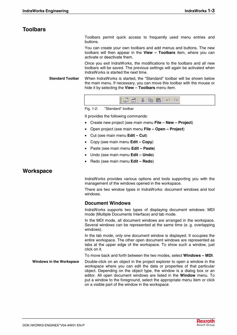
When IndraWorks is started, the "Standard" toolbar will be shown belowthe main menu. If necessary, you can move this toolbar with the mouse orhide it by selecting the View – Toolbars menu item.
Fig. 1-2: "Standard" toolbar
It provides the following commands:
• Create new project (see main menu File – New – Project)
• Open project (see main menu File – Open – Project)
• Cut (see main menu Edit – Cut)
• Copy (see main menu Edit – Copy)
• Paste (see main menu Edit – Paste)
• Undo (see main menu Edit – Undo)
• Redo (see main menu Edit – Redo)
WorkspaceIndraWorks provides various options and tools supporting you with themanagement of the windows opened in the workspace.
There are two window types in IndraWorks: document windows and toolwindows.
Document WindowsIndraWorks supports two types of displaying document windows: MDImode (Multiple Documents Interface) and tab mode.
In the MDI mode, all document windows are arranged in the workspace.Several windows can be represented at the same time (e. g. overlappingwindows).
In the tab mode, only one document window is displayed. It occupies theentire workspace. The other open document windows are represented astabs at the upper edge of the workspace. To show such a window, justclick on it.
To move back and forth between the two modes, select Windows – MDI.
Double-click on an object in the project explorer to open a window in theworkspace where you can edit the data or properties of that particularobject. Depending on the object type, the window is a dialog box or aneditor. All open document windows are listed in the Window menu. Toput a window to the foreground, select the appropriate menu item or clickon a visible part of the window in the workspace.
Standard Toolbar
Windows in the Workspace

1-4 IndraWorks IndraWorks Engineering
DOK-IWORKS-ENGINEE*V04-AW01-EN-P
Select the Windows – Windows menu item to open the "Window List…"where you can manage the windows opened in the workspace.
Fig. 1-3: "Window List…" dialog box
Tool WindowsTool windows are listed in the View – Other Windows menu item. Tochange the behavior of the tool windows, either use the system menu (byright-clicking on the title bar of the tool window) or the Window menu.
Tool windows are "dockable" by default. A tool window is opened either inthe floating mode or it is docked to the edge of the workspace. To dock afloating tool window to the edge of the workspace, just deselect the"dockable" property. This window will also be arranged as an additionaltab in the workspace. If you reselect the "dockable" property, the windowwill return to the position it had taken before you arranged it in theworkspace.
This command hides the active window. You can show the window againusing the View menu.
This command changes the window from the floating mode to the dockedmode and vice versa.
This setting hides the tool window at the edge of the borders such that it isonly indicated by a tab displaying the window title. To fully maximize thewindow again, just move the mouse pointer over the tab. In this manner,the workspace can be enlarged.
Arranging the WindowsIn the MDI mode, the windows in the workspace can be arranged in theoverlapping, cascading and tiled modes. To achieve this, select theappropriate command from the Window menu.
In the tap mode, document windows can be grouped. To achieve this, usethe commands of the system menu of the document windows. You canarrange document windows in vertical and horizontal groups and easilymove them from one group to the other.
Note: In the tab mode, you can drag-and-drop document windowswithin the document window area.
Using the system menu of the document windows in the MDI mode, youcan minimize, restore, close and move these windows as well as zoomthem in and out. Using the system menu in the tab mode, you can createnew horizontal and vertical groups, move document windows from onegroup to the other and close document windows. To activate thedocument windows one after the other, press <Ctrl>+<F6>.
Dockable
Hide
Floating
Auto Hide
Overlapping, Cascading, Tiled
Grouping Document Windows
System Menu of DocumentWindows

IndraWorks Engineering IndraWorks 1-5
DOK-IWORKS-ENGINEE*V04-AW01-EN-P
To display as large an area of your document as possible on the screen,activate the full-frame mode by selecting View – Full Screen. All toolwindows are hidden, and the workspace occupies the entire remainingarea. The menu bar is still shown. The "Customizing" dialog box allowsyou to add toolbars as you wish. The View menu allows you to displayany tool windows you wish, even in the full-frame mode. The configurationselected is stored on exiting the full-frame mode and will be restoredwhen it is called the next time. To return to the normal display mode, clickon the "Full Screen" button of the "Full Screen" toolbar. Alternatively, youcan also press <Ctrl>+<Alt>+<F> or use the menu.
Project ExplorerThe project explorer is arranged to the left of the workspace in theIndraWorks main window. The project explorer represents the projectsand their components in a structured manner.
ProjectA project contains all devices, communication connections and othercomponents required for operating a machine or system. The treestructure of these components reflects the device topology of theautomation solution.
DeviceA device is a components of a project, e. g. a control or a drive. Usually, adevice consists of a hardware section and a software section.
In IndraWorks, devices are selected from a library and added to a project.Then the functions available in the devices are called and/or lower-leveldevices are projected.
Library ExplorerThe library explorer is arranged to the right of the workspace in theIndraWorks main window. It represents all libraries available for yourprojects in a structured manner. Libraries can contain hardwarecomponents, i. e. devices, and software components, e. g. functionblocks.
Full Screen

1-6 IndraWorks IndraWorks Engineering
DOK-IWORKS-ENGINEE*V04-AW01-EN-P
1.2 Getting Started
This section describes some of the typical operating sequences inIndraWorks.
Follow these descriptions, and you will become familiar with how to useIndraWorks and recognize how the various components are cooperatingwith each other.
Starting IndraWorksStart IndraWorks via Start – All Programs – Rexroth – IndraWorks –Engineering.
Creating a New ProjectTo create a new IndraWorks project, select File – New – Project…
The "Create New IndraWorks Project" dialog box will appear. Enter aname for the project and select the directory where the project will befiled.
Fig. 1-4: "Create New IndraWorks Project" dialog box
Click "Browse…" to move to the Windows file browser and navigate to theproject directory desired. The language you select as the project languagewill be the master language of your user texts. To define the associatedletter types and font sizes, click "Fonts…".

IndraWorks Engineering IndraWorks 1-7
DOK-IWORKS-ENGINEE*V04-AW01-EN-P
Opening a ProjectTo open a project, select File – Open – Project… . .
Your personal directory "My Documents" is the default setting in the"Open project" dialog box. Move to the desired IndraWorks project andconfirm your selection with "Open". The project will now be uploaded.
Fig. 1-5: "Open project" dialog box
Adding a New Device to a ProjectThe library explorer displays all available devices of the libraries installed.
To add a device to the current project, drag the device from the library tothe project. Note that you can drag the device only directly to the projectfolder or to devices of the project which accept the currently selecteddevice type as a subordinate device.
Fig. 1-6: Devices in the library
Exiting IndraWorksExit IndraWorks by selecting File – Exit or by pressing <Alt>+<F4>.

1-8 IndraWorks IndraWorks Engineering
DOK-IWORKS-ENGINEE*V04-AW01-EN-P

IndraWorks Engineering Working with IndraWorks 2-1
DOK-IWORKS-ENGINEE*V04-AW01-EN-P
2 Working with IndraWorks
2.1 General Information
IndraWorks provides objects with various contents, called applicationdata. These objects can be created, managed, edited and filed in astructured manner, as files in an IndraWorks project. The workspace inIndraWorks consists of a top-level project. Each project can, in turn,contain a collection of folders and files. These objects are also calledresources.
2.2 Working with Projects and Devices
Projects and Project DataIn IndraWorks, devices and objects (resources) are compiled to projectswhich are represented in a tree structure in the project explorer. A projectis always at the uppermost hierarchy level. Only one project can beprocessed at a time.
All further nodes in the tree represent devices, communicationconnections, functions or merely structuring elements, e. g. folders, whichare comparable with directories in a file system. The figure below is anexample of a project with a drive.

2-2 Working with IndraWorks IndraWorks Engineering
DOK-IWORKS-ENGINEE*V04-AW01-EN-P
Fig. 2-1: Project in a tree structure
On principle, each node can provide a corresponding main menu entrywith subitems and a context-sensitive menu. The content and function ofthe commands provided in this menu are depending on the particularnode.
If necessary, the "Project" toolbar can be shown. When shown for the firsttime, this toolbar is floating, but can be moved to the desired position withthe mouse.
Fig. 2-2: "Project" toolbar
The "Project" toolbar provides the following commands:
• Switch project offline (see main menu Project – Offline)
• Switch project online (see main menu Project – Online)
• File project to archive (see main menu Project – Archive)
• Restore project (see main menu Project – Restore)

IndraWorks Engineering Working with IndraWorks 2-3
DOK-IWORKS-ENGINEE*V04-AW01-EN-P
To create a new project, select File – New – Project… or press<Ctrl>+>Shift>+<N>.
Enter a name for the project in the "Create New IndraWorks Project"dialog box and select the directory to which you wish to save the project.From the dialog box, select the master language for the project, i. e. thelanguage used for creating the project.
You can also define the fonts to be used for displaying the text, both forproportional fonts and for non-proportional fonts. This is particularlyrecommended for languages requiring specific fonts for displaying thetext, e. g. Asiatic languages.
Fig. 2-3: "Create New IndraWorks Project" dialog box
To open existing projects, select File – Open – Project… or press<Ctrl>+<Shift>+<O>. The "Open project" dialog box shows all projects inthe preset project path.
First select the folder of the project desired and then the project file. Thefile extension of project files is "iwp". The project is now uploaded.
Creating a New Project
Opening an Existing Project

2-4 Working with IndraWorks IndraWorks Engineering
DOK-IWORKS-ENGINEE*V04-AW01-EN-P
Fig. 2-4: "Open project" dialog box
The File – Recent Projects menu item provides a list of the projects youhave processed recently. You can also open the project by double-clicking on the respective entry in this list.
Fig. 2-5: "Recent Projects" menu item
Close a current project by selecting File – Close – Project. All changesyou have made will be saved automatically.
Recent Projects
Closing a Project

IndraWorks Engineering Working with IndraWorks 2-5
DOK-IWORKS-ENGINEE*V04-AW01-EN-P
You can change the project name by clicking on the activated project, byusing the context-sensitive menu or by pressing <F2>.
Note: It is only the name of the project file "*.iwp" that is modified.The name of the path and the directory where the projectname is residing remains unchanged.
To open the "Properties" dialog box, select a project and choose theProperties item from the context-sensitive menu. The "Properties" dialogbox displays the essential settings of the current project. In the selectionwindow to the left, you can move back and forth between path settings,modification times and states.
Fig. 2-6: "Properties" dialog box, "Paths"
Selecting "Paths" will provide information on the name and the memorylocation of the project.
Fig. 2-7: "Properties" dialog box, "Times"
Selecting "Times" will display the creation date and time as well as thetime and date of both the last write access and the last read access.
Renaming a Project
Properties

2-6 Working with IndraWorks IndraWorks Engineering
DOK-IWORKS-ENGINEE*V04-AW01-EN-P
Fig. 2-8: "Properties" dialog box, "States"
Selecting "States" will display the current state (offline, online) and theproject language selected.
An edited project is identified by an asterisk following the project name inthe title bar of the project explorer. To save an edited or a new project,select the Save Project XXX item from the context-sensitive menu. Whenyou close a project, all changes are saved automatically.
To save the currently open project to a different memory location with adifferent name, select the File – Save As menu item.
Fig. 2-9: "Save project as" dialog box
Saving a Project
Saving a Project As

IndraWorks Engineering Working with IndraWorks 2-7
DOK-IWORKS-ENGINEE*V04-AW01-EN-P
Enter a destination directory and a name for the project. After the dialogbox has been exited with "Save", IndraWorks saves and closes thecurrent project and creates a copy with the name selected in thedestination directory specified.
Note: All changes in the project structure and in the project datamade up to that point will also be included in the originalproject.
The project information file "*.iwp" is not directly filed to thedestination directory specified, but to a new directory havingthe same name.
1st special case:
The destination directory selected is already existing.
In this case, IndraWorks provides the option of deleting the directorybefore the copying step. If you do not wish to use this option, the "SaveAs" process is stopped.
Fig. 2-10: "Save IndraWorks project as" dialog box: delete destinationdirectory?
2nd special case:
If the destination directory contains an open IndraWorks project, theprocess is stopped and a corresponding message is displayed.
Fig. 2-11: "Save IndraWorks project as" dialog box, error message
Startup PictureUnless a project has been uploaded, the startup picture will be displayedautomatically when the Engineering Desktop is running up.
This startup picture is displayed in the following three cases:
• IndraWorks has been installed for the time.
• The project was closed before IndraWorks was exited the last time.
• The setting causing the previous project to be uploaded on start hasnot been activated.
The startup picture provides various options of creating or opening aproject. To activate the various functions, click on them or select themwith <Tab> and <Enter>.

2-8 Working with IndraWorks IndraWorks Engineering
DOK-IWORKS-ENGINEE*V04-AW01-EN-P
Once a project is uploaded, the startup picture is closed. You can showthe startup picture at any time by selecting the View – Show StartupPicture menu item.
Fig. 2-12: Startup picture
This function opens the "Create New IndraWorks Project" dialog box. It isequal to the File – New – Project item of the main menu.
This function creates an empty project with a defined name and starts thescanner to search for devices. At the same time, the "Configure" view isactivated (see "Scan for Devices").
This function opens a project which is filed to a local drive or a networkdrive. It is equal to the File – Open – Project item of the main menu.
This function restores a project from an archive residing on a local drive,a network drive or a removable disk. It is equal to the Project – Restore –From File System item of the main menu.
The list of recently opened projects displays the project name and thechanging date. To open a project, click on the project name. This functionis equal to the File – Recently Opened Projects item of the main menu.
If you check this checkbox, the startup picture will not be displayedautomatically when the Engineering Desktop is running up.
Create an Empty Project
Scan for Devices
Open Project
Restore Project
Recently Opened Projects
Hide on Next Startup

IndraWorks Engineering Working with IndraWorks 2-9
DOK-IWORKS-ENGINEE*V04-AW01-EN-P
Devices
Inserting Devices From the LibraryAdd devices to a project by drag-and-drop and by using the context-sensitive menu.
The context-sensitive menu provides the commands available in theparticular context concerned. The commands for editing the devices, suchas Cut, Delete, Copy, and Paste, are also provided in the Edit menu. Incontrast to the context-sensitive menu, inactive items are visible in themain menu. They are displayed in gray.
Select a device from the library and drag it to the project explorer.
The mouse pointer indicates possible insertion positions.
An arrow with a plus sign on a destination device with blue background(including the project itself) signals that the device can be inserted at thisposition.
Fig. 2-13: Insertion by drag-and-drop from the library
The new device is added to all devices inserted at this element.
Context-Sensitive Menu
Insertion by Drag-and-DropFrom the Library

2-10 Working with IndraWorks IndraWorks Engineering
DOK-IWORKS-ENGINEE*V04-AW01-EN-P
A circle with a backslash signals that it is not possible to insert a device atthis position.
Fig. 2-14: Insertion by drag-and-drop not allowed
You can also insert new devices in the project at certain selectedpositions.
Move the mouse to the desired destination position. This position isrepresented by a line. The background color of the associated destinationelement changes to blue.
In the first example, the new device is inserted in Device 1 betweenCommissioning drive and Device 1.1.
Fig. 2-15: Insertion at the desired destination position

IndraWorks Engineering Working with IndraWorks 2-11
DOK-IWORKS-ENGINEE*V04-AW01-EN-P
In the second example, the new device is inserted directly at the projectnode AssemblyLine, between Device 1 and Device 2.
Fig. 2-16: Insertion at the project node
You can also use the clipboard to add devices to a project.
Fig. 2-17: Pasting devices from the clipboard
Pasting via the Clipboard

2-12 Working with IndraWorks IndraWorks Engineering
DOK-IWORKS-ENGINEE*V04-AW01-EN-P
Note: You can also paste devices from foreign components to theproject explorer via the clipboard. This requires that acomplete description of the device be copied to the clipboardas XML text.
Devices in the Project ExplorerTo delete devices, press <Del> or use Delete.
The Cut command files a reference to the selected device to theclipboard.
The device prepared for cutting is identified by a special icon (arrowpointing to the upper right) and gray lettering as long as the deviceinformation resides in the clipboard. You can stop this process with<Esc>.
If you paste the device to a new position, it will be removed from itsoriginal position.
The Copy command applies a copy of the selected element to theclipboard. You can now paste the element to the destination position.
It is again possible to paste the device directly to an element or topositions intermediate the elements.
You can also copy, cut and paste devices by drag-and-drop. Drag adevice to a different possible position and it will be moved to that position.If you additionally press and hold <Ctrl> while you are doing this, a copy ofthe device is created at the destination position.
You can change the device name by clicking on the activated element, byusing the context-sensitive menu or by pressing <F2>.
The name of the element is displayed in the input mode. You can stop theediting process at any time with <Esc>. If the name entered is notaccepted, the original name is automatically re-entered.
To open a dialog or editor associated to a project node, double-click onthat project node or press <Enter>.
To view brief information on a device, place the mouse pointer on thatdevice for more than one second.
Fig. 2-18: Displaying tool tips for devices
Deleting Devices
Cutting Devices
Copying Devices
Copying, Cutting and Pastingwith the Mouse
Renaming Devices
Opening Node-Specific Dialogsand Editors
Tool Tips

IndraWorks Engineering Working with IndraWorks 2-13
DOK-IWORKS-ENGINEE*V04-AW01-EN-P
If the device-specific software signals an error, the device in question isshown with red letters. If the device in question belongs to a non-expanded part of the tree, the device that is visible at the next higher levelin the hierarchy is shown in red. The failed element itself is identified by ared exclamation mark in the icon.
Fig. 2-19: Displaying error states at devices
This shows failed elements immediately in the tree structure.
Fig. 2-20: Displaying error states at device nodes
Displaying Error States

2-14 Working with IndraWorks IndraWorks Engineering
DOK-IWORKS-ENGINEE*V04-AW01-EN-P
Deselected elements are shown in italics and with a gray background.
Fig. 2-21: Display of deselected elements in the project explorer
You can deselect a device through a check box. To view this check box,place the mouse on the icon.
Fig. 2-22: Deselecting devices in the project explorer
Deselected Elements

IndraWorks Engineering Working with IndraWorks 2-15
DOK-IWORKS-ENGINEE*V04-AW01-EN-P
Elements can be disabled if, for example, the element in question cannotbe reached in the particular context. Disabled elements are shown withlight-gray letters in the tree structure; the icon of the device is lightened.Such elements cannot be reached or modified by commands any longer.
Fig. 2-23: Disabled elements in the project explorer
Using the context-sensitive menu New – Folder, new folders can beadded to the structure at permissible positions.
As can be done with devices, folders can also be moved, copied, deletedand renamed.
Fig. 2-24: Restructuring with folders
Disabled Elements
Restructuring with Folders

2-16 Working with IndraWorks IndraWorks Engineering
DOK-IWORKS-ENGINEE*V04-AW01-EN-P
Using the LibraryThe library contains all devices available on the platform. The library usesdata from the standardized device description file, which is required forconfiguration and parameterization. This data is filed to the"Runtime\Library\Devices\Group name" directory in a structure andsubdivided according to manufacturers.
Function AreasThe library is subdivided in a navigation area with the tree structurerepresenting all devices installed and in an area providing currentinformation on the device selected.
The navigation area is subdivided in library groups. The various groupsare subdivided according to manufacturers and functional components.The devices are defined by their name and the device-specific icon.
Once you have selected an element from the navigation area, the currentdata on the device is displayed in the information area.
1: Library group with its own tree2: Folders3: Devices4: Module for the device5: Navigation area6: Information area
Fig. 2-25: Function areas of the library
Navigation Area
Information Area

IndraWorks Engineering Working with IndraWorks 2-17
DOK-IWORKS-ENGINEE*V04-AW01-EN-P
OperationYou can navigate in the tree structure of the devices with the cursor keysand with the mouse.
To expand nodes at the "plus" sign, press the <cursor right> key ordouble-click; to close the nodes at the "minus" sign, press the <cursorleft> key or double-click.
Devices are applied from the library to the project navigator by drag-and-drop (see "Inserting Devices From the Library", p. 2-9). After insertion, thesoftware package relating to the device is started.
You can also use the Copy and Paste functions and the clipboard for theinsertion of devices.
Devices are added by copying new device description files or completestructures to the "Runtime\Library\Devices\Group name" directory. Theassociated data is automatically applied to the graphical representationwhen the platform is started the next time. Copying data on the level oflibrary groups is not allowed.
Filing and Restoring ProjectsIndraWorks provides the option of filing projects to archives on the localfile system or on a device connected through a network. These archivescan be restored on the file system of the local computer.
While working with project archives, you are supported by a wizard. Ifallowed by the parameter entries, you can move back and forth amongthe various pages of the wizard by clicking on the "<<Back" and "Next>>"buttons. When a page is opened for the first time, default values are pre-assigned to the input boxes. Otherwise, your last entries will be displayed.You can exit the wizard at any time with "Cancel". Values entered up tothat point will not be saved; the archiving process is stopped.
Archiving ProjectsTo archive a project, select it from the project explorer and chooseArchive… from the context-sensitive menu, Project – Archive from themain menu, or the following button from the toolbar:
Fig. 2-26: "Project" toolbar
Filing a Project to an Archive on a File SystemThe first page of the wizard prompts you to select whether you wish tosave the archive to a local file system or to a device connected through anetwork. In this case, select "Archive in file system".
Proceed to the next page to define the filing location, the name of thearchive and a comment on the archive. Enter a directory of your local filesystem for the filing location or select it with the "…" button.
Optionally, the archive can be protected by a password. Enter thepassword a second time in the "Confirm password" field to verify yourentry.
Navigation
Applying Devices to the Project
Expanding the Library
Selecting the Archive Type
Settings for Destination Archive

2-18 Working with IndraWorks IndraWorks Engineering
DOK-IWORKS-ENGINEE*V04-AW01-EN-P
Fig. 2-27: Archiving a project on a file system: destination archive settings
This page allows a check of your settings. Start creation of the archive byclicking the "Finish" button.
Fig. 2-28: Filing a project to an archive on a file system, check of entries
Checking the User Entries

IndraWorks Engineering Working with IndraWorks 2-19
DOK-IWORKS-ENGINEE*V04-AW01-EN-P
The archive is created in the destination directory of the local computer.This process is indicated by a progress bar.
After archiving has been completed, settings and results are displayed.
Note: To avoid inconsistencies during archiving, the active project isclosed before and re-opened after archiving.
Fig. 2-29: Filing a project to an archive on a file system; archiving results
"Create Archive"Progress Bar
Summary

2-20 Working with IndraWorks IndraWorks Engineering
DOK-IWORKS-ENGINEE*V04-AW01-EN-P
Filing a Project to an Archive on a DeviceThe first page prompts you to select whether you wish to save the archiveto a local file system or to a device connected through a network. In thiscase, select "Archive on device".
On this page, you can define the destination device, the name of thearchive and a comment on the archive.
Fig. 2-30: Filing a project to an archive on a device; device and settings fordestination archive
In the "Device" input box, enter the destination device to which you wishto save the archive. There are four options:
• IP address (nnn.nnn.nnn.nnn)
• Computer name of the destination device
• Selection via a drop-down list box. This list box contains all FTPcapable devices of the active project as well as the last five devicesused in archiving.
• Selection via the "…" button. Apply the destination device from the listof all FTP capable devices shown for the active project.
Enter a name for filing the archive to the destination device. You can alsoenter a comment related to the archive.
Optionally, the archive can be protected by a password. Enter thepassword a second time in the "Confirm password" field to verify yourentry.
Confirm with "Next". The wizard will then automatically establish aconnection to the device set. Disturbances in the connection to thedestination device are displayed by means of error messages.
Selecting the Archive Type
Settings for Destination Archive
Device
Archive Name, Comment,Password
Establishing the Connection

IndraWorks Engineering Working with IndraWorks 2-21
DOK-IWORKS-ENGINEE*V04-AW01-EN-P
This page allows a check of your settings. Start creation of the archive byclicking the "Finish" button.
Fig. 2-31: Filing a project to an archive on a device; check of entries
While archiving is in progress, a temporary archive will initially be createdon the local computer. This process is indicated by a progress bar.
After having been created, the archive is copied to the destination device.This process is indicated by a second progress bar.
Checking the User Entries
1st Progress Bar: "CreateTemporary Archive"
2nd Progress Bar: "Copy Archiveto Destination Device"

2-22 Working with IndraWorks IndraWorks Engineering
DOK-IWORKS-ENGINEE*V04-AW01-EN-P
After archiving has been completed, settings and results are displayed ina summary.
Note: To avoid inconsistencies during archiving, the active project isclosed before and re-opened after archiving.
Fig. 2-32: Filing a project to an archive on a device: archiving results
Restoring ProjectsTo restore a project, select Project – Restore… from the main menu orthe following tool button in the toolbar:
Fig. 2-33: "Project" toolbar
Summary

IndraWorks Engineering Working with IndraWorks 2-23
DOK-IWORKS-ENGINEE*V04-AW01-EN-P
Restoring a Project from a File SystemThe first page of the wizard prompts you to select whether you wish torestore the project from an archive of the local file system or from adevice connected through a network. In this case, select "Restore fromfile system".
Select the archive from the next page. Click on the "…" button to searchfor the archive.
This will display the comment related to the archive selected.
Fig. 2-34: Restoring a project from a file system; selecting the archive
Note: If the archive type is unknown, the comment area will displaythe message "***ATTENTION! The selected archive is not anIndraWorks project archive ***". In this case, you can continuethe restore process after having confirmed a safety prompt.
Selecting the Restore Type
Selecting the Archive

2-24 Working with IndraWorks IndraWorks Engineering
DOK-IWORKS-ENGINEE*V04-AW01-EN-P
On this page, select the directory to which you wish to restore the project.
Fig. 2-35: Restoring a project from a file system; select destination directory
This page allows a check of your settings. Start restoration of the projectfrom the archive by clicking the "Finish" button.
Fig. 2-36: Restoring a project from a file system; check of entries
Selecting the DestinationDirectory
Checking the User Entries

IndraWorks Engineering Working with IndraWorks 2-25
DOK-IWORKS-ENGINEE*V04-AW01-EN-P
If you have protected the archive with a password, you will now beprompted to enter that password.
The project is initially restored from the archive and to a temporarydirectory of the local drive. This process is indicated by a progress bar.After restoration is completed, the project is copied to the destinationdirectory.
If a project folder is already contained in the destination directoryspecified, you will be prompted to rename the project folder.
Fig. 2-37: Restoring a project from a file system; renaming the project folder
After restoration, settings and results are displayed.
Fig. 2-38: Restoring a project from a file system; results
Entering a Password
Progress Bar:"Restore on Temporary
Directory"
Summary

2-26 Working with IndraWorks IndraWorks Engineering
DOK-IWORKS-ENGINEE*V04-AW01-EN-P
Restoring a Project from a DeviceOn the first page, you can select whether you wish to restore the projectfrom an archive of the local file system or from a device connectedthrough a network. In this case, select "Restore from device".
Select the device and the archive name from this page.
Fig. 2-39: Restoring a project from a device; selecting the archive
In this field, enter the device where the archive to be restored is residing.There are four options:
• IP address (nnn.nnn.nnn.nnn)
• Computer name of the destination device
• Selection via a drop-down list box This list box contains all FTPcapable devices of the active project as well as the last five devicesused in archiving.
• Selection of a device via the "…" browser button.
If you select the device from the drop-down list box or the device browser,the connection to the device selected is established automatically.
If you enter the IP address or the computer name, establish theconnection to the destination device by clicking the "Connect" button.
After the connection has been established, all archives available on thedevice are displayed in the "Archive overview" list. Select the archive to berestored and click the "Next>>" button.
Selecting the Restore Type
Selecting the Archive
Device

IndraWorks Engineering Working with IndraWorks 2-27
DOK-IWORKS-ENGINEE*V04-AW01-EN-P
From the local drive, select a directory to which you wish to restore theproject from the archive.
Fig. 2-40: Restoring a project from a device; selecting the destination directory
This page allows a check of your settings. Start restoration by clicking the"Finish" button.
Fig. 2-41: Restoring a project from a device; check of entries
Selecting the Destination Directory
Checking the User Entries

2-28 Working with IndraWorks IndraWorks Engineering
DOK-IWORKS-ENGINEE*V04-AW01-EN-P
While restoration is in progress, the archive is initially copied from thedevice to the local drive. This process is indicated by a progress bar.
If you have protected the archive with a password, you will now beprompted to enter that password.
The project is then restored from the archive and to a temporary directoryof the local drive. This process is indicated by a progress bar. Afterrestoration is completed, the project is copied to the destination directory.
If the destination directory selected is already existing, you will beprompted to enter a new one.
After restoration has been completed, settings and results are displayed.
Fig. 2-42: Restoring a project from a device; results
1st Progress Bar: "Get Archivefrom Destination Device"
Entering a Password
Progress Bar:"Restore on Temporary
Directory"
Summary

IndraWorks Engineering Working with IndraWorks 2-29
DOK-IWORKS-ENGINEE*V04-AW01-EN-P
Activating a Project for the Operation DesktopIndraWorks Operation can only be started with an activated project.
Fig. 2-43: Rexroth IndraWorks Operation message window
To activate the project, proceed as follows:
1. Start the Engineering Desktop and open the project for which youwish to activate the Operation Desktop.
2. Execute an HMI download for the HMI device (e. g. BTV 40) availablein the project.
3. Activate the project via Project – Activate for Operation.4. Exit the Engineering Desktop.5. Start the Operation Desktop.The Operation Desktop will now visualize the activated project.
Scan for DevicesIndraWorks provides the option of scanning for available devices of theinstalled libraries. This option is supported by a wizard.
Depending on the device type selected, you can scan the devices via theserial interface or the Ethernet, PCI or Profibus interface.
To call the wizard, select an empty project, switch to the online mode andselect Scan for devices… from the context-sensitive menu.
The project is switched to the online mode automatically, if you selectProject – Scan for devices… from the main menu or the following buttonfrom the toolbar:
Fig. 2-44: Toolbar: scan for devices
If you open a page of the wizard for the first time, default values areassigned to the input boxes. Otherwise, the previous values you haveentered for a successful scan for a device and application to a project willbe displayed.If allowed by the parameter entries, you can move back and forth amongthe various pages of the wizard by clicking on the "<<Back" and "Next>>"buttons.
The last page (the scan dialog) provides the "Finish" button which isactive once a device has been found. This button stops the scan process;the found devices are applied to the project. Any values you entered onthe wizard pages up to that point will be saved for future scanning.
You can exit the wizard at any time with "Cancel". Changed values will notbe saved, and the scan process is canceled.

2-30 Working with IndraWorks IndraWorks Engineering
DOK-IWORKS-ENGINEE*V04-AW01-EN-P
OperationFirst select the device types you wish to scan for. Select the appropriateentries from the "Installed" list and apply them with the "right arrow", bydouble-clicking or by drag-and-drop. The devices selected can bedeselected with the "left arrow", by double-clicking or by drag-and-drop.The scan order can be changed by the "up" and "down" arrows.
Fig. 2-45: Scan for devices; selecting the devices
Click the "Next>>" button to move to the next dialog. This dialog dependson the interface used to scan for the device. The interface (serial,Ethernet, PCI, Profibus) is specified with the device type.
Select Devices

IndraWorks Engineering Working with IndraWorks 2-31
DOK-IWORKS-ENGINEE*V04-AW01-EN-P
If you have selected a device type allowing the scanning via a serialinterface, the following dialog box will be displayed.
Fig. 2-46: Scan for devices, serial device data
To define the COM ports to be used for scanning for a device, apply theappropriate entries of the "Available" list with the "right arrow", by double-clicking or by drag-and-drop. Any selected COM ports can also bedeselected. The scan order can be changed by the "up" and "down"arrows.
In addition, the parity and the baudrate must be selected for the scanning.You can set the device to a defined baudrate. To achieve this, check the"Adjust baudrate" check box. In this case, only one baudrate can beselected.
Note: If you adjust the baudrate, existing configurations might bechanged. As a result, devices that have already beenconfigured might not be functioning properly any longer afterthe scan process.
Click "Advanced…" to open a dialog box where you can enter the timeoutfor the device type used by the scanner.
Note: The scanner attempts to establish a communicationconnection to the devices to be scanned. This timeout is thetime interval available to the connected devices for respondingto a request of the scanner, thus identifying themselves. Thescan process is decelerated by a high timeout value andaccelerated by a low timeout value. If the timeout is too low,the scanner might fail to detect all devices.
Note: We recommend to use the default timeout value.
Settings for the Serial Interface

2-32 Working with IndraWorks IndraWorks Engineering
DOK-IWORKS-ENGINEE*V04-AW01-EN-P
To reset any changed values to the default values of the library, click onthe "Default setting" button.
If you have selected COM port, baudrate and parity, the "Next>>" buttonis activated. Click this button to move to the next setting dialog box or tothe scan dialog box.
If you have selected a device type allowing the scanning via an Ethernetinterface, the following dialog box will be displayed.
Fig. 2-47: Scan for devices, Ethernet device data
You must enter at least one IP address and one IP port. But you can alsoenter ranges. In this case, the IP addresses may only differ from eachother in the final numerical range. Moreover, the input boxes for the IPaddresses contain a drop-down list box with the recent ten valid IPaddresses. Open this list box by pressing <F4> or clicking on the "downarrow" and select an IP address.
If you enter invalid characters and special characters, a red circle with awhite exclamation mark will be displayed when you exit the input box. Thetool tip for this icon displays the cause of this message.
Click "Advanced…" to open a dialog box where you can enter the timeoutfor the device type.
Note: The scanner attempts to establish a communicationconnection to the devices to be scanned. This timeout is thetime interval available to the connected devices for respondingto a request of the scanner, thus identifying themselves. Thescan process is decelerated by a high timeout value andaccelerated by a low timeout value. If the timeout is too low,the scanner might fail to detect all devices.
Note: We recommend to use the default timeout value.
Settings for the EthernetInterface

IndraWorks Engineering Working with IndraWorks 2-33
DOK-IWORKS-ENGINEE*V04-AW01-EN-P
To reset any changed values to the default values of the library, click onthe "Default" button.
If you have selected an IP address and an IP port, click the "Next>>"button to move to the next setting dialog box or to the scan dialog box.
If you have selected a device allowing the scanning via a PCI interface,you do not have to enter any further data. The next setting dialog box orthe scan dialog box will be opened directly.
If you have selected a device allowing the scanning via a Profibusinterface, the following dialog box will be displayed.
Fig. 2-48: Scan for devices, Profibus device data
Enter a baudrate and an address for the Profibus master.
In addition, the ident number of the device type is displayed, but cannotbe edited.
If you enter invalid characters, special characters or a number outside ofthe value range, a red circle with a white exclamation mark will bedisplayed when you exit the input box. The tool tip for this icon displaysthe cause of this message.
Click "Advanced…" to open a dialog box where you can enter the timeoutfor the device type used by the scanner.
Note: The scanner attempts to establish a communicationconnection to the devices to be scanned. This timeout is thetime interval available to the connected devices for respondingto a request of the scanner, thus identifying themselves. Thescan process is decelerated by a high timeout value andaccelerated by a low timeout value. If the timeout is too low,the scanner might fail to detect all devices.
Note: We recommend to use the default timeout value.
Settings for PCI
Settings for Profibus
2-34 Working with IndraWorks IndraWorks Engineering
DOK-IWORKS-ENGINEE*V04-AW01-EN-P
To reset any changed values to the default values of the library, click onthe "Default" button.
If you have selected an address and a baudrate for the bus master, clickon the "Next>>" button to move to the next setting dialog box or to thescan dialog box.
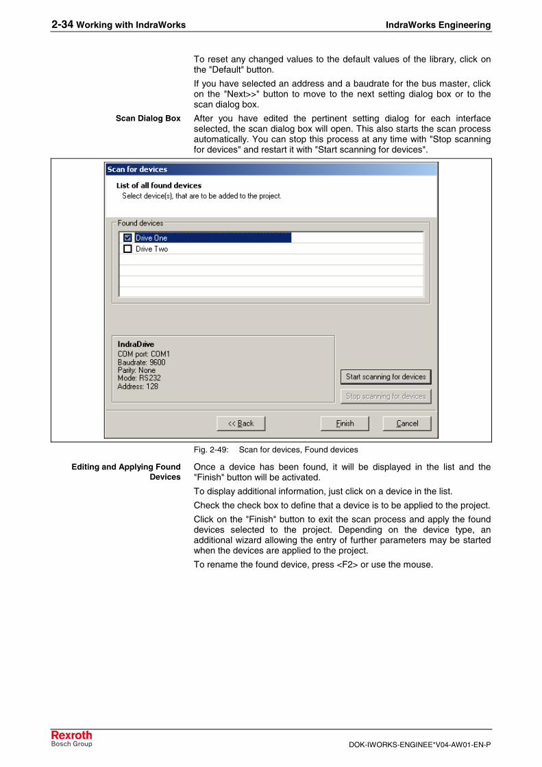
After you have edited the pertinent setting dialog for each interfaceselected, the scan dialog box will open. This also starts the scan processautomatically. You can stop this process at any time with "Stop scanningfor devices" and restart it with "Start scanning for devices".
Fig. 2-49: Scan for devices, Found devices
Once a device has been found, it will be displayed in the list and the"Finish" button will be activated.
To display additional information, just click on a device in the list.
Check the check box to define that a device is to be applied to the project.
Click on the "Finish" button to exit the scan process and apply the founddevices selected to the project. Depending on the device type, anadditional wizard allowing the entry of further parameters may be startedwhen the devices are applied to the project.
To rename the found device, press <F2> or use the mouse.
Scan Dialog Box
Editing and Applying FoundDevices

IndraWorks Engineering Working with IndraWorks 2-35
DOK-IWORKS-ENGINEE*V04-AW01-EN-P
Offline and Online Modes
Offline ModeWhen a new project is created or when an existing project is opened,IndraWorks is in the offline mode. Any changes of project data will besaved to the project, but they will not have any effect on the data in thedestination devices yet.
The offline mode of the user interface is shown in the status bar ofIndraWorks:
• The status bar displays "Offline".
• A diagram next to the text symbolizes the offline mode.
Fig. 2-50: Status bar, offline mode
Online ModeIn the online mode, your changes to the project will be saved andsimultaneously be transferred to the data memory of the destinationdevice.
CAUTION
Material damage may be caused by failures inthe activation of motors and moving elements!⇒ In the online mode, considerable material damage or
personal injury may be caused by an inadvertenttransfer of data to the destination device. For thatreason, please be absolutely sure to verify that, ifyou edit the project data, this will not cause anydamage or injury before you make that change.
The online mode of the user interface is shown in the status bar ofIndraWorks:
• The status bar displays "Online".
• A diagram next to the text symbolizes the online mode.
Fig. 2-51: Status bar: online mode
Offline Mode Display
Online Mode Display

2-36 Working with IndraWorks IndraWorks Engineering
DOK-IWORKS-ENGINEE*V04-AW01-EN-P
Switching Back and Forth Between Offline and Online
What Happens?Once you switch a project to the online mode, IndraWorks performs thefollowing steps:
• In the first step, IndraWorks attempts to establish a communicationconnection to all devices in the project (communication adjustment).
• In the second step, IndraWorks checks whether the projected devicestructure is equal to the existing device structure (structureadjustment).
• In the third step, IndraWorks verifies whether the projectedconfiguration of each device is equal to the existing configuration(configuration adjustment).
• In the final step, IndraWorks compares the data of each device in theproject with the appropriate data in the destination device (dataadjustment).
A device will not be switched to the online mode before all the abovesteps have been completed successfully.
The sections below will provide a detailed description of these steps.
How to ProceedSwitch a project to the online mode by selecting Project – Online.
Fig. 2-52: Switching to the online mode
Communication AdjustmentIn the first step, the communication connection to the devices of theproject is verified. If IndraWorks can communicate with all devices, thestructure adjustment is automatically carried out in the next step.Otherwise, you can
• search (scan) for a device,
• or stop switching the device in question to the online mode.
Fig. 2-53: Switching to the online mode: communication connection message
The scanner is used for searching a device (see "Scan for Devices", p. 2-29).
If the scanning is successful, the communication settings of the deviceare applied. If the scanning is not successful, switching the device to theonline mode is stopped.
Four Switching Steps
Checking the CommunicationConnection
Scanning for a Device

IndraWorks Engineering Working with IndraWorks 2-37
DOK-IWORKS-ENGINEE*V04-AW01-EN-P
Structure AdjustmentIn the structure adjustment step, IndraWorks checks whether theprojected device structure is equal to the existing structure. For example,the device peripherals for a control are checked as follows:
• number and type of the drives connected,
• number and type of the I/O bus users connected.
Note: The structure adjustment depends on the device type. Fordetails on switching a device to the online mode, please referto the present documentation.
If the projected structure is equal to the existing structure, theconfiguration adjustment is carried out in the next step.
If the data in the project is different from the data in the destinationdevice, then this is shown in a tool window. The tool window provides thefollowing information:
• overview of structural inconsistencies,
• data set in the project,
• data existing in the destination device,
• cause of the problem,
• possible solution to the problem.
Fig. 2-54: Switching to the online mode, information on inconsistencies foundin the structure adjustment
Once you have eliminated the problem, you can restart the switchingsteps. If IndraWorks does not detect any differences in the structures anylonger, the configuration adjustment is carried out as the next step.
Eliminating StructuralInconsistencies

2-38 Working with IndraWorks IndraWorks Engineering
DOK-IWORKS-ENGINEE*V04-AW01-EN-P
Configuration AdjustmentThe configuration of the various devices must be adjusted (e. g. theprojected drive number may be different from the actually set number of adrive in a Sercos ring).
Note: The configuration adjustment depends on the device type. Fordetails on switching a device to the online mode, please referto the present documentation.
If the projected configuration is equal to the existing configuration, thedata adjustment is carried out in the next step.
If the data in the project is different from the data in the destinationdevice, then this is shown in a tool window. The tool window provides thefollowing information:
• overview of configuration inconsistencies,
• data set in the project,
• data existing in the destination device,
• cause of the problem,
• possible solution to the problem.
Once you have eliminated the problem, you can restart the switchingsteps. If IndraWorks does not detect any differences in the configurationsany longer, the data adjustment is carried out in the next step.
Data AdjustmentThe data of the various devices must be adjusted, for example:
• motion program of a control,
• velocity limitation of a drive.
Note: The data adjustment depends on the device type. For detailson switching a device to the online mode, please refer to thepresent documentation.
If the data in the project is different from the data in the destinationdevice, then this is shown in a tool window. The tool window provides thefollowing information:
• overview of data inconsistencies,
• data set in the project,
• data existing in the destination device,
• cause of the problem,
• possible solution to the problem.
Once you have eliminated the problem, you can restart the switchingsteps. If IndraWorks does not detect any data differences any longer,switching to the online mode is completed.
Eliminating ConfigurationInconsistencies
Eliminating Data Inconsistencies

IndraWorks Engineering Working with IndraWorks 2-39
DOK-IWORKS-ENGINEE*V04-AW01-EN-P
2.3 Adding Files to an IndraWorks Project
IntroductionExisting files can be added to an IndraWorks project, so thatdocumentations, data sheets or additional information can be transferredwith the project.
The embedded file is displayed in the project. To edit the file, call thecurrently registered application in IndraWorks.
Adding a FileIf a project node allows the insertion of files, the context-sensitive menuprovides the Add – File item.
Fig. 2-55: Adding files to a project
Selecting this menu item opens the "Open" dialog box.
Fig. 2-56: "Open" dialog box
Select a file and insert a copy of this file in your project by clicking on the"Open" button. The file can then be edited there.

2-40 Working with IndraWorks IndraWorks Engineering
DOK-IWORKS-ENGINEE*V04-AW01-EN-P
Fig. 2-57: File inserted in the project
The icon used is the default icon of this file type. The name is equal to thefile name without filename extension.
Editing a FileTo open the embedded file, double-click on it, press <Enter> or use thecontext-sensitive menu. IndraWorks will then start the applicationregistered for editing in the Windows operating system.
Fig. 2-58: Editing an embedded file
In the case shown above, Acrobat Reader (PDF) will be started.
Note: IndraWorks can start the editing application when the file isopened and exit it when the project is closed or the userinterface is run down.
All other actions, such as printing or saving a file, are executedthrough the editing application.
Open

IndraWorks Engineering Working with IndraWorks 2-41
DOK-IWORKS-ENGINEE*V04-AW01-EN-P
If there is no registered application or if you wish to register a differentapplication, select Open with… from the context-sensitive menu.
Fig. 2-59: Inserted file, Open with…
From the "Open with" dialog box, select an application for editing your file.If you check the check box "Always use the selected program to open thiskind of file", this application will be used for all further editing actions.
Fig. 2-60: "Open with" dialog box
Note: This dialog box does not start modally, i. e. if you click on theIndraWorks desktop while this dialog box is open, it willdisappear to the background. To put it to the foreground again,press <Alt-Tab>.
Open with…

2-42 Working with IndraWorks IndraWorks Engineering
DOK-IWORKS-ENGINEE*V04-AW01-EN-P
To move the file in the project, select Cut and Paste. You can also usedrag-and-drop.
If you use the Copy and Paste functions, a copy of the file will be createdat a different point in the project.
To remove the file from the project, select the Delete item. If started, theediting program will be exited.
To rename the file, press <F2> or use the context-sensitive menu.
Select Properties… from the context-sensitive menu to open the"Properties" dialog box, which depends on the type of the embedded file.
Fig. 2-61: "Properties" dialog box
This dialog is not modal either.
Removing a File from the ProjectTo remove embedded files from the project, select the Delete item. Thesubdirectory containing the file will be moved to the Windows recycle bin,together with the file.
Cutting, Copying, Pasting
Delete
Rename
Properties

IndraWorks Engineering Working with IndraWorks 2-43
DOK-IWORKS-ENGINEE*V04-AW01-EN-P
2.4 Working with the Workspace
IntroductionThe workspace contains and manages the projects created by the user.In addition, the projects of the workspace may contain specifically defineddevices. Projects and devices are represented in a tree structure.
Each entry comprises an icon and a name. The device icons are specifiedby the device itself.
New projects are inserted either via the context-sensitive menu of theworkspace or by drag-and-drop from the project explorer.
Workspace StructureThe workspace consists of a navigation area with the tree structure whichrepresents all projects inserted by the user and their specifically defineddevices.
The root of the tree is always the workspace.
The projects desired can be inserted, created and deleted at the levelsbelow the workspace.
Fig. 2-62: Workspace in IndraWorks

2-44 Working with IndraWorks IndraWorks Engineering
DOK-IWORKS-ENGINEE*V04-AW01-EN-P
Workspace
Creating a WorkspaceProjects can only be inserted if a workspace has been created or loaded.
To create a new workspace, select the File – New – Workspace item.
Fig. 2-63: Workspace, creating a new workspace
The following window appears:
Fig. 2-64: "Create New IndraWorks Workspace" dialog box
Enter any name and directory for the workspace you wish.

IndraWorks Engineering Working with IndraWorks 2-45
DOK-IWORKS-ENGINEE*V04-AW01-EN-P
Opening the WorkspaceTo open already existing workspaces, select the File – Open –Workspace item.
Fig. 2-65: Opening a workspace
You can then select a workspace from the dialog box that appears. Thefilename extension of the corresponding files is ".iww".
Deleting a WorkspaceThe context-sensitive menu of the workspace node provides the option ofdeleting the workspace.
Fig. 2-66: Deleting a workspace
Note: The "Delete" item only deletes the workspace from the datamedium, not the projects it contains.

2-46 Working with IndraWorks IndraWorks Engineering
DOK-IWORKS-ENGINEE*V04-AW01-EN-P
Projects in the Workspace
Adding ProjectsThe workspace is intended to comprise and manage several projects.There are various ways of adding projects to the workspace.
Using the context-sensitive menu, you can add existing projects. Selectthe Add – existing project item. The options provided in the dialog boxthat appears is the same as those when projects are opened.
Fig. 2-67: Workspace, adding projects
Select the Add – new project item to insert new projects to theworkspace.
Note: Projects that have been created in the workspace will beopened directly in the project explorer.
You can also move projects from the project explorer to the workspace bydrag-and-drop.
Opening a ProjectTo open a project, double-click on the project name in the workspace oruse the context-sensitive menu.
The status of the project is indicated by the icon in the tree structure.
Icon Description
Project available but not opened
Project deleted or no connection to source computer
Project opened in the project explorer
Fig. 2-68: Project status, icons
Deleting a ProjectAny project can be removed from the workspace by using its context-sensitive menu.
Note: However, the project will not be deleted, only its reference isremoved from the workspace.

IndraWorks Engineering Working with IndraWorks 2-47
DOK-IWORKS-ENGINEE*V04-AW01-EN-P
PropertiesThe context-sensitive menu of a project can be used to display theproperties of that project.
Fig. 2-69: "Properties" dialog box
The dialog box displays the times when the project has been created andedited as well as the path.
The output can be specifically expanded by the devices inserted in theproject.
Devices in Projects"Top-level" devices are also displayed in the explorer of the workspacebelow their associated project. Use the context-sensitive menu to addressfunctions for and view properties of these devices. Devices which do notbelong to the "top level" are not displayed in the explorer of theworkspace.
2.5 Persistence
IndraWorks opens the previously opened project on the next start.
Windows arranged in the document window area before IndraWorks hasbeen exited will be provided there after restart.
If the workspace is empty after start, you can create a new project oropen an existing project.

2-48 Working with IndraWorks IndraWorks Engineering
DOK-IWORKS-ENGINEE*V04-AW01-EN-P
2.6 Multilingual Projects
The language and text management integrated in IndraWorks allows tocreate and edit multilingual projects. The multilingual function relates tothe language of the user texts (e. g. projectable messages, texts in HMIscreens, program comments). Do not mistake this multilingual function forthe language of the user interface.
We recommend to proceed as follows:
• Create the project and select the master language.
• Plan the project (all texts are entered in the master language).
• Add the desired additional languages to the project.
• Export each user text of the project to its translation file per additionallanguage.
• Translate the texts, i. e. edit the translation files.
• Import the translated texts to the project.
Defining the Master Language of a ProjectThe language used for originally creating an IndraWorks project is calledthe master language. At a later point, any number of further languagescan be added to the project, in addition to the master language.
Define the master language in the "Project language" list box of the"Create New IndraWorks Project" dialog box while you create a newproject.
Fig. 2-70: "Create New IndraWorks Project" dialog box
Use the "Fonts" button to define the fonts for the text display. This isparticularly recommended for languages requiring specific fonts fordisplaying the text, e. g. Asiatic languages.
The default setting for the fonts of the master language is as follows:
Proportional font: Arial, 10 points
Non-proportional font: Courier New, 10 points
Creating and Editing MultilingualProjects

IndraWorks Engineering Working with IndraWorks 2-49
DOK-IWORKS-ENGINEE*V04-AW01-EN-P
Managing Project LanguagesTo add a new language to the project, select Project – Language –Manage Project Languages.
Fig. 2-71: "Manage Project Languages" dialog box
To open the "Add Project Language" dialog box, click on the "Add…"button in the "Manage Project Languages" dialog box.
Fig. 2-72: "Add Project Language" dialog box
Adding a New Language to theProject

2-50 Working with IndraWorks IndraWorks Engineering
DOK-IWORKS-ENGINEE*V04-AW01-EN-P
Select the language you wish to add to the project.
Fig. 2-73: "Manage Project Languages" dialog box
Repeat this process until you have added all necessary languages to theproject.
To change the font of an additional language, select the language fromthe "Additional languages" list and click on "Fonts…".
Click on "Close" to return to the IndraWorks main window.
Note: When a new language is added, the internal text memoriesare prepared to incorporate and manage texts in thislanguage. Translations to this language are, however, notmade.
Note: Any of the languages added to the project can be selected tobe the active language. As a result, all entered language-specific user texts are filed to the text memories of thelanguage in question at and after this point.
Editing in an additional language is only suitable for correctinga text or for making minor changes to a project.
For actual project planning, we explicitly recommend that youwork in the master language only and do not add newlanguages and translate user texts until the project has beencompleted technically.
If you wish to expand or revise a project, we also recommendthat you first proceed in the master language and translate thenew user texts only thereafter.
To remove a language from the project, select Project – Language –Manage Project Languages. Select the language to be deleted from the"Additional languages" list and click on the "Delete…" button. Confirm thesubsequent safety prompt.
Deleting an Additional Languagefrom the Project

IndraWorks Engineering Working with IndraWorks 2-51
DOK-IWORKS-ENGINEE*V04-AW01-EN-P
External Project TranslationIndraWorks is provided with an export/import interface for the texts of aproject. This data interface allows to export texts to a translation file whichcan then be translated outside of IndraWorks.
To do this, you need a spreadsheet program which is able to read andwrite *.csv files and which supports UNICODE.
For example, Microsoft Excel 2003 or OpenOffice.org Calc are suitablefor editing translation files. The operation of these two programs differsonly in the setting of text export and text import filters for opening andsaving the translation files.
After the translation is completed, import the translation file. IndraWorksassigns the appropriate translations from the translation file to the originaltexts in the project.
The sections below describes the translation of the texts of a translationfile by the example of OpenOffice.org Calc.
The following steps are required:
1. Export the translation file from IndraWorks.2. Import the translation file to OpenOffice.org Calc.3. Translation of the texts. The translated texts are inserted in the
translation file.4. Export the translation file from OpenOffice.org Calc.5. Import the translation file to IndraWorks.
Exporting the Translation File from IndraWorksTo open the "Export Translation File" dialog box, select the Project –Language – Export Translation File item.
Fig. 2-74: "Export Translation File" dialog box
In this list box, define the language version of the texts which will bewritten to the translation file as original text.
The language preset in this list box after opening of the dialog box is themaster language. You can also select any other language of the projectas the source language.
In this list box, define the language which will be entered as the targetlanguage in the translation file. This entry will later be evaluated duringimport, so that the imported texts can be properly assigned to the correcttext memories in the project.
Source Language
Target Language
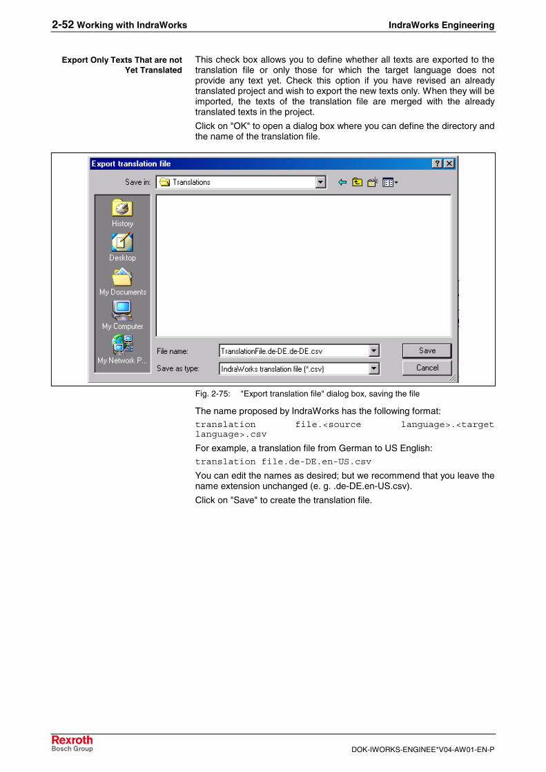
2-52 Working with IndraWorks IndraWorks Engineering
DOK-IWORKS-ENGINEE*V04-AW01-EN-P
This check box allows you to define whether all texts are exported to thetranslation file or only those for which the target language does notprovide any text yet. Check this option if you have revised an alreadytranslated project and wish to export the new texts only. When they will beimported, the texts of the translation file are merged with the alreadytranslated texts in the project.
Click on "OK" to open a dialog box where you can define the directory andthe name of the translation file.
Fig. 2-75: "Export translation file" dialog box, saving the file
The name proposed by IndraWorks has the following format:translation file.<source language>.<targetlanguage>.csv
For example, a translation file from German to US English:translation file.de-DE.en-US.csv
You can edit the names as desired; but we recommend that you leave thename extension unchanged (e. g. .de-DE.en-US.csv).
Click on "Save" to create the translation file.
Export Only Texts That are notYet Translated

IndraWorks Engineering Working with IndraWorks 2-53
DOK-IWORKS-ENGINEE*V04-AW01-EN-P
Importing the Translation File to OpenOffice.org CalcDownload a translation file to OpenOffice.org Calc by selecting File –Open. Select the file to be opened and click on "Open".
This opens the "Text Import" dialog box.
Fig. 2-76: OpenOffice.org Calc: "Text Import" dialog box
"Unicode" must be set in this list box. This should already be presetproperly because OpenOffice.org Calc automatically detects the characterset used in the file.
Select the separator option "Separated by" and "Tab" as separator.
Text delimiters are not used in the translation file. Delete the suggestedseparator.
Click on "OK" to download the translation file to OpenOffice.org Calc.
Character Set
Separator Options
Text Delimiter

2-54 Working with IndraWorks IndraWorks Engineering
DOK-IWORKS-ENGINEE*V04-AW01-EN-P
Translating Texts in OpenOffice.org CalcAfter having downloaded the translation file to OpenOffice.org Calc, aspreadsheet with five columns and a number of lines depending on thenumber of texts is opened.
Fig. 2-77: OpenOffice.org Calc: translating texts
The first line of the spreadsheet is a header which describes the columncontents.
Column 1 contains the texts of the source language. The ISO code forthis language is entered in the header.
Column 2 contains the texts of the target language. The ISO code for thislanguage is entered in the header. Depending on the settings in theexport dialog box, the remaining lines of this column are empty or displayalready existing translations.
Columns 3 to 5 contain management data which can be used to assignthe translated texts properly when they are imported to IndraWorks.
Note: Do not change the header or the management data.Otherwise, the translation file cannot be imported.
During the translation, the translated texts are entered in column 2. Whilebeing imported, these texts are read in IndraWorks.
Note: Please observe the following character strings for thetranslation: "{%tab%}", "{%lf%}", "{%crlf%}"
During the export, these character strings are inserted in textswhich contain tabulator and end-of-line characters. Apply thecharacter strings as they are to the translation.
Example:
Source text: Hallo{%tab%}Welt!!!
Translation: Hello{%tab%}World!!!
While the translation file is imported to IndraWorks, thecharacter strings are reconverted into the original characters.
Column 1: Source Language
Column 2: Target Language
Columns 3, 4, 5: ManagementData

IndraWorks Engineering Working with IndraWorks 2-55
DOK-IWORKS-ENGINEE*V04-AW01-EN-P
Exporting the Translation File from OpenOffice.org CalcAfter the translation is completed, save the translation file. Werecommend to save the edited file under a different name with Dateispeichern unter (File Save As).
Fig. 2-78: OpenOffice.org Calc: "Datei Speichern unter (Save File As)" dialogbox, exporting the translation file
Select "Text CSV" from the "Dateityp (File type)" list box.
The "Edit filter settings" check box allows you to select the filter settingsbefore saving the file to the "Export of text files" dialog box.
To move to the "Export of text files" dialog box, click on "Speichern(Save)".
Fig. 2-79: OpenOffice.org Calc: "Export of text files" dialog box
Select "Unicode" from this list box.
Select "{Tab]" as field delimiter.
Delete the character in the text delimiter list box.
The export filter must be set exactly as described above because,otherwise, the translation file cannot be imported to IndraWorks.
Click on "OK" to save the translation file.
Dateityp (File type)
Editing Filter Settings
Character Set
Field Delimiter
Text Delimiter

2-56 Working with IndraWorks IndraWorks Engineering
DOK-IWORKS-ENGINEE*V04-AW01-EN-P
Importing the Translation File to IndraWorksTo import the texts of a translation file to the current project, selectProject – Language – Import translation file. From the file selectiondialog box that appears, select the translation file to be imported.
Fig. 2-80: "Import translation file" dialog box, selecting the file
You can now set the import options in the "Import translation file" dialogbox.
Fig. 2-81: "Import translation file" dialog box
Check this check box to replace already existing translations by thecurrent translations. For example, this is reasonable if the translation filecontains a complete set of texts which have been revised in theirlanguage and are now to be applied to the project.
If you do not activate this option, any already translated texts in the projectwill not be changed; the corresponding texts of the translation file will beignored.
Replace Already TranslatedTexts by Current Translation

IndraWorks Engineering Working with IndraWorks 2-57
DOK-IWORKS-ENGINEE*V04-AW01-EN-P
Check this check box to view import statistics after the import.
Fig. 2-82: "Import Statistics" dialog box
Total number of lines read from the translation file.
Number of the lines in the translation files that have been rated as valid.
Number of the lines in the translation files that have been rated as invalid.Such lines develop mainly if the export filter failed to be set properly whilethe translation file was translated and saved in the external program.
Number of new texts imported to the project.
Number of the texts already translated in the project which have beenoverwritten by the imported more current text.
2.7 Print
General InformationThe Print and Print Preview functions as well as the configuration settingsfor printing are available through the following menu items:
• File – Print
• File – Print Preview
• File – Page Setup
These menu items can be selected only if a printable element (screenarea or node) has been selected.
For details on how to set the print options, please refer to the section"Printing" on page 2-78.
Show Statistics After Import
Total Entries
Valid
Invalid
Added Texts
Replaced Texts

2-58 Working with IndraWorks IndraWorks Engineering
DOK-IWORKS-ENGINEE*V04-AW01-EN-P
2.8 User Management
General InformationThe user management serves as a protection against unauthorizedaccess to information, functions and operator actions of the IndraWorksenvironment.
The user management allows you to create users and user groups and toassign these users to the user groups.
The user management supports a role-based assignment ofauthorizations to individual users or user groups.
The following user roles are available:
• Engineer
• Maintenance
• Operator
• Observer
These roles are supplemented by two additional default properties:
• Administrator (authorized to install / uninstall software)
• OEM (the user is a member of the staff of the machine manufacturerand receives the extended authorizations of the machinemanufacturer)
If user roles and default properties do not suffice to implement youroperation and authorization model, you can extend the user authorizationsby additional special authorizations.
You can define additional special authorizations as you wish. These canbe summarized in special authorization profiles.
The special authorizations are inter-component properties used to controlthe overall system.
By default, the user management contains the following specialauthorizations:
Special authorization Description
Accounting Manager Authorized to administer the usermanagement, i. e. setting up andmanaging users, user groups and theassociated authorizations.
BRC Special authorization for personsbelonging to the staff of BOSCHRexroth Service. For enablingadditional service-specific functions.
Teleservice Authorized to administer theteleservice (I-Remote) (activation /deactivation / configuration).
Fig. 2-83: Special authorizations
The user management provides interface components representing theuser data in lists or in a tree structure. The data is only displayed to usershaving the special authorization of "Accounting Manager".

IndraWorks Engineering Working with IndraWorks 2-59
DOK-IWORKS-ENGINEE*V04-AW01-EN-P
The user management can be operated in various layouts:
• dialog-based (basic setting),
• MDI-based.
The user management can be operated in the normal mode or in theexpert mode.
The basic setting provides the user management in the normal mode.This provides the most common configuration of the user management,which contains a part of the functions of the expert mode.
In the normal mode, operation is restricted to the management of users,role-based user groups and organizational units (grouping) as well as tothe configuration of some global settings (e. g. password guidelines).
You can also change to the expert mode.
The export mode provides further functions. In this mode, the usermanagement contains, for example, a connectable address managementwhich can be used to map organizational forms and save personal data ofthe users.
In the expert mode, the user management data is displayed in a treestructure. You can configure this structure by hiding unnecessarybranches of the tree or the appropriate portions of the configurationinterfaces.
Working with the User ManagementThe user management data is saved as a part of the IndraWorks projectand is valid in this project only. Inter-project authorizations cannot beassigned.
The user management is always operated in the "account sharing" mode.That means that any login and logout of a user in one application affectsall other applications, and a new started application applies the userauthorization of existing applications.
If no user has logged in, there is no shared user account on start of anapplication yet. In this case, the application is started with the user role of"Observer" without any additional special authorizations.
If the autologin mechanism is activated and an autologin user has beenconfigured, a user is implicitly logged in to the user account of theautologin user. The application starts with a default user who is definedvia the autologin mechanism.
If the autologin mechanism is deactivated or incompletely configured, adialog box for user login appears.
After a successful user login, all applications using the shared useraccount receive the authorizations of the user who is filed in the account.
If the user login is interrupted, operation of the application is continuedwith the role of "Observer".
If the user management is activated in your environment, you can call iton the Engineering Desktop by opening the Project () menu or on theOperation Desktop by selecting the File item.
Normal Mode
Expert Mode

2-60 Working with IndraWorks IndraWorks Engineering
DOK-IWORKS-ENGINEE*V04-AW01-EN-P
The following menu items are provided:
• Login
• Logout
• Configuration
LoginSelect Project – User Login to log in an IndraWorks user.
Fig. 2-84: "User Login" dialog box
Note: The only users authorized to configure the user managementare exclusively those with the role of "Engineer" and with thespecial authorization of "Accounting Manager".

IndraWorks Engineering Working with IndraWorks 2-61
DOK-IWORKS-ENGINEE*V04-AW01-EN-P
Using AuthorizationsThe table below illustrates the authorization structures required foraccessing various IndraWorks components.
Example: The user management may only be configured by users havingthe role of "Engineer" and the special authorization of "AccountingManager". Here, the attributes of "Administrator" and "OEM" are notevaluated in the authorization check.
Role Administratorattribute
OEMattribute
Specialauthorization
Component Description
Engineer -- -- AccountingManager
User management For administering the usermanagement
-- Yes -- -- WinLock Only users with the "Administrator"attribute are permitted to access
the OS
-- -- -- BRC General, MTX For identifying BOSCH RexrothService staff (for mapping the MTX
levels 4 and 5)
-- -- -- Teleservice Teleservice Authorized to activate, deactivate,configure the teleservice
Fig. 2-85: Roles, authorizations and components
(-- = not applicable or not evaluated)

2-62 Working with IndraWorks IndraWorks Engineering
DOK-IWORKS-ENGINEE*V04-AW01-EN-P
2.9 Firmware Management
The firmware management in IndraWorks provides the followingfunctions:
• Downloading the firmware to a device
• Displaying the current firmware in a device
• Displaying the firmware available for a download
To start the firmware management, use the context-sensitive menu of adevice or the device-specific menu. Select the Firmware Managementitem.
Fig. 2-86: "Firmware Management" dialog box
Starting the FirmwareManagement

IndraWorks Engineering Working with IndraWorks 2-63
DOK-IWORKS-ENGINEE*V04-AW01-EN-P
2.10 License Management
Licensing of IndraWorks ComponentsThe licenses of IndraWorks software components are managed via the"Options" dialog box. To open the "Options" dialog box, select the Tools –Options item and then "Software licenses" from the "General" folder.
Fig. 2-87: "Options" dialog box, licensing
The page displays all available software components requiring a licenseand their license state. The scope of the entries depends on the systeminstalled.
License state Description
- No license has been installed on this computer. Thecomponent cannot be used.
Licensed A full license has been installed on this computer.The component can be used without any restrictions.
30-day demo license A limited demo license has been installed on thiscomputer. The component can still be used forevaluation for the number of days specified (no morethan 30 days).
Fig. 2-88: License state
To view a description of the license, place the mouse pointer on thelicense entry in question.

2-64 Working with IndraWorks IndraWorks Engineering
DOK-IWORKS-ENGINEE*V04-AW01-EN-P
Installing a LicenseTo license a software component, select it from the list and click on"License…".
Note: If a full license is already installed, the "License.." button isdeactivated.
Fig. 2-89: "Install licenses" dialog box, entering the license type
Decide whether you wish to install an unrestricted full license or a demolicense. The demo license allows you to test the software componentsselected for 30 days.
Note: If "Demo license" is deactivated, a demo license has eitheralready been installed or the component selected does notsupport a demo license.
For installing a full license, enter the license key and, if displayed, theserial number. The necessary data was sent to you with the license.
Click on "Next>>".

IndraWorks Engineering Working with IndraWorks 2-65
DOK-IWORKS-ENGINEE*V04-AW01-EN-P
Fig. 2-90: "Install licenses" dialog box, license conditions
Thoroughly read the license conditions from beginning to end.
To accept the license conditions, select "I accept the license conditions"and click on "Finish".
If you do not accept the license conditions, click on "Cancel". In this case,the license will not be installed.
Licensing Firmware FunctionsFirmware functions requiring a license are enabled via the context-sensitive menu of the particular device in the project explorer. If a devicesupports functions that can be enabled, it provides a menu itemFirmware licenses….
Fig. 2-91: Device licensing

2-66 Working with IndraWorks IndraWorks Engineering
DOK-IWORKS-ENGINEE*V04-AW01-EN-P
Fig. 2-92: "Firmware licenses" dialog box
The "Firmware licenses" dialog box displays all functions that can beenabled, together with their license state. The scope of the entriesdepends on the device type.
License state Description
- Function disabled.
Licensed Function enabled.
Fig. 2-93: License state
To view a description of a function, place the mouse pointer on thecorresponding entry.
Enabling Firmware Functions
Note: A license key is not required for enabling firmware functions.However, the functions provided in the "Firmware licenses"dialog box must be paid. You are allowed to enable and usethese functions only if you acquired the appropriate licenses.

IndraWorks Engineering Working with IndraWorks 2-67
DOK-IWORKS-ENGINEE*V04-AW01-EN-P
To enable a function, select it and click on "License…".
Fig. 2-94: "Install licenses" dialog box: accepting license conditions
Thoroughly read the license conditions from beginning to end.
To accept the license conditions, select "I accept the license conditions"and click on "Finish".
If you do not accept the license conditions, click on "Cancel". Thefunctions selected are not enabled.
Removing Firmware LicensesTo cancel the enabling of functions, select the functions desired and clickon "Cancel".
Fig. 2-95: Removing licenses
To confirm the safety prompt, click on "Yes".

2-68 Working with IndraWorks IndraWorks Engineering
DOK-IWORKS-ENGINEE*V04-AW01-EN-P
2.11 Remote Service
With I-Remote, an efficient teleservice software is available in IndraWorksfor the remote control of PC systems. The use of I-Remote allows you toaccess remote machines and to perform diagnostics or maintenancesteps.
The I-Remote teleservice software consists of two software components.
Software component Description
Client Software component installed on the PC to beremote-controlled. After completed installation,the client PC can be remote-controlled from aservice PC.
Control Software component installed on the remote-controlling PC. After completed installation, thecontrol PC can remote-control PCs on which aclient is installed.
The client installation is an integral part of IndraWorks and can beenabled by acquiring a valid license.
The control installation is delivered as a separate data carrier. Enabling ofthis component also requires a valid license. For detailed help on theinstallation and operation of the I-Remote control software, please refer tothe data carrier of the control installation.
General Information
Software Components
Delivery

IndraWorks Engineering Working with IndraWorks 2-69
DOK-IWORKS-ENGINEE*V04-AW01-EN-P
I-Remote Client SoftwareThe sections following below refer exclusively to the I-Remote clientsoftware.
While IndraWorks is installed, the I-Remote setup for the client softwareis filed to each control PC.
To install the software, please proceed as follows:
• Select the Install Teleservice menu item from the Start – Programs– Rexroth – IndraWorks – Teleservice menu.
• Select the language and accept the license conditions.
• Enter the license information which you received when you purchasedIndraWorks I-Remote in the "General" tab and click on "Generate".
Fig. 2-96: "NetSupport License Manager" dialog box
Note: Enter the information precisely, considering upper and lowercases.
• Click on "Install".
• Close all applications and restart the computer. This completes theinstallation of IndraWorks I-Remote.
After successful installation, the Teleservice menu containing theActivate, De-activate and Configuration menu items is available in theTools menu of the IndraWorks Engineering desktop.
Installation
IndraWorks Integration

2-70 Working with IndraWorks IndraWorks Engineering
DOK-IWORKS-ENGINEE*V04-AW01-EN-P
The use of the I-Remote functions requires the following authorizations:
• You must have logged in as main user or administrator in Windows.
• The user having logged in IndraWorks must have the specialauthorization of "Teleservice" or be a member of the group having thisspecial authorization (see "User Management", p. 2-58).
Activates the I-Remote software. You can now access this PC from aservice PC with the I-Remote control software. For safety reasons, theuser must still confirm a connection request of the service PC in thedefault configuration.
Deactivates the I-Remote software. The PC cannot be accessed withinthe scope of I-Remote any longer.
The teleservice session between the service PC and the client PC can beconfigured as desired with regard to important configuration parameters,for example:
• Safety (user management, access rights)
• Transport protocol
• Functionality available during access
• WEB interface
While a teleservice session is established, the configuration is applicableto both users of the session, i. e. to the service PC and to the client PC.
Please use the supplied documentation and online help of the NetSupportManager to make adjustments to the configuration.
2.12 External Applications
IndraWorks provides the option of calling any external applicationsdesired. Once they have been configured appropriately, these programsare displayed in the Tools menu and can be started by selecting theassociated entry.
To configure and manage external applications, select Tools – ExternalApplications.
Fig. 2-97: "External Applications" dialog box
Authorization
Activate
Deactivate
Configure

IndraWorks Engineering Working with IndraWorks 2-71
DOK-IWORKS-ENGINEE*V04-AW01-EN-P
Adding an ApplicationClick on "Add" to select the application file via an appropriate dialog box.
Fig. 2-98: "Select file" dialog box
Confirm the file selected with "Open" to view the application in the"Properties" dialog box. There you can define the properties (see"Changing the Properties of an Application", p .2-72).
After you have confirmed all dialogs, the application is displayed and canbe called in the Tools menu.
Fig. 2-99: External application in the Tools menu

2-72 Working with IndraWorks IndraWorks Engineering
DOK-IWORKS-ENGINEE*V04-AW01-EN-P
Changing the Properties of an ApplicationTo open the "Properties" dialog box for an application, select theappropriate item from the "External Applications" dialog box and click on"Properties".
Fig. 2-100: "Properties" dialog box, properties of external applications
This field automatically contains the descriptive text of the application.The title is also used in the menu as display text.
Enter the application file in this field or select by clicking on "…".
This field provides the option of entering arguments to be transferred tothe application when it is started.
Optionally enter the working directory or select it by clicking on "…".
If you check this check box, the application is started in the full screenmode provided it evaluates this call parameter.
Deleting an ApplicationTo remove an application from IndraWorks, select the appropriate entryfrom the "External Applications" dialog box and click on "Remove".
Title
Command
Arguments
Working Directory
Full Screen Mode

IndraWorks Engineering Working with IndraWorks 2-73
DOK-IWORKS-ENGINEE*V04-AW01-EN-P
2.13 Options Dialog Box
The options dialog box provides comprehensive setting options allowingyou to customize IndraWorks.
These setting options cover the appearance and the behavior of the userinterface as well as specific settings of various program parts.
The setting options are organized on options pages. A single pagecontains coherent or related settings.
Select Tools – Options to move to the "Options" dialog box.
Function AreasThe "Options" dialog box is divided in a navigation area and an area fordisplaying the options pages.
The navigation area contains the tree-like hierarchy of the options pages.The highest level only comprises folders. Folders may contain optionswindows and subfolders.
Select an element from the navigation area to display the appropriateoptions page where you can view and edit the particular settings.
Select a folder from the navigation area to open an overview providing abrief description of the options pages available in the folder.
OperationSelect an element from the navigation area of the "Options" dialog box todisplay the corresponding options page.
Make the desired settings on that options page. Several options pagescan be edited one after the other. These changes are preserved as longas the "Options" dialog box is open.
Changes will become effective only after you have clicked on "Apply" or"OK".
To restore the default values on the current options page, click on"Reset". Then click on "Apply" or "OK" so that the default settings willbecome effective.
Click on "Help" to open the online help for the current options page.
Click "OK" to exit the "Options" dialog box. The changes will now becomeeffective.
To discard all changes and to close the "Options" dialog box, click on"Cancel".
General Options
Language SettingsUse the "Language settings" options page to select the user interfacelanguage for IndraWorks.
As soon as the language selected has become effective by clicking on"OK" or "Apply", the display of the user interface is updated, i. e. the userinterface is displayed in the language desired immediately.
Software LicensesUse this page to manage the licenses of software components (see"Licensing of IndraWorks Components", p. 2-63).
Navigation Area
Options Pages
Changing Settings
Making Changed SettingsEffective
Restoring Settings to DefaultValues
Calling Help
Exiting the Options Dialog Box

2-74 Working with IndraWorks IndraWorks Engineering
DOK-IWORKS-ENGINEE*V04-AW01-EN-P
Key Combinations (Shortcuts)Use the "Shortcuts" options page to assign shortcuts to commands.
Fig. 2-101: "Options" dialog box, shortcuts
Select a category to list the commands of that category in the"Commands" column.
This field provides a brief description of the command selected.
If assigned to selected commands, shortcuts are shown in this field. Clickon "Delete" to remove the shortcut. If a shortcut does not exist, this fieldshows "None".
Use this field to define a new shortcut for the command selected bypressing a key or a combination of keys. If the shortcut is alreadyassigned to a different command, this field shows "Shortcut is being usedby".
Note: Any shortcut can be assigned to one command only. If youassign an already used shortcut to a new command, thatshortcut cannot be used for the previous command any longer.
Categories
Description
Shortcut for Selected Command
Press Shortcut

IndraWorks Engineering Working with IndraWorks 2-75
DOK-IWORKS-ENGINEE*V04-AW01-EN-P
Frame PropertiesUse this options page to set the frame properties and the options for thelayout management.
Fig. 2-102: "Options" dialog box, Frame
You can
• activate a prompt on exiting the desktop,
• define that the previously configured layout is restored during the start,
• show and hide the menu bar,
• view tool tips,
• view shortcuts in the tool tips.
To reset edited menus and tool windows to the default configuration, clickon the "Menus and toolbars" and "Tool window" buttons.

2-76 Working with IndraWorks IndraWorks Engineering
DOK-IWORKS-ENGINEE*V04-AW01-EN-P
Logging ManagerUse this page to parameterize the message window in IndraWorks. Toexpand the output options, enter a file, a database or an e-mail address.
Fig. 2-103: "Options" dialog box: Logging Manager
The "File" tab provides the option of entering the path of an output file towhich error messages will be written. If you activate the "Append" checkbox, the available file contents will not be deleted; any new errormessages will be added to these file contents.
The "Database" tab provides the option of selecting Access or SQL. Enterthe data source, the name, the user ID, and a password.
The "E-mail" tab provides the option of activating the e-mail messagingfunction in the event of an error.
Outputting Error Messages to aFile
Output to a Database
E-Mail Messaging

IndraWorks Engineering Working with IndraWorks 2-77
DOK-IWORKS-ENGINEE*V04-AW01-EN-P
Project ExplorerUse this options page to change the settings for the project explorer.
These changes will not become effective before the next restart.
Fig. 2-104: "Options" dialog box, Project explorer

2-78 Working with IndraWorks IndraWorks Engineering
DOK-IWORKS-ENGINEE*V04-AW01-EN-P
PrintingThe "Table of Content" options page provides the possibility of setting thefonts for the various heading levels and for the cover page.
If you check the "Vertical Alignment" check box, the table of contents willbe output left-aligned. If you do not check it, each new heading level willbe indented in relation to the previous level.
To discard all changes and activate the default settings, click on "Reset".
Fig. 2-105: "Options" dialog box, Printing, Table of Content
"Table of Content" PrintingOption

IndraWorks Engineering Working with IndraWorks 2-79
DOK-IWORKS-ENGINEE*V04-AW01-EN-P
This options page provides a header preview and a footer preview. Youcan define the format, font and content of headers and footersindividually.
Fig. 2-106: "Options" dialog box, Printing, Header and Footer
Click the "Edit Header" or "Edit Footer" button to open the appropriateconfiguration dialog box.
Fig. 2-107: "Options" dialog box, Printing, Edit Header
This dialog box allows you to configure a two-line header with left, centerand right sections. The font can be separately set for each output section.To achieve this, select the desired section and click on "Font…".
"Header and Footer" PrintingOption

2-80 Working with IndraWorks IndraWorks Engineering
DOK-IWORKS-ENGINEE*V04-AW01-EN-P
Click the "Variable list…" button to insert wild card characters for variabletexts, such as #PRINT_DATE#. The wild card character will be replacedby the appropriate values on printout.
If you check the "Header Border" check box, a separation line will bedisplayed between the two rows of the header and you can showseparation lines between the various output sections by checking the four"Border" check boxes.
Confirm your configuration with "OK".
2.14 Customizing Dialog Box
The "Customizing" dialog box provides the option of editing both the menuand the toolbars.
To open this dialog box, select Tools – Customizing….
To add a command to a toolbar, activate that toolbar. Then select Tools –Customizing… and the "Commands" page. Select the category for thecommand. Drag the command to be added from the "Commands" field tothe appropriate point in the menu or the toolbar.
Toolbars can be shown or hidden. To do this, select Tools –Customizing… and the "Toolbars" page. Make the appropriate settingsin the "Toolbars" field.
To create your own toolbar, click the "New…" button on the "Toolbars"page. This will open the "Create new toolbar" dialog box where you entera name for the new toolbar. Click "OK" to create the toolbar, which will beof the floating type. The toolbar name will be entered in the toolbar list.
Select the user-defined toolbar which you wish to rename from the"Toolbars" field on the "Toolbars" page. Click on "Rename…".
Note: User-defined toolbars are the only ones that can be renamed.
Select the user-defined toolbar which you wish to delete from the"Toolbars" field on the "Toolbars" page. Click on "Delete" and confirm the"Delete Toolbar" message.
Note: User-defined toolbars are the only ones that can be deleted.
Adding a Command to the Menuor to a Toolbar
Showing and Hiding Toolbars
Creating a New Toolbar
Renaming a Toolbar
Deleting a Toolbar

IndraWorks Engineering Working with IndraWorks 2-81
DOK-IWORKS-ENGINEE*V04-AW01-EN-P
2.15 Info
The Help – Info menu item provides the option of calling the informationdialog box of IndraWorks. This dialog box displays detailed information onthe various components. The upper part of the dialog box shows theprecise version and the build number of the basic installation. The lowerpart of the dialog box displays the license conditions.
Fig. 2-108: "Info" dialog box
This list displays the products that are installed.
Select a product from the list to view detailed information (type code andcopyright) in the "Product details" field.
Click on the "Advanced>>" button to additionally show the basiccomponents of the installed software packages in the "Installed products"list. To hide this information again, click on "Advanced<<".
Click on "Copy Info" to copy the information displayed. IndraWorks copiesnot only the build and version information on IndraWorks itself, but alsothe information on assemblies, such as file size, creation date and themost important information on the particular computer, processor andoperating system. After the copies are completed, an editor for furtherprocessing that information is started.
To open the extra info filed for the product select, click on the "Extra Info"button.
Click on "Close" to exit the dialog box.
Installed Products
Product Details
Advanced Information
Copy Info
Calling Extra Info

2-82 Working with IndraWorks IndraWorks Engineering
DOK-IWORKS-ENGINEE*V04-AW01-EN-P
2.16 Message Box
IndraWorks provides a mechanism for recording failures, errors andmessages.
The message box is divided in three tabs each of which assumes onesingle function. In the normal operating mode, only two tabs are visible.The third tab is intended for diagnostic purposes during startup and canonly be activated by an additional start parameter.
Fig. 2-109: Output box
The "Output" box records processes such as a download or thetranslation of a program.
The "Task list" box lists failures and errors necessitating a reaction. If, forexample, program errors are recorded here, these errors must beeliminated before the translation process can be repeated without anyerrors. The box also displays the level and, thus, the error class and theorigin of the respective error message.
Use the "Logging Manager" page of the "Options" dialog box toparameterize the message box in IndraWorks.
To show and hide the device diagnostics, select the View – Otherwindows – Device diagnostics menu item. In the "online" mode of theproject, the device diagnostics window shows a list of the currentdiagnostics of a device if
• this device or one of its sub-items is selected from the project explorer,
• the device supports diagnostic messages, and
• the device is in the "online" mode.
In all other cases, the list shown is empty.
Each diagnostic message shows the diagnostic number, the diagnosticsource (module in case of ProVi messages, channel number in case ofMTX), the date and time of occurrence as well as a descriptive text.
Fig. 2-110: "Device Diagnostics" window
Output
Task List
Parameterizing the Message Box
Device Diagnostics

IndraWorks Engineering Working with IndraWorks 2-83
DOK-IWORKS-ENGINEE*V04-AW01-EN-P
2.17 Help
Select the Help menu to start the online user documentation.
Fig. 2-111: "Help" menu
Select Content… to open the table of contents of the completeIndraWorks help.
Select Index to search for keywords in the help index.
Fig. 2-112: Help, Index
Help
Content
Index

2-84 Working with IndraWorks IndraWorks Engineering
DOK-IWORKS-ENGINEE*V04-AW01-EN-P
The Search tab allows you to search the entire help for keywords. Theresults are displayed in a list containing all associated topics.
Fig. 2-113: Help, search for topics
Select Rexroth Homepage to move to the Bosch Rexroth homepage,provided you are connected to the network.
Search
Rexroth Homepage

IndraWorks Engineering Working with IndraWorks 2-85
DOK-IWORKS-ENGINEE*V04-AW01-EN-P
2.18 Controlling the Oscilloscope Function
General InformationThe oscilloscope function can be used to represent and evaluatemeasured values graphically; such measured values result, for example,from the transient response of a motor.
Its main field of application is for commissioning of drives, test andservice.
The device connected must be prepared for supporting the oscilloscopefunction.
Starting the Oscilloscope FunctionTo activate the oscilloscope function in the main menu, select Diagnosis– Start Oscilloscope….
Fig. 2-114: Starting the oscilloscope
If no device is selected at this point or if the online mode is not activated,the oscilloscope starts in the offline mode. This mode does not allow anymeasurements. However, already saved measurements resulting fromother measuring processes can be read and viewed.
If a device is selected at this point or if the online mode is activated, theoscilloscope starts in the online mode.
Note: You can also switch to the online mode subsequently.
Requirements
Offline Mode
Online Mode

2-86 Working with IndraWorks IndraWorks Engineering
DOK-IWORKS-ENGINEE*V04-AW01-EN-P
Online and Offline Modes
Starting in the Offline ModeIf the oscilloscope is started in the offline mode, it is not possible to take ameasurement directly. The measurement must first be configured.
The "State" field in the "Current measurement" area indicates whetheryou are already connected to a device which supports the oscilloscopefunction.
Click on the "Signals" button to open the "Configure Signals" dialog boxwhich allows you to connect to devices supporting the oscilloscopefunction.
Fig. 2-115: Oscilloscope, started in the offline mode
Note: To read and analyze any measurements in the offline mode,select the Load measurement data menu item.
After you have connected the oscilloscope to a device, you can select thesignals for the measurement. Thereafter, you can configure the triggersand the measurement.
State
Signals

IndraWorks Engineering Working with IndraWorks 2-87
DOK-IWORKS-ENGINEE*V04-AW01-EN-P
Starting in and Switching to the Online ModeAfter activation of the online mode, the oscilloscope shows the lastmeasurement from the project directory of the device to which you haveconnected. If a saved measurement is not available, e.g. in a new project,the system attempts to read the last measurement from the device. Thisis displayed in a message box.
The message displayed is called the current measurement.
Note: If a measurement is not available in the project directory nor inthe device, an empty measurement is displayed.
A measurement contains the measured data and the configuration data.
The state of the measurement is displayed in the "State" field in the"Current measurement" area. If a measurement can be taken, its state is"ready". Further states are: "disconnected", "not configured", "nottriggered", "triggered", and "storing".
The signal overview shows the represented signals with their names andtheir unit. Signals can be shown and hidden.
Fig. 2-116: Oscilloscope, display of the last measurement
The display is always scaled according to the active signal. Active signalshave a gray background in the signal overview and a greater width in thegraph. To activate a signal, click on it in the graph or in the signaloverview.
Current Measurement
State
Signal Overview
Active Signal

2-88 Working with IndraWorks IndraWorks Engineering
DOK-IWORKS-ENGINEE*V04-AW01-EN-P
Recording a New MeasurementYou can take a new measurement if you are connected to a device whichsupports the oscilloscope function.
Select the device and the signals, configure the measurement and thetrigger, and start the measurement by clicking on the "Startmeasurement" button. The measurement can be repeated.
Connecting Devices and Selecting SignalsClick on the "Signals…" button to open the "Configure Signals" dialog box.
Fig. 2-117: "Configure Signals" dialog box
Select the device you wish to connect to.
Fig. 2-118: "Configure Signals" dialog box, device selection
Selecting a Device

IndraWorks Engineering Working with IndraWorks 2-89
DOK-IWORKS-ENGINEE*V04-AW01-EN-P
The "Existing signals" list contains all signals of the connected device.Select the signals whose measurement values you wish to record.
Fig. 2-119: "Configure Signals" dialog box, selecting existing signals
Click on the "Select" button or double-click on a signal to apply theselected signals to the "Selected signals" list.
Fig. 2-120: "Configure Signals" dialog box, selected signals
Note: The number of signals allowed for measurement does notexceed the number of signals which can be processed by theconnected device simultaneously (see "max. number ofchannels" and "Free channels" fields).
To remove a signal from the "Selected signals" list, select it and click onthe "Remove" button or press the <Del> key.
If you exit the dialog box with "OK", the selected signals are applied to thesignal overview. As long as there is no measured data for these signalsyet, the signals are inactive, i. e. they are displayed with gray letters. Todiscard your settings, click on "Cancel".
Existing Signals
Select
Remove

2-90 Working with IndraWorks IndraWorks Engineering
DOK-IWORKS-ENGINEE*V04-AW01-EN-P
Configuring the Current MeasurementTo change the memory depth and the time period of the measurement,click on the "Configure…" button in the "Current measurement" area.
Fig. 2-121: "Configure…" button
The "Configure Measurement" dialog box that appears displays thedefault values for the device selected.
Fig. 2-122: "Configure Measurement" dialog box
This field displays the product from memory depth and time period. It isrecalculated for each change.
The device provides the maximum memory depth. The lower limit is 1 %of the maximum memory depth. If it exceeds or falls below the limits, yourentry will be corrected.
The device provides the possible time period values for comparisonpurposes. If your entry is different from the time period values, it will beautomatically corrected to the nearest value.
To save your changes, click on the "OK" button. Before the values aresaved, the limits are checked and, if necessary, your entries arecorrected. The new measurement is now completely configured; if ameasurement has been recorded or loaded beforehand, it will beremoved from the display.
To discard your changes, click on the "Cancel" button.
Recording Time
Memory Depth
Time Period

IndraWorks Engineering Working with IndraWorks 2-91
DOK-IWORKS-ENGINEE*V04-AW01-EN-P
Configuring the TriggerTo customize the trigger settings, click on the "Configure" button in the"Trigger" area.
Fig. 2-123: "Configure trigger" button
This opens the "Configure Trigger" dialog box.
Fig. 2-124: "Configure Trigger" dialog box
The oscilloscope displays the trigger types supported by the device.
The oscilloscope supports two trigger types:
• Manual trigger
• Signal trigger

2-92 Working with IndraWorks IndraWorks Engineering
DOK-IWORKS-ENGINEE*V04-AW01-EN-P
If you select the "Manual trigger" option from the "Trigger types" area, the"Current measurement" area will provide the "Manual trigger" button. Thisbutton enables the trigger. The measurement time is calculated from thememory depth and the time period. The data is displayed with thepretrigger taken into consideration.
Fig. 2-125: "Enable manual trigger" button
The pretrigger defines the percentage of the measurement to be calledbefore the actual trigger signal. The pretrigger values that can be selectedrange from 0 to 100 %.
Note: If the trigger is enabled before the time defined for thepretrigger has elapsed, only a part of the desired pretrigger willbe shown.
If you intend to start recording a measurement in relation to a signal,select the "Signal trigger" type. If the signal configured as trigger hasexceeded or fallen below the set value, the trigger is enabled. Themeasurement time is calculated from the memory depth and the timeperiod. The data is displayed with the pretrigger taken into consideration.
To select the trigger signal, click on the "Select" button in the "ConfigureTrigger" dialog box.
Fig. 2-126: "Configure Trigger" dialog box, with selected "Signal trigger"
"Manual Trigger" Type
PreTrigger
"Signal Trigger" Type

IndraWorks Engineering Working with IndraWorks 2-93
DOK-IWORKS-ENGINEE*V04-AW01-EN-P
Now all signals provided by the device for the signal trigger are displayed:
Fig. 2-127: "Configure Trigger" dialog box, "Select Trigger Signal"
Select a signal from the list. To apply the signal, click on the "Select"button or double-click on the signal.
If you do not wish to select a signal trigger, click on the "Cancel" button.
The trigger signal will be displayed in the "Configure Trigger" dialog box.
Fig. 2-128: "Configure Trigger" dialog box, completing the settings
This area only provides the trigger conditions supported by the device.They show how the value to be entered is to be linked in order to enablethe trigger event.
Selecting the Signal
Cancel
Trigger Edge

2-94 Working with IndraWorks IndraWorks Engineering
DOK-IWORKS-ENGINEE*V04-AW01-EN-P
Enter the trigger threshold to be reached or exceeded by the trigger signalto enable the trigger event.
Note: If the trigger signal fails to be reached during themeasurement, the measurement must be stopped. Make theappropriate changes in the trigger dialog box.
This field is intended to display the current value of the trigger signalduring the measurement.
This field displays the unit of the trigger signal.
You can also select a binary signal as trigger signal from the trigger dialogbox. In this case, you can trigger to a specific bit and evaluate its state.Internally, the trigger mask is linked to the trigger value in a logic ANDoperation. If the evaluation results in logic "1", the trigger is enabled afterthe measurement has been started.
The "S-0-0013 Class 3 diagnostics" signal consists of 16 bits. For acomplete meaning of all bits, please refer to the literature at the end ofthis description.
Here, bit 0, velocity feedback value = velocity command value, and bit 1,velocity feedback value < standstill window, are to be used for enablingthe trigger.
Fig. 2-129: "Configure Trigger" dialog box, bit signal as signal trigger
You can define the mask bitwise by checking the individual check boxesor by directly entering the bits in the "Trigger mask (bin)" field.
Click on this button to set all bits.
Trigger Threshold
Current value
Unit
Triggering with Binary Signals
Example
Set Bits

IndraWorks Engineering Working with IndraWorks 2-95
DOK-IWORKS-ENGINEE*V04-AW01-EN-P
Click on this button to delete all bits.
Note: If you click on the individual bits, both the trigger mask and thetrigger threshold are adjusted for the logic AND operation. Youcan also change the trigger value manually, independently ofthe trigger mask.
If you check this check box, the bit selection is limited to a single bit. Inthis case, the trigger mask and the trigger value are identical and will notbe displayed any longer. You can only trigger to falling or rising edges.The figure below shows the selection of a bit trigger.
Fig. 2-130: "Configure Trigger" dialog box, bit signal, bit trigger
Note: The number of the selection points shown depends on the bitwidth of the trigger signal selected. It ranges from 8 bits to 32bits.
Delete Bits
Bit Trigger

2-96 Working with IndraWorks IndraWorks Engineering
DOK-IWORKS-ENGINEE*V04-AW01-EN-P
Starting the Measurement
Fig. 2-131: "Start measurement" button
Click on the "Start measurement" button to start the measurement withthe previously defined conditions. The current state of the measurementis shown in the "State" field.
If possible, the measurement takes as long necessary to reach therecording time defined in the "Configure Measurement" dialog box.
After successful completion of the measurement, the state is "ready"again and the measured values will be shown in the graphical display.
Fig. 2-132: Oscilloscope, successfully completed measurement

IndraWorks Engineering Working with IndraWorks 2-97
DOK-IWORKS-ENGINEE*V04-AW01-EN-P
Graphical Display
Signal OverviewThe check boxes allow you to show and hide selected signals.
Active signals are displayed on a gray background. To activate a signal,click on it in the graph or in the signal overview.
Note: In the graph, any active signal is represented with a width oftwo pixels; an inactive signal, however, has a width of onepixel only.
The interrupted red line in the graph indicates the trigger time.
The two continuous black vertical lines are the two line cursors. Thesecursors can be moved horizontally with the mouse. The number next tothe line cursor corresponds to the value in the abscissa. At the sametime, the intersection point between the line cursor and the active signal ishighlighted a little.
Fig. 2-133: Display of the two line cursors
The line cursors can be moved with the mouse or with the arrow keys.The increment size depends on the defined time period.
Note: To move the active (wider) cursor in single increments, pressthe left or right arrow keys. To move it in increments of ten,press <Ctrl><Alt> and the arrow keys.
Trigger Time
Line Cursor

2-98 Working with IndraWorks IndraWorks Engineering
DOK-IWORKS-ENGINEE*V04-AW01-EN-P
ZoomTo zoom in an area, left-click on the graph, hold the button and move themouse. A rectangle will appear the size of which changes with the mousemovements. Once you release the mouse button, the zooming-in area isdefined. It will be automatically sized to the entire graphical area.
The figures below show the definition of an area and its result.
Fig. 2-134: Display with zooming area
Fig. 2-135: Display zoomed in
To further zoom in the area, repeat the above steps.
Zooming the Area In

IndraWorks Engineering Working with IndraWorks 2-99
DOK-IWORKS-ENGINEE*V04-AW01-EN-P
Each new definition of a zoom area is managed as a zoom level in ameasurement. To switch back and forth between these levels, click on the"+" and "–" buttons in the "Zoom" field.
Fig. 2-136: "Zoom level down" button
To return to the original graph, click on the "1:1" button.
Pressing the following shortcuts will also change the zoom levels:
• <Strg><Alt><P> corresponds to the "-" button
• <Strg><Alt><N> corresponds to the "+" button
• <Strg><Alt><Q> corresponds to the "1:1" button
If the line cursor is not shown on a zoom level, get it back to the graphicalarea by clicking on the "Show cursor" button.
Fig. 2-137: "Show cursor" button
Click on this button or press the <Ctrl><Alt><Z> keys to increase the areabetween the two line cursors.
Fig. 2-138: "Zoom between both cursors" button
Moving the Active Signal in Y DirectionYou can move the active signal in Y direction by clicking on the "up arrow"and "down arrow" buttons in the "Y scaling" area.
Fig. 2-139: "Move the active signal in Y direction" button
Zoom Levels
Showing the Line Cursor
Zoom Line Cursor

2-100 Working with IndraWorks IndraWorks Engineering
DOK-IWORKS-ENGINEE*V04-AW01-EN-P
Scaling the Active Signal in Y DirectionTo scale the active signal, click the "+" and "-" buttons in the "Y scaling"area. Scaling of the signal is accordingly reduced or increased in definedsteps.
In absolute scaling, the signals shown depend on the largest signal.
Fig. 2-140: "Scale display" button
The figures below illustrate two different types of representation by theexample of two signals. The first figure shows the signals with absolutescaling.
Fig. 2-141: Display with absolute scaling
Absolute Scaling
Example

IndraWorks Engineering Working with IndraWorks 2-101
DOK-IWORKS-ENGINEE*V04-AW01-EN-P
The next figure shows the signals with full scaling. All signals utilize theentire display area.
Fig. 2-142: Display with full scaling

2-102 Working with IndraWorks IndraWorks Engineering
DOK-IWORKS-ENGINEE*V04-AW01-EN-P
Logic AnalyzerThe "Configure Signals" dialog box also provides the option of selecting abit signal for the measurement. In this case, you can select single bitswith signal courses that are automatically arranged one above the otheras is the case with a logic analyzer from the extended dialog box.
Select the "Class 3 diagnostics" signal which comprises 16 bits. Thefollowing extended dialog box will appear.
Fig. 2-143: "Configure Signals" dialog box, selected bit signal
On each bit selection, the free and the used bits are counted. Select thebits for display.
Note: The maximum number of selectable bits refers to all selectedbit signals. The total number of bits that can be selected is 16.
For the example, select a signal trigger with the "S-0-0040 Velocityfeedback value" signal, with falling edge, and with a trigger value of –200rpm.
Example
Configuring the Trigger

IndraWorks Engineering Working with IndraWorks 2-103
DOK-IWORKS-ENGINEE*V04-AW01-EN-P
Select the memory depth of 1000 measurement values within a timeperiod of 1 ms.
The figure below shows the measurement result where the bit signals arenot divided yet.
Fig. 2-144: Display with comprised bit signal
To show the single bits, click on the following button:
Fig. 2-145: "Separate bit signals" button
Configuring the Measurement

2-104 Working with IndraWorks IndraWorks Engineering
DOK-IWORKS-ENGINEE*V04-AW01-EN-P
The figure below shows the result of the bit computation. The remainingsignals have been hidden.
Fig. 2-146: Display of extracted bit signals
As you can see below, the rising edge of the second signal from below isnot an exactly vertical line. This is caused by the fact that the values areinterpolated and represented as curve trace. This is reasonable for analogsignals, but not for bit signals.
Fig. 2-147: Display of bit signals with inclined edge
Graphical Interpolation

IndraWorks Engineering Working with IndraWorks 2-105
DOK-IWORKS-ENGINEE*V04-AW01-EN-P
Exact representation can be achieved with the following item:
Fig. 2-148: Display of real measurement points
The figure below shows the result.
Fig. 2-149: Display of real measurement points with rectangular edge
ComputationMeasured signals can be combined with each other mathematically, inorder to obtain further findings. Select the desired computation and thenthe signals to be combined. The signal overview and the display show thesignals computated.
SummationStart computation as follows:
Fig. 2-150: "Select computation" button

2-106 Working with IndraWorks IndraWorks Engineering
DOK-IWORKS-ENGINEE*V04-AW01-EN-P
This will open the "Configure Computations" dialog box.
Fig. 2-151: "Configure Computations" dialog box
You can select a type of computation. The general computation formulaof two signals is preselected. If you wish to form the sum of two signals,please select this computation type from the dialog box.

IndraWorks Engineering Working with IndraWorks 2-107
DOK-IWORKS-ENGINEE*V04-AW01-EN-P
Fig. 2-152: "Configure Computations" dialog box, addition of two signals
Click on the "OK" button to initiate the computation and to apply the signalto the graph and to the signal overview.
If you wish to discard your changes, click on "Cancel".

2-108 Working with IndraWorks IndraWorks Engineering
DOK-IWORKS-ENGINEE*V04-AW01-EN-P
Fig. 2-153: Display of the addition of two signals
Further Computation OptionsThe figure below shows a list of computation options available by default.
Fig. 2-154: "Configure Computations" dialog box, computation options
Depending on the computation selected, the fields required are providedin the dialog box.

IndraWorks Engineering Working with IndraWorks 2-109
DOK-IWORKS-ENGINEE*V04-AW01-EN-P
A Fast Fourier Transformation can be computated for the signal selected.
Fig. 2-155: "Configure Computations" dialog box, FFT
If the bandwidth measurement is selected, the bandwidth is computatedby means of the command and actual signals selected.
Fig. 2-156: "Configure Computations" dialog box, bandwidth
Fast Fourier Transformation FFT
Bandwidth Measurement

2-110 Working with IndraWorks IndraWorks Engineering
DOK-IWORKS-ENGINEE*V04-AW01-EN-P
The bandwidth command value simulation simulates a noise signal fortaking the bandwidth measurement.
Fig. 2-157: "Configure Computations" dialog box, bandwidth command signalsimulation
The actual signal simulation simulates an actual signal for a bandwidthmeasurement on the basis of a command signal recorded beforehand.
Fig. 2-158: "Configure Computations" dialog box, bandwidth actual signalsimulation
Bandwidth Command SignalSimulation
Bandwidth Actual SignalSimulation

IndraWorks Engineering Working with IndraWorks 2-111
DOK-IWORKS-ENGINEE*V04-AW01-EN-P
If selected from the signal overview, a computation can be repeated.
Fig. 2-159: "Repeat computation" button
A computation must be repeated whenever the associated measurementwas repeated as well.
Loading and Saving a MeasurementAfter start, the Diagnosis menu item provides the following items:
Fig. 2-160: Menu items relating to the oscilloscope
Select Import configuration or Export configuration to read or saverespectively the configuration of a measurement. The filename extensionis OCD.
The Load measurement and Save measurement items refer to thecurrent project directory. The files read are those with the extension ZIP,XML and OCD. The files saved are those with the extension ZIP andXML.
The Import measurement and Export measurement items refer to anydirectory. The files read are those with the extension ZIP, XML and OCD.The files saved are those with the extension ZIP, XML and TXT.
Select Load measurement data to view any measurement, even if youare not connected to a device. The files read are those with the extensionZIP and XML.
Compressed file in ZIP format, containing a complete measurement.
Text file in XML format, containing a complete measurement.
Text file in XML format, containing the configuration of a measurement.
Output of the measured data as text file which can be read in Excel.
Repeating the Computation
ZIP
XML
OCD
TXT

2-112 Working with IndraWorks IndraWorks Engineering
DOK-IWORKS-ENGINEE*V04-AW01-EN-P
Document Window in ClipboardPress the <Ctrl><Alt><J> keys to copy the entire workspace of theoscilloscope (graph with control elements) as screenshot to the clipboard.The measurement represented can be applied to other programs fordocumentation purposes.
Exporting a Measurement as Text FilePress the <Ctrl><Alt><R> keys to copy a measurement as text to theclipboard. This allows you to apply the values directly to Excel, withouthaving to use a separate file of the Export measurement menu item.
ReferencesPlease refer to the following references for support on signals which aresuitable for being recorded graphically.
• Rexroth IndraDrive, Drive Controllers, Parameter Description: DOK-INDRV*-GEN-**VRS**-PA02-EN-P
• Rexroth IndraDrive, Firmware for Drive Controllers MPH-02, MPB-02,MPD-02 Functional DescriptionDOK-INDRV*-MP*-**VRS**-FK01-EN-P
• Rexroth IndraDrive Firmware for Drive Controllers MPx02, MPx02 andHMV, Troubleshooting Guide;DOK-INDRV*-GEN-**VRS**-WA02-EN-P

IndraWorks Engineering Working with IndraWorks 2-113
DOK-IWORKS-ENGINEE*V04-AW01-EN-P
2.19 I/O Configuration
General InformationIndraWorks I/O configuration covers project engineering of inputs andoutputs. The following elements can be configured:
• local I/O addresses, e. g. onboard I/O of the IndraLogic L40 control,
• I/O addresses for local inline modules, e. g. additionally fitted RexrothInline modules in the IndraLogic L40 control,
• external I/O modules, e. g. fieldbus modules or devices.
I/O configuration is intended to assign PLC addresses to actual I/Oterminal points.
For fieldbus configuration, it is also possible to project fieldbus-specificdata, e. g. for Profibus DP:
• editing vendor-specific data,
• defining bus-specific settings.
After completion of Profibus configuration, the data is transferred to thetarget device with the help of IndraLogic.
Note: Changed settings will not be activated in the PLC before thenext download!
Additional functions permit data management, observation and trouble-shooting:
• Import of IndraLogic projects
• Comparison of command and actual values of the bus configuration(in preparation)
• Input and output status indicator (in preparation)
• Online diagnosis
IndraWorks provides special functions for filing to archives (seeIndraWorks Help).
I/O Configuration
Fieldbus Configuration
Additional Functions

2-114 Working with IndraWorks IndraWorks Engineering
DOK-IWORKS-ENGINEE*V04-AW01-EN-P
Screen Layout
Fig. 2-161: IndraWorks I/O configuration
The library is used for listing and selecting the available fieldbus devicesand modules.
A new field device or module can be inserted in the current IndraWorksproject from the library by drag-and-drop.
The editor can be used to edit various data pertaining to the currentlyselected device or module.
Internal tasks and sequences are recorded in the output window.
Creating Project and ControlThe IndraWorks project explorer permits insertion of projects. Each ofthese projects may contain multiple controls or devices.
A new project can be created with the "File", "New", "Project" menu item.A dialog box appears, in which the project name can be entered.
Fig. 2-162: Creating a new IndraWorks project
Library (1)
Project Explorer (2)
Editor (3)
Output (4)

IndraWorks Engineering Working with IndraWorks 2-115
DOK-IWORKS-ENGINEE*V04-AW01-EN-P
After a new project has been created, a control listed in the library mustbe inserted in the project explorer.
Inserting Slaves or ModulesInsert a slave from the library to the current control by drag-and-drop.
Slaves can be inserted in the workspace at permissible positions only,e. g. Profibus DP slaves can be inserted in the IndraLogic L40 control onlybelow the "Profibus/M" object node.
Fig. 2-163: Inserting a slave by drag-and-drop
After a device has been inserted in the workspace explorer, a wizardappears, which can be used to change the project settings, see "SlaveSettings (Profibus DP)". Then, the device is integrated in the projectexplorer
A slave is subdivided in modules. The I/O areas of the modules areassigned to the physical addresses (e. g. I/O addresses of the PLC).
Profibus DP distinguishes between two slave types:
• Compact: A compact slave has an invariably defined modulestructure.
• Modular: A modular slave permits individual assignment of themodules, depending on their fitting specification.
Inserting Slaves
Inserting Modules

2-116 Working with IndraWorks IndraWorks Engineering
DOK-IWORKS-ENGINEE*V04-AW01-EN-P
After a slave has been inserted in the project explorer, the modules belowthe slave object node are already completely available in case of acompact design of the slaves. However, the modules for modular slaveshave to be assigned manually. Where internal Rexroth Inline devices areconcerned (e. g. IndraLogic L40 control), the inline modules are alsoassigned manually.
Insert the modules by drag-and-drop. The modules can be inserted in theproject folder at permissible positions only, e. g. Inline modules of theIndraLogic L40 control can only be inserted below the "Inline I/O" objectnode.
Fig. 2-164: Inserting a module by drag-and-drop
After the module has been inserted, a wizard appears which can be usedto make the Module Settings, for example I/O addressing. Then, thedevice is integrated in the project explorer

IndraWorks Engineering Working with IndraWorks 2-117
DOK-IWORKS-ENGINEE*V04-AW01-EN-P
The figure below shows an I/O configuration with slaves, modules andassigned I/O addresses, with IndraLogic L40 as an example.
1: IndraWorks project2: PLC project, here: IndraLogic L403: Internal I/O range of L404: Internal Rexroth Inline range of L405: Internal Profibus DP master of L406: DP slave at the internal Profibus DP master7: Modules of the DP slave8: Physical module addresses
Fig. 2-165: Devices in the project explorer (example: IndraLogic L40)
Slaves and Modules in theProject Explorer

2-118 Working with IndraWorks IndraWorks Engineering
DOK-IWORKS-ENGINEE*V04-AW01-EN-P
Slave Settings (Profibus DP)
Slave SettingsWhen a slave is inserted in the project explorer, the general slave data isshown in a dialog box (wizard). Some data can be changed.
All entries made in the wizard can be also changed later. To achieve this,double-click on the desired slave in the project explorer.
Fig. 2-166: Slave settings
Name: Device name of the slave according to the GSD file
Based on: Ident number according to the GSD file
SW version: Software version according to the GSD file
HW version: Hardware version according to the GSD file
Bus address: Here, the next free bus address (FDL address) isautomatically entered. The address can be overwritten or changed bymeans of the browse key "...", see "Setting the Bus Address". The lowestpossible slave address is 2.
The bus address of the slave is also displayed in the project explorer. Itprecedes the slave name.
Example, see figure below: Slave "R-IL PB BK" with bus address 2 isindicated in the project explorer as "2-R-IL PB BK".
Active: Activate this option, so that the slave is transferred to the masterparameter set, thus being prepared for operation at the Profibus on thenext download. Deactivate this option to configure and file the slave to anarchive; in this case, however, it is not operable at the Profibus. You canalso switch back and forth between Active/Passive in the project explorerat the slave, see figure below.
Slave Settings (1)

IndraWorks Engineering Working with IndraWorks 2-119
DOK-IWORKS-ENGINEE*V04-AW01-EN-P
1: Slave is in operation2: Slave is not in operation
Fig. 2-167: Switching back and forth between Active and Passive in the projectexplorer
Note: Changed settings will not be activated in the PLC before thenext download!
Comment: Please enter here any comment about the device.
The modules can be automatically addressed in consecutive order. Enterthe desired start address in the input box From output or From input.Automatic addressing is started with Apply. All modules are sequentiallyprovided with PLC addresses in consecutive order. If addresses areoverlapping with already assigned addresses, the next coherent freeaddress range is searched. In this case, a dialog box appears asking theuser whether this unassigned range is to be used for addressing.
The "Vendor-Specific Data" tab can be used to view and/or edit additionaldata.
The "Group Assignment" tab can be used to define sync and freezecommands.
Vendor-Specific DataIf available in the GSD file, "vendor-specific data" for the slave isdisplayed. Depending on its instancing in the GSD file, the data can bedisplayed in two ways:
With this type of display (1), a parameter value is shown and edited on thebasis of its data type, e. g. "activated" and "deactivated" for Booleanvalues. The resulting parameter data is also shown in the byte display (2).
Fig. 2-168: Display of address, parameter name and parameter value
I/O Settings (2)
Vendor-Specific Data (3)
Group Assignment (4)
Display of Address, ParameterName and Parameter Value

2-120 Working with IndraWorks IndraWorks Engineering
DOK-IWORKS-ENGINEE*V04-AW01-EN-P
With this type of display, the values are subdivided in bytes. To displaythe byte values, the numerical basis can be set.
Fig. 2-169: Display of address and value
Click Default to overwrite all edited values by the original values from theGSD file.
Group AssignmentThe group assignment refers to the sync and freeze commands of the"global control" services of Profibus DP. Select the group to which youwish to assign the slave from the "Member of" column. Multiple selectionis possible.
The Sync-Mode and Freeze-Mode columns indicate the groups selectedby the master on transmission of the sync or freeze command. Theseassignments are set in the "Groups" tab in the "Master Settings".
Note: The group assignment takes effect only if the Profibus DPmaster supports the sync and freeze modes.
Example: If settings are made as shown in the figure below, the mastertransmits sync commands to groups 3 and 4 and freeze commands togroup 1 and 3. The outputs of the slaves are frozen (synchronized) to thecurrent value as soon as the master transmits the sync command togroup 3. The states of the inputs are frozen to the current value as soonas the master transmits the freeze command to group 1.
Fig. 2-170: Group assignment of a Profibus DP slave
Display of Address and Value

IndraWorks Engineering Working with IndraWorks 2-121
DOK-IWORKS-ENGINEE*V04-AW01-EN-P
Module Settings for Slave Modules
Module SettingsWhen a slave module (Profibus DP) is inserted in the project explorer, themodule data is shown in a dialog box (wizard). Some data can bechanged.
All entries made in the wizard can be also changed later. To achieve this,double-click on the desired module in the project explorer.
Fig. 2-171: Module data
Module name according to the GSD file
Internal module identification: extract from the GSD file
The I/O areas of the modules are assigned to the physical addresses(e. g. I/O addresses of the PLC).
Identifier: This column shows the individual input and output modules.The symbol +/– can be used to show or hide the bitwise illustration.Furthermore, a symbolic identifier can be assigned. The variable name tobe classified in the PLC project as global variable is entered as symbolicaddress.
Example: The figure shows the symbolic identifiers Output01 andOutput02. They are assigned to the byte addresses %QB2 and %QB3,see column "Address". These outputs can be addressed in the PLCproject (IndraLogic) via the names Output01 or Output02.
Address: Here, the I/O address can be edited bytewise (e. g. %QB4).The bit addresses in italics serve only for display purposes and cannot beedited.
Comment: Please enter any comment.
Status: Here, the real physical status of the input or output in thediagnostic mode is displayed (in preparation).
Name (1)
Configuration Bytes (2)
I/O Addresses (3)

2-122 Working with IndraWorks IndraWorks Engineering
DOK-IWORKS-ENGINEE*V04-AW01-EN-P
The modules can also be automatically addressed in consecutive order.Enter the desired start address in the input box From output or Frominput. Automatic addressing is started with Apply. All modules aresequentially provided with PLC addresses in consecutive order. Ifaddresses are overlapping with already assigned addresses, the nextcoherent free address range is searched. In this case, a dialog boxappears asking the user whether this unassigned range is to be used foraddressing.
The "Vendor-Specific Data" tab can be used to view and/or edit additionaldata.
Vendor-Specific DataIf available in the GSD file, "Vendor-specific data" for the module isdisplayed. Depending on its instancing in the GSD file, the data can bedisplayed in two ways and edited accordingly; also see "Slave Settings,Vendor-Specific Data":
• Display of parameter name and parameter value
• Display of address and value
Click Default to overwrite all edited values by the original values from theGSD file.
Module Settings for Inline Modules
Module SettingsWhen a Rexroth Inline module is inserted in the project explorer, themodule data is shown in a dialog box (wizard). Some data can bechanged.
All entries made in the wizard can also be changed later. To achieve this,double-click on the desired module in the project explorer.
Fig. 2-172: Module data for Rexroth Inline modules
Re-Addressing (4)
Vendor-Specific Data (5)

IndraWorks Engineering Working with IndraWorks 2-123
DOK-IWORKS-ENGINEE*V04-AW01-EN-P
Name: Module name
Based on: The device description file is a fixed part of the installed targetsystem.
ID: Identification for internal purposes.
Comment: Please enter here any comment about the Inline module.
The I/O ranges of the Inline modules are assigned to the physicaladdresses (I/O addresses of the PLC).
Identifier: This column shows the individual input and output modules.The symbol +/– can be used to show or hide the bitwise illustration.Furthermore, a symbolic identifier can be assigned. The variable name tobe classified in the PLC project as global variable is entered as symbolicaddress.
Example: The figure shows the symbolic identifier Input01. It is assignedto the byte address %IB0, see column "Address". This output can beaddressed in the PLC project (IndraLogic) via the name Input01.
Address: Here, the I/O address can be edited bytewise (e. g. %IB0). Thebit addresses in italics serve only for display purposes and cannot beedited.
Comment: Please enter any comment.
Status: Here, the real physical status of the input or output in thediagnostic mode is displayed (in preparation).
Onboard Settings
Onboard SettingsOnboard inputs and outputs are I/O terminals which are integrated in thecontrol, e. g. in Rexroth IndraControl L40.
Physical addresses (e. g. I/O addresses of the PLC) must be assigned tothe onboard I/O. To achieve this, double-click on the "Onboard I/O" objectnode in the project explorer.
Fig. 2-173: IndraLogic L40 in the project explorer
Module Settings (1)
I/O Settings (2)

2-124 Working with IndraWorks IndraWorks Engineering
DOK-IWORKS-ENGINEE*V04-AW01-EN-P
Fig. 2-174: Onboard I/O of the IndraLogic L40Name: Onboard I/O = onboard inputs and outputs
Based on: The device description file is a fixed part of the installed targetsystem.
ID: Identification for internal purposes
Comment: Please enter here any comment about the onboard I/O.
Identifier: This column shows the individual input and output modules.The symbol +/– can be used to show or hide the bitwise illustration.Furthermore, a symbolic identifier can be assigned. The variable name tobe classified in the PLC project as global variable is entered as symbolicaddress.
Example: The figure shows the symbolic identifier OnboardIOInputByte0suggested by the system. It is assigned to the byte address %IB10, seecolumn "Address". These inputs can be addressed in the PLC project(IndraLogic) via the names OnboardIOInputByte0.
Address: Here, the I/O address can be edited bytewise (e. g. %IB0). Thebit addresses in italics serve only for display purposes and cannot beedited.
Comment: Please enter any comment.
Status: Here, the real physical status of the input or output in thediagnostic mode is displayed (in preparation).
Onboard Settings (1)
I/O Settings (2)

IndraWorks Engineering Working with IndraWorks 2-125
DOK-IWORKS-ENGINEE*V04-AW01-EN-P
Master Settings
Master Settings and Bus ParametersOperation parameters of the bus system can be defined for Profibus DP.To achieve this, for example for the IndraLogic L40 control, open themaster information by double-clicking on node "Profibus/M" in the projectexplorer.
Note: Changed settings will not be activated in the PLC before thenext download!
Fig. 2-175: Master settings
The following data is displayed. Some data can be changed:
Name: Device name of the bus master according to the GSD file
Based on: Ident number according to the GSD file
SW version: Software version according to the GSD file
HW version: Hardware version according to the GSD file
Bus address: Here, bus address 1 (FDL address) is automaticallyentered. The address can be overwritten or changed by means of thebrowse key "...", see "Setting the Bus Address". Address 0 is reserved forengineering devices and cannot be used here.
Note: Always use bus addresses being as low as possible for themaster, as for high bus addresses the bus performance(concerning the token ring management) deteriorates.
Comment: Please enter here any comment about the master.
Master Settings (1)

2-126 Working with IndraWorks IndraWorks Engineering
DOK-IWORKS-ENGINEE*V04-AW01-EN-P
The bus parameters important for the operation of the Profibus DP areindicated here. If the Optimization (3) is set to Default, only the boxes"Baud rate" and "Max. retry limit" can be edited. All other parameters aredefault values, that are optimized to the current baud rate. These defaultvalues correspond to a recommendation of the Profibus user organizationand are suitable for the majority of applications. Only for specialexceptional cases is it necessary to modify a few parameters manually.For this, activate the Optimization: Manually (in preparation).
CAUTION
Modifications of the default bus parameters cancause an unpredictable behavior of theProfibus DP!⇒ Bus parameters may only be modified by specially
trained Profibus DP experts.
Baud rate (transfer rate): Select the data transfer rate of the entire bussystem. The baud rate cannot be higher than the highest possible baudrate of the "worst" slave.
Max. retry limit: Maximum number of repetitions of a request telegramby the initiator if the responder fails to send a response. Adjustmentrange: 1 to 15.
Highest station address (HSA): Highest possible address of a master inthe system. Up to this address, master stations are automaticallyintegrated in the logical token ring when they are coupled to the bus.Adjustment range: 1 to 126.
Quiet time (Tqui): Modulator quite time or repeater switchover time.During this time, the system waits for "silence at the bus". Telegrams areneither transmitted nor received. Adjustment range: 0 to 255 Tbits (bittime units).
Setup time (Tset): Release time. Maximum time elapsing from the pointwhere an event arrives to the point where the necessary reaction isexecuted. Adjustment range: 1 to 255 Tbits.
Slot time (Tsl): "Wait for reception" time. Maximum time it takes for theinitiator to wait for the reception of immediate acknowledgement or aresponse after a request telegram has been transmitted (message cycle).Through the direct influence of Tid2, the settings can be selected from arange between Tid2 + 15 and 16383 Tbits.
Poll timeout: Time monitoring for an acyclic service (DPV1). Maximumtime it takes for the initiator for the reception of the response after anacyclic request has been transmitted.
Settings can be selected from a range between 10 and 655350 ms in10 ms increments.
Note: The poll timeout of the IndraLogic L40 is invariable set to500 ms. It is not possible to change this value!
Watchdog time (Twd): This time is used by the slave for thresholdmonitoring, i. e. the watchdog timer in the slave is set to this time andstarted each time a data telegram arrives. If the timer has elapsed beforethe next data telegram arrives, all outputs of the slave is put to the failsafestate.
Settings can be selected from a range between 20 and 65025 ms in10 ms increments.
Bus Parameters (2)(3)

IndraWorks Engineering Working with IndraWorks 2-127
DOK-IWORKS-ENGINEE*V04-AW01-EN-P
Tid1 (idle time 1): This special bus parameter is used to calculate otherparameters.
Adjustment range: 35 to 1023 Tbits.
Tid2 (idle time 2): This special bus parameter is used to calculate otherparameters. Tid2 is directly included in the slot time (Tsl).
Adjustment range: Tid1 to 1023 Tbits.
Min. Tsdr: Minimum time it takes for the responder to respond to arequest telegram.
Adjustment range: 11 to 255 Tbits.
Max. Tsdr: Maximum time it takes for the responder to respond to arequest telegram.
Adjustment range: 35 to 1023 Tbits.
Min_Slave_Intervall: Minimum time period having to elapse between twoaccesses of the bus master to the same slave.
Adjustment range: 1 to 65535 (factor: 100 µs)
Data_Control_Time: Slave-related monitoring time in the bus master,within which at least one user data transfer must be processed with theslave in question. Adjustment range: 1 to 65535 (factor: 10 ms)
GAP update factor: Factor for controlling the number of bus cycles afterwhich new masters are detected.
Adjustment range: 1 to 10
With Groups, sync and freeze commands of the master can be assignedto specific slave groups.
Here, vendor-specific Parameters of the master can be viewed and/oredited.
GroupsThe group assignment refers to the sync and freeze commands of the"global control" services of Profibus DP. In the "Sync-Mode" and "Freeze-Mode" columns, check the group(s) to which the master has to transmitthe sync and freeze commands respectively.
Example: If the groups are assigned as shown in the figure below, themaster transmits the sync commands to the slaves of groups 3 and 4 andthe freeze commands to the slaves of groups 1 and 3.
Slaves are assigned in the "Group Assignment" of the "Slave Settings(Profibus DP)".
Fig. 2-176: Master information: groups
Groups (4)
Parameters (5)

2-128 Working with IndraWorks IndraWorks Engineering
DOK-IWORKS-ENGINEE*V04-AW01-EN-P
ParametersHere, vendor-specific parameters of the master can be viewed andedited. Please see the appropriate documentation or the help menu of thebus master or the control. If there are no specific parameters, this fieldremains empty.
Fig. 2-177: Master information: Parameters
Setting the Bus AddressUse the browse button "..." in the Slave Settings (Profibus DP) or MasterSettings or use the context-sensitive menu (see figure below) to open adialog box where you can change the current bus address.
Fig. 2-178: Context-sensitive menu, slave
The dialog box displays all bus addresses and, in the Status column, thebus user assigned to an address.
Double-click on the field with the desired bus address. The dialog box isclosed, and the new bus address is assigned to the slave or master.
Fig. 2-179: Changing a Profibus address

IndraWorks Engineering Working with IndraWorks 2-129
DOK-IWORKS-ENGINEE*V04-AW01-EN-P
Wrong Profibus Baud RateWhenever IndraLogic is called or when the "Compile All" function isexecuted, the system checks whether the baud rates of all slaves, whichare allowed according to GSD files, comply with the Master Settings. Ifone of the slaves fails to support the baud rate configured, Profibuscannot be operated.
If an error is detected in this check, the following dialog box is displayed:
Fig. 2-180: Error Profibus Baud Rate
This field displays the name of the control with the error.
This field displays the baud rate set for the Profibus master. This baudrate is configured in the "Master Settings".
In tabular form, this field displays all configured slaves which do notsupport the baud rate displayed.
This list box displays the baud rates which are jointly supported by allslaves. From the "Master Settings", select one of the baud rates shownhere to eliminate the error.
Device (1)
Set Baud Rate (2)
Bus Devices (3)
Possible Baud Rates (4)

2-130 Working with IndraWorks IndraWorks Engineering
DOK-IWORKS-ENGINEE*V04-AW01-EN-P
Profibus DP DiagnosisActivate and deactivate the Profibus DP diagnostic function using thecontext-sensitive menu of the Profibus master:
Fig. 2-181: Context-sensitive menu, Profibus master
Diagnostic information is read cyclically by the master on activation of thediagnostic function.
Note: Activate the diagnostic function only as long as you wish toevaluate diagnostic data. Otherwise, the diagnostic functionwould unnecessarily occupy the communication channelbetween the Engineering Desktop and the control.
If diagnosis is active for one or more slaves, the slaves in question aremarked in red in the project explorer. It is also possible that this markingis applied only temporarily, depending on the existing error.
Fig. 2-182: Slave marked in red if diagnosis is active for it
In the context-sensitive menu of the slave, click on "Diagnosis" to obtaindetailed diagnostic information. A diagnostic box will be displayed:
Fig. 2-183: Detailed diagnostic information

IndraWorks Engineering Working with IndraWorks 2-131
DOK-IWORKS-ENGINEE*V04-AW01-EN-P
This item displays the default diagnostic messages of Profibus DP.
If extended diagnosis is active, the specific diagnostic messages are readfrom the associated GSD file and displayed here.
Default Diagnosis (1)
Extended Diagnosis (2)

2-132 Working with IndraWorks IndraWorks Engineering
DOK-IWORKS-ENGINEE*V04-AW01-EN-P

IndraWorks Engineering List of Figures 3-1
DOK-IWORKS-ENGINEE*V04-AW01-EN-P
3 List of FiguresFig. 1-1: IndraWorks user interface 1-2
Fig. 1-2: "Standard" toolbar 1-3
Fig. 1-3: "Window List…" dialog box 1-4
Fig. 1-4: "Create New IndraWorks Project" dialog box 1-6
Fig. 1-5: "Open project" dialog box 1-7
Fig. 1-6: Devices in the library 1-7
Fig. 2-1: Project in a tree structure 2-2
Fig. 2-2: "Project" toolbar 2-2
Fig. 2-3: "Create New IndraWorks Project" dialog box 2-3
Fig. 2-4: "Open project" dialog box 2-4
Fig. 2-5: "Recent Projects" menu item 2-4
Fig. 2-6: "Properties" dialog box, "Paths" 2-5
Fig. 2-7: "Properties" dialog box, "Times" 2-5
Fig. 2-8: "Properties" dialog box, "States" 2-6
Fig. 2-9: "Save project as" dialog box 2-6
Fig. 2-10: "Save IndraWorks project as" dialog box: delete destination directory? 2-7
Fig. 2-11: "Save IndraWorks project as" dialog box, error message 2-7
Fig. 2-12: Startup picture 2-8
Fig. 2-13: Insertion by drag-and-drop from the library 2-9
Fig. 2-14: Insertion by drag-and-drop not allowed 2-10
Fig. 2-15: Insertion at the desired destination position 2-10
Fig. 2-16: Insertion at the project node 2-11
Fig. 2-17: Pasting devices from the clipboard 2-11
Fig. 2-18: Displaying tool tips for devices 2-12
Fig. 2-19: Displaying error states at devices 2-13
Fig. 2-20: Displaying error states at device nodes 2-13
Fig. 2-21: Display of deselected elements in the project explorer 2-14
Fig. 2-22: Deselecting devices in the project explorer 2-14
Fig. 2-23: Disabled elements in the project explorer 2-15
Fig. 2-24: Restructuring with folders 2-15
Fig. 2-25: Function areas of the library 2-16
Fig. 2-26: "Project" toolbar 2-17
Fig. 2-27: Archiving a project on a file system: destination archive settings2-18
Fig. 2-28: Filing a project to an archive on a file system, check of entries2-18
Fig. 2-29: Filing a project to an archive on a file system; archiving results2-19
Fig. 2-30: Filing a project to an archive on a device; device and settingsfor destination archive 2-20
Fig. 2-31: Filing a project to an archive on a device; check of entries 2-21
Fig. 2-32: Filing a project to an archive on a device: archiving results 2-22

3-2 List of Figures IndraWorks Engineering
DOK-IWORKS-ENGINEE*V04-AW01-EN-P
Fig. 2-33: "Project" toolbar 2-22
Fig. 2-34: Restoring a project from a file system; selecting the archive2-23
Fig. 2-35: Restoring a project from a file system; select destinationdirectory 2-24
Fig. 2-36: Restoring a project from a file system; check of entries 2-24
Fig. 2-37: Restoring a project from a file system; renaming the projectfolder 2-25
Fig. 2-38: Restoring a project from a file system; results 2-25
Fig. 2-39: Restoring a project from a device; selecting the archive 2-26
Fig. 2-40: Restoring a project from a device; selecting the destinationdirectory 2-27
Fig. 2-41: Restoring a project from a device; check of entries 2-27
Fig. 2-42: Restoring a project from a device; results 2-28
Fig. 2-43: Rexroth IndraWorks Operation message window 2-29
Fig. 2-44: Toolbar: scan for devices 2-29
Fig. 2-45: Scan for devices; selecting the devices 2-30
Fig. 2-46: Scan for devices, serial device data 2-31
Fig. 2-47: Scan for devices, Ethernet device data 2-32
Fig. 2-48: Scan for devices, Profibus device data 2-33
Fig. 2-49: Scan for devices, Found devices 2-34
Fig. 2-50: Status bar, offline mode 2-35
Fig. 2-51: Status bar: online mode 2-35
Fig. 2-52: Switching to the online mode 2-36
Fig. 2-53: Switching to the online mode: communication connectionmessage 2-36
Fig. 2-54: Switching to the online mode, information on inconsistenciesfound in the structure adjustment 2-37
Fig. 2-55: Adding files to a project 2-39
Fig. 2-56: "Open" dialog box 2-39
Fig. 2-57: File inserted in the project 2-40
Fig. 2-58: Editing an embedded file 2-40
Fig. 2-59: Inserted file, Open with… 2-41
Fig. 2-60: "Open with" dialog box 2-41
Fig. 2-61: "Properties" dialog box 2-42
Fig. 2-62: Workspace in IndraWorks 2-43
Fig. 2-63: Workspace, creating a new workspace 2-44
Fig. 2-64: "Create New IndraWorks Workspace" dialog box 2-44
Fig. 2-65: Opening a workspace 2-45
Fig. 2-66: Deleting a workspace 2-45
Fig. 2-67: Workspace, adding projects 2-46
Fig. 2-68: Project status, icons 2-46
Fig. 2-69: "Properties" dialog box 2-47
Fig. 2-70: "Create New IndraWorks Project" dialog box 2-48
Fig. 2-71: "Manage Project Languages" dialog box 2-49
Fig. 2-72: "Add Project Language" dialog box 2-49

IndraWorks Engineering List of Figures 3-3
DOK-IWORKS-ENGINEE*V04-AW01-EN-P
Fig. 2-73: "Manage Project Languages" dialog box 2-50
Fig. 2-74: "Export Translation File" dialog box 2-51
Fig. 2-75: "Export translation file" dialog box, saving the file 2-52
Fig. 2-76: OpenOffice.org Calc: "Text Import" dialog box 2-53
Fig. 2-77: OpenOffice.org Calc: translating texts 2-54
Fig. 2-78: OpenOffice.org Calc: "Datei Speichern unter (Save File As)"dialog box, exporting the translation file 2-55
Fig. 2-79: OpenOffice.org Calc: "Export of text files" dialog box 2-55
Fig. 2-80: "Import translation file" dialog box, selecting the file 2-56
Fig. 2-81: "Import translation file" dialog box 2-56
Fig. 2-82: "Import Statistics" dialog box 2-57
Fig. 2-83: Special authorizations 2-58
Fig. 2-84: "User Login" dialog box 2-60
Fig. 2-85: Roles, authorizations and components 2-61
Fig. 2-86: "Firmware Management" dialog box 2-62
Fig. 2-87: "Options" dialog box, licensing 2-63
Fig. 2-88: License state 2-63
Fig. 2-89: "Install licenses" dialog box, entering the license type 2-64
Fig. 2-90: "Install licenses" dialog box, license conditions 2-65
Fig. 2-91: Device licensing 2-65
Fig. 2-92: "Firmware licenses" dialog box 2-66
Fig. 2-93: License state 2-66
Fig. 2-94: "Install licenses" dialog box: accepting license conditions 2-67
Fig. 2-95: Removing licenses 2-67
Fig. 2-96: "NetSupport License Manager" dialog box 2-69
Fig. 2-97: "External Applications" dialog box 2-70
Fig. 2-98: "Select file" dialog box 2-71
Fig. 2-99: External application in the Tools menu 2-71
Fig. 2-100: "Properties" dialog box, properties of external applications 2-72
Fig. 2-101: "Options" dialog box, shortcuts 2-74
Fig. 2-102: "Options" dialog box, Frame 2-75
Fig. 2-103: "Options" dialog box: Logging Manager 2-76
Fig. 2-104: "Options" dialog box, Project explorer 2-77
Fig. 2-105: "Options" dialog box, Printing, Table of Content 2-78
Fig. 2-106: "Options" dialog box, Printing, Header and Footer 2-79
Fig. 2-107: "Options" dialog box, Printing, Edit Header 2-79
Fig. 2-108: "Info" dialog box 2-81
Fig. 2-109: Output box 2-82
Fig. 2-110: "Device Diagnostics" window 2-82
Fig. 2-111: "Help" menu 2-83
Fig. 2-112: Help, Index 2-83
Fig. 2-113: Help, search for topics 2-84
Fig. 2-114: Starting the oscilloscope 2-85

3-4 List of Figures IndraWorks Engineering
DOK-IWORKS-ENGINEE*V04-AW01-EN-P
Fig. 2-115: Oscilloscope, started in the offline mode 2-86
Fig. 2-116: Oscilloscope, display of the last measurement 2-87
Fig. 2-117: "Configure Signals" dialog box 2-88
Fig. 2-118: "Configure Signals" dialog box, device selection 2-88
Fig. 2-119: "Configure Signals" dialog box, selecting existing signals 2-89
Fig. 2-120: "Configure Signals" dialog box, selected signals 2-89
Fig. 2-121: "Configure…" button 2-90
Fig. 2-122: "Configure Measurement" dialog box 2-90
Fig. 2-123: "Configure trigger" button 2-91
Fig. 2-124: "Configure Trigger" dialog box 2-91
Fig. 2-125: "Enable manual trigger" button 2-92
Fig. 2-126: "Configure Trigger" dialog box, with selected "Signal trigger" 2-92
Fig. 2-127: "Configure Trigger" dialog box, "Select Trigger Signal" 2-93
Fig. 2-128: "Configure Trigger" dialog box, completing the settings 2-93
Fig. 2-129: "Configure Trigger" dialog box, bit signal as signal trigger 2-94
Fig. 2-130: "Configure Trigger" dialog box, bit signal, bit trigger 2-95
Fig. 2-131: "Start measurement" button 2-96
Fig. 2-132: Oscilloscope, successfully completed measurement 2-96
Fig. 2-133: Display of the two line cursors 2-97
Fig. 2-134: Display with zooming area 2-98
Fig. 2-135: Display zoomed in 2-98
Fig. 2-136: "Zoom level down" button 2-99
Fig. 2-137: "Show cursor" button 2-99
Fig. 2-138: "Zoom between both cursors" button 2-99
Fig. 2-139: "Move the active signal in Y direction" button 2-99
Fig. 2-140: "Scale display" button 2-100
Fig. 2-141: Display with absolute scaling 2-100
Fig. 2-142: Display with full scaling 2-101
Fig. 2-143: "Configure Signals" dialog box, selected bit signal 2-102
Fig. 2-144: Display with comprised bit signal 2-103
Fig. 2-145: "Separate bit signals" button 2-103
Fig. 2-146: Display of extracted bit signals 2-104
Fig. 2-147: Display of bit signals with inclined edge 2-104
Fig. 2-148: Display of real measurement points 2-105
Fig. 2-149: Display of real measurement points with rectangular edge 2-105
Fig. 2-150: "Select computation" button 2-105
Fig. 2-151: "Configure Computations" dialog box 2-106
Fig. 2-152: "Configure Computations" dialog box, addition of two signals 2-107
Fig. 2-153: Display of the addition of two signals 2-108
Fig. 2-154: "Configure Computations" dialog box, computation options 2-108
Fig. 2-155: "Configure Computations" dialog box, FFT 2-109

IndraWorks Engineering List of Figures 3-5
DOK-IWORKS-ENGINEE*V04-AW01-EN-P
Fig. 2-156: "Configure Computations" dialog box, bandwidth 2-109
Fig. 2-157: "Configure Computations" dialog box, bandwidth command signal simulation 2-110
Fig. 2-158: "Configure Computations" dialog box, bandwidth actual signal simulation 2-110
Fig. 2-159: "Repeat computation" button 2-111
Fig. 2-160: Menu items relating to the oscilloscope 2-111
Fig. 2-161: IndraWorks I/O configuration 2-114
Fig. 2-162: Creating a new IndraWorks project 2-114
Fig. 2-163: Inserting a slave by drag-and-drop 2-115
Fig. 2-164: Inserting a module by drag-and-drop 2-116
Fig. 2-165: Devices in the project explorer (example: IndraLogic L40) 2-117
Fig. 2-166: Slave settings 2-118
Fig. 2-167: Switching back and forth between Active and Passive in the project explorer 2-119
Fig. 2-168: Display of address, parameter name and parameter value 2-119
Fig. 2-169: Display of address and value 2-120
Fig. 2-170: Group assignment of a Profibus DP slave 2-120
Fig. 2-171: Module data 2-121
Fig. 2-172: Module data for Rexroth Inline modules 2-122
Fig. 2-173: IndraLogic L40 in the project explorer 2-123
Fig. 2-174: Onboard I/O of the IndraLogic L40
Fig. 2-175: Master settings 2-125
Fig. 2-176: Master information: groups 2-127
Fig. 2-177: Master information: Parameters 2-128
Fig. 2-178: Context-sensitive menu, slave 2-128
Fig. 2-179: Changing a Profibus address 2-128
Fig. 2-180: Error Profibus Baud Rate 2-129
Fig. 2-181: Context-sensitive menu, Profibus master 2-130
Fig. 2-182: Slave marked in red if diagnosis is active for it 2-130
Fig. 2-183: Detailed diagnostic information 2-130

3-6 List of Figures IndraWorks Engineering
DOK-IWORKS-ENGINEE*V04-AW01-EN-P

IndraWorks Engineering Service & Support 4-1
DOK-IWORKS-ENGINEE*V04-AW01-EN-P
4 Service & Support
4.1 Helpdesk
Unser Kundendienst-Helpdesk im Hauptwerk Lohram Main steht Ihnen mit Rat und Tat zur Seite.Sie erreichen uns
Our service helpdesk at our headquarters in Lohr amMain, Germany can assist you in all kinds of inquiries.Contact us
- telefonisch - by phone: +49 (0) 9352 40 50 60über Service Call Entry Center Mo-Fr 07:00-18:00 Central European Time- via Service Call Entry Center Mo-Fr 7:00 am - 6:00 pm CET
- per Fax - by fax: +49 (0) 9352 40 49 41
- per e-Mail - by e-mail: [email protected]
4.2 Service-Hotline
Außerhalb der Helpdesk-Zeiten ist der ServiceDeutschland direkt ansprechbar unter
After helpdesk hours, contact the German serviceexperts directly at
+49 (0) 171 333 88 26oder - or +49 (0) 172 660 04 06
Hotline-Rufnummern anderer Länder entnehmenSie bitte den Adressen in den jeweiligen Regionen.
Hotline numbers of other countries to be seen inthe addresses of each region.
4.3 Internet
Unter www.boschrexroth.com finden Sieergänzende Hinweise zu Service, Reparatur undTraining sowie die aktuellen Adressen *) unsererauf den folgenden Seiten aufgeführten Vertriebs-und Servicebüros.
Verkaufsniederlassungen
Niederlassungen mit Kundendienst
Außerhalb Deutschlands nehmen Sie bitte zuerst Kontakt mitunserem für Sie nächstgelegenen Ansprechpartner auf.
*) Die Angaben in der vorliegenden Dokumentation könnenseit Drucklegung überholt sein.
At www.boschrexroth.com you can findadditional notes about service, repairs and training.The current addresses *) for our sales and servicefacilities locations around the world are on thefollowing pages.
sales agencies
sales agencies providing service
Please contact our sales / service office in your area first.
*) Data in the present documentation may have becomeobsolete since printing.
4.4 Vor der Kontaktaufnahme... - Before contacting us...
Wir können Ihnen schnell und effizient helfen wenn Siefolgende Informationen bereithalten:
1. detaillierte Beschreibung der Störung und derUmstände.
2. Angaben auf dem Typenschild der betreffendenProdukte, insbesondere Typenschlüssel undSeriennummern.
3. Tel.-/Faxnummern und e-Mail-Adresse, unter denenSie für Rückfragen zu erreichen sind.
For quick and efficient help, please have the followinginformation ready:
1. Detailed description of the failure andcircumstances.
2. Information on the type plate of the affectedproducts, especially type codes and serial numbers.
3. Your phone/fax numbers and e-mail address, so wecan contact you in case of questions.

4-2 Service & Support IndraWorks Engineering
DOK-IWORKS-ENGINEE*V04-AW01-EN-P
4.5 Kundenbetreuungsstellen - Sales & Service Facilities
Deutschland – Germany vom Ausland: (0) nach Landeskennziffer weglassen!from abroad: don’t dial (0) after country code!
Vertriebsgebiet Mitte Germany Centre
Bosch RexrothElectrice Drives and Controls GmbHBgm.-Dr.-Nebel-Str. 2 / Postf. 135797816 Lohr am Main / 97803 Lohr
Kompetenz-Zentrum Europa
Tel.: +49 (0)9352 40-0Fax: +49 (0)9352 40-4885
S E R V I C E A U T O M A T I O N
C A L L E N T R Y C E N T E RH e l p d e s kMO – FR
von 07:00 - 18:00 Uhrfrom 7 am – 6 pm
Tel. +49 (0) 9352 40 50 60Fax +49 (0) 9352 40 49 41
S E R V I C E A U T O M A T I O N
HO T L INE 24 / 7 / 3 6 5
außerhalb der Helpdesk-Zeitout of helpdesk hours
Tel.: +49 (0)172 660 04 06o d e r / o r
Tel.: +49 (0)171 333 88 26
S E R V I C E A U T O M A T I O N
ERSATZTEILE / SPARESverlängerte Ansprechzeit- extended office time -
♦ nur an Werktagen- only on working days -
♦ von 07:00 - 18:00 Uhr- from 7 am - 6 pm -
Tel. +49 (0) 9352 40 42 22
Vertriebsgebiet Süd Germany South
Bosch Rexroth AGLandshuter Allee 8-1080637 München
Tel.: +49 (0)89 127 14-0Fax: +49 (0)89 127 14-490
Vertriebsgebiet West Germany West
Bosch Rexroth AGRegionalzentrum WestBorsigstrasse 1540880 Ratingen
Tel.: +49 (0)2102 409-0Fax: +49 (0)2102 409-406
+49 (0)2102 409-430
Gebiet Südwest Germany South-West
Bosch Rexroth AGService-Regionalzentrum Süd-WestSiemensstr. 170736 Fellbach
Tel.: +49 (0)711 51046–0Fax: +49 (0)711 51046–248
Vertriebsgebiet Nord Germany North
Bosch Rexroth AGWalsroder Str. 9330853 Langenhagen
Tel.: +49 (0) 511 72 66 57-0Service: +49 (0) 511 72 66 57-256Fax: +49 (0) 511 72 66 57-93Service: +49 (0) 511 72 66 57-783
Vertriebsgebiet Mitte Germany Centre
Bosch Rexroth AGRegionalzentrum MitteWaldecker Straße 1364546 Mörfelden-Walldorf
Tel.: +49 (0) 61 05 702-3Fax: +49 (0) 61 05 702-444
Vertriebsgebiet Ost Germany East
Bosch Rexroth AGBeckerstraße 3109120 Chemnitz
Tel.: +49 (0)371 35 55-0Fax: +49 (0)371 35 55-333
Vertriebsgebiet Ost Germany East
Bosch Rexroth AGRegionalzentrum OstWalter-Köhn-Str. 4d04356 Leipzig
Tel.: +49 (0)341 25 61-0Fax: +49 (0)341 25 61-111

IndraWorks Engineering Service & Support 4-3
DOK-IWORKS-ENGINEE*V04-AW01-EN-P
Europa (West) - Europe (West)
vom Ausland: (0) nach Landeskennziffer weglassen, Italien: 0 nach Landeskennziffer mitwählenfrom abroad: don’t dial (0) after country code, Italy: dial 0 after country code
Austria - Österreich
Bosch Rexroth GmbHElectric Drives & ControlsStachegasse 131120 Wien
Tel.: +43 (0) 1 985 25 40Fax: +43 (0) 1 985 25 40-1459
Austria – Österreich
Bosch Rexroth GmbHElectric Drives & ControlsIndustriepark 184061 Pasching
Tel.: +43 (0)7221 605-0Fax: +43 (0)7221 605-1220
Belgium - Belgien
Bosch Rexroth NV/SAHenri Genessestraat 11070 Bruxelles
Tel: +32 (0) 2 451 26 08Fax: +32 (0) 2 451 27 90 [email protected] [email protected]
Denmark - Dänemark
BEC A/SZinkvej 68900 Randers
Tel.: +45 87 11 90 60Fax: +45 87 11 90 61
Denmark - Dänemark
Bosch Rexroth A/SEngelsholmvej 268900 Randers
Tel.: +45 36 77 44 66Fax: +45 70 10 03 20 [email protected]
Great Britain – Großbritannien
Bosch Rexroth Ltd.Electric Drives & ControlsBroadway Lane, South CerneyCirencester, Glos GL7 5UH
Tel.: +44 (0)1285 863-000Fax: +44 (0)1285 863-030 [email protected] [email protected]
Finland - Finnland
Bosch Rexroth OyElectric Drives & ControlsAnsatie 601740 Vantaa
Tel.: +358 10 3441 000Fax: +358 10 3441 506
France - Frankreich
Bosch Rexroth SASElectric Drives & ControlsAvenue de la Trentaine(BP. 74)77503 Chelles Cedex
Tel.: +33 (0)164 72-63 22Fax: +33 (0)164 72-63 20Hotline: +33 (0)608 33 43 28
France - Frankreich
Bosch Rexroth SASElectric Drives & ControlsZI de Thibaud, 20 bd. Thibaud(BP. 1751)31084 Toulouse
Tel.: +33 (0)5 61 43 61 87Fax: +33 (0)5 61 43 94 12
France – Frankreich
Bosch Rexroth SASElectric Drives & Controls91, Bd. Irène Joliot-Curie69634 Vénissieux – CedexTel.: +33 (0)4 78 78 53 65Fax: +33 (0)4 78 78 53 62
France – Frankreich
Tightening & Press-fit:Globe Techniques Nouvelles143, Av. du Général de Gaulle92252 La Garenne Colombes
Tel.: +33 (0)1 41 19 33 33
Italy - Italien
Bosch Rexroth S.p.A.Strada Statale PadanaSuperiore 11, no. 4120063 Cernusco S/N.MIHotline: +39 02 92 365 563Tel.: +39 02 92 365 1Service: +39 02 92 365 300Fax: +39 02 92 365 500Service: +39 02 92 365 516
Italy - Italien
Bosch Rexroth S.p.A.Via Paolo Veronesi, 25010148 Torino
Tel.: +39 011 224 88 11Fax: +39 011 224 88 30
Italy - Italien
Bosch Rexroth S.p.A.Via Mascia, 180053 Castellamare di Stabia NA
Tel.: +39 081 8 71 57 00Fax: +39 081 8 71 68 85
Italy - Italien
Bosch Rexroth S.p.A.Via del Progresso, 16 (Zona Ind.)35020 Padova
Tel.: +39 049 8 70 13 70Fax: +39 049 8 70 13 77
Italy - Italien
Bosch Rexroth S.p.A.Via Isonzo, 6140033 Casalecchio di Reno (Bo)
Tel.: +39 051 29 86 430Fax: +39 051 29 86 490
Italy - Italien
Tightening & Press-fit:TEMA S.p.A. AutomazioneVia Juker, 2820025 Legnano
Tel.: +39 0 331 4671
Netherlands – Niederlande/Holland
Bosch Rexroth B.V.Kruisbroeksestraat 1(P.O. Box 32)5281 RV Boxtel
Tel.: +31 (0) 411 65 16 40Fax: +31 (0) 411 65 14 83 www.boschrexroth.nl
Netherlands - Niederlande/Holland
Bosch Rexroth Services B.V.Technical ServicesKruisbroeksestraat 1(P.O. Box 32)5281 RV BoxtelTel.: +31 (0) 411 65 19 51Fax: +31 (0) 411 67 78 14Hotline: +31 (0) 411 65 19 51 [email protected]
Norway - Norwegen
Bosch Rexroth ASElectric Drives & ControlsBerghagan 1 or: Box 30071405 Ski-Langhus 1402 SkiTel.: +47 64 86 41 00
Fax: +47 64 86 90 62
Hotline: +47 64 86 94 82 [email protected]

4-4 Service & Support IndraWorks Engineering
DOK-IWORKS-ENGINEE*V04-AW01-EN-P
Spain – Spanien
Goimendi Automation S.L.Parque Empresarial ZuatzuC/ Francisco Grandmontagne no.220018 San Sebastian
Tel.: +34 9 43 31 84 21- service: +34 9 43 31 84 56Fax: +34 9 43 31 84 27- service: +34 9 43 31 84 60 [email protected]
Spain - Spanien
Bosch Rexroth S.A.Electric Drives & ControlsCentro Industrial SantigaObradors 14-1608130 Santa Perpetua de MogodaBarcelona
Tel.: +34 9 37 47 94-00Fax: +34 9 37 47 94-01
Spain - Spanien
Bosch Rexroth S.A.Electric Drives & Controlsc/ Almazara, 928760 Tres Cantos (Madrid)
Tel.: +34 91 806 24 79Fax: +34 91 806 24 72 [email protected]
Sweden - Schweden
Bosch Rexroth ABElectric Drives & Controls- Varuvägen 7(Service: Konsumentvägen 4, Älfsjö)125 81 Stockholm
Tel.: +46 (0) 8 727 92 00Fax: +46 (0) 8 647 32 77
Sweden - Schweden
Bosch Rexroth ABElectric Drives & ControlsEkvändan 7254 67 HelsingborgTel.: +46 (0) 4 238 88 -50Fax: +46 (0) 4 238 88 -74
Switzerland East - Schweiz Ost
Bosch Rexroth Schweiz AGElectric Drives & ControlsHemrietstrasse 28863 ButtikonTel. +41 (0) 55 46 46 111Fax +41 (0) 55 46 46 222
Switzerland West - Schweiz West
Bosch Rexroth Suisse SAAv. Général Guisan 261800 Vevey 1
Tel.: +41 (0)21 632 84 20Fax: +41 (0)21 632 84 21

IndraWorks Engineering Service & Support 4-5
DOK-IWORKS-ENGINEE*V04-AW01-EN-P
Europa (Ost) - Europe (East)
vom Ausland: (0) nach Landeskennziffer weglassen from abroad: don’t dial (0) after country code
Czech Republic - Tschechien
Bosch -Rexroth, spol.s.r.o.Hviezdoslavova 5627 00 Brno
Tel.: +420 (0)5 48 126 358Fax: +420 (0)5 48 126 112
Czech Republic - Tschechien
Tightening & Press-fit:Bosch -Rexroth, spol.s.r.o.Stetkova 18140 68 Praha 4
Tel.: +420 (0)241 406 675
Hungary - Ungarn
Bosch Rexroth Kft.Angol utca 341149 Budapest
Tel.: +36 (1) 422 3200Fax: +36 (1) 422 3201
Poland – Polen
Bosch Rexroth Sp.zo.o.ul. Staszica 105-800 Pruszków
Tel.: +48 (0) 22 738 18 00– service: +48 (0) 22 738 18 46Fax: +48 (0) 22 758 87 35– service: +48 (0) 22 738 18 42
Poland – Polen
Bosch Rexroth Sp.zo.o.Biuro Poznanul. Dabrowskiego 81/8560-529 Poznan
Tel.: +48 061 847 64 62 /-63Fax: +48 061 847 64 02
Romania - Rumänien
East Electric S.R.L.Bdul Basarabia no.250, sector 373429 Bucuresti
Tel./Fax:: +40 (0)21 255 35 07+40 (0)21 255 77 13
Fax: +40 (0)21 725 61 21 [email protected]
Romania - Rumänien
Bosch Rexroth Sp.zo.o.Str. Drobety nr. 4-10, app. 1470258 Bucuresti, Sector 2
Tel.: +40 (0)1 210 48 25+40 (0)1 210 29 50
Fax: +40 (0)1 210 29 52
Russia - Russland
Bosch Rexroth OOOTschschjolkowskoje Chaussee 100105523 Moskau
Tel.: +7-495-783 30 60 + 64Fax: +7-495 783 30 68 + 69 brcschrexroth.ru
Turkey - Türkei
Bosch Rexroth OtomasyonSan & Tic. A..S.Fevzi Cakmak Cad No. 334295 Sefaköy Istanbul
Tel.: +90 212 411-13 00Fax: +90 212 411-13 17 www.boschrexroth.com.tr
Turkey - Türkei
Servo Kontrol Ltd. Sti.Perpa Ticaret Merkezi B BlokKat: 11 No: 160980270 Okmeydani-Istanbul
Tel: +90 212 320 30 80Fax: +90 212 320 30 81 [email protected] www.servokontrol.com
Slowakia - Slowakei
Tightening & Press-fit:
MTS, spol .s.r.o.02755 Kriva 53Tel.: +421 43 5819 161
Slowenia - Slowenien
DOMELOtoki 2164 228 Zelezniki
Tel.: +386 5 5117 152Fax: +386 5 5117 225 [email protected]
Australien, Süd-Afrika - Australia, South AfricaAustralia - Australien
AIMS - Australian IndustrialMachinery Services Pty. Ltd.28 Westside DriveLaverton North Vic 3026Melbourne
Tel.: +61 3 93 14 3321Fax: +61 3 93 14 3329Hotlines: +61 3 93 14 3321
+61 4 19 369 195 [email protected]
Australia - Australien
Bosch Rexroth Pty. Ltd.No. 7, Endeavour WayBraeside Victoria, 31 95Melbourne
Tel.: +61 3 95 80 39 33Fax: +61 3 95 80 17 33 [email protected]
South Africa - Südafrika
TECTRA Automation (Pty) Ltd.100 Newton Road, MeadowdaleEdenvale 1609
Tel.: +27 11 971 94 00Fax: +27 11 971 94 40Hotline: +27 82 903 29 23 [email protected]
South Africa - Südafrika
Tightening & Press-fit:Jendamark Automation76A York Road, North End6000 Port Elizabeth
Tel.: +27 41 391 4735

4-6 Service & Support IndraWorks Engineering
DOK-IWORKS-ENGINEE*V04-AW01-EN-P
Asien - Asia (incl. Pacific Rim)China
Shanghai Bosch RexrothHydraulics & Automation Ltd.No.122, Fu Te Dong Yi RoadWaigaoqiao, Free Trade ZoneShanghai 200131 - P.R.China
Tel.: +86 21 58 66 30 30Fax: +86 21 58 66 55 [email protected]
China
Shanghai Bosch RexrothHydraulics & Automation Ltd.4/f, Marine TowerNo.1, Pudong AvenueShanghai 200120 - P.R.China
Tel: +86 21 68 86 15 88Fax: +86 21 68 86 05 99
+86 21 58 40 65 77 [email protected]
China
Bosch Rexroth (China) Ltd.Satellite Service Office ChangchunRm. 1910, Guangming BuildingNo.336 Xi’an Rd., Chao Yang Distr.Changchun 130061 - P.R.China
Tel.+Fax: +86 431 898 1129Mobile: +86 139 431 92 659 [email protected]
China
Bosch Rexroth (China) Ltd.Satellite Service Office WuhanNo. 22, Pinglanju, Milanyuan, GoldenHarborNo. 236 Longyang AvenueEconomic & Technology DevelopmentZoneWuhan 430056 - P.R.China
Tel.+Fax: +86 27 84 23 23 92Mobile: +86 139 71 58 89 67 [email protected]
China
Bosch Rexroth (China) Ltd.Beijing Representative OfficeXi San Qi Dong, De Sheng Mei WaiHai Dian DistrictBeijing 100096, P.R.China
Tel.: +86 10 82 91 22 29Fax: +86 10 82 91 81 09 [email protected]
China
Bosch Rexroth (China) Ltd.Guangzhou Repres. OfficeRoom 3710-3716, Metro Plaza,Tian He District, 183 Tian He Bei RdGuangzhou 510075, P.R.China
Tel.: +86 20 87 55 00 30+86 20 87 55 00 11
Fax: +86 20 87 55 23 87 [email protected]
China
Bosch Rexroth (China) Ltd.Dalian Representative OfficeRoom 2005,Pearl River Int. BuildingNo.99 Xin Kai Rd., Xi Gang DistrictDalian, 116011, P.R.China
Tel.: +86 411 83 68 26 02Fax: +86 411 83 68 27 02 [email protected]
China
Tightening & Press-fit:C. Melchers GmbH & CoShanghai Representation 13 Floor Est Ocean CentreNo.588 Yanan Rd. East65 Yanan Rd. WestShanghai 200001Tel.: +86 21 63 52 88 48Fax: +86 21 63 51 31 38 [email protected]
Hongkong
Bosch Rexroth (China) Ltd.6th Floor,Yeung Yiu Chung No.6 Ind Bldg.19 Cheung Shun StreetCheung Sha Wan,Kowloon, Hongkong
Tel.: +852 27 86 46 32Fax: +852 27 42 60 [email protected]
India - Indien
Bosch Rexroth (India) Ltd.Electric Drives & ControlsPlot. No.96, Phase IIIPeenya Industrial AreaBangalore – 560058
Tel.: +91 80 41 17 0211Fax: +91 80 83 97 374 [email protected]
India - Indien
Bosch Rexroth (India) Ltd.Electric Drives & ControlsAdvance House, II FloorArk Industrial CompoundNarol Naka, Makwana RoadAndheri (East), Mumbai - 400 059
Tel.: +91 22 28 56 32 90+91 22 28 56 33 18
Fax: +91 22 28 56 32 [email protected]
India - Indien
Tightening & Press-fit:
MICOHosur Road Adugodi560 030 Bangalore Karnataki
Tel.: +91 80 22 99 28 86
India - Indien
Bosch Rexroth (India) Ltd.S-10, Green Park ExtensionNew Delhi – 110016
Tel.: +91 11 26 56 65 25+91 11 26 56 65 27
Fax: +91 11 26 56 68 [email protected]
Indonesia - Indonesien
PT. Bosch RexrothBuilding # 202, Cilandak CommercialEstateJl. Cilandak KKO, Jakarta 12560
Tel.: +62 21 7891169 (5 lines)Fax: +62 21 7891170 - [email protected]
Japan
Bosch Rexroth CorporationService Center Japan2125-1 atsukawado-choKasugai-shi Aichi-ken486-0932, Japan
Tel.: +81 586 (35) 7701Fax: +81 586 (35) 7705
Japan
Bosch Rexroth CorporationElectric Drives & ControlsBOSCH Bldg. 4F, 3-6-7 ShibuyaShibuya-ku, Tokyo150-0002, Japan
Tel : +81-3-54 85-7240Fax: +81-3-54 85-7241
Korea
Bosch Rexroth-Korea Ltd.Electric Drives & Controls1515-14 Dadae-Dong, Saha-guPusan Metropolitan City, 604-050
Tel.: +82 51 26 00 741Fax: +82 51 26 00 747 [email protected]
Korea
Bosch Rexroth-Korea Ltd.Electric Drives and ControlsBongwoo Bldg. 7FL, 31-7, 1GaJangchoong-dong, Jung-guSeoul, 100-391
Tel.: +82 234 061 813Fax: +82 222 641 295
Korea
Bosch Rexroth-Korea Ltd.Electric Drives & Controls1515-14 Dadae-Dong, Saha-guUlsan, 680-010
Tel.: +82 52 256-0734Fax: +82 52 256-0738 [email protected]
Korea
Tightening & Press-fit:KVT Co., Ltd.901, Daeryung Techno Town 8481-11 Gasan-DongGeumcheon-GuSeoul, 153-775Tel.: +82 2 2163 0231 9
Malaysia
Bosch Rexroth Sdn.Bhd.11, Jalan U8/82, Seksyen U840150 Shah AlamSelangor, Malaysia
Tel.: +60 3 78 44 80 00Fax: +60 3 78 45 48 00 [email protected] [email protected]
Singapore - Singapur
Bosch Rexroth Pte Ltd15D Tuas RoadSingapore 638520
Tel.: +65 68 61 87 33Fax: +65 68 61 18 25 [email protected]
Taiwan
Bosch Rexroth Co., Ltd.Taichung Industrial AreaNo.19, 38 RoadTaichung, Taiwan 407, R.O.C.
Tel : +886 - 4 -235 08 383Fax: +886 - 4 -235 08 586 [email protected] [email protected]
Taiwan
Bosch Rexroth Co., Ltd.Tainan BranchNo. 17, Alley 24, Lane 737Chung Cheng N.Rd. YungkangTainan Hsien, Taiwan, R.O.C.
Tel : +886 - 6 –253 6565Fax: +886 - 6 –253 4754 [email protected]

IndraWorks Engineering Service & Support 4-7
DOK-IWORKS-ENGINEE*V04-AW01-EN-P
Thailand
NC Advance Technology Co. Ltd.59/76 Moo 9Ramintra road 34Tharang, Bangkhen,Bangkok 10230
Tel.: +66 2 943 70 62 +66 2 943 71 21Fax: +66 2 509 23 62Hotline +66 1 984 61 52 [email protected]

4-8 Service & Support IndraWorks Engineering
DOK-IWORKS-ENGINEE*V04-AW01-EN-P
Nordamerika – North AmericaUSAHeadquarters - Hauptniederlassung
Bosch Rexroth CorporationElectric Drives & Controls5150 Prairie Stone ParkwayHoffman Estates, IL 60192-3707
Tel.: +1 847 645-3600Fax: +1 847 [email protected] [email protected]
USA Central Region - Mitte
Bosch Rexroth CorporationElectric Drives & Controls1701 Harmon RoadAuburn Hills, MI 48326
Tel.: +1 248 393-3330Fax: +1 248 393-2906
USA Southeast Region - Südost
Bosch Rexroth CorporationElectric Drives & Controls2810 Premiere Parkway, Suite 500Duluth, GA 30097
Tel.: +1 678 957-4050Fax: +1 678 417-6637
USA SERVICE-HOTLINE
- 7 days week/ 24 hrs day -
+1-800-REXROTH+1 800 739 7684
USA Northeast Region – Nordost
Bosch Rexroth CorporationElectric Drives & Controls99 Rainbow RoadEast Granby, CT 06026
Tel.: +1 860 844-8377Fax: +1 860 844-8595
USA West Region – West
Bosch Rexroth CorporationElectric Drives & Controls7901 Stoneridge Drive, Suite 220Pleasanton, CA 94588
Tel.: +1 925 227-1084Fax: +1 925 227-1081
Canada East - Kanada Ost
Bosch Rexroth Canada Corporation5345 Outer Drive unit 5Windsor, OntarioCanada N9A 6J3
Tel.: +1 519 737 7393Fax.: +1 519 737 9999
Canada East - Kanada Ost
Bosch Rexroth Canada CorporationAutomation Division3426 Mainway DriveBurlington, OntarioCanada L7M 1A8
Tel.: +1 905 335 5511Fax: +1 905 335 4184 (Main)
+1 905 335 9803 (Serv.)
[email protected]@boschrexroth.ca
Canada West - Kanada West
Bosch Rexroth Canada Corporation5345 Goring St.Burnaby, British ColumbiaCanada V7J 1R1
Tel. +1 604 205 5777Fax +1 604 205 6944
[email protected]@boschrexroth.ca
CANADA SERVICE HOTLINE
- 7 days week/ 24 hrs day -
+1 905 335 5511
Mexico
Bosch Rexroth Mexico S.A. de C.V.Calle Neptuno 72Unidad Ind. Vallejo07700 Mexico, D.F.
Tel.: +52 55 57 54 17 11Fax: +52 55 57 54 50 [email protected]
Mexico
Bosch Rexroth S.A. de C.V.Calle Argentina No 3913Fracc. las Torres64930 Monterrey, N.L.
Tel.: +52 81 83 49 80 91+52 81 83 49 80 92+52 81 83 49 80 93
Fax: +52 81 83 65 52 80
Südamerika – South AmericaArgentina - Argentinien
Bosch Rexroth S.A.I.C."The Drive & Control Company"Rosario 2302B1606DLD CarapachayProvincia de Buenos Aires
Tel.: +54 11 4756 01 40+54 11 4756 02 40+54 11 4756 03 40+54 11 4756 04 40
Fax: +54 11 4756 01 36+54 11 4721 91 53
Argentina - Argentinien
NAKASE SRLServicio Tecnico CNCCalle 49, No. 5764/66B1653AOX Villa BalesterProvincia de Buenos Aires
Tel.: +54 11 4768 42 42Fax: +54 11 4768 42 42 111Hotline: +54 11 155 307 6781 [email protected]
Brazil - Brasilien
Bosch Rexroth Ltda.Av. Tégula, 888Ponte Alta, Atibaia SPCEP 12942-440
Tel.: +55 11 4414 -56 92+55 11 4414 -56 84
Fax sales: +55 11 4414 -57 07Fax serv.: +55 11 4414 -56 86 [email protected]
Brazil - Brasilien
Bosch Rexroth Ltda.R. Dr.Humberto Pinheiro Vieira, 100Distrito Industrial [Caixa Postal 1273]89220-390 Joinville - SC
Tel./Fax: +55 47 473 58 33Mobil: +55 47 9974 6645
Columbia - Kolumbien
Reflutec de Colombia Ltda.Calle 37 No. 22-31Santafé de Bogotá, D.C.Colombia
Tel.: +57 1 208 65 55Fax: +57 1 269 97 [email protected]


Bosch Rexroth AGElectric Drives and ControlsP.O. Box 13 5797803 Lohr, GermanyBgm.-Dr.-Nebel-Str. 297816 Lohr, GermanyPhone +49 (0)93 52-40-50 60Fax +49 (0)93 52-40-49 [email protected]
Printed in GermanyDOK-IWORKS-ENGINEE*V04-AW01-EN-PR911313099