Rexroth IndraDrive MPx-17 Version Notes
332
Release Notes Electric Drives and Controls Pneumatics Service Linear Motion and Assembly Technologies Hydraulics Rexroth IndraDrive MPx-17 Version Notes R911331588 Edition 02
-
Upload
khangminh22 -
Category
Documents
-
view
0 -
download
0
Transcript of Rexroth IndraDrive MPx-17 Version Notes

Release Notes
Electric Drivesand Controls Pneumatics Service
Linear Motion and Assembly TechnologiesHydraulics
Rexroth IndraDriveMPx-17Version Notes
R911331588Edition 02

Rexroth IndraDriveMPx-17Version Notes
Release Notes
DOK-INDRV*-MP*-17VRS**-RN02-EN-P
RS-58b9227b0f3b0f5e0a6846a0010168cd-2-en-US-5
The Version Notes contain an overview of the firmware function or the sub‐ject of the section. The Version Notes can contain, for example, general ba‐sics, the most important features of the function, overviews and examples ofapplication.The section "Notes on Application" contains the compatible and incompatiblenew functions and functional enhancements, as well as lists of new, modifiedand no longer existing parameters and diagnostic messages.
Edition Release Date Notes
DOK-INDRV*-MP*-17RS**-RN01-EN-P 2011-04-18 First editionDOK-INDRV*-MP*-17RS**-RN02-EN-P 2011-08-19 Second edition
Copyright © Bosch Rexroth AG 2011Copying this document, giving it to others and the use or communication ofthe contents thereof without express authority, are forbidden. Offenders areliable for the payment of damages. All rights are reserved in the event of thegrant of a patent or the registration of a utility model or design (DIN 34-1).
Trademark
EtherCAT® is registered trademark and patented technology, licensed byBeckhoff Automation GmbH, Germany.
Validity The specified data is for product description purposes only and may not bedeemed to be guaranteed unless expressly confirmed in the contract. Allrights are reserved with respect to the content of this documentation and theavailability of the product.
Published by Bosch Rexroth AGBgm.-Dr.-Nebel-Str. 2 ■ 97816 Lohr a. Main, GermanyTelephone +49 (0)93 52/ 40-0 ■ Fax +49 (0)93 52/ 40-48 85http://www.boschrexroth.com/Dept. DC-IA/EDYE-mail: [email protected]
Title
Type of Documentation
Document Typecode
Internal File Reference
Purpose of Documentation
Record of Revision
Bosch Rexroth AG DOK-INDRV*-MP*-17VRS**-RN02-EN-P Rexroth IndraDrive MPx-17 Version Notes

Table of ContentsPage
1 General Information....................................................................................................... 9
2 Important Directions for Use ....................................................................................... 112.1 Appropriate Use ................................................................................................................................... 112.1.1 Introduction........................................................................................................................................ 112.1.2 Areas of Use and Application............................................................................................................ 112.2 Inappropriate Use................................................................................................................................. 12
3 Safety Instructions for Electric Drives and Controls..................................................... 133.1 Definitions of Terms.............................................................................................................................. 133.2 General Information.............................................................................................................................. 143.2.1 Using the Safety Instructions and Passing Them on to Others......................................................... 143.2.2 Requirements for Safe Use............................................................................................................... 143.2.3 Hazards by Improper Use.................................................................................................................. 153.3 Instructions with Regard to Specific Dangers....................................................................................... 173.3.1 Protection Against Contact With Electrical Parts and Housings........................................................ 173.3.2 Protective Extra-Low Voltage as Protection Against Electric Shock ................................................ 183.3.3 Protection Against Dangerous Movements....................................................................................... 193.3.4 Protection Against Magnetic and Electromagnetic Fields During Operation and Mounting.............. 203.3.5 Protection Against Contact With Hot Parts........................................................................................ 203.3.6 Protection During Handling and Mounting......................................................................................... 213.3.7 Battery Safety.................................................................................................................................... 213.3.8 Protection Against Pressurized Systems........................................................................................... 223.4 Explanation of Signal Words and the Safety Alert Symbol................................................................... 22
4 Brief Functional Descriptions....................................................................................... 254.1 System Overview.................................................................................................................................. 254.1.1 General Information........................................................................................................................... 25
About This Documentation............................................................................................................. 25How to Use This Documentation.................................................................................................... 26Overview of Drive Firmware........................................................................................................... 29Terms, Basic Principles.................................................................................................................. 30
4.1.2 Drive Controllers................................................................................................................................ 35Overview......................................................................................................................................... 35Power Section................................................................................................................................ 36Control Sections............................................................................................................................. 37
4.1.3 Supported Motors and Measuring Systems...................................................................................... 37Supported Motors........................................................................................................................... 37Supported Measuring Systems...................................................................................................... 38
4.1.4 Overview of Master Communication.................................................................................................. 384.1.5 Overview of Functions/Functional Packages..................................................................................... 38
Overview......................................................................................................................................... 38Base Packages............................................................................................................................... 42
DOK-INDRV*-MP*-17VRS**-RN02-EN-P Rexroth IndraDrive MPx-17 Version Notes
Bosch Rexroth AG I/329
Table of Contents

Page
Alternative Functional Packages.................................................................................................... 43Additive Functional Packages........................................................................................................ 45
4.1.6 Performance Data............................................................................................................................. 45Overview......................................................................................................................................... 45Control Section Design and Performance...................................................................................... 46Performance When Switching Frequency is Reduced................................................................... 47
4.2 Master Communication......................................................................................................................... 484.2.1 Safety Instructions............................................................................................................................. 484.2.2 Basic Functions of Master Communication....................................................................................... 48
Brief Description ............................................................................................................................ 484.2.3 Control Options/Additional Functions................................................................................................ 50
Configurable Signal Control Word.................................................................................................. 50Configurable Signal Status Word................................................................................................... 50Multiplex Channel........................................................................................................................... 50
4.2.4 Operating Modes of Master Communication..................................................................................... 52Introduction and Overview.............................................................................................................. 52
4.2.5 Profile Types (with Field Bus Interfaces)........................................................................................... 54Brief Description............................................................................................................................. 54
4.2.6 SERCOS III....................................................................................................................................... 56Brief Description............................................................................................................................. 56
4.2.7 EtherCAT®........................................................................................................................................ 61Brief Description............................................................................................................................. 61
4.2.8 EtherNet/IP(TM) Interface................................................................................................................. 63Brief Description............................................................................................................................. 63
4.2.9 PROFINET®...................................................................................................................................... 66Brief Description............................................................................................................................. 66
4.2.10 PROFIBUS-DP.................................................................................................................................. 71Brief Description............................................................................................................................. 71
4.2.11 CANopen Interface............................................................................................................................ 74Brief Description............................................................................................................................. 74
4.2.12 Analog Interface................................................................................................................................ 76Brief Description............................................................................................................................. 76
4.3 Motor, Mechanical Axis System, Measuring Systems.......................................................................... 784.3.1 Safety Instructions............................................................................................................................. 784.3.2 General Information on Operation of Motors With IndraDrive........................................................... 78
Basics on the Motors to be Controlled............................................................................................ 78Motor Temperature Monitoring....................................................................................................... 80
4.3.3 Rexroth Motors.................................................................................................................................. 80Basics on the Rexroth Motors........................................................................................................ 80Rexroth Housing Motors................................................................................................................. 83Rexroth Kit Motors.......................................................................................................................... 85
4.3.4 Third-Party Motors at IndraDrive Controllers .................................................................................... 87General Information on Third-Party Motors ................................................................................... 87
4.3.5 Motor Holding Brake ......................................................................................................................... 88Monitoring the Brake Current......................................................................................................... 88Operating Behavior of the Motor Holding Brake............................................................................. 89
Bosch Rexroth AG DOK-INDRV*-MP*-17VRS**-RN02-EN-P Rexroth IndraDrive MPx-17 Version Notes
II/329
Table of Contents

Page
Function Check of Motor Holding Brake, Drive-Controlled............................................................. 904.3.6 Measuring Systems........................................................................................................................... 91
Basics on Measuring Systems, Resolution.................................................................................... 91Monitoring the Measuring Systems................................................................................................ 93Absolute Measuring Systems......................................................................................................... 94Relative Measuring Systems.......................................................................................................... 95Establishing the Position Data Reference...................................................................................... 96
4.3.7 Mechanical Axis System and Arrangement of Measuring Systems................................................ 104Brief Description........................................................................................................................... 104
4.3.8 Scaling of Physical Data.................................................................................................................. 108Brief Description........................................................................................................................... 108
4.4 Drive Control....................................................................................................................................... 1104.4.1 Safety Instructions........................................................................................................................... 1104.4.2 Overview of Drive Control................................................................................................................ 110
Brief Description........................................................................................................................... 1104.4.3 Motor Control................................................................................................................................... 117
General Information on Motor Control.......................................................................................... 117Motor Control Frequency.............................................................................................................. 121Voltage-Controlled Open-Loop Operation (U/f Control)............................................................... 122Field-Oriented Current Control (FOC Control).............................................................................. 124Sensorless Motor Operation, Flux-Controlled (FXC Control) ...................................................... 126
4.4.4 Automatic Setting of Motor Control.................................................................................................. 128Brief Description........................................................................................................................... 128
4.4.5 Open-Loop Axis Control (Open-Loop Operation)............................................................................ 131Brief Description........................................................................................................................... 131
4.4.6 Closed-Loop Axis Control (Closed-Loop Operation)....................................................................... 132General Information on Closed-Loop Axis Control....................................................................... 132Automatic Setting of Closed-Loop Axis Control............................................................................ 135Velocity Loop (Including the Respective Filters)........................................................................... 137Position Loop (with Respective Feedforward Functions and Actual Value Adjustment).............. 139
4.4.7 Commutation Setting....................................................................................................................... 140Basics on Commutation Setting................................................................................................... 140Commutation Setting for Rexroth motors MLF, LSF ................................................................... 148Saturation Method........................................................................................................................ 150Sine-Wave Method....................................................................................................................... 151Commutation Setting via Digital Hall Sensors.............................................................................. 151
4.4.8 Limitations....................................................................................................................................... 152Overview of Limitations................................................................................................................ 152Current and Torque/Force Limitation............................................................................................ 153Velocity Limitation......................................................................................................................... 155Position Limitation/Travel Range Limit Switches.......................................................................... 155
4.4.9 Power Supply.................................................................................................................................. 157Brief Description........................................................................................................................... 157
4.5 Operation Modes................................................................................................................................ 1604.5.1 Safety Instructions........................................................................................................................... 1604.5.2 General Information on the Operation Modes................................................................................. 160
DOK-INDRV*-MP*-17VRS**-RN02-EN-P Rexroth IndraDrive MPx-17 Version Notes
Bosch Rexroth AG III/329
Table of Contents

Page
Supported Operation Modes........................................................................................................ 160Operation Mode Handling............................................................................................................. 161
4.5.3 Torque/Force Control...................................................................................................................... 165Brief Description........................................................................................................................... 165
4.5.4 Velocity Control............................................................................................................................... 166Brief Description........................................................................................................................... 166
4.5.5 Position Control With Cyclic Command Value Input........................................................................ 168Brief Description........................................................................................................................... 168
4.5.6 Drive-Internal Interpolation.............................................................................................................. 170Brief Description........................................................................................................................... 170
4.5.7 Drive-Controlled Positioning............................................................................................................ 172Brief Description........................................................................................................................... 172
4.5.8 Positioning Block Mode................................................................................................................... 174Brief Description........................................................................................................................... 174
4.5.9 Synchronization Modes................................................................................................................... 176Basic Functions of the Synchronization Modes............................................................................ 176Velocity Synchronization With Real/Virtual Master Axis............................................................... 180Position Synchronization: Phase Synchronization....................................................................... 182Position Synchronization: Electronic Cam.................................................................................... 183Position Synchronization: MotionProfile....................................................................................... 186
4.6 Extended Axis Functions.................................................................................................................... 1894.6.1 Safety Instructions........................................................................................................................... 1894.6.2 Availability of the Extended Axis Functions..................................................................................... 1894.6.3 Drive Halt......................................................................................................................................... 190
Brief Description........................................................................................................................... 1904.6.4 Error Reactions................................................................................................................................ 191
Overview of Error Reactions......................................................................................................... 191Best Possible Deceleration........................................................................................................... 192Package Reaction on Error.......................................................................................................... 193Axis-specific Monitoring................................................................................................................ 195Control Reaction on Error............................................................................................................. 195
4.6.5 E-Stop Function............................................................................................................................... 196Brief Description........................................................................................................................... 196
4.6.6 Compensation Functions / Corrections........................................................................................... 196Friction Torque Compensation..................................................................................................... 196Axis Error Correction.................................................................................................................... 197Quadrant Error Correction............................................................................................................ 198Cogging Torque Compensation.................................................................................................... 198Correction of Torque/Force Constant........................................................................................... 199
4.6.7 Measuring Wheel Mode................................................................................................................... 200Brief Description........................................................................................................................... 200
4.6.8 Positive Stop Drive Procedure......................................................................................................... 202Brief Description........................................................................................................................... 202
4.6.9 Redundant Motor Encoder.............................................................................................................. 202Brief Description........................................................................................................................... 202
4.6.10 Spindle Positioning.......................................................................................................................... 203
Bosch Rexroth AG DOK-INDRV*-MP*-17VRS**-RN02-EN-P Rexroth IndraDrive MPx-17 Version Notes
IV/329
Table of Contents

Page
Brief Description........................................................................................................................... 2034.6.11 Parameter Set Switching................................................................................................................. 204
Brief Description........................................................................................................................... 2044.6.12 Star-Delta Switching........................................................................................................................ 205
Brief Description........................................................................................................................... 2054.6.13 Drive-Controlled Oscillation............................................................................................................. 207
Brief Description........................................................................................................................... 2074.6.14 Parking Axis..................................................................................................................................... 208
Brief Description........................................................................................................................... 2084.6.15 Integrated Safety Technology.......................................................................................................... 208
General Information...................................................................................................................... 208Product Presentation.................................................................................................................... 208Safe Torque Off (STO)................................................................................................................. 211Safe Brake Control (SBC)............................................................................................................ 212
4.7 Optional Device Functions.................................................................................................................. 2144.7.1 Safety Instructions........................................................................................................................... 2144.7.2 Availability of the Optional Device Functions................................................................................... 2144.7.3 Cross Communication (CCD).......................................................................................................... 215
Brief Description........................................................................................................................... 2154.7.4 Digital Inputs/Outputs...................................................................................................................... 222
Brief Description........................................................................................................................... 2224.7.5 Analog Inputs................................................................................................................................... 225
Brief Description........................................................................................................................... 2254.7.6 Virtual Master Axis Generator......................................................................................................... 227
Brief Description........................................................................................................................... 2274.7.7 Drive-Integrated Command Value Generator.................................................................................. 230
Brief Description........................................................................................................................... 2304.7.8 Drive-internal "Command Value Box".............................................................................................. 232
Brief Description........................................................................................................................... 2324.7.9 Programmable Position Switch........................................................................................................ 233
Brief Description........................................................................................................................... 2334.7.10 Probe Function................................................................................................................................ 233
Brief Description........................................................................................................................... 2334.7.11 Measuring Encoder......................................................................................................................... 235
Brief Description........................................................................................................................... 2354.8 Handling, Diagnostic and Service Functions...................................................................................... 2374.8.1 Safety Instructions........................................................................................................................... 2374.8.2 Parameters, Basics......................................................................................................................... 237
Properties/Features of Parameters.............................................................................................. 237Loading, Storing and Saving Parameters..................................................................................... 237IDN Lists of Parameters............................................................................................................... 239Using a Password......................................................................................................................... 239
4.8.3 Device Configuration....................................................................................................................... 240Controller Design.......................................................................................................................... 240Circuit Board Code....................................................................................................................... 243Operating Hours Counter............................................................................................................. 245
DOK-INDRV*-MP*-17VRS**-RN02-EN-P Rexroth IndraDrive MPx-17 Version Notes
Bosch Rexroth AG V/329
Table of Contents

Page
Error Memory (Power Section and Control Section).................................................................... 2464.8.4 Diagnostic System........................................................................................................................... 246
Coded Diagnostic Messages of the Drive.................................................................................... 246Status Classes, Status Displays, Control Parameters.................................................................. 247Diagnostic Data of Motor Operation............................................................................................. 247Load Preview................................................................................................................................ 247
4.8.5 Control Panel of the IndraDrive Controller....................................................................................... 249Control Panel................................................................................................................................ 249
4.8.6 Firmware Replacement................................................................................................................... 250Brief Description........................................................................................................................... 250Firmware Release Update............................................................................................................ 251Firmware Version Upgrade........................................................................................................... 254Possible Problems During Firmware Replacement...................................................................... 254
4.8.7 Notes on How to Replace the Devices............................................................................................ 255Replacing the Supply Unit............................................................................................................ 255
4.8.8 Replacing the Controller.................................................................................................................. 255Overview....................................................................................................................................... 255How to Proceed when Replacing Controllers............................................................................... 256Possible Problems During Controller Replacement..................................................................... 258
4.8.9 Enabling of Functional Packages.................................................................................................... 259Brief Description .......................................................................................................................... 259
4.8.10 Extended Diagnostic Possibilities.................................................................................................... 259Monitoring Function...................................................................................................................... 259Logbook Function......................................................................................................................... 260Patch Function.............................................................................................................................. 260
4.8.11 Oscilloscope Function..................................................................................................................... 261Brief Description........................................................................................................................... 261
4.9 Engineering/Diagnostic Interfaces...................................................................................................... 2624.9.1 Safety Instructions........................................................................................................................... 2624.9.2 S/IP Protocol.................................................................................................................................... 262
Brief Description........................................................................................................................... 2624.9.3 TCP/IP Communication................................................................................................................... 263
Brief Description........................................................................................................................... 2634.9.4 Firmware Download via TFTP Server ............................................................................................ 264
Brief Description .......................................................................................................................... 264
5 Notes on Application.................................................................................................. 2675.1 Safety Instructions.............................................................................................................................. 2675.2 Definitions of Terms............................................................................................................................ 2675.3 Incompatible New Functions and Functional Changes ...................................................................... 2675.3.1 System Overview............................................................................................................................. 267
IndraDrive Cs W54 Device........................................................................................................... 2675.3.2 Master Communication.................................................................................................................... 268
PROFINET®................................................................................................................................. 268Maximum Activation Time ........................................................................................................... 269Resource Optimization SERCOS III Slave................................................................................... 269
Bosch Rexroth AG DOK-INDRV*-MP*-17VRS**-RN02-EN-P Rexroth IndraDrive MPx-17 Version Notes
VI/329
Table of Contents

Page
Heterogeneous Connections ....................................................................................................... 2705.3.3 Drive Control.................................................................................................................................... 270
Magnetization Time of Asynchronous Motors ............................................................................. 270Effective Actual Velocity Value..................................................................................................... 270
5.3.4 Operation Modes............................................................................................................................. 271Group Master Axis for Real Axes................................................................................................. 271
5.3.5 Optional Device Functions............................................................................................................... 271Rexroth IndraMotion MLD (Drive-Integrated PLC)....................................................................... 271CCD State Machine Separated from Sub-Device State Machine................................................ 271Synchronization of the System Time............................................................................................ 272
5.3.6 Handling, Diagnostic and Service Functions................................................................................... 272Safe PL Detection and Restoring................................................................................................. 272Explicit Acknowledgment During Transition Command ............................................................... 277
5.3.7 Engineering/Diagnostic Interfaces................................................................................................... 277S/IP Server in the Drive................................................................................................................ 277
5.4 Compatible new Functions and Functional Changes ........................................................................ 2785.4.1 System Overview............................................................................................................................. 278
Adjustment of Hardware Requirements........................................................................................ 2785.4.2 Master Communication.................................................................................................................... 278
Field Bus Profile, Deactivating the Profile Preselection ............................................................... 278CANopen...................................................................................................................................... 279EIDN Extension Parameter Channel for PROFIBUS® and PROFINET®.................................... 280
5.4.3 Motor, Mechanical Axis System, Measuring Systems..................................................................... 281Third-Party Motor with Motor-Specifically Adapted HIPERFACE® Encoder ............................... 281Motor Identification....................................................................................................................... 281Parameter Scaling for Torque/Force Data ................................................................................... 282Actual Value Monitoring for Encoders with Endat2.1- and with a HIPERFACE® interface........... 282HIPERFACE Encoder with Integrated Encoder Data................................................................... 282SSI Encoder Evaluation ............................................................................................................... 283SSI Combined Encoder ............................................................................................................... 283Time Interval Monitoring without Error ......................................................................................... 284
5.4.4 Drive Control.................................................................................................................................... 284Automatic Control Loop Optimization........................................................................................... 284Acceleration Feedforward for ECONOMY Performance.............................................................. 284Fine Interpolation of the Velocity Command Values .................................................................... 284Second Order Filter...................................................................................................................... 284Phase Failure Handling................................................................................................................ 285Converter Mode at Energy Store ................................................................................................. 285Evaluation of Digital Hall Sensors................................................................................................ 285Quick Stop Torque Limit .............................................................................................................. 286Interpolation Delay, S-0-0081....................................................................................................... 287Motor-Related Actual Speed Value and Limitation for Linear Load-Related Scaling................... 289Monitoring Mechanical Transfer Elements for Slip....................................................................... 289PWM Switching Depending on Velocity....................................................................................... 289
5.4.5 Operation Modes............................................................................................................................. 290Single-Step Relative Set in Operation Mode "MotionProfile"....................................................... 290
DOK-INDRV*-MP*-17VRS**-RN02-EN-P Rexroth IndraDrive MPx-17 Version Notes
Bosch Rexroth AG VII/329
Table of Contents

Page
5.4.6 Extended Axis Functions................................................................................................................. 290Star-Delta Switching for Synchronous Motors ............................................................................. 290Cogging Torque Compensation for Encoders without Reference Mark....................................... 292External Cogging Torque Compensation..................................................................................... 293
5.4.7 Optional Device Functions............................................................................................................... 293MLD 1G with SERCOS III Modular I/Os....................................................................................... 293Identification for CCD Slaves........................................................................................................ 294SERCOS III CCD System Mode................................................................................................... 294Backup-Restore Function ............................................................................................................ 295Rotary Preferred Scaling of the Measuring Encoder.................................................................... 295
5.4.8 Handling, Diagnostic and Service Functions................................................................................... 295Percentage-Based Scaling of the Message n_feedback == n_command ................................... 295Configurable Error Class ............................................................................................................. 296"Reboot" Command ..................................................................................................................... 297Outlook for Load........................................................................................................................... 297Configurable Standard Control Panel Application........................................................................ 298
5.4.9 Engineering/Diagnostic Interfaces................................................................................................... 298Deactivation of Diagnostic Message as Running Text................................................................. 298ComServer................................................................................................................................... 299Default IP Address for Engineering Port....................................................................................... 299
5.5 New, Modified or no Longer Existing Parameters.............................................................................. 2995.5.1 New Parameters.............................................................................................................................. 2995.5.2 Modified Parameters....................................................................................................................... 3145.5.3 No Longer Existing Parameters....................................................................................................... 3155.6 New, Modified or no Longer Existing Diagnostic Messages............................................................... 3165.6.1 New Diagnostic Messages.............................................................................................................. 3165.6.2 Modified Diagnostic Messages........................................................................................................ 3195.6.3 No Longer Existing Diagnostic Messages....................................................................................... 319
6 Service and Support.................................................................................................. 321
Index.......................................................................................................................... 323
Bosch Rexroth AG DOK-INDRV*-MP*-17VRS**-RN02-EN-P Rexroth IndraDrive MPx-17 Version Notes
VIII/329
Table of Contents

1 General InformationThe Version Notes contain● the new functions and functional enhancements● the new and modified parameters and those that no longer exist● the new and modified diagnostic messages and those that no longer ex‐
ist● an overview of the firmware function or the subject of the section.
Content can include general basics, the most important features of thefunction and overviews and examples of applications.
In the section "Notes on Application", the incompatible and compatible func‐tions and functional enhancements are differentiated.
DOK-INDRV*-MP*-17VRS**-RN02-EN-P Rexroth IndraDrive MPx-17 Version Notes
Bosch Rexroth AG 9/329
General Information

Bosch Rexroth AG DOK-INDRV*-MP*-17VRS**-RN02-EN-P Rexroth IndraDrive MPx-17 Version Notes
10/329

2 Important Directions for Use2.1 Appropriate Use2.1.1 Introduction
Rexroth products represent state-of-the-art developments and manufacturing.They are tested prior to delivery to ensure operating safety and reliability.
Personal injury and property damage causedby incorrect use of the products!
WARNING
The products have been designed for use in the industrial environment andmay only be used in the appropriate way. If they are not used in the appropri‐ate way, situations resulting in property damage and personal injury can oc‐cur.
Rexroth as manufacturer is not liable for any damages resultingfrom inappropriate use. In such cases, the guarantee and theright to payment of damages resulting from inappropriate use areforfeited. The user alone carries all responsibility of the risks.
Before using Rexroth products, make sure that all the pre-requisites for anappropriate use of the products are satisfied:● Personnel that in any way, shape or form uses our products must first
read and understand the relevant safety instructions and be familiar withappropriate use.
● If the products take the form of hardware, then they must remain in theiroriginal state, in other words, no structural changes are permitted. It isnot permitted to decompile software products or alter source codes.
● Do not mount damaged or faulty products or use them in operation.● Make sure that the products have been installed in the manner descri‐
bed in the relevant documentation.
2.1.2 Areas of Use and ApplicationDrive controllers made by Rexroth are designed to control electrical motorsand monitor their operation.Control and monitoring of the Drive controllers may require additional sensorsand actors.
The drive controllers may only be used with the accessories andparts specified in this documentation. If a component has notbeen specifically named, then it may neither be mounted nor con‐nected. The same applies to cables and lines.Operation is only permitted in the specified configurations andcombinations of components using the software and firmware asspecified in the relevant Functional Descriptions.
Drive controllers have to be programmed before commissioning, making itpossible for the motor to execute the specific functions of an application.Drive controllers of the Rexroth IndraDrive line have been developed for usein single- and multi-axis drive and control tasks.
DOK-INDRV*-MP*-17VRS**-RN02-EN-P Rexroth IndraDrive MPx-17 Version Notes
Bosch Rexroth AG 11/329
Important Directions for Use

To ensure application-specific use of Drive controllers, device types of differ‐ent drive power and different interfaces are available.Typical applications include, for example:● Handling and mounting systems,● Packaging and food machines,● Printing and paper processing machines and● Machine tools.Drive controllers may only be operated under the assembly and installationconditions described in this documentation, in the specified position of normaluse and under the ambient conditions as described (temperature, degree ofprotection, humidity, EMC, etc.).
2.2 Inappropriate UseUsing the Drive controllers outside of the operating conditions described inthis documentation and outside of the indicated technical data and specifica‐tions is defined as "inappropriate use".Drive controllers must not be used, if ...● they are subject to operating conditions that do not meet the specified
ambient conditions. This includes, for example, operation under water,under extreme temperature fluctuations or extremely high maximumtemperatures.
● Furthermore, Drive controllers must not be used in applications whichhave not been expressly authorized by Rexroth. Please carefully followthe specifications outlined in the general Safety Instructions!
Components of the drive system Rexroth IndraDrive are productsof category C3 (with restricted distribution) according toIEC 61800‑3. These components are not provided for use in apublic low-voltage mains supplying residential areas. If thesecomponents are used in such a mains, high-frequency interfer‐ence is to be expected. This can require additional measures ofradio interference suppression.
Bosch Rexroth AG DOK-INDRV*-MP*-17VRS**-RN02-EN-P Rexroth IndraDrive MPx-17 Version Notes
12/329
Important Directions for Use

3 Safety Instructions for Electric Drives and Controls3.1 Definitions of Terms
Application Documentation Application documentation comprises the entire documentation used to in‐form the user of the product about the use and safety-relevant features forconfiguring, integrating, installing, mounting, commissioning, operating, main‐taining, repairing and decommissioning the product. The following terms arealso used for this kind of documentation: User Guide, Operation Manual,Commissioning Manual, Instruction Manual, Project Planning Manual, Appli‐cation Manual, etc.
Component A component is a combination of elements with a specified function, whichare part of a piece of equipment, device or system. Components of the elec‐tric drive and control system are, for example, supply units, drive controllers,mains choke, mains filter, motors, cables, etc.
Control System A control system comprises several interconnected control componentsplaced on the market as a single functional unit.
Device A device is a finished product with a defined function, intended for users andplaced on the market as an individual piece of merchandise.
Electrical Equipment Electrical equipment encompasses all devices used to generate, convert,transmit, distribute or apply electrical energy, such as electric motors, trans‐formers, switching devices, cables, lines, power-consuming devices, circuitboard assemblies, plug-in units, control cabinets, etc.
Electric Drive System An electric drive system comprises all components from mains supply to mo‐tor shaft; this includes, for example, electric motor(s), motor encoder(s), sup‐ply units and drive controllers, as well as auxiliary and additional compo‐nents, such as mains filter, mains choke and the corresponding lines and ca‐bles.
Installation An installation consists of several devices or systems interconnected for adefined purpose and on a defined site which, however, are not intended to beplaced on the market as a single functional unit.
Machine A machine is the entirety of interconnected parts or units at least one ofwhich is movable. Thus, a machine consists of the appropriate machine driveelements, as well as control and power circuits, which have been assembledfor a specific application. A machine is, for example, intended for processing,treatment, movement or packaging of a material. The term "machine" alsocovers a combination of machines which are arranged and controlled in sucha way that they function as a unified whole.
Manufacturer The manufacturer is an individual or legal entity bearing responsibility for thedesign and manufacture of a product which is placed on the market in the in‐dividual's or legal entity's name. The manufacturer can use finished products,finished parts or finished elements, or contract out work to subcontractors.However, the manufacturer must always have overall control and possessthe required authority to take responsibility for the product.
Product Examples of a product: Device, component, part, system, software, firmware,among other things.
Project Planning Manual A project planning manual is part of the application documentation used tosupport the sizing and planning of systems, machines or installations.
Qualified Persons In terms of this application documentation, qualified persons are those per‐sons who are familiar with the installation, mounting, commissioning and op‐eration of the components of the electric drive and control system, as well aswith the hazards this implies, and who possess the qualifications their work
DOK-INDRV*-MP*-17VRS**-RN02-EN-P Rexroth IndraDrive MPx-17 Version Notes
Bosch Rexroth AG 13/329
Safety Instructions for Electric Drives and Controls

requires. To comply with these qualifications, it is necessary, among otherthings,1) to be trained, instructed or authorized to switch electric circuits and devi‐ces safely on and off, to ground them and to mark them2) to be trained or instructed to maintain and use adequate safety equipment3) to attend a course of instruction in first aid
User A user is a person installing, commissioning or using a product which hasbeen placed on the market.
3.2 General Information3.2.1 Using the Safety Instructions and Passing Them on to Others
Do not attempt to install and operate the components of the electric drive andcontrol system without first reading all documentation provided with the prod‐uct. Read and understand these safety instructions and all user documenta‐tion prior to working with these components. If you do not have the user doc‐umentation for the components, contact your responsible Rexroth sales part‐ner. Ask for these documents to be sent immediately to the person or per‐sons responsible for the safe operation of the components.If the component is resold, rented and/or passed on to others in any otherform, these safety instructions must be delivered with the component in theofficial language of the user's country.Improper use of these components, failure to follow the safety instructions inthis document or tampering with the product, including disabling of safety de‐vices, could result in property damage, injury, electric shock or even death.
3.2.2 Requirements for Safe UseRead the following instructions before initial commissioning of the compo‐nents of the electric drive and control system in order to eliminate the risk ofinjury and/or property damage. You must follow these safety instructions.● Rexroth is not liable for damages resulting from failure to observe the
safety instructions.● Read the operating, maintenance and safety instructions in your lan‐
guage before commissioning. If you find that you cannot completely un‐derstand the application documentation in the available language,please ask your supplier to clarify.
● Proper and correct transport, storage, mounting and installation, as wellas care in operation and maintenance, are prerequisites for optimal andsafe operation of the component.
● Only qualified persons may work with components of the electric driveand control system or within its proximity.
● Only use accessories and spare parts approved by Rexroth.● Follow the safety regulations and requirements of the country in which
the components of the electric drive and control system are operated.● Only use the components of the electric drive and control system in the
manner that is defined as appropriate. See chapter "Appropriate Use".● The ambient and operating conditions given in the available application
documentation must be observed.● Applications for functional safety are only allowed if clearly and explicitly
specified in the application documentation "Integrated Safety Technolo‐
Bosch Rexroth AG DOK-INDRV*-MP*-17VRS**-RN02-EN-P Rexroth IndraDrive MPx-17 Version Notes
14/329
Safety Instructions for Electric Drives and Controls

gy". If this is not the case, they are excluded. Functional safety is a safe‐ty concept in which measures of risk reduction for personal safety de‐pend on electrical, electronic or programmable control systems.
● The information given in the application documentation with regard tothe use of the delivered components contains only examples of applica‐tions and suggestions.The machine and installation manufacturers must– make sure that the delivered components are suited for their indi‐
vidual application and check the information given in this applica‐tion documentation with regard to the use of the components,
– make sure that their individual application complies with the appli‐cable safety regulations and standards and carry out the requiredmeasures, modifications and complements.
● Commissioning of the delivered components is only allowed once it issure that the machine or installation in which the components are instal‐led complies with the national regulations, safety specifications andstandards of the application.
● Operation is only allowed if the national EMC regulations for the applica‐tion are met.
● The instructions for installation in accordance with EMC requirementscan be found in the section on EMC in the respective application docu‐mentation.The machine or installation manufacturer is responsible for compliancewith the limit values as prescribed in the national regulations.
● The technical data, connection and installation conditions of the compo‐nents are specified in the respective application documentations andmust be followed at all times.
National regulations which the user must take into account● European countries: In accordance with European EN standards● United States of America (USA):
– National Electrical Code (NEC)– National Electrical Manufacturers Association (NEMA), as well as
local engineering regulations– Regulations of the National Fire Protection Association (NFPA)
● Canada: Canadian Standards Association (CSA)● Other countries:
– International Organization for Standardization (ISO)– International Electrotechnical Commission (IEC)
3.2.3 Hazards by Improper Use● High electrical voltage and high working current! Danger to life or seri‐
ous injury by electric shock!● High electrical voltage by incorrect connection! Danger to life or injury by
electric shock!● Dangerous movements! Danger to life, serious injury or property dam‐
age by unintended motor movements!● Health hazard for persons with heart pacemakers, metal implants and
hearing aids in proximity to electric drive systems!
DOK-INDRV*-MP*-17VRS**-RN02-EN-P Rexroth IndraDrive MPx-17 Version Notes
Bosch Rexroth AG 15/329
Safety Instructions for Electric Drives and Controls

● Risk of burns by hot housing surfaces!● Risk of injury by improper handling! Injury by crushing, shearing, cutting,
hitting!● Risk of injury by improper handling of batteries!● Risk of injury by improper handling of pressurized lines!
Bosch Rexroth AG DOK-INDRV*-MP*-17VRS**-RN02-EN-P Rexroth IndraDrive MPx-17 Version Notes
16/329
Safety Instructions for Electric Drives and Controls

3.3 Instructions with Regard to Specific Dangers3.3.1 Protection Against Contact With Electrical Parts and Housings
This section concerns components of the electric drive and con‐trol system with voltages of more than 50 volts.
Contact with parts conducting voltages above 50 volts can cause personaldanger and electric shock. When operating components of the electric driveand control system, it is unavoidable that some parts of these componentsconduct dangerous voltage. High electrical voltage! Danger to life, risk of injury by electric shock or seri‐ous injury!● Only qualified persons are allowed to operate, maintain and/or repair the
components of the electric drive and control system.● Follow the general installation and safety regulations when working on
power installations.● Before switching on, the equipment grounding conductor must have
been permanently connected to all electric components in accordancewith the connection diagram.
● Even for brief measurements or tests, operation is only allowed if theequipment grounding conductor has been permanently connected to thepoints of the components provided for this purpose.
● Before accessing electrical parts with voltage potentials higher than50 V, you must disconnect electric components from the mains or fromthe power supply unit. Secure the electric component from reconnec‐tion.
● With electric components, observe the following aspects:Always wait 30 minutes after switching off power to allow live capacitorsto discharge before accessing an electric component. Measure the elec‐trical voltage of live parts before beginning to work to make sure that theequipment is safe to touch.
● Install the covers and guards provided for this purpose before switchingon.
● Never touch electrical connection points of the components while poweris turned on.
● Do not remove or plug in connectors when the component has beenpowered.
● Under specific conditions, electric drive systems can be operated atmains protected by residual-current-operated circuit-breakers sensitiveto universal current (RCDs/RCMs).
● Secure built-in devices from penetrating foreign objects and water, aswell as from direct contact, by providing an external housing, for exam‐ple a control cabinet.
High housing voltage and high leakage current! Danger to life, risk of injuryby electric shock!● Before switching on and before commissioning, ground or connect the
components of the electric drive and control system to the equipmentgrounding conductor at the grounding points.
DOK-INDRV*-MP*-17VRS**-RN02-EN-P Rexroth IndraDrive MPx-17 Version Notes
Bosch Rexroth AG 17/329
Safety Instructions for Electric Drives and Controls

● Connect the equipment grounding conductor of the components of theelectric drive and control system permanently to the main power supplyat all times. The leakage current is greater than 3.5 mA.
● Establish an equipment grounding connection with a minimum crosssection according to the table below. With an outer conductor cross sec‐tion smaller than 10 mm2 (8 AWG), the alternative connection of twoequipment grounding conductors is allowed, each having the samecross section as the outer conductors.
Cross section outer con‐ductor
Minimum cross section equipment grounding conductorLeakage current ≥ 3.5 mA
1 equipment groundingconductor
2 equipment groundingconductors
1,5 mm2 (AWG 16)
10 mm2 (AWG 8)
2 × 1,5 mm2 (AWG 16)
2,5 mm2 (AWG 14) 2 × 2,5 mm2 (AWG 14)
4 mm2 (AWG 12) 2 × 4 mm2 (AWG 12)
6 mm2 (AWG 10) 2 × 6 mm2 (AWG 10)
10 mm2 (AWG 8) -
16 mm2 (AWG 6)
16 mm2 (AWG 6)
-
25 mm2 (AWG 4) -
35 mm2 (AWG 2) -
50 mm2 (AWG 1/0) 25 mm2 (AWG 4) -
70 mm2 (AWG 2/0) 35 mm2 (AWG 2) -
... ... ...
Fig.3-1: Minimum Cross Section of the Equipment Grounding Connection
3.3.2 Protective Extra-Low Voltage as Protection Against Electric Shock Protective extra-low voltage is used to allow connecting devices with basic in‐sulation to extra-low voltage circuits.On components of an electric drive and control system provided by Rexroth,all connections and terminals with voltages between 5 and 50 volts are PELV("Protective Extra-Low Voltage") systems. It is allowed to connect devicesequipped with basic insulation (such as programming devices, PCs, note‐books, display units) to these connections. Danger to life, risk of injury by electric shock! High electrical voltage by incor‐rect connection!If extra-low voltage circuits of devices containing voltages and circuits ofmore than 50 volts (e.g., the mains connection) are connected to Rexrothproducts, the connected extra-low voltage circuits must comply with the re‐quirements for PELV ("Protective Extra-Low Voltage").
Bosch Rexroth AG DOK-INDRV*-MP*-17VRS**-RN02-EN-P Rexroth IndraDrive MPx-17 Version Notes
18/329
Safety Instructions for Electric Drives and Controls

3.3.3 Protection Against Dangerous MovementsDangerous movements can be caused by faulty control of connected motors.Some common examples are:● Improper or wrong wiring or cable connection● Operator errors● Wrong input of parameters before commissioning● Malfunction of sensors and encoders● Defective components● Software or firmware errorsThese errors can occur immediately after equipment is switched on or evenafter an unspecified time of trouble-free operation.The monitoring functions in the components of the electric drive and controlsystem will normally be sufficient to avoid malfunction in the connecteddrives. Regarding personal safety, especially the danger of injury and/orproperty damage, this alone cannot be relied upon to ensure complete safety.Until the integrated monitoring functions become effective, it must be as‐sumed in any case that faulty drive movements will occur. The extent of faultydrive movements depends upon the type of control and the state of opera‐tion. Dangerous movements! Danger to life, risk of injury, serious injury or propertydamage!A risk assessment must be prepared for the installation or machine, with itsspecific conditions, in which the components of the electric drive and controlsystem are installed.As a result of the risk assessment, the user must provide for monitoring func‐tions and higher-level measures on the installation side for personal safety.The safety regulations applicable to the installation or machine must be takeninto consideration. Unintended machine movements or other malfunctionsare possible if safety devices are disabled, bypassed or not activated.To avoid accidents, injury and/or property damage:● Keep free and clear of the machine’s range of motion and moving ma‐
chine parts. Prevent personnel from accidentally entering the machine’srange of motion by using, for example:– Safety fences– Safety guards– Protective coverings– Light barriers
● Make sure the safety fences and protective coverings are strong enoughto resist maximum possible kinetic energy.
● Mount emergency stopping switches in the immediate reach of the oper‐ator. Before commissioning, verify that the emergency stopping equip‐ment works. Do not operate the machine if the emergency stoppingswitch is not working.
● Prevent unintended start-up. Isolate the drive power connection bymeans of OFF switches/OFF buttons or use a safe starting lockout.
● Make sure that the drives are brought to safe standstill before accessingor entering the danger zone.
DOK-INDRV*-MP*-17VRS**-RN02-EN-P Rexroth IndraDrive MPx-17 Version Notes
Bosch Rexroth AG 19/329
Safety Instructions for Electric Drives and Controls

● Additionally secure vertical axes against falling or dropping after switch‐ing off the motor power by, for example,– mechanically securing the vertical axes,– adding an external braking/arrester/clamping mechanism or– ensuring sufficient counterbalancing of the vertical axes.
● The standard equipment motor holding brake or an external holdingbrake controlled by the drive controller is not sufficient to guarantee per‐sonal safety!
● Disconnect electrical power to the components of the electric drive andcontrol system using the master switch and secure them from reconnec‐tion ("lock out") for:– Maintenance and repair work– Cleaning of equipment– Long periods of discontinued equipment use
● Prevent the operation of high-frequency, remote control and radio equip‐ment near components of the electric drive and control system and theirsupply leads. If the use of these devices cannot be avoided, check themachine or installation, at initial commissioning of the electric drive andcontrol system, for possible malfunctions when operating such high-fre‐quency, remote control and radio equipment in its possible positions ofnormal use. It might possibly be necessary to perform a special electro‐magnetic compatibility (EMC) test.
3.3.4 Protection Against Magnetic and Electromagnetic Fields During Oper‐ation and Mounting
Magnetic and electromagnetic fields generated by current-carrying conduc‐tors or permanent magnets of electric motors represent a serious danger topersons with heart pacemakers, metal implants and hearing aids.Health hazard for persons with heart pacemakers, metal implants and hear‐ing aids in proximity to electric components!● Persons with heart pacemakers and metal implants are not allowed to
enter the following areas:– Areas in which components of the electric drive and control sys‐
tems are mounted, commissioned and operated.– Areas in which parts of motors with permanent magnets are stored,
repaired or mounted.● If it is necessary for somebody with a heart pacemaker to enter such an
area, a doctor must be consulted prior to doing so. The noise immunityof implanted heart pacemakers differs so greatly that no general rulescan be given.
● Those with metal implants or metal pieces, as well as with hearing aids,must consult a doctor before they enter the areas described above.
3.3.5 Protection Against Contact With Hot PartsHot surfaces of components of the electric drive and control system. Risk ofburns!
Bosch Rexroth AG DOK-INDRV*-MP*-17VRS**-RN02-EN-P Rexroth IndraDrive MPx-17 Version Notes
20/329
Safety Instructions for Electric Drives and Controls

● Do not touch hot surfaces of, for example, braking resistors, heat sinks,supply units and drive controllers, motors, windings and laminatedcores!
● According to the operating conditions, temperatures of the surfaces canbe higher than 60 °C (140 °F) during or after operation.
● Before touching motors after having switched them off, let them cooldown for a sufficient period of time. Cooling down can require up to 140minutes! The time required for cooling down is approximately five timesthe thermal time constant specified in the technical data.
● After switching chokes, supply units and drive controllers off, wait 15 mi‐nutes to allow them to cool down before touching them.
● Wear safety gloves or do not work at hot surfaces.● For certain applications, and in accordance with the respective safety
regulations, the manufacturer of the machine or installation must takemeasures to avoid injuries caused by burns in the final application.These measures can be, for example: Warnings at the machine or in‐stallation, guards (shieldings or barriers) or safety instructions in the ap‐plication documentation.
3.3.6 Protection During Handling and MountingRisk of injury by improper handling! Injury by crushing, shearing, cutting, hit‐ting!● Observe the relevant statutory regulations of accident prevention.● Use suitable equipment for mounting and transport.● Avoid jamming and crushing by appropriate measures.● Always use suitable tools. Use special tools if specified.● Use lifting equipment and tools in the correct manner.● Use suitable protective equipment (hard hat, safety goggles, safety
shoes, safety gloves, for example).● Do not stand under hanging loads.● Immediately clean up any spilled liquids from the floor due to the risk of
falling!
3.3.7 Battery SafetyBatteries consist of active chemicals in a solid housing. Therefore, improperhandling can cause injury or property damage.Risk of injury by improper handling!● Do not attempt to reactivate low batteries by heating or other methods
(risk of explosion and cauterization).● Do not attempt to recharge the batteries as this may cause leakage or
explosion.● Do not throw batteries into open flames.● Do not dismantle batteries.● When replacing the battery/batteries, do not damage the electrical parts
installed in the devices.● Only use the battery types specified for the product.
DOK-INDRV*-MP*-17VRS**-RN02-EN-P Rexroth IndraDrive MPx-17 Version Notes
Bosch Rexroth AG 21/329
Safety Instructions for Electric Drives and Controls

Environmental protection and disposal! The batteries contained inthe product are considered dangerous goods during land, air, andsea transport (risk of explosion) in the sense of the legal regula‐tions. Dispose of used batteries separately from other waste. Ob‐serve the national regulations of your country.
3.3.8 Protection Against Pressurized SystemsAccording to the information given in the Project Planning Manuals, motorsand components cooled with liquids and compressed air can be partially sup‐plied with externally fed, pressurized media, such as compressed air, hy‐draulics oil, cooling liquids and cooling lubricants. Improper handling of theconnected supply systems, supply lines or connections can cause injuries orproperty damage.Risk of injury by improper handling of pressurized lines!● Do not attempt to disconnect, open or cut pressurized lines (risk of ex‐
plosion).● Observe the respective manufacturer's operating instructions.● Before dismounting lines, relieve pressure and empty medium.● Use suitable protective equipment (safety goggles, safety shoes, safety
gloves, for example).● Immediately clean up any spilled liquids from the floor due to the risk of
falling!
Environmental protection and disposal! The agents (e.g., fluids)used to operate the product might not be environmentally friendly.Dispose of agents harmful to the environment separately fromother waste. Observe the national regulations of your country.
3.4 Explanation of Signal Words and the Safety Alert SymbolThe Safety Instructions in the available application documentation containspecific signal words (DANGER, WARNING, CAUTION or NOTICE) and,where required, a safety alert symbol (in accordance withANSI Z535.6-2006).The signal word is meant to draw the reader's attention to the safety instruc‐tion and identifies the hazard severity.The safety alert symbol (a triangle with an exclamation point), which pre‐cedes the signal words DANGER, WARNING and CAUTION, is used to alertthe reader to personal injury hazards.
DANGER
In case of non-compliance with this safety instruction, death or serious injurywill occur.
Bosch Rexroth AG DOK-INDRV*-MP*-17VRS**-RN02-EN-P Rexroth IndraDrive MPx-17 Version Notes
22/329
Safety Instructions for Electric Drives and Controls

WARNING
In case of non-compliance with this safety instruction, death or serious injurycould occur.
CAUTION
In case of non-compliance with this safety instruction, minor or moderate in‐jury could occur.
NOTICEIn case of non-compliance with this safety instruction, property damage couldoccur.
DOK-INDRV*-MP*-17VRS**-RN02-EN-P Rexroth IndraDrive MPx-17 Version Notes
Bosch Rexroth AG 23/329
Safety Instructions for Electric Drives and Controls

Bosch Rexroth AG DOK-INDRV*-MP*-17VRS**-RN02-EN-P Rexroth IndraDrive MPx-17 Version Notes
24/329

4 Brief Functional Descriptions4.1 System Overview4.1.1 General InformationAbout This Documentation
Means of Representation in ThisDocumentation
To make the reading of this documentation easier, the table below containsthe means of representation and notations of recurring terms.
What? How? For example...
Important facts which are to be high‐lighted in the body text
Boldface Transmission of freely configurable ex‐ternal process data (command valuesand actual values of the external controlsection)
Parameter names, diagnostic messagenames, function designations
Quotation marks ...the function "Set/shift coordinate sys‐tem" for the MPx17 firmware...
Fig.4-1: Conventions of NotationAll important notes are highlighted. A symbol indicates what kind of note isused in the text. The symbols have the following meanings:
...DANGER
In case of non-compliance with this safety instruction, death or serious injurywill occur.
...WARNING
In case of non-compliance with this safety instruction, death or serious injurycould occur.
...CAUTION
In case of non-compliance with this safety instruction, minor or moderate in‐jury could occur.
...NOTICEIn case of non-compliance with this safety instruction, property damage couldoccur.
Signal words in accordance with ANSI Z535.6-2006 draw the reader's atten‐tion to hazards (see "Explanation of Signal Words and the Safety AlertSymbol").
This box contains important information that should be taken intoconsideration.
This symbol highlights useful tips and tricks.
DOK-INDRV*-MP*-17VRS**-RN02-EN-P Rexroth IndraDrive MPx-17 Version Notes
Bosch Rexroth AG 25/329
Brief Functional Descriptions

Your Feedback Your experience is important for our improvement processes of products anddocumentation.If there are mistakes in this documentation or changes are recommended,send your feedback to the following e-mail address:[email protected] need the following information to handle your feedback:● The number indicated under "Internal File Reference".● The page number.
How to Use This DocumentationStructure of the Version NotesThe functional descriptions of the IndraDrive firmware are divided into fixedsections. The individual subjects of the firmware description are assigned tothese sections according to their content.The description of the respective firmware functionality is basically divided in‐to the following sections:● Brief Description● Functional Description● Notes on Commissioning● Diagnostic and Status Messages, Monitoring FunctionsWithin one subject, these sections are always contained in the mentioned or‐der, but for practical and formal reasons they are not always existing or mayhave a different title.
This documentation for Rexroth IndraDrive, MPx-17, VersionNotes contains only the "brief description" sections.The brief description contains an overview of the firmware func‐tion or the subject of the section. The brief description can con‐tain, for example, general basics, the most important features ofthe function, overviews and examples of application.The last section of the Version Notes contains the compatible andincompatible functional enhancements, as well as lists of new,modified and no longer existing parameters and diagnostic mes‐sages.
The detailed description of the parameters, their function and structureis contained in the separate documentation "Rexroth IndraDrive, Parame‐ters".
The detailed description of the diagnostic messages, their causes andremedies is contained in the separate documentation "Rexroth IndraDrive,Diagnostic Messages" .
Markers and TermsThe complete functionality of the IndraDrive firmware is divided into functionalpackages (base packages and optional expansion packages). The scope ofthe available functions does not only depend on the hardware design, but inthe majority of cases also on the variant and characteristic of the firmware.
Bosch Rexroth AG DOK-INDRV*-MP*-17VRS**-RN02-EN-P Rexroth IndraDrive MPx-17 Version Notes
26/329
Brief Functional Descriptions

The descriptions of the master communication, the drive functions and theoperation modes have a marker containing information on the availability ofthis functionality in the respective functional package of the firmware, e.g.:
Assignment to the functional firmware package, see the section"Supported Operation Modes"
Terms The application-specific scalability of the hardware and firmware provides amultitude of possibilities. For detailed information, the following terms areused in the Functional Description:● Firmware family, e.g. IndraDrive● Firmware design, e.g. single-axis, double-axis or multi-axis● Firmware variant, e.g. MPB, MPE● Firmware version, e.g. MPM-17VRS● Firmware characteristic, e.g. (open-loop/closed-loop)● Firmware performance, e.g. Basic/Economy/Advanced● Firmware type complete firmware type designation
Cross ReferencesMany basic subfunctions of the firmware, as well as necessary settings anddefinitions, are of multiple use within the overall functionality or have an effecton neighboring areas of the drive functionality. Such subfunctions normallyare described only once. Descriptions that are part of other IndraDrive docu‐mentation (Parameter Description, Troubleshooting Guide, Project PlanningManuals ...) are only repeated in detail in exceptional cases. Cross referen‐ces indicate the source for more detailed information.For cross references to other sections or documentation, the following dis‐tinction is made:● References to sections within this documentation are specified by indi‐
cating the title of the respective section and the designation of the su‐perordinate topic, if necessary (both can be easily found via the index).
● References to other documentation are also signaled by the "infoicon" if they are not contained in a note, in a table or in parentheses.
DOK-INDRV*-MP*-17VRS**-RN02-EN-P Rexroth IndraDrive MPx-17 Version Notes
Bosch Rexroth AG 27/329
Brief Functional Descriptions

Reference DocumentationsDrive Systems, System ComponentsDrive Systems with Multi-Axis Drive Controllers
Title Kind of documentation Document typecode1) Part numberR911…
Rexroth IndraDriveDrive Controllers HCQ02, HCT02
Project Planning Manual DOK-INDRV*-HCQ-T+HMQ-T-PRxx-EN-P
324185
Rexroth IndraDriveAdditional Components and Accesso‐ries
Project Planning Manual DOK-INDRV*-ADDCOMP****-PRxx-EN-P
306140
Rexroth IndraControl VDP 80.1Machine Operator PanelOperator Display
Project Planning Manual DOK-SUPPL*-VDP*80.1***-PRxx-EN-P
329156
1) In the document typecodes, "xx" is a wild card for the current edition ofthe documentation (example: PR01 is the first edition of a ProjectPlanning Manual)
Fig.4-2: Documentations – Drive Systems, System ComponentsDrive Systems With Single-Axis Drive Controllers
TitleRexroth IndraDrive …
Kind of documentation Document typecode1)
DOK-INDRV*-…
Part numberR911…
Cs Drive Systems With HCS01 Project Planning Manual HCS01******-PRxx-EN-P 322210
Additional Components and Acces‐sories
Project Planning Manual ADDCOMP****-PRxx-EN-P 306140
1) In the document typecodes, "xx" is a wild card for the current edition ofthe documentation (example: PR01 is the first edition of a ProjectPlanning Manual)
Fig.4-3: Documentations – Drive Systems, System Components
Motors
TitleRexroth IndraDyn …
Kind of documentation Document typecode1)
DOK-MOTOR*-…
Part numberR911…
A Asynchronous MotorsMAD / MAF
Project Planning Manual MAD/MAF****-PRxx-EN-P 295781
H Synchronous Kit Spindle Motors Project Planning Manual MBS-H******-PRxx-EN-P 297895
L Synchronous Linear Motors Project Planning Manual MLF********-PRxx-EN-P 293635
S MKE Synchronous Motors Project Planning Manual MKE*GEN2***-PRxx-EN-P 297663
S MSK Synchronous Motors Project Planning Manual MSK********-PRxx-EN-P 296289
S Synchronous Motors MSM Data Sheet MSM********-DAxx-EN-P 329338
S Synchronous Motors QSK Project Planning Manual QSK********-PRxx-EN-P 330321
T Synchronous Torque Motors Project Planning Manual MBT********-PRxx-EN-P 298798
1) In the document typecodes, "xx" is a wild card for the current edition ofthe documentation (example: PR01 is the first edition of a ProjectPlanning Manual)
Fig.4-4: Documentations – Motors
Bosch Rexroth AG DOK-INDRV*-MP*-17VRS**-RN02-EN-P Rexroth IndraDrive MPx-17 Version Notes
28/329
Brief Functional Descriptions

Cables
Title Kind of documentation Document typecode1)
DOK-CONNEC-…
Part numberR911…
Rexroth Connection Cables Selection Data CABLE*INDRV-CAxx-EN-P 322949
1) In the document typecodes, "xx" is a wild card for the current edition ofthe documentation (example: CA02 is the second edition of the docu‐mentation "Selection Data")
Fig.4-5: Documentations – Cables
Firmware
TitleRexroth IndraDrive ...
Kind of documentation Document typecode1)
DOK-INDRV*-…
Part numberR911…
MPx-17Functions
Application Manual MP*-17VRS**-APxx-EN-P 331236
MPx-17Version Notes
Release Notes MP*-17VRS**-RNxx-EN-P 331588
MPx-16Functions
Application Manual MP*-16VRS**-APxx-EN-P 326767
MPx-16Version Notes
Release Notes MP*-16VRS**-RNxx-EN-P 329272
MPx-16 and MPx-17Parameters
Reference Book GEN1-PARA**-RExx-EN-P 328651
MPx-16 and MPx-17Diagnostic Messages
Reference Book GEN1-DIAG**-RExx-EN-P 326738
Integrated Safety Technologyas of MPx-1x
Application Manual SI3-OP-MAN*-APxx-EN-P 332634
Rexroth IndraMotion MLDLibraries as of MPx17
Reference Book MLD-SYSLIB2-RExx-EN-P 332627
Rexroth IndraMotion MLDas of MPx-17
Application Manual MLD2-**VRS*-APxx-EN-P 334351
1) In the document typecodes, "xx" is a wild card for the current edition ofthe documentation (example: RE02 is the second edition of a Refer‐ence Book)
Fig.4-6: Documentations – Firmware
Overview of Drive FirmwareFirmware VariantsFor the IndraDrive range, there are different application-related firmwaretypes available that are characterized by their scope of functions and theirperformance:● MPx: Drives for general automation (including machine tool applica‐
tions) with a MultiEthernet interface (SERCOS III, EtherCAT®,PROFINET®, EtherNet/IPTM), field bus interface (e.g. Profibus DP) andanalog interface (design version include MPB, MPC, MPE and MPM;see below)
DOK-INDRV*-MP*-17VRS**-RN02-EN-P Rexroth IndraDrive MPx-17 Version Notes
Bosch Rexroth AG 29/329
Brief Functional Descriptions

The first two letters of the firmware designation identify the appli‐cation and profile of the firmware:● MP: "Multi Purpose" → Drives for general automation (includ‐
ing machine tool applications) with a MultiEthernet interface(SERCOS III, EtherCAT®, PROFINET®, EtherNet/IPTM),field bus interface (e.g. Profibus DP) and analog interface.
The third letter of the firmware designation identifies the hard‐ware, as well as the performance and functionality of the firmware(x contains B, C, E and M):● B: Single-axis firmware with BASIC performance and func‐
tionality● C: Single-axis firmware with ADVANCED performance and
functionality● E: Single-axis firmware with ECONOMY performance and
functionality● M: Double-axis/Multi-axis firmware with BASIC performance
and functionality
This documentation describes the functionality of the following firmwaretypes:● FWA‑INDRV*‑MPB‑17VRS‑D5● FWA‑INDRV*‑MPC‑17VRS‑D5● FWA‑INDRV*‑MPE‑17VRS‑D5● FWA‑INDRV*‑MPM‑17VRS‑D5The "IndraWorks Ds/D/MLD" commissioning tool is available for commission‐ing these firmware variants.
Organization of the FirmwareFor application-specific definition of drive functionality, the firmware functionsare divided into different "functional packages". There are a generally availa‐ble base package and various additional functional packages that can be op‐tionally activated.
The scope of functions of the functional packages and their possi‐ble combinations are described in the section "Overview of Func‐tions/Functional Packages".
Terms, Basic PrinciplesParametersCommunication between master and drive takes place, with a few excep‐tions, by means of parameters.Parameters are used for:● Determining the configuration● Parameterizing the control loop● Triggering and controlling drive functions and commands● Transmitting command values and actual values (according to require‐
ments, cyclically or acyclically)All operating data is mapped to parameters!
Bosch Rexroth AG DOK-INDRV*-MP*-17VRS**-RN02-EN-P Rexroth IndraDrive MPx-17 Version Notes
30/329
Brief Functional Descriptions

The operating data stored in parameters can be identified by means of theIDN. It can be read and transferred, if required. The user write access to pa‐rameters depends on the properties of the respective parameter and the cur‐rent communication phase. The drive firmware checks specific parameter val‐ues (operating data) for validity.
Data Storage and Parameter HandlingData Memory Several non-volatile data memories are available in an IndraDrive device:
● In the controller● In the motor encoder (depending on motor type)● In the control panelIn addition, a volatile data memory (working memory) is available in the con‐troller.
Condition as Supplied Condition as supplied of the Rexroth drive components:● The controller memory contains controller-specific parameter values.● The control panel contains the firmware.● The motor encoder memory contains the encoder-specific and, depend‐
ing on the motor type, the motor-specific parameter values.Storing the Application-Specific
Parameter ValuesThe application-specific parameter values are stored in the control panel.Due to the limited number of writing cycles of non-volatile storage media, ap‐plication-specific parameter values can also be stored in the working memory(volatile memory) of the controller.
Storing Parameter Values Saving application-specific parameter values is required in the following ca‐ses:● After initial commissioning of the machine axis or the motor● Before replacing the controller for servicing (if possible)Application-specific parameter values can be saved via:● Commissioning tool "IndraWorks Ds/D/MLD"
→ Saving parameter values on external data carrier● control master
→ Saving parameter values on master-side data carrierParameter IDN Lists The drive supports master-side saving of parameter values by listing parame‐
ter identification numbers (IDNs). Using these lists guarantees complete stor‐age of the application-specific parameter values. It is also possible to deter‐mine IDN lists defined by the customer.
Loading Parameter Values Loading parameter values is required in the following cases:● Initial commissioning of the motor
→ Loading default values (factory settings) and the motor-specific pa‐rameter values
● Serial commissioning of machine axes on series machines→ Loading the values saved after initial commissioning
● Reestablishing a defined initial status→ Reloading the values saved after initial commissioning
● Replacing the controller for servicing→ Loading the currently saved parameter values before servicing
Possibilities of loading parameter values to the controller:● Motor encoder data memory
DOK-INDRV*-MP*-17VRS**-RN02-EN-P Rexroth IndraDrive MPx-17 Version Notes
Bosch Rexroth AG 31/329
Brief Functional Descriptions

→ Loading the parameter values by command or via the control panelduring initial motor commissioning
● Commissioning tool "IndraWorks Ds/D/MLD"→ Loading parameter values on external data carrier
● control master→ Loading parameter values on master-side data carrier
Checksum of Parameter Values By means of checksum comparison, the control master can determine wheth‐er the values of the application-specific parameter values currently active inthe drive correspond to the values saved on the master side.
PasswordIndraDrive controllers provide the possibility to protect parameter valuesagainst accidental or unauthorized change by means of a password. With re‐gard to write protection, there are 3 groups of writable parameters:● Parameters that are generally write-protected, such as motor parame‐
ters, hardware code parameters, encoder parameters, error memories,etc. ("administration parameters"). The values of these parameters en‐sure correct function and performance of the drive.
● Parameters the customer can combine in groups and protect them witha so-called customer password. This allows protecting parameter val‐ues, that are used for adjusting the drive to the axis, after having deter‐mined them.
● All other writable parameters and are not contained in the above-men‐tioned groups. They are not write-protected.
Kinds of Passwords The drive firmware allows activating and deactivating the write protection forparameter values by means of three hierarchically different passwords:● Customer password
The parameter values of a parameter group combined by the customercan be protected.
● Control passwordParameters protected by a customer password are writable; "adminis‐tration parameters" remain read-only.
● Master passwordAll writable parameters, including "administration parameters" and pa‐rameters protected by a customer password, can be changed.
CommandsCommands are used to activate and control complex functions or monitoringfeatures in the drive. The higher-level master can start, interrupt or clear com‐mands.Each command is assigned to a parameter by means of which the executionof the command can be controlled. While the command is executed, the dis‐play of the control panel reads "Cx", "C" representing the diagnostic com‐mand message and "x" representing the number of the command.
Each command that was started must be actively cleared again.
All commands available in the drive are stored in parameter "S‑0‑0025, IDN-list of all procedure commands".
Kinds of Commands There are 3 different kinds of commands:● Drive control commands
Bosch Rexroth AG DOK-INDRV*-MP*-17VRS**-RN02-EN-P Rexroth IndraDrive MPx-17 Version Notes
32/329
Brief Functional Descriptions
– can cause automatic drive motion,– can be started only when drive enable has been set,– deactivate the active operation mode while they are executed.
● Monitor commands– activate or deactivate monitoring or functions in the drive.
● Administration commands– carry out administration task,– cannot be interrupted.
See also section "Command Processing"
Operation ModesThe selection of operation modes defines which command values will be pro‐cessed in which way, in order to lead to the desired drive motion. The opera‐tion mode does not determine how these command values are transmittedfrom the master to the slave.One of the eight operation modes that are defined in parameters is alwaysactive if the conditions below are fulfilled:● Control section and power section are ready for operation● Drive enable signal sees a positive edge● Drive follows command value● "Drive Halt" function has not been activated● No drive control command is active● No error reaction is carried outThe display of the control panel reads "AF" when an operation mode was ac‐tivated.
All implemented operation modes are stored in parameter"S‑0‑0292, List of supported operation modes".
See also section "Operation Modes"
WarningsDepending on the active operation mode and the parameter settings, manymonitoring functions are carried out. If a status is detected that permits cor‐rect operation, but if continued results in the occurrence of an error and theautomatic shutdown of the drive, the drive firmware generates an error mes‐sage.
Warnings do not cause automatic shutdown (exception: fatalwarnings).
Classes of Warnings Warnings are classified in different warning classes which determine whetheror not the drive carries out an automatic reaction when the warning is gener‐ated.
The warning class can be recognized by the diagnostic message.
The following classes of warnings are distinguished:● Without drive reaction → diagnostic message number E2xxx, E3xxx,
E4xxx
DOK-INDRV*-MP*-17VRS**-RN02-EN-P Rexroth IndraDrive MPx-17 Version Notes
Bosch Rexroth AG 33/329
Brief Functional Descriptions

● With drive reaction → diagnostic message number E8xxx
Warnings cannot be cleared. They persist until the condition thatactivated the warning is no longer fulfilled.
ErrorsDepending on the active operation mode and the parameter settings, manymonitoring functions are carried out. If a status is detected that affects or pre‐vents correct operation the drive firmware generates an error message.
Error Classes Errors are assigned to various error classes that differ based on the differentreactions of the drive to error.
The error class can be recognized by the diagnostic messagenumber.
Diagnostic messagenumber Error class
F2xxx Non-fatal error
F3xxx Non-fatal safety technology error
F4xxx Interface error
F6xxx Travel range error
F8xxx Fatal error
F9xxx Fatal system error
Fig.4-7: Overview of Error Classes
Apart from the mentioned error classes that can occur during op‐eration, errors can occur when the devices are booted and duringfirmware download. These errors are displayed on the controlpanel with a short diagnostic text rather than with a diagnosticmessage number of the "Fxxxx" pattern. Boot and firmware down‐load errors are described in a separate "Troubleshooting Guide"documentation (description of diagnostic messages).
Error Reactions of the Drive If the drive controller is in control and an error status is detected, the execu‐tion of a drive error reaction is automatically started. The diagnostic messagenumber "Fxxxx" flashes on the display of the control panel.The drive reaction in case of F2xxx-, F3xxx-, F4xxx-, F6xxx errors is definedin parameter "P‑0‑0119, Best possible deceleration". At the end of each errorreaction, the drive goes torque-free.See also "Error Reactions"
Clearing an Error Message Error messages are not automatically deleted; instead, there is a procedurefor this depending on the severity of the error; see the separate documenta‐tion "Troubleshooting guide" (description of diagnostic messages).If the error status persists the error message is immediately generated again.
Clearing Error Messages whenDrive Enable Was Set
If a drive error occurs while operating with drive enable having been set, thedrive carries out an error reaction. The drive automatically deactivates itselfat the end of each error reaction; in other words, the output stage is switchedoff and the drive switches from an energized to a de-energized state.To reactivate the drive:● clear the error message and
Bosch Rexroth AG DOK-INDRV*-MP*-17VRS**-RN02-EN-P Rexroth IndraDrive MPx-17 Version Notes
34/329
Brief Functional Descriptions

● prescribe a positive edge for drive enable again.Error Memory The diagnostic message numbers of occurring errors are written to an error
memory. This memory contains the diagnostic message numbers of the last50 errors that occurred and the time when they occurred. Errors caused by ashutdown of the control voltage (e.g. "F8070 +24Volt DC error") are not stor‐ed in the error memory.The diagnostic message numbers in the error memory are mapped to param‐eter "P‑0‑0192, Error memory of diagnostic numbers" and can be displayedby means of the control panel. The "IndraWorks Ds/D/MLD" commissioningtool allows displaying the diagnostic message numbers and the respectivetimes at which the errors occurred.
Reconfigure Error as Warning In some cases, the user can reconfigure an error as a warning. After an errorhas been reconfigured, it is not an error reaction that takes place when suchan error occurs, but only a warning is output. The list of axis errors that canbe reconfigured can be found in "P‑0‑0173, List of configurable axis-specificmonitoring functions"; the reconfiguration occurs there as well.
When an error has been reconfigured, only a warning is output in‐stead of the error message; the warning shows the control masterthat there is a problem. It is the user's responsibility to react to thediagnostic warning messages in an appropriate way. If this is notthe case, the machine or installation can be damaged.
The reconfiguration of errors as warnings can be used in applications in thefollowing:● Use of an external encoder as a redundant motor encoder, see the sec‐
tion "Redundant Motor Encoder"● Use of a measuring encoder, see "Measuring Encoder"● Position control with cyclic command value input, see the section of the
same name, "Position Control With Cyclic Command Value Input" under"Operation Modes"
4.1.2 Drive ControllersOverview
Standard Design of the IndraDrive ControllersAs a standard, IndraDrive controllers consist of two hardware components:
DOK-INDRV*-MP*-17VRS**-RN02-EN-P Rexroth IndraDrive MPx-17 Version Notes
Bosch Rexroth AG 35/329
Brief Functional Descriptions

Fig.4-8: Design of the IndraDrive ControllersPower Section The following are connected to the power section:
● Power supply or DC bus voltage● 24 V control voltage● Motor
The design versions of the power sections are described, respec‐tively, in separate documentation (see "Other applicable docu‐mentation").
Power SectionThe following power sections for the standard design of IndraDrive controllerscan be operated with the firmware MPx-17VRS:
IndraDrive CsSingle-axis converter
IndraDrive CMulti-axis converter
HCS01
HCQ02HCT02
IndraDrive MMulti-axis inverter
HMQ02HMT02
Fig.4-9: Power Section Platform for IndraDrive Firmware
Bosch Rexroth AG DOK-INDRV*-MP*-17VRS**-RN02-EN-P Rexroth IndraDrive MPx-17 Version Notes
36/329
Brief Functional Descriptions

Control SectionsSupported Control Section CardsThe following overview contains the supported configurations of control sec‐tion cards as regards the support by the MPx‑17VRS firmware.
Our sales representative will help you with the current status ofavailable control section card types.
Control section type → HCS01BASIC
"Single-axis"
HCS01ADVANCED"Single-axis"
HSC01ECONOMY"Single-axis"
HCQ02, HCT02,HMQ02, HMT02
BASIC"Multi-axis"
Firmware variant → MPB-17VRS MPC-17VRS MPE-17VRS MPM-17VRS
Optional modules for master communication
ET MultiEthernet ■ ■ - -
PB PROFIBUS-DP ■ ■ - -
CN CANopen ■ ■ - -
Optional modules for encoder evaluation
EC
Encoder interfacefor EnDat2.1,1Vpp sine andTTL signals, HI‐PERFACE®
■ ■ - -
EM Encoder emula‐tion ■ ■ - -
Optional modules for safety technology
L3 STO ■ ■ ■ -
L4 STO/SBC ■ ■ ■ -
Fig.4-10: Supported Control Section Configurations
4.1.3 Supported Motors and Measuring SystemsSupported Motors
The following table provides an overview of the Rexroth motors that are sup‐ported by this firmware:
Rexroth housing motors Rexroth kit motors
Synchronous Asynchronous Synchronous Asynchronous
MSK (IndraDyn S)MSPMSM
MAD (IndraDyn A)MAF (IndraDyn A)MAL
MLF (IndraDyn L)MBS (Standard)MBSxx2 (IndraDynH)MBT (IndraDyn T)
1MB
Fig.4-11: Appropriate Rexroth Motors for IndraDrive
DOK-INDRV*-MP*-17VRS**-RN02-EN-P Rexroth IndraDrive MPx-17 Version Notes
Bosch Rexroth AG 37/329
Brief Functional Descriptions

Supported Measuring SystemsSupported Encoder Systems Encoder systems with a supply voltage of 5 and 12 volt
● MSM motor encoder● MSK motor encoder● Sin-cos encoder 1Vpp; HIPERFACE®● Sin-cos encoder 1Vpp; EnDat2.1● Sin-cos encoder 1Vpp; with reference track● 5V-TTL square-wave encoder; with reference track● SSI (in preparation)● Resolvers● Hall-Sensor-Box SHL02.1● Hall Sensor Box SHL03.1 (in preparation)
4.1.4 Overview of Master CommunicationThe firmware MPx-17VRS supports the following interfaces for master com‐munication:
Firmware Variant
Master Communication MPB MPC MPE MPM
SERCOS III ■ ■ ■ ■
PROFIBUS-DP ■ ■ - -
EtherNet/IP-Interface ■ ■ - -
PROFINET ■ ■ - -
Analog Interface ■ ■ ■ -
EtherCAT® ■ ■ - -
CANopen ■ ■ - -
Fig.4-12: Supported Interfaces for Master Communication
4.1.5 Overview of Functions/Functional PackagesOverview
General InformationThe application-specific scope of usable functions of theFWA‑INDRV*‑MP*-17VRS drive firmware depends on● the existing device configuration- and -● the licensed functional firmware packages.
Depending on the hardware design, the scope of firmware func‐tionality can be determined according to the respective applica‐tion (scalability of the firmware functionality). The scope of corre‐sponding parameters depends on the available functions.
Bosch Rexroth AG DOK-INDRV*-MP*-17VRS**-RN02-EN-P Rexroth IndraDrive MPx-17 Version Notes
38/329
Brief Functional Descriptions

Scaling the Drive FunctionalityFirmware Scaling by Control Sec‐
tion ConfigurationIndraDrive drive controller have a maximum of 2 optional card slots. Depend‐ing on the available optional cards, it is possible to activate certain functions(incl. corresponding parameters), e.g.:● Master communication● Safety technology (STO, SBC)● Encoder emulation
The functions and parameters for the evaluation of the measuringsystems as control encoders or measuring encoders do not de‐pend on the device configuration, since their functions can befreely assigned to the various optional encoder modules.
See also the section "Drive Controllers"Firmware Scaling by Functional
PackagesThe firmware functionality is divided into the following package groups:
● Base packages (open-loop or closed-loop)● Optional expansion packages:
– Alternative functional packages (expansion packages for servofunction, main spindle function, synchronization)
– Additive functional package "IndraMotion MLD"(drive-integrated PLC and technology functions)
Depending on the hardware configuration, the base packages are availablewithout any access enable. Using the optional expansion packages, however,requires licensing.
The desired scope of firmware functions should preferably be de‐fined when the firmware is ordered. This guarantees that the re‐quired functional packages have been enabled when the firmwareis delivered. In individual cases, it is possible to provide accessenable subsequently (additional licensing) or to reduce the activa‐ted scope of functions.This procedure is described in the section "Enabling of FunctionalPackages" .
The drive-integrated safety technology is a functionality only scal‐able by means of the hardware and does not require any addition‐al enabling of functions!
The figure below contains an overview of the possibilities of firmware scalingby functional packages:
DOK-INDRV*-MP*-17VRS**-RN02-EN-P Rexroth IndraDrive MPx-17 Version Notes
Bosch Rexroth AG 39/329
Brief Functional Descriptions

* IndraMotion MLD, only MLD-S functionality, single-axis motion, notwith MPM firmware
** IndraMotion MLD-M functionality, multi-axis motionFig.4-13: Functional Packages of IndraDrive Firmware MPx17 Depending on
Control Performance
Brief Description of the Functional PackagesThe overall functionality of an IndraDrive device is divided into groups offunctions, the so-called "functional packages". The firmware FWA-INDRV*-MP*-17VRS supports the functional packages listed below.
Each of the listed packages is available in Basic, Economy orAdvanced design which differ with regard to their performanceand functionality.
Base Packages The following base packages are available:● Base package "open-loop" (open-loop motor control)
→ No position evaluation and functions depending thereof and no posi‐tion control modes are possible
● Base package "closed-loop" (closed-loop motor control)→ Position evaluation and functions and operation modes that depend‐ing on it are possible
Alternative Functional Packages The following alternative functional packages are available:● Servo functions 1)
This package makes available all specific expansions for servo applica‐tions, such as compensations and correction functions (e.g. axis errorcorrection, quadrant error correction).
● Synchronization1)
With this package the possibilities of synchronization of the drive can beused (support of synchronization modes, measuring encoder function,probe function ...).
● Main spindle functions 1)
Bosch Rexroth AG DOK-INDRV*-MP*-17VRS**-RN02-EN-P Rexroth IndraDrive MPx-17 Version Notes
40/329
Brief Functional Descriptions

This package contains the specific functions for the use of main spindles(e.g. spindle positioning, parameter set switching).
1)...These functional packages cannot be activated simultaneously(only individually)!
Additive Functional Packages There is also an additional functional package available:● IndraMotion MLD
For single-axis devices (ADVANCED and BASIC) the expansionpackage "IndraMotion MLD" can be activated in addition to a pos‐sibly available alternative package.
Overview of Dependencies The overview below illustrates how the individual functional packages are de‐pending on the respective hardware and the firmware type:
Firmware variant → MPB MPC MPE1) MPM
Firmware characteristic → OL CL OL CL OL CL OL CL
Base pack‐age
Basic functions ■ ■ ■ ■ ■ ■ ■ ■
Base package "open-loop" ■ ■ ■ ■ ■ ■ ■ ■
Base package "closed-loop" – ■ – ■ – ■ – ■
Alternativefunctionalpackages
Servo function – ■ – ■ – – – ■
Synchronization ■ ■ ■ ■ – – ■ ■
Main spindle ■ ■ ■ ■ – 2) ■ ■
Additivefunctionalpackage
IndraMotion MLD ■ ■ ■ ■ – – – –
MPB Single-axis firmware with Basic performanceMPC Single-axis firmware with Advanced performanceMPE Single-axis firmware with Economy performanceMPM Multi-axis firmware with Basic performanceOL Open-loop characteristicCL Closed-loop characteristic1) For Economy firmware MPE, there is only one expanded base pack‐
age available2) The expanded base package contains the function "Parameter set
switching".Fig.4-14: Dependence of Functional Packages on Hardware and Firmware Var‐
iant
Firmware TypesStructure of the Firmware Type
DesignationThe type designation of the IndraDrive firmware consists of the following typecode elements:
DOK-INDRV*-MP*-17VRS**-RN02-EN-P Rexroth IndraDrive MPx-17 Version Notes
Bosch Rexroth AG 41/329
Brief Functional Descriptions

IndraDrive firm‐ware
Basepackageof variant(depend‐ing oncontrolsection)
Version Release Language OL/CLAlternativeexpansionpackages
Additiveexpansionpackages
Basic single-axis FWA-INDRV* -MPB- 17 VRS- D5- x- xxx- xx
Advanced sin‐gle-axis FWA-INDRV* -MPC- 17 VRS- D5- x- xxx- xx
Economy single-axis FWA-INDRV* -MPE- 17 VRS- D5- x- xxx- xx
Basic multi-axis FWA-INDRV* -MPM- 17 VRS- D5- x- xxx- xx
OL Open-loop characteristicCL Closed-loop characteristicFig.4-15: Basic Structure of the Firmware Type Designation
Function-Specific Abbreviations inType Designation of IndraDrive
Firmware
Base package (application and performance):● MPB → Single-axis firmware with Basic performance● MPC → Single-axis firmware with Advanced performance● MPE → Single-axis firmware with Economy performance● MPM → Multi-axis firmware with Basic performanceFirmware characteristic:● 0 → Open-loop● 1 → Closed-loopAlternative expansion packages:● NNN → Without alternative expansion package● SRV → Functional package "Servo function"● SNC → Functional package "Synchronization"● MSP → Functional package "Main spindle"● ALL → All alternative expansion packagesAdditive expansion packages:● NN → Without additive expansion package● TF → IndraMotion MLD for using the technology functions (for MPB firm‐
ware)● ML → IndraMotion MLD for free programming; incl. use of technology
functions (for MPB, MPC firmware)● MA → IndraMotion MLD Advanced (only for MPB, MPC firmware)
The sales representative in charge will help you with the currentstatus of available firmware types.
Base PackagesGeneral InformationIn the base packages of the firmware, the minimum scope of functionalities isavailable depending on the respective firmware characteristic ("open-loop" or"closed-loop"). They contain the basic functions of a drive firmware and anumber of other fundamental functions.
Bosch Rexroth AG DOK-INDRV*-MP*-17VRS**-RN02-EN-P Rexroth IndraDrive MPx-17 Version Notes
42/329
Brief Functional Descriptions

Basic FunctionsThe following basic functions are available for every drive and contain thefundamental basic functions of a digital drive (available in the firmware char‐acteristics "open-loop" and "closed-loop"):● Extensive diagnostic functions:
– Drive-internal generation of diagnostic messages– Monitoring function– Patch function– Status displays, status classes– Oscilloscope function– Code of optional card– Parameter value check– Operating hours counter, logbook function, error memory
● Undervoltage monitor● Output of control signals● Limitations that can be parameterized
Scope of Functions of Base PackagesApart from the basic functions, there are other functions available in the basepackage of the firmware. Their scope depends on the firmware variant and itsdesign ("open-loop" or "closed-loop"). For example, in the base package isthe function "Set/shift coordinate system" for the firmware MPx17 with"closed loop" characteristic
See "Supported Operation Modes" in the section "Operation Modes: GeneralInformation"See "Availability of the Extended Axis Functions"See "Availability of the Optional Device Functions"
Alternative Functional PackagesGeneral InformationIn addition to the base packages that are always available, the alternativefunction packages are offered as optional expansion packages. When thesefunction packages are used, only one package can be activated (alternativeactivation).The following expansion packages are available:● Expanded servo function● Synchronization● Main Spindle Function
Servo FunctionDepending on the firmware variant and characteristic, the "servo function" ex‐pansion package has the following scope of functions:
DOK-INDRV*-MP*-17VRS**-RN02-EN-P Rexroth IndraDrive MPx-17 Version Notes
Bosch Rexroth AG 43/329
Brief Functional Descriptions

Firmware variant → MPB MPC MPE MPM
Functions of the "Servo function" expan‐sion package OL CL OL CL OL CL OL CL
Precision axis error correction – ■ – ■ – – – –
Temperature error correction – ■ – ■ – – – ■
Quadrant Error Correction – ■ – ■ – – – ■
Cogging torque compensation – ■ – ■ – – – ■
Programmable position switch – ■ – ■ – – – –
OL Open-loop characteristicCL Closed-loop characteristicFig.4-16: Overview of the "Servo Function" Expansion Package
SynchronizationDepending on the firmware variant and characteristic, the "Synchronization"expansion package has the following scope of functions:
Firmware variant → MPB MPC MPE MPM
Functions of the expansion package "syn‐chronization" OL CL OL CL OL CL OL CL
Velocity synchronization ■ ■ ■ ■ – – ■ ■
Phase synchronization – ■ – ■ – – – ■
Electronic cam – ■ – ■ – – – ■
Electronic motion profile – ■ – ■ – – – ■
Cogging Torque Compensation – ■ – ■ – – – ■
Measuring wheel mode – ■ – ■ – – – ■
Programmable position switch – ■ – ■ – – – –
Measuring Encoder ■ ■ ■ ■ – – – ■
OL Open-loop characteristicCL Closed-loop characteristicFig.4-17: Overview of the "Synchronization" Expansion Package
Main Spindle FunctionDepending on the firmware variant and characteristic, the "Main spindle" ex‐pansion package has the following scope of functions:
Firmware variant → MPB MPC MPE MPM
Functions of the expansion package "mainspindle" OL CL OL CL OL CL OL CL
Spindle positioning – ■ – ■ – – – ■
Parameter Set Switching ■ ■ ■ ■ – ■1) ■ ■
Drive-controlled oscillation ■ ■ ■ ■ – – ■ ■
OL Open-loop characteristicCL Closed-loop characteristic1) Contained in the base package for the MPEFig.4-18: Overview of the "Main Spindle" Expansion Package
Bosch Rexroth AG DOK-INDRV*-MP*-17VRS**-RN02-EN-P Rexroth IndraDrive MPx-17 Version Notes
44/329
Brief Functional Descriptions

Additive Functional PackagesGeneral InformationThe so-called additive functional packages are part of the optional expansionpackages. Additive functional packages can be used in addition to the basicfunction and one of the alternative functional packages (additive activation).At present, there is the following additive functional package available (in dif‐ferent designs):● IndraMotion MLD (drive-integrated PLC and technology functions)
IndraMotion MLD (Drive-Integrated PLC)Depending on the structure (type designation), the extension package"IndraMotion MLD" offers the following scope of functions:● Integrated logic control (type designation "ML")
Standard PLC tasks● Integrated multi-axis motion control (MLD-M), MPC firmware only; inte‐
grated single-axis motion control (MLD-S), MPB and MPC firmware(type designation "ML")Motion function block according to PLCopen for single-axis positioningon local and remote axes and synchronization mode (synchronous run‐ning, cam shaft) → "low-level motion functions"
● Basis for technology functions (type designation "TF" or "ML")Examples: Synchronous separator, pick&place, process controller (reg‐ister controller, winding computation, etc.), preventive maintenance, freefunction block combination
● IndraMotion MLD Advanced (type designation "MA")
Integrated Safety Technology
The drive-integrated safety technology is a functionality only scal‐able by means of the hardware and does not require any addition‐al enabling of functions! The requirement for using this function isthe use of the optional safety technology modules L3 and L4 de‐pending on the control section configuration.
In connection with the safety technology option modules L3 and L4, the safe‐ty function "Safe torque off" (STO) is supported.When the safety function "Safe torque off" (STO) is selected, the safe brakecontrol (SBC) is automatically activated at L4.
4.1.6 Performance DataOverview
Levels of Control PerformanceFor the control performance of the IndraDrive range, there are basically threedifferent levels with regard to the clock rates: ● Advanced performance
High control performance due to shorter clock rates (cycle times) for thecontrol loops and signal processing of inputs and outputs.
● Basic performance
DOK-INDRV*-MP*-17VRS**-RN02-EN-P Rexroth IndraDrive MPx-17 Version Notes
Bosch Rexroth AG 45/329
Brief Functional Descriptions

→ Standard control performance due to average internal clock rates (cy‐cle times) for the control loops and signal processing of inputs and out‐puts.
● Economy performance→ Low control performance due to reduced clock rates (cycle times) forthe control loops and signal processing of inputs and outputs.
Performance and Clock RatesIn this documentation the clock rate data refer to the following characteristicvalues:● Current loop clock TA_current
● Velocity loop clock TA_velocity
● Position loop clock TA_position
● Cycle time of master communication TMastCom
The table below contains an overview of the clock rates depending on the re‐spective control performance. The detailed assignment of clock rate to con‐trol section design, performance level and parameter setting is contained inthe table "Performance depending on the control section design" in the sec‐tion "Control Section Design and Performance" (see below).
Perform‐ance TA_current TA_velocity TA_position TMastCom
Single-axis
Economy125 500 1000 1000 1)
2000
Basic 125 250 500 500
Advanced 62,5 125 250 250
Multi-axis Basic 125 250 500 500
1) With half the quantity of cyclic dataFig.4-19: Clock Rates (in μs)
The control performance is not synonymous with the control sec‐tion design because they are determined by several factors.
The available performance depends on the following requirements and pa‐rameter settings:● Device configuration and the associated drive firmware (MPB, MPC,
MPM and MPE)● Activation of functional packages (cf. P-0-2004)● Performance level in "P‑0‑0556, Config word of axis controller"● Switching frequency in "P‑0‑0001, Switching frequency of the power
output stage"See also "Overview of Drive Control"
Control Section Design and PerformanceThe control section design differs with regard to the performance levels thatcan be reached (cycle times or switching frequencies).The table below contains an overview of the performance levels and clockrates that can be reached depending on the control section design.
Bosch Rexroth AG DOK-INDRV*-MP*-17VRS**-RN02-EN-P Rexroth IndraDrive MPx-17 Version Notes
46/329
Brief Functional Descriptions

Control section/Firmware Perform‐ance level fPWM
1)
PWMchange-
over switch2)
TA_current TA_velocity TA_position TMastCom
IndraDrive-Cs withMPB and MPC
Basic 2 kHz No 250 μs 250 μs 500 μs
As for(TA_position
3)
1000 μs 4)
2000 μs 5)
500 µs6)
Basic 4 kHz Yes 125 μs 250 μs 500 μs
Basic 8 kHz Yes 125 μs 250 μs 500 μs
Basic 12 kHz Yes 83.3 μs 250 μs 500 μs
Basic 16 kHz Yes 62.5 μs 250 μs 500 μs
Advanced 4 kHz No 125 μs 125 μs 250 μs
Advanced 8 kHz Yes 62.5 μs 125 μs 250 μs
Advanced 16 kHz Yes 62.5 μs 125 μs 250 μs
IndraDrive-Cs withMPE
Economy 4 kHz No 125 μs 500 μs 1000 μs 2000 μs
Economy 8 kHz No 125 μs 500 μs 1000 μs 2000 μs
IndraDrive C multi-axis(HCQ02) withMPM
Basic 4 kHz No 125 μs 250 μs 500 μsAs for
(TA_position3)Basic 8 kHz No 125 μs 250 μs 500 μs
1) Switching frequency of the power output stage, device dependent(can be set via P‑-0‑0001)
2) Reduction of the PWM frequency depending on velocity or load (canbe set via P-0-0045)
3) For Sercos III4) For PROFIBUS®5) For PROFINET® and EtherNet/IPTM
6) For EtherCAT®Fig.4-20: Performance Depending on the Control Section Design
Performance When Switching Frequency is ReducedAt switching frequencies of 4 kHz, 8 kHz,12 kHz or 16 kHz and a correspond‐ing setting in parameter "P‑0‑0045, Control word of current controller" this isreduced automatically by half in order to increase the ability of the controllerto withstand thermal loads:● Dependent on the thermal loading of the controller● Dependent on velocityWhen the reduction of the PWM frequency is used, the switching frequencyof the power output stage is changed, but not the cycle times! There is no re‐duction in performance!See "Current Limitation: Dynamic Current Limitation"See "Automatic PWM adjustment: "
DOK-INDRV*-MP*-17VRS**-RN02-EN-P Rexroth IndraDrive MPx-17 Version Notes
Bosch Rexroth AG 47/329
Brief Functional Descriptions

4.2 Master Communication4.2.1 Safety Instructions
Dangerous movements! Danger to life, risk ofinjury, serious injury or property damage!
WARNING
● Keep free and clear of the ranges of motion of machines and movingmachine parts.
● Prevent personnel from accidentally entering the machine’s range ofmotion (e.g., by safety fence, safety guard, protective covering, light bar‐rier).
● Make sure that the drives are brought to safe standstill before accessingor entering the danger zone.
● In addition, observe the safety message "Protection Against DangerousMovements" in the chapter "Safety Instructions for Electric Drives andControls".
4.2.2 Basic Functions of Master CommunicationBrief Description
General InformationThe basic functions of the master communication with IndraDrive drives applyfor the MultiEthernet interface (SERCOS III, EtherCAT®, PROFINET®,EtherNet/IPTM), the field bus interface and the analog interface.
FeaturesAll variants of master communication supported by IndraDrive have the fol‐lowing functional features in common:● Address assignment
Communications address that can be freely parameterized (via mastercommunication, "Engineering over IP" and control panel) using parame‐ter "S‑0‑1040, Drive address of master communication"
● Command processingDrive commands to be externally activated (via master communication,"Engineering over IP" and control panel)
● Device control (state machine)Individual state machines for master communication and device– According to the variant of master communication, the master com‐
munication state machine has different functionality and complexi‐ty. The communication-specific states are distinguished and map‐ped to the status words of the corresponding master communica‐tion (e.g. for SERCOS III: "S‑0‑0135, Drive status word";"S‑0‑1045, SERCOS III: Device Status (S-Dev)".
– The device state machine is independent of the variant of mastercommunication and maps the device-specific states to parameter"S‑0‑0424, Status parameterization level". Operating mode (OM)and parameter mode (PM) are always differentiated.
● Extended possibilities of control– Signal control word (S‑0‑0145) and signal status word (S‑0‑0144)– Multiplex Channel
Bosch Rexroth AG DOK-INDRV*-MP*-17VRS**-RN02-EN-P Rexroth IndraDrive MPx-17 Version Notes
48/329
Brief Functional Descriptions

See the section "Control Options / Additional Functions".
The state machine of the master communications is briefly out‐lined in this section; it will be described in detail, i.e. including theindividual status transitions, in the main section of the respectivemaster communication.
Pertinent ParametersThe following parameters are used independent of the variant of master com‐munication:
Parameters for State Machine andPhase Switch
● S‑0‑0011, Class 1 diagnostics● S‑0‑0012, Class 2 diagnostics● S‑0‑0013, Class 3 diagnostics● S‑0‑0014, Interface status● S‑0‑0420, C0400 Activate parameterization level procedure command● S‑0‑0422, C0200 Exit parameterization level procedure command● S‑0‑0423, IDN-list of invalid data for parameterization levels● S‑0‑0424, Status parameterization level● P‑0‑4086, Master communication status● P‑0‑4088, Master communication: Drive configuration
Operation Mode Parameters ● S‑0‑0032, Primary operation mode● S‑0‑0033, Secondary operation mode 1● S‑0‑0034, Secondary operation mode 2● S‑0‑0035, Secondary operation mode 3● S‑0‑0284, Secondary operation mode 4● S‑0‑0285, Secondary operation mode 5● S‑0‑0286, Secondary operation mode 6● S‑0‑0287, Secondary operation mode 7
Control and Status Words Specificto SERCOS III
With the "SERCOS III" interface the following additional parameters are used:● S‑0‑0134, Master control word● S‑0‑0135, Drive status word● S‑0‑1044, SERCOS III: Device Control (C-Dev)● S‑0‑1045, SERCOS III: Device Status (S-Dev)
Field-Bus-Specific Parameters With field buses, the following additional parameters are used:● P‑0‑4068, Field bus: Control word IO● P‑0‑4077, Field bus: Control word● P‑0‑4078, Field bus: Status word
Specific Parameters for Parallel/Analog Interface
With the analog interface, the following additional parameters are used:● P‑0‑4028, Device control word● P‑0‑0115, Device control: Status word
Pertinent Diagnostic Messages● C0100 Communication phase 3 transition check● C5200 Communication phase 4 transition check
DOK-INDRV*-MP*-17VRS**-RN02-EN-P Rexroth IndraDrive MPx-17 Version Notes
Bosch Rexroth AG 49/329
Brief Functional Descriptions

● C0200 Exit parameterization level procedure command● C0400 Activate parameterization level 1 procedure command
4.2.3 Control Options/Additional FunctionsConfigurable Signal Control Word
Brief DescriptionThe signal control word allows writing individual control bits, that are availablein different parameters, by a freely configurable collective parameter. Theconfigurable signal control word is used to accept a maximum of 16 copies ofbits from other drive parameters.
Examples of Use This functionality can be used, for example,● for freely configuring the digital inputs● for setting-up mode via digital inputs● for setting bits in drive parameters and for starting commands via the cy‐
clic channel (master communication)
For SERCOS and field bus interfaces the parameter "S‑0‑0145,Signal control word" must be accordingly configured in the cyclicdata so that the configured control bits are evaluated.
Pertinent Parameters ● S‑0‑0027, Configuration list for signal control word● S‑0‑0145, Signal control word● S‑0‑0329, Assign list signal control word● S‑0‑0399, IDN-list of configurable data in signal control word
Configurable Signal Status WordBrief DescriptionThe configurable signal status word is used to accept a maximum of 16 cop‐ies of bits from other drive parameters. The user can thereby freely configurea bit list with status bits. This allows defining a bit list which contains all im‐portant status information of the drive for the control section.
Pertinent Parameters ● S‑0‑0026, Configuration list for signal status word● S‑0‑0144, Signal status word● S‑0‑0328, Assign list signal status word● S‑0‑0398, IDN-list of configurable data in signal status word
Multiplex ChannelBrief DescriptionThe multiplex channel is an expansion of the cyclic data channel. By meansof index assignment and switching, cyclic access to list elements is possiblefor the multiplex channel, too.
The mechanism "multiplex channel" cannot be used with the ana‐log interface.
Features ● 8 multiplex containers with 4 bytes each are available for cyclic com‐mand value data (MDT) and cyclic actual value data (AT)
● Multiplex data to be transmitted is addressed via parameter "S‑0‑0368,Data container A: Addressing" (L-byte for MDT; H-byte for AT)
Bosch Rexroth AG DOK-INDRV*-MP*-17VRS**-RN02-EN-P Rexroth IndraDrive MPx-17 Version Notes
50/329
Brief Functional Descriptions

● Individual elements from list parameters can be addressed via parame‐ters S‑0‑0362 and S‑0‑0366
● Multiplex data are transmitted in communication cyclePossible Applications By means of the multiplex channel it is possible:
● To increase the number of transmittable bytes in the cyclic real-timechannel (command and actual values) by multiplexing data,
● To transmit the multiplex data with a cycle time of "Tscyc x number ofmultiplex data" by incrementing the addressing index (S‑0‑0368)
● To achieve operation mode dependent configuration of the cyclic databy index switching in case the operation mode is changed.
When IndraMotion MLC is used, the multiplex channel is used forcommunication between MLC and drive and can therefore no lon‐ger be used freely!
Pertinent Parameters Parameters for command value channel:● S‑0‑0362, Data container A: List index command values● S‑0‑0368, Data container A: Addressing● S‑0‑0360, Data container A: Command value 1● S‑0‑0450, Data container A: Command value 2
- to -S‑0‑0456, Data container A: Command value 8
Parameters for actual value channel:● S‑0‑0366, Data container A: List index feedback values● S‑0‑0364, Data container A: Feedback value 1● S‑0‑0480, Data container A: Feedback value 2
- to -S‑0‑0486, Data container A: Feedback value 8
Configuration lists of the command value data containers:● S‑0‑0370, Data container A: Configuration list command value-1● S‑0‑0490, Data container A: Configuration list command value 2
- to -S‑0‑0496, Data container A: Configuration list command value 8
Configuration lists of the actual value data containers:● S‑0‑0371, Data container A: Configuration list feedback value-1● S‑0‑0500, Data container A: Configuration list feedback value 2
- to -S‑0‑0506, Data container A: Configuration list feedback value 8
Pertinent Diagnostic Messages ● C0151 IDN for command value data container not allowed● C0152 IDN for actual value data container not allowed● C0238 Order of cyclic command value configuration incorrect● E4008 Invalid addressing command value data container A● E4009 Invalid addressing actual value data container A
DOK-INDRV*-MP*-17VRS**-RN02-EN-P Rexroth IndraDrive MPx-17 Version Notes
Bosch Rexroth AG 51/329
Brief Functional Descriptions

4.2.4 Operating Modes of Master CommunicationIntroduction and Overview
Overview of Operating Modes and Possibilities of Command Trigger‐ingCommand triggering for the drive can take place by an external control mas‐ter (remote mode) or internally using the inputs/outputs which are available(local mode).The figure below contains an overview of the possibilities of drive commandtriggering.
Fig.4-21: Overview of Possibilities of Command Triggering for an IndraDrive De‐vice
Operating Modes and Changes ofStates
The overview below shows the basically possible operating states and theactions required for change/transition from one operating mode to the other.
Bosch Rexroth AG DOK-INDRV*-MP*-17VRS**-RN02-EN-P Rexroth IndraDrive MPx-17 Version Notes
52/329
Brief Functional Descriptions

Fig.4-22: Operating States and Operating Modes of Master CommunicationDevice Control and State Machine According to the kind of master communication or setting of the device con‐
trol, different control words take effect. Internally, however, all relevant controlbits are always displayed in parameter "P‑0‑0116, Device control: Controlword".
The actual state machines of master communication are descri‐bed in the section "Device Control and State Machines"!
Normal Operation (via Internal or External Control Section)In the so-called normal operation, the command triggering for the drive takesplace via an external control section (e.g. IndraMotion MTX or MLC); the fol‐lowing cases are distinguished:● Remote mode with active master communication (standard case)
Command triggering for the axis takes place via the master communica‐tion (SERCOS III, field bus, analog/parallel).Special cases (respective configuration via "P‑0‑4088Mastercommunication: Drive configuration"):– Analog mode for SERCOS or field bus devices (master communi‐
cation has been deactivated and a device with SERCOS or fieldbus interface is permanently operated via the digital/analog inputs/outputs)
– EtherNet/IPTM communication via the engineering interface
Local Setting-Up Mode/Emergency Mode (Easy Startup Mode)During operation, the drive can, due to the situation, change to a local modefor setting-up or to remedy an emergency (e.g. bus failure). The following op‐erating modes are differentiated here:● Setting-up mode (easy startup mode)
DOK-INDRV*-MP*-17VRS**-RN02-EN-P Rexroth IndraDrive MPx-17 Version Notes
Bosch Rexroth AG 53/329
Brief Functional Descriptions

For commissioning or the setting-up procedure, the drive can temporari‐ly be moved via the inputs/outputs (digital and analog), independently ofthe external master (e.g. field bus interfaced PLC or NC).
● Emergency mode in the case of bus failure (freezing the last commandvalues)Even if the master communication fails, it is possible to continue operat‐ing the drive in an emergency mode via the (local) inputs/outputs at thedevice.
Using the emergency mode requires the corresponding configura‐tion in the parameter "P‑0‑4088, Master communication: Driveconfiguration"; the automatic activation of the easy startup modecan be set in this parameter, if necessary.
4.2.5 Profile Types (with Field Bus Interfaces)Brief Description
Supported Profile Types, OverviewWhen a field bus interface is used for master communication, IndraDrive con‐trollers support the following profile types (modes):● "No profile"● I/O mode positioning● I/O mode preset velocity● Freely configurable mode (IndraDrive profile type)The tables below contain an overview of the most important properties andfeatures of these 4 profile types:
Profile type: "No profile"
Content of "P‑0‑4084,Field bus: Profiletype"
Master Com‐munication Field bus or drive operation mode Features
0x0000
PROFIBUS®CANopenPROFINET®
EtherNet/IPTM
- With the profile type "No profile", allsettings relevant to the profile typeare deactivated- The profile type "No profile" ismainly relevant to MLD applicationswith "permanent control" on the axis
- Profile type without field bus control wordand field bus status word- Real-time data can be freely configured- Operation mode can be freely selected
Fig.4-23: Profile Type "No Profile"
Bosch Rexroth AG DOK-INDRV*-MP*-17VRS**-RN02-EN-P Rexroth IndraDrive MPx-17 Version Notes
54/329
Brief Functional Descriptions

I/O mode positioning
Content of "P‑0‑4084,Field bus: Profiletype"
Master Com‐munication Field bus or drive operation mode Features
0xFF82PROFIBUS®CANopenPROFINET®
EtherNet/IPTM
I/O mode positioning (positioningblock mode, encoder 1, lagless)
- up to 64 positioning blocks can be con‐trolled via field bus- apart from control and status word, otherreal-time data can be configured (inP-0-4080 and P-0-4081)- bits can be freely defined in signalstatus word via function "configurable sig‐nal status word"
Fig.4-24: Profile Type "I/O Mode Positioning"
I/O mode preset velocity
Content of "P‑0‑4084,Field bus: Profiletype"
Master Com‐munication Field bus or drive operation mode Features
0xFF92 PROFIBUS®CANopenPROFINET®
EtherNet/IPTM
I/O mode preset velocity - fixed velocity command values can becontrolled and ramp-function generator canbe operated via field bus- apart from control and status word, otherreal-time data can be configured (inP-0-4080 and P-0-4081)- bits can be freely defined in signalstatus word via function "configurable sig‐nal status word"
Fig.4-25: Profile Type "I/O Mode Preset Velocity"
Freely configurable mode
Content of "P‑0‑4084,Field bus: Profiletype"
Master Com‐munication Field bus or drive operation mode Features
0xFFFE PROFIBUS®CANopenPROFINET®
EtherNet/IPTM
Freely configurable mode(Default assignment is "drive-control‐led positioning" with correspondingrequired cyclic data)
- possible use of complete drive functional‐ity by free configuration of real-time dataand operation mode selection- control word and status word have aRexroth-specific structure- selection suited for operation withanalog command values incommissioning phase
0xFFFD As for profile 0xFFFE, but a reduced field bus control word
Fig.4-26: Profile Type "Freely Configurable Mode"
Pertinent Parameters ● S‑0‑0026, Configuration list for signal status word● S‑0‑0144, Signal status word● S‑0‑0328, Assign list signal status word● P‑0‑4068, Field bus: Control word IO
DOK-INDRV*-MP*-17VRS**-RN02-EN-P Rexroth IndraDrive MPx-17 Version Notes
Bosch Rexroth AG 55/329
Brief Functional Descriptions

● P‑0‑4071, Field bus: Length of cyclic command value data channel● P‑0‑4074, Field bus: Data format● P‑0‑4077, Field bus: Control word● P‑0‑4078, Field bus: Status word● P‑0‑4080, Field bus: Config. list of cyclic actual value data ch.● P‑0‑4081, Field bus: Config. list of cyclic command value data ch.● P‑0‑4082, Field bus: length of cyclic actual value data channel● P‑0‑4083, Parameter channel: Length● P‑0‑4084, Field bus: Profile type
Supported Profile Types, Basic Principles and TermsDrive Profile The drive profile defines
● the structure of the field bus control word (P‑0‑4077) and of the field busstatus word (P‑0‑4078),
● the structure and content of real-time channel (P‑0‑4080, P‑0‑4081),● the active operation mode (S‑0‑0032, S‑0‑0033, S‑0‑0034, S‑0‑0035),● the drive states and their transitions (state machine of IndraDrive profile
type or I/O mode).By selecting a profile type, the commissioning of field bus drives becomesvery easy for the user. The advantage of the profile selection is that all impor‐tant basic settings for the desired drive function are thereby made automati‐cally in the drive. As the profile types are defined independently of the bus,the transfer of applications from one field bus to the other is also facilitated.
State Machine A status (e.g. Drive Halt, drive error, ...) represents a specific internal and ex‐ternal behavior. The status can be exited by defined events (e.g. drive com‐mands, switching of operation modes, ...). Corresponding status transitionsare assigned to the events. The interaction of control and status bits and thestatus transitions are called state machine.
Abbreviations ● i16: 16-bit variable with sign (1 word) in Intel format● i32: 32-bit variable with sign (2 words) in Intel format● u16: 16-bit variable without sign (1 word) in Intel format● u32: 32-bit variable without sign (2 words) in Intel format● ZKL1: Class 1 diagnostics● ZKL2: Class 2 diagnostics
4.2.6 SERCOS IIIBrief Description
Topology
Bosch Rexroth AG DOK-INDRV*-MP*-17VRS**-RN02-EN-P Rexroth IndraDrive MPx-17 Version Notes
56/329
Brief Functional Descriptions

1 Engineering via free SERCOS III port of a participant on the bus2 Engineering via optional SERCOS III-netSWITCH3 Engineering via IndraWorks on SERCOS III control4 Engineering via Routing using control (if Routing control is available)Fig.4-27: Engineering Possibilities Using SERCOS IIIIt is possible to operate IndraDrive controllers with a MultiEthernet interface(ET) or an optional module "SERCOS III" (S3) as SERCOS III master com‐munication. Via these modules, it is possible to exchange real-time data witha SERCOS III master.The following communication channels are distinguished:● Cyclic data channel
→ Channel for cyclic transmission of useful data (process data) in realtime
● Acyclic data channel (service channel)→ Channel for acyclic transmission of useful data (service data)
● Non-real time channel (NRT channel)→ Defined time slot within the cycle time for transmission of standardEthernet telegrams
General Features ● Transmission rate 100 Mbit/s● Cyclical data exchange of command and actual values in equal time in‐
tervals● Data transmission via Ethernet cable (CAT5e-copper)● Service channel for parameterization and diagnosis● Free configuration of telegram contents● Synchronization between time command value takes effect and meas‐
urement starting time of the actual values for all devices on a ring● Overall synchronization of all connected devices
DOK-INDRV*-MP*-17VRS**-RN02-EN-P Rexroth IndraDrive MPx-17 Version Notes
Bosch Rexroth AG 57/329
Brief Functional Descriptions

Firmware-Specific Features
BASICMPB-17VRS
ECONOMYMPE-17VRS
Position loop cycle Tposition µs 250/500 1000
MastCom cycle timeMin. µs 250/500 2000
Max. ms 65 65
Motion dataRespectively for MDT/
AT[excluding 2 byte con‐nection control word
(C_Con)]
TSercos=TpositionByte 26 ---
IDN 12 ---
TSercos>Tposition
Byte 50 50
IDN 16 16
CC connections[excluding 2 byte connection control word
(C_Con)]
Byte 8 8
IDN 2 2
Fig.4-28: Key SERCOS III Data● IndraDrive supports 4 connections, 2 between control and drive and 2
CC connections for direct communication with one or several other par‐ticipants
In this firmware version, CC connections are implemented ac‐cording to the status of the SERCOS specification (SCP V1.1.2).Regarding use and configuration, see Technical Note"TN_332_CC-Verbindungen_SERCOS3_EIDN.pdf"
● Cycle time: Min. 250/500 μs, max. 65 ms (multiples of position clock250 μs or 500 μs can be set)
● Max. number of configurable consumer data: 50 bytes / 16 identificationnumbers
● Max. number of configurable producer-consumer data: 50 bytes / 16identification numbers
The number of configurable bytes in consumer/producer connec‐tions depends on the relation of the position cycle time (P-0-0556,bit 2) to the SERCOS cycle time:● SERCOS cycle time = position cycle time → max. length 26
bytes / 12 identification numbers● SERCOS cycle time > position cycle time → max. length 50
bytes / 16 identification numbersThe NRT channel is only possible, if a time slot of more than 125µs is available.
Hardware Requirements The optional module with SERCOS III interface is available for the followingdevice:● Single-axis Economy (HCS01.1-W00xx-X-0X-E-S3-EC-NN-NN-NN-NN-
FW )The optional module with MultiEthernet interface is available for the followingdevice:
Bosch Rexroth AG DOK-INDRV*-MP*-17VRS**-RN02-EN-P Rexroth IndraDrive MPx-17 Version Notes
58/329
Brief Functional Descriptions

● Single-axis BASIC UNIVERSAL (HCS01.1-W00xx-X-0X-E-S3-EC-NN-NN-NN-NN-FW )
Axis Addresses The axis address can be set directly using the control panel of the drive. Thiscan be done using the so-called Easy menu (see also "Standard ControlPanel").
Fig.4-29: Submenu for "Slave___" "_Address"Alternatively, the address can be changed or displayed using the parameter"S‑0‑1040, Drive address of master communication". With SERCOS IIII theaddress can be set remotely and automatically via the master using remoteaddress assignment. This function must be supported by the master, e.g. theCCD master. In this regard, see the section "Cross Communication (CCD)" inthe manual "Rexroth IndraDrive Firmware for Drive Controllers MPH, MPB,MPD, MPC-07".The axis address is always displayed in the left side of the standard displayof the control panel.
Pertinent Parameters Specific parameters for SERCOS III communication:● S‑0‑1000, SERCOS III: SCP Type & Version● S‑0‑1002, SERCOS III: Communication Cycle time (tScyc)● S‑0‑1005, SERCOS III: Minimum feedback processing time (t5)● S‑0‑1006, SERCOS III: AT0 transmission starting time (t1)● S‑0‑1007, SERCOS III: Feedback acquisition capture point (t4)● S‑0‑1008, SERCOS III: Command value valid time (t3)● S‑0‑1009, SERCOS III: Device Control (C-Dev) offset in MDT● S‑0‑1010, SERCOS III: Lengths of MDTs● S‑0‑1011, SERCOS III: Device Status (S-Dev) offset in AT● S‑0‑1012, SERCOS III: Length of ATs● S‑0‑1013, SERCOS III: SVC offset in MDT● S‑0‑1014, SERCOS III: SVC offset in AT● S‑0‑1015, SERCOS III: Ring delay● S‑0‑1016, SERCOS III: Slave delay (P/S)
DOK-INDRV*-MP*-17VRS**-RN02-EN-P Rexroth IndraDrive MPx-17 Version Notes
Bosch Rexroth AG 59/329
Brief Functional Descriptions

● S‑0‑1017, SERCOS III: NRT transmission time● S‑0‑1019, Master comm. engineering over IP: MAC address● S‑0‑1020, Master comm. engineering over IP: IP address● S‑0‑1021, Master comm. engineering over IP: Network mask● S‑0‑1022, Master comm. engineering over IP: Gateway address● S‑0‑1023, SERCOS III: SYNC jitter● S‑0‑1024, C5300 SERCOS III: SYNC delay measuring procedure
command● S‑0‑1026, SERCOS III: Version of communication hardware● S‑0‑1027.0.1, SERCOS III: Requested MTU● S‑0‑1027.0.2, SERCOS III: Effective MTU● S‑0‑1031, SERCOS III: Signal assignment TSx● S‑0‑1035, SERCOS III: Error counter Port1 & Port2● S‑0‑1041, SERCOS III: AT Command value valid time (t9)● S‑0‑1044, SERCOS III: Device Control (C-Dev)● S‑0‑1045, SERCOS III: Device Status (S-Dev)● S‑0‑1046, List of slave addresses in device● S‑0‑1047, SERCOS III: Maximum Consumer Activation Time● S‑0‑1050.x.1, SIII-Connection: Connection setup● S‑0‑1050.x.2, SIII-Connection: Connection number● S‑0‑1050.x.3, SIII-Connection: Telegram assignment● S‑0‑1050.x.4, SIII-Connection: Max. length of connection● S‑0‑1050.x.5, SIII-Connection: Current length of connection● S‑0‑1050.x.6, SIII-Connection: Configuration list● S‑0‑1050.x.8, SIII-Connection: Connection control (C-Con)● S‑0‑1050.x.10, SIII-Connection: Producer cycle time● S‑0‑1050.x.11, SIII-Connection: Allowed data losses● S‑0‑1050.x.12, SIII-Connection: Error counter data losses● S‑0‑1050.x.20, SIII-Connection: IDN allocation of real-time bit● S‑0‑1050.x.21, SIII-Connection: Bit allocation of real-time bit● S‑0‑1051, SIII-Connection: Image of connection setups
Pertinent Diagnostic Messages ● C0108 Time slot parameter > Sercos cycle time● C0109 Telegram offset unsuitable● C0112 TNcyc (S-0-0001) or TScyc (S-0-0002) error● C0113 Relation TNcyc (S-0-0001) to TScyc (S-0-0002) error● C0170 Config. IDNs for connection not configurable● C0171 Maximum length for connections exceeded● C0172 Delay measurement (S-0-1024) not carried out● C0173 Connections (number) not configurable● C0174 Connection configuration not allowed● C0175 Producer cycle time of a connection not correct● C5301 SERCOS III: Delay measurement failed
Bosch Rexroth AG DOK-INDRV*-MP*-17VRS**-RN02-EN-P Rexroth IndraDrive MPx-17 Version Notes
60/329
Brief Functional Descriptions

● E4001 Sync telegram failure● E4005 No command value input via master communication● E4007 SERCOS III: Consumer connection failed● E4010 Slave not scanned or address 0● E4020 SIII: Ring interruption (FF to LF)● F4001 Sync telegram failure● F4002 RTD telegram failure● F4003 Invalid communication phase shutdown● F4004 Error during phase progression● F4005 Error during phase regression● F4006 Phase switching without ready signal● F4017 S-III: Incorrect sequence during phase switch
4.2.7 EtherCAT®Brief Description
Topology
1 Engineering using EoE via optional Ethernet switch port2 Engineering using EoE via optional Ethernet switch port3 Engineering using ADS interface via third-party control
or Engineering using EoE (control includes switch port)Fig.4-30: Engineering Possibilities with EtherCAT®IndraDrive controllers with MultiEthernet interface (ET) can be operated asEtherCAT® master communication. Via these modules it is possible to ex‐change real-time data with a EtherCAT® master. The "Servo Drive Profileover EtherCAT®", which is based on the SERCOS II specification, is suppor‐ted.The following communication channels are distinguished:
DOK-INDRV*-MP*-17VRS**-RN02-EN-P Rexroth IndraDrive MPx-17 Version Notes
Bosch Rexroth AG 61/329
Brief Functional Descriptions

● Cyclic data channel (process data)→ Data container for cyclic transmission of useful data (process data) inreal time
● Acyclic data channel (service channel)→ EtherCAT® mailbox method for acyclic transmission of useful data(service data)
● Non-real time channel [Ethernet over EtherCAT® (EoE)]→ Transmission of Ethernet telegrams via an EtherCAT® mailbox meth‐od [Ethernet over EtherCAT® (EoE)]
General Features ● Transmission rate 100 Mbit/s● Data transmission via Ethernet cable (CAT5e-copper)● Topology: "Line"● Access to 16 bit SERCOS parameters of the drive via "SoE" protocol
("Servo Drive Profile over EtherCAT®" protocol)● EtherCAT® mailbox method for parameterization and diagnostic mes‐
sages● Cyclical data exchanged of command and actual values● Free configuration of telegram contents● Max. length of the configurable MDT/AT data, 15 IDNs with max. 48
bytes; if bus clock = position clock, the max. length is divided by 2 to 24bytes
● Cycle time: Min. 500 µs (multiples of the position clock can be set)● "Distributed clock synchronization" (exact adjustment of distributed
clocks)● Synchronization between time command value takes effect and meas‐
urement starting time of the actual values for all drives on a ring● Overall synchronization of all connected drives to the master● "CAN over EtherCAT®" (CoE) is not supported● Only released in connection with "Beckhoff-TwinCAT"
Hardware Requirements Using the master communication "EtherCAT®" requires the following controlsection design:● Single-axis BASIC UNIVERSAL (HCS01.1-W00xx-X-0X-E-S3-EC-NN-
NN-NN-NN-FW )● Single-axis ADVANCED (HCS01.1-W00xx-X-0X-A-CC-EC-ET-NN-NN-
NN-FW )The option ET must be present as a master communication module.
Axis Addresses There is no connection from the MastCom address (S‑0‑1040)shown in the display to the address given in the master (e.g. Sys‐temManager by BECKHOFF). The drives are identified onlybased on the order in the bus (e.g. address = "1" in the mastercorresponds with "1st drive" in the line).
Pertinent Parameters ● S‑0‑0001, NC cycle time (TNcyc)● S‑0‑0002, SERCOS cycle time (TScyc)● S‑0‑0005, Minimum feedback acquisition time (T4min)● S‑0‑0007, Feedback acquisition starting time (T4)
Bosch Rexroth AG DOK-INDRV*-MP*-17VRS**-RN02-EN-P Rexroth IndraDrive MPx-17 Version Notes
62/329
Brief Functional Descriptions

● S‑0‑0014, Interface status● S‑0‑0015, Telegram type parameter● S‑0‑0016, Configuration list of AT● S‑0‑0024, Configuration list of MDT● S‑0‑0029, MDT error counter● S‑0‑0097, Mask class 2 diagnostics● S‑0‑0098, Mask class 3 diagnostics● S‑0‑0134, Master control word● S‑0‑0135, Drive status word● S‑0‑0185, Length of the configurable data record in the AT● S‑0‑0186, Length of the configurable data record in the MDT● S‑0‑0187, List of configurable data in the AT● S‑0‑0188, List of configurable data in the MDT● S‑0‑0301, Allocation of real-time control bit 1● S‑0‑0303, Allocation of real-time control bit 2● S‑0‑0305, Allocation of real-time status bit 1● S‑0‑0307, Allocation of real-time status bit 2● S‑0‑0413, Bit number allocation of real-time control bit 1● S‑0‑0414, Bit number allocation of real-time control bit 2● S‑0‑0415, Bit number allocation of real-time status bit 1● S‑0‑0416, Bit number allocation of real-time status bit 2
Pertinent Diagnostic Messages ● C0101 Invalid parameters (-> S-0-0021)● C0104 Config. IDN for MDT not configurable● C0105 Maximum length for MDT exceeded● C0106 Config. IDNs for AT not configurable● C0107 Maximum length for AT exceeded● C0108 Time slot parameter > Sercos cycle time● C0112 TNcyc (S-0-0001) or TScyc (S-0-0002) error● C0113 Relation TNcyc (S-0-0001) to TScyc (S-0-0002) error● C0114 T4 > TScyc (S-0-0002) - T4min (S-0-0005)● C0201 Invalid parameters (->S-0-0423)● C0299 Configuration changed. Restart● E4005 No command value input via master communication● F4002 RTD telegram failure● F4009 Bus failure
4.2.8 EtherNet/IP(TM) InterfaceBrief Description
Topology
DOK-INDRV*-MP*-17VRS**-RN02-EN-P Rexroth IndraDrive MPx-17 Version Notes
Bosch Rexroth AG 63/329
Brief Functional Descriptions

1 Engineering via free EtherNet/IP TM port of a participant on the bus2 Engineering using optional industrial Ethernet switch3 Engineering using third-party control is not possibleFig.4-31: EtherNet/IP(TM) TopologyIndraDrive controllers with MultiEthernet interface (ET) can be operated asEtherNet/IP TM master communication. This module can be used to exchangereal-time data with an EtherNet/IPTM scanner.Real-time data can be transmitted via this interface using an I/O connection(class 1 connection).To achieve high system flexibility, all data are accessible via objects. WithEthernet/IP TM interfaces, these objects can be addressed via class, instanceand attribute. Some of these objects can be assigned to the I/O connectionas real-time data and thus be cyclically transmitted. There is also the optionof transmitting via "Explicit Message", but no objects defined in the real-timechannel (P‑0‑4081) may be written by the master via "Explicit Message".
Features ● Transmission rate 100 Mbit/s (full duplex)● Data transmission via Ethernet cable (CAT5e-copper)● Topologies: "star", "line" (with integrated cut through switch)● Autonegotiation is supported; the transmission rate listed above is re‐
quired● Profile type is "Generic Device", specified in ODVA 2.0 (Open Device‐
Net Vendors Association)● EtherNet/IPTM Level 2 server● Cyclic exchange via "Ethernet/IPTM I/O messaging" (class 1)● Acyclic data exchange via "Ethernet/IPTM Unconnected Explicit Messag‐
ing" and "Explicit Messaging" (class 3)
Bosch Rexroth AG DOK-INDRV*-MP*-17VRS**-RN02-EN-P Rexroth IndraDrive MPx-17 Version Notes
64/329
Brief Functional Descriptions

● The smallest supported cycle time (API → Actual Packet Interval) is2 ms.
● Configurable cyclic data up to 15 parameters (incl. field bus control wordand field bus status word) in both data directions (max. 48 bytes or24 words)
It is recommended that● the industrial Ethernet network not be coupled with a compa‐
ny network (office communications). (Alternatively, a Level 2router can be used to connect the industrial Ethernet net‐work with a company network.)
● only switches with cut through be used for industrial Ethernetcommunication
● a star topology with cable type AWG22 or shielded cable beused, particularly for cables that exit the switching cabinetand for cable longer than 10 meters
● Supported field bus profiles:– 0x0000: "No profile selected"– 0xFF82: I/O mode "positioning" with configurable real-time data– 0xFF92: I/O mode "preset velocity" with configurable real-time data– 0xFFFD: Freely configurable mode "Neutral operation modes"– 0xFFFE: Freely configurable mode
Hardware Requirements Using the master communication "EtherNet/IPTM" requires the following con‐trol section design:● Single-axis BASIC UNIVERSAL (HCS01.1-W00xx-X-0X-E-S3-EC-NN-
NN-NN-NN-FW )● Single-axis ADVANCED (HCS01.1-W00xx-X-0X-A-CC-EC-ET-NN-NN-
NN-FW )
Axis Addresses With EtherNet/IP the master communication address is an IP address. It isset in P-0-4089.0.13. The address shown in the display on the drive is notsignificant with regard to EtherNet/IP.
Pertinent Parameters ● P‑0‑4073, Field bus: Diagnostic message● P‑0‑4074, Field bus: Data format● P‑0‑4075, Field bus: Watchdog● P‑0‑4076, Field bus: Process data - updating clock● P‑0‑4079, Field bus: Baud rate● P‑0‑4088, Master communication: Drive configuration● P‑0‑4089.0.2, Master communication: Device name● P‑0‑4089.0.10, Master communication: MAC address device● P‑0‑4089.0.13, Master communication: IP address● P‑0‑4089.0.14, Master communication: Network mask● P‑0‑4089.0.15, Master communication: Gateway addressProfile type parametersIn addition to simple communication parameters, parameters are used in con‐junction with the profile types.In this regard, see "Profile Types (with Field Bus Interfaces)"
DOK-INDRV*-MP*-17VRS**-RN02-EN-P Rexroth IndraDrive MPx-17 Version Notes
Bosch Rexroth AG 65/329
Brief Functional Descriptions

Parameters for extended communicationAdditional parameters are used for extended communication.See following sections:● "Configurable Signal Control Word"● "Configurable Signal Status Word"● "Multiplex Channel"
Pertinent Diagnostic Messages ● C0229 Field bus: IDN for cycl. command val. not configurable● C0230 Field bus: Max. length for cycl. command val. exceeded● C0231 Field bus: IDN for cycl. actual val. not configurable● C0232 Field bus: Length for cycl. actual values exceeded● C0233 Field bus: Tcyc (P-0-4076) incorrect● C0234 Field bus: P-0-4077 missing for cycl. command values● C0299 Configuration changed. Restart● E4005 No command value input via master communication● E4006 Communication module overload● E4011 Communication watchdog: Overload of cyclic communication● F4009 Bus failure● F4011Communication watchdog: Overload of cyclic communication
4.2.9 PROFINET®Brief Description
Topology
Bosch Rexroth AG DOK-INDRV*-MP*-17VRS**-RN02-EN-P Rexroth IndraDrive MPx-17 Version Notes
66/329
Brief Functional Descriptions

1 Engineering via free PROFINET® port of a participant on the bus2 Engineering using optional industrial Ethernet switch3 Engineering using third-party control via TCI is not possibleFig.4-32: Engineering Possibilities with PROFINET®IndraDrive controllers with MultiEthernet interface (ET) can be operated asPROFINET® master communication. Via this module it is possible to ex‐change real-time data with a PROFINET® controller.The field bus provides data containers in which useful data can be cyclicallytransmitted. This section is referred to as cyclic data channel PROFINET®.The cyclic data channel is divided as follows:● One (optional) device-specific parameter channel for reading and writing
of all parameters via PROFINET®.
The device-specific parameter channel does not fulfill any "real-time properties"!
● One (optional) secure, axis-specific process data channel (PROFIsafe).
The secure, axis-specific process data channel is not available inthe MPx17VRS. For configuration, however, the module "F-Mod‐ule not used" must be integrated!
● One axis-specific process data channel (real-time channel) which con‐tains fixed, selected information that can be directly interpreted by thereceiver.
DOK-INDRV*-MP*-17VRS**-RN02-EN-P Rexroth IndraDrive MPx-17 Version Notes
Bosch Rexroth AG 67/329
Brief Functional Descriptions

Fig.4-33: Overview of Cyclic Data Channel
To simplify field bus communication, PLC function blocks areavailable for different programmable logic controllers (PLCs). Thefunction blocks support the basic functionalities of the axis-specif‐ic process data channel and device-specific parameter channel.The principles applied can be easily used for other PROFINET®controllers.
Features The PROFINET® device circuit with MultiEthernet interface has the followingfeatures:● Ethernet in accordance with IEEE 802.3 and prioritization in accordance
with IEEE 802.1Q● Transmission rate 100 Mbit/s● Data transmission via Ethernet cable (CAT5e-copper)● Topologies: "star", "line" (with integrated cut through switch)● Assignment of the IP addresses via DCP protocol (Discovery and Basic
Configuration)● The lowest supported cycle time (IO cycle update time) is 2 ms.
The IO cycle update time is described by the control and is thetime cycle in which the process data from the PROFINET networkare accepted onto the MultiEthernet interface and written in theother direction.
● Configurable cyclic data up to 15 parameters (incl. field bus control wordand field bus status word) in both data directions (max. 48 bytes or24 words)
● Setting possibilities via "P‑0‑4076, Field bus: Process data - updatingclock", min. 2 ms, max. 65 ms (can be set in 1 ms increments).
The parameter "P‑0‑4076, Field bus: Process data - updatingclock" is used to set the update cycle with which the process datafrom the MultiEthernet interface is accepted onto the drive andvice versa.
Bosch Rexroth AG DOK-INDRV*-MP*-17VRS**-RN02-EN-P Rexroth IndraDrive MPx-17 Version Notes
68/329
Brief Functional Descriptions

In the planning, assembly and commissioning of an installation,the following guidelines are referred to (designation: PROFINETtrilogy):● Planning guideline● Assembly guideline● Commissioning guidelineThe guidelines can be purchased from the administrative office ofthe PNO (PROFIBUS Nutzerorganisation e. V.).
It is recommended that● the industrial Ethernet network not be coupled with a compa‐
ny network (office communications). (Alternatively, a Level 2router can be used to connect the industrial Ethernet net‐work with a company network.)
● only switches with cut through be used for industrial Ethernetcommunication
● a star topology with cable type AWG22 or shielded cable beused, particularly for cables that exit the switching cabinetand for cable longer than 10 meters
● Additional optional parameter channel in the cyclic channel with up to 16bytes (8 words)
● LED for diagnosing PROFINET® status (network status)● LEDs for displaying link/activity status● Support for CCA and RT_CLASS_1● Diagnostic messages and alarms are not used due to reasons of com‐
patibility with IndraDrive drive controllers with the PROFIBUS® mastercommunication module.
● PROFINET® IRT is not supported.● Operation in PROFINET® IRT networks is not possible.● Supported field bus profiles:
– 0x0000: "No profile" selected– 0xFF82: I/O mode "positioning" with configurable real-time data– 0xFF92: I/O mode "preset velocity" with configurable real-time data– 0xFFFD: Freely configurable mode "Neutral operation modes"– 0xFFFE: Freely configurable mode
Hardware Requirements Using the master communication "PROFINET®" requires the following con‐trol section design:● Single-axis BASIC UNIVERSAL (HCS01.1-W00xx-X-0X-E-S3-EC-NN-
NN-NN-NN-FW )● Single-axis ADVANCED (HCS01.1-W00xx-X-0X-A-CC-EC-ET-NN-NN-
NN-FW )The option ET must be present as a master communication module.
Axis Addresses A participant in PROFINET is addressed using the so-called device name.This name is saved in P‑0‑4089.0.2 and can be changed there. The addressshown in the display on the drive is not significant with regard to PROFINET.
Pertinent Parameters Communication parameters
DOK-INDRV*-MP*-17VRS**-RN02-EN-P Rexroth IndraDrive MPx-17 Version Notes
Bosch Rexroth AG 69/329
Brief Functional Descriptions

Specific parameters for communication via PROFINET®:● P‑0‑4089.0.11, Master communication: MAC address Port1● P‑0‑4089.0.12, Master communication: MAC address Port2Parameters for general communication via field bus interfaces:● P‑0‑4073, Field bus: Diagnostic message● P‑0‑4074, Field bus: Data format● P‑0‑4075, Field bus: Watchdog● P‑0‑4076, Field bus: Process data - updating clock● P‑0‑4079, Field bus: Baud rate● P‑0‑4083, Parameter channel: Length● P‑0‑4083.0.1, Parameter channel: Configuration● P‑0‑4088, Master communication: Drive configuration● P‑0‑4089.0.2, Master communication: Device name● P‑0‑4089.0.10, Master communication: MAC address device● P‑0‑4089.0.13, Master communication: IP address● P‑0‑4089.0.14, Master communication: Network mask● P‑0‑4089.0.15, Master communication: Gateway addressProfile type parametersIn addition to simple communication parameters, parameters are used in con‐junction with the profile types.In this regard, see "Profile Types (with Field Bus Interfaces)"In this regard, see "Engineering/diagnostic interfaces"Parameters for extended communicationAdditional parameters are used for extended communication.See following sections:● "Configurable Signal Control Word"● "Configurable Signal Status Word"● " Multiplex Channel"
Pertinent Diagnostic Messages ● C0229 Field bus: IDN for cycl. command val. not configurable● C0230 Field bus: Max. length for cycl. command val. exceeded● C0231 Field bus: IDN for cycl. actual val. not configurable● C0232 Field bus: Length for cycl. actual values exceeded● C0233 Field bus: Tcyc (P-0-4076) incorrect● C0234 Field bus: P-0-4077 missing for cycl. command values● C0299 Configuration changed. Restart● E4005 No command value input via master communication● E4006 Communication module overload● E4011 Communication watchdog: Overload of cyclic communication● F4009Bus failure● F4011Communication watchdog: Overload of cyclic communication● F4012Incorrect I/O length
Bosch Rexroth AG DOK-INDRV*-MP*-17VRS**-RN02-EN-P Rexroth IndraDrive MPx-17 Version Notes
70/329
Brief Functional Descriptions

4.2.10 PROFIBUS-DPBrief Description
IndraDrive controller with PROFIBUS interface (PB) can be operated asPROFIBUS slaves in a PROFIBUS installation. Via these PROFIBUS compo‐nents, it is possible to exchange real-time data with a PROFIBUS-DP master.Cyclic data channel (PROFIBUS-DP)The field bus provides data containers in which useful data can be cyclicallytransmitted. This section is referred to as cyclic data channel.The cyclic data channel is divided as follows:● One (optional) device-specific parameter channel for reading and writing
of all IndraDrive parameters via PROFIBUS‑DP.
The device-specific parameter channel does not fulfill any "real-time properties"!
● One (optional) secure, axis-specific process data channel (PROFIsafe).
The secure, axis-specific process data channel is not available inthe MPx17VRS. For configuration, however, the module "F-Mod‐ule not used" must be integrated!
● One axis-specific process data channel (real-time channel) which con‐tains fixed, selected information that can be directly interpreted by thereceiver.
Fig.4-34: Overview of Cyclic Data Channel
To simplify field bus communication, Rexroth PLC function blocksare available for different programmable logic controllers (PLCs).The function blocks support the basic functionalities of the axis-specific process data channel and device-specific parameterchannel. The principles applied can be easily used for other fieldbus masters.
Features The slave PROFIBUS-DP circuit with master communication modulePROFIBUS interface (PB) has the following functional features:● Support of RS485 interfaces according to IEC 61158‑2● Support of all data rates according to IEC 61158‑2, with exclusive use of
PROFIBUS-DP (9.6 kBaud, 19.2 kBaud, 45.45 kBaud, 93.75 kBaud,187.5 kBaud, 500 kBaud,1.5 MBaud, 3 MBaud, 6 MBaud, 12 Mbaud)
● Automatic baud rate detection● Configurable cyclic data up to 15 parameters (incl. field bus control word
and field bus status word) in both data directions (max. 48 bytes or24 words)
DOK-INDRV*-MP*-17VRS**-RN02-EN-P Rexroth IndraDrive MPx-17 Version Notes
Bosch Rexroth AG 71/329
Brief Functional Descriptions

● Setting possibilities for P‑0‑4076: min. 2 ms, max. 65 ms (can be set in1 ms increments)
The parameter "P‑0‑4076, Field bus: Process data - updatingclock" is used to set the update cycle with which the process datafrom the PROFIBUS interface is accepted onto the drive and viceversa.
● Additional optional parameter channel in the cyclic channel with up to 16bytes (8 words)
● Monitoring of the cyclical data exchange (watchdog function)● LED for diagnosing the PROFIBUS interface● Supported DPV0 services:
– Slave_Diag (read diagnostic data)– Get_Cfg (read configuration data)– Set_Prm (send parameterization data)– Chk_Cfg (check configuration data)– Data Exchange (transfer I/O data)– Global Control (synchronization)– RD_Outp (read output data)– RD_Inp (read input data)
● Supported DPV1 Class 1 services– DDLM_Initiate (establishment of connection)– DDLM_Read (acyclic read access)– DDLM_Write (acyclic write access)– DDLM_Abort (abortion of connection)– DDLM_Idle (connection monitoring)
● Support of up to two DPV1 Class 2 connections● TCI (Tool Calling Interface) support● Supported field bus profiles:
– 0x0000: "No profile selected"– 0xFF82: I/O mode "positioning" with configurable real-time data– 0xFF92: I/O mode "preset velocity" with configurable real-time data– 0xFFFD: Freely configurable mode "Neutral operation modes"– 0xFFFE: Freely configurable mode
Hardware Requirements Using the master communication "PROFIBUS-DP" requires the following de‐vice design:● Single-axis BASIC UNIVERSAL (HCS01.1-W00xx-X-0X-B-ET-EC-PB-
NN-NN-NN-FW )● Single-axis ADVANCED (HCS01.1-W00xx-X-0X-A-CC-EC-PB-NN-NN-
NN-FW )
When the Profibus card is inserted, a switch can only be madebetween inactive master communication and Profibus mastercommunication. Switching into SERCOS III, EtherCAT, Ethernet/IP or PROFINET is not possible.
Bosch Rexroth AG DOK-INDRV*-MP*-17VRS**-RN02-EN-P Rexroth IndraDrive MPx-17 Version Notes
72/329
Brief Functional Descriptions

Axis Addresses The axis address can be set directly using the control panel of the drive. Thiscan be done using the so-called Easy menu.
Fig.4-35: Submenu for "Slave___" "_Address"Alternatively, the address can be changed or displayed using the parameter"S‑0‑1040, Drive address of master communication".The axis address is always displayed in the left side of the standard displayof the control panel.
Pertinent Parameters Communication parametersSpecific parameters for communication via PROFIBUS-DP:● P‑0‑4069, Field bus: Module diagnosisParameters for general communication via field bus interfaces:● P‑0‑4073, Field bus: Diagnostic message● P‑0‑4074, Field bus: Data format● P‑0‑4075, Field bus: Watchdog● P‑0‑4076, Field bus: Process data - updating clock● P‑0‑4079, Field bus: Baud rate● P‑0‑4083, Parameter channel: Length● P‑0‑4083.0.1, Parameter channel: ConfigurationProfile type parametersIn addition to simple communication parameters, parameters are used in con‐junction with the profile types.In this regard, see "Profile Types (with Field Bus Interfaces)"Parameters for extended communicationAdditional parameters are used for extended communication.See following sections:● "Configurable Signal Control Word"● "Configurable Signal Status Word"● " Multiplex Channel"
Pertinent Diagnostic Messages ● C0229 Field bus: IDN for cycl. command val. not configurable
DOK-INDRV*-MP*-17VRS**-RN02-EN-P Rexroth IndraDrive MPx-17 Version Notes
Bosch Rexroth AG 73/329
Brief Functional Descriptions

● C0230 Field bus: Max. length for cycl. command val. exceeded● C0231 Field bus: IDN for cycl. actual val. not configurable● C0232 Field bus: Length for cycl. actual values exceeded● C0233 Field bus: Tcyc (P-0-4076) incorrect● C0234 Field bus: P-0-4077 missing for cycl. command values● E4005 No command value input via master communication● F4009Bus failure● F4012Incorrect I/O length
4.2.11 CANopen InterfaceBrief Description
It is possible to operate IndraDrive controllers with a CANopen interface asmaster communication module. This requires the control section with the op‐tional module "CANopen" (CO). Via this optional module, it is possible to ex‐change real-time data with a CANopen master. The "CANopen" protocol (ac‐cording to Draft Standard DS301, version 4.0.2) has been implemented in thedrive controller.
Communication Channels The following communication channels are differentiated:● Cyclic data channel (process data objects → PDO)
The field bus provides data containers in which useful data can be cycli‐cally transmitted in real time (process data objects).
● Acyclic data channel (service data objects → SDO)The field bus provides data containers in which useful data (service dataobjects) can be acyclically transmitted.
The process data are always transmitted via PDOs.
Features ● Simple configuration through use of "Predefined Connection Set" and"Minimal Boot-Up" according to DS301
● Baud rates of 20, 50, 125, 250, 500, 800 and 1000 kbit/s specified byCANopen according to DS301 are supported
● Configurable cyclic data up to 15 parameters (incl. field bus control wordand field bus status word) in both data directions (max. 32 bytes or16 words)
● Functional compatibility with EcoDrive functions through profile selection(I/O mode)
● Node monitoring (heartbeat function and node guard function)● LED displays at the front panel of the master communication module for
simple diagnosis of bus functions and most important communication re‐lationships between drive and field bus (2 LEDs: "Run" status and"Error" status)
● All parameters of the drive can be directly read via SDO and, if permit‐ted, can be written
● Upload/download function for all parameters of the drive possible withSDO services
● Event-controlled or synchronous transmission of process data
Bosch Rexroth AG DOK-INDRV*-MP*-17VRS**-RN02-EN-P Rexroth IndraDrive MPx-17 Version Notes
74/329
Brief Functional Descriptions

● CANopen Device profile DSP402 is not supported; field bus profiles ac‐cording to DSP402 are partly supported (see "Profile Types (with FieldBus Interfaces)")
Hardware Requirements The optional module with CANopen interface is available for the followingconfigurable control sections:● Single-axis BASIC UNIVERSAL (HCS01.1-W00xx-X-0X-B-ET-EC-CN-
NN-NN-NN-FW )● Single-axis ADVANCED (HCS01.1-W00xx-X-0X-A-CC-EC-CN-NN-NN-
NN-FW )
Pertinent Parameters Communication parametersSpecific parameters for CANopen communication:● P‑0‑3610, CANopen: Heartbeat/NodeGuard Configuration● P‑0‑3611, CANopen: COB-IDs● P‑0‑3612, CANopen: Transmission Types● P‑0‑3613, CANopen: List of the Event ParametersParameters for general field bus communication:● P‑0‑4025, Drive address of master communication● P‑0‑4073, Field bus: Diagnostic message● P‑0‑4074, Field bus: Data format● P‑0‑4075, Field bus: Watchdog● P‑0‑4076, Field bus: Process data - updating clock● P‑0‑4079, Field bus: Baud rateProfile type parametersIn addition to simple communication parameters, parameters are used in con‐junction with the profile types.In this regard, see "Profile Types (with Field Bus Interfaces)"Parameters for extended communicationAdditional parameters are used for extended communication.See following sections:● "Configurable Signal Control Word"● "Configurable Signal Status Word"
Pertinent Diagnostic Messages ● C0229 Field bus: IDN for cycl. command val. not configurable● C0230 Field bus: Max. length for cycl. command val. exceeded● C0231 Field bus: IDN for cycl. actual val. not configurable● C0232 Field bus: Length for cycl. actual values exceeded● C0233 Field bus: Tcyc (P-0-4076) incorrect● C0234 Field bus: P-0-4077 missing for cycl. command values● F4001Sync telegram failure● F4002RTD telegram failure● F4009Bus failure● F4012Incorrect I/O length
DOK-INDRV*-MP*-17VRS**-RN02-EN-P Rexroth IndraDrive MPx-17 Version Notes
Bosch Rexroth AG 75/329
Brief Functional Descriptions

4.2.12 Analog InterfaceBrief Description
Overview Apart from the digital master communication interfaces (SERCOS,PROFIBUS…), the drive controllers of the IndraDrive range provide an inter‐face for analog master communication (analog interface). This allows assign‐ing an analog command value to a drive parameter (e.g. "S‑0‑0036, Velocitycommand value").The figures below illustrate the structure of drive solutions with analog inter‐face and open-loop or closed-loop operation.
Fig.4-36: Open-Loop Operation With Analog Interface (with Optional PositionFeedback to Open-Loop Control)
Fig.4-37: Closed-Loop Operation with Analog Interface (with Analog CommandValue Input and SSI Emulation)
This section describes the basic functions of the analog interface and con‐tains notes on commissioning and parameterization. The single functionused, "Analog inputs", is described separately.See also "Analog inputs"
Features The analog interface is an interface for master communication with analogcommand values and digital I/Os (drive enable, Drive Halt...).Features of the analog inputs:● Analog inputs (14 bit) which can be assigned to parameters, with
smoothing to be set (number of analog inputs depending on control sec‐tion design)
Bosch Rexroth AG DOK-INDRV*-MP*-17VRS**-RN02-EN-P Rexroth IndraDrive MPx-17 Version Notes
76/329
Brief Functional Descriptions

● Sampling of the analog inputs in the position loop clock Tposition (see"Performance Data"
Features of the analog assignment:● Two assignments to parameters are possible; offset and scaling of the
analog input can be set for each assignment● Sampling rates for analog input assignment:
– Assignment channel A → assignment in position loop clock Tposition
– Assignment channel B → assignment in clock of 2 msFeatures of the digital inputs/outputs:● Digital control and status information determined via configuration of the
digital inputs of the control section:– Digital control inputs for analog master communication:
– Signals "drive enable" and "Drive Halt"– Zero switch, limit switch (+/-); clearing errors and E-Stop
– Digital status outputs for analog master communication:– Ready and warning output– Relay output for readiness for operation
Hardware Requirements There are no hardware dependencies. However, for analog operation, themaster communication must be deactivated.The Multi-Ethernet interface can still be used for Engineering and diagnosticpurposes.
Pertinent Parameters Control and status parameters:● P‑0‑0115, Device control: Status word● P‑0‑0116, Device control: Control word● P‑0‑4028, Device control wordDigital inputs/outputs:● P‑0‑0300, Digital inputs, assignment list● P‑0‑0301, Digital inputs, bit numbers● P‑0‑0303, Digital inputs, input image of device● P‑0‑0304, Digital outputs, output image of device● P‑0‑0306, Digital inputs, assignment connector and pin● P‑0‑0307, Digital inputs, input image sub-device● P‑0‑0310, Digital outputs, assignment list● P‑0‑0311, Digital outputs, bit numbers● P‑0‑0312, Digital outputs, assignment sub-device● P‑0‑0313, Digital outputs, output image sub-device● P‑0‑0316, Digital outputs, assignment connector and pinAnalog inputs:● P‑0‑0210, Analog input 1● P‑0‑0212, Analog input, list of assignable parameters● P‑0‑0213, Analog input, assignment A, target parameter● P‑0‑0214, Analog input, assignment A, scaling per 10V full scale● P‑0‑0215, Analog input, assignment A, signal value at 0V
DOK-INDRV*-MP*-17VRS**-RN02-EN-P Rexroth IndraDrive MPx-17 Version Notes
Bosch Rexroth AG 77/329
Brief Functional Descriptions

● P‑0‑0216, Analog input, assignment A, dead zone● P‑0‑0217, Analog input 1, time constant input filter● P‑0‑0218, Analog input, control parameter● P‑0‑0219, Analog input, maximum value for adjustment● P‑0‑0220, C2800 Analog input adjustment command● P‑0‑0236, Analog input, assignment B, target parameter● P‑0‑0237, Analog input, assignment B, scaling per 10V full scale● P‑0‑0238, Analog input, assignment B, signal value at 0V● P‑0‑0239, Analog input, assignment B, dead zone● P‑0‑3901, Adjustment values of control section
4.3 Motor, Mechanical Axis System, Measuring Systems4.3.1 Safety Instructions
Dangerous movements! Danger to life, risk ofinjury, serious injury or property damage!
WARNING
● Keep free and clear of the ranges of motion of machines and movingmachine parts.
● Prevent personnel from accidentally entering the machine’s range ofmotion (e.g., by safety fence, safety guard, protective covering, light bar‐rier).
● Make sure that the drives are brought to safe standstill before accessingor entering the danger zone.
● In addition, observe the safety message "Protection Against DangerousMovements" in the chapter "Safety Instructions for Electric Drives andControls".
4.3.2 General Information on Operation of Motors With IndraDriveBasics on the Motors to be Controlled
Brief DescriptionWith the controllers of the IndraDrive range it is possible to control both syn‐chronous motors and asynchronous motors.
Types of Construction The following types of construction are possible:● Rotary motors● Linear motorsBoth types can be used in housing design (motor with an output shaft that in‐cludes the bearing) or in kit design (stator and rotor as individual compo‐nents).
Thermal Monitoring When IndraDrive is used, the controlled motors are protected against thermaldamage when they are provided with a temperature sensor connected to thecontroller. The controllers are equipped for evaluating the following tempera‐ture sensors:● NTC thermistor K227 (manufacturer: Siemens)● PTC thermistor KTY84 (manufacturer: Siemens)● Thermal switch SNM150DK (manufacturer: Thermik)
Bosch Rexroth AG DOK-INDRV*-MP*-17VRS**-RN02-EN-P Rexroth IndraDrive MPx-17 Version Notes
78/329
Brief Functional Descriptions

In addition, it is possible to evaluate temperature sensors not listed above,but their specific resistance characteristics have to be entered manually!
Diagnostic Data of Motor Opera‐tion
The firmware provides the option to collect dynamic operating data of the mo‐tor and store it (operating hours counter, thermal and mechanical operatingdata, operational performance).
Adjusting Motor/Controller The IndraDrive controllers are adjusted to the motor to be controlled by pro‐viding or inputting the motor-specific data.● In the case of Rexroth motors, this can be done without any problem,
because the manufacturer provides a specific data set for adjustingeach motor type. The data are documented by the manufacturer as pa‐rameter values, stored and made available in motor-specific parame‐ters.
● In the case of third-party motors, it is necessary to check, by means ofthe motor data and the data of the possibly available motor encoder,whether they are basically suited for operation with IndraDrive. The pa‐rameter values for adjusting the controller have to be specifically deter‐mined for each motor.
Rexroth motors, by motor-specific parameter values made availa‐ble and temperature evaluation adjusted in an optimum way,guarantee easy commissioning, full drive performance and a highdegree of operational safety!
Motor Holding Brakes IndraDrive allows controlling and monitoring holding brakes that are mechani‐cally connected to the motor:● Electrically releasing brakes (self-holding)● Electrically holding brakes (self-releasing)
Hardware Data For the electrical connection of the motors to the controller, see the ProjectPlanning Manuals for the IndraDrive controllers. A complete connection dia‐gram for the use of Rexroth motors is contained in the respective ProjectPlanning Manual.
Pertinent Parameters Motor parameters:● S‑0‑0109, Motor peak current● S‑0‑0111, Motor current at standstill● S‑0‑0113, Maximum motor speed● S‑0‑0141, Motor type● P‑0‑0018, Number of pole pairs/pole pair distance● P‑0‑0051, Torque/force constant● P‑0‑0510, Rotor inertia● P‑0‑0640, Cooling type● P‑0‑4014, Type of construction of motor● P‑0‑4048, Stator resistanceSynchronous motor parameters:● P‑0‑4016, Direct-axis inductance of motor● P‑0‑4002, Charact. of quadrature-axis induct. of motor, inductances● P‑0‑4003, Charact. of quadrature-axis inductance of motor, currents● P‑0‑4005, Flux-generating current, limit value● P‑0‑4013, Current limit value of demagnetization
DOK-INDRV*-MP*-17VRS**-RN02-EN-P Rexroth IndraDrive MPx-17 Version Notes
Bosch Rexroth AG 79/329
Brief Functional Descriptions

Asynchronous motor parameters:● P‑0‑0532, Premagnetization factor● P‑0‑4004, Magnetizing current● P‑0‑0529, Scaling of stall current limit● P‑0‑0530, Slip increase● P‑0‑4039, Stator leakage inductance● P‑0‑4040, Rotor leakage inductance● P‑0‑4041, Motor magnetizing inductance● P‑0‑4042, Characteristic of motor magnetizing inductance● P‑0‑4043, Rotor time constantField-weakening range parameters:● P‑0‑0533, Voltage loop proportional gain● P‑0‑0534, Voltage loop integral action time● P‑0‑0535, Motor voltage at no load● P‑0‑0536, Maximum motor voltage
Other Motor-Relevant Parameters In connection with the motor, there are other important parameters of the fol‐lowing parameter groups:● Measuring system parameters● Motor holding brake parameters● Temperature sensor parameters● Motor temperature model parameters● Default control loop parameters
Motor Temperature MonitoringBrief DescriptionSee "Basics on the Motors to be Controlled"
Pertinent Parameters ● S‑0‑0201, Motor warning temperature● S‑0‑0204, Motor shutdown temperature● S‑0‑0383, Motor temperature● P‑0‑0512, Temperature sensor● P‑0‑0513, Temperature sensor characteristic
Pertinent Diagnostic Messages ● E2021 Motor temperature outside of measuring range● E2051 Motor overtemp. prewarning● F2019Motor overtemperature shutdown● F2021Motor temperature monitor defective
4.3.3 Rexroth MotorsBasics on the Rexroth Motors
Brief DescriptionClassification In the "Electric Drives and Controls" technology field, Rexroth offers a wide
range of motors for equipping machines and installations with drives.Due to their types of construction, Rexroth electric motors can be divided in‐to:
Bosch Rexroth AG DOK-INDRV*-MP*-17VRS**-RN02-EN-P Rexroth IndraDrive MPx-17 Version Notes
80/329
Brief Functional Descriptions

● Housing motors with output shaft and flange or mounting supports● Kit motors to be installed in machines and installations; consisting of in‐
dividual components that are mounted to a moving and a static part ofthe mechanical system
Adjusting Motor/Controller The controllers can be adjusted to Rexroth motors without any problem be‐cause the manufacturer provides the respective data set for each motor type.These data are available as parameter values.● In the case of housing motors with data memory in the motor encoder,
the parameter values are delivered as an integral part of the motor. Atthe initial commissioning they are automatically loaded to the controller.
● In the case of kit motors (individual components) and housing motorswithout data memory in the motor encoder, the respective motor param‐eters are not supplied with the motor. They can be easily loaded to thecontroller, however, from a database in the "IndraWorks Ds/D/MLD"commissioning tool.
The motor parameter values determined by the manufacturer guarantee thatthe motor can be loaded in accordance with its operating characteristic, if therequired current and the corresponding power are provided by controller andsupply unit.The motor-specific parameter values of Rexroth motors can be loaded intothe controller in different ways:● Automatically for housing motors with encoder data memory● Supported by a database for kit motors when using the commissioning
tool "IndraWorks Ds/D/MLD"● File-supported by loading a drive parameter set● Manually by entering the parameter values based on a motor-specific
data listFor automatic, database supported and file supported loading procedures,the motor-specific parameter values are written into a memory area of thecontroller that maintains the data unchanged, similar to a conventional "typeplate". The data, which is converted depending on the scaling, is copied fromthis "type plate" memory area into the parameters active in the control. Formanual input, the parameters of the "type plate" memory area should be de‐scribed.
Thermal Motor Monitoring Rexroth motors are thermally monitored by the controller and protectedagainst overheating. To do this the current motor temperature is determinedby thermo sensors installed in the motor winding. Depending on temperaturethresholds that can be set, the controller generates a warning or switches themotor off.
Due to the availability of motor parameters and perfectly adjustedtemperature evaluation, Rexroth motors guarantee easy commis‐sioning, full drive performance and a high degree of operationalsafety!
Measuring System As a standard, Rexroth housing motors are equipped with a position measur‐ing system. The individual motor series have different measuring systemswhich allows offering cost-efficient motors depending on the application.The following measuring systems of Rexroth housing motors are supportedby this firmware.● Encoders with sine signals and HIPERFACE® interface (1 Vpp)● Encoders with sine signals and EnDat2.1 interface (1 Vpp)
DOK-INDRV*-MP*-17VRS**-RN02-EN-P Rexroth IndraDrive MPx-17 Version Notes
Bosch Rexroth AG 81/329
Brief Functional Descriptions

● Encoders with sine signals (1 Vpp)● Encoders of MSM motors with digital interfacesVarious encoder systems can be used together with Rexroth kit motors:● Encoders with sine signals and EnDat2.1 interface, 1Vpp, Heidenhain
standard● Encoders with sine signals and HIPERFACE® interface (1 Vpp) as long
as the encoder is approved by Rexroth (seeFAQ_IndraDrive_HIPERFA‐CEEncoder)
● Encoder with sine signals, 1Vpp, Heidenhain standard● Encoder with square-wave signals, TTL, Heidenhain standard
Pertinent Parameters The "type plate" contains the parameters listed below, among others. The pa‐rameters, which are converted depending on the scaling, are copied into theparameters active in the control (see "Pertinent Parameters" under "Basicson the Motors to be Controlled").General motor parameters:● P‑0‑2109, Motor peak current, type plate● P‑0‑2111, Motor current at standstill, type plate● P‑0‑2113, Maximum velocity of motor, type plate● P‑0‑2141, Motor type, type plate● P‑0‑3000, Module code of motor, type plate● P‑0‑3002, Number of pole pairs/pole pair distance, type plate● P‑0‑3003, Rotor inertia, type plate● P‑0‑3005, Torque/force constant, type plate● P‑0‑3007, Stator resistance, type plate● P‑0‑3008, Commutation offset, type plateSynchronous motor parameters● P‑0‑3016, Direct-axis inductance of motor, type plate● P‑0‑3017, Quadrature-axis inductance of motor, type plate● P‑0‑3018, Charact. quadr.-axis induct. of motor, induct., type plate● P‑0‑3019, Charact. quadr.-axis induct. of motor, currents, type plate● P‑0‑3015, Flux-generating current, limit value, type plate● P‑0‑3023, Current limit value of demagnetization, type plate● P‑0‑3008, Commutation offset, type plateAsynchronous motor parameters● P‑0‑3032, Premagnetization factor, type plate● P‑0‑3014, Magnetizing current, type plate● P‑0‑3029, Scaling of stall current limit, type plate● P‑0‑3039, Stator leakage inductance, type plate● P‑0‑3040, Rotor leakage inductance, type plate● P‑0‑3041, Motor magnetizing inductance, type plate● P‑0‑3042, Characteristic of motor magnetizing inductance, type plate● P‑0‑3043, Rotor time constant, type plateField-weakening range parameters● P‑0‑3033, Voltage loop proportional gain, type plate
Bosch Rexroth AG DOK-INDRV*-MP*-17VRS**-RN02-EN-P Rexroth IndraDrive MPx-17 Version Notes
82/329
Brief Functional Descriptions

● P‑0‑3034, Voltage loop intergral action time, type plate● P‑0‑3035, Motor voltage at no load, type plate● P‑0‑3036, Maximum motor voltage, type plateParameters for measuring system:● P‑0‑1000, Kind of encoder 1, encoder memory● P‑0‑1001, Encoder 1 resolution, encoder memoryOnly for absolute encoders (multi-turn):● P‑0‑1002, Absolute encoder offset 1, encoder memoryParameter for motor holding brake (if available):● P‑0‑3010, Torque of motor holding brake, type plateDefault control loop parameters:● P‑0‑2100, Velocity loop proportional gain, type plate● P‑0‑2101, Velocity loop integral-action time, type plate● P‑0‑2104, Position loop Kv-factor, type plate● P‑0‑2106, Current loop proportional gain 1, type plate● P‑0‑2107, Current loop integral-action time 1, type plate● P‑0‑3004, Speed controller smoothing time constant, type plate
At a command, default control loop parameters can be loaded tothe controller. They are useful starting values for further controlloop optimization.
Pertinent Diagnostic Messages ● C0700 Load defaults proced. command (motor-spec. controller val.)● C0702 Default parameters not available● C0703 Default parameters invalid● C0704 Parameters not copyable● C0706 Error when reading the controller parameters● F2008RL The motor type has changed.● F2104Commutation offset invalid
Rexroth Housing MotorsRexroth Housing Motors With Encoder Data MemoryMotor LinesThe following Rexroth housing motors that are supported by this firmware areequipped with encoder data memory.● MSK, MSP, MSM● MAD, MAF
Brief DescriptionSee the section "Basics on the Rexroth Motors"
Pertinent Parameters See "Pertinent Parameters" in the section "Basics on the Rexroth Motors"In addition to the parameters listed above there are other parameters for thedata transfer from the encoder data memory into the parameter memory ofthe controller (administration parameters that users cannot interpret, thenumber of which depends on the number of encoder interfaces present):● P‑0‑1031, Content of encoder memory optional slot 1
DOK-INDRV*-MP*-17VRS**-RN02-EN-P Rexroth IndraDrive MPx-17 Version Notes
Bosch Rexroth AG 83/329
Brief Functional Descriptions

● P‑0‑1032, Content of encoder memory optional slot 2● P‑0‑1033, Content of encoder memory optional slot 3● P‑0‑1034, Content of encoder memory optional slot 4
Pertinent Diagnostic Messages See "Pertinent Diagnostic Messages" in the section "Basics on the RexrothMotors"
Notes on CommissioningInitial Commissioning In the case of Rexroth housing motors with encoder data memory, the values
for the motor parameters stored in the encoder, the measuring system pa‐rameters and, where required, the motor holding brake parameters are auto‐matically loaded to the "type plate" parameters of the controller when thedrive is switched on.When a drive is commissioned for the first time, first the error message"F2008 RL The motor type has changed." appears. This message onlymeans that this motor has not yet been connected to the controller.By clearing this error message (reset via control panel or command"S‑0‑0099, C0500 Reset class 1 diagnostics"), the command "S‑0‑0262,C07_x Load defaults procedure command" is automatically started. In thisway, default control loop parameter values for this motor are loaded from the"type plate" parameters into the active parameters of the controller.
With the command C07_x Load defaults procedure command(S‑0‑0262), depending on the setting in "P‑0‑4090, Configurationfor loading default values", the following parameter values areloaded:● default control loop parameter values (default setting)● Default values of the firmware (factory settings)
In the case of motors with integrated holding brake, the type of motor holdingbrake and the activation of the brake control is automatically set in "P‑0‑0525,Holding brake control word".In the case of motors with several cooling type variants (MSK), the load datacan be referred to the cooling type realized by entering the correspondingvalue in "P‑0‑0640, Cooling type".
Recommissioning During servicing the motor can be replaced by a motor of the same type with‐out any problem. The adjustment to the controller does not need to be repea‐ted. In the case of an absolute motor encoder, it is only necessary to makean adjustment to the machine axis by establishing the position data refer‐ence.If the motor type connected to the controller has changed, the controller sig‐nals this with "F2008 RL The motor type has changed." and requests the de‐fault values of the control loop parameters and the motor type parameter tobe loaded. In the case of a desired motor change, initial commissioning of thenew axis motor is necessary. Otherwise, there is an assembly error that hasto be corrected!
Diagnostic Messages In connection with the loading and verifying of parameter values from the en‐coder data memory, the following messages might possibly be generated:● When the default control loop parameter values and the motor-specific
parameters are loaded→ C07_0 Command for loading default values
● If the parameter values in the encoder data memory cannot be read
Bosch Rexroth AG DOK-INDRV*-MP*-17VRS**-RN02-EN-P Rexroth IndraDrive MPx-17 Version Notes
84/329
Brief Functional Descriptions

→ C0706 Error when reading the controller parameters● If the motor type connected to the controller has changed
→ F2008 RL The motor type has changed.● If an invalid value for the commutation offset is contained in the encoder
memory→ F2104 Commutation offset invalid
Rexroth Housing Motors Without Encoder Data MemoryMotor LinesThe following Rexroth housing motor supported by this firmware does nothave encoder data memory:● MAL
Brief DescriptionSee the section "Basics on the Rexroth Motors"
Pertinent Parameters See "Pertinent Parameters" in the section "Basics on the Rexroth Motors"Pertinent Diagnostic Messages See "Pertinent Diagnostic Messages" in the section "Basics on the Rexroth
Motors"For further information, see the section "Basics on the Rexroth Motors"
Rexroth Kit MotorsGeneral InformationKit motors consist of individual components that are mounted to a movingand as static part of the machine's mechanical system and functionally put to‐gether to form a motor.A kit motor consists of the following components:● Electrically active part with thermo sensor● Electrically passive part● Measuring System● storageThe electrical parts of the kit motor are supplied by Rexroth, the measuringsystem and the bearing are provided on the machine side.Rexroth kit motors are built according to the functional principles associatedwith "asynchronous motors" or "synchronous motors". With regard to control,the functional principles have different requirements:● In the case of synchronous motors, the current in the windings of the
stator must have a fixed allocation to the permanent magnetic field ofthe rotor so that the maximum torque or the maximum force is gener‐ated.
● In the case of asynchronous motors there is no fixed allocation betweenstator and rotor required in order to generate the maximum torque or themaximum force.
Rexroth Kit Motors, SynchronousBrief DescriptionThe following Rexroth kit motors are manufactured according to the function‐al principle "synchronous motor":● Linear motor MLF● Rotary motors MBS and MBT
DOK-INDRV*-MP*-17VRS**-RN02-EN-P Rexroth IndraDrive MPx-17 Version Notes
Bosch Rexroth AG 85/329
Brief Functional Descriptions

As the motor is assembled in the machine, stator, rotor and measuring sys‐tem can only be put together on site. The electric-magnetic-mechanical allo‐cation of the synchronous motor is therefore only to be made on site. This isdone by determining and setting the commutation offset.
The measuring system should be realized with high resolutionand as a motor encoder to be evaluated in absolute form (see al‐so "Absolute Measuring Systems"). If it is necessary to use an in‐cremental measuring system, using encoders with square-wavesignals should be avoided!
Determining the Commutation Off‐set
The commutation offset can be determined with different methods. The meth‐od is chosen in accordance with the axis geometry, the practicability and thechances of success of the respective method depending on the mechanicalaxis system:● Measuring method for motor encoders that can be evaluated in absolute
form→ Distance measurement, currentless (only possible for Rexroth linearkit motors)
● Saturation method (axis needs to be blocked or at standstill)→ With current (possible with all types of construction in combinationwith motor encoders that can be evaluated in absolute form or with rela‐tive motor encoders)
● Sine method (requires unrestricted movement of axis)→ With current (possible with all types of construction in combinationwith motor encoders that can be evaluated in absolute form or with rela‐tive motor encoders)
In the case of absolute measuring systems, the commutation off‐set only has to be determined once (at initial commissioning), inthe case of incremental measuring systems this has to be doneeach time the drive is switched on again!
Description of the method for commutation setting, see "Drive Control: Com‐mutation setting"
Pertinent Parameters See "Pertinent Parameters" in the section "Basics on the Rexroth Motors"Pertinent Diagnostic Messages See "Pertinent Diagnostic Messages" in the section "Basics on the Rexroth
Motors"For further information, see the section Basics on the Rexroth Motors
Rexroth Kit Motors, AsynchronousBrief DescriptionThe following Rexroth kit motors are manufactured according to the function‐al principle "asynchronous motor":● Rotary motors 1 MBAs the motor is assembled in the machine, stator, rotor and measuring sys‐tem can only be put together on site. After loading the specific parameter val‐ues for motor and measuring system the assembled motor can be put intooperation independent of rotor position and allocation of the measuring sys‐tem.
Bosch Rexroth AG DOK-INDRV*-MP*-17VRS**-RN02-EN-P Rexroth IndraDrive MPx-17 Version Notes
86/329
Brief Functional Descriptions

The measuring system should be realized with high resolution!Avoid using encoders with square-wave signals!
Pertinent Parameters See "Pertinent Parameters" in the section "Basics on the Rexroth Motors"Pertinent Diagnostic Messages See "Pertinent Diagnostic Messages" in the section "Basics on the Rexroth
Motors"For further information, see the section Basics on the Rexroth Motors
4.3.4 Third-Party Motors at IndraDrive Controllers General Information on Third-Party Motors
Today, machine axes are mainly moved with electric drives. Motors of stand‐ard design are used in most cases, as this is the most cost-efficient solution.
Special Requirements Due to special requirements at machine axes, constructional or safety-relatedaspects, it may be necessary for the machine manufacturer to use a motorconstruction diverging from the standard.
Motor Design not Included inProduct Range
For these cases there is the demand on the drive supplier to realize, apartfrom the deliverable standard drive consisting of (standard) motor, controller,cable and, if required, machine control section, drives with motors that arenot included in his own product range due to the special design.With Rexroth controllers of the IndraDrive range, it is also possible to controlthird-party motors.
Checking Whether Third-PartyMotors Can be Controlled
For successfully and fail-safely controlling a third-party motor, it is necessaryto check beforehand● whether the third-party motor to be controlled meets the requirements of
the controller,● whether the third-party motor has the required minimum inductance,● whether the mounted position measuring system can be evaluated by
the controller or which position measuring system can be selected for kitmotors,
● whether the motor can be protected against inadmissible temperaturerise in the case of overload,
● which controller, including supply, is suitable due to the motor power tobe delivered.
How to do Project Planning? The requirements relevant in the system combination are documented in theProject Planning Manual of the drive system.The filled out "forms for the required manufacturer's motor data" are to bemade available for the motor suitability test!
See the documentation "Rexroth IndraDrive Drive System, Project Plan‐ning Manual" (DOK-INDRV*-SYSTEM*****-PR**-EN-P; part no.:R911309636)!
How to Commission? First, the motor parameter values must be determined (see the section "De‐termining the Parameter Values for Motor and Motor Control"). The parame‐ter values of motor control are calculated by command internally in the firm‐ware.The determined motor parameter values are to be documented in the formsincluded in the section "Forms for Parameter Values".
DOK-INDRV*-MP*-17VRS**-RN02-EN-P Rexroth IndraDrive MPx-17 Version Notes
Bosch Rexroth AG 87/329
Brief Functional Descriptions

4.3.5 Motor Holding Brake Monitoring the Brake Current
Brief DescriptionFields of Application
Base package of all firmware variants in open-loop and closed-loop characteristic
Background Particularly with vertical servo axes, the reliable function of a holding brake isfundamentally important to the operational safety of a machine. The "Func‐tion Check of Motor Holding Brake" can be used to check the holding brakefor wear and corrosion; however, the use of this function check is left to theuser.Even with a cyclical function check, wire break that occurs in the meantimewould lead to undesirable closing and possibly destruction of the brake be‐fore the functional fault could be recognized in the next function check. Be‐tween the function check intervals, the monitoring of the brake current, whichis always active, recognizes faults with the holding brake control and drawsattention to them immediately.
Overview of FunctionsOperating Principle The controller monitors the current that flows through the terminals on the
controller side to operate the brake. The brake current monitoring recognizesthese states:● Wire break (brake current less than 100 mA)● Brake current ok● Short circuitIn case of "wire break" or "short circuit", the error message "F2068, Brakeerror" is generated. The monitoring is active as soon as an existing holdingbrake is entered in "P‑0‑0525, Holding brake control word".
The wire break monitoring can be deactivated, e.g. in case ofbrake control via relays.
The status of the monitoring of the holding brake current is displayed in"P‑0‑0539, Holding brake status word"; for IndraDrive, the measured holdingbrake current is displayed in "P‑0‑0527, Actual holding brake current".
For HCQ, holding break current output is not possible!
Hardware RequirementsNo special hardware is required to use the function "brake current monitor‐ing"!For Rexroth motors with encoder data memory, the presence of a motor hold‐ing brake is automatically recognized; brake current monitoring is automati‐cally activated. To activate the function for third-party motors and motors withexternal holding brakes, the presence of a holding brake must be entered inthe holding brake control word.
Pertinent Parameters● P‑0‑0525, Holding brake control word● P‑0‑0539, Holding brake status word
Bosch Rexroth AG DOK-INDRV*-MP*-17VRS**-RN02-EN-P Rexroth IndraDrive MPx-17 Version Notes
88/329
Brief Functional Descriptions

● P‑0‑0527, Actual holding brake current
Pertinent Diagnostic Messages● F2068, Brake error
Operating Behavior of the Motor Holding BrakeBrief DescriptionMotor holding brakes are used to hold axes with drive enable having beenswitched off. This is particularly important for non-equilibrated vertical axes.With IndraDrive controllers it is possible to control and monitor motor holdingbrakes in a wear-resistant way.
Holding brakes at Rexroth motors normallyaren't designed for decelerating when in op‐eration. Increased wear caused by decelera‐tion in operation can destroy the holdingbrake at an early stage!
NOTICE
The following motor holding brake types are possible:● Electrically releasing brakes (self-holding) for servo drives● Electrically holding brakes (self-releasing) for main drivesThe motor holding brake can be directly mounted on the motor shaft, e.g. inthe case of Rexroth housing motors, or directly connected to the mechanicalaxis system, e.g. in the case of linear kit motors.IndraDrive controllers include application-specific controls of the holdingbrake in order to minimize wear of the brake in the case of error. The follow‐ing two functional principles of holding brake control are supported:● Control of holding brake for servo drives● Control of holding brake for main drivesControl of the holding brake is linked with drive enable, considering holdingand releasing delays. In special cases it may be appropriate to avoid this pro‐grammed link and release or apply the holding brake independently. This,too, is possible with IndraDrive!
Hardware Requirements The motor holding brake is controlled via a controller-internal relay contact.Power supply is realized by the controller via the 24V control voltage. Theholding brake must be suited for the voltage that is output, the holding brakecurrent is not permitted to exceed the allowed maximum value of the respec‐tive device (see documentation ""Supply Units and Power Sections; ProjectPlanning Manual for Controllers"), or if necessary the holding brake has to becontrolled separately.
The optionally available holding brakes for Rexroth motors can bedirectly controlled via the controller!
Pertinent Parameters ● S‑0‑0206, Drive on delay time● S‑0‑0207, Drive off delay time● S‑0‑0273, Maximum drive off delay time● P‑0‑0525, Holding brake control word● P‑0‑0539, Holding brake status word● P‑0‑0540, Torque of holding brake
DOK-INDRV*-MP*-17VRS**-RN02-EN-P Rexroth IndraDrive MPx-17 Version Notes
Bosch Rexroth AG 89/329
Brief Functional Descriptions

● P‑0‑0542, C2000 Command Release holding brake● P‑0‑0543, C3800 Command Apply holding brake
Pertinent Diagnostic Messages ● C2000Command Release motor holding brake● C2001Command not enabled● C3800Command Apply motor holding brake● F6024Maximum braking time exceeded
Function Check of Motor Holding Brake, Drive-ControlledBrief DescriptionIf the braking torque of holding brakes is too low due to wear and corrosion,this can interrupt the service and endanger safety in machines and installa‐tions. IndraDrive controllers have the advantage of monitoring the effective‐ness of the holding brake upon a command of the control master and record‐ing the monitoring intervals.This allows cyclic brake check according to EN‑954‑1, cat. 2 or dynamization/check of one of two redundant holding systems according to EN‑954‑1,cat. 3.In the case of corrosion, the effectiveness of the holding brake can be rees‐tablished by a drive-controlled "resurfacing procedure".
Pertinent Parameters ● P‑0‑0525, Holding brake control word● P‑0‑0539, Holding brake status word● P‑0‑0540, Torque of holding brake● P‑0‑0541, C2100 Holding system check command● P‑0‑0544, C3900 Command Holding brake resurfacing● P‑0‑0545, Test torque for releasing holding system● P‑0‑0546, Starting torque for releasing holding system● P‑0‑0547, Nominal load of holding system● P‑0‑0549, Oper. hours control sec. at last succ. holding system check● P‑0‑0550, Time interval holding system check● P‑0‑0554, Current torque value of the motor holding brake● S‑0‑0084, Torque/force feedback value● S‑0‑0135, Drive status word
Pertinent Diagnostic Messages ● C2100Command Holding system check● C2101Holding system check only possible with drive enable● C2103Holding brake: Torque too low● C2104Command execution impossible● C2105Load of holding system greater than test torque● C2106Test torque of holding system not reached● C3900Command Holding brake resurfacing● C3901Resurfacing of holding brake only possible with drive enable● C3902Error during resurfacing of holding brake● C3903Command execution impossible● E3115 Prewarning, end of brake check time interval● F3115Brake check time interval exceeded
Bosch Rexroth AG DOK-INDRV*-MP*-17VRS**-RN02-EN-P Rexroth IndraDrive MPx-17 Version Notes
90/329
Brief Functional Descriptions

4.3.6 Measuring SystemsBasics on Measuring Systems, Resolution
Brief DescriptionControl Loops and Measuring Sys‐
temsOperating drives in the closed control loop requires measuring systems in or‐der to metrologically acquire the current status of the physical value to becontrolled, the so-called actual value.The following drive control loops are distinguished:● Torque/force control loop
→ Actual value by evaluating the current measuring system and convert‐ing the value
● Velocity control loop→ Actual value by evaluating the position measuring system and time-derivation
● Position control loop→ Actual value by evaluating the position measuring system
The actual value of the torque/force control loop is generated by means ofthe internal current measurement. The measuring system is inaccessible forthe user and has a fixed configuration.
Possibilities of Position Measuring For acquiring the actual values of the velocity and position control loop thereare position measuring systems available that provide the user possibilities ofconfiguration. Position measurement can be carried out:● At the motor only (measurement via motor encoder)- or -● Both at the motor and at the mechanical axis system (measurement via
motor encoder and "external" or "optional" encoder).
Position measurement via motor encoder is always required,measurement at the mechanical axis system is optional, the en‐coder at the mechanical axis system is therefore called "optionalencoder". It is also called "external encoder" because this encod‐er is not installed internally at the motor, but externally at the axis.
Types of Position Measuring Sys‐tems
Position measuring systems are available for the different kinds of motion inadapted types of construction:● Rotary encoders● Linear encodersWith the appropriate signal specification, encoders in both types of construc‐tion can be evaluated by IndraDrive controllers.
Evaluating Position Measurement Depending on their design and the mechanical arrangement at the axis, theposition encoders can be evaluated as● relative encoders (incremental encoders)● Absolute encoders (absolute value encoders).The position information of the encoder can be embodied as● two analog voltage signals with sinusoidal profile at constant speed and
a 90° phase offset ("analog encoder")● digital encoder signal with defined number of increments per encoder
revolution ("digital encoder")
DOK-INDRV*-MP*-17VRS**-RN02-EN-P Rexroth IndraDrive MPx-17 Version Notes
Bosch Rexroth AG 91/329
Brief Functional Descriptions

Relative Position Measurement In the case of relative position measurement, only position differences can beevaluated by means of the measuring system. The actual position values sig‐naled by the measuring system refer to the (mostly undefined) position at thetime the drive is switched on. To operate the drive within a limited travelrange a position reference must be established ("homing") after each time thedrive is switched on again.
Absolute Position Measurement In the case of absolute position measurement, the encoder signals actual po‐sition values with a fixed encoder-dependent reference point to the controller.After each time the drive is switched on the correct actual position value isimmediately available with each axis position. Due to the mostly undefinedmounting situation of the encoder to motor or mechanical axis system, it isnecessary to determine the position offset ("setting the absolute value") onceat the initial commissioning.
Precision, Resolution The precision of the position measurement depends on:● the resolution of the measuring system (division periods (DP) for analog
encoders; increments/revolution for digital encoders)● the absolute encoder precision● the digitalization quality for analog encoder signals● the dimension of the travel range of the axis
Monitoring Functions Correct position information is of fundamental importance for reliable drivebehavior and motion according to contour. The encoder signals are thereforemonitored for validity and compliance with the allowed tolerances.In addition, it is possible to monitor drives with an encoder that can be evalu‐ated in absolute form for compliance with the position when switching oncompared to the last time the drive was switched off.It is also possible to monitor the difference between the actual position valuesof motor encoder and external encoder.See also "Monitoring the Measuring Systems"
Hardware Requirements For connecting the measuring systems to the controller there are two optionalinterfaces available. The parameters "P‑0‑0077, Assignment motor encoder->optional slot" and "P‑0‑0078, Assignment optional encoder->optional slot"define the interface to which the respective encoder is connected.
See also the documentation "Rexroth IndraDrive Cs, Drive Systems"and "Rexroth IndraDrive HCQ, Drive Systems"
The following points apply to the parameters P‑0‑0077 andP‑0‑0078:● For motors with motor encoder data memory, the value for
parameter P‑0‑0077 is automatically set correctly.● For motors without motor encoder data memory (e.g.
Rexroth kit motors), the value for parameter P‑0‑0077 mustbe set manually.
● In the case of optional encoders, the value for parameterP‑0‑0078 has to be set manually, too.
Pertinent Parameters ● S‑0‑0051, Position feedback value 1● S‑0‑0053, Position feedback value 2● S‑0‑0115, Position feedback 2 type● S‑0‑0116, Resolution of feedback 1
Bosch Rexroth AG DOK-INDRV*-MP*-17VRS**-RN02-EN-P Rexroth IndraDrive MPx-17 Version Notes
92/329
Brief Functional Descriptions

● S‑0‑0117, Resolution of feedback 2● S‑0‑0256, Multiplication 1 (motor encoder)● S‑0‑0257, Multiplication 2 (optional encoder)● S‑0‑0277, Position feedback 1 type● S‑0‑0278, Maximum travel range● P‑0‑0074, Encoder type 1 (motor encoder)● P‑0‑0075, Encoder type 2 (optional encoder)● P‑0‑0129, Internal position data format
Monitoring the Measuring SystemsBrief Description
Monitoring the Encoder Signals Correct position information is the prerequisite for reliable drive behavior andmotion according to contour. In order to guarantee best possible positionevaluation the encoder signals are therefore monitored for validity and com‐pliance with the allowed tolerances.Monitoring the encoder signals allows detecting faulty states, such as:● Encoder is dirty● Noise injection in the case of inappropriate wire routing or wire design● Exceeding the max. allowed encoder velocity (limit frequency of the en‐
coder signals)● Wire break or short circuit on wire
Monitoring the Axis Position whenSwitching On
In addition it is possible to monitor drives with an encoder that can be evalu‐ated in absolute form for compliance with the position when switching oncompared to the last time the drive was switched off. This allows detecting,for example, whether a vertical axis moved down after the machine wasswitched off or whether an axis was moved away from the position it hadwhen the machine stopped.
Monitoring Mechanical TransferElements
It is also possible to monitor the difference between the actual position valuesof motor encoder and external encoder as well as percentage of slip. This al‐lows, for example, detecting elasticity or slip due to wear in mechanical trans‐fer elements between motor and axis at an early stage.
Monitoring the Position Data Ref‐erence
If the loss of the position data reference of absolute encoders (motor encoderor optional encoder) is detected due to changes in parameter values, e.g. ofthe mechanical drive system, the drive will signal this faulty status.
Pertinent Parameters ● S‑0‑0391, Monitoring window feedback 2● P‑0‑0095, Absolute encoder monitoring window for motor encoder● P‑0‑0096, Absolute encoder monitoring window for opt. encoder● P‑0‑0177, Absolute encoder buffer 1 (motor encoder)● P‑0‑0178, Absolute encoder buffer 2 (optional encoder)● P‑0‑0185, Control word of encoder 2 (optional encoder)● P‑0‑0391, Actual position value difference encoder1 - encoder2
Pertinent Diagnostic Messages ● E2074 Encoder 1: Encoder signals disturbed● E2075 Encoder 2: Encoder signals disturbed● F2036Excessive position feedback difference● F2042Encoder 2: Encoder signals incorrect● F2048Low battery voltage
DOK-INDRV*-MP*-17VRS**-RN02-EN-P Rexroth IndraDrive MPx-17 Version Notes
Bosch Rexroth AG 93/329
Brief Functional Descriptions

● F2074Actual pos. value 1 outside absolute encoder window● F2075Actual pos. value 2 outside absolute encoder window● F2174Loss of motor encoder reference● F2175Loss of optional encoder reference● F8022Enc. 1: Enc. signals incorr. (can be cleared in ph. 2)
Absolute Measuring SystemsBrief Description
Evaluating Position Measurement Depending on their design and the mechanical arrangement at the axis, posi‐tion encoders can be evaluated by IndraDrive controllers as● relative encoders (incremental encoders)or as● absolute encoders (absolute value encoders)if they have the required signal specification.Rexroth position encoders and motor encoders of Rexroth housing motorsare available in one of the two designs:● Single-turn encoders (absolute actual position values over one encoder
shaft revolution)● Multi-turn encoders (absolute actual position values over 4096 encoder
shaft revolutions).These encoders can be evaluated as absolute encoders if the travel range ofthe axis can be represented within the absolute actual position value range ofthe encoder:● In the case of single-turn encoders within one encoder shaft revolution● In the case of multi-turn encoders within 4096 encoder shaft revolutions
Encoders of Rexroth Housing Mo‐tors
As a standard, Rexroth housing motors are equipped with a position measur‐ing system. The individual motor series have different measuring systemswhich allows offering cost-efficient motors depending on the application.The following measuring systems are supported by this firmware:● Motor encoder option S1 or M1: HIPERFACE® encoder, single- or mul‐
ti-turn type● Motor encoder option S2 or M2: EnDat2.1 encoder, single- or multi-turn
typeAbsolute Encoders for Kit Motors
and External EncodersFor kit motors or directly at the mechanical axis system, the following meas‐uring systems, that can be evaluated in absolute form, can be used:● EnDat2.1 linear encoder (Heidenhain) or HIPERFACE® linear encoder
(Stegmannn, only Rexroth authorized types or encoders with type ID"FF") for linear motors or linear axes
● Rotary EnDat2.1 encoder (Heidenhain) or rotary HIPERFACE® (Steg‐mannn, only Rexroth authorized types or encoders with type ID "FF") forrotary kit motors or rotary axes
Establishing Axis-Related Abso‐lute Distance
Initially, the actual position values of an absolute encoder only relate to theencoder itself. Due to the mostly undefined mounting situation of the encoderto motor or mechanical axis system, at the initial commissioning it is necessa‐ry to determine the position offset between encoder and axis zero point once(see also "Position Data Reference: Establishing Position Data Reference forAbsolute Measuring Systems").
Bosch Rexroth AG DOK-INDRV*-MP*-17VRS**-RN02-EN-P Rexroth IndraDrive MPx-17 Version Notes
94/329
Brief Functional Descriptions

Hardware Requirements The signal specification of third-party encoders for position and homing sig‐nals with regard to amplitude and phase angle can be found in the documen‐tation "Control Sections for Drive Controllers; Project Planning Manual".
Rexroth encoders correspond to the required signal specification!
Pertinent Parameters ● S‑0‑0115, Position feedback 2 type● S‑0‑0277, Position feedback 1 type● S‑0‑0278, Maximum travel range● S‑0‑0378, Absolute encoder range of motor encoder● S‑0‑0379, Absolute encoder range of optional encoder● P‑0‑0019, Initial position value
Relative Measuring SystemsBrief Description
Evaluating Position Measurement IndraDrive controllers can evaluate the signals of both absolute and relativemeasuring systems, if the encoder signals correspond to the specification.The disadvantages of relative encoders as opposed to encoders that can beevaluated in absolute form are as follows:● Axes with relative position encoder must go through a homing proce‐
dure after switching on so that they can be operated in position control.● Relative encoders are unsuitable as motor encoders for synchronous
motors because each time the drive is restarted it has to go through aprocedure for setting the commutation offset. Therefore, the immediatereadiness for operation is not guaranteed for synchronous motors!
The advantages of relative encoders as opposed to encoders that can beevaluated in absolute form are as follows:● Longer travel distances are possible for linear encoders.● The costs of the encoder are mostly lower given equal absolute preci‐
sion and number of lines or division period length.Aspects of Use Due to the above disadvantages, relative measuring systems are not used as
motor encoders for synchronous Rexroth housing motors. For asynchronousmotors there aren't any disadvantages when using relative motor encoders.For kit motors it can be necessary, however, to use relative encoders as mo‐tor encoders if absolute encoders of the required design are not available:● Great encoder lengths for long travel distances in the case of linear mo‐
tors● Hollow-shaft encoders with special drill diameters or encoders for high
maximum speeds in the case of rotary kit motorsEstablishing Axis-Related Abso‐
lute DistanceThe actual position values of relative encoders first do not have any positionreference. In any axis position the actual position value of the respective rela‐tive encoder, when switching the drive on, is written with the so-called initialposition value, if no other encoder being in reference has been connected.There are two ways to establish the axis-related absolute distance:● Moving to a defined axis position with reproducible precision.- or -● Detecting a defined axis position by "passing" two distance-coded refer‐
ence marks of the encoder.
DOK-INDRV*-MP*-17VRS**-RN02-EN-P Rexroth IndraDrive MPx-17 Version Notes
Bosch Rexroth AG 95/329
Brief Functional Descriptions

At a defined position, the actual position value of the encoder to be homed iswritten with the corresponding absolute value of the axis (see "Position DataReference: Establishing Position Data Reference for Relative Measuring Sys‐tems").
Hardware Requirements The signal specification for position and homing signals with regard to ampli‐tude and phase angle can be found in the documentation "Control Sectionsfor Drive Controllers; Project Planning Manual".
Pertinent Parameters ● S‑0‑0115, Position feedback 2 type● S‑0‑0116, Resolution of feedback 1● S‑0‑0117, Resolution of feedback 2● S‑0‑0165, Distance-coded reference offset A● S‑0‑0166, Distance-coded reference offset B● S‑0‑0277, Position feedback 1 type● S‑0‑0440, Marker position feedback 1● S‑0‑0441, Marker position feedback 2● S‑0‑0442, Counter marker position feedback 1● S‑0‑0443, Counter marker position feedback 2● P‑0‑0019, Initial position value
Establishing the Position Data ReferenceGeneral Information on Establishing the Position Data ReferenceBrief DescriptionDuring the initial commissioning of a drive the actual position values transmit‐ted by the measuring systems do not yet have any reference to the machineaxis. This applies to● Relative measuring systems and● Absolute measuring systems.For more detailed information on relative and absolute evaluation of measur‐ing systems, see "Absolute Measuring Systems"
Relative Measuring Systems The position data reference of a relative measuring system to the axis has tobe reestablished after each time the drive is switched on or after the positiondata reference is lost. For this it is necessary to move to a defined axis posi‐tion and the actual position value is set to an axis-related value in a definedposition (exception: For relative encoders with distance-coded referencemarks movement is only required via two marks!)
Absolute Measuring Systems The position data reference of an absolute measuring system to the axis hasto be established once during initial commissioning after replacing the motoror encoder (motor encoder or external encoder) and changes in the mechani‐cal axis system. The position data reference still is maintained and the actualposition values are axis-related immediately after the drive is switched on.
Establishing the Position DataReference, Drive-Controlled
For establishing the position data reference in a drive-controlled way, the po‐sition data reference is automatically established by the drive by master-sidetriggering of a command. The procedure depends on the kind of measuringsystem:● In the case of a relative measuring system without distance-coded refer‐
ence marks, the axis moves to the reference point or to a dedicatedpoint and then automatically switches to axis-related actual position val‐ues.
Bosch Rexroth AG DOK-INDRV*-MP*-17VRS**-RN02-EN-P Rexroth IndraDrive MPx-17 Version Notes
96/329
Brief Functional Descriptions

● In the case of a relative measuring system with distance-coded refer‐ence marks, the axis moves between two reference marks and then au‐tomatically switches to axis-related actual position values.
● In the case of an absolute measuring system, the automatic switching tothe axis-related actual position value is carried out with the axis instandstill.
The presettings for establishing the position data reference are made via as‐signed parameters.
Establishing the Position DataReference, NC-Controlled
For establishing the position data reference in an NC-controlled way, thedrive makes available three commands to the master. The master has togenerate the travel motion for searching the mark:● The master starts the command "NC-controlled homing" and for search‐
ing the reference point or dedicated point of the axis has to move theaxis by inputting command values.
● To calculate the offset and switch to axis-related actual position values itis necessary to start further commands.
The presettings for establishing the position data reference are made via as‐signed parameters.
Displaying the Position Data Ref‐erence
A position status parameter shows whether the position data reference of ameasuring system evaluated by the controller has been established.
Motor Encoder and External En‐coders
In addition to the motor encoder an external (optional) encoder can be availa‐ble. Both encoders, in any combination of relative and absolute measuringsystems, can● have position data reference to the axis independently of each other
(both encoders have different actual position values)- or -● have position data reference to the axis depending on each other (both
encoders have the same actual position values).This is configured via parameters and realized with the commands for estab‐lishing the position data reference.
Actual Position Value Offset The difference of the actual position value before and after establishing theposition data reference is displayed, related to the motor encoder or externalencoder, in one parameter respectively.See also the following sections:● "Establishing Position Data Reference for Absolute Measuring Systems"● "Establishing Position Data Reference for Relative Measuring Systems"
Pertinent Parameters ● S‑0‑0115, Position feedback 2 type● S‑0‑0175, Offset parameter 1● S‑0‑0176, Offset parameter 2● S‑0‑0277, Position feedback 1 type● S‑0‑0403, Position feedback value status● P‑0‑0074, Encoder type 1 (motor encoder)● P‑0‑0075, Encoder type 2 (optional encoder)
DOK-INDRV*-MP*-17VRS**-RN02-EN-P Rexroth IndraDrive MPx-17 Version Notes
Bosch Rexroth AG 97/329
Brief Functional Descriptions

Establishing Position Data Reference for Absolute Measuring Sys‐temsBrief Description
Base package of all variants in closed-loop characteristic.
See also the section "General Information on Establishing the Position DataReference"The position data reference of an absolute measuring system to the axis hasto be established once during initial commissioning, after replacing the motoror encoder (motor encoder or external encoder) and changes in the mechani‐cal axis system.
Establishing Position Data Refer‐ence via Drive Commands
In the case of measuring systems to be evaluated in absolute form, the posi‐tion data reference can be automatically established by the drive by startingthe command● "C0300 Set absolute position procedure command"- or -● "C0600 Drive-controlled homing procedure command".The position data reference once established is maintained until one of thetwo commands is started again. The actual position values therefore are axis-related ("homed") immediately after the drive is switched on.
Motor Encoder and External En‐coder
If two absolute measuring systems have been connected to the controller, theposition data reference can be separately established for both measuringsystems. If the position data reference was only set for one of the measuringsystems, both actual position values are equal at the position at which the po‐sition data reference was established.
If the position data reference was only set for one encoder, theactual position values of both encoders remain equal as long asmechanical axis system and encoder systems are mechanicallyconnected without slip (slip control is possible!).
"Set Absolute Measuring" Com‐mand
It is recommended to start the "Set absolute measuring" command when theaxis is in standstill without drive enable. In the cases in which the axis, for es‐tablishing the position data reference, is to be brought to a defined positionon the master side and be held in this position by the drive, "Set absolutemeasuring" can also be executed with active drive.
"Drive-Controlled Homing Proce‐dure" Command
When the command "C0600 Drive-controlled homing procedure command" isstarted, without an existing reference the drive moves the axis independentlyas defined in parameter "S‑0‑0147, Homing parameter" and establishes theposition data reference. If the drive position system already has a referencewhen the command "C0600 Drive-controlled homing procedure command" isstarted, the reference point already determined is approached and the com‐manded is acknowledged positively.For absolute encoders, the command "Drive-controlled homing procedure"can be advantageously used after loss of position data reference after:● encoder replacement in conjunction with a home switch or● encoder error with peripheral causes in the case of modulo-scaled axes
(e.g. encoder cable damage).
Bosch Rexroth AG DOK-INDRV*-MP*-17VRS**-RN02-EN-P Rexroth IndraDrive MPx-17 Version Notes
98/329
Brief Functional Descriptions

"Active drive" means the drive that is in control. Drive enable (AF)has been set.
Assigning the Axis-Related ActualPosition Value with "Set Absolute
Measuring"
By starting the command "Set absolute measuring", the previous actual posi‐tion value of an encoder at a dedicated position of the axis is set to a newvalue. This value is the current axis position related to the coordinate systemof the machine.The dedicated position is defined by:● the current axis position- or -● the positioning of the axis at a "striking" axis position (e.g. value "0").The required assignments and configurations for "Setting absolute measur‐ing" are realized via parameter settings.
Assigning the Axis-Related ActualPosition Value with "Drive-Control‐
led Homing Procedure"
By starting the command "Drive-Controlled Homing Procedure", the previousactual position value of an encoder at a dedicated position of the axis is setto a new value. This value is the current axis position related to the coordi‐nate system of the machine.The required assignments and configurations for the "Drive-Controlled Hom‐ing Procedure" are made using parameter settings (see the information re‐garding "Drive-Controlled Homing Procedure" in the section "Establishing Po‐sition Data Reference for Relative Measuring Systems").
Pertinent Parameters ● S‑0‑0052, Reference distance 1● S‑0‑0054, Reference distance 2● S‑0‑0148, C0600 Drive-controlled homing procedure command● S‑0‑0447, C0300 Set absolute position procedure command● S‑0‑0448, Set absolute position control● P‑0‑0177, Absolute encoder buffer 1 (motor encoder)● P‑0‑0178, Absolute encoder buffer 2 (optional encoder)● P‑0‑1002, Absolute encoder offset 1, encoder memory● P‑0‑1012, Absolute encoder offset 2, encoder memory
Pertinent Diagnostic Messages ● C0300 Set absolute position procedure command● C0301 Measuring system unavailable● C0302 Absolute evaluation of measuring system impossible● C0303 Absolute encoder offset cannot be saved● C0304 Command cannot be executed under drive enable● C0600 Drive-controlled homing procedure command● C0601 Homing only possible with drive enable● C0602 Distance home switch - reference mark erroneous● C0603 Homing impossible with optional encoder● C0606 Reference mark not detected● C0607 Reference cam input not assigned● C0608 Pos. stop a. HW lim. switch not allowed f. modulo axes● C0609 Different travel directions parameterized● C0610 Absolute encoder offset could not be saved
DOK-INDRV*-MP*-17VRS**-RN02-EN-P Rexroth IndraDrive MPx-17 Version Notes
Bosch Rexroth AG 99/329
Brief Functional Descriptions

Establishing Position Data Reference for Relative Measuring Systems(Homing)Brief Description
Base package for all firmware variants in closed loop characteris‐tic.
See also the section "General Information on Establishing the Position DataReference"
Actual Position Value of RelativeMeasuring Systems when Switch‐
ing On
After the drive is switched on the actual position values signaled by relativemeasuring systems do not yet have any reference to the machine axis.Measuring systems can be installed at the motor (motor encoder) and directlyat the mechanical axis system (external or optional encoder).For information on encoder arrangement and mechanical axis system see al‐so "Mechanical Axis System and Arrangement of Measuring Systems"The position data reference of relative measuring systems to the axis has tobe established again each time after the drive was switched on or after allprocedures that cause the position data reference to get lost (homing proce‐dure).
Establishing the Position DataReference, Drive-Controlled
After start of the respective command by the master, the drive can automati‐cally establish the position data reference.To do this, the drive moves the axis until the controller can detect a dedicatedpoint. The actual position values then are automatically switched to axis ref‐erence. The presettings for the sequence for establishing the position datareference are made via assigned parameters.
Establishing the Position DataReference, NC-Controlled
As an alternative to establishing the position data reference in a drive-control‐led way, the NC ("master") can control the homing procedure.In this case the master inputs the command values for moving the axis to thededicated point and controls the homing procedure via commands and as‐signed parameters.The NC-controlled homing procedure can be advantageous for drives with arigid mechanical connection (e.g. for Gantry axes) because the master caninput coordinated command values for the drives for the homing motion.
Dedicated Point for Establishingthe Position Data Reference
The dedicated point for establishing the position data reference, in the caseof linear axes, is at one end of the travel range. This allows finding the dedi‐cated point from any axis position (situation when switched on) by moving ina defined direction. Rotary axes do not have an axis end position, the dedica‐ted point is at a defined position within the travel range.
Reference Mark for RelativeMeasuring Systems
The precision with which this dedicated point is detected considerably influ‐ences the absolute precision of the axis. Apart from the signals for positiondetection, relative measuring systems therefore also provide a signal for ex‐act determination of a dedicated point. This signal is called "reference mark".Depending on their type, relative measuring systems have one or several ref‐erence marks over the range of measurement.
Reference Mark and Home Switch Especially in the case of rotary measuring systems (e.g. motor encoder) ataxes moved in a linear way, the reference mark of the encoder can occurseveral times over the entire travel range. In this case it is required, by axis-side activation of a switch contact at the end of the travel range, to identifyone reference mark signal. This defines an unequivocal dedicated point thatcan be found with reproducible precision. This switch contact is called "homeswitch". A possibly available travel range limit switch can be used like a homeswitch, too.
Bosch Rexroth AG DOK-INDRV*-MP*-17VRS**-RN02-EN-P Rexroth IndraDrive MPx-17 Version Notes
100/329
Brief Functional Descriptions

In addition, a reference mark signal can be identified by detecting axis block‐ing when positive stop at the end of the axis has been reached.Independent of the number of reference marks over the travel range, an axis-side additional device (home switch or travel range limit switches or positivestop), is indispensable for linear axes for detecting the axis end position!If only one reference mark occurs over the travel range in the case of rotaryaxes, the home switch in most cases is not required!
Dedicated Point and ReferencePoint of an Axis
The dedicated point identified by an encoder reference mark and, if necessa‐ry, by a home switch, in most cases is not identical to the reference point ofthe axis. The distance between reference point and zero point normally is de‐termined on the machine side. Especially in the case of serial machines, thisdistance should be equal for axes of the same kind. The position of the dedi‐cated point, however, is influenced by the kind of encoder arrangement andtherefore differs from axis to axis.
Reference Offset The position difference between dedicated point and reference point of theaxis can be compensated by an offset value (reference offset).See also the section "General Information on Establishing the Position DataReference"
Pertinent Parameters Parameters for relative measuring systems:● S‑0‑0041, Homing velocity● S‑0‑0042, Homing acceleration● S‑0‑0052, Reference distance 1● S‑0‑0054, Reference distance 2● S‑0‑0108, Feedrate override● S‑0‑0147, Homing parameter● S‑0‑0148, C0600 Drive-controlled homing procedure command● S‑0‑0150, Reference offset 1● S‑0‑0151, Reference offset 2● S‑0‑0173, Marker position A● S‑0‑0174, Marker position B● S‑0‑0191, C1500 Cancel reference point procedure command● S‑0‑0298, Reference cam shift● S‑0‑0299, Home switch offset● S‑0‑0349, Bipolar jerk limit● S‑0‑0400, Home switch● S‑0‑0403, Position feedback value status● P‑0‑0153, Optimum distance home switch-reference mark
Parameters for NC-controlled homing:● S‑0‑0146 C4300 NC-controlled homing procedure command● S‑0‑0171, C4400 Calculate displacement procedure command● S‑0‑0172, C4500 Displacement to referenced system procedure
command● S‑0‑0175, Offset parameter 1● S‑0‑0176, Offset parameter 2● S‑0‑0404, Position command value status
DOK-INDRV*-MP*-17VRS**-RN02-EN-P Rexroth IndraDrive MPx-17 Version Notes
Bosch Rexroth AG 101/329
Brief Functional Descriptions

● S‑0‑0407, Homing enable● S‑0‑0408, Reference marker pulse registered
Parameters for relative measuring systems, distance-coded:● S‑0‑0165, Distance-coded reference offset A● S‑0‑0166, Distance-coded reference offset B● S‑0‑0177, Absolute offset 1● S‑0‑0178, Absolute offset 2
Parameters for homing at travel range limit switches:● P‑0‑0090, Travel range limit parameter● P‑0‑0222, Travel range limit switch inputs
Parameters for homing at positive stop:● S‑0‑0082, Torque/force limit value positive● S‑0‑0083, Torque/force limit value negative● S‑0‑0092, Bipolar torque/force limit value● S‑0‑0124, Standstill window● S‑0‑0331, Status "n_feedback = 0"● S‑0‑0333, Status "T >= Tx"
Pertinent Diagnostic Messages Diagnostic messages for drive-controlled homing:● C0600 Drive-controlled homing procedure command● C0601 Homing only possible with drive enable● C0602 Distance home switch - reference mark erroneous● C0606 Reference mark not detected● C0607 Reference cam input not assigned
Diagnostic messages for NC-controlled homing:● C4302Distance home switch - reference mark erroneous● C4304Homing impossible with absolute encoder● C4306Reference mark not detected● C4307Reference cam input not assigned● C4308Pos. stop a. HW lim. switch not allowed f. modulo axes● C4400Calculate displacement procedure command
Establishing Position Data Reference for Relative Measuring Systems,Drive-controlled Homing ProcedureBrief Description
Basic Sequence of"Search for Dedicated Point"
After activation of "S‑0‑0148, C0600 Drive-controlled homing procedurecommand" the drive for searching the dedicated point moves the axis accord‐ing to the reference travel direction set in "S‑0‑0147, Homing parameter".When the controller has detected the position of the dedicated point, e.g. byreference mark detection of the encoder selected in S‑0‑0147, the positiondata reference of the actual position values to the axis can be established.Determining the homing appropriate procedure for the existing axis type (set‐tings in S‑0‑0147) ensures that during the search for the dedicated point theaxis only moves within the allowed travel range!
Bosch Rexroth AG DOK-INDRV*-MP*-17VRS**-RN02-EN-P Rexroth IndraDrive MPx-17 Version Notes
102/329
Brief Functional Descriptions

For information on the actual position value after establishing the position da‐ta reference for motor encoder and external encoder see the section "Gener‐al Information on Establishing the Position Data Reference"
Establishing Position Data Reference for Relative Measuring Systems,NC-controlled HomingBrief Description
Sequence of NC-Controlled Hom‐ing
For NC-controlled homing the master (NC control section) controls the hom‐ing motion for searching the dedicated point of the axis. To do this the masteractivates the parameter● S‑0‑0146, C4300 NC-controlled homing procedure commandand presets the command value for axis motion, according to the active oper‐ation mode.When the drive has detected the dedicated point, it informs the master of thisfact and stores the position of the dedicated point. The master then com‐pletes the execution of command C4300 and afterwards activates the param‐eter● S‑0‑0171, C4400 Calculate displacement procedure command.The required displacement of the actual position values is now calculated inthe drive controller, in order to establish the reference of the actual positionvalue to the axis zero point.When the displacement required for establishing the position data referencehas been determined, the master completes the execution of commandC4400 and then activates the parameter● S‑0‑0172, C4500 Displacement to referenced system procedure
command.Drive-internally the actual position value now is changed by the calculatedabsolute displacement value and thereby the reference of the actual positionvalue to the axis zero point is established. The master has to adjust its com‐mand value input to the changed actual position value, before it completesthe NC-controlled homing procedure by deactivating command C4500.
Shifting the Position Data Reference for Absolute and Relative Meas‐uring Systems (Shift Coordinate System Procedure)Brief DescriptionFields of Application
Base package of all firmware variants in open-loop and closed-loop characteristic
The existing position data reference of the measuring systems to the axis canbe shifted if the respective command was activated by the master. It is possi‐ble to shift the data reference in standstill or while the axis is moving. Thisdoes not affect the position reference of the axis because it is only the actualposition values output for the master that are displayed in "shifted" form. In‐ternally the original ("non-shifted") position data reference is maintained.Shifting the position data reference affects the motor encoder and, if availa‐ble, the external encoder, independent of which encoder is the active encod‐er for position control. If different actual position values are valid for the en‐coders (both encoders possibly have position data reference independent ofeach other), the actual position values of both measuring systems are shiftedby the same difference.
DOK-INDRV*-MP*-17VRS**-RN02-EN-P Rexroth IndraDrive MPx-17 Version Notes
Bosch Rexroth AG 103/329
Brief Functional Descriptions

Pertinent Parameters ● S‑0‑0197, C3300 Set coordinate system procedure command● S‑0‑0198, Initial coordinate value● S‑0‑0199, C3400 Shift coordinate system procedure command● S‑0‑0275, Coordinate offset value● S‑0‑0283, Current coordinate offset
Pertinent Diagnostic Messages ● C3300Set coordinate system procedure command● C3400Shift coordinate system procedure command● C0600 Drive-controlled homing procedure command
Detecting the Marker PositionBrief Description
Base package for all firmware variants in closed loop characteris‐tic.
The "get marker position" function, that is activated via the respective com‐mand, can be used for:● Checking the correct detection of the reference mark of an incremental
measuring system- or -● Determining the position of the reference mark in case the homing pro‐
cedure is carried out by the control master. In this case, the coordinatesystem is switched in the master with the position information of the ref‐erence mark.
A possibly available home switch is not evaluated with this func‐tion!
Pertinent Parameters ● S‑0‑0173, Marker position A● P‑0‑0014, C1400 Command Get marker position
Pertinent Diagnostic Messages ● C1400Command Get marker position
4.3.7 Mechanical Axis System and Arrangement of Measuring SystemsBrief Description
Motor Encoder Controlled motor activation requires a position measuring system that meas‐ures the current rotor position or the position of the moving part as opposedto the static part of the motor.This position measurement is required for the:● Current control loop● Velocity control loop● if required, position control loopThe precision and resolution of the position measurement is decisive for thequality of the actual values, especially in the velocity and position controlloop.
External Encoders Depending on the mechanical properties of the mechanical system betweendriven motor shaft and machine axis it can be required to carry out the posi‐tion control by means of an external position encoder (not integrated in themotor) directly at the moving part of the axis, e.g. in the case of
Bosch Rexroth AG DOK-INDRV*-MP*-17VRS**-RN02-EN-P Rexroth IndraDrive MPx-17 Version Notes
104/329
Brief Functional Descriptions

● mechanical system with slip,● gear play or a low degree of stiffness of the mechanical system, etc.The external (optional) encoder can also be used as a measuring wheel en‐coder (frictionally engaged on transported material).See "Measuring wheel mode"For information on encoder evaluation and encoder monitoring see also "Ba‐sics on Measuring Systems, Resolution" and "Monitoring the Measuring Sys‐tems"
Motor Encoders of Rexroth Hous‐ing Motors
Rexroth housing motors have integrated position measuring systems:● EnDat2.1 encoder with 2048 increments for high precision requirements● HIPERFACE® encoder with 128 increments for lower precision require‐
mentsThey are optionally available as● Relative measuring system ("single-turn motor encoder")or● absolute measuring system ("multi-turn motor encoders", range of val‐
ues ±4096 motor revolutions)The measuring systems of Rexroth housing motors support the commission‐ing because the data for encoder type and resolution are stored in the encod‐er. They are loaded to the controller when the controller is switched on.
Motor Encoders for Rexroth KitMotors and Third-Party Encoders
Rexroth kit motors are supplied as individual components and assembled inthe machine to form the motor. It consists of a moving and a static part, thebearing and the motor encoder.The following measuring systems can be used as a motor encoder:● Incremental encoders with sine signals
(compatible with signal specification of Heidenhain)● Encoders with EnDat2.1 interface from Heidenhain● Encoder with HIPERFACE® interface from Stegmann, as long as ap‐
proved by Rexroth (see automation portal (registration required):En_FAQ_IndraDrive_HIPERFACEEncoder).
● Incremental encoders with square-wave signals (compatible with signalspecification of Heidenhain)
Do not use incremental encoders with square-wave signals asmotor encoders. Bad drive characteristics are to be expected.
The mentioned measuring systems can be used as motor encoders for third-party kit motors and third-party housing motors.
For synchronous kit motors or synchronous third-party motors it isrecommended that the measuring system used as a motor encod‐er can be evaluated in absolute form, so that the commutation off‐set of the motor must be determined only once (during initial com‐missioning) (see also "Absolute Measuring Systems").
Motor Encoder with Gear Especially with rotary kit motors it is sometimes impossible to connect themotor encoder directly to the motor shaft. IndraDrive provides the possibilityto evaluate a motor encoder connected via a gear.
DOK-INDRV*-MP*-17VRS**-RN02-EN-P Rexroth IndraDrive MPx-17 Version Notes
Bosch Rexroth AG 105/329
Brief Functional Descriptions

For synchronous motors in combination with a motor encoderwhich can be evaluated in absolute form, the advantage of settingthe commutation offset only once (see above) can only be usedwith an encoder gear with i = "1" or when there is no encodergear available.Ab MPx16V04:In two special cases, however, for synchronous motors with en‐coder gear and a motor that can be evaluated in absolute form(rotary encoders only) the commutation setting is performed onlyduring initial commissioning. Then, when the drive is switched onagain, it is immediately ready for operation; automatic commuta‐tion setting for initial drive enabling (AF) is not required, so it isnot performed in the following cases:Case 1, Single-turn (or multi-turn) encoder:- if an n-fold motor revolution (n is an integer) yields exactly oneencoder revolutionCase 2, Multi-turn encoder:- if exactly one motor revolution yields an m-fold encoder revolu‐tion (m is an integer)
External Encoders at Machine Ax‐es
IndraDrive controllers can evaluate the following measuring systems as ex‐ternal encoders:● Incremental encoders with sine signals
(compatible with signal specification of Heidenhain)● Encoders with EnDat2.1 interface from Heidenhain● Encoder with HIPERFACE® interface from Stegmann, as long as ap‐
proved by Rexroth (see automation portal (registration required):En_FAQ_IndraDrive_HIPERFACEEncoder).
● Incremental encoders with square-wave signals (compatible with signalspecification of Heidenhain)
Possibilities of Arranging Measur‐ing Systems
The figure below shows an overview of arrangement possibilities of mechani‐cal drive system and measuring systems.
Bosch Rexroth AG DOK-INDRV*-MP*-17VRS**-RN02-EN-P Rexroth IndraDrive MPx-17 Version Notes
106/329
Brief Functional Descriptions

1) S‑0‑0051 or S‑0‑0053, depending on scaling (S‑0‑0076)S‑0‑0051 Position feedback 1 valueS‑0‑0053 Position feedback 2 valueS‑0‑0076 Position data scaling typeS‑0‑0115 Position Feedback 2 TypeS‑0‑0116 Feedback 1 ResolutionS‑0‑0117 Feedback 2 ResolutionS‑0‑0121 Input revolutions of load gearS‑0‑0122 Output revolutions of load gearS‑0‑0123 Feed constantS‑0‑0277 Position Feedback 1 TypeP‑0‑0074 Encoder type 1 (motor encoder)P‑0‑0075 Encoder type 2 (optional encoder)P‑0‑0121 Gear 1 motor-side (motor encoder)P‑0‑0122 Gear 1 encoder-side (motor encoder)P‑0‑0124 Gear 2 load-side (optional encoder)P‑0‑0125 Gear 2 encoder-side (optional encoder)P‑0‑0123 Feed constant 2 (optional encoder)P‑0‑0185 Control word of encoder 2 (optional encoder)Fig.4-38: Overview of Arrangement Possibilities of Mechanical Drive System
and Measuring Systems
Hardware Requirements For connecting the measuring systems to the controller there are 2 optionalinterfaces available. The parameters "P‑0‑0077, Assignment motor encoder->optional slot" and "P‑0‑0078, Assignment optional encoder->optional slot"define the interface to which the respective encoder is connected.
Pertinent Parameters ● S‑0‑0115, Position feedback 2 type● S‑0‑0121, Input revolutions of load gear● S‑0‑0122, Output revolutions of load gear
DOK-INDRV*-MP*-17VRS**-RN02-EN-P Rexroth IndraDrive MPx-17 Version Notes
Bosch Rexroth AG 107/329
Brief Functional Descriptions

● S‑0‑0123, Feed constant● S‑0‑0277, Position feedback 1 type● P‑0‑0121, Gear 1 motor-side (motor encoder)● P‑0‑0122, Gear 1 encoder-side (motor encoder)● P‑0‑0123, Feed constant 2 (optional encoder)● P‑0‑0124, Gear 2 load-side (optional encoder)● P‑0‑0125, Gear 2 encoder-side (optional encoder)● P‑0‑0185, Control word of encoder 2 (optional encoder)
4.3.8 Scaling of Physical DataBrief Description
The controller via data maps the drive to an internal mathematical model. Thestatus variables of the drive are determined on the basis of the followingmeasurements:● Position Measurement● Current measurement● Temperature measurementThe measured values collected in this way are converted into physical data:● Position, velocity, acceleration and jerk data● Current data, torque and force data● Temperature data and load dataThe master transmits command values to the drive that are used by the con‐troller for transforming them at the motor output shaft or mechanical axis sys‐tem. The drive in return registers and transmits actual values, signals operat‐ing and command states and, if necessary, generates error messages andwarnings.Communication between drive and master also takes place by exchangingdata.
Scaling An operating data (numeric value) can only be evaluated as a physical value,when the numeric value is connected to a physical unit and the position of thedecimal point (decimal places). The data thereby is "scaled" in a qualitativeand quantitative way.
Parameters All data are stored in parameters and transmitted as parameter values (forexplanations regarding parameters see "Parameters, Basics"). The scaling ofthe parameters containing data of the following physical values can be de‐fined by the customer:● Position● Velocity● Acceleration● Torque/force● Temperature
Preferred Scaling/Parameter Scal‐ing
To simplify the scaling definition so-called "preferred scalings" were prede‐fined. But physical data can also be exchanged in the control-internal format,i.e. without specific reference to physical units. To do this, the scaling for cer‐tain data can be freely set ("parameter scaling").
Linear and Rotary Data Depending on the kind of motion of motor or load, the data can be displayedas follows:
Bosch Rexroth AG DOK-INDRV*-MP*-17VRS**-RN02-EN-P Rexroth IndraDrive MPx-17 Version Notes
108/329
Brief Functional Descriptions

● In linear form (linear axis or motor motion)- or -● In rotary form (rotary axis or motor motion)
Motor Reference/Load Reference In the drive firmware there are mechanical transfer elements between motorand load mapped by means of mathematical models. The physical data canthereby be referred to● the point where the load takes effect (load-side data reference)- or -● the point where the force is input (motor-side data reference).
Absolute/Modulo Evaluation For technical reasons, the value range of the position data the controller candisplay is limited.For axes with limited travel range (e.g. linear axes) the current axis positionwithin the controller-side value range can be unambiguously displayed (see""Basics on Measuring Systems, Resolution").In the case of axes with unlimited travel range (e.g. rotary axes) it is useful tolimit the infinite value range of the position data to a finite value. With continu‐ous motion, the value range is recurrently run from minimum to maximum val‐ue ("modulo" evaluation of the actual position value).
Pertinent Parameters ● S‑0‑0043, Velocity polarity parameter● S‑0‑0044, Velocity data scaling type● S‑0‑0045, Velocity data scaling factor● S‑0‑0046, Velocity data scaling exponent● S‑0‑0055, Position polarities● S‑0‑0076, Position data scaling type● S‑0‑0077, Linear position data scaling factor● S‑0‑0078, Linear position data scaling exponent● S‑0‑0079, Rotational position resolution● S‑0‑0085, Torque/force polarity parameter● S‑0‑0086, Torque/force data scaling type● S‑0‑0093, Torque/force data scaling factor● S‑0‑0094, Torque/force data scaling exponent● S‑0‑0103, Modulo value● S‑0‑0121, Input revolutions of load gear● S‑0‑0122, Output revolutions of load gear● S‑0‑0123, Feed constant● S‑0‑0160, Acceleration data scaling type● S‑0‑0161, Acceleration data scaling factor● S‑0‑0162, Acceleration data scaling exponent● S‑0‑0208, Temperature data scaling type
DOK-INDRV*-MP*-17VRS**-RN02-EN-P Rexroth IndraDrive MPx-17 Version Notes
Bosch Rexroth AG 109/329
Brief Functional Descriptions

4.4 Drive Control4.4.1 Safety Instructions
Dangerous movements! Danger to life, risk ofinjury, serious injury or property damage!
WARNING
● Keep free and clear of the ranges of motion of machines and movingmachine parts.
● Prevent personnel from accidentally entering the machine’s range ofmotion (e.g., by safety fence, safety guard, protective covering, light bar‐rier).
● Make sure that the drives are brought to safe standstill before accessingor entering the danger zone.
● In addition, observe the safety message "Protection Against DangerousMovements" in the chapter "Safety Instructions for Electric Drives andControls".
4.4.2 Overview of Drive ControlBrief Description
Basic Principles and TermsThe IndraDrive firmware supports the following two basic principles of drivecontrol:● Axis control or open-loop operation (U/f control)
→ Open-loop-controlled operation without encoder information● Axis control or closed-loop axis control (various methods of control)
– With encoder feedback→ Closed-loop-controlled operation (position, velocity and current)
– Without encoder feedback→ Closed-loop-controlled operation with motor model (velocity andcurrent)
When selecting the functional packages, take the desired methodof control into account because a choice must be made betweenopen-loop and closed-loop base packages!
Operation mode /command valueadjustment Control mode
Functional principleof motor
Encoderavailable
Required basepackage Method of control
U/f control withcommand valueadjustment of thevelocity control
Voltage-controlledoperation Asynchronous
Yes Closed-loop Not relevant
No Open-loop U/f Control
Torque/Force Con‐trol
Field-oriented cur‐rent control
AsynchronousYes Closed-loop FOC control
No -- No procedure available
SynchronousYes Closed-loop FOC control
No -- No procedure available
Bosch Rexroth AG DOK-INDRV*-MP*-17VRS**-RN02-EN-P Rexroth IndraDrive MPx-17 Version Notes
110/329
Brief Functional Descriptions

Operation mode /command valueadjustment Control mode
Functional principleof motor
Encoderavailable
Required basepackage Method of control
Velocity control /velocity synchroni‐zation
Velocity control
AsynchronousYes Closed-loop FOC control
No Open-loop FXC control
SynchronousYes Closed-loop FOC control
No Closed-loop FOCsl control
Position control,drive-controlled po‐sitioning, position‐ing block mode,phase synchroniza‐tion, electronicCam
Position control
AsynchronousYes Closed-loop FOC control
No Closed-loop FXC control 1)
Synchronous
Yes Closed-loop FOC control
No Closed-loop FOCsl control
1) Only with external encoderFig.4-39: Overview: Operation Modes and Available Control Methods
For scaling the drive firmware, the functional base packages with"open-loop" and "closed-loop" characteristic are differentiated; inthis case, however, the meaning is not identical to how the termsare used in conjunction with drive control!
See also the section "Overview of Functions/Functional Packages"
Principles of Drive ControlOverview of Open-Loop Axis ControlAxis control (or "open-loop operation") allows controlled operation of the drivewithout motor encoder (U/f control).The primary operation mode "velocity control" is configured, but only thecommand value processing specific to this operation mode takes effect.Closed-loop control (position and velocity) and functions and operationmodes depending on it are not possible.See "Voltage-Controlled Open-Loop Operation (U/f Control)"
Fig.4-40: Principle of Drive Control (Open-Loop Operation)See also the section "Closed-Loop Axis Control (Closed-Loop Operation)"
DOK-INDRV*-MP*-17VRS**-RN02-EN-P Rexroth IndraDrive MPx-17 Version Notes
Bosch Rexroth AG 111/329
Brief Functional Descriptions

See also the section "Overview of Functions/Functional Packages"
Overview of Closed-Loop Axis Control
The base package "Closed-Loop" also contains the functions ofthe base package "Open-Loop".
Axis control (or "closed-loop operation") allows closed-loop-controlled opera‐tion of the drive; two principles of drive control are differentiated:● Operation with encoder
The velocity control loop and the position control loop are closed bymeans of the encoder feedback so that the following operation modesare supported by field-oriented current control with encoder feedback:– Velocity control– Position Control With Cyclic Command Value Input– Positioning operation modes (drive-controlled positioning, position‐
ing block mode)– Synchronization operation modes
● Sensorless operationThe velocity control loop is closed by means of a motor model (monitor)so that field-oriented current control without encoder feedback supportsvelocity control without encoder.
See the section "Field-oriented Current Control"
Fig.4-41: Principle of Drive Control (Closed-Loop Operation)See also the section "Open-Loop Axis Control (Open-Loop Operation)"See also the section "Overview of Functions/Functional Packages"
Control Loop StructureGeneral InformationThe drive controller has a so-called cascade structure, i.e. the individualloops (position, velocity and current) are interconnected in cascaded form.Depending on the active operation mode, only the torque/force control loop,the torque/force control loop and the velocity control loop or, in addition tothese two control loops, the position control loop are closed in the drive.
Torque/Force Control The "torque/force control" mode actually isn't torque or force control but cur‐rent control. Therefore, only the current control loop is closed in the drive.See also "Torque/Force Control"
Bosch Rexroth AG DOK-INDRV*-MP*-17VRS**-RN02-EN-P Rexroth IndraDrive MPx-17 Version Notes
112/329
Brief Functional Descriptions

Velocity Control In the "Velocity control" operation mode, the velocity control loop, apart formthe current control loop, is closed in the drive, too.See also "Velocity Control"
Position Control For the following position control operation modes, the position control loop,apart from the current and velocity control loops, is closed internally (in thedrive):● Position Control With Cyclic Command Value Input● Drive-internal interpolation● Positioning operation modes (drive-controlled positioning, positioning
block mode)See also description of the respective operation modeThe figures in the following two paragraphs contain an overview of the struc‐ture and the interaction of the control loops (distinguished according to the il‐lustration of the setting parameters and the display parameters).
DOK-INDRV*-MP*-17VRS**-RN02-EN-P Rexroth IndraDrive MPx-17 Version Notes
Bosch Rexroth AG 113/329
Brief Functional Descriptions

Control Loop Structure with Setting Parameters
TA Sampling times (see table in the section "Features of the ControlLoops")
Fig.4-42: Overall Structure of the Control Loops with Points at which the SettingParameters Take Effect (Example for Field-oriented Control with En‐coder)
Bosch Rexroth AG DOK-INDRV*-MP*-17VRS**-RN02-EN-P Rexroth IndraDrive MPx-17 Version Notes
114/329
Brief Functional Descriptions

Control Loop Structure With Display Parameters
TA Sampling times (see table in the section "Features of the ControlLoops")
Fig.4-43: Overall Structure of the Control Loops With Display Parameters (Ex‐ample)
Features of the Control LoopsPerformance (Controller Cycle Times)The internal controller cycle times (current, velocity and position) depend onthe following conditions and parameters:● Activation of the functional packages● P‑0‑0001, Switching frequency of the power output stage● P‑0‑0556, Config word of axis controller (bit 2)Depending on these factors, the following cycle and switching times can beachieved:
MPE MPB MPM
PWM switching frequency Max. 8 kHz Max. 16 kHz Max. 8 kHz
Position loop clock (TA_position) 1000 µs 250 µs 500 µs
DOK-INDRV*-MP*-17VRS**-RN02-EN-P Rexroth IndraDrive MPx-17 Version Notes
Bosch Rexroth AG 115/329
Brief Functional Descriptions

MPE MPB MPM
Velocity loop clock (TA_velocity) 500 µs 125 µs 250 µs
Current loop clock (TA_current) 125 µs 62.5 µs 125 µs
Fig.4-44: Cycle and Switching Times to be Achieved With IndraDrive
All performance data are listed under "System Overview:Perform‐ance Data".
Current LoopThe current loop is characterized by the following features:● PI loop for d-axis and q-axis of the field-oriented d-q coordinate system
(S-0-0106, S-0-0107)● Inductance feedforward for decoupling d-axis and q-axis (P‑0‑4017,
P‑0‑4016) for synchronous motors● Inductance characteristic for adjusting the current loop parameters in
the case of saturation phenomena● Precontrol of e.m.f.
Velocity LoopThe velocity loop is characterized by the following features:● PI loop that can be set via the following parameters: "S‑0‑0100, Velocity
loop proportional gain" S‑0‑0101, Velocity loop integral action time● Standardization of the output value at the velocity loop to Newton (N) or
Newton meter (Nm); therefore, depending on the motor type, the follow‐ing unit results for the parameter "S‑0‑0100, Velocity loop proportionalgain":– Rotary motor → Nm * s/rad– Linear motor → N * min/mm
● Has filter options for filtering encoder noise and resonance frequencies– a first order filter (first order low-pass), can be parameterized via
P‑0‑0004– four second order filters (second order low-pass, band-stop filter,
second order filter), can be activated via P‑0‑1120 with the settingparameters (P‑0‑1121), P‑0‑1122, P‑0‑1123, P‑0‑1140,P‑0‑1141,P‑0‑1143
In firmware variant MPE, only two second order filters are availa‐ble.
● Acceleration feedforward can be set in parameter P-0-1126● Option to mix the actual velocity value used for the control from the ac‐
tual value of the motor-side and load-side encoder using a "mix factor"P‑0‑1119
● Limitation of command acceleration (velocity command value modifica‐tion) in velocity control by setting in parameter "S‑0‑0138, Bipolaracceleration limit value"
● Limitation of the command velocity using parameters S‑0‑0113,S‑0‑0038, S‑0‑0039, S‑0‑0091 and P‑0‑0113
Bosch Rexroth AG DOK-INDRV*-MP*-17VRS**-RN02-EN-P Rexroth IndraDrive MPx-17 Version Notes
116/329
Brief Functional Descriptions

See also"Velocity Loop (Including the Respective Filters)"
Position loopThe position loop is characterized by the following features:● P loop, can be set using "S‑0‑0104 Position loop Kv-factor"● Velocity feedforward (degree of feedforward) can be set in parameter
"P‑0‑0040, Velocity feedforward evaluation" (0 %…100 %)● Acceleration feedforward can be set in parameter S‑0‑0348● For the control, the actual value of the motor encoder or the optional en‐
coder can be used al the actual position value. It is possible, however,to use both actual position values for position control ("hybrid actual po‐sition value").
See also "Position Loop (with Respective Feedforward Functions and ActualValue Adjustment)"
4.4.3 Motor ControlGeneral Information on Motor Control
Overview of Motor Control MethodsClassification of Motor Control MethodsThere are different methods available to control the motor; the main differ‐ence between these methods is the fact whether a motor encoder is requiredor not.
Motor Control With Motor Encoder Motor control with position feedback via a motor encoder (field-oriented cur‐rent control → FOC) is the highest-quality method of motor control providingthe best control performance. It can be used for synchronous and asynchro‐nous motors and, within the precision and performance of motor and control‐ler determined by the hardware, allows unrestricted motor operation in thefollowing operation modes:● Position control operation modes● Velocity control● Torque/Force Control
Motor Control Without Motor En‐coder
For sensorless motor control, there are different model-based methods avail‐able for synchronous and asynchronous motors.● For asynchronous motors:
– Voltage-Controlled Open-Loop Operation (U/f Control)– Flux-controlled operation (FXC)
● For synchronous motors– Flux-controlled operation (FXC)
Regarding the possible operation modes when using these methods, observethe following restrictions:● Position control operation modes (positioning) are possible with sensor‐
less synchronous and asynchronous motors in flux-controlled operation(FXC) in connection with an external encoder. In these cases, generallytake the performance losses into account!
● Velocity control, too, can only be used with performance losses!
Torque/force control cannot be used for motor control without mo‐tor encoder!
DOK-INDRV*-MP*-17VRS**-RN02-EN-P Rexroth IndraDrive MPx-17 Version Notes
Bosch Rexroth AG 117/329
Brief Functional Descriptions

Motor Control Method and Func‐tional Principle of Motor
Make sure that the requirements regarding functional principle of motor andmotor encoder have been fulfilled for specified motor control mode. The tablebelow contains an overview for selecting the method.
Motor encod‐er?
Functional princi‐ple of motor
Motor controlmethod Specific information for use Possible operation modes
WithMotor encoder
Synchronous mo‐tor
Asynchronousmotor
FOC Parallel operation of linear motorsMLF is possible!
Position control operationmodesVelocity controlTorque/Force Control
WithoutMotor encoder
Asynchronousmotor
FXC Only single-motor operation!Position control operationmodesVelocity control
U/f Control Parallel operation of motors is possi‐ble! Velocity control
WithoutMotor encoder
Synchronous mo‐tor FXC Only single-motor operation!
Position control operationmodesVelocity control
Fig.4-45: Overview of Motor Operation with and without Motor EncoderSee also "Overview of Drive Control"
Field-Oriented Current Control With Motor Encoder (FOC)Features and Use Field-oriented current control with position feedback via motor encoder (FOC)
is characterized by the following features:● Highest-quality method of motor control
→ To be used when there are high demands on the quality of controland the dynamic response!
● Can be used for synchronous and asynchronous motorsOperation Modes With FOC Within the hardware-side precision and performance of motor and controller,
field-oriented current control with position feedback via motor encoder allowsunrestricted motor operation in the following operation modes:● Position control operation modes● Velocity control● Torque/Force ControlSee the main section "Field-Oriented Current Control (FOC Control)"
Model-Based Current Control Without Motor Encoder (FXC)Features and Use Model-based current control without motor encoder is characterized by the
following features:● Cost-saving motors, compared to the FOC method, can be used, as no
motor encoder is required (however, performance losses)● flux-controlled method (FXC) can be used without motor-specific restric‐
tionsOperation Modes with FXC Current control without motor encoder allows using the following operation
modes:● Velocity control (only suited for single motors, parallel operation of mo‐
tors is not possible)● Position control operation modes possible with external encoder
Bosch Rexroth AG DOK-INDRV*-MP*-17VRS**-RN02-EN-P Rexroth IndraDrive MPx-17 Version Notes
118/329
Brief Functional Descriptions

Torque/force control cannot be used for sensorless (model-based) motor control!
See the main section "Sensorless Motor Operation, Flux-Controlled (FXCControl)"
Voltage-Controlled Open-Loop Operation (U/f Control)Features and Use Voltage-controlled motor operation without motor encoder is characterized by
the following features:● Cost-saving motors, compared to the FOC method, can be used, as no
motor encoder is required (however, performance losses)● Can only be used for asynchronous motors● Linear or square U/f characteristic can be selected
Operation Mode With U/f Control For voltage-controlled operation without motor encoder, only the "velocitycontrol" operation mode with the following features can be used:● Parallel operation of motors is possible● Adjustment of motor control to velocity-proportional increase in load
(e.g. with blowers) by adjusted ("square") U/f characteristic to reducethe motor losses
● Performance losses compared to velocity control with motor encoder
Torque/force control and position control operation modes cannotbe used for voltage-controlled operation without motor encoder!
See the main section "Voltage-Controlled Open-Loop Operation (U/f Control)"
Notes on Selection of Motor Control MethodMotor Control Performance The performance of motor control significantly depends on the type of control
section including the corresponding firmware, as well as on the PWM fre‐quency of the power output stage which has been set.
An overview of the performance to be achieved and the clockrates depending on control section design and parameter settingsis contained in the section "Performance Data".
Selection Criteria The following criteria have to be taken into account when selecting the appro‐priate motor control method:
Motor type Motor encoderavailable?
Parallel connection ofmotors?
Motor control meth‐od Notes on use
Synchronous motor
No No
FOC
for standard applications with medi‐um demands on quality of controland dynamic response
YesRotary: no
Linear: Yes 1)
for standard applications with highdemands on quality of control anddynamic response
DOK-INDRV*-MP*-17VRS**-RN02-EN-P Rexroth IndraDrive MPx-17 Version Notes
Bosch Rexroth AG 119/329
Brief Functional Descriptions

Motor type Motor encoderavailable?
Parallel connection ofmotors?
Motor control meth‐od Notes on use
Asynchronous motor
No
No FXCfor standard applications with medi‐um demands on quality of controland dynamic response
Yes U/f Controlfor standard applications with lowdemands on quality of control anddynamic response
Yes No FOCfor standard applications with highdemands on quality of control anddynamic response
1) Observe Mechanical Setup According to Motor DataFig.4-46: Basic Selection Criteria for the Motor Control MethodSee also "Overview of Drive Control"
Operating Properties for Control ofSynchronous Motors
Observe the following differences for controlling synchronous motors in oper‐ation with and without motor encoder:
Motor characteristic FOC FXC
Speed working rangesBasic speed range Yes Yes
Field weakening range Yes Yes
Supported operation modes
Torque/force control Yes No
Velocity control (incl. syn‐chronization) Yes
Yes(with limitations)
Position control/positioning(incl. synchronization) Yes
Yes(with limitations, external en‐
coder required)
Torque limitation Yes Yes
Maximum torque high medium
Dynamic response high medium to high
Running smoothness/speed quality
high(depending on measuring sys‐tem, motor type, mechanical
system)
medium to high
Torque ripple low (< ± 5%) medium to high
Required precision of the motor parameters low medium to high
Robustness high medium
Sensitivity against disturbances low medium
Validity (availability) of the position informationAbsolute encoder: in PM + OM depending on load-side en‐
coder type usedRelative encoder: in OM
PM Parameter modeOM Operating modeFig.4-47: Comparison of Motor Control without Encoder and with Encoder for
Synchronous Motors
Bosch Rexroth AG DOK-INDRV*-MP*-17VRS**-RN02-EN-P Rexroth IndraDrive MPx-17 Version Notes
120/329
Brief Functional Descriptions

Operating Properties for Control ofAsynchronous Motors
Observe the following differences for controlling asynchronous motors as re‐gards operation with and without encoder:
Motor characteristic FOC FXC U/f Control
Speed working rangesBasic speed range Yes Yes Yes
Field weakening range Yes Yes Yes
Supported operationmodes
Torque/force control Yes No No
Velocity control (incl. syn‐chronization) Yes
Yes(with restrictions)
Yes(with restrictions)
Position control/positioning(incl. synchronization) Yes only with external
position encoder No
Torque limitation YesYes No
(only stall protectionloop)
Maximum torque high medium low
Dynamic response high medium low
Running smoothness/speed quality
high(depending on measur‐ing system, motor type,
mechanical system)
medium low
Torque ripple low (< ± 5%) high high
required accuracy of the motor parameters lowlow high, if high perform‐
ance must bereached
Robustness high medium low
Sensitivity against disturbances low high high
Validity (availability) of the position information
Absolute encoder: inPM + OM depending on
load-side encodertype used
not availableRelative encoder: on‐
ly in OM
PM Parameter modeOM Operating modeFig.4-48: Comparison of Motor Control without Encoder and with Encoder for
Asynchronous Motors
Motor Control FrequencyBrief Description
General Information The speed of three-phase motors depends on the frequency of the voltagecreated at the motor. The maximum possible frequency of the motor voltagesupplied from the controller depending on the PWM frequency with which thepower output stage is controlled (cycled).
Value in P‑0‑0001PWM frequency in Hz
max. motor control frequency in Hz1)
4000 400
8000 800
DOK-INDRV*-MP*-17VRS**-RN02-EN-P Rexroth IndraDrive MPx-17 Version Notes
Bosch Rexroth AG 121/329
Brief Functional Descriptions

Value in P‑0‑0001PWM frequency in Hz
max. motor control frequency in Hz1)
12000 1200
16000 1600
1) See the source "Supply Modules and Power Sections, Project Plan‐ning Manual"
Fig.4-49: Maximum Motor Control Frequency, Depending on PWM SettingNote on Dimensioning The required PWM frequency must be observed when selecting
the controller because the continuous current used with the con‐troller is affected by the PWM frequency setting:● Based on continuous current used with the controller, select
the lowest possible PWM frequency● Based on motor control frequency, select a PWM frequency
that is only as high as necessary.Advantageous Behavior Due to the continuous current reduction with PWM frequencies greater than
4kHz, the controller can set the most advantageous PWM frequency auto‐matically depending on the required motor control frequency.
Availability Depending on the control section design, the follow PWM frequencies areavailable:
Device/control section FirmwareAvailable
PWM frequency / Hz
IndraDrive-Cs withEconomy control section Starting with MPE16VRS
40008000
IndraDrive-Cs with Basiccontrol section Starting with MPB16VRS
200040008000
1200016000
Fig.4-50: Hardware and Firmware Dependencies of the PWM FrequencyPertinent Parameters ● P‑0‑0001, Switching frequency of the power output stage
● P‑0‑0045, Control word of current controllerPertinent Diagnostic Messages The switching of the PWM frequency is displayed in the respective bit of
"P‑0‑0046, Status word of current controller".
Voltage-Controlled Open-Loop Operation (U/f Control)Brief DescriptionThe drive function "voltage-controlled open-loop operation of asynchronousmotors without encoder in U/f control" is made available in the base package"open-loop" in the "velocity control" operation mode. When the expansionpackage "synchronization" has been enabled, the operation mode "velocitysynchronization with real/virtual master axis" is additionally available.
Bosch Rexroth AG DOK-INDRV*-MP*-17VRS**-RN02-EN-P Rexroth IndraDrive MPx-17 Version Notes
122/329
Brief Functional Descriptions

Fig.4-51: Principle of U/f ControlU/f motor control is characterized by the following features or core functions:
Features ● Monitoring and limitation of the maximum stator frequency slope that re‐sults from the command velocity change
● Stall protection loop (PI loop that can be optionally activated to preventbreakdown of the machine when the torque limits are attained)
● Slip compensation (feedforward of estimated slip of the machine bymeans of slip compensation factor)
● Calculation of output voltage by means of U/f characteristic based onmotor model data
● Subsequent trimming of magnetization via premagnetization factor, aswell as linear or square characteristic to be selected
● IxR boost (adjustable load-dependent feedforward of the output voltagedue to the voltage drop on the motor winding resistance)
● Oscillation damping (adjustable load-dependent feedforward to preventvelocity oscillations in the partial load and idling ranges)
● D.C. braking to reach standstill more quickly● User-side torque/force limitation via enabled stall protection loop● Velocity search mode of a coasting machine after switching drive enable
on (can be set for the preset rotational direction or both rotational direc‐tions)
Pertinent Parameters ● S‑0‑0040, Velocity feedback value● S‑0‑0106, Current loop proportional gain 1● S‑0‑0107, Current loop integral action time 1● P‑0‑0043, Torque-generating current, actual value● P‑0‑0044, Flux-generating current, actual value● P‑0‑0045, Control word of current controller● P‑0‑0046, Status word of current controller● P‑0‑0048, Effective velocity command value● P‑0‑0063, Torque-generating voltage, actual value● P‑0‑0064, Flux-generating voltage, actual value● P‑0‑0065, Absolute voltage value, actual value
DOK-INDRV*-MP*-17VRS**-RN02-EN-P Rexroth IndraDrive MPx-17 Version Notes
Bosch Rexroth AG 123/329
Brief Functional Descriptions

● P‑0‑0440, Actual output current value (absolute value)● P‑0‑0442, Actual value torque limit positive (stationary)● P‑0‑0443, Actual value torque limit negative (stationary)● P‑0‑0532, Premagnetization factor● P‑0‑0556, Config word of axis controller● P‑0‑0568, Voltage boost● P‑0‑0569, Maximum stator frequency slope● P‑0‑0570, Stall protection loop proportional gain● P‑0‑0571, Stall protection loop integral action time● P‑0‑0572, Slip compensation factor● P‑0‑0573, IxR boost factor● P‑0‑0574, Oscillation damping factor● P‑0‑0575, Search mode: Search current factor● P‑0‑0576, Search mode: Finding point slip factor● P‑0‑0577, Square characteristic: Lowering factor● P‑0‑0578, Current for deceleration, absolute value● P‑0‑0579, Current for deceleration, time period● P‑0‑4036, Rated motor speed● P‑0‑4046, Effective peak current
Pertinent Diagnostic Messages ● E8040 Torque/force actual value limit active● E8041 Current limit active● E8260 Torque/force command value limit active
Field-Oriented Current Control (FOC Control)Brief Description
Base package of all firmware variants in closed loop characteristic
The current loop was preset for all Rexroth motors and the pa‐rameter values have been stored in the motor encoder data mem‐ory or in the commissioning tool ("IndraWorks Ds/D/MLD", "Drive‐Top").For information regarding commissioning the current loop forthird-party motors, see "Third-Party Motors on IndraDrive Control‐lers"!
Principle of Field-Oriented CurrentControl
In the case of field-oriented current control, the internal control task consistsin generating the transformed currents Id and Iq in controlled form:● Id (flux-generating current) → PI loop for Id● Iq (torque-generating current) → PI loop for IqThe figure below illustrates the principle of field-oriented current control foroperation with motor encoder:
Bosch Rexroth AG DOK-INDRV*-MP*-17VRS**-RN02-EN-P Rexroth IndraDrive MPx-17 Version Notes
124/329
Brief Functional Descriptions

v-loop Velocity loopI-loop Current loopFig.4-52: Simplified Schematic Diagram for Field-Oriented Current Control With
Higher-Level Velocity Control
Working Ranges Field-oriented current control of asynchronous and synchronous motors al‐lows operation in the entire speed range.The speed range is divided into the following working ranges:● Basic speed range → constant torque● Field weakening range 1 → constant power● Field weakening range 2 → power limit range
General Features Field-oriented current control has the following general features:● Control of the motor current according to the principle of field orienta‐
tion, i.e. separate control of the torque-generating current and the flux-generating current
● Compensation of the cross coupling of the d and q axes to increase dy‐namics
● Voltage loop for operation in the field weakening range● Activation of the optimum current loop proportional gain value, depend‐
ing on the current PWM frequency when loading the default values (mo‐tor-specific controller values)
Features of Synchronous MotorControl
In the case of synchronous motors, field-oriented current control additionallyhas the following features:● Limitation of the Iq command value at the voltage limit for protection
against too little control margin● Utilization of the reluctance effect to increase the available torque in the
basic speed range● Support of synchronous motors with reluctance torque, i.e. motors with
significantly different inductances in the d and q axesFeatures of Asynchronous Motor
ControlIn the case of asynchronous motors, field-oriented current control has the fol‐lowing features in addition to the general features:● Optimum torque linearity, even in the field weakening range, by:
– Permanent correction of the torque constant and the slip factor bymeans of the currently calculated rotor flux
– Rotor flux model taking temperature and saturation behavior of themagnetizing inductance into account
● Improved dynamic behavior by:
DOK-INDRV*-MP*-17VRS**-RN02-EN-P Rexroth IndraDrive MPx-17 Version Notes
Bosch Rexroth AG 125/329
Brief Functional Descriptions

– Voltage- and load-dependent flux feedforward– Voltage loop for correcting the flux feedforward– Flux loop for dynamically generating the rotor flux
● Possibility of reducing the magnetizing current for low-loss operation atno load or in partial load range
Pertinent Parameters Current loop setting:● S‑0‑0106, Current loop proportional gain 1● S‑0‑0107, Current loop integral action time 1● P‑0‑0001, Switching frequency of the power output stage● P‑0‑0045, Control word of current controller● P‑0‑4002, Charact. of quadrature-axis induct. of motor, inductances● P‑0‑4003, Charact. of quadrature-axis inductance of motor, currentsVoltage loop setting:● P‑0‑0533, Voltage loop proportional gain● P‑0‑0534, Voltage loop integral action time● P‑0‑0535, Motor voltage at no load● P‑0‑0536, Maximum motor voltageRotor flux control for asynchronous motors:● P‑0‑0528, Flux control loop proportional gain● P‑0‑0529, Scaling of stall current limit● P‑0‑0530, Slip increase● P‑0‑0532, Premagnetization factorPower monitoring:● S‑0‑0158, Power threshold Px● S‑0‑0337, Status "P >= Px"● S‑0‑0382, DC bus powerDisplay parameters:● S‑0‑0380, DC bus voltage● P‑0‑0046, Status word of current controller● P‑0‑0063, Torque-generating voltage, actual value● P‑0‑0064, Flux-generating voltage, actual value● P‑0‑0065, Absolute voltage value, actual value
Pertinent Diagnostic Messages ● C0132 Invalid settings for controller cycle times● E8025 Overvoltage in power section● E8028 Overcurrent in power section● F2077Current measurement trim wrong● F8060Overcurrent in power section
Sensorless Motor Operation, Flux-Controlled (FXC Control) Brief Description
Base package of all firmware variants in open-loop and closed-loop characteristic
Bosch Rexroth AG DOK-INDRV*-MP*-17VRS**-RN02-EN-P Rexroth IndraDrive MPx-17 Version Notes
126/329
Brief Functional Descriptions

For asynchronous and synchronous motors, flux-controlled, sensorless motoroperation is available in the base packages "open-loop" and "closed-loop" ofall firmware variants and can be used in the "velocity control" operation modeand in position-controlled operation modes which use position encoder 2 (ex‐ternal encoder).When using the firmware expansion package "synchronization", the operationmode "velocity synchronization with real/virtual master axis" can also be run.
Fig.4-53: Principle of Sensorless, Flux-Controlled Motor OperationFeatures ● Limitation of the maximum stator frequency slope that results from the
command velocity change● "Stable" motor operation
→ To maintain the maximum possible torque● Slip compensation for asynchronous motors (estimated motor slip taken
into account for calculating actual velocity value)→ To minimize the stationary speed deviations, due to slip, from thecommand value when the asynchronous motor is loaded
● Motor speed does not tend to oscillation in operation at partial load andno-load operation
● Velocity search mode of a coasting asynchronous motor after switchingdrive enable on
● Possibility of taking user-side torque/force limitation into accountPertinent Parameters Motor control parameters of sensorless, flux-controlled motor operation:
● P‑0‑4033, C3200 Command Calculate motor data● P‑0‑0532, Premagnetization factor● P‑0‑0565, C3600 Command Motor data identification● P‑0‑0578, Current for deceleration, absolute value● P‑0‑0579, Current for deceleration, time period● P‑0‑0580, Motor frequency● P‑0‑0593, FXC: Total flux loop proportional gain● P‑0‑0594, FXC: Total flux loop integral action time● P‑0‑0595, Frequency loop proportional gain (FXC)● P‑0‑0596, FXC: Frequency loop scaling factor of inertia● P‑0‑0597, FXC: Current loop proportional gain
DOK-INDRV*-MP*-17VRS**-RN02-EN-P Rexroth IndraDrive MPx-17 Version Notes
Bosch Rexroth AG 127/329
Brief Functional Descriptions

● P‑0‑0598, FXC: Current loop integral action time● P‑0‑0599, FXC: Slip frequency filter time constant● P‑0‑0600, FXC: Rated slip frequency● P‑0‑0602, FXC: Minimum no-load currentMotor data parameters:● P‑0‑0510, Rotor inertia● P‑0‑4004, Magnetizing current● P‑0‑4032, Motor type plate dataAxis data parameters:● P‑0‑4010, Load inertiaControl parameters:● P‑0‑0045, Control word of current controller● P‑0‑0601, Configuration motor data identification
4.4.4 Automatic Setting of Motor ControlBrief Description
Base package of all firmware variants in open-loop and closed-loop characteristic
For operating motors, it is necessary to collect the values for motor parame‐ters (resistance values, inductances, ...), in order to determine the motor con‐trol parameters (flux loop, voltage loop, current loop, ...) with these values.Depending on the manufacturer and type of the motor to be controlled, thevalues for motor parameters and motor control parameters are made availa‐ble to the controller in different ways.
Rexroth Motors For Rexroth motors, the values for the motor and motor control parametersare optimized and made available by the manufacturer. The automatic settingof the motor control parameters by the drive firmware is not required and notallowed for Rexroth motors!● For motors with motor encoder data memory:
→ Parameters loaded automatically when drive is switched on (see "De‐fault Settings in the Motor Encoder Data Memory ("Loading Default Val‐ues")"
● For motors without motor encoder data memory:– Parameters loaded via the commissioning tool "IndraWorks Ds/D/
MLD" from the motor data base (DriveBase)- or -
– Individual parameters manually written via the serial interface orthe master communication interface by means of a motor parame‐ter list.
Third-party Motors For third-party motors, the drive firmware possesses commands by means ofwhich the values for the motor and motor control parameters are generateddepending on the available output data and the functional principle of the mo‐tor.The following commands are available for calculating values for the motorand motor control parameters:● C3200Command Calculate motor data
Bosch Rexroth AG DOK-INDRV*-MP*-17VRS**-RN02-EN-P Rexroth IndraDrive MPx-17 Version Notes
128/329
Brief Functional Descriptions

1. Calculating the motor parameter values for asynchronous motorsfrom the data on the type plate
2. Calculating the values to be set for the motor control parameters● C3600Command Motor data identification
1. Identifying (or optimizing) the motor parameter values for asyn‐chronous motorsNote: Appropriate start values already have to be available!
2. Calculating the values of the motor control parameters● C4600Command Calculate motor control parameters
Calculating the values of the motor control parameters from the motorparameters for synchronous motors and, if necessary, for asynchronousmotors (after manual input of motor data in motor parameters)
The prerequisite is the form "Manufacturer-Side Data for Synchro‐nous Motors" or " Manufacturer-Side Data of Asynchronous Mo‐tors" to be filled out by the motor manufacturer; it is located in thesection "Third-Party Motors on IndraDrive Controllers"!
Overview The figure below illustrates an overview of the possibilities of determining themotor and motor control parameters for motors without motor encoder datamemory:
DOK-INDRV*-MP*-17VRS**-RN02-EN-P Rexroth IndraDrive MPx-17 Version Notes
Bosch Rexroth AG 129/329
Brief Functional Descriptions

P‑0‑4032 Motor type plate dataFig.4-54: Determining Motor and Motor Control Parameters for Motors Without
Motor Encoder Data Memory
In addition to collecting or determining the motor and motor con‐trol parameters, further data on measuring system, temperaturesensor, motor temperature model, motor holding brake and, ifnecessary, position and velocity loop are required.See "Closed-Loop Axis Control (Closed-Loop Operation)"See the "Notes on Commissioning" in the section "Third-PartyMotors on IndraDrive Controllers"
Pertinent Parameters ● P‑0‑0565, C3600 Command Motor data identification● P‑0‑0566, C4600 Command Calculate motor control parameters● P‑0‑4032, Motor type plate data
Bosch Rexroth AG DOK-INDRV*-MP*-17VRS**-RN02-EN-P Rexroth IndraDrive MPx-17 Version Notes
130/329
Brief Functional Descriptions

● P‑0‑4033, C3200 Command Calculate motor data
Pertinent Diagnostic Messages ● C3200Command Calculate motor data● C3201Incorrect input for current● C3202Incorrect input for voltage● C3203Incorrect input for frequency● C3204Incorrect input for speed● C3205Incorrect input for power factor● C3206Incorrect input for power● C3207Type plate list incomplete● C3208 Error when writing parameters (->S-0-0423)● C3600 Command Motor data identification● C3601 Motor not or not correctly connected● C3602 Determined values invalid● C3603 Device current limit too low● C3604 Error when writing parameters (->S-0-0423)● C3605 Motor turning● C3606 Type of construction of motor not allowed● C4600 Command Calculate motor control parameters● C4601 Error when writing parameters (->S-0-0423)
4.4.5 Open-Loop Axis Control (Open-Loop Operation)Brief Description
In sensorless operation (open-loop operation), the velocity control loop is notclosed in the drive, but the drive is operated in a velocity-controlled way (with‐out feedback) via open-loop U/f control.
The method of open-loop/closed-loop motor control can be selec‐ted via bit 14 of "P‑0‑0045, Control word of current controller".
See also the section "Motor Control"
Fig.4-55: Principle of Drive Control in Open-Loop OperationFeatures The velocity control has the following features:
DOK-INDRV*-MP*-17VRS**-RN02-EN-P Rexroth IndraDrive MPx-17 Version Notes
Bosch Rexroth AG 131/329
Brief Functional Descriptions

● Fine interpolation of the velocity command value (can be switched off)● Monitoring of the velocity control loop is possible (can be switched off
via P‑0‑0556; bit 1)● Parameterizable filtering of the actual velocity value● Additive velocity command value (S‑0‑0037)● Display of the resulting command value (in P‑0‑0048)● Monitoring and limitation of the maximum stator frequency slope that re‐
sults from the command velocity change● Stall protection loop (PI loop that can be optionally activated to prevent
breakdown of the machine when the torque limits are attained)● Slip compensation (feedforward of estimated slip of the machine by
means of rotor time constant and slip compensation factor)● Calculation of output voltage by means of U/f characteristic based on
motor model data● Subsequent trimming of magnetization via premagnetization factor (line‐
ar or square characteristic to be selected)● IxR boost (adjustable load-dependent feedforward of the output voltage
due to the voltage drop on the motor winding resistance)● Oscillation damping (adjustable load-dependent feedforward to prevent
velocity oscillations in the partial load and idling ranges)● Current limitation loop to protect the output stage● Velocity search mode of a coasting machine after switching drive enable
on (can be set for one or both rotational directions)
Pertinent Parameters ● S‑0‑0037, Additive velocity command value● S‑0‑0040, Velocity feedback value● S‑0‑0091, Bipolar velocity limit value● P‑0‑0048, Effective velocity command value● P‑0‑0049, Effective torque/force command value● P‑0‑0555, axis controller messages● P‑0‑0556, Config word of axis controller
Pertinent Diagnostic Messages,S‑0‑0091 Exceeded
● F8079 Velocity limit value exceeded (S‑0‑0091)
4.4.6 Closed-Loop Axis Control (Closed-Loop Operation)General Information on Closed-Loop Axis Control
Control Loop StructureThe drive controller has a so-called cascade structure, i.e. the individualloops (position, velocity and current) are interconnected. Depending on theoperation mode there are different control loop structures with different pointsof input and paths of the command values. Depending on the active opera‐tion mode, only the torque control loop, the torque control loop and the veloci‐ty control loop or, in addition to these two control loops the position controlloop can be closed in the drive.The structure and the interaction of the control loops are shown in two figuresin the "Overview of Drive Control" (see "Control Loop Structure With SettingParameters" or "Control Loop Structure With Display Parameters").
Bosch Rexroth AG DOK-INDRV*-MP*-17VRS**-RN02-EN-P Rexroth IndraDrive MPx-17 Version Notes
132/329
Brief Functional Descriptions

Features of the Control LoopsFor the simplification of the parameterization of the control loops and for anincrease in performance, a number of standardizations and structuralchanges have been carried out.Current loop, velocity loop and position loop are described in the section"Performance (Controller Cycle Times)" (see "Overview of Drive Control,Features of the Control Loop").
Possibilities of Access to Included Control LoopsIn closed-loop operation it is possible to add command values in addition tothe command values available in the control loop. Depending on the activeoperation mode, the following parameters are available to do this:
Operation mode S‑0‑0081 S‑0‑0037 P‑0‑0059 S‑0‑0048
U/f control (command value pro‐cessing in velocity control) -- -- -- --
Torque/Force Control ■ -- -- --
Velocity control / velocity syn‐chronization ■ ■ -- --
Position control ■ ■ ■ --
Drive-Controlled Positioning ■ ■ ■ --
Positioning Block Mode ■ ■ ■ --
Phase synchronization ■ ■ -- ■
Electronic cam ■ ■ -- ■
S‑0‑0081 Additive torque/force command valueS‑0‑0037 Additive velocity command valueP‑0‑0059 Additive position command value, controllerS‑0‑0048 Additive position command valueFig.4-56: Overview of the Additive Command Values Depending on the Opera‐
tion ModeIn closed-loop operation, it is possible to access the outer control loops froma higher-level operation mode. The access options to the individual controlloops are illustrated in the following example:
DOK-INDRV*-MP*-17VRS**-RN02-EN-P Rexroth IndraDrive MPx-17 Version Notes
Bosch Rexroth AG 133/329
Brief Functional Descriptions

S‑0‑0037 Additive velocity command valueS-0-0047 Position command valueS‑0‑0081 Additive torque/force command valueS‑0‑0100 Velocity loop proportional gainS‑0‑0101 Velocity loop integral action timeS‑0‑0104 Position loop Kv-factorP‑0‑0059 Additive position command value, controllerFig.4-57: Structural overview with access options
Command Value Processing Depending on Operation ModePosition control For the following operation modes, the position control loop is closed internal‐
ly (in the drive) in addition to the velocity and the current control loops:● Position Control With Cyclic Command Value Input● Drive-internal interpolation● Positioning operation modes (drive-controlled positioning, positioning
block mode)See also description of the respective operation mode.
Velocity control In the "Velocity control" operation mode, the velocity control loop, apart formthe current control loop, is closed in the drive, too.See also "Velocity Control"
Torque/Force Control The "torque/force control" operation mode actually isn't torque or force con‐trol but current control. Therefore, only the current control loop is closed inthe drive.See also "Torque/Force Control"
Bosch Rexroth AG DOK-INDRV*-MP*-17VRS**-RN02-EN-P Rexroth IndraDrive MPx-17 Version Notes
134/329
Brief Functional Descriptions

Default Settings in the Motor Encoder Data Memory ("Load motor de‐fault values")
"Load Motor Default Values" Com‐mand
For all Rexroth motors of the lines with motor encoder data memory (e.g.MKE, MSK and possibly MAD and MAF), the basic settings for the controllersare stored and can be loaded to the drive by executing the command "Loaddefault values" (S-0-0262).The parameter "S‑0‑0262, C07_x Load defaults procedure command" can beactivated in two ways:● Automatically when running up the drive by recognizing that the motor
type (cf. parameter S-0-0141) has changed. The display then reads"RL" and by pressing the "Esc" button on the control panel, the com‐mand "Load motor default values" is internally started unless this wasdeactivated in "P‑0‑0556, Config word of axis controller".
● Starting the command by writing "11b" to parameter S-0-0262.See also "Loading, Storing and Saving Parameters"
In order to start the command "Load motor default values", in pa‐rameter "P‑0‑4090, Configuration for loading default values" thevalue "0" (default setting) must have been set.
During the load motor default values procedure, the following control loop pa‐rameters are set to their default values optimized for the respective motor:● S‑0‑0100, Velocity loop proportional gain● S‑0‑0101, Velocity loop integral action time● S‑0‑0104, Position loop Kv-factor● S‑0‑0106, Current loop proportional gain 1● S‑0‑0107, Current loop integral action time 1● P‑0‑0004, Velocity loop smoothing time constant
The default settings for the current loop (cf. S-0-0106 andS-0-0107) are automatically adjusted to the currently parameter‐ized PWM frequency (cf. P-0-0001) and performance setting (cf.P-0-0556)!
In addition, when the motor default values are loaded, the following controlloop parameters are set on the firmware-side default value even though thereis no default value stored in the motor data memory for this.● S‑0‑0348, Acceleration feedforward gain
In the majority of cases, the controller settings stored in the motorencoder data memory provide a useful and reliable control loopsetting. In exceptional cases, however, it may be necessary tomake the settings with regard to the specific application.
Automatic Setting of Closed-Loop Axis ControlBrief DescriptionTo facilitate drive parameterization, the IndraDrive firmware provides auto‐matic control loop setting in closed-loop operation. The result of the controlloop setting (obtained control loop dynamics) can be influenced via"P‑0‑0163, Damping factor for autom. controller setting" and "P‑0‑0164,Application for autom. controller setting".
DOK-INDRV*-MP*-17VRS**-RN02-EN-P Rexroth IndraDrive MPx-17 Version Notes
Bosch Rexroth AG 135/329
Brief Functional Descriptions

Depending on the settings in "P‑0‑0165, Drive optimization,control word" it is necessary to move the drive to carry out the au‐tomatic control loop setting. A motion is made when load inertia isdetermined and when the velocity and position control loops areoptimized.
Features ● Definition of a travel range for movement control for the automatic con‐trol loop setting by– Absolute position limits for the travel range- or -– Entering a relative travel distance based on the current actual posi‐
tion● Use of drive-internal interpolation and its parameters● Via "P-0-0165, Drive optimization, control word" it is possible, by select‐
ing the corresponding bit, to activate (bit = 1) or deactivate (bit = 0) therespective subfunction of the automatic control loop setting:– Calculation of velocity and/or position loop parameters (drive does
not move)– Optimization of velocity and/or position loop parameters (drive
moves)– Determination of acceleration feedforward (drive does not move)– Determination of load inertia (drive moves)– Determination of the maximum acceleration (drive does not move)– Oscillation movement / unipolar movement– Absolute travel limits / relative movement around start position
Pertinent Parameters ● P‑0‑0162, C1800 Command Drive optimization / command value box● P‑0‑0163, Damping factor for autom. controller setting● P‑0‑0164, Application for autom. controller setting● P‑0‑0165, Drive optimization, control word● P‑0‑0166, Drive optimization, end position negative● P‑0‑0167, Drive optimization, end position positive● P‑0‑0168, Maximum acceleration to be parameterized● P‑0‑0169, Drive optimization, travel distance● P‑0‑0170, Drive optimization, acceleration● P‑0‑0171, Drive optimization, velocity
Pertinent Diagnostic Messages ● C1800 Command Drive optimization / command value box● C1801 Start requires drive enable● C1802 Motor feedback data not valid● C1803 Inertia detection failed● C1804 Automatic controller setting failed● C1805 Travel range invalid● C1806 Travel range exceeded● C1807 Determining travel range only via travel distance● E2049 Positioning velocity >= limit value (S‑0‑0091)● E2055 Feedrate override S-0-0108 = 0
Bosch Rexroth AG DOK-INDRV*-MP*-17VRS**-RN02-EN-P Rexroth IndraDrive MPx-17 Version Notes
136/329
Brief Functional Descriptions

Velocity Loop (Including the Respective Filters)Brief DescriptionIn closed-loop operation, in addition to the field-oriented current controller,the velocity control loop is also closed in the drive by means of the drive soft‐ware (PI cascade structure).The controlled-loop operation (current and velocity) can be carried with en‐coder for all types of motors and for asynchronous motors also without en‐coders.
The selection of the type of motor control is carried out via the pa‐rameter "P‑0‑0045, Control word of current controller" (Bit 14, 15).
Fig.4-58: Structure of the Velocity Loop
The following description is restricted to the velocity loop includingthe respective options of filtration and feedforward. The process‐ing of the velocity command value is described within the opera‐tion mode "Velocity control".
Features ● Digital PI controller with anti-windup function, can be set by means ofthe following parameters:– S‑0‑0100, Velocity loop proportional gain– S‑0‑0101, Velocity loop integral action time
● Setting can be carried out by– One time execution of the function "Load default values (motor-
specific controller values)"- or -
– Manual optimization (see description below)- or -
– Automatic parameteriztion of the axis controller (see "AutomaticSetting of Closed-Loop Axis Control").
● Depending on the control performance which has been set, the cycletime TA_velocity is used for velocity loop calculations (see "PerformanceData").
● Possibility of mixing the velocities of motor encoder and optional encod‐er
DOK-INDRV*-MP*-17VRS**-RN02-EN-P Rexroth IndraDrive MPx-17 Version Notes
Bosch Rexroth AG 137/329
Brief Functional Descriptions

● Four freely configurable filters of second order (e.g. band-stop filters) forfiltering resonance frequencies
For firmware variant MPE, only two freely configurable filters areavailable.
● Low-pass filter to attenuate interference frequencies, to be set viaP-0-0004 (VZ1)
● Fine interpolation of the command values of the position loop (can beswitched on by P‑0‑0556, Bit 0)
● Monitoring of the velocity control loop (can be switched off by P‑0‑0556;Bit 1)
● Optional acceleration feedforward from the torque command value (withfiltering option)
Pertinent Parameters ● S‑0‑0037, Additive velocity command value● S‑0‑0040, Velocity feedback value● S‑0‑0081, Additive torque/force command value● S‑0‑0084, Torque/force feedback value● S‑0‑0091, Bipolar velocity limit value● S‑0‑0100, Velocity loop proportional gain● S‑0‑0101, Velocity loop integral action time● S‑0‑0149, C1300 Positive stop drive procedure command● S‑0‑0155, Friction compensation● S‑0‑0164, Acceleration feedback value 1● S‑0‑0347, Velocity error● P‑0‑0004, Velocity loop smoothing time constant● P‑0‑0048, Effective velocity command value● P‑0‑0049, Effective torque/force command value● P‑0‑0180, Acceleration feedforward smoothing time constant● P‑0‑0451, Actual acceleration torque/force value● P‑0‑0452, Actual process torque/force value● P‑0‑0555, axis controller messages● P‑0‑0556, Config word of axis controller● P‑0‑1119, Velocity mix factor feedback 1 & 2● P‑0‑1120, Velocity control loop filter: Filter type● P‑0‑1121, Velocity control loop filter: Limit frequency of low pass● P‑0‑1122, Velocity control loop filter: Bandwidth of band-stop filter● P‑0‑1123, Vel. cont. loop filter: Center frequency of band-stop filter● P‑0‑1126, Velocity control loop: Acceleration feedforward● P‑0‑1140, Velocity control loop filter: Numerator natural frequency● P‑0‑1141, Velocity control loop filter: Denominator natural frequency● P‑0‑1142, Velocity control loop filter: Numerator damping● P‑0‑1143, Velocity control loop filter: Denominator damping● P‑0‑2100, Velocity loop proportional gain, type plate
Bosch Rexroth AG DOK-INDRV*-MP*-17VRS**-RN02-EN-P Rexroth IndraDrive MPx-17 Version Notes
138/329
Brief Functional Descriptions

● P‑0‑2101, Velocity loop integral-action time, type plate● P‑0‑3004, Speed controller smoothing time constant, type plate
Pertinent Diagnostic Messages ● E2059 Velocity command value limit active● E8260 Torque/force command value limit active● F8078 Speed loop error
Position Loop (with Respective Feedforward Functions and Actual Value Adjustment)Brief DescriptionThe following section only describes the position loop with the respectivefeedforward possibilities (velocity and acceleration feedforward).
Fig.4-59: Structure of the Position Loop
The preprocessing of the position command value (command val‐ue adjustment) is described in the corresponding section of theposition control operation mode (e.g. position control with cycliccommand value input, positioning block mode, ...).
Features ● Digital proportional loop, can be set via the following parameter:– S‑0‑0104, Position loop Kv-factor
● Lag error is minimized by:– Variable velocity feedforward (see P‑0‑0040)
- and -– Variable acceleration feedforward (see S‑0‑0348), including
smoothing filter● Depending on the control performance which has been set, the cycle
time TA_position is used for position loop calculations (see "PerformanceData").
● With lag error or lagless, i.e. with velocity feedforward● Model monitor for the lag error (see also F2028)
DOK-INDRV*-MP*-17VRS**-RN02-EN-P Rexroth IndraDrive MPx-17 Version Notes
Bosch Rexroth AG 139/329
Brief Functional Descriptions

● Possibility of evaluating a "hybrid actual position value" from motor en‐coder and external position control encoder (up to now only motor en‐coder and measuring wheel encoder)
Pertinent Parameters ● S‑0‑0032, Primary operation mode→ Bit 3 = 1 → Activation of lagless operation
● S‑0‑0038, Positive velocity limit value● S‑0‑0039, Negative velocity limit value● S‑0‑0040, Velocity feedback value● S‑0‑0048, Additive position command value● S‑0‑0051, Position feedback value 1● S‑0‑0053, Position feedback value 2● S‑0‑0091, Bipolar velocity limit value● S‑0‑0092, Bipolar torque/force limit value● S‑0‑0104, Position loop Kv-factor● S‑0‑0189, Following distance● S‑0‑0348, Acceleration feedforward gain● S‑0‑0386, Active position feedback value● S‑0‑0520, Axis control word● S‑0‑0521, Axis status word● P‑0‑0040, Velocity feedforward evaluation● P‑0‑0048, Effective velocity command value● P‑0‑0049, Effective torque/force command value● P‑0‑0059, Additive position command value, controller● P‑0‑0109, Torque/force peak limit● P‑0‑0180, Acceleration feedforward smoothing time constant● P‑0‑0241, Actual pos. smoothing time constant for hybrid pos. control● P‑0‑0434, Position command value of controller● P‑0‑0454, Velocity feedforward actual value● P‑0‑0455, Acceleration feedforward actual value● P‑0‑0556, Config word of axis controller● P‑0‑0691, Additive position command value, process loop
Pertinent Diagnostic Messages ● F2028 Excessive deviation● F2036 Excessive position feedback difference● F2037 Excessive position command difference
4.4.7 Commutation SettingBasics on Commutation Setting
Brief DescriptionGeneral Information
Significance of Commutation Off‐set
Three-phase synchronous motors are only operational if the current in the pri‐mary part to the magnetic field in the secondary part is correctly assigned. Todo this, the position of the primary part (motor windings) with respect to thepole pair of the secondary part must always be known by the control. De‐
Bosch Rexroth AG DOK-INDRV*-MP*-17VRS**-RN02-EN-P Rexroth IndraDrive MPx-17 Version Notes
140/329
Brief Functional Descriptions

pending on the primary part position reported by the motor encoder, the"commutation offset" is used to generate the current in the three-phase wind‐ing such that a force effect is produced in the motor.A synchronous motor can only produce the maximum force with respect tothe motor current if the value of the commutation offset is correct. Otherwise,the relation of torque/force to motor current (torque/force constant) would belower and not optimum. A highly incorrect value implies the danger of the mo‐tor having a "runaway effect".If the motor encoder is not installed in the defined orientation with respect tothe primary and secondary part of the motor, an individual commutation offsetvalue must be determined for each synchronous motor:● With Rexroth synchronous motors with integrated motor encoders and
encoder data memory (e.g. MSK motors), the commutation offset hasalready been determined at the factory and is delivered in the motor en‐coder data memory. The user no longer needs to set the commutationoffset!
● Rexroth synchronous kit motors consists of motor components (primarypart, secondary part). They are finally put together as an operationalmotor when they are installed in the machine axis and completed by thecustomer with a motor encoder. The commutation offset can only be de‐termined by the user after the motor is complete.The following Rexroth kit motors are manufactured according to thefunctional principle "synchronous motor":– Linear motors LSF, MLF– Rotary motors MBS and MBT
Motor Encoders for SynchronousMotors
Ideally, absolute motor encoders should be used for synchronous Rexroth kitmotors. The advantage in this case is the absolute position detection of themotor position which immediately ensures, when drive enable is set, the cor‐rect assignment of current in the primary part to the magnetic field in the sec‐ondary part if the commutation offset was determined in the initial commis‐sioning of the motor and saved in the drive.For some applications it is necessary to use relative motor encoders becausethe available length of absolute motor encoders is limited, for example. Thedisadvantage in this case is that absolute detection of the motor position isimpossible. It is therefore necessary, after each time the drive is switched onagain or after having changed the communication phase from "PM" to "OM"("bb" or "Ab") to set the commutation offset again. For linear motors, this dis‐advantage can be removed by using the Hall sensor component or option be‐cause with regard to commutation setting the relative motor encoder then be‐haves like an absolute motor encoder.
If a relative motor encoder is used with a Rexroth linear motor,the use of the Hall sensor component is absolutely recommen‐ded! This achieves the greatest safety with regard to correct mo‐tor function and compliance with the power data!
Concerning operationally reliable drives with synchronous third-party motorsand IndraDrive controllers with regard to the selected motor encoder, thesame principles apply as for Rexroth synchronous kit motors (see above);however, the Hall sensor box SHL02.1 cannot be used for linear third-partymotors.
DOK-INDRV*-MP*-17VRS**-RN02-EN-P Rexroth IndraDrive MPx-17 Version Notes
Bosch Rexroth AG 141/329
Brief Functional Descriptions

Overview of the Motor EncodersUsable with Synchronous Motors Motor encoder Rexroth synchronous
kit motor
(rotary, linear)
Rexroth synchronouskit motor (linear) with
SHL02 or Hall unit
Synchronous third-party motor
Absolute + -- +
Relative o + o
+ Advantageous combinationo Combination possible, initial commissioning might possibly require es‐
pecially trained staff-- Combination not usefulFig.4-60: Possible Combinations of Motor Encoders and Synchronous Motors
for Which Commutation Setting is Required
The motor encoder should be implemented with a high resolutionand as a motor encoder to be evaluated in absolute form. If it isnecessary to use a relative motor encoder, using encoders withsquare-wave signals should be avoided!With synchronous motors with a gear between motor and motorencoder (encoder gear), in general an absolute motor encodercannot be evaluated as an absolute commutation encoder (forspecial cases, see below)!For synchronous motors with relative motor encoders in combina‐tion with an additional external encoder that can be evaluated inabsolute form installed on the axis, with a slip-free mechanical ax‐is system the external encoder can be used as an absolute com‐mutation encoder for the motor (for special cases, see below).
Pertinent Parameters Except for the motor parameters (see overview of parameters in "Basics onthe Motors to be Controlled") the other for the commutation setting are availa‐ble:● P‑0‑0506, Amplitude for angle acquisition● P‑0‑0507, Test frequency for angle acquisition● P‑0‑0508, Commutation offset● P‑0‑0509, Commutation offset coarse● P‑0‑0517, Commutation: Required harmonics component● P‑0‑0518, C5600 Command subsequent optimization of commutation
offset● P‑0‑0519, Commutation status word● P‑0‑0521, Effective commutation offset● P‑0‑0522, Control word for commutation setting● P‑0‑0523, Commutation setting measured value● P‑0‑0524, C1200 Commutation offset setting command● P‑0‑3008, Commutation offset, type plate
Pertinent Diagnostic Messages ● C1200 Commutation offset setting command● C1204 Error in offset calculation● C1208 No adjustment with asynchronous motor● C1209 Proceed to phase 4● C1211 Commutation offset could not be determined.
Bosch Rexroth AG DOK-INDRV*-MP*-17VRS**-RN02-EN-P Rexroth IndraDrive MPx-17 Version Notes
142/329
Brief Functional Descriptions

● C1212 Motion range exceeded during commutation● C1214 Command only possible with linear synchronous motor● C1215 Command only possible in 'bb'● C1216 Commutation determination not selected● C1217 Setting only possible in 'Ab'● C1218 Automatic commutation: Current too low● C1219 Automatic commutation: Overcurrent● C1220 Automatic commutation: Timeout● C1221 Automatic commutation: Iteration without result● C1222 Error when writing offset parameters● C1223 Command execution impossible● C5600 Command subsequent optimization of commutation offset● C5601 Command requires drive enable● C5602 Axis blocked● C5603 Timeout: Axis in motion● F2032 Validation error during commutation fine adjustment● F8010 Autom. commutation: Max. motion range when moving back● F8011 Commutation offset could not be determined● F8012 Autom. commutation: Max. motion range● F8013 Automatic commutation: Current too low● F8014 Automatic commutation: Overcurrent● F8015 Automatic commutation: Timeout● F8016 Automatic commutation: Iteration without result● F8017 Automatic commutation: Incorrect commutation adjustment
Overview of Methods for Determining the Commutation OffsetMethods for Determining the Com‐
mutation OffsetThe commutation offset can be determined with different methods. The meth‐od is chosen in accordance with the axis geometry, the practicability and thechances of success of the respective method depending on motor and me‐chanical axis system.The following methods are possible:● Calculation method
→ For relative motor encoder when using the Hall sensor componentSHL02 (distance measurement, currentless → only possible withRexroth linear kit motors, see documentation "Hall SensorBox SHL02.1")
● Measuring method→ For motor encoder that can be evaluated in absolute form (distancemeasurement, currentless → only possible with Rexroth linear kit mo‐tors)
● Saturation method (axis needs to be blocked or at standstill, with cur‐rent)→ Possible with all types of motors in combination with motor encodersthat can be evaluated in absolute form and with relative motor encoders;but see "Restrictions for saturation method" in table below
● Sine method (requires unrestricted movement of axis, with current)
DOK-INDRV*-MP*-17VRS**-RN02-EN-P Rexroth IndraDrive MPx-17 Version Notes
Bosch Rexroth AG 143/329
Brief Functional Descriptions

→ Possible with all types of motors in combination with motor encodersthat can be evaluated in absolute form and with relative motor encoders;but see "Restrictions for sine method" in table below
Recommendations for selecting the determination method:
Motor type
Determination method(and motor encoders that can be used)
Calculation method(relative linear encoderwith Hall sensor com‐
ponent)
Measuring meth‐od
(absolute linearencoders only)
Saturation method*
(absolute or relativemotor encoder)
Sine method*
(absolute or relativemotor encoder)
MBSxx0 -- -- + o
MBSxx2(high speed)
-- -- o +
MBT -- -- + o
LSF + (with SHL02) + + o
MLF + (with SHL02) + + o
MCL(not required for "Hall
unit..." option) + -- o
MSP -- -- + o
Sy third-party motors(rotary and linear)
-- -- + o
+ Recommended methodo Method not recommended-- Method not possible* See application-related limitationsFig.4-61: Recommendations for Selecting Determination Method for Commuta‐
tion Offset Depending on Motor Type (for Rexroth Motors)
The sine method (generally requires unrestricted movement ofaxis) should only be used if the saturation method cannot beused!
Restrictions for Saturation Method Applications of synchronous motors Restrictions for saturation method
Third-party motors that have no satura‐tion effects or where they are low (e.g.ironless motors or motors with high mag‐netic leakage flux)
Saturation method cannot be used fordetermining commutation offset!
Applications with relative measuring sys‐tem (without using the optimum commu‐tation offset value with regard to the ref‐erence point)
Max. torque/force can be reduced by ap‐prox. 20% compared to the optimum val‐ue (autom. determination of the commu‐tation offset with "AF" - drive enable)!
Applications with relative measuring sys‐tem that are using the optimum commu‐tation offset value with regard to the ref‐erence point
Max. torque/force until reference mark ispassed can be reduced by approx. 20%!
Bosch Rexroth AG DOK-INDRV*-MP*-17VRS**-RN02-EN-P Rexroth IndraDrive MPx-17 Version Notes
144/329
Brief Functional Descriptions

Applications of synchronous motors Restrictions for saturation method
Drives that can be in motion during thedetermination of the commutation offset,e.g. coasting spindles, printing rollerdrives etc.
Saturation method is only possible formotors in standstill!
Drives with a low degree of overload ca‐pacity
Saturation method only possible if ampli‐fier current is sufficiently high (2...4-foldcontinuous motor current required)!
Drives that are not permitted to moveduring determination of the commutationoffset (low-friction axes with low inertia)
Saturation method (with current) cancause a motor "runaway effect"!
Fig.4-62: Typical Applications and Restrictions for Saturation MethodRestrictions for Sine-wave Method Applications of synchronous motors Restrictions for sine-wave method
Linear axis with single motor or parallelmotor
Only balanced (e.g. horizontal) axes withlow friction!
Linear axes in Gantry arrangement Only balanced (e.g. horizontal) axes withlow friction! In addition, both drives haveto carry out sequential commutation set‐tings; in this case "AF" may not be al‐lowed to be active at the other drive!
Axis with holding brake (e.g. vertical axis) Holding brake must be opened to deter‐mine the commutation offset successful‐ly. Only balance axes!
Rotary axes with single drive Only balanced axes with little friction;high inertia can cause problems!
Rotary axes, mechanically connected See above "Linear axes in gantry ar‐rangement"!
Fig.4-63: Typical Applications and Restrictions for Sine-Wave MethodLimitations for Motors with Rela‐tive Motor Encoders and Digital
Hall Sensors
The respective limitations are explained in the sub-section.
Identification of the Motor Encoder
DOK-INDRV*-MP*-17VRS**-RN02-EN-P Rexroth IndraDrive MPx-17 Version Notes
Bosch Rexroth AG 145/329
Brief Functional Descriptions

Fig.4-64: Identification of Absolute or Relative Motor Encoders Depending onthe Motor and Application-related Limitations
Effect of an Encoder Gear If a motor encoder to be evaluated in absolute form is connected with an en‐coder gear in the case of a synchronous motor, in general there is no unam‐biguous assignment of electrical angle and absolute actual position value.For this reason, the motor encoder to be evaluated in absolute form now be‐haves as a relative motor encoder with respect to the commutation.In two special cases, however, absolute commutation encoder evaluation ispossible for synchronous motors with encoder gear (rotary encoders only):Case 1, Single-turn (or multi-turn) encoder:- if an n-fold motor revolution (n is an integer) yields exactly one encoder rev‐olutionCase 2, Multi-turn encoder:- if exactly one motor revolution yields an m-fold encoder revolution (m is aninteger)
Effect of an External Absolute En‐coder
For synchronous motors with relative motor encoders in combination with anadditional external encoder that can be evaluated in absolute form installedon the axis, with a slip-free mechanical axis system the external encoder canbe used as an absolute commutation encoder for the motor. If this is thecase, in "P‑0‑0185, Control word of encoder 2 (optional encoder)" the exter‐nal encoder can be assigned as commutation encoder. Then the specifica‐tions as for a synchronous motor with a motor encoder that can be evaluatedin absolute form apply.
Bosch Rexroth AG DOK-INDRV*-MP*-17VRS**-RN02-EN-P Rexroth IndraDrive MPx-17 Version Notes
146/329
Brief Functional Descriptions

Determining the Commutation Off‐set
The active commutation offset value is located in parameter "P‑0‑0521,Effective commutation offset". Due to it significance for the torque/force de‐velopment of the motor and operational safety, P-0-0521 is always write-pro‐tected.Depending on the motor encoder used, the commutation offset must be de‐termined for the following situations:● With absolute motor encoder only during initial commissioning of the
drive● With relative motor encoder both during initial commissioning of the mo‐
tor and each time the drive has been switched on again (recommission‐ing)
With Rexroth synchronous motors with integrated motor encoders(e.g. MSK motors), the initial commissioning has already beenperformed at the factory and the correct commutation offset hasbeen determined and is delivered in the motor encoder datamemory. The user no longer needs to set the commutation offset!
Initial Commissioning and Recom‐missioning
In the initial commissioning of Rexroth kit and third-party synchronous mo‐tors, the commutation offset is determined in the initial commissioning of themotor with a suitable, available method from the drive. The quality of thiscommutation offset determination is subject to variations that can be causedby the current conditions of the mechanical axis and electromagnetic sys‐tems. Because the torque or force development of the motor depends on thequality of the commutation offset value, however, this value should be care‐fully optimized during the initial commissioning of the motor.However, to do this it is necessary to allow the description of parameter"P‑0‑0521, Effective commutation offset", which is normally write-protected,so that the value can also be optimized manually if necessary. To do this, thedrive has "initial commissioning mode" (activation in "P‑0‑0522, Control wordfor commutation setting").The optimum value of the commutation offset identified in initial commission‐ing is displayed in "P‑0‑0521, Effective commutation offset" and should alsobe effective when the drive is switched on again (recommissioned). To dothis, this value must be save in the "initial commissioning mode" in an appro‐priate manner such that it is available during recommissioning:● For motors with absolute motor encoders as well as for relative motor
encoders and analog Hall sensors (SHL02 for MLF, analog Hall unit forMCL):The value of the effective commutation offset (P‑0‑0521) is automatical‐ly saved in "P‑0‑0508, Commutation offset" as well. When the drive isrecommissioned, this saved value becomes effective again. If the motorencoder has data memory, the value of P‑0‑0521 is also saved in"P‑0‑3008, Commutation offset, type plate".
● For motors with relative motor encoders and motors with additional digi‐tal Hall sensors (digital Hall unit for MCL, third-party motors):The value of the effective commutation offset (P‑0‑0521) is saved in ref‐erence to a fixed, reproducible motor or axis position in "P‑0‑0508,Commutation offset". To do this, the user must execute appropriatedrive actions. When recommissioning, after the drive is initially enabled(AF), first the automatic commutation setting of the motor is carried outor, in the case of digital Hall sensors, the acceptance of "P‑0‑0509,Commutation offset coarse" in P‑0‑0521. In turn, based on the appropri‐ate drive actions taken by the user, the value saved in P‑0‑0508 be‐
DOK-INDRV*-MP*-17VRS**-RN02-EN-P Rexroth IndraDrive MPx-17 Version Notes
Bosch Rexroth AG 147/329
Brief Functional Descriptions

comes effective in a manner that is optimized for the automatically de‐termined commutation offset (P‑0‑0521) in that a correction value is de‐termined and added.
By adding a correction value, after the motor is recommissioned,the effective commutation offset (P‑0‑0521) achieves the qualityof the value effective in the initial commissioning of the drive. Thisyields reproducible drive behavior with respect to torque/force de‐velopment. The determination of the suitable correction value issupported by the reference mark of the motor encoder or thehoming reference position of the axis; for this reason, the methodis designated as "reference point optimized commutation offset".
Commutation Setting for Rexroth motors MLF, LSF Brief DescriptionRexroth kit linear motors of the MLF and MCL lines are manufactured accord‐ing to the functional principle "synchronous motor". For kit motors, the motorcomponents primary part, secondary part and motor encoder are finally as‐sembled on the customer side in the machine.
Motors with Absolute Motor En‐coders
The operational capability of the synchronous motor can only be establishedon site by determining and setting the commutation offset. For motors with amotor encoder that can be evaluated in absolute form, this is done once dur‐ing initial commissioning.
Motors with Relative Motor Encod‐ers
For synchronous motors with a relative motor encoder, it is necessary to re‐determine the commutation offset each time the drive is switched on again.Deviating commutation offset values are possible due to redetermination andthis can cause lower force development at the same motor current.To prevent this, it is recommended that Hall sensor components, developedespecially for Rexroth linear motors be used in addition to the relative motorencoder.
Analog Hall Sensors Via analog signals from Hall sensors, the controller detects the position of themotor windings with respect to the magnetic field of the motor and in this wayalso completes the commutation setting during initial commissioning. Whenthe drive is recommissioned, the correct commutation offset is immediatelyavailable at drive enable ("AF").● Hall sensor-Box SHL02.1 for MLF motors● Analog Hall unit (motor option) for MCL motors
A second encoder input is required on the controller for evaluatingthe analog Hall sensor signals. This requires a controller with aBasic control section; an Economy control section cannot be usedfor this purpose!
Digital Hall Sensors There is also a Hall unit with digital signals available as a motor option for theironless motor MCL in Economy applications. Via three digital signals that areoffset by 120° with respect to a pole pair, the controller detects the position ofthe motor windings with respect to the magnetic field of the motor with a pre‐cision of +/-30° (with respect to the pole pair). This enables the motor, imme‐diately after it is switched on, to operate at at least 50% of the possible motorforce.The following homing procedures of the relative measuring system allows fullmotor force to be achieved again if this was prepared accordingly in the initial
Bosch Rexroth AG DOK-INDRV*-MP*-17VRS**-RN02-EN-P Rexroth IndraDrive MPx-17 Version Notes
148/329
Brief Functional Descriptions

commissioning. The current status of the performance of the motor is diag‐nosed and can be queried from the control master side.
To evaluate the digital Hall sensor signals, the additional compo‐nent "SHL03" is required (conflating motor encoder and Hall sen‐sor signals). One control section with just one encoder input issufficient for the controller. For this reason, Economy control sec‐tions can be used!
In principle, MLF or MCL motors in combination with a relative motor encodercan also be commutated without using a Hall unit or SHL02 additional com‐ponents by using the available current supply method.● Saturation method for MLF motors● Sine method for MCL motorsEach time the drive is switched on again, the commutation setting is per‐formed again in connection with the disadvantages listed above. These dis‐advantages can be compensated for by using the "reference point optimizedcommutation offset".
Application-related limitations are to be noted for the saturationand sine methods! Using the "reference point optimized commu‐tation offset" is urgently recommended! !See above!)
Hall Sensor Box SHL02.1 for MLF The Hall sensor box SHL02.1 is an absolute measuring system, outside ofthe motor, within one pole pair distance of Rexroth linear MLF motors.
1 Secondary part2 Primary part3 Hall sensor box SHL02 (connected with the primary part)Fig.4-65: Rexroth Linear Motor with Hall Sensor Box SHL02For information on mounting and connection see the documentation on Hallsensor box SHL02.1.
Hall Unit, Motor Option with MCL The Hall unit is an absolute measuring system, integrated into the motor,within one pole pair distance of Rexroth linear MCL motors. The Hall unit isoptional; it can be ordered directly or retrofitted.
DOK-INDRV*-MP*-17VRS**-RN02-EN-P Rexroth IndraDrive MPx-17 Version Notes
Bosch Rexroth AG 149/329
Brief Functional Descriptions

Fig.4-66: "Hall Unit" Option for MCL Motors; Dismounting the Dummy Unit, Ret‐rofitting the Hall Unit
Information regarding dismounting/assembly and connection is contained inthe "Ironless Linear MCL Motors" documentation.
Saturation MethodBrief DescriptionFor rotary synchronous Rexroth kit motors and synchronous third-party mo‐tors, IndraDrive controllers only provide methods with current to determinethe commutation offset. The saturation method, which requires that the motordoes not move, is among these methods. A possibly available holding brakeshould remain applied!
For Rexroth synchronous motors with integrated motor encoder(MSK, MHD, MKD, MKE motors), it is not necessary to set thecommutation offset! The correct value is provided in the motor en‐coder data memory and is automatically activated.
The saturation method is also relevant for linear synchronous Rexroth kit mo‐tors if they are equipped only with a relative motor encoder or for motors witha motor encoder that can be evaluated in absolute form if distance measure‐ment at the axis is not possible due to installation issues.As a prerequisite for successful application of the saturation method, the ironmaterial of the motor must be magnetically saturated when current is sup‐plied, i.e. the controller must be able to provide sufficiently high current to themotor. For synchronous motors which are not magnetically saturated at maxi‐mum allowed current, this method is unsuited for determining the commuta‐tion offset!
If the saturation method cannot be used, the controller providesthe sine-wave method (works with current, too) for determiningthe commutation offset.
The saturation method is suitable for both the initial commissioning and therecommissioning, although the limitations must be observed.
The limitations to be observed when using the saturation methodare described in the section "Basics on Commutation Setting".This section outlines the different methods which can be used fordetermining the commutation offset.
Bosch Rexroth AG DOK-INDRV*-MP*-17VRS**-RN02-EN-P Rexroth IndraDrive MPx-17 Version Notes
150/329
Brief Functional Descriptions
Sine-Wave MethodBrief DescriptionFor synchronous motors, in addition to the saturation method, IndraDrivecontrollers provide the sine-wave method, also with current, to determine thecommutation offset.
Application-Related Aspect The sine-wave method for determining the commutation offset can be usedfor all types of synchronous motors.The disadvantage of the sine-wave method is that the motor has to be put in‐to motion by supplying current. Limitations of the motivity (e.g. friction orblocking) can reduce the quality of offset determination or even cause offsetdetermination to fail! See the section "Basics on Commutation Setting"Before using the sine-wave method, carefully check whether it is possible touse the saturation method, because unrestricted movement of the axis gen‐erally causes problems. For the saturation method movement of axis is notnecessary, it should be blocked, if possible.The sine method is suitable for both the initial commissioning and the recom‐missioning, although the limitations must be observed.
The limitations to be observed when using the sine method aredescribed in the section "Basics on Commutation Setting". Thissection outlines the different methods which can be used for de‐termining the commutation offset.
Commutation Setting via Digital Hall SensorsBrief DescriptionGeneral Information
Digital Hall Sensors for Three-Phase Synchronous Motors
In addition to the typical absolute measuring systems on the market, forthree-phrase synchronous motors the position of the motor windings with re‐spect to the magnetic field of the motor can also be identified using three digi‐tal signals that are offset by 120° with respect to a pole pair. The precision of+/-30° with respect to a pole pair is low; however, with respect to the commu‐tation offset it is still sufficient for use.In combination with a relative motor encoder, for synchronous motors an ab‐solute motor measuring system can be realized with respect to the commuta‐tion offset; this system can be evaluated by IndraDrive controllers. To do this,the additional component "SHL03" is required, which brings both measuringsystems together and enables the connection to just one encoder input of thecontroller.
Rexroth MCL Motors, "Digital HallUnit" Option
Digital Hall sensors are available for the ironless Rexroth MCL linear motors.They can be ordered as motor option "Hall sensor, digital" and integrated intothe primary part of the motor. An additional relative motor encoder and theSHL03 component are required!
● For information regarding the commutation setting of MCLmotors, see the section "Commutation Setting for RexrothLinear Motors MLF, MCL"
● See also the documentation "Rexroth IndraDyn L, IronlessLinear MCL Motors; Project Planning Manual"
Third-party Motors with Digital HallSensors
General Conditions
DOK-INDRV*-MP*-17VRS**-RN02-EN-P Rexroth IndraDrive MPx-17 Version Notes
Bosch Rexroth AG 151/329
Brief Functional Descriptions

● Three-phase synchronous motors with a fixed interconnection (star ordelta switching)
● Three Hall sensor signals offset by 120° (with respect to a pole pair) formotor commutation
● Relative motor encoder for motor operationHardware-side features and requirements● Supply voltage for the motor encoder: DC5V● Supply voltage for the Hall sensors: DC12V● Voltage level of the Hall sensor signals: 5VTTL● SHL03 component for bringing together the motor encoder and Hall
sensor signals for connection to an encoder input of the controller.
For more information regarding the technical data, see the docu‐mentation "IndraDrive Cs Drive Systems. Project Planning Man‐ual"
4.4.8 LimitationsOverview of Limitations
To protect the mechanical axis system, the controllers and the motors againstoverload, IndraDrive devices have different possibilities of limitation:● Torque/Force limitation
– Axis-side torque/force limit values, depending on the precedingsign
– Axis-side torque/force limit values, related to the absolute value (in‐dependent of the preceding sign)
● Current limitation– Absolute current limit values, depending on controller or motor– Dynamic current limitation, depending on the thermal load of con‐
troller or motor● Velocity limitation
– Motor-side velocity limit values– Axis-side velocity limit values
● Position limitation– Evaluation of axis-side travel range limit switches– Firmware-side travel range limit values
The existing limiting facilities are active depending on the method of motorcontrol.
Voltage-Controlled Open-LoopOperation (U/f Control)
With voltage-controlled, sensorless operation, the following limitations areavailable to protect the device or motor:● Torque/force limitation via stall protection loop● Current limitation via current limitation loop● Position limitation by
– Travel range limit switches– Software limit switches
Closed-Loop Operation of Motors(FXC, FOC, FOCsl)
In closed-loop operation (flux-controlled or current-controlled), there are thefollowing parameterizable limitations to protect the device or motor:
Bosch Rexroth AG DOK-INDRV*-MP*-17VRS**-RN02-EN-P Rexroth IndraDrive MPx-17 Version Notes
152/329
Brief Functional Descriptions

● Torque/Force Limitation● Current limitation● Velocity Limitation● Position limitation by
– Travel range limit switches– Software limit switches
Current and Torque/Force LimitationBrief DescriptionCurrent limitation and torque/force limitation avoid mechanical overload of theaxis and thermal overload of motor and controller.Torque/force limit values due to axis conditions and processing take effectstatically as positive and negative limits of the torque/force command value.The thermal overload protection might possibly reduce these limits dynami‐cally, depending on the current thermal load of motor and controller.
Features ● User-side limit values for torque/force (drive-internally converted to cur‐rent limit values):– Bipolar limit values (S‑0‑0092, P‑0‑0109)– Unipolar limit values (S‑0‑0082, S‑0‑0083)
● Display of the current torque/force command value in "P‑0‑0049,Effective torque/force command value"
● Display of the process torque or process force in "S‑0‑0084, Torque/force feedback value"
● Drive side, absolute current limit values in "S‑0‑0110, Amplifier peakcurrent" and "S‑0‑0109, Motor peak current"
● Dynamic current limitation depending on work load reduces maximumcurrent to the thermally allowed continuous current on the basis of motorand amplifier temperature model (depending on motor type and possiblyselected cooling type, as well as on PWM frequency and amplifier type);currently available maximum current and thermally possible continuouscurrent displayed in the parameters:– P‑0‑4045, Maximum possible continuous current– P‑0‑4046, Effective peak current
● Resulting torque/force limit values from the user-side torque/force limita‐tions and the (dynamic) current limitation depending on work load aredisplayed in the parameters:– P‑0‑0442, Actual value torque limit positive (stationary)– P‑0‑0443, Actual value torque limit negative (stationary)– P‑0‑0444, Actual value peak torque limit
● Status word for analysis of the currently active torque/current limitation(P‑0‑0445)
● Display of effective torque-generating current command value ("limited"current command value) in parameter– P‑0‑0038, Torque-generating current, command value
● Display of actual current values in the parameters– P‑0‑0440, Actual output current value (absolute value)– P‑0‑0043, Torque-generating current, actual value
DOK-INDRV*-MP*-17VRS**-RN02-EN-P Rexroth IndraDrive MPx-17 Version Notes
Bosch Rexroth AG 153/329
Brief Functional Descriptions

– P‑0‑0044, Flux-generating current, actual value
Pertinent Parameters ● S‑0‑0082, Torque/force limit value positive● S‑0‑0083, Torque/force limit value negative● S‑0‑0092, Bipolar torque/force limit value● S‑0‑0109, Motor peak current● S‑0‑0110, Amplifier peak current● S‑0‑0111, Motor current at standstill● S‑0‑0112, Amplifier nominal current● S‑0‑0384, Amplifier temperature● P‑0‑0001, Switching frequency of the power output stage● P‑0‑0038, Torque-generating current, command value● P‑0‑0049, Effective torque/force command value● P‑0‑0051, Torque/force constant● P‑0‑0109, Torque/force peak limit● P‑0‑0141, Thermal drive load● P‑0‑0440, Actual output current value (absolute value)● P‑0‑0441, Thermal drive load warning threshold● P‑0‑0442, Actual value torque limit positive (stationary)● P‑0‑0443, Actual value torque limit negative (stationary)● P‑0‑0444, Actual value peak torque limit● P‑0‑0445, Status word torque/current limit● P‑0‑0045, Control word of current controller● P‑0‑0640, Cooling type● P‑0‑4034, Thermal time constant of winding● P‑0‑4035, Thermal time constant of motor● P‑0‑4037, Thermal short-time overload of winding● P‑0‑4045, Maximum possible continuous current● P‑0‑4046, Effective peak current● P‑0‑4058, Amplifier type data● P‑0‑4059, Electric type data of power section
Pertinent Diagnostic Messages ● E2050 Device overtemp. prewarning● E2051 Motor overtemp. prewarning● E2056 Torque limit = 0● E2061 Device overload prewarning● E8055 Motor overload, current limit active● E8057 Device overload, current limit active● F2018 Device overtemperature shutdown● F2019 Motor overtemperature shutdown● F2021 Motor temperature monitor defective● F2022 Device temperature monitor defective
Bosch Rexroth AG DOK-INDRV*-MP*-17VRS**-RN02-EN-P Rexroth IndraDrive MPx-17 Version Notes
154/329
Brief Functional Descriptions

Velocity LimitationBrief DescriptionVelocity limitations are implemented in the drive that allow the velocity com‐mand value to be limited to a freely definable value or to various positive andnegative values.
Features ● Unipolar velocity limit values (S‑0‑0038, S‑0‑0039), scaled, referencedto load if necessary
● Cyclically configurable, bipolar velocity limit value (S‑0‑0091), scaled,reference to load if necessary
● Bipolar velocity limit value (P‑0‑0113) of the motor, unscaled, referencedonly to the motor
Pertinent Parameters ● S‑0‑0036, Velocity command value● S‑0‑0037, Additive velocity command value● S‑0‑0038, Positive velocity limit value● S‑0‑0039, Negative velocity limit value● S‑0‑0091, Bipolar velocity limit value● P‑0‑0113, Bipolar velocity limit value of motor
Pertinent Diagnostic Messages ● E2059 Velocity command value limit active● E2063 Velocity command value > limit value● F8079 Velocity limit value exceeded
Position Limitation/Travel Range Limit SwitchesBrief DescriptionTo avoid accidents and damages to the machine, comprehensive preventivesafety precautions are provided. Part of these safety precautions is the limita‐tion of the allowed working range (travel range) by the drive. For this pur‐pose, position monitoring functions and position limitations have been imple‐mented in the drive.
The travel range monitoring function (travelrange limit switches or software limitswitches) only fulfills the requirements forprotecting machinery, but is not sufficient forpersonal protection!
CAUTION
Realizing Travel Range Monitoring The drive provides two possibilities of determining and monitoring a limitationof the working range (travel range):● Monitoring of position limit values (software limit switches)
Monitoring of the motor position for exceeding one of the two positionlimit values (positive/negative → S‑0‑0049/S‑0‑0050) by the homed ac‐tual position value (S‑0‑0403), i.e. value related to the machine zeropoint.
● Monitoring of travel range limit switchesMonitoring for activation of one of the two travel range limit switches(Limit+, Limit-) that are connected to the digital inputs of the drive.
DOK-INDRV*-MP*-17VRS**-RN02-EN-P Rexroth IndraDrive MPx-17 Version Notes
Bosch Rexroth AG 155/329
Brief Functional Descriptions

The functionality of the travel range limit switches is only guaran‐teed, if the corresponding digital inputs have been configured forthis purpose!See "Digital Inputs/Outputs"
Features of Travel Range LimitSwitches
● Two travel range limit switches (Limit+, Limit-) can be monitored at thedrive
● Signal behavior of travel range limit switches (N/C and N/O) can be set● Travel range limit switches activated via parameter● Reaction (error/warning) when exceeding travel range can be set● Status display of travel range limit switches● Command values monitored for validity when limit switch activated● Travel range limit switches evaluated and position limit value monitor
activated in 2 ms clockFeatures of Position Limit Values ● Two position limit values ("software limit switches") can be parameter‐
ized; only operational when axis has been homed● Reaction (error/warning) when exceeding position limit values can be
set● Position limit values activated via parameter● Automatic reference to measuring system that has been homed● Command values monitored for validity when position limit values ex‐
ceeded
Pertinent Parameters ● S‑0‑0012, Class 2 diagnostics● S‑0‑0049, Positive position limit value● S‑0‑0050, Negative position limit value● S‑0‑0055, Position polarities● S‑0‑0147, Homing parameter● S‑0‑0403, Position feedback value status● P‑0‑0090, Travel range limit parameter● P‑0‑0222, Travel range limit switch inputs
Pertinent Diagnostic Messages ● E2053 Target position out of travel range● E8029 Positive position limit exceeded● E8030 Negative position limit exceeded● E8042 Both travel range limit switches activated● E8043 Positive travel range limit switch activated● E8044 Negative travel range limit switch activated● F6029 Positive position limit exceeded● F6030 Negative position limit exceeded● F6042 Both travel range limit switches activated● F6043 Positive travel range limit switch activated● F6044 Negative travel range limit switch activated
Bosch Rexroth AG DOK-INDRV*-MP*-17VRS**-RN02-EN-P Rexroth IndraDrive MPx-17 Version Notes
156/329
Brief Functional Descriptions

4.4.9 Power SupplyBrief Description
Possibilities of Power SupplyThe following IndraDrive devices are supported by this firmware:● Single-axis converters in the IndraDrive Cs range (controllers HCS01.1)● Multi-axis converters (controllers HCQ, HCT)Converters include a supply unit and an inverter unit. They are suitable for di‐rect power supply connection, but can only be used in a single-axis design(HCS01.1) and a bus linked, modular drive system.
Pertinent Parameters ● S‑0‑0380, DC bus voltage● P‑0‑0114, Undervoltage threshold● P‑0‑0118, Power supply, configuration● P‑0‑0119, Best possible deceleration● P‑0‑0460, Module group, control word● P‑0‑0461, Module group, status word● P‑0‑0806, Current mains voltage crest value● P‑0‑0809, Properties of charging circuit● P‑0‑0810, Minimum mains crest value● P‑0‑0815, Nominal mains voltage crest value● P‑0‑0816, Amplifier temperature 2● P‑0‑0819, Energy counter● P‑0‑0833, Braking resistor threshold● P‑0‑0844, thermal load of Braking resistor● P‑0‑0858, Data of external braking resistor● P‑0‑0859, Data of internal braking resistor● P‑0‑0860, Converter configuration● P‑0‑0861, Power supply status word
Pertinent Diagnostic Messages ● E2026 Undervoltage in power section● E2040 Device overtemperature 2 prewarning● E2050 Device overtemp. prewarning● E2061 Device overload prewarning● E2086 Prewarning supply module overload● E2810 Drive system not ready for operation● E2814 Undervoltage in mains● E2816 Undervoltage in power section● E2819 Mains failure● E2820 Braking resistor overload prewarning● E2829 Not ready for power on● E8025 Overvoltage in power section● E8028 Overcurrent in power section● E8057 Device overload, current limit active● E8058 Drive system not ready for operation
DOK-INDRV*-MP*-17VRS**-RN02-EN-P Rexroth IndraDrive MPx-17 Version Notes
Bosch Rexroth AG 157/329
Brief Functional Descriptions

● F2026 Undervoltage in power section● F2086 Error supply module● F2087 Module group communication error● F2816 Softstart fault power supply unit● F2818 Phase failure● F2819 Mains failure● F2820 Braking resistor overload● F2821 Error in control of braking resistor● F2825 Switch-on threshold braking resistor too low● F2836 DC bus balancing monitor error● F8838 Overcurrent external braking resistor
Possible Device Combinations and Mains Connection
The possible device combinations are only described in principlefor the purpose of explanation. The device types that can actuallybe combined and what in particular must be noted is described inthe separate documentation "Rexroth IndraDrive Cs – Drive Sys‐tem, Project Planning Manual" (DOK-INDRV*-HCS01******-PR01;part no.:
Central Supply The figure below illustrates the principle of central supply:
Fig.4-67: Mains Supply via ConverterGroup Supply The figure below illustrates the principle of group supply:
Bosch Rexroth AG DOK-INDRV*-MP*-17VRS**-RN02-EN-P Rexroth IndraDrive MPx-17 Version Notes
158/329
Brief Functional Descriptions

Fig.4-68: Mains supply via all devicesCommunication in Drive Group Depending on the task of a drive system or of several drives cooperating in a
process, it can be appropriate to rapidly carry out a common reaction to cer‐tain events. This requires the exchange of signals (communication) betweenthe cooperating devices.● Multi-axis converters have internal communication between the supply
unit and the axis axis inverters● Single-axis converters (IndraDrive Cs) are interconnected via the mod‐
ule bus.Note Regarding Single-axis Con‐
verters, IndraDriveCsA single-axis converter joins the supply unit and inverter in one device. In a"drive system" (several drives the DC buses and module buses of which areinterconnected), a converter can fulfill the following functions:● Supply of an integrated inverter and other inverters or converters oper‐
ated as such- or -● Operation only as an inverter in a DC bus
Note Regarding Multi-axis Con‐verters
A multi-axis converter joins the supply unit and several inverters in one de‐vice. It always functions as a "drive system" (several drives that have theirDC bus and module bus connected with each other). Supply of other externalinverters or converters or external module bus connection is not possible!
Regenerated Energy In the case of regenerative operation (e.g. deceleration mode) of the motorsconnected to a single-axis or multi-axis converter, the regenerated energy isfirst absorbed by the DC bus. If the ability to absorb energy is exhausted, theenergy absorbed is transformed into heat via the braking resistor.
Braking Resistor The braking resistor is connected on the DC bus side. Depending on the de‐vice line, an internal braking resistor is available or an external braking resis‐tor can be connected.
Module Bus As regards hardware, connections and signals, the module bus is describedin the documentation of the devices (Project Planning Manuals).
DOK-INDRV*-MP*-17VRS**-RN02-EN-P Rexroth IndraDrive MPx-17 Version Notes
Bosch Rexroth AG 159/329
Brief Functional Descriptions

4.5 Operation Modes4.5.1 Safety Instructions
Dangerous movements! Danger to life, risk ofinjury, serious injury or property damage!
WARNING
● Keep free and clear of the ranges of motion of machines and movingmachine parts.
● Prevent personnel from accidentally entering the machine’s range ofmotion (e.g., by safety fence, safety guard, protective covering, light bar‐rier).
● Make sure that the drives are brought to safe standstill before accessingor entering the danger zone.
● In addition, observe the safety message "Protection Against DangerousMovements" in the chapter "Safety Instructions for Electric Drives andControls".
4.5.2 General Information on the Operation ModesSupported Operation Modes
The operation modes supported by the firmware depend on thehardware and firmware and are contained in parameter"S‑0‑0292, List of supported operation modes".
The following overview illustrates with which base or functional package therespective operation mode is supported and it applies for the two firmwarevariants MPB and MPM. The firmware variant MPE is only supported by anexpanded base package.
Operation modeIn base package(characteristic)
In functional package ...(on the basis of a base package with the following character‐
istics)
Servo function Synchronization Main spindle
Standard operation modes:
- torque/force control CL – – –
- velocity control OL/CL – – –
- position control CL – – –
- drive-internal interpolation CL – – –
- drive-controlled positioning CL – – –
- positioning block mode CL – – –
Synchronization operation modes:
- velocity synchronization – – OL/CL –
- phase synchronization – – CL –
Bosch Rexroth AG DOK-INDRV*-MP*-17VRS**-RN02-EN-P Rexroth IndraDrive MPx-17 Version Notes
160/329
Brief Functional Descriptions

Operation modeIn base package(characteristic)
In functional package ...(on the basis of a base package with the following character‐
istics)
Servo function Synchronization Main spindle
- electronic cam – – CL –
- electronic motion profile – – CL –
OL Open-loop characteristicCL Closed-loop characteristicFig.4-69: Supported Operation ModesTo use a functional package, it must have been activated (enabled). The cur‐rently enabled functional packages are displayed in parameter "P‑0‑2004,Active functional packages".See also "Enabling of Functional Packages"
Operation Mode HandlingSelecting the Operation ModeIt is possible to configure up to 8 different operation modes in the drive (de‐pending on "S‑0‑0292, List of supported operation modes"). Assignment andconfiguration are made via the following parameters:● S‑0‑0032, Primary operation mode● S‑0‑0033, Secondary operation mode 1● S‑0‑0034, Secondary operation mode 2● S‑0‑0035, Secondary operation mode 3● S‑0‑0284, Secondary operation mode 4● S‑0‑0285, Secondary operation mode 5● S‑0‑0286, Secondary operation mode 6● S‑0‑0287, Secondary operation mode 7
If the value "0" was entered in one of these parameters, the errormessage "F2007 Switching to non-initialized operation mode" isgenerated when this operation mode is activated.
Activating the Operation Mode The operation mode is activated and controlled via bits 8, 9 and 11 in param‐eter "P‑0‑0116,Device control: Control word".The following applies to parameter P‑0‑0116:● Bits 8 and 9 → Selecting primary mode of operation and secondary oper.
modes 1 to 3● Bit 11 → Selecting secondary operation modes 4 to 7 (only SERCOS)
The secondary operation modes 4 to 7 can only be used viaSERCOS interface. Bit 11 therefore only takes effect in the con‐trol word of the device control (P‑0‑0116) in conjunction with pa‐rameter S‑0‑0134 (master control word for SERCOS)!
The figure below illustrates the interrelation of the control word of the respec‐tive master communication and the device control word/device status wordwith regard to the operation mode selection.
DOK-INDRV*-MP*-17VRS**-RN02-EN-P Rexroth IndraDrive MPx-17 Version Notes
Bosch Rexroth AG 161/329
Brief Functional Descriptions

Fig.4-70: Operation Mode Selection via Control Word
The control bits (8 and 9) contained in parameter P‑0‑0116 are al‐so contained in the control words depending on the master com‐munication (cf. S‑0‑0134, P‑0‑4077, P‑0‑4068 and P‑0‑4028) andcan therefore be written via the control words.
An operation mode defined via the operation mode selection is active when:● The drive (control section and power section) is ready for operation- and -● The drive enable signal sees a positive edge.
Acknowledging the Active Opera‐tion Mode
As regards the activation of an operation mode, there are the following kindsof feedback:● With active operation mode, the display of the control panel reads "AF".● In parameter "S‑0‑0390, Diagnostic message number", the respective
diagnostic message number of the active operation mode is displayed(e.g. "A0101" in "velocity control" mode).
● In parameter "S‑0‑0095, Diagnostic message", the active operationmode is displayed in text form (e.g. "A0101 Velocity control").
● In parameter "P‑0‑0115, Device control: Status word", bit 3 ("Drive fol‐lows external command values") is used to acknowledge whether thedrive is running in the preset operation mode or not.
● In parameter "P‑0‑0115, Device control: Status word", bits 8, 9 and 10("Acknowledgment of operation mode") are used to signal the operationmode presently active.
Bosch Rexroth AG DOK-INDRV*-MP*-17VRS**-RN02-EN-P Rexroth IndraDrive MPx-17 Version Notes
162/329
Brief Functional Descriptions

The status bits contained in parameter P‑0‑0115 (3, 8, 9 and 10)are also contained in the status words depending on the mastercommunication (S‑0‑0135, P‑0‑4078) and can therefore be readin the status words. Bit 10, however, is only activated withSERCOS interface!
See also "Device Control and State Machines"
Changing the Operation ModeWhen drive enable is activated, the drive, after having gone through the initi‐alization routines, changes to the operation mode that was selected via bits 8and 9 of the specific control word of the respective master communication(S‑0‑0134, P‑0‑4077, P‑0‑4068 4028 or P‑0‑0116).
The change of operation modes is carried out within one positionloop clock (Advanced: 250 µs; Basic: 500 µs). Another positionloop clock passes until the command values of the activated oper‐ation mode become effective, because the initialization of the op‐eration mode is carried out first.
Special Cases With the following exceptional circumstances, the desired operation mode isnot carried out in spite of the operation mode having been correctly selected:● Drive error is present
→ The corresponding error reaction is carried out.● Fatal warning was triggered
→ The corresponding reaction is carried out.● A "drive command" (e.g. homing procedure, set absolute measuring, ...)
is executed→ The command started is carried out.
● Drive Halt→ This drive function is carried out.
See also "Device Control and State Machines"Drive-Controlled Change of Oper‐
ation ModeIn order to achieve a quick and smooth change of operation mode in runningoperation, it is possible to make a "drive-controlled change of operationmode". Drive-internally this procedure ensures that, when the operationmode is changed, the transition is carried out in a synchronized way, even ifthe command value changes abruptly.See also "Command Value Adjustment with Position Control"
Command Value Acceptance and AcknowledgmentImmediate Command Value Ac‐
ceptanceEach preset command value is accepted immediately, when the respectivecommand value parameter (e.g. S‑0‑0036, S‑0‑0080, S‑0‑0258, …) is writtenin the case of the operation modes:● Torque/Force Control● Velocity control● Position Control With Cyclic Command Value Input● Drive-internal interpolation● synchronization operation modes:
– Velocity Synchronization With Real/Virtual Master Axis
DOK-INDRV*-MP*-17VRS**-RN02-EN-P Rexroth IndraDrive MPx-17 Version Notes
Bosch Rexroth AG 163/329
Brief Functional Descriptions

– Phase Synchronization With Real/Virtual Master Axis– Electronic Cam With Real/Virtual Master Axis– Electronic motion profile with real/virtual master axis
Command Value Acceptance AfterMaster Request
In the positioning modes (drive-controlled positioning, positioning blockmode), however, the command value (target position, velocity, positioningblock, ...) is only accepted, when the master explicitly requests this by a"command value acceptance".The command value acceptance is carried out in a different way, according tothe positioning mode or profile type:● Operation mode "Drive-controlled positioning"
Acceptance of preset command value (position, velocity) by togglingbit 0 of parameter "S‑0‑0346, Positioning control word"→ Toggle mechanism
● Operation mode "Positioning block mode":Acceptance of the positioning block selected via "P‑0‑4026, Positioningblock selection" by a 0-1 edge of bit 0 of parameter "P‑0‑4060,Positioning block control word", when the parallel interface or, in thecase of field buses, the I/O mode is used as master communication→ Edge control
When the positioning block mode is used for field buses in thefreely configurable operating mode (P‑0‑4084 = 0xFFFE) or withSERCOS interface, the toggle mechanism is used in spite of theabove rule.
Command Value Acknowledgment The explicit acknowledgment of the command value acceptance only takesplace for the positioning modes (drive-controlled positioning, positioning blockmode).It is possible to check in the master whether and when the preset commandvalue was accepted in the drive (command value acceptance handshake).The command value acknowledgment is carried out in a different way, ac‐cording to the positioning mode:● Operation mode "Drive-controlled positioning"
The drive acknowledges the command value acceptance by togglingbit 0 of parameter "S‑0‑0419, Positioning command acknowledge".
● Operation mode "Positioning block mode":The drive acknowledges the command value acceptance by displayingthe effective positioning block in parameter "P‑0‑4051, Positioning blockacknowledgment".
In the positioning block mode, too, the acceptance of a new posi‐tioning block causes bit 0 of parameter S‑0‑0419 to be toggled,because in this case the internal processing of the positioningcommand values is identical to the "drive-controlled positioning"mode.
Bosch Rexroth AG DOK-INDRV*-MP*-17VRS**-RN02-EN-P Rexroth IndraDrive MPx-17 Version Notes
164/329
Brief Functional Descriptions

4.5.3 Torque/Force ControlBrief Description
Assignment to functional firmware package, see chapter "Suppor‐ted Operation Modes".
In the "torque/force control" mode, a torque/force command value is presetfor the drive. If required, this command value can be filtered. When the oper‐ation mode has been activated, the diagnostic message is "A0100 Torquecontrol".
Fig.4-71: Block Diagram, "Torque/Force Control"Features ● Torque/force control with regard to the sum of the command values pre‐
set in parameters "S‑0‑0080, Torque/force command value" and"S‑0‑0081, Additive torque/force command value"
● Torque/force command value is generated internally by the velocityloop; value of S‑0‑0081 can be added as additive component
● Limitation of the preset command value to limit value that can be para‐meterized
● Command value filtered via "S‑0‑0822, Torque/force ramp" and"S‑0‑0823, Torque/force ramp time"
Pertinent Parameters ● S‑0‑0080, Torque/force command value● S‑0‑0081, Additive torque/force command value● S‑0‑0082, Torque/force limit value positive● S‑0‑0083, Torque/force limit value negative● S‑0‑0092, Bipolar torque/force limit value● S‑0‑0109, Motor peak current● S‑0‑0110, Amplifier peak current● S‑0‑0111, Motor current at standstill● S‑0‑0822, Torque/force ramp● S‑0‑0823, Torque/force ramp time● S‑0‑0824, Status "Torque/force command value attained"● P‑0‑0001, Switching frequency of the power output stage● P‑0‑0038, Torque-generating current, command value● P‑0‑0049, Effective torque/force command value● P‑0‑0051, Torque/force constant● P‑0‑0109, Torque/force peak limit● P‑0‑4046, Effective peak current
Pertinent Diagnostic Messages ● A0100 Torque control● E8057 Device overload, current limit active
DOK-INDRV*-MP*-17VRS**-RN02-EN-P Rexroth IndraDrive MPx-17 Version Notes
Bosch Rexroth AG 165/329
Brief Functional Descriptions

● E8260 Torque/force command value limit active● F8079 Velocity limit value exceeded
4.5.4 Velocity ControlBrief Description
Assignment to functional firmware package, see chapter "Suppor‐ted Operation Modes".
In the "velocity control" operation mode, a velocity command value is presetfor the drive. The velocity command value is limited by ramps and filters.
Fig.4-72: Block Diagram, "Velocity Control"Features ● Specification of an external velocity command value (sum of
"S‑0‑0036, Velocity command value" and "S‑0‑0037, Additive velocitycommand value") via analog inputs or master communication interface(SERCOS, field bus, ...)
● Selection of predefined and internally stored velocity command values(31 fixed values) is possible via binarily coded digital inputs (e.g. for jog‐ging forward/backward, feeding, setting up, ...) with separately definableacceleration and deceleration ramps (31 different ramps), as well as jerkfilter to be set (31 different time constants)
● Use of a drive-internal command value generator for generating com‐mand value ramps ("motor potentiometer")
● Inversion of the provided velocity command value before it is processedin the ramp-function generator
● Window comparator for masking critical velocity ranges in the commandvalue channel (e.g. machine resonances) with corresponding accelera‐tion adjustment (see P‑0‑1209)
● Ramp-function generator with separately adjustable, two-stage acceler‐ation and deceleration limits of the preset velocity command value;switching from ramp 1 to ramp 2 is done with selectable velocity andrun-up stop that can be parameterized
● Velocity control via a digital PI loop with extensive filter measures● Monitoring the command velocity and actual velocity for exceeding pa‐
rameter "S‑0‑0091, Bipolar velocity limit value"● Smoothing of velocity control loop difference via filter that can be para‐
meterized● Smoothing of preset command value by means of average filter (jerk
limitation by means of moving average filter)● Fine interpolation of the velocity command values; transmission of these
command values in the position loop clock; fine interpolator can beswitched on or off (P‑0‑0556, bit 0)
Bosch Rexroth AG DOK-INDRV*-MP*-17VRS**-RN02-EN-P Rexroth IndraDrive MPx-17 Version Notes
166/329
Brief Functional Descriptions

● Velocity control loop monitoring (cannot be parameterized) to preventthe drive from running away; monitor can be switched on or off(P‑0‑0556, bit 1)
● Velocity loop internally generates the torque/force command value towhich the value of parameter "S‑0‑0081, Additive torque/force commandvalue" can be added as an additive component
● Control word and status word especially for "velocity control" operationmode (P‑0‑1200 and P‑0‑1210)
Pertinent Parameters ● S‑0‑0036, Velocity command value● S‑0‑0037, Additive velocity command value● S‑0‑0091, Bipolar velocity limit value● S‑0‑0100, Velocity loop proportional gain● S‑0‑0101, Velocity loop integral action time● P‑0‑0004, Velocity loop smoothing time constant● P‑0‑0048, Effective velocity command value● P‑0‑0556, Config word of axis controller● P‑0‑1119, Velocity mix factor feedback 1 & 2(applies only for single-axis
firmware MPB16 and multi-axis firmware MPM16)● P‑0‑1120, Velocity control loop filter: Filter type● P‑0‑1126, Velocity control loop: Acceleration feedforward● P‑0‑1200, Control word 1 velocity control● P‑0‑1201, Ramp 1 pitch● P‑0‑1202, Final speed ramp 1● P‑0‑1203, Ramp 2 pitch● P‑0‑1206, Memory of velocity command values● P‑0‑1207, Lower limit of velocity masking window● P‑0‑1208, Upper limit of velocity masking window● P‑0‑1209, Acceleration factors for velocity masking window● P‑0‑1210, Status word of velocity control mode● P‑0‑1211, Deceleration ramp 1● P‑0‑1213, Deceleration ramp 2● P‑0‑1214, Control word 2 velocity control● P‑0‑1215, Motor potentiometer, acceleration● P‑0‑1216, Motor potentiometer, deceleration● P‑0‑1217, Motor potentiometer, step size● P‑0‑1218, Motor potentiometer, command value● P‑0‑1222, Velocity command filter● P‑0‑1223, List of acceleration ramps● P‑0‑1224, List of deceleration ramps● P‑0‑1225, List of smoothing time constants
Pertinent Diagnostic Messages ● A0101 Velocity control● E2059 Velocity command value limit active● E2063 Velocity command value > limit value
DOK-INDRV*-MP*-17VRS**-RN02-EN-P Rexroth IndraDrive MPx-17 Version Notes
Bosch Rexroth AG 167/329
Brief Functional Descriptions

● E8260 Torque/force command value limit active● F8078 Speed loop error● F8079 Velocity limit value exceeded
4.5.5 Position Control With Cyclic Command Value InputBrief Description
Assignment to functional firmware package, see chapter "Suppor‐ted Operation Modes".
In the "position control" mode, a cyclic position command value is preset forthe drive in NC cycle time. This command value is fine interpolated in thedrive and jerk-limited via filters, if necessary, before being transmitted to theposition loop.To minimize the lag error, variable acceleration feedforward is available inaddition to variable velocity feedforward.There are different forms of the "position control" mode which result in thecorresponding diagnostic messages when the operating mode was activated(see below "Pertinent Diagnostic Messages").
Fig.4-73: Block Diagram, "Position Control With Cyclic Command Value Input"Features ● Position control with regard to the command value preset in parameter
"S‑0‑0047, Position command value"● NC-controlled or drive-controlled position control with internal, dynamic
synchronization when changing operation modes● Timebase for cyclic command value input defined by "S‑0‑0001, NC
cycle time (TNcyc)"● Monitoring of the position command value difference for exceeding pa‐
rameter "S‑0‑0091, Bipolar velocity limit value"● Position command values of the control section smoothed by means of
adjustable average value filter; calculation from acceleration and jerklimit values; display in parameter "P‑0‑0042, Current position commandaverage value filter order"
● Fine interpolation of position command value of the control section toposition loop clock; can be switched via "P‑0‑0187, Position commandprocessing mode"
● Adjustable position command value delay in position cycle times(P‑0‑0456, Position command value delay), maximum of 32 cycles.
● Position control with regard to actual position value encoder 1 (motorencoder) or actual position value encoder 2 [external (load-side) encod‐er], can be dynamically switched
● Velocity feedforward through adjustable factor of 0 to 150 % (de‐fault = 100 %)
Bosch Rexroth AG DOK-INDRV*-MP*-17VRS**-RN02-EN-P Rexroth IndraDrive MPx-17 Version Notes
168/329
Brief Functional Descriptions

● Cyclic acceptance of an additive torque/force command value of thecontrol section (external determination of acceleration feedfoward)
The condition for this operating mode is synchronous communica‐tion between the control section and the drive, as is the case withSERCOS interface, for example.
Pertinent Parameters ● S‑0‑0047, Position command value● S‑0‑0081, Additive torque/force command value● S‑0‑0091, Bipolar velocity limit value● S‑0‑0138, Bipolar acceleration limit value● S‑0‑0520, Axis control word● P‑0‑0010, Excessive position command value● P‑0‑0011, Last valid position command value● P‑0‑0041, Position command average value filter time constant● P‑0‑0042, Current position command average value filter order● P‑0‑0047, Position command value control● P‑0‑0059, Additive position command value, controller● P‑0‑0070, Effective additive torque/force command value● P‑0‑0099, Position command smoothing time constant● P‑0‑0142, Synchronization acceleration● P‑0‑0143, Synchronization velocity● P‑0‑0187, Position command processing mode● P‑0‑0434, Position command value of controller● P‑0‑0456, Position command value delay● P‑0‑0457, Position command value generator● P‑0‑0458, Delay of add. command values● P‑0‑0556, Config word of axis controller
Pertinent Diagnostic Messages ● A0102 Position mode, encoder 1● A0103 Position mode, encoder 2● A0104 Position mode lagless, encoder 1● A0105 Position mode lagless, encoder 2● A0154 Position mode drive controlled, encoder 1● A0155 Position mode drive controlled, encoder 2● A0156 Position mode lagless, encoder 1 drive controlled● A0157 Position mode lagless, encoder 2 drive controlled● F2036 Excessive position feedback difference● F2037 Excessive position command difference
The error message F2037 can also be configured as a warning.In this case, there is no error reaction on the drive side. The useris then responsible for initiating an appropriate reaction via thecontrol master
DOK-INDRV*-MP*-17VRS**-RN02-EN-P Rexroth IndraDrive MPx-17 Version Notes
Bosch Rexroth AG 169/329
Brief Functional Descriptions

4.5.6 Drive-Internal InterpolationBrief Description
Assignment to functional firmware package, see chapter "Suppor‐ted Operation Modes".
The two operation modes "drive-internal interpolation" and "drive-controlledpositioning" allow time-optimized positioning of a single axis. The "drive-inter‐nal interpolation" mode is the basis for the more comprehensive functionalityof the "drive-controlled positioning" mode.In the "drive-internal interpolation" mode, a target position is directly presetfor the drive. In the internal positioning generator, a position command valuecharacteristic is generated (interpolated), from the preset value for the targetposition considering preset positioning data (velocity, acceleration and jerk),as the input value for the position loop.There are different forms of the "drive-internal interpolation" mode which re‐sult in the corresponding diagnostic messages when the operating mode wasactivated (see below "Pertinent Diagnostic Messages").
Fig.4-74: Block Diagram, "Drive-internal Interpolation"Features ● Drive-internal generation of a position command value profile to travel to
a preset target position (S‑0‑0258) while maintaining the positioning ve‐locity (S‑0‑0259) and positioning acceleration (S‑0‑0260) or positioningdeceleration (S‑0‑0359) that can be set; can be set separately
● Command value generation runs in the NC cycle "S‑0‑0001, NC cycletime (TNcyc)". The transition into the position loop cycle is made by cu‐bic fine interpolation.
● Jerk limitation of the generated position command value via "S‑0‑0193,Positioning jerk"
● Setting of the average value filter (jerk limitation) to a fixed filter timewith interpolation command value average value filter time constant(P‑0‑0641)
● Adjustable position command value delay in position cycle times(P‑0‑0456), maximum of 32 cycles.
● Evaluation of the positioning velocity with "S‑0‑0108, Feedrate override"● Monitoring of the positioning velocity for exceeding "S‑0‑0091, Bipolar
velocity limit value"● Monitoring of the target position for compliance with the position limit
values● Command value mode can be set (S‑0‑0393) in modulo format (shortest
distance, only positive or only negative direction)● Position control with regard to "S‑0‑0051, Position feedback value 1"
(motor encoder) or "S‑0‑0053, Position feedback value 2" [external(load-side) encoder]
Bosch Rexroth AG DOK-INDRV*-MP*-17VRS**-RN02-EN-P Rexroth IndraDrive MPx-17 Version Notes
170/329
Brief Functional Descriptions

● Acceleration and deceleration ramps, can be set separately● No change in direction of motion when
"command value mode in modulo format" equals "shortest distance", ifvact > S‑0‑0417
● "Shortest distance" mode when "command value mode in modulo for‐mat" equals "only positive/negative direction of motion" and target posi‐tion within "S-0-0418, Target position window in modulo mode"
In this operating mode, it is possible to separately parameterizethe acceleration and deceleration processes. This allows optimumadjustment to the respective application-specific requirements.
Pertinent Parameters ● S‑0‑0108, Feedrate override● S‑0‑0138, Bipolar acceleration limit value● S‑0‑0193, Positioning jerk● S‑0‑0258, Target position● S‑0‑0259, Positioning velocity● S‑0‑0260, Positioning acceleration● S‑0‑0342, Status "Target position attained"● S‑0‑0343, Status "Interpolator halted"● S‑0‑0359, Positioning deceleration● S‑0‑0393, Command value mode● S‑0‑0417, Positioning velocity threshold in modulo mode● S‑0‑0418, Target position window in modulo mode● S‑0‑0430, Effective target position● S‑0‑0437, Positioning status● P‑0‑0059, Additive position command value, controller● P‑0‑0434, Position command value of controller● P‑0‑0456, Position command value delay● P‑0‑0457, Position command value generator● P‑0‑0556, Config word of axis controller● P‑0‑0641, Interpolation cmd value average value filter time constant
Pertinent Diagnostic Messages ● A0106 Drive-internal interpolation, encoder 1● A0107 Drive-internal interpolation, encoder 2● A0108 Drive controlled interpolation, lagless, encoder 1● A0109 Drive controlled interpolation, lagless, encoder 2● E2049 Positioning velocity >= limit value● E2053 Target position out of travel range● E2055 Feedrate override S-0-0108 = 0● F2057 Target position out of travel range
DOK-INDRV*-MP*-17VRS**-RN02-EN-P Rexroth IndraDrive MPx-17 Version Notes
Bosch Rexroth AG 171/329
Brief Functional Descriptions

4.5.7 Drive-Controlled PositioningBrief Description
Assignment to functional firmware package, see chapter "Suppor‐ted Operation Modes".
The operation modes "drive-internal interpolation" and "drive-controlled posi‐tioning" allow time-optimized positioning of a single axis. The "drive-internalinterpolation" mode is the basis for the more comprehensive functionality ofthe "drive-controlled positioning" mode.In the "drive-controlled positioning" mode, a positioning command value ispreset for the drive. The drive can continue processing this value internally inabsolute (position target) or relative (travel distance) form. In the internal in‐terpolator, a position command value characteristic is generated as the inputvalue for the position loop from the preset positioning data (effective targetposition, velocity, acceleration and jerk).There are different forms of the "drive-controlled positioning" mode which re‐sult in the corresponding diagnostic messages when the operation mode wasactivated (see below "Pertinent Diagnostic Messages").
Fig.4-75: Block Diagram, Drive-Controlled PositioningFeatures ● Processing of an absolute target position or a relative travel distance
● Drive-internal generation of a position command value profile to travel tothe positioning command value (S‑0‑0282) while maintaining the posi‐tioning velocity (S‑0‑0259) and positioning acceleration (S‑0‑0260) orpositioning deceleration (S‑0‑0359) that can be set; can be set sepa‐rately
● Command value generation runs in the NC cycle "S‑0‑0001, NC cycletime (TNcyc)". The transition into the position loop cycle is made by cu‐bic fine interpolation.
● Acceptance of the positioning command value via toggle bit (S‑0‑0346,bit 0)
● Jerk limitation of the generated position command value with parameter"S‑0‑0193, Positioning jerk"
● Setting of the average value filter (jerk limitation) to a fixed filter timewith interpolation command value average value filter time constant(P‑0‑0641)
● Adjustable position command value delay in position cycle times(P‑0‑0456), maximum of 32 cycles.
● Evaluation of the positioning velocity with parameter "S‑0‑0108,Feedrate override"
● Monitoring of the positioning velocity for exceeding the value in parame‐ter "S‑0‑0091, Bipolar velocity limit value"
Bosch Rexroth AG DOK-INDRV*-MP*-17VRS**-RN02-EN-P Rexroth IndraDrive MPx-17 Version Notes
172/329
Brief Functional Descriptions
● Monitoring of the target position for compliance with the position limitvalues (see "S‑0‑0049, Positive position limit value", "S‑0‑0050,Negative position limit value")
● Command value mode can be set in modulo format in parameter"S‑0‑0393, Command value mode" (shortest distance, positive only ornegative only direction, no reversal of direction of rotation)
● Position control with regard to "S‑0‑0051, Position feedback value 1"(motor encoder) or "S‑0‑0053, Position feedback value 2" [external(load-side) encoder]
● Acceleration and deceleration ramps can be set separately ("S‑0‑0260,Positioning acceleration" or "S‑0‑0359, Positioning deceleration")
● Position limit values taken into account when accepting target position,positioning velocity and positioning acceleration
● Jog mode ("infinite travel" positive/negative; S‑0‑0346, bits 1 and 2)● Residual path processing can be activated● "On-the-fly acceptance" of the new target position or intermediate stop
In this operation mode, it is possible to separately parameterizethe acceleration and deceleration processes in order to achieveoptimum adjustment to the respective application-specific require‐ments.
Pertinent Parameters ● S‑0‑0057, Position window● S‑0‑0108, Feedrate override● S‑0‑0138, Bipolar acceleration limit value● S‑0‑0193, Positioning jerk● S‑0‑0259, Positioning velocity● S‑0‑0260, Positioning acceleration● S‑0‑0282, Positioning command value● S‑0‑0342, Status "Target position attained"● S‑0‑0343, Status "Interpolator halted"● S‑0‑0346, Positioning control word● S‑0‑0359, Positioning deceleration● S‑0‑0393, Command value mode● S‑0‑0417, Positioning velocity threshold in modulo mode● S‑0‑0418, Target position window in modulo mode● S‑0‑0419, Positioning command acknowledge● S‑0‑0430, Effective target position● S‑0‑0437, Positioning status● P‑0‑0059, Additive position command value, controller● P‑0‑0434, Position command value of controller● P‑0‑0456, Position command value delay● P‑0‑0457, Position command value generator● P‑0‑0556, Config word of axis controller● P‑0‑0641, Interpolation cmd value average value filter time constant
Pertinent Diagnostic Messages ● A0150 Drive-controlled positioning, encoder 1
DOK-INDRV*-MP*-17VRS**-RN02-EN-P Rexroth IndraDrive MPx-17 Version Notes
Bosch Rexroth AG 173/329
Brief Functional Descriptions

● A0151 Drive-controlled positioning, encoder 1, lagless● A0152 Drive-controlled positioning, encoder 2● A0153 Drive-controlled positioning, encoder 2, lagless● E2049 Positioning velocity >= limit value● E2053 Target position out of travel range● E2055 Feedrate override S-0-0108 = 0● F2050 Overflow of target position preset memory● F2057 Target position out of travel range
4.5.8 Positioning Block ModeBrief Description
Assignment to functional firmware package, see chapter "Suppor‐ted Operation Modes".
In the operation mode, it is possible to run up to 64 programmed positioningblocks. The drive moves to the target position in position control, while main‐taining velocity, acceleration, deceleration and jerk limits as defined in the re‐spective positioning block.
Fig.4-76: Block Diagram, "Positioning Block Mode":Features ● Parameterization of up to 64 positioning blocks; each with target posi‐
tion/travel distance, velocity, acceleration, deceleration and jerk● Command value generation runs in the NC cycle "S‑0‑0001, NC cycle
time (TNcyc)". The transition into the position loop cycle is made by cu‐bic fine interpolation.
● Jerk limitation of the generated position command value via "P‑0‑4009,Positioning block jerk"
● Setting of the average value filter (jerk limitation) to a fixed filter timewith interpolation command value average value filter time constant(P‑0‑0641)
● Adjustable position command value delay in position cycle times(P‑0‑0456), maximum of 32 cycles.
● Defined block acceptance by toggling bit 0 in S‑0‑0346 with reactiontime tR_strobe = tposition
Note: For field bus drives, the I/O mode is an exception. In these cases,acceptance takes place by a 0-1 edge of bit 0 in P‑0‑4060.→ Block selection and acknowledgment via separate parameters (hand‐shake principle)
● Positioning modes to be freely parameterized:– Relative positioning– Absolute positioning
Bosch Rexroth AG DOK-INDRV*-MP*-17VRS**-RN02-EN-P Rexroth IndraDrive MPx-17 Version Notes
174/329
Brief Functional Descriptions

– Infinite travel (positive or negative)● Single-block or sequential block mode with different conditions for ad‐
vance:– Block advance with switch cams– Block advance at defined position value– Block transition with "old" or "new" positioning velocity
● Positioning block transition with freely definable delay time (P‑0‑4018)● Positioning while taking command value mode into account (shortest
distance, positive direction, ...)● Residual path processing can be activated (→ no loss of incremental di‐
mension)● "Slow travel" mode can be activated● Velocity override to be set
Fields of Application Sequential block processing allows executing several positioning blocks in di‐rect sequence without having to give a new start signal each time. Typicalfields of application are:● There is none or only a very simple higher-level control section available
and control is realized via digital I/Os only or a field bus control word (I/O mode with field bus interface).
● There are quick reaction times or block advances required. The requiredmotion profiles can be represented in the drive by the maximum possi‐ble 64 positioning blocks.
● There are positioning processes required which cover long distances athigh speeds (rapid traverse) and then position at the end position at lowspeed without any intermediate stops; for example:– Taking up or putting down transport goods in handling robots– Execution of joining processes in assembly facilities
Pertinent Parameters ● S‑0‑0138, Bipolar acceleration limit value● S‑0‑0259, Positioning velocity● S‑0‑0346, Positioning control word● S‑0‑0393, Command value mode● S‑0‑0419, Positioning command acknowledge● S‑0‑0430, Effective target position● S‑0‑0437, Positioning status● P‑0‑0059, Additive position command value, controller● P‑0‑0434, Position command value of controller● P‑0‑0456, Position command value delay● P‑0‑0457, Position command value generator● P‑0‑0556, Config word of axis controller● P‑0‑0641, Interpolation cmd value average value filter time constant● P‑0‑4006, Positioning block target position● P‑0‑4007, Positioning block velocity● P‑0‑4008, Positioning block acceleration● P‑0‑4009, Positioning block jerk● P‑0‑4018, Positioning block delay time
DOK-INDRV*-MP*-17VRS**-RN02-EN-P Rexroth IndraDrive MPx-17 Version Notes
Bosch Rexroth AG 175/329
Brief Functional Descriptions

● P‑0‑4019, Positioning block mode● P‑0‑4026, Positioning block selection● P‑0‑4051, Positioning block acknowledgment● P‑0‑4052, Positioning block, last accepted● P‑0‑4053, Positioning block, last active● P‑0‑4057, Positioning block, input linked blocks● P‑0‑4060, Positioning block control word● P‑0‑4061, Positioning block status word● P‑0‑4063, Positioning block deceleration
Parameter S‑0‑0259 is used in positioning block mode to reducepositioning velocity (see also "P‑0‑4060, Positioning block controlword").
Pertinent Diagnostic Messages ● A0162 Positioning block mode● A0206 Positioning block mode, encoder 1● A0207 Positioning block mode lagless, encoder 1● A0210 Positioning block mode, encoder 2● A0211 Positioning block mode lagless, encoder 2● E2049 Positioning velocity >= limit value● E2053 Target position out of travel range● E2054 Not homed● E2055 Feedrate override S-0-0108 = 0● E2058 Selected positioning block has not been programmed● F2028 Excessive deviation
4.5.9 Synchronization ModesBasic Functions of the Synchronization Modes
OverviewGeneral Information on Synchronization ModesThe synchronization modes allow the drive to run synchronously with regardto a real or virtual master axis. The synchronization modes are basically divi‐ded into the following groups:● Velocity synchronization● Position synchronization with the operation modes
– Phase synchronization– Electronic cam– MotionProfile
The figure below illustrates how the synchronization modes are integrated inthe control loop structure.
Bosch Rexroth AG DOK-INDRV*-MP*-17VRS**-RN02-EN-P Rexroth IndraDrive MPx-17 Version Notes
176/329
Brief Functional Descriptions

1) No position loop with "velocity synchronization" operation modeFig.4-77: General Block Diagram of the Synchronization ModesAll synchronization modes have the following identical or similar basic func‐tions which are comprehensively described in this section:● Adjustment of master axis, consisting of
– Generation of master axis– Master axis offset and modulo limitation– Electronic gear with fine adjustment
● Drive-controlled dynamic synchronization
The individual synchronization modes basically differ in the follow‐ing function blocks:- Command value processing specific to operation mode- Command value addition for slave axisThese function blocks are described specific to operation mode inthe individual sections on the respective synchronization modes.
The figure below illustrates the interaction of the individual basic functions(function blocks) of the synchronization modes.
DOK-INDRV*-MP*-17VRS**-RN02-EN-P Rexroth IndraDrive MPx-17 Version Notes
Bosch Rexroth AG 177/329
Brief Functional Descriptions

P‑0‑0048 Effective velocity command valueP‑0‑0052 Actual position value of measuring encoderP‑0‑0053 Master axis positionP‑0‑0054 Additive master axis positionP‑0‑0434 Position command value of controllerP‑0‑0692 Additive position command value, process loopP‑0‑0694 Gear ratio fine adjustment, process loopP‑0‑0761 Master axis position for slave axesP‑0‑0764 Master Axis SpeedP‑0‑0775 Resulting Master Axis PositionP‑0‑0776 Effective master axis positionP‑0‑0777 Effective master axis velocityP‑0‑0778 Synchronous position command valueP‑0‑0779 Synchronous velocityP‑0‑0787 Group axis positionFig.4-78: Function Blocks of the Synchronization Modes
Explanation of TermsMaster axis:The virtual or real axis that provides the master axis position for generatingthe synchronous position command value for the slave axis is called masteraxis.Master axis cycleThe master axis cycle specifies the range in which the master axis valuesmove. It corresponds to one master axis revolution or a multiple of that. Sothat the master axis positions can be processed correctly (e.g. in the case ofmodulo overflow), the size of the master axis cycle must be known in thedrive. The control communicates the size of the master axis cycle to the drivein the configuration of parameter "P‑0‑0750, Master axis revolutions permaster axis cycle".Slave axis:The drive that follows the command values derived from the master axis iscalled the slave axis.Command value cycle:
Bosch Rexroth AG DOK-INDRV*-MP*-17VRS**-RN02-EN-P Rexroth IndraDrive MPx-17 Version Notes
178/329
Brief Functional Descriptions

In processes with different machining cycles, the slave axis must be able tosynchronize over several master axis revolutions or divisions of a master axisrevolution. The so-called command value cycle provides this option. Themodulo value of the command value cycle is calculated internally dependingon the electronic gear (P‑0‑0156, Master drive gear input revolutions;P‑0‑0157, Master drive gear output revolutions) and the sizes "P‑0‑0750,Master axis revolutions per master axis cycle" and "S‑0‑0103, Modulo value".See also parameter description "P‑0‑0754, Command value cycle".Actual value cycle (actual position value in the actual value cycle)The actual value cycle ("P‑0‑0786, Modulo value actual value cycle") is themodulo range within which the actual position values of the slave axis are tobe found when the position synchronization operation mode is active(P‑0‑0753, Position actual value in actual value cycle ). The user can specifythe modulo value of the actual value cycle.
The operation modes of the position synchronization (phase syn‐chronization, cam and MotionProfile) use the "actual position val‐ue in the actual value cycle" (P‑0‑0753) to close their control loop.
The travel distance for synchronization is determined using the "actual posi‐tion value in the actual value cycle" and the set synchronization range (seeparameter description "P‑0‑0155, Synchronization mode") when one of theoperation modes of the position synchronization is activated. The travel dis‐tance is limited by the synchronization range, i.e. the command value cycle,division of the command value cycle or modulo range (S‑0‑0103, Probe value1 positive edge).See parameter description "P‑0‑0753, Position actual value in actual valuecycle".See parameter description "P‑0‑0786, Modulo value actual value cycle"The modulo value of the actual value cycle must be specified such that it cor‐responds with a whole number multiple of the command value cycle or themodulo range (S‑0‑0103, Probe value 1 positive edge).
Configuring and Controlling the Synchronization ModesThe synchronization modes velocity synchronization and position synchroni‐zation are configured and controlled by means of the following synchroniza‐tion parameters:
Pertinent Parameters (Synchroni‐zation Parameters)
● S‑0‑0520, Axis control word● S‑0‑0521, Axis status word● P‑0‑0086, Configuration word synchronous operation modes● P‑0‑0088, Control word synchronization modes● P‑0‑0089, Status word synchronization modesThe following specifications can be made for the position-controlled operationmodes using parameter S-0-0520:● Position control with lag error or lagless● Use of encoder 1 or encoder 2See also "Operation Mode-Handling"
Command Value AdditionThis section contains an overview of the basic possibilities of adding com‐mand values. The characteristics and details specific to operation mode aredescribed in the section of the respective synchronization mode.
DOK-INDRV*-MP*-17VRS**-RN02-EN-P Rexroth IndraDrive MPx-17 Version Notes
Bosch Rexroth AG 179/329
Brief Functional Descriptions

Pertinent Parameters ● S‑0‑0037, Additive velocity command value● S‑0‑0048, Additive position command value● P‑0‑0048, Effective velocity command value● P‑0‑0054, Additive master axis position● P‑0‑0060, Filter time constant additive position cmd value● P‑0‑0434, Position command value of controller● P‑0‑0686, Additive position command value, positioning velocity● P‑0‑0687, Additive position command value, positioning acceleration● P‑0‑0688, Additive master axis position, positioning velocity● P‑0‑0689, Additive master axis position, positioning acceleration● P‑0‑0690, Additive velocity command value, process loop● P‑0‑0691, Additive position command value, process loop● P‑0‑0692, Additive master axis position, process loop● P‑0‑0693, Filter time constant, add. master axis pos., process loopThe figure below contains a rough overview of the command values whichcan act on the master and slave axis and of how they can be influenced.
Fig.4-79: Possibilities of Command Value Addition for Master and Slave Axis
Velocity Synchronization With Real/Virtual Master AxisBrief Description
Assignment to functional firmware package, see chapter "Suppor‐ted Operation Modes".
In the operating mode "velocity synchronization with real/virtual master axis",the drive follows a preset master axis velocity at a synchronous velocity.The real master axis velocity is generated by a measuring encoder; in con‐trast, the virtual master axis velocity is preset by the master.See also "Dynamic Synchronization of the Slave Axis" in the section "BasicFunctions of the Synchronization Modes"
Features ● Determination of the effective velocity command value (P‑0‑0048) fromthe differentiated and fine interpolated sum of master axis position(P‑0‑0053) or measuring encoder position (P‑0‑0052) and additive com‐ponents of "P‑0‑0054, Additive master axis position" and "P‑0‑0692,
Bosch Rexroth AG DOK-INDRV*-MP*-17VRS**-RN02-EN-P Rexroth IndraDrive MPx-17 Version Notes
180/329
Brief Functional Descriptions

Additive master axis position, process loop", multiplied by master axisgear and fine adjustment
● Adjustable master axis polarity● Synchronization takes place in single-step form● Synchronization mode to be selected
– Velocity adjustment always uses synchronization acceleration(P‑0‑0142)
– Velocity adjustment using synchronization acceleration (P‑0‑0142)only in the first synchronization
The figure below illustrates the interaction of the individual subfunctions(function blocks) of the "velocity synchronization" mode:
P‑0‑0048 Effective velocity command valueP‑0‑0052 Actual position value of measuring encoderP‑0‑0053 Master axis positionP‑0‑0777 Effective master axis velocityFig.4-80: Function Blocks of the Operation Mode "Velocity Synchronization With
Real/Virtual Master Axis"Variants of the Operation Mode The following variants can be configured:
● Velocity synchronization with real master axis● Velocity synchronization with virtual master axis
Application of the Operating Mode Velocity synchronization is used, for example, for simple transport rolls ofprinting machines. The drive runs with a velocity synchronous to the masteraxis. The track speed at the circumference of the transport roll or the winderis preset by the electric gear. A defined tension can be set by the fine adjust‐ment of the gear.
Pertinent Parameters In addition to the general parameters of all synchronization modes, there areother parameters involved in velocity synchronization:● S‑0‑0037, Additive velocity command value● S‑0‑0183, Velocity synchronization window● P‑0‑0159, Slave drive feed travel● P‑0‑0690, Additive velocity command value, process loop● P‑0‑0777, Effective master axis velocitySee also "Pertinent Parameters" in the subsections of "Basic Functions of theSynchronization Modes"
Pertinent Diagnostic Messages In addition to the general diagnostic messages of all synchronization modes,there are other diagnostic messages involved in velocity synchronization:● A0110 Velocity synchronization, virtual master axis● A0111 Velocity synchronization, real master axis
DOK-INDRV*-MP*-17VRS**-RN02-EN-P Rexroth IndraDrive MPx-17 Version Notes
Bosch Rexroth AG 181/329
Brief Functional Descriptions

● A0164 Velocity synchronization● E2063 Velocity command value > limit valueSee also "Pertinent Diagnostic Messages" in the subsections of "Basic Func‐tions of the Synchronization Modes"
Position Synchronization: Phase SynchronizationBrief Description
Assignment to functional firmware package, see chapter "Suppor‐ted Operation Modes".
In the operating mode "phase synchronization with real/virtual master axis",the drive follows a preset master axis position in an absolute or relativephase synchronous way.The real master axis velocity is generated by a measuring encoder; in con‐trast, the virtual master axis velocity is preset by the master.See also "Dynamic Synchronization of the Slave Axis" in the section "BasicFunctions of the Synchronization Modes"
Features ● Determination of the position command value from the master axis posi‐tion using the electronic gear with fine adjustment, adjustable master ax‐is polarity
● Synchronization mode to be selected● Single-step, double-step or optimized double-step synchronization● Absolute or relative phase synchronization● Synchronization range to be selectedThe figure below illustrates the interaction of the individual subfunctions(function blocks) of the "phase synchronization" mode:
P‑0‑0052 Actual position value of measuring encoderP‑0‑0053 Master axis positionP‑0‑0434 Position command value of controllerP‑0‑0776 Effective master axis positionP‑0‑0777 Effective master axis velocityP‑0‑0778 Synchronous position command valueP‑0‑0779 Synchronous velocityFig.4-81: Function Blocks of the Operation Mode "Phase Synchronization With
Real/Virtual Master Axis"Variants of the Operation Mode The following variants can be configured:
● Position synchronization: Phase synchronization– Phase synchronization with real master axis, encoder 1
Bosch Rexroth AG DOK-INDRV*-MP*-17VRS**-RN02-EN-P Rexroth IndraDrive MPx-17 Version Notes
182/329
Brief Functional Descriptions

– Phase synchronization with real master axis, encoder 2– Phase synchronization with real master axis, encoder 1, lagless– Phase synchronization with real master axis, encoder 2, lagless– Phase synchronization with virtual master axis, encoder 1– Phase synchronization with virtual master axis, encoder 2– Phase synchronization with virtual master axis, encoder 1, lagless– Phase synchronization with virtual master axis, encoder 2, lagless
The position synchronization operation mode "phase synchroni‐zation", "cam" or "MotionProfile" and the active master axis areselected in parameter "P‑0‑0088, Control word synchronizationmodes". Encoder selection and specification of lagless positioncontrol or position control with lag error are made in parameter"S‑0‑0520, Axis control word".
Application "Absolute Phase Syn‐chronization"
In machining processes that require absolute phase synchronization, e.g.printing, punching or perforating in printing machines, the absolute positionreference to the master axis is established in the operating mode "phase syn‐chronization". The drive synchronizes with a position command value that isgenerated from master axis position and additive position command value.
Application "Relative Phase Syn‐chronization"
For machining processes that only require relative phase synchronization,e.g. synchronization of belts or feed rollers without defined starting point, arelative position reference to the master axis is established. During the firstsynchronization, there is only an adjustment to the synchronous velocity butno position adjustment carried out.
Pertinent Parameters In addition to the general parameters of all synchronization modes, there areother parameters involved in phase synchronization:● S‑0‑0103, Modulo value● S‑0‑0520, Axis control word● S‑0‑0521, Axis status word● P‑0‑0086, Configuration word synchronous operation modes● P‑0‑0088, Control word synchronization modes● P‑0‑0089, Status word synchronization modes● P‑0‑0159, Slave drive feed travel● P‑0‑0776, Effective master axis position● P‑0‑0777, Effective master axis velocity● P‑0‑0778, Synchronous position command value● P‑0‑0779, Synchronous velocitySee also "Pertinent Parameters" in the subsections of "Basic Functions of theSynchronization Modes"
Position Synchronization: Electronic CamBrief Description
Assignment to functional firmware package, see chapter "Suppor‐ted Operation Modes".
In the operation mode "electronic cam with real/virtual master axis", there is afixed relationship between the master axis position and the slave axis.
DOK-INDRV*-MP*-17VRS**-RN02-EN-P Rexroth IndraDrive MPx-17 Version Notes
Bosch Rexroth AG 183/329
Brief Functional Descriptions

The real master axis velocity is generated by a measuring encoder; in con‐trast, the virtual master axis velocity is preset by the master.See also "Dynamic Synchronization of the Slave Axis" in the section "BasicFunctions of the Synchronization Modes"
Features ● 4 cam shaft profiles with a max. of 1024 data points (P‑0‑0072,P‑0‑0092, P‑0‑0780, P‑0‑0781)
● 4 cam shaft profiles with a max. of 128 data points (P‑0‑0783,P‑0‑0784, P‑0‑0785, P‑0‑0786)
● Cubic spline interpolation of the cam data points● Dynamic angle offset and angle offset at begin of profile● Freely definable switch angle for cam and cam distance● Synchronization mode to be selected● Single-step, double-step or optimized double-step synchronization● Absolute or relative phase synchronization● Synchronization range to be selected● Change of format "on the fly"● Cross cutter function● Clocked Pull RollThe figure below illustrates the interaction of the individual subfunctions(function blocks) of the "electronic cam" mode:
P‑0‑0052 Actual position value of measuring encoderP‑0‑0053 Master axis positionP‑0‑0434 Position command value of controllerP‑0‑0776 Effective master axis positionP‑0‑0777 Effective master axis velocityP‑0‑0778 Synchronous position command valueP‑0‑0779 Synchronous velocityFig.4-82: Function Blocks of the Operation Mode "Electronic Cam"
Variants of the Operation Mode The following variants can be configured:● Position synchronization: Cam with real master axis, encoder 1● Position synchronization: Cam with real master axis, encoder 2● Position synchronization: Cam with real master axis, encoder 1, lagless● Position synchronization: Cam with real master axis, encoder 2, lagless● Position synchronization: Cam with virtual master axis, encoder 1● Position synchronization: Cam with virtual master axis, encoder 2● Position synchronization: Cam with virtual master axis, encoder 1, lag‐
less
Bosch Rexroth AG DOK-INDRV*-MP*-17VRS**-RN02-EN-P Rexroth IndraDrive MPx-17 Version Notes
184/329
Brief Functional Descriptions

● Position synchronization: Cam with virtual master axis, encoder 2, lag‐less
The position synchronization operation mode "phase synchroni‐zation", "cam" or "MotionProfile" and the active master axis areselected in parameter "P‑0‑0088, Control word synchronizationmodes". Encoder selection and specification of lagless positioncontrol or position control with lag error are made in parameter"S‑0‑0520, Axis control word".
Pertinent Parameters In addition to the general parameters of all synchronization modes, there areother parameters involved in this operating mode:● S‑0‑0103, Modulo value● S‑0‑0520, Axis control word● S‑0‑0521, Axis status word● P‑0‑0061, Angle offset begin of table● P‑0‑0072, Cam table 1● P‑0‑0073, Cam distance 2● P‑0‑0085, Dynamic angle offset● P‑0‑0086, Configuration word synchronous operation modes● P‑0‑0088, Control word synchronization modes● P‑0‑0089, Status word synchronization modes● P‑0‑0092, Cam table 2● P‑0‑0093, Cam distance● P‑0‑0094, Cam switch angle● P‑0‑0144, Cam distance switch angle● P‑0‑0158, Angle offset change rate● P‑0‑0159, Slave drive feed travel● P‑0‑0227, Cam table, access angle● P‑0‑0695, Angle offset begin of profile, process loop● P‑0‑0696, Filter time constant, angle offset profile, process loop● P‑0‑0776, Effective master axis position● P‑0‑0777, Effective master axis velocity● P‑0‑0778, Synchronous position command value● P‑0‑0779, Synchronous velocity● P‑0‑0780, Cam table 3● P‑0‑0781, Cam table 4● P‑0‑0782, Cam table 5● P‑0‑0783, Cam table 6● P‑0‑0784, Cam table 7● P‑0‑0785, Cam table 8See also "Pertinent Parameters" in the subsections of "Basic Functions of theSynchronization Modes"
Pertinent Diagnostic Messages In addition to the general diagnostic messages of all synchronization modes,there are other diagnostic messages involved in this operating mode:
DOK-INDRV*-MP*-17VRS**-RN02-EN-P Rexroth IndraDrive MPx-17 Version Notes
Bosch Rexroth AG 185/329
Brief Functional Descriptions

● A0128 Cam, encoder 1, virtual master axis● A0129 Cam, encoder 2, virtual master axis● A0130 Cam, encoder 1, real master axis● A0131 Cam, encoder 2, real master axis● A0132 Cam, lagless, encoder 1, virt. master axis● A0133 Cam, lagless, encoder 2, virt. master axis● A0134 Cam, lagless, encoder 1, real master axis● A0135 Cam, lagless, encoder 2, real master axis● A0163 Position synchronization● F2002 Assignment of encoder for synchronization is not allowed● F2005 Cam table invalidSee also "Pertinent Diagnostic Messages" in the subsections of "Basic Func‐tions of the Synchronization Modes"
Position Synchronization: MotionProfileBrief Description
Expansion package Synchronization (order code SNC) for thevariants MPB and MPD in closed-loop characteristic
In the operation mode "MotionProfile with real/virtual master axis", there is afixed relationship between the master axis position and the slave axis.The real master axis velocity is generated by a measuring encoder; in con‐trast, the virtual master axis velocity is preset by the master.See also "Dynamic Synchronization of the Slave Axis" in the section "BasicFunctions of the Synchronization Modes"
Features ● 2 sequences of motion with up to 8 motion steps per master axis revolu‐tion
● Definition of a motion step by standardized profile or cam table● Motion laws can be selected (rest in rest, rest in velocity, velocity in rest,
velocity in velocity, constant velocity)● Motion laws realized by 5th order polynomial or, in the case of rest in
rest, alternatively by inclined sine curve● Individual distance for each motion step● Dynamic angle offset and angle offset at begin of profile● Absolute synchronization can be switched off● Synchronization mode to be selected● Absolute or relative processing of the motion steps to be selected● Synchronization range to be selected● Cross cutter functionThe figure below illustrates the interaction of the individual subfunctions(function blocks) of the "MotionProfile" mode:
Bosch Rexroth AG DOK-INDRV*-MP*-17VRS**-RN02-EN-P Rexroth IndraDrive MPx-17 Version Notes
186/329
Brief Functional Descriptions

P‑0‑0052 Actual position value of measuring encoderP‑0‑0053 Master axis positionP‑0‑0434 Position command value of controllerP‑0‑0776 Effective master axis positionP‑0‑0777 Effective master axis velocityP‑0‑0778 Synchronous position command valueP‑0‑0779 Synchronous velocityFig.4-83: Function Blocks of the "MotionProfile" Operation Mode
Variants of the Operation Mode The following variants can be configured:● Position synchronization: MotionProfile
– MotionProfile with real master axis, encoder 1– MotionProfile with real master axis, encoder 2– MotionProfile with real master axis, encoder 1, lagless– MotionProfile with real master axis, encoder 2, lagless– MotionProfile with virtual master axis, encoder 1– MotionProfile with virtual master axis, encoder 2– MotionProfile with virtual master axis, encoder 1, lagless– MotionProfile with virtual master axis, encoder 2, lagless
The position synchronization operation mode "phase synchroni‐zation", "cam" or "MotionProfile" and the active master axis areselected in parameter "P‑0‑0088, Control word synchronizationmodes". Encoder selection and specification of lagless positioncontrol or position control with lag error are made in parameter"S‑0‑0520, Axis control word".
Pertinent Parameters In addition to the general parameters of all synchronization modes, there areother parameters involved in this operating mode:● S‑0‑0103, Modulo value● S‑0‑0520, Axis control word● S‑0‑0521, Axis status word● P‑0‑0061, Angle offset begin of table● P‑0‑0085, Dynamic angle offset● P‑0‑0086, Configuration word synchronous operation modes● P‑0‑0088, Control word synchronization modes● P‑0‑0089, Status word synchronization modes● P‑0‑0158, Angle offset change rate
DOK-INDRV*-MP*-17VRS**-RN02-EN-P Rexroth IndraDrive MPx-17 Version Notes
Bosch Rexroth AG 187/329
Brief Functional Descriptions

● P‑0‑0159, Slave drive feed travel● P‑0‑0227, Cam table, access angle● P‑0‑0695, Angle offset begin of profile, process loop● P‑0‑0696, Filter time constant, angle offset profile, process loop● P‑0‑0700, MotionProfile, master axis switching position● P‑0‑0701, Motion step 1, slave axis initial position● P‑0‑0702, MotionProfile, diagnosis, set 0● P‑0‑0703, Number of motion steps, set 0● P‑0‑0704, Master axis velocity, set 0● P‑0‑0705, List of master axis initial positions, set 0● P‑0‑0706, List of motion laws, set 0● P‑0‑0707, List of distances, set 0● P‑0‑0708, List of slave axis velocities, set 0● P‑0‑0709, MotionProfile, diagnosis, set 1● P‑0‑0710, Number of motion steps, set 1● P‑0‑0711, Master axis velocity, set 1● P‑0‑0712, List of master axis initial positions, set 1● P‑0‑0713, List of motion laws, set 1● P‑0‑0714, List of distances, set 1● P‑0‑0715, List of slave axis velocities, set 1● P‑0‑0755, Gear reduction● P‑0‑0776, Effective master axis position● P‑0‑0777, Effective master axis velocity● P‑0‑0778, Synchronous position command value● P‑0‑0779, Synchronous velocitySee also "Pertinent Parameters" in the subsections of "Basic Functions of theSynchronization Modes"
Pertinent Diagnostic Messages In addition to the general diagnostic messages of all synchronization modes,there are other diagnostic messages involved in this operating mode:● A0136 MotionProfile, encoder 1, virtual master axis● A0137 MotionProfile, encoder 2, virtual master axis● A0138 MotionProfile, encoder 2, real master axis● A0139 MotionProfile, encoder 1, real master axis● A0140 MotionProfile lagless, encoder 1, virtual master axis● A0141 MotionProfile lagless, encoder 2, virtual master axis● A0142 MotionProfile lagless, encoder 1, real master axis● A0143 MotionProfile lagless, encoder 2, real master axis● A0163 Position synchronization● F2002 Assignment of encoder for synchronization is not allowed● F2003 Motion step skipped● F2004 Error in MotionProfileSee also "Pertinent Diagnostic Messages" in the subsections of "Basic Func‐tions of the Synchronization Modes"
Bosch Rexroth AG DOK-INDRV*-MP*-17VRS**-RN02-EN-P Rexroth IndraDrive MPx-17 Version Notes
188/329
Brief Functional Descriptions

4.6 Extended Axis Functions4.6.1 Safety Instructions
Dangerous movements! Danger to life, risk ofinjury, serious injury or property damage!
WARNING
● Keep free and clear of the ranges of motion of machines and movingmachine parts.
● Prevent personnel from accidentally entering the machine’s range ofmotion (e.g., by safety fence, safety guard, protective covering, light bar‐rier).
● Make sure that the drives are brought to safe standstill before accessingor entering the danger zone.
● In addition, observe the safety message "Protection Against DangerousMovements" in the chapter "Safety Instructions for Electric Drives andControls".
4.6.2 Availability of the Extended Axis FunctionsThe following overview illustrates by which base or functional packages therespective extended axis function is supported (if not stated otherwise, thisapplies to all three firmware versions, MPB, MPM and MPE).
Extended axis functionIn base pack‐
age(characteristic)
In functional package ...(on the basis of a base package with the following charac‐
teristics)
Servo function Synchronization Main spindle
Drive Halt OL/CL – – –
vcmd reset ("emergency halt") OL/CL – – –
vcmd reset with ramp ("quick stop") OL/CL – – –
cmd reset while maintaining amax CL – – –
Torque enable OL/CL – – –
Package reaction on error OL/CL – – –
NC reaction on error OL/CL – – –
E-Stop function OL/CL – – –
Friction torque compensation CL – – –
Backlash on reversal correction CL 1) – – –
Precision axis error correction – CL 1) – –
Control-side axis error correction – CL 1) – –
Temperature error correction – CL 1) – –
Quadrant error correction – CL 1) – –
Cogging torque compensation – CL 1) CL 1) –
Measuring wheel mode – – CL 1) –
DOK-INDRV*-MP*-17VRS**-RN02-EN-P Rexroth IndraDrive MPx-17 Version Notes
Bosch Rexroth AG 189/329
Brief Functional Descriptions

Extended axis functionIn base pack‐
age(characteristic)
In functional package ...(on the basis of a base package with the following charac‐
teristics)
Servo function Synchronization Main spindle
Positive stop drive procedure OL/CL – – –
Redundant motor encoder CL 1) – – –
Spindle positioning – – – CL 1)
Parameter set switching – – – OL/CL 1)
Drive-controlled oscillation – – – OL/CL 1)
Parking axis OL/CL – – –
Programmable position switch – CL 1)2) CL 1)2) –
Set/shift coordinate system – CL 1) CL 1) CL 1)
OL Open-loop characteristicCL Closed-loop characteristic1) Not for the firmware version MPE2) Not for the firmware version MPMFig.4-84: Availability of the Extended Axis Functions
To use a functional package, it must have been activated (enabled). The cur‐rently enabled functional packages are displayed in parameter "P‑0‑2004,Active functional packages".See also "Enabling of Functional Packages"
4.6.3 Drive HaltBrief Description
Assignment to functional firmware package, see chapter "Availa‐bility of the Extended Axis Functions".
The "Drive Halt" function is used to shut down an axis with defined accelera‐tion and defined jerk.In the default case, Drive Halt is executed as a quick stop in position controlor velocity control. Position control is activated when one of the operationmodes (S‑0‑0032 ...) with position control is defined (including internal PLCoperation modes). Otherwise, velocity control is active.With the Drive Halt configuration (P‑0‑0558, Bit 1,2), the type of control canalso be freely selected.● Bit 1,2 = 1,1 position control● Bit 1,2 = 1,0 velocity controlWith the configuration "Drive Halt" (P‑0‑0558, Bit 0 = 1), a switch can bemade to the function "operational halt". Then the operation modes "velocitycontrol", "drive-internal interpolation", "drive-controlled positioning" and "posi‐tioning block" are stopped internally with V cmd = 0. After "Drive Halt" hasbeen removed, motion is active again.The adjustable position command value delay in position cycle times(P‑0‑0456) is a maximum of 32 cycles.
Bosch Rexroth AG DOK-INDRV*-MP*-17VRS**-RN02-EN-P Rexroth IndraDrive MPx-17 Version Notes
190/329
Brief Functional Descriptions

In addition to the "Drive Halt" function, there is an operational stopfor the operation modes "drive-controlled positioning" and "drive-internal interpolation". This function, however, has its own controlsignal.
Features ● Activation using the "halt bit" of the master communication (see "DeviceControl and State Machines")
● Active operating mode interrupted; drive remains in control (after settingthe "halt bit" the interrupted operating mode is continued)
● Quick stop in position control→ Shutdown with acceleration (S‑0‑0372) and jerk limit values(S‑0‑0349) in position control
● Quick stop in velocity control→ Shutdown with acceleration (S‑0‑0372) and jerk limit values(S‑0‑0349) in velocity control
● If the Drive Halt acceleration bipolar (S‑0‑0372) is set to "0", " S‑0‑0138,Bipolar acceleration limit value" is effective at shutdown.
● Acknowledgement of "Drive Halt" in P‑0‑0115
Pertinent Parameters ● S‑0‑0124, Standstill window● S‑0‑0349, Bipolar jerk limit● S‑0‑0372, Drive Halt acceleration bipolar● S‑0‑0138, Bipolar acceleration limit value● P‑0‑0115, Device control: Status word● P‑0‑0434, Position command value of controller● P‑0‑0456, Position command value delay● P‑0‑0457, Position command value generator● P‑0‑0558, Drive Halt configuration
4.6.4 Error ReactionsOverview of Error Reactions
Depending on the operation mode that is used and some parameter settings,the drive controller carries out monitoring functions. An error message is gen‐erated by the drive controller, if a status is detected that no longer allows cor‐rect operation.Errors are classified in error classes. The error class is represented by thefirst two digits of the diagnostic message number.See also "Terms, Basic Principles"See also "Diagnostic System"If the drive controller is in control (drive enable was set) and an error occurs,the drive controller automatically starts a drive error reaction.This drive error reaction depends on:● The error class of the error occurred and● The settings of the following parameters:
– P‑0‑0117, Activation of control unit reaction on error– P‑0‑0118, Power supply, configuration– P‑0‑0119, Best possible deceleration
DOK-INDRV*-MP*-17VRS**-RN02-EN-P Rexroth IndraDrive MPx-17 Version Notes
Bosch Rexroth AG 191/329
Brief Functional Descriptions

At the end of each error reaction, the drive goes torque-free. Pow‐er off depends on the setting in P‑0‑0118!
Error Classes There are 8 error classes with different priority:
Diagnos‐tic mes‐
sagenumber
Error class Error Reaction
F2xxx Non-fatal error According to setting in parameters"P‑0‑0119, Best possible deceleration" and"P‑0‑0117, Activation of control unit reactionon error"
F3xxx Non-fatal safety technolo‐gy error
According to setting in "P‑0‑0119, Bestpossible deceleration" and "P‑0‑0117,Activation of control unit reaction on error"
F4xxx Interface error According to setting in "P‑0‑0119, Bestpossible deceleration"
F6xxx Travel range error Velocity command value reset ("emergencyhalt")
F8xxx Fatal error Immediate torque enable if this is also theerror reaction for non-fatal errors; otherwise,deceleration of the motor by short circuitingthe motor windings
F9xxx Fatal system error immediate torque enable
E-xxxx Fatal system error "pro‐cessor exception"
immediate torque enable
Fig.4-85: Error Classes and Drive Reaction
The error class can be recognized by the diagnostic messagenumber and defines the drive behavior in the case of error.
Best Possible DecelerationShort DescriptionThe error reaction "best possible deceleration" (can be set in parameter"P‑0‑0119, Best possible deceleration") is carried out automatically in thecase of the following states:● Non-Fatal Errors (F2xxx)● Non-Fatal Safety Technology Errors (F3xxx)● Interface Errors (F4xxx)● Communication phase is reset● Drive enable is removed (see S‑0‑0134 resp. P‑0‑4077 or P‑0‑0115, bit
15)● Travel range error (F6xxx)● Fatal warnings which require the reaction "velocity command value re‐
set" (e.g. E8034, E6044)One of the following reactions for "best possible deceleration" can be set inP-0-0119:● Velocity command value reset (emergency halt)
Bosch Rexroth AG DOK-INDRV*-MP*-17VRS**-RN02-EN-P Rexroth IndraDrive MPx-17 Version Notes
192/329
Brief Functional Descriptions

● Velocity command value reset with ramp and filter● Velocity command value reset while maintaining the maximum accelera‐
tion● Torque enable
See also parameter description "P‑0‑0119, Best possible deceleration"
If the error reaction "torque enable" was setin P‑0‑0119, the drive also reacts to F8 errorswith a torque enable; otherwise, for most F8errors, the motor is decelerated by short cir‐cuiting the motor windings!Due to the system, decelerating by short cir‐cuiting the motor windings is not possiblewith:● F8000 Fatal hardware error● F8060 Overcurrent in power section
NOTICE
In the case of fatal system errors (F9xxx) the setting in P‑0‑0119 is ignored;the drive is shut down with an immediate torque enable.
Package Reaction on ErrorBrief Description
Assignment to functional firmware package, see chapter "Availa‐bility of the Extended Axis Functions".
"Package reaction" is the simultaneous error reaction of all axis drives sup‐plied by a common power bus (DC bus). Drive errors of a drive can be sig‐naled to all other axis drives via the module bus (signal bus) which allows thesimultaneous error reaction (according to setting in parameter "P‑0‑0119,Best possible deceleration") of all axis drives.The settings for signaling drive errors and package reaction are made individ‐ually for each drive in "P‑0‑0118, Power supply, configuration". This allowsactivating the package reaction only for individual axes. The behavior of theaxes for which the package reaction has not been activated has to be takeninto account for the case of error and must be controlled on the master side,if necessary!
The supply unit switches off power supply only in the case of itsown errors and in the case of fatal drive errors (F8xxx), if the drivesignaling errors signals F8 errors to the supply.
Fields of Application Examples of applications with interactive (interpolating, synchronized) use ofdrives that are supplied by a common power bus ("drive package"):● Machine tools (e.g. milling, turning, grinding machines)● Gear cutting machines (gear wheel machining)● Printing mechanisms of printing machines, etc.By setting the error reaction of the drive system devices according to the ap‐plication, the following damages can be minimized:
DOK-INDRV*-MP*-17VRS**-RN02-EN-P Rexroth IndraDrive MPx-17 Version Notes
Bosch Rexroth AG 193/329
Brief Functional Descriptions

● Machine damages● Tool/workpiece/material damages
The package reaction is not suitable foravoiding personal injury!
WARNING
Reaction to drive er‐rors
Priority of appropriateerror reactions for typi‐cal drive applications Setting in P‑0‑0117 Setting in P‑0‑0118 General Conditions
NC master-side reac‐tion
NC master-side priorityof shutdown and pow‐er off
NC reaction active no package reaction,no signaling of driveerrors
Drive with F8 errordoes not decelerate!
Drive reaction Shutdown spindledrive (asynchronousmotors)Shutdown servo drives(synchronous motors)Power off
NC reaction not active Package reaction, sig‐naling of drive errors
Drive with F8 errordoes not decelerate! ,No DC bus short circuitPower off via NC mas‐ter
Shutdown servo drives(synchronous motors)Power offShutdown spindledrive (asynchronousmotors) irrelevant
NC reaction not active Package reaction,signaling of drive er‐rors,signaling of F8 errorsto supply
Power off only with F8error, otherwise via NCmaster with DC busshort circuit
Power offShutdown spindledrive (asynchronousmotors)Shutdown servo drives(synchronous motors)
NC reaction not active Package reaction,signaling of drive er‐rors,signaling of F8 errorsto supply
Power off only with F8error, otherwise via NCmaster; no DC busshort circuit, drive withF8 error does not de‐celerate!
Power offShutdown servo drives(synchronous motors)Shutdown spindledrive (asynchronousmotors)
NC reaction not active Package reaction,signaling of drive er‐rors,signaling of F8 errorsto supply
Power off only with F8error, otherwise via NCmaster with DC busshort circuit
Fig.4-86: Examples of Settings in P‑0‑0117 and P‑0‑0118, Depending on thePriority of Appropriate Error Reactions (with General Conditions)
The above examples are not binding and provide basic informa‐tion on the settings that have to be made according to the axis-specific and application-dependent requirements.
Pertinent Parameters ● P‑0‑0118, Power supply, configuration● P‑0‑0119, Best possible deceleration
Bosch Rexroth AG DOK-INDRV*-MP*-17VRS**-RN02-EN-P Rexroth IndraDrive MPx-17 Version Notes
194/329
Brief Functional Descriptions

Axis-specific MonitoringBrief Description
Assignment to functional firmware package, see chapter "Availa‐bility of the Extended Axis Functions".
Control Reaction on ErrorNC Reaction on ErrorBrief Description
Assignment to functional firmware package, see chapter "Availa‐bility of the Extended Axis Functions".
To avoid damage to the machine, some applications require that the master(e.g. NC) retains control of the travel profile of the axes even in case of errorand shuts down the machine axes in a coordinated way. For this case, the"NC reaction on error" option was implemented; it can be activated via pa‐rameter P‑0‑0117.The master is informed of an error in the drive controller via the drive statusword (see S‑0‑0135) so that the master can shut down the machine axes in acoordinated way and therefore avoid possible damage.
NC reaction on error is only possible with non-fatal errors (diag‐nostic message F2xxx), otherwise the drive always reacts with animmediate drive-side error reaction.
Pertinent Parameters ● S‑0‑0135, Drive status word● P‑0‑0117, Activation of control unit reaction on error● P‑0‑0119, Best possible deceleration
MLD Reaction on ErrorBrief Description
Assignment to functional firmware package, see chapter "Availa‐bility of the Extended Axis Functions".
As an alternative to the NC reaction, the IndraMotion MLD reaction on errorcan also be realized for the (local) axis. Here the MLD reaction and the NCreaction are differentiated functionally in that by means of IndraMotion MLD,even for an interface error (F4xxx), an error reaction to be defined by the op‐erator can be executed for the (local) axis.
Prerequisite for using the MLD error reaction is an enable for thePLC function in the drive (see "Enabling of Functional Pack‐ages").
Pertinent Parameters ● S‑0‑0135, Drive status word● P‑0‑0117, Activation of control unit reaction on error● P‑0‑0119, Best possible deceleration
DOK-INDRV*-MP*-17VRS**-RN02-EN-P Rexroth IndraDrive MPx-17 Version Notes
Bosch Rexroth AG 195/329
Brief Functional Descriptions
● P‑0‑2003, Selection of functional packages
4.6.5 E-Stop FunctionBrief Description
Assignment to functional firmware package, see chapter "Availa‐bility of the Extended Axis Functions".
The E-Stop function is used to shut down the drive with selectable drive reac‐tion (see Parameter Description "P‑0‑0008, Activation E-Stop function") via adigital input of the drive controller.The following options are available for using the E-Stop function:● E-Stop with reaction to interface error (F4034 Emergency-Stop
activated)→ Reaction: Best possible deceleration (as set in P‑0‑0119)
● E-Stop with reaction to travel range error (F6034 Emergency-Stopactivated)→ Reaction: Velocity command value reset
● E-Stop as fatal warning "E8034 Emergency-Stop activated"→ Reaction: Best possible deceleration (as set in P‑0‑0119)
If "E-Stop" was parameterized as a warning, the diagnostic mes‐sage does not have to be cleared!
Pertinent Parameters ● P‑0‑0008, Activation E-Stop function● P‑0‑0119, Best possible deceleration● P‑0‑0223, E-Stop input
Pertinent Diagnostic Messages ● E8034 Emergency-Stop activated● F4034 Emergency-Stop activated● F6034 Emergency-Stop activated
4.6.6 Compensation Functions / CorrectionsFriction Torque Compensation
Brief Description
Assignment to functional firmware package, see chapter "Availa‐bility of the Extended Axis Functions".
The behavior of a machine axis is negatively affected by static friction whenstarting or when reversing the direction. The drive-internal friction torquecompensation allows compensating the static friction by adding, dependingon the direction of movement, a torque/force command value.
Bosch Rexroth AG DOK-INDRV*-MP*-17VRS**-RN02-EN-P Rexroth IndraDrive MPx-17 Version Notes
196/329
Brief Functional Descriptions
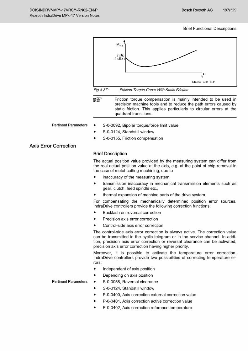
Fig.4-87: Friction Torque Curve With Static Friction
Friction torque compensation is mainly intended to be used inprecision machine tools and to reduce the path errors caused bystatic friction. This applies particularly to circular errors at thequadrant transitions.
Pertinent Parameters ● S‑0‑0092, Bipolar torque/force limit value● S‑0‑0124, Standstill window● S‑0‑0155, Friction compensation
Axis Error CorrectionBrief DescriptionThe actual position value provided by the measuring system can differ fromthe real actual position value at the axis, e.g. at the point of chip removal inthe case of metal-cutting machining, due to● inaccuracy of the measuring system,● transmission inaccuracy in mechanical transmission elements such as
gear, clutch, feed spindle etc.,● thermal expansion of machine parts of the drive system.For compensating the mechanically determined position error sources,IndraDrive controllers provide the following correction functions:● Backlash on reversal correction● Precision axis error correction● Control-side axis error correctionThe control-side axis error correction is always active. The correction valuecan be transmitted in the cyclic telegram or in the service channel. In addi‐tion, precision axis error correction or reversal clearance can be activated,precision axis error correction having higher priority.Moreover, it is possible to activate the temperature error correction.IndraDrive controllers provide two possibilities of correcting temperature er‐rors:● Independent of axis position● Depending on axis position
Pertinent Parameters ● S‑0‑0058, Reversal clearance● S‑0‑0124, Standstill window● P‑0‑0400, Axis correction external correction value● P‑0‑0401, Axis correction active correction value● P‑0‑0402, Axis correction reference temperature
DOK-INDRV*-MP*-17VRS**-RN02-EN-P Rexroth IndraDrive MPx-17 Version Notes
Bosch Rexroth AG 197/329
Brief Functional Descriptions

● P‑0‑0403, Axis correction reference position for temp. corr.● P‑0‑0404, Axis correction actual temperature pos.-dependent● P‑0‑0405, Axis correction actual temperature pos.-independent● P‑0‑0406, Axis correction temperature factor pos.-dependent● P‑0‑0407, Axis correction temperature factor pos.-independent● P‑0‑0408, Axis correction start position● P‑0‑0409, Axis correction end position● P‑0‑0410, Axis correction support point distance● P‑0‑0411, Axis correction, correction table positive● P‑0‑0412, Axis correction, correction table negative● P‑0‑0413, Axis correction control word
Quadrant Error CorrectionBrief Description
Assignment to functional firmware package, see chapter "Availa‐bility of the Extended Axis Functions".
In the case of axis drives that are controlled, for example, in circular interpo‐lation, static friction at the reversal points of the direction of motion can causedistortion of the circular contour.In order to compensate this contour error at the so-called "quadrant transi‐tions" (velocity reversal), IndraDrive controllers provide the "quadrant errorcorrection" function.This correction function is useful for such cases when drives are operated incyclic position control and in circular interpolation by the control master.
Pertinent Parameters ● P‑0‑0100, Position command value extension● P‑0‑0435, Control word of position controller● P‑0‑0436, Reference radius for quadrant error correction● P‑0‑0437, Velocity time range for quadrant error correction● P‑0‑0438, Table of path velocities for quadrant error correction● P‑0‑0439, Table of velocity pulse for quadrant error correction
Cogging Torque CompensationBrief Description
Assignment to functional firmware package, see chapter "Availa‐bility of the Extended Axis Functions".
Motors for which the magnetic excitation is realized with permanent magnets(e.g. synchronous motors) in many cases show cogging torques or coggingforces. Cogging torques/cogging forces already act on the moving compo‐nent of the motor in the de-energized state and aim at moving it to a stableposition.When the motor is put into motion by control, the cogging torques/coggingforces act on the motor in a decelerating or accelerating way, according tothe position. For applications in which minimum lag error or very constant ve‐locity is important, the position-dependent cogging torques/cogging forcescan have a negative effect.
Bosch Rexroth AG DOK-INDRV*-MP*-17VRS**-RN02-EN-P Rexroth IndraDrive MPx-17 Version Notes
198/329
Brief Functional Descriptions

To improve the synchronous operation and lag error behavior of synchronousmotors, IndraDrive controllers provide cogging torque and cogging force com‐pensation for drives with high demands on lag error and synchronous opera‐tion quality. For this purpose, the position dependent, additive torque com‐mand values that take effect in the drive control require an unambiguous po‐sition reference from the motor measuring system to the motor.The position reference is automatically established using a search of the ref‐erence marks. If this is not possible, a switch can be made into the function"Position reference by homing" (P‑0‑1131, Control word of cogging torquecompensation). The position reference is then established only with the com‐mand "Homing"; in this way, even encoders without a mark or with severalmarks can be used.
Hardware Requirements The motor must be equipped with a motor encoder. Cogging torque compen‐sation is not possible with sensorless motor operation!
Pertinent Parameters ● P‑0‑0162, C1800 Command Drive optimization / command value box● P‑0‑0165, Drive optimization, control word● P‑0‑0170, Drive optimization, acceleration● P‑0‑0171, Drive optimization, velocity● P‑0‑1129, Cogging torque compensation value● P‑0‑1130, Table of cogging torque compensation values pos. direction● P‑0‑1131, Control word of cogging torque compensation● P‑0‑1132, Table of cogging torque compensation values neg. direction● P‑0‑1133, Status word of cogging torque compensation● P‑0‑1134, Velocity threshold for attenuation of cogging torque compens● P‑0‑1135, Velocity threshold for switching off cogging torque compens.● P‑0‑1136, Lead time cogging torque compensation● P‑0‑1138, C4800 Command Determine cogging torque compensation
table● P‑0‑1139, Cogging torque compensation adaption factor
Pertinent Diagnostic Messages ● C1808 Drive not homed● C4800 Command Determine cogging torque compensation table● C4801 Cogging torque compensation: Measuring vel. too high● C4802 Cogging torque compensation: Measuring vel. too low● C4803 Cogging torque compensation: Inadmissible acceleration● C4804 Cogging torque comp.: Err. when storing corr. val table● C4805 Cogging torque comp.: Motor measuring system not homed
Correction of Torque/Force ConstantBrief DescriptionFields of Application
Base package of all firmware variants in closed loop characteristic
Display of Motor Load, Load LimitValues
For IndraDrive devices, the current load of the motor is determined and dis‐played on the drive side. The load can be limited by means of the controller.
DOK-INDRV*-MP*-17VRS**-RN02-EN-P Rexroth IndraDrive MPx-17 Version Notes
Bosch Rexroth AG 199/329
Brief Functional Descriptions

The unit of the load display and load limit value input can be selected:● Percentage-based, with relation to the continuous motor current or nom‐
inal motor current● Physically, values in "Nm" (rotary) or "N" (linear)The load of the motor is determined by means of the measured motor cur‐rent; with physical scaling, the controller determines the motor torque or forceby using the currently flowing current for calculating the motor-type-specifictorque or force constant.If torque/force precision up to approx. +/- 5% is required (e.g., for load limita‐tion) due to the mechanical axis system or process technology, the controllerprovides the "correction of torque/force constant". In this case, the motor-type-specific value is corrected depending on the current motor current, themotor temperature and the average speed.
Due to the downward compatibility of the firmware and possiblyunavailable parameter values (e.g., for third-party motors), thiscorrection must be separately activated!
Pertinent Parameters● P‑0‑0448, Temperature-dependent torque/force coefficient● P‑0‑0449, Speed-dependent torque/force coefficient● P‑0‑0450, Current torque/force constant● P‑0‑0556, Config word of axis controller● P‑0‑3055, Maximum motor torque/force, encoder memory● P‑0‑3056, Nominal motor torque/force, encoder memory● P‑0‑3057, Speed-dependent torque/force coefficient, encoder memory● P‑0‑3058, Temperature-dependent torque/force coefficient, enc.
memory● S‑0‑0533, Nominal torque/force of motor● S‑0‑0534, Maximum torque/force of motor
Pertinent Diagnostic Messages- None -
4.6.7 Measuring Wheel ModeBrief Description
Assignment to functional firmware package, see chapter "Availa‐bility of the Extended Axis Functions".
The measuring wheel mode is used for material feed axes, e.g. in sheet-met‐al machining. For direct measurement of the infeed of moved material, a rota‐ry encoder that is detecting the infeed length is driven via a measuring wheelwith frictionally engaged contact to the material surface.The position control loop is closed via motor encoder and measuring wheelencoder, possible slip between motor and material does not cause incorrectmeasured values of material length.
Bosch Rexroth AG DOK-INDRV*-MP*-17VRS**-RN02-EN-P Rexroth IndraDrive MPx-17 Version Notes
200/329
Brief Functional Descriptions

The measuring wheel mode may only be activated when contacthas been established between measuring wheel and material sur‐face.
Fig.4-88: Typical arrangement of drive for material infeed with measuring wheelencoder
Hardware Requirements The measuring wheel encoder is an optional (external) encoder that is con‐nected according to the connection diagram contained in the separate docu‐mentation (see "Other applicable documentation").See also Measuring Systems
Pertinent Parameters The following parameters are used to parameterize this function:● S‑0‑0520, Axis control word● S‑0‑0521, Axis status word● P‑0‑0241, Actual pos. smoothing time constant for hybrid pos. control● P‑0‑0242, Current actual slip value● P‑0‑0243, Maximum occurred actual slip value● P‑0‑0244, Monitoring window of slipThe following parameters are used to parameterize the measuring wheel en‐coder:● S‑0‑0115, Position feedback 2 type● S‑0‑0117, Resolution of feedback 2● P‑0‑0123, Feed constant 2 (optional encoder)● P‑0‑0124, Gear 2 load-side (optional encoder)● P‑0‑0125, Gear 2 encoder-side (optional encoder)● P‑0‑0185, Control word of encoder 2 (optional encoder)
Pertinent Diagnostic Messages ● F2036 Excessive position feedback difference
DOK-INDRV*-MP*-17VRS**-RN02-EN-P Rexroth IndraDrive MPx-17 Version Notes
Bosch Rexroth AG 201/329
Brief Functional Descriptions

4.6.8 Positive Stop Drive ProcedureBrief Description
Assignment to functional firmware package, see chapter "Availa‐bility of the Extended Axis Functions".
For special applications, it is required to move machine axes operated in po‐sition or velocity control up to a limit stop in order to generate forces of pres‐sure.When an axis in the standard situation has moved up to a limit stop, the driveshould signal a drive error by the monitoring facilities of the position or veloci‐ty control loop and react with shutdown.But if the drive can detect the special case of operation "positive stop driveprocedure", it can ignore the messages of the position and motions monitorsand generate the required force of pressure, if necessary.The control master signals this special case to the controller of IndraDrive de‐vices via a command. Upon this command, the drive switches off the respec‐tive monitors and acknowledges axis standstill to have been detected and aparameterizable force or torque threshold to have been exceeded.
Pertinent Parameters ● S‑0‑0082, Torque/force limit value positive● S‑0‑0083, Torque/force limit value negative● S‑0‑0092, Bipolar torque/force limit value● S‑0‑0124, Standstill window● S‑0‑0149, C1300 Positive stop drive procedure command
Pertinent Diagnostic Messages ● C1300 Positive stop drive procedure command● C1301 Class 1 diagnostics error at command start
4.6.9 Redundant Motor EncoderBrief Description
Assignment to functional firmware package, see chapter "Availa‐bility of the Extended Axis Functions".
Motor control of synchronous motors requires a position measuring systemthat measures the position of the moving part of the motor as opposed to thestatic part. If there is malfunction or defect in the position measuring system(motor encoder), a synchronous motor can no longer be decelerated in acontrolled way.Depending on the requirements, position control can require an externalmeasuring system at the axis which detects the position at the load with therequired precision.For axis control, the entire mechanical drive system between motor encoderand load position of the external encoder is mapped via parameters. This al‐lows calculating the position of the motor encoder from the position of the ex‐ternal encoder or determining the load position from the motor encoder posi‐tion, if the mechanical drive system is without slip.If there is a defect in the motor encoder, the motor position, when an externalencoder is used, can be determined via the position of the external encoderand the synchronous motor can be decelerated in a controlled way.
Bosch Rexroth AG DOK-INDRV*-MP*-17VRS**-RN02-EN-P Rexroth IndraDrive MPx-17 Version Notes
202/329
Brief Functional Descriptions

For asynchronous motors with motor encoder, it is also possible to use an ex‐ternal measuring system for controlled deceleration, if there is a defect in themotor encoder. But if the asynchronous motor, depending on the drive task,is operated without encoder, controlled deceleration via external encoder inthe case of error is not possible!
Only measuring systems with Upp = 1V or resolvers can be usedas redundant motor encoders!
Pertinent Parameters ● P‑0‑0185, Control word of encoder 2 (optional encoder)
Pertinent Diagnostic Messages ● F2031 Encoder 1 error: signal amplitude incorrect● F2042 Encoder 2: Encoder signals incorrect● F8022 Enc. 1: Enc. signals incorr. (can be cleared in ph. 2)● F8042 Encoder 2 error: Signal amplitude incorrect
4.6.10 Spindle PositioningBrief Description
Assignment to functional firmware package, see chapter "Availa‐bility of the Extended Axis Functions".
With the drive function "spindle positioning", the drive, at a command of themaster, aligns the spindle independently with regard to the spindle zero posi‐tion. The command position is transmitted to the drive controller via parame‐ter and can be preset as absolute or relative position.By means of the "position spindle" command, the spindle can be positionedin a position-controlled way (e.g. within the "velocity control" mode) withouthaving to switch the operation mode from velocity to position control.How to use the drive function "spindle positioning":● For milling and drilling spindles
– To prepare tool change → spindle remains at a defined position toallow changing the tool
● For turning machine main spindles– To change the workpiece (if required)– To place balancing drillings for workpieces to be balanced– To index the workpiece for further machining
● For revolving transfer machines– To advance the turntable in order to bring workpieces to a defined
machining position at the different stations
Hardware Requirements The use of a home switch may be required.See "Establishing Position Data Reference for Relative Measuring Systems"
Pertinent Parameters ● S‑0‑0152, C0900 Position spindle procedure command● S‑0‑0153, Spindle angle position● S‑0‑0154, Spindle positioning parameter● S‑0‑0180, Spindle relative offset● S‑0‑0222, Spindle positioning speed
DOK-INDRV*-MP*-17VRS**-RN02-EN-P Rexroth IndraDrive MPx-17 Version Notes
Bosch Rexroth AG 203/329
Brief Functional Descriptions

● S‑0‑0372, Drive Halt acceleration bipolar● S‑0‑0417, Positioning velocity threshold in modulo mode● S‑0‑0418, Target position window in modulo mode● S‑0‑0437, Positioning status● S‑0‑0041, Homing velocity● S‑0‑0042, Homing acceleration● P‑0‑1201, Ramp 1 pitch● P‑0‑1202, Final speed ramp 1● P‑0‑1203, Ramp 2 pitch● P‑0‑1211, Deceleration ramp 1● P‑0‑1213, Deceleration ramp 2
Pertinent Diagnostic Messages ● C0900 Position spindle command● C0902 Spindle positioning requires drive enable● C0903 Error during initialization● C0906 Error during search for zero pulse
4.6.11 Parameter Set SwitchingBrief Description
Assignment to functional firmware package, see chapter "Availa‐bility of the Extended Axis Functions".
IndraDrive drives are equipped with eight parameter sets (MPB-17VRS,MPC-17VRS, MPE-17VRS) or four parameter sets (MPM-17VRS) andswitches can be made among them during operation. One of the switchableparameter sets is always active. Switching takes place upon command of thecontrol master.
Notes on Applications By switching parameter sets during operation, the values of specific parame‐ters can be adjusted to the different operating phases or machining process‐es. This supports the work flow in flexible production facilities.Examples of application:● Changing from C-axis to roughing or finishing operation in the case of
spindles● Positioning mode for tool change with different gear ratios● Changing motor spindles for different machining phases● Adjusting the control loop gains to different load inertia or load masses
(e.g. with very different workpieces)● Star-delta switching of motors with switchable winding to increase the
torque in short-time operationClassification of Switchable Pa‐
rametersUnder the application-related point of view, the parameters to be switchedare divided into the following groups:● Application Parameters● Control Loop Parameters● Load gear parameters (for MPB-17VRS, MPC-17VRS, MPM-17VRS on‐
ly in the alternative functional package Main spindle function)
Bosch Rexroth AG DOK-INDRV*-MP*-17VRS**-RN02-EN-P Rexroth IndraDrive MPx-17 Version Notes
204/329
Brief Functional Descriptions

● Winding parameters (for MPB-17VRS, MPC-17VRS, MPM-7VRS only inthe alternative functional package Main spindle function)
● Motor control and motor encoder parameters (for MPB-17VRS,MPC-17VRS, MPM-17VRS only in the alternative functional packageMain spindle function)
Pertinent Parameters ● S‑0‑0216, C4100 Switch parameter set command● S‑0‑0217, Preselect parameter set command● S‑0‑0219, IDN-list of parameter set
List parameters S‑0‑0219 to S‑7‑0219 contain parameter sets no.0 to no. 7
● S‑0‑0254, Current parameter set● P‑0‑2216, Parameter set switching, configuration● P‑0‑2217, Parameter set switching, preselection range● P‑0‑2218, Parameter set switching, delay time
Pertinent Diagnostic Messages ● C0273 Modulo value for motor encoder cannot be displayed● C0278 Modulo value for optional encoder cannot be displayed● C0280 Maximum travel range cannot be displayed internally● C4100 Switch parameter set command● C4101 Switching only possible without AF● C4103 Preselect parameter set forbidden value● C4104 Error during parameter set switching (->S-0-0423)
4.6.12 Star-Delta SwitchingBrief Description
Fields of ApplicationWith star(Y)-delta(D) switching, the torque power characteristic of a spindlefor short-time operation without mechanical transmission elements can beadapted to various processing requirements:● Removing material (roughing): high torque, low speed● Fine machining (finishing): high speed, low torque
DOK-INDRV*-MP*-17VRS**-RN02-EN-P Rexroth IndraDrive MPx-17 Version Notes
Bosch Rexroth AG 205/329
Brief Functional Descriptions

Y Star connectionD Delta connectionFig.4-89: Schematic Operating Characteristic of a Spindle Drive with a Star-Del‐
ta-Switchable MotorThe spindle output capacity with star connection is just 2/3 of the capacitywith delta connection, i.e. the star-delta-switching is not a complete replace‐ment for gear switching because for each gear level the same output capacityis available! The increased torque in short-time operation with star connectionin comparison with delta connection is not associated with an increase in thecontinuous torque of the spindle!
The increase in the short-time operation torque can also be ach‐ieved with an increased type current of the controller with a nes‐ted motor instead of with star-delta-switching. This eliminates theprotective circuit that is not maintenance free over the long termwith which additional wiring effort and braking problems in case ofmains power failure are associated!
For milling spindles, due to long run-up times for star connection, star-deltaswitching is usually not suitable!
Bosch Rexroth AG DOK-INDRV*-MP*-17VRS**-RN02-EN-P Rexroth IndraDrive MPx-17 Version Notes
206/329
Brief Functional Descriptions

FeaturesMotor design Star-delta switching can only be used with Rexroth motors specially designed
for this purpose or with third-party motors. With these motors, all six windingends of the three-phase motor are run into the motor terminal box. Standardmotors are interconnected internally in a fixed manner; only three power con‐nections are accessible!
Procedure for Star-Delta Switching IndraDrive controllers support star-delta switching of synchronous and asyn‐chronous three-phase motors in the following way:● Using switchable parameters, a parameter set with all of the relevant
motor parameters is assigned to every type of motor connection in thecontroller. To do this, the functional package "Main spindle" is required,which offers "parameter set switching".
● Star-delta switching can be performed during operation, i.e. with an ac‐tive drive. The controller converts the motor control voltage to the newtype of connection and, in so doing, implements a connection type tran‐sition without it being noticed. However, the controller does not controlthe contactors for switching the motor windings; this is carried out exter‐nally by the control master.
● Each connection type must be taken into operation respectively andeach is independently effective and functional. There is no conversion ofwinding-specific parameter values based on the respective connectiontype.
Triggering Star-Delta Switching The change into the other connection type is triggered by switching parame‐ters ("parameter set switching").
Pertinent Parameters● P‑0‑2216, Parameter set switching, configuration● S‑0‑0217, Preselect parameter set command● S‑0‑0216, C4100 Switch parameter set command● S‑0‑0219, IDN-list of parameter set
Pertinent Diagnostic Messages● C4100 Switch parameter set command
4.6.13 Drive-Controlled OscillationBrief Description
Assignment to functional firmware package, see chapter "Availa‐bility of the Extended Axis Functions".
Upon a command of the control master, the drive ignores the cyclic commandvalue input and independently turns alternately in positive and negative direc‐tion (speed oscillation). The cyclic speed characteristic can be set via param‐eters and can be realized symmetrically or asymmetrically.
Notes on Applications With speed oscillation the main drive supports the following applications, forexample:● Meshing the toothed wheels when switching a gear train● Engaging positive clutches (e.g. connecting IC engine equipment under
test to test stands)
Pertinent Parameters ● S‑0‑0213, Oscillation speed
DOK-INDRV*-MP*-17VRS**-RN02-EN-P Rexroth IndraDrive MPx-17 Version Notes
Bosch Rexroth AG 207/329
Brief Functional Descriptions

● S‑0‑0214, Oscillation offset speed● S‑0‑0215, Oscillation cycle time
Pertinent Diagnostic Messages ● C4200 Drive-controlled oscillation command● C4201 Oscillation requires drive enable● C4202 Oscillation command speed cannot be reached
4.6.14 Parking AxisBrief Description
Assignment to functional firmware package, see chapter "Availa‐bility of the Extended Axis Functions".
If individual axes within a master communication group (e.g. SERCOS ring,PROFIBUS) are to be temporarily deactivated, without taking them out of theaxis group on the hardware and communication side, the function "parkingaxis" can be activated via command.When a drive has been put into the status "parking axis", it behaves "neutral‐ly" with regard to hardware and master communication. Errors possibly de‐tected by the drive are suppressed and have no effect on the axes in opera‐tion. This allows, for example, uncoupling the motor and the motor encoder inthe status "parking axis" without errors being signaled.The axis that has been "parked" behaves as if it would not exist!
Pertinent Parameters ● S‑0‑0139, C1600 Parking axis procedure command
Pertinent Diagnostic Messages ● C1600 Parking axis command
4.6.15 Integrated Safety TechnologyGeneral Information
The integrated safety functions "Safe torque off" and "Safe brake control"(L4) can be used as of the firmware version MPx16V14.
The following section provides an overview of the integrated safe‐ty functions. Details concerning function, notes on commissioningand examples of application are described in the separate docu‐mentation "Rexroth IndraDrive, Integrated Safety Technology asof MPx-1x" (DOK-INDRV*-SI3-OP-MAN*-OPxx-DE-P; partno. R911332836).
Product PresentationWhat is "Integrated Safety Technology"?The control sections of the IndraDrive Cs range can be equipped with the op‐tional modules "L3" [STO (Safe Torque Off)] or "L4" [STO (Safe Torque Off)and SBC (Safe Brake Control)].By the mentioned optional modules, IndraDrive Cs is equipped with integra‐ted safety technology which provides the user with safe torque off, as well as,when using the optional module "L4", with safe control of a brake.
Definition ● "Safe Torque Off" means application-related safety functions which areapplicable for personal protection at machines according toEN ISO 13849‑1 Category 4 PL e and IEC EN 62061 SIL 3.
Bosch Rexroth AG DOK-INDRV*-MP*-17VRS**-RN02-EN-P Rexroth IndraDrive MPx-17 Version Notes
208/329
Brief Functional Descriptions

● "Safe Brake Control" means application-related safety functions whichare applicable for personal protection at machines according toEN ISO 13849‑1 Category 4 PL e and IEC EN 62061 SIL 3.
Selecting the Function The safety functions can be selected via 24 V inputs at the drive controller.Certification The safety technology was certified by TÜV Rheinland ®; the NRTL listing by
TÜV Rheinland of North America is in preparation.
Certificates are available on the Internet/Extranet.
Requirements That Can Be Real‐ized
The integrated safety technology is independent of the type of master com‐munication, the higher-level control units and the supply modules. It is availa‐ble as a functional characteristic of the standard drive system. The require‐ments below can be realized in the machine or in the installation:● Measures according to EN ISO 12100‑2, if accessing the danger zone is
required, for example, for equipping, teaching or material withdrawal.● Requirements for safety-related parts of control units according to
EN ISO 13849‑1 Category 4 PL e and IEC EN 62061 SIL 3, as requiredin EN 1010‑1 (printing and paper converting machines), EN 12415 (turn‐ing machines) and EN 12417 (machining centres).
● Control functions in the case of error according to EN 60204‑1 (see"Using diversity" in EN 60204‑1).
Integrated Safety Technology as IndraDrive Platform SolutionThe type code below shows the different characteristics of IndraDrive Cs.
DOK-INDRV*-MP*-17VRS**-RN02-EN-P Rexroth IndraDrive MPx-17 Version Notes
Bosch Rexroth AG 209/329
Brief Functional Descriptions

Fig.4-90: Type Code HCS01
Bosch Rexroth AG DOK-INDRV*-MP*-17VRS**-RN02-EN-P Rexroth IndraDrive MPx-17 Version Notes
210/329
Brief Functional Descriptions

To employ the integrated safety technology according toIEC EN 61800-5-2, you must at least use the following firmwareversion or higher in the drive.● Optional module "L3": MP*17V06● Optional module "L4": MP*16V14
Safe Torque Off (STO)Brief Description
Using the function "Safe torque off" requires the optional safetytechnology module "L3" or "L4".
The energy supply to the motor is safely interrupted with the safety function"Safe torque off". The drive cannot generate any torque/force and, as a con‐sequence, it cannot generate any dangerous motions, either.
Before activating the safety function "Safe torque off", the drivesystem must be decelerated via the command value input; thereis no drive-controlled deceleration!
Lethal injury and/or property damage causedby unintended axis motion!
WARNING
⇒ If external force influences are to be expected with the safety function"Safe torque off", e.g. in the case of a vertical axis, this motion has to besafely prevented by additional measures, e.g. a mechanical brake or a weightcompensation; for such axes, Bosch Rexroth recommends that you use thesafe braking and holding system.
High electrical voltage! Danger to life, risk ofinjury by electric shock or serious injury!
WARNING
During the time a safety function is active, power is not removed from the mo‐tor; de-energize the motor's drive before working on it.
Features The safety function "Safe torque off" (STO) has the following features:● When the optional safety technology module "L4" is used and the safety
function "Safe torque off" (STO) is selected, the "Safe brake control"(SBC) is automatically activated.
● Corresponds to stop category 0 according to EN 60204‑1● Is suited for safety-relevant applications up to Category 4 PL e accord‐
ing to EN ISO 13849‑1 or SIL 3 according to IEC EN 62061.● The energy supply to the motor is safely interrupted via two channels.● The selection can take place via two channels, alternatively by means of
– a passive safety unit with dual-channel, isolated conventional (non-solid-state) normally closed contacts (e.g., safety switching devicefor emergency stop, safety door monitor, etc.) or
– an active safety unit with plus-plus-switching or plus-minus-switch‐ing OSSD outputs (e.g., safety control units, laser scanners, etc.).
● The selection can take place via one channel, alternatively by means of
DOK-INDRV*-MP*-17VRS**-RN02-EN-P Rexroth IndraDrive MPx-17 Version Notes
Bosch Rexroth AG 211/329
Brief Functional Descriptions

– a passive safety unit with an isolated conventional (non-solid-state)normally closed contact (designed in compliance with SIL3), e.g.,safety switching device for emergency stop, safety door monitor,etc.In addition, the elimination of errors in the wiring (considering EN61800‑5‑2: 2007, table D.1 or EN ISO 13849‑2: 2008, table D.4) isrequired, or
– by means of an active safety unit with plus-switching OSSD output(e.g., safety control units, laser scanners, etc.). In addition, theelimination of errors in the wiring (considering EN 61800‑5‑2: 2007,table D.1 or EN ISO 13849‑2: 2008, table D.4) is required.
● The dynamization of the safety function selection takes place alterna‐tively by means of– the OSSD dynamization of the active safety unit or– the dynamization outputs at the X49 terminal connector of the op‐
tional safety technology module "L3" or "L4" in the case of controlby passive safety units.
● It is possible to set up a zone by connecting up to 25 drives in parallel.● Online dynamization of the outputs and interrupting circuits● Quick reaction time (18 ms)● The status of the safety function "Safe torque off" is displayed via the
parameter "P‑0‑0106, Operating status STO/SBC".Pertinent Parameters The following parameters are used in conjunction with the safety function
"Safe torque off":● P‑0‑0106, Operating status STO/SBC
Pertinent Diagnostic Messages The following diagnostic messages can be generated in conjunction with thesafety function "Safe torque off":● A0011 STO/SBC active● E8027 STO/SBC while drive enabled● F3134 Dynamization time interval incorrect● F8027 STO/SBC while drive enabled● F8300 Dynamization pulse width incorrect● F8301 Error when checking selection signals● F8302 Error when checking switch-off channels STO/SBC● F8303 System error STO/SBCWith the safety function "Safe torque off" activated, the display of theIndraDrive control panel shows "STO".
Safe Brake Control (SBC)Brief Description
Using the function "Safe brake control (SBC)" requires the option‐al safety technology module "L4".
With the safety function "Safe brake control (SBC)", the motor holding brakeis switched off safely (via two channels).
Before activating the safety function "Safe brake control (SBC)",the drive system must be decelerated via the command value in‐put; there is no drive-controlled deceleration!
Bosch Rexroth AG DOK-INDRV*-MP*-17VRS**-RN02-EN-P Rexroth IndraDrive MPx-17 Version Notes
212/329
Brief Functional Descriptions

Features The safety function "Safe brake control" (SBC) has the following features:● The safety function "Safe brake control" (SBC) is automatically activated
when the safety function "Safe torque off" (STO) is selected● Is suited for safety-relevant applications up to Category 4 PL e accord‐
ing to EN ISO 13849-1 or SIL 3 according to IEC EN 62061.● The energy supply to the motor holding brake is safely interrupted via
two channels.● The selection can take place via two channels, alternatively by means of
– a passive safety unit with dual-channel, isolated conventional (non-solid-state) normally closed contacts (e.g., safety switching devicefor emergency stop, safety door monitor, etc.) or
– by an active safety unit with plus-plus-switching or plus-minus-switching OSSD outputs (e.g., safety control units, laser scanners,etc.).
● The selection can take place via one channel, alternatively by means of– a passive safety unit with an isolated conventional (non-solid-state)
normally closed contact (designed in compliance with SIL3), e.g.,safety switching device for emergency stop, safety door monitor,etc.In addition, the elimination of errors in the wiring (considering EN61800-5-2: 2007, table D.1 or EN ISO 13849-2: 2008, table D.4) isrequired, or
– by means of an active safety unit with plus-switching OSSD output(e.g., safety control units, laser scanners, etc.). In addition, theelimination of errors in the wiring (considering EN 61800-5-2: 2007,table D.1 or EN ISO 13849-2: 2008, table D.4) is required.
● The dynamization of the safety function selection takes place alterna‐tively by means of– the OSSD dynamization of the active safety unit or– the dynamization outputs at the X49 terminal connector of the op‐
tional safety technology module "L4" in the case of control by pas‐sive safety units.
● It is possible to set up a zone by connecting up to 25 drives in parallel● Only self-holding (electrically releasing) brakes are supported● Online dynamization of the outputs and interrupting circuits● Quick reaction time (18 ms plus brake delay time)● The status of the safety function "Safe brake control" is displayed via the
parameter "P‑0‑0106, Operating status STO/SBC".Pertinent Parameters The following parameter is used in conjunction with the safety function "Safe
brake control":● P‑0‑0106, Operating status STO/SBC
Pertinent Diagnostic Messages The following diagnostic messages can be generated in conjunction with thesafety function "Safe brake control" (SBC):● A0011 STO/SBC active● C0256 Safety technology configuration error● E8027 STO/SBC while drive enabled● F3134 Dynamization time interval incorrect● F8027 STO/SBC while drive enabled
DOK-INDRV*-MP*-17VRS**-RN02-EN-P Rexroth IndraDrive MPx-17 Version Notes
Bosch Rexroth AG 213/329
Brief Functional Descriptions

● F8300 Dynamization pulse width incorrect● F8301 Error when checking selection signals● F8302 Error when checking switch-off channels STO/SBC● F8303 System error STO/SBCWith the safety function "Safe brake control" activated, the display of theIndraDrive control panel shows "STO", because the safe brake control canonly be activated in conjunction with the safe torque off (STO) function.
4.7 Optional Device Functions4.7.1 Safety Instructions
Dangerous movements! Danger to life, risk ofinjury, serious injury or property damage!
WARNING
● Keep free and clear of the ranges of motion of machines and movingmachine parts.
● Prevent personnel from accidentally entering the machine’s range ofmotion (e.g., by safety fence, safety guard, protective covering, light bar‐rier).
● Make sure that the drives are brought to safe standstill before accessingor entering the danger zone.
● In addition, observe the safety message "Protection Against DangerousMovements" in the chapter "Safety Instructions for Electric Drives andControls".
4.7.2 Availability of the Optional Device FunctionsThe following overview illustrates by which base or functional packages therespective optional device function is supported (if not stated otherwise, thisapplies to all firmware versions, MPB, MPE and MPC).
Optional device functionIn base package(characteristic)
In functional package ...(on the basis of a base package with the following character‐
istics)
Servo function Synchronization Main spindle
Digital inputs/outputs 1) OL/CL – – –
Analog inputs 1) OL/CL – – –
Command value generator OL/CL – – –
command value box CL – – –
Programmable position switch – CL2)3) CL2)3) –
Probe CL – – –
Measuring encoder1) – OL/CL 2) OL/CL 2) –
OL Open-loop characteristicCL Closed-loop characteristic1) Depending on hardware configuration2) Not for the firmware version MPE3) Not for the firmware version MPMFig.4-91: Availability of the Optional Device Functions
Bosch Rexroth AG DOK-INDRV*-MP*-17VRS**-RN02-EN-P Rexroth IndraDrive MPx-17 Version Notes
214/329
Brief Functional Descriptions

To use a functional package, it must have been activated (enabled). The cur‐rently enabled functional packages are displayed in parameter "P‑0‑2004,Active functional packages".See also "Enabling of Functional Packages"
4.7.3 Cross Communication (CCD)Brief Description
Overview The IndraDrive "cross communication" device function (Cross Communica‐tion Drives → CCD) allows electronic (digital) coupling of axes and the con‐nection of I/O modules for IndraMotion MLD.
Fig.4-92: Hardware Topology of Drive Cross Communication (CCD)Bus Topology Configuration of the CCD slaves and communication with the external control
section always takes place via the CCD master drive, as the individual CCDslaves are connected to the master via a SERCOS III interface. Therefore,external access always takes place via the drive acting as the CCD master,which requires a master communication interface (e.g. PROFIBUS) in addi‐tion to the CCD optional module ("SERCOS III master connection").
CCD Modes (Kinds of Coupling) When cross communication (CCD) is used between the drives, the followingvariants (CCD modes) are differentiated:● CCD system mode
The CCD slaves have a direct logic connection to the field bus master.The command triggering and input of process data are carried out via anexternal control.
● CCD basic mode
DOK-INDRV*-MP*-17VRS**-RN02-EN-P Rexroth IndraDrive MPx-17 Version Notes
Bosch Rexroth AG 215/329
Brief Functional Descriptions

The same functions as for the CCD system mode are available. Howev‐er, the user has to program them. It is not possible to use the MLD-Mfunctionality in the master axis.
● MLD-M system modeThe CCD slaves have no direct logic connection to the external controlsection, but only to the MLD-M in the CCD master. Command triggeringand input of process data take place by the MLD‑M in the CCD master.
Features The device function "cross communication (CCD)" is characterized by the fol‐lowing features:● Synchronization of CCD slaves to CCD master● Transmission of freely configurable external process data (command
values and actual values of the external control section)● Command value linking by transmission of freely configurable process
data of the CCD axes (e.g. master/slave, Gantry axis)● Connection of I/O extensions for SERCOS III via CCD (a maximum of 4
modules per CCD master)● CCD (SERCOS III) cycle time can be parameterized (0.25 ms to 4 ms;
depends on CCD mode, controller performance and number of axes)● Max. baud rate: 100 MBaud● CCD communication protocol: SERCOS III (see "SERCOS III")● Data channels:
– Cyclic data channel (MDT, AT): Max. 48 bytes and 16 IDN– Parameter or service channel: 4 bytes
● Parameterization of all axes in the CCD group via the CCD master inter‐faces (RS232, Engineering Port, field bus, …)
● Command triggering of the CCD slaves depending on selected CCDmode via external control section or internally via MLD in CCD master
● Max. number of CCD slaves: 7 or 9 (depends on CCD mode; see below"Performance Features")
Fields of Application Typical fields of application for cross communication:● Control tasks for multi-axis applications
– Anti backlash– Synchronous operation control– Load control of several axes
● Simple command value linking– Position command value linking (Gantry axes)– Torque/force linking
● Simple motion controls with decentralized command value adjustmentfor single-axis positioning and master axis linking
● I/O extension by connection of I/O modules for SERCOS III via CCDRestrictions When using cross communication, observe the following restrictions:
● With the cross communication function, "Coordinated Motion" is not pos‐sible!
● In the MLD-M system mode, the multiplex channel for external controlsin the CCD is not available
Bosch Rexroth AG DOK-INDRV*-MP*-17VRS**-RN02-EN-P Rexroth IndraDrive MPx-17 Version Notes
216/329
Brief Functional Descriptions

● The higher-level master is usually a PLC with a field bus which does nothave real-time and synchronization ability (PROFIBUS®, DeviceNetTM,EtherNet/IPTM).
Hardware Requirements Using the drive function "cross communication" requires the following controlsection design:● CCD master
Control section/device in ADVANCED form with CCD option→ CSH-01.3C-xx-xxx-xxx-CCD-xx-x-..→ HCS01.1E-W00xx-A-0x-A-xx-xx-xx-xx-xx-FW
● CCD slavesControl section with master communication interface "SERCOS III" (S3)or "Multiethernet" (ET); possible with the following designs:– BASIC UNIVERSAL single-axis → CSB-01.xC-S3-xxx-xx-x,
CSB-01.xC-ET-xxx-xx-x– BASIC UNIVERSAL double-axis → CDB-01.xC-S3-xxx-xx-x,
CDB-01.xC-ET-xxx-xx-x– ADVANCED single-axis → CSH-01.xC-S3-xxx-xx-x, CSH-01.xC-
ET-xxx-xx-x– IndraDrive Cs-single-axis → HCS01.1E-W00xx-A-0x-x-xx-xx-xx-xx-
xx-FW
See documentation "Control Sections for Drive Controllers; ProjectPlanning Manual"
Firmware Requirements When using the drive function "cross communication", observe the followingaspects regarding the firmware:● This drive function is supported as of the firmware version MPx04.● For firmware versions MPx04 and MPx05 all drives of a CCD group
(CCD master and CCD slaves) have to be operated with the same firm‐ware version (e.g. all MPx05VRS).
● The CCD master has to be operated with MPC0xVRS (CSH1.3), prMPC17 (HCS01.1E-W00xx-A-0x-A-xx-xx-xx-xx-xx-FW). In this case,CCD slaves with MPx04 or MPx05 cannot be operated.
● As for integrated safety technology, this firmware function does not re‐quire separate enabling of functional packages; the function of drivecross communication is available with the corresponding hardware de‐sign.
Pertinent Parameters The parameters listed below only exist for the CCD master:● P‑0‑0197, System time● P‑0‑1600, CCD: configuration● P‑0‑1601, CCD: addresses of projected drives● P‑0‑1602, CCD: timing settings● P‑0‑1603, CCD: Actual topology addresses● P‑0‑1604, CCD: addresses of projected I/Os● P‑0‑1605, CCD: command communication phase● P‑0‑1606, CCD: actual communication phase● P‑0‑1607, CCD: axis error● P‑0‑1609, CCD: status word
DOK-INDRV*-MP*-17VRS**-RN02-EN-P Rexroth IndraDrive MPx-17 Version Notes
Bosch Rexroth AG 217/329
Brief Functional Descriptions

● P‑0‑1610, CCD: cycle time● P‑0‑1610.0.3, CCD: Actual topology● P‑0‑1610.0.21, CCD: Slave addresses at end of line● P‑0‑1610.0.30, CCD: Diagnostic message text● P‑0‑1611, CCD: configuration list signal status word● P‑0‑1612, CCD: configuration list signal control word● P‑0‑1613, CCD: assignment list signal status word● P‑0‑1614, CCD: assignment list signal control word● P‑0‑1615, CCD: extrapolated cmd value IDN list signal selection● P‑0‑1616, CCD: extrapolated cmd value signal selection● P‑0‑1617, CCD: number of extrapolation steps● P‑0‑1618, CCD: extrapolated command value● P‑0‑1619, CCD: Slave information at topology location● P‑0‑1620.0.3, CCD: Command topology● P‑0‑1620.0.4, CCD: Slave identification● P‑0‑1620.0.5, C7400 CCD: Switching to phase 2● P‑0‑1620.0.6, C7500 CCD: Switching to phase 4● P‑0‑1620.0.21, C7100 CCD: Command Close ring● P‑0‑1620.0.30, CCD: I/O selection for commando C72● P‑0‑1620.0.31, C7200 CCD: Commando Apply I/O configuration● P‑0‑1621, CCD: configuration list master communication cmd values● P‑0‑1621.x.1, CCD: Slave address in high level network● P‑0‑1621.x.9, CCD: Master comm. C0100 Comm. phase 3 transition
check● P‑0‑1621.x.10, CCD: Master comm. C5200 Comm. phase 4 transition
check● P‑0‑1621.x.24, CCD: Master communication gateway parameter pool 1● P‑0‑1621.x.25, CCD: Master communication gateway parameter pool 2● P‑0‑1621.x.35, g C5300 CCD: SIII SYNC delay measuring procedure
command● P‑0‑1622, CCD: configuration list master communication actual values● P‑0‑1623, CCD: configuration list master cmd values● P‑0‑1624, CCD: configuration list actual master values● P‑0‑1625, CCD: configuration list slave cmd values● P‑0‑1626, CCD: configuration list actual slave values● P‑0‑1627, CCD: configuration list master cmd values I/Os● P‑0‑1628, CCD: configuration list act. master values I/Os● P‑0‑1629, CCD: configuration compact I/Os● P‑0‑1630, CCD: diagnosis● P‑0‑1630.x.1, CCD: Slave IP address● P‑0‑1630.x.2, CCD: Device Status (S-Dev)● P‑0‑1630.x.3, CCD: Connection-Control #0 (C-Con)● P‑0‑1630.x.20, CCD: Resource-Status (S-Res)
Bosch Rexroth AG DOK-INDRV*-MP*-17VRS**-RN02-EN-P Rexroth IndraDrive MPx-17 Version Notes
218/329
Brief Functional Descriptions

● P‑0‑1631, CCD: AT error counter● P‑0‑1632, CCD: system data 2 bytes● P‑0‑1633, CCD: system data 4 bytes● P‑0‑1634.x.1, CCD: Module type codes of the modular I/Os● P‑0‑1635, C7000 CCD: command adjust slave addresses● P‑0‑1636, CCD: Command topology addresses● P‑0‑1637, CCD: error counter Port-1● P‑0‑1638, CCD: error counter Port-2● P‑0‑1639, CCD: allowed telegram failures● P‑0‑1640, CCD: MAC address● P‑0‑1641, CCD: IP address● P‑0‑1642, CCD: network mask● P‑0‑1643, CCD: gateway address● P‑0‑1644, CCD: status IP communication● P‑0‑1645.x.1, CCD connection: Configuration● P‑0‑1645.x.2, CCD connection: Connection number● P‑0‑1645.x.3, CCD connection: Telegram assignment● P‑0‑1645.x.4, CCD connection: Max. length of connection● P‑0‑1645.x.5, CCD connection: Current connection length● P‑0‑1645.x.6, CCD connection: Configuration list● P‑0‑1645.x.8, CCD connection: Connection control (C-Con)● P‑0‑1645.x.10, CCD connection: Producer cycle time● P‑0‑1645.x.11, CCD connection: Allowed losses of producer data● P‑0‑1645.x.12, CCD connection: Error counter data losses● P‑0‑1645.x.20, CCD connection: IDN allocation of real-time bits● P‑0‑1645.x.21, CCD connection: Bit number allocation of real-time bits● P‑0‑1651, CCD: master control word, slave 1
(up to P‑0‑1659)● P‑0‑1660.x.2, CCD: Device Control (C-Res)● P‑0‑1660.x.3, CCD: Connection-Control #1 (C-Con)● P‑0‑1660.x.20, CDD: Resource-Control (C-Res)● P‑0‑1661, CCD: drive status word, slave 1
(up to P‑0‑1669)● P‑0‑1670, CCD: active actual position value, master● P‑0‑1671, CCD: active actual position value, slave 1
(up to P‑0‑1679)● P‑0‑1680, CCD: actual velocity value, master● P‑0‑1681, CCD: actual velocity value, slave 1
(up to P‑0‑1689)● P‑0‑1690, CCD: actual torque/force value, master● P‑0‑1691, CCD: actual torque/force value, slave 1
(up to P‑0‑1699)
DOK-INDRV*-MP*-17VRS**-RN02-EN-P Rexroth IndraDrive MPx-17 Version Notes
Bosch Rexroth AG 219/329
Brief Functional Descriptions

● P‑0‑1701, CCD: Diagnostic message number, slave 1(up to P‑0‑1709)
● P‑0‑1710, CCD: signal status word, master● P‑0‑1711, CCD: signal status word, slave 1
(up to P‑0‑1719)● P‑0‑1720, CCD: signal control word, master● P‑0‑1721, CCD: signal control word, slave 1
(up to P‑0‑1729)● P‑0‑1730, CCD: Command value data container 1, Master 4Byte● P‑0‑1731, CCD: Command value data container 1, Slave 1 4Byte
(up to P‑0‑1739)● P‑0‑1740, CCD: Command value data container 2, Master 4Byte● P‑0‑1741, CCD: Command value data container 2, Slave 1 4Byte
(up to P‑0‑1749)● P‑0‑1750, CCD: Command value data container 3, Master 4Byte● P‑0‑1751, CCD: Command value data container 3, Slave 1 4Byte
(up to P‑0‑1759)● P‑0‑1760, CCD: Command value data container 4, Master 4Byte● P‑0‑1761, CCD: Command value data container 4, Slave 1 4Byte
(up to P‑0‑1769)● P‑0‑1770, CCD: Actual value data container 1, Master 4Byte● P‑0‑1771, CCD: Actual value data container 1, Slave 1 4Byte
(up to P‑0‑1779)● P‑0‑1780, CCD: Actual value data container 2, Master 4Byte● P‑0‑1781, CCD: Actual value data container 2, Slave 1 4Byte
(up to P‑0‑1789)● P‑0‑1790, CCD: Actual value data container 3, Master 4Byte● P‑0‑1791, CCD: Actual value data container 3, Slave 1 4Byte
(up to P‑0‑1799)● P‑0‑1800, CCD: Actual value data container 4, Master 4Byte● P‑0‑1801, CCD: Actual value data container 4, Slave 1 4Byte
(up to P‑0‑1809)● P‑0‑1810, CCD: Status word synchronous operation modes, master● P‑0‑1811, CCD: Status word synchronous operation modes, slave 1
(up to P‑0‑1819)● P‑0‑1820, CCD: Command value data container 1, Master 2Byte● P‑0‑1821, CCD: Command value data container 1, Slave 1 2Byte
(up to P‑0‑1829)● P‑0‑1830, CCD: Command value data container 2, Master 2Byte● P‑0‑1831, CCD: Command value data container 2, Slave 1 2Byte
(up to P‑0‑1839)● P‑0‑1840, CCD: Command value data container 3, Master 2Byte
Bosch Rexroth AG DOK-INDRV*-MP*-17VRS**-RN02-EN-P Rexroth IndraDrive MPx-17 Version Notes
220/329
Brief Functional Descriptions

● P‑0‑1841, CCD: Command value data container 3, Slave 1 2Byte(up to P‑0‑1849)
● P‑0‑1850, CCD: Command value data container 4, Master 2Byte● P‑0‑1851, CCD: Command value data container 4, Slave 1 2Byte
(up to P‑0‑1859)● P‑0‑1860, CCD: Actual value data container 1, Master 2Byte● P‑0‑1861, CCD: Actual value data container 1, Slave 1 2Byte
(up to P‑0‑1869)● P‑0‑1870, CCD: Actual value data container 2, Master 2Byte● P‑0‑1871, CCD: Actual value data container 2, Slave 1 2Byte
(up to P‑0‑1879)● P‑0‑1880, CCD: Actual value data container 3, Master 2Byte● P‑0‑1881, CCD: Actual value data container 3, Slave 1 2Byte
(up to P‑0‑1889)● P‑0‑1890, CCD: Actual value data container 3, Master 2Byte● P‑0‑1891, CCD: Actual value data container 3, Slave 1 2Byte
(up to P‑0‑1899)
For configuring the SERCOS III communication in the slaves, thestandard SERCOS III parameters are used (e.g. "S‑0‑1002,SERCOS III: Communication Cycle time (tScyc)" etc.).
Pertinent Diagnostic Messages ● C0265 Incorrect CCD address configuration● C0266 Incorrect CCD phase switch● C0267 CCD timeout phase switch● C0403 Switching to CCD phase 2 impossible● C7000 CCD: Command Close ring● C7001 CCD: Impossible to close ring● C7100 CCD: Command Close ring● C7101 CCD: Impossible to close ring● C7200 CCD: Command Apply I/O configuration● C7201 CCD: Impossible to apply I/O configuration● C7400 CCD: Switching to phase 2● C7401 CCD: Impossible to switch to phase 2● C7500 CCD: Switching to phase 4● C7501 CCD: Impossible to switch to phase 4● E4012 Maximum number of CCD slaves exceeded● E4013 Incorrect CCD addressing● E4014 Incorrect phase switch of CCD slaves● E4016 CCD: Topology error● E4017 CCD: Unknown I/O configuration● F2140 CCD slave error● F4012 Incorrect I/O length● F4140 CCD communication error
DOK-INDRV*-MP*-17VRS**-RN02-EN-P Rexroth IndraDrive MPx-17 Version Notes
Bosch Rexroth AG 221/329
Brief Functional Descriptions

● F6140 CCD slave error (emergency halt)● F8140 Fatal CCD error
4.7.4 Digital Inputs/OutputsBrief Description
General InformationThe basic variants of the IndraDrive Cs controllers with their ECONOMY andBASIC control section versions and the IndraDrive C multi-axis controllerswith BASIC control section version already have configurable digital inputs/outputs.
Hardware Requirements The number, assignment and function of the digital inputs/outputs depend onthe type of the drive controller and are contained in the respective hardwaredescription (Project Planning Manual).
Digital Inputs/Outputs on Control SectionFeatures ● Sampling of digital inputs and outputs or transmitting data to them is
done in the position loop clock TA_position (see "Performance Data")● Configurable digital inputs/outputs with effective direction that can be
freely set to some extent (input or output):– IndraDrive Cs with firmware MPB or MPE:
– 1 switchable digital input/output– 7 digital inputs [2 of which are quick inputs as probe inputs
(µs increments)]– IndraDrive C multi-axis controllers with firmware MPM:
– 16 digital outputs– 32 digital inputs [4 of which are quick inputs as probe inputs
(µs increments)]● All inputs/outputs refer to the level of 0 V (LOW) or 24 V (HIGH)● Assignment of the inputs/outputs on several axes within one device pos‐
sibleAn IndraDrive Cs drive controller includes an axis (subdevice)An IndraDrive C four-axis controller includes four axes (subdevices)
● Several axes within one device can be addressed by one digital input● Within a device, each axis can access each input/output present on the
hardware side● Multiple assignments for an input possible with multiple parameters● An axis output can be used simultaneously as in input on the same pa‐
rameter.● Signal states of digital inputs/outputs of a device are mapped to their re‐
spective individual parameters.● In addition, the signal states of digital inputs/outputs of an axis are map‐
ped to their respective individual parameters.● Digital outputs can be directly controlled by the control master, if not
used on drive-side● Galvanic isolation of the inputs/outputs from the internal control voltage
supply
Bosch Rexroth AG DOK-INDRV*-MP*-17VRS**-RN02-EN-P Rexroth IndraDrive MPx-17 Version Notes
222/329
Brief Functional Descriptions

Assignment of each individual input or output to drive parameterspossible. The IDN of the permitted parameters can be found inthe IDN lists of S‑0‑0398 and S‑0‑0399.
Cases to Distinguish for Determin‐ing Source or Target
Depending on whether an IDN is parameterized in the parameter "P‑0‑0300,Digital inputs, assignment list" or "P‑0‑0310, Digital outputs, assignment list"the IDN entry is used as a target or source.● Input of an axis (subdevice)
For an entry, the bit configured in the parameter "P‑0‑0301, Digitalinputs, bit numbers" of an identification number defined in P‑0‑0300 iswritten with the logic value (0 or 1) provided at the input.
● Output of an axis (subdevice)In the case of an output, the content of the bit configured in "P‑0‑0311,Digital outputs, bit numbers" is taken from the identification number(source parameter) determined in P‑0‑0300 and transmitted to the out‐put of the subdevice (P-0-0313).
When P‑0‑0300[i] = "S‑0‑0000", the respective entry in P‑0‑0301is ignored! If P‑0‑0310[i] = "S‑0‑0000" is parameterized, the re‐spective entry in P‑0‑0301 is not significant!
● Access to the axis on a hardware inputThe parameter P‑0‑0306 is used to assign any hardware input to the in‐put map of an axis (P‑0‑0307).
● Description of a hardware outputThe output map of an axis (P‑0‑0313) is linked to any hardware outputusing P‑0‑0312 and P‑0‑0316.
State map of the assigned param‐eters of an axis The following parameters can be used as a state map of the as‐
signed parameters:● P‑0‑0307, Digital inputs, input image sub-device● P‑0‑0313, Digital outputs, output image sub-device
Status of Device-side Inputs/Out‐puts The signal status of the digital inputs/outputs is displayed in the
following parameters:● P‑0‑0303, Digital inputs, input image of device● P‑0‑0304, Digital outputs, output image of device
The following table shows a standard configuration with firmware MPB as anexample:
PLUG_PIN Function P‑0‑0300[i] P‑0‑0301[i]
X31_1 Probe 1 S‑0‑0401 0
X31_2 Probe 2 S‑0‑0402 0
X31_3 E-Stop input P‑0‑0223 0
X31_4 Travel range limit inputs P‑0‑0222 0
X31_5 Travel range limit inputs P‑0‑0222 1
X31_6 Not assigned S‑0‑0000 0
DOK-INDRV*-MP*-17VRS**-RN02-EN-P Rexroth IndraDrive MPx-17 Version Notes
Bosch Rexroth AG 223/329
Brief Functional Descriptions

PLUG_PIN Function P‑0‑0300[i] P‑0‑0301[i]
X31_7 Not assigned S‑0‑0000 0
X31_8 Not assigned S‑0‑0000 0
i = index List elementFig.4-93: Standard Configurations for Digital Inputs/Outputs (Examples)
Deactivation To deactivate an input, in parameter P‑0‑0300 in the respective list element,the IDN "S‑0‑0000" must be entered; alternatively, in P‑0‑0306 the corre‐sponding list element can be written with "0".When deactivating an output, in parameter P‑0‑0310 the corresponding listelement can be written with the IDN "S‑0‑0000" or in parameter P‑0‑0312 orP‑0‑0316 the corresponding list element can be written with "0".
Validity Check of ConfigurationLists
When a new assignment list is input or an element of the list is changed, allentries are checked for validity. If an entry is invalid (i.e. no allowed IDN en‐tered) only this invalid entry is rejected.
Incorrect entries are rejected when the list is checked and set tothe respective default value.
Pertinent Parameters ● S‑0‑0398, IDN-list of configurable data in signal status word● S‑0‑0399, IDN-list of configurable data in signal control word● P‑0‑0300, Digital inputs, assignment list● P‑0‑0301, Digital inputs, bit numbers● P‑0‑0303, Digital inputs, input image of device● P‑0‑0304, Digital outputs, output image of device● P‑0‑0306, Digital inputs, assignment connector and pin● P‑0‑0307, Digital inputs, input image sub-device● P‑0‑0310, Digital outputs, assignment list● P‑0‑0311, Digital outputs, bit numbers● P‑0‑0312, Digital outputs, assignment sub-device● P‑0‑0313, Digital outputs, output image sub-device● P‑0‑0316, Digital outputs, assignment connector and pin
Pertinent Diagnostic Messages ● F2010 Error when initializing digital I/O (-> S-0-0423)
Digital Inputs/Outputs on Optional Modules OM1 and OM2For the multi-axis controllers, it is possible to individually configure, apartfrom the standard digital inputs/outputs, an extension of these inputs/outputs.The option modules OM1 and OM2 can be used for the following purposes:● Making available digital inputs/outputs to external control section● Enabling input/output of drive parameters
Using the digital I/O extension by using the optional module OM1or OM2 is only possible for multi-axis controllers with MPM firm‐ware!
Features ● All inputs/outputs refer to the level of 0 V (LOW) or 24 V (HIGH)● External 24 V supply of the digital outputs required● Galvanic isolation of the inputs/outputs from the control voltage supply
Bosch Rexroth AG DOK-INDRV*-MP*-17VRS**-RN02-EN-P Rexroth IndraDrive MPx-17 Version Notes
224/329
Brief Functional Descriptions

● Assignment of inputs/outputs to internal parameters or bits● 32 digital inputs per option module OM1 or OM2● 16 digital outputs per option module OM1 or OM2
Pertinent Parameters ● S‑0‑0398, IDN-list of configurable data in signal status word● S‑0‑0399, IDN-list of configurable data in signal control word● P‑0‑0300, Digital inputs, assignment list● P‑0‑0301, Digital inputs, bit numbers● P‑0‑0303, Digital inputs, input image of device● P‑0‑0304, Digital outputs, output image of device● P‑0‑0306, Digital inputs, assignment connector and pin● P‑0‑0307, Digital inputs, input image sub-device● P‑0‑0310, Digital outputs, assignment list● P‑0‑0311, Digital outputs, bit numbers● P‑0‑0312, Digital outputs, assignment sub-device● P‑0‑0313, Digital outputs, output image sub-device● P‑0‑0316, Digital outputs, assignment connector and pin
4.7.5 Analog InputsBrief Description
Assignment to functional firmware package, see chapter "Availa‐bility of the Optional Device Functions".
Overview According to type, IndraDrive controllers already have an analog input in theirbasic configuration (without optional modules).
P‑0‑0210 Analog input 1P‑0‑0213 Analog input, assignment A, target parameterP‑0‑0214 Analog input, assignment A, scaling per 10V full scaleP‑0‑0215 Analog input, assignment A, signal value at 0VP‑0‑0216 Analog input, assignment A, dead zoneP‑0‑0217 Analog input 1, time constant input filterP‑0‑0218 Analog input, control parameterFig.4-94: Overview: Analog Input and Assignment (Example for Control Section
CSH01.1C)Features General features:
● Two assignment mechanisms for analog input (assignment A)● Different sampling rate for assignment A
DOK-INDRV*-MP*-17VRS**-RN02-EN-P Rexroth IndraDrive MPx-17 Version Notes
Bosch Rexroth AG 225/329
Brief Functional Descriptions

– Assignment channel A works in position loop clock (see "Perform‐ance Data")
● Assignment to command value/limit value/control parameters of thedrive by means of adjustable scaling
● Assignment of max. 1 analog inputs to internal drive parameters possi‐ble
● Variable scaling for 1 analog channel● Dead zone to be entered for suppressing the zero drift for the analog in‐
put● Offset and amplification adjust for the analog input via commandFeatures of the analog input on the control section:● Low-pass filtering for the analogchannel can be activated● Analog input designed as differential input● Input voltage range of ± 10 V
Pertinent Parameters Configuration of the analog input:● P‑0‑0212, Analog input, list of assignable parameters● P‑0‑0218, Analog input, control parameter● P‑0‑0219, Analog input, maximum value for adjustment● P‑0‑0220, C2800 Analog input adjustment command● P‑0‑3901, Adjustment values of control section● P‑0‑3904, Adjustment values analog I/O interface 3-4● P‑0‑3905, Adjustment values analog I/O interface 5-6Analog input values:● P‑0‑0210, Analog input 1● P‑0‑0217, Analog input 1, time constant input filter● P‑0‑0232, Analog input 3, time constant input filter● P‑0‑0233, Analog input 4, time constant input filter● P‑0‑0234, Analog input 5, time constant input filter● P‑0‑0235, Analog input 6, time constant input filterAssignment A:● P‑0‑0213, Analog input, assignment A, target parameter● P‑0‑0214, Analog input, assignment A, scaling per 10V full scale● P‑0‑0215, Analog input, assignment A, signal value at 0V● P‑0‑0216, Analog input, assignment A, dead zone
Pertinent Diagnostic Messages ● C2800 Analog input adjustment command● C2801 Analog input not configured● C2802 Oscillations of input signal outside tolerance range● C2803 Measured values at zero point and max. value identical● C2804 Automatic adjustment failed
Bosch Rexroth AG DOK-INDRV*-MP*-17VRS**-RN02-EN-P Rexroth IndraDrive MPx-17 Version Notes
226/329
Brief Functional Descriptions

4.7.6 Virtual Master Axis GeneratorBrief Description
Assignment to functional firmware package, see chapter "Availa‐bility of the Optional Device Functions".
The master axis generator serves for generating a master axis position,which is used as input variable for the position synchronization operationmodes and the operation mode "velocity synchronization".There are three ways of generating the master axis position:● Format conversion of an actual position value or a command position
value of the local axis or of an axis connected via CCD [1]● Generating a virtual actual position value via a positioning motion and
subsequent format conversion [2]● Phase-synchronous motion of the master axis position to a primary
master (secondary master mode) [3]
DOK-INDRV*-MP*-17VRS**-RN02-EN-P Rexroth IndraDrive MPx-17 Version Notes
Bosch Rexroth AG 227/329
Brief Functional Descriptions

Fig.4-95: Possibilities of Generating the Master Axis Position for the Slave Axis
Features Features of generating the virtual actual position value with the master axisgenerator:● 3rd order command value interpolator● Absolute, relative and additive positioning capability● "Infinite travel" (jogging) is possible
Bosch Rexroth AG DOK-INDRV*-MP*-17VRS**-RN02-EN-P Rexroth IndraDrive MPx-17 Version Notes
228/329
Brief Functional Descriptions

● Position data format to be set:– Linear → 0.0001 mm / 0.0001 inch– Rotary → 0.0001 degrees
● Modulo value to be set● "Absolute" or "modulo" master axis● Format conversion from position format "Virtual master axis" to master
axis format (modulo value "virtual master axis" → 2P‑0‑0084 × P‑0‑0750 or2P‑0‑0773 × P‑0‑0763)
● Virtual master axis generator realized as virtual axis in IndraMotion MLDwith individual scaling system
● Setting of virtual master axis generator, either directly via parameters orvia the following function blocks:– MC_MoveVelocity / MX_MoveVelocity– MC_MoveAbsolut / MX_MoveAbsolut– MC_MoveAdditiv / MX_MoveAdditiv– MC_MoveRelativ / MX_MoveRelativ– MC_Stop– MB_StopNote:The function blocks for the virtual axis behave exactly like those for a re‐al axis. The diagnostic and error messages, however, are different.
Features of the secondary master mode:● Real and virtual primary master can be selected● Electronic gear with fine adjustment● Dynamic synchronization to the primary master● Master axis position is added as an offset with parameterization of the
acceleration and velocity that can be changed● Activating by means of the functional block "MB_GearInPos"; deactivat‐
ing by means of the functional block "MB_GearOut"
Pertinent Parameters ● P‑0‑0084, Number of bits per master axis revolution● P‑0‑0750, Master axis revolutions per master axis cycle● P‑0‑0756, Virtual master axis, scaling type● P‑0‑0757, Virtual master axis, modulo value● P‑0‑0758, Virtual master axis, actual position value● P‑0‑0759, Virtual master axis, actual velocity value● P‑0‑0760, Virtual master axis, positioning control word● P‑0‑0761, Master axis position for slave axis● P‑0‑0762, Virtual master axis, velocity limit value● P‑0‑0763, Modulo factor, master axis format converter● P‑0‑0766, Virtual master axis, positioning command value● P‑0‑0767, Virtual master axis, effective target position● P‑0‑0768, Virtual master axis, positioning status● P‑0‑0769, Virtual master axis, command value mode● P‑0‑0770, Virtual master axis, positioning velocity
DOK-INDRV*-MP*-17VRS**-RN02-EN-P Rexroth IndraDrive MPx-17 Version Notes
Bosch Rexroth AG 229/329
Brief Functional Descriptions

● P‑0‑0771, Virtual master axis, positioning acceleration● P‑0‑0772, Virtual master axis, positioning deceleration● P‑0‑0773, Number of bits per master axis revolution, format converter● P‑0‑0774, Virtual master axis, positioning window shortest distance● P‑0‑0911, Virtual master axis, positioning window● P‑0‑0912, Virtual master axis, standstill window● P‑0‑0913, Virtual master axis, positioning jerk● P‑0‑0914, Virtual master axis, velocity threshold positioning● P‑0‑0915, Master axis format converter IDN list signal selection● P‑0‑0916, Master axis format converter signal selection● P‑0‑0917, Control word of master axis generator● P‑0‑0918, Feed travel internal virtual master axis● P‑0‑0919, Synchronization mode, secondary master● P‑0‑0920, Synchronization acceleration, secondary master● P‑0‑0921, Synchronization velocity, secondary master● P‑0‑0922, Preferred synchronization direction, secondary master● P‑0‑0923, Synchroniz. window for shortest distance, secondary master● P‑0‑0924, Selection primary master● P‑0‑0925, Master drive gear input revolutions, secondary master● P‑0‑0926, Master drive gear output revolutions, secondary master● P‑0‑0927, Master drive gear fine adjustment, secondary master● P‑0‑0928, Additive master axis position, secondary master● P‑0‑0929, Change velocity of add. master axis posit., secondary master● P‑0‑0930, Change accel. of add. master axis posit., secondary master● P‑0‑0931, Synchronous position, secondary master● P‑0‑0932, Synchronization range, secondary master
Pertinent Diagnostic Messages ● E2100 Positioning velocity of master axis generator too high● F2063 Internal overflow master axis generator● F2064 Incorrect cmd value direction master axis generator
4.7.7 Drive-Integrated Command Value GeneratorBrief Description
Assignment to functional firmware package, see chapter "Availa‐bility of the Optional Device Functions".
The drive-integrated command value generator can be used for commission‐ing and controller optimization of drives. The command value generator isused to generate various signal forms (square wave, sine, noise, sine sweep)that are added to the closed control loop as command values.
In conjunction with the integrated oscilloscope function, the drive-integrated command value generator also provides the possibilityof measuring the frequency response.
Bosch Rexroth AG DOK-INDRV*-MP*-17VRS**-RN02-EN-P Rexroth IndraDrive MPx-17 Version Notes
230/329
Brief Functional Descriptions

The figure below illustrates the points at which the drive-integrated commandvalue generator can take effect:
S‑0‑0037 Additive velocity command valueS-0-0047 Position command valueS‑0‑0081 Additive torque/force command valueP‑0‑0038 Torque-generating current, command valueP‑0‑0039 Flux-generating current, command valueP‑0‑0059 Additive position command value, controllerP‑0‑1150 Command value generator outputP‑0‑1152 Command value generator, target parameter assignmentFig.4-96: Points at which function "command value generator" can take effect
Features ● Possibility of generating different signal shapes that are added as com‐mand values to the respective control loop command value (position,velocity or current)The following signal shapes are possible:– Square-wave signals– Sine signals– Noise signals– Modified sine signals– Sine sweep
● Generating velocity and position command values in the position loopclock; current command values in the velocity loop clock
● With regard to amplitude and frequency, generated command valuescan be freely defined
Pertinent Parameters ● P‑0‑1150, Command value generator output● P‑0‑1151, Command value generator, list of possible target parameters● P‑0‑1152, Command value generator, target parameter assignment● P‑0‑1153, Command value generator, control word● P‑0‑1154, Command value generator, offset● P‑0‑1155, Command value generator, amplitude● P‑0‑1156, Command value generator, duration 1● P‑0‑1157, Command value generator, duration 2● P‑0‑1158, Command value generator, periodic time
DOK-INDRV*-MP*-17VRS**-RN02-EN-P Rexroth IndraDrive MPx-17 Version Notes
Bosch Rexroth AG 231/329
Brief Functional Descriptions

● P‑0‑1159, Command value generator, sine sweep start frequency● P‑0‑1160, Command value generator, sine sweep end frequency● P‑0‑0028, Oscilloscope: Control word● P‑0‑0031, Oscilloscope: Time resolution● P‑0‑0032, Oscilloscope: Size of memory
4.7.8 Drive-internal "Command Value Box"Brief Description
Assignment to functional firmware package, see chapter "Availa‐bility of the Optional Device Functions".
With IndraDrive controllers, a so-called "command value box" is internallyavailable for manual drive optimization. It offers the possibility to internally (in‐dependent of the master) generate a command value characteristic that canbe defined by the user. By this, an axis drive can be moved in the same wayas with an external command value box, without an external command valuebeing effective (→drive-internal "command value box"). Drive enable mustmerely be set for the drive.The command value characteristic that can be defined by the user, allows foran axis to be moved within determinable position limits in continuous se‐quence in the velocity control loop or position control loop. This can be madeuse of, in order to manually optimize the control loop parameters of the drive,by e.g. moving the drive with a low velocity command value and by evaluat‐ing the status variables "actual current value" and "actual velocity value".
More details on the manual control loop setting are described inthe "Overview of Drive Control: Notes on Commissioning for Con‐trol Loop Setting".
By the internal command value box, an axis can be continuously moved in an"oscillating movement" (oscillating between two position limit values) or in"stepper mode" (unidirectional moving over a defined path or a travel range).The internal command value box is configured via a command word, thecommand value characteristic is defined via the respective parameters. Acti‐vating the internal command value box is carried out via a command.
Pertinent Parameters ● P‑0‑0162, C1800 Command Drive optimization / command value box● P‑0‑0165, Drive optimization, control word● P‑0‑0166, Drive optimization, end position negative● P‑0‑0167, Drive optimization, end position positive● P‑0‑0169, Drive optimization, travel distance● P‑0‑0170, Drive optimization, acceleration● P‑0‑0171, Drive optimization, velocity● P‑0‑0172, Drive optimization, dwell time
Pertinent Diagnostic Messages ● C1800 Command Drive optimization / command value box● C1801 Start requires drive enable● C1806 Travel range exceeded
Bosch Rexroth AG DOK-INDRV*-MP*-17VRS**-RN02-EN-P Rexroth IndraDrive MPx-17 Version Notes
232/329
Brief Functional Descriptions

4.7.9 Programmable Position SwitchBrief Description
Assignment to functional firmware package, see chapter "Availa‐bility of the Optional Device Functions".
The firmware function "programmable position switch" can be used instead ofa mechanical position switch that has to be externally mounted.
Features ● Realization of a maximum of 8 dynamic position switch points (switchcams) in the position loop clock
● Freely selectable reference signals (P‑0‑0130) for generating the switchcams, all 8 cams are referring to the same signal (P‑0‑0131)
● Switch-on and switch-off position can be separately parameterized vialist parameters (P‑0‑0132, P‑0‑0133); corresponding position switch bitcan be inverted by selecting the switch-on and switch-off threshold
● Lead time that can be separately parameterized via list parameter(P‑0‑0134) for compensating internal processing times (dead time com‐pensation)
● 8 position switch bits displayed in the position switch status word(P‑0‑0135) which can be assigned to digital outputs or cyclically trans‐mitted via master communication interface
● Permanently defined switch hysteresis to avoid position switch bit flickerwhen the switch-on or switch-off threshold is reached
Pertinent Parameters ● P‑0‑0130, Position switch signal selection list● P‑0‑0131, Position switch signal selection● P‑0‑0132, Position switch switch-on threshold● P‑0‑0133, Position switch switch-off thresholds● P‑0‑0134, Position switch lead times● P‑0‑0135, Position switch status word
Pertinent Diagnostic Messages ● C0242 Multiple configuration of a parameter (->S-0-0423)
4.7.10 Probe FunctionBrief Description
Assignment to functional firmware package, see chapter "Availa‐bility of the Optional Device Functions".
Features ● Two probes (S‑0‑0401 / S‑0‑0402) can be evaluated per axis.● Each probe (S‑0‑0401 / S‑0‑0402) can be assigned to any digital input
that can handle probes. Several probes can use the same digital input.Depending on the control section, these include digital inputs E1, E2, E3and E4 (see Control Sections for Drive Controllers; Project PlanningManual).
● Measuring signals can be actual position values of motor encoder, ex‐ternal encoder or measuring encoder, in addition master axis positionvalues
● Measurement of absolute signal values, of signal value differences, de‐tection of time intervals between measuring signals
DOK-INDRV*-MP*-17VRS**-RN02-EN-P Rexroth IndraDrive MPx-17 Version Notes
Bosch Rexroth AG 233/329
Brief Functional Descriptions

● Measurement triggered by positive and/or negative probe signal edges● Single measurement or continuous measurement to be selected, meas‐
urement events are counted in the case of continuous measurement● Position value range ("expectation window") per probe can be defined
within which measurement can take place (activation of a "failure coun‐ter" when expectation window is passed through without measuringevent)
● Quick stop triggered via probe input● Adjustable dead time compensation for each probe, separated for each
edge (positive / negative) up to 50000µs● Measuring accuracy depends on the hardware version (see the section
"Probes" in the documentation "Control Sections for Drive Controllers;Project Planning Manual")
Pertinent Parameters ● S‑0‑0130, Probe value 1 positive edge● S‑0‑0131, Probe value 1 negative edge● S‑0‑0132, Probe value 2 positive edge● S‑0‑0133, Probe value 2 negative edge● S‑0‑0169, Probe control parameter● S‑0‑0170, Probing cycle procedure command● S‑0‑0179, Probe status● S‑0‑0401, Probe 1● S‑0‑0402, Probe 2● S‑0‑0405, Probe 1 enable● S‑0‑0406, Probe 2 enable● S‑0‑0409, Probe 1 positive latched● S‑0‑0410, Probe 1 negative latched● S‑0‑0411, Probe 2 positive latched● S‑0‑0412, Probe 2 negative latched● S‑0‑0426, Signal selection probe 1● S‑0‑0427, Signal selection probe 2● S‑0‑0428, Probe, IDN-list signal selection● S‑0‑0524, Dead time compensation, positive edge, probe 1● S‑0‑0525, Dead time compensation, negative edge, probe 1● S‑0‑0526, Dead time compensation, positive edge, probe 2● S‑0‑0527, Dead time compensation, negative edge, probe 2● P‑0‑0200, Start position probe function 2 active● P‑0‑0201, End position probe function 2 active● P‑0‑0202, Difference probe values 1● P‑0‑0203, Difference probe values 2● P‑0‑0204, Start position probe function 1 active● P‑0‑0205, End position probe function 1 active● P‑0‑0206, Probe 1, max. number of marker failures● P‑0‑0207, Probe 2, max. number of marker failures● P‑0‑0224, Probe 1, number of marker failures
Bosch Rexroth AG DOK-INDRV*-MP*-17VRS**-RN02-EN-P Rexroth IndraDrive MPx-17 Version Notes
234/329
Brief Functional Descriptions

● P‑0‑0225, Probe 2, number of marker failures● P‑0‑0226, Probe, extended control word● P‑0‑0300, Digital inputs, assignment list● P‑0‑0306, Digital inputs, assignment connector and pin
Pertinent Diagnostic Messages ● A0403 Quick stop with probe detection is active● C0250 Probe inputs incorrectly configured
4.7.11 Measuring EncoderBrief Description
Assignment to functional firmware package, see chapter "Availa‐bility of the Optional Device Functions".
Position Measurement Measuring encoders are used for position evaluation of a rotary motion thattakes effect as a command variable for drive control. The actual position val‐ue of the measuring encoder therefore is of command value nature for drivecontrol, the measuring encoder acts as a master axis encoder, for example.
Evaluating Position Measurement Depending on its design and the mechanical arrangement at the axis, themeasuring encoder can be evaluated as● Relative encoder (incremental encoder)- or -● Absolute encoder (absolute value encoder).
Relative Position Measurement In the case of relative position measurement, only position differences can beevaluated by means of the measuring system. The actual position values sig‐naled by the measuring system refer to the (mostly undefined) position at thetime the drive is switched on. If the actual position value is to refer to an axisor shaft, it is necessary to establish position data reference ("homing").
Absolute Position Measurement In the case of absolute position measurement, the encoder signals actual po‐sition values with a fixed encoder-dependent reference point to the controller.After the drive is switched on, the correct actual position value is immediatelyavailable for each axis or shaft position. Due to the mostly undefined mount‐ing situation of the encoder, it is necessary during initial commissioning toonce adjust the actual position value to the axis or shaft ("set absolute meas‐uring").
Precision, Resolution The precision of the position measurement depends on● the resolution of the measuring system (division periods = DP),● the absolute encoder precision,● the digitalization quality of the analog encoder signals,● the size of the selected modulo range of the encoder.
Monitoring Functions The correct position information of the measuring encoder is required for cor‐rect recording of a command variable. The encoder signals are thereforemonitored for validity and compliance with the allowed tolerances.In addition, it is possible to monitor drives with an encoder that can be evalu‐ated in absolute form for compliance with the position when switching oncompared to the last time the drive was switched off.See "Monitoring the Measuring Systems"
Hardware Requirements For connecting the measuring systems to the controller, the control sectionhas to be equipped with the corresponding interfaces. Parameter "P‑0‑0079,
DOK-INDRV*-MP*-17VRS**-RN02-EN-P Rexroth IndraDrive MPx-17 Version Notes
Bosch Rexroth AG 235/329
Brief Functional Descriptions

Assignment measuring encoder->optional slot" is used to determine the inter‐face to which the respective encoder is connected.
Pertinent Parameters ● P‑0‑0052, Actual position value of measuring encoder● P‑0‑0076, Encoder type 3 (measuring encoder)● P‑0‑0079, Assignment measuring encoder->optional slot● P‑0‑0084, Number of bits per master axis revolution● P‑0‑0087, Actual position value offset of measuring encoder● P‑0‑0097, Absolute encoder monitoring window for measuring encoder● P‑0‑0127, Input revolutions of measuring gear● P‑0‑0128, Output revolutions of measuring gear● P‑0‑0179, Absolute encoder buffer 3 (measuring encoder)● P‑0‑0326, Multiplication of measuring encoder● P‑0‑0327, Encoder resolution of measuring encoder● P‑0‑0328, Type of position encoder for measuring encoder● P‑0‑0329, Smoothing of actual position value 3 of measuring encoder● P‑0‑0330, Control word of measuring encoder● P‑0‑0331, Status of measuring encoder● P‑0‑0332, Actual velocity value of measuring encoder● P‑0‑0334, Absolute encoder range of measuring encoder● P‑0‑0347, Encoder 3, cosine signal● P‑0‑0348, Encoder 3, sine signal● P‑0‑0765, Modulo factor measuring encoder● P‑0‑1020, Kind of encoder 3, encoder memory● P‑0‑1021, Encoder 3 resolution, encoder memory● P‑0‑1022, Absolute encoder offset 3, encoder memory
Pertinent Diagnostic Messages ● C0227 Error when initializing position of measuring encoder● C0228 Initialization velocity measuring encoder too high● E2076 Measuring encoder: Encoder signals disturbed● F2043 Measuring encoder: Encoder signals incorrect
The error message F2043 can also be configured as a warning.In this case, there is no error reaction on the drive side. The useris then responsible for initiating an appropriate reaction via thecontrol master
● F2076 Actual pos. value 3 outside absolute encoder window● F2176 Loss of measuring encoder reference● F2179 Modulo limitation error of measuring encoder
Bosch Rexroth AG DOK-INDRV*-MP*-17VRS**-RN02-EN-P Rexroth IndraDrive MPx-17 Version Notes
236/329
Brief Functional Descriptions

4.8 Handling, Diagnostic and Service Functions4.8.1 Safety Instructions
Dangerous movements! Danger to life, risk ofinjury, serious injury or property damage!
WARNING
● Keep free and clear of the ranges of motion of machines and movingmachine parts.
● Prevent personnel from accidentally entering the machine’s range ofmotion (e.g., by safety fence, safety guard, protective covering, light bar‐rier).
● Make sure that the drives are brought to safe standstill before accessingor entering the danger zone.
● In addition, observe the safety message "Protection Against DangerousMovements" in the chapter "Safety Instructions for Electric Drives andControls".
4.8.2 Parameters, BasicsProperties/Features of Parameters
Brief DescriptionThe controller firmware via data maps the drive to an internal mathematicalmodel. All operating data relevant therefor are mapped to parameters. Anidentification number (IDN) is assigned to each parameter. The IDN allowsaccessing operating data via● the serial interface- or -● a master communication interface suited for data transfer.The operating data stored in parameters can be identified by means of theIDN. It can be read and transferred, if required. The user write access to pa‐rameters depends on the properties of the respective parameter and the cur‐rent communication phase. Specific parameter values (operating data) arechecked for validity by the drive firmware.
Loading, Storing and Saving ParametersBrief Description
Parameters All relevant operating data are mapped to parameters and stored in the con‐troller.
Data Memory Several non-volatile data memories are available in an IndraDrive device:● In the controller● In the motor encoder (depending on motor type)In addition, the controller has a volatile data memory (working memory).
Condition as Supplied Condition as supplied of the Rexroth drive components:● The controller memory contains the drive firmware and the controller-
specific parameter values.● The motor encoder memory contains the encoder-specific and, depend‐
ing on the motor type, the motor-specific parameter values.
DOK-INDRV*-MP*-17VRS**-RN02-EN-P Rexroth IndraDrive MPx-17 Version Notes
Bosch Rexroth AG 237/329
Brief Functional Descriptions

Storing the Application-SpecificParameter Values
The application-specific parameter values are stored in the controller. Due tothe limited number of writing cycles of non-volatile storage media, applica‐tion-specific parameter values can be stored in the working memory (volatilememory), too.
Saving Parameter Values Saving application-specific parameter values is required in the following ca‐ses:● After initial commissioning of the machine axis or the motor● Before replacing the controller for servicing (if possible)Application-specific parameter values can be saved via:● "IndraWorks Ds/D/MLD" commissioning tool → saving the parameter
values to an external data carrier● Control master → saving parameter values on master-side data carrier
Parameter IDN Lists The drive supports master-side saving of parameter values by listing parame‐ter identification numbers (IDNs). Using these lists guarantees complete stor‐age of the application-specific parameter values. It is also possible to deter‐mine IDN lists defined by the customer.
Loading Parameter Values Loading parameter values is required in the following cases:● Initial commissioning of the motor (loading default values and motor-
specific parameter values)● Serial commissioning of machine axes at series machines (loading the
values saved after initial commissioning)● Reestablishing a defined initial status (repeated loading of the values
saved after initial commissioning)● Replacing the controller for servicing (loading the current parameter val‐
ues saved before servicing)Possibilities of loading parameter values to the controller:● Motor encoder data memory → loading the parameter values by com‐
mand or via the control panel during initial motor commissioning● "IndraWorks Ds/D/MLD" commissioning tool → loading the parameter
values from an external data carrier● Control master → loading the parameter values from master-side data
carrierChecksum of Parameter Values By means of checksum comparison, the control master can determine wheth‐
er the values of the application-specific parameter values currently active inthe drive correspond to the values saved on the master side.
Pertinent Parameters ● S‑0‑0017, IDN-list of all operation data● S‑0‑0192, IDN-list of all backup operation data● S‑0‑0262, C07_x Load defaults procedure command● S‑0‑0263, C2300 Load working memory procedure command● S‑0‑0264, C2200 Backup working memory procedure command● S‑0‑0269, Storage mode● S‑0‑0270, IDN-list of selected backup operation data● S‑0‑0293 , C2400 Selectively backup working memory procedure
command● S‑0‑0326, Parameter checksum● S‑0‑0327, IDN list of checksum parameter● S‑0‑0531, Checksum of backup operation data
Bosch Rexroth AG DOK-INDRV*-MP*-17VRS**-RN02-EN-P Rexroth IndraDrive MPx-17 Version Notes
238/329
Brief Functional Descriptions

● P‑0‑0013, List of all IDNs not corresponding to default value● P‑0‑4023, C0400 Communication phase 2 transition● P‑0‑4065, Active non-volatile memory● P‑0‑4090, Configuration for loading default values
Pertinent Diagnostic Messages Load default values (factory settings):● C07_0 Load defaults proced. command (motor-spec. controller val.)● C0702 Default parameters not available● C0703 Default parameters invalid● C0704 Parameters not copyable● C0706 Error when reading the controller parametersLoad default values:● C07_1 Load defaults procedure command (factory settings)● C0751 Parameter default value incorrect (-> S-0-0423)● C0752 Locked with passwordBackup working memory procedure:● C2202 Error when writing data to non-volatile memory● C2200 Backup working memory procedure commandLoading working memory:● C2300 Load working memory procedure command● C2301 Error when reading non-volatile memory● C2302 Error when converting parametersSelectively backup working memory procedure:● C2400 Selectively backup working memory procedure command● C2402 Error when saving parametersOther diagnostic messages:● F2100 Incorrect access to command value memory● F2102 It was impossible to address I2C memory● F2103 It was impossible to address EnDat memory
IDN Lists of ParametersGeneral InformationSome of the parameters stored in the drive contain, as their operating data(parameter value), a list of IDNs of drive parameters corresponding to a spe‐cific, given criterion. These so-called IDN lists enable the master or a com‐missioning software to handle drive parameters in a specific way.
Using a PasswordBrief DescriptionIndraDrive controllers provide the possibility to protect parameter valuesagainst accidental or unauthorized change by means of a password. With re‐gard to write protection, there are 3 groups of writable parameters:● Parameters that are generally write-protected, such as motor parame‐
ters, hardware code parameters, encoder parameters, error memories,etc. ("administration parameters"). The values of these parameters en‐sure correct function and performance of the drive.
DOK-INDRV*-MP*-17VRS**-RN02-EN-P Rexroth IndraDrive MPx-17 Version Notes
Bosch Rexroth AG 239/329
Brief Functional Descriptions

● Parameters the customer can combine in groups and protect them witha so-called customer password. This allows protecting parameter val‐ues, that are used for adjusting the drive to the axis, after having deter‐mined them.
● All other writable parameters and are not contained in the above-men‐tioned groups. They are not write-protected.
The drive firmware allows activating and deactivating the write protection forparameter values by means of three hierarchically different passwords:● Customer password
→ The parameter values of a parameter group combined by the custom‐er can be protected.
● Control password→ Parameters protected by a customer password are writable; "adminis‐tration parameters" remain read-only.
● Master password→ All writable parameters, including "administration parameters" and pa‐rameters protected by a customer password, can be changed.
The customer password can be defined by the customer, the con‐trol password and the master password are defined by the manu‐facturer!
Pertinent Parameters ● S‑0‑0192, IDN-list of all backup operation data● S‑0‑0267, Password● S‑0‑0279, IDN-list of password-protected operation data● P‑0‑4064, Password level
4.8.3 Device ConfigurationController Design
The drive controllers of the IndraDrive range consist of several modules. Inprinciple, the control section is differentiated from the power section:
Bosch Rexroth AG DOK-INDRV*-MP*-17VRS**-RN02-EN-P Rexroth IndraDrive MPx-17 Version Notes
240/329
Brief Functional Descriptions

Fig.4-97: Example of design including device, modules and circuit boards forIndraDrive controllers
Cooperation between firmware version and single-axis converter:
DOK-INDRV*-MP*-17VRS**-RN02-EN-P Rexroth IndraDrive MPx-17 Version Notes
Bosch Rexroth AG 241/329
Brief Functional Descriptions

ProductLine
Performanceclass Design
Requiredfirmware version
HCS01.1E
- W0003 - A-02-
E-S3-EC-xx-xx-xx-xx as of MPE-16VRS
B-ET-EC-xx-xx-xx-xx as of MPB-16VRS
A-CD-EC-xx-xx-xx-xx as of MPC-17VRS
- W0006 - A-02-
E-S3-EC-xx-xx-xx-xx as of MPE-16VRS
B-ET-EC-xx-xx-xx-xx as of MPB-16VRS
A-CD-EC-xx-xx-xx-xx as of MPC-17VRS
- W0009 - A-02-
E-S3-EC-xx-xx-xx-xx as of MPE-16VRS
B-ET-EC-xx-xx-xx-xx as of MPB-16VRS
A-CD-EC-xx-xx-xx-xx as of MPC-17VRS
- W0013 - A-02-
E-S3-EC-xx-xx-xx-xx as of MPE-16VRS
B-ET-EC-xx-xx-xx-xx as of MPB-16VRS
A-CD-EC-xx-xx-xx-xx as of MPC-17VRS
- W0018 - A-02-
E-S3-EC-xx-xx-xx-xx as of MPE-16VRS
B-ET-EC-xx-xx-xx-xx as of MPB-16VRS
A-CD-EC-xx-xx-xx-xx as of MPC-17VRS
- W0005 - A-03-
E-S3-EC-xx-xx-xx-xx as of MPE-16VRS
B-ET-EC-xx-xx-xx-xx as of MPB-16VRS
A-CD-EC-xx-xx-xx-xx as of MPC-17VRS
- W0008 - A-03-
E-S3-EC-xx-xx-xx-xx as of MPE-16VRS
B-ET-EC-xx-xx-xx-xx as of MPB-16VRS
A-CD-EC-xx-xx-xx-xx as of MPC-17VRS
- W0018 - A-03-
E-S3-EC-xx-xx-xx-xx as of MPE-16VRS
B-ET-EC-xx-xx-xx-xx as of MPB-16VRS
A-CD-EC-xx-xx-xx-xx as of MPC-17VRS
- W0028 - A-03-
E-S3-EC-xx-xx-xx-xx as of MPE-16VRS
B-ET-EC-xx-xx-xx-xx as of MPB-16VRS
A-CD-EC-xx-xx-xx-xx as of MPC-17VRS
- W0054 - A-03-
E-S3-EC-xx-xx-xx-xx as of MPE-17VRS
B-ET-EC-xx-xx-xx-xx as of MPB-17VRS
A-CD-EC-xx-xx-xx-xx as of MPC-17VRS
Fig.4-98: Required Firmware Versions for ConvertersCooperation between firmware version and multi-axis converter:
Bosch Rexroth AG DOK-INDRV*-MP*-17VRS**-RN02-EN-P Rexroth IndraDrive MPx-17 Version Notes
242/329
Brief Functional Descriptions

ProductLine
Typeper‐form‐ance
Control sec‐tion design
Master com‐munication
Supported as offirmware version
HCQ02.1E - W0025 - A-03- -B- ET MPM-16VRS
HCT02.1E - W0020 - A-03- -B- ET MPM-16VRS
Fig.4-99: Required Firmware Versions for Converters (Multi-Axis)
The devices are configured at the factory and can be read via pa‐rameters, if required.
Circuit Board CodeBrief DescriptionThe configurable control section of a drive controller consists of the basiccontrol section circuit board and one or several optional modules (see typecode in the documentation "Control Sections for Drive Controllers; ProjectPlanning Manual").An individual parameter is assigned to each slot for circuit board or optionalmodule (cf. P‑0‑1506 to P‑0‑1514). The specific data (circuit board code) ofthe circuit board that has been plugged are stored in these parameters.
The circuit board codes are stored directly on the circuit board orthe respective optional module.
DOK-INDRV*-MP*-17VRS**-RN02-EN-P Rexroth IndraDrive MPx-17 Version Notes
Bosch Rexroth AG 243/329
Brief Functional Descriptions

S‑0‑0140 Controller typeP‑0‑1506 Circuit board code optional module 1P‑0‑1507 Circuit board code optional module 2P‑0‑1508 Circuit board code optional module 3P‑0‑1510 Circuit board code power sectionP‑0‑1511 Circuit board code control sectionP‑0‑1512 Circuit board code optional module 4P‑0‑1518 Module code of control sectionP‑0‑1519 Module code of power sectionP‑0‑1520 Control section typeFig.4-100: Device Configuration and Circuit Board Code for IndraDriveIn the initialization phase (when booting), the drive firmware automaticallychecks the arrangement (configuration) of the control section by means of theindividual circuit board codes, and on this basis generates the content of pa‐rameter "P‑0‑1520, Control section type". The configuration of the controlsection used can be read via this parameter.
The control section is configured at the factory and the configura‐tion is displayed in parameter P‑0‑1520 for diagnostic purposes(type designation in plain text)!
Pertinent Parameters ● S‑0‑0140, Controller type● P‑0‑1506, Circuit board code optional module 1● P‑0‑1507, Circuit board code optional module 2
Bosch Rexroth AG DOK-INDRV*-MP*-17VRS**-RN02-EN-P Rexroth IndraDrive MPx-17 Version Notes
244/329
Brief Functional Descriptions

● P‑0‑1508, Circuit board code optional module 3● P‑0‑1510, Circuit board code power section● P‑0‑1511, Circuit board code control section● P‑0‑1512, Circuit board code of optional module 4● P‑0‑1518, Module code of control section● P‑0‑1519, Module code of power section● P‑0‑1520, Control section type
Pertinent Diagnostic Messages During the initialization phase the drive, apart from checking the existing con‐figuration, carries out some additional checks. Errors detected during thechecks are classified according to their cause.General malfunction of a circuit board with specific error messages:● F8091 Power section defective● F8122 Control section defectiveConfiguration of control section not allowed, i.e. an optional card was pluggedinto a slot that does not support this card (observe allowed combinations ofthe individual optional modules; see documentation "Control Sections forDrive Controllers; Project Planning Manual"):● F8118 Invalid power section/firmware combination● F8120 Invalid control section/firmware combination
Operating Hours CounterBrief DescriptionThere are operating hours counters available in the drive that separately re‐cord the operating time for control section and power section. The respectiveoperating time is displayed in the parameters P‑0‑0190 or P‑0‑0191. Thesetimes are directly stored from the control section or power section so that as‐signment is maintained also for servicing.
Pertinent Parameters ● P‑0‑0190, Operating hours control section● P‑0‑0191, Operating hours power section
Parameter "P‑0‑0190, Operating hours control section" displays the operatingtime of the control section of the drive. The unit is seconds.The time the drive has been switched on is considered to be the operatingtime of the control section.
Parameter "P‑0‑0191, Operating hours power section" displays the operatingtime of the power section of the drive with drive enable having been set. Theunit is seconds.The time during which the output stage has been enabled is considered to bethe operating time of the power section.
Before delivery, the operating hours counters are set to a definedvalue at the factory. They can therefore indicate the total runtimeof a component in field duty.
In addition, there is an operating hours counter for motors with which the dy‐namic operating data of the motor are collected and stored.See the section "Diagnostic Data of Motor Operation"
DOK-INDRV*-MP*-17VRS**-RN02-EN-P Rexroth IndraDrive MPx-17 Version Notes
Bosch Rexroth AG 245/329
Brief Functional Descriptions

Error Memory (Power Section and Control Section)Brief DescriptionIn the drive, all errors occurred are recorded in an error memory on the con‐trol section. If an error occurs in the power section, it is additionally stored ina separate error memory on the power section. It is thereby made sure thatthe relevant information is still available on the power section after separatingthe power section and control section.
When an error occurs, the diagnostic message number and thecurrent count of the operating hours counter are automaticallystored.
Pertinent Parameters ● S‑0‑0390, Diagnostic message number● P‑0‑0190, Operating hours control section● P‑0‑0191, Operating hours power section● P‑0‑0192, Error memory of diagnostic numbers● P‑0‑0193, Error memory operating hours of control section
The contents of the parameters P‑0‑0192 and P‑0‑0193 are stor‐ed on the control section. The content of parameter P‑0‑0194 isstored on the power section.
4.8.4 Diagnostic SystemCoded Diagnostic Messages of the Drive
Brief DescriptionThe drive provides a diagnostic system including different options that are ba‐sically divided into two groups:● Recognizing and displaying the current drive status by means of drive-
internal, priority-dependent generation of diagnostic messages● Collective messages for various status messagesAdditionally, there are parameters for all important operating data the valuesof which can be transmitted both via master communication (e.g., SERCOS)and a parameterization interface (RS-232/485 in the ASCII protocol or SISprotocol; see "Serial Communication").
Pertinent Parameters ● S‑0‑0030, Manufacturer version● S‑0‑0095, Diagnostic message● S‑0‑0140, Controller type● S‑0‑0142, Application type● S‑0‑0375, Diagnostic numbers list● S‑0‑0390, Diagnostic message number● P‑0‑0007, Display text of diagnostic message● P‑0‑0009, Error number● P‑0‑0478, Logbook event● P‑0‑0479, Logbook time stamp
Bosch Rexroth AG DOK-INDRV*-MP*-17VRS**-RN02-EN-P Rexroth IndraDrive MPx-17 Version Notes
246/329
Brief Functional Descriptions

Status Classes, Status Displays, Control ParametersGeneral InformationIn the drive there are many parameters with important status information (bitlists). Some of the bits contained in these lists can be used for configuring re‐al-time status bits and additionally can be assigned to digital outputs or to theconfigurable signal status word.See "Digital Inputs/Outputs"See "Configurable Signal Status Word"The drive differentiates the error, warning and message states (stateclasses).In the drive there are parameters● with direct relation to the status of the sequence of different drive func‐
tions (fixed status displays)● for controlling the drive functions (control parameters)
Diagnostic Data of Motor OperationBrief DescriptionFor preventive maintenance and service purposes, the firmware provides theoption to collect dynamic operating data of the motor and store them in thecontroller.The operating hours counter for motors allows planning maintenance inter‐vals, minimize machine downtimes and reduce maintenance costs.
Features ● Recording the total time during which:– Operating state "AF" present– Velocity is unequal zero– Motor temperature is greater than 10 K below shutdown threshold
(parameter "S‑0‑0204, Motor shutdown temperature")● Recording the maximum velocity of the motor in operation● Determining the average value of the motor velocity in operation● Recording the maximum temperature of the motor winding in motor op‐
eration● Determining the average value of the motor winding temperature, refer‐
ring to the duration of the operating status "AF"● Determining the operational performance of the motor by multiplying
average speed and duration with velocity unequal zero
Pertinent Parameters ● P‑0‑2051, Operating hours counter, motor● P‑0‑2052, Thermal operating data, motor● P‑0‑2053, Mechanical operating data, motor● P‑0‑2054, Operational performance, motor● P‑0‑2055, Serial number, motor
Load PreviewBrief DescriptionWhen operating electrical drives when power or torque/force is delivered bythe motor, there is also power dissipation. For electrical equipment or electri‐cal components, due to the materials used, there is a maximum permissibleoperating temperature up to which continuous operation is safe. This temper‐
DOK-INDRV*-MP*-17VRS**-RN02-EN-P Rexroth IndraDrive MPx-17 Version Notes
Bosch Rexroth AG 247/329
Brief Functional Descriptions

ature determines the permissible continuous load for the electrical compo‐nents.
Overload Capability The heating of electrical components based on current supply runs in parallelwith their thermal time constants. As long as the maximum permissible oper‐ating temperature has not be reached, an electrical component may be over‐loaded, i.e. short-time operation with more than the permissible continuousload. This causes heating to occur more quickly but does not pose a problemas long as the permissible operating temperature is not exceeded.If the permissible operating temperature is reached, the overload must be re‐duced to the permissible continuous load so that the electrical componentsare not damaged. Functions for limiting overload are present on BoschRexroth drives for various drive component that are relevant to performance:● Motor● Controller inverter● Braking resistor of the supply unit or converter
Protective Functions The functions that supply protection from loads that are not permitted are re‐alized in the hardware or firmware side:● Hardware-side temperature measurement in the motor windings and on
the controller heat sink● Firmware-side temperature model calculation for temperatures at tem‐
perature-sensitive components that cannot be measured on the hard‐ware-side.
With hardware-side temperature measurement, only the heating processesthat take place in the seconds range can be recorded; heating that takesplace more quickly can only be monitored using firmware-side model calcula‐tion anyway.
Overload Limit The high overload capability of the electrical drives can only be realized suchthat operational safety is ensured by using temperature model calculationand automatic overload limits:● Current limitation with controller temperature model (inverter)● Current limitation with motor temperature model● Output limitation with braking resistor temperature model
Load Preview Limits that intervene automatically do protect the electrical components fromdamage, but also affects drive torque or power delivery and can lead to shut‐down due to resulting errors or rejects during processing. Early detection andreporting of threatening limitations is possible with the function "Load pre‐view" for the three temperature model calculations listed above:● Processing the machining cycle with the highest load● Determining the stroke of the load sequence (difference between maxi‐
mum and start value)● Determination of a threshold value fo the load at which the expected
load stroke is still just possible without reaching the limit● Message when the thermal load has reached the specified threshold
value.Pertinent Parameters ● P‑0‑0141, Thermal drive load
● P‑0‑0441, Thermal drive load warning threshold● P‑0‑0446, Thermal motor load● P‑0‑0465, Maximum value thermal drive load● P‑0‑0466, Maximum value thermal motor load
Bosch Rexroth AG DOK-INDRV*-MP*-17VRS**-RN02-EN-P Rexroth IndraDrive MPx-17 Version Notes
248/329
Brief Functional Descriptions

● P‑0‑0467, Maximum value thermal load of Braking resistor● P‑0‑0468, Prewarning threshold of therm. motor load● P‑0‑0469, Prewarning threshold of therm. load of braking resistor● P‑0‑0844, thermal load of Braking resistor
Pertinent Diagnostic Messages ● E2051 Motor overtemp. prewarning● E2061 Device overload prewarning● E2820 Braking resistor overload prewarning
4.8.5 Control Panel of the IndraDrive ControllerControl Panel
Brief DescriptionIndraDrive controllers are equipped with an operating unit whose front, i.e.,the "control panel", consists of a display and four keys located below it. Thedisplay shows operating states, command and error diagnoses, as well aspresent warnings.
Fig.4-101: Control Panel of the IndraDrive Cs with Optional Memory Card
Fig.4-102: Schematic Illustration of the IndraDrive Cs Operating PanelThe four keys can be used to display further diagnostic messages and initiatesimple commands (additional for master communication, IndraWorks or NCcontrol). The menus are all in English; any present diagnostic and error mes‐sages are displayed in the language set in parameter S‑0‑0265.
Display Options for the OperatingPanel
The display of the IndraDrive controller automatically shows● status of the master communication● the operating status,● commands and diagnostic command messages,● warnings and diagnostic error messages,
DOK-INDRV*-MP*-17VRS**-RN02-EN-P Rexroth IndraDrive MPx-17 Version Notes
Bosch Rexroth AG 249/329
Brief Functional Descriptions

● extended displays such as contents of error memories, diagnostic mes‐sage memory, operating hours counter of control section, operatinghours counter of power section, type designation of firmware active inthe device, safety technology code (if safety technology option availa‐ble)
Control Panel Variants There are two control panel variants as follows1. Standard control panel2. Advanced control panelIn addition to the functions of the Standard control panel, the Advanced con‐trol panel has another slot on the left side for a micro SD card. Using theAdvanced control panel requires an IndraDrive Cs Advanced.
Setting Options Using the ControlPanel
The following settings can be made using the control panel:● Setting the drive address (drive number in the bus system of the master
communication)● Activating the Easy startup mode for initial commissioning● Setting the master communication protocol● Setting IP addresses for Engineering
Command Activation Using theControl Panel
The following commands can be activated using the control panel:● Activating "S‑0‑0262, C07_x Load defaults procedure command" (load
controller parameters or basic parameters)● Activating other commands, such as:
– C0200 Exit parameterization level procedure command– C0300 Set absolute position procedure command– C0400 Activate parameterization level 1 procedure command– C2000 Command Release motor holding brake– C2200 Backup working memory procedure command– C2300 Load working memory procedure command– C2800 Analog input adjustment command
VCP Operator Terminal Using the Engineering interface of the controller, it is also possible to connectan independent VCP operator terminal that can, for example, be integrated inthe front of the control cabinet.VCP operator terminals are separate components (terminals) that can beused in addition to the control panel. They can be connected to the controllervia Ethernet.VCPs can be programmed by users; accessing all of the parameters of thedrive and variables of the MLD is possible.
4.8.6 Firmware ReplacementBrief Description
Basic PrinciplesExplanation of Terms The following cases are distinguished for firmware replacement:
● Release updateAn old firmware release (e.g. MPB-17V02) contained in the device is re‐placed by a new firmware release (e.g. MPB-17V04).
● Version upgradeThe old firmware version contained in the device is replaced by a newfirmware version (example: MPB17V06 is replaced by MPB18V02).
Bosch Rexroth AG DOK-INDRV*-MP*-17VRS**-RN02-EN-P Rexroth IndraDrive MPx-17 Version Notes
250/329
Brief Functional Descriptions

With the firmware MPx17, it is currently impossible to make a ver‐sion upgrade!
Firmware for IndraDrive can be replaced using the following hardware andsoftware:● Computer with software "IndraWorks" or● Computer with TFTP client or● Change of the programming module (only IndraDrive Cs)
The "IndraWorks" commissioning software can be ordered fromRexroth.The scope of supply of "IndraWorks" contains a documentationwhich describes the operation of the program.
Preparations and Conditions for Firmware ReplacementPreparing the Firmware Replace‐
mentThe following preparations are necessary for firmware replacement:
1. Drive controller must be on (24V-V supply).2. Drive controller is not permitted to be in operating mode (communication
phase 4) (cf. P‑0‑0115).3. It is recommended to save the parameter values before replacing the
firmware (see Functional Description "Loading, Storing and SavingParameters").
General Notes on How to CarryOut Firmware Replacement
Observe the following points when carrying out the firmware replacement:
● Do not switch off the 24V control voltage while replacing the firmware.● The firmware replacement always must be carried out completely.
Firmware Release UpdateIndraDrive CsGeneral Information
During a firmware release update, the following must be ob‐served:● If the master communication protocol is changed to Ether‐
CAT® (P‑0‑4089.000.001) after the firmware release update,during phase progression with TwinCAT (BECKHOFF) thedrive will generate the switching error C0101 once. In thiscase, the parameters listed in S‑0‑0021 must be set to "val‐id" using IndraWorks.
● Before the firmware release update, saving the backup pa‐rameters of the drive is recommended!
Communication Types For engineering, the two Ethernet ports (X24/X25) are available. In general,users must know which master communication is used:● PROFIBUS®
For a PROFIBUS® device, both Ethernet ports (X24/X25) are availableexclusively as Engineering ports (see also the functional description"TCP/IP Communication"). This is used to carry out the firmware down‐load as well.
DOK-INDRV*-MP*-17VRS**-RN02-EN-P Rexroth IndraDrive MPx-17 Version Notes
Bosch Rexroth AG 251/329
Brief Functional Descriptions

● EtherNet/IPTM, PROFINET®With EtherNet/IPTM and PROFINET®, a firmware download can be car‐ried out using "Engineering over IP".
After the master communication has been changed, the devicemust be restarted for activating the settings.
● EtherCAT®With EtherCAT® the firmware update can be carried out using the pro‐file "Ethernet over EtherCAT".
● SERCOS IIIWhen SERCOS III has been activated as master communication,"Engineering over IP" is available. The computer can, for example, bedirectly connected to the last device in the bus and thus, a firmware up‐date can be started.
If there are several devices in the bus, make sure that an unam‐biguous IP address is assigned for each node.
Via the programming module, the active IP settings can be viewed or adjus‐ted, if necessary (see Functional Description "Standard Control Panel").
After the IP settings have been changed, the device must be re‐started for activating the settings.
IP Configuration in the "EasyMe‐nue"
See Functional Description "Standard Control Panel"
IP Settings at the Computer See Microsoft help, keyword "LAN connection"Changing the Master Communica‐
tionSee Functional Description "MultiEthernet"
Switching to "PM" 1. Via IndraWorks ‑ e.g. Menu Project ▶ Switch Devices Online... or in thecontext menu of the axis, the drive can be switched online.
2. Switch to parameter mode (PM):● Via IndraWorks e.g. Menu Device Status ▶ Activate Parameteriza‐
tion Level or● the button PM.● Or via the extended menu of the programming module (see Func‐
tional Description "Standard Control Panel").
Firmware Release Update With Computer1. Connect drive to computer (recommended: Cat-5e EtherNet cable)2. Load firmware
There are two possibilities of performing a firmware release update us‐ing a computer:● By means of IndraWorks or● with a TFTP client
1. Firmware Release Update by Means of IndraWorks1.1 Call "IndraWorks".1.2 Load project for corresponding axis or create new project;
to do this, address axis via Ethernet.1.3 Switch project "online".
Bosch Rexroth AG DOK-INDRV*-MP*-17VRS**-RN02-EN-P Rexroth IndraDrive MPx-17 Version Notes
252/329
Brief Functional Descriptions

1.4 Select/highlight controller and call "Firmware Management"in context menu.A new window opens and firmware currently available indrive is displayed.
1.5 Highlight new firmware (*.ibf file) in upper part of dialog andstart firmware download via "Download" button.Firmware download runs automatically and all requiredfirmware components are loaded to drive.
1.6 After firmware download has been completed, close "Firm‐ware Management" window.
1.7 Reboot the drive controller or execute the command "Re‐boot".
2. Firmware Release Update Using a TFTP Client2.1 Firmware update service is made available via a TFTP
server. Command for sending the firmware is "put" com‐mand.
It is possible with any TFTP client supporting this command (e.g.Windows command line program "tftp.exe") to carry out afirmware release update without IndraWorks.Example (with "Microsoft Windows consoles TFTP client"):To carry out a firmware release update, only a "put" request istransmitted. Do not use an optional alternative name for the fileon the target system. For the host, the IP address of the device isto be specified (standard is 192.168.0.1): tftp -i192.168.0.1 put FWA-INDRV_-MPB-16V04-D5.ibf
See also Functional Description "Firmware Download viaTFTP Server"
3. Put machine into ready-for-operation status again according to machinemanufacturer's instructions.
4. Check functions of drive.
Firmware Release Update With Programming ModuleOn the programming module, the firmware and the user data used in the de‐vice are stored.
Before replacing the programming module, a programming mod‐ule with the desired firmware must be ordered from Rexroth.
To replace the programming module, proceed as follows:1. Switch drive off.2. Remove old programming module.3. Plug in new programming module.4. Switch drive on.5. Put machine into ready-for-operation status again according to machine
manufacturer's instructions.6. Check functions of drive.
DOK-INDRV*-MP*-17VRS**-RN02-EN-P Rexroth IndraDrive MPx-17 Version Notes
Bosch Rexroth AG 253/329
Brief Functional Descriptions

IndraDrive HCQ / IndraDrive HCTThe firmware replacement for "IndraDrive HCQ" / "IndraDrive HCT" is descri‐bed in the documentation "Rexroth IndraMotion, MTX micro 10VRS, SystemDescription" (DOK-MTXMIC-SYS*DES*V10-PR01-EN-P, part numberR911330178).
For the firmware release update from MPM16V02 to MPM16V04,more device parameters are required that can only be entered bya Rexroth service technician!
Firmware Version Upgrade
With the firmware MPx-17, it is currently impossible to make afirmware version upgrade!
Possible Problems During Firmware ReplacementGeneral Information After an incomplete firmware update, the drive controller possibly is no longer
operable.Firmware replacement is carried out incompletely, if one of the following sit‐uations occurs during the sequence of firmware replacement:● 24V supply of control section is switched off● Connection to drive is interrupted (e.g., defective interface cable)● Crash of update software / of computerIf there isn't any valid firmware available in the control section, the loader isstarted. The text "LOADER IP address; 192.168.0.1" runs through the dis‐play. With the loader, it is possible to replace the firmware of the control sec‐tion.
Upon successful firmware replacement in the control section, arestart has to be carried out.
Firmware Replacement in ControlSection in the Case of Error
The following steps are required for loading the firmware to the control sec‐tion in the case of error:1. Call "IndraWorks".2. In menu under Tools Drive ▶ Firmware Management call firmware man‐
agement.A new window opens and firmware available in current firmware directo‐ry is displayed on its left side.
3. Select "Download via Ethernet" tab.4. Set IP address "192.168.0.1".5. Highlight desired firmware (*.ibf file) and start firmware download via
Download button.6. Firmware download runs automatically and all required firmware compo‐
nents are loaded to drive.7. After firmware download has been completed, close "Firmware Manage‐
ment" window.8. Restart drive.
Bosch Rexroth AG DOK-INDRV*-MP*-17VRS**-RN02-EN-P Rexroth IndraDrive MPx-17 Version Notes
254/329
Brief Functional Descriptions

4.8.7 Notes on How to Replace the DevicesReplacing the Supply Unit
General InformationThe concept of Rexroth supply units includes safe, quick and uncomplicatedreplacement of devices. This allows reducing production downtimes, causedby failures of these devices, to a minimum.Failures in the supply unit are displayed by means of diagnostic messages.According to the diagnostic error message, the measure "replacing the sup‐ply unit" can be indicated.
See documentation "Troubleshooting Guide" (Description of DiagnosticMessages)Immediately after having replaced the device, the drive is operational again,because it is not required to repeat the adjustment of the drive to the ma‐chine.
How to Replace the Supply UnitProcure Replacement Device Identify device to be replaced by means of type plate; procure supply unit of
same type from Rexroth!
See also documentation of the respective supply unitFill Out Fault Report In the documentation of the respective supply unit is a fault report form to be
copied. Please copy this fault report, fill it out carefully and completely andenclose it with the defective device! The fault report filled out completely sup‐ports quick handling of repair and helps recognizing application-related failurecauses.
Replace Supply Unit De-energize drive system; wait for DC bus to discharge; then replace defec‐tive supply unit!
Live conductor bars (higher than 50 V), evenif mains voltage switched off!Electric shock when touching!
WARNING
⇒ Wait for the DC bus (L+/L-) to discharge; before touching the conductorbar, check whether below 50 V!
Notes on how to mount and dismount the supply unit, see documenta‐tion of the respective supply unit
Put Drive System Into OperationAgain
Put machine into operation again according to machine manufacturer's in‐structions!
4.8.8 Replacing the ControllerOverview
A controller of the IndraDrive range consists of the components power sec‐tion and control section (incl. firmware). The control section can be config‐ured with additional components (encoder interface). The control section andpower section are firmly connected; only Rexroth service engineers or espe‐cially trained users are allowed to replace individual components. The para‐
DOK-INDRV*-MP*-17VRS**-RN02-EN-P Rexroth IndraDrive MPx-17 Version Notes
Bosch Rexroth AG 255/329
Brief Functional Descriptions

graphs below describe how to replace the complete controller as regards theparameter backup. The mounting and dismounting of the entire drive control‐ler is described in the Project Planning Manual for the power section.
The controller must be replaced by a device of the identical type.Only in this way is it ensured that the originally configured func‐tions can be used in unchanged form.If you use devices with integrated safety technology, you shouldreplace several devices one after the other to avoid interchangingthe device types.
A device which is intended for replacement and has already beenin operation (thus is not in the factory-new condition as supplied),must be brought to the condition as supplied again ("load defaultsprocedure (factory settings)") before it is used.
The figure below illustrates the basically required individual steps.
Fig.4-103: General Sequence of Controller Replacement
How to Proceed when Replacing Controllers1. Save parameter values
Before dismounting the defective device, save the drive parameter val‐ues, if possible.
If saving the parameter values before replacing the device shouldbe impossible due to a total breakdown of the device, only the pa‐rameter values backed up after initial commissioning can be loa‐ded when the parameter values are loaded later on (see "LoadParameter Values in Case of Total Breakdown of Device")!
1. Switch to the parameter mode (PM or P2)2. Saving the parameter values of the defective device can take placevia the "IndraWorks Ds/D/MLD" commissioning tool or the control mas‐ter:● "IndraWorks" commissioning tool:
Bosch Rexroth AG DOK-INDRV*-MP*-17VRS**-RN02-EN-P Rexroth IndraDrive MPx-17 Version Notes
256/329
Brief Functional Descriptions

The backup operation data can be stored by means of the follow‐ing procedure.1. In IndraWorks, open the context menu of the device2. In the context menu, select the menu item "Saving..." under "Pa‐rameters"3. The following window opens
Fig.4-104: Save ParametersAt the top of the window, specify a data path; below, select the axisto be replaced and click the "Save" button.
● Control master:By the control master, store the parameter values according to thelist parameters S‑0‑0192 and P‑0‑0195 on a master-side data car‐rier.
2. Replace controller1. Open main switch2. Make sure main switch cannot be switched on again3. Make sure the drive controller is completely de-energized
Lethal electric shock by live parts withmore than 50 V!
WARNING
Before working on live parts: De-energize installation and secure powerswitch against unintentional or unauthorized re-energization.Wait at least 30 minutes after switching off the supply voltages to allowdischarging.Check whether voltage has fallen below 50 V before touching live parts!
4. Separate connection lines from controller and dismount drive control‐ler from the control cabinet5. Mount new controller and connect it according to the machine circuitdiagram
The controller must be replaced by a device of the identical type.Only in this way is it ensured that the originally configured func‐tions can be used in unchanged form.
3. Plug display of the defective device in new controller
DOK-INDRV*-MP*-17VRS**-RN02-EN-P Rexroth IndraDrive MPx-17 Version Notes
Bosch Rexroth AG 257/329
Brief Functional Descriptions

4. Load firmware and parameter values (if item 3. impossible, e.g. displaydefective)When firmware and drive parameters are to be transmitted to the re‐placed controller, the required firmware and a parameter backup of therespective axis must be available.
To be noticed with EtherCAT®: After the master communicationprotocol has been changed for the first time, some additional pa‐rameters can be activated. Initially, they are invalid and must beset valid manually. This can be done by means of "load basic pa‐rameters". "Load basic parameters" can be executed via the dis‐play
1. Press ESC+Enter keys until "1. Er. Anz." appears on the dis‐play
2. Go to the menu "2. Command" and press Enter3. In the command menu, go to "2.5 C07" and press Enter4. Select "P4090=1"
By pressing the Enter key, "load basic parameters" is executedand the EtherCAT®-specific parameters are valid.
1. Reestablish the control voltage supply of the controller2. Carry out firmware update, see also chapter "Firmware Replacement"3. Via the "IndraWorks" commissioning tool or the control master, loadthe parameter file to the controller:● "IndraWorks" commissioning tool
Load the operating data saved under item 2 to the controller.● Control master
Load the axis-specific parameter values (according to list parame‐ters S‑0‑0192 and P‑0‑0195) saved before the replacement of thedevice.
5. Put machine into ready-for-operation status1. Put machine into ready-for-operation status again according to themachine manufacturer's instructions.2. Check functions of the drive.
Possible Problems During Controller ReplacementThe paragraphs below give a brief description of critical problems and theirrecommended handling.
Loading Parameter Values inCase of Total Breakdown of De‐
vice
If it should have been impossible to save the parameter values according tothe list parameters S‑0‑0192 and P‑0‑0195 immediately before replacing thedevice (total breakdown of device), the parameter values saved after initialcommissioning have to be loaded.
In the case of drives with absolute value encoder and modulo for‐mat, the position data reference must be established again afterhaving loaded the parameter values saved after initial commis‐sioning, even if the actual position values are signaled to be validvia the parameter "S‑0‑0403, Position feedback value status"!
Bosch Rexroth AG DOK-INDRV*-MP*-17VRS**-RN02-EN-P Rexroth IndraDrive MPx-17 Version Notes
258/329
Brief Functional Descriptions

The parameter values saved after initial com‐missioning are not generally suited for rees‐tablishing the operatability of the drive afterreplacement of devices!
NOTICE
Check actual position values and active target position before setting driveenable!
4.8.9 Enabling of Functional PackagesBrief Description
The scope of functionality of the IndraDrive firmware can be scaled by theuser. This allows adjusting the scope of firmware functions to the respectiverequirements and, if necessary, reducing its complexity.The drive functionality is scaled by licensing (enabling) optional expansionpackages that are available in addition to the standard base package of therespective IndraDrive firmware.See also "Overview of Functions/Functional Packages"
Features ● Activated functional packages displayed in parameter "P‑0‑2004, Activefunctional packages"
● Firmware type designation in parameter "S‑0‑0030, Manufacturerversion" dynamically adjusted to the active functional packages dis‐played in P‑0‑2004
● Functional packages activated/deactivated via parameter● Count of operating hours counter at last change of access enable is
stored
Pertinent Parameters ● S‑0‑0030, Manufacturer version● P‑0‑2002, Oper. hours of contr. sect. at change of functional packages● P‑0‑2003, Selection of functional packages● P‑0‑2004, Active functional packages
Pertinent Diagnostic Messages ● C0202 Parameter limit error (->S-0-0423)● C0299 Configuration changed. Restart
4.8.10 Extended Diagnostic PossibilitiesMonitoring Function
Brief Description
The so-called "monitor function" implemented in the drive is for in‐ternal use only, or can be used as an extended possibility of diag‐nosis in the case of error.
The monitoring function provides the following options:● Displaying memory ranges● Changing storage locations● Writing/reading EEPROM memory cells (controller and encoder)● Adjusting analog measured values● Displaying internal system states● Executing several test routines for software and hardware
DOK-INDRV*-MP*-17VRS**-RN02-EN-P Rexroth IndraDrive MPx-17 Version Notes
Bosch Rexroth AG 259/329
Brief Functional Descriptions

Using the monitor function requires a VT100 terminal, an ANSIterminal or a corresponding emulation. It is recommended to havea 132-column display.
Pertinent Parameters ● P‑0‑4021, Baud rate RS-232/485● P‑0‑4025, Drive address of master communication● P‑0‑4095, RS-232/485 Parity
Logbook FunctionBrief DescriptionA logbook function is realized in the drive firmware in order to obtain a de‐tailed diagnostic error message in the case of error. The information providedby the logbook function allows reproducing the internal firmware sequence, ifrequired.
Pertinent Parameters ● P‑0‑0478, Logbook event● P‑0‑0479, Logbook time stamp
Patch FunctionBrief DescriptionThe patch function can be used for reading and writing any storage location(or internal variable) as a data object via the master communication, the ana‐log output or the oscilloscope function.In conjunction with the analog output or the oscilloscope function, this func‐tionality can be used for locating errors.The PLC patch function serves for diagnosis of internal signal states and in‐ternal data of the PLC by developers and instructed users.
When using the patch display in the oscilloscope take into ac‐count that first the patch address and then the oscilloscope signalis assigned. This must be repeated after every change in thepatch address.
As it is a function for exclusive use by the development staff, thepatch display parameters P‑0‑0485 and P‑0‑0491 write-protectedwith the master password.The configuration parameters of the patch function are not storedin the flash, but are lost when the drive is switched off.
Pertinent Parameters General patch functions:● P‑0‑0480, Patch function 1, source pointer● P‑0‑0481, Patch function 1, attribute● P‑0‑0482, Patch function 1, bit mask● P‑0‑0483, Patch function 1, exponent● P‑0‑0485, Patch function 1, display● P‑0‑0486, Patch function 2, source pointer● P‑0‑0487, Patch function 2, attribute● P‑0‑0488, Patch function 2, bit mask● P‑0‑0489, Patch function 2, exponent
Bosch Rexroth AG DOK-INDRV*-MP*-17VRS**-RN02-EN-P Rexroth IndraDrive MPx-17 Version Notes
260/329
Brief Functional Descriptions

● P‑0‑0491, Patch function 2, display
4.8.11 Oscilloscope FunctionBrief Description
The oscilloscope function can be used to record drive-internal and externalstatus variables (parameter contents). This function can be effectively usedboth for initial commissioning and debugging. Its functionality can be com‐pared to that of a 4‑channel oscilloscope.The total scope of the oscilloscope function is divided into the following func‐tion blocks:● Recording measured values
It is possible to record 4 channels at the same time, the signals beingselected by configuration of signal selection lists (IDN lists).
● Configuration (basic settings)The control/status block determines the basic functions (start/stop, timeresolution, size of memory, operating mode). The current status (statusdiagram) of the oscilloscope is continuously transmitted to the master.
● Trigger functionBesides extensive trigger functions, the drive provides the possibility oftriggering at different signals and events in the drive.
Features The oscilloscope function is characterized by the following features:● Recording measured values
– 4 channels, each with a maximum of 8192 measured values– Time resolution to be freely selected in steps of the position loop
clock (see "Performance Data")– Signal selection by indicating the IDN of the respective parameter
● Configuration (basic settings)– 4-channel display in "IndraWorks Ds/D/MLD"– More than 100 different measuring and trigger signals (cf.
P‑0‑0149)– Expanded oscilloscope function using patch function
● Trigger function– Trigger signal selection by indicating the parameter IDN– Internal trigger or external trigger– External trigger with trigger offset determination for synchronizing
multiple-axis measurements– Unit of trigger level adjusting to trigger signal selection– Possibility of triggering at internal memory contents with patch sig‐
nal
Pertinent Parameters Control/status:● P‑0‑0028, Oscilloscope: Control word● P‑0‑0029, Oscilloscope: Status word● P‑0‑0031, Oscilloscope: Time resolution● P‑0‑0032, Oscilloscope: Size of memory● P‑0‑0149, Oscilloscope: Signal selection list
DOK-INDRV*-MP*-17VRS**-RN02-EN-P Rexroth IndraDrive MPx-17 Version Notes
Bosch Rexroth AG 261/329
Brief Functional Descriptions

● P‑0‑0150, Oscilloscope: Number of valid measured valuesMeasuring channels:● P‑0‑0021, Oscilloscope: List of measured values 1● P‑0‑0022, Oscilloscope: List of measured values 2● P‑0‑0023, Oscilloscope: Signal selection 1● P‑0‑0024, Oscilloscope: Signal selection 2● P‑0‑0145, Oscilloscope: List of measured values 3● P‑0‑0146, Oscilloscope: List of measured values 4● P‑0‑0147, Oscilloscope: Signal selection 3● P‑0‑0148, Oscilloscope: Signal selection 4Trigger function:● P‑0‑0025, Oscilloscope: Trigger mask● P‑0‑0026, Oscilloscope: Trigger signal selection● P‑0‑0027, Oscilloscope: Trigger level● P‑0‑0030, Oscilloscope: Trigger edge● P‑0‑0033, Oscilloscope: Number of measured values after trigger event● P‑0‑0035, Oscilloscope: Trigger control offset● P‑0‑0036, Oscilloscope: External trigger signal● P‑0‑0037, Oscilloscope: Internal trigger signal
4.9 Engineering/Diagnostic Interfaces4.9.1 Safety Instructions
Dangerous movements! Danger to life, risk ofinjury, serious injury or property damage!
WARNING
● Keep free and clear of the ranges of motion of machines and movingmachine parts.
● Prevent personnel from accidentally entering the machine’s range ofmotion (e.g., by safety fence, safety guard, protective covering, light bar‐rier).
● Make sure that the drives are brought to safe standstill before accessingor entering the danger zone.
● In addition, observe the safety message "Protection Against DangerousMovements" in the chapter "Safety Instructions for Electric Drives andControls".
4.9.2 S/IP ProtocolBrief Description
Fields of ApplicationS/IP enables easy access to all drive parameters.Typical areas of application are:● Communication with the drive for Engineering via the company's own
tool
Bosch Rexroth AG DOK-INDRV*-MP*-17VRS**-RN02-EN-P Rexroth IndraDrive MPx-17 Version Notes
262/329
Brief Functional Descriptions

● Replacement for cyclic bus communication for controlling simple axisapplications without real-time requirements, e.g. in positioning blockmode or for drive-controlled positioning
Overview of FunctionsFeatures● TCP/IP-based protocol● The protocol is focused on exchanging data; very little management is
required.● User-defined Busy-Timeout (time until drive sends a defined answer)● User-defined Lease-Timeout (time after which the connection is re‐
leased again if no new queries are made)● Its own service for reading out all information of a parameter in a query● Up to two connections possible simultaneously
Pertinent Diagnostic MessagesThe following error messages are defined and are sent directly back into thedrive's own service:
Name Value in telegram Significance
CONNECTION_ERROR 1 Error in establishing theconnection
ABORTED 2 Procedure aborted
UNKNOWN_MES‐SAGE_TYPE 3 Message type in header is
unknown
SERVICE_SPECIFIC 4 Service -specific error, e.g."Data is write-protected"
Fig.4-105: S/IP Error Classes
4.9.3 TCP/IP CommunicationBrief Description
In the section "TCP/IP Communication" all necessary informationfor standard Ethernet communication is given. In addition to TCP/IP, communication via UDP/IP is also possible.To prevent confusion with the master communication "EtherNet/IPTM interface", the designation "Ethernet communication" wasnot used here; instead, the term "IP communication" is used.
It is possible to communicate with an IndraDrive controller via standardEthernet telegrams. These Ethernet telegrams contain TCP/IP or UDP/IPtelegrams for application-side connection. For communication with the de‐vice, the CSMA/CD access method is applied. Interfaces over which TCP/IPcommunication is possible provide connection options. This can be a freeport of the master communication card (e.g. SERCOS III or EtherNet/IPTM) ora separate Engineering port (if present).
Example, SERCOS III MasterCommunication
DOK-INDRV*-MP*-17VRS**-RN02-EN-P Rexroth IndraDrive MPx-17 Version Notes
Bosch Rexroth AG 263/329
Brief Functional Descriptions

For SERCOS III, in addition to the time-controlled transmission of SERCOS-type Ethernet telegrams (MDT and AT), an NRT channel (NonRealTime or IPchannel) exists, for which telegrams are sent in a specially reserved time slot.Therefore, for SERCOS III, another option for asynchronous data transmis‐sion is available in addition to the existing service channel, that is very wellsuitable for large data volumes due to the maximum lengths of useful data ofapprox. 1500 bytes.
Possible Applications With the utilization of the TCP/IP communication in the drive, different appli‐cation options are available, which are summarized in the following table.
Connection Server application Possible client applications
SIS Protocol Parameterization via SIS-based parameter services,integrated in TCP
Addressed on the client-side via SCP in IndraWorks
TFTP Firmware update service Implementing a firmware update
Fig.4-106: Overview of the Possible ApplicationsPertinent Parameters ● S‑0‑1019, Master comm. engineering over IP: MAC address
● S‑0‑1020, Master comm. engineering over IP: IP address● S‑0‑1021, Master comm. engineering over IP: Network mask● S‑0‑1022, Master comm. engineering over IP: Gateway address● P‑0‑1044, Master comm. engineering over IP: Status IP communication● P‑0‑1530, Engineering: MAC address● P‑0‑1531, Engineering: IP address● P‑0‑1532, Engineering: Network mask● P‑0‑1533, Engineering: Gateway address● P‑0‑1534, C6100 Command Activate IP settings● P‑0‑1544, Engineering: Status IP communication
Pertinent Diagnostic Messages ● C6101 Incorrect IP settings● F2190 Incorrect Ethernet configuration
4.9.4 Firmware Download via TFTP ServerBrief Description
Fields of ApplicationIf a firmware download is to be carried out, a TFTP server is available. Thismakes it possible to download new firmware to the device.
Overview of FunctionsIdentifying Firmware A special "ReadRequest" can be used to identify firmware existing in the de‐
vice. To do this, in the "ReadRequest" the string "Firmware" is transmitted.The response telegram contains a data packet, the first four bytes of whichare the control section circuit board code and the following content is themanufacturer's version (cf. S-0-0030.0.0).
Firmware Download The download procedure is started using a WriteRequest. To do this, thedrive must be in PM. Here the "WriteRequest" also initiates the connect to theTFTP server.Then "DataRequests" is used to download the firmware onto the device. Thedevice takes over various testing:● Can the new firmware file be used with this device (compatibility test)?
Bosch Rexroth AG DOK-INDRV*-MP*-17VRS**-RN02-EN-P Rexroth IndraDrive MPx-17 Version Notes
264/329
Brief Functional Descriptions

● Was the correct amount of data transmitted (data integrity test)?● Was the firmware file transferred correctly and properly (validity test)?
Error Diagnostics Any possible error that occurs during this procedure is sent back via the Er‐rorFrame in the TFTP. The error text is included as plain text.
FeaturesThe TFTP server of an IndraDrive device has the following features:● A TFTP connection does not recognize authentication● The following five packet types are present in a TFTP connection:
– "ReadRequest" (reading of files from server/drive starts)– "WriteRequest" (writing of files from server/drive starts)– "Data" (data is transmitted)– "Acknowledge" (data packets are confirmed)– "Error" (any type of error message)
● Each data packet must be confirmed with "Acknowledge" before thenext data packet is sent.
Pertinent Diagnostic MessagesErrors that occur are transmitted as plain text via "TFTP ErrorFrame" (see thedescription of diagnostic message: "Firmware Download")
DOK-INDRV*-MP*-17VRS**-RN02-EN-P Rexroth IndraDrive MPx-17 Version Notes
Bosch Rexroth AG 265/329
Brief Functional Descriptions

Bosch Rexroth AG DOK-INDRV*-MP*-17VRS**-RN02-EN-P Rexroth IndraDrive MPx-17 Version Notes
266/329

5 Notes on Application5.1 Safety Instructions
Dangerous movements! Danger to life, risk ofinjury, serious injury or property damage!
WARNING
● Keep free and clear of the ranges of motion of machines and movingmachine parts.
● Prevent personnel from accidentally entering the machine’s range ofmotion (e.g., by safety fence, safety guard, protective covering, light bar‐rier).
● Make sure that the drives are brought to safe standstill before accessingor entering the danger zone.
● In addition, observe the safety message "Protection Against DangerousMovements" in the chapter "Safety Instructions for Electric Drives andControls".
5.2 Definitions of TermsIncompatible and compatible functions and functional enhancements are dif‐ferentiated.
Incompatible Functions Incompatible new functions or incompatible functional enhancements pro‐duce an axis behavior which does not correspond to the previous version.The causes can be, for example:● Changes in the error behavior● Change of default values (e.g. inertia)● Change of filter types and filter degree● Additional monitoring functions (e.g. in the safety technology) take effect
Before commissioning, check whether the new firmware in the ap‐plication results in a different behavior at the axis, which mightpossibly cause problems.
The behavior of the previous version can partly be reestablished by parame‐ter adjustment.
Compatible Functions Compatibility of a new function or functional enhancement means that, for ex‐ample, a parameter file from a previous version (MPx16VRS in this case) canbe used in the new firmware (MPx17V06 in this case).With the standard settings of the new firmware and/or the parameter settingsfrom the previous version, the drive shows the same behavior as before theupgrade; the reaction to a command value input, for example, does not differin either firmware. It is not necessary to adjust parameters.
5.3 Incompatible New Functions and Functional Changes 5.3.1 System OverviewIndraDrive Cs W54 Device
The IndraDrive Cs W54 device is supported as of firmware MPx-17VRS.
DOK-INDRV*-MP*-17VRS**-RN02-EN-P Rexroth IndraDrive MPx-17 Version Notes
Bosch Rexroth AG 267/329
Notes on Application

5.3.2 Master CommunicationPROFINET®
With PROFINET® master communication, make sure that X25 correspondsto the logic Port 1 and X24 corresponds to the logic Port 2 in the Engineering.When the process data length configured in the device deviates from theprocess data length configured in the control section, the error "F4012Incorrect I/O length" is generated in the device when PROFINET® is used.With PROFINET®, the device name and the network settings are reset to thedefault value when the device is reset to the factory setting; i.e. the devicename and the IP address are cleared. With PROFINET® and, for example,via the "HW Config" configuration tool by Siemens, "Reset to factory settings"can be carried out for any device. The "Edit Ethernet Node" dialog is used forthis purpose.
Fig.5-1: Reset to Factory Settings
Bosch Rexroth AG DOK-INDRV*-MP*-17VRS**-RN02-EN-P Rexroth IndraDrive MPx-17 Version Notes
268/329
Notes on Application

Maximum Activation Time In IndraDrive, the process data are processed in a synchronous way. Thecharacteristic of synchronous processing is that a master, via timing parame‐ter, can exactly define the time of actual value determination (and commandvalue acceptance). For the calculation, each slave via parameter makesavailable its time conditions (processing times, protection times etc.).The maximum activation time of the consumer is implemented in IndraDrivein the new parameter "S‑0‑1047, SERCOS III: Maximum ConsumerActivation Time" and made available to the user.
Resource Optimization SERCOS III SlaveAs of MPx17, a diagnostic LED in accordance with the SERCOS III specifica‐tion is implemented in IndraDrive.
Blinking code Function
Displaypriority
(1 = high‐est)
Off Off Off Off Off Off Off Off Off Off Off OffNo SERCOS IIITelegrams(NRT mode)
6
Or‐ange
Or‐ange
Or‐ange
Or‐ange
Or‐ange
Or‐ange
Or‐ange
Or‐ange
Or‐ange
Or‐ange
Or‐ange
Or‐ange CP0 6
Or‐ange
Green
Or‐ange
Or‐ange
Or‐ange
Or‐ange
Or‐ange
Or‐ange
Or‐ange
Or‐ange
Or‐ange
Or‐ange CP1 6
Or‐ange
Green
Or‐ange
Green
Or‐ange
Or‐ange
Or‐ange
Or‐ange
Or‐ange
Or‐ange
Or‐ange
Or‐ange CP2 6
Or‐ange
Green
Or‐ange
Green
Or‐ange
Green
Or‐ange
Or‐ange
Or‐ange
Or‐ange
Or‐ange
Or‐ange CP3 6
Green
Green
Green
Green
Green
Green
Green
Green
Green
Green
Green
Green CP4 6
Green Off Gree
n Off Green Off Gree
n Off Green Off Gree
n Off CPx →Loopback 5
Red Or‐ange Red Or‐
ange Red Or‐ange Red Or‐
ange Red Or‐ange Red Or‐
angeApplication-relatedC1D 4
Red Green Red Gree
n Red Green Red Gree
n Red Green Red Gree
nS-Dev.Bit15(MST warning)
3
Red Red Red Red Red Red Red Red Red Red Red RedC1D ofCommunication
2
Or‐ange Off Or‐
ange Off Or‐ange Off Or‐
ange Off Or‐ange Off Or‐
ange OffC-Dev.Bit15(Identification)
1
Red Off Red Off Red Off Red Off Red Off Red OffInternal watchdoghas triggered
0
Black LED is offFig.5-2: Supported Blinking Codes and Their Significance of the Diagnostic
LED According to SERCOS III Specification
DOK-INDRV*-MP*-17VRS**-RN02-EN-P Rexroth IndraDrive MPx-17 Version Notes
Bosch Rexroth AG 269/329
Notes on Application

Heterogeneous Connections As of the firmware MPx-17, IndraDrive with SERCOS III interface supportsconnections with different properties. To describe the connection properties,the "S‑0‑1060.x.y, SIII-Connection type ..." parameters are implemented.These properties can be assigned to the connections. In the structure ele‐ment 7, the corresponding instance of "S‑0‑1050.x.y, SIII-Connection ..."points to the connection class contained in "S‑0‑1060.x.y, SIII-Connectiontype ...". Thus, the connection inherits the properties of the referenced class.
5.3.3 Drive ControlMagnetization Time of Asynchronous Motors
After "AF", the asynchronous motor must be magnetized before it can delivertorque. For this purpose, the magnetizing current command value in previousfirmware was set to the 2-fold nominal magnetizing current and the reactionto master-side command values took place in a fixed interval of 300 ms after"set AF".To reduce the reaction time to master-side command values, a maximum of70% of the allowed maximum motor current is now internally preset as mag‐netizing current command value (if possible on controller side) and externalcommand values are enabled when the magnetic flux in the motor hasreached 75% of the command value of the magnetic flux.Due to the increased magnetizing current, the field is built up faster than be‐fore. The drive releases the holding brake and enables the external com‐mand value at 75% of the flux command value. The flux command value isinfluenced by the premagnetization factor.The flux command value for the flux loop is calculated as follows:Flux command value = nominal flux * premagnetization factorA premagnetization factor smaller than 100% reduces the reaction time fromAF to the enabling of the external command value; the immediate torque de‐velopment of the asynchronous motor, however, is reduced to the percentagevalue that is entered. This effect is transient, i.e. the reduction does not takeeffect in the case of stationary load.
Effective Actual Velocity ValueFor MPx17 the actual value for the velocity control is "S‑0‑0535, Activevelocity feedback value". If an external encoder is used, the value ofS‑0‑0535 can be generated by mixing; the mixing ratio is specified in"P‑0‑1119, Velocity mix factor feedback 1 & 2":
S‑0‑0535 Active velocity feedback valueS‑0‑0040 Velocity feedback valueS‑0‑0156 Velocity feedback value 2P‑0‑1119 Velocity mix factor encoder 1 and encoder 2Fig.5-3: Calculation of "S‑0‑0535, Velocity feedback value"
In previous firmware versions, the value of S‑0‑0040 was the ac‐tual value for the velocity control (result of the velocity mix factorfeedback)!
The values of S‑0‑0040 and S‑0‑0156 are scaled (e.g. load-referenced, etc.).The actual velocity of the motor is displayed in "P‑0‑0112, Actual velocityvalue of motor".
Bosch Rexroth AG DOK-INDRV*-MP*-17VRS**-RN02-EN-P Rexroth IndraDrive MPx-17 Version Notes
270/329
Notes on Application

5.3.4 Operation ModesGroup Master Axis for Real Axes
The "P‑0‑0787, Group axis 1 position" is no longer used only as group axisbetween IndraMotion MLD-M and a higher-level control section, but also asvirtual master axis for the real synchronous operation modes. For this pur‐pose, the parameters "P‑0‑0787, Group axis 1 position" and "P‑0‑0788,Group axis 1 position, fine-interpolated" are displayed for all derivates (MPx),when the functional package "Synchronization" has been activated. In addi‐tion, the selection of the master axis in parameter "P‑0‑0088, Control wordsynchronization modes" is extended by the group axis 1 position.
5.3.5 Optional Device FunctionsRexroth IndraMotion MLD (Drive-Integrated PLC)
MLD 1G Solution for IndraDrive Cs With the following changes, the existing MLD 1G solution is ported toIndraDrive Cs with Basic Universal signal processing.● Big-endian
The data filing is converted from little-endian to big-endian. The data in‐terpretation of binary data is no longer compatible. This affects the MLDuser programs in the case of the corresponding data access.
● Storage conceptThe "BOOT.SDB" and "persist.dat" files are stored in two new list pa‐rameters in the drive. (For IndraDrive C and IndraDrive M, these filesare stored on the MMC.) It is impossible to access user files with thePLC program or create user files via existing libraries.
● Characteristics of the PLC– The maximum size of the compressed boot project in 192 kB, the
uncompressed size is approx. 400 kB (distributed to a maximum of6 parameters)
– The maximum size of the uncompressed "BOOT.SDB" of 32 kB isensured, with 600 symbols, stored in a parameter
– Retain memory of 512 Byte has been integrated in the program‐ming module
– MLD performance is below the one of a CSH01.1 control section– MLD-S function is ported, i.e. there aren't any remote axes and no
decentralized I/Os
CCD State Machine Separated from Sub-Device State MachineAs of MPC-08VRS and with "P‑0‑1600, CCD: configuration", bit 5, the behav‐ior or the linking of the state machine/phase progression of the CCD slavescan be configured. It is possible to separate the phase input for the CCDslaves from the state machine of the CCD master (for the default setting as ofMPC-08VRS, the following setting applies: P‑0‑1600, bit 5 = "0"). The previ‐ous behavior of the firmware versions up to MPC-07VRS can be set, i.e. fixedlinking of state machine of the CCD master and phase input of the CCDslaves: P‑0‑1600, bit 5 = "1".The separation of the parameter mode (PM) ↔ operating mode (OM) switch‐ing (sub-device state machine) of the CCD master and the SERCOS phaseswitch of the CCD slaves results in the following behavior: After the deviceshave been switched on, the SERCOS communication of the CCD group in
DOK-INDRV*-MP*-17VRS**-RN02-EN-P Rexroth IndraDrive MPx-17 Version Notes
Bosch Rexroth AG 271/329
Notes on Application

most cases is in phase 4 or, as far as possible, remains in phase 4, inde‐pendent of the PM/OM status of the CCD master.The SERCOS(II+III)-CCD system mode is an exception: In this mode, theSERCOS phase input for the CCD group is directly linked to the SERCOSphase switch of the CCD master (this does not affect the PM ↔ OM switch‐ing). When the control section switches the CCD master to phase 2/4, theCCD slaves (in the CCD system mode) are automatically switched to phase2/4, too.In the CCD group, the sub-device state machine of the CCD master is linkedto the sub-device state machines of the CCD slaves (only drives). WhenPM→OM switching takes place in the CCD master (automatically during run-up or later, depending on "P‑0‑4088, Master communication: Driveconfiguration", bit 0, in the CCD master), the CCD master carries out thePM→OM switching for the CCD slaves (only drives), too, as soon as the CCDgroup is in phase 4. OM→PM switching in the CCD master does not have aneffect on the SERCOS phase, but switches the CCD slaves (only drives) toPM, too.
Synchronization of the System TimeIn each CCD mode, the CCD master in the phase progression, i.e. directly af‐ter CCD phase 2 has been reached and once again shortly before switchingto phase 4, automatically sets the parameter "P‑0‑0197, System time" in theCCD slaves to the value of P‑0‑0197 in the CCD master. The system time inthe CCD slaves (P‑0‑0197) is also set to the value of P‑0‑0197 in the CCDmaster, when P‑0‑0197 is written in the CCD master. This allows nearly syn‐chronous error diagnosis of the CCD group.The delay for the setting or transmission of the system time in the CCDslaves is taken into account and compensated by the CCD master. Via bit 6in "P‑0‑1600, CCD: configuration", this function of the automatic writing of thesystem time (P‑0‑0197) in the CCD slaves by the CCD master can be deacti‐vated. In the CCD master, the system time is stored in P‑0‑0197 and it ismaintained after the drive has been switched off. When a different value iswritten to the parameter P‑0‑0197, counting continues with this value as ofthis point of time. If no value was entered in P‑0‑0197, counting starts auto‐matically with 2000-01-01.The parameter P‑0‑0197 is not contained in "P‑0‑0192, Error memory ofdiagnostic numbers" and is not overwritten with "load basic parameters".
5.3.6 Handling, Diagnostic and Service FunctionsSafe PL Detection and Restoring
Due to "safe PL detection and restoring", the error condition changes in thecase of update to the new version (MPx-16VRS to MPx-17VRS). Instead of"F2009 PL Load parameter default values", the user must now load the pa‐rameters manually.The following procedure must be observed:
1. Save the backup operating data of the drive.2. Firmware upgrade (MPx-16VRS to MPx-17VRS)3. Restart drive (24 V)4. F8100 Error when initializing the parameter handling5. Default IP address is already active "192.168.0. <drive address>".
The drive address can be seen on the display and is also stored in"S‑0‑1040, ". Go online with IndraWorks and set "P‑0‑2003, Selection of
Bosch Rexroth AG DOK-INDRV*-MP*-17VRS**-RN02-EN-P Rexroth IndraDrive MPx-17 Version Notes
272/329
Notes on Application

functional packages" and "P‑0‑4089.0.1, Master communication:Protocol" manually valid. This can be done via the IndraWorks dialogs:Functional Packages "P‑0‑2003, Selection of functional packages"
Fig.5-4: Menu Item Functional Packages
DOK-INDRV*-MP*-17VRS**-RN02-EN-P Rexroth IndraDrive MPx-17 Version Notes
Bosch Rexroth AG 273/329
Notes on Application

Fig.5-5: Selection of Functional Packages
Even if only the closed-loop base package is used, the functionalpackage must once be explicitly selected so that the value is de‐tected as being valid and selected by the user.
Master Communication "P‑0‑4089.0.1, Master communication: Protocol"
Bosch Rexroth AG DOK-INDRV*-MP*-17VRS**-RN02-EN-P Rexroth IndraDrive MPx-17 Version Notes
274/329
Notes on Application

Fig.5-6: Selected Master Communication
● Even if the setting is already correct, the correct protocolmust be selected once again so that the value is applied.
● For PROFIBUS® devices, too, the protocol must be explicitlyselected again.
6. Load Basic Parameters
Fig.5-7: Load Basic Parameters
DOK-INDRV*-MP*-17VRS**-RN02-EN-P Rexroth IndraDrive MPx-17 Version Notes
Bosch Rexroth AG 275/329
Notes on Application

Fig.5-8: "Load Basic Parameters" Dialog7. Load the saved parameters to the drive.8. Restart drive
oras of IndraWorks 11V06 via the "Reboot..." button in the master commu‐nication dialogorswitch 24 V control voltage supply off and on.
When EtherCAT® is selected as master communication, engi‐neering communication is impossible after the restart. To continuethe commissioning, it is absolutely necessary to have an Ether‐CAT® control section. If supported by the control section, it ispossible to continue working with IndraWorks with the activeEtherCAT® control section via EoE (Ethernet over EtherCAT).
9. If there are invalid parameters, they are entered in the parameter"S‑0‑0423, IDN-list of invalid data for parameterization levels" whenphase switch to phase 4 takes place again and a transition commanderror is generated. Via IndraWorks, these parameters can be collectivelyset valid.
Bosch Rexroth AG DOK-INDRV*-MP*-17VRS**-RN02-EN-P Rexroth IndraDrive MPx-17 Version Notes
276/329
Notes on Application

With MPB17-V04 and activated MLD, the following parametersbecome additionally invalid when phase progression takes placefor the first time. They must be set valid once during the firstphase progression.● P‑0‑1611.0.0, CCD: configuration list signal status word● P‑0‑1612.0.0, CCD: configuration list signal control word● P‑0‑1613.0.0, CCD: assignment list signal status word● P‑0‑1614.0.0, CCD: assignment list signal control word● P‑0‑1623.0.0, CCD: configuration list master cmd values● P‑0‑1624.0.0, CCD: configuration list actual master values● P‑0‑1625.0.0, CCD: configuration list slave cmd values● P‑0‑1626.0.0, CCD: configuration list actual slave values
10. Put drive into operation again according to the machine manufacturer'sdirectives and check the correct function.
Explicit Acknowledgment During Transition Command When the run-up process of the controller, with automatic run-up to the oper‐ating mode after the booting process, is aborted during run-up with a C02xxcommand error, the command is not automatically cleared. The drive contin‐ues displaying the error. The configuration error must be resolved before thedrive boots up.
5.3.7 Engineering/Diagnostic InterfacesS/IP Server in the Drive
In the SERCOS III specification for the NRT channel, the S/IP service hasbeen defined.It is based on the TCP/IP stack and is available not only via the SERCOS IIINRT channel, but is made available on all the available TCP/IP networks,such as Ethernet engineering, PROFINET-RT, EtherNet/IPTM andEtherCAT® (EoE).
Service1 Server
Connection
63: Connect Yes
65: Ping Yes
66: Busy Yes
67: Exception Yes
Parameters
69: Read Everything Yes
71: Read Only Data Yes
73: Read Description Yes
74: Read Data Status Yes
83: Write Data Yes
85: Write Data Bits Yes
DOK-INDRV*-MP*-17VRS**-RN02-EN-P Rexroth IndraDrive MPx-17 Version Notes
Bosch Rexroth AG 277/329
Notes on Application

Service1 Server
Nameplate 89: Nameplate Yes
Watchdog 101: Watchdog No
1 The server informs the client of the available services in the "ConnectResponse".
Fig.5-9: Realized Services
With the firmware variant MPC, there is a maximum of three com‐munication interfaces:● MultiEthernet master communication● Cross communication (CCD)● Engineering PortWith the other firmware variants (MPE, MPB, MPM), onlyMultiEthernet master communication is possible.
● It is possible to have several connections (Connection Sockets) at thesame time.
● For reasons of simplification and to save resources, incoming requestsfor each connection are processed in sequential form (synchronously).
5.4 Compatible new Functions and Functional Changes 5.4.1 System OverviewAdjustment of Hardware Requirements
IndraDrive MI V2 is based on the control section platform of the IndraDriveCs device range with STO/SBC functionality. All the necessary adjustmentswere made to support IndraDrive MI V2 with the MPx-17VRS firmware incompatible form.
5.4.2 Master CommunicationField Bus Profile, Deactivating the Profile Preselection
In the parameter "P‑0‑4084, Field bus: Profile type", the profile preselectioncan be deactivated by the selection "0x0000". In this way, the real-time datacan be configured without field bus control word and status word.The tables below contain an overview of the most important properties andfeatures of the profile type "No profile":
Profile type: "No profile"
Content of "P‑0‑4084,Field bus: Profiletype"
Master Com‐munication Field bus or drive operation mode Features
0x0000
PROFIBUS®CANopenPROFINET®
EtherNet/IPTM
- With the profile type "No profile", allsettings relevant to the profile typeare deactivated- The profile type "No profile" ismainly relevant to MLD applicationswith "permanent control" on the axis
- Profile type without field bus control wordand field bus status word- Real-time data can be freely configured- Operation mode can be freely selected
Fig.5-10: Profile Type "No Profile"
Bosch Rexroth AG DOK-INDRV*-MP*-17VRS**-RN02-EN-P Rexroth IndraDrive MPx-17 Version Notes
278/329
Notes on Application

CANopenCAN Controller for IndraDriveCANopen is available as another master communication.It is possible to operate IndraDrive controllers with a CANopen interface asmaster communication module. This requires the control section with the op‐tional module "CANopen" (CO). Via this optional module, it is possible to ex‐change real-time data with a CANopen master. The "CANopen" protocol (ac‐cording to Draft Standard DS301, version 4.0.2) has been implemented in thedrive controller.
Communication Channels The following communication channels are differentiated:● Cyclic data channel (process data objects → PDO)
The field bus provides data containers in which useful data can be cycli‐cally transmitted in real time (process data objects).
● Acyclic data channel (service data objects → SDO)The field bus provides data containers in which useful data (service dataobjects) can be acyclically transmitted.
The process data are always transmitted via PDOs.
Features ● Simple configuration through use of "Predefined Connection Set" and"Minimal Boot-Up" according to DS301
● Baud rates of 20, 50, 125, 250, 500, 800 and 1000 kbit/s specified byCANopen according to DS301 are supported– Configurable cyclic data up to 12 parameters (incl. field bus control
word and field bus status word) in both data directions (max.32 bytes or 16 words)
● Functional compatibility with EcoDrive functions through profile selection(I/O mode)
● Node monitoring (heartbeat function and node guard function)● LED displays at the front panel of the master communication module for
simple diagnosis of bus functions and most important communication re‐lationships between drive and field bus (2 LEDs: "Run" status and"Error" status)
● IDN parameters of the drive can be directly read via SDO and, if permit‐ted, can be written
● Upload/download function for IDN parameters of the drive possible withSDO services
● Event-controlled or synchronous transmission of process data● CANopen Device profile DSP402 is not supported; field bus profiles ac‐
cording to DSP402 are partly supported (see "Profile Types (with FieldBus Interfaces)")
Transmission Type 1 with CANopen, "No PLL Synchronization" Var‐iantThe PLL synchronization can be switched off via bit 9 of "P‑0‑4088, Mastercommunication: Drive configuration":● Bit 9 = "0" → PLL synchronization active● Bit 9 = "1" → PLL synchronization not active
DOK-INDRV*-MP*-17VRS**-RN02-EN-P Rexroth IndraDrive MPx-17 Version Notes
Bosch Rexroth AG 279/329
Notes on Application

In the next position loop clock after the Sync telegram has been received andwith PLL synchronization switched off,● the command values are applied from the last RxPDO and● the actual values are registered and transmitted as TxPDO.
Enabling of 4th PDO with CANopenExtension of the cycl. data from 3 PDOs (24 bytes) to 4 PDOs (32 bytes).Another PDO is created on the basis of the existing PDOs. This extends thereal-time data width from 24 bytes to 32 bytes. The corresponding configura‐tion parameters were extended.Up to MPx05, the 4th PDO had been reserved for the CANopen multiplexchannel, since MPx05 it is no longer supported.
Transmission Type 254 with Cyclic EventWith bit 11 of "P‑0‑4088, Master communication: Drive configuration", it ispossible to switch between the event types "ChangeOfState" and "cyclic".● Bit 11 = 0: Event type "ChangeOfState"● Bit 11 = 1: Event type "cyclic"With the cyclic event, PDO telegrams with the transmission type "254" aretransmitted cyclically in the clock of the parameter "P‑0‑4076, Field bus:Process data - updating clock", i.e. the PDO telegrams have one common cy‐clic clock.
EIDN Extension Parameter Channel for PROFIBUS® and PROFINET®The parameter channel configuration is extended by the EIDN access config‐uration and harmonized between PROFIBUS® and PROFINET®.When IDN parameters or EIDN parameters are to be written via the parame‐ter channel, observe the following aspects:● IDN parameters
To write a 2-byte IDN parameter (e.g. P‑0‑4006), include the "ParamChIDN" module and configure it accordingly in the parameter"P‑0‑4083.0.1, Parameter channel: Configuration".
● EIDN parametersTo write a 4-byte EIDN parameter (e.g. P‑0‑4006.0.0), include the "Par‐amCh EIDN" module and configure it accordingly in the parameter"P‑0‑4083.0.1, Parameter channel: Configuration".
Configuring the parameter channelThe new general configuration parameter "P‑0‑4083.0.1, Parameter channel:Configuration" provides the following configuration options:● 0: Deactivated
The parameter channel has been deactivated.● 1: IDN access
Access to IDN parameters of the drive takes place via the parameterchannel.
● 2: EIDN accessVia the "EIDN parameter channel access", IDN and EIDN parameters ofthe drive can be accessed.
For IndraLogic and Siemens S7, there are functions blocks available whichuse the parameter channel protocol. The user does not need to deal with theparameter channel details. The parameter channel is described in the Tech‐
Bosch Rexroth AG DOK-INDRV*-MP*-17VRS**-RN02-EN-P Rexroth IndraDrive MPx-17 Version Notes
280/329
Notes on Application

nical Note "TN_40_Bosch_Rexroth PROFIBUS_PROFINET_Parameterka‐nal_V1.x".
5.4.3 Motor, Mechanical Axis System, Measuring SystemsThird-Party Motor with Motor-Specifically Adapted HIPERFACE® Encoder
For reasons of commutation, some motor manufacturers (e.g. SEW) shift, forHIPERFACE® encoders, the digital absolute track as compared to the incre‐mental analog signals. This can cause an initialization error with IndraDrive.This initialization error can be avoided by position initialization without incre‐mental track, to be activated in the position feedback type parameter(S‑0‑0277, Position feedback 1 type).The diagnostic messages● C0220 Error when initializing position of encoder 1● C0224 Error when initializing position of encoder 2● C0227 Error when initializing position of measuring encoderwere extended by the error cause "absolute position shifted as compared tothe incremental track".The position can also be initialized without incremental track. This can beconfigured in:● S‑0‑0277, Position feedback 1 type● S‑0‑0115, Position feedback 2 type● P‑0‑0328, Type of position encoder for measuring encoder
Motor IdentificationIdentification of the motor data from third-party motors with added test volt‐age is now also available of synchronous motors. The procedure is startedwith "P‑0‑0565, C3600 Command Motor data identification"; ideally it shouldbe performed with a rotating motor because more precise results can be ex‐pected then. The sequence for motor identification is in P‑0‑0601,Configuration motor data identification.Input values for synchronous motors are:● P‑0‑0018, Number of pole pairs/pole pair distance● P‑0‑4036, Rated motor speed● S‑0‑0111, Motor current at standstillThe following data is determined for synchronous motors via C3600:● P‑0‑4048, Stator resistance● P‑0‑0051, Torque/force constant● P‑0‑4016, Direct-axis inductance of motor● P‑0‑4017, Quadrature-axis inductance of motor● P‑0‑0510, Rotor inertiaIn addition, for synchronous and asynchronous motors● Plausibility testing of the motor data and● Sense of rotation testing from motor encoder to motor windingscan be carried out if there are difficulties during the commissioning of third-party motors that could be caused by faulty motor data. The correspondingerror is reported in case of negative results.
DOK-INDRV*-MP*-17VRS**-RN02-EN-P Rexroth IndraDrive MPx-17 Version Notes
Bosch Rexroth AG 281/329
Notes on Application

Parameter Scaling for Torque/Force Data Parameter scaling is now possible for the torque/force scaling. For this pur‐pose, the bit 3 is used in the scaling type for torque/force data (S‑0‑0086,Torque/force data scaling type).The scaling factor for torque/force data (S‑0‑0093, Torque/force data scalingfactor) can be set to a value unequal "1".The scaling exponent for torque/force data (S‑0‑0094, Torque/force datascaling exponent) can be set to the maximum value "6".● When an exponent from 1 to 3 is set, the unit of the torque/force data is
set to kN or kNm, kilo pound force or inch kilo pound force.● When an exponent from 4 to 6 is set, the unit of the torque/force data is
set to MN or MNm, American units (pound force, inch pound force) arenot possible.
The unit "mega pound force" does not exist.
Force values up to a maximum of 32768 MN and torque values up to a maxi‐mum of 32768 MNm are possible.
Actual Value Monitoring for Encoders with Endat2.1- and with a HIPERFACE® interfaceEncoders with Endat2.1- or with HIPERFACE® interfaces provide analog anddigital position information. When the encoder is initialized, the digital abso‐lute position value is transmitted serially to the controller. The motor control isexecuted via the analog relative sine signal of the encoder because to agreat extent it can be read without delay in comparison with the serial trans‐mission of the absolute actual position values.The absolute actual position value is generated from the absolute initial posi‐tion value and an added relative actual position value. The absolute value de‐termined in this way is compared cyclically with the digital serial absolute val‐ue to detect and report any measuring errors using redundant position testing(warning E2074).
HIPERFACE Encoder with Integrated Encoder DataUp to now it had only been possible to evaluate HIPERFACE encoders, whenencoder-specific data for their "type ID", such as● Checksum● Structure● Encoder resolution● Absolute encoder range● Namehad been stored in a firmware-internal database. Up to now it had only beenpossible to evaluate new encoder types, when the data of their type ID hadbeen included in the firmware-internal database. Depending on the firmwarerelease, it might therefore be possible to evaluate different HIPERFACE en‐coders. This situation caused uncertainty with regard to the correct use of aHIPERFACE encoder.HIPERFACE encoders of the type ID "0xFF" now include their encoder-spe‐cific data in an encoder-integrated memory. The drive firmware reads the en‐coder-specific data directly from the connected Hiperface encoder. It is nolonger necessary to enter the data in the firmware-internal database; the pos‐
Bosch Rexroth AG DOK-INDRV*-MP*-17VRS**-RN02-EN-P Rexroth IndraDrive MPx-17 Version Notes
282/329
Notes on Application

sibility of encoder type evaluation no longer depends on the firmware releasestatus!
SSI Encoder Evaluation Encoders in accordance with the SSI standard already provide merely digitalposition information for the encoder input of the controller. Encoders in ac‐cordance with the SSI standard (rotary and linear ones) can be evaluated bythe MPx-17 firmware. A supply voltage of 5 VDC or 12 VDC is possible. Graycode and binary evaluation are supported, the baud rate can be set in stepsof 100 kHz from 100 kHz to 400 kHz. With rotary SSI encoders, single-turnevaluation (up to 31 bits) and multi-turn evaluation (also theoretically up to 31bits) are possible; with linear encoders, the data width can be freely set be‐tween 0 to 31 bits.For high quality motor controls the SSI encoders that function serially are on‐ly suitable in certain cases because the position information must be providedmust be as current as possible, i.e. provided as quickly as possible. The pre‐ferred slot for motor encoders is X4, the encoder evaluation at this slot takesplace in the velocity loop clock; at all other slots it takes place in the positionloop clock. Measuring encoders with SSI format cannot be evaluated.The SSI encoder evaluation takes place in the two-level SERCOS III encoderprofile and contains a so-called "Basic" and a so-called "Extended" evalua‐tion. The "Basic" evaluation makes available standardized encoder raw data,the "Extended" evaluation is independent of the encoder type and processesthe standardized encoder raw data with the selected scaling and the influen‐ces of mechanical transmission elements, as well as position data referenceor absolute position. The parameterization is supported via the correspondingdialogs in IndraWorks.
The two-level SERCOS III encoder evaluation allows multipleevaluation of SSI encoders at different controllers. Several "Ex‐tended" evaluations can access the standardized raw data of a"Basic" evaluation.
SSI Combined Encoder An SSI combined encoder consists of two components:● SSI encoder (absolute measuring system)● Sine-cosine encoder with 1Vss output signals (relative measuring sys‐
tem)The SSI combined encoder is suitable for use as a motor encoder because itunites the advantage of absolute position detection with the precision andquick supply of the actual position value of a 1Vss encoder. The disadvant‐age of the time delay of the actual position value caused by serial SSI datatransmission is insignificant because the absolute actual position value is on‐ly read out when the encoder is initialized and for cyclic actual position valuetesting.As a motor encoder for synchronous motors, the SSI combined encoder of‐fers the advantage that the commutation angle only has to be determined forinitial commissioning and the motor is immediately operational when it isswitched on again.For the evaluation of the SSI combined encoder, the items listed under "SSIencoder evaluation" apply.The two components of an SSI combined encoder are connected to an en‐coder interface.
DOK-INDRV*-MP*-17VRS**-RN02-EN-P Rexroth IndraDrive MPx-17 Version Notes
Bosch Rexroth AG 283/329
Notes on Application

Time Interval Monitoring without Error Bit 12 was implemented in "P‑0‑0525, Holding brake control word" to sup‐press the error when the "holding brake check" time interval is active.The time interval monitoring is activated with P‑0‑0525, bit 6 = "1". When bit12 has been additionally set in parameter P‑0‑0525 (bit 12 = "1"), only thestatus of the motor holding brake is set to invalid (P‑0‑0539, Holding brakestatus word, bit 1, 2, 3 = "0") when the time interval is exceeded (P‑0‑0551,Current load torque), but there isn't any warning or error diagnosed.The status of the holding brake will only be set to valid upon a successfulbrake check.
5.4.4 Drive ControlAutomatic Control Loop Optimization
The sequence of the automatic control loop setting has a new structure. Thefollowing functions can now be individually selected:● Determination of inertia● Calculation of control loop parameters (speed loop and/or position loop)● Optimization of control loop parameters (speed loop and/or position
loop)● Determination of acceleration feedforward (S‑0‑0348, Acceleration
feedforward gain)● Calculation of the max. accelerationFor this purpose, the drive optimization control word (P‑0‑0165, Driveoptimization, control word) was partly redefined.
Acceleration Feedforward for ECONOMY PerformanceWith MPE-17VRS (single-axis firmware with ECONOMY performance) it isnow possible to use the acceleration feedforward (S‑0‑0348, Accelerationfeedforward gain).
Fine Interpolation of the Velocity Command Values In the case of a position-controlled operation mode or velocity control in thedrive, the velocity command value generated in the position loop clock can befine interpolated to the velocity loop clock.The fine interpolation of the position loop clock, which is half as fast as thevelocity loop clock, to the velocity loop clock has been implemented as a line‐ar interpolation. This interpolation causes less noise in the effective torquecommand value (output of speed loop). However, the interpolation causes adelay in a position-controlled operation mode. The velocity command valuesare interpolated to the velocity loop clock, when bit 0 has been set to "0".
The fine interpolation takes effect like an additional delay in theposition control loop, reduce the control loop gain in this case.
The function does not take effect automatically, but can be activated as anadditional function via "P‑0‑0556, Config word of axis controller", bit 0.
Second Order FilterThe existing velocity control loop filter is extended by the filter type "2nd orderfilter".In the drive, up to 4 different filters can be activated with the parameter"P‑0‑1120, Velocity control loop filter: Filter type".
Bosch Rexroth AG DOK-INDRV*-MP*-17VRS**-RN02-EN-P Rexroth IndraDrive MPx-17 Version Notes
284/329
Notes on Application

Fig.5-11: Activating the Filters with "P‑0‑1120, Velocity control loop filter: Filtertype"
The parameter "P‑0‑1120, Velocity control loop filter: Filter type" is extendedby the filter type "2nd order filter", value 3.Four new parameters are implemented for the 2nd order filter:● P‑0‑1140, Velocity control loop filter: Numerator natural frequency● P‑0‑1141, Velocity control loop filter: Denominator natural frequency● P‑0‑1142, Velocity control loop filter: Numerator damping● P‑0‑1143, Velocity control loop filter: Denominator dampingThe "natural frequency" parameters have the unit [Hz]. The "damping" pa‐rameters do not have any unit.
Phase Failure HandlingThe mains phase monitoring of the IndraDrive Cs devices can be deactivatedto suppress the error message F2818 in the case of single-phase mains volt‐age supply. It is necessary, however, to distinguish between HCS01.1E-W00xx-A-02 devices and HCS01.1E-W00xx-A-03 devices. In the case of de‐vices with the voltage index 02, the complete power of the drive controller isstill available, even after a mains phase has failed. In the case of devices withthe voltage index 03, deactivating the mains phase monitoring limits the con‐troller output current to 25% of the nominal device current in order not tooverload the device.
Converter Mode at Energy Store With an energy store connected, it is possible to continue operating HCS01/HCQ/HCT devices without mains or in the case of mains failure, as long asthe DC bus is sufficiently backed up from the energy store.This functionality is parameterized via the parameters P‑0‑0860 andP‑0‑0114.
Evaluation of Digital Hall SensorsThe evaluation of digital Hall sensors helps to determine the commutation an‐gle without current and without motion when commissioning a synchronousmotor equipped with a relative motor measuring system. During the initializa‐tion of the motor, the commutation angle is determined by evaluating the Hallsensor signals with a precision of +/-30° electrical (1 pole pair = 360° electri‐cal). With this "rough" commutation angle, the synchronous motor developsat least 50% of its maximum possible torque or its force. With this reducedvalue, the motor must be able to move in such a way that the position data
DOK-INDRV*-MP*-17VRS**-RN02-EN-P Rexroth IndraDrive MPx-17 Version Notes
Bosch Rexroth AG 285/329
Notes on Application

reference can be established or that a reference mark of the encoder can beread in.The full torque or full motor force can be achieved by activating an optimumvalue for the commutation angle, as soon as the motor or the axis has beenhomed or has detected an unequivocal reference mark of the motor encoderrelated to the travel distance (drive- or NC-controlled homing, spindle posi‐tioning, cyclic mark detection).
During the initial commissioning, a commutation angle must beidentified which causes the maximum force effect of the motor atminimum current. By means of a homing procedure or a motormotion for reading in a reference mark of the motor encoder, thisoptimum commutation angle is converted to an unequivocal dedi‐cated point (actual position value) of the travel distance and stor‐ed in the drive, when the so-called "initial commissioning mode"had been activated.
During recommissioning of the motor ("initial commissioning mode" deactiva‐ted!), the initially active commutation angle, when the position data referenceis established or the reference mark is passed, is automatically corrected totake a value corresponding to the optimum value (this correction can beswitched off via a configuration bit). The status of the active commutation an‐gle is displayed in a parameter.
When a motor encoder that can be evaluated in absolute form isused, digital Hall sensors are not required! Using only digital Hallsensors (without incremental motor encoder) is impossible!
Hardware details:● The digital Hall sensors must be shifted by 120° electrical with regard to
a motor pole pair and must be in correct phase relation to the motorwindings. Integration in the motor winding space is not required. The po‐sition of the Hall sensors with regard to the motor windings is adjustedby means of a parameter.
● It is only possible to connect the digital Hall sensors via the additionalcomponent SHL03.1. The supply voltage for the Hall sensors is DC12V.1Vpp encoders can be used as motor encoders. It is obligatory to use amotor encoder.
● The additional component SHL03.1 combines the motor encoder signals(1Vpp) and the signals of the digital Hall sensors. SHL03.1 is connectedto the encoder input of the controller with only one cable.
Quick Stop Torque Limit When drive enable is switched off, switching to the machine limitation takesplace.Some torque limitations are available in IndraDrive Cs. The limit values canbe divided into process limitations and machine limitations. The parametersto be used for torque limitation in the production process can be cyclicallyconfigured and are adjusted by the control section in accordance with theprocess. These are the torque limit values:● S‑0‑0082, Torque/force limit value positive● S‑0‑0083, Torque/force limit value negative● S‑0‑0092, Bipolar torque/force limit value
Bosch Rexroth AG DOK-INDRV*-MP*-17VRS**-RN02-EN-P Rexroth IndraDrive MPx-17 Version Notes
286/329
Notes on Application

The parameter "P‑0‑0109, Torque/force peak limit" should be set to the limitvalue of the machine. This value cannot be cyclically configured and it shouldnot be possible for the NC to write it (configuration parameter). The setting of"P‑0‑0119, Best possible deceleration", bit 0-3, takes effect in these cases:● Drive enable switched off● Drive-controlled stopping process by the E-Stop function● Drive-controlled stopping process in the case of errors of error classes
F2 and F4During the drive-controlled stopping process, it is always the parameter"P‑0‑0109, Torque/force peak limit" which takes effect.
In the case of NC reaction to drive errors, the process values re‐main effective.
Interpolation Delay, S-0-0081In the "cyclic position control" modes, the parameter "S‑0‑0081, Additivetorque/force command value" takes effect synchronously to the position com‐mand value.The "cyclic position control" mode is extended as follows:● The cyclic additive torque command value is applied in the NC clock,
synchronously to the position command value.● The torque command value (internal) is smoothed in an average value
filter (filter order as "P‑0‑0041, Position command average value filtertime constant").
● With a linear fine interpolator, the torque command value (filtered) is tak‐en from the NC clock to the position clock.
● By means of a delay element (max. 64 clocks), the torque commandvalue (position) is delayed by n position clocks. (Compensation of delayof cubic fine interpolation and "P‑0‑0456, Position command valuedelay")
The acceptance and processing of the additive torque command value is in‐tegrated in the "cyclic position control" mode. The torque command value isprocessed and transmitted to the controllers synchronously to the positioncommand value.Average value filterThe position command value in the operation mode can be smoothed via anaverage value filter (max. 64 values). The filter runs in the NC clock and isset via the parameter "P‑0‑0041, Position command average value filter timeconstant".If necessary, "additive torque command value" is smoothed via a parallelaverage value filter. The filter setting is taken from the position filter, i.e. thesame time constant and filter order.Fine interpolationFor the transition to the position clock, a fine interpolator is required for thetorque, too. A linear fine interpolator (2nd derivative) is sufficient. The addi‐tional delay of the "cubic fine interpolation of position" is taken into account ina delay element.With a "linear fine interpolator of position", a subsequent VZ1 filter (P‑0‑0099,Position command smoothing time constant) can be used. This is not takeninto account for the processing of the torque. For linear fine interpolation, the
DOK-INDRV*-MP*-17VRS**-RN02-EN-P Rexroth IndraDrive MPx-17 Version Notes
Bosch Rexroth AG 287/329
Notes on Application

cyclic acceptance "S‑0‑0081, Additive torque/force command value" is notrecommended.Delay elementTo compensate the delay in the position clock, a delay element according tothe position command value delay is implemented for the torque value. Thiscompensates the delays described below.The cubic fine interpolation, approximation delays the position command val‐ue additionally as compared to linear fine interpolation.Example:Cubic approximation (P‑0‑0187 = "1", "P‑0‑0187, Position commandprocessing mode") is additionally delayed by 1 NC clock + n position clocks.The position command value delay (P‑0‑0456, Position command valuedelay) can be up to 32 position clocks.To generate the command velocity, the position command value is delayedby 1 clock.It is sufficient to delay the torque command value by a maximum of 64 cycles.For this purpose, the parameter "P‑0‑0458, " is implemented; this parameteractivates the function (input value > 0).The parameter "P‑0‑0070, Effective additive torque/force command value" in‐stead of "S‑0‑0081, Additive torque/force command value" is added in the ve‐locity loop, when the function has been activated. The torque command valueis generated in the position loop clock and not fine interpolated to the velocityloop, the value can be smoothed via a filter (P‑0‑0180, Accelerationfeedforward smoothing time constant).The "additive torque command value" takes effect before the anti-windup limi‐tation.The fine interpolation is derived from the "fine interpolation of position", thedelay must be set separately, but it can be calculated from the position delay.
Linear fine interpolation Delay
Linear fine interpolation ofposition command value
Linear fine interpolation ofS‑0‑0081 in position loopclockVZ1 filter (P‑0‑0099) is nottaken into account
Delay by one NC clock +position command valuedelay from P‑0‑0456
Cubic approximation ofposition command value
Linear fine interpolation ofS‑0‑0081 in position loopclock
Delay by two NC clocks + nposition clocks + positioncommand value delay fromP‑0‑0456
Cubic fine interpolation ofposition command value(acc. to contour)
Linear fine interpolation ofS‑0‑0081 in position loopclock
Delay by two NC clocks +position command valuedelay from P‑0‑0456
Fig.5-12: Internal Delay of the Position Command Value● Linear fine interpolation
P‑0‑0458 = P‑0‑0456 + 11 clock due to delay X-cmd by velocity feedforward
● Cubic approximationP‑0‑0485 = P‑0‑0456 + (NC clock / position clock – 1) + 1
● Cubic fine interpolation (according to contour)
Bosch Rexroth AG DOK-INDRV*-MP*-17VRS**-RN02-EN-P Rexroth IndraDrive MPx-17 Version Notes
288/329
Notes on Application

P‑0‑0485 = P‑0‑0456 + NC clock / position clock + 1With a clock ratio 1/1, the clock ratio term is not required
No fine interpolation of "S‑0‑0037, Additive velocity commandvalue"!
The "additive torque command value" is not reduced by a limitation. The ad‐ditive torque takes effect in unchanged form before the anti-windup limitation.According to the feedforward mode ("P‑0‑0556, Config word of axiscontroller", bit 14), it is still possible to shift the point at which the torque takeseffect.
Motor-Related Actual Speed Value and Limitation for Linear Load-Related ScalingFor the limitation of the motor velocity with regard to the application, the pa‐rameter "P‑0‑0113, " is implemented; for display, the parameter "P‑0‑0112, "in implemented. The new parameters are independent of the scaling.For these parameters, the fixed scaling is defined as in "S‑0‑0113, Maximummotor speed" (rpm with 4 decimal places or mm/min with 2 decimal places).For reasons of compatibility, the same procedure as for "S‑0‑0038, Positivevelocity limit value" and "S‑0‑0039, Negative velocity limit value" is used for"P‑0‑0113, ". That is to say the default value for the parameters is "0" (switch‐ed off).The parameter P‑0‑0113 can only be written in the parameter mode and ittakes effect like the parameter S‑0‑0113; that is to say, if the value ofP‑0‑0113 differs from "0", the smallest value of the following parameterstakes effect:● S‑0‑0038, Positive velocity limit value● S‑0‑0039, Negative velocity limit value● S‑0‑0091, Bipolar velocity limit value● P‑0‑0113,● S‑0‑0113, Maximum motor speedThe parameter "P‑0‑0112, " can be recorded with the oscilloscope of thedrive.
Monitoring Mechanical Transfer Elements for SlipFor axis drives that are equipped with an external encoder, the controller pro‐vides the possibility of using the encoder in addition to the existing motor en‐coder to monitor any mechanical axis slip with regard to a maximum valuethat can be set. Previously slip monitoring was only possible with "measuringwheel mode", but this limitation has now been removed. In principle, monitor‐ing can be activated if the drive is equipped with a motor encoder and an ex‐ternal encoder.If the slip that occurs exceeds a set threshold value, an error is reported andthe drive reacts with the set error reaction.
PWM Switching Depending on Velocity
The maximum motor control frequency that a controller can output is propor‐tional to the active PWM control frequency of the inverter. For high speedmotors or motors with a large number of pole pairs, appropriately increasingthe PWM frequency may be required to achieve the required motor speed.However, the current carrying capacity of the controllers is reduced with in‐creasing PWM frequency.
DOK-INDRV*-MP*-17VRS**-RN02-EN-P Rexroth IndraDrive MPx-17 Version Notes
Bosch Rexroth AG 289/329
Notes on Application

The experience that at high speeds the working power is mainly generated bythe speed and the required torque (along with the motor current) is low andthat at low speeds high processing torque is required indicates that the PWMfrequency should be switched depending on the motor speed. For this rea‐son, above a motor control frequency threshold the preselected PWM fre‐quency is effective; below this threshold value, provided with a hysteresis,only half of the PWM frequency is effective. For this reason, the current carry‐ing capacity at low speeds is greater than at high speeds, which correspondsto the torque required by spindles, which depends on speed. The current da‐ta for the respective, active PWM frequency apply.The velocity dependent PWM switching must be activated itself (Control wordof current controller). The desired maximum PWM frequency must be set onthe parameter side.
Value of P‑0‑0001 in Hz Velocity dependent activePWM frequency in kHz
Motor control frequencythresholds in Hz for accel‐
erating/braking
4000 4 / 2 200 /160
8000 8 / 4 400 / 360
12000 12 / 6 600 / 560
16000 16 / 8 800 / 760
Fig.5-13: PWM Frequencies and Associated Motor Control Frequency Thresh‐olds for PWM Switching
"Speed dependent PWM switching" and "load dependent PWMswitching" cannot be activated simultaneously!
5.4.5 Operation ModesSingle-Step Relative Set in Operation Mode "MotionProfile"
In the "MotionProfile" mode, it is possible to describe a relative rest in restmotion by the motion law of one step. Previously, a set with at least 2 seg‐ments was always required for relative processing.
5.4.6 Extended Axis FunctionsStar-Delta Switching for Synchronous Motors
With IndraDrive, star-delta switching is generally handled as winding switch‐ing. That is to say, the motor data are not automatically calculated from starto delta and vice versa, but the corresponding data for inductance, resist‐ance, current loop gain etc. must be entered separately for each parameterset. The input is supported by the IndraWorks dialog "Parameter Set Switch‐ing".The paragraphs below describe the commissioning and determination of thecommutation setting. The starting point of the described procedure is an al‐ready parameterized motor for star and delta switching in the respective pa‐rameter sets.The motor encoder used determines the commissioning steps. Three encod‐er types are differentiated:● Rexroth motors with absolute encoder and data memory● Absolute motor encoder with data memory● Incremental encoder
Bosch Rexroth AG DOK-INDRV*-MP*-17VRS**-RN02-EN-P Rexroth IndraDrive MPx-17 Version Notes
290/329
Notes on Application

Rexroth motors with absolute encoder and data memoryFor Rexroth motors, the motor data and the commutation offset have beenstored in the feedback memory. With star-delta-switchable motors, the com‐mutation offset (P‑0‑3008, Commutation offset, type plate) and the motor da‐ta have only been stored for star switching. The data for delta switching arenot contained and must be subsequently loaded with IndraWorks. Rexrothmotors with motor data in the data memory are not suited for star-deltaswitching.Absolute motor encoder with data memoryFor third-party motors or Rexroth kit motors, there aren't any motor data stor‐ed in the encoder memory.Even if the encoder has a data memory, the commutation offset is not al‐lowed to be stored there because only one memory cell has been reserved.To avoid the storing of the commutation offset, set bit 9 = "1" in the parame‐ter "P‑0‑0522, Control word for commutation setting".It is therefore necessary to carry out the initial commissioning of the commu‐tation for the parameter sets used.During the initial commissioning, the values for "P‑0‑0508, Commutationoffset" to P‑7‑0508 must be determined by the automatic commutation settingwhich has to be carried out in the corresponding parameter set. Thus, thevalues of P‑0‑0508 to P‑7‑0508 are only stored in the drive and not in thefeedback. When the parameter sets are switched, the parameter "P‑0‑0521,Effective commutation offset" is initialized from the parameters P‑0‑0508 toP‑7‑0508.
After a motor was replaced, the commutation angles are wrong;the initial commissioning must be repeated.
Incremental encoderAfter the control voltage has been switched on or by switching to the parame‐ter mode, the commutation angle of the motor is unknown. With incrementalmeasuring systems, the actual position value is set to zero as switching tothe operating mode takes place. The commutation offset, the angle betweenthe actual position value and the correct commutation angle, must be deter‐mined first.This is done automatically when switching drive enable on or by the "commu‐tation setting" command. Due to the type of construction of the motor and theexternal load depending on the application, the commutation setting is not al‐ways ideal. To always ensure the optimum commutation offset for incremen‐tal measuring systems, the commutation offset should be related to the refer‐ence mark of the encoder.For this purpose, initial commissioning must be carried out:Initial commissioningFor encoders with one reference mark per revolution, the optimum correctionwith regard to the reference mark can be used (an encoder gear is not al‐lowed). For this purpose, the initial commissioning must be carried out ineach parameter set. (Initial commissioning of the commutation "P‑0‑0522,Control word for commutation setting", bit 15 = "1")It is first necessary to determine the optimum commutation angle by the com‐mand for "commutation offset determination" and subsequent optimization.Afterwards, the commutation angle must be related to the zero mark of theencoder and stored in the parameter "P‑x‑0508, Commutation offset".Optimized commutation by homing procedure
DOK-INDRV*-MP*-17VRS**-RN02-EN-P Rexroth IndraDrive MPx-17 Version Notes
Bosch Rexroth AG 291/329
Notes on Application

If the reference has not been established, the reference mark evaluation isactivated in the case of the commands "drive-controlled homing procedure"or "spindle positioning". When the axis passes the reference mark of the en‐coder, the offset between the commutation angle and the reference mark isstored in the parameter "P‑x‑0508, Commutation offset" of the current param‐eter set.The optimization and homing procedure must be carried out in each parame‐ter set so that the respective optimum commutation offset with regard to thereference mark is stored in each P‑x‑0508.
When the "spindle positioning" command is used, the referencemust be cleared before, e.g. with the "clear reference" command.
Optimized commutation by means of cyclic reference mark evaluationWhen the cyclic reference mark evaluation ("S‑0‑0277, Position feedback 1type", bit 9 = "1") and the acceptance in the case of cyclic reference markevaluation have been activated ("P‑0‑0522, Control word for commutationsetting", bit 10), the commutation offset with regard to the reference mark isstored at the next reference mark of the encoder.Upon successful initial commissioning, the bit 15 must be cleared in the pa‐rameter P‑0‑0522 (bit 15 = "0").Acceptance of optimized commutation offset during homing procedureIf the optimum commutation angle with regard to the reference mark is to beaccepted, bit 11 must be set in the parameter "P‑0‑0522, Control word forcommutation setting" (bit 11 = "1"). That is to say, the reference mark evalua‐tion is activated during the execution of the "drive-controlled homing proce‐dure" command or the "spindle positioning" command (if the reference hasnot been established). When the reference mark is passed, the optimizedcommutation angle becomes active.Acceptance of optimized commutation offset by means of cyclic referencemark evaluationThe cyclic reference mark evaluation must be active.If bit 10 = "1" and bit 11 = "1" in the parameter "P‑0‑0522, Control word forcommutation setting", acceptance takes place automatically when the firstreference mark of the encoder is passed.In the case of winding switching, the acceptance of the optimum commutationangle with regard to the reference point is restarted after each parameter setswitching. Thus, for each winding switching the optimized commutation anglebecomes active after the parameter set switching, when the first referencemark of the encoder is passed.
Cogging Torque Compensation for Encoders without Reference MarkThe determination of the position reference for cogging torque compensationby homing is activated in the control word of cogging torque compensation(P‑0‑1131, Control word of cogging torque compensation, bit 14).The automatic marker search for determining the position reference is switch‐ed off. In the case of encoders with a zero mark, for example, the position ref‐erence up to now had been established when the zero mark was detected forthe first time.The position reference is determined during the homing procedure. Thus, theposition reference for cogging torque compensation can also be establishedfor special cases:● Selection of mark via reference cam
Bosch Rexroth AG DOK-INDRV*-MP*-17VRS**-RN02-EN-P Rexroth IndraDrive MPx-17 Version Notes
292/329
Notes on Application

● Reference value is positive stop● Reference value is travel range limit switchIn the functions "drive-controlled" and "NC-controlled homing", the positionvalue is stored as the position reference value for cogging torque compensa‐tion when the reference (cam, positive stop, etc.) is detected.
External Cogging Torque CompensationPosition dependent torque/force command values become effective in themotor control to compensate for the cogging behavior of a synchronous mo‐tor. These position dependent compensation values are saved internally inthe drive tables of list parameters. The currently effective compensation com‐mand value is displayed in the new parameter "P‑0‑1129, Control word forcommutation settingCogging torque compensation value".The following limitations are in effect for compensation values:● S‑0‑0092, Bipolar torque/force limit value● P‑0‑0109, Torque/force peak limitThe following limitations are not in effect for compensation values:● S‑0‑0082, Torque/force limit value positive● S‑0‑0083, Torque/force limit value negative
The parameter "P‑0‑1129, Cogging torque compensation value" is set to thevalue "0" if the (drive-internal) cogging torque compensation is deactivated.P‑0‑1129 can then be described cyclically by a control master; the processingin the controller takes place in the velocity loop clock. The value is entered inthe motor control as an added torque/force command value. In this way, cog‐ging torque compensation values can take effect in the motor control from anexternal location (e.g. via MLD, etc.). If the drive-internal cogging torque com‐pensation is activated, values written to P‑0‑1129 from an external locationare ignored.
The drive-internal cogging torque compensation is only availablein the functional packages "Servo" and "Sync"! Cogging torquecompensation values can already be specified from an externallocation in the base package via P-0-1129!
5.4.7 Optional Device FunctionsMLD 1G with SERCOS III Modular I/Os
The following types of up to 4 SERCOS modular I/O devices with a maximumof 16 modules each are supported:● Digital outputs (S‑0‑1502)● Digital inputs (S‑0‑1503)● Analog outputs (S‑0‑1504)● Analog inputs (S‑0‑1505)● Possibly selected I/O nodes (modules) of the inline I/Os with complex
protocol (S‑0‑1507)In IndraWorks-MLD, the actual configuration and command configuration aredisplayed for diagnostic purposes. The current diagnosis and the properties(electric type plate) of the I/O device are displayed, too. For each I/O slave,MLD makes available a container parameter which can include the maximumsupported input/output image of a modular I/O (200 bytes). The container pa‐rameter is a list parameter P‑0‑14xy of a maximum length of 200 bytes. If this
DOK-INDRV*-MP*-17VRS**-RN02-EN-P Rexroth IndraDrive MPx-17 Version Notes
Bosch Rexroth AG 293/329
Notes on Application

parameter is configured in "P‑0‑1627, CCD: configuration list master cmdvalues I/Os", there is no length check and as many bytes as configured in theconnection to the I/O are taken from the container parameter and transmittedto the I/O slave.Container parameters for SERCOS III E/AInputs:● P‑0‑1470.0.1, PLC inputs area AT %IB1000 - %IB1199● P‑0‑1470.0.2, PLC inputs area AT %IB1200 - %IB1399● P‑0‑1470.0.3, PLC inputs area AT %IB1400 - %IB1599● P‑0‑1470.0.4, PLC inputs area AT %IB1600 - %IB1799Outputs:● P‑0‑1471.0.1, PLC outputs area AT %QB1000 - %QB1199● P‑0‑1471.0.2, PLC outputs area AT %QB1200 - %QB1399● P‑0‑1471.0.3, PLC outputs area AT %QB1400 - %QB1599● P‑0‑1471.0.4, PLC outputs area AT %QB1600 - %QB1799The configuration of the modular I/Os in IndraWorks has not been providedfor.Therefore, operation is limited to● I/O devices which are directly configured via a separate tool● modules which do not need to be configured● modules with a complex protocol (S‑0‑1507) which can be configured at
runtime by means of a function blockThe I/O image of the maximum of four I/O devices has been permanentlymapped to the process image.
Identification for CCD SlavesWhen the CCD group is in phase 2, it is possible with P-0-1619 to recognizewhich slave type is at which position in the CCD group. This allows, for exam‐ple, checking the topology and the wiring order to ensure correct remote ad‐dress assignment. The parameter P‑0‑1619 provides different pieces of infor‐mation on the recognized slaves at their topology locations.From the CCD master, it is possible to specifically control the diagnostic LEDof a SERCOS III slave in the CCD group. With "P‑0‑1620.0.4, CCD: Slaveidentification" for a SERCOS III slave in phase 2 it is possible to control thediagnostic LED from the CCD master by entering a topology location (cf."P‑0‑1603, CCD: Actual topology addresses"). This allows identifying a spe‐cific SERCOS III slave at a topology location.
SERCOS III CCD System ModeWith the corresponding master communication of the CCD master, theSERCOS III or EtherCAT® CCD system mode can be set for the CCD group.In this way, the communication channels of the superimposed SERCOS III/EtherCAT® network are available to the CCD slaves of the subordinateSERCOS III network (CCD group).The CCD slaves (in the subordinate network) can be directly addressed bythe master of the superimposed network and behave as if they had been di‐rectly included in the superimposed network. With regard to the higher-levelmaster communication master, the CCD group (CCD master + CCD slaves)behaves like a device with up to 8 axes/slaves. The SERCOS III I/Os andSERCOS III encoders, however, cannot be addressed by the higher-levelmaster communication master and they are invisible to the master.
Bosch Rexroth AG DOK-INDRV*-MP*-17VRS**-RN02-EN-P Rexroth IndraDrive MPx-17 Version Notes
294/329
Notes on Application

Backup-Restore Function This function allows managing the device data of a complete CCD group bymeans of a central machine archive. The machine archive is stored on theSD card of the CCD master. It is possible to store the active parameterizationof all drives in the CCD group in centralized form and to restore it, if required,or to load an existing machine archive to another installation.The machine archive contains all the application-relevant data (parametersaccording to the list of backup operation data, MLD program, retain variables,firmware).The following actions are possible:● Save, restore or update an MLD project with and without MLD retain da‐
ta● Save, restore or update the operating data of one or several axes● Carry out a firmware update● After a device has been replaced, put the new device into operation with
the configuration of the old device● Duplicate an existing installation
The backup-restore function requires an IndraDrive Cs Advanceddevice with SD card.
Rotary Preferred Scaling of the Measuring EncoderUp to now, only incremental scaling had been possible for measuring encod‐ers. Rotary preferred scaling is now possible with the fixed setting of modulo360° per measuring encoder revolution and four decimal places. The settingis made in parameter "P‑0‑0330, Control word of measuring encoder". Themeasuring encoder can still be used as a master axis encoder (incrementalscaling) for the axis, and alternatively as an actual position value encoder (ro‐tary scaling) for the control master. The position data reference of the meas‐uring encoder is established as before, the encoders that can be used areunchanged.
When rotary scaling has been set, the measuring encoder can nolonger be used as a master axis encoder for the axis!
5.4.8 Handling, Diagnostic and Service FunctionsPercentage-Based Scaling of the Message n_feedback == n_command
In addition to the absolute velocity window (S‑0‑0157, Velocity window ), apercentage-based velocity window (S‑0‑0272, Velocity window aspercentage) is implemented. The message n_feedback = n_command is out‐put when the absolute velocity window (S‑0‑0157) or the percentage-basedvelocity window (S‑0‑0272) has been reached. The effective velocity windowis calculated as follows:Effective V-window = (percentage-based V-window) * V-command value +(absolute V-window)Effective V-window = S‑0‑0272 * (S‑0‑0036 + S‑0‑0037 + P‑0‑0690) +S‑0‑0157When the percentage-based window is set to "0", only the absolute windowtakes effect, the message behaves as it did before "S‑0‑0272, Velocitywindow as percentage" had been implemented.
DOK-INDRV*-MP*-17VRS**-RN02-EN-P Rexroth IndraDrive MPx-17 Version Notes
Bosch Rexroth AG 295/329
Notes on Application

The default value of parameter S‑0‑0272 = "0". When the absolute window isset to "0", only the percentage-based window takes effect.Status messages:● S‑0‑0330, n_feedback = n_command● n_command = S‑0‑0036 + S‑0‑0037 + P‑0‑0690● n_command = velocity command value + (additive velocity command
value) + (additive velocity command value, process loop)● n_feedback = "S‑0‑0040, Velocity feedback value"● S‑0‑0330 = "1", when
| (n_cmd - n_feedback) | <= | (n_cmd) * S‑0‑0272 + S‑0‑0157 |
Configurable Error Class In MPx17, the user can reclassify some error cases as warning. After an errorhas been reclassified, it is not an error reaction that takes place when suchan error occurs, but only a warning is output. The parameter "P‑0‑0173, Listof configurable axis-specific monitoring functions" is used for reclassification.
When an error has been reclassified, only a warning is output in‐stead of the error message; the warning shows the control masterthat there is a problem. It is the user's responsibility to react to thediagnostic warning messages in an appropriate way. If this is notthe case, the machine or installation can be damaged.
List of the currently planned reclassifiable axis errors for MPx17: "P‑0‑0173,List of configurable axis-specific monitoring functions"
List element Default value Diagnostic text Alternative diagnosticmessages Diagnostic text
0 0x000F2031 Encoder 1 error: Signalamplitude incorrect 0x000E2031
Encoder 1 warning:Signal amplitude incor‐rect
1 0x000F2037 Excessive positioncommand difference 0x000E2037
Excessive positioncommand differencewarning
2 0x000F2042 Encoder 2: Encodersignals incorrect 0x000E2042
Encoder 2 warning:Encoder signals incor‐rect
3 0x000F2043Measuring encoder:Encoder signals incor‐rect
0x000E2043Measuring encoderwarning: Encoder sig‐nals incorrect
Fig.5-14: P‑0‑0173, List of Configurable Axis-specific Monitoring FunctionsThe reclassification of errors as warnings has consequences, particularlywhen an external encoder is used as a redundant motor encoder:If the error case "signal amplitude/encoder signals incorrect" of the motor en‐coder (F2031 Encoder 1 error: signal amplitude incorrect) has been classifiedas a warning:● When the motor encoder is defective and the external encoder is intact,
there is no error reaction. The control of the motor continues with the ex‐ternal encoder acting as a redundant motor control encoder. The driveoutputs the warning "E2031 Encoder 1 warning: Signal amplitudeincorrect".
Bosch Rexroth AG DOK-INDRV*-MP*-17VRS**-RN02-EN-P Rexroth IndraDrive MPx-17 Version Notes
296/329
Notes on Application

● When the motor encoder is defective and the external encoder has al‐ready been defective, the drive signals the fatal error "F8022 Enc. 1:Enc. signals incorr. (can be cleared in ph. 2)", the motor goes torque-free and coasts to stop.
If the error case "signal amplitude/encoder signals incorrect" of the ext. en‐coder (F2042 Encoder 2: Encoder signals incorrect) has been classified as awarning:● When the external encoder is defective, there is no error reaction, if the
motor encoder is intact. The control of the motor is maintained, becausenormal operation is not disturbed. The drive outputs the warning "E2042Encoder 2 warning: Encoder signals incorrect".
● When the external encoder is defective and the motor encoder has al‐ready been defective, the drive signals the fatal error "F8042 Encoder 2error: Signal amplitude incorrect", the motor goes torque-free andcoasts to stop.
If the error case "signal amplitude/encoder signals incorrect", neither for themotor encoder (F2031) nor for the ext. encoder (F2042) has been classifiedas a warning:● When one of the two encoders is defective, the configured error reaction
takes place, because one encoder can still be used for motor control.The drive outputs the corresponding error message "F2031 Encoder 1error: signal amplitude incorrect" or "F2042 Encoder 2: Encoder signalsincorrect".
Resetting the described errors and clearing the warnings is only possible bychanging to the parameter mode (PM, P2).
"Reboot" CommandBy means of the "C6400 Reboot command", the drive can be directly restar‐ted via the higher-level control section or via an engineering tool, withoutswitching the 24 V control voltage supply off and on. The drive goes throughthe booting process as usual and changes are applied which require the re‐boot of the device, such as a change in the master communication in param‐eter "P‑0‑4089.0.1, Master communication: Protocol" or a change of the func‐tional packages (P‑0‑2003, Selection of functional packages). The commandis started with a delay of 2 seconds so that the master can restart all driveswithout interruption in the case of multi-axis systems.The delay cannot be parameterized.The command is started via the parameter "S‑0‑1350, C6400 rebootcommand". The command can only be executed in the parameter mode.
Outlook for LoadBy presetting the load of the thermal monitoring models to 90%, for example,for the amplifier, motor and braking resistor, it is possible to recognize, whena machining cycle is processed, whether the load basically falls or keeps ris‐ing. It is thereby possible to judge whether the average load is smaller thanthe maximum load.If high peak load values occur during a machining cycle, the thermal modelslimit the output current. This is not allowed in many processes.In order to decide whether a machining cycle is thermally possible, the maxi‐mum load must be determined with a small load during a cycle.The following procedure is necessary (example of amplifier load):● Before starting a machining cycle, reset the parameter "P‑0‑0465,
Maximum value thermal drive load" (P‑0‑0465 = "0").
DOK-INDRV*-MP*-17VRS**-RN02-EN-P Rexroth IndraDrive MPx-17 Version Notes
Bosch Rexroth AG 297/329
Notes on Application

● Before starting a machining cycle, read the current load "P‑0‑0141,Thermal drive load".
● After the first machining cycle, read the parameter "P‑0‑0465, Maximumvalue thermal drive load".
● Calculate the load resource for a machining cycle from: (P‑0‑0465,Maximum value thermal drive load) - (P‑0‑0141, Thermal drive load)
● Set the parameter for the load "P‑0‑0141, Thermal drive load" to the val‐ue: 100% - ([P‑0‑0465] - [P‑0‑0141])
● If the load continued to rise after another machining cycle, the machin‐ing cycle cannot be processed. If the load falls, continuous processing ispossible.
Carry out this procedure for the motor load and braking resistor load, too.Using the prewarning thresholds:To avoid transmitting the load data always in the cyclic channel for monitor‐ing, there are prewarning thresholds.When the prewarning thresholds are set to the value: 100% - ([P‑0‑0465] -[P‑0‑0141]), the load can be monitored with bit 2 of "S‑0‑0012, Class 2diagnostics" as a prewarning bit. The prewarning bits can be configured for areal-time status bit or signal status word.Pertinent Parameters:● P‑0‑0141, Thermal drive load● P‑0‑0441, Thermal drive load warning threshold● P‑0‑0465, Maximum value thermal drive load● P‑0‑0466, Maximum value thermal motor load● P‑0‑0467, Maximum value thermal load of Braking resistor● P‑0‑0468, Prewarning threshold of therm. motor load● P‑0‑0469, Prewarning threshold of therm. load of braking resistor● P‑0‑0844, thermal load of Braking resistorThe long-term trend of the load can only be recognized by writing the value =100% - ([P‑0‑0465] - [P‑0‑0141]) to the load.
Configurable Standard Control Panel ApplicationThe configurable standard control panel application is made available to theuser in the form of two new menu items within the easy menu. For eachmenu item, there is a configuration parameter. One configuration parameteris made available for the menu item "Quick Setup" (changeable parameters),another configuration parameter for the menu item "Actual Values" (parame‐ters to be displayed, actual values): "P‑0‑0680.0.1, Control panel: Config. listof changeable app. parameters" and "P‑0‑0680.0.2., Ctrl panel: Config. list ofapp. parameters to be displayed".
5.4.9 Engineering/Diagnostic InterfacesDeactivation of Diagnostic Message as Running Text
Via the parameter "P‑0‑0680, Control panel: Configuration", bit 15, the run‐ning text of the diagnostic messages on the display (e.g. in the case of com‐mand errors) can be switched off and on. In the default state, the diagnosticmessage is output as a running text. When the running text of the diagnosticmessage has been switched off, the display only shows the diagnostic mes‐sage number.
Bosch Rexroth AG DOK-INDRV*-MP*-17VRS**-RN02-EN-P Rexroth IndraDrive MPx-17 Version Notes
298/329
Notes on Application

ComServerWith MPx-17, Rexroth IndraWorks HMI with the VCP device group is suppor‐ted. VCP can access all S and P parameters in reading form and, if necessa‐ry, in writing form. Accessing MLD variables requires the Advanced controlpanel with plugged SD card.
Default IP Address for Engineering PortThe default IP address for the Engineering Port of the Advanced device is"192.168.1.<S‑0‑01040>".
5.5 New, Modified or no Longer Existing Parameters5.5.1 New Parameters
● P‑0‑0070, Effective additive torque/force command value● P‑0‑0101, Configuration STO/SBC● P‑0‑0112, Actual velocity value of motor● P‑0‑0113, Bipolar velocity limit value of motor● P‑0‑0173, List of configurable axis-specific monitoring functions● P‑0‑0174, Enabling of device-specific error reaction● P‑0‑0175, List of configurable device-specific monitoring functions● P‑0‑0249, E-Stop and safety zones● P‑0‑0250, System identification● P‑0‑0250.0.1, System data● P‑0‑0446, Thermal motor load● P‑0‑0447, Motor shaft power● P‑0‑0458, Delay of add. command values● P‑0‑0465, Maximum value thermal drive load● P‑0‑0466, Maximum value thermal motor load● P‑0‑0467, Maximum value thermal load of Braking resistor● P‑0‑0468, Prewarning threshold of therm. motor load● P‑0‑0469, Prewarning threshold of therm. load of braking resistor● P‑0‑0509, Commutation offset coarse● P‑0‑0519, Commutation status word● P‑0‑0526, Displacement during brake check● P‑0‑0553, Voltage loop proportional gain● P‑0‑0610, Control word of current rms value generator● P‑0‑0611, Current rms value● P‑0‑0660.0.0, configurable factory default values● P‑0‑0664, C6800 Control command device data archiving● P‑0‑0665, C6500 Command Archive device data● P‑0‑0666, C6600 Command Restore device data● P‑0‑0667, C6700 Command update of device data● P‑0‑0668, Device data archiving, configuration● P‑0‑0669, Device data archiving, status● P‑0‑0680, Control panel: Configuration
DOK-INDRV*-MP*-17VRS**-RN02-EN-P Rexroth IndraDrive MPx-17 Version Notes
Bosch Rexroth AG 299/329
Notes on Application

● P‑0‑0680.0.1, Control panel: Config. list of changeable app. parameters● P‑0‑0680.0.2, Ctrl panel: Config. list of app. parameters to be displayed● P‑0‑0710, Number of motion steps, set 1● P‑0‑0756, Virtual master axis, scaling type● P‑0‑0757, Virtual master axis, modulo value● P‑0‑0758, Virtual master axis, actual position value● P‑0‑0759, Virtual master axis, actual velocity value● P‑0‑0760, Virtual master axis, positioning control word● P‑0‑0761, Master axis position for slave axis● P‑0‑0762, Virtual master axis, velocity limit value● P‑0‑0763, Modulo factor, master axis format converter● P‑0‑0766, Virtual master axis, positioning command value● P‑0‑0767, Virtual master axis, effective target position● P‑0‑0768, Virtual master axis, positioning status● P‑0‑0769, Virtual master axis, command value mode● P‑0‑0770, Virtual master axis, positioning velocity● P‑0‑0771, Virtual master axis, positioning acceleration● P‑0‑0772, Virtual master axis, positioning deceleration● P‑0‑0773, Number of bits per master axis revolution, format converter● P‑0‑0774, Virtual master axis, positioning window shortest distance● P‑0‑0787, Group axis 1 position● P‑0‑0788, Group axis 1 position, fine-interpolated● P‑0‑0900, Encoder emulation signal selection list● P‑0‑0901.0.1, Encoder emulation signal selection● P‑0‑0901.0.2, Encoder emulation control parameter● P‑0‑0901.0.3, Encoder emulation resolution● P‑0‑0901.0.4, Encoder emulation zero pulse offset● P‑0‑0901.0.5, Encoder emulation zero pulse distance● P‑0‑0901.0.6, Encoder emulation assignment● P‑0‑0901.0.7, Encoder emulation, external signal● P‑0‑0901.0.8, Encoder emulation, modulo value of external signal● P‑0‑0911, Virtual master axis, positioning window● P‑0‑0912, Virtual master axis, standstill window● P‑0‑0913, Virtual master axis, positioning jerk● P‑0‑0914, Virtual master axis, velocity threshold positioning● P‑0‑0915, Master axis format converter IDN list signal selection● P‑0‑0916, Master axis format converter signal selection● P‑0‑0917, Control word of master axis generator● P‑0‑0918, Feed travel internal virtual master axis● P‑0‑0919, Synchronization mode, secondary master● P‑0‑0920, Synchronization acceleration, secondary master● P‑0‑0921, Synchronization velocity, secondary master● P‑0‑0922, Preferred synchronization direction, secondary master
Bosch Rexroth AG DOK-INDRV*-MP*-17VRS**-RN02-EN-P Rexroth IndraDrive MPx-17 Version Notes
300/329
Notes on Application

● P‑0‑0923, Synchroniz. window for shortest distance, secondary master● P‑0‑0924, Selection primary master● P‑0‑0925, Master drive gear input revolutions, secondary master● P‑0‑0926, Master drive gear output revolutions, secondary master● P‑0‑0927, Master drive gear fine adjustment, secondary master● P‑0‑0928, Additive master axis position, secondary master● P‑0‑0929, Change velocity of add. master axis posit., secondary master● P‑0‑0930, Change accel. of add. master axis posit., secondary master● P‑0‑0931, Synchronous position, secondary master● P‑0‑0932, Synchronization range, secondary master● P‑0‑1129, Cogging torque compensation value● P‑0‑1140, Velocity control loop filter: Numerator natural frequency● P‑0‑1141, Velocity control loop filter: Denominator natural frequency● P‑0‑1142, Velocity control loop filter: Numerator damping● P‑0‑1143, Velocity control loop filter: Denominator damping● P‑0‑1159, Command value generator, sine sweep start frequency● P‑0‑1160, Command value generator, sine sweep end frequency● P‑0‑1270, PLC Global Register A0● P‑0‑1271, PLC Global Register A1● P‑0‑1272, PLC Global Register A2● P‑0‑1273, PLC Global Register A3● P‑0‑1274, PLC Global Register A4● P‑0‑1275, PLC Global Register A5● P‑0‑1276, PLC Global Register A6● P‑0‑1277, PLC Global Register A7● P‑0‑1278, PLC Global Register A8● P‑0‑1279, PLC Global Register A9● P‑0‑1280, PLC Global Register A10● P‑0‑1281, PLC Global Register A11● P‑0‑1282, PLC Global Register A12● P‑0‑1283, PLC Global Register A13● P‑0‑1284, PLC Global Register A14● P‑0‑1285, PLC Global Register A15● P‑0‑1286, PLC Global Register A16● P‑0‑1287, PLC Global Register A17● P‑0‑1288, PLC Global Register A18● P‑0‑1289, PLC Global Register A19● P‑0‑1290, PLC Global Register A20● P‑0‑1291, PLC Global Register A21● P‑0‑1292, PLC Global Register A22● P‑0‑1293, PLC Global Register A23● P‑0‑1294, PLC Global Register A24● P‑0‑1295, PLC Global Register A25
DOK-INDRV*-MP*-17VRS**-RN02-EN-P Rexroth IndraDrive MPx-17 Version Notes
Bosch Rexroth AG 301/329
Notes on Application

● P‑0‑1296, PLC Global Register A26● P‑0‑1297, PLC Global Register A27● P‑0‑1298, PLC Global Register A28● P‑0‑1299, PLC Global Register A29● P‑0‑1300, PLC Global Register A30● P‑0‑1301, PLC Global Register A31● P‑0‑1311, PLC Global Register GL1● P‑0‑1312, PLC Global Register GL2● P‑0‑1316, PLC Global Register G16● P‑0‑1317, PLC Global Register G17● P‑0‑1318, PLC Global Register G18● P‑0‑1319, PLC Global Register G19● P‑0‑1320, PLC Global Register G20● P‑0‑1321, PLC Global Register G21● P‑0‑1322, PLC Global Register G22● P‑0‑1323, PLC Global Register G23● P‑0‑1324, PLC Global Register G24● P‑0‑1325, PLC Global Register G25● P‑0‑1326, PLC Global Register G26● P‑0‑1327, PLC Global Register G27● P‑0‑1328, PLC Global Register G28● P‑0‑1329, PLC Global Register G29● P‑0‑1330, PLC Global Register G30● P‑0‑1331, PLC Global Register G31● P‑0‑1350, PLC control word● P‑0‑1351, PLC status word● P‑0‑1352, PLC user program administration data● P‑0‑1353, PLC user program area 0● P‑0‑1354, PLC user program area 1● P‑0‑1355, PLC user program area 2● P‑0‑1356, PLC user program area 3● P‑0‑1357, PLC user program area 4● P‑0‑1358, PLC user program area 5● P‑0‑1359, PLC retain data● P‑0‑1360, PLC program identifier● P‑0‑1361, PLC program name● P‑0‑1363, PLC project info● P‑0‑1364, PLC idle time● P‑0‑1365, PLC error message● P‑0‑1367, PLC configuration● P‑0‑1368, PLC Global Register AL0● P‑0‑1370, PLC Global Register G0● P‑0‑1371, PLC Global Register G1
Bosch Rexroth AG DOK-INDRV*-MP*-17VRS**-RN02-EN-P Rexroth IndraDrive MPx-17 Version Notes
302/329
Notes on Application

● P‑0‑1372, PLC Global Register G2● P‑0‑1373, PLC Global Register G3● P‑0‑1374, PLC Global Register G4● P‑0‑1375, PLC Global Register G5● P‑0‑1376, PLC Global Register G6● P‑0‑1377, PLC Global Register G7● P‑0‑1378, PLC Global Register G8● P‑0‑1379, PLC Global Register G9● P‑0‑1380, PLC Global Register G10● P‑0‑1381, PLC Global Register G11● P‑0‑1382, PLC Global Register G12● P‑0‑1383, PLC Global Register G13● P‑0‑1384, PLC Global Register G14● P‑0‑1385, PLC Global Register G15● P‑0‑1386, PLC display format Global Register● P‑0‑1387, PLC Global Register AT0● P‑0‑1388, PLC Global Register AT1● P‑0‑1389, PLC Global Register GL0● P‑0‑1390, PLC input WORD0 AT %IB0● P‑0‑1391, PLC input WORD1 AT %IB2● P‑0‑1392, PLC input WORD2 AT %IB4● P‑0‑1393, PLC input WORD3 AT %IB6● P‑0‑1394, PLC input WORD4 AT %IB8● P‑0‑1395, PLC input WORD5 AT %IB10● P‑0‑1396, PLC input WORD6 AT %IB12● P‑0‑1397, PLC input WORD7 AT %IB14● P‑0‑1398, PLC input WORD8 AT %IB16● P‑0‑1399, PLC input WORD9 AT %IB18● P‑0‑1400, PLC input WORD10 AT %IB20● P‑0‑1401, PLC input WORD11 AT %IB22● P‑0‑1402, PLC input WORD12 AT %IB24● P‑0‑1403, PLC input WORD13 AT %IB26● P‑0‑1404, PLC input WORD14 AT %IB28● P‑0‑1405, PLC input WORD15 AT %IB30● P‑0‑1406, PLC input WORD16 AT %IB32● P‑0‑1407, PLC input WORD17 AT %IB34● P‑0‑1408, PLC input WORD18 AT %IB36● P‑0‑1409, PLC input WORD19 AT %IB38● P‑0‑1410, PLC output WORD0 AT %QB0● P‑0‑1411, PLC output WORD1 AT %QB2● P‑0‑1412, PLC output WORD2 AT %QB4● P‑0‑1413, PLC output WORD3 AT %QB6● P‑0‑1414, PLC output WORD4 AT %QB8
DOK-INDRV*-MP*-17VRS**-RN02-EN-P Rexroth IndraDrive MPx-17 Version Notes
Bosch Rexroth AG 303/329
Notes on Application

● P‑0‑1415, PLC output WORD5 AT %QB10● P‑0‑1416, PLC output WORD6 AT %QB12● P‑0‑1417, PLC output WORD7 AT %QB14● P‑0‑1418, PLC output WORD8 AT %QB16● P‑0‑1419, PLC output WORD9 AT %QB18● P‑0‑1420, PLC output WORD10 AT %QB20● P‑0‑1421, PLC output WORD11 AT %QB22● P‑0‑1422, PLC output WORD12 AT %QB24● P‑0‑1423, PLC output WORD13 AT %QB26● P‑0‑1424, PLC output WORD14 AT %QB28● P‑0‑1425, PLC output WORD15 AT %QB30● P‑0‑1426, PLC output WORD16 AT %QB32● P‑0‑1427, PLC output WORD17 AT %QB34● P‑0‑1428, PLC output WORD18 AT %QB36● P‑0‑1429, PLC output WORD19 AT %QB38● P‑0‑1440, PLC input DWORD25 AT %IB100● P‑0‑1441, PLC input DWORD26 AT %IB104● P‑0‑1442, PLC input DWORD27 AT %IB108● P‑0‑1443, PLC input DWORD28 AT %IB112● P‑0‑1444, PLC input DWORD29 AT %IB116● P‑0‑1445, PLC input DWORD30 AT %IB120● P‑0‑1446, PLC input DWORD31 AT %IB124● P‑0‑1447, PLC input DWORD32 AT %IB128● P‑0‑1449, C4900 PLC command● P‑0‑1470.0.1, PLC inputs area AT %IB1000 - %IB1199● P‑0‑1470.0.2, PLC inputs area AT %IB1200 - %IB1399● P‑0‑1470.0.3, PLC inputs area AT %IB1400 - %IB1599● P‑0‑1470.0.4, PLC inputs area AT %IB1600 - %IB1799● P‑0‑1471.0.1, PLC outputs area AT %QB1000 - %QB1199● P‑0‑1471.0.2, PLC outputs area AT %QB1200 - %QB1399● P‑0‑1471.0.3, PLC outputs area AT %QB1400 - %QB1599● P‑0‑1471.0.4, PLC outputs area AT %QB1600 - %QB1799● P‑0‑1516, Circuit board code optional module 5● P‑0‑1517, Circuit board code optional module 6● P‑0‑1521, Programming module identifier● P‑0‑1522, Type data of module 3● P‑0‑1600, CCD: configuration● P‑0‑1601, CCD: addresses of projected drives● P‑0‑1602, CCD: timing settings● P‑0‑1603, CCD: Actual topology addresses● P‑0‑1604, CCD: addresses of projected I/Os● P‑0‑1605, CCD: command communication phase● P‑0‑1606, CCD: actual communication phase
Bosch Rexroth AG DOK-INDRV*-MP*-17VRS**-RN02-EN-P Rexroth IndraDrive MPx-17 Version Notes
304/329
Notes on Application

● P‑0‑1607, CCD: axis error● P‑0‑1608, CCD: control word● P‑0‑1609, CCD: status word● P‑0‑1610, CCD: cycle time● P‑0‑1610.0.3, CCD: Actual topology● P‑0‑1610.0.21, CCD: Slave addresses at end of line● P‑0‑1610.0.30, CCD: Diagnostic message text● P‑0‑1610.0.31, CCD: Diagnosis code● P‑0‑1611, CCD: configuration list signal status word● P‑0‑1612, CCD: configuration list signal control word● P‑0‑1613, CCD: assignment list signal status word● P‑0‑1614, CCD: assignment list signal control word● P‑0‑1615, CCD: extrapolated cmd value IDN list signal selection● P‑0‑1616, CCD: extrapolated cmd value signal selection● P‑0‑1617, CCD: number of extrapolation steps● P‑0‑1618, CCD: extrapolated command value● P‑0‑1619, CCD: Slave information at topology location● P‑0‑1620.0.3, CCD: Command topology● P‑0‑1620.0.4, CCD: Slave identification● P‑0‑1620.0.5, C7400 CCD: Switching to phase 2● P‑0‑1620.0.6, C7500 CCD: Switching to phase 4● P‑0‑1620.0.21, C7100 CCD: Command Close ring● P‑0‑1620.0.30, CCD: I/O selection for commando C72● P‑0‑1620.0.31, C7200 CCD: Commando Apply I/O configuration● P‑0‑1621, CCD: configuration list master communication cmd values● P‑0‑1621.0.1, CCD: Slave address in high level network● P‑0‑1621.0.9, CCD: Master comm. C0100 Comm. phase 3 transition
check● P‑0‑1621.0.10, CCD: Master comm. C5200 Comm. phase 4 transition
check● P‑0‑1621.0.24, CCD: Master communication gateway parameter pool 1● P‑0‑1621.0.25, CCD: Master communication gateway parameter pool 2● P‑0‑1621.0.35, C5300 CCD: SIII SYNC delay measuring procedure
command● P‑0‑1622, CCD: configuration list master communication actual values● P‑0‑1623, CCD: configuration list master cmd values● P‑0‑1624, CCD: configuration list actual master values● P‑0‑1625, CCD: configuration list slave cmd values● P‑0‑1626, CCD: configuration list actual slave values● P‑0‑1627, CCD: configuration list master cmd values I/Os● P‑0‑1628, CCD: configuration list act. master values I/Os● P‑0‑1629, CCD: configuration compact I/Os● P‑0‑1630, CCD: diagnosis● P-0-1630.000.001, CCD: Slave IP address
DOK-INDRV*-MP*-17VRS**-RN02-EN-P Rexroth IndraDrive MPx-17 Version Notes
Bosch Rexroth AG 305/329
Notes on Application

● P-0-1630.000.002, CCD: Device Status (S-Dev)● P-0-1630.000.003, CCD: Connection-Control #0 (C-Con)● P-0-1630.000.020, CCD: Resource-Status (S-Res)● P-0-1631, CCD: AT error counter● P-0-1632, CCD: system data 2 bytes● P-0-1633, CCD: system data 4 bytes● P-0-1634.0.1, CCD: Module type codes of the modular I/Os● P-0-1635, C7000 CCD: command adjust slave addresses● P-0-1636, CCD: Command topology addresses● P-0-1637, CCD: error counter Port-1● P-0-1638, CCD: error counter Port-2● P-0-1639, CCD: allowed telegram failures● P-0-1641, CCD: IP address● P-0-1642 CCD: network mask● P-0-1643 CCD: gateway address● P-0-1644 CCD: status IP communication● P-0-1645.001, CCD connection: Configuration● P-0-1645.002, CCD connection: Connection number● P-0-1645.003, CCD connection: Telegram assignment● P-0-1645.004, CCD connection: Max. length of connection● P-0-1645.005, CCD connection: Current connection length● P-0-1645.006, CCD connection: Configuration list● P-0-1645.007, CCD connection: Assigned connection capability● P-0-1645.008, CCD connection: Connection control (C-Con)● P-0-1645.009, CCD connection: State● P-0-1645.010, CCD connection: Producer cycle time● P-0-1645.011, CCD connection: Allowed losses of producer data● P-0-1645.012, CCD connection: Error counter data losses● P-0-1645.020, CCD connection: IDN allocation of real-time bits● P-0-1645.021, CCD connection: Bit number allocation of real-time bits● P-0-1651, CCD: master control word, slave 1● P-0-1652, CCD: master control word, slave 2● P-0-1653, CCD: master control word, slave 3● P-0-1654, CCD: master control word, slave 4● P-0-1655, CCD: master control word, slave 5● P-0-1656, CCD: master control word, slave 6● P-0-1657, CCD: master control word, slave 7● P-0-1658, CCD: master control word, slave 8● P-0-1659, CCD: master control word, slave 9● P-0-1660.002, CCD: Device Control (C-Res)● P-0-1660.003, CCD: Connection-Control #1 (C-Con)● P-0-1660.020, CDD: Resource-Control (C-Res)● P-0-1661, CCD: drive status word, slave 1
Bosch Rexroth AG DOK-INDRV*-MP*-17VRS**-RN02-EN-P Rexroth IndraDrive MPx-17 Version Notes
306/329
Notes on Application

● P-0-1662, CCD: drive status word, slave 2● P-0-1663, CCD: drive status word, slave 3● P-0-1664, CCD: drive status word, slave 4● P-0-1666, CCD: drive status word, slave 6● P-0-1667, CCD: drive status word, slave 7● P-0-1668, CCD: drive status word, slave 8● P-0-1669, CCD: drive status word, slave 9● P-0-1670, CCD: active actual position value, master● P-0-1671, CCD: active actual position value, slave 1● P-0-1672, CCD: active actual position value, slave 2● P-0-1673, CCD: active actual position value, slave 3● P-0-1674, CCD: active actual position value, slave 4● P-0-1675, CCD: active actual position value, slave 5● P-0-1676, CCD: active actual position value, slave 6● P-0-1677, CCD: active actual position value, slave 7● P-0-1678, CCD: active actual position value, slave 8● P-0-1679, CCD: active actual position value, slave 9● P-0-1680, CCD: actual velocity value, master● P-0-1681, CCD: actual velocity value, slave 1● P-0-1682, CCD: actual velocity value, slave 2● P-0-1683, CCD: actual velocity value, slave 3● P-0-1684, CCD: actual velocity value, slave 4● P-0-1685, CCD: actual velocity value, slave 5● P-0-1686, CCD: actual velocity value, slave 6● P-0-1687, CCD: actual velocity value, slave 7● P-0-1688, CCD: actual velocity value, slave 8● P-0-1689, CCD: actual velocity value, slave 9● P-0-1690, CCD: actual torque/force value, master● P-0-1691, CCD: actual torque/force value, slave 1● P-0-1692, CCD: actual torque/force value, slave 2● P-0-1693, CCD: actual torque/force value, slave 3● P-0-1694, CCD: actual torque/force value, slave 4● P-0-1695, CCD: actual torque/force value, slave 5● P-0-1696, CCD: actual torque/force value, slave 6● P-0-1697, CCD: actual torque/force value, slave 7● P-0-1698, CCD: actual torque/force value, slave 8● P-0-1699, CCD: actual torque/force value, slave 9● P-0-1701, CCD: Diagnostic message number, slave 1● P-0-1702, CCD: Diagnostic message number, slave 2● P-0-1703, CCD: Diagnostic message number, slave 3● P-0-1704, CCD: Diagnostic message number, slave 4● P-0-1705, CCD: Diagnostic message number, slave 5● P-0-1706, CCD: Diagnostic message number, slave 6
DOK-INDRV*-MP*-17VRS**-RN02-EN-P Rexroth IndraDrive MPx-17 Version Notes
Bosch Rexroth AG 307/329
Notes on Application

● P-0-1707, CCD: Diagnostic message number, slave 7● P-0-1708, CCD: Diagnostic message number, slave 8● P-0-1709, CCD: Diagnostic message number, slave 9● P-0-1710, CCD: signal status word, master● P-0-1711, CCD: signal status word, slave 1● P-0-1712, CCD: signal status word, slave 2● P-0-1713, CCD: signal status word, slave 3● P-0-1714, CCD: signal status word, slave 4● P-0-1715, CCD: signal status word, slave 5● P-0-1716, CCD: signal status word, slave 6● P-0-1717, CCD: signal status word, slave 7● P-0-1718, CCD: signal status word, slave 8● P-0-1719, CCD: signal status word, slave 9● P-0-1720, CCD: signal control word, master● P-0-1721, CCD: signal control word, slave 1● P-0-1722, CCD: signal control word, slave 2● P-0-1723, CCD: signal control word, slave 3● P-0-1724, CCD: signal control word, slave 4● P-0-1725, CCD: signal control word, slave 5● P-0-1726, CCD: signal control word, slave 6● P-0-1727, CCD: signal control word, slave 7● P-0-1728, CCD: signal control word, slave 8● P-0-1729, CCD: signal control word, slave 9● P‑0‑1730, CCD: Command value data container 1, Master 4Byte● P-0-1731, CCD: Command value data container 1, Slave 1 4Byte● P-0-1732, CCD: Command value data container 1, Slave 2 4Byte● P-0-1733, CCD: Command value data container 1, Slave 3 4Byte● P-0-1734. CCD: Command value data container 1, Slave 4 4Byte● P-0-1735, CCD: Command value data container 1, Slave 5 4Byte● P-0-1736, CCD: Command value data container 1, Slave 6 4Byte● P-0-1737, CCD: Command value data container 1, Slave 7 4Byte● P-0-1738, CCD: Command value data container 1, Slave 8 4Byte● P-0-1739, CCD: Command value data container 1, Slave 9 4Byte● P‑0‑1740, CCD: Command value data container 2, Master 4Byte● P-0-1741, CCD: Command value data container 2, Slave 1 4Byte● P-0-1742, CCD: Command value data container 2, Slave 2 4Byte● P-0-1743, CCD: Command value data container 2, Slave 3 4Byte● P-0-1744, CCD: Command value data container 2, Slave 4 4Byte● P-0-1745, CCD: Command value data container 2, Slave 5 4Byte● P-0-1746, CCD: Command value data container 2, Slave 6 4Byte● P-0-1747, CCD: Command value data container 2, Slave 7 4Byte● P-0-1748, CCD: Command value data container 2, Slave 8 4Byte● P-0-1749, CCD: Command value data container 2, Slave 9 4Byte
Bosch Rexroth AG DOK-INDRV*-MP*-17VRS**-RN02-EN-P Rexroth IndraDrive MPx-17 Version Notes
308/329
Notes on Application

● P‑0‑1750, CCD: Command value data container 3, Master 4Byte● P-0-1751, CCD: Command value data container 3, Slave 1 4Byte● P-0-1752, CCD: Command value data container 3, Slave 2 4Byte● P-0-1753, CCD: Command value data container 3, Slave 3 4Byte● P-0-1754, CCD: Command value data container 3, Slave 4 4Byte● P-0-1755, CCD: Command value data container 3, Slave 5 4Byte● P-0-1756, CCD: Command value data container 3, Slave 6 4Byte● P-0-1757, CCD: Command value data container 3, Slave 7 4Byte● P-0-1758, CCD: Command value data container 3, Slave 8 4Byte● P-0-1759, CCD: Command value data container 3, Slave 9 4Byte● P‑0‑1760, CCD: Command value data container 4, Master 4Byte● P-0-1761, CCD: Command value data container 4, Slave 1 4Byte● P-0-1762, CCD: Command value data container 4, Slave 2 4Byte● P-0-1763, CCD: Command value data container 4, Slave 3 4Byte● P-0-1764, CCD: Command value data container 4, Slave 4 4Byte● P-0-1765, CCD: Command value data container 4, Slave 5 4Byte● P-0-1766, CCD: Command value data container 4, Slave 6 4Byte● P-0-1767, CCD: Command value data container 4, Slave 7 4Byte● P-0-1768, CCD: Command value data container 4, Slave 8 4Byte● P-0-1769, CCD: Command value data container 4, Slave 9 4Byte● P‑0‑1770, CCD: Actual value data container 1, Master 4Byte● P-0-1771, CCD: Actual value data container 1, Slave 1 4Byte● P-0-1772, CCD: Actual value data container 1, Slave 2 4Byte● P-0-1773, CCD: Actual value data container 1, Slave 3 4Byte● P-0-1774, CCD: Actual value data container 1, Slave 4 4Byte● P-0-1775, CCD: Actual value data container 1, Slave 5 4Byte● P-0-1776, CCD: Actual value data container 1, Slave 6 4Byte● P-0-1777, CCD: Actual value data container 1, Slave 7 4Byte● P-0-1778, CCD: Actual value data container 1, Slave 8 4Byte● P-0-1779, CCD: Actual value data container 1, Slave 9 4Byte● P‑0‑1780, CCD: Actual value data container 2, Master 4Byte● P-0-1781, CCD: Actual value data container 2, Slave 1 4Byte● P-0-1782, CCD: Actual value data container 2, Slave 2 4Byte● P-0-1783, CCD: Actual value data container 2, Slave 3 4Byte● P-0-1784, CCD: Actual value data container 2, Slave 4 4Byte● P-0-1785, CCD: Actual value data container 2, Slave 5 4Byte● P-0-1786, CCD: Actual value data container 2, Slave 6 4Byte● P-0-1787, CCD: Actual value data container 2, Slave 7 4Byte● P-0-1788, CCD: Actual value data container 2, Slave 8 4Byte● P-0-1789, CCD: Actual value data container 2, Slave 9 4Byte● P‑0‑1790, CCD: Actual value data container 3, Master 4Byte● P-0-1791, CCD: Actual value data container 3, Slave 1 4Byte● P-0-1792, CCD: Actual value data container 3, Slave 2 4Byte
DOK-INDRV*-MP*-17VRS**-RN02-EN-P Rexroth IndraDrive MPx-17 Version Notes
Bosch Rexroth AG 309/329
Notes on Application

● P-0-1793, CCD: Actual value data container 3, Slave 3 4Byte● P-0-1794, CCD: Actual value data container 3, Slave 4 4Byte● P-0-1795, CCD: Actual value data container 3, Slave 5 4Byte● P-0-1796, CCD: Actual value data container 3, Slave 6 4Byte● P-0-1797, CCD: Actual value data container 3, Slave 7 4Byte● P-0-1798, CCD: Actual value data container 3, Slave 8 4Byte● P-0-1799, CCD: Actual value data container 3, Slave 9 4Byte● P‑0‑1800, CCD: Actual value data container 4, Master 4Byte● P-0-1801, CCD: Actual value data container 4, Slave 1 4Byte● P-0-1802, CCD: Actual value data container 4, Slave 2 4Byte● P-0-1803, CCD: Actual value data container 4, Slave 3 4Byte● P-0-1804, CCD: Actual value data container 4, Slave 4 4Byte● P-0-1805, CCD: Actual value data container 4, Slave 5 4Byte● P-0-1806, CCD: Actual value data container 4, Slave 6 4Byte● P-0-1807, CCD: Actual value data container 4, Slave 7 4Byte● P-0-1808, CCD: Actual value data container 4, Slave 8 4Byte● P-0-1809, CCD: Actual value data container 4, Slave 9 4Byte● P‑0‑1810, CCD: Status word synchronous operation modes, master● P-0-1811, CCD: Status word synchronous operation modes, slave 1● P-0-1812, CCD: Status word synchronous operation modes, slave 2● P-0-1813, CCD: Status word synchronous operation modes, slave 3● P-0-1814, CCD: Status word synchronous operation modes, slave 4● P-0-1815, CCD: Status word synchronous operation modes, slave 5● P-0-1816, CCD: Status word synchronous operation modes, slave 6● P-0-1817, CCD: Status word synchronous operation modes, slave 7● P-0-1818, CCD: Status word synchronous operation modes, slave 8● P-0-1819, CCD: Status word synchronous operation modes, slave 9● P‑0‑1820, CCD: Command value data container 1, Master 2Byte● P-0-1821, CCD: Command value data container 1, Slave 1 2Byte● P-0-1822, CCD: Command value data container 1, Slave 2 2Byte● P-0-1823, CCD: Command value data container 1, Slave 3 2Byte● P-0-1824, CCD: Command value data container 1, Slave 4 2Byte● P-0-1825, CCD: Command value data container 1, Slave 5 2Byte● P-0-1826, CCD: Command value data container 1, Slave 6 2Byte● P-0-1827, CCD: Command value data container 1, Slave 7 2Byte● P-0-1828, CCD: Command value data container 1, Slave 8 2Byte● P-0-1829, CCD: Command value data container 1, Slave 9 2Byte● P‑0‑1830, CCD: Command value data container 2, Master 2Byte● P-0-1831, CCD: Command value data container 2, Slave 1 2Byte● P-0-1832, CCD: Command value data container 2, Slave 2 2Byte● P-0-1833, CCD: Command value data container 2, Slave 3 2Byte● P-0-1834, CCD: Command value data container 2, Slave 4 2Byte● P-0-1835, CCD: Command value data container 2, Slave 5 2Byte
Bosch Rexroth AG DOK-INDRV*-MP*-17VRS**-RN02-EN-P Rexroth IndraDrive MPx-17 Version Notes
310/329
Notes on Application

● P-0-1836, CCD: Command value data container 2, Slave 6 2Byte● P-0-1837, CCD: Command value data container 2, Slave 7 2Byte● P-0-1838, CCD: Command value data container 2, Slave 8 2Byte● P-0-1839, CCD: Command value data container 2, Slave 9 2Byte● P‑0‑1840, CCD: Command value data container 3, Master 2Byte● P-0-1841, CCD: Command value data container 3, Slave 1 2Byte● P-0-1842, CCD: Command value data container 3, Slave 2 2Byte● P-0-1843, CCD: Command value data container 3, Slave 3 2Byte● P-0-1844, CCD: Command value data container 3, Slave 4 2Byte● P-0-1845, CCD: Command value data container 3, Slave 5 2Byte● P-0-1846, CCD: Command value data container 3, Slave 6 2Byte● P-0-1847, CCD: Command value data container 3, Slave 7 2Byte● P-0-1848, CCD: Command value data container 3, Slave 8 2Byte● P-0-1849, CCD: Command value data container 3, Slave 9 2Byte● P‑0‑1850, CCD: Command value data container 4, Master 2Byte● P-0-1851, CCD: Command value data container 4, Slave 1 2Byte● P-0-1852, CCD: Command value data container 4, Slave 2 2Byte● P-0-1853, CCD: Command value data container 4, Slave 3 2Byte● P-0-1854, CCD: Command value data container 4, Slave 4 2Byte● P-0-1855, CCD: Command value data container 4, Slave 5 2Byte● P-0-1856, CCD: Command value data container 4, Slave 6 2Byte● P-0-1857, CCD: Command value data container 4, Slave 7 2Byte● P-0-1858, CCD: Command value data container 4, Slave 8 2Byte● P-0-1859, CCD: Command value data container 4, Slave 9 2Byte● P‑0‑1860, CCD: Actual value data container 1, Master 2Byte● P-0-1861, CCD: Actual value data container 1, Slave 1 2Byte● P-0-1862, CCD: Actual value data container 1, Slave 2 2Byte● P-0-1863, CCD: Actual value data container 1, Slave 3 2Byte● P-0-1864, CCD: Actual value data container 1, Slave 4 2Byte● P-0-1865, CCD: Actual value data container 1, Slave 5 2Byte● P-0-1866, CCD: Actual value data container 1, Slave 6 2Byte● P-0-1867, CCD: Actual value data container 1, Slave 7 2Byte● P-0-1868, CCD: Actual value data container 1, Slave 8 2Byte● P-0-1869, CCD: Actual value data container 1, Slave 9 2Byte● P‑0‑1870, CCD: Actual value data container 2, Master 2Byte● P-0-1871, CCD: Actual value data container 2, Slave 1 2Byte● P-0-1872, CCD: Actual value data container 2, Slave 2 2Byte● P-0-1873, CCD: Actual value data container 2, Slave 3 2Byte● P-0-1874, CCD: Actual value data container 2, Slave 4 2Byte● P-0-1875, CCD: Actual value data container 2, Slave 5 2Byte● P-0-1876, CCD: Actual value data container 2, Slave 6 2Byte● P-0-1877, CCD: Actual value data container 2, Slave 7 2Byte● P-0-1878, CCD: Actual value data container 2, Slave 8 2Byte
DOK-INDRV*-MP*-17VRS**-RN02-EN-P Rexroth IndraDrive MPx-17 Version Notes
Bosch Rexroth AG 311/329
Notes on Application

● P-0-1879, CCD: Actual value data container 2, Slave 9 2Byte● P‑0‑1880, CCD: Actual value data container 3, Master 2Byte● P-0-1881, CCD: Actual value data container 3, Slave 1 2Byte● P-0-1882, CCD: Actual value data container 3, Slave 2 2Byte● P-0-1883, CCD: Actual value data container 3, Slave 3 2Byte● P-0-1884, CCD: Actual value data container 3, Slave 4 2Byte● P-0-1885, CCD: Actual value data container 3, Slave 5 2Byte● P-0-1886, CCD: Actual value data container 3, Slave 6 2Byte● P-0-1887, CCD: Actual value data container 3, Slave 7 2Byte● P-0-1888, CCD: Actual value data container 3, Slave 8 2Byte● P-0-1889, CCD: Actual value data container 3, Slave 9 2Byte● P‑0‑1890, CCD: Actual value data container 4, Master 2Byte● P-0-1891, CCD: Actual value data container 4, Slave 1 2Byte● P-0-1892, CCD: Actual value data container 4, Slave 2 2Byte● P-0-1893, CCD: Actual value data container 4, Slave 3 2Byte● P-0-1894, CCD: Actual value data container 4, Slave 4 2Byte● P-0-1895, CCD: Actual value data container 4, Slave 5 2Byte● P-0-1896, CCD: Actual value data container 4, Slave 6 2Byte● P-0-1897, CCD: Actual value data container 4, Slave 7 2Byte● P-0-1898, CCD: Actual value data container 4, Slave 8 2Byte● P-0-1899, CCD: Actual value data container 4, Slave 9 2Byte● P‑0‑3610, CANopen: Heartbeat/NodeGuard Configuration● P‑0‑3611, CANopen: COB-IDs● P‑0‑3612, CANopen: Transmission Types● P‑0‑3613, CANopen: List of the Event Parameters● P‑0‑3912, Command values for adjustment of PI interface extension● P‑0‑3913, Adjustment values of PI interface extension● P‑0‑3914, Type data of PI interface extension● P‑0‑3930, C7600 Command Create parameter image● P‑0‑3931, Config. Of create parameter image● P‑0‑3933, Service password● P‑0‑4066, Card Identification Data● P‑0‑4083.0.1, Parameter channel: Configuration● P‑0‑4089.0.3, Device Address● P‑0‑4089.0.4, Active Device Address● P‑0‑4089.0.5, Master communication: Configuration
● S‑0‑0272, Velocity window as percentage● S‑0‑0381, DC bus current● S‑0‑0535, Active velocity feedback value● S‑0‑0600.0.20, Encoder data out container● S‑0‑0601.0.1, Encoder data out configuration● S‑0‑0601.0.2, Resolution position
Bosch Rexroth AG DOK-INDRV*-MP*-17VRS**-RN02-EN-P Rexroth IndraDrive MPx-17 Version Notes
312/329
Notes on Application

● S‑0‑0601.0.6, Absolute position range● S‑0‑0601.0.10, Overflow threshold position● S‑0‑0601.0.11, Encoder available data out● S‑0‑0601.0.12, Encoder refresh time data out● S‑0‑0602.0.1, Phy. Encoder type● S‑0‑0602.0.2, Phy. Encoder properties● S‑0‑0602.0.3, Phy. Encoder resolution (incremental)● S‑0‑0602.0.4, Phy. Encoder resolution (absolute)● S‑0‑0602.0.7, Phy. Encoder protocol configuration● S‑0‑0610.0.1, Encoder status (input)● S‑0‑0610.0.2, Position not scaled (input)● S‑0‑0610.0.20, Encoder data out container (input)● S‑0‑0611.0.1, Encoder data out configuration (input)● S‑0‑0611.0.2, Resolution position (input)● S‑0‑0611.0.6, Absolute position range (input)● S‑0‑0611.0.10, Overflow threshold position (input)● S‑0‑0611.0.11, Encoder available data out (input)● S‑0‑0611.0.12, Encoder refresh time data out (input)● S‑0‑1036, SERCOS III: Inter Frame Gap● S‑0‑1037, SERCOS III: Slave Jitter● S‑0‑1039, Hostname● S‑0‑1047, SERCOS III: Maximum Consumer Activation Time● S‑0‑1050.0.7, SIII-Connection: Assigned connection capability● S‑0‑1050.0.9, SIII-Connection: State● S‑0‑1060.0.1, SIII-Connectiontype: Default configuration● S‑0‑1060.0.2, SIII-Connectiontype: Configuration mask● S‑0‑1060.0.3, SIII-Connectiontype: Max. quantity of this conn. capability● S‑0‑1060.0.4, SIII-Connectiontype: Max. Length of Connection● S‑0‑1060.0.6, SIII-Connectiontype: Configurable EIDNs● S‑0‑1060.0.7, SIII-Connectiontype: Min. processing time● S‑0‑1060.0.10, SIII-Connectiontype: Minimum producer cycle time● S‑0‑1061, SERCOS III: Maximum ScycCnt● S‑0‑1099.0.1, SERCOS III: Test-IDN for Conformity purpose -
configuration● S‑0‑1099.0.2, SERCOS III: Test-IDN for Conformity purpose● S‑0‑1100.0.1, Diagnostic counter sent SMP fragments● S‑0‑1100.0.2, Diagnostic counter received SMP fragments● S‑0‑1100.0.3, Diagnostic counter dropped SMP fragments● S‑0‑1101.0.1, SMP Container Data● S‑0‑1101.0.2, List of session identifiers● S‑0‑1101.0.3, List of session priorities● S‑0‑1300.0.1, Component Name● S‑0‑1300.0.4, Device Name
DOK-INDRV*-MP*-17VRS**-RN02-EN-P Rexroth IndraDrive MPx-17 Version Notes
Bosch Rexroth AG 313/329
Notes on Application

● S‑0‑1300.0.8, Hardware Revision● S‑0‑1300.0.9, Software Revision● S‑0‑1300.0.11, Order Number● S‑0‑1300.0.12, Serial Number● S‑0‑1300.0.20, Operational Hours● S‑0‑1305.0.2, SERCOS III: SERCOS current fine time● S‑0‑1350, C6400 reboot command
5.5.2 Modified Parameters● P‑0‑0045, Control word of current controller● P‑0‑0052, Actual position value of measuring encoder● P‑0‑0054, Additive master axis position● P-0-0074, Encoder type 1 (motor encoder)● P‑0‑0078, Assignment optional encoder->optional slot● P‑0‑0079, Assignment measuring encoder->optional slot● P‑0‑0087, Actual position value offset of measuring encoder● P‑0‑0088, Control word synchronization modes● P‑0‑0097, Absolute encoder monitoring window for measuring encoder● P‑0‑0114, Undervoltage threshold● P‑0‑0119, Best possible deceleration● P‑0‑0155, Synchronization mode● P‑0‑0165, Drive optimization, control word● P‑0‑0197, System time● P‑0‑0223, E-Stop input● P‑0‑0241, Actual pos. smoothing time constant for hybrid pos. control● P‑0‑0242, Current actual slip value● P‑0‑0243, Maximum occurred actual slip value● P‑0‑0244, Monitoring window of slip● P‑0‑0328, Type of position encoder for measuring encoder● P‑0‑0330, Control word of measuring encoder● P‑0‑0441, Thermal drive load warning threshold● P‑0‑0508, Commutation offset● P‑0‑0522, Control word for commutation setting● P‑0‑0533, Voltage loop proportional gain● P‑0‑0555, axis controller messages● P‑0‑0556, Config word of axis controller● P‑0‑0601, Configuration motor data identification● P‑0‑0703, Number of motion steps, set 0● P‑0‑0710, Number of motion steps, set 1● P‑0‑0775, Resulting master axis position● P‑0‑0844, thermal load of Braking resistor● P‑0‑0860, Converter configuration● P‑0‑0861, Power supply status word
Bosch Rexroth AG DOK-INDRV*-MP*-17VRS**-RN02-EN-P Rexroth IndraDrive MPx-17 Version Notes
314/329
Notes on Application

● P‑0‑1120, Velocity control loop filter: Filter type● P‑0‑1131, Control word of cogging torque compensation● P‑0‑4025.0.0, Drive address of master communication● P‑0‑4031, Overview of device addresses● P‑0‑4075, Field bus: Watchdog● P‑0‑4076, Field bus: Process data - updating clock● P‑0‑4083, Parameter channel: Length● P‑0‑4084, Field bus: Profile type● P‑0‑4088, Master communication: Drive configuration● P‑0‑4089.0.10, Master communication: MAC address device● P‑0‑4089.0.11, Master communication: MAC address Port1● P‑0‑4089.0.12, Master communication: MAC address Port2● P‑0‑4089.0.13, Master communication: IP address● P‑0‑4089.0.14, Master communication: Network mask● P‑0‑4089.0.15, Master communication: Gateway address● P‑0‑4089.0.127, Master communication: Master debugging● S‑0‑0002, SERCOS cycle time (TScyc)● S‑0‑0006, AT Transmission starting time (T1)● S‑0‑0013, Class 3 diagnostics● S‑0‑0086, Torque/force data scaling type● S‑0‑0089, MDT Transmit starting time (T2)● S‑0‑0093, Torque/force data scaling factor● S‑0‑0094, Torque/force data scaling exponent
S‑0‑0096, Slave arrangement (SLKN)● S‑0‑0115, Position feedback 2 type● S‑0‑0157, Velocity window● S‑0‑0222, Spindle positioning speed● S‑0‑0277, Position feedback 1 type● S‑0‑0292, List of supported operation modes● S‑0‑0330, Status "n_feedback = n_command"● S‑0‑0446, Ramp reference velocity for acceleration data● S‑0‑0521, Axis status word● S‑0‑1012, SERCOS III: Length of ATs● S‑0‑1019, Master comm. engineering over IP: MAC address● S‑0‑1020, Master comm. engineering over IP: IP address● S‑0‑1021, Master comm. engineering over IP: Network mask● S‑0‑1022, Master comm. engineering over IP: Gateway address● S‑0‑1040, Drive address of master communication
5.5.3 No Longer Existing Parameters● P‑0‑4022, Drive address of serial interface● P‑0‑4027, Transmission length SERCOS interface● P‑0‑4067, Project identification
DOK-INDRV*-MP*-17VRS**-RN02-EN-P Rexroth IndraDrive MPx-17 Version Notes
Bosch Rexroth AG 315/329
Notes on Application

● P‑0‑4087, Baud rate SERCOS interface● S‑0‑0003, Minimum AT transmit starting time (T1min)● S‑0‑0004, Transmit/receive transition time (TATMT)● S‑0‑0006, AT Transmission starting time (T1)● S‑0‑0008, Command value valid time (T3)● S‑0‑0009, Position of data record in MDT● S‑0‑0010, Length of master data telegram● S‑0‑0028, MST error counter● S‑0‑0087, Transmit to transmit recovery time (TATAT)● S‑0‑0088, Receive to receive recovery time (TMTSY)● S‑0‑0090, Command value proceeding time (TMTSG)● S‑0‑0143, SERCOS interface version● S‑0‑0601.0.8, Status word, encoder● S‑0‑0601.0.13, Overflow threshold, encoder
5.6 New, Modified or no Longer Existing Diagnostic Messages5.6.1 New Diagnostic Messages
The following new diagnostic messages were implemented in firmware ver‐sion MPx17:● A0008 SERCOS III: NRT Mode● A0165 Position control with control word of axis controller● A0166 Drive-internal interpolat. with ctrl word of axis controller● A4002 Drive in automatic mode● C0241 Incorrect parameterization of motion task● C0252 Incorrect MLD initialization (write access->S-0-0423)● C0259 MLD configuration error (->S-0-0423)● C0260 Incremental enc. emulator resol. cannot be displayed● C0265 Incorrect CCD address configuration● C0266 Incorrect CCD phase switch● C0267 CCD timeout phase switch● C0296 Error in initialization of absolute encoder monitoring● C0403 Switching to CCD phase 2 impossible● C0730 Load defaults procedure command (MLD)● C0761 Factory default values incorrect (->S-0-0423)● C3607 Motor revolution/motion impeded● C3608 Incorrect motor phases or rotational direction of encoder● C3609 Incorrect number of pole pairs or number of encoder lines● C3610 No encoder: Validation check impossible● C3611 Test velocity not reached● C3612 Command execution impossible● C4900 PLC command● C4901 PLC command error no. 1● C4902 PLC command error no. 2
Bosch Rexroth AG DOK-INDRV*-MP*-17VRS**-RN02-EN-P Rexroth IndraDrive MPx-17 Version Notes
316/329
Notes on Application

● C4903 PLC command error no. 3● C4904 PLC command error no. 4● C4910 PLC command timeout● C6400 Reboot command● C6401 reboot command impossible● C6500 Archive device data● C6501 Error when creating machine archive● C6502 Error when reading device data● C6503 Inconsistent backup of machine archive● C6600 Restore device data● C6601 Error when accessing machine archive● C6602 Error when writing device data● C6604 Error when reading device data● C6605 Device data incompletely restored● C6606 PLC user program is active● C6700 Update of device data● C6701 Error when accessing update archive● C6702 Error when writing device data● C6703 Warning - Incomplete update of device data● C6706 PLC user program is active● C6800 Control command device data archiving● C6704 Machine archive is not up-to-date● C7000 CCD: command adjust slave addresses● C7001 CCD: impossible to adjust slave addresses● C7100 CCD: Command Close ring● C7101 CCD: Impossible to close ring● C7200 CCD: Command Apply I/O configuration● C7201 CCD: Impossible to apply I/O configuration● C7400 CCD: Switching to phase 2● C7401 CCD: Impossible to switch to phase 2● C7500 CCD: Switching to phase 4● C7501 CCD: Impossible to switch to phase 4● C7600 Command Create parameter image● C7601 Memory access impossible● C7602 Slave access impossible● E2011 PLC - Warning no. 1● E2012 PLC - Warning no. 2● E2013 PLC - Warning no. 3● E2014 PLC - Warning no. 4● E2015 PLC - Warning no. 5● E2016 PLC - Warning no. 6● E2017 PLC - Warning no. 7● E2031 Encoder 1 warning: Signal amplitude incorrect
DOK-INDRV*-MP*-17VRS**-RN02-EN-P Rexroth IndraDrive MPx-17 Version Notes
Bosch Rexroth AG 317/329
Notes on Application

● E2037 Excessive position command difference warning● E2042 Encoder 2 warning: Encoder signals incorrect● E2043 Measuring encoder warning: Encoder signals incorrect● E2077 Absolute encoder monitoring, motor encoder (encoder alarm)● E2078 Absolute encoder monitoring, opt. encoder (encoder alarm)● E2079 Absolute enc. monitoring, measuring encoder (encoder alarm)● E2100 Positioning velocity of master axis generator too high● E2140 CCD error at node● E2667 Machine archive is not up-to-date● E4006 Communication module overload● E4012 Maximum number of CCD slaves exceeded● E4013 Incorrect CCD addressing● E4014 Incorrect phase switch of CCD slaves● E4016 CCD: Topology error● E4017 CCD: Unknown I/O configuration● E4020 SIII: Ring interruption (FF to LF)● F2011 PLC - Error no. 1● F2012 PLC - Error no. 2● F2013 PLC - Error no. 3● F2014 PLC - Error no. 4● F2015 PLC - Error no. 5● F2016 PLC - Error no. 6● F2017 PLC - Error no. 7● F2053 Incr. encoder emulator: Pulse frequency too high● F2054 Incr. encoder emulator: Hardware error● F2063 Internal overflow master axis generator● F2064 Incorrect cmd value direction master axis generator● F2072 Error in power supply of brake● F2101 File system structure error on the memory card● F2120 Memory card could not be initialized● F2140 CCD slave error● F2150 MLD motion function block error● F2860 Overcurrent in mains-side power section● F4016 PLC double real-time channel failure● F4020 SIII: Cable break (L+F to NRT)● F4140 CCD communication error● F6002 Assignment of encoder for synchronization is not allowed● F6003 Motion step skipped● F6004 Error in MotionProfile● F6005 Cam table invalid● F6006 Incorrect initialization of effective master axis position● F6007 Switching to non-initialized operation mode● F6010 PLC runtime error
Bosch Rexroth AG DOK-INDRV*-MP*-17VRS**-RN02-EN-P Rexroth IndraDrive MPx-17 Version Notes
318/329
Notes on Application

● F6058 Internal overflow by positioning input● F6059 Incorrect command value direction when positioning● F6140 CCD slave error (emergency halt)● F8027 STO/SBC while drive enabled● F8140 Fatal CCD error
5.6.2 Modified Diagnostic MessagesThe following diagnostic messages were extended or modified in firmwareversion MPx17:● A0160 Pos. ctrl drive-controlled with ctrl word of axis controller● A0161 Drive-controlled posit. with ctrl word of axis controller● C0174 Connection configuration not allowed● C0220 Error when initializing position of encoder 1● C0221 Initialization velocity encoder 1 too high● C0224 Error when initializing position of encoder 2● C0225 Initialization velocity encoder 2 too high● C0227 Error when initializing position of measuring encoder● C0228 Initialization velocity measuring encoder too high● C0230 Field bus: Max. length for cycl. command val. exceeded● C0232 Field bus: Length for cycl. actual values exceeded● C0233 Field bus: Tcyc (P-0-4076) incorrect● C6100 Command Activate IP settings● E2021 Motor temperature outside of measuring range● E2051 Motor overtemp. prewarning● E2061 Device overload prewarning● E2074 Encoder 1: Encoder signals disturbed● E2075 Encoder 2: Encoder signals disturbed● E2076 Measuring encoder: Encoder signals disturbed● E2820 Braking resistor overload prewarning● F2007 Switching to non-initialized operation mode● F2022 Device temperature monitor defective● F2031 Encoder 1 error: signal amplitude incorrect● F2037 Excessive position command difference● F2042 Encoder 2: Encoder signals incorrect● F2043 Measuring encoder: Encoder signals incorrect● F2190 Incorrect Ethernet configuration● F8070 Control voltage failure● F8071 Overvoltage of control voltage
5.6.3 No Longer Existing Diagnostic MessagesCompared to the firmware version MPx16, all diagnostic messages still existand none of them were replaced by other diagnostic messages.
DOK-INDRV*-MP*-17VRS**-RN02-EN-P Rexroth IndraDrive MPx-17 Version Notes
Bosch Rexroth AG 319/329
Notes on Application

Bosch Rexroth AG DOK-INDRV*-MP*-17VRS**-RN02-EN-P Rexroth IndraDrive MPx-17 Version Notes
320/329

6 Service and SupportThe Bosch Rexroth service helpdesk at out headquarters in Lohr, Germany,and our worldwide service provide 24/7 support and assistance.
Helpdesk Worldwide service hot‐line
Phone +49 (0) 9352 40 50 60 Outside Germany,please contact yoursales/service office first.For hotline numbers, re‐fer to the sales office ad‐dresses on the internet.
Fax +49 (0) 9352 40 49 41
E-mail [email protected]
InternetFor additional information on service, maintenance (e.g. deliveryaddresses) and training, please go tohttp://www.boschrexroth.com
Required information Please provide the following information:
● Detailed description of malfunction and circumstances leading to themalfunction
● Type plate name of the affected products, in particular type codes andserial numbers
● Phone and fax numbers as well as your e-mail address
DOK-INDRV*-MP*-17VRS**-RN02-EN-P Rexroth IndraDrive MPx-17 Version Notes
Bosch Rexroth AG 321/329
Service and Support

Bosch Rexroth AG DOK-INDRV*-MP*-17VRS**-RN02-EN-P Rexroth IndraDrive MPx-17 Version Notes
322/329

IndexSymbols2nd order filter................................................... 284
AAcceleration feedforward for ECONOMYfirmware............................................................ 284Actual value adjustment (for position loop)....... 139Actual value cycle............................................. 179Adjustment of hardware requirements.............. 278Administration commands................................... 33Advanced performance....................................... 45Analog inputs.................................................... 225Analog interface.................................................. 76Appropriate use................................................... 11
Applications .................................................. 11Automatic control loop optimization.................. 284Availability
Extended axis functions ............................. 189Optional device functions ........................... 214
Axis controlPosition loop ............................................... 139Velocity loop ............................................... 137
Axis control (closed-loop operation)Overview .................................................... 112
Axis control (open-loop operation)Overview .................................................... 111
Axis error correction.......................................... 197Axis functions, extended................................... 189
Availability .................................................. 189Axis-specific monitoring.................................... 195
BBackup-restore function.................................... 295Basic functions of master communication........... 48Basic functions of the synchronization modes. . 176Basic performance.............................................. 45Best possible deceleration................................ 192
Short description ........................................ 192Brief descriptions ............................................... 25Brief functional descriptions................................ 25
CCam, electronic................................................. 183CAN controller for IndraDrive............................ 279CANopen interface.............................................. 74CCD (cross communication)............................. 215CCD state machine separated from sub-de‐vice state machine............................................ 271Changing the operation mode........................... 163Checksum of parameter values.................. 32, 238Circuit board code............................................. 243Classes of warnings............................................ 33Clearing an error message................................. 34Clock rates.......................................................... 46
CClosed-loop axis control.................................... 132
Automatic setting ........................................ 135Closed-loop axis control (closed-loop operation)
General information .................................... 132Closed-loop operation (axis control)
Overview .................................................... 112Cogging torque compensation.......................... 198Cogging torque compensation for encoderswithout reference mark..................................... 292Commands.......................................................... 32Command value acceptance............................ 163Command value acknowledgment.................... 163Command value box, drive-internal.................. 232Command value cycle....................................... 178Command value generator, drive-integrated... . 230Commutation offset
Determination with sine method ................. 151Determined by saturation method .............. 150Determined by sine-wave method .............. 151
Commutation setting......................................... 140Basics ......................................................... 140For Rexroth motors .................................... 148
Compatible new functions and functionalchanges............................................................ 278Compensation functions................................... 196
Axis error correction ................................... 197Cogging torque compensation ................... 198Friction torque compensation ..................... 196
ComServer........................................................ 299Configurable error class.................................... 296Configurable standard control panel applica‐tion.................................................................... 298Configurations of the control section................... 37Controller design............................................... 240Controllers, overview.......................................... 35Control loop features......................................... 133Control loops
Features ..................................................... 115Control loop structure................................ 112, 132Control loop structure (figure)
With display parameters ............................. 115With setting parameters ............................. 114
Control options (via master communication)....... 50Control panel
... of the standard control panel .................. 249Control panels................................................... 249Control password.............................................. 240Control section configurations............................. 37Control sections, overview.................................. 37Converter mode at energy store....................... 285Cross communication (CCD)............................ 215Current and torque/force limitation.................... 153Current control, field-oriented (FOC control)..... 124Customer password.......................................... 240
DOK-INDRV*-MP*-17VRS**-RN02-EN-P Rexroth IndraDrive MPx-17 Version Notes
Bosch Rexroth AG 323/329
Index

Ccycle times.......................................................... 45
DData storage....................................................... 31Deactivation of diagnostic message as run‐ning text............................................................ 298Deceleration, best possible............................... 192Default IP address for engineering port............ 299Definitions of terms, general basic principles...... 30Detecting the marker position........................... 104Device configuration......................................... 240Device functions, optional................................. 214
Availability .................................................. 214Diagnosis.......................................................... 246Diagnostic data of motor operation................... 247Diagnostic interfaces......................................... 262Diagnostic messages
Modified ...................................................... 319New ............................................................ 316No longer existing ...................................... 319
Diagnostic messages of the drive..................... 246Diagnostic possibilities, extended..................... 259Diagnostic system............................................. 246Digital inputs..................................................... 222Digital inputs/outputs......................................... 222Digital outputs................................................... 222Documentation
Overview ...................................................... 28Reference documentations .......................... 28
Documentation, notes on how to use it............... 26Drive control...................................................... 110
Basic principles and terms ......................... 110Overview .................................................... 110Principles .................................................... 111
Drive control commands..................................... 32Drive-controlled homing procedure................... 102Drive-controlled oscillation................................ 207Drive-controlled positioning............................... 172
Block diagram ............................................ 172Drive controller
Replace ...................................................... 257Drive controllers
Control sections ........................................... 37Overview ...................................................... 35Power section platform ................................. 36
Drive controllers, standard design...................... 35Drive firmware, overview..................................... 29Drive Halt.......................................................... 190Drive-integrated PLC.......................................... 45Drive-internal interpolation................................ 170
Block diagram ............................................ 170Drive profile......................................................... 56Drive system....................................................... 13
EEconomy performance........................................ 46EIDN extension parameter channel forPROFIBUS and PROFINET............................. 280Electric drive system........................................... 13Electronic cam with real/virtual master axis...... 183Enabling of 4th PDO with CANopen................. 280Enabling of functional packages....................... 259Engineering/diagnostic interfaces..................... 262Error classes............................................... 34, 192Error corrections
Axis error correction ................................... 197Quadrant error correction ........................... 198
Error memory...................................................... 35Power section and control section ............. 246
Error reactions.................................................. 191Axis-specific monitoring ............................. 195Best possible deceleration ......................... 192Drive error reactions ..................................... 34MLD reaction .............................................. 195NC reaction ................................................ 195Overview .................................................... 191Package reaction ....................................... 193
Errors.................................................................. 34Drive error reactions ..................................... 34
Establishing position data referenceFor relative measuring systems . 100, 102, 103
Establishing the position data reference............. 96Establishing the position data reference,general information............................................. 96Establish position data reference
For absolute measuring systems ................. 98E-Stop function................................................. 196EtherNet/IP(TM) interface................................... 63Evaluation of digital Hall sensors...................... 285Evaluation of HIPERFACE encoder with in‐tegrated encoder data....................................... 282Explanation of terms (for synchronizationmodes).............................................................. 178Explicit Acknowledgment During TransitionCommand......................................................... 277Extended axis functions.................................... 189
Availability .................................................. 189Extended diagnostic possibilities...................... 259
Logbook function ........................................ 260Monitoring function ..................................... 259Patch function ............................................ 260
FFault report........................................................ 255Field bus profile, deactivating the profile pre‐selection............................................................ 278Field-oriented current control (FOC control)..... 124Field-oriented current control with motor en‐coder (FOC)...................................................... 118Fine interpolation of the velocity commandvalues................................................................ 284
Bosch Rexroth AG DOK-INDRV*-MP*-17VRS**-RN02-EN-P Rexroth IndraDrive MPx-17 Version Notes
324/329
Index
C

FFirmware release update.................................. 251Firmware replacement...................................... 250
Basic principles, terms ............................... 250Possible problems ...................................... 254
Firmware types................................................... 41Firmware update............................................... 250Firmware upgrade............................................. 250Firmware variants............................................... 29FOC control............................................... 118, 124Friction torque compensation............................ 196Functional enhancement
Drive control ....... 270, 284, 285, 286, 287, 289Engineering/diagnostic interfaces ...... 298, 299Extended axis functions ..................... 290, 292FEAT-00009852 ......................................... 290FEAT-00010736 ......................................... 282FEAT-00010737 ......................................... 295FEAT-00010738 ......................................... 282FEAT-00010739 ......................................... 285FEAT-00010740 ......................................... 284FEAT-00010812 ......................................... 292FEAT-00011351 ......................................... 279FEAT-00011356 ......................................... 280FEAT-00011357 ......................................... 278FEAT-00011377 ......................................... 297FEAT-00011426 ......................................... 267FEAT-00011575 ......................................... 296FEAT-00011750 ......................................... 277FEAT-00011765 ......................................... 279FEAT-00011783 ......................................... 271FEAT-00011801 ......................................... 280FEAT-00011976 ......................................... 285FEAT-00011995 ......................................... 285FEAT-00012007 ......................................... 280FEAT-00012093 ......................................... 281FEAT-00012445 ......................................... 286FEAT-00012733 ......................................... 297FEAT-00013075 ......................................... 298FEAT-00013076 ......................................... 299FEAT-00015506 ......................................... 284FEAT-00015606 ......................................... 287FEAT-00015626 ......................................... 269FEAT-00015629 ......................................... 269FEAT-00015631 ......................................... 270FEAT-00015649 ......................................... 283FEAT-00015653 ......................................... 284FEAT-00015658 ......................................... 283FEAT-00015669 ......................................... 278FEAT-00016060 ................................. 270, 289FEAT-00016081 ......................................... 298FEAT-00016087 ......................................... 294FEAT-00016088 ......................................... 294FEAT-00016100 ......................................... 268FEAT-00016321 ......................................... 295FEAT-00016385 ......................................... 299FEAT-00016398 ......................................... 290
F...Functional enhancement
FEAT-00016513 ......................................... 295FEAT-00016807 ......................................... 284Handling, diagnostic and service func‐tions .................................... 295, 296, 297, 298Master communication ............... 278, 279, 280Motor, mechanical axis system, measur‐ing systems ........................ 281, 282, 283, 284Operation modes ........................................ 290Optional device functions ................... 294, 295REQ-00016429 .......................................... 284System overview ........................................ 278
Functional enhancement, incompatibleDrive control ............................................... 270Engineering/diagnostic interfaces .............. 277FEAT-00009855 ......................................... 271FEAT-00011089 ......................................... 272FEAT-00011350 ......................................... 271FEAT-00011379 ......................................... 277FEAT-00011793 ......................................... 293FEAT-00015945 ......................................... 270FEAT-00016450 ......................................... 272Handling, diagnostic and service func‐tions .................................................... 272, 277Master communication ............... 268, 269, 270Operation modes ........................................ 271Optional device functions ........... 271, 272, 293System overview ........................................ 267
Functional packages........................................... 38Additive functional packages ........................ 45Alternative functional packages ................... 43Base packages ............................................. 42Enabling ..................................................... 259
FXC control............................................... 118, 126
GGroup master axis for real axes........................ 271
HHall sensor box SHL......................................... 149Handling, diagnostic and service functions....... 237Heterogeneous connections............................. 270Homing...................................................... 100, 103How to use this documentation........................... 26How to use this documentation, notes................ 26
IIdentification for CCD slaves............................. 294IDN lists of parameters..................................... 239Inappropriate use................................................ 12
Consequences, exclusion of liability ............ 11Incompatible new functions and functionalchanges............................................................ 267IndraDrive Cs W54 device................................ 267IndraMotion MLD................................................ 45
DOK-INDRV*-MP*-17VRS**-RN02-EN-P Rexroth IndraDrive MPx-17 Version Notes
Bosch Rexroth AG 325/329
Index
F

I...IndraMotion MLD
MLD 1G solution for IndraDrive Cs ........... 271MLD 1G with SERCOS III modular I/Os ..... 293
Integrated safety technology....................... 45, 208Interpolation delay, S-0-0081............................ 287
KKinds of commands............................................ 32Kinds of passwords, overview............................. 32
LL3...................................................................... 211L4.............................................................. 211, 212Limitations......................................................... 152
Current and torque/force limitation ............. 153Overview .................................................... 152Position limitation ....................................... 155Velocity limitation ....................................... 155
Limit switches.................................................... 155LOADER IP address: 192.168.0.1.................... 254Loading parameter values, general.................... 31Loading parameter values in case of totalbreakdown of device......................................... 258Load motor default values................................. 135Load preview..................................................... 247Logbook function............................................... 260
MMagnetization time of asynchronous motors.. . . 270Master axis........................................................ 178Master axis generator, virtual............................ 227Master axis range............................................. 178Master communication........................................ 48
Analog interface ........................................... 76Basic functions ............................................. 48CANopen interface ....................................... 74EtherNet/IP(TM) interface ............................ 63Operating modes .......................................... 52Overview ...................................................... 38PROFIBUS-DP ....................................... 66, 71SERCOS III .................................................. 56
Master password............................................... 240Maximum activation time.................................. 269Means of representation
Conventions of notation ............................... 25Notations ...................................................... 25Notes ............................................................ 25
Measuring encoder........................................... 235Measuring systems............................................. 91
Absolute measuring systems ....................... 94Arrangement .............................................. 104Basics ........................................................... 91Monitoring .................................................... 93Relative measuring systems ........................ 95Resolution .................................................... 91
M...Measuring systems
Supported measuring systems ..................... 38Measuring wheel mode..................................... 200Mechanical axis system.................................... 104MLD 1G for IndraDrive Cs........................ 271, 293MLD reaction on error....................................... 195Model-based current control without motorencoder (FXC).................................................. 118Monitor commands............................................. 33Monitoring function............................................ 259Monitoring functions
Measuring systems ...................................... 93Motor temperature ........................................ 80
MotionProfile..................................................... 186MotionProfile with real/virtual master axis......... 186Motor control..................................................... 117
Automatic setting ........................................ 128General information .................................... 117
Motor control frequency.................................... 121Motor control method
Notes on selection of method ..................... 119Motor control methods
Field-oriented current control with motorencoder (FOC) ........................................... 118Model-based current control without mo‐tor encoder (FXC) ...................................... 118Overview .................................................... 117
Motor control parametersAutomatic setting ........................................ 128
Motor encoder, redundant................................. 202Motor encoder data memory............................. 135Motor holding brake............................................ 88
Function check ............................................. 90Operating behavior ....................................... 89
Motor operation, diagnostic data....................... 247Motor operation, sensorless, flux-controlled..... 126Motor parameters
Automatic setting ........................................ 128Motor-related actual speed value and limita‐tion for linear load-related scaling..................... 289Motor-related effective actual velocity value..... 270Motors
Basics ........................................................... 78General information for operation withIndraDrive ..................................................... 78Hardware data .............................................. 79Rexroth housing motors ............................... 83Rexroth kit motors ........................................ 85Supported motors ......................................... 37Temperature monitoring ............................... 80Third-party motors ........................................ 87
Motor temperature monitoring............................. 80Multiplex channel................................................ 50
NNC-controlled homing....................................... 103
Bosch Rexroth AG DOK-INDRV*-MP*-17VRS**-RN02-EN-P Rexroth IndraDrive MPx-17 Version Notes
326/329
Index
I

NNC reaction on error......................................... 195Non-volatile data memories................................ 31Notes on application......................................... 267
OOpen-loop axis control...................................... 131Open-loop operation (axis control)
Overview .................................................... 111Operating hours counter................................... 245Operating modes
Drive-internal interpolation ......................... 170Position control with cyclic command val‐ue input ...................................................... 168Positioning block mode .............................. 174Synchronization modes .............................. 176Velocity control ........................................... 166Velocity synchronization with real/virtualmaster axis ................................................. 180
Operating modes of master communication....... 52Operation modes.............................................. 160
Basic principles ............................................ 33Changing the operation mode .................... 163Drive-controlled positioning ........................ 172Electronic cam with real/virtual masteraxis ............................................................. 183General information .................................... 160MotionProfile with real/virtual master axis . . 186Operation mode handling ........................... 161Phase synchronization with real/virtualmaster axis ................................................. 182Selecting the operation mode .................... 161Supported operation modes ....................... 160Torque/force control ................................... 165
Optional device functions.................................. 214Availability .................................................. 214
Oscillation, drive-controlled............................... 207Oscilloscope function........................................ 261Outlook for load................................................. 297Overview of functions/functional packages......... 38
PPackage reaction on error................................. 193Parameter handling, general............................... 31Parameters
Basics ......................................................... 237Definitions of terms ...................................... 30Loading, storing and saving ....................... 237Modified ...................................................... 314New ............................................................ 299No longer existing ...................................... 315Properties/features ..................................... 237
Parameter scaling for torque/force data............ 282Parameter set switching.................................... 204Parking axis...................................................... 208Password.................................................... 32, 239
PPatch function
General patch function ............................... 260PLC patch function ..................................... 260
PELV................................................................... 18Percentage-based scaling of the messagen_feedback == n_command.............................. 295Performance data............................................... 45Phase failure handling...................................... 285Phase synchronization with real/virtual mas‐ter axis.............................................................. 182PLC patch function............................................ 260PN certification.................................................. 268Position control
Block diagram ............................................ 168Positioning block mode..................................... 174Position limitation.............................................. 155Position loop..................................................... 139Position switch, programmable......................... 233Positive stop...................................................... 202Positive stop drive procedure............................ 202Power sections, overview................................... 36Power supply.................................................... 157
Mains connection ....................................... 158Possible device combinations .................... 158
Probe function................................................... 233PROFIBUS-DP.................................................... 71Profile types
Freely configurable mode ............................. 54I/O mode ...................................................... 54Overview ...................................................... 54
Profile types (with field bus interfaces)............... 54PROFINET-DP.................................................... 66Protective extra-low voltage................................ 18
QQuadrant error correction.................................. 198Quick stop torque limit...................................... 286
R"Reboot" command........................................... 297Redundant motor encoder................................ 202Reference documentations................................. 28Release Notes, notes on how to use them......... 26Release update................................................. 250Replace
Drive controller ........................................... 257Replacement of devices.................................... 255
Fault report ................................................. 255Replacing devices
Drive controller ........................................... 255Supply unit ................................................. 255
Resolution of measuring systems....................... 91Resource optimization SERCOS III slave......... 269Rexroth housing motors
With encoder data memory .......................... 83
DOK-INDRV*-MP*-17VRS**-RN02-EN-P Rexroth IndraDrive MPx-17 Version Notes
Bosch Rexroth AG 327/329
Index
N

R...Rexroth housing motors
Without encoder data memory ..................... 85Rexroth kit motors............................................... 85
Asynchronous .............................................. 86Synchronous ................................................ 85
Rexroth motors................................................... 80Basics ........................................................... 80Rexroth housing motors ............................... 83Rexroth kit motors ........................................ 85
Rotary preferred scaling of the measuringencoder............................................................. 295
SS/IP Communication......................................... 262S/IP server in the drive...................................... 277Safe PL detection and restoring........................ 272Safety instructions for electric drives andcontrols............................................................... 13Safety technology, integrated..................... 45, 208Saturation method............................................. 150Scaling of physical data.................................... 108Scaling the drive functionality............................. 39Selecting the operation mode........................... 161Sensorless motor operation, flux-controlled...... 126SERCOS III......................................................... 56SERCOS III CCD system mode........................ 294Set/shift coordinate system procedure.............. 103Set absolute measuring...................................... 98SEW motor with HIPERFACE encoder atIndraDrive......................................................... 281Shifting the position data reference.................. 103Signal control word............................................. 50Signal status word............................................... 50Sine method...................................................... 151Sine-wave method............................................ 151Single-step relative set in operation mode"MotionProfile"................................................... 290Slave axis.......................................................... 178Spindle positioning............................................ 203SSI encoder evaluation..................................... 283Star-delta switching........................................... 205Star-delta switching for synchronous motors.... 290State machine..................................................... 56State-of-the-art.................................................... 11
SStoring parameter values, general...................... 31Supply unit
Replacing devices ...................................... 255Support
see Service-Hotline .................................... 321Synchronization modes..................................... 176
Basic functions ........................................... 176Synchronization of the system time.................. 272System overview................................................. 25
TTCP/IP communication..................................... 263Time interval monitoring without error............... 284Torque/force control
Block diagram ............................................ 165Torque/force limitation...................................... 153Transmission type 1 with CANopen, "NoPLL synchronization" variant............................. 279Transmission type 254 with cyclic event........... 280Travel range limit switches................................ 155
UU/f control.......................................................... 122Use
Appropriate use ............................................ 11Inappropriate use ......................................... 12
VVelocity control
Block diagram ............................................ 166Velocity limitation.............................................. 155Velocity loop...................................................... 137Velocity synchronization with real/virtualmaster axis........................................................ 180Version Notes, notes on how to use them.......... 26Version upgrade................................................ 250Virtual master axis generator............................ 227Voltage-controlled open-loop operation (U/fcontrol).............................................................. 122
WWarnings............................................................. 33
Bosch Rexroth AG DOK-INDRV*-MP*-17VRS**-RN02-EN-P Rexroth IndraDrive MPx-17 Version Notes
328/329
Index
R

Notes
DOK-INDRV*-MP*-17VRS**-RN02-EN-P Rexroth IndraDrive MPx-17 Version Notes
Bosch Rexroth AG 329/329

Printed in GermanyDOK-INDRV*-MP*-17VRS**-RN02-EN-PR911331588
Bosch Rexroth AGElectric Drives and ControlsP.O. Box 13 5797803 Lohr, GermanyBgm.-Dr.-Nebel-Str. 297816 Lohr, GermanyTel. +49 (0)93 52-40-0Fax +49 (0)93 52-48 85www.boschrexroth.com/electrics