Rexroth IndraControl VEP **.3 Embedded Terminal
112
Project Planning Manual Electric Drives and Controls Pneumatics Service Linear Motion and Assembly Technologies Hydraulics Rexroth IndraControl VEP **.3 Embedded Terminal R911323264 Edition 03
-
Upload
khangminh22 -
Category
Documents
-
view
0 -
download
0
Transcript of Rexroth IndraControl VEP **.3 Embedded Terminal

Project Planning Manual
Electric Drivesand Controls Pneumatics Service
Linear Motion and Assembly TechnologiesHydraulics
Rexroth IndraControlVEP **.3Embedded Terminal
R911323264Edition 03

Rexroth IndraControlVEP **.3Embedded Terminal
Project Planning Manual
DOK-SUPPL*-VEP**.3****-PR03-EN-P
RS-7f42ed884670d2580a6846a000f01abe-3-en-US-5
This documentation describes the Embedded Terminals IndraControl VEP30.3, VEP 40.3, and VEP 50.3.
Edition Release Date Notes
120-2100-B394-01/EN 01.2008 First edition120-2100-B394-02/EN 06.2009 Second edition120-2100-B394-03/EN 07.2011 Third edition
Copyright © Bosch Rexroth AG 2008Copying this document, giving it to others and the use or communication ofthe contents thereof without express authority, are forbidden. Offenders areliable for the payment of damages. All rights are reserved in the event of thegrant of a patent or the registration of a utility model or design (DIN 34-1).
Validity The specified data is for product description purposes only and may not bedeemed to be guaranteed unless expressly confirmed in the contract. Allrights are reserved with respect to the content of this documentation and theavailability of the product.
Published by Bosch Rexroth AGBgm.-Dr.-Nebel-Str. 2 ■ 97816 Lohr am Main, GermanyPhone +49 (0)93 52/ 40-0 ■ Fax +49 (0)93 52/ 40-48 85http://www.boschrexroth.com/Development Control Platform HP (CS)
Note This document has been printed on chlorine-free bleached paper.
Title
Type of Documentation
Document Typecode
Internal File Reference
Purpose of Documentation
Record of Revision
Bosch Rexroth AG DOK-SUPPL*-VEP**.3****-PR03-EN-P Rexroth IndraControl VEP **.3 Embedded Terminal

Table of ContentsPage
1 System Presentation...................................................................................................... 51.1 Brief Description for the IndraControl VEP 30.3, VEP 40.3 and VEP 50.3............................................. 51.1.1 General Information............................................................................................................................. 51.1.2 IndraControl VEP **.3.......................................................................................................................... 51.1.3 Embedded Terminals with Touch Screen............................................................................................ 71.1.4 Front of the IndraControl VEP with Touch Screen.............................................................................. 81.2 Front of the IndraControl VEP 30.3DK with Touch Screen, 3 Buttons and EMERGENCY STOP......... 91.3 Front of the IndraControl VEP 30.3FC with Touch Screen, Easy Panel Keys and EMERGENCY STOP
.............................................................................................................................................................. 101.4 Operating System................................................................................................................................. 101.5 Commissioning..................................................................................................................................... 10
2 Important Instructions on Use ..................................................................................... 112.1 Appropriate Use ................................................................................................................................... 112.1.1 Introduction........................................................................................................................................ 112.1.2 Areas of Use and Application............................................................................................................ 112.2 Inappropriate Use................................................................................................................................. 12
3 Safety Instructions for Electric Drives and Controls..................................................... 133.1 Definitions of Terms.............................................................................................................................. 133.2 General Information.............................................................................................................................. 143.2.1 Using the Safety Instructions and Passing Them on to Others......................................................... 143.2.2 Requirements for Safe Use............................................................................................................... 143.2.3 Hazards by Improper Use.................................................................................................................. 153.3 Instructions with Regard to Specific Dangers....................................................................................... 173.3.1 Protection Against Contact With Electrical Parts and Housings........................................................ 173.3.2 Protective Extra-Low Voltage as Protection Against Electric Shock ................................................ 183.3.3 Protection Against Dangerous Movements....................................................................................... 193.3.4 Protection Against Magnetic and Electromagnetic Fields During Operation and Mounting.............. 203.3.5 Protection Against Contact With Hot Parts........................................................................................ 203.3.6 Protection During Handling and Mounting......................................................................................... 213.3.7 Battery Safety.................................................................................................................................... 213.3.8 Protection Against Pressurized Systems........................................................................................... 223.4 Explanation of Signal Words and the Safety Alert Symbol................................................................... 22
4 Technical Data............................................................................................................. 254.1 Technical Data of the Front Panel........................................................................................................ 254.1.1 IndraControl VEP 30.3....................................................................................................................... 254.1.2 IndraControl VEP 40.3....................................................................................................................... 254.1.3 IndraControl VEP 50.3....................................................................................................................... 254.2 EMERGENCY STOP Button................................................................................................................ 264.3 Technical Data of the VEP **.3 Devices............................................................................................... 264.4 Capacitor Pack as Short-Time UPS..................................................................................................... 27
DOK-SUPPL*-VEP**.3****-PR03-EN-P Rexroth IndraControl VEP **.3 Embedded Terminal
Bosch Rexroth AG I/109
Table of Contents

Page
4.5 Ambient Conditions............................................................................................................................... 274.6 Weight................................................................................................................................................... 284.7 Used Standards.................................................................................................................................... 284.7.1 Used standards................................................................................................................................. 284.7.2 CE Marking........................................................................................................................................ 29
Declaration of Conformity .............................................................................................................. 29Note for the Machine Manufacturer................................................................................................ 30
4.7.3 UL and CSA certified......................................................................................................................... 304.8 Wear Parts............................................................................................................................................ 314.9 Compatibility Test................................................................................................................................. 31
5 Dimensions, Installation and Wiring............................................................................. 335.1 General Information.............................................................................................................................. 335.2 Housing Dimensions............................................................................................................................. 335.2.1 Housing Dimensions of the IndraControl VEP 30.3CCN .................................................................. 335.2.2 Housing Dimensions of the IndraControl VEP 30.3CCU .................................................................. 355.2.3 Housing Dimensions of the IndraControl VEP 30.3DKN and VEP 30.3DKU.................................... 385.2.4 Housing Dimensions of the IndraControl VEP 30.3FCN and VEP 30.3FCU..................................... 425.2.5 Housing Dimensions of the IndraControl VEP 40.3CEN................................................................... 445.2.6 Housing Dimensions of the IndraControl VEP 40.3CEU................................................................... 465.2.7 Housing Dimensions of the IndraControl VEP 50.3CHN................................................................... 485.2.8 Housing Dimensions of the IndraControl VEP 50.3CHU................................................................... 505.3 Installation............................................................................................................................................. 525.3.1 Installation Notes............................................................................................................................... 525.3.2 Mounting............................................................................................................................................ 535.3.3 Mounting Cut-Out.............................................................................................................................. 555.3.4 Mounting to a Standardized VESA Bracket on a VEP 30.3DK and VEP 30.3FC.............................. 565.3.5 VESA Bracket for VEP 30.3DK and VEP 30.3FC............................................................................. 565.3.6 Mounting Dimensions of the IndraControl VEP 30.3CC.................................................................... 575.3.7 Mounting Dimensions of the IndraControl VEP 30.3DK and VEP 30.3FC........................................ 585.3.8 Mounting Dimensions of the IndraControl VEP 40.3CE.................................................................... 595.3.9 Mounting Dimensions of the IndraControl VEP 50.3CH.................................................................... 605.4 Wiring.................................................................................................................................................... 605.4.1 General Information........................................................................................................................... 60
6 Display and Operating Components............................................................................ 636.1 Backlight Dimming................................................................................................................................ 636.2 Touch Screen....................................................................................................................................... 63
7 Pin Assignments.......................................................................................................... 657.1 Connector Panel of the VEP Visu Device............................................................................................. 657.2 Connector Panel of the IndraLogic Device with COM PROFIBUS Module.......................................... 657.3 VEP 30.3DK IP 54 Device.................................................................................................................... 657.3.1 General Information........................................................................................................................... 657.3.2 Housing VEP 30.3DK........................................................................................................................ 66
Bosch Rexroth AG DOK-SUPPL*-VEP**.3****-PR03-EN-P Rexroth IndraControl VEP **.3 Embedded Terminal
II/109
Table of Contents

Page
7.3.3 Housing Cover of the VEP 30.3DK.................................................................................................... 667.3.4 Keypad of the VEP 30.3DK............................................................................................................... 667.3.5 Connection Scheme of the VEP 30.3DK Keypad.............................................................................. 677.3.6 Pin Asssignment – Keypad of the VEP 30.3DK................................................................................. 687.4 VEP 30.3FC IP 54 Device.................................................................................................................... 697.4.1 General Information........................................................................................................................... 697.4.2 Housing of the VEP 30.3FC.............................................................................................................. 707.4.3 Housing Cover of the VEP 30.3FC.................................................................................................... 727.4.4 Keypad of the VEP 30.3FC............................................................................................................... 727.4.5 Connection Scheme of the VEP 30.3FC Keypad.............................................................................. 727.4.6 Pin Asssignment – Keypad of the VEP 30.3FC................................................................................. 737.5 Interfaces.............................................................................................................................................. 757.5.1 General Information........................................................................................................................... 757.5.2 Overview............................................................................................................................................ 757.5.3 Serial Interface XCOM1..................................................................................................................... 767.5.4 USB Interfaces XUSB........................................................................................................................ 767.5.5 Ethernet Interfaces X7E1 and X7E2.................................................................................................. 777.5.6 DC 24 V Voltage Supply XS1............................................................................................................ 787.5.7 Fieldbus Module................................................................................................................................ 79
PROFIBUS Interfaces X7P............................................................................................................. 79Technical Data of the PROFIBUS Master Interface....................................................................... 79Status Displays and Diagnostic Displays of the PROFIBUS Master.............................................. 79
8 Maintenance and Installation....................................................................................... 818.1 General Information.............................................................................................................................. 818.2 LCD Display.......................................................................................................................................... 818.3 CMOS Battery....................................................................................................................................... 82
9 Software....................................................................................................................... 839.1 General Information.............................................................................................................................. 839.2 First Commissioning............................................................................................................................. 839.3 Touch Screen Calibration..................................................................................................................... 849.4 Rexroth CE Settings............................................................................................................................. 849.4.1 General Information........................................................................................................................... 849.4.2 Rexroth CE Settings – Ethernet Adapter........................................................................................... 85
General Information........................................................................................................................ 859.4.3 Rexroth CE Settings – Application Settings....................................................................................... 85
General Information........................................................................................................................ 85Visualization................................................................................................................................... 86UDP Real-Time Data Transmission............................................................................................... 86Visualization Data Source.............................................................................................................. 86
9.4.4 Rexroth CE Settings - Data Server.................................................................................................... 87General Information........................................................................................................................ 87
9.4.5 Rexroth CE Settings – System Info................................................................................................... 87General Information........................................................................................................................ 87
DOK-SUPPL*-VEP**.3****-PR03-EN-P Rexroth IndraControl VEP **.3 Embedded Terminal
Bosch Rexroth AG III/109
Table of Contents

Page
9.5 Windows CE 4.2 .NET.......................................................................................................................... 889.5.1 General Information........................................................................................................................... 889.5.2 Operation........................................................................................................................................... 88
Touch Screen Operation................................................................................................................ 88Text Input via the Virtual Keyboard................................................................................................ 89
9.5.3 Memory Distribution........................................................................................................................... 909.5.4 USB Support...................................................................................................................................... 919.5.5 Microsoft Programs........................................................................................................................... 91
General Information........................................................................................................................ 91Further Desktop Icons ................................................................................................................... 91
9.5.6 FTP Server........................................................................................................................................ 929.5.7 Web Server........................................................................................................................................ 929.5.8 Telnet Server..................................................................................................................................... 929.5.9 CE User Configuration....................................................................................................................... 929.6 IndraLogicWinCE.................................................................................................................................. 929.7 WinStudio............................................................................................................................................. 939.7.1 General Information........................................................................................................................... 939.7.2 Remote Agent – Setup...................................................................................................................... 94
10 Environmental Protection and Disposal ...................................................................... 9710.1 Environmental Protection...................................................................................................................... 9710.2 Disposal................................................................................................................................................ 97
11 Ordering Information.................................................................................................... 9911.1 Type Designation Code........................................................................................................................ 9911.1.1 General Information........................................................................................................................... 9911.1.2 IndraControl VEP 30.3....................................................................................................................... 9911.1.3 IndraControl VEP 40.3..................................................................................................................... 10011.1.4 IndraControl VEP 50.3..................................................................................................................... 10111.2 Accessories........................................................................................................................................ 10211.2.1 Plugs and Assembled Cables.......................................................................................................... 10211.2.2 Storage Media................................................................................................................................. 10211.2.3 Cable Grommets (Mounting and Sealing Kit).................................................................................. 102
12 Service and Support.................................................................................................. 103
Index.......................................................................................................................... 105
Bosch Rexroth AG DOK-SUPPL*-VEP**.3****-PR03-EN-P Rexroth IndraControl VEP **.3 Embedded Terminal
IV/109
Table of Contents

1 System Presentation1.1 Brief Description for the IndraControl VEP 30.3, VEP 40.3
and VEP 50.31.1.1 General Information
The IndraControl VEP 30.3, VEP 40.3 and VEP 50.3 are PC-based machineoperator terminals. Depending on the respective application or configiruationthey can also perform control functions.
In this documentation the IndraControl IndraControl VEP 30.3,VEP 40.3, and VEP 50.3 devices are named as VEP **.3.
1.1.2 IndraControl VEP **.3The IndraControl VEP **.3 Embedded Terminals are available as differentvariants. They differ only in the display size and in the different design of thePC box.
Variants Devices Degreeof pro‐tection
Pro‐cessor,memory
Displaysize
Fronttype
Order number and type designa‐tion code
Visu IP 20 600MHz,256 MB
213 mm(8.4")
Touchscreen
R911170849VEP30.3CCN-256NN-MAD-128-NN-FW
304 mm(12")
Touchscreen
R911170850VEP40.3CEN-256NN-MAD-128-NN-FW
381 mm(15")
Touchscreen
R911170851VEP50.3CHN-256NN-MAD-128-NN-FW
Visu IP 54 256 MB,600MHz
213 mm(8.4")
Touchscreen,3 but‐tons,EMER‐GENCYSTOP
R911171626VEP30.3DKN-256NN-MAD-128-CG-FW
Touchscreen,Easypanel,EMER‐GENCYSTOP
R911171821VEP30.3FCN-256NN-MAD-128-CG-FW
IndraLogic
IP 20 600MHz,256 MB
213 mm(8.4")
Touchscreen
R911170853VEP30.3CCU-256NA-MAD-128-NN-FW
DOK-SUPPL*-VEP**.3****-PR03-EN-P Rexroth IndraControl VEP **.3 Embedded Terminal
Bosch Rexroth AG 5/109
System Presentation

Devices Degreeof pro‐tection
Pro‐cessor,memory
Displaysize
Fronttype
Order number and type designa‐tion code
304 mm(12")
Touchscreen
R911170854VEP40.3CEU-256NA- MAD-128-NN-FW
381 mm(15")
Touchscreen
R911170855VEP50.3CHU-256NA-MAD-128-NN-FW
IndraLogic
IP 54 600MHz,256 MB
213 mm(8.4")
Touchscreen,3 but‐tons,EMER‐GENCYSTOP
R911170860VEP30.3DKU-256NA-MAD-128-CG-FW
Touchscreen,Easypanel,EMER‐GENCYSTOP
R911172320VEP30.3FCU-256NA-MAD-128-CG-FW
Fig.1-1: VEP **.3 variantsDifferent display sizes VEP 30.3CC
Display 213 mm TFT (8.4")
Touch screen Yes
Buttons No
Fig.1-2: Front of the IndraControl VEP 30.3CC
VEP 30.3DK
Display 213 mm TFT (8.4")
Touch screen Yes
Buttons 3 buttons, 1 EMERGENCY STOP button
Fig.1-3: Front of the IndraControl VEP 30.3DK
VEP 30.3FC
Display 213 mm TFT (8.4")
Touch screen Yes
Buttons Easy panel keyboard, 1 EMERGENCY STOP but‐ton
Fig.1-4: Front of the IndraControl VEP 30.3FC
Bosch Rexroth AG DOK-SUPPL*-VEP**.3****-PR03-EN-P Rexroth IndraControl VEP **.3 Embedded Terminal
6/109
System Presentation

VEP 40.3CE
Display 304 mm TFT (12.1")
Touch screen Yes
Buttons No
Fig.1-5: Front of the IndraControl VEP 40.3
VEP 50.3CH
Display 381 mm TFT (15")
Touch screen Yes
Buttons No
Fig.1-6: Front of the IndraControl VEP 50.3The IndraControl VEP **.3 devices are equipped with different PC boxes.
Different PC boxes The PC boxes differ according to the application:
VEP **.3 Visu ● Celeron 600 MHz● Min. 256 MB RAM● 1 Ethernet interface● Without fieldbus● Without short-time UPS
VEP **.3 IndraLogic ● Celeron 600 MHz● Min. 256 MB RAM● 2 Ethernet interfaces● 1 COM fieldbus module● With short-time UPS
Fig.1-7: Different PC boxesPower unit of the PC boxes All PC boxes are provided with a 24 V power supply unit and can be connec‐
ted to an external UPS. The PC boxes are only cooled passively. An externalfan connection is provided for a 12 V fan. However, this fan is not requiredwithin the specified temperature range (see chapter 4.5 "Ambient Condi‐tions" on page 27). The boxes feature a voltage and internal temperaturemonitoring. In case of error, the device is switched off to prevent the destruc‐tion of the electronic components.
1.1.3 Embedded Terminals with Touch ScreenThe front panel with touch screen allows to operate the application softwarevia the touch-sensitive surface of the display without keyboard and mouse.
DOK-SUPPL*-VEP**.3****-PR03-EN-P Rexroth IndraControl VEP **.3 Embedded Terminal
Bosch Rexroth AG 7/109
System Presentation

1.1.4 Front of the IndraControl VEP with Touch Screen
Fig.1-8: Front of the IndraControl VEP with touch screen
Bosch Rexroth AG DOK-SUPPL*-VEP**.3****-PR03-EN-P Rexroth IndraControl VEP **.3 Embedded Terminal
8/109
System Presentation

1.2 Front of the IndraControl VEP 30.3DK with Touch Screen, 3Buttons and EMERGENCY STOP
Fig.1-9: Front of the IndraControl VEP 30.3DK with touch screen, 3 buttonsand EMERGENCY STOP button
DOK-SUPPL*-VEP**.3****-PR03-EN-P Rexroth IndraControl VEP **.3 Embedded Terminal
Bosch Rexroth AG 9/109
System Presentation

1.3 Front of the IndraControl VEP 30.3FC with Touch Screen,Easy Panel Keys and EMERGENCY STOP
IndraControl V
OpCon
Fig.1-10: Front of the IndraControl VEP 30.3FC with touch screen, easy panelkeys and EMERGENCY STOP button
1.4 Operating SystemFor license reasons the devices of the IndraControl VEP **.3 type are onlydelivered with already installed operating system. For further information onthe operating system, please refer to chapter 9 "Software" on page 83.
1.5 CommissioningMount the device properly (see chapter 5 "Dimensions, Installation and Wir‐ing" on page 33). Then connect the device to the power supply and, if re‐quired, to the network.
Bosch Rexroth AG DOK-SUPPL*-VEP**.3****-PR03-EN-P Rexroth IndraControl VEP **.3 Embedded Terminal
10/109
System Presentation

2 Important Instructions on Use2.1 Appropriate Use2.1.1 Introduction
Rexroth products represent state-of-the-art developments and manufacturing.They are tested prior to delivery to ensure operational safety and reliability.
Physical injury and material damage mightresult from an inappropriate use of the prod‐ucts!
WARNING
The products are designed for the use in an industrial environment and maytherefore only be used for the intended purpose. If they are not used as in‐tended, situations causing personal injury as well as material damage can oc‐cur.
Rexroth disclaims as manufacturer any warranty, liability or dam‐ages occurring due to inappropriate use of the products. Further‐more, Rexroth is not paying any compensation. The user is re‐sponsible for any risks resulting from inappropriate use of theproducts.
Before using Rexroth products, the following requirements must be met toensure appropriate use of the products:● Anyone handling one of the Rexroth products in any way has to read
and understand the respective safety-related guidelines as well as theinstructions on appropriate use.
● Hardware products have to remain in their original state, i. e. no modifi‐cation regarding the design is allowed. Software products must not bedecompiled and their source codes must not be modified.
● Damaged or faulty products must not be implemented or put into opera‐tion.
● It must be ensured that the products are installed as specified in thedocumentation.
2.1.2 Areas of Use and ApplicationThe VEP **.3 Embedded Terminals are PC based machine operator termi‐nals. Depending on the respective application or configuration they also canperform control functionalities.It can be necessary to connect additional sensors and actuators to controland monitor the VEP **.3.
The VEP **.3 may only be used with the accessories and add-oncomponents specified in this documentation. Components notnamed expressly mentioned must neither be mounted nor con‐nected. The same applies to cables and conduits.The products may only be operated with the expressly stated con‐figurations and component combinations as well as with the soft‐ware and firmware which given and specified in the respectivefunctional description.
DOK-SUPPL*-VEP**.3****-PR03-EN-P Rexroth IndraControl VEP **.3 Embedded Terminal
Bosch Rexroth AG 11/109
Important Instructions on Use

Each drive control device has to be programmed before commissioning sothat the motor executes the application-specific functions.The VEP **.3 were developed for the single axis as well as for the multipleaxes drive tasks and control tasks.For the application-specific use of the VEP **.3 , device types are availablewith a different drive performance and different interfaces.For the application specific use of machine control and visualization termi‐nals, device types with different equipment and different interfaces are availa‐ble.Typical areas of application of the VEP **.3 are:● Handling systems and assembly systems● Packaging and food processing machines● Printing machines and paper converting machines● Machine toolsThe VEP **.3 may only be operated under the assembly conditions and in‐stallation conditions, in the specified position of application and under thespecified ambient conditions (temperature, degree of protection, humidity,EMC etc.) given in this documentation.
2.2 Inappropriate UseThe application of VEP **.3 that are not whithin the specicified areas of appli‐cation or under operating conditions deviating from the operating conditionsand technical data specified in the documentation are considered as "inap‐propriate".VEP **.3 must not be used if ...● it is exposed to operating conditions that do not fulfill the ambient condi‐
tions specified. For instance, operation under water, in case of extremevariations of temperature or in extreme maximum temperatures is not al‐lowed.
● the intended applications have not expressly been allowed by Rexroth.It is imperative that you also note the information given in the generalnotes on safety!
Bosch Rexroth AG DOK-SUPPL*-VEP**.3****-PR03-EN-P Rexroth IndraControl VEP **.3 Embedded Terminal
12/109
Important Instructions on Use

3 Safety Instructions for Electric Drives and Controls3.1 Definitions of Terms
Application Documentation Application documentation comprises the entire documentation used to in‐form the user of the product about the use and safety-relevant features forconfiguring, integrating, installing, mounting, commissioning, operating, main‐taining, repairing and decommissioning the product. The following terms arealso used for this kind of documentation: User Guide, Operation Manual,Commissioning Manual, Instruction Manual, Project Planning Manual, Appli‐cation Manual, etc.
Component A component is a combination of elements with a specified function, whichare part of a piece of equipment, device or system. Components of the elec‐tric drive and control system are, for example, supply units, drive controllers,mains choke, mains filter, motors, cables, etc.
Control System A control system comprises several interconnected control componentsplaced on the market as a single functional unit.
Device A device is a finished product with a defined function, intended for users andplaced on the market as an individual piece of merchandise.
Electrical Equipment Electrical equipment encompasses all devices used to generate, convert,transmit, distribute or apply electrical energy, such as electric motors, trans‐formers, switching devices, cables, lines, power-consuming devices, circuitboard assemblies, plug-in units, control cabinets, etc.
Electric Drive System An electric drive system comprises all components from mains supply to mo‐tor shaft; this includes, for example, electric motor(s), motor encoder(s), sup‐ply units and drive controllers, as well as auxiliary and additional compo‐nents, such as mains filter, mains choke and the corresponding lines and ca‐bles.
Installation An installation consists of several devices or systems interconnected for adefined purpose and on a defined site which, however, are not intended to beplaced on the market as a single functional unit.
Machine A machine is the entirety of interconnected parts or units at least one ofwhich is movable. Thus, a machine consists of the appropriate machine driveelements, as well as control and power circuits, which have been assembledfor a specific application. A machine is, for example, intended for processing,treatment, movement or packaging of a material. The term "machine" alsocovers a combination of machines which are arranged and controlled in sucha way that they function as a unified whole.
Manufacturer The manufacturer is an individual or legal entity bearing responsibility for thedesign and manufacture of a product which is placed on the market in the in‐dividual's or legal entity's name. The manufacturer can use finished products,finished parts or finished elements, or contract out work to subcontractors.However, the manufacturer must always have overall control and possessthe required authority to take responsibility for the product.
Product Examples of a product: Device, component, part, system, software, firmware,among other things.
Project Planning Manual A project planning manual is part of the application documentation used tosupport the sizing and planning of systems, machines or installations.
Qualified Persons In terms of this application documentation, qualified persons are those per‐sons who are familiar with the installation, mounting, commissioning and op‐eration of the components of the electric drive and control system, as well aswith the hazards this implies, and who possess the qualifications their work
DOK-SUPPL*-VEP**.3****-PR03-EN-P Rexroth IndraControl VEP **.3 Embedded Terminal
Bosch Rexroth AG 13/109
Safety Instructions for Electric Drives and Controls

requires. To comply with these qualifications, it is necessary, among otherthings,1) to be trained, instructed or authorized to switch electric circuits and devi‐ces safely on and off, to ground them and to mark them2) to be trained or instructed to maintain and use adequate safety equipment3) to attend a course of instruction in first aid
User A user is a person installing, commissioning or using a product which hasbeen placed on the market.
3.2 General Information3.2.1 Using the Safety Instructions and Passing Them on to Others
Do not attempt to install and operate the components of the electric drive andcontrol system without first reading all documentation provided with the prod‐uct. Read and understand these safety instructions and all user documenta‐tion prior to working with these components. If you do not have the user doc‐umentation for the components, contact your responsible Bosch Rexrothsales partner. Ask for these documents to be sent immediately to the personor persons responsible for the safe operation of the components.If the component is resold, rented and/or passed on to others in any otherform, these safety instructions must be delivered with the component in theofficial language of the user's country.Improper use of these components, failure to follow the safety instructions inthis document or tampering with the product, including disabling of safety de‐vices, could result in property damage, injury, electric shock or even death.
3.2.2 Requirements for Safe UseRead the following instructions before initial commissioning of the compo‐nents of the electric drive and control system in order to eliminate the risk ofinjury and/or property damage. You must follow these safety instructions.● Bosch Rexroth is not liable for damages resulting from failure to observe
the safety instructions.● Read the operating, maintenance and safety instructions in your lan‐
guage before commissioning. If you find that you cannot completely un‐derstand the application documentation in the available language,please ask your supplier to clarify.
● Proper and correct transport, storage, mounting and installation, as wellas care in operation and maintenance, are prerequisites for optimal andsafe operation of the component.
● Only qualified persons may work with components of the electric driveand control system or within its proximity.
● Only use accessories and spare parts approved by Bosch Rexroth.● Follow the safety regulations and requirements of the country in which
the components of the electric drive and control system are operated.● Only use the components of the electric drive and control system in the
manner that is defined as appropriate. See chapter "Appropriate Use".● The ambient and operating conditions given in the available application
documentation must be observed.● Applications for functional safety are only allowed if clearly and explicitly
specified in the application documentation "Integrated Safety Technolo‐
Bosch Rexroth AG DOK-SUPPL*-VEP**.3****-PR03-EN-P Rexroth IndraControl VEP **.3 Embedded Terminal
14/109
Safety Instructions for Electric Drives and Controls

gy". If this is not the case, they are excluded. Functional safety is a safe‐ty concept in which measures of risk reduction for personal safety de‐pend on electrical, electronic or programmable control systems.
● The information given in the application documentation with regard tothe use of the delivered components contains only examples of applica‐tions and suggestions.The machine and installation manufacturers must– make sure that the delivered components are suited for their indi‐
vidual application and check the information given in this applica‐tion documentation with regard to the use of the components,
– make sure that their individual application complies with the appli‐cable safety regulations and standards and carry out the requiredmeasures, modifications and complements.
● Commissioning of the delivered components is only allowed once it issure that the machine or installation in which the components are instal‐led complies with the national regulations, safety specifications andstandards of the application.
● Operation is only allowed if the national EMC regulations for the applica‐tion are met.
● The instructions for installation in accordance with EMC requirementscan be found in the section on EMC in the respective application docu‐mentation.The machine or installation manufacturer is responsible for compliancewith the limit values as prescribed in the national regulations.
● The technical data, connection and installation conditions of the compo‐nents are specified in the respective application documentations andmust be followed at all times.
National regulations which the user must take into account● European countries: In accordance with European EN standards● United States of America (USA):
– National Electrical Code (NEC)– National Electrical Manufacturers Association (NEMA), as well as
local engineering regulations– Regulations of the National Fire Protection Association (NFPA)
● Canada: Canadian Standards Association (CSA)● Other countries:
– International Organization for Standardization (ISO)– International Electrotechnical Commission (IEC)
3.2.3 Hazards by Improper Use● High electrical voltage and high working current! Danger to life or seri‐
ous injury by electric shock!● High electrical voltage by incorrect connection! Danger to life or injury by
electric shock!● Dangerous movements! Danger to life, serious injury or property dam‐
age by unintended motor movements!● Health hazard for persons with heart pacemakers, metal implants and
hearing aids in proximity to electric drive systems!
DOK-SUPPL*-VEP**.3****-PR03-EN-P Rexroth IndraControl VEP **.3 Embedded Terminal
Bosch Rexroth AG 15/109
Safety Instructions for Electric Drives and Controls

● Risk of burns by hot housing surfaces!● Risk of injury by improper handling! Injury by crushing, shearing, cutting,
hitting!● Risk of injury by improper handling of batteries!● Risk of injury by improper handling of pressurized lines!
Bosch Rexroth AG DOK-SUPPL*-VEP**.3****-PR03-EN-P Rexroth IndraControl VEP **.3 Embedded Terminal
16/109
Safety Instructions for Electric Drives and Controls

3.3 Instructions with Regard to Specific Dangers3.3.1 Protection Against Contact With Electrical Parts and Housings
This section concerns components of the electric drive and con‐trol system with voltages of more than 50 volts.
Contact with parts conducting voltages above 50 volts can cause personaldanger and electric shock. When operating components of the electric driveand control system, it is unavoidable that some parts of these componentsconduct dangerous voltage. High electrical voltage! Danger to life, risk of injury by electric shock or seri‐ous injury!● Only qualified persons are allowed to operate, maintain and/or repair the
components of the electric drive and control system.● Follow the general installation and safety regulations when working on
power installations.● Before switching on, the equipment grounding conductor must have
been permanently connected to all electric components in accordancewith the connection diagram.
● Even for brief measurements or tests, operation is only allowed if theequipment grounding conductor has been permanently connected to thepoints of the components provided for this purpose.
● Before accessing electrical parts with voltage potentials higher than50 V, you must disconnect electric components from the mains or fromthe power supply unit. Secure the electric component from reconnec‐tion.
● With electric components, observe the following aspects:Always wait 30 minutes after switching off power to allow live capacitorsto discharge before accessing an electric component. Measure the elec‐trical voltage of live parts before beginning to work to make sure that theequipment is safe to touch.
● Install the covers and guards provided for this purpose before switchingon.
● Never touch electrical connection points of the components while poweris turned on.
● Do not remove or plug in connectors when the component has beenpowered.
● Under specific conditions, electric drive systems can be operated atmains protected by residual-current-operated circuit-breakers sensitiveto universal current (RCDs/RCMs).
● Secure built-in devices from penetrating foreign objects and water, aswell as from direct contact, by providing an external housing, for exam‐ple a control cabinet.
High housing voltage and high leakage current! Danger to life, risk of injuryby electric shock!● Before switching on and before commissioning, ground or connect the
components of the electric drive and control system to the equipmentgrounding conductor at the grounding points.
DOK-SUPPL*-VEP**.3****-PR03-EN-P Rexroth IndraControl VEP **.3 Embedded Terminal
Bosch Rexroth AG 17/109
Safety Instructions for Electric Drives and Controls
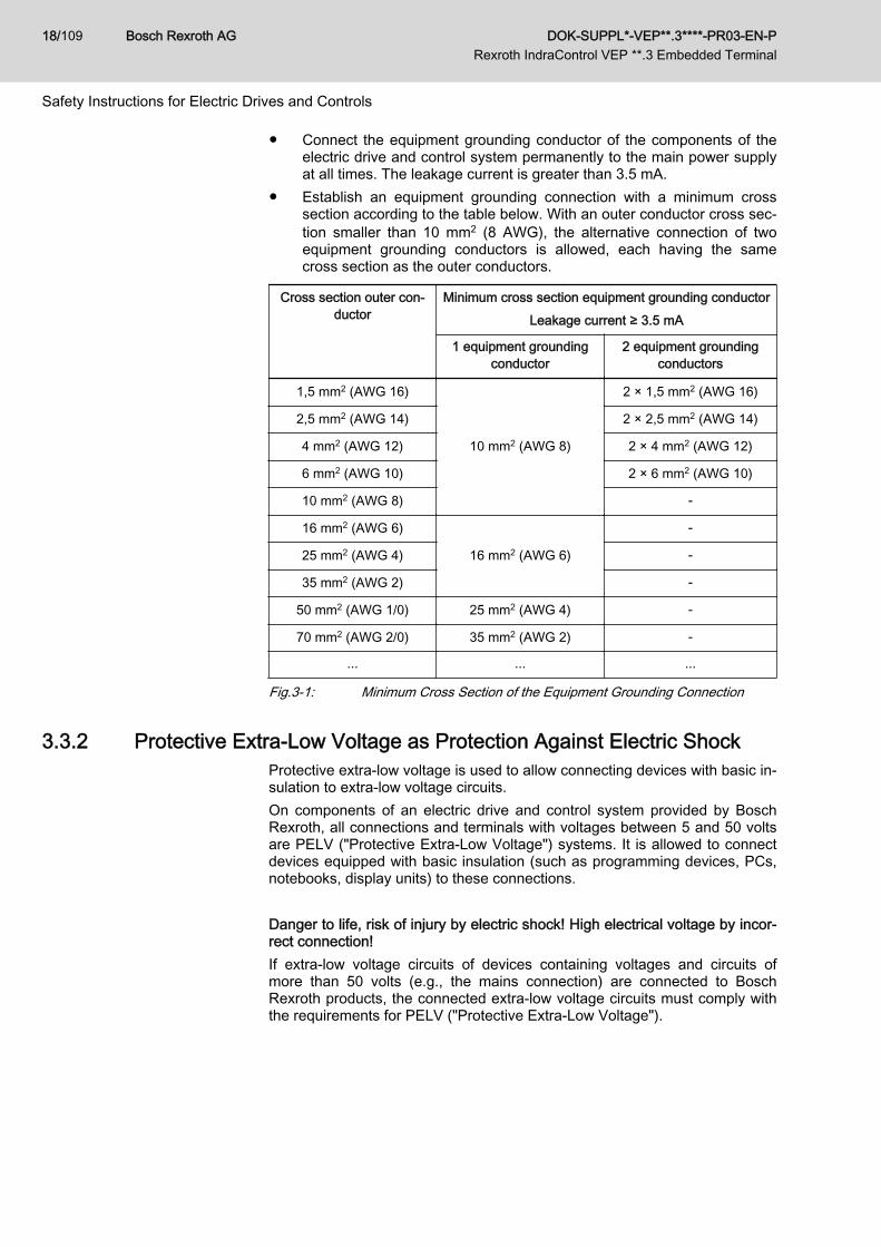
● Connect the equipment grounding conductor of the components of theelectric drive and control system permanently to the main power supplyat all times. The leakage current is greater than 3.5 mA.
● Establish an equipment grounding connection with a minimum crosssection according to the table below. With an outer conductor cross sec‐tion smaller than 10 mm2 (8 AWG), the alternative connection of twoequipment grounding conductors is allowed, each having the samecross section as the outer conductors.
Cross section outer con‐ductor
Minimum cross section equipment grounding conductorLeakage current ≥ 3.5 mA
1 equipment groundingconductor
2 equipment groundingconductors
1,5 mm2 (AWG 16)
10 mm2 (AWG 8)
2 × 1,5 mm2 (AWG 16)
2,5 mm2 (AWG 14) 2 × 2,5 mm2 (AWG 14)
4 mm2 (AWG 12) 2 × 4 mm2 (AWG 12)
6 mm2 (AWG 10) 2 × 6 mm2 (AWG 10)
10 mm2 (AWG 8) -
16 mm2 (AWG 6)
16 mm2 (AWG 6)
-
25 mm2 (AWG 4) -
35 mm2 (AWG 2) -
50 mm2 (AWG 1/0) 25 mm2 (AWG 4) -
70 mm2 (AWG 2/0) 35 mm2 (AWG 2) -
... ... ...
Fig.3-1: Minimum Cross Section of the Equipment Grounding Connection
3.3.2 Protective Extra-Low Voltage as Protection Against Electric Shock Protective extra-low voltage is used to allow connecting devices with basic in‐sulation to extra-low voltage circuits.On components of an electric drive and control system provided by BoschRexroth, all connections and terminals with voltages between 5 and 50 voltsare PELV ("Protective Extra-Low Voltage") systems. It is allowed to connectdevices equipped with basic insulation (such as programming devices, PCs,notebooks, display units) to these connections. Danger to life, risk of injury by electric shock! High electrical voltage by incor‐rect connection!If extra-low voltage circuits of devices containing voltages and circuits ofmore than 50 volts (e.g., the mains connection) are connected to BoschRexroth products, the connected extra-low voltage circuits must comply withthe requirements for PELV ("Protective Extra-Low Voltage").
Bosch Rexroth AG DOK-SUPPL*-VEP**.3****-PR03-EN-P Rexroth IndraControl VEP **.3 Embedded Terminal
18/109
Safety Instructions for Electric Drives and Controls

3.3.3 Protection Against Dangerous MovementsDangerous movements can be caused by faulty control of connected motors.Some common examples are:● Improper or wrong wiring or cable connection● Operator errors● Wrong input of parameters before commissioning● Malfunction of sensors and encoders● Defective components● Software or firmware errorsThese errors can occur immediately after equipment is switched on or evenafter an unspecified time of trouble-free operation.The monitoring functions in the components of the electric drive and controlsystem will normally be sufficient to avoid malfunction in the connecteddrives. Regarding personal safety, especially the danger of injury and/orproperty damage, this alone cannot be relied upon to ensure complete safety.Until the integrated monitoring functions become effective, it must be as‐sumed in any case that faulty drive movements will occur. The extent of faultydrive movements depends upon the type of control and the state of opera‐tion. Dangerous movements! Danger to life, risk of injury, serious injury or propertydamage!A risk assessment must be prepared for the installation or machine, with itsspecific conditions, in which the components of the electric drive and controlsystem are installed.As a result of the risk assessment, the user must provide for monitoring func‐tions and higher-level measures on the installation side for personal safety.The safety regulations applicable to the installation or machine must be takeninto consideration. Unintended machine movements or other malfunctionsare possible if safety devices are disabled, bypassed or not activated.To avoid accidents, injury and/or property damage:● Keep free and clear of the machine’s range of motion and moving ma‐
chine parts. Prevent personnel from accidentally entering the machine’srange of motion by using, for example:– Safety fences– Safety guards– Protective coverings– Light barriers
● Make sure the safety fences and protective coverings are strong enoughto resist maximum possible kinetic energy.
● Mount emergency stopping switches in the immediate reach of the oper‐ator. Before commissioning, verify that the emergency stopping equip‐ment works. Do not operate the machine if the emergency stoppingswitch is not working.
● Prevent unintended start-up. Isolate the drive power connection bymeans of OFF switches/OFF buttons or use a safe starting lockout.
● Make sure that the drives are brought to safe standstill before accessingor entering the danger zone.
DOK-SUPPL*-VEP**.3****-PR03-EN-P Rexroth IndraControl VEP **.3 Embedded Terminal
Bosch Rexroth AG 19/109
Safety Instructions for Electric Drives and Controls

● Additionally secure vertical axes against falling or dropping after switch‐ing off the motor power by, for example,– mechanically securing the vertical axes,– adding an external braking/arrester/clamping mechanism or– ensuring sufficient counterbalancing of the vertical axes.
● The standard equipment motor holding brake or an external holdingbrake controlled by the drive controller is not sufficient to guarantee per‐sonal safety!
● Disconnect electrical power to the components of the electric drive andcontrol system using the master switch and secure them from reconnec‐tion ("lock out") for:– Maintenance and repair work– Cleaning of equipment– Long periods of discontinued equipment use
● Prevent the operation of high-frequency, remote control and radio equip‐ment near components of the electric drive and control system and theirsupply leads. If the use of these devices cannot be avoided, check themachine or installation, at initial commissioning of the electric drive andcontrol system, for possible malfunctions when operating such high-fre‐quency, remote control and radio equipment in its possible positions ofnormal use. It might possibly be necessary to perform a special electro‐magnetic compatibility (EMC) test.
3.3.4 Protection Against Magnetic and Electromagnetic Fields During Oper‐ation and Mounting
Magnetic and electromagnetic fields generated by current-carrying conduc‐tors or permanent magnets of electric motors represent a serious danger topersons with heart pacemakers, metal implants and hearing aids.Health hazard for persons with heart pacemakers, metal implants and hear‐ing aids in proximity to electric components!● Persons with heart pacemakers and metal implants are not allowed to
enter the following areas:– Areas in which components of the electric drive and control sys‐
tems are mounted, commissioned and operated.– Areas in which parts of motors with permanent magnets are stored,
repaired or mounted.● If it is necessary for somebody with a heart pacemaker to enter such an
area, a doctor must be consulted prior to doing so. The noise immunityof implanted heart pacemakers differs so greatly that no general rulescan be given.
● Those with metal implants or metal pieces, as well as with hearing aids,must consult a doctor before they enter the areas described above.
3.3.5 Protection Against Contact With Hot PartsHot surfaces of components of the electric drive and control system. Risk ofburns!
Bosch Rexroth AG DOK-SUPPL*-VEP**.3****-PR03-EN-P Rexroth IndraControl VEP **.3 Embedded Terminal
20/109
Safety Instructions for Electric Drives and Controls

● Do not touch hot surfaces of, for example, braking resistors, heat sinks,supply units and drive controllers, motors, windings and laminatedcores!
● According to the operating conditions, temperatures of the surfaces canbe higher than 60 °C (140 °F) during or after operation.
● Before touching motors after having switched them off, let them cooldown for a sufficient period of time. Cooling down can require up to 140minutes! The time required for cooling down is approximately five timesthe thermal time constant specified in the technical data.
● After switching chokes, supply units and drive controllers off, wait 15 mi‐nutes to allow them to cool down before touching them.
● Wear safety gloves or do not work at hot surfaces.● For certain applications, and in accordance with the respective safety
regulations, the manufacturer of the machine or installation must takemeasures to avoid injuries caused by burns in the final application.These measures can be, for example: Warnings at the machine or in‐stallation, guards (shieldings or barriers) or safety instructions in the ap‐plication documentation.
3.3.6 Protection During Handling and MountingRisk of injury by improper handling! Injury by crushing, shearing, cutting, hit‐ting!● Observe the relevant statutory regulations of accident prevention.● Use suitable equipment for mounting and transport.● Avoid jamming and crushing by appropriate measures.● Always use suitable tools. Use special tools if specified.● Use lifting equipment and tools in the correct manner.● Use suitable protective equipment (hard hat, safety goggles, safety
shoes, safety gloves, for example).● Do not stand under hanging loads.● Immediately clean up any spilled liquids from the floor due to the risk of
falling!
3.3.7 Battery SafetyBatteries consist of active chemicals in a solid housing. Therefore, improperhandling can cause injury or property damage.Risk of injury by improper handling!● Do not attempt to reactivate low batteries by heating or other methods
(risk of explosion and cauterization).● Do not attempt to recharge the batteries as this may cause leakage or
explosion.● Do not throw batteries into open flames.● Do not dismantle batteries.● When replacing the battery/batteries, do not damage the electrical parts
installed in the devices.● Only use the battery types specified for the product.
DOK-SUPPL*-VEP**.3****-PR03-EN-P Rexroth IndraControl VEP **.3 Embedded Terminal
Bosch Rexroth AG 21/109
Safety Instructions for Electric Drives and Controls

Environmental protection and disposal! The batteries contained inthe product are considered dangerous goods during land, air, andsea transport (risk of explosion) in the sense of the legal regula‐tions. Dispose of used batteries separately from other waste. Ob‐serve the national regulations of your country.
3.3.8 Protection Against Pressurized SystemsAccording to the information given in the Project Planning Manuals, motorsand components cooled with liquids and compressed air can be partially sup‐plied with externally fed, pressurized media, such as compressed air, hy‐draulics oil, cooling liquids and cooling lubricants. Improper handling of theconnected supply systems, supply lines or connections can cause injuries orproperty damage.Risk of injury by improper handling of pressurized lines!● Do not attempt to disconnect, open or cut pressurized lines (risk of ex‐
plosion).● Observe the respective manufacturer's operating instructions.● Before dismounting lines, relieve pressure and empty medium.● Use suitable protective equipment (safety goggles, safety shoes, safety
gloves, for example).● Immediately clean up any spilled liquids from the floor due to the risk of
falling!
Environmental protection and disposal! The agents (e.g., fluids)used to operate the product might not be environmentally friendly.Dispose of agents harmful to the environment separately fromother waste. Observe the national regulations of your country.
3.4 Explanation of Signal Words and the Safety Alert SymbolThe Safety Instructions in the available application documentation containspecific signal words (DANGER, WARNING, CAUTION or NOTICE) and,where required, a safety alert symbol (in accordance withANSI Z535.6-2006).The signal word is meant to draw the reader's attention to the safety instruc‐tion and identifies the hazard severity.The safety alert symbol (a triangle with an exclamation point), which pre‐cedes the signal words DANGER, WARNING and CAUTION, is used to alertthe reader to personal injury hazards.
DANGER
In case of non-compliance with this safety instruction, death or serious injurywill occur.
Bosch Rexroth AG DOK-SUPPL*-VEP**.3****-PR03-EN-P Rexroth IndraControl VEP **.3 Embedded Terminal
22/109
Safety Instructions for Electric Drives and Controls

WARNING
In case of non-compliance with this safety instruction, death or serious injurycould occur.
CAUTION
In case of non-compliance with this safety instruction, minor or moderate in‐jury could occur.
NOTICEIn case of non-compliance with this safety instruction, property damage couldoccur.
DOK-SUPPL*-VEP**.3****-PR03-EN-P Rexroth IndraControl VEP **.3 Embedded Terminal
Bosch Rexroth AG 23/109
Safety Instructions for Electric Drives and Controls

Bosch Rexroth AG DOK-SUPPL*-VEP**.3****-PR03-EN-P Rexroth IndraControl VEP **.3 Embedded Terminal
24/109

4 Technical Data4.1 Technical Data of the Front Panel4.1.1 IndraControl VEP 30.3
VEP 30.3CC VEP 30.3DK VEP 30.3FC
Display 213 mm TFT (8.4"), 800 × 600 pixels, 262144 colors
Operation Touch screen oper‐ation
Touch operation, 3buttons and EMER‐GENCY STOP
Touch operation,easy panel keysand EMERGENCYSTOP
Color of the surface– front panel
RAL 7035 light gray
Degree of protec‐tion, front panel
IP 65 acc. to DIN 40 050, IEC 529.Front type 1 according to NEMA (UL)
Degree of protec‐tion, total device
IP 20 IP 54
Fig.4-1: Technical data, front panel of the IndraControl VEP 30.3
4.1.2 IndraControl VEP 40.3 VEP 40.3CE
Display 304 mm TFT (12.1"), 800 × 600 pixels, 262144 colors
Operation Touch screen operation
Color of the surface– front panel
RAL 7035 light gray
Degree of protec‐tion
Front panel IP 65 acc. to DIN 40 050, IEC 529Front type 1 according to NEMA (UL)whole device IP 20 (VEP 40.3CE)
Fig.4-2: Technical data, front panel of the IndraControl VEP 40.3
4.1.3 IndraControl VEP 50.3 VEP 50.3CH
Display 381 mm TFT (15"), 1024 × 768 pixels, 262144 colors
Operation Touch screen operation
Color of the surface– front panel
RAL 7035 light gray
Degree of protec‐tion
Front panel IP 65 acc. to DIN 40 050, IEC 529Front type 1 according to NEMA (UL)whole device IP 20 (VEP 50.3CH)
Fig.4-3: Technical data, front panel of the IndraControl VEP 50.3
DOK-SUPPL*-VEP**.3****-PR03-EN-P Rexroth IndraControl VEP **.3 Embedded Terminal
Bosch Rexroth AG 25/109
Technical Data

4.2 EMERGENCY STOP ButtonManufacturer RAFI
Manufacturer designation RAFIX 22 FS; EMERGENCY STOP button
Operating voltage AC/DCOperating current AC/DCMax. switching capacity
42 V100 mA250 mW
B10d value RAFIX 22 FS Electrics:B10d = 5,000,000 (according to the manufacturer)Assumption: B10d = 5 x B10Exclusion of failure at < 6050 switching cyclesMechanics:B10d = 250,000 (according to the manufacturer)Assumption: B10d = 5 x B10Exclusion of failure at < 6050 switching cycles
Fig.4-4: Technical data, EMERGENCY STOP button
4.3 Technical Data of the VEP **.3 DevicesPC box VISU IndraLogic
Processor Intel Ultra Low Voltage Celeron 600 MHz,Integrated graphics controller
RAM Min. 256 MB
Compact FlashCard
Min. 128 MB, two slots
Interfaces(available in allvariants)
● 2 × USB 2.0 connection(type A)
● 1 × Ethernet connection(RJ 45, 10/100 Base-T)
● 1 × serial standard inter‐face RS232 (9-pin; D-Sub)
● 2 × USB 2.0 connection(type A)
● 2 × Ethernet connection(RJ 45, 10/100 Base-T)
● 1 × serial standard inter‐face RS232 (9-pin; D-Sub)
Slots No module equipped Fieldbus interface module equip‐ped
Short-timeUPS
No short-time UPS Capacitor pack as short-timeUPS
Voltage supply DC 24 V
Input voltagerange
DC 24 V (+19 V to +30 V)
Emitted inter‐ference andsurge immunity
Umax = 35 V (for t < 100 ms)
Max. input cur‐rent
1.5 A
Bosch Rexroth AG DOK-SUPPL*-VEP**.3****-PR03-EN-P Rexroth IndraControl VEP **.3 Embedded Terminal
26/109
Technical Data

PC box VISU IndraLogic
Max. inrushcurrent:
7 A / 6 ms
Max. powerconsumptionfor maximumconfiguration
36 W
Fig.4-5: Technical data of the PC box of IndraControl VEP **.3 devices
Danger without protective separation!DANGER
The DC 24 V input voltage must comply with the requirements of the "Protec‐tive separation"!Plug and unplug the connector only if there is no voltage!
Interfering AC voltage components such as the ones resulting from an uncon‐trolled three-phase bridge circuit without smoothing and with a ripple factor(see DIN 40110/10.75, section 1.2) of 5 % are allowed.That results in the greatest absolute value of 30.2 V as upper voltage limit.The lowest absolute value of 18.5 V is the lower voltage limit.
4.4 Capacitor Pack as Short-Time UPSThe short-time UPS consists of a capacitor pack, which is installed in the PCbox, and the pending charging circuit in the power supply area of the carrierboard. The short-time UPS supplies the device for a certain time with volt‐age,when the 24 V voltage supply fails. In this time remanent data is safelystored on the Compact Flash card.
The short-time UPS is only installed in IndracLogic devices!
4.5 Ambient Conditions In operation Transport Storage
Max. surrounding air temper‐ature
+5 ℃ up to +45 ℃ -20 ℃ up to +60 ℃ -20 ℃ up to +60 ℃
Max. temperature gradient Temporal temperaturechanges up to 3 K per minute
Temporal temperaturechanges up to 3 K per minute
Temporal temperaturechanges up to 3 K per minute
Humidity Min. relative humidity: 5 %Max. relative humidity: 85%Min. absolute humidity: 1 g/m3
Max. absolute humidity: 25 g/m3
Non-condensingCorresponds to climatic class3K3 acc. to EN 60721-3-3
Min. relative humidity: 5 %Max. relative humidity: 75%Min. absolute humidity: 1 g/m3
Max. absolute humidity: 25 g/m3
Non-condensingCorresponds to climatic class2K2 acc. to EN 60721-3-2
Min. relative humidity: 5 %Max. relative humidity: 85%Min. absolute humidity: 1 g/m3
Max. absolute humidity: 25 g/m3
Non-condensingCorresponds to climatic class1K2 acc. to EN 60721-3-1
Air pressure Up to 2000 m above sea lev‐el acc. to EN 61131-2
Up to 3000 m above sea lev‐el acc. to EN 61131-2
Up to 3000 m above sea lev‐el acc. to EN 61131-2
DOK-SUPPL*-VEP**.3****-PR03-EN-P Rexroth IndraControl VEP **.3 Embedded Terminal
Bosch Rexroth AG 27/109
Technical Data

In operation Transport Storage
Mechanical strength Max. vibration:Frequency range: 10 Hz upto 150 HzExcursion: 0.075 mm for10 Hz to 57 HzAcceleration: 1 g for 57 Hz to150 Hzacc. to EN 600068-2-6
Max. shock:15 g 11 msacc. to EN 60068-2-27,No breakdown of the function
Max. shock:15 g 11 msacc. to EN 60068-2-27,No breakdown of the function
Degree of pollution 2 2 2
Overvoltage category 2 - -
Fig.4-6: Ambient conditions
Damage due to humidity caused during trans‐portation
NOTICE
Observe that humidity (condensation) may arise on the device during trans‐portation due to temperature variations. Accommodate the device slowly tothe ambient temperature before putting it into operation. In case of condensa‐tion, wait approx. twelve hours before putting the device into operation.
4.6 WeightVEP 30.3CC Approx. 2.3 kg
VEP 40.3CE Approx. 3.8 kg
VEP 50.3CH Approx. 5.4 kg
VEP 30.3DK Approx. 4.5 kg
VEP 30.3FC Approx. 4.5 kg
Fig.4-7: Weight of the IndraControl VEP **.3 devices
4.7 Used Standards4.7.1 Used standards
The system components of the IndraControl VEP **.3 devices comply withthe following standards:
Standard Meaning
EN 60 61000-6-4 Generic standard, emitted interference (industrial environ‐ment)
EN 60 61000-6-2 Generic standard, noise immunity (industrial environment)
EN 61558-2-6 Transformer for 24 V power supply unit, protective separa‐tion
EN 60664-1 Overvoltage category II
EN 61 131-2 Requirements on the 24 V power supply
ISO 13850 Safety of machinery, emergency stop - principles for de‐sign
Bosch Rexroth AG DOK-SUPPL*-VEP**.3****-PR03-EN-P Rexroth IndraControl VEP **.3 Embedded Terminal
28/109
Technical Data

Standard Meaning
EN 60 529 Degrees of protection (including housings and installationcompartments)
EN 60 068-2-6 Vibration test
EN 60068-2-27 Shock test
EN 60721-3-3 Classification of ambient conditions, operation
EN 60721-3-2 Classification of ambient conditions, transport
EN 60721-3-1 Classification of ambient conditions, storage
UL 508 Industrial Control Equipment
Fig.4-8: Used standardsEMERGENCY STOP button,
standardsThe EMERGENCY STOP button is disclosed by the manufacturer as safetycomponent according to machinery directive 2006/42/EC (annex V-10, emer‐gency stop devices). The compliance with the directive is proven by adher‐ence to the following European standards:● IEC 60204-1 (safety of machinery - electrical equipment of machines)● IEC 60947-5-1/5 (requirements for control circuit devices, requirements
for emergency stop devices)● ISO 13850 (safety of machinery - emergency stop - principles for de‐
sign)According to DIN EN ISO13849-1 the B10d value is:
Mechanics Electrics
B10d = 250,000 (according to the manu‐facturer)Assumption: B10d = 5 x B10Exclusion of failure at < 6050 switchingcycles
B10d = 5,000,000 (according to the man‐ufacturer)Assumption: B10d = 5 x B10Exclusion of failure at < 6050 switchingcycles
Fig.4-9: EMERGENCY STOP button, B10d value, service life
4.7.2 CE MarkingDeclaration of Conformity
The electronic products described in this project planning manual comply withthe requirements and goals of the following EC directive and with theharmonized European standards:EMC guideline 2004/108/ECThe electronic products described in this project planning manual comply withthe requirements on the operation within the industrial environment:
DOK-SUPPL*-VEP**.3****-PR03-EN-P Rexroth IndraControl VEP **.3 Embedded Terminal
Bosch Rexroth AG 29/109
Technical Data

Standard Title Edition
DIN EN61000-6-4(VDE0839-6-4)
Electromagnetic compatibility (EMC)Volume: 6-4: Generic standards – emitted interfer‐ence for industrial environments (IEC61000-6-4:2006)
September2007
DIN EN61000-6-2(VDE0839-6-2)
Electromagnetic compatibility (EMC)Volume: 6-2: Generic standards – noise immunityfor industrial environments (IEC 61000-6-2:2005)
March 2006
Fig.4-10: Electromagnetic compatibility (EMC) standards
Note for the Machine ManufacturerThe electronic products described in this project planning manual do not fallunder the machines listed in the EC machinery directive. Therefore, explana‐tions are not required for the 2006/42/EC machinery directive and do not ex‐ist.2006/42/EC, the EU directive for machines, specifies the requirements on amachine. In this directive, a machine is defined as a combination of the com‐ponents or mechanisms combined with each other. The described productsbelong to the electrical equipment of a machine. Therefore, they have to beincluded in the declaration of conformity of the machine manufacturer.The standard EN 60204-1 (safety of machinery, general requirements on theelectrical equipment of the machines) can be used for the electrical equip‐ment of the machines.
Loss of CE conformity due to modifications ofthe device.
NOTICE
The CE marking is only valid for the device in its delivery status (ex works).After modifying the device, the CE conformity has to be verified.
4.7.3 UL and CSA certified
The devices of the VEP **.3 product family are certificated according to● UL508 (Industrial Control Equipment) and● C22.2 no. 142-M1987 (CSA)UL file no. E210730However, there can be combinations or stages of expansions with limited ormissing certification. Therefore verify the certification by using the UL label onthe device.
To guarantee an UL- and CSA-compliant operation, the followingconditions have to be fulfilled:● Use only insulated copper wire suitable for at least 60/75 °C.
Bosch Rexroth AG DOK-SUPPL*-VEP**.3****-PR03-EN-P Rexroth IndraControl VEP **.3 Embedded Terminal
30/109
Technical Data

Loss of UL and CSA compliance due tochanges on the device.
NOTICE
The UL- and CSA- marking is only valid for the device in its delivery status.After having modified the device the UL and CSA compliance must be veri‐fied.
4.8 Wear PartsThe wear parts as well as their service life are described in this section. Wearparts are not subject to any warranty.
Backlight The service life of the backlight is limited to a certain number of operatinghours. After this time has been exceeded, the backlight will produce only 50% of its original brightness. This time differs for the used displays.Manufacturer specifications for the service life of the displays:
Display size Service life
213 mm (8.4") Typ. 50,000 hours
304 mm (12.1") Typ. 50,000 hours
381 mm (15") Typ. 50,000 hours
Fig.4-11: Service life of the displayCMOS battery The service life of a CMOS battery is at least 5 years. To exchange this bat‐
tery, please contact the Bosch Rexroth Service, see chapter 12 "Service andSupport" on page 103.
UPS capacitor pack The number of charging cycles of the capacitor pack and thus, its service life,depends on the surrounding air temperature, in which the capacitor pack isused. Surrounding air temperature is defined as the temperature, in which theembedded terminal and the capacitor pack is situated, e.g. the internal tem‐perature of the control cabinet or in a operator panel housing.
Surrounding air tempera‐ture Service life Maintenance interval
45 °C 48,000 hours 5 years at continuous oper‐ation
Fig.4-12: Service life of the capacitor packIf you do not know exactly the conditions, Bosch Rexroth recommends you toexchange the capacitor pack every five years.
4.9 Compatibility TestAll Rexroth controls and drives are developed and tested according to the lat‐est state-of-the-art of technology.As it is not possible to follow the continuing development of all materials (e. g.lubricants in machine tools) which may interact with our controls and drives, itcannot be completely ruled out that any reactions with the materials used byBosch Rexroth might occur.For this reason, before using the respective material a compatibility test hasto be carried out for new materials (e. g. lubricants and cleaning agents) andour housing or our housing materials.
DOK-SUPPL*-VEP**.3****-PR03-EN-P Rexroth IndraControl VEP **.3 Embedded Terminal
Bosch Rexroth AG 31/109
Technical Data

Bosch Rexroth AG DOK-SUPPL*-VEP**.3****-PR03-EN-P Rexroth IndraControl VEP **.3 Embedded Terminal
32/109

5 Dimensions, Installation and Wiring5.1 General Information
All values in the illustrations are given in mm.
5.2 Housing Dimensions5.2.1 Housing Dimensions of the IndraControl VEP 30.3CCN
Fig.5-1: Front view of the IndraControl VEP 30.3CCN
DOK-SUPPL*-VEP**.3****-PR03-EN-P Rexroth IndraControl VEP **.3 Embedded Terminal
Bosch Rexroth AG 33/109
Dimensions, Installation and Wiring

Fig.5-2: Side view of the IndraControl VEP 30.3CCN
Fig.5-3: Top view on the IndraControl VEP 30.3CCN
Bosch Rexroth AG DOK-SUPPL*-VEP**.3****-PR03-EN-P Rexroth IndraControl VEP **.3 Embedded Terminal
34/109
Dimensions, Installation and Wiring

5.2.2 Housing Dimensions of the IndraControl VEP 30.3CCU
Fig.5-4: Front view of the IndraControl VEP 30.3CCU
Fig.5-5: Side view of the IndraControl VEP 30.3CCU
DOK-SUPPL*-VEP**.3****-PR03-EN-P Rexroth IndraControl VEP **.3 Embedded Terminal
Bosch Rexroth AG 35/109
Dimensions, Installation and Wiring

Fig.5-6: Top view on the IndraControl VEP 30.3CCU
Bosch Rexroth AG DOK-SUPPL*-VEP**.3****-PR03-EN-P Rexroth IndraControl VEP **.3 Embedded Terminal
36/109
Dimensions, Installation and Wiring

DOK-SUPPL*-VEP**.3****-PR03-EN-P Rexroth IndraControl VEP **.3 Embedded Terminal
Bosch Rexroth AG 37/109

5.2.3 Housing Dimensions of the IndraControl VEP 30.3DKN andVEP 30.3DKU
Fig.5-7: Front view of the IndraControl VEP 30.3DKN and VEP 30.3DKU
Bosch Rexroth AG DOK-SUPPL*-VEP**.3****-PR03-EN-P Rexroth IndraControl VEP **.3 Embedded Terminal
38/109
Dimensions, Installation and Wiring

Fig.5-8: Side view of the IndraControl VEP 30.3DKN and VEP 30.3DKU
24V0V
24VUSVREADY1READY2
VCC
Stat.Err
X1SXCOM1
XCF2XCF1XUSB
X7E1
Fig.5-9: Bottom view on the IndraControl VEP 30.3DKN
DOK-SUPPL*-VEP**.3****-PR03-EN-P Rexroth IndraControl VEP **.3 Embedded Terminal
Bosch Rexroth AG 39/109
Dimensions, Installation and Wiring
0V
24VUSV24V
READY1READY2
VC
CS
tat.
Err.
X1SXCOM1X7E1 X7E2
XCF2
X7P
XCF1XUSB
Stat.
BU
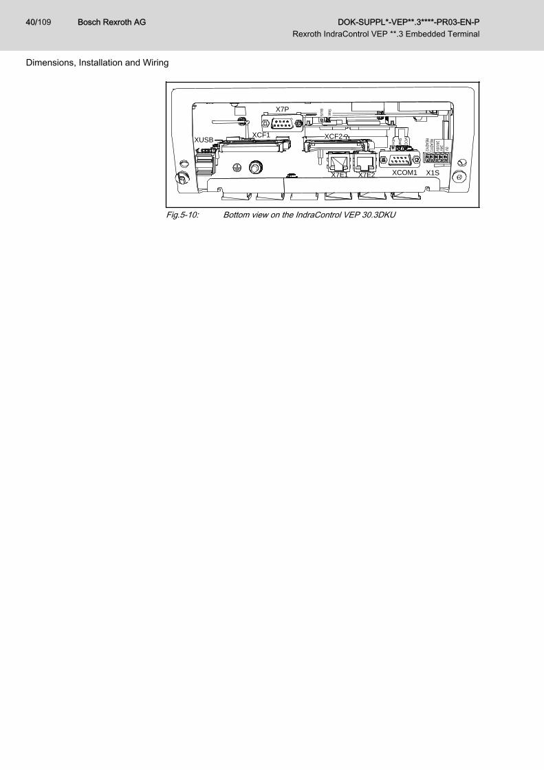
SFig.5-10: Bottom view on the IndraControl VEP 30.3DKU
Bosch Rexroth AG DOK-SUPPL*-VEP**.3****-PR03-EN-P Rexroth IndraControl VEP **.3 Embedded Terminal
40/109
Dimensions, Installation and Wiring

DOK-SUPPL*-VEP**.3****-PR03-EN-P Rexroth IndraControl VEP **.3 Embedded Terminal
Bosch Rexroth AG 41/109

5.2.4 Housing Dimensions of the IndraControl VEP 30.3FCN andVEP 30.3FCU
Fig.5-11: Front view of the IndraControl VEP 30.3FCN and VEP 30.3FCU
Bosch Rexroth AG DOK-SUPPL*-VEP**.3****-PR03-EN-P Rexroth IndraControl VEP **.3 Embedded Terminal
42/109
Dimensions, Installation and Wiring

Fig.5-12: Side view of the IndraControl VEP 30.3FCN and VEP 30.3FCU
X2 X3
XCF1 XCF2
XUSB
XCOM1 X1S
0V24V
24VUSVReadyReady
VC
CS
tat.E
rr.
X7E1
1 1
Fig.5-13: Bottom view on the IndraControl VEP 30.3FCN
DOK-SUPPL*-VEP**.3****-PR03-EN-P Rexroth IndraControl VEP **.3 Embedded Terminal
Bosch Rexroth AG 43/109
Dimensions, Installation and Wiring

X2 X3X7P
Stat.BUS
0V24V
24VUSVReadyReady
VC
CS
tat.E
rr.XCF1 XCF2XUSB
X7E1 X7E2 XCOM1 X1S
Fig.5-14: Bottom view on the IndraControl VEP 30.3FCU
5.2.5 Housing Dimensions of the IndraControl VEP 40.3CEN
Fig.5-15: Front view of the IndraControl VEP 40.3CEN
Bosch Rexroth AG DOK-SUPPL*-VEP**.3****-PR03-EN-P Rexroth IndraControl VEP **.3 Embedded Terminal
44/109
Dimensions, Installation and Wiring

Fig.5-16: Side view of the IndraControl VEP 40.3CEN
Fig.5-17: Top view on the IndraControl VEP 40.3CEN
DOK-SUPPL*-VEP**.3****-PR03-EN-P Rexroth IndraControl VEP **.3 Embedded Terminal
Bosch Rexroth AG 45/109
Dimensions, Installation and Wiring

5.2.6 Housing Dimensions of the IndraControl VEP 40.3CEU
Fig.5-18: Front view of the IndraControl VEP 40.3CEU
Bosch Rexroth AG DOK-SUPPL*-VEP**.3****-PR03-EN-P Rexroth IndraControl VEP **.3 Embedded Terminal
46/109
Dimensions, Installation and Wiring

Fig.5-19: Side view of the IndraControl VEP 40.3CEU
Fig.5-20: Top view on the IndraControl VEP 40.3CEU
DOK-SUPPL*-VEP**.3****-PR03-EN-P Rexroth IndraControl VEP **.3 Embedded Terminal
Bosch Rexroth AG 47/109
Dimensions, Installation and Wiring

5.2.7 Housing Dimensions of the IndraControl VEP 50.3CHN
Fig.5-21: Front view of the IndraControl VEP 50.3CHN
Bosch Rexroth AG DOK-SUPPL*-VEP**.3****-PR03-EN-P Rexroth IndraControl VEP **.3 Embedded Terminal
48/109
Dimensions, Installation and Wiring
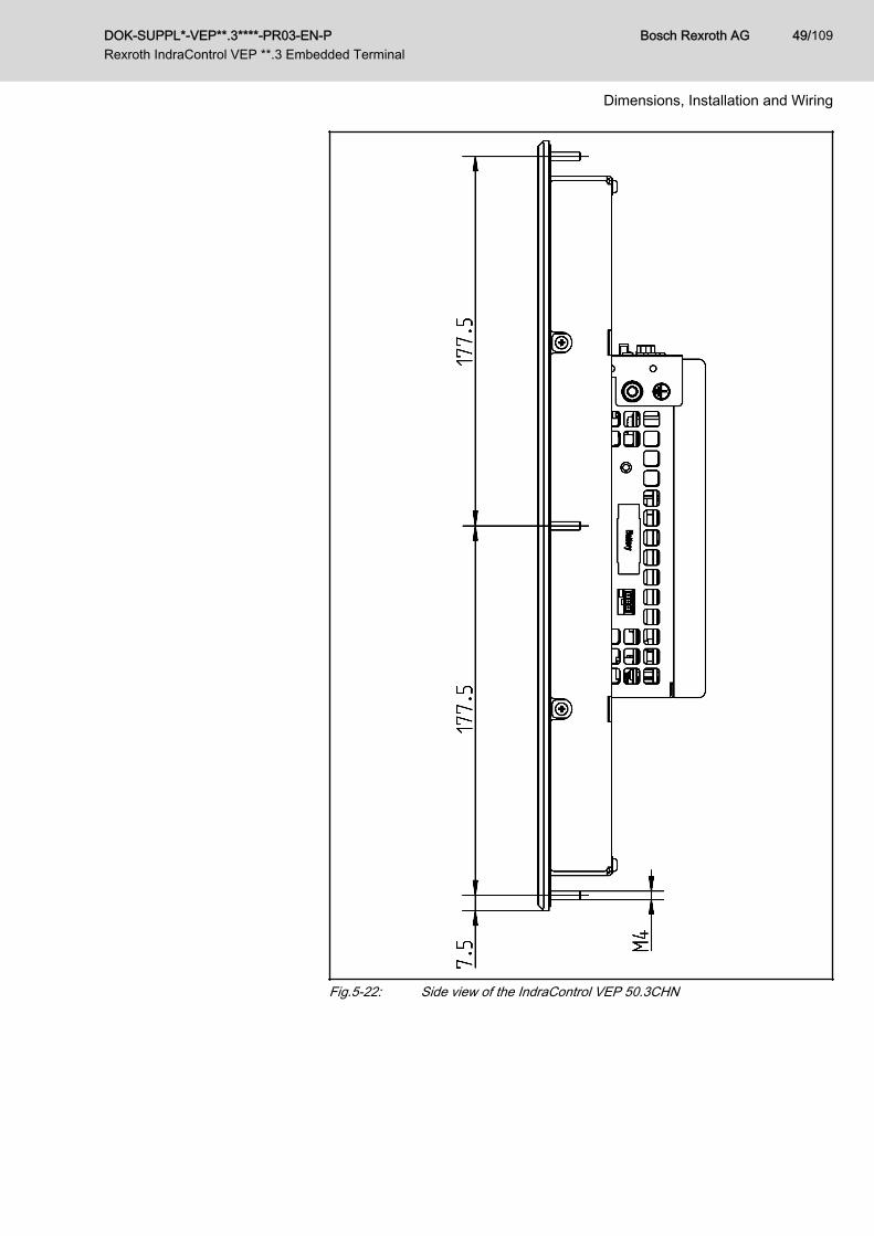
Fig.5-22: Side view of the IndraControl VEP 50.3CHN
DOK-SUPPL*-VEP**.3****-PR03-EN-P Rexroth IndraControl VEP **.3 Embedded Terminal
Bosch Rexroth AG 49/109
Dimensions, Installation and Wiring

Fig.5-23: Top view on the IndraControl VEP 50.3CHN
5.2.8 Housing Dimensions of the IndraControl VEP 50.3CHU
Fig.5-24: Front view of the IndraControl VEP 50.3CHU
Bosch Rexroth AG DOK-SUPPL*-VEP**.3****-PR03-EN-P Rexroth IndraControl VEP **.3 Embedded Terminal
50/109
Dimensions, Installation and Wiring

Fig.5-25: Side view of the IndraControl VEP 50.3CHU
DOK-SUPPL*-VEP**.3****-PR03-EN-P Rexroth IndraControl VEP **.3 Embedded Terminal
Bosch Rexroth AG 51/109
Dimensions, Installation and Wiring

Fig.5-26: Top view on the IndraControl VEP 50.3CHU
5.3 Installation5.3.1 Installation Notes
● When installing the VEP **.3, ensure an ergonomic operation. Addition‐ally, ensure that all moving machine components can be seen by theoperator!
● Avoid installation locations exposed to direct UV light or sunlight, be‐cause the screen readability is reduced and additional heat develop‐ment can occur.
● Mount the VEP **.3 in a manner ensuring easy access to the connectorpanel (top side).
● Provide a sufficient space of 50 mm (on all sides of the device) for cool‐ing and cable routing.
● Lay all connecting cables in loops and use strain reliefs for all cables.● Keep as much distance as possible to noise sources.For maintaining the degree of protection IP 54, use only cable grommets thatfit to the cable cross-sections for cable bushing, see also the following tablefig. 5-27 "Cable diameter and corresponding cable grommets" on page 52.
Designation of the cable grommet(mounting/sealing kit) Cable diameter
QT4 4-5 mm
QT5 5-6 mm
QT6 6-7 mm
QT7 7-8 mm
QT8 8-9 mm
QT11 11-12 mm
QT12 12-13 mm
QTB Blind grommet
Fig.5-27: Cable diameter and corresponding cable grommets
Bosch Rexroth AG DOK-SUPPL*-VEP**.3****-PR03-EN-P Rexroth IndraControl VEP **.3 Embedded Terminal
52/109
Dimensions, Installation and Wiring

The cables, which are lead through a cable grommet, have to be providedwith a strain relief. This can be done e.g. via a cable tie behind the grommet.
5.3.2 Mounting
Loss of IP degree of protection due to wrongsize or wrong mounting of the cable grom‐met.
NOTICE
Use a cable grommet fitting to the cable diameter. Mount the cable grommetproperly. The sealing of the cover must not be damaged. Mount the coverproperly and fasten it with the correct mounting torque, see also fig. 5-34"Mounting torques" on page 55.
Loss of IP degree of protection due to dam‐aged or wrongly mounted or not sufficientlyfastened covers.
NOTICE
The sealing of the cover must not be damaged. Mount the cover properly.Tighten the screws with the correct torque, see fig. 5-34 "Mounting torques"on page 55.
Position of the connections The connectors (③) are located under the housing cover (②), see fig. 5-28"Position of the connections on the VEP 30.3" on page 53.
211
OnOff
S1XVID XSER XUSB1/2 XUSB3/4 XUSBIN
X1S124V
3
1 2
① Screws② Cover③ Connectors (are located under the cover)Fig.5-28: Position of the connections on the VEP 30.3
Dismounting the cover Dismount the cover by loosening the screws, see the following figure.
DOK-SUPPL*-VEP**.3****-PR03-EN-P Rexroth IndraControl VEP **.3 Embedded Terminal
Bosch Rexroth AG 53/109
Dimensions, Installation and Wiring

x
Openings for cable grommets
Fig.5-29: Dismounting the coverUsing the cable grommet ● Select the corresponding cable grommet from the table, see fig. 5-27
"Cable diameter and corresponding cable grommets" on page 52.● The cable grommets and the connector for connecting the keypad are in
the delivered accessories kit.● Lay the cable grommet around the cable, see fig. 5-30 "Laying the cable
grommet around the cable" on page 54.
cable
Select cable grommetaccording to the table
Fig.5-30: Laying the cable grommet around the cable
● Plug the cable grommet into the housing, see fig. 5-31 "Plugging the ca‐ble grommet into the housing" on page 54.
housing
cable grommet
flat surface
Fig.5-31: Plugging the cable grommet into the housing● The cables, which are lead through a cable grommet, have to be provi‐
ded with a strain relief, see fig. 5-32 "Strain relief realized by a cable tie"on page 55.
Bosch Rexroth AG DOK-SUPPL*-VEP**.3****-PR03-EN-P Rexroth IndraControl VEP **.3 Embedded Terminal
54/109
Dimensions, Installation and Wiring
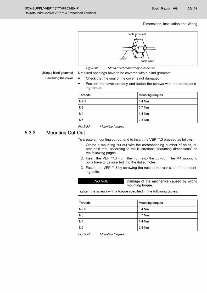
cable grommet
cable wrapcable
Fig.5-32: Strain relief realized by a cable tieUsing a blind grommet Not used openings have to be covered with a blind grommet.
Fastening the cover ● Check that the seal of the cover is not damaged.● Position the cover properly and fasten the screws with the correspond‐
ing torque:
Threads Mounting torques
M2.5 0.4 Nm
M3 0.7 Nm
M4 1.4 Nm
M5 2.8 Nm
Fig.5-33: Mounting torques
5.3.3 Mounting Cut-OutTo create a mounting cut-out and to insert the VEP **.3 proceed as follows:
1. Create a mounting cut-out with the corresponding number of holes, di‐ameter 5 mm, according to the illustrations "Mounting dimensions" onthe following pages.
2. Insert the VEP **.3 from the front into the cut-out. The M4 mountingbolts have to be inserted into the drilled holes.
3. Fasten the VEP **.3 by screwing the nuts at the rear side of the mount‐ing bolts.
Damage of the mechanics caused by wrongmounting torque.
NOTICE
Tighten the screws with a torque specified in the following tables.
Threads Mounting torques
M2.5 0.4 Nm
M3 0.7 Nm
M4 1.4 Nm
M5 2.8 Nm
Fig.5-34: Mounting torques
DOK-SUPPL*-VEP**.3****-PR03-EN-P Rexroth IndraControl VEP **.3 Embedded Terminal
Bosch Rexroth AG 55/109
Dimensions, Installation and Wiring

5.3.4 Mounting to a Standardized VESA Bracket on a VEP 30.3DK andVEP 30.3FC
Do observe the minimum bending radius of the used cables.Use appropriate cable material (sufficient bending and torsionalstrength).
1
2
① VESA attachment with four M4 threaded bolts (75 mm × 75 mm)② Cable bushings, appropriate for ready-made cablesFig.5-35: Position of VESA fastening screws and cable bushings
5.3.5 VESA Bracket for VEP 30.3DK and VEP 30.3FCThe operator terminals can be attached to a standardized VESA bracket,which is offered by different manufacturers.
Bosch Rexroth AG DOK-SUPPL*-VEP**.3****-PR03-EN-P Rexroth IndraControl VEP **.3 Embedded Terminal
56/109
Dimensions, Installation and Wiring

Fig.5-36: VESA bracket
5.3.6 Mounting Dimensions of the IndraControl VEP 30.3CC
Fig.5-37: Mounting dimensions of the IndraControl VEP 30.3CC
DOK-SUPPL*-VEP**.3****-PR03-EN-P Rexroth IndraControl VEP **.3 Embedded Terminal
Bosch Rexroth AG 57/109
Dimensions, Installation and Wiring

5.3.7 Mounting Dimensions of the IndraControl VEP 30.3DK andVEP 30.3FC
Fig.5-38: Mounting dimensions of the IndraControl VEP 30.3DK andVEP 30.3FC
Bosch Rexroth AG DOK-SUPPL*-VEP**.3****-PR03-EN-P Rexroth IndraControl VEP **.3 Embedded Terminal
58/109
Dimensions, Installation and Wiring

5.3.8 Mounting Dimensions of the IndraControl VEP 40.3CE
Fig.5-39: Mounting dimensions of the IndraControl VEP 40.3CE
DOK-SUPPL*-VEP**.3****-PR03-EN-P Rexroth IndraControl VEP **.3 Embedded Terminal
Bosch Rexroth AG 59/109
Dimensions, Installation and Wiring

5.3.9 Mounting Dimensions of the IndraControl VEP 50.3CH
Fig.5-40: Mounting dimensions of the IndraControl VEP 50.3CH
5.4 Wiring5.4.1 General Information
Danger without protective separation!DANGER
The DC 24 V input voltage must comply with the requirements of the "Protec‐tive separation"!Plug and unplug the connector only if there is no voltage!
Interfering AC voltage components such as the ones resulting from an uncon‐trolled three-phase bridge circuit without smoothing and with a ripple factor(see DIN 40110/10.75, section 1.2) of 5 % are allowed.That results in the greatest absolute value of 30.2 V as upper voltage limit.The lowest absolute value of 18.5 V is the lower voltage limit.
Bosch Rexroth AG DOK-SUPPL*-VEP**.3****-PR03-EN-P Rexroth IndraControl VEP **.3 Embedded Terminal
60/109
Dimensions, Installation and Wiring

Wiring 230 V
PE
PE PE
PEPE
PE
PE(1)
6 mm² (green/yellow)16 mm² (green/yellow)
min. 16 mm² (green/yellow)
all housing parts (functional earth)to the deviceto the housing of the control cabinet
PE neutral point
230V
400V 4 mm² (green/yellow)
16 mm² (green/yellow)
4 mm² (green/yellow
Fuses, better: protective motor switches
category III
category II
Transformer
Terminals in e.g. drives
W1 NV1
U1
L1 L2 L3 N
leads
L1.1
L2.1
L3.1
N PE
PE N U2
PE N1
U2
4 mm² (green/yellow)
24 VDC
Length max. 4 m
Power unitVAP01.1H-W23024-010-NN
+24 V
0 V
24 VDC
Overvoltage
Overvoltage
acc. to EN60742
isolated arrangement
N-conductor:Use only with permission ofthe operator!
230 V power supplyoperator terminalsservice plug receptacle(s)
category IOvervoltage
PE bars are to be installed preferably on the mounting plate.In case of isolated PE bars, both ends must be connected to the mounting plateby means of copper strips with a maximum length of 20 cm.The cross-section of the copper strips has to be at least equal to that of the incoming mains cable.
(1)
Fig.5-41: Wiring 230 V
Danger of death by high electric voltageDANGER
● Connect power supply units, which generate protective extra-low volt‐age (PELV) (24 V), only to supply voltages for which they are designed.Observe the overvoltage categories, see fig. 5-41 "Wiring 230 V" onpage 61.
● Do not apply the supply voltage to the protective extra-low voltage(PELV).
DOK-SUPPL*-VEP**.3****-PR03-EN-P Rexroth IndraControl VEP **.3 Embedded Terminal
Bosch Rexroth AG 61/109
Dimensions, Installation and Wiring

Wiring 400 V
PE
PE PE
PEPE
PE
PE(1)
6 mm² (green/yellow)16 mm² (green/yellow)
min. 16 mm² (green/yellow)
all housing parts (functional earth)to the deviceto the housing of the control cabinet
L1.1
L2.1
L3.1
PE
PE neutral point
230V
400V 4 mm² (green/yellow)
16 mm² (green/yellow)
4 mm² (green/yellow)
Fuses, better: protective motor switchesOvervoltage
Transformer
Terminals in isolated arrangement
e.g.drives
W1 NV1
U1
L1 L2 L3 N
leads
L1.1
L2.1
L3.1
N PE
PE N U2
PE N1
U2
4 mm² (green/yellow)
230 V supply
= 24 VDC
Power unit
+24 V
24 VDC
category III
acc. to EN 60742
Overvoltagecategory II
Overvoltagecategory I
operator terminalsservice plug receptacle(s)
N conductor:Use only withpermission of the operator!
0 V
PE bars are to be installed preferably on the mounting plate.In case of isolated PE bars, both ends must be connected to the mounting plateby means of copper strips with a maximum length of 20 cm.The cross-section of the copper strips has to be at least equal to that of the incoming mains cable.
(1)
Fig.5-42: Wiring 400 V
Danger of death by high electric voltageDANGER
● Connect power supply units, which generate protective extra-low volt‐age (PELV) (24 V), only to supply voltages for which they are designed.Observe the overvoltage categories, see fig. 5-42 "Wiring 400 V" onpage 62.
● Do not apply the supply voltage to the protective extra-low voltage(PELV).
Wiring the VEP **.3
10 mm² (green/yellow)
PE
bar
B
Overvoltage category I
FE =Functional earth
XS1
FE
10 mm² (green/yellow)
A=
B=
(1) Easily removable and visible
VEP
24 V
6 mm² (blue)
A
A
(2)
+24V
0 V(2)
2
1
Non-isolatedterminal block
Isolatedterminal block
(1)
(2)
Cable length between 24 V power supply unit and VEP max. 6 m at a minimumcross-section of 0.75 mm .Cable length between 24 V power supply unit and VAM max. 10 m at a minimumcross-section of 1.5 mm .An additional power supply unit is required if the length exceeds
2
2
10 m.
VEP
Fig.5-43: Wiring the VEP **.3
Bosch Rexroth AG DOK-SUPPL*-VEP**.3****-PR03-EN-P Rexroth IndraControl VEP **.3 Embedded Terminal
62/109
Dimensions, Installation and Wiring

6 Display and Operating Components6.1 Backlight Dimming
The backlight, background lighting of the display, has a limited service life(see chapter 4.8 "Wear Parts" on page 31).The display features a dimming to extend the service life. This function "dark‐ens" the display if the VEP **.3 has not been operated for a certain period oftime.The length of the time until the dimming is switched on, can be set underWindows CE in the "Display Properties". The Display Properties can be dis‐played via right mouse-click on the desktop or via Start ▶ Settings ▶ Controlpanel ▶ Display.The default value is five minutes. Avoid waiting times longer than five minutesto ensure a longer service life of the backlight.
Fig.6-1: Display Properties – backlight dimming
The modified values for the backlight dimming have to be savedwith the "Save Registry" tool into the registration database.
6.2 Touch ScreenAll variants are provided with a touch screen, that allows the operation of theapplication software via the touch-sensitive surface of the display.A short touch of the touch screen is taken as "left mouse click". To do a "rightmouse-klick" the touch screen is to be touched on the corresponding positionfor approx. 2 seconds.
Danger of destruction of the touch screen ifoperated with inappropriate objects (e.g.screwdriver).
NOTICE
Operate the touch screen only with your finger or with a touch pen.
DOK-SUPPL*-VEP**.3****-PR03-EN-P Rexroth IndraControl VEP **.3 Embedded Terminal
Bosch Rexroth AG 63/109
Display and Operating Components

Bosch Rexroth AG DOK-SUPPL*-VEP**.3****-PR03-EN-P Rexroth IndraControl VEP **.3 Embedded Terminal
64/109

7 Pin Assignments7.1 Connector Panel of the VEP Visu Device
Fig.7-1: Connector panel of the VEP Visu device
7.2 Connector Panel of the IndraLogic Device with COMPROFIBUS Module
Fig.7-2: Connector panel of the IndraLogic device with COM PROFIBUS mod‐ule
7.3 VEP 30.3DK IP 54 Device7.3.1 General Information
The VEP 30.3 DK device features the IP 54 degree of protection. Here thecomponents of the VEP 30.3CC device were installed in an IP 54 aluminiumhousing. The device is additionally equipped with 3 buttons and one EMER‐GENCY STOP button, but they are not connected electrically to the device.
DOK-SUPPL*-VEP**.3****-PR03-EN-P Rexroth IndraControl VEP **.3 Embedded Terminal
Bosch Rexroth AG 65/109
Pin Assignments

7.3.2 Housing VEP 30.3DK
Fig.7-3: Housing VEP 30.3DK
7.3.3 Housing Cover of the VEP 30.3DK
Fig.7-4: Housing cover VEP 30.3DK
7.3.4 Keypad of the VEP 30.3DKThe VEP **.3 features a start, stop and EMERGENCY STOP button.
Bosch Rexroth AG DOK-SUPPL*-VEP**.3****-PR03-EN-P Rexroth IndraControl VEP **.3 Embedded Terminal
66/109
Pin Assignments

Fig.7-5: Keypad of the VEP 30.3DK
7.3.5 Connection Scheme of the VEP 30.3DK Keypad
S1emergency stop
LED2 LED4
X3 X2
S2 S3 S4
Fig.7-6: Connection scheme of the VEP 30.3DK keypad
The maximum load for each contact must not exceed 500 mA.
Death or serious injury caused by wrong han‐dling.
WARNING
● The EMERGENCY STOP button can be used as operating element inan EMERGENCY STOP circuit.
● The EMERGENCY STOP circuit has to be designed by the machinemanufacturer.
● Only qualified persons may connect the EMERGENCY STOP buttonand check it afterwards.
● The connection has to be performed according to the connectionscheme chapter 7.3.5 "Connection Scheme of the VEP 30.3DK Key‐pad" on page 67.
● The max. load current is 500 mA.
According to DIN EN ISO13849-1 the B10d value is:
DOK-SUPPL*-VEP**.3****-PR03-EN-P Rexroth IndraControl VEP **.3 Embedded Terminal
Bosch Rexroth AG 67/109
Pin Assignments

Mechanics Electrics
B10d = 250,000 (according to the manu‐facturer)Assumption: B10d = 5 x B10Exclusion of failure at < 6050 switchingcycles
B10d = 5,000,000 (according to the man‐ufacturer)Assumption: B10d = 5 x B10Exclusion of failure at < 6050 switchingcycles
Fig.7-7: B10d value of the EMERGENCY STOP button
7.3.6 Pin Asssignment – Keypad of the VEP 30.3DKPin Function
1 S1 (EMERGENCY STOP) N/C contact 1
2 S1 (EMERGENCY STOP) N/C contact 1
3 S1 (EMERGENCY STOP) N/C contact 2
4 S1 (EMERGENCY STOP) N/C contact 2
5 S2 (white key) N/O contact / N/C contact
6 S2 (white key) N/O contact
7 S2 (white key) N/C contact
8 S3 (black key) N/O contact / N/C contact
9 S3 (black key) N/O contact
10 S3 (black key) N/C contact
Fig.7-8: Pin assignment keypad VEP 30.3DK, connector X3
Pin Function
1 S4 (blue key) N/O contact / N/C contact
2 S4 (blue key) N/O contact
3 S4 (blue key) N/C contact
4 LED2 in S2 (white key) +24V
5 LED4 in S4 (blue key) +24 V
6 LED2/LED4 -0V
Fig.7-9: Pin assignment keypad VEP 30.3DK, connector X2
Destruction of screw terminals, insufficientcontact and loss of UL/CSA certificiation if nocopper wire is used and/or wrong tighteningtorque.
NOTICE
For terminal connectors use copper wire only. Tighten the screws of thescrew terminals with a torque of 2.25 lb in (0.25 Nm).
Connector X2, X3 The X2 and X3 connectors are located behind the housing cover, see fig.7-10 "VEP 30.3DK, X2, X3 connector" on page 69.
Bosch Rexroth AG DOK-SUPPL*-VEP**.3****-PR03-EN-P Rexroth IndraControl VEP **.3 Embedded Terminal
68/109
Pin Assignments

X3 X2
PIN 1
Fig.7-10: VEP 30.3DK, X2, X3 connector
7.4 VEP 30.3FC IP 54 Device7.4.1 General Information
The VEP 30.3 FC device features the IP 54 degree of protection. Here thecomponents of the VEP 30.3CC device were installed in an IP 54 aluminiumhousing. The device is additionally equipped with an easy panel keypad andan EMERGENCY STOP button, but these elements are not connected elec‐trically to the device.
DOK-SUPPL*-VEP**.3****-PR03-EN-P Rexroth IndraControl VEP **.3 Embedded Terminal
Bosch Rexroth AG 69/109
Pin Assignments

7.4.2 Housing of the VEP 30.3FC
Fig.7-11: Housing of the VEP 30.3FC
Bosch Rexroth AG DOK-SUPPL*-VEP**.3****-PR03-EN-P Rexroth IndraControl VEP **.3 Embedded Terminal
70/109
Pin Assignments

DOK-SUPPL*-VEP**.3****-PR03-EN-P Rexroth IndraControl VEP **.3 Embedded Terminal
Bosch Rexroth AG 71/109

7.4.3 Housing Cover of the VEP 30.3FC
Fig.7-12: Housing of the VEP 30.3FC
7.4.4 Keypad of the VEP 30.3FCThe VEP **.3 features a start, stop and EMERGENCY STOP button.
Fig.7-13: Keypad of the VEP 30.3FC
7.4.5 Connection Scheme of the VEP 30.3FC KeypadThe pinning of the X1 and X2 connectors as well as the connection schemefor the keypad of the VEP 30.3FC device are shown in the following.For fur‐ther information on the pin assignment, please refer to chapter 7.4.6 "PinAsssignment – Keypad of the VEP 30.3FC" on page 73.
X1112
1
X2
13Fig.7-14: Pinning VEP 30.3FC, connector X1 and X2
Bosch Rexroth AG DOK-SUPPL*-VEP**.3****-PR03-EN-P Rexroth IndraControl VEP **.3 Embedded Terminal
72/109
Pin Assignments

X2/1
X1/2X2/2 X2/4
X2/3
X1/4
X1/1 X1/5 X1/6 X1/7
X1/8 X1/9 X1/10
24V
X1/3 24V 24V 24V
24V 24V 24V
X1/12
X2/6 X2/7 X2/8 X2/9
X2/10 X2/11 X2/12
S1 S2 S3 S4 S5
S8S6 S7 S8
S1 S1 = EMERGENCY STOPFig.7-15: Connection scheme keypad VEP 30.3FC
Death or serious injury caused by wrong han‐dling.
WARNING
● The EMERGENCY STOP button can be used as operating element inan EMERGENCY STOP circuit.
● The EMERGENCY STOP circuit has to be designed by the machinemanufacturer.
● Only qualified persons may connect the EMERGENCY STOP buttonand check it afterwards.
● The connection has to be performed according to the connectionscheme chapter 7.3.5 "Connection Scheme of the VEP 30.3DK Key‐pad" on page 67.
● The max. load current is 500 mA.
According to DIN EN ISO13849-1 the B10d value is:
Mechanics Electrics
B10d = 250,000 (according to the manu‐facturer)Assumption: B10d = 5 x B10Exclusion of failure at < 6050 switchingcycles
B10d = 5,000,000 (according to the man‐ufacturer)Assumption: B10d = 5 x B10Exclusion of failure at < 6050 switchingcycles
Fig.7-16: B10d value of the EMERGENCY STOP button
The max. load must not exceed 500 mA.LEDs and voltage dropping resistor are designed for 24 V.
7.4.6 Pin Asssignment – Keypad of the VEP 30.3FCPin Function
1 S2 N/O contact 1
2 S9 N/C contact 1
3 S2 N/O contact 2
4 S9 N/C contact 2
5 S3 N/O contact
6 S4 N/O contact
7 S5 N/O contact
DOK-SUPPL*-VEP**.3****-PR03-EN-P Rexroth IndraControl VEP **.3 Embedded Terminal
Bosch Rexroth AG 73/109
Pin Assignments

Pin Function
8 S6 N/O contact
9 S7 N/O contact
10 S8 N/O contact
11 24 V supply
12 S9 N/O contact
Fig.7-17: Pin assignment keypad VEP 30.3FC, connector X1
Pin Function
1 S1 (EMERGENCY STOP) N/C contact 1, contact 1
2 S1 (EMERGENCY STOP) N/C contact 2, contact 1
3 S1 (EMERGENCY STOP) N/C contact 1, contact 2
4 S1 (EMERGENCY STOP) N/C contact 2, contact 2
5 GND
6 S2 LED anode
7 S3 LED anode
8 S4 LED anode
9 S5 LED anode
10 S6 LED anode
11 S7 LED anode
12 S8 LED anode
13 Not assigned
Fig.7-18: Pin assignment keypad VEP 30.3FC, connector X2
Destruction of screw terminals, insufficientcontact and loss of UL/CSA certificiation if nocopper wire is used and/or wrong tighteningtorque.
NOTICE
For terminal connectors use copper wire only. Tighten the screws of thescrew terminals with a torque of 2.25 lb in (0.25 Nm).
Connector X2, X1 The connectors X1 and X2 are located behind the housing cover of theVEP 30.3FC devices, see fig. 7-10 "VEP 30.3DK, X2, X3 connector" on page69.
Bosch Rexroth AG DOK-SUPPL*-VEP**.3****-PR03-EN-P Rexroth IndraControl VEP **.3 Embedded Terminal
74/109
Pin Assignments
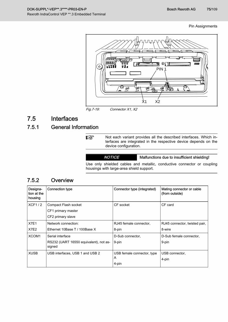
X1 X2
PIN 1
Fig.7-19: Connector X1, X2
7.5 Interfaces7.5.1 General Information
Not each variant provides all the described interfaces. Which in‐terfaces are integrated in the respective device depends on thedevice configuration.
Malfunctions due to insufficient shielding!NOTICEUse only shielded cables and metallic, conductive connector or couplinghousings with large-area shield support.
7.5.2 OverviewDesigna‐tion at thehousing
Connection type Connector type (integrated) Mating connector or cable(from outside)
XCF1 / 2 Compact Flash socketCF1 primary masterCF2 primary slave
CF socket CF card
X7E1X7E2
Network connection:Ethernet 10Base T / 100Base X
RJ45 female connector,8-pin
RJ45 connector, twisted pair,8-wire
XCOM1 Serial interfaceRS232 (UART 16550 equivalent), not as‐signed
D-Sub connector,9-pin
D-Sub female connector,9-pin
XUSB USB interfaces, USB 1 and USB 2 USB female connector, typeA4-pin
USB connector,4-pin
DOK-SUPPL*-VEP**.3****-PR03-EN-P Rexroth IndraControl VEP **.3 Embedded Terminal
Bosch Rexroth AG 75/109
Pin Assignments
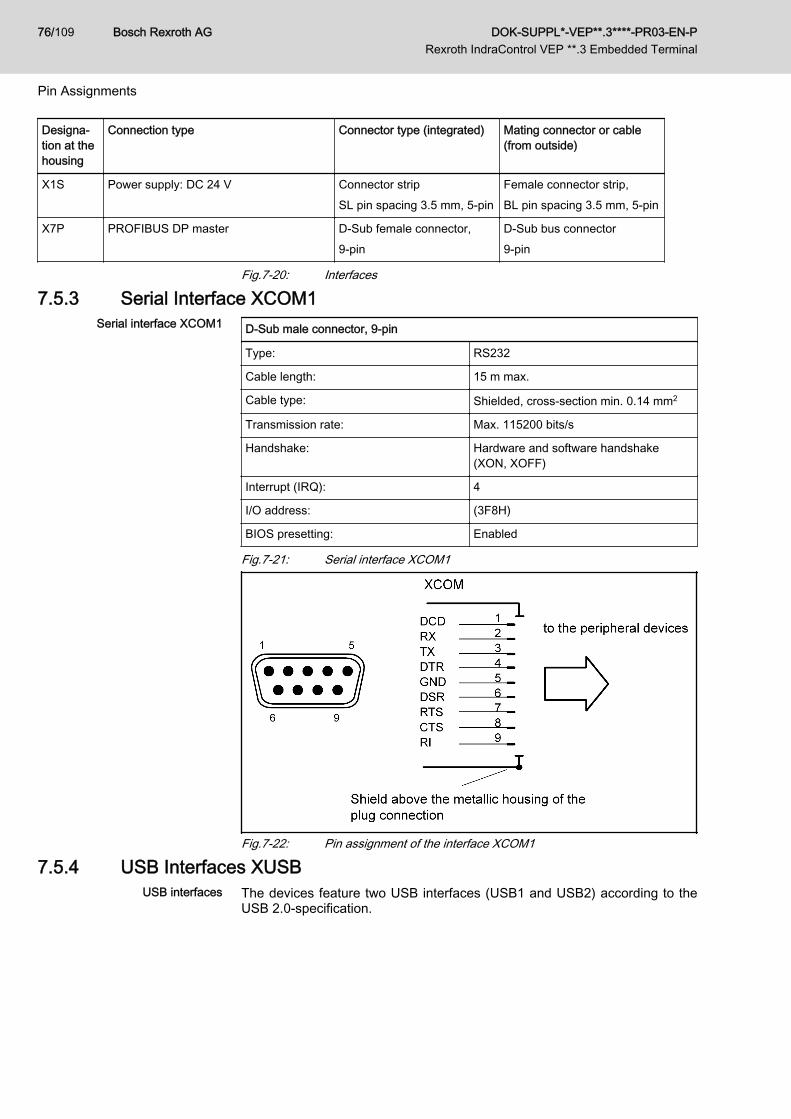
Designa‐tion at thehousing
Connection type Connector type (integrated) Mating connector or cable(from outside)
X1S Power supply: DC 24 V Connector stripSL pin spacing 3.5 mm, 5-pin
Female connector strip,BL pin spacing 3.5 mm, 5-pin
X7P PROFIBUS DP master D-Sub female connector,9-pin
D-Sub bus connector9-pin
Fig.7-20: Interfaces
7.5.3 Serial Interface XCOM1Serial interface XCOM1 D-Sub male connector, 9-pin
Type: RS232
Cable length: 15 m max.
Cable type: Shielded, cross-section min. 0.14 mm2
Transmission rate: Max. 115200 bits/s
Handshake: Hardware and software handshake(XON, XOFF)
Interrupt (IRQ): 4
I/O address: (3F8H)
BIOS presetting: Enabled
Fig.7-21: Serial interface XCOM1
Fig.7-22: Pin assignment of the interface XCOM1
7.5.4 USB Interfaces XUSBUSB interfaces The devices feature two USB interfaces (USB1 and USB2) according to the
USB 2.0-specification.
Bosch Rexroth AG DOK-SUPPL*-VEP**.3****-PR03-EN-P Rexroth IndraControl VEP **.3 Embedded Terminal
76/109
Pin Assignments

USB devices (e. g. keyboard) switch off if the power consumptionis exceeded.The max. power consumption of one USB connector must not ex‐ceed 500 mA.If the maximum power consumption is exceeded, a message dis‐plays that the USB devices are disabled. The USB devices areenabled as soon as the power consumption of one USB connec‐tor is below 500 mA.
Not all USB devices are recognized.The Windows CE operating system does not support all USB de‐vices. Devices that require a special USB driver, which is not inte‐grated in the system, cannot be operated at the USB interfaces.
Fig.7-23: USB interfaces
Pin Function
1 USB power supply (max. 500 mA)
2 Data -
3 Data +
4 USB ground
Fig.7-24: Pin assignment of the USB interfaces
7.5.5 Ethernet Interfaces X7E1 and X7E2Ethernet interface Via the Ethernet interface, the VEP **.3 can be connected to an Ethernet net‐
work.
RJ45, female connector, 8-pin
Type Ethernet 10Base T / 100Base X
Cable length 100 m max.
Cable type Shielded, twisted pair
Transmission rate 10 or 100 Mbits/s
Fig.7-25: Ethernet – network connection
DOK-SUPPL*-VEP**.3****-PR03-EN-P Rexroth IndraControl VEP **.3 Embedded Terminal
Bosch Rexroth AG 77/109
Pin Assignments

Fig.7-26: Pin assignment of the Ethernet interfaceFor a more detailed description of the Ethernet interface, please refer tochapter 9 "Software" on page 83.
Status displays and diagnostic dis‐plays of the Ethernet interface LED link On Connection to network available
Off No connection
LED status On Communication is running
Off No communication
Fig.7-27: Diagnostics display of the Ethernet interface
7.5.6 DC 24 V Voltage Supply XS1XS1 – DC 24 V voltage supply All internally required voltages are generated via a DC/DC converter. The
connection is designed as male connector strip SL 3.5 mm pin spacing, 5-pin.To this connector terminal, cables with a cross section of maximum 1.5 mm2
can be connected.
Fig.7-28: Pin assignment of the DC 24 connection XS1XS1 24 V voltage supply
PIN Function Description
1 0 V 0 V voltage supply
2 24 V 24 V voltage supply
3 24 V UPS 24 V UPS to connect an external UPS
4 RDY1 Ready contact 1
5 RDY2 Ready contact 2
Fig.7-29: Power supply connector XS1
Bosch Rexroth AG DOK-SUPPL*-VEP**.3****-PR03-EN-P Rexroth IndraControl VEP **.3 Embedded Terminal
78/109
Pin Assignments

Destruction of screw terminals, insufficientcontact and loss of UL/CSA certificiation if nocopper wire is used and/or wrong tighteningtorque.
NOTICE
For terminal connectors use copper wire only. Tighten the screws of thescrew terminals with a torque of 2.25 lb in (0.25 Nm).
Destruction of the Embedded Terminalcaused by polarity reversal when the 0 V loadis simultaneously grounded.
CAUTION
Polarity reversal of the XS1 connector might destruct the operator terminal, ifthere is no additional external protection (fire hazard). The reason for this isthe grounding of the 0 V in the operator terminal and simultaneously to thatthe grounding of the 0 V load (PELV).
7.5.7 Fieldbus ModulePROFIBUS Interfaces X7P
This interface is only available for VEP **.3 devices with PROFIBUS configu‐ration.
PIN Signal designation PIN Signal designation
1 RGND – reference potential 2 NC
3 RxD/TxD-P – transmit/receive 4 NC
5 DGND – reference potential 6 VP - supply voltage - Plus
7 NC 8 RxD/TxD-N – transmit/receive
9 NC
Fig.7-30: Pin assignment of the PROFIBUS Master interface DP-M X7P
Technical Data of the PROFIBUS Master InterfaceInterface data
Communication interface PROFIBUS DP, 12 Mbauds max., floating
Diagnostic interface RS232C, 9600 bauds, non-isolated
Fig.7-31: Technical data of the PROFIBUS Master interface
Status Displays and Diagnostic Displays of the PROFIBUS MasterThe status and diagnostics displays of the PROFIBUS Master module arevisible on the front panel of the VEP **.3 devices.During the startup the PROFIBUS Master card performs a self-test. After theinitialization phase of this test (approx. 2-3 seconds), the two ERR and STALEDs turn dark. The yellow RDY LED lights yellow after successful comple‐tion. If not, the RDY LED starts flashing and the processing of the program isdiscontinued. Further meanings of the display during the initialization phaseare listed in the following overview, see fig. 7-32 "Diagnostic display of thePROFIBUS fieldbus module" on page 80.
DOK-SUPPL*-VEP**.3****-PR03-EN-P Rexroth IndraControl VEP **.3 Embedded Terminal
Bosch Rexroth AG 79/109
Pin Assignments

LED BUS (red) On Bus error and missing bus connection
Flashing Slave diagnostics is pending
Off No error / bus ok
LED stat(green)
On Communication is running
Flashing No configuration
On Configuration ok
Fig.7-32: Diagnostic display of the PROFIBUS fieldbus module
Bosch Rexroth AG DOK-SUPPL*-VEP**.3****-PR03-EN-P Rexroth IndraControl VEP **.3 Embedded Terminal
80/109
Pin Assignments

8 Maintenance and Installation8.1 General Information
The VEP **.3 Embedded Terminals are maintenance-free. However, somecomponents are subject to wear and must be replaced.
Maintenance work in the device is only per‐missible by skilled staff!
NOTICE
If hardware or software components have to be exchanged, please contactthe Bosch Rexroth Service or ensure that only skilled staff changes the re‐spective components.
In order to avoid incorrect operation, clean the devices only whenthey are switched off.
Maintenance Include the following measures in the maintenance schedule:● Clean the screen at least once a week using an antistatic fabric or a
cleansing agent containing alcohol when the device is switched off.Avoid hard objects that may cause scratches.
Dissolution of the foil surface as well as thedisplay seal by solvents or by high pressurecleaning devices!
NOTICE
● Do not use any solvents (e. g. diluents)!● Do not use compressed air, steam jet and high pressure cleaning devi‐
ces!
● At least once a year, check all plug and terminal connections of thecomponents regarding proper tightness and possible damage. Checkthat cables are not broken or crushed. Replace damaged parts immedi‐ately.
● Check the fan at least once a year.
Risk of injury by rotating fan impeller!DANGER
The fan impeller must not be touched by persons or come in contact with oth‐er objects.
Function compatibility for spare parts is ensured for at least fiveyears.
8.2 LCD DisplayA fading backlight causes a progressive deterioration of the readability of theLCD display, so that a backlight exchange is required. For further information,please contact the Bosch Rexroth Service (see chapter 12 "Service andSupport" on page 103).
DOK-SUPPL*-VEP**.3****-PR03-EN-P Rexroth IndraControl VEP **.3 Embedded Terminal
Bosch Rexroth AG 81/109
Maintenance and Installation

8.3 CMOS BatteryThe VEP **.3 devices are provided with a lithium battery to buffer the real-time clock in the BIOS. If this battery is empty or weak, the clock setting islost in the BIOS. To exchange the battery, please contact the Bosch RexrothService (see chapter 12 "Service and Support" on page 103).
Batteries can cause fire, explosions or chemi‐cal burn.
WARNING
Do not load, remove, destroy, burn or heat batteries over 100 °C. Dispose oldbatteries immediately and properly. Keep away from children!
Battery exchange Data loss due to switched off control.NOTICEThe control must be switched on when the battery is exchanged.
Open the battery case when the control is switched on and pull the batterywith the plastic strap out of the housing.Insert the new battery and lock the battery cover again.Use only "CR2450" battery type.The order code of the spare batteries is "CAP01.1-B2."
Bosch Rexroth AG DOK-SUPPL*-VEP**.3****-PR03-EN-P Rexroth IndraControl VEP **.3 Embedded Terminal
82/109
Maintenance and Installation

9 Software9.1 General Information
The VEP **.3 devices are delivered with the Embedded operating system Mi‐crosoft Windows CE .NET 4.2. The operating system is included in the firm‐ware (FWA). The firmware has to be ordered separately to the VEP **.3 devi‐ces. Furthermore, this firmware contains the "IndraLogicWinCE" PLC and the"WinStudio lite" visualization software. IndraLogicWinCE has to be activatedvia a license so that it can be used. The functional range of the visualizationsoftware "WinStudio lite" is restricted. If you want to use an extended func‐tional range, a license has to be ordered.The following tables list the available licenses.
Order code Parts number Description
FWA-VEP*03-CWL-01VRS-D0 R911170958 Windows CE 4.2 .NET with preinstalledIndraLogicWinCE and WinStudio "lite".Languages: German, English withAsian character sets for Chinese, Japa‐nese and Korean
Fig.9-1: Firmware types
Order code Parts number Description
SWL-VE**01-ILC-04VRS-NN-0024 R911319873 IndraLogicWinCE license
SWS-WINSTU-RUN-06VRS-D0-WCE1K5
R911306954 WinStudio Runtime licenseMax. 1,500 variables, 256 array ele‐ments, 32 class elements
SWS-WINSTU-RUN-06VRS-D0-WCE4K
R911306951 WinStudio Runtime licenseMax. 4,000 variables, 512 array ele‐ments, 32 class elements
Fig.9-2: Software options
All required settings of the VEP **.3 devices, especially the net‐work settings, are done via the "Rexroth CE Settings" configura‐tion dialog. Settings, which are done directly in the control panelof Windows CE, are overwritten by the Rexroth CE settings! Fur‐thermore, the Rexroth CE Settings influence the OPCServer.ini.All settings made under Windows CE are saved in the WindowsCE registration database. Therefore any modification has to besaved via the desktop icon "Save Registry" or via Start ▶ Pro‐grams ▶ Tools ▶ Save Registry .
9.2 First CommissioningTo be able to configure the IndraControl VEP **.3 devices comfortably duringthe first commissioning, the configuration applications touch calibration (seechapter 9.3 "Touch Screen Calibration" on page 84) and then the RexrothCE Settings (see chapter 9.4 "Rexroth CE Settings" on page 84) start au‐tomatically. For just delivered devices these settings are already done exworks.
DOK-SUPPL*-VEP**.3****-PR03-EN-P Rexroth IndraControl VEP **.3 Embedded Terminal
Bosch Rexroth AG 83/109
Software

To reset the IndraControl VEP **.3 device to its original state (e.g.the device cannot be operated because of wrong touch calibra‐tion), delete the "boot.boo" file in the main directory of the Com‐pact Flash card. When the IndraControl VEP **.3 is restarted, thedevice behaves like after the first start.
9.3 Touch Screen CalibrationFor this, touch exactly the 4 calibration points one after each other with atouch pen (red point at the arrowhead). After having touched the last calibra‐tion point, the display changes to the Windows desktop after a waiting time ofapprox. 5 seconds. In the Windows desktop, the proper calibration of thetouch screen can be tested and confirmed with "OK".The touch calibration can be repeated later either via the desktop icon"Touch Calibration" or via the start menu Start ▶ Programs ▶ Tools ▶ TouchCalibration .
After the touch calibration the registry is to be saved via SAVEREGISTRY (desktop icon). With this the calibration values aresaved in the registry.
Fig.9-3: Touch calibration of the VEP **.3 devicesDuring the first commissioning the configuration tool "Rexroth CE Settings"starts automatically after the touch calibration.
9.4 Rexroth CE Settings9.4.1 General Information
All basic settings of the IndraControl VEP **.3 devices are made via the tool"Rexroth CE Settings". This tool starts automatically during the first commis‐sioning after the touch calibration.
Bosch Rexroth AG DOK-SUPPL*-VEP**.3****-PR03-EN-P Rexroth IndraControl VEP **.3 Embedded Terminal
84/109
Software

Start Rexroth CE Settings Alternatively, this tool can be started via the "Rexroth CE Settings" desktopicon or via the start menu: Start ▶ Programs ▶ Tools ▶ Rexroth CE Settings .
9.4.2 Rexroth CE Settings – Ethernet AdapterGeneral Information
In this tab the Ethernet Adapter of the IndraControl VEP **.3 device can beconfigured.
Fig.9-4: Rexroth CE Settings – Ethernet AdapterObtain an IP address via DHCP Automatic assignment of the network parameters via DHCP.
Specify an IP address Manual configuration of the network parameters.● IP address: Manual input of the device's IP address.● Subnet mask:Manual input of the subnet mask.● Gateway: Manual input of the Gateway.● DNS: Manual input of the Domain Name Server (DNS).
9.4.3 Rexroth CE Settings – Application SettingsGeneral Information
In this tab the settings for autostart and the visualization connection to thecontrol can be configured.
Settings made in the application settings, influence the OPCServ‐er.ini directly!
DOK-SUPPL*-VEP**.3****-PR03-EN-P Rexroth IndraControl VEP **.3 Embedded Terminal
Bosch Rexroth AG 85/109
Software

Fig.9-5: Rexroth CE Settings – Application Settings
VisualizationNone: No visualization variant is automatically started.
Remote Desktop: Autostart of the Remote Desktop Client. A PC with Remote Desktop Server inthe network is operated by remote control via the IndraControl VEP **.3 de‐vice. The IP of the PC to be remotely operated has to be registered under"Ethernet Server IP".
Web Browser: Start of a web visualization. The IP of the Web Server providing the web sitehas to be registered under "Ethernet".
WinStudio: Autostart of " startup.cmd", which is filed in the "StorageCard\Rexroth\Win‐studio" directory. The user can modify the file to adapt the start behavior. IfWinStudio has been selected, the OPC server is registered and the corre‐sponding information is entered in the "OPCServer.ini".
VisiWin: Autostart of " startup.cmd", which is filed in the "StorageCard\Rexroth\Visi‐Win" directory. The user can modify the file to adapt the start behavior.
IndraWorks Operation: Use of the IndraWorks Operation Desktop.UserStart: Autostart of "startup.cmd", which is filed in the "StorageCard\Rexroth\User"
directory. The user can define the complete start process in this file.Upload from DataSource: Downloads the file "startup.cmd" via FTP from the control (enter the IP of the
FTP server under Ethernet Server IP) to "StorageCard\Rexroth\startup.cmd".Autostart of the PLC: Via "Start PLC automatically (license needed)" the autostart of the internal
soft PLC IndraLogic is determined. To use the PLC a license is required.
UDP Real-Time Data TransmissionSend real time telegram to PLC: Selection, if the data is to be sent to the control (control IP) via UDP tele‐
gram.PLC IP: IP address of the control to which the UDP telegrams are to be sent.
Visualization Data SourceControl Type: Selection of the control to be visualized.
● PPC SYNAX● PPC VM (VisualMotion)● CML 20● CML 40
Bosch Rexroth AG DOK-SUPPL*-VEP**.3****-PR03-EN-P Rexroth IndraControl VEP **.3 Embedded Terminal
86/109
Software

● IndraLogicCE● IndraDrive
Control Name: Logic name of the PLC in the OPC configuration.Timeout: Timeout time until the communication interrupt is recognized.
Serial communication Setting the interface parameters for the serial connection to the control.Ethernet: Setting the IP address for the Ethernet connection to the control.
9.4.4 Rexroth CE Settings - Data ServerGeneral Information
In the "Data Server" tab the start of FTP, Web and Telnet server can be set.
Fig.9-6: Rexroth CE Settings – Data ServerStart FTP server automatically With this checkbox the autostart of the internal FTP server is set.Start web server automatically With this checkbox the autostart of the internal Web server is set.
Start Telnet server automatically With this checkbox the autostart of the internal Telnet server is set.
9.4.5 Rexroth CE Settings – System InfoGeneral Information
The "System Info" tab contains information about firmware (FWA) and Indra‐Control hardware.
Fig.9-7: Rexroth CE Settings – System Info
DOK-SUPPL*-VEP**.3****-PR03-EN-P Rexroth IndraControl VEP **.3 Embedded Terminal
Bosch Rexroth AG 87/109
Software

FWA version: Display of part short text, version and parts number of the FWA (firmware).CE kernel version: Display of the CE kernel version.
Operating hours: Display of the runtime of IndraControl devices.Screen resolution: Display of the screen resolution.
User RAM size: Display of the user RAM size (working memory) that is available for the user.Setting data Display of the storage location of the device settings.
9.5 Windows CE 4.2 .NET9.5.1 General Information
Fig.9-8: Windows CE 4.2 .NET desktopThe Windows CE 4.2 .NET operating system image provides various pro‐grams and tools.
9.5.2 OperationTouch Screen Operation
Operate the touch screen of the IndraControl VEP **.3 devices with your fin‐ger or better with a special touch pen.
Bosch Rexroth AG DOK-SUPPL*-VEP**.3****-PR03-EN-P Rexroth IndraControl VEP **.3 Embedded Terminal
88/109
Software

The "right mouse button" function is activated by touching the touch screen 2seconds. For a better appreciation of this waiting time a small circle appearsaround the mouse pointer.
Danger of destruction of the touch screen ifoperated with inappropriate objects (e.g.screwdriver).
NOTICE
Operate the touch screen only with your finger or with a touch pen.
Text Input via the Virtual KeyboardTo enter texts a virtual keyboard automatically opens for corresponding dia‐log boxes. The virtual keyboard can be operated via the touch screen. To callthis keyboard manually, click the "Input Panel" icon in the start bar on theright bottom side of the desktop. With the "Input-Panel" icon also the size ofthe virtual keyboard can be modified or the virtual keyboard can be closedagain.
Fig.9-9: Selecting the virtual keyboard
Fig.9-10: Virtual keyboard, small
DOK-SUPPL*-VEP**.3****-PR03-EN-P Rexroth IndraControl VEP **.3 Embedded Terminal
Bosch Rexroth AG 89/109
Software

Fig.9-11: Virtual keyboard, large
9.5.3 Memory DistributionWindows CE is a so-called "embedded operating system", which uses partsof the working memory as RAM disk. The rest of the working memory is pro‐vided as program and data memory (storage memory).Under Start ▶ Settings ▶ Control panel ▶ System the partition between"data memory" and "program memory" can be set in the "Memory" tab.
Data memory The data memory is a defined sector in the working memory, into which datais written. All data that is copied onto the IndraControl VEP **.3 device (notonto the Compact Flash card), is written into this sector.
Program memory A defined sector in the working memory that is used for executable programs.
Fig.9-12: System Properties – Working MemoryIf the slider is moved to the left, more memory for executable programs is re‐served. Therefore these programs can run with a better performance. If theslider is moved to the right, more memory for writing data is reserved."Allocated" indicates the reserved memory in KB. "In Use" shows the actuallyused memory.
Data loss due to not saved registry.NOTICEAfter the memory distribution has been modified, the registry has to be savedvia the "Save Registry" desktop icon!
Bosch Rexroth AG DOK-SUPPL*-VEP**.3****-PR03-EN-P Rexroth IndraControl VEP **.3 Embedded Terminal
90/109
Software

9.5.4 USB SupportWindows CE .NET 4.2 is an Embedded operating system with selected devi‐ces and drivers. Therefore only specific USB devices enabled by BoschRexroth can be operated with the IndraControl VEP **.3 devices. Other devi‐ces that are not mentioned in the table below may work. However, BoschRexroth does not assume any warranty for this.
Device class Description
USB keyboard Standard USB keyboard without internal USB strokeHP model no.: KU-0133Logitech Internet Navigator KeyboardCherry G81-3000
USB mouse IBM model: MO09BOCherry Mouse Model M-5000Microsoft Basic Optical Mouse
USB memory stick IOMEGA Mini 128MB USB2.0
Fig.9-13: Enabled USB devices
9.5.5 Microsoft ProgramsGeneral Information
The following programs can be called either directly via desktop icons or viathe start menu.
Microsoft File Viewer ● Microsoft Excel Viewer: Program to display table files in *.XL* format.● Microsoft Image Viewer: Program to display image files and slideshows
and to create slideshows.● Microsoft PDF Viewer: Program to display portable document files in
*.PDF format.● Microsoft PowerPoint Viewer: Program to display presentation files in
*.PPT and *.PPS format.● Microsoft Word Viewer: Program to display text documents in *.DOC
and *.RTF format.Further Microsoft Programs ● Command Prompt: MS DOS prompt.
● Internet Explorer: Program to display web sites.● Media Player: Program to display media data.● Microsoft WordPad: Program to display and create text files.● Remote Desktop Connection: Remote desktop client. Permits to operate
computers by remote control with the remote desktop server in the net‐work.
● Windows Explorer: Program to display the file structure, to create and toremove files.
Further Desktop Icons● My Computer: Shows data structure and files on the IndraCon‐
trol VEP **.3 device.● Recycle Bin: Recycle bin.● My Documents: Opens the folder "My Documents".● Save Registry: Saves the Windows CE 4.2 .NET registry.
DOK-SUPPL*-VEP**.3****-PR03-EN-P Rexroth IndraControl VEP **.3 Embedded Terminal
Bosch Rexroth AG 91/109
Software

● Shortcut to repllog: Starts the "Active Sync-Server". This server allowsconnections from another computer via an active sync connection.
● WinStudio CE Server: Starts the WinStudio CE server. For further infor‐mation on the "WinStudio CE Server", please refer to chapter 9.7 "Win‐Studio" on page 93.
9.5.6 FTP ServerThe FTP server can be activated or deactivated via the Rexroth CE Settings(see chapter 9.4.4 "Rexroth CE Settings - Data Server" on page 87). If auser logs in as "Anonymous" at the FTP server, he gets access to the"\FTP_Public" directory that is on the RAM disk. This directory is automatical‐ly generated while accessing the FTP server for the first time. If a user logsin, who is registered on the CE device, he gets additional access to the"\StorageCard" directory. The Compact Flash card can be accessed directlyvia this directory. The users are registered via the control panel.
A password must be assigned to the user via the control panel.Therefore the user can log in as registered user on the FTP serv‐er.
9.5.7 Web ServerA web server, that can be activated via the Rexroth CE Settings, is integratedin the device (see chapter 9.4.4 "Rexroth CE Settings - Data Server" onpage 87). The root directory for the web server is "Windows\www\wwwpub".The web application has to be configured on the Compact Flash card under"\Storagecard\CE\Profiles\Windows\www\wwwpub". During the start, data isautomatically copied to the root directory.
9.5.8 Telnet ServerThe telnet server is deactivated.
9.5.9 CE User ConfigurationEntries in the start menu as well as desktop links and web applications areconfigured on the Compact Flash card under the " \Storagecard\CE\Profiles\Windows" directory and its subdirectories. When starting the device, all filesare copied to the Windows system directory and are interpreted.
9.6 IndraLogicWinCEThe IndraControl VEP **.3 devices contain the soft PLC "IndraLogicWinCE"(according to EN 61131-3). To use it in IndraControl VEP **.3 devices, a li‐cense is to be ordered, with which IndraLogicWinCE can be activated.To activate IndraLogic, click on Start ▶ Programs ▶ Rexroth ▶ IndraLogic ▶ ILConfigurator.
Bosch Rexroth AG DOK-SUPPL*-VEP**.3****-PR03-EN-P Rexroth IndraControl VEP **.3 Embedded Terminal
92/109
Software

Fig.9-14: Activation of IndraLogicWinCE
9.7 WinStudio9.7.1 General Information
The IndraControl VEP **.3 devices contain the runtime of the visualizationsoftware WinStudio "lite". The "lite" variant features a limited functional range.If an extended functional range is required, a license has to be ordered, seechapter 9.7.2 "Remote Agent – Setup" on page 94.
Variables 500
Arrays 256
Class elements 32
Number of missing images 1
Simultaneously used drivers 1
Fig.9-15: Functional range WinStudio "lite"To transmit a visualization application to the IndraControl VEP **.3 device,you have to start the WinStudio CE server. Start the WinStudio CE server viathe desktop icon or via Start ▶ Programs ▶ Rexroth ▶ WinStudio ▶ Shortcutto CE Server.
DOK-SUPPL*-VEP**.3****-PR03-EN-P Rexroth IndraControl VEP **.3 Embedded Terminal
Bosch Rexroth AG 93/109
Software

Fig.9-16: WinStudio CE Server – Remote AgentConnection status Displays the status of the connection.
Log Shows log messages.Setup Button to call up the setup dialog.Start Button to start the visualization application.Exit Button to finish the Remote Agent.
9.7.2 Remote Agent – Setup
Fig.9-17: Remote Agent – SetupDevice Connection With the Device Connection options connection settings can be defined. The
TCP/IP connections or the serial interface can be selected. Infrared (IndraRed) is not possible. If a serial connection was selected, the baudrate andthe use of the "RTS" and "CTS" signals can be configured via the Advancedbutton.
Run CEView on startup: Use the Run CEView on startup option to set whether the "CEView" programshall be automatically started while starting the system.
Bosch Rexroth AG DOK-SUPPL*-VEP**.3****-PR03-EN-P Rexroth IndraControl VEP **.3 Embedded Terminal
94/109
Software

License: Use the License button to license the product or to modify the license.
A new licensing procedure is used for WinStudio version 7.x andhigher versions. The licensing is not done anymore in the RemoteAgent, but in a separate tool that can be called via the start menu.Please find further information about the new licensing procedurein the "Rexroth IndraWorks HMI 10VRS" operating and program‐ming instructions (parts number R911328776).
Users: Start of the safety system. User administration is possible.
DOK-SUPPL*-VEP**.3****-PR03-EN-P Rexroth IndraControl VEP **.3 Embedded Terminal
Bosch Rexroth AG 95/109
Software

Bosch Rexroth AG DOK-SUPPL*-VEP**.3****-PR03-EN-P Rexroth IndraControl VEP **.3 Embedded Terminal
96/109

10 Environmental Protection and Disposal10.1 Environmental Protection
Production Processes The products are made with energy- and resource-optimized production pro‐cesses which allow re-using and recycling the resulting waste. We regularlytry to replace pollutant-loaded raw materials and supplies by more environ‐ment-friendly alternatives.
No Release of Hazardous Sub‐stances
Our products do not contain any hazardous substances which may be re‐leased in the case of appropriate use. Normally, our products will not haveany negativ influences on the environment.
Significant Components Basically, our products contain the following components:Electronic devices Motors∙ steel ∙ steel∙ aluminum ∙ aluminum∙ copper ∙ copper∙ synthetic materials ∙ brass∙ electronic components and modules ∙ magnetic materials ∙ electronic components and modules
10.2 DisposalReturn of Products Our products can be returned to our premises free of charge for disposal. It is
a precondition, however, that the products are free of oil, grease or other dirt.Furthermore, the products returned for disposal must not contain any undueforeign material or foreign components.Send the products ”free domicile” to the following address: Bosch Rexroth AG Electric Drives and Controls Buergermeister-Dr.-Nebel-Strasse 2 97816 Lohr am Main, Germany
Packaging The packaging materials consist of cardboard, wood and polystyrene. Thesematerials can be recycled anywhere without any problem.For ecological reasons, please refrain from returning the empty packages tous.
Batteries and Accumulators Batteries and accumulators can be labeled with this symbol.
The symbol indicating "separate collection" for all batteries and accu‐mulators is the crossed-out wheeled bin.The end user within the EU is legally obligated to return used batteries. Out‐side the validity of the EU Directive 2006/66/EC keep the stipulated direc‐tives.Used batteries can contain hazardous substances, which can harm the envi‐ronment or the people´s health when they are improper stored or disposed of.After use, the batteries or accumulators contained in Rexroth products haveto be properly disposed of according to the country-specific collection.
Recycling Most of the products can be recycled due to their high content of metal. Inorder to recycle the metal in the best possible way, the products must be dis‐assembled into individual modules.
DOK-SUPPL*-VEP**.3****-PR03-EN-P Rexroth IndraControl VEP **.3 Embedded Terminal
Bosch Rexroth AG 97/109
Environmental Protection and Disposal

Metals contained in electric and electronic modules can also be recycled bymeans of special separation processes.Products made of plastics can contain flame retardants. These plastic partsare labeled according to EN ISO 1043. They have to be recycled separatelyor disposed of according to the valid legal requirements.
Bosch Rexroth AG DOK-SUPPL*-VEP**.3****-PR03-EN-P Rexroth IndraControl VEP **.3 Embedded Terminal
98/109
Environmental Protection and Disposal

11 Ordering Information11.1 Type Designation Code11.1.1 General Information
The Embedded Terminals VEP 30.3, VEP 40.3 and VEP 50.3 are availableas different variants according to the following type designation codes:
11.1.2 IndraControl VEP 30.3
Fig.11-1: Type designation code of the IndraControl VEP 30.3
DOK-SUPPL*-VEP**.3****-PR03-EN-P Rexroth IndraControl VEP **.3 Embedded Terminal
Bosch Rexroth AG 99/109
Ordering Information

11.1.3 IndraControl VEP 40.3
Fig.11-2: Type designation code of the IndraControl VEP 40.3
Bosch Rexroth AG DOK-SUPPL*-VEP**.3****-PR03-EN-P Rexroth IndraControl VEP **.3 Embedded Terminal
100/109
Ordering Information

11.1.4 IndraControl VEP 50.3
Fig.11-3: Type designation code of the IndraControl VEP 50.3
DOK-SUPPL*-VEP**.3****-PR03-EN-P Rexroth IndraControl VEP **.3 Embedded Terminal
Bosch Rexroth AG 101/109
Ordering Information

11.2 Accessories11.2.1 Plugs and Assembled Cables
Order codeReady-made cable
Mating connector of the de‐vice
Rexroth cable Design of the cable end
IKB0033/000,0MN1) :R911291808
PROFIBUS cable
Fig.11-4: IKB0033/000,0MN:
R911291809
Fig.11-5:
Fig.11-6: Connectors and cables for IndraControl VEP **.3 devices
11.2.2 Storage MediaOrder code Parts number Description
CFM01.1-0128-N-LBA-NN-NW R911308469 Compact Flash module 128 Mbytes
CFM01.1-01G0-N-LBA-NN-NW R911171628 Compact Flash module 1 Gbyte
Fig.11-7: Storage media for IndraControl VEP **.3 devices
11.2.3 Cable Grommets (Mounting and Sealing Kit)Designation Description
Grommet QT4 Cable grommet for cables with 4-5 mm diameter
Grommet QT5 Cable grommet for cables with 5-6 mm diameter
Grommet QT6 Cable grommet for cables with 6-7 mm diameter
Grommet QT7 Cable grommet for cables with 7-8 mm diameter
Grommet QT8 Cable grommet for cables with 8-9 mm diameter
Grommet QT11 Cable grommet for cables with 11-12 mm diameter
Grommet QT12 Cable grommet for cables with 12-13 mm diameter
Grommet QTB Blind grommet
Fig.11-8: Cable grommets for IndraControl VEP **.3 devices
1) MN=parts number
Bosch Rexroth AG DOK-SUPPL*-VEP**.3****-PR03-EN-P Rexroth IndraControl VEP **.3 Embedded Terminal
102/109
Ordering Information

12 Service and SupportThe Bosch Rexroth service helpdesk at out headquarters in Lohr, Germany,and our worldwide service provide 24/7 support and assistance.
Helpdesk Worldwide service hot‐line
Phone +49 (0) 9352 40 50 60 Outside Germany,please contact yoursales/service office first.For hotline numbers, re‐fer to the sales office ad‐dresses on the internet.
Fax +49 (0) 9352 40 49 41
E-mail [email protected]
InternetFor additional information on service, maintenance (e.g. deliveryaddresses) and training, please go tohttp://www.boschrexroth.com
Required information Please provide the following information:
● Detailed description of malfunction and circumstances leading to themalfunction
● Type plate name of the affected products, in particular type codes andserial numbers
● Phone and fax numbers as well as your e-mail address
DOK-SUPPL*-VEP**.3****-PR03-EN-P Rexroth IndraControl VEP **.3 Embedded Terminal
Bosch Rexroth AG 103/109
Service and Support

Bosch Rexroth AG DOK-SUPPL*-VEP**.3****-PR03-EN-P Rexroth IndraControl VEP **.3 Embedded Terminal
104/109

IndexSymbols24 V power supply unit........................................ 60
AAccessories....................................................... 102Accumulators...................................................... 97Ambient conditions........................................ 27, 28Appropriate use................................................... 11
BB10d value.......................................................... 29Backlight............................................................. 31Backlight dimming............................................... 63Batteries.............................................................. 97Battery................................................................. 82
CCable grommet........................................... 54, 102Calibration of the touch screen........................... 84Capacitor pack as short-time UPS...................... 27CE marking......................................................... 29CE user configuration......................................... 92CMOS battery............................................... 31, 82Commissioning................................................... 83Compact Flash modules for VEP **.3............... 102Compatibility test................................................. 31Connector X1, X2................................................ 75Connector X2, X1................................................ 74Connector X2, X3.......................................... 68, 69Contained substances
see "Significant components" ....................... 97CSA certified....................................................... 30
DData memory...................................................... 90DC 24 V voltage supply...................................... 78Declaration of conformity.................................... 29Dimensions......................................................... 33
Housing dimensions IndraCon‐trol VEP 30.3CCN ........................................ 33Housing dimensions IndraCon‐trol VEP 30.3CCU ........................................ 35Housing dimensions IndraCon‐trol VEP 40.3CEN ........................................ 44Housing dimensions IndraCon‐trol VEP 40.3CEU ........................................ 46Housing dimensions IndraCon‐trol VEP 50.3CHN ........................................ 48Housing dimensions IndraCon‐trol VEP 50.3CHU ........................................ 50Housing Dimensions of the IndraCon‐trol VEP 30.3DKN and VEP 30.3DKU .......... 38
D...Dimensions
Housing Dimensions of the IndraCon‐trol VEP 30.3FCN and VEP 30.3FCU .......... 42IndraControl VEP 30.3DK und VEP 30.3FC 58Installation notes .......................................... 52Mounting cut-out .......................................... 55Mounting dimensions IndraControlVEP 40.3CE ................................................. 59
Dimming the backlight......................................... 63Dismounting the cover........................................ 53Display and operating components..................... 63Display sizes......................................................... 6Disposal.............................................................. 97Drive system....................................................... 13
EElectrical wiring................................................... 60Electric drive system........................................... 13EMERGENCY STOP.......................................... 26
Connection ............................................. 67, 73EMERGENCY STOP button
Standards ..................................................... 29Environmental protection.................................... 97
FFastening the cover............................................ 55Firmware types................................................... 83Front IndraControl VEP......................................... 8Front IndraControl VEP 30.3DK............................ 9Front IndraControl VEP 30.3FC.......................... 10Front panel.......................................................... 25FTP server.......................................................... 92
HHazardous substances....................................... 97Housing cover VEP 30.3DK................................ 66Housing cover VEP 30.3FC................................ 72
IInappropriate use
Consequences, exclusion of liability ............ 11IndraLogicWinCE................................................ 92Installation..................................................... 33, 52Installation notes................................................. 52Interfaces............................................................ 75
DC 24 V voltage supply ................................ 78Ethernet interface ......................................... 77Fieldbus module ........................................... 79Overview ...................................................... 75PROFIBUS interface DP-M .......................... 79Serial interface XCOM1 ............................... 76USB interfaces ............................................. 76
DOK-SUPPL*-VEP**.3****-PR03-EN-P Rexroth IndraControl VEP **.3 Embedded Terminal
Bosch Rexroth AG 105/109
Index

KKeypad VEP 30.3DK
Connection scheme ..................................... 67Pin assignment ............................................. 68
Keypad VEP 30.3DK........................................... 66Keypad VEP 30.3FC
Pin assignment ............................................. 73Keypad VEP 30.3FC........................................... 72
Connection scheme ..................................... 72
MMaintenance....................................................... 81
General information ...................................... 81LCD display .................................................. 81
Memory distribution............................................. 90Microsoft programs............................................. 91Mounting............................................................. 52Mounting and sealing kit................................... 102Mounting dimensions
IndraControl VEP 50.3CH ............................ 60Mounting Dimensions
IndraControl VEP 30.3CC ............................ 57Mounting torques................................................ 55
OOrdering information........................................... 99Overview interfaces............................................ 76
PPackaging........................................................... 97PC boxes.............................................................. 7PELV................................................................... 18Pin assignment – keypad.............................. 68, 73Pin assignments.................................................. 65Plugs and assembled cables............................ 102Position of the connections................................. 53Power supply unit................................................ 60Production processes......................................... 97PROFIBUS Master
Status displays and diagnostic displays ....... 79Technical data of the interface ..................... 79
Program memory................................................ 90Protective extra-low voltage................................ 18
RReal-time data transmission............................... 86Recycling............................................................ 97Remote Agent – Setup........................................ 94Return of products.............................................. 97Rexroth CE Settings........................................... 84
Application Settings ...................................... 85Data Server .................................................. 87Ethernet Adapter .......................................... 85System Info .................................................. 87
SSafety instructions for electric drives andcontrols............................................................... 13Service life.......................................................... 31Short-time UPS................................................... 27Significant components....................................... 97Software.............................................................. 83Software options................................................. 83State-of-the-art ................................................... 11Storage media................................................... 102Support
see Service-Hotline .................................... 103System presentation............................................. 5
Brief description ............................................. 5Commissioning ............................................. 10Operating system ......................................... 10
TTechnical data..................................................... 25
24 V power supply unit ................................. 60Ambient conditions ....................................... 27EMERGENCY STOP ................................... 26Front panel ................................................... 25Used standards ............................................ 28VEP **.3 devices .......................................... 26Wear parts .................................................... 31Weight .......................................................... 28
Telnet server....................................................... 92Text input............................................................ 89Touch screen...................................................... 63Touch screen calibration..................................... 84Touch screen operation...................................... 88Type designation code........................................ 99
UUL and CSA certified.......................................... 30UPS..................................................................... 27UPS capacitor pack............................................ 31USB devices, enabled......................................... 91USB support........................................................ 91Use
Appropriate use ............................................ 11Inappropriate use ......................................... 12
VVariants................................................................. 5VEP **.3 devices, technical data......................... 26VESA bracket...................................................... 56Virtual keyboard.................................................. 89
WWeb server.......................................................... 92Weight................................................................. 28Windows CE 4.2 .NET........................................ 88WinStudio............................................................ 93
Bosch Rexroth AG DOK-SUPPL*-VEP**.3****-PR03-EN-P Rexroth IndraControl VEP **.3 Embedded Terminal
106/109
Index
K

WWinStudio "lite" Functional range........................ 93Wiring.................................................................. 33Wiring 230 V....................................................... 61Wiring 400 V....................................................... 62Working Memory................................................. 90
XX7E1, X7E2........................................................ 77
XX7P..................................................................... 79XCOM1............................................................... 76XS1..................................................................... 78XUSB.................................................................. 76
DOK-SUPPL*-VEP**.3****-PR03-EN-P Rexroth IndraControl VEP **.3 Embedded Terminal
Bosch Rexroth AG 107/109
Index
W

Bosch Rexroth AG DOK-SUPPL*-VEP**.3****-PR03-EN-P Rexroth IndraControl VEP **.3 Embedded Terminal
108/109

Notes
DOK-SUPPL*-VEP**.3****-PR03-EN-P Rexroth IndraControl VEP **.3 Embedded Terminal
Bosch Rexroth AG 109/109
Printed in GermanyDOK-SUPPL*-VEP**.3****-PR03-EN-PR911323264
Bosch Rexroth AGElectric Drives and ControlsP.O. Box 13 5797803 Lohr, GermanyBgm.-Dr.-Nebel-Str. 297816 Lohr, GermanyTel. +49 (0)93 52-40-0Fax +49 (0)93 52-48 85www.boschrexroth.com/electrics